Using automatic nonuniform meshing#
Here we demonstrate how to use the automatic nonuniform grid generation available in Tidy3D. We show different possible ways to discretize the air-slot waveguide first introduced in this reference.
If you are new to the finite-difference time-domain (FDTD) method, we highly recommend going through our FDTD101 tutorials.
[1]:
# basic imports
import matplotlib.pylab as plt
import numpy as np

# tidy3d imports
import tidy3d as td
from tidy3d.plugins.mode import ModeSolver
[2]:
# basic parameters (note, all length units are microns)
nm = 1e-3
wavelength = 1550 * nm
freq0 = td.C_0 / wavelength

# waveguide parameters
slot_width = 50 * nm
box_length = 300 * nm
box_height = 180 * nm

# materials
si_med = td.Medium(permittivity=3.48**2)
sub_med = td.Medium(permittivity=1.46**2)

# structures
box1 = td.Structure(
    geometry=td.Box(
        center=(0, -box_length / 2 - slot_width / 2, 0),
        size=(td.inf, box_length, box_height),
    ),
    medium=si_med,
)
box2 = td.Structure(
    geometry=td.Box(
        center=(0, box_length / 2 + slot_width / 2, 0),
        size=(td.inf, box_length, box_height),
    ),
    medium=si_med,
)

# boundaries
boundary_spec = td.BoundarySpec.all_sides(boundary=td.PML())
Define a helper function to show us the various grids as we go along this example.
[3]:
# Plot simulation and overlay grid in the yz and xy planes
def plot_sim_grid(sim):
    fig, ax = plt.subplots(1, 2, figsize=(12, 6))
    sim.plot(x=0, ax=ax[0])
    sim.plot_grid(x=0, ax=ax[0], lw=0.4, colors="r")
    ax[0].set_xlim(-0.6, 0.6)
    ax[0].set_ylim(-0.4, 0.4)
    sim.plot(z=0, ax=ax[1])
    sim.plot_grid(z=0, ax=ax[1], lw=0.4, colors="r")
    ax[1].set_xlim(-0.6, 0.6)
    ax[1].set_ylim(-0.4, 0.4)
    print(f"Total number of grid points (millions): {sim.num_cells / 1e6:1.2}")

    return ax
Uniform grid#
The most standard way to define a simulation is to use a constant grid size in each of the three directions. This can be achieved simply using td.GridSpec.uniform(dl=...) as shown below.
[4]:
sim_uniform = td.Simulation(
    size=[5, 3, 3],
    grid_spec=td.GridSpec.uniform(dl=20 * nm),
    medium=sub_med,
    structures=[box1, box2],
    boundary_spec=boundary_spec,
    run_time=1e-12,
)

ax = plot_sim_grid(sim_uniform)
Total number of grid points (millions): 8.3
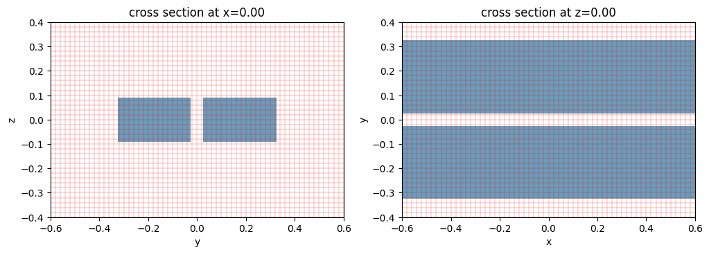
Note: Tidy3D is warning us that our Simulation does not contain sources. In this case, since we are using the simulation as a demonstration of the meshing process and are not running any simulations, we may safely ignore this warning throughout this notebook.
Quasi-uniform grid#
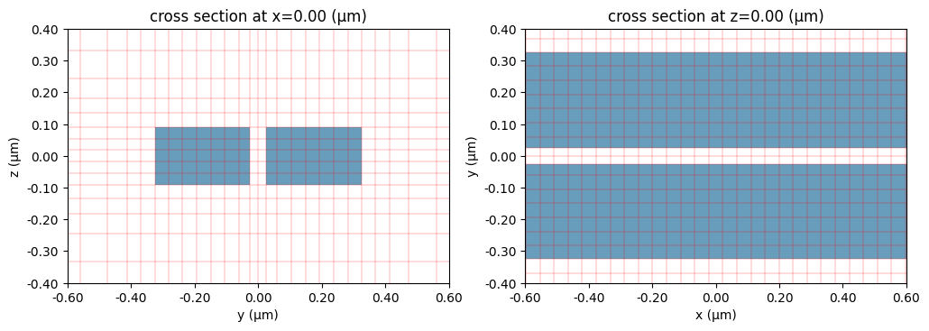
In many simulations, we aim to have a meshing that is almost uniform everywhere, but locally adjust to structure boundaries or snapping points. This can be achieved simply using td.GridSpec.quasiuniform(dl=...) as shown below.
[5]:
sim_quasiuniform = td.Simulation(
    size=[5, 3, 3],
    grid_spec=td.GridSpec.quasiuniform(dl=20 * nm),
    medium=sub_med,
    structures=[box1, box2],
    boundary_spec=boundary_spec,
    run_time=1e-12,
)

ax = plot_sim_grid(sim_quasiuniform)
Total number of grid points (millions): 8.4

The grids look quite uniform. Compared to the uniform grid figure, here the grid is aligned with the edges of the two waveguides’ boundaries.
Automatic nonuniform grid#
By default, Tidy3D uses a more advanced meshing, using an algorithm to automatically define a nonuniform grid in all three directions. The resolution of this grid is specified using two parameters:
Minimum steps per wavelength in each material (
min_steps_per_wvl = 10by default). This specification therefore requires a target wavelength, which can be either provided directly togrid_spec, or inferred from any sources present in the simulation. The two simulations below will have the same grid;Minimum steps per longest edge length of simulation domain bounding box (
min_steps_per_sim_size=10by default). This specification is relevant when the entire simulation domain is subwavelength, e.g. in radio-frequency simulations.
[6]:
# provide wavelength directly
sim_nonuniform_10 = td.Simulation(
    size=[5, 3, 3],
    grid_spec=td.GridSpec.auto(wavelength=wavelength),
    medium=sub_med,
    structures=[box1, box2],
    boundary_spec=boundary_spec,
    run_time=1e-12,
)

# no grid_spec defined; using default with wavelength taken from source
source = td.ModeSource(
    center=(-2, 0, 0),
    size=(0, 2, 2),
    mode_index=0,
    direction="+",
    source_time=td.GaussianPulse(freq0=freq0, fwidth=freq0 / 10),
)
sim_nonuniform_10 = td.Simulation(
    size=[5, 3, 3],
    medium=sub_med,
    structures=[box1, box2],
    boundary_spec=boundary_spec,
    run_time=1e-12,
    sources=[source],
)

ax = plot_sim_grid(sim_nonuniform_10)
Total number of grid points (millions): 0.53
The default grid is somewhat coarse, but it is often good for initial simulations. We can easily refine it by requiring a higher number of steps per wavelength:
[7]:
sim_nonuniform_20 = td.Simulation(
    size=[5, 3, 3],
    grid_spec=td.GridSpec.auto(
        wavelength=wavelength,
        min_steps_per_wvl=20,
    ),
    medium=sub_med,
    structures=[box1, box2],
    boundary_spec=boundary_spec,
    run_time=1e-12,
)
ax = plot_sim_grid(sim_nonuniform_20)
Total number of grid points (millions): 2.3
Notice how the automatic grid conforms to the structures in the simulation, and the grid steps are high in the high-index regions.
Lower bound of grid size#
Sometimes the grid size in the automatically generated mesh is too small. A lower bound dl_min can be set to increase the minimal grid size. Note that the bound is soft, meaning that the actual grid size might be slightly smaller.
The minimal step size along y-direction in the previous setup is,
[8]:
print(f"Minimal grid size along y-direction = {min(sim_nonuniform_20.grid.sizes.y) * 1e3:1.2f}nm")
Minimal grid size along y-direction = 16.67nm
Now let’s set a lower bound of 25nm.
[9]:
sim_nonuniform_20 = td.Simulation(
    size=[5, 3, 3],
    grid_spec=td.GridSpec.auto(
        wavelength=wavelength,
        min_steps_per_wvl=20,
        dl_min=25 * nm,
    ),
    medium=sub_med,
    structures=[box1, box2],
    boundary_spec=boundary_spec,
    run_time=1e-12,
)
ax = plot_sim_grid(sim_nonuniform_20)
print(f"Minimal grid size along y-direction = {min(sim_nonuniform_20.grid.sizes.y) * 1e3:1.2f}nm")
Total number of grid points (millions): 1.9
Minimal grid size along y-direction = 24.57nm
The actual minimal grid size along y-direction is 24.57nm, greater than 16.67nm when dl_min is not set.
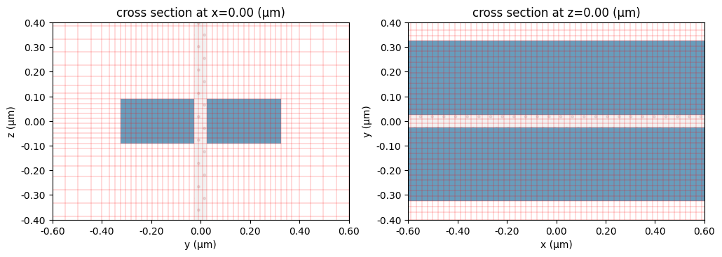
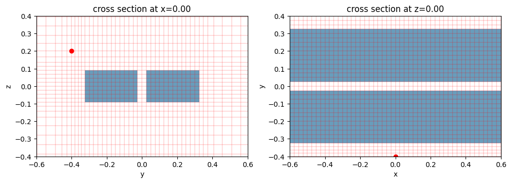
Grid snapping points#
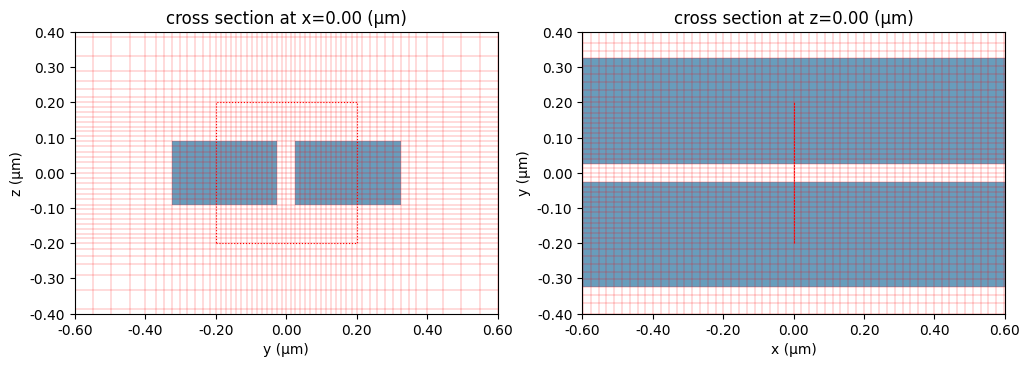
Sometimes we want to make sure that grids are placed at certain locations. This can be achieved by adding snapping_points to the simulation grid_spec. snapping_points is a list of coordinates defining the positions of the points. Note that the snapping of grids is not enforced if they are too close among themselves or to structure boundaries.
In the previous example, there is no grid point at (0, -0.4, 0.2). Let’s add a snapping point there to see the effects. As illustrated below, the snapping point is visualized as a red dot. Now grid boundaries pass through this point.
[10]:
sim_nonuniform_20 = td.Simulation(
    size=[5, 3, 3],
    grid_spec=td.GridSpec.auto(
        wavelength=wavelength,
        min_steps_per_wvl=20,
        dl_min=25 * nm,
        snapping_points=[
            (0, -0.4, 0.2),
        ],
    ),
    medium=sub_med,
    structures=[box1, box2],
    boundary_spec=boundary_spec,
    run_time=1e-12,
)
ax = plot_sim_grid(sim_nonuniform_20)
Total number of grid points (millions): 2.0

Mesh override structures#
For this particular problem, we may want to do a final refinement around the slot, where we expect the fields to be strongest. This can be achieved by adding override_structures to the simulation grid_spec.
override_structures is a list of Tidy3D structures each with an arbitrary geometry which are used exclusively for the meshing, added on top of any physical simulation structures.
There are two types of Tidy3D structures that can be added the override_structures list. The first type defines a fictitious medium inside the override structure so that the grid size is decided by the minimum steps per wavelength in the medium; The second type is more straightforward: one can directly define the grid size along each axis inside the override structures.
Override Structure – option 1#
The first type is identical to the Structure object that consists of a Geometry and a Medium. The grid step in the override_structure region is decided by the minimum steps per wavelength in this medium.
[11]:
# Define a "dummy" box with refractive index 5 around the central location of the waveguide
refine_box = td.Structure(
    geometry=td.Box(center=(0, 0, 0), size=(td.inf, 0.4, 0.4)),
    medium=td.Medium(permittivity=5**2),
)

# Use the box as a grid refinement structure
sim_nonuniform_20_refine = td.Simulation(
    size=[5, 3, 3],
    grid_spec=td.GridSpec.auto(
        wavelength=wavelength,
        min_steps_per_wvl=20,
        override_structures=[refine_box],
    ),
    medium=sub_med,
    structures=[box1, box2],
    boundary_spec=boundary_spec,
    run_time=1e-12,
)

ax = plot_sim_grid(sim_nonuniform_20_refine)
Total number of grid points (millions): 4.0

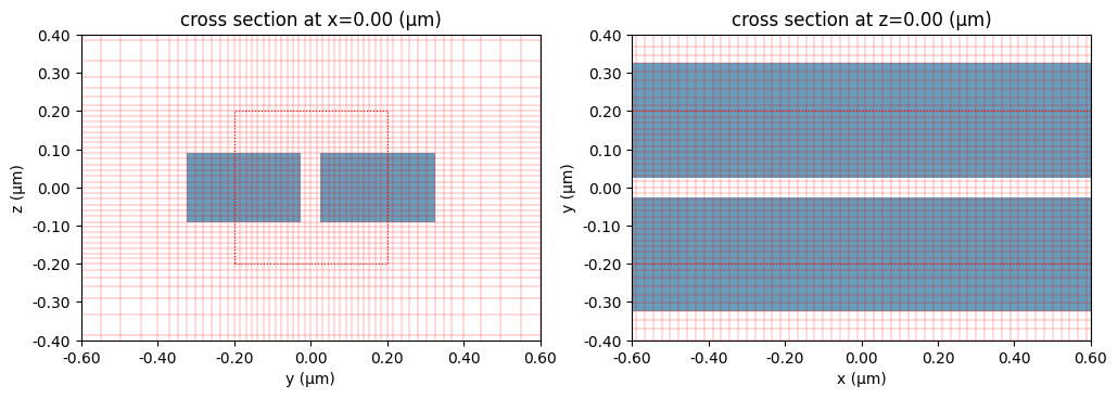
Note that the override region is highlighted in the grid plotting. Now this looks pretty good - the grid size of the points around the slot region is 1550 / 20 / 5 = 15.5 nanometers, while overall the simulation has twice fewer total number of grid points (4.0M) compared to the simulation with a uniform mesh step of 20 nanometers (8.3M). One thing to note, however, is that the override structure made the grid along the x-dimension small, which may not be necessary. To avoid this,
we can change that structure to have size = 0 along that dimension. This would force the non-uniform grid to place a grid boundary at the center of the override structure along x, but apart from that it will not refine the grid step along x.
[12]:
# Redefine the box with size 0 along x
refine_box = td.Structure(
    geometry=td.Box(center=(0, 0, 0), size=(0, 0.4, 0.4)),
    medium=td.Medium(permittivity=5**2),
)

# Use the box as a grid refinement structure
sim_nonuniform_20_refine = td.Simulation(
    size=[5, 3, 3],
    grid_spec=td.GridSpec.auto(
        wavelength=wavelength,
        min_steps_per_wvl=20,
        override_structures=[refine_box],
    ),
    medium=sub_med,
    structures=[box1, box2],
    boundary_spec=boundary_spec,
    run_time=1e-12,
)

ax = plot_sim_grid(sim_nonuniform_20_refine)
Total number of grid points (millions): 3.0
Override Structure – option 2#
The second type is the MeshOverrideStructure object that consists of a Geometry, and a tuple dl specifying the grid sizes along x,y,z directions. We can override the grid sizes just along a few selected directions by setting the value to be None in the dl tuple along the other directions.
E.g. if we only plan to refine the grid size along x-direction with grid size 0.01 micron, we can apply dl=(0.01, None, None). In the following, we override the grid size along y and z to be 15.5nm.
[13]:
refine_box = td.MeshOverrideStructure(
    geometry=td.Box(center=(0, 0, 0), size=(td.inf, 0.4, 0.4)),
    dl=[None, 15.5 * nm, 15.5 * nm],
)

# Use the box as a grid refinement structure
sim_nonuniform_20_refine = td.Simulation(
    size=[5, 3, 3],
    grid_spec=td.GridSpec.auto(
        wavelength=wavelength,
        min_steps_per_wvl=20,
        override_structures=[refine_box],
    ),
    medium=sub_med,
    structures=[box1, box2],
    boundary_spec=boundary_spec,
    run_time=1e-12,
)

ax = plot_sim_grid(sim_nonuniform_20_refine)
Total number of grid points (millions): 2.9
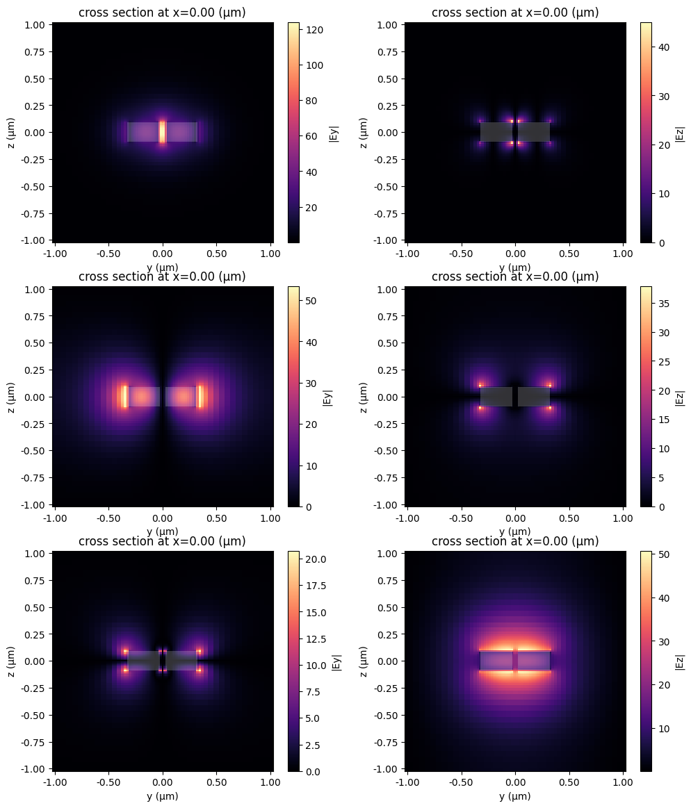
Just for fun, we can also have a look at the modes of this structure.
[14]:
num_modes = 3
plane = td.Box(center=(0, 0, 0), size=(0, 2, 2))
mode_spec = td.ModeSpec(num_modes=num_modes)
ms = ModeSolver(
    simulation=sim_nonuniform_20_refine, plane=plane, mode_spec=mode_spec, freqs=[freq0]
)
modes = ms.solve()
fig, axs = ms.plot_field_components(
    field_names=("Ey", "Ez"),
    mode_indices=tuple(range(num_modes)),
    val="abs",
    f=freq0,
    robust=False,
    figsize=(12, 14),
)
plt.show()
16:09:25 CEST WARNING: Use the remote mode solver with subpixel averaging for
              better accuracy through 'tidy3d.web.run(...)' or the deprecated
              'tidy3d.plugins.mode.web.run(...)'. Alternatively, you can install
              the package 'tidy3d-extras' using 'pip install "tidy3d"' and set
              'config.simulation.use_local_subpixel=True'.
Mesh override with coarser grid size#
Sometimes, instead of refinement, we want to override a region with a coarser mesh. This can be achieved by setting enforce=True in MeshOverrideStructure.
First, let’s see the default behavior where enforce=False so that the override structure with coarser mesh will be ignored unless it fully covers the structure of fine mesh. In the following example, we try to override the mesh along x-direction be to 40nm.
[15]:
refine_box = td.MeshOverrideStructure(
    geometry=td.Box(center=(0, 0, 0), size=(td.inf, 0.4, 0.4)),
    dl=[50 * nm, 15.5 * nm, 15.5 * nm],
)

# Use the box as a grid refinement structure
sim_nonuniform_20_coarser = td.Simulation(
    size=[5, 3, 3],
    grid_spec=td.GridSpec.auto(
        wavelength=wavelength,
        min_steps_per_wvl=20,
        override_structures=[refine_box],
    ),
    medium=sub_med,
    structures=[box1, box2],
    boundary_spec=boundary_spec,
    run_time=1e-12,
)

ax = plot_sim_grid(sim_nonuniform_20_coarser)
print(
    f"Minimal grid size along x-direction = {min(sim_nonuniform_20_coarser.grid.sizes.x) * 1e3:1.2f}nm"
)
Total number of grid points (millions): 2.9
Minimal grid size along x-direction = 22.22nm

The minimal grid size along x-direction is still 22nm, so the override_structures doesn’t take effect. This is because, by default, the meshing chooses the step size based on the highest-index structure (real or override) at any given cross-section. However, this behavior can be overridden if we set enforce=True in an MeshOverrideStructure, in which case other structures are ignored.
[16]:
refine_box = td.MeshOverrideStructure(
    geometry=td.Box(center=(0, 0, 0), size=(td.inf, 0.4, 0.4)),
    dl=[40 * nm, None, None],
    enforce=True,
)

# Use the box as a grid refinement structure
sim_nonuniform_20_coarser = td.Simulation(
    size=[5, 3, 3],
    grid_spec=td.GridSpec.auto(
        wavelength=wavelength,
        min_steps_per_wvl=20,
        override_structures=[refine_box],
    ),
    medium=sub_med,
    structures=[box1, box2],
    boundary_spec=boundary_spec,
    run_time=1e-12,
)

ax = plot_sim_grid(sim_nonuniform_20_coarser)
print(
    f"Minimal grid size along x-direction = {min(sim_nonuniform_20_coarser.grid.sizes.x) * 1e3:1.2f}nm"
)
Total number of grid points (millions): 1.4
Minimal grid size along x-direction = 40.00nm

Now the minimal grid size along x-direction is target 40nm. When multiple override structures with enforce=True overlap, the grid size in the intersection region is decided by the last such structure in the list.
Combination of uniform and nonuniform grid#
Finally, we note that Tidy3D allows another easy way to handle the x direction in our example, namely applying different grid specifications along each of the three simulation directions. For example, we can set a fixed grid size of 40nm along the propagation direction, where we expect the field dependence to be smooth, while still using the refined nonuniform mesh in the other two directions. This achieves the same effect as in the plot above.
[17]:
grid_spec = td.GridSpec(
    grid_x=td.UniformGrid(dl=0.04),
    grid_y=td.AutoGrid(min_steps_per_wvl=20),
    grid_z=td.AutoGrid(min_steps_per_wvl=20),
    wavelength=wavelength,
    override_structures=[refine_box],
)

sim_nonuniform_yz_uniform_x = td.Simulation(
    size=[5, 3, 3],
    grid_spec=grid_spec,
    medium=sub_med,
    structures=[box1, box2],
    boundary_spec=boundary_spec,
    run_time=1e-12,
)

ax = plot_sim_grid(sim_nonuniform_yz_uniform_x)
16:09:27 CEST WARNING: Override structures take no effect along x-axis. If
              intending to apply override structures to this axis, use
              'AutoGrid' or 'QuasiUniformGrid'.
Total number of grid points (millions): 1.4
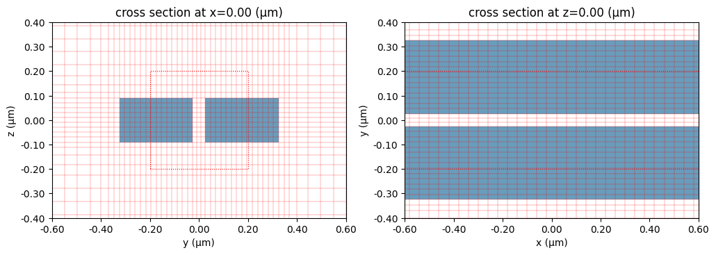
Note: the 2nd warning is just letting us know that we are using uniform grid along x-axis even though the override structures have some extent in these dimensions. We can ignore as this is intended.