

LiDAR Chip Layout and Verification
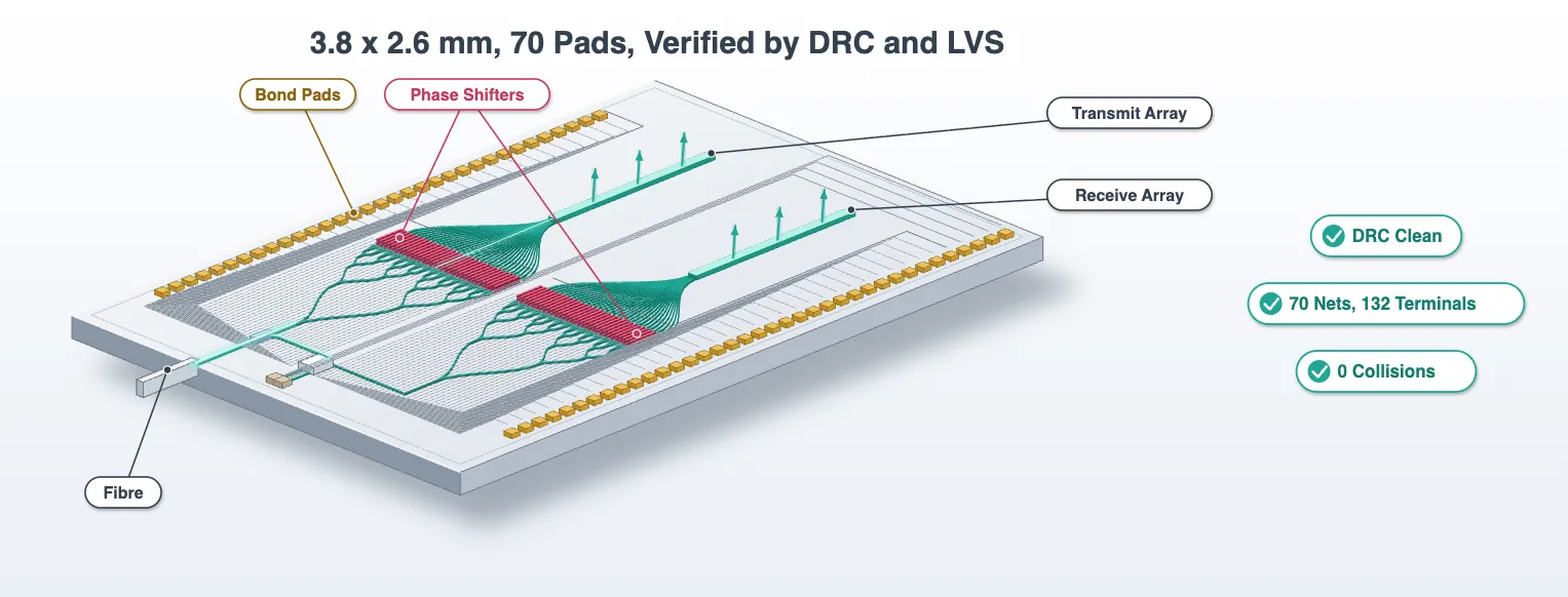
The component library left eight cells that each carry their own model. This notebook places them: a phased array that splits one input into 32 phase-shifted channels and fans them into 32 antennas, placed twice for transmit and receive, the coherent receiver between the two, the edge coupler at the facet, and the metal that takes 64 heaters and two photodiodes out to bond pads.
Two parts of the layout need design decisions.
The first is the fan-in. The phase shifters sit 25 um apart so that their heaters do not couple thermally, and the antennas sit 1.3 um apart to steer without grating lobes. Every channel therefore bends inward by a different amount over the same length, and the outer channels are longer. The technology page worked out what that costs when the laser is tuned. This notebook shows that the difference cannot be made up with straight waveguide, and records it instead.
The second is the metal. Sixty-four heater nets and two diodes leave a bank a few hundred micrometres tall and have to reach pad rows several millimetres long on a single metal layer, without one trace crossing another. The trace pattern is nested by construction. The notebook closes by checking the drawn nets against the intended ones, which is a layout-versus-schematic check.
The mask is written out at the end and checked against the design rules of the process.
# The cells, the technology and every measured number come fromfrom runpy import run_path
# Lidar_Components.qmd defines what this notebook builds on. Its shared cells are# generated into the module below; see docs/scripts/generate_notebook_modules.py.globals().update(    {k: v for k, v in run_path("misc/lidar_components.py").items() if not k.startswith("_")})
# Open the interactive layout viewer, which redraws as cells are built belowfrom photonforge.live_viewer import LiveViewer
viewer = LiveViewer()LiveViewer started at http://127.0.0.1:34703. Call its 'stop()' method to free the port.# Layout parameters. The phase-shifter pitch comes from the heater crosstalk measured on# the steering page: 3.5 percent at 20 um, so 25 um keeps the correction small.n_ch = 32 # Channels per arraypitch_ps = 25.0 # Phase-shifter pitch (um)pitch_ant = pitch # Antenna pitch (um), from the system budget: below the wavelengthl_fan = 600.0 # x budget of the fan-in from the shifter pitch to the antenna pitch (um)pad_size = 50.0 # Bond pad (um)pad_pitch = 90.0 # Pad centre to centre (um)bank_gap = 150.0 # Clear space between the two arrays (um)trace_pitch = 6.0 # Heater trace column and level pitch: 3 um metal, 3 um gap (um)lane_x0 = -250.0 # Leftmost heater-trace column, left of the tree root (um)escape = 30.0 # First trace level above and below a bank (um)
# Analytic waveguide model carrying the measured strip index and loss for every routeroute_model = pf.AnalyticWaveguideModel( n_eff=n_eff_strip, n_group=n_group_strip, propagation_loss=scattering_db_cm * 1e-4, # dB/cm to dB/um reference_frequency=f0,)# Give it the matching time stepper, which propagates through a real delay line.# The default fits poles to the S matrix, and that cannot hold a long delay.route_model.time_stepper = pf.AnalyticWaveguideTimeStepper( n_eff=n_eff_strip, n_group=n_group_strip, propagation_loss=scattering_db_cm * 1e-4,)# Apply it to every primitive the router builds routes fromfor primitive in ("bend", "s_bend", "straight", "route_s_bend"): pf.config.default_kwargs[primitive] = {"model": route_model}The phased array feed
Section titled “The phased array feed”One cell holds everything between the input waveguide and the antennas: a five-stage tree of 1x2 splitters, a bank of 32 phase shifters, and the fan-in. It is used twice, once per array.
The tree is balanced: every channel passes through five splitters and five S bends, and the S bends of one stage all have the same offset, so every channel reaches its phase shifter with the same path. The stage spacing is set from the offset each S bend has to make.
The phase shifters start on one line. Their heaters are then aligned, which the metal routing below needs, and the fan-in starts from one line too.
The fan-in is one S bend per channel over a common x budget, so the antennas also start on one line. Its arc length grows with the offset, and the offsets run from half a micrometre for the centre channels to nearly four hundred for the outer ones. A straight cannot make up that difference: any straight added to an inner channel takes x away from its S bend, and a shorter S bend for the same offset is longer still. Bending the inner channels outward first and back again does equalize the arcs, but only by giving every channel the same final offset, which puts every apex on the same line and the channels on top of each other. The equal-length alternatives all need tens of micrometres of room per channel, which a 25 um pitch does not have, so the mismatch is kept, measured with route_length, and stored on the cell for the steering page to correct with the heaters.
Every heater end becomes a terminal of the cell, H0_k on the signal side and H1_k on the
ground side, and the fan-in outputs become its ports A0 to A31. The cell carries a circuit
model, so the steering page can ask it for the amplitude and
phase that reach each antenna.
@pf.parametric_component(name_prefix="OPA")def phased_array(*, pitch=pitch_ps, fan_length=l_fan):    # Empty name, so the decorator builds one from the arguments    c = pf.Component()
    # Length of one splitter cell, which sets the stage spacing with the S bends    mmi_len = splitter.size()[0]
    # Tree: stage j holds 2^j splitters at centre spacing pitch * 2^(5 - j)    x = 0.0    stage_refs, links = [], []    for j in range(5):        # Centre spacing of this stage, and the y of each splitter in it        spacing = pitch * 2 ** (5 - j)        ys = (np.arange(2**j) - (2**j - 1) / 2) * spacing
        # Place the splitters of this stage on one line        refs = [c.add_reference(splitter).translate((x, y)) for y in ys]        stage_refs.append(refs)
        # Link each splitter to its parent; even children hang off P1, odd children off P2        if j > 0:            prev = stage_refs[j - 1]            links.append(                [                    c.add_reference(                        pf.parametric.route_s_bend(                            port1=(prev[k // 2], "P2" if k % 2 else "P1"),                            port2=(ref, "P0"),                        )                    )                    for k, ref in enumerate(refs)                ]            )
        # Advance to the next stage by the cell length plus room for the S bend offset        offset = spacing / 4 - 1.0 if j < 4 else pitch / 2 - 1.0        x += mmi_len + max(20.0, 2.5 * offset)
    # Every phase shifter starts on this line    x_ps = x
    # Channel positions at the shifter pitch    y_ch = (np.arange(n_ch) - (n_ch - 1) / 2) * pitch
    # Place one shifter per channel, link it to the last splitter stage, expose its heater ends    final = []    for k in range(n_ch):        ps_ref = c.add_reference(ps).translate((x_ps, y_ch[k]))        final.append(            c.add_reference(                pf.parametric.route_s_bend(                    port1=(stage_refs[-1][k // 2], "P2" if k % 2 else "P1"),                    port2=(ps_ref, "P0"),                )            )        )        c.add_terminal(ps_ref["H0"], f"H0_{k}")        c.add_terminal(ps_ref["H1"], f"H1_{k}")
    # Antenna positions, and the line the fan-in starts from    y_ant = (np.arange(n_ch) - (n_ch - 1) / 2) * pitch_ant    x_fan = x_ps + ps.size()[0]
    # Fan-in: one S bend per channel over the common x budget, its far end an antenna port    fans = []    for k in range(n_ch):        fan = c.add_reference(            pf.parametric.s_bend(                port_spec="TE_1550_500",                length=fan_length,                offset=float(y_ant[k] - y_ch[k]),            )        ).translate((x_fan, y_ch[k]))        fans.append(fan)        c.add_port(fan["P1"], f"A{k}")
    # The tree root is the input of the whole cell    c.add_port(stage_refs[0][0]["P0"], "IN")
    # Check that neighbouring fans do not touch: two channels' silicon must merge into two polygons    for k in range(n_ch - 1):        pair = pf.Component()        for r in (fans[k], fans[k + 1]):            pair.add_reference(r.component).translate(r.origin)        assert (            len(pf.boolean(pair.get_structures("Si"), [], "+")) == 2        ), f"fan-in channels {k} and {k + 1} touch"
    # Measure the path from the input to each antenna: the links on the channel's branch of    # the tree, its last S bend, the shifter and its fan    path = np.zeros(n_ch)    for k in range(n_ch):        for j, stage in enumerate(links, start=1):            path[k] += pf.route_length(stage[k // 2 ** (5 - j)].component)        path[k] += (            pf.route_length(final[k].component)            + ps.size()[0]            + pf.route_length(fans[k].component)        )
    # Store the geometry the chip and the steering page read back    for key, value in (        ("x_ps", x_ps),        ("x_fan", x_fan),        ("y_ch", y_ch.tolist()),        ("path", path.tolist()),    ):        c.properties[key] = value
    # A circuit model, so the feed answers for the amplitude and phase it delivers to each antenna    c.add_model(pf.CircuitModel(), "Circuit")    return c
# Build the feed cell and read the recorded paths backfeed = phased_array()path = np.array(feed.properties["path"])print(    f"feed cell {feed.size()[0]:.0f} x {feed.size()[1]:.0f} um, {len(feed.references)} references, "    f"{len(feed.ports)} ports, {len(feed.terminals)} terminals")print(    f"path from input to antenna: {path.min():.2f} to {path.max():.2f} um, mismatch {path.max() - path.min():.1f} um")
# Phase the mismatch puts between the centre and the outer channel over the tuning rangetune = wavelengths[-1] - wavelengths[0]  # Laser tuning range (um)drift = 2 * np.pi * n_group_strip * (path.max() - path.min()) * tune / lda0**2print(    f"over the {tune * 1e3:.0f} nm tune the outer channel drifts {drift:.0f} rad against the centre one")viewer(feed)
feed cell 1888 x 778 um, 157 references, 33 ports, 64 terminalspath from input to antenna: 1866.50 to 2006.54 um, mismatch 140.0 umover the 40 nm tune the outer channel drifts 61 rad against the centre one;fill:%23221f20;font-weight:bold;font-size:38.673000px;}.terminal{fill:none;stroke:%23805080;stroke-width:4.834125;}.dashed{stroke-dasharray:24.170625,14.502375;}.port{fill:none;stroke:%23805080;stroke-width:9.668250;}.virtual-connection{fill:none;stroke:%23907090;stroke-width:7.251188;}.layer_10_0{stroke:%23878787;fill:%23888888;fill-opacity:0.094;}.label_10_0{fill:%23878787;}.layer_98_0{stroke:%23c8385a;fill:none;}.label_98_0{fill:%23c8385a;}.layer_99_0{stroke:%232e7d5b;fill:none;}.label_99_0{fill:%232e7d5b;}.layer_7_0{stroke:%237a5c99;fill:url(%23pat-layer_7_0);fill-opacity:0.492;}.label_7_0{fill:%237a5c99;}.layer_11_0{stroke:%23666666;fill:%23666666;fill-opacity:0.094;}.label_11_0{fill:%23666666;}.layer_12_0{stroke:%23b88b14;fill:url(%23pat-layer_12_0);fill-opacity:0.492;}.label_12_0{fill:%23b88b14;}.layer_14_0{stroke:%23838383;fill:%23b0b0b0;fill-opacity:0.094;}.label_14_0{fill:%23838383;}.layer_15_0{stroke:%23000000;fill:url(%23pat-layer_15_0);fill-opacity:0.492;}.label_15_0{fill:%23000000;}.layer_1_0{stroke:%231f4e79;fill:url(%23pat-layer_1_0);fill-opacity:0.492;}.label_1_0{fill:%231f4e79;}.layer_2_0{stroke:%234f8fc9;fill:url(%23pat-layer_2_0);fill-opacity:0.492;}.label_2_0{fill:%234f8fc9;}.layer_13_0{stroke:%23878787;fill:%23aaaaaa;fill-opacity:0.094;}.label_13_0{fill:%23878787;}</style><defs><path id=%22port-symbol%22 class=%22port%22 d=%22M 0,-19.336500 L 29.004750,0 0,19.336500%22 /><path id=%22ref-port-symbol%22 class=%22port%22 style=%22stroke-opacity:0.33;%22 d=%22M 0,-14.502375 C 19.336500,-14.502375 19.336500,14.502375 0,14.502375%22 /><circle id=%22port-bend-symbol%22 style=%22stroke-width:0;stroke:none;fill:%23805080;fill-opacity:1;%22 cx=%220%22 cy=%220%22 r=%228.701425%22 /><circle id=%22connection-symbol%22 style=%22stroke-width:0;stroke:none;fill:%23907090;fill-opacity:1;%22 cx=%220%22 cy=%220%22 r=%2210.151663%22 /><pattern id=%22pat-layer_7_0%22 patternUnits=%22userSpaceOnUse%22 width=%2224.170625%22 height=%2224.170625%22 patternTransform=%22translate(21.327022,1.272138)%22><line x1=%2212.085313%22 y1=%220%22 x2=%2212.085313%22 y2=%2224.170625%22 style=%22stroke:%237a5c99;stroke-width:2.417063%22 /><line x1=%220%22 y1=%2212.085313%22 x2=%2224.170625%22 y2=%2212.085313%22 style=%22stroke:%237a5c99;stroke-width:2.417063%22 /></pattern><pattern id=%22pat-layer_12_0%22 patternUnits=%22userSpaceOnUse%22 width=%2224.170625%22 height=%2224.170625%22 patternTransform=%22translate(22.748824,22.898487)%22><line x1=%220%22 y1=%2212.085313%22 x2=%2224.170625%22 y2=%2212.085313%22 style=%22stroke:%23b88b14;stroke-width:2.417063%22 /></pattern><pattern id=%22pat-layer_15_0%22 patternUnits=%22userSpaceOnUse%22 width=%2214.502375%22 height=%2214.502375%22 patternTransform=%22translate(2.559243,9.922678)%22><circle cx=%227.251188%22 cy=%227.251188%22 r=%222.417063%22 style=%22stroke:none;fill:%23000000;fill-opacity:1.0%22 /></pattern><pattern id=%22pat-layer_1_0%22 patternUnits=%22userSpaceOnUse%22 width=%2224.170625%22 height=%2224.170625%22 patternTransform=%22translate(9.952610,13.993520)%22><line x1=%220%22 y1=%220%22 x2=%2224.170625%22 y2=%2224.170625%22 style=%22stroke:%231f4e79;stroke-width:2.417063%22 /><line x1=%22-12.085313%22 y1=%2212.085313%22 x2=%2212.085313%22 y2=%2236.255938%22 style=%22stroke:%231f4e79;stroke-width:2.417063%22 /><line x1=%2212.085313%22 y1=%22-12.085313%22 x2=%2236.255938%22 y2=%2212.085313%22 style=%22stroke:%231f4e79;stroke-width:2.417063%22 /></pattern><pattern id=%22pat-layer_2_0%22 patternUnits=%22userSpaceOnUse%22 width=%2224.170625%22 height=%2224.170625%22 patternTransform=%22translate(19.905221,3.816414)%22><line x1=%2224.170625%22 y1=%220%22 x2=%220%22 y2=%2224.170625%22 style=%22stroke:%234f8fc9;stroke-width:2.417063%22 /><line x1=%2236.255938%22 y1=%2212.085313%22 x2=%2212.085313%22 y2=%2236.255938%22 style=%22stroke:%234f8fc9;stroke-width:2.417063%22 /><line x1=%2212.085313%22 y1=%22-12.085313%22 x2=%22-12.085313%22 y2=%2212.085313%22 style=%22stroke:%234f8fc9;stroke-width:2.417063%22 /></pattern><g id=%22C1%22 data-name=%22MMI__Y2E325E5LTS7VCJM34U4E36Q4BZFKXA2VZF35CLMCY5WY3J7NVSA%22><rect class=%22layer_1_0%22 x=%22-7.000000%22 y=%22-2.000000%22 width=%2214.000000%22 height=%224.000000%22 /><path class=%22layer_1_0%22 d=%22M -12.000000,-0.250000 -7.000000,-0.750000 -7.000000,0.750000 -12.000000,0.250000 z%22 /><path class=%22layer_1_0%22 d=%22M 12.000000,-0.750000 7.000000,-0.250000 7.000000,-1.750000 12.000000,-1.250000 z%22 /><path class=%22layer_1_0%22 d=%22M 12.000000,1.250000 7.000000,1.750000 7.000000,0.250000 12.000000,0.750000 z%22 /></g><g id=%22C10%22 data-name=%22route_s_bend__VCTT3BKA5DEDPQS4XZVT2PAAAPAB7YY5NEF7DDQZ2UWWU5THQBBA%22><path class=%22layer_1_0%22 d=%22M 805.000000,-101.250000 805.963000,-101.255000 807.888000,-101.297000 809.812000,-101.381000 810.773000,-101.438000 811.733000,-101.506000 812.693000,-101.585000 813.652000,-101.674000 814.609000,-101.773000 815.566000,-101.883000 816.521000,-102.003000 817.475000,-102.133000 818.427000,-102.274000 819.378000,-102.425000 820.328000,-102.586000 821.275000,-102.758000 822.220000,-102.940000 824.105000,-103.335000 825.044000,-103.548000 825.981000,-103.771000 826.915000,-104.004000 828.775000,-104.501000 829.701000,-104.764000 830.624000,-105.038000 832.461000,-105.615000 834.286000,-106.232000 835.192000,-106.555000 836.096000,-106.889000 837.891000,-107.584000 839.671000,-108.319000 840.555000,-108.701000 841.435000,-109.092000 843.181000,-109.903000 844.048000,-110.323000 844.910000,-110.752000 845.767000,-111.191000 846.619000,-111.639000 847.466000,-112.096000 848.309000,-112.562000 849.146000,-113.037000 850.805000,-114.015000 852.442000,-115.029000 853.252000,-115.549000 854.057000,-116.078000 855.648000,-117.162000 857.216000,-118.280000 857.990000,-118.852000 859.521000,-120.021000 861.025000,-121.223000 862.503000,-122.457000 863.232000,-123.086000 863.954000,-123.723000 864.669000,-124.368000 866.078000,-125.681000 866.782000,-126.345000 868.213000,-127.650000 869.672000,-128.923000 870.412000,-129.548000 871.912000,-130.773000 873.438000,-131.965000 874.989000,-133.123000 875.775000,-133.690000 876.566000,-134.248000 878.166000,-135.338000 878.975000,-135.870000 879.790000,-136.393000 881.437000,-137.413000 882.268000,-137.909000 883.105000,-138.396000 883.947000,-138.874000 884.794000,-139.343000 885.646000,-139.803000 886.503000,-140.253000 887.365000,-140.694000 888.232000,-141.126000 889.103000,-141.548000 889.979000,-141.961000 890.859000,-142.364000 892.633000,-143.141000 894.423000,-143.880000 895.324000,-144.235000 896.229000,-144.580000 897.137000,-144.915000 898.049000,-145.240000 898.965000,-145.555000 899.884000,-145.860000 901.731000,-146.441000 902.659000,-146.716000 903.591000,-146.981000 904.525000,-147.236000 906.401000,-147.715000 907.343000,-147.939000 908.287000,-148.153000 909.234000,-148.357000 910.182000,-148.550000 911.133000,-148.733000 912.086000,-148.906000 913.040000,-149.068000 913.997000,-149.220000 914.955000,-149.362000 915.914000,-149.493000 916.875000,-149.614000 917.837000,-149.724000 918.800000,-149.824000 919.764000,-149.913000 920.729000,-149.992000 921.695000,-150.061000 923.628000,-150.166000 924.596000,-150.203000 926.532000,-150.245000 927.500000,-150.250000 927.500000,-149.750000 926.537000,-149.745000 924.612000,-149.703000 923.650000,-149.666000 922.688000,-149.619000 921.727000,-149.562000 920.767000,-149.494000 919.807000,-149.415000 918.848000,-149.326000 917.891000,-149.227000 916.934000,-149.117000 915.979000,-148.997000 915.025000,-148.867000 914.073000,-148.726000 913.122000,-148.575000 912.173000,-148.414000 911.225000,-148.242000 910.280000,-148.060000 908.395000,-147.665000 907.456000,-147.452000 906.519000,-147.229000 905.585000,-146.996000 903.725000,-146.499000 902.799000,-146.236000 901.876000,-145.962000 900.039000,-145.385000 898.214000,-144.768000 897.308000,-144.445000 896.404000,-144.111000 894.609000,-143.416000 892.829000,-142.681000 891.065000,-141.908000 889.319000,-141.097000 888.452000,-140.677000 887.590000,-140.248000 886.733000,-139.809000 885.881000,-139.361000 884.191000,-138.438000 883.354000,-137.963000 881.695000,-136.985000 880.058000,-135.971000 879.248000,-135.451000 878.443000,-134.922000 876.852000,-133.838000 875.284000,-132.720000 874.510000,-132.148000 872.979000,-130.979000 871.475000,-129.777000 869.997000,-128.543000 869.268000,-127.914000 868.546000,-127.277000 867.831000,-126.632000 866.422000,-125.319000 865.718000,-124.655000 864.287000,-123.350000 862.828000,-122.077000 862.088000,-121.452000 860.588000,-120.227000 859.062000,-119.035000 857.511000,-117.877000 856.725000,-117.310000 855.934000,-116.752000 855.137000,-116.203000 854.334000,-115.662000 853.525000,-115.130000 852.710000,-114.607000 851.063000,-113.587000 850.232000,-113.091000 849.395000,-112.604000 848.553000,-112.126000 847.706000,-111.657000 846.854000,-111.197000 845.997000,-110.747000 845.135000,-110.306000 844.268000,-109.874000 843.397000,-109.452000 842.521000,-109.039000 841.641000,-108.636000 839.867000,-107.859000 838.077000,-107.120000 837.176000,-106.765000 836.271000,-106.420000 835.363000,-106.085000 834.451000,-105.760000 833.535000,-105.445000 832.616000,-105.140000 830.769000,-104.559000 829.841000,-104.284000 828.909000,-104.019000 827.975000,-103.764000 826.099000,-103.285000 825.157000,-103.061000 824.213000,-102.847000 823.266000,-102.643000 822.318000,-102.450000 821.367000,-102.267000 820.414000,-102.094000 819.460000,-101.932000 818.503000,-101.780000 817.545000,-101.638000 816.586000,-101.507000 815.625000,-101.386000 814.663000,-101.276000 813.700000,-101.176000 812.736000,-101.087000 811.771000,-101.008000 810.805000,-100.939000 808.872000,-100.834000 807.904000,-100.797000 805.968000,-100.755000 805.000000,-100.750000 z%22 /></g><g id=%22C11%22 data-name=%22route_s_bend__3XRO3HQ4XV6T6VEE7HR2SDM7X3LVTE2ID2OEQBIJHR3KVLKMM2OQ%22><path class=%22layer_1_0%22 d=%22M 805.000000,-99.250000 805.968000,-99.245000 807.904000,-99.203000 808.872000,-99.166000 810.805000,-99.061000 811.771000,-98.992000 812.736000,-98.913000 813.700000,-98.824000 814.663000,-98.724000 815.625000,-98.614000 816.586000,-98.493000 817.545000,-98.362000 818.503000,-98.220000 819.460000,-98.068000 820.414000,-97.906000 821.367000,-97.733000 822.318000,-97.550000 823.266000,-97.357000 824.213000,-97.153000 825.157000,-96.939000 826.099000,-96.715000 827.975000,-96.236000 828.909000,-95.981000 829.841000,-95.716000 830.769000,-95.441000 832.616000,-94.860000 833.535000,-94.555000 834.451000,-94.240000 835.363000,-93.915000 836.271000,-93.580000 837.176000,-93.235000 838.077000,-92.880000 839.867000,-92.141000 841.641000,-91.364000 842.521000,-90.961000 843.397000,-90.548000 844.268000,-90.126000 845.135000,-89.694000 845.997000,-89.253000 846.854000,-88.803000 847.706000,-88.343000 848.553000,-87.874000 849.395000,-87.396000 850.232000,-86.909000 851.063000,-86.413000 852.710000,-85.393000 853.525000,-84.870000 854.334000,-84.338000 855.137000,-83.797000 855.934000,-83.248000 856.725000,-82.690000 857.511000,-82.123000 859.062000,-80.965000 860.588000,-79.773000 862.088000,-78.548000 862.828000,-77.923000 864.287000,-76.650000 865.718000,-75.345000 866.422000,-74.681000 867.831000,-73.368000 868.546000,-72.723000 869.268000,-72.086000 869.997000,-71.457000 871.475000,-70.223000 872.979000,-69.021000 874.510000,-67.852000 875.284000,-67.280000 876.852000,-66.162000 878.443000,-65.078000 879.248000,-64.549000 880.058000,-64.029000 881.695000,-63.015000 883.354000,-62.037000 884.191000,-61.562000 885.881000,-60.639000 886.733000,-60.191000 887.590000,-59.752000 888.452000,-59.323000 889.319000,-58.903000 890.190000,-58.493000 891.065000,-58.092000 892.829000,-57.319000 894.609000,-56.584000 896.404000,-55.889000 897.308000,-55.555000 898.214000,-55.232000 900.039000,-54.615000 901.876000,-54.038000 902.799000,-53.764000 903.725000,-53.501000 905.585000,-53.004000 906.519000,-52.771000 907.456000,-52.548000 908.395000,-52.335000 910.280000,-51.940000 911.225000,-51.758000 912.173000,-51.586000 913.122000,-51.425000 914.073000,-51.274000 915.025000,-51.133000 915.979000,-51.003000 916.934000,-50.883000 917.891000,-50.773000 918.848000,-50.674000 919.807000,-50.585000 920.767000,-50.506000 921.727000,-50.438000 922.688000,-50.381000 923.650000,-50.334000 924.612000,-50.297000 926.537000,-50.255000 927.500000,-50.250000 927.500000,-49.750000 926.532000,-49.755000 924.596000,-49.797000 923.628000,-49.834000 921.695000,-49.939000 920.729000,-50.008000 919.764000,-50.087000 918.800000,-50.176000 917.837000,-50.276000 916.875000,-50.386000 915.914000,-50.507000 914.955000,-50.638000 913.997000,-50.780000 913.040000,-50.932000 912.086000,-51.094000 911.133000,-51.267000 910.182000,-51.450000 909.234000,-51.643000 908.287000,-51.847000 907.343000,-52.061000 906.401000,-52.285000 904.525000,-52.764000 903.591000,-53.019000 902.659000,-53.284000 901.731000,-53.559000 899.884000,-54.140000 898.965000,-54.445000 898.049000,-54.760000 897.137000,-55.085000 896.229000,-55.420000 895.324000,-55.765000 894.423000,-56.120000 892.633000,-56.859000 890.859000,-57.636000 889.979000,-58.039000 889.103000,-58.452000 888.232000,-58.874000 887.365000,-59.306000 886.503000,-59.747000 885.646000,-60.197000 884.794000,-60.657000 883.947000,-61.126000 883.105000,-61.604000 882.268000,-62.091000 881.437000,-62.587000 879.790000,-63.607000 878.975000,-64.130000 878.166000,-64.662000 876.566000,-65.752000 875.775000,-66.310000 874.989000,-66.877000 873.438000,-68.035000 871.912000,-69.227000 870.412000,-70.452000 869.672000,-71.077000 868.213000,-72.350000 866.782000,-73.655000 866.078000,-74.319000 864.669000,-75.632000 863.954000,-76.277000 863.232000,-76.914000 862.503000,-77.543000 861.025000,-78.777000 859.521000,-79.979000 857.990000,-81.148000 857.216000,-81.720000 855.648000,-82.838000 854.057000,-83.922000 853.252000,-84.451000 852.442000,-84.971000 850.805000,-85.985000 849.146000,-86.963000 848.309000,-87.438000 847.466000,-87.904000 846.619000,-88.361000 845.767000,-88.809000 844.910000,-89.248000 844.048000,-89.677000 843.181000,-90.097000 841.435000,-90.908000 840.555000,-91.299000 839.671000,-91.681000 837.891000,-92.416000 836.096000,-93.111000 835.192000,-93.445000 834.286000,-93.768000 832.461000,-94.385000 830.624000,-94.962000 829.701000,-95.236000 828.775000,-95.499000 826.915000,-95.996000 825.981000,-96.229000 825.044000,-96.452000 824.105000,-96.665000 822.220000,-97.060000 821.275000,-97.242000 820.328000,-97.414000 819.378000,-97.575000 818.427000,-97.726000 817.475000,-97.867000 816.521000,-97.997000 815.566000,-98.117000 814.609000,-98.227000 813.652000,-98.326000 812.693000,-98.415000 811.733000,-98.494000 810.773000,-98.562000 809.812000,-98.619000 807.888000,-98.703000 805.963000,-98.745000 805.000000,-98.750000 z%22 /></g><g id=%22C12%22 data-name=%22route_s_bend__2RDVHBGERRJPEPLH2HJY6YBOO2KKGPUVIKTPTWMAAJFD5YYI3TUA%22><path class=%22layer_1_0%22 d=%22M 805.000000,98.750000 805.963000,98.745000 807.888000,98.703000 809.812000,98.619000 810.773000,98.562000 811.733000,98.494000 812.693000,98.415000 813.652000,98.326000 814.609000,98.227000 815.566000,98.117000 816.521000,97.997000 817.475000,97.867000 818.427000,97.726000 819.378000,97.575000 820.328000,97.414000 821.275000,97.242000 822.220000,97.060000 824.105000,96.665000 825.044000,96.452000 825.981000,96.229000 826.915000,95.996000 828.775000,95.499000 829.701000,95.236000 830.624000,94.962000 832.461000,94.385000 834.286000,93.768000 835.192000,93.445000 836.096000,93.111000 837.891000,92.416000 839.671000,91.681000 840.555000,91.299000 841.435000,90.908000 843.181000,90.097000 844.048000,89.677000 844.910000,89.248000 845.767000,88.809000 846.619000,88.361000 847.466000,87.904000 848.309000,87.438000 849.146000,86.963000 850.805000,85.985000 852.442000,84.971000 853.252000,84.451000 854.057000,83.922000 855.648000,82.838000 857.216000,81.720000 857.990000,81.148000 859.521000,79.979000 861.025000,78.777000 862.503000,77.543000 863.232000,76.914000 863.954000,76.277000 864.669000,75.632000 866.078000,74.319000 866.782000,73.655000 868.213000,72.350000 869.672000,71.077000 870.412000,70.452000 871.912000,69.227000 873.438000,68.035000 874.989000,66.877000 875.775000,66.310000 876.566000,65.752000 878.166000,64.662000 878.975000,64.130000 879.790000,63.607000 881.437000,62.587000 882.268000,62.091000 883.105000,61.604000 883.947000,61.126000 884.794000,60.657000 885.646000,60.197000 886.503000,59.747000 887.365000,59.306000 888.232000,58.874000 889.103000,58.452000 889.979000,58.039000 890.859000,57.636000 892.633000,56.859000 894.423000,56.120000 895.324000,55.765000 896.229000,55.420000 897.137000,55.085000 898.049000,54.760000 898.965000,54.445000 899.884000,54.140000 901.731000,53.559000 902.659000,53.284000 903.591000,53.019000 904.525000,52.764000 906.401000,52.285000 907.343000,52.061000 908.287000,51.847000 909.234000,51.643000 910.182000,51.450000 911.133000,51.267000 912.086000,51.094000 913.040000,50.932000 913.997000,50.780000 914.955000,50.638000 915.914000,50.507000 916.875000,50.386000 917.837000,50.276000 918.800000,50.176000 919.764000,50.087000 920.729000,50.008000 921.695000,49.939000 923.628000,49.834000 924.596000,49.797000 926.532000,49.755000 927.500000,49.750000 927.500000,50.250000 926.537000,50.255000 924.612000,50.297000 923.650000,50.334000 922.688000,50.381000 921.727000,50.438000 920.767000,50.506000 919.807000,50.585000 918.848000,50.674000 917.891000,50.773000 916.934000,50.883000 915.979000,51.003000 915.025000,51.133000 914.073000,51.274000 913.122000,51.425000 912.173000,51.586000 911.225000,51.758000 910.280000,51.940000 908.395000,52.335000 907.456000,52.548000 906.519000,52.771000 905.585000,53.004000 903.725000,53.501000 902.799000,53.764000 901.876000,54.038000 900.039000,54.615000 898.214000,55.232000 897.308000,55.555000 896.404000,55.889000 894.609000,56.584000 892.829000,57.319000 891.065000,58.092000 889.319000,58.903000 888.452000,59.323000 887.590000,59.752000 886.733000,60.191000 885.881000,60.639000 884.191000,61.562000 883.354000,62.037000 881.695000,63.015000 880.058000,64.029000 879.248000,64.549000 878.443000,65.078000 876.852000,66.162000 875.284000,67.280000 874.510000,67.852000 872.979000,69.021000 871.475000,70.223000 869.997000,71.457000 869.268000,72.086000 868.546000,72.723000 867.831000,73.368000 866.422000,74.681000 865.718000,75.345000 864.287000,76.650000 862.828000,77.923000 862.088000,78.548000 860.588000,79.773000 859.062000,80.965000 857.511000,82.123000 856.725000,82.690000 855.934000,83.248000 855.137000,83.797000 854.334000,84.338000 853.525000,84.870000 852.710000,85.393000 851.063000,86.413000 850.232000,86.909000 849.395000,87.396000 848.553000,87.874000 847.706000,88.343000 846.854000,88.803000 845.997000,89.253000 845.135000,89.694000 844.268000,90.126000 843.397000,90.548000 842.521000,90.961000 841.641000,91.364000 839.867000,92.141000 838.077000,92.880000 837.176000,93.235000 836.271000,93.580000 835.363000,93.915000 834.451000,94.240000 833.535000,94.555000 832.616000,94.860000 830.769000,95.441000 829.841000,95.716000 828.909000,95.981000 827.975000,96.236000 826.099000,96.715000 825.157000,96.939000 824.213000,97.153000 823.266000,97.357000 822.318000,97.550000 821.367000,97.733000 820.414000,97.906000 819.460000,98.068000 818.503000,98.220000 817.545000,98.362000 816.586000,98.493000 815.625000,98.614000 814.663000,98.724000 813.700000,98.824000 812.736000,98.913000 811.771000,98.992000 810.805000,99.061000 808.872000,99.166000 807.904000,99.203000 805.968000,99.245000 805.000000,99.250000 z%22 /></g><g id=%22C13%22 data-name=%22route_s_bend__574QZPXXWVKJ4PPTEA5R3NG2SOKHVMUETNUPYMLGVE32Z5QNN2TQ%22><path class=%22layer_1_0%22 d=%22M 805.000000,100.750000 805.968000,100.755000 807.904000,100.797000 808.872000,100.834000 810.805000,100.939000 811.771000,101.008000 812.736000,101.087000 813.700000,101.176000 814.663000,101.276000 815.625000,101.386000 816.586000,101.507000 817.545000,101.638000 818.503000,101.780000 819.460000,101.932000 820.414000,102.094000 821.367000,102.267000 822.318000,102.450000 823.266000,102.643000 824.213000,102.847000 825.157000,103.061000 826.099000,103.285000 827.975000,103.764000 828.909000,104.019000 829.841000,104.284000 830.769000,104.559000 832.616000,105.140000 833.535000,105.445000 834.451000,105.760000 835.363000,106.085000 836.271000,106.420000 837.176000,106.765000 838.077000,107.120000 839.867000,107.859000 841.641000,108.636000 842.521000,109.039000 843.397000,109.452000 844.268000,109.874000 845.135000,110.306000 845.997000,110.747000 846.854000,111.197000 847.706000,111.657000 848.553000,112.126000 849.395000,112.604000 850.232000,113.091000 851.063000,113.587000 852.710000,114.607000 853.525000,115.130000 854.334000,115.662000 855.137000,116.203000 855.934000,116.752000 856.725000,117.310000 857.511000,117.877000 859.062000,119.035000 860.588000,120.227000 862.088000,121.452000 862.828000,122.077000 864.287000,123.350000 865.718000,124.655000 866.422000,125.319000 867.831000,126.632000 868.546000,127.277000 869.268000,127.914000 869.997000,128.543000 871.475000,129.777000 872.979000,130.979000 874.510000,132.148000 875.284000,132.720000 876.852000,133.838000 878.443000,134.922000 879.248000,135.451000 880.058000,135.971000 881.695000,136.985000 883.354000,137.963000 884.191000,138.438000 885.881000,139.361000 886.733000,139.809000 887.590000,140.248000 888.452000,140.677000 889.319000,141.097000 890.190000,141.507000 891.065000,141.908000 892.829000,142.681000 894.609000,143.416000 896.404000,144.111000 897.308000,144.445000 898.214000,144.768000 900.039000,145.385000 901.876000,145.962000 902.799000,146.236000 903.725000,146.499000 905.585000,146.996000 906.519000,147.229000 907.456000,147.452000 908.395000,147.665000 910.280000,148.060000 911.225000,148.242000 912.173000,148.414000 913.122000,148.575000 914.073000,148.726000 915.025000,148.867000 915.979000,148.997000 916.934000,149.117000 917.891000,149.227000 918.848000,149.326000 919.807000,149.415000 920.767000,149.494000 921.727000,149.562000 922.688000,149.619000 923.650000,149.666000 924.612000,149.703000 926.537000,149.745000 927.500000,149.750000 927.500000,150.250000 926.532000,150.245000 924.596000,150.203000 923.628000,150.166000 921.695000,150.061000 920.729000,149.992000 919.764000,149.913000 918.800000,149.824000 917.837000,149.724000 916.875000,149.614000 915.914000,149.493000 914.955000,149.362000 913.997000,149.220000 913.040000,149.068000 912.086000,148.906000 911.133000,148.733000 910.182000,148.550000 909.234000,148.357000 908.287000,148.153000 907.343000,147.939000 906.401000,147.715000 904.525000,147.236000 903.591000,146.981000 902.659000,146.716000 901.731000,146.441000 899.884000,145.860000 898.965000,145.555000 898.049000,145.240000 897.137000,144.915000 896.229000,144.580000 895.324000,144.235000 894.423000,143.880000 892.633000,143.141000 890.859000,142.364000 889.979000,141.961000 889.103000,141.548000 888.232000,141.126000 887.365000,140.694000 886.503000,140.253000 885.646000,139.803000 884.794000,139.343000 883.947000,138.874000 883.105000,138.396000 882.268000,137.909000 881.437000,137.413000 879.790000,136.393000 878.975000,135.870000 878.166000,135.338000 876.566000,134.248000 875.775000,133.690000 874.989000,133.123000 873.438000,131.965000 871.912000,130.773000 870.412000,129.548000 869.672000,128.923000 868.213000,127.650000 866.782000,126.345000 866.078000,125.681000 864.669000,124.368000 863.954000,123.723000 863.232000,123.086000 862.503000,122.457000 861.025000,121.223000 859.521000,120.021000 857.990000,118.852000 857.216000,118.280000 855.648000,117.162000 854.057000,116.078000 853.252000,115.549000 852.442000,115.029000 850.805000,114.015000 849.146000,113.037000 848.309000,112.562000 847.466000,112.096000 846.619000,111.639000 845.767000,111.191000 844.910000,110.752000 844.048000,110.323000 843.181000,109.903000 841.435000,109.092000 840.555000,108.701000 839.671000,108.319000 837.891000,107.584000 836.096000,106.889000 835.192000,106.555000 834.286000,106.232000 832.461000,105.615000 830.624000,105.038000 829.701000,104.764000 828.775000,104.501000 826.915000,104.004000 825.981000,103.771000 825.044000,103.548000 824.105000,103.335000 822.220000,102.940000 821.275000,102.758000 820.328000,102.586000 819.378000,102.425000 818.427000,102.274000 817.475000,102.133000 816.521000,102.003000 815.566000,101.883000 814.609000,101.773000 813.652000,101.674000 812.693000,101.585000 811.733000,101.506000 810.773000,101.438000 809.812000,101.381000 807.888000,101.297000 805.963000,101.255000 805.000000,101.250000 z%22 /></g><g id=%22C14%22 data-name=%22route_s_bend__YJ2JPA65WKFABNGP5S6CI5PUMNCTH2ELF6CQOBWYYORO5ELMZMFA%22><path class=%22layer_1_0%22 d=%22M 805.000000,298.750000 805.963000,298.745000 807.888000,298.703000 809.812000,298.619000 810.773000,298.562000 811.733000,298.494000 812.693000,298.415000 813.652000,298.326000 814.609000,298.227000 815.566000,298.117000 816.521000,297.997000 817.475000,297.867000 818.427000,297.726000 819.378000,297.575000 820.328000,297.414000 821.275000,297.242000 822.220000,297.060000 824.105000,296.665000 825.044000,296.452000 825.981000,296.229000 826.915000,295.996000 828.775000,295.499000 829.701000,295.236000 830.624000,294.962000 832.461000,294.385000 834.286000,293.768000 835.192000,293.445000 836.096000,293.111000 837.891000,292.416000 839.671000,291.681000 840.555000,291.299000 841.435000,290.908000 843.181000,290.097000 844.048000,289.677000 844.910000,289.248000 845.767000,288.809000 846.619000,288.361000 847.466000,287.904000 848.309000,287.438000 849.146000,286.963000 850.805000,285.985000 852.442000,284.971000 853.252000,284.451000 854.057000,283.922000 855.648000,282.838000 857.216000,281.720000 857.990000,281.148000 859.521000,279.979000 861.025000,278.777000 862.503000,277.543000 863.232000,276.914000 863.954000,276.277000 864.669000,275.632000 866.078000,274.319000 866.782000,273.655000 868.213000,272.350000 869.672000,271.077000 870.412000,270.452000 871.912000,269.227000 873.438000,268.035000 874.989000,266.877000 875.775000,266.310000 876.566000,265.752000 878.166000,264.662000 878.975000,264.130000 879.790000,263.607000 881.437000,262.587000 882.268000,262.091000 883.105000,261.604000 883.947000,261.126000 884.794000,260.657000 885.646000,260.197000 886.503000,259.747000 887.365000,259.306000 888.232000,258.874000 889.103000,258.452000 889.979000,258.039000 890.859000,257.636000 892.633000,256.859000 894.423000,256.120000 895.324000,255.765000 896.229000,255.420000 897.137000,255.085000 898.049000,254.760000 898.965000,254.445000 899.884000,254.140000 901.731000,253.559000 902.659000,253.284000 903.591000,253.019000 904.525000,252.764000 906.401000,252.285000 907.343000,252.061000 908.287000,251.847000 909.234000,251.643000 910.182000,251.450000 911.133000,251.267000 912.086000,251.094000 913.040000,250.932000 913.997000,250.780000 914.955000,250.638000 915.914000,250.507000 916.875000,250.386000 917.837000,250.276000 918.800000,250.176000 919.764000,250.087000 920.729000,250.008000 921.695000,249.939000 923.628000,249.834000 924.596000,249.797000 926.532000,249.755000 927.500000,249.750000 927.500000,250.250000 926.537000,250.255000 924.612000,250.297000 923.650000,250.334000 922.688000,250.381000 921.727000,250.438000 920.767000,250.506000 919.807000,250.585000 918.848000,250.674000 917.891000,250.773000 916.934000,250.883000 915.979000,251.003000 915.025000,251.133000 914.073000,251.274000 913.122000,251.425000 912.173000,251.586000 911.225000,251.758000 910.280000,251.940000 908.395000,252.335000 907.456000,252.548000 906.519000,252.771000 905.585000,253.004000 903.725000,253.501000 902.799000,253.764000 901.876000,254.038000 900.039000,254.615000 898.214000,255.232000 897.308000,255.555000 896.404000,255.889000 894.609000,256.584000 892.829000,257.319000 891.065000,258.092000 889.319000,258.903000 888.452000,259.323000 887.590000,259.752000 886.733000,260.191000 885.881000,260.639000 884.191000,261.562000 883.354000,262.037000 881.695000,263.015000 880.058000,264.029000 879.248000,264.549000 878.443000,265.078000 876.852000,266.162000 875.284000,267.280000 874.510000,267.852000 872.979000,269.021000 871.475000,270.223000 869.997000,271.457000 869.268000,272.086000 868.546000,272.723000 867.831000,273.368000 866.422000,274.681000 865.718000,275.345000 864.287000,276.650000 862.828000,277.923000 862.088000,278.548000 860.588000,279.773000 859.062000,280.965000 857.511000,282.123000 856.725000,282.690000 855.934000,283.248000 855.137000,283.797000 854.334000,284.338000 853.525000,284.870000 852.710000,285.393000 851.063000,286.413000 850.232000,286.909000 849.395000,287.396000 848.553000,287.874000 847.706000,288.343000 846.854000,288.803000 845.997000,289.253000 845.135000,289.694000 844.268000,290.126000 843.397000,290.548000 842.521000,290.961000 841.641000,291.364000 839.867000,292.141000 838.077000,292.880000 837.176000,293.235000 836.271000,293.580000 835.363000,293.915000 834.451000,294.240000 833.535000,294.555000 832.616000,294.860000 830.769000,295.441000 829.841000,295.716000 828.909000,295.981000 827.975000,296.236000 826.099000,296.715000 825.157000,296.939000 824.213000,297.153000 823.266000,297.357000 822.318000,297.550000 821.367000,297.733000 820.414000,297.906000 819.460000,298.068000 818.503000,298.220000 817.545000,298.362000 816.586000,298.493000 815.625000,298.614000 814.663000,298.724000 813.700000,298.824000 812.736000,298.913000 811.771000,298.992000 810.805000,299.061000 808.872000,299.166000 807.904000,299.203000 805.968000,299.245000 805.000000,299.250000 z%22 /></g><g id=%22C15%22 data-name=%22route_s_bend__3QXRATPXWSVTC6N5Q5PX2UTYXYNJ4LIJQJ64NMGFPQJPZ3M4PKRA%22><path class=%22layer_1_0%22 d=%22M 805.000000,300.750000 805.968000,300.755000 807.904000,300.797000 808.872000,300.834000 810.805000,300.939000 811.771000,301.008000 812.736000,301.087000 813.700000,301.176000 814.663000,301.276000 815.625000,301.386000 816.586000,301.507000 817.545000,301.638000 818.503000,301.780000 819.460000,301.932000 820.414000,302.094000 821.367000,302.267000 822.318000,302.450000 823.266000,302.643000 824.213000,302.847000 825.157000,303.061000 826.099000,303.285000 827.975000,303.764000 828.909000,304.019000 829.841000,304.284000 830.769000,304.559000 832.616000,305.140000 833.535000,305.445000 834.451000,305.760000 835.363000,306.085000 836.271000,306.420000 837.176000,306.765000 838.077000,307.120000 839.867000,307.859000 841.641000,308.636000 842.521000,309.039000 843.397000,309.452000 844.268000,309.874000 845.135000,310.306000 845.997000,310.747000 846.854000,311.197000 847.706000,311.657000 848.553000,312.126000 849.395000,312.604000 850.232000,313.091000 851.063000,313.587000 852.710000,314.607000 853.525000,315.130000 854.334000,315.662000 855.137000,316.203000 855.934000,316.752000 856.725000,317.310000 857.511000,317.877000 859.062000,319.035000 860.588000,320.227000 862.088000,321.452000 862.828000,322.077000 864.287000,323.350000 865.718000,324.655000 866.422000,325.319000 867.831000,326.632000 868.546000,327.277000 869.268000,327.914000 869.997000,328.543000 871.475000,329.777000 872.979000,330.979000 874.510000,332.148000 875.284000,332.720000 876.852000,333.838000 878.443000,334.922000 879.248000,335.451000 880.058000,335.971000 881.695000,336.985000 883.354000,337.963000 884.191000,338.438000 885.881000,339.361000 886.733000,339.809000 887.590000,340.248000 888.452000,340.677000 889.319000,341.097000 890.190000,341.507000 891.065000,341.908000 892.829000,342.681000 894.609000,343.416000 896.404000,344.111000 897.308000,344.445000 898.214000,344.768000 900.039000,345.385000 901.876000,345.962000 902.799000,346.236000 903.725000,346.499000 905.585000,346.996000 906.519000,347.229000 907.456000,347.452000 908.395000,347.665000 910.280000,348.060000 911.225000,348.242000 912.173000,348.414000 913.122000,348.575000 914.073000,348.726000 915.025000,348.867000 915.979000,348.997000 916.934000,349.117000 917.891000,349.227000 918.848000,349.326000 919.807000,349.415000 920.767000,349.494000 921.727000,349.562000 922.688000,349.619000 923.650000,349.666000 924.612000,349.703000 926.537000,349.745000 927.500000,349.750000 927.500000,350.250000 926.532000,350.245000 924.596000,350.203000 923.628000,350.166000 921.695000,350.061000 920.729000,349.992000 919.764000,349.913000 918.800000,349.824000 917.837000,349.724000 916.875000,349.614000 915.914000,349.493000 914.955000,349.362000 913.997000,349.220000 913.040000,349.068000 912.086000,348.906000 911.133000,348.733000 910.182000,348.550000 909.234000,348.357000 908.287000,348.153000 907.343000,347.939000 906.401000,347.715000 904.525000,347.236000 903.591000,346.981000 902.659000,346.716000 901.731000,346.441000 899.884000,345.860000 898.965000,345.555000 898.049000,345.240000 897.137000,344.915000 896.229000,344.580000 895.324000,344.235000 894.423000,343.880000 892.633000,343.141000 890.859000,342.364000 889.979000,341.961000 889.103000,341.548000 888.232000,341.126000 887.365000,340.694000 886.503000,340.253000 885.646000,339.803000 884.794000,339.343000 883.947000,338.874000 883.105000,338.396000 882.268000,337.909000 881.437000,337.413000 879.790000,336.393000 878.975000,335.870000 878.166000,335.338000 876.566000,334.248000 875.775000,333.690000 874.989000,333.123000 873.438000,331.965000 871.912000,330.773000 870.412000,329.548000 869.672000,328.923000 868.213000,327.650000 866.782000,326.345000 866.078000,325.681000 864.669000,324.368000 863.954000,323.723000 863.232000,323.086000 862.503000,322.457000 861.025000,321.223000 859.521000,320.021000 857.990000,318.852000 857.216000,318.280000 855.648000,317.162000 854.057000,316.078000 853.252000,315.549000 852.442000,315.029000 850.805000,314.015000 849.146000,313.037000 848.309000,312.562000 847.466000,312.096000 846.619000,311.639000 845.767000,311.191000 844.910000,310.752000 844.048000,310.323000 843.181000,309.903000 841.435000,309.092000 840.555000,308.701000 839.671000,308.319000 837.891000,307.584000 836.096000,306.889000 835.192000,306.555000 834.286000,306.232000 832.461000,305.615000 830.624000,305.038000 829.701000,304.764000 828.775000,304.501000 826.915000,304.004000 825.981000,303.771000 825.044000,303.548000 824.105000,303.335000 822.220000,302.940000 821.275000,302.758000 820.328000,302.586000 819.378000,302.425000 818.427000,302.274000 817.475000,302.133000 816.521000,302.003000 815.566000,301.883000 814.609000,301.773000 813.652000,301.674000 812.693000,301.585000 811.733000,301.506000 810.773000,301.438000 809.812000,301.381000 807.888000,301.297000 805.963000,301.255000 805.000000,301.250000 z%22 /></g><g id=%22C16%22 data-name=%22route_s_bend__JQCWAOQP4ZYUADE2JNAIAZT3MGBF3L3E4Y2Z3KLU54N5426GXSQA%22><path class=%22layer_1_0%22 d=%22M 951.500000,-351.250000 952.186000,-351.255000 953.556000,-351.299000 954.241000,-351.337000 954.925000,-351.386000 955.608000,-351.446000 956.290000,-351.516000 956.971000,-351.597000 958.328000,-351.792000 959.005000,-351.906000 959.679000,-352.030000 960.351000,-352.165000 961.021000,-352.311000 961.689000,-352.467000 962.354000,-352.634000 963.016000,-352.811000 963.676000,-352.999000 964.332000,-353.197000 964.985000,-353.406000 965.635000,-353.625000 966.281000,-353.854000 967.563000,-354.343000 968.197000,-354.603000 968.828000,-354.873000 969.454000,-355.152000 970.692000,-355.741000 971.304000,-356.051000 971.911000,-356.369000 972.513000,-356.698000 973.110000,-357.036000 973.701000,-357.383000 974.287000,-357.740000 974.867000,-358.106000 975.441000,-358.481000 976.009000,-358.865000 976.571000,-359.258000 977.675000,-360.070000 978.754000,-360.917000 979.805000,-361.798000 980.320000,-362.251000 981.328000,-363.181000 982.347000,-364.122000 982.868000,-364.580000 983.396000,-365.030000 983.931000,-365.471000 984.473000,-365.904000 985.022000,-366.328000 985.577000,-366.743000 986.139000,-367.150000 987.282000,-367.936000 987.863000,-368.315000 988.450000,-368.685000 989.042000,-369.046000 989.640000,-369.397000 990.244000,-369.739000 990.853000,-370.071000 991.467000,-370.394000 992.086000,-370.707000 992.710000,-371.009000 993.339000,-371.302000 993.972000,-371.585000 994.610000,-371.858000 995.252000,-372.121000 996.548000,-372.616000 997.201000,-372.847000 997.859000,-373.069000 998.519000,-373.280000 999.183000,-373.481000 999.851000,-373.671000 1000.521000,-373.850000 1001.193000,-374.019000 1001.869000,-374.177000 1002.547000,-374.324000 1003.227000,-374.461000 1003.909000,-374.586000 1004.593000,-374.701000 1005.278000,-374.805000 1005.966000,-374.899000 1006.655000,-374.981000 1007.344000,-375.052000 1008.035000,-375.113000 1008.727000,-375.162000 1009.420000,-375.201000 1010.113000,-375.228000 1010.806000,-375.244000 1011.500000,-375.250000 1011.500000,-374.750000 1010.814000,-374.745000 1009.444000,-374.701000 1008.759000,-374.663000 1008.075000,-374.614000 1007.392000,-374.554000 1006.710000,-374.484000 1006.029000,-374.403000 1004.672000,-374.208000 1003.995000,-374.094000 1003.321000,-373.970000 1002.649000,-373.835000 1001.979000,-373.689000 1001.311000,-373.533000 1000.646000,-373.366000 999.984000,-373.189000 999.324000,-373.001000 998.015000,-372.594000 997.365000,-372.375000 996.719000,-372.146000 995.437000,-371.657000 994.803000,-371.397000 994.172000,-371.127000 993.546000,-370.847000 992.925000,-370.558000 992.308000,-370.259000 991.089000,-369.631000 990.487000,-369.302000 989.890000,-368.964000 989.299000,-368.617000 988.713000,-368.260000 988.133000,-367.894000 987.559000,-367.519000 986.991000,-367.135000 986.429000,-366.742000 985.874000,-366.340000 985.325000,-365.930000 984.246000,-365.083000 983.195000,-364.202000 982.680000,-363.749000 981.672000,-362.819000 980.653000,-361.878000 980.132000,-361.420000 979.604000,-360.970000 979.069000,-360.529000 978.527000,-360.096000 977.978000,-359.672000 977.423000,-359.257000 976.861000,-358.850000 975.718000,-358.064000 975.137000,-357.685000 974.550000,-357.315000 973.958000,-356.954000 973.360000,-356.603000 972.756000,-356.261000 972.147000,-355.929000 971.533000,-355.606000 970.914000,-355.293000 970.290000,-354.991000 969.661000,-354.698000 969.028000,-354.415000 968.390000,-354.142000 967.748000,-353.879000 966.452000,-353.384000 965.799000,-353.153000 965.141000,-352.931000 964.481000,-352.720000 963.817000,-352.519000 963.149000,-352.329000 962.479000,-352.150000 961.807000,-351.981000 961.131000,-351.823000 960.454000,-351.676000 959.773000,-351.539000 959.091000,-351.414000 958.407000,-351.299000 957.722000,-351.195000 957.034000,-351.101000 956.345000,-351.019000 955.656000,-350.948000 954.965000,-350.887000 954.273000,-350.838000 953.580000,-350.799000 952.194000,-350.755000 951.500000,-350.750000 z%22 /></g><g id=%22C17%22 data-name=%22route_s_bend__ABOFGUTD6RQ34C74SEX7PWVEZXLJ6ZY3UH3M7TOH7TNQ2VSWE43Q%22><path class=%22layer_1_0%22 d=%22M 951.500000,-349.250000 952.194000,-349.244000 952.887000,-349.228000 953.580000,-349.201000 954.273000,-349.162000 954.965000,-349.113000 955.656000,-349.052000 956.345000,-348.981000 957.034000,-348.899000 957.722000,-348.805000 958.407000,-348.701000 959.091000,-348.586000 959.773000,-348.461000 960.454000,-348.324000 961.131000,-348.177000 961.807000,-348.019000 962.479000,-347.850000 963.149000,-347.671000 963.817000,-347.481000 964.481000,-347.280000 965.141000,-347.069000 965.799000,-346.847000 966.452000,-346.616000 967.748000,-346.121000 968.390000,-345.858000 969.028000,-345.585000 969.661000,-345.302000 970.290000,-345.009000 970.914000,-344.707000 971.533000,-344.394000 972.147000,-344.071000 972.756000,-343.739000 973.360000,-343.397000 973.958000,-343.046000 974.550000,-342.685000 975.137000,-342.315000 975.718000,-341.936000 976.861000,-341.150000 977.423000,-340.743000 977.978000,-340.328000 978.527000,-339.904000 979.069000,-339.471000 979.604000,-339.030000 980.132000,-338.580000 980.653000,-338.122000 981.672000,-337.181000 982.680000,-336.251000 983.195000,-335.798000 984.246000,-334.917000 985.325000,-334.070000 985.874000,-333.660000 986.429000,-333.258000 986.991000,-332.865000 987.559000,-332.481000 988.133000,-332.106000 988.713000,-331.740000 989.299000,-331.383000 989.890000,-331.036000 990.487000,-330.698000 991.089000,-330.369000 992.308000,-329.741000 993.546000,-329.152000 994.172000,-328.873000 994.803000,-328.603000 995.437000,-328.343000 996.719000,-327.854000 997.365000,-327.625000 998.015000,-327.406000 998.668000,-327.197000 999.324000,-326.999000 999.984000,-326.811000 1000.646000,-326.634000 1001.311000,-326.467000 1001.979000,-326.311000 1002.649000,-326.165000 1003.321000,-326.030000 1003.995000,-325.906000 1004.672000,-325.792000 1006.029000,-325.597000 1006.710000,-325.516000 1007.392000,-325.446000 1008.075000,-325.386000 1008.759000,-325.337000 1009.444000,-325.299000 1010.814000,-325.255000 1011.500000,-325.250000 1011.500000,-324.750000 1010.806000,-324.755000 1009.420000,-324.799000 1008.727000,-324.838000 1008.035000,-324.887000 1007.344000,-324.948000 1006.655000,-325.019000 1005.966000,-325.101000 1005.278000,-325.195000 1004.593000,-325.299000 1003.909000,-325.414000 1003.227000,-325.539000 1002.547000,-325.676000 1001.869000,-325.823000 1001.193000,-325.981000 1000.521000,-326.150000 999.851000,-326.329000 999.183000,-326.519000 998.519000,-326.720000 997.859000,-326.931000 997.201000,-327.153000 996.548000,-327.384000 995.252000,-327.879000 994.610000,-328.142000 993.972000,-328.415000 993.339000,-328.698000 992.710000,-328.991000 992.086000,-329.293000 991.467000,-329.606000 990.853000,-329.929000 990.244000,-330.261000 989.640000,-330.603000 989.042000,-330.954000 988.450000,-331.315000 987.863000,-331.685000 987.282000,-332.064000 986.139000,-332.850000 985.577000,-333.257000 985.022000,-333.672000 984.473000,-334.096000 983.931000,-334.529000 983.396000,-334.970000 982.868000,-335.420000 982.347000,-335.878000 981.328000,-336.819000 980.320000,-337.749000 979.805000,-338.202000 978.754000,-339.083000 977.675000,-339.930000 976.571000,-340.742000 976.009000,-341.135000 975.441000,-341.519000 974.867000,-341.894000 974.287000,-342.260000 973.701000,-342.617000 973.110000,-342.964000 972.513000,-343.302000 971.911000,-343.631000 971.304000,-343.949000 970.692000,-344.259000 970.075000,-344.558000 969.454000,-344.847000 968.828000,-345.127000 968.197000,-345.397000 967.563000,-345.657000 966.281000,-346.146000 965.635000,-346.375000 964.985000,-346.594000 963.676000,-347.001000 963.016000,-347.189000 962.354000,-347.366000 961.689000,-347.533000 961.021000,-347.689000 960.351000,-347.835000 959.679000,-347.970000 959.005000,-348.094000 958.328000,-348.208000 956.971000,-348.403000 956.290000,-348.484000 955.608000,-348.554000 954.925000,-348.614000 954.241000,-348.663000 953.556000,-348.701000 952.186000,-348.745000 951.500000,-348.750000 z%22 /></g><g id=%22C18%22 data-name=%22route_s_bend__RKTGFWVWOMUWHVWOARDELD3DAKT4CZLUHRZTAZANFDIEYUACENWA%22><path class=%22layer_1_0%22 d=%22M 951.500000,-251.250000 952.186000,-251.255000 953.556000,-251.299000 954.241000,-251.337000 954.925000,-251.386000 955.608000,-251.446000 956.290000,-251.516000 956.971000,-251.597000 958.328000,-251.792000 959.005000,-251.906000 959.679000,-252.030000 960.351000,-252.165000 961.021000,-252.311000 961.689000,-252.467000 962.354000,-252.634000 963.016000,-252.811000 963.676000,-252.999000 964.332000,-253.197000 964.985000,-253.406000 965.635000,-253.625000 966.281000,-253.854000 967.563000,-254.343000 968.197000,-254.603000 968.828000,-254.873000 969.454000,-255.152000 970.692000,-255.741000 971.304000,-256.051000 971.911000,-256.369000 972.513000,-256.698000 973.110000,-257.036000 973.701000,-257.383000 974.287000,-257.740000 974.867000,-258.106000 975.441000,-258.481000 976.009000,-258.865000 976.571000,-259.258000 977.675000,-260.070000 978.754000,-260.917000 979.805000,-261.798000 980.320000,-262.251000 981.328000,-263.181000 982.347000,-264.122000 982.868000,-264.580000 983.396000,-265.030000 983.931000,-265.471000 984.473000,-265.904000 985.022000,-266.328000 985.577000,-266.743000 986.139000,-267.150000 987.282000,-267.936000 987.863000,-268.315000 988.450000,-268.685000 989.042000,-269.046000 989.640000,-269.397000 990.244000,-269.739000 990.853000,-270.071000 991.467000,-270.394000 992.086000,-270.707000 992.710000,-271.009000 993.339000,-271.302000 993.972000,-271.585000 994.610000,-271.858000 995.252000,-272.121000 996.548000,-272.616000 997.201000,-272.847000 997.859000,-273.069000 998.519000,-273.280000 999.183000,-273.481000 999.851000,-273.671000 1000.521000,-273.850000 1001.193000,-274.019000 1001.869000,-274.177000 1002.547000,-274.324000 1003.227000,-274.461000 1003.909000,-274.586000 1004.593000,-274.701000 1005.278000,-274.805000 1005.966000,-274.899000 1006.655000,-274.981000 1007.344000,-275.052000 1008.035000,-275.113000 1008.727000,-275.162000 1009.420000,-275.201000 1010.113000,-275.228000 1010.806000,-275.244000 1011.500000,-275.250000 1011.500000,-274.750000 1010.814000,-274.745000 1009.444000,-274.701000 1008.759000,-274.663000 1008.075000,-274.614000 1007.392000,-274.554000 1006.710000,-274.484000 1006.029000,-274.403000 1004.672000,-274.208000 1003.995000,-274.094000 1003.321000,-273.970000 1002.649000,-273.835000 1001.979000,-273.689000 1001.311000,-273.533000 1000.646000,-273.366000 999.984000,-273.189000 999.324000,-273.001000 998.015000,-272.594000 997.365000,-272.375000 996.719000,-272.146000 995.437000,-271.657000 994.803000,-271.397000 994.172000,-271.127000 993.546000,-270.847000 992.925000,-270.558000 992.308000,-270.259000 991.089000,-269.631000 990.487000,-269.302000 989.890000,-268.964000 989.299000,-268.617000 988.713000,-268.260000 988.133000,-267.894000 987.559000,-267.519000 986.991000,-267.135000 986.429000,-266.742000 985.874000,-266.340000 985.325000,-265.930000 984.246000,-265.083000 983.195000,-264.202000 982.680000,-263.749000 981.672000,-262.819000 980.653000,-261.878000 980.132000,-261.420000 979.604000,-260.970000 979.069000,-260.529000 978.527000,-260.096000 977.978000,-259.672000 977.423000,-259.257000 976.861000,-258.850000 975.718000,-258.064000 975.137000,-257.685000 974.550000,-257.315000 973.958000,-256.954000 973.360000,-256.603000 972.756000,-256.261000 972.147000,-255.929000 971.533000,-255.606000 970.914000,-255.293000 970.290000,-254.991000 969.661000,-254.698000 969.028000,-254.415000 968.390000,-254.142000 967.748000,-253.879000 966.452000,-253.384000 965.799000,-253.153000 965.141000,-252.931000 964.481000,-252.720000 963.817000,-252.519000 963.149000,-252.329000 962.479000,-252.150000 961.807000,-251.981000 961.131000,-251.823000 960.454000,-251.676000 959.773000,-251.539000 959.091000,-251.414000 958.407000,-251.299000 957.722000,-251.195000 957.034000,-251.101000 956.345000,-251.019000 955.656000,-250.948000 954.965000,-250.887000 954.273000,-250.838000 953.580000,-250.799000 952.194000,-250.755000 951.500000,-250.750000 z%22 /></g><g id=%22C19%22 data-name=%22route_s_bend__PU6JG6U7OPUFYKYILYZTVPK2QB6GEVPR557WOKEDBLCTA7M56ASQ%22><path class=%22layer_1_0%22 d=%22M 951.500000,-249.250000 952.194000,-249.244000 952.887000,-249.228000 953.580000,-249.201000 954.273000,-249.162000 954.965000,-249.113000 955.656000,-249.052000 956.345000,-248.981000 957.034000,-248.899000 957.722000,-248.805000 958.407000,-248.701000 959.091000,-248.586000 959.773000,-248.461000 960.454000,-248.324000 961.131000,-248.177000 961.807000,-248.019000 962.479000,-247.850000 963.149000,-247.671000 963.817000,-247.481000 964.481000,-247.280000 965.141000,-247.069000 965.799000,-246.847000 966.452000,-246.616000 967.748000,-246.121000 968.390000,-245.858000 969.028000,-245.585000 969.661000,-245.302000 970.290000,-245.009000 970.914000,-244.707000 971.533000,-244.394000 972.147000,-244.071000 972.756000,-243.739000 973.360000,-243.397000 973.958000,-243.046000 974.550000,-242.685000 975.137000,-242.315000 975.718000,-241.936000 976.861000,-241.150000 977.423000,-240.743000 977.978000,-240.328000 978.527000,-239.904000 979.069000,-239.471000 979.604000,-239.030000 980.132000,-238.580000 980.653000,-238.122000 981.672000,-237.181000 982.680000,-236.251000 983.195000,-235.798000 984.246000,-234.917000 985.325000,-234.070000 985.874000,-233.660000 986.429000,-233.258000 986.991000,-232.865000 987.559000,-232.481000 988.133000,-232.106000 988.713000,-231.740000 989.299000,-231.383000 989.890000,-231.036000 990.487000,-230.698000 991.089000,-230.369000 992.308000,-229.741000 993.546000,-229.152000 994.172000,-228.873000 994.803000,-228.603000 995.437000,-228.343000 996.719000,-227.854000 997.365000,-227.625000 998.015000,-227.406000 998.668000,-227.197000 999.324000,-226.999000 999.984000,-226.811000 1000.646000,-226.634000 1001.311000,-226.467000 1001.979000,-226.311000 1002.649000,-226.165000 1003.321000,-226.030000 1003.995000,-225.906000 1004.672000,-225.792000 1006.029000,-225.597000 1006.710000,-225.516000 1007.392000,-225.446000 1008.075000,-225.386000 1008.759000,-225.337000 1009.444000,-225.299000 1010.814000,-225.255000 1011.500000,-225.250000 1011.500000,-224.750000 1010.806000,-224.755000 1009.420000,-224.799000 1008.727000,-224.838000 1008.035000,-224.887000 1007.344000,-224.948000 1006.655000,-225.019000 1005.966000,-225.101000 1005.278000,-225.195000 1004.593000,-225.299000 1003.909000,-225.414000 1003.227000,-225.539000 1002.547000,-225.676000 1001.869000,-225.823000 1001.193000,-225.981000 1000.521000,-226.150000 999.851000,-226.329000 999.183000,-226.519000 998.519000,-226.720000 997.859000,-226.931000 997.201000,-227.153000 996.548000,-227.384000 995.252000,-227.879000 994.610000,-228.142000 993.972000,-228.415000 993.339000,-228.698000 992.710000,-228.991000 992.086000,-229.293000 991.467000,-229.606000 990.853000,-229.929000 990.244000,-230.261000 989.640000,-230.603000 989.042000,-230.954000 988.450000,-231.315000 987.863000,-231.685000 987.282000,-232.064000 986.139000,-232.850000 985.577000,-233.257000 985.022000,-233.672000 984.473000,-234.096000 983.931000,-234.529000 983.396000,-234.970000 982.868000,-235.420000 982.347000,-235.878000 981.328000,-236.819000 980.320000,-237.749000 979.805000,-238.202000 978.754000,-239.083000 977.675000,-239.930000 976.571000,-240.742000 976.009000,-241.135000 975.441000,-241.519000 974.867000,-241.894000 974.287000,-242.260000 973.701000,-242.617000 973.110000,-242.964000 972.513000,-243.302000 971.911000,-243.631000 971.304000,-243.949000 970.692000,-244.259000 970.075000,-244.558000 969.454000,-244.847000 968.828000,-245.127000 968.197000,-245.397000 967.563000,-245.657000 966.281000,-246.146000 965.635000,-246.375000 964.985000,-246.594000 963.676000,-247.001000 963.016000,-247.189000 962.354000,-247.366000 961.689000,-247.533000 961.021000,-247.689000 960.351000,-247.835000 959.679000,-247.970000 959.005000,-248.094000 958.328000,-248.208000 956.971000,-248.403000 956.290000,-248.484000 955.608000,-248.554000 954.925000,-248.614000 954.241000,-248.663000 953.556000,-248.701000 952.186000,-248.745000 951.500000,-248.750000 z%22 /></g><g id=%22C2%22 data-name=%22route_s_bend__EC67ASGEXYCCXR3KMC65R6GKINB2ZIEK2PW2C6TA3HEVW742V6ZA%22><path class=%22layer_1_0%22 d=%22M 12.000000,-1.250000 13.932000,-1.255000 17.795000,-1.297000 21.657000,-1.379000 23.588000,-1.436000 27.449000,-1.581000 31.307000,-1.767000 33.236000,-1.876000 35.164000,-1.995000 37.091000,-2.124000 39.018000,-2.264000 40.944000,-2.414000 42.869000,-2.574000 44.793000,-2.745000 46.716000,-2.926000 50.560000,-3.318000 52.480000,-3.530000 54.398000,-3.752000 58.232000,-4.227000 60.147000,-4.480000 62.061000,-4.743000 65.884000,-5.300000 67.793000,-5.594000 71.607000,-6.213000 73.511000,-6.537000 75.413000,-6.872000 77.314000,-7.217000 79.213000,-7.572000 83.004000,-8.313000 86.788000,-9.094000 90.563000,-9.916000 92.447000,-10.342000 94.329000,-10.778000 98.085000,-11.681000 99.960000,-12.147000 103.701000,-13.110000 107.432000,-14.113000 111.152000,-15.156000 113.008000,-15.692000 116.710000,-16.795000 118.557000,-17.361000 120.401000,-17.937000 122.242000,-18.523000 125.913000,-19.724000 129.572000,-20.965000 133.217000,-22.244000 136.849000,-23.563000 138.659000,-24.237000 140.466000,-24.921000 142.268000,-25.614000 144.068000,-26.317000 147.655000,-27.752000 151.226000,-29.225000 154.782000,-30.736000 156.553000,-31.506000 158.321000,-32.286000 161.843000,-33.873000 165.348000,-35.498000 167.094000,-36.324000 170.572000,-38.005000 172.305000,-38.860000 175.756000,-40.597000 179.188000,-42.370000 180.897000,-43.271000 184.300000,-45.099000 185.994000,-46.027000 187.683000,-46.964000 189.367000,-47.910000 191.046000,-48.865000 194.389000,-50.803000 196.052000,-51.784000 197.711000,-52.775000 201.011000,-54.784000 202.653000,-55.801000 204.290000,-56.827000 205.921000,-57.862000 209.166000,-59.958000 212.389000,-62.088000 215.588000,-64.254000 217.179000,-65.349000 218.765000,-66.453000 220.344000,-67.565000 223.484000,-69.815000 225.046000,-70.953000 228.150000,-73.253000 229.692000,-74.415000 231.229000,-75.586000 234.283000,-77.952000 237.311000,-80.351000 240.313000,-82.782000 243.290000,-85.245000 246.239000,-87.740000 249.162000,-90.267000 252.058000,-92.824000 254.926000,-95.413000 256.349000,-96.718000 257.766000,-98.032000 260.578000,-100.681000 263.393000,-103.334000 266.237000,-105.957000 269.109000,-108.549000 272.009000,-111.110000 273.469000,-112.379000 276.409000,-114.893000 277.889000,-116.138000 280.870000,-118.605000 282.370000,-119.826000 285.390000,-122.244000 286.909000,-123.441000 289.967000,-125.811000 293.051000,-128.147000 296.159000,-130.451000 297.722000,-131.590000 299.292000,-132.721000 300.867000,-133.843000 302.449000,-134.957000 305.629000,-137.159000 308.833000,-139.327000 312.061000,-141.461000 315.310000,-143.560000 316.944000,-144.596000 320.227000,-146.642000 321.877000,-147.652000 323.532000,-148.653000 325.192000,-149.645000 326.858000,-150.629000 328.529000,-151.603000 331.887000,-153.525000 335.265000,-155.411000 336.961000,-156.340000 340.369000,-158.171000 342.080000,-159.073000 345.517000,-160.849000 348.973000,-162.588000 350.708000,-163.444000 352.447000,-164.290000 355.939000,-165.955000 359.449000,-167.582000 362.976000,-169.171000 364.746000,-169.952000 366.520000,-170.723000 370.081000,-172.236000 371.867000,-172.979000 375.451000,-174.435000 379.051000,-175.852000 382.665000,-177.231000 384.478000,-177.906000 386.295000,-178.571000 389.938000,-179.872000 391.765000,-180.508000 393.595000,-181.134000 397.265000,-182.357000 400.949000,-183.540000 402.795000,-184.117000 404.645000,-184.684000 406.497000,-185.241000 408.352000,-185.788000 410.211000,-186.325000 412.072000,-186.852000 413.936000,-187.369000 415.802000,-187.876000 417.672000,-188.373000 419.544000,-188.860000 421.418000,-189.337000 423.295000,-189.805000 427.057000,-190.708000 428.941000,-191.145000 430.828000,-191.572000 434.608000,-192.395000 438.397000,-193.177000 440.295000,-193.553000 442.194000,-193.919000 444.095000,-194.275000 445.999000,-194.620000 447.904000,-194.955000 449.811000,-195.280000 451.719000,-195.595000 453.629000,-195.900000 455.541000,-196.194000 459.369000,-196.752000 463.203000,-197.269000 467.043000,-197.744000 468.964000,-197.967000 470.887000,-198.179000 474.736000,-198.572000 476.661000,-198.753000 478.588000,-198.924000 482.444000,-199.235000 486.304000,-199.504000 488.234000,-199.623000 490.166000,-199.732000 494.030000,-199.918000 495.963000,-199.996000 499.829000,-200.120000 501.763000,-200.167000 505.631000,-200.229000 507.566000,-200.245000 509.500000,-200.250000 509.500000,-199.750000 507.568000,-199.745000 503.705000,-199.703000 499.843000,-199.621000 497.912000,-199.564000 494.051000,-199.419000 490.193000,-199.233000 488.264000,-199.124000 486.336000,-199.005000 484.409000,-198.876000 482.482000,-198.736000 480.556000,-198.586000 478.631000,-198.426000 476.707000,-198.255000 474.784000,-198.074000 470.940000,-197.682000 469.020000,-197.470000 467.102000,-197.248000 463.268000,-196.773000 461.353000,-196.520000 459.439000,-196.257000 457.527000,-195.983000 453.707000,-195.406000 449.893000,-194.787000 447.989000,-194.463000 446.087000,-194.128000 444.186000,-193.783000 442.287000,-193.428000 438.496000,-192.687000 434.712000,-191.906000 430.937000,-191.084000 429.053000,-190.658000 427.171000,-190.222000 423.415000,-189.319000 421.540000,-188.853000 417.799000,-187.890000 414.068000,-186.887000 410.348000,-185.844000 408.492000,-185.308000 404.790000,-184.205000 402.943000,-183.639000 401.099000,-183.063000 399.258000,-182.477000 395.587000,-181.276000 391.928000,-180.035000 388.283000,-178.756000 384.651000,-177.437000 382.841000,-176.763000 381.034000,-176.079000 379.232000,-175.386000 377.432000,-174.683000 373.845000,-173.248000 370.274000,-171.775000 366.718000,-170.264000 364.947000,-169.494000 363.179000,-168.714000 359.657000,-167.127000 356.152000,-165.502000 354.406000,-164.676000 350.928000,-162.995000 349.195000,-162.140000 345.744000,-160.403000 342.312000,-158.630000 340.603000,-157.729000 337.200000,-155.901000 335.506000,-154.973000 333.817000,-154.036000 332.133000,-153.090000 330.454000,-152.135000 328.780000,-151.170000 325.448000,-149.216000 323.789000,-148.225000 322.137000,-147.225000 318.847000,-145.199000 317.210000,-144.173000 315.579000,-143.138000 313.954000,-142.094000 312.334000,-141.042000 309.111000,-138.912000 307.509000,-137.833000 304.321000,-135.651000 302.735000,-134.547000 301.156000,-133.435000 298.016000,-131.185000 296.454000,-130.047000 294.899000,-128.901000 293.350000,-127.747000 291.808000,-126.585000 290.271000,-125.414000 287.217000,-123.048000 284.189000,-120.649000 282.685000,-119.437000 281.187000,-118.218000 278.210000,-115.755000 275.261000,-113.260000 272.338000,-110.733000 269.442000,-108.176000 266.574000,-105.587000 265.151000,-104.282000 263.734000,-102.968000 260.922000,-100.319000 258.107000,-97.666000 255.263000,-95.043000 252.391000,-92.451000 249.491000,-89.890000 248.031000,-88.621000 245.091000,-86.107000 243.611000,-84.862000 240.630000,-82.395000 237.624000,-79.961000 234.591000,-77.559000 231.533000,-75.189000 228.449000,-72.853000 225.341000,-70.549000 223.778000,-69.410000 222.208000,-68.279000 220.633000,-67.157000 219.051000,-66.043000 215.871000,-63.841000 212.667000,-61.673000 209.439000,-59.539000 206.190000,-57.440000 204.556000,-56.404000 201.273000,-54.358000 199.623000,-53.348000 197.968000,-52.347000 194.642000,-50.371000 192.971000,-49.397000 189.613000,-47.475000 186.235000,-45.589000 184.539000,-44.660000 181.131000,-42.829000 179.420000,-41.927000 175.983000,-40.151000 172.527000,-38.412000 170.792000,-37.556000 169.053000,-36.710000 165.561000,-35.045000 162.051000,-33.418000 158.524000,-31.829000 156.754000,-31.048000 154.980000,-30.277000 153.201000,-29.516000 149.633000,-28.021000 146.049000,-26.565000 142.449000,-25.148000 138.835000,-23.769000 137.022000,-23.094000 135.205000,-22.429000 131.562000,-21.128000 129.735000,-20.492000 127.905000,-19.866000 124.235000,-18.643000 120.551000,-17.460000 118.705000,-16.883000 116.856000,-16.316000 115.003000,-15.759000 113.148000,-15.212000 111.289000,-14.675000 109.428000,-14.148000 107.564000,-13.631000 105.698000,-13.124000 103.828000,-12.627000 100.082000,-11.662000 98.205000,-11.195000 96.325000,-10.739000 94.443000,-10.292000 92.559000,-9.855000 90.672000,-9.428000 86.892000,-8.605000 83.103000,-7.823000 81.205000,-7.447000 79.306000,-7.081000 77.405000,-6.725000 75.501000,-6.380000 73.596000,-6.045000 71.689000,-5.720000 69.781000,-5.405000 67.871000,-5.100000 65.959000,-4.806000 62.131000,-4.248000 58.297000,-3.731000 56.378000,-3.489000 52.536000,-3.033000 50.613000,-2.821000 46.764000,-2.428000 44.839000,-2.247000 42.912000,-2.076000 39.056000,-1.765000 35.196000,-1.496000 33.266000,-1.377000 31.334000,-1.268000 27.470000,-1.082000 25.537000,-1.004000 23.604000,-0.937000 21.671000,-0.880000 19.737000,-0.833000 15.869000,-0.771000 13.934000,-0.755000 12.000000,-0.750000 z%22 /></g><g id=%22C20%22 data-name=%22route_s_bend__GF5FOYXKAJYOIFJ6GVKAEFZ4ANANNACMC3VHODRVS2UCZ7YPG62A%22><path class=%22layer_1_0%22 d=%22M 951.500000,-151.250000 952.186000,-151.255000 953.556000,-151.299000 954.241000,-151.337000 954.925000,-151.386000 955.608000,-151.446000 956.290000,-151.516000 956.971000,-151.597000 958.328000,-151.792000 959.005000,-151.906000 959.679000,-152.030000 960.351000,-152.165000 961.021000,-152.311000 961.689000,-152.467000 962.354000,-152.634000 963.016000,-152.811000 963.676000,-152.999000 964.332000,-153.197000 964.985000,-153.406000 965.635000,-153.625000 966.281000,-153.854000 967.563000,-154.343000 968.197000,-154.603000 968.828000,-154.873000 969.454000,-155.152000 970.692000,-155.741000 971.304000,-156.051000 971.911000,-156.369000 972.513000,-156.698000 973.110000,-157.036000 973.701000,-157.383000 974.287000,-157.740000 974.867000,-158.106000 975.441000,-158.481000 976.009000,-158.865000 976.571000,-159.258000 977.675000,-160.070000 978.754000,-160.917000 979.805000,-161.798000 980.320000,-162.251000 981.328000,-163.181000 982.347000,-164.122000 982.868000,-164.580000 983.396000,-165.030000 983.931000,-165.471000 984.473000,-165.904000 985.022000,-166.328000 985.577000,-166.743000 986.139000,-167.150000 987.282000,-167.936000 987.863000,-168.315000 988.450000,-168.685000 989.042000,-169.046000 989.640000,-169.397000 990.244000,-169.739000 990.853000,-170.071000 991.467000,-170.394000 992.086000,-170.707000 992.710000,-171.009000 993.339000,-171.302000 993.972000,-171.585000 994.610000,-171.858000 995.252000,-172.121000 996.548000,-172.616000 997.201000,-172.847000 997.859000,-173.069000 998.519000,-173.280000 999.183000,-173.481000 999.851000,-173.671000 1000.521000,-173.850000 1001.193000,-174.019000 1001.869000,-174.177000 1002.547000,-174.324000 1003.227000,-174.461000 1003.909000,-174.586000 1004.593000,-174.701000 1005.278000,-174.805000 1005.966000,-174.899000 1006.655000,-174.981000 1007.344000,-175.052000 1008.035000,-175.113000 1008.727000,-175.162000 1009.420000,-175.201000 1010.113000,-175.228000 1010.806000,-175.244000 1011.500000,-175.250000 1011.500000,-174.750000 1010.814000,-174.745000 1009.444000,-174.701000 1008.759000,-174.663000 1008.075000,-174.614000 1007.392000,-174.554000 1006.710000,-174.484000 1006.029000,-174.403000 1004.672000,-174.208000 1003.995000,-174.094000 1003.321000,-173.970000 1002.649000,-173.835000 1001.979000,-173.689000 1001.311000,-173.533000 1000.646000,-173.366000 999.984000,-173.189000 999.324000,-173.001000 998.015000,-172.594000 997.365000,-172.375000 996.719000,-172.146000 995.437000,-171.657000 994.803000,-171.397000 994.172000,-171.127000 993.546000,-170.847000 992.925000,-170.558000 992.308000,-170.259000 991.089000,-169.631000 990.487000,-169.302000 989.890000,-168.964000 989.299000,-168.617000 988.713000,-168.260000 988.133000,-167.894000 987.559000,-167.519000 986.991000,-167.135000 986.429000,-166.742000 985.874000,-166.340000 985.325000,-165.930000 984.246000,-165.083000 983.195000,-164.202000 982.680000,-163.749000 981.672000,-162.819000 980.653000,-161.878000 980.132000,-161.420000 979.604000,-160.970000 979.069000,-160.529000 978.527000,-160.096000 977.978000,-159.672000 977.423000,-159.257000 976.861000,-158.850000 975.718000,-158.064000 975.137000,-157.685000 974.550000,-157.315000 973.958000,-156.954000 973.360000,-156.603000 972.756000,-156.261000 972.147000,-155.929000 971.533000,-155.606000 970.914000,-155.293000 970.290000,-154.991000 969.661000,-154.698000 969.028000,-154.415000 968.390000,-154.142000 967.748000,-153.879000 966.452000,-153.384000 965.799000,-153.153000 965.141000,-152.931000 964.481000,-152.720000 963.817000,-152.519000 963.149000,-152.329000 962.479000,-152.150000 961.807000,-151.981000 961.131000,-151.823000 960.454000,-151.676000 959.773000,-151.539000 959.091000,-151.414000 958.407000,-151.299000 957.722000,-151.195000 957.034000,-151.101000 956.345000,-151.019000 955.656000,-150.948000 954.965000,-150.887000 954.273000,-150.838000 953.580000,-150.799000 952.194000,-150.755000 951.500000,-150.750000 z%22 /></g><g id=%22C21%22 data-name=%22route_s_bend__NMKLTX7VIUSF44WWAO4CQ33MI7ZCIFIQB2LPPI3LXKDGCFO4YNOA%22><path class=%22layer_1_0%22 d=%22M 951.500000,-149.250000 952.194000,-149.244000 952.887000,-149.228000 953.580000,-149.201000 954.273000,-149.162000 954.965000,-149.113000 955.656000,-149.052000 956.345000,-148.981000 957.034000,-148.899000 957.722000,-148.805000 958.407000,-148.701000 959.091000,-148.586000 959.773000,-148.461000 960.454000,-148.324000 961.131000,-148.177000 961.807000,-148.019000 962.479000,-147.850000 963.149000,-147.671000 963.817000,-147.481000 964.481000,-147.280000 965.141000,-147.069000 965.799000,-146.847000 966.452000,-146.616000 967.748000,-146.121000 968.390000,-145.858000 969.028000,-145.585000 969.661000,-145.302000 970.290000,-145.009000 970.914000,-144.707000 971.533000,-144.394000 972.147000,-144.071000 972.756000,-143.739000 973.360000,-143.397000 973.958000,-143.046000 974.550000,-142.685000 975.137000,-142.315000 975.718000,-141.936000 976.861000,-141.150000 977.423000,-140.743000 977.978000,-140.328000 978.527000,-139.904000 979.069000,-139.471000 979.604000,-139.030000 980.132000,-138.580000 980.653000,-138.122000 981.672000,-137.181000 982.680000,-136.251000 983.195000,-135.798000 984.246000,-134.917000 985.325000,-134.070000 985.874000,-133.660000 986.429000,-133.258000 986.991000,-132.865000 987.559000,-132.481000 988.133000,-132.106000 988.713000,-131.740000 989.299000,-131.383000 989.890000,-131.036000 990.487000,-130.698000 991.089000,-130.369000 992.308000,-129.741000 993.546000,-129.152000 994.172000,-128.873000 994.803000,-128.603000 995.437000,-128.343000 996.719000,-127.854000 997.365000,-127.625000 998.015000,-127.406000 998.668000,-127.197000 999.324000,-126.999000 999.984000,-126.811000 1000.646000,-126.634000 1001.311000,-126.467000 1001.979000,-126.311000 1002.649000,-126.165000 1003.321000,-126.030000 1003.995000,-125.906000 1004.672000,-125.792000 1006.029000,-125.597000 1006.710000,-125.516000 1007.392000,-125.446000 1008.075000,-125.386000 1008.759000,-125.337000 1009.444000,-125.299000 1010.814000,-125.255000 1011.500000,-125.250000 1011.500000,-124.750000 1010.806000,-124.755000 1009.420000,-124.799000 1008.727000,-124.838000 1008.035000,-124.887000 1007.344000,-124.948000 1006.655000,-125.019000 1005.966000,-125.101000 1005.278000,-125.195000 1004.593000,-125.299000 1003.909000,-125.414000 1003.227000,-125.539000 1002.547000,-125.676000 1001.869000,-125.823000 1001.193000,-125.981000 1000.521000,-126.150000 999.851000,-126.329000 999.183000,-126.519000 998.519000,-126.720000 997.859000,-126.931000 997.201000,-127.153000 996.548000,-127.384000 995.252000,-127.879000 994.610000,-128.142000 993.972000,-128.415000 993.339000,-128.698000 992.710000,-128.991000 992.086000,-129.293000 991.467000,-129.606000 990.853000,-129.929000 990.244000,-130.261000 989.640000,-130.603000 989.042000,-130.954000 988.450000,-131.315000 987.863000,-131.685000 987.282000,-132.064000 986.139000,-132.850000 985.577000,-133.257000 985.022000,-133.672000 984.473000,-134.096000 983.931000,-134.529000 983.396000,-134.970000 982.868000,-135.420000 982.347000,-135.878000 981.328000,-136.819000 980.320000,-137.749000 979.805000,-138.202000 978.754000,-139.083000 977.675000,-139.930000 976.571000,-140.742000 976.009000,-141.135000 975.441000,-141.519000 974.867000,-141.894000 974.287000,-142.260000 973.701000,-142.617000 973.110000,-142.964000 972.513000,-143.302000 971.911000,-143.631000 971.304000,-143.949000 970.692000,-144.259000 970.075000,-144.558000 969.454000,-144.847000 968.828000,-145.127000 968.197000,-145.397000 967.563000,-145.657000 966.281000,-146.146000 965.635000,-146.375000 964.985000,-146.594000 963.676000,-147.001000 963.016000,-147.189000 962.354000,-147.366000 961.689000,-147.533000 961.021000,-147.689000 960.351000,-147.835000 959.679000,-147.970000 959.005000,-148.094000 958.328000,-148.208000 956.971000,-148.403000 956.290000,-148.484000 955.608000,-148.554000 954.925000,-148.614000 954.241000,-148.663000 953.556000,-148.701000 952.186000,-148.745000 951.500000,-148.750000 z%22 /></g><g id=%22C22%22 data-name=%22route_s_bend__IQTLSXB6ILBT52KJNGYSLJCMRDMBFQ7DEDZCKVB5GOVLQNQPTDWA%22><path class=%22layer_1_0%22 d=%22M 951.500000,-51.250000 952.186000,-51.255000 953.556000,-51.299000 954.241000,-51.337000 954.925000,-51.386000 955.608000,-51.446000 956.290000,-51.516000 956.971000,-51.597000 958.328000,-51.792000 959.005000,-51.906000 959.679000,-52.030000 960.351000,-52.165000 961.021000,-52.311000 961.689000,-52.467000 962.354000,-52.634000 963.016000,-52.811000 963.676000,-52.999000 964.332000,-53.197000 964.985000,-53.406000 965.635000,-53.625000 966.281000,-53.854000 967.563000,-54.343000 968.197000,-54.603000 968.828000,-54.873000 969.454000,-55.152000 970.692000,-55.741000 971.304000,-56.051000 971.911000,-56.369000 972.513000,-56.698000 973.110000,-57.036000 973.701000,-57.383000 974.287000,-57.740000 974.867000,-58.106000 975.441000,-58.481000 976.009000,-58.865000 976.571000,-59.258000 977.675000,-60.070000 978.754000,-60.917000 979.805000,-61.798000 980.320000,-62.251000 981.328000,-63.181000 982.347000,-64.122000 982.868000,-64.580000 983.396000,-65.030000 983.931000,-65.471000 984.473000,-65.904000 985.022000,-66.328000 985.577000,-66.743000 986.139000,-67.150000 987.282000,-67.936000 987.863000,-68.315000 988.450000,-68.685000 989.042000,-69.046000 989.640000,-69.397000 990.244000,-69.739000 990.853000,-70.071000 991.467000,-70.394000 992.086000,-70.707000 992.710000,-71.009000 993.339000,-71.302000 993.972000,-71.585000 994.610000,-71.858000 995.252000,-72.121000 996.548000,-72.616000 997.201000,-72.847000 997.859000,-73.069000 998.519000,-73.280000 999.183000,-73.481000 999.851000,-73.671000 1000.521000,-73.850000 1001.193000,-74.019000 1001.869000,-74.177000 1002.547000,-74.324000 1003.227000,-74.461000 1003.909000,-74.586000 1004.593000,-74.701000 1005.278000,-74.805000 1005.966000,-74.899000 1006.655000,-74.981000 1007.344000,-75.052000 1008.035000,-75.113000 1008.727000,-75.162000 1009.420000,-75.201000 1010.113000,-75.228000 1010.806000,-75.244000 1011.500000,-75.250000 1011.500000,-74.750000 1010.814000,-74.745000 1009.444000,-74.701000 1008.759000,-74.663000 1008.075000,-74.614000 1007.392000,-74.554000 1006.710000,-74.484000 1006.029000,-74.403000 1004.672000,-74.208000 1003.995000,-74.094000 1003.321000,-73.970000 1002.649000,-73.835000 1001.979000,-73.689000 1001.311000,-73.533000 1000.646000,-73.366000 999.984000,-73.189000 999.324000,-73.001000 998.015000,-72.594000 997.365000,-72.375000 996.719000,-72.146000 995.437000,-71.657000 994.803000,-71.397000 994.172000,-71.127000 993.546000,-70.847000 992.925000,-70.558000 992.308000,-70.259000 991.089000,-69.631000 990.487000,-69.302000 989.890000,-68.964000 989.299000,-68.617000 988.713000,-68.260000 988.133000,-67.894000 987.559000,-67.519000 986.991000,-67.135000 986.429000,-66.742000 985.874000,-66.340000 985.325000,-65.930000 984.246000,-65.083000 983.195000,-64.202000 982.680000,-63.749000 981.672000,-62.819000 980.653000,-61.878000 980.132000,-61.420000 979.604000,-60.970000 979.069000,-60.529000 978.527000,-60.096000 977.978000,-59.672000 977.423000,-59.257000 976.861000,-58.850000 975.718000,-58.064000 975.137000,-57.685000 974.550000,-57.315000 973.958000,-56.954000 973.360000,-56.603000 972.756000,-56.261000 972.147000,-55.929000 971.533000,-55.606000 970.914000,-55.293000 970.290000,-54.991000 969.661000,-54.698000 969.028000,-54.415000 968.390000,-54.142000 967.748000,-53.879000 966.452000,-53.384000 965.799000,-53.153000 965.141000,-52.931000 964.481000,-52.720000 963.817000,-52.519000 963.149000,-52.329000 962.479000,-52.150000 961.807000,-51.981000 961.131000,-51.823000 960.454000,-51.676000 959.773000,-51.539000 959.091000,-51.414000 958.407000,-51.299000 957.722000,-51.195000 957.034000,-51.101000 956.345000,-51.019000 955.656000,-50.948000 954.965000,-50.887000 954.273000,-50.838000 953.580000,-50.799000 952.194000,-50.755000 951.500000,-50.750000 z%22 /></g><g id=%22C23%22 data-name=%22route_s_bend__2WLCPS6OJU3AE5XAMX7KA7ST6VJXZRMJT77C45QZH2YDNWDEIAOQ%22><path class=%22layer_1_0%22 d=%22M 951.500000,-49.250000 952.194000,-49.244000 952.887000,-49.228000 953.580000,-49.201000 954.273000,-49.162000 954.965000,-49.113000 955.656000,-49.052000 956.345000,-48.981000 957.034000,-48.899000 957.722000,-48.805000 958.407000,-48.701000 959.091000,-48.586000 959.773000,-48.461000 960.454000,-48.324000 961.131000,-48.177000 961.807000,-48.019000 962.479000,-47.850000 963.149000,-47.671000 963.817000,-47.481000 964.481000,-47.280000 965.141000,-47.069000 965.799000,-46.847000 966.452000,-46.616000 967.748000,-46.121000 968.390000,-45.858000 969.028000,-45.585000 969.661000,-45.302000 970.290000,-45.009000 970.914000,-44.707000 971.533000,-44.394000 972.147000,-44.071000 972.756000,-43.739000 973.360000,-43.397000 973.958000,-43.046000 974.550000,-42.685000 975.137000,-42.315000 975.718000,-41.936000 976.861000,-41.150000 977.423000,-40.743000 977.978000,-40.328000 978.527000,-39.904000 979.069000,-39.471000 979.604000,-39.030000 980.132000,-38.580000 980.653000,-38.122000 981.672000,-37.181000 982.680000,-36.251000 983.195000,-35.798000 984.246000,-34.917000 985.325000,-34.070000 985.874000,-33.660000 986.429000,-33.258000 986.991000,-32.865000 987.559000,-32.481000 988.133000,-32.106000 988.713000,-31.740000 989.299000,-31.383000 989.890000,-31.036000 990.487000,-30.698000 991.089000,-30.369000 992.308000,-29.741000 993.546000,-29.152000 994.172000,-28.873000 994.803000,-28.603000 995.437000,-28.343000 996.719000,-27.854000 997.365000,-27.625000 998.015000,-27.406000 998.668000,-27.197000 999.324000,-26.999000 999.984000,-26.811000 1000.646000,-26.634000 1001.311000,-26.467000 1001.979000,-26.311000 1002.649000,-26.165000 1003.321000,-26.030000 1003.995000,-25.906000 1004.672000,-25.792000 1006.029000,-25.597000 1006.710000,-25.516000 1007.392000,-25.446000 1008.075000,-25.386000 1008.759000,-25.337000 1009.444000,-25.299000 1010.814000,-25.255000 1011.500000,-25.250000 1011.500000,-24.750000 1010.806000,-24.755000 1009.420000,-24.799000 1008.727000,-24.838000 1008.035000,-24.887000 1007.344000,-24.948000 1006.655000,-25.019000 1005.966000,-25.101000 1005.278000,-25.195000 1004.593000,-25.299000 1003.909000,-25.414000 1003.227000,-25.539000 1002.547000,-25.676000 1001.869000,-25.823000 1001.193000,-25.981000 1000.521000,-26.150000 999.851000,-26.329000 999.183000,-26.519000 998.519000,-26.720000 997.859000,-26.931000 997.201000,-27.153000 996.548000,-27.384000 995.252000,-27.879000 994.610000,-28.142000 993.972000,-28.415000 993.339000,-28.698000 992.710000,-28.991000 992.086000,-29.293000 991.467000,-29.606000 990.853000,-29.929000 990.244000,-30.261000 989.640000,-30.603000 989.042000,-30.954000 988.450000,-31.315000 987.863000,-31.685000 987.282000,-32.064000 986.139000,-32.850000 985.577000,-33.257000 985.022000,-33.672000 984.473000,-34.096000 983.931000,-34.529000 983.396000,-34.970000 982.868000,-35.420000 982.347000,-35.878000 981.328000,-36.819000 980.320000,-37.749000 979.805000,-38.202000 978.754000,-39.083000 977.675000,-39.930000 976.571000,-40.742000 976.009000,-41.135000 975.441000,-41.519000 974.867000,-41.894000 974.287000,-42.260000 973.701000,-42.617000 973.110000,-42.964000 972.513000,-43.302000 971.911000,-43.631000 971.304000,-43.949000 970.692000,-44.259000 970.075000,-44.558000 969.454000,-44.847000 968.828000,-45.127000 968.197000,-45.397000 967.563000,-45.657000 966.281000,-46.146000 965.635000,-46.375000 964.985000,-46.594000 963.676000,-47.001000 963.016000,-47.189000 962.354000,-47.366000 961.689000,-47.533000 961.021000,-47.689000 960.351000,-47.835000 959.679000,-47.970000 959.005000,-48.094000 958.328000,-48.208000 956.971000,-48.403000 956.290000,-48.484000 955.608000,-48.554000 954.925000,-48.614000 954.241000,-48.663000 953.556000,-48.701000 952.186000,-48.745000 951.500000,-48.750000 z%22 /></g><g id=%22C24%22 data-name=%22route_s_bend__53AXB4QVXG6EG6PQUV62PSXT4ZHGJGO3Q5BC3ZEALAQVGHJNBBZA%22><path class=%22layer_1_0%22 d=%22M 951.500000,48.750000 952.186000,48.745000 953.556000,48.701000 954.241000,48.663000 954.925000,48.614000 955.608000,48.554000 956.290000,48.484000 956.971000,48.403000 958.328000,48.208000 959.005000,48.094000 959.679000,47.970000 960.351000,47.835000 961.021000,47.689000 961.689000,47.533000 962.354000,47.366000 963.016000,47.189000 963.676000,47.001000 964.332000,46.803000 964.985000,46.594000 965.635000,46.375000 966.281000,46.146000 967.563000,45.657000 968.197000,45.397000 968.828000,45.127000 969.454000,44.848000 970.692000,44.259000 971.304000,43.949000 971.911000,43.631000 972.513000,43.302000 973.110000,42.964000 973.701000,42.617000 974.287000,42.260000 974.867000,41.894000 975.441000,41.519000 976.009000,41.135000 976.571000,40.742000 977.675000,39.930000 978.754000,39.083000 979.805000,38.202000 980.320000,37.749000 981.328000,36.819000 982.347000,35.878000 982.868000,35.420000 983.396000,34.970000 983.931000,34.529000 984.473000,34.096000 985.022000,33.672000 985.577000,33.257000 986.139000,32.850000 987.282000,32.064000 987.863000,31.685000 988.450000,31.315000 989.042000,30.954000 989.640000,30.603000 990.244000,30.261000 990.853000,29.929000 991.467000,29.606000 992.086000,29.293000 992.710000,28.991000 993.339000,28.698000 993.972000,28.415000 994.610000,28.142000 995.252000,27.879000 996.548000,27.384000 997.201000,27.153000 997.859000,26.931000 998.519000,26.720000 999.183000,26.519000 999.851000,26.329000 1000.521000,26.150000 1001.193000,25.981000 1001.869000,25.823000 1002.547000,25.676000 1003.227000,25.539000 1003.909000,25.414000 1004.593000,25.299000 1005.278000,25.195000 1005.966000,25.101000 1006.655000,25.019000 1007.344000,24.948000 1008.035000,24.887000 1008.727000,24.838000 1009.420000,24.799000 1010.113000,24.772000 1010.806000,24.756000 1011.500000,24.750000 1011.500000,25.250000 1010.814000,25.255000 1009.444000,25.299000 1008.759000,25.337000 1008.075000,25.386000 1007.392000,25.446000 1006.710000,25.516000 1006.029000,25.597000 1004.672000,25.792000 1003.995000,25.906000 1003.321000,26.030000 1002.649000,26.165000 1001.979000,26.311000 1001.311000,26.467000 1000.646000,26.634000 999.984000,26.811000 999.324000,26.999000 998.015000,27.406000 997.365000,27.625000 996.719000,27.854000 995.437000,28.343000 994.803000,28.603000 994.172000,28.873000 993.546000,29.153000 992.925000,29.442000 992.308000,29.741000 991.089000,30.369000 990.487000,30.698000 989.890000,31.036000 989.299000,31.383000 988.713000,31.740000 988.133000,32.106000 987.559000,32.481000 986.991000,32.865000 986.429000,33.258000 985.874000,33.660000 985.325000,34.070000 984.246000,34.917000 983.195000,35.798000 982.680000,36.251000 981.672000,37.181000 980.653000,38.122000 980.132000,38.580000 979.604000,39.030000 979.069000,39.471000 978.527000,39.904000 977.978000,40.328000 977.423000,40.743000 976.861000,41.150000 975.718000,41.936000 975.137000,42.315000 974.550000,42.685000 973.958000,43.046000 973.360000,43.397000 972.756000,43.739000 972.147000,44.071000 971.533000,44.394000 970.914000,44.707000 970.290000,45.009000 969.661000,45.302000 969.028000,45.585000 968.390000,45.858000 967.748000,46.121000 966.452000,46.616000 965.799000,46.847000 965.141000,47.069000 964.481000,47.280000 963.817000,47.481000 963.149000,47.671000 962.479000,47.850000 961.807000,48.019000 961.131000,48.177000 960.454000,48.324000 959.773000,48.461000 959.091000,48.586000 958.407000,48.701000 957.722000,48.805000 957.034000,48.899000 956.345000,48.981000 955.656000,49.052000 954.965000,49.113000 954.273000,49.162000 953.580000,49.201000 952.194000,49.245000 951.500000,49.250000 z%22 /></g><g id=%22C25%22 data-name=%22route_s_bend__XXV4BH7LEZFGB2P3DLWXQIHU6VCIWQR7HTC2YZZVDMKLF3ICCWIQ%22><path class=%22layer_1_0%22 d=%22M 951.500000,50.750000 952.194000,50.756000 952.887000,50.772000 953.580000,50.799000 954.273000,50.838000 954.965000,50.887000 955.656000,50.948000 956.345000,51.019000 957.034000,51.101000 957.722000,51.195000 958.407000,51.299000 959.091000,51.414000 959.773000,51.539000 960.454000,51.676000 961.131000,51.823000 961.807000,51.981000 962.479000,52.150000 963.149000,52.329000 963.817000,52.519000 964.481000,52.720000 965.141000,52.931000 965.799000,53.153000 966.452000,53.384000 967.748000,53.879000 968.390000,54.142000 969.028000,54.415000 969.661000,54.698000 970.290000,54.991000 970.914000,55.293000 971.533000,55.606000 972.147000,55.929000 972.756000,56.261000 973.360000,56.603000 973.958000,56.954000 974.550000,57.315000 975.137000,57.685000 975.718000,58.064000 976.861000,58.850000 977.423000,59.257000 977.978000,59.672000 978.527000,60.096000 979.069000,60.529000 979.604000,60.970000 980.132000,61.420000 980.653000,61.878000 981.672000,62.819000 982.680000,63.749000 983.195000,64.202000 984.246000,65.083000 985.325000,65.930000 985.874000,66.340000 986.429000,66.742000 986.991000,67.135000 987.559000,67.519000 988.133000,67.894000 988.713000,68.260000 989.299000,68.617000 989.890000,68.964000 990.487000,69.302000 991.089000,69.631000 992.308000,70.259000 993.546000,70.848000 994.172000,71.127000 994.803000,71.397000 995.437000,71.657000 996.719000,72.146000 997.365000,72.375000 998.015000,72.594000 998.668000,72.803000 999.324000,73.001000 999.984000,73.189000 1000.646000,73.366000 1001.311000,73.533000 1001.979000,73.689000 1002.649000,73.835000 1003.321000,73.970000 1003.995000,74.094000 1004.672000,74.208000 1006.029000,74.403000 1006.710000,74.484000 1007.392000,74.554000 1008.075000,74.614000 1008.759000,74.663000 1009.444000,74.701000 1010.814000,74.745000 1011.500000,74.750000 1011.500000,75.250000 1010.806000,75.245000 1009.420000,75.201000 1008.727000,75.162000 1008.035000,75.113000 1007.344000,75.052000 1006.655000,74.981000 1005.966000,74.899000 1005.278000,74.805000 1004.593000,74.701000 1003.909000,74.586000 1003.227000,74.461000 1002.547000,74.324000 1001.869000,74.177000 1001.193000,74.019000 1000.521000,73.850000 999.851000,73.671000 999.183000,73.481000 998.519000,73.280000 997.859000,73.069000 997.201000,72.847000 996.548000,72.616000 995.252000,72.121000 994.610000,71.858000 993.972000,71.585000 993.339000,71.302000 992.710000,71.009000 992.086000,70.707000 991.467000,70.394000 990.853000,70.071000 990.244000,69.739000 989.640000,69.397000 989.042000,69.046000 988.450000,68.685000 987.863000,68.315000 987.282000,67.936000 986.139000,67.150000 985.577000,66.743000 985.022000,66.328000 984.473000,65.904000 983.931000,65.471000 983.396000,65.030000 982.868000,64.580000 982.347000,64.122000 981.328000,63.181000 980.320000,62.251000 979.805000,61.798000 978.754000,60.917000 977.675000,60.070000 976.571000,59.258000 976.009000,58.865000 975.441000,58.481000 974.867000,58.106000 974.287000,57.740000 973.701000,57.383000 973.110000,57.036000 972.513000,56.698000 971.911000,56.369000 971.304000,56.051000 970.692000,55.741000 970.075000,55.442000 969.454000,55.153000 968.828000,54.873000 968.197000,54.603000 967.563000,54.343000 966.281000,53.854000 965.635000,53.625000 964.985000,53.406000 963.676000,52.999000 963.016000,52.811000 962.354000,52.634000 961.689000,52.467000 961.021000,52.311000 960.351000,52.165000 959.679000,52.030000 959.005000,51.906000 958.328000,51.792000 956.971000,51.597000 956.290000,51.516000 955.608000,51.446000 954.925000,51.386000 954.241000,51.337000 953.556000,51.299000 952.186000,51.255000 951.500000,51.250000 z%22 /></g><g id=%22C26%22 data-name=%22route_s_bend__BZSSM5CUL2DQ7CTYHYA7FKFAO5747WI2W5LWLSHAXL5F6OYPTJVQ%22><path class=%22layer_1_0%22 d=%22M 951.500000,148.750000 952.186000,148.745000 953.556000,148.701000 954.241000,148.663000 954.925000,148.614000 955.608000,148.554000 956.290000,148.484000 956.971000,148.403000 958.328000,148.208000 959.005000,148.094000 959.679000,147.970000 960.351000,147.835000 961.021000,147.689000 961.689000,147.533000 962.354000,147.366000 963.016000,147.189000 963.676000,147.001000 964.332000,146.803000 964.985000,146.594000 965.635000,146.375000 966.281000,146.146000 967.563000,145.657000 968.197000,145.397000 968.828000,145.127000 969.454000,144.848000 970.692000,144.259000 971.304000,143.949000 971.911000,143.631000 972.513000,143.302000 973.110000,142.964000 973.701000,142.617000 974.287000,142.260000 974.867000,141.894000 975.441000,141.519000 976.009000,141.135000 976.571000,140.742000 977.675000,139.930000 978.754000,139.083000 979.805000,138.202000 980.320000,137.749000 981.328000,136.819000 982.347000,135.878000 982.868000,135.420000 983.396000,134.970000 983.931000,134.529000 984.473000,134.096000 985.022000,133.672000 985.577000,133.257000 986.139000,132.850000 987.282000,132.064000 987.863000,131.685000 988.450000,131.315000 989.042000,130.954000 989.640000,130.603000 990.244000,130.261000 990.853000,129.929000 991.467000,129.606000 992.086000,129.293000 992.710000,128.991000 993.339000,128.698000 993.972000,128.415000 994.610000,128.142000 995.252000,127.879000 996.548000,127.384000 997.201000,127.153000 997.859000,126.931000 998.519000,126.720000 999.183000,126.519000 999.851000,126.329000 1000.521000,126.150000 1001.193000,125.981000 1001.869000,125.823000 1002.547000,125.676000 1003.227000,125.539000 1003.909000,125.414000 1004.593000,125.299000 1005.278000,125.195000 1005.966000,125.101000 1006.655000,125.019000 1007.344000,124.948000 1008.035000,124.887000 1008.727000,124.838000 1009.420000,124.799000 1010.113000,124.772000 1010.806000,124.756000 1011.500000,124.750000 1011.500000,125.250000 1010.814000,125.255000 1009.444000,125.299000 1008.759000,125.337000 1008.075000,125.386000 1007.392000,125.446000 1006.710000,125.516000 1006.029000,125.597000 1004.672000,125.792000 1003.995000,125.906000 1003.321000,126.030000 1002.649000,126.165000 1001.979000,126.311000 1001.311000,126.467000 1000.646000,126.634000 999.984000,126.811000 999.324000,126.999000 998.015000,127.406000 997.365000,127.625000 996.719000,127.854000 995.437000,128.343000 994.803000,128.603000 994.172000,128.873000 993.546000,129.153000 992.925000,129.442000 992.308000,129.741000 991.089000,130.369000 990.487000,130.698000 989.890000,131.036000 989.299000,131.383000 988.713000,131.740000 988.133000,132.106000 987.559000,132.481000 986.991000,132.865000 986.429000,133.258000 985.874000,133.660000 985.325000,134.070000 984.246000,134.917000 983.195000,135.798000 982.680000,136.251000 981.672000,137.181000 980.653000,138.122000 980.132000,138.580000 979.604000,139.030000 979.069000,139.471000 978.527000,139.904000 977.978000,140.328000 977.423000,140.743000 976.861000,141.150000 975.718000,141.936000 975.137000,142.315000 974.550000,142.685000 973.958000,143.046000 973.360000,143.397000 972.756000,143.739000 972.147000,144.071000 971.533000,144.394000 970.914000,144.707000 970.290000,145.009000 969.661000,145.302000 969.028000,145.585000 968.390000,145.858000 967.748000,146.121000 966.452000,146.616000 965.799000,146.847000 965.141000,147.069000 964.481000,147.280000 963.817000,147.481000 963.149000,147.671000 962.479000,147.850000 961.807000,148.019000 961.131000,148.177000 960.454000,148.324000 959.773000,148.461000 959.091000,148.586000 958.407000,148.701000 957.722000,148.805000 957.034000,148.899000 956.345000,148.981000 955.656000,149.052000 954.965000,149.113000 954.273000,149.162000 953.580000,149.201000 952.194000,149.245000 951.500000,149.250000 z%22 /></g><g id=%22C27%22 data-name=%22route_s_bend__DPCNKBB24AB4YKTBQ74FAS3OAS7S3YKR4ZS3XXUJK5CP2RVWIUOA%22><path class=%22layer_1_0%22 d=%22M 951.500000,150.750000 952.194000,150.756000 952.887000,150.772000 953.580000,150.799000 954.273000,150.838000 954.965000,150.887000 955.656000,150.948000 956.345000,151.019000 957.034000,151.101000 957.722000,151.195000 958.407000,151.299000 959.091000,151.414000 959.773000,151.539000 960.454000,151.676000 961.131000,151.823000 961.807000,151.981000 962.479000,152.150000 963.149000,152.329000 963.817000,152.519000 964.481000,152.720000 965.141000,152.931000 965.799000,153.153000 966.452000,153.384000 967.748000,153.879000 968.390000,154.142000 969.028000,154.415000 969.661000,154.698000 970.290000,154.991000 970.914000,155.293000 971.533000,155.606000 972.147000,155.929000 972.756000,156.261000 973.360000,156.603000 973.958000,156.954000 974.550000,157.315000 975.137000,157.685000 975.718000,158.064000 976.861000,158.850000 977.423000,159.257000 977.978000,159.672000 978.527000,160.096000 979.069000,160.529000 979.604000,160.970000 980.132000,161.420000 980.653000,161.878000 981.672000,162.819000 982.680000,163.749000 983.195000,164.202000 984.246000,165.083000 985.325000,165.930000 985.874000,166.340000 986.429000,166.742000 986.991000,167.135000 987.559000,167.519000 988.133000,167.894000 988.713000,168.260000 989.299000,168.617000 989.890000,168.964000 990.487000,169.302000 991.089000,169.631000 992.308000,170.259000 993.546000,170.848000 994.172000,171.127000 994.803000,171.397000 995.437000,171.657000 996.719000,172.146000 997.365000,172.375000 998.015000,172.594000 998.668000,172.803000 999.324000,173.001000 999.984000,173.189000 1000.646000,173.366000 1001.311000,173.533000 1001.979000,173.689000 1002.649000,173.835000 1003.321000,173.970000 1003.995000,174.094000 1004.672000,174.208000 1006.029000,174.403000 1006.710000,174.484000 1007.392000,174.554000 1008.075000,174.614000 1008.759000,174.663000 1009.444000,174.701000 1010.814000,174.745000 1011.500000,174.750000 1011.500000,175.250000 1010.806000,175.245000 1009.420000,175.201000 1008.727000,175.162000 1008.035000,175.113000 1007.344000,175.052000 1006.655000,174.981000 1005.966000,174.899000 1005.278000,174.805000 1004.593000,174.701000 1003.909000,174.586000 1003.227000,174.461000 1002.547000,174.324000 1001.869000,174.177000 1001.193000,174.019000 1000.521000,173.850000 999.851000,173.671000 999.183000,173.481000 998.519000,173.280000 997.859000,173.069000 997.201000,172.847000 996.548000,172.616000 995.252000,172.121000 994.610000,171.858000 993.972000,171.585000 993.339000,171.302000 992.710000,171.009000 992.086000,170.707000 991.467000,170.394000 990.853000,170.071000 990.244000,169.739000 989.640000,169.397000 989.042000,169.046000 988.450000,168.685000 987.863000,168.315000 987.282000,167.936000 986.139000,167.150000 985.577000,166.743000 985.022000,166.328000 984.473000,165.904000 983.931000,165.471000 983.396000,165.030000 982.868000,164.580000 982.347000,164.122000 981.328000,163.181000 980.320000,162.251000 979.805000,161.798000 978.754000,160.917000 977.675000,160.070000 976.571000,159.258000 976.009000,158.865000 975.441000,158.481000 974.867000,158.106000 974.287000,157.740000 973.701000,157.383000 973.110000,157.036000 972.513000,156.698000 971.911000,156.369000 971.304000,156.051000 970.692000,155.741000 970.075000,155.442000 969.454000,155.153000 968.828000,154.873000 968.197000,154.603000 967.563000,154.343000 966.281000,153.854000 965.635000,153.625000 964.985000,153.406000 963.676000,152.999000 963.016000,152.811000 962.354000,152.634000 961.689000,152.467000 961.021000,152.311000 960.351000,152.165000 959.679000,152.030000 959.005000,151.906000 958.328000,151.792000 956.971000,151.597000 956.290000,151.516000 955.608000,151.446000 954.925000,151.386000 954.241000,151.337000 953.556000,151.299000 952.186000,151.255000 951.500000,151.250000 z%22 /></g><g id=%22C28%22 data-name=%22route_s_bend__D6PS3STKDWUDPSZATMU6MPTBK3DPJ4RY5Y3QT3LI5VX76VFY4VGA%22><path class=%22layer_1_0%22 d=%22M 951.500000,248.750000 952.186000,248.745000 953.556000,248.701000 954.241000,248.663000 954.925000,248.614000 955.608000,248.554000 956.290000,248.484000 956.971000,248.403000 958.328000,248.208000 959.005000,248.094000 959.679000,247.970000 960.351000,247.835000 961.021000,247.689000 961.689000,247.533000 962.354000,247.366000 963.016000,247.189000 963.676000,247.001000 964.332000,246.803000 964.985000,246.594000 965.635000,246.375000 966.281000,246.146000 967.563000,245.657000 968.197000,245.397000 968.828000,245.127000 969.454000,244.848000 970.692000,244.259000 971.304000,243.949000 971.911000,243.631000 972.513000,243.302000 973.110000,242.964000 973.701000,242.617000 974.287000,242.260000 974.867000,241.894000 975.441000,241.519000 976.009000,241.135000 976.571000,240.742000 977.675000,239.930000 978.754000,239.083000 979.805000,238.202000 980.320000,237.749000 981.328000,236.819000 982.347000,235.878000 982.868000,235.420000 983.396000,234.970000 983.931000,234.529000 984.473000,234.096000 985.022000,233.672000 985.577000,233.257000 986.139000,232.850000 987.282000,232.064000 987.863000,231.685000 988.450000,231.315000 989.042000,230.954000 989.640000,230.603000 990.244000,230.261000 990.853000,229.929000 991.467000,229.606000 992.086000,229.293000 992.710000,228.991000 993.339000,228.698000 993.972000,228.415000 994.610000,228.142000 995.252000,227.879000 996.548000,227.384000 997.201000,227.153000 997.859000,226.931000 998.519000,226.720000 999.183000,226.519000 999.851000,226.329000 1000.521000,226.150000 1001.193000,225.981000 1001.869000,225.823000 1002.547000,225.676000 1003.227000,225.539000 1003.909000,225.414000 1004.593000,225.299000 1005.278000,225.195000 1005.966000,225.101000 1006.655000,225.019000 1007.344000,224.948000 1008.035000,224.887000 1008.727000,224.838000 1009.420000,224.799000 1010.113000,224.772000 1010.806000,224.756000 1011.500000,224.750000 1011.500000,225.250000 1010.814000,225.255000 1009.444000,225.299000 1008.759000,225.337000 1008.075000,225.386000 1007.392000,225.446000 1006.710000,225.516000 1006.029000,225.597000 1004.672000,225.792000 1003.995000,225.906000 1003.321000,226.030000 1002.649000,226.165000 1001.979000,226.311000 1001.311000,226.467000 1000.646000,226.634000 999.984000,226.811000 999.324000,226.999000 998.015000,227.406000 997.365000,227.625000 996.719000,227.854000 995.437000,228.343000 994.803000,228.603000 994.172000,228.873000 993.546000,229.153000 992.925000,229.442000 992.308000,229.741000 991.089000,230.369000 990.487000,230.698000 989.890000,231.036000 989.299000,231.383000 988.713000,231.740000 988.133000,232.106000 987.559000,232.481000 986.991000,232.865000 986.429000,233.258000 985.874000,233.660000 985.325000,234.070000 984.246000,234.917000 983.195000,235.798000 982.680000,236.251000 981.672000,237.181000 980.653000,238.122000 980.132000,238.580000 979.604000,239.030000 979.069000,239.471000 978.527000,239.904000 977.978000,240.328000 977.423000,240.743000 976.861000,241.150000 975.718000,241.936000 975.137000,242.315000 974.550000,242.685000 973.958000,243.046000 973.360000,243.397000 972.756000,243.739000 972.147000,244.071000 971.533000,244.394000 970.914000,244.707000 970.290000,245.009000 969.661000,245.302000 969.028000,245.585000 968.390000,245.858000 967.748000,246.121000 966.452000,246.616000 965.799000,246.847000 965.141000,247.069000 964.481000,247.280000 963.817000,247.481000 963.149000,247.671000 962.479000,247.850000 961.807000,248.019000 961.131000,248.177000 960.454000,248.324000 959.773000,248.461000 959.091000,248.586000 958.407000,248.701000 957.722000,248.805000 957.034000,248.899000 956.345000,248.981000 955.656000,249.052000 954.965000,249.113000 954.273000,249.162000 953.580000,249.201000 952.194000,249.245000 951.500000,249.250000 z%22 /></g><g id=%22C29%22 data-name=%22route_s_bend__QNWZEVE2C4UFV5AOS4EQM43MM4LPGBABHAEGBMVQSFMU5QJX7OSA%22><path class=%22layer_1_0%22 d=%22M 951.500000,250.750000 952.194000,250.756000 952.887000,250.772000 953.580000,250.799000 954.273000,250.838000 954.965000,250.887000 955.656000,250.948000 956.345000,251.019000 957.034000,251.101000 957.722000,251.195000 958.407000,251.299000 959.091000,251.414000 959.773000,251.539000 960.454000,251.676000 961.131000,251.823000 961.807000,251.981000 962.479000,252.150000 963.149000,252.329000 963.817000,252.519000 964.481000,252.720000 965.141000,252.931000 965.799000,253.153000 966.452000,253.384000 967.748000,253.879000 968.390000,254.142000 969.028000,254.415000 969.661000,254.698000 970.290000,254.991000 970.914000,255.293000 971.533000,255.606000 972.147000,255.929000 972.756000,256.261000 973.360000,256.603000 973.958000,256.954000 974.550000,257.315000 975.137000,257.685000 975.718000,258.064000 976.861000,258.850000 977.423000,259.257000 977.978000,259.672000 978.527000,260.096000 979.069000,260.529000 979.604000,260.970000 980.132000,261.420000 980.653000,261.878000 981.672000,262.819000 982.680000,263.749000 983.195000,264.202000 984.246000,265.083000 985.325000,265.930000 985.874000,266.340000 986.429000,266.742000 986.991000,267.135000 987.559000,267.519000 988.133000,267.894000 988.713000,268.260000 989.299000,268.617000 989.890000,268.964000 990.487000,269.302000 991.089000,269.631000 992.308000,270.259000 993.546000,270.848000 994.172000,271.127000 994.803000,271.397000 995.437000,271.657000 996.719000,272.146000 997.365000,272.375000 998.015000,272.594000 998.668000,272.803000 999.324000,273.001000 999.984000,273.189000 1000.646000,273.366000 1001.311000,273.533000 1001.979000,273.689000 1002.649000,273.835000 1003.321000,273.970000 1003.995000,274.094000 1004.672000,274.208000 1006.029000,274.403000 1006.710000,274.484000 1007.392000,274.554000 1008.075000,274.614000 1008.759000,274.663000 1009.444000,274.701000 1010.814000,274.745000 1011.500000,274.750000 1011.500000,275.250000 1010.806000,275.245000 1009.420000,275.201000 1008.727000,275.162000 1008.035000,275.113000 1007.344000,275.052000 1006.655000,274.981000 1005.966000,274.899000 1005.278000,274.805000 1004.593000,274.701000 1003.909000,274.586000 1003.227000,274.461000 1002.547000,274.324000 1001.869000,274.177000 1001.193000,274.019000 1000.521000,273.850000 999.851000,273.671000 999.183000,273.481000 998.519000,273.280000 997.859000,273.069000 997.201000,272.847000 996.548000,272.616000 995.252000,272.121000 994.610000,271.858000 993.972000,271.585000 993.339000,271.302000 992.710000,271.009000 992.086000,270.707000 991.467000,270.394000 990.853000,270.071000 990.244000,269.739000 989.640000,269.397000 989.042000,269.046000 988.450000,268.685000 987.863000,268.315000 987.282000,267.936000 986.139000,267.150000 985.577000,266.743000 985.022000,266.328000 984.473000,265.904000 983.931000,265.471000 983.396000,265.030000 982.868000,264.580000 982.347000,264.122000 981.328000,263.181000 980.320000,262.251000 979.805000,261.798000 978.754000,260.917000 977.675000,260.070000 976.571000,259.258000 976.009000,258.865000 975.441000,258.481000 974.867000,258.106000 974.287000,257.740000 973.701000,257.383000 973.110000,257.036000 972.513000,256.698000 971.911000,256.369000 971.304000,256.051000 970.692000,255.741000 970.075000,255.442000 969.454000,255.153000 968.828000,254.873000 968.197000,254.603000 967.563000,254.343000 966.281000,253.854000 965.635000,253.625000 964.985000,253.406000 963.676000,252.999000 963.016000,252.811000 962.354000,252.634000 961.689000,252.467000 961.021000,252.311000 960.351000,252.165000 959.679000,252.030000 959.005000,251.906000 958.328000,251.792000 956.971000,251.597000 956.290000,251.516000 955.608000,251.446000 954.925000,251.386000 954.241000,251.337000 953.556000,251.299000 952.186000,251.255000 951.500000,251.250000 z%22 /></g><g id=%22C3%22 data-name=%22route_s_bend__Y46YCEXFXNKFVUIME6R56LDJJNJNAD3DOWF45WV6JLL3UAYFBU6A%22><path class=%22layer_1_0%22 d=%22M 12.000000,0.750000 13.934000,0.755000 15.869000,0.771000 19.737000,0.833000 21.671000,0.880000 23.604000,0.937000 25.537000,1.004000 27.470000,1.082000 31.334000,1.268000 33.266000,1.377000 35.196000,1.496000 39.056000,1.765000 42.912000,2.076000 44.839000,2.247000 46.764000,2.428000 50.613000,2.821000 52.536000,3.033000 56.378000,3.489000 58.297000,3.731000 62.131000,4.248000 65.959000,4.806000 67.871000,5.100000 69.781000,5.405000 71.689000,5.720000 73.596000,6.045000 75.501000,6.380000 77.405000,6.725000 79.306000,7.081000 81.205000,7.447000 83.103000,7.823000 86.892000,8.605000 90.672000,9.428000 92.559000,9.855000 94.443000,10.292000 96.325000,10.739000 98.205000,11.195000 101.956000,12.140000 103.828000,12.627000 105.698000,13.124000 107.564000,13.631000 109.428000,14.148000 111.289000,14.675000 113.148000,15.212000 115.003000,15.759000 116.856000,16.316000 118.705000,16.883000 120.551000,17.460000 124.235000,18.643000 127.905000,19.866000 129.735000,20.492000 131.562000,21.128000 135.205000,22.429000 137.022000,23.094000 138.835000,23.769000 142.449000,25.148000 146.049000,26.565000 149.633000,28.021000 153.201000,29.516000 154.980000,30.277000 156.754000,31.048000 158.524000,31.829000 162.051000,33.418000 165.561000,35.045000 169.053000,36.710000 170.792000,37.556000 172.527000,38.412000 175.983000,40.151000 179.420000,41.927000 181.131000,42.829000 184.539000,44.660000 186.235000,45.589000 189.613000,47.475000 192.971000,49.397000 194.642000,50.371000 197.968000,52.347000 199.623000,53.348000 201.273000,54.358000 204.556000,56.404000 206.190000,57.440000 209.439000,59.539000 212.667000,61.673000 215.871000,63.841000 219.051000,66.043000 220.633000,67.157000 222.208000,68.279000 223.778000,69.410000 225.341000,70.549000 228.449000,72.853000 231.533000,75.189000 234.591000,77.559000 237.624000,79.961000 240.630000,82.395000 243.611000,84.862000 245.091000,86.107000 248.031000,88.621000 249.491000,89.890000 252.391000,92.451000 255.263000,95.043000 258.107000,97.666000 260.922000,100.319000 263.734000,102.968000 265.151000,104.282000 266.574000,105.587000 269.442000,108.176000 272.338000,110.733000 275.261000,113.260000 278.210000,115.755000 281.187000,118.218000 282.685000,119.437000 284.189000,120.649000 287.217000,123.048000 290.271000,125.414000 291.808000,126.585000 293.350000,127.747000 294.899000,128.901000 296.454000,130.047000 298.016000,131.185000 301.156000,133.435000 302.735000,134.547000 304.321000,135.651000 307.509000,137.833000 309.111000,138.912000 312.334000,141.042000 313.954000,142.094000 315.579000,143.138000 317.210000,144.173000 318.847000,145.199000 322.137000,147.225000 323.789000,148.225000 325.448000,149.216000 328.780000,151.170000 330.454000,152.135000 332.133000,153.090000 333.817000,154.036000 335.506000,154.973000 337.200000,155.901000 340.603000,157.729000 342.312000,158.630000 345.744000,160.403000 349.195000,162.140000 350.928000,162.995000 354.406000,164.676000 356.152000,165.502000 359.657000,167.127000 363.179000,168.714000 364.947000,169.494000 366.718000,170.264000 370.274000,171.775000 373.845000,173.248000 377.432000,174.683000 379.232000,175.386000 381.034000,176.079000 382.841000,176.763000 384.651000,177.437000 388.283000,178.756000 391.928000,180.035000 395.587000,181.276000 399.258000,182.477000 401.099000,183.063000 402.943000,183.639000 404.790000,184.205000 408.492000,185.308000 410.348000,185.844000 414.068000,186.887000 417.799000,187.890000 421.540000,188.853000 423.415000,189.319000 427.171000,190.222000 429.053000,190.658000 430.937000,191.084000 434.712000,191.906000 438.496000,192.687000 442.287000,193.428000 444.186000,193.783000 446.087000,194.128000 447.989000,194.463000 449.893000,194.787000 453.707000,195.406000 455.616000,195.700000 459.439000,196.257000 461.353000,196.520000 463.268000,196.773000 467.102000,197.248000 469.020000,197.470000 470.940000,197.682000 474.784000,198.074000 476.707000,198.255000 478.631000,198.426000 480.556000,198.586000 482.482000,198.736000 484.409000,198.876000 486.336000,199.005000 488.264000,199.124000 490.193000,199.233000 494.051000,199.419000 497.912000,199.564000 499.843000,199.621000 503.705000,199.703000 507.568000,199.745000 509.500000,199.750000 509.500000,200.250000 507.566000,200.245000 505.631000,200.229000 501.763000,200.167000 499.829000,200.120000 495.963000,199.996000 494.030000,199.918000 490.166000,199.732000 488.234000,199.623000 486.304000,199.504000 482.444000,199.235000 478.588000,198.924000 476.661000,198.753000 474.736000,198.572000 470.887000,198.179000 468.964000,197.967000 467.043000,197.744000 463.203000,197.269000 459.369000,196.752000 455.541000,196.194000 453.629000,195.900000 451.719000,195.595000 449.811000,195.280000 447.904000,194.955000 445.999000,194.620000 444.095000,194.275000 442.194000,193.919000 440.295000,193.553000 438.397000,193.177000 434.608000,192.395000 430.828000,191.572000 428.941000,191.145000 427.057000,190.708000 423.295000,189.805000 421.418000,189.338000 417.672000,188.373000 415.802000,187.876000 413.936000,187.369000 412.072000,186.852000 410.211000,186.325000 408.352000,185.788000 406.497000,185.241000 404.645000,184.684000 402.795000,184.117000 400.949000,183.540000 397.265000,182.357000 393.595000,181.134000 391.765000,180.508000 389.938000,179.872000 386.295000,178.571000 384.478000,177.906000 382.665000,177.231000 379.051000,175.852000 375.451000,174.435000 371.867000,172.979000 370.081000,172.236000 366.520000,170.723000 364.746000,169.952000 362.976000,169.171000 359.449000,167.582000 355.939000,165.955000 352.447000,164.290000 350.708000,163.444000 348.973000,162.588000 345.517000,160.849000 342.080000,159.073000 340.369000,158.171000 336.961000,156.340000 335.265000,155.411000 331.887000,153.525000 328.529000,151.603000 326.858000,150.629000 325.192000,149.645000 323.532000,148.653000 321.877000,147.652000 320.227000,146.642000 316.944000,144.596000 315.310000,143.560000 312.061000,141.461000 308.833000,139.327000 305.629000,137.159000 302.449000,134.957000 300.867000,133.843000 299.292000,132.721000 297.722000,131.590000 296.159000,130.451000 293.051000,128.147000 289.967000,125.811000 286.909000,123.441000 285.390000,122.244000 282.370000,119.826000 280.870000,118.605000 277.889000,116.138000 276.409000,114.893000 273.469000,112.379000 272.009000,111.110000 269.109000,108.549000 266.237000,105.957000 263.393000,103.334000 260.578000,100.681000 257.766000,98.032000 256.349000,96.718000 254.926000,95.413000 252.058000,92.824000 249.162000,90.267000 246.239000,87.740000 243.290000,85.245000 240.313000,82.782000 237.311000,80.351000 234.283000,77.952000 231.229000,75.586000 229.692000,74.415000 228.150000,73.253000 225.046000,70.953000 223.484000,69.815000 220.344000,67.565000 218.765000,66.453000 217.179000,65.349000 215.588000,64.254000 212.389000,62.088000 209.166000,59.958000 205.921000,57.862000 204.290000,56.827000 202.653000,55.801000 201.011000,54.784000 197.711000,52.775000 196.052000,51.784000 194.389000,50.803000 191.046000,48.865000 189.367000,47.910000 187.683000,46.964000 185.994000,46.027000 184.300000,45.099000 180.897000,43.271000 179.188000,42.370000 175.756000,40.597000 172.305000,38.860000 170.572000,38.005000 167.094000,36.324000 165.348000,35.498000 161.843000,33.873000 158.321000,32.286000 156.553000,31.506000 154.782000,30.736000 151.226000,29.225000 147.655000,27.752000 144.068000,26.317000 142.268000,25.614000 140.466000,24.921000 138.659000,24.237000 136.849000,23.563000 133.217000,22.244000 129.572000,20.965000 125.913000,19.724000 122.242000,18.523000 120.401000,17.937000 118.557000,17.361000 116.710000,16.795000 113.008000,15.692000 111.152000,15.156000 107.432000,14.113000 103.701000,13.110000 99.960000,12.147000 98.085000,11.681000 94.329000,10.778000 92.447000,10.342000 90.563000,9.916000 86.788000,9.094000 83.004000,8.313000 79.213000,7.572000 77.314000,7.217000 75.413000,6.872000 73.511000,6.537000 71.607000,6.213000 67.793000,5.594000 63.973000,5.017000 62.061000,4.743000 60.147000,4.480000 58.232000,4.227000 54.398000,3.752000 52.480000,3.530000 50.560000,3.318000 46.716000,2.926000 44.793000,2.745000 42.869000,2.574000 40.944000,2.414000 39.018000,2.264000 37.091000,2.124000 35.164000,1.995000 33.236000,1.876000 31.307000,1.767000 27.449000,1.581000 23.588000,1.436000 21.657000,1.379000 17.795000,1.297000 13.932000,1.255000 12.000000,1.250000 z%22 /></g><g id=%22C30%22 data-name=%22route_s_bend__NYWS33TMW6GVZNP3EAVDBUYFARTO2BSPTR5RV67LNGWXYSM4BYIQ%22><path class=%22layer_1_0%22 d=%22M 951.500000,348.750000 952.186000,348.745000 953.556000,348.701000 954.241000,348.663000 954.925000,348.614000 955.608000,348.554000 956.290000,348.484000 956.971000,348.403000 958.328000,348.208000 959.005000,348.094000 959.679000,347.970000 960.351000,347.835000 961.021000,347.689000 961.689000,347.533000 962.354000,347.366000 963.016000,347.189000 963.676000,347.001000 964.332000,346.803000 964.985000,346.594000 965.635000,346.375000 966.281000,346.146000 967.563000,345.657000 968.197000,345.397000 968.828000,345.127000 969.454000,344.848000 970.692000,344.259000 971.304000,343.949000 971.911000,343.631000 972.513000,343.302000 973.110000,342.964000 973.701000,342.617000 974.287000,342.260000 974.867000,341.894000 975.441000,341.519000 976.009000,341.135000 976.571000,340.742000 977.675000,339.930000 978.754000,339.083000 979.805000,338.202000 980.320000,337.749000 981.328000,336.819000 982.347000,335.878000 982.868000,335.420000 983.396000,334.970000 983.931000,334.529000 984.473000,334.096000 985.022000,333.672000 985.577000,333.257000 986.139000,332.850000 987.282000,332.064000 987.863000,331.685000 988.450000,331.315000 989.042000,330.954000 989.640000,330.603000 990.244000,330.261000 990.853000,329.929000 991.467000,329.606000 992.086000,329.293000 992.710000,328.991000 993.339000,328.698000 993.972000,328.415000 994.610000,328.142000 995.252000,327.879000 996.548000,327.384000 997.201000,327.153000 997.859000,326.931000 998.519000,326.720000 999.183000,326.519000 999.851000,326.329000 1000.521000,326.150000 1001.193000,325.981000 1001.869000,325.823000 1002.547000,325.676000 1003.227000,325.539000 1003.909000,325.414000 1004.593000,325.299000 1005.278000,325.195000 1005.966000,325.101000 1006.655000,325.019000 1007.344000,324.948000 1008.035000,324.887000 1008.727000,324.838000 1009.420000,324.799000 1010.113000,324.772000 1010.806000,324.756000 1011.500000,324.750000 1011.500000,325.250000 1010.814000,325.255000 1009.444000,325.299000 1008.759000,325.337000 1008.075000,325.386000 1007.392000,325.446000 1006.710000,325.516000 1006.029000,325.597000 1004.672000,325.792000 1003.995000,325.906000 1003.321000,326.030000 1002.649000,326.165000 1001.979000,326.311000 1001.311000,326.467000 1000.646000,326.634000 999.984000,326.811000 999.324000,326.999000 998.015000,327.406000 997.365000,327.625000 996.719000,327.854000 995.437000,328.343000 994.803000,328.603000 994.172000,328.873000 993.546000,329.153000 992.925000,329.442000 992.308000,329.741000 991.089000,330.369000 990.487000,330.698000 989.890000,331.036000 989.299000,331.383000 988.713000,331.740000 988.133000,332.106000 987.559000,332.481000 986.991000,332.865000 986.429000,333.258000 985.874000,333.660000 985.325000,334.070000 984.246000,334.917000 983.195000,335.798000 982.680000,336.251000 981.672000,337.181000 980.653000,338.122000 980.132000,338.580000 979.604000,339.030000 979.069000,339.471000 978.527000,339.904000 977.978000,340.328000 977.423000,340.743000 976.861000,341.150000 975.718000,341.936000 975.137000,342.315000 974.550000,342.685000 973.958000,343.046000 973.360000,343.397000 972.756000,343.739000 972.147000,344.071000 971.533000,344.394000 970.914000,344.707000 970.290000,345.009000 969.661000,345.302000 969.028000,345.585000 968.390000,345.858000 967.748000,346.121000 966.452000,346.616000 965.799000,346.847000 965.141000,347.069000 964.481000,347.280000 963.817000,347.481000 963.149000,347.671000 962.479000,347.850000 961.807000,348.019000 961.131000,348.177000 960.454000,348.324000 959.773000,348.461000 959.091000,348.586000 958.407000,348.701000 957.722000,348.805000 957.034000,348.899000 956.345000,348.981000 955.656000,349.052000 954.965000,349.113000 954.273000,349.162000 953.580000,349.201000 952.194000,349.245000 951.500000,349.250000 z%22 /></g><g id=%22C31%22 data-name=%22route_s_bend__5RPUJJPEBJSTEPQ6RWAMENKTOJYCRE3B7X7LA5J6ILGAQJNIBIPA%22><path class=%22layer_1_0%22 d=%22M 951.500000,350.750000 952.194000,350.756000 952.887000,350.772000 953.580000,350.799000 954.273000,350.838000 954.965000,350.887000 955.656000,350.948000 956.345000,351.019000 957.034000,351.101000 957.722000,351.195000 958.407000,351.299000 959.091000,351.414000 959.773000,351.539000 960.454000,351.676000 961.131000,351.823000 961.807000,351.981000 962.479000,352.150000 963.149000,352.329000 963.817000,352.519000 964.481000,352.720000 965.141000,352.931000 965.799000,353.153000 966.452000,353.384000 967.748000,353.879000 968.390000,354.142000 969.028000,354.415000 969.661000,354.698000 970.290000,354.991000 970.914000,355.293000 971.533000,355.606000 972.147000,355.929000 972.756000,356.261000 973.360000,356.603000 973.958000,356.954000 974.550000,357.315000 975.137000,357.685000 975.718000,358.064000 976.861000,358.850000 977.423000,359.257000 977.978000,359.672000 978.527000,360.096000 979.069000,360.529000 979.604000,360.970000 980.132000,361.420000 980.653000,361.878000 981.672000,362.819000 982.680000,363.749000 983.195000,364.202000 984.246000,365.083000 985.325000,365.930000 985.874000,366.340000 986.429000,366.742000 986.991000,367.135000 987.559000,367.519000 988.133000,367.894000 988.713000,368.260000 989.299000,368.617000 989.890000,368.964000 990.487000,369.302000 991.089000,369.631000 992.308000,370.259000 993.546000,370.848000 994.172000,371.127000 994.803000,371.397000 995.437000,371.657000 996.719000,372.146000 997.365000,372.375000 998.015000,372.594000 998.668000,372.803000 999.324000,373.001000 999.984000,373.189000 1000.646000,373.366000 1001.311000,373.533000 1001.979000,373.689000 1002.649000,373.835000 1003.321000,373.970000 1003.995000,374.094000 1004.672000,374.208000 1006.029000,374.403000 1006.710000,374.484000 1007.392000,374.554000 1008.075000,374.614000 1008.759000,374.663000 1009.444000,374.701000 1010.814000,374.745000 1011.500000,374.750000 1011.500000,375.250000 1010.806000,375.245000 1009.420000,375.201000 1008.727000,375.162000 1008.035000,375.113000 1007.344000,375.052000 1006.655000,374.981000 1005.966000,374.899000 1005.278000,374.805000 1004.593000,374.701000 1003.909000,374.586000 1003.227000,374.461000 1002.547000,374.324000 1001.869000,374.177000 1001.193000,374.019000 1000.521000,373.850000 999.851000,373.671000 999.183000,373.481000 998.519000,373.280000 997.859000,373.069000 997.201000,372.847000 996.548000,372.616000 995.252000,372.121000 994.610000,371.858000 993.972000,371.585000 993.339000,371.302000 992.710000,371.009000 992.086000,370.707000 991.467000,370.394000 990.853000,370.071000 990.244000,369.739000 989.640000,369.397000 989.042000,369.046000 988.450000,368.685000 987.863000,368.315000 987.282000,367.936000 986.139000,367.150000 985.577000,366.743000 985.022000,366.328000 984.473000,365.904000 983.931000,365.471000 983.396000,365.030000 982.868000,364.580000 982.347000,364.122000 981.328000,363.181000 980.320000,362.251000 979.805000,361.798000 978.754000,360.917000 977.675000,360.070000 976.571000,359.258000 976.009000,358.865000 975.441000,358.481000 974.867000,358.106000 974.287000,357.740000 973.701000,357.383000 973.110000,357.036000 972.513000,356.698000 971.911000,356.369000 971.304000,356.051000 970.692000,355.741000 970.075000,355.442000 969.454000,355.153000 968.828000,354.873000 968.197000,354.603000 967.563000,354.343000 966.281000,353.854000 965.635000,353.625000 964.985000,353.406000 963.676000,352.999000 963.016000,352.811000 962.354000,352.634000 961.689000,352.467000 961.021000,352.311000 960.351000,352.165000 959.679000,352.030000 959.005000,351.906000 958.328000,351.792000 956.971000,351.597000 956.290000,351.516000 955.608000,351.446000 954.925000,351.386000 954.241000,351.337000 953.556000,351.299000 952.186000,351.255000 951.500000,351.250000 z%22 /></g><g id=%22C32%22 data-name=%22PS_h_1P0_k_1P08_l_200P0_p_0P0_v_3P0%22><rect class=%22layer_1_0%22 x=%220.000000%22 y=%22-0.250000%22 width=%22200.000000%22 height=%220.500000%22 /><rect class=%22layer_12_0%22 x=%220.000000%22 y=%22-0.500000%22 width=%22200.000000%22 height=%221.000000%22 /><rect class=%22layer_13_0%22 x=%220.000000%22 y=%22-0.400000%22 width=%223.000000%22 height=%220.800000%22 /><rect class=%22layer_13_0%22 x=%22197.000000%22 y=%22-0.400000%22 width=%223.000000%22 height=%220.800000%22 /><rect class=%22layer_14_0%22 x=%220.000000%22 y=%22-1.500000%22 width=%223.000000%22 height=%223.000000%22 /><rect class=%22layer_14_0%22 x=%22197.000000%22 y=%22-1.500000%22 width=%223.000000%22 height=%223.000000%22 /><rect class=%22terminal dashed%22 x=%220.000000%22 y=%22-1.500000%22 width=%223.000000%22 height=%223.000000%22 /><rect class=%22terminal dashed%22 x=%22197.000000%22 y=%22-1.500000%22 width=%223.000000%22 height=%223.000000%22 /></g><g id=%22C33%22 data-name=%22route_s_bend__CJC2BVDKVWLJJQ7LD5V4QO3ZRTXVPL5VYE6CDFMXVBJYWMGI7SNA%22><path class=%22layer_1_0%22 d=%22M 1035.500000,-376.250000 1036.166000,-376.256000 1036.831000,-376.273000 1037.496000,-376.301000 1038.161000,-376.342000 1038.824000,-376.393000 1039.487000,-376.456000 1040.149000,-376.530000 1040.809000,-376.616000 1041.467000,-376.713000 1042.124000,-376.821000 1042.779000,-376.940000 1043.432000,-377.071000 1044.082000,-377.213000 1044.730000,-377.366000 1045.375000,-377.530000 1046.018000,-377.706000 1046.657000,-377.892000 1047.292000,-378.089000 1047.925000,-378.297000 1048.553000,-378.516000 1049.178000,-378.746000 1049.799000,-378.987000 1050.415000,-379.238000 1051.028000,-379.499000 1052.238000,-380.054000 1052.836000,-380.347000 1053.428000,-380.650000 1054.016000,-380.963000 1054.598000,-381.287000 1055.174000,-381.620000 1055.744000,-381.963000 1056.322000,-382.311000 1056.906000,-382.648000 1057.495000,-382.976000 1058.090000,-383.293000 1058.691000,-383.600000 1059.296000,-383.897000 1059.907000,-384.183000 1060.522000,-384.459000 1061.142000,-384.724000 1061.766000,-384.978000 1062.395000,-385.222000 1063.028000,-385.454000 1063.665000,-385.676000 1064.305000,-385.887000 1064.949000,-386.087000 1065.597000,-386.276000 1066.247000,-386.453000 1066.901000,-386.619000 1067.557000,-386.775000 1068.216000,-386.918000 1068.877000,-387.051000 1069.540000,-387.172000 1070.205000,-387.281000 1070.873000,-387.380000 1071.541000,-387.466000 1072.211000,-387.542000 1072.883000,-387.605000 1073.555000,-387.657000 1074.228000,-387.698000 1074.902000,-387.727000 1075.576000,-387.744000 1076.250000,-387.750000 1076.250000,-387.250000 1075.584000,-387.244000 1074.919000,-387.227000 1074.254000,-387.199000 1073.589000,-387.158000 1072.926000,-387.107000 1072.263000,-387.044000 1071.601000,-386.970000 1070.941000,-386.884000 1070.283000,-386.787000 1069.626000,-386.679000 1068.971000,-386.560000 1068.318000,-386.429000 1067.668000,-386.287000 1067.020000,-386.134000 1066.375000,-385.970000 1065.733000,-385.794000 1065.093000,-385.608000 1064.458000,-385.411000 1063.825000,-385.203000 1063.197000,-384.984000 1062.572000,-384.754000 1061.951000,-384.513000 1061.335000,-384.262000 1060.722000,-384.001000 1059.512000,-383.446000 1058.914000,-383.153000 1058.322000,-382.850000 1057.734000,-382.537000 1057.152000,-382.213000 1056.576000,-381.880000 1056.006000,-381.537000 1055.428000,-381.189000 1054.844000,-380.852000 1054.255000,-380.524000 1053.660000,-380.207000 1053.059000,-379.900000 1052.454000,-379.603000 1051.843000,-379.317000 1051.228000,-379.041000 1050.608000,-378.776000 1049.984000,-378.522000 1049.355000,-378.278000 1048.722000,-378.046000 1048.085000,-377.824000 1047.445000,-377.613000 1046.801000,-377.413000 1046.153000,-377.224000 1045.503000,-377.047000 1044.849000,-376.881000 1044.193000,-376.725000 1043.534000,-376.582000 1042.873000,-376.449000 1042.210000,-376.328000 1041.545000,-376.219000 1040.877000,-376.120000 1040.209000,-376.034000 1039.539000,-375.958000 1038.867000,-375.895000 1038.195000,-375.843000 1037.522000,-375.802000 1036.848000,-375.773000 1036.174000,-375.756000 1035.500000,-375.750000 z%22 /></g><g id=%22C34%22 data-name=%22route_s_bend__JE63CHE2LWOYK2KDG3UDBMPBEPAVCLIBT3SBIVO2IHYKZHH2WGWQ%22><path class=%22layer_1_0%22 d=%22M 1035.500000,-374.250000 1036.174000,-374.244000 1036.848000,-374.227000 1037.522000,-374.198000 1038.195000,-374.157000 1038.867000,-374.105000 1039.539000,-374.042000 1040.209000,-373.966000 1040.877000,-373.880000 1041.545000,-373.781000 1042.210000,-373.672000 1042.873000,-373.551000 1043.534000,-373.418000 1044.193000,-373.275000 1044.849000,-373.119000 1045.503000,-372.953000 1046.153000,-372.776000 1046.801000,-372.587000 1047.445000,-372.387000 1048.085000,-372.176000 1048.722000,-371.954000 1049.355000,-371.722000 1049.984000,-371.478000 1050.608000,-371.224000 1051.228000,-370.959000 1051.843000,-370.683000 1052.454000,-370.397000 1053.059000,-370.100000 1053.660000,-369.793000 1054.255000,-369.476000 1054.844000,-369.148000 1055.428000,-368.811000 1056.006000,-368.463000 1056.576000,-368.120000 1057.152000,-367.787000 1057.734000,-367.463000 1058.322000,-367.150000 1058.914000,-366.847000 1059.512000,-366.554000 1060.722000,-365.999000 1061.335000,-365.738000 1061.951000,-365.487000 1062.572000,-365.246000 1063.197000,-365.016000 1063.825000,-364.797000 1064.458000,-364.589000 1065.093000,-364.392000 1065.733000,-364.206000 1066.375000,-364.030000 1067.020000,-363.866000 1067.668000,-363.713000 1068.318000,-363.571000 1068.971000,-363.440000 1069.626000,-363.321000 1070.283000,-363.213000 1070.941000,-363.116000 1071.601000,-363.030000 1072.263000,-362.956000 1072.926000,-362.893000 1073.589000,-362.842000 1074.254000,-362.801000 1074.919000,-362.773000 1075.584000,-362.756000 1076.250000,-362.750000 1076.250000,-362.250000 1075.576000,-362.256000 1074.902000,-362.273000 1074.228000,-362.302000 1073.555000,-362.343000 1072.883000,-362.395000 1072.211000,-362.458000 1071.541000,-362.534000 1070.873000,-362.620000 1070.205000,-362.719000 1069.540000,-362.828000 1068.877000,-362.949000 1068.216000,-363.082000 1067.557000,-363.225000 1066.901000,-363.381000 1066.247000,-363.547000 1065.597000,-363.724000 1064.949000,-363.913000 1064.305000,-364.113000 1063.665000,-364.324000 1063.028000,-364.546000 1062.395000,-364.778000 1061.766000,-365.022000 1061.142000,-365.276000 1060.522000,-365.541000 1059.907000,-365.817000 1059.296000,-366.103000 1058.691000,-366.400000 1058.090000,-366.707000 1057.495000,-367.024000 1056.906000,-367.352000 1056.322000,-367.689000 1055.744000,-368.037000 1055.174000,-368.380000 1054.598000,-368.713000 1054.016000,-369.037000 1053.428000,-369.350000 1052.836000,-369.653000 1052.238000,-369.946000 1051.028000,-370.501000 1050.415000,-370.762000 1049.799000,-371.013000 1049.178000,-371.254000 1048.553000,-371.484000 1047.925000,-371.703000 1047.292000,-371.911000 1046.657000,-372.108000 1046.018000,-372.294000 1045.375000,-372.470000 1044.730000,-372.634000 1044.082000,-372.787000 1043.432000,-372.929000 1042.779000,-373.060000 1042.124000,-373.179000 1041.467000,-373.287000 1040.809000,-373.384000 1040.149000,-373.470000 1039.487000,-373.544000 1038.824000,-373.607000 1038.161000,-373.658000 1037.496000,-373.699000 1036.831000,-373.727000 1036.166000,-373.744000 1035.500000,-373.750000 z%22 /></g><g id=%22C35%22 data-name=%22route_s_bend__OZXBSCEK3DV3ANHU2BRDB3ZP4RWNETX747TKFIGJRX27DCQS7DKA%22><path class=%22layer_1_0%22 d=%22M 1035.500000,-326.250000 1036.166000,-326.256000 1036.831000,-326.273000 1037.496000,-326.301000 1038.161000,-326.342000 1038.824000,-326.393000 1039.487000,-326.456000 1040.149000,-326.530000 1040.809000,-326.616000 1041.467000,-326.713000 1042.124000,-326.821000 1042.779000,-326.940000 1043.432000,-327.071000 1044.082000,-327.213000 1044.730000,-327.366000 1045.375000,-327.530000 1046.018000,-327.706000 1046.657000,-327.892000 1047.292000,-328.089000 1047.925000,-328.297000 1048.553000,-328.516000 1049.178000,-328.746000 1049.799000,-328.987000 1050.415000,-329.238000 1051.028000,-329.499000 1052.238000,-330.054000 1052.836000,-330.347000 1053.428000,-330.650000 1054.016000,-330.963000 1054.598000,-331.287000 1055.174000,-331.620000 1055.744000,-331.963000 1056.322000,-332.311000 1056.906000,-332.648000 1057.495000,-332.976000 1058.090000,-333.293000 1058.691000,-333.600000 1059.296000,-333.897000 1059.907000,-334.183000 1060.522000,-334.459000 1061.142000,-334.724000 1061.766000,-334.978000 1062.395000,-335.222000 1063.028000,-335.454000 1063.665000,-335.676000 1064.305000,-335.887000 1064.949000,-336.087000 1065.597000,-336.276000 1066.247000,-336.453000 1066.901000,-336.619000 1067.557000,-336.775000 1068.216000,-336.918000 1068.877000,-337.051000 1069.540000,-337.172000 1070.205000,-337.281000 1070.873000,-337.380000 1071.541000,-337.466000 1072.211000,-337.542000 1072.883000,-337.605000 1073.555000,-337.657000 1074.228000,-337.698000 1074.902000,-337.727000 1075.576000,-337.744000 1076.250000,-337.750000 1076.250000,-337.250000 1075.584000,-337.244000 1074.919000,-337.227000 1074.254000,-337.199000 1073.589000,-337.158000 1072.926000,-337.107000 1072.263000,-337.044000 1071.601000,-336.970000 1070.941000,-336.884000 1070.283000,-336.787000 1069.626000,-336.679000 1068.971000,-336.560000 1068.318000,-336.429000 1067.668000,-336.287000 1067.020000,-336.134000 1066.375000,-335.970000 1065.733000,-335.794000 1065.093000,-335.608000 1064.458000,-335.411000 1063.825000,-335.203000 1063.197000,-334.984000 1062.572000,-334.754000 1061.951000,-334.513000 1061.335000,-334.262000 1060.722000,-334.001000 1059.512000,-333.446000 1058.914000,-333.153000 1058.322000,-332.850000 1057.734000,-332.537000 1057.152000,-332.213000 1056.576000,-331.880000 1056.006000,-331.537000 1055.428000,-331.189000 1054.844000,-330.852000 1054.255000,-330.524000 1053.660000,-330.207000 1053.059000,-329.900000 1052.454000,-329.603000 1051.843000,-329.317000 1051.228000,-329.041000 1050.608000,-328.776000 1049.984000,-328.522000 1049.355000,-328.278000 1048.722000,-328.046000 1048.085000,-327.824000 1047.445000,-327.613000 1046.801000,-327.413000 1046.153000,-327.224000 1045.503000,-327.047000 1044.849000,-326.881000 1044.193000,-326.725000 1043.534000,-326.582000 1042.873000,-326.449000 1042.210000,-326.328000 1041.545000,-326.219000 1040.877000,-326.120000 1040.209000,-326.034000 1039.539000,-325.958000 1038.867000,-325.895000 1038.195000,-325.843000 1037.522000,-325.802000 1036.848000,-325.773000 1036.174000,-325.756000 1035.500000,-325.750000 z%22 /></g><g id=%22C36%22 data-name=%22route_s_bend__QG55NVYU566PWJH2HZG3PTFRBZ4CA54UYSM3QXXHDLVXJSNXHCLQ%22><path class=%22layer_1_0%22 d=%22M 1035.500000,-324.250000 1036.174000,-324.244000 1036.848000,-324.227000 1037.522000,-324.198000 1038.195000,-324.157000 1038.867000,-324.105000 1039.539000,-324.042000 1040.209000,-323.966000 1040.877000,-323.880000 1041.545000,-323.781000 1042.210000,-323.672000 1042.873000,-323.551000 1043.534000,-323.418000 1044.193000,-323.275000 1044.849000,-323.119000 1045.503000,-322.953000 1046.153000,-322.776000 1046.801000,-322.587000 1047.445000,-322.387000 1048.085000,-322.176000 1048.722000,-321.954000 1049.355000,-321.722000 1049.984000,-321.478000 1050.608000,-321.224000 1051.228000,-320.959000 1051.843000,-320.683000 1052.454000,-320.397000 1053.059000,-320.100000 1053.660000,-319.793000 1054.255000,-319.476000 1054.844000,-319.148000 1055.428000,-318.811000 1056.006000,-318.463000 1056.576000,-318.120000 1057.152000,-317.787000 1057.734000,-317.463000 1058.322000,-317.150000 1058.914000,-316.847000 1059.512000,-316.554000 1060.722000,-315.999000 1061.335000,-315.738000 1061.951000,-315.487000 1062.572000,-315.246000 1063.197000,-315.016000 1063.825000,-314.797000 1064.458000,-314.589000 1065.093000,-314.392000 1065.733000,-314.206000 1066.375000,-314.030000 1067.020000,-313.866000 1067.668000,-313.713000 1068.318000,-313.571000 1068.971000,-313.440000 1069.626000,-313.321000 1070.283000,-313.213000 1070.941000,-313.116000 1071.601000,-313.030000 1072.263000,-312.956000 1072.926000,-312.893000 1073.589000,-312.842000 1074.254000,-312.801000 1074.919000,-312.773000 1075.584000,-312.756000 1076.250000,-312.750000 1076.250000,-312.250000 1075.576000,-312.256000 1074.902000,-312.273000 1074.228000,-312.302000 1073.555000,-312.343000 1072.883000,-312.395000 1072.211000,-312.458000 1071.541000,-312.534000 1070.873000,-312.620000 1070.205000,-312.719000 1069.540000,-312.828000 1068.877000,-312.949000 1068.216000,-313.082000 1067.557000,-313.225000 1066.901000,-313.381000 1066.247000,-313.547000 1065.597000,-313.724000 1064.949000,-313.913000 1064.305000,-314.113000 1063.665000,-314.324000 1063.028000,-314.546000 1062.395000,-314.778000 1061.766000,-315.022000 1061.142000,-315.276000 1060.522000,-315.541000 1059.907000,-315.817000 1059.296000,-316.103000 1058.691000,-316.400000 1058.090000,-316.707000 1057.495000,-317.024000 1056.906000,-317.352000 1056.322000,-317.689000 1055.744000,-318.037000 1055.174000,-318.380000 1054.598000,-318.713000 1054.016000,-319.037000 1053.428000,-319.350000 1052.836000,-319.653000 1052.238000,-319.946000 1051.028000,-320.501000 1050.415000,-320.762000 1049.799000,-321.013000 1049.178000,-321.254000 1048.553000,-321.484000 1047.925000,-321.703000 1047.292000,-321.911000 1046.657000,-322.108000 1046.018000,-322.294000 1045.375000,-322.470000 1044.730000,-322.634000 1044.082000,-322.787000 1043.432000,-322.929000 1042.779000,-323.060000 1042.124000,-323.179000 1041.467000,-323.287000 1040.809000,-323.384000 1040.149000,-323.470000 1039.487000,-323.544000 1038.824000,-323.607000 1038.161000,-323.658000 1037.496000,-323.699000 1036.831000,-323.727000 1036.166000,-323.744000 1035.500000,-323.750000 z%22 /></g><g id=%22C37%22 data-name=%22route_s_bend__4Q5BPVU5IKWUWKJ6JNPPRYTD7LG3IMEEAVZ5P5A5EWWV2U2BX5DA%22><path class=%22layer_1_0%22 d=%22M 1035.500000,-276.250000 1036.166000,-276.256000 1036.831000,-276.273000 1037.496000,-276.301000 1038.161000,-276.342000 1038.824000,-276.393000 1039.487000,-276.456000 1040.149000,-276.530000 1040.809000,-276.616000 1041.467000,-276.713000 1042.124000,-276.821000 1042.779000,-276.940000 1043.432000,-277.071000 1044.082000,-277.213000 1044.730000,-277.366000 1045.375000,-277.530000 1046.018000,-277.706000 1046.657000,-277.892000 1047.292000,-278.089000 1047.925000,-278.297000 1048.553000,-278.516000 1049.178000,-278.746000 1049.799000,-278.987000 1050.415000,-279.238000 1051.028000,-279.499000 1052.238000,-280.054000 1052.836000,-280.347000 1053.428000,-280.650000 1054.016000,-280.963000 1054.598000,-281.287000 1055.174000,-281.620000 1055.744000,-281.963000 1056.322000,-282.311000 1056.906000,-282.648000 1057.495000,-282.976000 1058.090000,-283.293000 1058.691000,-283.600000 1059.296000,-283.897000 1059.907000,-284.183000 1060.522000,-284.459000 1061.142000,-284.724000 1061.766000,-284.978000 1062.395000,-285.222000 1063.028000,-285.454000 1063.665000,-285.676000 1064.305000,-285.887000 1064.949000,-286.087000 1065.597000,-286.276000 1066.247000,-286.453000 1066.901000,-286.619000 1067.557000,-286.775000 1068.216000,-286.918000 1068.877000,-287.051000 1069.540000,-287.172000 1070.205000,-287.281000 1070.873000,-287.380000 1071.541000,-287.466000 1072.211000,-287.542000 1072.883000,-287.605000 1073.555000,-287.657000 1074.228000,-287.698000 1074.902000,-287.727000 1075.576000,-287.744000 1076.250000,-287.750000 1076.250000,-287.250000 1075.584000,-287.244000 1074.919000,-287.227000 1074.254000,-287.199000 1073.589000,-287.158000 1072.926000,-287.107000 1072.263000,-287.044000 1071.601000,-286.970000 1070.941000,-286.884000 1070.283000,-286.787000 1069.626000,-286.679000 1068.971000,-286.560000 1068.318000,-286.429000 1067.668000,-286.287000 1067.020000,-286.134000 1066.375000,-285.970000 1065.733000,-285.794000 1065.093000,-285.608000 1064.458000,-285.411000 1063.825000,-285.203000 1063.197000,-284.984000 1062.572000,-284.754000 1061.951000,-284.513000 1061.335000,-284.262000 1060.722000,-284.001000 1059.512000,-283.446000 1058.914000,-283.153000 1058.322000,-282.850000 1057.734000,-282.537000 1057.152000,-282.213000 1056.576000,-281.880000 1056.006000,-281.537000 1055.428000,-281.189000 1054.844000,-280.852000 1054.255000,-280.524000 1053.660000,-280.207000 1053.059000,-279.900000 1052.454000,-279.603000 1051.843000,-279.317000 1051.228000,-279.041000 1050.608000,-278.776000 1049.984000,-278.522000 1049.355000,-278.278000 1048.722000,-278.046000 1048.085000,-277.824000 1047.445000,-277.613000 1046.801000,-277.413000 1046.153000,-277.224000 1045.503000,-277.047000 1044.849000,-276.881000 1044.193000,-276.725000 1043.534000,-276.582000 1042.873000,-276.449000 1042.210000,-276.328000 1041.545000,-276.219000 1040.877000,-276.120000 1040.209000,-276.034000 1039.539000,-275.958000 1038.867000,-275.895000 1038.195000,-275.843000 1037.522000,-275.802000 1036.848000,-275.773000 1036.174000,-275.756000 1035.500000,-275.750000 z%22 /></g><g id=%22C38%22 data-name=%22route_s_bend__RCL2GNLCBG7PNTNTMHXFZSFIDON42SH3CFV6GQVMTVDXDIJACMYQ%22><path class=%22layer_1_0%22 d=%22M 1035.500000,-274.250000 1036.174000,-274.244000 1036.848000,-274.227000 1037.522000,-274.198000 1038.195000,-274.157000 1038.867000,-274.105000 1039.539000,-274.042000 1040.209000,-273.966000 1040.877000,-273.880000 1041.545000,-273.781000 1042.210000,-273.672000 1042.873000,-273.551000 1043.534000,-273.418000 1044.193000,-273.275000 1044.849000,-273.119000 1045.503000,-272.953000 1046.153000,-272.776000 1046.801000,-272.587000 1047.445000,-272.387000 1048.085000,-272.176000 1048.722000,-271.954000 1049.355000,-271.722000 1049.984000,-271.478000 1050.608000,-271.224000 1051.228000,-270.959000 1051.843000,-270.683000 1052.454000,-270.397000 1053.059000,-270.100000 1053.660000,-269.793000 1054.255000,-269.476000 1054.844000,-269.148000 1055.428000,-268.811000 1056.006000,-268.463000 1056.576000,-268.120000 1057.152000,-267.787000 1057.734000,-267.463000 1058.322000,-267.150000 1058.914000,-266.847000 1059.512000,-266.554000 1060.722000,-265.999000 1061.335000,-265.738000 1061.951000,-265.487000 1062.572000,-265.246000 1063.197000,-265.016000 1063.825000,-264.797000 1064.458000,-264.589000 1065.093000,-264.392000 1065.733000,-264.206000 1066.375000,-264.030000 1067.020000,-263.866000 1067.668000,-263.713000 1068.318000,-263.571000 1068.971000,-263.440000 1069.626000,-263.321000 1070.283000,-263.213000 1070.941000,-263.116000 1071.601000,-263.030000 1072.263000,-262.956000 1072.926000,-262.893000 1073.589000,-262.842000 1074.254000,-262.801000 1074.919000,-262.773000 1075.584000,-262.756000 1076.250000,-262.750000 1076.250000,-262.250000 1075.576000,-262.256000 1074.902000,-262.273000 1074.228000,-262.302000 1073.555000,-262.343000 1072.883000,-262.395000 1072.211000,-262.458000 1071.541000,-262.534000 1070.873000,-262.620000 1070.205000,-262.719000 1069.540000,-262.828000 1068.877000,-262.949000 1068.216000,-263.082000 1067.557000,-263.225000 1066.901000,-263.381000 1066.247000,-263.547000 1065.597000,-263.724000 1064.949000,-263.913000 1064.305000,-264.113000 1063.665000,-264.324000 1063.028000,-264.546000 1062.395000,-264.778000 1061.766000,-265.022000 1061.142000,-265.276000 1060.522000,-265.541000 1059.907000,-265.817000 1059.296000,-266.103000 1058.691000,-266.400000 1058.090000,-266.707000 1057.495000,-267.024000 1056.906000,-267.352000 1056.322000,-267.689000 1055.744000,-268.037000 1055.174000,-268.380000 1054.598000,-268.713000 1054.016000,-269.037000 1053.428000,-269.350000 1052.836000,-269.653000 1052.238000,-269.946000 1051.028000,-270.501000 1050.415000,-270.762000 1049.799000,-271.013000 1049.178000,-271.254000 1048.553000,-271.484000 1047.925000,-271.703000 1047.292000,-271.911000 1046.657000,-272.108000 1046.018000,-272.294000 1045.375000,-272.470000 1044.730000,-272.634000 1044.082000,-272.787000 1043.432000,-272.929000 1042.779000,-273.060000 1042.124000,-273.179000 1041.467000,-273.287000 1040.809000,-273.384000 1040.149000,-273.470000 1039.487000,-273.544000 1038.824000,-273.607000 1038.161000,-273.658000 1037.496000,-273.699000 1036.831000,-273.727000 1036.166000,-273.744000 1035.500000,-273.750000 z%22 /></g><g id=%22C39%22 data-name=%22route_s_bend__THEJ5MAKQZEB7B7SMLSX6IEFD4BHLXVJEK2YRFOFKDVACCYJJK3A%22><path class=%22layer_1_0%22 d=%22M 1035.500000,-226.250000 1036.166000,-226.256000 1036.831000,-226.273000 1037.496000,-226.301000 1038.161000,-226.342000 1038.824000,-226.393000 1039.487000,-226.456000 1040.149000,-226.530000 1040.809000,-226.616000 1041.467000,-226.713000 1042.124000,-226.821000 1042.779000,-226.940000 1043.432000,-227.071000 1044.082000,-227.213000 1044.730000,-227.366000 1045.375000,-227.530000 1046.018000,-227.706000 1046.657000,-227.892000 1047.292000,-228.089000 1047.925000,-228.297000 1048.553000,-228.516000 1049.178000,-228.746000 1049.799000,-228.987000 1050.415000,-229.238000 1051.028000,-229.499000 1052.238000,-230.054000 1052.836000,-230.347000 1053.428000,-230.650000 1054.016000,-230.963000 1054.598000,-231.287000 1055.174000,-231.620000 1055.744000,-231.963000 1056.322000,-232.311000 1056.906000,-232.648000 1057.495000,-232.976000 1058.090000,-233.293000 1058.691000,-233.600000 1059.296000,-233.897000 1059.907000,-234.183000 1060.522000,-234.459000 1061.142000,-234.724000 1061.766000,-234.978000 1062.395000,-235.222000 1063.028000,-235.454000 1063.665000,-235.676000 1064.305000,-235.887000 1064.949000,-236.087000 1065.597000,-236.276000 1066.247000,-236.453000 1066.901000,-236.619000 1067.557000,-236.775000 1068.216000,-236.918000 1068.877000,-237.051000 1069.540000,-237.172000 1070.205000,-237.281000 1070.873000,-237.380000 1071.541000,-237.466000 1072.211000,-237.542000 1072.883000,-237.605000 1073.555000,-237.657000 1074.228000,-237.698000 1074.902000,-237.727000 1075.576000,-237.744000 1076.250000,-237.750000 1076.250000,-237.250000 1075.584000,-237.244000 1074.919000,-237.227000 1074.254000,-237.199000 1073.589000,-237.158000 1072.926000,-237.107000 1072.263000,-237.044000 1071.601000,-236.970000 1070.941000,-236.884000 1070.283000,-236.787000 1069.626000,-236.679000 1068.971000,-236.560000 1068.318000,-236.429000 1067.668000,-236.287000 1067.020000,-236.134000 1066.375000,-235.970000 1065.733000,-235.794000 1065.093000,-235.608000 1064.458000,-235.411000 1063.825000,-235.203000 1063.197000,-234.984000 1062.572000,-234.754000 1061.951000,-234.513000 1061.335000,-234.262000 1060.722000,-234.001000 1059.512000,-233.446000 1058.914000,-233.153000 1058.322000,-232.850000 1057.734000,-232.537000 1057.152000,-232.213000 1056.576000,-231.880000 1056.006000,-231.537000 1055.428000,-231.189000 1054.844000,-230.852000 1054.255000,-230.524000 1053.660000,-230.207000 1053.059000,-229.900000 1052.454000,-229.603000 1051.843000,-229.317000 1051.228000,-229.041000 1050.608000,-228.776000 1049.984000,-228.522000 1049.355000,-228.278000 1048.722000,-228.046000 1048.085000,-227.824000 1047.445000,-227.613000 1046.801000,-227.413000 1046.153000,-227.224000 1045.503000,-227.047000 1044.849000,-226.881000 1044.193000,-226.725000 1043.534000,-226.582000 1042.873000,-226.449000 1042.210000,-226.328000 1041.545000,-226.219000 1040.877000,-226.120000 1040.209000,-226.034000 1039.539000,-225.958000 1038.867000,-225.895000 1038.195000,-225.843000 1037.522000,-225.802000 1036.848000,-225.773000 1036.174000,-225.756000 1035.500000,-225.750000 z%22 /></g><g id=%22C4%22 data-name=%22route_s_bend__Z3R35H75EFPW6B73PP5K7MUQG6IK3TPHYZ62PBXYDCFCERGY3IDQ%22><path class=%22layer_1_0%22 d=%22M 533.500000,-201.250000 534.864000,-201.255000 537.591000,-201.297000 538.954000,-201.333000 540.317000,-201.380000 543.041000,-201.504000 545.763000,-201.670000 548.483000,-201.877000 551.198000,-202.126000 552.555000,-202.266000 553.910000,-202.416000 556.617000,-202.747000 559.319000,-203.120000 560.668000,-203.321000 562.015000,-203.533000 563.360000,-203.755000 566.046000,-204.230000 567.386000,-204.483000 568.724000,-204.746000 570.060000,-205.019000 572.725000,-205.596000 575.382000,-206.213000 578.029000,-206.871000 579.348000,-207.215000 580.665000,-207.569000 581.979000,-207.933000 584.599000,-208.690000 585.905000,-209.084000 587.207000,-209.488000 589.803000,-210.325000 592.385000,-211.202000 593.671000,-211.655000 594.954000,-212.118000 596.233000,-212.590000 598.781000,-213.564000 601.313000,-214.577000 602.573000,-215.098000 605.081000,-216.169000 606.329000,-216.718000 607.573000,-217.277000 610.048000,-218.423000 612.505000,-219.607000 614.943000,-220.828000 617.363000,-222.086000 618.566000,-222.729000 619.764000,-223.381000 622.144000,-224.712000 624.504000,-226.079000 625.676000,-226.776000 628.004000,-228.197000 629.160000,-228.920000 631.455000,-230.394000 633.727000,-231.902000 634.854000,-232.669000 637.092000,-234.229000 638.201000,-235.021000 639.305000,-235.822000 641.494000,-237.450000 642.579000,-238.275000 644.730000,-239.952000 646.855000,-241.661000 647.908000,-242.528000 649.993000,-244.285000 652.052000,-246.074000 653.071000,-246.980000 654.083000,-247.894000 656.087000,-249.744000 657.078000,-250.681000 658.071000,-251.620000 659.072000,-252.552000 660.080000,-253.476000 662.117000,-255.301000 663.146000,-256.202000 665.224000,-257.980000 666.273000,-258.857000 668.391000,-260.587000 670.535000,-262.285000 672.705000,-263.949000 673.799000,-264.769000 674.900000,-265.581000 677.119000,-267.179000 679.363000,-268.743000 681.630000,-270.273000 682.772000,-271.025000 683.920000,-271.768000 685.073000,-272.502000 687.397000,-273.945000 688.567000,-274.653000 690.923000,-276.041000 692.109000,-276.722000 693.300000,-277.394000 694.496000,-278.057000 695.697000,-278.711000 696.903000,-279.356000 699.329000,-280.617000 701.775000,-281.842000 703.004000,-282.440000 704.239000,-283.029000 705.477000,-283.608000 707.967000,-284.739000 709.219000,-285.290000 711.734000,-286.363000 714.266000,-287.398000 715.537000,-287.901000 718.092000,-288.878000 719.374000,-289.352000 720.661000,-289.816000 721.950000,-290.270000 723.244000,-290.715000 725.840000,-291.574000 727.143000,-291.989000 728.449000,-292.394000 729.758000,-292.789000 731.070000,-293.174000 733.703000,-293.914000 735.024000,-294.269000 737.673000,-294.948000 739.001000,-295.273000 741.665000,-295.892000 744.338000,-296.470000 745.678000,-296.744000 747.020000,-297.008000 749.709000,-297.505000 751.057000,-297.738000 753.757000,-298.173000 755.109000,-298.375000 756.463000,-298.567000 759.175000,-298.920000 760.533000,-299.081000 761.892000,-299.231000 763.252000,-299.371000 764.613000,-299.501000 765.976000,-299.621000 767.339000,-299.730000 768.703000,-299.829000 770.067000,-299.917000 771.432000,-299.995000 772.798000,-300.063000 774.164000,-300.120000 775.531000,-300.167000 778.265000,-300.229000 779.633000,-300.245000 781.000000,-300.250000 781.000000,-299.750000 779.636000,-299.745000 776.909000,-299.703000 775.546000,-299.667000 774.183000,-299.620000 771.459000,-299.496000 768.737000,-299.330000 766.017000,-299.123000 763.302000,-298.874000 761.945000,-298.734000 760.590000,-298.584000 757.883000,-298.253000 755.181000,-297.880000 753.832000,-297.679000 752.485000,-297.467000 751.140000,-297.245000 748.454000,-296.770000 747.114000,-296.517000 745.776000,-296.254000 744.440000,-295.981000 741.775000,-295.404000 739.118000,-294.787000 736.471000,-294.129000 735.152000,-293.785000 733.835000,-293.431000 732.521000,-293.067000 729.901000,-292.310000 728.595000,-291.916000 727.293000,-291.512000 724.697000,-290.675000 722.115000,-289.798000 720.829000,-289.345000 718.267000,-288.410000 715.719000,-287.436000 713.187000,-286.423000 711.927000,-285.902000 710.671000,-285.371000 708.171000,-284.282000 706.927000,-283.723000 704.452000,-282.577000 701.995000,-281.393000 699.557000,-280.172000 697.137000,-278.914000 695.934000,-278.271000 694.736000,-277.619000 692.356000,-276.288000 689.996000,-274.921000 688.824000,-274.224000 686.496000,-272.803000 684.190000,-271.347000 683.045000,-270.606000 680.773000,-269.098000 679.646000,-268.331000 677.408000,-266.771000 676.299000,-265.979000 675.195000,-265.178000 674.098000,-264.368000 673.006000,-263.550000 671.921000,-262.724000 669.770000,-261.048000 667.645000,-259.339000 666.592000,-258.472000 664.507000,-256.715000 662.448000,-254.926000 661.429000,-254.020000 660.417000,-253.106000 658.413000,-251.256000 657.422000,-250.319000 656.429000,-249.380000 655.428000,-248.448000 654.420000,-247.524000 652.383000,-245.699000 651.354000,-244.798000 649.276000,-243.020000 648.227000,-242.143000 646.109000,-240.413000 643.965000,-238.715000 641.795000,-237.051000 640.701000,-236.231000 639.600000,-235.419000 637.381000,-233.821000 636.262000,-233.035000 635.137000,-232.257000 632.870000,-230.727000 631.728000,-229.975000 630.580000,-229.232000 629.427000,-228.498000 627.103000,-227.055000 625.933000,-226.347000 624.758000,-225.648000 623.577000,-224.958000 621.200000,-223.606000 620.004000,-222.943000 618.803000,-222.289000 617.597000,-221.644000 615.171000,-220.383000 612.725000,-219.158000 611.496000,-218.560000 610.261000,-217.971000 609.023000,-217.392000 606.533000,-216.261000 605.281000,-215.710000 602.766000,-214.637000 600.234000,-213.602000 598.963000,-213.099000 597.687000,-212.605000 595.126000,-211.648000 593.839000,-211.184000 592.550000,-210.730000 591.256000,-210.285000 588.660000,-209.426000 587.357000,-209.011000 586.051000,-208.606000 584.742000,-208.211000 583.430000,-207.826000 582.115000,-207.451000 580.797000,-207.086000 579.476000,-206.731000 576.827000,-206.052000 575.499000,-205.727000 572.835000,-205.108000 570.162000,-204.530000 568.822000,-204.256000 567.480000,-203.992000 564.791000,-203.495000 563.443000,-203.262000 560.743000,-202.827000 559.391000,-202.625000 558.037000,-202.433000 555.325000,-202.080000 553.967000,-201.919000 552.608000,-201.769000 551.248000,-201.629000 549.887000,-201.499000 548.524000,-201.379000 547.161000,-201.270000 545.797000,-201.171000 544.433000,-201.083000 543.068000,-201.005000 541.702000,-200.937000 540.336000,-200.880000 538.969000,-200.833000 536.235000,-200.771000 534.867000,-200.755000 533.500000,-200.750000 z%22 /></g><g id=%22C40%22 data-name=%22route_s_bend__QLYCHM7GQO2HANFHFW4YSZMOK47WPG2JXCQUXXSOPUFX4HMTDJHA%22><path class=%22layer_1_0%22 d=%22M 1035.500000,-224.250000 1036.174000,-224.244000 1036.848000,-224.227000 1037.522000,-224.198000 1038.195000,-224.157000 1038.867000,-224.105000 1039.539000,-224.042000 1040.209000,-223.966000 1040.877000,-223.880000 1041.545000,-223.781000 1042.210000,-223.672000 1042.873000,-223.551000 1043.534000,-223.418000 1044.193000,-223.275000 1044.849000,-223.119000 1045.503000,-222.953000 1046.153000,-222.776000 1046.801000,-222.587000 1047.445000,-222.387000 1048.085000,-222.176000 1048.722000,-221.954000 1049.355000,-221.722000 1049.984000,-221.478000 1050.608000,-221.224000 1051.228000,-220.959000 1051.843000,-220.683000 1052.454000,-220.397000 1053.059000,-220.100000 1053.660000,-219.793000 1054.255000,-219.476000 1054.844000,-219.148000 1055.428000,-218.811000 1056.006000,-218.463000 1056.576000,-218.120000 1057.152000,-217.787000 1057.734000,-217.463000 1058.322000,-217.150000 1058.914000,-216.847000 1059.512000,-216.554000 1060.722000,-215.999000 1061.335000,-215.738000 1061.951000,-215.487000 1062.572000,-215.246000 1063.197000,-215.016000 1063.825000,-214.797000 1064.458000,-214.589000 1065.093000,-214.392000 1065.733000,-214.206000 1066.375000,-214.030000 1067.020000,-213.866000 1067.668000,-213.713000 1068.318000,-213.571000 1068.971000,-213.440000 1069.626000,-213.321000 1070.283000,-213.213000 1070.941000,-213.116000 1071.601000,-213.030000 1072.263000,-212.956000 1072.926000,-212.893000 1073.589000,-212.842000 1074.254000,-212.801000 1074.919000,-212.773000 1075.584000,-212.756000 1076.250000,-212.750000 1076.250000,-212.250000 1075.576000,-212.256000 1074.902000,-212.273000 1074.228000,-212.302000 1073.555000,-212.343000 1072.883000,-212.395000 1072.211000,-212.458000 1071.541000,-212.534000 1070.873000,-212.620000 1070.205000,-212.719000 1069.540000,-212.828000 1068.877000,-212.949000 1068.216000,-213.082000 1067.557000,-213.225000 1066.901000,-213.381000 1066.247000,-213.547000 1065.597000,-213.724000 1064.949000,-213.913000 1064.305000,-214.113000 1063.665000,-214.324000 1063.028000,-214.546000 1062.395000,-214.778000 1061.766000,-215.022000 1061.142000,-215.276000 1060.522000,-215.541000 1059.907000,-215.817000 1059.296000,-216.103000 1058.691000,-216.400000 1058.090000,-216.707000 1057.495000,-217.024000 1056.906000,-217.352000 1056.322000,-217.689000 1055.744000,-218.037000 1055.174000,-218.380000 1054.598000,-218.713000 1054.016000,-219.037000 1053.428000,-219.350000 1052.836000,-219.653000 1052.238000,-219.946000 1051.028000,-220.501000 1050.415000,-220.762000 1049.799000,-221.013000 1049.178000,-221.254000 1048.553000,-221.484000 1047.925000,-221.703000 1047.292000,-221.911000 1046.657000,-222.108000 1046.018000,-222.294000 1045.375000,-222.470000 1044.730000,-222.634000 1044.082000,-222.787000 1043.432000,-222.929000 1042.779000,-223.060000 1042.124000,-223.179000 1041.467000,-223.287000 1040.809000,-223.384000 1040.149000,-223.470000 1039.487000,-223.544000 1038.824000,-223.607000 1038.161000,-223.658000 1037.496000,-223.699000 1036.831000,-223.727000 1036.166000,-223.744000 1035.500000,-223.750000 z%22 /></g><g id=%22C41%22 data-name=%22route_s_bend__GG2IPEKX3Y3KUUEZRHCCGQMOMCXVPGXJ7P27L3WUKV3G3OWLQVZQ%22><path class=%22layer_1_0%22 d=%22M 1035.500000,-176.250000 1036.166000,-176.256000 1036.831000,-176.273000 1037.496000,-176.301000 1038.161000,-176.342000 1038.824000,-176.393000 1039.487000,-176.456000 1040.149000,-176.530000 1040.809000,-176.616000 1041.467000,-176.713000 1042.124000,-176.821000 1042.779000,-176.940000 1043.432000,-177.071000 1044.082000,-177.213000 1044.730000,-177.366000 1045.375000,-177.530000 1046.018000,-177.706000 1046.657000,-177.892000 1047.292000,-178.089000 1047.925000,-178.297000 1048.553000,-178.516000 1049.178000,-178.746000 1049.799000,-178.987000 1050.415000,-179.238000 1051.028000,-179.499000 1052.238000,-180.054000 1052.836000,-180.347000 1053.428000,-180.650000 1054.016000,-180.963000 1054.598000,-181.287000 1055.174000,-181.620000 1055.744000,-181.963000 1056.322000,-182.311000 1056.906000,-182.648000 1057.495000,-182.976000 1058.090000,-183.293000 1058.691000,-183.600000 1059.296000,-183.897000 1059.907000,-184.183000 1060.522000,-184.459000 1061.142000,-184.724000 1061.766000,-184.978000 1062.395000,-185.222000 1063.028000,-185.454000 1063.665000,-185.676000 1064.305000,-185.887000 1064.949000,-186.087000 1065.597000,-186.276000 1066.247000,-186.453000 1066.901000,-186.619000 1067.557000,-186.775000 1068.216000,-186.918000 1068.877000,-187.051000 1069.540000,-187.172000 1070.205000,-187.281000 1070.873000,-187.380000 1071.541000,-187.466000 1072.211000,-187.542000 1072.883000,-187.605000 1073.555000,-187.657000 1074.228000,-187.698000 1074.902000,-187.727000 1075.576000,-187.744000 1076.250000,-187.750000 1076.250000,-187.250000 1075.584000,-187.244000 1074.919000,-187.227000 1074.254000,-187.199000 1073.589000,-187.158000 1072.926000,-187.107000 1072.263000,-187.044000 1071.601000,-186.970000 1070.941000,-186.884000 1070.283000,-186.787000 1069.626000,-186.679000 1068.971000,-186.560000 1068.318000,-186.429000 1067.668000,-186.287000 1067.020000,-186.134000 1066.375000,-185.970000 1065.733000,-185.794000 1065.093000,-185.608000 1064.458000,-185.411000 1063.825000,-185.203000 1063.197000,-184.984000 1062.572000,-184.754000 1061.951000,-184.513000 1061.335000,-184.262000 1060.722000,-184.001000 1059.512000,-183.446000 1058.914000,-183.153000 1058.322000,-182.850000 1057.734000,-182.537000 1057.152000,-182.213000 1056.576000,-181.880000 1056.006000,-181.537000 1055.428000,-181.189000 1054.844000,-180.852000 1054.255000,-180.524000 1053.660000,-180.207000 1053.059000,-179.900000 1052.454000,-179.603000 1051.843000,-179.317000 1051.228000,-179.041000 1050.608000,-178.776000 1049.984000,-178.522000 1049.355000,-178.278000 1048.722000,-178.046000 1048.085000,-177.824000 1047.445000,-177.613000 1046.801000,-177.413000 1046.153000,-177.224000 1045.503000,-177.047000 1044.849000,-176.881000 1044.193000,-176.725000 1043.534000,-176.582000 1042.873000,-176.449000 1042.210000,-176.328000 1041.545000,-176.219000 1040.877000,-176.120000 1040.209000,-176.034000 1039.539000,-175.958000 1038.867000,-175.895000 1038.195000,-175.843000 1037.522000,-175.802000 1036.848000,-175.773000 1036.174000,-175.756000 1035.500000,-175.750000 z%22 /></g><g id=%22C42%22 data-name=%22route_s_bend__EWFJBDSX3J6DSJIWTYPX3ND4D34KCPSMMZYPGWYWSETH2UR7R4OQ%22><path class=%22layer_1_0%22 d=%22M 1035.500000,-174.250000 1036.174000,-174.244000 1036.848000,-174.227000 1037.522000,-174.198000 1038.195000,-174.157000 1038.867000,-174.105000 1039.539000,-174.042000 1040.209000,-173.966000 1040.877000,-173.880000 1041.545000,-173.781000 1042.210000,-173.672000 1042.873000,-173.551000 1043.534000,-173.418000 1044.193000,-173.275000 1044.849000,-173.119000 1045.503000,-172.953000 1046.153000,-172.776000 1046.801000,-172.587000 1047.445000,-172.387000 1048.085000,-172.176000 1048.722000,-171.954000 1049.355000,-171.722000 1049.984000,-171.478000 1050.608000,-171.224000 1051.228000,-170.959000 1051.843000,-170.683000 1052.454000,-170.397000 1053.059000,-170.100000 1053.660000,-169.793000 1054.255000,-169.476000 1054.844000,-169.148000 1055.428000,-168.811000 1056.006000,-168.463000 1056.576000,-168.120000 1057.152000,-167.787000 1057.734000,-167.463000 1058.322000,-167.150000 1058.914000,-166.847000 1059.512000,-166.554000 1060.722000,-165.999000 1061.335000,-165.738000 1061.951000,-165.487000 1062.572000,-165.246000 1063.197000,-165.016000 1063.825000,-164.797000 1064.458000,-164.589000 1065.093000,-164.392000 1065.733000,-164.206000 1066.375000,-164.030000 1067.020000,-163.866000 1067.668000,-163.713000 1068.318000,-163.571000 1068.971000,-163.440000 1069.626000,-163.321000 1070.283000,-163.213000 1070.941000,-163.116000 1071.601000,-163.030000 1072.263000,-162.956000 1072.926000,-162.893000 1073.589000,-162.842000 1074.254000,-162.801000 1074.919000,-162.773000 1075.584000,-162.756000 1076.250000,-162.750000 1076.250000,-162.250000 1075.576000,-162.256000 1074.902000,-162.273000 1074.228000,-162.302000 1073.555000,-162.343000 1072.883000,-162.395000 1072.211000,-162.458000 1071.541000,-162.534000 1070.873000,-162.620000 1070.205000,-162.719000 1069.540000,-162.828000 1068.877000,-162.949000 1068.216000,-163.082000 1067.557000,-163.225000 1066.901000,-163.381000 1066.247000,-163.547000 1065.597000,-163.724000 1064.949000,-163.913000 1064.305000,-164.113000 1063.665000,-164.324000 1063.028000,-164.546000 1062.395000,-164.778000 1061.766000,-165.022000 1061.142000,-165.276000 1060.522000,-165.541000 1059.907000,-165.817000 1059.296000,-166.103000 1058.691000,-166.400000 1058.090000,-166.707000 1057.495000,-167.024000 1056.906000,-167.352000 1056.322000,-167.689000 1055.744000,-168.037000 1055.174000,-168.380000 1054.598000,-168.713000 1054.016000,-169.037000 1053.428000,-169.350000 1052.836000,-169.653000 1052.238000,-169.946000 1051.028000,-170.501000 1050.415000,-170.762000 1049.799000,-171.013000 1049.178000,-171.254000 1048.553000,-171.484000 1047.925000,-171.703000 1047.292000,-171.911000 1046.657000,-172.108000 1046.018000,-172.294000 1045.375000,-172.470000 1044.730000,-172.634000 1044.082000,-172.787000 1043.432000,-172.929000 1042.779000,-173.060000 1042.124000,-173.179000 1041.467000,-173.287000 1040.809000,-173.384000 1040.149000,-173.470000 1039.487000,-173.544000 1038.824000,-173.607000 1038.161000,-173.658000 1037.496000,-173.699000 1036.831000,-173.727000 1036.166000,-173.744000 1035.500000,-173.750000 z%22 /></g><g id=%22C43%22 data-name=%22route_s_bend__7P2EACPJ3LK53N4SZAMDLQVSOWOFL5PR4LE2Z3MHDEN6PDJDPXRA%22><path class=%22layer_1_0%22 d=%22M 1035.500000,-126.250000 1036.166000,-126.256000 1036.831000,-126.273000 1037.496000,-126.301000 1038.161000,-126.342000 1038.824000,-126.393000 1039.487000,-126.456000 1040.149000,-126.530000 1040.809000,-126.616000 1041.467000,-126.713000 1042.124000,-126.821000 1042.779000,-126.940000 1043.432000,-127.071000 1044.082000,-127.213000 1044.730000,-127.366000 1045.375000,-127.530000 1046.018000,-127.706000 1046.657000,-127.892000 1047.292000,-128.089000 1047.925000,-128.297000 1048.553000,-128.516000 1049.178000,-128.746000 1049.799000,-128.987000 1050.415000,-129.238000 1051.028000,-129.499000 1052.238000,-130.054000 1052.836000,-130.347000 1053.428000,-130.650000 1054.016000,-130.963000 1054.598000,-131.287000 1055.174000,-131.620000 1055.744000,-131.963000 1056.322000,-132.311000 1056.906000,-132.648000 1057.495000,-132.976000 1058.090000,-133.293000 1058.691000,-133.600000 1059.296000,-133.897000 1059.907000,-134.183000 1060.522000,-134.459000 1061.142000,-134.724000 1061.766000,-134.978000 1062.395000,-135.222000 1063.028000,-135.454000 1063.665000,-135.676000 1064.305000,-135.887000 1064.949000,-136.087000 1065.597000,-136.276000 1066.247000,-136.453000 1066.901000,-136.619000 1067.557000,-136.775000 1068.216000,-136.918000 1068.877000,-137.051000 1069.540000,-137.172000 1070.205000,-137.281000 1070.873000,-137.380000 1071.541000,-137.466000 1072.211000,-137.542000 1072.883000,-137.605000 1073.555000,-137.657000 1074.228000,-137.698000 1074.902000,-137.727000 1075.576000,-137.744000 1076.250000,-137.750000 1076.250000,-137.250000 1075.584000,-137.244000 1074.919000,-137.227000 1074.254000,-137.199000 1073.589000,-137.158000 1072.926000,-137.107000 1072.263000,-137.044000 1071.601000,-136.970000 1070.941000,-136.884000 1070.283000,-136.787000 1069.626000,-136.679000 1068.971000,-136.560000 1068.318000,-136.429000 1067.668000,-136.287000 1067.020000,-136.134000 1066.375000,-135.970000 1065.733000,-135.794000 1065.093000,-135.608000 1064.458000,-135.411000 1063.825000,-135.203000 1063.197000,-134.984000 1062.572000,-134.754000 1061.951000,-134.513000 1061.335000,-134.262000 1060.722000,-134.001000 1059.512000,-133.446000 1058.914000,-133.153000 1058.322000,-132.850000 1057.734000,-132.537000 1057.152000,-132.213000 1056.576000,-131.880000 1056.006000,-131.537000 1055.428000,-131.189000 1054.844000,-130.852000 1054.255000,-130.524000 1053.660000,-130.207000 1053.059000,-129.900000 1052.454000,-129.603000 1051.843000,-129.317000 1051.228000,-129.041000 1050.608000,-128.776000 1049.984000,-128.522000 1049.355000,-128.278000 1048.722000,-128.046000 1048.085000,-127.824000 1047.445000,-127.613000 1046.801000,-127.413000 1046.153000,-127.224000 1045.503000,-127.047000 1044.849000,-126.881000 1044.193000,-126.725000 1043.534000,-126.582000 1042.873000,-126.449000 1042.210000,-126.328000 1041.545000,-126.219000 1040.877000,-126.120000 1040.209000,-126.034000 1039.539000,-125.958000 1038.867000,-125.895000 1038.195000,-125.843000 1037.522000,-125.802000 1036.848000,-125.773000 1036.174000,-125.756000 1035.500000,-125.750000 z%22 /></g><g id=%22C44%22 data-name=%22route_s_bend__UKYARRMN3HVMSPBLI5VPJ2LUFG3LXBOJUPICQOG36ASFLAZBT3WQ%22><path class=%22layer_1_0%22 d=%22M 1035.500000,-124.250000 1036.174000,-124.244000 1036.848000,-124.227000 1037.522000,-124.198000 1038.195000,-124.157000 1038.867000,-124.105000 1039.539000,-124.042000 1040.209000,-123.966000 1040.877000,-123.880000 1041.545000,-123.781000 1042.210000,-123.672000 1042.873000,-123.551000 1043.534000,-123.418000 1044.193000,-123.275000 1044.849000,-123.119000 1045.503000,-122.953000 1046.153000,-122.776000 1046.801000,-122.587000 1047.445000,-122.387000 1048.085000,-122.176000 1048.722000,-121.954000 1049.355000,-121.722000 1049.984000,-121.478000 1050.608000,-121.224000 1051.228000,-120.959000 1051.843000,-120.683000 1052.454000,-120.397000 1053.059000,-120.100000 1053.660000,-119.793000 1054.255000,-119.476000 1054.844000,-119.148000 1055.428000,-118.811000 1056.006000,-118.463000 1056.576000,-118.120000 1057.152000,-117.787000 1057.734000,-117.463000 1058.322000,-117.150000 1058.914000,-116.847000 1059.512000,-116.554000 1060.722000,-115.999000 1061.335000,-115.738000 1061.951000,-115.487000 1062.572000,-115.246000 1063.197000,-115.016000 1063.825000,-114.797000 1064.458000,-114.589000 1065.093000,-114.392000 1065.733000,-114.206000 1066.375000,-114.030000 1067.020000,-113.866000 1067.668000,-113.713000 1068.318000,-113.571000 1068.971000,-113.440000 1069.626000,-113.321000 1070.283000,-113.213000 1070.941000,-113.116000 1071.601000,-113.030000 1072.263000,-112.956000 1072.926000,-112.893000 1073.589000,-112.842000 1074.254000,-112.801000 1074.919000,-112.773000 1075.584000,-112.756000 1076.250000,-112.750000 1076.250000,-112.250000 1075.576000,-112.256000 1074.902000,-112.273000 1074.228000,-112.302000 1073.555000,-112.343000 1072.883000,-112.395000 1072.211000,-112.458000 1071.541000,-112.534000 1070.873000,-112.620000 1070.205000,-112.719000 1069.540000,-112.828000 1068.877000,-112.949000 1068.216000,-113.082000 1067.557000,-113.225000 1066.901000,-113.381000 1066.247000,-113.547000 1065.597000,-113.724000 1064.949000,-113.913000 1064.305000,-114.113000 1063.665000,-114.324000 1063.028000,-114.546000 1062.395000,-114.778000 1061.766000,-115.022000 1061.142000,-115.276000 1060.522000,-115.541000 1059.907000,-115.817000 1059.296000,-116.103000 1058.691000,-116.400000 1058.090000,-116.707000 1057.495000,-117.024000 1056.906000,-117.352000 1056.322000,-117.689000 1055.744000,-118.037000 1055.174000,-118.380000 1054.598000,-118.713000 1054.016000,-119.037000 1053.428000,-119.350000 1052.836000,-119.653000 1052.238000,-119.946000 1051.028000,-120.501000 1050.415000,-120.762000 1049.799000,-121.013000 1049.178000,-121.254000 1048.553000,-121.484000 1047.925000,-121.703000 1047.292000,-121.911000 1046.657000,-122.108000 1046.018000,-122.294000 1045.375000,-122.470000 1044.730000,-122.634000 1044.082000,-122.787000 1043.432000,-122.929000 1042.779000,-123.060000 1042.124000,-123.179000 1041.467000,-123.287000 1040.809000,-123.384000 1040.149000,-123.470000 1039.487000,-123.544000 1038.824000,-123.607000 1038.161000,-123.658000 1037.496000,-123.699000 1036.831000,-123.727000 1036.166000,-123.744000 1035.500000,-123.750000 z%22 /></g><g id=%22C45%22 data-name=%22route_s_bend__OAWBXBNVF3PDIRE2ZZ2AGB6VZAFJZH7KI4UV2HO4OFDEO7OYGUBQ%22><path class=%22layer_1_0%22 d=%22M 1035.500000,-76.250000 1036.166000,-76.256000 1036.831000,-76.273000 1037.496000,-76.301000 1038.161000,-76.342000 1038.824000,-76.393000 1039.487000,-76.456000 1040.149000,-76.530000 1040.809000,-76.616000 1041.467000,-76.713000 1042.124000,-76.821000 1042.779000,-76.940000 1043.432000,-77.071000 1044.082000,-77.213000 1044.730000,-77.366000 1045.375000,-77.530000 1046.018000,-77.706000 1046.657000,-77.892000 1047.292000,-78.089000 1047.925000,-78.297000 1048.553000,-78.516000 1049.178000,-78.746000 1049.799000,-78.987000 1050.415000,-79.238000 1051.028000,-79.499000 1052.238000,-80.054000 1052.836000,-80.347000 1053.428000,-80.650000 1054.016000,-80.963000 1054.598000,-81.287000 1055.174000,-81.620000 1055.744000,-81.963000 1056.322000,-82.311000 1056.906000,-82.648000 1057.495000,-82.976000 1058.090000,-83.293000 1058.691000,-83.600000 1059.296000,-83.897000 1059.907000,-84.183000 1060.522000,-84.459000 1061.142000,-84.724000 1061.766000,-84.978000 1062.395000,-85.222000 1063.028000,-85.454000 1063.665000,-85.676000 1064.305000,-85.887000 1064.949000,-86.087000 1065.597000,-86.276000 1066.247000,-86.453000 1066.901000,-86.619000 1067.557000,-86.775000 1068.216000,-86.918000 1068.877000,-87.051000 1069.540000,-87.172000 1070.205000,-87.281000 1070.873000,-87.380000 1071.541000,-87.466000 1072.211000,-87.542000 1072.883000,-87.605000 1073.555000,-87.657000 1074.228000,-87.698000 1074.902000,-87.727000 1075.576000,-87.744000 1076.250000,-87.750000 1076.250000,-87.250000 1075.584000,-87.244000 1074.919000,-87.227000 1074.254000,-87.199000 1073.589000,-87.158000 1072.926000,-87.107000 1072.263000,-87.044000 1071.601000,-86.970000 1070.941000,-86.884000 1070.283000,-86.787000 1069.626000,-86.679000 1068.971000,-86.560000 1068.318000,-86.429000 1067.668000,-86.287000 1067.020000,-86.134000 1066.375000,-85.970000 1065.733000,-85.794000 1065.093000,-85.608000 1064.458000,-85.411000 1063.825000,-85.203000 1063.197000,-84.984000 1062.572000,-84.754000 1061.951000,-84.513000 1061.335000,-84.262000 1060.722000,-84.001000 1059.512000,-83.446000 1058.914000,-83.153000 1058.322000,-82.850000 1057.734000,-82.537000 1057.152000,-82.213000 1056.576000,-81.880000 1056.006000,-81.537000 1055.428000,-81.189000 1054.844000,-80.852000 1054.255000,-80.524000 1053.660000,-80.207000 1053.059000,-79.900000 1052.454000,-79.603000 1051.843000,-79.317000 1051.228000,-79.041000 1050.608000,-78.776000 1049.984000,-78.522000 1049.355000,-78.278000 1048.722000,-78.046000 1048.085000,-77.824000 1047.445000,-77.613000 1046.801000,-77.413000 1046.153000,-77.224000 1045.503000,-77.047000 1044.849000,-76.881000 1044.193000,-76.725000 1043.534000,-76.582000 1042.873000,-76.449000 1042.210000,-76.328000 1041.545000,-76.219000 1040.877000,-76.120000 1040.209000,-76.034000 1039.539000,-75.958000 1038.867000,-75.895000 1038.195000,-75.843000 1037.522000,-75.802000 1036.848000,-75.773000 1036.174000,-75.756000 1035.500000,-75.750000 z%22 /></g><g id=%22C46%22 data-name=%22route_s_bend__UVK3Q3UYQGKSDODF5TLYMY7TZPJHSKPPJ6YUED7G6HBSBW2XEKNQ%22><path class=%22layer_1_0%22 d=%22M 1035.500000,-74.250000 1036.174000,-74.244000 1036.848000,-74.227000 1037.522000,-74.198000 1038.195000,-74.157000 1038.867000,-74.105000 1039.539000,-74.042000 1040.209000,-73.966000 1040.877000,-73.880000 1041.545000,-73.781000 1042.210000,-73.672000 1042.873000,-73.551000 1043.534000,-73.418000 1044.193000,-73.275000 1044.849000,-73.119000 1045.503000,-72.953000 1046.153000,-72.776000 1046.801000,-72.587000 1047.445000,-72.387000 1048.085000,-72.176000 1048.722000,-71.954000 1049.355000,-71.722000 1049.984000,-71.478000 1050.608000,-71.224000 1051.228000,-70.959000 1051.843000,-70.683000 1052.454000,-70.397000 1053.059000,-70.100000 1053.660000,-69.793000 1054.255000,-69.476000 1054.844000,-69.148000 1055.428000,-68.811000 1056.006000,-68.463000 1056.576000,-68.120000 1057.152000,-67.787000 1057.734000,-67.463000 1058.322000,-67.150000 1058.914000,-66.847000 1059.512000,-66.554000 1060.722000,-65.999000 1061.335000,-65.738000 1061.951000,-65.487000 1062.572000,-65.246000 1063.197000,-65.016000 1063.825000,-64.797000 1064.458000,-64.589000 1065.093000,-64.392000 1065.733000,-64.206000 1066.375000,-64.030000 1067.020000,-63.866000 1067.668000,-63.713000 1068.318000,-63.571000 1068.971000,-63.440000 1069.626000,-63.321000 1070.283000,-63.213000 1070.941000,-63.116000 1071.601000,-63.030000 1072.263000,-62.956000 1072.926000,-62.893000 1073.589000,-62.842000 1074.254000,-62.801000 1074.919000,-62.773000 1075.584000,-62.756000 1076.250000,-62.750000 1076.250000,-62.250000 1075.576000,-62.256000 1074.902000,-62.273000 1074.228000,-62.302000 1073.555000,-62.343000 1072.883000,-62.395000 1072.211000,-62.458000 1071.541000,-62.534000 1070.873000,-62.620000 1070.205000,-62.719000 1069.540000,-62.828000 1068.877000,-62.949000 1068.216000,-63.082000 1067.557000,-63.225000 1066.901000,-63.381000 1066.247000,-63.547000 1065.597000,-63.724000 1064.949000,-63.913000 1064.305000,-64.113000 1063.665000,-64.324000 1063.028000,-64.546000 1062.395000,-64.778000 1061.766000,-65.022000 1061.142000,-65.276000 1060.522000,-65.541000 1059.907000,-65.817000 1059.296000,-66.103000 1058.691000,-66.400000 1058.090000,-66.707000 1057.495000,-67.024000 1056.906000,-67.352000 1056.322000,-67.689000 1055.744000,-68.037000 1055.174000,-68.380000 1054.598000,-68.713000 1054.016000,-69.037000 1053.428000,-69.350000 1052.836000,-69.653000 1052.238000,-69.946000 1051.028000,-70.501000 1050.415000,-70.762000 1049.799000,-71.013000 1049.178000,-71.254000 1048.553000,-71.484000 1047.925000,-71.703000 1047.292000,-71.911000 1046.657000,-72.108000 1046.018000,-72.294000 1045.375000,-72.470000 1044.730000,-72.634000 1044.082000,-72.787000 1043.432000,-72.929000 1042.779000,-73.060000 1042.124000,-73.179000 1041.467000,-73.287000 1040.809000,-73.384000 1040.149000,-73.470000 1039.487000,-73.544000 1038.824000,-73.607000 1038.161000,-73.658000 1037.496000,-73.699000 1036.831000,-73.727000 1036.166000,-73.744000 1035.500000,-73.750000 z%22 /></g><g id=%22C47%22 data-name=%22route_s_bend__AUJERLSODNGSEBZ7BFDIALSQKIUPJHGXPB5E6TZKRUSE4ESNSD7A%22><path class=%22layer_1_0%22 d=%22M 1035.500000,-26.250000 1036.166000,-26.256000 1036.831000,-26.273000 1037.496000,-26.301000 1038.161000,-26.342000 1038.824000,-26.393000 1039.487000,-26.456000 1040.149000,-26.530000 1040.809000,-26.616000 1041.467000,-26.713000 1042.124000,-26.821000 1042.779000,-26.940000 1043.432000,-27.071000 1044.082000,-27.213000 1044.730000,-27.366000 1045.375000,-27.530000 1046.018000,-27.706000 1046.657000,-27.892000 1047.292000,-28.089000 1047.925000,-28.297000 1048.553000,-28.516000 1049.178000,-28.746000 1049.799000,-28.987000 1050.415000,-29.238000 1051.028000,-29.499000 1052.238000,-30.054000 1052.836000,-30.347000 1053.428000,-30.650000 1054.016000,-30.963000 1054.598000,-31.287000 1055.174000,-31.620000 1055.744000,-31.963000 1056.322000,-32.311000 1056.906000,-32.648000 1057.495000,-32.976000 1058.090000,-33.293000 1058.691000,-33.600000 1059.296000,-33.897000 1059.907000,-34.183000 1060.522000,-34.459000 1061.142000,-34.724000 1061.766000,-34.978000 1062.395000,-35.222000 1063.028000,-35.454000 1063.665000,-35.676000 1064.305000,-35.887000 1064.949000,-36.087000 1065.597000,-36.276000 1066.247000,-36.453000 1066.901000,-36.619000 1067.557000,-36.775000 1068.216000,-36.918000 1068.877000,-37.051000 1069.540000,-37.172000 1070.205000,-37.281000 1070.873000,-37.380000 1071.541000,-37.466000 1072.211000,-37.542000 1072.883000,-37.605000 1073.555000,-37.657000 1074.228000,-37.698000 1074.902000,-37.727000 1075.576000,-37.744000 1076.250000,-37.750000 1076.250000,-37.250000 1075.584000,-37.244000 1074.919000,-37.227000 1074.254000,-37.199000 1073.589000,-37.158000 1072.926000,-37.107000 1072.263000,-37.044000 1071.601000,-36.970000 1070.941000,-36.884000 1070.283000,-36.787000 1069.626000,-36.679000 1068.971000,-36.560000 1068.318000,-36.429000 1067.668000,-36.287000 1067.020000,-36.134000 1066.375000,-35.970000 1065.733000,-35.794000 1065.093000,-35.608000 1064.458000,-35.411000 1063.825000,-35.203000 1063.197000,-34.984000 1062.572000,-34.754000 1061.951000,-34.513000 1061.335000,-34.262000 1060.722000,-34.001000 1059.512000,-33.446000 1058.914000,-33.153000 1058.322000,-32.850000 1057.734000,-32.537000 1057.152000,-32.213000 1056.576000,-31.880000 1056.006000,-31.537000 1055.428000,-31.189000 1054.844000,-30.852000 1054.255000,-30.524000 1053.660000,-30.207000 1053.059000,-29.900000 1052.454000,-29.603000 1051.843000,-29.317000 1051.228000,-29.041000 1050.608000,-28.776000 1049.984000,-28.522000 1049.355000,-28.278000 1048.722000,-28.046000 1048.085000,-27.824000 1047.445000,-27.613000 1046.801000,-27.413000 1046.153000,-27.224000 1045.503000,-27.047000 1044.849000,-26.881000 1044.193000,-26.725000 1043.534000,-26.582000 1042.873000,-26.449000 1042.210000,-26.328000 1041.545000,-26.219000 1040.877000,-26.120000 1040.209000,-26.034000 1039.539000,-25.958000 1038.867000,-25.895000 1038.195000,-25.843000 1037.522000,-25.802000 1036.848000,-25.773000 1036.174000,-25.756000 1035.500000,-25.750000 z%22 /></g><g id=%22C48%22 data-name=%22route_s_bend__6DUBCPJO44ZE37P7UWATF2FVOB7B35EB73LMQXUWHDH7325GMSLA%22><path class=%22layer_1_0%22 d=%22M 1035.500000,-24.250000 1036.174000,-24.244000 1036.848000,-24.227000 1037.522000,-24.198000 1038.195000,-24.157000 1038.867000,-24.105000 1039.539000,-24.042000 1040.209000,-23.966000 1040.877000,-23.880000 1041.545000,-23.781000 1042.210000,-23.672000 1042.873000,-23.551000 1043.534000,-23.418000 1044.193000,-23.275000 1044.849000,-23.119000 1045.503000,-22.953000 1046.153000,-22.776000 1046.801000,-22.587000 1047.445000,-22.387000 1048.085000,-22.176000 1048.722000,-21.954000 1049.355000,-21.722000 1049.984000,-21.478000 1050.608000,-21.224000 1051.228000,-20.959000 1051.843000,-20.683000 1052.454000,-20.397000 1053.059000,-20.100000 1053.660000,-19.793000 1054.255000,-19.476000 1054.844000,-19.148000 1055.428000,-18.811000 1056.006000,-18.463000 1056.576000,-18.120000 1057.152000,-17.787000 1057.734000,-17.463000 1058.322000,-17.150000 1058.914000,-16.847000 1059.512000,-16.554000 1060.722000,-15.999000 1061.335000,-15.738000 1061.951000,-15.487000 1062.572000,-15.246000 1063.197000,-15.016000 1063.825000,-14.797000 1064.458000,-14.589000 1065.093000,-14.392000 1065.733000,-14.206000 1066.375000,-14.030000 1067.020000,-13.866000 1067.668000,-13.713000 1068.318000,-13.571000 1068.971000,-13.440000 1069.626000,-13.321000 1070.283000,-13.213000 1070.941000,-13.116000 1071.601000,-13.030000 1072.263000,-12.956000 1072.926000,-12.893000 1073.589000,-12.842000 1074.254000,-12.801000 1074.919000,-12.773000 1075.584000,-12.756000 1076.250000,-12.750000 1076.250000,-12.250000 1075.576000,-12.256000 1074.902000,-12.273000 1074.228000,-12.302000 1073.555000,-12.343000 1072.883000,-12.395000 1072.211000,-12.458000 1071.541000,-12.534000 1070.873000,-12.620000 1070.205000,-12.719000 1069.540000,-12.828000 1068.877000,-12.949000 1068.216000,-13.082000 1067.557000,-13.225000 1066.901000,-13.381000 1066.247000,-13.547000 1065.597000,-13.724000 1064.949000,-13.913000 1064.305000,-14.113000 1063.665000,-14.324000 1063.028000,-14.546000 1062.395000,-14.778000 1061.766000,-15.022000 1061.142000,-15.276000 1060.522000,-15.541000 1059.907000,-15.817000 1059.296000,-16.103000 1058.691000,-16.400000 1058.090000,-16.707000 1057.495000,-17.024000 1056.906000,-17.352000 1056.322000,-17.689000 1055.744000,-18.037000 1055.174000,-18.380000 1054.598000,-18.713000 1054.016000,-19.037000 1053.428000,-19.350000 1052.836000,-19.653000 1052.238000,-19.946000 1051.028000,-20.501000 1050.415000,-20.762000 1049.799000,-21.013000 1049.178000,-21.254000 1048.553000,-21.484000 1047.925000,-21.703000 1047.292000,-21.911000 1046.657000,-22.108000 1046.018000,-22.294000 1045.375000,-22.470000 1044.730000,-22.634000 1044.082000,-22.787000 1043.432000,-22.929000 1042.779000,-23.060000 1042.124000,-23.179000 1041.467000,-23.287000 1040.809000,-23.384000 1040.149000,-23.470000 1039.487000,-23.544000 1038.824000,-23.607000 1038.161000,-23.658000 1037.496000,-23.699000 1036.831000,-23.727000 1036.166000,-23.744000 1035.500000,-23.750000 z%22 /></g><g id=%22C49%22 data-name=%22route_s_bend__USLP3LTHQDBTBY3EYUUDLXQJVF2UAKL2URCPDA2JITC4OGL3B6OQ%22><path class=%22layer_1_0%22 d=%22M 1035.500000,23.750000 1036.166000,23.744000 1036.831000,23.727000 1037.496000,23.699000 1038.161000,23.658000 1038.824000,23.607000 1039.487000,23.544000 1040.149000,23.470000 1040.809000,23.384000 1041.467000,23.287000 1042.124000,23.179000 1042.779000,23.060000 1043.432000,22.929000 1044.082000,22.787000 1044.730000,22.634000 1045.375000,22.470000 1046.018000,22.294000 1046.657000,22.108000 1047.292000,21.911000 1047.925000,21.703000 1048.553000,21.484000 1049.178000,21.254000 1049.799000,21.013000 1050.415000,20.762000 1051.028000,20.501000 1052.238000,19.946000 1052.836000,19.653000 1053.428000,19.350000 1054.016000,19.037000 1054.598000,18.713000 1055.174000,18.380000 1055.744000,18.037000 1056.322000,17.689000 1056.906000,17.352000 1057.495000,17.024000 1058.090000,16.707000 1058.691000,16.400000 1059.296000,16.103000 1059.907000,15.817000 1060.522000,15.541000 1061.142000,15.276000 1061.766000,15.022000 1062.395000,14.778000 1063.028000,14.546000 1063.665000,14.324000 1064.305000,14.113000 1064.949000,13.913000 1065.597000,13.724000 1066.247000,13.547000 1066.901000,13.381000 1067.557000,13.225000 1068.216000,13.082000 1068.877000,12.949000 1069.540000,12.828000 1070.205000,12.719000 1070.873000,12.620000 1071.541000,12.534000 1072.211000,12.458000 1072.883000,12.395000 1073.555000,12.343000 1074.228000,12.302000 1074.902000,12.273000 1075.576000,12.256000 1076.250000,12.250000 1076.250000,12.750000 1075.584000,12.756000 1074.919000,12.773000 1074.254000,12.801000 1073.589000,12.842000 1072.926000,12.893000 1072.263000,12.956000 1071.601000,13.030000 1070.941000,13.116000 1070.283000,13.213000 1069.626000,13.321000 1068.971000,13.440000 1068.318000,13.571000 1067.668000,13.713000 1067.020000,13.866000 1066.375000,14.030000 1065.733000,14.206000 1065.093000,14.392000 1064.458000,14.589000 1063.825000,14.797000 1063.197000,15.016000 1062.572000,15.246000 1061.951000,15.487000 1061.335000,15.738000 1060.722000,15.999000 1059.512000,16.554000 1058.914000,16.847000 1058.322000,17.150000 1057.734000,17.463000 1057.152000,17.787000 1056.576000,18.120000 1056.006000,18.463000 1055.428000,18.811000 1054.844000,19.148000 1054.255000,19.476000 1053.660000,19.793000 1053.059000,20.100000 1052.454000,20.397000 1051.843000,20.683000 1051.228000,20.959000 1050.608000,21.224000 1049.984000,21.478000 1049.355000,21.722000 1048.722000,21.954000 1048.085000,22.176000 1047.445000,22.387000 1046.801000,22.587000 1046.153000,22.776000 1045.503000,22.953000 1044.849000,23.119000 1044.193000,23.275000 1043.534000,23.418000 1042.873000,23.551000 1042.210000,23.672000 1041.545000,23.781000 1040.877000,23.880000 1040.209000,23.966000 1039.539000,24.042000 1038.867000,24.105000 1038.195000,24.157000 1037.522000,24.198000 1036.848000,24.227000 1036.174000,24.244000 1035.500000,24.250000 z%22 /></g><g id=%22C5%22 data-name=%22route_s_bend__OPGNJFEKMZS6V5F6QVNLLTKVB3ZZ5V2S2CWNOVBPC55IFO34CU4A%22><path class=%22layer_1_0%22 d=%22M 533.500000,-199.250000 534.867000,-199.245000 536.235000,-199.229000 538.969000,-199.167000 540.336000,-199.120000 541.702000,-199.063000 543.068000,-198.995000 544.433000,-198.917000 545.797000,-198.829000 547.161000,-198.730000 548.524000,-198.621000 549.887000,-198.501000 551.248000,-198.371000 552.608000,-198.231000 553.967000,-198.081000 555.325000,-197.920000 558.037000,-197.567000 559.391000,-197.375000 560.743000,-197.173000 563.443000,-196.738000 564.791000,-196.505000 567.480000,-196.008000 568.822000,-195.744000 570.162000,-195.470000 572.835000,-194.892000 575.499000,-194.273000 576.827000,-193.948000 579.476000,-193.269000 580.797000,-192.914000 582.115000,-192.549000 583.430000,-192.174000 584.742000,-191.789000 586.051000,-191.394000 587.357000,-190.989000 588.660000,-190.574000 591.256000,-189.715000 592.550000,-189.270000 593.839000,-188.816000 595.126000,-188.352000 596.408000,-187.878000 598.963000,-186.901000 600.234000,-186.398000 602.766000,-185.363000 605.281000,-184.290000 606.533000,-183.739000 609.023000,-182.608000 610.261000,-182.029000 611.496000,-181.440000 612.725000,-180.842000 615.171000,-179.617000 617.597000,-178.356000 618.803000,-177.711000 620.004000,-177.057000 621.200000,-176.394000 622.391000,-175.722000 623.577000,-175.041000 625.933000,-173.653000 627.103000,-172.945000 629.427000,-171.502000 630.580000,-170.768000 631.728000,-170.025000 632.870000,-169.273000 635.137000,-167.743000 636.262000,-166.965000 637.381000,-166.179000 639.600000,-164.581000 640.701000,-163.769000 641.795000,-162.949000 643.965000,-161.285000 646.109000,-159.587000 648.227000,-157.857000 649.276000,-156.980000 651.354000,-155.202000 652.383000,-154.301000 654.420000,-152.476000 655.428000,-151.552000 656.429000,-150.620000 657.422000,-149.681000 658.413000,-148.744000 660.417000,-146.894000 661.429000,-145.980000 662.448000,-145.074000 664.507000,-143.285000 666.592000,-141.528000 667.645000,-140.661000 669.770000,-138.952000 671.921000,-137.275000 674.098000,-135.632000 675.195000,-134.822000 676.299000,-134.021000 677.408000,-133.229000 679.646000,-131.669000 680.773000,-130.902000 683.045000,-129.394000 685.340000,-127.920000 687.658000,-126.482000 688.824000,-125.776000 689.996000,-125.079000 692.356000,-123.712000 694.736000,-122.381000 695.934000,-121.729000 697.137000,-121.086000 699.557000,-119.828000 701.995000,-118.607000 704.452000,-117.423000 706.927000,-116.277000 708.171000,-115.718000 710.671000,-114.629000 711.927000,-114.098000 713.187000,-113.577000 715.719000,-112.564000 718.267000,-111.590000 720.829000,-110.655000 722.115000,-110.202000 724.697000,-109.325000 727.293000,-108.488000 728.595000,-108.084000 729.901000,-107.690000 732.521000,-106.933000 733.835000,-106.569000 735.152000,-106.215000 736.471000,-105.871000 739.118000,-105.213000 741.775000,-104.596000 744.440000,-104.019000 745.776000,-103.746000 747.114000,-103.483000 748.454000,-103.230000 751.140000,-102.755000 752.485000,-102.533000 753.832000,-102.321000 755.181000,-102.120000 757.883000,-101.747000 760.590000,-101.416000 761.945000,-101.266000 763.302000,-101.126000 766.017000,-100.877000 768.737000,-100.670000 771.459000,-100.504000 774.183000,-100.380000 775.546000,-100.333000 776.909000,-100.297000 779.636000,-100.255000 781.000000,-100.250000 781.000000,-99.750000 779.633000,-99.755000 778.265000,-99.771000 775.531000,-99.833000 774.164000,-99.880000 772.798000,-99.937000 771.432000,-100.005000 770.067000,-100.083000 768.703000,-100.171000 767.339000,-100.270000 765.976000,-100.379000 764.613000,-100.499000 763.252000,-100.629000 761.892000,-100.769000 760.533000,-100.919000 759.175000,-101.080000 756.463000,-101.433000 755.109000,-101.625000 753.757000,-101.827000 751.057000,-102.262000 749.709000,-102.495000 747.020000,-102.992000 745.678000,-103.256000 744.338000,-103.530000 741.665000,-104.108000 739.001000,-104.727000 737.673000,-105.052000 735.024000,-105.731000 733.703000,-106.086000 731.070000,-106.826000 729.758000,-107.211000 728.449000,-107.606000 727.143000,-108.011000 725.840000,-108.426000 723.244000,-109.285000 721.950000,-109.730000 720.661000,-110.184000 719.374000,-110.648000 716.813000,-111.605000 715.537000,-112.099000 714.266000,-112.602000 711.734000,-113.637000 709.219000,-114.710000 707.967000,-115.261000 705.477000,-116.392000 704.239000,-116.971000 703.004000,-117.560000 701.775000,-118.158000 699.329000,-119.383000 696.903000,-120.644000 695.697000,-121.289000 694.496000,-121.943000 693.300000,-122.606000 690.923000,-123.958000 689.742000,-124.648000 688.567000,-125.347000 687.397000,-126.055000 685.073000,-127.498000 683.920000,-128.232000 682.772000,-128.975000 681.630000,-129.727000 679.363000,-131.257000 677.119000,-132.821000 674.900000,-134.419000 673.799000,-135.231000 672.705000,-136.051000 670.535000,-137.715000 668.391000,-139.413000 666.273000,-141.143000 665.224000,-142.020000 663.146000,-143.798000 662.117000,-144.699000 660.080000,-146.524000 659.072000,-147.448000 658.071000,-148.380000 657.078000,-149.319000 656.087000,-150.256000 654.083000,-152.106000 653.071000,-153.020000 652.052000,-153.926000 649.993000,-155.715000 647.908000,-157.472000 646.855000,-158.339000 644.730000,-160.048000 642.579000,-161.724000 641.494000,-162.550000 639.305000,-164.178000 638.201000,-164.979000 637.092000,-165.771000 634.854000,-167.331000 633.727000,-168.098000 631.455000,-169.606000 630.310000,-170.347000 628.004000,-171.803000 625.676000,-173.224000 624.504000,-173.921000 622.144000,-175.288000 619.764000,-176.619000 618.566000,-177.271000 617.363000,-177.914000 614.943000,-179.172000 612.505000,-180.393000 610.048000,-181.577000 607.573000,-182.723000 606.329000,-183.282000 605.081000,-183.831000 602.573000,-184.902000 601.313000,-185.423000 598.781000,-186.436000 596.233000,-187.410000 594.954000,-187.882000 593.671000,-188.345000 592.385000,-188.798000 589.803000,-189.675000 587.207000,-190.512000 585.905000,-190.916000 584.599000,-191.310000 581.979000,-192.067000 580.665000,-192.431000 579.348000,-192.785000 578.029000,-193.129000 575.382000,-193.787000 572.725000,-194.404000 570.060000,-194.981000 568.724000,-195.254000 567.386000,-195.517000 566.046000,-195.770000 563.360000,-196.245000 562.015000,-196.467000 560.668000,-196.679000 559.319000,-196.880000 556.617000,-197.253000 553.910000,-197.584000 552.555000,-197.734000 551.198000,-197.874000 548.483000,-198.123000 545.763000,-198.330000 543.041000,-198.496000 540.317000,-198.620000 538.954000,-198.667000 537.591000,-198.703000 534.864000,-198.745000 533.500000,-198.750000 z%22 /></g><g id=%22C50%22 data-name=%22route_s_bend__OHYH4W7L7T46XUHVYWGY3XE7AXLZTUV3J3LIRS4QG6F4M4BLWXSA%22><path class=%22layer_1_0%22 d=%22M 1035.500000,25.750000 1036.174000,25.756000 1036.848000,25.773000 1037.522000,25.802000 1038.195000,25.843000 1038.867000,25.895000 1039.539000,25.958000 1040.209000,26.034000 1040.877000,26.120000 1041.545000,26.219000 1042.210000,26.328000 1042.873000,26.449000 1043.534000,26.582000 1044.193000,26.725000 1044.849000,26.881000 1045.503000,27.047000 1046.153000,27.224000 1046.801000,27.413000 1047.445000,27.613000 1048.085000,27.824000 1048.722000,28.046000 1049.355000,28.278000 1049.984000,28.522000 1050.608000,28.776000 1051.228000,29.041000 1051.843000,29.317000 1052.454000,29.603000 1053.059000,29.900000 1053.660000,30.207000 1054.255000,30.524000 1054.844000,30.852000 1055.428000,31.189000 1056.006000,31.537000 1056.576000,31.880000 1057.152000,32.213000 1057.734000,32.537000 1058.322000,32.850000 1058.914000,33.153000 1059.512000,33.446000 1060.722000,34.001000 1061.335000,34.262000 1061.951000,34.513000 1062.572000,34.754000 1063.197000,34.984000 1063.825000,35.203000 1064.458000,35.411000 1065.093000,35.608000 1065.733000,35.794000 1066.375000,35.970000 1067.020000,36.134000 1067.668000,36.287000 1068.318000,36.429000 1068.971000,36.560000 1069.626000,36.679000 1070.283000,36.787000 1070.941000,36.884000 1071.601000,36.970000 1072.263000,37.044000 1072.926000,37.107000 1073.589000,37.158000 1074.254000,37.199000 1074.919000,37.227000 1075.584000,37.244000 1076.250000,37.250000 1076.250000,37.750000 1075.576000,37.744000 1074.902000,37.727000 1074.228000,37.698000 1073.555000,37.657000 1072.883000,37.605000 1072.211000,37.542000 1071.541000,37.466000 1070.873000,37.380000 1070.205000,37.281000 1069.540000,37.172000 1068.877000,37.051000 1068.216000,36.918000 1067.557000,36.775000 1066.901000,36.619000 1066.247000,36.453000 1065.597000,36.276000 1064.949000,36.087000 1064.305000,35.887000 1063.665000,35.676000 1063.028000,35.454000 1062.395000,35.222000 1061.766000,34.978000 1061.142000,34.724000 1060.522000,34.459000 1059.907000,34.183000 1059.296000,33.897000 1058.691000,33.600000 1058.090000,33.293000 1057.495000,32.976000 1056.906000,32.648000 1056.322000,32.311000 1055.744000,31.963000 1055.174000,31.620000 1054.598000,31.287000 1054.016000,30.963000 1053.428000,30.650000 1052.836000,30.347000 1052.238000,30.054000 1051.028000,29.499000 1050.415000,29.238000 1049.799000,28.987000 1049.178000,28.746000 1048.553000,28.516000 1047.925000,28.297000 1047.292000,28.089000 1046.657000,27.892000 1046.018000,27.706000 1045.375000,27.530000 1044.730000,27.366000 1044.082000,27.213000 1043.432000,27.071000 1042.779000,26.940000 1042.124000,26.821000 1041.467000,26.713000 1040.809000,26.616000 1040.149000,26.530000 1039.487000,26.456000 1038.824000,26.393000 1038.161000,26.342000 1037.496000,26.301000 1036.831000,26.273000 1036.166000,26.256000 1035.500000,26.250000 z%22 /></g><g id=%22C51%22 data-name=%22route_s_bend__CRWBXC7HOBI6PKDN5KX7SSM7KJBCBZKHBYHXHWW5WC5QLZL63KAA%22><path class=%22layer_1_0%22 d=%22M 1035.500000,73.750000 1036.166000,73.744000 1036.831000,73.727000 1037.496000,73.699000 1038.161000,73.658000 1038.824000,73.607000 1039.487000,73.544000 1040.149000,73.470000 1040.809000,73.384000 1041.467000,73.287000 1042.124000,73.179000 1042.779000,73.060000 1043.432000,72.929000 1044.082000,72.787000 1044.730000,72.634000 1045.375000,72.470000 1046.018000,72.294000 1046.657000,72.108000 1047.292000,71.911000 1047.925000,71.703000 1048.553000,71.484000 1049.178000,71.254000 1049.799000,71.013000 1050.415000,70.762000 1051.028000,70.501000 1052.238000,69.946000 1052.836000,69.653000 1053.428000,69.350000 1054.016000,69.037000 1054.598000,68.713000 1055.174000,68.380000 1055.744000,68.037000 1056.322000,67.689000 1056.906000,67.352000 1057.495000,67.024000 1058.090000,66.707000 1058.691000,66.400000 1059.296000,66.103000 1059.907000,65.817000 1060.522000,65.541000 1061.142000,65.276000 1061.766000,65.022000 1062.395000,64.778000 1063.028000,64.546000 1063.665000,64.324000 1064.305000,64.113000 1064.949000,63.913000 1065.597000,63.724000 1066.247000,63.547000 1066.901000,63.381000 1067.557000,63.225000 1068.216000,63.082000 1068.877000,62.949000 1069.540000,62.828000 1070.205000,62.719000 1070.873000,62.620000 1071.541000,62.534000 1072.211000,62.458000 1072.883000,62.395000 1073.555000,62.343000 1074.228000,62.302000 1074.902000,62.273000 1075.576000,62.256000 1076.250000,62.250000 1076.250000,62.750000 1075.584000,62.756000 1074.919000,62.773000 1074.254000,62.801000 1073.589000,62.842000 1072.926000,62.893000 1072.263000,62.956000 1071.601000,63.030000 1070.941000,63.116000 1070.283000,63.213000 1069.626000,63.321000 1068.971000,63.440000 1068.318000,63.571000 1067.668000,63.713000 1067.020000,63.866000 1066.375000,64.030000 1065.733000,64.206000 1065.093000,64.392000 1064.458000,64.589000 1063.825000,64.797000 1063.197000,65.016000 1062.572000,65.246000 1061.951000,65.487000 1061.335000,65.738000 1060.722000,65.999000 1059.512000,66.554000 1058.914000,66.847000 1058.322000,67.150000 1057.734000,67.463000 1057.152000,67.787000 1056.576000,68.120000 1056.006000,68.463000 1055.428000,68.811000 1054.844000,69.148000 1054.255000,69.476000 1053.660000,69.793000 1053.059000,70.100000 1052.454000,70.397000 1051.843000,70.683000 1051.228000,70.959000 1050.608000,71.224000 1049.984000,71.478000 1049.355000,71.722000 1048.722000,71.954000 1048.085000,72.176000 1047.445000,72.387000 1046.801000,72.587000 1046.153000,72.776000 1045.503000,72.953000 1044.849000,73.119000 1044.193000,73.275000 1043.534000,73.418000 1042.873000,73.551000 1042.210000,73.672000 1041.545000,73.781000 1040.877000,73.880000 1040.209000,73.966000 1039.539000,74.042000 1038.867000,74.105000 1038.195000,74.157000 1037.522000,74.198000 1036.848000,74.227000 1036.174000,74.244000 1035.500000,74.250000 z%22 /></g><g id=%22C52%22 data-name=%22route_s_bend__GRVIX55JJF5WBHHUWCY3XAX76RB7BEBP7TU4ZJQ6NDOK77H4J6VQ%22><path class=%22layer_1_0%22 d=%22M 1035.500000,75.750000 1036.174000,75.756000 1036.848000,75.773000 1037.522000,75.802000 1038.195000,75.843000 1038.867000,75.895000 1039.539000,75.958000 1040.209000,76.034000 1040.877000,76.120000 1041.545000,76.219000 1042.210000,76.328000 1042.873000,76.449000 1043.534000,76.582000 1044.193000,76.725000 1044.849000,76.881000 1045.503000,77.047000 1046.153000,77.224000 1046.801000,77.413000 1047.445000,77.613000 1048.085000,77.824000 1048.722000,78.046000 1049.355000,78.278000 1049.984000,78.522000 1050.608000,78.776000 1051.228000,79.041000 1051.843000,79.317000 1052.454000,79.603000 1053.059000,79.900000 1053.660000,80.207000 1054.255000,80.524000 1054.844000,80.852000 1055.428000,81.189000 1056.006000,81.537000 1056.576000,81.880000 1057.152000,82.213000 1057.734000,82.537000 1058.322000,82.850000 1058.914000,83.153000 1059.512000,83.446000 1060.722000,84.001000 1061.335000,84.262000 1061.951000,84.513000 1062.572000,84.754000 1063.197000,84.984000 1063.825000,85.203000 1064.458000,85.411000 1065.093000,85.608000 1065.733000,85.794000 1066.375000,85.970000 1067.020000,86.134000 1067.668000,86.287000 1068.318000,86.429000 1068.971000,86.560000 1069.626000,86.679000 1070.283000,86.787000 1070.941000,86.884000 1071.601000,86.970000 1072.263000,87.044000 1072.926000,87.107000 1073.589000,87.158000 1074.254000,87.199000 1074.919000,87.227000 1075.584000,87.244000 1076.250000,87.250000 1076.250000,87.750000 1075.576000,87.744000 1074.902000,87.727000 1074.228000,87.698000 1073.555000,87.657000 1072.883000,87.605000 1072.211000,87.542000 1071.541000,87.466000 1070.873000,87.380000 1070.205000,87.281000 1069.540000,87.172000 1068.877000,87.051000 1068.216000,86.918000 1067.557000,86.775000 1066.901000,86.619000 1066.247000,86.453000 1065.597000,86.276000 1064.949000,86.087000 1064.305000,85.887000 1063.665000,85.676000 1063.028000,85.454000 1062.395000,85.222000 1061.766000,84.978000 1061.142000,84.724000 1060.522000,84.459000 1059.907000,84.183000 1059.296000,83.897000 1058.691000,83.600000 1058.090000,83.293000 1057.495000,82.976000 1056.906000,82.648000 1056.322000,82.311000 1055.744000,81.963000 1055.174000,81.620000 1054.598000,81.287000 1054.016000,80.963000 1053.428000,80.650000 1052.836000,80.347000 1052.238000,80.054000 1051.028000,79.499000 1050.415000,79.238000 1049.799000,78.987000 1049.178000,78.746000 1048.553000,78.516000 1047.925000,78.297000 1047.292000,78.089000 1046.657000,77.892000 1046.018000,77.706000 1045.375000,77.530000 1044.730000,77.366000 1044.082000,77.213000 1043.432000,77.071000 1042.779000,76.940000 1042.124000,76.821000 1041.467000,76.713000 1040.809000,76.616000 1040.149000,76.530000 1039.487000,76.456000 1038.824000,76.393000 1038.161000,76.342000 1037.496000,76.301000 1036.831000,76.273000 1036.166000,76.256000 1035.500000,76.250000 z%22 /></g><g id=%22C53%22 data-name=%22route_s_bend__JW7BPYBC46ITFLO7ZDZBOEOA727VRQHYUA5R4NVY7X4LFSD3BEFA%22><path class=%22layer_1_0%22 d=%22M 1035.500000,123.750000 1036.166000,123.744000 1036.831000,123.727000 1037.496000,123.699000 1038.161000,123.658000 1038.824000,123.607000 1039.487000,123.544000 1040.149000,123.470000 1040.809000,123.384000 1041.467000,123.287000 1042.124000,123.179000 1042.779000,123.060000 1043.432000,122.929000 1044.082000,122.787000 1044.730000,122.634000 1045.375000,122.470000 1046.018000,122.294000 1046.657000,122.108000 1047.292000,121.911000 1047.925000,121.703000 1048.553000,121.484000 1049.178000,121.254000 1049.799000,121.013000 1050.415000,120.762000 1051.028000,120.501000 1052.238000,119.946000 1052.836000,119.653000 1053.428000,119.350000 1054.016000,119.037000 1054.598000,118.713000 1055.174000,118.380000 1055.744000,118.037000 1056.322000,117.689000 1056.906000,117.352000 1057.495000,117.024000 1058.090000,116.707000 1058.691000,116.400000 1059.296000,116.103000 1059.907000,115.817000 1060.522000,115.541000 1061.142000,115.276000 1061.766000,115.022000 1062.395000,114.778000 1063.028000,114.546000 1063.665000,114.324000 1064.305000,114.113000 1064.949000,113.913000 1065.597000,113.724000 1066.247000,113.547000 1066.901000,113.381000 1067.557000,113.225000 1068.216000,113.082000 1068.877000,112.949000 1069.540000,112.828000 1070.205000,112.719000 1070.873000,112.620000 1071.541000,112.534000 1072.211000,112.458000 1072.883000,112.395000 1073.555000,112.343000 1074.228000,112.302000 1074.902000,112.273000 1075.576000,112.256000 1076.250000,112.250000 1076.250000,112.750000 1075.584000,112.756000 1074.919000,112.773000 1074.254000,112.801000 1073.589000,112.842000 1072.926000,112.893000 1072.263000,112.956000 1071.601000,113.030000 1070.941000,113.116000 1070.283000,113.213000 1069.626000,113.321000 1068.971000,113.440000 1068.318000,113.571000 1067.668000,113.713000 1067.020000,113.866000 1066.375000,114.030000 1065.733000,114.206000 1065.093000,114.392000 1064.458000,114.589000 1063.825000,114.797000 1063.197000,115.016000 1062.572000,115.246000 1061.951000,115.487000 1061.335000,115.738000 1060.722000,115.999000 1059.512000,116.554000 1058.914000,116.847000 1058.322000,117.150000 1057.734000,117.463000 1057.152000,117.787000 1056.576000,118.120000 1056.006000,118.463000 1055.428000,118.811000 1054.844000,119.148000 1054.255000,119.476000 1053.660000,119.793000 1053.059000,120.100000 1052.454000,120.397000 1051.843000,120.683000 1051.228000,120.959000 1050.608000,121.224000 1049.984000,121.478000 1049.355000,121.722000 1048.722000,121.954000 1048.085000,122.176000 1047.445000,122.387000 1046.801000,122.587000 1046.153000,122.776000 1045.503000,122.953000 1044.849000,123.119000 1044.193000,123.275000 1043.534000,123.418000 1042.873000,123.551000 1042.210000,123.672000 1041.545000,123.781000 1040.877000,123.880000 1040.209000,123.966000 1039.539000,124.042000 1038.867000,124.105000 1038.195000,124.157000 1037.522000,124.198000 1036.848000,124.227000 1036.174000,124.244000 1035.500000,124.250000 z%22 /></g><g id=%22C54%22 data-name=%22route_s_bend__XHZYW7ZWCBUCZBLXCIJ2WAEGBV22NB3QA2TJOLRIVKGLTQPNXCUA%22><path class=%22layer_1_0%22 d=%22M 1035.500000,125.750000 1036.174000,125.756000 1036.848000,125.773000 1037.522000,125.802000 1038.195000,125.843000 1038.867000,125.895000 1039.539000,125.958000 1040.209000,126.034000 1040.877000,126.120000 1041.545000,126.219000 1042.210000,126.328000 1042.873000,126.449000 1043.534000,126.582000 1044.193000,126.725000 1044.849000,126.881000 1045.503000,127.047000 1046.153000,127.224000 1046.801000,127.413000 1047.445000,127.613000 1048.085000,127.824000 1048.722000,128.046000 1049.355000,128.278000 1049.984000,128.522000 1050.608000,128.776000 1051.228000,129.041000 1051.843000,129.317000 1052.454000,129.603000 1053.059000,129.900000 1053.660000,130.207000 1054.255000,130.524000 1054.844000,130.852000 1055.428000,131.189000 1056.006000,131.537000 1056.576000,131.880000 1057.152000,132.213000 1057.734000,132.537000 1058.322000,132.850000 1058.914000,133.153000 1059.512000,133.446000 1060.722000,134.001000 1061.335000,134.262000 1061.951000,134.513000 1062.572000,134.754000 1063.197000,134.984000 1063.825000,135.203000 1064.458000,135.411000 1065.093000,135.608000 1065.733000,135.794000 1066.375000,135.970000 1067.020000,136.134000 1067.668000,136.287000 1068.318000,136.429000 1068.971000,136.560000 1069.626000,136.679000 1070.283000,136.787000 1070.941000,136.884000 1071.601000,136.970000 1072.263000,137.044000 1072.926000,137.107000 1073.589000,137.158000 1074.254000,137.199000 1074.919000,137.227000 1075.584000,137.244000 1076.250000,137.250000 1076.250000,137.750000 1075.576000,137.744000 1074.902000,137.727000 1074.228000,137.698000 1073.555000,137.657000 1072.883000,137.605000 1072.211000,137.542000 1071.541000,137.466000 1070.873000,137.380000 1070.205000,137.281000 1069.540000,137.172000 1068.877000,137.051000 1068.216000,136.918000 1067.557000,136.775000 1066.901000,136.619000 1066.247000,136.453000 1065.597000,136.276000 1064.949000,136.087000 1064.305000,135.887000 1063.665000,135.676000 1063.028000,135.454000 1062.395000,135.222000 1061.766000,134.978000 1061.142000,134.724000 1060.522000,134.459000 1059.907000,134.183000 1059.296000,133.897000 1058.691000,133.600000 1058.090000,133.293000 1057.495000,132.976000 1056.906000,132.648000 1056.322000,132.311000 1055.744000,131.963000 1055.174000,131.620000 1054.598000,131.287000 1054.016000,130.963000 1053.428000,130.650000 1052.836000,130.347000 1052.238000,130.054000 1051.028000,129.499000 1050.415000,129.238000 1049.799000,128.987000 1049.178000,128.746000 1048.553000,128.516000 1047.925000,128.297000 1047.292000,128.089000 1046.657000,127.892000 1046.018000,127.706000 1045.375000,127.530000 1044.730000,127.366000 1044.082000,127.213000 1043.432000,127.071000 1042.779000,126.940000 1042.124000,126.821000 1041.467000,126.713000 1040.809000,126.616000 1040.149000,126.530000 1039.487000,126.456000 1038.824000,126.393000 1038.161000,126.342000 1037.496000,126.301000 1036.831000,126.273000 1036.166000,126.256000 1035.500000,126.250000 z%22 /></g><g id=%22C55%22 data-name=%22route_s_bend__YSTWVJ6PYTZBHC5GNLA6UFC3ZTLJM4YYODI6SF4HAELN636QUYMA%22><path class=%22layer_1_0%22 d=%22M 1035.500000,173.750000 1036.166000,173.744000 1036.831000,173.727000 1037.496000,173.699000 1038.161000,173.658000 1038.824000,173.607000 1039.487000,173.544000 1040.149000,173.470000 1040.809000,173.384000 1041.467000,173.287000 1042.124000,173.179000 1042.779000,173.060000 1043.432000,172.929000 1044.082000,172.787000 1044.730000,172.634000 1045.375000,172.470000 1046.018000,172.294000 1046.657000,172.108000 1047.292000,171.911000 1047.925000,171.703000 1048.553000,171.484000 1049.178000,171.254000 1049.799000,171.013000 1050.415000,170.762000 1051.028000,170.501000 1052.238000,169.946000 1052.836000,169.653000 1053.428000,169.350000 1054.016000,169.037000 1054.598000,168.713000 1055.174000,168.380000 1055.744000,168.037000 1056.322000,167.689000 1056.906000,167.352000 1057.495000,167.024000 1058.090000,166.707000 1058.691000,166.400000 1059.296000,166.103000 1059.907000,165.817000 1060.522000,165.541000 1061.142000,165.276000 1061.766000,165.022000 1062.395000,164.778000 1063.028000,164.546000 1063.665000,164.324000 1064.305000,164.113000 1064.949000,163.913000 1065.597000,163.724000 1066.247000,163.547000 1066.901000,163.381000 1067.557000,163.225000 1068.216000,163.082000 1068.877000,162.949000 1069.540000,162.828000 1070.205000,162.719000 1070.873000,162.620000 1071.541000,162.534000 1072.211000,162.458000 1072.883000,162.395000 1073.555000,162.343000 1074.228000,162.302000 1074.902000,162.273000 1075.576000,162.256000 1076.250000,162.250000 1076.250000,162.750000 1075.584000,162.756000 1074.919000,162.773000 1074.254000,162.801000 1073.589000,162.842000 1072.926000,162.893000 1072.263000,162.956000 1071.601000,163.030000 1070.941000,163.116000 1070.283000,163.213000 1069.626000,163.321000 1068.971000,163.440000 1068.318000,163.571000 1067.668000,163.713000 1067.020000,163.866000 1066.375000,164.030000 1065.733000,164.206000 1065.093000,164.392000 1064.458000,164.589000 1063.825000,164.797000 1063.197000,165.016000 1062.572000,165.246000 1061.951000,165.487000 1061.335000,165.738000 1060.722000,165.999000 1059.512000,166.554000 1058.914000,166.847000 1058.322000,167.150000 1057.734000,167.463000 1057.152000,167.787000 1056.576000,168.120000 1056.006000,168.463000 1055.428000,168.811000 1054.844000,169.148000 1054.255000,169.476000 1053.660000,169.793000 1053.059000,170.100000 1052.454000,170.397000 1051.843000,170.683000 1051.228000,170.959000 1050.608000,171.224000 1049.984000,171.478000 1049.355000,171.722000 1048.722000,171.954000 1048.085000,172.176000 1047.445000,172.387000 1046.801000,172.587000 1046.153000,172.776000 1045.503000,172.953000 1044.849000,173.119000 1044.193000,173.275000 1043.534000,173.418000 1042.873000,173.551000 1042.210000,173.672000 1041.545000,173.781000 1040.877000,173.880000 1040.209000,173.966000 1039.539000,174.042000 1038.867000,174.105000 1038.195000,174.157000 1037.522000,174.198000 1036.848000,174.227000 1036.174000,174.244000 1035.500000,174.250000 z%22 /></g><g id=%22C56%22 data-name=%22route_s_bend__IBMQDB23UR6FFJGPYBI5JN7L5NEUCFLZYL6ECXN4CSFQY5LCOYCQ%22><path class=%22layer_1_0%22 d=%22M 1035.500000,175.750000 1036.174000,175.756000 1036.848000,175.773000 1037.522000,175.802000 1038.195000,175.843000 1038.867000,175.895000 1039.539000,175.958000 1040.209000,176.034000 1040.877000,176.120000 1041.545000,176.219000 1042.210000,176.328000 1042.873000,176.449000 1043.534000,176.582000 1044.193000,176.725000 1044.849000,176.881000 1045.503000,177.047000 1046.153000,177.224000 1046.801000,177.413000 1047.445000,177.613000 1048.085000,177.824000 1048.722000,178.046000 1049.355000,178.278000 1049.984000,178.522000 1050.608000,178.776000 1051.228000,179.041000 1051.843000,179.317000 1052.454000,179.603000 1053.059000,179.900000 1053.660000,180.207000 1054.255000,180.524000 1054.844000,180.852000 1055.428000,181.189000 1056.006000,181.537000 1056.576000,181.880000 1057.152000,182.213000 1057.734000,182.537000 1058.322000,182.850000 1058.914000,183.153000 1059.512000,183.446000 1060.722000,184.001000 1061.335000,184.262000 1061.951000,184.513000 1062.572000,184.754000 1063.197000,184.984000 1063.825000,185.203000 1064.458000,185.411000 1065.093000,185.608000 1065.733000,185.794000 1066.375000,185.970000 1067.020000,186.134000 1067.668000,186.287000 1068.318000,186.429000 1068.971000,186.560000 1069.626000,186.679000 1070.283000,186.787000 1070.941000,186.884000 1071.601000,186.970000 1072.263000,187.044000 1072.926000,187.107000 1073.589000,187.158000 1074.254000,187.199000 1074.919000,187.227000 1075.584000,187.244000 1076.250000,187.250000 1076.250000,187.750000 1075.576000,187.744000 1074.902000,187.727000 1074.228000,187.698000 1073.555000,187.657000 1072.883000,187.605000 1072.211000,187.542000 1071.541000,187.466000 1070.873000,187.380000 1070.205000,187.281000 1069.540000,187.172000 1068.877000,187.051000 1068.216000,186.918000 1067.557000,186.775000 1066.901000,186.619000 1066.247000,186.453000 1065.597000,186.276000 1064.949000,186.087000 1064.305000,185.887000 1063.665000,185.676000 1063.028000,185.454000 1062.395000,185.222000 1061.766000,184.978000 1061.142000,184.724000 1060.522000,184.459000 1059.907000,184.183000 1059.296000,183.897000 1058.691000,183.600000 1058.090000,183.293000 1057.495000,182.976000 1056.906000,182.648000 1056.322000,182.311000 1055.744000,181.963000 1055.174000,181.620000 1054.598000,181.287000 1054.016000,180.963000 1053.428000,180.650000 1052.836000,180.347000 1052.238000,180.054000 1051.028000,179.499000 1050.415000,179.238000 1049.799000,178.987000 1049.178000,178.746000 1048.553000,178.516000 1047.925000,178.297000 1047.292000,178.089000 1046.657000,177.892000 1046.018000,177.706000 1045.375000,177.530000 1044.730000,177.366000 1044.082000,177.213000 1043.432000,177.071000 1042.779000,176.940000 1042.124000,176.821000 1041.467000,176.713000 1040.809000,176.616000 1040.149000,176.530000 1039.487000,176.456000 1038.824000,176.393000 1038.161000,176.342000 1037.496000,176.301000 1036.831000,176.273000 1036.166000,176.256000 1035.500000,176.250000 z%22 /></g><g id=%22C57%22 data-name=%22route_s_bend__FPPZHZYQMRYGRA3NRNLKSDYEZNWQTVGOTOM7ZFFZPR7O77B7I7IA%22><path class=%22layer_1_0%22 d=%22M 1035.500000,223.750000 1036.166000,223.744000 1036.831000,223.727000 1037.496000,223.699000 1038.161000,223.658000 1038.824000,223.607000 1039.487000,223.544000 1040.149000,223.470000 1040.809000,223.384000 1041.467000,223.287000 1042.124000,223.179000 1042.779000,223.060000 1043.432000,222.929000 1044.082000,222.787000 1044.730000,222.634000 1045.375000,222.470000 1046.018000,222.294000 1046.657000,222.108000 1047.292000,221.911000 1047.925000,221.703000 1048.553000,221.484000 1049.178000,221.254000 1049.799000,221.013000 1050.415000,220.762000 1051.028000,220.501000 1052.238000,219.946000 1052.836000,219.653000 1053.428000,219.350000 1054.016000,219.037000 1054.598000,218.713000 1055.174000,218.380000 1055.744000,218.037000 1056.322000,217.689000 1056.906000,217.352000 1057.495000,217.024000 1058.090000,216.707000 1058.691000,216.400000 1059.296000,216.103000 1059.907000,215.817000 1060.522000,215.541000 1061.142000,215.276000 1061.766000,215.022000 1062.395000,214.778000 1063.028000,214.546000 1063.665000,214.324000 1064.305000,214.113000 1064.949000,213.913000 1065.597000,213.724000 1066.247000,213.547000 1066.901000,213.381000 1067.557000,213.225000 1068.216000,213.082000 1068.877000,212.949000 1069.540000,212.828000 1070.205000,212.719000 1070.873000,212.620000 1071.541000,212.534000 1072.211000,212.458000 1072.883000,212.395000 1073.555000,212.343000 1074.228000,212.302000 1074.902000,212.273000 1075.576000,212.256000 1076.250000,212.250000 1076.250000,212.750000 1075.584000,212.756000 1074.919000,212.773000 1074.254000,212.801000 1073.589000,212.842000 1072.926000,212.893000 1072.263000,212.956000 1071.601000,213.030000 1070.941000,213.116000 1070.283000,213.213000 1069.626000,213.321000 1068.971000,213.440000 1068.318000,213.571000 1067.668000,213.713000 1067.020000,213.866000 1066.375000,214.030000 1065.733000,214.206000 1065.093000,214.392000 1064.458000,214.589000 1063.825000,214.797000 1063.197000,215.016000 1062.572000,215.246000 1061.951000,215.487000 1061.335000,215.738000 1060.722000,215.999000 1059.512000,216.554000 1058.914000,216.847000 1058.322000,217.150000 1057.734000,217.463000 1057.152000,217.787000 1056.576000,218.120000 1056.006000,218.463000 1055.428000,218.811000 1054.844000,219.148000 1054.255000,219.476000 1053.660000,219.793000 1053.059000,220.100000 1052.454000,220.397000 1051.843000,220.683000 1051.228000,220.959000 1050.608000,221.224000 1049.984000,221.478000 1049.355000,221.722000 1048.722000,221.954000 1048.085000,222.176000 1047.445000,222.387000 1046.801000,222.587000 1046.153000,222.776000 1045.503000,222.953000 1044.849000,223.119000 1044.193000,223.275000 1043.534000,223.418000 1042.873000,223.551000 1042.210000,223.672000 1041.545000,223.781000 1040.877000,223.880000 1040.209000,223.966000 1039.539000,224.042000 1038.867000,224.105000 1038.195000,224.157000 1037.522000,224.198000 1036.848000,224.227000 1036.174000,224.244000 1035.500000,224.250000 z%22 /></g><g id=%22C58%22 data-name=%22route_s_bend__U2ZGU6JAAMREJWEG6ZJWCXGSQ77JR7EEDI7UFKVELD4AFJTZH47A%22><path class=%22layer_1_0%22 d=%22M 1035.500000,225.750000 1036.174000,225.756000 1036.848000,225.773000 1037.522000,225.802000 1038.195000,225.843000 1038.867000,225.895000 1039.539000,225.958000 1040.209000,226.034000 1040.877000,226.120000 1041.545000,226.219000 1042.210000,226.328000 1042.873000,226.449000 1043.534000,226.582000 1044.193000,226.725000 1044.849000,226.881000 1045.503000,227.047000 1046.153000,227.224000 1046.801000,227.413000 1047.445000,227.613000 1048.085000,227.824000 1048.722000,228.046000 1049.355000,228.278000 1049.984000,228.522000 1050.608000,228.776000 1051.228000,229.041000 1051.843000,229.317000 1052.454000,229.603000 1053.059000,229.900000 1053.660000,230.207000 1054.255000,230.524000 1054.844000,230.852000 1055.428000,231.189000 1056.006000,231.537000 1056.576000,231.880000 1057.152000,232.213000 1057.734000,232.537000 1058.322000,232.850000 1058.914000,233.153000 1059.512000,233.446000 1060.722000,234.001000 1061.335000,234.262000 1061.951000,234.513000 1062.572000,234.754000 1063.197000,234.984000 1063.825000,235.203000 1064.458000,235.411000 1065.093000,235.608000 1065.733000,235.794000 1066.375000,235.970000 1067.020000,236.134000 1067.668000,236.287000 1068.318000,236.429000 1068.971000,236.560000 1069.626000,236.679000 1070.283000,236.787000 1070.941000,236.884000 1071.601000,236.970000 1072.263000,237.044000 1072.926000,237.107000 1073.589000,237.158000 1074.254000,237.199000 1074.919000,237.227000 1075.584000,237.244000 1076.250000,237.250000 1076.250000,237.750000 1075.576000,237.744000 1074.902000,237.727000 1074.228000,237.698000 1073.555000,237.657000 1072.883000,237.605000 1072.211000,237.542000 1071.541000,237.466000 1070.873000,237.380000 1070.205000,237.281000 1069.540000,237.172000 1068.877000,237.051000 1068.216000,236.918000 1067.557000,236.775000 1066.901000,236.619000 1066.247000,236.453000 1065.597000,236.276000 1064.949000,236.087000 1064.305000,235.887000 1063.665000,235.676000 1063.028000,235.454000 1062.395000,235.222000 1061.766000,234.978000 1061.142000,234.724000 1060.522000,234.459000 1059.907000,234.183000 1059.296000,233.897000 1058.691000,233.600000 1058.090000,233.293000 1057.495000,232.976000 1056.906000,232.648000 1056.322000,232.311000 1055.744000,231.963000 1055.174000,231.620000 1054.598000,231.287000 1054.016000,230.963000 1053.428000,230.650000 1052.836000,230.347000 1052.238000,230.054000 1051.028000,229.499000 1050.415000,229.238000 1049.799000,228.987000 1049.178000,228.746000 1048.553000,228.516000 1047.925000,228.297000 1047.292000,228.089000 1046.657000,227.892000 1046.018000,227.706000 1045.375000,227.530000 1044.730000,227.366000 1044.082000,227.213000 1043.432000,227.071000 1042.779000,226.940000 1042.124000,226.821000 1041.467000,226.713000 1040.809000,226.616000 1040.149000,226.530000 1039.487000,226.456000 1038.824000,226.393000 1038.161000,226.342000 1037.496000,226.301000 1036.831000,226.273000 1036.166000,226.256000 1035.500000,226.250000 z%22 /></g><g id=%22C59%22 data-name=%22route_s_bend__MTXSJBPIYNPUCX2MCMGXJFBAGJJYPV2FTIIBJA5B7M7HHKQEN5TQ%22><path class=%22layer_1_0%22 d=%22M 1035.500000,273.750000 1036.166000,273.744000 1036.831000,273.727000 1037.496000,273.699000 1038.161000,273.658000 1038.824000,273.607000 1039.487000,273.544000 1040.149000,273.470000 1040.809000,273.384000 1041.467000,273.287000 1042.124000,273.179000 1042.779000,273.060000 1043.432000,272.929000 1044.082000,272.787000 1044.730000,272.634000 1045.375000,272.470000 1046.018000,272.294000 1046.657000,272.108000 1047.292000,271.911000 1047.925000,271.703000 1048.553000,271.484000 1049.178000,271.254000 1049.799000,271.013000 1050.415000,270.762000 1051.028000,270.501000 1052.238000,269.946000 1052.836000,269.653000 1053.428000,269.350000 1054.016000,269.037000 1054.598000,268.713000 1055.174000,268.380000 1055.744000,268.037000 1056.322000,267.689000 1056.906000,267.352000 1057.495000,267.024000 1058.090000,266.707000 1058.691000,266.400000 1059.296000,266.103000 1059.907000,265.817000 1060.522000,265.541000 1061.142000,265.276000 1061.766000,265.022000 1062.395000,264.778000 1063.028000,264.546000 1063.665000,264.324000 1064.305000,264.113000 1064.949000,263.913000 1065.597000,263.724000 1066.247000,263.547000 1066.901000,263.381000 1067.557000,263.225000 1068.216000,263.082000 1068.877000,262.949000 1069.540000,262.828000 1070.205000,262.719000 1070.873000,262.620000 1071.541000,262.534000 1072.211000,262.458000 1072.883000,262.395000 1073.555000,262.343000 1074.228000,262.302000 1074.902000,262.273000 1075.576000,262.256000 1076.250000,262.250000 1076.250000,262.750000 1075.584000,262.756000 1074.919000,262.773000 1074.254000,262.801000 1073.589000,262.842000 1072.926000,262.893000 1072.263000,262.956000 1071.601000,263.030000 1070.941000,263.116000 1070.283000,263.213000 1069.626000,263.321000 1068.971000,263.440000 1068.318000,263.571000 1067.668000,263.713000 1067.020000,263.866000 1066.375000,264.030000 1065.733000,264.206000 1065.093000,264.392000 1064.458000,264.589000 1063.825000,264.797000 1063.197000,265.016000 1062.572000,265.246000 1061.951000,265.487000 1061.335000,265.738000 1060.722000,265.999000 1059.512000,266.554000 1058.914000,266.847000 1058.322000,267.150000 1057.734000,267.463000 1057.152000,267.787000 1056.576000,268.120000 1056.006000,268.463000 1055.428000,268.811000 1054.844000,269.148000 1054.255000,269.476000 1053.660000,269.793000 1053.059000,270.100000 1052.454000,270.397000 1051.843000,270.683000 1051.228000,270.959000 1050.608000,271.224000 1049.984000,271.478000 1049.355000,271.722000 1048.722000,271.954000 1048.085000,272.176000 1047.445000,272.387000 1046.801000,272.587000 1046.153000,272.776000 1045.503000,272.953000 1044.849000,273.119000 1044.193000,273.275000 1043.534000,273.418000 1042.873000,273.551000 1042.210000,273.672000 1041.545000,273.781000 1040.877000,273.880000 1040.209000,273.966000 1039.539000,274.042000 1038.867000,274.105000 1038.195000,274.157000 1037.522000,274.198000 1036.848000,274.227000 1036.174000,274.244000 1035.500000,274.250000 z%22 /></g><g id=%22C6%22 data-name=%22route_s_bend__7EOLU2EGWTQWQOSORLZV325DAPSNHTGNIP4W2TWB7LFKUX7GLMLQ%22><path class=%22layer_1_0%22 d=%22M 533.500000,198.750000 534.864000,198.745000 537.591000,198.703000 538.954000,198.667000 540.317000,198.620000 543.041000,198.496000 545.763000,198.330000 548.483000,198.123000 551.198000,197.874000 552.555000,197.734000 553.910000,197.584000 556.617000,197.253000 559.319000,196.880000 560.668000,196.679000 562.015000,196.467000 563.360000,196.245000 566.046000,195.770000 567.386000,195.517000 568.724000,195.254000 570.060000,194.981000 572.725000,194.404000 575.382000,193.787000 578.029000,193.129000 579.348000,192.785000 580.665000,192.431000 581.979000,192.067000 584.599000,191.310000 585.905000,190.916000 587.207000,190.512000 589.803000,189.675000 592.385000,188.798000 593.671000,188.345000 594.954000,187.882000 596.233000,187.410000 598.781000,186.436000 601.313000,185.423000 602.573000,184.902000 605.081000,183.831000 606.329000,183.282000 607.573000,182.723000 610.048000,181.577000 612.505000,180.393000 614.943000,179.172000 617.363000,177.914000 618.566000,177.271000 619.764000,176.619000 622.144000,175.288000 624.504000,173.921000 625.676000,173.224000 628.004000,171.803000 629.160000,171.080000 631.455000,169.606000 633.727000,168.098000 634.854000,167.331000 637.092000,165.771000 638.201000,164.979000 639.305000,164.178000 641.494000,162.550000 642.579000,161.725000 644.730000,160.048000 646.855000,158.339000 647.908000,157.472000 649.993000,155.715000 652.052000,153.926000 653.071000,153.020000 654.083000,152.106000 656.087000,150.256000 657.078000,149.319000 658.071000,148.380000 659.072000,147.448000 660.080000,146.524000 662.117000,144.699000 663.146000,143.798000 665.224000,142.020000 666.273000,141.143000 668.391000,139.413000 670.535000,137.715000 672.705000,136.051000 673.799000,135.231000 674.900000,134.419000 677.119000,132.821000 679.363000,131.257000 681.630000,129.727000 682.772000,128.975000 683.920000,128.232000 685.073000,127.498000 687.397000,126.055000 688.567000,125.347000 690.923000,123.959000 692.109000,123.278000 693.300000,122.606000 694.496000,121.943000 695.697000,121.289000 696.903000,120.644000 699.329000,119.383000 701.775000,118.158000 703.004000,117.560000 704.239000,116.971000 705.477000,116.392000 707.967000,115.261000 709.219000,114.710000 711.734000,113.637000 714.266000,112.602000 715.537000,112.099000 718.092000,111.122000 719.374000,110.648000 720.661000,110.184000 721.950000,109.730000 723.244000,109.285000 725.840000,108.426000 727.143000,108.011000 728.449000,107.606000 729.758000,107.211000 731.070000,106.826000 733.703000,106.086000 735.024000,105.731000 737.673000,105.052000 739.001000,104.727000 741.665000,104.108000 744.338000,103.530000 745.678000,103.256000 747.020000,102.992000 749.709000,102.495000 751.057000,102.262000 753.757000,101.827000 755.109000,101.625000 756.463000,101.433000 759.175000,101.080000 760.533000,100.919000 761.892000,100.769000 763.252000,100.629000 764.613000,100.499000 765.976000,100.379000 767.339000,100.270000 768.703000,100.171000 770.067000,100.083000 771.432000,100.005000 772.798000,99.937000 774.164000,99.880000 775.531000,99.833000 778.265000,99.771000 779.633000,99.755000 781.000000,99.750000 781.000000,100.250000 779.636000,100.255000 776.909000,100.297000 775.546000,100.333000 774.183000,100.380000 771.459000,100.504000 768.737000,100.670000 766.017000,100.877000 763.302000,101.126000 761.945000,101.266000 760.590000,101.416000 757.883000,101.747000 755.181000,102.120000 753.832000,102.321000 752.485000,102.533000 751.140000,102.755000 748.454000,103.230000 747.114000,103.483000 745.776000,103.746000 744.440000,104.019000 741.775000,104.596000 739.118000,105.213000 736.471000,105.871000 735.152000,106.215000 733.835000,106.569000 732.521000,106.933000 729.901000,107.690000 728.595000,108.084000 727.293000,108.488000 724.697000,109.325000 722.115000,110.202000 720.829000,110.655000 718.267000,111.590000 715.719000,112.564000 713.187000,113.577000 711.927000,114.098000 710.671000,114.629000 708.171000,115.718000 706.927000,116.277000 704.452000,117.423000 701.995000,118.607000 699.557000,119.828000 697.137000,121.086000 695.934000,121.729000 694.736000,122.381000 692.356000,123.712000 689.996000,125.079000 688.824000,125.776000 686.496000,127.197000 684.190000,128.653000 683.045000,129.394000 680.773000,130.902000 679.646000,131.669000 677.408000,133.229000 676.299000,134.021000 675.195000,134.822000 674.098000,135.632000 673.006000,136.450000 671.921000,137.276000 669.770000,138.952000 667.645000,140.661000 666.592000,141.528000 664.507000,143.285000 662.448000,145.074000 661.429000,145.980000 660.417000,146.894000 658.413000,148.744000 657.422000,149.681000 656.429000,150.620000 655.428000,151.552000 654.420000,152.476000 652.383000,154.301000 651.354000,155.202000 649.276000,156.980000 648.227000,157.857000 646.109000,159.587000 643.965000,161.285000 641.795000,162.949000 640.701000,163.769000 639.600000,164.581000 637.381000,166.179000 636.262000,166.965000 635.137000,167.743000 632.870000,169.273000 631.728000,170.025000 630.580000,170.768000 629.427000,171.502000 627.103000,172.945000 625.933000,173.653000 624.758000,174.352000 623.577000,175.042000 621.200000,176.394000 620.004000,177.057000 618.803000,177.711000 617.597000,178.356000 615.171000,179.617000 612.725000,180.842000 611.496000,181.440000 610.261000,182.029000 609.023000,182.608000 606.533000,183.739000 605.281000,184.290000 602.766000,185.363000 600.234000,186.398000 598.963000,186.901000 597.687000,187.395000 595.126000,188.352000 593.839000,188.816000 592.550000,189.270000 591.256000,189.715000 588.660000,190.574000 587.357000,190.989000 586.051000,191.394000 584.742000,191.789000 583.430000,192.174000 582.115000,192.549000 580.797000,192.914000 579.476000,193.269000 576.827000,193.948000 575.499000,194.273000 572.835000,194.892000 570.162000,195.470000 568.822000,195.744000 567.480000,196.008000 564.791000,196.505000 563.443000,196.738000 560.743000,197.173000 559.391000,197.375000 558.037000,197.567000 555.325000,197.920000 553.967000,198.081000 552.608000,198.231000 551.248000,198.371000 549.887000,198.501000 548.524000,198.621000 547.161000,198.730000 545.797000,198.829000 544.433000,198.917000 543.068000,198.995000 541.702000,199.063000 540.336000,199.120000 538.969000,199.167000 536.235000,199.229000 534.867000,199.245000 533.500000,199.250000 z%22 /></g><g id=%22C60%22 data-name=%22route_s_bend__4QUJY72VHWLXIQFX4UGDOY4SPY5BZ6KYCYY7AJKPRHKYLEVRHWWA%22><path class=%22layer_1_0%22 d=%22M 1035.500000,275.750000 1036.174000,275.756000 1036.848000,275.773000 1037.522000,275.802000 1038.195000,275.843000 1038.867000,275.895000 1039.539000,275.958000 1040.209000,276.034000 1040.877000,276.120000 1041.545000,276.219000 1042.210000,276.328000 1042.873000,276.449000 1043.534000,276.582000 1044.193000,276.725000 1044.849000,276.881000 1045.503000,277.047000 1046.153000,277.224000 1046.801000,277.413000 1047.445000,277.613000 1048.085000,277.824000 1048.722000,278.046000 1049.355000,278.278000 1049.984000,278.522000 1050.608000,278.776000 1051.228000,279.041000 1051.843000,279.317000 1052.454000,279.603000 1053.059000,279.900000 1053.660000,280.207000 1054.255000,280.524000 1054.844000,280.852000 1055.428000,281.189000 1056.006000,281.537000 1056.576000,281.880000 1057.152000,282.213000 1057.734000,282.537000 1058.322000,282.850000 1058.914000,283.153000 1059.512000,283.446000 1060.722000,284.001000 1061.335000,284.262000 1061.951000,284.513000 1062.572000,284.754000 1063.197000,284.984000 1063.825000,285.203000 1064.458000,285.411000 1065.093000,285.608000 1065.733000,285.794000 1066.375000,285.970000 1067.020000,286.134000 1067.668000,286.287000 1068.318000,286.429000 1068.971000,286.560000 1069.626000,286.679000 1070.283000,286.787000 1070.941000,286.884000 1071.601000,286.970000 1072.263000,287.044000 1072.926000,287.107000 1073.589000,287.158000 1074.254000,287.199000 1074.919000,287.227000 1075.584000,287.244000 1076.250000,287.250000 1076.250000,287.750000 1075.576000,287.744000 1074.902000,287.727000 1074.228000,287.698000 1073.555000,287.657000 1072.883000,287.605000 1072.211000,287.542000 1071.541000,287.466000 1070.873000,287.380000 1070.205000,287.281000 1069.540000,287.172000 1068.877000,287.051000 1068.216000,286.918000 1067.557000,286.775000 1066.901000,286.619000 1066.247000,286.453000 1065.597000,286.276000 1064.949000,286.087000 1064.305000,285.887000 1063.665000,285.676000 1063.028000,285.454000 1062.395000,285.222000 1061.766000,284.978000 1061.142000,284.724000 1060.522000,284.459000 1059.907000,284.183000 1059.296000,283.897000 1058.691000,283.600000 1058.090000,283.293000 1057.495000,282.976000 1056.906000,282.648000 1056.322000,282.311000 1055.744000,281.963000 1055.174000,281.620000 1054.598000,281.287000 1054.016000,280.963000 1053.428000,280.650000 1052.836000,280.347000 1052.238000,280.054000 1051.028000,279.499000 1050.415000,279.238000 1049.799000,278.987000 1049.178000,278.746000 1048.553000,278.516000 1047.925000,278.297000 1047.292000,278.089000 1046.657000,277.892000 1046.018000,277.706000 1045.375000,277.530000 1044.730000,277.366000 1044.082000,277.213000 1043.432000,277.071000 1042.779000,276.940000 1042.124000,276.821000 1041.467000,276.713000 1040.809000,276.616000 1040.149000,276.530000 1039.487000,276.456000 1038.824000,276.393000 1038.161000,276.342000 1037.496000,276.301000 1036.831000,276.273000 1036.166000,276.256000 1035.500000,276.250000 z%22 /></g><g id=%22C61%22 data-name=%22route_s_bend__CX67IR52A53IQVIRSADC2SWW34ZLYNDC2WTPB4AMJJLNGJAEHS3Q%22><path class=%22layer_1_0%22 d=%22M 1035.500000,323.750000 1036.166000,323.744000 1036.831000,323.727000 1037.496000,323.699000 1038.161000,323.658000 1038.824000,323.607000 1039.487000,323.544000 1040.149000,323.470000 1040.809000,323.384000 1041.467000,323.287000 1042.124000,323.179000 1042.779000,323.060000 1043.432000,322.929000 1044.082000,322.787000 1044.730000,322.634000 1045.375000,322.470000 1046.018000,322.294000 1046.657000,322.108000 1047.292000,321.911000 1047.925000,321.703000 1048.553000,321.484000 1049.178000,321.254000 1049.799000,321.013000 1050.415000,320.762000 1051.028000,320.501000 1052.238000,319.946000 1052.836000,319.653000 1053.428000,319.350000 1054.016000,319.037000 1054.598000,318.713000 1055.174000,318.380000 1055.744000,318.037000 1056.322000,317.689000 1056.906000,317.352000 1057.495000,317.024000 1058.090000,316.707000 1058.691000,316.400000 1059.296000,316.103000 1059.907000,315.817000 1060.522000,315.541000 1061.142000,315.276000 1061.766000,315.022000 1062.395000,314.778000 1063.028000,314.546000 1063.665000,314.324000 1064.305000,314.113000 1064.949000,313.913000 1065.597000,313.724000 1066.247000,313.547000 1066.901000,313.381000 1067.557000,313.225000 1068.216000,313.082000 1068.877000,312.949000 1069.540000,312.828000 1070.205000,312.719000 1070.873000,312.620000 1071.541000,312.534000 1072.211000,312.458000 1072.883000,312.395000 1073.555000,312.343000 1074.228000,312.302000 1074.902000,312.273000 1075.576000,312.256000 1076.250000,312.250000 1076.250000,312.750000 1075.584000,312.756000 1074.919000,312.773000 1074.254000,312.801000 1073.589000,312.842000 1072.926000,312.893000 1072.263000,312.956000 1071.601000,313.030000 1070.941000,313.116000 1070.283000,313.213000 1069.626000,313.321000 1068.971000,313.440000 1068.318000,313.571000 1067.668000,313.713000 1067.020000,313.866000 1066.375000,314.030000 1065.733000,314.206000 1065.093000,314.392000 1064.458000,314.589000 1063.825000,314.797000 1063.197000,315.016000 1062.572000,315.246000 1061.951000,315.487000 1061.335000,315.738000 1060.722000,315.999000 1059.512000,316.554000 1058.914000,316.847000 1058.322000,317.150000 1057.734000,317.463000 1057.152000,317.787000 1056.576000,318.120000 1056.006000,318.463000 1055.428000,318.811000 1054.844000,319.148000 1054.255000,319.476000 1053.660000,319.793000 1053.059000,320.100000 1052.454000,320.397000 1051.843000,320.683000 1051.228000,320.959000 1050.608000,321.224000 1049.984000,321.478000 1049.355000,321.722000 1048.722000,321.954000 1048.085000,322.176000 1047.445000,322.387000 1046.801000,322.587000 1046.153000,322.776000 1045.503000,322.953000 1044.849000,323.119000 1044.193000,323.275000 1043.534000,323.418000 1042.873000,323.551000 1042.210000,323.672000 1041.545000,323.781000 1040.877000,323.880000 1040.209000,323.966000 1039.539000,324.042000 1038.867000,324.105000 1038.195000,324.157000 1037.522000,324.198000 1036.848000,324.227000 1036.174000,324.244000 1035.500000,324.250000 z%22 /></g><g id=%22C62%22 data-name=%22route_s_bend__6W66VC5UYEYX5EQHDSIJTEHRXOMT2DMAVQEFA5UGN6RETZBPZWVA%22><path class=%22layer_1_0%22 d=%22M 1035.500000,325.750000 1036.174000,325.756000 1036.848000,325.773000 1037.522000,325.802000 1038.195000,325.843000 1038.867000,325.895000 1039.539000,325.958000 1040.209000,326.034000 1040.877000,326.120000 1041.545000,326.219000 1042.210000,326.328000 1042.873000,326.449000 1043.534000,326.582000 1044.193000,326.725000 1044.849000,326.881000 1045.503000,327.047000 1046.153000,327.224000 1046.801000,327.413000 1047.445000,327.613000 1048.085000,327.824000 1048.722000,328.046000 1049.355000,328.278000 1049.984000,328.522000 1050.608000,328.776000 1051.228000,329.041000 1051.843000,329.317000 1052.454000,329.603000 1053.059000,329.900000 1053.660000,330.207000 1054.255000,330.524000 1054.844000,330.852000 1055.428000,331.189000 1056.006000,331.537000 1056.576000,331.880000 1057.152000,332.213000 1057.734000,332.537000 1058.322000,332.850000 1058.914000,333.153000 1059.512000,333.446000 1060.722000,334.001000 1061.335000,334.262000 1061.951000,334.513000 1062.572000,334.754000 1063.197000,334.984000 1063.825000,335.203000 1064.458000,335.411000 1065.093000,335.608000 1065.733000,335.794000 1066.375000,335.970000 1067.020000,336.134000 1067.668000,336.287000 1068.318000,336.429000 1068.971000,336.560000 1069.626000,336.679000 1070.283000,336.787000 1070.941000,336.884000 1071.601000,336.970000 1072.263000,337.044000 1072.926000,337.107000 1073.589000,337.158000 1074.254000,337.199000 1074.919000,337.227000 1075.584000,337.244000 1076.250000,337.250000 1076.250000,337.750000 1075.576000,337.744000 1074.902000,337.727000 1074.228000,337.698000 1073.555000,337.657000 1072.883000,337.605000 1072.211000,337.542000 1071.541000,337.466000 1070.873000,337.380000 1070.205000,337.281000 1069.540000,337.172000 1068.877000,337.051000 1068.216000,336.918000 1067.557000,336.775000 1066.901000,336.619000 1066.247000,336.453000 1065.597000,336.276000 1064.949000,336.087000 1064.305000,335.887000 1063.665000,335.676000 1063.028000,335.454000 1062.395000,335.222000 1061.766000,334.978000 1061.142000,334.724000 1060.522000,334.459000 1059.907000,334.183000 1059.296000,333.897000 1058.691000,333.600000 1058.090000,333.293000 1057.495000,332.976000 1056.906000,332.648000 1056.322000,332.311000 1055.744000,331.963000 1055.174000,331.620000 1054.598000,331.287000 1054.016000,330.963000 1053.428000,330.650000 1052.836000,330.347000 1052.238000,330.054000 1051.028000,329.499000 1050.415000,329.238000 1049.799000,328.987000 1049.178000,328.746000 1048.553000,328.516000 1047.925000,328.297000 1047.292000,328.089000 1046.657000,327.892000 1046.018000,327.706000 1045.375000,327.530000 1044.730000,327.366000 1044.082000,327.213000 1043.432000,327.071000 1042.779000,326.940000 1042.124000,326.821000 1041.467000,326.713000 1040.809000,326.616000 1040.149000,326.530000 1039.487000,326.456000 1038.824000,326.393000 1038.161000,326.342000 1037.496000,326.301000 1036.831000,326.273000 1036.166000,326.256000 1035.500000,326.250000 z%22 /></g><g id=%22C63%22 data-name=%22route_s_bend__L3NZQIIKBL2V72OIYGC7HICSSEFEP4YZNWYTCR53WHTVA3UJXYBA%22><path class=%22layer_1_0%22 d=%22M 1035.500000,373.750000 1036.166000,373.744000 1036.831000,373.727000 1037.496000,373.699000 1038.161000,373.658000 1038.824000,373.607000 1039.487000,373.544000 1040.149000,373.470000 1040.809000,373.384000 1041.467000,373.287000 1042.124000,373.179000 1042.779000,373.060000 1043.432000,372.929000 1044.082000,372.787000 1044.730000,372.634000 1045.375000,372.470000 1046.018000,372.294000 1046.657000,372.108000 1047.292000,371.911000 1047.925000,371.703000 1048.553000,371.484000 1049.178000,371.254000 1049.799000,371.013000 1050.415000,370.762000 1051.028000,370.501000 1052.238000,369.946000 1052.836000,369.653000 1053.428000,369.350000 1054.016000,369.037000 1054.598000,368.713000 1055.174000,368.380000 1055.744000,368.037000 1056.322000,367.689000 1056.906000,367.352000 1057.495000,367.024000 1058.090000,366.707000 1058.691000,366.400000 1059.296000,366.103000 1059.907000,365.817000 1060.522000,365.541000 1061.142000,365.276000 1061.766000,365.022000 1062.395000,364.778000 1063.028000,364.546000 1063.665000,364.324000 1064.305000,364.113000 1064.949000,363.913000 1065.597000,363.724000 1066.247000,363.547000 1066.901000,363.381000 1067.557000,363.225000 1068.216000,363.082000 1068.877000,362.949000 1069.540000,362.828000 1070.205000,362.719000 1070.873000,362.620000 1071.541000,362.534000 1072.211000,362.458000 1072.883000,362.395000 1073.555000,362.343000 1074.228000,362.302000 1074.902000,362.273000 1075.576000,362.256000 1076.250000,362.250000 1076.250000,362.750000 1075.584000,362.756000 1074.919000,362.773000 1074.254000,362.801000 1073.589000,362.842000 1072.926000,362.893000 1072.263000,362.956000 1071.601000,363.030000 1070.941000,363.116000 1070.283000,363.213000 1069.626000,363.321000 1068.971000,363.440000 1068.318000,363.571000 1067.668000,363.713000 1067.020000,363.866000 1066.375000,364.030000 1065.733000,364.206000 1065.093000,364.392000 1064.458000,364.589000 1063.825000,364.797000 1063.197000,365.016000 1062.572000,365.246000 1061.951000,365.487000 1061.335000,365.738000 1060.722000,365.999000 1059.512000,366.554000 1058.914000,366.847000 1058.322000,367.150000 1057.734000,367.463000 1057.152000,367.787000 1056.576000,368.120000 1056.006000,368.463000 1055.428000,368.811000 1054.844000,369.148000 1054.255000,369.476000 1053.660000,369.793000 1053.059000,370.100000 1052.454000,370.397000 1051.843000,370.683000 1051.228000,370.959000 1050.608000,371.224000 1049.984000,371.478000 1049.355000,371.722000 1048.722000,371.954000 1048.085000,372.176000 1047.445000,372.387000 1046.801000,372.587000 1046.153000,372.776000 1045.503000,372.953000 1044.849000,373.119000 1044.193000,373.275000 1043.534000,373.418000 1042.873000,373.551000 1042.210000,373.672000 1041.545000,373.781000 1040.877000,373.880000 1040.209000,373.966000 1039.539000,374.042000 1038.867000,374.105000 1038.195000,374.157000 1037.522000,374.198000 1036.848000,374.227000 1036.174000,374.244000 1035.500000,374.250000 z%22 /></g><g id=%22C64%22 data-name=%22route_s_bend__7QVWB6GKTOFGGQGHJ7JEXS73OTWCAQ3I6M6KW22PVABSWCQJLFFQ%22><path class=%22layer_1_0%22 d=%22M 1035.500000,375.750000 1036.174000,375.756000 1036.848000,375.773000 1037.522000,375.802000 1038.195000,375.843000 1038.867000,375.895000 1039.539000,375.958000 1040.209000,376.034000 1040.877000,376.120000 1041.545000,376.219000 1042.210000,376.328000 1042.873000,376.449000 1043.534000,376.582000 1044.193000,376.725000 1044.849000,376.881000 1045.503000,377.047000 1046.153000,377.224000 1046.801000,377.413000 1047.445000,377.613000 1048.085000,377.824000 1048.722000,378.046000 1049.355000,378.278000 1049.984000,378.522000 1050.608000,378.776000 1051.228000,379.041000 1051.843000,379.317000 1052.454000,379.603000 1053.059000,379.900000 1053.660000,380.207000 1054.255000,380.524000 1054.844000,380.852000 1055.428000,381.189000 1056.006000,381.537000 1056.576000,381.880000 1057.152000,382.213000 1057.734000,382.537000 1058.322000,382.850000 1058.914000,383.153000 1059.512000,383.446000 1060.722000,384.001000 1061.335000,384.262000 1061.951000,384.513000 1062.572000,384.754000 1063.197000,384.984000 1063.825000,385.203000 1064.458000,385.411000 1065.093000,385.608000 1065.733000,385.794000 1066.375000,385.970000 1067.020000,386.134000 1067.668000,386.287000 1068.318000,386.429000 1068.971000,386.560000 1069.626000,386.679000 1070.283000,386.787000 1070.941000,386.884000 1071.601000,386.970000 1072.263000,387.044000 1072.926000,387.107000 1073.589000,387.158000 1074.254000,387.199000 1074.919000,387.227000 1075.584000,387.244000 1076.250000,387.250000 1076.250000,387.750000 1075.576000,387.744000 1074.902000,387.727000 1074.228000,387.698000 1073.555000,387.657000 1072.883000,387.605000 1072.211000,387.542000 1071.541000,387.466000 1070.873000,387.380000 1070.205000,387.281000 1069.540000,387.172000 1068.877000,387.051000 1068.216000,386.918000 1067.557000,386.775000 1066.901000,386.619000 1066.247000,386.453000 1065.597000,386.276000 1064.949000,386.087000 1064.305000,385.887000 1063.665000,385.676000 1063.028000,385.454000 1062.395000,385.222000 1061.766000,384.978000 1061.142000,384.724000 1060.522000,384.459000 1059.907000,384.183000 1059.296000,383.897000 1058.691000,383.600000 1058.090000,383.293000 1057.495000,382.976000 1056.906000,382.648000 1056.322000,382.311000 1055.744000,381.963000 1055.174000,381.620000 1054.598000,381.287000 1054.016000,380.963000 1053.428000,380.650000 1052.836000,380.347000 1052.238000,380.054000 1051.028000,379.499000 1050.415000,379.238000 1049.799000,378.987000 1049.178000,378.746000 1048.553000,378.516000 1047.925000,378.297000 1047.292000,378.089000 1046.657000,377.892000 1046.018000,377.706000 1045.375000,377.530000 1044.730000,377.366000 1044.082000,377.213000 1043.432000,377.071000 1042.779000,376.940000 1042.124000,376.821000 1041.467000,376.713000 1040.809000,376.616000 1040.149000,376.530000 1039.487000,376.456000 1038.824000,376.393000 1038.161000,376.342000 1037.496000,376.301000 1036.831000,376.273000 1036.166000,376.256000 1035.500000,376.250000 z%22 /></g><g id=%22C65%22 data-name=%22s_bend_l_600P0_o_367P35_p_TE_1550_500%22><path class=%22layer_1_0%22 d=%22M 0.000000,-0.250000 3.704000,-0.230000 7.407000,-0.169000 11.109000,-0.067000 12.960000,-0.001000 16.660000,0.162000 20.358000,0.365000 24.054000,0.609000 27.747000,0.894000 29.592000,1.051000 31.436000,1.219000 33.279000,1.397000 35.122000,1.585000 36.963000,1.783000 38.803000,1.991000 40.642000,2.209000 42.480000,2.437000 46.151000,2.924000 47.985000,3.183000 51.648000,3.730000 53.477000,4.019000 55.305000,4.318000 57.131000,4.627000 60.778000,5.274000 62.598000,5.613000 64.417000,5.962000 66.234000,6.321000 69.861000,7.069000 73.480000,7.856000 75.286000,8.265000 78.892000,9.112000 80.691000,9.550000 84.282000,10.457000 87.863000,11.402000 91.434000,12.387000 94.993000,13.412000 96.768000,13.938000 100.310000,15.021000 102.077000,15.577000 105.600000,16.718000 107.357000,17.303000 110.862000,18.502000 114.353000,19.739000 116.093000,20.372000 119.563000,21.667000 121.293000,22.328000 124.741000,23.680000 126.460000,24.370000 129.885000,25.778000 133.295000,27.224000 134.994000,27.961000 138.379000,29.463000 140.066000,30.228000 143.426000,31.785000 145.100000,32.578000 148.434000,34.191000 150.095000,35.011000 151.751000,35.840000 153.402000,36.678000 155.048000,37.525000 158.328000,39.247000 159.960000,40.121000 163.211000,41.897000 164.829000,42.798000 168.049000,44.627000 169.652000,45.554000 171.250000,46.491000 174.430000,48.390000 176.012000,49.352000 179.160000,51.304000 180.726000,52.292000 182.286000,53.289000 185.390000,55.309000 188.472000,57.363000 191.532000,59.451000 193.053000,60.507000 196.077000,62.645000 197.581000,63.726000 200.569000,65.914000 202.055000,67.020000 205.007000,69.256000 206.474000,70.386000 209.389000,72.671000 210.837000,73.825000 213.714000,76.158000 215.143000,77.336000 216.566000,78.522000 217.981000,79.715000 219.391000,80.917000 222.189000,83.343000 223.579000,84.567000 226.337000,87.039000 227.706000,88.286000 230.423000,90.803000 233.112000,93.350000 234.446000,94.634000 235.773000,95.926000 238.406000,98.531000 239.712000,99.844000 242.301000,102.492000 243.585000,103.827000 246.130000,106.517000 248.646000,109.235000 251.132000,111.981000 253.587000,114.754000 256.012000,117.554000 257.213000,118.963000 259.591000,121.803000 261.938000,124.668000 263.100000,126.110000 265.399000,129.014000 267.667000,131.942000 269.902000,134.896000 271.007000,136.381000 273.193000,139.371000 274.274000,140.875000 276.410000,143.900000 277.466000,145.422000 279.552000,148.482000 280.583000,150.021000 282.619000,153.115000 283.624000,154.670000 285.608000,157.797000 287.558000,160.946000 289.473000,164.116000 290.418000,165.709000 292.280000,168.910000 294.108000,172.132000 295.900000,175.373000 297.656000,178.634000 299.376000,181.914000 300.223000,183.561000 301.068000,185.206000 301.922000,186.846000 303.658000,190.111000 304.539000,191.737000 305.429000,193.358000 306.328000,194.974000 307.236000,196.585000 309.079000,199.791000 310.013000,201.387000 311.908000,204.563000 313.838000,207.718000 315.802000,210.851000 316.797000,212.410000 318.813000,215.510000 319.833000,217.052000 320.862000,218.589000 322.946000,221.644000 324.000000,223.164000 325.062000,224.677000 327.212000,227.686000 329.395000,230.671000 331.611000,233.633000 333.859000,236.569000 336.139000,239.481000 338.451000,242.367000 339.618000,243.801000 341.977000,246.649000 344.368000,249.471000 346.789000,252.267000 349.241000,255.035000 350.478000,256.410000 352.975000,259.137000 355.502000,261.838000 356.776000,263.178000 359.347000,265.836000 361.948000,268.466000 363.258000,269.770000 365.901000,272.357000 368.573000,274.914000 369.919000,276.182000 372.632000,278.695000 375.373000,281.178000 376.753000,282.409000 379.534000,284.846000 380.935000,286.054000 383.756000,288.445000 385.176000,289.629000 388.036000,291.974000 390.921000,294.287000 392.374000,295.432000 395.297000,297.697000 396.768000,298.818000 399.728000,301.034000 401.217000,302.130000 402.713000,303.218000 405.721000,305.370000 408.752000,307.488000 411.807000,309.572000 413.343000,310.602000 416.432000,312.636000 417.984000,313.640000 421.106000,315.623000 424.250000,317.571000 427.414000,319.485000 429.004000,320.429000 432.200000,322.290000 435.416000,324.116000 437.031000,325.016000 440.277000,326.789000 441.907000,327.662000 443.542000,328.526000 446.826000,330.227000 450.128000,331.892000 453.448000,333.520000 455.115000,334.321000 456.786000,335.112000 460.142000,336.667000 461.826000,337.431000 465.206000,338.931000 468.603000,340.393000 472.016000,341.818000 475.444000,343.205000 477.164000,343.885000 480.614000,345.216000 482.345000,345.867000 485.817000,347.141000 489.303000,348.376000 492.802000,349.573000 496.314000,350.732000 499.839000,351.852000 503.375000,352.933000 505.148000,353.459000 506.924000,353.975000 510.483000,354.978000 512.267000,355.465000 514.054000,355.942000 517.634000,356.867000 521.225000,357.752000 523.024000,358.180000 524.825000,358.598000 526.629000,359.006000 530.242000,359.792000 533.865000,360.539000 535.679000,360.897000 539.313000,361.584000 542.954000,362.231000 544.777000,362.539000 548.428000,363.126000 550.256000,363.404000 552.086000,363.672000 555.749000,364.179000 557.583000,364.417000 559.418000,364.645000 563.092000,365.070000 564.930000,365.268000 566.770000,365.456000 570.452000,365.801000 572.294000,365.958000 575.982000,366.242000 579.672000,366.486000 583.365000,366.689000 587.059000,366.851000 588.907000,366.917000 590.756000,366.973000 592.604000,367.019000 596.302000,367.080000 600.000000,367.100000 600.000000,367.600000 596.296000,367.580000 592.593000,367.519000 590.742000,367.473000 587.040000,367.351000 583.340000,367.188000 579.642000,366.985000 575.946000,366.741000 572.253000,366.456000 570.408000,366.299000 568.564000,366.131000 566.721000,365.953000 564.878000,365.765000 563.037000,365.567000 561.197000,365.359000 559.358000,365.141000 557.520000,364.913000 553.849000,364.426000 552.015000,364.167000 548.352000,363.620000 546.523000,363.331000 544.695000,363.032000 542.869000,362.723000 539.222000,362.076000 537.402000,361.737000 535.583000,361.388000 533.766000,361.029000 530.139000,360.281000 526.520000,359.494000 524.714000,359.085000 521.108000,358.238000 519.309000,357.800000 515.718000,356.893000 512.137000,355.948000 508.566000,354.963000 506.785000,354.455000 503.232000,353.412000 499.690000,352.329000 497.923000,351.773000 494.400000,350.632000 492.643000,350.047000 489.138000,348.848000 485.647000,347.611000 483.907000,346.978000 482.170000,346.335000 478.707000,345.022000 475.259000,343.670000 473.540000,342.980000 470.115000,341.572000 466.705000,340.126000 465.006000,339.389000 461.621000,337.887000 459.934000,337.122000 456.574000,335.565000 454.900000,334.772000 453.231000,333.970000 449.905000,332.339000 446.598000,330.672000 444.952000,329.825000 441.672000,328.103000 438.412000,326.346000 435.171000,324.552000 433.559000,323.642000 430.348000,321.796000 427.158000,319.914000 423.988000,317.998000 422.412000,317.026000 419.274000,315.058000 417.714000,314.061000 414.610000,312.041000 411.528000,309.987000 409.995000,308.947000 406.947000,306.843000 405.432000,305.778000 402.419000,303.624000 400.922000,302.534000 397.945000,300.330000 396.466000,299.216000 393.526000,296.964000 392.065000,295.825000 389.163000,293.525000 386.286000,291.192000 383.434000,288.828000 382.019000,287.635000 380.609000,286.433000 379.207000,285.224000 376.421000,282.783000 375.039000,281.551000 372.294000,279.064000 369.577000,276.547000 368.229000,275.277000 365.554000,272.716000 362.907000,270.125000 360.288000,267.506000 357.699000,264.858000 356.415000,263.523000 353.870000,260.833000 351.354000,258.115000 348.868000,255.369000 346.413000,252.596000 345.197000,251.199000 342.787000,248.387000 341.594000,246.970000 339.232000,244.118000 336.900000,241.240000 335.747000,239.791000 333.463000,236.875000 332.334000,235.408000 330.098000,232.455000 327.896000,229.477000 325.726000,226.475000 323.590000,223.450000 322.534000,221.928000 321.487000,220.401000 319.417000,217.329000 317.381000,214.235000 316.376000,212.680000 314.392000,209.553000 312.442000,206.404000 311.480000,204.821000 309.582000,201.641000 307.720000,198.440000 305.892000,195.218000 304.100000,191.977000 302.344000,188.716000 300.624000,185.436000 299.777000,183.789000 298.932000,182.144000 298.078000,180.504000 297.214000,178.869000 295.461000,175.613000 294.571000,173.992000 293.672000,172.376000 292.764000,170.765000 291.847000,169.160000 289.987000,165.963000 288.092000,162.787000 286.162000,159.632000 284.198000,156.499000 283.203000,154.940000 282.199000,153.387000 280.167000,150.298000 279.138000,148.761000 278.100000,147.231000 276.000000,144.186000 274.938000,142.673000 272.788000,139.664000 270.605000,136.679000 269.501000,135.195000 267.269000,132.246000 266.141000,130.781000 263.861000,127.869000 261.550000,124.983000 260.382000,123.549000 258.023000,120.701000 255.632000,117.879000 253.211000,115.083000 250.759000,112.315000 248.277000,109.573000 245.765000,106.859000 243.224000,104.172000 240.653000,101.514000 239.356000,100.196000 236.742000,97.580000 234.099000,94.993000 232.766000,93.711000 230.081000,91.168000 227.368000,88.655000 226.001000,87.410000 223.247000,84.941000 221.860000,83.719000 219.065000,81.296000 216.244000,78.905000 214.824000,77.721000 211.964000,75.376000 209.079000,73.063000 207.626000,71.918000 206.168000,70.782000 203.232000,68.532000 200.272000,66.316000 197.288000,64.132000 194.279000,61.980000 191.248000,59.862000 189.723000,58.816000 186.657000,56.748000 183.568000,54.714000 182.016000,53.710000 178.894000,51.727000 177.325000,50.749000 175.750000,49.779000 172.586000,47.865000 170.996000,46.921000 167.800000,45.060000 166.195000,44.143000 162.969000,42.334000 159.723000,40.561000 158.093000,39.688000 154.819000,37.969000 153.174000,37.123000 149.872000,35.458000 146.552000,33.830000 144.885000,33.029000 143.214000,32.238000 141.538000,31.456000 138.174000,29.919000 134.794000,28.419000 131.397000,26.957000 127.984000,25.532000 126.272000,24.834000 122.836000,23.465000 119.386000,22.134000 117.655000,21.483000 115.921000,20.842000 112.442000,19.587000 110.697000,18.974000 107.198000,17.777000 103.686000,16.618000 100.161000,15.498000 96.625000,14.417000 94.852000,13.891000 93.076000,13.375000 89.517000,12.372000 87.733000,11.885000 85.946000,11.408000 82.366000,10.483000 78.775000,9.598000 76.976000,9.170000 75.175000,8.752000 73.371000,8.344000 69.758000,7.558000 66.135000,6.811000 64.321000,6.453000 60.687000,5.766000 57.046000,5.119000 55.223000,4.811000 51.572000,4.224000 49.744000,3.946000 47.914000,3.678000 44.251000,3.171000 42.417000,2.933000 40.582000,2.705000 38.746000,2.488000 35.070000,2.082000 33.230000,1.894000 29.548000,1.549000 27.706000,1.392000 24.018000,1.108000 20.328000,0.864000 16.635000,0.661000 12.941000,0.499000 11.093000,0.433000 7.396000,0.331000 3.698000,0.270000 0.000000,0.250000 z%22 /></g><g id=%22C66%22 data-name=%22s_bend_l_600P0_o_343P65_p_TE_1550_500%22><path class=%22layer_1_0%22 d=%22M 0.000000,-0.250000 3.772000,-0.230000 7.543000,-0.168000 9.428000,-0.122000 13.198000,0.000000 16.966000,0.164000 20.732000,0.368000 22.614000,0.485000 26.376000,0.751000 28.256000,0.899000 32.014000,1.225000 33.891000,1.404000 37.643000,1.792000 39.517000,2.001000 41.390000,2.220000 43.262000,2.449000 47.002000,2.938000 50.736000,3.468000 52.601000,3.748000 54.464000,4.038000 56.326000,4.338000 58.186000,4.648000 60.044000,4.968000 63.756000,5.639000 67.460000,6.350000 71.156000,7.101000 74.844000,7.892000 78.523000,8.723000 82.192000,9.594000 84.024000,10.044000 85.852000,10.504000 89.502000,11.455000 91.324000,11.944000 93.142000,12.444000 96.771000,13.473000 98.581000,14.002000 100.388000,14.541000 102.192000,15.090000 105.791000,16.217000 107.586000,16.795000 111.167000,17.980000 114.734000,19.204000 118.288000,20.467000 120.060000,21.113000 121.828000,21.768000 125.354000,23.107000 127.112000,23.791000 130.615000,25.188000 132.361000,25.900000 134.104000,26.622000 135.842000,27.353000 139.306000,28.844000 141.032000,29.603000 144.472000,31.150000 147.895000,32.734000 149.600000,33.540000 152.997000,35.180000 154.688000,36.013000 158.058000,37.708000 159.736000,38.569000 161.409000,39.439000 164.741000,41.206000 166.400000,42.103000 169.702000,43.924000 171.346000,44.848000 172.985000,45.781000 176.248000,47.673000 179.490000,49.601000 182.711000,51.563000 184.313000,52.557000 185.910000,53.560000 189.088000,55.592000 192.243000,57.658000 195.376000,59.758000 196.934000,60.821000 200.032000,62.972000 203.107000,65.156000 206.158000,67.374000 209.184000,69.624000 212.186000,71.907000 215.164000,74.223000 218.115000,76.570000 219.582000,77.756000 222.495000,80.151000 225.383000,82.578000 228.243000,85.036000 229.664000,86.276000 232.484000,88.780000 235.277000,91.315000 236.664000,92.593000 238.043000,93.879000 240.781000,96.474000 242.139000,97.782000 244.834000,100.421000 246.171000,101.751000 247.500000,103.088000 250.137000,105.784000 251.445000,107.143000 254.038000,109.882000 255.324000,111.262000 257.872000,114.043000 259.135000,115.443000 261.637000,118.265000 262.877000,119.686000 264.109000,121.113000 265.334000,122.548000 267.759000,125.436000 268.960000,126.890000 271.338000,129.818000 272.515000,131.291000 274.845000,134.257000 277.143000,137.247000 278.280000,138.752000 280.529000,141.780000 282.745000,144.832000 284.928000,147.907000 286.007000,149.454000 288.139000,152.565000 289.193000,154.129000 291.275000,157.274000 292.303000,158.855000 294.333000,162.034000 296.329000,165.234000 297.314000,166.842000 299.257000,170.074000 300.216000,171.699000 302.139000,174.937000 304.097000,178.154000 306.090000,181.350000 307.099000,182.939000 308.117000,184.523000 310.179000,187.675000 312.275000,190.805000 313.335000,192.361000 314.404000,193.911000 316.567000,196.994000 317.661000,198.527000 319.874000,201.574000 322.120000,204.598000 324.398000,207.597000 326.709000,210.571000 329.052000,213.519000 330.235000,214.984000 331.427000,216.443000 333.833000,219.340000 336.270000,222.211000 337.501000,223.637000 339.984000,226.468000 342.499000,229.272000 345.043000,232.048000 347.618000,234.797000 348.916000,236.161000 351.535000,238.868000 354.183000,241.546000 356.860000,244.195000 358.209000,245.509000 359.565000,246.815000 362.299000,249.406000 363.676000,250.690000 366.452000,253.236000 369.255000,255.751000 370.666000,256.998000 373.510000,259.468000 374.941000,260.691000 377.824000,263.114000 380.734000,265.506000 382.198000,266.690000 385.146000,269.034000 388.118000,271.346000 391.116000,273.626000 392.624000,274.754000 395.659000,276.985000 397.185000,278.088000 400.255000,280.269000 401.799000,281.347000 404.905000,283.478000 406.466000,284.531000 409.606000,286.611000 412.768000,288.657000 414.357000,289.667000 415.952000,290.668000 419.157000,292.646000 422.384000,294.588000 424.005000,295.546000 427.263000,297.435000 428.900000,298.367000 432.188000,300.203000 433.839000,301.108000 435.496000,302.004000 438.823000,303.768000 442.169000,305.497000 445.534000,307.189000 447.223000,308.021000 450.615000,309.658000 452.317000,310.463000 455.735000,312.045000 457.451000,312.822000 460.894000,314.348000 462.622000,315.097000 466.089000,316.567000 467.829000,317.288000 469.572000,317.999000 471.320000,318.701000 474.826000,320.076000 476.584000,320.750000 478.347000,321.414000 480.112000,322.068000 481.882000,322.713000 483.654000,323.348000 485.431000,323.974000 487.210000,324.590000 488.993000,325.196000 492.568000,326.379000 494.361000,326.957000 497.955000,328.082000 499.757000,328.630000 503.369000,329.697000 506.992000,330.724000 508.808000,331.223000 512.447000,332.192000 516.097000,333.121000 519.757000,334.010000 521.590000,334.440000 523.426000,334.860000 525.264000,335.270000 528.946000,336.059000 532.637000,336.809000 534.485000,337.169000 536.336000,337.519000 538.188000,337.859000 540.042000,338.189000 541.898000,338.509000 543.755000,338.819000 547.475000,339.408000 549.337000,339.688000 551.201000,339.957000 554.933000,340.466000 556.800000,340.705000 560.540000,341.153000 564.284000,341.560000 568.032000,341.927000 571.784000,342.253000 573.662000,342.401000 577.419000,342.666000 579.298000,342.783000 581.178000,342.890000 584.940000,343.074000 586.821000,343.150000 588.703000,343.216000 592.468000,343.318000 596.234000,343.380000 600.000000,343.400000 600.000000,343.900000 596.228000,343.880000 592.457000,343.818000 590.572000,343.772000 586.802000,343.650000 583.034000,343.486000 581.151000,343.389000 579.268000,343.282000 577.386000,343.165000 573.624000,342.899000 571.744000,342.751000 567.986000,342.425000 566.109000,342.246000 562.357000,341.858000 560.483000,341.649000 558.610000,341.430000 556.738000,341.201000 552.998000,340.712000 549.264000,340.182000 547.399000,339.902000 545.536000,339.612000 543.674000,339.312000 541.814000,339.002000 539.956000,338.682000 536.244000,338.011000 532.540000,337.300000 528.844000,336.549000 525.156000,335.758000 521.477000,334.927000 519.641000,334.496000 515.976000,333.606000 514.148000,333.146000 512.321000,332.675000 508.676000,331.706000 506.858000,331.206000 503.229000,330.177000 501.419000,329.648000 499.612000,329.109000 497.808000,328.560000 494.209000,327.433000 492.414000,326.855000 488.833000,325.670000 485.266000,324.446000 481.712000,323.183000 478.172000,321.882000 474.646000,320.543000 472.888000,319.859000 471.135000,319.165000 467.639000,317.750000 465.896000,317.028000 464.158000,316.297000 462.424000,315.556000 458.968000,314.047000 455.528000,312.500000 452.105000,310.916000 450.400000,310.110000 447.003000,308.470000 445.312000,307.637000 441.942000,305.942000 440.264000,305.081000 438.591000,304.211000 435.259000,302.444000 433.600000,301.547000 430.298000,299.726000 428.654000,298.802000 427.015000,297.869000 425.381000,296.927000 423.752000,295.977000 422.128000,295.018000 418.897000,293.073000 415.687000,291.093000 414.090000,290.090000 410.912000,288.058000 407.757000,285.992000 404.624000,283.892000 403.066000,282.829000 399.968000,280.678000 396.893000,278.494000 393.842000,276.276000 390.816000,274.026000 387.814000,271.743000 384.836000,269.427000 381.885000,267.080000 380.418000,265.894000 377.505000,263.499000 374.617000,261.072000 373.184000,259.847000 370.336000,257.374000 367.516000,254.870000 366.116000,253.606000 363.336000,251.057000 361.957000,249.771000 359.219000,247.176000 357.861000,245.868000 356.510000,244.552000 353.829000,241.899000 352.500000,240.562000 351.178000,239.217000 349.863000,237.866000 348.555000,236.507000 345.962000,233.768000 344.677000,232.388000 342.128000,229.607000 339.610000,226.799000 338.363000,225.385000 335.891000,222.537000 334.666000,221.102000 332.241000,218.214000 331.040000,216.760000 329.847000,215.299000 327.485000,212.359000 325.155000,209.393000 322.857000,206.403000 321.720000,204.898000 319.471000,201.870000 317.255000,198.818000 315.072000,195.743000 313.993000,194.196000 312.923000,192.643000 310.807000,189.521000 308.725000,186.376000 307.697000,184.795000 305.667000,181.616000 303.671000,178.416000 302.686000,176.808000 300.743000,173.576000 299.784000,171.951000 297.861000,168.713000 295.903000,165.496000 293.910000,162.300000 292.901000,160.711000 291.883000,159.127000 289.821000,155.975000 288.777000,154.407000 286.665000,151.289000 285.596000,149.739000 283.433000,146.656000 282.339000,145.123000 280.126000,142.076000 277.880000,139.052000 275.602000,136.054000 273.291000,133.079000 272.124000,131.602000 269.765000,128.666000 268.573000,127.207000 266.167000,124.310000 263.730000,121.439000 262.499000,120.013000 260.016000,117.182000 257.501000,114.378000 254.957000,111.602000 253.673000,110.224000 251.084000,107.489000 248.465000,104.782000 245.817000,102.104000 244.482000,100.776000 241.791000,98.141000 240.435000,96.835000 237.701000,94.244000 236.324000,92.960000 233.548000,90.414000 232.150000,89.153000 229.334000,86.652000 227.915000,85.413000 225.059000,82.959000 222.176000,80.536000 220.724000,79.336000 217.802000,76.960000 214.854000,74.616000 211.882000,72.304000 210.386000,71.160000 207.376000,68.896000 204.341000,66.665000 202.815000,65.562000 199.745000,63.381000 198.201000,62.303000 195.095000,60.172000 193.534000,59.119000 190.394000,57.039000 187.232000,54.993000 185.643000,53.983000 184.048000,52.982000 180.843000,51.004000 177.616000,49.062000 175.995000,48.104000 174.368000,47.155000 171.100000,45.283000 169.459000,44.361000 166.161000,42.542000 162.843000,40.760000 161.177000,39.882000 157.831000,38.153000 154.466000,36.461000 152.777000,35.629000 151.083000,34.806000 147.683000,33.187000 144.265000,31.605000 142.549000,30.828000 139.106000,29.302000 137.378000,28.553000 133.911000,27.083000 132.171000,26.362000 130.428000,25.651000 128.680000,24.949000 126.929000,24.257000 123.416000,22.900000 121.653000,22.236000 119.888000,21.582000 118.118000,20.937000 114.570000,19.676000 112.790000,19.060000 111.007000,18.454000 109.221000,17.858000 105.639000,16.693000 102.045000,15.568000 100.243000,15.020000 96.632000,13.953000 93.008000,12.926000 91.192000,12.427000 87.553000,11.458000 83.903000,10.529000 80.243000,9.640000 78.410000,9.210000 76.574000,8.790000 74.736000,8.380000 72.896000,7.981000 71.054000,7.591000 69.209000,7.211000 67.363000,6.841000 65.515000,6.481000 63.664000,6.131000 61.812000,5.791000 59.958000,5.461000 58.102000,5.141000 56.245000,4.831000 52.525000,4.242000 50.663000,3.962000 48.799000,3.693000 45.067000,3.184000 43.200000,2.945000 39.460000,2.497000 35.716000,2.090000 31.968000,1.723000 28.216000,1.397000 26.338000,1.249000 22.581000,0.984000 20.702000,0.867000 18.822000,0.760000 15.060000,0.576000 13.179000,0.500000 11.297000,0.434000 7.532000,0.332000 3.766000,0.270000 0.000000,0.250000 z%22 /></g><g id=%22C67%22 data-name=%22s_bend_l_600P0_o_319P95_p_TE_1550_500%22><path class=%22layer_1_0%22 d=%22M 0.000000,-0.250000 1.925000,-0.245000 5.775000,-0.204000 7.700000,-0.168000 9.624000,-0.122000 13.473000,0.001000 17.320000,0.165000 19.242000,0.262000 23.086000,0.488000 25.007000,0.616000 26.927000,0.754000 30.765000,1.061000 34.599000,1.409000 38.430000,1.798000 42.256000,2.228000 44.167000,2.458000 46.077000,2.698000 49.894000,3.209000 51.800000,3.480000 53.704000,3.761000 55.607000,4.052000 57.508000,4.353000 61.306000,4.986000 63.203000,5.317000 65.097000,5.659000 68.881000,6.372000 70.770000,6.744000 72.657000,7.126000 76.424000,7.920000 78.305000,8.332000 80.183000,8.754000 82.059000,9.186000 83.933000,9.628000 85.804000,10.080000 89.539000,11.013000 91.403000,11.495000 95.123000,12.488000 98.832000,13.521000 100.683000,14.052000 102.530000,14.593000 104.375000,15.144000 106.216000,15.705000 108.055000,16.276000 109.891000,16.856000 111.723000,17.446000 115.378000,18.655000 117.201000,19.274000 119.021000,19.903000 122.650000,21.190000 124.459000,21.848000 128.067000,23.193000 131.660000,24.576000 135.238000,25.997000 137.022000,26.722000 138.801000,27.456000 140.577000,28.200000 142.348000,28.953000 145.880000,30.488000 149.394000,32.061000 152.892000,33.670000 156.372000,35.317000 158.105000,36.154000 161.559000,37.857000 163.279000,38.721000 164.994000,39.595000 168.411000,41.371000 170.112000,42.272000 171.808000,43.182000 175.186000,45.030000 176.867000,45.967000 180.215000,47.869000 181.882000,48.833000 183.543000,49.806000 186.850000,51.778000 190.135000,53.786000 193.399000,55.828000 195.023000,56.862000 198.254000,58.956000 199.861000,60.016000 203.058000,62.162000 204.648000,63.247000 206.232000,64.341000 209.382000,66.554000 212.509000,68.801000 214.064000,69.937000 215.612000,71.081000 218.690000,73.393000 221.744000,75.739000 223.261000,76.923000 226.277000,79.317000 229.267000,81.743000 232.231000,84.200000 235.168000,86.689000 236.627000,87.945000 239.525000,90.481000 242.395000,93.047000 245.238000,95.644000 246.649000,96.953000 249.450000,99.595000 250.840000,100.927000 253.598000,103.613000 254.967000,104.967000 257.682000,107.697000 259.029000,109.073000 261.700000,111.846000 263.024000,113.243000 265.651000,116.058000 266.953000,117.476000 269.534000,120.333000 270.814000,121.771000 273.349000,124.669000 274.605000,126.128000 277.094000,129.066000 279.551000,132.030000 281.977000,135.020000 284.370000,138.036000 285.555000,139.553000 287.900000,142.607000 290.212000,145.685000 292.492000,148.788000 294.738000,151.915000 295.849000,153.488000 298.045000,156.650000 299.131000,158.240000 300.208000,159.836000 301.283000,161.429000 303.459000,164.599000 305.669000,167.745000 307.912000,170.868000 310.189000,173.967000 311.339000,175.507000 313.665000,178.569000 316.023000,181.605000 318.413000,184.617000 320.836000,187.603000 322.059000,189.086000 323.290000,190.563000 324.528000,192.033000 327.029000,194.954000 328.291000,196.404000 330.838000,199.284000 333.416000,202.137000 334.716000,203.553000 337.339000,206.364000 339.992000,209.147000 342.674000,211.902000 344.026000,213.269000 346.752000,215.980000 349.507000,218.663000 352.290000,221.316000 355.101000,223.939000 357.940000,226.532000 360.807000,229.095000 363.700000,231.626000 366.620000,234.128000 369.567000,236.597000 372.540000,239.036000 374.036000,240.243000 377.048000,242.633000 380.084000,244.992000 383.146000,247.317000 384.686000,248.468000 387.785000,250.745000 390.907000,252.988000 394.053000,255.198000 397.223000,257.374000 398.817000,258.450000 402.021000,260.576000 405.247000,262.667000 406.868000,263.700000 408.495000,264.724000 411.766000,266.746000 413.409000,267.744000 415.057000,268.733000 418.370000,270.685000 420.034000,271.648000 423.377000,273.546000 426.741000,275.410000 428.430000,276.328000 431.822000,278.137000 435.234000,279.910000 436.947000,280.783000 440.387000,282.501000 442.113000,283.346000 443.844000,284.182000 447.320000,285.827000 449.064000,286.635000 452.565000,288.224000 456.083000,289.775000 457.848000,290.537000 459.618000,291.289000 461.391000,292.032000 464.949000,293.489000 466.734000,294.204000 468.522000,294.909000 472.111000,296.290000 473.910000,296.966000 477.520000,298.289000 479.330000,298.937000 481.144000,299.575000 482.961000,300.203000 486.605000,301.430000 488.431000,302.029000 490.261000,302.618000 493.931000,303.767000 495.770000,304.327000 497.612000,304.877000 501.304000,305.948000 505.008000,306.979000 508.723000,307.971000 512.448000,308.923000 514.315000,309.385000 516.183000,309.836000 519.928000,310.709000 521.804000,311.130000 525.562000,311.943000 527.444000,312.334000 531.214000,313.087000 533.103000,313.448000 534.993000,313.799000 536.885000,314.140000 538.778000,314.471000 540.674000,314.792000 542.571000,315.103000 544.470000,315.404000 546.370000,315.695000 548.272000,315.975000 552.080000,316.506000 553.986000,316.756000 555.894000,316.996000 559.712000,317.445000 561.623000,317.655000 563.535000,317.854000 567.363000,318.222000 571.194000,318.549000 573.110000,318.697000 576.946000,318.963000 578.865000,319.081000 580.784000,319.188000 582.704000,319.285000 584.625000,319.372000 588.467000,319.516000 592.311000,319.618000 596.155000,319.680000 600.000000,319.700000 600.000000,320.200000 596.150000,320.180000 592.300000,320.118000 588.451000,320.016000 586.527000,319.949000 584.604000,319.872000 580.758000,319.688000 576.914000,319.462000 574.993000,319.334000 573.073000,319.196000 569.235000,318.889000 565.401000,318.541000 561.570000,318.152000 557.744000,317.722000 555.833000,317.492000 553.923000,317.252000 550.106000,316.741000 546.296000,316.189000 544.393000,315.898000 542.492000,315.597000 540.592000,315.286000 536.797000,314.633000 534.903000,314.291000 531.119000,313.578000 529.230000,313.206000 527.343000,312.824000 523.576000,312.030000 521.695000,311.618000 519.817000,311.196000 517.941000,310.764000 516.067000,310.322000 514.196000,309.870000 510.461000,308.937000 508.597000,308.455000 504.877000,307.462000 501.168000,306.429000 499.317000,305.898000 497.470000,305.357000 495.625000,304.806000 493.784000,304.245000 490.109000,303.094000 488.277000,302.504000 484.622000,301.295000 482.799000,300.676000 480.979000,300.047000 477.350000,298.760000 475.541000,298.102000 471.933000,296.757000 468.340000,295.374000 464.762000,293.953000 462.978000,293.228000 461.199000,292.494000 459.423000,291.750000 457.652000,290.997000 454.120000,289.462000 450.606000,287.889000 447.108000,286.280000 443.628000,284.633000 441.895000,283.796000 440.166000,282.949000 436.721000,281.229000 435.006000,280.355000 431.589000,278.579000 429.888000,277.678000 428.192000,276.768000 424.814000,274.920000 423.133000,273.983000 421.456000,273.036000 418.118000,271.117000 416.457000,270.144000 413.150000,268.172000 409.865000,266.164000 406.601000,264.122000 404.977000,263.088000 401.746000,260.994000 400.139000,259.934000 398.538000,258.865000 395.352000,256.703000 393.768000,255.609000 390.618000,253.396000 389.051000,252.276000 387.491000,251.149000 385.936000,250.013000 384.388000,248.869000 381.310000,246.557000 379.780000,245.388000 376.739000,243.027000 373.723000,240.633000 370.733000,238.207000 367.769000,235.750000 366.297000,234.509000 363.373000,232.005000 360.475000,229.469000 357.605000,226.903000 356.180000,225.608000 353.351000,222.997000 350.550000,220.355000 349.160000,219.023000 347.777000,217.683000 345.033000,214.983000 342.318000,212.253000 340.971000,210.877000 338.300000,208.104000 335.659000,205.303000 334.349000,203.892000 333.047000,202.474000 331.753000,201.049000 329.186000,198.179000 326.651000,195.281000 325.395000,193.822000 322.906000,190.884000 320.449000,187.920000 318.023000,184.930000 316.823000,183.425000 314.445000,180.397000 312.100000,177.343000 309.788000,174.265000 307.508000,171.162000 305.262000,168.035000 304.151000,166.462000 303.049000,164.884000 300.869000,161.710000 299.792000,160.114000 298.717000,158.521000 296.541000,155.351000 294.331000,152.205000 292.088000,149.082000 289.811000,145.983000 288.661000,144.443000 286.335000,141.381000 283.977000,138.345000 281.587000,135.333000 279.164000,132.347000 277.941000,130.864000 275.472000,127.917000 272.971000,124.996000 271.709000,123.546000 269.162000,120.666000 266.584000,117.813000 265.284000,116.397000 262.661000,113.586000 260.008000,110.803000 257.326000,108.048000 255.974000,106.681000 253.248000,103.970000 250.493000,101.287000 247.710000,98.634000 244.899000,96.011000 242.060000,93.418000 240.630000,92.133000 237.750000,89.586000 236.300000,88.324000 233.380000,85.822000 230.433000,83.353000 227.460000,80.914000 225.964000,79.707000 222.952000,77.317000 219.916000,74.958000 218.388000,73.792000 215.314000,71.482000 212.215000,69.205000 209.093000,66.962000 205.947000,64.752000 204.365000,63.660000 201.183000,61.500000 197.980000,59.374000 194.753000,57.283000 193.132000,56.250000 191.505000,55.226000 188.234000,53.204000 186.591000,52.206000 184.943000,51.217000 181.630000,49.265000 179.966000,48.302000 176.623000,46.404000 173.259000,44.540000 171.570000,43.622000 168.178000,41.813000 164.766000,40.040000 163.053000,39.167000 159.613000,37.449000 157.887000,36.604000 156.156000,35.768000 152.680000,34.123000 150.936000,33.315000 147.435000,31.726000 145.678000,30.946000 142.152000,29.413000 138.609000,27.918000 136.832000,27.185000 133.266000,25.746000 129.685000,24.346000 127.889000,23.660000 126.090000,22.984000 124.287000,22.318000 120.670000,21.013000 118.856000,20.375000 117.039000,19.747000 113.395000,18.520000 111.569000,17.921000 109.739000,17.332000 106.070000,16.183000 104.230000,15.623000 102.388000,15.073000 98.696000,14.002000 94.992000,12.971000 91.277000,11.979000 89.415000,11.498000 85.685000,10.565000 83.817000,10.114000 80.072000,9.241000 78.196000,8.820000 74.438000,8.007000 72.556000,7.616000 68.786000,6.863000 66.897000,6.502000 65.007000,6.151000 63.115000,5.810000 61.222000,5.479000 59.326000,5.158000 57.429000,4.847000 55.530000,4.546000 53.630000,4.255000 51.728000,3.975000 47.920000,3.444000 46.014000,3.194000 44.106000,2.954000 40.288000,2.505000 38.377000,2.295000 36.465000,2.096000 32.637000,1.728000 28.806000,1.401000 26.890000,1.253000 23.054000,0.987000 21.135000,0.869000 19.216000,0.762000 17.296000,0.665000 13.454000,0.501000 11.533000,0.434000 9.611000,0.378000 7.689000,0.332000 3.845000,0.270000 0.000000,0.250000 z%22 /></g><g id=%22C68%22 data-name=%22s_bend_l_600P0_o_296P25_p_TE_1550_500%22><path class=%22layer_1_0%22 d=%22M 0.000000,-0.250000 1.971000,-0.245000 5.912000,-0.204000 9.852000,-0.122000 11.822000,-0.065000 13.791000,0.002000 17.729000,0.166000 19.697000,0.263000 21.665000,0.371000 23.632000,0.489000 27.564000,0.756000 29.529000,0.905000 33.457000,1.233000 37.381000,1.602000 39.341000,1.802000 41.300000,2.012000 45.216000,2.463000 47.172000,2.704000 49.126000,2.955000 51.079000,3.216000 53.031000,3.487000 56.931000,4.060000 58.878000,4.362000 60.824000,4.674000 62.768000,4.996000 64.710000,5.328000 68.590000,6.023000 72.462000,6.758000 74.395000,7.141000 76.326000,7.534000 80.182000,8.349000 82.107000,8.772000 84.029000,9.205000 85.949000,9.648000 87.867000,10.101000 89.783000,10.564000 91.696000,11.037000 93.606000,11.520000 95.514000,12.013000 99.322000,13.028000 103.120000,14.083000 106.906000,15.178000 108.795000,15.740000 110.680000,16.312000 114.443000,17.485000 118.193000,18.698000 121.930000,19.949000 123.794000,20.589000 127.511000,21.899000 131.215000,23.248000 133.061000,23.936000 136.743000,25.343000 138.578000,26.060000 140.410000,26.787000 144.062000,28.270000 145.882000,29.025000 147.698000,29.790000 151.318000,31.349000 153.121000,32.142000 156.717000,33.757000 158.508000,34.578000 160.295000,35.409000 163.856000,37.098000 167.399000,38.825000 169.163000,39.702000 172.679000,41.483000 174.430000,42.388000 177.917000,44.224000 181.385000,46.097000 184.833000,48.006000 186.550000,48.973000 189.968000,50.936000 191.669000,51.930000 195.056000,53.946000 198.421000,55.996000 201.766000,58.082000 205.088000,60.203000 208.388000,62.358000 210.029000,63.448000 213.295000,65.654000 216.538000,67.894000 219.757000,70.168000 222.952000,72.476000 226.123000,74.816000 229.269000,77.190000 230.833000,78.389000 232.391000,79.596000 235.487000,82.034000 237.026000,83.265000 240.084000,85.752000 241.603000,87.007000 244.621000,89.541000 246.121000,90.820000 249.099000,93.401000 252.051000,96.013000 254.975000,98.656000 257.871000,101.328000 259.309000,102.676000 262.163000,105.394000 264.989000,108.141000 267.786000,110.918000 270.554000,113.724000 271.927000,115.137000 274.650000,117.986000 276.001000,119.421000 278.680000,122.312000 280.008000,123.768000 282.641000,126.700000 285.244000,129.660000 287.815000,132.647000 289.089000,134.150000 291.614000,137.176000 294.107000,140.229000 296.568000,143.308000 297.786000,144.856000 300.198000,147.973000 302.608000,151.085000 305.049000,154.173000 306.282000,155.707000 308.772000,158.755000 311.293000,161.778000 312.565000,163.279000 315.134000,166.262000 316.429000,167.743000 317.733000,169.218000 320.363000,172.146000 321.689000,173.600000 323.023000,175.047000 324.364000,176.487000 327.069000,179.346000 329.804000,182.177000 332.568000,184.979000 333.961000,186.369000 336.769000,189.128000 339.605000,191.857000 342.470000,194.556000 345.363000,197.225000 346.819000,198.549000 349.753000,201.172000 351.230000,202.473000 354.205000,205.050000 355.702000,206.327000 357.206000,207.597000 360.234000,210.112000 363.288000,212.595000 364.824000,213.825000 367.916000,216.260000 371.034000,218.663000 374.176000,221.033000 375.756000,222.206000 377.343000,223.371000 378.935000,224.527000 380.534000,225.675000 383.749000,227.946000 385.365000,229.069000 388.615000,231.289000 391.888000,233.475000 393.533000,234.556000 396.840000,236.690000 398.501000,237.745000 400.168000,238.791000 401.841000,239.828000 405.202000,241.876000 406.891000,242.887000 408.585000,243.889000 410.284000,244.882000 413.697000,246.842000 417.131000,248.766000 420.584000,250.654000 424.057000,252.506000 427.549000,254.322000 431.060000,256.101000 434.590000,257.844000 436.361000,258.701000 438.137000,259.549000 439.917000,260.388000 441.702000,261.218000 445.284000,262.849000 447.081000,263.651000 450.688000,265.226000 452.498000,266.000000 454.311000,266.764000 457.951000,268.263000 459.776000,268.999000 461.605000,269.725000 465.275000,271.148000 467.115000,271.846000 470.806000,273.212000 474.512000,274.539000 478.231000,275.828000 481.963000,277.077000 483.834000,277.688000 487.586000,278.879000 489.466000,279.460000 491.349000,280.031000 495.125000,281.144000 497.017000,281.686000 500.809000,282.739000 502.709000,283.251000 506.518000,284.246000 508.426000,284.728000 510.336000,285.200000 514.164000,286.115000 518.002000,286.990000 519.924000,287.412000 523.775000,288.227000 525.703000,288.619000 527.634000,289.001000 529.566000,289.373000 531.501000,289.735000 533.437000,290.087000 535.375000,290.429000 537.315000,290.761000 541.200000,291.394000 543.145000,291.695000 545.091000,291.986000 547.039000,292.268000 548.988000,292.539000 552.891000,293.050000 556.799000,293.521000 558.754000,293.741000 562.669000,294.150000 564.628000,294.340000 568.548000,294.688000 570.510000,294.847000 574.435000,295.134000 576.399000,295.262000 578.364000,295.380000 582.294000,295.585000 584.260000,295.672000 586.227000,295.749000 590.161000,295.872000 594.096000,295.954000 598.032000,295.995000 600.000000,296.000000 600.000000,296.500000 598.029000,296.495000 594.088000,296.454000 590.148000,296.372000 588.178000,296.315000 586.209000,296.248000 582.271000,296.084000 580.303000,295.987000 578.335000,295.879000 576.368000,295.761000 572.436000,295.494000 570.471000,295.345000 566.543000,295.017000 562.619000,294.648000 560.659000,294.448000 558.700000,294.238000 554.784000,293.787000 552.828000,293.546000 550.874000,293.295000 548.921000,293.034000 546.969000,292.763000 543.069000,292.190000 541.122000,291.888000 539.176000,291.576000 537.232000,291.254000 535.290000,290.922000 531.410000,290.227000 527.538000,289.492000 525.605000,289.109000 523.674000,288.716000 519.818000,287.901000 517.893000,287.478000 515.971000,287.045000 514.051000,286.602000 512.133000,286.149000 510.217000,285.686000 508.304000,285.213000 506.394000,284.730000 504.486000,284.237000 500.678000,283.222000 496.880000,282.167000 493.094000,281.072000 491.205000,280.510000 489.320000,279.938000 485.557000,278.765000 481.807000,277.552000 478.070000,276.301000 476.206000,275.661000 472.489000,274.351000 470.635000,273.681000 466.939000,272.314000 465.096000,271.615000 461.422000,270.190000 459.590000,269.463000 457.762000,268.726000 454.118000,267.225000 452.302000,266.460000 448.682000,264.901000 446.879000,264.108000 443.283000,262.493000 441.492000,261.672000 439.705000,260.841000 436.144000,259.152000 432.601000,257.425000 430.837000,256.548000 427.321000,254.767000 425.570000,253.862000 422.083000,252.026000 418.615000,250.153000 416.889000,249.203000 413.450000,247.277000 411.739000,246.300000 408.331000,244.320000 404.944000,242.304000 401.579000,240.254000 398.234000,238.168000 394.912000,236.047000 393.260000,234.974000 391.612000,233.892000 389.971000,232.802000 386.705000,230.596000 383.462000,228.356000 380.243000,226.082000 377.048000,223.774000 373.877000,221.434000 372.301000,220.251000 369.167000,217.862000 366.058000,215.439000 362.974000,212.985000 359.916000,210.498000 358.397000,209.243000 355.379000,206.709000 353.880000,205.430000 350.901000,202.849000 347.949000,200.237000 346.484000,198.920000 345.025000,197.594000 342.129000,194.922000 340.691000,193.574000 337.837000,190.856000 335.011000,188.109000 332.214000,185.332000 329.446000,182.526000 326.708000,179.692000 323.999000,176.829000 321.320000,173.938000 319.992000,172.482000 317.359000,169.550000 314.756000,166.590000 313.467000,165.100000 310.911000,162.100000 308.386000,159.074000 305.893000,156.021000 303.432000,152.942000 302.214000,151.394000 299.802000,148.277000 297.392000,145.165000 294.951000,142.077000 293.718000,140.543000 291.228000,137.495000 288.707000,134.472000 287.435000,132.971000 286.154000,131.476000 283.571000,128.507000 282.267000,127.032000 280.956000,125.565000 278.311000,122.650000 275.636000,119.763000 272.931000,116.904000 270.196000,114.073000 267.432000,111.271000 266.039000,109.881000 263.231000,107.122000 260.395000,104.393000 257.530000,101.694000 256.087000,100.356000 253.181000,97.701000 251.717000,96.386000 248.770000,93.777000 247.286000,92.485000 245.795000,91.200000 242.794000,88.653000 239.766000,86.138000 238.242000,84.893000 235.176000,82.425000 232.084000,79.990000 228.966000,77.587000 227.398000,76.398000 224.244000,74.044000 222.657000,72.879000 221.065000,71.723000 219.466000,70.575000 216.251000,68.304000 214.635000,67.181000 211.385000,64.961000 209.751000,63.864000 206.467000,61.694000 204.817000,60.623000 201.499000,58.505000 199.832000,57.459000 198.159000,56.422000 194.798000,54.374000 193.109000,53.363000 191.415000,52.361000 189.716000,51.368000 186.303000,49.408000 182.869000,47.484000 179.416000,45.596000 175.943000,43.744000 172.451000,41.928000 168.940000,40.149000 165.410000,38.406000 163.639000,37.549000 160.083000,35.862000 158.298000,35.032000 156.509000,34.212000 154.716000,33.401000 152.919000,32.599000 151.118000,31.807000 147.502000,30.250000 145.689000,29.486000 143.871000,28.732000 140.224000,27.251000 138.395000,26.525000 136.562000,25.809000 132.885000,24.404000 129.194000,23.038000 125.488000,21.711000 121.769000,20.422000 119.905000,19.793000 116.166000,18.562000 112.414000,17.371000 110.534000,16.790000 108.651000,16.219000 104.875000,15.106000 102.983000,14.564000 101.089000,14.033000 99.191000,13.511000 97.291000,12.999000 93.482000,12.004000 91.574000,11.522000 89.664000,11.050000 85.836000,10.135000 81.998000,9.260000 80.076000,8.838000 76.225000,8.023000 74.297000,7.631000 72.366000,7.249000 70.434000,6.877000 68.499000,6.515000 66.563000,6.163000 64.625000,5.821000 62.685000,5.489000 58.800000,4.856000 56.855000,4.555000 52.961000,3.982000 51.012000,3.712000 49.061000,3.451000 47.109000,3.200000 43.201000,2.729000 41.246000,2.509000 37.331000,2.100000 35.372000,1.910000 31.452000,1.562000 29.490000,1.403000 25.565000,1.116000 23.601000,0.988000 21.636000,0.870000 17.706000,0.665000 15.740000,0.578000 13.773000,0.501000 9.839000,0.378000 5.904000,0.296000 1.968000,0.255000 0.000000,0.250000 z%22 /></g><g id=%22C69%22 data-name=%22s_bend_l_600P0_o_272P55_p_TE_1550_500%22><path class=%22layer_1_0%22 d=%22M 0.000000,-0.250000 2.023000,-0.245000 6.070000,-0.204000 8.093000,-0.168000 10.115000,-0.122000 12.138000,-0.065000 16.182000,0.079000 20.224000,0.263000 22.245000,0.371000 24.265000,0.489000 28.302000,0.756000 30.320000,0.905000 32.337000,1.064000 34.353000,1.233000 38.383000,1.602000 42.409000,2.012000 46.430000,2.463000 48.439000,2.704000 50.447000,2.955000 52.453000,3.216000 56.462000,3.769000 58.464000,4.061000 60.465000,4.363000 62.464000,4.675000 64.461000,4.997000 66.457000,5.329000 68.451000,5.671000 70.443000,6.024000 74.423000,6.759000 76.409000,7.142000 78.394000,7.535000 80.377000,7.938000 82.358000,8.351000 86.313000,9.207000 88.287000,9.650000 90.259000,10.103000 94.195000,11.040000 96.160000,11.523000 98.123000,12.016000 102.040000,13.032000 103.994000,13.555000 107.895000,14.630000 109.841000,15.183000 113.726000,16.318000 115.663000,16.900000 117.598000,17.492000 119.530000,18.094000 123.384000,19.327000 125.306000,19.958000 127.225000,20.599000 131.054000,21.910000 132.963000,22.580000 136.771000,23.949000 138.669000,24.648000 140.565000,25.357000 142.456000,26.075000 144.344000,26.803000 148.108000,28.288000 149.985000,29.044000 151.858000,29.810000 155.591000,31.371000 159.309000,32.970000 161.161000,33.783000 163.010000,34.606000 164.854000,35.438000 166.694000,36.279000 168.530000,37.130000 172.188000,38.859000 174.011000,39.738000 175.829000,40.626000 179.451000,42.429000 183.055000,44.270000 184.850000,45.203000 188.426000,47.098000 191.982000,49.029000 195.518000,50.996000 197.279000,51.993000 200.785000,54.013000 202.530000,55.037000 204.270000,56.070000 206.005000,57.111000 207.734000,58.161000 211.177000,60.287000 214.598000,62.449000 216.301000,63.542000 217.997000,64.644000 219.688000,65.755000 221.374000,66.875000 224.727000,69.139000 226.396000,70.284000 228.058000,71.437000 231.365000,73.769000 233.010000,74.948000 236.281000,77.330000 239.527000,79.745000 241.142000,80.965000 242.750000,82.193000 245.947000,84.674000 249.118000,87.187000 250.695000,88.456000 252.264000,89.732000 253.828000,91.017000 256.935000,93.609000 260.015000,96.233000 263.069000,98.888000 266.095000,101.574000 269.094000,104.291000 270.584000,105.661000 272.066000,107.038000 275.009000,109.815000 277.924000,112.622000 279.371000,114.036000 282.243000,116.887000 283.668000,118.323000 286.496000,121.217000 289.295000,124.140000 290.683000,125.612000 293.437000,128.577000 296.160000,131.570000 297.511000,133.077000 298.853000,134.590000 300.188000,136.111000 302.863000,139.141000 304.211000,140.646000 306.931000,143.635000 309.682000,146.596000 311.068000,148.066000 313.863000,150.985000 316.688000,153.876000 318.111000,155.310000 320.980000,158.157000 322.425000,159.570000 325.336000,162.373000 326.802000,163.764000 329.756000,166.522000 331.243000,167.890000 332.737000,169.250000 335.747000,171.948000 337.261000,173.286000 340.311000,175.938000 343.388000,178.559000 346.491000,181.148000 348.052000,182.431000 351.194000,184.973000 352.775000,186.232000 355.955000,188.725000 359.161000,191.187000 362.391000,193.615000 365.646000,196.011000 368.925000,198.373000 372.228000,200.703000 375.554000,202.998000 378.904000,205.260000 380.587000,206.378000 383.971000,208.588000 387.377000,210.764000 389.088000,211.839000 390.804000,212.905000 394.254000,215.011000 395.986000,216.051000 399.467000,218.105000 402.969000,220.123000 406.491000,222.105000 408.259000,223.083000 410.032000,224.052000 413.594000,225.962000 415.382000,226.904000 418.972000,228.760000 420.774000,229.674000 422.581000,230.579000 424.392000,231.475000 428.028000,233.240000 431.682000,234.967000 433.515000,235.817000 437.195000,237.488000 439.041000,238.310000 440.891000,239.122000 444.604000,240.719000 446.467000,241.503000 450.203000,243.042000 452.077000,243.798000 455.837000,245.281000 457.723000,246.008000 461.505000,247.433000 465.301000,248.820000 469.111000,250.168000 472.934000,251.477000 476.771000,252.748000 480.620000,253.979000 482.549000,254.580000 486.417000,255.753000 490.296000,256.886000 492.240000,257.438000 494.187000,257.980000 498.089000,259.035000 500.043000,259.547000 503.960000,260.542000 507.887000,261.497000 509.855000,261.960000 513.796000,262.855000 517.746000,263.710000 521.704000,264.525000 523.686000,264.917000 527.657000,265.672000 529.645000,266.034000 531.635000,266.386000 533.626000,266.728000 535.620000,267.060000 537.615000,267.382000 541.609000,267.995000 543.609000,268.286000 545.610000,268.567000 549.616000,269.099000 551.622000,269.350000 553.628000,269.590000 555.636000,269.820000 557.644000,270.040000 559.654000,270.250000 561.665000,270.450000 565.690000,270.819000 567.703000,270.988000 569.718000,271.147000 573.749000,271.434000 577.783000,271.680000 581.819000,271.885000 583.838000,271.972000 585.858000,272.049000 589.897000,272.172000 593.938000,272.254000 597.979000,272.295000 600.000000,272.300000 600.000000,272.800000 597.977000,272.795000 593.930000,272.754000 591.907000,272.718000 589.885000,272.672000 587.862000,272.615000 583.818000,272.471000 579.776000,272.287000 577.755000,272.179000 575.735000,272.061000 571.698000,271.794000 569.680000,271.645000 567.663000,271.486000 565.647000,271.317000 561.617000,270.948000 557.591000,270.538000 553.570000,270.087000 551.561000,269.846000 549.553000,269.595000 547.547000,269.334000 543.538000,268.781000 541.536000,268.489000 539.535000,268.187000 537.536000,267.875000 535.539000,267.553000 533.543000,267.221000 531.549000,266.879000 529.557000,266.526000 525.577000,265.791000 523.591000,265.408000 521.606000,265.015000 519.623000,264.612000 517.642000,264.199000 513.687000,263.343000 511.713000,262.900000 509.741000,262.447000 505.805000,261.510000 503.840000,261.027000 501.877000,260.534000 499.918000,260.031000 497.961000,259.518000 496.006000,258.995000 492.105000,257.920000 490.159000,257.367000 486.274000,256.232000 484.337000,255.650000 482.402000,255.058000 480.470000,254.456000 476.616000,253.223000 474.694000,252.592000 472.775000,251.951000 468.946000,250.640000 467.037000,249.970000 463.229000,248.601000 461.331000,247.902000 459.435000,247.193000 457.544000,246.475000 455.656000,245.747000 453.772000,245.009000 450.015000,243.506000 448.143000,242.740000 444.409000,241.179000 440.691000,239.580000 438.839000,238.767000 436.990000,237.944000 433.306000,236.271000 431.470000,235.420000 427.812000,233.691000 425.989000,232.812000 424.171000,231.924000 420.549000,230.121000 418.745000,229.205000 415.150000,227.347000 411.574000,225.452000 408.018000,223.521000 406.248000,222.542000 404.482000,221.554000 402.721000,220.557000 399.215000,218.537000 397.470000,217.513000 393.995000,215.439000 392.266000,214.389000 388.823000,212.263000 387.110000,211.186000 383.699000,209.008000 382.003000,207.906000 380.312000,206.795000 378.626000,205.675000 376.947000,204.547000 375.273000,203.411000 373.604000,202.266000 371.942000,201.113000 368.635000,198.781000 366.990000,197.602000 363.719000,195.220000 360.473000,192.805000 358.858000,191.585000 357.250000,190.357000 354.053000,187.876000 350.882000,185.363000 349.305000,184.094000 347.736000,182.818000 346.172000,181.533000 343.065000,178.941000 339.985000,176.317000 336.931000,173.662000 333.905000,170.976000 332.402000,169.621000 329.416000,166.889000 327.934000,165.512000 324.991000,162.735000 323.530000,161.335000 320.629000,158.514000 317.757000,155.663000 316.332000,154.227000 313.504000,151.333000 310.705000,148.410000 309.317000,146.938000 306.563000,143.973000 305.198000,142.480000 302.489000,139.473000 301.147000,137.960000 299.812000,136.439000 297.137000,133.409000 295.789000,131.905000 293.069000,128.915000 291.697000,127.431000 288.932000,124.484000 286.137000,121.565000 283.312000,118.674000 281.889000,117.240000 279.020000,114.393000 277.575000,112.980000 276.123000,111.575000 273.198000,108.786000 271.724000,107.403000 268.757000,104.660000 267.263000,103.300000 265.761000,101.947000 262.739000,99.264000 259.689000,96.612000 256.612000,93.991000 255.064000,92.693000 251.948000,90.119000 248.806000,87.577000 247.225000,86.318000 244.045000,83.825000 240.839000,81.363000 237.609000,78.935000 234.354000,76.539000 231.075000,74.177000 227.772000,71.847000 224.446000,69.552000 221.096000,67.290000 219.413000,66.172000 216.029000,63.962000 212.623000,61.786000 210.912000,60.711000 209.196000,59.645000 205.746000,57.539000 204.014000,56.499000 200.533000,54.445000 197.031000,52.427000 195.273000,51.432000 191.741000,49.467000 189.968000,48.498000 186.406000,46.588000 184.618000,45.646000 181.028000,43.790000 179.226000,42.876000 175.608000,41.075000 171.972000,39.310000 170.147000,38.442000 166.485000,36.733000 164.647000,35.893000 160.959000,34.240000 159.109000,33.428000 155.396000,31.831000 153.533000,31.047000 151.667000,30.273000 147.923000,28.752000 144.163000,27.269000 142.277000,26.542000 138.495000,25.117000 134.699000,23.730000 130.889000,22.382000 127.066000,21.073000 123.229000,19.802000 119.380000,18.571000 117.451000,17.970000 113.583000,16.797000 109.704000,15.664000 107.760000,15.112000 105.813000,14.570000 101.912000,13.515000 99.957000,13.003000 96.040000,12.008000 92.113000,11.053000 90.146000,10.590000 86.204000,9.695000 82.254000,8.840000 78.296000,8.025000 76.314000,7.633000 72.343000,6.878000 70.355000,6.516000 68.365000,6.164000 66.374000,5.822000 64.380000,5.490000 62.385000,5.168000 58.391000,4.555000 56.391000,4.264000 54.390000,3.983000 50.384000,3.451000 48.378000,3.200000 46.372000,2.960000 44.364000,2.730000 42.356000,2.510000 40.346000,2.300000 38.335000,2.100000 34.310000,1.731000 32.297000,1.562000 30.282000,1.403000 26.251000,1.116000 22.217000,0.870000 18.181000,0.665000 16.162000,0.578000 14.142000,0.501000 10.103000,0.378000 6.062000,0.296000 2.021000,0.255000 0.000000,0.250000 z%22 /></g><g id=%22C7%22 data-name=%22route_s_bend__5EAYCGRKPFECFXNOQTSUWWXY5PGBYANCMRV2WFUUYQHLTP6AT2IQ%22><path class=%22layer_1_0%22 d=%22M 533.500000,200.750000 534.867000,200.755000 536.235000,200.771000 538.969000,200.833000 540.336000,200.880000 541.702000,200.937000 543.068000,201.005000 544.433000,201.083000 545.797000,201.171000 547.161000,201.270000 548.524000,201.379000 549.887000,201.499000 551.248000,201.629000 552.608000,201.769000 553.967000,201.919000 555.325000,202.080000 558.037000,202.433000 559.391000,202.625000 560.743000,202.827000 563.443000,203.262000 564.791000,203.495000 567.480000,203.992000 568.822000,204.256000 570.162000,204.530000 572.835000,205.108000 575.499000,205.727000 576.827000,206.052000 579.476000,206.731000 580.797000,207.086000 582.115000,207.451000 583.430000,207.826000 584.742000,208.211000 586.051000,208.606000 587.357000,209.011000 588.660000,209.426000 591.256000,210.285000 592.550000,210.730000 593.839000,211.184000 595.126000,211.648000 596.408000,212.122000 598.963000,213.099000 600.234000,213.602000 602.766000,214.637000 605.281000,215.710000 606.533000,216.261000 609.023000,217.392000 610.261000,217.971000 611.496000,218.560000 612.725000,219.158000 615.171000,220.383000 617.597000,221.644000 618.803000,222.289000 620.004000,222.943000 621.200000,223.606000 622.391000,224.278000 623.577000,224.959000 625.933000,226.347000 627.103000,227.055000 629.427000,228.498000 630.580000,229.232000 631.728000,229.975000 632.870000,230.727000 635.137000,232.257000 636.262000,233.035000 637.381000,233.821000 639.600000,235.419000 640.701000,236.231000 641.795000,237.051000 643.965000,238.715000 646.109000,240.413000 648.227000,242.143000 649.276000,243.020000 651.354000,244.798000 652.383000,245.699000 654.420000,247.524000 655.428000,248.448000 656.429000,249.380000 657.422000,250.319000 658.413000,251.256000 660.417000,253.106000 661.429000,254.020000 662.448000,254.926000 664.507000,256.715000 666.592000,258.472000 667.645000,259.339000 669.770000,261.048000 671.921000,262.725000 674.098000,264.368000 675.195000,265.178000 676.299000,265.979000 677.408000,266.771000 679.646000,268.331000 680.773000,269.098000 683.045000,270.606000 685.340000,272.080000 687.658000,273.518000 688.824000,274.224000 689.996000,274.921000 692.356000,276.288000 694.736000,277.619000 695.934000,278.271000 697.137000,278.914000 699.557000,280.172000 701.995000,281.393000 704.452000,282.577000 706.927000,283.723000 708.171000,284.282000 710.671000,285.371000 711.927000,285.902000 713.187000,286.423000 715.719000,287.436000 718.267000,288.410000 720.829000,289.345000 722.115000,289.798000 724.697000,290.675000 727.293000,291.512000 728.595000,291.916000 729.901000,292.310000 732.521000,293.067000 733.835000,293.431000 735.152000,293.785000 736.471000,294.129000 739.118000,294.787000 741.775000,295.404000 744.440000,295.981000 745.776000,296.254000 747.114000,296.517000 748.454000,296.770000 751.140000,297.245000 752.485000,297.467000 753.832000,297.679000 755.181000,297.880000 757.883000,298.253000 760.590000,298.584000 761.945000,298.734000 763.302000,298.874000 766.017000,299.123000 768.737000,299.330000 771.459000,299.496000 774.183000,299.620000 775.546000,299.667000 776.909000,299.703000 779.636000,299.745000 781.000000,299.750000 781.000000,300.250000 779.633000,300.245000 778.265000,300.229000 775.531000,300.167000 774.164000,300.120000 772.798000,300.063000 771.432000,299.995000 770.067000,299.917000 768.703000,299.829000 767.339000,299.730000 765.976000,299.621000 764.613000,299.501000 763.252000,299.371000 761.892000,299.231000 760.533000,299.081000 759.175000,298.920000 756.463000,298.567000 755.109000,298.375000 753.757000,298.173000 751.057000,297.738000 749.709000,297.505000 747.020000,297.008000 745.678000,296.744000 744.338000,296.470000 741.665000,295.892000 739.001000,295.273000 737.673000,294.948000 735.024000,294.269000 733.703000,293.914000 731.070000,293.174000 729.758000,292.789000 728.449000,292.394000 727.143000,291.989000 725.840000,291.574000 723.244000,290.715000 721.950000,290.270000 720.661000,289.816000 719.374000,289.352000 716.813000,288.395000 715.537000,287.901000 714.266000,287.398000 711.734000,286.363000 709.219000,285.290000 707.967000,284.739000 705.477000,283.608000 704.239000,283.029000 703.004000,282.440000 701.775000,281.842000 699.329000,280.617000 696.903000,279.356000 695.697000,278.711000 694.496000,278.057000 693.300000,277.394000 690.923000,276.042000 689.742000,275.352000 688.567000,274.653000 687.397000,273.945000 685.073000,272.502000 683.920000,271.768000 682.772000,271.025000 681.630000,270.273000 679.363000,268.743000 677.119000,267.179000 674.900000,265.581000 673.799000,264.769000 672.705000,263.949000 670.535000,262.285000 668.391000,260.587000 666.273000,258.857000 665.224000,257.980000 663.146000,256.202000 662.117000,255.301000 660.080000,253.476000 659.072000,252.552000 658.071000,251.620000 657.078000,250.681000 656.087000,249.744000 654.083000,247.894000 653.071000,246.980000 652.052000,246.074000 649.993000,244.285000 647.908000,242.528000 646.855000,241.661000 644.730000,239.952000 642.579000,238.276000 641.494000,237.450000 639.305000,235.822000 638.201000,235.021000 637.092000,234.229000 634.854000,232.669000 633.727000,231.902000 631.455000,230.394000 630.310000,229.653000 628.004000,228.197000 625.676000,226.776000 624.504000,226.079000 622.144000,224.712000 619.764000,223.381000 618.566000,222.729000 617.363000,222.086000 614.943000,220.828000 612.505000,219.607000 610.048000,218.423000 607.573000,217.277000 606.329000,216.718000 605.081000,216.169000 602.573000,215.098000 601.313000,214.577000 598.781000,213.564000 596.233000,212.590000 594.954000,212.118000 593.671000,211.655000 592.385000,211.202000 589.803000,210.325000 587.207000,209.488000 585.905000,209.084000 584.599000,208.690000 581.979000,207.933000 580.665000,207.569000 579.348000,207.215000 578.029000,206.871000 575.382000,206.213000 572.725000,205.596000 570.060000,205.019000 568.724000,204.746000 567.386000,204.483000 566.046000,204.230000 563.360000,203.755000 562.015000,203.533000 560.668000,203.321000 559.319000,203.120000 556.617000,202.747000 553.910000,202.416000 552.555000,202.266000 551.198000,202.126000 548.483000,201.877000 545.763000,201.670000 543.041000,201.504000 540.317000,201.380000 538.954000,201.333000 537.591000,201.297000 534.864000,201.255000 533.500000,201.250000 z%22 /></g><g id=%22C70%22 data-name=%22s_bend_l_600P0_o_248P85_p_TE_1550_500%22><path class=%22layer_1_0%22 d=%22M 0.000000,-0.250000 4.169000,-0.230000 8.337000,-0.168000 10.421000,-0.122000 12.504000,-0.066000 14.588000,0.001000 16.671000,0.078000 20.835000,0.262000 24.998000,0.487000 29.158000,0.753000 33.315000,1.060000 35.393000,1.229000 37.469000,1.408000 41.620000,1.797000 43.694000,2.007000 45.766000,2.227000 47.838000,2.457000 49.909000,2.697000 51.978000,2.947000 56.112000,3.478000 58.178000,3.759000 60.242000,4.050000 62.304000,4.351000 64.365000,4.662000 68.482000,5.315000 70.539000,5.657000 74.646000,6.370000 76.697000,6.742000 78.746000,7.124000 80.793000,7.516000 82.838000,7.918000 86.922000,8.753000 88.962000,9.185000 93.033000,10.079000 97.096000,11.014000 99.124000,11.496000 101.149000,11.988000 103.172000,12.490000 105.192000,13.002000 107.210000,13.524000 109.226000,14.056000 113.249000,15.149000 117.260000,16.282000 119.262000,16.863000 121.261000,17.454000 123.257000,18.055000 127.239000,19.286000 129.226000,19.916000 131.210000,20.556000 135.168000,21.865000 137.142000,22.534000 139.112000,23.213000 143.044000,24.600000 146.961000,26.025000 148.915000,26.752000 152.811000,28.235000 156.692000,29.756000 160.558000,31.315000 164.409000,32.912000 168.244000,34.547000 172.062000,36.220000 175.864000,37.929000 177.758000,38.798000 181.535000,40.564000 185.293000,42.367000 187.166000,43.282000 190.898000,45.140000 192.757000,46.083000 194.611000,47.035000 196.461000,47.996000 198.306000,48.966000 200.146000,49.945000 201.981000,50.933000 205.637000,52.936000 209.273000,54.975000 211.083000,56.008000 214.689000,58.101000 216.484000,59.160000 220.058000,61.305000 221.837000,62.391000 225.379000,64.589000 227.142000,65.701000 230.652000,67.951000 232.398000,69.089000 234.139000,70.235000 237.603000,72.553000 239.327000,73.725000 242.757000,76.095000 246.164000,78.497000 247.858000,79.711000 251.229000,82.164000 254.575000,84.650000 257.897000,87.168000 261.194000,89.719000 264.466000,92.303000 267.712000,94.918000 270.932000,97.565000 272.533000,98.901000 275.714000,101.595000 278.868000,104.321000 280.435000,105.695000 283.549000,108.467000 285.095000,109.864000 288.168000,112.681000 289.694000,114.101000 292.725000,116.964000 295.727000,119.855000 298.701000,122.777000 300.177000,124.248000 301.651000,125.718000 303.133000,127.181000 306.118000,130.084000 307.621000,131.525000 310.648000,134.384000 313.703000,137.213000 315.241000,138.616000 318.337000,141.399000 319.896000,142.780000 321.461000,144.153000 324.611000,146.875000 327.789000,149.566000 329.387000,150.900000 330.992000,152.226000 334.222000,154.854000 335.846000,156.156000 339.114000,158.737000 340.757000,160.015000 344.063000,162.547000 347.393000,165.046000 349.067000,166.283000 352.434000,168.733000 355.825000,171.150000 359.239000,173.533000 360.955000,174.712000 364.404000,177.044000 366.137000,178.198000 369.620000,180.480000 373.126000,182.727000 374.886000,183.837000 378.424000,186.033000 381.984000,188.193000 385.564000,190.318000 387.363000,191.368000 390.974000,193.440000 392.787000,194.463000 396.429000,196.482000 400.090000,198.464000 401.928000,199.442000 405.618000,201.371000 407.470000,202.322000 411.189000,204.196000 414.925000,206.033000 416.800000,206.938000 418.679000,207.834000 422.451000,209.598000 424.343000,210.466000 428.141000,212.173000 431.955000,213.844000 435.785000,215.477000 439.631000,217.072000 443.493000,218.629000 445.429000,219.394000 447.369000,220.149000 451.261000,221.630000 453.212000,222.356000 457.125000,223.779000 459.087000,224.477000 463.020000,225.842000 464.992000,226.511000 468.945000,227.818000 470.926000,228.457000 472.911000,229.087000 474.898000,229.707000 476.889000,230.317000 478.882000,230.917000 482.878000,232.088000 486.885000,233.219000 488.893000,233.770000 490.903000,234.311000 494.932000,235.364000 496.950000,235.875000 500.993000,236.868000 503.019000,237.350000 507.077000,238.283000 509.109000,238.735000 513.180000,239.608000 515.219000,240.030000 519.302000,240.843000 523.394000,241.616000 527.492000,242.349000 531.598000,243.041000 533.654000,243.372000 535.711000,243.693000 537.769000,244.004000 539.829000,244.305000 541.891000,244.596000 543.954000,244.876000 546.018000,245.146000 548.083000,245.407000 550.150000,245.657000 552.218000,245.897000 556.358000,246.346000 560.501000,246.755000 562.575000,246.944000 566.724000,247.291000 570.876000,247.598000 575.032000,247.864000 579.189000,248.089000 583.349000,248.273000 587.510000,248.416000 591.673000,248.518000 595.836000,248.580000 600.000000,248.600000 600.000000,249.100000 595.831000,249.080000 593.747000,249.054000 589.579000,248.972000 587.496000,248.916000 585.412000,248.849000 583.329000,248.772000 579.165000,248.588000 575.002000,248.363000 570.842000,248.097000 566.685000,247.790000 564.607000,247.621000 562.531000,247.442000 558.380000,247.053000 554.234000,246.624000 550.091000,246.153000 548.022000,245.903000 543.888000,245.372000 541.822000,245.091000 539.758000,244.800000 537.696000,244.499000 535.635000,244.188000 531.518000,243.535000 529.461000,243.193000 525.354000,242.480000 523.303000,242.108000 521.254000,241.726000 519.207000,241.334000 517.162000,240.932000 515.119000,240.519000 511.038000,239.665000 506.967000,238.771000 502.904000,237.836000 500.876000,237.354000 498.851000,236.862000 496.828000,236.360000 494.808000,235.848000 492.790000,235.326000 490.774000,234.794000 486.752000,233.701000 482.740000,232.568000 480.738000,231.987000 478.739000,231.396000 476.743000,230.795000 472.761000,229.564000 470.774000,228.934000 468.790000,228.294000 464.832000,226.985000 462.858000,226.316000 460.888000,225.637000 456.956000,224.250000 453.039000,222.825000 451.085000,222.098000 447.189000,220.615000 443.308000,219.094000 439.442000,217.535000 435.591000,215.938000 431.756000,214.303000 427.938000,212.630000 424.136000,210.921000 422.242000,210.052000 418.465000,208.286000 416.584000,207.389000 412.834000,205.568000 409.102000,203.710000 407.243000,202.767000 403.539000,200.854000 401.694000,199.884000 399.854000,198.905000 398.019000,197.917000 394.363000,195.914000 390.727000,193.875000 388.917000,192.842000 387.112000,191.800000 383.516000,189.690000 379.942000,187.545000 378.163000,186.459000 374.621000,184.261000 372.858000,183.149000 369.348000,180.899000 365.861000,178.615000 362.397000,176.297000 360.673000,175.125000 357.243000,172.755000 353.836000,170.353000 352.142000,169.139000 348.771000,166.686000 345.425000,164.200000 342.103000,161.682000 338.806000,159.131000 335.534000,156.547000 332.288000,153.932000 329.068000,151.285000 327.467000,149.949000 324.286000,147.255000 322.706000,145.896000 319.565000,143.155000 316.451000,140.383000 314.905000,138.986000 311.832000,136.169000 310.306000,134.749000 307.275000,131.886000 304.273000,128.995000 302.783000,127.538000 299.823000,124.602000 298.349000,123.132000 296.867000,121.669000 295.378000,120.214000 292.379000,117.325000 289.352000,114.466000 286.297000,111.637000 284.759000,110.234000 281.663000,107.451000 278.539000,104.697000 275.389000,101.975000 273.803000,100.626000 270.613000,97.950000 269.008000,96.624000 267.396000,95.306000 264.154000,92.694000 260.886000,90.113000 259.243000,88.835000 257.593000,87.565000 255.937000,86.304000 252.607000,83.804000 250.933000,82.567000 247.566000,80.117000 244.175000,77.700000 240.761000,75.317000 239.045000,74.138000 237.323000,72.968000 233.863000,70.652000 230.380000,68.370000 226.874000,66.123000 225.114000,65.013000 221.576000,62.817000 218.016000,60.657000 214.436000,58.532000 212.637000,57.482000 209.026000,55.410000 207.213000,54.387000 203.571000,52.368000 199.910000,50.386000 198.072000,49.408000 194.382000,47.479000 192.530000,46.528000 188.811000,44.654000 185.075000,42.817000 181.321000,41.016000 177.549000,39.252000 175.657000,38.384000 171.859000,36.677000 168.045000,35.006000 164.215000,33.373000 160.369000,31.778000 158.440000,30.995000 154.571000,29.456000 152.631000,28.701000 148.739000,27.220000 146.788000,26.494000 144.833000,25.778000 140.913000,24.373000 138.948000,23.686000 135.008000,22.339000 131.055000,21.032000 127.089000,19.763000 125.102000,19.143000 123.111000,18.533000 121.118000,17.933000 117.122000,16.762000 113.115000,15.631000 111.107000,15.080000 109.097000,14.539000 105.068000,13.486000 103.050000,12.975000 99.007000,11.982000 96.981000,11.500000 94.954000,11.029000 90.891000,10.115000 86.820000,9.242000 84.781000,8.820000 80.698000,8.007000 76.606000,7.234000 72.508000,6.501000 68.402000,5.809000 66.346000,5.478000 64.289000,5.157000 62.231000,4.846000 60.171000,4.545000 58.109000,4.254000 56.046000,3.974000 51.917000,3.443000 49.850000,3.193000 47.782000,2.953000 43.642000,2.504000 39.499000,2.095000 37.425000,1.906000 33.276000,1.559000 29.124000,1.252000 24.968000,0.986000 20.811000,0.761000 16.651000,0.577000 12.490000,0.434000 10.408000,0.378000 8.327000,0.332000 4.164000,0.270000 0.000000,0.250000 z%22 /></g><g id=%22C71%22 data-name=%22s_bend_l_600P0_o_225P15_p_TE_1550_500%22><path class=%22layer_1_0%22 d=%22M 0.000000,-0.250000 4.310000,-0.230000 8.620000,-0.169000 12.930000,-0.067000 15.084000,-0.001000 19.391000,0.162000 23.697000,0.366000 25.849000,0.483000 30.151000,0.747000 34.451000,1.052000 38.747000,1.398000 40.894000,1.586000 45.185000,1.993000 47.330000,2.211000 49.473000,2.440000 51.615000,2.679000 55.895000,3.187000 58.033000,3.456000 60.170000,3.735000 62.306000,4.024000 64.440000,4.323000 68.705000,4.952000 70.835000,5.282000 75.090000,5.971000 77.215000,6.331000 81.459000,7.080000 83.579000,7.470000 85.697000,7.870000 87.813000,8.280000 92.039000,9.129000 96.256000,10.019000 98.362000,10.478000 100.465000,10.948000 104.665000,11.917000 106.762000,12.416000 110.948000,13.445000 113.037000,13.974000 117.208000,15.061000 121.369000,16.188000 123.445000,16.766000 125.518000,17.354000 127.589000,17.952000 131.722000,19.177000 133.784000,19.804000 137.899000,21.087000 142.001000,22.410000 144.048000,23.085000 146.091000,23.770000 148.131000,24.465000 152.202000,25.884000 156.258000,27.341000 160.301000,28.836000 162.317000,29.598000 164.330000,30.370000 168.343000,31.941000 170.345000,32.741000 172.342000,33.550000 174.336000,34.369000 176.325000,35.197000 180.293000,36.882000 182.271000,37.738000 184.245000,38.604000 188.180000,40.363000 190.141000,41.256000 194.051000,43.071000 195.999000,43.992000 199.883000,45.862000 203.749000,47.769000 205.675000,48.736000 209.513000,50.697000 213.333000,52.694000 217.134000,54.728000 219.027000,55.758000 220.915000,56.797000 224.677000,58.902000 226.550000,59.967000 230.281000,62.125000 233.992000,64.318000 237.682000,66.546000 239.519000,67.673000 243.177000,69.953000 244.998000,71.106000 248.623000,73.438000 250.428000,74.617000 252.226000,75.804000 254.020000,77.000000 257.589000,79.416000 261.135000,81.866000 262.900000,83.104000 266.411000,85.604000 268.158000,86.867000 271.633000,89.417000 273.362000,90.704000 275.084000,91.999000 278.511000,94.614000 281.912000,97.261000 285.289000,99.940000 288.640000,102.651000 291.966000,105.394000 293.619000,106.777000 296.905000,109.566000 300.164000,112.387000 303.421000,115.204000 306.703000,117.990000 308.354000,119.372000 311.676000,122.111000 313.347000,123.469000 316.707000,126.161000 318.396000,127.496000 321.794000,130.140000 325.217000,132.752000 328.665000,135.332000 332.136000,137.879000 335.632000,140.393000 339.151000,142.874000 340.919000,144.102000 344.473000,146.532000 346.259000,147.735000 349.847000,150.115000 351.649000,151.293000 355.270000,153.622000 358.914000,155.917000 362.578000,158.177000 366.264000,160.402000 368.115000,161.502000 369.971000,162.593000 373.698000,164.749000 377.446000,166.869000 379.327000,167.916000 383.104000,169.982000 386.901000,172.014000 388.806000,173.016000 390.716000,174.009000 392.631000,174.993000 396.475000,176.934000 400.336000,178.838000 402.274000,179.777000 406.162000,181.626000 408.112000,182.537000 410.067000,183.439000 412.027000,184.332000 415.957000,186.089000 417.929000,186.954000 421.884000,188.655000 423.868000,189.492000 425.855000,190.319000 427.847000,191.137000 431.841000,192.744000 433.844000,193.534000 435.851000,194.314000 439.875000,195.846000 443.913000,197.339000 445.937000,198.072000 447.965000,198.795000 452.031000,200.212000 454.069000,200.906000 458.154000,202.265000 462.253000,203.586000 464.306000,204.232000 466.363000,204.868000 470.485000,206.111000 472.551000,206.718000 474.619000,207.315000 478.764000,208.480000 480.841000,209.048000 482.920000,209.606000 485.002000,210.154000 487.087000,210.692000 491.263000,211.739000 493.355000,212.248000 497.546000,213.235000 499.645000,213.714000 501.746000,214.183000 503.849000,214.642000 505.955000,215.092000 508.062000,215.531000 512.284000,216.380000 514.397000,216.789000 518.630000,217.578000 520.749000,217.957000 524.993000,218.686000 527.117000,219.035000 529.243000,219.374000 531.371000,219.703000 535.630000,220.332000 537.762000,220.631000 539.896000,220.920000 544.166000,221.467000 546.304000,221.726000 550.582000,222.213000 554.864000,222.660000 557.007000,222.868000 561.295000,223.254000 565.587000,223.599000 569.882000,223.904000 572.030000,224.041000 576.329000,224.285000 578.479000,224.392000 582.781000,224.575000 587.085000,224.717000 591.389000,224.819000 595.694000,224.880000 600.000000,224.900000 600.000000,225.400000 595.690000,225.380000 591.380000,225.319000 587.070000,225.217000 584.916000,225.151000 580.609000,224.988000 578.456000,224.891000 576.303000,224.784000 574.151000,224.667000 569.849000,224.403000 565.549000,224.098000 561.253000,223.752000 559.106000,223.564000 556.960000,223.365000 552.670000,222.939000 550.527000,222.710000 548.385000,222.471000 544.105000,221.963000 541.967000,221.694000 539.830000,221.415000 537.694000,221.126000 535.560000,220.827000 531.295000,220.198000 529.165000,219.868000 524.910000,219.179000 522.786000,218.819000 518.541000,218.070000 516.421000,217.680000 514.303000,217.280000 512.187000,216.870000 507.961000,216.021000 505.852000,215.581000 501.638000,214.672000 499.535000,214.202000 495.335000,213.233000 493.238000,212.734000 491.144000,212.224000 489.052000,211.705000 486.963000,211.176000 482.792000,210.089000 478.631000,208.962000 476.555000,208.384000 474.482000,207.796000 472.411000,207.198000 468.278000,205.973000 466.216000,205.346000 462.101000,204.063000 460.049000,203.406000 455.952000,202.065000 453.909000,201.380000 451.869000,200.685000 447.798000,199.266000 443.742000,197.809000 439.699000,196.314000 437.683000,195.552000 435.670000,194.780000 431.657000,193.209000 429.655000,192.409000 427.658000,191.600000 425.664000,190.781000 423.675000,189.953000 421.689000,189.115000 417.729000,187.412000 415.755000,186.546000 411.820000,184.787000 409.859000,183.894000 405.949000,182.079000 404.001000,181.158000 400.117000,179.288000 396.251000,177.381000 394.325000,176.414000 390.487000,174.453000 386.667000,172.456000 382.866000,170.422000 380.973000,169.392000 379.085000,168.353000 377.202000,167.305000 373.450000,165.183000 369.719000,163.025000 367.861000,161.933000 366.008000,160.832000 362.318000,158.604000 360.481000,157.477000 356.823000,155.197000 355.002000,154.044000 351.377000,151.712000 349.572000,150.533000 345.980000,148.150000 342.411000,145.734000 338.865000,143.284000 337.100000,142.046000 333.589000,139.546000 330.102000,137.012000 326.638000,134.446000 323.200000,131.848000 321.489000,130.536000 318.088000,127.889000 314.711000,125.210000 311.360000,122.499000 308.034000,119.756000 306.381000,118.373000 303.095000,115.584000 299.836000,112.763000 298.211000,111.351000 294.941000,108.549000 291.646000,105.778000 288.324000,103.039000 284.976000,100.331000 281.604000,97.654000 278.206000,95.010000 274.783000,92.398000 271.335000,89.818000 267.864000,87.271000 264.368000,84.757000 260.849000,82.276000 259.081000,81.048000 257.307000,79.829000 253.741000,77.415000 251.950000,76.221000 248.351000,73.857000 244.730000,71.528000 241.086000,69.233000 237.422000,66.973000 235.581000,65.856000 231.885000,63.648000 230.029000,62.557000 226.302000,60.401000 222.554000,58.281000 220.673000,57.234000 216.896000,55.168000 213.099000,53.136000 211.194000,52.134000 209.284000,51.141000 207.369000,50.157000 203.525000,48.216000 199.664000,46.312000 197.726000,45.373000 195.784000,44.444000 191.888000,42.613000 189.933000,41.711000 187.973000,40.818000 184.043000,39.061000 180.095000,37.341000 178.116000,36.495000 176.132000,35.658000 174.145000,34.831000 172.153000,34.013000 170.158000,33.205000 166.156000,31.616000 164.149000,30.836000 160.125000,29.304000 158.108000,28.553000 154.063000,27.078000 152.035000,26.355000 147.969000,24.938000 145.931000,24.244000 141.846000,22.885000 137.747000,21.564000 135.694000,20.918000 133.637000,20.282000 129.515000,19.039000 127.449000,18.432000 125.381000,17.835000 121.236000,16.670000 119.159000,16.102000 117.080000,15.544000 114.998000,14.996000 112.913000,14.458000 108.737000,13.411000 106.645000,12.902000 102.454000,11.915000 100.355000,11.436000 98.254000,10.967000 94.045000,10.058000 91.938000,9.619000 87.716000,8.770000 85.603000,8.361000 81.370000,7.572000 79.251000,7.193000 75.007000,6.464000 72.883000,6.115000 70.757000,5.776000 68.629000,5.447000 64.370000,4.818000 62.238000,4.519000 60.104000,4.230000 55.834000,3.683000 53.696000,3.424000 49.418000,2.937000 45.136000,2.490000 42.993000,2.282000 38.705000,1.896000 34.413000,1.551000 30.118000,1.246000 27.970000,1.109000 23.671000,0.865000 21.521000,0.758000 17.219000,0.575000 12.915000,0.433000 8.611000,0.331000 4.306000,0.270000 0.000000,0.250000 z%22 /></g><g id=%22C72%22 data-name=%22s_bend_l_600P0_o_201P45_p_TE_1550_500%22><path class=%22layer_1_0%22 d=%22M 0.000000,-0.250000 2.269000,-0.245000 4.538000,-0.229000 9.076000,-0.167000 11.345000,-0.121000 13.613000,-0.064000 18.149000,0.081000 20.417000,0.169000 24.950000,0.376000 27.216000,0.495000 31.747000,0.764000 34.011000,0.914000 38.537000,1.245000 40.799000,1.426000 43.060000,1.617000 47.580000,2.031000 49.838000,2.253000 52.095000,2.486000 54.351000,2.729000 56.606000,2.982000 58.860000,3.245000 61.113000,3.519000 63.364000,3.803000 65.614000,4.097000 67.863000,4.401000 70.110000,4.716000 72.356000,5.041000 74.600000,5.376000 76.843000,5.722000 81.323000,6.443000 85.797000,7.206000 88.031000,7.602000 90.264000,8.009000 92.494000,8.426000 94.723000,8.853000 96.950000,9.290000 101.397000,10.195000 105.836000,11.141000 108.052000,11.629000 110.266000,12.127000 112.477000,12.635000 114.686000,13.153000 116.893000,13.681000 121.299000,14.768000 123.499000,15.326000 127.890000,16.473000 132.270000,17.660000 136.640000,18.887000 140.998000,20.154000 143.172000,20.802000 145.344000,21.460000 147.512000,22.128000 149.678000,22.806000 151.840000,23.494000 156.156000,24.899000 160.458000,26.344000 164.747000,27.827000 169.022000,29.350000 171.155000,30.126000 175.408000,31.707000 177.530000,32.512000 179.648000,33.327000 183.872000,34.986000 185.979000,35.829000 190.180000,37.546000 192.275000,38.418000 194.366000,39.300000 196.452000,40.191000 200.613000,42.003000 202.688000,42.923000 204.758000,43.852000 206.824000,44.791000 210.942000,46.697000 212.995000,47.664000 217.087000,49.627000 219.127000,50.622000 221.161000,51.626000 223.192000,52.640000 227.238000,54.695000 229.254000,55.736000 231.266000,56.787000 233.272000,57.846000 235.274000,58.915000 237.271000,59.993000 241.249000,62.176000 243.231000,63.281000 247.180000,65.519000 249.146000,66.651000 253.064000,68.942000 256.960000,71.269000 260.835000,73.631000 264.688000,76.029000 266.607000,77.241000 270.427000,79.691000 272.328000,80.929000 276.115000,83.431000 279.878000,85.968000 281.751000,87.249000 285.479000,89.837000 289.183000,92.459000 292.864000,95.114000 296.520000,97.803000 298.338000,99.160000 300.151000,100.526000 301.962000,101.890000 303.778000,103.245000 307.431000,105.931000 309.266000,107.262000 311.107000,108.584000 312.955000,109.898000 316.667000,112.500000 318.532000,113.789000 320.403000,115.069000 324.163000,117.603000 326.051000,118.857000 329.845000,121.339000 333.661000,123.787000 335.578000,124.998000 337.500000,126.200000 339.427000,127.393000 343.298000,129.753000 345.242000,130.920000 349.145000,133.226000 351.104000,134.366000 353.069000,135.497000 357.013000,137.733000 358.993000,138.837000 360.978000,139.932000 362.968000,141.018000 366.962000,143.162000 368.967000,144.221000 372.990000,146.311000 375.009000,147.342000 377.033000,148.364000 379.061000,149.376000 383.131000,151.374000 387.219000,153.334000 391.325000,155.257000 393.384000,156.204000 395.448000,157.142000 399.588000,158.989000 401.665000,159.899000 403.745000,160.799000 405.830000,161.690000 407.918000,162.571000 412.108000,164.304000 414.208000,165.157000 416.313000,166.000000 420.533000,167.657000 422.648000,168.471000 424.768000,169.275000 429.018000,170.854000 431.148000,171.630000 435.419000,173.151000 437.559000,173.897000 439.703000,174.633000 444.001000,176.076000 446.155000,176.783000 448.312000,177.480000 450.473000,178.167000 452.636000,178.844000 454.802000,179.512000 459.144000,180.817000 463.498000,182.082000 465.679000,182.700000 467.863000,183.308000 470.049000,183.906000 474.431000,185.071000 476.625000,185.639000 478.822000,186.197000 481.022000,186.745000 483.224000,187.283000 487.636000,188.328000 489.845000,188.836000 494.271000,189.821000 496.487000,190.298000 498.705000,190.765000 500.925000,191.222000 503.148000,191.669000 505.372000,192.106000 507.599000,192.533000 509.827000,192.949000 514.289000,193.752000 516.523000,194.138000 520.996000,194.879000 523.234000,195.234000 525.475000,195.579000 527.717000,195.914000 529.960000,196.239000 532.205000,196.553000 534.452000,196.857000 536.700000,197.151000 538.949000,197.435000 543.451000,197.972000 547.957000,198.467000 550.212000,198.699000 552.468000,198.921000 554.725000,199.133000 559.242000,199.526000 563.762000,199.877000 566.023000,200.037000 568.285000,200.187000 572.811000,200.456000 577.339000,200.683000 581.869000,200.869000 584.134000,200.947000 586.400000,201.014000 588.667000,201.071000 590.933000,201.117000 593.200000,201.153000 595.466000,201.179000 597.733000,201.195000 600.000000,201.200000 600.000000,201.700000 597.731000,201.695000 595.462000,201.679000 593.193000,201.653000 588.655000,201.571000 586.387000,201.514000 581.851000,201.369000 579.583000,201.281000 575.050000,201.074000 572.784000,200.955000 568.253000,200.686000 565.989000,200.536000 561.463000,200.205000 559.201000,200.024000 556.940000,199.833000 552.420000,199.419000 550.162000,199.197000 547.905000,198.964000 545.649000,198.721000 543.394000,198.468000 541.140000,198.205000 538.887000,197.931000 536.636000,197.647000 534.386000,197.353000 532.137000,197.049000 529.890000,196.734000 527.644000,196.409000 525.400000,196.074000 523.157000,195.728000 518.677000,195.007000 514.203000,194.244000 511.969000,193.848000 509.736000,193.441000 507.506000,193.024000 505.277000,192.597000 503.050000,192.160000 498.603000,191.255000 494.164000,190.309000 491.948000,189.821000 489.734000,189.323000 487.523000,188.815000 485.314000,188.297000 483.107000,187.769000 480.902000,187.230000 476.501000,186.124000 472.110000,184.977000 467.730000,183.790000 463.360000,182.563000 461.180000,181.935000 456.828000,180.648000 454.656000,179.990000 452.488000,179.322000 450.322000,178.644000 448.160000,177.956000 443.844000,176.551000 439.542000,175.106000 435.253000,173.623000 430.978000,172.100000 428.846000,171.324000 424.592000,169.743000 422.470000,168.938000 420.352000,168.123000 418.238000,167.298000 414.021000,165.621000 409.820000,163.904000 407.725000,163.032000 405.634000,162.150000 403.548000,161.259000 401.465000,160.358000 397.312000,158.527000 395.242000,157.598000 393.176000,156.659000 389.058000,154.753000 387.005000,153.786000 384.957000,152.809000 382.913000,151.823000 380.873000,150.828000 378.839000,149.824000 376.808000,148.810000 372.762000,146.755000 370.746000,145.714000 366.728000,143.604000 364.726000,142.535000 362.729000,141.457000 358.751000,139.274000 356.769000,138.169000 352.820000,135.931000 350.854000,134.799000 346.936000,132.508000 343.040000,130.181000 339.165000,127.819000 335.312000,125.421000 333.393000,124.209000 329.573000,121.759000 327.672000,120.521000 323.885000,118.019000 322.001000,116.755000 318.249000,114.201000 314.521000,111.613000 310.817000,108.991000 307.136000,106.336000 303.480000,103.647000 301.662000,102.290000 299.849000,100.924000 298.038000,99.560000 296.222000,98.205000 294.398000,96.858000 290.734000,94.188000 288.893000,92.866000 287.045000,91.552000 285.192000,90.247000 281.468000,87.661000 279.597000,86.381000 275.837000,83.847000 273.949000,82.593000 270.155000,80.111000 266.339000,77.663000 264.422000,76.452000 262.500000,75.250000 260.573000,74.057000 256.702000,71.697000 252.809000,69.373000 250.855000,68.224000 248.896000,67.084000 246.931000,65.953000 242.987000,63.717000 241.007000,62.613000 239.022000,61.518000 237.032000,60.432000 233.038000,58.288000 231.033000,57.229000 227.010000,55.139000 224.991000,54.108000 220.939000,52.074000 216.869000,50.076000 212.781000,48.116000 208.675000,46.193000 206.616000,45.246000 204.552000,44.308000 202.484000,43.380000 200.412000,42.461000 198.335000,41.551000 196.255000,40.651000 194.170000,39.760000 192.082000,38.879000 189.989000,38.008000 187.892000,37.146000 185.792000,36.293000 183.687000,35.450000 179.467000,33.793000 177.352000,32.979000 175.232000,32.175000 173.109000,31.381000 168.852000,29.820000 166.719000,29.055000 164.581000,28.299000 162.441000,27.553000 160.297000,26.817000 155.999000,25.374000 153.845000,24.667000 151.688000,23.970000 149.527000,23.283000 145.198000,21.938000 140.856000,20.633000 136.502000,19.368000 134.321000,18.750000 132.137000,18.142000 129.951000,17.544000 125.569000,16.379000 123.375000,15.811000 121.178000,15.253000 118.978000,14.705000 116.776000,14.167000 112.364000,13.122000 110.155000,12.614000 105.729000,11.629000 103.513000,11.152000 101.295000,10.685000 99.075000,10.228000 96.852000,9.781000 94.628000,9.344000 92.401000,8.917000 90.173000,8.501000 85.711000,7.698000 83.477000,7.312000 79.004000,6.571000 76.766000,6.216000 74.525000,5.871000 72.283000,5.536000 70.040000,5.211000 67.795000,4.897000 65.548000,4.593000 63.300000,4.299000 61.051000,4.015000 56.549000,3.478000 52.043000,2.983000 49.788000,2.751000 47.532000,2.529000 45.275000,2.317000 43.017000,2.116000 38.499000,1.744000 36.238000,1.573000 33.977000,1.413000 31.715000,1.263000 27.189000,0.994000 22.661000,0.767000 20.396000,0.669000 15.866000,0.503000 13.600000,0.436000 11.333000,0.379000 9.067000,0.333000 4.534000,0.271000 2.267000,0.255000 0.000000,0.250000 z%22 /></g><g id=%22C73%22 data-name=%22s_bend_l_600P0_o_177P75_p_TE_1550_500%22><path class=%22layer_1_0%22 d=%22M 0.000000,-0.250000 2.369000,-0.245000 4.737000,-0.230000 9.474000,-0.169000 14.210000,-0.067000 16.578000,-0.001000 21.313000,0.162000 26.046000,0.366000 30.776000,0.610000 35.505000,0.895000 37.869000,1.053000 42.593000,1.399000 47.315000,1.785000 52.033000,2.212000 56.747000,2.680000 61.457000,3.188000 63.810000,3.457000 68.513000,4.026000 73.211000,4.635000 75.558000,4.955000 77.904000,5.285000 80.248000,5.625000 82.591000,5.975000 84.932000,6.335000 87.271000,6.705000 89.609000,7.085000 91.945000,7.475000 96.613000,8.286000 98.944000,8.706000 103.601000,9.577000 105.926000,10.027000 110.571000,10.958000 112.890000,11.438000 117.523000,12.429000 119.836000,12.939000 122.147000,13.459000 126.762000,14.529000 129.066000,15.079000 133.666000,16.208000 138.257000,17.377000 140.549000,17.976000 145.124000,19.205000 147.408000,19.833000 151.967000,21.120000 154.242000,21.778000 156.515000,22.446000 161.051000,23.811000 165.576000,25.215000 170.088000,26.658000 172.339000,27.394000 176.833000,28.895000 179.074000,29.660000 183.548000,31.219000 188.008000,32.816000 190.232000,33.629000 192.454000,34.452000 194.671000,35.284000 199.096000,36.977000 201.303000,37.837000 203.506000,38.707000 207.901000,40.476000 210.092000,41.374000 214.464000,43.199000 218.820000,45.062000 220.991000,46.007000 225.323000,47.926000 227.482000,48.899000 231.789000,50.873000 233.935000,51.874000 238.216000,53.904000 242.479000,55.970000 246.724000,58.073000 248.839000,59.138000 253.057000,61.296000 255.159000,62.388000 259.348000,64.600000 261.435000,65.719000 265.596000,67.985000 267.669000,69.131000 269.737000,70.286000 271.800000,71.450000 275.910000,73.805000 277.958000,74.995000 280.001000,76.194000 282.038000,77.402000 284.070000,78.619000 288.119000,81.079000 290.135000,82.322000 292.146000,83.573000 294.152000,84.833000 298.147000,87.379000 300.136000,88.665000 302.124000,89.950000 304.116000,91.226000 306.115000,92.494000 308.119000,93.753000 312.142000,96.245000 316.187000,98.703000 320.253000,101.125000 324.340000,103.513000 328.447000,105.865000 330.508000,107.028000 332.574000,108.182000 334.645000,109.327000 338.802000,111.591000 340.887000,112.709000 345.073000,114.919000 349.277000,117.092000 353.500000,119.230000 355.618000,120.285000 357.741000,121.331000 359.869000,122.368000 364.136000,124.414000 368.422000,126.423000 372.724000,128.396000 377.043000,130.331000 379.209000,131.285000 383.553000,133.164000 385.731000,134.090000 387.913000,135.007000 390.098000,135.914000 394.482000,137.699000 396.679000,138.578000 401.085000,140.307000 405.505000,141.998000 407.721000,142.830000 412.163000,144.464000 416.619000,146.059000 418.852000,146.843000 421.088000,147.617000 425.571000,149.136000 427.817000,149.881000 432.319000,151.342000 434.575000,152.058000 436.833000,152.764000 441.360000,154.147000 445.898000,155.492000 450.447000,156.797000 452.726000,157.435000 457.292000,158.682000 461.868000,159.889000 464.160000,160.478000 466.455000,161.057000 468.752000,161.626000 471.051000,162.185000 475.657000,163.274000 480.273000,164.323000 482.584000,164.833000 484.897000,165.333000 489.529000,166.302000 491.849000,166.772000 494.170000,167.232000 496.493000,167.682000 498.819000,168.122000 501.146000,168.552000 503.475000,168.972000 505.806000,169.382000 508.138000,169.782000 512.808000,170.551000 515.145000,170.921000 517.484000,171.281000 519.825000,171.631000 524.510000,172.300000 529.201000,172.929000 531.549000,173.228000 533.898000,173.517000 536.248000,173.796000 538.599000,174.065000 540.951000,174.324000 543.305000,174.573000 548.014000,175.040000 552.728000,175.467000 555.086000,175.665000 557.445000,175.853000 559.805000,176.031000 564.527000,176.356000 569.251000,176.641000 573.978000,176.885000 578.707000,177.088000 581.072000,177.175000 583.437000,177.251000 588.168000,177.373000 590.534000,177.419000 595.267000,177.480000 600.000000,177.500000 600.000000,178.000000 597.631000,177.995000 595.263000,177.980000 590.526000,177.919000 588.158000,177.873000 583.422000,177.751000 578.687000,177.588000 576.321000,177.491000 571.589000,177.267000 569.224000,177.140000 564.495000,176.855000 562.131000,176.697000 557.407000,176.351000 552.685000,175.965000 547.967000,175.538000 545.610000,175.309000 543.253000,175.070000 538.543000,174.562000 536.190000,174.293000 531.487000,173.724000 526.789000,173.115000 524.442000,172.795000 522.096000,172.465000 519.752000,172.125000 517.409000,171.775000 515.068000,171.415000 512.729000,171.045000 510.391000,170.665000 508.055000,170.275000 503.387000,169.464000 501.056000,169.044000 496.399000,168.173000 494.074000,167.723000 489.429000,166.792000 487.110000,166.312000 482.477000,165.321000 480.164000,164.811000 477.853000,164.291000 473.238000,163.221000 470.934000,162.671000 466.334000,161.542000 461.743000,160.373000 459.451000,159.774000 454.876000,158.546000 452.592000,157.917000 448.033000,156.630000 445.758000,155.972000 443.485000,155.304000 438.949000,153.939000 434.424000,152.535000 429.912000,151.092000 427.661000,150.356000 425.412000,149.610000 423.168000,148.855000 420.926000,148.090000 416.452000,146.531000 411.992000,144.934000 409.768000,144.121000 407.546000,143.298000 405.329000,142.466000 403.115000,141.624000 398.697000,139.913000 396.494000,139.043000 392.099000,137.274000 389.908000,136.376000 385.536000,134.551000 381.180000,132.688000 379.009000,131.743000 374.677000,129.824000 372.518000,128.851000 368.211000,126.877000 366.065000,125.876000 361.784000,123.846000 357.521000,121.780000 353.276000,119.677000 351.161000,118.612000 346.943000,116.454000 344.841000,115.362000 340.652000,113.150000 338.565000,112.031000 334.404000,109.765000 332.331000,108.619000 330.263000,107.464000 328.200000,106.300000 326.143000,105.127000 322.042000,102.755000 319.999000,101.556000 317.962000,100.348000 315.930000,99.131000 311.881000,96.671000 307.854000,94.177000 305.848000,92.917000 301.853000,90.371000 299.864000,89.085000 295.884000,86.524000 293.885000,85.256000 291.881000,83.997000 287.858000,81.505000 283.813000,79.047000 279.747000,76.625000 275.660000,74.237000 271.553000,71.885000 269.492000,70.722000 267.426000,69.568000 265.355000,68.423000 261.198000,66.159000 259.113000,65.041000 254.927000,62.831000 250.723000,60.658000 246.500000,58.520000 244.382000,57.465000 242.259000,56.419000 240.131000,55.382000 235.864000,53.336000 231.578000,51.327000 227.276000,49.354000 222.957000,47.419000 220.791000,46.465000 218.621000,45.521000 214.269000,43.660000 209.902000,41.836000 207.712000,40.939000 203.321000,39.172000 198.915000,37.443000 196.707000,36.593000 192.279000,34.920000 187.837000,33.286000 185.611000,32.484000 181.148000,30.907000 178.912000,30.133000 174.429000,28.614000 172.183000,27.869000 167.681000,26.408000 165.425000,25.692000 163.167000,24.986000 158.640000,23.603000 154.102000,22.258000 149.553000,20.953000 147.274000,20.315000 142.708000,19.068000 138.132000,17.861000 135.840000,17.272000 133.545000,16.693000 131.248000,16.124000 128.949000,15.565000 124.343000,14.476000 119.727000,13.427000 117.416000,12.917000 115.103000,12.417000 110.471000,11.448000 108.151000,10.978000 105.830000,10.518000 103.507000,10.068000 101.181000,9.628000 98.854000,9.198000 96.525000,8.778000 94.194000,8.368000 91.862000,7.968000 87.192000,7.199000 84.855000,6.829000 82.516000,6.469000 80.175000,6.119000 75.490000,5.450000 70.799000,4.821000 68.451000,4.522000 66.102000,4.233000 63.752000,3.954000 61.401000,3.685000 59.049000,3.426000 56.695000,3.177000 51.986000,2.710000 47.272000,2.283000 44.914000,2.085000 42.555000,1.897000 40.195000,1.719000 35.473000,1.394000 30.749000,1.109000 26.022000,0.865000 21.293000,0.662000 16.563000,0.499000 11.832000,0.377000 9.466000,0.331000 4.733000,0.270000 2.367000,0.255000 0.000000,0.250000 z%22 /></g><g id=%22C74%22 data-name=%22s_bend_l_600P0_o_154P05_p_TE_1550_500%22><path class=%22layer_1_0%22 d=%22M 0.000000,-0.250000 5.051000,-0.230000 10.101000,-0.168000 12.626000,-0.122000 15.150000,-0.066000 17.675000,0.001000 22.723000,0.165000 27.769000,0.369000 30.292000,0.487000 35.336000,0.753000 37.857000,0.901000 42.897000,1.229000 45.416000,1.408000 47.934000,1.597000 50.451000,1.796000 52.968000,2.006000 55.484000,2.226000 60.512000,2.696000 63.025000,2.946000 65.537000,3.207000 70.557000,3.758000 75.573000,4.351000 78.079000,4.662000 80.584000,4.984000 85.590000,5.657000 88.090000,6.009000 93.087000,6.744000 95.583000,7.126000 100.571000,7.921000 103.062000,8.334000 105.552000,8.757000 108.040000,9.190000 110.526000,9.633000 113.011000,10.086000 115.493000,10.549000 117.974000,11.022000 120.452000,11.505000 125.404000,12.502000 127.876000,13.015000 132.815000,14.072000 135.281000,14.615000 140.207000,15.732000 145.123000,16.889000 147.578000,17.482000 150.030000,18.085000 152.480000,18.698000 154.927000,19.321000 157.372000,19.954000 159.814000,20.597000 162.254000,21.250000 167.125000,22.585000 171.985000,23.960000 174.410000,24.662000 179.253000,26.095000 184.084000,27.568000 186.495000,28.319000 188.903000,29.080000 193.710000,30.631000 196.109000,31.421000 198.504000,32.221000 203.285000,33.850000 208.052000,35.517000 210.431000,36.365000 212.806000,37.223000 215.178000,38.091000 219.910000,39.854000 222.271000,40.750000 224.629000,41.656000 229.332000,43.496000 234.021000,45.375000 236.359000,46.328000 238.694000,47.291000 241.024000,48.263000 245.674000,50.236000 250.307000,52.246000 254.924000,54.294000 259.524000,56.380000 261.817000,57.436000 264.107000,58.502000 268.672000,60.662000 273.220000,62.859000 277.750000,65.092000 282.262000,67.362000 284.511000,68.511000 288.995000,70.836000 293.459000,73.197000 295.685000,74.391000 297.905000,75.594000 300.120000,76.806000 302.334000,78.017000 306.776000,80.412000 309.004000,81.596000 311.237000,82.771000 315.717000,85.094000 320.216000,87.381000 324.734000,89.631000 326.999000,90.742000 331.543000,92.937000 336.105000,95.095000 340.685000,97.216000 345.281000,99.299000 347.585000,100.327000 349.894000,101.346000 354.524000,103.355000 356.844000,104.345000 359.169000,105.326000 361.498000,106.297000 366.167000,108.212000 370.852000,110.089000 373.200000,111.013000 375.552000,111.927000 377.907000,112.832000 380.266000,113.728000 382.629000,114.614000 387.365000,116.357000 392.115000,118.062000 396.878000,119.728000 401.655000,121.355000 406.445000,122.944000 411.248000,124.493000 413.654000,125.254000 418.475000,126.745000 420.891000,127.476000 423.309000,128.197000 428.153000,129.610000 433.010000,130.983000 435.442000,131.655000 440.314000,132.970000 442.754000,133.612000 447.642000,134.867000 452.540000,136.082000 454.993000,136.675000 457.448000,137.258000 462.365000,138.394000 467.291000,139.489000 469.758000,140.022000 472.226000,140.545000 474.697000,141.058000 477.170000,141.561000 479.644000,142.054000 482.121000,142.537000 484.600000,143.010000 489.562000,143.925000 492.047000,144.368000 497.020000,145.223000 502.001000,146.038000 504.493000,146.430000 506.987000,146.812000 509.483000,147.184000 511.980000,147.546000 516.979000,148.239000 521.983000,148.892000 524.487000,149.203000 529.499000,149.795000 534.516000,150.346000 539.536000,150.857000 542.048000,151.097000 547.075000,151.546000 552.105000,151.955000 554.621000,152.144000 557.138000,152.323000 562.174000,152.650000 567.212000,152.936000 569.732000,153.064000 574.774000,153.289000 577.295000,153.386000 579.817000,153.473000 584.862000,153.616000 587.384000,153.672000 592.430000,153.754000 594.953000,153.780000 600.000000,153.800000 600.000000,154.300000 594.949000,154.280000 592.424000,154.254000 587.374000,154.172000 584.850000,154.116000 582.325000,154.049000 579.801000,153.972000 577.277000,153.885000 572.231000,153.681000 569.708000,153.563000 564.664000,153.297000 562.143000,153.149000 557.103000,152.821000 554.584000,152.642000 552.066000,152.453000 549.549000,152.254000 547.032000,152.044000 544.516000,151.824000 539.488000,151.354000 536.975000,151.104000 534.463000,150.843000 529.443000,150.292000 524.427000,149.699000 521.921000,149.388000 519.416000,149.066000 514.410000,148.393000 511.910000,148.041000 506.913000,147.306000 504.417000,146.924000 499.429000,146.129000 496.938000,145.716000 494.448000,145.293000 491.960000,144.860000 489.474000,144.417000 486.989000,143.964000 484.507000,143.501000 482.026000,143.028000 479.548000,142.545000 474.596000,141.548000 472.124000,141.035000 467.185000,139.978000 464.719000,139.435000 459.793000,138.318000 454.877000,137.161000 452.422000,136.568000 449.970000,135.965000 447.520000,135.352000 445.073000,134.729000 442.628000,134.096000 440.186000,133.453000 437.746000,132.800000 432.875000,131.465000 428.015000,130.090000 425.590000,129.388000 420.747000,127.955000 415.916000,126.482000 413.505000,125.731000 411.097000,124.970000 406.290000,123.419000 403.891000,122.629000 401.496000,121.829000 396.715000,120.200000 391.948000,118.533000 389.569000,117.685000 387.194000,116.827000 384.822000,115.959000 380.090000,114.196000 377.729000,113.300000 375.371000,112.394000 370.668000,110.554000 365.979000,108.675000 363.641000,107.722000 361.306000,106.759000 358.976000,105.787000 354.326000,103.814000 349.693000,101.804000 345.076000,99.756000 342.774000,98.718000 338.183000,96.614000 335.893000,95.548000 331.328000,93.388000 329.052000,92.294000 326.780000,91.191000 322.250000,88.958000 317.738000,86.688000 315.489000,85.539000 311.005000,83.214000 308.771000,82.038000 304.315000,79.659000 302.095000,78.456000 299.880000,77.244000 297.666000,76.033000 293.224000,73.638000 290.996000,72.454000 288.763000,71.279000 284.283000,68.956000 279.784000,66.669000 275.266000,64.419000 273.001000,63.308000 268.457000,61.113000 263.895000,58.955000 259.315000,56.834000 257.019000,55.788000 252.415000,53.723000 250.106000,52.704000 245.476000,50.695000 243.156000,49.705000 240.831000,48.724000 238.502000,47.753000 233.833000,45.838000 229.148000,43.961000 226.800000,43.037000 224.448000,42.123000 219.734000,40.322000 217.371000,39.436000 212.635000,37.693000 207.885000,35.988000 203.122000,34.322000 198.345000,32.695000 193.555000,31.106000 191.155000,30.327000 186.346000,28.796000 181.525000,27.305000 179.109000,26.574000 176.691000,25.853000 171.847000,24.440000 166.991000,23.067000 164.558000,22.395000 162.123000,21.733000 157.246000,20.438000 152.358000,19.183000 147.460000,17.968000 145.007000,17.375000 142.552000,16.792000 137.635000,15.656000 135.173000,15.104000 132.709000,14.561000 130.242000,14.028000 127.774000,13.505000 125.303000,12.992000 122.830000,12.489000 120.356000,11.996000 117.879000,11.513000 115.400000,11.040000 110.438000,10.125000 107.953000,9.682000 102.980000,8.827000 100.490000,8.415000 95.507000,7.620000 93.013000,7.238000 90.517000,6.866000 88.020000,6.504000 83.021000,5.811000 78.017000,5.158000 75.513000,4.847000 70.501000,4.255000 65.484000,3.704000 60.464000,3.193000 57.952000,2.953000 52.925000,2.504000 47.895000,2.095000 45.379000,1.906000 42.862000,1.727000 37.826000,1.400000 32.788000,1.114000 30.268000,0.986000 25.226000,0.761000 22.705000,0.664000 20.183000,0.577000 15.138000,0.434000 12.616000,0.378000 10.093000,0.332000 5.047000,0.270000 0.000000,0.250000 z%22 /></g><g id=%22C75%22 data-name=%22s_bend_l_600P0_o_130P35_p_TE_1550_500%22><path class=%22layer_1_0%22 d=%22M 0.000000,-0.250000 2.715000,-0.245000 5.429000,-0.230000 10.858000,-0.168000 13.572000,-0.123000 16.286000,-0.067000 21.713000,0.076000 27.139000,0.259000 29.852000,0.366000 32.564000,0.483000 37.986000,0.748000 40.697000,0.896000 43.407000,1.054000 48.825000,1.400000 51.533000,1.588000 56.947000,1.995000 62.357000,2.443000 65.061000,2.682000 67.764000,2.931000 73.168000,3.460000 75.868000,3.740000 78.567000,4.030000 81.265000,4.330000 83.961000,4.640000 86.657000,4.960000 89.351000,5.290000 94.736000,5.981000 100.116000,6.712000 102.804000,7.093000 105.490000,7.484000 108.175000,7.885000 110.858000,8.296000 113.540000,8.717000 116.220000,9.148000 121.575000,10.041000 124.250000,10.502000 126.923000,10.973000 132.265000,11.946000 137.598000,12.959000 140.262000,13.480000 145.584000,14.553000 150.898000,15.666000 153.552000,16.237000 158.853000,17.410000 161.500000,18.011000 164.145000,18.622000 166.788000,19.243000 169.428000,19.874000 172.066000,20.515000 177.334000,21.826000 182.592000,23.177000 185.218000,23.867000 190.461000,25.277000 195.693000,26.726000 200.914000,28.215000 203.520000,28.974000 208.724000,30.521000 211.322000,31.309000 213.916000,32.107000 219.096000,33.732000 224.264000,35.396000 229.419000,37.099000 234.562000,38.840000 239.691000,40.620000 244.806000,42.439000 247.359000,43.362000 249.908000,44.295000 254.995000,46.190000 260.069000,48.123000 262.600000,49.104000 267.651000,51.094000 272.687000,53.122000 275.200000,54.150000 280.213000,56.235000 282.713000,57.291000 285.210000,58.357000 287.702000,59.432000 292.675000,61.610000 295.156000,62.713000 300.104000,64.948000 305.048000,67.180000 310.010000,69.375000 312.497000,70.459000 314.987000,71.533000 319.981000,73.654000 322.484000,74.700000 327.501000,76.765000 330.016000,77.783000 335.056000,79.790000 337.582000,80.780000 342.644000,82.731000 345.181000,83.692000 350.265000,85.585000 352.812000,86.518000 355.363000,87.441000 360.475000,89.258000 365.601000,91.037000 370.739000,92.777000 375.891000,94.478000 378.471000,95.315000 383.642000,96.958000 388.825000,98.563000 394.019000,100.128000 399.225000,101.655000 404.443000,103.142000 409.671000,104.591000 414.910000,106.000000 420.160000,107.369000 422.789000,108.039000 428.053000,109.350000 430.689000,109.990000 435.968000,111.241000 438.611000,111.852000 443.904000,113.043000 446.554000,113.624000 449.206000,114.195000 451.860000,114.756000 454.516000,115.307000 457.174000,115.848000 459.835000,116.379000 462.497000,116.900000 465.161000,117.411000 467.827000,117.912000 470.495000,118.403000 473.164000,118.884000 475.836000,119.355000 478.509000,119.816000 481.184000,120.267000 483.861000,120.708000 486.539000,121.139000 489.219000,121.560000 491.900000,121.971000 497.267000,122.762000 502.640000,123.513000 505.329000,123.873000 510.710000,124.564000 513.403000,124.894000 516.097000,125.214000 521.488000,125.823000 524.185000,126.113000 529.582000,126.662000 534.984000,127.170000 537.686000,127.409000 540.389000,127.638000 545.797000,128.065000 551.209000,128.451000 556.623000,128.797000 559.331000,128.955000 562.040000,129.103000 564.749000,129.240000 570.169000,129.484000 572.880000,129.591000 575.591000,129.688000 581.013000,129.851000 586.437000,129.973000 589.150000,130.019000 594.575000,130.080000 597.287000,130.095000 600.000000,130.100000 600.000000,130.600000 597.285000,130.595000 594.571000,130.580000 589.142000,130.519000 583.714000,130.417000 578.287000,130.274000 572.861000,130.091000 570.148000,129.984000 567.436000,129.867000 562.014000,129.602000 559.303000,129.454000 556.593000,129.296000 551.175000,128.950000 548.467000,128.762000 543.053000,128.355000 537.643000,127.907000 534.939000,127.668000 532.236000,127.419000 526.832000,126.890000 524.132000,126.610000 521.433000,126.320000 518.735000,126.020000 516.039000,125.710000 513.343000,125.390000 510.649000,125.060000 505.264000,124.369000 499.884000,123.638000 497.196000,123.257000 494.510000,122.866000 491.825000,122.465000 489.142000,122.054000 486.460000,121.633000 483.780000,121.202000 478.425000,120.309000 475.750000,119.848000 473.077000,119.377000 467.735000,118.404000 462.402000,117.391000 459.738000,116.870000 454.416000,115.797000 449.102000,114.684000 446.448000,114.113000 441.147000,112.940000 438.500000,112.339000 435.855000,111.728000 433.212000,111.107000 430.572000,110.476000 427.934000,109.835000 422.666000,108.524000 417.408000,107.173000 414.782000,106.483000 409.539000,105.073000 404.307000,103.624000 399.086000,102.135000 396.480000,101.376000 391.276000,99.829000 388.678000,99.041000 386.084000,98.243000 380.904000,96.618000 375.736000,94.954000 370.581000,93.251000 365.438000,91.510000 360.309000,89.730000 357.750000,88.825000 352.641000,86.988000 350.092000,86.055000 345.005000,84.160000 339.931000,82.227000 337.400000,81.246000 332.349000,79.256000 327.313000,77.228000 324.800000,76.200000 319.787000,74.115000 317.287000,73.059000 314.790000,71.993000 312.298000,70.918000 307.325000,68.740000 304.844000,67.637000 299.896000,65.402000 294.952000,63.170000 292.473000,62.068000 289.990000,60.975000 287.503000,59.891000 285.013000,58.817000 280.019000,56.696000 277.516000,55.650000 272.499000,53.585000 269.984000,52.567000 267.466000,51.559000 262.418000,49.570000 257.356000,47.619000 254.819000,46.658000 252.279000,45.707000 247.188000,43.832000 244.637000,42.909000 239.525000,41.092000 234.399000,39.313000 229.261000,37.573000 226.686000,36.718000 221.529000,35.035000 216.358000,33.392000 211.175000,31.787000 205.981000,30.222000 200.775000,28.695000 195.557000,27.208000 190.329000,25.759000 187.711000,25.050000 182.466000,23.661000 179.840000,22.981000 177.211000,22.311000 171.947000,21.000000 169.311000,20.360000 164.032000,19.109000 161.389000,18.498000 156.096000,17.307000 153.446000,16.726000 150.794000,16.155000 148.140000,15.594000 145.484000,15.043000 142.826000,14.502000 140.165000,13.971000 137.503000,13.450000 134.839000,12.939000 132.173000,12.438000 129.505000,11.947000 126.836000,11.466000 124.164000,10.995000 121.491000,10.534000 118.816000,10.083000 116.139000,9.642000 113.461000,9.211000 110.781000,8.790000 108.100000,8.379000 102.733000,7.588000 97.360000,6.837000 94.671000,6.477000 89.290000,5.786000 86.597000,5.456000 83.903000,5.136000 78.512000,4.527000 75.815000,4.237000 70.418000,3.688000 65.016000,3.180000 62.314000,2.941000 59.611000,2.712000 54.203000,2.285000 48.791000,1.899000 43.377000,1.553000 40.669000,1.395000 35.251000,1.110000 29.831000,0.866000 24.409000,0.662000 18.987000,0.499000 13.563000,0.377000 10.850000,0.331000 5.425000,0.270000 2.713000,0.255000 0.000000,0.250000 z%22 /></g><g id=%22C76%22 data-name=%22s_bend_l_600P0_o_106P65_p_TE_1550_500%22><path class=%22layer_1_0%22 d=%22M 0.000000,-0.250000 3.004000,-0.245000 9.011000,-0.203000 12.014000,-0.167000 18.020000,-0.064000 24.026000,0.082000 30.030000,0.268000 33.032000,0.377000 39.034000,0.625000 45.034000,0.915000 51.032000,1.247000 54.030000,1.428000 57.028000,1.619000 63.021000,2.033000 66.016000,2.256000 72.004000,2.732000 77.989000,3.249000 83.970000,3.808000 86.959000,4.103000 89.947000,4.408000 92.934000,4.723000 95.920000,5.049000 98.905000,5.385000 101.889000,5.731000 104.871000,6.088000 107.852000,6.455000 110.832000,6.832000 113.810000,7.219000 116.788000,7.617000 122.738000,8.443000 128.682000,9.310000 131.652000,9.759000 137.587000,10.688000 140.552000,11.168000 143.515000,11.658000 146.477000,12.158000 149.437000,12.668000 152.395000,13.189000 155.351000,13.720000 158.306000,14.260000 164.209000,15.373000 167.158000,15.944000 170.105000,16.526000 173.049000,17.118000 175.992000,17.720000 178.933000,18.332000 181.871000,18.954000 187.741000,20.229000 193.603000,21.544000 196.530000,22.217000 199.455000,22.900000 205.298000,24.296000 211.131000,25.733000 214.043000,26.466000 216.953000,27.209000 222.766000,28.726000 225.668000,29.499000 231.465000,31.076000 237.250000,32.693000 240.139000,33.516000 245.908000,35.193000 248.787000,36.046000 251.664000,36.909000 254.538000,37.782000 257.409000,38.665000 263.142000,40.460000 266.003000,41.373000 271.717000,43.228000 274.569000,44.170000 277.418000,45.122000 283.105000,47.055000 288.779000,49.028000 291.611000,50.029000 297.265000,52.060000 300.086000,53.090000 302.906000,54.120000 305.729000,55.140000 308.556000,56.150000 314.220000,58.141000 317.057000,59.122000 319.898000,60.093000 322.741000,61.054000 325.589000,62.006000 331.293000,63.879000 334.149000,64.801000 337.009000,65.713000 339.872000,66.615000 345.608000,68.390000 351.355000,70.125000 354.234000,70.978000 359.999000,72.653000 362.886000,73.476000 365.775000,74.289000 368.668000,75.092000 371.563000,75.885000 374.461000,76.668000 377.362000,77.441000 380.265000,78.204000 386.080000,79.699000 388.991000,80.432000 391.904000,81.155000 394.820000,81.868000 400.660000,83.263000 403.583000,83.946000 406.508000,84.618000 412.367000,85.933000 415.299000,86.575000 418.233000,87.207000 421.170000,87.829000 427.050000,89.042000 429.993000,89.634000 432.938000,90.215000 435.885000,90.786000 438.834000,91.347000 441.785000,91.898000 447.693000,92.969000 450.649000,93.489000 453.607000,93.999000 456.567000,94.499000 459.529000,94.989000 462.492000,95.468000 465.457000,95.937000 468.424000,96.396000 471.392000,96.845000 477.333000,97.712000 480.305000,98.130000 486.255000,98.935000 489.232000,99.322000 492.210000,99.699000 495.189000,100.066000 498.170000,100.422000 501.152000,100.768000 504.135000,101.104000 507.119000,101.430000 510.104000,101.745000 513.091000,102.050000 519.066000,102.629000 522.056000,102.903000 528.037000,103.420000 531.029000,103.663000 537.016000,104.118000 540.010000,104.330000 543.005000,104.532000 548.997000,104.904000 551.994000,105.075000 557.990000,105.385000 560.989000,105.525000 563.988000,105.655000 566.987000,105.774000 572.987000,105.981000 575.988000,106.069000 581.990000,106.214000 584.991000,106.271000 590.995000,106.353000 593.996000,106.379000 596.998000,106.395000 600.000000,106.400000 600.000000,106.900000 596.996000,106.895000 590.989000,106.853000 584.983000,106.771000 581.980000,106.714000 575.974000,106.568000 572.972000,106.480000 569.970000,106.382000 566.968000,106.273000 560.966000,106.025000 554.966000,105.735000 548.968000,105.403000 542.972000,105.031000 536.979000,104.617000 533.984000,104.394000 527.996000,103.918000 522.011000,103.401000 516.030000,102.842000 513.041000,102.547000 510.053000,102.242000 507.066000,101.927000 504.080000,101.601000 501.095000,101.265000 498.111000,100.919000 495.129000,100.562000 492.148000,100.195000 489.168000,99.818000 486.190000,99.431000 483.212000,99.033000 477.262000,98.207000 471.318000,97.340000 468.348000,96.891000 462.413000,95.962000 459.448000,95.482000 456.485000,94.992000 453.523000,94.492000 450.563000,93.982000 447.605000,93.461000 441.694000,92.390000 435.791000,91.277000 432.842000,90.706000 429.895000,90.124000 424.008000,88.930000 418.129000,87.696000 412.259000,86.421000 406.397000,85.106000 403.470000,84.433000 400.545000,83.750000 394.702000,82.354000 391.785000,81.641000 385.957000,80.184000 383.047000,79.441000 377.234000,77.924000 374.332000,77.151000 368.535000,75.574000 362.750000,73.957000 359.861000,73.134000 356.975000,72.300000 354.092000,71.457000 351.213000,70.604000 348.336000,69.741000 345.462000,68.868000 342.591000,67.985000 336.858000,66.190000 333.997000,65.277000 328.283000,63.422000 325.431000,62.480000 322.582000,61.528000 316.895000,59.595000 311.221000,57.622000 308.389000,56.621000 302.735000,54.590000 299.914000,53.560000 297.094000,52.530000 294.271000,51.510000 291.444000,50.500000 285.780000,48.509000 282.943000,47.528000 280.102000,46.557000 277.259000,45.596000 274.411000,44.644000 268.707000,42.771000 265.851000,41.849000 262.991000,40.937000 260.128000,40.035000 254.392000,38.260000 248.645000,36.525000 245.766000,35.672000 240.001000,33.997000 237.114000,33.174000 234.225000,32.361000 231.332000,31.558000 228.437000,30.765000 225.539000,29.982000 222.638000,29.209000 219.735000,28.446000 213.920000,26.951000 211.009000,26.218000 208.096000,25.495000 205.180000,24.782000 199.340000,23.387000 196.417000,22.704000 193.492000,22.032000 187.633000,20.717000 184.701000,20.075000 181.767000,19.443000 178.830000,18.821000 172.950000,17.608000 170.007000,17.016000 167.062000,16.435000 164.115000,15.864000 161.166000,15.303000 158.215000,14.752000 152.307000,13.681000 149.351000,13.161000 146.393000,12.651000 143.433000,12.151000 140.471000,11.661000 137.508000,11.182000 134.543000,10.713000 131.576000,10.254000 128.608000,9.805000 122.667000,8.938000 119.695000,8.520000 113.745000,7.715000 110.768000,7.328000 107.790000,6.951000 104.811000,6.584000 101.830000,6.228000 98.848000,5.882000 95.865000,5.546000 89.896000,4.905000 86.909000,4.600000 80.934000,4.021000 77.944000,3.747000 71.963000,3.230000 68.971000,2.987000 62.984000,2.532000 59.990000,2.320000 56.995000,2.118000 51.003000,1.746000 48.006000,1.575000 45.008000,1.415000 42.010000,1.265000 36.012000,0.995000 33.013000,0.876000 27.013000,0.669000 24.012000,0.581000 18.010000,0.436000 15.009000,0.379000 12.007000,0.333000 6.004000,0.271000 3.002000,0.255000 0.000000,0.250000 z%22 /></g><g id=%22C77%22 data-name=%22s_bend_l_600P0_o_82P95_p_TE_1550_500%22><path class=%22layer_1_0%22 d=%22M 0.000000,-0.250000 3.376000,-0.245000 10.129000,-0.204000 13.505000,-0.168000 20.257000,-0.064000 23.633000,0.003000 27.009000,0.080000 30.384000,0.167000 33.759000,0.265000 40.508000,0.492000 43.882000,0.621000 47.255000,0.760000 50.628000,0.909000 54.001000,1.069000 60.745000,1.419000 64.116000,1.610000 70.856000,2.022000 77.594000,2.475000 80.961000,2.717000 87.694000,3.232000 91.060000,3.505000 94.424000,3.788000 101.151000,4.385000 104.513000,4.699000 107.873000,5.023000 111.233000,5.358000 117.950000,6.057000 124.662000,6.798000 128.016000,7.184000 131.369000,7.580000 134.721000,7.986000 138.072000,8.402000 141.421000,8.829000 144.769000,9.266000 148.116000,9.713000 151.461000,10.170000 158.147000,11.115000 161.488000,11.603000 164.828000,12.101000 171.502000,13.128000 174.837000,13.657000 178.170000,14.196000 181.501000,14.745000 184.831000,15.304000 188.159000,15.873000 194.810000,17.042000 198.133000,17.642000 201.454000,18.252000 204.773000,18.872000 208.090000,19.502000 214.718000,20.793000 221.338000,22.124000 224.645000,22.805000 227.950000,23.496000 231.253000,24.197000 234.554000,24.908000 241.149000,26.360000 244.443000,27.101000 251.024000,28.614000 254.311000,29.385000 260.878000,30.958000 267.435000,32.571000 273.983000,34.224000 277.253000,35.065000 283.785000,36.778000 290.306000,38.531000 293.563000,39.422000 296.817000,40.323000 300.068000,41.234000 303.318000,42.145000 306.570000,43.046000 309.825000,43.937000 313.083000,44.818000 316.344000,45.689000 319.607000,46.550000 322.873000,47.401000 326.141000,48.242000 329.412000,49.073000 332.685000,49.894000 335.961000,50.705000 339.240000,51.506000 342.521000,52.297000 345.804000,53.078000 349.090000,53.849000 352.378000,54.610000 355.668000,55.361000 358.960000,56.102000 362.255000,56.833000 368.851000,58.264000 372.153000,58.965000 378.762000,60.336000 382.069000,61.006000 385.379000,61.666000 392.004000,62.957000 398.637000,64.206000 401.957000,64.816000 408.601000,66.005000 411.926000,66.584000 415.252000,67.153000 418.581000,67.712000 421.911000,68.261000 428.576000,69.328000 431.910000,69.846000 435.247000,70.354000 438.585000,70.852000 441.924000,71.340000 448.608000,72.285000 451.951000,72.742000 458.643000,73.625000 461.991000,74.052000 465.340000,74.468000 468.690000,74.874000 472.042000,75.270000 475.395000,75.655000 478.749000,76.030000 482.104000,76.395000 485.460000,76.750000 488.817000,77.095000 492.175000,77.429000 498.895000,78.067000 505.618000,78.664000 508.981000,78.947000 515.710000,79.482000 519.075000,79.734000 522.441000,79.976000 525.808000,80.208000 532.544000,80.640000 535.913000,80.841000 542.653000,81.212000 549.394000,81.541000 556.138000,81.830000 562.883000,82.077000 566.256000,82.185000 569.630000,82.283000 576.378000,82.448000 579.752000,82.515000 586.501000,82.618000 589.875000,82.654000 596.625000,82.695000 600.000000,82.700000 600.000000,83.200000 596.624000,83.195000 589.871000,83.154000 586.495000,83.118000 579.743000,83.014000 572.991000,82.870000 569.616000,82.783000 566.241000,82.685000 559.492000,82.458000 556.118000,82.329000 549.372000,82.041000 545.999000,81.881000 539.255000,81.531000 535.884000,81.340000 529.144000,80.928000 522.406000,80.475000 519.039000,80.233000 512.306000,79.718000 508.940000,79.445000 505.576000,79.162000 498.849000,78.565000 492.127000,77.927000 488.767000,77.592000 482.050000,76.893000 475.338000,76.152000 471.984000,75.766000 468.631000,75.370000 465.279000,74.964000 461.928000,74.548000 458.579000,74.121000 455.231000,73.684000 451.884000,73.237000 448.539000,72.780000 441.853000,71.835000 438.512000,71.347000 435.172000,70.849000 428.498000,69.822000 425.163000,69.293000 421.830000,68.754000 418.499000,68.205000 415.169000,67.646000 411.841000,67.077000 405.190000,65.908000 401.867000,65.308000 398.546000,64.698000 395.227000,64.078000 391.910000,63.448000 385.282000,62.157000 378.662000,60.826000 375.355000,60.145000 372.050000,59.454000 368.747000,58.753000 365.446000,58.042000 358.851000,56.590000 355.557000,55.849000 348.976000,54.336000 345.689000,53.565000 339.122000,51.992000 332.565000,50.379000 326.017000,48.726000 322.747000,47.885000 316.215000,46.172000 309.694000,44.419000 306.437000,43.528000 303.183000,42.627000 299.932000,41.716000 296.682000,40.805000 293.430000,39.904000 290.175000,39.013000 286.917000,38.132000 283.656000,37.261000 277.127000,35.549000 273.859000,34.708000 270.588000,33.877000 267.315000,33.056000 264.039000,32.245000 260.760000,31.444000 257.479000,30.653000 254.196000,29.872000 250.910000,29.101000 247.622000,28.340000 244.332000,27.589000 241.040000,26.848000 237.745000,26.117000 231.149000,24.686000 227.847000,23.985000 221.238000,22.614000 217.931000,21.944000 214.621000,21.284000 207.996000,19.993000 201.363000,18.744000 198.043000,18.134000 191.399000,16.945000 188.074000,16.366000 184.748000,15.797000 181.419000,15.238000 178.089000,14.689000 171.424000,13.622000 168.090000,13.104000 164.753000,12.596000 161.415000,12.098000 158.076000,11.610000 151.392000,10.665000 148.049000,10.208000 141.357000,9.325000 138.009000,8.898000 134.660000,8.482000 131.310000,8.076000 127.958000,7.680000 124.605000,7.295000 121.251000,6.920000 117.896000,6.555000 114.540000,6.200000 111.183000,5.855000 107.825000,5.521000 101.105000,4.883000 94.382000,4.286000 91.019000,4.003000 84.290000,3.468000 80.925000,3.216000 77.559000,2.974000 74.192000,2.742000 67.456000,2.310000 64.087000,2.109000 57.347000,1.738000 50.606000,1.409000 43.862000,1.121000 40.490000,0.992000 37.117000,0.873000 33.744000,0.765000 30.370000,0.667000 23.622000,0.502000 20.248000,0.435000 13.499000,0.332000 10.125000,0.296000 3.375000,0.255000 0.000000,0.250000 z%22 /></g><g id=%22C78%22 data-name=%22s_bend_l_600P0_o_59P25_p_TE_1550_500%22><path class=%22layer_1_0%22 d=%22M 0.000000,-0.250000 3.974000,-0.245000 11.921000,-0.204000 15.894000,-0.168000 23.841000,-0.065000 31.787000,0.079000 39.732000,0.265000 47.676000,0.491000 55.619000,0.759000 63.560000,1.067000 67.530000,1.237000 75.468000,1.607000 79.437000,1.808000 87.373000,2.240000 95.306000,2.713000 99.271000,2.965000 107.201000,3.500000 115.127000,4.076000 119.089000,4.379000 127.011000,5.017000 134.929000,5.695000 138.887000,6.050000 146.799000,6.790000 150.754000,7.175000 154.708000,7.571000 158.661000,7.977000 162.613000,8.393000 166.563000,8.819000 170.513000,9.256000 178.409000,10.160000 182.355000,10.627000 186.300000,11.104000 190.243000,11.592000 194.185000,12.090000 198.126000,12.598000 202.066000,13.116000 206.004000,13.645000 209.941000,14.184000 213.877000,14.733000 217.811000,15.292000 221.744000,15.861000 225.675000,16.440000 233.533000,17.630000 237.459000,18.240000 241.384000,18.860000 245.307000,19.490000 253.149000,20.781000 257.067000,21.442000 260.984000,22.113000 264.899000,22.794000 272.723000,24.187000 276.632000,24.898000 280.540000,25.620000 284.446000,26.352000 288.349000,27.094000 292.251000,27.846000 296.151000,28.608000 300.049000,29.380000 303.946000,30.152000 307.844000,30.914000 315.647000,32.407000 323.458000,33.860000 327.366000,34.571000 331.276000,35.272000 335.188000,35.963000 339.101000,36.644000 343.017000,37.315000 350.852000,38.626000 354.773000,39.266000 358.695000,39.896000 362.618000,40.516000 370.470000,41.726000 374.399000,42.315000 378.329000,42.894000 382.260000,43.463000 386.193000,44.022000 390.127000,44.571000 394.063000,45.110000 398.000000,45.638000 401.938000,46.156000 405.878000,46.664000 409.819000,47.162000 417.705000,48.127000 421.650000,48.594000 425.596000,49.051000 433.491000,49.934000 437.440000,50.360000 445.342000,51.182000 449.295000,51.577000 457.203000,52.337000 461.159000,52.702000 465.115000,53.057000 473.031000,53.735000 476.990000,54.059000 480.950000,54.372000 488.872000,54.968000 492.834000,55.251000 500.761000,55.786000 504.725000,56.038000 512.656000,56.511000 516.622000,56.732000 520.589000,56.943000 524.556000,57.143000 532.492000,57.513000 540.430000,57.843000 548.369000,58.131000 556.310000,58.378000 560.281000,58.486000 568.224000,58.671000 572.195000,58.748000 576.167000,58.815000 584.111000,58.918000 588.083000,58.954000 596.028000,58.995000 600.000000,59.000000 600.000000,59.500000 596.026000,59.495000 588.079000,59.454000 584.106000,59.418000 576.159000,59.315000 568.213000,59.171000 564.241000,59.083000 560.268000,58.985000 552.324000,58.759000 544.381000,58.491000 536.440000,58.183000 532.470000,58.013000 524.532000,57.643000 520.563000,57.442000 512.627000,57.010000 504.694000,56.537000 500.729000,56.285000 492.799000,55.750000 484.873000,55.174000 480.911000,54.871000 472.989000,54.233000 465.071000,53.555000 461.113000,53.200000 453.201000,52.460000 449.246000,52.075000 445.292000,51.679000 441.339000,51.273000 437.387000,50.857000 433.437000,50.431000 429.487000,49.994000 421.591000,49.090000 417.645000,48.623000 413.700000,48.146000 409.757000,47.658000 405.815000,47.160000 401.874000,46.652000 397.934000,46.134000 393.996000,45.605000 386.123000,44.518000 378.256000,43.389000 374.325000,42.810000 366.467000,41.620000 362.541000,41.010000 358.616000,40.390000 354.693000,39.760000 346.851000,38.469000 342.933000,37.808000 339.016000,37.137000 335.101000,36.456000 327.277000,35.063000 323.368000,34.352000 319.460000,33.630000 315.554000,32.898000 311.651000,32.156000 307.749000,31.404000 303.849000,30.642000 299.951000,29.870000 296.054000,29.098000 292.156000,28.336000 284.353000,26.843000 276.542000,25.390000 272.634000,24.679000 268.724000,23.978000 264.812000,23.287000 260.899000,22.606000 256.983000,21.935000 249.148000,20.624000 245.227000,19.984000 241.305000,19.354000 237.382000,18.734000 229.530000,17.524000 225.601000,16.935000 221.671000,16.356000 217.740000,15.787000 213.807000,15.228000 209.873000,14.679000 205.937000,14.140000 202.000000,13.612000 198.062000,13.094000 194.122000,12.586000 190.181000,12.088000 182.295000,11.123000 174.405000,10.199000 166.509000,9.316000 162.560000,8.890000 158.609000,8.474000 150.705000,7.673000 142.797000,6.913000 134.885000,6.193000 126.969000,5.515000 123.010000,5.191000 119.050000,4.878000 111.128000,4.282000 107.166000,3.999000 99.239000,3.464000 95.275000,3.212000 87.344000,2.739000 83.378000,2.518000 79.411000,2.307000 75.444000,2.107000 71.476000,1.917000 67.508000,1.737000 59.570000,1.407000 51.631000,1.119000 43.690000,0.872000 39.719000,0.764000 31.776000,0.579000 27.805000,0.502000 23.833000,0.435000 15.889000,0.332000 11.917000,0.296000 3.972000,0.255000 0.000000,0.250000 z%22 /></g><g id=%22C79%22 data-name=%22s_bend_l_600P0_o_35P55_p_TE_1550_500%22><path class=%22layer_1_0%22 d=%22M 0.000000,-0.250000 5.185000,-0.245000 10.370000,-0.229000 20.740000,-0.165000 25.925000,-0.118000 31.109000,-0.060000 36.294000,0.009000 46.663000,0.179000 51.847000,0.279000 57.030000,0.390000 62.214000,0.512000 67.397000,0.644000 77.763000,0.940000 82.946000,1.104000 88.128000,1.279000 93.309000,1.464000 98.491000,1.660000 103.672000,1.866000 114.032000,2.310000 119.212000,2.548000 124.391000,2.797000 129.569000,3.056000 139.925000,3.606000 145.102000,3.897000 150.278000,4.198000 155.453000,4.510000 165.803000,5.166000 170.976000,5.509000 176.149000,5.863000 181.321000,6.228000 191.664000,6.989000 202.002000,7.793000 207.171000,8.210000 212.338000,8.638000 222.670000,9.526000 227.834000,9.986000 232.998000,10.456000 238.161000,10.937000 243.323000,11.428000 253.643000,12.442000 263.959000,13.498000 269.115000,14.042000 274.271000,14.597000 279.425000,15.162000 284.578000,15.737000 289.730000,16.323000 300.030000,17.527000 305.178000,18.134000 310.327000,18.730000 315.478000,19.316000 320.630000,19.891000 325.783000,20.456000 330.938000,21.011000 341.250000,22.088000 351.566000,23.123000 361.886000,24.116000 372.210000,25.066000 377.374000,25.526000 382.538000,25.975000 392.870000,26.841000 398.037000,27.259000 403.205000,27.666000 408.374000,28.062000 413.544000,28.448000 418.714000,28.823000 423.885000,29.188000 429.057000,29.542000 439.403000,30.218000 444.577000,30.541000 449.752000,30.853000 454.927000,31.154000 460.103000,31.445000 465.279000,31.725000 470.456000,31.995000 475.634000,32.254000 485.990000,32.740000 491.169000,32.968000 501.529000,33.391000 506.709000,33.586000 517.071000,33.946000 522.252000,34.110000 532.616000,34.406000 537.798000,34.538000 542.981000,34.660000 553.347000,34.872000 563.713000,35.041000 568.897000,35.110000 574.080000,35.168000 584.448000,35.252000 589.632000,35.279000 594.816000,35.295000 600.000000,35.300000 600.000000,35.800000 594.815000,35.795000 589.630000,35.779000 584.445000,35.752000 574.075000,35.668000 568.891000,35.610000 563.706000,35.541000 558.522000,35.461000 553.337000,35.371000 548.153000,35.271000 542.970000,35.160000 537.786000,35.038000 532.603000,34.906000 522.237000,34.610000 517.054000,34.446000 511.872000,34.271000 506.691000,34.086000 501.509000,33.890000 496.328000,33.684000 491.148000,33.467000 485.968000,33.240000 480.788000,33.002000 475.609000,32.753000 470.431000,32.494000 460.075000,31.944000 454.898000,31.653000 449.722000,31.352000 444.547000,31.040000 439.372000,30.717000 434.197000,30.384000 429.024000,30.041000 423.851000,29.687000 418.679000,29.322000 408.336000,28.561000 403.167000,28.164000 392.829000,27.340000 387.662000,26.912000 377.330000,26.024000 372.166000,25.564000 367.002000,25.094000 361.839000,24.613000 356.677000,24.122000 346.357000,23.108000 336.041000,22.052000 330.885000,21.508000 325.729000,20.953000 320.575000,20.388000 315.422000,19.813000 310.270000,19.227000 299.970000,18.023000 294.822000,17.416000 289.673000,16.820000 284.522000,16.234000 279.370000,15.659000 274.217000,15.094000 269.062000,14.540000 263.907000,13.996000 258.750000,13.462000 248.434000,12.427000 238.114000,11.434000 227.790000,10.484000 222.626000,10.024000 217.462000,9.575000 207.130000,8.709000 201.963000,8.291000 196.795000,7.884000 191.626000,7.488000 186.456000,7.102000 181.286000,6.727000 176.115000,6.362000 170.943000,6.008000 165.770000,5.665000 160.597000,5.332000 155.423000,5.009000 150.248000,4.697000 145.073000,4.396000 139.897000,4.105000 134.721000,3.825000 129.544000,3.555000 124.366000,3.296000 114.010000,2.810000 108.831000,2.582000 98.471000,2.159000 93.291000,1.964000 82.929000,1.604000 77.748000,1.440000 67.384000,1.144000 62.202000,1.012000 57.019000,0.890000 46.653000,0.678000 36.287000,0.509000 31.103000,0.440000 25.920000,0.382000 20.736000,0.335000 10.368000,0.271000 5.184000,0.255000 0.000000,0.250000 z%22 /></g><g id=%22C8%22 data-name=%22route_s_bend__FQD7LEWKAA4ELHO6ABOAN225DYAWSUOAXMPVMPDRZ6XQ4HTLISKQ%22><path class=%22layer_1_0%22 d=%22M 805.000000,-301.250000 805.963000,-301.255000 807.888000,-301.297000 809.812000,-301.381000 810.773000,-301.438000 811.733000,-301.506000 812.693000,-301.585000 813.652000,-301.674000 814.609000,-301.773000 815.566000,-301.883000 816.521000,-302.003000 817.475000,-302.133000 818.427000,-302.274000 819.378000,-302.425000 820.328000,-302.586000 821.275000,-302.758000 822.220000,-302.940000 824.105000,-303.335000 825.044000,-303.548000 825.981000,-303.771000 826.915000,-304.004000 828.775000,-304.501000 829.701000,-304.764000 830.624000,-305.038000 832.461000,-305.615000 834.286000,-306.232000 835.192000,-306.555000 836.096000,-306.889000 837.891000,-307.584000 839.671000,-308.319000 840.555000,-308.701000 841.435000,-309.092000 843.181000,-309.903000 844.048000,-310.323000 844.910000,-310.752000 845.767000,-311.191000 846.619000,-311.639000 847.466000,-312.096000 848.309000,-312.562000 849.146000,-313.037000 850.805000,-314.015000 852.442000,-315.029000 853.252000,-315.549000 854.057000,-316.078000 855.648000,-317.162000 857.216000,-318.280000 857.990000,-318.852000 859.521000,-320.021000 861.025000,-321.223000 862.503000,-322.457000 863.232000,-323.086000 863.954000,-323.723000 864.669000,-324.368000 866.078000,-325.681000 866.782000,-326.345000 868.213000,-327.650000 869.672000,-328.923000 870.412000,-329.548000 871.912000,-330.773000 873.438000,-331.965000 874.989000,-333.123000 875.775000,-333.690000 876.566000,-334.248000 878.166000,-335.338000 878.975000,-335.870000 879.790000,-336.393000 881.437000,-337.413000 882.268000,-337.909000 883.105000,-338.396000 883.947000,-338.874000 884.794000,-339.343000 885.646000,-339.803000 886.503000,-340.253000 887.365000,-340.694000 888.232000,-341.126000 889.103000,-341.548000 889.979000,-341.961000 890.859000,-342.364000 892.633000,-343.141000 894.423000,-343.880000 895.324000,-344.235000 896.229000,-344.580000 897.137000,-344.915000 898.049000,-345.240000 898.965000,-345.555000 899.884000,-345.860000 901.731000,-346.441000 902.659000,-346.716000 903.591000,-346.981000 904.525000,-347.236000 906.401000,-347.715000 907.343000,-347.939000 908.287000,-348.153000 909.234000,-348.357000 910.182000,-348.550000 911.133000,-348.733000 912.086000,-348.906000 913.040000,-349.068000 913.997000,-349.220000 914.955000,-349.362000 915.914000,-349.493000 916.875000,-349.614000 917.837000,-349.724000 918.800000,-349.824000 919.764000,-349.913000 920.729000,-349.992000 921.695000,-350.061000 923.628000,-350.166000 924.596000,-350.203000 926.532000,-350.245000 927.500000,-350.250000 927.500000,-349.750000 926.537000,-349.745000 924.612000,-349.703000 923.650000,-349.666000 922.688000,-349.619000 921.727000,-349.562000 920.767000,-349.494000 919.807000,-349.415000 918.848000,-349.326000 917.891000,-349.227000 916.934000,-349.117000 915.979000,-348.997000 915.025000,-348.867000 914.073000,-348.726000 913.122000,-348.575000 912.173000,-348.414000 911.225000,-348.242000 910.280000,-348.060000 908.395000,-347.665000 907.456000,-347.452000 906.519000,-347.229000 905.585000,-346.996000 903.725000,-346.499000 902.799000,-346.236000 901.876000,-345.962000 900.039000,-345.385000 898.214000,-344.768000 897.308000,-344.445000 896.404000,-344.111000 894.609000,-343.416000 892.829000,-342.681000 891.065000,-341.908000 889.319000,-341.097000 888.452000,-340.677000 887.590000,-340.248000 886.733000,-339.809000 885.881000,-339.361000 884.191000,-338.438000 883.354000,-337.963000 881.695000,-336.985000 880.058000,-335.971000 879.248000,-335.451000 878.443000,-334.922000 876.852000,-333.838000 875.284000,-332.720000 874.510000,-332.148000 872.979000,-330.979000 871.475000,-329.777000 869.997000,-328.543000 869.268000,-327.914000 868.546000,-327.277000 867.831000,-326.632000 866.422000,-325.319000 865.718000,-324.655000 864.287000,-323.350000 862.828000,-322.077000 862.088000,-321.452000 860.588000,-320.227000 859.062000,-319.035000 857.511000,-317.877000 856.725000,-317.310000 855.934000,-316.752000 855.137000,-316.203000 854.334000,-315.662000 853.525000,-315.130000 852.710000,-314.607000 851.063000,-313.587000 850.232000,-313.091000 849.395000,-312.604000 848.553000,-312.126000 847.706000,-311.657000 846.854000,-311.197000 845.997000,-310.747000 845.135000,-310.306000 844.268000,-309.874000 843.397000,-309.452000 842.521000,-309.039000 841.641000,-308.636000 839.867000,-307.859000 838.077000,-307.120000 837.176000,-306.765000 836.271000,-306.420000 835.363000,-306.085000 834.451000,-305.760000 833.535000,-305.445000 832.616000,-305.140000 830.769000,-304.559000 829.841000,-304.284000 828.909000,-304.019000 827.975000,-303.764000 826.099000,-303.285000 825.157000,-303.061000 824.213000,-302.847000 823.266000,-302.643000 822.318000,-302.450000 821.367000,-302.267000 820.414000,-302.094000 819.460000,-301.932000 818.503000,-301.780000 817.545000,-301.638000 816.586000,-301.507000 815.625000,-301.386000 814.663000,-301.276000 813.700000,-301.176000 812.736000,-301.087000 811.771000,-301.008000 810.805000,-300.939000 808.872000,-300.834000 807.904000,-300.797000 805.968000,-300.755000 805.000000,-300.750000 z%22 /></g><g id=%22C80%22 data-name=%22s_bend_l_600P0_o_11P85_p_TE_1550_500%22><path class=%22layer_1_0%22 d=%22M 0.000000,-0.250000 9.378000,-0.244000 18.755000,-0.227000 28.133000,-0.198000 37.511000,-0.157000 46.888000,-0.105000 56.266000,-0.042000 65.643000,0.034000 75.021000,0.120000 84.398000,0.219000 93.775000,0.329000 103.152000,0.450000 112.529000,0.583000 121.905000,0.728000 131.282000,0.884000 140.658000,1.052000 150.034000,1.231000 159.410000,1.422000 168.786000,1.625000 178.161000,1.839000 187.536000,2.065000 196.911000,2.302000 206.285000,2.551000 215.659000,2.811000 225.033000,3.083000 234.406000,3.367000 243.780000,3.662000 253.152000,3.968000 262.525000,4.287000 271.897000,4.616000 281.268000,4.958000 290.639000,5.311000 300.010000,5.675000 309.380000,6.040000 318.750000,6.393000 328.121000,6.734000 337.493000,7.064000 346.864000,7.382000 356.236000,7.689000 365.609000,7.984000 374.982000,8.267000 384.355000,8.539000 393.729000,8.799000 403.102000,9.048000 412.476000,9.285000 421.851000,9.511000 431.226000,9.725000 440.601000,9.928000 449.976000,10.119000 459.351000,10.298000 468.727000,10.466000 478.103000,10.622000 487.479000,10.767000 496.855000,10.900000 506.231000,11.021000 515.608000,11.131000 524.984000,11.230000 534.361000,11.316000 543.738000,11.392000 553.115000,11.455000 562.492000,11.507000 571.869000,11.548000 581.246000,11.577000 590.623000,11.594000 600.000000,11.600000 600.000000,12.100000 590.622000,12.094000 581.245000,12.077000 571.867000,12.048000 562.489000,12.007000 553.112000,11.955000 543.734000,11.892000 524.979000,11.730000 515.602000,11.631000 506.225000,11.521000 496.848000,11.400000 487.471000,11.267000 478.095000,11.122000 468.718000,10.966000 459.342000,10.798000 449.966000,10.619000 440.590000,10.428000 431.214000,10.225000 421.839000,10.011000 412.464000,9.785000 403.089000,9.548000 393.715000,9.299000 384.341000,9.039000 374.967000,8.767000 365.594000,8.483000 356.220000,8.188000 346.848000,7.882000 337.475000,7.563000 328.103000,7.234000 318.732000,6.892000 309.361000,6.539000 299.990000,6.175000 290.620000,5.810000 281.250000,5.457000 271.879000,5.116000 262.507000,4.786000 253.136000,4.468000 243.764000,4.161000 234.391000,3.866000 225.018000,3.583000 215.645000,3.311000 206.271000,3.051000 196.898000,2.802000 187.524000,2.565000 178.149000,2.339000 168.774000,2.125000 159.400000,1.922000 150.024000,1.731000 140.649000,1.552000 131.273000,1.384000 121.897000,1.228000 112.521000,1.083000 103.145000,0.950000 93.769000,0.829000 84.392000,0.719000 75.016000,0.620000 56.262000,0.458000 46.885000,0.395000 37.508000,0.343000 28.131000,0.302000 18.754000,0.273000 9.377000,0.256000 0.000000,0.250000 z%22 /></g><g id=%22C81%22 data-name=%22s_bend_l_600P0_o_N11P85_p_TE_1550_500%22><path class=%22layer_1_0%22 d=%22M 0.000000,-0.250000 9.377000,-0.256000 18.754000,-0.273000 28.131000,-0.302000 37.508000,-0.343000 46.885000,-0.395000 56.262000,-0.458000 75.016000,-0.620000 84.392000,-0.719000 93.769000,-0.829000 103.145000,-0.950000 112.521000,-1.083000 121.897000,-1.228000 131.273000,-1.384000 140.649000,-1.552000 150.024000,-1.731000 159.400000,-1.922000 168.774000,-2.125000 178.149000,-2.339000 187.524000,-2.565000 196.898000,-2.802000 206.271000,-3.051000 215.645000,-3.311000 225.018000,-3.583000 234.391000,-3.866000 243.764000,-4.161000 253.136000,-4.468000 262.507000,-4.786000 271.879000,-5.116000 281.250000,-5.457000 290.620000,-5.810000 299.990000,-6.175000 309.361000,-6.539000 318.732000,-6.892000 328.103000,-7.234000 337.475000,-7.563000 346.848000,-7.882000 356.220000,-8.188000 365.594000,-8.483000 374.967000,-8.767000 384.341000,-9.039000 393.715000,-9.299000 403.089000,-9.548000 412.464000,-9.785000 421.839000,-10.011000 431.214000,-10.225000 440.590000,-10.428000 449.966000,-10.619000 459.342000,-10.798000 468.718000,-10.966000 478.095000,-11.122000 487.471000,-11.267000 496.848000,-11.400000 506.225000,-11.521000 515.602000,-11.631000 524.979000,-11.730000 543.734000,-11.892000 553.112000,-11.955000 562.489000,-12.007000 571.867000,-12.048000 581.245000,-12.077000 590.622000,-12.094000 600.000000,-12.100000 600.000000,-11.600000 590.623000,-11.594000 581.246000,-11.577000 571.869000,-11.548000 562.492000,-11.507000 553.115000,-11.455000 543.738000,-11.392000 534.361000,-11.316000 524.984000,-11.230000 515.608000,-11.131000 506.231000,-11.021000 496.855000,-10.900000 487.479000,-10.767000 478.103000,-10.622000 468.727000,-10.466000 459.351000,-10.298000 449.976000,-10.119000 440.601000,-9.928000 431.226000,-9.725000 421.851000,-9.511000 412.476000,-9.285000 403.102000,-9.048000 393.729000,-8.799000 384.355000,-8.539000 374.982000,-8.267000 365.609000,-7.984000 356.236000,-7.689000 346.864000,-7.382000 337.493000,-7.064000 328.121000,-6.734000 318.750000,-6.393000 309.380000,-6.040000 300.010000,-5.675000 290.639000,-5.311000 281.268000,-4.958000 271.897000,-4.616000 262.525000,-4.287000 253.152000,-3.968000 243.780000,-3.662000 234.406000,-3.367000 225.033000,-3.083000 215.659000,-2.811000 206.285000,-2.551000 196.911000,-2.302000 187.536000,-2.065000 178.161000,-1.839000 168.786000,-1.625000 159.410000,-1.422000 150.034000,-1.231000 140.658000,-1.052000 131.282000,-0.884000 121.905000,-0.728000 112.529000,-0.583000 103.152000,-0.450000 93.775000,-0.329000 84.398000,-0.219000 75.021000,-0.120000 65.643000,-0.034000 56.266000,0.042000 46.888000,0.105000 37.511000,0.157000 28.133000,0.198000 18.755000,0.227000 9.378000,0.244000 0.000000,0.250000 z%22 /></g><g id=%22C82%22 data-name=%22s_bend_l_600P0_o_N35P55_p_TE_1550_500%22><path class=%22layer_1_0%22 d=%22M 0.000000,-0.250000 5.184000,-0.255000 10.368000,-0.271000 20.736000,-0.335000 25.920000,-0.382000 31.103000,-0.440000 36.287000,-0.509000 46.653000,-0.678000 57.019000,-0.890000 62.202000,-1.012000 67.384000,-1.144000 77.748000,-1.440000 82.929000,-1.604000 93.291000,-1.964000 98.471000,-2.159000 108.831000,-2.582000 114.010000,-2.810000 124.366000,-3.296000 129.544000,-3.555000 134.721000,-3.825000 139.897000,-4.105000 145.073000,-4.396000 150.248000,-4.697000 155.423000,-5.009000 160.597000,-5.332000 165.770000,-5.665000 170.943000,-6.008000 176.115000,-6.362000 181.286000,-6.727000 186.456000,-7.102000 191.626000,-7.488000 196.795000,-7.884000 201.963000,-8.291000 207.130000,-8.709000 217.462000,-9.575000 222.626000,-10.024000 227.790000,-10.484000 238.114000,-11.434000 248.434000,-12.427000 258.750000,-13.462000 269.062000,-14.539000 274.217000,-15.094000 279.370000,-15.659000 284.522000,-16.234000 289.673000,-16.820000 294.822000,-17.416000 299.970000,-18.023000 310.270000,-19.227000 315.422000,-19.813000 320.575000,-20.388000 325.729000,-20.953000 330.885000,-21.508000 336.041000,-22.052000 346.357000,-23.108000 356.677000,-24.122000 361.839000,-24.613000 367.002000,-25.094000 372.166000,-25.564000 377.330000,-26.024000 387.662000,-26.912000 392.829000,-27.340000 403.167000,-28.164000 408.336000,-28.561000 418.679000,-29.322000 423.851000,-29.687000 429.024000,-30.041000 434.197000,-30.384000 439.372000,-30.717000 444.547000,-31.040000 449.722000,-31.352000 454.898000,-31.653000 460.075000,-31.944000 470.431000,-32.494000 475.609000,-32.753000 480.788000,-33.002000 485.968000,-33.240000 491.148000,-33.467000 496.328000,-33.684000 501.509000,-33.890000 506.691000,-34.086000 511.872000,-34.271000 517.054000,-34.446000 522.237000,-34.610000 532.603000,-34.906000 537.786000,-35.038000 542.970000,-35.160000 548.153000,-35.271000 553.337000,-35.371000 558.522000,-35.461000 563.706000,-35.541000 568.891000,-35.610000 574.075000,-35.668000 584.445000,-35.752000 589.630000,-35.779000 594.815000,-35.795000 600.000000,-35.800000 600.000000,-35.300000 594.816000,-35.295000 589.632000,-35.279000 584.448000,-35.252000 574.080000,-35.168000 568.897000,-35.110000 563.713000,-35.041000 553.347000,-34.872000 542.981000,-34.660000 537.798000,-34.538000 532.616000,-34.406000 522.252000,-34.110000 517.071000,-33.946000 506.709000,-33.586000 501.529000,-33.391000 491.169000,-32.968000 485.990000,-32.740000 475.634000,-32.254000 470.456000,-31.995000 465.279000,-31.725000 460.103000,-31.445000 454.927000,-31.154000 449.752000,-30.853000 444.577000,-30.541000 439.403000,-30.218000 429.057000,-29.542000 423.885000,-29.188000 418.714000,-28.823000 413.544000,-28.448000 408.374000,-28.062000 403.205000,-27.666000 398.037000,-27.259000 392.870000,-26.841000 382.538000,-25.975000 377.374000,-25.526000 372.210000,-25.066000 361.886000,-24.116000 351.566000,-23.123000 341.250000,-22.088000 336.093000,-21.554000 330.938000,-21.010000 325.783000,-20.456000 320.630000,-19.891000 315.478000,-19.316000 310.327000,-18.730000 305.178000,-18.134000 300.030000,-17.527000 289.730000,-16.323000 284.578000,-15.737000 279.425000,-15.162000 274.271000,-14.597000 269.115000,-14.042000 263.959000,-13.498000 253.643000,-12.442000 243.323000,-11.428000 238.161000,-10.937000 232.998000,-10.456000 227.834000,-9.986000 222.670000,-9.526000 212.338000,-8.638000 207.171000,-8.210000 202.002000,-7.793000 191.664000,-6.989000 181.321000,-6.228000 176.149000,-5.863000 170.976000,-5.509000 165.803000,-5.166000 155.453000,-4.510000 150.278000,-4.198000 145.102000,-3.897000 139.925000,-3.606000 129.569000,-3.056000 124.391000,-2.797000 119.212000,-2.548000 114.032000,-2.310000 103.672000,-1.866000 98.491000,-1.660000 93.309000,-1.464000 88.128000,-1.279000 82.946000,-1.104000 77.763000,-0.940000 67.397000,-0.644000 62.214000,-0.512000 57.030000,-0.390000 51.847000,-0.279000 46.663000,-0.179000 36.294000,-0.009000 31.109000,0.060000 25.925000,0.118000 20.740000,0.165000 10.370000,0.229000 5.185000,0.245000 0.000000,0.250000 z%22 /></g><g id=%22C83%22 data-name=%22s_bend_l_600P0_o_N59P25_p_TE_1550_500%22><path class=%22layer_1_0%22 d=%22M 0.000000,-0.250000 3.972000,-0.255000 11.917000,-0.296000 15.889000,-0.332000 23.833000,-0.435000 27.805000,-0.502000 31.776000,-0.579000 39.719000,-0.764000 43.690000,-0.872000 51.631000,-1.119000 59.570000,-1.407000 67.508000,-1.737000 71.476000,-1.917000 75.444000,-2.107000 79.411000,-2.307000 83.378000,-2.518000 87.344000,-2.739000 95.275000,-3.212000 99.239000,-3.464000 107.166000,-3.999000 111.128000,-4.282000 119.050000,-4.878000 123.010000,-5.191000 126.969000,-5.515000 134.885000,-6.193000 142.797000,-6.913000 150.705000,-7.673000 154.658000,-8.068000 162.560000,-8.890000 166.509000,-9.316000 174.405000,-10.199000 182.295000,-11.123000 190.181000,-12.088000 194.122000,-12.586000 198.062000,-13.094000 202.000000,-13.612000 205.937000,-14.140000 209.873000,-14.679000 213.807000,-15.228000 217.740000,-15.787000 221.671000,-16.356000 225.601000,-16.935000 229.530000,-17.524000 237.382000,-18.734000 241.305000,-19.354000 245.227000,-19.984000 249.148000,-20.624000 256.983000,-21.935000 260.899000,-22.606000 264.812000,-23.287000 268.724000,-23.978000 272.634000,-24.679000 276.542000,-25.390000 284.353000,-26.843000 292.156000,-28.336000 296.054000,-29.098000 299.951000,-29.870000 303.849000,-30.642000 307.749000,-31.404000 311.651000,-32.156000 315.554000,-32.898000 319.460000,-33.630000 323.368000,-34.352000 327.277000,-35.063000 335.101000,-36.456000 339.016000,-37.137000 342.933000,-37.808000 346.851000,-38.469000 354.693000,-39.760000 358.616000,-40.390000 362.541000,-41.010000 366.467000,-41.620000 374.325000,-42.810000 378.256000,-43.389000 382.189000,-43.958000 386.123000,-44.517000 390.059000,-45.066000 393.996000,-45.605000 397.934000,-46.134000 401.874000,-46.652000 405.815000,-47.160000 409.757000,-47.658000 413.700000,-48.146000 417.645000,-48.623000 421.591000,-49.090000 429.487000,-49.994000 433.437000,-50.431000 437.387000,-50.857000 441.339000,-51.273000 445.292000,-51.679000 449.246000,-52.075000 453.201000,-52.460000 461.113000,-53.200000 465.071000,-53.555000 472.989000,-54.233000 480.911000,-54.871000 484.873000,-55.174000 492.799000,-55.750000 500.729000,-56.285000 504.694000,-56.537000 512.627000,-57.010000 520.563000,-57.442000 524.532000,-57.643000 532.470000,-58.013000 536.440000,-58.183000 544.381000,-58.491000 552.324000,-58.759000 560.268000,-58.985000 564.241000,-59.083000 568.213000,-59.171000 576.159000,-59.315000 584.106000,-59.418000 588.079000,-59.454000 596.026000,-59.495000 600.000000,-59.500000 600.000000,-59.000000 596.028000,-58.995000 588.083000,-58.954000 584.111000,-58.918000 576.167000,-58.815000 572.195000,-58.748000 568.224000,-58.671000 560.281000,-58.486000 556.310000,-58.378000 548.369000,-58.131000 540.430000,-57.843000 532.492000,-57.513000 524.556000,-57.143000 520.589000,-56.943000 516.622000,-56.732000 512.656000,-56.511000 504.725000,-56.038000 500.761000,-55.786000 492.834000,-55.251000 488.872000,-54.968000 480.950000,-54.372000 476.990000,-54.059000 473.031000,-53.735000 465.115000,-53.057000 461.159000,-52.702000 457.203000,-52.337000 449.295000,-51.577000 441.391000,-50.776000 437.440000,-50.360000 433.491000,-49.934000 425.596000,-49.051000 421.650000,-48.594000 417.705000,-48.127000 409.819000,-47.162000 405.878000,-46.664000 401.938000,-46.156000 398.000000,-45.638000 394.063000,-45.110000 390.127000,-44.571000 386.193000,-44.022000 382.260000,-43.463000 378.329000,-42.894000 374.399000,-42.315000 370.470000,-41.726000 362.618000,-40.516000 358.695000,-39.896000 354.773000,-39.266000 350.852000,-38.626000 343.017000,-37.315000 339.101000,-36.644000 335.188000,-35.963000 331.276000,-35.272000 327.366000,-34.571000 323.458000,-33.860000 315.647000,-32.407000 307.844000,-30.914000 303.946000,-30.152000 300.049000,-29.380000 296.151000,-28.608000 292.251000,-27.846000 288.349000,-27.094000 284.446000,-26.352000 280.540000,-25.620000 276.632000,-24.898000 272.723000,-24.187000 264.899000,-22.794000 260.984000,-22.113000 257.067000,-21.442000 253.149000,-20.781000 245.307000,-19.490000 241.384000,-18.860000 237.459000,-18.240000 233.533000,-17.630000 225.675000,-16.440000 221.744000,-15.861000 213.877000,-14.732000 206.004000,-13.645000 202.066000,-13.116000 198.126000,-12.598000 194.185000,-12.090000 190.243000,-11.592000 186.300000,-11.104000 182.355000,-10.627000 178.409000,-10.160000 170.513000,-9.256000 166.563000,-8.819000 162.613000,-8.393000 158.661000,-7.977000 154.708000,-7.571000 150.754000,-7.175000 146.799000,-6.790000 138.887000,-6.050000 134.929000,-5.695000 127.011000,-5.017000 119.089000,-4.379000 115.127000,-4.076000 107.201000,-3.500000 99.271000,-2.965000 95.306000,-2.713000 87.373000,-2.240000 79.437000,-1.808000 75.468000,-1.607000 67.530000,-1.237000 63.560000,-1.067000 55.619000,-0.759000 47.676000,-0.491000 39.732000,-0.265000 31.787000,-0.079000 23.841000,0.065000 15.894000,0.168000 11.921000,0.204000 3.974000,0.245000 0.000000,0.250000 z%22 /></g><g id=%22C84%22 data-name=%22s_bend_l_600P0_o_N82P95_p_TE_1550_500%22><path class=%22layer_1_0%22 d=%22M 0.000000,-0.250000 3.375000,-0.255000 10.125000,-0.296000 13.499000,-0.332000 20.248000,-0.435000 23.622000,-0.502000 30.370000,-0.667000 33.744000,-0.765000 37.117000,-0.873000 43.862000,-1.120000 50.606000,-1.409000 57.347000,-1.738000 64.087000,-2.109000 67.456000,-2.310000 74.192000,-2.742000 77.559000,-2.974000 80.925000,-3.216000 84.290000,-3.468000 91.019000,-4.003000 94.382000,-4.286000 101.105000,-4.883000 107.825000,-5.521000 111.183000,-5.855000 114.540000,-6.200000 117.896000,-6.555000 121.251000,-6.920000 124.605000,-7.295000 127.958000,-7.680000 131.310000,-8.076000 134.660000,-8.482000 138.009000,-8.898000 141.357000,-9.325000 148.049000,-10.208000 151.392000,-10.665000 158.076000,-11.610000 161.415000,-12.098000 164.753000,-12.596000 168.090000,-13.104000 171.424000,-13.622000 178.089000,-14.689000 181.419000,-15.238000 184.748000,-15.797000 188.074000,-16.366000 191.399000,-16.945000 198.043000,-18.134000 201.363000,-18.744000 207.996000,-19.993000 214.621000,-21.284000 217.931000,-21.944000 221.238000,-22.614000 227.847000,-23.985000 231.149000,-24.686000 237.745000,-26.117000 241.040000,-26.848000 244.332000,-27.589000 247.622000,-28.340000 250.910000,-29.101000 254.196000,-29.872000 257.479000,-30.653000 260.760000,-31.444000 264.039000,-32.245000 267.315000,-33.056000 270.588000,-33.877000 273.859000,-34.708000 277.127000,-35.549000 280.393000,-36.400000 283.656000,-37.261000 286.917000,-38.132000 290.175000,-39.013000 293.430000,-39.904000 296.682000,-40.805000 299.932000,-41.716000 303.183000,-42.627000 306.437000,-43.528000 309.694000,-44.419000 316.215000,-46.172000 322.747000,-47.885000 326.017000,-48.726000 332.565000,-50.379000 339.122000,-51.992000 345.689000,-53.565000 348.976000,-54.336000 355.557000,-55.849000 358.851000,-56.590000 365.446000,-58.042000 368.747000,-58.753000 372.050000,-59.454000 375.355000,-60.145000 378.662000,-60.826000 385.282000,-62.157000 391.910000,-63.448000 395.227000,-64.078000 398.546000,-64.698000 401.867000,-65.308000 405.190000,-65.908000 411.841000,-67.077000 415.169000,-67.646000 418.499000,-68.205000 421.830000,-68.754000 425.163000,-69.293000 428.498000,-69.822000 435.172000,-70.849000 438.512000,-71.347000 441.853000,-71.835000 448.539000,-72.780000 451.884000,-73.237000 455.231000,-73.684000 458.579000,-74.121000 461.928000,-74.548000 465.279000,-74.964000 468.631000,-75.370000 471.984000,-75.766000 475.338000,-76.152000 482.050000,-76.893000 488.767000,-77.592000 492.127000,-77.927000 498.849000,-78.565000 505.576000,-79.162000 508.940000,-79.445000 512.306000,-79.718000 519.039000,-80.233000 522.406000,-80.475000 529.144000,-80.928000 535.884000,-81.340000 539.255000,-81.531000 545.999000,-81.881000 549.372000,-82.041000 556.118000,-82.329000 559.492000,-82.458000 566.241000,-82.685000 569.616000,-82.783000 572.991000,-82.870000 579.743000,-83.014000 586.495000,-83.118000 589.871000,-83.154000 596.624000,-83.195000 600.000000,-83.200000 600.000000,-82.700000 596.625000,-82.695000 589.875000,-82.654000 586.501000,-82.618000 579.752000,-82.515000 576.378000,-82.448000 569.630000,-82.283000 566.256000,-82.185000 562.883000,-82.077000 559.510000,-81.958000 556.138000,-81.829000 549.394000,-81.541000 542.653000,-81.212000 535.913000,-80.841000 532.544000,-80.640000 525.808000,-80.208000 522.441000,-79.976000 519.075000,-79.734000 515.710000,-79.482000 508.981000,-78.947000 505.618000,-78.664000 498.895000,-78.067000 492.175000,-77.429000 488.817000,-77.095000 485.460000,-76.750000 482.104000,-76.395000 478.749000,-76.030000 475.395000,-75.655000 472.042000,-75.270000 468.690000,-74.874000 465.340000,-74.468000 461.991000,-74.052000 458.643000,-73.625000 451.951000,-72.742000 448.608000,-72.285000 441.924000,-71.340000 438.585000,-70.852000 435.247000,-70.354000 431.910000,-69.846000 428.576000,-69.328000 421.911000,-68.261000 418.581000,-67.712000 415.252000,-67.153000 411.926000,-66.584000 408.601000,-66.005000 401.957000,-64.816000 398.637000,-64.206000 392.004000,-62.957000 385.379000,-61.666000 382.069000,-61.006000 378.762000,-60.336000 372.153000,-58.965000 368.851000,-58.264000 362.255000,-56.833000 358.960000,-56.102000 355.668000,-55.361000 352.378000,-54.610000 349.090000,-53.849000 345.804000,-53.078000 342.521000,-52.297000 339.240000,-51.506000 335.961000,-50.705000 332.685000,-49.894000 329.412000,-49.073000 326.141000,-48.242000 322.873000,-47.401000 316.344000,-45.689000 313.083000,-44.818000 309.825000,-43.937000 306.570000,-43.046000 303.318000,-42.145000 300.068000,-41.234000 296.817000,-40.323000 293.563000,-39.422000 290.306000,-38.531000 283.785000,-36.778000 277.253000,-35.065000 273.983000,-34.224000 267.435000,-32.571000 260.878000,-30.958000 254.311000,-29.385000 251.024000,-28.614000 244.443000,-27.101000 241.149000,-26.360000 234.554000,-24.908000 231.253000,-24.197000 227.950000,-23.496000 224.645000,-22.805000 221.338000,-22.124000 214.718000,-20.793000 208.090000,-19.502000 204.773000,-18.872000 201.454000,-18.252000 198.133000,-17.642000 194.810000,-17.042000 188.159000,-15.873000 184.831000,-15.304000 181.501000,-14.745000 178.170000,-14.196000 174.837000,-13.657000 171.502000,-13.128000 164.828000,-12.101000 161.488000,-11.603000 158.147000,-11.115000 151.461000,-10.170000 148.116000,-9.713000 144.769000,-9.266000 141.421000,-8.829000 138.072000,-8.402000 134.721000,-7.986000 131.369000,-7.580000 128.016000,-7.184000 124.662000,-6.798000 117.950000,-6.057000 111.233000,-5.358000 107.873000,-5.023000 104.513000,-4.699000 101.151000,-4.385000 94.424000,-3.788000 91.060000,-3.505000 87.694000,-3.232000 80.961000,-2.717000 77.594000,-2.475000 70.856000,-2.022000 64.116000,-1.610000 60.745000,-1.419000 54.001000,-1.069000 50.628000,-0.909000 47.255000,-0.760000 43.882000,-0.621000 40.508000,-0.492000 33.759000,-0.265000 30.384000,-0.167000 27.009000,-0.080000 23.633000,-0.003000 20.257000,0.064000 13.505000,0.168000 10.129000,0.204000 3.376000,0.245000 0.000000,0.250000 z%22 /></g><g id=%22C85%22 data-name=%22s_bend_l_600P0_o_N106P65_p_TE_1550_500%22><path class=%22layer_1_0%22 d=%22M 0.000000,-0.250000 3.002000,-0.255000 6.004000,-0.271000 12.007000,-0.333000 15.009000,-0.379000 18.010000,-0.436000 24.012000,-0.581000 27.013000,-0.669000 33.013000,-0.876000 36.012000,-0.995000 42.010000,-1.265000 45.008000,-1.415000 48.006000,-1.575000 51.003000,-1.746000 56.995000,-2.118000 59.990000,-2.320000 62.984000,-2.532000 68.971000,-2.987000 71.963000,-3.230000 77.944000,-3.747000 80.934000,-4.021000 86.909000,-4.600000 89.896000,-4.905000 92.881000,-5.220000 95.865000,-5.546000 98.848000,-5.882000 101.830000,-6.228000 104.811000,-6.584000 107.790000,-6.951000 110.768000,-7.328000 113.745000,-7.715000 119.695000,-8.520000 122.667000,-8.938000 128.608000,-9.805000 131.576000,-10.254000 134.543000,-10.713000 137.508000,-11.182000 140.471000,-11.661000 143.433000,-12.151000 146.393000,-12.651000 149.351000,-13.161000 152.307000,-13.681000 158.215000,-14.752000 161.166000,-15.303000 164.115000,-15.864000 167.062000,-16.435000 170.007000,-17.016000 172.950000,-17.608000 178.830000,-18.821000 181.767000,-19.443000 184.701000,-20.075000 187.633000,-20.717000 193.492000,-22.032000 196.417000,-22.704000 199.340000,-23.387000 205.180000,-24.782000 208.096000,-25.495000 211.009000,-26.218000 213.920000,-26.951000 219.735000,-28.446000 222.638000,-29.209000 225.539000,-29.982000 228.437000,-30.765000 231.332000,-31.558000 234.225000,-32.361000 237.114000,-33.174000 240.001000,-33.997000 245.766000,-35.672000 248.645000,-36.525000 254.392000,-38.260000 260.128000,-40.035000 262.991000,-40.937000 265.851000,-41.849000 268.707000,-42.771000 274.411000,-44.644000 277.259000,-45.596000 280.102000,-46.557000 282.943000,-47.528000 285.780000,-48.509000 291.444000,-50.500000 294.271000,-51.510000 297.094000,-52.530000 299.914000,-53.560000 302.735000,-54.590000 308.389000,-56.621000 311.221000,-57.622000 316.895000,-59.595000 322.582000,-61.528000 325.431000,-62.480000 328.283000,-63.422000 333.997000,-65.277000 336.858000,-66.190000 342.591000,-67.985000 345.462000,-68.868000 348.336000,-69.741000 351.213000,-70.604000 354.092000,-71.457000 359.861000,-73.134000 362.750000,-73.957000 368.535000,-75.574000 374.332000,-77.151000 377.234000,-77.924000 383.047000,-79.441000 385.957000,-80.184000 388.869000,-80.917000 394.702000,-82.354000 400.545000,-83.750000 403.470000,-84.433000 406.397000,-85.106000 412.259000,-86.421000 418.129000,-87.696000 424.008000,-88.930000 429.895000,-90.124000 432.842000,-90.706000 435.791000,-91.277000 441.694000,-92.390000 447.605000,-93.461000 450.563000,-93.982000 453.523000,-94.492000 456.485000,-94.992000 459.448000,-95.482000 462.413000,-95.962000 468.348000,-96.891000 471.318000,-97.340000 477.262000,-98.207000 483.212000,-99.033000 486.190000,-99.431000 489.168000,-99.818000 492.148000,-100.195000 495.129000,-100.562000 498.111000,-100.919000 501.095000,-101.265000 504.080000,-101.601000 507.066000,-101.927000 510.053000,-102.242000 513.041000,-102.547000 516.030000,-102.842000 522.011000,-103.401000 527.996000,-103.918000 533.984000,-104.394000 536.979000,-104.617000 542.972000,-105.031000 548.968000,-105.403000 554.966000,-105.735000 560.966000,-106.025000 566.968000,-106.273000 569.970000,-106.382000 572.972000,-106.480000 575.974000,-106.568000 581.980000,-106.714000 587.986000,-106.817000 590.989000,-106.853000 596.996000,-106.895000 600.000000,-106.900000 600.000000,-106.400000 596.998000,-106.395000 593.996000,-106.379000 590.995000,-106.353000 584.991000,-106.271000 581.990000,-106.214000 575.988000,-106.069000 572.987000,-105.981000 566.987000,-105.774000 563.988000,-105.655000 560.989000,-105.525000 557.990000,-105.385000 551.994000,-105.075000 548.997000,-104.904000 543.005000,-104.532000 540.010000,-104.330000 537.016000,-104.118000 531.029000,-103.663000 528.037000,-103.420000 522.056000,-102.903000 519.066000,-102.629000 513.091000,-102.050000 510.104000,-101.745000 504.135000,-101.104000 501.152000,-100.768000 498.170000,-100.422000 495.189000,-100.066000 492.210000,-99.699000 489.232000,-99.322000 486.255000,-98.935000 480.305000,-98.130000 477.333000,-97.712000 471.392000,-96.845000 468.424000,-96.396000 465.457000,-95.937000 462.492000,-95.468000 459.529000,-94.989000 456.567000,-94.499000 453.607000,-93.999000 450.649000,-93.489000 447.693000,-92.969000 441.785000,-91.898000 438.834000,-91.347000 435.885000,-90.786000 432.938000,-90.215000 429.993000,-89.634000 427.050000,-89.042000 421.170000,-87.829000 418.233000,-87.207000 415.299000,-86.575000 412.367000,-85.933000 406.508000,-84.618000 403.583000,-83.946000 400.660000,-83.263000 394.820000,-81.868000 391.904000,-81.155000 388.991000,-80.432000 386.080000,-79.699000 380.265000,-78.204000 377.362000,-77.441000 374.461000,-76.668000 371.563000,-75.885000 368.668000,-75.092000 365.775000,-74.289000 362.886000,-73.476000 359.999000,-72.653000 354.234000,-70.978000 351.355000,-70.125000 345.608000,-68.390000 339.872000,-66.615000 337.009000,-65.713000 334.149000,-64.801000 331.293000,-63.879000 325.589000,-62.006000 322.741000,-61.054000 319.898000,-60.093000 317.057000,-59.122000 314.220000,-58.141000 308.556000,-56.150000 305.729000,-55.140000 302.906000,-54.120000 300.086000,-53.090000 297.265000,-52.060000 291.611000,-50.029000 288.779000,-49.028000 283.105000,-47.055000 277.418000,-45.122000 274.569000,-44.170000 271.717000,-43.228000 266.003000,-41.373000 263.142000,-40.460000 257.409000,-38.665000 254.538000,-37.782000 251.664000,-36.909000 248.787000,-36.046000 245.908000,-35.193000 240.139000,-33.516000 237.250000,-32.693000 231.465000,-31.076000 225.668000,-29.499000 222.766000,-28.726000 216.953000,-27.209000 214.043000,-26.466000 208.215000,-25.009000 205.298000,-24.296000 199.455000,-22.900000 196.530000,-22.217000 193.603000,-21.544000 187.741000,-20.229000 181.871000,-18.954000 178.933000,-18.332000 175.992000,-17.720000 173.049000,-17.118000 170.105000,-16.526000 167.158000,-15.944000 164.209000,-15.373000 158.306000,-14.260000 155.351000,-13.720000 152.395000,-13.189000 149.437000,-12.668000 146.477000,-12.158000 143.515000,-11.658000 140.552000,-11.168000 137.587000,-10.688000 131.652000,-9.759000 128.682000,-9.310000 122.738000,-8.443000 116.788000,-7.617000 113.810000,-7.219000 110.832000,-6.832000 107.852000,-6.455000 104.871000,-6.088000 101.889000,-5.731000 98.905000,-5.385000 95.920000,-5.049000 92.934000,-4.723000 89.947000,-4.408000 86.959000,-4.103000 83.970000,-3.808000 77.989000,-3.249000 72.004000,-2.732000 66.016000,-2.256000 63.021000,-2.033000 57.028000,-1.619000 54.030000,-1.428000 51.032000,-1.247000 45.034000,-0.915000 39.034000,-0.625000 33.032000,-0.377000 30.030000,-0.268000 24.026000,-0.082000 18.020000,0.064000 15.017000,0.121000 9.011000,0.203000 3.004000,0.245000 0.000000,0.250000 z%22 /></g><g id=%22C86%22 data-name=%22s_bend_l_600P0_o_N130P35_p_TE_1550_500%22><path class=%22layer_1_0%22 d=%22M 0.000000,-0.250000 2.713000,-0.255000 5.425000,-0.270000 10.850000,-0.331000 13.563000,-0.377000 18.987000,-0.499000 24.409000,-0.662000 29.831000,-0.866000 35.251000,-1.110000 37.960000,-1.247000 40.669000,-1.395000 43.377000,-1.553000 48.791000,-1.899000 54.203000,-2.285000 59.611000,-2.712000 62.314000,-2.941000 65.016000,-3.180000 70.418000,-3.688000 75.815000,-4.237000 78.512000,-4.527000 83.903000,-5.136000 86.597000,-5.456000 89.290000,-5.786000 94.671000,-6.477000 97.360000,-6.837000 102.733000,-7.588000 108.100000,-8.379000 110.781000,-8.790000 113.461000,-9.211000 116.139000,-9.642000 118.816000,-10.083000 121.491000,-10.534000 124.164000,-10.995000 126.836000,-11.466000 129.505000,-11.947000 132.173000,-12.438000 134.839000,-12.939000 137.503000,-13.450000 140.165000,-13.971000 142.826000,-14.502000 145.484000,-15.043000 148.140000,-15.594000 150.794000,-16.155000 153.446000,-16.726000 156.096000,-17.307000 161.389000,-18.498000 164.032000,-19.109000 169.311000,-20.360000 171.947000,-21.000000 177.211000,-22.311000 179.840000,-22.981000 185.090000,-24.350000 190.329000,-25.759000 195.557000,-27.208000 200.775000,-28.695000 205.981000,-30.222000 211.175000,-31.787000 216.358000,-33.392000 221.529000,-35.035000 226.686000,-36.718000 229.261000,-37.573000 234.399000,-39.313000 239.525000,-41.092000 244.637000,-42.909000 247.188000,-43.832000 252.279000,-45.707000 254.819000,-46.658000 257.356000,-47.619000 262.418000,-49.570000 267.466000,-51.559000 269.984000,-52.567000 272.499000,-53.585000 277.516000,-55.650000 280.019000,-56.696000 285.013000,-58.817000 287.503000,-59.891000 289.990000,-60.975000 292.473000,-62.068000 294.952000,-63.170000 299.896000,-65.402000 304.844000,-67.637000 307.325000,-68.740000 312.298000,-70.918000 314.790000,-71.993000 317.287000,-73.059000 319.787000,-74.115000 324.800000,-76.200000 327.313000,-77.228000 332.349000,-79.256000 337.400000,-81.246000 339.931000,-82.227000 345.005000,-84.160000 350.092000,-86.055000 352.641000,-86.988000 357.750000,-88.825000 360.309000,-89.730000 365.438000,-91.510000 370.581000,-93.251000 375.736000,-94.954000 380.904000,-96.618000 386.084000,-98.243000 388.678000,-99.041000 391.276000,-99.829000 396.480000,-101.376000 399.086000,-102.135000 404.307000,-103.624000 409.539000,-105.073000 414.782000,-106.483000 417.408000,-107.173000 422.666000,-108.524000 427.934000,-109.835000 430.572000,-110.476000 433.212000,-111.107000 435.855000,-111.728000 438.500000,-112.339000 441.147000,-112.940000 446.448000,-114.113000 449.102000,-114.684000 454.416000,-115.797000 459.738000,-116.870000 462.402000,-117.391000 467.735000,-118.404000 473.077000,-119.377000 475.750000,-119.848000 478.425000,-120.309000 483.780000,-121.202000 486.460000,-121.633000 489.142000,-122.054000 491.825000,-122.465000 494.510000,-122.866000 497.196000,-123.257000 499.884000,-123.638000 505.264000,-124.369000 510.649000,-125.060000 513.343000,-125.390000 516.039000,-125.710000 518.735000,-126.020000 521.433000,-126.320000 524.132000,-126.610000 526.832000,-126.890000 532.236000,-127.419000 534.939000,-127.668000 537.643000,-127.907000 543.053000,-128.355000 548.467000,-128.762000 551.175000,-128.950000 556.593000,-129.296000 559.303000,-129.454000 562.014000,-129.602000 567.436000,-129.867000 570.148000,-129.984000 572.861000,-130.091000 578.287000,-130.274000 583.714000,-130.417000 586.428000,-130.473000 591.857000,-130.554000 594.571000,-130.580000 597.285000,-130.595000 600.000000,-130.600000 600.000000,-130.100000 597.287000,-130.095000 594.575000,-130.080000 589.150000,-130.019000 586.437000,-129.973000 581.013000,-129.851000 575.591000,-129.688000 572.880000,-129.591000 570.169000,-129.484000 564.749000,-129.240000 559.331000,-128.955000 556.623000,-128.797000 551.209000,-128.451000 545.797000,-128.065000 540.389000,-127.638000 537.686000,-127.409000 534.984000,-127.170000 529.582000,-126.662000 524.185000,-126.113000 521.488000,-125.823000 516.097000,-125.214000 513.403000,-124.894000 510.710000,-124.564000 505.329000,-123.873000 502.640000,-123.513000 497.267000,-122.762000 491.900000,-121.971000 489.219000,-121.560000 486.539000,-121.139000 483.861000,-120.708000 481.184000,-120.267000 478.509000,-119.816000 475.836000,-119.355000 473.164000,-118.884000 470.495000,-118.403000 467.827000,-117.912000 465.161000,-117.411000 462.497000,-116.900000 459.835000,-116.379000 457.174000,-115.848000 454.516000,-115.307000 451.860000,-114.756000 449.206000,-114.195000 446.554000,-113.624000 443.904000,-113.043000 438.611000,-111.852000 435.968000,-111.241000 430.689000,-109.990000 428.053000,-109.350000 422.789000,-108.039000 420.160000,-107.369000 417.534000,-106.689000 412.289000,-105.300000 409.671000,-104.591000 404.443000,-103.142000 399.225000,-101.655000 394.019000,-100.128000 388.825000,-98.563000 383.642000,-96.958000 378.471000,-95.315000 375.891000,-94.478000 370.739000,-92.777000 365.601000,-91.037000 360.475000,-89.258000 355.363000,-87.441000 352.812000,-86.518000 350.265000,-85.585000 345.181000,-83.692000 342.644000,-82.731000 337.582000,-80.780000 335.056000,-79.790000 330.016000,-77.783000 327.501000,-76.765000 322.484000,-74.700000 319.981000,-73.654000 314.987000,-71.533000 312.497000,-70.459000 310.010000,-69.375000 305.048000,-67.180000 300.104000,-64.948000 295.156000,-62.713000 292.675000,-61.610000 287.702000,-59.432000 285.210000,-58.357000 282.713000,-57.291000 280.213000,-56.235000 275.200000,-54.150000 272.687000,-53.122000 267.651000,-51.094000 262.600000,-49.104000 260.069000,-48.123000 254.995000,-46.190000 249.908000,-44.295000 247.359000,-43.362000 244.806000,-42.439000 239.691000,-40.620000 234.562000,-38.840000 229.419000,-37.099000 224.264000,-35.396000 219.096000,-33.732000 213.916000,-32.107000 211.322000,-31.309000 208.724000,-30.521000 203.520000,-28.974000 200.914000,-28.215000 195.693000,-26.726000 190.461000,-25.277000 185.218000,-23.867000 182.592000,-23.177000 177.334000,-21.826000 172.066000,-20.515000 169.428000,-19.874000 166.788000,-19.243000 164.145000,-18.622000 161.500000,-18.011000 158.853000,-17.410000 153.552000,-16.237000 150.898000,-15.666000 145.584000,-14.553000 140.262000,-13.480000 137.598000,-12.959000 132.265000,-11.946000 126.923000,-10.973000 124.250000,-10.502000 121.575000,-10.041000 116.220000,-9.148000 113.540000,-8.717000 110.858000,-8.296000 108.175000,-7.885000 105.490000,-7.484000 102.804000,-7.093000 100.116000,-6.712000 94.736000,-5.981000 89.351000,-5.290000 86.657000,-4.960000 83.961000,-4.640000 81.265000,-4.330000 78.567000,-4.030000 75.868000,-3.740000 73.168000,-3.460000 67.764000,-2.931000 65.061000,-2.682000 62.357000,-2.443000 56.947000,-1.995000 51.533000,-1.588000 48.825000,-1.400000 43.407000,-1.054000 40.697000,-0.896000 37.986000,-0.748000 32.564000,-0.483000 29.852000,-0.366000 27.139000,-0.259000 21.713000,-0.076000 16.286000,0.067000 10.858000,0.169000 5.429000,0.230000 2.715000,0.245000 0.000000,0.250000 z%22 /></g><g id=%22C87%22 data-name=%22s_bend_l_600P0_o_N154P05_p_TE_1550_500%22><path class=%22layer_1_0%22 d=%22M 0.000000,-0.250000 5.047000,-0.270000 10.093000,-0.332000 12.616000,-0.378000 15.138000,-0.434000 20.183000,-0.577000 22.705000,-0.664000 25.226000,-0.761000 30.268000,-0.986000 32.788000,-1.114000 37.826000,-1.400000 42.862000,-1.727000 45.379000,-1.906000 47.895000,-2.095000 52.925000,-2.504000 57.952000,-2.953000 60.464000,-3.193000 65.484000,-3.704000 70.501000,-4.255000 75.513000,-4.847000 78.017000,-5.158000 83.021000,-5.811000 88.020000,-6.504000 90.517000,-6.866000 93.013000,-7.238000 95.507000,-7.620000 97.999000,-8.012000 102.980000,-8.827000 107.953000,-9.682000 110.438000,-10.125000 115.400000,-11.040000 117.879000,-11.513000 120.356000,-11.996000 122.830000,-12.489000 125.303000,-12.992000 127.774000,-13.505000 130.242000,-14.028000 132.709000,-14.561000 135.173000,-15.104000 137.635000,-15.656000 142.552000,-16.792000 145.007000,-17.375000 147.460000,-17.968000 152.358000,-19.183000 157.246000,-20.438000 159.686000,-21.080000 164.558000,-22.395000 166.991000,-23.067000 171.847000,-24.440000 176.691000,-25.853000 179.109000,-26.574000 181.525000,-27.305000 186.346000,-28.796000 191.155000,-30.327000 193.555000,-31.106000 198.345000,-32.695000 203.122000,-34.322000 207.885000,-35.988000 212.635000,-37.693000 217.371000,-39.436000 219.734000,-40.322000 224.448000,-42.123000 226.800000,-43.037000 229.148000,-43.961000 233.833000,-45.838000 238.502000,-47.753000 240.831000,-48.724000 243.156000,-49.705000 245.476000,-50.695000 250.106000,-52.704000 252.415000,-53.723000 257.019000,-55.788000 259.315000,-56.834000 263.895000,-58.955000 268.457000,-61.113000 273.001000,-63.308000 275.266000,-64.419000 279.784000,-66.669000 284.283000,-68.956000 288.763000,-71.279000 290.996000,-72.454000 293.224000,-73.638000 297.666000,-76.033000 299.880000,-77.244000 302.095000,-78.456000 304.315000,-79.659000 308.771000,-82.038000 311.005000,-83.214000 315.489000,-85.539000 317.738000,-86.688000 322.250000,-88.958000 326.780000,-91.191000 329.052000,-92.294000 331.328000,-93.388000 335.893000,-95.548000 338.183000,-96.614000 340.476000,-97.670000 345.076000,-99.756000 349.693000,-101.804000 354.326000,-103.814000 358.976000,-105.787000 361.306000,-106.759000 363.641000,-107.722000 365.979000,-108.675000 370.668000,-110.554000 375.371000,-112.394000 377.729000,-113.300000 380.090000,-114.196000 384.822000,-115.959000 387.194000,-116.827000 389.569000,-117.685000 391.948000,-118.533000 396.715000,-120.200000 401.496000,-121.829000 403.891000,-122.629000 406.290000,-123.419000 411.097000,-124.970000 413.505000,-125.731000 415.916000,-126.482000 420.747000,-127.955000 425.590000,-129.388000 428.015000,-130.090000 432.875000,-131.465000 437.746000,-132.800000 440.186000,-133.453000 442.628000,-134.096000 445.073000,-134.729000 447.520000,-135.352000 449.970000,-135.965000 452.422000,-136.568000 454.877000,-137.161000 459.793000,-138.318000 464.719000,-139.435000 467.185000,-139.978000 472.124000,-141.035000 474.596000,-141.548000 479.548000,-142.545000 482.026000,-143.028000 484.507000,-143.501000 486.989000,-143.964000 489.474000,-144.417000 491.960000,-144.860000 494.448000,-145.293000 496.938000,-145.716000 499.429000,-146.129000 504.417000,-146.924000 506.913000,-147.306000 511.910000,-148.041000 514.410000,-148.393000 519.416000,-149.066000 521.921000,-149.388000 524.427000,-149.699000 529.443000,-150.292000 534.463000,-150.843000 536.975000,-151.104000 539.488000,-151.354000 544.516000,-151.824000 547.032000,-152.044000 549.549000,-152.254000 552.066000,-152.453000 554.584000,-152.642000 557.103000,-152.821000 562.143000,-153.149000 564.664000,-153.297000 569.708000,-153.563000 572.231000,-153.681000 577.277000,-153.885000 579.801000,-153.972000 582.325000,-154.049000 584.850000,-154.116000 587.374000,-154.172000 592.424000,-154.254000 594.949000,-154.280000 600.000000,-154.300000 600.000000,-153.800000 594.953000,-153.780000 592.430000,-153.754000 587.384000,-153.672000 584.862000,-153.616000 579.817000,-153.473000 577.295000,-153.386000 574.774000,-153.289000 569.732000,-153.064000 567.212000,-152.936000 562.174000,-152.650000 557.138000,-152.323000 554.621000,-152.144000 552.105000,-151.955000 547.075000,-151.546000 542.048000,-151.097000 539.536000,-150.857000 534.516000,-150.346000 529.499000,-149.795000 524.487000,-149.203000 521.983000,-148.892000 516.979000,-148.239000 511.980000,-147.546000 509.483000,-147.184000 506.987000,-146.812000 504.493000,-146.430000 502.001000,-146.037000 499.510000,-145.635000 497.020000,-145.223000 492.047000,-144.368000 489.562000,-143.925000 484.600000,-143.010000 482.121000,-142.537000 479.644000,-142.054000 477.170000,-141.561000 474.697000,-141.058000 472.226000,-140.545000 469.758000,-140.022000 467.291000,-139.489000 462.365000,-138.394000 457.448000,-137.258000 454.993000,-136.675000 452.540000,-136.082000 447.642000,-134.867000 442.754000,-133.612000 437.877000,-132.317000 435.442000,-131.655000 433.010000,-130.983000 428.153000,-129.610000 423.309000,-128.197000 420.891000,-127.476000 418.475000,-126.745000 413.654000,-125.254000 411.248000,-124.493000 406.445000,-122.944000 401.655000,-121.355000 396.878000,-119.728000 392.115000,-118.062000 387.365000,-116.357000 382.629000,-114.614000 380.266000,-113.728000 377.907000,-112.832000 375.552000,-111.927000 373.200000,-111.013000 370.852000,-110.089000 366.167000,-108.212000 361.498000,-106.297000 359.169000,-105.326000 356.844000,-104.345000 354.524000,-103.355000 349.894000,-101.346000 347.585000,-100.327000 345.281000,-99.299000 340.685000,-97.216000 336.105000,-95.095000 331.543000,-92.937000 326.999000,-90.742000 324.734000,-89.631000 320.216000,-87.381000 315.717000,-85.094000 311.237000,-82.771000 309.004000,-81.596000 306.776000,-80.412000 302.334000,-78.017000 300.120000,-76.806000 297.905000,-75.594000 295.685000,-74.391000 293.459000,-73.197000 288.995000,-70.836000 284.511000,-68.511000 282.262000,-67.362000 277.750000,-65.092000 273.220000,-62.859000 268.672000,-60.662000 264.107000,-58.502000 261.817000,-57.436000 257.226000,-55.332000 254.924000,-54.294000 250.307000,-52.246000 245.674000,-50.236000 241.024000,-48.263000 238.694000,-47.291000 236.359000,-46.328000 234.021000,-45.375000 229.332000,-43.496000 224.629000,-41.656000 222.271000,-40.750000 219.910000,-39.854000 215.178000,-38.091000 212.806000,-37.223000 210.431000,-36.365000 208.052000,-35.517000 203.285000,-33.850000 198.504000,-32.221000 196.109000,-31.421000 193.710000,-30.631000 188.903000,-29.080000 186.495000,-28.319000 184.084000,-27.568000 179.253000,-26.095000 174.410000,-24.662000 171.985000,-23.960000 167.125000,-22.585000 162.254000,-21.250000 159.814000,-20.597000 157.372000,-19.954000 154.927000,-19.321000 152.480000,-18.698000 150.030000,-18.085000 147.578000,-17.482000 145.123000,-16.889000 140.207000,-15.732000 135.281000,-14.615000 132.815000,-14.072000 127.876000,-13.015000 125.404000,-12.502000 120.452000,-11.505000 117.974000,-11.022000 115.493000,-10.549000 113.011000,-10.086000 110.526000,-9.633000 108.040000,-9.190000 105.552000,-8.757000 103.062000,-8.334000 100.571000,-7.921000 95.583000,-7.126000 93.087000,-6.744000 88.090000,-6.009000 85.590000,-5.657000 80.584000,-4.984000 78.079000,-4.662000 75.573000,-4.351000 70.557000,-3.758000 65.537000,-3.207000 63.025000,-2.946000 60.512000,-2.696000 55.484000,-2.226000 52.968000,-2.006000 50.451000,-1.796000 47.934000,-1.597000 45.416000,-1.408000 42.897000,-1.229000 37.857000,-0.901000 35.336000,-0.753000 30.292000,-0.487000 27.769000,-0.369000 22.723000,-0.165000 17.675000,-0.001000 15.150000,0.066000 12.626000,0.122000 10.101000,0.168000 5.051000,0.230000 0.000000,0.250000 z%22 /></g><g id=%22C88%22 data-name=%22s_bend_l_600P0_o_N177P75_p_TE_1550_500%22><path class=%22layer_1_0%22 d=%22M 0.000000,-0.250000 2.367000,-0.255000 4.733000,-0.270000 9.466000,-0.331000 11.832000,-0.377000 16.563000,-0.499000 18.928000,-0.575000 23.658000,-0.759000 26.022000,-0.865000 30.749000,-1.109000 35.473000,-1.394000 40.195000,-1.719000 42.555000,-1.897000 44.914000,-2.085000 47.272000,-2.283000 51.986000,-2.710000 56.695000,-3.177000 59.049000,-3.426000 61.401000,-3.685000 63.752000,-3.954000 66.102000,-4.233000 68.451000,-4.522000 70.799000,-4.821000 75.490000,-5.450000 80.175000,-6.119000 82.516000,-6.469000 84.855000,-6.829000 87.192000,-7.199000 91.862000,-7.968000 94.194000,-8.368000 96.525000,-8.778000 98.854000,-9.198000 101.181000,-9.628000 103.507000,-10.068000 105.830000,-10.518000 108.151000,-10.978000 110.471000,-11.448000 115.103000,-12.417000 117.416000,-12.917000 119.727000,-13.427000 124.343000,-14.476000 128.949000,-15.565000 131.248000,-16.124000 133.545000,-16.693000 135.840000,-17.272000 138.132000,-17.861000 142.708000,-19.068000 147.274000,-20.315000 149.553000,-20.953000 154.102000,-22.258000 158.640000,-23.603000 163.167000,-24.986000 165.425000,-25.692000 167.681000,-26.408000 172.183000,-27.869000 174.429000,-28.614000 178.912000,-30.133000 181.148000,-30.907000 185.611000,-32.484000 187.837000,-33.286000 192.279000,-34.920000 196.707000,-36.593000 198.915000,-37.443000 203.321000,-39.172000 207.712000,-40.939000 209.902000,-41.836000 212.087000,-42.743000 216.447000,-44.586000 220.791000,-46.465000 222.957000,-47.419000 227.276000,-49.354000 231.578000,-51.327000 235.864000,-53.336000 240.131000,-55.382000 242.259000,-56.419000 244.382000,-57.465000 246.500000,-58.520000 250.723000,-60.658000 254.927000,-62.831000 259.113000,-65.041000 261.198000,-66.159000 265.355000,-68.423000 267.426000,-69.568000 269.492000,-70.722000 271.553000,-71.885000 275.660000,-74.237000 279.747000,-76.625000 283.813000,-79.047000 287.858000,-81.505000 291.881000,-83.997000 293.885000,-85.256000 295.884000,-86.524000 299.864000,-89.085000 301.853000,-90.371000 305.848000,-92.917000 307.854000,-94.177000 311.881000,-96.671000 315.930000,-99.131000 317.962000,-100.348000 319.999000,-101.556000 322.042000,-102.755000 326.143000,-105.127000 328.200000,-106.300000 330.263000,-107.464000 332.331000,-108.619000 334.404000,-109.765000 338.565000,-112.031000 340.652000,-113.150000 344.841000,-115.362000 346.943000,-116.454000 351.161000,-118.612000 353.276000,-119.677000 357.521000,-121.780000 361.784000,-123.846000 366.065000,-125.876000 368.211000,-126.877000 372.518000,-128.851000 374.677000,-129.824000 379.009000,-131.743000 381.180000,-132.688000 385.536000,-134.551000 389.908000,-136.376000 392.099000,-137.274000 396.494000,-139.043000 398.697000,-139.913000 403.115000,-141.624000 405.329000,-142.466000 407.546000,-143.298000 409.768000,-144.121000 411.992000,-144.934000 416.452000,-146.531000 420.926000,-148.090000 423.168000,-148.855000 425.412000,-149.610000 427.661000,-150.356000 429.912000,-151.092000 434.424000,-152.535000 438.949000,-153.939000 443.485000,-155.304000 445.758000,-155.972000 448.033000,-156.630000 452.592000,-157.917000 457.162000,-159.164000 459.451000,-159.774000 461.743000,-160.373000 466.334000,-161.542000 470.934000,-162.671000 473.238000,-163.221000 477.853000,-164.291000 480.164000,-164.811000 482.477000,-165.321000 487.110000,-166.312000 489.429000,-166.792000 494.074000,-167.723000 496.399000,-168.173000 501.056000,-169.044000 503.387000,-169.464000 508.055000,-170.275000 510.391000,-170.665000 512.729000,-171.045000 515.068000,-171.415000 517.409000,-171.775000 519.752000,-172.125000 522.096000,-172.465000 524.442000,-172.795000 526.789000,-173.115000 531.487000,-173.724000 536.190000,-174.293000 538.543000,-174.562000 543.253000,-175.070000 545.610000,-175.309000 547.967000,-175.538000 552.685000,-175.965000 557.407000,-176.351000 562.131000,-176.697000 564.495000,-176.855000 569.224000,-177.140000 571.589000,-177.267000 576.321000,-177.491000 578.687000,-177.588000 583.422000,-177.751000 588.158000,-177.873000 590.526000,-177.919000 595.263000,-177.980000 597.631000,-177.995000 600.000000,-178.000000 600.000000,-177.500000 595.267000,-177.480000 590.534000,-177.419000 588.168000,-177.373000 583.437000,-177.251000 578.707000,-177.088000 573.978000,-176.885000 569.251000,-176.641000 564.527000,-176.356000 559.805000,-176.031000 557.445000,-175.853000 555.086000,-175.665000 552.728000,-175.467000 548.014000,-175.040000 543.305000,-174.573000 540.951000,-174.324000 538.599000,-174.065000 536.248000,-173.796000 533.898000,-173.517000 531.549000,-173.228000 529.201000,-172.929000 524.510000,-172.300000 519.825000,-171.631000 517.484000,-171.281000 515.145000,-170.921000 512.808000,-170.551000 508.138000,-169.782000 505.806000,-169.382000 503.475000,-168.972000 501.146000,-168.552000 498.819000,-168.122000 496.493000,-167.682000 494.170000,-167.232000 491.849000,-166.772000 489.529000,-166.302000 484.897000,-165.333000 482.584000,-164.833000 480.273000,-164.323000 475.657000,-163.274000 471.051000,-162.185000 468.752000,-161.626000 466.455000,-161.057000 464.160000,-160.478000 461.868000,-159.889000 457.292000,-158.682000 452.726000,-157.435000 450.447000,-156.797000 445.898000,-155.492000 441.360000,-154.147000 436.833000,-152.764000 434.575000,-152.058000 432.319000,-151.342000 427.817000,-149.881000 425.571000,-149.136000 421.088000,-147.617000 418.852000,-146.843000 416.619000,-146.059000 412.163000,-144.464000 407.721000,-142.830000 405.505000,-141.998000 401.085000,-140.307000 396.679000,-138.578000 394.482000,-137.699000 390.098000,-135.914000 385.731000,-134.090000 383.553000,-133.164000 379.209000,-131.285000 377.043000,-130.331000 372.724000,-128.396000 368.422000,-126.423000 364.136000,-124.414000 359.869000,-122.368000 357.741000,-121.331000 355.618000,-120.285000 353.500000,-119.230000 349.277000,-117.092000 345.073000,-114.919000 340.887000,-112.709000 338.802000,-111.591000 334.645000,-109.327000 332.574000,-108.182000 330.508000,-107.028000 328.447000,-105.865000 324.340000,-103.513000 320.253000,-101.125000 316.187000,-98.703000 312.142000,-96.245000 308.119000,-93.753000 306.115000,-92.494000 304.116000,-91.226000 302.124000,-89.950000 300.136000,-88.665000 298.147000,-87.379000 294.152000,-84.833000 292.146000,-83.573000 290.135000,-82.322000 288.119000,-81.079000 284.070000,-78.619000 282.038000,-77.402000 280.001000,-76.194000 277.958000,-74.995000 275.910000,-73.805000 271.800000,-71.450000 269.737000,-70.286000 267.669000,-69.131000 265.596000,-67.985000 261.435000,-65.719000 259.348000,-64.600000 255.159000,-62.388000 253.057000,-61.296000 248.839000,-59.138000 246.724000,-58.073000 242.479000,-55.970000 238.216000,-53.904000 233.935000,-51.874000 231.789000,-50.873000 227.482000,-48.899000 225.323000,-47.926000 220.991000,-46.007000 218.820000,-45.062000 214.464000,-43.199000 210.092000,-41.374000 207.901000,-40.476000 203.506000,-38.707000 201.303000,-37.837000 199.096000,-36.977000 194.671000,-35.284000 192.454000,-34.452000 190.232000,-33.629000 188.008000,-32.816000 183.548000,-31.219000 179.074000,-29.660000 176.833000,-28.895000 172.339000,-27.394000 170.088000,-26.658000 165.576000,-25.215000 161.051000,-23.811000 156.515000,-22.446000 154.242000,-21.778000 151.967000,-21.120000 147.408000,-19.833000 145.124000,-19.204000 140.549000,-17.976000 138.257000,-17.377000 133.666000,-16.208000 129.066000,-15.079000 126.762000,-14.529000 122.147000,-13.459000 119.836000,-12.939000 117.523000,-12.429000 112.890000,-11.438000 110.571000,-10.958000 105.926000,-10.027000 103.601000,-9.577000 98.944000,-8.706000 96.613000,-8.286000 91.945000,-7.475000 89.609000,-7.085000 87.271000,-6.705000 84.932000,-6.335000 82.591000,-5.975000 80.248000,-5.625000 77.904000,-5.285000 75.558000,-4.955000 73.211000,-4.635000 68.513000,-4.026000 63.810000,-3.457000 61.457000,-3.188000 56.747000,-2.680000 52.033000,-2.212000 47.315000,-1.785000 42.593000,-1.399000 37.869000,-1.053000 35.505000,-0.895000 30.776000,-0.610000 26.046000,-0.366000 21.313000,-0.162000 16.578000,0.001000 14.210000,0.067000 9.474000,0.169000 4.737000,0.230000 2.369000,0.245000 0.000000,0.250000 z%22 /></g><g id=%22C89%22 data-name=%22s_bend_l_600P0_o_N201P45_p_TE_1550_500%22><path class=%22layer_1_0%22 d=%22M 0.000000,-0.250000 2.267000,-0.255000 4.534000,-0.271000 9.067000,-0.333000 11.333000,-0.379000 13.600000,-0.436000 15.866000,-0.503000 20.396000,-0.669000 22.661000,-0.767000 27.189000,-0.994000 31.715000,-1.263000 33.977000,-1.413000 36.238000,-1.573000 40.758000,-1.924000 45.275000,-2.317000 47.532000,-2.529000 49.788000,-2.751000 52.043000,-2.983000 56.549000,-3.478000 61.051000,-4.015000 63.300000,-4.299000 65.548000,-4.593000 67.795000,-4.897000 70.040000,-5.211000 72.283000,-5.536000 74.525000,-5.871000 76.766000,-6.216000 79.004000,-6.571000 83.477000,-7.312000 85.711000,-7.698000 90.173000,-8.501000 92.401000,-8.917000 94.628000,-9.344000 96.852000,-9.781000 99.075000,-10.228000 101.295000,-10.685000 103.513000,-11.152000 105.729000,-11.629000 110.155000,-12.614000 112.364000,-13.122000 116.776000,-14.167000 118.978000,-14.705000 121.178000,-15.253000 123.375000,-15.811000 125.569000,-16.379000 129.951000,-17.544000 132.137000,-18.142000 134.321000,-18.750000 136.502000,-19.368000 140.856000,-20.633000 145.198000,-21.938000 149.527000,-23.283000 151.688000,-23.970000 153.845000,-24.667000 155.999000,-25.374000 160.297000,-26.817000 162.441000,-27.553000 164.581000,-28.299000 166.719000,-29.055000 168.852000,-29.820000 173.109000,-31.381000 175.232000,-32.175000 177.352000,-32.979000 179.467000,-33.793000 183.687000,-35.450000 185.792000,-36.293000 187.892000,-37.146000 189.989000,-38.008000 192.082000,-38.879000 194.170000,-39.760000 196.255000,-40.651000 198.335000,-41.551000 200.412000,-42.461000 202.484000,-43.380000 204.552000,-44.308000 206.616000,-45.246000 208.675000,-46.193000 212.781000,-48.116000 216.869000,-50.076000 220.939000,-52.074000 222.967000,-53.086000 224.991000,-54.108000 227.010000,-55.139000 231.033000,-57.229000 233.038000,-58.288000 237.032000,-60.432000 239.022000,-61.518000 241.007000,-62.613000 242.987000,-63.717000 246.931000,-65.953000 248.896000,-67.084000 250.855000,-68.224000 254.758000,-70.530000 256.702000,-71.697000 260.573000,-74.057000 262.500000,-75.250000 264.422000,-76.452000 266.339000,-77.663000 270.155000,-80.111000 273.949000,-82.593000 275.837000,-83.847000 279.597000,-86.381000 281.468000,-87.661000 285.192000,-90.247000 287.045000,-91.552000 288.893000,-92.866000 290.734000,-94.188000 294.398000,-96.858000 296.222000,-98.205000 298.038000,-99.560000 299.849000,-100.924000 301.662000,-102.290000 303.480000,-103.647000 307.136000,-106.336000 310.817000,-108.991000 314.521000,-111.613000 318.249000,-114.201000 320.122000,-115.482000 323.885000,-118.019000 327.672000,-120.521000 329.573000,-121.759000 333.393000,-124.209000 335.312000,-125.421000 339.165000,-127.819000 343.040000,-130.181000 346.936000,-132.508000 350.854000,-134.799000 352.820000,-135.931000 356.769000,-138.169000 358.751000,-139.274000 362.729000,-141.457000 364.726000,-142.535000 366.728000,-143.604000 370.746000,-145.714000 372.762000,-146.755000 376.808000,-148.810000 378.839000,-149.824000 380.873000,-150.828000 382.913000,-151.823000 384.957000,-152.809000 387.005000,-153.786000 389.058000,-154.753000 393.176000,-156.659000 395.242000,-157.598000 397.312000,-158.527000 399.387000,-159.447000 403.548000,-161.259000 405.634000,-162.150000 407.725000,-163.032000 409.820000,-163.904000 414.021000,-165.621000 418.238000,-167.298000 420.352000,-168.123000 422.470000,-168.938000 424.592000,-169.743000 428.846000,-171.324000 430.978000,-172.100000 435.253000,-173.623000 439.542000,-175.106000 443.844000,-176.551000 448.160000,-177.956000 450.322000,-178.644000 452.488000,-179.322000 454.656000,-179.990000 456.828000,-180.648000 459.002000,-181.296000 463.360000,-182.563000 467.730000,-183.790000 472.110000,-184.977000 476.501000,-186.124000 480.902000,-187.230000 483.107000,-187.769000 485.314000,-188.297000 487.523000,-188.815000 489.734000,-189.323000 491.948000,-189.821000 494.164000,-190.309000 498.603000,-191.255000 503.050000,-192.160000 505.277000,-192.597000 507.506000,-193.024000 509.736000,-193.441000 511.969000,-193.848000 514.203000,-194.244000 518.677000,-195.007000 523.157000,-195.728000 525.400000,-196.074000 527.644000,-196.409000 529.890000,-196.734000 532.137000,-197.049000 534.386000,-197.353000 536.636000,-197.647000 538.887000,-197.931000 541.140000,-198.205000 543.394000,-198.468000 545.649000,-198.721000 547.905000,-198.964000 550.162000,-199.197000 552.420000,-199.419000 556.940000,-199.833000 559.201000,-200.024000 561.463000,-200.205000 565.989000,-200.536000 568.253000,-200.686000 572.784000,-200.955000 575.050000,-201.074000 579.583000,-201.281000 581.851000,-201.369000 586.387000,-201.514000 588.655000,-201.571000 593.193000,-201.653000 595.462000,-201.679000 597.731000,-201.695000 600.000000,-201.700000 600.000000,-201.200000 597.733000,-201.195000 595.466000,-201.179000 593.200000,-201.153000 590.933000,-201.117000 588.667000,-201.071000 586.400000,-201.014000 584.134000,-200.947000 581.869000,-200.869000 577.339000,-200.683000 572.811000,-200.456000 568.285000,-200.187000 566.023000,-200.037000 563.762000,-199.877000 561.501000,-199.706000 556.983000,-199.334000 554.725000,-199.133000 552.468000,-198.921000 550.212000,-198.699000 547.957000,-198.467000 543.451000,-197.972000 538.949000,-197.435000 536.700000,-197.151000 534.452000,-196.857000 532.205000,-196.553000 529.960000,-196.239000 527.717000,-195.914000 525.475000,-195.579000 523.234000,-195.234000 520.996000,-194.879000 516.523000,-194.138000 514.289000,-193.752000 509.827000,-192.949000 507.599000,-192.533000 505.372000,-192.106000 503.148000,-191.669000 500.925000,-191.222000 498.705000,-190.765000 496.487000,-190.298000 494.271000,-189.821000 489.845000,-188.836000 487.636000,-188.328000 483.224000,-187.283000 481.022000,-186.745000 478.822000,-186.197000 476.625000,-185.639000 474.431000,-185.071000 470.049000,-183.906000 467.863000,-183.308000 465.679000,-182.700000 463.498000,-182.082000 459.144000,-180.817000 454.802000,-179.512000 452.636000,-178.844000 450.473000,-178.167000 448.312000,-177.480000 446.155000,-176.783000 444.001000,-176.076000 439.703000,-174.633000 437.559000,-173.897000 435.419000,-173.151000 431.148000,-171.630000 429.018000,-170.854000 424.768000,-169.275000 422.648000,-168.471000 420.533000,-167.657000 416.313000,-166.000000 414.208000,-165.157000 412.108000,-164.304000 407.918000,-162.571000 405.830000,-161.690000 403.745000,-160.799000 401.665000,-159.899000 399.588000,-158.989000 395.448000,-157.142000 393.384000,-156.204000 391.325000,-155.257000 387.219000,-153.334000 383.131000,-151.374000 379.061000,-149.376000 375.009000,-147.342000 372.990000,-146.311000 368.967000,-144.221000 366.962000,-143.162000 362.968000,-141.018000 360.978000,-139.932000 358.993000,-138.837000 357.013000,-137.733000 353.069000,-135.497000 351.104000,-134.366000 349.145000,-133.226000 347.191000,-132.077000 345.242000,-130.919000 343.298000,-129.753000 339.427000,-127.393000 337.500000,-126.200000 335.578000,-124.998000 333.661000,-123.787000 329.845000,-121.339000 326.051000,-118.857000 324.163000,-117.603000 320.403000,-115.069000 318.532000,-113.789000 316.667000,-112.500000 312.955000,-109.898000 311.107000,-108.584000 309.266000,-107.262000 307.431000,-105.931000 303.778000,-103.245000 301.962000,-101.890000 300.151000,-100.526000 298.338000,-99.160000 296.520000,-97.803000 292.864000,-95.114000 289.183000,-92.459000 285.479000,-89.837000 281.751000,-87.249000 277.999000,-84.695000 276.115000,-83.431000 272.328000,-80.929000 270.427000,-79.691000 266.607000,-77.241000 264.688000,-76.029000 260.835000,-73.631000 256.960000,-71.269000 253.064000,-68.942000 249.146000,-66.651000 247.180000,-65.519000 243.231000,-63.281000 241.249000,-62.176000 237.271000,-59.993000 235.274000,-58.915000 233.272000,-57.846000 231.266000,-56.787000 229.254000,-55.736000 227.238000,-54.695000 223.192000,-52.640000 221.161000,-51.626000 219.127000,-50.622000 217.087000,-49.627000 212.995000,-47.664000 210.942000,-46.697000 206.824000,-44.791000 204.758000,-43.852000 202.688000,-42.923000 198.535000,-41.092000 196.452000,-40.191000 194.366000,-39.300000 192.275000,-38.418000 190.180000,-37.546000 185.979000,-35.829000 183.872000,-34.986000 179.648000,-33.327000 177.530000,-32.512000 175.408000,-31.707000 171.155000,-30.126000 169.022000,-29.350000 164.747000,-27.827000 160.458000,-26.344000 156.156000,-24.899000 151.840000,-23.494000 149.678000,-22.806000 147.512000,-22.128000 145.344000,-21.460000 143.172000,-20.802000 138.820000,-19.515000 136.640000,-18.887000 132.270000,-17.660000 127.890000,-16.473000 123.499000,-15.326000 121.299000,-14.768000 116.893000,-13.681000 114.686000,-13.153000 112.477000,-12.635000 110.266000,-12.127000 108.052000,-11.629000 105.836000,-11.141000 101.397000,-10.195000 96.950000,-9.290000 94.723000,-8.853000 92.494000,-8.426000 90.264000,-8.009000 88.031000,-7.602000 85.797000,-7.206000 81.323000,-6.443000 76.843000,-5.722000 74.600000,-5.376000 72.356000,-5.041000 70.110000,-4.716000 67.863000,-4.401000 65.614000,-4.097000 63.364000,-3.803000 61.113000,-3.519000 58.860000,-3.245000 56.606000,-2.982000 54.351000,-2.729000 52.095000,-2.486000 49.838000,-2.253000 47.580000,-2.031000 43.060000,-1.617000 40.799000,-1.426000 38.537000,-1.245000 34.011000,-0.914000 31.747000,-0.764000 27.216000,-0.495000 24.950000,-0.376000 20.417000,-0.169000 18.149000,-0.081000 13.613000,0.064000 11.345000,0.121000 9.076000,0.167000 4.538000,0.229000 2.269000,0.245000 0.000000,0.250000 z%22 /></g><g id=%22C9%22 data-name=%22route_s_bend__2FDWPBC2WO3H3JBS4U7LALG5UMKNZVBDHX6J3E275ALS7BFHNH5A%22><path class=%22layer_1_0%22 d=%22M 805.000000,-299.250000 805.968000,-299.245000 807.904000,-299.203000 808.872000,-299.166000 810.805000,-299.061000 811.771000,-298.992000 812.736000,-298.913000 813.700000,-298.824000 814.663000,-298.724000 815.625000,-298.614000 816.586000,-298.493000 817.545000,-298.362000 818.503000,-298.220000 819.460000,-298.068000 820.414000,-297.906000 821.367000,-297.733000 822.318000,-297.550000 823.266000,-297.357000 824.213000,-297.153000 825.157000,-296.939000 826.099000,-296.715000 827.975000,-296.236000 828.909000,-295.981000 829.841000,-295.716000 830.769000,-295.441000 832.616000,-294.860000 833.535000,-294.555000 834.451000,-294.240000 835.363000,-293.915000 836.271000,-293.580000 837.176000,-293.235000 838.077000,-292.880000 839.867000,-292.141000 841.641000,-291.364000 842.521000,-290.961000 843.397000,-290.548000 844.268000,-290.126000 845.135000,-289.694000 845.997000,-289.253000 846.854000,-288.803000 847.706000,-288.343000 848.553000,-287.874000 849.395000,-287.396000 850.232000,-286.909000 851.063000,-286.413000 852.710000,-285.393000 853.525000,-284.870000 854.334000,-284.338000 855.137000,-283.797000 855.934000,-283.248000 856.725000,-282.690000 857.511000,-282.123000 859.062000,-280.965000 860.588000,-279.773000 862.088000,-278.548000 862.828000,-277.923000 864.287000,-276.650000 865.718000,-275.345000 866.422000,-274.681000 867.831000,-273.368000 868.546000,-272.723000 869.268000,-272.086000 869.997000,-271.457000 871.475000,-270.223000 872.979000,-269.021000 874.510000,-267.852000 875.284000,-267.280000 876.852000,-266.162000 878.443000,-265.078000 879.248000,-264.549000 880.058000,-264.029000 881.695000,-263.015000 883.354000,-262.037000 884.191000,-261.562000 885.881000,-260.639000 886.733000,-260.191000 887.590000,-259.752000 888.452000,-259.323000 889.319000,-258.903000 890.190000,-258.493000 891.065000,-258.092000 892.829000,-257.319000 894.609000,-256.584000 896.404000,-255.889000 897.308000,-255.555000 898.214000,-255.232000 900.039000,-254.615000 901.876000,-254.038000 902.799000,-253.764000 903.725000,-253.501000 905.585000,-253.004000 906.519000,-252.771000 907.456000,-252.548000 908.395000,-252.335000 910.280000,-251.940000 911.225000,-251.758000 912.173000,-251.586000 913.122000,-251.425000 914.073000,-251.274000 915.025000,-251.133000 915.979000,-251.003000 916.934000,-250.883000 917.891000,-250.773000 918.848000,-250.674000 919.807000,-250.585000 920.767000,-250.506000 921.727000,-250.438000 922.688000,-250.381000 923.650000,-250.334000 924.612000,-250.297000 926.537000,-250.255000 927.500000,-250.250000 927.500000,-249.750000 926.532000,-249.755000 924.596000,-249.797000 923.628000,-249.834000 921.695000,-249.939000 920.729000,-250.008000 919.764000,-250.087000 918.800000,-250.176000 917.837000,-250.276000 916.875000,-250.386000 915.914000,-250.507000 914.955000,-250.638000 913.997000,-250.780000 913.040000,-250.932000 912.086000,-251.094000 911.133000,-251.267000 910.182000,-251.450000 909.234000,-251.643000 908.287000,-251.847000 907.343000,-252.061000 906.401000,-252.285000 904.525000,-252.764000 903.591000,-253.019000 902.659000,-253.284000 901.731000,-253.559000 899.884000,-254.140000 898.965000,-254.445000 898.049000,-254.760000 897.137000,-255.085000 896.229000,-255.420000 895.324000,-255.765000 894.423000,-256.120000 892.633000,-256.859000 890.859000,-257.636000 889.979000,-258.039000 889.103000,-258.452000 888.232000,-258.874000 887.365000,-259.306000 886.503000,-259.747000 885.646000,-260.197000 884.794000,-260.657000 883.947000,-261.126000 883.105000,-261.604000 882.268000,-262.091000 881.437000,-262.587000 879.790000,-263.607000 878.975000,-264.130000 878.166000,-264.662000 876.566000,-265.752000 875.775000,-266.310000 874.989000,-266.877000 873.438000,-268.035000 871.912000,-269.227000 870.412000,-270.452000 869.672000,-271.077000 868.213000,-272.350000 866.782000,-273.655000 866.078000,-274.319000 864.669000,-275.632000 863.954000,-276.277000 863.232000,-276.914000 862.503000,-277.543000 861.025000,-278.777000 859.521000,-279.979000 857.990000,-281.148000 857.216000,-281.720000 855.648000,-282.838000 854.057000,-283.922000 853.252000,-284.451000 852.442000,-284.971000 850.805000,-285.985000 849.146000,-286.963000 848.309000,-287.438000 847.466000,-287.904000 846.619000,-288.361000 845.767000,-288.809000 844.910000,-289.248000 844.048000,-289.677000 843.181000,-290.097000 841.435000,-290.908000 840.555000,-291.299000 839.671000,-291.681000 837.891000,-292.416000 836.096000,-293.111000 835.192000,-293.445000 834.286000,-293.768000 832.461000,-294.385000 830.624000,-294.962000 829.701000,-295.236000 828.775000,-295.499000 826.915000,-295.996000 825.981000,-296.229000 825.044000,-296.452000 824.105000,-296.665000 822.220000,-297.060000 821.275000,-297.242000 820.328000,-297.414000 819.378000,-297.575000 818.427000,-297.726000 817.475000,-297.867000 816.521000,-297.997000 815.566000,-298.117000 814.609000,-298.227000 813.652000,-298.326000 812.693000,-298.415000 811.733000,-298.494000 810.773000,-298.562000 809.812000,-298.619000 807.888000,-298.703000 805.963000,-298.745000 805.000000,-298.750000 z%22 /></g><g id=%22C90%22 data-name=%22s_bend_l_600P0_o_N225P15_p_TE_1550_500%22><path class=%22layer_1_0%22 d=%22M 0.000000,-0.250000 4.306000,-0.270000 8.611000,-0.331000 12.915000,-0.433000 17.219000,-0.575000 21.521000,-0.758000 23.671000,-0.865000 27.970000,-1.109000 30.118000,-1.246000 34.413000,-1.551000 38.705000,-1.896000 42.993000,-2.282000 45.136000,-2.490000 49.418000,-2.937000 53.696000,-3.424000 55.834000,-3.683000 60.104000,-4.230000 62.238000,-4.519000 64.370000,-4.818000 68.629000,-5.447000 70.757000,-5.776000 72.883000,-6.115000 75.007000,-6.464000 79.251000,-7.193000 81.370000,-7.572000 85.603000,-8.361000 87.716000,-8.770000 91.938000,-9.619000 94.045000,-10.058000 98.254000,-10.967000 100.355000,-11.436000 102.454000,-11.915000 106.645000,-12.902000 108.737000,-13.411000 112.913000,-14.458000 114.998000,-14.996000 117.080000,-15.544000 119.159000,-16.102000 121.236000,-16.670000 125.381000,-17.835000 127.449000,-18.432000 129.515000,-19.039000 133.637000,-20.282000 135.694000,-20.918000 137.747000,-21.564000 141.846000,-22.885000 145.931000,-24.244000 147.969000,-24.938000 152.035000,-26.355000 154.063000,-27.078000 158.108000,-28.553000 160.125000,-29.304000 164.149000,-30.836000 166.156000,-31.616000 170.158000,-33.205000 172.153000,-34.013000 174.145000,-34.831000 176.132000,-35.658000 178.116000,-36.495000 182.071000,-38.196000 184.043000,-39.061000 187.973000,-40.818000 189.933000,-41.711000 191.888000,-42.613000 195.784000,-44.444000 197.726000,-45.373000 199.664000,-46.312000 203.525000,-48.216000 207.369000,-50.157000 209.284000,-51.141000 211.194000,-52.134000 213.099000,-53.136000 216.896000,-55.168000 220.673000,-57.234000 222.554000,-58.281000 226.302000,-60.401000 230.029000,-62.557000 231.885000,-63.648000 235.581000,-65.856000 237.422000,-66.973000 241.086000,-69.233000 244.730000,-71.528000 248.351000,-73.857000 251.950000,-76.221000 253.741000,-77.415000 257.307000,-79.829000 259.081000,-81.048000 260.849000,-82.276000 264.368000,-84.757000 267.864000,-87.271000 271.335000,-89.818000 274.783000,-92.398000 278.206000,-95.010000 281.604000,-97.654000 284.976000,-100.331000 288.324000,-103.039000 291.646000,-105.778000 294.941000,-108.549000 298.211000,-111.351000 299.836000,-112.763000 303.095000,-115.584000 306.381000,-118.373000 308.034000,-119.756000 311.360000,-122.499000 314.711000,-125.210000 318.088000,-127.889000 321.489000,-130.536000 324.916000,-133.151000 326.638000,-134.446000 330.102000,-137.012000 333.589000,-139.546000 337.100000,-142.046000 338.865000,-143.284000 342.411000,-145.734000 345.980000,-148.150000 349.572000,-150.533000 351.377000,-151.712000 355.002000,-154.044000 356.823000,-155.197000 360.481000,-157.477000 362.318000,-158.604000 366.008000,-160.832000 369.719000,-163.025000 373.450000,-165.183000 377.202000,-167.305000 379.085000,-168.353000 380.973000,-169.392000 382.866000,-170.422000 386.667000,-172.456000 390.487000,-174.453000 394.325000,-176.414000 396.251000,-177.381000 400.117000,-179.288000 404.001000,-181.158000 405.949000,-182.079000 409.859000,-183.894000 411.820000,-184.787000 415.755000,-186.546000 417.729000,-187.412000 421.689000,-189.115000 423.675000,-189.953000 425.664000,-190.781000 427.658000,-191.600000 429.655000,-192.409000 431.657000,-193.209000 435.670000,-194.780000 437.683000,-195.552000 439.699000,-196.314000 443.742000,-197.809000 447.798000,-199.266000 451.869000,-200.685000 453.909000,-201.380000 455.952000,-202.065000 460.049000,-203.406000 462.101000,-204.063000 466.216000,-205.346000 468.278000,-205.973000 472.411000,-207.198000 474.482000,-207.796000 476.555000,-208.384000 478.631000,-208.962000 482.792000,-210.089000 486.963000,-211.176000 489.052000,-211.705000 493.238000,-212.734000 495.335000,-213.233000 499.535000,-214.202000 501.638000,-214.672000 505.852000,-215.581000 507.961000,-216.021000 512.187000,-216.870000 514.303000,-217.280000 516.421000,-217.680000 518.541000,-218.070000 522.786000,-218.819000 524.910000,-219.179000 529.165000,-219.868000 531.295000,-220.198000 535.560000,-220.827000 537.694000,-221.126000 539.830000,-221.415000 541.967000,-221.694000 544.105000,-221.963000 548.385000,-222.471000 550.527000,-222.710000 552.670000,-222.939000 556.960000,-223.365000 559.106000,-223.564000 561.253000,-223.752000 565.549000,-224.098000 569.849000,-224.403000 574.151000,-224.667000 576.303000,-224.784000 578.456000,-224.891000 580.609000,-224.988000 584.916000,-225.151000 587.070000,-225.217000 591.380000,-225.319000 595.690000,-225.380000 600.000000,-225.400000 600.000000,-224.900000 595.694000,-224.880000 591.389000,-224.819000 587.085000,-224.717000 582.781000,-224.575000 578.479000,-224.392000 576.329000,-224.285000 572.030000,-224.041000 569.882000,-223.904000 565.587000,-223.599000 561.295000,-223.254000 557.007000,-222.868000 554.864000,-222.660000 550.582000,-222.213000 546.304000,-221.726000 544.166000,-221.467000 539.896000,-220.920000 537.762000,-220.631000 535.630000,-220.332000 531.371000,-219.703000 529.243000,-219.374000 527.117000,-219.035000 524.993000,-218.686000 520.749000,-217.957000 518.630000,-217.578000 514.397000,-216.789000 512.284000,-216.380000 508.062000,-215.531000 505.955000,-215.092000 503.849000,-214.642000 501.746000,-214.183000 499.645000,-213.714000 497.546000,-213.235000 493.355000,-212.248000 491.263000,-211.739000 487.087000,-210.692000 485.002000,-210.154000 482.920000,-209.606000 480.841000,-209.048000 478.764000,-208.480000 474.619000,-207.315000 472.551000,-206.718000 470.485000,-206.111000 466.363000,-204.868000 464.306000,-204.232000 462.253000,-203.586000 458.154000,-202.265000 454.069000,-200.906000 452.031000,-200.212000 447.965000,-198.795000 445.937000,-198.072000 443.913000,-197.339000 439.875000,-195.846000 435.851000,-194.314000 433.844000,-193.534000 431.841000,-192.744000 427.847000,-191.137000 425.855000,-190.319000 423.868000,-189.492000 421.884000,-188.655000 419.905000,-187.809000 415.957000,-186.089000 412.027000,-184.332000 410.067000,-183.439000 408.112000,-182.537000 406.162000,-181.626000 402.274000,-179.777000 400.336000,-178.838000 396.475000,-176.934000 392.631000,-174.993000 390.716000,-174.009000 388.806000,-173.016000 386.901000,-172.014000 383.104000,-169.982000 379.327000,-167.916000 377.446000,-166.869000 373.698000,-164.749000 369.971000,-162.593000 368.115000,-161.502000 366.264000,-160.402000 362.578000,-158.177000 358.914000,-155.917000 355.270000,-153.622000 351.649000,-151.293000 349.847000,-150.115000 346.259000,-147.735000 344.473000,-146.532000 340.919000,-144.102000 339.151000,-142.874000 335.632000,-140.393000 332.136000,-137.879000 328.665000,-135.332000 325.217000,-132.752000 321.794000,-130.140000 318.396000,-127.496000 315.024000,-124.819000 311.676000,-122.111000 308.354000,-119.372000 306.703000,-117.990000 303.421000,-115.204000 300.164000,-112.387000 296.905000,-109.566000 293.619000,-106.777000 291.966000,-105.394000 288.640000,-102.651000 285.289000,-99.940000 281.912000,-97.261000 280.215000,-95.934000 276.801000,-93.302000 273.362000,-90.704000 271.633000,-89.417000 268.158000,-86.867000 266.411000,-85.604000 262.900000,-83.104000 261.135000,-81.866000 257.589000,-79.416000 254.020000,-77.000000 252.226000,-75.804000 250.428000,-74.617000 248.623000,-73.438000 244.998000,-71.106000 243.177000,-69.953000 239.519000,-67.673000 237.682000,-66.546000 233.992000,-64.318000 232.139000,-63.217000 230.281000,-62.125000 226.550000,-59.967000 224.677000,-58.902000 220.915000,-56.797000 219.027000,-55.758000 217.134000,-54.728000 213.333000,-52.694000 209.513000,-50.697000 205.675000,-48.736000 203.749000,-47.769000 199.883000,-45.862000 195.999000,-43.992000 194.051000,-43.071000 190.141000,-41.256000 188.180000,-40.363000 184.245000,-38.604000 182.271000,-37.738000 180.293000,-36.882000 176.325000,-35.197000 174.336000,-34.369000 172.342000,-33.550000 170.345000,-32.741000 168.343000,-31.941000 164.330000,-30.370000 162.317000,-29.598000 160.301000,-28.836000 156.258000,-27.341000 152.202000,-25.884000 148.131000,-24.465000 146.091000,-23.770000 144.048000,-23.085000 142.001000,-22.410000 137.899000,-21.087000 133.784000,-19.804000 131.722000,-19.177000 127.589000,-17.952000 125.518000,-17.354000 123.445000,-16.766000 121.369000,-16.188000 117.208000,-15.061000 113.037000,-13.974000 110.948000,-13.445000 106.762000,-12.416000 104.665000,-11.917000 100.465000,-10.948000 98.362000,-10.478000 96.256000,-10.019000 92.039000,-9.129000 87.813000,-8.280000 85.697000,-7.870000 83.579000,-7.470000 81.459000,-7.080000 77.215000,-6.331000 75.090000,-5.971000 70.835000,-5.282000 68.705000,-4.952000 64.440000,-4.323000 62.306000,-4.024000 60.170000,-3.735000 58.033000,-3.456000 55.895000,-3.187000 51.615000,-2.679000 49.473000,-2.440000 47.330000,-2.211000 45.185000,-1.993000 40.894000,-1.586000 38.747000,-1.398000 34.451000,-1.052000 30.151000,-0.747000 25.849000,-0.483000 23.697000,-0.366000 19.391000,-0.162000 15.084000,0.001000 12.930000,0.067000 8.620000,0.169000 4.310000,0.230000 0.000000,0.250000 z%22 /></g><g id=%22C91%22 data-name=%22s_bend_l_600P0_o_N248P85_p_TE_1550_500%22><path class=%22layer_1_0%22 d=%22M 0.000000,-0.250000 4.164000,-0.270000 8.327000,-0.332000 10.408000,-0.378000 12.490000,-0.434000 16.651000,-0.577000 20.811000,-0.761000 24.968000,-0.986000 29.124000,-1.252000 33.276000,-1.559000 37.425000,-1.906000 39.499000,-2.095000 43.642000,-2.504000 47.782000,-2.953000 49.850000,-3.193000 51.917000,-3.443000 56.046000,-3.974000 58.109000,-4.254000 60.171000,-4.545000 62.231000,-4.846000 64.289000,-5.157000 66.346000,-5.478000 68.402000,-5.809000 72.508000,-6.501000 76.606000,-7.234000 80.698000,-8.007000 84.781000,-8.820000 86.820000,-9.242000 90.891000,-10.115000 94.954000,-11.029000 96.981000,-11.500000 99.007000,-11.982000 103.050000,-12.975000 105.068000,-13.486000 109.097000,-14.539000 111.107000,-15.080000 113.115000,-15.631000 117.122000,-16.762000 121.118000,-17.933000 123.111000,-18.533000 125.102000,-19.143000 127.089000,-19.763000 131.055000,-21.032000 135.008000,-22.339000 138.948000,-23.686000 140.913000,-24.373000 144.833000,-25.778000 146.788000,-26.494000 148.739000,-27.220000 152.631000,-28.701000 154.571000,-29.456000 158.440000,-30.995000 160.369000,-31.778000 164.215000,-33.373000 168.045000,-35.006000 171.859000,-36.677000 175.657000,-38.384000 177.549000,-39.252000 181.321000,-41.016000 185.075000,-42.817000 188.811000,-44.654000 192.530000,-46.528000 194.382000,-47.479000 198.072000,-49.408000 199.910000,-50.386000 203.571000,-52.368000 207.213000,-54.387000 209.026000,-55.410000 212.637000,-57.482000 214.436000,-58.532000 218.016000,-60.657000 221.576000,-62.817000 225.114000,-65.013000 226.874000,-66.123000 230.380000,-68.370000 233.863000,-70.652000 237.323000,-72.968000 239.045000,-74.138000 240.761000,-75.317000 244.175000,-77.700000 247.566000,-80.117000 250.933000,-82.567000 252.607000,-83.804000 255.937000,-86.303000 259.243000,-88.835000 260.886000,-90.113000 264.154000,-92.694000 267.396000,-95.306000 269.008000,-96.624000 270.613000,-97.950000 273.803000,-100.626000 275.389000,-101.975000 278.539000,-104.697000 281.663000,-107.451000 284.759000,-110.234000 286.297000,-111.637000 289.352000,-114.466000 292.379000,-117.325000 295.378000,-120.214000 296.867000,-121.669000 298.349000,-123.132000 299.823000,-124.602000 302.783000,-127.538000 304.273000,-128.995000 307.275000,-131.886000 310.306000,-134.749000 311.832000,-136.169000 314.905000,-138.986000 316.451000,-140.383000 319.565000,-143.155000 322.706000,-145.896000 324.286000,-147.255000 327.467000,-149.949000 329.068000,-151.285000 332.288000,-153.932000 335.534000,-156.547000 338.806000,-159.131000 342.103000,-161.682000 345.425000,-164.200000 348.771000,-166.686000 352.142000,-169.139000 353.836000,-170.353000 357.243000,-172.755000 360.673000,-175.125000 362.397000,-176.297000 365.861000,-178.615000 369.348000,-180.899000 372.858000,-183.149000 374.621000,-184.261000 378.163000,-186.459000 379.942000,-187.545000 383.516000,-189.690000 387.112000,-191.800000 388.917000,-192.842000 390.727000,-193.875000 394.363000,-195.914000 398.019000,-197.917000 399.854000,-198.905000 401.694000,-199.884000 403.539000,-200.854000 407.243000,-202.767000 409.102000,-203.710000 412.834000,-205.568000 416.584000,-207.389000 418.465000,-208.286000 422.242000,-210.052000 424.136000,-210.921000 427.938000,-212.630000 431.756000,-214.303000 435.591000,-215.938000 439.442000,-217.535000 443.308000,-219.094000 447.189000,-220.615000 451.085000,-222.098000 453.039000,-222.825000 456.956000,-224.250000 460.888000,-225.637000 462.858000,-226.316000 464.832000,-226.985000 468.790000,-228.294000 470.774000,-228.934000 472.761000,-229.564000 476.743000,-230.795000 478.739000,-231.396000 480.738000,-231.987000 482.740000,-232.568000 486.752000,-233.701000 490.774000,-234.794000 492.790000,-235.326000 494.808000,-235.848000 496.828000,-236.360000 498.851000,-236.862000 500.876000,-237.354000 502.904000,-237.836000 506.967000,-238.771000 511.038000,-239.665000 515.119000,-240.519000 517.162000,-240.932000 519.207000,-241.334000 521.254000,-241.726000 523.303000,-242.108000 525.354000,-242.480000 529.461000,-243.193000 531.518000,-243.535000 535.635000,-244.188000 537.696000,-244.499000 539.758000,-244.800000 541.822000,-245.091000 543.888000,-245.372000 548.022000,-245.903000 550.091000,-246.153000 552.162000,-246.393000 554.234000,-246.623000 556.306000,-246.843000 558.380000,-247.053000 562.531000,-247.442000 564.607000,-247.621000 566.685000,-247.790000 570.842000,-248.097000 575.002000,-248.363000 579.165000,-248.588000 583.329000,-248.772000 585.412000,-248.849000 587.496000,-248.916000 589.579000,-248.972000 593.747000,-249.054000 595.831000,-249.080000 600.000000,-249.100000 600.000000,-248.600000 595.836000,-248.580000 591.673000,-248.518000 587.510000,-248.416000 583.349000,-248.273000 579.189000,-248.089000 575.032000,-247.864000 570.876000,-247.598000 566.724000,-247.291000 562.575000,-246.944000 560.501000,-246.755000 556.358000,-246.346000 552.218000,-245.897000 550.150000,-245.657000 548.083000,-245.407000 543.954000,-244.876000 541.891000,-244.596000 539.829000,-244.305000 537.769000,-244.004000 535.711000,-243.693000 533.654000,-243.372000 531.598000,-243.041000 527.492000,-242.349000 523.394000,-241.616000 519.302000,-240.843000 515.219000,-240.030000 513.180000,-239.608000 509.109000,-238.735000 507.077000,-238.283000 503.019000,-237.350000 500.993000,-236.868000 496.950000,-235.875000 494.932000,-235.364000 490.903000,-234.311000 488.893000,-233.770000 486.885000,-233.219000 482.878000,-232.088000 478.882000,-230.917000 476.889000,-230.317000 474.898000,-229.707000 472.911000,-229.087000 468.945000,-227.818000 464.992000,-226.511000 463.020000,-225.842000 459.087000,-224.477000 457.125000,-223.779000 453.212000,-222.356000 451.261000,-221.630000 447.369000,-220.149000 445.429000,-219.394000 443.493000,-218.629000 439.631000,-217.072000 435.785000,-215.477000 431.955000,-213.844000 428.141000,-212.173000 424.343000,-210.466000 422.451000,-209.598000 418.679000,-207.834000 416.800000,-206.938000 414.925000,-206.033000 411.189000,-204.196000 407.470000,-202.322000 405.618000,-201.371000 401.928000,-199.442000 400.090000,-198.464000 396.429000,-196.482000 392.787000,-194.463000 390.974000,-193.440000 387.363000,-191.368000 385.564000,-190.318000 381.984000,-188.193000 378.424000,-186.033000 374.886000,-183.837000 373.126000,-182.727000 369.620000,-180.480000 366.137000,-178.198000 364.404000,-177.044000 360.955000,-174.712000 359.239000,-173.533000 355.825000,-171.150000 352.434000,-168.733000 349.067000,-166.283000 347.393000,-165.046000 345.725000,-163.800000 342.407000,-161.285000 340.757000,-160.015000 339.114000,-158.737000 335.846000,-156.156000 334.222000,-154.854000 330.992000,-152.226000 329.387000,-150.900000 327.789000,-149.566000 324.611000,-146.875000 321.461000,-144.153000 319.896000,-142.780000 318.337000,-141.399000 315.241000,-138.616000 313.703000,-137.213000 310.648000,-134.384000 307.621000,-131.525000 306.118000,-130.084000 303.133000,-127.181000 301.651000,-125.718000 300.177000,-124.248000 298.701000,-122.777000 295.727000,-119.855000 292.725000,-116.964000 289.694000,-114.101000 288.168000,-112.681000 285.095000,-109.864000 283.549000,-108.467000 280.435000,-105.695000 278.868000,-104.321000 275.714000,-101.595000 272.533000,-98.901000 270.932000,-97.565000 267.712000,-94.918000 264.466000,-92.303000 261.194000,-89.719000 257.897000,-87.168000 254.575000,-84.650000 251.229000,-82.164000 247.858000,-79.711000 246.164000,-78.497000 242.757000,-76.095000 239.327000,-73.725000 237.603000,-72.553000 234.139000,-70.235000 232.398000,-69.089000 230.652000,-67.951000 227.142000,-65.701000 225.379000,-64.589000 221.837000,-62.391000 220.058000,-61.305000 216.484000,-59.160000 214.689000,-58.101000 211.083000,-56.008000 209.273000,-54.975000 205.637000,-52.936000 201.981000,-50.933000 200.146000,-49.945000 198.306000,-48.966000 196.461000,-47.996000 194.611000,-47.035000 192.757000,-46.083000 190.898000,-45.140000 187.166000,-43.282000 185.293000,-42.367000 181.535000,-40.564000 177.758000,-38.798000 175.864000,-37.929000 172.062000,-36.220000 168.244000,-34.547000 164.409000,-32.912000 160.558000,-31.315000 156.692000,-29.756000 152.811000,-28.235000 148.915000,-26.752000 146.961000,-26.025000 143.044000,-24.600000 139.112000,-23.213000 137.142000,-22.534000 135.168000,-21.865000 131.210000,-20.556000 129.226000,-19.916000 127.239000,-19.286000 123.257000,-18.055000 121.261000,-17.454000 119.262000,-16.863000 117.260000,-16.282000 113.249000,-15.149000 109.226000,-14.056000 107.210000,-13.524000 105.192000,-13.002000 103.172000,-12.490000 101.149000,-11.988000 99.124000,-11.496000 97.096000,-11.014000 93.033000,-10.079000 88.962000,-9.185000 86.922000,-8.753000 82.838000,-7.918000 80.793000,-7.516000 78.746000,-7.124000 76.697000,-6.742000 74.646000,-6.370000 70.539000,-5.657000 68.482000,-5.315000 64.365000,-4.662000 62.304000,-4.351000 60.242000,-4.050000 58.178000,-3.759000 56.112000,-3.478000 51.978000,-2.947000 49.909000,-2.697000 45.766000,-2.226000 41.620000,-1.797000 37.469000,-1.408000 35.393000,-1.229000 33.315000,-1.060000 29.158000,-0.753000 24.998000,-0.487000 20.835000,-0.262000 16.671000,-0.078000 14.588000,-0.001000 12.504000,0.066000 10.421000,0.122000 8.337000,0.168000 4.169000,0.230000 0.000000,0.250000 z%22 /></g><g id=%22C92%22 data-name=%22s_bend_l_600P0_o_N272P55_p_TE_1550_500%22><path class=%22layer_1_0%22 d=%22M 0.000000,-0.250000 2.021000,-0.255000 6.062000,-0.296000 10.103000,-0.378000 14.142000,-0.501000 16.162000,-0.578000 18.181000,-0.665000 22.217000,-0.870000 26.251000,-1.116000 30.282000,-1.403000 32.297000,-1.562000 34.310000,-1.731000 38.335000,-2.100000 40.346000,-2.300000 42.356000,-2.510000 44.364000,-2.730000 46.372000,-2.960000 48.378000,-3.200000 50.384000,-3.451000 54.390000,-3.983000 56.391000,-4.264000 58.391000,-4.555000 62.385000,-5.168000 64.380000,-5.490000 66.374000,-5.822000 68.365000,-6.164000 70.355000,-6.516000 72.343000,-6.878000 76.314000,-7.633000 78.296000,-8.025000 82.254000,-8.840000 86.204000,-9.695000 90.146000,-10.590000 92.113000,-11.053000 96.040000,-12.008000 99.957000,-13.003000 101.912000,-13.515000 105.813000,-14.570000 107.760000,-15.112000 109.704000,-15.664000 113.583000,-16.797000 117.451000,-17.970000 119.380000,-18.571000 123.229000,-19.802000 127.066000,-21.073000 130.889000,-22.382000 134.699000,-23.730000 138.495000,-25.117000 142.277000,-26.542000 144.163000,-27.269000 147.923000,-28.752000 151.667000,-30.273000 153.533000,-31.047000 155.396000,-31.831000 159.109000,-33.428000 160.959000,-34.240000 164.647000,-35.893000 166.485000,-36.733000 170.147000,-38.442000 171.972000,-39.310000 175.608000,-41.075000 179.226000,-42.876000 181.028000,-43.790000 184.618000,-45.646000 186.406000,-46.588000 189.968000,-48.498000 191.741000,-49.467000 195.273000,-51.432000 197.031000,-52.427000 200.533000,-54.445000 204.014000,-56.499000 205.746000,-57.539000 209.196000,-59.645000 210.912000,-60.711000 212.623000,-61.786000 216.029000,-63.962000 219.413000,-66.172000 221.096000,-67.290000 224.446000,-69.552000 227.772000,-71.847000 231.075000,-74.177000 234.354000,-76.539000 237.609000,-78.935000 240.839000,-81.363000 244.045000,-83.825000 247.225000,-86.318000 248.806000,-87.577000 251.948000,-90.119000 255.064000,-92.693000 256.612000,-93.991000 259.689000,-96.612000 262.739000,-99.264000 265.761000,-101.947000 267.263000,-103.300000 268.757000,-104.660000 271.724000,-107.403000 273.198000,-108.786000 276.123000,-111.575000 277.575000,-112.980000 279.020000,-114.393000 281.889000,-117.240000 283.312000,-118.674000 286.137000,-121.565000 288.932000,-124.484000 291.697000,-127.431000 293.069000,-128.915000 295.789000,-131.904000 298.478000,-134.921000 299.812000,-136.439000 301.147000,-137.960000 302.489000,-139.473000 305.198000,-142.480000 306.563000,-143.973000 309.317000,-146.938000 310.705000,-148.410000 313.504000,-151.333000 316.332000,-154.227000 317.757000,-155.663000 320.629000,-158.514000 323.530000,-161.335000 324.991000,-162.735000 327.934000,-165.512000 329.416000,-166.889000 332.402000,-169.621000 333.905000,-170.976000 336.931000,-173.662000 339.985000,-176.317000 343.065000,-178.941000 346.172000,-181.533000 347.736000,-182.818000 349.305000,-184.094000 350.882000,-185.363000 354.053000,-187.876000 357.250000,-190.357000 358.858000,-191.585000 360.473000,-192.805000 363.719000,-195.220000 366.990000,-197.602000 368.635000,-198.781000 371.942000,-201.113000 373.604000,-202.266000 375.273000,-203.411000 376.947000,-204.547000 378.626000,-205.675000 380.312000,-206.795000 382.003000,-207.906000 383.699000,-209.008000 387.110000,-211.186000 388.823000,-212.263000 392.266000,-214.389000 393.995000,-215.439000 397.470000,-217.513000 399.215000,-218.537000 402.721000,-220.557000 404.482000,-221.554000 406.248000,-222.542000 408.018000,-223.521000 411.574000,-225.452000 415.150000,-227.347000 418.745000,-229.205000 420.549000,-230.121000 424.171000,-231.924000 425.989000,-232.812000 427.812000,-233.691000 431.470000,-235.420000 433.306000,-236.271000 436.990000,-237.944000 438.839000,-238.767000 440.691000,-239.580000 444.409000,-241.179000 448.143000,-242.740000 450.015000,-243.506000 453.772000,-245.009000 455.656000,-245.747000 457.544000,-246.475000 459.435000,-247.193000 461.331000,-247.902000 463.229000,-248.601000 467.037000,-249.970000 468.946000,-250.640000 472.775000,-251.951000 474.694000,-252.592000 476.616000,-253.223000 480.470000,-254.456000 482.402000,-255.058000 484.337000,-255.650000 486.274000,-256.232000 490.159000,-257.367000 492.105000,-257.920000 496.006000,-258.995000 497.961000,-259.518000 499.918000,-260.031000 501.877000,-260.534000 503.840000,-261.027000 505.805000,-261.510000 509.741000,-262.447000 511.713000,-262.900000 513.687000,-263.343000 517.642000,-264.199000 519.623000,-264.612000 521.606000,-265.015000 523.591000,-265.408000 525.577000,-265.791000 529.557000,-266.526000 531.549000,-266.879000 533.543000,-267.221000 535.539000,-267.553000 537.536000,-267.875000 539.535000,-268.187000 541.536000,-268.489000 543.538000,-268.781000 547.547000,-269.334000 549.553000,-269.595000 551.561000,-269.846000 553.570000,-270.087000 557.591000,-270.538000 561.617000,-270.948000 565.647000,-271.317000 567.663000,-271.486000 569.680000,-271.645000 571.698000,-271.794000 575.735000,-272.061000 577.755000,-272.179000 579.776000,-272.287000 583.818000,-272.471000 587.862000,-272.615000 589.885000,-272.672000 591.907000,-272.718000 593.930000,-272.754000 597.977000,-272.795000 600.000000,-272.800000 600.000000,-272.300000 597.979000,-272.295000 593.938000,-272.254000 589.897000,-272.172000 585.858000,-272.049000 583.838000,-271.972000 581.819000,-271.885000 577.783000,-271.680000 573.749000,-271.434000 569.718000,-271.147000 567.703000,-270.988000 565.690000,-270.819000 561.665000,-270.450000 559.654000,-270.250000 557.644000,-270.040000 555.636000,-269.820000 553.628000,-269.590000 551.622000,-269.350000 549.616000,-269.099000 545.610000,-268.567000 543.609000,-268.286000 541.609000,-267.995000 537.615000,-267.382000 535.620000,-267.060000 533.626000,-266.728000 531.635000,-266.386000 529.645000,-266.034000 527.657000,-265.672000 523.686000,-264.917000 521.704000,-264.525000 517.746000,-263.710000 513.796000,-262.855000 509.855000,-261.960000 507.887000,-261.497000 503.960000,-260.542000 500.043000,-259.547000 498.089000,-259.035000 494.187000,-257.980000 492.240000,-257.438000 490.296000,-256.886000 486.417000,-255.753000 482.549000,-254.580000 480.620000,-253.979000 476.771000,-252.748000 472.934000,-251.477000 469.111000,-250.168000 465.301000,-248.820000 461.505000,-247.433000 457.723000,-246.008000 455.837000,-245.281000 452.077000,-243.798000 450.203000,-243.042000 446.467000,-241.503000 444.604000,-240.719000 440.891000,-239.122000 439.041000,-238.310000 437.195000,-237.488000 433.515000,-235.817000 431.682000,-234.967000 428.028000,-233.240000 424.392000,-231.475000 422.581000,-230.579000 420.774000,-229.674000 418.972000,-228.760000 415.382000,-226.904000 413.594000,-225.962000 410.032000,-224.052000 408.259000,-223.083000 406.491000,-222.105000 402.969000,-220.123000 399.467000,-218.105000 395.986000,-216.051000 394.254000,-215.011000 390.804000,-212.905000 389.088000,-211.839000 387.377000,-210.764000 383.971000,-208.588000 380.587000,-206.378000 378.904000,-205.260000 375.554000,-202.998000 372.228000,-200.703000 368.925000,-198.373000 365.646000,-196.011000 362.391000,-193.615000 359.161000,-191.187000 355.955000,-188.725000 352.775000,-186.232000 351.194000,-184.973000 348.052000,-182.431000 346.491000,-181.148000 343.388000,-178.559000 340.311000,-175.938000 337.261000,-173.286000 335.747000,-171.948000 332.737000,-169.250000 331.243000,-167.890000 329.756000,-166.522000 326.802000,-163.764000 325.336000,-162.373000 322.425000,-159.570000 320.980000,-158.157000 318.111000,-155.310000 316.688000,-153.876000 313.863000,-150.985000 311.068000,-148.066000 309.682000,-146.596000 306.931000,-143.635000 304.211000,-140.645000 302.863000,-139.141000 300.188000,-136.111000 298.853000,-134.590000 297.511000,-133.077000 296.160000,-131.570000 293.437000,-128.577000 290.683000,-125.612000 289.295000,-124.140000 286.496000,-121.217000 283.668000,-118.323000 282.243000,-116.887000 279.371000,-114.036000 277.924000,-112.622000 275.009000,-109.815000 272.066000,-107.038000 270.584000,-105.661000 269.094000,-104.291000 266.095000,-101.574000 263.069000,-98.888000 260.015000,-96.233000 256.935000,-93.609000 253.828000,-91.017000 252.264000,-89.732000 250.695000,-88.456000 249.118000,-87.187000 245.947000,-84.674000 242.750000,-82.193000 241.142000,-80.965000 239.527000,-79.745000 236.281000,-77.330000 233.010000,-74.948000 231.365000,-73.769000 228.058000,-71.437000 226.396000,-70.284000 224.727000,-69.139000 221.374000,-66.875000 219.688000,-65.755000 217.997000,-64.644000 216.301000,-63.542000 214.598000,-62.449000 211.177000,-60.287000 207.734000,-58.161000 206.005000,-57.111000 204.270000,-56.070000 202.530000,-55.037000 200.785000,-54.013000 197.279000,-51.993000 195.518000,-50.996000 191.982000,-49.029000 188.426000,-47.098000 184.850000,-45.203000 183.055000,-44.270000 179.451000,-42.429000 175.829000,-40.626000 174.011000,-39.738000 172.188000,-38.859000 168.530000,-37.130000 166.694000,-36.279000 164.854000,-35.438000 163.010000,-34.606000 161.161000,-33.783000 159.309000,-32.970000 155.591000,-31.371000 151.858000,-29.810000 149.985000,-29.044000 148.108000,-28.288000 144.344000,-26.803000 142.456000,-26.075000 140.565000,-25.357000 138.669000,-24.648000 136.771000,-23.949000 132.963000,-22.580000 131.054000,-21.910000 127.225000,-20.599000 125.306000,-19.958000 123.384000,-19.327000 119.530000,-18.094000 117.598000,-17.492000 115.663000,-16.900000 113.726000,-16.318000 109.841000,-15.183000 107.895000,-14.630000 103.994000,-13.555000 102.040000,-13.032000 98.123000,-12.016000 96.160000,-11.523000 94.195000,-11.040000 90.259000,-10.103000 88.287000,-9.650000 86.313000,-9.207000 82.358000,-8.351000 80.377000,-7.938000 78.394000,-7.535000 76.409000,-7.142000 74.423000,-6.759000 70.443000,-6.024000 68.451000,-5.671000 66.457000,-5.329000 64.461000,-4.997000 62.464000,-4.675000 60.465000,-4.363000 58.464000,-4.061000 56.462000,-3.769000 52.453000,-3.216000 50.447000,-2.955000 48.439000,-2.704000 46.430000,-2.463000 42.409000,-2.012000 38.383000,-1.602000 34.353000,-1.233000 32.337000,-1.064000 30.320000,-0.905000 28.302000,-0.756000 24.265000,-0.489000 22.245000,-0.371000 20.224000,-0.263000 16.182000,-0.079000 12.138000,0.065000 10.115000,0.122000 8.093000,0.168000 6.070000,0.204000 2.023000,0.245000 0.000000,0.250000 z%22 /></g><g id=%22C93%22 data-name=%22s_bend_l_600P0_o_N296P25_p_TE_1550_500%22><path class=%22layer_1_0%22 d=%22M 0.000000,-0.250000 1.968000,-0.255000 5.904000,-0.296000 9.839000,-0.378000 13.773000,-0.501000 15.740000,-0.578000 17.706000,-0.665000 21.636000,-0.870000 23.601000,-0.988000 25.565000,-1.116000 29.490000,-1.403000 31.452000,-1.562000 35.372000,-1.910000 37.331000,-2.100000 41.246000,-2.509000 43.201000,-2.729000 47.109000,-3.200000 51.012000,-3.711000 52.961000,-3.982000 56.855000,-4.555000 58.800000,-4.856000 62.685000,-5.489000 64.625000,-5.821000 66.563000,-6.163000 68.499000,-6.515000 70.434000,-6.877000 72.366000,-7.249000 74.297000,-7.631000 76.225000,-8.023000 80.076000,-8.838000 81.998000,-9.260000 85.836000,-10.135000 89.664000,-11.050000 91.574000,-11.522000 93.482000,-12.004000 97.291000,-12.999000 99.191000,-13.511000 101.089000,-14.033000 102.983000,-14.564000 104.875000,-15.106000 108.651000,-16.219000 110.534000,-16.790000 112.414000,-17.371000 116.166000,-18.562000 119.905000,-19.793000 121.769000,-20.422000 125.488000,-21.711000 129.194000,-23.038000 132.885000,-24.404000 136.562000,-25.809000 138.395000,-26.525000 140.224000,-27.251000 143.871000,-28.732000 145.689000,-29.486000 147.502000,-30.250000 151.118000,-31.807000 152.919000,-32.599000 154.716000,-33.401000 156.509000,-34.212000 158.298000,-35.032000 160.083000,-35.862000 163.639000,-37.549000 165.410000,-38.406000 168.940000,-40.149000 172.451000,-41.928000 175.943000,-43.744000 179.416000,-45.596000 182.869000,-47.484000 186.303000,-49.408000 189.716000,-51.368000 191.415000,-52.361000 193.109000,-53.363000 194.798000,-54.374000 198.159000,-56.422000 199.832000,-57.459000 201.499000,-58.505000 204.817000,-60.623000 206.467000,-61.694000 209.751000,-63.864000 211.385000,-64.961000 214.635000,-67.181000 216.251000,-68.304000 219.466000,-70.575000 221.065000,-71.723000 222.657000,-72.879000 224.244000,-74.044000 227.398000,-76.398000 228.966000,-77.587000 232.084000,-79.990000 235.176000,-82.425000 238.242000,-84.893000 239.766000,-86.138000 242.794000,-88.653000 245.795000,-91.200000 247.286000,-92.485000 248.770000,-93.777000 251.717000,-96.386000 253.181000,-97.701000 256.087000,-100.356000 257.530000,-101.694000 260.395000,-104.393000 263.231000,-107.122000 266.039000,-109.881000 267.432000,-111.271000 270.196000,-114.073000 272.931000,-116.904000 275.636000,-119.763000 278.311000,-122.650000 280.956000,-125.565000 282.267000,-127.032000 283.571000,-128.507000 286.154000,-131.476000 287.435000,-132.971000 288.707000,-134.472000 291.228000,-137.495000 293.718000,-140.543000 294.951000,-142.077000 297.392000,-145.165000 299.802000,-148.277000 302.214000,-151.394000 303.432000,-152.942000 305.893000,-156.021000 308.386000,-159.074000 310.911000,-162.100000 313.467000,-165.100000 314.756000,-166.590000 317.359000,-169.550000 319.992000,-172.482000 321.320000,-173.938000 323.999000,-176.829000 326.708000,-179.692000 329.446000,-182.526000 332.214000,-185.332000 335.011000,-188.109000 337.837000,-190.856000 340.691000,-193.574000 342.129000,-194.922000 345.025000,-197.594000 347.949000,-200.237000 350.901000,-202.849000 353.880000,-205.430000 355.379000,-206.709000 358.397000,-209.243000 359.916000,-210.498000 362.974000,-212.985000 366.058000,-215.439000 367.609000,-216.654000 370.731000,-219.060000 373.877000,-221.434000 377.048000,-223.774000 380.243000,-226.082000 383.462000,-228.356000 386.705000,-230.596000 389.971000,-232.802000 391.612000,-233.892000 393.260000,-234.974000 394.912000,-236.047000 398.234000,-238.168000 401.579000,-240.254000 404.944000,-242.304000 408.331000,-244.320000 411.739000,-246.300000 413.450000,-247.277000 416.889000,-249.203000 418.615000,-250.153000 422.083000,-252.026000 425.570000,-253.862000 427.321000,-254.767000 430.837000,-256.548000 432.601000,-257.425000 436.144000,-259.152000 439.705000,-260.841000 441.492000,-261.672000 443.283000,-262.493000 446.879000,-264.108000 448.682000,-264.901000 452.302000,-266.460000 454.118000,-267.225000 457.762000,-268.726000 459.590000,-269.463000 461.422000,-270.190000 465.096000,-271.615000 466.939000,-272.314000 470.635000,-273.681000 472.489000,-274.351000 476.206000,-275.661000 478.070000,-276.301000 481.807000,-277.552000 485.557000,-278.765000 489.320000,-279.938000 491.205000,-280.510000 493.094000,-281.072000 496.880000,-282.167000 500.678000,-283.222000 504.486000,-284.237000 506.394000,-284.730000 508.304000,-285.213000 510.217000,-285.686000 512.133000,-286.149000 514.051000,-286.602000 515.971000,-287.045000 517.893000,-287.478000 519.818000,-287.901000 523.674000,-288.716000 525.605000,-289.109000 527.538000,-289.492000 531.410000,-290.227000 535.290000,-290.922000 537.232000,-291.254000 539.176000,-291.576000 541.122000,-291.888000 543.069000,-292.190000 546.969000,-292.763000 548.921000,-293.034000 550.874000,-293.295000 552.828000,-293.546000 554.784000,-293.787000 558.700000,-294.238000 560.659000,-294.448000 562.619000,-294.648000 566.543000,-295.017000 570.471000,-295.345000 572.436000,-295.494000 576.368000,-295.761000 578.335000,-295.879000 580.303000,-295.987000 582.271000,-296.084000 586.209000,-296.248000 588.178000,-296.315000 590.148000,-296.372000 594.088000,-296.454000 598.029000,-296.495000 600.000000,-296.500000 600.000000,-296.000000 598.032000,-295.995000 594.096000,-295.954000 590.161000,-295.872000 586.227000,-295.749000 584.260000,-295.672000 582.294000,-295.585000 578.364000,-295.380000 576.399000,-295.262000 574.435000,-295.134000 570.510000,-294.847000 568.548000,-294.688000 564.628000,-294.340000 562.669000,-294.150000 558.754000,-293.741000 556.799000,-293.521000 552.891000,-293.050000 550.939000,-292.799000 547.039000,-292.268000 543.145000,-291.695000 541.200000,-291.394000 537.315000,-290.761000 535.375000,-290.429000 533.437000,-290.087000 531.501000,-289.735000 529.566000,-289.373000 527.634000,-289.001000 525.703000,-288.619000 523.775000,-288.227000 519.924000,-287.412000 518.002000,-286.990000 514.164000,-286.115000 510.336000,-285.200000 508.426000,-284.728000 506.518000,-284.246000 502.709000,-283.251000 500.809000,-282.739000 497.017000,-281.686000 495.125000,-281.144000 491.349000,-280.031000 489.466000,-279.460000 487.586000,-278.879000 483.834000,-277.688000 481.963000,-277.077000 478.231000,-275.828000 474.512000,-274.539000 470.806000,-273.212000 467.115000,-271.846000 465.275000,-271.148000 461.605000,-269.725000 459.776000,-268.999000 457.951000,-268.263000 454.311000,-266.764000 452.498000,-266.000000 450.688000,-265.226000 447.081000,-263.651000 445.284000,-262.849000 441.702000,-261.218000 439.917000,-260.388000 438.137000,-259.549000 436.361000,-258.701000 434.590000,-257.844000 431.060000,-256.101000 427.549000,-254.322000 424.057000,-252.506000 420.584000,-250.654000 417.131000,-248.766000 413.697000,-246.842000 410.284000,-244.882000 408.585000,-243.889000 406.891000,-242.887000 405.202000,-241.876000 401.841000,-239.828000 400.168000,-238.791000 398.501000,-237.745000 396.840000,-236.690000 393.533000,-234.556000 391.888000,-233.475000 388.615000,-231.289000 385.365000,-229.069000 383.749000,-227.946000 380.534000,-225.675000 378.935000,-224.527000 377.343000,-223.371000 375.756000,-222.206000 374.176000,-221.033000 371.034000,-218.663000 367.916000,-216.260000 364.824000,-213.825000 363.288000,-212.595000 360.234000,-210.112000 357.206000,-207.597000 355.702000,-206.327000 354.205000,-205.050000 351.230000,-202.473000 349.753000,-201.172000 346.819000,-198.549000 345.363000,-197.225000 342.470000,-194.556000 339.605000,-191.857000 336.769000,-189.128000 333.961000,-186.369000 332.568000,-184.979000 329.804000,-182.177000 327.069000,-179.346000 324.364000,-176.487000 323.023000,-175.047000 321.689000,-173.600000 320.363000,-172.146000 317.733000,-169.218000 316.429000,-167.743000 315.134000,-166.262000 312.565000,-163.279000 311.293000,-161.778000 308.772000,-158.755000 306.282000,-155.707000 305.049000,-154.173000 302.608000,-151.085000 300.198000,-147.973000 297.786000,-144.856000 296.568000,-143.308000 294.107000,-140.229000 291.614000,-137.176000 289.089000,-134.150000 287.815000,-132.647000 285.244000,-129.660000 282.641000,-126.700000 280.008000,-123.768000 278.680000,-122.312000 276.001000,-119.421000 274.650000,-117.986000 271.927000,-115.137000 270.554000,-113.724000 267.786000,-110.918000 264.989000,-108.141000 262.163000,-105.394000 259.309000,-102.676000 257.871000,-101.328000 256.426000,-99.988000 253.516000,-97.330000 252.051000,-96.013000 249.099000,-93.401000 246.121000,-90.820000 244.621000,-89.541000 241.603000,-87.007000 240.084000,-85.752000 237.026000,-83.265000 233.942000,-80.811000 230.833000,-78.388000 229.269000,-77.190000 226.123000,-74.816000 222.952000,-72.476000 219.757000,-70.168000 216.538000,-67.894000 213.295000,-65.654000 210.029000,-63.448000 208.388000,-62.358000 205.088000,-60.203000 201.766000,-58.082000 198.421000,-55.996000 195.056000,-53.946000 191.669000,-51.930000 189.968000,-50.936000 186.550000,-48.973000 184.833000,-48.006000 181.385000,-46.097000 177.917000,-44.224000 174.430000,-42.388000 172.679000,-41.483000 169.163000,-39.702000 167.399000,-38.825000 163.856000,-37.098000 160.295000,-35.409000 158.508000,-34.578000 156.717000,-33.757000 153.121000,-32.142000 151.318000,-31.349000 147.698000,-29.790000 145.882000,-29.025000 144.062000,-28.270000 140.410000,-26.787000 138.578000,-26.060000 136.743000,-25.343000 133.061000,-23.936000 131.215000,-23.248000 127.511000,-21.899000 123.794000,-20.589000 121.930000,-19.949000 118.193000,-18.698000 114.443000,-17.485000 110.680000,-16.312000 108.795000,-15.740000 106.906000,-15.178000 103.120000,-14.083000 99.322000,-13.028000 95.514000,-12.013000 93.606000,-11.520000 91.696000,-11.037000 89.783000,-10.564000 87.867000,-10.101000 85.949000,-9.648000 84.029000,-9.205000 82.107000,-8.772000 80.182000,-8.349000 76.326000,-7.534000 74.395000,-7.141000 72.462000,-6.758000 68.590000,-6.023000 64.710000,-5.328000 62.768000,-4.996000 60.824000,-4.674000 58.878000,-4.362000 56.931000,-4.060000 53.031000,-3.487000 51.079000,-3.216000 49.126000,-2.955000 47.172000,-2.704000 45.216000,-2.463000 41.300000,-2.012000 39.341000,-1.802000 37.381000,-1.602000 33.457000,-1.233000 29.529000,-0.905000 27.564000,-0.756000 23.632000,-0.489000 21.665000,-0.371000 19.697000,-0.263000 17.729000,-0.166000 13.791000,-0.002000 11.822000,0.065000 9.852000,0.122000 5.912000,0.204000 1.971000,0.245000 0.000000,0.250000 z%22 /></g><g id=%22C94%22 data-name=%22s_bend_l_600P0_o_N319P95_p_TE_1550_500%22><path class=%22layer_1_0%22 d=%22M 0.000000,-0.250000 3.845000,-0.270000 7.689000,-0.332000 9.611000,-0.378000 11.533000,-0.434000 13.454000,-0.501000 17.296000,-0.665000 19.216000,-0.762000 21.135000,-0.869000 23.054000,-0.987000 26.890000,-1.253000 28.806000,-1.401000 32.637000,-1.728000 36.465000,-2.096000 38.377000,-2.295000 40.288000,-2.505000 44.106000,-2.954000 46.014000,-3.194000 47.920000,-3.444000 51.728000,-3.975000 53.630000,-4.255000 55.530000,-4.546000 57.429000,-4.847000 59.326000,-5.158000 61.222000,-5.479000 63.115000,-5.810000 65.007000,-6.151000 66.897000,-6.502000 68.786000,-6.863000 72.556000,-7.616000 74.438000,-8.007000 78.196000,-8.820000 80.072000,-9.241000 83.817000,-10.114000 85.685000,-10.565000 89.415000,-11.498000 91.277000,-11.979000 94.992000,-12.971000 98.696000,-14.002000 102.388000,-15.073000 104.230000,-15.623000 106.070000,-16.183000 109.739000,-17.332000 111.569000,-17.921000 113.395000,-18.520000 117.039000,-19.747000 118.856000,-20.375000 120.670000,-21.013000 124.287000,-22.318000 126.090000,-22.984000 127.889000,-23.660000 131.478000,-25.041000 133.266000,-25.746000 136.832000,-27.185000 138.609000,-27.918000 142.152000,-29.413000 145.678000,-30.946000 147.435000,-31.726000 150.936000,-33.315000 152.680000,-34.123000 156.156000,-35.768000 157.887000,-36.604000 159.613000,-37.449000 163.053000,-39.167000 164.766000,-40.040000 168.178000,-41.813000 171.570000,-43.622000 173.259000,-44.540000 176.623000,-46.404000 179.966000,-48.302000 181.630000,-49.265000 184.943000,-51.217000 186.591000,-52.206000 188.234000,-53.204000 191.505000,-55.226000 193.132000,-56.250000 194.753000,-57.283000 197.980000,-59.374000 201.183000,-61.500000 204.365000,-63.660000 205.947000,-64.752000 209.093000,-66.962000 212.215000,-69.205000 215.314000,-71.482000 218.388000,-73.792000 219.916000,-74.958000 222.952000,-77.317000 225.964000,-79.707000 227.460000,-80.914000 230.433000,-83.353000 233.380000,-85.822000 236.300000,-88.324000 239.193000,-90.855000 242.060000,-93.418000 244.899000,-96.011000 247.710000,-98.634000 250.493000,-101.287000 253.248000,-103.970000 255.974000,-106.681000 257.326000,-108.048000 260.008000,-110.803000 262.661000,-113.586000 265.284000,-116.397000 266.584000,-117.813000 269.162000,-120.666000 271.709000,-123.546000 272.971000,-124.996000 275.472000,-127.917000 277.941000,-130.864000 279.164000,-132.347000 281.587000,-135.333000 283.977000,-138.345000 286.335000,-141.381000 288.661000,-144.443000 289.811000,-145.983000 292.088000,-149.082000 294.331000,-152.205000 296.541000,-155.351000 298.717000,-158.521000 299.792000,-160.114000 300.869000,-161.710000 303.049000,-164.884000 304.151000,-166.462000 305.262000,-168.035000 307.508000,-171.162000 309.788000,-174.265000 312.100000,-177.343000 314.445000,-180.397000 316.823000,-183.425000 318.023000,-184.930000 320.449000,-187.920000 322.906000,-190.884000 325.395000,-193.822000 326.651000,-195.281000 329.186000,-198.179000 331.753000,-201.049000 333.047000,-202.474000 334.349000,-203.892000 335.659000,-205.303000 338.300000,-208.104000 340.971000,-210.877000 342.318000,-212.253000 345.033000,-214.983000 347.777000,-217.683000 349.160000,-219.023000 350.550000,-220.355000 353.351000,-222.997000 356.180000,-225.608000 357.605000,-226.903000 360.475000,-229.469000 363.373000,-232.005000 366.297000,-234.509000 367.769000,-235.750000 370.733000,-238.207000 373.723000,-240.633000 376.739000,-243.027000 379.780000,-245.388000 381.310000,-246.557000 384.388000,-248.869000 385.936000,-250.013000 387.491000,-251.149000 389.051000,-252.276000 390.618000,-253.396000 393.768000,-255.609000 395.352000,-256.703000 398.538000,-258.865000 400.139000,-259.934000 401.746000,-260.994000 404.977000,-263.088000 406.601000,-264.122000 409.865000,-266.164000 413.150000,-268.172000 416.457000,-270.144000 418.118000,-271.117000 421.456000,-273.036000 423.133000,-273.983000 424.814000,-274.920000 428.192000,-276.768000 429.888000,-277.678000 431.589000,-278.579000 435.006000,-280.355000 436.721000,-281.229000 440.166000,-282.949000 441.895000,-283.796000 443.628000,-284.633000 447.108000,-286.280000 450.606000,-287.889000 454.120000,-289.462000 457.652000,-290.997000 459.423000,-291.750000 461.199000,-292.494000 462.978000,-293.228000 464.762000,-293.953000 468.340000,-295.374000 471.933000,-296.757000 475.541000,-298.102000 477.350000,-298.760000 480.979000,-300.047000 482.799000,-300.676000 484.622000,-301.295000 488.277000,-302.504000 490.109000,-303.094000 493.784000,-304.245000 495.625000,-304.806000 497.470000,-305.357000 499.317000,-305.898000 501.168000,-306.429000 504.877000,-307.462000 508.597000,-308.455000 510.461000,-308.937000 514.196000,-309.870000 516.067000,-310.322000 517.941000,-310.764000 519.817000,-311.196000 521.695000,-311.618000 523.576000,-312.030000 527.343000,-312.824000 529.230000,-313.206000 531.119000,-313.578000 534.903000,-314.291000 536.797000,-314.633000 538.694000,-314.964000 542.492000,-315.597000 544.393000,-315.898000 546.296000,-316.189000 550.106000,-316.741000 553.923000,-317.252000 555.833000,-317.492000 557.744000,-317.722000 561.570000,-318.152000 565.401000,-318.541000 569.235000,-318.889000 573.073000,-319.196000 574.993000,-319.334000 576.914000,-319.462000 580.758000,-319.688000 584.604000,-319.872000 586.527000,-319.949000 590.376000,-320.072000 592.300000,-320.118000 594.225000,-320.154000 598.075000,-320.195000 600.000000,-320.200000 600.000000,-319.700000 596.155000,-319.680000 592.311000,-319.618000 588.467000,-319.516000 584.625000,-319.372000 582.704000,-319.285000 580.784000,-319.188000 578.865000,-319.081000 576.946000,-318.963000 573.110000,-318.697000 571.194000,-318.549000 567.363000,-318.222000 563.535000,-317.854000 561.623000,-317.655000 559.712000,-317.445000 555.894000,-316.996000 553.986000,-316.756000 552.080000,-316.506000 548.272000,-315.975000 546.370000,-315.695000 544.470000,-315.404000 542.571000,-315.103000 540.674000,-314.792000 538.778000,-314.471000 536.885000,-314.140000 534.993000,-313.799000 533.103000,-313.448000 531.214000,-313.087000 527.444000,-312.334000 525.562000,-311.943000 521.804000,-311.130000 519.928000,-310.709000 516.183000,-309.836000 514.315000,-309.385000 512.448000,-308.923000 508.723000,-307.971000 505.008000,-306.979000 501.304000,-305.948000 497.612000,-304.877000 495.770000,-304.327000 493.931000,-303.767000 490.261000,-302.618000 488.431000,-302.029000 486.605000,-301.430000 482.961000,-300.203000 481.144000,-299.575000 479.330000,-298.937000 477.520000,-298.289000 473.910000,-296.966000 472.111000,-296.290000 470.315000,-295.604000 466.734000,-294.204000 464.949000,-293.489000 461.391000,-292.032000 459.618000,-291.289000 457.848000,-290.537000 456.083000,-289.775000 452.565000,-288.224000 449.064000,-286.635000 447.320000,-285.827000 443.844000,-284.182000 442.113000,-283.346000 440.387000,-282.501000 436.947000,-280.783000 435.234000,-279.910000 431.822000,-278.137000 428.430000,-276.328000 426.741000,-275.410000 423.377000,-273.546000 420.034000,-271.648000 418.370000,-270.685000 415.057000,-268.733000 413.409000,-267.744000 411.766000,-266.746000 408.495000,-264.724000 406.868000,-263.700000 405.247000,-262.667000 402.021000,-260.576000 398.817000,-258.450000 397.223000,-257.374000 394.053000,-255.198000 390.907000,-252.988000 387.785000,-250.745000 384.686000,-248.468000 383.146000,-247.317000 380.084000,-244.992000 377.048000,-242.633000 374.036000,-240.243000 372.540000,-239.036000 369.567000,-236.597000 366.620000,-234.128000 365.157000,-232.881000 362.250000,-230.364000 359.370000,-227.817000 357.940000,-226.532000 355.101000,-223.939000 352.290000,-221.316000 349.507000,-218.663000 346.752000,-215.980000 344.026000,-213.269000 342.674000,-211.902000 339.992000,-209.147000 337.339000,-206.364000 334.716000,-203.553000 333.416000,-202.137000 330.838000,-199.284000 328.291000,-196.404000 327.029000,-194.954000 324.528000,-192.033000 323.290000,-190.563000 322.059000,-189.086000 320.836000,-187.603000 318.413000,-184.617000 316.023000,-181.605000 313.665000,-178.569000 311.339000,-175.507000 310.189000,-173.967000 307.912000,-170.868000 305.669000,-167.745000 303.459000,-164.599000 301.283000,-161.429000 300.208000,-159.836000 299.131000,-158.240000 298.045000,-156.650000 295.849000,-153.488000 294.738000,-151.915000 292.492000,-148.788000 290.212000,-145.685000 287.900000,-142.607000 285.555000,-139.553000 284.370000,-138.036000 281.977000,-135.020000 279.551000,-132.030000 277.094000,-129.066000 274.605000,-126.128000 273.349000,-124.669000 270.814000,-121.771000 269.534000,-120.333000 266.953000,-117.476000 265.651000,-116.058000 263.024000,-113.243000 261.700000,-111.846000 259.029000,-109.073000 257.682000,-107.697000 254.967000,-104.967000 253.598000,-103.613000 250.840000,-100.927000 249.450000,-99.595000 246.649000,-96.953000 245.238000,-95.644000 242.395000,-93.047000 239.525000,-90.481000 236.627000,-87.945000 235.168000,-86.689000 232.231000,-84.200000 229.267000,-81.743000 226.277000,-79.317000 223.261000,-76.923000 221.744000,-75.739000 218.690000,-73.393000 215.612000,-71.081000 214.064000,-69.937000 212.509000,-68.801000 209.382000,-66.554000 206.232000,-64.341000 204.648000,-63.247000 203.058000,-62.162000 199.861000,-60.016000 198.254000,-58.956000 195.023000,-56.862000 193.399000,-55.828000 190.135000,-53.786000 186.850000,-51.778000 183.543000,-49.806000 181.882000,-48.833000 180.215000,-47.869000 176.867000,-45.967000 175.186000,-45.030000 171.808000,-43.182000 170.112000,-42.272000 168.411000,-41.371000 164.994000,-39.595000 163.279000,-38.721000 161.559000,-37.857000 158.105000,-36.154000 156.372000,-35.317000 152.892000,-33.670000 149.394000,-32.061000 145.880000,-30.488000 142.348000,-28.953000 140.577000,-28.200000 138.801000,-27.456000 137.022000,-26.722000 135.238000,-25.997000 131.660000,-24.576000 128.067000,-23.193000 124.459000,-21.848000 122.650000,-21.190000 119.021000,-19.903000 117.201000,-19.274000 115.378000,-18.655000 111.723000,-17.446000 109.891000,-16.856000 108.055000,-16.276000 106.216000,-15.705000 104.375000,-15.144000 102.530000,-14.593000 100.683000,-14.052000 98.832000,-13.521000 95.123000,-12.488000 91.403000,-11.495000 89.539000,-11.013000 85.804000,-10.080000 83.933000,-9.628000 82.059000,-9.186000 80.183000,-8.754000 78.305000,-8.332000 76.424000,-7.920000 72.657000,-7.126000 70.770000,-6.744000 68.881000,-6.372000 65.097000,-5.659000 63.203000,-5.317000 59.408000,-4.664000 57.508000,-4.353000 55.607000,-4.052000 53.704000,-3.761000 51.800000,-3.480000 49.894000,-3.209000 46.077000,-2.698000 44.167000,-2.458000 42.256000,-2.228000 38.430000,-1.798000 34.599000,-1.409000 30.765000,-1.061000 26.927000,-0.754000 25.007000,-0.616000 23.086000,-0.488000 19.242000,-0.262000 17.320000,-0.165000 13.473000,-0.001000 11.549000,0.066000 7.700000,0.168000 3.850000,0.230000 0.000000,0.250000 z%22 /></g><g id=%22C95%22 data-name=%22s_bend_l_600P0_o_N343P65_p_TE_1550_500%22><path class=%22layer_1_0%22 d=%22M 0.000000,-0.250000 3.766000,-0.270000 7.532000,-0.332000 11.297000,-0.434000 13.179000,-0.500000 15.060000,-0.576000 18.822000,-0.760000 20.702000,-0.867000 22.581000,-0.984000 26.338000,-1.249000 28.216000,-1.397000 31.968000,-1.723000 35.716000,-2.090000 39.460000,-2.497000 43.200000,-2.945000 45.067000,-3.184000 48.799000,-3.693000 50.663000,-3.962000 52.525000,-4.242000 56.245000,-4.831000 58.102000,-5.141000 59.958000,-5.461000 61.812000,-5.791000 63.664000,-6.131000 65.515000,-6.481000 67.363000,-6.841000 69.209000,-7.211000 71.054000,-7.591000 72.896000,-7.981000 74.736000,-8.380000 76.574000,-8.790000 78.410000,-9.210000 80.243000,-9.640000 83.903000,-10.529000 87.553000,-11.458000 91.192000,-12.427000 93.008000,-12.926000 96.632000,-13.953000 100.243000,-15.020000 102.045000,-15.568000 105.639000,-16.693000 109.221000,-17.858000 111.007000,-18.454000 112.790000,-19.060000 114.570000,-19.676000 118.118000,-20.937000 119.888000,-21.582000 121.653000,-22.236000 123.416000,-22.900000 126.929000,-24.257000 128.680000,-24.949000 130.428000,-25.651000 132.171000,-26.362000 133.911000,-27.083000 137.378000,-28.553000 139.106000,-29.302000 142.549000,-30.828000 144.265000,-31.605000 147.683000,-33.187000 151.083000,-34.806000 152.777000,-35.629000 154.466000,-36.461000 157.831000,-38.153000 161.177000,-39.882000 164.504000,-41.646000 166.161000,-42.542000 169.459000,-44.361000 171.100000,-45.283000 174.368000,-47.155000 175.995000,-48.104000 177.616000,-49.062000 180.843000,-51.004000 184.048000,-52.982000 185.643000,-53.983000 187.232000,-54.993000 190.394000,-57.039000 193.534000,-59.119000 195.095000,-60.172000 198.201000,-62.303000 199.745000,-63.381000 202.815000,-65.562000 204.341000,-66.665000 207.376000,-68.896000 210.386000,-71.160000 211.882000,-72.304000 214.854000,-74.616000 217.802000,-76.960000 220.724000,-79.336000 222.176000,-80.536000 225.059000,-82.959000 227.915000,-85.413000 229.334000,-86.652000 232.150000,-89.153000 233.548000,-90.414000 236.324000,-92.960000 237.701000,-94.244000 240.435000,-96.835000 241.791000,-98.141000 244.482000,-100.776000 245.817000,-102.104000 248.465000,-104.782000 251.084000,-107.489000 253.673000,-110.224000 254.957000,-111.602000 257.501000,-114.378000 260.016000,-117.182000 262.499000,-120.013000 263.730000,-121.439000 266.167000,-124.310000 268.573000,-127.207000 269.765000,-128.666000 272.124000,-131.602000 273.291000,-133.079000 275.602000,-136.053000 277.880000,-139.052000 280.126000,-142.076000 282.339000,-145.123000 283.433000,-146.656000 285.596000,-149.739000 286.665000,-151.289000 288.777000,-154.407000 289.821000,-155.975000 291.883000,-159.127000 292.901000,-160.711000 293.910000,-162.300000 295.903000,-165.496000 297.861000,-168.713000 299.784000,-171.951000 300.743000,-173.576000 302.686000,-176.808000 303.671000,-178.416000 305.667000,-181.616000 307.697000,-184.795000 308.725000,-186.376000 310.807000,-189.521000 312.923000,-192.643000 313.993000,-194.196000 315.072000,-195.743000 317.255000,-198.818000 319.471000,-201.870000 321.720000,-204.898000 322.857000,-206.403000 325.155000,-209.393000 327.485000,-212.359000 329.847000,-215.299000 331.040000,-216.760000 332.241000,-218.214000 334.666000,-221.102000 335.891000,-222.537000 338.363000,-225.385000 339.610000,-226.799000 342.128000,-229.607000 344.677000,-232.388000 345.962000,-233.768000 348.555000,-236.507000 349.863000,-237.866000 351.178000,-239.217000 352.500000,-240.562000 353.829000,-241.899000 356.510000,-244.552000 357.861000,-245.868000 359.219000,-247.176000 361.957000,-249.771000 363.336000,-251.057000 366.116000,-253.606000 367.516000,-254.870000 370.336000,-257.374000 373.184000,-259.847000 374.617000,-261.072000 377.505000,-263.499000 380.418000,-265.894000 381.885000,-267.080000 384.836000,-269.427000 387.814000,-271.743000 390.816000,-274.026000 393.842000,-276.276000 396.893000,-278.494000 399.968000,-280.678000 403.066000,-282.829000 404.624000,-283.892000 407.757000,-285.992000 410.912000,-288.058000 414.090000,-290.090000 415.687000,-291.093000 417.289000,-292.087000 420.510000,-294.049000 422.128000,-295.017000 423.752000,-295.977000 427.015000,-297.869000 428.654000,-298.802000 430.298000,-299.726000 433.600000,-301.547000 435.259000,-302.444000 438.591000,-304.211000 440.264000,-305.081000 441.942000,-305.942000 445.312000,-307.637000 447.003000,-308.470000 450.400000,-310.110000 452.105000,-310.916000 455.528000,-312.500000 458.968000,-314.047000 462.424000,-315.556000 464.158000,-316.297000 465.896000,-317.028000 467.639000,-317.750000 471.135000,-319.165000 472.888000,-319.859000 474.646000,-320.543000 478.172000,-321.882000 481.712000,-323.183000 485.266000,-324.446000 488.833000,-325.670000 492.414000,-326.855000 494.209000,-327.433000 497.808000,-328.560000 499.612000,-329.109000 501.419000,-329.648000 503.229000,-330.177000 506.858000,-331.206000 508.676000,-331.706000 512.321000,-332.675000 514.148000,-333.146000 515.976000,-333.606000 519.641000,-334.496000 521.477000,-334.927000 525.156000,-335.758000 528.844000,-336.549000 532.540000,-337.300000 536.244000,-338.011000 539.956000,-338.682000 541.814000,-339.002000 543.674000,-339.312000 545.536000,-339.612000 547.399000,-339.902000 549.264000,-340.182000 552.998000,-340.712000 556.738000,-341.201000 558.610000,-341.430000 560.483000,-341.649000 562.357000,-341.858000 566.109000,-342.246000 567.986000,-342.425000 571.744000,-342.751000 573.624000,-342.899000 577.386000,-343.165000 579.268000,-343.282000 581.151000,-343.389000 583.034000,-343.486000 586.802000,-343.650000 590.572000,-343.772000 592.457000,-343.818000 596.228000,-343.880000 600.000000,-343.900000 600.000000,-343.400000 596.234000,-343.380000 592.468000,-343.318000 588.703000,-343.216000 586.821000,-343.150000 584.940000,-343.074000 581.178000,-342.890000 579.298000,-342.783000 577.419000,-342.666000 573.662000,-342.401000 571.784000,-342.253000 568.032000,-341.927000 564.284000,-341.560000 560.540000,-341.153000 556.800000,-340.705000 554.933000,-340.466000 551.201000,-339.957000 549.337000,-339.688000 547.475000,-339.408000 543.755000,-338.819000 541.898000,-338.509000 540.042000,-338.189000 538.188000,-337.859000 536.336000,-337.519000 534.485000,-337.169000 532.637000,-336.809000 528.946000,-336.059000 525.264000,-335.270000 523.426000,-334.860000 521.590000,-334.440000 519.757000,-334.010000 516.097000,-333.121000 512.447000,-332.192000 508.808000,-331.223000 506.992000,-330.724000 503.369000,-329.697000 499.757000,-328.630000 497.955000,-328.082000 494.361000,-326.957000 492.568000,-326.379000 488.993000,-325.196000 487.210000,-324.590000 485.431000,-323.974000 483.654000,-323.348000 481.882000,-322.713000 480.112000,-322.068000 478.347000,-321.414000 476.584000,-320.750000 474.826000,-320.076000 471.320000,-318.701000 469.572000,-317.999000 467.829000,-317.288000 466.089000,-316.567000 462.622000,-315.097000 460.894000,-314.348000 457.451000,-312.822000 455.735000,-312.045000 452.317000,-310.463000 450.615000,-309.658000 447.223000,-308.021000 445.534000,-307.189000 442.169000,-305.497000 438.823000,-303.768000 437.157000,-302.890000 433.839000,-301.108000 432.188000,-300.203000 428.900000,-298.367000 427.263000,-297.435000 424.005000,-295.546000 422.384000,-294.588000 419.157000,-292.646000 415.952000,-290.668000 414.357000,-289.667000 412.768000,-288.657000 409.606000,-286.611000 406.466000,-284.531000 404.905000,-283.478000 401.799000,-281.347000 400.255000,-280.269000 397.185000,-278.088000 395.659000,-276.985000 392.624000,-274.754000 391.116000,-273.626000 388.118000,-271.346000 385.146000,-269.034000 382.198000,-266.690000 380.734000,-265.506000 377.824000,-263.114000 374.941000,-260.691000 373.510000,-259.468000 370.666000,-256.998000 369.255000,-255.751000 366.452000,-253.236000 363.676000,-250.690000 362.299000,-249.406000 359.565000,-246.815000 358.209000,-245.509000 356.860000,-244.195000 354.183000,-241.546000 351.535000,-238.868000 348.916000,-236.161000 347.618000,-234.797000 345.043000,-232.048000 342.499000,-229.272000 339.984000,-226.468000 337.501000,-223.637000 336.270000,-222.211000 333.833000,-219.340000 331.427000,-216.443000 330.235000,-214.984000 329.052000,-213.519000 326.709000,-210.571000 324.398000,-207.596000 322.120000,-204.598000 319.874000,-201.574000 317.661000,-198.527000 316.567000,-196.994000 314.404000,-193.911000 313.335000,-192.361000 311.223000,-189.243000 310.179000,-187.675000 308.117000,-184.523000 307.099000,-182.939000 306.090000,-181.350000 304.097000,-178.154000 302.139000,-174.937000 300.216000,-171.699000 299.257000,-170.074000 297.314000,-166.842000 296.329000,-165.234000 294.333000,-162.034000 292.303000,-158.855000 291.275000,-157.274000 289.193000,-154.129000 288.139000,-152.565000 286.007000,-149.454000 284.928000,-147.907000 282.745000,-144.832000 280.529000,-141.780000 278.280000,-138.752000 277.143000,-137.247000 274.845000,-134.257000 272.515000,-131.291000 271.338000,-129.818000 268.960000,-126.890000 267.759000,-125.436000 265.334000,-122.548000 264.109000,-121.113000 262.877000,-119.686000 261.637000,-118.265000 259.135000,-115.443000 257.872000,-114.043000 255.324000,-111.262000 254.038000,-109.882000 251.445000,-107.143000 250.137000,-105.784000 247.500000,-103.088000 246.171000,-101.751000 244.834000,-100.421000 242.139000,-97.782000 240.781000,-96.474000 238.043000,-93.879000 236.664000,-92.593000 235.277000,-91.315000 232.484000,-88.780000 229.664000,-86.276000 228.243000,-85.036000 225.383000,-82.578000 222.495000,-80.151000 219.582000,-77.756000 218.115000,-76.570000 215.164000,-74.223000 212.186000,-71.907000 209.184000,-69.624000 206.158000,-67.374000 203.107000,-65.156000 200.032000,-62.972000 196.934000,-60.821000 195.376000,-59.758000 192.243000,-57.658000 189.088000,-55.592000 185.910000,-53.560000 184.313000,-52.557000 181.103000,-50.577000 177.872000,-48.632000 176.248000,-47.673000 172.985000,-45.781000 171.346000,-44.848000 169.702000,-43.924000 166.400000,-42.103000 164.741000,-41.206000 161.409000,-39.439000 159.736000,-38.569000 158.058000,-37.708000 154.688000,-36.013000 152.997000,-35.180000 149.600000,-33.540000 147.895000,-32.734000 144.472000,-31.150000 141.032000,-29.603000 139.306000,-28.844000 135.842000,-27.353000 134.104000,-26.622000 132.361000,-25.900000 130.615000,-25.188000 127.112000,-23.791000 125.354000,-23.107000 121.828000,-21.768000 120.060000,-21.113000 118.288000,-20.467000 114.734000,-19.204000 111.167000,-17.980000 107.586000,-16.795000 105.791000,-16.217000 102.192000,-15.090000 100.388000,-14.541000 98.581000,-14.002000 96.771000,-13.473000 93.142000,-12.444000 91.324000,-11.944000 89.502000,-11.455000 85.852000,-10.504000 84.024000,-10.044000 82.192000,-9.594000 78.523000,-8.723000 74.844000,-7.892000 71.156000,-7.101000 67.460000,-6.350000 63.756000,-5.639000 60.044000,-4.968000 58.186000,-4.648000 56.326000,-4.338000 54.464000,-4.038000 52.601000,-3.748000 50.736000,-3.468000 47.002000,-2.938000 43.262000,-2.449000 41.390000,-2.220000 39.517000,-2.001000 37.643000,-1.792000 33.891000,-1.404000 32.014000,-1.225000 28.256000,-0.899000 26.376000,-0.751000 22.614000,-0.485000 20.732000,-0.368000 16.966000,-0.164000 13.198000,0.000000 9.428000,0.122000 7.543000,0.168000 3.772000,0.230000 0.000000,0.250000 z%22 /></g><g id=%22C96%22 data-name=%22s_bend_l_600P0_o_N367P35_p_TE_1550_500%22><path class=%22layer_1_0%22 d=%22M 0.000000,-0.250000 3.698000,-0.270000 7.396000,-0.331000 11.093000,-0.433000 12.941000,-0.499000 16.635000,-0.661000 20.328000,-0.864000 24.018000,-1.108000 27.706000,-1.392000 29.548000,-1.549000 33.230000,-1.894000 35.070000,-2.082000 38.746000,-2.488000 40.582000,-2.705000 42.417000,-2.933000 44.251000,-3.171000 47.914000,-3.678000 49.744000,-3.946000 51.572000,-4.224000 55.223000,-4.811000 57.046000,-5.119000 60.687000,-5.766000 64.321000,-6.453000 66.135000,-6.811000 69.758000,-7.558000 73.371000,-8.344000 75.175000,-8.752000 76.976000,-9.170000 78.775000,-9.598000 82.366000,-10.483000 85.946000,-11.408000 87.733000,-11.885000 89.517000,-12.372000 93.076000,-13.375000 94.852000,-13.891000 96.625000,-14.417000 100.161000,-15.498000 103.686000,-16.618000 107.198000,-17.777000 110.697000,-18.974000 114.183000,-20.209000 117.655000,-21.483000 119.386000,-22.134000 122.836000,-23.465000 126.272000,-24.834000 127.984000,-25.532000 131.397000,-26.957000 134.794000,-28.419000 138.174000,-29.919000 141.538000,-31.456000 143.214000,-32.238000 144.885000,-33.029000 146.552000,-33.830000 149.872000,-35.458000 153.174000,-37.123000 154.819000,-37.969000 158.093000,-39.688000 159.723000,-40.561000 162.969000,-42.334000 166.195000,-44.143000 167.800000,-45.060000 170.996000,-46.921000 172.586000,-47.865000 175.750000,-49.779000 177.325000,-50.749000 178.894000,-51.727000 182.016000,-53.710000 183.568000,-54.714000 186.657000,-56.748000 189.723000,-58.816000 191.248000,-59.862000 194.279000,-61.980000 197.288000,-64.132000 200.272000,-66.316000 203.232000,-68.532000 206.168000,-70.782000 207.626000,-71.918000 209.079000,-73.063000 211.964000,-75.376000 214.824000,-77.721000 216.244000,-78.905000 219.065000,-81.296000 221.860000,-83.719000 223.247000,-84.941000 226.001000,-87.410000 227.368000,-88.655000 230.081000,-91.168000 232.766000,-93.711000 234.099000,-94.993000 236.742000,-97.580000 239.356000,-100.196000 240.653000,-101.514000 243.224000,-104.172000 245.765000,-106.859000 248.277000,-109.573000 249.522000,-110.940000 251.989000,-113.696000 253.211000,-115.083000 255.632000,-117.879000 258.023000,-120.701000 260.382000,-123.549000 261.550000,-124.983000 263.861000,-127.869000 266.141000,-130.781000 268.389000,-133.717000 270.605000,-136.679000 272.788000,-139.664000 274.938000,-142.673000 276.000000,-144.186000 278.100000,-147.231000 279.138000,-148.761000 280.167000,-150.298000 282.199000,-153.387000 283.203000,-154.940000 284.198000,-156.499000 286.162000,-159.632000 288.092000,-162.787000 289.987000,-165.963000 291.847000,-169.160000 292.764000,-170.765000 293.672000,-172.376000 294.571000,-173.992000 295.461000,-175.613000 297.214000,-178.869000 298.078000,-180.504000 298.932000,-182.144000 299.777000,-183.789000 300.624000,-185.436000 302.344000,-188.716000 304.100000,-191.977000 305.892000,-195.218000 307.720000,-198.440000 309.582000,-201.641000 311.480000,-204.821000 312.442000,-206.404000 314.392000,-209.553000 316.376000,-212.680000 317.381000,-214.235000 319.417000,-217.329000 321.487000,-220.401000 322.534000,-221.928000 323.590000,-223.450000 325.726000,-226.475000 327.896000,-229.477000 328.993000,-230.969000 330.098000,-232.454000 332.334000,-235.408000 333.463000,-236.875000 335.747000,-239.791000 336.900000,-241.240000 339.232000,-244.118000 341.594000,-246.970000 342.787000,-248.387000 345.197000,-251.199000 346.413000,-252.596000 348.868000,-255.369000 351.354000,-258.115000 353.870000,-260.833000 356.415000,-263.523000 357.699000,-264.858000 360.288000,-267.506000 362.907000,-270.125000 365.554000,-272.716000 368.229000,-275.277000 369.577000,-276.547000 372.294000,-279.064000 375.039000,-281.551000 376.421000,-282.783000 379.207000,-285.224000 380.609000,-286.433000 382.019000,-287.635000 383.434000,-288.828000 386.286000,-291.192000 389.163000,-293.525000 392.065000,-295.825000 393.526000,-296.964000 396.466000,-299.216000 397.945000,-300.330000 400.922000,-302.534000 402.419000,-303.624000 405.432000,-305.778000 406.947000,-306.843000 409.995000,-308.947000 411.528000,-309.987000 414.610000,-312.041000 417.714000,-314.061000 419.274000,-315.058000 422.412000,-317.026000 423.988000,-317.998000 427.158000,-319.914000 430.348000,-321.796000 433.559000,-323.642000 435.171000,-324.552000 436.789000,-325.453000 440.040000,-327.229000 441.672000,-328.103000 444.952000,-329.825000 446.598000,-330.672000 449.905000,-332.339000 453.231000,-333.970000 454.900000,-334.772000 456.574000,-335.565000 459.934000,-337.122000 461.621000,-337.887000 465.006000,-339.389000 466.705000,-340.126000 470.115000,-341.572000 473.540000,-342.980000 475.259000,-343.670000 478.707000,-345.022000 482.170000,-346.335000 483.907000,-346.978000 485.647000,-347.611000 489.138000,-348.848000 492.643000,-350.047000 494.400000,-350.632000 497.923000,-351.773000 499.690000,-352.329000 503.232000,-353.412000 506.785000,-354.455000 508.566000,-354.963000 512.137000,-355.948000 515.718000,-356.893000 519.309000,-357.800000 521.108000,-358.238000 524.714000,-359.085000 526.520000,-359.494000 530.139000,-360.281000 533.766000,-361.029000 535.583000,-361.388000 537.402000,-361.737000 539.222000,-362.076000 542.869000,-362.723000 544.695000,-363.032000 546.523000,-363.331000 548.352000,-363.620000 552.015000,-364.167000 553.849000,-364.426000 557.520000,-364.913000 559.358000,-365.141000 561.197000,-365.359000 563.037000,-365.567000 564.878000,-365.765000 566.721000,-365.953000 568.564000,-366.131000 570.408000,-366.299000 572.253000,-366.456000 575.946000,-366.741000 579.642000,-366.985000 583.340000,-367.188000 587.040000,-367.351000 590.742000,-367.473000 592.593000,-367.519000 596.296000,-367.580000 600.000000,-367.600000 600.000000,-367.100000 596.302000,-367.080000 592.604000,-367.019000 590.756000,-366.973000 588.907000,-366.917000 587.059000,-366.851000 583.365000,-366.689000 579.672000,-366.486000 575.982000,-366.242000 572.294000,-365.958000 570.452000,-365.801000 566.770000,-365.456000 564.930000,-365.268000 563.092000,-365.070000 559.418000,-364.645000 557.583000,-364.417000 555.749000,-364.179000 552.086000,-363.672000 550.256000,-363.404000 548.428000,-363.126000 544.777000,-362.539000 542.954000,-362.231000 539.313000,-361.584000 535.679000,-360.897000 533.865000,-360.539000 530.242000,-359.792000 526.629000,-359.006000 524.825000,-358.598000 523.024000,-358.180000 521.225000,-357.752000 517.634000,-356.867000 514.054000,-355.942000 512.267000,-355.465000 510.483000,-354.978000 506.924000,-353.975000 505.148000,-353.459000 503.375000,-352.933000 499.839000,-351.852000 496.314000,-350.732000 492.802000,-349.573000 489.303000,-348.376000 487.558000,-347.763000 485.817000,-347.140000 482.345000,-345.867000 480.614000,-345.216000 477.164000,-343.885000 475.444000,-343.205000 472.016000,-341.818000 468.603000,-340.393000 465.206000,-338.931000 461.826000,-337.431000 460.142000,-336.667000 456.786000,-335.112000 455.115000,-334.321000 453.448000,-333.520000 450.128000,-331.892000 446.826000,-330.227000 443.542000,-328.526000 441.907000,-327.662000 440.277000,-326.789000 437.031000,-325.016000 435.416000,-324.116000 432.200000,-322.290000 429.004000,-320.429000 427.414000,-319.485000 424.250000,-317.571000 421.106000,-315.623000 417.984000,-313.640000 416.432000,-312.636000 413.343000,-310.602000 411.807000,-309.572000 408.752000,-307.488000 405.721000,-305.370000 402.713000,-303.218000 401.217000,-302.130000 399.728000,-301.034000 396.768000,-298.818000 395.297000,-297.697000 392.374000,-295.432000 390.921000,-294.287000 388.036000,-291.974000 385.176000,-289.629000 383.756000,-288.445000 380.935000,-286.054000 379.534000,-284.846000 376.753000,-282.409000 375.373000,-281.178000 372.632000,-278.695000 369.919000,-276.182000 368.573000,-274.914000 365.901000,-272.357000 363.258000,-269.770000 361.948000,-268.466000 359.347000,-265.836000 356.776000,-263.178000 354.235000,-260.491000 351.723000,-257.777000 349.241000,-255.035000 346.789000,-252.267000 344.368000,-249.471000 341.977000,-246.649000 339.618000,-243.801000 338.451000,-242.367000 336.139000,-239.481000 334.995000,-238.028000 332.731000,-235.104000 330.499000,-232.155000 329.395000,-230.671000 327.212000,-227.686000 325.062000,-224.677000 324.000000,-223.164000 322.946000,-221.644000 320.862000,-218.589000 319.833000,-217.052000 318.813000,-215.510000 316.797000,-212.410000 315.802000,-210.851000 313.838000,-207.718000 311.908000,-204.563000 310.013000,-201.387000 309.079000,-199.791000 307.236000,-196.585000 306.328000,-194.974000 305.429000,-193.358000 304.539000,-191.737000 303.658000,-190.111000 301.922000,-186.846000 301.068000,-185.206000 300.223000,-183.561000 299.376000,-181.914000 297.656000,-178.634000 295.900000,-175.373000 294.108000,-172.132000 292.280000,-168.910000 290.418000,-165.709000 289.473000,-164.116000 287.558000,-160.946000 285.608000,-157.797000 283.624000,-154.670000 282.619000,-153.115000 280.583000,-150.021000 279.552000,-148.482000 277.466000,-145.422000 276.410000,-143.900000 274.274000,-140.875000 272.104000,-137.873000 269.902000,-134.895000 267.667000,-131.942000 265.399000,-129.014000 263.100000,-126.110000 261.938000,-124.668000 259.591000,-121.803000 257.213000,-118.963000 256.012000,-117.554000 253.587000,-114.754000 251.132000,-111.981000 248.646000,-109.235000 246.130000,-106.517000 243.585000,-103.827000 242.301000,-102.492000 239.712000,-99.844000 238.406000,-98.531000 235.773000,-95.926000 234.446000,-94.634000 233.112000,-93.350000 230.423000,-90.803000 227.706000,-88.286000 226.337000,-87.039000 223.579000,-84.567000 222.189000,-83.343000 219.391000,-80.917000 217.981000,-79.715000 216.566000,-78.522000 215.143000,-77.336000 213.714000,-76.158000 210.837000,-73.825000 209.389000,-72.671000 206.474000,-70.386000 205.007000,-69.256000 202.055000,-67.020000 200.569000,-65.914000 197.581000,-63.726000 196.077000,-62.645000 193.053000,-60.507000 191.532000,-59.451000 188.472000,-57.363000 185.390000,-55.309000 182.286000,-53.289000 180.726000,-52.292000 179.160000,-51.304000 176.012000,-49.352000 174.430000,-48.390000 171.250000,-46.491000 169.652000,-45.554000 168.049000,-44.627000 164.829000,-42.798000 161.588000,-41.004000 158.328000,-39.247000 155.048000,-37.525000 153.402000,-36.678000 151.751000,-35.840000 150.095000,-35.011000 148.434000,-34.191000 145.100000,-32.578000 143.426000,-31.785000 140.066000,-30.228000 138.379000,-29.463000 134.994000,-27.961000 133.295000,-27.224000 129.885000,-25.778000 126.460000,-24.370000 124.741000,-23.680000 121.293000,-22.328000 119.563000,-21.667000 116.093000,-20.372000 114.353000,-19.739000 110.862000,-18.502000 107.357000,-17.303000 105.600000,-16.718000 102.077000,-15.577000 100.310000,-15.021000 96.768000,-13.938000 94.993000,-13.412000 91.434000,-12.387000 87.863000,-11.402000 84.282000,-10.457000 80.691000,-9.550000 78.892000,-9.112000 75.286000,-8.265000 73.480000,-7.856000 69.861000,-7.069000 66.234000,-6.321000 64.417000,-5.962000 62.598000,-5.613000 60.778000,-5.274000 57.131000,-4.627000 55.305000,-4.318000 53.477000,-4.019000 51.648000,-3.730000 47.985000,-3.183000 46.151000,-2.924000 42.480000,-2.437000 40.642000,-2.209000 38.803000,-1.991000 36.963000,-1.783000 35.122000,-1.585000 33.279000,-1.397000 31.436000,-1.219000 29.592000,-1.051000 27.747000,-0.894000 24.054000,-0.609000 20.358000,-0.365000 16.660000,-0.162000 12.960000,0.001000 11.109000,0.067000 7.407000,0.169000 3.704000,0.230000 0.000000,0.250000 z%22 /></g></defs><g transform=%22scale(1 -1)%22><g id=%22C0%22 data-name=%22OPA_f_600P0_p_25P0%22><use transform=%22translate(0.000000 0.000000)%22 href=%22%23C1%22 /><use transform=%22translate(521.500000 -200.000000)%22 href=%22%23C1%22 /><use transform=%22translate(521.500000 200.000000)%22 href=%22%23C1%22 /><use transform=%22translate(0.000000 0.000000)%22 href=%22%23C2%22 /><use transform=%22translate(0.000000 0.000000)%22 href=%22%23C3%22 /><use transform=%22translate(793.000000 -300.000000)%22 href=%22%23C1%22 /><use transform=%22translate(793.000000 -100.000000)%22 href=%22%23C1%22 /><use transform=%22translate(793.000000 100.000000)%22 href=%22%23C1%22 /><use transform=%22translate(793.000000 300.000000)%22 href=%22%23C1%22 /><use transform=%22translate(0.000000 0.000000)%22 href=%22%23C4%22 /><use transform=%22translate(0.000000 0.000000)%22 href=%22%23C5%22 /><use transform=%22translate(0.000000 0.000000)%22 href=%22%23C6%22 /><use transform=%22translate(0.000000 0.000000)%22 href=%22%23C7%22 /><use transform=%22translate(939.500000 -350.000000)%22 href=%22%23C1%22 /><use transform=%22translate(939.500000 -250.000000)%22 href=%22%23C1%22 /><use transform=%22translate(939.500000 -150.000000)%22 href=%22%23C1%22 /><use transform=%22translate(939.500000 -50.000000)%22 href=%22%23C1%22 /><use transform=%22translate(939.500000 50.000000)%22 href=%22%23C1%22 /><use transform=%22translate(939.500000 150.000000)%22 href=%22%23C1%22 /><use transform=%22translate(939.500000 250.000000)%22 href=%22%23C1%22 /><use transform=%22translate(939.500000 350.000000)%22 href=%22%23C1%22 /><use transform=%22translate(0.000000 0.000000)%22 href=%22%23C8%22 /><use transform=%22translate(0.000000 0.000000)%22 href=%22%23C9%22 /><use transform=%22translate(0.000000 0.000000)%22 href=%22%23C10%22 /><use transform=%22translate(0.000000 0.000000)%22 href=%22%23C11%22 /><use transform=%22translate(0.000000 0.000000)%22 href=%22%23C12%22 /><use transform=%22translate(0.000000 0.000000)%22 href=%22%23C13%22 /><use transform=%22translate(0.000000 0.000000)%22 href=%22%23C14%22 /><use transform=%22translate(0.000000 0.000000)%22 href=%22%23C15%22 /><use transform=%22translate(1023.500000 -375.000000)%22 href=%22%23C1%22 /><use transform=%22translate(1023.500000 -325.000000)%22 href=%22%23C1%22 /><use transform=%22translate(1023.500000 -275.000000)%22 href=%22%23C1%22 /><use transform=%22translate(1023.500000 -225.000000)%22 href=%22%23C1%22 /><use transform=%22translate(1023.500000 -175.000000)%22 href=%22%23C1%22 /><use transform=%22translate(1023.500000 -125.000000)%22 href=%22%23C1%22 /><use transform=%22translate(1023.500000 -75.000000)%22 href=%22%23C1%22 /><use transform=%22translate(1023.500000 -25.000000)%22 href=%22%23C1%22 /><use transform=%22translate(1023.500000 25.000000)%22 href=%22%23C1%22 /><use transform=%22translate(1023.500000 75.000000)%22 href=%22%23C1%22 /><use transform=%22translate(1023.500000 125.000000)%22 href=%22%23C1%22 /><use transform=%22translate(1023.500000 175.000000)%22 href=%22%23C1%22 /><use transform=%22translate(1023.500000 225.000000)%22 href=%22%23C1%22 /><use transform=%22translate(1023.500000 275.000000)%22 href=%22%23C1%22 /><use transform=%22translate(1023.500000 325.000000)%22 href=%22%23C1%22 /><use transform=%22translate(1023.500000 375.000000)%22 href=%22%23C1%22 /><use transform=%22translate(0.000000 0.000000)%22 href=%22%23C16%22 /><use transform=%22translate(0.000000 0.000000)%22 href=%22%23C17%22 /><use transform=%22translate(0.000000 0.000000)%22 href=%22%23C18%22 /><use transform=%22translate(0.000000 0.000000)%22 href=%22%23C19%22 /><use transform=%22translate(0.000000 0.000000)%22 href=%22%23C20%22 /><use transform=%22translate(0.000000 0.000000)%22 href=%22%23C21%22 /><use transform=%22translate(0.000000 0.000000)%22 href=%22%23C22%22 /><use transform=%22translate(0.000000 0.000000)%22 href=%22%23C23%22 /><use transform=%22translate(0.000000 0.000000)%22 href=%22%23C24%22 /><use transform=%22translate(0.000000 0.000000)%22 href=%22%23C25%22 /><use transform=%22translate(0.000000 0.000000)%22 href=%22%23C26%22 /><use transform=%22translate(0.000000 0.000000)%22 href=%22%23C27%22 /><use transform=%22translate(0.000000 0.000000)%22 href=%22%23C28%22 /><use transform=%22translate(0.000000 0.000000)%22 href=%22%23C29%22 /><use transform=%22translate(0.000000 0.000000)%22 href=%22%23C30%22 /><use transform=%22translate(0.000000 0.000000)%22 href=%22%23C31%22 /><use transform=%22translate(1076.250000 -387.500000)%22 href=%22%23C32%22 /><use transform=%22translate(0.000000 0.000000)%22 href=%22%23C33%22 /><use transform=%22translate(1076.250000 -362.500000)%22 href=%22%23C32%22 /><use transform=%22translate(0.000000 0.000000)%22 href=%22%23C34%22 /><use transform=%22translate(1076.250000 -337.500000)%22 href=%22%23C32%22 /><use transform=%22translate(0.000000 0.000000)%22 href=%22%23C35%22 /><use transform=%22translate(1076.250000 -312.500000)%22 href=%22%23C32%22 /><use transform=%22translate(0.000000 0.000000)%22 href=%22%23C36%22 /><use transform=%22translate(1076.250000 -287.500000)%22 href=%22%23C32%22 /><use transform=%22translate(0.000000 0.000000)%22 href=%22%23C37%22 /><use transform=%22translate(1076.250000 -262.500000)%22 href=%22%23C32%22 /><use transform=%22translate(0.000000 0.000000)%22 href=%22%23C38%22 /><use transform=%22translate(1076.250000 -237.500000)%22 href=%22%23C32%22 /><use transform=%22translate(0.000000 0.000000)%22 href=%22%23C39%22 /><use transform=%22translate(1076.250000 -212.500000)%22 href=%22%23C32%22 /><use transform=%22translate(0.000000 0.000000)%22 href=%22%23C40%22 /><use transform=%22translate(1076.250000 -187.500000)%22 href=%22%23C32%22 /><use transform=%22translate(0.000000 0.000000)%22 href=%22%23C41%22 /><use transform=%22translate(1076.250000 -162.500000)%22 href=%22%23C32%22 /><use transform=%22translate(0.000000 0.000000)%22 href=%22%23C42%22 /><use transform=%22translate(1076.250000 -137.500000)%22 href=%22%23C32%22 /><use transform=%22translate(0.000000 0.000000)%22 href=%22%23C43%22 /><use transform=%22translate(1076.250000 -112.500000)%22 href=%22%23C32%22 /><use transform=%22translate(0.000000 0.000000)%22 href=%22%23C44%22 /><use transform=%22translate(1076.250000 -87.500000)%22 href=%22%23C32%22 /><use transform=%22translate(0.000000 0.000000)%22 href=%22%23C45%22 /><use transform=%22translate(1076.250000 -62.500000)%22 href=%22%23C32%22 /><use transform=%22translate(0.000000 0.000000)%22 href=%22%23C46%22 /><use transform=%22translate(1076.250000 -37.500000)%22 href=%22%23C32%22 /><use transform=%22translate(0.000000 0.000000)%22 href=%22%23C47%22 /><use transform=%22translate(1076.250000 -12.500000)%22 href=%22%23C32%22 /><use transform=%22translate(0.000000 0.000000)%22 href=%22%23C48%22 /><use transform=%22translate(1076.250000 12.500000)%22 href=%22%23C32%22 /><use transform=%22translate(0.000000 0.000000)%22 href=%22%23C49%22 /><use transform=%22translate(1076.250000 37.500000)%22 href=%22%23C32%22 /><use transform=%22translate(0.000000 0.000000)%22 href=%22%23C50%22 /><use transform=%22translate(1076.250000 62.500000)%22 href=%22%23C32%22 /><use transform=%22translate(0.000000 0.000000)%22 href=%22%23C51%22 /><use transform=%22translate(1076.250000 87.500000)%22 href=%22%23C32%22 /><use transform=%22translate(0.000000 0.000000)%22 href=%22%23C52%22 /><use transform=%22translate(1076.250000 112.500000)%22 href=%22%23C32%22 /><use transform=%22translate(0.000000 0.000000)%22 href=%22%23C53%22 /><use transform=%22translate(1076.250000 137.500000)%22 href=%22%23C32%22 /><use transform=%22translate(0.000000 0.000000)%22 href=%22%23C54%22 /><use transform=%22translate(1076.250000 162.500000)%22 href=%22%23C32%22 /><use transform=%22translate(0.000000 0.000000)%22 href=%22%23C55%22 /><use transform=%22translate(1076.250000 187.500000)%22 href=%22%23C32%22 /><use transform=%22translate(0.000000 0.000000)%22 href=%22%23C56%22 /><use transform=%22translate(1076.250000 212.500000)%22 href=%22%23C32%22 /><use transform=%22translate(0.000000 0.000000)%22 href=%22%23C57%22 /><use transform=%22translate(1076.250000 237.500000)%22 href=%22%23C32%22 /><use transform=%22translate(0.000000 0.000000)%22 href=%22%23C58%22 /><use transform=%22translate(1076.250000 262.500000)%22 href=%22%23C32%22 /><use transform=%22translate(0.000000 0.000000)%22 href=%22%23C59%22 /><use transform=%22translate(1076.250000 287.500000)%22 href=%22%23C32%22 /><use transform=%22translate(0.000000 0.000000)%22 href=%22%23C60%22 /><use transform=%22translate(1076.250000 312.500000)%22 href=%22%23C32%22 /><use transform=%22translate(0.000000 0.000000)%22 href=%22%23C61%22 /><use transform=%22translate(1076.250000 337.500000)%22 href=%22%23C32%22 /><use transform=%22translate(0.000000 0.000000)%22 href=%22%23C62%22 /><use transform=%22translate(1076.250000 362.500000)%22 href=%22%23C32%22 /><use transform=%22translate(0.000000 0.000000)%22 href=%22%23C63%22 /><use transform=%22translate(1076.250000 387.500000)%22 href=%22%23C32%22 /><use transform=%22translate(0.000000 0.000000)%22 href=%22%23C64%22 /><use transform=%22translate(1276.250000 -387.500000)%22 href=%22%23C65%22 /><use transform=%22translate(1276.250000 -362.500000)%22 href=%22%23C66%22 /><use transform=%22translate(1276.250000 -337.500000)%22 href=%22%23C67%22 /><use transform=%22translate(1276.250000 -312.500000)%22 href=%22%23C68%22 /><use transform=%22translate(1276.250000 -287.500000)%22 href=%22%23C69%22 /><use transform=%22translate(1276.250000 -262.500000)%22 href=%22%23C70%22 /><use transform=%22translate(1276.250000 -237.500000)%22 href=%22%23C71%22 /><use transform=%22translate(1276.250000 -212.500000)%22 href=%22%23C72%22 /><use transform=%22translate(1276.250000 -187.500000)%22 href=%22%23C73%22 /><use transform=%22translate(1276.250000 -162.500000)%22 href=%22%23C74%22 /><use transform=%22translate(1276.250000 -137.500000)%22 href=%22%23C75%22 /><use transform=%22translate(1276.250000 -112.500000)%22 href=%22%23C76%22 /><use transform=%22translate(1276.250000 -87.500000)%22 href=%22%23C77%22 /><use transform=%22translate(1276.250000 -62.500000)%22 href=%22%23C78%22 /><use transform=%22translate(1276.250000 -37.500000)%22 href=%22%23C79%22 /><use transform=%22translate(1276.250000 -12.500000)%22 href=%22%23C80%22 /><use transform=%22translate(1276.250000 12.500000)%22 href=%22%23C81%22 /><use transform=%22translate(1276.250000 37.500000)%22 href=%22%23C82%22 /><use transform=%22translate(1276.250000 62.500000)%22 href=%22%23C83%22 /><use transform=%22translate(1276.250000 87.500000)%22 href=%22%23C84%22 /><use transform=%22translate(1276.250000 112.500000)%22 href=%22%23C85%22 /><use transform=%22translate(1276.250000 137.500000)%22 href=%22%23C86%22 /><use transform=%22translate(1276.250000 162.500000)%22 href=%22%23C87%22 /><use transform=%22translate(1276.250000 187.500000)%22 href=%22%23C88%22 /><use transform=%22translate(1276.250000 212.500000)%22 href=%22%23C89%22 /><use transform=%22translate(1276.250000 237.500000)%22 href=%22%23C90%22 /><use transform=%22translate(1276.250000 262.500000)%22 href=%22%23C91%22 /><use transform=%22translate(1276.250000 287.500000)%22 href=%22%23C92%22 /><use transform=%22translate(1276.250000 312.500000)%22 href=%22%23C93%22 /><use transform=%22translate(1276.250000 337.500000)%22 href=%22%23C94%22 /><use transform=%22translate(1276.250000 362.500000)%22 href=%22%23C95%22 /><use transform=%22translate(1276.250000 387.500000)%22 href=%22%23C96%22 /><g transform=%22translate(1876.250000 -20.150000) rotate(180.000000)%22><path class=%22port%22 d=%22M 0,-1.500000 V 1.500000%22 /><use href=%22%23port-symbol%22 /></g><text class=%22label%22 text-anchor=%22end%22 dominant-baseline=%22text-before-edge%22 x=%221876.250000%22 y=%2220.150000%22>A0</text><g transform=%22translate(1876.250000 -18.850000) rotate(180.000000)%22><path class=%22port%22 d=%22M 0,-1.500000 V 1.500000%22 /><use href=%22%23port-symbol%22 /></g><text class=%22label%22 text-anchor=%22end%22 dominant-baseline=%22text-before-edge%22 x=%221876.250000%22 y=%2218.850000%22>A1</text><g transform=%22translate(1876.250000 -7.150000) rotate(180.000000)%22><path class=%22port%22 d=%22M 0,-1.500000 V 1.500000%22 /><use href=%22%23port-symbol%22 /></g><text class=%22label%22 text-anchor=%22end%22 dominant-baseline=%22text-before-edge%22 x=%221876.250000%22 y=%227.150000%22>A10</text><g transform=%22translate(1876.250000 -5.850000) rotate(180.000000)%22><path class=%22port%22 d=%22M 0,-1.500000 V 1.500000%22 /><use href=%22%23port-symbol%22 /></g><text class=%22label%22 text-anchor=%22end%22 dominant-baseline=%22text-before-edge%22 x=%221876.250000%22 y=%225.850000%22>A11</text><g transform=%22translate(1876.250000 -4.550000) rotate(180.000000)%22><path class=%22port%22 d=%22M 0,-1.500000 V 1.500000%22 /><use href=%22%23port-symbol%22 /></g><text class=%22label%22 text-anchor=%22end%22 dominant-baseline=%22text-before-edge%22 x=%221876.250000%22 y=%224.550000%22>A12</text><g transform=%22translate(1876.250000 -3.250000) rotate(180.000000)%22><path class=%22port%22 d=%22M 0,-1.500000 V 1.500000%22 /><use href=%22%23port-symbol%22 /></g><text class=%22label%22 text-anchor=%22end%22 dominant-baseline=%22text-before-edge%22 x=%221876.250000%22 y=%223.250000%22>A13</text><g transform=%22translate(1876.250000 -1.950000) rotate(180.000000)%22><path class=%22port%22 d=%22M 0,-1.500000 V 1.500000%22 /><use href=%22%23port-symbol%22 /></g><text class=%22label%22 text-anchor=%22end%22 dominant-baseline=%22text-before-edge%22 x=%221876.250000%22 y=%221.950000%22>A14</text><g transform=%22translate(1876.250000 -0.650000) rotate(180.000000)%22><path class=%22port%22 d=%22M 0,-1.500000 V 1.500000%22 /><use href=%22%23port-symbol%22 /></g><text class=%22label%22 text-anchor=%22end%22 dominant-baseline=%22text-before-edge%22 x=%221876.250000%22 y=%220.650000%22>A15</text><g transform=%22translate(1876.250000 0.650000) rotate(180.000000)%22><path class=%22port%22 d=%22M 0,-1.500000 V 1.500000%22 /><use href=%22%23port-symbol%22 /></g><text class=%22label%22 text-anchor=%22end%22 dominant-baseline=%22text-before-edge%22 x=%221876.250000%22 y=%22-0.650000%22>A16</text><g transform=%22translate(1876.250000 1.950000) rotate(180.000000)%22><path class=%22port%22 d=%22M 0,-1.500000 V 1.500000%22 /><use href=%22%23port-symbol%22 /></g><text class=%22label%22 text-anchor=%22end%22 dominant-baseline=%22text-before-edge%22 x=%221876.250000%22 y=%22-1.950000%22>A17</text><g transform=%22translate(1876.250000 3.250000) rotate(180.000000)%22><path class=%22port%22 d=%22M 0,-1.500000 V 1.500000%22 /><use href=%22%23port-symbol%22 /></g><text class=%22label%22 text-anchor=%22end%22 dominant-baseline=%22text-before-edge%22 x=%221876.250000%22 y=%22-3.250000%22>A18</text><g transform=%22translate(1876.250000 4.550000) rotate(180.000000)%22><path class=%22port%22 d=%22M 0,-1.500000 V 1.500000%22 /><use href=%22%23port-symbol%22 /></g><text class=%22label%22 text-anchor=%22end%22 dominant-baseline=%22text-before-edge%22 x=%221876.250000%22 y=%22-4.550000%22>A19</text><g transform=%22translate(1876.250000 -17.550000) rotate(180.000000)%22><path class=%22port%22 d=%22M 0,-1.500000 V 1.500000%22 /><use href=%22%23port-symbol%22 /></g><text class=%22label%22 text-anchor=%22end%22 dominant-baseline=%22text-before-edge%22 x=%221876.250000%22 y=%2217.550000%22>A2</text><g transform=%22translate(1876.250000 5.850000) rotate(180.000000)%22><path class=%22port%22 d=%22M 0,-1.500000 V 1.500000%22 /><use href=%22%23port-symbol%22 /></g><text class=%22label%22 text-anchor=%22end%22 dominant-baseline=%22text-before-edge%22 x=%221876.250000%22 y=%22-5.850000%22>A20</text><g transform=%22translate(1876.250000 7.150000) rotate(180.000000)%22><path class=%22port%22 d=%22M 0,-1.500000 V 1.500000%22 /><use href=%22%23port-symbol%22 /></g><text class=%22label%22 text-anchor=%22end%22 dominant-baseline=%22text-before-edge%22 x=%221876.250000%22 y=%22-7.150000%22>A21</text><g transform=%22translate(1876.250000 8.450000) rotate(180.000000)%22><path class=%22port%22 d=%22M 0,-1.500000 V 1.500000%22 /><use href=%22%23port-symbol%22 /></g><text class=%22label%22 text-anchor=%22end%22 dominant-baseline=%22text-before-edge%22 x=%221876.250000%22 y=%22-8.450000%22>A22</text><g transform=%22translate(1876.250000 9.750000) rotate(180.000000)%22><path class=%22port%22 d=%22M 0,-1.500000 V 1.500000%22 /><use href=%22%23port-symbol%22 /></g><text class=%22label%22 text-anchor=%22end%22 dominant-baseline=%22text-before-edge%22 x=%221876.250000%22 y=%22-9.750000%22>A23</text><g transform=%22translate(1876.250000 11.050000) rotate(180.000000)%22><path class=%22port%22 d=%22M 0,-1.500000 V 1.500000%22 /><use href=%22%23port-symbol%22 /></g><text class=%22label%22 text-anchor=%22end%22 dominant-baseline=%22text-before-edge%22 x=%221876.250000%22 y=%22-11.050000%22>A24</text><g transform=%22translate(1876.250000 12.350000) rotate(180.000000)%22><path class=%22port%22 d=%22M 0,-1.500000 V 1.500000%22 /><use href=%22%23port-symbol%22 /></g><text class=%22label%22 text-anchor=%22end%22 dominant-baseline=%22text-before-edge%22 x=%221876.250000%22 y=%22-12.350000%22>A25</text><g transform=%22translate(1876.250000 13.650000) rotate(180.000000)%22><path class=%22port%22 d=%22M 0,-1.500000 V 1.500000%22 /><use href=%22%23port-symbol%22 /></g><text class=%22label%22 text-anchor=%22end%22 dominant-baseline=%22text-before-edge%22 x=%221876.250000%22 y=%22-13.650000%22>A26</text><g transform=%22translate(1876.250000 14.950000) rotate(180.000000)%22><path class=%22port%22 d=%22M 0,-1.500000 V 1.500000%22 /><use href=%22%23port-symbol%22 /></g><text class=%22label%22 text-anchor=%22end%22 dominant-baseline=%22text-before-edge%22 x=%221876.250000%22 y=%22-14.950000%22>A27</text><g transform=%22translate(1876.250000 16.250000) rotate(180.000000)%22><path class=%22port%22 d=%22M 0,-1.500000 V 1.500000%22 /><use href=%22%23port-symbol%22 /></g><text class=%22label%22 text-anchor=%22end%22 dominant-baseline=%22text-before-edge%22 x=%221876.250000%22 y=%22-16.250000%22>A28</text><g transform=%22translate(1876.250000 17.550000) rotate(180.000000)%22><path class=%22port%22 d=%22M 0,-1.500000 V 1.500000%22 /><use href=%22%23port-symbol%22 /></g><text class=%22label%22 text-anchor=%22end%22 dominant-baseline=%22text-before-edge%22 x=%221876.250000%22 y=%22-17.550000%22>A29</text><g transform=%22translate(1876.250000 -16.250000) rotate(180.000000)%22><path class=%22port%22 d=%22M 0,-1.500000 V 1.500000%22 /><use href=%22%23port-symbol%22 /></g><text class=%22label%22 text-anchor=%22end%22 dominant-baseline=%22text-before-edge%22 x=%221876.250000%22 y=%2216.250000%22>A3</text><g transform=%22translate(1876.250000 18.850000) rotate(180.000000)%22><path class=%22port%22 d=%22M 0,-1.500000 V 1.500000%22 /><use href=%22%23port-symbol%22 /></g><text class=%22label%22 text-anchor=%22end%22 dominant-baseline=%22text-before-edge%22 x=%221876.250000%22 y=%22-18.850000%22>A30</text><g transform=%22translate(1876.250000 20.150000) rotate(180.000000)%22><path class=%22port%22 d=%22M 0,-1.500000 V 1.500000%22 /><use href=%22%23port-symbol%22 /></g><text class=%22label%22 text-anchor=%22end%22 dominant-baseline=%22text-before-edge%22 x=%221876.250000%22 y=%22-20.150000%22>A31</text><g transform=%22translate(1876.250000 -14.950000) rotate(180.000000)%22><path class=%22port%22 d=%22M 0,-1.500000 V 1.500000%22 /><use href=%22%23port-symbol%22 /></g><text class=%22label%22 text-anchor=%22end%22 dominant-baseline=%22text-before-edge%22 x=%221876.250000%22 y=%2214.950000%22>A4</text><g transform=%22translate(1876.250000 -13.650000) rotate(180.000000)%22><path class=%22port%22 d=%22M 0,-1.500000 V 1.500000%22 /><use href=%22%23port-symbol%22 /></g><text class=%22label%22 text-anchor=%22end%22 dominant-baseline=%22text-before-edge%22 x=%221876.250000%22 y=%2213.650000%22>A5</text><g transform=%22translate(1876.250000 -12.350000) rotate(180.000000)%22><path class=%22port%22 d=%22M 0,-1.500000 V 1.500000%22 /><use href=%22%23port-symbol%22 /></g><text class=%22label%22 text-anchor=%22end%22 dominant-baseline=%22text-before-edge%22 x=%221876.250000%22 y=%2212.350000%22>A6</text><g transform=%22translate(1876.250000 -11.050000) rotate(180.000000)%22><path class=%22port%22 d=%22M 0,-1.500000 V 1.500000%22 /><use href=%22%23port-symbol%22 /></g><text class=%22label%22 text-anchor=%22end%22 dominant-baseline=%22text-before-edge%22 x=%221876.250000%22 y=%2211.050000%22>A7</text><g transform=%22translate(1876.250000 -9.750000) rotate(180.000000)%22><path class=%22port%22 d=%22M 0,-1.500000 V 1.500000%22 /><use href=%22%23port-symbol%22 /></g><text class=%22label%22 text-anchor=%22end%22 dominant-baseline=%22text-before-edge%22 x=%221876.250000%22 y=%229.750000%22>A8</text><g transform=%22translate(1876.250000 -8.450000) rotate(180.000000)%22><path class=%22port%22 d=%22M 0,-1.500000 V 1.500000%22 /><use href=%22%23port-symbol%22 /></g><text class=%22label%22 text-anchor=%22end%22 dominant-baseline=%22text-before-edge%22 x=%221876.250000%22 y=%228.450000%22>A9</text><g transform=%22translate(-12.000000 0.000000) rotate(0.000000)%22><path class=%22port%22 d=%22M 0,-1.500000 V 1.500000%22 /><use href=%22%23port-symbol%22 /></g><text class=%22label%22 text-anchor=%22start%22 dominant-baseline=%22text-after-edge%22 x=%22-12.000000%22 y=%22-0.000000%22>IN</text><g transform=%22translate(1077.750000 -387.500000)%22><text class=%22label label_14_0%22 text-anchor=%22middle%22 dominant-baseline=%22central%22 x=%220%22 y=%220%22>H0_0</text></g><rect class=%22terminal%22 x=%221076.250000%22 y=%22-389.000000%22 width=%223.000000%22 height=%223.000000%22 /><g transform=%22translate(1077.750000 -362.500000)%22><text class=%22label label_14_0%22 text-anchor=%22middle%22 dominant-baseline=%22central%22 x=%220%22 y=%220%22>H0_1</text></g><rect class=%22terminal%22 x=%221076.250000%22 y=%22-364.000000%22 width=%223.000000%22 height=%223.000000%22 /><g transform=%22translate(1077.750000 -137.500000)%22><text class=%22label label_14_0%22 text-anchor=%22middle%22 dominant-baseline=%22central%22 x=%220%22 y=%220%22>H0_10</text></g><rect class=%22terminal%22 x=%221076.250000%22 y=%22-139.000000%22 width=%223.000000%22 height=%223.000000%22 /><g transform=%22translate(1077.750000 -112.500000)%22><text class=%22label label_14_0%22 text-anchor=%22middle%22 dominant-baseline=%22central%22 x=%220%22 y=%220%22>H0_11</text></g><rect class=%22terminal%22 x=%221076.250000%22 y=%22-114.000000%22 width=%223.000000%22 height=%223.000000%22 /><g transform=%22translate(1077.750000 -87.500000)%22><text class=%22label label_14_0%22 text-anchor=%22middle%22 dominant-baseline=%22central%22 x=%220%22 y=%220%22>H0_12</text></g><rect class=%22terminal%22 x=%221076.250000%22 y=%22-89.000000%22 width=%223.000000%22 height=%223.000000%22 /><g transform=%22translate(1077.750000 -62.500000)%22><text class=%22label label_14_0%22 text-anchor=%22middle%22 dominant-baseline=%22central%22 x=%220%22 y=%220%22>H0_13</text></g><rect class=%22terminal%22 x=%221076.250000%22 y=%22-64.000000%22 width=%223.000000%22 height=%223.000000%22 /><g transform=%22translate(1077.750000 -37.500000)%22><text class=%22label label_14_0%22 text-anchor=%22middle%22 dominant-baseline=%22central%22 x=%220%22 y=%220%22>H0_14</text></g><rect class=%22terminal%22 x=%221076.250000%22 y=%22-39.000000%22 width=%223.000000%22 height=%223.000000%22 /><g transform=%22translate(1077.750000 -12.500000)%22><text class=%22label label_14_0%22 text-anchor=%22middle%22 dominant-baseline=%22central%22 x=%220%22 y=%220%22>H0_15</text></g><rect class=%22terminal%22 x=%221076.250000%22 y=%22-14.000000%22 width=%223.000000%22 height=%223.000000%22 /><g transform=%22translate(1077.750000 12.500000)%22><text class=%22label label_14_0%22 text-anchor=%22middle%22 dominant-baseline=%22central%22 x=%220%22 y=%220%22>H0_16</text></g><rect class=%22terminal%22 x=%221076.250000%22 y=%2211.000000%22 width=%223.000000%22 height=%223.000000%22 /><g transform=%22translate(1077.750000 37.500000)%22><text class=%22label label_14_0%22 text-anchor=%22middle%22 dominant-baseline=%22central%22 x=%220%22 y=%220%22>H0_17</text></g><rect class=%22terminal%22 x=%221076.250000%22 y=%2236.000000%22 width=%223.000000%22 height=%223.000000%22 /><g transform=%22translate(1077.750000 62.500000)%22><text class=%22label label_14_0%22 text-anchor=%22middle%22 dominant-baseline=%22central%22 x=%220%22 y=%220%22>H0_18</text></g><rect class=%22terminal%22 x=%221076.250000%22 y=%2261.000000%22 width=%223.000000%22 height=%223.000000%22 /><g transform=%22translate(1077.750000 87.500000)%22><text class=%22label label_14_0%22 text-anchor=%22middle%22 dominant-baseline=%22central%22 x=%220%22 y=%220%22>H0_19</text></g><rect class=%22terminal%22 x=%221076.250000%22 y=%2286.000000%22 width=%223.000000%22 height=%223.000000%22 /><g transform=%22translate(1077.750000 -337.500000)%22><text class=%22label label_14_0%22 text-anchor=%22middle%22 dominant-baseline=%22central%22 x=%220%22 y=%220%22>H0_2</text></g><rect class=%22terminal%22 x=%221076.250000%22 y=%22-339.000000%22 width=%223.000000%22 height=%223.000000%22 /><g transform=%22translate(1077.750000 112.500000)%22><text class=%22label label_14_0%22 text-anchor=%22middle%22 dominant-baseline=%22central%22 x=%220%22 y=%220%22>H0_20</text></g><rect class=%22terminal%22 x=%221076.250000%22 y=%22111.000000%22 width=%223.000000%22 height=%223.000000%22 /><g transform=%22translate(1077.750000 137.500000)%22><text class=%22label label_14_0%22 text-anchor=%22middle%22 dominant-baseline=%22central%22 x=%220%22 y=%220%22>H0_21</text></g><rect class=%22terminal%22 x=%221076.250000%22 y=%22136.000000%22 width=%223.000000%22 height=%223.000000%22 /><g transform=%22translate(1077.750000 162.500000)%22><text class=%22label label_14_0%22 text-anchor=%22middle%22 dominant-baseline=%22central%22 x=%220%22 y=%220%22>H0_22</text></g><rect class=%22terminal%22 x=%221076.250000%22 y=%22161.000000%22 width=%223.000000%22 height=%223.000000%22 /><g transform=%22translate(1077.750000 187.500000)%22><text class=%22label label_14_0%22 text-anchor=%22middle%22 dominant-baseline=%22central%22 x=%220%22 y=%220%22>H0_23</text></g><rect class=%22terminal%22 x=%221076.250000%22 y=%22186.000000%22 width=%223.000000%22 height=%223.000000%22 /><g transform=%22translate(1077.750000 212.500000)%22><text class=%22label label_14_0%22 text-anchor=%22middle%22 dominant-baseline=%22central%22 x=%220%22 y=%220%22>H0_24</text></g><rect class=%22terminal%22 x=%221076.250000%22 y=%22211.000000%22 width=%223.000000%22 height=%223.000000%22 /><g transform=%22translate(1077.750000 237.500000)%22><text class=%22label label_14_0%22 text-anchor=%22middle%22 dominant-baseline=%22central%22 x=%220%22 y=%220%22>H0_25</text></g><rect class=%22terminal%22 x=%221076.250000%22 y=%22236.000000%22 width=%223.000000%22 height=%223.000000%22 /><g transform=%22translate(1077.750000 262.500000)%22><text class=%22label label_14_0%22 text-anchor=%22middle%22 dominant-baseline=%22central%22 x=%220%22 y=%220%22>H0_26</text></g><rect class=%22terminal%22 x=%221076.250000%22 y=%22261.000000%22 width=%223.000000%22 height=%223.000000%22 /><g transform=%22translate(1077.750000 287.500000)%22><text class=%22label label_14_0%22 text-anchor=%22middle%22 dominant-baseline=%22central%22 x=%220%22 y=%220%22>H0_27</text></g><rect class=%22terminal%22 x=%221076.250000%22 y=%22286.000000%22 width=%223.000000%22 height=%223.000000%22 /><g transform=%22translate(1077.750000 312.500000)%22><text class=%22label label_14_0%22 text-anchor=%22middle%22 dominant-baseline=%22central%22 x=%220%22 y=%220%22>H0_28</text></g><rect class=%22terminal%22 x=%221076.250000%22 y=%22311.000000%22 width=%223.000000%22 height=%223.000000%22 /><g transform=%22translate(1077.750000 337.500000)%22><text class=%22label label_14_0%22 text-anchor=%22middle%22 dominant-baseline=%22central%22 x=%220%22 y=%220%22>H0_29</text></g><rect class=%22terminal%22 x=%221076.250000%22 y=%22336.000000%22 width=%223.000000%22 height=%223.000000%22 /><g transform=%22translate(1077.750000 -312.500000)%22><text class=%22label label_14_0%22 text-anchor=%22middle%22 dominant-baseline=%22central%22 x=%220%22 y=%220%22>H0_3</text></g><rect class=%22terminal%22 x=%221076.250000%22 y=%22-314.000000%22 width=%223.000000%22 height=%223.000000%22 /><g transform=%22translate(1077.750000 362.500000)%22><text class=%22label label_14_0%22 text-anchor=%22middle%22 dominant-baseline=%22central%22 x=%220%22 y=%220%22>H0_30</text></g><rect class=%22terminal%22 x=%221076.250000%22 y=%22361.000000%22 width=%223.000000%22 height=%223.000000%22 /><g transform=%22translate(1077.750000 387.500000)%22><text class=%22label label_14_0%22 text-anchor=%22middle%22 dominant-baseline=%22central%22 x=%220%22 y=%220%22>H0_31</text></g><rect class=%22terminal%22 x=%221076.250000%22 y=%22386.000000%22 width=%223.000000%22 height=%223.000000%22 /><g transform=%22translate(1077.750000 -287.500000)%22><text class=%22label label_14_0%22 text-anchor=%22middle%22 dominant-baseline=%22central%22 x=%220%22 y=%220%22>H0_4</text></g><rect class=%22terminal%22 x=%221076.250000%22 y=%22-289.000000%22 width=%223.000000%22 height=%223.000000%22 /><g transform=%22translate(1077.750000 -262.500000)%22><text class=%22label label_14_0%22 text-anchor=%22middle%22 dominant-baseline=%22central%22 x=%220%22 y=%220%22>H0_5</text></g><rect class=%22terminal%22 x=%221076.250000%22 y=%22-264.000000%22 width=%223.000000%22 height=%223.000000%22 /><g transform=%22translate(1077.750000 -237.500000)%22><text class=%22label label_14_0%22 text-anchor=%22middle%22 dominant-baseline=%22central%22 x=%220%22 y=%220%22>H0_6</text></g><rect class=%22terminal%22 x=%221076.250000%22 y=%22-239.000000%22 width=%223.000000%22 height=%223.000000%22 /><g transform=%22translate(1077.750000 -212.500000)%22><text class=%22label label_14_0%22 text-anchor=%22middle%22 dominant-baseline=%22central%22 x=%220%22 y=%220%22>H0_7</text></g><rect class=%22terminal%22 x=%221076.250000%22 y=%22-214.000000%22 width=%223.000000%22 height=%223.000000%22 /><g transform=%22translate(1077.750000 -187.500000)%22><text class=%22label label_14_0%22 text-anchor=%22middle%22 dominant-baseline=%22central%22 x=%220%22 y=%220%22>H0_8</text></g><rect class=%22terminal%22 x=%221076.250000%22 y=%22-189.000000%22 width=%223.000000%22 height=%223.000000%22 /><g transform=%22translate(1077.750000 -162.500000)%22><text class=%22label label_14_0%22 text-anchor=%22middle%22 dominant-baseline=%22central%22 x=%220%22 y=%220%22>H0_9</text></g><rect class=%22terminal%22 x=%221076.250000%22 y=%22-164.000000%22 width=%223.000000%22 height=%223.000000%22 /><g transform=%22translate(1274.750000 -387.500000)%22><text class=%22label label_14_0%22 text-anchor=%22middle%22 dominant-baseline=%22central%22 x=%220%22 y=%220%22>H1_0</text></g><rect class=%22terminal%22 x=%221273.250000%22 y=%22-389.000000%22 width=%223.000000%22 height=%223.000000%22 /><g transform=%22translate(1274.750000 -362.500000)%22><text class=%22label label_14_0%22 text-anchor=%22middle%22 dominant-baseline=%22central%22 x=%220%22 y=%220%22>H1_1</text></g><rect class=%22terminal%22 x=%221273.250000%22 y=%22-364.000000%22 width=%223.000000%22 height=%223.000000%22 /><g transform=%22translate(1274.750000 -137.500000)%22><text class=%22label label_14_0%22 text-anchor=%22middle%22 dominant-baseline=%22central%22 x=%220%22 y=%220%22>H1_10</text></g><rect class=%22terminal%22 x=%221273.250000%22 y=%22-139.000000%22 width=%223.000000%22 height=%223.000000%22 /><g transform=%22translate(1274.750000 -112.500000)%22><text class=%22label label_14_0%22 text-anchor=%22middle%22 dominant-baseline=%22central%22 x=%220%22 y=%220%22>H1_11</text></g><rect class=%22terminal%22 x=%221273.250000%22 y=%22-114.000000%22 width=%223.000000%22 height=%223.000000%22 /><g transform=%22translate(1274.750000 -87.500000)%22><text class=%22label label_14_0%22 text-anchor=%22middle%22 dominant-baseline=%22central%22 x=%220%22 y=%220%22>H1_12</text></g><rect class=%22terminal%22 x=%221273.250000%22 y=%22-89.000000%22 width=%223.000000%22 height=%223.000000%22 /><g transform=%22translate(1274.750000 -62.500000)%22><text class=%22label label_14_0%22 text-anchor=%22middle%22 dominant-baseline=%22central%22 x=%220%22 y=%220%22>H1_13</text></g><rect class=%22terminal%22 x=%221273.250000%22 y=%22-64.000000%22 width=%223.000000%22 height=%223.000000%22 /><g transform=%22translate(1274.750000 -37.500000)%22><text class=%22label label_14_0%22 text-anchor=%22middle%22 dominant-baseline=%22central%22 x=%220%22 y=%220%22>H1_14</text></g><rect class=%22terminal%22 x=%221273.250000%22 y=%22-39.000000%22 width=%223.000000%22 height=%223.000000%22 /><g transform=%22translate(1274.750000 -12.500000)%22><text class=%22label label_14_0%22 text-anchor=%22middle%22 dominant-baseline=%22central%22 x=%220%22 y=%220%22>H1_15</text></g><rect class=%22terminal%22 x=%221273.250000%22 y=%22-14.000000%22 width=%223.000000%22 height=%223.000000%22 /><g transform=%22translate(1274.750000 12.500000)%22><text class=%22label label_14_0%22 text-anchor=%22middle%22 dominant-baseline=%22central%22 x=%220%22 y=%220%22>H1_16</text></g><rect class=%22terminal%22 x=%221273.250000%22 y=%2211.000000%22 width=%223.000000%22 height=%223.000000%22 /><g transform=%22translate(1274.750000 37.500000)%22><text class=%22label label_14_0%22 text-anchor=%22middle%22 dominant-baseline=%22central%22 x=%220%22 y=%220%22>H1_17</text></g><rect class=%22terminal%22 x=%221273.250000%22 y=%2236.000000%22 width=%223.000000%22 height=%223.000000%22 /><g transform=%22translate(1274.750000 62.500000)%22><text class=%22label label_14_0%22 text-anchor=%22middle%22 dominant-baseline=%22central%22 x=%220%22 y=%220%22>H1_18</text></g><rect class=%22terminal%22 x=%221273.250000%22 y=%2261.000000%22 width=%223.000000%22 height=%223.000000%22 /><g transform=%22translate(1274.750000 87.500000)%22><text class=%22label label_14_0%22 text-anchor=%22middle%22 dominant-baseline=%22central%22 x=%220%22 y=%220%22>H1_19</text></g><rect class=%22terminal%22 x=%221273.250000%22 y=%2286.000000%22 width=%223.000000%22 height=%223.000000%22 /><g transform=%22translate(1274.750000 -337.500000)%22><text class=%22label label_14_0%22 text-anchor=%22middle%22 dominant-baseline=%22central%22 x=%220%22 y=%220%22>H1_2</text></g><rect class=%22terminal%22 x=%221273.250000%22 y=%22-339.000000%22 width=%223.000000%22 height=%223.000000%22 /><g transform=%22translate(1274.750000 112.500000)%22><text class=%22label label_14_0%22 text-anchor=%22middle%22 dominant-baseline=%22central%22 x=%220%22 y=%220%22>H1_20</text></g><rect class=%22terminal%22 x=%221273.250000%22 y=%22111.000000%22 width=%223.000000%22 height=%223.000000%22 /><g transform=%22translate(1274.750000 137.500000)%22><text class=%22label label_14_0%22 text-anchor=%22middle%22 dominant-baseline=%22central%22 x=%220%22 y=%220%22>H1_21</text></g><rect class=%22terminal%22 x=%221273.250000%22 y=%22136.000000%22 width=%223.000000%22 height=%223.000000%22 /><g transform=%22translate(1274.750000 162.500000)%22><text class=%22label label_14_0%22 text-anchor=%22middle%22 dominant-baseline=%22central%22 x=%220%22 y=%220%22>H1_22</text></g><rect class=%22terminal%22 x=%221273.250000%22 y=%22161.000000%22 width=%223.000000%22 height=%223.000000%22 /><g transform=%22translate(1274.750000 187.500000)%22><text class=%22label label_14_0%22 text-anchor=%22middle%22 dominant-baseline=%22central%22 x=%220%22 y=%220%22>H1_23</text></g><rect class=%22terminal%22 x=%221273.250000%22 y=%22186.000000%22 width=%223.000000%22 height=%223.000000%22 /><g transform=%22translate(1274.750000 212.500000)%22><text class=%22label label_14_0%22 text-anchor=%22middle%22 dominant-baseline=%22central%22 x=%220%22 y=%220%22>H1_24</text></g><rect class=%22terminal%22 x=%221273.250000%22 y=%22211.000000%22 width=%223.000000%22 height=%223.000000%22 /><g transform=%22translate(1274.750000 237.500000)%22><text class=%22label label_14_0%22 text-anchor=%22middle%22 dominant-baseline=%22central%22 x=%220%22 y=%220%22>H1_25</text></g><rect class=%22terminal%22 x=%221273.250000%22 y=%22236.000000%22 width=%223.000000%22 height=%223.000000%22 /><g transform=%22translate(1274.750000 262.500000)%22><text class=%22label label_14_0%22 text-anchor=%22middle%22 dominant-baseline=%22central%22 x=%220%22 y=%220%22>H1_26</text></g><rect class=%22terminal%22 x=%221273.250000%22 y=%22261.000000%22 width=%223.000000%22 height=%223.000000%22 /><g transform=%22translate(1274.750000 287.500000)%22><text class=%22label label_14_0%22 text-anchor=%22middle%22 dominant-baseline=%22central%22 x=%220%22 y=%220%22>H1_27</text></g><rect class=%22terminal%22 x=%221273.250000%22 y=%22286.000000%22 width=%223.000000%22 height=%223.000000%22 /><g transform=%22translate(1274.750000 312.500000)%22><text class=%22label label_14_0%22 text-anchor=%22middle%22 dominant-baseline=%22central%22 x=%220%22 y=%220%22>H1_28</text></g><rect class=%22terminal%22 x=%221273.250000%22 y=%22311.000000%22 width=%223.000000%22 height=%223.000000%22 /><g transform=%22translate(1274.750000 337.500000)%22><text class=%22label label_14_0%22 text-anchor=%22middle%22 dominant-baseline=%22central%22 x=%220%22 y=%220%22>H1_29</text></g><rect class=%22terminal%22 x=%221273.250000%22 y=%22336.000000%22 width=%223.000000%22 height=%223.000000%22 /><g transform=%22translate(1274.750000 -312.500000)%22><text class=%22label label_14_0%22 text-anchor=%22middle%22 dominant-baseline=%22central%22 x=%220%22 y=%220%22>H1_3</text></g><rect class=%22terminal%22 x=%221273.250000%22 y=%22-314.000000%22 width=%223.000000%22 height=%223.000000%22 /><g transform=%22translate(1274.750000 362.500000)%22><text class=%22label label_14_0%22 text-anchor=%22middle%22 dominant-baseline=%22central%22 x=%220%22 y=%220%22>H1_30</text></g><rect class=%22terminal%22 x=%221273.250000%22 y=%22361.000000%22 width=%223.000000%22 height=%223.000000%22 /><g transform=%22translate(1274.750000 387.500000)%22><text class=%22label label_14_0%22 text-anchor=%22middle%22 dominant-baseline=%22central%22 x=%220%22 y=%220%22>H1_31</text></g><rect class=%22terminal%22 x=%221273.250000%22 y=%22386.000000%22 width=%223.000000%22 height=%223.000000%22 /><g transform=%22translate(1274.750000 -287.500000)%22><text class=%22label label_14_0%22 text-anchor=%22middle%22 dominant-baseline=%22central%22 x=%220%22 y=%220%22>H1_4</text></g><rect class=%22terminal%22 x=%221273.250000%22 y=%22-289.000000%22 width=%223.000000%22 height=%223.000000%22 /><g transform=%22translate(1274.750000 -262.500000)%22><text class=%22label label_14_0%22 text-anchor=%22middle%22 dominant-baseline=%22central%22 x=%220%22 y=%220%22>H1_5</text></g><rect class=%22terminal%22 x=%221273.250000%22 y=%22-264.000000%22 width=%223.000000%22 height=%223.000000%22 /><g transform=%22translate(1274.750000 -237.500000)%22><text class=%22label label_14_0%22 text-anchor=%22middle%22 dominant-baseline=%22central%22 x=%220%22 y=%220%22>H1_6</text></g><rect class=%22terminal%22 x=%221273.250000%22 y=%22-239.000000%22 width=%223.000000%22 height=%223.000000%22 /><g transform=%22translate(1274.750000 -212.500000)%22><text class=%22label label_14_0%22 text-anchor=%22middle%22 dominant-baseline=%22central%22 x=%220%22 y=%220%22>H1_7</text></g><rect class=%22terminal%22 x=%221273.250000%22 y=%22-214.000000%22 width=%223.000000%22 height=%223.000000%22 /><g transform=%22translate(1274.750000 -187.500000)%22><text class=%22label label_14_0%22 text-anchor=%22middle%22 dominant-baseline=%22central%22 x=%220%22 y=%220%22>H1_8</text></g><rect class=%22terminal%22 x=%221273.250000%22 y=%22-189.000000%22 width=%223.000000%22 height=%223.000000%22 /><g transform=%22translate(1274.750000 -162.500000)%22><text class=%22label label_14_0%22 text-anchor=%22middle%22 dominant-baseline=%22central%22 x=%220%22 y=%220%22>H1_9</text></g><rect class=%22terminal%22 x=%221273.250000%22 y=%22-164.000000%22 width=%223.000000%22 height=%223.000000%22 /></g></g></svg>)
The mismatch is quadratic in the channel position, since an S bend’s excess length grows with the square of its offset. Across the tuning range it amounts to tens of radians between the centre and the edge of the array, which is why the heater settings on the steering page are a table against wavelength rather than one set of numbers. For the 2 GHz chirp of a single range measurement the same mismatch is a few hundredths of a radian, which is negligible.
The antenna array
Section titled “The antenna array”The two antenna cells designed on the antenna page are 20-period test sections with full FDTD models. The array needs the full-length versions, with the 500 nm and the 450 nm strip alternating down the array so that every antenna has a detuned neighbour on both sides. The full-length antennas cannot carry an FDTD model: no chip simulation can afford one, and the far field it would produce is not an S parameter. From the circuit’s point of view an antenna is a waveguide that loses its light on purpose, so each long antenna gets an AnalyticWaveguideModel with its measured grating index and its radiation strength entered as propagation loss. What leaves the far end is the 10 percent that the antenna length was chosen to leave. The steering page takes the direction of the radiated light from the patterns saved on the antenna page.
# The two antennas at full length, each with its own period, tooth and index from the antenna pagelong_antennas = {}for width, design in antenna_design.items():    cell = grating_antenna(        period=design["period"],        tooth=design["tooth"],        duty=design["duty"],        width=width,        num_periods=int(round(l_antenna / design["period"])),        overlap=0.01,    )    # Radiation as a propagation loss: the guided power falls as exp(-2 alpha x). The length is    # given explicitly, since the model's own path measurement stops at the narrower strip's tapers.    loss_db_per_um = 2 * design["alpha"] * 10 / np.log(10) + scattering_db_cm * 1e-4    model = pf.AnalyticWaveguideModel(        n_eff=design["n_avg"],        n_group=n_group_strip,        length=cell.size()[0],        propagation_loss=loss_db_per_um,        reference_frequency=f0,    )    model.time_stepper = pf.AnalyticWaveguideTimeStepper(        n_eff=design["n_avg"],        n_group=n_group_strip,        length=cell.size()[0],        propagation_loss=loss_db_per_um,    )    # The latest model added is the active one, so the FDTD model stays attached but unused    cell.add_model(model, "radiating")    long_antennas[width] = cellwidths = list(long_antennas)  # 500 nm on even channels, 450 nm on odd ones
# Antenna positions at the antenna pitchantenna_array = pf.Component("antenna_array")y_ant = (np.arange(n_ch) - (n_ch - 1) / 2) * pitch_ant
# Place the 32 antennas, widths alternating, and expose their inputs and far ends as portsfor k in range(n_ch):    ref = antenna_array.add_reference(long_antennas[widths[k % 2]]).translate(        (0, y_ant[k])    )    antenna_array.add_port(ref["P0"], f"A{k}")    antenna_array.add_port(ref["P1"], f"END{k}")
# What reaches the far end of each antenna, from the models just attachedfor width, cell in long_antennas.items():    s_ant = cell.s_matrix([f0], show_progress=False)    print(        f"{width * 1e3:.0f} nm antenna, {cell.size()[0]:.0f} um long: transmitted to the far end "        f"{10 * np.log10(abs(s_ant[('P0@0', 'P1@0')][0]) ** 2):.1f} dB"    )print(f"array {antenna_array.size()[0]:.0f} x {antenna_array.size()[1]:.1f} um")viewer(antenna_array)
500 nm antenna, 1052 um long: transmitted to the far end -11.1 dB450 nm antenna, 1056 um long: transmitted to the far end -10.5 dBarray 1056 x 43.3 um;fill:%23221f20;font-weight:bold;font-size:5.956244px;}.terminal{fill:none;stroke:%23805080;stroke-width:0.744531;}.dashed{stroke-dasharray:3.722653,2.233592;}.port{fill:none;stroke:%23805080;stroke-width:1.489061;}.virtual-connection{fill:none;stroke:%23907090;stroke-width:1.116796;}.layer_10_0{stroke:%23878787;fill:%23888888;fill-opacity:0.094;}.label_10_0{fill:%23878787;}.layer_98_0{stroke:%23c8385a;fill:none;}.label_98_0{fill:%23c8385a;}.layer_99_0{stroke:%232e7d5b;fill:none;}.label_99_0{fill:%232e7d5b;}.layer_7_0{stroke:%237a5c99;fill:url(%23pat-layer_7_0);fill-opacity:0.492;}.label_7_0{fill:%237a5c99;}.layer_11_0{stroke:%23666666;fill:%23666666;fill-opacity:0.094;}.label_11_0{fill:%23666666;}.layer_12_0{stroke:%23b88b14;fill:url(%23pat-layer_12_0);fill-opacity:0.492;}.label_12_0{fill:%23b88b14;}.layer_14_0{stroke:%23838383;fill:%23b0b0b0;fill-opacity:0.094;}.label_14_0{fill:%23838383;}.layer_15_0{stroke:%23000000;fill:url(%23pat-layer_15_0);fill-opacity:0.492;}.label_15_0{fill:%23000000;}.layer_1_0{stroke:%231f4e79;fill:url(%23pat-layer_1_0);fill-opacity:0.492;}.label_1_0{fill:%231f4e79;}.layer_2_0{stroke:%234f8fc9;fill:url(%23pat-layer_2_0);fill-opacity:0.492;}.label_2_0{fill:%234f8fc9;}.layer_13_0{stroke:%23878787;fill:%23aaaaaa;fill-opacity:0.094;}.label_13_0{fill:%23878787;}</style><defs><path id=%22port-symbol%22 class=%22port%22 d=%22M 0,-2.978122 L 4.467183,0 0,2.978122%22 /><path id=%22ref-port-symbol%22 class=%22port%22 style=%22stroke-opacity:0.33;%22 d=%22M 0,-2.233592 C 2.978122,-2.233592 2.978122,2.233592 0,2.233592%22 /><circle id=%22port-bend-symbol%22 style=%22stroke-width:0;stroke:none;fill:%23805080;fill-opacity:1;%22 cx=%220%22 cy=%220%22 r=%221.340155%22 /><circle id=%22connection-symbol%22 style=%22stroke-width:0;stroke:none;fill:%23907090;fill-opacity:1;%22 cx=%220%22 cy=%220%22 r=%221.563514%22 /><pattern id=%22pat-layer_7_0%22 patternUnits=%22userSpaceOnUse%22 width=%223.722653%22 height=%223.722653%22 patternTransform=%22translate(3.284693,0.195929)%22><line x1=%221.861326%22 y1=%220%22 x2=%221.861326%22 y2=%223.722653%22 style=%22stroke:%237a5c99;stroke-width:0.372265%22 /><line x1=%220%22 y1=%221.861326%22 x2=%223.722653%22 y2=%221.861326%22 style=%22stroke:%237a5c99;stroke-width:0.372265%22 /></pattern><pattern id=%22pat-layer_12_0%22 patternUnits=%22userSpaceOnUse%22 width=%223.722653%22 height=%223.722653%22 patternTransform=%22translate(3.503673,3.526723)%22><line x1=%220%22 y1=%221.861326%22 x2=%223.722653%22 y2=%221.861326%22 style=%22stroke:%23b88b14;stroke-width:0.372265%22 /></pattern><pattern id=%22pat-layer_15_0%22 patternUnits=%22userSpaceOnUse%22 width=%222.233592%22 height=%222.233592%22 patternTransform=%22translate(0.394163,1.528247)%22><circle cx=%221.116796%22 cy=%221.116796%22 r=%220.372265%22 style=%22stroke:none;fill:%23000000;fill-opacity:1.0%22 /></pattern><pattern id=%22pat-layer_1_0%22 patternUnits=%22userSpaceOnUse%22 width=%223.722653%22 height=%223.722653%22 patternTransform=%22translate(1.532857,2.155220)%22><line x1=%220%22 y1=%220%22 x2=%223.722653%22 y2=%223.722653%22 style=%22stroke:%231f4e79;stroke-width:0.372265%22 /><line x1=%22-1.861326%22 y1=%221.861326%22 x2=%221.861326%22 y2=%225.583979%22 style=%22stroke:%231f4e79;stroke-width:0.372265%22 /><line x1=%221.861326%22 y1=%22-1.861326%22 x2=%225.583979%22 y2=%221.861326%22 style=%22stroke:%231f4e79;stroke-width:0.372265%22 /></pattern><pattern id=%22pat-layer_2_0%22 patternUnits=%22userSpaceOnUse%22 width=%223.722653%22 height=%223.722653%22 patternTransform=%22translate(3.065714,0.587787)%22><line x1=%223.722653%22 y1=%220%22 x2=%220%22 y2=%223.722653%22 style=%22stroke:%234f8fc9;stroke-width:0.372265%22 /><line x1=%225.583979%22 y1=%221.861326%22 x2=%221.861326%22 y2=%225.583979%22 style=%22stroke:%234f8fc9;stroke-width:0.372265%22 /><line x1=%221.861326%22 y1=%22-1.861326%22 x2=%22-1.861326%22 y2=%221.861326%22 style=%22stroke:%234f8fc9;stroke-width:0.372265%22 /></pattern><g id=%22C1%22 data-name=%22ANT__THEPHDLNHFTN4NC6EHYL4MNSIGBLX75IU7FXJFD4NCDAWUT5RJVQ%22><rect class=%22layer_1_0%22 x=%22-1.000000%22 y=%22-0.250000%22 width=%221.000000%22 height=%220.500000%22 /><rect class=%22layer_1_0%22 x=%221049.798690%22 y=%22-0.250000%22 width=%221.000000%22 height=%220.500000%22 /><rect class=%22layer_1_0%22 x=%22-0.000005%22 y=%22-0.250000%22 width=%221049.798690%22 height=%220.500000%22 /><rect class=%22layer_2_0%22 x=%220.000000%22 y=%22-0.350000%22 width=%220.190000%22 height=%220.700000%22 /><rect class=%22layer_2_0%22 x=%220.679480%22 y=%22-0.350000%22 width=%220.190000%22 height=%220.700000%22 /><rect class=%22layer_2_0%22 x=%221.358960%22 y=%22-0.350000%22 width=%220.190000%22 height=%220.700000%22 /><rect class=%22layer_2_0%22 x=%222.038440%22 y=%22-0.350000%22 width=%220.190000%22 height=%220.700000%22 /><rect class=%22layer_2_0%22 x=%222.717930%22 y=%22-0.350000%22 width=%220.190000%22 height=%220.700000%22 /><rect class=%22layer_2_0%22 x=%223.397410%22 y=%22-0.350000%22 width=%220.190000%22 height=%220.700000%22 /><rect class=%22layer_2_0%22 x=%224.076890%22 y=%22-0.350000%22 width=%220.190000%22 height=%220.700000%22 /><rect class=%22layer_2_0%22 x=%224.756370%22 y=%22-0.350000%22 width=%220.190000%22 height=%220.700000%22 /><rect class=%22layer_2_0%22 x=%225.435850%22 y=%22-0.350000%22 width=%220.190000%22 height=%220.700000%22 /><rect class=%22layer_2_0%22 x=%226.115330%22 y=%22-0.350000%22 width=%220.190000%22 height=%220.700000%22 /><rect class=%22layer_2_0%22 x=%226.794810%22 y=%22-0.350000%22 width=%220.190000%22 height=%220.700000%22 /><rect class=%22layer_2_0%22 x=%227.474290%22 y=%22-0.350000%22 width=%220.190000%22 height=%220.700000%22 /><rect class=%22layer_2_0%22 x=%228.153780%22 y=%22-0.350000%22 width=%220.190000%22 height=%220.700000%22 /><rect class=%22layer_2_0%22 x=%228.833260%22 y=%22-0.350000%22 width=%220.190000%22 height=%220.700000%22 /><rect class=%22layer_2_0%22 x=%229.512740%22 y=%22-0.350000%22 width=%220.190000%22 height=%220.700000%22 /><rect class=%22layer_2_0%22 x=%2210.192220%22 y=%22-0.350000%22 width=%220.190000%22 height=%220.700000%22 /><rect class=%22layer_2_0%22 x=%2210.871700%22 y=%22-0.350000%22 width=%220.190000%22 height=%220.700000%22 /><rect class=%22layer_2_0%22 x=%2211.551180%22 y=%22-0.350000%22 width=%220.190000%22 height=%220.700000%22 /><rect class=%22layer_2_0%22 x=%2212.230660%22 y=%22-0.350000%22 width=%220.190000%22 height=%220.700000%22 /><rect class=%22layer_2_0%22 x=%2212.910150%22 y=%22-0.350000%22 width=%220.190000%22 height=%220.700000%22 /><rect class=%22layer_2_0%22 x=%2213.589630%22 y=%22-0.350000%22 width=%220.190000%22 height=%220.700000%22 /><rect class=%22layer_2_0%22 x=%2214.269110%22 y=%22-0.350000%22 width=%220.190000%22 height=%220.700000%22 /><rect class=%22layer_2_0%22 x=%2214.948590%22 y=%22-0.350000%22 width=%220.190000%22 height=%220.700000%22 /><rect class=%22layer_2_0%22 x=%2215.628070%22 y=%22-0.350000%22 width=%220.190000%22 height=%220.700000%22 /><rect class=%22layer_2_0%22 x=%2216.307550%22 y=%22-0.350000%22 width=%220.190000%22 height=%220.700000%22 /><rect class=%22layer_2_0%22 x=%2216.987030%22 y=%22-0.350000%22 width=%220.190000%22 height=%220.700000%22 /><rect class=%22layer_2_0%22 x=%2217.666520%22 y=%22-0.350000%22 width=%220.190000%22 height=%220.700000%22 /><rect class=%22layer_2_0%22 x=%2218.346000%22 y=%22-0.350000%22 width=%220.190000%22 height=%220.700000%22 /><rect class=%22layer_2_0%22 x=%2219.025480%22 y=%22-0.350000%22 width=%220.190000%22 height=%220.700000%22 /><rect class=%22layer_2_0%22 x=%2219.704960%22 y=%22-0.350000%22 width=%220.190000%22 height=%220.700000%22 /><rect class=%22layer_2_0%22 x=%2220.384440%22 y=%22-0.350000%22 width=%220.190000%22 height=%220.700000%22 /><rect class=%22layer_2_0%22 x=%2221.063920%22 y=%22-0.350000%22 width=%220.190000%22 height=%220.700000%22 /><rect class=%22layer_2_0%22 x=%2221.743400%22 y=%22-0.350000%22 width=%220.190000%22 height=%220.700000%22 /><rect class=%22layer_2_0%22 x=%2222.422880%22 y=%22-0.350000%22 width=%220.190000%22 height=%220.700000%22 /><rect class=%22layer_2_0%22 x=%2223.102370%22 y=%22-0.350000%22 width=%220.190000%22 height=%220.700000%22 /><rect class=%22layer_2_0%22 x=%2223.781850%22 y=%22-0.350000%22 width=%220.190000%22 height=%220.700000%22 /><rect class=%22layer_2_0%22 x=%2224.461330%22 y=%22-0.350000%22 width=%220.190000%22 height=%220.700000%22 /><rect class=%22layer_2_0%22 x=%2225.140810%22 y=%22-0.350000%22 width=%220.190000%22 height=%220.700000%22 /><rect class=%22layer_2_0%22 x=%2225.820290%22 y=%22-0.350000%22 width=%220.190000%22 height=%220.700000%22 /><rect class=%22layer_2_0%22 x=%2226.499770%22 y=%22-0.350000%22 width=%220.190000%22 height=%220.700000%22 /><rect class=%22layer_2_0%22 x=%2227.179250%22 y=%22-0.350000%22 width=%220.190000%22 height=%220.700000%22 /><rect class=%22layer_2_0%22 x=%2227.858740%22 y=%22-0.350000%22 width=%220.190000%22 height=%220.700000%22 /><rect class=%22layer_2_0%22 x=%2228.538220%22 y=%22-0.350000%22 width=%220.190000%22 height=%220.700000%22 /><rect class=%22layer_2_0%22 x=%2229.217700%22 y=%22-0.350000%22 width=%220.190000%22 height=%220.700000%22 /><rect class=%22layer_2_0%22 x=%2229.897180%22 y=%22-0.350000%22 width=%220.190000%22 height=%220.700000%22 /><rect class=%22layer_2_0%22 x=%2230.576660%22 y=%22-0.350000%22 width=%220.190000%22 height=%220.700000%22 /><rect class=%22layer_2_0%22 x=%2231.256140%22 y=%22-0.350000%22 width=%220.190000%22 height=%220.700000%22 /><rect class=%22layer_2_0%22 x=%2231.935620%22 y=%22-0.350000%22 width=%220.190000%22 height=%220.700000%22 /><rect class=%22layer_2_0%22 x=%2232.615100%22 y=%22-0.350000%22 width=%220.190000%22 height=%220.700000%22 /><rect class=%22layer_2_0%22 x=%2233.294590%22 y=%22-0.350000%22 width=%220.190000%22 height=%220.700000%22 /><rect class=%22layer_2_0%22 x=%2233.974070%22 y=%22-0.350000%22 width=%220.190000%22 height=%220.700000%22 /><rect class=%22layer_2_0%22 x=%2234.653550%22 y=%22-0.350000%22 width=%220.190000%22 height=%220.700000%22 /><rect class=%22layer_2_0%22 x=%2235.333030%22 y=%22-0.350000%22 width=%220.190000%22 height=%220.700000%22 /><rect class=%22layer_2_0%22 x=%2236.012510%22 y=%22-0.350000%22 width=%220.190000%22 height=%220.700000%22 /><rect class=%22layer_2_0%22 x=%2236.691990%22 y=%22-0.350000%22 width=%220.190000%22 height=%220.700000%22 /><rect class=%22layer_2_0%22 x=%2237.371470%22 y=%22-0.350000%22 width=%220.190000%22 height=%220.700000%22 /><rect class=%22layer_2_0%22 x=%2238.050960%22 y=%22-0.350000%22 width=%220.190000%22 height=%220.700000%22 /><rect class=%22layer_2_0%22 x=%2238.730440%22 y=%22-0.350000%22 width=%220.190000%22 height=%220.700000%22 /><rect class=%22layer_2_0%22 x=%2239.409920%22 y=%22-0.350000%22 width=%220.190000%22 height=%220.700000%22 /><rect class=%22layer_2_0%22 x=%2240.089400%22 y=%22-0.350000%22 width=%220.190000%22 height=%220.700000%22 /><rect class=%22layer_2_0%22 x=%2240.768880%22 y=%22-0.350000%22 width=%220.190000%22 height=%220.700000%22 /><rect class=%22layer_2_0%22 x=%2241.448360%22 y=%22-0.350000%22 width=%220.190000%22 height=%220.700000%22 /><rect class=%22layer_2_0%22 x=%2242.127840%22 y=%22-0.350000%22 width=%220.190000%22 height=%220.700000%22 /><rect class=%22layer_2_0%22 x=%2242.807330%22 y=%22-0.350000%22 width=%220.190000%22 height=%220.700000%22 /><rect class=%22layer_2_0%22 x=%2243.486810%22 y=%22-0.350000%22 width=%220.190000%22 height=%220.700000%22 /><rect class=%22layer_2_0%22 x=%2244.166290%22 y=%22-0.350000%22 width=%220.190000%22 height=%220.700000%22 /><rect class=%22layer_2_0%22 x=%2244.845770%22 y=%22-0.350000%22 width=%220.190000%22 height=%220.700000%22 /><rect class=%22layer_2_0%22 x=%2245.525250%22 y=%22-0.350000%22 width=%220.190000%22 height=%220.700000%22 /><rect class=%22layer_2_0%22 x=%2246.204730%22 y=%22-0.350000%22 width=%220.190000%22 height=%220.700000%22 /><rect class=%22layer_2_0%22 x=%2246.884210%22 y=%22-0.350000%22 width=%220.190000%22 height=%220.700000%22 /><rect class=%22layer_2_0%22 x=%2247.563690%22 y=%22-0.350000%22 width=%220.190000%22 height=%220.700000%22 /><rect class=%22layer_2_0%22 x=%2248.243180%22 y=%22-0.350000%22 width=%220.190000%22 height=%220.700000%22 /><rect class=%22layer_2_0%22 x=%2248.922660%22 y=%22-0.350000%22 width=%220.190000%22 height=%220.700000%22 /><rect class=%22layer_2_0%22 x=%2249.602140%22 y=%22-0.350000%22 width=%220.190000%22 height=%220.700000%22 /><rect class=%22layer_2_0%22 x=%2250.281620%22 y=%22-0.350000%22 width=%220.190000%22 height=%220.700000%22 /><rect class=%22layer_2_0%22 x=%2250.961100%22 y=%22-0.350000%22 width=%220.190000%22 height=%220.700000%22 /><rect class=%22layer_2_0%22 x=%2251.640580%22 y=%22-0.350000%22 width=%220.190000%22 height=%220.700000%22 /><rect class=%22layer_2_0%22 x=%2252.320060%22 y=%22-0.350000%22 width=%220.190000%22 height=%220.700000%22 /><rect class=%22layer_2_0%22 x=%2252.999550%22 y=%22-0.350000%22 width=%220.190000%22 height=%220.700000%22 /><rect class=%22layer_2_0%22 x=%2253.679030%22 y=%22-0.350000%22 width=%220.190000%22 height=%220.700000%22 /><rect class=%22layer_2_0%22 x=%2254.358510%22 y=%22-0.350000%22 width=%220.190000%22 height=%220.700000%22 /><rect class=%22layer_2_0%22 x=%2255.037990%22 y=%22-0.350000%22 width=%220.190000%22 height=%220.700000%22 /><rect class=%22layer_2_0%22 x=%2255.717470%22 y=%22-0.350000%22 width=%220.190000%22 height=%220.700000%22 /><rect class=%22layer_2_0%22 x=%2256.396950%22 y=%22-0.350000%22 width=%220.190000%22 height=%220.700000%22 /><rect class=%22layer_2_0%22 x=%2257.076430%22 y=%22-0.350000%22 width=%220.190000%22 height=%220.700000%22 /><rect class=%22layer_2_0%22 x=%2257.755910%22 y=%22-0.350000%22 width=%220.190000%22 height=%220.700000%22 /><rect class=%22layer_2_0%22 x=%2258.435400%22 y=%22-0.350000%22 width=%220.190000%22 height=%220.700000%22 /><rect class=%22layer_2_0%22 x=%2259.114880%22 y=%22-0.350000%22 width=%220.190000%22 height=%220.700000%22 /><rect class=%22layer_2_0%22 x=%2259.794360%22 y=%22-0.350000%22 width=%220.190000%22 height=%220.700000%22 /><rect class=%22layer_2_0%22 x=%2260.473840%22 y=%22-0.350000%22 width=%220.190000%22 height=%220.700000%22 /><rect class=%22layer_2_0%22 x=%2261.153320%22 y=%22-0.350000%22 width=%220.190000%22 height=%220.700000%22 /><rect class=%22layer_2_0%22 x=%2261.832800%22 y=%22-0.350000%22 width=%220.190000%22 height=%220.700000%22 /><rect class=%22layer_2_0%22 x=%2262.512280%22 y=%22-0.350000%22 width=%220.190000%22 height=%220.700000%22 /><rect class=%22layer_2_0%22 x=%2263.191770%22 y=%22-0.350000%22 width=%220.190000%22 height=%220.700000%22 /><rect class=%22layer_2_0%22 x=%2263.871250%22 y=%22-0.350000%22 width=%220.190000%22 height=%220.700000%22 /><rect class=%22layer_2_0%22 x=%2264.550730%22 y=%22-0.350000%22 width=%220.190000%22 height=%220.700000%22 /><rect class=%22layer_2_0%22 x=%2265.230210%22 y=%22-0.350000%22 width=%220.190000%22 height=%220.700000%22 /><rect class=%22layer_2_0%22 x=%2265.909690%22 y=%22-0.350000%22 width=%220.190000%22 height=%220.700000%22 /><rect class=%22layer_2_0%22 x=%2266.589170%22 y=%22-0.350000%22 width=%220.190000%22 height=%220.700000%22 /><rect class=%22layer_2_0%22 x=%2267.268650%22 y=%22-0.350000%22 width=%220.190000%22 height=%220.700000%22 /><rect class=%22layer_2_0%22 x=%2267.948130%22 y=%22-0.350000%22 width=%220.190000%22 height=%220.700000%22 /><rect class=%22layer_2_0%22 x=%2268.627620%22 y=%22-0.350000%22 width=%220.190000%22 height=%220.700000%22 /><rect class=%22layer_2_0%22 x=%2269.307100%22 y=%22-0.350000%22 width=%220.190000%22 height=%220.700000%22 /><rect class=%22layer_2_0%22 x=%2269.986580%22 y=%22-0.350000%22 width=%220.190000%22 height=%220.700000%22 /><rect class=%22layer_2_0%22 x=%2270.666060%22 y=%22-0.350000%22 width=%220.190000%22 height=%220.700000%22 /><rect class=%22layer_2_0%22 x=%2271.345540%22 y=%22-0.350000%22 width=%220.190000%22 height=%220.700000%22 /><rect class=%22layer_2_0%22 x=%2272.025020%22 y=%22-0.350000%22 width=%220.190000%22 height=%220.700000%22 /><rect class=%22layer_2_0%22 x=%2272.704500%22 y=%22-0.350000%22 width=%220.190000%22 height=%220.700000%22 /><rect class=%22layer_2_0%22 x=%2273.383990%22 y=%22-0.350000%22 width=%220.190000%22 height=%220.700000%22 /><rect class=%22layer_2_0%22 x=%2274.063470%22 y=%22-0.350000%22 width=%220.190000%22 height=%220.700000%22 /><rect class=%22layer_2_0%22 x=%2274.742950%22 y=%22-0.350000%22 width=%220.190000%22 height=%220.700000%22 /><rect class=%22layer_2_0%22 x=%2275.422430%22 y=%22-0.350000%22 width=%220.190000%22 height=%220.700000%22 /><rect class=%22layer_2_0%22 x=%2276.101910%22 y=%22-0.350000%22 width=%220.190000%22 height=%220.700000%22 /><rect class=%22layer_2_0%22 x=%2276.781390%22 y=%22-0.350000%22 width=%220.190000%22 height=%220.700000%22 /><rect class=%22layer_2_0%22 x=%2277.460870%22 y=%22-0.350000%22 width=%220.190000%22 height=%220.700000%22 /><rect class=%22layer_2_0%22 x=%2278.140360%22 y=%22-0.350000%22 width=%220.190000%22 height=%220.700000%22 /><rect class=%22layer_2_0%22 x=%2278.819840%22 y=%22-0.350000%22 width=%220.190000%22 height=%220.700000%22 /><rect class=%22layer_2_0%22 x=%2279.499320%22 y=%22-0.350000%22 width=%220.190000%22 height=%220.700000%22 /><rect class=%22layer_2_0%22 x=%2280.178800%22 y=%22-0.350000%22 width=%220.190000%22 height=%220.700000%22 /><rect class=%22layer_2_0%22 x=%2280.858280%22 y=%22-0.350000%22 width=%220.190000%22 height=%220.700000%22 /><rect class=%22layer_2_0%22 x=%2281.537760%22 y=%22-0.350000%22 width=%220.190000%22 height=%220.700000%22 /><rect class=%22layer_2_0%22 x=%2282.217240%22 y=%22-0.350000%22 width=%220.190000%22 height=%220.700000%22 /><rect class=%22layer_2_0%22 x=%2282.896720%22 y=%22-0.350000%22 width=%220.190000%22 height=%220.700000%22 /><rect class=%22layer_2_0%22 x=%2283.576210%22 y=%22-0.350000%22 width=%220.190000%22 height=%220.700000%22 /><rect class=%22layer_2_0%22 x=%2284.255690%22 y=%22-0.350000%22 width=%220.190000%22 height=%220.700000%22 /><rect class=%22layer_2_0%22 x=%2284.935170%22 y=%22-0.350000%22 width=%220.190000%22 height=%220.700000%22 /><rect class=%22layer_2_0%22 x=%2285.614650%22 y=%22-0.350000%22 width=%220.190000%22 height=%220.700000%22 /><rect class=%22layer_2_0%22 x=%2286.294130%22 y=%22-0.350000%22 width=%220.190000%22 height=%220.700000%22 /><rect class=%22layer_2_0%22 x=%2286.973610%22 y=%22-0.350000%22 width=%220.190000%22 height=%220.700000%22 /><rect class=%22layer_2_0%22 x=%2287.653090%22 y=%22-0.350000%22 width=%220.190000%22 height=%220.700000%22 /><rect class=%22layer_2_0%22 x=%2288.332580%22 y=%22-0.350000%22 width=%220.190000%22 height=%220.700000%22 /><rect class=%22layer_2_0%22 x=%2289.012060%22 y=%22-0.350000%22 width=%220.190000%22 height=%220.700000%22 /><rect class=%22layer_2_0%22 x=%2289.691540%22 y=%22-0.350000%22 width=%220.190000%22 height=%220.700000%22 /><rect class=%22layer_2_0%22 x=%2290.371020%22 y=%22-0.350000%22 width=%220.190000%22 height=%220.700000%22 /><rect class=%22layer_2_0%22 x=%2291.050500%22 y=%22-0.350000%22 width=%220.190000%22 height=%220.700000%22 /><rect class=%22layer_2_0%22 x=%2291.729980%22 y=%22-0.350000%22 width=%220.190000%22 height=%220.700000%22 /><rect class=%22layer_2_0%22 x=%2292.409460%22 y=%22-0.350000%22 width=%220.190000%22 height=%220.700000%22 /><rect class=%22layer_2_0%22 x=%2293.088940%22 y=%22-0.350000%22 width=%220.190000%22 height=%220.700000%22 /><rect class=%22layer_2_0%22 x=%2293.768430%22 y=%22-0.350000%22 width=%220.190000%22 height=%220.700000%22 /><rect class=%22layer_2_0%22 x=%2294.447910%22 y=%22-0.350000%22 width=%220.190000%22 height=%220.700000%22 /><rect class=%22layer_2_0%22 x=%2295.127390%22 y=%22-0.350000%22 width=%220.190000%22 height=%220.700000%22 /><rect class=%22layer_2_0%22 x=%2295.806870%22 y=%22-0.350000%22 width=%220.190000%22 height=%220.700000%22 /><rect class=%22layer_2_0%22 x=%2296.486350%22 y=%22-0.350000%22 width=%220.190000%22 height=%220.700000%22 /><rect class=%22layer_2_0%22 x=%2297.165830%22 y=%22-0.350000%22 width=%220.190000%22 height=%220.700000%22 /><rect class=%22layer_2_0%22 x=%2297.845310%22 y=%22-0.350000%22 width=%220.190000%22 height=%220.700000%22 /><rect class=%22layer_2_0%22 x=%2298.524800%22 y=%22-0.350000%22 width=%220.190000%22 height=%220.700000%22 /><rect class=%22layer_2_0%22 x=%2299.204280%22 y=%22-0.350000%22 width=%220.190000%22 height=%220.700000%22 /><rect class=%22layer_2_0%22 x=%2299.883760%22 y=%22-0.350000%22 width=%220.190000%22 height=%220.700000%22 /><rect class=%22layer_2_0%22 x=%22100.563240%22 y=%22-0.350000%22 width=%220.190000%22 height=%220.700000%22 /><rect class=%22layer_2_0%22 x=%22101.242720%22 y=%22-0.350000%22 width=%220.190000%22 height=%220.700000%22 /><rect class=%22layer_2_0%22 x=%22101.922200%22 y=%22-0.350000%22 width=%220.190000%22 height=%220.700000%22 /><rect class=%22layer_2_0%22 x=%22102.601680%22 y=%22-0.350000%22 width=%220.190000%22 height=%220.700000%22 /><rect class=%22layer_2_0%22 x=%22103.281170%22 y=%22-0.350000%22 width=%220.190000%22 height=%220.700000%22 /><rect class=%22layer_2_0%22 x=%22103.960650%22 y=%22-0.350000%22 width=%220.190000%22 height=%220.700000%22 /><rect class=%22layer_2_0%22 x=%22104.640130%22 y=%22-0.350000%22 width=%220.190000%22 height=%220.700000%22 /><rect class=%22layer_2_0%22 x=%22105.319610%22 y=%22-0.350000%22 width=%220.190000%22 height=%220.700000%22 /><rect class=%22layer_2_0%22 x=%22105.999090%22 y=%22-0.350000%22 width=%220.190000%22 height=%220.700000%22 /><rect class=%22layer_2_0%22 x=%22106.678570%22 y=%22-0.350000%22 width=%220.190000%22 height=%220.700000%22 /><rect class=%22layer_2_0%22 x=%22107.358050%22 y=%22-0.350000%22 width=%220.190000%22 height=%220.700000%22 /><rect class=%22layer_2_0%22 x=%22108.037530%22 y=%22-0.350000%22 width=%220.190000%22 height=%220.700000%22 /><rect class=%22layer_2_0%22 x=%22108.717020%22 y=%22-0.350000%22 width=%220.190000%22 height=%220.700000%22 /><rect class=%22layer_2_0%22 x=%22109.396500%22 y=%22-0.350000%22 width=%220.190000%22 height=%220.700000%22 /><rect class=%22layer_2_0%22 x=%22110.075980%22 y=%22-0.350000%22 width=%220.190000%22 height=%220.700000%22 /><rect class=%22layer_2_0%22 x=%22110.755460%22 y=%22-0.350000%22 width=%220.190000%22 height=%220.700000%22 /><rect class=%22layer_2_0%22 x=%22111.434940%22 y=%22-0.350000%22 width=%220.190000%22 height=%220.700000%22 /><rect class=%22layer_2_0%22 x=%22112.114420%22 y=%22-0.350000%22 width=%220.190000%22 height=%220.700000%22 /><rect class=%22layer_2_0%22 x=%22112.793900%22 y=%22-0.350000%22 width=%220.190000%22 height=%220.700000%22 /><rect class=%22layer_2_0%22 x=%22113.473390%22 y=%22-0.350000%22 width=%220.190000%22 height=%220.700000%22 /><rect class=%22layer_2_0%22 x=%22114.152870%22 y=%22-0.350000%22 width=%220.190000%22 height=%220.700000%22 /><rect class=%22layer_2_0%22 x=%22114.832350%22 y=%22-0.350000%22 width=%220.190000%22 height=%220.700000%22 /><rect class=%22layer_2_0%22 x=%22115.511830%22 y=%22-0.350000%22 width=%220.190000%22 height=%220.700000%22 /><rect class=%22layer_2_0%22 x=%22116.191310%22 y=%22-0.350000%22 width=%220.190000%22 height=%220.700000%22 /><rect class=%22layer_2_0%22 x=%22116.870790%22 y=%22-0.350000%22 width=%220.190000%22 height=%220.700000%22 /><rect class=%22layer_2_0%22 x=%22117.550270%22 y=%22-0.350000%22 width=%220.190000%22 height=%220.700000%22 /><rect class=%22layer_2_0%22 x=%22118.229750%22 y=%22-0.350000%22 width=%220.190000%22 height=%220.700000%22 /><rect class=%22layer_2_0%22 x=%22118.909240%22 y=%22-0.350000%22 width=%220.190000%22 height=%220.700000%22 /><rect class=%22layer_2_0%22 x=%22119.588720%22 y=%22-0.350000%22 width=%220.190000%22 height=%220.700000%22 /><rect class=%22layer_2_0%22 x=%22120.268200%22 y=%22-0.350000%22 width=%220.190000%22 height=%220.700000%22 /><rect class=%22layer_2_0%22 x=%22120.947680%22 y=%22-0.350000%22 width=%220.190000%22 height=%220.700000%22 /><rect class=%22layer_2_0%22 x=%22121.627160%22 y=%22-0.350000%22 width=%220.190000%22 height=%220.700000%22 /><rect class=%22layer_2_0%22 x=%22122.306640%22 y=%22-0.350000%22 width=%220.190000%22 height=%220.700000%22 /><rect class=%22layer_2_0%22 x=%22122.986120%22 y=%22-0.350000%22 width=%220.190000%22 height=%220.700000%22 /><rect class=%22layer_2_0%22 x=%22123.665610%22 y=%22-0.350000%22 width=%220.190000%22 height=%220.700000%22 /><rect class=%22layer_2_0%22 x=%22124.345090%22 y=%22-0.350000%22 width=%220.190000%22 height=%220.700000%22 /><rect class=%22layer_2_0%22 x=%22125.024570%22 y=%22-0.350000%22 width=%220.190000%22 height=%220.700000%22 /><rect class=%22layer_2_0%22 x=%22125.704050%22 y=%22-0.350000%22 width=%220.190000%22 height=%220.700000%22 /><rect class=%22layer_2_0%22 x=%22126.383530%22 y=%22-0.350000%22 width=%220.190000%22 height=%220.700000%22 /><rect class=%22layer_2_0%22 x=%22127.063010%22 y=%22-0.350000%22 width=%220.190000%22 height=%220.700000%22 /><rect class=%22layer_2_0%22 x=%22127.742490%22 y=%22-0.350000%22 width=%220.190000%22 height=%220.700000%22 /><rect class=%22layer_2_0%22 x=%22128.421980%22 y=%22-0.350000%22 width=%220.190000%22 height=%220.700000%22 /><rect class=%22layer_2_0%22 x=%22129.101460%22 y=%22-0.350000%22 width=%220.190000%22 height=%220.700000%22 /><rect class=%22layer_2_0%22 x=%22129.780940%22 y=%22-0.350000%22 width=%220.190000%22 height=%220.700000%22 /><rect class=%22layer_2_0%22 x=%22130.460420%22 y=%22-0.350000%22 width=%220.190000%22 height=%220.700000%22 /><rect class=%22layer_2_0%22 x=%22131.139900%22 y=%22-0.350000%22 width=%220.190000%22 height=%220.700000%22 /><rect class=%22layer_2_0%22 x=%22131.819380%22 y=%22-0.350000%22 width=%220.190000%22 height=%220.700000%22 /><rect class=%22layer_2_0%22 x=%22132.498860%22 y=%22-0.350000%22 width=%220.190000%22 height=%220.700000%22 /><rect class=%22layer_2_0%22 x=%22133.178340%22 y=%22-0.350000%22 width=%220.190000%22 height=%220.700000%22 /><rect class=%22layer_2_0%22 x=%22133.857830%22 y=%22-0.350000%22 width=%220.190000%22 height=%220.700000%22 /><rect class=%22layer_2_0%22 x=%22134.537310%22 y=%22-0.350000%22 width=%220.190000%22 height=%220.700000%22 /><rect class=%22layer_2_0%22 x=%22135.216790%22 y=%22-0.350000%22 width=%220.190000%22 height=%220.700000%22 /><rect class=%22layer_2_0%22 x=%22135.896270%22 y=%22-0.350000%22 width=%220.190000%22 height=%220.700000%22 /><rect class=%22layer_2_0%22 x=%22136.575750%22 y=%22-0.350000%22 width=%220.190000%22 height=%220.700000%22 /><rect class=%22layer_2_0%22 x=%22137.255230%22 y=%22-0.350000%22 width=%220.190000%22 height=%220.700000%22 /><rect class=%22layer_2_0%22 x=%22137.934710%22 y=%22-0.350000%22 width=%220.190000%22 height=%220.700000%22 /><rect class=%22layer_2_0%22 x=%22138.614200%22 y=%22-0.350000%22 width=%220.190000%22 height=%220.700000%22 /><rect class=%22layer_2_0%22 x=%22139.293680%22 y=%22-0.350000%22 width=%220.190000%22 height=%220.700000%22 /><rect class=%22layer_2_0%22 x=%22139.973160%22 y=%22-0.350000%22 width=%220.190000%22 height=%220.700000%22 /><rect class=%22layer_2_0%22 x=%22140.652640%22 y=%22-0.350000%22 width=%220.190000%22 height=%220.700000%22 /><rect class=%22layer_2_0%22 x=%22141.332120%22 y=%22-0.350000%22 width=%220.190000%22 height=%220.700000%22 /><rect class=%22layer_2_0%22 x=%22142.011600%22 y=%22-0.350000%22 width=%220.190000%22 height=%220.700000%22 /><rect class=%22layer_2_0%22 x=%22142.691080%22 y=%22-0.350000%22 width=%220.190000%22 height=%220.700000%22 /><rect class=%22layer_2_0%22 x=%22143.370560%22 y=%22-0.350000%22 width=%220.190000%22 height=%220.700000%22 /><rect class=%22layer_2_0%22 x=%22144.050050%22 y=%22-0.350000%22 width=%220.190000%22 height=%220.700000%22 /><rect class=%22layer_2_0%22 x=%22144.729530%22 y=%22-0.350000%22 width=%220.190000%22 height=%220.700000%22 /><rect class=%22layer_2_0%22 x=%22145.409010%22 y=%22-0.350000%22 width=%220.190000%22 height=%220.700000%22 /><rect class=%22layer_2_0%22 x=%22146.088490%22 y=%22-0.350000%22 width=%220.190000%22 height=%220.700000%22 /><rect class=%22layer_2_0%22 x=%22146.767970%22 y=%22-0.350000%22 width=%220.190000%22 height=%220.700000%22 /><rect class=%22layer_2_0%22 x=%22147.447450%22 y=%22-0.350000%22 width=%220.190000%22 height=%220.700000%22 /><rect class=%22layer_2_0%22 x=%22148.126930%22 y=%22-0.350000%22 width=%220.190000%22 height=%220.700000%22 /><rect class=%22layer_2_0%22 x=%22148.806420%22 y=%22-0.350000%22 width=%220.190000%22 height=%220.700000%22 /><rect class=%22layer_2_0%22 x=%22149.485900%22 y=%22-0.350000%22 width=%220.190000%22 height=%220.700000%22 /><rect class=%22layer_2_0%22 x=%22150.165380%22 y=%22-0.350000%22 width=%220.190000%22 height=%220.700000%22 /><rect class=%22layer_2_0%22 x=%22150.844860%22 y=%22-0.350000%22 width=%220.190000%22 height=%220.700000%22 /><rect class=%22layer_2_0%22 x=%22151.524340%22 y=%22-0.350000%22 width=%220.190000%22 height=%220.700000%22 /><rect class=%22layer_2_0%22 x=%22152.203820%22 y=%22-0.350000%22 width=%220.190000%22 height=%220.700000%22 /><rect class=%22layer_2_0%22 x=%22152.883300%22 y=%22-0.350000%22 width=%220.190000%22 height=%220.700000%22 /><rect class=%22layer_2_0%22 x=%22153.562790%22 y=%22-0.350000%22 width=%220.190000%22 height=%220.700000%22 /><rect class=%22layer_2_0%22 x=%22154.242270%22 y=%22-0.350000%22 width=%220.190000%22 height=%220.700000%22 /><rect class=%22layer_2_0%22 x=%22154.921750%22 y=%22-0.350000%22 width=%220.190000%22 height=%220.700000%22 /><rect class=%22layer_2_0%22 x=%22155.601230%22 y=%22-0.350000%22 width=%220.190000%22 height=%220.700000%22 /><rect class=%22layer_2_0%22 x=%22156.280710%22 y=%22-0.350000%22 width=%220.190000%22 height=%220.700000%22 /><rect class=%22layer_2_0%22 x=%22156.960190%22 y=%22-0.350000%22 width=%220.190000%22 height=%220.700000%22 /><rect class=%22layer_2_0%22 x=%22157.639670%22 y=%22-0.350000%22 width=%220.190000%22 height=%220.700000%22 /><rect class=%22layer_2_0%22 x=%22158.319150%22 y=%22-0.350000%22 width=%220.190000%22 height=%220.700000%22 /><rect class=%22layer_2_0%22 x=%22158.998640%22 y=%22-0.350000%22 width=%220.190000%22 height=%220.700000%22 /><rect class=%22layer_2_0%22 x=%22159.678120%22 y=%22-0.350000%22 width=%220.190000%22 height=%220.700000%22 /><rect class=%22layer_2_0%22 x=%22160.357600%22 y=%22-0.350000%22 width=%220.190000%22 height=%220.700000%22 /><rect class=%22layer_2_0%22 x=%22161.037080%22 y=%22-0.350000%22 width=%220.190000%22 height=%220.700000%22 /><rect class=%22layer_2_0%22 x=%22161.716560%22 y=%22-0.350000%22 width=%220.190000%22 height=%220.700000%22 /><rect class=%22layer_2_0%22 x=%22162.396040%22 y=%22-0.350000%22 width=%220.190000%22 height=%220.700000%22 /><rect class=%22layer_2_0%22 x=%22163.075520%22 y=%22-0.350000%22 width=%220.190000%22 height=%220.700000%22 /><rect class=%22layer_2_0%22 x=%22163.755010%22 y=%22-0.350000%22 width=%220.190000%22 height=%220.700000%22 /><rect class=%22layer_2_0%22 x=%22164.434490%22 y=%22-0.350000%22 width=%220.190000%22 height=%220.700000%22 /><rect class=%22layer_2_0%22 x=%22165.113970%22 y=%22-0.350000%22 width=%220.190000%22 height=%220.700000%22 /><rect class=%22layer_2_0%22 x=%22165.793450%22 y=%22-0.350000%22 width=%220.190000%22 height=%220.700000%22 /><rect class=%22layer_2_0%22 x=%22166.472930%22 y=%22-0.350000%22 width=%220.190000%22 height=%220.700000%22 /><rect class=%22layer_2_0%22 x=%22167.152410%22 y=%22-0.350000%22 width=%220.190000%22 height=%220.700000%22 /><rect class=%22layer_2_0%22 x=%22167.831890%22 y=%22-0.350000%22 width=%220.190000%22 height=%220.700000%22 /><rect class=%22layer_2_0%22 x=%22168.511370%22 y=%22-0.350000%22 width=%220.190000%22 height=%220.700000%22 /><rect class=%22layer_2_0%22 x=%22169.190860%22 y=%22-0.350000%22 width=%220.190000%22 height=%220.700000%22 /><rect class=%22layer_2_0%22 x=%22169.870340%22 y=%22-0.350000%22 width=%220.190000%22 height=%220.700000%22 /><rect class=%22layer_2_0%22 x=%22170.549820%22 y=%22-0.350000%22 width=%220.190000%22 height=%220.700000%22 /><rect class=%22layer_2_0%22 x=%22171.229300%22 y=%22-0.350000%22 width=%220.190000%22 height=%220.700000%22 /><rect class=%22layer_2_0%22 x=%22171.908780%22 y=%22-0.350000%22 width=%220.190000%22 height=%220.700000%22 /><rect class=%22layer_2_0%22 x=%22172.588260%22 y=%22-0.350000%22 width=%220.190000%22 height=%220.700000%22 /><rect class=%22layer_2_0%22 x=%22173.267740%22 y=%22-0.350000%22 width=%220.190000%22 height=%220.700000%22 /><rect class=%22layer_2_0%22 x=%22173.947230%22 y=%22-0.350000%22 width=%220.190000%22 height=%220.700000%22 /><rect class=%22layer_2_0%22 x=%22174.626710%22 y=%22-0.350000%22 width=%220.190000%22 height=%220.700000%22 /><rect class=%22layer_2_0%22 x=%22175.306190%22 y=%22-0.350000%22 width=%220.190000%22 height=%220.700000%22 /><rect class=%22layer_2_0%22 x=%22175.985670%22 y=%22-0.350000%22 width=%220.190000%22 height=%220.700000%22 /><rect class=%22layer_2_0%22 x=%22176.665150%22 y=%22-0.350000%22 width=%220.190000%22 height=%220.700000%22 /><rect class=%22layer_2_0%22 x=%22177.344630%22 y=%22-0.350000%22 width=%220.190000%22 height=%220.700000%22 /><rect class=%22layer_2_0%22 x=%22178.024110%22 y=%22-0.350000%22 width=%220.190000%22 height=%220.700000%22 /><rect class=%22layer_2_0%22 x=%22178.703590%22 y=%22-0.350000%22 width=%220.190000%22 height=%220.700000%22 /><rect class=%22layer_2_0%22 x=%22179.383080%22 y=%22-0.350000%22 width=%220.190000%22 height=%220.700000%22 /><rect class=%22layer_2_0%22 x=%22180.062560%22 y=%22-0.350000%22 width=%220.190000%22 height=%220.700000%22 /><rect class=%22layer_2_0%22 x=%22180.742040%22 y=%22-0.350000%22 width=%220.190000%22 height=%220.700000%22 /><rect class=%22layer_2_0%22 x=%22181.421520%22 y=%22-0.350000%22 width=%220.190000%22 height=%220.700000%22 /><rect class=%22layer_2_0%22 x=%22182.101000%22 y=%22-0.350000%22 width=%220.190000%22 height=%220.700000%22 /><rect class=%22layer_2_0%22 x=%22182.780480%22 y=%22-0.350000%22 width=%220.190000%22 height=%220.700000%22 /><rect class=%22layer_2_0%22 x=%22183.459960%22 y=%22-0.350000%22 width=%220.190000%22 height=%220.700000%22 /><rect class=%22layer_2_0%22 x=%22184.139450%22 y=%22-0.350000%22 width=%220.190000%22 height=%220.700000%22 /><rect class=%22layer_2_0%22 x=%22184.818930%22 y=%22-0.350000%22 width=%220.190000%22 height=%220.700000%22 /><rect class=%22layer_2_0%22 x=%22185.498410%22 y=%22-0.350000%22 width=%220.190000%22 height=%220.700000%22 /><rect class=%22layer_2_0%22 x=%22186.177890%22 y=%22-0.350000%22 width=%220.190000%22 height=%220.700000%22 /><rect class=%22layer_2_0%22 x=%22186.857370%22 y=%22-0.350000%22 width=%220.190000%22 height=%220.700000%22 /><rect class=%22layer_2_0%22 x=%22187.536850%22 y=%22-0.350000%22 width=%220.190000%22 height=%220.700000%22 /><rect class=%22layer_2_0%22 x=%22188.216330%22 y=%22-0.350000%22 width=%220.190000%22 height=%220.700000%22 /><rect class=%22layer_2_0%22 x=%22188.895820%22 y=%22-0.350000%22 width=%220.190000%22 height=%220.700000%22 /><rect class=%22layer_2_0%22 x=%22189.575300%22 y=%22-0.350000%22 width=%220.190000%22 height=%220.700000%22 /><rect class=%22layer_2_0%22 x=%22190.254780%22 y=%22-0.350000%22 width=%220.190000%22 height=%220.700000%22 /><rect class=%22layer_2_0%22 x=%22190.934260%22 y=%22-0.350000%22 width=%220.190000%22 height=%220.700000%22 /><rect class=%22layer_2_0%22 x=%22191.613740%22 y=%22-0.350000%22 width=%220.190000%22 height=%220.700000%22 /><rect class=%22layer_2_0%22 x=%22192.293220%22 y=%22-0.350000%22 width=%220.190000%22 height=%220.700000%22 /><rect class=%22layer_2_0%22 x=%22192.972700%22 y=%22-0.350000%22 width=%220.190000%22 height=%220.700000%22 /><rect class=%22layer_2_0%22 x=%22193.652180%22 y=%22-0.350000%22 width=%220.190000%22 height=%220.700000%22 /><rect class=%22layer_2_0%22 x=%22194.331670%22 y=%22-0.350000%22 width=%220.190000%22 height=%220.700000%22 /><rect class=%22layer_2_0%22 x=%22195.011150%22 y=%22-0.350000%22 width=%220.190000%22 height=%220.700000%22 /><rect class=%22layer_2_0%22 x=%22195.690630%22 y=%22-0.350000%22 width=%220.190000%22 height=%220.700000%22 /><rect class=%22layer_2_0%22 x=%22196.370110%22 y=%22-0.350000%22 width=%220.190000%22 height=%220.700000%22 /><rect class=%22layer_2_0%22 x=%22197.049590%22 y=%22-0.350000%22 width=%220.190000%22 height=%220.700000%22 /><rect class=%22layer_2_0%22 x=%22197.729070%22 y=%22-0.350000%22 width=%220.190000%22 height=%220.700000%22 /><rect class=%22layer_2_0%22 x=%22198.408550%22 y=%22-0.350000%22 width=%220.190000%22 height=%220.700000%22 /><rect class=%22layer_2_0%22 x=%22199.088040%22 y=%22-0.350000%22 width=%220.190000%22 height=%220.700000%22 /><rect class=%22layer_2_0%22 x=%22199.767520%22 y=%22-0.350000%22 width=%220.190000%22 height=%220.700000%22 /><rect class=%22layer_2_0%22 x=%22200.447000%22 y=%22-0.350000%22 width=%220.190000%22 height=%220.700000%22 /><rect class=%22layer_2_0%22 x=%22201.126480%22 y=%22-0.350000%22 width=%220.190000%22 height=%220.700000%22 /><rect class=%22layer_2_0%22 x=%22201.805960%22 y=%22-0.350000%22 width=%220.190000%22 height=%220.700000%22 /><rect class=%22layer_2_0%22 x=%22202.485440%22 y=%22-0.350000%22 width=%220.190000%22 height=%220.700000%22 /><rect class=%22layer_2_0%22 x=%22203.164920%22 y=%22-0.350000%22 width=%220.190000%22 height=%220.700000%22 /><rect class=%22layer_2_0%22 x=%22203.844400%22 y=%22-0.350000%22 width=%220.190000%22 height=%220.700000%22 /><rect class=%22layer_2_0%22 x=%22204.523890%22 y=%22-0.350000%22 width=%220.190000%22 height=%220.700000%22 /><rect class=%22layer_2_0%22 x=%22205.203370%22 y=%22-0.350000%22 width=%220.190000%22 height=%220.700000%22 /><rect class=%22layer_2_0%22 x=%22205.882850%22 y=%22-0.350000%22 width=%220.190000%22 height=%220.700000%22 /><rect class=%22layer_2_0%22 x=%22206.562330%22 y=%22-0.350000%22 width=%220.190000%22 height=%220.700000%22 /><rect class=%22layer_2_0%22 x=%22207.241810%22 y=%22-0.350000%22 width=%220.190000%22 height=%220.700000%22 /><rect class=%22layer_2_0%22 x=%22207.921290%22 y=%22-0.350000%22 width=%220.190000%22 height=%220.700000%22 /><rect class=%22layer_2_0%22 x=%22208.600770%22 y=%22-0.350000%22 width=%220.190000%22 height=%220.700000%22 /><rect class=%22layer_2_0%22 x=%22209.280260%22 y=%22-0.350000%22 width=%220.190000%22 height=%220.700000%22 /><rect class=%22layer_2_0%22 x=%22209.959740%22 y=%22-0.350000%22 width=%220.190000%22 height=%220.700000%22 /><rect class=%22layer_2_0%22 x=%22210.639220%22 y=%22-0.350000%22 width=%220.190000%22 height=%220.700000%22 /><rect class=%22layer_2_0%22 x=%22211.318700%22 y=%22-0.350000%22 width=%220.190000%22 height=%220.700000%22 /><rect class=%22layer_2_0%22 x=%22211.998180%22 y=%22-0.350000%22 width=%220.190000%22 height=%220.700000%22 /><rect class=%22layer_2_0%22 x=%22212.677660%22 y=%22-0.350000%22 width=%220.190000%22 height=%220.700000%22 /><rect class=%22layer_2_0%22 x=%22213.357140%22 y=%22-0.350000%22 width=%220.190000%22 height=%220.700000%22 /><rect class=%22layer_2_0%22 x=%22214.036630%22 y=%22-0.350000%22 width=%220.190000%22 height=%220.700000%22 /><rect class=%22layer_2_0%22 x=%22214.716110%22 y=%22-0.350000%22 width=%220.190000%22 height=%220.700000%22 /><rect class=%22layer_2_0%22 x=%22215.395590%22 y=%22-0.350000%22 width=%220.190000%22 height=%220.700000%22 /><rect class=%22layer_2_0%22 x=%22216.075070%22 y=%22-0.350000%22 width=%220.190000%22 height=%220.700000%22 /><rect class=%22layer_2_0%22 x=%22216.754550%22 y=%22-0.350000%22 width=%220.190000%22 height=%220.700000%22 /><rect class=%22layer_2_0%22 x=%22217.434030%22 y=%22-0.350000%22 width=%220.190000%22 height=%220.700000%22 /><rect class=%22layer_2_0%22 x=%22218.113510%22 y=%22-0.350000%22 width=%220.190000%22 height=%220.700000%22 /><rect class=%22layer_2_0%22 x=%22218.792990%22 y=%22-0.350000%22 width=%220.190000%22 height=%220.700000%22 /><rect class=%22layer_2_0%22 x=%22219.472480%22 y=%22-0.350000%22 width=%220.190000%22 height=%220.700000%22 /><rect class=%22layer_2_0%22 x=%22220.151960%22 y=%22-0.350000%22 width=%220.190000%22 height=%220.700000%22 /><rect class=%22layer_2_0%22 x=%22220.831440%22 y=%22-0.350000%22 width=%220.190000%22 height=%220.700000%22 /><rect class=%22layer_2_0%22 x=%22221.510920%22 y=%22-0.350000%22 width=%220.190000%22 height=%220.700000%22 /><rect class=%22layer_2_0%22 x=%22222.190400%22 y=%22-0.350000%22 width=%220.190000%22 height=%220.700000%22 /><rect class=%22layer_2_0%22 x=%22222.869880%22 y=%22-0.350000%22 width=%220.190000%22 height=%220.700000%22 /><rect class=%22layer_2_0%22 x=%22223.549360%22 y=%22-0.350000%22 width=%220.190000%22 height=%220.700000%22 /><rect class=%22layer_2_0%22 x=%22224.228850%22 y=%22-0.350000%22 width=%220.190000%22 height=%220.700000%22 /><rect class=%22layer_2_0%22 x=%22224.908330%22 y=%22-0.350000%22 width=%220.190000%22 height=%220.700000%22 /><rect class=%22layer_2_0%22 x=%22225.587810%22 y=%22-0.350000%22 width=%220.190000%22 height=%220.700000%22 /><rect class=%22layer_2_0%22 x=%22226.267290%22 y=%22-0.350000%22 width=%220.190000%22 height=%220.700000%22 /><rect class=%22layer_2_0%22 x=%22226.946770%22 y=%22-0.350000%22 width=%220.190000%22 height=%220.700000%22 /><rect class=%22layer_2_0%22 x=%22227.626250%22 y=%22-0.350000%22 width=%220.190000%22 height=%220.700000%22 /><rect class=%22layer_2_0%22 x=%22228.305730%22 y=%22-0.350000%22 width=%220.190000%22 height=%220.700000%22 /><rect class=%22layer_2_0%22 x=%22228.985210%22 y=%22-0.350000%22 width=%220.190000%22 height=%220.700000%22 /><rect class=%22layer_2_0%22 x=%22229.664700%22 y=%22-0.350000%22 width=%220.190000%22 height=%220.700000%22 /><rect class=%22layer_2_0%22 x=%22230.344180%22 y=%22-0.350000%22 width=%220.190000%22 height=%220.700000%22 /><rect class=%22layer_2_0%22 x=%22231.023660%22 y=%22-0.350000%22 width=%220.190000%22 height=%220.700000%22 /><rect class=%22layer_2_0%22 x=%22231.703140%22 y=%22-0.350000%22 width=%220.190000%22 height=%220.700000%22 /><rect class=%22layer_2_0%22 x=%22232.382620%22 y=%22-0.350000%22 width=%220.190000%22 height=%220.700000%22 /><rect class=%22layer_2_0%22 x=%22233.062100%22 y=%22-0.350000%22 width=%220.190000%22 height=%220.700000%22 /><rect class=%22layer_2_0%22 x=%22233.741580%22 y=%22-0.350000%22 width=%220.190000%22 height=%220.700000%22 /><rect class=%22layer_2_0%22 x=%22234.421070%22 y=%22-0.350000%22 width=%220.190000%22 height=%220.700000%22 /><rect class=%22layer_2_0%22 x=%22235.100550%22 y=%22-0.350000%22 width=%220.190000%22 height=%220.700000%22 /><rect class=%22layer_2_0%22 x=%22235.780030%22 y=%22-0.350000%22 width=%220.190000%22 height=%220.700000%22 /><rect class=%22layer_2_0%22 x=%22236.459510%22 y=%22-0.350000%22 width=%220.190000%22 height=%220.700000%22 /><rect class=%22layer_2_0%22 x=%22237.138990%22 y=%22-0.350000%22 width=%220.190000%22 height=%220.700000%22 /><rect class=%22layer_2_0%22 x=%22237.818470%22 y=%22-0.350000%22 width=%220.190000%22 height=%220.700000%22 /><rect class=%22layer_2_0%22 x=%22238.497950%22 y=%22-0.350000%22 width=%220.190000%22 height=%220.700000%22 /><rect class=%22layer_2_0%22 x=%22239.177440%22 y=%22-0.350000%22 width=%220.190000%22 height=%220.700000%22 /><rect class=%22layer_2_0%22 x=%22239.856920%22 y=%22-0.350000%22 width=%220.190000%22 height=%220.700000%22 /><rect class=%22layer_2_0%22 x=%22240.536400%22 y=%22-0.350000%22 width=%220.190000%22 height=%220.700000%22 /><rect class=%22layer_2_0%22 x=%22241.215880%22 y=%22-0.350000%22 width=%220.190000%22 height=%220.700000%22 /><rect class=%22layer_2_0%22 x=%22241.895360%22 y=%22-0.350000%22 width=%220.190000%22 height=%220.700000%22 /><rect class=%22layer_2_0%22 x=%22242.574840%22 y=%22-0.350000%22 width=%220.190000%22 height=%220.700000%22 /><rect class=%22layer_2_0%22 x=%22243.254320%22 y=%22-0.350000%22 width=%220.190000%22 height=%220.700000%22 /><rect class=%22layer_2_0%22 x=%22243.933800%22 y=%22-0.350000%22 width=%220.190000%22 height=%220.700000%22 /><rect class=%22layer_2_0%22 x=%22244.613290%22 y=%22-0.350000%22 width=%220.190000%22 height=%220.700000%22 /><rect class=%22layer_2_0%22 x=%22245.292770%22 y=%22-0.350000%22 width=%220.190000%22 height=%220.700000%22 /><rect class=%22layer_2_0%22 x=%22245.972250%22 y=%22-0.350000%22 width=%220.190000%22 height=%220.700000%22 /><rect class=%22layer_2_0%22 x=%22246.651730%22 y=%22-0.350000%22 width=%220.190000%22 height=%220.700000%22 /><rect class=%22layer_2_0%22 x=%22247.331210%22 y=%22-0.350000%22 width=%220.190000%22 height=%220.700000%22 /><rect class=%22layer_2_0%22 x=%22248.010690%22 y=%22-0.350000%22 width=%220.190000%22 height=%220.700000%22 /><rect class=%22layer_2_0%22 x=%22248.690170%22 y=%22-0.350000%22 width=%220.190000%22 height=%220.700000%22 /><rect class=%22layer_2_0%22 x=%22249.369660%22 y=%22-0.350000%22 width=%220.190000%22 height=%220.700000%22 /><rect class=%22layer_2_0%22 x=%22250.049140%22 y=%22-0.350000%22 width=%220.190000%22 height=%220.700000%22 /><rect class=%22layer_2_0%22 x=%22250.728620%22 y=%22-0.350000%22 width=%220.190000%22 height=%220.700000%22 /><rect class=%22layer_2_0%22 x=%22251.408100%22 y=%22-0.350000%22 width=%220.190000%22 height=%220.700000%22 /><rect class=%22layer_2_0%22 x=%22252.087580%22 y=%22-0.350000%22 width=%220.190000%22 height=%220.700000%22 /><rect class=%22layer_2_0%22 x=%22252.767060%22 y=%22-0.350000%22 width=%220.190000%22 height=%220.700000%22 /><rect class=%22layer_2_0%22 x=%22253.446540%22 y=%22-0.350000%22 width=%220.190000%22 height=%220.700000%22 /><rect class=%22layer_2_0%22 x=%22254.126020%22 y=%22-0.350000%22 width=%220.190000%22 height=%220.700000%22 /><rect class=%22layer_2_0%22 x=%22254.805510%22 y=%22-0.350000%22 width=%220.190000%22 height=%220.700000%22 /><rect class=%22layer_2_0%22 x=%22255.484990%22 y=%22-0.350000%22 width=%220.190000%22 height=%220.700000%22 /><rect class=%22layer_2_0%22 x=%22256.164470%22 y=%22-0.350000%22 width=%220.190000%22 height=%220.700000%22 /><rect class=%22layer_2_0%22 x=%22256.843950%22 y=%22-0.350000%22 width=%220.190000%22 height=%220.700000%22 /><rect class=%22layer_2_0%22 x=%22257.523430%22 y=%22-0.350000%22 width=%220.190000%22 height=%220.700000%22 /><rect class=%22layer_2_0%22 x=%22258.202910%22 y=%22-0.350000%22 width=%220.190000%22 height=%220.700000%22 /><rect class=%22layer_2_0%22 x=%22258.882390%22 y=%22-0.350000%22 width=%220.190000%22 height=%220.700000%22 /><rect class=%22layer_2_0%22 x=%22259.561880%22 y=%22-0.350000%22 width=%220.190000%22 height=%220.700000%22 /><rect class=%22layer_2_0%22 x=%22260.241360%22 y=%22-0.350000%22 width=%220.190000%22 height=%220.700000%22 /><rect class=%22layer_2_0%22 x=%22260.920840%22 y=%22-0.350000%22 width=%220.190000%22 height=%220.700000%22 /><rect class=%22layer_2_0%22 x=%22261.600320%22 y=%22-0.350000%22 width=%220.190000%22 height=%220.700000%22 /><rect class=%22layer_2_0%22 x=%22262.279800%22 y=%22-0.350000%22 width=%220.190000%22 height=%220.700000%22 /><rect class=%22layer_2_0%22 x=%22262.959280%22 y=%22-0.350000%22 width=%220.190000%22 height=%220.700000%22 /><rect class=%22layer_2_0%22 x=%22263.638760%22 y=%22-0.350000%22 width=%220.190000%22 height=%220.700000%22 /><rect class=%22layer_2_0%22 x=%22264.318250%22 y=%22-0.350000%22 width=%220.190000%22 height=%220.700000%22 /><rect class=%22layer_2_0%22 x=%22264.997730%22 y=%22-0.350000%22 width=%220.190000%22 height=%220.700000%22 /><rect class=%22layer_2_0%22 x=%22265.677210%22 y=%22-0.350000%22 width=%220.190000%22 height=%220.700000%22 /><rect class=%22layer_2_0%22 x=%22266.356690%22 y=%22-0.350000%22 width=%220.190000%22 height=%220.700000%22 /><rect class=%22layer_2_0%22 x=%22267.036170%22 y=%22-0.350000%22 width=%220.190000%22 height=%220.700000%22 /><rect class=%22layer_2_0%22 x=%22267.715650%22 y=%22-0.350000%22 width=%220.190000%22 height=%220.700000%22 /><rect class=%22layer_2_0%22 x=%22268.395130%22 y=%22-0.350000%22 width=%220.190000%22 height=%220.700000%22 /><rect class=%22layer_2_0%22 x=%22269.074610%22 y=%22-0.350000%22 width=%220.190000%22 height=%220.700000%22 /><rect class=%22layer_2_0%22 x=%22269.754100%22 y=%22-0.350000%22 width=%220.190000%22 height=%220.700000%22 /><rect class=%22layer_2_0%22 x=%22270.433580%22 y=%22-0.350000%22 width=%220.190000%22 height=%220.700000%22 /><rect class=%22layer_2_0%22 x=%22271.113060%22 y=%22-0.350000%22 width=%220.190000%22 height=%220.700000%22 /><rect class=%22layer_2_0%22 x=%22271.792540%22 y=%22-0.350000%22 width=%220.190000%22 height=%220.700000%22 /><rect class=%22layer_2_0%22 x=%22272.472020%22 y=%22-0.350000%22 width=%220.190000%22 height=%220.700000%22 /><rect class=%22layer_2_0%22 x=%22273.151500%22 y=%22-0.350000%22 width=%220.190000%22 height=%220.700000%22 /><rect class=%22layer_2_0%22 x=%22273.830980%22 y=%22-0.350000%22 width=%220.190000%22 height=%220.700000%22 /><rect class=%22layer_2_0%22 x=%22274.510470%22 y=%22-0.350000%22 width=%220.190000%22 height=%220.700000%22 /><rect class=%22layer_2_0%22 x=%22275.189950%22 y=%22-0.350000%22 width=%220.190000%22 height=%220.700000%22 /><rect class=%22layer_2_0%22 x=%22275.869430%22 y=%22-0.350000%22 width=%220.190000%22 height=%220.700000%22 /><rect class=%22layer_2_0%22 x=%22276.548910%22 y=%22-0.350000%22 width=%220.190000%22 height=%220.700000%22 /><rect class=%22layer_2_0%22 x=%22277.228390%22 y=%22-0.350000%22 width=%220.190000%22 height=%220.700000%22 /><rect class=%22layer_2_0%22 x=%22277.907870%22 y=%22-0.350000%22 width=%220.190000%22 height=%220.700000%22 /><rect class=%22layer_2_0%22 x=%22278.587350%22 y=%22-0.350000%22 width=%220.190000%22 height=%220.700000%22 /><rect class=%22layer_2_0%22 x=%22279.266830%22 y=%22-0.350000%22 width=%220.190000%22 height=%220.700000%22 /><rect class=%22layer_2_0%22 x=%22279.946320%22 y=%22-0.350000%22 width=%220.190000%22 height=%220.700000%22 /><rect class=%22layer_2_0%22 x=%22280.625800%22 y=%22-0.350000%22 width=%220.190000%22 height=%220.700000%22 /><rect class=%22layer_2_0%22 x=%22281.305280%22 y=%22-0.350000%22 width=%220.190000%22 height=%220.700000%22 /><rect class=%22layer_2_0%22 x=%22281.984760%22 y=%22-0.350000%22 width=%220.190000%22 height=%220.700000%22 /><rect class=%22layer_2_0%22 x=%22282.664240%22 y=%22-0.350000%22 width=%220.190000%22 height=%220.700000%22 /><rect class=%22layer_2_0%22 x=%22283.343720%22 y=%22-0.350000%22 width=%220.190000%22 height=%220.700000%22 /><rect class=%22layer_2_0%22 x=%22284.023200%22 y=%22-0.350000%22 width=%220.190000%22 height=%220.700000%22 /><rect class=%22layer_2_0%22 x=%22284.702690%22 y=%22-0.350000%22 width=%220.190000%22 height=%220.700000%22 /><rect class=%22layer_2_0%22 x=%22285.382170%22 y=%22-0.350000%22 width=%220.190000%22 height=%220.700000%22 /><rect class=%22layer_2_0%22 x=%22286.061650%22 y=%22-0.350000%22 width=%220.190000%22 height=%220.700000%22 /><rect class=%22layer_2_0%22 x=%22286.741130%22 y=%22-0.350000%22 width=%220.190000%22 height=%220.700000%22 /><rect class=%22layer_2_0%22 x=%22287.420610%22 y=%22-0.350000%22 width=%220.190000%22 height=%220.700000%22 /><rect class=%22layer_2_0%22 x=%22288.100090%22 y=%22-0.350000%22 width=%220.190000%22 height=%220.700000%22 /><rect class=%22layer_2_0%22 x=%22288.779570%22 y=%22-0.350000%22 width=%220.190000%22 height=%220.700000%22 /><rect class=%22layer_2_0%22 x=%22289.459050%22 y=%22-0.350000%22 width=%220.190000%22 height=%220.700000%22 /><rect class=%22layer_2_0%22 x=%22290.138540%22 y=%22-0.350000%22 width=%220.190000%22 height=%220.700000%22 /><rect class=%22layer_2_0%22 x=%22290.818020%22 y=%22-0.350000%22 width=%220.190000%22 height=%220.700000%22 /><rect class=%22layer_2_0%22 x=%22291.497500%22 y=%22-0.350000%22 width=%220.190000%22 height=%220.700000%22 /><rect class=%22layer_2_0%22 x=%22292.176980%22 y=%22-0.350000%22 width=%220.190000%22 height=%220.700000%22 /><rect class=%22layer_2_0%22 x=%22292.856460%22 y=%22-0.350000%22 width=%220.190000%22 height=%220.700000%22 /><rect class=%22layer_2_0%22 x=%22293.535940%22 y=%22-0.350000%22 width=%220.190000%22 height=%220.700000%22 /><rect class=%22layer_2_0%22 x=%22294.215420%22 y=%22-0.350000%22 width=%220.190000%22 height=%220.700000%22 /><rect class=%22layer_2_0%22 x=%22294.894910%22 y=%22-0.350000%22 width=%220.190000%22 height=%220.700000%22 /><rect class=%22layer_2_0%22 x=%22295.574390%22 y=%22-0.350000%22 width=%220.190000%22 height=%220.700000%22 /><rect class=%22layer_2_0%22 x=%22296.253870%22 y=%22-0.350000%22 width=%220.190000%22 height=%220.700000%22 /><rect class=%22layer_2_0%22 x=%22296.933350%22 y=%22-0.350000%22 width=%220.190000%22 height=%220.700000%22 /><rect class=%22layer_2_0%22 x=%22297.612830%22 y=%22-0.350000%22 width=%220.190000%22 height=%220.700000%22 /><rect class=%22layer_2_0%22 x=%22298.292310%22 y=%22-0.350000%22 width=%220.190000%22 height=%220.700000%22 /><rect class=%22layer_2_0%22 x=%22298.971790%22 y=%22-0.350000%22 width=%220.190000%22 height=%220.700000%22 /><rect class=%22layer_2_0%22 x=%22299.651280%22 y=%22-0.350000%22 width=%220.190000%22 height=%220.700000%22 /><rect class=%22layer_2_0%22 x=%22300.330760%22 y=%22-0.350000%22 width=%220.190000%22 height=%220.700000%22 /><rect class=%22layer_2_0%22 x=%22301.010240%22 y=%22-0.350000%22 width=%220.190000%22 height=%220.700000%22 /><rect class=%22layer_2_0%22 x=%22301.689720%22 y=%22-0.350000%22 width=%220.190000%22 height=%220.700000%22 /><rect class=%22layer_2_0%22 x=%22302.369200%22 y=%22-0.350000%22 width=%220.190000%22 height=%220.700000%22 /><rect class=%22layer_2_0%22 x=%22303.048680%22 y=%22-0.350000%22 width=%220.190000%22 height=%220.700000%22 /><rect class=%22layer_2_0%22 x=%22303.728160%22 y=%22-0.350000%22 width=%220.190000%22 height=%220.700000%22 /><rect class=%22layer_2_0%22 x=%22304.407640%22 y=%22-0.350000%22 width=%220.190000%22 height=%220.700000%22 /><rect class=%22layer_2_0%22 x=%22305.087130%22 y=%22-0.350000%22 width=%220.190000%22 height=%220.700000%22 /><rect class=%22layer_2_0%22 x=%22305.766610%22 y=%22-0.350000%22 width=%220.190000%22 height=%220.700000%22 /><rect class=%22layer_2_0%22 x=%22306.446090%22 y=%22-0.350000%22 width=%220.190000%22 height=%220.700000%22 /><rect class=%22layer_2_0%22 x=%22307.125570%22 y=%22-0.350000%22 width=%220.190000%22 height=%220.700000%22 /><rect class=%22layer_2_0%22 x=%22307.805050%22 y=%22-0.350000%22 width=%220.190000%22 height=%220.700000%22 /><rect class=%22layer_2_0%22 x=%22308.484530%22 y=%22-0.350000%22 width=%220.190000%22 height=%220.700000%22 /><rect class=%22layer_2_0%22 x=%22309.164010%22 y=%22-0.350000%22 width=%220.190000%22 height=%220.700000%22 /><rect class=%22layer_2_0%22 x=%22309.843500%22 y=%22-0.350000%22 width=%220.190000%22 height=%220.700000%22 /><rect class=%22layer_2_0%22 x=%22310.522980%22 y=%22-0.350000%22 width=%220.190000%22 height=%220.700000%22 /><rect class=%22layer_2_0%22 x=%22311.202460%22 y=%22-0.350000%22 width=%220.190000%22 height=%220.700000%22 /><rect class=%22layer_2_0%22 x=%22311.881940%22 y=%22-0.350000%22 width=%220.190000%22 height=%220.700000%22 /><rect class=%22layer_2_0%22 x=%22312.561420%22 y=%22-0.350000%22 width=%220.190000%22 height=%220.700000%22 /><rect class=%22layer_2_0%22 x=%22313.240900%22 y=%22-0.350000%22 width=%220.190000%22 height=%220.700000%22 /><rect class=%22layer_2_0%22 x=%22313.920380%22 y=%22-0.350000%22 width=%220.190000%22 height=%220.700000%22 /><rect class=%22layer_2_0%22 x=%22314.599860%22 y=%22-0.350000%22 width=%220.190000%22 height=%220.700000%22 /><rect class=%22layer_2_0%22 x=%22315.279350%22 y=%22-0.350000%22 width=%220.190000%22 height=%220.700000%22 /><rect class=%22layer_2_0%22 x=%22315.958830%22 y=%22-0.350000%22 width=%220.190000%22 height=%220.700000%22 /><rect class=%22layer_2_0%22 x=%22316.638310%22 y=%22-0.350000%22 width=%220.190000%22 height=%220.700000%22 /><rect class=%22layer_2_0%22 x=%22317.317790%22 y=%22-0.350000%22 width=%220.190000%22 height=%220.700000%22 /><rect class=%22layer_2_0%22 x=%22317.997270%22 y=%22-0.350000%22 width=%220.190000%22 height=%220.700000%22 /><rect class=%22layer_2_0%22 x=%22318.676750%22 y=%22-0.350000%22 width=%220.190000%22 height=%220.700000%22 /><rect class=%22layer_2_0%22 x=%22319.356230%22 y=%22-0.350000%22 width=%220.190000%22 height=%220.700000%22 /><rect class=%22layer_2_0%22 x=%22320.035720%22 y=%22-0.350000%22 width=%220.190000%22 height=%220.700000%22 /><rect class=%22layer_2_0%22 x=%22320.715200%22 y=%22-0.350000%22 width=%220.190000%22 height=%220.700000%22 /><rect class=%22layer_2_0%22 x=%22321.394680%22 y=%22-0.350000%22 width=%220.190000%22 height=%220.700000%22 /><rect class=%22layer_2_0%22 x=%22322.074160%22 y=%22-0.350000%22 width=%220.190000%22 height=%220.700000%22 /><rect class=%22layer_2_0%22 x=%22322.753640%22 y=%22-0.350000%22 width=%220.190000%22 height=%220.700000%22 /><rect class=%22layer_2_0%22 x=%22323.433120%22 y=%22-0.350000%22 width=%220.190000%22 height=%220.700000%22 /><rect class=%22layer_2_0%22 x=%22324.112600%22 y=%22-0.350000%22 width=%220.190000%22 height=%220.700000%22 /><rect class=%22layer_2_0%22 x=%22324.792090%22 y=%22-0.350000%22 width=%220.190000%22 height=%220.700000%22 /><rect class=%22layer_2_0%22 x=%22325.471570%22 y=%22-0.350000%22 width=%220.190000%22 height=%220.700000%22 /><rect class=%22layer_2_0%22 x=%22326.151050%22 y=%22-0.350000%22 width=%220.190000%22 height=%220.700000%22 /><rect class=%22layer_2_0%22 x=%22326.830530%22 y=%22-0.350000%22 width=%220.190000%22 height=%220.700000%22 /><rect class=%22layer_2_0%22 x=%22327.510010%22 y=%22-0.350000%22 width=%220.190000%22 height=%220.700000%22 /><rect class=%22layer_2_0%22 x=%22328.189490%22 y=%22-0.350000%22 width=%220.190000%22 height=%220.700000%22 /><rect class=%22layer_2_0%22 x=%22328.868970%22 y=%22-0.350000%22 width=%220.190000%22 height=%220.700000%22 /><rect class=%22layer_2_0%22 x=%22329.548450%22 y=%22-0.350000%22 width=%220.190000%22 height=%220.700000%22 /><rect class=%22layer_2_0%22 x=%22330.227940%22 y=%22-0.350000%22 width=%220.190000%22 height=%220.700000%22 /><rect class=%22layer_2_0%22 x=%22330.907420%22 y=%22-0.350000%22 width=%220.190000%22 height=%220.700000%22 /><rect class=%22layer_2_0%22 x=%22331.586900%22 y=%22-0.350000%22 width=%220.190000%22 height=%220.700000%22 /><rect class=%22layer_2_0%22 x=%22332.266380%22 y=%22-0.350000%22 width=%220.190000%22 height=%220.700000%22 /><rect class=%22layer_2_0%22 x=%22332.945860%22 y=%22-0.350000%22 width=%220.190000%22 height=%220.700000%22 /><rect class=%22layer_2_0%22 x=%22333.625340%22 y=%22-0.350000%22 width=%220.190000%22 height=%220.700000%22 /><rect class=%22layer_2_0%22 x=%22334.304820%22 y=%22-0.350000%22 width=%220.190000%22 height=%220.700000%22 /><rect class=%22layer_2_0%22 x=%22334.984310%22 y=%22-0.350000%22 width=%220.190000%22 height=%220.700000%22 /><rect class=%22layer_2_0%22 x=%22335.663790%22 y=%22-0.350000%22 width=%220.190000%22 height=%220.700000%22 /><rect class=%22layer_2_0%22 x=%22336.343270%22 y=%22-0.350000%22 width=%220.190000%22 height=%220.700000%22 /><rect class=%22layer_2_0%22 x=%22337.022750%22 y=%22-0.350000%22 width=%220.190000%22 height=%220.700000%22 /><rect class=%22layer_2_0%22 x=%22337.702230%22 y=%22-0.350000%22 width=%220.190000%22 height=%220.700000%22 /><rect class=%22layer_2_0%22 x=%22338.381710%22 y=%22-0.350000%22 width=%220.190000%22 height=%220.700000%22 /><rect class=%22layer_2_0%22 x=%22339.061190%22 y=%22-0.350000%22 width=%220.190000%22 height=%220.700000%22 /><rect class=%22layer_2_0%22 x=%22339.740670%22 y=%22-0.350000%22 width=%220.190000%22 height=%220.700000%22 /><rect class=%22layer_2_0%22 x=%22340.420160%22 y=%22-0.350000%22 width=%220.190000%22 height=%220.700000%22 /><rect class=%22layer_2_0%22 x=%22341.099640%22 y=%22-0.350000%22 width=%220.190000%22 height=%220.700000%22 /><rect class=%22layer_2_0%22 x=%22341.779120%22 y=%22-0.350000%22 width=%220.190000%22 height=%220.700000%22 /><rect class=%22layer_2_0%22 x=%22342.458600%22 y=%22-0.350000%22 width=%220.190000%22 height=%220.700000%22 /><rect class=%22layer_2_0%22 x=%22343.138080%22 y=%22-0.350000%22 width=%220.190000%22 height=%220.700000%22 /><rect class=%22layer_2_0%22 x=%22343.817560%22 y=%22-0.350000%22 width=%220.190000%22 height=%220.700000%22 /><rect class=%22layer_2_0%22 x=%22344.497040%22 y=%22-0.350000%22 width=%220.190000%22 height=%220.700000%22 /><rect class=%22layer_2_0%22 x=%22345.176530%22 y=%22-0.350000%22 width=%220.190000%22 height=%220.700000%22 /><rect class=%22layer_2_0%22 x=%22345.856010%22 y=%22-0.350000%22 width=%220.190000%22 height=%220.700000%22 /><rect class=%22layer_2_0%22 x=%22346.535490%22 y=%22-0.350000%22 width=%220.190000%22 height=%220.700000%22 /><rect class=%22layer_2_0%22 x=%22347.214970%22 y=%22-0.350000%22 width=%220.190000%22 height=%220.700000%22 /><rect class=%22layer_2_0%22 x=%22347.894450%22 y=%22-0.350000%22 width=%220.190000%22 height=%220.700000%22 /><rect class=%22layer_2_0%22 x=%22348.573930%22 y=%22-0.350000%22 width=%220.190000%22 height=%220.700000%22 /><rect class=%22layer_2_0%22 x=%22349.253410%22 y=%22-0.350000%22 width=%220.190000%22 height=%220.700000%22 /><rect class=%22layer_2_0%22 x=%22349.932900%22 y=%22-0.350000%22 width=%220.190000%22 height=%220.700000%22 /><rect class=%22layer_2_0%22 x=%22350.612380%22 y=%22-0.350000%22 width=%220.190000%22 height=%220.700000%22 /><rect class=%22layer_2_0%22 x=%22351.291860%22 y=%22-0.350000%22 width=%220.190000%22 height=%220.700000%22 /><rect class=%22layer_2_0%22 x=%22351.971340%22 y=%22-0.350000%22 width=%220.190000%22 height=%220.700000%22 /><rect class=%22layer_2_0%22 x=%22352.650820%22 y=%22-0.350000%22 width=%220.190000%22 height=%220.700000%22 /><rect class=%22layer_2_0%22 x=%22353.330300%22 y=%22-0.350000%22 width=%220.190000%22 height=%220.700000%22 /><rect class=%22layer_2_0%22 x=%22354.009780%22 y=%22-0.350000%22 width=%220.190000%22 height=%220.700000%22 /><rect class=%22layer_2_0%22 x=%22354.689260%22 y=%22-0.350000%22 width=%220.190000%22 height=%220.700000%22 /><rect class=%22layer_2_0%22 x=%22355.368750%22 y=%22-0.350000%22 width=%220.190000%22 height=%220.700000%22 /><rect class=%22layer_2_0%22 x=%22356.048230%22 y=%22-0.350000%22 width=%220.190000%22 height=%220.700000%22 /><rect class=%22layer_2_0%22 x=%22356.727710%22 y=%22-0.350000%22 width=%220.190000%22 height=%220.700000%22 /><rect class=%22layer_2_0%22 x=%22357.407190%22 y=%22-0.350000%22 width=%220.190000%22 height=%220.700000%22 /><rect class=%22layer_2_0%22 x=%22358.086670%22 y=%22-0.350000%22 width=%220.190000%22 height=%220.700000%22 /><rect class=%22layer_2_0%22 x=%22358.766150%22 y=%22-0.350000%22 width=%220.190000%22 height=%220.700000%22 /><rect class=%22layer_2_0%22 x=%22359.445630%22 y=%22-0.350000%22 width=%220.190000%22 height=%220.700000%22 /><rect class=%22layer_2_0%22 x=%22360.125120%22 y=%22-0.350000%22 width=%220.190000%22 height=%220.700000%22 /><rect class=%22layer_2_0%22 x=%22360.804600%22 y=%22-0.350000%22 width=%220.190000%22 height=%220.700000%22 /><rect class=%22layer_2_0%22 x=%22361.484080%22 y=%22-0.350000%22 width=%220.190000%22 height=%220.700000%22 /><rect class=%22layer_2_0%22 x=%22362.163560%22 y=%22-0.350000%22 width=%220.190000%22 height=%220.700000%22 /><rect class=%22layer_2_0%22 x=%22362.843040%22 y=%22-0.350000%22 width=%220.190000%22 height=%220.700000%22 /><rect class=%22layer_2_0%22 x=%22363.522520%22 y=%22-0.350000%22 width=%220.190000%22 height=%220.700000%22 /><rect class=%22layer_2_0%22 x=%22364.202000%22 y=%22-0.350000%22 width=%220.190000%22 height=%220.700000%22 /><rect class=%22layer_2_0%22 x=%22364.881480%22 y=%22-0.350000%22 width=%220.190000%22 height=%220.700000%22 /><rect class=%22layer_2_0%22 x=%22365.560970%22 y=%22-0.350000%22 width=%220.190000%22 height=%220.700000%22 /><rect class=%22layer_2_0%22 x=%22366.240450%22 y=%22-0.350000%22 width=%220.190000%22 height=%220.700000%22 /><rect class=%22layer_2_0%22 x=%22366.919930%22 y=%22-0.350000%22 width=%220.190000%22 height=%220.700000%22 /><rect class=%22layer_2_0%22 x=%22367.599410%22 y=%22-0.350000%22 width=%220.190000%22 height=%220.700000%22 /><rect class=%22layer_2_0%22 x=%22368.278890%22 y=%22-0.350000%22 width=%220.190000%22 height=%220.700000%22 /><rect class=%22layer_2_0%22 x=%22368.958370%22 y=%22-0.350000%22 width=%220.190000%22 height=%220.700000%22 /><rect class=%22layer_2_0%22 x=%22369.637850%22 y=%22-0.350000%22 width=%220.190000%22 height=%220.700000%22 /><rect class=%22layer_2_0%22 x=%22370.317340%22 y=%22-0.350000%22 width=%220.190000%22 height=%220.700000%22 /><rect class=%22layer_2_0%22 x=%22370.996820%22 y=%22-0.350000%22 width=%220.190000%22 height=%220.700000%22 /><rect class=%22layer_2_0%22 x=%22371.676300%22 y=%22-0.350000%22 width=%220.190000%22 height=%220.700000%22 /><rect class=%22layer_2_0%22 x=%22372.355780%22 y=%22-0.350000%22 width=%220.190000%22 height=%220.700000%22 /><rect class=%22layer_2_0%22 x=%22373.035260%22 y=%22-0.350000%22 width=%220.190000%22 height=%220.700000%22 /><rect class=%22layer_2_0%22 x=%22373.714740%22 y=%22-0.350000%22 width=%220.190000%22 height=%220.700000%22 /><rect class=%22layer_2_0%22 x=%22374.394220%22 y=%22-0.350000%22 width=%220.190000%22 height=%220.700000%22 /><rect class=%22layer_2_0%22 x=%22375.073700%22 y=%22-0.350000%22 width=%220.190000%22 height=%220.700000%22 /><rect class=%22layer_2_0%22 x=%22375.753190%22 y=%22-0.350000%22 width=%220.190000%22 height=%220.700000%22 /><rect class=%22layer_2_0%22 x=%22376.432670%22 y=%22-0.350000%22 width=%220.190000%22 height=%220.700000%22 /><rect class=%22layer_2_0%22 x=%22377.112150%22 y=%22-0.350000%22 width=%220.190000%22 height=%220.700000%22 /><rect class=%22layer_2_0%22 x=%22377.791630%22 y=%22-0.350000%22 width=%220.190000%22 height=%220.700000%22 /><rect class=%22layer_2_0%22 x=%22378.471110%22 y=%22-0.350000%22 width=%220.190000%22 height=%220.700000%22 /><rect class=%22layer_2_0%22 x=%22379.150590%22 y=%22-0.350000%22 width=%220.190000%22 height=%220.700000%22 /><rect class=%22layer_2_0%22 x=%22379.830070%22 y=%22-0.350000%22 width=%220.190000%22 height=%220.700000%22 /><rect class=%22layer_2_0%22 x=%22380.509560%22 y=%22-0.350000%22 width=%220.190000%22 height=%220.700000%22 /><rect class=%22layer_2_0%22 x=%22381.189040%22 y=%22-0.350000%22 width=%220.190000%22 height=%220.700000%22 /><rect class=%22layer_2_0%22 x=%22381.868520%22 y=%22-0.350000%22 width=%220.190000%22 height=%220.700000%22 /><rect class=%22layer_2_0%22 x=%22382.548000%22 y=%22-0.350000%22 width=%220.190000%22 height=%220.700000%22 /><rect class=%22layer_2_0%22 x=%22383.227480%22 y=%22-0.350000%22 width=%220.190000%22 height=%220.700000%22 /><rect class=%22layer_2_0%22 x=%22383.906960%22 y=%22-0.350000%22 width=%220.190000%22 height=%220.700000%22 /><rect class=%22layer_2_0%22 x=%22384.586440%22 y=%22-0.350000%22 width=%220.190000%22 height=%220.700000%22 /><rect class=%22layer_2_0%22 x=%22385.265930%22 y=%22-0.350000%22 width=%220.190000%22 height=%220.700000%22 /><rect class=%22layer_2_0%22 x=%22385.945410%22 y=%22-0.350000%22 width=%220.190000%22 height=%220.700000%22 /><rect class=%22layer_2_0%22 x=%22386.624890%22 y=%22-0.350000%22 width=%220.190000%22 height=%220.700000%22 /><rect class=%22layer_2_0%22 x=%22387.304370%22 y=%22-0.350000%22 width=%220.190000%22 height=%220.700000%22 /><rect class=%22layer_2_0%22 x=%22387.983850%22 y=%22-0.350000%22 width=%220.190000%22 height=%220.700000%22 /><rect class=%22layer_2_0%22 x=%22388.663330%22 y=%22-0.350000%22 width=%220.190000%22 height=%220.700000%22 /><rect class=%22layer_2_0%22 x=%22389.342810%22 y=%22-0.350000%22 width=%220.190000%22 height=%220.700000%22 /><rect class=%22layer_2_0%22 x=%22390.022290%22 y=%22-0.350000%22 width=%220.190000%22 height=%220.700000%22 /><rect class=%22layer_2_0%22 x=%22390.701780%22 y=%22-0.350000%22 width=%220.190000%22 height=%220.700000%22 /><rect class=%22layer_2_0%22 x=%22391.381260%22 y=%22-0.350000%22 width=%220.190000%22 height=%220.700000%22 /><rect class=%22layer_2_0%22 x=%22392.060740%22 y=%22-0.350000%22 width=%220.190000%22 height=%220.700000%22 /><rect class=%22layer_2_0%22 x=%22392.740220%22 y=%22-0.350000%22 width=%220.190000%22 height=%220.700000%22 /><rect class=%22layer_2_0%22 x=%22393.419700%22 y=%22-0.350000%22 width=%220.190000%22 height=%220.700000%22 /><rect class=%22layer_2_0%22 x=%22394.099180%22 y=%22-0.350000%22 width=%220.190000%22 height=%220.700000%22 /><rect class=%22layer_2_0%22 x=%22394.778660%22 y=%22-0.350000%22 width=%220.190000%22 height=%220.700000%22 /><rect class=%22layer_2_0%22 x=%22395.458150%22 y=%22-0.350000%22 width=%220.190000%22 height=%220.700000%22 /><rect class=%22layer_2_0%22 x=%22396.137630%22 y=%22-0.350000%22 width=%220.190000%22 height=%220.700000%22 /><rect class=%22layer_2_0%22 x=%22396.817110%22 y=%22-0.350000%22 width=%220.190000%22 height=%220.700000%22 /><rect class=%22layer_2_0%22 x=%22397.496590%22 y=%22-0.350000%22 width=%220.190000%22 height=%220.700000%22 /><rect class=%22layer_2_0%22 x=%22398.176070%22 y=%22-0.350000%22 width=%220.190000%22 height=%220.700000%22 /><rect class=%22layer_2_0%22 x=%22398.855550%22 y=%22-0.350000%22 width=%220.190000%22 height=%220.700000%22 /><rect class=%22layer_2_0%22 x=%22399.535030%22 y=%22-0.350000%22 width=%220.190000%22 height=%220.700000%22 /><rect class=%22layer_2_0%22 x=%22400.214510%22 y=%22-0.350000%22 width=%220.190000%22 height=%220.700000%22 /><rect class=%22layer_2_0%22 x=%22400.894000%22 y=%22-0.350000%22 width=%220.190000%22 height=%220.700000%22 /><rect class=%22layer_2_0%22 x=%22401.573480%22 y=%22-0.350000%22 width=%220.190000%22 height=%220.700000%22 /><rect class=%22layer_2_0%22 x=%22402.252960%22 y=%22-0.350000%22 width=%220.190000%22 height=%220.700000%22 /><rect class=%22layer_2_0%22 x=%22402.932440%22 y=%22-0.350000%22 width=%220.190000%22 height=%220.700000%22 /><rect class=%22layer_2_0%22 x=%22403.611920%22 y=%22-0.350000%22 width=%220.190000%22 height=%220.700000%22 /><rect class=%22layer_2_0%22 x=%22404.291400%22 y=%22-0.350000%22 width=%220.190000%22 height=%220.700000%22 /><rect class=%22layer_2_0%22 x=%22404.970880%22 y=%22-0.350000%22 width=%220.190000%22 height=%220.700000%22 /><rect class=%22layer_2_0%22 x=%22405.650370%22 y=%22-0.350000%22 width=%220.190000%22 height=%220.700000%22 /><rect class=%22layer_2_0%22 x=%22406.329850%22 y=%22-0.350000%22 width=%220.190000%22 height=%220.700000%22 /><rect class=%22layer_2_0%22 x=%22407.009330%22 y=%22-0.350000%22 width=%220.190000%22 height=%220.700000%22 /><rect class=%22layer_2_0%22 x=%22407.688810%22 y=%22-0.350000%22 width=%220.190000%22 height=%220.700000%22 /><rect class=%22layer_2_0%22 x=%22408.368290%22 y=%22-0.350000%22 width=%220.190000%22 height=%220.700000%22 /><rect class=%22layer_2_0%22 x=%22409.047770%22 y=%22-0.350000%22 width=%220.190000%22 height=%220.700000%22 /><rect class=%22layer_2_0%22 x=%22409.727250%22 y=%22-0.350000%22 width=%220.190000%22 height=%220.700000%22 /><rect class=%22layer_2_0%22 x=%22410.406740%22 y=%22-0.350000%22 width=%220.190000%22 height=%220.700000%22 /><rect class=%22layer_2_0%22 x=%22411.086220%22 y=%22-0.350000%22 width=%220.190000%22 height=%220.700000%22 /><rect class=%22layer_2_0%22 x=%22411.765700%22 y=%22-0.350000%22 width=%220.190000%22 height=%220.700000%22 /><rect class=%22layer_2_0%22 x=%22412.445180%22 y=%22-0.350000%22 width=%220.190000%22 height=%220.700000%22 /><rect class=%22layer_2_0%22 x=%22413.124660%22 y=%22-0.350000%22 width=%220.190000%22 height=%220.700000%22 /><rect class=%22layer_2_0%22 x=%22413.804140%22 y=%22-0.350000%22 width=%220.190000%22 height=%220.700000%22 /><rect class=%22layer_2_0%22 x=%22414.483620%22 y=%22-0.350000%22 width=%220.190000%22 height=%220.700000%22 /><rect class=%22layer_2_0%22 x=%22415.163100%22 y=%22-0.350000%22 width=%220.190000%22 height=%220.700000%22 /><rect class=%22layer_2_0%22 x=%22415.842590%22 y=%22-0.350000%22 width=%220.190000%22 height=%220.700000%22 /><rect class=%22layer_2_0%22 x=%22416.522070%22 y=%22-0.350000%22 width=%220.190000%22 height=%220.700000%22 /><rect class=%22layer_2_0%22 x=%22417.201550%22 y=%22-0.350000%22 width=%220.190000%22 height=%220.700000%22 /><rect class=%22layer_2_0%22 x=%22417.881030%22 y=%22-0.350000%22 width=%220.190000%22 height=%220.700000%22 /><rect class=%22layer_2_0%22 x=%22418.560510%22 y=%22-0.350000%22 width=%220.190000%22 height=%220.700000%22 /><rect class=%22layer_2_0%22 x=%22419.239990%22 y=%22-0.350000%22 width=%220.190000%22 height=%220.700000%22 /><rect class=%22layer_2_0%22 x=%22419.919470%22 y=%22-0.350000%22 width=%220.190000%22 height=%220.700000%22 /><rect class=%22layer_2_0%22 x=%22420.598960%22 y=%22-0.350000%22 width=%220.190000%22 height=%220.700000%22 /><rect class=%22layer_2_0%22 x=%22421.278440%22 y=%22-0.350000%22 width=%220.190000%22 height=%220.700000%22 /><rect class=%22layer_2_0%22 x=%22421.957920%22 y=%22-0.350000%22 width=%220.190000%22 height=%220.700000%22 /><rect class=%22layer_2_0%22 x=%22422.637400%22 y=%22-0.350000%22 width=%220.190000%22 height=%220.700000%22 /><rect class=%22layer_2_0%22 x=%22423.316880%22 y=%22-0.350000%22 width=%220.190000%22 height=%220.700000%22 /><rect class=%22layer_2_0%22 x=%22423.996360%22 y=%22-0.350000%22 width=%220.190000%22 height=%220.700000%22 /><rect class=%22layer_2_0%22 x=%22424.675840%22 y=%22-0.350000%22 width=%220.190000%22 height=%220.700000%22 /><rect class=%22layer_2_0%22 x=%22425.355320%22 y=%22-0.350000%22 width=%220.190000%22 height=%220.700000%22 /><rect class=%22layer_2_0%22 x=%22426.034810%22 y=%22-0.350000%22 width=%220.190000%22 height=%220.700000%22 /><rect class=%22layer_2_0%22 x=%22426.714290%22 y=%22-0.350000%22 width=%220.190000%22 height=%220.700000%22 /><rect class=%22layer_2_0%22 x=%22427.393770%22 y=%22-0.350000%22 width=%220.190000%22 height=%220.700000%22 /><rect class=%22layer_2_0%22 x=%22428.073250%22 y=%22-0.350000%22 width=%220.190000%22 height=%220.700000%22 /><rect class=%22layer_2_0%22 x=%22428.752730%22 y=%22-0.350000%22 width=%220.190000%22 height=%220.700000%22 /><rect class=%22layer_2_0%22 x=%22429.432210%22 y=%22-0.350000%22 width=%220.190000%22 height=%220.700000%22 /><rect class=%22layer_2_0%22 x=%22430.111690%22 y=%22-0.350000%22 width=%220.190000%22 height=%220.700000%22 /><rect class=%22layer_2_0%22 x=%22430.791180%22 y=%22-0.350000%22 width=%220.190000%22 height=%220.700000%22 /><rect class=%22layer_2_0%22 x=%22431.470660%22 y=%22-0.350000%22 width=%220.190000%22 height=%220.700000%22 /><rect class=%22layer_2_0%22 x=%22432.150140%22 y=%22-0.350000%22 width=%220.190000%22 height=%220.700000%22 /><rect class=%22layer_2_0%22 x=%22432.829620%22 y=%22-0.350000%22 width=%220.190000%22 height=%220.700000%22 /><rect class=%22layer_2_0%22 x=%22433.509100%22 y=%22-0.350000%22 width=%220.190000%22 height=%220.700000%22 /><rect class=%22layer_2_0%22 x=%22434.188580%22 y=%22-0.350000%22 width=%220.190000%22 height=%220.700000%22 /><rect class=%22layer_2_0%22 x=%22434.868060%22 y=%22-0.350000%22 width=%220.190000%22 height=%220.700000%22 /><rect class=%22layer_2_0%22 x=%22435.547550%22 y=%22-0.350000%22 width=%220.190000%22 height=%220.700000%22 /><rect class=%22layer_2_0%22 x=%22436.227030%22 y=%22-0.350000%22 width=%220.190000%22 height=%220.700000%22 /><rect class=%22layer_2_0%22 x=%22436.906510%22 y=%22-0.350000%22 width=%220.190000%22 height=%220.700000%22 /><rect class=%22layer_2_0%22 x=%22437.585990%22 y=%22-0.350000%22 width=%220.190000%22 height=%220.700000%22 /><rect class=%22layer_2_0%22 x=%22438.265470%22 y=%22-0.350000%22 width=%220.190000%22 height=%220.700000%22 /><rect class=%22layer_2_0%22 x=%22438.944950%22 y=%22-0.350000%22 width=%220.190000%22 height=%220.700000%22 /><rect class=%22layer_2_0%22 x=%22439.624430%22 y=%22-0.350000%22 width=%220.190000%22 height=%220.700000%22 /><rect class=%22layer_2_0%22 x=%22440.303910%22 y=%22-0.350000%22 width=%220.190000%22 height=%220.700000%22 /><rect class=%22layer_2_0%22 x=%22440.983400%22 y=%22-0.350000%22 width=%220.190000%22 height=%220.700000%22 /><rect class=%22layer_2_0%22 x=%22441.662880%22 y=%22-0.350000%22 width=%220.190000%22 height=%220.700000%22 /><rect class=%22layer_2_0%22 x=%22442.342360%22 y=%22-0.350000%22 width=%220.190000%22 height=%220.700000%22 /><rect class=%22layer_2_0%22 x=%22443.021840%22 y=%22-0.350000%22 width=%220.190000%22 height=%220.700000%22 /><rect class=%22layer_2_0%22 x=%22443.701320%22 y=%22-0.350000%22 width=%220.190000%22 height=%220.700000%22 /><rect class=%22layer_2_0%22 x=%22444.380800%22 y=%22-0.350000%22 width=%220.190000%22 height=%220.700000%22 /><rect class=%22layer_2_0%22 x=%22445.060280%22 y=%22-0.350000%22 width=%220.190000%22 height=%220.700000%22 /><rect class=%22layer_2_0%22 x=%22445.739770%22 y=%22-0.350000%22 width=%220.190000%22 height=%220.700000%22 /><rect class=%22layer_2_0%22 x=%22446.419250%22 y=%22-0.350000%22 width=%220.190000%22 height=%220.700000%22 /><rect class=%22layer_2_0%22 x=%22447.098730%22 y=%22-0.350000%22 width=%220.190000%22 height=%220.700000%22 /><rect class=%22layer_2_0%22 x=%22447.778210%22 y=%22-0.350000%22 width=%220.190000%22 height=%220.700000%22 /><rect class=%22layer_2_0%22 x=%22448.457690%22 y=%22-0.350000%22 width=%220.190000%22 height=%220.700000%22 /><rect class=%22layer_2_0%22 x=%22449.137170%22 y=%22-0.350000%22 width=%220.190000%22 height=%220.700000%22 /><rect class=%22layer_2_0%22 x=%22449.816650%22 y=%22-0.350000%22 width=%220.190000%22 height=%220.700000%22 /><rect class=%22layer_2_0%22 x=%22450.496130%22 y=%22-0.350000%22 width=%220.190000%22 height=%220.700000%22 /><rect class=%22layer_2_0%22 x=%22451.175620%22 y=%22-0.350000%22 width=%220.190000%22 height=%220.700000%22 /><rect class=%22layer_2_0%22 x=%22451.855100%22 y=%22-0.350000%22 width=%220.190000%22 height=%220.700000%22 /><rect class=%22layer_2_0%22 x=%22452.534580%22 y=%22-0.350000%22 width=%220.190000%22 height=%220.700000%22 /><rect class=%22layer_2_0%22 x=%22453.214060%22 y=%22-0.350000%22 width=%220.190000%22 height=%220.700000%22 /><rect class=%22layer_2_0%22 x=%22453.893540%22 y=%22-0.350000%22 width=%220.190000%22 height=%220.700000%22 /><rect class=%22layer_2_0%22 x=%22454.573020%22 y=%22-0.350000%22 width=%220.190000%22 height=%220.700000%22 /><rect class=%22layer_2_0%22 x=%22455.252500%22 y=%22-0.350000%22 width=%220.190000%22 height=%220.700000%22 /><rect class=%22layer_2_0%22 x=%22455.931990%22 y=%22-0.350000%22 width=%220.190000%22 height=%220.700000%22 /><rect class=%22layer_2_0%22 x=%22456.611470%22 y=%22-0.350000%22 width=%220.190000%22 height=%220.700000%22 /><rect class=%22layer_2_0%22 x=%22457.290950%22 y=%22-0.350000%22 width=%220.190000%22 height=%220.700000%22 /><rect class=%22layer_2_0%22 x=%22457.970430%22 y=%22-0.350000%22 width=%220.190000%22 height=%220.700000%22 /><rect class=%22layer_2_0%22 x=%22458.649910%22 y=%22-0.350000%22 width=%220.190000%22 height=%220.700000%22 /><rect class=%22layer_2_0%22 x=%22459.329390%22 y=%22-0.350000%22 width=%220.190000%22 height=%220.700000%22 /><rect class=%22layer_2_0%22 x=%22460.008870%22 y=%22-0.350000%22 width=%220.190000%22 height=%220.700000%22 /><rect class=%22layer_2_0%22 x=%22460.688360%22 y=%22-0.350000%22 width=%220.190000%22 height=%220.700000%22 /><rect class=%22layer_2_0%22 x=%22461.367840%22 y=%22-0.350000%22 width=%220.190000%22 height=%220.700000%22 /><rect class=%22layer_2_0%22 x=%22462.047320%22 y=%22-0.350000%22 width=%220.190000%22 height=%220.700000%22 /><rect class=%22layer_2_0%22 x=%22462.726800%22 y=%22-0.350000%22 width=%220.190000%22 height=%220.700000%22 /><rect class=%22layer_2_0%22 x=%22463.406280%22 y=%22-0.350000%22 width=%220.190000%22 height=%220.700000%22 /><rect class=%22layer_2_0%22 x=%22464.085760%22 y=%22-0.350000%22 width=%220.190000%22 height=%220.700000%22 /><rect class=%22layer_2_0%22 x=%22464.765240%22 y=%22-0.350000%22 width=%220.190000%22 height=%220.700000%22 /><rect class=%22layer_2_0%22 x=%22465.444720%22 y=%22-0.350000%22 width=%220.190000%22 height=%220.700000%22 /><rect class=%22layer_2_0%22 x=%22466.124210%22 y=%22-0.350000%22 width=%220.190000%22 height=%220.700000%22 /><rect class=%22layer_2_0%22 x=%22466.803690%22 y=%22-0.350000%22 width=%220.190000%22 height=%220.700000%22 /><rect class=%22layer_2_0%22 x=%22467.483170%22 y=%22-0.350000%22 width=%220.190000%22 height=%220.700000%22 /><rect class=%22layer_2_0%22 x=%22468.162650%22 y=%22-0.350000%22 width=%220.190000%22 height=%220.700000%22 /><rect class=%22layer_2_0%22 x=%22468.842130%22 y=%22-0.350000%22 width=%220.190000%22 height=%220.700000%22 /><rect class=%22layer_2_0%22 x=%22469.521610%22 y=%22-0.350000%22 width=%220.190000%22 height=%220.700000%22 /><rect class=%22layer_2_0%22 x=%22470.201090%22 y=%22-0.350000%22 width=%220.190000%22 height=%220.700000%22 /><rect class=%22layer_2_0%22 x=%22470.880580%22 y=%22-0.350000%22 width=%220.190000%22 height=%220.700000%22 /><rect class=%22layer_2_0%22 x=%22471.560060%22 y=%22-0.350000%22 width=%220.190000%22 height=%220.700000%22 /><rect class=%22layer_2_0%22 x=%22472.239540%22 y=%22-0.350000%22 width=%220.190000%22 height=%220.700000%22 /><rect class=%22layer_2_0%22 x=%22472.919020%22 y=%22-0.350000%22 width=%220.190000%22 height=%220.700000%22 /><rect class=%22layer_2_0%22 x=%22473.598500%22 y=%22-0.350000%22 width=%220.190000%22 height=%220.700000%22 /><rect class=%22layer_2_0%22 x=%22474.277980%22 y=%22-0.350000%22 width=%220.190000%22 height=%220.700000%22 /><rect class=%22layer_2_0%22 x=%22474.957460%22 y=%22-0.350000%22 width=%220.190000%22 height=%220.700000%22 /><rect class=%22layer_2_0%22 x=%22475.636940%22 y=%22-0.350000%22 width=%220.190000%22 height=%220.700000%22 /><rect class=%22layer_2_0%22 x=%22476.316430%22 y=%22-0.350000%22 width=%220.190000%22 height=%220.700000%22 /><rect class=%22layer_2_0%22 x=%22476.995910%22 y=%22-0.350000%22 width=%220.190000%22 height=%220.700000%22 /><rect class=%22layer_2_0%22 x=%22477.675390%22 y=%22-0.350000%22 width=%220.190000%22 height=%220.700000%22 /><rect class=%22layer_2_0%22 x=%22478.354870%22 y=%22-0.350000%22 width=%220.190000%22 height=%220.700000%22 /><rect class=%22layer_2_0%22 x=%22479.034350%22 y=%22-0.350000%22 width=%220.190000%22 height=%220.700000%22 /><rect class=%22layer_2_0%22 x=%22479.713830%22 y=%22-0.350000%22 width=%220.190000%22 height=%220.700000%22 /><rect class=%22layer_2_0%22 x=%22480.393310%22 y=%22-0.350000%22 width=%220.190000%22 height=%220.700000%22 /><rect class=%22layer_2_0%22 x=%22481.072800%22 y=%22-0.350000%22 width=%220.190000%22 height=%220.700000%22 /><rect class=%22layer_2_0%22 x=%22481.752280%22 y=%22-0.350000%22 width=%220.190000%22 height=%220.700000%22 /><rect class=%22layer_2_0%22 x=%22482.431760%22 y=%22-0.350000%22 width=%220.190000%22 height=%220.700000%22 /><rect class=%22layer_2_0%22 x=%22483.111240%22 y=%22-0.350000%22 width=%220.190000%22 height=%220.700000%22 /><rect class=%22layer_2_0%22 x=%22483.790720%22 y=%22-0.350000%22 width=%220.190000%22 height=%220.700000%22 /><rect class=%22layer_2_0%22 x=%22484.470200%22 y=%22-0.350000%22 width=%220.190000%22 height=%220.700000%22 /><rect class=%22layer_2_0%22 x=%22485.149680%22 y=%22-0.350000%22 width=%220.190000%22 height=%220.700000%22 /><rect class=%22layer_2_0%22 x=%22485.829160%22 y=%22-0.350000%22 width=%220.190000%22 height=%220.700000%22 /><rect class=%22layer_2_0%22 x=%22486.508650%22 y=%22-0.350000%22 width=%220.190000%22 height=%220.700000%22 /><rect class=%22layer_2_0%22 x=%22487.188130%22 y=%22-0.350000%22 width=%220.190000%22 height=%220.700000%22 /><rect class=%22layer_2_0%22 x=%22487.867610%22 y=%22-0.350000%22 width=%220.190000%22 height=%220.700000%22 /><rect class=%22layer_2_0%22 x=%22488.547090%22 y=%22-0.350000%22 width=%220.190000%22 height=%220.700000%22 /><rect class=%22layer_2_0%22 x=%22489.226570%22 y=%22-0.350000%22 width=%220.190000%22 height=%220.700000%22 /><rect class=%22layer_2_0%22 x=%22489.906050%22 y=%22-0.350000%22 width=%220.190000%22 height=%220.700000%22 /><rect class=%22layer_2_0%22 x=%22490.585530%22 y=%22-0.350000%22 width=%220.190000%22 height=%220.700000%22 /><rect class=%22layer_2_0%22 x=%22491.265020%22 y=%22-0.350000%22 width=%220.190000%22 height=%220.700000%22 /><rect class=%22layer_2_0%22 x=%22491.944500%22 y=%22-0.350000%22 width=%220.190000%22 height=%220.700000%22 /><rect class=%22layer_2_0%22 x=%22492.623980%22 y=%22-0.350000%22 width=%220.190000%22 height=%220.700000%22 /><rect class=%22layer_2_0%22 x=%22493.303460%22 y=%22-0.350000%22 width=%220.190000%22 height=%220.700000%22 /><rect class=%22layer_2_0%22 x=%22493.982940%22 y=%22-0.350000%22 width=%220.190000%22 height=%220.700000%22 /><rect class=%22layer_2_0%22 x=%22494.662420%22 y=%22-0.350000%22 width=%220.190000%22 height=%220.700000%22 /><rect class=%22layer_2_0%22 x=%22495.341900%22 y=%22-0.350000%22 width=%220.190000%22 height=%220.700000%22 /><rect class=%22layer_2_0%22 x=%22496.021390%22 y=%22-0.350000%22 width=%220.190000%22 height=%220.700000%22 /><rect class=%22layer_2_0%22 x=%22496.700870%22 y=%22-0.350000%22 width=%220.190000%22 height=%220.700000%22 /><rect class=%22layer_2_0%22 x=%22497.380350%22 y=%22-0.350000%22 width=%220.190000%22 height=%220.700000%22 /><rect class=%22layer_2_0%22 x=%22498.059830%22 y=%22-0.350000%22 width=%220.190000%22 height=%220.700000%22 /><rect class=%22layer_2_0%22 x=%22498.739310%22 y=%22-0.350000%22 width=%220.190000%22 height=%220.700000%22 /><rect class=%22layer_2_0%22 x=%22499.418790%22 y=%22-0.350000%22 width=%220.190000%22 height=%220.700000%22 /><rect class=%22layer_2_0%22 x=%22500.098270%22 y=%22-0.350000%22 width=%220.190000%22 height=%220.700000%22 /><rect class=%22layer_2_0%22 x=%22500.777750%22 y=%22-0.350000%22 width=%220.190000%22 height=%220.700000%22 /><rect class=%22layer_2_0%22 x=%22501.457240%22 y=%22-0.350000%22 width=%220.190000%22 height=%220.700000%22 /><rect class=%22layer_2_0%22 x=%22502.136720%22 y=%22-0.350000%22 width=%220.190000%22 height=%220.700000%22 /><rect class=%22layer_2_0%22 x=%22502.816200%22 y=%22-0.350000%22 width=%220.190000%22 height=%220.700000%22 /><rect class=%22layer_2_0%22 x=%22503.495680%22 y=%22-0.350000%22 width=%220.190000%22 height=%220.700000%22 /><rect class=%22layer_2_0%22 x=%22504.175160%22 y=%22-0.350000%22 width=%220.190000%22 height=%220.700000%22 /><rect class=%22layer_2_0%22 x=%22504.854640%22 y=%22-0.350000%22 width=%220.190000%22 height=%220.700000%22 /><rect class=%22layer_2_0%22 x=%22505.534120%22 y=%22-0.350000%22 width=%220.190000%22 height=%220.700000%22 /><rect class=%22layer_2_0%22 x=%22506.213610%22 y=%22-0.350000%22 width=%220.190000%22 height=%220.700000%22 /><rect class=%22layer_2_0%22 x=%22506.893090%22 y=%22-0.350000%22 width=%220.190000%22 height=%220.700000%22 /><rect class=%22layer_2_0%22 x=%22507.572570%22 y=%22-0.350000%22 width=%220.190000%22 height=%220.700000%22 /><rect class=%22layer_2_0%22 x=%22508.252050%22 y=%22-0.350000%22 width=%220.190000%22 height=%220.700000%22 /><rect class=%22layer_2_0%22 x=%22508.931530%22 y=%22-0.350000%22 width=%220.190000%22 height=%220.700000%22 /><rect class=%22layer_2_0%22 x=%22509.611010%22 y=%22-0.350000%22 width=%220.190000%22 height=%220.700000%22 /><rect class=%22layer_2_0%22 x=%22510.290490%22 y=%22-0.350000%22 width=%220.190000%22 height=%220.700000%22 /><rect class=%22layer_2_0%22 x=%22510.969970%22 y=%22-0.350000%22 width=%220.190000%22 height=%220.700000%22 /><rect class=%22layer_2_0%22 x=%22511.649460%22 y=%22-0.350000%22 width=%220.190000%22 height=%220.700000%22 /><rect class=%22layer_2_0%22 x=%22512.328940%22 y=%22-0.350000%22 width=%220.190000%22 height=%220.700000%22 /><rect class=%22layer_2_0%22 x=%22513.008420%22 y=%22-0.350000%22 width=%220.190000%22 height=%220.700000%22 /><rect class=%22layer_2_0%22 x=%22513.687900%22 y=%22-0.350000%22 width=%220.190000%22 height=%220.700000%22 /><rect class=%22layer_2_0%22 x=%22514.367380%22 y=%22-0.350000%22 width=%220.190000%22 height=%220.700000%22 /><rect class=%22layer_2_0%22 x=%22515.046860%22 y=%22-0.350000%22 width=%220.190000%22 height=%220.700000%22 /><rect class=%22layer_2_0%22 x=%22515.726340%22 y=%22-0.350000%22 width=%220.190000%22 height=%220.700000%22 /><rect class=%22layer_2_0%22 x=%22516.405830%22 y=%22-0.350000%22 width=%220.190000%22 height=%220.700000%22 /><rect class=%22layer_2_0%22 x=%22517.085310%22 y=%22-0.350000%22 width=%220.190000%22 height=%220.700000%22 /><rect class=%22layer_2_0%22 x=%22517.764790%22 y=%22-0.350000%22 width=%220.190000%22 height=%220.700000%22 /><rect class=%22layer_2_0%22 x=%22518.444270%22 y=%22-0.350000%22 width=%220.190000%22 height=%220.700000%22 /><rect class=%22layer_2_0%22 x=%22519.123750%22 y=%22-0.350000%22 width=%220.190000%22 height=%220.700000%22 /><rect class=%22layer_2_0%22 x=%22519.803230%22 y=%22-0.350000%22 width=%220.190000%22 height=%220.700000%22 /><rect class=%22layer_2_0%22 x=%22520.482710%22 y=%22-0.350000%22 width=%220.190000%22 height=%220.700000%22 /><rect class=%22layer_2_0%22 x=%22521.162200%22 y=%22-0.350000%22 width=%220.190000%22 height=%220.700000%22 /><rect class=%22layer_2_0%22 x=%22521.841680%22 y=%22-0.350000%22 width=%220.190000%22 height=%220.700000%22 /><rect class=%22layer_2_0%22 x=%22522.521160%22 y=%22-0.350000%22 width=%220.190000%22 height=%220.700000%22 /><rect class=%22layer_2_0%22 x=%22523.200640%22 y=%22-0.350000%22 width=%220.190000%22 height=%220.700000%22 /><rect class=%22layer_2_0%22 x=%22523.880120%22 y=%22-0.350000%22 width=%220.190000%22 height=%220.700000%22 /><rect class=%22layer_2_0%22 x=%22524.559600%22 y=%22-0.350000%22 width=%220.190000%22 height=%220.700000%22 /><rect class=%22layer_2_0%22 x=%22525.239080%22 y=%22-0.350000%22 width=%220.190000%22 height=%220.700000%22 /><rect class=%22layer_2_0%22 x=%22525.918560%22 y=%22-0.350000%22 width=%220.190000%22 height=%220.700000%22 /><rect class=%22layer_2_0%22 x=%22526.598050%22 y=%22-0.350000%22 width=%220.190000%22 height=%220.700000%22 /><rect class=%22layer_2_0%22 x=%22527.277530%22 y=%22-0.350000%22 width=%220.190000%22 height=%220.700000%22 /><rect class=%22layer_2_0%22 x=%22527.957010%22 y=%22-0.350000%22 width=%220.190000%22 height=%220.700000%22 /><rect class=%22layer_2_0%22 x=%22528.636490%22 y=%22-0.350000%22 width=%220.190000%22 height=%220.700000%22 /><rect class=%22layer_2_0%22 x=%22529.315970%22 y=%22-0.350000%22 width=%220.190000%22 height=%220.700000%22 /><rect class=%22layer_2_0%22 x=%22529.995450%22 y=%22-0.350000%22 width=%220.190000%22 height=%220.700000%22 /><rect class=%22layer_2_0%22 x=%22530.674930%22 y=%22-0.350000%22 width=%220.190000%22 height=%220.700000%22 /><rect class=%22layer_2_0%22 x=%22531.354420%22 y=%22-0.350000%22 width=%220.190000%22 height=%220.700000%22 /><rect class=%22layer_2_0%22 x=%22532.033900%22 y=%22-0.350000%22 width=%220.190000%22 height=%220.700000%22 /><rect class=%22layer_2_0%22 x=%22532.713380%22 y=%22-0.350000%22 width=%220.190000%22 height=%220.700000%22 /><rect class=%22layer_2_0%22 x=%22533.392860%22 y=%22-0.350000%22 width=%220.190000%22 height=%220.700000%22 /><rect class=%22layer_2_0%22 x=%22534.072340%22 y=%22-0.350000%22 width=%220.190000%22 height=%220.700000%22 /><rect class=%22layer_2_0%22 x=%22534.751820%22 y=%22-0.350000%22 width=%220.190000%22 height=%220.700000%22 /><rect class=%22layer_2_0%22 x=%22535.431300%22 y=%22-0.350000%22 width=%220.190000%22 height=%220.700000%22 /><rect class=%22layer_2_0%22 x=%22536.110780%22 y=%22-0.350000%22 width=%220.190000%22 height=%220.700000%22 /><rect class=%22layer_2_0%22 x=%22536.790270%22 y=%22-0.350000%22 width=%220.190000%22 height=%220.700000%22 /><rect class=%22layer_2_0%22 x=%22537.469750%22 y=%22-0.350000%22 width=%220.190000%22 height=%220.700000%22 /><rect class=%22layer_2_0%22 x=%22538.149230%22 y=%22-0.350000%22 width=%220.190000%22 height=%220.700000%22 /><rect class=%22layer_2_0%22 x=%22538.828710%22 y=%22-0.350000%22 width=%220.190000%22 height=%220.700000%22 /><rect class=%22layer_2_0%22 x=%22539.508190%22 y=%22-0.350000%22 width=%220.190000%22 height=%220.700000%22 /><rect class=%22layer_2_0%22 x=%22540.187670%22 y=%22-0.350000%22 width=%220.190000%22 height=%220.700000%22 /><rect class=%22layer_2_0%22 x=%22540.867150%22 y=%22-0.350000%22 width=%220.190000%22 height=%220.700000%22 /><rect class=%22layer_2_0%22 x=%22541.546640%22 y=%22-0.350000%22 width=%220.190000%22 height=%220.700000%22 /><rect class=%22layer_2_0%22 x=%22542.226120%22 y=%22-0.350000%22 width=%220.190000%22 height=%220.700000%22 /><rect class=%22layer_2_0%22 x=%22542.905600%22 y=%22-0.350000%22 width=%220.190000%22 height=%220.700000%22 /><rect class=%22layer_2_0%22 x=%22543.585080%22 y=%22-0.350000%22 width=%220.190000%22 height=%220.700000%22 /><rect class=%22layer_2_0%22 x=%22544.264560%22 y=%22-0.350000%22 width=%220.190000%22 height=%220.700000%22 /><rect class=%22layer_2_0%22 x=%22544.944040%22 y=%22-0.350000%22 width=%220.190000%22 height=%220.700000%22 /><rect class=%22layer_2_0%22 x=%22545.623520%22 y=%22-0.350000%22 width=%220.190000%22 height=%220.700000%22 /><rect class=%22layer_2_0%22 x=%22546.303010%22 y=%22-0.350000%22 width=%220.190000%22 height=%220.700000%22 /><rect class=%22layer_2_0%22 x=%22546.982490%22 y=%22-0.350000%22 width=%220.190000%22 height=%220.700000%22 /><rect class=%22layer_2_0%22 x=%22547.661970%22 y=%22-0.350000%22 width=%220.190000%22 height=%220.700000%22 /><rect class=%22layer_2_0%22 x=%22548.341450%22 y=%22-0.350000%22 width=%220.190000%22 height=%220.700000%22 /><rect class=%22layer_2_0%22 x=%22549.020930%22 y=%22-0.350000%22 width=%220.190000%22 height=%220.700000%22 /><rect class=%22layer_2_0%22 x=%22549.700410%22 y=%22-0.350000%22 width=%220.190000%22 height=%220.700000%22 /><rect class=%22layer_2_0%22 x=%22550.379890%22 y=%22-0.350000%22 width=%220.190000%22 height=%220.700000%22 /><rect class=%22layer_2_0%22 x=%22551.059370%22 y=%22-0.350000%22 width=%220.190000%22 height=%220.700000%22 /><rect class=%22layer_2_0%22 x=%22551.738860%22 y=%22-0.350000%22 width=%220.190000%22 height=%220.700000%22 /><rect class=%22layer_2_0%22 x=%22552.418340%22 y=%22-0.350000%22 width=%220.190000%22 height=%220.700000%22 /><rect class=%22layer_2_0%22 x=%22553.097820%22 y=%22-0.350000%22 width=%220.190000%22 height=%220.700000%22 /><rect class=%22layer_2_0%22 x=%22553.777300%22 y=%22-0.350000%22 width=%220.190000%22 height=%220.700000%22 /><rect class=%22layer_2_0%22 x=%22554.456780%22 y=%22-0.350000%22 width=%220.190000%22 height=%220.700000%22 /><rect class=%22layer_2_0%22 x=%22555.136260%22 y=%22-0.350000%22 width=%220.190000%22 height=%220.700000%22 /><rect class=%22layer_2_0%22 x=%22555.815740%22 y=%22-0.350000%22 width=%220.190000%22 height=%220.700000%22 /><rect class=%22layer_2_0%22 x=%22556.495230%22 y=%22-0.350000%22 width=%220.190000%22 height=%220.700000%22 /><rect class=%22layer_2_0%22 x=%22557.174710%22 y=%22-0.350000%22 width=%220.190000%22 height=%220.700000%22 /><rect class=%22layer_2_0%22 x=%22557.854190%22 y=%22-0.350000%22 width=%220.190000%22 height=%220.700000%22 /><rect class=%22layer_2_0%22 x=%22558.533670%22 y=%22-0.350000%22 width=%220.190000%22 height=%220.700000%22 /><rect class=%22layer_2_0%22 x=%22559.213150%22 y=%22-0.350000%22 width=%220.190000%22 height=%220.700000%22 /><rect class=%22layer_2_0%22 x=%22559.892630%22 y=%22-0.350000%22 width=%220.190000%22 height=%220.700000%22 /><rect class=%22layer_2_0%22 x=%22560.572110%22 y=%22-0.350000%22 width=%220.190000%22 height=%220.700000%22 /><rect class=%22layer_2_0%22 x=%22561.251590%22 y=%22-0.350000%22 width=%220.190000%22 height=%220.700000%22 /><rect class=%22layer_2_0%22 x=%22561.931080%22 y=%22-0.350000%22 width=%220.190000%22 height=%220.700000%22 /><rect class=%22layer_2_0%22 x=%22562.610560%22 y=%22-0.350000%22 width=%220.190000%22 height=%220.700000%22 /><rect class=%22layer_2_0%22 x=%22563.290040%22 y=%22-0.350000%22 width=%220.190000%22 height=%220.700000%22 /><rect class=%22layer_2_0%22 x=%22563.969520%22 y=%22-0.350000%22 width=%220.190000%22 height=%220.700000%22 /><rect class=%22layer_2_0%22 x=%22564.649000%22 y=%22-0.350000%22 width=%220.190000%22 height=%220.700000%22 /><rect class=%22layer_2_0%22 x=%22565.328480%22 y=%22-0.350000%22 width=%220.190000%22 height=%220.700000%22 /><rect class=%22layer_2_0%22 x=%22566.007960%22 y=%22-0.350000%22 width=%220.190000%22 height=%220.700000%22 /><rect class=%22layer_2_0%22 x=%22566.687450%22 y=%22-0.350000%22 width=%220.190000%22 height=%220.700000%22 /><rect class=%22layer_2_0%22 x=%22567.366930%22 y=%22-0.350000%22 width=%220.190000%22 height=%220.700000%22 /><rect class=%22layer_2_0%22 x=%22568.046410%22 y=%22-0.350000%22 width=%220.190000%22 height=%220.700000%22 /><rect class=%22layer_2_0%22 x=%22568.725890%22 y=%22-0.350000%22 width=%220.190000%22 height=%220.700000%22 /><rect class=%22layer_2_0%22 x=%22569.405370%22 y=%22-0.350000%22 width=%220.190000%22 height=%220.700000%22 /><rect class=%22layer_2_0%22 x=%22570.084850%22 y=%22-0.350000%22 width=%220.190000%22 height=%220.700000%22 /><rect class=%22layer_2_0%22 x=%22570.764330%22 y=%22-0.350000%22 width=%220.190000%22 height=%220.700000%22 /><rect class=%22layer_2_0%22 x=%22571.443820%22 y=%22-0.350000%22 width=%220.190000%22 height=%220.700000%22 /><rect class=%22layer_2_0%22 x=%22572.123300%22 y=%22-0.350000%22 width=%220.190000%22 height=%220.700000%22 /><rect class=%22layer_2_0%22 x=%22572.802780%22 y=%22-0.350000%22 width=%220.190000%22 height=%220.700000%22 /><rect class=%22layer_2_0%22 x=%22573.482260%22 y=%22-0.350000%22 width=%220.190000%22 height=%220.700000%22 /><rect class=%22layer_2_0%22 x=%22574.161740%22 y=%22-0.350000%22 width=%220.190000%22 height=%220.700000%22 /><rect class=%22layer_2_0%22 x=%22574.841220%22 y=%22-0.350000%22 width=%220.190000%22 height=%220.700000%22 /><rect class=%22layer_2_0%22 x=%22575.520700%22 y=%22-0.350000%22 width=%220.190000%22 height=%220.700000%22 /><rect class=%22layer_2_0%22 x=%22576.200180%22 y=%22-0.350000%22 width=%220.190000%22 height=%220.700000%22 /><rect class=%22layer_2_0%22 x=%22576.879670%22 y=%22-0.350000%22 width=%220.190000%22 height=%220.700000%22 /><rect class=%22layer_2_0%22 x=%22577.559150%22 y=%22-0.350000%22 width=%220.190000%22 height=%220.700000%22 /><rect class=%22layer_2_0%22 x=%22578.238630%22 y=%22-0.350000%22 width=%220.190000%22 height=%220.700000%22 /><rect class=%22layer_2_0%22 x=%22578.918110%22 y=%22-0.350000%22 width=%220.190000%22 height=%220.700000%22 /><rect class=%22layer_2_0%22 x=%22579.597590%22 y=%22-0.350000%22 width=%220.190000%22 height=%220.700000%22 /><rect class=%22layer_2_0%22 x=%22580.277070%22 y=%22-0.350000%22 width=%220.190000%22 height=%220.700000%22 /><rect class=%22layer_2_0%22 x=%22580.956550%22 y=%22-0.350000%22 width=%220.190000%22 height=%220.700000%22 /><rect class=%22layer_2_0%22 x=%22581.636040%22 y=%22-0.350000%22 width=%220.190000%22 height=%220.700000%22 /><rect class=%22layer_2_0%22 x=%22582.315520%22 y=%22-0.350000%22 width=%220.190000%22 height=%220.700000%22 /><rect class=%22layer_2_0%22 x=%22582.995000%22 y=%22-0.350000%22 width=%220.190000%22 height=%220.700000%22 /><rect class=%22layer_2_0%22 x=%22583.674480%22 y=%22-0.350000%22 width=%220.190000%22 height=%220.700000%22 /><rect class=%22layer_2_0%22 x=%22584.353960%22 y=%22-0.350000%22 width=%220.190000%22 height=%220.700000%22 /><rect class=%22layer_2_0%22 x=%22585.033440%22 y=%22-0.350000%22 width=%220.190000%22 height=%220.700000%22 /><rect class=%22layer_2_0%22 x=%22585.712920%22 y=%22-0.350000%22 width=%220.190000%22 height=%220.700000%22 /><rect class=%22layer_2_0%22 x=%22586.392400%22 y=%22-0.350000%22 width=%220.190000%22 height=%220.700000%22 /><rect class=%22layer_2_0%22 x=%22587.071890%22 y=%22-0.350000%22 width=%220.190000%22 height=%220.700000%22 /><rect class=%22layer_2_0%22 x=%22587.751370%22 y=%22-0.350000%22 width=%220.190000%22 height=%220.700000%22 /><rect class=%22layer_2_0%22 x=%22588.430850%22 y=%22-0.350000%22 width=%220.190000%22 height=%220.700000%22 /><rect class=%22layer_2_0%22 x=%22589.110330%22 y=%22-0.350000%22 width=%220.190000%22 height=%220.700000%22 /><rect class=%22layer_2_0%22 x=%22589.789810%22 y=%22-0.350000%22 width=%220.190000%22 height=%220.700000%22 /><rect class=%22layer_2_0%22 x=%22590.469290%22 y=%22-0.350000%22 width=%220.190000%22 height=%220.700000%22 /><rect class=%22layer_2_0%22 x=%22591.148770%22 y=%22-0.350000%22 width=%220.190000%22 height=%220.700000%22 /><rect class=%22layer_2_0%22 x=%22591.828260%22 y=%22-0.350000%22 width=%220.190000%22 height=%220.700000%22 /><rect class=%22layer_2_0%22 x=%22592.507740%22 y=%22-0.350000%22 width=%220.190000%22 height=%220.700000%22 /><rect class=%22layer_2_0%22 x=%22593.187220%22 y=%22-0.350000%22 width=%220.190000%22 height=%220.700000%22 /><rect class=%22layer_2_0%22 x=%22593.866700%22 y=%22-0.350000%22 width=%220.190000%22 height=%220.700000%22 /><rect class=%22layer_2_0%22 x=%22594.546180%22 y=%22-0.350000%22 width=%220.190000%22 height=%220.700000%22 /><rect class=%22layer_2_0%22 x=%22595.225660%22 y=%22-0.350000%22 width=%220.190000%22 height=%220.700000%22 /><rect class=%22layer_2_0%22 x=%22595.905140%22 y=%22-0.350000%22 width=%220.190000%22 height=%220.700000%22 /><rect class=%22layer_2_0%22 x=%22596.584620%22 y=%22-0.350000%22 width=%220.190000%22 height=%220.700000%22 /><rect class=%22layer_2_0%22 x=%22597.264110%22 y=%22-0.350000%22 width=%220.190000%22 height=%220.700000%22 /><rect class=%22layer_2_0%22 x=%22597.943590%22 y=%22-0.350000%22 width=%220.190000%22 height=%220.700000%22 /><rect class=%22layer_2_0%22 x=%22598.623070%22 y=%22-0.350000%22 width=%220.190000%22 height=%220.700000%22 /><rect class=%22layer_2_0%22 x=%22599.302550%22 y=%22-0.350000%22 width=%220.190000%22 height=%220.700000%22 /><rect class=%22layer_2_0%22 x=%22599.982030%22 y=%22-0.350000%22 width=%220.190000%22 height=%220.700000%22 /><rect class=%22layer_2_0%22 x=%22600.661510%22 y=%22-0.350000%22 width=%220.190000%22 height=%220.700000%22 /><rect class=%22layer_2_0%22 x=%22601.340990%22 y=%22-0.350000%22 width=%220.190000%22 height=%220.700000%22 /><rect class=%22layer_2_0%22 x=%22602.020480%22 y=%22-0.350000%22 width=%220.190000%22 height=%220.700000%22 /><rect class=%22layer_2_0%22 x=%22602.699960%22 y=%22-0.350000%22 width=%220.190000%22 height=%220.700000%22 /><rect class=%22layer_2_0%22 x=%22603.379440%22 y=%22-0.350000%22 width=%220.190000%22 height=%220.700000%22 /><rect class=%22layer_2_0%22 x=%22604.058920%22 y=%22-0.350000%22 width=%220.190000%22 height=%220.700000%22 /><rect class=%22layer_2_0%22 x=%22604.738400%22 y=%22-0.350000%22 width=%220.190000%22 height=%220.700000%22 /><rect class=%22layer_2_0%22 x=%22605.417880%22 y=%22-0.350000%22 width=%220.190000%22 height=%220.700000%22 /><rect class=%22layer_2_0%22 x=%22606.097360%22 y=%22-0.350000%22 width=%220.190000%22 height=%220.700000%22 /><rect class=%22layer_2_0%22 x=%22606.776850%22 y=%22-0.350000%22 width=%220.190000%22 height=%220.700000%22 /><rect class=%22layer_2_0%22 x=%22607.456330%22 y=%22-0.350000%22 width=%220.190000%22 height=%220.700000%22 /><rect class=%22layer_2_0%22 x=%22608.135810%22 y=%22-0.350000%22 width=%220.190000%22 height=%220.700000%22 /><rect class=%22layer_2_0%22 x=%22608.815290%22 y=%22-0.350000%22 width=%220.190000%22 height=%220.700000%22 /><rect class=%22layer_2_0%22 x=%22609.494770%22 y=%22-0.350000%22 width=%220.190000%22 height=%220.700000%22 /><rect class=%22layer_2_0%22 x=%22610.174250%22 y=%22-0.350000%22 width=%220.190000%22 height=%220.700000%22 /><rect class=%22layer_2_0%22 x=%22610.853730%22 y=%22-0.350000%22 width=%220.190000%22 height=%220.700000%22 /><rect class=%22layer_2_0%22 x=%22611.533210%22 y=%22-0.350000%22 width=%220.190000%22 height=%220.700000%22 /><rect class=%22layer_2_0%22 x=%22612.212700%22 y=%22-0.350000%22 width=%220.190000%22 height=%220.700000%22 /><rect class=%22layer_2_0%22 x=%22612.892180%22 y=%22-0.350000%22 width=%220.190000%22 height=%220.700000%22 /><rect class=%22layer_2_0%22 x=%22613.571660%22 y=%22-0.350000%22 width=%220.190000%22 height=%220.700000%22 /><rect class=%22layer_2_0%22 x=%22614.251140%22 y=%22-0.350000%22 width=%220.190000%22 height=%220.700000%22 /><rect class=%22layer_2_0%22 x=%22614.930620%22 y=%22-0.350000%22 width=%220.190000%22 height=%220.700000%22 /><rect class=%22layer_2_0%22 x=%22615.610100%22 y=%22-0.350000%22 width=%220.190000%22 height=%220.700000%22 /><rect class=%22layer_2_0%22 x=%22616.289580%22 y=%22-0.350000%22 width=%220.190000%22 height=%220.700000%22 /><rect class=%22layer_2_0%22 x=%22616.969070%22 y=%22-0.350000%22 width=%220.190000%22 height=%220.700000%22 /><rect class=%22layer_2_0%22 x=%22617.648550%22 y=%22-0.350000%22 width=%220.190000%22 height=%220.700000%22 /><rect class=%22layer_2_0%22 x=%22618.328030%22 y=%22-0.350000%22 width=%220.190000%22 height=%220.700000%22 /><rect class=%22layer_2_0%22 x=%22619.007510%22 y=%22-0.350000%22 width=%220.190000%22 height=%220.700000%22 /><rect class=%22layer_2_0%22 x=%22619.686990%22 y=%22-0.350000%22 width=%220.190000%22 height=%220.700000%22 /><rect class=%22layer_2_0%22 x=%22620.366470%22 y=%22-0.350000%22 width=%220.190000%22 height=%220.700000%22 /><rect class=%22layer_2_0%22 x=%22621.045950%22 y=%22-0.350000%22 width=%220.190000%22 height=%220.700000%22 /><rect class=%22layer_2_0%22 x=%22621.725430%22 y=%22-0.350000%22 width=%220.190000%22 height=%220.700000%22 /><rect class=%22layer_2_0%22 x=%22622.404920%22 y=%22-0.350000%22 width=%220.190000%22 height=%220.700000%22 /><rect class=%22layer_2_0%22 x=%22623.084400%22 y=%22-0.350000%22 width=%220.190000%22 height=%220.700000%22 /><rect class=%22layer_2_0%22 x=%22623.763880%22 y=%22-0.350000%22 width=%220.190000%22 height=%220.700000%22 /><rect class=%22layer_2_0%22 x=%22624.443360%22 y=%22-0.350000%22 width=%220.190000%22 height=%220.700000%22 /><rect class=%22layer_2_0%22 x=%22625.122840%22 y=%22-0.350000%22 width=%220.190000%22 height=%220.700000%22 /><rect class=%22layer_2_0%22 x=%22625.802320%22 y=%22-0.350000%22 width=%220.190000%22 height=%220.700000%22 /><rect class=%22layer_2_0%22 x=%22626.481800%22 y=%22-0.350000%22 width=%220.190000%22 height=%220.700000%22 /><rect class=%22layer_2_0%22 x=%22627.161290%22 y=%22-0.350000%22 width=%220.190000%22 height=%220.700000%22 /><rect class=%22layer_2_0%22 x=%22627.840770%22 y=%22-0.350000%22 width=%220.190000%22 height=%220.700000%22 /><rect class=%22layer_2_0%22 x=%22628.520250%22 y=%22-0.350000%22 width=%220.190000%22 height=%220.700000%22 /><rect class=%22layer_2_0%22 x=%22629.199730%22 y=%22-0.350000%22 width=%220.190000%22 height=%220.700000%22 /><rect class=%22layer_2_0%22 x=%22629.879210%22 y=%22-0.350000%22 width=%220.190000%22 height=%220.700000%22 /><rect class=%22layer_2_0%22 x=%22630.558690%22 y=%22-0.350000%22 width=%220.190000%22 height=%220.700000%22 /><rect class=%22layer_2_0%22 x=%22631.238170%22 y=%22-0.350000%22 width=%220.190000%22 height=%220.700000%22 /><rect class=%22layer_2_0%22 x=%22631.917660%22 y=%22-0.350000%22 width=%220.190000%22 height=%220.700000%22 /><rect class=%22layer_2_0%22 x=%22632.597140%22 y=%22-0.350000%22 width=%220.190000%22 height=%220.700000%22 /><rect class=%22layer_2_0%22 x=%22633.276620%22 y=%22-0.350000%22 width=%220.190000%22 height=%220.700000%22 /><rect class=%22layer_2_0%22 x=%22633.956100%22 y=%22-0.350000%22 width=%220.190000%22 height=%220.700000%22 /><rect class=%22layer_2_0%22 x=%22634.635580%22 y=%22-0.350000%22 width=%220.190000%22 height=%220.700000%22 /><rect class=%22layer_2_0%22 x=%22635.315060%22 y=%22-0.350000%22 width=%220.190000%22 height=%220.700000%22 /><rect class=%22layer_2_0%22 x=%22635.994540%22 y=%22-0.350000%22 width=%220.190000%22 height=%220.700000%22 /><rect class=%22layer_2_0%22 x=%22636.674020%22 y=%22-0.350000%22 width=%220.190000%22 height=%220.700000%22 /><rect class=%22layer_2_0%22 x=%22637.353510%22 y=%22-0.350000%22 width=%220.190000%22 height=%220.700000%22 /><rect class=%22layer_2_0%22 x=%22638.032990%22 y=%22-0.350000%22 width=%220.190000%22 height=%220.700000%22 /><rect class=%22layer_2_0%22 x=%22638.712470%22 y=%22-0.350000%22 width=%220.190000%22 height=%220.700000%22 /><rect class=%22layer_2_0%22 x=%22639.391950%22 y=%22-0.350000%22 width=%220.190000%22 height=%220.700000%22 /><rect class=%22layer_2_0%22 x=%22640.071430%22 y=%22-0.350000%22 width=%220.190000%22 height=%220.700000%22 /><rect class=%22layer_2_0%22 x=%22640.750910%22 y=%22-0.350000%22 width=%220.190000%22 height=%220.700000%22 /><rect class=%22layer_2_0%22 x=%22641.430390%22 y=%22-0.350000%22 width=%220.190000%22 height=%220.700000%22 /><rect class=%22layer_2_0%22 x=%22642.109880%22 y=%22-0.350000%22 width=%220.190000%22 height=%220.700000%22 /><rect class=%22layer_2_0%22 x=%22642.789360%22 y=%22-0.350000%22 width=%220.190000%22 height=%220.700000%22 /><rect class=%22layer_2_0%22 x=%22643.468840%22 y=%22-0.350000%22 width=%220.190000%22 height=%220.700000%22 /><rect class=%22layer_2_0%22 x=%22644.148320%22 y=%22-0.350000%22 width=%220.190000%22 height=%220.700000%22 /><rect class=%22layer_2_0%22 x=%22644.827800%22 y=%22-0.350000%22 width=%220.190000%22 height=%220.700000%22 /><rect class=%22layer_2_0%22 x=%22645.507280%22 y=%22-0.350000%22 width=%220.190000%22 height=%220.700000%22 /><rect class=%22layer_2_0%22 x=%22646.186760%22 y=%22-0.350000%22 width=%220.190000%22 height=%220.700000%22 /><rect class=%22layer_2_0%22 x=%22646.866240%22 y=%22-0.350000%22 width=%220.190000%22 height=%220.700000%22 /><rect class=%22layer_2_0%22 x=%22647.545730%22 y=%22-0.350000%22 width=%220.190000%22 height=%220.700000%22 /><rect class=%22layer_2_0%22 x=%22648.225210%22 y=%22-0.350000%22 width=%220.190000%22 height=%220.700000%22 /><rect class=%22layer_2_0%22 x=%22648.904690%22 y=%22-0.350000%22 width=%220.190000%22 height=%220.700000%22 /><rect class=%22layer_2_0%22 x=%22649.584170%22 y=%22-0.350000%22 width=%220.190000%22 height=%220.700000%22 /><rect class=%22layer_2_0%22 x=%22650.263650%22 y=%22-0.350000%22 width=%220.190000%22 height=%220.700000%22 /><rect class=%22layer_2_0%22 x=%22650.943130%22 y=%22-0.350000%22 width=%220.190000%22 height=%220.700000%22 /><rect class=%22layer_2_0%22 x=%22651.622610%22 y=%22-0.350000%22 width=%220.190000%22 height=%220.700000%22 /><rect class=%22layer_2_0%22 x=%22652.302100%22 y=%22-0.350000%22 width=%220.190000%22 height=%220.700000%22 /><rect class=%22layer_2_0%22 x=%22652.981580%22 y=%22-0.350000%22 width=%220.190000%22 height=%220.700000%22 /><rect class=%22layer_2_0%22 x=%22653.661060%22 y=%22-0.350000%22 width=%220.190000%22 height=%220.700000%22 /><rect class=%22layer_2_0%22 x=%22654.340540%22 y=%22-0.350000%22 width=%220.190000%22 height=%220.700000%22 /><rect class=%22layer_2_0%22 x=%22655.020020%22 y=%22-0.350000%22 width=%220.190000%22 height=%220.700000%22 /><rect class=%22layer_2_0%22 x=%22655.699500%22 y=%22-0.350000%22 width=%220.190000%22 height=%220.700000%22 /><rect class=%22layer_2_0%22 x=%22656.378980%22 y=%22-0.350000%22 width=%220.190000%22 height=%220.700000%22 /><rect class=%22layer_2_0%22 x=%22657.058470%22 y=%22-0.350000%22 width=%220.190000%22 height=%220.700000%22 /><rect class=%22layer_2_0%22 x=%22657.737950%22 y=%22-0.350000%22 width=%220.190000%22 height=%220.700000%22 /><rect class=%22layer_2_0%22 x=%22658.417430%22 y=%22-0.350000%22 width=%220.190000%22 height=%220.700000%22 /><rect class=%22layer_2_0%22 x=%22659.096910%22 y=%22-0.350000%22 width=%220.190000%22 height=%220.700000%22 /><rect class=%22layer_2_0%22 x=%22659.776390%22 y=%22-0.350000%22 width=%220.190000%22 height=%220.700000%22 /><rect class=%22layer_2_0%22 x=%22660.455870%22 y=%22-0.350000%22 width=%220.190000%22 height=%220.700000%22 /><rect class=%22layer_2_0%22 x=%22661.135350%22 y=%22-0.350000%22 width=%220.190000%22 height=%220.700000%22 /><rect class=%22layer_2_0%22 x=%22661.814830%22 y=%22-0.350000%22 width=%220.190000%22 height=%220.700000%22 /><rect class=%22layer_2_0%22 x=%22662.494320%22 y=%22-0.350000%22 width=%220.190000%22 height=%220.700000%22 /><rect class=%22layer_2_0%22 x=%22663.173800%22 y=%22-0.350000%22 width=%220.190000%22 height=%220.700000%22 /><rect class=%22layer_2_0%22 x=%22663.853280%22 y=%22-0.350000%22 width=%220.190000%22 height=%220.700000%22 /><rect class=%22layer_2_0%22 x=%22664.532760%22 y=%22-0.350000%22 width=%220.190000%22 height=%220.700000%22 /><rect class=%22layer_2_0%22 x=%22665.212240%22 y=%22-0.350000%22 width=%220.190000%22 height=%220.700000%22 /><rect class=%22layer_2_0%22 x=%22665.891720%22 y=%22-0.350000%22 width=%220.190000%22 height=%220.700000%22 /><rect class=%22layer_2_0%22 x=%22666.571200%22 y=%22-0.350000%22 width=%220.190000%22 height=%220.700000%22 /><rect class=%22layer_2_0%22 x=%22667.250690%22 y=%22-0.350000%22 width=%220.190000%22 height=%220.700000%22 /><rect class=%22layer_2_0%22 x=%22667.930170%22 y=%22-0.350000%22 width=%220.190000%22 height=%220.700000%22 /><rect class=%22layer_2_0%22 x=%22668.609650%22 y=%22-0.350000%22 width=%220.190000%22 height=%220.700000%22 /><rect class=%22layer_2_0%22 x=%22669.289130%22 y=%22-0.350000%22 width=%220.190000%22 height=%220.700000%22 /><rect class=%22layer_2_0%22 x=%22669.968610%22 y=%22-0.350000%22 width=%220.190000%22 height=%220.700000%22 /><rect class=%22layer_2_0%22 x=%22670.648090%22 y=%22-0.350000%22 width=%220.190000%22 height=%220.700000%22 /><rect class=%22layer_2_0%22 x=%22671.327570%22 y=%22-0.350000%22 width=%220.190000%22 height=%220.700000%22 /><rect class=%22layer_2_0%22 x=%22672.007050%22 y=%22-0.350000%22 width=%220.190000%22 height=%220.700000%22 /><rect class=%22layer_2_0%22 x=%22672.686540%22 y=%22-0.350000%22 width=%220.190000%22 height=%220.700000%22 /><rect class=%22layer_2_0%22 x=%22673.366020%22 y=%22-0.350000%22 width=%220.190000%22 height=%220.700000%22 /><rect class=%22layer_2_0%22 x=%22674.045500%22 y=%22-0.350000%22 width=%220.190000%22 height=%220.700000%22 /><rect class=%22layer_2_0%22 x=%22674.724980%22 y=%22-0.350000%22 width=%220.190000%22 height=%220.700000%22 /><rect class=%22layer_2_0%22 x=%22675.404460%22 y=%22-0.350000%22 width=%220.190000%22 height=%220.700000%22 /><rect class=%22layer_2_0%22 x=%22676.083940%22 y=%22-0.350000%22 width=%220.190000%22 height=%220.700000%22 /><rect class=%22layer_2_0%22 x=%22676.763420%22 y=%22-0.350000%22 width=%220.190000%22 height=%220.700000%22 /><rect class=%22layer_2_0%22 x=%22677.442910%22 y=%22-0.350000%22 width=%220.190000%22 height=%220.700000%22 /><rect class=%22layer_2_0%22 x=%22678.122390%22 y=%22-0.350000%22 width=%220.190000%22 height=%220.700000%22 /><rect class=%22layer_2_0%22 x=%22678.801870%22 y=%22-0.350000%22 width=%220.190000%22 height=%220.700000%22 /><rect class=%22layer_2_0%22 x=%22679.481350%22 y=%22-0.350000%22 width=%220.190000%22 height=%220.700000%22 /><rect class=%22layer_2_0%22 x=%22680.160830%22 y=%22-0.350000%22 width=%220.190000%22 height=%220.700000%22 /><rect class=%22layer_2_0%22 x=%22680.840310%22 y=%22-0.350000%22 width=%220.190000%22 height=%220.700000%22 /><rect class=%22layer_2_0%22 x=%22681.519790%22 y=%22-0.350000%22 width=%220.190000%22 height=%220.700000%22 /><rect class=%22layer_2_0%22 x=%22682.199280%22 y=%22-0.350000%22 width=%220.190000%22 height=%220.700000%22 /><rect class=%22layer_2_0%22 x=%22682.878760%22 y=%22-0.350000%22 width=%220.190000%22 height=%220.700000%22 /><rect class=%22layer_2_0%22 x=%22683.558240%22 y=%22-0.350000%22 width=%220.190000%22 height=%220.700000%22 /><rect class=%22layer_2_0%22 x=%22684.237720%22 y=%22-0.350000%22 width=%220.190000%22 height=%220.700000%22 /><rect class=%22layer_2_0%22 x=%22684.917200%22 y=%22-0.350000%22 width=%220.190000%22 height=%220.700000%22 /><rect class=%22layer_2_0%22 x=%22685.596680%22 y=%22-0.350000%22 width=%220.190000%22 height=%220.700000%22 /><rect class=%22layer_2_0%22 x=%22686.276160%22 y=%22-0.350000%22 width=%220.190000%22 height=%220.700000%22 /><rect class=%22layer_2_0%22 x=%22686.955640%22 y=%22-0.350000%22 width=%220.190000%22 height=%220.700000%22 /><rect class=%22layer_2_0%22 x=%22687.635130%22 y=%22-0.350000%22 width=%220.190000%22 height=%220.700000%22 /><rect class=%22layer_2_0%22 x=%22688.314610%22 y=%22-0.350000%22 width=%220.190000%22 height=%220.700000%22 /><rect class=%22layer_2_0%22 x=%22688.994090%22 y=%22-0.350000%22 width=%220.190000%22 height=%220.700000%22 /><rect class=%22layer_2_0%22 x=%22689.673570%22 y=%22-0.350000%22 width=%220.190000%22 height=%220.700000%22 /><rect class=%22layer_2_0%22 x=%22690.353050%22 y=%22-0.350000%22 width=%220.190000%22 height=%220.700000%22 /><rect class=%22layer_2_0%22 x=%22691.032530%22 y=%22-0.350000%22 width=%220.190000%22 height=%220.700000%22 /><rect class=%22layer_2_0%22 x=%22691.712010%22 y=%22-0.350000%22 width=%220.190000%22 height=%220.700000%22 /><rect class=%22layer_2_0%22 x=%22692.391500%22 y=%22-0.350000%22 width=%220.190000%22 height=%220.700000%22 /><rect class=%22layer_2_0%22 x=%22693.070980%22 y=%22-0.350000%22 width=%220.190000%22 height=%220.700000%22 /><rect class=%22layer_2_0%22 x=%22693.750460%22 y=%22-0.350000%22 width=%220.190000%22 height=%220.700000%22 /><rect class=%22layer_2_0%22 x=%22694.429940%22 y=%22-0.350000%22 width=%220.190000%22 height=%220.700000%22 /><rect class=%22layer_2_0%22 x=%22695.109420%22 y=%22-0.350000%22 width=%220.190000%22 height=%220.700000%22 /><rect class=%22layer_2_0%22 x=%22695.788900%22 y=%22-0.350000%22 width=%220.190000%22 height=%220.700000%22 /><rect class=%22layer_2_0%22 x=%22696.468380%22 y=%22-0.350000%22 width=%220.190000%22 height=%220.700000%22 /><rect class=%22layer_2_0%22 x=%22697.147860%22 y=%22-0.350000%22 width=%220.190000%22 height=%220.700000%22 /><rect class=%22layer_2_0%22 x=%22697.827350%22 y=%22-0.350000%22 width=%220.190000%22 height=%220.700000%22 /><rect class=%22layer_2_0%22 x=%22698.506830%22 y=%22-0.350000%22 width=%220.190000%22 height=%220.700000%22 /><rect class=%22layer_2_0%22 x=%22699.186310%22 y=%22-0.350000%22 width=%220.190000%22 height=%220.700000%22 /><rect class=%22layer_2_0%22 x=%22699.865790%22 y=%22-0.350000%22 width=%220.190000%22 height=%220.700000%22 /><rect class=%22layer_2_0%22 x=%22700.545270%22 y=%22-0.350000%22 width=%220.190000%22 height=%220.700000%22 /><rect class=%22layer_2_0%22 x=%22701.224750%22 y=%22-0.350000%22 width=%220.190000%22 height=%220.700000%22 /><rect class=%22layer_2_0%22 x=%22701.904230%22 y=%22-0.350000%22 width=%220.190000%22 height=%220.700000%22 /><rect class=%22layer_2_0%22 x=%22702.583720%22 y=%22-0.350000%22 width=%220.190000%22 height=%220.700000%22 /><rect class=%22layer_2_0%22 x=%22703.263200%22 y=%22-0.350000%22 width=%220.190000%22 height=%220.700000%22 /><rect class=%22layer_2_0%22 x=%22703.942680%22 y=%22-0.350000%22 width=%220.190000%22 height=%220.700000%22 /><rect class=%22layer_2_0%22 x=%22704.622160%22 y=%22-0.350000%22 width=%220.190000%22 height=%220.700000%22 /><rect class=%22layer_2_0%22 x=%22705.301640%22 y=%22-0.350000%22 width=%220.190000%22 height=%220.700000%22 /><rect class=%22layer_2_0%22 x=%22705.981120%22 y=%22-0.350000%22 width=%220.190000%22 height=%220.700000%22 /><rect class=%22layer_2_0%22 x=%22706.660600%22 y=%22-0.350000%22 width=%220.190000%22 height=%220.700000%22 /><rect class=%22layer_2_0%22 x=%22707.340080%22 y=%22-0.350000%22 width=%220.190000%22 height=%220.700000%22 /><rect class=%22layer_2_0%22 x=%22708.019570%22 y=%22-0.350000%22 width=%220.190000%22 height=%220.700000%22 /><rect class=%22layer_2_0%22 x=%22708.699050%22 y=%22-0.350000%22 width=%220.190000%22 height=%220.700000%22 /><rect class=%22layer_2_0%22 x=%22709.378530%22 y=%22-0.350000%22 width=%220.190000%22 height=%220.700000%22 /><rect class=%22layer_2_0%22 x=%22710.058010%22 y=%22-0.350000%22 width=%220.190000%22 height=%220.700000%22 /><rect class=%22layer_2_0%22 x=%22710.737490%22 y=%22-0.350000%22 width=%220.190000%22 height=%220.700000%22 /><rect class=%22layer_2_0%22 x=%22711.416970%22 y=%22-0.350000%22 width=%220.190000%22 height=%220.700000%22 /><rect class=%22layer_2_0%22 x=%22712.096450%22 y=%22-0.350000%22 width=%220.190000%22 height=%220.700000%22 /><rect class=%22layer_2_0%22 x=%22712.775940%22 y=%22-0.350000%22 width=%220.190000%22 height=%220.700000%22 /><rect class=%22layer_2_0%22 x=%22713.455420%22 y=%22-0.350000%22 width=%220.190000%22 height=%220.700000%22 /><rect class=%22layer_2_0%22 x=%22714.134900%22 y=%22-0.350000%22 width=%220.190000%22 height=%220.700000%22 /><rect class=%22layer_2_0%22 x=%22714.814380%22 y=%22-0.350000%22 width=%220.190000%22 height=%220.700000%22 /><rect class=%22layer_2_0%22 x=%22715.493860%22 y=%22-0.350000%22 width=%220.190000%22 height=%220.700000%22 /><rect class=%22layer_2_0%22 x=%22716.173340%22 y=%22-0.350000%22 width=%220.190000%22 height=%220.700000%22 /><rect class=%22layer_2_0%22 x=%22716.852820%22 y=%22-0.350000%22 width=%220.190000%22 height=%220.700000%22 /><rect class=%22layer_2_0%22 x=%22717.532310%22 y=%22-0.350000%22 width=%220.190000%22 height=%220.700000%22 /><rect class=%22layer_2_0%22 x=%22718.211790%22 y=%22-0.350000%22 width=%220.190000%22 height=%220.700000%22 /><rect class=%22layer_2_0%22 x=%22718.891270%22 y=%22-0.350000%22 width=%220.190000%22 height=%220.700000%22 /><rect class=%22layer_2_0%22 x=%22719.570750%22 y=%22-0.350000%22 width=%220.190000%22 height=%220.700000%22 /><rect class=%22layer_2_0%22 x=%22720.250230%22 y=%22-0.350000%22 width=%220.190000%22 height=%220.700000%22 /><rect class=%22layer_2_0%22 x=%22720.929710%22 y=%22-0.350000%22 width=%220.190000%22 height=%220.700000%22 /><rect class=%22layer_2_0%22 x=%22721.609190%22 y=%22-0.350000%22 width=%220.190000%22 height=%220.700000%22 /><rect class=%22layer_2_0%22 x=%22722.288670%22 y=%22-0.350000%22 width=%220.190000%22 height=%220.700000%22 /><rect class=%22layer_2_0%22 x=%22722.968160%22 y=%22-0.350000%22 width=%220.190000%22 height=%220.700000%22 /><rect class=%22layer_2_0%22 x=%22723.647640%22 y=%22-0.350000%22 width=%220.190000%22 height=%220.700000%22 /><rect class=%22layer_2_0%22 x=%22724.327120%22 y=%22-0.350000%22 width=%220.190000%22 height=%220.700000%22 /><rect class=%22layer_2_0%22 x=%22725.006600%22 y=%22-0.350000%22 width=%220.190000%22 height=%220.700000%22 /><rect class=%22layer_2_0%22 x=%22725.686080%22 y=%22-0.350000%22 width=%220.190000%22 height=%220.700000%22 /><rect class=%22layer_2_0%22 x=%22726.365560%22 y=%22-0.350000%22 width=%220.190000%22 height=%220.700000%22 /><rect class=%22layer_2_0%22 x=%22727.045040%22 y=%22-0.350000%22 width=%220.190000%22 height=%220.700000%22 /><rect class=%22layer_2_0%22 x=%22727.724530%22 y=%22-0.350000%22 width=%220.190000%22 height=%220.700000%22 /><rect class=%22layer_2_0%22 x=%22728.404010%22 y=%22-0.350000%22 width=%220.190000%22 height=%220.700000%22 /><rect class=%22layer_2_0%22 x=%22729.083490%22 y=%22-0.350000%22 width=%220.190000%22 height=%220.700000%22 /><rect class=%22layer_2_0%22 x=%22729.762970%22 y=%22-0.350000%22 width=%220.190000%22 height=%220.700000%22 /><rect class=%22layer_2_0%22 x=%22730.442450%22 y=%22-0.350000%22 width=%220.190000%22 height=%220.700000%22 /><rect class=%22layer_2_0%22 x=%22731.121930%22 y=%22-0.350000%22 width=%220.190000%22 height=%220.700000%22 /><rect class=%22layer_2_0%22 x=%22731.801410%22 y=%22-0.350000%22 width=%220.190000%22 height=%220.700000%22 /><rect class=%22layer_2_0%22 x=%22732.480890%22 y=%22-0.350000%22 width=%220.190000%22 height=%220.700000%22 /><rect class=%22layer_2_0%22 x=%22733.160380%22 y=%22-0.350000%22 width=%220.190000%22 height=%220.700000%22 /><rect class=%22layer_2_0%22 x=%22733.839860%22 y=%22-0.350000%22 width=%220.190000%22 height=%220.700000%22 /><rect class=%22layer_2_0%22 x=%22734.519340%22 y=%22-0.350000%22 width=%220.190000%22 height=%220.700000%22 /><rect class=%22layer_2_0%22 x=%22735.198820%22 y=%22-0.350000%22 width=%220.190000%22 height=%220.700000%22 /><rect class=%22layer_2_0%22 x=%22735.878300%22 y=%22-0.350000%22 width=%220.190000%22 height=%220.700000%22 /><rect class=%22layer_2_0%22 x=%22736.557780%22 y=%22-0.350000%22 width=%220.190000%22 height=%220.700000%22 /><rect class=%22layer_2_0%22 x=%22737.237260%22 y=%22-0.350000%22 width=%220.190000%22 height=%220.700000%22 /><rect class=%22layer_2_0%22 x=%22737.916750%22 y=%22-0.350000%22 width=%220.190000%22 height=%220.700000%22 /><rect class=%22layer_2_0%22 x=%22738.596230%22 y=%22-0.350000%22 width=%220.190000%22 height=%220.700000%22 /><rect class=%22layer_2_0%22 x=%22739.275710%22 y=%22-0.350000%22 width=%220.190000%22 height=%220.700000%22 /><rect class=%22layer_2_0%22 x=%22739.955190%22 y=%22-0.350000%22 width=%220.190000%22 height=%220.700000%22 /><rect class=%22layer_2_0%22 x=%22740.634670%22 y=%22-0.350000%22 width=%220.190000%22 height=%220.700000%22 /><rect class=%22layer_2_0%22 x=%22741.314150%22 y=%22-0.350000%22 width=%220.190000%22 height=%220.700000%22 /><rect class=%22layer_2_0%22 x=%22741.993630%22 y=%22-0.350000%22 width=%220.190000%22 height=%220.700000%22 /><rect class=%22layer_2_0%22 x=%22742.673120%22 y=%22-0.350000%22 width=%220.190000%22 height=%220.700000%22 /><rect class=%22layer_2_0%22 x=%22743.352600%22 y=%22-0.350000%22 width=%220.190000%22 height=%220.700000%22 /><rect class=%22layer_2_0%22 x=%22744.032080%22 y=%22-0.350000%22 width=%220.190000%22 height=%220.700000%22 /><rect class=%22layer_2_0%22 x=%22744.711560%22 y=%22-0.350000%22 width=%220.190000%22 height=%220.700000%22 /><rect class=%22layer_2_0%22 x=%22745.391040%22 y=%22-0.350000%22 width=%220.190000%22 height=%220.700000%22 /><rect class=%22layer_2_0%22 x=%22746.070520%22 y=%22-0.350000%22 width=%220.190000%22 height=%220.700000%22 /><rect class=%22layer_2_0%22 x=%22746.750000%22 y=%22-0.350000%22 width=%220.190000%22 height=%220.700000%22 /><rect class=%22layer_2_0%22 x=%22747.429480%22 y=%22-0.350000%22 width=%220.190000%22 height=%220.700000%22 /><rect class=%22layer_2_0%22 x=%22748.108970%22 y=%22-0.350000%22 width=%220.190000%22 height=%220.700000%22 /><rect class=%22layer_2_0%22 x=%22748.788450%22 y=%22-0.350000%22 width=%220.190000%22 height=%220.700000%22 /><rect class=%22layer_2_0%22 x=%22749.467930%22 y=%22-0.350000%22 width=%220.190000%22 height=%220.700000%22 /><rect class=%22layer_2_0%22 x=%22750.147410%22 y=%22-0.350000%22 width=%220.190000%22 height=%220.700000%22 /><rect class=%22layer_2_0%22 x=%22750.826890%22 y=%22-0.350000%22 width=%220.190000%22 height=%220.700000%22 /><rect class=%22layer_2_0%22 x=%22751.506370%22 y=%22-0.350000%22 width=%220.190000%22 height=%220.700000%22 /><rect class=%22layer_2_0%22 x=%22752.185850%22 y=%22-0.350000%22 width=%220.190000%22 height=%220.700000%22 /><rect class=%22layer_2_0%22 x=%22752.865340%22 y=%22-0.350000%22 width=%220.190000%22 height=%220.700000%22 /><rect class=%22layer_2_0%22 x=%22753.544820%22 y=%22-0.350000%22 width=%220.190000%22 height=%220.700000%22 /><rect class=%22layer_2_0%22 x=%22754.224300%22 y=%22-0.350000%22 width=%220.190000%22 height=%220.700000%22 /><rect class=%22layer_2_0%22 x=%22754.903780%22 y=%22-0.350000%22 width=%220.190000%22 height=%220.700000%22 /><rect class=%22layer_2_0%22 x=%22755.583260%22 y=%22-0.350000%22 width=%220.190000%22 height=%220.700000%22 /><rect class=%22layer_2_0%22 x=%22756.262740%22 y=%22-0.350000%22 width=%220.190000%22 height=%220.700000%22 /><rect class=%22layer_2_0%22 x=%22756.942220%22 y=%22-0.350000%22 width=%220.190000%22 height=%220.700000%22 /><rect class=%22layer_2_0%22 x=%22757.621700%22 y=%22-0.350000%22 width=%220.190000%22 height=%220.700000%22 /><rect class=%22layer_2_0%22 x=%22758.301190%22 y=%22-0.350000%22 width=%220.190000%22 height=%220.700000%22 /><rect class=%22layer_2_0%22 x=%22758.980670%22 y=%22-0.350000%22 width=%220.190000%22 height=%220.700000%22 /><rect class=%22layer_2_0%22 x=%22759.660150%22 y=%22-0.350000%22 width=%220.190000%22 height=%220.700000%22 /><rect class=%22layer_2_0%22 x=%22760.339630%22 y=%22-0.350000%22 width=%220.190000%22 height=%220.700000%22 /><rect class=%22layer_2_0%22 x=%22761.019110%22 y=%22-0.350000%22 width=%220.190000%22 height=%220.700000%22 /><rect class=%22layer_2_0%22 x=%22761.698590%22 y=%22-0.350000%22 width=%220.190000%22 height=%220.700000%22 /><rect class=%22layer_2_0%22 x=%22762.378070%22 y=%22-0.350000%22 width=%220.190000%22 height=%220.700000%22 /><rect class=%22layer_2_0%22 x=%22763.057560%22 y=%22-0.350000%22 width=%220.190000%22 height=%220.700000%22 /><rect class=%22layer_2_0%22 x=%22763.737040%22 y=%22-0.350000%22 width=%220.190000%22 height=%220.700000%22 /><rect class=%22layer_2_0%22 x=%22764.416520%22 y=%22-0.350000%22 width=%220.190000%22 height=%220.700000%22 /><rect class=%22layer_2_0%22 x=%22765.096000%22 y=%22-0.350000%22 width=%220.190000%22 height=%220.700000%22 /><rect class=%22layer_2_0%22 x=%22765.775480%22 y=%22-0.350000%22 width=%220.190000%22 height=%220.700000%22 /><rect class=%22layer_2_0%22 x=%22766.454960%22 y=%22-0.350000%22 width=%220.190000%22 height=%220.700000%22 /><rect class=%22layer_2_0%22 x=%22767.134440%22 y=%22-0.350000%22 width=%220.190000%22 height=%220.700000%22 /><rect class=%22layer_2_0%22 x=%22767.813930%22 y=%22-0.350000%22 width=%220.190000%22 height=%220.700000%22 /><rect class=%22layer_2_0%22 x=%22768.493410%22 y=%22-0.350000%22 width=%220.190000%22 height=%220.700000%22 /><rect class=%22layer_2_0%22 x=%22769.172890%22 y=%22-0.350000%22 width=%220.190000%22 height=%220.700000%22 /><rect class=%22layer_2_0%22 x=%22769.852370%22 y=%22-0.350000%22 width=%220.190000%22 height=%220.700000%22 /><rect class=%22layer_2_0%22 x=%22770.531850%22 y=%22-0.350000%22 width=%220.190000%22 height=%220.700000%22 /><rect class=%22layer_2_0%22 x=%22771.211330%22 y=%22-0.350000%22 width=%220.190000%22 height=%220.700000%22 /><rect class=%22layer_2_0%22 x=%22771.890810%22 y=%22-0.350000%22 width=%220.190000%22 height=%220.700000%22 /><rect class=%22layer_2_0%22 x=%22772.570290%22 y=%22-0.350000%22 width=%220.190000%22 height=%220.700000%22 /><rect class=%22layer_2_0%22 x=%22773.249780%22 y=%22-0.350000%22 width=%220.190000%22 height=%220.700000%22 /><rect class=%22layer_2_0%22 x=%22773.929260%22 y=%22-0.350000%22 width=%220.190000%22 height=%220.700000%22 /><rect class=%22layer_2_0%22 x=%22774.608740%22 y=%22-0.350000%22 width=%220.190000%22 height=%220.700000%22 /><rect class=%22layer_2_0%22 x=%22775.288220%22 y=%22-0.350000%22 width=%220.190000%22 height=%220.700000%22 /><rect class=%22layer_2_0%22 x=%22775.967700%22 y=%22-0.350000%22 width=%220.190000%22 height=%220.700000%22 /><rect class=%22layer_2_0%22 x=%22776.647180%22 y=%22-0.350000%22 width=%220.190000%22 height=%220.700000%22 /><rect class=%22layer_2_0%22 x=%22777.326660%22 y=%22-0.350000%22 width=%220.190000%22 height=%220.700000%22 /><rect class=%22layer_2_0%22 x=%22778.006150%22 y=%22-0.350000%22 width=%220.190000%22 height=%220.700000%22 /><rect class=%22layer_2_0%22 x=%22778.685630%22 y=%22-0.350000%22 width=%220.190000%22 height=%220.700000%22 /><rect class=%22layer_2_0%22 x=%22779.365110%22 y=%22-0.350000%22 width=%220.190000%22 height=%220.700000%22 /><rect class=%22layer_2_0%22 x=%22780.044590%22 y=%22-0.350000%22 width=%220.190000%22 height=%220.700000%22 /><rect class=%22layer_2_0%22 x=%22780.724070%22 y=%22-0.350000%22 width=%220.190000%22 height=%220.700000%22 /><rect class=%22layer_2_0%22 x=%22781.403550%22 y=%22-0.350000%22 width=%220.190000%22 height=%220.700000%22 /><rect class=%22layer_2_0%22 x=%22782.083030%22 y=%22-0.350000%22 width=%220.190000%22 height=%220.700000%22 /><rect class=%22layer_2_0%22 x=%22782.762510%22 y=%22-0.350000%22 width=%220.190000%22 height=%220.700000%22 /><rect class=%22layer_2_0%22 x=%22783.442000%22 y=%22-0.350000%22 width=%220.190000%22 height=%220.700000%22 /><rect class=%22layer_2_0%22 x=%22784.121480%22 y=%22-0.350000%22 width=%220.190000%22 height=%220.700000%22 /><rect class=%22layer_2_0%22 x=%22784.800960%22 y=%22-0.350000%22 width=%220.190000%22 height=%220.700000%22 /><rect class=%22layer_2_0%22 x=%22785.480440%22 y=%22-0.350000%22 width=%220.190000%22 height=%220.700000%22 /><rect class=%22layer_2_0%22 x=%22786.159920%22 y=%22-0.350000%22 width=%220.190000%22 height=%220.700000%22 /><rect class=%22layer_2_0%22 x=%22786.839400%22 y=%22-0.350000%22 width=%220.190000%22 height=%220.700000%22 /><rect class=%22layer_2_0%22 x=%22787.518880%22 y=%22-0.350000%22 width=%220.190000%22 height=%220.700000%22 /><rect class=%22layer_2_0%22 x=%22788.198370%22 y=%22-0.350000%22 width=%220.190000%22 height=%220.700000%22 /><rect class=%22layer_2_0%22 x=%22788.877850%22 y=%22-0.350000%22 width=%220.190000%22 height=%220.700000%22 /><rect class=%22layer_2_0%22 x=%22789.557330%22 y=%22-0.350000%22 width=%220.190000%22 height=%220.700000%22 /><rect class=%22layer_2_0%22 x=%22790.236810%22 y=%22-0.350000%22 width=%220.190000%22 height=%220.700000%22 /><rect class=%22layer_2_0%22 x=%22790.916290%22 y=%22-0.350000%22 width=%220.190000%22 height=%220.700000%22 /><rect class=%22layer_2_0%22 x=%22791.595770%22 y=%22-0.350000%22 width=%220.190000%22 height=%220.700000%22 /><rect class=%22layer_2_0%22 x=%22792.275250%22 y=%22-0.350000%22 width=%220.190000%22 height=%220.700000%22 /><rect class=%22layer_2_0%22 x=%22792.954740%22 y=%22-0.350000%22 width=%220.190000%22 height=%220.700000%22 /><rect class=%22layer_2_0%22 x=%22793.634220%22 y=%22-0.350000%22 width=%220.190000%22 height=%220.700000%22 /><rect class=%22layer_2_0%22 x=%22794.313700%22 y=%22-0.350000%22 width=%220.190000%22 height=%220.700000%22 /><rect class=%22layer_2_0%22 x=%22794.993180%22 y=%22-0.350000%22 width=%220.190000%22 height=%220.700000%22 /><rect class=%22layer_2_0%22 x=%22795.672660%22 y=%22-0.350000%22 width=%220.190000%22 height=%220.700000%22 /><rect class=%22layer_2_0%22 x=%22796.352140%22 y=%22-0.350000%22 width=%220.190000%22 height=%220.700000%22 /><rect class=%22layer_2_0%22 x=%22797.031620%22 y=%22-0.350000%22 width=%220.190000%22 height=%220.700000%22 /><rect class=%22layer_2_0%22 x=%22797.711100%22 y=%22-0.350000%22 width=%220.190000%22 height=%220.700000%22 /><rect class=%22layer_2_0%22 x=%22798.390590%22 y=%22-0.350000%22 width=%220.190000%22 height=%220.700000%22 /><rect class=%22layer_2_0%22 x=%22799.070070%22 y=%22-0.350000%22 width=%220.190000%22 height=%220.700000%22 /><rect class=%22layer_2_0%22 x=%22799.749550%22 y=%22-0.350000%22 width=%220.190000%22 height=%220.700000%22 /><rect class=%22layer_2_0%22 x=%22800.429030%22 y=%22-0.350000%22 width=%220.190000%22 height=%220.700000%22 /><rect class=%22layer_2_0%22 x=%22801.108510%22 y=%22-0.350000%22 width=%220.190000%22 height=%220.700000%22 /><rect class=%22layer_2_0%22 x=%22801.787990%22 y=%22-0.350000%22 width=%220.190000%22 height=%220.700000%22 /><rect class=%22layer_2_0%22 x=%22802.467470%22 y=%22-0.350000%22 width=%220.190000%22 height=%220.700000%22 /><rect class=%22layer_2_0%22 x=%22803.146960%22 y=%22-0.350000%22 width=%220.190000%22 height=%220.700000%22 /><rect class=%22layer_2_0%22 x=%22803.826440%22 y=%22-0.350000%22 width=%220.190000%22 height=%220.700000%22 /><rect class=%22layer_2_0%22 x=%22804.505920%22 y=%22-0.350000%22 width=%220.190000%22 height=%220.700000%22 /><rect class=%22layer_2_0%22 x=%22805.185400%22 y=%22-0.350000%22 width=%220.190000%22 height=%220.700000%22 /><rect class=%22layer_2_0%22 x=%22805.864880%22 y=%22-0.350000%22 width=%220.190000%22 height=%220.700000%22 /><rect class=%22layer_2_0%22 x=%22806.544360%22 y=%22-0.350000%22 width=%220.190000%22 height=%220.700000%22 /><rect class=%22layer_2_0%22 x=%22807.223840%22 y=%22-0.350000%22 width=%220.190000%22 height=%220.700000%22 /><rect class=%22layer_2_0%22 x=%22807.903320%22 y=%22-0.350000%22 width=%220.190000%22 height=%220.700000%22 /><rect class=%22layer_2_0%22 x=%22808.582810%22 y=%22-0.350000%22 width=%220.190000%22 height=%220.700000%22 /><rect class=%22layer_2_0%22 x=%22809.262290%22 y=%22-0.350000%22 width=%220.190000%22 height=%220.700000%22 /><rect class=%22layer_2_0%22 x=%22809.941770%22 y=%22-0.350000%22 width=%220.190000%22 height=%220.700000%22 /><rect class=%22layer_2_0%22 x=%22810.621250%22 y=%22-0.350000%22 width=%220.190000%22 height=%220.700000%22 /><rect class=%22layer_2_0%22 x=%22811.300730%22 y=%22-0.350000%22 width=%220.190000%22 height=%220.700000%22 /><rect class=%22layer_2_0%22 x=%22811.980210%22 y=%22-0.350000%22 width=%220.190000%22 height=%220.700000%22 /><rect class=%22layer_2_0%22 x=%22812.659690%22 y=%22-0.350000%22 width=%220.190000%22 height=%220.700000%22 /><rect class=%22layer_2_0%22 x=%22813.339180%22 y=%22-0.350000%22 width=%220.190000%22 height=%220.700000%22 /><rect class=%22layer_2_0%22 x=%22814.018660%22 y=%22-0.350000%22 width=%220.190000%22 height=%220.700000%22 /><rect class=%22layer_2_0%22 x=%22814.698140%22 y=%22-0.350000%22 width=%220.190000%22 height=%220.700000%22 /><rect class=%22layer_2_0%22 x=%22815.377620%22 y=%22-0.350000%22 width=%220.190000%22 height=%220.700000%22 /><rect class=%22layer_2_0%22 x=%22816.057100%22 y=%22-0.350000%22 width=%220.190000%22 height=%220.700000%22 /><rect class=%22layer_2_0%22 x=%22816.736580%22 y=%22-0.350000%22 width=%220.190000%22 height=%220.700000%22 /><rect class=%22layer_2_0%22 x=%22817.416060%22 y=%22-0.350000%22 width=%220.190000%22 height=%220.700000%22 /><rect class=%22layer_2_0%22 x=%22818.095540%22 y=%22-0.350000%22 width=%220.190000%22 height=%220.700000%22 /><rect class=%22layer_2_0%22 x=%22818.775030%22 y=%22-0.350000%22 width=%220.190000%22 height=%220.700000%22 /><rect class=%22layer_2_0%22 x=%22819.454510%22 y=%22-0.350000%22 width=%220.190000%22 height=%220.700000%22 /><rect class=%22layer_2_0%22 x=%22820.133990%22 y=%22-0.350000%22 width=%220.190000%22 height=%220.700000%22 /><rect class=%22layer_2_0%22 x=%22820.813470%22 y=%22-0.350000%22 width=%220.190000%22 height=%220.700000%22 /><rect class=%22layer_2_0%22 x=%22821.492950%22 y=%22-0.350000%22 width=%220.190000%22 height=%220.700000%22 /><rect class=%22layer_2_0%22 x=%22822.172430%22 y=%22-0.350000%22 width=%220.190000%22 height=%220.700000%22 /><rect class=%22layer_2_0%22 x=%22822.851910%22 y=%22-0.350000%22 width=%220.190000%22 height=%220.700000%22 /><rect class=%22layer_2_0%22 x=%22823.531400%22 y=%22-0.350000%22 width=%220.190000%22 height=%220.700000%22 /><rect class=%22layer_2_0%22 x=%22824.210880%22 y=%22-0.350000%22 width=%220.190000%22 height=%220.700000%22 /><rect class=%22layer_2_0%22 x=%22824.890360%22 y=%22-0.350000%22 width=%220.190000%22 height=%220.700000%22 /><rect class=%22layer_2_0%22 x=%22825.569840%22 y=%22-0.350000%22 width=%220.190000%22 height=%220.700000%22 /><rect class=%22layer_2_0%22 x=%22826.249320%22 y=%22-0.350000%22 width=%220.190000%22 height=%220.700000%22 /><rect class=%22layer_2_0%22 x=%22826.928800%22 y=%22-0.350000%22 width=%220.190000%22 height=%220.700000%22 /><rect class=%22layer_2_0%22 x=%22827.608280%22 y=%22-0.350000%22 width=%220.190000%22 height=%220.700000%22 /><rect class=%22layer_2_0%22 x=%22828.287770%22 y=%22-0.350000%22 width=%220.190000%22 height=%220.700000%22 /><rect class=%22layer_2_0%22 x=%22828.967250%22 y=%22-0.350000%22 width=%220.190000%22 height=%220.700000%22 /><rect class=%22layer_2_0%22 x=%22829.646730%22 y=%22-0.350000%22 width=%220.190000%22 height=%220.700000%22 /><rect class=%22layer_2_0%22 x=%22830.326210%22 y=%22-0.350000%22 width=%220.190000%22 height=%220.700000%22 /><rect class=%22layer_2_0%22 x=%22831.005690%22 y=%22-0.350000%22 width=%220.190000%22 height=%220.700000%22 /><rect class=%22layer_2_0%22 x=%22831.685170%22 y=%22-0.350000%22 width=%220.190000%22 height=%220.700000%22 /><rect class=%22layer_2_0%22 x=%22832.364650%22 y=%22-0.350000%22 width=%220.190000%22 height=%220.700000%22 /><rect class=%22layer_2_0%22 x=%22833.044130%22 y=%22-0.350000%22 width=%220.190000%22 height=%220.700000%22 /><rect class=%22layer_2_0%22 x=%22833.723620%22 y=%22-0.350000%22 width=%220.190000%22 height=%220.700000%22 /><rect class=%22layer_2_0%22 x=%22834.403100%22 y=%22-0.350000%22 width=%220.190000%22 height=%220.700000%22 /><rect class=%22layer_2_0%22 x=%22835.082580%22 y=%22-0.350000%22 width=%220.190000%22 height=%220.700000%22 /><rect class=%22layer_2_0%22 x=%22835.762060%22 y=%22-0.350000%22 width=%220.190000%22 height=%220.700000%22 /><rect class=%22layer_2_0%22 x=%22836.441540%22 y=%22-0.350000%22 width=%220.190000%22 height=%220.700000%22 /><rect class=%22layer_2_0%22 x=%22837.121020%22 y=%22-0.350000%22 width=%220.190000%22 height=%220.700000%22 /><rect class=%22layer_2_0%22 x=%22837.800500%22 y=%22-0.350000%22 width=%220.190000%22 height=%220.700000%22 /><rect class=%22layer_2_0%22 x=%22838.479990%22 y=%22-0.350000%22 width=%220.190000%22 height=%220.700000%22 /><rect class=%22layer_2_0%22 x=%22839.159470%22 y=%22-0.350000%22 width=%220.190000%22 height=%220.700000%22 /><rect class=%22layer_2_0%22 x=%22839.838950%22 y=%22-0.350000%22 width=%220.190000%22 height=%220.700000%22 /><rect class=%22layer_2_0%22 x=%22840.518430%22 y=%22-0.350000%22 width=%220.190000%22 height=%220.700000%22 /><rect class=%22layer_2_0%22 x=%22841.197910%22 y=%22-0.350000%22 width=%220.190000%22 height=%220.700000%22 /><rect class=%22layer_2_0%22 x=%22841.877390%22 y=%22-0.350000%22 width=%220.190000%22 height=%220.700000%22 /><rect class=%22layer_2_0%22 x=%22842.556870%22 y=%22-0.350000%22 width=%220.190000%22 height=%220.700000%22 /><rect class=%22layer_2_0%22 x=%22843.236350%22 y=%22-0.350000%22 width=%220.190000%22 height=%220.700000%22 /><rect class=%22layer_2_0%22 x=%22843.915840%22 y=%22-0.350000%22 width=%220.190000%22 height=%220.700000%22 /><rect class=%22layer_2_0%22 x=%22844.595320%22 y=%22-0.350000%22 width=%220.190000%22 height=%220.700000%22 /><rect class=%22layer_2_0%22 x=%22845.274800%22 y=%22-0.350000%22 width=%220.190000%22 height=%220.700000%22 /><rect class=%22layer_2_0%22 x=%22845.954280%22 y=%22-0.350000%22 width=%220.190000%22 height=%220.700000%22 /><rect class=%22layer_2_0%22 x=%22846.633760%22 y=%22-0.350000%22 width=%220.190000%22 height=%220.700000%22 /><rect class=%22layer_2_0%22 x=%22847.313240%22 y=%22-0.350000%22 width=%220.190000%22 height=%220.700000%22 /><rect class=%22layer_2_0%22 x=%22847.992720%22 y=%22-0.350000%22 width=%220.190000%22 height=%220.700000%22 /><rect class=%22layer_2_0%22 x=%22848.672210%22 y=%22-0.350000%22 width=%220.190000%22 height=%220.700000%22 /><rect class=%22layer_2_0%22 x=%22849.351690%22 y=%22-0.350000%22 width=%220.190000%22 height=%220.700000%22 /><rect class=%22layer_2_0%22 x=%22850.031170%22 y=%22-0.350000%22 width=%220.190000%22 height=%220.700000%22 /><rect class=%22layer_2_0%22 x=%22850.710650%22 y=%22-0.350000%22 width=%220.190000%22 height=%220.700000%22 /><rect class=%22layer_2_0%22 x=%22851.390130%22 y=%22-0.350000%22 width=%220.190000%22 height=%220.700000%22 /><rect class=%22layer_2_0%22 x=%22852.069610%22 y=%22-0.350000%22 width=%220.190000%22 height=%220.700000%22 /><rect class=%22layer_2_0%22 x=%22852.749090%22 y=%22-0.350000%22 width=%220.190000%22 height=%220.700000%22 /><rect class=%22layer_2_0%22 x=%22853.428580%22 y=%22-0.350000%22 width=%220.190000%22 height=%220.700000%22 /><rect class=%22layer_2_0%22 x=%22854.108060%22 y=%22-0.350000%22 width=%220.190000%22 height=%220.700000%22 /><rect class=%22layer_2_0%22 x=%22854.787540%22 y=%22-0.350000%22 width=%220.190000%22 height=%220.700000%22 /><rect class=%22layer_2_0%22 x=%22855.467020%22 y=%22-0.350000%22 width=%220.190000%22 height=%220.700000%22 /><rect class=%22layer_2_0%22 x=%22856.146500%22 y=%22-0.350000%22 width=%220.190000%22 height=%220.700000%22 /><rect class=%22layer_2_0%22 x=%22856.825980%22 y=%22-0.350000%22 width=%220.190000%22 height=%220.700000%22 /><rect class=%22layer_2_0%22 x=%22857.505460%22 y=%22-0.350000%22 width=%220.190000%22 height=%220.700000%22 /><rect class=%22layer_2_0%22 x=%22858.184940%22 y=%22-0.350000%22 width=%220.190000%22 height=%220.700000%22 /><rect class=%22layer_2_0%22 x=%22858.864430%22 y=%22-0.350000%22 width=%220.190000%22 height=%220.700000%22 /><rect class=%22layer_2_0%22 x=%22859.543910%22 y=%22-0.350000%22 width=%220.190000%22 height=%220.700000%22 /><rect class=%22layer_2_0%22 x=%22860.223390%22 y=%22-0.350000%22 width=%220.190000%22 height=%220.700000%22 /><rect class=%22layer_2_0%22 x=%22860.902870%22 y=%22-0.350000%22 width=%220.190000%22 height=%220.700000%22 /><rect class=%22layer_2_0%22 x=%22861.582350%22 y=%22-0.350000%22 width=%220.190000%22 height=%220.700000%22 /><rect class=%22layer_2_0%22 x=%22862.261830%22 y=%22-0.350000%22 width=%220.190000%22 height=%220.700000%22 /><rect class=%22layer_2_0%22 x=%22862.941310%22 y=%22-0.350000%22 width=%220.190000%22 height=%220.700000%22 /><rect class=%22layer_2_0%22 x=%22863.620800%22 y=%22-0.350000%22 width=%220.190000%22 height=%220.700000%22 /><rect class=%22layer_2_0%22 x=%22864.300280%22 y=%22-0.350000%22 width=%220.190000%22 height=%220.700000%22 /><rect class=%22layer_2_0%22 x=%22864.979760%22 y=%22-0.350000%22 width=%220.190000%22 height=%220.700000%22 /><rect class=%22layer_2_0%22 x=%22865.659240%22 y=%22-0.350000%22 width=%220.190000%22 height=%220.700000%22 /><rect class=%22layer_2_0%22 x=%22866.338720%22 y=%22-0.350000%22 width=%220.190000%22 height=%220.700000%22 /><rect class=%22layer_2_0%22 x=%22867.018200%22 y=%22-0.350000%22 width=%220.190000%22 height=%220.700000%22 /><rect class=%22layer_2_0%22 x=%22867.697680%22 y=%22-0.350000%22 width=%220.190000%22 height=%220.700000%22 /><rect class=%22layer_2_0%22 x=%22868.377160%22 y=%22-0.350000%22 width=%220.190000%22 height=%220.700000%22 /><rect class=%22layer_2_0%22 x=%22869.056650%22 y=%22-0.350000%22 width=%220.190000%22 height=%220.700000%22 /><rect class=%22layer_2_0%22 x=%22869.736130%22 y=%22-0.350000%22 width=%220.190000%22 height=%220.700000%22 /><rect class=%22layer_2_0%22 x=%22870.415610%22 y=%22-0.350000%22 width=%220.190000%22 height=%220.700000%22 /><rect class=%22layer_2_0%22 x=%22871.095090%22 y=%22-0.350000%22 width=%220.190000%22 height=%220.700000%22 /><rect class=%22layer_2_0%22 x=%22871.774570%22 y=%22-0.350000%22 width=%220.190000%22 height=%220.700000%22 /><rect class=%22layer_2_0%22 x=%22872.454050%22 y=%22-0.350000%22 width=%220.190000%22 height=%220.700000%22 /><rect class=%22layer_2_0%22 x=%22873.133530%22 y=%22-0.350000%22 width=%220.190000%22 height=%220.700000%22 /><rect class=%22layer_2_0%22 x=%22873.813020%22 y=%22-0.350000%22 width=%220.190000%22 height=%220.700000%22 /><rect class=%22layer_2_0%22 x=%22874.492500%22 y=%22-0.350000%22 width=%220.190000%22 height=%220.700000%22 /><rect class=%22layer_2_0%22 x=%22875.171980%22 y=%22-0.350000%22 width=%220.190000%22 height=%220.700000%22 /><rect class=%22layer_2_0%22 x=%22875.851460%22 y=%22-0.350000%22 width=%220.190000%22 height=%220.700000%22 /><rect class=%22layer_2_0%22 x=%22876.530940%22 y=%22-0.350000%22 width=%220.190000%22 height=%220.700000%22 /><rect class=%22layer_2_0%22 x=%22877.210420%22 y=%22-0.350000%22 width=%220.190000%22 height=%220.700000%22 /><rect class=%22layer_2_0%22 x=%22877.889900%22 y=%22-0.350000%22 width=%220.190000%22 height=%220.700000%22 /><rect class=%22layer_2_0%22 x=%22878.569390%22 y=%22-0.350000%22 width=%220.190000%22 height=%220.700000%22 /><rect class=%22layer_2_0%22 x=%22879.248870%22 y=%22-0.350000%22 width=%220.190000%22 height=%220.700000%22 /><rect class=%22layer_2_0%22 x=%22879.928350%22 y=%22-0.350000%22 width=%220.190000%22 height=%220.700000%22 /><rect class=%22layer_2_0%22 x=%22880.607830%22 y=%22-0.350000%22 width=%220.190000%22 height=%220.700000%22 /><rect class=%22layer_2_0%22 x=%22881.287310%22 y=%22-0.350000%22 width=%220.190000%22 height=%220.700000%22 /><rect class=%22layer_2_0%22 x=%22881.966790%22 y=%22-0.350000%22 width=%220.190000%22 height=%220.700000%22 /><rect class=%22layer_2_0%22 x=%22882.646270%22 y=%22-0.350000%22 width=%220.190000%22 height=%220.700000%22 /><rect class=%22layer_2_0%22 x=%22883.325750%22 y=%22-0.350000%22 width=%220.190000%22 height=%220.700000%22 /><rect class=%22layer_2_0%22 x=%22884.005240%22 y=%22-0.350000%22 width=%220.190000%22 height=%220.700000%22 /><rect class=%22layer_2_0%22 x=%22884.684720%22 y=%22-0.350000%22 width=%220.190000%22 height=%220.700000%22 /><rect class=%22layer_2_0%22 x=%22885.364200%22 y=%22-0.350000%22 width=%220.190000%22 height=%220.700000%22 /><rect class=%22layer_2_0%22 x=%22886.043680%22 y=%22-0.350000%22 width=%220.190000%22 height=%220.700000%22 /><rect class=%22layer_2_0%22 x=%22886.723160%22 y=%22-0.350000%22 width=%220.190000%22 height=%220.700000%22 /><rect class=%22layer_2_0%22 x=%22887.402640%22 y=%22-0.350000%22 width=%220.190000%22 height=%220.700000%22 /><rect class=%22layer_2_0%22 x=%22888.082120%22 y=%22-0.350000%22 width=%220.190000%22 height=%220.700000%22 /><rect class=%22layer_2_0%22 x=%22888.761610%22 y=%22-0.350000%22 width=%220.190000%22 height=%220.700000%22 /><rect class=%22layer_2_0%22 x=%22889.441090%22 y=%22-0.350000%22 width=%220.190000%22 height=%220.700000%22 /><rect class=%22layer_2_0%22 x=%22890.120570%22 y=%22-0.350000%22 width=%220.190000%22 height=%220.700000%22 /><rect class=%22layer_2_0%22 x=%22890.800050%22 y=%22-0.350000%22 width=%220.190000%22 height=%220.700000%22 /><rect class=%22layer_2_0%22 x=%22891.479530%22 y=%22-0.350000%22 width=%220.190000%22 height=%220.700000%22 /><rect class=%22layer_2_0%22 x=%22892.159010%22 y=%22-0.350000%22 width=%220.190000%22 height=%220.700000%22 /><rect class=%22layer_2_0%22 x=%22892.838490%22 y=%22-0.350000%22 width=%220.190000%22 height=%220.700000%22 /><rect class=%22layer_2_0%22 x=%22893.517970%22 y=%22-0.350000%22 width=%220.190000%22 height=%220.700000%22 /><rect class=%22layer_2_0%22 x=%22894.197460%22 y=%22-0.350000%22 width=%220.190000%22 height=%220.700000%22 /><rect class=%22layer_2_0%22 x=%22894.876940%22 y=%22-0.350000%22 width=%220.190000%22 height=%220.700000%22 /><rect class=%22layer_2_0%22 x=%22895.556420%22 y=%22-0.350000%22 width=%220.190000%22 height=%220.700000%22 /><rect class=%22layer_2_0%22 x=%22896.235900%22 y=%22-0.350000%22 width=%220.190000%22 height=%220.700000%22 /><rect class=%22layer_2_0%22 x=%22896.915380%22 y=%22-0.350000%22 width=%220.190000%22 height=%220.700000%22 /><rect class=%22layer_2_0%22 x=%22897.594860%22 y=%22-0.350000%22 width=%220.190000%22 height=%220.700000%22 /><rect class=%22layer_2_0%22 x=%22898.274340%22 y=%22-0.350000%22 width=%220.190000%22 height=%220.700000%22 /><rect class=%22layer_2_0%22 x=%22898.953830%22 y=%22-0.350000%22 width=%220.190000%22 height=%220.700000%22 /><rect class=%22layer_2_0%22 x=%22899.633310%22 y=%22-0.350000%22 width=%220.190000%22 height=%220.700000%22 /><rect class=%22layer_2_0%22 x=%22900.312790%22 y=%22-0.350000%22 width=%220.190000%22 height=%220.700000%22 /><rect class=%22layer_2_0%22 x=%22900.992270%22 y=%22-0.350000%22 width=%220.190000%22 height=%220.700000%22 /><rect class=%22layer_2_0%22 x=%22901.671750%22 y=%22-0.350000%22 width=%220.190000%22 height=%220.700000%22 /><rect class=%22layer_2_0%22 x=%22902.351230%22 y=%22-0.350000%22 width=%220.190000%22 height=%220.700000%22 /><rect class=%22layer_2_0%22 x=%22903.030710%22 y=%22-0.350000%22 width=%220.190000%22 height=%220.700000%22 /><rect class=%22layer_2_0%22 x=%22903.710200%22 y=%22-0.350000%22 width=%220.190000%22 height=%220.700000%22 /><rect class=%22layer_2_0%22 x=%22904.389680%22 y=%22-0.350000%22 width=%220.190000%22 height=%220.700000%22 /><rect class=%22layer_2_0%22 x=%22905.069160%22 y=%22-0.350000%22 width=%220.190000%22 height=%220.700000%22 /><rect class=%22layer_2_0%22 x=%22905.748640%22 y=%22-0.350000%22 width=%220.190000%22 height=%220.700000%22 /><rect class=%22layer_2_0%22 x=%22906.428120%22 y=%22-0.350000%22 width=%220.190000%22 height=%220.700000%22 /><rect class=%22layer_2_0%22 x=%22907.107600%22 y=%22-0.350000%22 width=%220.190000%22 height=%220.700000%22 /><rect class=%22layer_2_0%22 x=%22907.787080%22 y=%22-0.350000%22 width=%220.190000%22 height=%220.700000%22 /><rect class=%22layer_2_0%22 x=%22908.466560%22 y=%22-0.350000%22 width=%220.190000%22 height=%220.700000%22 /><rect class=%22layer_2_0%22 x=%22909.146050%22 y=%22-0.350000%22 width=%220.190000%22 height=%220.700000%22 /><rect class=%22layer_2_0%22 x=%22909.825530%22 y=%22-0.350000%22 width=%220.190000%22 height=%220.700000%22 /><rect class=%22layer_2_0%22 x=%22910.505010%22 y=%22-0.350000%22 width=%220.190000%22 height=%220.700000%22 /><rect class=%22layer_2_0%22 x=%22911.184490%22 y=%22-0.350000%22 width=%220.190000%22 height=%220.700000%22 /><rect class=%22layer_2_0%22 x=%22911.863970%22 y=%22-0.350000%22 width=%220.190000%22 height=%220.700000%22 /><rect class=%22layer_2_0%22 x=%22912.543450%22 y=%22-0.350000%22 width=%220.190000%22 height=%220.700000%22 /><rect class=%22layer_2_0%22 x=%22913.222930%22 y=%22-0.350000%22 width=%220.190000%22 height=%220.700000%22 /><rect class=%22layer_2_0%22 x=%22913.902420%22 y=%22-0.350000%22 width=%220.190000%22 height=%220.700000%22 /><rect class=%22layer_2_0%22 x=%22914.581900%22 y=%22-0.350000%22 width=%220.190000%22 height=%220.700000%22 /><rect class=%22layer_2_0%22 x=%22915.261380%22 y=%22-0.350000%22 width=%220.190000%22 height=%220.700000%22 /><rect class=%22layer_2_0%22 x=%22915.940860%22 y=%22-0.350000%22 width=%220.190000%22 height=%220.700000%22 /><rect class=%22layer_2_0%22 x=%22916.620340%22 y=%22-0.350000%22 width=%220.190000%22 height=%220.700000%22 /><rect class=%22layer_2_0%22 x=%22917.299820%22 y=%22-0.350000%22 width=%220.190000%22 height=%220.700000%22 /><rect class=%22layer_2_0%22 x=%22917.979300%22 y=%22-0.350000%22 width=%220.190000%22 height=%220.700000%22 /><rect class=%22layer_2_0%22 x=%22918.658780%22 y=%22-0.350000%22 width=%220.190000%22 height=%220.700000%22 /><rect class=%22layer_2_0%22 x=%22919.338270%22 y=%22-0.350000%22 width=%220.190000%22 height=%220.700000%22 /><rect class=%22layer_2_0%22 x=%22920.017750%22 y=%22-0.350000%22 width=%220.190000%22 height=%220.700000%22 /><rect class=%22layer_2_0%22 x=%22920.697230%22 y=%22-0.350000%22 width=%220.190000%22 height=%220.700000%22 /><rect class=%22layer_2_0%22 x=%22921.376710%22 y=%22-0.350000%22 width=%220.190000%22 height=%220.700000%22 /><rect class=%22layer_2_0%22 x=%22922.056190%22 y=%22-0.350000%22 width=%220.190000%22 height=%220.700000%22 /><rect class=%22layer_2_0%22 x=%22922.735670%22 y=%22-0.350000%22 width=%220.190000%22 height=%220.700000%22 /><rect class=%22layer_2_0%22 x=%22923.415150%22 y=%22-0.350000%22 width=%220.190000%22 height=%220.700000%22 /><rect class=%22layer_2_0%22 x=%22924.094640%22 y=%22-0.350000%22 width=%220.190000%22 height=%220.700000%22 /><rect class=%22layer_2_0%22 x=%22924.774120%22 y=%22-0.350000%22 width=%220.190000%22 height=%220.700000%22 /><rect class=%22layer_2_0%22 x=%22925.453600%22 y=%22-0.350000%22 width=%220.190000%22 height=%220.700000%22 /><rect class=%22layer_2_0%22 x=%22926.133080%22 y=%22-0.350000%22 width=%220.190000%22 height=%220.700000%22 /><rect class=%22layer_2_0%22 x=%22926.812560%22 y=%22-0.350000%22 width=%220.190000%22 height=%220.700000%22 /><rect class=%22layer_2_0%22 x=%22927.492040%22 y=%22-0.350000%22 width=%220.190000%22 height=%220.700000%22 /><rect class=%22layer_2_0%22 x=%22928.171520%22 y=%22-0.350000%22 width=%220.190000%22 height=%220.700000%22 /><rect class=%22layer_2_0%22 x=%22928.851000%22 y=%22-0.350000%22 width=%220.190000%22 height=%220.700000%22 /><rect class=%22layer_2_0%22 x=%22929.530490%22 y=%22-0.350000%22 width=%220.190000%22 height=%220.700000%22 /><rect class=%22layer_2_0%22 x=%22930.209970%22 y=%22-0.350000%22 width=%220.190000%22 height=%220.700000%22 /><rect class=%22layer_2_0%22 x=%22930.889450%22 y=%22-0.350000%22 width=%220.190000%22 height=%220.700000%22 /><rect class=%22layer_2_0%22 x=%22931.568930%22 y=%22-0.350000%22 width=%220.190000%22 height=%220.700000%22 /><rect class=%22layer_2_0%22 x=%22932.248410%22 y=%22-0.350000%22 width=%220.190000%22 height=%220.700000%22 /><rect class=%22layer_2_0%22 x=%22932.927890%22 y=%22-0.350000%22 width=%220.190000%22 height=%220.700000%22 /><rect class=%22layer_2_0%22 x=%22933.607370%22 y=%22-0.350000%22 width=%220.190000%22 height=%220.700000%22 /><rect class=%22layer_2_0%22 x=%22934.286860%22 y=%22-0.350000%22 width=%220.190000%22 height=%220.700000%22 /><rect class=%22layer_2_0%22 x=%22934.966340%22 y=%22-0.350000%22 width=%220.190000%22 height=%220.700000%22 /><rect class=%22layer_2_0%22 x=%22935.645820%22 y=%22-0.350000%22 width=%220.190000%22 height=%220.700000%22 /><rect class=%22layer_2_0%22 x=%22936.325300%22 y=%22-0.350000%22 width=%220.190000%22 height=%220.700000%22 /><rect class=%22layer_2_0%22 x=%22937.004780%22 y=%22-0.350000%22 width=%220.190000%22 height=%220.700000%22 /><rect class=%22layer_2_0%22 x=%22937.684260%22 y=%22-0.350000%22 width=%220.190000%22 height=%220.700000%22 /><rect class=%22layer_2_0%22 x=%22938.363740%22 y=%22-0.350000%22 width=%220.190000%22 height=%220.700000%22 /><rect class=%22layer_2_0%22 x=%22939.043230%22 y=%22-0.350000%22 width=%220.190000%22 height=%220.700000%22 /><rect class=%22layer_2_0%22 x=%22939.722710%22 y=%22-0.350000%22 width=%220.190000%22 height=%220.700000%22 /><rect class=%22layer_2_0%22 x=%22940.402190%22 y=%22-0.350000%22 width=%220.190000%22 height=%220.700000%22 /><rect class=%22layer_2_0%22 x=%22941.081670%22 y=%22-0.350000%22 width=%220.190000%22 height=%220.700000%22 /><rect class=%22layer_2_0%22 x=%22941.761150%22 y=%22-0.350000%22 width=%220.190000%22 height=%220.700000%22 /><rect class=%22layer_2_0%22 x=%22942.440630%22 y=%22-0.350000%22 width=%220.190000%22 height=%220.700000%22 /><rect class=%22layer_2_0%22 x=%22943.120110%22 y=%22-0.350000%22 width=%220.190000%22 height=%220.700000%22 /><rect class=%22layer_2_0%22 x=%22943.799590%22 y=%22-0.350000%22 width=%220.190000%22 height=%220.700000%22 /><rect class=%22layer_2_0%22 x=%22944.479080%22 y=%22-0.350000%22 width=%220.190000%22 height=%220.700000%22 /><rect class=%22layer_2_0%22 x=%22945.158560%22 y=%22-0.350000%22 width=%220.190000%22 height=%220.700000%22 /><rect class=%22layer_2_0%22 x=%22945.838040%22 y=%22-0.350000%22 width=%220.190000%22 height=%220.700000%22 /><rect class=%22layer_2_0%22 x=%22946.517520%22 y=%22-0.350000%22 width=%220.190000%22 height=%220.700000%22 /><rect class=%22layer_2_0%22 x=%22947.197000%22 y=%22-0.350000%22 width=%220.190000%22 height=%220.700000%22 /><rect class=%22layer_2_0%22 x=%22947.876480%22 y=%22-0.350000%22 width=%220.190000%22 height=%220.700000%22 /><rect class=%22layer_2_0%22 x=%22948.555960%22 y=%22-0.350000%22 width=%220.190000%22 height=%220.700000%22 /><rect class=%22layer_2_0%22 x=%22949.235450%22 y=%22-0.350000%22 width=%220.190000%22 height=%220.700000%22 /><rect class=%22layer_2_0%22 x=%22949.914930%22 y=%22-0.350000%22 width=%220.190000%22 height=%220.700000%22 /><rect class=%22layer_2_0%22 x=%22950.594410%22 y=%22-0.350000%22 width=%220.190000%22 height=%220.700000%22 /><rect class=%22layer_2_0%22 x=%22951.273890%22 y=%22-0.350000%22 width=%220.190000%22 height=%220.700000%22 /><rect class=%22layer_2_0%22 x=%22951.953370%22 y=%22-0.350000%22 width=%220.190000%22 height=%220.700000%22 /><rect class=%22layer_2_0%22 x=%22952.632850%22 y=%22-0.350000%22 width=%220.190000%22 height=%220.700000%22 /><rect class=%22layer_2_0%22 x=%22953.312330%22 y=%22-0.350000%22 width=%220.190000%22 height=%220.700000%22 /><rect class=%22layer_2_0%22 x=%22953.991810%22 y=%22-0.350000%22 width=%220.190000%22 height=%220.700000%22 /><rect class=%22layer_2_0%22 x=%22954.671300%22 y=%22-0.350000%22 width=%220.190000%22 height=%220.700000%22 /><rect class=%22layer_2_0%22 x=%22955.350780%22 y=%22-0.350000%22 width=%220.190000%22 height=%220.700000%22 /><rect class=%22layer_2_0%22 x=%22956.030260%22 y=%22-0.350000%22 width=%220.190000%22 height=%220.700000%22 /><rect class=%22layer_2_0%22 x=%22956.709740%22 y=%22-0.350000%22 width=%220.190000%22 height=%220.700000%22 /><rect class=%22layer_2_0%22 x=%22957.389220%22 y=%22-0.350000%22 width=%220.190000%22 height=%220.700000%22 /><rect class=%22layer_2_0%22 x=%22958.068700%22 y=%22-0.350000%22 width=%220.190000%22 height=%220.700000%22 /><rect class=%22layer_2_0%22 x=%22958.748180%22 y=%22-0.350000%22 width=%220.190000%22 height=%220.700000%22 /><rect class=%22layer_2_0%22 x=%22959.427670%22 y=%22-0.350000%22 width=%220.190000%22 height=%220.700000%22 /><rect class=%22layer_2_0%22 x=%22960.107150%22 y=%22-0.350000%22 width=%220.190000%22 height=%220.700000%22 /><rect class=%22layer_2_0%22 x=%22960.786630%22 y=%22-0.350000%22 width=%220.190000%22 height=%220.700000%22 /><rect class=%22layer_2_0%22 x=%22961.466110%22 y=%22-0.350000%22 width=%220.190000%22 height=%220.700000%22 /><rect class=%22layer_2_0%22 x=%22962.145590%22 y=%22-0.350000%22 width=%220.190000%22 height=%220.700000%22 /><rect class=%22layer_2_0%22 x=%22962.825070%22 y=%22-0.350000%22 width=%220.190000%22 height=%220.700000%22 /><rect class=%22layer_2_0%22 x=%22963.504550%22 y=%22-0.350000%22 width=%220.190000%22 height=%220.700000%22 /><rect class=%22layer_2_0%22 x=%22964.184040%22 y=%22-0.350000%22 width=%220.190000%22 height=%220.700000%22 /><rect class=%22layer_2_0%22 x=%22964.863520%22 y=%22-0.350000%22 width=%220.190000%22 height=%220.700000%22 /><rect class=%22layer_2_0%22 x=%22965.543000%22 y=%22-0.350000%22 width=%220.190000%22 height=%220.700000%22 /><rect class=%22layer_2_0%22 x=%22966.222480%22 y=%22-0.350000%22 width=%220.190000%22 height=%220.700000%22 /><rect class=%22layer_2_0%22 x=%22966.901960%22 y=%22-0.350000%22 width=%220.190000%22 height=%220.700000%22 /><rect class=%22layer_2_0%22 x=%22967.581440%22 y=%22-0.350000%22 width=%220.190000%22 height=%220.700000%22 /><rect class=%22layer_2_0%22 x=%22968.260920%22 y=%22-0.350000%22 width=%220.190000%22 height=%220.700000%22 /><rect class=%22layer_2_0%22 x=%22968.940400%22 y=%22-0.350000%22 width=%220.190000%22 height=%220.700000%22 /><rect class=%22layer_2_0%22 x=%22969.619890%22 y=%22-0.350000%22 width=%220.190000%22 height=%220.700000%22 /><rect class=%22layer_2_0%22 x=%22970.299370%22 y=%22-0.350000%22 width=%220.190000%22 height=%220.700000%22 /><rect class=%22layer_2_0%22 x=%22970.978850%22 y=%22-0.350000%22 width=%220.190000%22 height=%220.700000%22 /><rect class=%22layer_2_0%22 x=%22971.658330%22 y=%22-0.350000%22 width=%220.190000%22 height=%220.700000%22 /><rect class=%22layer_2_0%22 x=%22972.337810%22 y=%22-0.350000%22 width=%220.190000%22 height=%220.700000%22 /><rect class=%22layer_2_0%22 x=%22973.017290%22 y=%22-0.350000%22 width=%220.190000%22 height=%220.700000%22 /><rect class=%22layer_2_0%22 x=%22973.696770%22 y=%22-0.350000%22 width=%220.190000%22 height=%220.700000%22 /><rect class=%22layer_2_0%22 x=%22974.376260%22 y=%22-0.350000%22 width=%220.190000%22 height=%220.700000%22 /><rect class=%22layer_2_0%22 x=%22975.055740%22 y=%22-0.350000%22 width=%220.190000%22 height=%220.700000%22 /><rect class=%22layer_2_0%22 x=%22975.735220%22 y=%22-0.350000%22 width=%220.190000%22 height=%220.700000%22 /><rect class=%22layer_2_0%22 x=%22976.414700%22 y=%22-0.350000%22 width=%220.190000%22 height=%220.700000%22 /><rect class=%22layer_2_0%22 x=%22977.094180%22 y=%22-0.350000%22 width=%220.190000%22 height=%220.700000%22 /><rect class=%22layer_2_0%22 x=%22977.773660%22 y=%22-0.350000%22 width=%220.190000%22 height=%220.700000%22 /><rect class=%22layer_2_0%22 x=%22978.453140%22 y=%22-0.350000%22 width=%220.190000%22 height=%220.700000%22 /><rect class=%22layer_2_0%22 x=%22979.132620%22 y=%22-0.350000%22 width=%220.190000%22 height=%220.700000%22 /><rect class=%22layer_2_0%22 x=%22979.812110%22 y=%22-0.350000%22 width=%220.190000%22 height=%220.700000%22 /><rect class=%22layer_2_0%22 x=%22980.491590%22 y=%22-0.350000%22 width=%220.190000%22 height=%220.700000%22 /><rect class=%22layer_2_0%22 x=%22981.171070%22 y=%22-0.350000%22 width=%220.190000%22 height=%220.700000%22 /><rect class=%22layer_2_0%22 x=%22981.850550%22 y=%22-0.350000%22 width=%220.190000%22 height=%220.700000%22 /><rect class=%22layer_2_0%22 x=%22982.530030%22 y=%22-0.350000%22 width=%220.190000%22 height=%220.700000%22 /><rect class=%22layer_2_0%22 x=%22983.209510%22 y=%22-0.350000%22 width=%220.190000%22 height=%220.700000%22 /><rect class=%22layer_2_0%22 x=%22983.888990%22 y=%22-0.350000%22 width=%220.190000%22 height=%220.700000%22 /><rect class=%22layer_2_0%22 x=%22984.568480%22 y=%22-0.350000%22 width=%220.190000%22 height=%220.700000%22 /><rect class=%22layer_2_0%22 x=%22985.247960%22 y=%22-0.350000%22 width=%220.190000%22 height=%220.700000%22 /><rect class=%22layer_2_0%22 x=%22985.927440%22 y=%22-0.350000%22 width=%220.190000%22 height=%220.700000%22 /><rect class=%22layer_2_0%22 x=%22986.606920%22 y=%22-0.350000%22 width=%220.190000%22 height=%220.700000%22 /><rect class=%22layer_2_0%22 x=%22987.286400%22 y=%22-0.350000%22 width=%220.190000%22 height=%220.700000%22 /><rect class=%22layer_2_0%22 x=%22987.965880%22 y=%22-0.350000%22 width=%220.190000%22 height=%220.700000%22 /><rect class=%22layer_2_0%22 x=%22988.645360%22 y=%22-0.350000%22 width=%220.190000%22 height=%220.700000%22 /><rect class=%22layer_2_0%22 x=%22989.324850%22 y=%22-0.350000%22 width=%220.190000%22 height=%220.700000%22 /><rect class=%22layer_2_0%22 x=%22990.004330%22 y=%22-0.350000%22 width=%220.190000%22 height=%220.700000%22 /><rect class=%22layer_2_0%22 x=%22990.683810%22 y=%22-0.350000%22 width=%220.190000%22 height=%220.700000%22 /><rect class=%22layer_2_0%22 x=%22991.363290%22 y=%22-0.350000%22 width=%220.190000%22 height=%220.700000%22 /><rect class=%22layer_2_0%22 x=%22992.042770%22 y=%22-0.350000%22 width=%220.190000%22 height=%220.700000%22 /><rect class=%22layer_2_0%22 x=%22992.722250%22 y=%22-0.350000%22 width=%220.190000%22 height=%220.700000%22 /><rect class=%22layer_2_0%22 x=%22993.401730%22 y=%22-0.350000%22 width=%220.190000%22 height=%220.700000%22 /><rect class=%22layer_2_0%22 x=%22994.081210%22 y=%22-0.350000%22 width=%220.190000%22 height=%220.700000%22 /><rect class=%22layer_2_0%22 x=%22994.760700%22 y=%22-0.350000%22 width=%220.190000%22 height=%220.700000%22 /><rect class=%22layer_2_0%22 x=%22995.440180%22 y=%22-0.350000%22 width=%220.190000%22 height=%220.700000%22 /><rect class=%22layer_2_0%22 x=%22996.119660%22 y=%22-0.350000%22 width=%220.190000%22 height=%220.700000%22 /><rect class=%22layer_2_0%22 x=%22996.799140%22 y=%22-0.350000%22 width=%220.190000%22 height=%220.700000%22 /><rect class=%22layer_2_0%22 x=%22997.478620%22 y=%22-0.350000%22 width=%220.190000%22 height=%220.700000%22 /><rect class=%22layer_2_0%22 x=%22998.158100%22 y=%22-0.350000%22 width=%220.190000%22 height=%220.700000%22 /><rect class=%22layer_2_0%22 x=%22998.837580%22 y=%22-0.350000%22 width=%220.190000%22 height=%220.700000%22 /><rect class=%22layer_2_0%22 x=%22999.517070%22 y=%22-0.350000%22 width=%220.190000%22 height=%220.700000%22 /><rect class=%22layer_2_0%22 x=%221000.196550%22 y=%22-0.350000%22 width=%220.190000%22 height=%220.700000%22 /><rect class=%22layer_2_0%22 x=%221000.876030%22 y=%22-0.350000%22 width=%220.190000%22 height=%220.700000%22 /><rect class=%22layer_2_0%22 x=%221001.555510%22 y=%22-0.350000%22 width=%220.190000%22 height=%220.700000%22 /><rect class=%22layer_2_0%22 x=%221002.234990%22 y=%22-0.350000%22 width=%220.190000%22 height=%220.700000%22 /><rect class=%22layer_2_0%22 x=%221002.914470%22 y=%22-0.350000%22 width=%220.190000%22 height=%220.700000%22 /><rect class=%22layer_2_0%22 x=%221003.593950%22 y=%22-0.350000%22 width=%220.190000%22 height=%220.700000%22 /><rect class=%22layer_2_0%22 x=%221004.273430%22 y=%22-0.350000%22 width=%220.190000%22 height=%220.700000%22 /><rect class=%22layer_2_0%22 x=%221004.952920%22 y=%22-0.350000%22 width=%220.190000%22 height=%220.700000%22 /><rect class=%22layer_2_0%22 x=%221005.632400%22 y=%22-0.350000%22 width=%220.190000%22 height=%220.700000%22 /><rect class=%22layer_2_0%22 x=%221006.311880%22 y=%22-0.350000%22 width=%220.190000%22 height=%220.700000%22 /><rect class=%22layer_2_0%22 x=%221006.991360%22 y=%22-0.350000%22 width=%220.190000%22 height=%220.700000%22 /><rect class=%22layer_2_0%22 x=%221007.670840%22 y=%22-0.350000%22 width=%220.190000%22 height=%220.700000%22 /><rect class=%22layer_2_0%22 x=%221008.350320%22 y=%22-0.350000%22 width=%220.190000%22 height=%220.700000%22 /><rect class=%22layer_2_0%22 x=%221009.029800%22 y=%22-0.350000%22 width=%220.190000%22 height=%220.700000%22 /><rect class=%22layer_2_0%22 x=%221009.709290%22 y=%22-0.350000%22 width=%220.190000%22 height=%220.700000%22 /><rect class=%22layer_2_0%22 x=%221010.388770%22 y=%22-0.350000%22 width=%220.190000%22 height=%220.700000%22 /><rect class=%22layer_2_0%22 x=%221011.068250%22 y=%22-0.350000%22 width=%220.190000%22 height=%220.700000%22 /><rect class=%22layer_2_0%22 x=%221011.747730%22 y=%22-0.350000%22 width=%220.190000%22 height=%220.700000%22 /><rect class=%22layer_2_0%22 x=%221012.427210%22 y=%22-0.350000%22 width=%220.190000%22 height=%220.700000%22 /><rect class=%22layer_2_0%22 x=%221013.106690%22 y=%22-0.350000%22 width=%220.190000%22 height=%220.700000%22 /><rect class=%22layer_2_0%22 x=%221013.786170%22 y=%22-0.350000%22 width=%220.190000%22 height=%220.700000%22 /><rect class=%22layer_2_0%22 x=%221014.465650%22 y=%22-0.350000%22 width=%220.190000%22 height=%220.700000%22 /><rect class=%22layer_2_0%22 x=%221015.145140%22 y=%22-0.350000%22 width=%220.190000%22 height=%220.700000%22 /><rect class=%22layer_2_0%22 x=%221015.824620%22 y=%22-0.350000%22 width=%220.190000%22 height=%220.700000%22 /><rect class=%22layer_2_0%22 x=%221016.504100%22 y=%22-0.350000%22 width=%220.190000%22 height=%220.700000%22 /><rect class=%22layer_2_0%22 x=%221017.183580%22 y=%22-0.350000%22 width=%220.190000%22 height=%220.700000%22 /><rect class=%22layer_2_0%22 x=%221017.863060%22 y=%22-0.350000%22 width=%220.190000%22 height=%220.700000%22 /><rect class=%22layer_2_0%22 x=%221018.542540%22 y=%22-0.350000%22 width=%220.190000%22 height=%220.700000%22 /><rect class=%22layer_2_0%22 x=%221019.222020%22 y=%22-0.350000%22 width=%220.190000%22 height=%220.700000%22 /><rect class=%22layer_2_0%22 x=%221019.901510%22 y=%22-0.350000%22 width=%220.190000%22 height=%220.700000%22 /><rect class=%22layer_2_0%22 x=%221020.580990%22 y=%22-0.350000%22 width=%220.190000%22 height=%220.700000%22 /><rect class=%22layer_2_0%22 x=%221021.260470%22 y=%22-0.350000%22 width=%220.190000%22 height=%220.700000%22 /><rect class=%22layer_2_0%22 x=%221021.939950%22 y=%22-0.350000%22 width=%220.190000%22 height=%220.700000%22 /><rect class=%22layer_2_0%22 x=%221022.619430%22 y=%22-0.350000%22 width=%220.190000%22 height=%220.700000%22 /><rect class=%22layer_2_0%22 x=%221023.298910%22 y=%22-0.350000%22 width=%220.190000%22 height=%220.700000%22 /><rect class=%22layer_2_0%22 x=%221023.978390%22 y=%22-0.350000%22 width=%220.190000%22 height=%220.700000%22 /><rect class=%22layer_2_0%22 x=%221024.657880%22 y=%22-0.350000%22 width=%220.190000%22 height=%220.700000%22 /><rect class=%22layer_2_0%22 x=%221025.337360%22 y=%22-0.350000%22 width=%220.190000%22 height=%220.700000%22 /><rect class=%22layer_2_0%22 x=%221026.016840%22 y=%22-0.350000%22 width=%220.190000%22 height=%220.700000%22 /><rect class=%22layer_2_0%22 x=%221026.696320%22 y=%22-0.350000%22 width=%220.190000%22 height=%220.700000%22 /><rect class=%22layer_2_0%22 x=%221027.375800%22 y=%22-0.350000%22 width=%220.190000%22 height=%220.700000%22 /><rect class=%22layer_2_0%22 x=%221028.055280%22 y=%22-0.350000%22 width=%220.190000%22 height=%220.700000%22 /><rect class=%22layer_2_0%22 x=%221028.734760%22 y=%22-0.350000%22 width=%220.190000%22 height=%220.700000%22 /><rect class=%22layer_2_0%22 x=%221029.414240%22 y=%22-0.350000%22 width=%220.190000%22 height=%220.700000%22 /><rect class=%22layer_2_0%22 x=%221030.093730%22 y=%22-0.350000%22 width=%220.190000%22 height=%220.700000%22 /><rect class=%22layer_2_0%22 x=%221030.773210%22 y=%22-0.350000%22 width=%220.190000%22 height=%220.700000%22 /><rect class=%22layer_2_0%22 x=%221031.452690%22 y=%22-0.350000%22 width=%220.190000%22 height=%220.700000%22 /><rect class=%22layer_2_0%22 x=%221032.132170%22 y=%22-0.350000%22 width=%220.190000%22 height=%220.700000%22 /><rect class=%22layer_2_0%22 x=%221032.811650%22 y=%22-0.350000%22 width=%220.190000%22 height=%220.700000%22 /><rect class=%22layer_2_0%22 x=%221033.491130%22 y=%22-0.350000%22 width=%220.190000%22 height=%220.700000%22 /><rect class=%22layer_2_0%22 x=%221034.170610%22 y=%22-0.350000%22 width=%220.190000%22 height=%220.700000%22 /><rect class=%22layer_2_0%22 x=%221034.850100%22 y=%22-0.350000%22 width=%220.190000%22 height=%220.700000%22 /><rect class=%22layer_2_0%22 x=%221035.529580%22 y=%22-0.350000%22 width=%220.190000%22 height=%220.700000%22 /><rect class=%22layer_2_0%22 x=%221036.209060%22 y=%22-0.350000%22 width=%220.190000%22 height=%220.700000%22 /><rect class=%22layer_2_0%22 x=%221036.888540%22 y=%22-0.350000%22 width=%220.190000%22 height=%220.700000%22 /><rect class=%22layer_2_0%22 x=%221037.568020%22 y=%22-0.350000%22 width=%220.190000%22 height=%220.700000%22 /><rect class=%22layer_2_0%22 x=%221038.247500%22 y=%22-0.350000%22 width=%220.190000%22 height=%220.700000%22 /><rect class=%22layer_2_0%22 x=%221038.926980%22 y=%22-0.350000%22 width=%220.190000%22 height=%220.700000%22 /><rect class=%22layer_2_0%22 x=%221039.606460%22 y=%22-0.350000%22 width=%220.190000%22 height=%220.700000%22 /><rect class=%22layer_2_0%22 x=%221040.285950%22 y=%22-0.350000%22 width=%220.190000%22 height=%220.700000%22 /><rect class=%22layer_2_0%22 x=%221040.965430%22 y=%22-0.350000%22 width=%220.190000%22 height=%220.700000%22 /><rect class=%22layer_2_0%22 x=%221041.644910%22 y=%22-0.350000%22 width=%220.190000%22 height=%220.700000%22 /><rect class=%22layer_2_0%22 x=%221042.324390%22 y=%22-0.350000%22 width=%220.190000%22 height=%220.700000%22 /><rect class=%22layer_2_0%22 x=%221043.003870%22 y=%22-0.350000%22 width=%220.190000%22 height=%220.700000%22 /><rect class=%22layer_2_0%22 x=%221043.683350%22 y=%22-0.350000%22 width=%220.190000%22 height=%220.700000%22 /><rect class=%22layer_2_0%22 x=%221044.362830%22 y=%22-0.350000%22 width=%220.190000%22 height=%220.700000%22 /><rect class=%22layer_2_0%22 x=%221045.042320%22 y=%22-0.350000%22 width=%220.190000%22 height=%220.700000%22 /><rect class=%22layer_2_0%22 x=%221045.721800%22 y=%22-0.350000%22 width=%220.190000%22 height=%220.700000%22 /><rect class=%22layer_2_0%22 x=%221046.401280%22 y=%22-0.350000%22 width=%220.190000%22 height=%220.700000%22 /><rect class=%22layer_2_0%22 x=%221047.080760%22 y=%22-0.350000%22 width=%220.190000%22 height=%220.700000%22 /><rect class=%22layer_2_0%22 x=%221047.760240%22 y=%22-0.350000%22 width=%220.190000%22 height=%220.700000%22 /><rect class=%22layer_2_0%22 x=%221048.439720%22 y=%22-0.350000%22 width=%220.190000%22 height=%220.700000%22 /><rect class=%22layer_2_0%22 x=%221049.119200%22 y=%22-0.350000%22 width=%220.190000%22 height=%220.700000%22 /></g><g id=%22C2%22 data-name=%22ANT__ZEVETJACVC4ZIFYNLTGB53MSYA537TCVHWMVA2VG4UVAZVF75G5A%22><rect class=%22layer_1_0%22 x=%22-3.000000%22 y=%22-0.250000%22 width=%221.000000%22 height=%220.500000%22 /><rect class=%22layer_1_0%22 x=%221052.060630%22 y=%22-0.250000%22 width=%221.000000%22 height=%220.500000%22 /><path class=%22layer_1_0%22 d=%22M -2.000000,-0.250000 -1.000000,-0.237000 0.000000,-0.225000 0.000000,0.225000 -1.000000,0.238000 -2.000000,0.250000 z%22 /><path class=%22layer_1_0%22 d=%22M 1050.051000,-0.225000 1051.056000,-0.237000 1052.061000,-0.250000 1052.061000,0.250000 1051.056000,0.238000 1050.051000,0.225000 z%22 /><rect class=%22layer_1_0%22 x=%22-0.000005%22 y=%22-0.225000%22 width=%221050.060630%22 height=%220.450000%22 /><rect class=%22layer_2_0%22 x=%220.000000%22 y=%22-0.325000%22 width=%220.150000%22 height=%220.650000%22 /><rect class=%22layer_2_0%22 x=%220.709980%22 y=%22-0.325000%22 width=%220.150000%22 height=%220.650000%22 /><rect class=%22layer_2_0%22 x=%221.419960%22 y=%22-0.325000%22 width=%220.150000%22 height=%220.650000%22 /><rect class=%22layer_2_0%22 x=%222.129940%22 y=%22-0.325000%22 width=%220.150000%22 height=%220.650000%22 /><rect class=%22layer_2_0%22 x=%222.839920%22 y=%22-0.325000%22 width=%220.150000%22 height=%220.650000%22 /><rect class=%22layer_2_0%22 x=%223.549900%22 y=%22-0.325000%22 width=%220.150000%22 height=%220.650000%22 /><rect class=%22layer_2_0%22 x=%224.259880%22 y=%22-0.325000%22 width=%220.150000%22 height=%220.650000%22 /><rect class=%22layer_2_0%22 x=%224.969860%22 y=%22-0.325000%22 width=%220.150000%22 height=%220.650000%22 /><rect class=%22layer_2_0%22 x=%225.679840%22 y=%22-0.325000%22 width=%220.150000%22 height=%220.650000%22 /><rect class=%22layer_2_0%22 x=%226.389820%22 y=%22-0.325000%22 width=%220.150000%22 height=%220.650000%22 /><rect class=%22layer_2_0%22 x=%227.099800%22 y=%22-0.325000%22 width=%220.150000%22 height=%220.650000%22 /><rect class=%22layer_2_0%22 x=%227.809780%22 y=%22-0.325000%22 width=%220.150000%22 height=%220.650000%22 /><rect class=%22layer_2_0%22 x=%228.519760%22 y=%22-0.325000%22 width=%220.150000%22 height=%220.650000%22 /><rect class=%22layer_2_0%22 x=%229.229740%22 y=%22-0.325000%22 width=%220.150000%22 height=%220.650000%22 /><rect class=%22layer_2_0%22 x=%229.939720%22 y=%22-0.325000%22 width=%220.150000%22 height=%220.650000%22 /><rect class=%22layer_2_0%22 x=%2210.649700%22 y=%22-0.325000%22 width=%220.150000%22 height=%220.650000%22 /><rect class=%22layer_2_0%22 x=%2211.359680%22 y=%22-0.325000%22 width=%220.150000%22 height=%220.650000%22 /><rect class=%22layer_2_0%22 x=%2212.069660%22 y=%22-0.325000%22 width=%220.150000%22 height=%220.650000%22 /><rect class=%22layer_2_0%22 x=%2212.779640%22 y=%22-0.325000%22 width=%220.150000%22 height=%220.650000%22 /><rect class=%22layer_2_0%22 x=%2213.489620%22 y=%22-0.325000%22 width=%220.150000%22 height=%220.650000%22 /><rect class=%22layer_2_0%22 x=%2214.199600%22 y=%22-0.325000%22 width=%220.150000%22 height=%220.650000%22 /><rect class=%22layer_2_0%22 x=%2214.909580%22 y=%22-0.325000%22 width=%220.150000%22 height=%220.650000%22 /><rect class=%22layer_2_0%22 x=%2215.619560%22 y=%22-0.325000%22 width=%220.150000%22 height=%220.650000%22 /><rect class=%22layer_2_0%22 x=%2216.329540%22 y=%22-0.325000%22 width=%220.150000%22 height=%220.650000%22 /><rect class=%22layer_2_0%22 x=%2217.039520%22 y=%22-0.325000%22 width=%220.150000%22 height=%220.650000%22 /><rect class=%22layer_2_0%22 x=%2217.749500%22 y=%22-0.325000%22 width=%220.150000%22 height=%220.650000%22 /><rect class=%22layer_2_0%22 x=%2218.459480%22 y=%22-0.325000%22 width=%220.150000%22 height=%220.650000%22 /><rect class=%22layer_2_0%22 x=%2219.169460%22 y=%22-0.325000%22 width=%220.150000%22 height=%220.650000%22 /><rect class=%22layer_2_0%22 x=%2219.879440%22 y=%22-0.325000%22 width=%220.150000%22 height=%220.650000%22 /><rect class=%22layer_2_0%22 x=%2220.589420%22 y=%22-0.325000%22 width=%220.150000%22 height=%220.650000%22 /><rect class=%22layer_2_0%22 x=%2221.299400%22 y=%22-0.325000%22 width=%220.150000%22 height=%220.650000%22 /><rect class=%22layer_2_0%22 x=%2222.009380%22 y=%22-0.325000%22 width=%220.150000%22 height=%220.650000%22 /><rect class=%22layer_2_0%22 x=%2222.719360%22 y=%22-0.325000%22 width=%220.150000%22 height=%220.650000%22 /><rect class=%22layer_2_0%22 x=%2223.429340%22 y=%22-0.325000%22 width=%220.150000%22 height=%220.650000%22 /><rect class=%22layer_2_0%22 x=%2224.139320%22 y=%22-0.325000%22 width=%220.150000%22 height=%220.650000%22 /><rect class=%22layer_2_0%22 x=%2224.849300%22 y=%22-0.325000%22 width=%220.150000%22 height=%220.650000%22 /><rect class=%22layer_2_0%22 x=%2225.559290%22 y=%22-0.325000%22 width=%220.150000%22 height=%220.650000%22 /><rect class=%22layer_2_0%22 x=%2226.269270%22 y=%22-0.325000%22 width=%220.150000%22 height=%220.650000%22 /><rect class=%22layer_2_0%22 x=%2226.979250%22 y=%22-0.325000%22 width=%220.150000%22 height=%220.650000%22 /><rect class=%22layer_2_0%22 x=%2227.689230%22 y=%22-0.325000%22 width=%220.150000%22 height=%220.650000%22 /><rect class=%22layer_2_0%22 x=%2228.399210%22 y=%22-0.325000%22 width=%220.150000%22 height=%220.650000%22 /><rect class=%22layer_2_0%22 x=%2229.109190%22 y=%22-0.325000%22 width=%220.150000%22 height=%220.650000%22 /><rect class=%22layer_2_0%22 x=%2229.819170%22 y=%22-0.325000%22 width=%220.150000%22 height=%220.650000%22 /><rect class=%22layer_2_0%22 x=%2230.529150%22 y=%22-0.325000%22 width=%220.150000%22 height=%220.650000%22 /><rect class=%22layer_2_0%22 x=%2231.239130%22 y=%22-0.325000%22 width=%220.150000%22 height=%220.650000%22 /><rect class=%22layer_2_0%22 x=%2231.949110%22 y=%22-0.325000%22 width=%220.150000%22 height=%220.650000%22 /><rect class=%22layer_2_0%22 x=%2232.659090%22 y=%22-0.325000%22 width=%220.150000%22 height=%220.650000%22 /><rect class=%22layer_2_0%22 x=%2233.369070%22 y=%22-0.325000%22 width=%220.150000%22 height=%220.650000%22 /><rect class=%22layer_2_0%22 x=%2234.079050%22 y=%22-0.325000%22 width=%220.150000%22 height=%220.650000%22 /><rect class=%22layer_2_0%22 x=%2234.789030%22 y=%22-0.325000%22 width=%220.150000%22 height=%220.650000%22 /><rect class=%22layer_2_0%22 x=%2235.499010%22 y=%22-0.325000%22 width=%220.150000%22 height=%220.650000%22 /><rect class=%22layer_2_0%22 x=%2236.208990%22 y=%22-0.325000%22 width=%220.150000%22 height=%220.650000%22 /><rect class=%22layer_2_0%22 x=%2236.918970%22 y=%22-0.325000%22 width=%220.150000%22 height=%220.650000%22 /><rect class=%22layer_2_0%22 x=%2237.628950%22 y=%22-0.325000%22 width=%220.150000%22 height=%220.650000%22 /><rect class=%22layer_2_0%22 x=%2238.338930%22 y=%22-0.325000%22 width=%220.150000%22 height=%220.650000%22 /><rect class=%22layer_2_0%22 x=%2239.048910%22 y=%22-0.325000%22 width=%220.150000%22 height=%220.650000%22 /><rect class=%22layer_2_0%22 x=%2239.758890%22 y=%22-0.325000%22 width=%220.150000%22 height=%220.650000%22 /><rect class=%22layer_2_0%22 x=%2240.468870%22 y=%22-0.325000%22 width=%220.150000%22 height=%220.650000%22 /><rect class=%22layer_2_0%22 x=%2241.178850%22 y=%22-0.325000%22 width=%220.150000%22 height=%220.650000%22 /><rect class=%22layer_2_0%22 x=%2241.888830%22 y=%22-0.325000%22 width=%220.150000%22 height=%220.650000%22 /><rect class=%22layer_2_0%22 x=%2242.598810%22 y=%22-0.325000%22 width=%220.150000%22 height=%220.650000%22 /><rect class=%22layer_2_0%22 x=%2243.308790%22 y=%22-0.325000%22 width=%220.150000%22 height=%220.650000%22 /><rect class=%22layer_2_0%22 x=%2244.018770%22 y=%22-0.325000%22 width=%220.150000%22 height=%220.650000%22 /><rect class=%22layer_2_0%22 x=%2244.728750%22 y=%22-0.325000%22 width=%220.150000%22 height=%220.650000%22 /><rect class=%22layer_2_0%22 x=%2245.438730%22 y=%22-0.325000%22 width=%220.150000%22 height=%220.650000%22 /><rect class=%22layer_2_0%22 x=%2246.148710%22 y=%22-0.325000%22 width=%220.150000%22 height=%220.650000%22 /><rect class=%22layer_2_0%22 x=%2246.858690%22 y=%22-0.325000%22 width=%220.150000%22 height=%220.650000%22 /><rect class=%22layer_2_0%22 x=%2247.568670%22 y=%22-0.325000%22 width=%220.150000%22 height=%220.650000%22 /><rect class=%22layer_2_0%22 x=%2248.278650%22 y=%22-0.325000%22 width=%220.150000%22 height=%220.650000%22 /><rect class=%22layer_2_0%22 x=%2248.988630%22 y=%22-0.325000%22 width=%220.150000%22 height=%220.650000%22 /><rect class=%22layer_2_0%22 x=%2249.698610%22 y=%22-0.325000%22 width=%220.150000%22 height=%220.650000%22 /><rect class=%22layer_2_0%22 x=%2250.408590%22 y=%22-0.325000%22 width=%220.150000%22 height=%220.650000%22 /><rect class=%22layer_2_0%22 x=%2251.118570%22 y=%22-0.325000%22 width=%220.150000%22 height=%220.650000%22 /><rect class=%22layer_2_0%22 x=%2251.828550%22 y=%22-0.325000%22 width=%220.150000%22 height=%220.650000%22 /><rect class=%22layer_2_0%22 x=%2252.538530%22 y=%22-0.325000%22 width=%220.150000%22 height=%220.650000%22 /><rect class=%22layer_2_0%22 x=%2253.248510%22 y=%22-0.325000%22 width=%220.150000%22 height=%220.650000%22 /><rect class=%22layer_2_0%22 x=%2253.958490%22 y=%22-0.325000%22 width=%220.150000%22 height=%220.650000%22 /><rect class=%22layer_2_0%22 x=%2254.668470%22 y=%22-0.325000%22 width=%220.150000%22 height=%220.650000%22 /><rect class=%22layer_2_0%22 x=%2255.378450%22 y=%22-0.325000%22 width=%220.150000%22 height=%220.650000%22 /><rect class=%22layer_2_0%22 x=%2256.088430%22 y=%22-0.325000%22 width=%220.150000%22 height=%220.650000%22 /><rect class=%22layer_2_0%22 x=%2256.798410%22 y=%22-0.325000%22 width=%220.150000%22 height=%220.650000%22 /><rect class=%22layer_2_0%22 x=%2257.508390%22 y=%22-0.325000%22 width=%220.150000%22 height=%220.650000%22 /><rect class=%22layer_2_0%22 x=%2258.218370%22 y=%22-0.325000%22 width=%220.150000%22 height=%220.650000%22 /><rect class=%22layer_2_0%22 x=%2258.928350%22 y=%22-0.325000%22 width=%220.150000%22 height=%220.650000%22 /><rect class=%22layer_2_0%22 x=%2259.638330%22 y=%22-0.325000%22 width=%220.150000%22 height=%220.650000%22 /><rect class=%22layer_2_0%22 x=%2260.348310%22 y=%22-0.325000%22 width=%220.150000%22 height=%220.650000%22 /><rect class=%22layer_2_0%22 x=%2261.058290%22 y=%22-0.325000%22 width=%220.150000%22 height=%220.650000%22 /><rect class=%22layer_2_0%22 x=%2261.768270%22 y=%22-0.325000%22 width=%220.150000%22 height=%220.650000%22 /><rect class=%22layer_2_0%22 x=%2262.478250%22 y=%22-0.325000%22 width=%220.150000%22 height=%220.650000%22 /><rect class=%22layer_2_0%22 x=%2263.188230%22 y=%22-0.325000%22 width=%220.150000%22 height=%220.650000%22 /><rect class=%22layer_2_0%22 x=%2263.898210%22 y=%22-0.325000%22 width=%220.150000%22 height=%220.650000%22 /><rect class=%22layer_2_0%22 x=%2264.608190%22 y=%22-0.325000%22 width=%220.150000%22 height=%220.650000%22 /><rect class=%22layer_2_0%22 x=%2265.318170%22 y=%22-0.325000%22 width=%220.150000%22 height=%220.650000%22 /><rect class=%22layer_2_0%22 x=%2266.028150%22 y=%22-0.325000%22 width=%220.150000%22 height=%220.650000%22 /><rect class=%22layer_2_0%22 x=%2266.738130%22 y=%22-0.325000%22 width=%220.150000%22 height=%220.650000%22 /><rect class=%22layer_2_0%22 x=%2267.448110%22 y=%22-0.325000%22 width=%220.150000%22 height=%220.650000%22 /><rect class=%22layer_2_0%22 x=%2268.158090%22 y=%22-0.325000%22 width=%220.150000%22 height=%220.650000%22 /><rect class=%22layer_2_0%22 x=%2268.868070%22 y=%22-0.325000%22 width=%220.150000%22 height=%220.650000%22 /><rect class=%22layer_2_0%22 x=%2269.578050%22 y=%22-0.325000%22 width=%220.150000%22 height=%220.650000%22 /><rect class=%22layer_2_0%22 x=%2270.288030%22 y=%22-0.325000%22 width=%220.150000%22 height=%220.650000%22 /><rect class=%22layer_2_0%22 x=%2270.998010%22 y=%22-0.325000%22 width=%220.150000%22 height=%220.650000%22 /><rect class=%22layer_2_0%22 x=%2271.707990%22 y=%22-0.325000%22 width=%220.150000%22 height=%220.650000%22 /><rect class=%22layer_2_0%22 x=%2272.417970%22 y=%22-0.325000%22 width=%220.150000%22 height=%220.650000%22 /><rect class=%22layer_2_0%22 x=%2273.127950%22 y=%22-0.325000%22 width=%220.150000%22 height=%220.650000%22 /><rect class=%22layer_2_0%22 x=%2273.837930%22 y=%22-0.325000%22 width=%220.150000%22 height=%220.650000%22 /><rect class=%22layer_2_0%22 x=%2274.547910%22 y=%22-0.325000%22 width=%220.150000%22 height=%220.650000%22 /><rect class=%22layer_2_0%22 x=%2275.257900%22 y=%22-0.325000%22 width=%220.150000%22 height=%220.650000%22 /><rect class=%22layer_2_0%22 x=%2275.967880%22 y=%22-0.325000%22 width=%220.150000%22 height=%220.650000%22 /><rect class=%22layer_2_0%22 x=%2276.677860%22 y=%22-0.325000%22 width=%220.150000%22 height=%220.650000%22 /><rect class=%22layer_2_0%22 x=%2277.387840%22 y=%22-0.325000%22 width=%220.150000%22 height=%220.650000%22 /><rect class=%22layer_2_0%22 x=%2278.097820%22 y=%22-0.325000%22 width=%220.150000%22 height=%220.650000%22 /><rect class=%22layer_2_0%22 x=%2278.807800%22 y=%22-0.325000%22 width=%220.150000%22 height=%220.650000%22 /><rect class=%22layer_2_0%22 x=%2279.517780%22 y=%22-0.325000%22 width=%220.150000%22 height=%220.650000%22 /><rect class=%22layer_2_0%22 x=%2280.227760%22 y=%22-0.325000%22 width=%220.150000%22 height=%220.650000%22 /><rect class=%22layer_2_0%22 x=%2280.937740%22 y=%22-0.325000%22 width=%220.150000%22 height=%220.650000%22 /><rect class=%22layer_2_0%22 x=%2281.647720%22 y=%22-0.325000%22 width=%220.150000%22 height=%220.650000%22 /><rect class=%22layer_2_0%22 x=%2282.357700%22 y=%22-0.325000%22 width=%220.150000%22 height=%220.650000%22 /><rect class=%22layer_2_0%22 x=%2283.067680%22 y=%22-0.325000%22 width=%220.150000%22 height=%220.650000%22 /><rect class=%22layer_2_0%22 x=%2283.777660%22 y=%22-0.325000%22 width=%220.150000%22 height=%220.650000%22 /><rect class=%22layer_2_0%22 x=%2284.487640%22 y=%22-0.325000%22 width=%220.150000%22 height=%220.650000%22 /><rect class=%22layer_2_0%22 x=%2285.197620%22 y=%22-0.325000%22 width=%220.150000%22 height=%220.650000%22 /><rect class=%22layer_2_0%22 x=%2285.907600%22 y=%22-0.325000%22 width=%220.150000%22 height=%220.650000%22 /><rect class=%22layer_2_0%22 x=%2286.617580%22 y=%22-0.325000%22 width=%220.150000%22 height=%220.650000%22 /><rect class=%22layer_2_0%22 x=%2287.327560%22 y=%22-0.325000%22 width=%220.150000%22 height=%220.650000%22 /><rect class=%22layer_2_0%22 x=%2288.037540%22 y=%22-0.325000%22 width=%220.150000%22 height=%220.650000%22 /><rect class=%22layer_2_0%22 x=%2288.747520%22 y=%22-0.325000%22 width=%220.150000%22 height=%220.650000%22 /><rect class=%22layer_2_0%22 x=%2289.457500%22 y=%22-0.325000%22 width=%220.150000%22 height=%220.650000%22 /><rect class=%22layer_2_0%22 x=%2290.167480%22 y=%22-0.325000%22 width=%220.150000%22 height=%220.650000%22 /><rect class=%22layer_2_0%22 x=%2290.877460%22 y=%22-0.325000%22 width=%220.150000%22 height=%220.650000%22 /><rect class=%22layer_2_0%22 x=%2291.587440%22 y=%22-0.325000%22 width=%220.150000%22 height=%220.650000%22 /><rect class=%22layer_2_0%22 x=%2292.297420%22 y=%22-0.325000%22 width=%220.150000%22 height=%220.650000%22 /><rect class=%22layer_2_0%22 x=%2293.007400%22 y=%22-0.325000%22 width=%220.150000%22 height=%220.650000%22 /><rect class=%22layer_2_0%22 x=%2293.717380%22 y=%22-0.325000%22 width=%220.150000%22 height=%220.650000%22 /><rect class=%22layer_2_0%22 x=%2294.427360%22 y=%22-0.325000%22 width=%220.150000%22 height=%220.650000%22 /><rect class=%22layer_2_0%22 x=%2295.137340%22 y=%22-0.325000%22 width=%220.150000%22 height=%220.650000%22 /><rect class=%22layer_2_0%22 x=%2295.847320%22 y=%22-0.325000%22 width=%220.150000%22 height=%220.650000%22 /><rect class=%22layer_2_0%22 x=%2296.557300%22 y=%22-0.325000%22 width=%220.150000%22 height=%220.650000%22 /><rect class=%22layer_2_0%22 x=%2297.267280%22 y=%22-0.325000%22 width=%220.150000%22 height=%220.650000%22 /><rect class=%22layer_2_0%22 x=%2297.977260%22 y=%22-0.325000%22 width=%220.150000%22 height=%220.650000%22 /><rect class=%22layer_2_0%22 x=%2298.687240%22 y=%22-0.325000%22 width=%220.150000%22 height=%220.650000%22 /><rect class=%22layer_2_0%22 x=%2299.397220%22 y=%22-0.325000%22 width=%220.150000%22 height=%220.650000%22 /><rect class=%22layer_2_0%22 x=%22100.107200%22 y=%22-0.325000%22 width=%220.150000%22 height=%220.650000%22 /><rect class=%22layer_2_0%22 x=%22100.817180%22 y=%22-0.325000%22 width=%220.150000%22 height=%220.650000%22 /><rect class=%22layer_2_0%22 x=%22101.527160%22 y=%22-0.325000%22 width=%220.150000%22 height=%220.650000%22 /><rect class=%22layer_2_0%22 x=%22102.237140%22 y=%22-0.325000%22 width=%220.150000%22 height=%220.650000%22 /><rect class=%22layer_2_0%22 x=%22102.947120%22 y=%22-0.325000%22 width=%220.150000%22 height=%220.650000%22 /><rect class=%22layer_2_0%22 x=%22103.657100%22 y=%22-0.325000%22 width=%220.150000%22 height=%220.650000%22 /><rect class=%22layer_2_0%22 x=%22104.367080%22 y=%22-0.325000%22 width=%220.150000%22 height=%220.650000%22 /><rect class=%22layer_2_0%22 x=%22105.077060%22 y=%22-0.325000%22 width=%220.150000%22 height=%220.650000%22 /><rect class=%22layer_2_0%22 x=%22105.787040%22 y=%22-0.325000%22 width=%220.150000%22 height=%220.650000%22 /><rect class=%22layer_2_0%22 x=%22106.497020%22 y=%22-0.325000%22 width=%220.150000%22 height=%220.650000%22 /><rect class=%22layer_2_0%22 x=%22107.207000%22 y=%22-0.325000%22 width=%220.150000%22 height=%220.650000%22 /><rect class=%22layer_2_0%22 x=%22107.916980%22 y=%22-0.325000%22 width=%220.150000%22 height=%220.650000%22 /><rect class=%22layer_2_0%22 x=%22108.626960%22 y=%22-0.325000%22 width=%220.150000%22 height=%220.650000%22 /><rect class=%22layer_2_0%22 x=%22109.336940%22 y=%22-0.325000%22 width=%220.150000%22 height=%220.650000%22 /><rect class=%22layer_2_0%22 x=%22110.046920%22 y=%22-0.325000%22 width=%220.150000%22 height=%220.650000%22 /><rect class=%22layer_2_0%22 x=%22110.756900%22 y=%22-0.325000%22 width=%220.150000%22 height=%220.650000%22 /><rect class=%22layer_2_0%22 x=%22111.466880%22 y=%22-0.325000%22 width=%220.150000%22 height=%220.650000%22 /><rect class=%22layer_2_0%22 x=%22112.176860%22 y=%22-0.325000%22 width=%220.150000%22 height=%220.650000%22 /><rect class=%22layer_2_0%22 x=%22112.886840%22 y=%22-0.325000%22 width=%220.150000%22 height=%220.650000%22 /><rect class=%22layer_2_0%22 x=%22113.596820%22 y=%22-0.325000%22 width=%220.150000%22 height=%220.650000%22 /><rect class=%22layer_2_0%22 x=%22114.306800%22 y=%22-0.325000%22 width=%220.150000%22 height=%220.650000%22 /><rect class=%22layer_2_0%22 x=%22115.016780%22 y=%22-0.325000%22 width=%220.150000%22 height=%220.650000%22 /><rect class=%22layer_2_0%22 x=%22115.726760%22 y=%22-0.325000%22 width=%220.150000%22 height=%220.650000%22 /><rect class=%22layer_2_0%22 x=%22116.436740%22 y=%22-0.325000%22 width=%220.150000%22 height=%220.650000%22 /><rect class=%22layer_2_0%22 x=%22117.146720%22 y=%22-0.325000%22 width=%220.150000%22 height=%220.650000%22 /><rect class=%22layer_2_0%22 x=%22117.856700%22 y=%22-0.325000%22 width=%220.150000%22 height=%220.650000%22 /><rect class=%22layer_2_0%22 x=%22118.566680%22 y=%22-0.325000%22 width=%220.150000%22 height=%220.650000%22 /><rect class=%22layer_2_0%22 x=%22119.276660%22 y=%22-0.325000%22 width=%220.150000%22 height=%220.650000%22 /><rect class=%22layer_2_0%22 x=%22119.986640%22 y=%22-0.325000%22 width=%220.150000%22 height=%220.650000%22 /><rect class=%22layer_2_0%22 x=%22120.696620%22 y=%22-0.325000%22 width=%220.150000%22 height=%220.650000%22 /><rect class=%22layer_2_0%22 x=%22121.406600%22 y=%22-0.325000%22 width=%220.150000%22 height=%220.650000%22 /><rect class=%22layer_2_0%22 x=%22122.116580%22 y=%22-0.325000%22 width=%220.150000%22 height=%220.650000%22 /><rect class=%22layer_2_0%22 x=%22122.826560%22 y=%22-0.325000%22 width=%220.150000%22 height=%220.650000%22 /><rect class=%22layer_2_0%22 x=%22123.536540%22 y=%22-0.325000%22 width=%220.150000%22 height=%220.650000%22 /><rect class=%22layer_2_0%22 x=%22124.246520%22 y=%22-0.325000%22 width=%220.150000%22 height=%220.650000%22 /><rect class=%22layer_2_0%22 x=%22124.956510%22 y=%22-0.325000%22 width=%220.150000%22 height=%220.650000%22 /><rect class=%22layer_2_0%22 x=%22125.666490%22 y=%22-0.325000%22 width=%220.150000%22 height=%220.650000%22 /><rect class=%22layer_2_0%22 x=%22126.376470%22 y=%22-0.325000%22 width=%220.150000%22 height=%220.650000%22 /><rect class=%22layer_2_0%22 x=%22127.086450%22 y=%22-0.325000%22 width=%220.150000%22 height=%220.650000%22 /><rect class=%22layer_2_0%22 x=%22127.796430%22 y=%22-0.325000%22 width=%220.150000%22 height=%220.650000%22 /><rect class=%22layer_2_0%22 x=%22128.506410%22 y=%22-0.325000%22 width=%220.150000%22 height=%220.650000%22 /><rect class=%22layer_2_0%22 x=%22129.216390%22 y=%22-0.325000%22 width=%220.150000%22 height=%220.650000%22 /><rect class=%22layer_2_0%22 x=%22129.926370%22 y=%22-0.325000%22 width=%220.150000%22 height=%220.650000%22 /><rect class=%22layer_2_0%22 x=%22130.636350%22 y=%22-0.325000%22 width=%220.150000%22 height=%220.650000%22 /><rect class=%22layer_2_0%22 x=%22131.346330%22 y=%22-0.325000%22 width=%220.150000%22 height=%220.650000%22 /><rect class=%22layer_2_0%22 x=%22132.056310%22 y=%22-0.325000%22 width=%220.150000%22 height=%220.650000%22 /><rect class=%22layer_2_0%22 x=%22132.766290%22 y=%22-0.325000%22 width=%220.150000%22 height=%220.650000%22 /><rect class=%22layer_2_0%22 x=%22133.476270%22 y=%22-0.325000%22 width=%220.150000%22 height=%220.650000%22 /><rect class=%22layer_2_0%22 x=%22134.186250%22 y=%22-0.325000%22 width=%220.150000%22 height=%220.650000%22 /><rect class=%22layer_2_0%22 x=%22134.896230%22 y=%22-0.325000%22 width=%220.150000%22 height=%220.650000%22 /><rect class=%22layer_2_0%22 x=%22135.606210%22 y=%22-0.325000%22 width=%220.150000%22 height=%220.650000%22 /><rect class=%22layer_2_0%22 x=%22136.316190%22 y=%22-0.325000%22 width=%220.150000%22 height=%220.650000%22 /><rect class=%22layer_2_0%22 x=%22137.026170%22 y=%22-0.325000%22 width=%220.150000%22 height=%220.650000%22 /><rect class=%22layer_2_0%22 x=%22137.736150%22 y=%22-0.325000%22 width=%220.150000%22 height=%220.650000%22 /><rect class=%22layer_2_0%22 x=%22138.446130%22 y=%22-0.325000%22 width=%220.150000%22 height=%220.650000%22 /><rect class=%22layer_2_0%22 x=%22139.156110%22 y=%22-0.325000%22 width=%220.150000%22 height=%220.650000%22 /><rect class=%22layer_2_0%22 x=%22139.866090%22 y=%22-0.325000%22 width=%220.150000%22 height=%220.650000%22 /><rect class=%22layer_2_0%22 x=%22140.576070%22 y=%22-0.325000%22 width=%220.150000%22 height=%220.650000%22 /><rect class=%22layer_2_0%22 x=%22141.286050%22 y=%22-0.325000%22 width=%220.150000%22 height=%220.650000%22 /><rect class=%22layer_2_0%22 x=%22141.996030%22 y=%22-0.325000%22 width=%220.150000%22 height=%220.650000%22 /><rect class=%22layer_2_0%22 x=%22142.706010%22 y=%22-0.325000%22 width=%220.150000%22 height=%220.650000%22 /><rect class=%22layer_2_0%22 x=%22143.415990%22 y=%22-0.325000%22 width=%220.150000%22 height=%220.650000%22 /><rect class=%22layer_2_0%22 x=%22144.125970%22 y=%22-0.325000%22 width=%220.150000%22 height=%220.650000%22 /><rect class=%22layer_2_0%22 x=%22144.835950%22 y=%22-0.325000%22 width=%220.150000%22 height=%220.650000%22 /><rect class=%22layer_2_0%22 x=%22145.545930%22 y=%22-0.325000%22 width=%220.150000%22 height=%220.650000%22 /><rect class=%22layer_2_0%22 x=%22146.255910%22 y=%22-0.325000%22 width=%220.150000%22 height=%220.650000%22 /><rect class=%22layer_2_0%22 x=%22146.965890%22 y=%22-0.325000%22 width=%220.150000%22 height=%220.650000%22 /><rect class=%22layer_2_0%22 x=%22147.675870%22 y=%22-0.325000%22 width=%220.150000%22 height=%220.650000%22 /><rect class=%22layer_2_0%22 x=%22148.385850%22 y=%22-0.325000%22 width=%220.150000%22 height=%220.650000%22 /><rect class=%22layer_2_0%22 x=%22149.095830%22 y=%22-0.325000%22 width=%220.150000%22 height=%220.650000%22 /><rect class=%22layer_2_0%22 x=%22149.805810%22 y=%22-0.325000%22 width=%220.150000%22 height=%220.650000%22 /><rect class=%22layer_2_0%22 x=%22150.515790%22 y=%22-0.325000%22 width=%220.150000%22 height=%220.650000%22 /><rect class=%22layer_2_0%22 x=%22151.225770%22 y=%22-0.325000%22 width=%220.150000%22 height=%220.650000%22 /><rect class=%22layer_2_0%22 x=%22151.935750%22 y=%22-0.325000%22 width=%220.150000%22 height=%220.650000%22 /><rect class=%22layer_2_0%22 x=%22152.645730%22 y=%22-0.325000%22 width=%220.150000%22 height=%220.650000%22 /><rect class=%22layer_2_0%22 x=%22153.355710%22 y=%22-0.325000%22 width=%220.150000%22 height=%220.650000%22 /><rect class=%22layer_2_0%22 x=%22154.065690%22 y=%22-0.325000%22 width=%220.150000%22 height=%220.650000%22 /><rect class=%22layer_2_0%22 x=%22154.775670%22 y=%22-0.325000%22 width=%220.150000%22 height=%220.650000%22 /><rect class=%22layer_2_0%22 x=%22155.485650%22 y=%22-0.325000%22 width=%220.150000%22 height=%220.650000%22 /><rect class=%22layer_2_0%22 x=%22156.195630%22 y=%22-0.325000%22 width=%220.150000%22 height=%220.650000%22 /><rect class=%22layer_2_0%22 x=%22156.905610%22 y=%22-0.325000%22 width=%220.150000%22 height=%220.650000%22 /><rect class=%22layer_2_0%22 x=%22157.615590%22 y=%22-0.325000%22 width=%220.150000%22 height=%220.650000%22 /><rect class=%22layer_2_0%22 x=%22158.325570%22 y=%22-0.325000%22 width=%220.150000%22 height=%220.650000%22 /><rect class=%22layer_2_0%22 x=%22159.035550%22 y=%22-0.325000%22 width=%220.150000%22 height=%220.650000%22 /><rect class=%22layer_2_0%22 x=%22159.745530%22 y=%22-0.325000%22 width=%220.150000%22 height=%220.650000%22 /><rect class=%22layer_2_0%22 x=%22160.455510%22 y=%22-0.325000%22 width=%220.150000%22 height=%220.650000%22 /><rect class=%22layer_2_0%22 x=%22161.165490%22 y=%22-0.325000%22 width=%220.150000%22 height=%220.650000%22 /><rect class=%22layer_2_0%22 x=%22161.875470%22 y=%22-0.325000%22 width=%220.150000%22 height=%220.650000%22 /><rect class=%22layer_2_0%22 x=%22162.585450%22 y=%22-0.325000%22 width=%220.150000%22 height=%220.650000%22 /><rect class=%22layer_2_0%22 x=%22163.295430%22 y=%22-0.325000%22 width=%220.150000%22 height=%220.650000%22 /><rect class=%22layer_2_0%22 x=%22164.005410%22 y=%22-0.325000%22 width=%220.150000%22 height=%220.650000%22 /><rect class=%22layer_2_0%22 x=%22164.715390%22 y=%22-0.325000%22 width=%220.150000%22 height=%220.650000%22 /><rect class=%22layer_2_0%22 x=%22165.425370%22 y=%22-0.325000%22 width=%220.150000%22 height=%220.650000%22 /><rect class=%22layer_2_0%22 x=%22166.135350%22 y=%22-0.325000%22 width=%220.150000%22 height=%220.650000%22 /><rect class=%22layer_2_0%22 x=%22166.845330%22 y=%22-0.325000%22 width=%220.150000%22 height=%220.650000%22 /><rect class=%22layer_2_0%22 x=%22167.555310%22 y=%22-0.325000%22 width=%220.150000%22 height=%220.650000%22 /><rect class=%22layer_2_0%22 x=%22168.265290%22 y=%22-0.325000%22 width=%220.150000%22 height=%220.650000%22 /><rect class=%22layer_2_0%22 x=%22168.975270%22 y=%22-0.325000%22 width=%220.150000%22 height=%220.650000%22 /><rect class=%22layer_2_0%22 x=%22169.685250%22 y=%22-0.325000%22 width=%220.150000%22 height=%220.650000%22 /><rect class=%22layer_2_0%22 x=%22170.395230%22 y=%22-0.325000%22 width=%220.150000%22 height=%220.650000%22 /><rect class=%22layer_2_0%22 x=%22171.105210%22 y=%22-0.325000%22 width=%220.150000%22 height=%220.650000%22 /><rect class=%22layer_2_0%22 x=%22171.815190%22 y=%22-0.325000%22 width=%220.150000%22 height=%220.650000%22 /><rect class=%22layer_2_0%22 x=%22172.525170%22 y=%22-0.325000%22 width=%220.150000%22 height=%220.650000%22 /><rect class=%22layer_2_0%22 x=%22173.235150%22 y=%22-0.325000%22 width=%220.150000%22 height=%220.650000%22 /><rect class=%22layer_2_0%22 x=%22173.945130%22 y=%22-0.325000%22 width=%220.150000%22 height=%220.650000%22 /><rect class=%22layer_2_0%22 x=%22174.655120%22 y=%22-0.325000%22 width=%220.150000%22 height=%220.650000%22 /><rect class=%22layer_2_0%22 x=%22175.365100%22 y=%22-0.325000%22 width=%220.150000%22 height=%220.650000%22 /><rect class=%22layer_2_0%22 x=%22176.075080%22 y=%22-0.325000%22 width=%220.150000%22 height=%220.650000%22 /><rect class=%22layer_2_0%22 x=%22176.785060%22 y=%22-0.325000%22 width=%220.150000%22 height=%220.650000%22 /><rect class=%22layer_2_0%22 x=%22177.495040%22 y=%22-0.325000%22 width=%220.150000%22 height=%220.650000%22 /><rect class=%22layer_2_0%22 x=%22178.205020%22 y=%22-0.325000%22 width=%220.150000%22 height=%220.650000%22 /><rect class=%22layer_2_0%22 x=%22178.915000%22 y=%22-0.325000%22 width=%220.150000%22 height=%220.650000%22 /><rect class=%22layer_2_0%22 x=%22179.624980%22 y=%22-0.325000%22 width=%220.150000%22 height=%220.650000%22 /><rect class=%22layer_2_0%22 x=%22180.334960%22 y=%22-0.325000%22 width=%220.150000%22 height=%220.650000%22 /><rect class=%22layer_2_0%22 x=%22181.044940%22 y=%22-0.325000%22 width=%220.150000%22 height=%220.650000%22 /><rect class=%22layer_2_0%22 x=%22181.754920%22 y=%22-0.325000%22 width=%220.150000%22 height=%220.650000%22 /><rect class=%22layer_2_0%22 x=%22182.464900%22 y=%22-0.325000%22 width=%220.150000%22 height=%220.650000%22 /><rect class=%22layer_2_0%22 x=%22183.174880%22 y=%22-0.325000%22 width=%220.150000%22 height=%220.650000%22 /><rect class=%22layer_2_0%22 x=%22183.884860%22 y=%22-0.325000%22 width=%220.150000%22 height=%220.650000%22 /><rect class=%22layer_2_0%22 x=%22184.594840%22 y=%22-0.325000%22 width=%220.150000%22 height=%220.650000%22 /><rect class=%22layer_2_0%22 x=%22185.304820%22 y=%22-0.325000%22 width=%220.150000%22 height=%220.650000%22 /><rect class=%22layer_2_0%22 x=%22186.014800%22 y=%22-0.325000%22 width=%220.150000%22 height=%220.650000%22 /><rect class=%22layer_2_0%22 x=%22186.724780%22 y=%22-0.325000%22 width=%220.150000%22 height=%220.650000%22 /><rect class=%22layer_2_0%22 x=%22187.434760%22 y=%22-0.325000%22 width=%220.150000%22 height=%220.650000%22 /><rect class=%22layer_2_0%22 x=%22188.144740%22 y=%22-0.325000%22 width=%220.150000%22 height=%220.650000%22 /><rect class=%22layer_2_0%22 x=%22188.854720%22 y=%22-0.325000%22 width=%220.150000%22 height=%220.650000%22 /><rect class=%22layer_2_0%22 x=%22189.564700%22 y=%22-0.325000%22 width=%220.150000%22 height=%220.650000%22 /><rect class=%22layer_2_0%22 x=%22190.274680%22 y=%22-0.325000%22 width=%220.150000%22 height=%220.650000%22 /><rect class=%22layer_2_0%22 x=%22190.984660%22 y=%22-0.325000%22 width=%220.150000%22 height=%220.650000%22 /><rect class=%22layer_2_0%22 x=%22191.694640%22 y=%22-0.325000%22 width=%220.150000%22 height=%220.650000%22 /><rect class=%22layer_2_0%22 x=%22192.404620%22 y=%22-0.325000%22 width=%220.150000%22 height=%220.650000%22 /><rect class=%22layer_2_0%22 x=%22193.114600%22 y=%22-0.325000%22 width=%220.150000%22 height=%220.650000%22 /><rect class=%22layer_2_0%22 x=%22193.824580%22 y=%22-0.325000%22 width=%220.150000%22 height=%220.650000%22 /><rect class=%22layer_2_0%22 x=%22194.534560%22 y=%22-0.325000%22 width=%220.150000%22 height=%220.650000%22 /><rect class=%22layer_2_0%22 x=%22195.244540%22 y=%22-0.325000%22 width=%220.150000%22 height=%220.650000%22 /><rect class=%22layer_2_0%22 x=%22195.954520%22 y=%22-0.325000%22 width=%220.150000%22 height=%220.650000%22 /><rect class=%22layer_2_0%22 x=%22196.664500%22 y=%22-0.325000%22 width=%220.150000%22 height=%220.650000%22 /><rect class=%22layer_2_0%22 x=%22197.374480%22 y=%22-0.325000%22 width=%220.150000%22 height=%220.650000%22 /><rect class=%22layer_2_0%22 x=%22198.084460%22 y=%22-0.325000%22 width=%220.150000%22 height=%220.650000%22 /><rect class=%22layer_2_0%22 x=%22198.794440%22 y=%22-0.325000%22 width=%220.150000%22 height=%220.650000%22 /><rect class=%22layer_2_0%22 x=%22199.504420%22 y=%22-0.325000%22 width=%220.150000%22 height=%220.650000%22 /><rect class=%22layer_2_0%22 x=%22200.214400%22 y=%22-0.325000%22 width=%220.150000%22 height=%220.650000%22 /><rect class=%22layer_2_0%22 x=%22200.924380%22 y=%22-0.325000%22 width=%220.150000%22 height=%220.650000%22 /><rect class=%22layer_2_0%22 x=%22201.634360%22 y=%22-0.325000%22 width=%220.150000%22 height=%220.650000%22 /><rect class=%22layer_2_0%22 x=%22202.344340%22 y=%22-0.325000%22 width=%220.150000%22 height=%220.650000%22 /><rect class=%22layer_2_0%22 x=%22203.054320%22 y=%22-0.325000%22 width=%220.150000%22 height=%220.650000%22 /><rect class=%22layer_2_0%22 x=%22203.764300%22 y=%22-0.325000%22 width=%220.150000%22 height=%220.650000%22 /><rect class=%22layer_2_0%22 x=%22204.474280%22 y=%22-0.325000%22 width=%220.150000%22 height=%220.650000%22 /><rect class=%22layer_2_0%22 x=%22205.184260%22 y=%22-0.325000%22 width=%220.150000%22 height=%220.650000%22 /><rect class=%22layer_2_0%22 x=%22205.894240%22 y=%22-0.325000%22 width=%220.150000%22 height=%220.650000%22 /><rect class=%22layer_2_0%22 x=%22206.604220%22 y=%22-0.325000%22 width=%220.150000%22 height=%220.650000%22 /><rect class=%22layer_2_0%22 x=%22207.314200%22 y=%22-0.325000%22 width=%220.150000%22 height=%220.650000%22 /><rect class=%22layer_2_0%22 x=%22208.024180%22 y=%22-0.325000%22 width=%220.150000%22 height=%220.650000%22 /><rect class=%22layer_2_0%22 x=%22208.734160%22 y=%22-0.325000%22 width=%220.150000%22 height=%220.650000%22 /><rect class=%22layer_2_0%22 x=%22209.444140%22 y=%22-0.325000%22 width=%220.150000%22 height=%220.650000%22 /><rect class=%22layer_2_0%22 x=%22210.154120%22 y=%22-0.325000%22 width=%220.150000%22 height=%220.650000%22 /><rect class=%22layer_2_0%22 x=%22210.864100%22 y=%22-0.325000%22 width=%220.150000%22 height=%220.650000%22 /><rect class=%22layer_2_0%22 x=%22211.574080%22 y=%22-0.325000%22 width=%220.150000%22 height=%220.650000%22 /><rect class=%22layer_2_0%22 x=%22212.284060%22 y=%22-0.325000%22 width=%220.150000%22 height=%220.650000%22 /><rect class=%22layer_2_0%22 x=%22212.994040%22 y=%22-0.325000%22 width=%220.150000%22 height=%220.650000%22 /><rect class=%22layer_2_0%22 x=%22213.704020%22 y=%22-0.325000%22 width=%220.150000%22 height=%220.650000%22 /><rect class=%22layer_2_0%22 x=%22214.414000%22 y=%22-0.325000%22 width=%220.150000%22 height=%220.650000%22 /><rect class=%22layer_2_0%22 x=%22215.123980%22 y=%22-0.325000%22 width=%220.150000%22 height=%220.650000%22 /><rect class=%22layer_2_0%22 x=%22215.833960%22 y=%22-0.325000%22 width=%220.150000%22 height=%220.650000%22 /><rect class=%22layer_2_0%22 x=%22216.543940%22 y=%22-0.325000%22 width=%220.150000%22 height=%220.650000%22 /><rect class=%22layer_2_0%22 x=%22217.253920%22 y=%22-0.325000%22 width=%220.150000%22 height=%220.650000%22 /><rect class=%22layer_2_0%22 x=%22217.963900%22 y=%22-0.325000%22 width=%220.150000%22 height=%220.650000%22 /><rect class=%22layer_2_0%22 x=%22218.673880%22 y=%22-0.325000%22 width=%220.150000%22 height=%220.650000%22 /><rect class=%22layer_2_0%22 x=%22219.383860%22 y=%22-0.325000%22 width=%220.150000%22 height=%220.650000%22 /><rect class=%22layer_2_0%22 x=%22220.093840%22 y=%22-0.325000%22 width=%220.150000%22 height=%220.650000%22 /><rect class=%22layer_2_0%22 x=%22220.803820%22 y=%22-0.325000%22 width=%220.150000%22 height=%220.650000%22 /><rect class=%22layer_2_0%22 x=%22221.513800%22 y=%22-0.325000%22 width=%220.150000%22 height=%220.650000%22 /><rect class=%22layer_2_0%22 x=%22222.223780%22 y=%22-0.325000%22 width=%220.150000%22 height=%220.650000%22 /><rect class=%22layer_2_0%22 x=%22222.933760%22 y=%22-0.325000%22 width=%220.150000%22 height=%220.650000%22 /><rect class=%22layer_2_0%22 x=%22223.643740%22 y=%22-0.325000%22 width=%220.150000%22 height=%220.650000%22 /><rect class=%22layer_2_0%22 x=%22224.353730%22 y=%22-0.325000%22 width=%220.150000%22 height=%220.650000%22 /><rect class=%22layer_2_0%22 x=%22225.063710%22 y=%22-0.325000%22 width=%220.150000%22 height=%220.650000%22 /><rect class=%22layer_2_0%22 x=%22225.773690%22 y=%22-0.325000%22 width=%220.150000%22 height=%220.650000%22 /><rect class=%22layer_2_0%22 x=%22226.483670%22 y=%22-0.325000%22 width=%220.150000%22 height=%220.650000%22 /><rect class=%22layer_2_0%22 x=%22227.193650%22 y=%22-0.325000%22 width=%220.150000%22 height=%220.650000%22 /><rect class=%22layer_2_0%22 x=%22227.903630%22 y=%22-0.325000%22 width=%220.150000%22 height=%220.650000%22 /><rect class=%22layer_2_0%22 x=%22228.613610%22 y=%22-0.325000%22 width=%220.150000%22 height=%220.650000%22 /><rect class=%22layer_2_0%22 x=%22229.323590%22 y=%22-0.325000%22 width=%220.150000%22 height=%220.650000%22 /><rect class=%22layer_2_0%22 x=%22230.033570%22 y=%22-0.325000%22 width=%220.150000%22 height=%220.650000%22 /><rect class=%22layer_2_0%22 x=%22230.743550%22 y=%22-0.325000%22 width=%220.150000%22 height=%220.650000%22 /><rect class=%22layer_2_0%22 x=%22231.453530%22 y=%22-0.325000%22 width=%220.150000%22 height=%220.650000%22 /><rect class=%22layer_2_0%22 x=%22232.163510%22 y=%22-0.325000%22 width=%220.150000%22 height=%220.650000%22 /><rect class=%22layer_2_0%22 x=%22232.873490%22 y=%22-0.325000%22 width=%220.150000%22 height=%220.650000%22 /><rect class=%22layer_2_0%22 x=%22233.583470%22 y=%22-0.325000%22 width=%220.150000%22 height=%220.650000%22 /><rect class=%22layer_2_0%22 x=%22234.293450%22 y=%22-0.325000%22 width=%220.150000%22 height=%220.650000%22 /><rect class=%22layer_2_0%22 x=%22235.003430%22 y=%22-0.325000%22 width=%220.150000%22 height=%220.650000%22 /><rect class=%22layer_2_0%22 x=%22235.713410%22 y=%22-0.325000%22 width=%220.150000%22 height=%220.650000%22 /><rect class=%22layer_2_0%22 x=%22236.423390%22 y=%22-0.325000%22 width=%220.150000%22 height=%220.650000%22 /><rect class=%22layer_2_0%22 x=%22237.133370%22 y=%22-0.325000%22 width=%220.150000%22 height=%220.650000%22 /><rect class=%22layer_2_0%22 x=%22237.843350%22 y=%22-0.325000%22 width=%220.150000%22 height=%220.650000%22 /><rect class=%22layer_2_0%22 x=%22238.553330%22 y=%22-0.325000%22 width=%220.150000%22 height=%220.650000%22 /><rect class=%22layer_2_0%22 x=%22239.263310%22 y=%22-0.325000%22 width=%220.150000%22 height=%220.650000%22 /><rect class=%22layer_2_0%22 x=%22239.973290%22 y=%22-0.325000%22 width=%220.150000%22 height=%220.650000%22 /><rect class=%22layer_2_0%22 x=%22240.683270%22 y=%22-0.325000%22 width=%220.150000%22 height=%220.650000%22 /><rect class=%22layer_2_0%22 x=%22241.393250%22 y=%22-0.325000%22 width=%220.150000%22 height=%220.650000%22 /><rect class=%22layer_2_0%22 x=%22242.103230%22 y=%22-0.325000%22 width=%220.150000%22 height=%220.650000%22 /><rect class=%22layer_2_0%22 x=%22242.813210%22 y=%22-0.325000%22 width=%220.150000%22 height=%220.650000%22 /><rect class=%22layer_2_0%22 x=%22243.523190%22 y=%22-0.325000%22 width=%220.150000%22 height=%220.650000%22 /><rect class=%22layer_2_0%22 x=%22244.233170%22 y=%22-0.325000%22 width=%220.150000%22 height=%220.650000%22 /><rect class=%22layer_2_0%22 x=%22244.943150%22 y=%22-0.325000%22 width=%220.150000%22 height=%220.650000%22 /><rect class=%22layer_2_0%22 x=%22245.653130%22 y=%22-0.325000%22 width=%220.150000%22 height=%220.650000%22 /><rect class=%22layer_2_0%22 x=%22246.363110%22 y=%22-0.325000%22 width=%220.150000%22 height=%220.650000%22 /><rect class=%22layer_2_0%22 x=%22247.073090%22 y=%22-0.325000%22 width=%220.150000%22 height=%220.650000%22 /><rect class=%22layer_2_0%22 x=%22247.783070%22 y=%22-0.325000%22 width=%220.150000%22 height=%220.650000%22 /><rect class=%22layer_2_0%22 x=%22248.493050%22 y=%22-0.325000%22 width=%220.150000%22 height=%220.650000%22 /><rect class=%22layer_2_0%22 x=%22249.203030%22 y=%22-0.325000%22 width=%220.150000%22 height=%220.650000%22 /><rect class=%22layer_2_0%22 x=%22249.913010%22 y=%22-0.325000%22 width=%220.150000%22 height=%220.650000%22 /><rect class=%22layer_2_0%22 x=%22250.622990%22 y=%22-0.325000%22 width=%220.150000%22 height=%220.650000%22 /><rect class=%22layer_2_0%22 x=%22251.332970%22 y=%22-0.325000%22 width=%220.150000%22 height=%220.650000%22 /><rect class=%22layer_2_0%22 x=%22252.042950%22 y=%22-0.325000%22 width=%220.150000%22 height=%220.650000%22 /><rect class=%22layer_2_0%22 x=%22252.752930%22 y=%22-0.325000%22 width=%220.150000%22 height=%220.650000%22 /><rect class=%22layer_2_0%22 x=%22253.462910%22 y=%22-0.325000%22 width=%220.150000%22 height=%220.650000%22 /><rect class=%22layer_2_0%22 x=%22254.172890%22 y=%22-0.325000%22 width=%220.150000%22 height=%220.650000%22 /><rect class=%22layer_2_0%22 x=%22254.882870%22 y=%22-0.325000%22 width=%220.150000%22 height=%220.650000%22 /><rect class=%22layer_2_0%22 x=%22255.592850%22 y=%22-0.325000%22 width=%220.150000%22 height=%220.650000%22 /><rect class=%22layer_2_0%22 x=%22256.302830%22 y=%22-0.325000%22 width=%220.150000%22 height=%220.650000%22 /><rect class=%22layer_2_0%22 x=%22257.012810%22 y=%22-0.325000%22 width=%220.150000%22 height=%220.650000%22 /><rect class=%22layer_2_0%22 x=%22257.722790%22 y=%22-0.325000%22 width=%220.150000%22 height=%220.650000%22 /><rect class=%22layer_2_0%22 x=%22258.432770%22 y=%22-0.325000%22 width=%220.150000%22 height=%220.650000%22 /><rect class=%22layer_2_0%22 x=%22259.142750%22 y=%22-0.325000%22 width=%220.150000%22 height=%220.650000%22 /><rect class=%22layer_2_0%22 x=%22259.852730%22 y=%22-0.325000%22 width=%220.150000%22 height=%220.650000%22 /><rect class=%22layer_2_0%22 x=%22260.562710%22 y=%22-0.325000%22 width=%220.150000%22 height=%220.650000%22 /><rect class=%22layer_2_0%22 x=%22261.272690%22 y=%22-0.325000%22 width=%220.150000%22 height=%220.650000%22 /><rect class=%22layer_2_0%22 x=%22261.982670%22 y=%22-0.325000%22 width=%220.150000%22 height=%220.650000%22 /><rect class=%22layer_2_0%22 x=%22262.692650%22 y=%22-0.325000%22 width=%220.150000%22 height=%220.650000%22 /><rect class=%22layer_2_0%22 x=%22263.402630%22 y=%22-0.325000%22 width=%220.150000%22 height=%220.650000%22 /><rect class=%22layer_2_0%22 x=%22264.112610%22 y=%22-0.325000%22 width=%220.150000%22 height=%220.650000%22 /><rect class=%22layer_2_0%22 x=%22264.822590%22 y=%22-0.325000%22 width=%220.150000%22 height=%220.650000%22 /><rect class=%22layer_2_0%22 x=%22265.532570%22 y=%22-0.325000%22 width=%220.150000%22 height=%220.650000%22 /><rect class=%22layer_2_0%22 x=%22266.242550%22 y=%22-0.325000%22 width=%220.150000%22 height=%220.650000%22 /><rect class=%22layer_2_0%22 x=%22266.952530%22 y=%22-0.325000%22 width=%220.150000%22 height=%220.650000%22 /><rect class=%22layer_2_0%22 x=%22267.662510%22 y=%22-0.325000%22 width=%220.150000%22 height=%220.650000%22 /><rect class=%22layer_2_0%22 x=%22268.372490%22 y=%22-0.325000%22 width=%220.150000%22 height=%220.650000%22 /><rect class=%22layer_2_0%22 x=%22269.082470%22 y=%22-0.325000%22 width=%220.150000%22 height=%220.650000%22 /><rect class=%22layer_2_0%22 x=%22269.792450%22 y=%22-0.325000%22 width=%220.150000%22 height=%220.650000%22 /><rect class=%22layer_2_0%22 x=%22270.502430%22 y=%22-0.325000%22 width=%220.150000%22 height=%220.650000%22 /><rect class=%22layer_2_0%22 x=%22271.212410%22 y=%22-0.325000%22 width=%220.150000%22 height=%220.650000%22 /><rect class=%22layer_2_0%22 x=%22271.922390%22 y=%22-0.325000%22 width=%220.150000%22 height=%220.650000%22 /><rect class=%22layer_2_0%22 x=%22272.632370%22 y=%22-0.325000%22 width=%220.150000%22 height=%220.650000%22 /><rect class=%22layer_2_0%22 x=%22273.342350%22 y=%22-0.325000%22 width=%220.150000%22 height=%220.650000%22 /><rect class=%22layer_2_0%22 x=%22274.052340%22 y=%22-0.325000%22 width=%220.150000%22 height=%220.650000%22 /><rect class=%22layer_2_0%22 x=%22274.762320%22 y=%22-0.325000%22 width=%220.150000%22 height=%220.650000%22 /><rect class=%22layer_2_0%22 x=%22275.472300%22 y=%22-0.325000%22 width=%220.150000%22 height=%220.650000%22 /><rect class=%22layer_2_0%22 x=%22276.182280%22 y=%22-0.325000%22 width=%220.150000%22 height=%220.650000%22 /><rect class=%22layer_2_0%22 x=%22276.892260%22 y=%22-0.325000%22 width=%220.150000%22 height=%220.650000%22 /><rect class=%22layer_2_0%22 x=%22277.602240%22 y=%22-0.325000%22 width=%220.150000%22 height=%220.650000%22 /><rect class=%22layer_2_0%22 x=%22278.312220%22 y=%22-0.325000%22 width=%220.150000%22 height=%220.650000%22 /><rect class=%22layer_2_0%22 x=%22279.022200%22 y=%22-0.325000%22 width=%220.150000%22 height=%220.650000%22 /><rect class=%22layer_2_0%22 x=%22279.732180%22 y=%22-0.325000%22 width=%220.150000%22 height=%220.650000%22 /><rect class=%22layer_2_0%22 x=%22280.442160%22 y=%22-0.325000%22 width=%220.150000%22 height=%220.650000%22 /><rect class=%22layer_2_0%22 x=%22281.152140%22 y=%22-0.325000%22 width=%220.150000%22 height=%220.650000%22 /><rect class=%22layer_2_0%22 x=%22281.862120%22 y=%22-0.325000%22 width=%220.150000%22 height=%220.650000%22 /><rect class=%22layer_2_0%22 x=%22282.572100%22 y=%22-0.325000%22 width=%220.150000%22 height=%220.650000%22 /><rect class=%22layer_2_0%22 x=%22283.282080%22 y=%22-0.325000%22 width=%220.150000%22 height=%220.650000%22 /><rect class=%22layer_2_0%22 x=%22283.992060%22 y=%22-0.325000%22 width=%220.150000%22 height=%220.650000%22 /><rect class=%22layer_2_0%22 x=%22284.702040%22 y=%22-0.325000%22 width=%220.150000%22 height=%220.650000%22 /><rect class=%22layer_2_0%22 x=%22285.412020%22 y=%22-0.325000%22 width=%220.150000%22 height=%220.650000%22 /><rect class=%22layer_2_0%22 x=%22286.122000%22 y=%22-0.325000%22 width=%220.150000%22 height=%220.650000%22 /><rect class=%22layer_2_0%22 x=%22286.831980%22 y=%22-0.325000%22 width=%220.150000%22 height=%220.650000%22 /><rect class=%22layer_2_0%22 x=%22287.541960%22 y=%22-0.325000%22 width=%220.150000%22 height=%220.650000%22 /><rect class=%22layer_2_0%22 x=%22288.251940%22 y=%22-0.325000%22 width=%220.150000%22 height=%220.650000%22 /><rect class=%22layer_2_0%22 x=%22288.961920%22 y=%22-0.325000%22 width=%220.150000%22 height=%220.650000%22 /><rect class=%22layer_2_0%22 x=%22289.671900%22 y=%22-0.325000%22 width=%220.150000%22 height=%220.650000%22 /><rect class=%22layer_2_0%22 x=%22290.381880%22 y=%22-0.325000%22 width=%220.150000%22 height=%220.650000%22 /><rect class=%22layer_2_0%22 x=%22291.091860%22 y=%22-0.325000%22 width=%220.150000%22 height=%220.650000%22 /><rect class=%22layer_2_0%22 x=%22291.801840%22 y=%22-0.325000%22 width=%220.150000%22 height=%220.650000%22 /><rect class=%22layer_2_0%22 x=%22292.511820%22 y=%22-0.325000%22 width=%220.150000%22 height=%220.650000%22 /><rect class=%22layer_2_0%22 x=%22293.221800%22 y=%22-0.325000%22 width=%220.150000%22 height=%220.650000%22 /><rect class=%22layer_2_0%22 x=%22293.931780%22 y=%22-0.325000%22 width=%220.150000%22 height=%220.650000%22 /><rect class=%22layer_2_0%22 x=%22294.641760%22 y=%22-0.325000%22 width=%220.150000%22 height=%220.650000%22 /><rect class=%22layer_2_0%22 x=%22295.351740%22 y=%22-0.325000%22 width=%220.150000%22 height=%220.650000%22 /><rect class=%22layer_2_0%22 x=%22296.061720%22 y=%22-0.325000%22 width=%220.150000%22 height=%220.650000%22 /><rect class=%22layer_2_0%22 x=%22296.771700%22 y=%22-0.325000%22 width=%220.150000%22 height=%220.650000%22 /><rect class=%22layer_2_0%22 x=%22297.481680%22 y=%22-0.325000%22 width=%220.150000%22 height=%220.650000%22 /><rect class=%22layer_2_0%22 x=%22298.191660%22 y=%22-0.325000%22 width=%220.150000%22 height=%220.650000%22 /><rect class=%22layer_2_0%22 x=%22298.901640%22 y=%22-0.325000%22 width=%220.150000%22 height=%220.650000%22 /><rect class=%22layer_2_0%22 x=%22299.611620%22 y=%22-0.325000%22 width=%220.150000%22 height=%220.650000%22 /><rect class=%22layer_2_0%22 x=%22300.321600%22 y=%22-0.325000%22 width=%220.150000%22 height=%220.650000%22 /><rect class=%22layer_2_0%22 x=%22301.031580%22 y=%22-0.325000%22 width=%220.150000%22 height=%220.650000%22 /><rect class=%22layer_2_0%22 x=%22301.741560%22 y=%22-0.325000%22 width=%220.150000%22 height=%220.650000%22 /><rect class=%22layer_2_0%22 x=%22302.451540%22 y=%22-0.325000%22 width=%220.150000%22 height=%220.650000%22 /><rect class=%22layer_2_0%22 x=%22303.161520%22 y=%22-0.325000%22 width=%220.150000%22 height=%220.650000%22 /><rect class=%22layer_2_0%22 x=%22303.871500%22 y=%22-0.325000%22 width=%220.150000%22 height=%220.650000%22 /><rect class=%22layer_2_0%22 x=%22304.581480%22 y=%22-0.325000%22 width=%220.150000%22 height=%220.650000%22 /><rect class=%22layer_2_0%22 x=%22305.291460%22 y=%22-0.325000%22 width=%220.150000%22 height=%220.650000%22 /><rect class=%22layer_2_0%22 x=%22306.001440%22 y=%22-0.325000%22 width=%220.150000%22 height=%220.650000%22 /><rect class=%22layer_2_0%22 x=%22306.711420%22 y=%22-0.325000%22 width=%220.150000%22 height=%220.650000%22 /><rect class=%22layer_2_0%22 x=%22307.421400%22 y=%22-0.325000%22 width=%220.150000%22 height=%220.650000%22 /><rect class=%22layer_2_0%22 x=%22308.131380%22 y=%22-0.325000%22 width=%220.150000%22 height=%220.650000%22 /><rect class=%22layer_2_0%22 x=%22308.841360%22 y=%22-0.325000%22 width=%220.150000%22 height=%220.650000%22 /><rect class=%22layer_2_0%22 x=%22309.551340%22 y=%22-0.325000%22 width=%220.150000%22 height=%220.650000%22 /><rect class=%22layer_2_0%22 x=%22310.261320%22 y=%22-0.325000%22 width=%220.150000%22 height=%220.650000%22 /><rect class=%22layer_2_0%22 x=%22310.971300%22 y=%22-0.325000%22 width=%220.150000%22 height=%220.650000%22 /><rect class=%22layer_2_0%22 x=%22311.681280%22 y=%22-0.325000%22 width=%220.150000%22 height=%220.650000%22 /><rect class=%22layer_2_0%22 x=%22312.391260%22 y=%22-0.325000%22 width=%220.150000%22 height=%220.650000%22 /><rect class=%22layer_2_0%22 x=%22313.101240%22 y=%22-0.325000%22 width=%220.150000%22 height=%220.650000%22 /><rect class=%22layer_2_0%22 x=%22313.811220%22 y=%22-0.325000%22 width=%220.150000%22 height=%220.650000%22 /><rect class=%22layer_2_0%22 x=%22314.521200%22 y=%22-0.325000%22 width=%220.150000%22 height=%220.650000%22 /><rect class=%22layer_2_0%22 x=%22315.231180%22 y=%22-0.325000%22 width=%220.150000%22 height=%220.650000%22 /><rect class=%22layer_2_0%22 x=%22315.941160%22 y=%22-0.325000%22 width=%220.150000%22 height=%220.650000%22 /><rect class=%22layer_2_0%22 x=%22316.651140%22 y=%22-0.325000%22 width=%220.150000%22 height=%220.650000%22 /><rect class=%22layer_2_0%22 x=%22317.361120%22 y=%22-0.325000%22 width=%220.150000%22 height=%220.650000%22 /><rect class=%22layer_2_0%22 x=%22318.071100%22 y=%22-0.325000%22 width=%220.150000%22 height=%220.650000%22 /><rect class=%22layer_2_0%22 x=%22318.781080%22 y=%22-0.325000%22 width=%220.150000%22 height=%220.650000%22 /><rect class=%22layer_2_0%22 x=%22319.491060%22 y=%22-0.325000%22 width=%220.150000%22 height=%220.650000%22 /><rect class=%22layer_2_0%22 x=%22320.201040%22 y=%22-0.325000%22 width=%220.150000%22 height=%220.650000%22 /><rect class=%22layer_2_0%22 x=%22320.911020%22 y=%22-0.325000%22 width=%220.150000%22 height=%220.650000%22 /><rect class=%22layer_2_0%22 x=%22321.621000%22 y=%22-0.325000%22 width=%220.150000%22 height=%220.650000%22 /><rect class=%22layer_2_0%22 x=%22322.330980%22 y=%22-0.325000%22 width=%220.150000%22 height=%220.650000%22 /><rect class=%22layer_2_0%22 x=%22323.040960%22 y=%22-0.325000%22 width=%220.150000%22 height=%220.650000%22 /><rect class=%22layer_2_0%22 x=%22323.750940%22 y=%22-0.325000%22 width=%220.150000%22 height=%220.650000%22 /><rect class=%22layer_2_0%22 x=%22324.460930%22 y=%22-0.325000%22 width=%220.150000%22 height=%220.650000%22 /><rect class=%22layer_2_0%22 x=%22325.170910%22 y=%22-0.325000%22 width=%220.150000%22 height=%220.650000%22 /><rect class=%22layer_2_0%22 x=%22325.880890%22 y=%22-0.325000%22 width=%220.150000%22 height=%220.650000%22 /><rect class=%22layer_2_0%22 x=%22326.590870%22 y=%22-0.325000%22 width=%220.150000%22 height=%220.650000%22 /><rect class=%22layer_2_0%22 x=%22327.300850%22 y=%22-0.325000%22 width=%220.150000%22 height=%220.650000%22 /><rect class=%22layer_2_0%22 x=%22328.010830%22 y=%22-0.325000%22 width=%220.150000%22 height=%220.650000%22 /><rect class=%22layer_2_0%22 x=%22328.720810%22 y=%22-0.325000%22 width=%220.150000%22 height=%220.650000%22 /><rect class=%22layer_2_0%22 x=%22329.430790%22 y=%22-0.325000%22 width=%220.150000%22 height=%220.650000%22 /><rect class=%22layer_2_0%22 x=%22330.140770%22 y=%22-0.325000%22 width=%220.150000%22 height=%220.650000%22 /><rect class=%22layer_2_0%22 x=%22330.850750%22 y=%22-0.325000%22 width=%220.150000%22 height=%220.650000%22 /><rect class=%22layer_2_0%22 x=%22331.560730%22 y=%22-0.325000%22 width=%220.150000%22 height=%220.650000%22 /><rect class=%22layer_2_0%22 x=%22332.270710%22 y=%22-0.325000%22 width=%220.150000%22 height=%220.650000%22 /><rect class=%22layer_2_0%22 x=%22332.980690%22 y=%22-0.325000%22 width=%220.150000%22 height=%220.650000%22 /><rect class=%22layer_2_0%22 x=%22333.690670%22 y=%22-0.325000%22 width=%220.150000%22 height=%220.650000%22 /><rect class=%22layer_2_0%22 x=%22334.400650%22 y=%22-0.325000%22 width=%220.150000%22 height=%220.650000%22 /><rect class=%22layer_2_0%22 x=%22335.110630%22 y=%22-0.325000%22 width=%220.150000%22 height=%220.650000%22 /><rect class=%22layer_2_0%22 x=%22335.820610%22 y=%22-0.325000%22 width=%220.150000%22 height=%220.650000%22 /><rect class=%22layer_2_0%22 x=%22336.530590%22 y=%22-0.325000%22 width=%220.150000%22 height=%220.650000%22 /><rect class=%22layer_2_0%22 x=%22337.240570%22 y=%22-0.325000%22 width=%220.150000%22 height=%220.650000%22 /><rect class=%22layer_2_0%22 x=%22337.950550%22 y=%22-0.325000%22 width=%220.150000%22 height=%220.650000%22 /><rect class=%22layer_2_0%22 x=%22338.660530%22 y=%22-0.325000%22 width=%220.150000%22 height=%220.650000%22 /><rect class=%22layer_2_0%22 x=%22339.370510%22 y=%22-0.325000%22 width=%220.150000%22 height=%220.650000%22 /><rect class=%22layer_2_0%22 x=%22340.080490%22 y=%22-0.325000%22 width=%220.150000%22 height=%220.650000%22 /><rect class=%22layer_2_0%22 x=%22340.790470%22 y=%22-0.325000%22 width=%220.150000%22 height=%220.650000%22 /><rect class=%22layer_2_0%22 x=%22341.500450%22 y=%22-0.325000%22 width=%220.150000%22 height=%220.650000%22 /><rect class=%22layer_2_0%22 x=%22342.210430%22 y=%22-0.325000%22 width=%220.150000%22 height=%220.650000%22 /><rect class=%22layer_2_0%22 x=%22342.920410%22 y=%22-0.325000%22 width=%220.150000%22 height=%220.650000%22 /><rect class=%22layer_2_0%22 x=%22343.630390%22 y=%22-0.325000%22 width=%220.150000%22 height=%220.650000%22 /><rect class=%22layer_2_0%22 x=%22344.340370%22 y=%22-0.325000%22 width=%220.150000%22 height=%220.650000%22 /><rect class=%22layer_2_0%22 x=%22345.050350%22 y=%22-0.325000%22 width=%220.150000%22 height=%220.650000%22 /><rect class=%22layer_2_0%22 x=%22345.760330%22 y=%22-0.325000%22 width=%220.150000%22 height=%220.650000%22 /><rect class=%22layer_2_0%22 x=%22346.470310%22 y=%22-0.325000%22 width=%220.150000%22 height=%220.650000%22 /><rect class=%22layer_2_0%22 x=%22347.180290%22 y=%22-0.325000%22 width=%220.150000%22 height=%220.650000%22 /><rect class=%22layer_2_0%22 x=%22347.890270%22 y=%22-0.325000%22 width=%220.150000%22 height=%220.650000%22 /><rect class=%22layer_2_0%22 x=%22348.600250%22 y=%22-0.325000%22 width=%220.150000%22 height=%220.650000%22 /><rect class=%22layer_2_0%22 x=%22349.310230%22 y=%22-0.325000%22 width=%220.150000%22 height=%220.650000%22 /><rect class=%22layer_2_0%22 x=%22350.020210%22 y=%22-0.325000%22 width=%220.150000%22 height=%220.650000%22 /><rect class=%22layer_2_0%22 x=%22350.730190%22 y=%22-0.325000%22 width=%220.150000%22 height=%220.650000%22 /><rect class=%22layer_2_0%22 x=%22351.440170%22 y=%22-0.325000%22 width=%220.150000%22 height=%220.650000%22 /><rect class=%22layer_2_0%22 x=%22352.150150%22 y=%22-0.325000%22 width=%220.150000%22 height=%220.650000%22 /><rect class=%22layer_2_0%22 x=%22352.860130%22 y=%22-0.325000%22 width=%220.150000%22 height=%220.650000%22 /><rect class=%22layer_2_0%22 x=%22353.570110%22 y=%22-0.325000%22 width=%220.150000%22 height=%220.650000%22 /><rect class=%22layer_2_0%22 x=%22354.280090%22 y=%22-0.325000%22 width=%220.150000%22 height=%220.650000%22 /><rect class=%22layer_2_0%22 x=%22354.990070%22 y=%22-0.325000%22 width=%220.150000%22 height=%220.650000%22 /><rect class=%22layer_2_0%22 x=%22355.700050%22 y=%22-0.325000%22 width=%220.150000%22 height=%220.650000%22 /><rect class=%22layer_2_0%22 x=%22356.410030%22 y=%22-0.325000%22 width=%220.150000%22 height=%220.650000%22 /><rect class=%22layer_2_0%22 x=%22357.120010%22 y=%22-0.325000%22 width=%220.150000%22 height=%220.650000%22 /><rect class=%22layer_2_0%22 x=%22357.829990%22 y=%22-0.325000%22 width=%220.150000%22 height=%220.650000%22 /><rect class=%22layer_2_0%22 x=%22358.539970%22 y=%22-0.325000%22 width=%220.150000%22 height=%220.650000%22 /><rect class=%22layer_2_0%22 x=%22359.249950%22 y=%22-0.325000%22 width=%220.150000%22 height=%220.650000%22 /><rect class=%22layer_2_0%22 x=%22359.959930%22 y=%22-0.325000%22 width=%220.150000%22 height=%220.650000%22 /><rect class=%22layer_2_0%22 x=%22360.669910%22 y=%22-0.325000%22 width=%220.150000%22 height=%220.650000%22 /><rect class=%22layer_2_0%22 x=%22361.379890%22 y=%22-0.325000%22 width=%220.150000%22 height=%220.650000%22 /><rect class=%22layer_2_0%22 x=%22362.089870%22 y=%22-0.325000%22 width=%220.150000%22 height=%220.650000%22 /><rect class=%22layer_2_0%22 x=%22362.799850%22 y=%22-0.325000%22 width=%220.150000%22 height=%220.650000%22 /><rect class=%22layer_2_0%22 x=%22363.509830%22 y=%22-0.325000%22 width=%220.150000%22 height=%220.650000%22 /><rect class=%22layer_2_0%22 x=%22364.219810%22 y=%22-0.325000%22 width=%220.150000%22 height=%220.650000%22 /><rect class=%22layer_2_0%22 x=%22364.929790%22 y=%22-0.325000%22 width=%220.150000%22 height=%220.650000%22 /><rect class=%22layer_2_0%22 x=%22365.639770%22 y=%22-0.325000%22 width=%220.150000%22 height=%220.650000%22 /><rect class=%22layer_2_0%22 x=%22366.349750%22 y=%22-0.325000%22 width=%220.150000%22 height=%220.650000%22 /><rect class=%22layer_2_0%22 x=%22367.059730%22 y=%22-0.325000%22 width=%220.150000%22 height=%220.650000%22 /><rect class=%22layer_2_0%22 x=%22367.769710%22 y=%22-0.325000%22 width=%220.150000%22 height=%220.650000%22 /><rect class=%22layer_2_0%22 x=%22368.479690%22 y=%22-0.325000%22 width=%220.150000%22 height=%220.650000%22 /><rect class=%22layer_2_0%22 x=%22369.189670%22 y=%22-0.325000%22 width=%220.150000%22 height=%220.650000%22 /><rect class=%22layer_2_0%22 x=%22369.899650%22 y=%22-0.325000%22 width=%220.150000%22 height=%220.650000%22 /><rect class=%22layer_2_0%22 x=%22370.609630%22 y=%22-0.325000%22 width=%220.150000%22 height=%220.650000%22 /><rect class=%22layer_2_0%22 x=%22371.319610%22 y=%22-0.325000%22 width=%220.150000%22 height=%220.650000%22 /><rect class=%22layer_2_0%22 x=%22372.029590%22 y=%22-0.325000%22 width=%220.150000%22 height=%220.650000%22 /><rect class=%22layer_2_0%22 x=%22372.739570%22 y=%22-0.325000%22 width=%220.150000%22 height=%220.650000%22 /><rect class=%22layer_2_0%22 x=%22373.449550%22 y=%22-0.325000%22 width=%220.150000%22 height=%220.650000%22 /><rect class=%22layer_2_0%22 x=%22374.159540%22 y=%22-0.325000%22 width=%220.150000%22 height=%220.650000%22 /><rect class=%22layer_2_0%22 x=%22374.869520%22 y=%22-0.325000%22 width=%220.150000%22 height=%220.650000%22 /><rect class=%22layer_2_0%22 x=%22375.579500%22 y=%22-0.325000%22 width=%220.150000%22 height=%220.650000%22 /><rect class=%22layer_2_0%22 x=%22376.289480%22 y=%22-0.325000%22 width=%220.150000%22 height=%220.650000%22 /><rect class=%22layer_2_0%22 x=%22376.999460%22 y=%22-0.325000%22 width=%220.150000%22 height=%220.650000%22 /><rect class=%22layer_2_0%22 x=%22377.709440%22 y=%22-0.325000%22 width=%220.150000%22 height=%220.650000%22 /><rect class=%22layer_2_0%22 x=%22378.419420%22 y=%22-0.325000%22 width=%220.150000%22 height=%220.650000%22 /><rect class=%22layer_2_0%22 x=%22379.129400%22 y=%22-0.325000%22 width=%220.150000%22 height=%220.650000%22 /><rect class=%22layer_2_0%22 x=%22379.839380%22 y=%22-0.325000%22 width=%220.150000%22 height=%220.650000%22 /><rect class=%22layer_2_0%22 x=%22380.549360%22 y=%22-0.325000%22 width=%220.150000%22 height=%220.650000%22 /><rect class=%22layer_2_0%22 x=%22381.259340%22 y=%22-0.325000%22 width=%220.150000%22 height=%220.650000%22 /><rect class=%22layer_2_0%22 x=%22381.969320%22 y=%22-0.325000%22 width=%220.150000%22 height=%220.650000%22 /><rect class=%22layer_2_0%22 x=%22382.679300%22 y=%22-0.325000%22 width=%220.150000%22 height=%220.650000%22 /><rect class=%22layer_2_0%22 x=%22383.389280%22 y=%22-0.325000%22 width=%220.150000%22 height=%220.650000%22 /><rect class=%22layer_2_0%22 x=%22384.099260%22 y=%22-0.325000%22 width=%220.150000%22 height=%220.650000%22 /><rect class=%22layer_2_0%22 x=%22384.809240%22 y=%22-0.325000%22 width=%220.150000%22 height=%220.650000%22 /><rect class=%22layer_2_0%22 x=%22385.519220%22 y=%22-0.325000%22 width=%220.150000%22 height=%220.650000%22 /><rect class=%22layer_2_0%22 x=%22386.229200%22 y=%22-0.325000%22 width=%220.150000%22 height=%220.650000%22 /><rect class=%22layer_2_0%22 x=%22386.939180%22 y=%22-0.325000%22 width=%220.150000%22 height=%220.650000%22 /><rect class=%22layer_2_0%22 x=%22387.649160%22 y=%22-0.325000%22 width=%220.150000%22 height=%220.650000%22 /><rect class=%22layer_2_0%22 x=%22388.359140%22 y=%22-0.325000%22 width=%220.150000%22 height=%220.650000%22 /><rect class=%22layer_2_0%22 x=%22389.069120%22 y=%22-0.325000%22 width=%220.150000%22 height=%220.650000%22 /><rect class=%22layer_2_0%22 x=%22389.779100%22 y=%22-0.325000%22 width=%220.150000%22 height=%220.650000%22 /><rect class=%22layer_2_0%22 x=%22390.489080%22 y=%22-0.325000%22 width=%220.150000%22 height=%220.650000%22 /><rect class=%22layer_2_0%22 x=%22391.199060%22 y=%22-0.325000%22 width=%220.150000%22 height=%220.650000%22 /><rect class=%22layer_2_0%22 x=%22391.909040%22 y=%22-0.325000%22 width=%220.150000%22 height=%220.650000%22 /><rect class=%22layer_2_0%22 x=%22392.619020%22 y=%22-0.325000%22 width=%220.150000%22 height=%220.650000%22 /><rect class=%22layer_2_0%22 x=%22393.329000%22 y=%22-0.325000%22 width=%220.150000%22 height=%220.650000%22 /><rect class=%22layer_2_0%22 x=%22394.038980%22 y=%22-0.325000%22 width=%220.150000%22 height=%220.650000%22 /><rect class=%22layer_2_0%22 x=%22394.748960%22 y=%22-0.325000%22 width=%220.150000%22 height=%220.650000%22 /><rect class=%22layer_2_0%22 x=%22395.458940%22 y=%22-0.325000%22 width=%220.150000%22 height=%220.650000%22 /><rect class=%22layer_2_0%22 x=%22396.168920%22 y=%22-0.325000%22 width=%220.150000%22 height=%220.650000%22 /><rect class=%22layer_2_0%22 x=%22396.878900%22 y=%22-0.325000%22 width=%220.150000%22 height=%220.650000%22 /><rect class=%22layer_2_0%22 x=%22397.588880%22 y=%22-0.325000%22 width=%220.150000%22 height=%220.650000%22 /><rect class=%22layer_2_0%22 x=%22398.298860%22 y=%22-0.325000%22 width=%220.150000%22 height=%220.650000%22 /><rect class=%22layer_2_0%22 x=%22399.008840%22 y=%22-0.325000%22 width=%220.150000%22 height=%220.650000%22 /><rect class=%22layer_2_0%22 x=%22399.718820%22 y=%22-0.325000%22 width=%220.150000%22 height=%220.650000%22 /><rect class=%22layer_2_0%22 x=%22400.428800%22 y=%22-0.325000%22 width=%220.150000%22 height=%220.650000%22 /><rect class=%22layer_2_0%22 x=%22401.138780%22 y=%22-0.325000%22 width=%220.150000%22 height=%220.650000%22 /><rect class=%22layer_2_0%22 x=%22401.848760%22 y=%22-0.325000%22 width=%220.150000%22 height=%220.650000%22 /><rect class=%22layer_2_0%22 x=%22402.558740%22 y=%22-0.325000%22 width=%220.150000%22 height=%220.650000%22 /><rect class=%22layer_2_0%22 x=%22403.268720%22 y=%22-0.325000%22 width=%220.150000%22 height=%220.650000%22 /><rect class=%22layer_2_0%22 x=%22403.978700%22 y=%22-0.325000%22 width=%220.150000%22 height=%220.650000%22 /><rect class=%22layer_2_0%22 x=%22404.688680%22 y=%22-0.325000%22 width=%220.150000%22 height=%220.650000%22 /><rect class=%22layer_2_0%22 x=%22405.398660%22 y=%22-0.325000%22 width=%220.150000%22 height=%220.650000%22 /><rect class=%22layer_2_0%22 x=%22406.108640%22 y=%22-0.325000%22 width=%220.150000%22 height=%220.650000%22 /><rect class=%22layer_2_0%22 x=%22406.818620%22 y=%22-0.325000%22 width=%220.150000%22 height=%220.650000%22 /><rect class=%22layer_2_0%22 x=%22407.528600%22 y=%22-0.325000%22 width=%220.150000%22 height=%220.650000%22 /><rect class=%22layer_2_0%22 x=%22408.238580%22 y=%22-0.325000%22 width=%220.150000%22 height=%220.650000%22 /><rect class=%22layer_2_0%22 x=%22408.948560%22 y=%22-0.325000%22 width=%220.150000%22 height=%220.650000%22 /><rect class=%22layer_2_0%22 x=%22409.658540%22 y=%22-0.325000%22 width=%220.150000%22 height=%220.650000%22 /><rect class=%22layer_2_0%22 x=%22410.368520%22 y=%22-0.325000%22 width=%220.150000%22 height=%220.650000%22 /><rect class=%22layer_2_0%22 x=%22411.078500%22 y=%22-0.325000%22 width=%220.150000%22 height=%220.650000%22 /><rect class=%22layer_2_0%22 x=%22411.788480%22 y=%22-0.325000%22 width=%220.150000%22 height=%220.650000%22 /><rect class=%22layer_2_0%22 x=%22412.498460%22 y=%22-0.325000%22 width=%220.150000%22 height=%220.650000%22 /><rect class=%22layer_2_0%22 x=%22413.208440%22 y=%22-0.325000%22 width=%220.150000%22 height=%220.650000%22 /><rect class=%22layer_2_0%22 x=%22413.918420%22 y=%22-0.325000%22 width=%220.150000%22 height=%220.650000%22 /><rect class=%22layer_2_0%22 x=%22414.628400%22 y=%22-0.325000%22 width=%220.150000%22 height=%220.650000%22 /><rect class=%22layer_2_0%22 x=%22415.338380%22 y=%22-0.325000%22 width=%220.150000%22 height=%220.650000%22 /><rect class=%22layer_2_0%22 x=%22416.048360%22 y=%22-0.325000%22 width=%220.150000%22 height=%220.650000%22 /><rect class=%22layer_2_0%22 x=%22416.758340%22 y=%22-0.325000%22 width=%220.150000%22 height=%220.650000%22 /><rect class=%22layer_2_0%22 x=%22417.468320%22 y=%22-0.325000%22 width=%220.150000%22 height=%220.650000%22 /><rect class=%22layer_2_0%22 x=%22418.178300%22 y=%22-0.325000%22 width=%220.150000%22 height=%220.650000%22 /><rect class=%22layer_2_0%22 x=%22418.888280%22 y=%22-0.325000%22 width=%220.150000%22 height=%220.650000%22 /><rect class=%22layer_2_0%22 x=%22419.598260%22 y=%22-0.325000%22 width=%220.150000%22 height=%220.650000%22 /><rect class=%22layer_2_0%22 x=%22420.308240%22 y=%22-0.325000%22 width=%220.150000%22 height=%220.650000%22 /><rect class=%22layer_2_0%22 x=%22421.018220%22 y=%22-0.325000%22 width=%220.150000%22 height=%220.650000%22 /><rect class=%22layer_2_0%22 x=%22421.728200%22 y=%22-0.325000%22 width=%220.150000%22 height=%220.650000%22 /><rect class=%22layer_2_0%22 x=%22422.438180%22 y=%22-0.325000%22 width=%220.150000%22 height=%220.650000%22 /><rect class=%22layer_2_0%22 x=%22423.148160%22 y=%22-0.325000%22 width=%220.150000%22 height=%220.650000%22 /><rect class=%22layer_2_0%22 x=%22423.858150%22 y=%22-0.325000%22 width=%220.150000%22 height=%220.650000%22 /><rect class=%22layer_2_0%22 x=%22424.568130%22 y=%22-0.325000%22 width=%220.150000%22 height=%220.650000%22 /><rect class=%22layer_2_0%22 x=%22425.278110%22 y=%22-0.325000%22 width=%220.150000%22 height=%220.650000%22 /><rect class=%22layer_2_0%22 x=%22425.988090%22 y=%22-0.325000%22 width=%220.150000%22 height=%220.650000%22 /><rect class=%22layer_2_0%22 x=%22426.698070%22 y=%22-0.325000%22 width=%220.150000%22 height=%220.650000%22 /><rect class=%22layer_2_0%22 x=%22427.408050%22 y=%22-0.325000%22 width=%220.150000%22 height=%220.650000%22 /><rect class=%22layer_2_0%22 x=%22428.118030%22 y=%22-0.325000%22 width=%220.150000%22 height=%220.650000%22 /><rect class=%22layer_2_0%22 x=%22428.828010%22 y=%22-0.325000%22 width=%220.150000%22 height=%220.650000%22 /><rect class=%22layer_2_0%22 x=%22429.537990%22 y=%22-0.325000%22 width=%220.150000%22 height=%220.650000%22 /><rect class=%22layer_2_0%22 x=%22430.247970%22 y=%22-0.325000%22 width=%220.150000%22 height=%220.650000%22 /><rect class=%22layer_2_0%22 x=%22430.957950%22 y=%22-0.325000%22 width=%220.150000%22 height=%220.650000%22 /><rect class=%22layer_2_0%22 x=%22431.667930%22 y=%22-0.325000%22 width=%220.150000%22 height=%220.650000%22 /><rect class=%22layer_2_0%22 x=%22432.377910%22 y=%22-0.325000%22 width=%220.150000%22 height=%220.650000%22 /><rect class=%22layer_2_0%22 x=%22433.087890%22 y=%22-0.325000%22 width=%220.150000%22 height=%220.650000%22 /><rect class=%22layer_2_0%22 x=%22433.797870%22 y=%22-0.325000%22 width=%220.150000%22 height=%220.650000%22 /><rect class=%22layer_2_0%22 x=%22434.507850%22 y=%22-0.325000%22 width=%220.150000%22 height=%220.650000%22 /><rect class=%22layer_2_0%22 x=%22435.217830%22 y=%22-0.325000%22 width=%220.150000%22 height=%220.650000%22 /><rect class=%22layer_2_0%22 x=%22435.927810%22 y=%22-0.325000%22 width=%220.150000%22 height=%220.650000%22 /><rect class=%22layer_2_0%22 x=%22436.637790%22 y=%22-0.325000%22 width=%220.150000%22 height=%220.650000%22 /><rect class=%22layer_2_0%22 x=%22437.347770%22 y=%22-0.325000%22 width=%220.150000%22 height=%220.650000%22 /><rect class=%22layer_2_0%22 x=%22438.057750%22 y=%22-0.325000%22 width=%220.150000%22 height=%220.650000%22 /><rect class=%22layer_2_0%22 x=%22438.767730%22 y=%22-0.325000%22 width=%220.150000%22 height=%220.650000%22 /><rect class=%22layer_2_0%22 x=%22439.477710%22 y=%22-0.325000%22 width=%220.150000%22 height=%220.650000%22 /><rect class=%22layer_2_0%22 x=%22440.187690%22 y=%22-0.325000%22 width=%220.150000%22 height=%220.650000%22 /><rect class=%22layer_2_0%22 x=%22440.897670%22 y=%22-0.325000%22 width=%220.150000%22 height=%220.650000%22 /><rect class=%22layer_2_0%22 x=%22441.607650%22 y=%22-0.325000%22 width=%220.150000%22 height=%220.650000%22 /><rect class=%22layer_2_0%22 x=%22442.317630%22 y=%22-0.325000%22 width=%220.150000%22 height=%220.650000%22 /><rect class=%22layer_2_0%22 x=%22443.027610%22 y=%22-0.325000%22 width=%220.150000%22 height=%220.650000%22 /><rect class=%22layer_2_0%22 x=%22443.737590%22 y=%22-0.325000%22 width=%220.150000%22 height=%220.650000%22 /><rect class=%22layer_2_0%22 x=%22444.447570%22 y=%22-0.325000%22 width=%220.150000%22 height=%220.650000%22 /><rect class=%22layer_2_0%22 x=%22445.157550%22 y=%22-0.325000%22 width=%220.150000%22 height=%220.650000%22 /><rect class=%22layer_2_0%22 x=%22445.867530%22 y=%22-0.325000%22 width=%220.150000%22 height=%220.650000%22 /><rect class=%22layer_2_0%22 x=%22446.577510%22 y=%22-0.325000%22 width=%220.150000%22 height=%220.650000%22 /><rect class=%22layer_2_0%22 x=%22447.287490%22 y=%22-0.325000%22 width=%220.150000%22 height=%220.650000%22 /><rect class=%22layer_2_0%22 x=%22447.997470%22 y=%22-0.325000%22 width=%220.150000%22 height=%220.650000%22 /><rect class=%22layer_2_0%22 x=%22448.707450%22 y=%22-0.325000%22 width=%220.150000%22 height=%220.650000%22 /><rect class=%22layer_2_0%22 x=%22449.417430%22 y=%22-0.325000%22 width=%220.150000%22 height=%220.650000%22 /><rect class=%22layer_2_0%22 x=%22450.127410%22 y=%22-0.325000%22 width=%220.150000%22 height=%220.650000%22 /><rect class=%22layer_2_0%22 x=%22450.837390%22 y=%22-0.325000%22 width=%220.150000%22 height=%220.650000%22 /><rect class=%22layer_2_0%22 x=%22451.547370%22 y=%22-0.325000%22 width=%220.150000%22 height=%220.650000%22 /><rect class=%22layer_2_0%22 x=%22452.257350%22 y=%22-0.325000%22 width=%220.150000%22 height=%220.650000%22 /><rect class=%22layer_2_0%22 x=%22452.967330%22 y=%22-0.325000%22 width=%220.150000%22 height=%220.650000%22 /><rect class=%22layer_2_0%22 x=%22453.677310%22 y=%22-0.325000%22 width=%220.150000%22 height=%220.650000%22 /><rect class=%22layer_2_0%22 x=%22454.387290%22 y=%22-0.325000%22 width=%220.150000%22 height=%220.650000%22 /><rect class=%22layer_2_0%22 x=%22455.097270%22 y=%22-0.325000%22 width=%220.150000%22 height=%220.650000%22 /><rect class=%22layer_2_0%22 x=%22455.807250%22 y=%22-0.325000%22 width=%220.150000%22 height=%220.650000%22 /><rect class=%22layer_2_0%22 x=%22456.517230%22 y=%22-0.325000%22 width=%220.150000%22 height=%220.650000%22 /><rect class=%22layer_2_0%22 x=%22457.227210%22 y=%22-0.325000%22 width=%220.150000%22 height=%220.650000%22 /><rect class=%22layer_2_0%22 x=%22457.937190%22 y=%22-0.325000%22 width=%220.150000%22 height=%220.650000%22 /><rect class=%22layer_2_0%22 x=%22458.647170%22 y=%22-0.325000%22 width=%220.150000%22 height=%220.650000%22 /><rect class=%22layer_2_0%22 x=%22459.357150%22 y=%22-0.325000%22 width=%220.150000%22 height=%220.650000%22 /><rect class=%22layer_2_0%22 x=%22460.067130%22 y=%22-0.325000%22 width=%220.150000%22 height=%220.650000%22 /><rect class=%22layer_2_0%22 x=%22460.777110%22 y=%22-0.325000%22 width=%220.150000%22 height=%220.650000%22 /><rect class=%22layer_2_0%22 x=%22461.487090%22 y=%22-0.325000%22 width=%220.150000%22 height=%220.650000%22 /><rect class=%22layer_2_0%22 x=%22462.197070%22 y=%22-0.325000%22 width=%220.150000%22 height=%220.650000%22 /><rect class=%22layer_2_0%22 x=%22462.907050%22 y=%22-0.325000%22 width=%220.150000%22 height=%220.650000%22 /><rect class=%22layer_2_0%22 x=%22463.617030%22 y=%22-0.325000%22 width=%220.150000%22 height=%220.650000%22 /><rect class=%22layer_2_0%22 x=%22464.327010%22 y=%22-0.325000%22 width=%220.150000%22 height=%220.650000%22 /><rect class=%22layer_2_0%22 x=%22465.036990%22 y=%22-0.325000%22 width=%220.150000%22 height=%220.650000%22 /><rect class=%22layer_2_0%22 x=%22465.746970%22 y=%22-0.325000%22 width=%220.150000%22 height=%220.650000%22 /><rect class=%22layer_2_0%22 x=%22466.456950%22 y=%22-0.325000%22 width=%220.150000%22 height=%220.650000%22 /><rect class=%22layer_2_0%22 x=%22467.166930%22 y=%22-0.325000%22 width=%220.150000%22 height=%220.650000%22 /><rect class=%22layer_2_0%22 x=%22467.876910%22 y=%22-0.325000%22 width=%220.150000%22 height=%220.650000%22 /><rect class=%22layer_2_0%22 x=%22468.586890%22 y=%22-0.325000%22 width=%220.150000%22 height=%220.650000%22 /><rect class=%22layer_2_0%22 x=%22469.296870%22 y=%22-0.325000%22 width=%220.150000%22 height=%220.650000%22 /><rect class=%22layer_2_0%22 x=%22470.006850%22 y=%22-0.325000%22 width=%220.150000%22 height=%220.650000%22 /><rect class=%22layer_2_0%22 x=%22470.716830%22 y=%22-0.325000%22 width=%220.150000%22 height=%220.650000%22 /><rect class=%22layer_2_0%22 x=%22471.426810%22 y=%22-0.325000%22 width=%220.150000%22 height=%220.650000%22 /><rect class=%22layer_2_0%22 x=%22472.136790%22 y=%22-0.325000%22 width=%220.150000%22 height=%220.650000%22 /><rect class=%22layer_2_0%22 x=%22472.846770%22 y=%22-0.325000%22 width=%220.150000%22 height=%220.650000%22 /><rect class=%22layer_2_0%22 x=%22473.556760%22 y=%22-0.325000%22 width=%220.150000%22 height=%220.650000%22 /><rect class=%22layer_2_0%22 x=%22474.266740%22 y=%22-0.325000%22 width=%220.150000%22 height=%220.650000%22 /><rect class=%22layer_2_0%22 x=%22474.976720%22 y=%22-0.325000%22 width=%220.150000%22 height=%220.650000%22 /><rect class=%22layer_2_0%22 x=%22475.686700%22 y=%22-0.325000%22 width=%220.150000%22 height=%220.650000%22 /><rect class=%22layer_2_0%22 x=%22476.396680%22 y=%22-0.325000%22 width=%220.150000%22 height=%220.650000%22 /><rect class=%22layer_2_0%22 x=%22477.106660%22 y=%22-0.325000%22 width=%220.150000%22 height=%220.650000%22 /><rect class=%22layer_2_0%22 x=%22477.816640%22 y=%22-0.325000%22 width=%220.150000%22 height=%220.650000%22 /><rect class=%22layer_2_0%22 x=%22478.526620%22 y=%22-0.325000%22 width=%220.150000%22 height=%220.650000%22 /><rect class=%22layer_2_0%22 x=%22479.236600%22 y=%22-0.325000%22 width=%220.150000%22 height=%220.650000%22 /><rect class=%22layer_2_0%22 x=%22479.946580%22 y=%22-0.325000%22 width=%220.150000%22 height=%220.650000%22 /><rect class=%22layer_2_0%22 x=%22480.656560%22 y=%22-0.325000%22 width=%220.150000%22 height=%220.650000%22 /><rect class=%22layer_2_0%22 x=%22481.366540%22 y=%22-0.325000%22 width=%220.150000%22 height=%220.650000%22 /><rect class=%22layer_2_0%22 x=%22482.076520%22 y=%22-0.325000%22 width=%220.150000%22 height=%220.650000%22 /><rect class=%22layer_2_0%22 x=%22482.786500%22 y=%22-0.325000%22 width=%220.150000%22 height=%220.650000%22 /><rect class=%22layer_2_0%22 x=%22483.496480%22 y=%22-0.325000%22 width=%220.150000%22 height=%220.650000%22 /><rect class=%22layer_2_0%22 x=%22484.206460%22 y=%22-0.325000%22 width=%220.150000%22 height=%220.650000%22 /><rect class=%22layer_2_0%22 x=%22484.916440%22 y=%22-0.325000%22 width=%220.150000%22 height=%220.650000%22 /><rect class=%22layer_2_0%22 x=%22485.626420%22 y=%22-0.325000%22 width=%220.150000%22 height=%220.650000%22 /><rect class=%22layer_2_0%22 x=%22486.336400%22 y=%22-0.325000%22 width=%220.150000%22 height=%220.650000%22 /><rect class=%22layer_2_0%22 x=%22487.046380%22 y=%22-0.325000%22 width=%220.150000%22 height=%220.650000%22 /><rect class=%22layer_2_0%22 x=%22487.756360%22 y=%22-0.325000%22 width=%220.150000%22 height=%220.650000%22 /><rect class=%22layer_2_0%22 x=%22488.466340%22 y=%22-0.325000%22 width=%220.150000%22 height=%220.650000%22 /><rect class=%22layer_2_0%22 x=%22489.176320%22 y=%22-0.325000%22 width=%220.150000%22 height=%220.650000%22 /><rect class=%22layer_2_0%22 x=%22489.886300%22 y=%22-0.325000%22 width=%220.150000%22 height=%220.650000%22 /><rect class=%22layer_2_0%22 x=%22490.596280%22 y=%22-0.325000%22 width=%220.150000%22 height=%220.650000%22 /><rect class=%22layer_2_0%22 x=%22491.306260%22 y=%22-0.325000%22 width=%220.150000%22 height=%220.650000%22 /><rect class=%22layer_2_0%22 x=%22492.016240%22 y=%22-0.325000%22 width=%220.150000%22 height=%220.650000%22 /><rect class=%22layer_2_0%22 x=%22492.726220%22 y=%22-0.325000%22 width=%220.150000%22 height=%220.650000%22 /><rect class=%22layer_2_0%22 x=%22493.436200%22 y=%22-0.325000%22 width=%220.150000%22 height=%220.650000%22 /><rect class=%22layer_2_0%22 x=%22494.146180%22 y=%22-0.325000%22 width=%220.150000%22 height=%220.650000%22 /><rect class=%22layer_2_0%22 x=%22494.856160%22 y=%22-0.325000%22 width=%220.150000%22 height=%220.650000%22 /><rect class=%22layer_2_0%22 x=%22495.566140%22 y=%22-0.325000%22 width=%220.150000%22 height=%220.650000%22 /><rect class=%22layer_2_0%22 x=%22496.276120%22 y=%22-0.325000%22 width=%220.150000%22 height=%220.650000%22 /><rect class=%22layer_2_0%22 x=%22496.986100%22 y=%22-0.325000%22 width=%220.150000%22 height=%220.650000%22 /><rect class=%22layer_2_0%22 x=%22497.696080%22 y=%22-0.325000%22 width=%220.150000%22 height=%220.650000%22 /><rect class=%22layer_2_0%22 x=%22498.406060%22 y=%22-0.325000%22 width=%220.150000%22 height=%220.650000%22 /><rect class=%22layer_2_0%22 x=%22499.116040%22 y=%22-0.325000%22 width=%220.150000%22 height=%220.650000%22 /><rect class=%22layer_2_0%22 x=%22499.826020%22 y=%22-0.325000%22 width=%220.150000%22 height=%220.650000%22 /><rect class=%22layer_2_0%22 x=%22500.536000%22 y=%22-0.325000%22 width=%220.150000%22 height=%220.650000%22 /><rect class=%22layer_2_0%22 x=%22501.245980%22 y=%22-0.325000%22 width=%220.150000%22 height=%220.650000%22 /><rect class=%22layer_2_0%22 x=%22501.955960%22 y=%22-0.325000%22 width=%220.150000%22 height=%220.650000%22 /><rect class=%22layer_2_0%22 x=%22502.665940%22 y=%22-0.325000%22 width=%220.150000%22 height=%220.650000%22 /><rect class=%22layer_2_0%22 x=%22503.375920%22 y=%22-0.325000%22 width=%220.150000%22 height=%220.650000%22 /><rect class=%22layer_2_0%22 x=%22504.085900%22 y=%22-0.325000%22 width=%220.150000%22 height=%220.650000%22 /><rect class=%22layer_2_0%22 x=%22504.795880%22 y=%22-0.325000%22 width=%220.150000%22 height=%220.650000%22 /><rect class=%22layer_2_0%22 x=%22505.505860%22 y=%22-0.325000%22 width=%220.150000%22 height=%220.650000%22 /><rect class=%22layer_2_0%22 x=%22506.215840%22 y=%22-0.325000%22 width=%220.150000%22 height=%220.650000%22 /><rect class=%22layer_2_0%22 x=%22506.925820%22 y=%22-0.325000%22 width=%220.150000%22 height=%220.650000%22 /><rect class=%22layer_2_0%22 x=%22507.635800%22 y=%22-0.325000%22 width=%220.150000%22 height=%220.650000%22 /><rect class=%22layer_2_0%22 x=%22508.345780%22 y=%22-0.325000%22 width=%220.150000%22 height=%220.650000%22 /><rect class=%22layer_2_0%22 x=%22509.055760%22 y=%22-0.325000%22 width=%220.150000%22 height=%220.650000%22 /><rect class=%22layer_2_0%22 x=%22509.765740%22 y=%22-0.325000%22 width=%220.150000%22 height=%220.650000%22 /><rect class=%22layer_2_0%22 x=%22510.475720%22 y=%22-0.325000%22 width=%220.150000%22 height=%220.650000%22 /><rect class=%22layer_2_0%22 x=%22511.185700%22 y=%22-0.325000%22 width=%220.150000%22 height=%220.650000%22 /><rect class=%22layer_2_0%22 x=%22511.895680%22 y=%22-0.325000%22 width=%220.150000%22 height=%220.650000%22 /><rect class=%22layer_2_0%22 x=%22512.605660%22 y=%22-0.325000%22 width=%220.150000%22 height=%220.650000%22 /><rect class=%22layer_2_0%22 x=%22513.315640%22 y=%22-0.325000%22 width=%220.150000%22 height=%220.650000%22 /><rect class=%22layer_2_0%22 x=%22514.025620%22 y=%22-0.325000%22 width=%220.150000%22 height=%220.650000%22 /><rect class=%22layer_2_0%22 x=%22514.735600%22 y=%22-0.325000%22 width=%220.150000%22 height=%220.650000%22 /><rect class=%22layer_2_0%22 x=%22515.445580%22 y=%22-0.325000%22 width=%220.150000%22 height=%220.650000%22 /><rect class=%22layer_2_0%22 x=%22516.155560%22 y=%22-0.325000%22 width=%220.150000%22 height=%220.650000%22 /><rect class=%22layer_2_0%22 x=%22516.865540%22 y=%22-0.325000%22 width=%220.150000%22 height=%220.650000%22 /><rect class=%22layer_2_0%22 x=%22517.575520%22 y=%22-0.325000%22 width=%220.150000%22 height=%220.650000%22 /><rect class=%22layer_2_0%22 x=%22518.285500%22 y=%22-0.325000%22 width=%220.150000%22 height=%220.650000%22 /><rect class=%22layer_2_0%22 x=%22518.995480%22 y=%22-0.325000%22 width=%220.150000%22 height=%220.650000%22 /><rect class=%22layer_2_0%22 x=%22519.705460%22 y=%22-0.325000%22 width=%220.150000%22 height=%220.650000%22 /><rect class=%22layer_2_0%22 x=%22520.415440%22 y=%22-0.325000%22 width=%220.150000%22 height=%220.650000%22 /><rect class=%22layer_2_0%22 x=%22521.125420%22 y=%22-0.325000%22 width=%220.150000%22 height=%220.650000%22 /><rect class=%22layer_2_0%22 x=%22521.835400%22 y=%22-0.325000%22 width=%220.150000%22 height=%220.650000%22 /><rect class=%22layer_2_0%22 x=%22522.545380%22 y=%22-0.325000%22 width=%220.150000%22 height=%220.650000%22 /><rect class=%22layer_2_0%22 x=%22523.255370%22 y=%22-0.325000%22 width=%220.150000%22 height=%220.650000%22 /><rect class=%22layer_2_0%22 x=%22523.965350%22 y=%22-0.325000%22 width=%220.150000%22 height=%220.650000%22 /><rect class=%22layer_2_0%22 x=%22524.675330%22 y=%22-0.325000%22 width=%220.150000%22 height=%220.650000%22 /><rect class=%22layer_2_0%22 x=%22525.385310%22 y=%22-0.325000%22 width=%220.150000%22 height=%220.650000%22 /><rect class=%22layer_2_0%22 x=%22526.095290%22 y=%22-0.325000%22 width=%220.150000%22 height=%220.650000%22 /><rect class=%22layer_2_0%22 x=%22526.805270%22 y=%22-0.325000%22 width=%220.150000%22 height=%220.650000%22 /><rect class=%22layer_2_0%22 x=%22527.515250%22 y=%22-0.325000%22 width=%220.150000%22 height=%220.650000%22 /><rect class=%22layer_2_0%22 x=%22528.225230%22 y=%22-0.325000%22 width=%220.150000%22 height=%220.650000%22 /><rect class=%22layer_2_0%22 x=%22528.935210%22 y=%22-0.325000%22 width=%220.150000%22 height=%220.650000%22 /><rect class=%22layer_2_0%22 x=%22529.645190%22 y=%22-0.325000%22 width=%220.150000%22 height=%220.650000%22 /><rect class=%22layer_2_0%22 x=%22530.355170%22 y=%22-0.325000%22 width=%220.150000%22 height=%220.650000%22 /><rect class=%22layer_2_0%22 x=%22531.065150%22 y=%22-0.325000%22 width=%220.150000%22 height=%220.650000%22 /><rect class=%22layer_2_0%22 x=%22531.775130%22 y=%22-0.325000%22 width=%220.150000%22 height=%220.650000%22 /><rect class=%22layer_2_0%22 x=%22532.485110%22 y=%22-0.325000%22 width=%220.150000%22 height=%220.650000%22 /><rect class=%22layer_2_0%22 x=%22533.195090%22 y=%22-0.325000%22 width=%220.150000%22 height=%220.650000%22 /><rect class=%22layer_2_0%22 x=%22533.905070%22 y=%22-0.325000%22 width=%220.150000%22 height=%220.650000%22 /><rect class=%22layer_2_0%22 x=%22534.615050%22 y=%22-0.325000%22 width=%220.150000%22 height=%220.650000%22 /><rect class=%22layer_2_0%22 x=%22535.325030%22 y=%22-0.325000%22 width=%220.150000%22 height=%220.650000%22 /><rect class=%22layer_2_0%22 x=%22536.035010%22 y=%22-0.325000%22 width=%220.150000%22 height=%220.650000%22 /><rect class=%22layer_2_0%22 x=%22536.744990%22 y=%22-0.325000%22 width=%220.150000%22 height=%220.650000%22 /><rect class=%22layer_2_0%22 x=%22537.454970%22 y=%22-0.325000%22 width=%220.150000%22 height=%220.650000%22 /><rect class=%22layer_2_0%22 x=%22538.164950%22 y=%22-0.325000%22 width=%220.150000%22 height=%220.650000%22 /><rect class=%22layer_2_0%22 x=%22538.874930%22 y=%22-0.325000%22 width=%220.150000%22 height=%220.650000%22 /><rect class=%22layer_2_0%22 x=%22539.584910%22 y=%22-0.325000%22 width=%220.150000%22 height=%220.650000%22 /><rect class=%22layer_2_0%22 x=%22540.294890%22 y=%22-0.325000%22 width=%220.150000%22 height=%220.650000%22 /><rect class=%22layer_2_0%22 x=%22541.004870%22 y=%22-0.325000%22 width=%220.150000%22 height=%220.650000%22 /><rect class=%22layer_2_0%22 x=%22541.714850%22 y=%22-0.325000%22 width=%220.150000%22 height=%220.650000%22 /><rect class=%22layer_2_0%22 x=%22542.424830%22 y=%22-0.325000%22 width=%220.150000%22 height=%220.650000%22 /><rect class=%22layer_2_0%22 x=%22543.134810%22 y=%22-0.325000%22 width=%220.150000%22 height=%220.650000%22 /><rect class=%22layer_2_0%22 x=%22543.844790%22 y=%22-0.325000%22 width=%220.150000%22 height=%220.650000%22 /><rect class=%22layer_2_0%22 x=%22544.554770%22 y=%22-0.325000%22 width=%220.150000%22 height=%220.650000%22 /><rect class=%22layer_2_0%22 x=%22545.264750%22 y=%22-0.325000%22 width=%220.150000%22 height=%220.650000%22 /><rect class=%22layer_2_0%22 x=%22545.974730%22 y=%22-0.325000%22 width=%220.150000%22 height=%220.650000%22 /><rect class=%22layer_2_0%22 x=%22546.684710%22 y=%22-0.325000%22 width=%220.150000%22 height=%220.650000%22 /><rect class=%22layer_2_0%22 x=%22547.394690%22 y=%22-0.325000%22 width=%220.150000%22 height=%220.650000%22 /><rect class=%22layer_2_0%22 x=%22548.104670%22 y=%22-0.325000%22 width=%220.150000%22 height=%220.650000%22 /><rect class=%22layer_2_0%22 x=%22548.814650%22 y=%22-0.325000%22 width=%220.150000%22 height=%220.650000%22 /><rect class=%22layer_2_0%22 x=%22549.524630%22 y=%22-0.325000%22 width=%220.150000%22 height=%220.650000%22 /><rect class=%22layer_2_0%22 x=%22550.234610%22 y=%22-0.325000%22 width=%220.150000%22 height=%220.650000%22 /><rect class=%22layer_2_0%22 x=%22550.944590%22 y=%22-0.325000%22 width=%220.150000%22 height=%220.650000%22 /><rect class=%22layer_2_0%22 x=%22551.654570%22 y=%22-0.325000%22 width=%220.150000%22 height=%220.650000%22 /><rect class=%22layer_2_0%22 x=%22552.364550%22 y=%22-0.325000%22 width=%220.150000%22 height=%220.650000%22 /><rect class=%22layer_2_0%22 x=%22553.074530%22 y=%22-0.325000%22 width=%220.150000%22 height=%220.650000%22 /><rect class=%22layer_2_0%22 x=%22553.784510%22 y=%22-0.325000%22 width=%220.150000%22 height=%220.650000%22 /><rect class=%22layer_2_0%22 x=%22554.494490%22 y=%22-0.325000%22 width=%220.150000%22 height=%220.650000%22 /><rect class=%22layer_2_0%22 x=%22555.204470%22 y=%22-0.325000%22 width=%220.150000%22 height=%220.650000%22 /><rect class=%22layer_2_0%22 x=%22555.914450%22 y=%22-0.325000%22 width=%220.150000%22 height=%220.650000%22 /><rect class=%22layer_2_0%22 x=%22556.624430%22 y=%22-0.325000%22 width=%220.150000%22 height=%220.650000%22 /><rect class=%22layer_2_0%22 x=%22557.334410%22 y=%22-0.325000%22 width=%220.150000%22 height=%220.650000%22 /><rect class=%22layer_2_0%22 x=%22558.044390%22 y=%22-0.325000%22 width=%220.150000%22 height=%220.650000%22 /><rect class=%22layer_2_0%22 x=%22558.754370%22 y=%22-0.325000%22 width=%220.150000%22 height=%220.650000%22 /><rect class=%22layer_2_0%22 x=%22559.464350%22 y=%22-0.325000%22 width=%220.150000%22 height=%220.650000%22 /><rect class=%22layer_2_0%22 x=%22560.174330%22 y=%22-0.325000%22 width=%220.150000%22 height=%220.650000%22 /><rect class=%22layer_2_0%22 x=%22560.884310%22 y=%22-0.325000%22 width=%220.150000%22 height=%220.650000%22 /><rect class=%22layer_2_0%22 x=%22561.594290%22 y=%22-0.325000%22 width=%220.150000%22 height=%220.650000%22 /><rect class=%22layer_2_0%22 x=%22562.304270%22 y=%22-0.325000%22 width=%220.150000%22 height=%220.650000%22 /><rect class=%22layer_2_0%22 x=%22563.014250%22 y=%22-0.325000%22 width=%220.150000%22 height=%220.650000%22 /><rect class=%22layer_2_0%22 x=%22563.724230%22 y=%22-0.325000%22 width=%220.150000%22 height=%220.650000%22 /><rect class=%22layer_2_0%22 x=%22564.434210%22 y=%22-0.325000%22 width=%220.150000%22 height=%220.650000%22 /><rect class=%22layer_2_0%22 x=%22565.144190%22 y=%22-0.325000%22 width=%220.150000%22 height=%220.650000%22 /><rect class=%22layer_2_0%22 x=%22565.854170%22 y=%22-0.325000%22 width=%220.150000%22 height=%220.650000%22 /><rect class=%22layer_2_0%22 x=%22566.564150%22 y=%22-0.325000%22 width=%220.150000%22 height=%220.650000%22 /><rect class=%22layer_2_0%22 x=%22567.274130%22 y=%22-0.325000%22 width=%220.150000%22 height=%220.650000%22 /><rect class=%22layer_2_0%22 x=%22567.984110%22 y=%22-0.325000%22 width=%220.150000%22 height=%220.650000%22 /><rect class=%22layer_2_0%22 x=%22568.694090%22 y=%22-0.325000%22 width=%220.150000%22 height=%220.650000%22 /><rect class=%22layer_2_0%22 x=%22569.404070%22 y=%22-0.325000%22 width=%220.150000%22 height=%220.650000%22 /><rect class=%22layer_2_0%22 x=%22570.114050%22 y=%22-0.325000%22 width=%220.150000%22 height=%220.650000%22 /><rect class=%22layer_2_0%22 x=%22570.824030%22 y=%22-0.325000%22 width=%220.150000%22 height=%220.650000%22 /><rect class=%22layer_2_0%22 x=%22571.534010%22 y=%22-0.325000%22 width=%220.150000%22 height=%220.650000%22 /><rect class=%22layer_2_0%22 x=%22572.243990%22 y=%22-0.325000%22 width=%220.150000%22 height=%220.650000%22 /><rect class=%22layer_2_0%22 x=%22572.953980%22 y=%22-0.325000%22 width=%220.150000%22 height=%220.650000%22 /><rect class=%22layer_2_0%22 x=%22573.663960%22 y=%22-0.325000%22 width=%220.150000%22 height=%220.650000%22 /><rect class=%22layer_2_0%22 x=%22574.373940%22 y=%22-0.325000%22 width=%220.150000%22 height=%220.650000%22 /><rect class=%22layer_2_0%22 x=%22575.083920%22 y=%22-0.325000%22 width=%220.150000%22 height=%220.650000%22 /><rect class=%22layer_2_0%22 x=%22575.793900%22 y=%22-0.325000%22 width=%220.150000%22 height=%220.650000%22 /><rect class=%22layer_2_0%22 x=%22576.503880%22 y=%22-0.325000%22 width=%220.150000%22 height=%220.650000%22 /><rect class=%22layer_2_0%22 x=%22577.213860%22 y=%22-0.325000%22 width=%220.150000%22 height=%220.650000%22 /><rect class=%22layer_2_0%22 x=%22577.923840%22 y=%22-0.325000%22 width=%220.150000%22 height=%220.650000%22 /><rect class=%22layer_2_0%22 x=%22578.633820%22 y=%22-0.325000%22 width=%220.150000%22 height=%220.650000%22 /><rect class=%22layer_2_0%22 x=%22579.343800%22 y=%22-0.325000%22 width=%220.150000%22 height=%220.650000%22 /><rect class=%22layer_2_0%22 x=%22580.053780%22 y=%22-0.325000%22 width=%220.150000%22 height=%220.650000%22 /><rect class=%22layer_2_0%22 x=%22580.763760%22 y=%22-0.325000%22 width=%220.150000%22 height=%220.650000%22 /><rect class=%22layer_2_0%22 x=%22581.473740%22 y=%22-0.325000%22 width=%220.150000%22 height=%220.650000%22 /><rect class=%22layer_2_0%22 x=%22582.183720%22 y=%22-0.325000%22 width=%220.150000%22 height=%220.650000%22 /><rect class=%22layer_2_0%22 x=%22582.893700%22 y=%22-0.325000%22 width=%220.150000%22 height=%220.650000%22 /><rect class=%22layer_2_0%22 x=%22583.603680%22 y=%22-0.325000%22 width=%220.150000%22 height=%220.650000%22 /><rect class=%22layer_2_0%22 x=%22584.313660%22 y=%22-0.325000%22 width=%220.150000%22 height=%220.650000%22 /><rect class=%22layer_2_0%22 x=%22585.023640%22 y=%22-0.325000%22 width=%220.150000%22 height=%220.650000%22 /><rect class=%22layer_2_0%22 x=%22585.733620%22 y=%22-0.325000%22 width=%220.150000%22 height=%220.650000%22 /><rect class=%22layer_2_0%22 x=%22586.443600%22 y=%22-0.325000%22 width=%220.150000%22 height=%220.650000%22 /><rect class=%22layer_2_0%22 x=%22587.153580%22 y=%22-0.325000%22 width=%220.150000%22 height=%220.650000%22 /><rect class=%22layer_2_0%22 x=%22587.863560%22 y=%22-0.325000%22 width=%220.150000%22 height=%220.650000%22 /><rect class=%22layer_2_0%22 x=%22588.573540%22 y=%22-0.325000%22 width=%220.150000%22 height=%220.650000%22 /><rect class=%22layer_2_0%22 x=%22589.283520%22 y=%22-0.325000%22 width=%220.150000%22 height=%220.650000%22 /><rect class=%22layer_2_0%22 x=%22589.993500%22 y=%22-0.325000%22 width=%220.150000%22 height=%220.650000%22 /><rect class=%22layer_2_0%22 x=%22590.703480%22 y=%22-0.325000%22 width=%220.150000%22 height=%220.650000%22 /><rect class=%22layer_2_0%22 x=%22591.413460%22 y=%22-0.325000%22 width=%220.150000%22 height=%220.650000%22 /><rect class=%22layer_2_0%22 x=%22592.123440%22 y=%22-0.325000%22 width=%220.150000%22 height=%220.650000%22 /><rect class=%22layer_2_0%22 x=%22592.833420%22 y=%22-0.325000%22 width=%220.150000%22 height=%220.650000%22 /><rect class=%22layer_2_0%22 x=%22593.543400%22 y=%22-0.325000%22 width=%220.150000%22 height=%220.650000%22 /><rect class=%22layer_2_0%22 x=%22594.253380%22 y=%22-0.325000%22 width=%220.150000%22 height=%220.650000%22 /><rect class=%22layer_2_0%22 x=%22594.963360%22 y=%22-0.325000%22 width=%220.150000%22 height=%220.650000%22 /><rect class=%22layer_2_0%22 x=%22595.673340%22 y=%22-0.325000%22 width=%220.150000%22 height=%220.650000%22 /><rect class=%22layer_2_0%22 x=%22596.383320%22 y=%22-0.325000%22 width=%220.150000%22 height=%220.650000%22 /><rect class=%22layer_2_0%22 x=%22597.093300%22 y=%22-0.325000%22 width=%220.150000%22 height=%220.650000%22 /><rect class=%22layer_2_0%22 x=%22597.803280%22 y=%22-0.325000%22 width=%220.150000%22 height=%220.650000%22 /><rect class=%22layer_2_0%22 x=%22598.513260%22 y=%22-0.325000%22 width=%220.150000%22 height=%220.650000%22 /><rect class=%22layer_2_0%22 x=%22599.223240%22 y=%22-0.325000%22 width=%220.150000%22 height=%220.650000%22 /><rect class=%22layer_2_0%22 x=%22599.933220%22 y=%22-0.325000%22 width=%220.150000%22 height=%220.650000%22 /><rect class=%22layer_2_0%22 x=%22600.643200%22 y=%22-0.325000%22 width=%220.150000%22 height=%220.650000%22 /><rect class=%22layer_2_0%22 x=%22601.353180%22 y=%22-0.325000%22 width=%220.150000%22 height=%220.650000%22 /><rect class=%22layer_2_0%22 x=%22602.063160%22 y=%22-0.325000%22 width=%220.150000%22 height=%220.650000%22 /><rect class=%22layer_2_0%22 x=%22602.773140%22 y=%22-0.325000%22 width=%220.150000%22 height=%220.650000%22 /><rect class=%22layer_2_0%22 x=%22603.483120%22 y=%22-0.325000%22 width=%220.150000%22 height=%220.650000%22 /><rect class=%22layer_2_0%22 x=%22604.193100%22 y=%22-0.325000%22 width=%220.150000%22 height=%220.650000%22 /><rect class=%22layer_2_0%22 x=%22604.903080%22 y=%22-0.325000%22 width=%220.150000%22 height=%220.650000%22 /><rect class=%22layer_2_0%22 x=%22605.613060%22 y=%22-0.325000%22 width=%220.150000%22 height=%220.650000%22 /><rect class=%22layer_2_0%22 x=%22606.323040%22 y=%22-0.325000%22 width=%220.150000%22 height=%220.650000%22 /><rect class=%22layer_2_0%22 x=%22607.033020%22 y=%22-0.325000%22 width=%220.150000%22 height=%220.650000%22 /><rect class=%22layer_2_0%22 x=%22607.743000%22 y=%22-0.325000%22 width=%220.150000%22 height=%220.650000%22 /><rect class=%22layer_2_0%22 x=%22608.452980%22 y=%22-0.325000%22 width=%220.150000%22 height=%220.650000%22 /><rect class=%22layer_2_0%22 x=%22609.162960%22 y=%22-0.325000%22 width=%220.150000%22 height=%220.650000%22 /><rect class=%22layer_2_0%22 x=%22609.872940%22 y=%22-0.325000%22 width=%220.150000%22 height=%220.650000%22 /><rect class=%22layer_2_0%22 x=%22610.582920%22 y=%22-0.325000%22 width=%220.150000%22 height=%220.650000%22 /><rect class=%22layer_2_0%22 x=%22611.292900%22 y=%22-0.325000%22 width=%220.150000%22 height=%220.650000%22 /><rect class=%22layer_2_0%22 x=%22612.002880%22 y=%22-0.325000%22 width=%220.150000%22 height=%220.650000%22 /><rect class=%22layer_2_0%22 x=%22612.712860%22 y=%22-0.325000%22 width=%220.150000%22 height=%220.650000%22 /><rect class=%22layer_2_0%22 x=%22613.422840%22 y=%22-0.325000%22 width=%220.150000%22 height=%220.650000%22 /><rect class=%22layer_2_0%22 x=%22614.132820%22 y=%22-0.325000%22 width=%220.150000%22 height=%220.650000%22 /><rect class=%22layer_2_0%22 x=%22614.842800%22 y=%22-0.325000%22 width=%220.150000%22 height=%220.650000%22 /><rect class=%22layer_2_0%22 x=%22615.552780%22 y=%22-0.325000%22 width=%220.150000%22 height=%220.650000%22 /><rect class=%22layer_2_0%22 x=%22616.262760%22 y=%22-0.325000%22 width=%220.150000%22 height=%220.650000%22 /><rect class=%22layer_2_0%22 x=%22616.972740%22 y=%22-0.325000%22 width=%220.150000%22 height=%220.650000%22 /><rect class=%22layer_2_0%22 x=%22617.682720%22 y=%22-0.325000%22 width=%220.150000%22 height=%220.650000%22 /><rect class=%22layer_2_0%22 x=%22618.392700%22 y=%22-0.325000%22 width=%220.150000%22 height=%220.650000%22 /><rect class=%22layer_2_0%22 x=%22619.102680%22 y=%22-0.325000%22 width=%220.150000%22 height=%220.650000%22 /><rect class=%22layer_2_0%22 x=%22619.812660%22 y=%22-0.325000%22 width=%220.150000%22 height=%220.650000%22 /><rect class=%22layer_2_0%22 x=%22620.522640%22 y=%22-0.325000%22 width=%220.150000%22 height=%220.650000%22 /><rect class=%22layer_2_0%22 x=%22621.232620%22 y=%22-0.325000%22 width=%220.150000%22 height=%220.650000%22 /><rect class=%22layer_2_0%22 x=%22621.942600%22 y=%22-0.325000%22 width=%220.150000%22 height=%220.650000%22 /><rect class=%22layer_2_0%22 x=%22622.652580%22 y=%22-0.325000%22 width=%220.150000%22 height=%220.650000%22 /><rect class=%22layer_2_0%22 x=%22623.362570%22 y=%22-0.325000%22 width=%220.150000%22 height=%220.650000%22 /><rect class=%22layer_2_0%22 x=%22624.072550%22 y=%22-0.325000%22 width=%220.150000%22 height=%220.650000%22 /><rect class=%22layer_2_0%22 x=%22624.782530%22 y=%22-0.325000%22 width=%220.150000%22 height=%220.650000%22 /><rect class=%22layer_2_0%22 x=%22625.492510%22 y=%22-0.325000%22 width=%220.150000%22 height=%220.650000%22 /><rect class=%22layer_2_0%22 x=%22626.202490%22 y=%22-0.325000%22 width=%220.150000%22 height=%220.650000%22 /><rect class=%22layer_2_0%22 x=%22626.912470%22 y=%22-0.325000%22 width=%220.150000%22 height=%220.650000%22 /><rect class=%22layer_2_0%22 x=%22627.622450%22 y=%22-0.325000%22 width=%220.150000%22 height=%220.650000%22 /><rect class=%22layer_2_0%22 x=%22628.332430%22 y=%22-0.325000%22 width=%220.150000%22 height=%220.650000%22 /><rect class=%22layer_2_0%22 x=%22629.042410%22 y=%22-0.325000%22 width=%220.150000%22 height=%220.650000%22 /><rect class=%22layer_2_0%22 x=%22629.752390%22 y=%22-0.325000%22 width=%220.150000%22 height=%220.650000%22 /><rect class=%22layer_2_0%22 x=%22630.462370%22 y=%22-0.325000%22 width=%220.150000%22 height=%220.650000%22 /><rect class=%22layer_2_0%22 x=%22631.172350%22 y=%22-0.325000%22 width=%220.150000%22 height=%220.650000%22 /><rect class=%22layer_2_0%22 x=%22631.882330%22 y=%22-0.325000%22 width=%220.150000%22 height=%220.650000%22 /><rect class=%22layer_2_0%22 x=%22632.592310%22 y=%22-0.325000%22 width=%220.150000%22 height=%220.650000%22 /><rect class=%22layer_2_0%22 x=%22633.302290%22 y=%22-0.325000%22 width=%220.150000%22 height=%220.650000%22 /><rect class=%22layer_2_0%22 x=%22634.012270%22 y=%22-0.325000%22 width=%220.150000%22 height=%220.650000%22 /><rect class=%22layer_2_0%22 x=%22634.722250%22 y=%22-0.325000%22 width=%220.150000%22 height=%220.650000%22 /><rect class=%22layer_2_0%22 x=%22635.432230%22 y=%22-0.325000%22 width=%220.150000%22 height=%220.650000%22 /><rect class=%22layer_2_0%22 x=%22636.142210%22 y=%22-0.325000%22 width=%220.150000%22 height=%220.650000%22 /><rect class=%22layer_2_0%22 x=%22636.852190%22 y=%22-0.325000%22 width=%220.150000%22 height=%220.650000%22 /><rect class=%22layer_2_0%22 x=%22637.562170%22 y=%22-0.325000%22 width=%220.150000%22 height=%220.650000%22 /><rect class=%22layer_2_0%22 x=%22638.272150%22 y=%22-0.325000%22 width=%220.150000%22 height=%220.650000%22 /><rect class=%22layer_2_0%22 x=%22638.982130%22 y=%22-0.325000%22 width=%220.150000%22 height=%220.650000%22 /><rect class=%22layer_2_0%22 x=%22639.692110%22 y=%22-0.325000%22 width=%220.150000%22 height=%220.650000%22 /><rect class=%22layer_2_0%22 x=%22640.402090%22 y=%22-0.325000%22 width=%220.150000%22 height=%220.650000%22 /><rect class=%22layer_2_0%22 x=%22641.112070%22 y=%22-0.325000%22 width=%220.150000%22 height=%220.650000%22 /><rect class=%22layer_2_0%22 x=%22641.822050%22 y=%22-0.325000%22 width=%220.150000%22 height=%220.650000%22 /><rect class=%22layer_2_0%22 x=%22642.532030%22 y=%22-0.325000%22 width=%220.150000%22 height=%220.650000%22 /><rect class=%22layer_2_0%22 x=%22643.242010%22 y=%22-0.325000%22 width=%220.150000%22 height=%220.650000%22 /><rect class=%22layer_2_0%22 x=%22643.951990%22 y=%22-0.325000%22 width=%220.150000%22 height=%220.650000%22 /><rect class=%22layer_2_0%22 x=%22644.661970%22 y=%22-0.325000%22 width=%220.150000%22 height=%220.650000%22 /><rect class=%22layer_2_0%22 x=%22645.371950%22 y=%22-0.325000%22 width=%220.150000%22 height=%220.650000%22 /><rect class=%22layer_2_0%22 x=%22646.081930%22 y=%22-0.325000%22 width=%220.150000%22 height=%220.650000%22 /><rect class=%22layer_2_0%22 x=%22646.791910%22 y=%22-0.325000%22 width=%220.150000%22 height=%220.650000%22 /><rect class=%22layer_2_0%22 x=%22647.501890%22 y=%22-0.325000%22 width=%220.150000%22 height=%220.650000%22 /><rect class=%22layer_2_0%22 x=%22648.211870%22 y=%22-0.325000%22 width=%220.150000%22 height=%220.650000%22 /><rect class=%22layer_2_0%22 x=%22648.921850%22 y=%22-0.325000%22 width=%220.150000%22 height=%220.650000%22 /><rect class=%22layer_2_0%22 x=%22649.631830%22 y=%22-0.325000%22 width=%220.150000%22 height=%220.650000%22 /><rect class=%22layer_2_0%22 x=%22650.341810%22 y=%22-0.325000%22 width=%220.150000%22 height=%220.650000%22 /><rect class=%22layer_2_0%22 x=%22651.051790%22 y=%22-0.325000%22 width=%220.150000%22 height=%220.650000%22 /><rect class=%22layer_2_0%22 x=%22651.761770%22 y=%22-0.325000%22 width=%220.150000%22 height=%220.650000%22 /><rect class=%22layer_2_0%22 x=%22652.471750%22 y=%22-0.325000%22 width=%220.150000%22 height=%220.650000%22 /><rect class=%22layer_2_0%22 x=%22653.181730%22 y=%22-0.325000%22 width=%220.150000%22 height=%220.650000%22 /><rect class=%22layer_2_0%22 x=%22653.891710%22 y=%22-0.325000%22 width=%220.150000%22 height=%220.650000%22 /><rect class=%22layer_2_0%22 x=%22654.601690%22 y=%22-0.325000%22 width=%220.150000%22 height=%220.650000%22 /><rect class=%22layer_2_0%22 x=%22655.311670%22 y=%22-0.325000%22 width=%220.150000%22 height=%220.650000%22 /><rect class=%22layer_2_0%22 x=%22656.021650%22 y=%22-0.325000%22 width=%220.150000%22 height=%220.650000%22 /><rect class=%22layer_2_0%22 x=%22656.731630%22 y=%22-0.325000%22 width=%220.150000%22 height=%220.650000%22 /><rect class=%22layer_2_0%22 x=%22657.441610%22 y=%22-0.325000%22 width=%220.150000%22 height=%220.650000%22 /><rect class=%22layer_2_0%22 x=%22658.151590%22 y=%22-0.325000%22 width=%220.150000%22 height=%220.650000%22 /><rect class=%22layer_2_0%22 x=%22658.861570%22 y=%22-0.325000%22 width=%220.150000%22 height=%220.650000%22 /><rect class=%22layer_2_0%22 x=%22659.571550%22 y=%22-0.325000%22 width=%220.150000%22 height=%220.650000%22 /><rect class=%22layer_2_0%22 x=%22660.281530%22 y=%22-0.325000%22 width=%220.150000%22 height=%220.650000%22 /><rect class=%22layer_2_0%22 x=%22660.991510%22 y=%22-0.325000%22 width=%220.150000%22 height=%220.650000%22 /><rect class=%22layer_2_0%22 x=%22661.701490%22 y=%22-0.325000%22 width=%220.150000%22 height=%220.650000%22 /><rect class=%22layer_2_0%22 x=%22662.411470%22 y=%22-0.325000%22 width=%220.150000%22 height=%220.650000%22 /><rect class=%22layer_2_0%22 x=%22663.121450%22 y=%22-0.325000%22 width=%220.150000%22 height=%220.650000%22 /><rect class=%22layer_2_0%22 x=%22663.831430%22 y=%22-0.325000%22 width=%220.150000%22 height=%220.650000%22 /><rect class=%22layer_2_0%22 x=%22664.541410%22 y=%22-0.325000%22 width=%220.150000%22 height=%220.650000%22 /><rect class=%22layer_2_0%22 x=%22665.251390%22 y=%22-0.325000%22 width=%220.150000%22 height=%220.650000%22 /><rect class=%22layer_2_0%22 x=%22665.961370%22 y=%22-0.325000%22 width=%220.150000%22 height=%220.650000%22 /><rect class=%22layer_2_0%22 x=%22666.671350%22 y=%22-0.325000%22 width=%220.150000%22 height=%220.650000%22 /><rect class=%22layer_2_0%22 x=%22667.381330%22 y=%22-0.325000%22 width=%220.150000%22 height=%220.650000%22 /><rect class=%22layer_2_0%22 x=%22668.091310%22 y=%22-0.325000%22 width=%220.150000%22 height=%220.650000%22 /><rect class=%22layer_2_0%22 x=%22668.801290%22 y=%22-0.325000%22 width=%220.150000%22 height=%220.650000%22 /><rect class=%22layer_2_0%22 x=%22669.511270%22 y=%22-0.325000%22 width=%220.150000%22 height=%220.650000%22 /><rect class=%22layer_2_0%22 x=%22670.221250%22 y=%22-0.325000%22 width=%220.150000%22 height=%220.650000%22 /><rect class=%22layer_2_0%22 x=%22670.931230%22 y=%22-0.325000%22 width=%220.150000%22 height=%220.650000%22 /><rect class=%22layer_2_0%22 x=%22671.641210%22 y=%22-0.325000%22 width=%220.150000%22 height=%220.650000%22 /><rect class=%22layer_2_0%22 x=%22672.351190%22 y=%22-0.325000%22 width=%220.150000%22 height=%220.650000%22 /><rect class=%22layer_2_0%22 x=%22673.061180%22 y=%22-0.325000%22 width=%220.150000%22 height=%220.650000%22 /><rect class=%22layer_2_0%22 x=%22673.771160%22 y=%22-0.325000%22 width=%220.150000%22 height=%220.650000%22 /><rect class=%22layer_2_0%22 x=%22674.481140%22 y=%22-0.325000%22 width=%220.150000%22 height=%220.650000%22 /><rect class=%22layer_2_0%22 x=%22675.191120%22 y=%22-0.325000%22 width=%220.150000%22 height=%220.650000%22 /><rect class=%22layer_2_0%22 x=%22675.901100%22 y=%22-0.325000%22 width=%220.150000%22 height=%220.650000%22 /><rect class=%22layer_2_0%22 x=%22676.611080%22 y=%22-0.325000%22 width=%220.150000%22 height=%220.650000%22 /><rect class=%22layer_2_0%22 x=%22677.321060%22 y=%22-0.325000%22 width=%220.150000%22 height=%220.650000%22 /><rect class=%22layer_2_0%22 x=%22678.031040%22 y=%22-0.325000%22 width=%220.150000%22 height=%220.650000%22 /><rect class=%22layer_2_0%22 x=%22678.741020%22 y=%22-0.325000%22 width=%220.150000%22 height=%220.650000%22 /><rect class=%22layer_2_0%22 x=%22679.451000%22 y=%22-0.325000%22 width=%220.150000%22 height=%220.650000%22 /><rect class=%22layer_2_0%22 x=%22680.160980%22 y=%22-0.325000%22 width=%220.150000%22 height=%220.650000%22 /><rect class=%22layer_2_0%22 x=%22680.870960%22 y=%22-0.325000%22 width=%220.150000%22 height=%220.650000%22 /><rect class=%22layer_2_0%22 x=%22681.580940%22 y=%22-0.325000%22 width=%220.150000%22 height=%220.650000%22 /><rect class=%22layer_2_0%22 x=%22682.290920%22 y=%22-0.325000%22 width=%220.150000%22 height=%220.650000%22 /><rect class=%22layer_2_0%22 x=%22683.000900%22 y=%22-0.325000%22 width=%220.150000%22 height=%220.650000%22 /><rect class=%22layer_2_0%22 x=%22683.710880%22 y=%22-0.325000%22 width=%220.150000%22 height=%220.650000%22 /><rect class=%22layer_2_0%22 x=%22684.420860%22 y=%22-0.325000%22 width=%220.150000%22 height=%220.650000%22 /><rect class=%22layer_2_0%22 x=%22685.130840%22 y=%22-0.325000%22 width=%220.150000%22 height=%220.650000%22 /><rect class=%22layer_2_0%22 x=%22685.840820%22 y=%22-0.325000%22 width=%220.150000%22 height=%220.650000%22 /><rect class=%22layer_2_0%22 x=%22686.550800%22 y=%22-0.325000%22 width=%220.150000%22 height=%220.650000%22 /><rect class=%22layer_2_0%22 x=%22687.260780%22 y=%22-0.325000%22 width=%220.150000%22 height=%220.650000%22 /><rect class=%22layer_2_0%22 x=%22687.970760%22 y=%22-0.325000%22 width=%220.150000%22 height=%220.650000%22 /><rect class=%22layer_2_0%22 x=%22688.680740%22 y=%22-0.325000%22 width=%220.150000%22 height=%220.650000%22 /><rect class=%22layer_2_0%22 x=%22689.390720%22 y=%22-0.325000%22 width=%220.150000%22 height=%220.650000%22 /><rect class=%22layer_2_0%22 x=%22690.100700%22 y=%22-0.325000%22 width=%220.150000%22 height=%220.650000%22 /><rect class=%22layer_2_0%22 x=%22690.810680%22 y=%22-0.325000%22 width=%220.150000%22 height=%220.650000%22 /><rect class=%22layer_2_0%22 x=%22691.520660%22 y=%22-0.325000%22 width=%220.150000%22 height=%220.650000%22 /><rect class=%22layer_2_0%22 x=%22692.230640%22 y=%22-0.325000%22 width=%220.150000%22 height=%220.650000%22 /><rect class=%22layer_2_0%22 x=%22692.940620%22 y=%22-0.325000%22 width=%220.150000%22 height=%220.650000%22 /><rect class=%22layer_2_0%22 x=%22693.650600%22 y=%22-0.325000%22 width=%220.150000%22 height=%220.650000%22 /><rect class=%22layer_2_0%22 x=%22694.360580%22 y=%22-0.325000%22 width=%220.150000%22 height=%220.650000%22 /><rect class=%22layer_2_0%22 x=%22695.070560%22 y=%22-0.325000%22 width=%220.150000%22 height=%220.650000%22 /><rect class=%22layer_2_0%22 x=%22695.780540%22 y=%22-0.325000%22 width=%220.150000%22 height=%220.650000%22 /><rect class=%22layer_2_0%22 x=%22696.490520%22 y=%22-0.325000%22 width=%220.150000%22 height=%220.650000%22 /><rect class=%22layer_2_0%22 x=%22697.200500%22 y=%22-0.325000%22 width=%220.150000%22 height=%220.650000%22 /><rect class=%22layer_2_0%22 x=%22697.910480%22 y=%22-0.325000%22 width=%220.150000%22 height=%220.650000%22 /><rect class=%22layer_2_0%22 x=%22698.620460%22 y=%22-0.325000%22 width=%220.150000%22 height=%220.650000%22 /><rect class=%22layer_2_0%22 x=%22699.330440%22 y=%22-0.325000%22 width=%220.150000%22 height=%220.650000%22 /><rect class=%22layer_2_0%22 x=%22700.040420%22 y=%22-0.325000%22 width=%220.150000%22 height=%220.650000%22 /><rect class=%22layer_2_0%22 x=%22700.750400%22 y=%22-0.325000%22 width=%220.150000%22 height=%220.650000%22 /><rect class=%22layer_2_0%22 x=%22701.460380%22 y=%22-0.325000%22 width=%220.150000%22 height=%220.650000%22 /><rect class=%22layer_2_0%22 x=%22702.170360%22 y=%22-0.325000%22 width=%220.150000%22 height=%220.650000%22 /><rect class=%22layer_2_0%22 x=%22702.880340%22 y=%22-0.325000%22 width=%220.150000%22 height=%220.650000%22 /><rect class=%22layer_2_0%22 x=%22703.590320%22 y=%22-0.325000%22 width=%220.150000%22 height=%220.650000%22 /><rect class=%22layer_2_0%22 x=%22704.300300%22 y=%22-0.325000%22 width=%220.150000%22 height=%220.650000%22 /><rect class=%22layer_2_0%22 x=%22705.010280%22 y=%22-0.325000%22 width=%220.150000%22 height=%220.650000%22 /><rect class=%22layer_2_0%22 x=%22705.720260%22 y=%22-0.325000%22 width=%220.150000%22 height=%220.650000%22 /><rect class=%22layer_2_0%22 x=%22706.430240%22 y=%22-0.325000%22 width=%220.150000%22 height=%220.650000%22 /><rect class=%22layer_2_0%22 x=%22707.140220%22 y=%22-0.325000%22 width=%220.150000%22 height=%220.650000%22 /><rect class=%22layer_2_0%22 x=%22707.850200%22 y=%22-0.325000%22 width=%220.150000%22 height=%220.650000%22 /><rect class=%22layer_2_0%22 x=%22708.560180%22 y=%22-0.325000%22 width=%220.150000%22 height=%220.650000%22 /><rect class=%22layer_2_0%22 x=%22709.270160%22 y=%22-0.325000%22 width=%220.150000%22 height=%220.650000%22 /><rect class=%22layer_2_0%22 x=%22709.980140%22 y=%22-0.325000%22 width=%220.150000%22 height=%220.650000%22 /><rect class=%22layer_2_0%22 x=%22710.690120%22 y=%22-0.325000%22 width=%220.150000%22 height=%220.650000%22 /><rect class=%22layer_2_0%22 x=%22711.400100%22 y=%22-0.325000%22 width=%220.150000%22 height=%220.650000%22 /><rect class=%22layer_2_0%22 x=%22712.110080%22 y=%22-0.325000%22 width=%220.150000%22 height=%220.650000%22 /><rect class=%22layer_2_0%22 x=%22712.820060%22 y=%22-0.325000%22 width=%220.150000%22 height=%220.650000%22 /><rect class=%22layer_2_0%22 x=%22713.530040%22 y=%22-0.325000%22 width=%220.150000%22 height=%220.650000%22 /><rect class=%22layer_2_0%22 x=%22714.240020%22 y=%22-0.325000%22 width=%220.150000%22 height=%220.650000%22 /><rect class=%22layer_2_0%22 x=%22714.950000%22 y=%22-0.325000%22 width=%220.150000%22 height=%220.650000%22 /><rect class=%22layer_2_0%22 x=%22715.659980%22 y=%22-0.325000%22 width=%220.150000%22 height=%220.650000%22 /><rect class=%22layer_2_0%22 x=%22716.369960%22 y=%22-0.325000%22 width=%220.150000%22 height=%220.650000%22 /><rect class=%22layer_2_0%22 x=%22717.079940%22 y=%22-0.325000%22 width=%220.150000%22 height=%220.650000%22 /><rect class=%22layer_2_0%22 x=%22717.789920%22 y=%22-0.325000%22 width=%220.150000%22 height=%220.650000%22 /><rect class=%22layer_2_0%22 x=%22718.499900%22 y=%22-0.325000%22 width=%220.150000%22 height=%220.650000%22 /><rect class=%22layer_2_0%22 x=%22719.209880%22 y=%22-0.325000%22 width=%220.150000%22 height=%220.650000%22 /><rect class=%22layer_2_0%22 x=%22719.919860%22 y=%22-0.325000%22 width=%220.150000%22 height=%220.650000%22 /><rect class=%22layer_2_0%22 x=%22720.629840%22 y=%22-0.325000%22 width=%220.150000%22 height=%220.650000%22 /><rect class=%22layer_2_0%22 x=%22721.339820%22 y=%22-0.325000%22 width=%220.150000%22 height=%220.650000%22 /><rect class=%22layer_2_0%22 x=%22722.049800%22 y=%22-0.325000%22 width=%220.150000%22 height=%220.650000%22 /><rect class=%22layer_2_0%22 x=%22722.759790%22 y=%22-0.325000%22 width=%220.150000%22 height=%220.650000%22 /><rect class=%22layer_2_0%22 x=%22723.469770%22 y=%22-0.325000%22 width=%220.150000%22 height=%220.650000%22 /><rect class=%22layer_2_0%22 x=%22724.179750%22 y=%22-0.325000%22 width=%220.150000%22 height=%220.650000%22 /><rect class=%22layer_2_0%22 x=%22724.889730%22 y=%22-0.325000%22 width=%220.150000%22 height=%220.650000%22 /><rect class=%22layer_2_0%22 x=%22725.599710%22 y=%22-0.325000%22 width=%220.150000%22 height=%220.650000%22 /><rect class=%22layer_2_0%22 x=%22726.309690%22 y=%22-0.325000%22 width=%220.150000%22 height=%220.650000%22 /><rect class=%22layer_2_0%22 x=%22727.019670%22 y=%22-0.325000%22 width=%220.150000%22 height=%220.650000%22 /><rect class=%22layer_2_0%22 x=%22727.729650%22 y=%22-0.325000%22 width=%220.150000%22 height=%220.650000%22 /><rect class=%22layer_2_0%22 x=%22728.439630%22 y=%22-0.325000%22 width=%220.150000%22 height=%220.650000%22 /><rect class=%22layer_2_0%22 x=%22729.149610%22 y=%22-0.325000%22 width=%220.150000%22 height=%220.650000%22 /><rect class=%22layer_2_0%22 x=%22729.859590%22 y=%22-0.325000%22 width=%220.150000%22 height=%220.650000%22 /><rect class=%22layer_2_0%22 x=%22730.569570%22 y=%22-0.325000%22 width=%220.150000%22 height=%220.650000%22 /><rect class=%22layer_2_0%22 x=%22731.279550%22 y=%22-0.325000%22 width=%220.150000%22 height=%220.650000%22 /><rect class=%22layer_2_0%22 x=%22731.989530%22 y=%22-0.325000%22 width=%220.150000%22 height=%220.650000%22 /><rect class=%22layer_2_0%22 x=%22732.699510%22 y=%22-0.325000%22 width=%220.150000%22 height=%220.650000%22 /><rect class=%22layer_2_0%22 x=%22733.409490%22 y=%22-0.325000%22 width=%220.150000%22 height=%220.650000%22 /><rect class=%22layer_2_0%22 x=%22734.119470%22 y=%22-0.325000%22 width=%220.150000%22 height=%220.650000%22 /><rect class=%22layer_2_0%22 x=%22734.829450%22 y=%22-0.325000%22 width=%220.150000%22 height=%220.650000%22 /><rect class=%22layer_2_0%22 x=%22735.539430%22 y=%22-0.325000%22 width=%220.150000%22 height=%220.650000%22 /><rect class=%22layer_2_0%22 x=%22736.249410%22 y=%22-0.325000%22 width=%220.150000%22 height=%220.650000%22 /><rect class=%22layer_2_0%22 x=%22736.959390%22 y=%22-0.325000%22 width=%220.150000%22 height=%220.650000%22 /><rect class=%22layer_2_0%22 x=%22737.669370%22 y=%22-0.325000%22 width=%220.150000%22 height=%220.650000%22 /><rect class=%22layer_2_0%22 x=%22738.379350%22 y=%22-0.325000%22 width=%220.150000%22 height=%220.650000%22 /><rect class=%22layer_2_0%22 x=%22739.089330%22 y=%22-0.325000%22 width=%220.150000%22 height=%220.650000%22 /><rect class=%22layer_2_0%22 x=%22739.799310%22 y=%22-0.325000%22 width=%220.150000%22 height=%220.650000%22 /><rect class=%22layer_2_0%22 x=%22740.509290%22 y=%22-0.325000%22 width=%220.150000%22 height=%220.650000%22 /><rect class=%22layer_2_0%22 x=%22741.219270%22 y=%22-0.325000%22 width=%220.150000%22 height=%220.650000%22 /><rect class=%22layer_2_0%22 x=%22741.929250%22 y=%22-0.325000%22 width=%220.150000%22 height=%220.650000%22 /><rect class=%22layer_2_0%22 x=%22742.639230%22 y=%22-0.325000%22 width=%220.150000%22 height=%220.650000%22 /><rect class=%22layer_2_0%22 x=%22743.349210%22 y=%22-0.325000%22 width=%220.150000%22 height=%220.650000%22 /><rect class=%22layer_2_0%22 x=%22744.059190%22 y=%22-0.325000%22 width=%220.150000%22 height=%220.650000%22 /><rect class=%22layer_2_0%22 x=%22744.769170%22 y=%22-0.325000%22 width=%220.150000%22 height=%220.650000%22 /><rect class=%22layer_2_0%22 x=%22745.479150%22 y=%22-0.325000%22 width=%220.150000%22 height=%220.650000%22 /><rect class=%22layer_2_0%22 x=%22746.189130%22 y=%22-0.325000%22 width=%220.150000%22 height=%220.650000%22 /><rect class=%22layer_2_0%22 x=%22746.899110%22 y=%22-0.325000%22 width=%220.150000%22 height=%220.650000%22 /><rect class=%22layer_2_0%22 x=%22747.609090%22 y=%22-0.325000%22 width=%220.150000%22 height=%220.650000%22 /><rect class=%22layer_2_0%22 x=%22748.319070%22 y=%22-0.325000%22 width=%220.150000%22 height=%220.650000%22 /><rect class=%22layer_2_0%22 x=%22749.029050%22 y=%22-0.325000%22 width=%220.150000%22 height=%220.650000%22 /><rect class=%22layer_2_0%22 x=%22749.739030%22 y=%22-0.325000%22 width=%220.150000%22 height=%220.650000%22 /><rect class=%22layer_2_0%22 x=%22750.449010%22 y=%22-0.325000%22 width=%220.150000%22 height=%220.650000%22 /><rect class=%22layer_2_0%22 x=%22751.158990%22 y=%22-0.325000%22 width=%220.150000%22 height=%220.650000%22 /><rect class=%22layer_2_0%22 x=%22751.868970%22 y=%22-0.325000%22 width=%220.150000%22 height=%220.650000%22 /><rect class=%22layer_2_0%22 x=%22752.578950%22 y=%22-0.325000%22 width=%220.150000%22 height=%220.650000%22 /><rect class=%22layer_2_0%22 x=%22753.288930%22 y=%22-0.325000%22 width=%220.150000%22 height=%220.650000%22 /><rect class=%22layer_2_0%22 x=%22753.998910%22 y=%22-0.325000%22 width=%220.150000%22 height=%220.650000%22 /><rect class=%22layer_2_0%22 x=%22754.708890%22 y=%22-0.325000%22 width=%220.150000%22 height=%220.650000%22 /><rect class=%22layer_2_0%22 x=%22755.418870%22 y=%22-0.325000%22 width=%220.150000%22 height=%220.650000%22 /><rect class=%22layer_2_0%22 x=%22756.128850%22 y=%22-0.325000%22 width=%220.150000%22 height=%220.650000%22 /><rect class=%22layer_2_0%22 x=%22756.838830%22 y=%22-0.325000%22 width=%220.150000%22 height=%220.650000%22 /><rect class=%22layer_2_0%22 x=%22757.548810%22 y=%22-0.325000%22 width=%220.150000%22 height=%220.650000%22 /><rect class=%22layer_2_0%22 x=%22758.258790%22 y=%22-0.325000%22 width=%220.150000%22 height=%220.650000%22 /><rect class=%22layer_2_0%22 x=%22758.968770%22 y=%22-0.325000%22 width=%220.150000%22 height=%220.650000%22 /><rect class=%22layer_2_0%22 x=%22759.678750%22 y=%22-0.325000%22 width=%220.150000%22 height=%220.650000%22 /><rect class=%22layer_2_0%22 x=%22760.388730%22 y=%22-0.325000%22 width=%220.150000%22 height=%220.650000%22 /><rect class=%22layer_2_0%22 x=%22761.098710%22 y=%22-0.325000%22 width=%220.150000%22 height=%220.650000%22 /><rect class=%22layer_2_0%22 x=%22761.808690%22 y=%22-0.325000%22 width=%220.150000%22 height=%220.650000%22 /><rect class=%22layer_2_0%22 x=%22762.518670%22 y=%22-0.325000%22 width=%220.150000%22 height=%220.650000%22 /><rect class=%22layer_2_0%22 x=%22763.228650%22 y=%22-0.325000%22 width=%220.150000%22 height=%220.650000%22 /><rect class=%22layer_2_0%22 x=%22763.938630%22 y=%22-0.325000%22 width=%220.150000%22 height=%220.650000%22 /><rect class=%22layer_2_0%22 x=%22764.648610%22 y=%22-0.325000%22 width=%220.150000%22 height=%220.650000%22 /><rect class=%22layer_2_0%22 x=%22765.358590%22 y=%22-0.325000%22 width=%220.150000%22 height=%220.650000%22 /><rect class=%22layer_2_0%22 x=%22766.068570%22 y=%22-0.325000%22 width=%220.150000%22 height=%220.650000%22 /><rect class=%22layer_2_0%22 x=%22766.778550%22 y=%22-0.325000%22 width=%220.150000%22 height=%220.650000%22 /><rect class=%22layer_2_0%22 x=%22767.488530%22 y=%22-0.325000%22 width=%220.150000%22 height=%220.650000%22 /><rect class=%22layer_2_0%22 x=%22768.198510%22 y=%22-0.325000%22 width=%220.150000%22 height=%220.650000%22 /><rect class=%22layer_2_0%22 x=%22768.908490%22 y=%22-0.325000%22 width=%220.150000%22 height=%220.650000%22 /><rect class=%22layer_2_0%22 x=%22769.618470%22 y=%22-0.325000%22 width=%220.150000%22 height=%220.650000%22 /><rect class=%22layer_2_0%22 x=%22770.328450%22 y=%22-0.325000%22 width=%220.150000%22 height=%220.650000%22 /><rect class=%22layer_2_0%22 x=%22771.038430%22 y=%22-0.325000%22 width=%220.150000%22 height=%220.650000%22 /><rect class=%22layer_2_0%22 x=%22771.748410%22 y=%22-0.325000%22 width=%220.150000%22 height=%220.650000%22 /><rect class=%22layer_2_0%22 x=%22772.458400%22 y=%22-0.325000%22 width=%220.150000%22 height=%220.650000%22 /><rect class=%22layer_2_0%22 x=%22773.168380%22 y=%22-0.325000%22 width=%220.150000%22 height=%220.650000%22 /><rect class=%22layer_2_0%22 x=%22773.878360%22 y=%22-0.325000%22 width=%220.150000%22 height=%220.650000%22 /><rect class=%22layer_2_0%22 x=%22774.588340%22 y=%22-0.325000%22 width=%220.150000%22 height=%220.650000%22 /><rect class=%22layer_2_0%22 x=%22775.298320%22 y=%22-0.325000%22 width=%220.150000%22 height=%220.650000%22 /><rect class=%22layer_2_0%22 x=%22776.008300%22 y=%22-0.325000%22 width=%220.150000%22 height=%220.650000%22 /><rect class=%22layer_2_0%22 x=%22776.718280%22 y=%22-0.325000%22 width=%220.150000%22 height=%220.650000%22 /><rect class=%22layer_2_0%22 x=%22777.428260%22 y=%22-0.325000%22 width=%220.150000%22 height=%220.650000%22 /><rect class=%22layer_2_0%22 x=%22778.138240%22 y=%22-0.325000%22 width=%220.150000%22 height=%220.650000%22 /><rect class=%22layer_2_0%22 x=%22778.848220%22 y=%22-0.325000%22 width=%220.150000%22 height=%220.650000%22 /><rect class=%22layer_2_0%22 x=%22779.558200%22 y=%22-0.325000%22 width=%220.150000%22 height=%220.650000%22 /><rect class=%22layer_2_0%22 x=%22780.268180%22 y=%22-0.325000%22 width=%220.150000%22 height=%220.650000%22 /><rect class=%22layer_2_0%22 x=%22780.978160%22 y=%22-0.325000%22 width=%220.150000%22 height=%220.650000%22 /><rect class=%22layer_2_0%22 x=%22781.688140%22 y=%22-0.325000%22 width=%220.150000%22 height=%220.650000%22 /><rect class=%22layer_2_0%22 x=%22782.398120%22 y=%22-0.325000%22 width=%220.150000%22 height=%220.650000%22 /><rect class=%22layer_2_0%22 x=%22783.108100%22 y=%22-0.325000%22 width=%220.150000%22 height=%220.650000%22 /><rect class=%22layer_2_0%22 x=%22783.818080%22 y=%22-0.325000%22 width=%220.150000%22 height=%220.650000%22 /><rect class=%22layer_2_0%22 x=%22784.528060%22 y=%22-0.325000%22 width=%220.150000%22 height=%220.650000%22 /><rect class=%22layer_2_0%22 x=%22785.238040%22 y=%22-0.325000%22 width=%220.150000%22 height=%220.650000%22 /><rect class=%22layer_2_0%22 x=%22785.948020%22 y=%22-0.325000%22 width=%220.150000%22 height=%220.650000%22 /><rect class=%22layer_2_0%22 x=%22786.658000%22 y=%22-0.325000%22 width=%220.150000%22 height=%220.650000%22 /><rect class=%22layer_2_0%22 x=%22787.367980%22 y=%22-0.325000%22 width=%220.150000%22 height=%220.650000%22 /><rect class=%22layer_2_0%22 x=%22788.077960%22 y=%22-0.325000%22 width=%220.150000%22 height=%220.650000%22 /><rect class=%22layer_2_0%22 x=%22788.787940%22 y=%22-0.325000%22 width=%220.150000%22 height=%220.650000%22 /><rect class=%22layer_2_0%22 x=%22789.497920%22 y=%22-0.325000%22 width=%220.150000%22 height=%220.650000%22 /><rect class=%22layer_2_0%22 x=%22790.207900%22 y=%22-0.325000%22 width=%220.150000%22 height=%220.650000%22 /><rect class=%22layer_2_0%22 x=%22790.917880%22 y=%22-0.325000%22 width=%220.150000%22 height=%220.650000%22 /><rect class=%22layer_2_0%22 x=%22791.627860%22 y=%22-0.325000%22 width=%220.150000%22 height=%220.650000%22 /><rect class=%22layer_2_0%22 x=%22792.337840%22 y=%22-0.325000%22 width=%220.150000%22 height=%220.650000%22 /><rect class=%22layer_2_0%22 x=%22793.047820%22 y=%22-0.325000%22 width=%220.150000%22 height=%220.650000%22 /><rect class=%22layer_2_0%22 x=%22793.757800%22 y=%22-0.325000%22 width=%220.150000%22 height=%220.650000%22 /><rect class=%22layer_2_0%22 x=%22794.467780%22 y=%22-0.325000%22 width=%220.150000%22 height=%220.650000%22 /><rect class=%22layer_2_0%22 x=%22795.177760%22 y=%22-0.325000%22 width=%220.150000%22 height=%220.650000%22 /><rect class=%22layer_2_0%22 x=%22795.887740%22 y=%22-0.325000%22 width=%220.150000%22 height=%220.650000%22 /><rect class=%22layer_2_0%22 x=%22796.597720%22 y=%22-0.325000%22 width=%220.150000%22 height=%220.650000%22 /><rect class=%22layer_2_0%22 x=%22797.307700%22 y=%22-0.325000%22 width=%220.150000%22 height=%220.650000%22 /><rect class=%22layer_2_0%22 x=%22798.017680%22 y=%22-0.325000%22 width=%220.150000%22 height=%220.650000%22 /><rect class=%22layer_2_0%22 x=%22798.727660%22 y=%22-0.325000%22 width=%220.150000%22 height=%220.650000%22 /><rect class=%22layer_2_0%22 x=%22799.437640%22 y=%22-0.325000%22 width=%220.150000%22 height=%220.650000%22 /><rect class=%22layer_2_0%22 x=%22800.147620%22 y=%22-0.325000%22 width=%220.150000%22 height=%220.650000%22 /><rect class=%22layer_2_0%22 x=%22800.857600%22 y=%22-0.325000%22 width=%220.150000%22 height=%220.650000%22 /><rect class=%22layer_2_0%22 x=%22801.567580%22 y=%22-0.325000%22 width=%220.150000%22 height=%220.650000%22 /><rect class=%22layer_2_0%22 x=%22802.277560%22 y=%22-0.325000%22 width=%220.150000%22 height=%220.650000%22 /><rect class=%22layer_2_0%22 x=%22802.987540%22 y=%22-0.325000%22 width=%220.150000%22 height=%220.650000%22 /><rect class=%22layer_2_0%22 x=%22803.697520%22 y=%22-0.325000%22 width=%220.150000%22 height=%220.650000%22 /><rect class=%22layer_2_0%22 x=%22804.407500%22 y=%22-0.325000%22 width=%220.150000%22 height=%220.650000%22 /><rect class=%22layer_2_0%22 x=%22805.117480%22 y=%22-0.325000%22 width=%220.150000%22 height=%220.650000%22 /><rect class=%22layer_2_0%22 x=%22805.827460%22 y=%22-0.325000%22 width=%220.150000%22 height=%220.650000%22 /><rect class=%22layer_2_0%22 x=%22806.537440%22 y=%22-0.325000%22 width=%220.150000%22 height=%220.650000%22 /><rect class=%22layer_2_0%22 x=%22807.247420%22 y=%22-0.325000%22 width=%220.150000%22 height=%220.650000%22 /><rect class=%22layer_2_0%22 x=%22807.957400%22 y=%22-0.325000%22 width=%220.150000%22 height=%220.650000%22 /><rect class=%22layer_2_0%22 x=%22808.667380%22 y=%22-0.325000%22 width=%220.150000%22 height=%220.650000%22 /><rect class=%22layer_2_0%22 x=%22809.377360%22 y=%22-0.325000%22 width=%220.150000%22 height=%220.650000%22 /><rect class=%22layer_2_0%22 x=%22810.087340%22 y=%22-0.325000%22 width=%220.150000%22 height=%220.650000%22 /><rect class=%22layer_2_0%22 x=%22810.797320%22 y=%22-0.325000%22 width=%220.150000%22 height=%220.650000%22 /><rect class=%22layer_2_0%22 x=%22811.507300%22 y=%22-0.325000%22 width=%220.150000%22 height=%220.650000%22 /><rect class=%22layer_2_0%22 x=%22812.217280%22 y=%22-0.325000%22 width=%220.150000%22 height=%220.650000%22 /><rect class=%22layer_2_0%22 x=%22812.927260%22 y=%22-0.325000%22 width=%220.150000%22 height=%220.650000%22 /><rect class=%22layer_2_0%22 x=%22813.637240%22 y=%22-0.325000%22 width=%220.150000%22 height=%220.650000%22 /><rect class=%22layer_2_0%22 x=%22814.347220%22 y=%22-0.325000%22 width=%220.150000%22 height=%220.650000%22 /><rect class=%22layer_2_0%22 x=%22815.057200%22 y=%22-0.325000%22 width=%220.150000%22 height=%220.650000%22 /><rect class=%22layer_2_0%22 x=%22815.767180%22 y=%22-0.325000%22 width=%220.150000%22 height=%220.650000%22 /><rect class=%22layer_2_0%22 x=%22816.477160%22 y=%22-0.325000%22 width=%220.150000%22 height=%220.650000%22 /><rect class=%22layer_2_0%22 x=%22817.187140%22 y=%22-0.325000%22 width=%220.150000%22 height=%220.650000%22 /><rect class=%22layer_2_0%22 x=%22817.897120%22 y=%22-0.325000%22 width=%220.150000%22 height=%220.650000%22 /><rect class=%22layer_2_0%22 x=%22818.607100%22 y=%22-0.325000%22 width=%220.150000%22 height=%220.650000%22 /><rect class=%22layer_2_0%22 x=%22819.317080%22 y=%22-0.325000%22 width=%220.150000%22 height=%220.650000%22 /><rect class=%22layer_2_0%22 x=%22820.027060%22 y=%22-0.325000%22 width=%220.150000%22 height=%220.650000%22 /><rect class=%22layer_2_0%22 x=%22820.737040%22 y=%22-0.325000%22 width=%220.150000%22 height=%220.650000%22 /><rect class=%22layer_2_0%22 x=%22821.447020%22 y=%22-0.325000%22 width=%220.150000%22 height=%220.650000%22 /><rect class=%22layer_2_0%22 x=%22822.157010%22 y=%22-0.325000%22 width=%220.150000%22 height=%220.650000%22 /><rect class=%22layer_2_0%22 x=%22822.866990%22 y=%22-0.325000%22 width=%220.150000%22 height=%220.650000%22 /><rect class=%22layer_2_0%22 x=%22823.576970%22 y=%22-0.325000%22 width=%220.150000%22 height=%220.650000%22 /><rect class=%22layer_2_0%22 x=%22824.286950%22 y=%22-0.325000%22 width=%220.150000%22 height=%220.650000%22 /><rect class=%22layer_2_0%22 x=%22824.996930%22 y=%22-0.325000%22 width=%220.150000%22 height=%220.650000%22 /><rect class=%22layer_2_0%22 x=%22825.706910%22 y=%22-0.325000%22 width=%220.150000%22 height=%220.650000%22 /><rect class=%22layer_2_0%22 x=%22826.416890%22 y=%22-0.325000%22 width=%220.150000%22 height=%220.650000%22 /><rect class=%22layer_2_0%22 x=%22827.126870%22 y=%22-0.325000%22 width=%220.150000%22 height=%220.650000%22 /><rect class=%22layer_2_0%22 x=%22827.836850%22 y=%22-0.325000%22 width=%220.150000%22 height=%220.650000%22 /><rect class=%22layer_2_0%22 x=%22828.546830%22 y=%22-0.325000%22 width=%220.150000%22 height=%220.650000%22 /><rect class=%22layer_2_0%22 x=%22829.256810%22 y=%22-0.325000%22 width=%220.150000%22 height=%220.650000%22 /><rect class=%22layer_2_0%22 x=%22829.966790%22 y=%22-0.325000%22 width=%220.150000%22 height=%220.650000%22 /><rect class=%22layer_2_0%22 x=%22830.676770%22 y=%22-0.325000%22 width=%220.150000%22 height=%220.650000%22 /><rect class=%22layer_2_0%22 x=%22831.386750%22 y=%22-0.325000%22 width=%220.150000%22 height=%220.650000%22 /><rect class=%22layer_2_0%22 x=%22832.096730%22 y=%22-0.325000%22 width=%220.150000%22 height=%220.650000%22 /><rect class=%22layer_2_0%22 x=%22832.806710%22 y=%22-0.325000%22 width=%220.150000%22 height=%220.650000%22 /><rect class=%22layer_2_0%22 x=%22833.516690%22 y=%22-0.325000%22 width=%220.150000%22 height=%220.650000%22 /><rect class=%22layer_2_0%22 x=%22834.226670%22 y=%22-0.325000%22 width=%220.150000%22 height=%220.650000%22 /><rect class=%22layer_2_0%22 x=%22834.936650%22 y=%22-0.325000%22 width=%220.150000%22 height=%220.650000%22 /><rect class=%22layer_2_0%22 x=%22835.646630%22 y=%22-0.325000%22 width=%220.150000%22 height=%220.650000%22 /><rect class=%22layer_2_0%22 x=%22836.356610%22 y=%22-0.325000%22 width=%220.150000%22 height=%220.650000%22 /><rect class=%22layer_2_0%22 x=%22837.066590%22 y=%22-0.325000%22 width=%220.150000%22 height=%220.650000%22 /><rect class=%22layer_2_0%22 x=%22837.776570%22 y=%22-0.325000%22 width=%220.150000%22 height=%220.650000%22 /><rect class=%22layer_2_0%22 x=%22838.486550%22 y=%22-0.325000%22 width=%220.150000%22 height=%220.650000%22 /><rect class=%22layer_2_0%22 x=%22839.196530%22 y=%22-0.325000%22 width=%220.150000%22 height=%220.650000%22 /><rect class=%22layer_2_0%22 x=%22839.906510%22 y=%22-0.325000%22 width=%220.150000%22 height=%220.650000%22 /><rect class=%22layer_2_0%22 x=%22840.616490%22 y=%22-0.325000%22 width=%220.150000%22 height=%220.650000%22 /><rect class=%22layer_2_0%22 x=%22841.326470%22 y=%22-0.325000%22 width=%220.150000%22 height=%220.650000%22 /><rect class=%22layer_2_0%22 x=%22842.036450%22 y=%22-0.325000%22 width=%220.150000%22 height=%220.650000%22 /><rect class=%22layer_2_0%22 x=%22842.746430%22 y=%22-0.325000%22 width=%220.150000%22 height=%220.650000%22 /><rect class=%22layer_2_0%22 x=%22843.456410%22 y=%22-0.325000%22 width=%220.150000%22 height=%220.650000%22 /><rect class=%22layer_2_0%22 x=%22844.166390%22 y=%22-0.325000%22 width=%220.150000%22 height=%220.650000%22 /><rect class=%22layer_2_0%22 x=%22844.876370%22 y=%22-0.325000%22 width=%220.150000%22 height=%220.650000%22 /><rect class=%22layer_2_0%22 x=%22845.586350%22 y=%22-0.325000%22 width=%220.150000%22 height=%220.650000%22 /><rect class=%22layer_2_0%22 x=%22846.296330%22 y=%22-0.325000%22 width=%220.150000%22 height=%220.650000%22 /><rect class=%22layer_2_0%22 x=%22847.006310%22 y=%22-0.325000%22 width=%220.150000%22 height=%220.650000%22 /><rect class=%22layer_2_0%22 x=%22847.716290%22 y=%22-0.325000%22 width=%220.150000%22 height=%220.650000%22 /><rect class=%22layer_2_0%22 x=%22848.426270%22 y=%22-0.325000%22 width=%220.150000%22 height=%220.650000%22 /><rect class=%22layer_2_0%22 x=%22849.136250%22 y=%22-0.325000%22 width=%220.150000%22 height=%220.650000%22 /><rect class=%22layer_2_0%22 x=%22849.846230%22 y=%22-0.325000%22 width=%220.150000%22 height=%220.650000%22 /><rect class=%22layer_2_0%22 x=%22850.556210%22 y=%22-0.325000%22 width=%220.150000%22 height=%220.650000%22 /><rect class=%22layer_2_0%22 x=%22851.266190%22 y=%22-0.325000%22 width=%220.150000%22 height=%220.650000%22 /><rect class=%22layer_2_0%22 x=%22851.976170%22 y=%22-0.325000%22 width=%220.150000%22 height=%220.650000%22 /><rect class=%22layer_2_0%22 x=%22852.686150%22 y=%22-0.325000%22 width=%220.150000%22 height=%220.650000%22 /><rect class=%22layer_2_0%22 x=%22853.396130%22 y=%22-0.325000%22 width=%220.150000%22 height=%220.650000%22 /><rect class=%22layer_2_0%22 x=%22854.106110%22 y=%22-0.325000%22 width=%220.150000%22 height=%220.650000%22 /><rect class=%22layer_2_0%22 x=%22854.816090%22 y=%22-0.325000%22 width=%220.150000%22 height=%220.650000%22 /><rect class=%22layer_2_0%22 x=%22855.526070%22 y=%22-0.325000%22 width=%220.150000%22 height=%220.650000%22 /><rect class=%22layer_2_0%22 x=%22856.236050%22 y=%22-0.325000%22 width=%220.150000%22 height=%220.650000%22 /><rect class=%22layer_2_0%22 x=%22856.946030%22 y=%22-0.325000%22 width=%220.150000%22 height=%220.650000%22 /><rect class=%22layer_2_0%22 x=%22857.656010%22 y=%22-0.325000%22 width=%220.150000%22 height=%220.650000%22 /><rect class=%22layer_2_0%22 x=%22858.365990%22 y=%22-0.325000%22 width=%220.150000%22 height=%220.650000%22 /><rect class=%22layer_2_0%22 x=%22859.075970%22 y=%22-0.325000%22 width=%220.150000%22 height=%220.650000%22 /><rect class=%22layer_2_0%22 x=%22859.785950%22 y=%22-0.325000%22 width=%220.150000%22 height=%220.650000%22 /><rect class=%22layer_2_0%22 x=%22860.495930%22 y=%22-0.325000%22 width=%220.150000%22 height=%220.650000%22 /><rect class=%22layer_2_0%22 x=%22861.205910%22 y=%22-0.325000%22 width=%220.150000%22 height=%220.650000%22 /><rect class=%22layer_2_0%22 x=%22861.915890%22 y=%22-0.325000%22 width=%220.150000%22 height=%220.650000%22 /><rect class=%22layer_2_0%22 x=%22862.625870%22 y=%22-0.325000%22 width=%220.150000%22 height=%220.650000%22 /><rect class=%22layer_2_0%22 x=%22863.335850%22 y=%22-0.325000%22 width=%220.150000%22 height=%220.650000%22 /><rect class=%22layer_2_0%22 x=%22864.045830%22 y=%22-0.325000%22 width=%220.150000%22 height=%220.650000%22 /><rect class=%22layer_2_0%22 x=%22864.755810%22 y=%22-0.325000%22 width=%220.150000%22 height=%220.650000%22 /><rect class=%22layer_2_0%22 x=%22865.465790%22 y=%22-0.325000%22 width=%220.150000%22 height=%220.650000%22 /><rect class=%22layer_2_0%22 x=%22866.175770%22 y=%22-0.325000%22 width=%220.150000%22 height=%220.650000%22 /><rect class=%22layer_2_0%22 x=%22866.885750%22 y=%22-0.325000%22 width=%220.150000%22 height=%220.650000%22 /><rect class=%22layer_2_0%22 x=%22867.595730%22 y=%22-0.325000%22 width=%220.150000%22 height=%220.650000%22 /><rect class=%22layer_2_0%22 x=%22868.305710%22 y=%22-0.325000%22 width=%220.150000%22 height=%220.650000%22 /><rect class=%22layer_2_0%22 x=%22869.015690%22 y=%22-0.325000%22 width=%220.150000%22 height=%220.650000%22 /><rect class=%22layer_2_0%22 x=%22869.725670%22 y=%22-0.325000%22 width=%220.150000%22 height=%220.650000%22 /><rect class=%22layer_2_0%22 x=%22870.435650%22 y=%22-0.325000%22 width=%220.150000%22 height=%220.650000%22 /><rect class=%22layer_2_0%22 x=%22871.145630%22 y=%22-0.325000%22 width=%220.150000%22 height=%220.650000%22 /><rect class=%22layer_2_0%22 x=%22871.855610%22 y=%22-0.325000%22 width=%220.150000%22 height=%220.650000%22 /><rect class=%22layer_2_0%22 x=%22872.565600%22 y=%22-0.325000%22 width=%220.150000%22 height=%220.650000%22 /><rect class=%22layer_2_0%22 x=%22873.275580%22 y=%22-0.325000%22 width=%220.150000%22 height=%220.650000%22 /><rect class=%22layer_2_0%22 x=%22873.985560%22 y=%22-0.325000%22 width=%220.150000%22 height=%220.650000%22 /><rect class=%22layer_2_0%22 x=%22874.695540%22 y=%22-0.325000%22 width=%220.150000%22 height=%220.650000%22 /><rect class=%22layer_2_0%22 x=%22875.405520%22 y=%22-0.325000%22 width=%220.150000%22 height=%220.650000%22 /><rect class=%22layer_2_0%22 x=%22876.115500%22 y=%22-0.325000%22 width=%220.150000%22 height=%220.650000%22 /><rect class=%22layer_2_0%22 x=%22876.825480%22 y=%22-0.325000%22 width=%220.150000%22 height=%220.650000%22 /><rect class=%22layer_2_0%22 x=%22877.535460%22 y=%22-0.325000%22 width=%220.150000%22 height=%220.650000%22 /><rect class=%22layer_2_0%22 x=%22878.245440%22 y=%22-0.325000%22 width=%220.150000%22 height=%220.650000%22 /><rect class=%22layer_2_0%22 x=%22878.955420%22 y=%22-0.325000%22 width=%220.150000%22 height=%220.650000%22 /><rect class=%22layer_2_0%22 x=%22879.665400%22 y=%22-0.325000%22 width=%220.150000%22 height=%220.650000%22 /><rect class=%22layer_2_0%22 x=%22880.375380%22 y=%22-0.325000%22 width=%220.150000%22 height=%220.650000%22 /><rect class=%22layer_2_0%22 x=%22881.085360%22 y=%22-0.325000%22 width=%220.150000%22 height=%220.650000%22 /><rect class=%22layer_2_0%22 x=%22881.795340%22 y=%22-0.325000%22 width=%220.150000%22 height=%220.650000%22 /><rect class=%22layer_2_0%22 x=%22882.505320%22 y=%22-0.325000%22 width=%220.150000%22 height=%220.650000%22 /><rect class=%22layer_2_0%22 x=%22883.215300%22 y=%22-0.325000%22 width=%220.150000%22 height=%220.650000%22 /><rect class=%22layer_2_0%22 x=%22883.925280%22 y=%22-0.325000%22 width=%220.150000%22 height=%220.650000%22 /><rect class=%22layer_2_0%22 x=%22884.635260%22 y=%22-0.325000%22 width=%220.150000%22 height=%220.650000%22 /><rect class=%22layer_2_0%22 x=%22885.345240%22 y=%22-0.325000%22 width=%220.150000%22 height=%220.650000%22 /><rect class=%22layer_2_0%22 x=%22886.055220%22 y=%22-0.325000%22 width=%220.150000%22 height=%220.650000%22 /><rect class=%22layer_2_0%22 x=%22886.765200%22 y=%22-0.325000%22 width=%220.150000%22 height=%220.650000%22 /><rect class=%22layer_2_0%22 x=%22887.475180%22 y=%22-0.325000%22 width=%220.150000%22 height=%220.650000%22 /><rect class=%22layer_2_0%22 x=%22888.185160%22 y=%22-0.325000%22 width=%220.150000%22 height=%220.650000%22 /><rect class=%22layer_2_0%22 x=%22888.895140%22 y=%22-0.325000%22 width=%220.150000%22 height=%220.650000%22 /><rect class=%22layer_2_0%22 x=%22889.605120%22 y=%22-0.325000%22 width=%220.150000%22 height=%220.650000%22 /><rect class=%22layer_2_0%22 x=%22890.315100%22 y=%22-0.325000%22 width=%220.150000%22 height=%220.650000%22 /><rect class=%22layer_2_0%22 x=%22891.025080%22 y=%22-0.325000%22 width=%220.150000%22 height=%220.650000%22 /><rect class=%22layer_2_0%22 x=%22891.735060%22 y=%22-0.325000%22 width=%220.150000%22 height=%220.650000%22 /><rect class=%22layer_2_0%22 x=%22892.445040%22 y=%22-0.325000%22 width=%220.150000%22 height=%220.650000%22 /><rect class=%22layer_2_0%22 x=%22893.155020%22 y=%22-0.325000%22 width=%220.150000%22 height=%220.650000%22 /><rect class=%22layer_2_0%22 x=%22893.865000%22 y=%22-0.325000%22 width=%220.150000%22 height=%220.650000%22 /><rect class=%22layer_2_0%22 x=%22894.574980%22 y=%22-0.325000%22 width=%220.150000%22 height=%220.650000%22 /><rect class=%22layer_2_0%22 x=%22895.284960%22 y=%22-0.325000%22 width=%220.150000%22 height=%220.650000%22 /><rect class=%22layer_2_0%22 x=%22895.994940%22 y=%22-0.325000%22 width=%220.150000%22 height=%220.650000%22 /><rect class=%22layer_2_0%22 x=%22896.704920%22 y=%22-0.325000%22 width=%220.150000%22 height=%220.650000%22 /><rect class=%22layer_2_0%22 x=%22897.414900%22 y=%22-0.325000%22 width=%220.150000%22 height=%220.650000%22 /><rect class=%22layer_2_0%22 x=%22898.124880%22 y=%22-0.325000%22 width=%220.150000%22 height=%220.650000%22 /><rect class=%22layer_2_0%22 x=%22898.834860%22 y=%22-0.325000%22 width=%220.150000%22 height=%220.650000%22 /><rect class=%22layer_2_0%22 x=%22899.544840%22 y=%22-0.325000%22 width=%220.150000%22 height=%220.650000%22 /><rect class=%22layer_2_0%22 x=%22900.254820%22 y=%22-0.325000%22 width=%220.150000%22 height=%220.650000%22 /><rect class=%22layer_2_0%22 x=%22900.964800%22 y=%22-0.325000%22 width=%220.150000%22 height=%220.650000%22 /><rect class=%22layer_2_0%22 x=%22901.674780%22 y=%22-0.325000%22 width=%220.150000%22 height=%220.650000%22 /><rect class=%22layer_2_0%22 x=%22902.384760%22 y=%22-0.325000%22 width=%220.150000%22 height=%220.650000%22 /><rect class=%22layer_2_0%22 x=%22903.094740%22 y=%22-0.325000%22 width=%220.150000%22 height=%220.650000%22 /><rect class=%22layer_2_0%22 x=%22903.804720%22 y=%22-0.325000%22 width=%220.150000%22 height=%220.650000%22 /><rect class=%22layer_2_0%22 x=%22904.514700%22 y=%22-0.325000%22 width=%220.150000%22 height=%220.650000%22 /><rect class=%22layer_2_0%22 x=%22905.224680%22 y=%22-0.325000%22 width=%220.150000%22 height=%220.650000%22 /><rect class=%22layer_2_0%22 x=%22905.934660%22 y=%22-0.325000%22 width=%220.150000%22 height=%220.650000%22 /><rect class=%22layer_2_0%22 x=%22906.644640%22 y=%22-0.325000%22 width=%220.150000%22 height=%220.650000%22 /><rect class=%22layer_2_0%22 x=%22907.354620%22 y=%22-0.325000%22 width=%220.150000%22 height=%220.650000%22 /><rect class=%22layer_2_0%22 x=%22908.064600%22 y=%22-0.325000%22 width=%220.150000%22 height=%220.650000%22 /><rect class=%22layer_2_0%22 x=%22908.774580%22 y=%22-0.325000%22 width=%220.150000%22 height=%220.650000%22 /><rect class=%22layer_2_0%22 x=%22909.484560%22 y=%22-0.325000%22 width=%220.150000%22 height=%220.650000%22 /><rect class=%22layer_2_0%22 x=%22910.194540%22 y=%22-0.325000%22 width=%220.150000%22 height=%220.650000%22 /><rect class=%22layer_2_0%22 x=%22910.904520%22 y=%22-0.325000%22 width=%220.150000%22 height=%220.650000%22 /><rect class=%22layer_2_0%22 x=%22911.614500%22 y=%22-0.325000%22 width=%220.150000%22 height=%220.650000%22 /><rect class=%22layer_2_0%22 x=%22912.324480%22 y=%22-0.325000%22 width=%220.150000%22 height=%220.650000%22 /><rect class=%22layer_2_0%22 x=%22913.034460%22 y=%22-0.325000%22 width=%220.150000%22 height=%220.650000%22 /><rect class=%22layer_2_0%22 x=%22913.744440%22 y=%22-0.325000%22 width=%220.150000%22 height=%220.650000%22 /><rect class=%22layer_2_0%22 x=%22914.454420%22 y=%22-0.325000%22 width=%220.150000%22 height=%220.650000%22 /><rect class=%22layer_2_0%22 x=%22915.164400%22 y=%22-0.325000%22 width=%220.150000%22 height=%220.650000%22 /><rect class=%22layer_2_0%22 x=%22915.874380%22 y=%22-0.325000%22 width=%220.150000%22 height=%220.650000%22 /><rect class=%22layer_2_0%22 x=%22916.584360%22 y=%22-0.325000%22 width=%220.150000%22 height=%220.650000%22 /><rect class=%22layer_2_0%22 x=%22917.294340%22 y=%22-0.325000%22 width=%220.150000%22 height=%220.650000%22 /><rect class=%22layer_2_0%22 x=%22918.004320%22 y=%22-0.325000%22 width=%220.150000%22 height=%220.650000%22 /><rect class=%22layer_2_0%22 x=%22918.714300%22 y=%22-0.325000%22 width=%220.150000%22 height=%220.650000%22 /><rect class=%22layer_2_0%22 x=%22919.424280%22 y=%22-0.325000%22 width=%220.150000%22 height=%220.650000%22 /><rect class=%22layer_2_0%22 x=%22920.134260%22 y=%22-0.325000%22 width=%220.150000%22 height=%220.650000%22 /><rect class=%22layer_2_0%22 x=%22920.844240%22 y=%22-0.325000%22 width=%220.150000%22 height=%220.650000%22 /><rect class=%22layer_2_0%22 x=%22921.554220%22 y=%22-0.325000%22 width=%220.150000%22 height=%220.650000%22 /><rect class=%22layer_2_0%22 x=%22922.264210%22 y=%22-0.325000%22 width=%220.150000%22 height=%220.650000%22 /><rect class=%22layer_2_0%22 x=%22922.974190%22 y=%22-0.325000%22 width=%220.150000%22 height=%220.650000%22 /><rect class=%22layer_2_0%22 x=%22923.684170%22 y=%22-0.325000%22 width=%220.150000%22 height=%220.650000%22 /><rect class=%22layer_2_0%22 x=%22924.394150%22 y=%22-0.325000%22 width=%220.150000%22 height=%220.650000%22 /><rect class=%22layer_2_0%22 x=%22925.104130%22 y=%22-0.325000%22 width=%220.150000%22 height=%220.650000%22 /><rect class=%22layer_2_0%22 x=%22925.814110%22 y=%22-0.325000%22 width=%220.150000%22 height=%220.650000%22 /><rect class=%22layer_2_0%22 x=%22926.524090%22 y=%22-0.325000%22 width=%220.150000%22 height=%220.650000%22 /><rect class=%22layer_2_0%22 x=%22927.234070%22 y=%22-0.325000%22 width=%220.150000%22 height=%220.650000%22 /><rect class=%22layer_2_0%22 x=%22927.944050%22 y=%22-0.325000%22 width=%220.150000%22 height=%220.650000%22 /><rect class=%22layer_2_0%22 x=%22928.654030%22 y=%22-0.325000%22 width=%220.150000%22 height=%220.650000%22 /><rect class=%22layer_2_0%22 x=%22929.364010%22 y=%22-0.325000%22 width=%220.150000%22 height=%220.650000%22 /><rect class=%22layer_2_0%22 x=%22930.073990%22 y=%22-0.325000%22 width=%220.150000%22 height=%220.650000%22 /><rect class=%22layer_2_0%22 x=%22930.783970%22 y=%22-0.325000%22 width=%220.150000%22 height=%220.650000%22 /><rect class=%22layer_2_0%22 x=%22931.493950%22 y=%22-0.325000%22 width=%220.150000%22 height=%220.650000%22 /><rect class=%22layer_2_0%22 x=%22932.203930%22 y=%22-0.325000%22 width=%220.150000%22 height=%220.650000%22 /><rect class=%22layer_2_0%22 x=%22932.913910%22 y=%22-0.325000%22 width=%220.150000%22 height=%220.650000%22 /><rect class=%22layer_2_0%22 x=%22933.623890%22 y=%22-0.325000%22 width=%220.150000%22 height=%220.650000%22 /><rect class=%22layer_2_0%22 x=%22934.333870%22 y=%22-0.325000%22 width=%220.150000%22 height=%220.650000%22 /><rect class=%22layer_2_0%22 x=%22935.043850%22 y=%22-0.325000%22 width=%220.150000%22 height=%220.650000%22 /><rect class=%22layer_2_0%22 x=%22935.753830%22 y=%22-0.325000%22 width=%220.150000%22 height=%220.650000%22 /><rect class=%22layer_2_0%22 x=%22936.463810%22 y=%22-0.325000%22 width=%220.150000%22 height=%220.650000%22 /><rect class=%22layer_2_0%22 x=%22937.173790%22 y=%22-0.325000%22 width=%220.150000%22 height=%220.650000%22 /><rect class=%22layer_2_0%22 x=%22937.883770%22 y=%22-0.325000%22 width=%220.150000%22 height=%220.650000%22 /><rect class=%22layer_2_0%22 x=%22938.593750%22 y=%22-0.325000%22 width=%220.150000%22 height=%220.650000%22 /><rect class=%22layer_2_0%22 x=%22939.303730%22 y=%22-0.325000%22 width=%220.150000%22 height=%220.650000%22 /><rect class=%22layer_2_0%22 x=%22940.013710%22 y=%22-0.325000%22 width=%220.150000%22 height=%220.650000%22 /><rect class=%22layer_2_0%22 x=%22940.723690%22 y=%22-0.325000%22 width=%220.150000%22 height=%220.650000%22 /><rect class=%22layer_2_0%22 x=%22941.433670%22 y=%22-0.325000%22 width=%220.150000%22 height=%220.650000%22 /><rect class=%22layer_2_0%22 x=%22942.143650%22 y=%22-0.325000%22 width=%220.150000%22 height=%220.650000%22 /><rect class=%22layer_2_0%22 x=%22942.853630%22 y=%22-0.325000%22 width=%220.150000%22 height=%220.650000%22 /><rect class=%22layer_2_0%22 x=%22943.563610%22 y=%22-0.325000%22 width=%220.150000%22 height=%220.650000%22 /><rect class=%22layer_2_0%22 x=%22944.273590%22 y=%22-0.325000%22 width=%220.150000%22 height=%220.650000%22 /><rect class=%22layer_2_0%22 x=%22944.983570%22 y=%22-0.325000%22 width=%220.150000%22 height=%220.650000%22 /><rect class=%22layer_2_0%22 x=%22945.693550%22 y=%22-0.325000%22 width=%220.150000%22 height=%220.650000%22 /><rect class=%22layer_2_0%22 x=%22946.403530%22 y=%22-0.325000%22 width=%220.150000%22 height=%220.650000%22 /><rect class=%22layer_2_0%22 x=%22947.113510%22 y=%22-0.325000%22 width=%220.150000%22 height=%220.650000%22 /><rect class=%22layer_2_0%22 x=%22947.823490%22 y=%22-0.325000%22 width=%220.150000%22 height=%220.650000%22 /><rect class=%22layer_2_0%22 x=%22948.533470%22 y=%22-0.325000%22 width=%220.150000%22 height=%220.650000%22 /><rect class=%22layer_2_0%22 x=%22949.243450%22 y=%22-0.325000%22 width=%220.150000%22 height=%220.650000%22 /><rect class=%22layer_2_0%22 x=%22949.953430%22 y=%22-0.325000%22 width=%220.150000%22 height=%220.650000%22 /><rect class=%22layer_2_0%22 x=%22950.663410%22 y=%22-0.325000%22 width=%220.150000%22 height=%220.650000%22 /><rect class=%22layer_2_0%22 x=%22951.373390%22 y=%22-0.325000%22 width=%220.150000%22 height=%220.650000%22 /><rect class=%22layer_2_0%22 x=%22952.083370%22 y=%22-0.325000%22 width=%220.150000%22 height=%220.650000%22 /><rect class=%22layer_2_0%22 x=%22952.793350%22 y=%22-0.325000%22 width=%220.150000%22 height=%220.650000%22 /><rect class=%22layer_2_0%22 x=%22953.503330%22 y=%22-0.325000%22 width=%220.150000%22 height=%220.650000%22 /><rect class=%22layer_2_0%22 x=%22954.213310%22 y=%22-0.325000%22 width=%220.150000%22 height=%220.650000%22 /><rect class=%22layer_2_0%22 x=%22954.923290%22 y=%22-0.325000%22 width=%220.150000%22 height=%220.650000%22 /><rect class=%22layer_2_0%22 x=%22955.633270%22 y=%22-0.325000%22 width=%220.150000%22 height=%220.650000%22 /><rect class=%22layer_2_0%22 x=%22956.343250%22 y=%22-0.325000%22 width=%220.150000%22 height=%220.650000%22 /><rect class=%22layer_2_0%22 x=%22957.053230%22 y=%22-0.325000%22 width=%220.150000%22 height=%220.650000%22 /><rect class=%22layer_2_0%22 x=%22957.763210%22 y=%22-0.325000%22 width=%220.150000%22 height=%220.650000%22 /><rect class=%22layer_2_0%22 x=%22958.473190%22 y=%22-0.325000%22 width=%220.150000%22 height=%220.650000%22 /><rect class=%22layer_2_0%22 x=%22959.183170%22 y=%22-0.325000%22 width=%220.150000%22 height=%220.650000%22 /><rect class=%22layer_2_0%22 x=%22959.893150%22 y=%22-0.325000%22 width=%220.150000%22 height=%220.650000%22 /><rect class=%22layer_2_0%22 x=%22960.603130%22 y=%22-0.325000%22 width=%220.150000%22 height=%220.650000%22 /><rect class=%22layer_2_0%22 x=%22961.313110%22 y=%22-0.325000%22 width=%220.150000%22 height=%220.650000%22 /><rect class=%22layer_2_0%22 x=%22962.023090%22 y=%22-0.325000%22 width=%220.150000%22 height=%220.650000%22 /><rect class=%22layer_2_0%22 x=%22962.733070%22 y=%22-0.325000%22 width=%220.150000%22 height=%220.650000%22 /><rect class=%22layer_2_0%22 x=%22963.443050%22 y=%22-0.325000%22 width=%220.150000%22 height=%220.650000%22 /><rect class=%22layer_2_0%22 x=%22964.153030%22 y=%22-0.325000%22 width=%220.150000%22 height=%220.650000%22 /><rect class=%22layer_2_0%22 x=%22964.863010%22 y=%22-0.325000%22 width=%220.150000%22 height=%220.650000%22 /><rect class=%22layer_2_0%22 x=%22965.572990%22 y=%22-0.325000%22 width=%220.150000%22 height=%220.650000%22 /><rect class=%22layer_2_0%22 x=%22966.282970%22 y=%22-0.325000%22 width=%220.150000%22 height=%220.650000%22 /><rect class=%22layer_2_0%22 x=%22966.992950%22 y=%22-0.325000%22 width=%220.150000%22 height=%220.650000%22 /><rect class=%22layer_2_0%22 x=%22967.702930%22 y=%22-0.325000%22 width=%220.150000%22 height=%220.650000%22 /><rect class=%22layer_2_0%22 x=%22968.412910%22 y=%22-0.325000%22 width=%220.150000%22 height=%220.650000%22 /><rect class=%22layer_2_0%22 x=%22969.122890%22 y=%22-0.325000%22 width=%220.150000%22 height=%220.650000%22 /><rect class=%22layer_2_0%22 x=%22969.832870%22 y=%22-0.325000%22 width=%220.150000%22 height=%220.650000%22 /><rect class=%22layer_2_0%22 x=%22970.542850%22 y=%22-0.325000%22 width=%220.150000%22 height=%220.650000%22 /><rect class=%22layer_2_0%22 x=%22971.252830%22 y=%22-0.325000%22 width=%220.150000%22 height=%220.650000%22 /><rect class=%22layer_2_0%22 x=%22971.962820%22 y=%22-0.325000%22 width=%220.150000%22 height=%220.650000%22 /><rect class=%22layer_2_0%22 x=%22972.672800%22 y=%22-0.325000%22 width=%220.150000%22 height=%220.650000%22 /><rect class=%22layer_2_0%22 x=%22973.382780%22 y=%22-0.325000%22 width=%220.150000%22 height=%220.650000%22 /><rect class=%22layer_2_0%22 x=%22974.092760%22 y=%22-0.325000%22 width=%220.150000%22 height=%220.650000%22 /><rect class=%22layer_2_0%22 x=%22974.802740%22 y=%22-0.325000%22 width=%220.150000%22 height=%220.650000%22 /><rect class=%22layer_2_0%22 x=%22975.512720%22 y=%22-0.325000%22 width=%220.150000%22 height=%220.650000%22 /><rect class=%22layer_2_0%22 x=%22976.222700%22 y=%22-0.325000%22 width=%220.150000%22 height=%220.650000%22 /><rect class=%22layer_2_0%22 x=%22976.932680%22 y=%22-0.325000%22 width=%220.150000%22 height=%220.650000%22 /><rect class=%22layer_2_0%22 x=%22977.642660%22 y=%22-0.325000%22 width=%220.150000%22 height=%220.650000%22 /><rect class=%22layer_2_0%22 x=%22978.352640%22 y=%22-0.325000%22 width=%220.150000%22 height=%220.650000%22 /><rect class=%22layer_2_0%22 x=%22979.062620%22 y=%22-0.325000%22 width=%220.150000%22 height=%220.650000%22 /><rect class=%22layer_2_0%22 x=%22979.772600%22 y=%22-0.325000%22 width=%220.150000%22 height=%220.650000%22 /><rect class=%22layer_2_0%22 x=%22980.482580%22 y=%22-0.325000%22 width=%220.150000%22 height=%220.650000%22 /><rect class=%22layer_2_0%22 x=%22981.192560%22 y=%22-0.325000%22 width=%220.150000%22 height=%220.650000%22 /><rect class=%22layer_2_0%22 x=%22981.902540%22 y=%22-0.325000%22 width=%220.150000%22 height=%220.650000%22 /><rect class=%22layer_2_0%22 x=%22982.612520%22 y=%22-0.325000%22 width=%220.150000%22 height=%220.650000%22 /><rect class=%22layer_2_0%22 x=%22983.322500%22 y=%22-0.325000%22 width=%220.150000%22 height=%220.650000%22 /><rect class=%22layer_2_0%22 x=%22984.032480%22 y=%22-0.325000%22 width=%220.150000%22 height=%220.650000%22 /><rect class=%22layer_2_0%22 x=%22984.742460%22 y=%22-0.325000%22 width=%220.150000%22 height=%220.650000%22 /><rect class=%22layer_2_0%22 x=%22985.452440%22 y=%22-0.325000%22 width=%220.150000%22 height=%220.650000%22 /><rect class=%22layer_2_0%22 x=%22986.162420%22 y=%22-0.325000%22 width=%220.150000%22 height=%220.650000%22 /><rect class=%22layer_2_0%22 x=%22986.872400%22 y=%22-0.325000%22 width=%220.150000%22 height=%220.650000%22 /><rect class=%22layer_2_0%22 x=%22987.582380%22 y=%22-0.325000%22 width=%220.150000%22 height=%220.650000%22 /><rect class=%22layer_2_0%22 x=%22988.292360%22 y=%22-0.325000%22 width=%220.150000%22 height=%220.650000%22 /><rect class=%22layer_2_0%22 x=%22989.002340%22 y=%22-0.325000%22 width=%220.150000%22 height=%220.650000%22 /><rect class=%22layer_2_0%22 x=%22989.712320%22 y=%22-0.325000%22 width=%220.150000%22 height=%220.650000%22 /><rect class=%22layer_2_0%22 x=%22990.422300%22 y=%22-0.325000%22 width=%220.150000%22 height=%220.650000%22 /><rect class=%22layer_2_0%22 x=%22991.132280%22 y=%22-0.325000%22 width=%220.150000%22 height=%220.650000%22 /><rect class=%22layer_2_0%22 x=%22991.842260%22 y=%22-0.325000%22 width=%220.150000%22 height=%220.650000%22 /><rect class=%22layer_2_0%22 x=%22992.552240%22 y=%22-0.325000%22 width=%220.150000%22 height=%220.650000%22 /><rect class=%22layer_2_0%22 x=%22993.262220%22 y=%22-0.325000%22 width=%220.150000%22 height=%220.650000%22 /><rect class=%22layer_2_0%22 x=%22993.972200%22 y=%22-0.325000%22 width=%220.150000%22 height=%220.650000%22 /><rect class=%22layer_2_0%22 x=%22994.682180%22 y=%22-0.325000%22 width=%220.150000%22 height=%220.650000%22 /><rect class=%22layer_2_0%22 x=%22995.392160%22 y=%22-0.325000%22 width=%220.150000%22 height=%220.650000%22 /><rect class=%22layer_2_0%22 x=%22996.102140%22 y=%22-0.325000%22 width=%220.150000%22 height=%220.650000%22 /><rect class=%22layer_2_0%22 x=%22996.812120%22 y=%22-0.325000%22 width=%220.150000%22 height=%220.650000%22 /><rect class=%22layer_2_0%22 x=%22997.522100%22 y=%22-0.325000%22 width=%220.150000%22 height=%220.650000%22 /><rect class=%22layer_2_0%22 x=%22998.232080%22 y=%22-0.325000%22 width=%220.150000%22 height=%220.650000%22 /><rect class=%22layer_2_0%22 x=%22998.942060%22 y=%22-0.325000%22 width=%220.150000%22 height=%220.650000%22 /><rect class=%22layer_2_0%22 x=%22999.652040%22 y=%22-0.325000%22 width=%220.150000%22 height=%220.650000%22 /><rect class=%22layer_2_0%22 x=%221000.362020%22 y=%22-0.325000%22 width=%220.150000%22 height=%220.650000%22 /><rect class=%22layer_2_0%22 x=%221001.072000%22 y=%22-0.325000%22 width=%220.150000%22 height=%220.650000%22 /><rect class=%22layer_2_0%22 x=%221001.781980%22 y=%22-0.325000%22 width=%220.150000%22 height=%220.650000%22 /><rect class=%22layer_2_0%22 x=%221002.491960%22 y=%22-0.325000%22 width=%220.150000%22 height=%220.650000%22 /><rect class=%22layer_2_0%22 x=%221003.201940%22 y=%22-0.325000%22 width=%220.150000%22 height=%220.650000%22 /><rect class=%22layer_2_0%22 x=%221003.911920%22 y=%22-0.325000%22 width=%220.150000%22 height=%220.650000%22 /><rect class=%22layer_2_0%22 x=%221004.621900%22 y=%22-0.325000%22 width=%220.150000%22 height=%220.650000%22 /><rect class=%22layer_2_0%22 x=%221005.331880%22 y=%22-0.325000%22 width=%220.150000%22 height=%220.650000%22 /><rect class=%22layer_2_0%22 x=%221006.041860%22 y=%22-0.325000%22 width=%220.150000%22 height=%220.650000%22 /><rect class=%22layer_2_0%22 x=%221006.751840%22 y=%22-0.325000%22 width=%220.150000%22 height=%220.650000%22 /><rect class=%22layer_2_0%22 x=%221007.461820%22 y=%22-0.325000%22 width=%220.150000%22 height=%220.650000%22 /><rect class=%22layer_2_0%22 x=%221008.171800%22 y=%22-0.325000%22 width=%220.150000%22 height=%220.650000%22 /><rect class=%22layer_2_0%22 x=%221008.881780%22 y=%22-0.325000%22 width=%220.150000%22 height=%220.650000%22 /><rect class=%22layer_2_0%22 x=%221009.591760%22 y=%22-0.325000%22 width=%220.150000%22 height=%220.650000%22 /><rect class=%22layer_2_0%22 x=%221010.301740%22 y=%22-0.325000%22 width=%220.150000%22 height=%220.650000%22 /><rect class=%22layer_2_0%22 x=%221011.011720%22 y=%22-0.325000%22 width=%220.150000%22 height=%220.650000%22 /><rect class=%22layer_2_0%22 x=%221011.721700%22 y=%22-0.325000%22 width=%220.150000%22 height=%220.650000%22 /><rect class=%22layer_2_0%22 x=%221012.431680%22 y=%22-0.325000%22 width=%220.150000%22 height=%220.650000%22 /><rect class=%22layer_2_0%22 x=%221013.141660%22 y=%22-0.325000%22 width=%220.150000%22 height=%220.650000%22 /><rect class=%22layer_2_0%22 x=%221013.851640%22 y=%22-0.325000%22 width=%220.150000%22 height=%220.650000%22 /><rect class=%22layer_2_0%22 x=%221014.561620%22 y=%22-0.325000%22 width=%220.150000%22 height=%220.650000%22 /><rect class=%22layer_2_0%22 x=%221015.271600%22 y=%22-0.325000%22 width=%220.150000%22 height=%220.650000%22 /><rect class=%22layer_2_0%22 x=%221015.981580%22 y=%22-0.325000%22 width=%220.150000%22 height=%220.650000%22 /><rect class=%22layer_2_0%22 x=%221016.691560%22 y=%22-0.325000%22 width=%220.150000%22 height=%220.650000%22 /><rect class=%22layer_2_0%22 x=%221017.401540%22 y=%22-0.325000%22 width=%220.150000%22 height=%220.650000%22 /><rect class=%22layer_2_0%22 x=%221018.111520%22 y=%22-0.325000%22 width=%220.150000%22 height=%220.650000%22 /><rect class=%22layer_2_0%22 x=%221018.821500%22 y=%22-0.325000%22 width=%220.150000%22 height=%220.650000%22 /><rect class=%22layer_2_0%22 x=%221019.531480%22 y=%22-0.325000%22 width=%220.150000%22 height=%220.650000%22 /><rect class=%22layer_2_0%22 x=%221020.241460%22 y=%22-0.325000%22 width=%220.150000%22 height=%220.650000%22 /><rect class=%22layer_2_0%22 x=%221020.951440%22 y=%22-0.325000%22 width=%220.150000%22 height=%220.650000%22 /><rect class=%22layer_2_0%22 x=%221021.661430%22 y=%22-0.325000%22 width=%220.150000%22 height=%220.650000%22 /><rect class=%22layer_2_0%22 x=%221022.371410%22 y=%22-0.325000%22 width=%220.150000%22 height=%220.650000%22 /><rect class=%22layer_2_0%22 x=%221023.081390%22 y=%22-0.325000%22 width=%220.150000%22 height=%220.650000%22 /><rect class=%22layer_2_0%22 x=%221023.791370%22 y=%22-0.325000%22 width=%220.150000%22 height=%220.650000%22 /><rect class=%22layer_2_0%22 x=%221024.501350%22 y=%22-0.325000%22 width=%220.150000%22 height=%220.650000%22 /><rect class=%22layer_2_0%22 x=%221025.211330%22 y=%22-0.325000%22 width=%220.150000%22 height=%220.650000%22 /><rect class=%22layer_2_0%22 x=%221025.921310%22 y=%22-0.325000%22 width=%220.150000%22 height=%220.650000%22 /><rect class=%22layer_2_0%22 x=%221026.631290%22 y=%22-0.325000%22 width=%220.150000%22 height=%220.650000%22 /><rect class=%22layer_2_0%22 x=%221027.341270%22 y=%22-0.325000%22 width=%220.150000%22 height=%220.650000%22 /><rect class=%22layer_2_0%22 x=%221028.051250%22 y=%22-0.325000%22 width=%220.150000%22 height=%220.650000%22 /><rect class=%22layer_2_0%22 x=%221028.761230%22 y=%22-0.325000%22 width=%220.150000%22 height=%220.650000%22 /><rect class=%22layer_2_0%22 x=%221029.471210%22 y=%22-0.325000%22 width=%220.150000%22 height=%220.650000%22 /><rect class=%22layer_2_0%22 x=%221030.181190%22 y=%22-0.325000%22 width=%220.150000%22 height=%220.650000%22 /><rect class=%22layer_2_0%22 x=%221030.891170%22 y=%22-0.325000%22 width=%220.150000%22 height=%220.650000%22 /><rect class=%22layer_2_0%22 x=%221031.601150%22 y=%22-0.325000%22 width=%220.150000%22 height=%220.650000%22 /><rect class=%22layer_2_0%22 x=%221032.311130%22 y=%22-0.325000%22 width=%220.150000%22 height=%220.650000%22 /><rect class=%22layer_2_0%22 x=%221033.021110%22 y=%22-0.325000%22 width=%220.150000%22 height=%220.650000%22 /><rect class=%22layer_2_0%22 x=%221033.731090%22 y=%22-0.325000%22 width=%220.150000%22 height=%220.650000%22 /><rect class=%22layer_2_0%22 x=%221034.441070%22 y=%22-0.325000%22 width=%220.150000%22 height=%220.650000%22 /><rect class=%22layer_2_0%22 x=%221035.151050%22 y=%22-0.325000%22 width=%220.150000%22 height=%220.650000%22 /><rect class=%22layer_2_0%22 x=%221035.861030%22 y=%22-0.325000%22 width=%220.150000%22 height=%220.650000%22 /><rect class=%22layer_2_0%22 x=%221036.571010%22 y=%22-0.325000%22 width=%220.150000%22 height=%220.650000%22 /><rect class=%22layer_2_0%22 x=%221037.280990%22 y=%22-0.325000%22 width=%220.150000%22 height=%220.650000%22 /><rect class=%22layer_2_0%22 x=%221037.990970%22 y=%22-0.325000%22 width=%220.150000%22 height=%220.650000%22 /><rect class=%22layer_2_0%22 x=%221038.700950%22 y=%22-0.325000%22 width=%220.150000%22 height=%220.650000%22 /><rect class=%22layer_2_0%22 x=%221039.410930%22 y=%22-0.325000%22 width=%220.150000%22 height=%220.650000%22 /><rect class=%22layer_2_0%22 x=%221040.120910%22 y=%22-0.325000%22 width=%220.150000%22 height=%220.650000%22 /><rect class=%22layer_2_0%22 x=%221040.830890%22 y=%22-0.325000%22 width=%220.150000%22 height=%220.650000%22 /><rect class=%22layer_2_0%22 x=%221041.540870%22 y=%22-0.325000%22 width=%220.150000%22 height=%220.650000%22 /><rect class=%22layer_2_0%22 x=%221042.250850%22 y=%22-0.325000%22 width=%220.150000%22 height=%220.650000%22 /><rect class=%22layer_2_0%22 x=%221042.960830%22 y=%22-0.325000%22 width=%220.150000%22 height=%220.650000%22 /><rect class=%22layer_2_0%22 x=%221043.670810%22 y=%22-0.325000%22 width=%220.150000%22 height=%220.650000%22 /><rect class=%22layer_2_0%22 x=%221044.380790%22 y=%22-0.325000%22 width=%220.150000%22 height=%220.650000%22 /><rect class=%22layer_2_0%22 x=%221045.090770%22 y=%22-0.325000%22 width=%220.150000%22 height=%220.650000%22 /><rect class=%22layer_2_0%22 x=%221045.800750%22 y=%22-0.325000%22 width=%220.150000%22 height=%220.650000%22 /><rect class=%22layer_2_0%22 x=%221046.510730%22 y=%22-0.325000%22 width=%220.150000%22 height=%220.650000%22 /><rect class=%22layer_2_0%22 x=%221047.220710%22 y=%22-0.325000%22 width=%220.150000%22 height=%220.650000%22 /><rect class=%22layer_2_0%22 x=%221047.930690%22 y=%22-0.325000%22 width=%220.150000%22 height=%220.650000%22 /><rect class=%22layer_2_0%22 x=%221048.640670%22 y=%22-0.325000%22 width=%220.150000%22 height=%220.650000%22 /><rect class=%22layer_2_0%22 x=%221049.350650%22 y=%22-0.325000%22 width=%220.150000%22 height=%220.650000%22 /></g></defs><g transform=%22scale(1 -1)%22><g id=%22C0%22 data-name=%22antenna_array%22><use transform=%22translate(0.000000 -20.150000)%22 href=%22%23C1%22 /><use transform=%22translate(0.000000 -18.850000)%22 href=%22%23C2%22 /><use transform=%22translate(0.000000 -17.550000)%22 href=%22%23C1%22 /><use transform=%22translate(0.000000 -16.250000)%22 href=%22%23C2%22 /><use transform=%22translate(0.000000 -14.950000)%22 href=%22%23C1%22 /><use transform=%22translate(0.000000 -13.650000)%22 href=%22%23C2%22 /><use transform=%22translate(0.000000 -12.350000)%22 href=%22%23C1%22 /><use transform=%22translate(0.000000 -11.050000)%22 href=%22%23C2%22 /><use transform=%22translate(0.000000 -9.750000)%22 href=%22%23C1%22 /><use transform=%22translate(0.000000 -8.450000)%22 href=%22%23C2%22 /><use transform=%22translate(0.000000 -7.150000)%22 href=%22%23C1%22 /><use transform=%22translate(0.000000 -5.850000)%22 href=%22%23C2%22 /><use transform=%22translate(0.000000 -4.550000)%22 href=%22%23C1%22 /><use transform=%22translate(0.000000 -3.250000)%22 href=%22%23C2%22 /><use transform=%22translate(0.000000 -1.950000)%22 href=%22%23C1%22 /><use transform=%22translate(0.000000 -0.650000)%22 href=%22%23C2%22 /><use transform=%22translate(0.000000 0.650000)%22 href=%22%23C1%22 /><use transform=%22translate(0.000000 1.950000)%22 href=%22%23C2%22 /><use transform=%22translate(0.000000 3.250000)%22 href=%22%23C1%22 /><use transform=%22translate(0.000000 4.550000)%22 href=%22%23C2%22 /><use transform=%22translate(0.000000 5.850000)%22 href=%22%23C1%22 /><use transform=%22translate(0.000000 7.150000)%22 href=%22%23C2%22 /><use transform=%22translate(0.000000 8.450000)%22 href=%22%23C1%22 /><use transform=%22translate(0.000000 9.750000)%22 href=%22%23C2%22 /><use transform=%22translate(0.000000 11.050000)%22 href=%22%23C1%22 /><use transform=%22translate(0.000000 12.350000)%22 href=%22%23C2%22 /><use transform=%22translate(0.000000 13.650000)%22 href=%22%23C1%22 /><use transform=%22translate(0.000000 14.950000)%22 href=%22%23C2%22 /><use transform=%22translate(0.000000 16.250000)%22 href=%22%23C1%22 /><use transform=%22translate(0.000000 17.550000)%22 href=%22%23C2%22 /><use transform=%22translate(0.000000 18.850000)%22 href=%22%23C1%22 /><use transform=%22translate(0.000000 20.150000)%22 href=%22%23C2%22 /><g transform=%22translate(-1.000000 -20.150000) rotate(0.000000)%22><path class=%22port%22 d=%22M 0,-1.500000 V 1.500000%22 /><use href=%22%23port-symbol%22 /></g><text class=%22label%22 text-anchor=%22start%22 dominant-baseline=%22text-after-edge%22 x=%22-1.000000%22 y=%2220.150000%22>A0</text><g transform=%22translate(-3.000000 -18.850000) rotate(0.000000)%22><path class=%22port%22 d=%22M 0,-1.500000 V 1.500000%22 /><use href=%22%23port-symbol%22 /></g><text class=%22label%22 text-anchor=%22start%22 dominant-baseline=%22text-after-edge%22 x=%22-3.000000%22 y=%2218.850000%22>A1</text><g transform=%22translate(-1.000000 -7.150000) rotate(0.000000)%22><path class=%22port%22 d=%22M 0,-1.500000 V 1.500000%22 /><use href=%22%23port-symbol%22 /></g><text class=%22label%22 text-anchor=%22start%22 dominant-baseline=%22text-after-edge%22 x=%22-1.000000%22 y=%227.150000%22>A10</text><g transform=%22translate(-3.000000 -5.850000) rotate(0.000000)%22><path class=%22port%22 d=%22M 0,-1.500000 V 1.500000%22 /><use href=%22%23port-symbol%22 /></g><text class=%22label%22 text-anchor=%22start%22 dominant-baseline=%22text-after-edge%22 x=%22-3.000000%22 y=%225.850000%22>A11</text><g transform=%22translate(-1.000000 -4.550000) rotate(0.000000)%22><path class=%22port%22 d=%22M 0,-1.500000 V 1.500000%22 /><use href=%22%23port-symbol%22 /></g><text class=%22label%22 text-anchor=%22start%22 dominant-baseline=%22text-after-edge%22 x=%22-1.000000%22 y=%224.550000%22>A12</text><g transform=%22translate(-3.000000 -3.250000) rotate(0.000000)%22><path class=%22port%22 d=%22M 0,-1.500000 V 1.500000%22 /><use href=%22%23port-symbol%22 /></g><text class=%22label%22 text-anchor=%22start%22 dominant-baseline=%22text-after-edge%22 x=%22-3.000000%22 y=%223.250000%22>A13</text><g transform=%22translate(-1.000000 -1.950000) rotate(0.000000)%22><path class=%22port%22 d=%22M 0,-1.500000 V 1.500000%22 /><use href=%22%23port-symbol%22 /></g><text class=%22label%22 text-anchor=%22start%22 dominant-baseline=%22text-after-edge%22 x=%22-1.000000%22 y=%221.950000%22>A14</text><g transform=%22translate(-3.000000 -0.650000) rotate(0.000000)%22><path class=%22port%22 d=%22M 0,-1.500000 V 1.500000%22 /><use href=%22%23port-symbol%22 /></g><text class=%22label%22 text-anchor=%22start%22 dominant-baseline=%22text-after-edge%22 x=%22-3.000000%22 y=%220.650000%22>A15</text><g transform=%22translate(-1.000000 0.650000) rotate(0.000000)%22><path class=%22port%22 d=%22M 0,-1.500000 V 1.500000%22 /><use href=%22%23port-symbol%22 /></g><text class=%22label%22 text-anchor=%22start%22 dominant-baseline=%22text-after-edge%22 x=%22-1.000000%22 y=%22-0.650000%22>A16</text><g transform=%22translate(-3.000000 1.950000) rotate(0.000000)%22><path class=%22port%22 d=%22M 0,-1.500000 V 1.500000%22 /><use href=%22%23port-symbol%22 /></g><text class=%22label%22 text-anchor=%22start%22 dominant-baseline=%22text-after-edge%22 x=%22-3.000000%22 y=%22-1.950000%22>A17</text><g transform=%22translate(-1.000000 3.250000) rotate(0.000000)%22><path class=%22port%22 d=%22M 0,-1.500000 V 1.500000%22 /><use href=%22%23port-symbol%22 /></g><text class=%22label%22 text-anchor=%22start%22 dominant-baseline=%22text-after-edge%22 x=%22-1.000000%22 y=%22-3.250000%22>A18</text><g transform=%22translate(-3.000000 4.550000) rotate(0.000000)%22><path class=%22port%22 d=%22M 0,-1.500000 V 1.500000%22 /><use href=%22%23port-symbol%22 /></g><text class=%22label%22 text-anchor=%22start%22 dominant-baseline=%22text-after-edge%22 x=%22-3.000000%22 y=%22-4.550000%22>A19</text><g transform=%22translate(-1.000000 -17.550000) rotate(0.000000)%22><path class=%22port%22 d=%22M 0,-1.500000 V 1.500000%22 /><use href=%22%23port-symbol%22 /></g><text class=%22label%22 text-anchor=%22start%22 dominant-baseline=%22text-after-edge%22 x=%22-1.000000%22 y=%2217.550000%22>A2</text><g transform=%22translate(-1.000000 5.850000) rotate(0.000000)%22><path class=%22port%22 d=%22M 0,-1.500000 V 1.500000%22 /><use href=%22%23port-symbol%22 /></g><text class=%22label%22 text-anchor=%22start%22 dominant-baseline=%22text-after-edge%22 x=%22-1.000000%22 y=%22-5.850000%22>A20</text><g transform=%22translate(-3.000000 7.150000) rotate(0.000000)%22><path class=%22port%22 d=%22M 0,-1.500000 V 1.500000%22 /><use href=%22%23port-symbol%22 /></g><text class=%22label%22 text-anchor=%22start%22 dominant-baseline=%22text-after-edge%22 x=%22-3.000000%22 y=%22-7.150000%22>A21</text><g transform=%22translate(-1.000000 8.450000) rotate(0.000000)%22><path class=%22port%22 d=%22M 0,-1.500000 V 1.500000%22 /><use href=%22%23port-symbol%22 /></g><text class=%22label%22 text-anchor=%22start%22 dominant-baseline=%22text-after-edge%22 x=%22-1.000000%22 y=%22-8.450000%22>A22</text><g transform=%22translate(-3.000000 9.750000) rotate(0.000000)%22><path class=%22port%22 d=%22M 0,-1.500000 V 1.500000%22 /><use href=%22%23port-symbol%22 /></g><text class=%22label%22 text-anchor=%22start%22 dominant-baseline=%22text-after-edge%22 x=%22-3.000000%22 y=%22-9.750000%22>A23</text><g transform=%22translate(-1.000000 11.050000) rotate(0.000000)%22><path class=%22port%22 d=%22M 0,-1.500000 V 1.500000%22 /><use href=%22%23port-symbol%22 /></g><text class=%22label%22 text-anchor=%22start%22 dominant-baseline=%22text-after-edge%22 x=%22-1.000000%22 y=%22-11.050000%22>A24</text><g transform=%22translate(-3.000000 12.350000) rotate(0.000000)%22><path class=%22port%22 d=%22M 0,-1.500000 V 1.500000%22 /><use href=%22%23port-symbol%22 /></g><text class=%22label%22 text-anchor=%22start%22 dominant-baseline=%22text-after-edge%22 x=%22-3.000000%22 y=%22-12.350000%22>A25</text><g transform=%22translate(-1.000000 13.650000) rotate(0.000000)%22><path class=%22port%22 d=%22M 0,-1.500000 V 1.500000%22 /><use href=%22%23port-symbol%22 /></g><text class=%22label%22 text-anchor=%22start%22 dominant-baseline=%22text-after-edge%22 x=%22-1.000000%22 y=%22-13.650000%22>A26</text><g transform=%22translate(-3.000000 14.950000) rotate(0.000000)%22><path class=%22port%22 d=%22M 0,-1.500000 V 1.500000%22 /><use href=%22%23port-symbol%22 /></g><text class=%22label%22 text-anchor=%22start%22 dominant-baseline=%22text-after-edge%22 x=%22-3.000000%22 y=%22-14.950000%22>A27</text><g transform=%22translate(-1.000000 16.250000) rotate(0.000000)%22><path class=%22port%22 d=%22M 0,-1.500000 V 1.500000%22 /><use href=%22%23port-symbol%22 /></g><text class=%22label%22 text-anchor=%22start%22 dominant-baseline=%22text-after-edge%22 x=%22-1.000000%22 y=%22-16.250000%22>A28</text><g transform=%22translate(-3.000000 17.550000) rotate(0.000000)%22><path class=%22port%22 d=%22M 0,-1.500000 V 1.500000%22 /><use href=%22%23port-symbol%22 /></g><text class=%22label%22 text-anchor=%22start%22 dominant-baseline=%22text-after-edge%22 x=%22-3.000000%22 y=%22-17.550000%22>A29</text><g transform=%22translate(-3.000000 -16.250000) rotate(0.000000)%22><path class=%22port%22 d=%22M 0,-1.500000 V 1.500000%22 /><use href=%22%23port-symbol%22 /></g><text class=%22label%22 text-anchor=%22start%22 dominant-baseline=%22text-after-edge%22 x=%22-3.000000%22 y=%2216.250000%22>A3</text><g transform=%22translate(-1.000000 18.850000) rotate(0.000000)%22><path class=%22port%22 d=%22M 0,-1.500000 V 1.500000%22 /><use href=%22%23port-symbol%22 /></g><text class=%22label%22 text-anchor=%22start%22 dominant-baseline=%22text-after-edge%22 x=%22-1.000000%22 y=%22-18.850000%22>A30</text><g transform=%22translate(-3.000000 20.150000) rotate(0.000000)%22><path class=%22port%22 d=%22M 0,-1.500000 V 1.500000%22 /><use href=%22%23port-symbol%22 /></g><text class=%22label%22 text-anchor=%22start%22 dominant-baseline=%22text-after-edge%22 x=%22-3.000000%22 y=%22-20.150000%22>A31</text><g transform=%22translate(-1.000000 -14.950000) rotate(0.000000)%22><path class=%22port%22 d=%22M 0,-1.500000 V 1.500000%22 /><use href=%22%23port-symbol%22 /></g><text class=%22label%22 text-anchor=%22start%22 dominant-baseline=%22text-after-edge%22 x=%22-1.000000%22 y=%2214.950000%22>A4</text><g transform=%22translate(-3.000000 -13.650000) rotate(0.000000)%22><path class=%22port%22 d=%22M 0,-1.500000 V 1.500000%22 /><use href=%22%23port-symbol%22 /></g><text class=%22label%22 text-anchor=%22start%22 dominant-baseline=%22text-after-edge%22 x=%22-3.000000%22 y=%2213.650000%22>A5</text><g transform=%22translate(-1.000000 -12.350000) rotate(0.000000)%22><path class=%22port%22 d=%22M 0,-1.500000 V 1.500000%22 /><use href=%22%23port-symbol%22 /></g><text class=%22label%22 text-anchor=%22start%22 dominant-baseline=%22text-after-edge%22 x=%22-1.000000%22 y=%2212.350000%22>A6</text><g transform=%22translate(-3.000000 -11.050000) rotate(0.000000)%22><path class=%22port%22 d=%22M 0,-1.500000 V 1.500000%22 /><use href=%22%23port-symbol%22 /></g><text class=%22label%22 text-anchor=%22start%22 dominant-baseline=%22text-after-edge%22 x=%22-3.000000%22 y=%2211.050000%22>A7</text><g transform=%22translate(-1.000000 -9.750000) rotate(0.000000)%22><path class=%22port%22 d=%22M 0,-1.500000 V 1.500000%22 /><use href=%22%23port-symbol%22 /></g><text class=%22label%22 text-anchor=%22start%22 dominant-baseline=%22text-after-edge%22 x=%22-1.000000%22 y=%229.750000%22>A8</text><g transform=%22translate(-3.000000 -8.450000) rotate(0.000000)%22><path class=%22port%22 d=%22M 0,-1.500000 V 1.500000%22 /><use href=%22%23port-symbol%22 /></g><text class=%22label%22 text-anchor=%22start%22 dominant-baseline=%22text-after-edge%22 x=%22-3.000000%22 y=%228.450000%22>A9</text><g transform=%22translate(1050.799000 -20.150000) rotate(180.000000)%22><path class=%22port%22 d=%22M 0,-1.500000 V 1.500000%22 /><use href=%22%23port-symbol%22 /></g><text class=%22label%22 text-anchor=%22end%22 dominant-baseline=%22text-before-edge%22 x=%221050.799000%22 y=%2220.150000%22>END0</text><g transform=%22translate(1053.061000 -18.850000) rotate(180.000000)%22><path class=%22port%22 d=%22M 0,-1.500000 V 1.500000%22 /><use href=%22%23port-symbol%22 /></g><text class=%22label%22 text-anchor=%22end%22 dominant-baseline=%22text-before-edge%22 x=%221053.061000%22 y=%2218.850000%22>END1</text><g transform=%22translate(1050.799000 -7.150000) rotate(180.000000)%22><path class=%22port%22 d=%22M 0,-1.500000 V 1.500000%22 /><use href=%22%23port-symbol%22 /></g><text class=%22label%22 text-anchor=%22end%22 dominant-baseline=%22text-before-edge%22 x=%221050.799000%22 y=%227.150000%22>END10</text><g transform=%22translate(1053.061000 -5.850000) rotate(180.000000)%22><path class=%22port%22 d=%22M 0,-1.500000 V 1.500000%22 /><use href=%22%23port-symbol%22 /></g><text class=%22label%22 text-anchor=%22end%22 dominant-baseline=%22text-before-edge%22 x=%221053.061000%22 y=%225.850000%22>END11</text><g transform=%22translate(1050.799000 -4.550000) rotate(180.000000)%22><path class=%22port%22 d=%22M 0,-1.500000 V 1.500000%22 /><use href=%22%23port-symbol%22 /></g><text class=%22label%22 text-anchor=%22end%22 dominant-baseline=%22text-before-edge%22 x=%221050.799000%22 y=%224.550000%22>END12</text><g transform=%22translate(1053.061000 -3.250000) rotate(180.000000)%22><path class=%22port%22 d=%22M 0,-1.500000 V 1.500000%22 /><use href=%22%23port-symbol%22 /></g><text class=%22label%22 text-anchor=%22end%22 dominant-baseline=%22text-before-edge%22 x=%221053.061000%22 y=%223.250000%22>END13</text><g transform=%22translate(1050.799000 -1.950000) rotate(180.000000)%22><path class=%22port%22 d=%22M 0,-1.500000 V 1.500000%22 /><use href=%22%23port-symbol%22 /></g><text class=%22label%22 text-anchor=%22end%22 dominant-baseline=%22text-before-edge%22 x=%221050.799000%22 y=%221.950000%22>END14</text><g transform=%22translate(1053.061000 -0.650000) rotate(180.000000)%22><path class=%22port%22 d=%22M 0,-1.500000 V 1.500000%22 /><use href=%22%23port-symbol%22 /></g><text class=%22label%22 text-anchor=%22end%22 dominant-baseline=%22text-before-edge%22 x=%221053.061000%22 y=%220.650000%22>END15</text><g transform=%22translate(1050.799000 0.650000) rotate(180.000000)%22><path class=%22port%22 d=%22M 0,-1.500000 V 1.500000%22 /><use href=%22%23port-symbol%22 /></g><text class=%22label%22 text-anchor=%22end%22 dominant-baseline=%22text-before-edge%22 x=%221050.799000%22 y=%22-0.650000%22>END16</text><g transform=%22translate(1053.061000 1.950000) rotate(180.000000)%22><path class=%22port%22 d=%22M 0,-1.500000 V 1.500000%22 /><use href=%22%23port-symbol%22 /></g><text class=%22label%22 text-anchor=%22end%22 dominant-baseline=%22text-before-edge%22 x=%221053.061000%22 y=%22-1.950000%22>END17</text><g transform=%22translate(1050.799000 3.250000) rotate(180.000000)%22><path class=%22port%22 d=%22M 0,-1.500000 V 1.500000%22 /><use href=%22%23port-symbol%22 /></g><text class=%22label%22 text-anchor=%22end%22 dominant-baseline=%22text-before-edge%22 x=%221050.799000%22 y=%22-3.250000%22>END18</text><g transform=%22translate(1053.061000 4.550000) rotate(180.000000)%22><path class=%22port%22 d=%22M 0,-1.500000 V 1.500000%22 /><use href=%22%23port-symbol%22 /></g><text class=%22label%22 text-anchor=%22end%22 dominant-baseline=%22text-before-edge%22 x=%221053.061000%22 y=%22-4.550000%22>END19</text><g transform=%22translate(1050.799000 -17.550000) rotate(180.000000)%22><path class=%22port%22 d=%22M 0,-1.500000 V 1.500000%22 /><use href=%22%23port-symbol%22 /></g><text class=%22label%22 text-anchor=%22end%22 dominant-baseline=%22text-before-edge%22 x=%221050.799000%22 y=%2217.550000%22>END2</text><g transform=%22translate(1050.799000 5.850000) rotate(180.000000)%22><path class=%22port%22 d=%22M 0,-1.500000 V 1.500000%22 /><use href=%22%23port-symbol%22 /></g><text class=%22label%22 text-anchor=%22end%22 dominant-baseline=%22text-before-edge%22 x=%221050.799000%22 y=%22-5.850000%22>END20</text><g transform=%22translate(1053.061000 7.150000) rotate(180.000000)%22><path class=%22port%22 d=%22M 0,-1.500000 V 1.500000%22 /><use href=%22%23port-symbol%22 /></g><text class=%22label%22 text-anchor=%22end%22 dominant-baseline=%22text-before-edge%22 x=%221053.061000%22 y=%22-7.150000%22>END21</text><g transform=%22translate(1050.799000 8.450000) rotate(180.000000)%22><path class=%22port%22 d=%22M 0,-1.500000 V 1.500000%22 /><use href=%22%23port-symbol%22 /></g><text class=%22label%22 text-anchor=%22end%22 dominant-baseline=%22text-before-edge%22 x=%221050.799000%22 y=%22-8.450000%22>END22</text><g transform=%22translate(1053.061000 9.750000) rotate(180.000000)%22><path class=%22port%22 d=%22M 0,-1.500000 V 1.500000%22 /><use href=%22%23port-symbol%22 /></g><text class=%22label%22 text-anchor=%22end%22 dominant-baseline=%22text-before-edge%22 x=%221053.061000%22 y=%22-9.750000%22>END23</text><g transform=%22translate(1050.799000 11.050000) rotate(180.000000)%22><path class=%22port%22 d=%22M 0,-1.500000 V 1.500000%22 /><use href=%22%23port-symbol%22 /></g><text class=%22label%22 text-anchor=%22end%22 dominant-baseline=%22text-before-edge%22 x=%221050.799000%22 y=%22-11.050000%22>END24</text><g transform=%22translate(1053.061000 12.350000) rotate(180.000000)%22><path class=%22port%22 d=%22M 0,-1.500000 V 1.500000%22 /><use href=%22%23port-symbol%22 /></g><text class=%22label%22 text-anchor=%22end%22 dominant-baseline=%22text-before-edge%22 x=%221053.061000%22 y=%22-12.350000%22>END25</text><g transform=%22translate(1050.799000 13.650000) rotate(180.000000)%22><path class=%22port%22 d=%22M 0,-1.500000 V 1.500000%22 /><use href=%22%23port-symbol%22 /></g><text class=%22label%22 text-anchor=%22end%22 dominant-baseline=%22text-before-edge%22 x=%221050.799000%22 y=%22-13.650000%22>END26</text><g transform=%22translate(1053.061000 14.950000) rotate(180.000000)%22><path class=%22port%22 d=%22M 0,-1.500000 V 1.500000%22 /><use href=%22%23port-symbol%22 /></g><text class=%22label%22 text-anchor=%22end%22 dominant-baseline=%22text-before-edge%22 x=%221053.061000%22 y=%22-14.950000%22>END27</text><g transform=%22translate(1050.799000 16.250000) rotate(180.000000)%22><path class=%22port%22 d=%22M 0,-1.500000 V 1.500000%22 /><use href=%22%23port-symbol%22 /></g><text class=%22label%22 text-anchor=%22end%22 dominant-baseline=%22text-before-edge%22 x=%221050.799000%22 y=%22-16.250000%22>END28</text><g transform=%22translate(1053.061000 17.550000) rotate(180.000000)%22><path class=%22port%22 d=%22M 0,-1.500000 V 1.500000%22 /><use href=%22%23port-symbol%22 /></g><text class=%22label%22 text-anchor=%22end%22 dominant-baseline=%22text-before-edge%22 x=%221053.061000%22 y=%22-17.550000%22>END29</text><g transform=%22translate(1053.061000 -16.250000) rotate(180.000000)%22><path class=%22port%22 d=%22M 0,-1.500000 V 1.500000%22 /><use href=%22%23port-symbol%22 /></g><text class=%22label%22 text-anchor=%22end%22 dominant-baseline=%22text-before-edge%22 x=%221053.061000%22 y=%2216.250000%22>END3</text><g transform=%22translate(1050.799000 18.850000) rotate(180.000000)%22><path class=%22port%22 d=%22M 0,-1.500000 V 1.500000%22 /><use href=%22%23port-symbol%22 /></g><text class=%22label%22 text-anchor=%22end%22 dominant-baseline=%22text-before-edge%22 x=%221050.799000%22 y=%22-18.850000%22>END30</text><g transform=%22translate(1053.061000 20.150000) rotate(180.000000)%22><path class=%22port%22 d=%22M 0,-1.500000 V 1.500000%22 /><use href=%22%23port-symbol%22 /></g><text class=%22label%22 text-anchor=%22end%22 dominant-baseline=%22text-before-edge%22 x=%221053.061000%22 y=%22-20.150000%22>END31</text><g transform=%22translate(1050.799000 -14.950000) rotate(180.000000)%22><path class=%22port%22 d=%22M 0,-1.500000 V 1.500000%22 /><use href=%22%23port-symbol%22 /></g><text class=%22label%22 text-anchor=%22end%22 dominant-baseline=%22text-before-edge%22 x=%221050.799000%22 y=%2214.950000%22>END4</text><g transform=%22translate(1053.061000 -13.650000) rotate(180.000000)%22><path class=%22port%22 d=%22M 0,-1.500000 V 1.500000%22 /><use href=%22%23port-symbol%22 /></g><text class=%22label%22 text-anchor=%22end%22 dominant-baseline=%22text-before-edge%22 x=%221053.061000%22 y=%2213.650000%22>END5</text><g transform=%22translate(1050.799000 -12.350000) rotate(180.000000)%22><path class=%22port%22 d=%22M 0,-1.500000 V 1.500000%22 /><use href=%22%23port-symbol%22 /></g><text class=%22label%22 text-anchor=%22end%22 dominant-baseline=%22text-before-edge%22 x=%221050.799000%22 y=%2212.350000%22>END6</text><g transform=%22translate(1053.061000 -11.050000) rotate(180.000000)%22><path class=%22port%22 d=%22M 0,-1.500000 V 1.500000%22 /><use href=%22%23port-symbol%22 /></g><text class=%22label%22 text-anchor=%22end%22 dominant-baseline=%22text-before-edge%22 x=%221053.061000%22 y=%2211.050000%22>END7</text><g transform=%22translate(1050.799000 -9.750000) rotate(180.000000)%22><path class=%22port%22 d=%22M 0,-1.500000 V 1.500000%22 /><use href=%22%23port-symbol%22 /></g><text class=%22label%22 text-anchor=%22end%22 dominant-baseline=%22text-before-edge%22 x=%221050.799000%22 y=%229.750000%22>END8</text><g transform=%22translate(1053.061000 -8.450000) rotate(180.000000)%22><path class=%22port%22 d=%22M 0,-1.500000 V 1.500000%22 /><use href=%22%23port-symbol%22 /></g><text class=%22label%22 text-anchor=%22end%22 dominant-baseline=%22text-before-edge%22 x=%221053.061000%22 y=%228.450000%22>END9</text></g></g></svg>)
%22><use href=%22%23g-grating_coupler%22 transform=%22translate(-30.00 -30.00) scale(1.2)%22/><circle cx=%22-30.00%22 cy=%220.00%22 r=%224%22 fill=%22%2300643c%22 stroke=%22%2300643c%22 stroke-width=%221%22/><circle cx=%2230.00%22 cy=%220.00%22 r=%224%22 fill=%22%2300643c%22 stroke=%22%2300643c%22 stroke-width=%221%22/></g><text x=%2240.00%22 y=%225631.80%22 font-size=%229%22 fill=%22%23232530%22 font-weight=%22400%22 text-anchor=%22middle%22 dominant-baseline=%22hanging%22 stroke=%22%23ffffff%22 stroke-width=%223.15%22 stroke-linejoin=%22round%22 paint-order=%22stroke%22>ANT_1</text><text x=%22-2.00%22 y=%225600.00%22 font-size=%2210%22 fill=%22%23b8461c%22 font-weight=%22700%22 text-anchor=%22end%22 dominant-baseline=%22middle%22 stroke=%22%23ffffff%22 stroke-width=%223.50%22 stroke-linejoin=%22round%22 paint-order=%22stroke%22>A0</text><text x=%2282.00%22 y=%225600.00%22 font-size=%2210%22 fill=%22%23b8461c%22 font-weight=%22700%22 text-anchor=%22start%22 dominant-baseline=%22middle%22 stroke=%22%23ffffff%22 stroke-width=%223.50%22 stroke-linejoin=%22round%22 paint-order=%22stroke%22>END0</text><g transform=%22matrix(1 -0 0 1 40.000 5440.000)%22><use href=%22%23g-grating_coupler%22 transform=%22translate(-30.00 -30.00) scale(1.2)%22/><circle cx=%22-30.00%22 cy=%220.00%22 r=%224%22 fill=%22%2300643c%22 stroke=%22%2300643c%22 stroke-width=%221%22/><circle cx=%2230.00%22 cy=%220.00%22 r=%224%22 fill=%22%2300643c%22 stroke=%22%2300643c%22 stroke-width=%221%22/></g><text x=%2240.00%22 y=%225471.80%22 font-size=%229%22 fill=%22%23232530%22 font-weight=%22400%22 text-anchor=%22middle%22 dominant-baseline=%22hanging%22 stroke=%22%23ffffff%22 stroke-width=%223.15%22 stroke-linejoin=%22round%22 paint-order=%22stroke%22>ANT_2</text><text x=%22-2.00%22 y=%225440.00%22 font-size=%2210%22 fill=%22%23b8461c%22 font-weight=%22700%22 text-anchor=%22end%22 dominant-baseline=%22middle%22 stroke=%22%23ffffff%22 stroke-width=%223.50%22 stroke-linejoin=%22round%22 paint-order=%22stroke%22>A1</text><text x=%2282.00%22 y=%225440.00%22 font-size=%2210%22 fill=%22%23b8461c%22 font-weight=%22700%22 text-anchor=%22start%22 dominant-baseline=%22middle%22 stroke=%22%23ffffff%22 stroke-width=%223.50%22 stroke-linejoin=%22round%22 paint-order=%22stroke%22>END1</text><g transform=%22matrix(1 -0 0 1 40.000 5240.000)%22><use href=%22%23g-grating_coupler%22 transform=%22translate(-30.00 -30.00) scale(1.2)%22/><circle cx=%22-30.00%22 cy=%220.00%22 r=%224%22 fill=%22%2300643c%22 stroke=%22%2300643c%22 stroke-width=%221%22/><circle cx=%2230.00%22 cy=%220.00%22 r=%224%22 fill=%22%2300643c%22 stroke=%22%2300643c%22 stroke-width=%221%22/></g><text x=%2240.00%22 y=%225271.80%22 font-size=%229%22 fill=%22%23232530%22 font-weight=%22400%22 text-anchor=%22middle%22 dominant-baseline=%22hanging%22 stroke=%22%23ffffff%22 stroke-width=%223.15%22 stroke-linejoin=%22round%22 paint-order=%22stroke%22>ANT_3</text><text x=%22-2.00%22 y=%225240.00%22 font-size=%2210%22 fill=%22%23b8461c%22 font-weight=%22700%22 text-anchor=%22end%22 dominant-baseline=%22middle%22 stroke=%22%23ffffff%22 stroke-width=%223.50%22 stroke-linejoin=%22round%22 paint-order=%22stroke%22>A2</text><text x=%2282.00%22 y=%225240.00%22 font-size=%2210%22 fill=%22%23b8461c%22 font-weight=%22700%22 text-anchor=%22start%22 dominant-baseline=%22middle%22 stroke=%22%23ffffff%22 stroke-width=%223.50%22 stroke-linejoin=%22round%22 paint-order=%22stroke%22>END2</text><g transform=%22matrix(1 -0 0 1 40.000 5080.000)%22><use href=%22%23g-grating_coupler%22 transform=%22translate(-30.00 -30.00) scale(1.2)%22/><circle cx=%22-30.00%22 cy=%220.00%22 r=%224%22 fill=%22%2300643c%22 stroke=%22%2300643c%22 stroke-width=%221%22/><circle cx=%2230.00%22 cy=%220.00%22 r=%224%22 fill=%22%2300643c%22 stroke=%22%2300643c%22 stroke-width=%221%22/></g><text x=%2240.00%22 y=%225111.80%22 font-size=%229%22 fill=%22%23232530%22 font-weight=%22400%22 text-anchor=%22middle%22 dominant-baseline=%22hanging%22 stroke=%22%23ffffff%22 stroke-width=%223.15%22 stroke-linejoin=%22round%22 paint-order=%22stroke%22>ANT_4</text><text x=%22-2.00%22 y=%225080.00%22 font-size=%2210%22 fill=%22%23b8461c%22 font-weight=%22700%22 text-anchor=%22end%22 dominant-baseline=%22middle%22 stroke=%22%23ffffff%22 stroke-width=%223.50%22 stroke-linejoin=%22round%22 paint-order=%22stroke%22>A3</text><text x=%2282.00%22 y=%225080.00%22 font-size=%2210%22 fill=%22%23b8461c%22 font-weight=%22700%22 text-anchor=%22start%22 dominant-baseline=%22middle%22 stroke=%22%23ffffff%22 stroke-width=%223.50%22 stroke-linejoin=%22round%22 paint-order=%22stroke%22>END3</text><g transform=%22matrix(1 -0 0 1 40.000 4880.000)%22><use href=%22%23g-grating_coupler%22 transform=%22translate(-30.00 -30.00) scale(1.2)%22/><circle cx=%22-30.00%22 cy=%220.00%22 r=%224%22 fill=%22%2300643c%22 stroke=%22%2300643c%22 stroke-width=%221%22/><circle cx=%2230.00%22 cy=%220.00%22 r=%224%22 fill=%22%2300643c%22 stroke=%22%2300643c%22 stroke-width=%221%22/></g><text x=%2240.00%22 y=%224911.80%22 font-size=%229%22 fill=%22%23232530%22 font-weight=%22400%22 text-anchor=%22middle%22 dominant-baseline=%22hanging%22 stroke=%22%23ffffff%22 stroke-width=%223.15%22 stroke-linejoin=%22round%22 paint-order=%22stroke%22>ANT_5</text><text x=%22-2.00%22 y=%224880.00%22 font-size=%2210%22 fill=%22%23b8461c%22 font-weight=%22700%22 text-anchor=%22end%22 dominant-baseline=%22middle%22 stroke=%22%23ffffff%22 stroke-width=%223.50%22 stroke-linejoin=%22round%22 paint-order=%22stroke%22>A4</text><text x=%2282.00%22 y=%224880.00%22 font-size=%2210%22 fill=%22%23b8461c%22 font-weight=%22700%22 text-anchor=%22start%22 dominant-baseline=%22middle%22 stroke=%22%23ffffff%22 stroke-width=%223.50%22 stroke-linejoin=%22round%22 paint-order=%22stroke%22>END4</text><g transform=%22matrix(1 -0 0 1 40.000 4720.000)%22><use href=%22%23g-grating_coupler%22 transform=%22translate(-30.00 -30.00) scale(1.2)%22/><circle cx=%22-30.00%22 cy=%220.00%22 r=%224%22 fill=%22%2300643c%22 stroke=%22%2300643c%22 stroke-width=%221%22/><circle cx=%2230.00%22 cy=%220.00%22 r=%224%22 fill=%22%2300643c%22 stroke=%22%2300643c%22 stroke-width=%221%22/></g><text x=%2240.00%22 y=%224751.80%22 font-size=%229%22 fill=%22%23232530%22 font-weight=%22400%22 text-anchor=%22middle%22 dominant-baseline=%22hanging%22 stroke=%22%23ffffff%22 stroke-width=%223.15%22 stroke-linejoin=%22round%22 paint-order=%22stroke%22>ANT_6</text><text x=%22-2.00%22 y=%224720.00%22 font-size=%2210%22 fill=%22%23b8461c%22 font-weight=%22700%22 text-anchor=%22end%22 dominant-baseline=%22middle%22 stroke=%22%23ffffff%22 stroke-width=%223.50%22 stroke-linejoin=%22round%22 paint-order=%22stroke%22>A5</text><text x=%2282.00%22 y=%224720.00%22 font-size=%2210%22 fill=%22%23b8461c%22 font-weight=%22700%22 text-anchor=%22start%22 dominant-baseline=%22middle%22 stroke=%22%23ffffff%22 stroke-width=%223.50%22 stroke-linejoin=%22round%22 paint-order=%22stroke%22>END5</text><g transform=%22matrix(1 -0 0 1 40.000 4520.000)%22><use href=%22%23g-grating_coupler%22 transform=%22translate(-30.00 -30.00) scale(1.2)%22/><circle cx=%22-30.00%22 cy=%220.00%22 r=%224%22 fill=%22%2300643c%22 stroke=%22%2300643c%22 stroke-width=%221%22/><circle cx=%2230.00%22 cy=%220.00%22 r=%224%22 fill=%22%2300643c%22 stroke=%22%2300643c%22 stroke-width=%221%22/></g><text x=%2240.00%22 y=%224551.80%22 font-size=%229%22 fill=%22%23232530%22 font-weight=%22400%22 text-anchor=%22middle%22 dominant-baseline=%22hanging%22 stroke=%22%23ffffff%22 stroke-width=%223.15%22 stroke-linejoin=%22round%22 paint-order=%22stroke%22>ANT_7</text><text x=%22-2.00%22 y=%224520.00%22 font-size=%2210%22 fill=%22%23b8461c%22 font-weight=%22700%22 text-anchor=%22end%22 dominant-baseline=%22middle%22 stroke=%22%23ffffff%22 stroke-width=%223.50%22 stroke-linejoin=%22round%22 paint-order=%22stroke%22>A6</text><text x=%2282.00%22 y=%224520.00%22 font-size=%2210%22 fill=%22%23b8461c%22 font-weight=%22700%22 text-anchor=%22start%22 dominant-baseline=%22middle%22 stroke=%22%23ffffff%22 stroke-width=%223.50%22 stroke-linejoin=%22round%22 paint-order=%22stroke%22>END6</text><g transform=%22matrix(1 -0 0 1 40.000 4360.000)%22><use href=%22%23g-grating_coupler%22 transform=%22translate(-30.00 -30.00) scale(1.2)%22/><circle cx=%22-30.00%22 cy=%220.00%22 r=%224%22 fill=%22%2300643c%22 stroke=%22%2300643c%22 stroke-width=%221%22/><circle cx=%2230.00%22 cy=%220.00%22 r=%224%22 fill=%22%2300643c%22 stroke=%22%2300643c%22 stroke-width=%221%22/></g><text x=%2240.00%22 y=%224391.80%22 font-size=%229%22 fill=%22%23232530%22 font-weight=%22400%22 text-anchor=%22middle%22 dominant-baseline=%22hanging%22 stroke=%22%23ffffff%22 stroke-width=%223.15%22 stroke-linejoin=%22round%22 paint-order=%22stroke%22>ANT_8</text><text x=%22-2.00%22 y=%224360.00%22 font-size=%2210%22 fill=%22%23b8461c%22 font-weight=%22700%22 text-anchor=%22end%22 dominant-baseline=%22middle%22 stroke=%22%23ffffff%22 stroke-width=%223.50%22 stroke-linejoin=%22round%22 paint-order=%22stroke%22>A7</text><text x=%2282.00%22 y=%224360.00%22 font-size=%2210%22 fill=%22%23b8461c%22 font-weight=%22700%22 text-anchor=%22start%22 dominant-baseline=%22middle%22 stroke=%22%23ffffff%22 stroke-width=%223.50%22 stroke-linejoin=%22round%22 paint-order=%22stroke%22>END7</text><g transform=%22matrix(1 -0 0 1 40.000 4160.000)%22><use href=%22%23g-grating_coupler%22 transform=%22translate(-30.00 -30.00) scale(1.2)%22/><circle cx=%22-30.00%22 cy=%220.00%22 r=%224%22 fill=%22%2300643c%22 stroke=%22%2300643c%22 stroke-width=%221%22/><circle cx=%2230.00%22 cy=%220.00%22 r=%224%22 fill=%22%2300643c%22 stroke=%22%2300643c%22 stroke-width=%221%22/></g><text x=%2240.00%22 y=%224191.80%22 font-size=%229%22 fill=%22%23232530%22 font-weight=%22400%22 text-anchor=%22middle%22 dominant-baseline=%22hanging%22 stroke=%22%23ffffff%22 stroke-width=%223.15%22 stroke-linejoin=%22round%22 paint-order=%22stroke%22>ANT_9</text><text x=%22-2.00%22 y=%224160.00%22 font-size=%2210%22 fill=%22%23b8461c%22 font-weight=%22700%22 text-anchor=%22end%22 dominant-baseline=%22middle%22 stroke=%22%23ffffff%22 stroke-width=%223.50%22 stroke-linejoin=%22round%22 paint-order=%22stroke%22>A8</text><text x=%2282.00%22 y=%224160.00%22 font-size=%2210%22 fill=%22%23b8461c%22 font-weight=%22700%22 text-anchor=%22start%22 dominant-baseline=%22middle%22 stroke=%22%23ffffff%22 stroke-width=%223.50%22 stroke-linejoin=%22round%22 paint-order=%22stroke%22>END8</text><g transform=%22matrix(1 -0 0 1 40.000 4000.000)%22><use href=%22%23g-grating_coupler%22 transform=%22translate(-30.00 -30.00) scale(1.2)%22/><circle cx=%22-30.00%22 cy=%220.00%22 r=%224%22 fill=%22%2300643c%22 stroke=%22%2300643c%22 stroke-width=%221%22/><circle cx=%2230.00%22 cy=%220.00%22 r=%224%22 fill=%22%2300643c%22 stroke=%22%2300643c%22 stroke-width=%221%22/></g><text x=%2240.00%22 y=%224031.80%22 font-size=%229%22 fill=%22%23232530%22 font-weight=%22400%22 text-anchor=%22middle%22 dominant-baseline=%22hanging%22 stroke=%22%23ffffff%22 stroke-width=%223.15%22 stroke-linejoin=%22round%22 paint-order=%22stroke%22>ANT_10</text><text x=%22-2.00%22 y=%224000.00%22 font-size=%2210%22 fill=%22%23b8461c%22 font-weight=%22700%22 text-anchor=%22end%22 dominant-baseline=%22middle%22 stroke=%22%23ffffff%22 stroke-width=%223.50%22 stroke-linejoin=%22round%22 paint-order=%22stroke%22>A9</text><text x=%2282.00%22 y=%224000.00%22 font-size=%2210%22 fill=%22%23b8461c%22 font-weight=%22700%22 text-anchor=%22start%22 dominant-baseline=%22middle%22 stroke=%22%23ffffff%22 stroke-width=%223.50%22 stroke-linejoin=%22round%22 paint-order=%22stroke%22>END9</text><g transform=%22matrix(1 -0 0 1 40.000 3800.000)%22><use href=%22%23g-grating_coupler%22 transform=%22translate(-30.00 -30.00) scale(1.2)%22/><circle cx=%22-30.00%22 cy=%220.00%22 r=%224%22 fill=%22%2300643c%22 stroke=%22%2300643c%22 stroke-width=%221%22/><circle cx=%2230.00%22 cy=%220.00%22 r=%224%22 fill=%22%2300643c%22 stroke=%22%2300643c%22 stroke-width=%221%22/></g><text x=%2240.00%22 y=%223831.80%22 font-size=%229%22 fill=%22%23232530%22 font-weight=%22400%22 text-anchor=%22middle%22 dominant-baseline=%22hanging%22 stroke=%22%23ffffff%22 stroke-width=%223.15%22 stroke-linejoin=%22round%22 paint-order=%22stroke%22>ANT_11</text><text x=%22-2.00%22 y=%223800.00%22 font-size=%2210%22 fill=%22%23b8461c%22 font-weight=%22700%22 text-anchor=%22end%22 dominant-baseline=%22middle%22 stroke=%22%23ffffff%22 stroke-width=%223.50%22 stroke-linejoin=%22round%22 paint-order=%22stroke%22>A10</text><text x=%2282.00%22 y=%223800.00%22 font-size=%2210%22 fill=%22%23b8461c%22 font-weight=%22700%22 text-anchor=%22start%22 dominant-baseline=%22middle%22 stroke=%22%23ffffff%22 stroke-width=%223.50%22 stroke-linejoin=%22round%22 paint-order=%22stroke%22>END10</text><g transform=%22matrix(1 -0 0 1 40.000 3640.000)%22><use href=%22%23g-grating_coupler%22 transform=%22translate(-30.00 -30.00) scale(1.2)%22/><circle cx=%22-30.00%22 cy=%220.00%22 r=%224%22 fill=%22%2300643c%22 stroke=%22%2300643c%22 stroke-width=%221%22/><circle cx=%2230.00%22 cy=%220.00%22 r=%224%22 fill=%22%2300643c%22 stroke=%22%2300643c%22 stroke-width=%221%22/></g><text x=%2240.00%22 y=%223671.80%22 font-size=%229%22 fill=%22%23232530%22 font-weight=%22400%22 text-anchor=%22middle%22 dominant-baseline=%22hanging%22 stroke=%22%23ffffff%22 stroke-width=%223.15%22 stroke-linejoin=%22round%22 paint-order=%22stroke%22>ANT_12</text><text x=%22-2.00%22 y=%223640.00%22 font-size=%2210%22 fill=%22%23b8461c%22 font-weight=%22700%22 text-anchor=%22end%22 dominant-baseline=%22middle%22 stroke=%22%23ffffff%22 stroke-width=%223.50%22 stroke-linejoin=%22round%22 paint-order=%22stroke%22>A11</text><text x=%2282.00%22 y=%223640.00%22 font-size=%2210%22 fill=%22%23b8461c%22 font-weight=%22700%22 text-anchor=%22start%22 dominant-baseline=%22middle%22 stroke=%22%23ffffff%22 stroke-width=%223.50%22 stroke-linejoin=%22round%22 paint-order=%22stroke%22>END11</text><g transform=%22matrix(1 -0 0 1 40.000 3440.000)%22><use href=%22%23g-grating_coupler%22 transform=%22translate(-30.00 -30.00) scale(1.2)%22/><circle cx=%22-30.00%22 cy=%220.00%22 r=%224%22 fill=%22%2300643c%22 stroke=%22%2300643c%22 stroke-width=%221%22/><circle cx=%2230.00%22 cy=%220.00%22 r=%224%22 fill=%22%2300643c%22 stroke=%22%2300643c%22 stroke-width=%221%22/></g><text x=%2240.00%22 y=%223471.80%22 font-size=%229%22 fill=%22%23232530%22 font-weight=%22400%22 text-anchor=%22middle%22 dominant-baseline=%22hanging%22 stroke=%22%23ffffff%22 stroke-width=%223.15%22 stroke-linejoin=%22round%22 paint-order=%22stroke%22>ANT_13</text><text x=%22-2.00%22 y=%223440.00%22 font-size=%2210%22 fill=%22%23b8461c%22 font-weight=%22700%22 text-anchor=%22end%22 dominant-baseline=%22middle%22 stroke=%22%23ffffff%22 stroke-width=%223.50%22 stroke-linejoin=%22round%22 paint-order=%22stroke%22>A12</text><text x=%2282.00%22 y=%223440.00%22 font-size=%2210%22 fill=%22%23b8461c%22 font-weight=%22700%22 text-anchor=%22start%22 dominant-baseline=%22middle%22 stroke=%22%23ffffff%22 stroke-width=%223.50%22 stroke-linejoin=%22round%22 paint-order=%22stroke%22>END12</text><g transform=%22matrix(1 -0 0 1 40.000 3280.000)%22><use href=%22%23g-grating_coupler%22 transform=%22translate(-30.00 -30.00) scale(1.2)%22/><circle cx=%22-30.00%22 cy=%220.00%22 r=%224%22 fill=%22%2300643c%22 stroke=%22%2300643c%22 stroke-width=%221%22/><circle cx=%2230.00%22 cy=%220.00%22 r=%224%22 fill=%22%2300643c%22 stroke=%22%2300643c%22 stroke-width=%221%22/></g><text x=%2240.00%22 y=%223311.80%22 font-size=%229%22 fill=%22%23232530%22 font-weight=%22400%22 text-anchor=%22middle%22 dominant-baseline=%22hanging%22 stroke=%22%23ffffff%22 stroke-width=%223.15%22 stroke-linejoin=%22round%22 paint-order=%22stroke%22>ANT_14</text><text x=%22-2.00%22 y=%223280.00%22 font-size=%2210%22 fill=%22%23b8461c%22 font-weight=%22700%22 text-anchor=%22end%22 dominant-baseline=%22middle%22 stroke=%22%23ffffff%22 stroke-width=%223.50%22 stroke-linejoin=%22round%22 paint-order=%22stroke%22>A13</text><text x=%2282.00%22 y=%223280.00%22 font-size=%2210%22 fill=%22%23b8461c%22 font-weight=%22700%22 text-anchor=%22start%22 dominant-baseline=%22middle%22 stroke=%22%23ffffff%22 stroke-width=%223.50%22 stroke-linejoin=%22round%22 paint-order=%22stroke%22>END13</text><g transform=%22matrix(1 -0 0 1 40.000 3080.000)%22><use href=%22%23g-grating_coupler%22 transform=%22translate(-30.00 -30.00) scale(1.2)%22/><circle cx=%22-30.00%22 cy=%220.00%22 r=%224%22 fill=%22%2300643c%22 stroke=%22%2300643c%22 stroke-width=%221%22/><circle cx=%2230.00%22 cy=%220.00%22 r=%224%22 fill=%22%2300643c%22 stroke=%22%2300643c%22 stroke-width=%221%22/></g><text x=%2240.00%22 y=%223111.80%22 font-size=%229%22 fill=%22%23232530%22 font-weight=%22400%22 text-anchor=%22middle%22 dominant-baseline=%22hanging%22 stroke=%22%23ffffff%22 stroke-width=%223.15%22 stroke-linejoin=%22round%22 paint-order=%22stroke%22>ANT_15</text><text x=%22-2.00%22 y=%223080.00%22 font-size=%2210%22 fill=%22%23b8461c%22 font-weight=%22700%22 text-anchor=%22end%22 dominant-baseline=%22middle%22 stroke=%22%23ffffff%22 stroke-width=%223.50%22 stroke-linejoin=%22round%22 paint-order=%22stroke%22>A14</text><text x=%2282.00%22 y=%223080.00%22 font-size=%2210%22 fill=%22%23b8461c%22 font-weight=%22700%22 text-anchor=%22start%22 dominant-baseline=%22middle%22 stroke=%22%23ffffff%22 stroke-width=%223.50%22 stroke-linejoin=%22round%22 paint-order=%22stroke%22>END14</text><g transform=%22matrix(1 -0 0 1 40.000 2920.000)%22><use href=%22%23g-grating_coupler%22 transform=%22translate(-30.00 -30.00) scale(1.2)%22/><circle cx=%22-30.00%22 cy=%220.00%22 r=%224%22 fill=%22%2300643c%22 stroke=%22%2300643c%22 stroke-width=%221%22/><circle cx=%2230.00%22 cy=%220.00%22 r=%224%22 fill=%22%2300643c%22 stroke=%22%2300643c%22 stroke-width=%221%22/></g><text x=%2240.00%22 y=%222951.80%22 font-size=%229%22 fill=%22%23232530%22 font-weight=%22400%22 text-anchor=%22middle%22 dominant-baseline=%22hanging%22 stroke=%22%23ffffff%22 stroke-width=%223.15%22 stroke-linejoin=%22round%22 paint-order=%22stroke%22>ANT_16</text><text x=%22-2.00%22 y=%222920.00%22 font-size=%2210%22 fill=%22%23b8461c%22 font-weight=%22700%22 text-anchor=%22end%22 dominant-baseline=%22middle%22 stroke=%22%23ffffff%22 stroke-width=%223.50%22 stroke-linejoin=%22round%22 paint-order=%22stroke%22>A15</text><text x=%2282.00%22 y=%222920.00%22 font-size=%2210%22 fill=%22%23b8461c%22 font-weight=%22700%22 text-anchor=%22start%22 dominant-baseline=%22middle%22 stroke=%22%23ffffff%22 stroke-width=%223.50%22 stroke-linejoin=%22round%22 paint-order=%22stroke%22>END15</text><g transform=%22matrix(1 -0 0 1 40.000 2720.000)%22><use href=%22%23g-grating_coupler%22 transform=%22translate(-30.00 -30.00) scale(1.2)%22/><circle cx=%22-30.00%22 cy=%220.00%22 r=%224%22 fill=%22%2300643c%22 stroke=%22%2300643c%22 stroke-width=%221%22/><circle cx=%2230.00%22 cy=%220.00%22 r=%224%22 fill=%22%2300643c%22 stroke=%22%2300643c%22 stroke-width=%221%22/></g><text x=%2240.00%22 y=%222751.80%22 font-size=%229%22 fill=%22%23232530%22 font-weight=%22400%22 text-anchor=%22middle%22 dominant-baseline=%22hanging%22 stroke=%22%23ffffff%22 stroke-width=%223.15%22 stroke-linejoin=%22round%22 paint-order=%22stroke%22>ANT_17</text><text x=%22-2.00%22 y=%222720.00%22 font-size=%2210%22 fill=%22%23b8461c%22 font-weight=%22700%22 text-anchor=%22end%22 dominant-baseline=%22middle%22 stroke=%22%23ffffff%22 stroke-width=%223.50%22 stroke-linejoin=%22round%22 paint-order=%22stroke%22>A16</text><text x=%2282.00%22 y=%222720.00%22 font-size=%2210%22 fill=%22%23b8461c%22 font-weight=%22700%22 text-anchor=%22start%22 dominant-baseline=%22middle%22 stroke=%22%23ffffff%22 stroke-width=%223.50%22 stroke-linejoin=%22round%22 paint-order=%22stroke%22>END16</text><g transform=%22matrix(1 -0 0 1 40.000 2560.000)%22><use href=%22%23g-grating_coupler%22 transform=%22translate(-30.00 -30.00) scale(1.2)%22/><circle cx=%22-30.00%22 cy=%220.00%22 r=%224%22 fill=%22%2300643c%22 stroke=%22%2300643c%22 stroke-width=%221%22/><circle cx=%2230.00%22 cy=%220.00%22 r=%224%22 fill=%22%2300643c%22 stroke=%22%2300643c%22 stroke-width=%221%22/></g><text x=%2240.00%22 y=%222591.80%22 font-size=%229%22 fill=%22%23232530%22 font-weight=%22400%22 text-anchor=%22middle%22 dominant-baseline=%22hanging%22 stroke=%22%23ffffff%22 stroke-width=%223.15%22 stroke-linejoin=%22round%22 paint-order=%22stroke%22>ANT_18</text><text x=%22-2.00%22 y=%222560.00%22 font-size=%2210%22 fill=%22%23b8461c%22 font-weight=%22700%22 text-anchor=%22end%22 dominant-baseline=%22middle%22 stroke=%22%23ffffff%22 stroke-width=%223.50%22 stroke-linejoin=%22round%22 paint-order=%22stroke%22>A17</text><text x=%2282.00%22 y=%222560.00%22 font-size=%2210%22 fill=%22%23b8461c%22 font-weight=%22700%22 text-anchor=%22start%22 dominant-baseline=%22middle%22 stroke=%22%23ffffff%22 stroke-width=%223.50%22 stroke-linejoin=%22round%22 paint-order=%22stroke%22>END17</text><g transform=%22matrix(1 -0 0 1 40.000 2360.000)%22><use href=%22%23g-grating_coupler%22 transform=%22translate(-30.00 -30.00) scale(1.2)%22/><circle cx=%22-30.00%22 cy=%220.00%22 r=%224%22 fill=%22%2300643c%22 stroke=%22%2300643c%22 stroke-width=%221%22/><circle cx=%2230.00%22 cy=%220.00%22 r=%224%22 fill=%22%2300643c%22 stroke=%22%2300643c%22 stroke-width=%221%22/></g><text x=%2240.00%22 y=%222391.80%22 font-size=%229%22 fill=%22%23232530%22 font-weight=%22400%22 text-anchor=%22middle%22 dominant-baseline=%22hanging%22 stroke=%22%23ffffff%22 stroke-width=%223.15%22 stroke-linejoin=%22round%22 paint-order=%22stroke%22>ANT_19</text><text x=%22-2.00%22 y=%222360.00%22 font-size=%2210%22 fill=%22%23b8461c%22 font-weight=%22700%22 text-anchor=%22end%22 dominant-baseline=%22middle%22 stroke=%22%23ffffff%22 stroke-width=%223.50%22 stroke-linejoin=%22round%22 paint-order=%22stroke%22>A18</text><text x=%2282.00%22 y=%222360.00%22 font-size=%2210%22 fill=%22%23b8461c%22 font-weight=%22700%22 text-anchor=%22start%22 dominant-baseline=%22middle%22 stroke=%22%23ffffff%22 stroke-width=%223.50%22 stroke-linejoin=%22round%22 paint-order=%22stroke%22>END18</text><g transform=%22matrix(1 -0 0 1 40.000 2200.000)%22><use href=%22%23g-grating_coupler%22 transform=%22translate(-30.00 -30.00) scale(1.2)%22/><circle cx=%22-30.00%22 cy=%220.00%22 r=%224%22 fill=%22%2300643c%22 stroke=%22%2300643c%22 stroke-width=%221%22/><circle cx=%2230.00%22 cy=%220.00%22 r=%224%22 fill=%22%2300643c%22 stroke=%22%2300643c%22 stroke-width=%221%22/></g><text x=%2240.00%22 y=%222231.80%22 font-size=%229%22 fill=%22%23232530%22 font-weight=%22400%22 text-anchor=%22middle%22 dominant-baseline=%22hanging%22 stroke=%22%23ffffff%22 stroke-width=%223.15%22 stroke-linejoin=%22round%22 paint-order=%22stroke%22>ANT_20</text><text x=%22-2.00%22 y=%222200.00%22 font-size=%2210%22 fill=%22%23b8461c%22 font-weight=%22700%22 text-anchor=%22end%22 dominant-baseline=%22middle%22 stroke=%22%23ffffff%22 stroke-width=%223.50%22 stroke-linejoin=%22round%22 paint-order=%22stroke%22>A19</text><text x=%2282.00%22 y=%222200.00%22 font-size=%2210%22 fill=%22%23b8461c%22 font-weight=%22700%22 text-anchor=%22start%22 dominant-baseline=%22middle%22 stroke=%22%23ffffff%22 stroke-width=%223.50%22 stroke-linejoin=%22round%22 paint-order=%22stroke%22>END19</text><g transform=%22matrix(1 -0 0 1 40.000 2000.000)%22><use href=%22%23g-grating_coupler%22 transform=%22translate(-30.00 -30.00) scale(1.2)%22/><circle cx=%22-30.00%22 cy=%220.00%22 r=%224%22 fill=%22%2300643c%22 stroke=%22%2300643c%22 stroke-width=%221%22/><circle cx=%2230.00%22 cy=%220.00%22 r=%224%22 fill=%22%2300643c%22 stroke=%22%2300643c%22 stroke-width=%221%22/></g><text x=%2240.00%22 y=%222031.80%22 font-size=%229%22 fill=%22%23232530%22 font-weight=%22400%22 text-anchor=%22middle%22 dominant-baseline=%22hanging%22 stroke=%22%23ffffff%22 stroke-width=%223.15%22 stroke-linejoin=%22round%22 paint-order=%22stroke%22>ANT_21</text><text x=%22-2.00%22 y=%222000.00%22 font-size=%2210%22 fill=%22%23b8461c%22 font-weight=%22700%22 text-anchor=%22end%22 dominant-baseline=%22middle%22 stroke=%22%23ffffff%22 stroke-width=%223.50%22 stroke-linejoin=%22round%22 paint-order=%22stroke%22>A20</text><text x=%2282.00%22 y=%222000.00%22 font-size=%2210%22 fill=%22%23b8461c%22 font-weight=%22700%22 text-anchor=%22start%22 dominant-baseline=%22middle%22 stroke=%22%23ffffff%22 stroke-width=%223.50%22 stroke-linejoin=%22round%22 paint-order=%22stroke%22>END20</text><g transform=%22matrix(1 -0 0 1 40.000 1840.000)%22><use href=%22%23g-grating_coupler%22 transform=%22translate(-30.00 -30.00) scale(1.2)%22/><circle cx=%22-30.00%22 cy=%220.00%22 r=%224%22 fill=%22%2300643c%22 stroke=%22%2300643c%22 stroke-width=%221%22/><circle cx=%2230.00%22 cy=%220.00%22 r=%224%22 fill=%22%2300643c%22 stroke=%22%2300643c%22 stroke-width=%221%22/></g><text x=%2240.00%22 y=%221871.80%22 font-size=%229%22 fill=%22%23232530%22 font-weight=%22400%22 text-anchor=%22middle%22 dominant-baseline=%22hanging%22 stroke=%22%23ffffff%22 stroke-width=%223.15%22 stroke-linejoin=%22round%22 paint-order=%22stroke%22>ANT_22</text><text x=%22-2.00%22 y=%221840.00%22 font-size=%2210%22 fill=%22%23b8461c%22 font-weight=%22700%22 text-anchor=%22end%22 dominant-baseline=%22middle%22 stroke=%22%23ffffff%22 stroke-width=%223.50%22 stroke-linejoin=%22round%22 paint-order=%22stroke%22>A21</text><text x=%2282.00%22 y=%221840.00%22 font-size=%2210%22 fill=%22%23b8461c%22 font-weight=%22700%22 text-anchor=%22start%22 dominant-baseline=%22middle%22 stroke=%22%23ffffff%22 stroke-width=%223.50%22 stroke-linejoin=%22round%22 paint-order=%22stroke%22>END21</text><g transform=%22matrix(1 -0 0 1 40.000 1640.000)%22><use href=%22%23g-grating_coupler%22 transform=%22translate(-30.00 -30.00) scale(1.2)%22/><circle cx=%22-30.00%22 cy=%220.00%22 r=%224%22 fill=%22%2300643c%22 stroke=%22%2300643c%22 stroke-width=%221%22/><circle cx=%2230.00%22 cy=%220.00%22 r=%224%22 fill=%22%2300643c%22 stroke=%22%2300643c%22 stroke-width=%221%22/></g><text x=%2240.00%22 y=%221671.80%22 font-size=%229%22 fill=%22%23232530%22 font-weight=%22400%22 text-anchor=%22middle%22 dominant-baseline=%22hanging%22 stroke=%22%23ffffff%22 stroke-width=%223.15%22 stroke-linejoin=%22round%22 paint-order=%22stroke%22>ANT_23</text><text x=%22-2.00%22 y=%221640.00%22 font-size=%2210%22 fill=%22%23b8461c%22 font-weight=%22700%22 text-anchor=%22end%22 dominant-baseline=%22middle%22 stroke=%22%23ffffff%22 stroke-width=%223.50%22 stroke-linejoin=%22round%22 paint-order=%22stroke%22>A22</text><text x=%2282.00%22 y=%221640.00%22 font-size=%2210%22 fill=%22%23b8461c%22 font-weight=%22700%22 text-anchor=%22start%22 dominant-baseline=%22middle%22 stroke=%22%23ffffff%22 stroke-width=%223.50%22 stroke-linejoin=%22round%22 paint-order=%22stroke%22>END22</text><g transform=%22matrix(1 -0 0 1 40.000 1480.000)%22><use href=%22%23g-grating_coupler%22 transform=%22translate(-30.00 -30.00) scale(1.2)%22/><circle cx=%22-30.00%22 cy=%220.00%22 r=%224%22 fill=%22%2300643c%22 stroke=%22%2300643c%22 stroke-width=%221%22/><circle cx=%2230.00%22 cy=%220.00%22 r=%224%22 fill=%22%2300643c%22 stroke=%22%2300643c%22 stroke-width=%221%22/></g><text x=%2240.00%22 y=%221511.80%22 font-size=%229%22 fill=%22%23232530%22 font-weight=%22400%22 text-anchor=%22middle%22 dominant-baseline=%22hanging%22 stroke=%22%23ffffff%22 stroke-width=%223.15%22 stroke-linejoin=%22round%22 paint-order=%22stroke%22>ANT_24</text><text x=%22-2.00%22 y=%221480.00%22 font-size=%2210%22 fill=%22%23b8461c%22 font-weight=%22700%22 text-anchor=%22end%22 dominant-baseline=%22middle%22 stroke=%22%23ffffff%22 stroke-width=%223.50%22 stroke-linejoin=%22round%22 paint-order=%22stroke%22>A23</text><text x=%2282.00%22 y=%221480.00%22 font-size=%2210%22 fill=%22%23b8461c%22 font-weight=%22700%22 text-anchor=%22start%22 dominant-baseline=%22middle%22 stroke=%22%23ffffff%22 stroke-width=%223.50%22 stroke-linejoin=%22round%22 paint-order=%22stroke%22>END23</text><g transform=%22matrix(1 -0 0 1 40.000 1280.000)%22><use href=%22%23g-grating_coupler%22 transform=%22translate(-30.00 -30.00) scale(1.2)%22/><circle cx=%22-30.00%22 cy=%220.00%22 r=%224%22 fill=%22%2300643c%22 stroke=%22%2300643c%22 stroke-width=%221%22/><circle cx=%2230.00%22 cy=%220.00%22 r=%224%22 fill=%22%2300643c%22 stroke=%22%2300643c%22 stroke-width=%221%22/></g><text x=%2240.00%22 y=%221311.80%22 font-size=%229%22 fill=%22%23232530%22 font-weight=%22400%22 text-anchor=%22middle%22 dominant-baseline=%22hanging%22 stroke=%22%23ffffff%22 stroke-width=%223.15%22 stroke-linejoin=%22round%22 paint-order=%22stroke%22>ANT_25</text><text x=%22-2.00%22 y=%221280.00%22 font-size=%2210%22 fill=%22%23b8461c%22 font-weight=%22700%22 text-anchor=%22end%22 dominant-baseline=%22middle%22 stroke=%22%23ffffff%22 stroke-width=%223.50%22 stroke-linejoin=%22round%22 paint-order=%22stroke%22>A24</text><text x=%2282.00%22 y=%221280.00%22 font-size=%2210%22 fill=%22%23b8461c%22 font-weight=%22700%22 text-anchor=%22start%22 dominant-baseline=%22middle%22 stroke=%22%23ffffff%22 stroke-width=%223.50%22 stroke-linejoin=%22round%22 paint-order=%22stroke%22>END24</text><g transform=%22matrix(1 -0 0 1 40.000 1120.000)%22><use href=%22%23g-grating_coupler%22 transform=%22translate(-30.00 -30.00) scale(1.2)%22/><circle cx=%22-30.00%22 cy=%220.00%22 r=%224%22 fill=%22%2300643c%22 stroke=%22%2300643c%22 stroke-width=%221%22/><circle cx=%2230.00%22 cy=%220.00%22 r=%224%22 fill=%22%2300643c%22 stroke=%22%2300643c%22 stroke-width=%221%22/></g><text x=%2240.00%22 y=%221151.80%22 font-size=%229%22 fill=%22%23232530%22 font-weight=%22400%22 text-anchor=%22middle%22 dominant-baseline=%22hanging%22 stroke=%22%23ffffff%22 stroke-width=%223.15%22 stroke-linejoin=%22round%22 paint-order=%22stroke%22>ANT_26</text><text x=%22-2.00%22 y=%221120.00%22 font-size=%2210%22 fill=%22%23b8461c%22 font-weight=%22700%22 text-anchor=%22end%22 dominant-baseline=%22middle%22 stroke=%22%23ffffff%22 stroke-width=%223.50%22 stroke-linejoin=%22round%22 paint-order=%22stroke%22>A25</text><text x=%2282.00%22 y=%221120.00%22 font-size=%2210%22 fill=%22%23b8461c%22 font-weight=%22700%22 text-anchor=%22start%22 dominant-baseline=%22middle%22 stroke=%22%23ffffff%22 stroke-width=%223.50%22 stroke-linejoin=%22round%22 paint-order=%22stroke%22>END25</text><g transform=%22matrix(1 -0 0 1 40.000 920.000)%22><use href=%22%23g-grating_coupler%22 transform=%22translate(-30.00 -30.00) scale(1.2)%22/><circle cx=%22-30.00%22 cy=%220.00%22 r=%224%22 fill=%22%2300643c%22 stroke=%22%2300643c%22 stroke-width=%221%22/><circle cx=%2230.00%22 cy=%220.00%22 r=%224%22 fill=%22%2300643c%22 stroke=%22%2300643c%22 stroke-width=%221%22/></g><text x=%2240.00%22 y=%22951.80%22 font-size=%229%22 fill=%22%23232530%22 font-weight=%22400%22 text-anchor=%22middle%22 dominant-baseline=%22hanging%22 stroke=%22%23ffffff%22 stroke-width=%223.15%22 stroke-linejoin=%22round%22 paint-order=%22stroke%22>ANT_27</text><text x=%22-2.00%22 y=%22920.00%22 font-size=%2210%22 fill=%22%23b8461c%22 font-weight=%22700%22 text-anchor=%22end%22 dominant-baseline=%22middle%22 stroke=%22%23ffffff%22 stroke-width=%223.50%22 stroke-linejoin=%22round%22 paint-order=%22stroke%22>A26</text><text x=%2282.00%22 y=%22920.00%22 font-size=%2210%22 fill=%22%23b8461c%22 font-weight=%22700%22 text-anchor=%22start%22 dominant-baseline=%22middle%22 stroke=%22%23ffffff%22 stroke-width=%223.50%22 stroke-linejoin=%22round%22 paint-order=%22stroke%22>END26</text><g transform=%22matrix(1 -0 0 1 40.000 760.000)%22><use href=%22%23g-grating_coupler%22 transform=%22translate(-30.00 -30.00) scale(1.2)%22/><circle cx=%22-30.00%22 cy=%220.00%22 r=%224%22 fill=%22%2300643c%22 stroke=%22%2300643c%22 stroke-width=%221%22/><circle cx=%2230.00%22 cy=%220.00%22 r=%224%22 fill=%22%2300643c%22 stroke=%22%2300643c%22 stroke-width=%221%22/></g><text x=%2240.00%22 y=%22791.80%22 font-size=%229%22 fill=%22%23232530%22 font-weight=%22400%22 text-anchor=%22middle%22 dominant-baseline=%22hanging%22 stroke=%22%23ffffff%22 stroke-width=%223.15%22 stroke-linejoin=%22round%22 paint-order=%22stroke%22>ANT_28</text><text x=%22-2.00%22 y=%22760.00%22 font-size=%2210%22 fill=%22%23b8461c%22 font-weight=%22700%22 text-anchor=%22end%22 dominant-baseline=%22middle%22 stroke=%22%23ffffff%22 stroke-width=%223.50%22 stroke-linejoin=%22round%22 paint-order=%22stroke%22>A27</text><text x=%2282.00%22 y=%22760.00%22 font-size=%2210%22 fill=%22%23b8461c%22 font-weight=%22700%22 text-anchor=%22start%22 dominant-baseline=%22middle%22 stroke=%22%23ffffff%22 stroke-width=%223.50%22 stroke-linejoin=%22round%22 paint-order=%22stroke%22>END27</text><g transform=%22matrix(1 -0 0 1 40.000 560.000)%22><use href=%22%23g-grating_coupler%22 transform=%22translate(-30.00 -30.00) scale(1.2)%22/><circle cx=%22-30.00%22 cy=%220.00%22 r=%224%22 fill=%22%2300643c%22 stroke=%22%2300643c%22 stroke-width=%221%22/><circle cx=%2230.00%22 cy=%220.00%22 r=%224%22 fill=%22%2300643c%22 stroke=%22%2300643c%22 stroke-width=%221%22/></g><text x=%2240.00%22 y=%22591.80%22 font-size=%229%22 fill=%22%23232530%22 font-weight=%22400%22 text-anchor=%22middle%22 dominant-baseline=%22hanging%22 stroke=%22%23ffffff%22 stroke-width=%223.15%22 stroke-linejoin=%22round%22 paint-order=%22stroke%22>ANT_29</text><text x=%22-2.00%22 y=%22560.00%22 font-size=%2210%22 fill=%22%23b8461c%22 font-weight=%22700%22 text-anchor=%22end%22 dominant-baseline=%22middle%22 stroke=%22%23ffffff%22 stroke-width=%223.50%22 stroke-linejoin=%22round%22 paint-order=%22stroke%22>A28</text><text x=%2282.00%22 y=%22560.00%22 font-size=%2210%22 fill=%22%23b8461c%22 font-weight=%22700%22 text-anchor=%22start%22 dominant-baseline=%22middle%22 stroke=%22%23ffffff%22 stroke-width=%223.50%22 stroke-linejoin=%22round%22 paint-order=%22stroke%22>END28</text><g transform=%22matrix(1 -0 0 1 40.000 400.000)%22><use href=%22%23g-grating_coupler%22 transform=%22translate(-30.00 -30.00) scale(1.2)%22/><circle cx=%22-30.00%22 cy=%220.00%22 r=%224%22 fill=%22%2300643c%22 stroke=%22%2300643c%22 stroke-width=%221%22/><circle cx=%2230.00%22 cy=%220.00%22 r=%224%22 fill=%22%2300643c%22 stroke=%22%2300643c%22 stroke-width=%221%22/></g><text x=%2240.00%22 y=%22431.80%22 font-size=%229%22 fill=%22%23232530%22 font-weight=%22400%22 text-anchor=%22middle%22 dominant-baseline=%22hanging%22 stroke=%22%23ffffff%22 stroke-width=%223.15%22 stroke-linejoin=%22round%22 paint-order=%22stroke%22>ANT_30</text><text x=%22-2.00%22 y=%22400.00%22 font-size=%2210%22 fill=%22%23b8461c%22 font-weight=%22700%22 text-anchor=%22end%22 dominant-baseline=%22middle%22 stroke=%22%23ffffff%22 stroke-width=%223.50%22 stroke-linejoin=%22round%22 paint-order=%22stroke%22>A29</text><text x=%2282.00%22 y=%22400.00%22 font-size=%2210%22 fill=%22%23b8461c%22 font-weight=%22700%22 text-anchor=%22start%22 dominant-baseline=%22middle%22 stroke=%22%23ffffff%22 stroke-width=%223.50%22 stroke-linejoin=%22round%22 paint-order=%22stroke%22>END29</text><g transform=%22matrix(1 -0 0 1 40.000 200.000)%22><use href=%22%23g-grating_coupler%22 transform=%22translate(-30.00 -30.00) scale(1.2)%22/><circle cx=%22-30.00%22 cy=%220.00%22 r=%224%22 fill=%22%2300643c%22 stroke=%22%2300643c%22 stroke-width=%221%22/><circle cx=%2230.00%22 cy=%220.00%22 r=%224%22 fill=%22%2300643c%22 stroke=%22%2300643c%22 stroke-width=%221%22/></g><text x=%2240.00%22 y=%22231.80%22 font-size=%229%22 fill=%22%23232530%22 font-weight=%22400%22 text-anchor=%22middle%22 dominant-baseline=%22hanging%22 stroke=%22%23ffffff%22 stroke-width=%223.15%22 stroke-linejoin=%22round%22 paint-order=%22stroke%22>ANT_31</text><text x=%22-2.00%22 y=%22200.00%22 font-size=%2210%22 fill=%22%23b8461c%22 font-weight=%22700%22 text-anchor=%22end%22 dominant-baseline=%22middle%22 stroke=%22%23ffffff%22 stroke-width=%223.50%22 stroke-linejoin=%22round%22 paint-order=%22stroke%22>A30</text><text x=%2282.00%22 y=%22200.00%22 font-size=%2210%22 fill=%22%23b8461c%22 font-weight=%22700%22 text-anchor=%22start%22 dominant-baseline=%22middle%22 stroke=%22%23ffffff%22 stroke-width=%223.50%22 stroke-linejoin=%22round%22 paint-order=%22stroke%22>END30</text><g transform=%22matrix(1 -0 0 1 40.000 40.000)%22><use href=%22%23g-grating_coupler%22 transform=%22translate(-30.00 -30.00) scale(1.2)%22/><circle cx=%22-30.00%22 cy=%220.00%22 r=%224%22 fill=%22%2300643c%22 stroke=%22%2300643c%22 stroke-width=%221%22/><circle cx=%2230.00%22 cy=%220.00%22 r=%224%22 fill=%22%2300643c%22 stroke=%22%2300643c%22 stroke-width=%221%22/></g><text x=%2240.00%22 y=%2271.80%22 font-size=%229%22 fill=%22%23232530%22 font-weight=%22400%22 text-anchor=%22middle%22 dominant-baseline=%22hanging%22 stroke=%22%23ffffff%22 stroke-width=%223.15%22 stroke-linejoin=%22round%22 paint-order=%22stroke%22>ANT_32</text><text x=%22-2.00%22 y=%2240.00%22 font-size=%2210%22 fill=%22%23b8461c%22 font-weight=%22700%22 text-anchor=%22end%22 dominant-baseline=%22middle%22 stroke=%22%23ffffff%22 stroke-width=%223.50%22 stroke-linejoin=%22round%22 paint-order=%22stroke%22>A31</text><text x=%2282.00%22 y=%2240.00%22 font-size=%2210%22 fill=%22%23b8461c%22 font-weight=%22700%22 text-anchor=%22start%22 dominant-baseline=%22middle%22 stroke=%22%23ffffff%22 stroke-width=%223.50%22 stroke-linejoin=%22round%22 paint-order=%22stroke%22>END31</text><g fill=%22none%22 stroke-width=%222%22></g></svg>)
The chip
Section titled “The chip”The transmit array sits above the receive array, a copy of it translated down. The two are copies rather than mirror images because the antennas emit forward, ten degrees off normal in the direction of propagation, and both beams have to point the same way. The distance between the two apertures does not affect the link: the beam is 37 cm wide at ten metres, so a receiver a millimetre to the side sees the same return.
The input section runs along the left edge: the edge coupler at the facet, then the tap, then the transmit tree root. The tap arm is mirrored below the bus so the local oscillator can turn down towards the receiver at once; drawn above, it would have to cross the tree.
The receiver sits between the arrays: the 2x2 coupler rotated so its inputs face the receive tree root, with S bends fanning its four ports from 2 um to 20 um apart, because two waveguides cannot be routed to ports 2 um apart and two photodiodes cannot be placed on them.
The heater traces are the part that needs a rule. Every heater’s signal end runs left along its own channel, past the tree, to a column in a lane left of the tree root; up the column to a level above the bank; along the level to its pad; and into the pad row along the top edge. Channels farther from the pad row take the outer column, the outer level and the outer pad, so the traces nest and no two cross. The ground ends are shorter: each runs a few micrometres to a rail just past the heaters, and the rail leaves along the edge of the bank to the last pad of the row. The receive array is the same pattern reflected to the bottom row, and the four photodiode terminals take the four pads after the receive ground, escaping through the gap between the arrays.
Metal over a waveguide is not a problem here: the routing metal is 1.4 um above the silicon, and the mode’s evanescent tail has fallen by twenty orders of magnitude at that height. Metal over a heater is a problem, since it sinks the heat, and the design rules below check for it.
def centre(terminal):    """Centre of a terminal (a method on Terminal, an attribute on Port)."""    c = terminal.center    return np.asarray(c() if callable(c) else c)
def assemble_chip(antennas=True, name="lidar_chip"):    """Both arrays, the receiver, the facet, the pads and every trace. Returns the chip and the    intended electrical netlist as (terminal, pad, net name) triples.
    With antennas=False the fan-in outputs are exposed as ports instead, which is how the    steering and ranging pages drive the feed networks.    """    # Create the parent chip component; the intended nets are declared on it as the traces are drawn    chip = pf.Component(name)
    # Drop of the receive array: one bank height plus the gap between the arrays    bank_h = feed.size()[1]    y_rx = -(bank_h + bank_gap)
    # Place the two feeds, the receive one translated down    tx = chip.add_reference(feed)    rx = chip.add_reference(feed).translate((0, y_rx))
    # Butt an antenna array onto each feed, or expose the fan-in outputs as chip ports    if antennas:        tx_ant = chip.add_reference(antenna_array)        rx_ant = chip.add_reference(antenna_array)        tx_ant.connect("A0", tx["A0"])        rx_ant.connect("A0", rx["A0"])    else:        for k in range(n_ch):            chip.add_port(tx[f"A{k}"], f"TX{k}")            chip.add_port(rx[f"A{k}"], f"RX{k}")
    # Connect the tap's through port to the transmit tree root    tap_ref = chip.add_reference(tap)    tap_ref.connect("P2", tx["IN"])
    # Mirror the tap about its bus if the arm came out above it, so the LO can turn down    if tap_ref["P3"].center[1] > tap_ref["P2"].center[1]:        tap_ref.mirror(tap_ref["P0"].center, tap_ref["P2"].center)
    # Butt the edge coupler onto the tap's input; the facet and the unused arm end are chip ports    facet = chip.add_reference(ec)    facet.connect("P1", tap_ref["P0"])    chip.add_port(facet["P0"], "FIBER")    chip.add_port(tap_ref["P1"], "TAP_ISO")
    # Place the mixer between the arrays, rotated so its inputs face the receive tree root    mixer_ref = chip.add_reference(mixer).rotate(180)    mixer_ref.translate((-220.0 - mixer_ref.origin[0], y_rx / 2 + 60.0))
    # Sort the mixer's inputs and outputs by height, so the routing below can name them    in_upper, in_lower = sorted(        ("P0", "P1"), key=lambda p: mixer_ref[p].center[1], reverse=True    )    out_upper, out_lower = sorted(        ("P2", "P3"), key=lambda p: mixer_ref[p].center[1], reverse=True    )
    def fanned(port_name, up):        # S bend on one mixer port whose free end lies above (up) or below the port        # Try both offset signs: connect() rotates the bend to meet the port and can flip the sign        for sign in (+1, -1):            sb = pf.Reference(                pf.parametric.s_bend(                    port_spec="TE_1550_500", length=40.0, offset=9.0 * sign                )            )            sb.connect("P1", mixer_ref[port_name])            if (sb["P0"].center[1] > mixer_ref[port_name].center[1]) == up:                chip.add(sb)                return sb
    # Fan all four mixer ports from 2 um apart to 20 um apart    fan = {        name: fanned(name, up)        for name, up in (            (in_upper, True),            (in_lower, False),            (out_upper, True),            (out_lower, False),        )    }
    # Butt a photodiode onto each fanned output and expose its electrical port    pd_upper = chip.add_reference(pd)    pd_lower = chip.add_reference(pd)    pd_upper.connect("P0", fan[out_upper]["P0"])    pd_lower.connect("P0", fan[out_lower]["P0"])    chip.add_port(pd_upper["E0"], "PD_UPPER")    chip.add_port(pd_lower["E0"], "PD_LOWER")
    # Route the receive root to the lower mixer input, left to the router: one bend up, one left    chip.add_reference(        pf.parametric.route(port1=rx["IN"], port2=fan[in_lower]["P0"], radius=20.0)    )
    # Route the local oscillator to the upper input through waypoints, since the arm points at    # the tree. A waypoint is where a straight ends and its bend begins.    # Puts the downward run 17 um clear of the first splitter    x_lo = tap_ref["P3"].center[0] + 21.0    chip.add_reference(        pf.parametric.route(            port1=tap_ref["P3"],            port2=fan[in_upper]["P0"],            radius=20.0,            waypoints=[                (x_lo, tap_ref["P3"].center[1]),                (x_lo, fan[in_upper]["P0"].center[1]),            ],        )    )
    # Read the shifter line and the channel positions back from the feed cell    x_ps = feed.properties["x_ps"]    y_ch = np.array(feed.properties["y_ch"])
    # Pad rows: one above the transmit array, one below the receive array, past the trace levels    pad_y = {        +1: bank_h / 2 + escape + n_ch * trace_pitch + 80.0,        -1: y_rx - bank_h / 2 - escape - n_ch * trace_pitch - 80.0,    }
    def heater_traces(array_ref, y0, side, label):        # Signal traces to one pad row (side +1 above, -1 below) and the ground rail of one array        for k in range(n_ch):            # Rank of this channel from the far side of the bank; 0 is farthest from the pad row            m = k if side > 0 else n_ch - 1 - k
            # Farther channels take the outer column, the outer level and the outer pad            x_col = lane_x0 + trace_pitch * m            level = y0 + side * (bank_h / 2 + escape + trace_pitch * (n_ch - 1 - m))            x_pad = pad_pitch * m
            # Place the pad and draw the trace: along the channel, up the column, along the level            pad_ref = chip.add_reference(bond_pad).translate((x_pad, pad_y[side]))            chip.add_reference(                pf.parametric.route_manhattan(                    terminal1=(array_ref, f"H0_{k}"),                    terminal2=(pad_ref, "T0"),                    width=metal_width,                    waypoints=[(x_col, y0 + y_ch[k]), (x_col, level), (x_pad, level)],                )            )
            # Declare the net the trace was drawn for: the intent the LVS check compares against            chip.add_virtual_net([(array_ref, f"H0_{k}"), (pad_ref, "T0")])
        # Ground rail just past the heater ends, from the first channel to the bank edge        x_rail = x_ps + ps.size()[0] + 12.0        y_edge = y0 + side * (bank_h / 2 + 10.0)        chip.add(            "M1",            pf.Rectangle(                (x_rail - metal_width / 2, min(y0 + y_ch[0], y_edge)),                (x_rail + metal_width / 2, max(y0 + y_ch[-1], y_edge)),            ),        )
        # Ground pad at the end of the row        x_gnd = pad_pitch * n_ch        gnd = chip.add_reference(bond_pad).translate((x_gnd, pad_y[side]))
        # Stub from every ground end to the rail        for k in range(n_ch):            stub = pf.Terminal(                "M1",                pf.Rectangle(                    center=(x_rail, y0 + y_ch[k]), size=(metal_width, metal_width)                ),            )            chip.add_reference(                pf.parametric.route_manhattan(                    terminal1=(array_ref, f"H1_{k}"), terminal2=stub, width=metal_width                )            )        # One declared net for the whole ground: every heater's ground end and the ground pad        chip.add_virtual_net(            [(array_ref, f"H1_{k}") for k in range(n_ch)] + [(gnd, "T0")]        )
        # Rail out along the bank edge and up into the ground pad        chip.add(            "M1",            pf.Path((x_rail, y_edge), metal_width)            .segment((x_gnd, y_edge))            .segment((x_gnd, pad_y[side])),        )
    # Trace both arrays, the transmit one to the top row and the receive one to the bottom row    heater_traces(tx, 0.0, +1, "TX")    heater_traces(rx, y_rx, -1, "RX")
    def by_height(ref):        # The diode's two terminals, highest first        return sorted(            ("ANODE", "CATHODE"), key=lambda t: centre(ref[t])[1], reverse=True        )
    # Escape of each diode terminal away from the other diode, outer ones by 20 um and inner    # ones by 6 um, listed from the highest escape to the lowest    top_u, bot_u = by_height(pd_upper)    top_l, bot_l = by_height(pd_lower)    escapes = [        (pd_upper, top_u, +20.0),        (pd_upper, bot_u, -6.0),        (pd_lower, top_l, +6.0),        (pd_lower, bot_l, -20.0),    ]
    # Columns left of both diodes, levels in the gap between the arrays    x_pd_left = min(pd_upper.bounds()[0][0], pd_lower.bounds()[0][0])    y_gap = y_rx / 2 - 20.0
    # Trace each terminal: escape, left to its column, down to its level, right to its pad.    # Highest escape takes the leftmost column, the deepest level and the leftmost pad.    for i, (ref, term, dy) in enumerate(escapes):        x_col = x_pd_left - 15.0 - trace_pitch * (len(escapes) - 1 - i)        level = y_gap + 8.0 * i        x_pad = pad_pitch * (n_ch + 1 + i)        pad_ref = chip.add_reference(bond_pad).translate((x_pad, pad_y[-1]))        t = centre(ref[term])        chip.add_reference(            pf.parametric.route_manhattan(                terminal1=(ref, term),                terminal2=(pad_ref, "T0"),                width=metal_width,                waypoints=[                    (t[0], t[1] + dy),                    (x_col, t[1] + dy),                    (x_col, level),                    (x_pad, level),                ],            )        )        chip.add_virtual_net([(ref, term), (pad_ref, "T0")])
    # Floor plan around everything drawn, and the dicing street outside it    # Clear oxide inside the chip edge, and the width the saw needs (um)    margin, street = 50.0, 60.0    (x0, y0), (x1, y1) = chip.bounds()    chip.add(        "FloorPlan",        pf.Rectangle((x0 - margin, y0 - margin), (x1 + margin, y1 + margin)),    )    chip.add(        "Dicing",        *pf.boolean(            pf.Rectangle(                (x0 - margin - street, y0 - margin - street),                (x1 + margin + street, y1 + margin + street),            ),            pf.Rectangle((x0 - margin, y0 - margin), (x1 + margin, y1 + margin)),            "-",        ),    )
    # A circuit model, so the chip answers s_matrix from the models its cells carry    chip.add_model(pf.CircuitModel(), "Circuit")    return chip
# Build the chip with its antennas, which is what the mask and the checks below usechip = assemble_chip()
# Count what was placedpads = [r for r in chip.references if r.component is bond_pad]routes = [    r for r in chip.references if "route" in str(r.component.parametric_function or "")]print(    f"chip {chip.size()[0]:.0f} x {chip.size()[1]:.0f} um = {chip.size()[0] * chip.size()[1] * 1e-6:.2f} mm^2")print(    f"{len(chip.references)} references at the top level, {len(pads)} pads, {len(routes)} routes, "    f"ports {list(chip.ports)}")viewer(chip)
chip 3848 x 2580 um = 9.93 mm^2217 references at the top level, 70 pads, 134 routes, ports ['FIBER', 'PD_LOWER', 'PD_UPPER', 'TAP_ISO'];fill:%23221f20;font-weight:bold;font-size:118.591600px;}.terminal{fill:none;stroke:%23805080;stroke-width:14.823950;}.dashed{stroke-dasharray:74.119750,44.471850;}.port{fill:none;stroke:%23805080;stroke-width:29.647900;}.virtual-connection{fill:none;stroke:%23907090;stroke-width:22.235925;}.layer_10_0{stroke:%23878787;fill:%23888888;fill-opacity:0.094;}.label_10_0{fill:%23878787;}.layer_98_0{stroke:%23c8385a;fill:none;}.label_98_0{fill:%23c8385a;}.layer_99_0{stroke:%232e7d5b;fill:none;}.label_99_0{fill:%232e7d5b;}.layer_7_0{stroke:%237a5c99;fill:url(%23pat-layer_7_0);fill-opacity:0.492;}.label_7_0{fill:%237a5c99;}.layer_11_0{stroke:%23666666;fill:%23666666;fill-opacity:0.094;}.label_11_0{fill:%23666666;}.layer_12_0{stroke:%23b88b14;fill:url(%23pat-layer_12_0);fill-opacity:0.492;}.label_12_0{fill:%23b88b14;}.layer_14_0{stroke:%23838383;fill:%23b0b0b0;fill-opacity:0.094;}.label_14_0{fill:%23838383;}.layer_15_0{stroke:%23000000;fill:url(%23pat-layer_15_0);fill-opacity:0.492;}.label_15_0{fill:%23000000;}.layer_1_0{stroke:%231f4e79;fill:url(%23pat-layer_1_0);fill-opacity:0.492;}.label_1_0{fill:%231f4e79;}.layer_2_0{stroke:%234f8fc9;fill:url(%23pat-layer_2_0);fill-opacity:0.492;}.label_2_0{fill:%234f8fc9;}.layer_13_0{stroke:%23878787;fill:%23aaaaaa;fill-opacity:0.094;}.label_13_0{fill:%23878787;}</style><defs><path id=%22port-symbol%22 class=%22port%22 d=%22M 0,-59.295800 L 88.943700,0 0,59.295800%22 /><path id=%22ref-port-symbol%22 class=%22port%22 style=%22stroke-opacity:0.33;%22 d=%22M 0,-44.471850 C 59.295800,-44.471850 59.295800,44.471850 0,44.471850%22 /><circle id=%22port-bend-symbol%22 style=%22stroke-width:0;stroke:none;fill:%23805080;fill-opacity:1;%22 cx=%220%22 cy=%220%22 r=%2226.683110%22 /><circle id=%22connection-symbol%22 style=%22stroke-width:0;stroke:none;fill:%23907090;fill-opacity:1;%22 cx=%220%22 cy=%220%22 r=%2231.130295%22 /><pattern id=%22pat-layer_7_0%22 patternUnits=%22userSpaceOnUse%22 width=%2274.119750%22 height=%2274.119750%22 patternTransform=%22translate(65.399779,3.901039)%22><line x1=%2237.059875%22 y1=%220%22 x2=%2237.059875%22 y2=%2274.119750%22 style=%22stroke:%237a5c99;stroke-width:7.411975%22 /><line x1=%220%22 y1=%2237.059875%22 x2=%2274.119750%22 y2=%2237.059875%22 style=%22stroke:%237a5c99;stroke-width:7.411975%22 /></pattern><pattern id=%22pat-layer_12_0%22 patternUnits=%22userSpaceOnUse%22 width=%2274.119750%22 height=%2274.119750%22 patternTransform=%22translate(69.759765,70.218711)%22><line x1=%220%22 y1=%2237.059875%22 x2=%2274.119750%22 y2=%2237.059875%22 style=%22stroke:%23b88b14;stroke-width:7.411975%22 /></pattern><pattern id=%22pat-layer_15_0%22 patternUnits=%22userSpaceOnUse%22 width=%2244.471850%22 height=%2244.471850%22 patternTransform=%22translate(7.847974,30.428108)%22><circle cx=%2222.235925%22 cy=%2222.235925%22 r=%227.411975%22 style=%22stroke:none;fill:%23000000;fill-opacity:1.0%22 /></pattern><pattern id=%22pat-layer_1_0%22 patternUnits=%22userSpaceOnUse%22 width=%2274.119750%22 height=%2274.119750%22 patternTransform=%22translate(30.519897,42.911434)%22><line x1=%220%22 y1=%220%22 x2=%2274.119750%22 y2=%2274.119750%22 style=%22stroke:%231f4e79;stroke-width:7.411975%22 /><line x1=%22-37.059875%22 y1=%2237.059875%22 x2=%2237.059875%22 y2=%22111.179625%22 style=%22stroke:%231f4e79;stroke-width:7.411975%22 /><line x1=%2237.059875%22 y1=%22-37.059875%22 x2=%22111.179625%22 y2=%2237.059875%22 style=%22stroke:%231f4e79;stroke-width:7.411975%22 /></pattern><pattern id=%22pat-layer_2_0%22 patternUnits=%22userSpaceOnUse%22 width=%2274.119750%22 height=%2274.119750%22 patternTransform=%22translate(61.039794,11.703118)%22><line x1=%2274.119750%22 y1=%220%22 x2=%220%22 y2=%2274.119750%22 style=%22stroke:%234f8fc9;stroke-width:7.411975%22 /><line x1=%22111.179625%22 y1=%2237.059875%22 x2=%2237.059875%22 y2=%22111.179625%22 style=%22stroke:%234f8fc9;stroke-width:7.411975%22 /><line x1=%2237.059875%22 y1=%22-37.059875%22 x2=%22-37.059875%22 y2=%2237.059875%22 style=%22stroke:%234f8fc9;stroke-width:7.411975%22 /></pattern><g id=%22C1%22 data-name=%22OPA_f_600P0_p_25P0%22><use transform=%22translate(0.000000 0.000000)%22 href=%22%23C144%22 /><use transform=%22translate(521.500000 -200.000000)%22 href=%22%23C144%22 /><use transform=%22translate(521.500000 200.000000)%22 href=%22%23C144%22 /><use transform=%22translate(0.000000 0.000000)%22 href=%22%23C145%22 /><use transform=%22translate(0.000000 0.000000)%22 href=%22%23C146%22 /><use transform=%22translate(793.000000 -300.000000)%22 href=%22%23C144%22 /><use transform=%22translate(793.000000 -100.000000)%22 href=%22%23C144%22 /><use transform=%22translate(793.000000 100.000000)%22 href=%22%23C144%22 /><use transform=%22translate(793.000000 300.000000)%22 href=%22%23C144%22 /><use transform=%22translate(0.000000 0.000000)%22 href=%22%23C147%22 /><use transform=%22translate(0.000000 0.000000)%22 href=%22%23C148%22 /><use transform=%22translate(0.000000 0.000000)%22 href=%22%23C149%22 /><use transform=%22translate(0.000000 0.000000)%22 href=%22%23C150%22 /><use transform=%22translate(939.500000 -350.000000)%22 href=%22%23C144%22 /><use transform=%22translate(939.500000 -250.000000)%22 href=%22%23C144%22 /><use transform=%22translate(939.500000 -150.000000)%22 href=%22%23C144%22 /><use transform=%22translate(939.500000 -50.000000)%22 href=%22%23C144%22 /><use transform=%22translate(939.500000 50.000000)%22 href=%22%23C144%22 /><use transform=%22translate(939.500000 150.000000)%22 href=%22%23C144%22 /><use transform=%22translate(939.500000 250.000000)%22 href=%22%23C144%22 /><use transform=%22translate(939.500000 350.000000)%22 href=%22%23C144%22 /><use transform=%22translate(0.000000 0.000000)%22 href=%22%23C151%22 /><use transform=%22translate(0.000000 0.000000)%22 href=%22%23C152%22 /><use transform=%22translate(0.000000 0.000000)%22 href=%22%23C153%22 /><use transform=%22translate(0.000000 0.000000)%22 href=%22%23C154%22 /><use transform=%22translate(0.000000 0.000000)%22 href=%22%23C155%22 /><use transform=%22translate(0.000000 0.000000)%22 href=%22%23C156%22 /><use transform=%22translate(0.000000 0.000000)%22 href=%22%23C157%22 /><use transform=%22translate(0.000000 0.000000)%22 href=%22%23C158%22 /><use transform=%22translate(1023.500000 -375.000000)%22 href=%22%23C144%22 /><use transform=%22translate(1023.500000 -325.000000)%22 href=%22%23C144%22 /><use transform=%22translate(1023.500000 -275.000000)%22 href=%22%23C144%22 /><use transform=%22translate(1023.500000 -225.000000)%22 href=%22%23C144%22 /><use transform=%22translate(1023.500000 -175.000000)%22 href=%22%23C144%22 /><use transform=%22translate(1023.500000 -125.000000)%22 href=%22%23C144%22 /><use transform=%22translate(1023.500000 -75.000000)%22 href=%22%23C144%22 /><use transform=%22translate(1023.500000 -25.000000)%22 href=%22%23C144%22 /><use transform=%22translate(1023.500000 25.000000)%22 href=%22%23C144%22 /><use transform=%22translate(1023.500000 75.000000)%22 href=%22%23C144%22 /><use transform=%22translate(1023.500000 125.000000)%22 href=%22%23C144%22 /><use transform=%22translate(1023.500000 175.000000)%22 href=%22%23C144%22 /><use transform=%22translate(1023.500000 225.000000)%22 href=%22%23C144%22 /><use transform=%22translate(1023.500000 275.000000)%22 href=%22%23C144%22 /><use transform=%22translate(1023.500000 325.000000)%22 href=%22%23C144%22 /><use transform=%22translate(1023.500000 375.000000)%22 href=%22%23C144%22 /><use transform=%22translate(0.000000 0.000000)%22 href=%22%23C159%22 /><use transform=%22translate(0.000000 0.000000)%22 href=%22%23C160%22 /><use transform=%22translate(0.000000 0.000000)%22 href=%22%23C161%22 /><use transform=%22translate(0.000000 0.000000)%22 href=%22%23C162%22 /><use transform=%22translate(0.000000 0.000000)%22 href=%22%23C163%22 /><use transform=%22translate(0.000000 0.000000)%22 href=%22%23C164%22 /><use transform=%22translate(0.000000 0.000000)%22 href=%22%23C165%22 /><use transform=%22translate(0.000000 0.000000)%22 href=%22%23C166%22 /><use transform=%22translate(0.000000 0.000000)%22 href=%22%23C167%22 /><use transform=%22translate(0.000000 0.000000)%22 href=%22%23C168%22 /><use transform=%22translate(0.000000 0.000000)%22 href=%22%23C169%22 /><use transform=%22translate(0.000000 0.000000)%22 href=%22%23C170%22 /><use transform=%22translate(0.000000 0.000000)%22 href=%22%23C171%22 /><use transform=%22translate(0.000000 0.000000)%22 href=%22%23C172%22 /><use transform=%22translate(0.000000 0.000000)%22 href=%22%23C173%22 /><use transform=%22translate(0.000000 0.000000)%22 href=%22%23C174%22 /><use transform=%22translate(1076.250000 -387.500000)%22 href=%22%23C175%22 /><use transform=%22translate(0.000000 0.000000)%22 href=%22%23C176%22 /><use transform=%22translate(1076.250000 -362.500000)%22 href=%22%23C175%22 /><use transform=%22translate(0.000000 0.000000)%22 href=%22%23C177%22 /><use transform=%22translate(1076.250000 -337.500000)%22 href=%22%23C175%22 /><use transform=%22translate(0.000000 0.000000)%22 href=%22%23C178%22 /><use transform=%22translate(1076.250000 -312.500000)%22 href=%22%23C175%22 /><use transform=%22translate(0.000000 0.000000)%22 href=%22%23C179%22 /><use transform=%22translate(1076.250000 -287.500000)%22 href=%22%23C175%22 /><use transform=%22translate(0.000000 0.000000)%22 href=%22%23C180%22 /><use transform=%22translate(1076.250000 -262.500000)%22 href=%22%23C175%22 /><use transform=%22translate(0.000000 0.000000)%22 href=%22%23C181%22 /><use transform=%22translate(1076.250000 -237.500000)%22 href=%22%23C175%22 /><use transform=%22translate(0.000000 0.000000)%22 href=%22%23C182%22 /><use transform=%22translate(1076.250000 -212.500000)%22 href=%22%23C175%22 /><use transform=%22translate(0.000000 0.000000)%22 href=%22%23C183%22 /><use transform=%22translate(1076.250000 -187.500000)%22 href=%22%23C175%22 /><use transform=%22translate(0.000000 0.000000)%22 href=%22%23C184%22 /><use transform=%22translate(1076.250000 -162.500000)%22 href=%22%23C175%22 /><use transform=%22translate(0.000000 0.000000)%22 href=%22%23C185%22 /><use transform=%22translate(1076.250000 -137.500000)%22 href=%22%23C175%22 /><use transform=%22translate(0.000000 0.000000)%22 href=%22%23C186%22 /><use transform=%22translate(1076.250000 -112.500000)%22 href=%22%23C175%22 /><use transform=%22translate(0.000000 0.000000)%22 href=%22%23C187%22 /><use transform=%22translate(1076.250000 -87.500000)%22 href=%22%23C175%22 /><use transform=%22translate(0.000000 0.000000)%22 href=%22%23C188%22 /><use transform=%22translate(1076.250000 -62.500000)%22 href=%22%23C175%22 /><use transform=%22translate(0.000000 0.000000)%22 href=%22%23C189%22 /><use transform=%22translate(1076.250000 -37.500000)%22 href=%22%23C175%22 /><use transform=%22translate(0.000000 0.000000)%22 href=%22%23C190%22 /><use transform=%22translate(1076.250000 -12.500000)%22 href=%22%23C175%22 /><use transform=%22translate(0.000000 0.000000)%22 href=%22%23C191%22 /><use transform=%22translate(1076.250000 12.500000)%22 href=%22%23C175%22 /><use transform=%22translate(0.000000 0.000000)%22 href=%22%23C192%22 /><use transform=%22translate(1076.250000 37.500000)%22 href=%22%23C175%22 /><use transform=%22translate(0.000000 0.000000)%22 href=%22%23C193%22 /><use transform=%22translate(1076.250000 62.500000)%22 href=%22%23C175%22 /><use transform=%22translate(0.000000 0.000000)%22 href=%22%23C194%22 /><use transform=%22translate(1076.250000 87.500000)%22 href=%22%23C175%22 /><use transform=%22translate(0.000000 0.000000)%22 href=%22%23C195%22 /><use transform=%22translate(1076.250000 112.500000)%22 href=%22%23C175%22 /><use transform=%22translate(0.000000 0.000000)%22 href=%22%23C196%22 /><use transform=%22translate(1076.250000 137.500000)%22 href=%22%23C175%22 /><use transform=%22translate(0.000000 0.000000)%22 href=%22%23C197%22 /><use transform=%22translate(1076.250000 162.500000)%22 href=%22%23C175%22 /><use transform=%22translate(0.000000 0.000000)%22 href=%22%23C198%22 /><use transform=%22translate(1076.250000 187.500000)%22 href=%22%23C175%22 /><use transform=%22translate(0.000000 0.000000)%22 href=%22%23C199%22 /><use transform=%22translate(1076.250000 212.500000)%22 href=%22%23C175%22 /><use transform=%22translate(0.000000 0.000000)%22 href=%22%23C200%22 /><use transform=%22translate(1076.250000 237.500000)%22 href=%22%23C175%22 /><use transform=%22translate(0.000000 0.000000)%22 href=%22%23C201%22 /><use transform=%22translate(1076.250000 262.500000)%22 href=%22%23C175%22 /><use transform=%22translate(0.000000 0.000000)%22 href=%22%23C202%22 /><use transform=%22translate(1076.250000 287.500000)%22 href=%22%23C175%22 /><use transform=%22translate(0.000000 0.000000)%22 href=%22%23C203%22 /><use transform=%22translate(1076.250000 312.500000)%22 href=%22%23C175%22 /><use transform=%22translate(0.000000 0.000000)%22 href=%22%23C204%22 /><use transform=%22translate(1076.250000 337.500000)%22 href=%22%23C175%22 /><use transform=%22translate(0.000000 0.000000)%22 href=%22%23C205%22 /><use transform=%22translate(1076.250000 362.500000)%22 href=%22%23C175%22 /><use transform=%22translate(0.000000 0.000000)%22 href=%22%23C206%22 /><use transform=%22translate(1076.250000 387.500000)%22 href=%22%23C175%22 /><use transform=%22translate(0.000000 0.000000)%22 href=%22%23C207%22 /><use transform=%22translate(1276.250000 -387.500000)%22 href=%22%23C208%22 /><use transform=%22translate(1276.250000 -362.500000)%22 href=%22%23C209%22 /><use transform=%22translate(1276.250000 -337.500000)%22 href=%22%23C210%22 /><use transform=%22translate(1276.250000 -312.500000)%22 href=%22%23C211%22 /><use transform=%22translate(1276.250000 -287.500000)%22 href=%22%23C212%22 /><use transform=%22translate(1276.250000 -262.500000)%22 href=%22%23C213%22 /><use transform=%22translate(1276.250000 -237.500000)%22 href=%22%23C214%22 /><use transform=%22translate(1276.250000 -212.500000)%22 href=%22%23C215%22 /><use transform=%22translate(1276.250000 -187.500000)%22 href=%22%23C216%22 /><use transform=%22translate(1276.250000 -162.500000)%22 href=%22%23C217%22 /><use transform=%22translate(1276.250000 -137.500000)%22 href=%22%23C218%22 /><use transform=%22translate(1276.250000 -112.500000)%22 href=%22%23C219%22 /><use transform=%22translate(1276.250000 -87.500000)%22 href=%22%23C220%22 /><use transform=%22translate(1276.250000 -62.500000)%22 href=%22%23C221%22 /><use transform=%22translate(1276.250000 -37.500000)%22 href=%22%23C222%22 /><use transform=%22translate(1276.250000 -12.500000)%22 href=%22%23C223%22 /><use transform=%22translate(1276.250000 12.500000)%22 href=%22%23C224%22 /><use transform=%22translate(1276.250000 37.500000)%22 href=%22%23C225%22 /><use transform=%22translate(1276.250000 62.500000)%22 href=%22%23C226%22 /><use transform=%22translate(1276.250000 87.500000)%22 href=%22%23C227%22 /><use transform=%22translate(1276.250000 112.500000)%22 href=%22%23C228%22 /><use transform=%22translate(1276.250000 137.500000)%22 href=%22%23C229%22 /><use transform=%22translate(1276.250000 162.500000)%22 href=%22%23C230%22 /><use transform=%22translate(1276.250000 187.500000)%22 href=%22%23C231%22 /><use transform=%22translate(1276.250000 212.500000)%22 href=%22%23C232%22 /><use transform=%22translate(1276.250000 237.500000)%22 href=%22%23C233%22 /><use transform=%22translate(1276.250000 262.500000)%22 href=%22%23C234%22 /><use transform=%22translate(1276.250000 287.500000)%22 href=%22%23C235%22 /><use transform=%22translate(1276.250000 312.500000)%22 href=%22%23C236%22 /><use transform=%22translate(1276.250000 337.500000)%22 href=%22%23C237%22 /><use transform=%22translate(1276.250000 362.500000)%22 href=%22%23C238%22 /><use transform=%22translate(1276.250000 387.500000)%22 href=%22%23C239%22 /><rect class=%22terminal dashed%22 x=%221076.250000%22 y=%22-389.000000%22 width=%223.000000%22 height=%223.000000%22 /><rect class=%22terminal dashed%22 x=%221076.250000%22 y=%22-364.000000%22 width=%223.000000%22 height=%223.000000%22 /><rect class=%22terminal dashed%22 x=%221076.250000%22 y=%22-139.000000%22 width=%223.000000%22 height=%223.000000%22 /><rect class=%22terminal dashed%22 x=%221076.250000%22 y=%22-114.000000%22 width=%223.000000%22 height=%223.000000%22 /><rect class=%22terminal dashed%22 x=%221076.250000%22 y=%22-89.000000%22 width=%223.000000%22 height=%223.000000%22 /><rect class=%22terminal dashed%22 x=%221076.250000%22 y=%22-64.000000%22 width=%223.000000%22 height=%223.000000%22 /><rect class=%22terminal dashed%22 x=%221076.250000%22 y=%22-39.000000%22 width=%223.000000%22 height=%223.000000%22 /><rect class=%22terminal dashed%22 x=%221076.250000%22 y=%22-14.000000%22 width=%223.000000%22 height=%223.000000%22 /><rect class=%22terminal dashed%22 x=%221076.250000%22 y=%2211.000000%22 width=%223.000000%22 height=%223.000000%22 /><rect class=%22terminal dashed%22 x=%221076.250000%22 y=%2236.000000%22 width=%223.000000%22 height=%223.000000%22 /><rect class=%22terminal dashed%22 x=%221076.250000%22 y=%2261.000000%22 width=%223.000000%22 height=%223.000000%22 /><rect class=%22terminal dashed%22 x=%221076.250000%22 y=%2286.000000%22 width=%223.000000%22 height=%223.000000%22 /><rect class=%22terminal dashed%22 x=%221076.250000%22 y=%22-339.000000%22 width=%223.000000%22 height=%223.000000%22 /><rect class=%22terminal dashed%22 x=%221076.250000%22 y=%22111.000000%22 width=%223.000000%22 height=%223.000000%22 /><rect class=%22terminal dashed%22 x=%221076.250000%22 y=%22136.000000%22 width=%223.000000%22 height=%223.000000%22 /><rect class=%22terminal dashed%22 x=%221076.250000%22 y=%22161.000000%22 width=%223.000000%22 height=%223.000000%22 /><rect class=%22terminal dashed%22 x=%221076.250000%22 y=%22186.000000%22 width=%223.000000%22 height=%223.000000%22 /><rect class=%22terminal dashed%22 x=%221076.250000%22 y=%22211.000000%22 width=%223.000000%22 height=%223.000000%22 /><rect class=%22terminal dashed%22 x=%221076.250000%22 y=%22236.000000%22 width=%223.000000%22 height=%223.000000%22 /><rect class=%22terminal dashed%22 x=%221076.250000%22 y=%22261.000000%22 width=%223.000000%22 height=%223.000000%22 /><rect class=%22terminal dashed%22 x=%221076.250000%22 y=%22286.000000%22 width=%223.000000%22 height=%223.000000%22 /><rect class=%22terminal dashed%22 x=%221076.250000%22 y=%22311.000000%22 width=%223.000000%22 height=%223.000000%22 /><rect class=%22terminal dashed%22 x=%221076.250000%22 y=%22336.000000%22 width=%223.000000%22 height=%223.000000%22 /><rect class=%22terminal dashed%22 x=%221076.250000%22 y=%22-314.000000%22 width=%223.000000%22 height=%223.000000%22 /><rect class=%22terminal dashed%22 x=%221076.250000%22 y=%22361.000000%22 width=%223.000000%22 height=%223.000000%22 /><rect class=%22terminal dashed%22 x=%221076.250000%22 y=%22386.000000%22 width=%223.000000%22 height=%223.000000%22 /><rect class=%22terminal dashed%22 x=%221076.250000%22 y=%22-289.000000%22 width=%223.000000%22 height=%223.000000%22 /><rect class=%22terminal dashed%22 x=%221076.250000%22 y=%22-264.000000%22 width=%223.000000%22 height=%223.000000%22 /><rect class=%22terminal dashed%22 x=%221076.250000%22 y=%22-239.000000%22 width=%223.000000%22 height=%223.000000%22 /><rect class=%22terminal dashed%22 x=%221076.250000%22 y=%22-214.000000%22 width=%223.000000%22 height=%223.000000%22 /><rect class=%22terminal dashed%22 x=%221076.250000%22 y=%22-189.000000%22 width=%223.000000%22 height=%223.000000%22 /><rect class=%22terminal dashed%22 x=%221076.250000%22 y=%22-164.000000%22 width=%223.000000%22 height=%223.000000%22 /><rect class=%22terminal dashed%22 x=%221273.250000%22 y=%22-389.000000%22 width=%223.000000%22 height=%223.000000%22 /><rect class=%22terminal dashed%22 x=%221273.250000%22 y=%22-364.000000%22 width=%223.000000%22 height=%223.000000%22 /><rect class=%22terminal dashed%22 x=%221273.250000%22 y=%22-139.000000%22 width=%223.000000%22 height=%223.000000%22 /><rect class=%22terminal dashed%22 x=%221273.250000%22 y=%22-114.000000%22 width=%223.000000%22 height=%223.000000%22 /><rect class=%22terminal dashed%22 x=%221273.250000%22 y=%22-89.000000%22 width=%223.000000%22 height=%223.000000%22 /><rect class=%22terminal dashed%22 x=%221273.250000%22 y=%22-64.000000%22 width=%223.000000%22 height=%223.000000%22 /><rect class=%22terminal dashed%22 x=%221273.250000%22 y=%22-39.000000%22 width=%223.000000%22 height=%223.000000%22 /><rect class=%22terminal dashed%22 x=%221273.250000%22 y=%22-14.000000%22 width=%223.000000%22 height=%223.000000%22 /><rect class=%22terminal dashed%22 x=%221273.250000%22 y=%2211.000000%22 width=%223.000000%22 height=%223.000000%22 /><rect class=%22terminal dashed%22 x=%221273.250000%22 y=%2236.000000%22 width=%223.000000%22 height=%223.000000%22 /><rect class=%22terminal dashed%22 x=%221273.250000%22 y=%2261.000000%22 width=%223.000000%22 height=%223.000000%22 /><rect class=%22terminal dashed%22 x=%221273.250000%22 y=%2286.000000%22 width=%223.000000%22 height=%223.000000%22 /><rect class=%22terminal dashed%22 x=%221273.250000%22 y=%22-339.000000%22 width=%223.000000%22 height=%223.000000%22 /><rect class=%22terminal dashed%22 x=%221273.250000%22 y=%22111.000000%22 width=%223.000000%22 height=%223.000000%22 /><rect class=%22terminal dashed%22 x=%221273.250000%22 y=%22136.000000%22 width=%223.000000%22 height=%223.000000%22 /><rect class=%22terminal dashed%22 x=%221273.250000%22 y=%22161.000000%22 width=%223.000000%22 height=%223.000000%22 /><rect class=%22terminal dashed%22 x=%221273.250000%22 y=%22186.000000%22 width=%223.000000%22 height=%223.000000%22 /><rect class=%22terminal dashed%22 x=%221273.250000%22 y=%22211.000000%22 width=%223.000000%22 height=%223.000000%22 /><rect class=%22terminal dashed%22 x=%221273.250000%22 y=%22236.000000%22 width=%223.000000%22 height=%223.000000%22 /><rect class=%22terminal dashed%22 x=%221273.250000%22 y=%22261.000000%22 width=%223.000000%22 height=%223.000000%22 /><rect class=%22terminal dashed%22 x=%221273.250000%22 y=%22286.000000%22 width=%223.000000%22 height=%223.000000%22 /><rect class=%22terminal dashed%22 x=%221273.250000%22 y=%22311.000000%22 width=%223.000000%22 height=%223.000000%22 /><rect class=%22terminal dashed%22 x=%221273.250000%22 y=%22336.000000%22 width=%223.000000%22 height=%223.000000%22 /><rect class=%22terminal dashed%22 x=%221273.250000%22 y=%22-314.000000%22 width=%223.000000%22 height=%223.000000%22 /><rect class=%22terminal dashed%22 x=%221273.250000%22 y=%22361.000000%22 width=%223.000000%22 height=%223.000000%22 /><rect class=%22terminal dashed%22 x=%221273.250000%22 y=%22386.000000%22 width=%223.000000%22 height=%223.000000%22 /><rect class=%22terminal dashed%22 x=%221273.250000%22 y=%22-289.000000%22 width=%223.000000%22 height=%223.000000%22 /><rect class=%22terminal dashed%22 x=%221273.250000%22 y=%22-264.000000%22 width=%223.000000%22 height=%223.000000%22 /><rect class=%22terminal dashed%22 x=%221273.250000%22 y=%22-239.000000%22 width=%223.000000%22 height=%223.000000%22 /><rect class=%22terminal dashed%22 x=%221273.250000%22 y=%22-214.000000%22 width=%223.000000%22 height=%223.000000%22 /><rect class=%22terminal dashed%22 x=%221273.250000%22 y=%22-189.000000%22 width=%223.000000%22 height=%223.000000%22 /><rect class=%22terminal dashed%22 x=%221273.250000%22 y=%22-164.000000%22 width=%223.000000%22 height=%223.000000%22 /></g><g id=%22C10%22 data-name=%22route__NBUPGXTOUEDGKP2JBJWN4U6IUQJ6ZSI64PKUTIOVVCHC7LPXAP3A%22><use transform=%22translate(-12.000000 -6.700000)%22 href=%22%23C240%22 /><use transform=%22translate(9.000000 -6.700000)%22 href=%22%23C241%22 /><use transform=%22translate(29.000000 -26.700000) rotate(270.000000)%22 href=%22%23C242%22 /><use transform=%22translate(29.000000 -374.000000) rotate(270.000000)%22 href=%22%23C241%22 /><use transform=%22translate(9.000000 -394.000000) rotate(180.000000)%22 href=%22%23C243%22 /></g><g id=%22C100%22 data-name=%22route_manhattan__35SKCVSVLWVD2XLV4EAJ5EF7AH2KTOWG2QDUNCDRWFZKQQMNVZCA%22><path class=%22layer_14_0%22 d=%22M 1079.250000,-714.000000 -209.500000,-714.000000 -209.500000,-1492.500000 628.500000,-1492.500000 628.500000,-1644.000000 631.500000,-1644.000000 631.500000,-1489.500000 -206.500000,-1489.500000 -206.500000,-717.000000 1079.250000,-717.000000 z%22 /><rect class=%22terminal dashed%22 x=%221076.250000%22 y=%22-717.000000%22 width=%223.000000%22 height=%223.000000%22 /><rect class=%22terminal dashed%22 x=%22605.000000%22 y=%22-1644.000000%22 width=%2250.000000%22 height=%2250.000000%22 /></g><g id=%22C101%22 data-name=%22route_manhattan__K7KUWNUNF47O56MKQOUWX6XWKDE7OA6VWNROLD4MZEJ6XJ5Z3K4A%22><path class=%22layer_14_0%22 d=%22M 1079.250000,-689.000000 -215.500000,-689.000000 -215.500000,-1498.500000 538.500000,-1498.500000 538.500000,-1644.000000 541.500000,-1644.000000 541.500000,-1495.500000 -212.500000,-1495.500000 -212.500000,-692.000000 1079.250000,-692.000000 z%22 /><rect class=%22terminal dashed%22 x=%221076.250000%22 y=%22-692.000000%22 width=%223.000000%22 height=%223.000000%22 /><rect class=%22terminal dashed%22 x=%22515.000000%22 y=%22-1644.000000%22 width=%2250.000000%22 height=%2250.000000%22 /></g><g id=%22C102%22 data-name=%22route_manhattan__37JW5W5YUZSPUS5LH64LLOVL5V4GDTVIX3ZWECRLTB5AZDQMFFWQ%22><path class=%22layer_14_0%22 d=%22M 1079.250000,-664.000000 -221.500000,-664.000000 -221.500000,-1504.500000 448.500000,-1504.500000 448.500000,-1644.000000 451.500000,-1644.000000 451.500000,-1501.500000 -218.500000,-1501.500000 -218.500000,-667.000000 1079.250000,-667.000000 z%22 /><rect class=%22terminal dashed%22 x=%221076.250000%22 y=%22-667.000000%22 width=%223.000000%22 height=%223.000000%22 /><rect class=%22terminal dashed%22 x=%22425.000000%22 y=%22-1644.000000%22 width=%2250.000000%22 height=%2250.000000%22 /></g><g id=%22C103%22 data-name=%22route_manhattan__VWM2B2WMORXPRF3B6ADI7WIADBASIFZU2C52DNUIJBDOTA5HCIAA%22><path class=%22layer_14_0%22 d=%22M 1079.250000,-639.000000 -227.500000,-639.000000 -227.500000,-1510.500000 358.500000,-1510.500000 358.500000,-1644.000000 361.500000,-1644.000000 361.500000,-1507.500000 -224.500000,-1507.500000 -224.500000,-642.000000 1079.250000,-642.000000 z%22 /><rect class=%22terminal dashed%22 x=%221076.250000%22 y=%22-642.000000%22 width=%223.000000%22 height=%223.000000%22 /><rect class=%22terminal dashed%22 x=%22335.000000%22 y=%22-1644.000000%22 width=%2250.000000%22 height=%2250.000000%22 /></g><g id=%22C104%22 data-name=%22route_manhattan__DHLKBM4WQSVQO5USFL62ACJ5T3WHAJZUTIQCZZ7R5VQQOCQJOOWA%22><path class=%22layer_14_0%22 d=%22M 1079.250000,-614.000000 -233.500000,-614.000000 -233.500000,-1516.500000 268.500000,-1516.500000 268.500000,-1644.000000 271.500000,-1644.000000 271.500000,-1513.500000 -230.500000,-1513.500000 -230.500000,-617.000000 1079.250000,-617.000000 z%22 /><rect class=%22terminal dashed%22 x=%221076.250000%22 y=%22-617.000000%22 width=%223.000000%22 height=%223.000000%22 /><rect class=%22terminal dashed%22 x=%22245.000000%22 y=%22-1644.000000%22 width=%2250.000000%22 height=%2250.000000%22 /></g><g id=%22C105%22 data-name=%22route_manhattan__F34J4KQGOQVOLTQ4OFUYAUYKFSK6F3KFVWVH3HBWGX4C5BALCH6Q%22><path class=%22layer_14_0%22 d=%22M 1079.250000,-589.000000 -239.500000,-589.000000 -239.500000,-1522.500000 178.500000,-1522.500000 178.500000,-1644.000000 181.500000,-1644.000000 181.500000,-1519.500000 -236.500000,-1519.500000 -236.500000,-592.000000 1079.250000,-592.000000 z%22 /><rect class=%22terminal dashed%22 x=%221076.250000%22 y=%22-592.000000%22 width=%223.000000%22 height=%223.000000%22 /><rect class=%22terminal dashed%22 x=%22155.000000%22 y=%22-1644.000000%22 width=%2250.000000%22 height=%2250.000000%22 /></g><g id=%22C106%22 data-name=%22route_manhattan__RIG3WHG7DLVIDRIFI67X5UHBWWUQAEEVHEFRYPCIJTS2FAQZWL7A%22><path class=%22layer_14_0%22 d=%22M 1079.250000,-564.000000 -245.500000,-564.000000 -245.500000,-1528.500000 88.500000,-1528.500000 88.500000,-1644.000000 91.500000,-1644.000000 91.500000,-1525.500000 -242.500000,-1525.500000 -242.500000,-567.000000 1079.250000,-567.000000 z%22 /><rect class=%22terminal dashed%22 x=%221076.250000%22 y=%22-567.000000%22 width=%223.000000%22 height=%223.000000%22 /><rect class=%22terminal dashed%22 x=%2265.000000%22 y=%22-1644.000000%22 width=%2250.000000%22 height=%2250.000000%22 /></g><g id=%22C107%22 data-name=%22route_manhattan__YEVNOQHH4OY6H6JSAJF4YF7AZL4LJ2N2GXIWDKHY7ZJ5WLCJ4KWQ%22><path class=%22layer_14_0%22 d=%22M 1079.250000,-539.000000 -251.500000,-539.000000 -251.500000,-1534.500000 -1.500000,-1534.500000 -1.500000,-1644.000000 1.500000,-1644.000000 1.500000,-1531.500000 -248.500000,-1531.500000 -248.500000,-542.000000 1079.250000,-542.000000 z%22 /><rect class=%22terminal dashed%22 x=%221076.250000%22 y=%22-542.000000%22 width=%223.000000%22 height=%223.000000%22 /><rect class=%22terminal dashed%22 x=%22-25.000000%22 y=%22-1644.000000%22 width=%2250.000000%22 height=%2250.000000%22 /></g><g id=%22C108%22 data-name=%22route_manhattan__HY5KTCFJTAO5PCELDIIHPHFUMWMKC3DPAFCRBDR5RITAX55YDMSQ%22><path class=%22layer_14_0%22 d=%22M 1273.250000,-1317.000000 1289.750000,-1317.000000 1289.750000,-1314.000000 1273.250000,-1314.000000 z%22 /><rect class=%22terminal dashed%22 x=%221273.250000%22 y=%22-1317.000000%22 width=%223.000000%22 height=%223.000000%22 /><rect class=%22terminal dashed%22 x=%221286.750000%22 y=%22-1317.000000%22 width=%223.000000%22 height=%223.000000%22 /></g><g id=%22C109%22 data-name=%22route_manhattan__NLVTSBNEAT6PO2HEQM742KB3JYF73JGS65VAH4MRZ5PTDNJTRWAA%22><path class=%22layer_14_0%22 d=%22M 1273.250000,-1292.000000 1289.750000,-1292.000000 1289.750000,-1289.000000 1273.250000,-1289.000000 z%22 /><rect class=%22terminal dashed%22 x=%221273.250000%22 y=%22-1292.000000%22 width=%223.000000%22 height=%223.000000%22 /><rect class=%22terminal dashed%22 x=%221286.750000%22 y=%22-1292.000000%22 width=%223.000000%22 height=%223.000000%22 /></g><g id=%22C11%22 data-name=%22BondPad%22><rect class=%22layer_14_0%22 x=%22-25.000000%22 y=%22-25.000000%22 width=%2250.000000%22 height=%2250.000000%22 /><rect class=%22layer_15_0%22 x=%22-22.500000%22 y=%22-22.500000%22 width=%2245.000000%22 height=%2245.000000%22 /><rect class=%22terminal dashed%22 x=%22-25.000000%22 y=%22-25.000000%22 width=%2250.000000%22 height=%2250.000000%22 /></g><g id=%22C110%22 data-name=%22route_manhattan__6TRBU4IQ2P37PNOIWXJVDKXCCVPG232TKSQQNUKZV4AS6EYNOT7A%22><path class=%22layer_14_0%22 d=%22M 1273.250000,-1267.000000 1289.750000,-1267.000000 1289.750000,-1264.000000 1273.250000,-1264.000000 z%22 /><rect class=%22terminal dashed%22 x=%221273.250000%22 y=%22-1267.000000%22 width=%223.000000%22 height=%223.000000%22 /><rect class=%22terminal dashed%22 x=%221286.750000%22 y=%22-1267.000000%22 width=%223.000000%22 height=%223.000000%22 /></g><g id=%22C111%22 data-name=%22route_manhattan__MDWJUR6EEOMXAVX2FF2P4ULEBMSKKMRFBLLFQSQTQQD277SDJFVQ%22><path class=%22layer_14_0%22 d=%22M 1273.250000,-1242.000000 1289.750000,-1242.000000 1289.750000,-1239.000000 1273.250000,-1239.000000 z%22 /><rect class=%22terminal dashed%22 x=%221273.250000%22 y=%22-1242.000000%22 width=%223.000000%22 height=%223.000000%22 /><rect class=%22terminal dashed%22 x=%221286.750000%22 y=%22-1242.000000%22 width=%223.000000%22 height=%223.000000%22 /></g><g id=%22C112%22 data-name=%22route_manhattan__IWQP4Y24A2QUATS7DKY3OMF5JWIVE4XFHT2MTIENJPSYA3MZJEJQ%22><path class=%22layer_14_0%22 d=%22M 1273.250000,-1217.000000 1289.750000,-1217.000000 1289.750000,-1214.000000 1273.250000,-1214.000000 z%22 /><rect class=%22terminal dashed%22 x=%221273.250000%22 y=%22-1217.000000%22 width=%223.000000%22 height=%223.000000%22 /><rect class=%22terminal dashed%22 x=%221286.750000%22 y=%22-1217.000000%22 width=%223.000000%22 height=%223.000000%22 /></g><g id=%22C113%22 data-name=%22route_manhattan__II4M3EGQIKCA37F3DDRLOSYKAAVNDI4EA6MQ7E3OCHRLUL2IW2OQ%22><path class=%22layer_14_0%22 d=%22M 1273.250000,-1192.000000 1289.750000,-1192.000000 1289.750000,-1189.000000 1273.250000,-1189.000000 z%22 /><rect class=%22terminal dashed%22 x=%221273.250000%22 y=%22-1192.000000%22 width=%223.000000%22 height=%223.000000%22 /><rect class=%22terminal dashed%22 x=%221286.750000%22 y=%22-1192.000000%22 width=%223.000000%22 height=%223.000000%22 /></g><g id=%22C114%22 data-name=%22route_manhattan__4H5YPN4JNG23CA5UBBCLPUL27ZPC4T3C63KN7JN4ZHFA72ZJ6FEA%22><path class=%22layer_14_0%22 d=%22M 1273.250000,-1167.000000 1289.750000,-1167.000000 1289.750000,-1164.000000 1273.250000,-1164.000000 z%22 /><rect class=%22terminal dashed%22 x=%221273.250000%22 y=%22-1167.000000%22 width=%223.000000%22 height=%223.000000%22 /><rect class=%22terminal dashed%22 x=%221286.750000%22 y=%22-1167.000000%22 width=%223.000000%22 height=%223.000000%22 /></g><g id=%22C115%22 data-name=%22route_manhattan__SATBIHHGLF2OXFZLIJTDDCNB7MGMBY65WWVHIM7EVKCGEW62YVHQ%22><path class=%22layer_14_0%22 d=%22M 1273.250000,-1142.000000 1289.750000,-1142.000000 1289.750000,-1139.000000 1273.250000,-1139.000000 z%22 /><rect class=%22terminal dashed%22 x=%221273.250000%22 y=%22-1142.000000%22 width=%223.000000%22 height=%223.000000%22 /><rect class=%22terminal dashed%22 x=%221286.750000%22 y=%22-1142.000000%22 width=%223.000000%22 height=%223.000000%22 /></g><g id=%22C116%22 data-name=%22route_manhattan__NEFTCFOEH6EEX67PTUDTAMBWLIU2NST7R3XT4IBDHDBEPHUJVR2Q%22><path class=%22layer_14_0%22 d=%22M 1273.250000,-1117.000000 1289.750000,-1117.000000 1289.750000,-1114.000000 1273.250000,-1114.000000 z%22 /><rect class=%22terminal dashed%22 x=%221273.250000%22 y=%22-1117.000000%22 width=%223.000000%22 height=%223.000000%22 /><rect class=%22terminal dashed%22 x=%221286.750000%22 y=%22-1117.000000%22 width=%223.000000%22 height=%223.000000%22 /></g><g id=%22C117%22 data-name=%22route_manhattan__YCTK5MEMFL2BQXKG7M45ZF5DJHZDIPZTTMFLNMGFSJYLZWX73YXQ%22><path class=%22layer_14_0%22 d=%22M 1273.250000,-1092.000000 1289.750000,-1092.000000 1289.750000,-1089.000000 1273.250000,-1089.000000 z%22 /><rect class=%22terminal dashed%22 x=%221273.250000%22 y=%22-1092.000000%22 width=%223.000000%22 height=%223.000000%22 /><rect class=%22terminal dashed%22 x=%221286.750000%22 y=%22-1092.000000%22 width=%223.000000%22 height=%223.000000%22 /></g><g id=%22C118%22 data-name=%22route_manhattan__OK2CK2SQJD2HFMZ6L3IJF4EAS4AQKT3TKLUJPON6ZQLFR46S74KA%22><path class=%22layer_14_0%22 d=%22M 1273.250000,-1067.000000 1289.750000,-1067.000000 1289.750000,-1064.000000 1273.250000,-1064.000000 z%22 /><rect class=%22terminal dashed%22 x=%221273.250000%22 y=%22-1067.000000%22 width=%223.000000%22 height=%223.000000%22 /><rect class=%22terminal dashed%22 x=%221286.750000%22 y=%22-1067.000000%22 width=%223.000000%22 height=%223.000000%22 /></g><g id=%22C119%22 data-name=%22route_manhattan__ME3QVW764ULLWV5QZ5QJCNRSQ3HCV5LISX4TA6CLPVHC74FC6KMA%22><path class=%22layer_14_0%22 d=%22M 1273.250000,-1042.000000 1289.750000,-1042.000000 1289.750000,-1039.000000 1273.250000,-1039.000000 z%22 /><rect class=%22terminal dashed%22 x=%221273.250000%22 y=%22-1042.000000%22 width=%223.000000%22 height=%223.000000%22 /><rect class=%22terminal dashed%22 x=%221286.750000%22 y=%22-1042.000000%22 width=%223.000000%22 height=%223.000000%22 /></g><g id=%22C12%22 data-name=%22route_manhattan__4BKFGQUPO77Z6SOXLO7NHQAKWWWDXDD4PXZOKNDVWT2N3AP7W4KA%22><path class=%22layer_14_0%22 d=%22M 1079.250000,-386.000000 -248.500000,-386.000000 -248.500000,603.500000 1.500000,603.500000 1.500000,716.000000 -1.500000,716.000000 -1.500000,606.500000 -251.500000,606.500000 -251.500000,-389.000000 1079.250000,-389.000000 z%22 /><rect class=%22terminal dashed%22 x=%221076.250000%22 y=%22-389.000000%22 width=%223.000000%22 height=%223.000000%22 /><rect class=%22terminal dashed%22 x=%22-25.000000%22 y=%22666.000000%22 width=%2250.000000%22 height=%2250.000000%22 /></g><g id=%22C120%22 data-name=%22route_manhattan__PGVBBAVMCANNM5Y52BLSXXSQJGUHUUTRRYKJJN6FAGWNWXOQD5AQ%22><path class=%22layer_14_0%22 d=%22M 1273.250000,-1017.000000 1289.750000,-1017.000000 1289.750000,-1014.000000 1273.250000,-1014.000000 z%22 /><rect class=%22terminal dashed%22 x=%221273.250000%22 y=%22-1017.000000%22 width=%223.000000%22 height=%223.000000%22 /><rect class=%22terminal dashed%22 x=%221286.750000%22 y=%22-1017.000000%22 width=%223.000000%22 height=%223.000000%22 /></g><g id=%22C121%22 data-name=%22route_manhattan__LWLK5MFAFEPXMXUHHA7UTJYRHRQIT6BC54RY4E5PWUSZRAAQYM2A%22><path class=%22layer_14_0%22 d=%22M 1273.250000,-992.000000 1289.750000,-992.000000 1289.750000,-989.000000 1273.250000,-989.000000 z%22 /><rect class=%22terminal dashed%22 x=%221273.250000%22 y=%22-992.000000%22 width=%223.000000%22 height=%223.000000%22 /><rect class=%22terminal dashed%22 x=%221286.750000%22 y=%22-992.000000%22 width=%223.000000%22 height=%223.000000%22 /></g><g id=%22C122%22 data-name=%22route_manhattan__HCOAESGOOWCIQGWFFOXN5GIXHF5EN6M3KJ3UN2THLMFJAK4RH7QA%22><path class=%22layer_14_0%22 d=%22M 1273.250000,-967.000000 1289.750000,-967.000000 1289.750000,-964.000000 1273.250000,-964.000000 z%22 /><rect class=%22terminal dashed%22 x=%221273.250000%22 y=%22-967.000000%22 width=%223.000000%22 height=%223.000000%22 /><rect class=%22terminal dashed%22 x=%221286.750000%22 y=%22-967.000000%22 width=%223.000000%22 height=%223.000000%22 /></g><g id=%22C123%22 data-name=%22route_manhattan__M2YAFRVHKIEZR4CVUXZHGKA7YKPGQHKXPQHY2T3622NZS57MU27A%22><path class=%22layer_14_0%22 d=%22M 1273.250000,-942.000000 1289.750000,-942.000000 1289.750000,-939.000000 1273.250000,-939.000000 z%22 /><rect class=%22terminal dashed%22 x=%221273.250000%22 y=%22-942.000000%22 width=%223.000000%22 height=%223.000000%22 /><rect class=%22terminal dashed%22 x=%221286.750000%22 y=%22-942.000000%22 width=%223.000000%22 height=%223.000000%22 /></g><g id=%22C124%22 data-name=%22route_manhattan__AET2XZYHGTAFLBETN3BTHQ7DPGIV6Q4B64DCLIV333CNPDRKHX3Q%22><path class=%22layer_14_0%22 d=%22M 1273.250000,-917.000000 1289.750000,-917.000000 1289.750000,-914.000000 1273.250000,-914.000000 z%22 /><rect class=%22terminal dashed%22 x=%221273.250000%22 y=%22-917.000000%22 width=%223.000000%22 height=%223.000000%22 /><rect class=%22terminal dashed%22 x=%221286.750000%22 y=%22-917.000000%22 width=%223.000000%22 height=%223.000000%22 /></g><g id=%22C125%22 data-name=%22route_manhattan__IQNQAN42GVO2Y6VNPDKC3JSL2NDH5QYJULREWX273EL4HSP72XSA%22><path class=%22layer_14_0%22 d=%22M 1273.250000,-892.000000 1289.750000,-892.000000 1289.750000,-889.000000 1273.250000,-889.000000 z%22 /><rect class=%22terminal dashed%22 x=%221273.250000%22 y=%22-892.000000%22 width=%223.000000%22 height=%223.000000%22 /><rect class=%22terminal dashed%22 x=%221286.750000%22 y=%22-892.000000%22 width=%223.000000%22 height=%223.000000%22 /></g><g id=%22C126%22 data-name=%22route_manhattan__MS7N6AXDXB24W3CELOJUZ3OQB6YU6CYDCUB7QATSVM6ZCU2CRP4Q%22><path class=%22layer_14_0%22 d=%22M 1273.250000,-867.000000 1289.750000,-867.000000 1289.750000,-864.000000 1273.250000,-864.000000 z%22 /><rect class=%22terminal dashed%22 x=%221273.250000%22 y=%22-867.000000%22 width=%223.000000%22 height=%223.000000%22 /><rect class=%22terminal dashed%22 x=%221286.750000%22 y=%22-867.000000%22 width=%223.000000%22 height=%223.000000%22 /></g><g id=%22C127%22 data-name=%22route_manhattan__XVTS4GBJ2LTFRTLPYV7GKFRXZOSSTSWBJBPLBIOQUYOR5LUVC7VQ%22><path class=%22layer_14_0%22 d=%22M 1273.250000,-842.000000 1289.750000,-842.000000 1289.750000,-839.000000 1273.250000,-839.000000 z%22 /><rect class=%22terminal dashed%22 x=%221273.250000%22 y=%22-842.000000%22 width=%223.000000%22 height=%223.000000%22 /><rect class=%22terminal dashed%22 x=%221286.750000%22 y=%22-842.000000%22 width=%223.000000%22 height=%223.000000%22 /></g><g id=%22C128%22 data-name=%22route_manhattan__PVRMK7SAJBS2Z6NWKSAXCAS7NI7MQG4BOO5NHZBK7CUTGF5N5N6A%22><path class=%22layer_14_0%22 d=%22M 1273.250000,-817.000000 1289.750000,-817.000000 1289.750000,-814.000000 1273.250000,-814.000000 z%22 /><rect class=%22terminal dashed%22 x=%221273.250000%22 y=%22-817.000000%22 width=%223.000000%22 height=%223.000000%22 /><rect class=%22terminal dashed%22 x=%221286.750000%22 y=%22-817.000000%22 width=%223.000000%22 height=%223.000000%22 /></g><g id=%22C129%22 data-name=%22route_manhattan__75O42V6Y6VNB5OERQM7YWDUS7F3CHI7AYJ5DJHJFJIMMRMDTC3WQ%22><path class=%22layer_14_0%22 d=%22M 1273.250000,-792.000000 1289.750000,-792.000000 1289.750000,-789.000000 1273.250000,-789.000000 z%22 /><rect class=%22terminal dashed%22 x=%221273.250000%22 y=%22-792.000000%22 width=%223.000000%22 height=%223.000000%22 /><rect class=%22terminal dashed%22 x=%221286.750000%22 y=%22-792.000000%22 width=%223.000000%22 height=%223.000000%22 /></g><g id=%22C13%22 data-name=%22route_manhattan__QEDFUBNKZ2RBAEWUFDJEKBELJFXTH6HDH7KRAZGWJTQYDYPUZMZA%22><path class=%22layer_14_0%22 d=%22M 1079.250000,-361.000000 -242.500000,-361.000000 -242.500000,597.500000 91.500000,597.500000 91.500000,716.000000 88.500000,716.000000 88.500000,600.500000 -245.500000,600.500000 -245.500000,-364.000000 1079.250000,-364.000000 z%22 /><rect class=%22terminal dashed%22 x=%221076.250000%22 y=%22-364.000000%22 width=%223.000000%22 height=%223.000000%22 /><rect class=%22terminal dashed%22 x=%2265.000000%22 y=%22666.000000%22 width=%2250.000000%22 height=%2250.000000%22 /></g><g id=%22C130%22 data-name=%22route_manhattan__E5LJDMLFYZF6EPZFHDQV5CR2QHZG6CE2TVXBLTC6GVTVTD2PGZXQ%22><path class=%22layer_14_0%22 d=%22M 1273.250000,-767.000000 1289.750000,-767.000000 1289.750000,-764.000000 1273.250000,-764.000000 z%22 /><rect class=%22terminal dashed%22 x=%221273.250000%22 y=%22-767.000000%22 width=%223.000000%22 height=%223.000000%22 /><rect class=%22terminal dashed%22 x=%221286.750000%22 y=%22-767.000000%22 width=%223.000000%22 height=%223.000000%22 /></g><g id=%22C131%22 data-name=%22route_manhattan__4JURKR2WQJ66R56YVJKSKUAYW2VVIXUXAU4MPZBOMAFHJCN6JHAQ%22><path class=%22layer_14_0%22 d=%22M 1273.250000,-742.000000 1289.750000,-742.000000 1289.750000,-739.000000 1273.250000,-739.000000 z%22 /><rect class=%22terminal dashed%22 x=%221273.250000%22 y=%22-742.000000%22 width=%223.000000%22 height=%223.000000%22 /><rect class=%22terminal dashed%22 x=%221286.750000%22 y=%22-742.000000%22 width=%223.000000%22 height=%223.000000%22 /></g><g id=%22C132%22 data-name=%22route_manhattan__ZQEJCU37QO6AYM7WEBFDBRSFQ25KAZPNZZNRSHOOT35YBL5KOTMQ%22><path class=%22layer_14_0%22 d=%22M 1273.250000,-717.000000 1289.750000,-717.000000 1289.750000,-714.000000 1273.250000,-714.000000 z%22 /><rect class=%22terminal dashed%22 x=%221273.250000%22 y=%22-717.000000%22 width=%223.000000%22 height=%223.000000%22 /><rect class=%22terminal dashed%22 x=%221286.750000%22 y=%22-717.000000%22 width=%223.000000%22 height=%223.000000%22 /></g><g id=%22C133%22 data-name=%22route_manhattan__EWTIBHXLWHIZLAV3RP4IXAPU5ZDXJ6ZAJDU6DDHHGF4CCUKC5WPA%22><path class=%22layer_14_0%22 d=%22M 1273.250000,-692.000000 1289.750000,-692.000000 1289.750000,-689.000000 1273.250000,-689.000000 z%22 /><rect class=%22terminal dashed%22 x=%221273.250000%22 y=%22-692.000000%22 width=%223.000000%22 height=%223.000000%22 /><rect class=%22terminal dashed%22 x=%221286.750000%22 y=%22-692.000000%22 width=%223.000000%22 height=%223.000000%22 /></g><g id=%22C134%22 data-name=%22route_manhattan__XO5ZT74L4TBSSSWDVCARZOSQNWY4A5YZWU6FQCXTWUMPXVT4YSEA%22><path class=%22layer_14_0%22 d=%22M 1273.250000,-667.000000 1289.750000,-667.000000 1289.750000,-664.000000 1273.250000,-664.000000 z%22 /><rect class=%22terminal dashed%22 x=%221273.250000%22 y=%22-667.000000%22 width=%223.000000%22 height=%223.000000%22 /><rect class=%22terminal dashed%22 x=%221286.750000%22 y=%22-667.000000%22 width=%223.000000%22 height=%223.000000%22 /></g><g id=%22C135%22 data-name=%22route_manhattan__S3THFEJ5MKBVIVJJ5XWRKKL2K6Y77DCHCW2KOUWBBYSY7KYWDTNA%22><path class=%22layer_14_0%22 d=%22M 1273.250000,-642.000000 1289.750000,-642.000000 1289.750000,-639.000000 1273.250000,-639.000000 z%22 /><rect class=%22terminal dashed%22 x=%221273.250000%22 y=%22-642.000000%22 width=%223.000000%22 height=%223.000000%22 /><rect class=%22terminal dashed%22 x=%221286.750000%22 y=%22-642.000000%22 width=%223.000000%22 height=%223.000000%22 /></g><g id=%22C136%22 data-name=%22route_manhattan__5HOMXHJXM433O45IX7IVZVSMAFVB6AD57DZXAZ2CV5TD2K4YEPPQ%22><path class=%22layer_14_0%22 d=%22M 1273.250000,-617.000000 1289.750000,-617.000000 1289.750000,-614.000000 1273.250000,-614.000000 z%22 /><rect class=%22terminal dashed%22 x=%221273.250000%22 y=%22-617.000000%22 width=%223.000000%22 height=%223.000000%22 /><rect class=%22terminal dashed%22 x=%221286.750000%22 y=%22-617.000000%22 width=%223.000000%22 height=%223.000000%22 /></g><g id=%22C137%22 data-name=%22route_manhattan__R2ASTACAZR5X3TO662PIQ3K4CG2R3ZPHOSOV4RIKZHZYYDXYCC4A%22><path class=%22layer_14_0%22 d=%22M 1273.250000,-592.000000 1289.750000,-592.000000 1289.750000,-589.000000 1273.250000,-589.000000 z%22 /><rect class=%22terminal dashed%22 x=%221273.250000%22 y=%22-592.000000%22 width=%223.000000%22 height=%223.000000%22 /><rect class=%22terminal dashed%22 x=%221286.750000%22 y=%22-592.000000%22 width=%223.000000%22 height=%223.000000%22 /></g><g id=%22C138%22 data-name=%22route_manhattan__Y4ACHYSPHHEJSOJVU7GVOT5SG2SNGXKDGNQG36Z4XXZCZNV5HP6Q%22><path class=%22layer_14_0%22 d=%22M 1273.250000,-567.000000 1289.750000,-567.000000 1289.750000,-564.000000 1273.250000,-564.000000 z%22 /><rect class=%22terminal dashed%22 x=%221273.250000%22 y=%22-567.000000%22 width=%223.000000%22 height=%223.000000%22 /><rect class=%22terminal dashed%22 x=%221286.750000%22 y=%22-567.000000%22 width=%223.000000%22 height=%223.000000%22 /></g><g id=%22C139%22 data-name=%22route_manhattan__UODUG3UFI4VKIIOWJWJBACRQNLAHXPMKNZDVRWUAIBKVTTAPWS4A%22><path class=%22layer_14_0%22 d=%22M 1273.250000,-542.000000 1289.750000,-542.000000 1289.750000,-539.000000 1273.250000,-539.000000 z%22 /><rect class=%22terminal dashed%22 x=%221273.250000%22 y=%22-542.000000%22 width=%223.000000%22 height=%223.000000%22 /><rect class=%22terminal dashed%22 x=%221286.750000%22 y=%22-542.000000%22 width=%223.000000%22 height=%223.000000%22 /></g><g id=%22C14%22 data-name=%22route_manhattan__ON6FNG7CYXD4NEQATNQPFB56I6Y5ZKYL2P2OSKFHBVBAB6RHABVQ%22><path class=%22layer_14_0%22 d=%22M 1079.250000,-336.000000 -236.500000,-336.000000 -236.500000,591.500000 181.500000,591.500000 181.500000,716.000000 178.500000,716.000000 178.500000,594.500000 -239.500000,594.500000 -239.500000,-339.000000 1079.250000,-339.000000 z%22 /><rect class=%22terminal dashed%22 x=%221076.250000%22 y=%22-339.000000%22 width=%223.000000%22 height=%223.000000%22 /><rect class=%22terminal dashed%22 x=%22155.000000%22 y=%22666.000000%22 width=%2250.000000%22 height=%2250.000000%22 /></g><g id=%22C140%22 data-name=%22route_manhattan__2VCGKIBZOXNZ3YACOOM3CJ3M6KK6IUYML3P6Y5FSMNRKMHLIDZSA%22><path class=%22layer_14_0%22 d=%22M -311.400000,-392.350000 -311.400000,-370.350000 -362.900000,-370.350000 -362.900000,-485.500000 2968.500000,-485.500000 2968.500000,-1644.000000 2971.500000,-1644.000000 2971.500000,-482.500000 -359.900000,-482.500000 -359.900000,-373.350000 -314.400000,-373.350000 -314.400000,-392.350000 z%22 /><rect class=%22terminal dashed%22 x=%22-314.400000%22 y=%22-392.350000%22 width=%223.000000%22 height=%221.000000%22 transform=%22translate(-312.900000 -391.850000) rotate(180.000000) translate(312.900000 391.850000)%22 /><rect class=%22terminal dashed%22 x=%222945.000000%22 y=%22-1644.000000%22 width=%2250.000000%22 height=%2250.000000%22 /></g><g id=%22C141%22 data-name=%22route_manhattan__4NJDLHCXROYBMGH6TINPCY2BQMIDW2OOWR4Z3MKMN2MY2NTZDGIA%22><path class=%22layer_14_0%22 d=%22M -320.400000,-393.500000 -320.400000,-398.500000 -356.900000,-398.500000 -356.900000,-477.500000 3058.500000,-477.500000 3058.500000,-1644.000000 3061.500000,-1644.000000 3061.500000,-474.500000 -353.900000,-474.500000 -353.900000,-401.500000 -317.400000,-401.500000 -317.400000,-393.500000 z%22 /><rect class=%22terminal dashed%22 x=%22-320.400000%22 y=%22-394.500000%22 width=%223.000000%22 height=%221.000000%22 transform=%22translate(-318.900000 -394.000000) rotate(180.000000) translate(318.900000 394.000000)%22 /><rect class=%22terminal dashed%22 x=%223035.000000%22 y=%22-1644.000000%22 width=%2250.000000%22 height=%2250.000000%22 /></g><g id=%22C142%22 data-name=%22route_manhattan__T57UBVQY5SCCAU53P6FQGMZ7HYUS2EGJRHSQEWXLTVULSJALX2EQ%22><path class=%22layer_14_0%22 d=%22M -311.400000,-412.350000 -311.400000,-404.350000 -350.900000,-404.350000 -350.900000,-469.500000 3148.500000,-469.500000 3148.500000,-1644.000000 3151.500000,-1644.000000 3151.500000,-466.500000 -347.900000,-466.500000 -347.900000,-407.350000 -314.400000,-407.350000 -314.400000,-412.350000 z%22 /><rect class=%22terminal dashed%22 x=%22-314.400000%22 y=%22-412.350000%22 width=%223.000000%22 height=%221.000000%22 transform=%22translate(-312.900000 -411.850000) rotate(180.000000) translate(312.900000 411.850000)%22 /><rect class=%22terminal dashed%22 x=%223125.000000%22 y=%22-1644.000000%22 width=%2250.000000%22 height=%2250.000000%22 /></g><g id=%22C143%22 data-name=%22route_manhattan__22KMA6PNZIK2FAXMBK3WUUZAPFC723KWTH6UMBOZA65NVFAFTC6A%22><path class=%22layer_14_0%22 d=%22M -320.400000,-413.500000 -320.400000,-432.500000 -344.900000,-432.500000 -344.900000,-461.500000 3238.500000,-461.500000 3238.500000,-1644.000000 3241.500000,-1644.000000 3241.500000,-458.500000 -341.900000,-458.500000 -341.900000,-435.500000 -317.400000,-435.500000 -317.400000,-413.500000 z%22 /><rect class=%22terminal dashed%22 x=%22-320.400000%22 y=%22-414.500000%22 width=%223.000000%22 height=%221.000000%22 transform=%22translate(-318.900000 -414.000000) rotate(180.000000) translate(318.900000 414.000000)%22 /><rect class=%22terminal dashed%22 x=%223215.000000%22 y=%22-1644.000000%22 width=%2250.000000%22 height=%2250.000000%22 /></g><g id=%22C15%22 data-name=%22route_manhattan__EFSZQ2KYVYQRFT3ELPMV5GUJRDHXQXSLQMVJJFDHYTYX4EF4YL4Q%22><path class=%22layer_14_0%22 d=%22M 1079.250000,-311.000000 -230.500000,-311.000000 -230.500000,585.500000 271.500000,585.500000 271.500000,716.000000 268.500000,716.000000 268.500000,588.500000 -233.500000,588.500000 -233.500000,-314.000000 1079.250000,-314.000000 z%22 /><rect class=%22terminal dashed%22 x=%221076.250000%22 y=%22-314.000000%22 width=%223.000000%22 height=%223.000000%22 /><rect class=%22terminal dashed%22 x=%22245.000000%22 y=%22666.000000%22 width=%2250.000000%22 height=%2250.000000%22 /></g><g id=%22C16%22 data-name=%22route_manhattan__R6R23KXBMA4LRXAYWWLXSE5UAS3IHLU4JQZBJXJAQZDTHNKPTSMA%22><path class=%22layer_14_0%22 d=%22M 1079.250000,-286.000000 -224.500000,-286.000000 -224.500000,579.500000 361.500000,579.500000 361.500000,716.000000 358.500000,716.000000 358.500000,582.500000 -227.500000,582.500000 -227.500000,-289.000000 1079.250000,-289.000000 z%22 /><rect class=%22terminal dashed%22 x=%221076.250000%22 y=%22-289.000000%22 width=%223.000000%22 height=%223.000000%22 /><rect class=%22terminal dashed%22 x=%22335.000000%22 y=%22666.000000%22 width=%2250.000000%22 height=%2250.000000%22 /></g><g id=%22C17%22 data-name=%22route_manhattan__RYS5O3Q2A2QW3HDDN3PRDQGWTN3GCW5SATQEV2QYGWQE33GMJT7Q%22><path class=%22layer_14_0%22 d=%22M 1079.250000,-261.000000 -218.500000,-261.000000 -218.500000,573.500000 451.500000,573.500000 451.500000,716.000000 448.500000,716.000000 448.500000,576.500000 -221.500000,576.500000 -221.500000,-264.000000 1079.250000,-264.000000 z%22 /><rect class=%22terminal dashed%22 x=%221076.250000%22 y=%22-264.000000%22 width=%223.000000%22 height=%223.000000%22 /><rect class=%22terminal dashed%22 x=%22425.000000%22 y=%22666.000000%22 width=%2250.000000%22 height=%2250.000000%22 /></g><g id=%22C18%22 data-name=%22route_manhattan__FH34U7PJTTIMR5A47GIQCJPRHDJ2YN3RRYEFHDDJ4UFKLBYNP2DA%22><path class=%22layer_14_0%22 d=%22M 1079.250000,-236.000000 -212.500000,-236.000000 -212.500000,567.500000 541.500000,567.500000 541.500000,716.000000 538.500000,716.000000 538.500000,570.500000 -215.500000,570.500000 -215.500000,-239.000000 1079.250000,-239.000000 z%22 /><rect class=%22terminal dashed%22 x=%221076.250000%22 y=%22-239.000000%22 width=%223.000000%22 height=%223.000000%22 /><rect class=%22terminal dashed%22 x=%22515.000000%22 y=%22666.000000%22 width=%2250.000000%22 height=%2250.000000%22 /></g><g id=%22C19%22 data-name=%22route_manhattan__KWGVJXNDZ4PAIEZDTHDPO4UPDTQJG2YS6ZAGFCN5SHTKWBQAW3IA%22><path class=%22layer_14_0%22 d=%22M 1079.250000,-211.000000 -206.500000,-211.000000 -206.500000,561.500000 631.500000,561.500000 631.500000,716.000000 628.500000,716.000000 628.500000,564.500000 -209.500000,564.500000 -209.500000,-214.000000 1079.250000,-214.000000 z%22 /><rect class=%22terminal dashed%22 x=%221076.250000%22 y=%22-214.000000%22 width=%223.000000%22 height=%223.000000%22 /><rect class=%22terminal dashed%22 x=%22605.000000%22 y=%22666.000000%22 width=%2250.000000%22 height=%2250.000000%22 /></g><g id=%22C2%22 data-name=%22antenna_array%22><use transform=%22translate(0.000000 -20.150000)%22 href=%22%23C244%22 /><use transform=%22translate(0.000000 -18.850000)%22 href=%22%23C245%22 /><use transform=%22translate(0.000000 -17.550000)%22 href=%22%23C244%22 /><use transform=%22translate(0.000000 -16.250000)%22 href=%22%23C245%22 /><use transform=%22translate(0.000000 -14.950000)%22 href=%22%23C244%22 /><use transform=%22translate(0.000000 -13.650000)%22 href=%22%23C245%22 /><use transform=%22translate(0.000000 -12.350000)%22 href=%22%23C244%22 /><use transform=%22translate(0.000000 -11.050000)%22 href=%22%23C245%22 /><use transform=%22translate(0.000000 -9.750000)%22 href=%22%23C244%22 /><use transform=%22translate(0.000000 -8.450000)%22 href=%22%23C245%22 /><use transform=%22translate(0.000000 -7.150000)%22 href=%22%23C244%22 /><use transform=%22translate(0.000000 -5.850000)%22 href=%22%23C245%22 /><use transform=%22translate(0.000000 -4.550000)%22 href=%22%23C244%22 /><use transform=%22translate(0.000000 -3.250000)%22 href=%22%23C245%22 /><use transform=%22translate(0.000000 -1.950000)%22 href=%22%23C244%22 /><use transform=%22translate(0.000000 -0.650000)%22 href=%22%23C245%22 /><use transform=%22translate(0.000000 0.650000)%22 href=%22%23C244%22 /><use transform=%22translate(0.000000 1.950000)%22 href=%22%23C245%22 /><use transform=%22translate(0.000000 3.250000)%22 href=%22%23C244%22 /><use transform=%22translate(0.000000 4.550000)%22 href=%22%23C245%22 /><use transform=%22translate(0.000000 5.850000)%22 href=%22%23C244%22 /><use transform=%22translate(0.000000 7.150000)%22 href=%22%23C245%22 /><use transform=%22translate(0.000000 8.450000)%22 href=%22%23C244%22 /><use transform=%22translate(0.000000 9.750000)%22 href=%22%23C245%22 /><use transform=%22translate(0.000000 11.050000)%22 href=%22%23C244%22 /><use transform=%22translate(0.000000 12.350000)%22 href=%22%23C245%22 /><use transform=%22translate(0.000000 13.650000)%22 href=%22%23C244%22 /><use transform=%22translate(0.000000 14.950000)%22 href=%22%23C245%22 /><use transform=%22translate(0.000000 16.250000)%22 href=%22%23C244%22 /><use transform=%22translate(0.000000 17.550000)%22 href=%22%23C245%22 /><use transform=%22translate(0.000000 18.850000)%22 href=%22%23C244%22 /><use transform=%22translate(0.000000 20.150000)%22 href=%22%23C245%22 /></g><g id=%22C20%22 data-name=%22route_manhattan__QUS2FFFVHDWCGU6N7G5CDN2W4FWARGNVBDZWKLM53KLXHS2MRNCA%22><path class=%22layer_14_0%22 d=%22M 1079.250000,-186.000000 -200.500000,-186.000000 -200.500000,555.500000 721.500000,555.500000 721.500000,716.000000 718.500000,716.000000 718.500000,558.500000 -203.500000,558.500000 -203.500000,-189.000000 1079.250000,-189.000000 z%22 /><rect class=%22terminal dashed%22 x=%221076.250000%22 y=%22-189.000000%22 width=%223.000000%22 height=%223.000000%22 /><rect class=%22terminal dashed%22 x=%22695.000000%22 y=%22666.000000%22 width=%2250.000000%22 height=%2250.000000%22 /></g><g id=%22C21%22 data-name=%22route_manhattan__J75E6NG26IM3MA2WOMULOT65UUPGZJM2IIOPT652RUI4252W34AA%22><path class=%22layer_14_0%22 d=%22M 1079.250000,-161.000000 -194.500000,-161.000000 -194.500000,549.500000 811.500000,549.500000 811.500000,716.000000 808.500000,716.000000 808.500000,552.500000 -197.500000,552.500000 -197.500000,-164.000000 1079.250000,-164.000000 z%22 /><rect class=%22terminal dashed%22 x=%221076.250000%22 y=%22-164.000000%22 width=%223.000000%22 height=%223.000000%22 /><rect class=%22terminal dashed%22 x=%22785.000000%22 y=%22666.000000%22 width=%2250.000000%22 height=%2250.000000%22 /></g><g id=%22C22%22 data-name=%22route_manhattan__XYK35BSTA55AEICCXRRCB4P6N2KCKN3OZ4MGZZOCJTCSFWZAVL5Q%22><path class=%22layer_14_0%22 d=%22M 1079.250000,-136.000000 -188.500000,-136.000000 -188.500000,543.500000 901.500000,543.500000 901.500000,716.000000 898.500000,716.000000 898.500000,546.500000 -191.500000,546.500000 -191.500000,-139.000000 1079.250000,-139.000000 z%22 /><rect class=%22terminal dashed%22 x=%221076.250000%22 y=%22-139.000000%22 width=%223.000000%22 height=%223.000000%22 /><rect class=%22terminal dashed%22 x=%22875.000000%22 y=%22666.000000%22 width=%2250.000000%22 height=%2250.000000%22 /></g><g id=%22C23%22 data-name=%22route_manhattan__NY6J7QO36NFCQHNVA43N3LVD4VSEOMSH7IOQLY42YYROKBVNQHJA%22><path class=%22layer_14_0%22 d=%22M 1079.250000,-111.000000 -182.500000,-111.000000 -182.500000,537.500000 991.500000,537.500000 991.500000,716.000000 988.500000,716.000000 988.500000,540.500000 -185.500000,540.500000 -185.500000,-114.000000 1079.250000,-114.000000 z%22 /><rect class=%22terminal dashed%22 x=%221076.250000%22 y=%22-114.000000%22 width=%223.000000%22 height=%223.000000%22 /><rect class=%22terminal dashed%22 x=%22965.000000%22 y=%22666.000000%22 width=%2250.000000%22 height=%2250.000000%22 /></g><g id=%22C24%22 data-name=%22route_manhattan__63YMDFBWD233EX4OTFHJJQPS3QCYVTDCBETTOPW6K7REKRXBROTA%22><path class=%22layer_14_0%22 d=%22M 1079.250000,-86.000000 -176.500000,-86.000000 -176.500000,531.500000 1081.500000,531.500000 1081.500000,716.000000 1078.500000,716.000000 1078.500000,534.500000 -179.500000,534.500000 -179.500000,-89.000000 1079.250000,-89.000000 z%22 /><rect class=%22terminal dashed%22 x=%221076.250000%22 y=%22-89.000000%22 width=%223.000000%22 height=%223.000000%22 /><rect class=%22terminal dashed%22 x=%221055.000000%22 y=%22666.000000%22 width=%2250.000000%22 height=%2250.000000%22 /></g><g id=%22C25%22 data-name=%22route_manhattan__JLQPKTTIDPZWNWMO7BWK2AU6GSLJ67BJBLOS3QLZMHR5UGKZMBCA%22><path class=%22layer_14_0%22 d=%22M 1079.250000,-61.000000 -170.500000,-61.000000 -170.500000,525.500000 1171.500000,525.500000 1171.500000,716.000000 1168.500000,716.000000 1168.500000,528.500000 -173.500000,528.500000 -173.500000,-64.000000 1079.250000,-64.000000 z%22 /><rect class=%22terminal dashed%22 x=%221076.250000%22 y=%22-64.000000%22 width=%223.000000%22 height=%223.000000%22 /><rect class=%22terminal dashed%22 x=%221145.000000%22 y=%22666.000000%22 width=%2250.000000%22 height=%2250.000000%22 /></g><g id=%22C26%22 data-name=%22route_manhattan__OALJG2AIELORSBFEWWF3COXFSLT36FT5Y37PQGLA4PSI5YNO6TEA%22><path class=%22layer_14_0%22 d=%22M 1079.250000,-36.000000 -164.500000,-36.000000 -164.500000,519.500000 1261.500000,519.500000 1261.500000,716.000000 1258.500000,716.000000 1258.500000,522.500000 -167.500000,522.500000 -167.500000,-39.000000 1079.250000,-39.000000 z%22 /><rect class=%22terminal dashed%22 x=%221076.250000%22 y=%22-39.000000%22 width=%223.000000%22 height=%223.000000%22 /><rect class=%22terminal dashed%22 x=%221235.000000%22 y=%22666.000000%22 width=%2250.000000%22 height=%2250.000000%22 /></g><g id=%22C27%22 data-name=%22route_manhattan__ZOGIEGSG4MIBGBKIRUHJ6DSABCPWXXKTDF7I5L23IKMQMX4FG3AA%22><path class=%22layer_14_0%22 d=%22M 1079.250000,-11.000000 -158.500000,-11.000000 -158.500000,513.500000 1351.500000,513.500000 1351.500000,716.000000 1348.500000,716.000000 1348.500000,516.500000 -161.500000,516.500000 -161.500000,-14.000000 1079.250000,-14.000000 z%22 /><rect class=%22terminal dashed%22 x=%221076.250000%22 y=%22-14.000000%22 width=%223.000000%22 height=%223.000000%22 /><rect class=%22terminal dashed%22 x=%221325.000000%22 y=%22666.000000%22 width=%2250.000000%22 height=%2250.000000%22 /></g><g id=%22C28%22 data-name=%22route_manhattan__X6GJEMIGTVWWN5ZCNCB3VQNJPZXZYII2T4YQPLW42XFXQLCYSSVA%22><path class=%22layer_14_0%22 d=%22M 1079.250000,14.000000 -152.500000,14.000000 -152.500000,507.500000 1441.500000,507.500000 1441.500000,716.000000 1438.500000,716.000000 1438.500000,510.500000 -155.500000,510.500000 -155.500000,11.000000 1079.250000,11.000000 z%22 /><rect class=%22terminal dashed%22 x=%221076.250000%22 y=%2211.000000%22 width=%223.000000%22 height=%223.000000%22 /><rect class=%22terminal dashed%22 x=%221415.000000%22 y=%22666.000000%22 width=%2250.000000%22 height=%2250.000000%22 /></g><g id=%22C29%22 data-name=%22route_manhattan__SZVBFF3PTBXZIYBVRSPFYFVOZVXUMN24XBSLDGWTZB3HIIFTBTAQ%22><path class=%22layer_14_0%22 d=%22M 1079.250000,39.000000 -146.500000,39.000000 -146.500000,501.500000 1531.500000,501.500000 1531.500000,716.000000 1528.500000,716.000000 1528.500000,504.500000 -149.500000,504.500000 -149.500000,36.000000 1079.250000,36.000000 z%22 /><rect class=%22terminal dashed%22 x=%221076.250000%22 y=%2236.000000%22 width=%223.000000%22 height=%223.000000%22 /><rect class=%22terminal dashed%22 x=%221505.000000%22 y=%22666.000000%22 width=%2250.000000%22 height=%2250.000000%22 /></g><g id=%22C3%22 data-name=%22s_bend_straight_coupler__XFRPITA36PJQWE2DDA3Q5FW6LLTJC6UIMS64NGRV27MKN6F72NKQ%22><path class=%22layer_1_0%22 d=%22M 0.000000,-0.250000 27.663000,-0.250000 27.663000,0.250000 0.000000,0.250000 z%22 /><path class=%22layer_1_0%22 d=%22M 27.663000,6.950000 26.769000,6.940000 26.316000,6.917000 25.861000,6.871000 25.406000,6.795000 24.956000,6.682000 24.517000,6.530000 24.093000,6.340000 23.887000,6.232000 23.491000,5.989000 23.118000,5.712000 22.771000,5.406000 22.449000,5.077000 22.150000,4.735000 21.868000,4.383000 21.463000,3.850000 20.928000,3.153000 20.651000,2.821000 20.361000,2.506000 20.054000,2.213000 19.726000,1.947000 19.377000,1.712000 19.009000,1.507000 18.625000,1.335000 18.227000,1.198000 17.818000,1.095000 17.399000,1.025000 16.973000,0.982000 16.540000,0.959000 15.663000,0.950000 12.000000,0.950000 11.122000,0.959000 10.690000,0.982000 10.263000,1.025000 9.845000,1.095000 9.436000,1.198000 9.038000,1.335000 8.654000,1.507000 8.467000,1.605000 8.108000,1.826000 7.770000,2.076000 7.453000,2.356000 7.155000,2.661000 6.871000,2.985000 6.599000,3.324000 6.200000,3.850000 5.656000,4.559000 5.365000,4.907000 5.056000,5.244000 4.722000,5.562000 4.545000,5.712000 4.171000,5.989000 3.776000,6.232000 3.360000,6.439000 3.146000,6.530000 2.707000,6.682000 2.256000,6.795000 1.802000,6.871000 1.347000,6.917000 0.894000,6.940000 0.000000,6.950000 0.000000,6.450000 0.660000,6.446000 1.095000,6.432000 1.524000,6.400000 1.947000,6.344000 2.361000,6.258000 2.764000,6.138000 3.156000,5.983000 3.533000,5.795000 3.715000,5.688000 4.064000,5.453000 4.391000,5.187000 4.698000,4.894000 4.989000,4.579000 5.266000,4.247000 5.800000,3.550000 6.205000,3.017000 6.487000,2.666000 6.787000,2.323000 7.108000,1.994000 7.455000,1.688000 7.829000,1.411000 8.224000,1.168000 8.430000,1.060000 8.854000,0.870000 9.293000,0.718000 9.744000,0.605000 10.198000,0.529000 10.653000,0.483000 11.106000,0.460000 12.000000,0.450000 15.663000,0.450000 16.557000,0.460000 17.009000,0.483000 17.464000,0.529000 17.919000,0.605000 18.369000,0.718000 18.808000,0.870000 19.233000,1.060000 19.438000,1.168000 19.834000,1.411000 20.024000,1.546000 20.385000,1.838000 20.719000,2.156000 21.028000,2.493000 21.318000,2.841000 21.863000,3.550000 22.397000,4.247000 22.674000,4.579000 22.965000,4.894000 23.272000,5.187000 23.599000,5.453000 23.948000,5.688000 24.316000,5.893000 24.701000,6.065000 25.099000,6.202000 25.508000,6.305000 25.926000,6.375000 26.353000,6.418000 26.785000,6.441000 27.663000,6.450000 z%22 /></g><g id=%22C30%22 data-name=%22route_manhattan__SBE2JADVUU4AR7RPAPMP7XA5DDMMVONQN7GZNMLEBQV4BG53IR7A%22><path class=%22layer_14_0%22 d=%22M 1079.250000,64.000000 -140.500000,64.000000 -140.500000,495.500000 1621.500000,495.500000 1621.500000,716.000000 1618.500000,716.000000 1618.500000,498.500000 -143.500000,498.500000 -143.500000,61.000000 1079.250000,61.000000 z%22 /><rect class=%22terminal dashed%22 x=%221076.250000%22 y=%2261.000000%22 width=%223.000000%22 height=%223.000000%22 /><rect class=%22terminal dashed%22 x=%221595.000000%22 y=%22666.000000%22 width=%2250.000000%22 height=%2250.000000%22 /></g><g id=%22C31%22 data-name=%22route_manhattan__OSF7K3SG577MUHRBSRWMEO6LO3GYWTNKIJJ4S7IDOXIJY3JMLN7A%22><path class=%22layer_14_0%22 d=%22M 1079.250000,89.000000 -134.500000,89.000000 -134.500000,489.500000 1711.500000,489.500000 1711.500000,716.000000 1708.500000,716.000000 1708.500000,492.500000 -137.500000,492.500000 -137.500000,86.000000 1079.250000,86.000000 z%22 /><rect class=%22terminal dashed%22 x=%221076.250000%22 y=%2286.000000%22 width=%223.000000%22 height=%223.000000%22 /><rect class=%22terminal dashed%22 x=%221685.000000%22 y=%22666.000000%22 width=%2250.000000%22 height=%2250.000000%22 /></g><g id=%22C32%22 data-name=%22route_manhattan__QSUXDTZEONB37LYBU4ILTNGQSJVALLDNS2X6QNRO7KLLTB42SLEA%22><path class=%22layer_14_0%22 d=%22M 1079.250000,114.000000 -128.500000,114.000000 -128.500000,483.500000 1801.500000,483.500000 1801.500000,716.000000 1798.500000,716.000000 1798.500000,486.500000 -131.500000,486.500000 -131.500000,111.000000 1079.250000,111.000000 z%22 /><rect class=%22terminal dashed%22 x=%221076.250000%22 y=%22111.000000%22 width=%223.000000%22 height=%223.000000%22 /><rect class=%22terminal dashed%22 x=%221775.000000%22 y=%22666.000000%22 width=%2250.000000%22 height=%2250.000000%22 /></g><g id=%22C33%22 data-name=%22route_manhattan__WBA6HNVNMK43LE3KV75RNAE7SSTZVEAGUHZMC6U53LT6KX325QPQ%22><path class=%22layer_14_0%22 d=%22M 1079.250000,139.000000 -122.500000,139.000000 -122.500000,477.500000 1891.500000,477.500000 1891.500000,716.000000 1888.500000,716.000000 1888.500000,480.500000 -125.500000,480.500000 -125.500000,136.000000 1079.250000,136.000000 z%22 /><rect class=%22terminal dashed%22 x=%221076.250000%22 y=%22136.000000%22 width=%223.000000%22 height=%223.000000%22 /><rect class=%22terminal dashed%22 x=%221865.000000%22 y=%22666.000000%22 width=%2250.000000%22 height=%2250.000000%22 /></g><g id=%22C34%22 data-name=%22route_manhattan__BNQDFCRD76SX72QVTDNQPQ43CN3CJJSEF2QZVP65ADIPANZQBEAA%22><path class=%22layer_14_0%22 d=%22M 1079.250000,164.000000 -116.500000,164.000000 -116.500000,471.500000 1981.500000,471.500000 1981.500000,716.000000 1978.500000,716.000000 1978.500000,474.500000 -119.500000,474.500000 -119.500000,161.000000 1079.250000,161.000000 z%22 /><rect class=%22terminal dashed%22 x=%221076.250000%22 y=%22161.000000%22 width=%223.000000%22 height=%223.000000%22 /><rect class=%22terminal dashed%22 x=%221955.000000%22 y=%22666.000000%22 width=%2250.000000%22 height=%2250.000000%22 /></g><g id=%22C35%22 data-name=%22route_manhattan__BRVFI4HWTAOLKZ7R3ZUKG2ACVAWGHGS7IRBMMKHVEBF7VMPM7PAA%22><path class=%22layer_14_0%22 d=%22M 1079.250000,189.000000 -110.500000,189.000000 -110.500000,465.500000 2071.500000,465.500000 2071.500000,716.000000 2068.500000,716.000000 2068.500000,468.500000 -113.500000,468.500000 -113.500000,186.000000 1079.250000,186.000000 z%22 /><rect class=%22terminal dashed%22 x=%221076.250000%22 y=%22186.000000%22 width=%223.000000%22 height=%223.000000%22 /><rect class=%22terminal dashed%22 x=%222045.000000%22 y=%22666.000000%22 width=%2250.000000%22 height=%2250.000000%22 /></g><g id=%22C36%22 data-name=%22route_manhattan__MN7WD7BZ36QLPNWCFPR6X44DX2JUGMNHJQF7YSU7GJKQDMW3EYDQ%22><path class=%22layer_14_0%22 d=%22M 1079.250000,214.000000 -104.500000,214.000000 -104.500000,459.500000 2161.500000,459.500000 2161.500000,716.000000 2158.500000,716.000000 2158.500000,462.500000 -107.500000,462.500000 -107.500000,211.000000 1079.250000,211.000000 z%22 /><rect class=%22terminal dashed%22 x=%221076.250000%22 y=%22211.000000%22 width=%223.000000%22 height=%223.000000%22 /><rect class=%22terminal dashed%22 x=%222135.000000%22 y=%22666.000000%22 width=%2250.000000%22 height=%2250.000000%22 /></g><g id=%22C37%22 data-name=%22route_manhattan__AYB3RVWL6QMF5KIPUCUZT2TQG572BTE3ENZXFNNNPEUZ3MQZ6RRA%22><path class=%22layer_14_0%22 d=%22M 1079.250000,239.000000 -98.500000,239.000000 -98.500000,453.500000 2251.500000,453.500000 2251.500000,716.000000 2248.500000,716.000000 2248.500000,456.500000 -101.500000,456.500000 -101.500000,236.000000 1079.250000,236.000000 z%22 /><rect class=%22terminal dashed%22 x=%221076.250000%22 y=%22236.000000%22 width=%223.000000%22 height=%223.000000%22 /><rect class=%22terminal dashed%22 x=%222225.000000%22 y=%22666.000000%22 width=%2250.000000%22 height=%2250.000000%22 /></g><g id=%22C38%22 data-name=%22route_manhattan__UFRILKDJ7ZMORLQ44UCGSEJLNJO3KGSLKOJSBQSOJHWVAOEJF6YA%22><path class=%22layer_14_0%22 d=%22M 1079.250000,264.000000 -92.500000,264.000000 -92.500000,447.500000 2341.500000,447.500000 2341.500000,716.000000 2338.500000,716.000000 2338.500000,450.500000 -95.500000,450.500000 -95.500000,261.000000 1079.250000,261.000000 z%22 /><rect class=%22terminal dashed%22 x=%221076.250000%22 y=%22261.000000%22 width=%223.000000%22 height=%223.000000%22 /><rect class=%22terminal dashed%22 x=%222315.000000%22 y=%22666.000000%22 width=%2250.000000%22 height=%2250.000000%22 /></g><g id=%22C39%22 data-name=%22route_manhattan__KOCHJX2V4MNIVERAXEPAJYMC62OGM62D7NFQMLCGDOI5ZR7JXHQQ%22><path class=%22layer_14_0%22 d=%22M 1079.250000,289.000000 -86.500000,289.000000 -86.500000,441.500000 2431.500000,441.500000 2431.500000,716.000000 2428.500000,716.000000 2428.500000,444.500000 -89.500000,444.500000 -89.500000,286.000000 1079.250000,286.000000 z%22 /><rect class=%22terminal dashed%22 x=%221076.250000%22 y=%22286.000000%22 width=%223.000000%22 height=%223.000000%22 /><rect class=%22terminal dashed%22 x=%222405.000000%22 y=%22666.000000%22 width=%2250.000000%22 height=%2250.000000%22 /></g><g id=%22C4%22 data-name=%22EC_i_1P5_l_150P0_t_0P18%22><path class=%22layer_1_0%22 d=%22M 0.000000,-0.090000 75.000000,-0.170000 150.000000,-0.250000 150.000000,0.250000 75.000000,0.170000 0.000000,0.090000 z%22 /></g><g id=%22C40%22 data-name=%22route_manhattan__27OE6PHSKCDYAJK5O5HVJKPSORBQE6UMLF4N5VJUPPLEOADBVJ7A%22><path class=%22layer_14_0%22 d=%22M 1079.250000,314.000000 -80.500000,314.000000 -80.500000,435.500000 2521.500000,435.500000 2521.500000,716.000000 2518.500000,716.000000 2518.500000,438.500000 -83.500000,438.500000 -83.500000,311.000000 1079.250000,311.000000 z%22 /><rect class=%22terminal dashed%22 x=%221076.250000%22 y=%22311.000000%22 width=%223.000000%22 height=%223.000000%22 /><rect class=%22terminal dashed%22 x=%222495.000000%22 y=%22666.000000%22 width=%2250.000000%22 height=%2250.000000%22 /></g><g id=%22C41%22 data-name=%22route_manhattan__U232EFJAU3D4L7VC34LN5S46AKK42GUN3V6CKAOWZ6DWAZLMW3QQ%22><path class=%22layer_14_0%22 d=%22M 1079.250000,339.000000 -74.500000,339.000000 -74.500000,429.500000 2611.500000,429.500000 2611.500000,716.000000 2608.500000,716.000000 2608.500000,432.500000 -77.500000,432.500000 -77.500000,336.000000 1079.250000,336.000000 z%22 /><rect class=%22terminal dashed%22 x=%221076.250000%22 y=%22336.000000%22 width=%223.000000%22 height=%223.000000%22 /><rect class=%22terminal dashed%22 x=%222585.000000%22 y=%22666.000000%22 width=%2250.000000%22 height=%2250.000000%22 /></g><g id=%22C42%22 data-name=%22route_manhattan__B2I667Z7K3KUDMMCZYBMH3ZGGDXS6Q4MWHQ3QQVRBXLHJCYVXHZA%22><path class=%22layer_14_0%22 d=%22M 1079.250000,364.000000 -68.500000,364.000000 -68.500000,423.500000 2701.500000,423.500000 2701.500000,716.000000 2698.500000,716.000000 2698.500000,426.500000 -71.500000,426.500000 -71.500000,361.000000 1079.250000,361.000000 z%22 /><rect class=%22terminal dashed%22 x=%221076.250000%22 y=%22361.000000%22 width=%223.000000%22 height=%223.000000%22 /><rect class=%22terminal dashed%22 x=%222675.000000%22 y=%22666.000000%22 width=%2250.000000%22 height=%2250.000000%22 /></g><g id=%22C43%22 data-name=%22route_manhattan__ZJPIAHYXEG5IMJVVX3XC42MFIUM5E4U5SFGZ6QJFLESUN472YCTQ%22><path class=%22layer_14_0%22 d=%22M 1079.250000,389.000000 -62.500000,389.000000 -62.500000,417.500000 2791.500000,417.500000 2791.500000,716.000000 2788.500000,716.000000 2788.500000,420.500000 -65.500000,420.500000 -65.500000,386.000000 1079.250000,386.000000 z%22 /><rect class=%22terminal dashed%22 x=%221076.250000%22 y=%22386.000000%22 width=%223.000000%22 height=%223.000000%22 /><rect class=%22terminal dashed%22 x=%222765.000000%22 y=%22666.000000%22 width=%2250.000000%22 height=%2250.000000%22 /></g><g id=%22C44%22 data-name=%22route_manhattan__VCAIW6UNEKOX3OZKJTNH6DBT5HDS3CK272QF6UND6OPE4FFN4PFQ%22><path class=%22layer_14_0%22 d=%22M 1273.250000,-389.000000 1289.750000,-389.000000 1289.750000,-386.000000 1273.250000,-386.000000 z%22 /><rect class=%22terminal dashed%22 x=%221273.250000%22 y=%22-389.000000%22 width=%223.000000%22 height=%223.000000%22 /><rect class=%22terminal dashed%22 x=%221286.750000%22 y=%22-389.000000%22 width=%223.000000%22 height=%223.000000%22 /></g><g id=%22C45%22 data-name=%22route_manhattan__W5UNWRYCUMBBAEODRNTBLUTP7DZCPSTJQSEG47F6DPNUVBVJDUOA%22><path class=%22layer_14_0%22 d=%22M 1273.250000,-364.000000 1289.750000,-364.000000 1289.750000,-361.000000 1273.250000,-361.000000 z%22 /><rect class=%22terminal dashed%22 x=%221273.250000%22 y=%22-364.000000%22 width=%223.000000%22 height=%223.000000%22 /><rect class=%22terminal dashed%22 x=%221286.750000%22 y=%22-364.000000%22 width=%223.000000%22 height=%223.000000%22 /></g><g id=%22C46%22 data-name=%22route_manhattan__J7RUUJPLFX4XV4BT32VWJKBJG7VXNNLUQJXMWTZ42NT2VSAJAQMA%22><path class=%22layer_14_0%22 d=%22M 1273.250000,-339.000000 1289.750000,-339.000000 1289.750000,-336.000000 1273.250000,-336.000000 z%22 /><rect class=%22terminal dashed%22 x=%221273.250000%22 y=%22-339.000000%22 width=%223.000000%22 height=%223.000000%22 /><rect class=%22terminal dashed%22 x=%221286.750000%22 y=%22-339.000000%22 width=%223.000000%22 height=%223.000000%22 /></g><g id=%22C47%22 data-name=%22route_manhattan__4UIYDBL6LE5PY3NW5WOYEIYAIZOMFJW4YZDX64TZUIE56LZHJFQQ%22><path class=%22layer_14_0%22 d=%22M 1273.250000,-314.000000 1289.750000,-314.000000 1289.750000,-311.000000 1273.250000,-311.000000 z%22 /><rect class=%22terminal dashed%22 x=%221273.250000%22 y=%22-314.000000%22 width=%223.000000%22 height=%223.000000%22 /><rect class=%22terminal dashed%22 x=%221286.750000%22 y=%22-314.000000%22 width=%223.000000%22 height=%223.000000%22 /></g><g id=%22C48%22 data-name=%22route_manhattan__JUDWEIILBWMBWGINALVEWOTO6HCXPHOQAEAQT3JJHVEHGH3KQB5Q%22><path class=%22layer_14_0%22 d=%22M 1273.250000,-289.000000 1289.750000,-289.000000 1289.750000,-286.000000 1273.250000,-286.000000 z%22 /><rect class=%22terminal dashed%22 x=%221273.250000%22 y=%22-289.000000%22 width=%223.000000%22 height=%223.000000%22 /><rect class=%22terminal dashed%22 x=%221286.750000%22 y=%22-289.000000%22 width=%223.000000%22 height=%223.000000%22 /></g><g id=%22C49%22 data-name=%22route_manhattan__3CFLQXCSP7JWIS5VZR37XT74UXO6DM5HFAKESRGXWQ2ITABDBJVA%22><path class=%22layer_14_0%22 d=%22M 1273.250000,-264.000000 1289.750000,-264.000000 1289.750000,-261.000000 1273.250000,-261.000000 z%22 /><rect class=%22terminal dashed%22 x=%221273.250000%22 y=%22-264.000000%22 width=%223.000000%22 height=%223.000000%22 /><rect class=%22terminal dashed%22 x=%221286.750000%22 y=%22-264.000000%22 width=%223.000000%22 height=%223.000000%22 /></g><g id=%22C5%22 data-name=%22MMI__DXIGOET7B5H6LUWOYT5GZL774LS22MB2HSVANP3FOM2K5Z576RVQ%22><rect class=%22layer_1_0%22 x=%22-28.400000%22 y=%22-2.000000%22 width=%2256.800000%22 height=%224.000000%22 /><path class=%22layer_1_0%22 d=%22M -33.400000,-1.250000 -28.400000,-1.750000 -28.400000,-0.250000 -33.400000,-0.750000 z%22 /><path class=%22layer_1_0%22 d=%22M -33.400000,0.750000 -28.400000,0.250000 -28.400000,1.750000 -33.400000,1.250000 z%22 /><path class=%22layer_1_0%22 d=%22M 33.400000,-0.750000 28.400000,-0.250000 28.400000,-1.750000 33.400000,-1.250000 z%22 /><path class=%22layer_1_0%22 d=%22M 33.400000,1.250000 28.400000,1.750000 28.400000,0.250000 33.400000,0.750000 z%22 /></g><g id=%22C50%22 data-name=%22route_manhattan__5LKIO5NISKCS7QBNMSFHEZX4FYVJTGR2QVOQOJZWSUAUIXR57INQ%22><path class=%22layer_14_0%22 d=%22M 1273.250000,-239.000000 1289.750000,-239.000000 1289.750000,-236.000000 1273.250000,-236.000000 z%22 /><rect class=%22terminal dashed%22 x=%221273.250000%22 y=%22-239.000000%22 width=%223.000000%22 height=%223.000000%22 /><rect class=%22terminal dashed%22 x=%221286.750000%22 y=%22-239.000000%22 width=%223.000000%22 height=%223.000000%22 /></g><g id=%22C51%22 data-name=%22route_manhattan__Z2GBS4CQ2CLOZOKOA3NWFWNWSRNN7OA4JMNQKEXOGWZJ2H3X66OA%22><path class=%22layer_14_0%22 d=%22M 1273.250000,-214.000000 1289.750000,-214.000000 1289.750000,-211.000000 1273.250000,-211.000000 z%22 /><rect class=%22terminal dashed%22 x=%221273.250000%22 y=%22-214.000000%22 width=%223.000000%22 height=%223.000000%22 /><rect class=%22terminal dashed%22 x=%221286.750000%22 y=%22-214.000000%22 width=%223.000000%22 height=%223.000000%22 /></g><g id=%22C52%22 data-name=%22route_manhattan__4KEVYTVCNTJL3WCZ2SVKXSMVXDLKVWJKEFK3CALVJAJYLBPR4CLQ%22><path class=%22layer_14_0%22 d=%22M 1273.250000,-189.000000 1289.750000,-189.000000 1289.750000,-186.000000 1273.250000,-186.000000 z%22 /><rect class=%22terminal dashed%22 x=%221273.250000%22 y=%22-189.000000%22 width=%223.000000%22 height=%223.000000%22 /><rect class=%22terminal dashed%22 x=%221286.750000%22 y=%22-189.000000%22 width=%223.000000%22 height=%223.000000%22 /></g><g id=%22C53%22 data-name=%22route_manhattan__7O7HVSE3X2WWPCYCADR6632CR4NX62GDFZVTFSB2SLTVLUJRWOGQ%22><path class=%22layer_14_0%22 d=%22M 1273.250000,-164.000000 1289.750000,-164.000000 1289.750000,-161.000000 1273.250000,-161.000000 z%22 /><rect class=%22terminal dashed%22 x=%221273.250000%22 y=%22-164.000000%22 width=%223.000000%22 height=%223.000000%22 /><rect class=%22terminal dashed%22 x=%221286.750000%22 y=%22-164.000000%22 width=%223.000000%22 height=%223.000000%22 /></g><g id=%22C54%22 data-name=%22route_manhattan__BF7VBHS2TBXXKK3XREBYGRUH2UKDLPWWIUC5ULA4LOPQSV7I6B4A%22><path class=%22layer_14_0%22 d=%22M 1273.250000,-139.000000 1289.750000,-139.000000 1289.750000,-136.000000 1273.250000,-136.000000 z%22 /><rect class=%22terminal dashed%22 x=%221273.250000%22 y=%22-139.000000%22 width=%223.000000%22 height=%223.000000%22 /><rect class=%22terminal dashed%22 x=%221286.750000%22 y=%22-139.000000%22 width=%223.000000%22 height=%223.000000%22 /></g><g id=%22C55%22 data-name=%22route_manhattan__DOHNQE2N6FIWPQHNBZUJE7DHZLD72GJFGHV6SP4GDOLCG7OFBD4Q%22><path class=%22layer_14_0%22 d=%22M 1273.250000,-114.000000 1289.750000,-114.000000 1289.750000,-111.000000 1273.250000,-111.000000 z%22 /><rect class=%22terminal dashed%22 x=%221273.250000%22 y=%22-114.000000%22 width=%223.000000%22 height=%223.000000%22 /><rect class=%22terminal dashed%22 x=%221286.750000%22 y=%22-114.000000%22 width=%223.000000%22 height=%223.000000%22 /></g><g id=%22C56%22 data-name=%22route_manhattan__37QPDNARID2XVYQTKKA6HURCGLFPYV6UCKTA6RDKSSGZCPUBUV3A%22><path class=%22layer_14_0%22 d=%22M 1273.250000,-89.000000 1289.750000,-89.000000 1289.750000,-86.000000 1273.250000,-86.000000 z%22 /><rect class=%22terminal dashed%22 x=%221273.250000%22 y=%22-89.000000%22 width=%223.000000%22 height=%223.000000%22 /><rect class=%22terminal dashed%22 x=%221286.750000%22 y=%22-89.000000%22 width=%223.000000%22 height=%223.000000%22 /></g><g id=%22C57%22 data-name=%22route_manhattan__HEU3OMJUJWO2OQYJ5TX7A5Q7GWB74N2HR54PB6BALXOFU5PWA4VQ%22><path class=%22layer_14_0%22 d=%22M 1273.250000,-64.000000 1289.750000,-64.000000 1289.750000,-61.000000 1273.250000,-61.000000 z%22 /><rect class=%22terminal dashed%22 x=%221273.250000%22 y=%22-64.000000%22 width=%223.000000%22 height=%223.000000%22 /><rect class=%22terminal dashed%22 x=%221286.750000%22 y=%22-64.000000%22 width=%223.000000%22 height=%223.000000%22 /></g><g id=%22C58%22 data-name=%22route_manhattan__WOJJL6GPKXMCXOUZBXCWLSAXVWAKCHPHHOGFLIATEIHL7UTCG75Q%22><path class=%22layer_14_0%22 d=%22M 1273.250000,-39.000000 1289.750000,-39.000000 1289.750000,-36.000000 1273.250000,-36.000000 z%22 /><rect class=%22terminal dashed%22 x=%221273.250000%22 y=%22-39.000000%22 width=%223.000000%22 height=%223.000000%22 /><rect class=%22terminal dashed%22 x=%221286.750000%22 y=%22-39.000000%22 width=%223.000000%22 height=%223.000000%22 /></g><g id=%22C59%22 data-name=%22route_manhattan__JYZ36HUCU2NE34DLGGIOIJBFPLJUMYXVEXLVOLC2TU56KUE2C64A%22><path class=%22layer_14_0%22 d=%22M 1273.250000,-14.000000 1289.750000,-14.000000 1289.750000,-11.000000 1273.250000,-11.000000 z%22 /><rect class=%22terminal dashed%22 x=%221273.250000%22 y=%22-14.000000%22 width=%223.000000%22 height=%223.000000%22 /><rect class=%22terminal dashed%22 x=%221286.750000%22 y=%22-14.000000%22 width=%223.000000%22 height=%223.000000%22 /></g><g id=%22C6%22 data-name=%22s_bend_l_40P0_o_9P0_p_TE_1550_500%22><path class=%22layer_1_0%22 d=%22M 0.000000,-0.250000 0.742000,-0.244000 1.484000,-0.227000 2.225000,-0.197000 2.966000,-0.156000 3.707000,-0.103000 4.446000,-0.039000 5.184000,0.037000 5.921000,0.125000 6.656000,0.224000 7.390000,0.335000 8.122000,0.458000 8.852000,0.592000 9.580000,0.738000 10.305000,0.895000 11.028000,1.064000 11.748000,1.244000 12.465000,1.435000 13.178000,1.638000 13.889000,1.852000 14.596000,2.077000 15.300000,2.313000 15.999000,2.560000 16.695000,2.819000 17.386000,3.088000 18.073000,3.369000 18.756000,3.660000 19.434000,3.962000 20.107000,4.274000 20.773000,4.583000 21.444000,4.882000 22.119000,5.170000 22.799000,5.447000 23.483000,5.714000 24.171000,5.969000 24.863000,6.214000 25.559000,6.448000 26.259000,6.671000 26.962000,6.882000 27.668000,7.083000 28.378000,7.272000 29.090000,7.450000 29.805000,7.617000 30.522000,7.773000 31.242000,7.917000 31.964000,8.050000 32.689000,8.171000 33.414000,8.281000 34.142000,8.379000 34.871000,8.466000 35.601000,8.541000 36.333000,8.605000 37.065000,8.657000 37.798000,8.698000 38.532000,8.727000 39.266000,8.744000 40.000000,8.750000 40.000000,9.250000 39.258000,9.244000 38.516000,9.227000 37.775000,9.197000 37.034000,9.156000 36.293000,9.103000 35.554000,9.039000 34.816000,8.963000 34.079000,8.875000 33.344000,8.776000 32.610000,8.665000 31.878000,8.542000 31.148000,8.408000 30.420000,8.262000 29.695000,8.105000 28.972000,7.936000 28.253000,7.756000 27.536000,7.565000 26.822000,7.362000 26.111000,7.148000 25.404000,6.923000 24.700000,6.687000 24.001000,6.440000 23.305000,6.181000 22.614000,5.912000 21.927000,5.631000 21.244000,5.340000 20.566000,5.038000 19.893000,4.726000 19.227000,4.417000 18.556000,4.118000 17.881000,3.830000 17.201000,3.553000 16.517000,3.286000 15.829000,3.031000 15.137000,2.786000 14.441000,2.552000 13.741000,2.329000 13.038000,2.118000 12.332000,1.917000 11.622000,1.728000 10.910000,1.550000 10.195000,1.383000 9.478000,1.227000 8.758000,1.083000 8.036000,0.950000 7.311000,0.829000 6.586000,0.719000 5.858000,0.621000 5.129000,0.534000 4.399000,0.459000 3.667000,0.395000 2.935000,0.343000 2.202000,0.302000 1.468000,0.273000 0.734000,0.256000 0.000000,0.250000 z%22 /></g><g id=%22C60%22 data-name=%22route_manhattan__RNVRIVOEANPYU7G7VG7HV3LVXJ3BYO6LPOF5IMV3SJLWIPCGMJYA%22><path class=%22layer_14_0%22 d=%22M 1273.250000,11.000000 1289.750000,11.000000 1289.750000,14.000000 1273.250000,14.000000 z%22 /><rect class=%22terminal dashed%22 x=%221273.250000%22 y=%2211.000000%22 width=%223.000000%22 height=%223.000000%22 /><rect class=%22terminal dashed%22 x=%221286.750000%22 y=%2211.000000%22 width=%223.000000%22 height=%223.000000%22 /></g><g id=%22C61%22 data-name=%22route_manhattan__SRMERWVWNO2X4YQCNMEXT5WRIHJJ45FHPMKKRDW7FSWKIAAU236Q%22><path class=%22layer_14_0%22 d=%22M 1273.250000,36.000000 1289.750000,36.000000 1289.750000,39.000000 1273.250000,39.000000 z%22 /><rect class=%22terminal dashed%22 x=%221273.250000%22 y=%2236.000000%22 width=%223.000000%22 height=%223.000000%22 /><rect class=%22terminal dashed%22 x=%221286.750000%22 y=%2236.000000%22 width=%223.000000%22 height=%223.000000%22 /></g><g id=%22C62%22 data-name=%22route_manhattan__SQLQI5E2IH2WMEMVY3LGFVZKQWSFOPZBQIVQ2NVFCDFPDDPH3IGQ%22><path class=%22layer_14_0%22 d=%22M 1273.250000,61.000000 1289.750000,61.000000 1289.750000,64.000000 1273.250000,64.000000 z%22 /><rect class=%22terminal dashed%22 x=%221273.250000%22 y=%2261.000000%22 width=%223.000000%22 height=%223.000000%22 /><rect class=%22terminal dashed%22 x=%221286.750000%22 y=%2261.000000%22 width=%223.000000%22 height=%223.000000%22 /></g><g id=%22C63%22 data-name=%22route_manhattan__5KMDVYJK2YPW23M6LIVYTH6SAIGBZI3GPUVOVVSZLU3VDTKVATCA%22><path class=%22layer_14_0%22 d=%22M 1273.250000,86.000000 1289.750000,86.000000 1289.750000,89.000000 1273.250000,89.000000 z%22 /><rect class=%22terminal dashed%22 x=%221273.250000%22 y=%2286.000000%22 width=%223.000000%22 height=%223.000000%22 /><rect class=%22terminal dashed%22 x=%221286.750000%22 y=%2286.000000%22 width=%223.000000%22 height=%223.000000%22 /></g><g id=%22C64%22 data-name=%22route_manhattan__IMC6XTRXRX7HPPB3KUS6PVJJWCZSZB2OXUR77Z4OIMVQ7YPFRHDQ%22><path class=%22layer_14_0%22 d=%22M 1273.250000,111.000000 1289.750000,111.000000 1289.750000,114.000000 1273.250000,114.000000 z%22 /><rect class=%22terminal dashed%22 x=%221273.250000%22 y=%22111.000000%22 width=%223.000000%22 height=%223.000000%22 /><rect class=%22terminal dashed%22 x=%221286.750000%22 y=%22111.000000%22 width=%223.000000%22 height=%223.000000%22 /></g><g id=%22C65%22 data-name=%22route_manhattan__MS4XGO5K5NA7S2JGGOPRALDWR46IBBZBQGVE5BKPVHTPNQDC5XUQ%22><path class=%22layer_14_0%22 d=%22M 1273.250000,136.000000 1289.750000,136.000000 1289.750000,139.000000 1273.250000,139.000000 z%22 /><rect class=%22terminal dashed%22 x=%221273.250000%22 y=%22136.000000%22 width=%223.000000%22 height=%223.000000%22 /><rect class=%22terminal dashed%22 x=%221286.750000%22 y=%22136.000000%22 width=%223.000000%22 height=%223.000000%22 /></g><g id=%22C66%22 data-name=%22route_manhattan__B63Z5ERDNFAKGPCH2PA6U5GVEVWY3I4HLTQXDNEZ45XDOWRY5FRQ%22><path class=%22layer_14_0%22 d=%22M 1273.250000,161.000000 1289.750000,161.000000 1289.750000,164.000000 1273.250000,164.000000 z%22 /><rect class=%22terminal dashed%22 x=%221273.250000%22 y=%22161.000000%22 width=%223.000000%22 height=%223.000000%22 /><rect class=%22terminal dashed%22 x=%221286.750000%22 y=%22161.000000%22 width=%223.000000%22 height=%223.000000%22 /></g><g id=%22C67%22 data-name=%22route_manhattan__HH4LCHG6LN6VJFFHMRXAY3FLR75RH2R2YP6GS7JNBJ67YHIYG4PA%22><path class=%22layer_14_0%22 d=%22M 1273.250000,186.000000 1289.750000,186.000000 1289.750000,189.000000 1273.250000,189.000000 z%22 /><rect class=%22terminal dashed%22 x=%221273.250000%22 y=%22186.000000%22 width=%223.000000%22 height=%223.000000%22 /><rect class=%22terminal dashed%22 x=%221286.750000%22 y=%22186.000000%22 width=%223.000000%22 height=%223.000000%22 /></g><g id=%22C68%22 data-name=%22route_manhattan__IN6CFMZY67B4DPS4N6I6XIX2D7LDLK32TJND3MNIKHCD2W5ULIOA%22><path class=%22layer_14_0%22 d=%22M 1273.250000,211.000000 1289.750000,211.000000 1289.750000,214.000000 1273.250000,214.000000 z%22 /><rect class=%22terminal dashed%22 x=%221273.250000%22 y=%22211.000000%22 width=%223.000000%22 height=%223.000000%22 /><rect class=%22terminal dashed%22 x=%221286.750000%22 y=%22211.000000%22 width=%223.000000%22 height=%223.000000%22 /></g><g id=%22C69%22 data-name=%22route_manhattan__YJP26B47C7VRQDGUHSKT7V66VZDB4OQHR676NZD4CS6RUL4KQ2BA%22><path class=%22layer_14_0%22 d=%22M 1273.250000,236.000000 1289.750000,236.000000 1289.750000,239.000000 1273.250000,239.000000 z%22 /><rect class=%22terminal dashed%22 x=%221273.250000%22 y=%22236.000000%22 width=%223.000000%22 height=%223.000000%22 /><rect class=%22terminal dashed%22 x=%221286.750000%22 y=%22236.000000%22 width=%223.000000%22 height=%223.000000%22 /></g><g id=%22C7%22 data-name=%22s_bend_l_40P0_o_N9P0_p_TE_1550_500%22><path class=%22layer_1_0%22 d=%22M 0.000000,-0.250000 0.734000,-0.256000 1.468000,-0.273000 2.202000,-0.302000 2.935000,-0.343000 3.667000,-0.395000 4.399000,-0.459000 5.129000,-0.534000 5.858000,-0.621000 6.586000,-0.719000 7.311000,-0.829000 8.036000,-0.950000 8.758000,-1.083000 9.478000,-1.227000 10.195000,-1.383000 10.910000,-1.550000 11.622000,-1.728000 12.332000,-1.917000 13.038000,-2.118000 13.741000,-2.329000 14.441000,-2.552000 15.137000,-2.786000 15.829000,-3.031000 16.517000,-3.286000 17.201000,-3.553000 17.881000,-3.830000 18.556000,-4.118000 19.227000,-4.417000 19.893000,-4.726000 20.566000,-5.038000 21.244000,-5.340000 21.927000,-5.631000 22.614000,-5.912000 23.305000,-6.181000 24.001000,-6.440000 24.700000,-6.687000 25.404000,-6.923000 26.111000,-7.148000 26.822000,-7.362000 27.536000,-7.565000 28.253000,-7.756000 28.972000,-7.936000 29.695000,-8.105000 30.420000,-8.262000 31.148000,-8.408000 31.878000,-8.542000 32.610000,-8.665000 33.344000,-8.776000 34.079000,-8.875000 34.816000,-8.963000 35.554000,-9.039000 36.293000,-9.103000 37.034000,-9.156000 37.775000,-9.197000 38.516000,-9.227000 39.258000,-9.244000 40.000000,-9.250000 40.000000,-8.750000 39.266000,-8.744000 38.532000,-8.727000 37.798000,-8.698000 37.065000,-8.657000 36.333000,-8.605000 35.601000,-8.541000 34.871000,-8.466000 34.142000,-8.379000 33.414000,-8.281000 32.689000,-8.171000 31.964000,-8.050000 31.242000,-7.917000 30.522000,-7.773000 29.805000,-7.617000 29.090000,-7.450000 28.378000,-7.272000 27.668000,-7.083000 26.962000,-6.882000 26.259000,-6.671000 25.559000,-6.448000 24.863000,-6.214000 24.171000,-5.969000 23.483000,-5.714000 22.799000,-5.447000 22.119000,-5.170000 21.444000,-4.882000 20.773000,-4.583000 20.107000,-4.274000 19.434000,-3.962000 18.756000,-3.660000 18.073000,-3.369000 17.386000,-3.088000 16.695000,-2.819000 15.999000,-2.560000 15.300000,-2.313000 14.596000,-2.077000 13.889000,-1.852000 13.178000,-1.638000 12.465000,-1.435000 11.748000,-1.244000 11.028000,-1.064000 10.305000,-0.895000 9.580000,-0.738000 8.852000,-0.592000 8.122000,-0.458000 7.390000,-0.335000 6.656000,-0.224000 5.921000,-0.125000 5.184000,-0.037000 4.446000,0.039000 3.707000,0.103000 2.966000,0.156000 2.225000,0.197000 1.484000,0.227000 0.742000,0.244000 0.000000,0.250000 z%22 /></g><g id=%22C70%22 data-name=%22route_manhattan__GINXBYNJTZPAYBFM5Y5LTBWZIINYMC4EAFL6R2ZQ23IN5SDNUIEA%22><path class=%22layer_14_0%22 d=%22M 1273.250000,261.000000 1289.750000,261.000000 1289.750000,264.000000 1273.250000,264.000000 z%22 /><rect class=%22terminal dashed%22 x=%221273.250000%22 y=%22261.000000%22 width=%223.000000%22 height=%223.000000%22 /><rect class=%22terminal dashed%22 x=%221286.750000%22 y=%22261.000000%22 width=%223.000000%22 height=%223.000000%22 /></g><g id=%22C71%22 data-name=%22route_manhattan__ZEBYQHCJF6IKYQY3WI2GJ5WCNDG5JX4AXNJP6CCBCYGS27Y3WKZQ%22><path class=%22layer_14_0%22 d=%22M 1273.250000,286.000000 1289.750000,286.000000 1289.750000,289.000000 1273.250000,289.000000 z%22 /><rect class=%22terminal dashed%22 x=%221273.250000%22 y=%22286.000000%22 width=%223.000000%22 height=%223.000000%22 /><rect class=%22terminal dashed%22 x=%221286.750000%22 y=%22286.000000%22 width=%223.000000%22 height=%223.000000%22 /></g><g id=%22C72%22 data-name=%22route_manhattan__BLOOVYDEKAJ55NKYDT6YVMTKFQQ3QCTCGOJBQG5ORZEPKUG376BQ%22><path class=%22layer_14_0%22 d=%22M 1273.250000,311.000000 1289.750000,311.000000 1289.750000,314.000000 1273.250000,314.000000 z%22 /><rect class=%22terminal dashed%22 x=%221273.250000%22 y=%22311.000000%22 width=%223.000000%22 height=%223.000000%22 /><rect class=%22terminal dashed%22 x=%221286.750000%22 y=%22311.000000%22 width=%223.000000%22 height=%223.000000%22 /></g><g id=%22C73%22 data-name=%22route_manhattan__IKG4UP5JJHPIZOIBAOVCLRDPUN2OFMKCKSDRIJIO3R2LYC7UX34Q%22><path class=%22layer_14_0%22 d=%22M 1273.250000,336.000000 1289.750000,336.000000 1289.750000,339.000000 1273.250000,339.000000 z%22 /><rect class=%22terminal dashed%22 x=%221273.250000%22 y=%22336.000000%22 width=%223.000000%22 height=%223.000000%22 /><rect class=%22terminal dashed%22 x=%221286.750000%22 y=%22336.000000%22 width=%223.000000%22 height=%223.000000%22 /></g><g id=%22C74%22 data-name=%22route_manhattan__6DCBQHE64SWDZ5NWQ6ZFNIRUCN256LZI4I2XZGR6KSHSME6744LQ%22><path class=%22layer_14_0%22 d=%22M 1273.250000,361.000000 1289.750000,361.000000 1289.750000,364.000000 1273.250000,364.000000 z%22 /><rect class=%22terminal dashed%22 x=%221273.250000%22 y=%22361.000000%22 width=%223.000000%22 height=%223.000000%22 /><rect class=%22terminal dashed%22 x=%221286.750000%22 y=%22361.000000%22 width=%223.000000%22 height=%223.000000%22 /></g><g id=%22C75%22 data-name=%22route_manhattan__3JT5DN7PA56VFBFCGS3FIXVF3UPZUIF4MVON57L36XXKOEWIKU2Q%22><path class=%22layer_14_0%22 d=%22M 1273.250000,386.000000 1289.750000,386.000000 1289.750000,389.000000 1273.250000,389.000000 z%22 /><rect class=%22terminal dashed%22 x=%221273.250000%22 y=%22386.000000%22 width=%223.000000%22 height=%223.000000%22 /><rect class=%22terminal dashed%22 x=%221286.750000%22 y=%22386.000000%22 width=%223.000000%22 height=%223.000000%22 /></g><g id=%22C76%22 data-name=%22route_manhattan__XOZNO4DM5A662HPQP4ELBLACF36DLXZ47QLHEAQ7SKFEIGGY7MDQ%22><path class=%22layer_14_0%22 d=%22M 1079.250000,-1314.000000 -65.500000,-1314.000000 -65.500000,-1348.500000 2788.500000,-1348.500000 2788.500000,-1644.000000 2791.500000,-1644.000000 2791.500000,-1345.500000 -62.500000,-1345.500000 -62.500000,-1317.000000 1079.250000,-1317.000000 z%22 /><rect class=%22terminal dashed%22 x=%221076.250000%22 y=%22-1317.000000%22 width=%223.000000%22 height=%223.000000%22 /><rect class=%22terminal dashed%22 x=%222765.000000%22 y=%22-1644.000000%22 width=%2250.000000%22 height=%2250.000000%22 /></g><g id=%22C77%22 data-name=%22route_manhattan__YENX7HVLHXL2WO5RZ7CLXLYRA4BUQ4SUQJ4D43JQVAU2V6RVKEFA%22><path class=%22layer_14_0%22 d=%22M 1079.250000,-1289.000000 -71.500000,-1289.000000 -71.500000,-1354.500000 2698.500000,-1354.500000 2698.500000,-1644.000000 2701.500000,-1644.000000 2701.500000,-1351.500000 -68.500000,-1351.500000 -68.500000,-1292.000000 1079.250000,-1292.000000 z%22 /><rect class=%22terminal dashed%22 x=%221076.250000%22 y=%22-1292.000000%22 width=%223.000000%22 height=%223.000000%22 /><rect class=%22terminal dashed%22 x=%222675.000000%22 y=%22-1644.000000%22 width=%2250.000000%22 height=%2250.000000%22 /></g><g id=%22C78%22 data-name=%22route_manhattan__EYDIMD4C2QXOHHGF3QYHKKU5UY4S4IFVEHWNZCT3HIEY2CX3SQXQ%22><path class=%22layer_14_0%22 d=%22M 1079.250000,-1264.000000 -77.500000,-1264.000000 -77.500000,-1360.500000 2608.500000,-1360.500000 2608.500000,-1644.000000 2611.500000,-1644.000000 2611.500000,-1357.500000 -74.500000,-1357.500000 -74.500000,-1267.000000 1079.250000,-1267.000000 z%22 /><rect class=%22terminal dashed%22 x=%221076.250000%22 y=%22-1267.000000%22 width=%223.000000%22 height=%223.000000%22 /><rect class=%22terminal dashed%22 x=%222585.000000%22 y=%22-1644.000000%22 width=%2250.000000%22 height=%2250.000000%22 /></g><g id=%22C79%22 data-name=%22route_manhattan__INR6EAEKON7O6GLQ6QDN4MXP5OYIVIBCGA62URI7DGUUIRVHGACQ%22><path class=%22layer_14_0%22 d=%22M 1079.250000,-1239.000000 -83.500000,-1239.000000 -83.500000,-1366.500000 2518.500000,-1366.500000 2518.500000,-1644.000000 2521.500000,-1644.000000 2521.500000,-1363.500000 -80.500000,-1363.500000 -80.500000,-1242.000000 1079.250000,-1242.000000 z%22 /><rect class=%22terminal dashed%22 x=%221076.250000%22 y=%22-1242.000000%22 width=%223.000000%22 height=%223.000000%22 /><rect class=%22terminal dashed%22 x=%222495.000000%22 y=%22-1644.000000%22 width=%2250.000000%22 height=%2250.000000%22 /></g><g id=%22C8%22 data-name=%22PD__PIQRY43A7EY5UY2MNXN2A23NO6YUUAXQLPFQXJEYLZ4M6SKMJA7A%22><path class=%22layer_1_0%22 d=%22M -10.000000,-0.250000 -5.000000,-0.625000 0.000000,-1.000000 25.000000,-1.000000 25.000000,1.000000 0.000000,1.000000 -5.000000,0.625000 -10.000000,0.250000 z%22 /><rect class=%22layer_1_0%22 x=%220.000000%22 y=%22-3.000000%22 width=%2225.000000%22 height=%223.000000%22 /><rect class=%22layer_7_0%22 x=%220.000000%22 y=%22-1.000000%22 width=%2223.000000%22 height=%222.000000%22 /><rect class=%22layer_10_0%22 x=%221.000000%22 y=%22-2.800000%22 width=%2223.000000%22 height=%221.300000%22 /><rect class=%22layer_11_0%22 x=%222.000000%22 y=%22-0.500000%22 width=%2219.000000%22 height=%221.000000%22 /><rect class=%22layer_14_0%22 x=%228.000000%22 y=%22-2.650000%22 width=%223.000000%22 height=%221.000000%22 /><rect class=%22layer_14_0%22 x=%2214.000000%22 y=%22-0.500000%22 width=%223.000000%22 height=%221.000000%22 /><rect class=%22terminal dashed%22 x=%228.000000%22 y=%22-2.650000%22 width=%223.000000%22 height=%221.000000%22 /><rect class=%22terminal dashed%22 x=%2214.000000%22 y=%22-0.500000%22 width=%223.000000%22 height=%221.000000%22 /></g><g id=%22C80%22 data-name=%22route_manhattan__FNRT2HENIFEV6GBJCP372NBKXV2WOV7NJ5UOK62DZKI2ZEJSLSEA%22><path class=%22layer_14_0%22 d=%22M 1079.250000,-1214.000000 -89.500000,-1214.000000 -89.500000,-1372.500000 2428.500000,-1372.500000 2428.500000,-1644.000000 2431.500000,-1644.000000 2431.500000,-1369.500000 -86.500000,-1369.500000 -86.500000,-1217.000000 1079.250000,-1217.000000 z%22 /><rect class=%22terminal dashed%22 x=%221076.250000%22 y=%22-1217.000000%22 width=%223.000000%22 height=%223.000000%22 /><rect class=%22terminal dashed%22 x=%222405.000000%22 y=%22-1644.000000%22 width=%2250.000000%22 height=%2250.000000%22 /></g><g id=%22C81%22 data-name=%22route_manhattan__54PFFGGVR7HUMJE7FITIUH7V7ZH4Q6O6O2SAR5ASKGGGQRPLKIEQ%22><path class=%22layer_14_0%22 d=%22M 1079.250000,-1189.000000 -95.500000,-1189.000000 -95.500000,-1378.500000 2338.500000,-1378.500000 2338.500000,-1644.000000 2341.500000,-1644.000000 2341.500000,-1375.500000 -92.500000,-1375.500000 -92.500000,-1192.000000 1079.250000,-1192.000000 z%22 /><rect class=%22terminal dashed%22 x=%221076.250000%22 y=%22-1192.000000%22 width=%223.000000%22 height=%223.000000%22 /><rect class=%22terminal dashed%22 x=%222315.000000%22 y=%22-1644.000000%22 width=%2250.000000%22 height=%2250.000000%22 /></g><g id=%22C82%22 data-name=%22route_manhattan__E3AHVYNIWFCDBSAX6L2YUVQQ2P6JIRP46YUDWZKCQVMG2EKBCC7A%22><path class=%22layer_14_0%22 d=%22M 1079.250000,-1164.000000 -101.500000,-1164.000000 -101.500000,-1384.500000 2248.500000,-1384.500000 2248.500000,-1644.000000 2251.500000,-1644.000000 2251.500000,-1381.500000 -98.500000,-1381.500000 -98.500000,-1167.000000 1079.250000,-1167.000000 z%22 /><rect class=%22terminal dashed%22 x=%221076.250000%22 y=%22-1167.000000%22 width=%223.000000%22 height=%223.000000%22 /><rect class=%22terminal dashed%22 x=%222225.000000%22 y=%22-1644.000000%22 width=%2250.000000%22 height=%2250.000000%22 /></g><g id=%22C83%22 data-name=%22route_manhattan__IJM6S5J7B6UBT6RBUOLLTFIOHZWOSJWCX3EZYZEV4PADKLY7I76A%22><path class=%22layer_14_0%22 d=%22M 1079.250000,-1139.000000 -107.500000,-1139.000000 -107.500000,-1390.500000 2158.500000,-1390.500000 2158.500000,-1644.000000 2161.500000,-1644.000000 2161.500000,-1387.500000 -104.500000,-1387.500000 -104.500000,-1142.000000 1079.250000,-1142.000000 z%22 /><rect class=%22terminal dashed%22 x=%221076.250000%22 y=%22-1142.000000%22 width=%223.000000%22 height=%223.000000%22 /><rect class=%22terminal dashed%22 x=%222135.000000%22 y=%22-1644.000000%22 width=%2250.000000%22 height=%2250.000000%22 /></g><g id=%22C84%22 data-name=%22route_manhattan__B2YFHFRXMXBX5OZN2XCIOWYQFDRDB5OWPAI7BDWZIICVSJKJGHHA%22><path class=%22layer_14_0%22 d=%22M 1079.250000,-1114.000000 -113.500000,-1114.000000 -113.500000,-1396.500000 2068.500000,-1396.500000 2068.500000,-1644.000000 2071.500000,-1644.000000 2071.500000,-1393.500000 -110.500000,-1393.500000 -110.500000,-1117.000000 1079.250000,-1117.000000 z%22 /><rect class=%22terminal dashed%22 x=%221076.250000%22 y=%22-1117.000000%22 width=%223.000000%22 height=%223.000000%22 /><rect class=%22terminal dashed%22 x=%222045.000000%22 y=%22-1644.000000%22 width=%2250.000000%22 height=%2250.000000%22 /></g><g id=%22C85%22 data-name=%22route_manhattan__MEBWKJEULCOUG4UW5NI75XQ2MQGHSD5RFOPBIJVSUFRBMULJKPBA%22><path class=%22layer_14_0%22 d=%22M 1079.250000,-1089.000000 -119.500000,-1089.000000 -119.500000,-1402.500000 1978.500000,-1402.500000 1978.500000,-1644.000000 1981.500000,-1644.000000 1981.500000,-1399.500000 -116.500000,-1399.500000 -116.500000,-1092.000000 1079.250000,-1092.000000 z%22 /><rect class=%22terminal dashed%22 x=%221076.250000%22 y=%22-1092.000000%22 width=%223.000000%22 height=%223.000000%22 /><rect class=%22terminal dashed%22 x=%221955.000000%22 y=%22-1644.000000%22 width=%2250.000000%22 height=%2250.000000%22 /></g><g id=%22C86%22 data-name=%22route_manhattan__WVJXSKEDQHXOWHFRUAJPPUIA532FP45ZVQG6JRCIE7KN5AFJFVBA%22><path class=%22layer_14_0%22 d=%22M 1079.250000,-1064.000000 -125.500000,-1064.000000 -125.500000,-1408.500000 1888.500000,-1408.500000 1888.500000,-1644.000000 1891.500000,-1644.000000 1891.500000,-1405.500000 -122.500000,-1405.500000 -122.500000,-1067.000000 1079.250000,-1067.000000 z%22 /><rect class=%22terminal dashed%22 x=%221076.250000%22 y=%22-1067.000000%22 width=%223.000000%22 height=%223.000000%22 /><rect class=%22terminal dashed%22 x=%221865.000000%22 y=%22-1644.000000%22 width=%2250.000000%22 height=%2250.000000%22 /></g><g id=%22C87%22 data-name=%22route_manhattan__NRKRRLEMHCJL5JR2J2J4CB6GC45RU2GCE52GHYRG7OF2PY2MLESA%22><path class=%22layer_14_0%22 d=%22M 1079.250000,-1039.000000 -131.500000,-1039.000000 -131.500000,-1414.500000 1798.500000,-1414.500000 1798.500000,-1644.000000 1801.500000,-1644.000000 1801.500000,-1411.500000 -128.500000,-1411.500000 -128.500000,-1042.000000 1079.250000,-1042.000000 z%22 /><rect class=%22terminal dashed%22 x=%221076.250000%22 y=%22-1042.000000%22 width=%223.000000%22 height=%223.000000%22 /><rect class=%22terminal dashed%22 x=%221775.000000%22 y=%22-1644.000000%22 width=%2250.000000%22 height=%2250.000000%22 /></g><g id=%22C88%22 data-name=%22route_manhattan__MBZ346NZPS6IZBXFNNQO5PWEYNZ2QCYVT5HHF36JI76WOBJFCI7Q%22><path class=%22layer_14_0%22 d=%22M 1079.250000,-1014.000000 -137.500000,-1014.000000 -137.500000,-1420.500000 1708.500000,-1420.500000 1708.500000,-1644.000000 1711.500000,-1644.000000 1711.500000,-1417.500000 -134.500000,-1417.500000 -134.500000,-1017.000000 1079.250000,-1017.000000 z%22 /><rect class=%22terminal dashed%22 x=%221076.250000%22 y=%22-1017.000000%22 width=%223.000000%22 height=%223.000000%22 /><rect class=%22terminal dashed%22 x=%221685.000000%22 y=%22-1644.000000%22 width=%2250.000000%22 height=%2250.000000%22 /></g><g id=%22C89%22 data-name=%22route_manhattan__NTH3WKVCEMEOGV5VDP5I2U647ITKUUFEVTOFGRTGQ6OTPIXR53RA%22><path class=%22layer_14_0%22 d=%22M 1079.250000,-989.000000 -143.500000,-989.000000 -143.500000,-1426.500000 1618.500000,-1426.500000 1618.500000,-1644.000000 1621.500000,-1644.000000 1621.500000,-1423.500000 -140.500000,-1423.500000 -140.500000,-992.000000 1079.250000,-992.000000 z%22 /><rect class=%22terminal dashed%22 x=%221076.250000%22 y=%22-992.000000%22 width=%223.000000%22 height=%223.000000%22 /><rect class=%22terminal dashed%22 x=%221595.000000%22 y=%22-1644.000000%22 width=%2250.000000%22 height=%2250.000000%22 /></g><g id=%22C9%22 data-name=%22route__SABPBII45CGYUFRWFGJPUFON2YN3OFNHUASJU3HZHUYBLWV2DNJA%22><use transform=%22translate(-12.000000 -928.000000) rotate(180.000000)%22 href=%22%23C241%22 /><use transform=%22translate(-32.000000 -908.000000) rotate(90.000000)%22 href=%22%23C246%22 /><use transform=%22translate(-32.000000 -434.000000) rotate(90.000000)%22 href=%22%23C247%22 /><use transform=%22translate(-52.000000 -414.000000) rotate(180.000000)%22 href=%22%23C248%22 /></g><g id=%22C90%22 data-name=%22route_manhattan__VJ2HPKCCO7PFMRUU653OTDLA2UWEBARGYEVCICQZOLLGSNISZSFQ%22><path class=%22layer_14_0%22 d=%22M 1079.250000,-964.000000 -149.500000,-964.000000 -149.500000,-1432.500000 1528.500000,-1432.500000 1528.500000,-1644.000000 1531.500000,-1644.000000 1531.500000,-1429.500000 -146.500000,-1429.500000 -146.500000,-967.000000 1079.250000,-967.000000 z%22 /><rect class=%22terminal dashed%22 x=%221076.250000%22 y=%22-967.000000%22 width=%223.000000%22 height=%223.000000%22 /><rect class=%22terminal dashed%22 x=%221505.000000%22 y=%22-1644.000000%22 width=%2250.000000%22 height=%2250.000000%22 /></g><g id=%22C91%22 data-name=%22route_manhattan__HHONOQ6RWBSQIQ5Z6U3GEWO4ARJJAWJUUHLYOIBVLTHNLECGY5AQ%22><path class=%22layer_14_0%22 d=%22M 1079.250000,-939.000000 -155.500000,-939.000000 -155.500000,-1438.500000 1438.500000,-1438.500000 1438.500000,-1644.000000 1441.500000,-1644.000000 1441.500000,-1435.500000 -152.500000,-1435.500000 -152.500000,-942.000000 1079.250000,-942.000000 z%22 /><rect class=%22terminal dashed%22 x=%221076.250000%22 y=%22-942.000000%22 width=%223.000000%22 height=%223.000000%22 /><rect class=%22terminal dashed%22 x=%221415.000000%22 y=%22-1644.000000%22 width=%2250.000000%22 height=%2250.000000%22 /></g><g id=%22C92%22 data-name=%22route_manhattan__WGK7ZR6GJF72AGXMYKFQIV4TUSL7F3CC3BDPZQ2FF4LHTJPKDIIQ%22><path class=%22layer_14_0%22 d=%22M 1079.250000,-914.000000 -161.500000,-914.000000 -161.500000,-1444.500000 1348.500000,-1444.500000 1348.500000,-1644.000000 1351.500000,-1644.000000 1351.500000,-1441.500000 -158.500000,-1441.500000 -158.500000,-917.000000 1079.250000,-917.000000 z%22 /><rect class=%22terminal dashed%22 x=%221076.250000%22 y=%22-917.000000%22 width=%223.000000%22 height=%223.000000%22 /><rect class=%22terminal dashed%22 x=%221325.000000%22 y=%22-1644.000000%22 width=%2250.000000%22 height=%2250.000000%22 /></g><g id=%22C93%22 data-name=%22route_manhattan__7GUEPEEQONJTFGTHDMARA6PIMN3MNHZ6EB4E6YZNMW2KVYRINJJQ%22><path class=%22layer_14_0%22 d=%22M 1079.250000,-889.000000 -167.500000,-889.000000 -167.500000,-1450.500000 1258.500000,-1450.500000 1258.500000,-1644.000000 1261.500000,-1644.000000 1261.500000,-1447.500000 -164.500000,-1447.500000 -164.500000,-892.000000 1079.250000,-892.000000 z%22 /><rect class=%22terminal dashed%22 x=%221076.250000%22 y=%22-892.000000%22 width=%223.000000%22 height=%223.000000%22 /><rect class=%22terminal dashed%22 x=%221235.000000%22 y=%22-1644.000000%22 width=%2250.000000%22 height=%2250.000000%22 /></g><g id=%22C94%22 data-name=%22route_manhattan__B7M2RWBJ4ZPQULPR3LE2UO6T7OJ4ZKNIAHANSHHJQSX2P4SPQFEQ%22><path class=%22layer_14_0%22 d=%22M 1079.250000,-864.000000 -173.500000,-864.000000 -173.500000,-1456.500000 1168.500000,-1456.500000 1168.500000,-1644.000000 1171.500000,-1644.000000 1171.500000,-1453.500000 -170.500000,-1453.500000 -170.500000,-867.000000 1079.250000,-867.000000 z%22 /><rect class=%22terminal dashed%22 x=%221076.250000%22 y=%22-867.000000%22 width=%223.000000%22 height=%223.000000%22 /><rect class=%22terminal dashed%22 x=%221145.000000%22 y=%22-1644.000000%22 width=%2250.000000%22 height=%2250.000000%22 /></g><g id=%22C95%22 data-name=%22route_manhattan__OWLBLUJELUEEDICKVVJ7JQVX2PNUUSAPVGKLGQVPYYCJYVIPNZMQ%22><path class=%22layer_14_0%22 d=%22M 1079.250000,-839.000000 -179.500000,-839.000000 -179.500000,-1462.500000 1078.500000,-1462.500000 1078.500000,-1644.000000 1081.500000,-1644.000000 1081.500000,-1459.500000 -176.500000,-1459.500000 -176.500000,-842.000000 1079.250000,-842.000000 z%22 /><rect class=%22terminal dashed%22 x=%221076.250000%22 y=%22-842.000000%22 width=%223.000000%22 height=%223.000000%22 /><rect class=%22terminal dashed%22 x=%221055.000000%22 y=%22-1644.000000%22 width=%2250.000000%22 height=%2250.000000%22 /></g><g id=%22C96%22 data-name=%22route_manhattan__ZWMPSB3J5JYZ3GVQFKAS6AUFRKJUXNQPBVZOU5DSFZ233EGEXWMQ%22><path class=%22layer_14_0%22 d=%22M 1079.250000,-814.000000 -185.500000,-814.000000 -185.500000,-1468.500000 988.500000,-1468.500000 988.500000,-1644.000000 991.500000,-1644.000000 991.500000,-1465.500000 -182.500000,-1465.500000 -182.500000,-817.000000 1079.250000,-817.000000 z%22 /><rect class=%22terminal dashed%22 x=%221076.250000%22 y=%22-817.000000%22 width=%223.000000%22 height=%223.000000%22 /><rect class=%22terminal dashed%22 x=%22965.000000%22 y=%22-1644.000000%22 width=%2250.000000%22 height=%2250.000000%22 /></g><g id=%22C97%22 data-name=%22route_manhattan__LVRRZ7DPCFMSRIXCPS6JQNUBXX73EEZTXFXRNCMZUSAOAAVF5J5A%22><path class=%22layer_14_0%22 d=%22M 1079.250000,-789.000000 -191.500000,-789.000000 -191.500000,-1474.500000 898.500000,-1474.500000 898.500000,-1644.000000 901.500000,-1644.000000 901.500000,-1471.500000 -188.500000,-1471.500000 -188.500000,-792.000000 1079.250000,-792.000000 z%22 /><rect class=%22terminal dashed%22 x=%221076.250000%22 y=%22-792.000000%22 width=%223.000000%22 height=%223.000000%22 /><rect class=%22terminal dashed%22 x=%22875.000000%22 y=%22-1644.000000%22 width=%2250.000000%22 height=%2250.000000%22 /></g><g id=%22C98%22 data-name=%22route_manhattan__5XTJXLKTYJ6EARXTPL6CGNAQJV223P3NFPOWSCKMZOKG5M2TSIFA%22><path class=%22layer_14_0%22 d=%22M 1079.250000,-764.000000 -197.500000,-764.000000 -197.500000,-1480.500000 808.500000,-1480.500000 808.500000,-1644.000000 811.500000,-1644.000000 811.500000,-1477.500000 -194.500000,-1477.500000 -194.500000,-767.000000 1079.250000,-767.000000 z%22 /><rect class=%22terminal dashed%22 x=%221076.250000%22 y=%22-767.000000%22 width=%223.000000%22 height=%223.000000%22 /><rect class=%22terminal dashed%22 x=%22785.000000%22 y=%22-1644.000000%22 width=%2250.000000%22 height=%2250.000000%22 /></g><g id=%22C99%22 data-name=%22route_manhattan__QNOZCORKFLESKFKFVQRVX5ON2KHAMQW3HINFA7KOLQGIR776KN6A%22><path class=%22layer_14_0%22 d=%22M 1079.250000,-739.000000 -203.500000,-739.000000 -203.500000,-1486.500000 718.500000,-1486.500000 718.500000,-1644.000000 721.500000,-1644.000000 721.500000,-1483.500000 -200.500000,-1483.500000 -200.500000,-742.000000 1079.250000,-742.000000 z%22 /><rect class=%22terminal dashed%22 x=%221076.250000%22 y=%22-742.000000%22 width=%223.000000%22 height=%223.000000%22 /><rect class=%22terminal dashed%22 x=%22695.000000%22 y=%22-1644.000000%22 width=%2250.000000%22 height=%2250.000000%22 /></g><g id=%22C144%22 data-name=%22MMI__Y2E325E5LTS7VCJM34U4E36Q4BZFKXA2VZF35CLMCY5WY3J7NVSA%22><rect class=%22layer_1_0%22 x=%22-7.000000%22 y=%22-2.000000%22 width=%2214.000000%22 height=%224.000000%22 /><path class=%22layer_1_0%22 d=%22M -12.000000,-0.250000 -7.000000,-0.750000 -7.000000,0.750000 -12.000000,0.250000 z%22 /><path class=%22layer_1_0%22 d=%22M 12.000000,-0.750000 7.000000,-0.250000 7.000000,-1.750000 12.000000,-1.250000 z%22 /><path class=%22layer_1_0%22 d=%22M 12.000000,1.250000 7.000000,1.750000 7.000000,0.250000 12.000000,0.750000 z%22 /></g><g id=%22C145%22 data-name=%22route_s_bend__EC67ASGEXYCCXR3KMC65R6GKINB2ZIEK2PW2C6TA3HEVW742V6ZA%22><path class=%22layer_1_0%22 d=%22M 12.000000,-1.250000 13.932000,-1.255000 17.795000,-1.297000 21.657000,-1.379000 23.588000,-1.436000 27.449000,-1.581000 31.307000,-1.767000 33.236000,-1.876000 35.164000,-1.995000 37.091000,-2.124000 39.018000,-2.264000 40.944000,-2.414000 42.869000,-2.574000 44.793000,-2.745000 46.716000,-2.926000 50.560000,-3.318000 52.480000,-3.530000 54.398000,-3.752000 58.232000,-4.227000 60.147000,-4.480000 62.061000,-4.743000 65.884000,-5.300000 67.793000,-5.594000 71.607000,-6.213000 73.511000,-6.537000 75.413000,-6.872000 77.314000,-7.217000 79.213000,-7.572000 83.004000,-8.313000 86.788000,-9.094000 90.563000,-9.916000 92.447000,-10.342000 94.329000,-10.778000 98.085000,-11.681000 99.960000,-12.147000 103.701000,-13.110000 107.432000,-14.113000 111.152000,-15.156000 113.008000,-15.692000 116.710000,-16.795000 118.557000,-17.361000 120.401000,-17.937000 122.242000,-18.523000 125.913000,-19.724000 129.572000,-20.965000 133.217000,-22.244000 136.849000,-23.563000 138.659000,-24.237000 140.466000,-24.921000 142.268000,-25.614000 144.068000,-26.317000 147.655000,-27.752000 151.226000,-29.225000 154.782000,-30.736000 156.553000,-31.506000 158.321000,-32.286000 161.843000,-33.873000 165.348000,-35.498000 167.094000,-36.324000 170.572000,-38.005000 172.305000,-38.860000 175.756000,-40.597000 179.188000,-42.370000 180.897000,-43.271000 184.300000,-45.099000 185.994000,-46.027000 187.683000,-46.964000 189.367000,-47.910000 191.046000,-48.865000 194.389000,-50.803000 196.052000,-51.784000 197.711000,-52.775000 201.011000,-54.784000 202.653000,-55.801000 204.290000,-56.827000 205.921000,-57.862000 209.166000,-59.958000 212.389000,-62.088000 215.588000,-64.254000 217.179000,-65.349000 218.765000,-66.453000 220.344000,-67.565000 223.484000,-69.815000 225.046000,-70.953000 228.150000,-73.253000 229.692000,-74.415000 231.229000,-75.586000 234.283000,-77.952000 237.311000,-80.351000 240.313000,-82.782000 243.290000,-85.245000 246.239000,-87.740000 249.162000,-90.267000 252.058000,-92.824000 254.926000,-95.413000 256.349000,-96.718000 257.766000,-98.032000 260.578000,-100.681000 263.393000,-103.334000 266.237000,-105.957000 269.109000,-108.549000 272.009000,-111.110000 273.469000,-112.379000 276.409000,-114.893000 277.889000,-116.138000 280.870000,-118.605000 282.370000,-119.826000 285.390000,-122.244000 286.909000,-123.441000 289.967000,-125.811000 293.051000,-128.147000 296.159000,-130.451000 297.722000,-131.590000 299.292000,-132.721000 300.867000,-133.843000 302.449000,-134.957000 305.629000,-137.159000 308.833000,-139.327000 312.061000,-141.461000 315.310000,-143.560000 316.944000,-144.596000 320.227000,-146.642000 321.877000,-147.652000 323.532000,-148.653000 325.192000,-149.645000 326.858000,-150.629000 328.529000,-151.603000 331.887000,-153.525000 335.265000,-155.411000 336.961000,-156.340000 340.369000,-158.171000 342.080000,-159.073000 345.517000,-160.849000 348.973000,-162.588000 350.708000,-163.444000 352.447000,-164.290000 355.939000,-165.955000 359.449000,-167.582000 362.976000,-169.171000 364.746000,-169.952000 366.520000,-170.723000 370.081000,-172.236000 371.867000,-172.979000 375.451000,-174.435000 379.051000,-175.852000 382.665000,-177.231000 384.478000,-177.906000 386.295000,-178.571000 389.938000,-179.872000 391.765000,-180.508000 393.595000,-181.134000 397.265000,-182.357000 400.949000,-183.540000 402.795000,-184.117000 404.645000,-184.684000 406.497000,-185.241000 408.352000,-185.788000 410.211000,-186.325000 412.072000,-186.852000 413.936000,-187.369000 415.802000,-187.876000 417.672000,-188.373000 419.544000,-188.860000 421.418000,-189.337000 423.295000,-189.805000 427.057000,-190.708000 428.941000,-191.145000 430.828000,-191.572000 434.608000,-192.395000 438.397000,-193.177000 440.295000,-193.553000 442.194000,-193.919000 444.095000,-194.275000 445.999000,-194.620000 447.904000,-194.955000 449.811000,-195.280000 451.719000,-195.595000 453.629000,-195.900000 455.541000,-196.194000 459.369000,-196.752000 463.203000,-197.269000 467.043000,-197.744000 468.964000,-197.967000 470.887000,-198.179000 474.736000,-198.572000 476.661000,-198.753000 478.588000,-198.924000 482.444000,-199.235000 486.304000,-199.504000 488.234000,-199.623000 490.166000,-199.732000 494.030000,-199.918000 495.963000,-199.996000 499.829000,-200.120000 501.763000,-200.167000 505.631000,-200.229000 507.566000,-200.245000 509.500000,-200.250000 509.500000,-199.750000 507.568000,-199.745000 503.705000,-199.703000 499.843000,-199.621000 497.912000,-199.564000 494.051000,-199.419000 490.193000,-199.233000 488.264000,-199.124000 486.336000,-199.005000 484.409000,-198.876000 482.482000,-198.736000 480.556000,-198.586000 478.631000,-198.426000 476.707000,-198.255000 474.784000,-198.074000 470.940000,-197.682000 469.020000,-197.470000 467.102000,-197.248000 463.268000,-196.773000 461.353000,-196.520000 459.439000,-196.257000 457.527000,-195.983000 453.707000,-195.406000 449.893000,-194.787000 447.989000,-194.463000 446.087000,-194.128000 444.186000,-193.783000 442.287000,-193.428000 438.496000,-192.687000 434.712000,-191.906000 430.937000,-191.084000 429.053000,-190.658000 427.171000,-190.222000 423.415000,-189.319000 421.540000,-188.853000 417.799000,-187.890000 414.068000,-186.887000 410.348000,-185.844000 408.492000,-185.308000 404.790000,-184.205000 402.943000,-183.639000 401.099000,-183.063000 399.258000,-182.477000 395.587000,-181.276000 391.928000,-180.035000 388.283000,-178.756000 384.651000,-177.437000 382.841000,-176.763000 381.034000,-176.079000 379.232000,-175.386000 377.432000,-174.683000 373.845000,-173.248000 370.274000,-171.775000 366.718000,-170.264000 364.947000,-169.494000 363.179000,-168.714000 359.657000,-167.127000 356.152000,-165.502000 354.406000,-164.676000 350.928000,-162.995000 349.195000,-162.140000 345.744000,-160.403000 342.312000,-158.630000 340.603000,-157.729000 337.200000,-155.901000 335.506000,-154.973000 333.817000,-154.036000 332.133000,-153.090000 330.454000,-152.135000 328.780000,-151.170000 325.448000,-149.216000 323.789000,-148.225000 322.137000,-147.225000 318.847000,-145.199000 317.210000,-144.173000 315.579000,-143.138000 313.954000,-142.094000 312.334000,-141.042000 309.111000,-138.912000 307.509000,-137.833000 304.321000,-135.651000 302.735000,-134.547000 301.156000,-133.435000 298.016000,-131.185000 296.454000,-130.047000 294.899000,-128.901000 293.350000,-127.747000 291.808000,-126.585000 290.271000,-125.414000 287.217000,-123.048000 284.189000,-120.649000 282.685000,-119.437000 281.187000,-118.218000 278.210000,-115.755000 275.261000,-113.260000 272.338000,-110.733000 269.442000,-108.176000 266.574000,-105.587000 265.151000,-104.282000 263.734000,-102.968000 260.922000,-100.319000 258.107000,-97.666000 255.263000,-95.043000 252.391000,-92.451000 249.491000,-89.890000 248.031000,-88.621000 245.091000,-86.107000 243.611000,-84.862000 240.630000,-82.395000 237.624000,-79.961000 234.591000,-77.559000 231.533000,-75.189000 228.449000,-72.853000 225.341000,-70.549000 223.778000,-69.410000 222.208000,-68.279000 220.633000,-67.157000 219.051000,-66.043000 215.871000,-63.841000 212.667000,-61.673000 209.439000,-59.539000 206.190000,-57.440000 204.556000,-56.404000 201.273000,-54.358000 199.623000,-53.348000 197.968000,-52.347000 194.642000,-50.371000 192.971000,-49.397000 189.613000,-47.475000 186.235000,-45.589000 184.539000,-44.660000 181.131000,-42.829000 179.420000,-41.927000 175.983000,-40.151000 172.527000,-38.412000 170.792000,-37.556000 169.053000,-36.710000 165.561000,-35.045000 162.051000,-33.418000 158.524000,-31.829000 156.754000,-31.048000 154.980000,-30.277000 153.201000,-29.516000 149.633000,-28.021000 146.049000,-26.565000 142.449000,-25.148000 138.835000,-23.769000 137.022000,-23.094000 135.205000,-22.429000 131.562000,-21.128000 129.735000,-20.492000 127.905000,-19.866000 124.235000,-18.643000 120.551000,-17.460000 118.705000,-16.883000 116.856000,-16.316000 115.003000,-15.759000 113.148000,-15.212000 111.289000,-14.675000 109.428000,-14.148000 107.564000,-13.631000 105.698000,-13.124000 103.828000,-12.627000 100.082000,-11.662000 98.205000,-11.195000 96.325000,-10.739000 94.443000,-10.292000 92.559000,-9.855000 90.672000,-9.428000 86.892000,-8.605000 83.103000,-7.823000 81.205000,-7.447000 79.306000,-7.081000 77.405000,-6.725000 75.501000,-6.380000 73.596000,-6.045000 71.689000,-5.720000 69.781000,-5.405000 67.871000,-5.100000 65.959000,-4.806000 62.131000,-4.248000 58.297000,-3.731000 56.378000,-3.489000 52.536000,-3.033000 50.613000,-2.821000 46.764000,-2.428000 44.839000,-2.247000 42.912000,-2.076000 39.056000,-1.765000 35.196000,-1.496000 33.266000,-1.377000 31.334000,-1.268000 27.470000,-1.082000 25.537000,-1.004000 23.604000,-0.937000 21.671000,-0.880000 19.737000,-0.833000 15.869000,-0.771000 13.934000,-0.755000 12.000000,-0.750000 z%22 /></g><g id=%22C146%22 data-name=%22route_s_bend__Y46YCEXFXNKFVUIME6R56LDJJNJNAD3DOWF45WV6JLL3UAYFBU6A%22><path class=%22layer_1_0%22 d=%22M 12.000000,0.750000 13.934000,0.755000 15.869000,0.771000 19.737000,0.833000 21.671000,0.880000 23.604000,0.937000 25.537000,1.004000 27.470000,1.082000 31.334000,1.268000 33.266000,1.377000 35.196000,1.496000 39.056000,1.765000 42.912000,2.076000 44.839000,2.247000 46.764000,2.428000 50.613000,2.821000 52.536000,3.033000 56.378000,3.489000 58.297000,3.731000 62.131000,4.248000 65.959000,4.806000 67.871000,5.100000 69.781000,5.405000 71.689000,5.720000 73.596000,6.045000 75.501000,6.380000 77.405000,6.725000 79.306000,7.081000 81.205000,7.447000 83.103000,7.823000 86.892000,8.605000 90.672000,9.428000 92.559000,9.855000 94.443000,10.292000 96.325000,10.739000 98.205000,11.195000 101.956000,12.140000 103.828000,12.627000 105.698000,13.124000 107.564000,13.631000 109.428000,14.148000 111.289000,14.675000 113.148000,15.212000 115.003000,15.759000 116.856000,16.316000 118.705000,16.883000 120.551000,17.460000 124.235000,18.643000 127.905000,19.866000 129.735000,20.492000 131.562000,21.128000 135.205000,22.429000 137.022000,23.094000 138.835000,23.769000 142.449000,25.148000 146.049000,26.565000 149.633000,28.021000 153.201000,29.516000 154.980000,30.277000 156.754000,31.048000 158.524000,31.829000 162.051000,33.418000 165.561000,35.045000 169.053000,36.710000 170.792000,37.556000 172.527000,38.412000 175.983000,40.151000 179.420000,41.927000 181.131000,42.829000 184.539000,44.660000 186.235000,45.589000 189.613000,47.475000 192.971000,49.397000 194.642000,50.371000 197.968000,52.347000 199.623000,53.348000 201.273000,54.358000 204.556000,56.404000 206.190000,57.440000 209.439000,59.539000 212.667000,61.673000 215.871000,63.841000 219.051000,66.043000 220.633000,67.157000 222.208000,68.279000 223.778000,69.410000 225.341000,70.549000 228.449000,72.853000 231.533000,75.189000 234.591000,77.559000 237.624000,79.961000 240.630000,82.395000 243.611000,84.862000 245.091000,86.107000 248.031000,88.621000 249.491000,89.890000 252.391000,92.451000 255.263000,95.043000 258.107000,97.666000 260.922000,100.319000 263.734000,102.968000 265.151000,104.282000 266.574000,105.587000 269.442000,108.176000 272.338000,110.733000 275.261000,113.260000 278.210000,115.755000 281.187000,118.218000 282.685000,119.437000 284.189000,120.649000 287.217000,123.048000 290.271000,125.414000 291.808000,126.585000 293.350000,127.747000 294.899000,128.901000 296.454000,130.047000 298.016000,131.185000 301.156000,133.435000 302.735000,134.547000 304.321000,135.651000 307.509000,137.833000 309.111000,138.912000 312.334000,141.042000 313.954000,142.094000 315.579000,143.138000 317.210000,144.173000 318.847000,145.199000 322.137000,147.225000 323.789000,148.225000 325.448000,149.216000 328.780000,151.170000 330.454000,152.135000 332.133000,153.090000 333.817000,154.036000 335.506000,154.973000 337.200000,155.901000 340.603000,157.729000 342.312000,158.630000 345.744000,160.403000 349.195000,162.140000 350.928000,162.995000 354.406000,164.676000 356.152000,165.502000 359.657000,167.127000 363.179000,168.714000 364.947000,169.494000 366.718000,170.264000 370.274000,171.775000 373.845000,173.248000 377.432000,174.683000 379.232000,175.386000 381.034000,176.079000 382.841000,176.763000 384.651000,177.437000 388.283000,178.756000 391.928000,180.035000 395.587000,181.276000 399.258000,182.477000 401.099000,183.063000 402.943000,183.639000 404.790000,184.205000 408.492000,185.308000 410.348000,185.844000 414.068000,186.887000 417.799000,187.890000 421.540000,188.853000 423.415000,189.319000 427.171000,190.222000 429.053000,190.658000 430.937000,191.084000 434.712000,191.906000 438.496000,192.687000 442.287000,193.428000 444.186000,193.783000 446.087000,194.128000 447.989000,194.463000 449.893000,194.787000 453.707000,195.406000 455.616000,195.700000 459.439000,196.257000 461.353000,196.520000 463.268000,196.773000 467.102000,197.248000 469.020000,197.470000 470.940000,197.682000 474.784000,198.074000 476.707000,198.255000 478.631000,198.426000 480.556000,198.586000 482.482000,198.736000 484.409000,198.876000 486.336000,199.005000 488.264000,199.124000 490.193000,199.233000 494.051000,199.419000 497.912000,199.564000 499.843000,199.621000 503.705000,199.703000 507.568000,199.745000 509.500000,199.750000 509.500000,200.250000 507.566000,200.245000 505.631000,200.229000 501.763000,200.167000 499.829000,200.120000 495.963000,199.996000 494.030000,199.918000 490.166000,199.732000 488.234000,199.623000 486.304000,199.504000 482.444000,199.235000 478.588000,198.924000 476.661000,198.753000 474.736000,198.572000 470.887000,198.179000 468.964000,197.967000 467.043000,197.744000 463.203000,197.269000 459.369000,196.752000 455.541000,196.194000 453.629000,195.900000 451.719000,195.595000 449.811000,195.280000 447.904000,194.955000 445.999000,194.620000 444.095000,194.275000 442.194000,193.919000 440.295000,193.553000 438.397000,193.177000 434.608000,192.395000 430.828000,191.572000 428.941000,191.145000 427.057000,190.708000 423.295000,189.805000 421.418000,189.338000 417.672000,188.373000 415.802000,187.876000 413.936000,187.369000 412.072000,186.852000 410.211000,186.325000 408.352000,185.788000 406.497000,185.241000 404.645000,184.684000 402.795000,184.117000 400.949000,183.540000 397.265000,182.357000 393.595000,181.134000 391.765000,180.508000 389.938000,179.872000 386.295000,178.571000 384.478000,177.906000 382.665000,177.231000 379.051000,175.852000 375.451000,174.435000 371.867000,172.979000 370.081000,172.236000 366.520000,170.723000 364.746000,169.952000 362.976000,169.171000 359.449000,167.582000 355.939000,165.955000 352.447000,164.290000 350.708000,163.444000 348.973000,162.588000 345.517000,160.849000 342.080000,159.073000 340.369000,158.171000 336.961000,156.340000 335.265000,155.411000 331.887000,153.525000 328.529000,151.603000 326.858000,150.629000 325.192000,149.645000 323.532000,148.653000 321.877000,147.652000 320.227000,146.642000 316.944000,144.596000 315.310000,143.560000 312.061000,141.461000 308.833000,139.327000 305.629000,137.159000 302.449000,134.957000 300.867000,133.843000 299.292000,132.721000 297.722000,131.590000 296.159000,130.451000 293.051000,128.147000 289.967000,125.811000 286.909000,123.441000 285.390000,122.244000 282.370000,119.826000 280.870000,118.605000 277.889000,116.138000 276.409000,114.893000 273.469000,112.379000 272.009000,111.110000 269.109000,108.549000 266.237000,105.957000 263.393000,103.334000 260.578000,100.681000 257.766000,98.032000 256.349000,96.718000 254.926000,95.413000 252.058000,92.824000 249.162000,90.267000 246.239000,87.740000 243.290000,85.245000 240.313000,82.782000 237.311000,80.351000 234.283000,77.952000 231.229000,75.586000 229.692000,74.415000 228.150000,73.253000 225.046000,70.953000 223.484000,69.815000 220.344000,67.565000 218.765000,66.453000 217.179000,65.349000 215.588000,64.254000 212.389000,62.088000 209.166000,59.958000 205.921000,57.862000 204.290000,56.827000 202.653000,55.801000 201.011000,54.784000 197.711000,52.775000 196.052000,51.784000 194.389000,50.803000 191.046000,48.865000 189.367000,47.910000 187.683000,46.964000 185.994000,46.027000 184.300000,45.099000 180.897000,43.271000 179.188000,42.370000 175.756000,40.597000 172.305000,38.860000 170.572000,38.005000 167.094000,36.324000 165.348000,35.498000 161.843000,33.873000 158.321000,32.286000 156.553000,31.506000 154.782000,30.736000 151.226000,29.225000 147.655000,27.752000 144.068000,26.317000 142.268000,25.614000 140.466000,24.921000 138.659000,24.237000 136.849000,23.563000 133.217000,22.244000 129.572000,20.965000 125.913000,19.724000 122.242000,18.523000 120.401000,17.937000 118.557000,17.361000 116.710000,16.795000 113.008000,15.692000 111.152000,15.156000 107.432000,14.113000 103.701000,13.110000 99.960000,12.147000 98.085000,11.681000 94.329000,10.778000 92.447000,10.342000 90.563000,9.916000 86.788000,9.094000 83.004000,8.313000 79.213000,7.572000 77.314000,7.217000 75.413000,6.872000 73.511000,6.537000 71.607000,6.213000 67.793000,5.594000 63.973000,5.017000 62.061000,4.743000 60.147000,4.480000 58.232000,4.227000 54.398000,3.752000 52.480000,3.530000 50.560000,3.318000 46.716000,2.926000 44.793000,2.745000 42.869000,2.574000 40.944000,2.414000 39.018000,2.264000 37.091000,2.124000 35.164000,1.995000 33.236000,1.876000 31.307000,1.767000 27.449000,1.581000 23.588000,1.436000 21.657000,1.379000 17.795000,1.297000 13.932000,1.255000 12.000000,1.250000 z%22 /></g><g id=%22C147%22 data-name=%22route_s_bend__Z3R35H75EFPW6B73PP5K7MUQG6IK3TPHYZ62PBXYDCFCERGY3IDQ%22><path class=%22layer_1_0%22 d=%22M 533.500000,-201.250000 534.864000,-201.255000 537.591000,-201.297000 538.954000,-201.333000 540.317000,-201.380000 543.041000,-201.504000 545.763000,-201.670000 548.483000,-201.877000 551.198000,-202.126000 552.555000,-202.266000 553.910000,-202.416000 556.617000,-202.747000 559.319000,-203.120000 560.668000,-203.321000 562.015000,-203.533000 563.360000,-203.755000 566.046000,-204.230000 567.386000,-204.483000 568.724000,-204.746000 570.060000,-205.019000 572.725000,-205.596000 575.382000,-206.213000 578.029000,-206.871000 579.348000,-207.215000 580.665000,-207.569000 581.979000,-207.933000 584.599000,-208.690000 585.905000,-209.084000 587.207000,-209.488000 589.803000,-210.325000 592.385000,-211.202000 593.671000,-211.655000 594.954000,-212.118000 596.233000,-212.590000 598.781000,-213.564000 601.313000,-214.577000 602.573000,-215.098000 605.081000,-216.169000 606.329000,-216.718000 607.573000,-217.277000 610.048000,-218.423000 612.505000,-219.607000 614.943000,-220.828000 617.363000,-222.086000 618.566000,-222.729000 619.764000,-223.381000 622.144000,-224.712000 624.504000,-226.079000 625.676000,-226.776000 628.004000,-228.197000 629.160000,-228.920000 631.455000,-230.394000 633.727000,-231.902000 634.854000,-232.669000 637.092000,-234.229000 638.201000,-235.021000 639.305000,-235.822000 641.494000,-237.450000 642.579000,-238.275000 644.730000,-239.952000 646.855000,-241.661000 647.908000,-242.528000 649.993000,-244.285000 652.052000,-246.074000 653.071000,-246.980000 654.083000,-247.894000 656.087000,-249.744000 657.078000,-250.681000 658.071000,-251.620000 659.072000,-252.552000 660.080000,-253.476000 662.117000,-255.301000 663.146000,-256.202000 665.224000,-257.980000 666.273000,-258.857000 668.391000,-260.587000 670.535000,-262.285000 672.705000,-263.949000 673.799000,-264.769000 674.900000,-265.581000 677.119000,-267.179000 679.363000,-268.743000 681.630000,-270.273000 682.772000,-271.025000 683.920000,-271.768000 685.073000,-272.502000 687.397000,-273.945000 688.567000,-274.653000 690.923000,-276.041000 692.109000,-276.722000 693.300000,-277.394000 694.496000,-278.057000 695.697000,-278.711000 696.903000,-279.356000 699.329000,-280.617000 701.775000,-281.842000 703.004000,-282.440000 704.239000,-283.029000 705.477000,-283.608000 707.967000,-284.739000 709.219000,-285.290000 711.734000,-286.363000 714.266000,-287.398000 715.537000,-287.901000 718.092000,-288.878000 719.374000,-289.352000 720.661000,-289.816000 721.950000,-290.270000 723.244000,-290.715000 725.840000,-291.574000 727.143000,-291.989000 728.449000,-292.394000 729.758000,-292.789000 731.070000,-293.174000 733.703000,-293.914000 735.024000,-294.269000 737.673000,-294.948000 739.001000,-295.273000 741.665000,-295.892000 744.338000,-296.470000 745.678000,-296.744000 747.020000,-297.008000 749.709000,-297.505000 751.057000,-297.738000 753.757000,-298.173000 755.109000,-298.375000 756.463000,-298.567000 759.175000,-298.920000 760.533000,-299.081000 761.892000,-299.231000 763.252000,-299.371000 764.613000,-299.501000 765.976000,-299.621000 767.339000,-299.730000 768.703000,-299.829000 770.067000,-299.917000 771.432000,-299.995000 772.798000,-300.063000 774.164000,-300.120000 775.531000,-300.167000 778.265000,-300.229000 779.633000,-300.245000 781.000000,-300.250000 781.000000,-299.750000 779.636000,-299.745000 776.909000,-299.703000 775.546000,-299.667000 774.183000,-299.620000 771.459000,-299.496000 768.737000,-299.330000 766.017000,-299.123000 763.302000,-298.874000 761.945000,-298.734000 760.590000,-298.584000 757.883000,-298.253000 755.181000,-297.880000 753.832000,-297.679000 752.485000,-297.467000 751.140000,-297.245000 748.454000,-296.770000 747.114000,-296.517000 745.776000,-296.254000 744.440000,-295.981000 741.775000,-295.404000 739.118000,-294.787000 736.471000,-294.129000 735.152000,-293.785000 733.835000,-293.431000 732.521000,-293.067000 729.901000,-292.310000 728.595000,-291.916000 727.293000,-291.512000 724.697000,-290.675000 722.115000,-289.798000 720.829000,-289.345000 718.267000,-288.410000 715.719000,-287.436000 713.187000,-286.423000 711.927000,-285.902000 710.671000,-285.371000 708.171000,-284.282000 706.927000,-283.723000 704.452000,-282.577000 701.995000,-281.393000 699.557000,-280.172000 697.137000,-278.914000 695.934000,-278.271000 694.736000,-277.619000 692.356000,-276.288000 689.996000,-274.921000 688.824000,-274.224000 686.496000,-272.803000 684.190000,-271.347000 683.045000,-270.606000 680.773000,-269.098000 679.646000,-268.331000 677.408000,-266.771000 676.299000,-265.979000 675.195000,-265.178000 674.098000,-264.368000 673.006000,-263.550000 671.921000,-262.724000 669.770000,-261.048000 667.645000,-259.339000 666.592000,-258.472000 664.507000,-256.715000 662.448000,-254.926000 661.429000,-254.020000 660.417000,-253.106000 658.413000,-251.256000 657.422000,-250.319000 656.429000,-249.380000 655.428000,-248.448000 654.420000,-247.524000 652.383000,-245.699000 651.354000,-244.798000 649.276000,-243.020000 648.227000,-242.143000 646.109000,-240.413000 643.965000,-238.715000 641.795000,-237.051000 640.701000,-236.231000 639.600000,-235.419000 637.381000,-233.821000 636.262000,-233.035000 635.137000,-232.257000 632.870000,-230.727000 631.728000,-229.975000 630.580000,-229.232000 629.427000,-228.498000 627.103000,-227.055000 625.933000,-226.347000 624.758000,-225.648000 623.577000,-224.958000 621.200000,-223.606000 620.004000,-222.943000 618.803000,-222.289000 617.597000,-221.644000 615.171000,-220.383000 612.725000,-219.158000 611.496000,-218.560000 610.261000,-217.971000 609.023000,-217.392000 606.533000,-216.261000 605.281000,-215.710000 602.766000,-214.637000 600.234000,-213.602000 598.963000,-213.099000 597.687000,-212.605000 595.126000,-211.648000 593.839000,-211.184000 592.550000,-210.730000 591.256000,-210.285000 588.660000,-209.426000 587.357000,-209.011000 586.051000,-208.606000 584.742000,-208.211000 583.430000,-207.826000 582.115000,-207.451000 580.797000,-207.086000 579.476000,-206.731000 576.827000,-206.052000 575.499000,-205.727000 572.835000,-205.108000 570.162000,-204.530000 568.822000,-204.256000 567.480000,-203.992000 564.791000,-203.495000 563.443000,-203.262000 560.743000,-202.827000 559.391000,-202.625000 558.037000,-202.433000 555.325000,-202.080000 553.967000,-201.919000 552.608000,-201.769000 551.248000,-201.629000 549.887000,-201.499000 548.524000,-201.379000 547.161000,-201.270000 545.797000,-201.171000 544.433000,-201.083000 543.068000,-201.005000 541.702000,-200.937000 540.336000,-200.880000 538.969000,-200.833000 536.235000,-200.771000 534.867000,-200.755000 533.500000,-200.750000 z%22 /></g><g id=%22C148%22 data-name=%22route_s_bend__OPGNJFEKMZS6V5F6QVNLLTKVB3ZZ5V2S2CWNOVBPC55IFO34CU4A%22><path class=%22layer_1_0%22 d=%22M 533.500000,-199.250000 534.867000,-199.245000 536.235000,-199.229000 538.969000,-199.167000 540.336000,-199.120000 541.702000,-199.063000 543.068000,-198.995000 544.433000,-198.917000 545.797000,-198.829000 547.161000,-198.730000 548.524000,-198.621000 549.887000,-198.501000 551.248000,-198.371000 552.608000,-198.231000 553.967000,-198.081000 555.325000,-197.920000 558.037000,-197.567000 559.391000,-197.375000 560.743000,-197.173000 563.443000,-196.738000 564.791000,-196.505000 567.480000,-196.008000 568.822000,-195.744000 570.162000,-195.470000 572.835000,-194.892000 575.499000,-194.273000 576.827000,-193.948000 579.476000,-193.269000 580.797000,-192.914000 582.115000,-192.549000 583.430000,-192.174000 584.742000,-191.789000 586.051000,-191.394000 587.357000,-190.989000 588.660000,-190.574000 591.256000,-189.715000 592.550000,-189.270000 593.839000,-188.816000 595.126000,-188.352000 596.408000,-187.878000 598.963000,-186.901000 600.234000,-186.398000 602.766000,-185.363000 605.281000,-184.290000 606.533000,-183.739000 609.023000,-182.608000 610.261000,-182.029000 611.496000,-181.440000 612.725000,-180.842000 615.171000,-179.617000 617.597000,-178.356000 618.803000,-177.711000 620.004000,-177.057000 621.200000,-176.394000 622.391000,-175.722000 623.577000,-175.041000 625.933000,-173.653000 627.103000,-172.945000 629.427000,-171.502000 630.580000,-170.768000 631.728000,-170.025000 632.870000,-169.273000 635.137000,-167.743000 636.262000,-166.965000 637.381000,-166.179000 639.600000,-164.581000 640.701000,-163.769000 641.795000,-162.949000 643.965000,-161.285000 646.109000,-159.587000 648.227000,-157.857000 649.276000,-156.980000 651.354000,-155.202000 652.383000,-154.301000 654.420000,-152.476000 655.428000,-151.552000 656.429000,-150.620000 657.422000,-149.681000 658.413000,-148.744000 660.417000,-146.894000 661.429000,-145.980000 662.448000,-145.074000 664.507000,-143.285000 666.592000,-141.528000 667.645000,-140.661000 669.770000,-138.952000 671.921000,-137.275000 674.098000,-135.632000 675.195000,-134.822000 676.299000,-134.021000 677.408000,-133.229000 679.646000,-131.669000 680.773000,-130.902000 683.045000,-129.394000 685.340000,-127.920000 687.658000,-126.482000 688.824000,-125.776000 689.996000,-125.079000 692.356000,-123.712000 694.736000,-122.381000 695.934000,-121.729000 697.137000,-121.086000 699.557000,-119.828000 701.995000,-118.607000 704.452000,-117.423000 706.927000,-116.277000 708.171000,-115.718000 710.671000,-114.629000 711.927000,-114.098000 713.187000,-113.577000 715.719000,-112.564000 718.267000,-111.590000 720.829000,-110.655000 722.115000,-110.202000 724.697000,-109.325000 727.293000,-108.488000 728.595000,-108.084000 729.901000,-107.690000 732.521000,-106.933000 733.835000,-106.569000 735.152000,-106.215000 736.471000,-105.871000 739.118000,-105.213000 741.775000,-104.596000 744.440000,-104.019000 745.776000,-103.746000 747.114000,-103.483000 748.454000,-103.230000 751.140000,-102.755000 752.485000,-102.533000 753.832000,-102.321000 755.181000,-102.120000 757.883000,-101.747000 760.590000,-101.416000 761.945000,-101.266000 763.302000,-101.126000 766.017000,-100.877000 768.737000,-100.670000 771.459000,-100.504000 774.183000,-100.380000 775.546000,-100.333000 776.909000,-100.297000 779.636000,-100.255000 781.000000,-100.250000 781.000000,-99.750000 779.633000,-99.755000 778.265000,-99.771000 775.531000,-99.833000 774.164000,-99.880000 772.798000,-99.937000 771.432000,-100.005000 770.067000,-100.083000 768.703000,-100.171000 767.339000,-100.270000 765.976000,-100.379000 764.613000,-100.499000 763.252000,-100.629000 761.892000,-100.769000 760.533000,-100.919000 759.175000,-101.080000 756.463000,-101.433000 755.109000,-101.625000 753.757000,-101.827000 751.057000,-102.262000 749.709000,-102.495000 747.020000,-102.992000 745.678000,-103.256000 744.338000,-103.530000 741.665000,-104.108000 739.001000,-104.727000 737.673000,-105.052000 735.024000,-105.731000 733.703000,-106.086000 731.070000,-106.826000 729.758000,-107.211000 728.449000,-107.606000 727.143000,-108.011000 725.840000,-108.426000 723.244000,-109.285000 721.950000,-109.730000 720.661000,-110.184000 719.374000,-110.648000 716.813000,-111.605000 715.537000,-112.099000 714.266000,-112.602000 711.734000,-113.637000 709.219000,-114.710000 707.967000,-115.261000 705.477000,-116.392000 704.239000,-116.971000 703.004000,-117.560000 701.775000,-118.158000 699.329000,-119.383000 696.903000,-120.644000 695.697000,-121.289000 694.496000,-121.943000 693.300000,-122.606000 690.923000,-123.958000 689.742000,-124.648000 688.567000,-125.347000 687.397000,-126.055000 685.073000,-127.498000 683.920000,-128.232000 682.772000,-128.975000 681.630000,-129.727000 679.363000,-131.257000 677.119000,-132.821000 674.900000,-134.419000 673.799000,-135.231000 672.705000,-136.051000 670.535000,-137.715000 668.391000,-139.413000 666.273000,-141.143000 665.224000,-142.020000 663.146000,-143.798000 662.117000,-144.699000 660.080000,-146.524000 659.072000,-147.448000 658.071000,-148.380000 657.078000,-149.319000 656.087000,-150.256000 654.083000,-152.106000 653.071000,-153.020000 652.052000,-153.926000 649.993000,-155.715000 647.908000,-157.472000 646.855000,-158.339000 644.730000,-160.048000 642.579000,-161.724000 641.494000,-162.550000 639.305000,-164.178000 638.201000,-164.979000 637.092000,-165.771000 634.854000,-167.331000 633.727000,-168.098000 631.455000,-169.606000 630.310000,-170.347000 628.004000,-171.803000 625.676000,-173.224000 624.504000,-173.921000 622.144000,-175.288000 619.764000,-176.619000 618.566000,-177.271000 617.363000,-177.914000 614.943000,-179.172000 612.505000,-180.393000 610.048000,-181.577000 607.573000,-182.723000 606.329000,-183.282000 605.081000,-183.831000 602.573000,-184.902000 601.313000,-185.423000 598.781000,-186.436000 596.233000,-187.410000 594.954000,-187.882000 593.671000,-188.345000 592.385000,-188.798000 589.803000,-189.675000 587.207000,-190.512000 585.905000,-190.916000 584.599000,-191.310000 581.979000,-192.067000 580.665000,-192.431000 579.348000,-192.785000 578.029000,-193.129000 575.382000,-193.787000 572.725000,-194.404000 570.060000,-194.981000 568.724000,-195.254000 567.386000,-195.517000 566.046000,-195.770000 563.360000,-196.245000 562.015000,-196.467000 560.668000,-196.679000 559.319000,-196.880000 556.617000,-197.253000 553.910000,-197.584000 552.555000,-197.734000 551.198000,-197.874000 548.483000,-198.123000 545.763000,-198.330000 543.041000,-198.496000 540.317000,-198.620000 538.954000,-198.667000 537.591000,-198.703000 534.864000,-198.745000 533.500000,-198.750000 z%22 /></g><g id=%22C149%22 data-name=%22route_s_bend__7EOLU2EGWTQWQOSORLZV325DAPSNHTGNIP4W2TWB7LFKUX7GLMLQ%22><path class=%22layer_1_0%22 d=%22M 533.500000,198.750000 534.864000,198.745000 537.591000,198.703000 538.954000,198.667000 540.317000,198.620000 543.041000,198.496000 545.763000,198.330000 548.483000,198.123000 551.198000,197.874000 552.555000,197.734000 553.910000,197.584000 556.617000,197.253000 559.319000,196.880000 560.668000,196.679000 562.015000,196.467000 563.360000,196.245000 566.046000,195.770000 567.386000,195.517000 568.724000,195.254000 570.060000,194.981000 572.725000,194.404000 575.382000,193.787000 578.029000,193.129000 579.348000,192.785000 580.665000,192.431000 581.979000,192.067000 584.599000,191.310000 585.905000,190.916000 587.207000,190.512000 589.803000,189.675000 592.385000,188.798000 593.671000,188.345000 594.954000,187.882000 596.233000,187.410000 598.781000,186.436000 601.313000,185.423000 602.573000,184.902000 605.081000,183.831000 606.329000,183.282000 607.573000,182.723000 610.048000,181.577000 612.505000,180.393000 614.943000,179.172000 617.363000,177.914000 618.566000,177.271000 619.764000,176.619000 622.144000,175.288000 624.504000,173.921000 625.676000,173.224000 628.004000,171.803000 629.160000,171.080000 631.455000,169.606000 633.727000,168.098000 634.854000,167.331000 637.092000,165.771000 638.201000,164.979000 639.305000,164.178000 641.494000,162.550000 642.579000,161.725000 644.730000,160.048000 646.855000,158.339000 647.908000,157.472000 649.993000,155.715000 652.052000,153.926000 653.071000,153.020000 654.083000,152.106000 656.087000,150.256000 657.078000,149.319000 658.071000,148.380000 659.072000,147.448000 660.080000,146.524000 662.117000,144.699000 663.146000,143.798000 665.224000,142.020000 666.273000,141.143000 668.391000,139.413000 670.535000,137.715000 672.705000,136.051000 673.799000,135.231000 674.900000,134.419000 677.119000,132.821000 679.363000,131.257000 681.630000,129.727000 682.772000,128.975000 683.920000,128.232000 685.073000,127.498000 687.397000,126.055000 688.567000,125.347000 690.923000,123.959000 692.109000,123.278000 693.300000,122.606000 694.496000,121.943000 695.697000,121.289000 696.903000,120.644000 699.329000,119.383000 701.775000,118.158000 703.004000,117.560000 704.239000,116.971000 705.477000,116.392000 707.967000,115.261000 709.219000,114.710000 711.734000,113.637000 714.266000,112.602000 715.537000,112.099000 718.092000,111.122000 719.374000,110.648000 720.661000,110.184000 721.950000,109.730000 723.244000,109.285000 725.840000,108.426000 727.143000,108.011000 728.449000,107.606000 729.758000,107.211000 731.070000,106.826000 733.703000,106.086000 735.024000,105.731000 737.673000,105.052000 739.001000,104.727000 741.665000,104.108000 744.338000,103.530000 745.678000,103.256000 747.020000,102.992000 749.709000,102.495000 751.057000,102.262000 753.757000,101.827000 755.109000,101.625000 756.463000,101.433000 759.175000,101.080000 760.533000,100.919000 761.892000,100.769000 763.252000,100.629000 764.613000,100.499000 765.976000,100.379000 767.339000,100.270000 768.703000,100.171000 770.067000,100.083000 771.432000,100.005000 772.798000,99.937000 774.164000,99.880000 775.531000,99.833000 778.265000,99.771000 779.633000,99.755000 781.000000,99.750000 781.000000,100.250000 779.636000,100.255000 776.909000,100.297000 775.546000,100.333000 774.183000,100.380000 771.459000,100.504000 768.737000,100.670000 766.017000,100.877000 763.302000,101.126000 761.945000,101.266000 760.590000,101.416000 757.883000,101.747000 755.181000,102.120000 753.832000,102.321000 752.485000,102.533000 751.140000,102.755000 748.454000,103.230000 747.114000,103.483000 745.776000,103.746000 744.440000,104.019000 741.775000,104.596000 739.118000,105.213000 736.471000,105.871000 735.152000,106.215000 733.835000,106.569000 732.521000,106.933000 729.901000,107.690000 728.595000,108.084000 727.293000,108.488000 724.697000,109.325000 722.115000,110.202000 720.829000,110.655000 718.267000,111.590000 715.719000,112.564000 713.187000,113.577000 711.927000,114.098000 710.671000,114.629000 708.171000,115.718000 706.927000,116.277000 704.452000,117.423000 701.995000,118.607000 699.557000,119.828000 697.137000,121.086000 695.934000,121.729000 694.736000,122.381000 692.356000,123.712000 689.996000,125.079000 688.824000,125.776000 686.496000,127.197000 684.190000,128.653000 683.045000,129.394000 680.773000,130.902000 679.646000,131.669000 677.408000,133.229000 676.299000,134.021000 675.195000,134.822000 674.098000,135.632000 673.006000,136.450000 671.921000,137.276000 669.770000,138.952000 667.645000,140.661000 666.592000,141.528000 664.507000,143.285000 662.448000,145.074000 661.429000,145.980000 660.417000,146.894000 658.413000,148.744000 657.422000,149.681000 656.429000,150.620000 655.428000,151.552000 654.420000,152.476000 652.383000,154.301000 651.354000,155.202000 649.276000,156.980000 648.227000,157.857000 646.109000,159.587000 643.965000,161.285000 641.795000,162.949000 640.701000,163.769000 639.600000,164.581000 637.381000,166.179000 636.262000,166.965000 635.137000,167.743000 632.870000,169.273000 631.728000,170.025000 630.580000,170.768000 629.427000,171.502000 627.103000,172.945000 625.933000,173.653000 624.758000,174.352000 623.577000,175.042000 621.200000,176.394000 620.004000,177.057000 618.803000,177.711000 617.597000,178.356000 615.171000,179.617000 612.725000,180.842000 611.496000,181.440000 610.261000,182.029000 609.023000,182.608000 606.533000,183.739000 605.281000,184.290000 602.766000,185.363000 600.234000,186.398000 598.963000,186.901000 597.687000,187.395000 595.126000,188.352000 593.839000,188.816000 592.550000,189.270000 591.256000,189.715000 588.660000,190.574000 587.357000,190.989000 586.051000,191.394000 584.742000,191.789000 583.430000,192.174000 582.115000,192.549000 580.797000,192.914000 579.476000,193.269000 576.827000,193.948000 575.499000,194.273000 572.835000,194.892000 570.162000,195.470000 568.822000,195.744000 567.480000,196.008000 564.791000,196.505000 563.443000,196.738000 560.743000,197.173000 559.391000,197.375000 558.037000,197.567000 555.325000,197.920000 553.967000,198.081000 552.608000,198.231000 551.248000,198.371000 549.887000,198.501000 548.524000,198.621000 547.161000,198.730000 545.797000,198.829000 544.433000,198.917000 543.068000,198.995000 541.702000,199.063000 540.336000,199.120000 538.969000,199.167000 536.235000,199.229000 534.867000,199.245000 533.500000,199.250000 z%22 /></g><g id=%22C150%22 data-name=%22route_s_bend__5EAYCGRKPFECFXNOQTSUWWXY5PGBYANCMRV2WFUUYQHLTP6AT2IQ%22><path class=%22layer_1_0%22 d=%22M 533.500000,200.750000 534.867000,200.755000 536.235000,200.771000 538.969000,200.833000 540.336000,200.880000 541.702000,200.937000 543.068000,201.005000 544.433000,201.083000 545.797000,201.171000 547.161000,201.270000 548.524000,201.379000 549.887000,201.499000 551.248000,201.629000 552.608000,201.769000 553.967000,201.919000 555.325000,202.080000 558.037000,202.433000 559.391000,202.625000 560.743000,202.827000 563.443000,203.262000 564.791000,203.495000 567.480000,203.992000 568.822000,204.256000 570.162000,204.530000 572.835000,205.108000 575.499000,205.727000 576.827000,206.052000 579.476000,206.731000 580.797000,207.086000 582.115000,207.451000 583.430000,207.826000 584.742000,208.211000 586.051000,208.606000 587.357000,209.011000 588.660000,209.426000 591.256000,210.285000 592.550000,210.730000 593.839000,211.184000 595.126000,211.648000 596.408000,212.122000 598.963000,213.099000 600.234000,213.602000 602.766000,214.637000 605.281000,215.710000 606.533000,216.261000 609.023000,217.392000 610.261000,217.971000 611.496000,218.560000 612.725000,219.158000 615.171000,220.383000 617.597000,221.644000 618.803000,222.289000 620.004000,222.943000 621.200000,223.606000 622.391000,224.278000 623.577000,224.959000 625.933000,226.347000 627.103000,227.055000 629.427000,228.498000 630.580000,229.232000 631.728000,229.975000 632.870000,230.727000 635.137000,232.257000 636.262000,233.035000 637.381000,233.821000 639.600000,235.419000 640.701000,236.231000 641.795000,237.051000 643.965000,238.715000 646.109000,240.413000 648.227000,242.143000 649.276000,243.020000 651.354000,244.798000 652.383000,245.699000 654.420000,247.524000 655.428000,248.448000 656.429000,249.380000 657.422000,250.319000 658.413000,251.256000 660.417000,253.106000 661.429000,254.020000 662.448000,254.926000 664.507000,256.715000 666.592000,258.472000 667.645000,259.339000 669.770000,261.048000 671.921000,262.725000 674.098000,264.368000 675.195000,265.178000 676.299000,265.979000 677.408000,266.771000 679.646000,268.331000 680.773000,269.098000 683.045000,270.606000 685.340000,272.080000 687.658000,273.518000 688.824000,274.224000 689.996000,274.921000 692.356000,276.288000 694.736000,277.619000 695.934000,278.271000 697.137000,278.914000 699.557000,280.172000 701.995000,281.393000 704.452000,282.577000 706.927000,283.723000 708.171000,284.282000 710.671000,285.371000 711.927000,285.902000 713.187000,286.423000 715.719000,287.436000 718.267000,288.410000 720.829000,289.345000 722.115000,289.798000 724.697000,290.675000 727.293000,291.512000 728.595000,291.916000 729.901000,292.310000 732.521000,293.067000 733.835000,293.431000 735.152000,293.785000 736.471000,294.129000 739.118000,294.787000 741.775000,295.404000 744.440000,295.981000 745.776000,296.254000 747.114000,296.517000 748.454000,296.770000 751.140000,297.245000 752.485000,297.467000 753.832000,297.679000 755.181000,297.880000 757.883000,298.253000 760.590000,298.584000 761.945000,298.734000 763.302000,298.874000 766.017000,299.123000 768.737000,299.330000 771.459000,299.496000 774.183000,299.620000 775.546000,299.667000 776.909000,299.703000 779.636000,299.745000 781.000000,299.750000 781.000000,300.250000 779.633000,300.245000 778.265000,300.229000 775.531000,300.167000 774.164000,300.120000 772.798000,300.063000 771.432000,299.995000 770.067000,299.917000 768.703000,299.829000 767.339000,299.730000 765.976000,299.621000 764.613000,299.501000 763.252000,299.371000 761.892000,299.231000 760.533000,299.081000 759.175000,298.920000 756.463000,298.567000 755.109000,298.375000 753.757000,298.173000 751.057000,297.738000 749.709000,297.505000 747.020000,297.008000 745.678000,296.744000 744.338000,296.470000 741.665000,295.892000 739.001000,295.273000 737.673000,294.948000 735.024000,294.269000 733.703000,293.914000 731.070000,293.174000 729.758000,292.789000 728.449000,292.394000 727.143000,291.989000 725.840000,291.574000 723.244000,290.715000 721.950000,290.270000 720.661000,289.816000 719.374000,289.352000 716.813000,288.395000 715.537000,287.901000 714.266000,287.398000 711.734000,286.363000 709.219000,285.290000 707.967000,284.739000 705.477000,283.608000 704.239000,283.029000 703.004000,282.440000 701.775000,281.842000 699.329000,280.617000 696.903000,279.356000 695.697000,278.711000 694.496000,278.057000 693.300000,277.394000 690.923000,276.042000 689.742000,275.352000 688.567000,274.653000 687.397000,273.945000 685.073000,272.502000 683.920000,271.768000 682.772000,271.025000 681.630000,270.273000 679.363000,268.743000 677.119000,267.179000 674.900000,265.581000 673.799000,264.769000 672.705000,263.949000 670.535000,262.285000 668.391000,260.587000 666.273000,258.857000 665.224000,257.980000 663.146000,256.202000 662.117000,255.301000 660.080000,253.476000 659.072000,252.552000 658.071000,251.620000 657.078000,250.681000 656.087000,249.744000 654.083000,247.894000 653.071000,246.980000 652.052000,246.074000 649.993000,244.285000 647.908000,242.528000 646.855000,241.661000 644.730000,239.952000 642.579000,238.276000 641.494000,237.450000 639.305000,235.822000 638.201000,235.021000 637.092000,234.229000 634.854000,232.669000 633.727000,231.902000 631.455000,230.394000 630.310000,229.653000 628.004000,228.197000 625.676000,226.776000 624.504000,226.079000 622.144000,224.712000 619.764000,223.381000 618.566000,222.729000 617.363000,222.086000 614.943000,220.828000 612.505000,219.607000 610.048000,218.423000 607.573000,217.277000 606.329000,216.718000 605.081000,216.169000 602.573000,215.098000 601.313000,214.577000 598.781000,213.564000 596.233000,212.590000 594.954000,212.118000 593.671000,211.655000 592.385000,211.202000 589.803000,210.325000 587.207000,209.488000 585.905000,209.084000 584.599000,208.690000 581.979000,207.933000 580.665000,207.569000 579.348000,207.215000 578.029000,206.871000 575.382000,206.213000 572.725000,205.596000 570.060000,205.019000 568.724000,204.746000 567.386000,204.483000 566.046000,204.230000 563.360000,203.755000 562.015000,203.533000 560.668000,203.321000 559.319000,203.120000 556.617000,202.747000 553.910000,202.416000 552.555000,202.266000 551.198000,202.126000 548.483000,201.877000 545.763000,201.670000 543.041000,201.504000 540.317000,201.380000 538.954000,201.333000 537.591000,201.297000 534.864000,201.255000 533.500000,201.250000 z%22 /></g><g id=%22C151%22 data-name=%22route_s_bend__FQD7LEWKAA4ELHO6ABOAN225DYAWSUOAXMPVMPDRZ6XQ4HTLISKQ%22><path class=%22layer_1_0%22 d=%22M 805.000000,-301.250000 805.963000,-301.255000 807.888000,-301.297000 809.812000,-301.381000 810.773000,-301.438000 811.733000,-301.506000 812.693000,-301.585000 813.652000,-301.674000 814.609000,-301.773000 815.566000,-301.883000 816.521000,-302.003000 817.475000,-302.133000 818.427000,-302.274000 819.378000,-302.425000 820.328000,-302.586000 821.275000,-302.758000 822.220000,-302.940000 824.105000,-303.335000 825.044000,-303.548000 825.981000,-303.771000 826.915000,-304.004000 828.775000,-304.501000 829.701000,-304.764000 830.624000,-305.038000 832.461000,-305.615000 834.286000,-306.232000 835.192000,-306.555000 836.096000,-306.889000 837.891000,-307.584000 839.671000,-308.319000 840.555000,-308.701000 841.435000,-309.092000 843.181000,-309.903000 844.048000,-310.323000 844.910000,-310.752000 845.767000,-311.191000 846.619000,-311.639000 847.466000,-312.096000 848.309000,-312.562000 849.146000,-313.037000 850.805000,-314.015000 852.442000,-315.029000 853.252000,-315.549000 854.057000,-316.078000 855.648000,-317.162000 857.216000,-318.280000 857.990000,-318.852000 859.521000,-320.021000 861.025000,-321.223000 862.503000,-322.457000 863.232000,-323.086000 863.954000,-323.723000 864.669000,-324.368000 866.078000,-325.681000 866.782000,-326.345000 868.213000,-327.650000 869.672000,-328.923000 870.412000,-329.548000 871.912000,-330.773000 873.438000,-331.965000 874.989000,-333.123000 875.775000,-333.690000 876.566000,-334.248000 878.166000,-335.338000 878.975000,-335.870000 879.790000,-336.393000 881.437000,-337.413000 882.268000,-337.909000 883.105000,-338.396000 883.947000,-338.874000 884.794000,-339.343000 885.646000,-339.803000 886.503000,-340.253000 887.365000,-340.694000 888.232000,-341.126000 889.103000,-341.548000 889.979000,-341.961000 890.859000,-342.364000 892.633000,-343.141000 894.423000,-343.880000 895.324000,-344.235000 896.229000,-344.580000 897.137000,-344.915000 898.049000,-345.240000 898.965000,-345.555000 899.884000,-345.860000 901.731000,-346.441000 902.659000,-346.716000 903.591000,-346.981000 904.525000,-347.236000 906.401000,-347.715000 907.343000,-347.939000 908.287000,-348.153000 909.234000,-348.357000 910.182000,-348.550000 911.133000,-348.733000 912.086000,-348.906000 913.040000,-349.068000 913.997000,-349.220000 914.955000,-349.362000 915.914000,-349.493000 916.875000,-349.614000 917.837000,-349.724000 918.800000,-349.824000 919.764000,-349.913000 920.729000,-349.992000 921.695000,-350.061000 923.628000,-350.166000 924.596000,-350.203000 926.532000,-350.245000 927.500000,-350.250000 927.500000,-349.750000 926.537000,-349.745000 924.612000,-349.703000 923.650000,-349.666000 922.688000,-349.619000 921.727000,-349.562000 920.767000,-349.494000 919.807000,-349.415000 918.848000,-349.326000 917.891000,-349.227000 916.934000,-349.117000 915.979000,-348.997000 915.025000,-348.867000 914.073000,-348.726000 913.122000,-348.575000 912.173000,-348.414000 911.225000,-348.242000 910.280000,-348.060000 908.395000,-347.665000 907.456000,-347.452000 906.519000,-347.229000 905.585000,-346.996000 903.725000,-346.499000 902.799000,-346.236000 901.876000,-345.962000 900.039000,-345.385000 898.214000,-344.768000 897.308000,-344.445000 896.404000,-344.111000 894.609000,-343.416000 892.829000,-342.681000 891.065000,-341.908000 889.319000,-341.097000 888.452000,-340.677000 887.590000,-340.248000 886.733000,-339.809000 885.881000,-339.361000 884.191000,-338.438000 883.354000,-337.963000 881.695000,-336.985000 880.058000,-335.971000 879.248000,-335.451000 878.443000,-334.922000 876.852000,-333.838000 875.284000,-332.720000 874.510000,-332.148000 872.979000,-330.979000 871.475000,-329.777000 869.997000,-328.543000 869.268000,-327.914000 868.546000,-327.277000 867.831000,-326.632000 866.422000,-325.319000 865.718000,-324.655000 864.287000,-323.350000 862.828000,-322.077000 862.088000,-321.452000 860.588000,-320.227000 859.062000,-319.035000 857.511000,-317.877000 856.725000,-317.310000 855.934000,-316.752000 855.137000,-316.203000 854.334000,-315.662000 853.525000,-315.130000 852.710000,-314.607000 851.063000,-313.587000 850.232000,-313.091000 849.395000,-312.604000 848.553000,-312.126000 847.706000,-311.657000 846.854000,-311.197000 845.997000,-310.747000 845.135000,-310.306000 844.268000,-309.874000 843.397000,-309.452000 842.521000,-309.039000 841.641000,-308.636000 839.867000,-307.859000 838.077000,-307.120000 837.176000,-306.765000 836.271000,-306.420000 835.363000,-306.085000 834.451000,-305.760000 833.535000,-305.445000 832.616000,-305.140000 830.769000,-304.559000 829.841000,-304.284000 828.909000,-304.019000 827.975000,-303.764000 826.099000,-303.285000 825.157000,-303.061000 824.213000,-302.847000 823.266000,-302.643000 822.318000,-302.450000 821.367000,-302.267000 820.414000,-302.094000 819.460000,-301.932000 818.503000,-301.780000 817.545000,-301.638000 816.586000,-301.507000 815.625000,-301.386000 814.663000,-301.276000 813.700000,-301.176000 812.736000,-301.087000 811.771000,-301.008000 810.805000,-300.939000 808.872000,-300.834000 807.904000,-300.797000 805.968000,-300.755000 805.000000,-300.750000 z%22 /></g><g id=%22C152%22 data-name=%22route_s_bend__2FDWPBC2WO3H3JBS4U7LALG5UMKNZVBDHX6J3E275ALS7BFHNH5A%22><path class=%22layer_1_0%22 d=%22M 805.000000,-299.250000 805.968000,-299.245000 807.904000,-299.203000 808.872000,-299.166000 810.805000,-299.061000 811.771000,-298.992000 812.736000,-298.913000 813.700000,-298.824000 814.663000,-298.724000 815.625000,-298.614000 816.586000,-298.493000 817.545000,-298.362000 818.503000,-298.220000 819.460000,-298.068000 820.414000,-297.906000 821.367000,-297.733000 822.318000,-297.550000 823.266000,-297.357000 824.213000,-297.153000 825.157000,-296.939000 826.099000,-296.715000 827.975000,-296.236000 828.909000,-295.981000 829.841000,-295.716000 830.769000,-295.441000 832.616000,-294.860000 833.535000,-294.555000 834.451000,-294.240000 835.363000,-293.915000 836.271000,-293.580000 837.176000,-293.235000 838.077000,-292.880000 839.867000,-292.141000 841.641000,-291.364000 842.521000,-290.961000 843.397000,-290.548000 844.268000,-290.126000 845.135000,-289.694000 845.997000,-289.253000 846.854000,-288.803000 847.706000,-288.343000 848.553000,-287.874000 849.395000,-287.396000 850.232000,-286.909000 851.063000,-286.413000 852.710000,-285.393000 853.525000,-284.870000 854.334000,-284.338000 855.137000,-283.797000 855.934000,-283.248000 856.725000,-282.690000 857.511000,-282.123000 859.062000,-280.965000 860.588000,-279.773000 862.088000,-278.548000 862.828000,-277.923000 864.287000,-276.650000 865.718000,-275.345000 866.422000,-274.681000 867.831000,-273.368000 868.546000,-272.723000 869.268000,-272.086000 869.997000,-271.457000 871.475000,-270.223000 872.979000,-269.021000 874.510000,-267.852000 875.284000,-267.280000 876.852000,-266.162000 878.443000,-265.078000 879.248000,-264.549000 880.058000,-264.029000 881.695000,-263.015000 883.354000,-262.037000 884.191000,-261.562000 885.881000,-260.639000 886.733000,-260.191000 887.590000,-259.752000 888.452000,-259.323000 889.319000,-258.903000 890.190000,-258.493000 891.065000,-258.092000 892.829000,-257.319000 894.609000,-256.584000 896.404000,-255.889000 897.308000,-255.555000 898.214000,-255.232000 900.039000,-254.615000 901.876000,-254.038000 902.799000,-253.764000 903.725000,-253.501000 905.585000,-253.004000 906.519000,-252.771000 907.456000,-252.548000 908.395000,-252.335000 910.280000,-251.940000 911.225000,-251.758000 912.173000,-251.586000 913.122000,-251.425000 914.073000,-251.274000 915.025000,-251.133000 915.979000,-251.003000 916.934000,-250.883000 917.891000,-250.773000 918.848000,-250.674000 919.807000,-250.585000 920.767000,-250.506000 921.727000,-250.438000 922.688000,-250.381000 923.650000,-250.334000 924.612000,-250.297000 926.537000,-250.255000 927.500000,-250.250000 927.500000,-249.750000 926.532000,-249.755000 924.596000,-249.797000 923.628000,-249.834000 921.695000,-249.939000 920.729000,-250.008000 919.764000,-250.087000 918.800000,-250.176000 917.837000,-250.276000 916.875000,-250.386000 915.914000,-250.507000 914.955000,-250.638000 913.997000,-250.780000 913.040000,-250.932000 912.086000,-251.094000 911.133000,-251.267000 910.182000,-251.450000 909.234000,-251.643000 908.287000,-251.847000 907.343000,-252.061000 906.401000,-252.285000 904.525000,-252.764000 903.591000,-253.019000 902.659000,-253.284000 901.731000,-253.559000 899.884000,-254.140000 898.965000,-254.445000 898.049000,-254.760000 897.137000,-255.085000 896.229000,-255.420000 895.324000,-255.765000 894.423000,-256.120000 892.633000,-256.859000 890.859000,-257.636000 889.979000,-258.039000 889.103000,-258.452000 888.232000,-258.874000 887.365000,-259.306000 886.503000,-259.747000 885.646000,-260.197000 884.794000,-260.657000 883.947000,-261.126000 883.105000,-261.604000 882.268000,-262.091000 881.437000,-262.587000 879.790000,-263.607000 878.975000,-264.130000 878.166000,-264.662000 876.566000,-265.752000 875.775000,-266.310000 874.989000,-266.877000 873.438000,-268.035000 871.912000,-269.227000 870.412000,-270.452000 869.672000,-271.077000 868.213000,-272.350000 866.782000,-273.655000 866.078000,-274.319000 864.669000,-275.632000 863.954000,-276.277000 863.232000,-276.914000 862.503000,-277.543000 861.025000,-278.777000 859.521000,-279.979000 857.990000,-281.148000 857.216000,-281.720000 855.648000,-282.838000 854.057000,-283.922000 853.252000,-284.451000 852.442000,-284.971000 850.805000,-285.985000 849.146000,-286.963000 848.309000,-287.438000 847.466000,-287.904000 846.619000,-288.361000 845.767000,-288.809000 844.910000,-289.248000 844.048000,-289.677000 843.181000,-290.097000 841.435000,-290.908000 840.555000,-291.299000 839.671000,-291.681000 837.891000,-292.416000 836.096000,-293.111000 835.192000,-293.445000 834.286000,-293.768000 832.461000,-294.385000 830.624000,-294.962000 829.701000,-295.236000 828.775000,-295.499000 826.915000,-295.996000 825.981000,-296.229000 825.044000,-296.452000 824.105000,-296.665000 822.220000,-297.060000 821.275000,-297.242000 820.328000,-297.414000 819.378000,-297.575000 818.427000,-297.726000 817.475000,-297.867000 816.521000,-297.997000 815.566000,-298.117000 814.609000,-298.227000 813.652000,-298.326000 812.693000,-298.415000 811.733000,-298.494000 810.773000,-298.562000 809.812000,-298.619000 807.888000,-298.703000 805.963000,-298.745000 805.000000,-298.750000 z%22 /></g><g id=%22C153%22 data-name=%22route_s_bend__VCTT3BKA5DEDPQS4XZVT2PAAAPAB7YY5NEF7DDQZ2UWWU5THQBBA%22><path class=%22layer_1_0%22 d=%22M 805.000000,-101.250000 805.963000,-101.255000 807.888000,-101.297000 809.812000,-101.381000 810.773000,-101.438000 811.733000,-101.506000 812.693000,-101.585000 813.652000,-101.674000 814.609000,-101.773000 815.566000,-101.883000 816.521000,-102.003000 817.475000,-102.133000 818.427000,-102.274000 819.378000,-102.425000 820.328000,-102.586000 821.275000,-102.758000 822.220000,-102.940000 824.105000,-103.335000 825.044000,-103.548000 825.981000,-103.771000 826.915000,-104.004000 828.775000,-104.501000 829.701000,-104.764000 830.624000,-105.038000 832.461000,-105.615000 834.286000,-106.232000 835.192000,-106.555000 836.096000,-106.889000 837.891000,-107.584000 839.671000,-108.319000 840.555000,-108.701000 841.435000,-109.092000 843.181000,-109.903000 844.048000,-110.323000 844.910000,-110.752000 845.767000,-111.191000 846.619000,-111.639000 847.466000,-112.096000 848.309000,-112.562000 849.146000,-113.037000 850.805000,-114.015000 852.442000,-115.029000 853.252000,-115.549000 854.057000,-116.078000 855.648000,-117.162000 857.216000,-118.280000 857.990000,-118.852000 859.521000,-120.021000 861.025000,-121.223000 862.503000,-122.457000 863.232000,-123.086000 863.954000,-123.723000 864.669000,-124.368000 866.078000,-125.681000 866.782000,-126.345000 868.213000,-127.650000 869.672000,-128.923000 870.412000,-129.548000 871.912000,-130.773000 873.438000,-131.965000 874.989000,-133.123000 875.775000,-133.690000 876.566000,-134.248000 878.166000,-135.338000 878.975000,-135.870000 879.790000,-136.393000 881.437000,-137.413000 882.268000,-137.909000 883.105000,-138.396000 883.947000,-138.874000 884.794000,-139.343000 885.646000,-139.803000 886.503000,-140.253000 887.365000,-140.694000 888.232000,-141.126000 889.103000,-141.548000 889.979000,-141.961000 890.859000,-142.364000 892.633000,-143.141000 894.423000,-143.880000 895.324000,-144.235000 896.229000,-144.580000 897.137000,-144.915000 898.049000,-145.240000 898.965000,-145.555000 899.884000,-145.860000 901.731000,-146.441000 902.659000,-146.716000 903.591000,-146.981000 904.525000,-147.236000 906.401000,-147.715000 907.343000,-147.939000 908.287000,-148.153000 909.234000,-148.357000 910.182000,-148.550000 911.133000,-148.733000 912.086000,-148.906000 913.040000,-149.068000 913.997000,-149.220000 914.955000,-149.362000 915.914000,-149.493000 916.875000,-149.614000 917.837000,-149.724000 918.800000,-149.824000 919.764000,-149.913000 920.729000,-149.992000 921.695000,-150.061000 923.628000,-150.166000 924.596000,-150.203000 926.532000,-150.245000 927.500000,-150.250000 927.500000,-149.750000 926.537000,-149.745000 924.612000,-149.703000 923.650000,-149.666000 922.688000,-149.619000 921.727000,-149.562000 920.767000,-149.494000 919.807000,-149.415000 918.848000,-149.326000 917.891000,-149.227000 916.934000,-149.117000 915.979000,-148.997000 915.025000,-148.867000 914.073000,-148.726000 913.122000,-148.575000 912.173000,-148.414000 911.225000,-148.242000 910.280000,-148.060000 908.395000,-147.665000 907.456000,-147.452000 906.519000,-147.229000 905.585000,-146.996000 903.725000,-146.499000 902.799000,-146.236000 901.876000,-145.962000 900.039000,-145.385000 898.214000,-144.768000 897.308000,-144.445000 896.404000,-144.111000 894.609000,-143.416000 892.829000,-142.681000 891.065000,-141.908000 889.319000,-141.097000 888.452000,-140.677000 887.590000,-140.248000 886.733000,-139.809000 885.881000,-139.361000 884.191000,-138.438000 883.354000,-137.963000 881.695000,-136.985000 880.058000,-135.971000 879.248000,-135.451000 878.443000,-134.922000 876.852000,-133.838000 875.284000,-132.720000 874.510000,-132.148000 872.979000,-130.979000 871.475000,-129.777000 869.997000,-128.543000 869.268000,-127.914000 868.546000,-127.277000 867.831000,-126.632000 866.422000,-125.319000 865.718000,-124.655000 864.287000,-123.350000 862.828000,-122.077000 862.088000,-121.452000 860.588000,-120.227000 859.062000,-119.035000 857.511000,-117.877000 856.725000,-117.310000 855.934000,-116.752000 855.137000,-116.203000 854.334000,-115.662000 853.525000,-115.130000 852.710000,-114.607000 851.063000,-113.587000 850.232000,-113.091000 849.395000,-112.604000 848.553000,-112.126000 847.706000,-111.657000 846.854000,-111.197000 845.997000,-110.747000 845.135000,-110.306000 844.268000,-109.874000 843.397000,-109.452000 842.521000,-109.039000 841.641000,-108.636000 839.867000,-107.859000 838.077000,-107.120000 837.176000,-106.765000 836.271000,-106.420000 835.363000,-106.085000 834.451000,-105.760000 833.535000,-105.445000 832.616000,-105.140000 830.769000,-104.559000 829.841000,-104.284000 828.909000,-104.019000 827.975000,-103.764000 826.099000,-103.285000 825.157000,-103.061000 824.213000,-102.847000 823.266000,-102.643000 822.318000,-102.450000 821.367000,-102.267000 820.414000,-102.094000 819.460000,-101.932000 818.503000,-101.780000 817.545000,-101.638000 816.586000,-101.507000 815.625000,-101.386000 814.663000,-101.276000 813.700000,-101.176000 812.736000,-101.087000 811.771000,-101.008000 810.805000,-100.939000 808.872000,-100.834000 807.904000,-100.797000 805.968000,-100.755000 805.000000,-100.750000 z%22 /></g><g id=%22C154%22 data-name=%22route_s_bend__3XRO3HQ4XV6T6VEE7HR2SDM7X3LVTE2ID2OEQBIJHR3KVLKMM2OQ%22><path class=%22layer_1_0%22 d=%22M 805.000000,-99.250000 805.968000,-99.245000 807.904000,-99.203000 808.872000,-99.166000 810.805000,-99.061000 811.771000,-98.992000 812.736000,-98.913000 813.700000,-98.824000 814.663000,-98.724000 815.625000,-98.614000 816.586000,-98.493000 817.545000,-98.362000 818.503000,-98.220000 819.460000,-98.068000 820.414000,-97.906000 821.367000,-97.733000 822.318000,-97.550000 823.266000,-97.357000 824.213000,-97.153000 825.157000,-96.939000 826.099000,-96.715000 827.975000,-96.236000 828.909000,-95.981000 829.841000,-95.716000 830.769000,-95.441000 832.616000,-94.860000 833.535000,-94.555000 834.451000,-94.240000 835.363000,-93.915000 836.271000,-93.580000 837.176000,-93.235000 838.077000,-92.880000 839.867000,-92.141000 841.641000,-91.364000 842.521000,-90.961000 843.397000,-90.548000 844.268000,-90.126000 845.135000,-89.694000 845.997000,-89.253000 846.854000,-88.803000 847.706000,-88.343000 848.553000,-87.874000 849.395000,-87.396000 850.232000,-86.909000 851.063000,-86.413000 852.710000,-85.393000 853.525000,-84.870000 854.334000,-84.338000 855.137000,-83.797000 855.934000,-83.248000 856.725000,-82.690000 857.511000,-82.123000 859.062000,-80.965000 860.588000,-79.773000 862.088000,-78.548000 862.828000,-77.923000 864.287000,-76.650000 865.718000,-75.345000 866.422000,-74.681000 867.831000,-73.368000 868.546000,-72.723000 869.268000,-72.086000 869.997000,-71.457000 871.475000,-70.223000 872.979000,-69.021000 874.510000,-67.852000 875.284000,-67.280000 876.852000,-66.162000 878.443000,-65.078000 879.248000,-64.549000 880.058000,-64.029000 881.695000,-63.015000 883.354000,-62.037000 884.191000,-61.562000 885.881000,-60.639000 886.733000,-60.191000 887.590000,-59.752000 888.452000,-59.323000 889.319000,-58.903000 890.190000,-58.493000 891.065000,-58.092000 892.829000,-57.319000 894.609000,-56.584000 896.404000,-55.889000 897.308000,-55.555000 898.214000,-55.232000 900.039000,-54.615000 901.876000,-54.038000 902.799000,-53.764000 903.725000,-53.501000 905.585000,-53.004000 906.519000,-52.771000 907.456000,-52.548000 908.395000,-52.335000 910.280000,-51.940000 911.225000,-51.758000 912.173000,-51.586000 913.122000,-51.425000 914.073000,-51.274000 915.025000,-51.133000 915.979000,-51.003000 916.934000,-50.883000 917.891000,-50.773000 918.848000,-50.674000 919.807000,-50.585000 920.767000,-50.506000 921.727000,-50.438000 922.688000,-50.381000 923.650000,-50.334000 924.612000,-50.297000 926.537000,-50.255000 927.500000,-50.250000 927.500000,-49.750000 926.532000,-49.755000 924.596000,-49.797000 923.628000,-49.834000 921.695000,-49.939000 920.729000,-50.008000 919.764000,-50.087000 918.800000,-50.176000 917.837000,-50.276000 916.875000,-50.386000 915.914000,-50.507000 914.955000,-50.638000 913.997000,-50.780000 913.040000,-50.932000 912.086000,-51.094000 911.133000,-51.267000 910.182000,-51.450000 909.234000,-51.643000 908.287000,-51.847000 907.343000,-52.061000 906.401000,-52.285000 904.525000,-52.764000 903.591000,-53.019000 902.659000,-53.284000 901.731000,-53.559000 899.884000,-54.140000 898.965000,-54.445000 898.049000,-54.760000 897.137000,-55.085000 896.229000,-55.420000 895.324000,-55.765000 894.423000,-56.120000 892.633000,-56.859000 890.859000,-57.636000 889.979000,-58.039000 889.103000,-58.452000 888.232000,-58.874000 887.365000,-59.306000 886.503000,-59.747000 885.646000,-60.197000 884.794000,-60.657000 883.947000,-61.126000 883.105000,-61.604000 882.268000,-62.091000 881.437000,-62.587000 879.790000,-63.607000 878.975000,-64.130000 878.166000,-64.662000 876.566000,-65.752000 875.775000,-66.310000 874.989000,-66.877000 873.438000,-68.035000 871.912000,-69.227000 870.412000,-70.452000 869.672000,-71.077000 868.213000,-72.350000 866.782000,-73.655000 866.078000,-74.319000 864.669000,-75.632000 863.954000,-76.277000 863.232000,-76.914000 862.503000,-77.543000 861.025000,-78.777000 859.521000,-79.979000 857.990000,-81.148000 857.216000,-81.720000 855.648000,-82.838000 854.057000,-83.922000 853.252000,-84.451000 852.442000,-84.971000 850.805000,-85.985000 849.146000,-86.963000 848.309000,-87.438000 847.466000,-87.904000 846.619000,-88.361000 845.767000,-88.809000 844.910000,-89.248000 844.048000,-89.677000 843.181000,-90.097000 841.435000,-90.908000 840.555000,-91.299000 839.671000,-91.681000 837.891000,-92.416000 836.096000,-93.111000 835.192000,-93.445000 834.286000,-93.768000 832.461000,-94.385000 830.624000,-94.962000 829.701000,-95.236000 828.775000,-95.499000 826.915000,-95.996000 825.981000,-96.229000 825.044000,-96.452000 824.105000,-96.665000 822.220000,-97.060000 821.275000,-97.242000 820.328000,-97.414000 819.378000,-97.575000 818.427000,-97.726000 817.475000,-97.867000 816.521000,-97.997000 815.566000,-98.117000 814.609000,-98.227000 813.652000,-98.326000 812.693000,-98.415000 811.733000,-98.494000 810.773000,-98.562000 809.812000,-98.619000 807.888000,-98.703000 805.963000,-98.745000 805.000000,-98.750000 z%22 /></g><g id=%22C155%22 data-name=%22route_s_bend__2RDVHBGERRJPEPLH2HJY6YBOO2KKGPUVIKTPTWMAAJFD5YYI3TUA%22><path class=%22layer_1_0%22 d=%22M 805.000000,98.750000 805.963000,98.745000 807.888000,98.703000 809.812000,98.619000 810.773000,98.562000 811.733000,98.494000 812.693000,98.415000 813.652000,98.326000 814.609000,98.227000 815.566000,98.117000 816.521000,97.997000 817.475000,97.867000 818.427000,97.726000 819.378000,97.575000 820.328000,97.414000 821.275000,97.242000 822.220000,97.060000 824.105000,96.665000 825.044000,96.452000 825.981000,96.229000 826.915000,95.996000 828.775000,95.499000 829.701000,95.236000 830.624000,94.962000 832.461000,94.385000 834.286000,93.768000 835.192000,93.445000 836.096000,93.111000 837.891000,92.416000 839.671000,91.681000 840.555000,91.299000 841.435000,90.908000 843.181000,90.097000 844.048000,89.677000 844.910000,89.248000 845.767000,88.809000 846.619000,88.361000 847.466000,87.904000 848.309000,87.438000 849.146000,86.963000 850.805000,85.985000 852.442000,84.971000 853.252000,84.451000 854.057000,83.922000 855.648000,82.838000 857.216000,81.720000 857.990000,81.148000 859.521000,79.979000 861.025000,78.777000 862.503000,77.543000 863.232000,76.914000 863.954000,76.277000 864.669000,75.632000 866.078000,74.319000 866.782000,73.655000 868.213000,72.350000 869.672000,71.077000 870.412000,70.452000 871.912000,69.227000 873.438000,68.035000 874.989000,66.877000 875.775000,66.310000 876.566000,65.752000 878.166000,64.662000 878.975000,64.130000 879.790000,63.607000 881.437000,62.587000 882.268000,62.091000 883.105000,61.604000 883.947000,61.126000 884.794000,60.657000 885.646000,60.197000 886.503000,59.747000 887.365000,59.306000 888.232000,58.874000 889.103000,58.452000 889.979000,58.039000 890.859000,57.636000 892.633000,56.859000 894.423000,56.120000 895.324000,55.765000 896.229000,55.420000 897.137000,55.085000 898.049000,54.760000 898.965000,54.445000 899.884000,54.140000 901.731000,53.559000 902.659000,53.284000 903.591000,53.019000 904.525000,52.764000 906.401000,52.285000 907.343000,52.061000 908.287000,51.847000 909.234000,51.643000 910.182000,51.450000 911.133000,51.267000 912.086000,51.094000 913.040000,50.932000 913.997000,50.780000 914.955000,50.638000 915.914000,50.507000 916.875000,50.386000 917.837000,50.276000 918.800000,50.176000 919.764000,50.087000 920.729000,50.008000 921.695000,49.939000 923.628000,49.834000 924.596000,49.797000 926.532000,49.755000 927.500000,49.750000 927.500000,50.250000 926.537000,50.255000 924.612000,50.297000 923.650000,50.334000 922.688000,50.381000 921.727000,50.438000 920.767000,50.506000 919.807000,50.585000 918.848000,50.674000 917.891000,50.773000 916.934000,50.883000 915.979000,51.003000 915.025000,51.133000 914.073000,51.274000 913.122000,51.425000 912.173000,51.586000 911.225000,51.758000 910.280000,51.940000 908.395000,52.335000 907.456000,52.548000 906.519000,52.771000 905.585000,53.004000 903.725000,53.501000 902.799000,53.764000 901.876000,54.038000 900.039000,54.615000 898.214000,55.232000 897.308000,55.555000 896.404000,55.889000 894.609000,56.584000 892.829000,57.319000 891.065000,58.092000 889.319000,58.903000 888.452000,59.323000 887.590000,59.752000 886.733000,60.191000 885.881000,60.639000 884.191000,61.562000 883.354000,62.037000 881.695000,63.015000 880.058000,64.029000 879.248000,64.549000 878.443000,65.078000 876.852000,66.162000 875.284000,67.280000 874.510000,67.852000 872.979000,69.021000 871.475000,70.223000 869.997000,71.457000 869.268000,72.086000 868.546000,72.723000 867.831000,73.368000 866.422000,74.681000 865.718000,75.345000 864.287000,76.650000 862.828000,77.923000 862.088000,78.548000 860.588000,79.773000 859.062000,80.965000 857.511000,82.123000 856.725000,82.690000 855.934000,83.248000 855.137000,83.797000 854.334000,84.338000 853.525000,84.870000 852.710000,85.393000 851.063000,86.413000 850.232000,86.909000 849.395000,87.396000 848.553000,87.874000 847.706000,88.343000 846.854000,88.803000 845.997000,89.253000 845.135000,89.694000 844.268000,90.126000 843.397000,90.548000 842.521000,90.961000 841.641000,91.364000 839.867000,92.141000 838.077000,92.880000 837.176000,93.235000 836.271000,93.580000 835.363000,93.915000 834.451000,94.240000 833.535000,94.555000 832.616000,94.860000 830.769000,95.441000 829.841000,95.716000 828.909000,95.981000 827.975000,96.236000 826.099000,96.715000 825.157000,96.939000 824.213000,97.153000 823.266000,97.357000 822.318000,97.550000 821.367000,97.733000 820.414000,97.906000 819.460000,98.068000 818.503000,98.220000 817.545000,98.362000 816.586000,98.493000 815.625000,98.614000 814.663000,98.724000 813.700000,98.824000 812.736000,98.913000 811.771000,98.992000 810.805000,99.061000 808.872000,99.166000 807.904000,99.203000 805.968000,99.245000 805.000000,99.250000 z%22 /></g><g id=%22C156%22 data-name=%22route_s_bend__574QZPXXWVKJ4PPTEA5R3NG2SOKHVMUETNUPYMLGVE32Z5QNN2TQ%22><path class=%22layer_1_0%22 d=%22M 805.000000,100.750000 805.968000,100.755000 807.904000,100.797000 808.872000,100.834000 810.805000,100.939000 811.771000,101.008000 812.736000,101.087000 813.700000,101.176000 814.663000,101.276000 815.625000,101.386000 816.586000,101.507000 817.545000,101.638000 818.503000,101.780000 819.460000,101.932000 820.414000,102.094000 821.367000,102.267000 822.318000,102.450000 823.266000,102.643000 824.213000,102.847000 825.157000,103.061000 826.099000,103.285000 827.975000,103.764000 828.909000,104.019000 829.841000,104.284000 830.769000,104.559000 832.616000,105.140000 833.535000,105.445000 834.451000,105.760000 835.363000,106.085000 836.271000,106.420000 837.176000,106.765000 838.077000,107.120000 839.867000,107.859000 841.641000,108.636000 842.521000,109.039000 843.397000,109.452000 844.268000,109.874000 845.135000,110.306000 845.997000,110.747000 846.854000,111.197000 847.706000,111.657000 848.553000,112.126000 849.395000,112.604000 850.232000,113.091000 851.063000,113.587000 852.710000,114.607000 853.525000,115.130000 854.334000,115.662000 855.137000,116.203000 855.934000,116.752000 856.725000,117.310000 857.511000,117.877000 859.062000,119.035000 860.588000,120.227000 862.088000,121.452000 862.828000,122.077000 864.287000,123.350000 865.718000,124.655000 866.422000,125.319000 867.831000,126.632000 868.546000,127.277000 869.268000,127.914000 869.997000,128.543000 871.475000,129.777000 872.979000,130.979000 874.510000,132.148000 875.284000,132.720000 876.852000,133.838000 878.443000,134.922000 879.248000,135.451000 880.058000,135.971000 881.695000,136.985000 883.354000,137.963000 884.191000,138.438000 885.881000,139.361000 886.733000,139.809000 887.590000,140.248000 888.452000,140.677000 889.319000,141.097000 890.190000,141.507000 891.065000,141.908000 892.829000,142.681000 894.609000,143.416000 896.404000,144.111000 897.308000,144.445000 898.214000,144.768000 900.039000,145.385000 901.876000,145.962000 902.799000,146.236000 903.725000,146.499000 905.585000,146.996000 906.519000,147.229000 907.456000,147.452000 908.395000,147.665000 910.280000,148.060000 911.225000,148.242000 912.173000,148.414000 913.122000,148.575000 914.073000,148.726000 915.025000,148.867000 915.979000,148.997000 916.934000,149.117000 917.891000,149.227000 918.848000,149.326000 919.807000,149.415000 920.767000,149.494000 921.727000,149.562000 922.688000,149.619000 923.650000,149.666000 924.612000,149.703000 926.537000,149.745000 927.500000,149.750000 927.500000,150.250000 926.532000,150.245000 924.596000,150.203000 923.628000,150.166000 921.695000,150.061000 920.729000,149.992000 919.764000,149.913000 918.800000,149.824000 917.837000,149.724000 916.875000,149.614000 915.914000,149.493000 914.955000,149.362000 913.997000,149.220000 913.040000,149.068000 912.086000,148.906000 911.133000,148.733000 910.182000,148.550000 909.234000,148.357000 908.287000,148.153000 907.343000,147.939000 906.401000,147.715000 904.525000,147.236000 903.591000,146.981000 902.659000,146.716000 901.731000,146.441000 899.884000,145.860000 898.965000,145.555000 898.049000,145.240000 897.137000,144.915000 896.229000,144.580000 895.324000,144.235000 894.423000,143.880000 892.633000,143.141000 890.859000,142.364000 889.979000,141.961000 889.103000,141.548000 888.232000,141.126000 887.365000,140.694000 886.503000,140.253000 885.646000,139.803000 884.794000,139.343000 883.947000,138.874000 883.105000,138.396000 882.268000,137.909000 881.437000,137.413000 879.790000,136.393000 878.975000,135.870000 878.166000,135.338000 876.566000,134.248000 875.775000,133.690000 874.989000,133.123000 873.438000,131.965000 871.912000,130.773000 870.412000,129.548000 869.672000,128.923000 868.213000,127.650000 866.782000,126.345000 866.078000,125.681000 864.669000,124.368000 863.954000,123.723000 863.232000,123.086000 862.503000,122.457000 861.025000,121.223000 859.521000,120.021000 857.990000,118.852000 857.216000,118.280000 855.648000,117.162000 854.057000,116.078000 853.252000,115.549000 852.442000,115.029000 850.805000,114.015000 849.146000,113.037000 848.309000,112.562000 847.466000,112.096000 846.619000,111.639000 845.767000,111.191000 844.910000,110.752000 844.048000,110.323000 843.181000,109.903000 841.435000,109.092000 840.555000,108.701000 839.671000,108.319000 837.891000,107.584000 836.096000,106.889000 835.192000,106.555000 834.286000,106.232000 832.461000,105.615000 830.624000,105.038000 829.701000,104.764000 828.775000,104.501000 826.915000,104.004000 825.981000,103.771000 825.044000,103.548000 824.105000,103.335000 822.220000,102.940000 821.275000,102.758000 820.328000,102.586000 819.378000,102.425000 818.427000,102.274000 817.475000,102.133000 816.521000,102.003000 815.566000,101.883000 814.609000,101.773000 813.652000,101.674000 812.693000,101.585000 811.733000,101.506000 810.773000,101.438000 809.812000,101.381000 807.888000,101.297000 805.963000,101.255000 805.000000,101.250000 z%22 /></g><g id=%22C157%22 data-name=%22route_s_bend__YJ2JPA65WKFABNGP5S6CI5PUMNCTH2ELF6CQOBWYYORO5ELMZMFA%22><path class=%22layer_1_0%22 d=%22M 805.000000,298.750000 805.963000,298.745000 807.888000,298.703000 809.812000,298.619000 810.773000,298.562000 811.733000,298.494000 812.693000,298.415000 813.652000,298.326000 814.609000,298.227000 815.566000,298.117000 816.521000,297.997000 817.475000,297.867000 818.427000,297.726000 819.378000,297.575000 820.328000,297.414000 821.275000,297.242000 822.220000,297.060000 824.105000,296.665000 825.044000,296.452000 825.981000,296.229000 826.915000,295.996000 828.775000,295.499000 829.701000,295.236000 830.624000,294.962000 832.461000,294.385000 834.286000,293.768000 835.192000,293.445000 836.096000,293.111000 837.891000,292.416000 839.671000,291.681000 840.555000,291.299000 841.435000,290.908000 843.181000,290.097000 844.048000,289.677000 844.910000,289.248000 845.767000,288.809000 846.619000,288.361000 847.466000,287.904000 848.309000,287.438000 849.146000,286.963000 850.805000,285.985000 852.442000,284.971000 853.252000,284.451000 854.057000,283.922000 855.648000,282.838000 857.216000,281.720000 857.990000,281.148000 859.521000,279.979000 861.025000,278.777000 862.503000,277.543000 863.232000,276.914000 863.954000,276.277000 864.669000,275.632000 866.078000,274.319000 866.782000,273.655000 868.213000,272.350000 869.672000,271.077000 870.412000,270.452000 871.912000,269.227000 873.438000,268.035000 874.989000,266.877000 875.775000,266.310000 876.566000,265.752000 878.166000,264.662000 878.975000,264.130000 879.790000,263.607000 881.437000,262.587000 882.268000,262.091000 883.105000,261.604000 883.947000,261.126000 884.794000,260.657000 885.646000,260.197000 886.503000,259.747000 887.365000,259.306000 888.232000,258.874000 889.103000,258.452000 889.979000,258.039000 890.859000,257.636000 892.633000,256.859000 894.423000,256.120000 895.324000,255.765000 896.229000,255.420000 897.137000,255.085000 898.049000,254.760000 898.965000,254.445000 899.884000,254.140000 901.731000,253.559000 902.659000,253.284000 903.591000,253.019000 904.525000,252.764000 906.401000,252.285000 907.343000,252.061000 908.287000,251.847000 909.234000,251.643000 910.182000,251.450000 911.133000,251.267000 912.086000,251.094000 913.040000,250.932000 913.997000,250.780000 914.955000,250.638000 915.914000,250.507000 916.875000,250.386000 917.837000,250.276000 918.800000,250.176000 919.764000,250.087000 920.729000,250.008000 921.695000,249.939000 923.628000,249.834000 924.596000,249.797000 926.532000,249.755000 927.500000,249.750000 927.500000,250.250000 926.537000,250.255000 924.612000,250.297000 923.650000,250.334000 922.688000,250.381000 921.727000,250.438000 920.767000,250.506000 919.807000,250.585000 918.848000,250.674000 917.891000,250.773000 916.934000,250.883000 915.979000,251.003000 915.025000,251.133000 914.073000,251.274000 913.122000,251.425000 912.173000,251.586000 911.225000,251.758000 910.280000,251.940000 908.395000,252.335000 907.456000,252.548000 906.519000,252.771000 905.585000,253.004000 903.725000,253.501000 902.799000,253.764000 901.876000,254.038000 900.039000,254.615000 898.214000,255.232000 897.308000,255.555000 896.404000,255.889000 894.609000,256.584000 892.829000,257.319000 891.065000,258.092000 889.319000,258.903000 888.452000,259.323000 887.590000,259.752000 886.733000,260.191000 885.881000,260.639000 884.191000,261.562000 883.354000,262.037000 881.695000,263.015000 880.058000,264.029000 879.248000,264.549000 878.443000,265.078000 876.852000,266.162000 875.284000,267.280000 874.510000,267.852000 872.979000,269.021000 871.475000,270.223000 869.997000,271.457000 869.268000,272.086000 868.546000,272.723000 867.831000,273.368000 866.422000,274.681000 865.718000,275.345000 864.287000,276.650000 862.828000,277.923000 862.088000,278.548000 860.588000,279.773000 859.062000,280.965000 857.511000,282.123000 856.725000,282.690000 855.934000,283.248000 855.137000,283.797000 854.334000,284.338000 853.525000,284.870000 852.710000,285.393000 851.063000,286.413000 850.232000,286.909000 849.395000,287.396000 848.553000,287.874000 847.706000,288.343000 846.854000,288.803000 845.997000,289.253000 845.135000,289.694000 844.268000,290.126000 843.397000,290.548000 842.521000,290.961000 841.641000,291.364000 839.867000,292.141000 838.077000,292.880000 837.176000,293.235000 836.271000,293.580000 835.363000,293.915000 834.451000,294.240000 833.535000,294.555000 832.616000,294.860000 830.769000,295.441000 829.841000,295.716000 828.909000,295.981000 827.975000,296.236000 826.099000,296.715000 825.157000,296.939000 824.213000,297.153000 823.266000,297.357000 822.318000,297.550000 821.367000,297.733000 820.414000,297.906000 819.460000,298.068000 818.503000,298.220000 817.545000,298.362000 816.586000,298.493000 815.625000,298.614000 814.663000,298.724000 813.700000,298.824000 812.736000,298.913000 811.771000,298.992000 810.805000,299.061000 808.872000,299.166000 807.904000,299.203000 805.968000,299.245000 805.000000,299.250000 z%22 /></g><g id=%22C158%22 data-name=%22route_s_bend__3QXRATPXWSVTC6N5Q5PX2UTYXYNJ4LIJQJ64NMGFPQJPZ3M4PKRA%22><path class=%22layer_1_0%22 d=%22M 805.000000,300.750000 805.968000,300.755000 807.904000,300.797000 808.872000,300.834000 810.805000,300.939000 811.771000,301.008000 812.736000,301.087000 813.700000,301.176000 814.663000,301.276000 815.625000,301.386000 816.586000,301.507000 817.545000,301.638000 818.503000,301.780000 819.460000,301.932000 820.414000,302.094000 821.367000,302.267000 822.318000,302.450000 823.266000,302.643000 824.213000,302.847000 825.157000,303.061000 826.099000,303.285000 827.975000,303.764000 828.909000,304.019000 829.841000,304.284000 830.769000,304.559000 832.616000,305.140000 833.535000,305.445000 834.451000,305.760000 835.363000,306.085000 836.271000,306.420000 837.176000,306.765000 838.077000,307.120000 839.867000,307.859000 841.641000,308.636000 842.521000,309.039000 843.397000,309.452000 844.268000,309.874000 845.135000,310.306000 845.997000,310.747000 846.854000,311.197000 847.706000,311.657000 848.553000,312.126000 849.395000,312.604000 850.232000,313.091000 851.063000,313.587000 852.710000,314.607000 853.525000,315.130000 854.334000,315.662000 855.137000,316.203000 855.934000,316.752000 856.725000,317.310000 857.511000,317.877000 859.062000,319.035000 860.588000,320.227000 862.088000,321.452000 862.828000,322.077000 864.287000,323.350000 865.718000,324.655000 866.422000,325.319000 867.831000,326.632000 868.546000,327.277000 869.268000,327.914000 869.997000,328.543000 871.475000,329.777000 872.979000,330.979000 874.510000,332.148000 875.284000,332.720000 876.852000,333.838000 878.443000,334.922000 879.248000,335.451000 880.058000,335.971000 881.695000,336.985000 883.354000,337.963000 884.191000,338.438000 885.881000,339.361000 886.733000,339.809000 887.590000,340.248000 888.452000,340.677000 889.319000,341.097000 890.190000,341.507000 891.065000,341.908000 892.829000,342.681000 894.609000,343.416000 896.404000,344.111000 897.308000,344.445000 898.214000,344.768000 900.039000,345.385000 901.876000,345.962000 902.799000,346.236000 903.725000,346.499000 905.585000,346.996000 906.519000,347.229000 907.456000,347.452000 908.395000,347.665000 910.280000,348.060000 911.225000,348.242000 912.173000,348.414000 913.122000,348.575000 914.073000,348.726000 915.025000,348.867000 915.979000,348.997000 916.934000,349.117000 917.891000,349.227000 918.848000,349.326000 919.807000,349.415000 920.767000,349.494000 921.727000,349.562000 922.688000,349.619000 923.650000,349.666000 924.612000,349.703000 926.537000,349.745000 927.500000,349.750000 927.500000,350.250000 926.532000,350.245000 924.596000,350.203000 923.628000,350.166000 921.695000,350.061000 920.729000,349.992000 919.764000,349.913000 918.800000,349.824000 917.837000,349.724000 916.875000,349.614000 915.914000,349.493000 914.955000,349.362000 913.997000,349.220000 913.040000,349.068000 912.086000,348.906000 911.133000,348.733000 910.182000,348.550000 909.234000,348.357000 908.287000,348.153000 907.343000,347.939000 906.401000,347.715000 904.525000,347.236000 903.591000,346.981000 902.659000,346.716000 901.731000,346.441000 899.884000,345.860000 898.965000,345.555000 898.049000,345.240000 897.137000,344.915000 896.229000,344.580000 895.324000,344.235000 894.423000,343.880000 892.633000,343.141000 890.859000,342.364000 889.979000,341.961000 889.103000,341.548000 888.232000,341.126000 887.365000,340.694000 886.503000,340.253000 885.646000,339.803000 884.794000,339.343000 883.947000,338.874000 883.105000,338.396000 882.268000,337.909000 881.437000,337.413000 879.790000,336.393000 878.975000,335.870000 878.166000,335.338000 876.566000,334.248000 875.775000,333.690000 874.989000,333.123000 873.438000,331.965000 871.912000,330.773000 870.412000,329.548000 869.672000,328.923000 868.213000,327.650000 866.782000,326.345000 866.078000,325.681000 864.669000,324.368000 863.954000,323.723000 863.232000,323.086000 862.503000,322.457000 861.025000,321.223000 859.521000,320.021000 857.990000,318.852000 857.216000,318.280000 855.648000,317.162000 854.057000,316.078000 853.252000,315.549000 852.442000,315.029000 850.805000,314.015000 849.146000,313.037000 848.309000,312.562000 847.466000,312.096000 846.619000,311.639000 845.767000,311.191000 844.910000,310.752000 844.048000,310.323000 843.181000,309.903000 841.435000,309.092000 840.555000,308.701000 839.671000,308.319000 837.891000,307.584000 836.096000,306.889000 835.192000,306.555000 834.286000,306.232000 832.461000,305.615000 830.624000,305.038000 829.701000,304.764000 828.775000,304.501000 826.915000,304.004000 825.981000,303.771000 825.044000,303.548000 824.105000,303.335000 822.220000,302.940000 821.275000,302.758000 820.328000,302.586000 819.378000,302.425000 818.427000,302.274000 817.475000,302.133000 816.521000,302.003000 815.566000,301.883000 814.609000,301.773000 813.652000,301.674000 812.693000,301.585000 811.733000,301.506000 810.773000,301.438000 809.812000,301.381000 807.888000,301.297000 805.963000,301.255000 805.000000,301.250000 z%22 /></g><g id=%22C159%22 data-name=%22route_s_bend__JQCWAOQP4ZYUADE2JNAIAZT3MGBF3L3E4Y2Z3KLU54N5426GXSQA%22><path class=%22layer_1_0%22 d=%22M 951.500000,-351.250000 952.186000,-351.255000 953.556000,-351.299000 954.241000,-351.337000 954.925000,-351.386000 955.608000,-351.446000 956.290000,-351.516000 956.971000,-351.597000 958.328000,-351.792000 959.005000,-351.906000 959.679000,-352.030000 960.351000,-352.165000 961.021000,-352.311000 961.689000,-352.467000 962.354000,-352.634000 963.016000,-352.811000 963.676000,-352.999000 964.332000,-353.197000 964.985000,-353.406000 965.635000,-353.625000 966.281000,-353.854000 967.563000,-354.343000 968.197000,-354.603000 968.828000,-354.873000 969.454000,-355.152000 970.692000,-355.741000 971.304000,-356.051000 971.911000,-356.369000 972.513000,-356.698000 973.110000,-357.036000 973.701000,-357.383000 974.287000,-357.740000 974.867000,-358.106000 975.441000,-358.481000 976.009000,-358.865000 976.571000,-359.258000 977.675000,-360.070000 978.754000,-360.917000 979.805000,-361.798000 980.320000,-362.251000 981.328000,-363.181000 982.347000,-364.122000 982.868000,-364.580000 983.396000,-365.030000 983.931000,-365.471000 984.473000,-365.904000 985.022000,-366.328000 985.577000,-366.743000 986.139000,-367.150000 987.282000,-367.936000 987.863000,-368.315000 988.450000,-368.685000 989.042000,-369.046000 989.640000,-369.397000 990.244000,-369.739000 990.853000,-370.071000 991.467000,-370.394000 992.086000,-370.707000 992.710000,-371.009000 993.339000,-371.302000 993.972000,-371.585000 994.610000,-371.858000 995.252000,-372.121000 996.548000,-372.616000 997.201000,-372.847000 997.859000,-373.069000 998.519000,-373.280000 999.183000,-373.481000 999.851000,-373.671000 1000.521000,-373.850000 1001.193000,-374.019000 1001.869000,-374.177000 1002.547000,-374.324000 1003.227000,-374.461000 1003.909000,-374.586000 1004.593000,-374.701000 1005.278000,-374.805000 1005.966000,-374.899000 1006.655000,-374.981000 1007.344000,-375.052000 1008.035000,-375.113000 1008.727000,-375.162000 1009.420000,-375.201000 1010.113000,-375.228000 1010.806000,-375.244000 1011.500000,-375.250000 1011.500000,-374.750000 1010.814000,-374.745000 1009.444000,-374.701000 1008.759000,-374.663000 1008.075000,-374.614000 1007.392000,-374.554000 1006.710000,-374.484000 1006.029000,-374.403000 1004.672000,-374.208000 1003.995000,-374.094000 1003.321000,-373.970000 1002.649000,-373.835000 1001.979000,-373.689000 1001.311000,-373.533000 1000.646000,-373.366000 999.984000,-373.189000 999.324000,-373.001000 998.015000,-372.594000 997.365000,-372.375000 996.719000,-372.146000 995.437000,-371.657000 994.803000,-371.397000 994.172000,-371.127000 993.546000,-370.847000 992.925000,-370.558000 992.308000,-370.259000 991.089000,-369.631000 990.487000,-369.302000 989.890000,-368.964000 989.299000,-368.617000 988.713000,-368.260000 988.133000,-367.894000 987.559000,-367.519000 986.991000,-367.135000 986.429000,-366.742000 985.874000,-366.340000 985.325000,-365.930000 984.246000,-365.083000 983.195000,-364.202000 982.680000,-363.749000 981.672000,-362.819000 980.653000,-361.878000 980.132000,-361.420000 979.604000,-360.970000 979.069000,-360.529000 978.527000,-360.096000 977.978000,-359.672000 977.423000,-359.257000 976.861000,-358.850000 975.718000,-358.064000 975.137000,-357.685000 974.550000,-357.315000 973.958000,-356.954000 973.360000,-356.603000 972.756000,-356.261000 972.147000,-355.929000 971.533000,-355.606000 970.914000,-355.293000 970.290000,-354.991000 969.661000,-354.698000 969.028000,-354.415000 968.390000,-354.142000 967.748000,-353.879000 966.452000,-353.384000 965.799000,-353.153000 965.141000,-352.931000 964.481000,-352.720000 963.817000,-352.519000 963.149000,-352.329000 962.479000,-352.150000 961.807000,-351.981000 961.131000,-351.823000 960.454000,-351.676000 959.773000,-351.539000 959.091000,-351.414000 958.407000,-351.299000 957.722000,-351.195000 957.034000,-351.101000 956.345000,-351.019000 955.656000,-350.948000 954.965000,-350.887000 954.273000,-350.838000 953.580000,-350.799000 952.194000,-350.755000 951.500000,-350.750000 z%22 /></g><g id=%22C160%22 data-name=%22route_s_bend__ABOFGUTD6RQ34C74SEX7PWVEZXLJ6ZY3UH3M7TOH7TNQ2VSWE43Q%22><path class=%22layer_1_0%22 d=%22M 951.500000,-349.250000 952.194000,-349.244000 952.887000,-349.228000 953.580000,-349.201000 954.273000,-349.162000 954.965000,-349.113000 955.656000,-349.052000 956.345000,-348.981000 957.034000,-348.899000 957.722000,-348.805000 958.407000,-348.701000 959.091000,-348.586000 959.773000,-348.461000 960.454000,-348.324000 961.131000,-348.177000 961.807000,-348.019000 962.479000,-347.850000 963.149000,-347.671000 963.817000,-347.481000 964.481000,-347.280000 965.141000,-347.069000 965.799000,-346.847000 966.452000,-346.616000 967.748000,-346.121000 968.390000,-345.858000 969.028000,-345.585000 969.661000,-345.302000 970.290000,-345.009000 970.914000,-344.707000 971.533000,-344.394000 972.147000,-344.071000 972.756000,-343.739000 973.360000,-343.397000 973.958000,-343.046000 974.550000,-342.685000 975.137000,-342.315000 975.718000,-341.936000 976.861000,-341.150000 977.423000,-340.743000 977.978000,-340.328000 978.527000,-339.904000 979.069000,-339.471000 979.604000,-339.030000 980.132000,-338.580000 980.653000,-338.122000 981.672000,-337.181000 982.680000,-336.251000 983.195000,-335.798000 984.246000,-334.917000 985.325000,-334.070000 985.874000,-333.660000 986.429000,-333.258000 986.991000,-332.865000 987.559000,-332.481000 988.133000,-332.106000 988.713000,-331.740000 989.299000,-331.383000 989.890000,-331.036000 990.487000,-330.698000 991.089000,-330.369000 992.308000,-329.741000 993.546000,-329.152000 994.172000,-328.873000 994.803000,-328.603000 995.437000,-328.343000 996.719000,-327.854000 997.365000,-327.625000 998.015000,-327.406000 998.668000,-327.197000 999.324000,-326.999000 999.984000,-326.811000 1000.646000,-326.634000 1001.311000,-326.467000 1001.979000,-326.311000 1002.649000,-326.165000 1003.321000,-326.030000 1003.995000,-325.906000 1004.672000,-325.792000 1006.029000,-325.597000 1006.710000,-325.516000 1007.392000,-325.446000 1008.075000,-325.386000 1008.759000,-325.337000 1009.444000,-325.299000 1010.814000,-325.255000 1011.500000,-325.250000 1011.500000,-324.750000 1010.806000,-324.755000 1009.420000,-324.799000 1008.727000,-324.838000 1008.035000,-324.887000 1007.344000,-324.948000 1006.655000,-325.019000 1005.966000,-325.101000 1005.278000,-325.195000 1004.593000,-325.299000 1003.909000,-325.414000 1003.227000,-325.539000 1002.547000,-325.676000 1001.869000,-325.823000 1001.193000,-325.981000 1000.521000,-326.150000 999.851000,-326.329000 999.183000,-326.519000 998.519000,-326.720000 997.859000,-326.931000 997.201000,-327.153000 996.548000,-327.384000 995.252000,-327.879000 994.610000,-328.142000 993.972000,-328.415000 993.339000,-328.698000 992.710000,-328.991000 992.086000,-329.293000 991.467000,-329.606000 990.853000,-329.929000 990.244000,-330.261000 989.640000,-330.603000 989.042000,-330.954000 988.450000,-331.315000 987.863000,-331.685000 987.282000,-332.064000 986.139000,-332.850000 985.577000,-333.257000 985.022000,-333.672000 984.473000,-334.096000 983.931000,-334.529000 983.396000,-334.970000 982.868000,-335.420000 982.347000,-335.878000 981.328000,-336.819000 980.320000,-337.749000 979.805000,-338.202000 978.754000,-339.083000 977.675000,-339.930000 976.571000,-340.742000 976.009000,-341.135000 975.441000,-341.519000 974.867000,-341.894000 974.287000,-342.260000 973.701000,-342.617000 973.110000,-342.964000 972.513000,-343.302000 971.911000,-343.631000 971.304000,-343.949000 970.692000,-344.259000 970.075000,-344.558000 969.454000,-344.847000 968.828000,-345.127000 968.197000,-345.397000 967.563000,-345.657000 966.281000,-346.146000 965.635000,-346.375000 964.985000,-346.594000 963.676000,-347.001000 963.016000,-347.189000 962.354000,-347.366000 961.689000,-347.533000 961.021000,-347.689000 960.351000,-347.835000 959.679000,-347.970000 959.005000,-348.094000 958.328000,-348.208000 956.971000,-348.403000 956.290000,-348.484000 955.608000,-348.554000 954.925000,-348.614000 954.241000,-348.663000 953.556000,-348.701000 952.186000,-348.745000 951.500000,-348.750000 z%22 /></g><g id=%22C161%22 data-name=%22route_s_bend__RKTGFWVWOMUWHVWOARDELD3DAKT4CZLUHRZTAZANFDIEYUACENWA%22><path class=%22layer_1_0%22 d=%22M 951.500000,-251.250000 952.186000,-251.255000 953.556000,-251.299000 954.241000,-251.337000 954.925000,-251.386000 955.608000,-251.446000 956.290000,-251.516000 956.971000,-251.597000 958.328000,-251.792000 959.005000,-251.906000 959.679000,-252.030000 960.351000,-252.165000 961.021000,-252.311000 961.689000,-252.467000 962.354000,-252.634000 963.016000,-252.811000 963.676000,-252.999000 964.332000,-253.197000 964.985000,-253.406000 965.635000,-253.625000 966.281000,-253.854000 967.563000,-254.343000 968.197000,-254.603000 968.828000,-254.873000 969.454000,-255.152000 970.692000,-255.741000 971.304000,-256.051000 971.911000,-256.369000 972.513000,-256.698000 973.110000,-257.036000 973.701000,-257.383000 974.287000,-257.740000 974.867000,-258.106000 975.441000,-258.481000 976.009000,-258.865000 976.571000,-259.258000 977.675000,-260.070000 978.754000,-260.917000 979.805000,-261.798000 980.320000,-262.251000 981.328000,-263.181000 982.347000,-264.122000 982.868000,-264.580000 983.396000,-265.030000 983.931000,-265.471000 984.473000,-265.904000 985.022000,-266.328000 985.577000,-266.743000 986.139000,-267.150000 987.282000,-267.936000 987.863000,-268.315000 988.450000,-268.685000 989.042000,-269.046000 989.640000,-269.397000 990.244000,-269.739000 990.853000,-270.071000 991.467000,-270.394000 992.086000,-270.707000 992.710000,-271.009000 993.339000,-271.302000 993.972000,-271.585000 994.610000,-271.858000 995.252000,-272.121000 996.548000,-272.616000 997.201000,-272.847000 997.859000,-273.069000 998.519000,-273.280000 999.183000,-273.481000 999.851000,-273.671000 1000.521000,-273.850000 1001.193000,-274.019000 1001.869000,-274.177000 1002.547000,-274.324000 1003.227000,-274.461000 1003.909000,-274.586000 1004.593000,-274.701000 1005.278000,-274.805000 1005.966000,-274.899000 1006.655000,-274.981000 1007.344000,-275.052000 1008.035000,-275.113000 1008.727000,-275.162000 1009.420000,-275.201000 1010.113000,-275.228000 1010.806000,-275.244000 1011.500000,-275.250000 1011.500000,-274.750000 1010.814000,-274.745000 1009.444000,-274.701000 1008.759000,-274.663000 1008.075000,-274.614000 1007.392000,-274.554000 1006.710000,-274.484000 1006.029000,-274.403000 1004.672000,-274.208000 1003.995000,-274.094000 1003.321000,-273.970000 1002.649000,-273.835000 1001.979000,-273.689000 1001.311000,-273.533000 1000.646000,-273.366000 999.984000,-273.189000 999.324000,-273.001000 998.015000,-272.594000 997.365000,-272.375000 996.719000,-272.146000 995.437000,-271.657000 994.803000,-271.397000 994.172000,-271.127000 993.546000,-270.847000 992.925000,-270.558000 992.308000,-270.259000 991.089000,-269.631000 990.487000,-269.302000 989.890000,-268.964000 989.299000,-268.617000 988.713000,-268.260000 988.133000,-267.894000 987.559000,-267.519000 986.991000,-267.135000 986.429000,-266.742000 985.874000,-266.340000 985.325000,-265.930000 984.246000,-265.083000 983.195000,-264.202000 982.680000,-263.749000 981.672000,-262.819000 980.653000,-261.878000 980.132000,-261.420000 979.604000,-260.970000 979.069000,-260.529000 978.527000,-260.096000 977.978000,-259.672000 977.423000,-259.257000 976.861000,-258.850000 975.718000,-258.064000 975.137000,-257.685000 974.550000,-257.315000 973.958000,-256.954000 973.360000,-256.603000 972.756000,-256.261000 972.147000,-255.929000 971.533000,-255.606000 970.914000,-255.293000 970.290000,-254.991000 969.661000,-254.698000 969.028000,-254.415000 968.390000,-254.142000 967.748000,-253.879000 966.452000,-253.384000 965.799000,-253.153000 965.141000,-252.931000 964.481000,-252.720000 963.817000,-252.519000 963.149000,-252.329000 962.479000,-252.150000 961.807000,-251.981000 961.131000,-251.823000 960.454000,-251.676000 959.773000,-251.539000 959.091000,-251.414000 958.407000,-251.299000 957.722000,-251.195000 957.034000,-251.101000 956.345000,-251.019000 955.656000,-250.948000 954.965000,-250.887000 954.273000,-250.838000 953.580000,-250.799000 952.194000,-250.755000 951.500000,-250.750000 z%22 /></g><g id=%22C162%22 data-name=%22route_s_bend__PU6JG6U7OPUFYKYILYZTVPK2QB6GEVPR557WOKEDBLCTA7M56ASQ%22><path class=%22layer_1_0%22 d=%22M 951.500000,-249.250000 952.194000,-249.244000 952.887000,-249.228000 953.580000,-249.201000 954.273000,-249.162000 954.965000,-249.113000 955.656000,-249.052000 956.345000,-248.981000 957.034000,-248.899000 957.722000,-248.805000 958.407000,-248.701000 959.091000,-248.586000 959.773000,-248.461000 960.454000,-248.324000 961.131000,-248.177000 961.807000,-248.019000 962.479000,-247.850000 963.149000,-247.671000 963.817000,-247.481000 964.481000,-247.280000 965.141000,-247.069000 965.799000,-246.847000 966.452000,-246.616000 967.748000,-246.121000 968.390000,-245.858000 969.028000,-245.585000 969.661000,-245.302000 970.290000,-245.009000 970.914000,-244.707000 971.533000,-244.394000 972.147000,-244.071000 972.756000,-243.739000 973.360000,-243.397000 973.958000,-243.046000 974.550000,-242.685000 975.137000,-242.315000 975.718000,-241.936000 976.861000,-241.150000 977.423000,-240.743000 977.978000,-240.328000 978.527000,-239.904000 979.069000,-239.471000 979.604000,-239.030000 980.132000,-238.580000 980.653000,-238.122000 981.672000,-237.181000 982.680000,-236.251000 983.195000,-235.798000 984.246000,-234.917000 985.325000,-234.070000 985.874000,-233.660000 986.429000,-233.258000 986.991000,-232.865000 987.559000,-232.481000 988.133000,-232.106000 988.713000,-231.740000 989.299000,-231.383000 989.890000,-231.036000 990.487000,-230.698000 991.089000,-230.369000 992.308000,-229.741000 993.546000,-229.152000 994.172000,-228.873000 994.803000,-228.603000 995.437000,-228.343000 996.719000,-227.854000 997.365000,-227.625000 998.015000,-227.406000 998.668000,-227.197000 999.324000,-226.999000 999.984000,-226.811000 1000.646000,-226.634000 1001.311000,-226.467000 1001.979000,-226.311000 1002.649000,-226.165000 1003.321000,-226.030000 1003.995000,-225.906000 1004.672000,-225.792000 1006.029000,-225.597000 1006.710000,-225.516000 1007.392000,-225.446000 1008.075000,-225.386000 1008.759000,-225.337000 1009.444000,-225.299000 1010.814000,-225.255000 1011.500000,-225.250000 1011.500000,-224.750000 1010.806000,-224.755000 1009.420000,-224.799000 1008.727000,-224.838000 1008.035000,-224.887000 1007.344000,-224.948000 1006.655000,-225.019000 1005.966000,-225.101000 1005.278000,-225.195000 1004.593000,-225.299000 1003.909000,-225.414000 1003.227000,-225.539000 1002.547000,-225.676000 1001.869000,-225.823000 1001.193000,-225.981000 1000.521000,-226.150000 999.851000,-226.329000 999.183000,-226.519000 998.519000,-226.720000 997.859000,-226.931000 997.201000,-227.153000 996.548000,-227.384000 995.252000,-227.879000 994.610000,-228.142000 993.972000,-228.415000 993.339000,-228.698000 992.710000,-228.991000 992.086000,-229.293000 991.467000,-229.606000 990.853000,-229.929000 990.244000,-230.261000 989.640000,-230.603000 989.042000,-230.954000 988.450000,-231.315000 987.863000,-231.685000 987.282000,-232.064000 986.139000,-232.850000 985.577000,-233.257000 985.022000,-233.672000 984.473000,-234.096000 983.931000,-234.529000 983.396000,-234.970000 982.868000,-235.420000 982.347000,-235.878000 981.328000,-236.819000 980.320000,-237.749000 979.805000,-238.202000 978.754000,-239.083000 977.675000,-239.930000 976.571000,-240.742000 976.009000,-241.135000 975.441000,-241.519000 974.867000,-241.894000 974.287000,-242.260000 973.701000,-242.617000 973.110000,-242.964000 972.513000,-243.302000 971.911000,-243.631000 971.304000,-243.949000 970.692000,-244.259000 970.075000,-244.558000 969.454000,-244.847000 968.828000,-245.127000 968.197000,-245.397000 967.563000,-245.657000 966.281000,-246.146000 965.635000,-246.375000 964.985000,-246.594000 963.676000,-247.001000 963.016000,-247.189000 962.354000,-247.366000 961.689000,-247.533000 961.021000,-247.689000 960.351000,-247.835000 959.679000,-247.970000 959.005000,-248.094000 958.328000,-248.208000 956.971000,-248.403000 956.290000,-248.484000 955.608000,-248.554000 954.925000,-248.614000 954.241000,-248.663000 953.556000,-248.701000 952.186000,-248.745000 951.500000,-248.750000 z%22 /></g><g id=%22C163%22 data-name=%22route_s_bend__GF5FOYXKAJYOIFJ6GVKAEFZ4ANANNACMC3VHODRVS2UCZ7YPG62A%22><path class=%22layer_1_0%22 d=%22M 951.500000,-151.250000 952.186000,-151.255000 953.556000,-151.299000 954.241000,-151.337000 954.925000,-151.386000 955.608000,-151.446000 956.290000,-151.516000 956.971000,-151.597000 958.328000,-151.792000 959.005000,-151.906000 959.679000,-152.030000 960.351000,-152.165000 961.021000,-152.311000 961.689000,-152.467000 962.354000,-152.634000 963.016000,-152.811000 963.676000,-152.999000 964.332000,-153.197000 964.985000,-153.406000 965.635000,-153.625000 966.281000,-153.854000 967.563000,-154.343000 968.197000,-154.603000 968.828000,-154.873000 969.454000,-155.152000 970.692000,-155.741000 971.304000,-156.051000 971.911000,-156.369000 972.513000,-156.698000 973.110000,-157.036000 973.701000,-157.383000 974.287000,-157.740000 974.867000,-158.106000 975.441000,-158.481000 976.009000,-158.865000 976.571000,-159.258000 977.675000,-160.070000 978.754000,-160.917000 979.805000,-161.798000 980.320000,-162.251000 981.328000,-163.181000 982.347000,-164.122000 982.868000,-164.580000 983.396000,-165.030000 983.931000,-165.471000 984.473000,-165.904000 985.022000,-166.328000 985.577000,-166.743000 986.139000,-167.150000 987.282000,-167.936000 987.863000,-168.315000 988.450000,-168.685000 989.042000,-169.046000 989.640000,-169.397000 990.244000,-169.739000 990.853000,-170.071000 991.467000,-170.394000 992.086000,-170.707000 992.710000,-171.009000 993.339000,-171.302000 993.972000,-171.585000 994.610000,-171.858000 995.252000,-172.121000 996.548000,-172.616000 997.201000,-172.847000 997.859000,-173.069000 998.519000,-173.280000 999.183000,-173.481000 999.851000,-173.671000 1000.521000,-173.850000 1001.193000,-174.019000 1001.869000,-174.177000 1002.547000,-174.324000 1003.227000,-174.461000 1003.909000,-174.586000 1004.593000,-174.701000 1005.278000,-174.805000 1005.966000,-174.899000 1006.655000,-174.981000 1007.344000,-175.052000 1008.035000,-175.113000 1008.727000,-175.162000 1009.420000,-175.201000 1010.113000,-175.228000 1010.806000,-175.244000 1011.500000,-175.250000 1011.500000,-174.750000 1010.814000,-174.745000 1009.444000,-174.701000 1008.759000,-174.663000 1008.075000,-174.614000 1007.392000,-174.554000 1006.710000,-174.484000 1006.029000,-174.403000 1004.672000,-174.208000 1003.995000,-174.094000 1003.321000,-173.970000 1002.649000,-173.835000 1001.979000,-173.689000 1001.311000,-173.533000 1000.646000,-173.366000 999.984000,-173.189000 999.324000,-173.001000 998.015000,-172.594000 997.365000,-172.375000 996.719000,-172.146000 995.437000,-171.657000 994.803000,-171.397000 994.172000,-171.127000 993.546000,-170.847000 992.925000,-170.558000 992.308000,-170.259000 991.089000,-169.631000 990.487000,-169.302000 989.890000,-168.964000 989.299000,-168.617000 988.713000,-168.260000 988.133000,-167.894000 987.559000,-167.519000 986.991000,-167.135000 986.429000,-166.742000 985.874000,-166.340000 985.325000,-165.930000 984.246000,-165.083000 983.195000,-164.202000 982.680000,-163.749000 981.672000,-162.819000 980.653000,-161.878000 980.132000,-161.420000 979.604000,-160.970000 979.069000,-160.529000 978.527000,-160.096000 977.978000,-159.672000 977.423000,-159.257000 976.861000,-158.850000 975.718000,-158.064000 975.137000,-157.685000 974.550000,-157.315000 973.958000,-156.954000 973.360000,-156.603000 972.756000,-156.261000 972.147000,-155.929000 971.533000,-155.606000 970.914000,-155.293000 970.290000,-154.991000 969.661000,-154.698000 969.028000,-154.415000 968.390000,-154.142000 967.748000,-153.879000 966.452000,-153.384000 965.799000,-153.153000 965.141000,-152.931000 964.481000,-152.720000 963.817000,-152.519000 963.149000,-152.329000 962.479000,-152.150000 961.807000,-151.981000 961.131000,-151.823000 960.454000,-151.676000 959.773000,-151.539000 959.091000,-151.414000 958.407000,-151.299000 957.722000,-151.195000 957.034000,-151.101000 956.345000,-151.019000 955.656000,-150.948000 954.965000,-150.887000 954.273000,-150.838000 953.580000,-150.799000 952.194000,-150.755000 951.500000,-150.750000 z%22 /></g><g id=%22C164%22 data-name=%22route_s_bend__NMKLTX7VIUSF44WWAO4CQ33MI7ZCIFIQB2LPPI3LXKDGCFO4YNOA%22><path class=%22layer_1_0%22 d=%22M 951.500000,-149.250000 952.194000,-149.244000 952.887000,-149.228000 953.580000,-149.201000 954.273000,-149.162000 954.965000,-149.113000 955.656000,-149.052000 956.345000,-148.981000 957.034000,-148.899000 957.722000,-148.805000 958.407000,-148.701000 959.091000,-148.586000 959.773000,-148.461000 960.454000,-148.324000 961.131000,-148.177000 961.807000,-148.019000 962.479000,-147.850000 963.149000,-147.671000 963.817000,-147.481000 964.481000,-147.280000 965.141000,-147.069000 965.799000,-146.847000 966.452000,-146.616000 967.748000,-146.121000 968.390000,-145.858000 969.028000,-145.585000 969.661000,-145.302000 970.290000,-145.009000 970.914000,-144.707000 971.533000,-144.394000 972.147000,-144.071000 972.756000,-143.739000 973.360000,-143.397000 973.958000,-143.046000 974.550000,-142.685000 975.137000,-142.315000 975.718000,-141.936000 976.861000,-141.150000 977.423000,-140.743000 977.978000,-140.328000 978.527000,-139.904000 979.069000,-139.471000 979.604000,-139.030000 980.132000,-138.580000 980.653000,-138.122000 981.672000,-137.181000 982.680000,-136.251000 983.195000,-135.798000 984.246000,-134.917000 985.325000,-134.070000 985.874000,-133.660000 986.429000,-133.258000 986.991000,-132.865000 987.559000,-132.481000 988.133000,-132.106000 988.713000,-131.740000 989.299000,-131.383000 989.890000,-131.036000 990.487000,-130.698000 991.089000,-130.369000 992.308000,-129.741000 993.546000,-129.152000 994.172000,-128.873000 994.803000,-128.603000 995.437000,-128.343000 996.719000,-127.854000 997.365000,-127.625000 998.015000,-127.406000 998.668000,-127.197000 999.324000,-126.999000 999.984000,-126.811000 1000.646000,-126.634000 1001.311000,-126.467000 1001.979000,-126.311000 1002.649000,-126.165000 1003.321000,-126.030000 1003.995000,-125.906000 1004.672000,-125.792000 1006.029000,-125.597000 1006.710000,-125.516000 1007.392000,-125.446000 1008.075000,-125.386000 1008.759000,-125.337000 1009.444000,-125.299000 1010.814000,-125.255000 1011.500000,-125.250000 1011.500000,-124.750000 1010.806000,-124.755000 1009.420000,-124.799000 1008.727000,-124.838000 1008.035000,-124.887000 1007.344000,-124.948000 1006.655000,-125.019000 1005.966000,-125.101000 1005.278000,-125.195000 1004.593000,-125.299000 1003.909000,-125.414000 1003.227000,-125.539000 1002.547000,-125.676000 1001.869000,-125.823000 1001.193000,-125.981000 1000.521000,-126.150000 999.851000,-126.329000 999.183000,-126.519000 998.519000,-126.720000 997.859000,-126.931000 997.201000,-127.153000 996.548000,-127.384000 995.252000,-127.879000 994.610000,-128.142000 993.972000,-128.415000 993.339000,-128.698000 992.710000,-128.991000 992.086000,-129.293000 991.467000,-129.606000 990.853000,-129.929000 990.244000,-130.261000 989.640000,-130.603000 989.042000,-130.954000 988.450000,-131.315000 987.863000,-131.685000 987.282000,-132.064000 986.139000,-132.850000 985.577000,-133.257000 985.022000,-133.672000 984.473000,-134.096000 983.931000,-134.529000 983.396000,-134.970000 982.868000,-135.420000 982.347000,-135.878000 981.328000,-136.819000 980.320000,-137.749000 979.805000,-138.202000 978.754000,-139.083000 977.675000,-139.930000 976.571000,-140.742000 976.009000,-141.135000 975.441000,-141.519000 974.867000,-141.894000 974.287000,-142.260000 973.701000,-142.617000 973.110000,-142.964000 972.513000,-143.302000 971.911000,-143.631000 971.304000,-143.949000 970.692000,-144.259000 970.075000,-144.558000 969.454000,-144.847000 968.828000,-145.127000 968.197000,-145.397000 967.563000,-145.657000 966.281000,-146.146000 965.635000,-146.375000 964.985000,-146.594000 963.676000,-147.001000 963.016000,-147.189000 962.354000,-147.366000 961.689000,-147.533000 961.021000,-147.689000 960.351000,-147.835000 959.679000,-147.970000 959.005000,-148.094000 958.328000,-148.208000 956.971000,-148.403000 956.290000,-148.484000 955.608000,-148.554000 954.925000,-148.614000 954.241000,-148.663000 953.556000,-148.701000 952.186000,-148.745000 951.500000,-148.750000 z%22 /></g><g id=%22C165%22 data-name=%22route_s_bend__IQTLSXB6ILBT52KJNGYSLJCMRDMBFQ7DEDZCKVB5GOVLQNQPTDWA%22><path class=%22layer_1_0%22 d=%22M 951.500000,-51.250000 952.186000,-51.255000 953.556000,-51.299000 954.241000,-51.337000 954.925000,-51.386000 955.608000,-51.446000 956.290000,-51.516000 956.971000,-51.597000 958.328000,-51.792000 959.005000,-51.906000 959.679000,-52.030000 960.351000,-52.165000 961.021000,-52.311000 961.689000,-52.467000 962.354000,-52.634000 963.016000,-52.811000 963.676000,-52.999000 964.332000,-53.197000 964.985000,-53.406000 965.635000,-53.625000 966.281000,-53.854000 967.563000,-54.343000 968.197000,-54.603000 968.828000,-54.873000 969.454000,-55.152000 970.692000,-55.741000 971.304000,-56.051000 971.911000,-56.369000 972.513000,-56.698000 973.110000,-57.036000 973.701000,-57.383000 974.287000,-57.740000 974.867000,-58.106000 975.441000,-58.481000 976.009000,-58.865000 976.571000,-59.258000 977.675000,-60.070000 978.754000,-60.917000 979.805000,-61.798000 980.320000,-62.251000 981.328000,-63.181000 982.347000,-64.122000 982.868000,-64.580000 983.396000,-65.030000 983.931000,-65.471000 984.473000,-65.904000 985.022000,-66.328000 985.577000,-66.743000 986.139000,-67.150000 987.282000,-67.936000 987.863000,-68.315000 988.450000,-68.685000 989.042000,-69.046000 989.640000,-69.397000 990.244000,-69.739000 990.853000,-70.071000 991.467000,-70.394000 992.086000,-70.707000 992.710000,-71.009000 993.339000,-71.302000 993.972000,-71.585000 994.610000,-71.858000 995.252000,-72.121000 996.548000,-72.616000 997.201000,-72.847000 997.859000,-73.069000 998.519000,-73.280000 999.183000,-73.481000 999.851000,-73.671000 1000.521000,-73.850000 1001.193000,-74.019000 1001.869000,-74.177000 1002.547000,-74.324000 1003.227000,-74.461000 1003.909000,-74.586000 1004.593000,-74.701000 1005.278000,-74.805000 1005.966000,-74.899000 1006.655000,-74.981000 1007.344000,-75.052000 1008.035000,-75.113000 1008.727000,-75.162000 1009.420000,-75.201000 1010.113000,-75.228000 1010.806000,-75.244000 1011.500000,-75.250000 1011.500000,-74.750000 1010.814000,-74.745000 1009.444000,-74.701000 1008.759000,-74.663000 1008.075000,-74.614000 1007.392000,-74.554000 1006.710000,-74.484000 1006.029000,-74.403000 1004.672000,-74.208000 1003.995000,-74.094000 1003.321000,-73.970000 1002.649000,-73.835000 1001.979000,-73.689000 1001.311000,-73.533000 1000.646000,-73.366000 999.984000,-73.189000 999.324000,-73.001000 998.015000,-72.594000 997.365000,-72.375000 996.719000,-72.146000 995.437000,-71.657000 994.803000,-71.397000 994.172000,-71.127000 993.546000,-70.847000 992.925000,-70.558000 992.308000,-70.259000 991.089000,-69.631000 990.487000,-69.302000 989.890000,-68.964000 989.299000,-68.617000 988.713000,-68.260000 988.133000,-67.894000 987.559000,-67.519000 986.991000,-67.135000 986.429000,-66.742000 985.874000,-66.340000 985.325000,-65.930000 984.246000,-65.083000 983.195000,-64.202000 982.680000,-63.749000 981.672000,-62.819000 980.653000,-61.878000 980.132000,-61.420000 979.604000,-60.970000 979.069000,-60.529000 978.527000,-60.096000 977.978000,-59.672000 977.423000,-59.257000 976.861000,-58.850000 975.718000,-58.064000 975.137000,-57.685000 974.550000,-57.315000 973.958000,-56.954000 973.360000,-56.603000 972.756000,-56.261000 972.147000,-55.929000 971.533000,-55.606000 970.914000,-55.293000 970.290000,-54.991000 969.661000,-54.698000 969.028000,-54.415000 968.390000,-54.142000 967.748000,-53.879000 966.452000,-53.384000 965.799000,-53.153000 965.141000,-52.931000 964.481000,-52.720000 963.817000,-52.519000 963.149000,-52.329000 962.479000,-52.150000 961.807000,-51.981000 961.131000,-51.823000 960.454000,-51.676000 959.773000,-51.539000 959.091000,-51.414000 958.407000,-51.299000 957.722000,-51.195000 957.034000,-51.101000 956.345000,-51.019000 955.656000,-50.948000 954.965000,-50.887000 954.273000,-50.838000 953.580000,-50.799000 952.194000,-50.755000 951.500000,-50.750000 z%22 /></g><g id=%22C166%22 data-name=%22route_s_bend__2WLCPS6OJU3AE5XAMX7KA7ST6VJXZRMJT77C45QZH2YDNWDEIAOQ%22><path class=%22layer_1_0%22 d=%22M 951.500000,-49.250000 952.194000,-49.244000 952.887000,-49.228000 953.580000,-49.201000 954.273000,-49.162000 954.965000,-49.113000 955.656000,-49.052000 956.345000,-48.981000 957.034000,-48.899000 957.722000,-48.805000 958.407000,-48.701000 959.091000,-48.586000 959.773000,-48.461000 960.454000,-48.324000 961.131000,-48.177000 961.807000,-48.019000 962.479000,-47.850000 963.149000,-47.671000 963.817000,-47.481000 964.481000,-47.280000 965.141000,-47.069000 965.799000,-46.847000 966.452000,-46.616000 967.748000,-46.121000 968.390000,-45.858000 969.028000,-45.585000 969.661000,-45.302000 970.290000,-45.009000 970.914000,-44.707000 971.533000,-44.394000 972.147000,-44.071000 972.756000,-43.739000 973.360000,-43.397000 973.958000,-43.046000 974.550000,-42.685000 975.137000,-42.315000 975.718000,-41.936000 976.861000,-41.150000 977.423000,-40.743000 977.978000,-40.328000 978.527000,-39.904000 979.069000,-39.471000 979.604000,-39.030000 980.132000,-38.580000 980.653000,-38.122000 981.672000,-37.181000 982.680000,-36.251000 983.195000,-35.798000 984.246000,-34.917000 985.325000,-34.070000 985.874000,-33.660000 986.429000,-33.258000 986.991000,-32.865000 987.559000,-32.481000 988.133000,-32.106000 988.713000,-31.740000 989.299000,-31.383000 989.890000,-31.036000 990.487000,-30.698000 991.089000,-30.369000 992.308000,-29.741000 993.546000,-29.152000 994.172000,-28.873000 994.803000,-28.603000 995.437000,-28.343000 996.719000,-27.854000 997.365000,-27.625000 998.015000,-27.406000 998.668000,-27.197000 999.324000,-26.999000 999.984000,-26.811000 1000.646000,-26.634000 1001.311000,-26.467000 1001.979000,-26.311000 1002.649000,-26.165000 1003.321000,-26.030000 1003.995000,-25.906000 1004.672000,-25.792000 1006.029000,-25.597000 1006.710000,-25.516000 1007.392000,-25.446000 1008.075000,-25.386000 1008.759000,-25.337000 1009.444000,-25.299000 1010.814000,-25.255000 1011.500000,-25.250000 1011.500000,-24.750000 1010.806000,-24.755000 1009.420000,-24.799000 1008.727000,-24.838000 1008.035000,-24.887000 1007.344000,-24.948000 1006.655000,-25.019000 1005.966000,-25.101000 1005.278000,-25.195000 1004.593000,-25.299000 1003.909000,-25.414000 1003.227000,-25.539000 1002.547000,-25.676000 1001.869000,-25.823000 1001.193000,-25.981000 1000.521000,-26.150000 999.851000,-26.329000 999.183000,-26.519000 998.519000,-26.720000 997.859000,-26.931000 997.201000,-27.153000 996.548000,-27.384000 995.252000,-27.879000 994.610000,-28.142000 993.972000,-28.415000 993.339000,-28.698000 992.710000,-28.991000 992.086000,-29.293000 991.467000,-29.606000 990.853000,-29.929000 990.244000,-30.261000 989.640000,-30.603000 989.042000,-30.954000 988.450000,-31.315000 987.863000,-31.685000 987.282000,-32.064000 986.139000,-32.850000 985.577000,-33.257000 985.022000,-33.672000 984.473000,-34.096000 983.931000,-34.529000 983.396000,-34.970000 982.868000,-35.420000 982.347000,-35.878000 981.328000,-36.819000 980.320000,-37.749000 979.805000,-38.202000 978.754000,-39.083000 977.675000,-39.930000 976.571000,-40.742000 976.009000,-41.135000 975.441000,-41.519000 974.867000,-41.894000 974.287000,-42.260000 973.701000,-42.617000 973.110000,-42.964000 972.513000,-43.302000 971.911000,-43.631000 971.304000,-43.949000 970.692000,-44.259000 970.075000,-44.558000 969.454000,-44.847000 968.828000,-45.127000 968.197000,-45.397000 967.563000,-45.657000 966.281000,-46.146000 965.635000,-46.375000 964.985000,-46.594000 963.676000,-47.001000 963.016000,-47.189000 962.354000,-47.366000 961.689000,-47.533000 961.021000,-47.689000 960.351000,-47.835000 959.679000,-47.970000 959.005000,-48.094000 958.328000,-48.208000 956.971000,-48.403000 956.290000,-48.484000 955.608000,-48.554000 954.925000,-48.614000 954.241000,-48.663000 953.556000,-48.701000 952.186000,-48.745000 951.500000,-48.750000 z%22 /></g><g id=%22C167%22 data-name=%22route_s_bend__53AXB4QVXG6EG6PQUV62PSXT4ZHGJGO3Q5BC3ZEALAQVGHJNBBZA%22><path class=%22layer_1_0%22 d=%22M 951.500000,48.750000 952.186000,48.745000 953.556000,48.701000 954.241000,48.663000 954.925000,48.614000 955.608000,48.554000 956.290000,48.484000 956.971000,48.403000 958.328000,48.208000 959.005000,48.094000 959.679000,47.970000 960.351000,47.835000 961.021000,47.689000 961.689000,47.533000 962.354000,47.366000 963.016000,47.189000 963.676000,47.001000 964.332000,46.803000 964.985000,46.594000 965.635000,46.375000 966.281000,46.146000 967.563000,45.657000 968.197000,45.397000 968.828000,45.127000 969.454000,44.848000 970.692000,44.259000 971.304000,43.949000 971.911000,43.631000 972.513000,43.302000 973.110000,42.964000 973.701000,42.617000 974.287000,42.260000 974.867000,41.894000 975.441000,41.519000 976.009000,41.135000 976.571000,40.742000 977.675000,39.930000 978.754000,39.083000 979.805000,38.202000 980.320000,37.749000 981.328000,36.819000 982.347000,35.878000 982.868000,35.420000 983.396000,34.970000 983.931000,34.529000 984.473000,34.096000 985.022000,33.672000 985.577000,33.257000 986.139000,32.850000 987.282000,32.064000 987.863000,31.685000 988.450000,31.315000 989.042000,30.954000 989.640000,30.603000 990.244000,30.261000 990.853000,29.929000 991.467000,29.606000 992.086000,29.293000 992.710000,28.991000 993.339000,28.698000 993.972000,28.415000 994.610000,28.142000 995.252000,27.879000 996.548000,27.384000 997.201000,27.153000 997.859000,26.931000 998.519000,26.720000 999.183000,26.519000 999.851000,26.329000 1000.521000,26.150000 1001.193000,25.981000 1001.869000,25.823000 1002.547000,25.676000 1003.227000,25.539000 1003.909000,25.414000 1004.593000,25.299000 1005.278000,25.195000 1005.966000,25.101000 1006.655000,25.019000 1007.344000,24.948000 1008.035000,24.887000 1008.727000,24.838000 1009.420000,24.799000 1010.113000,24.772000 1010.806000,24.756000 1011.500000,24.750000 1011.500000,25.250000 1010.814000,25.255000 1009.444000,25.299000 1008.759000,25.337000 1008.075000,25.386000 1007.392000,25.446000 1006.710000,25.516000 1006.029000,25.597000 1004.672000,25.792000 1003.995000,25.906000 1003.321000,26.030000 1002.649000,26.165000 1001.979000,26.311000 1001.311000,26.467000 1000.646000,26.634000 999.984000,26.811000 999.324000,26.999000 998.015000,27.406000 997.365000,27.625000 996.719000,27.854000 995.437000,28.343000 994.803000,28.603000 994.172000,28.873000 993.546000,29.153000 992.925000,29.442000 992.308000,29.741000 991.089000,30.369000 990.487000,30.698000 989.890000,31.036000 989.299000,31.383000 988.713000,31.740000 988.133000,32.106000 987.559000,32.481000 986.991000,32.865000 986.429000,33.258000 985.874000,33.660000 985.325000,34.070000 984.246000,34.917000 983.195000,35.798000 982.680000,36.251000 981.672000,37.181000 980.653000,38.122000 980.132000,38.580000 979.604000,39.030000 979.069000,39.471000 978.527000,39.904000 977.978000,40.328000 977.423000,40.743000 976.861000,41.150000 975.718000,41.936000 975.137000,42.315000 974.550000,42.685000 973.958000,43.046000 973.360000,43.397000 972.756000,43.739000 972.147000,44.071000 971.533000,44.394000 970.914000,44.707000 970.290000,45.009000 969.661000,45.302000 969.028000,45.585000 968.390000,45.858000 967.748000,46.121000 966.452000,46.616000 965.799000,46.847000 965.141000,47.069000 964.481000,47.280000 963.817000,47.481000 963.149000,47.671000 962.479000,47.850000 961.807000,48.019000 961.131000,48.177000 960.454000,48.324000 959.773000,48.461000 959.091000,48.586000 958.407000,48.701000 957.722000,48.805000 957.034000,48.899000 956.345000,48.981000 955.656000,49.052000 954.965000,49.113000 954.273000,49.162000 953.580000,49.201000 952.194000,49.245000 951.500000,49.250000 z%22 /></g><g id=%22C168%22 data-name=%22route_s_bend__XXV4BH7LEZFGB2P3DLWXQIHU6VCIWQR7HTC2YZZVDMKLF3ICCWIQ%22><path class=%22layer_1_0%22 d=%22M 951.500000,50.750000 952.194000,50.756000 952.887000,50.772000 953.580000,50.799000 954.273000,50.838000 954.965000,50.887000 955.656000,50.948000 956.345000,51.019000 957.034000,51.101000 957.722000,51.195000 958.407000,51.299000 959.091000,51.414000 959.773000,51.539000 960.454000,51.676000 961.131000,51.823000 961.807000,51.981000 962.479000,52.150000 963.149000,52.329000 963.817000,52.519000 964.481000,52.720000 965.141000,52.931000 965.799000,53.153000 966.452000,53.384000 967.748000,53.879000 968.390000,54.142000 969.028000,54.415000 969.661000,54.698000 970.290000,54.991000 970.914000,55.293000 971.533000,55.606000 972.147000,55.929000 972.756000,56.261000 973.360000,56.603000 973.958000,56.954000 974.550000,57.315000 975.137000,57.685000 975.718000,58.064000 976.861000,58.850000 977.423000,59.257000 977.978000,59.672000 978.527000,60.096000 979.069000,60.529000 979.604000,60.970000 980.132000,61.420000 980.653000,61.878000 981.672000,62.819000 982.680000,63.749000 983.195000,64.202000 984.246000,65.083000 985.325000,65.930000 985.874000,66.340000 986.429000,66.742000 986.991000,67.135000 987.559000,67.519000 988.133000,67.894000 988.713000,68.260000 989.299000,68.617000 989.890000,68.964000 990.487000,69.302000 991.089000,69.631000 992.308000,70.259000 993.546000,70.848000 994.172000,71.127000 994.803000,71.397000 995.437000,71.657000 996.719000,72.146000 997.365000,72.375000 998.015000,72.594000 998.668000,72.803000 999.324000,73.001000 999.984000,73.189000 1000.646000,73.366000 1001.311000,73.533000 1001.979000,73.689000 1002.649000,73.835000 1003.321000,73.970000 1003.995000,74.094000 1004.672000,74.208000 1006.029000,74.403000 1006.710000,74.484000 1007.392000,74.554000 1008.075000,74.614000 1008.759000,74.663000 1009.444000,74.701000 1010.814000,74.745000 1011.500000,74.750000 1011.500000,75.250000 1010.806000,75.245000 1009.420000,75.201000 1008.727000,75.162000 1008.035000,75.113000 1007.344000,75.052000 1006.655000,74.981000 1005.966000,74.899000 1005.278000,74.805000 1004.593000,74.701000 1003.909000,74.586000 1003.227000,74.461000 1002.547000,74.324000 1001.869000,74.177000 1001.193000,74.019000 1000.521000,73.850000 999.851000,73.671000 999.183000,73.481000 998.519000,73.280000 997.859000,73.069000 997.201000,72.847000 996.548000,72.616000 995.252000,72.121000 994.610000,71.858000 993.972000,71.585000 993.339000,71.302000 992.710000,71.009000 992.086000,70.707000 991.467000,70.394000 990.853000,70.071000 990.244000,69.739000 989.640000,69.397000 989.042000,69.046000 988.450000,68.685000 987.863000,68.315000 987.282000,67.936000 986.139000,67.150000 985.577000,66.743000 985.022000,66.328000 984.473000,65.904000 983.931000,65.471000 983.396000,65.030000 982.868000,64.580000 982.347000,64.122000 981.328000,63.181000 980.320000,62.251000 979.805000,61.798000 978.754000,60.917000 977.675000,60.070000 976.571000,59.258000 976.009000,58.865000 975.441000,58.481000 974.867000,58.106000 974.287000,57.740000 973.701000,57.383000 973.110000,57.036000 972.513000,56.698000 971.911000,56.369000 971.304000,56.051000 970.692000,55.741000 970.075000,55.442000 969.454000,55.153000 968.828000,54.873000 968.197000,54.603000 967.563000,54.343000 966.281000,53.854000 965.635000,53.625000 964.985000,53.406000 963.676000,52.999000 963.016000,52.811000 962.354000,52.634000 961.689000,52.467000 961.021000,52.311000 960.351000,52.165000 959.679000,52.030000 959.005000,51.906000 958.328000,51.792000 956.971000,51.597000 956.290000,51.516000 955.608000,51.446000 954.925000,51.386000 954.241000,51.337000 953.556000,51.299000 952.186000,51.255000 951.500000,51.250000 z%22 /></g><g id=%22C169%22 data-name=%22route_s_bend__BZSSM5CUL2DQ7CTYHYA7FKFAO5747WI2W5LWLSHAXL5F6OYPTJVQ%22><path class=%22layer_1_0%22 d=%22M 951.500000,148.750000 952.186000,148.745000 953.556000,148.701000 954.241000,148.663000 954.925000,148.614000 955.608000,148.554000 956.290000,148.484000 956.971000,148.403000 958.328000,148.208000 959.005000,148.094000 959.679000,147.970000 960.351000,147.835000 961.021000,147.689000 961.689000,147.533000 962.354000,147.366000 963.016000,147.189000 963.676000,147.001000 964.332000,146.803000 964.985000,146.594000 965.635000,146.375000 966.281000,146.146000 967.563000,145.657000 968.197000,145.397000 968.828000,145.127000 969.454000,144.848000 970.692000,144.259000 971.304000,143.949000 971.911000,143.631000 972.513000,143.302000 973.110000,142.964000 973.701000,142.617000 974.287000,142.260000 974.867000,141.894000 975.441000,141.519000 976.009000,141.135000 976.571000,140.742000 977.675000,139.930000 978.754000,139.083000 979.805000,138.202000 980.320000,137.749000 981.328000,136.819000 982.347000,135.878000 982.868000,135.420000 983.396000,134.970000 983.931000,134.529000 984.473000,134.096000 985.022000,133.672000 985.577000,133.257000 986.139000,132.850000 987.282000,132.064000 987.863000,131.685000 988.450000,131.315000 989.042000,130.954000 989.640000,130.603000 990.244000,130.261000 990.853000,129.929000 991.467000,129.606000 992.086000,129.293000 992.710000,128.991000 993.339000,128.698000 993.972000,128.415000 994.610000,128.142000 995.252000,127.879000 996.548000,127.384000 997.201000,127.153000 997.859000,126.931000 998.519000,126.720000 999.183000,126.519000 999.851000,126.329000 1000.521000,126.150000 1001.193000,125.981000 1001.869000,125.823000 1002.547000,125.676000 1003.227000,125.539000 1003.909000,125.414000 1004.593000,125.299000 1005.278000,125.195000 1005.966000,125.101000 1006.655000,125.019000 1007.344000,124.948000 1008.035000,124.887000 1008.727000,124.838000 1009.420000,124.799000 1010.113000,124.772000 1010.806000,124.756000 1011.500000,124.750000 1011.500000,125.250000 1010.814000,125.255000 1009.444000,125.299000 1008.759000,125.337000 1008.075000,125.386000 1007.392000,125.446000 1006.710000,125.516000 1006.029000,125.597000 1004.672000,125.792000 1003.995000,125.906000 1003.321000,126.030000 1002.649000,126.165000 1001.979000,126.311000 1001.311000,126.467000 1000.646000,126.634000 999.984000,126.811000 999.324000,126.999000 998.015000,127.406000 997.365000,127.625000 996.719000,127.854000 995.437000,128.343000 994.803000,128.603000 994.172000,128.873000 993.546000,129.153000 992.925000,129.442000 992.308000,129.741000 991.089000,130.369000 990.487000,130.698000 989.890000,131.036000 989.299000,131.383000 988.713000,131.740000 988.133000,132.106000 987.559000,132.481000 986.991000,132.865000 986.429000,133.258000 985.874000,133.660000 985.325000,134.070000 984.246000,134.917000 983.195000,135.798000 982.680000,136.251000 981.672000,137.181000 980.653000,138.122000 980.132000,138.580000 979.604000,139.030000 979.069000,139.471000 978.527000,139.904000 977.978000,140.328000 977.423000,140.743000 976.861000,141.150000 975.718000,141.936000 975.137000,142.315000 974.550000,142.685000 973.958000,143.046000 973.360000,143.397000 972.756000,143.739000 972.147000,144.071000 971.533000,144.394000 970.914000,144.707000 970.290000,145.009000 969.661000,145.302000 969.028000,145.585000 968.390000,145.858000 967.748000,146.121000 966.452000,146.616000 965.799000,146.847000 965.141000,147.069000 964.481000,147.280000 963.817000,147.481000 963.149000,147.671000 962.479000,147.850000 961.807000,148.019000 961.131000,148.177000 960.454000,148.324000 959.773000,148.461000 959.091000,148.586000 958.407000,148.701000 957.722000,148.805000 957.034000,148.899000 956.345000,148.981000 955.656000,149.052000 954.965000,149.113000 954.273000,149.162000 953.580000,149.201000 952.194000,149.245000 951.500000,149.250000 z%22 /></g><g id=%22C170%22 data-name=%22route_s_bend__DPCNKBB24AB4YKTBQ74FAS3OAS7S3YKR4ZS3XXUJK5CP2RVWIUOA%22><path class=%22layer_1_0%22 d=%22M 951.500000,150.750000 952.194000,150.756000 952.887000,150.772000 953.580000,150.799000 954.273000,150.838000 954.965000,150.887000 955.656000,150.948000 956.345000,151.019000 957.034000,151.101000 957.722000,151.195000 958.407000,151.299000 959.091000,151.414000 959.773000,151.539000 960.454000,151.676000 961.131000,151.823000 961.807000,151.981000 962.479000,152.150000 963.149000,152.329000 963.817000,152.519000 964.481000,152.720000 965.141000,152.931000 965.799000,153.153000 966.452000,153.384000 967.748000,153.879000 968.390000,154.142000 969.028000,154.415000 969.661000,154.698000 970.290000,154.991000 970.914000,155.293000 971.533000,155.606000 972.147000,155.929000 972.756000,156.261000 973.360000,156.603000 973.958000,156.954000 974.550000,157.315000 975.137000,157.685000 975.718000,158.064000 976.861000,158.850000 977.423000,159.257000 977.978000,159.672000 978.527000,160.096000 979.069000,160.529000 979.604000,160.970000 980.132000,161.420000 980.653000,161.878000 981.672000,162.819000 982.680000,163.749000 983.195000,164.202000 984.246000,165.083000 985.325000,165.930000 985.874000,166.340000 986.429000,166.742000 986.991000,167.135000 987.559000,167.519000 988.133000,167.894000 988.713000,168.260000 989.299000,168.617000 989.890000,168.964000 990.487000,169.302000 991.089000,169.631000 992.308000,170.259000 993.546000,170.848000 994.172000,171.127000 994.803000,171.397000 995.437000,171.657000 996.719000,172.146000 997.365000,172.375000 998.015000,172.594000 998.668000,172.803000 999.324000,173.001000 999.984000,173.189000 1000.646000,173.366000 1001.311000,173.533000 1001.979000,173.689000 1002.649000,173.835000 1003.321000,173.970000 1003.995000,174.094000 1004.672000,174.208000 1006.029000,174.403000 1006.710000,174.484000 1007.392000,174.554000 1008.075000,174.614000 1008.759000,174.663000 1009.444000,174.701000 1010.814000,174.745000 1011.500000,174.750000 1011.500000,175.250000 1010.806000,175.245000 1009.420000,175.201000 1008.727000,175.162000 1008.035000,175.113000 1007.344000,175.052000 1006.655000,174.981000 1005.966000,174.899000 1005.278000,174.805000 1004.593000,174.701000 1003.909000,174.586000 1003.227000,174.461000 1002.547000,174.324000 1001.869000,174.177000 1001.193000,174.019000 1000.521000,173.850000 999.851000,173.671000 999.183000,173.481000 998.519000,173.280000 997.859000,173.069000 997.201000,172.847000 996.548000,172.616000 995.252000,172.121000 994.610000,171.858000 993.972000,171.585000 993.339000,171.302000 992.710000,171.009000 992.086000,170.707000 991.467000,170.394000 990.853000,170.071000 990.244000,169.739000 989.640000,169.397000 989.042000,169.046000 988.450000,168.685000 987.863000,168.315000 987.282000,167.936000 986.139000,167.150000 985.577000,166.743000 985.022000,166.328000 984.473000,165.904000 983.931000,165.471000 983.396000,165.030000 982.868000,164.580000 982.347000,164.122000 981.328000,163.181000 980.320000,162.251000 979.805000,161.798000 978.754000,160.917000 977.675000,160.070000 976.571000,159.258000 976.009000,158.865000 975.441000,158.481000 974.867000,158.106000 974.287000,157.740000 973.701000,157.383000 973.110000,157.036000 972.513000,156.698000 971.911000,156.369000 971.304000,156.051000 970.692000,155.741000 970.075000,155.442000 969.454000,155.153000 968.828000,154.873000 968.197000,154.603000 967.563000,154.343000 966.281000,153.854000 965.635000,153.625000 964.985000,153.406000 963.676000,152.999000 963.016000,152.811000 962.354000,152.634000 961.689000,152.467000 961.021000,152.311000 960.351000,152.165000 959.679000,152.030000 959.005000,151.906000 958.328000,151.792000 956.971000,151.597000 956.290000,151.516000 955.608000,151.446000 954.925000,151.386000 954.241000,151.337000 953.556000,151.299000 952.186000,151.255000 951.500000,151.250000 z%22 /></g><g id=%22C171%22 data-name=%22route_s_bend__D6PS3STKDWUDPSZATMU6MPTBK3DPJ4RY5Y3QT3LI5VX76VFY4VGA%22><path class=%22layer_1_0%22 d=%22M 951.500000,248.750000 952.186000,248.745000 953.556000,248.701000 954.241000,248.663000 954.925000,248.614000 955.608000,248.554000 956.290000,248.484000 956.971000,248.403000 958.328000,248.208000 959.005000,248.094000 959.679000,247.970000 960.351000,247.835000 961.021000,247.689000 961.689000,247.533000 962.354000,247.366000 963.016000,247.189000 963.676000,247.001000 964.332000,246.803000 964.985000,246.594000 965.635000,246.375000 966.281000,246.146000 967.563000,245.657000 968.197000,245.397000 968.828000,245.127000 969.454000,244.848000 970.692000,244.259000 971.304000,243.949000 971.911000,243.631000 972.513000,243.302000 973.110000,242.964000 973.701000,242.617000 974.287000,242.260000 974.867000,241.894000 975.441000,241.519000 976.009000,241.135000 976.571000,240.742000 977.675000,239.930000 978.754000,239.083000 979.805000,238.202000 980.320000,237.749000 981.328000,236.819000 982.347000,235.878000 982.868000,235.420000 983.396000,234.970000 983.931000,234.529000 984.473000,234.096000 985.022000,233.672000 985.577000,233.257000 986.139000,232.850000 987.282000,232.064000 987.863000,231.685000 988.450000,231.315000 989.042000,230.954000 989.640000,230.603000 990.244000,230.261000 990.853000,229.929000 991.467000,229.606000 992.086000,229.293000 992.710000,228.991000 993.339000,228.698000 993.972000,228.415000 994.610000,228.142000 995.252000,227.879000 996.548000,227.384000 997.201000,227.153000 997.859000,226.931000 998.519000,226.720000 999.183000,226.519000 999.851000,226.329000 1000.521000,226.150000 1001.193000,225.981000 1001.869000,225.823000 1002.547000,225.676000 1003.227000,225.539000 1003.909000,225.414000 1004.593000,225.299000 1005.278000,225.195000 1005.966000,225.101000 1006.655000,225.019000 1007.344000,224.948000 1008.035000,224.887000 1008.727000,224.838000 1009.420000,224.799000 1010.113000,224.772000 1010.806000,224.756000 1011.500000,224.750000 1011.500000,225.250000 1010.814000,225.255000 1009.444000,225.299000 1008.759000,225.337000 1008.075000,225.386000 1007.392000,225.446000 1006.710000,225.516000 1006.029000,225.597000 1004.672000,225.792000 1003.995000,225.906000 1003.321000,226.030000 1002.649000,226.165000 1001.979000,226.311000 1001.311000,226.467000 1000.646000,226.634000 999.984000,226.811000 999.324000,226.999000 998.015000,227.406000 997.365000,227.625000 996.719000,227.854000 995.437000,228.343000 994.803000,228.603000 994.172000,228.873000 993.546000,229.153000 992.925000,229.442000 992.308000,229.741000 991.089000,230.369000 990.487000,230.698000 989.890000,231.036000 989.299000,231.383000 988.713000,231.740000 988.133000,232.106000 987.559000,232.481000 986.991000,232.865000 986.429000,233.258000 985.874000,233.660000 985.325000,234.070000 984.246000,234.917000 983.195000,235.798000 982.680000,236.251000 981.672000,237.181000 980.653000,238.122000 980.132000,238.580000 979.604000,239.030000 979.069000,239.471000 978.527000,239.904000 977.978000,240.328000 977.423000,240.743000 976.861000,241.150000 975.718000,241.936000 975.137000,242.315000 974.550000,242.685000 973.958000,243.046000 973.360000,243.397000 972.756000,243.739000 972.147000,244.071000 971.533000,244.394000 970.914000,244.707000 970.290000,245.009000 969.661000,245.302000 969.028000,245.585000 968.390000,245.858000 967.748000,246.121000 966.452000,246.616000 965.799000,246.847000 965.141000,247.069000 964.481000,247.280000 963.817000,247.481000 963.149000,247.671000 962.479000,247.850000 961.807000,248.019000 961.131000,248.177000 960.454000,248.324000 959.773000,248.461000 959.091000,248.586000 958.407000,248.701000 957.722000,248.805000 957.034000,248.899000 956.345000,248.981000 955.656000,249.052000 954.965000,249.113000 954.273000,249.162000 953.580000,249.201000 952.194000,249.245000 951.500000,249.250000 z%22 /></g><g id=%22C172%22 data-name=%22route_s_bend__QNWZEVE2C4UFV5AOS4EQM43MM4LPGBABHAEGBMVQSFMU5QJX7OSA%22><path class=%22layer_1_0%22 d=%22M 951.500000,250.750000 952.194000,250.756000 952.887000,250.772000 953.580000,250.799000 954.273000,250.838000 954.965000,250.887000 955.656000,250.948000 956.345000,251.019000 957.034000,251.101000 957.722000,251.195000 958.407000,251.299000 959.091000,251.414000 959.773000,251.539000 960.454000,251.676000 961.131000,251.823000 961.807000,251.981000 962.479000,252.150000 963.149000,252.329000 963.817000,252.519000 964.481000,252.720000 965.141000,252.931000 965.799000,253.153000 966.452000,253.384000 967.748000,253.879000 968.390000,254.142000 969.028000,254.415000 969.661000,254.698000 970.290000,254.991000 970.914000,255.293000 971.533000,255.606000 972.147000,255.929000 972.756000,256.261000 973.360000,256.603000 973.958000,256.954000 974.550000,257.315000 975.137000,257.685000 975.718000,258.064000 976.861000,258.850000 977.423000,259.257000 977.978000,259.672000 978.527000,260.096000 979.069000,260.529000 979.604000,260.970000 980.132000,261.420000 980.653000,261.878000 981.672000,262.819000 982.680000,263.749000 983.195000,264.202000 984.246000,265.083000 985.325000,265.930000 985.874000,266.340000 986.429000,266.742000 986.991000,267.135000 987.559000,267.519000 988.133000,267.894000 988.713000,268.260000 989.299000,268.617000 989.890000,268.964000 990.487000,269.302000 991.089000,269.631000 992.308000,270.259000 993.546000,270.848000 994.172000,271.127000 994.803000,271.397000 995.437000,271.657000 996.719000,272.146000 997.365000,272.375000 998.015000,272.594000 998.668000,272.803000 999.324000,273.001000 999.984000,273.189000 1000.646000,273.366000 1001.311000,273.533000 1001.979000,273.689000 1002.649000,273.835000 1003.321000,273.970000 1003.995000,274.094000 1004.672000,274.208000 1006.029000,274.403000 1006.710000,274.484000 1007.392000,274.554000 1008.075000,274.614000 1008.759000,274.663000 1009.444000,274.701000 1010.814000,274.745000 1011.500000,274.750000 1011.500000,275.250000 1010.806000,275.245000 1009.420000,275.201000 1008.727000,275.162000 1008.035000,275.113000 1007.344000,275.052000 1006.655000,274.981000 1005.966000,274.899000 1005.278000,274.805000 1004.593000,274.701000 1003.909000,274.586000 1003.227000,274.461000 1002.547000,274.324000 1001.869000,274.177000 1001.193000,274.019000 1000.521000,273.850000 999.851000,273.671000 999.183000,273.481000 998.519000,273.280000 997.859000,273.069000 997.201000,272.847000 996.548000,272.616000 995.252000,272.121000 994.610000,271.858000 993.972000,271.585000 993.339000,271.302000 992.710000,271.009000 992.086000,270.707000 991.467000,270.394000 990.853000,270.071000 990.244000,269.739000 989.640000,269.397000 989.042000,269.046000 988.450000,268.685000 987.863000,268.315000 987.282000,267.936000 986.139000,267.150000 985.577000,266.743000 985.022000,266.328000 984.473000,265.904000 983.931000,265.471000 983.396000,265.030000 982.868000,264.580000 982.347000,264.122000 981.328000,263.181000 980.320000,262.251000 979.805000,261.798000 978.754000,260.917000 977.675000,260.070000 976.571000,259.258000 976.009000,258.865000 975.441000,258.481000 974.867000,258.106000 974.287000,257.740000 973.701000,257.383000 973.110000,257.036000 972.513000,256.698000 971.911000,256.369000 971.304000,256.051000 970.692000,255.741000 970.075000,255.442000 969.454000,255.153000 968.828000,254.873000 968.197000,254.603000 967.563000,254.343000 966.281000,253.854000 965.635000,253.625000 964.985000,253.406000 963.676000,252.999000 963.016000,252.811000 962.354000,252.634000 961.689000,252.467000 961.021000,252.311000 960.351000,252.165000 959.679000,252.030000 959.005000,251.906000 958.328000,251.792000 956.971000,251.597000 956.290000,251.516000 955.608000,251.446000 954.925000,251.386000 954.241000,251.337000 953.556000,251.299000 952.186000,251.255000 951.500000,251.250000 z%22 /></g><g id=%22C173%22 data-name=%22route_s_bend__NYWS33TMW6GVZNP3EAVDBUYFARTO2BSPTR5RV67LNGWXYSM4BYIQ%22><path class=%22layer_1_0%22 d=%22M 951.500000,348.750000 952.186000,348.745000 953.556000,348.701000 954.241000,348.663000 954.925000,348.614000 955.608000,348.554000 956.290000,348.484000 956.971000,348.403000 958.328000,348.208000 959.005000,348.094000 959.679000,347.970000 960.351000,347.835000 961.021000,347.689000 961.689000,347.533000 962.354000,347.366000 963.016000,347.189000 963.676000,347.001000 964.332000,346.803000 964.985000,346.594000 965.635000,346.375000 966.281000,346.146000 967.563000,345.657000 968.197000,345.397000 968.828000,345.127000 969.454000,344.848000 970.692000,344.259000 971.304000,343.949000 971.911000,343.631000 972.513000,343.302000 973.110000,342.964000 973.701000,342.617000 974.287000,342.260000 974.867000,341.894000 975.441000,341.519000 976.009000,341.135000 976.571000,340.742000 977.675000,339.930000 978.754000,339.083000 979.805000,338.202000 980.320000,337.749000 981.328000,336.819000 982.347000,335.878000 982.868000,335.420000 983.396000,334.970000 983.931000,334.529000 984.473000,334.096000 985.022000,333.672000 985.577000,333.257000 986.139000,332.850000 987.282000,332.064000 987.863000,331.685000 988.450000,331.315000 989.042000,330.954000 989.640000,330.603000 990.244000,330.261000 990.853000,329.929000 991.467000,329.606000 992.086000,329.293000 992.710000,328.991000 993.339000,328.698000 993.972000,328.415000 994.610000,328.142000 995.252000,327.879000 996.548000,327.384000 997.201000,327.153000 997.859000,326.931000 998.519000,326.720000 999.183000,326.519000 999.851000,326.329000 1000.521000,326.150000 1001.193000,325.981000 1001.869000,325.823000 1002.547000,325.676000 1003.227000,325.539000 1003.909000,325.414000 1004.593000,325.299000 1005.278000,325.195000 1005.966000,325.101000 1006.655000,325.019000 1007.344000,324.948000 1008.035000,324.887000 1008.727000,324.838000 1009.420000,324.799000 1010.113000,324.772000 1010.806000,324.756000 1011.500000,324.750000 1011.500000,325.250000 1010.814000,325.255000 1009.444000,325.299000 1008.759000,325.337000 1008.075000,325.386000 1007.392000,325.446000 1006.710000,325.516000 1006.029000,325.597000 1004.672000,325.792000 1003.995000,325.906000 1003.321000,326.030000 1002.649000,326.165000 1001.979000,326.311000 1001.311000,326.467000 1000.646000,326.634000 999.984000,326.811000 999.324000,326.999000 998.015000,327.406000 997.365000,327.625000 996.719000,327.854000 995.437000,328.343000 994.803000,328.603000 994.172000,328.873000 993.546000,329.153000 992.925000,329.442000 992.308000,329.741000 991.089000,330.369000 990.487000,330.698000 989.890000,331.036000 989.299000,331.383000 988.713000,331.740000 988.133000,332.106000 987.559000,332.481000 986.991000,332.865000 986.429000,333.258000 985.874000,333.660000 985.325000,334.070000 984.246000,334.917000 983.195000,335.798000 982.680000,336.251000 981.672000,337.181000 980.653000,338.122000 980.132000,338.580000 979.604000,339.030000 979.069000,339.471000 978.527000,339.904000 977.978000,340.328000 977.423000,340.743000 976.861000,341.150000 975.718000,341.936000 975.137000,342.315000 974.550000,342.685000 973.958000,343.046000 973.360000,343.397000 972.756000,343.739000 972.147000,344.071000 971.533000,344.394000 970.914000,344.707000 970.290000,345.009000 969.661000,345.302000 969.028000,345.585000 968.390000,345.858000 967.748000,346.121000 966.452000,346.616000 965.799000,346.847000 965.141000,347.069000 964.481000,347.280000 963.817000,347.481000 963.149000,347.671000 962.479000,347.850000 961.807000,348.019000 961.131000,348.177000 960.454000,348.324000 959.773000,348.461000 959.091000,348.586000 958.407000,348.701000 957.722000,348.805000 957.034000,348.899000 956.345000,348.981000 955.656000,349.052000 954.965000,349.113000 954.273000,349.162000 953.580000,349.201000 952.194000,349.245000 951.500000,349.250000 z%22 /></g><g id=%22C174%22 data-name=%22route_s_bend__5RPUJJPEBJSTEPQ6RWAMENKTOJYCRE3B7X7LA5J6ILGAQJNIBIPA%22><path class=%22layer_1_0%22 d=%22M 951.500000,350.750000 952.194000,350.756000 952.887000,350.772000 953.580000,350.799000 954.273000,350.838000 954.965000,350.887000 955.656000,350.948000 956.345000,351.019000 957.034000,351.101000 957.722000,351.195000 958.407000,351.299000 959.091000,351.414000 959.773000,351.539000 960.454000,351.676000 961.131000,351.823000 961.807000,351.981000 962.479000,352.150000 963.149000,352.329000 963.817000,352.519000 964.481000,352.720000 965.141000,352.931000 965.799000,353.153000 966.452000,353.384000 967.748000,353.879000 968.390000,354.142000 969.028000,354.415000 969.661000,354.698000 970.290000,354.991000 970.914000,355.293000 971.533000,355.606000 972.147000,355.929000 972.756000,356.261000 973.360000,356.603000 973.958000,356.954000 974.550000,357.315000 975.137000,357.685000 975.718000,358.064000 976.861000,358.850000 977.423000,359.257000 977.978000,359.672000 978.527000,360.096000 979.069000,360.529000 979.604000,360.970000 980.132000,361.420000 980.653000,361.878000 981.672000,362.819000 982.680000,363.749000 983.195000,364.202000 984.246000,365.083000 985.325000,365.930000 985.874000,366.340000 986.429000,366.742000 986.991000,367.135000 987.559000,367.519000 988.133000,367.894000 988.713000,368.260000 989.299000,368.617000 989.890000,368.964000 990.487000,369.302000 991.089000,369.631000 992.308000,370.259000 993.546000,370.848000 994.172000,371.127000 994.803000,371.397000 995.437000,371.657000 996.719000,372.146000 997.365000,372.375000 998.015000,372.594000 998.668000,372.803000 999.324000,373.001000 999.984000,373.189000 1000.646000,373.366000 1001.311000,373.533000 1001.979000,373.689000 1002.649000,373.835000 1003.321000,373.970000 1003.995000,374.094000 1004.672000,374.208000 1006.029000,374.403000 1006.710000,374.484000 1007.392000,374.554000 1008.075000,374.614000 1008.759000,374.663000 1009.444000,374.701000 1010.814000,374.745000 1011.500000,374.750000 1011.500000,375.250000 1010.806000,375.245000 1009.420000,375.201000 1008.727000,375.162000 1008.035000,375.113000 1007.344000,375.052000 1006.655000,374.981000 1005.966000,374.899000 1005.278000,374.805000 1004.593000,374.701000 1003.909000,374.586000 1003.227000,374.461000 1002.547000,374.324000 1001.869000,374.177000 1001.193000,374.019000 1000.521000,373.850000 999.851000,373.671000 999.183000,373.481000 998.519000,373.280000 997.859000,373.069000 997.201000,372.847000 996.548000,372.616000 995.252000,372.121000 994.610000,371.858000 993.972000,371.585000 993.339000,371.302000 992.710000,371.009000 992.086000,370.707000 991.467000,370.394000 990.853000,370.071000 990.244000,369.739000 989.640000,369.397000 989.042000,369.046000 988.450000,368.685000 987.863000,368.315000 987.282000,367.936000 986.139000,367.150000 985.577000,366.743000 985.022000,366.328000 984.473000,365.904000 983.931000,365.471000 983.396000,365.030000 982.868000,364.580000 982.347000,364.122000 981.328000,363.181000 980.320000,362.251000 979.805000,361.798000 978.754000,360.917000 977.675000,360.070000 976.571000,359.258000 976.009000,358.865000 975.441000,358.481000 974.867000,358.106000 974.287000,357.740000 973.701000,357.383000 973.110000,357.036000 972.513000,356.698000 971.911000,356.369000 971.304000,356.051000 970.692000,355.741000 970.075000,355.442000 969.454000,355.153000 968.828000,354.873000 968.197000,354.603000 967.563000,354.343000 966.281000,353.854000 965.635000,353.625000 964.985000,353.406000 963.676000,352.999000 963.016000,352.811000 962.354000,352.634000 961.689000,352.467000 961.021000,352.311000 960.351000,352.165000 959.679000,352.030000 959.005000,351.906000 958.328000,351.792000 956.971000,351.597000 956.290000,351.516000 955.608000,351.446000 954.925000,351.386000 954.241000,351.337000 953.556000,351.299000 952.186000,351.255000 951.500000,351.250000 z%22 /></g><g id=%22C175%22 data-name=%22PS_h_1P0_k_1P08_l_200P0_p_0P0_v_3P0%22><rect class=%22layer_1_0%22 x=%220.000000%22 y=%22-0.250000%22 width=%22200.000000%22 height=%220.500000%22 /><rect class=%22layer_12_0%22 x=%220.000000%22 y=%22-0.500000%22 width=%22200.000000%22 height=%221.000000%22 /><rect class=%22layer_13_0%22 x=%220.000000%22 y=%22-0.400000%22 width=%223.000000%22 height=%220.800000%22 /><rect class=%22layer_13_0%22 x=%22197.000000%22 y=%22-0.400000%22 width=%223.000000%22 height=%220.800000%22 /><rect class=%22layer_14_0%22 x=%220.000000%22 y=%22-1.500000%22 width=%223.000000%22 height=%223.000000%22 /><rect class=%22layer_14_0%22 x=%22197.000000%22 y=%22-1.500000%22 width=%223.000000%22 height=%223.000000%22 /><rect class=%22terminal dashed%22 x=%220.000000%22 y=%22-1.500000%22 width=%223.000000%22 height=%223.000000%22 /><rect class=%22terminal dashed%22 x=%22197.000000%22 y=%22-1.500000%22 width=%223.000000%22 height=%223.000000%22 /></g><g id=%22C176%22 data-name=%22route_s_bend__CJC2BVDKVWLJJQ7LD5V4QO3ZRTXVPL5VYE6CDFMXVBJYWMGI7SNA%22><path class=%22layer_1_0%22 d=%22M 1035.500000,-376.250000 1036.166000,-376.256000 1036.831000,-376.273000 1037.496000,-376.301000 1038.161000,-376.342000 1038.824000,-376.393000 1039.487000,-376.456000 1040.149000,-376.530000 1040.809000,-376.616000 1041.467000,-376.713000 1042.124000,-376.821000 1042.779000,-376.940000 1043.432000,-377.071000 1044.082000,-377.213000 1044.730000,-377.366000 1045.375000,-377.530000 1046.018000,-377.706000 1046.657000,-377.892000 1047.292000,-378.089000 1047.925000,-378.297000 1048.553000,-378.516000 1049.178000,-378.746000 1049.799000,-378.987000 1050.415000,-379.238000 1051.028000,-379.499000 1052.238000,-380.054000 1052.836000,-380.347000 1053.428000,-380.650000 1054.016000,-380.963000 1054.598000,-381.287000 1055.174000,-381.620000 1055.744000,-381.963000 1056.322000,-382.311000 1056.906000,-382.648000 1057.495000,-382.976000 1058.090000,-383.293000 1058.691000,-383.600000 1059.296000,-383.897000 1059.907000,-384.183000 1060.522000,-384.459000 1061.142000,-384.724000 1061.766000,-384.978000 1062.395000,-385.222000 1063.028000,-385.454000 1063.665000,-385.676000 1064.305000,-385.887000 1064.949000,-386.087000 1065.597000,-386.276000 1066.247000,-386.453000 1066.901000,-386.619000 1067.557000,-386.775000 1068.216000,-386.918000 1068.877000,-387.051000 1069.540000,-387.172000 1070.205000,-387.281000 1070.873000,-387.380000 1071.541000,-387.466000 1072.211000,-387.542000 1072.883000,-387.605000 1073.555000,-387.657000 1074.228000,-387.698000 1074.902000,-387.727000 1075.576000,-387.744000 1076.250000,-387.750000 1076.250000,-387.250000 1075.584000,-387.244000 1074.919000,-387.227000 1074.254000,-387.199000 1073.589000,-387.158000 1072.926000,-387.107000 1072.263000,-387.044000 1071.601000,-386.970000 1070.941000,-386.884000 1070.283000,-386.787000 1069.626000,-386.679000 1068.971000,-386.560000 1068.318000,-386.429000 1067.668000,-386.287000 1067.020000,-386.134000 1066.375000,-385.970000 1065.733000,-385.794000 1065.093000,-385.608000 1064.458000,-385.411000 1063.825000,-385.203000 1063.197000,-384.984000 1062.572000,-384.754000 1061.951000,-384.513000 1061.335000,-384.262000 1060.722000,-384.001000 1059.512000,-383.446000 1058.914000,-383.153000 1058.322000,-382.850000 1057.734000,-382.537000 1057.152000,-382.213000 1056.576000,-381.880000 1056.006000,-381.537000 1055.428000,-381.189000 1054.844000,-380.852000 1054.255000,-380.524000 1053.660000,-380.207000 1053.059000,-379.900000 1052.454000,-379.603000 1051.843000,-379.317000 1051.228000,-379.041000 1050.608000,-378.776000 1049.984000,-378.522000 1049.355000,-378.278000 1048.722000,-378.046000 1048.085000,-377.824000 1047.445000,-377.613000 1046.801000,-377.413000 1046.153000,-377.224000 1045.503000,-377.047000 1044.849000,-376.881000 1044.193000,-376.725000 1043.534000,-376.582000 1042.873000,-376.449000 1042.210000,-376.328000 1041.545000,-376.219000 1040.877000,-376.120000 1040.209000,-376.034000 1039.539000,-375.958000 1038.867000,-375.895000 1038.195000,-375.843000 1037.522000,-375.802000 1036.848000,-375.773000 1036.174000,-375.756000 1035.500000,-375.750000 z%22 /></g><g id=%22C177%22 data-name=%22route_s_bend__JE63CHE2LWOYK2KDG3UDBMPBEPAVCLIBT3SBIVO2IHYKZHH2WGWQ%22><path class=%22layer_1_0%22 d=%22M 1035.500000,-374.250000 1036.174000,-374.244000 1036.848000,-374.227000 1037.522000,-374.198000 1038.195000,-374.157000 1038.867000,-374.105000 1039.539000,-374.042000 1040.209000,-373.966000 1040.877000,-373.880000 1041.545000,-373.781000 1042.210000,-373.672000 1042.873000,-373.551000 1043.534000,-373.418000 1044.193000,-373.275000 1044.849000,-373.119000 1045.503000,-372.953000 1046.153000,-372.776000 1046.801000,-372.587000 1047.445000,-372.387000 1048.085000,-372.176000 1048.722000,-371.954000 1049.355000,-371.722000 1049.984000,-371.478000 1050.608000,-371.224000 1051.228000,-370.959000 1051.843000,-370.683000 1052.454000,-370.397000 1053.059000,-370.100000 1053.660000,-369.793000 1054.255000,-369.476000 1054.844000,-369.148000 1055.428000,-368.811000 1056.006000,-368.463000 1056.576000,-368.120000 1057.152000,-367.787000 1057.734000,-367.463000 1058.322000,-367.150000 1058.914000,-366.847000 1059.512000,-366.554000 1060.722000,-365.999000 1061.335000,-365.738000 1061.951000,-365.487000 1062.572000,-365.246000 1063.197000,-365.016000 1063.825000,-364.797000 1064.458000,-364.589000 1065.093000,-364.392000 1065.733000,-364.206000 1066.375000,-364.030000 1067.020000,-363.866000 1067.668000,-363.713000 1068.318000,-363.571000 1068.971000,-363.440000 1069.626000,-363.321000 1070.283000,-363.213000 1070.941000,-363.116000 1071.601000,-363.030000 1072.263000,-362.956000 1072.926000,-362.893000 1073.589000,-362.842000 1074.254000,-362.801000 1074.919000,-362.773000 1075.584000,-362.756000 1076.250000,-362.750000 1076.250000,-362.250000 1075.576000,-362.256000 1074.902000,-362.273000 1074.228000,-362.302000 1073.555000,-362.343000 1072.883000,-362.395000 1072.211000,-362.458000 1071.541000,-362.534000 1070.873000,-362.620000 1070.205000,-362.719000 1069.540000,-362.828000 1068.877000,-362.949000 1068.216000,-363.082000 1067.557000,-363.225000 1066.901000,-363.381000 1066.247000,-363.547000 1065.597000,-363.724000 1064.949000,-363.913000 1064.305000,-364.113000 1063.665000,-364.324000 1063.028000,-364.546000 1062.395000,-364.778000 1061.766000,-365.022000 1061.142000,-365.276000 1060.522000,-365.541000 1059.907000,-365.817000 1059.296000,-366.103000 1058.691000,-366.400000 1058.090000,-366.707000 1057.495000,-367.024000 1056.906000,-367.352000 1056.322000,-367.689000 1055.744000,-368.037000 1055.174000,-368.380000 1054.598000,-368.713000 1054.016000,-369.037000 1053.428000,-369.350000 1052.836000,-369.653000 1052.238000,-369.946000 1051.028000,-370.501000 1050.415000,-370.762000 1049.799000,-371.013000 1049.178000,-371.254000 1048.553000,-371.484000 1047.925000,-371.703000 1047.292000,-371.911000 1046.657000,-372.108000 1046.018000,-372.294000 1045.375000,-372.470000 1044.730000,-372.634000 1044.082000,-372.787000 1043.432000,-372.929000 1042.779000,-373.060000 1042.124000,-373.179000 1041.467000,-373.287000 1040.809000,-373.384000 1040.149000,-373.470000 1039.487000,-373.544000 1038.824000,-373.607000 1038.161000,-373.658000 1037.496000,-373.699000 1036.831000,-373.727000 1036.166000,-373.744000 1035.500000,-373.750000 z%22 /></g><g id=%22C178%22 data-name=%22route_s_bend__OZXBSCEK3DV3ANHU2BRDB3ZP4RWNETX747TKFIGJRX27DCQS7DKA%22><path class=%22layer_1_0%22 d=%22M 1035.500000,-326.250000 1036.166000,-326.256000 1036.831000,-326.273000 1037.496000,-326.301000 1038.161000,-326.342000 1038.824000,-326.393000 1039.487000,-326.456000 1040.149000,-326.530000 1040.809000,-326.616000 1041.467000,-326.713000 1042.124000,-326.821000 1042.779000,-326.940000 1043.432000,-327.071000 1044.082000,-327.213000 1044.730000,-327.366000 1045.375000,-327.530000 1046.018000,-327.706000 1046.657000,-327.892000 1047.292000,-328.089000 1047.925000,-328.297000 1048.553000,-328.516000 1049.178000,-328.746000 1049.799000,-328.987000 1050.415000,-329.238000 1051.028000,-329.499000 1052.238000,-330.054000 1052.836000,-330.347000 1053.428000,-330.650000 1054.016000,-330.963000 1054.598000,-331.287000 1055.174000,-331.620000 1055.744000,-331.963000 1056.322000,-332.311000 1056.906000,-332.648000 1057.495000,-332.976000 1058.090000,-333.293000 1058.691000,-333.600000 1059.296000,-333.897000 1059.907000,-334.183000 1060.522000,-334.459000 1061.142000,-334.724000 1061.766000,-334.978000 1062.395000,-335.222000 1063.028000,-335.454000 1063.665000,-335.676000 1064.305000,-335.887000 1064.949000,-336.087000 1065.597000,-336.276000 1066.247000,-336.453000 1066.901000,-336.619000 1067.557000,-336.775000 1068.216000,-336.918000 1068.877000,-337.051000 1069.540000,-337.172000 1070.205000,-337.281000 1070.873000,-337.380000 1071.541000,-337.466000 1072.211000,-337.542000 1072.883000,-337.605000 1073.555000,-337.657000 1074.228000,-337.698000 1074.902000,-337.727000 1075.576000,-337.744000 1076.250000,-337.750000 1076.250000,-337.250000 1075.584000,-337.244000 1074.919000,-337.227000 1074.254000,-337.199000 1073.589000,-337.158000 1072.926000,-337.107000 1072.263000,-337.044000 1071.601000,-336.970000 1070.941000,-336.884000 1070.283000,-336.787000 1069.626000,-336.679000 1068.971000,-336.560000 1068.318000,-336.429000 1067.668000,-336.287000 1067.020000,-336.134000 1066.375000,-335.970000 1065.733000,-335.794000 1065.093000,-335.608000 1064.458000,-335.411000 1063.825000,-335.203000 1063.197000,-334.984000 1062.572000,-334.754000 1061.951000,-334.513000 1061.335000,-334.262000 1060.722000,-334.001000 1059.512000,-333.446000 1058.914000,-333.153000 1058.322000,-332.850000 1057.734000,-332.537000 1057.152000,-332.213000 1056.576000,-331.880000 1056.006000,-331.537000 1055.428000,-331.189000 1054.844000,-330.852000 1054.255000,-330.524000 1053.660000,-330.207000 1053.059000,-329.900000 1052.454000,-329.603000 1051.843000,-329.317000 1051.228000,-329.041000 1050.608000,-328.776000 1049.984000,-328.522000 1049.355000,-328.278000 1048.722000,-328.046000 1048.085000,-327.824000 1047.445000,-327.613000 1046.801000,-327.413000 1046.153000,-327.224000 1045.503000,-327.047000 1044.849000,-326.881000 1044.193000,-326.725000 1043.534000,-326.582000 1042.873000,-326.449000 1042.210000,-326.328000 1041.545000,-326.219000 1040.877000,-326.120000 1040.209000,-326.034000 1039.539000,-325.958000 1038.867000,-325.895000 1038.195000,-325.843000 1037.522000,-325.802000 1036.848000,-325.773000 1036.174000,-325.756000 1035.500000,-325.750000 z%22 /></g><g id=%22C179%22 data-name=%22route_s_bend__QG55NVYU566PWJH2HZG3PTFRBZ4CA54UYSM3QXXHDLVXJSNXHCLQ%22><path class=%22layer_1_0%22 d=%22M 1035.500000,-324.250000 1036.174000,-324.244000 1036.848000,-324.227000 1037.522000,-324.198000 1038.195000,-324.157000 1038.867000,-324.105000 1039.539000,-324.042000 1040.209000,-323.966000 1040.877000,-323.880000 1041.545000,-323.781000 1042.210000,-323.672000 1042.873000,-323.551000 1043.534000,-323.418000 1044.193000,-323.275000 1044.849000,-323.119000 1045.503000,-322.953000 1046.153000,-322.776000 1046.801000,-322.587000 1047.445000,-322.387000 1048.085000,-322.176000 1048.722000,-321.954000 1049.355000,-321.722000 1049.984000,-321.478000 1050.608000,-321.224000 1051.228000,-320.959000 1051.843000,-320.683000 1052.454000,-320.397000 1053.059000,-320.100000 1053.660000,-319.793000 1054.255000,-319.476000 1054.844000,-319.148000 1055.428000,-318.811000 1056.006000,-318.463000 1056.576000,-318.120000 1057.152000,-317.787000 1057.734000,-317.463000 1058.322000,-317.150000 1058.914000,-316.847000 1059.512000,-316.554000 1060.722000,-315.999000 1061.335000,-315.738000 1061.951000,-315.487000 1062.572000,-315.246000 1063.197000,-315.016000 1063.825000,-314.797000 1064.458000,-314.589000 1065.093000,-314.392000 1065.733000,-314.206000 1066.375000,-314.030000 1067.020000,-313.866000 1067.668000,-313.713000 1068.318000,-313.571000 1068.971000,-313.440000 1069.626000,-313.321000 1070.283000,-313.213000 1070.941000,-313.116000 1071.601000,-313.030000 1072.263000,-312.956000 1072.926000,-312.893000 1073.589000,-312.842000 1074.254000,-312.801000 1074.919000,-312.773000 1075.584000,-312.756000 1076.250000,-312.750000 1076.250000,-312.250000 1075.576000,-312.256000 1074.902000,-312.273000 1074.228000,-312.302000 1073.555000,-312.343000 1072.883000,-312.395000 1072.211000,-312.458000 1071.541000,-312.534000 1070.873000,-312.620000 1070.205000,-312.719000 1069.540000,-312.828000 1068.877000,-312.949000 1068.216000,-313.082000 1067.557000,-313.225000 1066.901000,-313.381000 1066.247000,-313.547000 1065.597000,-313.724000 1064.949000,-313.913000 1064.305000,-314.113000 1063.665000,-314.324000 1063.028000,-314.546000 1062.395000,-314.778000 1061.766000,-315.022000 1061.142000,-315.276000 1060.522000,-315.541000 1059.907000,-315.817000 1059.296000,-316.103000 1058.691000,-316.400000 1058.090000,-316.707000 1057.495000,-317.024000 1056.906000,-317.352000 1056.322000,-317.689000 1055.744000,-318.037000 1055.174000,-318.380000 1054.598000,-318.713000 1054.016000,-319.037000 1053.428000,-319.350000 1052.836000,-319.653000 1052.238000,-319.946000 1051.028000,-320.501000 1050.415000,-320.762000 1049.799000,-321.013000 1049.178000,-321.254000 1048.553000,-321.484000 1047.925000,-321.703000 1047.292000,-321.911000 1046.657000,-322.108000 1046.018000,-322.294000 1045.375000,-322.470000 1044.730000,-322.634000 1044.082000,-322.787000 1043.432000,-322.929000 1042.779000,-323.060000 1042.124000,-323.179000 1041.467000,-323.287000 1040.809000,-323.384000 1040.149000,-323.470000 1039.487000,-323.544000 1038.824000,-323.607000 1038.161000,-323.658000 1037.496000,-323.699000 1036.831000,-323.727000 1036.166000,-323.744000 1035.500000,-323.750000 z%22 /></g><g id=%22C180%22 data-name=%22route_s_bend__4Q5BPVU5IKWUWKJ6JNPPRYTD7LG3IMEEAVZ5P5A5EWWV2U2BX5DA%22><path class=%22layer_1_0%22 d=%22M 1035.500000,-276.250000 1036.166000,-276.256000 1036.831000,-276.273000 1037.496000,-276.301000 1038.161000,-276.342000 1038.824000,-276.393000 1039.487000,-276.456000 1040.149000,-276.530000 1040.809000,-276.616000 1041.467000,-276.713000 1042.124000,-276.821000 1042.779000,-276.940000 1043.432000,-277.071000 1044.082000,-277.213000 1044.730000,-277.366000 1045.375000,-277.530000 1046.018000,-277.706000 1046.657000,-277.892000 1047.292000,-278.089000 1047.925000,-278.297000 1048.553000,-278.516000 1049.178000,-278.746000 1049.799000,-278.987000 1050.415000,-279.238000 1051.028000,-279.499000 1052.238000,-280.054000 1052.836000,-280.347000 1053.428000,-280.650000 1054.016000,-280.963000 1054.598000,-281.287000 1055.174000,-281.620000 1055.744000,-281.963000 1056.322000,-282.311000 1056.906000,-282.648000 1057.495000,-282.976000 1058.090000,-283.293000 1058.691000,-283.600000 1059.296000,-283.897000 1059.907000,-284.183000 1060.522000,-284.459000 1061.142000,-284.724000 1061.766000,-284.978000 1062.395000,-285.222000 1063.028000,-285.454000 1063.665000,-285.676000 1064.305000,-285.887000 1064.949000,-286.087000 1065.597000,-286.276000 1066.247000,-286.453000 1066.901000,-286.619000 1067.557000,-286.775000 1068.216000,-286.918000 1068.877000,-287.051000 1069.540000,-287.172000 1070.205000,-287.281000 1070.873000,-287.380000 1071.541000,-287.466000 1072.211000,-287.542000 1072.883000,-287.605000 1073.555000,-287.657000 1074.228000,-287.698000 1074.902000,-287.727000 1075.576000,-287.744000 1076.250000,-287.750000 1076.250000,-287.250000 1075.584000,-287.244000 1074.919000,-287.227000 1074.254000,-287.199000 1073.589000,-287.158000 1072.926000,-287.107000 1072.263000,-287.044000 1071.601000,-286.970000 1070.941000,-286.884000 1070.283000,-286.787000 1069.626000,-286.679000 1068.971000,-286.560000 1068.318000,-286.429000 1067.668000,-286.287000 1067.020000,-286.134000 1066.375000,-285.970000 1065.733000,-285.794000 1065.093000,-285.608000 1064.458000,-285.411000 1063.825000,-285.203000 1063.197000,-284.984000 1062.572000,-284.754000 1061.951000,-284.513000 1061.335000,-284.262000 1060.722000,-284.001000 1059.512000,-283.446000 1058.914000,-283.153000 1058.322000,-282.850000 1057.734000,-282.537000 1057.152000,-282.213000 1056.576000,-281.880000 1056.006000,-281.537000 1055.428000,-281.189000 1054.844000,-280.852000 1054.255000,-280.524000 1053.660000,-280.207000 1053.059000,-279.900000 1052.454000,-279.603000 1051.843000,-279.317000 1051.228000,-279.041000 1050.608000,-278.776000 1049.984000,-278.522000 1049.355000,-278.278000 1048.722000,-278.046000 1048.085000,-277.824000 1047.445000,-277.613000 1046.801000,-277.413000 1046.153000,-277.224000 1045.503000,-277.047000 1044.849000,-276.881000 1044.193000,-276.725000 1043.534000,-276.582000 1042.873000,-276.449000 1042.210000,-276.328000 1041.545000,-276.219000 1040.877000,-276.120000 1040.209000,-276.034000 1039.539000,-275.958000 1038.867000,-275.895000 1038.195000,-275.843000 1037.522000,-275.802000 1036.848000,-275.773000 1036.174000,-275.756000 1035.500000,-275.750000 z%22 /></g><g id=%22C181%22 data-name=%22route_s_bend__RCL2GNLCBG7PNTNTMHXFZSFIDON42SH3CFV6GQVMTVDXDIJACMYQ%22><path class=%22layer_1_0%22 d=%22M 1035.500000,-274.250000 1036.174000,-274.244000 1036.848000,-274.227000 1037.522000,-274.198000 1038.195000,-274.157000 1038.867000,-274.105000 1039.539000,-274.042000 1040.209000,-273.966000 1040.877000,-273.880000 1041.545000,-273.781000 1042.210000,-273.672000 1042.873000,-273.551000 1043.534000,-273.418000 1044.193000,-273.275000 1044.849000,-273.119000 1045.503000,-272.953000 1046.153000,-272.776000 1046.801000,-272.587000 1047.445000,-272.387000 1048.085000,-272.176000 1048.722000,-271.954000 1049.355000,-271.722000 1049.984000,-271.478000 1050.608000,-271.224000 1051.228000,-270.959000 1051.843000,-270.683000 1052.454000,-270.397000 1053.059000,-270.100000 1053.660000,-269.793000 1054.255000,-269.476000 1054.844000,-269.148000 1055.428000,-268.811000 1056.006000,-268.463000 1056.576000,-268.120000 1057.152000,-267.787000 1057.734000,-267.463000 1058.322000,-267.150000 1058.914000,-266.847000 1059.512000,-266.554000 1060.722000,-265.999000 1061.335000,-265.738000 1061.951000,-265.487000 1062.572000,-265.246000 1063.197000,-265.016000 1063.825000,-264.797000 1064.458000,-264.589000 1065.093000,-264.392000 1065.733000,-264.206000 1066.375000,-264.030000 1067.020000,-263.866000 1067.668000,-263.713000 1068.318000,-263.571000 1068.971000,-263.440000 1069.626000,-263.321000 1070.283000,-263.213000 1070.941000,-263.116000 1071.601000,-263.030000 1072.263000,-262.956000 1072.926000,-262.893000 1073.589000,-262.842000 1074.254000,-262.801000 1074.919000,-262.773000 1075.584000,-262.756000 1076.250000,-262.750000 1076.250000,-262.250000 1075.576000,-262.256000 1074.902000,-262.273000 1074.228000,-262.302000 1073.555000,-262.343000 1072.883000,-262.395000 1072.211000,-262.458000 1071.541000,-262.534000 1070.873000,-262.620000 1070.205000,-262.719000 1069.540000,-262.828000 1068.877000,-262.949000 1068.216000,-263.082000 1067.557000,-263.225000 1066.901000,-263.381000 1066.247000,-263.547000 1065.597000,-263.724000 1064.949000,-263.913000 1064.305000,-264.113000 1063.665000,-264.324000 1063.028000,-264.546000 1062.395000,-264.778000 1061.766000,-265.022000 1061.142000,-265.276000 1060.522000,-265.541000 1059.907000,-265.817000 1059.296000,-266.103000 1058.691000,-266.400000 1058.090000,-266.707000 1057.495000,-267.024000 1056.906000,-267.352000 1056.322000,-267.689000 1055.744000,-268.037000 1055.174000,-268.380000 1054.598000,-268.713000 1054.016000,-269.037000 1053.428000,-269.350000 1052.836000,-269.653000 1052.238000,-269.946000 1051.028000,-270.501000 1050.415000,-270.762000 1049.799000,-271.013000 1049.178000,-271.254000 1048.553000,-271.484000 1047.925000,-271.703000 1047.292000,-271.911000 1046.657000,-272.108000 1046.018000,-272.294000 1045.375000,-272.470000 1044.730000,-272.634000 1044.082000,-272.787000 1043.432000,-272.929000 1042.779000,-273.060000 1042.124000,-273.179000 1041.467000,-273.287000 1040.809000,-273.384000 1040.149000,-273.470000 1039.487000,-273.544000 1038.824000,-273.607000 1038.161000,-273.658000 1037.496000,-273.699000 1036.831000,-273.727000 1036.166000,-273.744000 1035.500000,-273.750000 z%22 /></g><g id=%22C182%22 data-name=%22route_s_bend__THEJ5MAKQZEB7B7SMLSX6IEFD4BHLXVJEK2YRFOFKDVACCYJJK3A%22><path class=%22layer_1_0%22 d=%22M 1035.500000,-226.250000 1036.166000,-226.256000 1036.831000,-226.273000 1037.496000,-226.301000 1038.161000,-226.342000 1038.824000,-226.393000 1039.487000,-226.456000 1040.149000,-226.530000 1040.809000,-226.616000 1041.467000,-226.713000 1042.124000,-226.821000 1042.779000,-226.940000 1043.432000,-227.071000 1044.082000,-227.213000 1044.730000,-227.366000 1045.375000,-227.530000 1046.018000,-227.706000 1046.657000,-227.892000 1047.292000,-228.089000 1047.925000,-228.297000 1048.553000,-228.516000 1049.178000,-228.746000 1049.799000,-228.987000 1050.415000,-229.238000 1051.028000,-229.499000 1052.238000,-230.054000 1052.836000,-230.347000 1053.428000,-230.650000 1054.016000,-230.963000 1054.598000,-231.287000 1055.174000,-231.620000 1055.744000,-231.963000 1056.322000,-232.311000 1056.906000,-232.648000 1057.495000,-232.976000 1058.090000,-233.293000 1058.691000,-233.600000 1059.296000,-233.897000 1059.907000,-234.183000 1060.522000,-234.459000 1061.142000,-234.724000 1061.766000,-234.978000 1062.395000,-235.222000 1063.028000,-235.454000 1063.665000,-235.676000 1064.305000,-235.887000 1064.949000,-236.087000 1065.597000,-236.276000 1066.247000,-236.453000 1066.901000,-236.619000 1067.557000,-236.775000 1068.216000,-236.918000 1068.877000,-237.051000 1069.540000,-237.172000 1070.205000,-237.281000 1070.873000,-237.380000 1071.541000,-237.466000 1072.211000,-237.542000 1072.883000,-237.605000 1073.555000,-237.657000 1074.228000,-237.698000 1074.902000,-237.727000 1075.576000,-237.744000 1076.250000,-237.750000 1076.250000,-237.250000 1075.584000,-237.244000 1074.919000,-237.227000 1074.254000,-237.199000 1073.589000,-237.158000 1072.926000,-237.107000 1072.263000,-237.044000 1071.601000,-236.970000 1070.941000,-236.884000 1070.283000,-236.787000 1069.626000,-236.679000 1068.971000,-236.560000 1068.318000,-236.429000 1067.668000,-236.287000 1067.020000,-236.134000 1066.375000,-235.970000 1065.733000,-235.794000 1065.093000,-235.608000 1064.458000,-235.411000 1063.825000,-235.203000 1063.197000,-234.984000 1062.572000,-234.754000 1061.951000,-234.513000 1061.335000,-234.262000 1060.722000,-234.001000 1059.512000,-233.446000 1058.914000,-233.153000 1058.322000,-232.850000 1057.734000,-232.537000 1057.152000,-232.213000 1056.576000,-231.880000 1056.006000,-231.537000 1055.428000,-231.189000 1054.844000,-230.852000 1054.255000,-230.524000 1053.660000,-230.207000 1053.059000,-229.900000 1052.454000,-229.603000 1051.843000,-229.317000 1051.228000,-229.041000 1050.608000,-228.776000 1049.984000,-228.522000 1049.355000,-228.278000 1048.722000,-228.046000 1048.085000,-227.824000 1047.445000,-227.613000 1046.801000,-227.413000 1046.153000,-227.224000 1045.503000,-227.047000 1044.849000,-226.881000 1044.193000,-226.725000 1043.534000,-226.582000 1042.873000,-226.449000 1042.210000,-226.328000 1041.545000,-226.219000 1040.877000,-226.120000 1040.209000,-226.034000 1039.539000,-225.958000 1038.867000,-225.895000 1038.195000,-225.843000 1037.522000,-225.802000 1036.848000,-225.773000 1036.174000,-225.756000 1035.500000,-225.750000 z%22 /></g><g id=%22C183%22 data-name=%22route_s_bend__QLYCHM7GQO2HANFHFW4YSZMOK47WPG2JXCQUXXSOPUFX4HMTDJHA%22><path class=%22layer_1_0%22 d=%22M 1035.500000,-224.250000 1036.174000,-224.244000 1036.848000,-224.227000 1037.522000,-224.198000 1038.195000,-224.157000 1038.867000,-224.105000 1039.539000,-224.042000 1040.209000,-223.966000 1040.877000,-223.880000 1041.545000,-223.781000 1042.210000,-223.672000 1042.873000,-223.551000 1043.534000,-223.418000 1044.193000,-223.275000 1044.849000,-223.119000 1045.503000,-222.953000 1046.153000,-222.776000 1046.801000,-222.587000 1047.445000,-222.387000 1048.085000,-222.176000 1048.722000,-221.954000 1049.355000,-221.722000 1049.984000,-221.478000 1050.608000,-221.224000 1051.228000,-220.959000 1051.843000,-220.683000 1052.454000,-220.397000 1053.059000,-220.100000 1053.660000,-219.793000 1054.255000,-219.476000 1054.844000,-219.148000 1055.428000,-218.811000 1056.006000,-218.463000 1056.576000,-218.120000 1057.152000,-217.787000 1057.734000,-217.463000 1058.322000,-217.150000 1058.914000,-216.847000 1059.512000,-216.554000 1060.722000,-215.999000 1061.335000,-215.738000 1061.951000,-215.487000 1062.572000,-215.246000 1063.197000,-215.016000 1063.825000,-214.797000 1064.458000,-214.589000 1065.093000,-214.392000 1065.733000,-214.206000 1066.375000,-214.030000 1067.020000,-213.866000 1067.668000,-213.713000 1068.318000,-213.571000 1068.971000,-213.440000 1069.626000,-213.321000 1070.283000,-213.213000 1070.941000,-213.116000 1071.601000,-213.030000 1072.263000,-212.956000 1072.926000,-212.893000 1073.589000,-212.842000 1074.254000,-212.801000 1074.919000,-212.773000 1075.584000,-212.756000 1076.250000,-212.750000 1076.250000,-212.250000 1075.576000,-212.256000 1074.902000,-212.273000 1074.228000,-212.302000 1073.555000,-212.343000 1072.883000,-212.395000 1072.211000,-212.458000 1071.541000,-212.534000 1070.873000,-212.620000 1070.205000,-212.719000 1069.540000,-212.828000 1068.877000,-212.949000 1068.216000,-213.082000 1067.557000,-213.225000 1066.901000,-213.381000 1066.247000,-213.547000 1065.597000,-213.724000 1064.949000,-213.913000 1064.305000,-214.113000 1063.665000,-214.324000 1063.028000,-214.546000 1062.395000,-214.778000 1061.766000,-215.022000 1061.142000,-215.276000 1060.522000,-215.541000 1059.907000,-215.817000 1059.296000,-216.103000 1058.691000,-216.400000 1058.090000,-216.707000 1057.495000,-217.024000 1056.906000,-217.352000 1056.322000,-217.689000 1055.744000,-218.037000 1055.174000,-218.380000 1054.598000,-218.713000 1054.016000,-219.037000 1053.428000,-219.350000 1052.836000,-219.653000 1052.238000,-219.946000 1051.028000,-220.501000 1050.415000,-220.762000 1049.799000,-221.013000 1049.178000,-221.254000 1048.553000,-221.484000 1047.925000,-221.703000 1047.292000,-221.911000 1046.657000,-222.108000 1046.018000,-222.294000 1045.375000,-222.470000 1044.730000,-222.634000 1044.082000,-222.787000 1043.432000,-222.929000 1042.779000,-223.060000 1042.124000,-223.179000 1041.467000,-223.287000 1040.809000,-223.384000 1040.149000,-223.470000 1039.487000,-223.544000 1038.824000,-223.607000 1038.161000,-223.658000 1037.496000,-223.699000 1036.831000,-223.727000 1036.166000,-223.744000 1035.500000,-223.750000 z%22 /></g><g id=%22C184%22 data-name=%22route_s_bend__GG2IPEKX3Y3KUUEZRHCCGQMOMCXVPGXJ7P27L3WUKV3G3OWLQVZQ%22><path class=%22layer_1_0%22 d=%22M 1035.500000,-176.250000 1036.166000,-176.256000 1036.831000,-176.273000 1037.496000,-176.301000 1038.161000,-176.342000 1038.824000,-176.393000 1039.487000,-176.456000 1040.149000,-176.530000 1040.809000,-176.616000 1041.467000,-176.713000 1042.124000,-176.821000 1042.779000,-176.940000 1043.432000,-177.071000 1044.082000,-177.213000 1044.730000,-177.366000 1045.375000,-177.530000 1046.018000,-177.706000 1046.657000,-177.892000 1047.292000,-178.089000 1047.925000,-178.297000 1048.553000,-178.516000 1049.178000,-178.746000 1049.799000,-178.987000 1050.415000,-179.238000 1051.028000,-179.499000 1052.238000,-180.054000 1052.836000,-180.347000 1053.428000,-180.650000 1054.016000,-180.963000 1054.598000,-181.287000 1055.174000,-181.620000 1055.744000,-181.963000 1056.322000,-182.311000 1056.906000,-182.648000 1057.495000,-182.976000 1058.090000,-183.293000 1058.691000,-183.600000 1059.296000,-183.897000 1059.907000,-184.183000 1060.522000,-184.459000 1061.142000,-184.724000 1061.766000,-184.978000 1062.395000,-185.222000 1063.028000,-185.454000 1063.665000,-185.676000 1064.305000,-185.887000 1064.949000,-186.087000 1065.597000,-186.276000 1066.247000,-186.453000 1066.901000,-186.619000 1067.557000,-186.775000 1068.216000,-186.918000 1068.877000,-187.051000 1069.540000,-187.172000 1070.205000,-187.281000 1070.873000,-187.380000 1071.541000,-187.466000 1072.211000,-187.542000 1072.883000,-187.605000 1073.555000,-187.657000 1074.228000,-187.698000 1074.902000,-187.727000 1075.576000,-187.744000 1076.250000,-187.750000 1076.250000,-187.250000 1075.584000,-187.244000 1074.919000,-187.227000 1074.254000,-187.199000 1073.589000,-187.158000 1072.926000,-187.107000 1072.263000,-187.044000 1071.601000,-186.970000 1070.941000,-186.884000 1070.283000,-186.787000 1069.626000,-186.679000 1068.971000,-186.560000 1068.318000,-186.429000 1067.668000,-186.287000 1067.020000,-186.134000 1066.375000,-185.970000 1065.733000,-185.794000 1065.093000,-185.608000 1064.458000,-185.411000 1063.825000,-185.203000 1063.197000,-184.984000 1062.572000,-184.754000 1061.951000,-184.513000 1061.335000,-184.262000 1060.722000,-184.001000 1059.512000,-183.446000 1058.914000,-183.153000 1058.322000,-182.850000 1057.734000,-182.537000 1057.152000,-182.213000 1056.576000,-181.880000 1056.006000,-181.537000 1055.428000,-181.189000 1054.844000,-180.852000 1054.255000,-180.524000 1053.660000,-180.207000 1053.059000,-179.900000 1052.454000,-179.603000 1051.843000,-179.317000 1051.228000,-179.041000 1050.608000,-178.776000 1049.984000,-178.522000 1049.355000,-178.278000 1048.722000,-178.046000 1048.085000,-177.824000 1047.445000,-177.613000 1046.801000,-177.413000 1046.153000,-177.224000 1045.503000,-177.047000 1044.849000,-176.881000 1044.193000,-176.725000 1043.534000,-176.582000 1042.873000,-176.449000 1042.210000,-176.328000 1041.545000,-176.219000 1040.877000,-176.120000 1040.209000,-176.034000 1039.539000,-175.958000 1038.867000,-175.895000 1038.195000,-175.843000 1037.522000,-175.802000 1036.848000,-175.773000 1036.174000,-175.756000 1035.500000,-175.750000 z%22 /></g><g id=%22C185%22 data-name=%22route_s_bend__EWFJBDSX3J6DSJIWTYPX3ND4D34KCPSMMZYPGWYWSETH2UR7R4OQ%22><path class=%22layer_1_0%22 d=%22M 1035.500000,-174.250000 1036.174000,-174.244000 1036.848000,-174.227000 1037.522000,-174.198000 1038.195000,-174.157000 1038.867000,-174.105000 1039.539000,-174.042000 1040.209000,-173.966000 1040.877000,-173.880000 1041.545000,-173.781000 1042.210000,-173.672000 1042.873000,-173.551000 1043.534000,-173.418000 1044.193000,-173.275000 1044.849000,-173.119000 1045.503000,-172.953000 1046.153000,-172.776000 1046.801000,-172.587000 1047.445000,-172.387000 1048.085000,-172.176000 1048.722000,-171.954000 1049.355000,-171.722000 1049.984000,-171.478000 1050.608000,-171.224000 1051.228000,-170.959000 1051.843000,-170.683000 1052.454000,-170.397000 1053.059000,-170.100000 1053.660000,-169.793000 1054.255000,-169.476000 1054.844000,-169.148000 1055.428000,-168.811000 1056.006000,-168.463000 1056.576000,-168.120000 1057.152000,-167.787000 1057.734000,-167.463000 1058.322000,-167.150000 1058.914000,-166.847000 1059.512000,-166.554000 1060.722000,-165.999000 1061.335000,-165.738000 1061.951000,-165.487000 1062.572000,-165.246000 1063.197000,-165.016000 1063.825000,-164.797000 1064.458000,-164.589000 1065.093000,-164.392000 1065.733000,-164.206000 1066.375000,-164.030000 1067.020000,-163.866000 1067.668000,-163.713000 1068.318000,-163.571000 1068.971000,-163.440000 1069.626000,-163.321000 1070.283000,-163.213000 1070.941000,-163.116000 1071.601000,-163.030000 1072.263000,-162.956000 1072.926000,-162.893000 1073.589000,-162.842000 1074.254000,-162.801000 1074.919000,-162.773000 1075.584000,-162.756000 1076.250000,-162.750000 1076.250000,-162.250000 1075.576000,-162.256000 1074.902000,-162.273000 1074.228000,-162.302000 1073.555000,-162.343000 1072.883000,-162.395000 1072.211000,-162.458000 1071.541000,-162.534000 1070.873000,-162.620000 1070.205000,-162.719000 1069.540000,-162.828000 1068.877000,-162.949000 1068.216000,-163.082000 1067.557000,-163.225000 1066.901000,-163.381000 1066.247000,-163.547000 1065.597000,-163.724000 1064.949000,-163.913000 1064.305000,-164.113000 1063.665000,-164.324000 1063.028000,-164.546000 1062.395000,-164.778000 1061.766000,-165.022000 1061.142000,-165.276000 1060.522000,-165.541000 1059.907000,-165.817000 1059.296000,-166.103000 1058.691000,-166.400000 1058.090000,-166.707000 1057.495000,-167.024000 1056.906000,-167.352000 1056.322000,-167.689000 1055.744000,-168.037000 1055.174000,-168.380000 1054.598000,-168.713000 1054.016000,-169.037000 1053.428000,-169.350000 1052.836000,-169.653000 1052.238000,-169.946000 1051.028000,-170.501000 1050.415000,-170.762000 1049.799000,-171.013000 1049.178000,-171.254000 1048.553000,-171.484000 1047.925000,-171.703000 1047.292000,-171.911000 1046.657000,-172.108000 1046.018000,-172.294000 1045.375000,-172.470000 1044.730000,-172.634000 1044.082000,-172.787000 1043.432000,-172.929000 1042.779000,-173.060000 1042.124000,-173.179000 1041.467000,-173.287000 1040.809000,-173.384000 1040.149000,-173.470000 1039.487000,-173.544000 1038.824000,-173.607000 1038.161000,-173.658000 1037.496000,-173.699000 1036.831000,-173.727000 1036.166000,-173.744000 1035.500000,-173.750000 z%22 /></g><g id=%22C186%22 data-name=%22route_s_bend__7P2EACPJ3LK53N4SZAMDLQVSOWOFL5PR4LE2Z3MHDEN6PDJDPXRA%22><path class=%22layer_1_0%22 d=%22M 1035.500000,-126.250000 1036.166000,-126.256000 1036.831000,-126.273000 1037.496000,-126.301000 1038.161000,-126.342000 1038.824000,-126.393000 1039.487000,-126.456000 1040.149000,-126.530000 1040.809000,-126.616000 1041.467000,-126.713000 1042.124000,-126.821000 1042.779000,-126.940000 1043.432000,-127.071000 1044.082000,-127.213000 1044.730000,-127.366000 1045.375000,-127.530000 1046.018000,-127.706000 1046.657000,-127.892000 1047.292000,-128.089000 1047.925000,-128.297000 1048.553000,-128.516000 1049.178000,-128.746000 1049.799000,-128.987000 1050.415000,-129.238000 1051.028000,-129.499000 1052.238000,-130.054000 1052.836000,-130.347000 1053.428000,-130.650000 1054.016000,-130.963000 1054.598000,-131.287000 1055.174000,-131.620000 1055.744000,-131.963000 1056.322000,-132.311000 1056.906000,-132.648000 1057.495000,-132.976000 1058.090000,-133.293000 1058.691000,-133.600000 1059.296000,-133.897000 1059.907000,-134.183000 1060.522000,-134.459000 1061.142000,-134.724000 1061.766000,-134.978000 1062.395000,-135.222000 1063.028000,-135.454000 1063.665000,-135.676000 1064.305000,-135.887000 1064.949000,-136.087000 1065.597000,-136.276000 1066.247000,-136.453000 1066.901000,-136.619000 1067.557000,-136.775000 1068.216000,-136.918000 1068.877000,-137.051000 1069.540000,-137.172000 1070.205000,-137.281000 1070.873000,-137.380000 1071.541000,-137.466000 1072.211000,-137.542000 1072.883000,-137.605000 1073.555000,-137.657000 1074.228000,-137.698000 1074.902000,-137.727000 1075.576000,-137.744000 1076.250000,-137.750000 1076.250000,-137.250000 1075.584000,-137.244000 1074.919000,-137.227000 1074.254000,-137.199000 1073.589000,-137.158000 1072.926000,-137.107000 1072.263000,-137.044000 1071.601000,-136.970000 1070.941000,-136.884000 1070.283000,-136.787000 1069.626000,-136.679000 1068.971000,-136.560000 1068.318000,-136.429000 1067.668000,-136.287000 1067.020000,-136.134000 1066.375000,-135.970000 1065.733000,-135.794000 1065.093000,-135.608000 1064.458000,-135.411000 1063.825000,-135.203000 1063.197000,-134.984000 1062.572000,-134.754000 1061.951000,-134.513000 1061.335000,-134.262000 1060.722000,-134.001000 1059.512000,-133.446000 1058.914000,-133.153000 1058.322000,-132.850000 1057.734000,-132.537000 1057.152000,-132.213000 1056.576000,-131.880000 1056.006000,-131.537000 1055.428000,-131.189000 1054.844000,-130.852000 1054.255000,-130.524000 1053.660000,-130.207000 1053.059000,-129.900000 1052.454000,-129.603000 1051.843000,-129.317000 1051.228000,-129.041000 1050.608000,-128.776000 1049.984000,-128.522000 1049.355000,-128.278000 1048.722000,-128.046000 1048.085000,-127.824000 1047.445000,-127.613000 1046.801000,-127.413000 1046.153000,-127.224000 1045.503000,-127.047000 1044.849000,-126.881000 1044.193000,-126.725000 1043.534000,-126.582000 1042.873000,-126.449000 1042.210000,-126.328000 1041.545000,-126.219000 1040.877000,-126.120000 1040.209000,-126.034000 1039.539000,-125.958000 1038.867000,-125.895000 1038.195000,-125.843000 1037.522000,-125.802000 1036.848000,-125.773000 1036.174000,-125.756000 1035.500000,-125.750000 z%22 /></g><g id=%22C187%22 data-name=%22route_s_bend__UKYARRMN3HVMSPBLI5VPJ2LUFG3LXBOJUPICQOG36ASFLAZBT3WQ%22><path class=%22layer_1_0%22 d=%22M 1035.500000,-124.250000 1036.174000,-124.244000 1036.848000,-124.227000 1037.522000,-124.198000 1038.195000,-124.157000 1038.867000,-124.105000 1039.539000,-124.042000 1040.209000,-123.966000 1040.877000,-123.880000 1041.545000,-123.781000 1042.210000,-123.672000 1042.873000,-123.551000 1043.534000,-123.418000 1044.193000,-123.275000 1044.849000,-123.119000 1045.503000,-122.953000 1046.153000,-122.776000 1046.801000,-122.587000 1047.445000,-122.387000 1048.085000,-122.176000 1048.722000,-121.954000 1049.355000,-121.722000 1049.984000,-121.478000 1050.608000,-121.224000 1051.228000,-120.959000 1051.843000,-120.683000 1052.454000,-120.397000 1053.059000,-120.100000 1053.660000,-119.793000 1054.255000,-119.476000 1054.844000,-119.148000 1055.428000,-118.811000 1056.006000,-118.463000 1056.576000,-118.120000 1057.152000,-117.787000 1057.734000,-117.463000 1058.322000,-117.150000 1058.914000,-116.847000 1059.512000,-116.554000 1060.722000,-115.999000 1061.335000,-115.738000 1061.951000,-115.487000 1062.572000,-115.246000 1063.197000,-115.016000 1063.825000,-114.797000 1064.458000,-114.589000 1065.093000,-114.392000 1065.733000,-114.206000 1066.375000,-114.030000 1067.020000,-113.866000 1067.668000,-113.713000 1068.318000,-113.571000 1068.971000,-113.440000 1069.626000,-113.321000 1070.283000,-113.213000 1070.941000,-113.116000 1071.601000,-113.030000 1072.263000,-112.956000 1072.926000,-112.893000 1073.589000,-112.842000 1074.254000,-112.801000 1074.919000,-112.773000 1075.584000,-112.756000 1076.250000,-112.750000 1076.250000,-112.250000 1075.576000,-112.256000 1074.902000,-112.273000 1074.228000,-112.302000 1073.555000,-112.343000 1072.883000,-112.395000 1072.211000,-112.458000 1071.541000,-112.534000 1070.873000,-112.620000 1070.205000,-112.719000 1069.540000,-112.828000 1068.877000,-112.949000 1068.216000,-113.082000 1067.557000,-113.225000 1066.901000,-113.381000 1066.247000,-113.547000 1065.597000,-113.724000 1064.949000,-113.913000 1064.305000,-114.113000 1063.665000,-114.324000 1063.028000,-114.546000 1062.395000,-114.778000 1061.766000,-115.022000 1061.142000,-115.276000 1060.522000,-115.541000 1059.907000,-115.817000 1059.296000,-116.103000 1058.691000,-116.400000 1058.090000,-116.707000 1057.495000,-117.024000 1056.906000,-117.352000 1056.322000,-117.689000 1055.744000,-118.037000 1055.174000,-118.380000 1054.598000,-118.713000 1054.016000,-119.037000 1053.428000,-119.350000 1052.836000,-119.653000 1052.238000,-119.946000 1051.028000,-120.501000 1050.415000,-120.762000 1049.799000,-121.013000 1049.178000,-121.254000 1048.553000,-121.484000 1047.925000,-121.703000 1047.292000,-121.911000 1046.657000,-122.108000 1046.018000,-122.294000 1045.375000,-122.470000 1044.730000,-122.634000 1044.082000,-122.787000 1043.432000,-122.929000 1042.779000,-123.060000 1042.124000,-123.179000 1041.467000,-123.287000 1040.809000,-123.384000 1040.149000,-123.470000 1039.487000,-123.544000 1038.824000,-123.607000 1038.161000,-123.658000 1037.496000,-123.699000 1036.831000,-123.727000 1036.166000,-123.744000 1035.500000,-123.750000 z%22 /></g><g id=%22C188%22 data-name=%22route_s_bend__OAWBXBNVF3PDIRE2ZZ2AGB6VZAFJZH7KI4UV2HO4OFDEO7OYGUBQ%22><path class=%22layer_1_0%22 d=%22M 1035.500000,-76.250000 1036.166000,-76.256000 1036.831000,-76.273000 1037.496000,-76.301000 1038.161000,-76.342000 1038.824000,-76.393000 1039.487000,-76.456000 1040.149000,-76.530000 1040.809000,-76.616000 1041.467000,-76.713000 1042.124000,-76.821000 1042.779000,-76.940000 1043.432000,-77.071000 1044.082000,-77.213000 1044.730000,-77.366000 1045.375000,-77.530000 1046.018000,-77.706000 1046.657000,-77.892000 1047.292000,-78.089000 1047.925000,-78.297000 1048.553000,-78.516000 1049.178000,-78.746000 1049.799000,-78.987000 1050.415000,-79.238000 1051.028000,-79.499000 1052.238000,-80.054000 1052.836000,-80.347000 1053.428000,-80.650000 1054.016000,-80.963000 1054.598000,-81.287000 1055.174000,-81.620000 1055.744000,-81.963000 1056.322000,-82.311000 1056.906000,-82.648000 1057.495000,-82.976000 1058.090000,-83.293000 1058.691000,-83.600000 1059.296000,-83.897000 1059.907000,-84.183000 1060.522000,-84.459000 1061.142000,-84.724000 1061.766000,-84.978000 1062.395000,-85.222000 1063.028000,-85.454000 1063.665000,-85.676000 1064.305000,-85.887000 1064.949000,-86.087000 1065.597000,-86.276000 1066.247000,-86.453000 1066.901000,-86.619000 1067.557000,-86.775000 1068.216000,-86.918000 1068.877000,-87.051000 1069.540000,-87.172000 1070.205000,-87.281000 1070.873000,-87.380000 1071.541000,-87.466000 1072.211000,-87.542000 1072.883000,-87.605000 1073.555000,-87.657000 1074.228000,-87.698000 1074.902000,-87.727000 1075.576000,-87.744000 1076.250000,-87.750000 1076.250000,-87.250000 1075.584000,-87.244000 1074.919000,-87.227000 1074.254000,-87.199000 1073.589000,-87.158000 1072.926000,-87.107000 1072.263000,-87.044000 1071.601000,-86.970000 1070.941000,-86.884000 1070.283000,-86.787000 1069.626000,-86.679000 1068.971000,-86.560000 1068.318000,-86.429000 1067.668000,-86.287000 1067.020000,-86.134000 1066.375000,-85.970000 1065.733000,-85.794000 1065.093000,-85.608000 1064.458000,-85.411000 1063.825000,-85.203000 1063.197000,-84.984000 1062.572000,-84.754000 1061.951000,-84.513000 1061.335000,-84.262000 1060.722000,-84.001000 1059.512000,-83.446000 1058.914000,-83.153000 1058.322000,-82.850000 1057.734000,-82.537000 1057.152000,-82.213000 1056.576000,-81.880000 1056.006000,-81.537000 1055.428000,-81.189000 1054.844000,-80.852000 1054.255000,-80.524000 1053.660000,-80.207000 1053.059000,-79.900000 1052.454000,-79.603000 1051.843000,-79.317000 1051.228000,-79.041000 1050.608000,-78.776000 1049.984000,-78.522000 1049.355000,-78.278000 1048.722000,-78.046000 1048.085000,-77.824000 1047.445000,-77.613000 1046.801000,-77.413000 1046.153000,-77.224000 1045.503000,-77.047000 1044.849000,-76.881000 1044.193000,-76.725000 1043.534000,-76.582000 1042.873000,-76.449000 1042.210000,-76.328000 1041.545000,-76.219000 1040.877000,-76.120000 1040.209000,-76.034000 1039.539000,-75.958000 1038.867000,-75.895000 1038.195000,-75.843000 1037.522000,-75.802000 1036.848000,-75.773000 1036.174000,-75.756000 1035.500000,-75.750000 z%22 /></g><g id=%22C189%22 data-name=%22route_s_bend__UVK3Q3UYQGKSDODF5TLYMY7TZPJHSKPPJ6YUED7G6HBSBW2XEKNQ%22><path class=%22layer_1_0%22 d=%22M 1035.500000,-74.250000 1036.174000,-74.244000 1036.848000,-74.227000 1037.522000,-74.198000 1038.195000,-74.157000 1038.867000,-74.105000 1039.539000,-74.042000 1040.209000,-73.966000 1040.877000,-73.880000 1041.545000,-73.781000 1042.210000,-73.672000 1042.873000,-73.551000 1043.534000,-73.418000 1044.193000,-73.275000 1044.849000,-73.119000 1045.503000,-72.953000 1046.153000,-72.776000 1046.801000,-72.587000 1047.445000,-72.387000 1048.085000,-72.176000 1048.722000,-71.954000 1049.355000,-71.722000 1049.984000,-71.478000 1050.608000,-71.224000 1051.228000,-70.959000 1051.843000,-70.683000 1052.454000,-70.397000 1053.059000,-70.100000 1053.660000,-69.793000 1054.255000,-69.476000 1054.844000,-69.148000 1055.428000,-68.811000 1056.006000,-68.463000 1056.576000,-68.120000 1057.152000,-67.787000 1057.734000,-67.463000 1058.322000,-67.150000 1058.914000,-66.847000 1059.512000,-66.554000 1060.722000,-65.999000 1061.335000,-65.738000 1061.951000,-65.487000 1062.572000,-65.246000 1063.197000,-65.016000 1063.825000,-64.797000 1064.458000,-64.589000 1065.093000,-64.392000 1065.733000,-64.206000 1066.375000,-64.030000 1067.020000,-63.866000 1067.668000,-63.713000 1068.318000,-63.571000 1068.971000,-63.440000 1069.626000,-63.321000 1070.283000,-63.213000 1070.941000,-63.116000 1071.601000,-63.030000 1072.263000,-62.956000 1072.926000,-62.893000 1073.589000,-62.842000 1074.254000,-62.801000 1074.919000,-62.773000 1075.584000,-62.756000 1076.250000,-62.750000 1076.250000,-62.250000 1075.576000,-62.256000 1074.902000,-62.273000 1074.228000,-62.302000 1073.555000,-62.343000 1072.883000,-62.395000 1072.211000,-62.458000 1071.541000,-62.534000 1070.873000,-62.620000 1070.205000,-62.719000 1069.540000,-62.828000 1068.877000,-62.949000 1068.216000,-63.082000 1067.557000,-63.225000 1066.901000,-63.381000 1066.247000,-63.547000 1065.597000,-63.724000 1064.949000,-63.913000 1064.305000,-64.113000 1063.665000,-64.324000 1063.028000,-64.546000 1062.395000,-64.778000 1061.766000,-65.022000 1061.142000,-65.276000 1060.522000,-65.541000 1059.907000,-65.817000 1059.296000,-66.103000 1058.691000,-66.400000 1058.090000,-66.707000 1057.495000,-67.024000 1056.906000,-67.352000 1056.322000,-67.689000 1055.744000,-68.037000 1055.174000,-68.380000 1054.598000,-68.713000 1054.016000,-69.037000 1053.428000,-69.350000 1052.836000,-69.653000 1052.238000,-69.946000 1051.028000,-70.501000 1050.415000,-70.762000 1049.799000,-71.013000 1049.178000,-71.254000 1048.553000,-71.484000 1047.925000,-71.703000 1047.292000,-71.911000 1046.657000,-72.108000 1046.018000,-72.294000 1045.375000,-72.470000 1044.730000,-72.634000 1044.082000,-72.787000 1043.432000,-72.929000 1042.779000,-73.060000 1042.124000,-73.179000 1041.467000,-73.287000 1040.809000,-73.384000 1040.149000,-73.470000 1039.487000,-73.544000 1038.824000,-73.607000 1038.161000,-73.658000 1037.496000,-73.699000 1036.831000,-73.727000 1036.166000,-73.744000 1035.500000,-73.750000 z%22 /></g><g id=%22C190%22 data-name=%22route_s_bend__AUJERLSODNGSEBZ7BFDIALSQKIUPJHGXPB5E6TZKRUSE4ESNSD7A%22><path class=%22layer_1_0%22 d=%22M 1035.500000,-26.250000 1036.166000,-26.256000 1036.831000,-26.273000 1037.496000,-26.301000 1038.161000,-26.342000 1038.824000,-26.393000 1039.487000,-26.456000 1040.149000,-26.530000 1040.809000,-26.616000 1041.467000,-26.713000 1042.124000,-26.821000 1042.779000,-26.940000 1043.432000,-27.071000 1044.082000,-27.213000 1044.730000,-27.366000 1045.375000,-27.530000 1046.018000,-27.706000 1046.657000,-27.892000 1047.292000,-28.089000 1047.925000,-28.297000 1048.553000,-28.516000 1049.178000,-28.746000 1049.799000,-28.987000 1050.415000,-29.238000 1051.028000,-29.499000 1052.238000,-30.054000 1052.836000,-30.347000 1053.428000,-30.650000 1054.016000,-30.963000 1054.598000,-31.287000 1055.174000,-31.620000 1055.744000,-31.963000 1056.322000,-32.311000 1056.906000,-32.648000 1057.495000,-32.976000 1058.090000,-33.293000 1058.691000,-33.600000 1059.296000,-33.897000 1059.907000,-34.183000 1060.522000,-34.459000 1061.142000,-34.724000 1061.766000,-34.978000 1062.395000,-35.222000 1063.028000,-35.454000 1063.665000,-35.676000 1064.305000,-35.887000 1064.949000,-36.087000 1065.597000,-36.276000 1066.247000,-36.453000 1066.901000,-36.619000 1067.557000,-36.775000 1068.216000,-36.918000 1068.877000,-37.051000 1069.540000,-37.172000 1070.205000,-37.281000 1070.873000,-37.380000 1071.541000,-37.466000 1072.211000,-37.542000 1072.883000,-37.605000 1073.555000,-37.657000 1074.228000,-37.698000 1074.902000,-37.727000 1075.576000,-37.744000 1076.250000,-37.750000 1076.250000,-37.250000 1075.584000,-37.244000 1074.919000,-37.227000 1074.254000,-37.199000 1073.589000,-37.158000 1072.926000,-37.107000 1072.263000,-37.044000 1071.601000,-36.970000 1070.941000,-36.884000 1070.283000,-36.787000 1069.626000,-36.679000 1068.971000,-36.560000 1068.318000,-36.429000 1067.668000,-36.287000 1067.020000,-36.134000 1066.375000,-35.970000 1065.733000,-35.794000 1065.093000,-35.608000 1064.458000,-35.411000 1063.825000,-35.203000 1063.197000,-34.984000 1062.572000,-34.754000 1061.951000,-34.513000 1061.335000,-34.262000 1060.722000,-34.001000 1059.512000,-33.446000 1058.914000,-33.153000 1058.322000,-32.850000 1057.734000,-32.537000 1057.152000,-32.213000 1056.576000,-31.880000 1056.006000,-31.537000 1055.428000,-31.189000 1054.844000,-30.852000 1054.255000,-30.524000 1053.660000,-30.207000 1053.059000,-29.900000 1052.454000,-29.603000 1051.843000,-29.317000 1051.228000,-29.041000 1050.608000,-28.776000 1049.984000,-28.522000 1049.355000,-28.278000 1048.722000,-28.046000 1048.085000,-27.824000 1047.445000,-27.613000 1046.801000,-27.413000 1046.153000,-27.224000 1045.503000,-27.047000 1044.849000,-26.881000 1044.193000,-26.725000 1043.534000,-26.582000 1042.873000,-26.449000 1042.210000,-26.328000 1041.545000,-26.219000 1040.877000,-26.120000 1040.209000,-26.034000 1039.539000,-25.958000 1038.867000,-25.895000 1038.195000,-25.843000 1037.522000,-25.802000 1036.848000,-25.773000 1036.174000,-25.756000 1035.500000,-25.750000 z%22 /></g><g id=%22C191%22 data-name=%22route_s_bend__6DUBCPJO44ZE37P7UWATF2FVOB7B35EB73LMQXUWHDH7325GMSLA%22><path class=%22layer_1_0%22 d=%22M 1035.500000,-24.250000 1036.174000,-24.244000 1036.848000,-24.227000 1037.522000,-24.198000 1038.195000,-24.157000 1038.867000,-24.105000 1039.539000,-24.042000 1040.209000,-23.966000 1040.877000,-23.880000 1041.545000,-23.781000 1042.210000,-23.672000 1042.873000,-23.551000 1043.534000,-23.418000 1044.193000,-23.275000 1044.849000,-23.119000 1045.503000,-22.953000 1046.153000,-22.776000 1046.801000,-22.587000 1047.445000,-22.387000 1048.085000,-22.176000 1048.722000,-21.954000 1049.355000,-21.722000 1049.984000,-21.478000 1050.608000,-21.224000 1051.228000,-20.959000 1051.843000,-20.683000 1052.454000,-20.397000 1053.059000,-20.100000 1053.660000,-19.793000 1054.255000,-19.476000 1054.844000,-19.148000 1055.428000,-18.811000 1056.006000,-18.463000 1056.576000,-18.120000 1057.152000,-17.787000 1057.734000,-17.463000 1058.322000,-17.150000 1058.914000,-16.847000 1059.512000,-16.554000 1060.722000,-15.999000 1061.335000,-15.738000 1061.951000,-15.487000 1062.572000,-15.246000 1063.197000,-15.016000 1063.825000,-14.797000 1064.458000,-14.589000 1065.093000,-14.392000 1065.733000,-14.206000 1066.375000,-14.030000 1067.020000,-13.866000 1067.668000,-13.713000 1068.318000,-13.571000 1068.971000,-13.440000 1069.626000,-13.321000 1070.283000,-13.213000 1070.941000,-13.116000 1071.601000,-13.030000 1072.263000,-12.956000 1072.926000,-12.893000 1073.589000,-12.842000 1074.254000,-12.801000 1074.919000,-12.773000 1075.584000,-12.756000 1076.250000,-12.750000 1076.250000,-12.250000 1075.576000,-12.256000 1074.902000,-12.273000 1074.228000,-12.302000 1073.555000,-12.343000 1072.883000,-12.395000 1072.211000,-12.458000 1071.541000,-12.534000 1070.873000,-12.620000 1070.205000,-12.719000 1069.540000,-12.828000 1068.877000,-12.949000 1068.216000,-13.082000 1067.557000,-13.225000 1066.901000,-13.381000 1066.247000,-13.547000 1065.597000,-13.724000 1064.949000,-13.913000 1064.305000,-14.113000 1063.665000,-14.324000 1063.028000,-14.546000 1062.395000,-14.778000 1061.766000,-15.022000 1061.142000,-15.276000 1060.522000,-15.541000 1059.907000,-15.817000 1059.296000,-16.103000 1058.691000,-16.400000 1058.090000,-16.707000 1057.495000,-17.024000 1056.906000,-17.352000 1056.322000,-17.689000 1055.744000,-18.037000 1055.174000,-18.380000 1054.598000,-18.713000 1054.016000,-19.037000 1053.428000,-19.350000 1052.836000,-19.653000 1052.238000,-19.946000 1051.028000,-20.501000 1050.415000,-20.762000 1049.799000,-21.013000 1049.178000,-21.254000 1048.553000,-21.484000 1047.925000,-21.703000 1047.292000,-21.911000 1046.657000,-22.108000 1046.018000,-22.294000 1045.375000,-22.470000 1044.730000,-22.634000 1044.082000,-22.787000 1043.432000,-22.929000 1042.779000,-23.060000 1042.124000,-23.179000 1041.467000,-23.287000 1040.809000,-23.384000 1040.149000,-23.470000 1039.487000,-23.544000 1038.824000,-23.607000 1038.161000,-23.658000 1037.496000,-23.699000 1036.831000,-23.727000 1036.166000,-23.744000 1035.500000,-23.750000 z%22 /></g><g id=%22C192%22 data-name=%22route_s_bend__USLP3LTHQDBTBY3EYUUDLXQJVF2UAKL2URCPDA2JITC4OGL3B6OQ%22><path class=%22layer_1_0%22 d=%22M 1035.500000,23.750000 1036.166000,23.744000 1036.831000,23.727000 1037.496000,23.699000 1038.161000,23.658000 1038.824000,23.607000 1039.487000,23.544000 1040.149000,23.470000 1040.809000,23.384000 1041.467000,23.287000 1042.124000,23.179000 1042.779000,23.060000 1043.432000,22.929000 1044.082000,22.787000 1044.730000,22.634000 1045.375000,22.470000 1046.018000,22.294000 1046.657000,22.108000 1047.292000,21.911000 1047.925000,21.703000 1048.553000,21.484000 1049.178000,21.254000 1049.799000,21.013000 1050.415000,20.762000 1051.028000,20.501000 1052.238000,19.946000 1052.836000,19.653000 1053.428000,19.350000 1054.016000,19.037000 1054.598000,18.713000 1055.174000,18.380000 1055.744000,18.037000 1056.322000,17.689000 1056.906000,17.352000 1057.495000,17.024000 1058.090000,16.707000 1058.691000,16.400000 1059.296000,16.103000 1059.907000,15.817000 1060.522000,15.541000 1061.142000,15.276000 1061.766000,15.022000 1062.395000,14.778000 1063.028000,14.546000 1063.665000,14.324000 1064.305000,14.113000 1064.949000,13.913000 1065.597000,13.724000 1066.247000,13.547000 1066.901000,13.381000 1067.557000,13.225000 1068.216000,13.082000 1068.877000,12.949000 1069.540000,12.828000 1070.205000,12.719000 1070.873000,12.620000 1071.541000,12.534000 1072.211000,12.458000 1072.883000,12.395000 1073.555000,12.343000 1074.228000,12.302000 1074.902000,12.273000 1075.576000,12.256000 1076.250000,12.250000 1076.250000,12.750000 1075.584000,12.756000 1074.919000,12.773000 1074.254000,12.801000 1073.589000,12.842000 1072.926000,12.893000 1072.263000,12.956000 1071.601000,13.030000 1070.941000,13.116000 1070.283000,13.213000 1069.626000,13.321000 1068.971000,13.440000 1068.318000,13.571000 1067.668000,13.713000 1067.020000,13.866000 1066.375000,14.030000 1065.733000,14.206000 1065.093000,14.392000 1064.458000,14.589000 1063.825000,14.797000 1063.197000,15.016000 1062.572000,15.246000 1061.951000,15.487000 1061.335000,15.738000 1060.722000,15.999000 1059.512000,16.554000 1058.914000,16.847000 1058.322000,17.150000 1057.734000,17.463000 1057.152000,17.787000 1056.576000,18.120000 1056.006000,18.463000 1055.428000,18.811000 1054.844000,19.148000 1054.255000,19.476000 1053.660000,19.793000 1053.059000,20.100000 1052.454000,20.397000 1051.843000,20.683000 1051.228000,20.959000 1050.608000,21.224000 1049.984000,21.478000 1049.355000,21.722000 1048.722000,21.954000 1048.085000,22.176000 1047.445000,22.387000 1046.801000,22.587000 1046.153000,22.776000 1045.503000,22.953000 1044.849000,23.119000 1044.193000,23.275000 1043.534000,23.418000 1042.873000,23.551000 1042.210000,23.672000 1041.545000,23.781000 1040.877000,23.880000 1040.209000,23.966000 1039.539000,24.042000 1038.867000,24.105000 1038.195000,24.157000 1037.522000,24.198000 1036.848000,24.227000 1036.174000,24.244000 1035.500000,24.250000 z%22 /></g><g id=%22C193%22 data-name=%22route_s_bend__OHYH4W7L7T46XUHVYWGY3XE7AXLZTUV3J3LIRS4QG6F4M4BLWXSA%22><path class=%22layer_1_0%22 d=%22M 1035.500000,25.750000 1036.174000,25.756000 1036.848000,25.773000 1037.522000,25.802000 1038.195000,25.843000 1038.867000,25.895000 1039.539000,25.958000 1040.209000,26.034000 1040.877000,26.120000 1041.545000,26.219000 1042.210000,26.328000 1042.873000,26.449000 1043.534000,26.582000 1044.193000,26.725000 1044.849000,26.881000 1045.503000,27.047000 1046.153000,27.224000 1046.801000,27.413000 1047.445000,27.613000 1048.085000,27.824000 1048.722000,28.046000 1049.355000,28.278000 1049.984000,28.522000 1050.608000,28.776000 1051.228000,29.041000 1051.843000,29.317000 1052.454000,29.603000 1053.059000,29.900000 1053.660000,30.207000 1054.255000,30.524000 1054.844000,30.852000 1055.428000,31.189000 1056.006000,31.537000 1056.576000,31.880000 1057.152000,32.213000 1057.734000,32.537000 1058.322000,32.850000 1058.914000,33.153000 1059.512000,33.446000 1060.722000,34.001000 1061.335000,34.262000 1061.951000,34.513000 1062.572000,34.754000 1063.197000,34.984000 1063.825000,35.203000 1064.458000,35.411000 1065.093000,35.608000 1065.733000,35.794000 1066.375000,35.970000 1067.020000,36.134000 1067.668000,36.287000 1068.318000,36.429000 1068.971000,36.560000 1069.626000,36.679000 1070.283000,36.787000 1070.941000,36.884000 1071.601000,36.970000 1072.263000,37.044000 1072.926000,37.107000 1073.589000,37.158000 1074.254000,37.199000 1074.919000,37.227000 1075.584000,37.244000 1076.250000,37.250000 1076.250000,37.750000 1075.576000,37.744000 1074.902000,37.727000 1074.228000,37.698000 1073.555000,37.657000 1072.883000,37.605000 1072.211000,37.542000 1071.541000,37.466000 1070.873000,37.380000 1070.205000,37.281000 1069.540000,37.172000 1068.877000,37.051000 1068.216000,36.918000 1067.557000,36.775000 1066.901000,36.619000 1066.247000,36.453000 1065.597000,36.276000 1064.949000,36.087000 1064.305000,35.887000 1063.665000,35.676000 1063.028000,35.454000 1062.395000,35.222000 1061.766000,34.978000 1061.142000,34.724000 1060.522000,34.459000 1059.907000,34.183000 1059.296000,33.897000 1058.691000,33.600000 1058.090000,33.293000 1057.495000,32.976000 1056.906000,32.648000 1056.322000,32.311000 1055.744000,31.963000 1055.174000,31.620000 1054.598000,31.287000 1054.016000,30.963000 1053.428000,30.650000 1052.836000,30.347000 1052.238000,30.054000 1051.028000,29.499000 1050.415000,29.238000 1049.799000,28.987000 1049.178000,28.746000 1048.553000,28.516000 1047.925000,28.297000 1047.292000,28.089000 1046.657000,27.892000 1046.018000,27.706000 1045.375000,27.530000 1044.730000,27.366000 1044.082000,27.213000 1043.432000,27.071000 1042.779000,26.940000 1042.124000,26.821000 1041.467000,26.713000 1040.809000,26.616000 1040.149000,26.530000 1039.487000,26.456000 1038.824000,26.393000 1038.161000,26.342000 1037.496000,26.301000 1036.831000,26.273000 1036.166000,26.256000 1035.500000,26.250000 z%22 /></g><g id=%22C194%22 data-name=%22route_s_bend__CRWBXC7HOBI6PKDN5KX7SSM7KJBCBZKHBYHXHWW5WC5QLZL63KAA%22><path class=%22layer_1_0%22 d=%22M 1035.500000,73.750000 1036.166000,73.744000 1036.831000,73.727000 1037.496000,73.699000 1038.161000,73.658000 1038.824000,73.607000 1039.487000,73.544000 1040.149000,73.470000 1040.809000,73.384000 1041.467000,73.287000 1042.124000,73.179000 1042.779000,73.060000 1043.432000,72.929000 1044.082000,72.787000 1044.730000,72.634000 1045.375000,72.470000 1046.018000,72.294000 1046.657000,72.108000 1047.292000,71.911000 1047.925000,71.703000 1048.553000,71.484000 1049.178000,71.254000 1049.799000,71.013000 1050.415000,70.762000 1051.028000,70.501000 1052.238000,69.946000 1052.836000,69.653000 1053.428000,69.350000 1054.016000,69.037000 1054.598000,68.713000 1055.174000,68.380000 1055.744000,68.037000 1056.322000,67.689000 1056.906000,67.352000 1057.495000,67.024000 1058.090000,66.707000 1058.691000,66.400000 1059.296000,66.103000 1059.907000,65.817000 1060.522000,65.541000 1061.142000,65.276000 1061.766000,65.022000 1062.395000,64.778000 1063.028000,64.546000 1063.665000,64.324000 1064.305000,64.113000 1064.949000,63.913000 1065.597000,63.724000 1066.247000,63.547000 1066.901000,63.381000 1067.557000,63.225000 1068.216000,63.082000 1068.877000,62.949000 1069.540000,62.828000 1070.205000,62.719000 1070.873000,62.620000 1071.541000,62.534000 1072.211000,62.458000 1072.883000,62.395000 1073.555000,62.343000 1074.228000,62.302000 1074.902000,62.273000 1075.576000,62.256000 1076.250000,62.250000 1076.250000,62.750000 1075.584000,62.756000 1074.919000,62.773000 1074.254000,62.801000 1073.589000,62.842000 1072.926000,62.893000 1072.263000,62.956000 1071.601000,63.030000 1070.941000,63.116000 1070.283000,63.213000 1069.626000,63.321000 1068.971000,63.440000 1068.318000,63.571000 1067.668000,63.713000 1067.020000,63.866000 1066.375000,64.030000 1065.733000,64.206000 1065.093000,64.392000 1064.458000,64.589000 1063.825000,64.797000 1063.197000,65.016000 1062.572000,65.246000 1061.951000,65.487000 1061.335000,65.738000 1060.722000,65.999000 1059.512000,66.554000 1058.914000,66.847000 1058.322000,67.150000 1057.734000,67.463000 1057.152000,67.787000 1056.576000,68.120000 1056.006000,68.463000 1055.428000,68.811000 1054.844000,69.148000 1054.255000,69.476000 1053.660000,69.793000 1053.059000,70.100000 1052.454000,70.397000 1051.843000,70.683000 1051.228000,70.959000 1050.608000,71.224000 1049.984000,71.478000 1049.355000,71.722000 1048.722000,71.954000 1048.085000,72.176000 1047.445000,72.387000 1046.801000,72.587000 1046.153000,72.776000 1045.503000,72.953000 1044.849000,73.119000 1044.193000,73.275000 1043.534000,73.418000 1042.873000,73.551000 1042.210000,73.672000 1041.545000,73.781000 1040.877000,73.880000 1040.209000,73.966000 1039.539000,74.042000 1038.867000,74.105000 1038.195000,74.157000 1037.522000,74.198000 1036.848000,74.227000 1036.174000,74.244000 1035.500000,74.250000 z%22 /></g><g id=%22C195%22 data-name=%22route_s_bend__GRVIX55JJF5WBHHUWCY3XAX76RB7BEBP7TU4ZJQ6NDOK77H4J6VQ%22><path class=%22layer_1_0%22 d=%22M 1035.500000,75.750000 1036.174000,75.756000 1036.848000,75.773000 1037.522000,75.802000 1038.195000,75.843000 1038.867000,75.895000 1039.539000,75.958000 1040.209000,76.034000 1040.877000,76.120000 1041.545000,76.219000 1042.210000,76.328000 1042.873000,76.449000 1043.534000,76.582000 1044.193000,76.725000 1044.849000,76.881000 1045.503000,77.047000 1046.153000,77.224000 1046.801000,77.413000 1047.445000,77.613000 1048.085000,77.824000 1048.722000,78.046000 1049.355000,78.278000 1049.984000,78.522000 1050.608000,78.776000 1051.228000,79.041000 1051.843000,79.317000 1052.454000,79.603000 1053.059000,79.900000 1053.660000,80.207000 1054.255000,80.524000 1054.844000,80.852000 1055.428000,81.189000 1056.006000,81.537000 1056.576000,81.880000 1057.152000,82.213000 1057.734000,82.537000 1058.322000,82.850000 1058.914000,83.153000 1059.512000,83.446000 1060.722000,84.001000 1061.335000,84.262000 1061.951000,84.513000 1062.572000,84.754000 1063.197000,84.984000 1063.825000,85.203000 1064.458000,85.411000 1065.093000,85.608000 1065.733000,85.794000 1066.375000,85.970000 1067.020000,86.134000 1067.668000,86.287000 1068.318000,86.429000 1068.971000,86.560000 1069.626000,86.679000 1070.283000,86.787000 1070.941000,86.884000 1071.601000,86.970000 1072.263000,87.044000 1072.926000,87.107000 1073.589000,87.158000 1074.254000,87.199000 1074.919000,87.227000 1075.584000,87.244000 1076.250000,87.250000 1076.250000,87.750000 1075.576000,87.744000 1074.902000,87.727000 1074.228000,87.698000 1073.555000,87.657000 1072.883000,87.605000 1072.211000,87.542000 1071.541000,87.466000 1070.873000,87.380000 1070.205000,87.281000 1069.540000,87.172000 1068.877000,87.051000 1068.216000,86.918000 1067.557000,86.775000 1066.901000,86.619000 1066.247000,86.453000 1065.597000,86.276000 1064.949000,86.087000 1064.305000,85.887000 1063.665000,85.676000 1063.028000,85.454000 1062.395000,85.222000 1061.766000,84.978000 1061.142000,84.724000 1060.522000,84.459000 1059.907000,84.183000 1059.296000,83.897000 1058.691000,83.600000 1058.090000,83.293000 1057.495000,82.976000 1056.906000,82.648000 1056.322000,82.311000 1055.744000,81.963000 1055.174000,81.620000 1054.598000,81.287000 1054.016000,80.963000 1053.428000,80.650000 1052.836000,80.347000 1052.238000,80.054000 1051.028000,79.499000 1050.415000,79.238000 1049.799000,78.987000 1049.178000,78.746000 1048.553000,78.516000 1047.925000,78.297000 1047.292000,78.089000 1046.657000,77.892000 1046.018000,77.706000 1045.375000,77.530000 1044.730000,77.366000 1044.082000,77.213000 1043.432000,77.071000 1042.779000,76.940000 1042.124000,76.821000 1041.467000,76.713000 1040.809000,76.616000 1040.149000,76.530000 1039.487000,76.456000 1038.824000,76.393000 1038.161000,76.342000 1037.496000,76.301000 1036.831000,76.273000 1036.166000,76.256000 1035.500000,76.250000 z%22 /></g><g id=%22C196%22 data-name=%22route_s_bend__JW7BPYBC46ITFLO7ZDZBOEOA727VRQHYUA5R4NVY7X4LFSD3BEFA%22><path class=%22layer_1_0%22 d=%22M 1035.500000,123.750000 1036.166000,123.744000 1036.831000,123.727000 1037.496000,123.699000 1038.161000,123.658000 1038.824000,123.607000 1039.487000,123.544000 1040.149000,123.470000 1040.809000,123.384000 1041.467000,123.287000 1042.124000,123.179000 1042.779000,123.060000 1043.432000,122.929000 1044.082000,122.787000 1044.730000,122.634000 1045.375000,122.470000 1046.018000,122.294000 1046.657000,122.108000 1047.292000,121.911000 1047.925000,121.703000 1048.553000,121.484000 1049.178000,121.254000 1049.799000,121.013000 1050.415000,120.762000 1051.028000,120.501000 1052.238000,119.946000 1052.836000,119.653000 1053.428000,119.350000 1054.016000,119.037000 1054.598000,118.713000 1055.174000,118.380000 1055.744000,118.037000 1056.322000,117.689000 1056.906000,117.352000 1057.495000,117.024000 1058.090000,116.707000 1058.691000,116.400000 1059.296000,116.103000 1059.907000,115.817000 1060.522000,115.541000 1061.142000,115.276000 1061.766000,115.022000 1062.395000,114.778000 1063.028000,114.546000 1063.665000,114.324000 1064.305000,114.113000 1064.949000,113.913000 1065.597000,113.724000 1066.247000,113.547000 1066.901000,113.381000 1067.557000,113.225000 1068.216000,113.082000 1068.877000,112.949000 1069.540000,112.828000 1070.205000,112.719000 1070.873000,112.620000 1071.541000,112.534000 1072.211000,112.458000 1072.883000,112.395000 1073.555000,112.343000 1074.228000,112.302000 1074.902000,112.273000 1075.576000,112.256000 1076.250000,112.250000 1076.250000,112.750000 1075.584000,112.756000 1074.919000,112.773000 1074.254000,112.801000 1073.589000,112.842000 1072.926000,112.893000 1072.263000,112.956000 1071.601000,113.030000 1070.941000,113.116000 1070.283000,113.213000 1069.626000,113.321000 1068.971000,113.440000 1068.318000,113.571000 1067.668000,113.713000 1067.020000,113.866000 1066.375000,114.030000 1065.733000,114.206000 1065.093000,114.392000 1064.458000,114.589000 1063.825000,114.797000 1063.197000,115.016000 1062.572000,115.246000 1061.951000,115.487000 1061.335000,115.738000 1060.722000,115.999000 1059.512000,116.554000 1058.914000,116.847000 1058.322000,117.150000 1057.734000,117.463000 1057.152000,117.787000 1056.576000,118.120000 1056.006000,118.463000 1055.428000,118.811000 1054.844000,119.148000 1054.255000,119.476000 1053.660000,119.793000 1053.059000,120.100000 1052.454000,120.397000 1051.843000,120.683000 1051.228000,120.959000 1050.608000,121.224000 1049.984000,121.478000 1049.355000,121.722000 1048.722000,121.954000 1048.085000,122.176000 1047.445000,122.387000 1046.801000,122.587000 1046.153000,122.776000 1045.503000,122.953000 1044.849000,123.119000 1044.193000,123.275000 1043.534000,123.418000 1042.873000,123.551000 1042.210000,123.672000 1041.545000,123.781000 1040.877000,123.880000 1040.209000,123.966000 1039.539000,124.042000 1038.867000,124.105000 1038.195000,124.157000 1037.522000,124.198000 1036.848000,124.227000 1036.174000,124.244000 1035.500000,124.250000 z%22 /></g><g id=%22C197%22 data-name=%22route_s_bend__XHZYW7ZWCBUCZBLXCIJ2WAEGBV22NB3QA2TJOLRIVKGLTQPNXCUA%22><path class=%22layer_1_0%22 d=%22M 1035.500000,125.750000 1036.174000,125.756000 1036.848000,125.773000 1037.522000,125.802000 1038.195000,125.843000 1038.867000,125.895000 1039.539000,125.958000 1040.209000,126.034000 1040.877000,126.120000 1041.545000,126.219000 1042.210000,126.328000 1042.873000,126.449000 1043.534000,126.582000 1044.193000,126.725000 1044.849000,126.881000 1045.503000,127.047000 1046.153000,127.224000 1046.801000,127.413000 1047.445000,127.613000 1048.085000,127.824000 1048.722000,128.046000 1049.355000,128.278000 1049.984000,128.522000 1050.608000,128.776000 1051.228000,129.041000 1051.843000,129.317000 1052.454000,129.603000 1053.059000,129.900000 1053.660000,130.207000 1054.255000,130.524000 1054.844000,130.852000 1055.428000,131.189000 1056.006000,131.537000 1056.576000,131.880000 1057.152000,132.213000 1057.734000,132.537000 1058.322000,132.850000 1058.914000,133.153000 1059.512000,133.446000 1060.722000,134.001000 1061.335000,134.262000 1061.951000,134.513000 1062.572000,134.754000 1063.197000,134.984000 1063.825000,135.203000 1064.458000,135.411000 1065.093000,135.608000 1065.733000,135.794000 1066.375000,135.970000 1067.020000,136.134000 1067.668000,136.287000 1068.318000,136.429000 1068.971000,136.560000 1069.626000,136.679000 1070.283000,136.787000 1070.941000,136.884000 1071.601000,136.970000 1072.263000,137.044000 1072.926000,137.107000 1073.589000,137.158000 1074.254000,137.199000 1074.919000,137.227000 1075.584000,137.244000 1076.250000,137.250000 1076.250000,137.750000 1075.576000,137.744000 1074.902000,137.727000 1074.228000,137.698000 1073.555000,137.657000 1072.883000,137.605000 1072.211000,137.542000 1071.541000,137.466000 1070.873000,137.380000 1070.205000,137.281000 1069.540000,137.172000 1068.877000,137.051000 1068.216000,136.918000 1067.557000,136.775000 1066.901000,136.619000 1066.247000,136.453000 1065.597000,136.276000 1064.949000,136.087000 1064.305000,135.887000 1063.665000,135.676000 1063.028000,135.454000 1062.395000,135.222000 1061.766000,134.978000 1061.142000,134.724000 1060.522000,134.459000 1059.907000,134.183000 1059.296000,133.897000 1058.691000,133.600000 1058.090000,133.293000 1057.495000,132.976000 1056.906000,132.648000 1056.322000,132.311000 1055.744000,131.963000 1055.174000,131.620000 1054.598000,131.287000 1054.016000,130.963000 1053.428000,130.650000 1052.836000,130.347000 1052.238000,130.054000 1051.028000,129.499000 1050.415000,129.238000 1049.799000,128.987000 1049.178000,128.746000 1048.553000,128.516000 1047.925000,128.297000 1047.292000,128.089000 1046.657000,127.892000 1046.018000,127.706000 1045.375000,127.530000 1044.730000,127.366000 1044.082000,127.213000 1043.432000,127.071000 1042.779000,126.940000 1042.124000,126.821000 1041.467000,126.713000 1040.809000,126.616000 1040.149000,126.530000 1039.487000,126.456000 1038.824000,126.393000 1038.161000,126.342000 1037.496000,126.301000 1036.831000,126.273000 1036.166000,126.256000 1035.500000,126.250000 z%22 /></g><g id=%22C198%22 data-name=%22route_s_bend__YSTWVJ6PYTZBHC5GNLA6UFC3ZTLJM4YYODI6SF4HAELN636QUYMA%22><path class=%22layer_1_0%22 d=%22M 1035.500000,173.750000 1036.166000,173.744000 1036.831000,173.727000 1037.496000,173.699000 1038.161000,173.658000 1038.824000,173.607000 1039.487000,173.544000 1040.149000,173.470000 1040.809000,173.384000 1041.467000,173.287000 1042.124000,173.179000 1042.779000,173.060000 1043.432000,172.929000 1044.082000,172.787000 1044.730000,172.634000 1045.375000,172.470000 1046.018000,172.294000 1046.657000,172.108000 1047.292000,171.911000 1047.925000,171.703000 1048.553000,171.484000 1049.178000,171.254000 1049.799000,171.013000 1050.415000,170.762000 1051.028000,170.501000 1052.238000,169.946000 1052.836000,169.653000 1053.428000,169.350000 1054.016000,169.037000 1054.598000,168.713000 1055.174000,168.380000 1055.744000,168.037000 1056.322000,167.689000 1056.906000,167.352000 1057.495000,167.024000 1058.090000,166.707000 1058.691000,166.400000 1059.296000,166.103000 1059.907000,165.817000 1060.522000,165.541000 1061.142000,165.276000 1061.766000,165.022000 1062.395000,164.778000 1063.028000,164.546000 1063.665000,164.324000 1064.305000,164.113000 1064.949000,163.913000 1065.597000,163.724000 1066.247000,163.547000 1066.901000,163.381000 1067.557000,163.225000 1068.216000,163.082000 1068.877000,162.949000 1069.540000,162.828000 1070.205000,162.719000 1070.873000,162.620000 1071.541000,162.534000 1072.211000,162.458000 1072.883000,162.395000 1073.555000,162.343000 1074.228000,162.302000 1074.902000,162.273000 1075.576000,162.256000 1076.250000,162.250000 1076.250000,162.750000 1075.584000,162.756000 1074.919000,162.773000 1074.254000,162.801000 1073.589000,162.842000 1072.926000,162.893000 1072.263000,162.956000 1071.601000,163.030000 1070.941000,163.116000 1070.283000,163.213000 1069.626000,163.321000 1068.971000,163.440000 1068.318000,163.571000 1067.668000,163.713000 1067.020000,163.866000 1066.375000,164.030000 1065.733000,164.206000 1065.093000,164.392000 1064.458000,164.589000 1063.825000,164.797000 1063.197000,165.016000 1062.572000,165.246000 1061.951000,165.487000 1061.335000,165.738000 1060.722000,165.999000 1059.512000,166.554000 1058.914000,166.847000 1058.322000,167.150000 1057.734000,167.463000 1057.152000,167.787000 1056.576000,168.120000 1056.006000,168.463000 1055.428000,168.811000 1054.844000,169.148000 1054.255000,169.476000 1053.660000,169.793000 1053.059000,170.100000 1052.454000,170.397000 1051.843000,170.683000 1051.228000,170.959000 1050.608000,171.224000 1049.984000,171.478000 1049.355000,171.722000 1048.722000,171.954000 1048.085000,172.176000 1047.445000,172.387000 1046.801000,172.587000 1046.153000,172.776000 1045.503000,172.953000 1044.849000,173.119000 1044.193000,173.275000 1043.534000,173.418000 1042.873000,173.551000 1042.210000,173.672000 1041.545000,173.781000 1040.877000,173.880000 1040.209000,173.966000 1039.539000,174.042000 1038.867000,174.105000 1038.195000,174.157000 1037.522000,174.198000 1036.848000,174.227000 1036.174000,174.244000 1035.500000,174.250000 z%22 /></g><g id=%22C199%22 data-name=%22route_s_bend__IBMQDB23UR6FFJGPYBI5JN7L5NEUCFLZYL6ECXN4CSFQY5LCOYCQ%22><path class=%22layer_1_0%22 d=%22M 1035.500000,175.750000 1036.174000,175.756000 1036.848000,175.773000 1037.522000,175.802000 1038.195000,175.843000 1038.867000,175.895000 1039.539000,175.958000 1040.209000,176.034000 1040.877000,176.120000 1041.545000,176.219000 1042.210000,176.328000 1042.873000,176.449000 1043.534000,176.582000 1044.193000,176.725000 1044.849000,176.881000 1045.503000,177.047000 1046.153000,177.224000 1046.801000,177.413000 1047.445000,177.613000 1048.085000,177.824000 1048.722000,178.046000 1049.355000,178.278000 1049.984000,178.522000 1050.608000,178.776000 1051.228000,179.041000 1051.843000,179.317000 1052.454000,179.603000 1053.059000,179.900000 1053.660000,180.207000 1054.255000,180.524000 1054.844000,180.852000 1055.428000,181.189000 1056.006000,181.537000 1056.576000,181.880000 1057.152000,182.213000 1057.734000,182.537000 1058.322000,182.850000 1058.914000,183.153000 1059.512000,183.446000 1060.722000,184.001000 1061.335000,184.262000 1061.951000,184.513000 1062.572000,184.754000 1063.197000,184.984000 1063.825000,185.203000 1064.458000,185.411000 1065.093000,185.608000 1065.733000,185.794000 1066.375000,185.970000 1067.020000,186.134000 1067.668000,186.287000 1068.318000,186.429000 1068.971000,186.560000 1069.626000,186.679000 1070.283000,186.787000 1070.941000,186.884000 1071.601000,186.970000 1072.263000,187.044000 1072.926000,187.107000 1073.589000,187.158000 1074.254000,187.199000 1074.919000,187.227000 1075.584000,187.244000 1076.250000,187.250000 1076.250000,187.750000 1075.576000,187.744000 1074.902000,187.727000 1074.228000,187.698000 1073.555000,187.657000 1072.883000,187.605000 1072.211000,187.542000 1071.541000,187.466000 1070.873000,187.380000 1070.205000,187.281000 1069.540000,187.172000 1068.877000,187.051000 1068.216000,186.918000 1067.557000,186.775000 1066.901000,186.619000 1066.247000,186.453000 1065.597000,186.276000 1064.949000,186.087000 1064.305000,185.887000 1063.665000,185.676000 1063.028000,185.454000 1062.395000,185.222000 1061.766000,184.978000 1061.142000,184.724000 1060.522000,184.459000 1059.907000,184.183000 1059.296000,183.897000 1058.691000,183.600000 1058.090000,183.293000 1057.495000,182.976000 1056.906000,182.648000 1056.322000,182.311000 1055.744000,181.963000 1055.174000,181.620000 1054.598000,181.287000 1054.016000,180.963000 1053.428000,180.650000 1052.836000,180.347000 1052.238000,180.054000 1051.028000,179.499000 1050.415000,179.238000 1049.799000,178.987000 1049.178000,178.746000 1048.553000,178.516000 1047.925000,178.297000 1047.292000,178.089000 1046.657000,177.892000 1046.018000,177.706000 1045.375000,177.530000 1044.730000,177.366000 1044.082000,177.213000 1043.432000,177.071000 1042.779000,176.940000 1042.124000,176.821000 1041.467000,176.713000 1040.809000,176.616000 1040.149000,176.530000 1039.487000,176.456000 1038.824000,176.393000 1038.161000,176.342000 1037.496000,176.301000 1036.831000,176.273000 1036.166000,176.256000 1035.500000,176.250000 z%22 /></g><g id=%22C200%22 data-name=%22route_s_bend__FPPZHZYQMRYGRA3NRNLKSDYEZNWQTVGOTOM7ZFFZPR7O77B7I7IA%22><path class=%22layer_1_0%22 d=%22M 1035.500000,223.750000 1036.166000,223.744000 1036.831000,223.727000 1037.496000,223.699000 1038.161000,223.658000 1038.824000,223.607000 1039.487000,223.544000 1040.149000,223.470000 1040.809000,223.384000 1041.467000,223.287000 1042.124000,223.179000 1042.779000,223.060000 1043.432000,222.929000 1044.082000,222.787000 1044.730000,222.634000 1045.375000,222.470000 1046.018000,222.294000 1046.657000,222.108000 1047.292000,221.911000 1047.925000,221.703000 1048.553000,221.484000 1049.178000,221.254000 1049.799000,221.013000 1050.415000,220.762000 1051.028000,220.501000 1052.238000,219.946000 1052.836000,219.653000 1053.428000,219.350000 1054.016000,219.037000 1054.598000,218.713000 1055.174000,218.380000 1055.744000,218.037000 1056.322000,217.689000 1056.906000,217.352000 1057.495000,217.024000 1058.090000,216.707000 1058.691000,216.400000 1059.296000,216.103000 1059.907000,215.817000 1060.522000,215.541000 1061.142000,215.276000 1061.766000,215.022000 1062.395000,214.778000 1063.028000,214.546000 1063.665000,214.324000 1064.305000,214.113000 1064.949000,213.913000 1065.597000,213.724000 1066.247000,213.547000 1066.901000,213.381000 1067.557000,213.225000 1068.216000,213.082000 1068.877000,212.949000 1069.540000,212.828000 1070.205000,212.719000 1070.873000,212.620000 1071.541000,212.534000 1072.211000,212.458000 1072.883000,212.395000 1073.555000,212.343000 1074.228000,212.302000 1074.902000,212.273000 1075.576000,212.256000 1076.250000,212.250000 1076.250000,212.750000 1075.584000,212.756000 1074.919000,212.773000 1074.254000,212.801000 1073.589000,212.842000 1072.926000,212.893000 1072.263000,212.956000 1071.601000,213.030000 1070.941000,213.116000 1070.283000,213.213000 1069.626000,213.321000 1068.971000,213.440000 1068.318000,213.571000 1067.668000,213.713000 1067.020000,213.866000 1066.375000,214.030000 1065.733000,214.206000 1065.093000,214.392000 1064.458000,214.589000 1063.825000,214.797000 1063.197000,215.016000 1062.572000,215.246000 1061.951000,215.487000 1061.335000,215.738000 1060.722000,215.999000 1059.512000,216.554000 1058.914000,216.847000 1058.322000,217.150000 1057.734000,217.463000 1057.152000,217.787000 1056.576000,218.120000 1056.006000,218.463000 1055.428000,218.811000 1054.844000,219.148000 1054.255000,219.476000 1053.660000,219.793000 1053.059000,220.100000 1052.454000,220.397000 1051.843000,220.683000 1051.228000,220.959000 1050.608000,221.224000 1049.984000,221.478000 1049.355000,221.722000 1048.722000,221.954000 1048.085000,222.176000 1047.445000,222.387000 1046.801000,222.587000 1046.153000,222.776000 1045.503000,222.953000 1044.849000,223.119000 1044.193000,223.275000 1043.534000,223.418000 1042.873000,223.551000 1042.210000,223.672000 1041.545000,223.781000 1040.877000,223.880000 1040.209000,223.966000 1039.539000,224.042000 1038.867000,224.105000 1038.195000,224.157000 1037.522000,224.198000 1036.848000,224.227000 1036.174000,224.244000 1035.500000,224.250000 z%22 /></g><g id=%22C201%22 data-name=%22route_s_bend__U2ZGU6JAAMREJWEG6ZJWCXGSQ77JR7EEDI7UFKVELD4AFJTZH47A%22><path class=%22layer_1_0%22 d=%22M 1035.500000,225.750000 1036.174000,225.756000 1036.848000,225.773000 1037.522000,225.802000 1038.195000,225.843000 1038.867000,225.895000 1039.539000,225.958000 1040.209000,226.034000 1040.877000,226.120000 1041.545000,226.219000 1042.210000,226.328000 1042.873000,226.449000 1043.534000,226.582000 1044.193000,226.725000 1044.849000,226.881000 1045.503000,227.047000 1046.153000,227.224000 1046.801000,227.413000 1047.445000,227.613000 1048.085000,227.824000 1048.722000,228.046000 1049.355000,228.278000 1049.984000,228.522000 1050.608000,228.776000 1051.228000,229.041000 1051.843000,229.317000 1052.454000,229.603000 1053.059000,229.900000 1053.660000,230.207000 1054.255000,230.524000 1054.844000,230.852000 1055.428000,231.189000 1056.006000,231.537000 1056.576000,231.880000 1057.152000,232.213000 1057.734000,232.537000 1058.322000,232.850000 1058.914000,233.153000 1059.512000,233.446000 1060.722000,234.001000 1061.335000,234.262000 1061.951000,234.513000 1062.572000,234.754000 1063.197000,234.984000 1063.825000,235.203000 1064.458000,235.411000 1065.093000,235.608000 1065.733000,235.794000 1066.375000,235.970000 1067.020000,236.134000 1067.668000,236.287000 1068.318000,236.429000 1068.971000,236.560000 1069.626000,236.679000 1070.283000,236.787000 1070.941000,236.884000 1071.601000,236.970000 1072.263000,237.044000 1072.926000,237.107000 1073.589000,237.158000 1074.254000,237.199000 1074.919000,237.227000 1075.584000,237.244000 1076.250000,237.250000 1076.250000,237.750000 1075.576000,237.744000 1074.902000,237.727000 1074.228000,237.698000 1073.555000,237.657000 1072.883000,237.605000 1072.211000,237.542000 1071.541000,237.466000 1070.873000,237.380000 1070.205000,237.281000 1069.540000,237.172000 1068.877000,237.051000 1068.216000,236.918000 1067.557000,236.775000 1066.901000,236.619000 1066.247000,236.453000 1065.597000,236.276000 1064.949000,236.087000 1064.305000,235.887000 1063.665000,235.676000 1063.028000,235.454000 1062.395000,235.222000 1061.766000,234.978000 1061.142000,234.724000 1060.522000,234.459000 1059.907000,234.183000 1059.296000,233.897000 1058.691000,233.600000 1058.090000,233.293000 1057.495000,232.976000 1056.906000,232.648000 1056.322000,232.311000 1055.744000,231.963000 1055.174000,231.620000 1054.598000,231.287000 1054.016000,230.963000 1053.428000,230.650000 1052.836000,230.347000 1052.238000,230.054000 1051.028000,229.499000 1050.415000,229.238000 1049.799000,228.987000 1049.178000,228.746000 1048.553000,228.516000 1047.925000,228.297000 1047.292000,228.089000 1046.657000,227.892000 1046.018000,227.706000 1045.375000,227.530000 1044.730000,227.366000 1044.082000,227.213000 1043.432000,227.071000 1042.779000,226.940000 1042.124000,226.821000 1041.467000,226.713000 1040.809000,226.616000 1040.149000,226.530000 1039.487000,226.456000 1038.824000,226.393000 1038.161000,226.342000 1037.496000,226.301000 1036.831000,226.273000 1036.166000,226.256000 1035.500000,226.250000 z%22 /></g><g id=%22C202%22 data-name=%22route_s_bend__MTXSJBPIYNPUCX2MCMGXJFBAGJJYPV2FTIIBJA5B7M7HHKQEN5TQ%22><path class=%22layer_1_0%22 d=%22M 1035.500000,273.750000 1036.166000,273.744000 1036.831000,273.727000 1037.496000,273.699000 1038.161000,273.658000 1038.824000,273.607000 1039.487000,273.544000 1040.149000,273.470000 1040.809000,273.384000 1041.467000,273.287000 1042.124000,273.179000 1042.779000,273.060000 1043.432000,272.929000 1044.082000,272.787000 1044.730000,272.634000 1045.375000,272.470000 1046.018000,272.294000 1046.657000,272.108000 1047.292000,271.911000 1047.925000,271.703000 1048.553000,271.484000 1049.178000,271.254000 1049.799000,271.013000 1050.415000,270.762000 1051.028000,270.501000 1052.238000,269.946000 1052.836000,269.653000 1053.428000,269.350000 1054.016000,269.037000 1054.598000,268.713000 1055.174000,268.380000 1055.744000,268.037000 1056.322000,267.689000 1056.906000,267.352000 1057.495000,267.024000 1058.090000,266.707000 1058.691000,266.400000 1059.296000,266.103000 1059.907000,265.817000 1060.522000,265.541000 1061.142000,265.276000 1061.766000,265.022000 1062.395000,264.778000 1063.028000,264.546000 1063.665000,264.324000 1064.305000,264.113000 1064.949000,263.913000 1065.597000,263.724000 1066.247000,263.547000 1066.901000,263.381000 1067.557000,263.225000 1068.216000,263.082000 1068.877000,262.949000 1069.540000,262.828000 1070.205000,262.719000 1070.873000,262.620000 1071.541000,262.534000 1072.211000,262.458000 1072.883000,262.395000 1073.555000,262.343000 1074.228000,262.302000 1074.902000,262.273000 1075.576000,262.256000 1076.250000,262.250000 1076.250000,262.750000 1075.584000,262.756000 1074.919000,262.773000 1074.254000,262.801000 1073.589000,262.842000 1072.926000,262.893000 1072.263000,262.956000 1071.601000,263.030000 1070.941000,263.116000 1070.283000,263.213000 1069.626000,263.321000 1068.971000,263.440000 1068.318000,263.571000 1067.668000,263.713000 1067.020000,263.866000 1066.375000,264.030000 1065.733000,264.206000 1065.093000,264.392000 1064.458000,264.589000 1063.825000,264.797000 1063.197000,265.016000 1062.572000,265.246000 1061.951000,265.487000 1061.335000,265.738000 1060.722000,265.999000 1059.512000,266.554000 1058.914000,266.847000 1058.322000,267.150000 1057.734000,267.463000 1057.152000,267.787000 1056.576000,268.120000 1056.006000,268.463000 1055.428000,268.811000 1054.844000,269.148000 1054.255000,269.476000 1053.660000,269.793000 1053.059000,270.100000 1052.454000,270.397000 1051.843000,270.683000 1051.228000,270.959000 1050.608000,271.224000 1049.984000,271.478000 1049.355000,271.722000 1048.722000,271.954000 1048.085000,272.176000 1047.445000,272.387000 1046.801000,272.587000 1046.153000,272.776000 1045.503000,272.953000 1044.849000,273.119000 1044.193000,273.275000 1043.534000,273.418000 1042.873000,273.551000 1042.210000,273.672000 1041.545000,273.781000 1040.877000,273.880000 1040.209000,273.966000 1039.539000,274.042000 1038.867000,274.105000 1038.195000,274.157000 1037.522000,274.198000 1036.848000,274.227000 1036.174000,274.244000 1035.500000,274.250000 z%22 /></g><g id=%22C203%22 data-name=%22route_s_bend__4QUJY72VHWLXIQFX4UGDOY4SPY5BZ6KYCYY7AJKPRHKYLEVRHWWA%22><path class=%22layer_1_0%22 d=%22M 1035.500000,275.750000 1036.174000,275.756000 1036.848000,275.773000 1037.522000,275.802000 1038.195000,275.843000 1038.867000,275.895000 1039.539000,275.958000 1040.209000,276.034000 1040.877000,276.120000 1041.545000,276.219000 1042.210000,276.328000 1042.873000,276.449000 1043.534000,276.582000 1044.193000,276.725000 1044.849000,276.881000 1045.503000,277.047000 1046.153000,277.224000 1046.801000,277.413000 1047.445000,277.613000 1048.085000,277.824000 1048.722000,278.046000 1049.355000,278.278000 1049.984000,278.522000 1050.608000,278.776000 1051.228000,279.041000 1051.843000,279.317000 1052.454000,279.603000 1053.059000,279.900000 1053.660000,280.207000 1054.255000,280.524000 1054.844000,280.852000 1055.428000,281.189000 1056.006000,281.537000 1056.576000,281.880000 1057.152000,282.213000 1057.734000,282.537000 1058.322000,282.850000 1058.914000,283.153000 1059.512000,283.446000 1060.722000,284.001000 1061.335000,284.262000 1061.951000,284.513000 1062.572000,284.754000 1063.197000,284.984000 1063.825000,285.203000 1064.458000,285.411000 1065.093000,285.608000 1065.733000,285.794000 1066.375000,285.970000 1067.020000,286.134000 1067.668000,286.287000 1068.318000,286.429000 1068.971000,286.560000 1069.626000,286.679000 1070.283000,286.787000 1070.941000,286.884000 1071.601000,286.970000 1072.263000,287.044000 1072.926000,287.107000 1073.589000,287.158000 1074.254000,287.199000 1074.919000,287.227000 1075.584000,287.244000 1076.250000,287.250000 1076.250000,287.750000 1075.576000,287.744000 1074.902000,287.727000 1074.228000,287.698000 1073.555000,287.657000 1072.883000,287.605000 1072.211000,287.542000 1071.541000,287.466000 1070.873000,287.380000 1070.205000,287.281000 1069.540000,287.172000 1068.877000,287.051000 1068.216000,286.918000 1067.557000,286.775000 1066.901000,286.619000 1066.247000,286.453000 1065.597000,286.276000 1064.949000,286.087000 1064.305000,285.887000 1063.665000,285.676000 1063.028000,285.454000 1062.395000,285.222000 1061.766000,284.978000 1061.142000,284.724000 1060.522000,284.459000 1059.907000,284.183000 1059.296000,283.897000 1058.691000,283.600000 1058.090000,283.293000 1057.495000,282.976000 1056.906000,282.648000 1056.322000,282.311000 1055.744000,281.963000 1055.174000,281.620000 1054.598000,281.287000 1054.016000,280.963000 1053.428000,280.650000 1052.836000,280.347000 1052.238000,280.054000 1051.028000,279.499000 1050.415000,279.238000 1049.799000,278.987000 1049.178000,278.746000 1048.553000,278.516000 1047.925000,278.297000 1047.292000,278.089000 1046.657000,277.892000 1046.018000,277.706000 1045.375000,277.530000 1044.730000,277.366000 1044.082000,277.213000 1043.432000,277.071000 1042.779000,276.940000 1042.124000,276.821000 1041.467000,276.713000 1040.809000,276.616000 1040.149000,276.530000 1039.487000,276.456000 1038.824000,276.393000 1038.161000,276.342000 1037.496000,276.301000 1036.831000,276.273000 1036.166000,276.256000 1035.500000,276.250000 z%22 /></g><g id=%22C204%22 data-name=%22route_s_bend__CX67IR52A53IQVIRSADC2SWW34ZLYNDC2WTPB4AMJJLNGJAEHS3Q%22><path class=%22layer_1_0%22 d=%22M 1035.500000,323.750000 1036.166000,323.744000 1036.831000,323.727000 1037.496000,323.699000 1038.161000,323.658000 1038.824000,323.607000 1039.487000,323.544000 1040.149000,323.470000 1040.809000,323.384000 1041.467000,323.287000 1042.124000,323.179000 1042.779000,323.060000 1043.432000,322.929000 1044.082000,322.787000 1044.730000,322.634000 1045.375000,322.470000 1046.018000,322.294000 1046.657000,322.108000 1047.292000,321.911000 1047.925000,321.703000 1048.553000,321.484000 1049.178000,321.254000 1049.799000,321.013000 1050.415000,320.762000 1051.028000,320.501000 1052.238000,319.946000 1052.836000,319.653000 1053.428000,319.350000 1054.016000,319.037000 1054.598000,318.713000 1055.174000,318.380000 1055.744000,318.037000 1056.322000,317.689000 1056.906000,317.352000 1057.495000,317.024000 1058.090000,316.707000 1058.691000,316.400000 1059.296000,316.103000 1059.907000,315.817000 1060.522000,315.541000 1061.142000,315.276000 1061.766000,315.022000 1062.395000,314.778000 1063.028000,314.546000 1063.665000,314.324000 1064.305000,314.113000 1064.949000,313.913000 1065.597000,313.724000 1066.247000,313.547000 1066.901000,313.381000 1067.557000,313.225000 1068.216000,313.082000 1068.877000,312.949000 1069.540000,312.828000 1070.205000,312.719000 1070.873000,312.620000 1071.541000,312.534000 1072.211000,312.458000 1072.883000,312.395000 1073.555000,312.343000 1074.228000,312.302000 1074.902000,312.273000 1075.576000,312.256000 1076.250000,312.250000 1076.250000,312.750000 1075.584000,312.756000 1074.919000,312.773000 1074.254000,312.801000 1073.589000,312.842000 1072.926000,312.893000 1072.263000,312.956000 1071.601000,313.030000 1070.941000,313.116000 1070.283000,313.213000 1069.626000,313.321000 1068.971000,313.440000 1068.318000,313.571000 1067.668000,313.713000 1067.020000,313.866000 1066.375000,314.030000 1065.733000,314.206000 1065.093000,314.392000 1064.458000,314.589000 1063.825000,314.797000 1063.197000,315.016000 1062.572000,315.246000 1061.951000,315.487000 1061.335000,315.738000 1060.722000,315.999000 1059.512000,316.554000 1058.914000,316.847000 1058.322000,317.150000 1057.734000,317.463000 1057.152000,317.787000 1056.576000,318.120000 1056.006000,318.463000 1055.428000,318.811000 1054.844000,319.148000 1054.255000,319.476000 1053.660000,319.793000 1053.059000,320.100000 1052.454000,320.397000 1051.843000,320.683000 1051.228000,320.959000 1050.608000,321.224000 1049.984000,321.478000 1049.355000,321.722000 1048.722000,321.954000 1048.085000,322.176000 1047.445000,322.387000 1046.801000,322.587000 1046.153000,322.776000 1045.503000,322.953000 1044.849000,323.119000 1044.193000,323.275000 1043.534000,323.418000 1042.873000,323.551000 1042.210000,323.672000 1041.545000,323.781000 1040.877000,323.880000 1040.209000,323.966000 1039.539000,324.042000 1038.867000,324.105000 1038.195000,324.157000 1037.522000,324.198000 1036.848000,324.227000 1036.174000,324.244000 1035.500000,324.250000 z%22 /></g><g id=%22C205%22 data-name=%22route_s_bend__6W66VC5UYEYX5EQHDSIJTEHRXOMT2DMAVQEFA5UGN6RETZBPZWVA%22><path class=%22layer_1_0%22 d=%22M 1035.500000,325.750000 1036.174000,325.756000 1036.848000,325.773000 1037.522000,325.802000 1038.195000,325.843000 1038.867000,325.895000 1039.539000,325.958000 1040.209000,326.034000 1040.877000,326.120000 1041.545000,326.219000 1042.210000,326.328000 1042.873000,326.449000 1043.534000,326.582000 1044.193000,326.725000 1044.849000,326.881000 1045.503000,327.047000 1046.153000,327.224000 1046.801000,327.413000 1047.445000,327.613000 1048.085000,327.824000 1048.722000,328.046000 1049.355000,328.278000 1049.984000,328.522000 1050.608000,328.776000 1051.228000,329.041000 1051.843000,329.317000 1052.454000,329.603000 1053.059000,329.900000 1053.660000,330.207000 1054.255000,330.524000 1054.844000,330.852000 1055.428000,331.189000 1056.006000,331.537000 1056.576000,331.880000 1057.152000,332.213000 1057.734000,332.537000 1058.322000,332.850000 1058.914000,333.153000 1059.512000,333.446000 1060.722000,334.001000 1061.335000,334.262000 1061.951000,334.513000 1062.572000,334.754000 1063.197000,334.984000 1063.825000,335.203000 1064.458000,335.411000 1065.093000,335.608000 1065.733000,335.794000 1066.375000,335.970000 1067.020000,336.134000 1067.668000,336.287000 1068.318000,336.429000 1068.971000,336.560000 1069.626000,336.679000 1070.283000,336.787000 1070.941000,336.884000 1071.601000,336.970000 1072.263000,337.044000 1072.926000,337.107000 1073.589000,337.158000 1074.254000,337.199000 1074.919000,337.227000 1075.584000,337.244000 1076.250000,337.250000 1076.250000,337.750000 1075.576000,337.744000 1074.902000,337.727000 1074.228000,337.698000 1073.555000,337.657000 1072.883000,337.605000 1072.211000,337.542000 1071.541000,337.466000 1070.873000,337.380000 1070.205000,337.281000 1069.540000,337.172000 1068.877000,337.051000 1068.216000,336.918000 1067.557000,336.775000 1066.901000,336.619000 1066.247000,336.453000 1065.597000,336.276000 1064.949000,336.087000 1064.305000,335.887000 1063.665000,335.676000 1063.028000,335.454000 1062.395000,335.222000 1061.766000,334.978000 1061.142000,334.724000 1060.522000,334.459000 1059.907000,334.183000 1059.296000,333.897000 1058.691000,333.600000 1058.090000,333.293000 1057.495000,332.976000 1056.906000,332.648000 1056.322000,332.311000 1055.744000,331.963000 1055.174000,331.620000 1054.598000,331.287000 1054.016000,330.963000 1053.428000,330.650000 1052.836000,330.347000 1052.238000,330.054000 1051.028000,329.499000 1050.415000,329.238000 1049.799000,328.987000 1049.178000,328.746000 1048.553000,328.516000 1047.925000,328.297000 1047.292000,328.089000 1046.657000,327.892000 1046.018000,327.706000 1045.375000,327.530000 1044.730000,327.366000 1044.082000,327.213000 1043.432000,327.071000 1042.779000,326.940000 1042.124000,326.821000 1041.467000,326.713000 1040.809000,326.616000 1040.149000,326.530000 1039.487000,326.456000 1038.824000,326.393000 1038.161000,326.342000 1037.496000,326.301000 1036.831000,326.273000 1036.166000,326.256000 1035.500000,326.250000 z%22 /></g><g id=%22C206%22 data-name=%22route_s_bend__L3NZQIIKBL2V72OIYGC7HICSSEFEP4YZNWYTCR53WHTVA3UJXYBA%22><path class=%22layer_1_0%22 d=%22M 1035.500000,373.750000 1036.166000,373.744000 1036.831000,373.727000 1037.496000,373.699000 1038.161000,373.658000 1038.824000,373.607000 1039.487000,373.544000 1040.149000,373.470000 1040.809000,373.384000 1041.467000,373.287000 1042.124000,373.179000 1042.779000,373.060000 1043.432000,372.929000 1044.082000,372.787000 1044.730000,372.634000 1045.375000,372.470000 1046.018000,372.294000 1046.657000,372.108000 1047.292000,371.911000 1047.925000,371.703000 1048.553000,371.484000 1049.178000,371.254000 1049.799000,371.013000 1050.415000,370.762000 1051.028000,370.501000 1052.238000,369.946000 1052.836000,369.653000 1053.428000,369.350000 1054.016000,369.037000 1054.598000,368.713000 1055.174000,368.380000 1055.744000,368.037000 1056.322000,367.689000 1056.906000,367.352000 1057.495000,367.024000 1058.090000,366.707000 1058.691000,366.400000 1059.296000,366.103000 1059.907000,365.817000 1060.522000,365.541000 1061.142000,365.276000 1061.766000,365.022000 1062.395000,364.778000 1063.028000,364.546000 1063.665000,364.324000 1064.305000,364.113000 1064.949000,363.913000 1065.597000,363.724000 1066.247000,363.547000 1066.901000,363.381000 1067.557000,363.225000 1068.216000,363.082000 1068.877000,362.949000 1069.540000,362.828000 1070.205000,362.719000 1070.873000,362.620000 1071.541000,362.534000 1072.211000,362.458000 1072.883000,362.395000 1073.555000,362.343000 1074.228000,362.302000 1074.902000,362.273000 1075.576000,362.256000 1076.250000,362.250000 1076.250000,362.750000 1075.584000,362.756000 1074.919000,362.773000 1074.254000,362.801000 1073.589000,362.842000 1072.926000,362.893000 1072.263000,362.956000 1071.601000,363.030000 1070.941000,363.116000 1070.283000,363.213000 1069.626000,363.321000 1068.971000,363.440000 1068.318000,363.571000 1067.668000,363.713000 1067.020000,363.866000 1066.375000,364.030000 1065.733000,364.206000 1065.093000,364.392000 1064.458000,364.589000 1063.825000,364.797000 1063.197000,365.016000 1062.572000,365.246000 1061.951000,365.487000 1061.335000,365.738000 1060.722000,365.999000 1059.512000,366.554000 1058.914000,366.847000 1058.322000,367.150000 1057.734000,367.463000 1057.152000,367.787000 1056.576000,368.120000 1056.006000,368.463000 1055.428000,368.811000 1054.844000,369.148000 1054.255000,369.476000 1053.660000,369.793000 1053.059000,370.100000 1052.454000,370.397000 1051.843000,370.683000 1051.228000,370.959000 1050.608000,371.224000 1049.984000,371.478000 1049.355000,371.722000 1048.722000,371.954000 1048.085000,372.176000 1047.445000,372.387000 1046.801000,372.587000 1046.153000,372.776000 1045.503000,372.953000 1044.849000,373.119000 1044.193000,373.275000 1043.534000,373.418000 1042.873000,373.551000 1042.210000,373.672000 1041.545000,373.781000 1040.877000,373.880000 1040.209000,373.966000 1039.539000,374.042000 1038.867000,374.105000 1038.195000,374.157000 1037.522000,374.198000 1036.848000,374.227000 1036.174000,374.244000 1035.500000,374.250000 z%22 /></g><g id=%22C207%22 data-name=%22route_s_bend__7QVWB6GKTOFGGQGHJ7JEXS73OTWCAQ3I6M6KW22PVABSWCQJLFFQ%22><path class=%22layer_1_0%22 d=%22M 1035.500000,375.750000 1036.174000,375.756000 1036.848000,375.773000 1037.522000,375.802000 1038.195000,375.843000 1038.867000,375.895000 1039.539000,375.958000 1040.209000,376.034000 1040.877000,376.120000 1041.545000,376.219000 1042.210000,376.328000 1042.873000,376.449000 1043.534000,376.582000 1044.193000,376.725000 1044.849000,376.881000 1045.503000,377.047000 1046.153000,377.224000 1046.801000,377.413000 1047.445000,377.613000 1048.085000,377.824000 1048.722000,378.046000 1049.355000,378.278000 1049.984000,378.522000 1050.608000,378.776000 1051.228000,379.041000 1051.843000,379.317000 1052.454000,379.603000 1053.059000,379.900000 1053.660000,380.207000 1054.255000,380.524000 1054.844000,380.852000 1055.428000,381.189000 1056.006000,381.537000 1056.576000,381.880000 1057.152000,382.213000 1057.734000,382.537000 1058.322000,382.850000 1058.914000,383.153000 1059.512000,383.446000 1060.722000,384.001000 1061.335000,384.262000 1061.951000,384.513000 1062.572000,384.754000 1063.197000,384.984000 1063.825000,385.203000 1064.458000,385.411000 1065.093000,385.608000 1065.733000,385.794000 1066.375000,385.970000 1067.020000,386.134000 1067.668000,386.287000 1068.318000,386.429000 1068.971000,386.560000 1069.626000,386.679000 1070.283000,386.787000 1070.941000,386.884000 1071.601000,386.970000 1072.263000,387.044000 1072.926000,387.107000 1073.589000,387.158000 1074.254000,387.199000 1074.919000,387.227000 1075.584000,387.244000 1076.250000,387.250000 1076.250000,387.750000 1075.576000,387.744000 1074.902000,387.727000 1074.228000,387.698000 1073.555000,387.657000 1072.883000,387.605000 1072.211000,387.542000 1071.541000,387.466000 1070.873000,387.380000 1070.205000,387.281000 1069.540000,387.172000 1068.877000,387.051000 1068.216000,386.918000 1067.557000,386.775000 1066.901000,386.619000 1066.247000,386.453000 1065.597000,386.276000 1064.949000,386.087000 1064.305000,385.887000 1063.665000,385.676000 1063.028000,385.454000 1062.395000,385.222000 1061.766000,384.978000 1061.142000,384.724000 1060.522000,384.459000 1059.907000,384.183000 1059.296000,383.897000 1058.691000,383.600000 1058.090000,383.293000 1057.495000,382.976000 1056.906000,382.648000 1056.322000,382.311000 1055.744000,381.963000 1055.174000,381.620000 1054.598000,381.287000 1054.016000,380.963000 1053.428000,380.650000 1052.836000,380.347000 1052.238000,380.054000 1051.028000,379.499000 1050.415000,379.238000 1049.799000,378.987000 1049.178000,378.746000 1048.553000,378.516000 1047.925000,378.297000 1047.292000,378.089000 1046.657000,377.892000 1046.018000,377.706000 1045.375000,377.530000 1044.730000,377.366000 1044.082000,377.213000 1043.432000,377.071000 1042.779000,376.940000 1042.124000,376.821000 1041.467000,376.713000 1040.809000,376.616000 1040.149000,376.530000 1039.487000,376.456000 1038.824000,376.393000 1038.161000,376.342000 1037.496000,376.301000 1036.831000,376.273000 1036.166000,376.256000 1035.500000,376.250000 z%22 /></g><g id=%22C208%22 data-name=%22s_bend_l_600P0_o_367P35_p_TE_1550_500%22><path class=%22layer_1_0%22 d=%22M 0.000000,-0.250000 3.704000,-0.230000 7.407000,-0.169000 11.109000,-0.067000 12.960000,-0.001000 16.660000,0.162000 20.358000,0.365000 24.054000,0.609000 27.747000,0.894000 29.592000,1.051000 31.436000,1.219000 33.279000,1.397000 35.122000,1.585000 36.963000,1.783000 38.803000,1.991000 40.642000,2.209000 42.480000,2.437000 46.151000,2.924000 47.985000,3.183000 51.648000,3.730000 53.477000,4.019000 55.305000,4.318000 57.131000,4.627000 60.778000,5.274000 62.598000,5.613000 64.417000,5.962000 66.234000,6.321000 69.861000,7.069000 73.480000,7.856000 75.286000,8.265000 78.892000,9.112000 80.691000,9.550000 84.282000,10.457000 87.863000,11.402000 91.434000,12.387000 94.993000,13.412000 96.768000,13.938000 100.310000,15.021000 102.077000,15.577000 105.600000,16.718000 107.357000,17.303000 110.862000,18.502000 114.353000,19.739000 116.093000,20.372000 119.563000,21.667000 121.293000,22.328000 124.741000,23.680000 126.460000,24.370000 129.885000,25.778000 133.295000,27.224000 134.994000,27.961000 138.379000,29.463000 140.066000,30.228000 143.426000,31.785000 145.100000,32.578000 148.434000,34.191000 150.095000,35.011000 151.751000,35.840000 153.402000,36.678000 155.048000,37.525000 158.328000,39.247000 159.960000,40.121000 163.211000,41.897000 164.829000,42.798000 168.049000,44.627000 169.652000,45.554000 171.250000,46.491000 174.430000,48.390000 176.012000,49.352000 179.160000,51.304000 180.726000,52.292000 182.286000,53.289000 185.390000,55.309000 188.472000,57.363000 191.532000,59.451000 193.053000,60.507000 196.077000,62.645000 197.581000,63.726000 200.569000,65.914000 202.055000,67.020000 205.007000,69.256000 206.474000,70.386000 209.389000,72.671000 210.837000,73.825000 213.714000,76.158000 215.143000,77.336000 216.566000,78.522000 217.981000,79.715000 219.391000,80.917000 222.189000,83.343000 223.579000,84.567000 226.337000,87.039000 227.706000,88.286000 230.423000,90.803000 233.112000,93.350000 234.446000,94.634000 235.773000,95.926000 238.406000,98.531000 239.712000,99.844000 242.301000,102.492000 243.585000,103.827000 246.130000,106.517000 248.646000,109.235000 251.132000,111.981000 253.587000,114.754000 256.012000,117.554000 257.213000,118.963000 259.591000,121.803000 261.938000,124.668000 263.100000,126.110000 265.399000,129.014000 267.667000,131.942000 269.902000,134.896000 271.007000,136.381000 273.193000,139.371000 274.274000,140.875000 276.410000,143.900000 277.466000,145.422000 279.552000,148.482000 280.583000,150.021000 282.619000,153.115000 283.624000,154.670000 285.608000,157.797000 287.558000,160.946000 289.473000,164.116000 290.418000,165.709000 292.280000,168.910000 294.108000,172.132000 295.900000,175.373000 297.656000,178.634000 299.376000,181.914000 300.223000,183.561000 301.068000,185.206000 301.922000,186.846000 303.658000,190.111000 304.539000,191.737000 305.429000,193.358000 306.328000,194.974000 307.236000,196.585000 309.079000,199.791000 310.013000,201.387000 311.908000,204.563000 313.838000,207.718000 315.802000,210.851000 316.797000,212.410000 318.813000,215.510000 319.833000,217.052000 320.862000,218.589000 322.946000,221.644000 324.000000,223.164000 325.062000,224.677000 327.212000,227.686000 329.395000,230.671000 331.611000,233.633000 333.859000,236.569000 336.139000,239.481000 338.451000,242.367000 339.618000,243.801000 341.977000,246.649000 344.368000,249.471000 346.789000,252.267000 349.241000,255.035000 350.478000,256.410000 352.975000,259.137000 355.502000,261.838000 356.776000,263.178000 359.347000,265.836000 361.948000,268.466000 363.258000,269.770000 365.901000,272.357000 368.573000,274.914000 369.919000,276.182000 372.632000,278.695000 375.373000,281.178000 376.753000,282.409000 379.534000,284.846000 380.935000,286.054000 383.756000,288.445000 385.176000,289.629000 388.036000,291.974000 390.921000,294.287000 392.374000,295.432000 395.297000,297.697000 396.768000,298.818000 399.728000,301.034000 401.217000,302.130000 402.713000,303.218000 405.721000,305.370000 408.752000,307.488000 411.807000,309.572000 413.343000,310.602000 416.432000,312.636000 417.984000,313.640000 421.106000,315.623000 424.250000,317.571000 427.414000,319.485000 429.004000,320.429000 432.200000,322.290000 435.416000,324.116000 437.031000,325.016000 440.277000,326.789000 441.907000,327.662000 443.542000,328.526000 446.826000,330.227000 450.128000,331.892000 453.448000,333.520000 455.115000,334.321000 456.786000,335.112000 460.142000,336.667000 461.826000,337.431000 465.206000,338.931000 468.603000,340.393000 472.016000,341.818000 475.444000,343.205000 477.164000,343.885000 480.614000,345.216000 482.345000,345.867000 485.817000,347.141000 489.303000,348.376000 492.802000,349.573000 496.314000,350.732000 499.839000,351.852000 503.375000,352.933000 505.148000,353.459000 506.924000,353.975000 510.483000,354.978000 512.267000,355.465000 514.054000,355.942000 517.634000,356.867000 521.225000,357.752000 523.024000,358.180000 524.825000,358.598000 526.629000,359.006000 530.242000,359.792000 533.865000,360.539000 535.679000,360.897000 539.313000,361.584000 542.954000,362.231000 544.777000,362.539000 548.428000,363.126000 550.256000,363.404000 552.086000,363.672000 555.749000,364.179000 557.583000,364.417000 559.418000,364.645000 563.092000,365.070000 564.930000,365.268000 566.770000,365.456000 570.452000,365.801000 572.294000,365.958000 575.982000,366.242000 579.672000,366.486000 583.365000,366.689000 587.059000,366.851000 588.907000,366.917000 590.756000,366.973000 592.604000,367.019000 596.302000,367.080000 600.000000,367.100000 600.000000,367.600000 596.296000,367.580000 592.593000,367.519000 590.742000,367.473000 587.040000,367.351000 583.340000,367.188000 579.642000,366.985000 575.946000,366.741000 572.253000,366.456000 570.408000,366.299000 568.564000,366.131000 566.721000,365.953000 564.878000,365.765000 563.037000,365.567000 561.197000,365.359000 559.358000,365.141000 557.520000,364.913000 553.849000,364.426000 552.015000,364.167000 548.352000,363.620000 546.523000,363.331000 544.695000,363.032000 542.869000,362.723000 539.222000,362.076000 537.402000,361.737000 535.583000,361.388000 533.766000,361.029000 530.139000,360.281000 526.520000,359.494000 524.714000,359.085000 521.108000,358.238000 519.309000,357.800000 515.718000,356.893000 512.137000,355.948000 508.566000,354.963000 506.785000,354.455000 503.232000,353.412000 499.690000,352.329000 497.923000,351.773000 494.400000,350.632000 492.643000,350.047000 489.138000,348.848000 485.647000,347.611000 483.907000,346.978000 482.170000,346.335000 478.707000,345.022000 475.259000,343.670000 473.540000,342.980000 470.115000,341.572000 466.705000,340.126000 465.006000,339.389000 461.621000,337.887000 459.934000,337.122000 456.574000,335.565000 454.900000,334.772000 453.231000,333.970000 449.905000,332.339000 446.598000,330.672000 444.952000,329.825000 441.672000,328.103000 438.412000,326.346000 435.171000,324.552000 433.559000,323.642000 430.348000,321.796000 427.158000,319.914000 423.988000,317.998000 422.412000,317.026000 419.274000,315.058000 417.714000,314.061000 414.610000,312.041000 411.528000,309.987000 409.995000,308.947000 406.947000,306.843000 405.432000,305.778000 402.419000,303.624000 400.922000,302.534000 397.945000,300.330000 396.466000,299.216000 393.526000,296.964000 392.065000,295.825000 389.163000,293.525000 386.286000,291.192000 383.434000,288.828000 382.019000,287.635000 380.609000,286.433000 379.207000,285.224000 376.421000,282.783000 375.039000,281.551000 372.294000,279.064000 369.577000,276.547000 368.229000,275.277000 365.554000,272.716000 362.907000,270.125000 360.288000,267.506000 357.699000,264.858000 356.415000,263.523000 353.870000,260.833000 351.354000,258.115000 348.868000,255.369000 346.413000,252.596000 345.197000,251.199000 342.787000,248.387000 341.594000,246.970000 339.232000,244.118000 336.900000,241.240000 335.747000,239.791000 333.463000,236.875000 332.334000,235.408000 330.098000,232.455000 327.896000,229.477000 325.726000,226.475000 323.590000,223.450000 322.534000,221.928000 321.487000,220.401000 319.417000,217.329000 317.381000,214.235000 316.376000,212.680000 314.392000,209.553000 312.442000,206.404000 311.480000,204.821000 309.582000,201.641000 307.720000,198.440000 305.892000,195.218000 304.100000,191.977000 302.344000,188.716000 300.624000,185.436000 299.777000,183.789000 298.932000,182.144000 298.078000,180.504000 297.214000,178.869000 295.461000,175.613000 294.571000,173.992000 293.672000,172.376000 292.764000,170.765000 291.847000,169.160000 289.987000,165.963000 288.092000,162.787000 286.162000,159.632000 284.198000,156.499000 283.203000,154.940000 282.199000,153.387000 280.167000,150.298000 279.138000,148.761000 278.100000,147.231000 276.000000,144.186000 274.938000,142.673000 272.788000,139.664000 270.605000,136.679000 269.501000,135.195000 267.269000,132.246000 266.141000,130.781000 263.861000,127.869000 261.550000,124.983000 260.382000,123.549000 258.023000,120.701000 255.632000,117.879000 253.211000,115.083000 250.759000,112.315000 248.277000,109.573000 245.765000,106.859000 243.224000,104.172000 240.653000,101.514000 239.356000,100.196000 236.742000,97.580000 234.099000,94.993000 232.766000,93.711000 230.081000,91.168000 227.368000,88.655000 226.001000,87.410000 223.247000,84.941000 221.860000,83.719000 219.065000,81.296000 216.244000,78.905000 214.824000,77.721000 211.964000,75.376000 209.079000,73.063000 207.626000,71.918000 206.168000,70.782000 203.232000,68.532000 200.272000,66.316000 197.288000,64.132000 194.279000,61.980000 191.248000,59.862000 189.723000,58.816000 186.657000,56.748000 183.568000,54.714000 182.016000,53.710000 178.894000,51.727000 177.325000,50.749000 175.750000,49.779000 172.586000,47.865000 170.996000,46.921000 167.800000,45.060000 166.195000,44.143000 162.969000,42.334000 159.723000,40.561000 158.093000,39.688000 154.819000,37.969000 153.174000,37.123000 149.872000,35.458000 146.552000,33.830000 144.885000,33.029000 143.214000,32.238000 141.538000,31.456000 138.174000,29.919000 134.794000,28.419000 131.397000,26.957000 127.984000,25.532000 126.272000,24.834000 122.836000,23.465000 119.386000,22.134000 117.655000,21.483000 115.921000,20.842000 112.442000,19.587000 110.697000,18.974000 107.198000,17.777000 103.686000,16.618000 100.161000,15.498000 96.625000,14.417000 94.852000,13.891000 93.076000,13.375000 89.517000,12.372000 87.733000,11.885000 85.946000,11.408000 82.366000,10.483000 78.775000,9.598000 76.976000,9.170000 75.175000,8.752000 73.371000,8.344000 69.758000,7.558000 66.135000,6.811000 64.321000,6.453000 60.687000,5.766000 57.046000,5.119000 55.223000,4.811000 51.572000,4.224000 49.744000,3.946000 47.914000,3.678000 44.251000,3.171000 42.417000,2.933000 40.582000,2.705000 38.746000,2.488000 35.070000,2.082000 33.230000,1.894000 29.548000,1.549000 27.706000,1.392000 24.018000,1.108000 20.328000,0.864000 16.635000,0.661000 12.941000,0.499000 11.093000,0.433000 7.396000,0.331000 3.698000,0.270000 0.000000,0.250000 z%22 /></g><g id=%22C209%22 data-name=%22s_bend_l_600P0_o_343P65_p_TE_1550_500%22><path class=%22layer_1_0%22 d=%22M 0.000000,-0.250000 3.772000,-0.230000 7.543000,-0.168000 9.428000,-0.122000 13.198000,0.000000 16.966000,0.164000 20.732000,0.368000 22.614000,0.485000 26.376000,0.751000 28.256000,0.899000 32.014000,1.225000 33.891000,1.404000 37.643000,1.792000 39.517000,2.001000 41.390000,2.220000 43.262000,2.449000 47.002000,2.938000 50.736000,3.468000 52.601000,3.748000 54.464000,4.038000 56.326000,4.338000 58.186000,4.648000 60.044000,4.968000 63.756000,5.639000 67.460000,6.350000 71.156000,7.101000 74.844000,7.892000 78.523000,8.723000 82.192000,9.594000 84.024000,10.044000 85.852000,10.504000 89.502000,11.455000 91.324000,11.944000 93.142000,12.444000 96.771000,13.473000 98.581000,14.002000 100.388000,14.541000 102.192000,15.090000 105.791000,16.217000 107.586000,16.795000 111.167000,17.980000 114.734000,19.204000 118.288000,20.467000 120.060000,21.113000 121.828000,21.768000 125.354000,23.107000 127.112000,23.791000 130.615000,25.188000 132.361000,25.900000 134.104000,26.622000 135.842000,27.353000 139.306000,28.844000 141.032000,29.603000 144.472000,31.150000 147.895000,32.734000 149.600000,33.540000 152.997000,35.180000 154.688000,36.013000 158.058000,37.708000 159.736000,38.569000 161.409000,39.439000 164.741000,41.206000 166.400000,42.103000 169.702000,43.924000 171.346000,44.848000 172.985000,45.781000 176.248000,47.673000 179.490000,49.601000 182.711000,51.563000 184.313000,52.557000 185.910000,53.560000 189.088000,55.592000 192.243000,57.658000 195.376000,59.758000 196.934000,60.821000 200.032000,62.972000 203.107000,65.156000 206.158000,67.374000 209.184000,69.624000 212.186000,71.907000 215.164000,74.223000 218.115000,76.570000 219.582000,77.756000 222.495000,80.151000 225.383000,82.578000 228.243000,85.036000 229.664000,86.276000 232.484000,88.780000 235.277000,91.315000 236.664000,92.593000 238.043000,93.879000 240.781000,96.474000 242.139000,97.782000 244.834000,100.421000 246.171000,101.751000 247.500000,103.088000 250.137000,105.784000 251.445000,107.143000 254.038000,109.882000 255.324000,111.262000 257.872000,114.043000 259.135000,115.443000 261.637000,118.265000 262.877000,119.686000 264.109000,121.113000 265.334000,122.548000 267.759000,125.436000 268.960000,126.890000 271.338000,129.818000 272.515000,131.291000 274.845000,134.257000 277.143000,137.247000 278.280000,138.752000 280.529000,141.780000 282.745000,144.832000 284.928000,147.907000 286.007000,149.454000 288.139000,152.565000 289.193000,154.129000 291.275000,157.274000 292.303000,158.855000 294.333000,162.034000 296.329000,165.234000 297.314000,166.842000 299.257000,170.074000 300.216000,171.699000 302.139000,174.937000 304.097000,178.154000 306.090000,181.350000 307.099000,182.939000 308.117000,184.523000 310.179000,187.675000 312.275000,190.805000 313.335000,192.361000 314.404000,193.911000 316.567000,196.994000 317.661000,198.527000 319.874000,201.574000 322.120000,204.598000 324.398000,207.597000 326.709000,210.571000 329.052000,213.519000 330.235000,214.984000 331.427000,216.443000 333.833000,219.340000 336.270000,222.211000 337.501000,223.637000 339.984000,226.468000 342.499000,229.272000 345.043000,232.048000 347.618000,234.797000 348.916000,236.161000 351.535000,238.868000 354.183000,241.546000 356.860000,244.195000 358.209000,245.509000 359.565000,246.815000 362.299000,249.406000 363.676000,250.690000 366.452000,253.236000 369.255000,255.751000 370.666000,256.998000 373.510000,259.468000 374.941000,260.691000 377.824000,263.114000 380.734000,265.506000 382.198000,266.690000 385.146000,269.034000 388.118000,271.346000 391.116000,273.626000 392.624000,274.754000 395.659000,276.985000 397.185000,278.088000 400.255000,280.269000 401.799000,281.347000 404.905000,283.478000 406.466000,284.531000 409.606000,286.611000 412.768000,288.657000 414.357000,289.667000 415.952000,290.668000 419.157000,292.646000 422.384000,294.588000 424.005000,295.546000 427.263000,297.435000 428.900000,298.367000 432.188000,300.203000 433.839000,301.108000 435.496000,302.004000 438.823000,303.768000 442.169000,305.497000 445.534000,307.189000 447.223000,308.021000 450.615000,309.658000 452.317000,310.463000 455.735000,312.045000 457.451000,312.822000 460.894000,314.348000 462.622000,315.097000 466.089000,316.567000 467.829000,317.288000 469.572000,317.999000 471.320000,318.701000 474.826000,320.076000 476.584000,320.750000 478.347000,321.414000 480.112000,322.068000 481.882000,322.713000 483.654000,323.348000 485.431000,323.974000 487.210000,324.590000 488.993000,325.196000 492.568000,326.379000 494.361000,326.957000 497.955000,328.082000 499.757000,328.630000 503.369000,329.697000 506.992000,330.724000 508.808000,331.223000 512.447000,332.192000 516.097000,333.121000 519.757000,334.010000 521.590000,334.440000 523.426000,334.860000 525.264000,335.270000 528.946000,336.059000 532.637000,336.809000 534.485000,337.169000 536.336000,337.519000 538.188000,337.859000 540.042000,338.189000 541.898000,338.509000 543.755000,338.819000 547.475000,339.408000 549.337000,339.688000 551.201000,339.957000 554.933000,340.466000 556.800000,340.705000 560.540000,341.153000 564.284000,341.560000 568.032000,341.927000 571.784000,342.253000 573.662000,342.401000 577.419000,342.666000 579.298000,342.783000 581.178000,342.890000 584.940000,343.074000 586.821000,343.150000 588.703000,343.216000 592.468000,343.318000 596.234000,343.380000 600.000000,343.400000 600.000000,343.900000 596.228000,343.880000 592.457000,343.818000 590.572000,343.772000 586.802000,343.650000 583.034000,343.486000 581.151000,343.389000 579.268000,343.282000 577.386000,343.165000 573.624000,342.899000 571.744000,342.751000 567.986000,342.425000 566.109000,342.246000 562.357000,341.858000 560.483000,341.649000 558.610000,341.430000 556.738000,341.201000 552.998000,340.712000 549.264000,340.182000 547.399000,339.902000 545.536000,339.612000 543.674000,339.312000 541.814000,339.002000 539.956000,338.682000 536.244000,338.011000 532.540000,337.300000 528.844000,336.549000 525.156000,335.758000 521.477000,334.927000 519.641000,334.496000 515.976000,333.606000 514.148000,333.146000 512.321000,332.675000 508.676000,331.706000 506.858000,331.206000 503.229000,330.177000 501.419000,329.648000 499.612000,329.109000 497.808000,328.560000 494.209000,327.433000 492.414000,326.855000 488.833000,325.670000 485.266000,324.446000 481.712000,323.183000 478.172000,321.882000 474.646000,320.543000 472.888000,319.859000 471.135000,319.165000 467.639000,317.750000 465.896000,317.028000 464.158000,316.297000 462.424000,315.556000 458.968000,314.047000 455.528000,312.500000 452.105000,310.916000 450.400000,310.110000 447.003000,308.470000 445.312000,307.637000 441.942000,305.942000 440.264000,305.081000 438.591000,304.211000 435.259000,302.444000 433.600000,301.547000 430.298000,299.726000 428.654000,298.802000 427.015000,297.869000 425.381000,296.927000 423.752000,295.977000 422.128000,295.018000 418.897000,293.073000 415.687000,291.093000 414.090000,290.090000 410.912000,288.058000 407.757000,285.992000 404.624000,283.892000 403.066000,282.829000 399.968000,280.678000 396.893000,278.494000 393.842000,276.276000 390.816000,274.026000 387.814000,271.743000 384.836000,269.427000 381.885000,267.080000 380.418000,265.894000 377.505000,263.499000 374.617000,261.072000 373.184000,259.847000 370.336000,257.374000 367.516000,254.870000 366.116000,253.606000 363.336000,251.057000 361.957000,249.771000 359.219000,247.176000 357.861000,245.868000 356.510000,244.552000 353.829000,241.899000 352.500000,240.562000 351.178000,239.217000 349.863000,237.866000 348.555000,236.507000 345.962000,233.768000 344.677000,232.388000 342.128000,229.607000 339.610000,226.799000 338.363000,225.385000 335.891000,222.537000 334.666000,221.102000 332.241000,218.214000 331.040000,216.760000 329.847000,215.299000 327.485000,212.359000 325.155000,209.393000 322.857000,206.403000 321.720000,204.898000 319.471000,201.870000 317.255000,198.818000 315.072000,195.743000 313.993000,194.196000 312.923000,192.643000 310.807000,189.521000 308.725000,186.376000 307.697000,184.795000 305.667000,181.616000 303.671000,178.416000 302.686000,176.808000 300.743000,173.576000 299.784000,171.951000 297.861000,168.713000 295.903000,165.496000 293.910000,162.300000 292.901000,160.711000 291.883000,159.127000 289.821000,155.975000 288.777000,154.407000 286.665000,151.289000 285.596000,149.739000 283.433000,146.656000 282.339000,145.123000 280.126000,142.076000 277.880000,139.052000 275.602000,136.054000 273.291000,133.079000 272.124000,131.602000 269.765000,128.666000 268.573000,127.207000 266.167000,124.310000 263.730000,121.439000 262.499000,120.013000 260.016000,117.182000 257.501000,114.378000 254.957000,111.602000 253.673000,110.224000 251.084000,107.489000 248.465000,104.782000 245.817000,102.104000 244.482000,100.776000 241.791000,98.141000 240.435000,96.835000 237.701000,94.244000 236.324000,92.960000 233.548000,90.414000 232.150000,89.153000 229.334000,86.652000 227.915000,85.413000 225.059000,82.959000 222.176000,80.536000 220.724000,79.336000 217.802000,76.960000 214.854000,74.616000 211.882000,72.304000 210.386000,71.160000 207.376000,68.896000 204.341000,66.665000 202.815000,65.562000 199.745000,63.381000 198.201000,62.303000 195.095000,60.172000 193.534000,59.119000 190.394000,57.039000 187.232000,54.993000 185.643000,53.983000 184.048000,52.982000 180.843000,51.004000 177.616000,49.062000 175.995000,48.104000 174.368000,47.155000 171.100000,45.283000 169.459000,44.361000 166.161000,42.542000 162.843000,40.760000 161.177000,39.882000 157.831000,38.153000 154.466000,36.461000 152.777000,35.629000 151.083000,34.806000 147.683000,33.187000 144.265000,31.605000 142.549000,30.828000 139.106000,29.302000 137.378000,28.553000 133.911000,27.083000 132.171000,26.362000 130.428000,25.651000 128.680000,24.949000 126.929000,24.257000 123.416000,22.900000 121.653000,22.236000 119.888000,21.582000 118.118000,20.937000 114.570000,19.676000 112.790000,19.060000 111.007000,18.454000 109.221000,17.858000 105.639000,16.693000 102.045000,15.568000 100.243000,15.020000 96.632000,13.953000 93.008000,12.926000 91.192000,12.427000 87.553000,11.458000 83.903000,10.529000 80.243000,9.640000 78.410000,9.210000 76.574000,8.790000 74.736000,8.380000 72.896000,7.981000 71.054000,7.591000 69.209000,7.211000 67.363000,6.841000 65.515000,6.481000 63.664000,6.131000 61.812000,5.791000 59.958000,5.461000 58.102000,5.141000 56.245000,4.831000 52.525000,4.242000 50.663000,3.962000 48.799000,3.693000 45.067000,3.184000 43.200000,2.945000 39.460000,2.497000 35.716000,2.090000 31.968000,1.723000 28.216000,1.397000 26.338000,1.249000 22.581000,0.984000 20.702000,0.867000 18.822000,0.760000 15.060000,0.576000 13.179000,0.500000 11.297000,0.434000 7.532000,0.332000 3.766000,0.270000 0.000000,0.250000 z%22 /></g><g id=%22C210%22 data-name=%22s_bend_l_600P0_o_319P95_p_TE_1550_500%22><path class=%22layer_1_0%22 d=%22M 0.000000,-0.250000 1.925000,-0.245000 5.775000,-0.204000 7.700000,-0.168000 9.624000,-0.122000 13.473000,0.001000 17.320000,0.165000 19.242000,0.262000 23.086000,0.488000 25.007000,0.616000 26.927000,0.754000 30.765000,1.061000 34.599000,1.409000 38.430000,1.798000 42.256000,2.228000 44.167000,2.458000 46.077000,2.698000 49.894000,3.209000 51.800000,3.480000 53.704000,3.761000 55.607000,4.052000 57.508000,4.353000 61.306000,4.986000 63.203000,5.317000 65.097000,5.659000 68.881000,6.372000 70.770000,6.744000 72.657000,7.126000 76.424000,7.920000 78.305000,8.332000 80.183000,8.754000 82.059000,9.186000 83.933000,9.628000 85.804000,10.080000 89.539000,11.013000 91.403000,11.495000 95.123000,12.488000 98.832000,13.521000 100.683000,14.052000 102.530000,14.593000 104.375000,15.144000 106.216000,15.705000 108.055000,16.276000 109.891000,16.856000 111.723000,17.446000 115.378000,18.655000 117.201000,19.274000 119.021000,19.903000 122.650000,21.190000 124.459000,21.848000 128.067000,23.193000 131.660000,24.576000 135.238000,25.997000 137.022000,26.722000 138.801000,27.456000 140.577000,28.200000 142.348000,28.953000 145.880000,30.488000 149.394000,32.061000 152.892000,33.670000 156.372000,35.317000 158.105000,36.154000 161.559000,37.857000 163.279000,38.721000 164.994000,39.595000 168.411000,41.371000 170.112000,42.272000 171.808000,43.182000 175.186000,45.030000 176.867000,45.967000 180.215000,47.869000 181.882000,48.833000 183.543000,49.806000 186.850000,51.778000 190.135000,53.786000 193.399000,55.828000 195.023000,56.862000 198.254000,58.956000 199.861000,60.016000 203.058000,62.162000 204.648000,63.247000 206.232000,64.341000 209.382000,66.554000 212.509000,68.801000 214.064000,69.937000 215.612000,71.081000 218.690000,73.393000 221.744000,75.739000 223.261000,76.923000 226.277000,79.317000 229.267000,81.743000 232.231000,84.200000 235.168000,86.689000 236.627000,87.945000 239.525000,90.481000 242.395000,93.047000 245.238000,95.644000 246.649000,96.953000 249.450000,99.595000 250.840000,100.927000 253.598000,103.613000 254.967000,104.967000 257.682000,107.697000 259.029000,109.073000 261.700000,111.846000 263.024000,113.243000 265.651000,116.058000 266.953000,117.476000 269.534000,120.333000 270.814000,121.771000 273.349000,124.669000 274.605000,126.128000 277.094000,129.066000 279.551000,132.030000 281.977000,135.020000 284.370000,138.036000 285.555000,139.553000 287.900000,142.607000 290.212000,145.685000 292.492000,148.788000 294.738000,151.915000 295.849000,153.488000 298.045000,156.650000 299.131000,158.240000 300.208000,159.836000 301.283000,161.429000 303.459000,164.599000 305.669000,167.745000 307.912000,170.868000 310.189000,173.967000 311.339000,175.507000 313.665000,178.569000 316.023000,181.605000 318.413000,184.617000 320.836000,187.603000 322.059000,189.086000 323.290000,190.563000 324.528000,192.033000 327.029000,194.954000 328.291000,196.404000 330.838000,199.284000 333.416000,202.137000 334.716000,203.553000 337.339000,206.364000 339.992000,209.147000 342.674000,211.902000 344.026000,213.269000 346.752000,215.980000 349.507000,218.663000 352.290000,221.316000 355.101000,223.939000 357.940000,226.532000 360.807000,229.095000 363.700000,231.626000 366.620000,234.128000 369.567000,236.597000 372.540000,239.036000 374.036000,240.243000 377.048000,242.633000 380.084000,244.992000 383.146000,247.317000 384.686000,248.468000 387.785000,250.745000 390.907000,252.988000 394.053000,255.198000 397.223000,257.374000 398.817000,258.450000 402.021000,260.576000 405.247000,262.667000 406.868000,263.700000 408.495000,264.724000 411.766000,266.746000 413.409000,267.744000 415.057000,268.733000 418.370000,270.685000 420.034000,271.648000 423.377000,273.546000 426.741000,275.410000 428.430000,276.328000 431.822000,278.137000 435.234000,279.910000 436.947000,280.783000 440.387000,282.501000 442.113000,283.346000 443.844000,284.182000 447.320000,285.827000 449.064000,286.635000 452.565000,288.224000 456.083000,289.775000 457.848000,290.537000 459.618000,291.289000 461.391000,292.032000 464.949000,293.489000 466.734000,294.204000 468.522000,294.909000 472.111000,296.290000 473.910000,296.966000 477.520000,298.289000 479.330000,298.937000 481.144000,299.575000 482.961000,300.203000 486.605000,301.430000 488.431000,302.029000 490.261000,302.618000 493.931000,303.767000 495.770000,304.327000 497.612000,304.877000 501.304000,305.948000 505.008000,306.979000 508.723000,307.971000 512.448000,308.923000 514.315000,309.385000 516.183000,309.836000 519.928000,310.709000 521.804000,311.130000 525.562000,311.943000 527.444000,312.334000 531.214000,313.087000 533.103000,313.448000 534.993000,313.799000 536.885000,314.140000 538.778000,314.471000 540.674000,314.792000 542.571000,315.103000 544.470000,315.404000 546.370000,315.695000 548.272000,315.975000 552.080000,316.506000 553.986000,316.756000 555.894000,316.996000 559.712000,317.445000 561.623000,317.655000 563.535000,317.854000 567.363000,318.222000 571.194000,318.549000 573.110000,318.697000 576.946000,318.963000 578.865000,319.081000 580.784000,319.188000 582.704000,319.285000 584.625000,319.372000 588.467000,319.516000 592.311000,319.618000 596.155000,319.680000 600.000000,319.700000 600.000000,320.200000 596.150000,320.180000 592.300000,320.118000 588.451000,320.016000 586.527000,319.949000 584.604000,319.872000 580.758000,319.688000 576.914000,319.462000 574.993000,319.334000 573.073000,319.196000 569.235000,318.889000 565.401000,318.541000 561.570000,318.152000 557.744000,317.722000 555.833000,317.492000 553.923000,317.252000 550.106000,316.741000 546.296000,316.189000 544.393000,315.898000 542.492000,315.597000 540.592000,315.286000 536.797000,314.633000 534.903000,314.291000 531.119000,313.578000 529.230000,313.206000 527.343000,312.824000 523.576000,312.030000 521.695000,311.618000 519.817000,311.196000 517.941000,310.764000 516.067000,310.322000 514.196000,309.870000 510.461000,308.937000 508.597000,308.455000 504.877000,307.462000 501.168000,306.429000 499.317000,305.898000 497.470000,305.357000 495.625000,304.806000 493.784000,304.245000 490.109000,303.094000 488.277000,302.504000 484.622000,301.295000 482.799000,300.676000 480.979000,300.047000 477.350000,298.760000 475.541000,298.102000 471.933000,296.757000 468.340000,295.374000 464.762000,293.953000 462.978000,293.228000 461.199000,292.494000 459.423000,291.750000 457.652000,290.997000 454.120000,289.462000 450.606000,287.889000 447.108000,286.280000 443.628000,284.633000 441.895000,283.796000 440.166000,282.949000 436.721000,281.229000 435.006000,280.355000 431.589000,278.579000 429.888000,277.678000 428.192000,276.768000 424.814000,274.920000 423.133000,273.983000 421.456000,273.036000 418.118000,271.117000 416.457000,270.144000 413.150000,268.172000 409.865000,266.164000 406.601000,264.122000 404.977000,263.088000 401.746000,260.994000 400.139000,259.934000 398.538000,258.865000 395.352000,256.703000 393.768000,255.609000 390.618000,253.396000 389.051000,252.276000 387.491000,251.149000 385.936000,250.013000 384.388000,248.869000 381.310000,246.557000 379.780000,245.388000 376.739000,243.027000 373.723000,240.633000 370.733000,238.207000 367.769000,235.750000 366.297000,234.509000 363.373000,232.005000 360.475000,229.469000 357.605000,226.903000 356.180000,225.608000 353.351000,222.997000 350.550000,220.355000 349.160000,219.023000 347.777000,217.683000 345.033000,214.983000 342.318000,212.253000 340.971000,210.877000 338.300000,208.104000 335.659000,205.303000 334.349000,203.892000 333.047000,202.474000 331.753000,201.049000 329.186000,198.179000 326.651000,195.281000 325.395000,193.822000 322.906000,190.884000 320.449000,187.920000 318.023000,184.930000 316.823000,183.425000 314.445000,180.397000 312.100000,177.343000 309.788000,174.265000 307.508000,171.162000 305.262000,168.035000 304.151000,166.462000 303.049000,164.884000 300.869000,161.710000 299.792000,160.114000 298.717000,158.521000 296.541000,155.351000 294.331000,152.205000 292.088000,149.082000 289.811000,145.983000 288.661000,144.443000 286.335000,141.381000 283.977000,138.345000 281.587000,135.333000 279.164000,132.347000 277.941000,130.864000 275.472000,127.917000 272.971000,124.996000 271.709000,123.546000 269.162000,120.666000 266.584000,117.813000 265.284000,116.397000 262.661000,113.586000 260.008000,110.803000 257.326000,108.048000 255.974000,106.681000 253.248000,103.970000 250.493000,101.287000 247.710000,98.634000 244.899000,96.011000 242.060000,93.418000 240.630000,92.133000 237.750000,89.586000 236.300000,88.324000 233.380000,85.822000 230.433000,83.353000 227.460000,80.914000 225.964000,79.707000 222.952000,77.317000 219.916000,74.958000 218.388000,73.792000 215.314000,71.482000 212.215000,69.205000 209.093000,66.962000 205.947000,64.752000 204.365000,63.660000 201.183000,61.500000 197.980000,59.374000 194.753000,57.283000 193.132000,56.250000 191.505000,55.226000 188.234000,53.204000 186.591000,52.206000 184.943000,51.217000 181.630000,49.265000 179.966000,48.302000 176.623000,46.404000 173.259000,44.540000 171.570000,43.622000 168.178000,41.813000 164.766000,40.040000 163.053000,39.167000 159.613000,37.449000 157.887000,36.604000 156.156000,35.768000 152.680000,34.123000 150.936000,33.315000 147.435000,31.726000 145.678000,30.946000 142.152000,29.413000 138.609000,27.918000 136.832000,27.185000 133.266000,25.746000 129.685000,24.346000 127.889000,23.660000 126.090000,22.984000 124.287000,22.318000 120.670000,21.013000 118.856000,20.375000 117.039000,19.747000 113.395000,18.520000 111.569000,17.921000 109.739000,17.332000 106.070000,16.183000 104.230000,15.623000 102.388000,15.073000 98.696000,14.002000 94.992000,12.971000 91.277000,11.979000 89.415000,11.498000 85.685000,10.565000 83.817000,10.114000 80.072000,9.241000 78.196000,8.820000 74.438000,8.007000 72.556000,7.616000 68.786000,6.863000 66.897000,6.502000 65.007000,6.151000 63.115000,5.810000 61.222000,5.479000 59.326000,5.158000 57.429000,4.847000 55.530000,4.546000 53.630000,4.255000 51.728000,3.975000 47.920000,3.444000 46.014000,3.194000 44.106000,2.954000 40.288000,2.505000 38.377000,2.295000 36.465000,2.096000 32.637000,1.728000 28.806000,1.401000 26.890000,1.253000 23.054000,0.987000 21.135000,0.869000 19.216000,0.762000 17.296000,0.665000 13.454000,0.501000 11.533000,0.434000 9.611000,0.378000 7.689000,0.332000 3.845000,0.270000 0.000000,0.250000 z%22 /></g><g id=%22C211%22 data-name=%22s_bend_l_600P0_o_296P25_p_TE_1550_500%22><path class=%22layer_1_0%22 d=%22M 0.000000,-0.250000 1.971000,-0.245000 5.912000,-0.204000 9.852000,-0.122000 11.822000,-0.065000 13.791000,0.002000 17.729000,0.166000 19.697000,0.263000 21.665000,0.371000 23.632000,0.489000 27.564000,0.756000 29.529000,0.905000 33.457000,1.233000 37.381000,1.602000 39.341000,1.802000 41.300000,2.012000 45.216000,2.463000 47.172000,2.704000 49.126000,2.955000 51.079000,3.216000 53.031000,3.487000 56.931000,4.060000 58.878000,4.362000 60.824000,4.674000 62.768000,4.996000 64.710000,5.328000 68.590000,6.023000 72.462000,6.758000 74.395000,7.141000 76.326000,7.534000 80.182000,8.349000 82.107000,8.772000 84.029000,9.205000 85.949000,9.648000 87.867000,10.101000 89.783000,10.564000 91.696000,11.037000 93.606000,11.520000 95.514000,12.013000 99.322000,13.028000 103.120000,14.083000 106.906000,15.178000 108.795000,15.740000 110.680000,16.312000 114.443000,17.485000 118.193000,18.698000 121.930000,19.949000 123.794000,20.589000 127.511000,21.899000 131.215000,23.248000 133.061000,23.936000 136.743000,25.343000 138.578000,26.060000 140.410000,26.787000 144.062000,28.270000 145.882000,29.025000 147.698000,29.790000 151.318000,31.349000 153.121000,32.142000 156.717000,33.757000 158.508000,34.578000 160.295000,35.409000 163.856000,37.098000 167.399000,38.825000 169.163000,39.702000 172.679000,41.483000 174.430000,42.388000 177.917000,44.224000 181.385000,46.097000 184.833000,48.006000 186.550000,48.973000 189.968000,50.936000 191.669000,51.930000 195.056000,53.946000 198.421000,55.996000 201.766000,58.082000 205.088000,60.203000 208.388000,62.358000 210.029000,63.448000 213.295000,65.654000 216.538000,67.894000 219.757000,70.168000 222.952000,72.476000 226.123000,74.816000 229.269000,77.190000 230.833000,78.389000 232.391000,79.596000 235.487000,82.034000 237.026000,83.265000 240.084000,85.752000 241.603000,87.007000 244.621000,89.541000 246.121000,90.820000 249.099000,93.401000 252.051000,96.013000 254.975000,98.656000 257.871000,101.328000 259.309000,102.676000 262.163000,105.394000 264.989000,108.141000 267.786000,110.918000 270.554000,113.724000 271.927000,115.137000 274.650000,117.986000 276.001000,119.421000 278.680000,122.312000 280.008000,123.768000 282.641000,126.700000 285.244000,129.660000 287.815000,132.647000 289.089000,134.150000 291.614000,137.176000 294.107000,140.229000 296.568000,143.308000 297.786000,144.856000 300.198000,147.973000 302.608000,151.085000 305.049000,154.173000 306.282000,155.707000 308.772000,158.755000 311.293000,161.778000 312.565000,163.279000 315.134000,166.262000 316.429000,167.743000 317.733000,169.218000 320.363000,172.146000 321.689000,173.600000 323.023000,175.047000 324.364000,176.487000 327.069000,179.346000 329.804000,182.177000 332.568000,184.979000 333.961000,186.369000 336.769000,189.128000 339.605000,191.857000 342.470000,194.556000 345.363000,197.225000 346.819000,198.549000 349.753000,201.172000 351.230000,202.473000 354.205000,205.050000 355.702000,206.327000 357.206000,207.597000 360.234000,210.112000 363.288000,212.595000 364.824000,213.825000 367.916000,216.260000 371.034000,218.663000 374.176000,221.033000 375.756000,222.206000 377.343000,223.371000 378.935000,224.527000 380.534000,225.675000 383.749000,227.946000 385.365000,229.069000 388.615000,231.289000 391.888000,233.475000 393.533000,234.556000 396.840000,236.690000 398.501000,237.745000 400.168000,238.791000 401.841000,239.828000 405.202000,241.876000 406.891000,242.887000 408.585000,243.889000 410.284000,244.882000 413.697000,246.842000 417.131000,248.766000 420.584000,250.654000 424.057000,252.506000 427.549000,254.322000 431.060000,256.101000 434.590000,257.844000 436.361000,258.701000 438.137000,259.549000 439.917000,260.388000 441.702000,261.218000 445.284000,262.849000 447.081000,263.651000 450.688000,265.226000 452.498000,266.000000 454.311000,266.764000 457.951000,268.263000 459.776000,268.999000 461.605000,269.725000 465.275000,271.148000 467.115000,271.846000 470.806000,273.212000 474.512000,274.539000 478.231000,275.828000 481.963000,277.077000 483.834000,277.688000 487.586000,278.879000 489.466000,279.460000 491.349000,280.031000 495.125000,281.144000 497.017000,281.686000 500.809000,282.739000 502.709000,283.251000 506.518000,284.246000 508.426000,284.728000 510.336000,285.200000 514.164000,286.115000 518.002000,286.990000 519.924000,287.412000 523.775000,288.227000 525.703000,288.619000 527.634000,289.001000 529.566000,289.373000 531.501000,289.735000 533.437000,290.087000 535.375000,290.429000 537.315000,290.761000 541.200000,291.394000 543.145000,291.695000 545.091000,291.986000 547.039000,292.268000 548.988000,292.539000 552.891000,293.050000 556.799000,293.521000 558.754000,293.741000 562.669000,294.150000 564.628000,294.340000 568.548000,294.688000 570.510000,294.847000 574.435000,295.134000 576.399000,295.262000 578.364000,295.380000 582.294000,295.585000 584.260000,295.672000 586.227000,295.749000 590.161000,295.872000 594.096000,295.954000 598.032000,295.995000 600.000000,296.000000 600.000000,296.500000 598.029000,296.495000 594.088000,296.454000 590.148000,296.372000 588.178000,296.315000 586.209000,296.248000 582.271000,296.084000 580.303000,295.987000 578.335000,295.879000 576.368000,295.761000 572.436000,295.494000 570.471000,295.345000 566.543000,295.017000 562.619000,294.648000 560.659000,294.448000 558.700000,294.238000 554.784000,293.787000 552.828000,293.546000 550.874000,293.295000 548.921000,293.034000 546.969000,292.763000 543.069000,292.190000 541.122000,291.888000 539.176000,291.576000 537.232000,291.254000 535.290000,290.922000 531.410000,290.227000 527.538000,289.492000 525.605000,289.109000 523.674000,288.716000 519.818000,287.901000 517.893000,287.478000 515.971000,287.045000 514.051000,286.602000 512.133000,286.149000 510.217000,285.686000 508.304000,285.213000 506.394000,284.730000 504.486000,284.237000 500.678000,283.222000 496.880000,282.167000 493.094000,281.072000 491.205000,280.510000 489.320000,279.938000 485.557000,278.765000 481.807000,277.552000 478.070000,276.301000 476.206000,275.661000 472.489000,274.351000 470.635000,273.681000 466.939000,272.314000 465.096000,271.615000 461.422000,270.190000 459.590000,269.463000 457.762000,268.726000 454.118000,267.225000 452.302000,266.460000 448.682000,264.901000 446.879000,264.108000 443.283000,262.493000 441.492000,261.672000 439.705000,260.841000 436.144000,259.152000 432.601000,257.425000 430.837000,256.548000 427.321000,254.767000 425.570000,253.862000 422.083000,252.026000 418.615000,250.153000 416.889000,249.203000 413.450000,247.277000 411.739000,246.300000 408.331000,244.320000 404.944000,242.304000 401.579000,240.254000 398.234000,238.168000 394.912000,236.047000 393.260000,234.974000 391.612000,233.892000 389.971000,232.802000 386.705000,230.596000 383.462000,228.356000 380.243000,226.082000 377.048000,223.774000 373.877000,221.434000 372.301000,220.251000 369.167000,217.862000 366.058000,215.439000 362.974000,212.985000 359.916000,210.498000 358.397000,209.243000 355.379000,206.709000 353.880000,205.430000 350.901000,202.849000 347.949000,200.237000 346.484000,198.920000 345.025000,197.594000 342.129000,194.922000 340.691000,193.574000 337.837000,190.856000 335.011000,188.109000 332.214000,185.332000 329.446000,182.526000 326.708000,179.692000 323.999000,176.829000 321.320000,173.938000 319.992000,172.482000 317.359000,169.550000 314.756000,166.590000 313.467000,165.100000 310.911000,162.100000 308.386000,159.074000 305.893000,156.021000 303.432000,152.942000 302.214000,151.394000 299.802000,148.277000 297.392000,145.165000 294.951000,142.077000 293.718000,140.543000 291.228000,137.495000 288.707000,134.472000 287.435000,132.971000 286.154000,131.476000 283.571000,128.507000 282.267000,127.032000 280.956000,125.565000 278.311000,122.650000 275.636000,119.763000 272.931000,116.904000 270.196000,114.073000 267.432000,111.271000 266.039000,109.881000 263.231000,107.122000 260.395000,104.393000 257.530000,101.694000 256.087000,100.356000 253.181000,97.701000 251.717000,96.386000 248.770000,93.777000 247.286000,92.485000 245.795000,91.200000 242.794000,88.653000 239.766000,86.138000 238.242000,84.893000 235.176000,82.425000 232.084000,79.990000 228.966000,77.587000 227.398000,76.398000 224.244000,74.044000 222.657000,72.879000 221.065000,71.723000 219.466000,70.575000 216.251000,68.304000 214.635000,67.181000 211.385000,64.961000 209.751000,63.864000 206.467000,61.694000 204.817000,60.623000 201.499000,58.505000 199.832000,57.459000 198.159000,56.422000 194.798000,54.374000 193.109000,53.363000 191.415000,52.361000 189.716000,51.368000 186.303000,49.408000 182.869000,47.484000 179.416000,45.596000 175.943000,43.744000 172.451000,41.928000 168.940000,40.149000 165.410000,38.406000 163.639000,37.549000 160.083000,35.862000 158.298000,35.032000 156.509000,34.212000 154.716000,33.401000 152.919000,32.599000 151.118000,31.807000 147.502000,30.250000 145.689000,29.486000 143.871000,28.732000 140.224000,27.251000 138.395000,26.525000 136.562000,25.809000 132.885000,24.404000 129.194000,23.038000 125.488000,21.711000 121.769000,20.422000 119.905000,19.793000 116.166000,18.562000 112.414000,17.371000 110.534000,16.790000 108.651000,16.219000 104.875000,15.106000 102.983000,14.564000 101.089000,14.033000 99.191000,13.511000 97.291000,12.999000 93.482000,12.004000 91.574000,11.522000 89.664000,11.050000 85.836000,10.135000 81.998000,9.260000 80.076000,8.838000 76.225000,8.023000 74.297000,7.631000 72.366000,7.249000 70.434000,6.877000 68.499000,6.515000 66.563000,6.163000 64.625000,5.821000 62.685000,5.489000 58.800000,4.856000 56.855000,4.555000 52.961000,3.982000 51.012000,3.712000 49.061000,3.451000 47.109000,3.200000 43.201000,2.729000 41.246000,2.509000 37.331000,2.100000 35.372000,1.910000 31.452000,1.562000 29.490000,1.403000 25.565000,1.116000 23.601000,0.988000 21.636000,0.870000 17.706000,0.665000 15.740000,0.578000 13.773000,0.501000 9.839000,0.378000 5.904000,0.296000 1.968000,0.255000 0.000000,0.250000 z%22 /></g><g id=%22C212%22 data-name=%22s_bend_l_600P0_o_272P55_p_TE_1550_500%22><path class=%22layer_1_0%22 d=%22M 0.000000,-0.250000 2.023000,-0.245000 6.070000,-0.204000 8.093000,-0.168000 10.115000,-0.122000 12.138000,-0.065000 16.182000,0.079000 20.224000,0.263000 22.245000,0.371000 24.265000,0.489000 28.302000,0.756000 30.320000,0.905000 32.337000,1.064000 34.353000,1.233000 38.383000,1.602000 42.409000,2.012000 46.430000,2.463000 48.439000,2.704000 50.447000,2.955000 52.453000,3.216000 56.462000,3.769000 58.464000,4.061000 60.465000,4.363000 62.464000,4.675000 64.461000,4.997000 66.457000,5.329000 68.451000,5.671000 70.443000,6.024000 74.423000,6.759000 76.409000,7.142000 78.394000,7.535000 80.377000,7.938000 82.358000,8.351000 86.313000,9.207000 88.287000,9.650000 90.259000,10.103000 94.195000,11.040000 96.160000,11.523000 98.123000,12.016000 102.040000,13.032000 103.994000,13.555000 107.895000,14.630000 109.841000,15.183000 113.726000,16.318000 115.663000,16.900000 117.598000,17.492000 119.530000,18.094000 123.384000,19.327000 125.306000,19.958000 127.225000,20.599000 131.054000,21.910000 132.963000,22.580000 136.771000,23.949000 138.669000,24.648000 140.565000,25.357000 142.456000,26.075000 144.344000,26.803000 148.108000,28.288000 149.985000,29.044000 151.858000,29.810000 155.591000,31.371000 159.309000,32.970000 161.161000,33.783000 163.010000,34.606000 164.854000,35.438000 166.694000,36.279000 168.530000,37.130000 172.188000,38.859000 174.011000,39.738000 175.829000,40.626000 179.451000,42.429000 183.055000,44.270000 184.850000,45.203000 188.426000,47.098000 191.982000,49.029000 195.518000,50.996000 197.279000,51.993000 200.785000,54.013000 202.530000,55.037000 204.270000,56.070000 206.005000,57.111000 207.734000,58.161000 211.177000,60.287000 214.598000,62.449000 216.301000,63.542000 217.997000,64.644000 219.688000,65.755000 221.374000,66.875000 224.727000,69.139000 226.396000,70.284000 228.058000,71.437000 231.365000,73.769000 233.010000,74.948000 236.281000,77.330000 239.527000,79.745000 241.142000,80.965000 242.750000,82.193000 245.947000,84.674000 249.118000,87.187000 250.695000,88.456000 252.264000,89.732000 253.828000,91.017000 256.935000,93.609000 260.015000,96.233000 263.069000,98.888000 266.095000,101.574000 269.094000,104.291000 270.584000,105.661000 272.066000,107.038000 275.009000,109.815000 277.924000,112.622000 279.371000,114.036000 282.243000,116.887000 283.668000,118.323000 286.496000,121.217000 289.295000,124.140000 290.683000,125.612000 293.437000,128.577000 296.160000,131.570000 297.511000,133.077000 298.853000,134.590000 300.188000,136.111000 302.863000,139.141000 304.211000,140.646000 306.931000,143.635000 309.682000,146.596000 311.068000,148.066000 313.863000,150.985000 316.688000,153.876000 318.111000,155.310000 320.980000,158.157000 322.425000,159.570000 325.336000,162.373000 326.802000,163.764000 329.756000,166.522000 331.243000,167.890000 332.737000,169.250000 335.747000,171.948000 337.261000,173.286000 340.311000,175.938000 343.388000,178.559000 346.491000,181.148000 348.052000,182.431000 351.194000,184.973000 352.775000,186.232000 355.955000,188.725000 359.161000,191.187000 362.391000,193.615000 365.646000,196.011000 368.925000,198.373000 372.228000,200.703000 375.554000,202.998000 378.904000,205.260000 380.587000,206.378000 383.971000,208.588000 387.377000,210.764000 389.088000,211.839000 390.804000,212.905000 394.254000,215.011000 395.986000,216.051000 399.467000,218.105000 402.969000,220.123000 406.491000,222.105000 408.259000,223.083000 410.032000,224.052000 413.594000,225.962000 415.382000,226.904000 418.972000,228.760000 420.774000,229.674000 422.581000,230.579000 424.392000,231.475000 428.028000,233.240000 431.682000,234.967000 433.515000,235.817000 437.195000,237.488000 439.041000,238.310000 440.891000,239.122000 444.604000,240.719000 446.467000,241.503000 450.203000,243.042000 452.077000,243.798000 455.837000,245.281000 457.723000,246.008000 461.505000,247.433000 465.301000,248.820000 469.111000,250.168000 472.934000,251.477000 476.771000,252.748000 480.620000,253.979000 482.549000,254.580000 486.417000,255.753000 490.296000,256.886000 492.240000,257.438000 494.187000,257.980000 498.089000,259.035000 500.043000,259.547000 503.960000,260.542000 507.887000,261.497000 509.855000,261.960000 513.796000,262.855000 517.746000,263.710000 521.704000,264.525000 523.686000,264.917000 527.657000,265.672000 529.645000,266.034000 531.635000,266.386000 533.626000,266.728000 535.620000,267.060000 537.615000,267.382000 541.609000,267.995000 543.609000,268.286000 545.610000,268.567000 549.616000,269.099000 551.622000,269.350000 553.628000,269.590000 555.636000,269.820000 557.644000,270.040000 559.654000,270.250000 561.665000,270.450000 565.690000,270.819000 567.703000,270.988000 569.718000,271.147000 573.749000,271.434000 577.783000,271.680000 581.819000,271.885000 583.838000,271.972000 585.858000,272.049000 589.897000,272.172000 593.938000,272.254000 597.979000,272.295000 600.000000,272.300000 600.000000,272.800000 597.977000,272.795000 593.930000,272.754000 591.907000,272.718000 589.885000,272.672000 587.862000,272.615000 583.818000,272.471000 579.776000,272.287000 577.755000,272.179000 575.735000,272.061000 571.698000,271.794000 569.680000,271.645000 567.663000,271.486000 565.647000,271.317000 561.617000,270.948000 557.591000,270.538000 553.570000,270.087000 551.561000,269.846000 549.553000,269.595000 547.547000,269.334000 543.538000,268.781000 541.536000,268.489000 539.535000,268.187000 537.536000,267.875000 535.539000,267.553000 533.543000,267.221000 531.549000,266.879000 529.557000,266.526000 525.577000,265.791000 523.591000,265.408000 521.606000,265.015000 519.623000,264.612000 517.642000,264.199000 513.687000,263.343000 511.713000,262.900000 509.741000,262.447000 505.805000,261.510000 503.840000,261.027000 501.877000,260.534000 499.918000,260.031000 497.961000,259.518000 496.006000,258.995000 492.105000,257.920000 490.159000,257.367000 486.274000,256.232000 484.337000,255.650000 482.402000,255.058000 480.470000,254.456000 476.616000,253.223000 474.694000,252.592000 472.775000,251.951000 468.946000,250.640000 467.037000,249.970000 463.229000,248.601000 461.331000,247.902000 459.435000,247.193000 457.544000,246.475000 455.656000,245.747000 453.772000,245.009000 450.015000,243.506000 448.143000,242.740000 444.409000,241.179000 440.691000,239.580000 438.839000,238.767000 436.990000,237.944000 433.306000,236.271000 431.470000,235.420000 427.812000,233.691000 425.989000,232.812000 424.171000,231.924000 420.549000,230.121000 418.745000,229.205000 415.150000,227.347000 411.574000,225.452000 408.018000,223.521000 406.248000,222.542000 404.482000,221.554000 402.721000,220.557000 399.215000,218.537000 397.470000,217.513000 393.995000,215.439000 392.266000,214.389000 388.823000,212.263000 387.110000,211.186000 383.699000,209.008000 382.003000,207.906000 380.312000,206.795000 378.626000,205.675000 376.947000,204.547000 375.273000,203.411000 373.604000,202.266000 371.942000,201.113000 368.635000,198.781000 366.990000,197.602000 363.719000,195.220000 360.473000,192.805000 358.858000,191.585000 357.250000,190.357000 354.053000,187.876000 350.882000,185.363000 349.305000,184.094000 347.736000,182.818000 346.172000,181.533000 343.065000,178.941000 339.985000,176.317000 336.931000,173.662000 333.905000,170.976000 332.402000,169.621000 329.416000,166.889000 327.934000,165.512000 324.991000,162.735000 323.530000,161.335000 320.629000,158.514000 317.757000,155.663000 316.332000,154.227000 313.504000,151.333000 310.705000,148.410000 309.317000,146.938000 306.563000,143.973000 305.198000,142.480000 302.489000,139.473000 301.147000,137.960000 299.812000,136.439000 297.137000,133.409000 295.789000,131.905000 293.069000,128.915000 291.697000,127.431000 288.932000,124.484000 286.137000,121.565000 283.312000,118.674000 281.889000,117.240000 279.020000,114.393000 277.575000,112.980000 276.123000,111.575000 273.198000,108.786000 271.724000,107.403000 268.757000,104.660000 267.263000,103.300000 265.761000,101.947000 262.739000,99.264000 259.689000,96.612000 256.612000,93.991000 255.064000,92.693000 251.948000,90.119000 248.806000,87.577000 247.225000,86.318000 244.045000,83.825000 240.839000,81.363000 237.609000,78.935000 234.354000,76.539000 231.075000,74.177000 227.772000,71.847000 224.446000,69.552000 221.096000,67.290000 219.413000,66.172000 216.029000,63.962000 212.623000,61.786000 210.912000,60.711000 209.196000,59.645000 205.746000,57.539000 204.014000,56.499000 200.533000,54.445000 197.031000,52.427000 195.273000,51.432000 191.741000,49.467000 189.968000,48.498000 186.406000,46.588000 184.618000,45.646000 181.028000,43.790000 179.226000,42.876000 175.608000,41.075000 171.972000,39.310000 170.147000,38.442000 166.485000,36.733000 164.647000,35.893000 160.959000,34.240000 159.109000,33.428000 155.396000,31.831000 153.533000,31.047000 151.667000,30.273000 147.923000,28.752000 144.163000,27.269000 142.277000,26.542000 138.495000,25.117000 134.699000,23.730000 130.889000,22.382000 127.066000,21.073000 123.229000,19.802000 119.380000,18.571000 117.451000,17.970000 113.583000,16.797000 109.704000,15.664000 107.760000,15.112000 105.813000,14.570000 101.912000,13.515000 99.957000,13.003000 96.040000,12.008000 92.113000,11.053000 90.146000,10.590000 86.204000,9.695000 82.254000,8.840000 78.296000,8.025000 76.314000,7.633000 72.343000,6.878000 70.355000,6.516000 68.365000,6.164000 66.374000,5.822000 64.380000,5.490000 62.385000,5.168000 58.391000,4.555000 56.391000,4.264000 54.390000,3.983000 50.384000,3.451000 48.378000,3.200000 46.372000,2.960000 44.364000,2.730000 42.356000,2.510000 40.346000,2.300000 38.335000,2.100000 34.310000,1.731000 32.297000,1.562000 30.282000,1.403000 26.251000,1.116000 22.217000,0.870000 18.181000,0.665000 16.162000,0.578000 14.142000,0.501000 10.103000,0.378000 6.062000,0.296000 2.021000,0.255000 0.000000,0.250000 z%22 /></g><g id=%22C213%22 data-name=%22s_bend_l_600P0_o_248P85_p_TE_1550_500%22><path class=%22layer_1_0%22 d=%22M 0.000000,-0.250000 4.169000,-0.230000 8.337000,-0.168000 10.421000,-0.122000 12.504000,-0.066000 14.588000,0.001000 16.671000,0.078000 20.835000,0.262000 24.998000,0.487000 29.158000,0.753000 33.315000,1.060000 35.393000,1.229000 37.469000,1.408000 41.620000,1.797000 43.694000,2.007000 45.766000,2.227000 47.838000,2.457000 49.909000,2.697000 51.978000,2.947000 56.112000,3.478000 58.178000,3.759000 60.242000,4.050000 62.304000,4.351000 64.365000,4.662000 68.482000,5.315000 70.539000,5.657000 74.646000,6.370000 76.697000,6.742000 78.746000,7.124000 80.793000,7.516000 82.838000,7.918000 86.922000,8.753000 88.962000,9.185000 93.033000,10.079000 97.096000,11.014000 99.124000,11.496000 101.149000,11.988000 103.172000,12.490000 105.192000,13.002000 107.210000,13.524000 109.226000,14.056000 113.249000,15.149000 117.260000,16.282000 119.262000,16.863000 121.261000,17.454000 123.257000,18.055000 127.239000,19.286000 129.226000,19.916000 131.210000,20.556000 135.168000,21.865000 137.142000,22.534000 139.112000,23.213000 143.044000,24.600000 146.961000,26.025000 148.915000,26.752000 152.811000,28.235000 156.692000,29.756000 160.558000,31.315000 164.409000,32.912000 168.244000,34.547000 172.062000,36.220000 175.864000,37.929000 177.758000,38.798000 181.535000,40.564000 185.293000,42.367000 187.166000,43.282000 190.898000,45.140000 192.757000,46.083000 194.611000,47.035000 196.461000,47.996000 198.306000,48.966000 200.146000,49.945000 201.981000,50.933000 205.637000,52.936000 209.273000,54.975000 211.083000,56.008000 214.689000,58.101000 216.484000,59.160000 220.058000,61.305000 221.837000,62.391000 225.379000,64.589000 227.142000,65.701000 230.652000,67.951000 232.398000,69.089000 234.139000,70.235000 237.603000,72.553000 239.327000,73.725000 242.757000,76.095000 246.164000,78.497000 247.858000,79.711000 251.229000,82.164000 254.575000,84.650000 257.897000,87.168000 261.194000,89.719000 264.466000,92.303000 267.712000,94.918000 270.932000,97.565000 272.533000,98.901000 275.714000,101.595000 278.868000,104.321000 280.435000,105.695000 283.549000,108.467000 285.095000,109.864000 288.168000,112.681000 289.694000,114.101000 292.725000,116.964000 295.727000,119.855000 298.701000,122.777000 300.177000,124.248000 301.651000,125.718000 303.133000,127.181000 306.118000,130.084000 307.621000,131.525000 310.648000,134.384000 313.703000,137.213000 315.241000,138.616000 318.337000,141.399000 319.896000,142.780000 321.461000,144.153000 324.611000,146.875000 327.789000,149.566000 329.387000,150.900000 330.992000,152.226000 334.222000,154.854000 335.846000,156.156000 339.114000,158.737000 340.757000,160.015000 344.063000,162.547000 347.393000,165.046000 349.067000,166.283000 352.434000,168.733000 355.825000,171.150000 359.239000,173.533000 360.955000,174.712000 364.404000,177.044000 366.137000,178.198000 369.620000,180.480000 373.126000,182.727000 374.886000,183.837000 378.424000,186.033000 381.984000,188.193000 385.564000,190.318000 387.363000,191.368000 390.974000,193.440000 392.787000,194.463000 396.429000,196.482000 400.090000,198.464000 401.928000,199.442000 405.618000,201.371000 407.470000,202.322000 411.189000,204.196000 414.925000,206.033000 416.800000,206.938000 418.679000,207.834000 422.451000,209.598000 424.343000,210.466000 428.141000,212.173000 431.955000,213.844000 435.785000,215.477000 439.631000,217.072000 443.493000,218.629000 445.429000,219.394000 447.369000,220.149000 451.261000,221.630000 453.212000,222.356000 457.125000,223.779000 459.087000,224.477000 463.020000,225.842000 464.992000,226.511000 468.945000,227.818000 470.926000,228.457000 472.911000,229.087000 474.898000,229.707000 476.889000,230.317000 478.882000,230.917000 482.878000,232.088000 486.885000,233.219000 488.893000,233.770000 490.903000,234.311000 494.932000,235.364000 496.950000,235.875000 500.993000,236.868000 503.019000,237.350000 507.077000,238.283000 509.109000,238.735000 513.180000,239.608000 515.219000,240.030000 519.302000,240.843000 523.394000,241.616000 527.492000,242.349000 531.598000,243.041000 533.654000,243.372000 535.711000,243.693000 537.769000,244.004000 539.829000,244.305000 541.891000,244.596000 543.954000,244.876000 546.018000,245.146000 548.083000,245.407000 550.150000,245.657000 552.218000,245.897000 556.358000,246.346000 560.501000,246.755000 562.575000,246.944000 566.724000,247.291000 570.876000,247.598000 575.032000,247.864000 579.189000,248.089000 583.349000,248.273000 587.510000,248.416000 591.673000,248.518000 595.836000,248.580000 600.000000,248.600000 600.000000,249.100000 595.831000,249.080000 593.747000,249.054000 589.579000,248.972000 587.496000,248.916000 585.412000,248.849000 583.329000,248.772000 579.165000,248.588000 575.002000,248.363000 570.842000,248.097000 566.685000,247.790000 564.607000,247.621000 562.531000,247.442000 558.380000,247.053000 554.234000,246.624000 550.091000,246.153000 548.022000,245.903000 543.888000,245.372000 541.822000,245.091000 539.758000,244.800000 537.696000,244.499000 535.635000,244.188000 531.518000,243.535000 529.461000,243.193000 525.354000,242.480000 523.303000,242.108000 521.254000,241.726000 519.207000,241.334000 517.162000,240.932000 515.119000,240.519000 511.038000,239.665000 506.967000,238.771000 502.904000,237.836000 500.876000,237.354000 498.851000,236.862000 496.828000,236.360000 494.808000,235.848000 492.790000,235.326000 490.774000,234.794000 486.752000,233.701000 482.740000,232.568000 480.738000,231.987000 478.739000,231.396000 476.743000,230.795000 472.761000,229.564000 470.774000,228.934000 468.790000,228.294000 464.832000,226.985000 462.858000,226.316000 460.888000,225.637000 456.956000,224.250000 453.039000,222.825000 451.085000,222.098000 447.189000,220.615000 443.308000,219.094000 439.442000,217.535000 435.591000,215.938000 431.756000,214.303000 427.938000,212.630000 424.136000,210.921000 422.242000,210.052000 418.465000,208.286000 416.584000,207.389000 412.834000,205.568000 409.102000,203.710000 407.243000,202.767000 403.539000,200.854000 401.694000,199.884000 399.854000,198.905000 398.019000,197.917000 394.363000,195.914000 390.727000,193.875000 388.917000,192.842000 387.112000,191.800000 383.516000,189.690000 379.942000,187.545000 378.163000,186.459000 374.621000,184.261000 372.858000,183.149000 369.348000,180.899000 365.861000,178.615000 362.397000,176.297000 360.673000,175.125000 357.243000,172.755000 353.836000,170.353000 352.142000,169.139000 348.771000,166.686000 345.425000,164.200000 342.103000,161.682000 338.806000,159.131000 335.534000,156.547000 332.288000,153.932000 329.068000,151.285000 327.467000,149.949000 324.286000,147.255000 322.706000,145.896000 319.565000,143.155000 316.451000,140.383000 314.905000,138.986000 311.832000,136.169000 310.306000,134.749000 307.275000,131.886000 304.273000,128.995000 302.783000,127.538000 299.823000,124.602000 298.349000,123.132000 296.867000,121.669000 295.378000,120.214000 292.379000,117.325000 289.352000,114.466000 286.297000,111.637000 284.759000,110.234000 281.663000,107.451000 278.539000,104.697000 275.389000,101.975000 273.803000,100.626000 270.613000,97.950000 269.008000,96.624000 267.396000,95.306000 264.154000,92.694000 260.886000,90.113000 259.243000,88.835000 257.593000,87.565000 255.937000,86.304000 252.607000,83.804000 250.933000,82.567000 247.566000,80.117000 244.175000,77.700000 240.761000,75.317000 239.045000,74.138000 237.323000,72.968000 233.863000,70.652000 230.380000,68.370000 226.874000,66.123000 225.114000,65.013000 221.576000,62.817000 218.016000,60.657000 214.436000,58.532000 212.637000,57.482000 209.026000,55.410000 207.213000,54.387000 203.571000,52.368000 199.910000,50.386000 198.072000,49.408000 194.382000,47.479000 192.530000,46.528000 188.811000,44.654000 185.075000,42.817000 181.321000,41.016000 177.549000,39.252000 175.657000,38.384000 171.859000,36.677000 168.045000,35.006000 164.215000,33.373000 160.369000,31.778000 158.440000,30.995000 154.571000,29.456000 152.631000,28.701000 148.739000,27.220000 146.788000,26.494000 144.833000,25.778000 140.913000,24.373000 138.948000,23.686000 135.008000,22.339000 131.055000,21.032000 127.089000,19.763000 125.102000,19.143000 123.111000,18.533000 121.118000,17.933000 117.122000,16.762000 113.115000,15.631000 111.107000,15.080000 109.097000,14.539000 105.068000,13.486000 103.050000,12.975000 99.007000,11.982000 96.981000,11.500000 94.954000,11.029000 90.891000,10.115000 86.820000,9.242000 84.781000,8.820000 80.698000,8.007000 76.606000,7.234000 72.508000,6.501000 68.402000,5.809000 66.346000,5.478000 64.289000,5.157000 62.231000,4.846000 60.171000,4.545000 58.109000,4.254000 56.046000,3.974000 51.917000,3.443000 49.850000,3.193000 47.782000,2.953000 43.642000,2.504000 39.499000,2.095000 37.425000,1.906000 33.276000,1.559000 29.124000,1.252000 24.968000,0.986000 20.811000,0.761000 16.651000,0.577000 12.490000,0.434000 10.408000,0.378000 8.327000,0.332000 4.164000,0.270000 0.000000,0.250000 z%22 /></g><g id=%22C214%22 data-name=%22s_bend_l_600P0_o_225P15_p_TE_1550_500%22><path class=%22layer_1_0%22 d=%22M 0.000000,-0.250000 4.310000,-0.230000 8.620000,-0.169000 12.930000,-0.067000 15.084000,-0.001000 19.391000,0.162000 23.697000,0.366000 25.849000,0.483000 30.151000,0.747000 34.451000,1.052000 38.747000,1.398000 40.894000,1.586000 45.185000,1.993000 47.330000,2.211000 49.473000,2.440000 51.615000,2.679000 55.895000,3.187000 58.033000,3.456000 60.170000,3.735000 62.306000,4.024000 64.440000,4.323000 68.705000,4.952000 70.835000,5.282000 75.090000,5.971000 77.215000,6.331000 81.459000,7.080000 83.579000,7.470000 85.697000,7.870000 87.813000,8.280000 92.039000,9.129000 96.256000,10.019000 98.362000,10.478000 100.465000,10.948000 104.665000,11.917000 106.762000,12.416000 110.948000,13.445000 113.037000,13.974000 117.208000,15.061000 121.369000,16.188000 123.445000,16.766000 125.518000,17.354000 127.589000,17.952000 131.722000,19.177000 133.784000,19.804000 137.899000,21.087000 142.001000,22.410000 144.048000,23.085000 146.091000,23.770000 148.131000,24.465000 152.202000,25.884000 156.258000,27.341000 160.301000,28.836000 162.317000,29.598000 164.330000,30.370000 168.343000,31.941000 170.345000,32.741000 172.342000,33.550000 174.336000,34.369000 176.325000,35.197000 180.293000,36.882000 182.271000,37.738000 184.245000,38.604000 188.180000,40.363000 190.141000,41.256000 194.051000,43.071000 195.999000,43.992000 199.883000,45.862000 203.749000,47.769000 205.675000,48.736000 209.513000,50.697000 213.333000,52.694000 217.134000,54.728000 219.027000,55.758000 220.915000,56.797000 224.677000,58.902000 226.550000,59.967000 230.281000,62.125000 233.992000,64.318000 237.682000,66.546000 239.519000,67.673000 243.177000,69.953000 244.998000,71.106000 248.623000,73.438000 250.428000,74.617000 252.226000,75.804000 254.020000,77.000000 257.589000,79.416000 261.135000,81.866000 262.900000,83.104000 266.411000,85.604000 268.158000,86.867000 271.633000,89.417000 273.362000,90.704000 275.084000,91.999000 278.511000,94.614000 281.912000,97.261000 285.289000,99.940000 288.640000,102.651000 291.966000,105.394000 293.619000,106.777000 296.905000,109.566000 300.164000,112.387000 303.421000,115.204000 306.703000,117.990000 308.354000,119.372000 311.676000,122.111000 313.347000,123.469000 316.707000,126.161000 318.396000,127.496000 321.794000,130.140000 325.217000,132.752000 328.665000,135.332000 332.136000,137.879000 335.632000,140.393000 339.151000,142.874000 340.919000,144.102000 344.473000,146.532000 346.259000,147.735000 349.847000,150.115000 351.649000,151.293000 355.270000,153.622000 358.914000,155.917000 362.578000,158.177000 366.264000,160.402000 368.115000,161.502000 369.971000,162.593000 373.698000,164.749000 377.446000,166.869000 379.327000,167.916000 383.104000,169.982000 386.901000,172.014000 388.806000,173.016000 390.716000,174.009000 392.631000,174.993000 396.475000,176.934000 400.336000,178.838000 402.274000,179.777000 406.162000,181.626000 408.112000,182.537000 410.067000,183.439000 412.027000,184.332000 415.957000,186.089000 417.929000,186.954000 421.884000,188.655000 423.868000,189.492000 425.855000,190.319000 427.847000,191.137000 431.841000,192.744000 433.844000,193.534000 435.851000,194.314000 439.875000,195.846000 443.913000,197.339000 445.937000,198.072000 447.965000,198.795000 452.031000,200.212000 454.069000,200.906000 458.154000,202.265000 462.253000,203.586000 464.306000,204.232000 466.363000,204.868000 470.485000,206.111000 472.551000,206.718000 474.619000,207.315000 478.764000,208.480000 480.841000,209.048000 482.920000,209.606000 485.002000,210.154000 487.087000,210.692000 491.263000,211.739000 493.355000,212.248000 497.546000,213.235000 499.645000,213.714000 501.746000,214.183000 503.849000,214.642000 505.955000,215.092000 508.062000,215.531000 512.284000,216.380000 514.397000,216.789000 518.630000,217.578000 520.749000,217.957000 524.993000,218.686000 527.117000,219.035000 529.243000,219.374000 531.371000,219.703000 535.630000,220.332000 537.762000,220.631000 539.896000,220.920000 544.166000,221.467000 546.304000,221.726000 550.582000,222.213000 554.864000,222.660000 557.007000,222.868000 561.295000,223.254000 565.587000,223.599000 569.882000,223.904000 572.030000,224.041000 576.329000,224.285000 578.479000,224.392000 582.781000,224.575000 587.085000,224.717000 591.389000,224.819000 595.694000,224.880000 600.000000,224.900000 600.000000,225.400000 595.690000,225.380000 591.380000,225.319000 587.070000,225.217000 584.916000,225.151000 580.609000,224.988000 578.456000,224.891000 576.303000,224.784000 574.151000,224.667000 569.849000,224.403000 565.549000,224.098000 561.253000,223.752000 559.106000,223.564000 556.960000,223.365000 552.670000,222.939000 550.527000,222.710000 548.385000,222.471000 544.105000,221.963000 541.967000,221.694000 539.830000,221.415000 537.694000,221.126000 535.560000,220.827000 531.295000,220.198000 529.165000,219.868000 524.910000,219.179000 522.786000,218.819000 518.541000,218.070000 516.421000,217.680000 514.303000,217.280000 512.187000,216.870000 507.961000,216.021000 505.852000,215.581000 501.638000,214.672000 499.535000,214.202000 495.335000,213.233000 493.238000,212.734000 491.144000,212.224000 489.052000,211.705000 486.963000,211.176000 482.792000,210.089000 478.631000,208.962000 476.555000,208.384000 474.482000,207.796000 472.411000,207.198000 468.278000,205.973000 466.216000,205.346000 462.101000,204.063000 460.049000,203.406000 455.952000,202.065000 453.909000,201.380000 451.869000,200.685000 447.798000,199.266000 443.742000,197.809000 439.699000,196.314000 437.683000,195.552000 435.670000,194.780000 431.657000,193.209000 429.655000,192.409000 427.658000,191.600000 425.664000,190.781000 423.675000,189.953000 421.689000,189.115000 417.729000,187.412000 415.755000,186.546000 411.820000,184.787000 409.859000,183.894000 405.949000,182.079000 404.001000,181.158000 400.117000,179.288000 396.251000,177.381000 394.325000,176.414000 390.487000,174.453000 386.667000,172.456000 382.866000,170.422000 380.973000,169.392000 379.085000,168.353000 377.202000,167.305000 373.450000,165.183000 369.719000,163.025000 367.861000,161.933000 366.008000,160.832000 362.318000,158.604000 360.481000,157.477000 356.823000,155.197000 355.002000,154.044000 351.377000,151.712000 349.572000,150.533000 345.980000,148.150000 342.411000,145.734000 338.865000,143.284000 337.100000,142.046000 333.589000,139.546000 330.102000,137.012000 326.638000,134.446000 323.200000,131.848000 321.489000,130.536000 318.088000,127.889000 314.711000,125.210000 311.360000,122.499000 308.034000,119.756000 306.381000,118.373000 303.095000,115.584000 299.836000,112.763000 298.211000,111.351000 294.941000,108.549000 291.646000,105.778000 288.324000,103.039000 284.976000,100.331000 281.604000,97.654000 278.206000,95.010000 274.783000,92.398000 271.335000,89.818000 267.864000,87.271000 264.368000,84.757000 260.849000,82.276000 259.081000,81.048000 257.307000,79.829000 253.741000,77.415000 251.950000,76.221000 248.351000,73.857000 244.730000,71.528000 241.086000,69.233000 237.422000,66.973000 235.581000,65.856000 231.885000,63.648000 230.029000,62.557000 226.302000,60.401000 222.554000,58.281000 220.673000,57.234000 216.896000,55.168000 213.099000,53.136000 211.194000,52.134000 209.284000,51.141000 207.369000,50.157000 203.525000,48.216000 199.664000,46.312000 197.726000,45.373000 195.784000,44.444000 191.888000,42.613000 189.933000,41.711000 187.973000,40.818000 184.043000,39.061000 180.095000,37.341000 178.116000,36.495000 176.132000,35.658000 174.145000,34.831000 172.153000,34.013000 170.158000,33.205000 166.156000,31.616000 164.149000,30.836000 160.125000,29.304000 158.108000,28.553000 154.063000,27.078000 152.035000,26.355000 147.969000,24.938000 145.931000,24.244000 141.846000,22.885000 137.747000,21.564000 135.694000,20.918000 133.637000,20.282000 129.515000,19.039000 127.449000,18.432000 125.381000,17.835000 121.236000,16.670000 119.159000,16.102000 117.080000,15.544000 114.998000,14.996000 112.913000,14.458000 108.737000,13.411000 106.645000,12.902000 102.454000,11.915000 100.355000,11.436000 98.254000,10.967000 94.045000,10.058000 91.938000,9.619000 87.716000,8.770000 85.603000,8.361000 81.370000,7.572000 79.251000,7.193000 75.007000,6.464000 72.883000,6.115000 70.757000,5.776000 68.629000,5.447000 64.370000,4.818000 62.238000,4.519000 60.104000,4.230000 55.834000,3.683000 53.696000,3.424000 49.418000,2.937000 45.136000,2.490000 42.993000,2.282000 38.705000,1.896000 34.413000,1.551000 30.118000,1.246000 27.970000,1.109000 23.671000,0.865000 21.521000,0.758000 17.219000,0.575000 12.915000,0.433000 8.611000,0.331000 4.306000,0.270000 0.000000,0.250000 z%22 /></g><g id=%22C215%22 data-name=%22s_bend_l_600P0_o_201P45_p_TE_1550_500%22><path class=%22layer_1_0%22 d=%22M 0.000000,-0.250000 2.269000,-0.245000 4.538000,-0.229000 9.076000,-0.167000 11.345000,-0.121000 13.613000,-0.064000 18.149000,0.081000 20.417000,0.169000 24.950000,0.376000 27.216000,0.495000 31.747000,0.764000 34.011000,0.914000 38.537000,1.245000 40.799000,1.426000 43.060000,1.617000 47.580000,2.031000 49.838000,2.253000 52.095000,2.486000 54.351000,2.729000 56.606000,2.982000 58.860000,3.245000 61.113000,3.519000 63.364000,3.803000 65.614000,4.097000 67.863000,4.401000 70.110000,4.716000 72.356000,5.041000 74.600000,5.376000 76.843000,5.722000 81.323000,6.443000 85.797000,7.206000 88.031000,7.602000 90.264000,8.009000 92.494000,8.426000 94.723000,8.853000 96.950000,9.290000 101.397000,10.195000 105.836000,11.141000 108.052000,11.629000 110.266000,12.127000 112.477000,12.635000 114.686000,13.153000 116.893000,13.681000 121.299000,14.768000 123.499000,15.326000 127.890000,16.473000 132.270000,17.660000 136.640000,18.887000 140.998000,20.154000 143.172000,20.802000 145.344000,21.460000 147.512000,22.128000 149.678000,22.806000 151.840000,23.494000 156.156000,24.899000 160.458000,26.344000 164.747000,27.827000 169.022000,29.350000 171.155000,30.126000 175.408000,31.707000 177.530000,32.512000 179.648000,33.327000 183.872000,34.986000 185.979000,35.829000 190.180000,37.546000 192.275000,38.418000 194.366000,39.300000 196.452000,40.191000 200.613000,42.003000 202.688000,42.923000 204.758000,43.852000 206.824000,44.791000 210.942000,46.697000 212.995000,47.664000 217.087000,49.627000 219.127000,50.622000 221.161000,51.626000 223.192000,52.640000 227.238000,54.695000 229.254000,55.736000 231.266000,56.787000 233.272000,57.846000 235.274000,58.915000 237.271000,59.993000 241.249000,62.176000 243.231000,63.281000 247.180000,65.519000 249.146000,66.651000 253.064000,68.942000 256.960000,71.269000 260.835000,73.631000 264.688000,76.029000 266.607000,77.241000 270.427000,79.691000 272.328000,80.929000 276.115000,83.431000 279.878000,85.968000 281.751000,87.249000 285.479000,89.837000 289.183000,92.459000 292.864000,95.114000 296.520000,97.803000 298.338000,99.160000 300.151000,100.526000 301.962000,101.890000 303.778000,103.245000 307.431000,105.931000 309.266000,107.262000 311.107000,108.584000 312.955000,109.898000 316.667000,112.500000 318.532000,113.789000 320.403000,115.069000 324.163000,117.603000 326.051000,118.857000 329.845000,121.339000 333.661000,123.787000 335.578000,124.998000 337.500000,126.200000 339.427000,127.393000 343.298000,129.753000 345.242000,130.920000 349.145000,133.226000 351.104000,134.366000 353.069000,135.497000 357.013000,137.733000 358.993000,138.837000 360.978000,139.932000 362.968000,141.018000 366.962000,143.162000 368.967000,144.221000 372.990000,146.311000 375.009000,147.342000 377.033000,148.364000 379.061000,149.376000 383.131000,151.374000 387.219000,153.334000 391.325000,155.257000 393.384000,156.204000 395.448000,157.142000 399.588000,158.989000 401.665000,159.899000 403.745000,160.799000 405.830000,161.690000 407.918000,162.571000 412.108000,164.304000 414.208000,165.157000 416.313000,166.000000 420.533000,167.657000 422.648000,168.471000 424.768000,169.275000 429.018000,170.854000 431.148000,171.630000 435.419000,173.151000 437.559000,173.897000 439.703000,174.633000 444.001000,176.076000 446.155000,176.783000 448.312000,177.480000 450.473000,178.167000 452.636000,178.844000 454.802000,179.512000 459.144000,180.817000 463.498000,182.082000 465.679000,182.700000 467.863000,183.308000 470.049000,183.906000 474.431000,185.071000 476.625000,185.639000 478.822000,186.197000 481.022000,186.745000 483.224000,187.283000 487.636000,188.328000 489.845000,188.836000 494.271000,189.821000 496.487000,190.298000 498.705000,190.765000 500.925000,191.222000 503.148000,191.669000 505.372000,192.106000 507.599000,192.533000 509.827000,192.949000 514.289000,193.752000 516.523000,194.138000 520.996000,194.879000 523.234000,195.234000 525.475000,195.579000 527.717000,195.914000 529.960000,196.239000 532.205000,196.553000 534.452000,196.857000 536.700000,197.151000 538.949000,197.435000 543.451000,197.972000 547.957000,198.467000 550.212000,198.699000 552.468000,198.921000 554.725000,199.133000 559.242000,199.526000 563.762000,199.877000 566.023000,200.037000 568.285000,200.187000 572.811000,200.456000 577.339000,200.683000 581.869000,200.869000 584.134000,200.947000 586.400000,201.014000 588.667000,201.071000 590.933000,201.117000 593.200000,201.153000 595.466000,201.179000 597.733000,201.195000 600.000000,201.200000 600.000000,201.700000 597.731000,201.695000 595.462000,201.679000 593.193000,201.653000 588.655000,201.571000 586.387000,201.514000 581.851000,201.369000 579.583000,201.281000 575.050000,201.074000 572.784000,200.955000 568.253000,200.686000 565.989000,200.536000 561.463000,200.205000 559.201000,200.024000 556.940000,199.833000 552.420000,199.419000 550.162000,199.197000 547.905000,198.964000 545.649000,198.721000 543.394000,198.468000 541.140000,198.205000 538.887000,197.931000 536.636000,197.647000 534.386000,197.353000 532.137000,197.049000 529.890000,196.734000 527.644000,196.409000 525.400000,196.074000 523.157000,195.728000 518.677000,195.007000 514.203000,194.244000 511.969000,193.848000 509.736000,193.441000 507.506000,193.024000 505.277000,192.597000 503.050000,192.160000 498.603000,191.255000 494.164000,190.309000 491.948000,189.821000 489.734000,189.323000 487.523000,188.815000 485.314000,188.297000 483.107000,187.769000 480.902000,187.230000 476.501000,186.124000 472.110000,184.977000 467.730000,183.790000 463.360000,182.563000 461.180000,181.935000 456.828000,180.648000 454.656000,179.990000 452.488000,179.322000 450.322000,178.644000 448.160000,177.956000 443.844000,176.551000 439.542000,175.106000 435.253000,173.623000 430.978000,172.100000 428.846000,171.324000 424.592000,169.743000 422.470000,168.938000 420.352000,168.123000 418.238000,167.298000 414.021000,165.621000 409.820000,163.904000 407.725000,163.032000 405.634000,162.150000 403.548000,161.259000 401.465000,160.358000 397.312000,158.527000 395.242000,157.598000 393.176000,156.659000 389.058000,154.753000 387.005000,153.786000 384.957000,152.809000 382.913000,151.823000 380.873000,150.828000 378.839000,149.824000 376.808000,148.810000 372.762000,146.755000 370.746000,145.714000 366.728000,143.604000 364.726000,142.535000 362.729000,141.457000 358.751000,139.274000 356.769000,138.169000 352.820000,135.931000 350.854000,134.799000 346.936000,132.508000 343.040000,130.181000 339.165000,127.819000 335.312000,125.421000 333.393000,124.209000 329.573000,121.759000 327.672000,120.521000 323.885000,118.019000 322.001000,116.755000 318.249000,114.201000 314.521000,111.613000 310.817000,108.991000 307.136000,106.336000 303.480000,103.647000 301.662000,102.290000 299.849000,100.924000 298.038000,99.560000 296.222000,98.205000 294.398000,96.858000 290.734000,94.188000 288.893000,92.866000 287.045000,91.552000 285.192000,90.247000 281.468000,87.661000 279.597000,86.381000 275.837000,83.847000 273.949000,82.593000 270.155000,80.111000 266.339000,77.663000 264.422000,76.452000 262.500000,75.250000 260.573000,74.057000 256.702000,71.697000 252.809000,69.373000 250.855000,68.224000 248.896000,67.084000 246.931000,65.953000 242.987000,63.717000 241.007000,62.613000 239.022000,61.518000 237.032000,60.432000 233.038000,58.288000 231.033000,57.229000 227.010000,55.139000 224.991000,54.108000 220.939000,52.074000 216.869000,50.076000 212.781000,48.116000 208.675000,46.193000 206.616000,45.246000 204.552000,44.308000 202.484000,43.380000 200.412000,42.461000 198.335000,41.551000 196.255000,40.651000 194.170000,39.760000 192.082000,38.879000 189.989000,38.008000 187.892000,37.146000 185.792000,36.293000 183.687000,35.450000 179.467000,33.793000 177.352000,32.979000 175.232000,32.175000 173.109000,31.381000 168.852000,29.820000 166.719000,29.055000 164.581000,28.299000 162.441000,27.553000 160.297000,26.817000 155.999000,25.374000 153.845000,24.667000 151.688000,23.970000 149.527000,23.283000 145.198000,21.938000 140.856000,20.633000 136.502000,19.368000 134.321000,18.750000 132.137000,18.142000 129.951000,17.544000 125.569000,16.379000 123.375000,15.811000 121.178000,15.253000 118.978000,14.705000 116.776000,14.167000 112.364000,13.122000 110.155000,12.614000 105.729000,11.629000 103.513000,11.152000 101.295000,10.685000 99.075000,10.228000 96.852000,9.781000 94.628000,9.344000 92.401000,8.917000 90.173000,8.501000 85.711000,7.698000 83.477000,7.312000 79.004000,6.571000 76.766000,6.216000 74.525000,5.871000 72.283000,5.536000 70.040000,5.211000 67.795000,4.897000 65.548000,4.593000 63.300000,4.299000 61.051000,4.015000 56.549000,3.478000 52.043000,2.983000 49.788000,2.751000 47.532000,2.529000 45.275000,2.317000 43.017000,2.116000 38.499000,1.744000 36.238000,1.573000 33.977000,1.413000 31.715000,1.263000 27.189000,0.994000 22.661000,0.767000 20.396000,0.669000 15.866000,0.503000 13.600000,0.436000 11.333000,0.379000 9.067000,0.333000 4.534000,0.271000 2.267000,0.255000 0.000000,0.250000 z%22 /></g><g id=%22C216%22 data-name=%22s_bend_l_600P0_o_177P75_p_TE_1550_500%22><path class=%22layer_1_0%22 d=%22M 0.000000,-0.250000 2.369000,-0.245000 4.737000,-0.230000 9.474000,-0.169000 14.210000,-0.067000 16.578000,-0.001000 21.313000,0.162000 26.046000,0.366000 30.776000,0.610000 35.505000,0.895000 37.869000,1.053000 42.593000,1.399000 47.315000,1.785000 52.033000,2.212000 56.747000,2.680000 61.457000,3.188000 63.810000,3.457000 68.513000,4.026000 73.211000,4.635000 75.558000,4.955000 77.904000,5.285000 80.248000,5.625000 82.591000,5.975000 84.932000,6.335000 87.271000,6.705000 89.609000,7.085000 91.945000,7.475000 96.613000,8.286000 98.944000,8.706000 103.601000,9.577000 105.926000,10.027000 110.571000,10.958000 112.890000,11.438000 117.523000,12.429000 119.836000,12.939000 122.147000,13.459000 126.762000,14.529000 129.066000,15.079000 133.666000,16.208000 138.257000,17.377000 140.549000,17.976000 145.124000,19.205000 147.408000,19.833000 151.967000,21.120000 154.242000,21.778000 156.515000,22.446000 161.051000,23.811000 165.576000,25.215000 170.088000,26.658000 172.339000,27.394000 176.833000,28.895000 179.074000,29.660000 183.548000,31.219000 188.008000,32.816000 190.232000,33.629000 192.454000,34.452000 194.671000,35.284000 199.096000,36.977000 201.303000,37.837000 203.506000,38.707000 207.901000,40.476000 210.092000,41.374000 214.464000,43.199000 218.820000,45.062000 220.991000,46.007000 225.323000,47.926000 227.482000,48.899000 231.789000,50.873000 233.935000,51.874000 238.216000,53.904000 242.479000,55.970000 246.724000,58.073000 248.839000,59.138000 253.057000,61.296000 255.159000,62.388000 259.348000,64.600000 261.435000,65.719000 265.596000,67.985000 267.669000,69.131000 269.737000,70.286000 271.800000,71.450000 275.910000,73.805000 277.958000,74.995000 280.001000,76.194000 282.038000,77.402000 284.070000,78.619000 288.119000,81.079000 290.135000,82.322000 292.146000,83.573000 294.152000,84.833000 298.147000,87.379000 300.136000,88.665000 302.124000,89.950000 304.116000,91.226000 306.115000,92.494000 308.119000,93.753000 312.142000,96.245000 316.187000,98.703000 320.253000,101.125000 324.340000,103.513000 328.447000,105.865000 330.508000,107.028000 332.574000,108.182000 334.645000,109.327000 338.802000,111.591000 340.887000,112.709000 345.073000,114.919000 349.277000,117.092000 353.500000,119.230000 355.618000,120.285000 357.741000,121.331000 359.869000,122.368000 364.136000,124.414000 368.422000,126.423000 372.724000,128.396000 377.043000,130.331000 379.209000,131.285000 383.553000,133.164000 385.731000,134.090000 387.913000,135.007000 390.098000,135.914000 394.482000,137.699000 396.679000,138.578000 401.085000,140.307000 405.505000,141.998000 407.721000,142.830000 412.163000,144.464000 416.619000,146.059000 418.852000,146.843000 421.088000,147.617000 425.571000,149.136000 427.817000,149.881000 432.319000,151.342000 434.575000,152.058000 436.833000,152.764000 441.360000,154.147000 445.898000,155.492000 450.447000,156.797000 452.726000,157.435000 457.292000,158.682000 461.868000,159.889000 464.160000,160.478000 466.455000,161.057000 468.752000,161.626000 471.051000,162.185000 475.657000,163.274000 480.273000,164.323000 482.584000,164.833000 484.897000,165.333000 489.529000,166.302000 491.849000,166.772000 494.170000,167.232000 496.493000,167.682000 498.819000,168.122000 501.146000,168.552000 503.475000,168.972000 505.806000,169.382000 508.138000,169.782000 512.808000,170.551000 515.145000,170.921000 517.484000,171.281000 519.825000,171.631000 524.510000,172.300000 529.201000,172.929000 531.549000,173.228000 533.898000,173.517000 536.248000,173.796000 538.599000,174.065000 540.951000,174.324000 543.305000,174.573000 548.014000,175.040000 552.728000,175.467000 555.086000,175.665000 557.445000,175.853000 559.805000,176.031000 564.527000,176.356000 569.251000,176.641000 573.978000,176.885000 578.707000,177.088000 581.072000,177.175000 583.437000,177.251000 588.168000,177.373000 590.534000,177.419000 595.267000,177.480000 600.000000,177.500000 600.000000,178.000000 597.631000,177.995000 595.263000,177.980000 590.526000,177.919000 588.158000,177.873000 583.422000,177.751000 578.687000,177.588000 576.321000,177.491000 571.589000,177.267000 569.224000,177.140000 564.495000,176.855000 562.131000,176.697000 557.407000,176.351000 552.685000,175.965000 547.967000,175.538000 545.610000,175.309000 543.253000,175.070000 538.543000,174.562000 536.190000,174.293000 531.487000,173.724000 526.789000,173.115000 524.442000,172.795000 522.096000,172.465000 519.752000,172.125000 517.409000,171.775000 515.068000,171.415000 512.729000,171.045000 510.391000,170.665000 508.055000,170.275000 503.387000,169.464000 501.056000,169.044000 496.399000,168.173000 494.074000,167.723000 489.429000,166.792000 487.110000,166.312000 482.477000,165.321000 480.164000,164.811000 477.853000,164.291000 473.238000,163.221000 470.934000,162.671000 466.334000,161.542000 461.743000,160.373000 459.451000,159.774000 454.876000,158.546000 452.592000,157.917000 448.033000,156.630000 445.758000,155.972000 443.485000,155.304000 438.949000,153.939000 434.424000,152.535000 429.912000,151.092000 427.661000,150.356000 425.412000,149.610000 423.168000,148.855000 420.926000,148.090000 416.452000,146.531000 411.992000,144.934000 409.768000,144.121000 407.546000,143.298000 405.329000,142.466000 403.115000,141.624000 398.697000,139.913000 396.494000,139.043000 392.099000,137.274000 389.908000,136.376000 385.536000,134.551000 381.180000,132.688000 379.009000,131.743000 374.677000,129.824000 372.518000,128.851000 368.211000,126.877000 366.065000,125.876000 361.784000,123.846000 357.521000,121.780000 353.276000,119.677000 351.161000,118.612000 346.943000,116.454000 344.841000,115.362000 340.652000,113.150000 338.565000,112.031000 334.404000,109.765000 332.331000,108.619000 330.263000,107.464000 328.200000,106.300000 326.143000,105.127000 322.042000,102.755000 319.999000,101.556000 317.962000,100.348000 315.930000,99.131000 311.881000,96.671000 307.854000,94.177000 305.848000,92.917000 301.853000,90.371000 299.864000,89.085000 295.884000,86.524000 293.885000,85.256000 291.881000,83.997000 287.858000,81.505000 283.813000,79.047000 279.747000,76.625000 275.660000,74.237000 271.553000,71.885000 269.492000,70.722000 267.426000,69.568000 265.355000,68.423000 261.198000,66.159000 259.113000,65.041000 254.927000,62.831000 250.723000,60.658000 246.500000,58.520000 244.382000,57.465000 242.259000,56.419000 240.131000,55.382000 235.864000,53.336000 231.578000,51.327000 227.276000,49.354000 222.957000,47.419000 220.791000,46.465000 218.621000,45.521000 214.269000,43.660000 209.902000,41.836000 207.712000,40.939000 203.321000,39.172000 198.915000,37.443000 196.707000,36.593000 192.279000,34.920000 187.837000,33.286000 185.611000,32.484000 181.148000,30.907000 178.912000,30.133000 174.429000,28.614000 172.183000,27.869000 167.681000,26.408000 165.425000,25.692000 163.167000,24.986000 158.640000,23.603000 154.102000,22.258000 149.553000,20.953000 147.274000,20.315000 142.708000,19.068000 138.132000,17.861000 135.840000,17.272000 133.545000,16.693000 131.248000,16.124000 128.949000,15.565000 124.343000,14.476000 119.727000,13.427000 117.416000,12.917000 115.103000,12.417000 110.471000,11.448000 108.151000,10.978000 105.830000,10.518000 103.507000,10.068000 101.181000,9.628000 98.854000,9.198000 96.525000,8.778000 94.194000,8.368000 91.862000,7.968000 87.192000,7.199000 84.855000,6.829000 82.516000,6.469000 80.175000,6.119000 75.490000,5.450000 70.799000,4.821000 68.451000,4.522000 66.102000,4.233000 63.752000,3.954000 61.401000,3.685000 59.049000,3.426000 56.695000,3.177000 51.986000,2.710000 47.272000,2.283000 44.914000,2.085000 42.555000,1.897000 40.195000,1.719000 35.473000,1.394000 30.749000,1.109000 26.022000,0.865000 21.293000,0.662000 16.563000,0.499000 11.832000,0.377000 9.466000,0.331000 4.733000,0.270000 2.367000,0.255000 0.000000,0.250000 z%22 /></g><g id=%22C217%22 data-name=%22s_bend_l_600P0_o_154P05_p_TE_1550_500%22><path class=%22layer_1_0%22 d=%22M 0.000000,-0.250000 5.051000,-0.230000 10.101000,-0.168000 12.626000,-0.122000 15.150000,-0.066000 17.675000,0.001000 22.723000,0.165000 27.769000,0.369000 30.292000,0.487000 35.336000,0.753000 37.857000,0.901000 42.897000,1.229000 45.416000,1.408000 47.934000,1.597000 50.451000,1.796000 52.968000,2.006000 55.484000,2.226000 60.512000,2.696000 63.025000,2.946000 65.537000,3.207000 70.557000,3.758000 75.573000,4.351000 78.079000,4.662000 80.584000,4.984000 85.590000,5.657000 88.090000,6.009000 93.087000,6.744000 95.583000,7.126000 100.571000,7.921000 103.062000,8.334000 105.552000,8.757000 108.040000,9.190000 110.526000,9.633000 113.011000,10.086000 115.493000,10.549000 117.974000,11.022000 120.452000,11.505000 125.404000,12.502000 127.876000,13.015000 132.815000,14.072000 135.281000,14.615000 140.207000,15.732000 145.123000,16.889000 147.578000,17.482000 150.030000,18.085000 152.480000,18.698000 154.927000,19.321000 157.372000,19.954000 159.814000,20.597000 162.254000,21.250000 167.125000,22.585000 171.985000,23.960000 174.410000,24.662000 179.253000,26.095000 184.084000,27.568000 186.495000,28.319000 188.903000,29.080000 193.710000,30.631000 196.109000,31.421000 198.504000,32.221000 203.285000,33.850000 208.052000,35.517000 210.431000,36.365000 212.806000,37.223000 215.178000,38.091000 219.910000,39.854000 222.271000,40.750000 224.629000,41.656000 229.332000,43.496000 234.021000,45.375000 236.359000,46.328000 238.694000,47.291000 241.024000,48.263000 245.674000,50.236000 250.307000,52.246000 254.924000,54.294000 259.524000,56.380000 261.817000,57.436000 264.107000,58.502000 268.672000,60.662000 273.220000,62.859000 277.750000,65.092000 282.262000,67.362000 284.511000,68.511000 288.995000,70.836000 293.459000,73.197000 295.685000,74.391000 297.905000,75.594000 300.120000,76.806000 302.334000,78.017000 306.776000,80.412000 309.004000,81.596000 311.237000,82.771000 315.717000,85.094000 320.216000,87.381000 324.734000,89.631000 326.999000,90.742000 331.543000,92.937000 336.105000,95.095000 340.685000,97.216000 345.281000,99.299000 347.585000,100.327000 349.894000,101.346000 354.524000,103.355000 356.844000,104.345000 359.169000,105.326000 361.498000,106.297000 366.167000,108.212000 370.852000,110.089000 373.200000,111.013000 375.552000,111.927000 377.907000,112.832000 380.266000,113.728000 382.629000,114.614000 387.365000,116.357000 392.115000,118.062000 396.878000,119.728000 401.655000,121.355000 406.445000,122.944000 411.248000,124.493000 413.654000,125.254000 418.475000,126.745000 420.891000,127.476000 423.309000,128.197000 428.153000,129.610000 433.010000,130.983000 435.442000,131.655000 440.314000,132.970000 442.754000,133.612000 447.642000,134.867000 452.540000,136.082000 454.993000,136.675000 457.448000,137.258000 462.365000,138.394000 467.291000,139.489000 469.758000,140.022000 472.226000,140.545000 474.697000,141.058000 477.170000,141.561000 479.644000,142.054000 482.121000,142.537000 484.600000,143.010000 489.562000,143.925000 492.047000,144.368000 497.020000,145.223000 502.001000,146.038000 504.493000,146.430000 506.987000,146.812000 509.483000,147.184000 511.980000,147.546000 516.979000,148.239000 521.983000,148.892000 524.487000,149.203000 529.499000,149.795000 534.516000,150.346000 539.536000,150.857000 542.048000,151.097000 547.075000,151.546000 552.105000,151.955000 554.621000,152.144000 557.138000,152.323000 562.174000,152.650000 567.212000,152.936000 569.732000,153.064000 574.774000,153.289000 577.295000,153.386000 579.817000,153.473000 584.862000,153.616000 587.384000,153.672000 592.430000,153.754000 594.953000,153.780000 600.000000,153.800000 600.000000,154.300000 594.949000,154.280000 592.424000,154.254000 587.374000,154.172000 584.850000,154.116000 582.325000,154.049000 579.801000,153.972000 577.277000,153.885000 572.231000,153.681000 569.708000,153.563000 564.664000,153.297000 562.143000,153.149000 557.103000,152.821000 554.584000,152.642000 552.066000,152.453000 549.549000,152.254000 547.032000,152.044000 544.516000,151.824000 539.488000,151.354000 536.975000,151.104000 534.463000,150.843000 529.443000,150.292000 524.427000,149.699000 521.921000,149.388000 519.416000,149.066000 514.410000,148.393000 511.910000,148.041000 506.913000,147.306000 504.417000,146.924000 499.429000,146.129000 496.938000,145.716000 494.448000,145.293000 491.960000,144.860000 489.474000,144.417000 486.989000,143.964000 484.507000,143.501000 482.026000,143.028000 479.548000,142.545000 474.596000,141.548000 472.124000,141.035000 467.185000,139.978000 464.719000,139.435000 459.793000,138.318000 454.877000,137.161000 452.422000,136.568000 449.970000,135.965000 447.520000,135.352000 445.073000,134.729000 442.628000,134.096000 440.186000,133.453000 437.746000,132.800000 432.875000,131.465000 428.015000,130.090000 425.590000,129.388000 420.747000,127.955000 415.916000,126.482000 413.505000,125.731000 411.097000,124.970000 406.290000,123.419000 403.891000,122.629000 401.496000,121.829000 396.715000,120.200000 391.948000,118.533000 389.569000,117.685000 387.194000,116.827000 384.822000,115.959000 380.090000,114.196000 377.729000,113.300000 375.371000,112.394000 370.668000,110.554000 365.979000,108.675000 363.641000,107.722000 361.306000,106.759000 358.976000,105.787000 354.326000,103.814000 349.693000,101.804000 345.076000,99.756000 342.774000,98.718000 338.183000,96.614000 335.893000,95.548000 331.328000,93.388000 329.052000,92.294000 326.780000,91.191000 322.250000,88.958000 317.738000,86.688000 315.489000,85.539000 311.005000,83.214000 308.771000,82.038000 304.315000,79.659000 302.095000,78.456000 299.880000,77.244000 297.666000,76.033000 293.224000,73.638000 290.996000,72.454000 288.763000,71.279000 284.283000,68.956000 279.784000,66.669000 275.266000,64.419000 273.001000,63.308000 268.457000,61.113000 263.895000,58.955000 259.315000,56.834000 257.019000,55.788000 252.415000,53.723000 250.106000,52.704000 245.476000,50.695000 243.156000,49.705000 240.831000,48.724000 238.502000,47.753000 233.833000,45.838000 229.148000,43.961000 226.800000,43.037000 224.448000,42.123000 219.734000,40.322000 217.371000,39.436000 212.635000,37.693000 207.885000,35.988000 203.122000,34.322000 198.345000,32.695000 193.555000,31.106000 191.155000,30.327000 186.346000,28.796000 181.525000,27.305000 179.109000,26.574000 176.691000,25.853000 171.847000,24.440000 166.991000,23.067000 164.558000,22.395000 162.123000,21.733000 157.246000,20.438000 152.358000,19.183000 147.460000,17.968000 145.007000,17.375000 142.552000,16.792000 137.635000,15.656000 135.173000,15.104000 132.709000,14.561000 130.242000,14.028000 127.774000,13.505000 125.303000,12.992000 122.830000,12.489000 120.356000,11.996000 117.879000,11.513000 115.400000,11.040000 110.438000,10.125000 107.953000,9.682000 102.980000,8.827000 100.490000,8.415000 95.507000,7.620000 93.013000,7.238000 90.517000,6.866000 88.020000,6.504000 83.021000,5.811000 78.017000,5.158000 75.513000,4.847000 70.501000,4.255000 65.484000,3.704000 60.464000,3.193000 57.952000,2.953000 52.925000,2.504000 47.895000,2.095000 45.379000,1.906000 42.862000,1.727000 37.826000,1.400000 32.788000,1.114000 30.268000,0.986000 25.226000,0.761000 22.705000,0.664000 20.183000,0.577000 15.138000,0.434000 12.616000,0.378000 10.093000,0.332000 5.047000,0.270000 0.000000,0.250000 z%22 /></g><g id=%22C218%22 data-name=%22s_bend_l_600P0_o_130P35_p_TE_1550_500%22><path class=%22layer_1_0%22 d=%22M 0.000000,-0.250000 2.715000,-0.245000 5.429000,-0.230000 10.858000,-0.168000 13.572000,-0.123000 16.286000,-0.067000 21.713000,0.076000 27.139000,0.259000 29.852000,0.366000 32.564000,0.483000 37.986000,0.748000 40.697000,0.896000 43.407000,1.054000 48.825000,1.400000 51.533000,1.588000 56.947000,1.995000 62.357000,2.443000 65.061000,2.682000 67.764000,2.931000 73.168000,3.460000 75.868000,3.740000 78.567000,4.030000 81.265000,4.330000 83.961000,4.640000 86.657000,4.960000 89.351000,5.290000 94.736000,5.981000 100.116000,6.712000 102.804000,7.093000 105.490000,7.484000 108.175000,7.885000 110.858000,8.296000 113.540000,8.717000 116.220000,9.148000 121.575000,10.041000 124.250000,10.502000 126.923000,10.973000 132.265000,11.946000 137.598000,12.959000 140.262000,13.480000 145.584000,14.553000 150.898000,15.666000 153.552000,16.237000 158.853000,17.410000 161.500000,18.011000 164.145000,18.622000 166.788000,19.243000 169.428000,19.874000 172.066000,20.515000 177.334000,21.826000 182.592000,23.177000 185.218000,23.867000 190.461000,25.277000 195.693000,26.726000 200.914000,28.215000 203.520000,28.974000 208.724000,30.521000 211.322000,31.309000 213.916000,32.107000 219.096000,33.732000 224.264000,35.396000 229.419000,37.099000 234.562000,38.840000 239.691000,40.620000 244.806000,42.439000 247.359000,43.362000 249.908000,44.295000 254.995000,46.190000 260.069000,48.123000 262.600000,49.104000 267.651000,51.094000 272.687000,53.122000 275.200000,54.150000 280.213000,56.235000 282.713000,57.291000 285.210000,58.357000 287.702000,59.432000 292.675000,61.610000 295.156000,62.713000 300.104000,64.948000 305.048000,67.180000 310.010000,69.375000 312.497000,70.459000 314.987000,71.533000 319.981000,73.654000 322.484000,74.700000 327.501000,76.765000 330.016000,77.783000 335.056000,79.790000 337.582000,80.780000 342.644000,82.731000 345.181000,83.692000 350.265000,85.585000 352.812000,86.518000 355.363000,87.441000 360.475000,89.258000 365.601000,91.037000 370.739000,92.777000 375.891000,94.478000 378.471000,95.315000 383.642000,96.958000 388.825000,98.563000 394.019000,100.128000 399.225000,101.655000 404.443000,103.142000 409.671000,104.591000 414.910000,106.000000 420.160000,107.369000 422.789000,108.039000 428.053000,109.350000 430.689000,109.990000 435.968000,111.241000 438.611000,111.852000 443.904000,113.043000 446.554000,113.624000 449.206000,114.195000 451.860000,114.756000 454.516000,115.307000 457.174000,115.848000 459.835000,116.379000 462.497000,116.900000 465.161000,117.411000 467.827000,117.912000 470.495000,118.403000 473.164000,118.884000 475.836000,119.355000 478.509000,119.816000 481.184000,120.267000 483.861000,120.708000 486.539000,121.139000 489.219000,121.560000 491.900000,121.971000 497.267000,122.762000 502.640000,123.513000 505.329000,123.873000 510.710000,124.564000 513.403000,124.894000 516.097000,125.214000 521.488000,125.823000 524.185000,126.113000 529.582000,126.662000 534.984000,127.170000 537.686000,127.409000 540.389000,127.638000 545.797000,128.065000 551.209000,128.451000 556.623000,128.797000 559.331000,128.955000 562.040000,129.103000 564.749000,129.240000 570.169000,129.484000 572.880000,129.591000 575.591000,129.688000 581.013000,129.851000 586.437000,129.973000 589.150000,130.019000 594.575000,130.080000 597.287000,130.095000 600.000000,130.100000 600.000000,130.600000 597.285000,130.595000 594.571000,130.580000 589.142000,130.519000 583.714000,130.417000 578.287000,130.274000 572.861000,130.091000 570.148000,129.984000 567.436000,129.867000 562.014000,129.602000 559.303000,129.454000 556.593000,129.296000 551.175000,128.950000 548.467000,128.762000 543.053000,128.355000 537.643000,127.907000 534.939000,127.668000 532.236000,127.419000 526.832000,126.890000 524.132000,126.610000 521.433000,126.320000 518.735000,126.020000 516.039000,125.710000 513.343000,125.390000 510.649000,125.060000 505.264000,124.369000 499.884000,123.638000 497.196000,123.257000 494.510000,122.866000 491.825000,122.465000 489.142000,122.054000 486.460000,121.633000 483.780000,121.202000 478.425000,120.309000 475.750000,119.848000 473.077000,119.377000 467.735000,118.404000 462.402000,117.391000 459.738000,116.870000 454.416000,115.797000 449.102000,114.684000 446.448000,114.113000 441.147000,112.940000 438.500000,112.339000 435.855000,111.728000 433.212000,111.107000 430.572000,110.476000 427.934000,109.835000 422.666000,108.524000 417.408000,107.173000 414.782000,106.483000 409.539000,105.073000 404.307000,103.624000 399.086000,102.135000 396.480000,101.376000 391.276000,99.829000 388.678000,99.041000 386.084000,98.243000 380.904000,96.618000 375.736000,94.954000 370.581000,93.251000 365.438000,91.510000 360.309000,89.730000 357.750000,88.825000 352.641000,86.988000 350.092000,86.055000 345.005000,84.160000 339.931000,82.227000 337.400000,81.246000 332.349000,79.256000 327.313000,77.228000 324.800000,76.200000 319.787000,74.115000 317.287000,73.059000 314.790000,71.993000 312.298000,70.918000 307.325000,68.740000 304.844000,67.637000 299.896000,65.402000 294.952000,63.170000 292.473000,62.068000 289.990000,60.975000 287.503000,59.891000 285.013000,58.817000 280.019000,56.696000 277.516000,55.650000 272.499000,53.585000 269.984000,52.567000 267.466000,51.559000 262.418000,49.570000 257.356000,47.619000 254.819000,46.658000 252.279000,45.707000 247.188000,43.832000 244.637000,42.909000 239.525000,41.092000 234.399000,39.313000 229.261000,37.573000 226.686000,36.718000 221.529000,35.035000 216.358000,33.392000 211.175000,31.787000 205.981000,30.222000 200.775000,28.695000 195.557000,27.208000 190.329000,25.759000 187.711000,25.050000 182.466000,23.661000 179.840000,22.981000 177.211000,22.311000 171.947000,21.000000 169.311000,20.360000 164.032000,19.109000 161.389000,18.498000 156.096000,17.307000 153.446000,16.726000 150.794000,16.155000 148.140000,15.594000 145.484000,15.043000 142.826000,14.502000 140.165000,13.971000 137.503000,13.450000 134.839000,12.939000 132.173000,12.438000 129.505000,11.947000 126.836000,11.466000 124.164000,10.995000 121.491000,10.534000 118.816000,10.083000 116.139000,9.642000 113.461000,9.211000 110.781000,8.790000 108.100000,8.379000 102.733000,7.588000 97.360000,6.837000 94.671000,6.477000 89.290000,5.786000 86.597000,5.456000 83.903000,5.136000 78.512000,4.527000 75.815000,4.237000 70.418000,3.688000 65.016000,3.180000 62.314000,2.941000 59.611000,2.712000 54.203000,2.285000 48.791000,1.899000 43.377000,1.553000 40.669000,1.395000 35.251000,1.110000 29.831000,0.866000 24.409000,0.662000 18.987000,0.499000 13.563000,0.377000 10.850000,0.331000 5.425000,0.270000 2.713000,0.255000 0.000000,0.250000 z%22 /></g><g id=%22C219%22 data-name=%22s_bend_l_600P0_o_106P65_p_TE_1550_500%22><path class=%22layer_1_0%22 d=%22M 0.000000,-0.250000 3.004000,-0.245000 9.011000,-0.203000 12.014000,-0.167000 18.020000,-0.064000 24.026000,0.082000 30.030000,0.268000 33.032000,0.377000 39.034000,0.625000 45.034000,0.915000 51.032000,1.247000 54.030000,1.428000 57.028000,1.619000 63.021000,2.033000 66.016000,2.256000 72.004000,2.732000 77.989000,3.249000 83.970000,3.808000 86.959000,4.103000 89.947000,4.408000 92.934000,4.723000 95.920000,5.049000 98.905000,5.385000 101.889000,5.731000 104.871000,6.088000 107.852000,6.455000 110.832000,6.832000 113.810000,7.219000 116.788000,7.617000 122.738000,8.443000 128.682000,9.310000 131.652000,9.759000 137.587000,10.688000 140.552000,11.168000 143.515000,11.658000 146.477000,12.158000 149.437000,12.668000 152.395000,13.189000 155.351000,13.720000 158.306000,14.260000 164.209000,15.373000 167.158000,15.944000 170.105000,16.526000 173.049000,17.118000 175.992000,17.720000 178.933000,18.332000 181.871000,18.954000 187.741000,20.229000 193.603000,21.544000 196.530000,22.217000 199.455000,22.900000 205.298000,24.296000 211.131000,25.733000 214.043000,26.466000 216.953000,27.209000 222.766000,28.726000 225.668000,29.499000 231.465000,31.076000 237.250000,32.693000 240.139000,33.516000 245.908000,35.193000 248.787000,36.046000 251.664000,36.909000 254.538000,37.782000 257.409000,38.665000 263.142000,40.460000 266.003000,41.373000 271.717000,43.228000 274.569000,44.170000 277.418000,45.122000 283.105000,47.055000 288.779000,49.028000 291.611000,50.029000 297.265000,52.060000 300.086000,53.090000 302.906000,54.120000 305.729000,55.140000 308.556000,56.150000 314.220000,58.141000 317.057000,59.122000 319.898000,60.093000 322.741000,61.054000 325.589000,62.006000 331.293000,63.879000 334.149000,64.801000 337.009000,65.713000 339.872000,66.615000 345.608000,68.390000 351.355000,70.125000 354.234000,70.978000 359.999000,72.653000 362.886000,73.476000 365.775000,74.289000 368.668000,75.092000 371.563000,75.885000 374.461000,76.668000 377.362000,77.441000 380.265000,78.204000 386.080000,79.699000 388.991000,80.432000 391.904000,81.155000 394.820000,81.868000 400.660000,83.263000 403.583000,83.946000 406.508000,84.618000 412.367000,85.933000 415.299000,86.575000 418.233000,87.207000 421.170000,87.829000 427.050000,89.042000 429.993000,89.634000 432.938000,90.215000 435.885000,90.786000 438.834000,91.347000 441.785000,91.898000 447.693000,92.969000 450.649000,93.489000 453.607000,93.999000 456.567000,94.499000 459.529000,94.989000 462.492000,95.468000 465.457000,95.937000 468.424000,96.396000 471.392000,96.845000 477.333000,97.712000 480.305000,98.130000 486.255000,98.935000 489.232000,99.322000 492.210000,99.699000 495.189000,100.066000 498.170000,100.422000 501.152000,100.768000 504.135000,101.104000 507.119000,101.430000 510.104000,101.745000 513.091000,102.050000 519.066000,102.629000 522.056000,102.903000 528.037000,103.420000 531.029000,103.663000 537.016000,104.118000 540.010000,104.330000 543.005000,104.532000 548.997000,104.904000 551.994000,105.075000 557.990000,105.385000 560.989000,105.525000 563.988000,105.655000 566.987000,105.774000 572.987000,105.981000 575.988000,106.069000 581.990000,106.214000 584.991000,106.271000 590.995000,106.353000 593.996000,106.379000 596.998000,106.395000 600.000000,106.400000 600.000000,106.900000 596.996000,106.895000 590.989000,106.853000 584.983000,106.771000 581.980000,106.714000 575.974000,106.568000 572.972000,106.480000 569.970000,106.382000 566.968000,106.273000 560.966000,106.025000 554.966000,105.735000 548.968000,105.403000 542.972000,105.031000 536.979000,104.617000 533.984000,104.394000 527.996000,103.918000 522.011000,103.401000 516.030000,102.842000 513.041000,102.547000 510.053000,102.242000 507.066000,101.927000 504.080000,101.601000 501.095000,101.265000 498.111000,100.919000 495.129000,100.562000 492.148000,100.195000 489.168000,99.818000 486.190000,99.431000 483.212000,99.033000 477.262000,98.207000 471.318000,97.340000 468.348000,96.891000 462.413000,95.962000 459.448000,95.482000 456.485000,94.992000 453.523000,94.492000 450.563000,93.982000 447.605000,93.461000 441.694000,92.390000 435.791000,91.277000 432.842000,90.706000 429.895000,90.124000 424.008000,88.930000 418.129000,87.696000 412.259000,86.421000 406.397000,85.106000 403.470000,84.433000 400.545000,83.750000 394.702000,82.354000 391.785000,81.641000 385.957000,80.184000 383.047000,79.441000 377.234000,77.924000 374.332000,77.151000 368.535000,75.574000 362.750000,73.957000 359.861000,73.134000 356.975000,72.300000 354.092000,71.457000 351.213000,70.604000 348.336000,69.741000 345.462000,68.868000 342.591000,67.985000 336.858000,66.190000 333.997000,65.277000 328.283000,63.422000 325.431000,62.480000 322.582000,61.528000 316.895000,59.595000 311.221000,57.622000 308.389000,56.621000 302.735000,54.590000 299.914000,53.560000 297.094000,52.530000 294.271000,51.510000 291.444000,50.500000 285.780000,48.509000 282.943000,47.528000 280.102000,46.557000 277.259000,45.596000 274.411000,44.644000 268.707000,42.771000 265.851000,41.849000 262.991000,40.937000 260.128000,40.035000 254.392000,38.260000 248.645000,36.525000 245.766000,35.672000 240.001000,33.997000 237.114000,33.174000 234.225000,32.361000 231.332000,31.558000 228.437000,30.765000 225.539000,29.982000 222.638000,29.209000 219.735000,28.446000 213.920000,26.951000 211.009000,26.218000 208.096000,25.495000 205.180000,24.782000 199.340000,23.387000 196.417000,22.704000 193.492000,22.032000 187.633000,20.717000 184.701000,20.075000 181.767000,19.443000 178.830000,18.821000 172.950000,17.608000 170.007000,17.016000 167.062000,16.435000 164.115000,15.864000 161.166000,15.303000 158.215000,14.752000 152.307000,13.681000 149.351000,13.161000 146.393000,12.651000 143.433000,12.151000 140.471000,11.661000 137.508000,11.182000 134.543000,10.713000 131.576000,10.254000 128.608000,9.805000 122.667000,8.938000 119.695000,8.520000 113.745000,7.715000 110.768000,7.328000 107.790000,6.951000 104.811000,6.584000 101.830000,6.228000 98.848000,5.882000 95.865000,5.546000 89.896000,4.905000 86.909000,4.600000 80.934000,4.021000 77.944000,3.747000 71.963000,3.230000 68.971000,2.987000 62.984000,2.532000 59.990000,2.320000 56.995000,2.118000 51.003000,1.746000 48.006000,1.575000 45.008000,1.415000 42.010000,1.265000 36.012000,0.995000 33.013000,0.876000 27.013000,0.669000 24.012000,0.581000 18.010000,0.436000 15.009000,0.379000 12.007000,0.333000 6.004000,0.271000 3.002000,0.255000 0.000000,0.250000 z%22 /></g><g id=%22C220%22 data-name=%22s_bend_l_600P0_o_82P95_p_TE_1550_500%22><path class=%22layer_1_0%22 d=%22M 0.000000,-0.250000 3.376000,-0.245000 10.129000,-0.204000 13.505000,-0.168000 20.257000,-0.064000 23.633000,0.003000 27.009000,0.080000 30.384000,0.167000 33.759000,0.265000 40.508000,0.492000 43.882000,0.621000 47.255000,0.760000 50.628000,0.909000 54.001000,1.069000 60.745000,1.419000 64.116000,1.610000 70.856000,2.022000 77.594000,2.475000 80.961000,2.717000 87.694000,3.232000 91.060000,3.505000 94.424000,3.788000 101.151000,4.385000 104.513000,4.699000 107.873000,5.023000 111.233000,5.358000 117.950000,6.057000 124.662000,6.798000 128.016000,7.184000 131.369000,7.580000 134.721000,7.986000 138.072000,8.402000 141.421000,8.829000 144.769000,9.266000 148.116000,9.713000 151.461000,10.170000 158.147000,11.115000 161.488000,11.603000 164.828000,12.101000 171.502000,13.128000 174.837000,13.657000 178.170000,14.196000 181.501000,14.745000 184.831000,15.304000 188.159000,15.873000 194.810000,17.042000 198.133000,17.642000 201.454000,18.252000 204.773000,18.872000 208.090000,19.502000 214.718000,20.793000 221.338000,22.124000 224.645000,22.805000 227.950000,23.496000 231.253000,24.197000 234.554000,24.908000 241.149000,26.360000 244.443000,27.101000 251.024000,28.614000 254.311000,29.385000 260.878000,30.958000 267.435000,32.571000 273.983000,34.224000 277.253000,35.065000 283.785000,36.778000 290.306000,38.531000 293.563000,39.422000 296.817000,40.323000 300.068000,41.234000 303.318000,42.145000 306.570000,43.046000 309.825000,43.937000 313.083000,44.818000 316.344000,45.689000 319.607000,46.550000 322.873000,47.401000 326.141000,48.242000 329.412000,49.073000 332.685000,49.894000 335.961000,50.705000 339.240000,51.506000 342.521000,52.297000 345.804000,53.078000 349.090000,53.849000 352.378000,54.610000 355.668000,55.361000 358.960000,56.102000 362.255000,56.833000 368.851000,58.264000 372.153000,58.965000 378.762000,60.336000 382.069000,61.006000 385.379000,61.666000 392.004000,62.957000 398.637000,64.206000 401.957000,64.816000 408.601000,66.005000 411.926000,66.584000 415.252000,67.153000 418.581000,67.712000 421.911000,68.261000 428.576000,69.328000 431.910000,69.846000 435.247000,70.354000 438.585000,70.852000 441.924000,71.340000 448.608000,72.285000 451.951000,72.742000 458.643000,73.625000 461.991000,74.052000 465.340000,74.468000 468.690000,74.874000 472.042000,75.270000 475.395000,75.655000 478.749000,76.030000 482.104000,76.395000 485.460000,76.750000 488.817000,77.095000 492.175000,77.429000 498.895000,78.067000 505.618000,78.664000 508.981000,78.947000 515.710000,79.482000 519.075000,79.734000 522.441000,79.976000 525.808000,80.208000 532.544000,80.640000 535.913000,80.841000 542.653000,81.212000 549.394000,81.541000 556.138000,81.830000 562.883000,82.077000 566.256000,82.185000 569.630000,82.283000 576.378000,82.448000 579.752000,82.515000 586.501000,82.618000 589.875000,82.654000 596.625000,82.695000 600.000000,82.700000 600.000000,83.200000 596.624000,83.195000 589.871000,83.154000 586.495000,83.118000 579.743000,83.014000 572.991000,82.870000 569.616000,82.783000 566.241000,82.685000 559.492000,82.458000 556.118000,82.329000 549.372000,82.041000 545.999000,81.881000 539.255000,81.531000 535.884000,81.340000 529.144000,80.928000 522.406000,80.475000 519.039000,80.233000 512.306000,79.718000 508.940000,79.445000 505.576000,79.162000 498.849000,78.565000 492.127000,77.927000 488.767000,77.592000 482.050000,76.893000 475.338000,76.152000 471.984000,75.766000 468.631000,75.370000 465.279000,74.964000 461.928000,74.548000 458.579000,74.121000 455.231000,73.684000 451.884000,73.237000 448.539000,72.780000 441.853000,71.835000 438.512000,71.347000 435.172000,70.849000 428.498000,69.822000 425.163000,69.293000 421.830000,68.754000 418.499000,68.205000 415.169000,67.646000 411.841000,67.077000 405.190000,65.908000 401.867000,65.308000 398.546000,64.698000 395.227000,64.078000 391.910000,63.448000 385.282000,62.157000 378.662000,60.826000 375.355000,60.145000 372.050000,59.454000 368.747000,58.753000 365.446000,58.042000 358.851000,56.590000 355.557000,55.849000 348.976000,54.336000 345.689000,53.565000 339.122000,51.992000 332.565000,50.379000 326.017000,48.726000 322.747000,47.885000 316.215000,46.172000 309.694000,44.419000 306.437000,43.528000 303.183000,42.627000 299.932000,41.716000 296.682000,40.805000 293.430000,39.904000 290.175000,39.013000 286.917000,38.132000 283.656000,37.261000 277.127000,35.549000 273.859000,34.708000 270.588000,33.877000 267.315000,33.056000 264.039000,32.245000 260.760000,31.444000 257.479000,30.653000 254.196000,29.872000 250.910000,29.101000 247.622000,28.340000 244.332000,27.589000 241.040000,26.848000 237.745000,26.117000 231.149000,24.686000 227.847000,23.985000 221.238000,22.614000 217.931000,21.944000 214.621000,21.284000 207.996000,19.993000 201.363000,18.744000 198.043000,18.134000 191.399000,16.945000 188.074000,16.366000 184.748000,15.797000 181.419000,15.238000 178.089000,14.689000 171.424000,13.622000 168.090000,13.104000 164.753000,12.596000 161.415000,12.098000 158.076000,11.610000 151.392000,10.665000 148.049000,10.208000 141.357000,9.325000 138.009000,8.898000 134.660000,8.482000 131.310000,8.076000 127.958000,7.680000 124.605000,7.295000 121.251000,6.920000 117.896000,6.555000 114.540000,6.200000 111.183000,5.855000 107.825000,5.521000 101.105000,4.883000 94.382000,4.286000 91.019000,4.003000 84.290000,3.468000 80.925000,3.216000 77.559000,2.974000 74.192000,2.742000 67.456000,2.310000 64.087000,2.109000 57.347000,1.738000 50.606000,1.409000 43.862000,1.121000 40.490000,0.992000 37.117000,0.873000 33.744000,0.765000 30.370000,0.667000 23.622000,0.502000 20.248000,0.435000 13.499000,0.332000 10.125000,0.296000 3.375000,0.255000 0.000000,0.250000 z%22 /></g><g id=%22C221%22 data-name=%22s_bend_l_600P0_o_59P25_p_TE_1550_500%22><path class=%22layer_1_0%22 d=%22M 0.000000,-0.250000 3.974000,-0.245000 11.921000,-0.204000 15.894000,-0.168000 23.841000,-0.065000 31.787000,0.079000 39.732000,0.265000 47.676000,0.491000 55.619000,0.759000 63.560000,1.067000 67.530000,1.237000 75.468000,1.607000 79.437000,1.808000 87.373000,2.240000 95.306000,2.713000 99.271000,2.965000 107.201000,3.500000 115.127000,4.076000 119.089000,4.379000 127.011000,5.017000 134.929000,5.695000 138.887000,6.050000 146.799000,6.790000 150.754000,7.175000 154.708000,7.571000 158.661000,7.977000 162.613000,8.393000 166.563000,8.819000 170.513000,9.256000 178.409000,10.160000 182.355000,10.627000 186.300000,11.104000 190.243000,11.592000 194.185000,12.090000 198.126000,12.598000 202.066000,13.116000 206.004000,13.645000 209.941000,14.184000 213.877000,14.733000 217.811000,15.292000 221.744000,15.861000 225.675000,16.440000 233.533000,17.630000 237.459000,18.240000 241.384000,18.860000 245.307000,19.490000 253.149000,20.781000 257.067000,21.442000 260.984000,22.113000 264.899000,22.794000 272.723000,24.187000 276.632000,24.898000 280.540000,25.620000 284.446000,26.352000 288.349000,27.094000 292.251000,27.846000 296.151000,28.608000 300.049000,29.380000 303.946000,30.152000 307.844000,30.914000 315.647000,32.407000 323.458000,33.860000 327.366000,34.571000 331.276000,35.272000 335.188000,35.963000 339.101000,36.644000 343.017000,37.315000 350.852000,38.626000 354.773000,39.266000 358.695000,39.896000 362.618000,40.516000 370.470000,41.726000 374.399000,42.315000 378.329000,42.894000 382.260000,43.463000 386.193000,44.022000 390.127000,44.571000 394.063000,45.110000 398.000000,45.638000 401.938000,46.156000 405.878000,46.664000 409.819000,47.162000 417.705000,48.127000 421.650000,48.594000 425.596000,49.051000 433.491000,49.934000 437.440000,50.360000 445.342000,51.182000 449.295000,51.577000 457.203000,52.337000 461.159000,52.702000 465.115000,53.057000 473.031000,53.735000 476.990000,54.059000 480.950000,54.372000 488.872000,54.968000 492.834000,55.251000 500.761000,55.786000 504.725000,56.038000 512.656000,56.511000 516.622000,56.732000 520.589000,56.943000 524.556000,57.143000 532.492000,57.513000 540.430000,57.843000 548.369000,58.131000 556.310000,58.378000 560.281000,58.486000 568.224000,58.671000 572.195000,58.748000 576.167000,58.815000 584.111000,58.918000 588.083000,58.954000 596.028000,58.995000 600.000000,59.000000 600.000000,59.500000 596.026000,59.495000 588.079000,59.454000 584.106000,59.418000 576.159000,59.315000 568.213000,59.171000 564.241000,59.083000 560.268000,58.985000 552.324000,58.759000 544.381000,58.491000 536.440000,58.183000 532.470000,58.013000 524.532000,57.643000 520.563000,57.442000 512.627000,57.010000 504.694000,56.537000 500.729000,56.285000 492.799000,55.750000 484.873000,55.174000 480.911000,54.871000 472.989000,54.233000 465.071000,53.555000 461.113000,53.200000 453.201000,52.460000 449.246000,52.075000 445.292000,51.679000 441.339000,51.273000 437.387000,50.857000 433.437000,50.431000 429.487000,49.994000 421.591000,49.090000 417.645000,48.623000 413.700000,48.146000 409.757000,47.658000 405.815000,47.160000 401.874000,46.652000 397.934000,46.134000 393.996000,45.605000 386.123000,44.518000 378.256000,43.389000 374.325000,42.810000 366.467000,41.620000 362.541000,41.010000 358.616000,40.390000 354.693000,39.760000 346.851000,38.469000 342.933000,37.808000 339.016000,37.137000 335.101000,36.456000 327.277000,35.063000 323.368000,34.352000 319.460000,33.630000 315.554000,32.898000 311.651000,32.156000 307.749000,31.404000 303.849000,30.642000 299.951000,29.870000 296.054000,29.098000 292.156000,28.336000 284.353000,26.843000 276.542000,25.390000 272.634000,24.679000 268.724000,23.978000 264.812000,23.287000 260.899000,22.606000 256.983000,21.935000 249.148000,20.624000 245.227000,19.984000 241.305000,19.354000 237.382000,18.734000 229.530000,17.524000 225.601000,16.935000 221.671000,16.356000 217.740000,15.787000 213.807000,15.228000 209.873000,14.679000 205.937000,14.140000 202.000000,13.612000 198.062000,13.094000 194.122000,12.586000 190.181000,12.088000 182.295000,11.123000 174.405000,10.199000 166.509000,9.316000 162.560000,8.890000 158.609000,8.474000 150.705000,7.673000 142.797000,6.913000 134.885000,6.193000 126.969000,5.515000 123.010000,5.191000 119.050000,4.878000 111.128000,4.282000 107.166000,3.999000 99.239000,3.464000 95.275000,3.212000 87.344000,2.739000 83.378000,2.518000 79.411000,2.307000 75.444000,2.107000 71.476000,1.917000 67.508000,1.737000 59.570000,1.407000 51.631000,1.119000 43.690000,0.872000 39.719000,0.764000 31.776000,0.579000 27.805000,0.502000 23.833000,0.435000 15.889000,0.332000 11.917000,0.296000 3.972000,0.255000 0.000000,0.250000 z%22 /></g><g id=%22C222%22 data-name=%22s_bend_l_600P0_o_35P55_p_TE_1550_500%22><path class=%22layer_1_0%22 d=%22M 0.000000,-0.250000 5.185000,-0.245000 10.370000,-0.229000 20.740000,-0.165000 25.925000,-0.118000 31.109000,-0.060000 36.294000,0.009000 46.663000,0.179000 51.847000,0.279000 57.030000,0.390000 62.214000,0.512000 67.397000,0.644000 77.763000,0.940000 82.946000,1.104000 88.128000,1.279000 93.309000,1.464000 98.491000,1.660000 103.672000,1.866000 114.032000,2.310000 119.212000,2.548000 124.391000,2.797000 129.569000,3.056000 139.925000,3.606000 145.102000,3.897000 150.278000,4.198000 155.453000,4.510000 165.803000,5.166000 170.976000,5.509000 176.149000,5.863000 181.321000,6.228000 191.664000,6.989000 202.002000,7.793000 207.171000,8.210000 212.338000,8.638000 222.670000,9.526000 227.834000,9.986000 232.998000,10.456000 238.161000,10.937000 243.323000,11.428000 253.643000,12.442000 263.959000,13.498000 269.115000,14.042000 274.271000,14.597000 279.425000,15.162000 284.578000,15.737000 289.730000,16.323000 300.030000,17.527000 305.178000,18.134000 310.327000,18.730000 315.478000,19.316000 320.630000,19.891000 325.783000,20.456000 330.938000,21.011000 341.250000,22.088000 351.566000,23.123000 361.886000,24.116000 372.210000,25.066000 377.374000,25.526000 382.538000,25.975000 392.870000,26.841000 398.037000,27.259000 403.205000,27.666000 408.374000,28.062000 413.544000,28.448000 418.714000,28.823000 423.885000,29.188000 429.057000,29.542000 439.403000,30.218000 444.577000,30.541000 449.752000,30.853000 454.927000,31.154000 460.103000,31.445000 465.279000,31.725000 470.456000,31.995000 475.634000,32.254000 485.990000,32.740000 491.169000,32.968000 501.529000,33.391000 506.709000,33.586000 517.071000,33.946000 522.252000,34.110000 532.616000,34.406000 537.798000,34.538000 542.981000,34.660000 553.347000,34.872000 563.713000,35.041000 568.897000,35.110000 574.080000,35.168000 584.448000,35.252000 589.632000,35.279000 594.816000,35.295000 600.000000,35.300000 600.000000,35.800000 594.815000,35.795000 589.630000,35.779000 584.445000,35.752000 574.075000,35.668000 568.891000,35.610000 563.706000,35.541000 558.522000,35.461000 553.337000,35.371000 548.153000,35.271000 542.970000,35.160000 537.786000,35.038000 532.603000,34.906000 522.237000,34.610000 517.054000,34.446000 511.872000,34.271000 506.691000,34.086000 501.509000,33.890000 496.328000,33.684000 491.148000,33.467000 485.968000,33.240000 480.788000,33.002000 475.609000,32.753000 470.431000,32.494000 460.075000,31.944000 454.898000,31.653000 449.722000,31.352000 444.547000,31.040000 439.372000,30.717000 434.197000,30.384000 429.024000,30.041000 423.851000,29.687000 418.679000,29.322000 408.336000,28.561000 403.167000,28.164000 392.829000,27.340000 387.662000,26.912000 377.330000,26.024000 372.166000,25.564000 367.002000,25.094000 361.839000,24.613000 356.677000,24.122000 346.357000,23.108000 336.041000,22.052000 330.885000,21.508000 325.729000,20.953000 320.575000,20.388000 315.422000,19.813000 310.270000,19.227000 299.970000,18.023000 294.822000,17.416000 289.673000,16.820000 284.522000,16.234000 279.370000,15.659000 274.217000,15.094000 269.062000,14.540000 263.907000,13.996000 258.750000,13.462000 248.434000,12.427000 238.114000,11.434000 227.790000,10.484000 222.626000,10.024000 217.462000,9.575000 207.130000,8.709000 201.963000,8.291000 196.795000,7.884000 191.626000,7.488000 186.456000,7.102000 181.286000,6.727000 176.115000,6.362000 170.943000,6.008000 165.770000,5.665000 160.597000,5.332000 155.423000,5.009000 150.248000,4.697000 145.073000,4.396000 139.897000,4.105000 134.721000,3.825000 129.544000,3.555000 124.366000,3.296000 114.010000,2.810000 108.831000,2.582000 98.471000,2.159000 93.291000,1.964000 82.929000,1.604000 77.748000,1.440000 67.384000,1.144000 62.202000,1.012000 57.019000,0.890000 46.653000,0.678000 36.287000,0.509000 31.103000,0.440000 25.920000,0.382000 20.736000,0.335000 10.368000,0.271000 5.184000,0.255000 0.000000,0.250000 z%22 /></g><g id=%22C223%22 data-name=%22s_bend_l_600P0_o_11P85_p_TE_1550_500%22><path class=%22layer_1_0%22 d=%22M 0.000000,-0.250000 9.378000,-0.244000 18.755000,-0.227000 28.133000,-0.198000 37.511000,-0.157000 46.888000,-0.105000 56.266000,-0.042000 65.643000,0.034000 75.021000,0.120000 84.398000,0.219000 93.775000,0.329000 103.152000,0.450000 112.529000,0.583000 121.905000,0.728000 131.282000,0.884000 140.658000,1.052000 150.034000,1.231000 159.410000,1.422000 168.786000,1.625000 178.161000,1.839000 187.536000,2.065000 196.911000,2.302000 206.285000,2.551000 215.659000,2.811000 225.033000,3.083000 234.406000,3.367000 243.780000,3.662000 253.152000,3.968000 262.525000,4.287000 271.897000,4.616000 281.268000,4.958000 290.639000,5.311000 300.010000,5.675000 309.380000,6.040000 318.750000,6.393000 328.121000,6.734000 337.493000,7.064000 346.864000,7.382000 356.236000,7.689000 365.609000,7.984000 374.982000,8.267000 384.355000,8.539000 393.729000,8.799000 403.102000,9.048000 412.476000,9.285000 421.851000,9.511000 431.226000,9.725000 440.601000,9.928000 449.976000,10.119000 459.351000,10.298000 468.727000,10.466000 478.103000,10.622000 487.479000,10.767000 496.855000,10.900000 506.231000,11.021000 515.608000,11.131000 524.984000,11.230000 534.361000,11.316000 543.738000,11.392000 553.115000,11.455000 562.492000,11.507000 571.869000,11.548000 581.246000,11.577000 590.623000,11.594000 600.000000,11.600000 600.000000,12.100000 590.622000,12.094000 581.245000,12.077000 571.867000,12.048000 562.489000,12.007000 553.112000,11.955000 543.734000,11.892000 524.979000,11.730000 515.602000,11.631000 506.225000,11.521000 496.848000,11.400000 487.471000,11.267000 478.095000,11.122000 468.718000,10.966000 459.342000,10.798000 449.966000,10.619000 440.590000,10.428000 431.214000,10.225000 421.839000,10.011000 412.464000,9.785000 403.089000,9.548000 393.715000,9.299000 384.341000,9.039000 374.967000,8.767000 365.594000,8.483000 356.220000,8.188000 346.848000,7.882000 337.475000,7.563000 328.103000,7.234000 318.732000,6.892000 309.361000,6.539000 299.990000,6.175000 290.620000,5.810000 281.250000,5.457000 271.879000,5.116000 262.507000,4.786000 253.136000,4.468000 243.764000,4.161000 234.391000,3.866000 225.018000,3.583000 215.645000,3.311000 206.271000,3.051000 196.898000,2.802000 187.524000,2.565000 178.149000,2.339000 168.774000,2.125000 159.400000,1.922000 150.024000,1.731000 140.649000,1.552000 131.273000,1.384000 121.897000,1.228000 112.521000,1.083000 103.145000,0.950000 93.769000,0.829000 84.392000,0.719000 75.016000,0.620000 56.262000,0.458000 46.885000,0.395000 37.508000,0.343000 28.131000,0.302000 18.754000,0.273000 9.377000,0.256000 0.000000,0.250000 z%22 /></g><g id=%22C224%22 data-name=%22s_bend_l_600P0_o_N11P85_p_TE_1550_500%22><path class=%22layer_1_0%22 d=%22M 0.000000,-0.250000 9.377000,-0.256000 18.754000,-0.273000 28.131000,-0.302000 37.508000,-0.343000 46.885000,-0.395000 56.262000,-0.458000 75.016000,-0.620000 84.392000,-0.719000 93.769000,-0.829000 103.145000,-0.950000 112.521000,-1.083000 121.897000,-1.228000 131.273000,-1.384000 140.649000,-1.552000 150.024000,-1.731000 159.400000,-1.922000 168.774000,-2.125000 178.149000,-2.339000 187.524000,-2.565000 196.898000,-2.802000 206.271000,-3.051000 215.645000,-3.311000 225.018000,-3.583000 234.391000,-3.866000 243.764000,-4.161000 253.136000,-4.468000 262.507000,-4.786000 271.879000,-5.116000 281.250000,-5.457000 290.620000,-5.810000 299.990000,-6.175000 309.361000,-6.539000 318.732000,-6.892000 328.103000,-7.234000 337.475000,-7.563000 346.848000,-7.882000 356.220000,-8.188000 365.594000,-8.483000 374.967000,-8.767000 384.341000,-9.039000 393.715000,-9.299000 403.089000,-9.548000 412.464000,-9.785000 421.839000,-10.011000 431.214000,-10.225000 440.590000,-10.428000 449.966000,-10.619000 459.342000,-10.798000 468.718000,-10.966000 478.095000,-11.122000 487.471000,-11.267000 496.848000,-11.400000 506.225000,-11.521000 515.602000,-11.631000 524.979000,-11.730000 543.734000,-11.892000 553.112000,-11.955000 562.489000,-12.007000 571.867000,-12.048000 581.245000,-12.077000 590.622000,-12.094000 600.000000,-12.100000 600.000000,-11.600000 590.623000,-11.594000 581.246000,-11.577000 571.869000,-11.548000 562.492000,-11.507000 553.115000,-11.455000 543.738000,-11.392000 534.361000,-11.316000 524.984000,-11.230000 515.608000,-11.131000 506.231000,-11.021000 496.855000,-10.900000 487.479000,-10.767000 478.103000,-10.622000 468.727000,-10.466000 459.351000,-10.298000 449.976000,-10.119000 440.601000,-9.928000 431.226000,-9.725000 421.851000,-9.511000 412.476000,-9.285000 403.102000,-9.048000 393.729000,-8.799000 384.355000,-8.539000 374.982000,-8.267000 365.609000,-7.984000 356.236000,-7.689000 346.864000,-7.382000 337.493000,-7.064000 328.121000,-6.734000 318.750000,-6.393000 309.380000,-6.040000 300.010000,-5.675000 290.639000,-5.311000 281.268000,-4.958000 271.897000,-4.616000 262.525000,-4.287000 253.152000,-3.968000 243.780000,-3.662000 234.406000,-3.367000 225.033000,-3.083000 215.659000,-2.811000 206.285000,-2.551000 196.911000,-2.302000 187.536000,-2.065000 178.161000,-1.839000 168.786000,-1.625000 159.410000,-1.422000 150.034000,-1.231000 140.658000,-1.052000 131.282000,-0.884000 121.905000,-0.728000 112.529000,-0.583000 103.152000,-0.450000 93.775000,-0.329000 84.398000,-0.219000 75.021000,-0.120000 65.643000,-0.034000 56.266000,0.042000 46.888000,0.105000 37.511000,0.157000 28.133000,0.198000 18.755000,0.227000 9.378000,0.244000 0.000000,0.250000 z%22 /></g><g id=%22C225%22 data-name=%22s_bend_l_600P0_o_N35P55_p_TE_1550_500%22><path class=%22layer_1_0%22 d=%22M 0.000000,-0.250000 5.184000,-0.255000 10.368000,-0.271000 20.736000,-0.335000 25.920000,-0.382000 31.103000,-0.440000 36.287000,-0.509000 46.653000,-0.678000 57.019000,-0.890000 62.202000,-1.012000 67.384000,-1.144000 77.748000,-1.440000 82.929000,-1.604000 93.291000,-1.964000 98.471000,-2.159000 108.831000,-2.582000 114.010000,-2.810000 124.366000,-3.296000 129.544000,-3.555000 134.721000,-3.825000 139.897000,-4.105000 145.073000,-4.396000 150.248000,-4.697000 155.423000,-5.009000 160.597000,-5.332000 165.770000,-5.665000 170.943000,-6.008000 176.115000,-6.362000 181.286000,-6.727000 186.456000,-7.102000 191.626000,-7.488000 196.795000,-7.884000 201.963000,-8.291000 207.130000,-8.709000 217.462000,-9.575000 222.626000,-10.024000 227.790000,-10.484000 238.114000,-11.434000 248.434000,-12.427000 258.750000,-13.462000 269.062000,-14.539000 274.217000,-15.094000 279.370000,-15.659000 284.522000,-16.234000 289.673000,-16.820000 294.822000,-17.416000 299.970000,-18.023000 310.270000,-19.227000 315.422000,-19.813000 320.575000,-20.388000 325.729000,-20.953000 330.885000,-21.508000 336.041000,-22.052000 346.357000,-23.108000 356.677000,-24.122000 361.839000,-24.613000 367.002000,-25.094000 372.166000,-25.564000 377.330000,-26.024000 387.662000,-26.912000 392.829000,-27.340000 403.167000,-28.164000 408.336000,-28.561000 418.679000,-29.322000 423.851000,-29.687000 429.024000,-30.041000 434.197000,-30.384000 439.372000,-30.717000 444.547000,-31.040000 449.722000,-31.352000 454.898000,-31.653000 460.075000,-31.944000 470.431000,-32.494000 475.609000,-32.753000 480.788000,-33.002000 485.968000,-33.240000 491.148000,-33.467000 496.328000,-33.684000 501.509000,-33.890000 506.691000,-34.086000 511.872000,-34.271000 517.054000,-34.446000 522.237000,-34.610000 532.603000,-34.906000 537.786000,-35.038000 542.970000,-35.160000 548.153000,-35.271000 553.337000,-35.371000 558.522000,-35.461000 563.706000,-35.541000 568.891000,-35.610000 574.075000,-35.668000 584.445000,-35.752000 589.630000,-35.779000 594.815000,-35.795000 600.000000,-35.800000 600.000000,-35.300000 594.816000,-35.295000 589.632000,-35.279000 584.448000,-35.252000 574.080000,-35.168000 568.897000,-35.110000 563.713000,-35.041000 553.347000,-34.872000 542.981000,-34.660000 537.798000,-34.538000 532.616000,-34.406000 522.252000,-34.110000 517.071000,-33.946000 506.709000,-33.586000 501.529000,-33.391000 491.169000,-32.968000 485.990000,-32.740000 475.634000,-32.254000 470.456000,-31.995000 465.279000,-31.725000 460.103000,-31.445000 454.927000,-31.154000 449.752000,-30.853000 444.577000,-30.541000 439.403000,-30.218000 429.057000,-29.542000 423.885000,-29.188000 418.714000,-28.823000 413.544000,-28.448000 408.374000,-28.062000 403.205000,-27.666000 398.037000,-27.259000 392.870000,-26.841000 382.538000,-25.975000 377.374000,-25.526000 372.210000,-25.066000 361.886000,-24.116000 351.566000,-23.123000 341.250000,-22.088000 336.093000,-21.554000 330.938000,-21.010000 325.783000,-20.456000 320.630000,-19.891000 315.478000,-19.316000 310.327000,-18.730000 305.178000,-18.134000 300.030000,-17.527000 289.730000,-16.323000 284.578000,-15.737000 279.425000,-15.162000 274.271000,-14.597000 269.115000,-14.042000 263.959000,-13.498000 253.643000,-12.442000 243.323000,-11.428000 238.161000,-10.937000 232.998000,-10.456000 227.834000,-9.986000 222.670000,-9.526000 212.338000,-8.638000 207.171000,-8.210000 202.002000,-7.793000 191.664000,-6.989000 181.321000,-6.228000 176.149000,-5.863000 170.976000,-5.509000 165.803000,-5.166000 155.453000,-4.510000 150.278000,-4.198000 145.102000,-3.897000 139.925000,-3.606000 129.569000,-3.056000 124.391000,-2.797000 119.212000,-2.548000 114.032000,-2.310000 103.672000,-1.866000 98.491000,-1.660000 93.309000,-1.464000 88.128000,-1.279000 82.946000,-1.104000 77.763000,-0.940000 67.397000,-0.644000 62.214000,-0.512000 57.030000,-0.390000 51.847000,-0.279000 46.663000,-0.179000 36.294000,-0.009000 31.109000,0.060000 25.925000,0.118000 20.740000,0.165000 10.370000,0.229000 5.185000,0.245000 0.000000,0.250000 z%22 /></g><g id=%22C226%22 data-name=%22s_bend_l_600P0_o_N59P25_p_TE_1550_500%22><path class=%22layer_1_0%22 d=%22M 0.000000,-0.250000 3.972000,-0.255000 11.917000,-0.296000 15.889000,-0.332000 23.833000,-0.435000 27.805000,-0.502000 31.776000,-0.579000 39.719000,-0.764000 43.690000,-0.872000 51.631000,-1.119000 59.570000,-1.407000 67.508000,-1.737000 71.476000,-1.917000 75.444000,-2.107000 79.411000,-2.307000 83.378000,-2.518000 87.344000,-2.739000 95.275000,-3.212000 99.239000,-3.464000 107.166000,-3.999000 111.128000,-4.282000 119.050000,-4.878000 123.010000,-5.191000 126.969000,-5.515000 134.885000,-6.193000 142.797000,-6.913000 150.705000,-7.673000 154.658000,-8.068000 162.560000,-8.890000 166.509000,-9.316000 174.405000,-10.199000 182.295000,-11.123000 190.181000,-12.088000 194.122000,-12.586000 198.062000,-13.094000 202.000000,-13.612000 205.937000,-14.140000 209.873000,-14.679000 213.807000,-15.228000 217.740000,-15.787000 221.671000,-16.356000 225.601000,-16.935000 229.530000,-17.524000 237.382000,-18.734000 241.305000,-19.354000 245.227000,-19.984000 249.148000,-20.624000 256.983000,-21.935000 260.899000,-22.606000 264.812000,-23.287000 268.724000,-23.978000 272.634000,-24.679000 276.542000,-25.390000 284.353000,-26.843000 292.156000,-28.336000 296.054000,-29.098000 299.951000,-29.870000 303.849000,-30.642000 307.749000,-31.404000 311.651000,-32.156000 315.554000,-32.898000 319.460000,-33.630000 323.368000,-34.352000 327.277000,-35.063000 335.101000,-36.456000 339.016000,-37.137000 342.933000,-37.808000 346.851000,-38.469000 354.693000,-39.760000 358.616000,-40.390000 362.541000,-41.010000 366.467000,-41.620000 374.325000,-42.810000 378.256000,-43.389000 382.189000,-43.958000 386.123000,-44.517000 390.059000,-45.066000 393.996000,-45.605000 397.934000,-46.134000 401.874000,-46.652000 405.815000,-47.160000 409.757000,-47.658000 413.700000,-48.146000 417.645000,-48.623000 421.591000,-49.090000 429.487000,-49.994000 433.437000,-50.431000 437.387000,-50.857000 441.339000,-51.273000 445.292000,-51.679000 449.246000,-52.075000 453.201000,-52.460000 461.113000,-53.200000 465.071000,-53.555000 472.989000,-54.233000 480.911000,-54.871000 484.873000,-55.174000 492.799000,-55.750000 500.729000,-56.285000 504.694000,-56.537000 512.627000,-57.010000 520.563000,-57.442000 524.532000,-57.643000 532.470000,-58.013000 536.440000,-58.183000 544.381000,-58.491000 552.324000,-58.759000 560.268000,-58.985000 564.241000,-59.083000 568.213000,-59.171000 576.159000,-59.315000 584.106000,-59.418000 588.079000,-59.454000 596.026000,-59.495000 600.000000,-59.500000 600.000000,-59.000000 596.028000,-58.995000 588.083000,-58.954000 584.111000,-58.918000 576.167000,-58.815000 572.195000,-58.748000 568.224000,-58.671000 560.281000,-58.486000 556.310000,-58.378000 548.369000,-58.131000 540.430000,-57.843000 532.492000,-57.513000 524.556000,-57.143000 520.589000,-56.943000 516.622000,-56.732000 512.656000,-56.511000 504.725000,-56.038000 500.761000,-55.786000 492.834000,-55.251000 488.872000,-54.968000 480.950000,-54.372000 476.990000,-54.059000 473.031000,-53.735000 465.115000,-53.057000 461.159000,-52.702000 457.203000,-52.337000 449.295000,-51.577000 441.391000,-50.776000 437.440000,-50.360000 433.491000,-49.934000 425.596000,-49.051000 421.650000,-48.594000 417.705000,-48.127000 409.819000,-47.162000 405.878000,-46.664000 401.938000,-46.156000 398.000000,-45.638000 394.063000,-45.110000 390.127000,-44.571000 386.193000,-44.022000 382.260000,-43.463000 378.329000,-42.894000 374.399000,-42.315000 370.470000,-41.726000 362.618000,-40.516000 358.695000,-39.896000 354.773000,-39.266000 350.852000,-38.626000 343.017000,-37.315000 339.101000,-36.644000 335.188000,-35.963000 331.276000,-35.272000 327.366000,-34.571000 323.458000,-33.860000 315.647000,-32.407000 307.844000,-30.914000 303.946000,-30.152000 300.049000,-29.380000 296.151000,-28.608000 292.251000,-27.846000 288.349000,-27.094000 284.446000,-26.352000 280.540000,-25.620000 276.632000,-24.898000 272.723000,-24.187000 264.899000,-22.794000 260.984000,-22.113000 257.067000,-21.442000 253.149000,-20.781000 245.307000,-19.490000 241.384000,-18.860000 237.459000,-18.240000 233.533000,-17.630000 225.675000,-16.440000 221.744000,-15.861000 213.877000,-14.732000 206.004000,-13.645000 202.066000,-13.116000 198.126000,-12.598000 194.185000,-12.090000 190.243000,-11.592000 186.300000,-11.104000 182.355000,-10.627000 178.409000,-10.160000 170.513000,-9.256000 166.563000,-8.819000 162.613000,-8.393000 158.661000,-7.977000 154.708000,-7.571000 150.754000,-7.175000 146.799000,-6.790000 138.887000,-6.050000 134.929000,-5.695000 127.011000,-5.017000 119.089000,-4.379000 115.127000,-4.076000 107.201000,-3.500000 99.271000,-2.965000 95.306000,-2.713000 87.373000,-2.240000 79.437000,-1.808000 75.468000,-1.607000 67.530000,-1.237000 63.560000,-1.067000 55.619000,-0.759000 47.676000,-0.491000 39.732000,-0.265000 31.787000,-0.079000 23.841000,0.065000 15.894000,0.168000 11.921000,0.204000 3.974000,0.245000 0.000000,0.250000 z%22 /></g><g id=%22C227%22 data-name=%22s_bend_l_600P0_o_N82P95_p_TE_1550_500%22><path class=%22layer_1_0%22 d=%22M 0.000000,-0.250000 3.375000,-0.255000 10.125000,-0.296000 13.499000,-0.332000 20.248000,-0.435000 23.622000,-0.502000 30.370000,-0.667000 33.744000,-0.765000 37.117000,-0.873000 43.862000,-1.120000 50.606000,-1.409000 57.347000,-1.738000 64.087000,-2.109000 67.456000,-2.310000 74.192000,-2.742000 77.559000,-2.974000 80.925000,-3.216000 84.290000,-3.468000 91.019000,-4.003000 94.382000,-4.286000 101.105000,-4.883000 107.825000,-5.521000 111.183000,-5.855000 114.540000,-6.200000 117.896000,-6.555000 121.251000,-6.920000 124.605000,-7.295000 127.958000,-7.680000 131.310000,-8.076000 134.660000,-8.482000 138.009000,-8.898000 141.357000,-9.325000 148.049000,-10.208000 151.392000,-10.665000 158.076000,-11.610000 161.415000,-12.098000 164.753000,-12.596000 168.090000,-13.104000 171.424000,-13.622000 178.089000,-14.689000 181.419000,-15.238000 184.748000,-15.797000 188.074000,-16.366000 191.399000,-16.945000 198.043000,-18.134000 201.363000,-18.744000 207.996000,-19.993000 214.621000,-21.284000 217.931000,-21.944000 221.238000,-22.614000 227.847000,-23.985000 231.149000,-24.686000 237.745000,-26.117000 241.040000,-26.848000 244.332000,-27.589000 247.622000,-28.340000 250.910000,-29.101000 254.196000,-29.872000 257.479000,-30.653000 260.760000,-31.444000 264.039000,-32.245000 267.315000,-33.056000 270.588000,-33.877000 273.859000,-34.708000 277.127000,-35.549000 280.393000,-36.400000 283.656000,-37.261000 286.917000,-38.132000 290.175000,-39.013000 293.430000,-39.904000 296.682000,-40.805000 299.932000,-41.716000 303.183000,-42.627000 306.437000,-43.528000 309.694000,-44.419000 316.215000,-46.172000 322.747000,-47.885000 326.017000,-48.726000 332.565000,-50.379000 339.122000,-51.992000 345.689000,-53.565000 348.976000,-54.336000 355.557000,-55.849000 358.851000,-56.590000 365.446000,-58.042000 368.747000,-58.753000 372.050000,-59.454000 375.355000,-60.145000 378.662000,-60.826000 385.282000,-62.157000 391.910000,-63.448000 395.227000,-64.078000 398.546000,-64.698000 401.867000,-65.308000 405.190000,-65.908000 411.841000,-67.077000 415.169000,-67.646000 418.499000,-68.205000 421.830000,-68.754000 425.163000,-69.293000 428.498000,-69.822000 435.172000,-70.849000 438.512000,-71.347000 441.853000,-71.835000 448.539000,-72.780000 451.884000,-73.237000 455.231000,-73.684000 458.579000,-74.121000 461.928000,-74.548000 465.279000,-74.964000 468.631000,-75.370000 471.984000,-75.766000 475.338000,-76.152000 482.050000,-76.893000 488.767000,-77.592000 492.127000,-77.927000 498.849000,-78.565000 505.576000,-79.162000 508.940000,-79.445000 512.306000,-79.718000 519.039000,-80.233000 522.406000,-80.475000 529.144000,-80.928000 535.884000,-81.340000 539.255000,-81.531000 545.999000,-81.881000 549.372000,-82.041000 556.118000,-82.329000 559.492000,-82.458000 566.241000,-82.685000 569.616000,-82.783000 572.991000,-82.870000 579.743000,-83.014000 586.495000,-83.118000 589.871000,-83.154000 596.624000,-83.195000 600.000000,-83.200000 600.000000,-82.700000 596.625000,-82.695000 589.875000,-82.654000 586.501000,-82.618000 579.752000,-82.515000 576.378000,-82.448000 569.630000,-82.283000 566.256000,-82.185000 562.883000,-82.077000 559.510000,-81.958000 556.138000,-81.829000 549.394000,-81.541000 542.653000,-81.212000 535.913000,-80.841000 532.544000,-80.640000 525.808000,-80.208000 522.441000,-79.976000 519.075000,-79.734000 515.710000,-79.482000 508.981000,-78.947000 505.618000,-78.664000 498.895000,-78.067000 492.175000,-77.429000 488.817000,-77.095000 485.460000,-76.750000 482.104000,-76.395000 478.749000,-76.030000 475.395000,-75.655000 472.042000,-75.270000 468.690000,-74.874000 465.340000,-74.468000 461.991000,-74.052000 458.643000,-73.625000 451.951000,-72.742000 448.608000,-72.285000 441.924000,-71.340000 438.585000,-70.852000 435.247000,-70.354000 431.910000,-69.846000 428.576000,-69.328000 421.911000,-68.261000 418.581000,-67.712000 415.252000,-67.153000 411.926000,-66.584000 408.601000,-66.005000 401.957000,-64.816000 398.637000,-64.206000 392.004000,-62.957000 385.379000,-61.666000 382.069000,-61.006000 378.762000,-60.336000 372.153000,-58.965000 368.851000,-58.264000 362.255000,-56.833000 358.960000,-56.102000 355.668000,-55.361000 352.378000,-54.610000 349.090000,-53.849000 345.804000,-53.078000 342.521000,-52.297000 339.240000,-51.506000 335.961000,-50.705000 332.685000,-49.894000 329.412000,-49.073000 326.141000,-48.242000 322.873000,-47.401000 316.344000,-45.689000 313.083000,-44.818000 309.825000,-43.937000 306.570000,-43.046000 303.318000,-42.145000 300.068000,-41.234000 296.817000,-40.323000 293.563000,-39.422000 290.306000,-38.531000 283.785000,-36.778000 277.253000,-35.065000 273.983000,-34.224000 267.435000,-32.571000 260.878000,-30.958000 254.311000,-29.385000 251.024000,-28.614000 244.443000,-27.101000 241.149000,-26.360000 234.554000,-24.908000 231.253000,-24.197000 227.950000,-23.496000 224.645000,-22.805000 221.338000,-22.124000 214.718000,-20.793000 208.090000,-19.502000 204.773000,-18.872000 201.454000,-18.252000 198.133000,-17.642000 194.810000,-17.042000 188.159000,-15.873000 184.831000,-15.304000 181.501000,-14.745000 178.170000,-14.196000 174.837000,-13.657000 171.502000,-13.128000 164.828000,-12.101000 161.488000,-11.603000 158.147000,-11.115000 151.461000,-10.170000 148.116000,-9.713000 144.769000,-9.266000 141.421000,-8.829000 138.072000,-8.402000 134.721000,-7.986000 131.369000,-7.580000 128.016000,-7.184000 124.662000,-6.798000 117.950000,-6.057000 111.233000,-5.358000 107.873000,-5.023000 104.513000,-4.699000 101.151000,-4.385000 94.424000,-3.788000 91.060000,-3.505000 87.694000,-3.232000 80.961000,-2.717000 77.594000,-2.475000 70.856000,-2.022000 64.116000,-1.610000 60.745000,-1.419000 54.001000,-1.069000 50.628000,-0.909000 47.255000,-0.760000 43.882000,-0.621000 40.508000,-0.492000 33.759000,-0.265000 30.384000,-0.167000 27.009000,-0.080000 23.633000,-0.003000 20.257000,0.064000 13.505000,0.168000 10.129000,0.204000 3.376000,0.245000 0.000000,0.250000 z%22 /></g><g id=%22C228%22 data-name=%22s_bend_l_600P0_o_N106P65_p_TE_1550_500%22><path class=%22layer_1_0%22 d=%22M 0.000000,-0.250000 3.002000,-0.255000 6.004000,-0.271000 12.007000,-0.333000 15.009000,-0.379000 18.010000,-0.436000 24.012000,-0.581000 27.013000,-0.669000 33.013000,-0.876000 36.012000,-0.995000 42.010000,-1.265000 45.008000,-1.415000 48.006000,-1.575000 51.003000,-1.746000 56.995000,-2.118000 59.990000,-2.320000 62.984000,-2.532000 68.971000,-2.987000 71.963000,-3.230000 77.944000,-3.747000 80.934000,-4.021000 86.909000,-4.600000 89.896000,-4.905000 92.881000,-5.220000 95.865000,-5.546000 98.848000,-5.882000 101.830000,-6.228000 104.811000,-6.584000 107.790000,-6.951000 110.768000,-7.328000 113.745000,-7.715000 119.695000,-8.520000 122.667000,-8.938000 128.608000,-9.805000 131.576000,-10.254000 134.543000,-10.713000 137.508000,-11.182000 140.471000,-11.661000 143.433000,-12.151000 146.393000,-12.651000 149.351000,-13.161000 152.307000,-13.681000 158.215000,-14.752000 161.166000,-15.303000 164.115000,-15.864000 167.062000,-16.435000 170.007000,-17.016000 172.950000,-17.608000 178.830000,-18.821000 181.767000,-19.443000 184.701000,-20.075000 187.633000,-20.717000 193.492000,-22.032000 196.417000,-22.704000 199.340000,-23.387000 205.180000,-24.782000 208.096000,-25.495000 211.009000,-26.218000 213.920000,-26.951000 219.735000,-28.446000 222.638000,-29.209000 225.539000,-29.982000 228.437000,-30.765000 231.332000,-31.558000 234.225000,-32.361000 237.114000,-33.174000 240.001000,-33.997000 245.766000,-35.672000 248.645000,-36.525000 254.392000,-38.260000 260.128000,-40.035000 262.991000,-40.937000 265.851000,-41.849000 268.707000,-42.771000 274.411000,-44.644000 277.259000,-45.596000 280.102000,-46.557000 282.943000,-47.528000 285.780000,-48.509000 291.444000,-50.500000 294.271000,-51.510000 297.094000,-52.530000 299.914000,-53.560000 302.735000,-54.590000 308.389000,-56.621000 311.221000,-57.622000 316.895000,-59.595000 322.582000,-61.528000 325.431000,-62.480000 328.283000,-63.422000 333.997000,-65.277000 336.858000,-66.190000 342.591000,-67.985000 345.462000,-68.868000 348.336000,-69.741000 351.213000,-70.604000 354.092000,-71.457000 359.861000,-73.134000 362.750000,-73.957000 368.535000,-75.574000 374.332000,-77.151000 377.234000,-77.924000 383.047000,-79.441000 385.957000,-80.184000 388.869000,-80.917000 394.702000,-82.354000 400.545000,-83.750000 403.470000,-84.433000 406.397000,-85.106000 412.259000,-86.421000 418.129000,-87.696000 424.008000,-88.930000 429.895000,-90.124000 432.842000,-90.706000 435.791000,-91.277000 441.694000,-92.390000 447.605000,-93.461000 450.563000,-93.982000 453.523000,-94.492000 456.485000,-94.992000 459.448000,-95.482000 462.413000,-95.962000 468.348000,-96.891000 471.318000,-97.340000 477.262000,-98.207000 483.212000,-99.033000 486.190000,-99.431000 489.168000,-99.818000 492.148000,-100.195000 495.129000,-100.562000 498.111000,-100.919000 501.095000,-101.265000 504.080000,-101.601000 507.066000,-101.927000 510.053000,-102.242000 513.041000,-102.547000 516.030000,-102.842000 522.011000,-103.401000 527.996000,-103.918000 533.984000,-104.394000 536.979000,-104.617000 542.972000,-105.031000 548.968000,-105.403000 554.966000,-105.735000 560.966000,-106.025000 566.968000,-106.273000 569.970000,-106.382000 572.972000,-106.480000 575.974000,-106.568000 581.980000,-106.714000 587.986000,-106.817000 590.989000,-106.853000 596.996000,-106.895000 600.000000,-106.900000 600.000000,-106.400000 596.998000,-106.395000 593.996000,-106.379000 590.995000,-106.353000 584.991000,-106.271000 581.990000,-106.214000 575.988000,-106.069000 572.987000,-105.981000 566.987000,-105.774000 563.988000,-105.655000 560.989000,-105.525000 557.990000,-105.385000 551.994000,-105.075000 548.997000,-104.904000 543.005000,-104.532000 540.010000,-104.330000 537.016000,-104.118000 531.029000,-103.663000 528.037000,-103.420000 522.056000,-102.903000 519.066000,-102.629000 513.091000,-102.050000 510.104000,-101.745000 504.135000,-101.104000 501.152000,-100.768000 498.170000,-100.422000 495.189000,-100.066000 492.210000,-99.699000 489.232000,-99.322000 486.255000,-98.935000 480.305000,-98.130000 477.333000,-97.712000 471.392000,-96.845000 468.424000,-96.396000 465.457000,-95.937000 462.492000,-95.468000 459.529000,-94.989000 456.567000,-94.499000 453.607000,-93.999000 450.649000,-93.489000 447.693000,-92.969000 441.785000,-91.898000 438.834000,-91.347000 435.885000,-90.786000 432.938000,-90.215000 429.993000,-89.634000 427.050000,-89.042000 421.170000,-87.829000 418.233000,-87.207000 415.299000,-86.575000 412.367000,-85.933000 406.508000,-84.618000 403.583000,-83.946000 400.660000,-83.263000 394.820000,-81.868000 391.904000,-81.155000 388.991000,-80.432000 386.080000,-79.699000 380.265000,-78.204000 377.362000,-77.441000 374.461000,-76.668000 371.563000,-75.885000 368.668000,-75.092000 365.775000,-74.289000 362.886000,-73.476000 359.999000,-72.653000 354.234000,-70.978000 351.355000,-70.125000 345.608000,-68.390000 339.872000,-66.615000 337.009000,-65.713000 334.149000,-64.801000 331.293000,-63.879000 325.589000,-62.006000 322.741000,-61.054000 319.898000,-60.093000 317.057000,-59.122000 314.220000,-58.141000 308.556000,-56.150000 305.729000,-55.140000 302.906000,-54.120000 300.086000,-53.090000 297.265000,-52.060000 291.611000,-50.029000 288.779000,-49.028000 283.105000,-47.055000 277.418000,-45.122000 274.569000,-44.170000 271.717000,-43.228000 266.003000,-41.373000 263.142000,-40.460000 257.409000,-38.665000 254.538000,-37.782000 251.664000,-36.909000 248.787000,-36.046000 245.908000,-35.193000 240.139000,-33.516000 237.250000,-32.693000 231.465000,-31.076000 225.668000,-29.499000 222.766000,-28.726000 216.953000,-27.209000 214.043000,-26.466000 208.215000,-25.009000 205.298000,-24.296000 199.455000,-22.900000 196.530000,-22.217000 193.603000,-21.544000 187.741000,-20.229000 181.871000,-18.954000 178.933000,-18.332000 175.992000,-17.720000 173.049000,-17.118000 170.105000,-16.526000 167.158000,-15.944000 164.209000,-15.373000 158.306000,-14.260000 155.351000,-13.720000 152.395000,-13.189000 149.437000,-12.668000 146.477000,-12.158000 143.515000,-11.658000 140.552000,-11.168000 137.587000,-10.688000 131.652000,-9.759000 128.682000,-9.310000 122.738000,-8.443000 116.788000,-7.617000 113.810000,-7.219000 110.832000,-6.832000 107.852000,-6.455000 104.871000,-6.088000 101.889000,-5.731000 98.905000,-5.385000 95.920000,-5.049000 92.934000,-4.723000 89.947000,-4.408000 86.959000,-4.103000 83.970000,-3.808000 77.989000,-3.249000 72.004000,-2.732000 66.016000,-2.256000 63.021000,-2.033000 57.028000,-1.619000 54.030000,-1.428000 51.032000,-1.247000 45.034000,-0.915000 39.034000,-0.625000 33.032000,-0.377000 30.030000,-0.268000 24.026000,-0.082000 18.020000,0.064000 15.017000,0.121000 9.011000,0.203000 3.004000,0.245000 0.000000,0.250000 z%22 /></g><g id=%22C229%22 data-name=%22s_bend_l_600P0_o_N130P35_p_TE_1550_500%22><path class=%22layer_1_0%22 d=%22M 0.000000,-0.250000 2.713000,-0.255000 5.425000,-0.270000 10.850000,-0.331000 13.563000,-0.377000 18.987000,-0.499000 24.409000,-0.662000 29.831000,-0.866000 35.251000,-1.110000 37.960000,-1.247000 40.669000,-1.395000 43.377000,-1.553000 48.791000,-1.899000 54.203000,-2.285000 59.611000,-2.712000 62.314000,-2.941000 65.016000,-3.180000 70.418000,-3.688000 75.815000,-4.237000 78.512000,-4.527000 83.903000,-5.136000 86.597000,-5.456000 89.290000,-5.786000 94.671000,-6.477000 97.360000,-6.837000 102.733000,-7.588000 108.100000,-8.379000 110.781000,-8.790000 113.461000,-9.211000 116.139000,-9.642000 118.816000,-10.083000 121.491000,-10.534000 124.164000,-10.995000 126.836000,-11.466000 129.505000,-11.947000 132.173000,-12.438000 134.839000,-12.939000 137.503000,-13.450000 140.165000,-13.971000 142.826000,-14.502000 145.484000,-15.043000 148.140000,-15.594000 150.794000,-16.155000 153.446000,-16.726000 156.096000,-17.307000 161.389000,-18.498000 164.032000,-19.109000 169.311000,-20.360000 171.947000,-21.000000 177.211000,-22.311000 179.840000,-22.981000 185.090000,-24.350000 190.329000,-25.759000 195.557000,-27.208000 200.775000,-28.695000 205.981000,-30.222000 211.175000,-31.787000 216.358000,-33.392000 221.529000,-35.035000 226.686000,-36.718000 229.261000,-37.573000 234.399000,-39.313000 239.525000,-41.092000 244.637000,-42.909000 247.188000,-43.832000 252.279000,-45.707000 254.819000,-46.658000 257.356000,-47.619000 262.418000,-49.570000 267.466000,-51.559000 269.984000,-52.567000 272.499000,-53.585000 277.516000,-55.650000 280.019000,-56.696000 285.013000,-58.817000 287.503000,-59.891000 289.990000,-60.975000 292.473000,-62.068000 294.952000,-63.170000 299.896000,-65.402000 304.844000,-67.637000 307.325000,-68.740000 312.298000,-70.918000 314.790000,-71.993000 317.287000,-73.059000 319.787000,-74.115000 324.800000,-76.200000 327.313000,-77.228000 332.349000,-79.256000 337.400000,-81.246000 339.931000,-82.227000 345.005000,-84.160000 350.092000,-86.055000 352.641000,-86.988000 357.750000,-88.825000 360.309000,-89.730000 365.438000,-91.510000 370.581000,-93.251000 375.736000,-94.954000 380.904000,-96.618000 386.084000,-98.243000 388.678000,-99.041000 391.276000,-99.829000 396.480000,-101.376000 399.086000,-102.135000 404.307000,-103.624000 409.539000,-105.073000 414.782000,-106.483000 417.408000,-107.173000 422.666000,-108.524000 427.934000,-109.835000 430.572000,-110.476000 433.212000,-111.107000 435.855000,-111.728000 438.500000,-112.339000 441.147000,-112.940000 446.448000,-114.113000 449.102000,-114.684000 454.416000,-115.797000 459.738000,-116.870000 462.402000,-117.391000 467.735000,-118.404000 473.077000,-119.377000 475.750000,-119.848000 478.425000,-120.309000 483.780000,-121.202000 486.460000,-121.633000 489.142000,-122.054000 491.825000,-122.465000 494.510000,-122.866000 497.196000,-123.257000 499.884000,-123.638000 505.264000,-124.369000 510.649000,-125.060000 513.343000,-125.390000 516.039000,-125.710000 518.735000,-126.020000 521.433000,-126.320000 524.132000,-126.610000 526.832000,-126.890000 532.236000,-127.419000 534.939000,-127.668000 537.643000,-127.907000 543.053000,-128.355000 548.467000,-128.762000 551.175000,-128.950000 556.593000,-129.296000 559.303000,-129.454000 562.014000,-129.602000 567.436000,-129.867000 570.148000,-129.984000 572.861000,-130.091000 578.287000,-130.274000 583.714000,-130.417000 586.428000,-130.473000 591.857000,-130.554000 594.571000,-130.580000 597.285000,-130.595000 600.000000,-130.600000 600.000000,-130.100000 597.287000,-130.095000 594.575000,-130.080000 589.150000,-130.019000 586.437000,-129.973000 581.013000,-129.851000 575.591000,-129.688000 572.880000,-129.591000 570.169000,-129.484000 564.749000,-129.240000 559.331000,-128.955000 556.623000,-128.797000 551.209000,-128.451000 545.797000,-128.065000 540.389000,-127.638000 537.686000,-127.409000 534.984000,-127.170000 529.582000,-126.662000 524.185000,-126.113000 521.488000,-125.823000 516.097000,-125.214000 513.403000,-124.894000 510.710000,-124.564000 505.329000,-123.873000 502.640000,-123.513000 497.267000,-122.762000 491.900000,-121.971000 489.219000,-121.560000 486.539000,-121.139000 483.861000,-120.708000 481.184000,-120.267000 478.509000,-119.816000 475.836000,-119.355000 473.164000,-118.884000 470.495000,-118.403000 467.827000,-117.912000 465.161000,-117.411000 462.497000,-116.900000 459.835000,-116.379000 457.174000,-115.848000 454.516000,-115.307000 451.860000,-114.756000 449.206000,-114.195000 446.554000,-113.624000 443.904000,-113.043000 438.611000,-111.852000 435.968000,-111.241000 430.689000,-109.990000 428.053000,-109.350000 422.789000,-108.039000 420.160000,-107.369000 417.534000,-106.689000 412.289000,-105.300000 409.671000,-104.591000 404.443000,-103.142000 399.225000,-101.655000 394.019000,-100.128000 388.825000,-98.563000 383.642000,-96.958000 378.471000,-95.315000 375.891000,-94.478000 370.739000,-92.777000 365.601000,-91.037000 360.475000,-89.258000 355.363000,-87.441000 352.812000,-86.518000 350.265000,-85.585000 345.181000,-83.692000 342.644000,-82.731000 337.582000,-80.780000 335.056000,-79.790000 330.016000,-77.783000 327.501000,-76.765000 322.484000,-74.700000 319.981000,-73.654000 314.987000,-71.533000 312.497000,-70.459000 310.010000,-69.375000 305.048000,-67.180000 300.104000,-64.948000 295.156000,-62.713000 292.675000,-61.610000 287.702000,-59.432000 285.210000,-58.357000 282.713000,-57.291000 280.213000,-56.235000 275.200000,-54.150000 272.687000,-53.122000 267.651000,-51.094000 262.600000,-49.104000 260.069000,-48.123000 254.995000,-46.190000 249.908000,-44.295000 247.359000,-43.362000 244.806000,-42.439000 239.691000,-40.620000 234.562000,-38.840000 229.419000,-37.099000 224.264000,-35.396000 219.096000,-33.732000 213.916000,-32.107000 211.322000,-31.309000 208.724000,-30.521000 203.520000,-28.974000 200.914000,-28.215000 195.693000,-26.726000 190.461000,-25.277000 185.218000,-23.867000 182.592000,-23.177000 177.334000,-21.826000 172.066000,-20.515000 169.428000,-19.874000 166.788000,-19.243000 164.145000,-18.622000 161.500000,-18.011000 158.853000,-17.410000 153.552000,-16.237000 150.898000,-15.666000 145.584000,-14.553000 140.262000,-13.480000 137.598000,-12.959000 132.265000,-11.946000 126.923000,-10.973000 124.250000,-10.502000 121.575000,-10.041000 116.220000,-9.148000 113.540000,-8.717000 110.858000,-8.296000 108.175000,-7.885000 105.490000,-7.484000 102.804000,-7.093000 100.116000,-6.712000 94.736000,-5.981000 89.351000,-5.290000 86.657000,-4.960000 83.961000,-4.640000 81.265000,-4.330000 78.567000,-4.030000 75.868000,-3.740000 73.168000,-3.460000 67.764000,-2.931000 65.061000,-2.682000 62.357000,-2.443000 56.947000,-1.995000 51.533000,-1.588000 48.825000,-1.400000 43.407000,-1.054000 40.697000,-0.896000 37.986000,-0.748000 32.564000,-0.483000 29.852000,-0.366000 27.139000,-0.259000 21.713000,-0.076000 16.286000,0.067000 10.858000,0.169000 5.429000,0.230000 2.715000,0.245000 0.000000,0.250000 z%22 /></g><g id=%22C230%22 data-name=%22s_bend_l_600P0_o_N154P05_p_TE_1550_500%22><path class=%22layer_1_0%22 d=%22M 0.000000,-0.250000 5.047000,-0.270000 10.093000,-0.332000 12.616000,-0.378000 15.138000,-0.434000 20.183000,-0.577000 22.705000,-0.664000 25.226000,-0.761000 30.268000,-0.986000 32.788000,-1.114000 37.826000,-1.400000 42.862000,-1.727000 45.379000,-1.906000 47.895000,-2.095000 52.925000,-2.504000 57.952000,-2.953000 60.464000,-3.193000 65.484000,-3.704000 70.501000,-4.255000 75.513000,-4.847000 78.017000,-5.158000 83.021000,-5.811000 88.020000,-6.504000 90.517000,-6.866000 93.013000,-7.238000 95.507000,-7.620000 97.999000,-8.012000 102.980000,-8.827000 107.953000,-9.682000 110.438000,-10.125000 115.400000,-11.040000 117.879000,-11.513000 120.356000,-11.996000 122.830000,-12.489000 125.303000,-12.992000 127.774000,-13.505000 130.242000,-14.028000 132.709000,-14.561000 135.173000,-15.104000 137.635000,-15.656000 142.552000,-16.792000 145.007000,-17.375000 147.460000,-17.968000 152.358000,-19.183000 157.246000,-20.438000 159.686000,-21.080000 164.558000,-22.395000 166.991000,-23.067000 171.847000,-24.440000 176.691000,-25.853000 179.109000,-26.574000 181.525000,-27.305000 186.346000,-28.796000 191.155000,-30.327000 193.555000,-31.106000 198.345000,-32.695000 203.122000,-34.322000 207.885000,-35.988000 212.635000,-37.693000 217.371000,-39.436000 219.734000,-40.322000 224.448000,-42.123000 226.800000,-43.037000 229.148000,-43.961000 233.833000,-45.838000 238.502000,-47.753000 240.831000,-48.724000 243.156000,-49.705000 245.476000,-50.695000 250.106000,-52.704000 252.415000,-53.723000 257.019000,-55.788000 259.315000,-56.834000 263.895000,-58.955000 268.457000,-61.113000 273.001000,-63.308000 275.266000,-64.419000 279.784000,-66.669000 284.283000,-68.956000 288.763000,-71.279000 290.996000,-72.454000 293.224000,-73.638000 297.666000,-76.033000 299.880000,-77.244000 302.095000,-78.456000 304.315000,-79.659000 308.771000,-82.038000 311.005000,-83.214000 315.489000,-85.539000 317.738000,-86.688000 322.250000,-88.958000 326.780000,-91.191000 329.052000,-92.294000 331.328000,-93.388000 335.893000,-95.548000 338.183000,-96.614000 340.476000,-97.670000 345.076000,-99.756000 349.693000,-101.804000 354.326000,-103.814000 358.976000,-105.787000 361.306000,-106.759000 363.641000,-107.722000 365.979000,-108.675000 370.668000,-110.554000 375.371000,-112.394000 377.729000,-113.300000 380.090000,-114.196000 384.822000,-115.959000 387.194000,-116.827000 389.569000,-117.685000 391.948000,-118.533000 396.715000,-120.200000 401.496000,-121.829000 403.891000,-122.629000 406.290000,-123.419000 411.097000,-124.970000 413.505000,-125.731000 415.916000,-126.482000 420.747000,-127.955000 425.590000,-129.388000 428.015000,-130.090000 432.875000,-131.465000 437.746000,-132.800000 440.186000,-133.453000 442.628000,-134.096000 445.073000,-134.729000 447.520000,-135.352000 449.970000,-135.965000 452.422000,-136.568000 454.877000,-137.161000 459.793000,-138.318000 464.719000,-139.435000 467.185000,-139.978000 472.124000,-141.035000 474.596000,-141.548000 479.548000,-142.545000 482.026000,-143.028000 484.507000,-143.501000 486.989000,-143.964000 489.474000,-144.417000 491.960000,-144.860000 494.448000,-145.293000 496.938000,-145.716000 499.429000,-146.129000 504.417000,-146.924000 506.913000,-147.306000 511.910000,-148.041000 514.410000,-148.393000 519.416000,-149.066000 521.921000,-149.388000 524.427000,-149.699000 529.443000,-150.292000 534.463000,-150.843000 536.975000,-151.104000 539.488000,-151.354000 544.516000,-151.824000 547.032000,-152.044000 549.549000,-152.254000 552.066000,-152.453000 554.584000,-152.642000 557.103000,-152.821000 562.143000,-153.149000 564.664000,-153.297000 569.708000,-153.563000 572.231000,-153.681000 577.277000,-153.885000 579.801000,-153.972000 582.325000,-154.049000 584.850000,-154.116000 587.374000,-154.172000 592.424000,-154.254000 594.949000,-154.280000 600.000000,-154.300000 600.000000,-153.800000 594.953000,-153.780000 592.430000,-153.754000 587.384000,-153.672000 584.862000,-153.616000 579.817000,-153.473000 577.295000,-153.386000 574.774000,-153.289000 569.732000,-153.064000 567.212000,-152.936000 562.174000,-152.650000 557.138000,-152.323000 554.621000,-152.144000 552.105000,-151.955000 547.075000,-151.546000 542.048000,-151.097000 539.536000,-150.857000 534.516000,-150.346000 529.499000,-149.795000 524.487000,-149.203000 521.983000,-148.892000 516.979000,-148.239000 511.980000,-147.546000 509.483000,-147.184000 506.987000,-146.812000 504.493000,-146.430000 502.001000,-146.037000 499.510000,-145.635000 497.020000,-145.223000 492.047000,-144.368000 489.562000,-143.925000 484.600000,-143.010000 482.121000,-142.537000 479.644000,-142.054000 477.170000,-141.561000 474.697000,-141.058000 472.226000,-140.545000 469.758000,-140.022000 467.291000,-139.489000 462.365000,-138.394000 457.448000,-137.258000 454.993000,-136.675000 452.540000,-136.082000 447.642000,-134.867000 442.754000,-133.612000 437.877000,-132.317000 435.442000,-131.655000 433.010000,-130.983000 428.153000,-129.610000 423.309000,-128.197000 420.891000,-127.476000 418.475000,-126.745000 413.654000,-125.254000 411.248000,-124.493000 406.445000,-122.944000 401.655000,-121.355000 396.878000,-119.728000 392.115000,-118.062000 387.365000,-116.357000 382.629000,-114.614000 380.266000,-113.728000 377.907000,-112.832000 375.552000,-111.927000 373.200000,-111.013000 370.852000,-110.089000 366.167000,-108.212000 361.498000,-106.297000 359.169000,-105.326000 356.844000,-104.345000 354.524000,-103.355000 349.894000,-101.346000 347.585000,-100.327000 345.281000,-99.299000 340.685000,-97.216000 336.105000,-95.095000 331.543000,-92.937000 326.999000,-90.742000 324.734000,-89.631000 320.216000,-87.381000 315.717000,-85.094000 311.237000,-82.771000 309.004000,-81.596000 306.776000,-80.412000 302.334000,-78.017000 300.120000,-76.806000 297.905000,-75.594000 295.685000,-74.391000 293.459000,-73.197000 288.995000,-70.836000 284.511000,-68.511000 282.262000,-67.362000 277.750000,-65.092000 273.220000,-62.859000 268.672000,-60.662000 264.107000,-58.502000 261.817000,-57.436000 257.226000,-55.332000 254.924000,-54.294000 250.307000,-52.246000 245.674000,-50.236000 241.024000,-48.263000 238.694000,-47.291000 236.359000,-46.328000 234.021000,-45.375000 229.332000,-43.496000 224.629000,-41.656000 222.271000,-40.750000 219.910000,-39.854000 215.178000,-38.091000 212.806000,-37.223000 210.431000,-36.365000 208.052000,-35.517000 203.285000,-33.850000 198.504000,-32.221000 196.109000,-31.421000 193.710000,-30.631000 188.903000,-29.080000 186.495000,-28.319000 184.084000,-27.568000 179.253000,-26.095000 174.410000,-24.662000 171.985000,-23.960000 167.125000,-22.585000 162.254000,-21.250000 159.814000,-20.597000 157.372000,-19.954000 154.927000,-19.321000 152.480000,-18.698000 150.030000,-18.085000 147.578000,-17.482000 145.123000,-16.889000 140.207000,-15.732000 135.281000,-14.615000 132.815000,-14.072000 127.876000,-13.015000 125.404000,-12.502000 120.452000,-11.505000 117.974000,-11.022000 115.493000,-10.549000 113.011000,-10.086000 110.526000,-9.633000 108.040000,-9.190000 105.552000,-8.757000 103.062000,-8.334000 100.571000,-7.921000 95.583000,-7.126000 93.087000,-6.744000 88.090000,-6.009000 85.590000,-5.657000 80.584000,-4.984000 78.079000,-4.662000 75.573000,-4.351000 70.557000,-3.758000 65.537000,-3.207000 63.025000,-2.946000 60.512000,-2.696000 55.484000,-2.226000 52.968000,-2.006000 50.451000,-1.796000 47.934000,-1.597000 45.416000,-1.408000 42.897000,-1.229000 37.857000,-0.901000 35.336000,-0.753000 30.292000,-0.487000 27.769000,-0.369000 22.723000,-0.165000 17.675000,-0.001000 15.150000,0.066000 12.626000,0.122000 10.101000,0.168000 5.051000,0.230000 0.000000,0.250000 z%22 /></g><g id=%22C231%22 data-name=%22s_bend_l_600P0_o_N177P75_p_TE_1550_500%22><path class=%22layer_1_0%22 d=%22M 0.000000,-0.250000 2.367000,-0.255000 4.733000,-0.270000 9.466000,-0.331000 11.832000,-0.377000 16.563000,-0.499000 18.928000,-0.575000 23.658000,-0.759000 26.022000,-0.865000 30.749000,-1.109000 35.473000,-1.394000 40.195000,-1.719000 42.555000,-1.897000 44.914000,-2.085000 47.272000,-2.283000 51.986000,-2.710000 56.695000,-3.177000 59.049000,-3.426000 61.401000,-3.685000 63.752000,-3.954000 66.102000,-4.233000 68.451000,-4.522000 70.799000,-4.821000 75.490000,-5.450000 80.175000,-6.119000 82.516000,-6.469000 84.855000,-6.829000 87.192000,-7.199000 91.862000,-7.968000 94.194000,-8.368000 96.525000,-8.778000 98.854000,-9.198000 101.181000,-9.628000 103.507000,-10.068000 105.830000,-10.518000 108.151000,-10.978000 110.471000,-11.448000 115.103000,-12.417000 117.416000,-12.917000 119.727000,-13.427000 124.343000,-14.476000 128.949000,-15.565000 131.248000,-16.124000 133.545000,-16.693000 135.840000,-17.272000 138.132000,-17.861000 142.708000,-19.068000 147.274000,-20.315000 149.553000,-20.953000 154.102000,-22.258000 158.640000,-23.603000 163.167000,-24.986000 165.425000,-25.692000 167.681000,-26.408000 172.183000,-27.869000 174.429000,-28.614000 178.912000,-30.133000 181.148000,-30.907000 185.611000,-32.484000 187.837000,-33.286000 192.279000,-34.920000 196.707000,-36.593000 198.915000,-37.443000 203.321000,-39.172000 207.712000,-40.939000 209.902000,-41.836000 212.087000,-42.743000 216.447000,-44.586000 220.791000,-46.465000 222.957000,-47.419000 227.276000,-49.354000 231.578000,-51.327000 235.864000,-53.336000 240.131000,-55.382000 242.259000,-56.419000 244.382000,-57.465000 246.500000,-58.520000 250.723000,-60.658000 254.927000,-62.831000 259.113000,-65.041000 261.198000,-66.159000 265.355000,-68.423000 267.426000,-69.568000 269.492000,-70.722000 271.553000,-71.885000 275.660000,-74.237000 279.747000,-76.625000 283.813000,-79.047000 287.858000,-81.505000 291.881000,-83.997000 293.885000,-85.256000 295.884000,-86.524000 299.864000,-89.085000 301.853000,-90.371000 305.848000,-92.917000 307.854000,-94.177000 311.881000,-96.671000 315.930000,-99.131000 317.962000,-100.348000 319.999000,-101.556000 322.042000,-102.755000 326.143000,-105.127000 328.200000,-106.300000 330.263000,-107.464000 332.331000,-108.619000 334.404000,-109.765000 338.565000,-112.031000 340.652000,-113.150000 344.841000,-115.362000 346.943000,-116.454000 351.161000,-118.612000 353.276000,-119.677000 357.521000,-121.780000 361.784000,-123.846000 366.065000,-125.876000 368.211000,-126.877000 372.518000,-128.851000 374.677000,-129.824000 379.009000,-131.743000 381.180000,-132.688000 385.536000,-134.551000 389.908000,-136.376000 392.099000,-137.274000 396.494000,-139.043000 398.697000,-139.913000 403.115000,-141.624000 405.329000,-142.466000 407.546000,-143.298000 409.768000,-144.121000 411.992000,-144.934000 416.452000,-146.531000 420.926000,-148.090000 423.168000,-148.855000 425.412000,-149.610000 427.661000,-150.356000 429.912000,-151.092000 434.424000,-152.535000 438.949000,-153.939000 443.485000,-155.304000 445.758000,-155.972000 448.033000,-156.630000 452.592000,-157.917000 457.162000,-159.164000 459.451000,-159.774000 461.743000,-160.373000 466.334000,-161.542000 470.934000,-162.671000 473.238000,-163.221000 477.853000,-164.291000 480.164000,-164.811000 482.477000,-165.321000 487.110000,-166.312000 489.429000,-166.792000 494.074000,-167.723000 496.399000,-168.173000 501.056000,-169.044000 503.387000,-169.464000 508.055000,-170.275000 510.391000,-170.665000 512.729000,-171.045000 515.068000,-171.415000 517.409000,-171.775000 519.752000,-172.125000 522.096000,-172.465000 524.442000,-172.795000 526.789000,-173.115000 531.487000,-173.724000 536.190000,-174.293000 538.543000,-174.562000 543.253000,-175.070000 545.610000,-175.309000 547.967000,-175.538000 552.685000,-175.965000 557.407000,-176.351000 562.131000,-176.697000 564.495000,-176.855000 569.224000,-177.140000 571.589000,-177.267000 576.321000,-177.491000 578.687000,-177.588000 583.422000,-177.751000 588.158000,-177.873000 590.526000,-177.919000 595.263000,-177.980000 597.631000,-177.995000 600.000000,-178.000000 600.000000,-177.500000 595.267000,-177.480000 590.534000,-177.419000 588.168000,-177.373000 583.437000,-177.251000 578.707000,-177.088000 573.978000,-176.885000 569.251000,-176.641000 564.527000,-176.356000 559.805000,-176.031000 557.445000,-175.853000 555.086000,-175.665000 552.728000,-175.467000 548.014000,-175.040000 543.305000,-174.573000 540.951000,-174.324000 538.599000,-174.065000 536.248000,-173.796000 533.898000,-173.517000 531.549000,-173.228000 529.201000,-172.929000 524.510000,-172.300000 519.825000,-171.631000 517.484000,-171.281000 515.145000,-170.921000 512.808000,-170.551000 508.138000,-169.782000 505.806000,-169.382000 503.475000,-168.972000 501.146000,-168.552000 498.819000,-168.122000 496.493000,-167.682000 494.170000,-167.232000 491.849000,-166.772000 489.529000,-166.302000 484.897000,-165.333000 482.584000,-164.833000 480.273000,-164.323000 475.657000,-163.274000 471.051000,-162.185000 468.752000,-161.626000 466.455000,-161.057000 464.160000,-160.478000 461.868000,-159.889000 457.292000,-158.682000 452.726000,-157.435000 450.447000,-156.797000 445.898000,-155.492000 441.360000,-154.147000 436.833000,-152.764000 434.575000,-152.058000 432.319000,-151.342000 427.817000,-149.881000 425.571000,-149.136000 421.088000,-147.617000 418.852000,-146.843000 416.619000,-146.059000 412.163000,-144.464000 407.721000,-142.830000 405.505000,-141.998000 401.085000,-140.307000 396.679000,-138.578000 394.482000,-137.699000 390.098000,-135.914000 385.731000,-134.090000 383.553000,-133.164000 379.209000,-131.285000 377.043000,-130.331000 372.724000,-128.396000 368.422000,-126.423000 364.136000,-124.414000 359.869000,-122.368000 357.741000,-121.331000 355.618000,-120.285000 353.500000,-119.230000 349.277000,-117.092000 345.073000,-114.919000 340.887000,-112.709000 338.802000,-111.591000 334.645000,-109.327000 332.574000,-108.182000 330.508000,-107.028000 328.447000,-105.865000 324.340000,-103.513000 320.253000,-101.125000 316.187000,-98.703000 312.142000,-96.245000 308.119000,-93.753000 306.115000,-92.494000 304.116000,-91.226000 302.124000,-89.950000 300.136000,-88.665000 298.147000,-87.379000 294.152000,-84.833000 292.146000,-83.573000 290.135000,-82.322000 288.119000,-81.079000 284.070000,-78.619000 282.038000,-77.402000 280.001000,-76.194000 277.958000,-74.995000 275.910000,-73.805000 271.800000,-71.450000 269.737000,-70.286000 267.669000,-69.131000 265.596000,-67.985000 261.435000,-65.719000 259.348000,-64.600000 255.159000,-62.388000 253.057000,-61.296000 248.839000,-59.138000 246.724000,-58.073000 242.479000,-55.970000 238.216000,-53.904000 233.935000,-51.874000 231.789000,-50.873000 227.482000,-48.899000 225.323000,-47.926000 220.991000,-46.007000 218.820000,-45.062000 214.464000,-43.199000 210.092000,-41.374000 207.901000,-40.476000 203.506000,-38.707000 201.303000,-37.837000 199.096000,-36.977000 194.671000,-35.284000 192.454000,-34.452000 190.232000,-33.629000 188.008000,-32.816000 183.548000,-31.219000 179.074000,-29.660000 176.833000,-28.895000 172.339000,-27.394000 170.088000,-26.658000 165.576000,-25.215000 161.051000,-23.811000 156.515000,-22.446000 154.242000,-21.778000 151.967000,-21.120000 147.408000,-19.833000 145.124000,-19.204000 140.549000,-17.976000 138.257000,-17.377000 133.666000,-16.208000 129.066000,-15.079000 126.762000,-14.529000 122.147000,-13.459000 119.836000,-12.939000 117.523000,-12.429000 112.890000,-11.438000 110.571000,-10.958000 105.926000,-10.027000 103.601000,-9.577000 98.944000,-8.706000 96.613000,-8.286000 91.945000,-7.475000 89.609000,-7.085000 87.271000,-6.705000 84.932000,-6.335000 82.591000,-5.975000 80.248000,-5.625000 77.904000,-5.285000 75.558000,-4.955000 73.211000,-4.635000 68.513000,-4.026000 63.810000,-3.457000 61.457000,-3.188000 56.747000,-2.680000 52.033000,-2.212000 47.315000,-1.785000 42.593000,-1.399000 37.869000,-1.053000 35.505000,-0.895000 30.776000,-0.610000 26.046000,-0.366000 21.313000,-0.162000 16.578000,0.001000 14.210000,0.067000 9.474000,0.169000 4.737000,0.230000 2.369000,0.245000 0.000000,0.250000 z%22 /></g><g id=%22C232%22 data-name=%22s_bend_l_600P0_o_N201P45_p_TE_1550_500%22><path class=%22layer_1_0%22 d=%22M 0.000000,-0.250000 2.267000,-0.255000 4.534000,-0.271000 9.067000,-0.333000 11.333000,-0.379000 13.600000,-0.436000 15.866000,-0.503000 20.396000,-0.669000 22.661000,-0.767000 27.189000,-0.994000 31.715000,-1.263000 33.977000,-1.413000 36.238000,-1.573000 40.758000,-1.924000 45.275000,-2.317000 47.532000,-2.529000 49.788000,-2.751000 52.043000,-2.983000 56.549000,-3.478000 61.051000,-4.015000 63.300000,-4.299000 65.548000,-4.593000 67.795000,-4.897000 70.040000,-5.211000 72.283000,-5.536000 74.525000,-5.871000 76.766000,-6.216000 79.004000,-6.571000 83.477000,-7.312000 85.711000,-7.698000 90.173000,-8.501000 92.401000,-8.917000 94.628000,-9.344000 96.852000,-9.781000 99.075000,-10.228000 101.295000,-10.685000 103.513000,-11.152000 105.729000,-11.629000 110.155000,-12.614000 112.364000,-13.122000 116.776000,-14.167000 118.978000,-14.705000 121.178000,-15.253000 123.375000,-15.811000 125.569000,-16.379000 129.951000,-17.544000 132.137000,-18.142000 134.321000,-18.750000 136.502000,-19.368000 140.856000,-20.633000 145.198000,-21.938000 149.527000,-23.283000 151.688000,-23.970000 153.845000,-24.667000 155.999000,-25.374000 160.297000,-26.817000 162.441000,-27.553000 164.581000,-28.299000 166.719000,-29.055000 168.852000,-29.820000 173.109000,-31.381000 175.232000,-32.175000 177.352000,-32.979000 179.467000,-33.793000 183.687000,-35.450000 185.792000,-36.293000 187.892000,-37.146000 189.989000,-38.008000 192.082000,-38.879000 194.170000,-39.760000 196.255000,-40.651000 198.335000,-41.551000 200.412000,-42.461000 202.484000,-43.380000 204.552000,-44.308000 206.616000,-45.246000 208.675000,-46.193000 212.781000,-48.116000 216.869000,-50.076000 220.939000,-52.074000 222.967000,-53.086000 224.991000,-54.108000 227.010000,-55.139000 231.033000,-57.229000 233.038000,-58.288000 237.032000,-60.432000 239.022000,-61.518000 241.007000,-62.613000 242.987000,-63.717000 246.931000,-65.953000 248.896000,-67.084000 250.855000,-68.224000 254.758000,-70.530000 256.702000,-71.697000 260.573000,-74.057000 262.500000,-75.250000 264.422000,-76.452000 266.339000,-77.663000 270.155000,-80.111000 273.949000,-82.593000 275.837000,-83.847000 279.597000,-86.381000 281.468000,-87.661000 285.192000,-90.247000 287.045000,-91.552000 288.893000,-92.866000 290.734000,-94.188000 294.398000,-96.858000 296.222000,-98.205000 298.038000,-99.560000 299.849000,-100.924000 301.662000,-102.290000 303.480000,-103.647000 307.136000,-106.336000 310.817000,-108.991000 314.521000,-111.613000 318.249000,-114.201000 320.122000,-115.482000 323.885000,-118.019000 327.672000,-120.521000 329.573000,-121.759000 333.393000,-124.209000 335.312000,-125.421000 339.165000,-127.819000 343.040000,-130.181000 346.936000,-132.508000 350.854000,-134.799000 352.820000,-135.931000 356.769000,-138.169000 358.751000,-139.274000 362.729000,-141.457000 364.726000,-142.535000 366.728000,-143.604000 370.746000,-145.714000 372.762000,-146.755000 376.808000,-148.810000 378.839000,-149.824000 380.873000,-150.828000 382.913000,-151.823000 384.957000,-152.809000 387.005000,-153.786000 389.058000,-154.753000 393.176000,-156.659000 395.242000,-157.598000 397.312000,-158.527000 399.387000,-159.447000 403.548000,-161.259000 405.634000,-162.150000 407.725000,-163.032000 409.820000,-163.904000 414.021000,-165.621000 418.238000,-167.298000 420.352000,-168.123000 422.470000,-168.938000 424.592000,-169.743000 428.846000,-171.324000 430.978000,-172.100000 435.253000,-173.623000 439.542000,-175.106000 443.844000,-176.551000 448.160000,-177.956000 450.322000,-178.644000 452.488000,-179.322000 454.656000,-179.990000 456.828000,-180.648000 459.002000,-181.296000 463.360000,-182.563000 467.730000,-183.790000 472.110000,-184.977000 476.501000,-186.124000 480.902000,-187.230000 483.107000,-187.769000 485.314000,-188.297000 487.523000,-188.815000 489.734000,-189.323000 491.948000,-189.821000 494.164000,-190.309000 498.603000,-191.255000 503.050000,-192.160000 505.277000,-192.597000 507.506000,-193.024000 509.736000,-193.441000 511.969000,-193.848000 514.203000,-194.244000 518.677000,-195.007000 523.157000,-195.728000 525.400000,-196.074000 527.644000,-196.409000 529.890000,-196.734000 532.137000,-197.049000 534.386000,-197.353000 536.636000,-197.647000 538.887000,-197.931000 541.140000,-198.205000 543.394000,-198.468000 545.649000,-198.721000 547.905000,-198.964000 550.162000,-199.197000 552.420000,-199.419000 556.940000,-199.833000 559.201000,-200.024000 561.463000,-200.205000 565.989000,-200.536000 568.253000,-200.686000 572.784000,-200.955000 575.050000,-201.074000 579.583000,-201.281000 581.851000,-201.369000 586.387000,-201.514000 588.655000,-201.571000 593.193000,-201.653000 595.462000,-201.679000 597.731000,-201.695000 600.000000,-201.700000 600.000000,-201.200000 597.733000,-201.195000 595.466000,-201.179000 593.200000,-201.153000 590.933000,-201.117000 588.667000,-201.071000 586.400000,-201.014000 584.134000,-200.947000 581.869000,-200.869000 577.339000,-200.683000 572.811000,-200.456000 568.285000,-200.187000 566.023000,-200.037000 563.762000,-199.877000 561.501000,-199.706000 556.983000,-199.334000 554.725000,-199.133000 552.468000,-198.921000 550.212000,-198.699000 547.957000,-198.467000 543.451000,-197.972000 538.949000,-197.435000 536.700000,-197.151000 534.452000,-196.857000 532.205000,-196.553000 529.960000,-196.239000 527.717000,-195.914000 525.475000,-195.579000 523.234000,-195.234000 520.996000,-194.879000 516.523000,-194.138000 514.289000,-193.752000 509.827000,-192.949000 507.599000,-192.533000 505.372000,-192.106000 503.148000,-191.669000 500.925000,-191.222000 498.705000,-190.765000 496.487000,-190.298000 494.271000,-189.821000 489.845000,-188.836000 487.636000,-188.328000 483.224000,-187.283000 481.022000,-186.745000 478.822000,-186.197000 476.625000,-185.639000 474.431000,-185.071000 470.049000,-183.906000 467.863000,-183.308000 465.679000,-182.700000 463.498000,-182.082000 459.144000,-180.817000 454.802000,-179.512000 452.636000,-178.844000 450.473000,-178.167000 448.312000,-177.480000 446.155000,-176.783000 444.001000,-176.076000 439.703000,-174.633000 437.559000,-173.897000 435.419000,-173.151000 431.148000,-171.630000 429.018000,-170.854000 424.768000,-169.275000 422.648000,-168.471000 420.533000,-167.657000 416.313000,-166.000000 414.208000,-165.157000 412.108000,-164.304000 407.918000,-162.571000 405.830000,-161.690000 403.745000,-160.799000 401.665000,-159.899000 399.588000,-158.989000 395.448000,-157.142000 393.384000,-156.204000 391.325000,-155.257000 387.219000,-153.334000 383.131000,-151.374000 379.061000,-149.376000 375.009000,-147.342000 372.990000,-146.311000 368.967000,-144.221000 366.962000,-143.162000 362.968000,-141.018000 360.978000,-139.932000 358.993000,-138.837000 357.013000,-137.733000 353.069000,-135.497000 351.104000,-134.366000 349.145000,-133.226000 347.191000,-132.077000 345.242000,-130.919000 343.298000,-129.753000 339.427000,-127.393000 337.500000,-126.200000 335.578000,-124.998000 333.661000,-123.787000 329.845000,-121.339000 326.051000,-118.857000 324.163000,-117.603000 320.403000,-115.069000 318.532000,-113.789000 316.667000,-112.500000 312.955000,-109.898000 311.107000,-108.584000 309.266000,-107.262000 307.431000,-105.931000 303.778000,-103.245000 301.962000,-101.890000 300.151000,-100.526000 298.338000,-99.160000 296.520000,-97.803000 292.864000,-95.114000 289.183000,-92.459000 285.479000,-89.837000 281.751000,-87.249000 277.999000,-84.695000 276.115000,-83.431000 272.328000,-80.929000 270.427000,-79.691000 266.607000,-77.241000 264.688000,-76.029000 260.835000,-73.631000 256.960000,-71.269000 253.064000,-68.942000 249.146000,-66.651000 247.180000,-65.519000 243.231000,-63.281000 241.249000,-62.176000 237.271000,-59.993000 235.274000,-58.915000 233.272000,-57.846000 231.266000,-56.787000 229.254000,-55.736000 227.238000,-54.695000 223.192000,-52.640000 221.161000,-51.626000 219.127000,-50.622000 217.087000,-49.627000 212.995000,-47.664000 210.942000,-46.697000 206.824000,-44.791000 204.758000,-43.852000 202.688000,-42.923000 198.535000,-41.092000 196.452000,-40.191000 194.366000,-39.300000 192.275000,-38.418000 190.180000,-37.546000 185.979000,-35.829000 183.872000,-34.986000 179.648000,-33.327000 177.530000,-32.512000 175.408000,-31.707000 171.155000,-30.126000 169.022000,-29.350000 164.747000,-27.827000 160.458000,-26.344000 156.156000,-24.899000 151.840000,-23.494000 149.678000,-22.806000 147.512000,-22.128000 145.344000,-21.460000 143.172000,-20.802000 138.820000,-19.515000 136.640000,-18.887000 132.270000,-17.660000 127.890000,-16.473000 123.499000,-15.326000 121.299000,-14.768000 116.893000,-13.681000 114.686000,-13.153000 112.477000,-12.635000 110.266000,-12.127000 108.052000,-11.629000 105.836000,-11.141000 101.397000,-10.195000 96.950000,-9.290000 94.723000,-8.853000 92.494000,-8.426000 90.264000,-8.009000 88.031000,-7.602000 85.797000,-7.206000 81.323000,-6.443000 76.843000,-5.722000 74.600000,-5.376000 72.356000,-5.041000 70.110000,-4.716000 67.863000,-4.401000 65.614000,-4.097000 63.364000,-3.803000 61.113000,-3.519000 58.860000,-3.245000 56.606000,-2.982000 54.351000,-2.729000 52.095000,-2.486000 49.838000,-2.253000 47.580000,-2.031000 43.060000,-1.617000 40.799000,-1.426000 38.537000,-1.245000 34.011000,-0.914000 31.747000,-0.764000 27.216000,-0.495000 24.950000,-0.376000 20.417000,-0.169000 18.149000,-0.081000 13.613000,0.064000 11.345000,0.121000 9.076000,0.167000 4.538000,0.229000 2.269000,0.245000 0.000000,0.250000 z%22 /></g><g id=%22C233%22 data-name=%22s_bend_l_600P0_o_N225P15_p_TE_1550_500%22><path class=%22layer_1_0%22 d=%22M 0.000000,-0.250000 4.306000,-0.270000 8.611000,-0.331000 12.915000,-0.433000 17.219000,-0.575000 21.521000,-0.758000 23.671000,-0.865000 27.970000,-1.109000 30.118000,-1.246000 34.413000,-1.551000 38.705000,-1.896000 42.993000,-2.282000 45.136000,-2.490000 49.418000,-2.937000 53.696000,-3.424000 55.834000,-3.683000 60.104000,-4.230000 62.238000,-4.519000 64.370000,-4.818000 68.629000,-5.447000 70.757000,-5.776000 72.883000,-6.115000 75.007000,-6.464000 79.251000,-7.193000 81.370000,-7.572000 85.603000,-8.361000 87.716000,-8.770000 91.938000,-9.619000 94.045000,-10.058000 98.254000,-10.967000 100.355000,-11.436000 102.454000,-11.915000 106.645000,-12.902000 108.737000,-13.411000 112.913000,-14.458000 114.998000,-14.996000 117.080000,-15.544000 119.159000,-16.102000 121.236000,-16.670000 125.381000,-17.835000 127.449000,-18.432000 129.515000,-19.039000 133.637000,-20.282000 135.694000,-20.918000 137.747000,-21.564000 141.846000,-22.885000 145.931000,-24.244000 147.969000,-24.938000 152.035000,-26.355000 154.063000,-27.078000 158.108000,-28.553000 160.125000,-29.304000 164.149000,-30.836000 166.156000,-31.616000 170.158000,-33.205000 172.153000,-34.013000 174.145000,-34.831000 176.132000,-35.658000 178.116000,-36.495000 182.071000,-38.196000 184.043000,-39.061000 187.973000,-40.818000 189.933000,-41.711000 191.888000,-42.613000 195.784000,-44.444000 197.726000,-45.373000 199.664000,-46.312000 203.525000,-48.216000 207.369000,-50.157000 209.284000,-51.141000 211.194000,-52.134000 213.099000,-53.136000 216.896000,-55.168000 220.673000,-57.234000 222.554000,-58.281000 226.302000,-60.401000 230.029000,-62.557000 231.885000,-63.648000 235.581000,-65.856000 237.422000,-66.973000 241.086000,-69.233000 244.730000,-71.528000 248.351000,-73.857000 251.950000,-76.221000 253.741000,-77.415000 257.307000,-79.829000 259.081000,-81.048000 260.849000,-82.276000 264.368000,-84.757000 267.864000,-87.271000 271.335000,-89.818000 274.783000,-92.398000 278.206000,-95.010000 281.604000,-97.654000 284.976000,-100.331000 288.324000,-103.039000 291.646000,-105.778000 294.941000,-108.549000 298.211000,-111.351000 299.836000,-112.763000 303.095000,-115.584000 306.381000,-118.373000 308.034000,-119.756000 311.360000,-122.499000 314.711000,-125.210000 318.088000,-127.889000 321.489000,-130.536000 324.916000,-133.151000 326.638000,-134.446000 330.102000,-137.012000 333.589000,-139.546000 337.100000,-142.046000 338.865000,-143.284000 342.411000,-145.734000 345.980000,-148.150000 349.572000,-150.533000 351.377000,-151.712000 355.002000,-154.044000 356.823000,-155.197000 360.481000,-157.477000 362.318000,-158.604000 366.008000,-160.832000 369.719000,-163.025000 373.450000,-165.183000 377.202000,-167.305000 379.085000,-168.353000 380.973000,-169.392000 382.866000,-170.422000 386.667000,-172.456000 390.487000,-174.453000 394.325000,-176.414000 396.251000,-177.381000 400.117000,-179.288000 404.001000,-181.158000 405.949000,-182.079000 409.859000,-183.894000 411.820000,-184.787000 415.755000,-186.546000 417.729000,-187.412000 421.689000,-189.115000 423.675000,-189.953000 425.664000,-190.781000 427.658000,-191.600000 429.655000,-192.409000 431.657000,-193.209000 435.670000,-194.780000 437.683000,-195.552000 439.699000,-196.314000 443.742000,-197.809000 447.798000,-199.266000 451.869000,-200.685000 453.909000,-201.380000 455.952000,-202.065000 460.049000,-203.406000 462.101000,-204.063000 466.216000,-205.346000 468.278000,-205.973000 472.411000,-207.198000 474.482000,-207.796000 476.555000,-208.384000 478.631000,-208.962000 482.792000,-210.089000 486.963000,-211.176000 489.052000,-211.705000 493.238000,-212.734000 495.335000,-213.233000 499.535000,-214.202000 501.638000,-214.672000 505.852000,-215.581000 507.961000,-216.021000 512.187000,-216.870000 514.303000,-217.280000 516.421000,-217.680000 518.541000,-218.070000 522.786000,-218.819000 524.910000,-219.179000 529.165000,-219.868000 531.295000,-220.198000 535.560000,-220.827000 537.694000,-221.126000 539.830000,-221.415000 541.967000,-221.694000 544.105000,-221.963000 548.385000,-222.471000 550.527000,-222.710000 552.670000,-222.939000 556.960000,-223.365000 559.106000,-223.564000 561.253000,-223.752000 565.549000,-224.098000 569.849000,-224.403000 574.151000,-224.667000 576.303000,-224.784000 578.456000,-224.891000 580.609000,-224.988000 584.916000,-225.151000 587.070000,-225.217000 591.380000,-225.319000 595.690000,-225.380000 600.000000,-225.400000 600.000000,-224.900000 595.694000,-224.880000 591.389000,-224.819000 587.085000,-224.717000 582.781000,-224.575000 578.479000,-224.392000 576.329000,-224.285000 572.030000,-224.041000 569.882000,-223.904000 565.587000,-223.599000 561.295000,-223.254000 557.007000,-222.868000 554.864000,-222.660000 550.582000,-222.213000 546.304000,-221.726000 544.166000,-221.467000 539.896000,-220.920000 537.762000,-220.631000 535.630000,-220.332000 531.371000,-219.703000 529.243000,-219.374000 527.117000,-219.035000 524.993000,-218.686000 520.749000,-217.957000 518.630000,-217.578000 514.397000,-216.789000 512.284000,-216.380000 508.062000,-215.531000 505.955000,-215.092000 503.849000,-214.642000 501.746000,-214.183000 499.645000,-213.714000 497.546000,-213.235000 493.355000,-212.248000 491.263000,-211.739000 487.087000,-210.692000 485.002000,-210.154000 482.920000,-209.606000 480.841000,-209.048000 478.764000,-208.480000 474.619000,-207.315000 472.551000,-206.718000 470.485000,-206.111000 466.363000,-204.868000 464.306000,-204.232000 462.253000,-203.586000 458.154000,-202.265000 454.069000,-200.906000 452.031000,-200.212000 447.965000,-198.795000 445.937000,-198.072000 443.913000,-197.339000 439.875000,-195.846000 435.851000,-194.314000 433.844000,-193.534000 431.841000,-192.744000 427.847000,-191.137000 425.855000,-190.319000 423.868000,-189.492000 421.884000,-188.655000 419.905000,-187.809000 415.957000,-186.089000 412.027000,-184.332000 410.067000,-183.439000 408.112000,-182.537000 406.162000,-181.626000 402.274000,-179.777000 400.336000,-178.838000 396.475000,-176.934000 392.631000,-174.993000 390.716000,-174.009000 388.806000,-173.016000 386.901000,-172.014000 383.104000,-169.982000 379.327000,-167.916000 377.446000,-166.869000 373.698000,-164.749000 369.971000,-162.593000 368.115000,-161.502000 366.264000,-160.402000 362.578000,-158.177000 358.914000,-155.917000 355.270000,-153.622000 351.649000,-151.293000 349.847000,-150.115000 346.259000,-147.735000 344.473000,-146.532000 340.919000,-144.102000 339.151000,-142.874000 335.632000,-140.393000 332.136000,-137.879000 328.665000,-135.332000 325.217000,-132.752000 321.794000,-130.140000 318.396000,-127.496000 315.024000,-124.819000 311.676000,-122.111000 308.354000,-119.372000 306.703000,-117.990000 303.421000,-115.204000 300.164000,-112.387000 296.905000,-109.566000 293.619000,-106.777000 291.966000,-105.394000 288.640000,-102.651000 285.289000,-99.940000 281.912000,-97.261000 280.215000,-95.934000 276.801000,-93.302000 273.362000,-90.704000 271.633000,-89.417000 268.158000,-86.867000 266.411000,-85.604000 262.900000,-83.104000 261.135000,-81.866000 257.589000,-79.416000 254.020000,-77.000000 252.226000,-75.804000 250.428000,-74.617000 248.623000,-73.438000 244.998000,-71.106000 243.177000,-69.953000 239.519000,-67.673000 237.682000,-66.546000 233.992000,-64.318000 232.139000,-63.217000 230.281000,-62.125000 226.550000,-59.967000 224.677000,-58.902000 220.915000,-56.797000 219.027000,-55.758000 217.134000,-54.728000 213.333000,-52.694000 209.513000,-50.697000 205.675000,-48.736000 203.749000,-47.769000 199.883000,-45.862000 195.999000,-43.992000 194.051000,-43.071000 190.141000,-41.256000 188.180000,-40.363000 184.245000,-38.604000 182.271000,-37.738000 180.293000,-36.882000 176.325000,-35.197000 174.336000,-34.369000 172.342000,-33.550000 170.345000,-32.741000 168.343000,-31.941000 164.330000,-30.370000 162.317000,-29.598000 160.301000,-28.836000 156.258000,-27.341000 152.202000,-25.884000 148.131000,-24.465000 146.091000,-23.770000 144.048000,-23.085000 142.001000,-22.410000 137.899000,-21.087000 133.784000,-19.804000 131.722000,-19.177000 127.589000,-17.952000 125.518000,-17.354000 123.445000,-16.766000 121.369000,-16.188000 117.208000,-15.061000 113.037000,-13.974000 110.948000,-13.445000 106.762000,-12.416000 104.665000,-11.917000 100.465000,-10.948000 98.362000,-10.478000 96.256000,-10.019000 92.039000,-9.129000 87.813000,-8.280000 85.697000,-7.870000 83.579000,-7.470000 81.459000,-7.080000 77.215000,-6.331000 75.090000,-5.971000 70.835000,-5.282000 68.705000,-4.952000 64.440000,-4.323000 62.306000,-4.024000 60.170000,-3.735000 58.033000,-3.456000 55.895000,-3.187000 51.615000,-2.679000 49.473000,-2.440000 47.330000,-2.211000 45.185000,-1.993000 40.894000,-1.586000 38.747000,-1.398000 34.451000,-1.052000 30.151000,-0.747000 25.849000,-0.483000 23.697000,-0.366000 19.391000,-0.162000 15.084000,0.001000 12.930000,0.067000 8.620000,0.169000 4.310000,0.230000 0.000000,0.250000 z%22 /></g><g id=%22C234%22 data-name=%22s_bend_l_600P0_o_N248P85_p_TE_1550_500%22><path class=%22layer_1_0%22 d=%22M 0.000000,-0.250000 4.164000,-0.270000 8.327000,-0.332000 10.408000,-0.378000 12.490000,-0.434000 16.651000,-0.577000 20.811000,-0.761000 24.968000,-0.986000 29.124000,-1.252000 33.276000,-1.559000 37.425000,-1.906000 39.499000,-2.095000 43.642000,-2.504000 47.782000,-2.953000 49.850000,-3.193000 51.917000,-3.443000 56.046000,-3.974000 58.109000,-4.254000 60.171000,-4.545000 62.231000,-4.846000 64.289000,-5.157000 66.346000,-5.478000 68.402000,-5.809000 72.508000,-6.501000 76.606000,-7.234000 80.698000,-8.007000 84.781000,-8.820000 86.820000,-9.242000 90.891000,-10.115000 94.954000,-11.029000 96.981000,-11.500000 99.007000,-11.982000 103.050000,-12.975000 105.068000,-13.486000 109.097000,-14.539000 111.107000,-15.080000 113.115000,-15.631000 117.122000,-16.762000 121.118000,-17.933000 123.111000,-18.533000 125.102000,-19.143000 127.089000,-19.763000 131.055000,-21.032000 135.008000,-22.339000 138.948000,-23.686000 140.913000,-24.373000 144.833000,-25.778000 146.788000,-26.494000 148.739000,-27.220000 152.631000,-28.701000 154.571000,-29.456000 158.440000,-30.995000 160.369000,-31.778000 164.215000,-33.373000 168.045000,-35.006000 171.859000,-36.677000 175.657000,-38.384000 177.549000,-39.252000 181.321000,-41.016000 185.075000,-42.817000 188.811000,-44.654000 192.530000,-46.528000 194.382000,-47.479000 198.072000,-49.408000 199.910000,-50.386000 203.571000,-52.368000 207.213000,-54.387000 209.026000,-55.410000 212.637000,-57.482000 214.436000,-58.532000 218.016000,-60.657000 221.576000,-62.817000 225.114000,-65.013000 226.874000,-66.123000 230.380000,-68.370000 233.863000,-70.652000 237.323000,-72.968000 239.045000,-74.138000 240.761000,-75.317000 244.175000,-77.700000 247.566000,-80.117000 250.933000,-82.567000 252.607000,-83.804000 255.937000,-86.303000 259.243000,-88.835000 260.886000,-90.113000 264.154000,-92.694000 267.396000,-95.306000 269.008000,-96.624000 270.613000,-97.950000 273.803000,-100.626000 275.389000,-101.975000 278.539000,-104.697000 281.663000,-107.451000 284.759000,-110.234000 286.297000,-111.637000 289.352000,-114.466000 292.379000,-117.325000 295.378000,-120.214000 296.867000,-121.669000 298.349000,-123.132000 299.823000,-124.602000 302.783000,-127.538000 304.273000,-128.995000 307.275000,-131.886000 310.306000,-134.749000 311.832000,-136.169000 314.905000,-138.986000 316.451000,-140.383000 319.565000,-143.155000 322.706000,-145.896000 324.286000,-147.255000 327.467000,-149.949000 329.068000,-151.285000 332.288000,-153.932000 335.534000,-156.547000 338.806000,-159.131000 342.103000,-161.682000 345.425000,-164.200000 348.771000,-166.686000 352.142000,-169.139000 353.836000,-170.353000 357.243000,-172.755000 360.673000,-175.125000 362.397000,-176.297000 365.861000,-178.615000 369.348000,-180.899000 372.858000,-183.149000 374.621000,-184.261000 378.163000,-186.459000 379.942000,-187.545000 383.516000,-189.690000 387.112000,-191.800000 388.917000,-192.842000 390.727000,-193.875000 394.363000,-195.914000 398.019000,-197.917000 399.854000,-198.905000 401.694000,-199.884000 403.539000,-200.854000 407.243000,-202.767000 409.102000,-203.710000 412.834000,-205.568000 416.584000,-207.389000 418.465000,-208.286000 422.242000,-210.052000 424.136000,-210.921000 427.938000,-212.630000 431.756000,-214.303000 435.591000,-215.938000 439.442000,-217.535000 443.308000,-219.094000 447.189000,-220.615000 451.085000,-222.098000 453.039000,-222.825000 456.956000,-224.250000 460.888000,-225.637000 462.858000,-226.316000 464.832000,-226.985000 468.790000,-228.294000 470.774000,-228.934000 472.761000,-229.564000 476.743000,-230.795000 478.739000,-231.396000 480.738000,-231.987000 482.740000,-232.568000 486.752000,-233.701000 490.774000,-234.794000 492.790000,-235.326000 494.808000,-235.848000 496.828000,-236.360000 498.851000,-236.862000 500.876000,-237.354000 502.904000,-237.836000 506.967000,-238.771000 511.038000,-239.665000 515.119000,-240.519000 517.162000,-240.932000 519.207000,-241.334000 521.254000,-241.726000 523.303000,-242.108000 525.354000,-242.480000 529.461000,-243.193000 531.518000,-243.535000 535.635000,-244.188000 537.696000,-244.499000 539.758000,-244.800000 541.822000,-245.091000 543.888000,-245.372000 548.022000,-245.903000 550.091000,-246.153000 552.162000,-246.393000 554.234000,-246.623000 556.306000,-246.843000 558.380000,-247.053000 562.531000,-247.442000 564.607000,-247.621000 566.685000,-247.790000 570.842000,-248.097000 575.002000,-248.363000 579.165000,-248.588000 583.329000,-248.772000 585.412000,-248.849000 587.496000,-248.916000 589.579000,-248.972000 593.747000,-249.054000 595.831000,-249.080000 600.000000,-249.100000 600.000000,-248.600000 595.836000,-248.580000 591.673000,-248.518000 587.510000,-248.416000 583.349000,-248.273000 579.189000,-248.089000 575.032000,-247.864000 570.876000,-247.598000 566.724000,-247.291000 562.575000,-246.944000 560.501000,-246.755000 556.358000,-246.346000 552.218000,-245.897000 550.150000,-245.657000 548.083000,-245.407000 543.954000,-244.876000 541.891000,-244.596000 539.829000,-244.305000 537.769000,-244.004000 535.711000,-243.693000 533.654000,-243.372000 531.598000,-243.041000 527.492000,-242.349000 523.394000,-241.616000 519.302000,-240.843000 515.219000,-240.030000 513.180000,-239.608000 509.109000,-238.735000 507.077000,-238.283000 503.019000,-237.350000 500.993000,-236.868000 496.950000,-235.875000 494.932000,-235.364000 490.903000,-234.311000 488.893000,-233.770000 486.885000,-233.219000 482.878000,-232.088000 478.882000,-230.917000 476.889000,-230.317000 474.898000,-229.707000 472.911000,-229.087000 468.945000,-227.818000 464.992000,-226.511000 463.020000,-225.842000 459.087000,-224.477000 457.125000,-223.779000 453.212000,-222.356000 451.261000,-221.630000 447.369000,-220.149000 445.429000,-219.394000 443.493000,-218.629000 439.631000,-217.072000 435.785000,-215.477000 431.955000,-213.844000 428.141000,-212.173000 424.343000,-210.466000 422.451000,-209.598000 418.679000,-207.834000 416.800000,-206.938000 414.925000,-206.033000 411.189000,-204.196000 407.470000,-202.322000 405.618000,-201.371000 401.928000,-199.442000 400.090000,-198.464000 396.429000,-196.482000 392.787000,-194.463000 390.974000,-193.440000 387.363000,-191.368000 385.564000,-190.318000 381.984000,-188.193000 378.424000,-186.033000 374.886000,-183.837000 373.126000,-182.727000 369.620000,-180.480000 366.137000,-178.198000 364.404000,-177.044000 360.955000,-174.712000 359.239000,-173.533000 355.825000,-171.150000 352.434000,-168.733000 349.067000,-166.283000 347.393000,-165.046000 345.725000,-163.800000 342.407000,-161.285000 340.757000,-160.015000 339.114000,-158.737000 335.846000,-156.156000 334.222000,-154.854000 330.992000,-152.226000 329.387000,-150.900000 327.789000,-149.566000 324.611000,-146.875000 321.461000,-144.153000 319.896000,-142.780000 318.337000,-141.399000 315.241000,-138.616000 313.703000,-137.213000 310.648000,-134.384000 307.621000,-131.525000 306.118000,-130.084000 303.133000,-127.181000 301.651000,-125.718000 300.177000,-124.248000 298.701000,-122.777000 295.727000,-119.855000 292.725000,-116.964000 289.694000,-114.101000 288.168000,-112.681000 285.095000,-109.864000 283.549000,-108.467000 280.435000,-105.695000 278.868000,-104.321000 275.714000,-101.595000 272.533000,-98.901000 270.932000,-97.565000 267.712000,-94.918000 264.466000,-92.303000 261.194000,-89.719000 257.897000,-87.168000 254.575000,-84.650000 251.229000,-82.164000 247.858000,-79.711000 246.164000,-78.497000 242.757000,-76.095000 239.327000,-73.725000 237.603000,-72.553000 234.139000,-70.235000 232.398000,-69.089000 230.652000,-67.951000 227.142000,-65.701000 225.379000,-64.589000 221.837000,-62.391000 220.058000,-61.305000 216.484000,-59.160000 214.689000,-58.101000 211.083000,-56.008000 209.273000,-54.975000 205.637000,-52.936000 201.981000,-50.933000 200.146000,-49.945000 198.306000,-48.966000 196.461000,-47.996000 194.611000,-47.035000 192.757000,-46.083000 190.898000,-45.140000 187.166000,-43.282000 185.293000,-42.367000 181.535000,-40.564000 177.758000,-38.798000 175.864000,-37.929000 172.062000,-36.220000 168.244000,-34.547000 164.409000,-32.912000 160.558000,-31.315000 156.692000,-29.756000 152.811000,-28.235000 148.915000,-26.752000 146.961000,-26.025000 143.044000,-24.600000 139.112000,-23.213000 137.142000,-22.534000 135.168000,-21.865000 131.210000,-20.556000 129.226000,-19.916000 127.239000,-19.286000 123.257000,-18.055000 121.261000,-17.454000 119.262000,-16.863000 117.260000,-16.282000 113.249000,-15.149000 109.226000,-14.056000 107.210000,-13.524000 105.192000,-13.002000 103.172000,-12.490000 101.149000,-11.988000 99.124000,-11.496000 97.096000,-11.014000 93.033000,-10.079000 88.962000,-9.185000 86.922000,-8.753000 82.838000,-7.918000 80.793000,-7.516000 78.746000,-7.124000 76.697000,-6.742000 74.646000,-6.370000 70.539000,-5.657000 68.482000,-5.315000 64.365000,-4.662000 62.304000,-4.351000 60.242000,-4.050000 58.178000,-3.759000 56.112000,-3.478000 51.978000,-2.947000 49.909000,-2.697000 45.766000,-2.226000 41.620000,-1.797000 37.469000,-1.408000 35.393000,-1.229000 33.315000,-1.060000 29.158000,-0.753000 24.998000,-0.487000 20.835000,-0.262000 16.671000,-0.078000 14.588000,-0.001000 12.504000,0.066000 10.421000,0.122000 8.337000,0.168000 4.169000,0.230000 0.000000,0.250000 z%22 /></g><g id=%22C235%22 data-name=%22s_bend_l_600P0_o_N272P55_p_TE_1550_500%22><path class=%22layer_1_0%22 d=%22M 0.000000,-0.250000 2.021000,-0.255000 6.062000,-0.296000 10.103000,-0.378000 14.142000,-0.501000 16.162000,-0.578000 18.181000,-0.665000 22.217000,-0.870000 26.251000,-1.116000 30.282000,-1.403000 32.297000,-1.562000 34.310000,-1.731000 38.335000,-2.100000 40.346000,-2.300000 42.356000,-2.510000 44.364000,-2.730000 46.372000,-2.960000 48.378000,-3.200000 50.384000,-3.451000 54.390000,-3.983000 56.391000,-4.264000 58.391000,-4.555000 62.385000,-5.168000 64.380000,-5.490000 66.374000,-5.822000 68.365000,-6.164000 70.355000,-6.516000 72.343000,-6.878000 76.314000,-7.633000 78.296000,-8.025000 82.254000,-8.840000 86.204000,-9.695000 90.146000,-10.590000 92.113000,-11.053000 96.040000,-12.008000 99.957000,-13.003000 101.912000,-13.515000 105.813000,-14.570000 107.760000,-15.112000 109.704000,-15.664000 113.583000,-16.797000 117.451000,-17.970000 119.380000,-18.571000 123.229000,-19.802000 127.066000,-21.073000 130.889000,-22.382000 134.699000,-23.730000 138.495000,-25.117000 142.277000,-26.542000 144.163000,-27.269000 147.923000,-28.752000 151.667000,-30.273000 153.533000,-31.047000 155.396000,-31.831000 159.109000,-33.428000 160.959000,-34.240000 164.647000,-35.893000 166.485000,-36.733000 170.147000,-38.442000 171.972000,-39.310000 175.608000,-41.075000 179.226000,-42.876000 181.028000,-43.790000 184.618000,-45.646000 186.406000,-46.588000 189.968000,-48.498000 191.741000,-49.467000 195.273000,-51.432000 197.031000,-52.427000 200.533000,-54.445000 204.014000,-56.499000 205.746000,-57.539000 209.196000,-59.645000 210.912000,-60.711000 212.623000,-61.786000 216.029000,-63.962000 219.413000,-66.172000 221.096000,-67.290000 224.446000,-69.552000 227.772000,-71.847000 231.075000,-74.177000 234.354000,-76.539000 237.609000,-78.935000 240.839000,-81.363000 244.045000,-83.825000 247.225000,-86.318000 248.806000,-87.577000 251.948000,-90.119000 255.064000,-92.693000 256.612000,-93.991000 259.689000,-96.612000 262.739000,-99.264000 265.761000,-101.947000 267.263000,-103.300000 268.757000,-104.660000 271.724000,-107.403000 273.198000,-108.786000 276.123000,-111.575000 277.575000,-112.980000 279.020000,-114.393000 281.889000,-117.240000 283.312000,-118.674000 286.137000,-121.565000 288.932000,-124.484000 291.697000,-127.431000 293.069000,-128.915000 295.789000,-131.904000 298.478000,-134.921000 299.812000,-136.439000 301.147000,-137.960000 302.489000,-139.473000 305.198000,-142.480000 306.563000,-143.973000 309.317000,-146.938000 310.705000,-148.410000 313.504000,-151.333000 316.332000,-154.227000 317.757000,-155.663000 320.629000,-158.514000 323.530000,-161.335000 324.991000,-162.735000 327.934000,-165.512000 329.416000,-166.889000 332.402000,-169.621000 333.905000,-170.976000 336.931000,-173.662000 339.985000,-176.317000 343.065000,-178.941000 346.172000,-181.533000 347.736000,-182.818000 349.305000,-184.094000 350.882000,-185.363000 354.053000,-187.876000 357.250000,-190.357000 358.858000,-191.585000 360.473000,-192.805000 363.719000,-195.220000 366.990000,-197.602000 368.635000,-198.781000 371.942000,-201.113000 373.604000,-202.266000 375.273000,-203.411000 376.947000,-204.547000 378.626000,-205.675000 380.312000,-206.795000 382.003000,-207.906000 383.699000,-209.008000 387.110000,-211.186000 388.823000,-212.263000 392.266000,-214.389000 393.995000,-215.439000 397.470000,-217.513000 399.215000,-218.537000 402.721000,-220.557000 404.482000,-221.554000 406.248000,-222.542000 408.018000,-223.521000 411.574000,-225.452000 415.150000,-227.347000 418.745000,-229.205000 420.549000,-230.121000 424.171000,-231.924000 425.989000,-232.812000 427.812000,-233.691000 431.470000,-235.420000 433.306000,-236.271000 436.990000,-237.944000 438.839000,-238.767000 440.691000,-239.580000 444.409000,-241.179000 448.143000,-242.740000 450.015000,-243.506000 453.772000,-245.009000 455.656000,-245.747000 457.544000,-246.475000 459.435000,-247.193000 461.331000,-247.902000 463.229000,-248.601000 467.037000,-249.970000 468.946000,-250.640000 472.775000,-251.951000 474.694000,-252.592000 476.616000,-253.223000 480.470000,-254.456000 482.402000,-255.058000 484.337000,-255.650000 486.274000,-256.232000 490.159000,-257.367000 492.105000,-257.920000 496.006000,-258.995000 497.961000,-259.518000 499.918000,-260.031000 501.877000,-260.534000 503.840000,-261.027000 505.805000,-261.510000 509.741000,-262.447000 511.713000,-262.900000 513.687000,-263.343000 517.642000,-264.199000 519.623000,-264.612000 521.606000,-265.015000 523.591000,-265.408000 525.577000,-265.791000 529.557000,-266.526000 531.549000,-266.879000 533.543000,-267.221000 535.539000,-267.553000 537.536000,-267.875000 539.535000,-268.187000 541.536000,-268.489000 543.538000,-268.781000 547.547000,-269.334000 549.553000,-269.595000 551.561000,-269.846000 553.570000,-270.087000 557.591000,-270.538000 561.617000,-270.948000 565.647000,-271.317000 567.663000,-271.486000 569.680000,-271.645000 571.698000,-271.794000 575.735000,-272.061000 577.755000,-272.179000 579.776000,-272.287000 583.818000,-272.471000 587.862000,-272.615000 589.885000,-272.672000 591.907000,-272.718000 593.930000,-272.754000 597.977000,-272.795000 600.000000,-272.800000 600.000000,-272.300000 597.979000,-272.295000 593.938000,-272.254000 589.897000,-272.172000 585.858000,-272.049000 583.838000,-271.972000 581.819000,-271.885000 577.783000,-271.680000 573.749000,-271.434000 569.718000,-271.147000 567.703000,-270.988000 565.690000,-270.819000 561.665000,-270.450000 559.654000,-270.250000 557.644000,-270.040000 555.636000,-269.820000 553.628000,-269.590000 551.622000,-269.350000 549.616000,-269.099000 545.610000,-268.567000 543.609000,-268.286000 541.609000,-267.995000 537.615000,-267.382000 535.620000,-267.060000 533.626000,-266.728000 531.635000,-266.386000 529.645000,-266.034000 527.657000,-265.672000 523.686000,-264.917000 521.704000,-264.525000 517.746000,-263.710000 513.796000,-262.855000 509.855000,-261.960000 507.887000,-261.497000 503.960000,-260.542000 500.043000,-259.547000 498.089000,-259.035000 494.187000,-257.980000 492.240000,-257.438000 490.296000,-256.886000 486.417000,-255.753000 482.549000,-254.580000 480.620000,-253.979000 476.771000,-252.748000 472.934000,-251.477000 469.111000,-250.168000 465.301000,-248.820000 461.505000,-247.433000 457.723000,-246.008000 455.837000,-245.281000 452.077000,-243.798000 450.203000,-243.042000 446.467000,-241.503000 444.604000,-240.719000 440.891000,-239.122000 439.041000,-238.310000 437.195000,-237.488000 433.515000,-235.817000 431.682000,-234.967000 428.028000,-233.240000 424.392000,-231.475000 422.581000,-230.579000 420.774000,-229.674000 418.972000,-228.760000 415.382000,-226.904000 413.594000,-225.962000 410.032000,-224.052000 408.259000,-223.083000 406.491000,-222.105000 402.969000,-220.123000 399.467000,-218.105000 395.986000,-216.051000 394.254000,-215.011000 390.804000,-212.905000 389.088000,-211.839000 387.377000,-210.764000 383.971000,-208.588000 380.587000,-206.378000 378.904000,-205.260000 375.554000,-202.998000 372.228000,-200.703000 368.925000,-198.373000 365.646000,-196.011000 362.391000,-193.615000 359.161000,-191.187000 355.955000,-188.725000 352.775000,-186.232000 351.194000,-184.973000 348.052000,-182.431000 346.491000,-181.148000 343.388000,-178.559000 340.311000,-175.938000 337.261000,-173.286000 335.747000,-171.948000 332.737000,-169.250000 331.243000,-167.890000 329.756000,-166.522000 326.802000,-163.764000 325.336000,-162.373000 322.425000,-159.570000 320.980000,-158.157000 318.111000,-155.310000 316.688000,-153.876000 313.863000,-150.985000 311.068000,-148.066000 309.682000,-146.596000 306.931000,-143.635000 304.211000,-140.645000 302.863000,-139.141000 300.188000,-136.111000 298.853000,-134.590000 297.511000,-133.077000 296.160000,-131.570000 293.437000,-128.577000 290.683000,-125.612000 289.295000,-124.140000 286.496000,-121.217000 283.668000,-118.323000 282.243000,-116.887000 279.371000,-114.036000 277.924000,-112.622000 275.009000,-109.815000 272.066000,-107.038000 270.584000,-105.661000 269.094000,-104.291000 266.095000,-101.574000 263.069000,-98.888000 260.015000,-96.233000 256.935000,-93.609000 253.828000,-91.017000 252.264000,-89.732000 250.695000,-88.456000 249.118000,-87.187000 245.947000,-84.674000 242.750000,-82.193000 241.142000,-80.965000 239.527000,-79.745000 236.281000,-77.330000 233.010000,-74.948000 231.365000,-73.769000 228.058000,-71.437000 226.396000,-70.284000 224.727000,-69.139000 221.374000,-66.875000 219.688000,-65.755000 217.997000,-64.644000 216.301000,-63.542000 214.598000,-62.449000 211.177000,-60.287000 207.734000,-58.161000 206.005000,-57.111000 204.270000,-56.070000 202.530000,-55.037000 200.785000,-54.013000 197.279000,-51.993000 195.518000,-50.996000 191.982000,-49.029000 188.426000,-47.098000 184.850000,-45.203000 183.055000,-44.270000 179.451000,-42.429000 175.829000,-40.626000 174.011000,-39.738000 172.188000,-38.859000 168.530000,-37.130000 166.694000,-36.279000 164.854000,-35.438000 163.010000,-34.606000 161.161000,-33.783000 159.309000,-32.970000 155.591000,-31.371000 151.858000,-29.810000 149.985000,-29.044000 148.108000,-28.288000 144.344000,-26.803000 142.456000,-26.075000 140.565000,-25.357000 138.669000,-24.648000 136.771000,-23.949000 132.963000,-22.580000 131.054000,-21.910000 127.225000,-20.599000 125.306000,-19.958000 123.384000,-19.327000 119.530000,-18.094000 117.598000,-17.492000 115.663000,-16.900000 113.726000,-16.318000 109.841000,-15.183000 107.895000,-14.630000 103.994000,-13.555000 102.040000,-13.032000 98.123000,-12.016000 96.160000,-11.523000 94.195000,-11.040000 90.259000,-10.103000 88.287000,-9.650000 86.313000,-9.207000 82.358000,-8.351000 80.377000,-7.938000 78.394000,-7.535000 76.409000,-7.142000 74.423000,-6.759000 70.443000,-6.024000 68.451000,-5.671000 66.457000,-5.329000 64.461000,-4.997000 62.464000,-4.675000 60.465000,-4.363000 58.464000,-4.061000 56.462000,-3.769000 52.453000,-3.216000 50.447000,-2.955000 48.439000,-2.704000 46.430000,-2.463000 42.409000,-2.012000 38.383000,-1.602000 34.353000,-1.233000 32.337000,-1.064000 30.320000,-0.905000 28.302000,-0.756000 24.265000,-0.489000 22.245000,-0.371000 20.224000,-0.263000 16.182000,-0.079000 12.138000,0.065000 10.115000,0.122000 8.093000,0.168000 6.070000,0.204000 2.023000,0.245000 0.000000,0.250000 z%22 /></g><g id=%22C236%22 data-name=%22s_bend_l_600P0_o_N296P25_p_TE_1550_500%22><path class=%22layer_1_0%22 d=%22M 0.000000,-0.250000 1.968000,-0.255000 5.904000,-0.296000 9.839000,-0.378000 13.773000,-0.501000 15.740000,-0.578000 17.706000,-0.665000 21.636000,-0.870000 23.601000,-0.988000 25.565000,-1.116000 29.490000,-1.403000 31.452000,-1.562000 35.372000,-1.910000 37.331000,-2.100000 41.246000,-2.509000 43.201000,-2.729000 47.109000,-3.200000 51.012000,-3.711000 52.961000,-3.982000 56.855000,-4.555000 58.800000,-4.856000 62.685000,-5.489000 64.625000,-5.821000 66.563000,-6.163000 68.499000,-6.515000 70.434000,-6.877000 72.366000,-7.249000 74.297000,-7.631000 76.225000,-8.023000 80.076000,-8.838000 81.998000,-9.260000 85.836000,-10.135000 89.664000,-11.050000 91.574000,-11.522000 93.482000,-12.004000 97.291000,-12.999000 99.191000,-13.511000 101.089000,-14.033000 102.983000,-14.564000 104.875000,-15.106000 108.651000,-16.219000 110.534000,-16.790000 112.414000,-17.371000 116.166000,-18.562000 119.905000,-19.793000 121.769000,-20.422000 125.488000,-21.711000 129.194000,-23.038000 132.885000,-24.404000 136.562000,-25.809000 138.395000,-26.525000 140.224000,-27.251000 143.871000,-28.732000 145.689000,-29.486000 147.502000,-30.250000 151.118000,-31.807000 152.919000,-32.599000 154.716000,-33.401000 156.509000,-34.212000 158.298000,-35.032000 160.083000,-35.862000 163.639000,-37.549000 165.410000,-38.406000 168.940000,-40.149000 172.451000,-41.928000 175.943000,-43.744000 179.416000,-45.596000 182.869000,-47.484000 186.303000,-49.408000 189.716000,-51.368000 191.415000,-52.361000 193.109000,-53.363000 194.798000,-54.374000 198.159000,-56.422000 199.832000,-57.459000 201.499000,-58.505000 204.817000,-60.623000 206.467000,-61.694000 209.751000,-63.864000 211.385000,-64.961000 214.635000,-67.181000 216.251000,-68.304000 219.466000,-70.575000 221.065000,-71.723000 222.657000,-72.879000 224.244000,-74.044000 227.398000,-76.398000 228.966000,-77.587000 232.084000,-79.990000 235.176000,-82.425000 238.242000,-84.893000 239.766000,-86.138000 242.794000,-88.653000 245.795000,-91.200000 247.286000,-92.485000 248.770000,-93.777000 251.717000,-96.386000 253.181000,-97.701000 256.087000,-100.356000 257.530000,-101.694000 260.395000,-104.393000 263.231000,-107.122000 266.039000,-109.881000 267.432000,-111.271000 270.196000,-114.073000 272.931000,-116.904000 275.636000,-119.763000 278.311000,-122.650000 280.956000,-125.565000 282.267000,-127.032000 283.571000,-128.507000 286.154000,-131.476000 287.435000,-132.971000 288.707000,-134.472000 291.228000,-137.495000 293.718000,-140.543000 294.951000,-142.077000 297.392000,-145.165000 299.802000,-148.277000 302.214000,-151.394000 303.432000,-152.942000 305.893000,-156.021000 308.386000,-159.074000 310.911000,-162.100000 313.467000,-165.100000 314.756000,-166.590000 317.359000,-169.550000 319.992000,-172.482000 321.320000,-173.938000 323.999000,-176.829000 326.708000,-179.692000 329.446000,-182.526000 332.214000,-185.332000 335.011000,-188.109000 337.837000,-190.856000 340.691000,-193.574000 342.129000,-194.922000 345.025000,-197.594000 347.949000,-200.237000 350.901000,-202.849000 353.880000,-205.430000 355.379000,-206.709000 358.397000,-209.243000 359.916000,-210.498000 362.974000,-212.985000 366.058000,-215.439000 367.609000,-216.654000 370.731000,-219.060000 373.877000,-221.434000 377.048000,-223.774000 380.243000,-226.082000 383.462000,-228.356000 386.705000,-230.596000 389.971000,-232.802000 391.612000,-233.892000 393.260000,-234.974000 394.912000,-236.047000 398.234000,-238.168000 401.579000,-240.254000 404.944000,-242.304000 408.331000,-244.320000 411.739000,-246.300000 413.450000,-247.277000 416.889000,-249.203000 418.615000,-250.153000 422.083000,-252.026000 425.570000,-253.862000 427.321000,-254.767000 430.837000,-256.548000 432.601000,-257.425000 436.144000,-259.152000 439.705000,-260.841000 441.492000,-261.672000 443.283000,-262.493000 446.879000,-264.108000 448.682000,-264.901000 452.302000,-266.460000 454.118000,-267.225000 457.762000,-268.726000 459.590000,-269.463000 461.422000,-270.190000 465.096000,-271.615000 466.939000,-272.314000 470.635000,-273.681000 472.489000,-274.351000 476.206000,-275.661000 478.070000,-276.301000 481.807000,-277.552000 485.557000,-278.765000 489.320000,-279.938000 491.205000,-280.510000 493.094000,-281.072000 496.880000,-282.167000 500.678000,-283.222000 504.486000,-284.237000 506.394000,-284.730000 508.304000,-285.213000 510.217000,-285.686000 512.133000,-286.149000 514.051000,-286.602000 515.971000,-287.045000 517.893000,-287.478000 519.818000,-287.901000 523.674000,-288.716000 525.605000,-289.109000 527.538000,-289.492000 531.410000,-290.227000 535.290000,-290.922000 537.232000,-291.254000 539.176000,-291.576000 541.122000,-291.888000 543.069000,-292.190000 546.969000,-292.763000 548.921000,-293.034000 550.874000,-293.295000 552.828000,-293.546000 554.784000,-293.787000 558.700000,-294.238000 560.659000,-294.448000 562.619000,-294.648000 566.543000,-295.017000 570.471000,-295.345000 572.436000,-295.494000 576.368000,-295.761000 578.335000,-295.879000 580.303000,-295.987000 582.271000,-296.084000 586.209000,-296.248000 588.178000,-296.315000 590.148000,-296.372000 594.088000,-296.454000 598.029000,-296.495000 600.000000,-296.500000 600.000000,-296.000000 598.032000,-295.995000 594.096000,-295.954000 590.161000,-295.872000 586.227000,-295.749000 584.260000,-295.672000 582.294000,-295.585000 578.364000,-295.380000 576.399000,-295.262000 574.435000,-295.134000 570.510000,-294.847000 568.548000,-294.688000 564.628000,-294.340000 562.669000,-294.150000 558.754000,-293.741000 556.799000,-293.521000 552.891000,-293.050000 550.939000,-292.799000 547.039000,-292.268000 543.145000,-291.695000 541.200000,-291.394000 537.315000,-290.761000 535.375000,-290.429000 533.437000,-290.087000 531.501000,-289.735000 529.566000,-289.373000 527.634000,-289.001000 525.703000,-288.619000 523.775000,-288.227000 519.924000,-287.412000 518.002000,-286.990000 514.164000,-286.115000 510.336000,-285.200000 508.426000,-284.728000 506.518000,-284.246000 502.709000,-283.251000 500.809000,-282.739000 497.017000,-281.686000 495.125000,-281.144000 491.349000,-280.031000 489.466000,-279.460000 487.586000,-278.879000 483.834000,-277.688000 481.963000,-277.077000 478.231000,-275.828000 474.512000,-274.539000 470.806000,-273.212000 467.115000,-271.846000 465.275000,-271.148000 461.605000,-269.725000 459.776000,-268.999000 457.951000,-268.263000 454.311000,-266.764000 452.498000,-266.000000 450.688000,-265.226000 447.081000,-263.651000 445.284000,-262.849000 441.702000,-261.218000 439.917000,-260.388000 438.137000,-259.549000 436.361000,-258.701000 434.590000,-257.844000 431.060000,-256.101000 427.549000,-254.322000 424.057000,-252.506000 420.584000,-250.654000 417.131000,-248.766000 413.697000,-246.842000 410.284000,-244.882000 408.585000,-243.889000 406.891000,-242.887000 405.202000,-241.876000 401.841000,-239.828000 400.168000,-238.791000 398.501000,-237.745000 396.840000,-236.690000 393.533000,-234.556000 391.888000,-233.475000 388.615000,-231.289000 385.365000,-229.069000 383.749000,-227.946000 380.534000,-225.675000 378.935000,-224.527000 377.343000,-223.371000 375.756000,-222.206000 374.176000,-221.033000 371.034000,-218.663000 367.916000,-216.260000 364.824000,-213.825000 363.288000,-212.595000 360.234000,-210.112000 357.206000,-207.597000 355.702000,-206.327000 354.205000,-205.050000 351.230000,-202.473000 349.753000,-201.172000 346.819000,-198.549000 345.363000,-197.225000 342.470000,-194.556000 339.605000,-191.857000 336.769000,-189.128000 333.961000,-186.369000 332.568000,-184.979000 329.804000,-182.177000 327.069000,-179.346000 324.364000,-176.487000 323.023000,-175.047000 321.689000,-173.600000 320.363000,-172.146000 317.733000,-169.218000 316.429000,-167.743000 315.134000,-166.262000 312.565000,-163.279000 311.293000,-161.778000 308.772000,-158.755000 306.282000,-155.707000 305.049000,-154.173000 302.608000,-151.085000 300.198000,-147.973000 297.786000,-144.856000 296.568000,-143.308000 294.107000,-140.229000 291.614000,-137.176000 289.089000,-134.150000 287.815000,-132.647000 285.244000,-129.660000 282.641000,-126.700000 280.008000,-123.768000 278.680000,-122.312000 276.001000,-119.421000 274.650000,-117.986000 271.927000,-115.137000 270.554000,-113.724000 267.786000,-110.918000 264.989000,-108.141000 262.163000,-105.394000 259.309000,-102.676000 257.871000,-101.328000 256.426000,-99.988000 253.516000,-97.330000 252.051000,-96.013000 249.099000,-93.401000 246.121000,-90.820000 244.621000,-89.541000 241.603000,-87.007000 240.084000,-85.752000 237.026000,-83.265000 233.942000,-80.811000 230.833000,-78.388000 229.269000,-77.190000 226.123000,-74.816000 222.952000,-72.476000 219.757000,-70.168000 216.538000,-67.894000 213.295000,-65.654000 210.029000,-63.448000 208.388000,-62.358000 205.088000,-60.203000 201.766000,-58.082000 198.421000,-55.996000 195.056000,-53.946000 191.669000,-51.930000 189.968000,-50.936000 186.550000,-48.973000 184.833000,-48.006000 181.385000,-46.097000 177.917000,-44.224000 174.430000,-42.388000 172.679000,-41.483000 169.163000,-39.702000 167.399000,-38.825000 163.856000,-37.098000 160.295000,-35.409000 158.508000,-34.578000 156.717000,-33.757000 153.121000,-32.142000 151.318000,-31.349000 147.698000,-29.790000 145.882000,-29.025000 144.062000,-28.270000 140.410000,-26.787000 138.578000,-26.060000 136.743000,-25.343000 133.061000,-23.936000 131.215000,-23.248000 127.511000,-21.899000 123.794000,-20.589000 121.930000,-19.949000 118.193000,-18.698000 114.443000,-17.485000 110.680000,-16.312000 108.795000,-15.740000 106.906000,-15.178000 103.120000,-14.083000 99.322000,-13.028000 95.514000,-12.013000 93.606000,-11.520000 91.696000,-11.037000 89.783000,-10.564000 87.867000,-10.101000 85.949000,-9.648000 84.029000,-9.205000 82.107000,-8.772000 80.182000,-8.349000 76.326000,-7.534000 74.395000,-7.141000 72.462000,-6.758000 68.590000,-6.023000 64.710000,-5.328000 62.768000,-4.996000 60.824000,-4.674000 58.878000,-4.362000 56.931000,-4.060000 53.031000,-3.487000 51.079000,-3.216000 49.126000,-2.955000 47.172000,-2.704000 45.216000,-2.463000 41.300000,-2.012000 39.341000,-1.802000 37.381000,-1.602000 33.457000,-1.233000 29.529000,-0.905000 27.564000,-0.756000 23.632000,-0.489000 21.665000,-0.371000 19.697000,-0.263000 17.729000,-0.166000 13.791000,-0.002000 11.822000,0.065000 9.852000,0.122000 5.912000,0.204000 1.971000,0.245000 0.000000,0.250000 z%22 /></g><g id=%22C237%22 data-name=%22s_bend_l_600P0_o_N319P95_p_TE_1550_500%22><path class=%22layer_1_0%22 d=%22M 0.000000,-0.250000 3.845000,-0.270000 7.689000,-0.332000 9.611000,-0.378000 11.533000,-0.434000 13.454000,-0.501000 17.296000,-0.665000 19.216000,-0.762000 21.135000,-0.869000 23.054000,-0.987000 26.890000,-1.253000 28.806000,-1.401000 32.637000,-1.728000 36.465000,-2.096000 38.377000,-2.295000 40.288000,-2.505000 44.106000,-2.954000 46.014000,-3.194000 47.920000,-3.444000 51.728000,-3.975000 53.630000,-4.255000 55.530000,-4.546000 57.429000,-4.847000 59.326000,-5.158000 61.222000,-5.479000 63.115000,-5.810000 65.007000,-6.151000 66.897000,-6.502000 68.786000,-6.863000 72.556000,-7.616000 74.438000,-8.007000 78.196000,-8.820000 80.072000,-9.241000 83.817000,-10.114000 85.685000,-10.565000 89.415000,-11.498000 91.277000,-11.979000 94.992000,-12.971000 98.696000,-14.002000 102.388000,-15.073000 104.230000,-15.623000 106.070000,-16.183000 109.739000,-17.332000 111.569000,-17.921000 113.395000,-18.520000 117.039000,-19.747000 118.856000,-20.375000 120.670000,-21.013000 124.287000,-22.318000 126.090000,-22.984000 127.889000,-23.660000 131.478000,-25.041000 133.266000,-25.746000 136.832000,-27.185000 138.609000,-27.918000 142.152000,-29.413000 145.678000,-30.946000 147.435000,-31.726000 150.936000,-33.315000 152.680000,-34.123000 156.156000,-35.768000 157.887000,-36.604000 159.613000,-37.449000 163.053000,-39.167000 164.766000,-40.040000 168.178000,-41.813000 171.570000,-43.622000 173.259000,-44.540000 176.623000,-46.404000 179.966000,-48.302000 181.630000,-49.265000 184.943000,-51.217000 186.591000,-52.206000 188.234000,-53.204000 191.505000,-55.226000 193.132000,-56.250000 194.753000,-57.283000 197.980000,-59.374000 201.183000,-61.500000 204.365000,-63.660000 205.947000,-64.752000 209.093000,-66.962000 212.215000,-69.205000 215.314000,-71.482000 218.388000,-73.792000 219.916000,-74.958000 222.952000,-77.317000 225.964000,-79.707000 227.460000,-80.914000 230.433000,-83.353000 233.380000,-85.822000 236.300000,-88.324000 239.193000,-90.855000 242.060000,-93.418000 244.899000,-96.011000 247.710000,-98.634000 250.493000,-101.287000 253.248000,-103.970000 255.974000,-106.681000 257.326000,-108.048000 260.008000,-110.803000 262.661000,-113.586000 265.284000,-116.397000 266.584000,-117.813000 269.162000,-120.666000 271.709000,-123.546000 272.971000,-124.996000 275.472000,-127.917000 277.941000,-130.864000 279.164000,-132.347000 281.587000,-135.333000 283.977000,-138.345000 286.335000,-141.381000 288.661000,-144.443000 289.811000,-145.983000 292.088000,-149.082000 294.331000,-152.205000 296.541000,-155.351000 298.717000,-158.521000 299.792000,-160.114000 300.869000,-161.710000 303.049000,-164.884000 304.151000,-166.462000 305.262000,-168.035000 307.508000,-171.162000 309.788000,-174.265000 312.100000,-177.343000 314.445000,-180.397000 316.823000,-183.425000 318.023000,-184.930000 320.449000,-187.920000 322.906000,-190.884000 325.395000,-193.822000 326.651000,-195.281000 329.186000,-198.179000 331.753000,-201.049000 333.047000,-202.474000 334.349000,-203.892000 335.659000,-205.303000 338.300000,-208.104000 340.971000,-210.877000 342.318000,-212.253000 345.033000,-214.983000 347.777000,-217.683000 349.160000,-219.023000 350.550000,-220.355000 353.351000,-222.997000 356.180000,-225.608000 357.605000,-226.903000 360.475000,-229.469000 363.373000,-232.005000 366.297000,-234.509000 367.769000,-235.750000 370.733000,-238.207000 373.723000,-240.633000 376.739000,-243.027000 379.780000,-245.388000 381.310000,-246.557000 384.388000,-248.869000 385.936000,-250.013000 387.491000,-251.149000 389.051000,-252.276000 390.618000,-253.396000 393.768000,-255.609000 395.352000,-256.703000 398.538000,-258.865000 400.139000,-259.934000 401.746000,-260.994000 404.977000,-263.088000 406.601000,-264.122000 409.865000,-266.164000 413.150000,-268.172000 416.457000,-270.144000 418.118000,-271.117000 421.456000,-273.036000 423.133000,-273.983000 424.814000,-274.920000 428.192000,-276.768000 429.888000,-277.678000 431.589000,-278.579000 435.006000,-280.355000 436.721000,-281.229000 440.166000,-282.949000 441.895000,-283.796000 443.628000,-284.633000 447.108000,-286.280000 450.606000,-287.889000 454.120000,-289.462000 457.652000,-290.997000 459.423000,-291.750000 461.199000,-292.494000 462.978000,-293.228000 464.762000,-293.953000 468.340000,-295.374000 471.933000,-296.757000 475.541000,-298.102000 477.350000,-298.760000 480.979000,-300.047000 482.799000,-300.676000 484.622000,-301.295000 488.277000,-302.504000 490.109000,-303.094000 493.784000,-304.245000 495.625000,-304.806000 497.470000,-305.357000 499.317000,-305.898000 501.168000,-306.429000 504.877000,-307.462000 508.597000,-308.455000 510.461000,-308.937000 514.196000,-309.870000 516.067000,-310.322000 517.941000,-310.764000 519.817000,-311.196000 521.695000,-311.618000 523.576000,-312.030000 527.343000,-312.824000 529.230000,-313.206000 531.119000,-313.578000 534.903000,-314.291000 536.797000,-314.633000 538.694000,-314.964000 542.492000,-315.597000 544.393000,-315.898000 546.296000,-316.189000 550.106000,-316.741000 553.923000,-317.252000 555.833000,-317.492000 557.744000,-317.722000 561.570000,-318.152000 565.401000,-318.541000 569.235000,-318.889000 573.073000,-319.196000 574.993000,-319.334000 576.914000,-319.462000 580.758000,-319.688000 584.604000,-319.872000 586.527000,-319.949000 590.376000,-320.072000 592.300000,-320.118000 594.225000,-320.154000 598.075000,-320.195000 600.000000,-320.200000 600.000000,-319.700000 596.155000,-319.680000 592.311000,-319.618000 588.467000,-319.516000 584.625000,-319.372000 582.704000,-319.285000 580.784000,-319.188000 578.865000,-319.081000 576.946000,-318.963000 573.110000,-318.697000 571.194000,-318.549000 567.363000,-318.222000 563.535000,-317.854000 561.623000,-317.655000 559.712000,-317.445000 555.894000,-316.996000 553.986000,-316.756000 552.080000,-316.506000 548.272000,-315.975000 546.370000,-315.695000 544.470000,-315.404000 542.571000,-315.103000 540.674000,-314.792000 538.778000,-314.471000 536.885000,-314.140000 534.993000,-313.799000 533.103000,-313.448000 531.214000,-313.087000 527.444000,-312.334000 525.562000,-311.943000 521.804000,-311.130000 519.928000,-310.709000 516.183000,-309.836000 514.315000,-309.385000 512.448000,-308.923000 508.723000,-307.971000 505.008000,-306.979000 501.304000,-305.948000 497.612000,-304.877000 495.770000,-304.327000 493.931000,-303.767000 490.261000,-302.618000 488.431000,-302.029000 486.605000,-301.430000 482.961000,-300.203000 481.144000,-299.575000 479.330000,-298.937000 477.520000,-298.289000 473.910000,-296.966000 472.111000,-296.290000 470.315000,-295.604000 466.734000,-294.204000 464.949000,-293.489000 461.391000,-292.032000 459.618000,-291.289000 457.848000,-290.537000 456.083000,-289.775000 452.565000,-288.224000 449.064000,-286.635000 447.320000,-285.827000 443.844000,-284.182000 442.113000,-283.346000 440.387000,-282.501000 436.947000,-280.783000 435.234000,-279.910000 431.822000,-278.137000 428.430000,-276.328000 426.741000,-275.410000 423.377000,-273.546000 420.034000,-271.648000 418.370000,-270.685000 415.057000,-268.733000 413.409000,-267.744000 411.766000,-266.746000 408.495000,-264.724000 406.868000,-263.700000 405.247000,-262.667000 402.021000,-260.576000 398.817000,-258.450000 397.223000,-257.374000 394.053000,-255.198000 390.907000,-252.988000 387.785000,-250.745000 384.686000,-248.468000 383.146000,-247.317000 380.084000,-244.992000 377.048000,-242.633000 374.036000,-240.243000 372.540000,-239.036000 369.567000,-236.597000 366.620000,-234.128000 365.157000,-232.881000 362.250000,-230.364000 359.370000,-227.817000 357.940000,-226.532000 355.101000,-223.939000 352.290000,-221.316000 349.507000,-218.663000 346.752000,-215.980000 344.026000,-213.269000 342.674000,-211.902000 339.992000,-209.147000 337.339000,-206.364000 334.716000,-203.553000 333.416000,-202.137000 330.838000,-199.284000 328.291000,-196.404000 327.029000,-194.954000 324.528000,-192.033000 323.290000,-190.563000 322.059000,-189.086000 320.836000,-187.603000 318.413000,-184.617000 316.023000,-181.605000 313.665000,-178.569000 311.339000,-175.507000 310.189000,-173.967000 307.912000,-170.868000 305.669000,-167.745000 303.459000,-164.599000 301.283000,-161.429000 300.208000,-159.836000 299.131000,-158.240000 298.045000,-156.650000 295.849000,-153.488000 294.738000,-151.915000 292.492000,-148.788000 290.212000,-145.685000 287.900000,-142.607000 285.555000,-139.553000 284.370000,-138.036000 281.977000,-135.020000 279.551000,-132.030000 277.094000,-129.066000 274.605000,-126.128000 273.349000,-124.669000 270.814000,-121.771000 269.534000,-120.333000 266.953000,-117.476000 265.651000,-116.058000 263.024000,-113.243000 261.700000,-111.846000 259.029000,-109.073000 257.682000,-107.697000 254.967000,-104.967000 253.598000,-103.613000 250.840000,-100.927000 249.450000,-99.595000 246.649000,-96.953000 245.238000,-95.644000 242.395000,-93.047000 239.525000,-90.481000 236.627000,-87.945000 235.168000,-86.689000 232.231000,-84.200000 229.267000,-81.743000 226.277000,-79.317000 223.261000,-76.923000 221.744000,-75.739000 218.690000,-73.393000 215.612000,-71.081000 214.064000,-69.937000 212.509000,-68.801000 209.382000,-66.554000 206.232000,-64.341000 204.648000,-63.247000 203.058000,-62.162000 199.861000,-60.016000 198.254000,-58.956000 195.023000,-56.862000 193.399000,-55.828000 190.135000,-53.786000 186.850000,-51.778000 183.543000,-49.806000 181.882000,-48.833000 180.215000,-47.869000 176.867000,-45.967000 175.186000,-45.030000 171.808000,-43.182000 170.112000,-42.272000 168.411000,-41.371000 164.994000,-39.595000 163.279000,-38.721000 161.559000,-37.857000 158.105000,-36.154000 156.372000,-35.317000 152.892000,-33.670000 149.394000,-32.061000 145.880000,-30.488000 142.348000,-28.953000 140.577000,-28.200000 138.801000,-27.456000 137.022000,-26.722000 135.238000,-25.997000 131.660000,-24.576000 128.067000,-23.193000 124.459000,-21.848000 122.650000,-21.190000 119.021000,-19.903000 117.201000,-19.274000 115.378000,-18.655000 111.723000,-17.446000 109.891000,-16.856000 108.055000,-16.276000 106.216000,-15.705000 104.375000,-15.144000 102.530000,-14.593000 100.683000,-14.052000 98.832000,-13.521000 95.123000,-12.488000 91.403000,-11.495000 89.539000,-11.013000 85.804000,-10.080000 83.933000,-9.628000 82.059000,-9.186000 80.183000,-8.754000 78.305000,-8.332000 76.424000,-7.920000 72.657000,-7.126000 70.770000,-6.744000 68.881000,-6.372000 65.097000,-5.659000 63.203000,-5.317000 59.408000,-4.664000 57.508000,-4.353000 55.607000,-4.052000 53.704000,-3.761000 51.800000,-3.480000 49.894000,-3.209000 46.077000,-2.698000 44.167000,-2.458000 42.256000,-2.228000 38.430000,-1.798000 34.599000,-1.409000 30.765000,-1.061000 26.927000,-0.754000 25.007000,-0.616000 23.086000,-0.488000 19.242000,-0.262000 17.320000,-0.165000 13.473000,-0.001000 11.549000,0.066000 7.700000,0.168000 3.850000,0.230000 0.000000,0.250000 z%22 /></g><g id=%22C238%22 data-name=%22s_bend_l_600P0_o_N343P65_p_TE_1550_500%22><path class=%22layer_1_0%22 d=%22M 0.000000,-0.250000 3.766000,-0.270000 7.532000,-0.332000 11.297000,-0.434000 13.179000,-0.500000 15.060000,-0.576000 18.822000,-0.760000 20.702000,-0.867000 22.581000,-0.984000 26.338000,-1.249000 28.216000,-1.397000 31.968000,-1.723000 35.716000,-2.090000 39.460000,-2.497000 43.200000,-2.945000 45.067000,-3.184000 48.799000,-3.693000 50.663000,-3.962000 52.525000,-4.242000 56.245000,-4.831000 58.102000,-5.141000 59.958000,-5.461000 61.812000,-5.791000 63.664000,-6.131000 65.515000,-6.481000 67.363000,-6.841000 69.209000,-7.211000 71.054000,-7.591000 72.896000,-7.981000 74.736000,-8.380000 76.574000,-8.790000 78.410000,-9.210000 80.243000,-9.640000 83.903000,-10.529000 87.553000,-11.458000 91.192000,-12.427000 93.008000,-12.926000 96.632000,-13.953000 100.243000,-15.020000 102.045000,-15.568000 105.639000,-16.693000 109.221000,-17.858000 111.007000,-18.454000 112.790000,-19.060000 114.570000,-19.676000 118.118000,-20.937000 119.888000,-21.582000 121.653000,-22.236000 123.416000,-22.900000 126.929000,-24.257000 128.680000,-24.949000 130.428000,-25.651000 132.171000,-26.362000 133.911000,-27.083000 137.378000,-28.553000 139.106000,-29.302000 142.549000,-30.828000 144.265000,-31.605000 147.683000,-33.187000 151.083000,-34.806000 152.777000,-35.629000 154.466000,-36.461000 157.831000,-38.153000 161.177000,-39.882000 164.504000,-41.646000 166.161000,-42.542000 169.459000,-44.361000 171.100000,-45.283000 174.368000,-47.155000 175.995000,-48.104000 177.616000,-49.062000 180.843000,-51.004000 184.048000,-52.982000 185.643000,-53.983000 187.232000,-54.993000 190.394000,-57.039000 193.534000,-59.119000 195.095000,-60.172000 198.201000,-62.303000 199.745000,-63.381000 202.815000,-65.562000 204.341000,-66.665000 207.376000,-68.896000 210.386000,-71.160000 211.882000,-72.304000 214.854000,-74.616000 217.802000,-76.960000 220.724000,-79.336000 222.176000,-80.536000 225.059000,-82.959000 227.915000,-85.413000 229.334000,-86.652000 232.150000,-89.153000 233.548000,-90.414000 236.324000,-92.960000 237.701000,-94.244000 240.435000,-96.835000 241.791000,-98.141000 244.482000,-100.776000 245.817000,-102.104000 248.465000,-104.782000 251.084000,-107.489000 253.673000,-110.224000 254.957000,-111.602000 257.501000,-114.378000 260.016000,-117.182000 262.499000,-120.013000 263.730000,-121.439000 266.167000,-124.310000 268.573000,-127.207000 269.765000,-128.666000 272.124000,-131.602000 273.291000,-133.079000 275.602000,-136.053000 277.880000,-139.052000 280.126000,-142.076000 282.339000,-145.123000 283.433000,-146.656000 285.596000,-149.739000 286.665000,-151.289000 288.777000,-154.407000 289.821000,-155.975000 291.883000,-159.127000 292.901000,-160.711000 293.910000,-162.300000 295.903000,-165.496000 297.861000,-168.713000 299.784000,-171.951000 300.743000,-173.576000 302.686000,-176.808000 303.671000,-178.416000 305.667000,-181.616000 307.697000,-184.795000 308.725000,-186.376000 310.807000,-189.521000 312.923000,-192.643000 313.993000,-194.196000 315.072000,-195.743000 317.255000,-198.818000 319.471000,-201.870000 321.720000,-204.898000 322.857000,-206.403000 325.155000,-209.393000 327.485000,-212.359000 329.847000,-215.299000 331.040000,-216.760000 332.241000,-218.214000 334.666000,-221.102000 335.891000,-222.537000 338.363000,-225.385000 339.610000,-226.799000 342.128000,-229.607000 344.677000,-232.388000 345.962000,-233.768000 348.555000,-236.507000 349.863000,-237.866000 351.178000,-239.217000 352.500000,-240.562000 353.829000,-241.899000 356.510000,-244.552000 357.861000,-245.868000 359.219000,-247.176000 361.957000,-249.771000 363.336000,-251.057000 366.116000,-253.606000 367.516000,-254.870000 370.336000,-257.374000 373.184000,-259.847000 374.617000,-261.072000 377.505000,-263.499000 380.418000,-265.894000 381.885000,-267.080000 384.836000,-269.427000 387.814000,-271.743000 390.816000,-274.026000 393.842000,-276.276000 396.893000,-278.494000 399.968000,-280.678000 403.066000,-282.829000 404.624000,-283.892000 407.757000,-285.992000 410.912000,-288.058000 414.090000,-290.090000 415.687000,-291.093000 417.289000,-292.087000 420.510000,-294.049000 422.128000,-295.017000 423.752000,-295.977000 427.015000,-297.869000 428.654000,-298.802000 430.298000,-299.726000 433.600000,-301.547000 435.259000,-302.444000 438.591000,-304.211000 440.264000,-305.081000 441.942000,-305.942000 445.312000,-307.637000 447.003000,-308.470000 450.400000,-310.110000 452.105000,-310.916000 455.528000,-312.500000 458.968000,-314.047000 462.424000,-315.556000 464.158000,-316.297000 465.896000,-317.028000 467.639000,-317.750000 471.135000,-319.165000 472.888000,-319.859000 474.646000,-320.543000 478.172000,-321.882000 481.712000,-323.183000 485.266000,-324.446000 488.833000,-325.670000 492.414000,-326.855000 494.209000,-327.433000 497.808000,-328.560000 499.612000,-329.109000 501.419000,-329.648000 503.229000,-330.177000 506.858000,-331.206000 508.676000,-331.706000 512.321000,-332.675000 514.148000,-333.146000 515.976000,-333.606000 519.641000,-334.496000 521.477000,-334.927000 525.156000,-335.758000 528.844000,-336.549000 532.540000,-337.300000 536.244000,-338.011000 539.956000,-338.682000 541.814000,-339.002000 543.674000,-339.312000 545.536000,-339.612000 547.399000,-339.902000 549.264000,-340.182000 552.998000,-340.712000 556.738000,-341.201000 558.610000,-341.430000 560.483000,-341.649000 562.357000,-341.858000 566.109000,-342.246000 567.986000,-342.425000 571.744000,-342.751000 573.624000,-342.899000 577.386000,-343.165000 579.268000,-343.282000 581.151000,-343.389000 583.034000,-343.486000 586.802000,-343.650000 590.572000,-343.772000 592.457000,-343.818000 596.228000,-343.880000 600.000000,-343.900000 600.000000,-343.400000 596.234000,-343.380000 592.468000,-343.318000 588.703000,-343.216000 586.821000,-343.150000 584.940000,-343.074000 581.178000,-342.890000 579.298000,-342.783000 577.419000,-342.666000 573.662000,-342.401000 571.784000,-342.253000 568.032000,-341.927000 564.284000,-341.560000 560.540000,-341.153000 556.800000,-340.705000 554.933000,-340.466000 551.201000,-339.957000 549.337000,-339.688000 547.475000,-339.408000 543.755000,-338.819000 541.898000,-338.509000 540.042000,-338.189000 538.188000,-337.859000 536.336000,-337.519000 534.485000,-337.169000 532.637000,-336.809000 528.946000,-336.059000 525.264000,-335.270000 523.426000,-334.860000 521.590000,-334.440000 519.757000,-334.010000 516.097000,-333.121000 512.447000,-332.192000 508.808000,-331.223000 506.992000,-330.724000 503.369000,-329.697000 499.757000,-328.630000 497.955000,-328.082000 494.361000,-326.957000 492.568000,-326.379000 488.993000,-325.196000 487.210000,-324.590000 485.431000,-323.974000 483.654000,-323.348000 481.882000,-322.713000 480.112000,-322.068000 478.347000,-321.414000 476.584000,-320.750000 474.826000,-320.076000 471.320000,-318.701000 469.572000,-317.999000 467.829000,-317.288000 466.089000,-316.567000 462.622000,-315.097000 460.894000,-314.348000 457.451000,-312.822000 455.735000,-312.045000 452.317000,-310.463000 450.615000,-309.658000 447.223000,-308.021000 445.534000,-307.189000 442.169000,-305.497000 438.823000,-303.768000 437.157000,-302.890000 433.839000,-301.108000 432.188000,-300.203000 428.900000,-298.367000 427.263000,-297.435000 424.005000,-295.546000 422.384000,-294.588000 419.157000,-292.646000 415.952000,-290.668000 414.357000,-289.667000 412.768000,-288.657000 409.606000,-286.611000 406.466000,-284.531000 404.905000,-283.478000 401.799000,-281.347000 400.255000,-280.269000 397.185000,-278.088000 395.659000,-276.985000 392.624000,-274.754000 391.116000,-273.626000 388.118000,-271.346000 385.146000,-269.034000 382.198000,-266.690000 380.734000,-265.506000 377.824000,-263.114000 374.941000,-260.691000 373.510000,-259.468000 370.666000,-256.998000 369.255000,-255.751000 366.452000,-253.236000 363.676000,-250.690000 362.299000,-249.406000 359.565000,-246.815000 358.209000,-245.509000 356.860000,-244.195000 354.183000,-241.546000 351.535000,-238.868000 348.916000,-236.161000 347.618000,-234.797000 345.043000,-232.048000 342.499000,-229.272000 339.984000,-226.468000 337.501000,-223.637000 336.270000,-222.211000 333.833000,-219.340000 331.427000,-216.443000 330.235000,-214.984000 329.052000,-213.519000 326.709000,-210.571000 324.398000,-207.596000 322.120000,-204.598000 319.874000,-201.574000 317.661000,-198.527000 316.567000,-196.994000 314.404000,-193.911000 313.335000,-192.361000 311.223000,-189.243000 310.179000,-187.675000 308.117000,-184.523000 307.099000,-182.939000 306.090000,-181.350000 304.097000,-178.154000 302.139000,-174.937000 300.216000,-171.699000 299.257000,-170.074000 297.314000,-166.842000 296.329000,-165.234000 294.333000,-162.034000 292.303000,-158.855000 291.275000,-157.274000 289.193000,-154.129000 288.139000,-152.565000 286.007000,-149.454000 284.928000,-147.907000 282.745000,-144.832000 280.529000,-141.780000 278.280000,-138.752000 277.143000,-137.247000 274.845000,-134.257000 272.515000,-131.291000 271.338000,-129.818000 268.960000,-126.890000 267.759000,-125.436000 265.334000,-122.548000 264.109000,-121.113000 262.877000,-119.686000 261.637000,-118.265000 259.135000,-115.443000 257.872000,-114.043000 255.324000,-111.262000 254.038000,-109.882000 251.445000,-107.143000 250.137000,-105.784000 247.500000,-103.088000 246.171000,-101.751000 244.834000,-100.421000 242.139000,-97.782000 240.781000,-96.474000 238.043000,-93.879000 236.664000,-92.593000 235.277000,-91.315000 232.484000,-88.780000 229.664000,-86.276000 228.243000,-85.036000 225.383000,-82.578000 222.495000,-80.151000 219.582000,-77.756000 218.115000,-76.570000 215.164000,-74.223000 212.186000,-71.907000 209.184000,-69.624000 206.158000,-67.374000 203.107000,-65.156000 200.032000,-62.972000 196.934000,-60.821000 195.376000,-59.758000 192.243000,-57.658000 189.088000,-55.592000 185.910000,-53.560000 184.313000,-52.557000 181.103000,-50.577000 177.872000,-48.632000 176.248000,-47.673000 172.985000,-45.781000 171.346000,-44.848000 169.702000,-43.924000 166.400000,-42.103000 164.741000,-41.206000 161.409000,-39.439000 159.736000,-38.569000 158.058000,-37.708000 154.688000,-36.013000 152.997000,-35.180000 149.600000,-33.540000 147.895000,-32.734000 144.472000,-31.150000 141.032000,-29.603000 139.306000,-28.844000 135.842000,-27.353000 134.104000,-26.622000 132.361000,-25.900000 130.615000,-25.188000 127.112000,-23.791000 125.354000,-23.107000 121.828000,-21.768000 120.060000,-21.113000 118.288000,-20.467000 114.734000,-19.204000 111.167000,-17.980000 107.586000,-16.795000 105.791000,-16.217000 102.192000,-15.090000 100.388000,-14.541000 98.581000,-14.002000 96.771000,-13.473000 93.142000,-12.444000 91.324000,-11.944000 89.502000,-11.455000 85.852000,-10.504000 84.024000,-10.044000 82.192000,-9.594000 78.523000,-8.723000 74.844000,-7.892000 71.156000,-7.101000 67.460000,-6.350000 63.756000,-5.639000 60.044000,-4.968000 58.186000,-4.648000 56.326000,-4.338000 54.464000,-4.038000 52.601000,-3.748000 50.736000,-3.468000 47.002000,-2.938000 43.262000,-2.449000 41.390000,-2.220000 39.517000,-2.001000 37.643000,-1.792000 33.891000,-1.404000 32.014000,-1.225000 28.256000,-0.899000 26.376000,-0.751000 22.614000,-0.485000 20.732000,-0.368000 16.966000,-0.164000 13.198000,0.000000 9.428000,0.122000 7.543000,0.168000 3.772000,0.230000 0.000000,0.250000 z%22 /></g><g id=%22C239%22 data-name=%22s_bend_l_600P0_o_N367P35_p_TE_1550_500%22><path class=%22layer_1_0%22 d=%22M 0.000000,-0.250000 3.698000,-0.270000 7.396000,-0.331000 11.093000,-0.433000 12.941000,-0.499000 16.635000,-0.661000 20.328000,-0.864000 24.018000,-1.108000 27.706000,-1.392000 29.548000,-1.549000 33.230000,-1.894000 35.070000,-2.082000 38.746000,-2.488000 40.582000,-2.705000 42.417000,-2.933000 44.251000,-3.171000 47.914000,-3.678000 49.744000,-3.946000 51.572000,-4.224000 55.223000,-4.811000 57.046000,-5.119000 60.687000,-5.766000 64.321000,-6.453000 66.135000,-6.811000 69.758000,-7.558000 73.371000,-8.344000 75.175000,-8.752000 76.976000,-9.170000 78.775000,-9.598000 82.366000,-10.483000 85.946000,-11.408000 87.733000,-11.885000 89.517000,-12.372000 93.076000,-13.375000 94.852000,-13.891000 96.625000,-14.417000 100.161000,-15.498000 103.686000,-16.618000 107.198000,-17.777000 110.697000,-18.974000 114.183000,-20.209000 117.655000,-21.483000 119.386000,-22.134000 122.836000,-23.465000 126.272000,-24.834000 127.984000,-25.532000 131.397000,-26.957000 134.794000,-28.419000 138.174000,-29.919000 141.538000,-31.456000 143.214000,-32.238000 144.885000,-33.029000 146.552000,-33.830000 149.872000,-35.458000 153.174000,-37.123000 154.819000,-37.969000 158.093000,-39.688000 159.723000,-40.561000 162.969000,-42.334000 166.195000,-44.143000 167.800000,-45.060000 170.996000,-46.921000 172.586000,-47.865000 175.750000,-49.779000 177.325000,-50.749000 178.894000,-51.727000 182.016000,-53.710000 183.568000,-54.714000 186.657000,-56.748000 189.723000,-58.816000 191.248000,-59.862000 194.279000,-61.980000 197.288000,-64.132000 200.272000,-66.316000 203.232000,-68.532000 206.168000,-70.782000 207.626000,-71.918000 209.079000,-73.063000 211.964000,-75.376000 214.824000,-77.721000 216.244000,-78.905000 219.065000,-81.296000 221.860000,-83.719000 223.247000,-84.941000 226.001000,-87.410000 227.368000,-88.655000 230.081000,-91.168000 232.766000,-93.711000 234.099000,-94.993000 236.742000,-97.580000 239.356000,-100.196000 240.653000,-101.514000 243.224000,-104.172000 245.765000,-106.859000 248.277000,-109.573000 249.522000,-110.940000 251.989000,-113.696000 253.211000,-115.083000 255.632000,-117.879000 258.023000,-120.701000 260.382000,-123.549000 261.550000,-124.983000 263.861000,-127.869000 266.141000,-130.781000 268.389000,-133.717000 270.605000,-136.679000 272.788000,-139.664000 274.938000,-142.673000 276.000000,-144.186000 278.100000,-147.231000 279.138000,-148.761000 280.167000,-150.298000 282.199000,-153.387000 283.203000,-154.940000 284.198000,-156.499000 286.162000,-159.632000 288.092000,-162.787000 289.987000,-165.963000 291.847000,-169.160000 292.764000,-170.765000 293.672000,-172.376000 294.571000,-173.992000 295.461000,-175.613000 297.214000,-178.869000 298.078000,-180.504000 298.932000,-182.144000 299.777000,-183.789000 300.624000,-185.436000 302.344000,-188.716000 304.100000,-191.977000 305.892000,-195.218000 307.720000,-198.440000 309.582000,-201.641000 311.480000,-204.821000 312.442000,-206.404000 314.392000,-209.553000 316.376000,-212.680000 317.381000,-214.235000 319.417000,-217.329000 321.487000,-220.401000 322.534000,-221.928000 323.590000,-223.450000 325.726000,-226.475000 327.896000,-229.477000 328.993000,-230.969000 330.098000,-232.454000 332.334000,-235.408000 333.463000,-236.875000 335.747000,-239.791000 336.900000,-241.240000 339.232000,-244.118000 341.594000,-246.970000 342.787000,-248.387000 345.197000,-251.199000 346.413000,-252.596000 348.868000,-255.369000 351.354000,-258.115000 353.870000,-260.833000 356.415000,-263.523000 357.699000,-264.858000 360.288000,-267.506000 362.907000,-270.125000 365.554000,-272.716000 368.229000,-275.277000 369.577000,-276.547000 372.294000,-279.064000 375.039000,-281.551000 376.421000,-282.783000 379.207000,-285.224000 380.609000,-286.433000 382.019000,-287.635000 383.434000,-288.828000 386.286000,-291.192000 389.163000,-293.525000 392.065000,-295.825000 393.526000,-296.964000 396.466000,-299.216000 397.945000,-300.330000 400.922000,-302.534000 402.419000,-303.624000 405.432000,-305.778000 406.947000,-306.843000 409.995000,-308.947000 411.528000,-309.987000 414.610000,-312.041000 417.714000,-314.061000 419.274000,-315.058000 422.412000,-317.026000 423.988000,-317.998000 427.158000,-319.914000 430.348000,-321.796000 433.559000,-323.642000 435.171000,-324.552000 436.789000,-325.453000 440.040000,-327.229000 441.672000,-328.103000 444.952000,-329.825000 446.598000,-330.672000 449.905000,-332.339000 453.231000,-333.970000 454.900000,-334.772000 456.574000,-335.565000 459.934000,-337.122000 461.621000,-337.887000 465.006000,-339.389000 466.705000,-340.126000 470.115000,-341.572000 473.540000,-342.980000 475.259000,-343.670000 478.707000,-345.022000 482.170000,-346.335000 483.907000,-346.978000 485.647000,-347.611000 489.138000,-348.848000 492.643000,-350.047000 494.400000,-350.632000 497.923000,-351.773000 499.690000,-352.329000 503.232000,-353.412000 506.785000,-354.455000 508.566000,-354.963000 512.137000,-355.948000 515.718000,-356.893000 519.309000,-357.800000 521.108000,-358.238000 524.714000,-359.085000 526.520000,-359.494000 530.139000,-360.281000 533.766000,-361.029000 535.583000,-361.388000 537.402000,-361.737000 539.222000,-362.076000 542.869000,-362.723000 544.695000,-363.032000 546.523000,-363.331000 548.352000,-363.620000 552.015000,-364.167000 553.849000,-364.426000 557.520000,-364.913000 559.358000,-365.141000 561.197000,-365.359000 563.037000,-365.567000 564.878000,-365.765000 566.721000,-365.953000 568.564000,-366.131000 570.408000,-366.299000 572.253000,-366.456000 575.946000,-366.741000 579.642000,-366.985000 583.340000,-367.188000 587.040000,-367.351000 590.742000,-367.473000 592.593000,-367.519000 596.296000,-367.580000 600.000000,-367.600000 600.000000,-367.100000 596.302000,-367.080000 592.604000,-367.019000 590.756000,-366.973000 588.907000,-366.917000 587.059000,-366.851000 583.365000,-366.689000 579.672000,-366.486000 575.982000,-366.242000 572.294000,-365.958000 570.452000,-365.801000 566.770000,-365.456000 564.930000,-365.268000 563.092000,-365.070000 559.418000,-364.645000 557.583000,-364.417000 555.749000,-364.179000 552.086000,-363.672000 550.256000,-363.404000 548.428000,-363.126000 544.777000,-362.539000 542.954000,-362.231000 539.313000,-361.584000 535.679000,-360.897000 533.865000,-360.539000 530.242000,-359.792000 526.629000,-359.006000 524.825000,-358.598000 523.024000,-358.180000 521.225000,-357.752000 517.634000,-356.867000 514.054000,-355.942000 512.267000,-355.465000 510.483000,-354.978000 506.924000,-353.975000 505.148000,-353.459000 503.375000,-352.933000 499.839000,-351.852000 496.314000,-350.732000 492.802000,-349.573000 489.303000,-348.376000 487.558000,-347.763000 485.817000,-347.140000 482.345000,-345.867000 480.614000,-345.216000 477.164000,-343.885000 475.444000,-343.205000 472.016000,-341.818000 468.603000,-340.393000 465.206000,-338.931000 461.826000,-337.431000 460.142000,-336.667000 456.786000,-335.112000 455.115000,-334.321000 453.448000,-333.520000 450.128000,-331.892000 446.826000,-330.227000 443.542000,-328.526000 441.907000,-327.662000 440.277000,-326.789000 437.031000,-325.016000 435.416000,-324.116000 432.200000,-322.290000 429.004000,-320.429000 427.414000,-319.485000 424.250000,-317.571000 421.106000,-315.623000 417.984000,-313.640000 416.432000,-312.636000 413.343000,-310.602000 411.807000,-309.572000 408.752000,-307.488000 405.721000,-305.370000 402.713000,-303.218000 401.217000,-302.130000 399.728000,-301.034000 396.768000,-298.818000 395.297000,-297.697000 392.374000,-295.432000 390.921000,-294.287000 388.036000,-291.974000 385.176000,-289.629000 383.756000,-288.445000 380.935000,-286.054000 379.534000,-284.846000 376.753000,-282.409000 375.373000,-281.178000 372.632000,-278.695000 369.919000,-276.182000 368.573000,-274.914000 365.901000,-272.357000 363.258000,-269.770000 361.948000,-268.466000 359.347000,-265.836000 356.776000,-263.178000 354.235000,-260.491000 351.723000,-257.777000 349.241000,-255.035000 346.789000,-252.267000 344.368000,-249.471000 341.977000,-246.649000 339.618000,-243.801000 338.451000,-242.367000 336.139000,-239.481000 334.995000,-238.028000 332.731000,-235.104000 330.499000,-232.155000 329.395000,-230.671000 327.212000,-227.686000 325.062000,-224.677000 324.000000,-223.164000 322.946000,-221.644000 320.862000,-218.589000 319.833000,-217.052000 318.813000,-215.510000 316.797000,-212.410000 315.802000,-210.851000 313.838000,-207.718000 311.908000,-204.563000 310.013000,-201.387000 309.079000,-199.791000 307.236000,-196.585000 306.328000,-194.974000 305.429000,-193.358000 304.539000,-191.737000 303.658000,-190.111000 301.922000,-186.846000 301.068000,-185.206000 300.223000,-183.561000 299.376000,-181.914000 297.656000,-178.634000 295.900000,-175.373000 294.108000,-172.132000 292.280000,-168.910000 290.418000,-165.709000 289.473000,-164.116000 287.558000,-160.946000 285.608000,-157.797000 283.624000,-154.670000 282.619000,-153.115000 280.583000,-150.021000 279.552000,-148.482000 277.466000,-145.422000 276.410000,-143.900000 274.274000,-140.875000 272.104000,-137.873000 269.902000,-134.895000 267.667000,-131.942000 265.399000,-129.014000 263.100000,-126.110000 261.938000,-124.668000 259.591000,-121.803000 257.213000,-118.963000 256.012000,-117.554000 253.587000,-114.754000 251.132000,-111.981000 248.646000,-109.235000 246.130000,-106.517000 243.585000,-103.827000 242.301000,-102.492000 239.712000,-99.844000 238.406000,-98.531000 235.773000,-95.926000 234.446000,-94.634000 233.112000,-93.350000 230.423000,-90.803000 227.706000,-88.286000 226.337000,-87.039000 223.579000,-84.567000 222.189000,-83.343000 219.391000,-80.917000 217.981000,-79.715000 216.566000,-78.522000 215.143000,-77.336000 213.714000,-76.158000 210.837000,-73.825000 209.389000,-72.671000 206.474000,-70.386000 205.007000,-69.256000 202.055000,-67.020000 200.569000,-65.914000 197.581000,-63.726000 196.077000,-62.645000 193.053000,-60.507000 191.532000,-59.451000 188.472000,-57.363000 185.390000,-55.309000 182.286000,-53.289000 180.726000,-52.292000 179.160000,-51.304000 176.012000,-49.352000 174.430000,-48.390000 171.250000,-46.491000 169.652000,-45.554000 168.049000,-44.627000 164.829000,-42.798000 161.588000,-41.004000 158.328000,-39.247000 155.048000,-37.525000 153.402000,-36.678000 151.751000,-35.840000 150.095000,-35.011000 148.434000,-34.191000 145.100000,-32.578000 143.426000,-31.785000 140.066000,-30.228000 138.379000,-29.463000 134.994000,-27.961000 133.295000,-27.224000 129.885000,-25.778000 126.460000,-24.370000 124.741000,-23.680000 121.293000,-22.328000 119.563000,-21.667000 116.093000,-20.372000 114.353000,-19.739000 110.862000,-18.502000 107.357000,-17.303000 105.600000,-16.718000 102.077000,-15.577000 100.310000,-15.021000 96.768000,-13.938000 94.993000,-13.412000 91.434000,-12.387000 87.863000,-11.402000 84.282000,-10.457000 80.691000,-9.550000 78.892000,-9.112000 75.286000,-8.265000 73.480000,-7.856000 69.861000,-7.069000 66.234000,-6.321000 64.417000,-5.962000 62.598000,-5.613000 60.778000,-5.274000 57.131000,-4.627000 55.305000,-4.318000 53.477000,-4.019000 51.648000,-3.730000 47.985000,-3.183000 46.151000,-2.924000 42.480000,-2.437000 40.642000,-2.209000 38.803000,-1.991000 36.963000,-1.783000 35.122000,-1.585000 33.279000,-1.397000 31.436000,-1.219000 29.592000,-1.051000 27.747000,-0.894000 24.054000,-0.609000 20.358000,-0.365000 16.660000,-0.162000 12.960000,0.001000 11.109000,0.067000 7.407000,0.169000 3.704000,0.230000 0.000000,0.250000 z%22 /></g><g id=%22C240%22 data-name=%22straight__DQ6ZABMV5MVLNGWINS3W2QKFBKKNQMEGAADZ5K5ABD2DKG7QIRYA%22><path class=%22layer_1_0%22 d=%22M 0.000000,-0.250000 21.000000,-0.250000 21.000000,0.250000 0.000000,0.250000 z%22 /></g><g id=%22C241%22 data-name=%22bend__R2NXTOGSGH25MCUEMUZNDKTWIJZKRYYNIJG5V5HR6F4NTK2Y7HMQ%22><path class=%22layer_1_0%22 d=%22M 0.000000,-0.250000 0.456000,-0.255000 1.368000,-0.297000 1.822000,-0.334000 2.729000,-0.439000 3.629000,-0.586000 4.077000,-0.675000 4.965000,-0.884000 5.405000,-1.004000 5.842000,-1.134000 6.276000,-1.274000 6.707000,-1.424000 7.135000,-1.584000 7.558000,-1.753000 8.393000,-2.122000 8.803000,-2.321000 9.209000,-2.529000 9.610000,-2.746000 10.397000,-3.208000 11.161000,-3.706000 11.535000,-3.968000 12.263000,-4.518000 12.965000,-5.101000 13.639000,-5.716000 14.284000,-6.361000 14.899000,-7.035000 15.482000,-7.737000 16.032000,-8.465000 16.294000,-8.839000 16.792000,-9.603000 17.254000,-10.390000 17.471000,-10.791000 17.878000,-11.607000 18.247000,-12.442000 18.416000,-12.865000 18.576000,-13.293000 18.726000,-13.724000 18.866000,-14.158000 18.996000,-14.595000 19.116000,-15.035000 19.325000,-15.923000 19.414000,-16.371000 19.561000,-17.271000 19.666000,-18.178000 19.703000,-18.632000 19.745000,-19.544000 19.750000,-20.000000 20.250000,-20.000000 20.245000,-19.532000 20.228000,-19.065000 20.201000,-18.598000 20.164000,-18.132000 20.115000,-17.666000 20.056000,-17.202000 19.986000,-16.740000 19.905000,-16.279000 19.814000,-15.820000 19.712000,-15.364000 19.600000,-14.910000 19.477000,-14.458000 19.344000,-14.010000 19.200000,-13.565000 18.883000,-12.685000 18.709000,-12.251000 18.525000,-11.821000 18.331000,-11.395000 18.127000,-10.974000 17.914000,-10.558000 17.691000,-10.146000 17.459000,-9.740000 17.217000,-9.340000 16.966000,-8.945000 16.706000,-8.556000 16.437000,-8.173000 16.160000,-7.797000 15.874000,-7.427000 15.579000,-7.063000 15.276000,-6.707000 14.965000,-6.358000 14.646000,-6.016000 14.319000,-5.681000 13.984000,-5.354000 13.642000,-5.035000 13.293000,-4.724000 12.937000,-4.421000 12.573000,-4.126000 12.203000,-3.840000 11.827000,-3.563000 11.444000,-3.294000 11.055000,-3.034000 10.660000,-2.783000 10.260000,-2.541000 9.854000,-2.309000 9.442000,-2.086000 9.026000,-1.873000 8.605000,-1.669000 8.179000,-1.475000 7.749000,-1.291000 7.315000,-1.117000 6.435000,-0.800000 5.990000,-0.656000 5.542000,-0.523000 5.090000,-0.400000 4.636000,-0.288000 4.180000,-0.186000 3.721000,-0.095000 3.260000,-0.014000 2.798000,0.056000 2.334000,0.115000 1.868000,0.164000 1.402000,0.201000 0.468000,0.245000 0.000000,0.250000 z%22 /></g><g id=%22C242%22 data-name=%22straight__VILMJLZTB4AUUNJ6C2P6CQPD566HWZYXIIEDZAW67XPA7DA6BCEQ%22><path class=%22layer_1_0%22 d=%22M 0.000000,-0.250000 347.300000,-0.250000 347.300000,0.250000 0.000000,0.250000 z%22 /></g><g id=%22C243%22 data-name=%22straight__6HXS4TRQVH5SL2S72Z3JKV42KJDPWRITJGNPFDAQWTUT556EIQDQ%22><path class=%22layer_1_0%22 d=%22M 0.000000,-0.250000 155.600000,-0.250000 155.600000,0.250000 0.000000,0.250000 z%22 /></g><g id=%22C244%22 data-name=%22ANT__THEPHDLNHFTN4NC6EHYL4MNSIGBLX75IU7FXJFD4NCDAWUT5RJVQ%22><rect class=%22layer_1_0%22 x=%22-1.000000%22 y=%22-0.250000%22 width=%221.000000%22 height=%220.500000%22 /><rect class=%22layer_1_0%22 x=%221049.798690%22 y=%22-0.250000%22 width=%221.000000%22 height=%220.500000%22 /><rect class=%22layer_1_0%22 x=%22-0.000005%22 y=%22-0.250000%22 width=%221049.798690%22 height=%220.500000%22 /><rect class=%22layer_2_0%22 x=%220.000000%22 y=%22-0.350000%22 width=%220.190000%22 height=%220.700000%22 /><rect class=%22layer_2_0%22 x=%220.679480%22 y=%22-0.350000%22 width=%220.190000%22 height=%220.700000%22 /><rect class=%22layer_2_0%22 x=%221.358960%22 y=%22-0.350000%22 width=%220.190000%22 height=%220.700000%22 /><rect class=%22layer_2_0%22 x=%222.038440%22 y=%22-0.350000%22 width=%220.190000%22 height=%220.700000%22 /><rect class=%22layer_2_0%22 x=%222.717930%22 y=%22-0.350000%22 width=%220.190000%22 height=%220.700000%22 /><rect class=%22layer_2_0%22 x=%223.397410%22 y=%22-0.350000%22 width=%220.190000%22 height=%220.700000%22 /><rect class=%22layer_2_0%22 x=%224.076890%22 y=%22-0.350000%22 width=%220.190000%22 height=%220.700000%22 /><rect class=%22layer_2_0%22 x=%224.756370%22 y=%22-0.350000%22 width=%220.190000%22 height=%220.700000%22 /><rect class=%22layer_2_0%22 x=%225.435850%22 y=%22-0.350000%22 width=%220.190000%22 height=%220.700000%22 /><rect class=%22layer_2_0%22 x=%226.115330%22 y=%22-0.350000%22 width=%220.190000%22 height=%220.700000%22 /><rect class=%22layer_2_0%22 x=%226.794810%22 y=%22-0.350000%22 width=%220.190000%22 height=%220.700000%22 /><rect class=%22layer_2_0%22 x=%227.474290%22 y=%22-0.350000%22 width=%220.190000%22 height=%220.700000%22 /><rect class=%22layer_2_0%22 x=%228.153780%22 y=%22-0.350000%22 width=%220.190000%22 height=%220.700000%22 /><rect class=%22layer_2_0%22 x=%228.833260%22 y=%22-0.350000%22 width=%220.190000%22 height=%220.700000%22 /><rect class=%22layer_2_0%22 x=%229.512740%22 y=%22-0.350000%22 width=%220.190000%22 height=%220.700000%22 /><rect class=%22layer_2_0%22 x=%2210.192220%22 y=%22-0.350000%22 width=%220.190000%22 height=%220.700000%22 /><rect class=%22layer_2_0%22 x=%2210.871700%22 y=%22-0.350000%22 width=%220.190000%22 height=%220.700000%22 /><rect class=%22layer_2_0%22 x=%2211.551180%22 y=%22-0.350000%22 width=%220.190000%22 height=%220.700000%22 /><rect class=%22layer_2_0%22 x=%2212.230660%22 y=%22-0.350000%22 width=%220.190000%22 height=%220.700000%22 /><rect class=%22layer_2_0%22 x=%2212.910150%22 y=%22-0.350000%22 width=%220.190000%22 height=%220.700000%22 /><rect class=%22layer_2_0%22 x=%2213.589630%22 y=%22-0.350000%22 width=%220.190000%22 height=%220.700000%22 /><rect class=%22layer_2_0%22 x=%2214.269110%22 y=%22-0.350000%22 width=%220.190000%22 height=%220.700000%22 /><rect class=%22layer_2_0%22 x=%2214.948590%22 y=%22-0.350000%22 width=%220.190000%22 height=%220.700000%22 /><rect class=%22layer_2_0%22 x=%2215.628070%22 y=%22-0.350000%22 width=%220.190000%22 height=%220.700000%22 /><rect class=%22layer_2_0%22 x=%2216.307550%22 y=%22-0.350000%22 width=%220.190000%22 height=%220.700000%22 /><rect class=%22layer_2_0%22 x=%2216.987030%22 y=%22-0.350000%22 width=%220.190000%22 height=%220.700000%22 /><rect class=%22layer_2_0%22 x=%2217.666520%22 y=%22-0.350000%22 width=%220.190000%22 height=%220.700000%22 /><rect class=%22layer_2_0%22 x=%2218.346000%22 y=%22-0.350000%22 width=%220.190000%22 height=%220.700000%22 /><rect class=%22layer_2_0%22 x=%2219.025480%22 y=%22-0.350000%22 width=%220.190000%22 height=%220.700000%22 /><rect class=%22layer_2_0%22 x=%2219.704960%22 y=%22-0.350000%22 width=%220.190000%22 height=%220.700000%22 /><rect class=%22layer_2_0%22 x=%2220.384440%22 y=%22-0.350000%22 width=%220.190000%22 height=%220.700000%22 /><rect class=%22layer_2_0%22 x=%2221.063920%22 y=%22-0.350000%22 width=%220.190000%22 height=%220.700000%22 /><rect class=%22layer_2_0%22 x=%2221.743400%22 y=%22-0.350000%22 width=%220.190000%22 height=%220.700000%22 /><rect class=%22layer_2_0%22 x=%2222.422880%22 y=%22-0.350000%22 width=%220.190000%22 height=%220.700000%22 /><rect class=%22layer_2_0%22 x=%2223.102370%22 y=%22-0.350000%22 width=%220.190000%22 height=%220.700000%22 /><rect class=%22layer_2_0%22 x=%2223.781850%22 y=%22-0.350000%22 width=%220.190000%22 height=%220.700000%22 /><rect class=%22layer_2_0%22 x=%2224.461330%22 y=%22-0.350000%22 width=%220.190000%22 height=%220.700000%22 /><rect class=%22layer_2_0%22 x=%2225.140810%22 y=%22-0.350000%22 width=%220.190000%22 height=%220.700000%22 /><rect class=%22layer_2_0%22 x=%2225.820290%22 y=%22-0.350000%22 width=%220.190000%22 height=%220.700000%22 /><rect class=%22layer_2_0%22 x=%2226.499770%22 y=%22-0.350000%22 width=%220.190000%22 height=%220.700000%22 /><rect class=%22layer_2_0%22 x=%2227.179250%22 y=%22-0.350000%22 width=%220.190000%22 height=%220.700000%22 /><rect class=%22layer_2_0%22 x=%2227.858740%22 y=%22-0.350000%22 width=%220.190000%22 height=%220.700000%22 /><rect class=%22layer_2_0%22 x=%2228.538220%22 y=%22-0.350000%22 width=%220.190000%22 height=%220.700000%22 /><rect class=%22layer_2_0%22 x=%2229.217700%22 y=%22-0.350000%22 width=%220.190000%22 height=%220.700000%22 /><rect class=%22layer_2_0%22 x=%2229.897180%22 y=%22-0.350000%22 width=%220.190000%22 height=%220.700000%22 /><rect class=%22layer_2_0%22 x=%2230.576660%22 y=%22-0.350000%22 width=%220.190000%22 height=%220.700000%22 /><rect class=%22layer_2_0%22 x=%2231.256140%22 y=%22-0.350000%22 width=%220.190000%22 height=%220.700000%22 /><rect class=%22layer_2_0%22 x=%2231.935620%22 y=%22-0.350000%22 width=%220.190000%22 height=%220.700000%22 /><rect class=%22layer_2_0%22 x=%2232.615100%22 y=%22-0.350000%22 width=%220.190000%22 height=%220.700000%22 /><rect class=%22layer_2_0%22 x=%2233.294590%22 y=%22-0.350000%22 width=%220.190000%22 height=%220.700000%22 /><rect class=%22layer_2_0%22 x=%2233.974070%22 y=%22-0.350000%22 width=%220.190000%22 height=%220.700000%22 /><rect class=%22layer_2_0%22 x=%2234.653550%22 y=%22-0.350000%22 width=%220.190000%22 height=%220.700000%22 /><rect class=%22layer_2_0%22 x=%2235.333030%22 y=%22-0.350000%22 width=%220.190000%22 height=%220.700000%22 /><rect class=%22layer_2_0%22 x=%2236.012510%22 y=%22-0.350000%22 width=%220.190000%22 height=%220.700000%22 /><rect class=%22layer_2_0%22 x=%2236.691990%22 y=%22-0.350000%22 width=%220.190000%22 height=%220.700000%22 /><rect class=%22layer_2_0%22 x=%2237.371470%22 y=%22-0.350000%22 width=%220.190000%22 height=%220.700000%22 /><rect class=%22layer_2_0%22 x=%2238.050960%22 y=%22-0.350000%22 width=%220.190000%22 height=%220.700000%22 /><rect class=%22layer_2_0%22 x=%2238.730440%22 y=%22-0.350000%22 width=%220.190000%22 height=%220.700000%22 /><rect class=%22layer_2_0%22 x=%2239.409920%22 y=%22-0.350000%22 width=%220.190000%22 height=%220.700000%22 /><rect class=%22layer_2_0%22 x=%2240.089400%22 y=%22-0.350000%22 width=%220.190000%22 height=%220.700000%22 /><rect class=%22layer_2_0%22 x=%2240.768880%22 y=%22-0.350000%22 width=%220.190000%22 height=%220.700000%22 /><rect class=%22layer_2_0%22 x=%2241.448360%22 y=%22-0.350000%22 width=%220.190000%22 height=%220.700000%22 /><rect class=%22layer_2_0%22 x=%2242.127840%22 y=%22-0.350000%22 width=%220.190000%22 height=%220.700000%22 /><rect class=%22layer_2_0%22 x=%2242.807330%22 y=%22-0.350000%22 width=%220.190000%22 height=%220.700000%22 /><rect class=%22layer_2_0%22 x=%2243.486810%22 y=%22-0.350000%22 width=%220.190000%22 height=%220.700000%22 /><rect class=%22layer_2_0%22 x=%2244.166290%22 y=%22-0.350000%22 width=%220.190000%22 height=%220.700000%22 /><rect class=%22layer_2_0%22 x=%2244.845770%22 y=%22-0.350000%22 width=%220.190000%22 height=%220.700000%22 /><rect class=%22layer_2_0%22 x=%2245.525250%22 y=%22-0.350000%22 width=%220.190000%22 height=%220.700000%22 /><rect class=%22layer_2_0%22 x=%2246.204730%22 y=%22-0.350000%22 width=%220.190000%22 height=%220.700000%22 /><rect class=%22layer_2_0%22 x=%2246.884210%22 y=%22-0.350000%22 width=%220.190000%22 height=%220.700000%22 /><rect class=%22layer_2_0%22 x=%2247.563690%22 y=%22-0.350000%22 width=%220.190000%22 height=%220.700000%22 /><rect class=%22layer_2_0%22 x=%2248.243180%22 y=%22-0.350000%22 width=%220.190000%22 height=%220.700000%22 /><rect class=%22layer_2_0%22 x=%2248.922660%22 y=%22-0.350000%22 width=%220.190000%22 height=%220.700000%22 /><rect class=%22layer_2_0%22 x=%2249.602140%22 y=%22-0.350000%22 width=%220.190000%22 height=%220.700000%22 /><rect class=%22layer_2_0%22 x=%2250.281620%22 y=%22-0.350000%22 width=%220.190000%22 height=%220.700000%22 /><rect class=%22layer_2_0%22 x=%2250.961100%22 y=%22-0.350000%22 width=%220.190000%22 height=%220.700000%22 /><rect class=%22layer_2_0%22 x=%2251.640580%22 y=%22-0.350000%22 width=%220.190000%22 height=%220.700000%22 /><rect class=%22layer_2_0%22 x=%2252.320060%22 y=%22-0.350000%22 width=%220.190000%22 height=%220.700000%22 /><rect class=%22layer_2_0%22 x=%2252.999550%22 y=%22-0.350000%22 width=%220.190000%22 height=%220.700000%22 /><rect class=%22layer_2_0%22 x=%2253.679030%22 y=%22-0.350000%22 width=%220.190000%22 height=%220.700000%22 /><rect class=%22layer_2_0%22 x=%2254.358510%22 y=%22-0.350000%22 width=%220.190000%22 height=%220.700000%22 /><rect class=%22layer_2_0%22 x=%2255.037990%22 y=%22-0.350000%22 width=%220.190000%22 height=%220.700000%22 /><rect class=%22layer_2_0%22 x=%2255.717470%22 y=%22-0.350000%22 width=%220.190000%22 height=%220.700000%22 /><rect class=%22layer_2_0%22 x=%2256.396950%22 y=%22-0.350000%22 width=%220.190000%22 height=%220.700000%22 /><rect class=%22layer_2_0%22 x=%2257.076430%22 y=%22-0.350000%22 width=%220.190000%22 height=%220.700000%22 /><rect class=%22layer_2_0%22 x=%2257.755910%22 y=%22-0.350000%22 width=%220.190000%22 height=%220.700000%22 /><rect class=%22layer_2_0%22 x=%2258.435400%22 y=%22-0.350000%22 width=%220.190000%22 height=%220.700000%22 /><rect class=%22layer_2_0%22 x=%2259.114880%22 y=%22-0.350000%22 width=%220.190000%22 height=%220.700000%22 /><rect class=%22layer_2_0%22 x=%2259.794360%22 y=%22-0.350000%22 width=%220.190000%22 height=%220.700000%22 /><rect class=%22layer_2_0%22 x=%2260.473840%22 y=%22-0.350000%22 width=%220.190000%22 height=%220.700000%22 /><rect class=%22layer_2_0%22 x=%2261.153320%22 y=%22-0.350000%22 width=%220.190000%22 height=%220.700000%22 /><rect class=%22layer_2_0%22 x=%2261.832800%22 y=%22-0.350000%22 width=%220.190000%22 height=%220.700000%22 /><rect class=%22layer_2_0%22 x=%2262.512280%22 y=%22-0.350000%22 width=%220.190000%22 height=%220.700000%22 /><rect class=%22layer_2_0%22 x=%2263.191770%22 y=%22-0.350000%22 width=%220.190000%22 height=%220.700000%22 /><rect class=%22layer_2_0%22 x=%2263.871250%22 y=%22-0.350000%22 width=%220.190000%22 height=%220.700000%22 /><rect class=%22layer_2_0%22 x=%2264.550730%22 y=%22-0.350000%22 width=%220.190000%22 height=%220.700000%22 /><rect class=%22layer_2_0%22 x=%2265.230210%22 y=%22-0.350000%22 width=%220.190000%22 height=%220.700000%22 /><rect class=%22layer_2_0%22 x=%2265.909690%22 y=%22-0.350000%22 width=%220.190000%22 height=%220.700000%22 /><rect class=%22layer_2_0%22 x=%2266.589170%22 y=%22-0.350000%22 width=%220.190000%22 height=%220.700000%22 /><rect class=%22layer_2_0%22 x=%2267.268650%22 y=%22-0.350000%22 width=%220.190000%22 height=%220.700000%22 /><rect class=%22layer_2_0%22 x=%2267.948130%22 y=%22-0.350000%22 width=%220.190000%22 height=%220.700000%22 /><rect class=%22layer_2_0%22 x=%2268.627620%22 y=%22-0.350000%22 width=%220.190000%22 height=%220.700000%22 /><rect class=%22layer_2_0%22 x=%2269.307100%22 y=%22-0.350000%22 width=%220.190000%22 height=%220.700000%22 /><rect class=%22layer_2_0%22 x=%2269.986580%22 y=%22-0.350000%22 width=%220.190000%22 height=%220.700000%22 /><rect class=%22layer_2_0%22 x=%2270.666060%22 y=%22-0.350000%22 width=%220.190000%22 height=%220.700000%22 /><rect class=%22layer_2_0%22 x=%2271.345540%22 y=%22-0.350000%22 width=%220.190000%22 height=%220.700000%22 /><rect class=%22layer_2_0%22 x=%2272.025020%22 y=%22-0.350000%22 width=%220.190000%22 height=%220.700000%22 /><rect class=%22layer_2_0%22 x=%2272.704500%22 y=%22-0.350000%22 width=%220.190000%22 height=%220.700000%22 /><rect class=%22layer_2_0%22 x=%2273.383990%22 y=%22-0.350000%22 width=%220.190000%22 height=%220.700000%22 /><rect class=%22layer_2_0%22 x=%2274.063470%22 y=%22-0.350000%22 width=%220.190000%22 height=%220.700000%22 /><rect class=%22layer_2_0%22 x=%2274.742950%22 y=%22-0.350000%22 width=%220.190000%22 height=%220.700000%22 /><rect class=%22layer_2_0%22 x=%2275.422430%22 y=%22-0.350000%22 width=%220.190000%22 height=%220.700000%22 /><rect class=%22layer_2_0%22 x=%2276.101910%22 y=%22-0.350000%22 width=%220.190000%22 height=%220.700000%22 /><rect class=%22layer_2_0%22 x=%2276.781390%22 y=%22-0.350000%22 width=%220.190000%22 height=%220.700000%22 /><rect class=%22layer_2_0%22 x=%2277.460870%22 y=%22-0.350000%22 width=%220.190000%22 height=%220.700000%22 /><rect class=%22layer_2_0%22 x=%2278.140360%22 y=%22-0.350000%22 width=%220.190000%22 height=%220.700000%22 /><rect class=%22layer_2_0%22 x=%2278.819840%22 y=%22-0.350000%22 width=%220.190000%22 height=%220.700000%22 /><rect class=%22layer_2_0%22 x=%2279.499320%22 y=%22-0.350000%22 width=%220.190000%22 height=%220.700000%22 /><rect class=%22layer_2_0%22 x=%2280.178800%22 y=%22-0.350000%22 width=%220.190000%22 height=%220.700000%22 /><rect class=%22layer_2_0%22 x=%2280.858280%22 y=%22-0.350000%22 width=%220.190000%22 height=%220.700000%22 /><rect class=%22layer_2_0%22 x=%2281.537760%22 y=%22-0.350000%22 width=%220.190000%22 height=%220.700000%22 /><rect class=%22layer_2_0%22 x=%2282.217240%22 y=%22-0.350000%22 width=%220.190000%22 height=%220.700000%22 /><rect class=%22layer_2_0%22 x=%2282.896720%22 y=%22-0.350000%22 width=%220.190000%22 height=%220.700000%22 /><rect class=%22layer_2_0%22 x=%2283.576210%22 y=%22-0.350000%22 width=%220.190000%22 height=%220.700000%22 /><rect class=%22layer_2_0%22 x=%2284.255690%22 y=%22-0.350000%22 width=%220.190000%22 height=%220.700000%22 /><rect class=%22layer_2_0%22 x=%2284.935170%22 y=%22-0.350000%22 width=%220.190000%22 height=%220.700000%22 /><rect class=%22layer_2_0%22 x=%2285.614650%22 y=%22-0.350000%22 width=%220.190000%22 height=%220.700000%22 /><rect class=%22layer_2_0%22 x=%2286.294130%22 y=%22-0.350000%22 width=%220.190000%22 height=%220.700000%22 /><rect class=%22layer_2_0%22 x=%2286.973610%22 y=%22-0.350000%22 width=%220.190000%22 height=%220.700000%22 /><rect class=%22layer_2_0%22 x=%2287.653090%22 y=%22-0.350000%22 width=%220.190000%22 height=%220.700000%22 /><rect class=%22layer_2_0%22 x=%2288.332580%22 y=%22-0.350000%22 width=%220.190000%22 height=%220.700000%22 /><rect class=%22layer_2_0%22 x=%2289.012060%22 y=%22-0.350000%22 width=%220.190000%22 height=%220.700000%22 /><rect class=%22layer_2_0%22 x=%2289.691540%22 y=%22-0.350000%22 width=%220.190000%22 height=%220.700000%22 /><rect class=%22layer_2_0%22 x=%2290.371020%22 y=%22-0.350000%22 width=%220.190000%22 height=%220.700000%22 /><rect class=%22layer_2_0%22 x=%2291.050500%22 y=%22-0.350000%22 width=%220.190000%22 height=%220.700000%22 /><rect class=%22layer_2_0%22 x=%2291.729980%22 y=%22-0.350000%22 width=%220.190000%22 height=%220.700000%22 /><rect class=%22layer_2_0%22 x=%2292.409460%22 y=%22-0.350000%22 width=%220.190000%22 height=%220.700000%22 /><rect class=%22layer_2_0%22 x=%2293.088940%22 y=%22-0.350000%22 width=%220.190000%22 height=%220.700000%22 /><rect class=%22layer_2_0%22 x=%2293.768430%22 y=%22-0.350000%22 width=%220.190000%22 height=%220.700000%22 /><rect class=%22layer_2_0%22 x=%2294.447910%22 y=%22-0.350000%22 width=%220.190000%22 height=%220.700000%22 /><rect class=%22layer_2_0%22 x=%2295.127390%22 y=%22-0.350000%22 width=%220.190000%22 height=%220.700000%22 /><rect class=%22layer_2_0%22 x=%2295.806870%22 y=%22-0.350000%22 width=%220.190000%22 height=%220.700000%22 /><rect class=%22layer_2_0%22 x=%2296.486350%22 y=%22-0.350000%22 width=%220.190000%22 height=%220.700000%22 /><rect class=%22layer_2_0%22 x=%2297.165830%22 y=%22-0.350000%22 width=%220.190000%22 height=%220.700000%22 /><rect class=%22layer_2_0%22 x=%2297.845310%22 y=%22-0.350000%22 width=%220.190000%22 height=%220.700000%22 /><rect class=%22layer_2_0%22 x=%2298.524800%22 y=%22-0.350000%22 width=%220.190000%22 height=%220.700000%22 /><rect class=%22layer_2_0%22 x=%2299.204280%22 y=%22-0.350000%22 width=%220.190000%22 height=%220.700000%22 /><rect class=%22layer_2_0%22 x=%2299.883760%22 y=%22-0.350000%22 width=%220.190000%22 height=%220.700000%22 /><rect class=%22layer_2_0%22 x=%22100.563240%22 y=%22-0.350000%22 width=%220.190000%22 height=%220.700000%22 /><rect class=%22layer_2_0%22 x=%22101.242720%22 y=%22-0.350000%22 width=%220.190000%22 height=%220.700000%22 /><rect class=%22layer_2_0%22 x=%22101.922200%22 y=%22-0.350000%22 width=%220.190000%22 height=%220.700000%22 /><rect class=%22layer_2_0%22 x=%22102.601680%22 y=%22-0.350000%22 width=%220.190000%22 height=%220.700000%22 /><rect class=%22layer_2_0%22 x=%22103.281170%22 y=%22-0.350000%22 width=%220.190000%22 height=%220.700000%22 /><rect class=%22layer_2_0%22 x=%22103.960650%22 y=%22-0.350000%22 width=%220.190000%22 height=%220.700000%22 /><rect class=%22layer_2_0%22 x=%22104.640130%22 y=%22-0.350000%22 width=%220.190000%22 height=%220.700000%22 /><rect class=%22layer_2_0%22 x=%22105.319610%22 y=%22-0.350000%22 width=%220.190000%22 height=%220.700000%22 /><rect class=%22layer_2_0%22 x=%22105.999090%22 y=%22-0.350000%22 width=%220.190000%22 height=%220.700000%22 /><rect class=%22layer_2_0%22 x=%22106.678570%22 y=%22-0.350000%22 width=%220.190000%22 height=%220.700000%22 /><rect class=%22layer_2_0%22 x=%22107.358050%22 y=%22-0.350000%22 width=%220.190000%22 height=%220.700000%22 /><rect class=%22layer_2_0%22 x=%22108.037530%22 y=%22-0.350000%22 width=%220.190000%22 height=%220.700000%22 /><rect class=%22layer_2_0%22 x=%22108.717020%22 y=%22-0.350000%22 width=%220.190000%22 height=%220.700000%22 /><rect class=%22layer_2_0%22 x=%22109.396500%22 y=%22-0.350000%22 width=%220.190000%22 height=%220.700000%22 /><rect class=%22layer_2_0%22 x=%22110.075980%22 y=%22-0.350000%22 width=%220.190000%22 height=%220.700000%22 /><rect class=%22layer_2_0%22 x=%22110.755460%22 y=%22-0.350000%22 width=%220.190000%22 height=%220.700000%22 /><rect class=%22layer_2_0%22 x=%22111.434940%22 y=%22-0.350000%22 width=%220.190000%22 height=%220.700000%22 /><rect class=%22layer_2_0%22 x=%22112.114420%22 y=%22-0.350000%22 width=%220.190000%22 height=%220.700000%22 /><rect class=%22layer_2_0%22 x=%22112.793900%22 y=%22-0.350000%22 width=%220.190000%22 height=%220.700000%22 /><rect class=%22layer_2_0%22 x=%22113.473390%22 y=%22-0.350000%22 width=%220.190000%22 height=%220.700000%22 /><rect class=%22layer_2_0%22 x=%22114.152870%22 y=%22-0.350000%22 width=%220.190000%22 height=%220.700000%22 /><rect class=%22layer_2_0%22 x=%22114.832350%22 y=%22-0.350000%22 width=%220.190000%22 height=%220.700000%22 /><rect class=%22layer_2_0%22 x=%22115.511830%22 y=%22-0.350000%22 width=%220.190000%22 height=%220.700000%22 /><rect class=%22layer_2_0%22 x=%22116.191310%22 y=%22-0.350000%22 width=%220.190000%22 height=%220.700000%22 /><rect class=%22layer_2_0%22 x=%22116.870790%22 y=%22-0.350000%22 width=%220.190000%22 height=%220.700000%22 /><rect class=%22layer_2_0%22 x=%22117.550270%22 y=%22-0.350000%22 width=%220.190000%22 height=%220.700000%22 /><rect class=%22layer_2_0%22 x=%22118.229750%22 y=%22-0.350000%22 width=%220.190000%22 height=%220.700000%22 /><rect class=%22layer_2_0%22 x=%22118.909240%22 y=%22-0.350000%22 width=%220.190000%22 height=%220.700000%22 /><rect class=%22layer_2_0%22 x=%22119.588720%22 y=%22-0.350000%22 width=%220.190000%22 height=%220.700000%22 /><rect class=%22layer_2_0%22 x=%22120.268200%22 y=%22-0.350000%22 width=%220.190000%22 height=%220.700000%22 /><rect class=%22layer_2_0%22 x=%22120.947680%22 y=%22-0.350000%22 width=%220.190000%22 height=%220.700000%22 /><rect class=%22layer_2_0%22 x=%22121.627160%22 y=%22-0.350000%22 width=%220.190000%22 height=%220.700000%22 /><rect class=%22layer_2_0%22 x=%22122.306640%22 y=%22-0.350000%22 width=%220.190000%22 height=%220.700000%22 /><rect class=%22layer_2_0%22 x=%22122.986120%22 y=%22-0.350000%22 width=%220.190000%22 height=%220.700000%22 /><rect class=%22layer_2_0%22 x=%22123.665610%22 y=%22-0.350000%22 width=%220.190000%22 height=%220.700000%22 /><rect class=%22layer_2_0%22 x=%22124.345090%22 y=%22-0.350000%22 width=%220.190000%22 height=%220.700000%22 /><rect class=%22layer_2_0%22 x=%22125.024570%22 y=%22-0.350000%22 width=%220.190000%22 height=%220.700000%22 /><rect class=%22layer_2_0%22 x=%22125.704050%22 y=%22-0.350000%22 width=%220.190000%22 height=%220.700000%22 /><rect class=%22layer_2_0%22 x=%22126.383530%22 y=%22-0.350000%22 width=%220.190000%22 height=%220.700000%22 /><rect class=%22layer_2_0%22 x=%22127.063010%22 y=%22-0.350000%22 width=%220.190000%22 height=%220.700000%22 /><rect class=%22layer_2_0%22 x=%22127.742490%22 y=%22-0.350000%22 width=%220.190000%22 height=%220.700000%22 /><rect class=%22layer_2_0%22 x=%22128.421980%22 y=%22-0.350000%22 width=%220.190000%22 height=%220.700000%22 /><rect class=%22layer_2_0%22 x=%22129.101460%22 y=%22-0.350000%22 width=%220.190000%22 height=%220.700000%22 /><rect class=%22layer_2_0%22 x=%22129.780940%22 y=%22-0.350000%22 width=%220.190000%22 height=%220.700000%22 /><rect class=%22layer_2_0%22 x=%22130.460420%22 y=%22-0.350000%22 width=%220.190000%22 height=%220.700000%22 /><rect class=%22layer_2_0%22 x=%22131.139900%22 y=%22-0.350000%22 width=%220.190000%22 height=%220.700000%22 /><rect class=%22layer_2_0%22 x=%22131.819380%22 y=%22-0.350000%22 width=%220.190000%22 height=%220.700000%22 /><rect class=%22layer_2_0%22 x=%22132.498860%22 y=%22-0.350000%22 width=%220.190000%22 height=%220.700000%22 /><rect class=%22layer_2_0%22 x=%22133.178340%22 y=%22-0.350000%22 width=%220.190000%22 height=%220.700000%22 /><rect class=%22layer_2_0%22 x=%22133.857830%22 y=%22-0.350000%22 width=%220.190000%22 height=%220.700000%22 /><rect class=%22layer_2_0%22 x=%22134.537310%22 y=%22-0.350000%22 width=%220.190000%22 height=%220.700000%22 /><rect class=%22layer_2_0%22 x=%22135.216790%22 y=%22-0.350000%22 width=%220.190000%22 height=%220.700000%22 /><rect class=%22layer_2_0%22 x=%22135.896270%22 y=%22-0.350000%22 width=%220.190000%22 height=%220.700000%22 /><rect class=%22layer_2_0%22 x=%22136.575750%22 y=%22-0.350000%22 width=%220.190000%22 height=%220.700000%22 /><rect class=%22layer_2_0%22 x=%22137.255230%22 y=%22-0.350000%22 width=%220.190000%22 height=%220.700000%22 /><rect class=%22layer_2_0%22 x=%22137.934710%22 y=%22-0.350000%22 width=%220.190000%22 height=%220.700000%22 /><rect class=%22layer_2_0%22 x=%22138.614200%22 y=%22-0.350000%22 width=%220.190000%22 height=%220.700000%22 /><rect class=%22layer_2_0%22 x=%22139.293680%22 y=%22-0.350000%22 width=%220.190000%22 height=%220.700000%22 /><rect class=%22layer_2_0%22 x=%22139.973160%22 y=%22-0.350000%22 width=%220.190000%22 height=%220.700000%22 /><rect class=%22layer_2_0%22 x=%22140.652640%22 y=%22-0.350000%22 width=%220.190000%22 height=%220.700000%22 /><rect class=%22layer_2_0%22 x=%22141.332120%22 y=%22-0.350000%22 width=%220.190000%22 height=%220.700000%22 /><rect class=%22layer_2_0%22 x=%22142.011600%22 y=%22-0.350000%22 width=%220.190000%22 height=%220.700000%22 /><rect class=%22layer_2_0%22 x=%22142.691080%22 y=%22-0.350000%22 width=%220.190000%22 height=%220.700000%22 /><rect class=%22layer_2_0%22 x=%22143.370560%22 y=%22-0.350000%22 width=%220.190000%22 height=%220.700000%22 /><rect class=%22layer_2_0%22 x=%22144.050050%22 y=%22-0.350000%22 width=%220.190000%22 height=%220.700000%22 /><rect class=%22layer_2_0%22 x=%22144.729530%22 y=%22-0.350000%22 width=%220.190000%22 height=%220.700000%22 /><rect class=%22layer_2_0%22 x=%22145.409010%22 y=%22-0.350000%22 width=%220.190000%22 height=%220.700000%22 /><rect class=%22layer_2_0%22 x=%22146.088490%22 y=%22-0.350000%22 width=%220.190000%22 height=%220.700000%22 /><rect class=%22layer_2_0%22 x=%22146.767970%22 y=%22-0.350000%22 width=%220.190000%22 height=%220.700000%22 /><rect class=%22layer_2_0%22 x=%22147.447450%22 y=%22-0.350000%22 width=%220.190000%22 height=%220.700000%22 /><rect class=%22layer_2_0%22 x=%22148.126930%22 y=%22-0.350000%22 width=%220.190000%22 height=%220.700000%22 /><rect class=%22layer_2_0%22 x=%22148.806420%22 y=%22-0.350000%22 width=%220.190000%22 height=%220.700000%22 /><rect class=%22layer_2_0%22 x=%22149.485900%22 y=%22-0.350000%22 width=%220.190000%22 height=%220.700000%22 /><rect class=%22layer_2_0%22 x=%22150.165380%22 y=%22-0.350000%22 width=%220.190000%22 height=%220.700000%22 /><rect class=%22layer_2_0%22 x=%22150.844860%22 y=%22-0.350000%22 width=%220.190000%22 height=%220.700000%22 /><rect class=%22layer_2_0%22 x=%22151.524340%22 y=%22-0.350000%22 width=%220.190000%22 height=%220.700000%22 /><rect class=%22layer_2_0%22 x=%22152.203820%22 y=%22-0.350000%22 width=%220.190000%22 height=%220.700000%22 /><rect class=%22layer_2_0%22 x=%22152.883300%22 y=%22-0.350000%22 width=%220.190000%22 height=%220.700000%22 /><rect class=%22layer_2_0%22 x=%22153.562790%22 y=%22-0.350000%22 width=%220.190000%22 height=%220.700000%22 /><rect class=%22layer_2_0%22 x=%22154.242270%22 y=%22-0.350000%22 width=%220.190000%22 height=%220.700000%22 /><rect class=%22layer_2_0%22 x=%22154.921750%22 y=%22-0.350000%22 width=%220.190000%22 height=%220.700000%22 /><rect class=%22layer_2_0%22 x=%22155.601230%22 y=%22-0.350000%22 width=%220.190000%22 height=%220.700000%22 /><rect class=%22layer_2_0%22 x=%22156.280710%22 y=%22-0.350000%22 width=%220.190000%22 height=%220.700000%22 /><rect class=%22layer_2_0%22 x=%22156.960190%22 y=%22-0.350000%22 width=%220.190000%22 height=%220.700000%22 /><rect class=%22layer_2_0%22 x=%22157.639670%22 y=%22-0.350000%22 width=%220.190000%22 height=%220.700000%22 /><rect class=%22layer_2_0%22 x=%22158.319150%22 y=%22-0.350000%22 width=%220.190000%22 height=%220.700000%22 /><rect class=%22layer_2_0%22 x=%22158.998640%22 y=%22-0.350000%22 width=%220.190000%22 height=%220.700000%22 /><rect class=%22layer_2_0%22 x=%22159.678120%22 y=%22-0.350000%22 width=%220.190000%22 height=%220.700000%22 /><rect class=%22layer_2_0%22 x=%22160.357600%22 y=%22-0.350000%22 width=%220.190000%22 height=%220.700000%22 /><rect class=%22layer_2_0%22 x=%22161.037080%22 y=%22-0.350000%22 width=%220.190000%22 height=%220.700000%22 /><rect class=%22layer_2_0%22 x=%22161.716560%22 y=%22-0.350000%22 width=%220.190000%22 height=%220.700000%22 /><rect class=%22layer_2_0%22 x=%22162.396040%22 y=%22-0.350000%22 width=%220.190000%22 height=%220.700000%22 /><rect class=%22layer_2_0%22 x=%22163.075520%22 y=%22-0.350000%22 width=%220.190000%22 height=%220.700000%22 /><rect class=%22layer_2_0%22 x=%22163.755010%22 y=%22-0.350000%22 width=%220.190000%22 height=%220.700000%22 /><rect class=%22layer_2_0%22 x=%22164.434490%22 y=%22-0.350000%22 width=%220.190000%22 height=%220.700000%22 /><rect class=%22layer_2_0%22 x=%22165.113970%22 y=%22-0.350000%22 width=%220.190000%22 height=%220.700000%22 /><rect class=%22layer_2_0%22 x=%22165.793450%22 y=%22-0.350000%22 width=%220.190000%22 height=%220.700000%22 /><rect class=%22layer_2_0%22 x=%22166.472930%22 y=%22-0.350000%22 width=%220.190000%22 height=%220.700000%22 /><rect class=%22layer_2_0%22 x=%22167.152410%22 y=%22-0.350000%22 width=%220.190000%22 height=%220.700000%22 /><rect class=%22layer_2_0%22 x=%22167.831890%22 y=%22-0.350000%22 width=%220.190000%22 height=%220.700000%22 /><rect class=%22layer_2_0%22 x=%22168.511370%22 y=%22-0.350000%22 width=%220.190000%22 height=%220.700000%22 /><rect class=%22layer_2_0%22 x=%22169.190860%22 y=%22-0.350000%22 width=%220.190000%22 height=%220.700000%22 /><rect class=%22layer_2_0%22 x=%22169.870340%22 y=%22-0.350000%22 width=%220.190000%22 height=%220.700000%22 /><rect class=%22layer_2_0%22 x=%22170.549820%22 y=%22-0.350000%22 width=%220.190000%22 height=%220.700000%22 /><rect class=%22layer_2_0%22 x=%22171.229300%22 y=%22-0.350000%22 width=%220.190000%22 height=%220.700000%22 /><rect class=%22layer_2_0%22 x=%22171.908780%22 y=%22-0.350000%22 width=%220.190000%22 height=%220.700000%22 /><rect class=%22layer_2_0%22 x=%22172.588260%22 y=%22-0.350000%22 width=%220.190000%22 height=%220.700000%22 /><rect class=%22layer_2_0%22 x=%22173.267740%22 y=%22-0.350000%22 width=%220.190000%22 height=%220.700000%22 /><rect class=%22layer_2_0%22 x=%22173.947230%22 y=%22-0.350000%22 width=%220.190000%22 height=%220.700000%22 /><rect class=%22layer_2_0%22 x=%22174.626710%22 y=%22-0.350000%22 width=%220.190000%22 height=%220.700000%22 /><rect class=%22layer_2_0%22 x=%22175.306190%22 y=%22-0.350000%22 width=%220.190000%22 height=%220.700000%22 /><rect class=%22layer_2_0%22 x=%22175.985670%22 y=%22-0.350000%22 width=%220.190000%22 height=%220.700000%22 /><rect class=%22layer_2_0%22 x=%22176.665150%22 y=%22-0.350000%22 width=%220.190000%22 height=%220.700000%22 /><rect class=%22layer_2_0%22 x=%22177.344630%22 y=%22-0.350000%22 width=%220.190000%22 height=%220.700000%22 /><rect class=%22layer_2_0%22 x=%22178.024110%22 y=%22-0.350000%22 width=%220.190000%22 height=%220.700000%22 /><rect class=%22layer_2_0%22 x=%22178.703590%22 y=%22-0.350000%22 width=%220.190000%22 height=%220.700000%22 /><rect class=%22layer_2_0%22 x=%22179.383080%22 y=%22-0.350000%22 width=%220.190000%22 height=%220.700000%22 /><rect class=%22layer_2_0%22 x=%22180.062560%22 y=%22-0.350000%22 width=%220.190000%22 height=%220.700000%22 /><rect class=%22layer_2_0%22 x=%22180.742040%22 y=%22-0.350000%22 width=%220.190000%22 height=%220.700000%22 /><rect class=%22layer_2_0%22 x=%22181.421520%22 y=%22-0.350000%22 width=%220.190000%22 height=%220.700000%22 /><rect class=%22layer_2_0%22 x=%22182.101000%22 y=%22-0.350000%22 width=%220.190000%22 height=%220.700000%22 /><rect class=%22layer_2_0%22 x=%22182.780480%22 y=%22-0.350000%22 width=%220.190000%22 height=%220.700000%22 /><rect class=%22layer_2_0%22 x=%22183.459960%22 y=%22-0.350000%22 width=%220.190000%22 height=%220.700000%22 /><rect class=%22layer_2_0%22 x=%22184.139450%22 y=%22-0.350000%22 width=%220.190000%22 height=%220.700000%22 /><rect class=%22layer_2_0%22 x=%22184.818930%22 y=%22-0.350000%22 width=%220.190000%22 height=%220.700000%22 /><rect class=%22layer_2_0%22 x=%22185.498410%22 y=%22-0.350000%22 width=%220.190000%22 height=%220.700000%22 /><rect class=%22layer_2_0%22 x=%22186.177890%22 y=%22-0.350000%22 width=%220.190000%22 height=%220.700000%22 /><rect class=%22layer_2_0%22 x=%22186.857370%22 y=%22-0.350000%22 width=%220.190000%22 height=%220.700000%22 /><rect class=%22layer_2_0%22 x=%22187.536850%22 y=%22-0.350000%22 width=%220.190000%22 height=%220.700000%22 /><rect class=%22layer_2_0%22 x=%22188.216330%22 y=%22-0.350000%22 width=%220.190000%22 height=%220.700000%22 /><rect class=%22layer_2_0%22 x=%22188.895820%22 y=%22-0.350000%22 width=%220.190000%22 height=%220.700000%22 /><rect class=%22layer_2_0%22 x=%22189.575300%22 y=%22-0.350000%22 width=%220.190000%22 height=%220.700000%22 /><rect class=%22layer_2_0%22 x=%22190.254780%22 y=%22-0.350000%22 width=%220.190000%22 height=%220.700000%22 /><rect class=%22layer_2_0%22 x=%22190.934260%22 y=%22-0.350000%22 width=%220.190000%22 height=%220.700000%22 /><rect class=%22layer_2_0%22 x=%22191.613740%22 y=%22-0.350000%22 width=%220.190000%22 height=%220.700000%22 /><rect class=%22layer_2_0%22 x=%22192.293220%22 y=%22-0.350000%22 width=%220.190000%22 height=%220.700000%22 /><rect class=%22layer_2_0%22 x=%22192.972700%22 y=%22-0.350000%22 width=%220.190000%22 height=%220.700000%22 /><rect class=%22layer_2_0%22 x=%22193.652180%22 y=%22-0.350000%22 width=%220.190000%22 height=%220.700000%22 /><rect class=%22layer_2_0%22 x=%22194.331670%22 y=%22-0.350000%22 width=%220.190000%22 height=%220.700000%22 /><rect class=%22layer_2_0%22 x=%22195.011150%22 y=%22-0.350000%22 width=%220.190000%22 height=%220.700000%22 /><rect class=%22layer_2_0%22 x=%22195.690630%22 y=%22-0.350000%22 width=%220.190000%22 height=%220.700000%22 /><rect class=%22layer_2_0%22 x=%22196.370110%22 y=%22-0.350000%22 width=%220.190000%22 height=%220.700000%22 /><rect class=%22layer_2_0%22 x=%22197.049590%22 y=%22-0.350000%22 width=%220.190000%22 height=%220.700000%22 /><rect class=%22layer_2_0%22 x=%22197.729070%22 y=%22-0.350000%22 width=%220.190000%22 height=%220.700000%22 /><rect class=%22layer_2_0%22 x=%22198.408550%22 y=%22-0.350000%22 width=%220.190000%22 height=%220.700000%22 /><rect class=%22layer_2_0%22 x=%22199.088040%22 y=%22-0.350000%22 width=%220.190000%22 height=%220.700000%22 /><rect class=%22layer_2_0%22 x=%22199.767520%22 y=%22-0.350000%22 width=%220.190000%22 height=%220.700000%22 /><rect class=%22layer_2_0%22 x=%22200.447000%22 y=%22-0.350000%22 width=%220.190000%22 height=%220.700000%22 /><rect class=%22layer_2_0%22 x=%22201.126480%22 y=%22-0.350000%22 width=%220.190000%22 height=%220.700000%22 /><rect class=%22layer_2_0%22 x=%22201.805960%22 y=%22-0.350000%22 width=%220.190000%22 height=%220.700000%22 /><rect class=%22layer_2_0%22 x=%22202.485440%22 y=%22-0.350000%22 width=%220.190000%22 height=%220.700000%22 /><rect class=%22layer_2_0%22 x=%22203.164920%22 y=%22-0.350000%22 width=%220.190000%22 height=%220.700000%22 /><rect class=%22layer_2_0%22 x=%22203.844400%22 y=%22-0.350000%22 width=%220.190000%22 height=%220.700000%22 /><rect class=%22layer_2_0%22 x=%22204.523890%22 y=%22-0.350000%22 width=%220.190000%22 height=%220.700000%22 /><rect class=%22layer_2_0%22 x=%22205.203370%22 y=%22-0.350000%22 width=%220.190000%22 height=%220.700000%22 /><rect class=%22layer_2_0%22 x=%22205.882850%22 y=%22-0.350000%22 width=%220.190000%22 height=%220.700000%22 /><rect class=%22layer_2_0%22 x=%22206.562330%22 y=%22-0.350000%22 width=%220.190000%22 height=%220.700000%22 /><rect class=%22layer_2_0%22 x=%22207.241810%22 y=%22-0.350000%22 width=%220.190000%22 height=%220.700000%22 /><rect class=%22layer_2_0%22 x=%22207.921290%22 y=%22-0.350000%22 width=%220.190000%22 height=%220.700000%22 /><rect class=%22layer_2_0%22 x=%22208.600770%22 y=%22-0.350000%22 width=%220.190000%22 height=%220.700000%22 /><rect class=%22layer_2_0%22 x=%22209.280260%22 y=%22-0.350000%22 width=%220.190000%22 height=%220.700000%22 /><rect class=%22layer_2_0%22 x=%22209.959740%22 y=%22-0.350000%22 width=%220.190000%22 height=%220.700000%22 /><rect class=%22layer_2_0%22 x=%22210.639220%22 y=%22-0.350000%22 width=%220.190000%22 height=%220.700000%22 /><rect class=%22layer_2_0%22 x=%22211.318700%22 y=%22-0.350000%22 width=%220.190000%22 height=%220.700000%22 /><rect class=%22layer_2_0%22 x=%22211.998180%22 y=%22-0.350000%22 width=%220.190000%22 height=%220.700000%22 /><rect class=%22layer_2_0%22 x=%22212.677660%22 y=%22-0.350000%22 width=%220.190000%22 height=%220.700000%22 /><rect class=%22layer_2_0%22 x=%22213.357140%22 y=%22-0.350000%22 width=%220.190000%22 height=%220.700000%22 /><rect class=%22layer_2_0%22 x=%22214.036630%22 y=%22-0.350000%22 width=%220.190000%22 height=%220.700000%22 /><rect class=%22layer_2_0%22 x=%22214.716110%22 y=%22-0.350000%22 width=%220.190000%22 height=%220.700000%22 /><rect class=%22layer_2_0%22 x=%22215.395590%22 y=%22-0.350000%22 width=%220.190000%22 height=%220.700000%22 /><rect class=%22layer_2_0%22 x=%22216.075070%22 y=%22-0.350000%22 width=%220.190000%22 height=%220.700000%22 /><rect class=%22layer_2_0%22 x=%22216.754550%22 y=%22-0.350000%22 width=%220.190000%22 height=%220.700000%22 /><rect class=%22layer_2_0%22 x=%22217.434030%22 y=%22-0.350000%22 width=%220.190000%22 height=%220.700000%22 /><rect class=%22layer_2_0%22 x=%22218.113510%22 y=%22-0.350000%22 width=%220.190000%22 height=%220.700000%22 /><rect class=%22layer_2_0%22 x=%22218.792990%22 y=%22-0.350000%22 width=%220.190000%22 height=%220.700000%22 /><rect class=%22layer_2_0%22 x=%22219.472480%22 y=%22-0.350000%22 width=%220.190000%22 height=%220.700000%22 /><rect class=%22layer_2_0%22 x=%22220.151960%22 y=%22-0.350000%22 width=%220.190000%22 height=%220.700000%22 /><rect class=%22layer_2_0%22 x=%22220.831440%22 y=%22-0.350000%22 width=%220.190000%22 height=%220.700000%22 /><rect class=%22layer_2_0%22 x=%22221.510920%22 y=%22-0.350000%22 width=%220.190000%22 height=%220.700000%22 /><rect class=%22layer_2_0%22 x=%22222.190400%22 y=%22-0.350000%22 width=%220.190000%22 height=%220.700000%22 /><rect class=%22layer_2_0%22 x=%22222.869880%22 y=%22-0.350000%22 width=%220.190000%22 height=%220.700000%22 /><rect class=%22layer_2_0%22 x=%22223.549360%22 y=%22-0.350000%22 width=%220.190000%22 height=%220.700000%22 /><rect class=%22layer_2_0%22 x=%22224.228850%22 y=%22-0.350000%22 width=%220.190000%22 height=%220.700000%22 /><rect class=%22layer_2_0%22 x=%22224.908330%22 y=%22-0.350000%22 width=%220.190000%22 height=%220.700000%22 /><rect class=%22layer_2_0%22 x=%22225.587810%22 y=%22-0.350000%22 width=%220.190000%22 height=%220.700000%22 /><rect class=%22layer_2_0%22 x=%22226.267290%22 y=%22-0.350000%22 width=%220.190000%22 height=%220.700000%22 /><rect class=%22layer_2_0%22 x=%22226.946770%22 y=%22-0.350000%22 width=%220.190000%22 height=%220.700000%22 /><rect class=%22layer_2_0%22 x=%22227.626250%22 y=%22-0.350000%22 width=%220.190000%22 height=%220.700000%22 /><rect class=%22layer_2_0%22 x=%22228.305730%22 y=%22-0.350000%22 width=%220.190000%22 height=%220.700000%22 /><rect class=%22layer_2_0%22 x=%22228.985210%22 y=%22-0.350000%22 width=%220.190000%22 height=%220.700000%22 /><rect class=%22layer_2_0%22 x=%22229.664700%22 y=%22-0.350000%22 width=%220.190000%22 height=%220.700000%22 /><rect class=%22layer_2_0%22 x=%22230.344180%22 y=%22-0.350000%22 width=%220.190000%22 height=%220.700000%22 /><rect class=%22layer_2_0%22 x=%22231.023660%22 y=%22-0.350000%22 width=%220.190000%22 height=%220.700000%22 /><rect class=%22layer_2_0%22 x=%22231.703140%22 y=%22-0.350000%22 width=%220.190000%22 height=%220.700000%22 /><rect class=%22layer_2_0%22 x=%22232.382620%22 y=%22-0.350000%22 width=%220.190000%22 height=%220.700000%22 /><rect class=%22layer_2_0%22 x=%22233.062100%22 y=%22-0.350000%22 width=%220.190000%22 height=%220.700000%22 /><rect class=%22layer_2_0%22 x=%22233.741580%22 y=%22-0.350000%22 width=%220.190000%22 height=%220.700000%22 /><rect class=%22layer_2_0%22 x=%22234.421070%22 y=%22-0.350000%22 width=%220.190000%22 height=%220.700000%22 /><rect class=%22layer_2_0%22 x=%22235.100550%22 y=%22-0.350000%22 width=%220.190000%22 height=%220.700000%22 /><rect class=%22layer_2_0%22 x=%22235.780030%22 y=%22-0.350000%22 width=%220.190000%22 height=%220.700000%22 /><rect class=%22layer_2_0%22 x=%22236.459510%22 y=%22-0.350000%22 width=%220.190000%22 height=%220.700000%22 /><rect class=%22layer_2_0%22 x=%22237.138990%22 y=%22-0.350000%22 width=%220.190000%22 height=%220.700000%22 /><rect class=%22layer_2_0%22 x=%22237.818470%22 y=%22-0.350000%22 width=%220.190000%22 height=%220.700000%22 /><rect class=%22layer_2_0%22 x=%22238.497950%22 y=%22-0.350000%22 width=%220.190000%22 height=%220.700000%22 /><rect class=%22layer_2_0%22 x=%22239.177440%22 y=%22-0.350000%22 width=%220.190000%22 height=%220.700000%22 /><rect class=%22layer_2_0%22 x=%22239.856920%22 y=%22-0.350000%22 width=%220.190000%22 height=%220.700000%22 /><rect class=%22layer_2_0%22 x=%22240.536400%22 y=%22-0.350000%22 width=%220.190000%22 height=%220.700000%22 /><rect class=%22layer_2_0%22 x=%22241.215880%22 y=%22-0.350000%22 width=%220.190000%22 height=%220.700000%22 /><rect class=%22layer_2_0%22 x=%22241.895360%22 y=%22-0.350000%22 width=%220.190000%22 height=%220.700000%22 /><rect class=%22layer_2_0%22 x=%22242.574840%22 y=%22-0.350000%22 width=%220.190000%22 height=%220.700000%22 /><rect class=%22layer_2_0%22 x=%22243.254320%22 y=%22-0.350000%22 width=%220.190000%22 height=%220.700000%22 /><rect class=%22layer_2_0%22 x=%22243.933800%22 y=%22-0.350000%22 width=%220.190000%22 height=%220.700000%22 /><rect class=%22layer_2_0%22 x=%22244.613290%22 y=%22-0.350000%22 width=%220.190000%22 height=%220.700000%22 /><rect class=%22layer_2_0%22 x=%22245.292770%22 y=%22-0.350000%22 width=%220.190000%22 height=%220.700000%22 /><rect class=%22layer_2_0%22 x=%22245.972250%22 y=%22-0.350000%22 width=%220.190000%22 height=%220.700000%22 /><rect class=%22layer_2_0%22 x=%22246.651730%22 y=%22-0.350000%22 width=%220.190000%22 height=%220.700000%22 /><rect class=%22layer_2_0%22 x=%22247.331210%22 y=%22-0.350000%22 width=%220.190000%22 height=%220.700000%22 /><rect class=%22layer_2_0%22 x=%22248.010690%22 y=%22-0.350000%22 width=%220.190000%22 height=%220.700000%22 /><rect class=%22layer_2_0%22 x=%22248.690170%22 y=%22-0.350000%22 width=%220.190000%22 height=%220.700000%22 /><rect class=%22layer_2_0%22 x=%22249.369660%22 y=%22-0.350000%22 width=%220.190000%22 height=%220.700000%22 /><rect class=%22layer_2_0%22 x=%22250.049140%22 y=%22-0.350000%22 width=%220.190000%22 height=%220.700000%22 /><rect class=%22layer_2_0%22 x=%22250.728620%22 y=%22-0.350000%22 width=%220.190000%22 height=%220.700000%22 /><rect class=%22layer_2_0%22 x=%22251.408100%22 y=%22-0.350000%22 width=%220.190000%22 height=%220.700000%22 /><rect class=%22layer_2_0%22 x=%22252.087580%22 y=%22-0.350000%22 width=%220.190000%22 height=%220.700000%22 /><rect class=%22layer_2_0%22 x=%22252.767060%22 y=%22-0.350000%22 width=%220.190000%22 height=%220.700000%22 /><rect class=%22layer_2_0%22 x=%22253.446540%22 y=%22-0.350000%22 width=%220.190000%22 height=%220.700000%22 /><rect class=%22layer_2_0%22 x=%22254.126020%22 y=%22-0.350000%22 width=%220.190000%22 height=%220.700000%22 /><rect class=%22layer_2_0%22 x=%22254.805510%22 y=%22-0.350000%22 width=%220.190000%22 height=%220.700000%22 /><rect class=%22layer_2_0%22 x=%22255.484990%22 y=%22-0.350000%22 width=%220.190000%22 height=%220.700000%22 /><rect class=%22layer_2_0%22 x=%22256.164470%22 y=%22-0.350000%22 width=%220.190000%22 height=%220.700000%22 /><rect class=%22layer_2_0%22 x=%22256.843950%22 y=%22-0.350000%22 width=%220.190000%22 height=%220.700000%22 /><rect class=%22layer_2_0%22 x=%22257.523430%22 y=%22-0.350000%22 width=%220.190000%22 height=%220.700000%22 /><rect class=%22layer_2_0%22 x=%22258.202910%22 y=%22-0.350000%22 width=%220.190000%22 height=%220.700000%22 /><rect class=%22layer_2_0%22 x=%22258.882390%22 y=%22-0.350000%22 width=%220.190000%22 height=%220.700000%22 /><rect class=%22layer_2_0%22 x=%22259.561880%22 y=%22-0.350000%22 width=%220.190000%22 height=%220.700000%22 /><rect class=%22layer_2_0%22 x=%22260.241360%22 y=%22-0.350000%22 width=%220.190000%22 height=%220.700000%22 /><rect class=%22layer_2_0%22 x=%22260.920840%22 y=%22-0.350000%22 width=%220.190000%22 height=%220.700000%22 /><rect class=%22layer_2_0%22 x=%22261.600320%22 y=%22-0.350000%22 width=%220.190000%22 height=%220.700000%22 /><rect class=%22layer_2_0%22 x=%22262.279800%22 y=%22-0.350000%22 width=%220.190000%22 height=%220.700000%22 /><rect class=%22layer_2_0%22 x=%22262.959280%22 y=%22-0.350000%22 width=%220.190000%22 height=%220.700000%22 /><rect class=%22layer_2_0%22 x=%22263.638760%22 y=%22-0.350000%22 width=%220.190000%22 height=%220.700000%22 /><rect class=%22layer_2_0%22 x=%22264.318250%22 y=%22-0.350000%22 width=%220.190000%22 height=%220.700000%22 /><rect class=%22layer_2_0%22 x=%22264.997730%22 y=%22-0.350000%22 width=%220.190000%22 height=%220.700000%22 /><rect class=%22layer_2_0%22 x=%22265.677210%22 y=%22-0.350000%22 width=%220.190000%22 height=%220.700000%22 /><rect class=%22layer_2_0%22 x=%22266.356690%22 y=%22-0.350000%22 width=%220.190000%22 height=%220.700000%22 /><rect class=%22layer_2_0%22 x=%22267.036170%22 y=%22-0.350000%22 width=%220.190000%22 height=%220.700000%22 /><rect class=%22layer_2_0%22 x=%22267.715650%22 y=%22-0.350000%22 width=%220.190000%22 height=%220.700000%22 /><rect class=%22layer_2_0%22 x=%22268.395130%22 y=%22-0.350000%22 width=%220.190000%22 height=%220.700000%22 /><rect class=%22layer_2_0%22 x=%22269.074610%22 y=%22-0.350000%22 width=%220.190000%22 height=%220.700000%22 /><rect class=%22layer_2_0%22 x=%22269.754100%22 y=%22-0.350000%22 width=%220.190000%22 height=%220.700000%22 /><rect class=%22layer_2_0%22 x=%22270.433580%22 y=%22-0.350000%22 width=%220.190000%22 height=%220.700000%22 /><rect class=%22layer_2_0%22 x=%22271.113060%22 y=%22-0.350000%22 width=%220.190000%22 height=%220.700000%22 /><rect class=%22layer_2_0%22 x=%22271.792540%22 y=%22-0.350000%22 width=%220.190000%22 height=%220.700000%22 /><rect class=%22layer_2_0%22 x=%22272.472020%22 y=%22-0.350000%22 width=%220.190000%22 height=%220.700000%22 /><rect class=%22layer_2_0%22 x=%22273.151500%22 y=%22-0.350000%22 width=%220.190000%22 height=%220.700000%22 /><rect class=%22layer_2_0%22 x=%22273.830980%22 y=%22-0.350000%22 width=%220.190000%22 height=%220.700000%22 /><rect class=%22layer_2_0%22 x=%22274.510470%22 y=%22-0.350000%22 width=%220.190000%22 height=%220.700000%22 /><rect class=%22layer_2_0%22 x=%22275.189950%22 y=%22-0.350000%22 width=%220.190000%22 height=%220.700000%22 /><rect class=%22layer_2_0%22 x=%22275.869430%22 y=%22-0.350000%22 width=%220.190000%22 height=%220.700000%22 /><rect class=%22layer_2_0%22 x=%22276.548910%22 y=%22-0.350000%22 width=%220.190000%22 height=%220.700000%22 /><rect class=%22layer_2_0%22 x=%22277.228390%22 y=%22-0.350000%22 width=%220.190000%22 height=%220.700000%22 /><rect class=%22layer_2_0%22 x=%22277.907870%22 y=%22-0.350000%22 width=%220.190000%22 height=%220.700000%22 /><rect class=%22layer_2_0%22 x=%22278.587350%22 y=%22-0.350000%22 width=%220.190000%22 height=%220.700000%22 /><rect class=%22layer_2_0%22 x=%22279.266830%22 y=%22-0.350000%22 width=%220.190000%22 height=%220.700000%22 /><rect class=%22layer_2_0%22 x=%22279.946320%22 y=%22-0.350000%22 width=%220.190000%22 height=%220.700000%22 /><rect class=%22layer_2_0%22 x=%22280.625800%22 y=%22-0.350000%22 width=%220.190000%22 height=%220.700000%22 /><rect class=%22layer_2_0%22 x=%22281.305280%22 y=%22-0.350000%22 width=%220.190000%22 height=%220.700000%22 /><rect class=%22layer_2_0%22 x=%22281.984760%22 y=%22-0.350000%22 width=%220.190000%22 height=%220.700000%22 /><rect class=%22layer_2_0%22 x=%22282.664240%22 y=%22-0.350000%22 width=%220.190000%22 height=%220.700000%22 /><rect class=%22layer_2_0%22 x=%22283.343720%22 y=%22-0.350000%22 width=%220.190000%22 height=%220.700000%22 /><rect class=%22layer_2_0%22 x=%22284.023200%22 y=%22-0.350000%22 width=%220.190000%22 height=%220.700000%22 /><rect class=%22layer_2_0%22 x=%22284.702690%22 y=%22-0.350000%22 width=%220.190000%22 height=%220.700000%22 /><rect class=%22layer_2_0%22 x=%22285.382170%22 y=%22-0.350000%22 width=%220.190000%22 height=%220.700000%22 /><rect class=%22layer_2_0%22 x=%22286.061650%22 y=%22-0.350000%22 width=%220.190000%22 height=%220.700000%22 /><rect class=%22layer_2_0%22 x=%22286.741130%22 y=%22-0.350000%22 width=%220.190000%22 height=%220.700000%22 /><rect class=%22layer_2_0%22 x=%22287.420610%22 y=%22-0.350000%22 width=%220.190000%22 height=%220.700000%22 /><rect class=%22layer_2_0%22 x=%22288.100090%22 y=%22-0.350000%22 width=%220.190000%22 height=%220.700000%22 /><rect class=%22layer_2_0%22 x=%22288.779570%22 y=%22-0.350000%22 width=%220.190000%22 height=%220.700000%22 /><rect class=%22layer_2_0%22 x=%22289.459050%22 y=%22-0.350000%22 width=%220.190000%22 height=%220.700000%22 /><rect class=%22layer_2_0%22 x=%22290.138540%22 y=%22-0.350000%22 width=%220.190000%22 height=%220.700000%22 /><rect class=%22layer_2_0%22 x=%22290.818020%22 y=%22-0.350000%22 width=%220.190000%22 height=%220.700000%22 /><rect class=%22layer_2_0%22 x=%22291.497500%22 y=%22-0.350000%22 width=%220.190000%22 height=%220.700000%22 /><rect class=%22layer_2_0%22 x=%22292.176980%22 y=%22-0.350000%22 width=%220.190000%22 height=%220.700000%22 /><rect class=%22layer_2_0%22 x=%22292.856460%22 y=%22-0.350000%22 width=%220.190000%22 height=%220.700000%22 /><rect class=%22layer_2_0%22 x=%22293.535940%22 y=%22-0.350000%22 width=%220.190000%22 height=%220.700000%22 /><rect class=%22layer_2_0%22 x=%22294.215420%22 y=%22-0.350000%22 width=%220.190000%22 height=%220.700000%22 /><rect class=%22layer_2_0%22 x=%22294.894910%22 y=%22-0.350000%22 width=%220.190000%22 height=%220.700000%22 /><rect class=%22layer_2_0%22 x=%22295.574390%22 y=%22-0.350000%22 width=%220.190000%22 height=%220.700000%22 /><rect class=%22layer_2_0%22 x=%22296.253870%22 y=%22-0.350000%22 width=%220.190000%22 height=%220.700000%22 /><rect class=%22layer_2_0%22 x=%22296.933350%22 y=%22-0.350000%22 width=%220.190000%22 height=%220.700000%22 /><rect class=%22layer_2_0%22 x=%22297.612830%22 y=%22-0.350000%22 width=%220.190000%22 height=%220.700000%22 /><rect class=%22layer_2_0%22 x=%22298.292310%22 y=%22-0.350000%22 width=%220.190000%22 height=%220.700000%22 /><rect class=%22layer_2_0%22 x=%22298.971790%22 y=%22-0.350000%22 width=%220.190000%22 height=%220.700000%22 /><rect class=%22layer_2_0%22 x=%22299.651280%22 y=%22-0.350000%22 width=%220.190000%22 height=%220.700000%22 /><rect class=%22layer_2_0%22 x=%22300.330760%22 y=%22-0.350000%22 width=%220.190000%22 height=%220.700000%22 /><rect class=%22layer_2_0%22 x=%22301.010240%22 y=%22-0.350000%22 width=%220.190000%22 height=%220.700000%22 /><rect class=%22layer_2_0%22 x=%22301.689720%22 y=%22-0.350000%22 width=%220.190000%22 height=%220.700000%22 /><rect class=%22layer_2_0%22 x=%22302.369200%22 y=%22-0.350000%22 width=%220.190000%22 height=%220.700000%22 /><rect class=%22layer_2_0%22 x=%22303.048680%22 y=%22-0.350000%22 width=%220.190000%22 height=%220.700000%22 /><rect class=%22layer_2_0%22 x=%22303.728160%22 y=%22-0.350000%22 width=%220.190000%22 height=%220.700000%22 /><rect class=%22layer_2_0%22 x=%22304.407640%22 y=%22-0.350000%22 width=%220.190000%22 height=%220.700000%22 /><rect class=%22layer_2_0%22 x=%22305.087130%22 y=%22-0.350000%22 width=%220.190000%22 height=%220.700000%22 /><rect class=%22layer_2_0%22 x=%22305.766610%22 y=%22-0.350000%22 width=%220.190000%22 height=%220.700000%22 /><rect class=%22layer_2_0%22 x=%22306.446090%22 y=%22-0.350000%22 width=%220.190000%22 height=%220.700000%22 /><rect class=%22layer_2_0%22 x=%22307.125570%22 y=%22-0.350000%22 width=%220.190000%22 height=%220.700000%22 /><rect class=%22layer_2_0%22 x=%22307.805050%22 y=%22-0.350000%22 width=%220.190000%22 height=%220.700000%22 /><rect class=%22layer_2_0%22 x=%22308.484530%22 y=%22-0.350000%22 width=%220.190000%22 height=%220.700000%22 /><rect class=%22layer_2_0%22 x=%22309.164010%22 y=%22-0.350000%22 width=%220.190000%22 height=%220.700000%22 /><rect class=%22layer_2_0%22 x=%22309.843500%22 y=%22-0.350000%22 width=%220.190000%22 height=%220.700000%22 /><rect class=%22layer_2_0%22 x=%22310.522980%22 y=%22-0.350000%22 width=%220.190000%22 height=%220.700000%22 /><rect class=%22layer_2_0%22 x=%22311.202460%22 y=%22-0.350000%22 width=%220.190000%22 height=%220.700000%22 /><rect class=%22layer_2_0%22 x=%22311.881940%22 y=%22-0.350000%22 width=%220.190000%22 height=%220.700000%22 /><rect class=%22layer_2_0%22 x=%22312.561420%22 y=%22-0.350000%22 width=%220.190000%22 height=%220.700000%22 /><rect class=%22layer_2_0%22 x=%22313.240900%22 y=%22-0.350000%22 width=%220.190000%22 height=%220.700000%22 /><rect class=%22layer_2_0%22 x=%22313.920380%22 y=%22-0.350000%22 width=%220.190000%22 height=%220.700000%22 /><rect class=%22layer_2_0%22 x=%22314.599860%22 y=%22-0.350000%22 width=%220.190000%22 height=%220.700000%22 /><rect class=%22layer_2_0%22 x=%22315.279350%22 y=%22-0.350000%22 width=%220.190000%22 height=%220.700000%22 /><rect class=%22layer_2_0%22 x=%22315.958830%22 y=%22-0.350000%22 width=%220.190000%22 height=%220.700000%22 /><rect class=%22layer_2_0%22 x=%22316.638310%22 y=%22-0.350000%22 width=%220.190000%22 height=%220.700000%22 /><rect class=%22layer_2_0%22 x=%22317.317790%22 y=%22-0.350000%22 width=%220.190000%22 height=%220.700000%22 /><rect class=%22layer_2_0%22 x=%22317.997270%22 y=%22-0.350000%22 width=%220.190000%22 height=%220.700000%22 /><rect class=%22layer_2_0%22 x=%22318.676750%22 y=%22-0.350000%22 width=%220.190000%22 height=%220.700000%22 /><rect class=%22layer_2_0%22 x=%22319.356230%22 y=%22-0.350000%22 width=%220.190000%22 height=%220.700000%22 /><rect class=%22layer_2_0%22 x=%22320.035720%22 y=%22-0.350000%22 width=%220.190000%22 height=%220.700000%22 /><rect class=%22layer_2_0%22 x=%22320.715200%22 y=%22-0.350000%22 width=%220.190000%22 height=%220.700000%22 /><rect class=%22layer_2_0%22 x=%22321.394680%22 y=%22-0.350000%22 width=%220.190000%22 height=%220.700000%22 /><rect class=%22layer_2_0%22 x=%22322.074160%22 y=%22-0.350000%22 width=%220.190000%22 height=%220.700000%22 /><rect class=%22layer_2_0%22 x=%22322.753640%22 y=%22-0.350000%22 width=%220.190000%22 height=%220.700000%22 /><rect class=%22layer_2_0%22 x=%22323.433120%22 y=%22-0.350000%22 width=%220.190000%22 height=%220.700000%22 /><rect class=%22layer_2_0%22 x=%22324.112600%22 y=%22-0.350000%22 width=%220.190000%22 height=%220.700000%22 /><rect class=%22layer_2_0%22 x=%22324.792090%22 y=%22-0.350000%22 width=%220.190000%22 height=%220.700000%22 /><rect class=%22layer_2_0%22 x=%22325.471570%22 y=%22-0.350000%22 width=%220.190000%22 height=%220.700000%22 /><rect class=%22layer_2_0%22 x=%22326.151050%22 y=%22-0.350000%22 width=%220.190000%22 height=%220.700000%22 /><rect class=%22layer_2_0%22 x=%22326.830530%22 y=%22-0.350000%22 width=%220.190000%22 height=%220.700000%22 /><rect class=%22layer_2_0%22 x=%22327.510010%22 y=%22-0.350000%22 width=%220.190000%22 height=%220.700000%22 /><rect class=%22layer_2_0%22 x=%22328.189490%22 y=%22-0.350000%22 width=%220.190000%22 height=%220.700000%22 /><rect class=%22layer_2_0%22 x=%22328.868970%22 y=%22-0.350000%22 width=%220.190000%22 height=%220.700000%22 /><rect class=%22layer_2_0%22 x=%22329.548450%22 y=%22-0.350000%22 width=%220.190000%22 height=%220.700000%22 /><rect class=%22layer_2_0%22 x=%22330.227940%22 y=%22-0.350000%22 width=%220.190000%22 height=%220.700000%22 /><rect class=%22layer_2_0%22 x=%22330.907420%22 y=%22-0.350000%22 width=%220.190000%22 height=%220.700000%22 /><rect class=%22layer_2_0%22 x=%22331.586900%22 y=%22-0.350000%22 width=%220.190000%22 height=%220.700000%22 /><rect class=%22layer_2_0%22 x=%22332.266380%22 y=%22-0.350000%22 width=%220.190000%22 height=%220.700000%22 /><rect class=%22layer_2_0%22 x=%22332.945860%22 y=%22-0.350000%22 width=%220.190000%22 height=%220.700000%22 /><rect class=%22layer_2_0%22 x=%22333.625340%22 y=%22-0.350000%22 width=%220.190000%22 height=%220.700000%22 /><rect class=%22layer_2_0%22 x=%22334.304820%22 y=%22-0.350000%22 width=%220.190000%22 height=%220.700000%22 /><rect class=%22layer_2_0%22 x=%22334.984310%22 y=%22-0.350000%22 width=%220.190000%22 height=%220.700000%22 /><rect class=%22layer_2_0%22 x=%22335.663790%22 y=%22-0.350000%22 width=%220.190000%22 height=%220.700000%22 /><rect class=%22layer_2_0%22 x=%22336.343270%22 y=%22-0.350000%22 width=%220.190000%22 height=%220.700000%22 /><rect class=%22layer_2_0%22 x=%22337.022750%22 y=%22-0.350000%22 width=%220.190000%22 height=%220.700000%22 /><rect class=%22layer_2_0%22 x=%22337.702230%22 y=%22-0.350000%22 width=%220.190000%22 height=%220.700000%22 /><rect class=%22layer_2_0%22 x=%22338.381710%22 y=%22-0.350000%22 width=%220.190000%22 height=%220.700000%22 /><rect class=%22layer_2_0%22 x=%22339.061190%22 y=%22-0.350000%22 width=%220.190000%22 height=%220.700000%22 /><rect class=%22layer_2_0%22 x=%22339.740670%22 y=%22-0.350000%22 width=%220.190000%22 height=%220.700000%22 /><rect class=%22layer_2_0%22 x=%22340.420160%22 y=%22-0.350000%22 width=%220.190000%22 height=%220.700000%22 /><rect class=%22layer_2_0%22 x=%22341.099640%22 y=%22-0.350000%22 width=%220.190000%22 height=%220.700000%22 /><rect class=%22layer_2_0%22 x=%22341.779120%22 y=%22-0.350000%22 width=%220.190000%22 height=%220.700000%22 /><rect class=%22layer_2_0%22 x=%22342.458600%22 y=%22-0.350000%22 width=%220.190000%22 height=%220.700000%22 /><rect class=%22layer_2_0%22 x=%22343.138080%22 y=%22-0.350000%22 width=%220.190000%22 height=%220.700000%22 /><rect class=%22layer_2_0%22 x=%22343.817560%22 y=%22-0.350000%22 width=%220.190000%22 height=%220.700000%22 /><rect class=%22layer_2_0%22 x=%22344.497040%22 y=%22-0.350000%22 width=%220.190000%22 height=%220.700000%22 /><rect class=%22layer_2_0%22 x=%22345.176530%22 y=%22-0.350000%22 width=%220.190000%22 height=%220.700000%22 /><rect class=%22layer_2_0%22 x=%22345.856010%22 y=%22-0.350000%22 width=%220.190000%22 height=%220.700000%22 /><rect class=%22layer_2_0%22 x=%22346.535490%22 y=%22-0.350000%22 width=%220.190000%22 height=%220.700000%22 /><rect class=%22layer_2_0%22 x=%22347.214970%22 y=%22-0.350000%22 width=%220.190000%22 height=%220.700000%22 /><rect class=%22layer_2_0%22 x=%22347.894450%22 y=%22-0.350000%22 width=%220.190000%22 height=%220.700000%22 /><rect class=%22layer_2_0%22 x=%22348.573930%22 y=%22-0.350000%22 width=%220.190000%22 height=%220.700000%22 /><rect class=%22layer_2_0%22 x=%22349.253410%22 y=%22-0.350000%22 width=%220.190000%22 height=%220.700000%22 /><rect class=%22layer_2_0%22 x=%22349.932900%22 y=%22-0.350000%22 width=%220.190000%22 height=%220.700000%22 /><rect class=%22layer_2_0%22 x=%22350.612380%22 y=%22-0.350000%22 width=%220.190000%22 height=%220.700000%22 /><rect class=%22layer_2_0%22 x=%22351.291860%22 y=%22-0.350000%22 width=%220.190000%22 height=%220.700000%22 /><rect class=%22layer_2_0%22 x=%22351.971340%22 y=%22-0.350000%22 width=%220.190000%22 height=%220.700000%22 /><rect class=%22layer_2_0%22 x=%22352.650820%22 y=%22-0.350000%22 width=%220.190000%22 height=%220.700000%22 /><rect class=%22layer_2_0%22 x=%22353.330300%22 y=%22-0.350000%22 width=%220.190000%22 height=%220.700000%22 /><rect class=%22layer_2_0%22 x=%22354.009780%22 y=%22-0.350000%22 width=%220.190000%22 height=%220.700000%22 /><rect class=%22layer_2_0%22 x=%22354.689260%22 y=%22-0.350000%22 width=%220.190000%22 height=%220.700000%22 /><rect class=%22layer_2_0%22 x=%22355.368750%22 y=%22-0.350000%22 width=%220.190000%22 height=%220.700000%22 /><rect class=%22layer_2_0%22 x=%22356.048230%22 y=%22-0.350000%22 width=%220.190000%22 height=%220.700000%22 /><rect class=%22layer_2_0%22 x=%22356.727710%22 y=%22-0.350000%22 width=%220.190000%22 height=%220.700000%22 /><rect class=%22layer_2_0%22 x=%22357.407190%22 y=%22-0.350000%22 width=%220.190000%22 height=%220.700000%22 /><rect class=%22layer_2_0%22 x=%22358.086670%22 y=%22-0.350000%22 width=%220.190000%22 height=%220.700000%22 /><rect class=%22layer_2_0%22 x=%22358.766150%22 y=%22-0.350000%22 width=%220.190000%22 height=%220.700000%22 /><rect class=%22layer_2_0%22 x=%22359.445630%22 y=%22-0.350000%22 width=%220.190000%22 height=%220.700000%22 /><rect class=%22layer_2_0%22 x=%22360.125120%22 y=%22-0.350000%22 width=%220.190000%22 height=%220.700000%22 /><rect class=%22layer_2_0%22 x=%22360.804600%22 y=%22-0.350000%22 width=%220.190000%22 height=%220.700000%22 /><rect class=%22layer_2_0%22 x=%22361.484080%22 y=%22-0.350000%22 width=%220.190000%22 height=%220.700000%22 /><rect class=%22layer_2_0%22 x=%22362.163560%22 y=%22-0.350000%22 width=%220.190000%22 height=%220.700000%22 /><rect class=%22layer_2_0%22 x=%22362.843040%22 y=%22-0.350000%22 width=%220.190000%22 height=%220.700000%22 /><rect class=%22layer_2_0%22 x=%22363.522520%22 y=%22-0.350000%22 width=%220.190000%22 height=%220.700000%22 /><rect class=%22layer_2_0%22 x=%22364.202000%22 y=%22-0.350000%22 width=%220.190000%22 height=%220.700000%22 /><rect class=%22layer_2_0%22 x=%22364.881480%22 y=%22-0.350000%22 width=%220.190000%22 height=%220.700000%22 /><rect class=%22layer_2_0%22 x=%22365.560970%22 y=%22-0.350000%22 width=%220.190000%22 height=%220.700000%22 /><rect class=%22layer_2_0%22 x=%22366.240450%22 y=%22-0.350000%22 width=%220.190000%22 height=%220.700000%22 /><rect class=%22layer_2_0%22 x=%22366.919930%22 y=%22-0.350000%22 width=%220.190000%22 height=%220.700000%22 /><rect class=%22layer_2_0%22 x=%22367.599410%22 y=%22-0.350000%22 width=%220.190000%22 height=%220.700000%22 /><rect class=%22layer_2_0%22 x=%22368.278890%22 y=%22-0.350000%22 width=%220.190000%22 height=%220.700000%22 /><rect class=%22layer_2_0%22 x=%22368.958370%22 y=%22-0.350000%22 width=%220.190000%22 height=%220.700000%22 /><rect class=%22layer_2_0%22 x=%22369.637850%22 y=%22-0.350000%22 width=%220.190000%22 height=%220.700000%22 /><rect class=%22layer_2_0%22 x=%22370.317340%22 y=%22-0.350000%22 width=%220.190000%22 height=%220.700000%22 /><rect class=%22layer_2_0%22 x=%22370.996820%22 y=%22-0.350000%22 width=%220.190000%22 height=%220.700000%22 /><rect class=%22layer_2_0%22 x=%22371.676300%22 y=%22-0.350000%22 width=%220.190000%22 height=%220.700000%22 /><rect class=%22layer_2_0%22 x=%22372.355780%22 y=%22-0.350000%22 width=%220.190000%22 height=%220.700000%22 /><rect class=%22layer_2_0%22 x=%22373.035260%22 y=%22-0.350000%22 width=%220.190000%22 height=%220.700000%22 /><rect class=%22layer_2_0%22 x=%22373.714740%22 y=%22-0.350000%22 width=%220.190000%22 height=%220.700000%22 /><rect class=%22layer_2_0%22 x=%22374.394220%22 y=%22-0.350000%22 width=%220.190000%22 height=%220.700000%22 /><rect class=%22layer_2_0%22 x=%22375.073700%22 y=%22-0.350000%22 width=%220.190000%22 height=%220.700000%22 /><rect class=%22layer_2_0%22 x=%22375.753190%22 y=%22-0.350000%22 width=%220.190000%22 height=%220.700000%22 /><rect class=%22layer_2_0%22 x=%22376.432670%22 y=%22-0.350000%22 width=%220.190000%22 height=%220.700000%22 /><rect class=%22layer_2_0%22 x=%22377.112150%22 y=%22-0.350000%22 width=%220.190000%22 height=%220.700000%22 /><rect class=%22layer_2_0%22 x=%22377.791630%22 y=%22-0.350000%22 width=%220.190000%22 height=%220.700000%22 /><rect class=%22layer_2_0%22 x=%22378.471110%22 y=%22-0.350000%22 width=%220.190000%22 height=%220.700000%22 /><rect class=%22layer_2_0%22 x=%22379.150590%22 y=%22-0.350000%22 width=%220.190000%22 height=%220.700000%22 /><rect class=%22layer_2_0%22 x=%22379.830070%22 y=%22-0.350000%22 width=%220.190000%22 height=%220.700000%22 /><rect class=%22layer_2_0%22 x=%22380.509560%22 y=%22-0.350000%22 width=%220.190000%22 height=%220.700000%22 /><rect class=%22layer_2_0%22 x=%22381.189040%22 y=%22-0.350000%22 width=%220.190000%22 height=%220.700000%22 /><rect class=%22layer_2_0%22 x=%22381.868520%22 y=%22-0.350000%22 width=%220.190000%22 height=%220.700000%22 /><rect class=%22layer_2_0%22 x=%22382.548000%22 y=%22-0.350000%22 width=%220.190000%22 height=%220.700000%22 /><rect class=%22layer_2_0%22 x=%22383.227480%22 y=%22-0.350000%22 width=%220.190000%22 height=%220.700000%22 /><rect class=%22layer_2_0%22 x=%22383.906960%22 y=%22-0.350000%22 width=%220.190000%22 height=%220.700000%22 /><rect class=%22layer_2_0%22 x=%22384.586440%22 y=%22-0.350000%22 width=%220.190000%22 height=%220.700000%22 /><rect class=%22layer_2_0%22 x=%22385.265930%22 y=%22-0.350000%22 width=%220.190000%22 height=%220.700000%22 /><rect class=%22layer_2_0%22 x=%22385.945410%22 y=%22-0.350000%22 width=%220.190000%22 height=%220.700000%22 /><rect class=%22layer_2_0%22 x=%22386.624890%22 y=%22-0.350000%22 width=%220.190000%22 height=%220.700000%22 /><rect class=%22layer_2_0%22 x=%22387.304370%22 y=%22-0.350000%22 width=%220.190000%22 height=%220.700000%22 /><rect class=%22layer_2_0%22 x=%22387.983850%22 y=%22-0.350000%22 width=%220.190000%22 height=%220.700000%22 /><rect class=%22layer_2_0%22 x=%22388.663330%22 y=%22-0.350000%22 width=%220.190000%22 height=%220.700000%22 /><rect class=%22layer_2_0%22 x=%22389.342810%22 y=%22-0.350000%22 width=%220.190000%22 height=%220.700000%22 /><rect class=%22layer_2_0%22 x=%22390.022290%22 y=%22-0.350000%22 width=%220.190000%22 height=%220.700000%22 /><rect class=%22layer_2_0%22 x=%22390.701780%22 y=%22-0.350000%22 width=%220.190000%22 height=%220.700000%22 /><rect class=%22layer_2_0%22 x=%22391.381260%22 y=%22-0.350000%22 width=%220.190000%22 height=%220.700000%22 /><rect class=%22layer_2_0%22 x=%22392.060740%22 y=%22-0.350000%22 width=%220.190000%22 height=%220.700000%22 /><rect class=%22layer_2_0%22 x=%22392.740220%22 y=%22-0.350000%22 width=%220.190000%22 height=%220.700000%22 /><rect class=%22layer_2_0%22 x=%22393.419700%22 y=%22-0.350000%22 width=%220.190000%22 height=%220.700000%22 /><rect class=%22layer_2_0%22 x=%22394.099180%22 y=%22-0.350000%22 width=%220.190000%22 height=%220.700000%22 /><rect class=%22layer_2_0%22 x=%22394.778660%22 y=%22-0.350000%22 width=%220.190000%22 height=%220.700000%22 /><rect class=%22layer_2_0%22 x=%22395.458150%22 y=%22-0.350000%22 width=%220.190000%22 height=%220.700000%22 /><rect class=%22layer_2_0%22 x=%22396.137630%22 y=%22-0.350000%22 width=%220.190000%22 height=%220.700000%22 /><rect class=%22layer_2_0%22 x=%22396.817110%22 y=%22-0.350000%22 width=%220.190000%22 height=%220.700000%22 /><rect class=%22layer_2_0%22 x=%22397.496590%22 y=%22-0.350000%22 width=%220.190000%22 height=%220.700000%22 /><rect class=%22layer_2_0%22 x=%22398.176070%22 y=%22-0.350000%22 width=%220.190000%22 height=%220.700000%22 /><rect class=%22layer_2_0%22 x=%22398.855550%22 y=%22-0.350000%22 width=%220.190000%22 height=%220.700000%22 /><rect class=%22layer_2_0%22 x=%22399.535030%22 y=%22-0.350000%22 width=%220.190000%22 height=%220.700000%22 /><rect class=%22layer_2_0%22 x=%22400.214510%22 y=%22-0.350000%22 width=%220.190000%22 height=%220.700000%22 /><rect class=%22layer_2_0%22 x=%22400.894000%22 y=%22-0.350000%22 width=%220.190000%22 height=%220.700000%22 /><rect class=%22layer_2_0%22 x=%22401.573480%22 y=%22-0.350000%22 width=%220.190000%22 height=%220.700000%22 /><rect class=%22layer_2_0%22 x=%22402.252960%22 y=%22-0.350000%22 width=%220.190000%22 height=%220.700000%22 /><rect class=%22layer_2_0%22 x=%22402.932440%22 y=%22-0.350000%22 width=%220.190000%22 height=%220.700000%22 /><rect class=%22layer_2_0%22 x=%22403.611920%22 y=%22-0.350000%22 width=%220.190000%22 height=%220.700000%22 /><rect class=%22layer_2_0%22 x=%22404.291400%22 y=%22-0.350000%22 width=%220.190000%22 height=%220.700000%22 /><rect class=%22layer_2_0%22 x=%22404.970880%22 y=%22-0.350000%22 width=%220.190000%22 height=%220.700000%22 /><rect class=%22layer_2_0%22 x=%22405.650370%22 y=%22-0.350000%22 width=%220.190000%22 height=%220.700000%22 /><rect class=%22layer_2_0%22 x=%22406.329850%22 y=%22-0.350000%22 width=%220.190000%22 height=%220.700000%22 /><rect class=%22layer_2_0%22 x=%22407.009330%22 y=%22-0.350000%22 width=%220.190000%22 height=%220.700000%22 /><rect class=%22layer_2_0%22 x=%22407.688810%22 y=%22-0.350000%22 width=%220.190000%22 height=%220.700000%22 /><rect class=%22layer_2_0%22 x=%22408.368290%22 y=%22-0.350000%22 width=%220.190000%22 height=%220.700000%22 /><rect class=%22layer_2_0%22 x=%22409.047770%22 y=%22-0.350000%22 width=%220.190000%22 height=%220.700000%22 /><rect class=%22layer_2_0%22 x=%22409.727250%22 y=%22-0.350000%22 width=%220.190000%22 height=%220.700000%22 /><rect class=%22layer_2_0%22 x=%22410.406740%22 y=%22-0.350000%22 width=%220.190000%22 height=%220.700000%22 /><rect class=%22layer_2_0%22 x=%22411.086220%22 y=%22-0.350000%22 width=%220.190000%22 height=%220.700000%22 /><rect class=%22layer_2_0%22 x=%22411.765700%22 y=%22-0.350000%22 width=%220.190000%22 height=%220.700000%22 /><rect class=%22layer_2_0%22 x=%22412.445180%22 y=%22-0.350000%22 width=%220.190000%22 height=%220.700000%22 /><rect class=%22layer_2_0%22 x=%22413.124660%22 y=%22-0.350000%22 width=%220.190000%22 height=%220.700000%22 /><rect class=%22layer_2_0%22 x=%22413.804140%22 y=%22-0.350000%22 width=%220.190000%22 height=%220.700000%22 /><rect class=%22layer_2_0%22 x=%22414.483620%22 y=%22-0.350000%22 width=%220.190000%22 height=%220.700000%22 /><rect class=%22layer_2_0%22 x=%22415.163100%22 y=%22-0.350000%22 width=%220.190000%22 height=%220.700000%22 /><rect class=%22layer_2_0%22 x=%22415.842590%22 y=%22-0.350000%22 width=%220.190000%22 height=%220.700000%22 /><rect class=%22layer_2_0%22 x=%22416.522070%22 y=%22-0.350000%22 width=%220.190000%22 height=%220.700000%22 /><rect class=%22layer_2_0%22 x=%22417.201550%22 y=%22-0.350000%22 width=%220.190000%22 height=%220.700000%22 /><rect class=%22layer_2_0%22 x=%22417.881030%22 y=%22-0.350000%22 width=%220.190000%22 height=%220.700000%22 /><rect class=%22layer_2_0%22 x=%22418.560510%22 y=%22-0.350000%22 width=%220.190000%22 height=%220.700000%22 /><rect class=%22layer_2_0%22 x=%22419.239990%22 y=%22-0.350000%22 width=%220.190000%22 height=%220.700000%22 /><rect class=%22layer_2_0%22 x=%22419.919470%22 y=%22-0.350000%22 width=%220.190000%22 height=%220.700000%22 /><rect class=%22layer_2_0%22 x=%22420.598960%22 y=%22-0.350000%22 width=%220.190000%22 height=%220.700000%22 /><rect class=%22layer_2_0%22 x=%22421.278440%22 y=%22-0.350000%22 width=%220.190000%22 height=%220.700000%22 /><rect class=%22layer_2_0%22 x=%22421.957920%22 y=%22-0.350000%22 width=%220.190000%22 height=%220.700000%22 /><rect class=%22layer_2_0%22 x=%22422.637400%22 y=%22-0.350000%22 width=%220.190000%22 height=%220.700000%22 /><rect class=%22layer_2_0%22 x=%22423.316880%22 y=%22-0.350000%22 width=%220.190000%22 height=%220.700000%22 /><rect class=%22layer_2_0%22 x=%22423.996360%22 y=%22-0.350000%22 width=%220.190000%22 height=%220.700000%22 /><rect class=%22layer_2_0%22 x=%22424.675840%22 y=%22-0.350000%22 width=%220.190000%22 height=%220.700000%22 /><rect class=%22layer_2_0%22 x=%22425.355320%22 y=%22-0.350000%22 width=%220.190000%22 height=%220.700000%22 /><rect class=%22layer_2_0%22 x=%22426.034810%22 y=%22-0.350000%22 width=%220.190000%22 height=%220.700000%22 /><rect class=%22layer_2_0%22 x=%22426.714290%22 y=%22-0.350000%22 width=%220.190000%22 height=%220.700000%22 /><rect class=%22layer_2_0%22 x=%22427.393770%22 y=%22-0.350000%22 width=%220.190000%22 height=%220.700000%22 /><rect class=%22layer_2_0%22 x=%22428.073250%22 y=%22-0.350000%22 width=%220.190000%22 height=%220.700000%22 /><rect class=%22layer_2_0%22 x=%22428.752730%22 y=%22-0.350000%22 width=%220.190000%22 height=%220.700000%22 /><rect class=%22layer_2_0%22 x=%22429.432210%22 y=%22-0.350000%22 width=%220.190000%22 height=%220.700000%22 /><rect class=%22layer_2_0%22 x=%22430.111690%22 y=%22-0.350000%22 width=%220.190000%22 height=%220.700000%22 /><rect class=%22layer_2_0%22 x=%22430.791180%22 y=%22-0.350000%22 width=%220.190000%22 height=%220.700000%22 /><rect class=%22layer_2_0%22 x=%22431.470660%22 y=%22-0.350000%22 width=%220.190000%22 height=%220.700000%22 /><rect class=%22layer_2_0%22 x=%22432.150140%22 y=%22-0.350000%22 width=%220.190000%22 height=%220.700000%22 /><rect class=%22layer_2_0%22 x=%22432.829620%22 y=%22-0.350000%22 width=%220.190000%22 height=%220.700000%22 /><rect class=%22layer_2_0%22 x=%22433.509100%22 y=%22-0.350000%22 width=%220.190000%22 height=%220.700000%22 /><rect class=%22layer_2_0%22 x=%22434.188580%22 y=%22-0.350000%22 width=%220.190000%22 height=%220.700000%22 /><rect class=%22layer_2_0%22 x=%22434.868060%22 y=%22-0.350000%22 width=%220.190000%22 height=%220.700000%22 /><rect class=%22layer_2_0%22 x=%22435.547550%22 y=%22-0.350000%22 width=%220.190000%22 height=%220.700000%22 /><rect class=%22layer_2_0%22 x=%22436.227030%22 y=%22-0.350000%22 width=%220.190000%22 height=%220.700000%22 /><rect class=%22layer_2_0%22 x=%22436.906510%22 y=%22-0.350000%22 width=%220.190000%22 height=%220.700000%22 /><rect class=%22layer_2_0%22 x=%22437.585990%22 y=%22-0.350000%22 width=%220.190000%22 height=%220.700000%22 /><rect class=%22layer_2_0%22 x=%22438.265470%22 y=%22-0.350000%22 width=%220.190000%22 height=%220.700000%22 /><rect class=%22layer_2_0%22 x=%22438.944950%22 y=%22-0.350000%22 width=%220.190000%22 height=%220.700000%22 /><rect class=%22layer_2_0%22 x=%22439.624430%22 y=%22-0.350000%22 width=%220.190000%22 height=%220.700000%22 /><rect class=%22layer_2_0%22 x=%22440.303910%22 y=%22-0.350000%22 width=%220.190000%22 height=%220.700000%22 /><rect class=%22layer_2_0%22 x=%22440.983400%22 y=%22-0.350000%22 width=%220.190000%22 height=%220.700000%22 /><rect class=%22layer_2_0%22 x=%22441.662880%22 y=%22-0.350000%22 width=%220.190000%22 height=%220.700000%22 /><rect class=%22layer_2_0%22 x=%22442.342360%22 y=%22-0.350000%22 width=%220.190000%22 height=%220.700000%22 /><rect class=%22layer_2_0%22 x=%22443.021840%22 y=%22-0.350000%22 width=%220.190000%22 height=%220.700000%22 /><rect class=%22layer_2_0%22 x=%22443.701320%22 y=%22-0.350000%22 width=%220.190000%22 height=%220.700000%22 /><rect class=%22layer_2_0%22 x=%22444.380800%22 y=%22-0.350000%22 width=%220.190000%22 height=%220.700000%22 /><rect class=%22layer_2_0%22 x=%22445.060280%22 y=%22-0.350000%22 width=%220.190000%22 height=%220.700000%22 /><rect class=%22layer_2_0%22 x=%22445.739770%22 y=%22-0.350000%22 width=%220.190000%22 height=%220.700000%22 /><rect class=%22layer_2_0%22 x=%22446.419250%22 y=%22-0.350000%22 width=%220.190000%22 height=%220.700000%22 /><rect class=%22layer_2_0%22 x=%22447.098730%22 y=%22-0.350000%22 width=%220.190000%22 height=%220.700000%22 /><rect class=%22layer_2_0%22 x=%22447.778210%22 y=%22-0.350000%22 width=%220.190000%22 height=%220.700000%22 /><rect class=%22layer_2_0%22 x=%22448.457690%22 y=%22-0.350000%22 width=%220.190000%22 height=%220.700000%22 /><rect class=%22layer_2_0%22 x=%22449.137170%22 y=%22-0.350000%22 width=%220.190000%22 height=%220.700000%22 /><rect class=%22layer_2_0%22 x=%22449.816650%22 y=%22-0.350000%22 width=%220.190000%22 height=%220.700000%22 /><rect class=%22layer_2_0%22 x=%22450.496130%22 y=%22-0.350000%22 width=%220.190000%22 height=%220.700000%22 /><rect class=%22layer_2_0%22 x=%22451.175620%22 y=%22-0.350000%22 width=%220.190000%22 height=%220.700000%22 /><rect class=%22layer_2_0%22 x=%22451.855100%22 y=%22-0.350000%22 width=%220.190000%22 height=%220.700000%22 /><rect class=%22layer_2_0%22 x=%22452.534580%22 y=%22-0.350000%22 width=%220.190000%22 height=%220.700000%22 /><rect class=%22layer_2_0%22 x=%22453.214060%22 y=%22-0.350000%22 width=%220.190000%22 height=%220.700000%22 /><rect class=%22layer_2_0%22 x=%22453.893540%22 y=%22-0.350000%22 width=%220.190000%22 height=%220.700000%22 /><rect class=%22layer_2_0%22 x=%22454.573020%22 y=%22-0.350000%22 width=%220.190000%22 height=%220.700000%22 /><rect class=%22layer_2_0%22 x=%22455.252500%22 y=%22-0.350000%22 width=%220.190000%22 height=%220.700000%22 /><rect class=%22layer_2_0%22 x=%22455.931990%22 y=%22-0.350000%22 width=%220.190000%22 height=%220.700000%22 /><rect class=%22layer_2_0%22 x=%22456.611470%22 y=%22-0.350000%22 width=%220.190000%22 height=%220.700000%22 /><rect class=%22layer_2_0%22 x=%22457.290950%22 y=%22-0.350000%22 width=%220.190000%22 height=%220.700000%22 /><rect class=%22layer_2_0%22 x=%22457.970430%22 y=%22-0.350000%22 width=%220.190000%22 height=%220.700000%22 /><rect class=%22layer_2_0%22 x=%22458.649910%22 y=%22-0.350000%22 width=%220.190000%22 height=%220.700000%22 /><rect class=%22layer_2_0%22 x=%22459.329390%22 y=%22-0.350000%22 width=%220.190000%22 height=%220.700000%22 /><rect class=%22layer_2_0%22 x=%22460.008870%22 y=%22-0.350000%22 width=%220.190000%22 height=%220.700000%22 /><rect class=%22layer_2_0%22 x=%22460.688360%22 y=%22-0.350000%22 width=%220.190000%22 height=%220.700000%22 /><rect class=%22layer_2_0%22 x=%22461.367840%22 y=%22-0.350000%22 width=%220.190000%22 height=%220.700000%22 /><rect class=%22layer_2_0%22 x=%22462.047320%22 y=%22-0.350000%22 width=%220.190000%22 height=%220.700000%22 /><rect class=%22layer_2_0%22 x=%22462.726800%22 y=%22-0.350000%22 width=%220.190000%22 height=%220.700000%22 /><rect class=%22layer_2_0%22 x=%22463.406280%22 y=%22-0.350000%22 width=%220.190000%22 height=%220.700000%22 /><rect class=%22layer_2_0%22 x=%22464.085760%22 y=%22-0.350000%22 width=%220.190000%22 height=%220.700000%22 /><rect class=%22layer_2_0%22 x=%22464.765240%22 y=%22-0.350000%22 width=%220.190000%22 height=%220.700000%22 /><rect class=%22layer_2_0%22 x=%22465.444720%22 y=%22-0.350000%22 width=%220.190000%22 height=%220.700000%22 /><rect class=%22layer_2_0%22 x=%22466.124210%22 y=%22-0.350000%22 width=%220.190000%22 height=%220.700000%22 /><rect class=%22layer_2_0%22 x=%22466.803690%22 y=%22-0.350000%22 width=%220.190000%22 height=%220.700000%22 /><rect class=%22layer_2_0%22 x=%22467.483170%22 y=%22-0.350000%22 width=%220.190000%22 height=%220.700000%22 /><rect class=%22layer_2_0%22 x=%22468.162650%22 y=%22-0.350000%22 width=%220.190000%22 height=%220.700000%22 /><rect class=%22layer_2_0%22 x=%22468.842130%22 y=%22-0.350000%22 width=%220.190000%22 height=%220.700000%22 /><rect class=%22layer_2_0%22 x=%22469.521610%22 y=%22-0.350000%22 width=%220.190000%22 height=%220.700000%22 /><rect class=%22layer_2_0%22 x=%22470.201090%22 y=%22-0.350000%22 width=%220.190000%22 height=%220.700000%22 /><rect class=%22layer_2_0%22 x=%22470.880580%22 y=%22-0.350000%22 width=%220.190000%22 height=%220.700000%22 /><rect class=%22layer_2_0%22 x=%22471.560060%22 y=%22-0.350000%22 width=%220.190000%22 height=%220.700000%22 /><rect class=%22layer_2_0%22 x=%22472.239540%22 y=%22-0.350000%22 width=%220.190000%22 height=%220.700000%22 /><rect class=%22layer_2_0%22 x=%22472.919020%22 y=%22-0.350000%22 width=%220.190000%22 height=%220.700000%22 /><rect class=%22layer_2_0%22 x=%22473.598500%22 y=%22-0.350000%22 width=%220.190000%22 height=%220.700000%22 /><rect class=%22layer_2_0%22 x=%22474.277980%22 y=%22-0.350000%22 width=%220.190000%22 height=%220.700000%22 /><rect class=%22layer_2_0%22 x=%22474.957460%22 y=%22-0.350000%22 width=%220.190000%22 height=%220.700000%22 /><rect class=%22layer_2_0%22 x=%22475.636940%22 y=%22-0.350000%22 width=%220.190000%22 height=%220.700000%22 /><rect class=%22layer_2_0%22 x=%22476.316430%22 y=%22-0.350000%22 width=%220.190000%22 height=%220.700000%22 /><rect class=%22layer_2_0%22 x=%22476.995910%22 y=%22-0.350000%22 width=%220.190000%22 height=%220.700000%22 /><rect class=%22layer_2_0%22 x=%22477.675390%22 y=%22-0.350000%22 width=%220.190000%22 height=%220.700000%22 /><rect class=%22layer_2_0%22 x=%22478.354870%22 y=%22-0.350000%22 width=%220.190000%22 height=%220.700000%22 /><rect class=%22layer_2_0%22 x=%22479.034350%22 y=%22-0.350000%22 width=%220.190000%22 height=%220.700000%22 /><rect class=%22layer_2_0%22 x=%22479.713830%22 y=%22-0.350000%22 width=%220.190000%22 height=%220.700000%22 /><rect class=%22layer_2_0%22 x=%22480.393310%22 y=%22-0.350000%22 width=%220.190000%22 height=%220.700000%22 /><rect class=%22layer_2_0%22 x=%22481.072800%22 y=%22-0.350000%22 width=%220.190000%22 height=%220.700000%22 /><rect class=%22layer_2_0%22 x=%22481.752280%22 y=%22-0.350000%22 width=%220.190000%22 height=%220.700000%22 /><rect class=%22layer_2_0%22 x=%22482.431760%22 y=%22-0.350000%22 width=%220.190000%22 height=%220.700000%22 /><rect class=%22layer_2_0%22 x=%22483.111240%22 y=%22-0.350000%22 width=%220.190000%22 height=%220.700000%22 /><rect class=%22layer_2_0%22 x=%22483.790720%22 y=%22-0.350000%22 width=%220.190000%22 height=%220.700000%22 /><rect class=%22layer_2_0%22 x=%22484.470200%22 y=%22-0.350000%22 width=%220.190000%22 height=%220.700000%22 /><rect class=%22layer_2_0%22 x=%22485.149680%22 y=%22-0.350000%22 width=%220.190000%22 height=%220.700000%22 /><rect class=%22layer_2_0%22 x=%22485.829160%22 y=%22-0.350000%22 width=%220.190000%22 height=%220.700000%22 /><rect class=%22layer_2_0%22 x=%22486.508650%22 y=%22-0.350000%22 width=%220.190000%22 height=%220.700000%22 /><rect class=%22layer_2_0%22 x=%22487.188130%22 y=%22-0.350000%22 width=%220.190000%22 height=%220.700000%22 /><rect class=%22layer_2_0%22 x=%22487.867610%22 y=%22-0.350000%22 width=%220.190000%22 height=%220.700000%22 /><rect class=%22layer_2_0%22 x=%22488.547090%22 y=%22-0.350000%22 width=%220.190000%22 height=%220.700000%22 /><rect class=%22layer_2_0%22 x=%22489.226570%22 y=%22-0.350000%22 width=%220.190000%22 height=%220.700000%22 /><rect class=%22layer_2_0%22 x=%22489.906050%22 y=%22-0.350000%22 width=%220.190000%22 height=%220.700000%22 /><rect class=%22layer_2_0%22 x=%22490.585530%22 y=%22-0.350000%22 width=%220.190000%22 height=%220.700000%22 /><rect class=%22layer_2_0%22 x=%22491.265020%22 y=%22-0.350000%22 width=%220.190000%22 height=%220.700000%22 /><rect class=%22layer_2_0%22 x=%22491.944500%22 y=%22-0.350000%22 width=%220.190000%22 height=%220.700000%22 /><rect class=%22layer_2_0%22 x=%22492.623980%22 y=%22-0.350000%22 width=%220.190000%22 height=%220.700000%22 /><rect class=%22layer_2_0%22 x=%22493.303460%22 y=%22-0.350000%22 width=%220.190000%22 height=%220.700000%22 /><rect class=%22layer_2_0%22 x=%22493.982940%22 y=%22-0.350000%22 width=%220.190000%22 height=%220.700000%22 /><rect class=%22layer_2_0%22 x=%22494.662420%22 y=%22-0.350000%22 width=%220.190000%22 height=%220.700000%22 /><rect class=%22layer_2_0%22 x=%22495.341900%22 y=%22-0.350000%22 width=%220.190000%22 height=%220.700000%22 /><rect class=%22layer_2_0%22 x=%22496.021390%22 y=%22-0.350000%22 width=%220.190000%22 height=%220.700000%22 /><rect class=%22layer_2_0%22 x=%22496.700870%22 y=%22-0.350000%22 width=%220.190000%22 height=%220.700000%22 /><rect class=%22layer_2_0%22 x=%22497.380350%22 y=%22-0.350000%22 width=%220.190000%22 height=%220.700000%22 /><rect class=%22layer_2_0%22 x=%22498.059830%22 y=%22-0.350000%22 width=%220.190000%22 height=%220.700000%22 /><rect class=%22layer_2_0%22 x=%22498.739310%22 y=%22-0.350000%22 width=%220.190000%22 height=%220.700000%22 /><rect class=%22layer_2_0%22 x=%22499.418790%22 y=%22-0.350000%22 width=%220.190000%22 height=%220.700000%22 /><rect class=%22layer_2_0%22 x=%22500.098270%22 y=%22-0.350000%22 width=%220.190000%22 height=%220.700000%22 /><rect class=%22layer_2_0%22 x=%22500.777750%22 y=%22-0.350000%22 width=%220.190000%22 height=%220.700000%22 /><rect class=%22layer_2_0%22 x=%22501.457240%22 y=%22-0.350000%22 width=%220.190000%22 height=%220.700000%22 /><rect class=%22layer_2_0%22 x=%22502.136720%22 y=%22-0.350000%22 width=%220.190000%22 height=%220.700000%22 /><rect class=%22layer_2_0%22 x=%22502.816200%22 y=%22-0.350000%22 width=%220.190000%22 height=%220.700000%22 /><rect class=%22layer_2_0%22 x=%22503.495680%22 y=%22-0.350000%22 width=%220.190000%22 height=%220.700000%22 /><rect class=%22layer_2_0%22 x=%22504.175160%22 y=%22-0.350000%22 width=%220.190000%22 height=%220.700000%22 /><rect class=%22layer_2_0%22 x=%22504.854640%22 y=%22-0.350000%22 width=%220.190000%22 height=%220.700000%22 /><rect class=%22layer_2_0%22 x=%22505.534120%22 y=%22-0.350000%22 width=%220.190000%22 height=%220.700000%22 /><rect class=%22layer_2_0%22 x=%22506.213610%22 y=%22-0.350000%22 width=%220.190000%22 height=%220.700000%22 /><rect class=%22layer_2_0%22 x=%22506.893090%22 y=%22-0.350000%22 width=%220.190000%22 height=%220.700000%22 /><rect class=%22layer_2_0%22 x=%22507.572570%22 y=%22-0.350000%22 width=%220.190000%22 height=%220.700000%22 /><rect class=%22layer_2_0%22 x=%22508.252050%22 y=%22-0.350000%22 width=%220.190000%22 height=%220.700000%22 /><rect class=%22layer_2_0%22 x=%22508.931530%22 y=%22-0.350000%22 width=%220.190000%22 height=%220.700000%22 /><rect class=%22layer_2_0%22 x=%22509.611010%22 y=%22-0.350000%22 width=%220.190000%22 height=%220.700000%22 /><rect class=%22layer_2_0%22 x=%22510.290490%22 y=%22-0.350000%22 width=%220.190000%22 height=%220.700000%22 /><rect class=%22layer_2_0%22 x=%22510.969970%22 y=%22-0.350000%22 width=%220.190000%22 height=%220.700000%22 /><rect class=%22layer_2_0%22 x=%22511.649460%22 y=%22-0.350000%22 width=%220.190000%22 height=%220.700000%22 /><rect class=%22layer_2_0%22 x=%22512.328940%22 y=%22-0.350000%22 width=%220.190000%22 height=%220.700000%22 /><rect class=%22layer_2_0%22 x=%22513.008420%22 y=%22-0.350000%22 width=%220.190000%22 height=%220.700000%22 /><rect class=%22layer_2_0%22 x=%22513.687900%22 y=%22-0.350000%22 width=%220.190000%22 height=%220.700000%22 /><rect class=%22layer_2_0%22 x=%22514.367380%22 y=%22-0.350000%22 width=%220.190000%22 height=%220.700000%22 /><rect class=%22layer_2_0%22 x=%22515.046860%22 y=%22-0.350000%22 width=%220.190000%22 height=%220.700000%22 /><rect class=%22layer_2_0%22 x=%22515.726340%22 y=%22-0.350000%22 width=%220.190000%22 height=%220.700000%22 /><rect class=%22layer_2_0%22 x=%22516.405830%22 y=%22-0.350000%22 width=%220.190000%22 height=%220.700000%22 /><rect class=%22layer_2_0%22 x=%22517.085310%22 y=%22-0.350000%22 width=%220.190000%22 height=%220.700000%22 /><rect class=%22layer_2_0%22 x=%22517.764790%22 y=%22-0.350000%22 width=%220.190000%22 height=%220.700000%22 /><rect class=%22layer_2_0%22 x=%22518.444270%22 y=%22-0.350000%22 width=%220.190000%22 height=%220.700000%22 /><rect class=%22layer_2_0%22 x=%22519.123750%22 y=%22-0.350000%22 width=%220.190000%22 height=%220.700000%22 /><rect class=%22layer_2_0%22 x=%22519.803230%22 y=%22-0.350000%22 width=%220.190000%22 height=%220.700000%22 /><rect class=%22layer_2_0%22 x=%22520.482710%22 y=%22-0.350000%22 width=%220.190000%22 height=%220.700000%22 /><rect class=%22layer_2_0%22 x=%22521.162200%22 y=%22-0.350000%22 width=%220.190000%22 height=%220.700000%22 /><rect class=%22layer_2_0%22 x=%22521.841680%22 y=%22-0.350000%22 width=%220.190000%22 height=%220.700000%22 /><rect class=%22layer_2_0%22 x=%22522.521160%22 y=%22-0.350000%22 width=%220.190000%22 height=%220.700000%22 /><rect class=%22layer_2_0%22 x=%22523.200640%22 y=%22-0.350000%22 width=%220.190000%22 height=%220.700000%22 /><rect class=%22layer_2_0%22 x=%22523.880120%22 y=%22-0.350000%22 width=%220.190000%22 height=%220.700000%22 /><rect class=%22layer_2_0%22 x=%22524.559600%22 y=%22-0.350000%22 width=%220.190000%22 height=%220.700000%22 /><rect class=%22layer_2_0%22 x=%22525.239080%22 y=%22-0.350000%22 width=%220.190000%22 height=%220.700000%22 /><rect class=%22layer_2_0%22 x=%22525.918560%22 y=%22-0.350000%22 width=%220.190000%22 height=%220.700000%22 /><rect class=%22layer_2_0%22 x=%22526.598050%22 y=%22-0.350000%22 width=%220.190000%22 height=%220.700000%22 /><rect class=%22layer_2_0%22 x=%22527.277530%22 y=%22-0.350000%22 width=%220.190000%22 height=%220.700000%22 /><rect class=%22layer_2_0%22 x=%22527.957010%22 y=%22-0.350000%22 width=%220.190000%22 height=%220.700000%22 /><rect class=%22layer_2_0%22 x=%22528.636490%22 y=%22-0.350000%22 width=%220.190000%22 height=%220.700000%22 /><rect class=%22layer_2_0%22 x=%22529.315970%22 y=%22-0.350000%22 width=%220.190000%22 height=%220.700000%22 /><rect class=%22layer_2_0%22 x=%22529.995450%22 y=%22-0.350000%22 width=%220.190000%22 height=%220.700000%22 /><rect class=%22layer_2_0%22 x=%22530.674930%22 y=%22-0.350000%22 width=%220.190000%22 height=%220.700000%22 /><rect class=%22layer_2_0%22 x=%22531.354420%22 y=%22-0.350000%22 width=%220.190000%22 height=%220.700000%22 /><rect class=%22layer_2_0%22 x=%22532.033900%22 y=%22-0.350000%22 width=%220.190000%22 height=%220.700000%22 /><rect class=%22layer_2_0%22 x=%22532.713380%22 y=%22-0.350000%22 width=%220.190000%22 height=%220.700000%22 /><rect class=%22layer_2_0%22 x=%22533.392860%22 y=%22-0.350000%22 width=%220.190000%22 height=%220.700000%22 /><rect class=%22layer_2_0%22 x=%22534.072340%22 y=%22-0.350000%22 width=%220.190000%22 height=%220.700000%22 /><rect class=%22layer_2_0%22 x=%22534.751820%22 y=%22-0.350000%22 width=%220.190000%22 height=%220.700000%22 /><rect class=%22layer_2_0%22 x=%22535.431300%22 y=%22-0.350000%22 width=%220.190000%22 height=%220.700000%22 /><rect class=%22layer_2_0%22 x=%22536.110780%22 y=%22-0.350000%22 width=%220.190000%22 height=%220.700000%22 /><rect class=%22layer_2_0%22 x=%22536.790270%22 y=%22-0.350000%22 width=%220.190000%22 height=%220.700000%22 /><rect class=%22layer_2_0%22 x=%22537.469750%22 y=%22-0.350000%22 width=%220.190000%22 height=%220.700000%22 /><rect class=%22layer_2_0%22 x=%22538.149230%22 y=%22-0.350000%22 width=%220.190000%22 height=%220.700000%22 /><rect class=%22layer_2_0%22 x=%22538.828710%22 y=%22-0.350000%22 width=%220.190000%22 height=%220.700000%22 /><rect class=%22layer_2_0%22 x=%22539.508190%22 y=%22-0.350000%22 width=%220.190000%22 height=%220.700000%22 /><rect class=%22layer_2_0%22 x=%22540.187670%22 y=%22-0.350000%22 width=%220.190000%22 height=%220.700000%22 /><rect class=%22layer_2_0%22 x=%22540.867150%22 y=%22-0.350000%22 width=%220.190000%22 height=%220.700000%22 /><rect class=%22layer_2_0%22 x=%22541.546640%22 y=%22-0.350000%22 width=%220.190000%22 height=%220.700000%22 /><rect class=%22layer_2_0%22 x=%22542.226120%22 y=%22-0.350000%22 width=%220.190000%22 height=%220.700000%22 /><rect class=%22layer_2_0%22 x=%22542.905600%22 y=%22-0.350000%22 width=%220.190000%22 height=%220.700000%22 /><rect class=%22layer_2_0%22 x=%22543.585080%22 y=%22-0.350000%22 width=%220.190000%22 height=%220.700000%22 /><rect class=%22layer_2_0%22 x=%22544.264560%22 y=%22-0.350000%22 width=%220.190000%22 height=%220.700000%22 /><rect class=%22layer_2_0%22 x=%22544.944040%22 y=%22-0.350000%22 width=%220.190000%22 height=%220.700000%22 /><rect class=%22layer_2_0%22 x=%22545.623520%22 y=%22-0.350000%22 width=%220.190000%22 height=%220.700000%22 /><rect class=%22layer_2_0%22 x=%22546.303010%22 y=%22-0.350000%22 width=%220.190000%22 height=%220.700000%22 /><rect class=%22layer_2_0%22 x=%22546.982490%22 y=%22-0.350000%22 width=%220.190000%22 height=%220.700000%22 /><rect class=%22layer_2_0%22 x=%22547.661970%22 y=%22-0.350000%22 width=%220.190000%22 height=%220.700000%22 /><rect class=%22layer_2_0%22 x=%22548.341450%22 y=%22-0.350000%22 width=%220.190000%22 height=%220.700000%22 /><rect class=%22layer_2_0%22 x=%22549.020930%22 y=%22-0.350000%22 width=%220.190000%22 height=%220.700000%22 /><rect class=%22layer_2_0%22 x=%22549.700410%22 y=%22-0.350000%22 width=%220.190000%22 height=%220.700000%22 /><rect class=%22layer_2_0%22 x=%22550.379890%22 y=%22-0.350000%22 width=%220.190000%22 height=%220.700000%22 /><rect class=%22layer_2_0%22 x=%22551.059370%22 y=%22-0.350000%22 width=%220.190000%22 height=%220.700000%22 /><rect class=%22layer_2_0%22 x=%22551.738860%22 y=%22-0.350000%22 width=%220.190000%22 height=%220.700000%22 /><rect class=%22layer_2_0%22 x=%22552.418340%22 y=%22-0.350000%22 width=%220.190000%22 height=%220.700000%22 /><rect class=%22layer_2_0%22 x=%22553.097820%22 y=%22-0.350000%22 width=%220.190000%22 height=%220.700000%22 /><rect class=%22layer_2_0%22 x=%22553.777300%22 y=%22-0.350000%22 width=%220.190000%22 height=%220.700000%22 /><rect class=%22layer_2_0%22 x=%22554.456780%22 y=%22-0.350000%22 width=%220.190000%22 height=%220.700000%22 /><rect class=%22layer_2_0%22 x=%22555.136260%22 y=%22-0.350000%22 width=%220.190000%22 height=%220.700000%22 /><rect class=%22layer_2_0%22 x=%22555.815740%22 y=%22-0.350000%22 width=%220.190000%22 height=%220.700000%22 /><rect class=%22layer_2_0%22 x=%22556.495230%22 y=%22-0.350000%22 width=%220.190000%22 height=%220.700000%22 /><rect class=%22layer_2_0%22 x=%22557.174710%22 y=%22-0.350000%22 width=%220.190000%22 height=%220.700000%22 /><rect class=%22layer_2_0%22 x=%22557.854190%22 y=%22-0.350000%22 width=%220.190000%22 height=%220.700000%22 /><rect class=%22layer_2_0%22 x=%22558.533670%22 y=%22-0.350000%22 width=%220.190000%22 height=%220.700000%22 /><rect class=%22layer_2_0%22 x=%22559.213150%22 y=%22-0.350000%22 width=%220.190000%22 height=%220.700000%22 /><rect class=%22layer_2_0%22 x=%22559.892630%22 y=%22-0.350000%22 width=%220.190000%22 height=%220.700000%22 /><rect class=%22layer_2_0%22 x=%22560.572110%22 y=%22-0.350000%22 width=%220.190000%22 height=%220.700000%22 /><rect class=%22layer_2_0%22 x=%22561.251590%22 y=%22-0.350000%22 width=%220.190000%22 height=%220.700000%22 /><rect class=%22layer_2_0%22 x=%22561.931080%22 y=%22-0.350000%22 width=%220.190000%22 height=%220.700000%22 /><rect class=%22layer_2_0%22 x=%22562.610560%22 y=%22-0.350000%22 width=%220.190000%22 height=%220.700000%22 /><rect class=%22layer_2_0%22 x=%22563.290040%22 y=%22-0.350000%22 width=%220.190000%22 height=%220.700000%22 /><rect class=%22layer_2_0%22 x=%22563.969520%22 y=%22-0.350000%22 width=%220.190000%22 height=%220.700000%22 /><rect class=%22layer_2_0%22 x=%22564.649000%22 y=%22-0.350000%22 width=%220.190000%22 height=%220.700000%22 /><rect class=%22layer_2_0%22 x=%22565.328480%22 y=%22-0.350000%22 width=%220.190000%22 height=%220.700000%22 /><rect class=%22layer_2_0%22 x=%22566.007960%22 y=%22-0.350000%22 width=%220.190000%22 height=%220.700000%22 /><rect class=%22layer_2_0%22 x=%22566.687450%22 y=%22-0.350000%22 width=%220.190000%22 height=%220.700000%22 /><rect class=%22layer_2_0%22 x=%22567.366930%22 y=%22-0.350000%22 width=%220.190000%22 height=%220.700000%22 /><rect class=%22layer_2_0%22 x=%22568.046410%22 y=%22-0.350000%22 width=%220.190000%22 height=%220.700000%22 /><rect class=%22layer_2_0%22 x=%22568.725890%22 y=%22-0.350000%22 width=%220.190000%22 height=%220.700000%22 /><rect class=%22layer_2_0%22 x=%22569.405370%22 y=%22-0.350000%22 width=%220.190000%22 height=%220.700000%22 /><rect class=%22layer_2_0%22 x=%22570.084850%22 y=%22-0.350000%22 width=%220.190000%22 height=%220.700000%22 /><rect class=%22layer_2_0%22 x=%22570.764330%22 y=%22-0.350000%22 width=%220.190000%22 height=%220.700000%22 /><rect class=%22layer_2_0%22 x=%22571.443820%22 y=%22-0.350000%22 width=%220.190000%22 height=%220.700000%22 /><rect class=%22layer_2_0%22 x=%22572.123300%22 y=%22-0.350000%22 width=%220.190000%22 height=%220.700000%22 /><rect class=%22layer_2_0%22 x=%22572.802780%22 y=%22-0.350000%22 width=%220.190000%22 height=%220.700000%22 /><rect class=%22layer_2_0%22 x=%22573.482260%22 y=%22-0.350000%22 width=%220.190000%22 height=%220.700000%22 /><rect class=%22layer_2_0%22 x=%22574.161740%22 y=%22-0.350000%22 width=%220.190000%22 height=%220.700000%22 /><rect class=%22layer_2_0%22 x=%22574.841220%22 y=%22-0.350000%22 width=%220.190000%22 height=%220.700000%22 /><rect class=%22layer_2_0%22 x=%22575.520700%22 y=%22-0.350000%22 width=%220.190000%22 height=%220.700000%22 /><rect class=%22layer_2_0%22 x=%22576.200180%22 y=%22-0.350000%22 width=%220.190000%22 height=%220.700000%22 /><rect class=%22layer_2_0%22 x=%22576.879670%22 y=%22-0.350000%22 width=%220.190000%22 height=%220.700000%22 /><rect class=%22layer_2_0%22 x=%22577.559150%22 y=%22-0.350000%22 width=%220.190000%22 height=%220.700000%22 /><rect class=%22layer_2_0%22 x=%22578.238630%22 y=%22-0.350000%22 width=%220.190000%22 height=%220.700000%22 /><rect class=%22layer_2_0%22 x=%22578.918110%22 y=%22-0.350000%22 width=%220.190000%22 height=%220.700000%22 /><rect class=%22layer_2_0%22 x=%22579.597590%22 y=%22-0.350000%22 width=%220.190000%22 height=%220.700000%22 /><rect class=%22layer_2_0%22 x=%22580.277070%22 y=%22-0.350000%22 width=%220.190000%22 height=%220.700000%22 /><rect class=%22layer_2_0%22 x=%22580.956550%22 y=%22-0.350000%22 width=%220.190000%22 height=%220.700000%22 /><rect class=%22layer_2_0%22 x=%22581.636040%22 y=%22-0.350000%22 width=%220.190000%22 height=%220.700000%22 /><rect class=%22layer_2_0%22 x=%22582.315520%22 y=%22-0.350000%22 width=%220.190000%22 height=%220.700000%22 /><rect class=%22layer_2_0%22 x=%22582.995000%22 y=%22-0.350000%22 width=%220.190000%22 height=%220.700000%22 /><rect class=%22layer_2_0%22 x=%22583.674480%22 y=%22-0.350000%22 width=%220.190000%22 height=%220.700000%22 /><rect class=%22layer_2_0%22 x=%22584.353960%22 y=%22-0.350000%22 width=%220.190000%22 height=%220.700000%22 /><rect class=%22layer_2_0%22 x=%22585.033440%22 y=%22-0.350000%22 width=%220.190000%22 height=%220.700000%22 /><rect class=%22layer_2_0%22 x=%22585.712920%22 y=%22-0.350000%22 width=%220.190000%22 height=%220.700000%22 /><rect class=%22layer_2_0%22 x=%22586.392400%22 y=%22-0.350000%22 width=%220.190000%22 height=%220.700000%22 /><rect class=%22layer_2_0%22 x=%22587.071890%22 y=%22-0.350000%22 width=%220.190000%22 height=%220.700000%22 /><rect class=%22layer_2_0%22 x=%22587.751370%22 y=%22-0.350000%22 width=%220.190000%22 height=%220.700000%22 /><rect class=%22layer_2_0%22 x=%22588.430850%22 y=%22-0.350000%22 width=%220.190000%22 height=%220.700000%22 /><rect class=%22layer_2_0%22 x=%22589.110330%22 y=%22-0.350000%22 width=%220.190000%22 height=%220.700000%22 /><rect class=%22layer_2_0%22 x=%22589.789810%22 y=%22-0.350000%22 width=%220.190000%22 height=%220.700000%22 /><rect class=%22layer_2_0%22 x=%22590.469290%22 y=%22-0.350000%22 width=%220.190000%22 height=%220.700000%22 /><rect class=%22layer_2_0%22 x=%22591.148770%22 y=%22-0.350000%22 width=%220.190000%22 height=%220.700000%22 /><rect class=%22layer_2_0%22 x=%22591.828260%22 y=%22-0.350000%22 width=%220.190000%22 height=%220.700000%22 /><rect class=%22layer_2_0%22 x=%22592.507740%22 y=%22-0.350000%22 width=%220.190000%22 height=%220.700000%22 /><rect class=%22layer_2_0%22 x=%22593.187220%22 y=%22-0.350000%22 width=%220.190000%22 height=%220.700000%22 /><rect class=%22layer_2_0%22 x=%22593.866700%22 y=%22-0.350000%22 width=%220.190000%22 height=%220.700000%22 /><rect class=%22layer_2_0%22 x=%22594.546180%22 y=%22-0.350000%22 width=%220.190000%22 height=%220.700000%22 /><rect class=%22layer_2_0%22 x=%22595.225660%22 y=%22-0.350000%22 width=%220.190000%22 height=%220.700000%22 /><rect class=%22layer_2_0%22 x=%22595.905140%22 y=%22-0.350000%22 width=%220.190000%22 height=%220.700000%22 /><rect class=%22layer_2_0%22 x=%22596.584620%22 y=%22-0.350000%22 width=%220.190000%22 height=%220.700000%22 /><rect class=%22layer_2_0%22 x=%22597.264110%22 y=%22-0.350000%22 width=%220.190000%22 height=%220.700000%22 /><rect class=%22layer_2_0%22 x=%22597.943590%22 y=%22-0.350000%22 width=%220.190000%22 height=%220.700000%22 /><rect class=%22layer_2_0%22 x=%22598.623070%22 y=%22-0.350000%22 width=%220.190000%22 height=%220.700000%22 /><rect class=%22layer_2_0%22 x=%22599.302550%22 y=%22-0.350000%22 width=%220.190000%22 height=%220.700000%22 /><rect class=%22layer_2_0%22 x=%22599.982030%22 y=%22-0.350000%22 width=%220.190000%22 height=%220.700000%22 /><rect class=%22layer_2_0%22 x=%22600.661510%22 y=%22-0.350000%22 width=%220.190000%22 height=%220.700000%22 /><rect class=%22layer_2_0%22 x=%22601.340990%22 y=%22-0.350000%22 width=%220.190000%22 height=%220.700000%22 /><rect class=%22layer_2_0%22 x=%22602.020480%22 y=%22-0.350000%22 width=%220.190000%22 height=%220.700000%22 /><rect class=%22layer_2_0%22 x=%22602.699960%22 y=%22-0.350000%22 width=%220.190000%22 height=%220.700000%22 /><rect class=%22layer_2_0%22 x=%22603.379440%22 y=%22-0.350000%22 width=%220.190000%22 height=%220.700000%22 /><rect class=%22layer_2_0%22 x=%22604.058920%22 y=%22-0.350000%22 width=%220.190000%22 height=%220.700000%22 /><rect class=%22layer_2_0%22 x=%22604.738400%22 y=%22-0.350000%22 width=%220.190000%22 height=%220.700000%22 /><rect class=%22layer_2_0%22 x=%22605.417880%22 y=%22-0.350000%22 width=%220.190000%22 height=%220.700000%22 /><rect class=%22layer_2_0%22 x=%22606.097360%22 y=%22-0.350000%22 width=%220.190000%22 height=%220.700000%22 /><rect class=%22layer_2_0%22 x=%22606.776850%22 y=%22-0.350000%22 width=%220.190000%22 height=%220.700000%22 /><rect class=%22layer_2_0%22 x=%22607.456330%22 y=%22-0.350000%22 width=%220.190000%22 height=%220.700000%22 /><rect class=%22layer_2_0%22 x=%22608.135810%22 y=%22-0.350000%22 width=%220.190000%22 height=%220.700000%22 /><rect class=%22layer_2_0%22 x=%22608.815290%22 y=%22-0.350000%22 width=%220.190000%22 height=%220.700000%22 /><rect class=%22layer_2_0%22 x=%22609.494770%22 y=%22-0.350000%22 width=%220.190000%22 height=%220.700000%22 /><rect class=%22layer_2_0%22 x=%22610.174250%22 y=%22-0.350000%22 width=%220.190000%22 height=%220.700000%22 /><rect class=%22layer_2_0%22 x=%22610.853730%22 y=%22-0.350000%22 width=%220.190000%22 height=%220.700000%22 /><rect class=%22layer_2_0%22 x=%22611.533210%22 y=%22-0.350000%22 width=%220.190000%22 height=%220.700000%22 /><rect class=%22layer_2_0%22 x=%22612.212700%22 y=%22-0.350000%22 width=%220.190000%22 height=%220.700000%22 /><rect class=%22layer_2_0%22 x=%22612.892180%22 y=%22-0.350000%22 width=%220.190000%22 height=%220.700000%22 /><rect class=%22layer_2_0%22 x=%22613.571660%22 y=%22-0.350000%22 width=%220.190000%22 height=%220.700000%22 /><rect class=%22layer_2_0%22 x=%22614.251140%22 y=%22-0.350000%22 width=%220.190000%22 height=%220.700000%22 /><rect class=%22layer_2_0%22 x=%22614.930620%22 y=%22-0.350000%22 width=%220.190000%22 height=%220.700000%22 /><rect class=%22layer_2_0%22 x=%22615.610100%22 y=%22-0.350000%22 width=%220.190000%22 height=%220.700000%22 /><rect class=%22layer_2_0%22 x=%22616.289580%22 y=%22-0.350000%22 width=%220.190000%22 height=%220.700000%22 /><rect class=%22layer_2_0%22 x=%22616.969070%22 y=%22-0.350000%22 width=%220.190000%22 height=%220.700000%22 /><rect class=%22layer_2_0%22 x=%22617.648550%22 y=%22-0.350000%22 width=%220.190000%22 height=%220.700000%22 /><rect class=%22layer_2_0%22 x=%22618.328030%22 y=%22-0.350000%22 width=%220.190000%22 height=%220.700000%22 /><rect class=%22layer_2_0%22 x=%22619.007510%22 y=%22-0.350000%22 width=%220.190000%22 height=%220.700000%22 /><rect class=%22layer_2_0%22 x=%22619.686990%22 y=%22-0.350000%22 width=%220.190000%22 height=%220.700000%22 /><rect class=%22layer_2_0%22 x=%22620.366470%22 y=%22-0.350000%22 width=%220.190000%22 height=%220.700000%22 /><rect class=%22layer_2_0%22 x=%22621.045950%22 y=%22-0.350000%22 width=%220.190000%22 height=%220.700000%22 /><rect class=%22layer_2_0%22 x=%22621.725430%22 y=%22-0.350000%22 width=%220.190000%22 height=%220.700000%22 /><rect class=%22layer_2_0%22 x=%22622.404920%22 y=%22-0.350000%22 width=%220.190000%22 height=%220.700000%22 /><rect class=%22layer_2_0%22 x=%22623.084400%22 y=%22-0.350000%22 width=%220.190000%22 height=%220.700000%22 /><rect class=%22layer_2_0%22 x=%22623.763880%22 y=%22-0.350000%22 width=%220.190000%22 height=%220.700000%22 /><rect class=%22layer_2_0%22 x=%22624.443360%22 y=%22-0.350000%22 width=%220.190000%22 height=%220.700000%22 /><rect class=%22layer_2_0%22 x=%22625.122840%22 y=%22-0.350000%22 width=%220.190000%22 height=%220.700000%22 /><rect class=%22layer_2_0%22 x=%22625.802320%22 y=%22-0.350000%22 width=%220.190000%22 height=%220.700000%22 /><rect class=%22layer_2_0%22 x=%22626.481800%22 y=%22-0.350000%22 width=%220.190000%22 height=%220.700000%22 /><rect class=%22layer_2_0%22 x=%22627.161290%22 y=%22-0.350000%22 width=%220.190000%22 height=%220.700000%22 /><rect class=%22layer_2_0%22 x=%22627.840770%22 y=%22-0.350000%22 width=%220.190000%22 height=%220.700000%22 /><rect class=%22layer_2_0%22 x=%22628.520250%22 y=%22-0.350000%22 width=%220.190000%22 height=%220.700000%22 /><rect class=%22layer_2_0%22 x=%22629.199730%22 y=%22-0.350000%22 width=%220.190000%22 height=%220.700000%22 /><rect class=%22layer_2_0%22 x=%22629.879210%22 y=%22-0.350000%22 width=%220.190000%22 height=%220.700000%22 /><rect class=%22layer_2_0%22 x=%22630.558690%22 y=%22-0.350000%22 width=%220.190000%22 height=%220.700000%22 /><rect class=%22layer_2_0%22 x=%22631.238170%22 y=%22-0.350000%22 width=%220.190000%22 height=%220.700000%22 /><rect class=%22layer_2_0%22 x=%22631.917660%22 y=%22-0.350000%22 width=%220.190000%22 height=%220.700000%22 /><rect class=%22layer_2_0%22 x=%22632.597140%22 y=%22-0.350000%22 width=%220.190000%22 height=%220.700000%22 /><rect class=%22layer_2_0%22 x=%22633.276620%22 y=%22-0.350000%22 width=%220.190000%22 height=%220.700000%22 /><rect class=%22layer_2_0%22 x=%22633.956100%22 y=%22-0.350000%22 width=%220.190000%22 height=%220.700000%22 /><rect class=%22layer_2_0%22 x=%22634.635580%22 y=%22-0.350000%22 width=%220.190000%22 height=%220.700000%22 /><rect class=%22layer_2_0%22 x=%22635.315060%22 y=%22-0.350000%22 width=%220.190000%22 height=%220.700000%22 /><rect class=%22layer_2_0%22 x=%22635.994540%22 y=%22-0.350000%22 width=%220.190000%22 height=%220.700000%22 /><rect class=%22layer_2_0%22 x=%22636.674020%22 y=%22-0.350000%22 width=%220.190000%22 height=%220.700000%22 /><rect class=%22layer_2_0%22 x=%22637.353510%22 y=%22-0.350000%22 width=%220.190000%22 height=%220.700000%22 /><rect class=%22layer_2_0%22 x=%22638.032990%22 y=%22-0.350000%22 width=%220.190000%22 height=%220.700000%22 /><rect class=%22layer_2_0%22 x=%22638.712470%22 y=%22-0.350000%22 width=%220.190000%22 height=%220.700000%22 /><rect class=%22layer_2_0%22 x=%22639.391950%22 y=%22-0.350000%22 width=%220.190000%22 height=%220.700000%22 /><rect class=%22layer_2_0%22 x=%22640.071430%22 y=%22-0.350000%22 width=%220.190000%22 height=%220.700000%22 /><rect class=%22layer_2_0%22 x=%22640.750910%22 y=%22-0.350000%22 width=%220.190000%22 height=%220.700000%22 /><rect class=%22layer_2_0%22 x=%22641.430390%22 y=%22-0.350000%22 width=%220.190000%22 height=%220.700000%22 /><rect class=%22layer_2_0%22 x=%22642.109880%22 y=%22-0.350000%22 width=%220.190000%22 height=%220.700000%22 /><rect class=%22layer_2_0%22 x=%22642.789360%22 y=%22-0.350000%22 width=%220.190000%22 height=%220.700000%22 /><rect class=%22layer_2_0%22 x=%22643.468840%22 y=%22-0.350000%22 width=%220.190000%22 height=%220.700000%22 /><rect class=%22layer_2_0%22 x=%22644.148320%22 y=%22-0.350000%22 width=%220.190000%22 height=%220.700000%22 /><rect class=%22layer_2_0%22 x=%22644.827800%22 y=%22-0.350000%22 width=%220.190000%22 height=%220.700000%22 /><rect class=%22layer_2_0%22 x=%22645.507280%22 y=%22-0.350000%22 width=%220.190000%22 height=%220.700000%22 /><rect class=%22layer_2_0%22 x=%22646.186760%22 y=%22-0.350000%22 width=%220.190000%22 height=%220.700000%22 /><rect class=%22layer_2_0%22 x=%22646.866240%22 y=%22-0.350000%22 width=%220.190000%22 height=%220.700000%22 /><rect class=%22layer_2_0%22 x=%22647.545730%22 y=%22-0.350000%22 width=%220.190000%22 height=%220.700000%22 /><rect class=%22layer_2_0%22 x=%22648.225210%22 y=%22-0.350000%22 width=%220.190000%22 height=%220.700000%22 /><rect class=%22layer_2_0%22 x=%22648.904690%22 y=%22-0.350000%22 width=%220.190000%22 height=%220.700000%22 /><rect class=%22layer_2_0%22 x=%22649.584170%22 y=%22-0.350000%22 width=%220.190000%22 height=%220.700000%22 /><rect class=%22layer_2_0%22 x=%22650.263650%22 y=%22-0.350000%22 width=%220.190000%22 height=%220.700000%22 /><rect class=%22layer_2_0%22 x=%22650.943130%22 y=%22-0.350000%22 width=%220.190000%22 height=%220.700000%22 /><rect class=%22layer_2_0%22 x=%22651.622610%22 y=%22-0.350000%22 width=%220.190000%22 height=%220.700000%22 /><rect class=%22layer_2_0%22 x=%22652.302100%22 y=%22-0.350000%22 width=%220.190000%22 height=%220.700000%22 /><rect class=%22layer_2_0%22 x=%22652.981580%22 y=%22-0.350000%22 width=%220.190000%22 height=%220.700000%22 /><rect class=%22layer_2_0%22 x=%22653.661060%22 y=%22-0.350000%22 width=%220.190000%22 height=%220.700000%22 /><rect class=%22layer_2_0%22 x=%22654.340540%22 y=%22-0.350000%22 width=%220.190000%22 height=%220.700000%22 /><rect class=%22layer_2_0%22 x=%22655.020020%22 y=%22-0.350000%22 width=%220.190000%22 height=%220.700000%22 /><rect class=%22layer_2_0%22 x=%22655.699500%22 y=%22-0.350000%22 width=%220.190000%22 height=%220.700000%22 /><rect class=%22layer_2_0%22 x=%22656.378980%22 y=%22-0.350000%22 width=%220.190000%22 height=%220.700000%22 /><rect class=%22layer_2_0%22 x=%22657.058470%22 y=%22-0.350000%22 width=%220.190000%22 height=%220.700000%22 /><rect class=%22layer_2_0%22 x=%22657.737950%22 y=%22-0.350000%22 width=%220.190000%22 height=%220.700000%22 /><rect class=%22layer_2_0%22 x=%22658.417430%22 y=%22-0.350000%22 width=%220.190000%22 height=%220.700000%22 /><rect class=%22layer_2_0%22 x=%22659.096910%22 y=%22-0.350000%22 width=%220.190000%22 height=%220.700000%22 /><rect class=%22layer_2_0%22 x=%22659.776390%22 y=%22-0.350000%22 width=%220.190000%22 height=%220.700000%22 /><rect class=%22layer_2_0%22 x=%22660.455870%22 y=%22-0.350000%22 width=%220.190000%22 height=%220.700000%22 /><rect class=%22layer_2_0%22 x=%22661.135350%22 y=%22-0.350000%22 width=%220.190000%22 height=%220.700000%22 /><rect class=%22layer_2_0%22 x=%22661.814830%22 y=%22-0.350000%22 width=%220.190000%22 height=%220.700000%22 /><rect class=%22layer_2_0%22 x=%22662.494320%22 y=%22-0.350000%22 width=%220.190000%22 height=%220.700000%22 /><rect class=%22layer_2_0%22 x=%22663.173800%22 y=%22-0.350000%22 width=%220.190000%22 height=%220.700000%22 /><rect class=%22layer_2_0%22 x=%22663.853280%22 y=%22-0.350000%22 width=%220.190000%22 height=%220.700000%22 /><rect class=%22layer_2_0%22 x=%22664.532760%22 y=%22-0.350000%22 width=%220.190000%22 height=%220.700000%22 /><rect class=%22layer_2_0%22 x=%22665.212240%22 y=%22-0.350000%22 width=%220.190000%22 height=%220.700000%22 /><rect class=%22layer_2_0%22 x=%22665.891720%22 y=%22-0.350000%22 width=%220.190000%22 height=%220.700000%22 /><rect class=%22layer_2_0%22 x=%22666.571200%22 y=%22-0.350000%22 width=%220.190000%22 height=%220.700000%22 /><rect class=%22layer_2_0%22 x=%22667.250690%22 y=%22-0.350000%22 width=%220.190000%22 height=%220.700000%22 /><rect class=%22layer_2_0%22 x=%22667.930170%22 y=%22-0.350000%22 width=%220.190000%22 height=%220.700000%22 /><rect class=%22layer_2_0%22 x=%22668.609650%22 y=%22-0.350000%22 width=%220.190000%22 height=%220.700000%22 /><rect class=%22layer_2_0%22 x=%22669.289130%22 y=%22-0.350000%22 width=%220.190000%22 height=%220.700000%22 /><rect class=%22layer_2_0%22 x=%22669.968610%22 y=%22-0.350000%22 width=%220.190000%22 height=%220.700000%22 /><rect class=%22layer_2_0%22 x=%22670.648090%22 y=%22-0.350000%22 width=%220.190000%22 height=%220.700000%22 /><rect class=%22layer_2_0%22 x=%22671.327570%22 y=%22-0.350000%22 width=%220.190000%22 height=%220.700000%22 /><rect class=%22layer_2_0%22 x=%22672.007050%22 y=%22-0.350000%22 width=%220.190000%22 height=%220.700000%22 /><rect class=%22layer_2_0%22 x=%22672.686540%22 y=%22-0.350000%22 width=%220.190000%22 height=%220.700000%22 /><rect class=%22layer_2_0%22 x=%22673.366020%22 y=%22-0.350000%22 width=%220.190000%22 height=%220.700000%22 /><rect class=%22layer_2_0%22 x=%22674.045500%22 y=%22-0.350000%22 width=%220.190000%22 height=%220.700000%22 /><rect class=%22layer_2_0%22 x=%22674.724980%22 y=%22-0.350000%22 width=%220.190000%22 height=%220.700000%22 /><rect class=%22layer_2_0%22 x=%22675.404460%22 y=%22-0.350000%22 width=%220.190000%22 height=%220.700000%22 /><rect class=%22layer_2_0%22 x=%22676.083940%22 y=%22-0.350000%22 width=%220.190000%22 height=%220.700000%22 /><rect class=%22layer_2_0%22 x=%22676.763420%22 y=%22-0.350000%22 width=%220.190000%22 height=%220.700000%22 /><rect class=%22layer_2_0%22 x=%22677.442910%22 y=%22-0.350000%22 width=%220.190000%22 height=%220.700000%22 /><rect class=%22layer_2_0%22 x=%22678.122390%22 y=%22-0.350000%22 width=%220.190000%22 height=%220.700000%22 /><rect class=%22layer_2_0%22 x=%22678.801870%22 y=%22-0.350000%22 width=%220.190000%22 height=%220.700000%22 /><rect class=%22layer_2_0%22 x=%22679.481350%22 y=%22-0.350000%22 width=%220.190000%22 height=%220.700000%22 /><rect class=%22layer_2_0%22 x=%22680.160830%22 y=%22-0.350000%22 width=%220.190000%22 height=%220.700000%22 /><rect class=%22layer_2_0%22 x=%22680.840310%22 y=%22-0.350000%22 width=%220.190000%22 height=%220.700000%22 /><rect class=%22layer_2_0%22 x=%22681.519790%22 y=%22-0.350000%22 width=%220.190000%22 height=%220.700000%22 /><rect class=%22layer_2_0%22 x=%22682.199280%22 y=%22-0.350000%22 width=%220.190000%22 height=%220.700000%22 /><rect class=%22layer_2_0%22 x=%22682.878760%22 y=%22-0.350000%22 width=%220.190000%22 height=%220.700000%22 /><rect class=%22layer_2_0%22 x=%22683.558240%22 y=%22-0.350000%22 width=%220.190000%22 height=%220.700000%22 /><rect class=%22layer_2_0%22 x=%22684.237720%22 y=%22-0.350000%22 width=%220.190000%22 height=%220.700000%22 /><rect class=%22layer_2_0%22 x=%22684.917200%22 y=%22-0.350000%22 width=%220.190000%22 height=%220.700000%22 /><rect class=%22layer_2_0%22 x=%22685.596680%22 y=%22-0.350000%22 width=%220.190000%22 height=%220.700000%22 /><rect class=%22layer_2_0%22 x=%22686.276160%22 y=%22-0.350000%22 width=%220.190000%22 height=%220.700000%22 /><rect class=%22layer_2_0%22 x=%22686.955640%22 y=%22-0.350000%22 width=%220.190000%22 height=%220.700000%22 /><rect class=%22layer_2_0%22 x=%22687.635130%22 y=%22-0.350000%22 width=%220.190000%22 height=%220.700000%22 /><rect class=%22layer_2_0%22 x=%22688.314610%22 y=%22-0.350000%22 width=%220.190000%22 height=%220.700000%22 /><rect class=%22layer_2_0%22 x=%22688.994090%22 y=%22-0.350000%22 width=%220.190000%22 height=%220.700000%22 /><rect class=%22layer_2_0%22 x=%22689.673570%22 y=%22-0.350000%22 width=%220.190000%22 height=%220.700000%22 /><rect class=%22layer_2_0%22 x=%22690.353050%22 y=%22-0.350000%22 width=%220.190000%22 height=%220.700000%22 /><rect class=%22layer_2_0%22 x=%22691.032530%22 y=%22-0.350000%22 width=%220.190000%22 height=%220.700000%22 /><rect class=%22layer_2_0%22 x=%22691.712010%22 y=%22-0.350000%22 width=%220.190000%22 height=%220.700000%22 /><rect class=%22layer_2_0%22 x=%22692.391500%22 y=%22-0.350000%22 width=%220.190000%22 height=%220.700000%22 /><rect class=%22layer_2_0%22 x=%22693.070980%22 y=%22-0.350000%22 width=%220.190000%22 height=%220.700000%22 /><rect class=%22layer_2_0%22 x=%22693.750460%22 y=%22-0.350000%22 width=%220.190000%22 height=%220.700000%22 /><rect class=%22layer_2_0%22 x=%22694.429940%22 y=%22-0.350000%22 width=%220.190000%22 height=%220.700000%22 /><rect class=%22layer_2_0%22 x=%22695.109420%22 y=%22-0.350000%22 width=%220.190000%22 height=%220.700000%22 /><rect class=%22layer_2_0%22 x=%22695.788900%22 y=%22-0.350000%22 width=%220.190000%22 height=%220.700000%22 /><rect class=%22layer_2_0%22 x=%22696.468380%22 y=%22-0.350000%22 width=%220.190000%22 height=%220.700000%22 /><rect class=%22layer_2_0%22 x=%22697.147860%22 y=%22-0.350000%22 width=%220.190000%22 height=%220.700000%22 /><rect class=%22layer_2_0%22 x=%22697.827350%22 y=%22-0.350000%22 width=%220.190000%22 height=%220.700000%22 /><rect class=%22layer_2_0%22 x=%22698.506830%22 y=%22-0.350000%22 width=%220.190000%22 height=%220.700000%22 /><rect class=%22layer_2_0%22 x=%22699.186310%22 y=%22-0.350000%22 width=%220.190000%22 height=%220.700000%22 /><rect class=%22layer_2_0%22 x=%22699.865790%22 y=%22-0.350000%22 width=%220.190000%22 height=%220.700000%22 /><rect class=%22layer_2_0%22 x=%22700.545270%22 y=%22-0.350000%22 width=%220.190000%22 height=%220.700000%22 /><rect class=%22layer_2_0%22 x=%22701.224750%22 y=%22-0.350000%22 width=%220.190000%22 height=%220.700000%22 /><rect class=%22layer_2_0%22 x=%22701.904230%22 y=%22-0.350000%22 width=%220.190000%22 height=%220.700000%22 /><rect class=%22layer_2_0%22 x=%22702.583720%22 y=%22-0.350000%22 width=%220.190000%22 height=%220.700000%22 /><rect class=%22layer_2_0%22 x=%22703.263200%22 y=%22-0.350000%22 width=%220.190000%22 height=%220.700000%22 /><rect class=%22layer_2_0%22 x=%22703.942680%22 y=%22-0.350000%22 width=%220.190000%22 height=%220.700000%22 /><rect class=%22layer_2_0%22 x=%22704.622160%22 y=%22-0.350000%22 width=%220.190000%22 height=%220.700000%22 /><rect class=%22layer_2_0%22 x=%22705.301640%22 y=%22-0.350000%22 width=%220.190000%22 height=%220.700000%22 /><rect class=%22layer_2_0%22 x=%22705.981120%22 y=%22-0.350000%22 width=%220.190000%22 height=%220.700000%22 /><rect class=%22layer_2_0%22 x=%22706.660600%22 y=%22-0.350000%22 width=%220.190000%22 height=%220.700000%22 /><rect class=%22layer_2_0%22 x=%22707.340080%22 y=%22-0.350000%22 width=%220.190000%22 height=%220.700000%22 /><rect class=%22layer_2_0%22 x=%22708.019570%22 y=%22-0.350000%22 width=%220.190000%22 height=%220.700000%22 /><rect class=%22layer_2_0%22 x=%22708.699050%22 y=%22-0.350000%22 width=%220.190000%22 height=%220.700000%22 /><rect class=%22layer_2_0%22 x=%22709.378530%22 y=%22-0.350000%22 width=%220.190000%22 height=%220.700000%22 /><rect class=%22layer_2_0%22 x=%22710.058010%22 y=%22-0.350000%22 width=%220.190000%22 height=%220.700000%22 /><rect class=%22layer_2_0%22 x=%22710.737490%22 y=%22-0.350000%22 width=%220.190000%22 height=%220.700000%22 /><rect class=%22layer_2_0%22 x=%22711.416970%22 y=%22-0.350000%22 width=%220.190000%22 height=%220.700000%22 /><rect class=%22layer_2_0%22 x=%22712.096450%22 y=%22-0.350000%22 width=%220.190000%22 height=%220.700000%22 /><rect class=%22layer_2_0%22 x=%22712.775940%22 y=%22-0.350000%22 width=%220.190000%22 height=%220.700000%22 /><rect class=%22layer_2_0%22 x=%22713.455420%22 y=%22-0.350000%22 width=%220.190000%22 height=%220.700000%22 /><rect class=%22layer_2_0%22 x=%22714.134900%22 y=%22-0.350000%22 width=%220.190000%22 height=%220.700000%22 /><rect class=%22layer_2_0%22 x=%22714.814380%22 y=%22-0.350000%22 width=%220.190000%22 height=%220.700000%22 /><rect class=%22layer_2_0%22 x=%22715.493860%22 y=%22-0.350000%22 width=%220.190000%22 height=%220.700000%22 /><rect class=%22layer_2_0%22 x=%22716.173340%22 y=%22-0.350000%22 width=%220.190000%22 height=%220.700000%22 /><rect class=%22layer_2_0%22 x=%22716.852820%22 y=%22-0.350000%22 width=%220.190000%22 height=%220.700000%22 /><rect class=%22layer_2_0%22 x=%22717.532310%22 y=%22-0.350000%22 width=%220.190000%22 height=%220.700000%22 /><rect class=%22layer_2_0%22 x=%22718.211790%22 y=%22-0.350000%22 width=%220.190000%22 height=%220.700000%22 /><rect class=%22layer_2_0%22 x=%22718.891270%22 y=%22-0.350000%22 width=%220.190000%22 height=%220.700000%22 /><rect class=%22layer_2_0%22 x=%22719.570750%22 y=%22-0.350000%22 width=%220.190000%22 height=%220.700000%22 /><rect class=%22layer_2_0%22 x=%22720.250230%22 y=%22-0.350000%22 width=%220.190000%22 height=%220.700000%22 /><rect class=%22layer_2_0%22 x=%22720.929710%22 y=%22-0.350000%22 width=%220.190000%22 height=%220.700000%22 /><rect class=%22layer_2_0%22 x=%22721.609190%22 y=%22-0.350000%22 width=%220.190000%22 height=%220.700000%22 /><rect class=%22layer_2_0%22 x=%22722.288670%22 y=%22-0.350000%22 width=%220.190000%22 height=%220.700000%22 /><rect class=%22layer_2_0%22 x=%22722.968160%22 y=%22-0.350000%22 width=%220.190000%22 height=%220.700000%22 /><rect class=%22layer_2_0%22 x=%22723.647640%22 y=%22-0.350000%22 width=%220.190000%22 height=%220.700000%22 /><rect class=%22layer_2_0%22 x=%22724.327120%22 y=%22-0.350000%22 width=%220.190000%22 height=%220.700000%22 /><rect class=%22layer_2_0%22 x=%22725.006600%22 y=%22-0.350000%22 width=%220.190000%22 height=%220.700000%22 /><rect class=%22layer_2_0%22 x=%22725.686080%22 y=%22-0.350000%22 width=%220.190000%22 height=%220.700000%22 /><rect class=%22layer_2_0%22 x=%22726.365560%22 y=%22-0.350000%22 width=%220.190000%22 height=%220.700000%22 /><rect class=%22layer_2_0%22 x=%22727.045040%22 y=%22-0.350000%22 width=%220.190000%22 height=%220.700000%22 /><rect class=%22layer_2_0%22 x=%22727.724530%22 y=%22-0.350000%22 width=%220.190000%22 height=%220.700000%22 /><rect class=%22layer_2_0%22 x=%22728.404010%22 y=%22-0.350000%22 width=%220.190000%22 height=%220.700000%22 /><rect class=%22layer_2_0%22 x=%22729.083490%22 y=%22-0.350000%22 width=%220.190000%22 height=%220.700000%22 /><rect class=%22layer_2_0%22 x=%22729.762970%22 y=%22-0.350000%22 width=%220.190000%22 height=%220.700000%22 /><rect class=%22layer_2_0%22 x=%22730.442450%22 y=%22-0.350000%22 width=%220.190000%22 height=%220.700000%22 /><rect class=%22layer_2_0%22 x=%22731.121930%22 y=%22-0.350000%22 width=%220.190000%22 height=%220.700000%22 /><rect class=%22layer_2_0%22 x=%22731.801410%22 y=%22-0.350000%22 width=%220.190000%22 height=%220.700000%22 /><rect class=%22layer_2_0%22 x=%22732.480890%22 y=%22-0.350000%22 width=%220.190000%22 height=%220.700000%22 /><rect class=%22layer_2_0%22 x=%22733.160380%22 y=%22-0.350000%22 width=%220.190000%22 height=%220.700000%22 /><rect class=%22layer_2_0%22 x=%22733.839860%22 y=%22-0.350000%22 width=%220.190000%22 height=%220.700000%22 /><rect class=%22layer_2_0%22 x=%22734.519340%22 y=%22-0.350000%22 width=%220.190000%22 height=%220.700000%22 /><rect class=%22layer_2_0%22 x=%22735.198820%22 y=%22-0.350000%22 width=%220.190000%22 height=%220.700000%22 /><rect class=%22layer_2_0%22 x=%22735.878300%22 y=%22-0.350000%22 width=%220.190000%22 height=%220.700000%22 /><rect class=%22layer_2_0%22 x=%22736.557780%22 y=%22-0.350000%22 width=%220.190000%22 height=%220.700000%22 /><rect class=%22layer_2_0%22 x=%22737.237260%22 y=%22-0.350000%22 width=%220.190000%22 height=%220.700000%22 /><rect class=%22layer_2_0%22 x=%22737.916750%22 y=%22-0.350000%22 width=%220.190000%22 height=%220.700000%22 /><rect class=%22layer_2_0%22 x=%22738.596230%22 y=%22-0.350000%22 width=%220.190000%22 height=%220.700000%22 /><rect class=%22layer_2_0%22 x=%22739.275710%22 y=%22-0.350000%22 width=%220.190000%22 height=%220.700000%22 /><rect class=%22layer_2_0%22 x=%22739.955190%22 y=%22-0.350000%22 width=%220.190000%22 height=%220.700000%22 /><rect class=%22layer_2_0%22 x=%22740.634670%22 y=%22-0.350000%22 width=%220.190000%22 height=%220.700000%22 /><rect class=%22layer_2_0%22 x=%22741.314150%22 y=%22-0.350000%22 width=%220.190000%22 height=%220.700000%22 /><rect class=%22layer_2_0%22 x=%22741.993630%22 y=%22-0.350000%22 width=%220.190000%22 height=%220.700000%22 /><rect class=%22layer_2_0%22 x=%22742.673120%22 y=%22-0.350000%22 width=%220.190000%22 height=%220.700000%22 /><rect class=%22layer_2_0%22 x=%22743.352600%22 y=%22-0.350000%22 width=%220.190000%22 height=%220.700000%22 /><rect class=%22layer_2_0%22 x=%22744.032080%22 y=%22-0.350000%22 width=%220.190000%22 height=%220.700000%22 /><rect class=%22layer_2_0%22 x=%22744.711560%22 y=%22-0.350000%22 width=%220.190000%22 height=%220.700000%22 /><rect class=%22layer_2_0%22 x=%22745.391040%22 y=%22-0.350000%22 width=%220.190000%22 height=%220.700000%22 /><rect class=%22layer_2_0%22 x=%22746.070520%22 y=%22-0.350000%22 width=%220.190000%22 height=%220.700000%22 /><rect class=%22layer_2_0%22 x=%22746.750000%22 y=%22-0.350000%22 width=%220.190000%22 height=%220.700000%22 /><rect class=%22layer_2_0%22 x=%22747.429480%22 y=%22-0.350000%22 width=%220.190000%22 height=%220.700000%22 /><rect class=%22layer_2_0%22 x=%22748.108970%22 y=%22-0.350000%22 width=%220.190000%22 height=%220.700000%22 /><rect class=%22layer_2_0%22 x=%22748.788450%22 y=%22-0.350000%22 width=%220.190000%22 height=%220.700000%22 /><rect class=%22layer_2_0%22 x=%22749.467930%22 y=%22-0.350000%22 width=%220.190000%22 height=%220.700000%22 /><rect class=%22layer_2_0%22 x=%22750.147410%22 y=%22-0.350000%22 width=%220.190000%22 height=%220.700000%22 /><rect class=%22layer_2_0%22 x=%22750.826890%22 y=%22-0.350000%22 width=%220.190000%22 height=%220.700000%22 /><rect class=%22layer_2_0%22 x=%22751.506370%22 y=%22-0.350000%22 width=%220.190000%22 height=%220.700000%22 /><rect class=%22layer_2_0%22 x=%22752.185850%22 y=%22-0.350000%22 width=%220.190000%22 height=%220.700000%22 /><rect class=%22layer_2_0%22 x=%22752.865340%22 y=%22-0.350000%22 width=%220.190000%22 height=%220.700000%22 /><rect class=%22layer_2_0%22 x=%22753.544820%22 y=%22-0.350000%22 width=%220.190000%22 height=%220.700000%22 /><rect class=%22layer_2_0%22 x=%22754.224300%22 y=%22-0.350000%22 width=%220.190000%22 height=%220.700000%22 /><rect class=%22layer_2_0%22 x=%22754.903780%22 y=%22-0.350000%22 width=%220.190000%22 height=%220.700000%22 /><rect class=%22layer_2_0%22 x=%22755.583260%22 y=%22-0.350000%22 width=%220.190000%22 height=%220.700000%22 /><rect class=%22layer_2_0%22 x=%22756.262740%22 y=%22-0.350000%22 width=%220.190000%22 height=%220.700000%22 /><rect class=%22layer_2_0%22 x=%22756.942220%22 y=%22-0.350000%22 width=%220.190000%22 height=%220.700000%22 /><rect class=%22layer_2_0%22 x=%22757.621700%22 y=%22-0.350000%22 width=%220.190000%22 height=%220.700000%22 /><rect class=%22layer_2_0%22 x=%22758.301190%22 y=%22-0.350000%22 width=%220.190000%22 height=%220.700000%22 /><rect class=%22layer_2_0%22 x=%22758.980670%22 y=%22-0.350000%22 width=%220.190000%22 height=%220.700000%22 /><rect class=%22layer_2_0%22 x=%22759.660150%22 y=%22-0.350000%22 width=%220.190000%22 height=%220.700000%22 /><rect class=%22layer_2_0%22 x=%22760.339630%22 y=%22-0.350000%22 width=%220.190000%22 height=%220.700000%22 /><rect class=%22layer_2_0%22 x=%22761.019110%22 y=%22-0.350000%22 width=%220.190000%22 height=%220.700000%22 /><rect class=%22layer_2_0%22 x=%22761.698590%22 y=%22-0.350000%22 width=%220.190000%22 height=%220.700000%22 /><rect class=%22layer_2_0%22 x=%22762.378070%22 y=%22-0.350000%22 width=%220.190000%22 height=%220.700000%22 /><rect class=%22layer_2_0%22 x=%22763.057560%22 y=%22-0.350000%22 width=%220.190000%22 height=%220.700000%22 /><rect class=%22layer_2_0%22 x=%22763.737040%22 y=%22-0.350000%22 width=%220.190000%22 height=%220.700000%22 /><rect class=%22layer_2_0%22 x=%22764.416520%22 y=%22-0.350000%22 width=%220.190000%22 height=%220.700000%22 /><rect class=%22layer_2_0%22 x=%22765.096000%22 y=%22-0.350000%22 width=%220.190000%22 height=%220.700000%22 /><rect class=%22layer_2_0%22 x=%22765.775480%22 y=%22-0.350000%22 width=%220.190000%22 height=%220.700000%22 /><rect class=%22layer_2_0%22 x=%22766.454960%22 y=%22-0.350000%22 width=%220.190000%22 height=%220.700000%22 /><rect class=%22layer_2_0%22 x=%22767.134440%22 y=%22-0.350000%22 width=%220.190000%22 height=%220.700000%22 /><rect class=%22layer_2_0%22 x=%22767.813930%22 y=%22-0.350000%22 width=%220.190000%22 height=%220.700000%22 /><rect class=%22layer_2_0%22 x=%22768.493410%22 y=%22-0.350000%22 width=%220.190000%22 height=%220.700000%22 /><rect class=%22layer_2_0%22 x=%22769.172890%22 y=%22-0.350000%22 width=%220.190000%22 height=%220.700000%22 /><rect class=%22layer_2_0%22 x=%22769.852370%22 y=%22-0.350000%22 width=%220.190000%22 height=%220.700000%22 /><rect class=%22layer_2_0%22 x=%22770.531850%22 y=%22-0.350000%22 width=%220.190000%22 height=%220.700000%22 /><rect class=%22layer_2_0%22 x=%22771.211330%22 y=%22-0.350000%22 width=%220.190000%22 height=%220.700000%22 /><rect class=%22layer_2_0%22 x=%22771.890810%22 y=%22-0.350000%22 width=%220.190000%22 height=%220.700000%22 /><rect class=%22layer_2_0%22 x=%22772.570290%22 y=%22-0.350000%22 width=%220.190000%22 height=%220.700000%22 /><rect class=%22layer_2_0%22 x=%22773.249780%22 y=%22-0.350000%22 width=%220.190000%22 height=%220.700000%22 /><rect class=%22layer_2_0%22 x=%22773.929260%22 y=%22-0.350000%22 width=%220.190000%22 height=%220.700000%22 /><rect class=%22layer_2_0%22 x=%22774.608740%22 y=%22-0.350000%22 width=%220.190000%22 height=%220.700000%22 /><rect class=%22layer_2_0%22 x=%22775.288220%22 y=%22-0.350000%22 width=%220.190000%22 height=%220.700000%22 /><rect class=%22layer_2_0%22 x=%22775.967700%22 y=%22-0.350000%22 width=%220.190000%22 height=%220.700000%22 /><rect class=%22layer_2_0%22 x=%22776.647180%22 y=%22-0.350000%22 width=%220.190000%22 height=%220.700000%22 /><rect class=%22layer_2_0%22 x=%22777.326660%22 y=%22-0.350000%22 width=%220.190000%22 height=%220.700000%22 /><rect class=%22layer_2_0%22 x=%22778.006150%22 y=%22-0.350000%22 width=%220.190000%22 height=%220.700000%22 /><rect class=%22layer_2_0%22 x=%22778.685630%22 y=%22-0.350000%22 width=%220.190000%22 height=%220.700000%22 /><rect class=%22layer_2_0%22 x=%22779.365110%22 y=%22-0.350000%22 width=%220.190000%22 height=%220.700000%22 /><rect class=%22layer_2_0%22 x=%22780.044590%22 y=%22-0.350000%22 width=%220.190000%22 height=%220.700000%22 /><rect class=%22layer_2_0%22 x=%22780.724070%22 y=%22-0.350000%22 width=%220.190000%22 height=%220.700000%22 /><rect class=%22layer_2_0%22 x=%22781.403550%22 y=%22-0.350000%22 width=%220.190000%22 height=%220.700000%22 /><rect class=%22layer_2_0%22 x=%22782.083030%22 y=%22-0.350000%22 width=%220.190000%22 height=%220.700000%22 /><rect class=%22layer_2_0%22 x=%22782.762510%22 y=%22-0.350000%22 width=%220.190000%22 height=%220.700000%22 /><rect class=%22layer_2_0%22 x=%22783.442000%22 y=%22-0.350000%22 width=%220.190000%22 height=%220.700000%22 /><rect class=%22layer_2_0%22 x=%22784.121480%22 y=%22-0.350000%22 width=%220.190000%22 height=%220.700000%22 /><rect class=%22layer_2_0%22 x=%22784.800960%22 y=%22-0.350000%22 width=%220.190000%22 height=%220.700000%22 /><rect class=%22layer_2_0%22 x=%22785.480440%22 y=%22-0.350000%22 width=%220.190000%22 height=%220.700000%22 /><rect class=%22layer_2_0%22 x=%22786.159920%22 y=%22-0.350000%22 width=%220.190000%22 height=%220.700000%22 /><rect class=%22layer_2_0%22 x=%22786.839400%22 y=%22-0.350000%22 width=%220.190000%22 height=%220.700000%22 /><rect class=%22layer_2_0%22 x=%22787.518880%22 y=%22-0.350000%22 width=%220.190000%22 height=%220.700000%22 /><rect class=%22layer_2_0%22 x=%22788.198370%22 y=%22-0.350000%22 width=%220.190000%22 height=%220.700000%22 /><rect class=%22layer_2_0%22 x=%22788.877850%22 y=%22-0.350000%22 width=%220.190000%22 height=%220.700000%22 /><rect class=%22layer_2_0%22 x=%22789.557330%22 y=%22-0.350000%22 width=%220.190000%22 height=%220.700000%22 /><rect class=%22layer_2_0%22 x=%22790.236810%22 y=%22-0.350000%22 width=%220.190000%22 height=%220.700000%22 /><rect class=%22layer_2_0%22 x=%22790.916290%22 y=%22-0.350000%22 width=%220.190000%22 height=%220.700000%22 /><rect class=%22layer_2_0%22 x=%22791.595770%22 y=%22-0.350000%22 width=%220.190000%22 height=%220.700000%22 /><rect class=%22layer_2_0%22 x=%22792.275250%22 y=%22-0.350000%22 width=%220.190000%22 height=%220.700000%22 /><rect class=%22layer_2_0%22 x=%22792.954740%22 y=%22-0.350000%22 width=%220.190000%22 height=%220.700000%22 /><rect class=%22layer_2_0%22 x=%22793.634220%22 y=%22-0.350000%22 width=%220.190000%22 height=%220.700000%22 /><rect class=%22layer_2_0%22 x=%22794.313700%22 y=%22-0.350000%22 width=%220.190000%22 height=%220.700000%22 /><rect class=%22layer_2_0%22 x=%22794.993180%22 y=%22-0.350000%22 width=%220.190000%22 height=%220.700000%22 /><rect class=%22layer_2_0%22 x=%22795.672660%22 y=%22-0.350000%22 width=%220.190000%22 height=%220.700000%22 /><rect class=%22layer_2_0%22 x=%22796.352140%22 y=%22-0.350000%22 width=%220.190000%22 height=%220.700000%22 /><rect class=%22layer_2_0%22 x=%22797.031620%22 y=%22-0.350000%22 width=%220.190000%22 height=%220.700000%22 /><rect class=%22layer_2_0%22 x=%22797.711100%22 y=%22-0.350000%22 width=%220.190000%22 height=%220.700000%22 /><rect class=%22layer_2_0%22 x=%22798.390590%22 y=%22-0.350000%22 width=%220.190000%22 height=%220.700000%22 /><rect class=%22layer_2_0%22 x=%22799.070070%22 y=%22-0.350000%22 width=%220.190000%22 height=%220.700000%22 /><rect class=%22layer_2_0%22 x=%22799.749550%22 y=%22-0.350000%22 width=%220.190000%22 height=%220.700000%22 /><rect class=%22layer_2_0%22 x=%22800.429030%22 y=%22-0.350000%22 width=%220.190000%22 height=%220.700000%22 /><rect class=%22layer_2_0%22 x=%22801.108510%22 y=%22-0.350000%22 width=%220.190000%22 height=%220.700000%22 /><rect class=%22layer_2_0%22 x=%22801.787990%22 y=%22-0.350000%22 width=%220.190000%22 height=%220.700000%22 /><rect class=%22layer_2_0%22 x=%22802.467470%22 y=%22-0.350000%22 width=%220.190000%22 height=%220.700000%22 /><rect class=%22layer_2_0%22 x=%22803.146960%22 y=%22-0.350000%22 width=%220.190000%22 height=%220.700000%22 /><rect class=%22layer_2_0%22 x=%22803.826440%22 y=%22-0.350000%22 width=%220.190000%22 height=%220.700000%22 /><rect class=%22layer_2_0%22 x=%22804.505920%22 y=%22-0.350000%22 width=%220.190000%22 height=%220.700000%22 /><rect class=%22layer_2_0%22 x=%22805.185400%22 y=%22-0.350000%22 width=%220.190000%22 height=%220.700000%22 /><rect class=%22layer_2_0%22 x=%22805.864880%22 y=%22-0.350000%22 width=%220.190000%22 height=%220.700000%22 /><rect class=%22layer_2_0%22 x=%22806.544360%22 y=%22-0.350000%22 width=%220.190000%22 height=%220.700000%22 /><rect class=%22layer_2_0%22 x=%22807.223840%22 y=%22-0.350000%22 width=%220.190000%22 height=%220.700000%22 /><rect class=%22layer_2_0%22 x=%22807.903320%22 y=%22-0.350000%22 width=%220.190000%22 height=%220.700000%22 /><rect class=%22layer_2_0%22 x=%22808.582810%22 y=%22-0.350000%22 width=%220.190000%22 height=%220.700000%22 /><rect class=%22layer_2_0%22 x=%22809.262290%22 y=%22-0.350000%22 width=%220.190000%22 height=%220.700000%22 /><rect class=%22layer_2_0%22 x=%22809.941770%22 y=%22-0.350000%22 width=%220.190000%22 height=%220.700000%22 /><rect class=%22layer_2_0%22 x=%22810.621250%22 y=%22-0.350000%22 width=%220.190000%22 height=%220.700000%22 /><rect class=%22layer_2_0%22 x=%22811.300730%22 y=%22-0.350000%22 width=%220.190000%22 height=%220.700000%22 /><rect class=%22layer_2_0%22 x=%22811.980210%22 y=%22-0.350000%22 width=%220.190000%22 height=%220.700000%22 /><rect class=%22layer_2_0%22 x=%22812.659690%22 y=%22-0.350000%22 width=%220.190000%22 height=%220.700000%22 /><rect class=%22layer_2_0%22 x=%22813.339180%22 y=%22-0.350000%22 width=%220.190000%22 height=%220.700000%22 /><rect class=%22layer_2_0%22 x=%22814.018660%22 y=%22-0.350000%22 width=%220.190000%22 height=%220.700000%22 /><rect class=%22layer_2_0%22 x=%22814.698140%22 y=%22-0.350000%22 width=%220.190000%22 height=%220.700000%22 /><rect class=%22layer_2_0%22 x=%22815.377620%22 y=%22-0.350000%22 width=%220.190000%22 height=%220.700000%22 /><rect class=%22layer_2_0%22 x=%22816.057100%22 y=%22-0.350000%22 width=%220.190000%22 height=%220.700000%22 /><rect class=%22layer_2_0%22 x=%22816.736580%22 y=%22-0.350000%22 width=%220.190000%22 height=%220.700000%22 /><rect class=%22layer_2_0%22 x=%22817.416060%22 y=%22-0.350000%22 width=%220.190000%22 height=%220.700000%22 /><rect class=%22layer_2_0%22 x=%22818.095540%22 y=%22-0.350000%22 width=%220.190000%22 height=%220.700000%22 /><rect class=%22layer_2_0%22 x=%22818.775030%22 y=%22-0.350000%22 width=%220.190000%22 height=%220.700000%22 /><rect class=%22layer_2_0%22 x=%22819.454510%22 y=%22-0.350000%22 width=%220.190000%22 height=%220.700000%22 /><rect class=%22layer_2_0%22 x=%22820.133990%22 y=%22-0.350000%22 width=%220.190000%22 height=%220.700000%22 /><rect class=%22layer_2_0%22 x=%22820.813470%22 y=%22-0.350000%22 width=%220.190000%22 height=%220.700000%22 /><rect class=%22layer_2_0%22 x=%22821.492950%22 y=%22-0.350000%22 width=%220.190000%22 height=%220.700000%22 /><rect class=%22layer_2_0%22 x=%22822.172430%22 y=%22-0.350000%22 width=%220.190000%22 height=%220.700000%22 /><rect class=%22layer_2_0%22 x=%22822.851910%22 y=%22-0.350000%22 width=%220.190000%22 height=%220.700000%22 /><rect class=%22layer_2_0%22 x=%22823.531400%22 y=%22-0.350000%22 width=%220.190000%22 height=%220.700000%22 /><rect class=%22layer_2_0%22 x=%22824.210880%22 y=%22-0.350000%22 width=%220.190000%22 height=%220.700000%22 /><rect class=%22layer_2_0%22 x=%22824.890360%22 y=%22-0.350000%22 width=%220.190000%22 height=%220.700000%22 /><rect class=%22layer_2_0%22 x=%22825.569840%22 y=%22-0.350000%22 width=%220.190000%22 height=%220.700000%22 /><rect class=%22layer_2_0%22 x=%22826.249320%22 y=%22-0.350000%22 width=%220.190000%22 height=%220.700000%22 /><rect class=%22layer_2_0%22 x=%22826.928800%22 y=%22-0.350000%22 width=%220.190000%22 height=%220.700000%22 /><rect class=%22layer_2_0%22 x=%22827.608280%22 y=%22-0.350000%22 width=%220.190000%22 height=%220.700000%22 /><rect class=%22layer_2_0%22 x=%22828.287770%22 y=%22-0.350000%22 width=%220.190000%22 height=%220.700000%22 /><rect class=%22layer_2_0%22 x=%22828.967250%22 y=%22-0.350000%22 width=%220.190000%22 height=%220.700000%22 /><rect class=%22layer_2_0%22 x=%22829.646730%22 y=%22-0.350000%22 width=%220.190000%22 height=%220.700000%22 /><rect class=%22layer_2_0%22 x=%22830.326210%22 y=%22-0.350000%22 width=%220.190000%22 height=%220.700000%22 /><rect class=%22layer_2_0%22 x=%22831.005690%22 y=%22-0.350000%22 width=%220.190000%22 height=%220.700000%22 /><rect class=%22layer_2_0%22 x=%22831.685170%22 y=%22-0.350000%22 width=%220.190000%22 height=%220.700000%22 /><rect class=%22layer_2_0%22 x=%22832.364650%22 y=%22-0.350000%22 width=%220.190000%22 height=%220.700000%22 /><rect class=%22layer_2_0%22 x=%22833.044130%22 y=%22-0.350000%22 width=%220.190000%22 height=%220.700000%22 /><rect class=%22layer_2_0%22 x=%22833.723620%22 y=%22-0.350000%22 width=%220.190000%22 height=%220.700000%22 /><rect class=%22layer_2_0%22 x=%22834.403100%22 y=%22-0.350000%22 width=%220.190000%22 height=%220.700000%22 /><rect class=%22layer_2_0%22 x=%22835.082580%22 y=%22-0.350000%22 width=%220.190000%22 height=%220.700000%22 /><rect class=%22layer_2_0%22 x=%22835.762060%22 y=%22-0.350000%22 width=%220.190000%22 height=%220.700000%22 /><rect class=%22layer_2_0%22 x=%22836.441540%22 y=%22-0.350000%22 width=%220.190000%22 height=%220.700000%22 /><rect class=%22layer_2_0%22 x=%22837.121020%22 y=%22-0.350000%22 width=%220.190000%22 height=%220.700000%22 /><rect class=%22layer_2_0%22 x=%22837.800500%22 y=%22-0.350000%22 width=%220.190000%22 height=%220.700000%22 /><rect class=%22layer_2_0%22 x=%22838.479990%22 y=%22-0.350000%22 width=%220.190000%22 height=%220.700000%22 /><rect class=%22layer_2_0%22 x=%22839.159470%22 y=%22-0.350000%22 width=%220.190000%22 height=%220.700000%22 /><rect class=%22layer_2_0%22 x=%22839.838950%22 y=%22-0.350000%22 width=%220.190000%22 height=%220.700000%22 /><rect class=%22layer_2_0%22 x=%22840.518430%22 y=%22-0.350000%22 width=%220.190000%22 height=%220.700000%22 /><rect class=%22layer_2_0%22 x=%22841.197910%22 y=%22-0.350000%22 width=%220.190000%22 height=%220.700000%22 /><rect class=%22layer_2_0%22 x=%22841.877390%22 y=%22-0.350000%22 width=%220.190000%22 height=%220.700000%22 /><rect class=%22layer_2_0%22 x=%22842.556870%22 y=%22-0.350000%22 width=%220.190000%22 height=%220.700000%22 /><rect class=%22layer_2_0%22 x=%22843.236350%22 y=%22-0.350000%22 width=%220.190000%22 height=%220.700000%22 /><rect class=%22layer_2_0%22 x=%22843.915840%22 y=%22-0.350000%22 width=%220.190000%22 height=%220.700000%22 /><rect class=%22layer_2_0%22 x=%22844.595320%22 y=%22-0.350000%22 width=%220.190000%22 height=%220.700000%22 /><rect class=%22layer_2_0%22 x=%22845.274800%22 y=%22-0.350000%22 width=%220.190000%22 height=%220.700000%22 /><rect class=%22layer_2_0%22 x=%22845.954280%22 y=%22-0.350000%22 width=%220.190000%22 height=%220.700000%22 /><rect class=%22layer_2_0%22 x=%22846.633760%22 y=%22-0.350000%22 width=%220.190000%22 height=%220.700000%22 /><rect class=%22layer_2_0%22 x=%22847.313240%22 y=%22-0.350000%22 width=%220.190000%22 height=%220.700000%22 /><rect class=%22layer_2_0%22 x=%22847.992720%22 y=%22-0.350000%22 width=%220.190000%22 height=%220.700000%22 /><rect class=%22layer_2_0%22 x=%22848.672210%22 y=%22-0.350000%22 width=%220.190000%22 height=%220.700000%22 /><rect class=%22layer_2_0%22 x=%22849.351690%22 y=%22-0.350000%22 width=%220.190000%22 height=%220.700000%22 /><rect class=%22layer_2_0%22 x=%22850.031170%22 y=%22-0.350000%22 width=%220.190000%22 height=%220.700000%22 /><rect class=%22layer_2_0%22 x=%22850.710650%22 y=%22-0.350000%22 width=%220.190000%22 height=%220.700000%22 /><rect class=%22layer_2_0%22 x=%22851.390130%22 y=%22-0.350000%22 width=%220.190000%22 height=%220.700000%22 /><rect class=%22layer_2_0%22 x=%22852.069610%22 y=%22-0.350000%22 width=%220.190000%22 height=%220.700000%22 /><rect class=%22layer_2_0%22 x=%22852.749090%22 y=%22-0.350000%22 width=%220.190000%22 height=%220.700000%22 /><rect class=%22layer_2_0%22 x=%22853.428580%22 y=%22-0.350000%22 width=%220.190000%22 height=%220.700000%22 /><rect class=%22layer_2_0%22 x=%22854.108060%22 y=%22-0.350000%22 width=%220.190000%22 height=%220.700000%22 /><rect class=%22layer_2_0%22 x=%22854.787540%22 y=%22-0.350000%22 width=%220.190000%22 height=%220.700000%22 /><rect class=%22layer_2_0%22 x=%22855.467020%22 y=%22-0.350000%22 width=%220.190000%22 height=%220.700000%22 /><rect class=%22layer_2_0%22 x=%22856.146500%22 y=%22-0.350000%22 width=%220.190000%22 height=%220.700000%22 /><rect class=%22layer_2_0%22 x=%22856.825980%22 y=%22-0.350000%22 width=%220.190000%22 height=%220.700000%22 /><rect class=%22layer_2_0%22 x=%22857.505460%22 y=%22-0.350000%22 width=%220.190000%22 height=%220.700000%22 /><rect class=%22layer_2_0%22 x=%22858.184940%22 y=%22-0.350000%22 width=%220.190000%22 height=%220.700000%22 /><rect class=%22layer_2_0%22 x=%22858.864430%22 y=%22-0.350000%22 width=%220.190000%22 height=%220.700000%22 /><rect class=%22layer_2_0%22 x=%22859.543910%22 y=%22-0.350000%22 width=%220.190000%22 height=%220.700000%22 /><rect class=%22layer_2_0%22 x=%22860.223390%22 y=%22-0.350000%22 width=%220.190000%22 height=%220.700000%22 /><rect class=%22layer_2_0%22 x=%22860.902870%22 y=%22-0.350000%22 width=%220.190000%22 height=%220.700000%22 /><rect class=%22layer_2_0%22 x=%22861.582350%22 y=%22-0.350000%22 width=%220.190000%22 height=%220.700000%22 /><rect class=%22layer_2_0%22 x=%22862.261830%22 y=%22-0.350000%22 width=%220.190000%22 height=%220.700000%22 /><rect class=%22layer_2_0%22 x=%22862.941310%22 y=%22-0.350000%22 width=%220.190000%22 height=%220.700000%22 /><rect class=%22layer_2_0%22 x=%22863.620800%22 y=%22-0.350000%22 width=%220.190000%22 height=%220.700000%22 /><rect class=%22layer_2_0%22 x=%22864.300280%22 y=%22-0.350000%22 width=%220.190000%22 height=%220.700000%22 /><rect class=%22layer_2_0%22 x=%22864.979760%22 y=%22-0.350000%22 width=%220.190000%22 height=%220.700000%22 /><rect class=%22layer_2_0%22 x=%22865.659240%22 y=%22-0.350000%22 width=%220.190000%22 height=%220.700000%22 /><rect class=%22layer_2_0%22 x=%22866.338720%22 y=%22-0.350000%22 width=%220.190000%22 height=%220.700000%22 /><rect class=%22layer_2_0%22 x=%22867.018200%22 y=%22-0.350000%22 width=%220.190000%22 height=%220.700000%22 /><rect class=%22layer_2_0%22 x=%22867.697680%22 y=%22-0.350000%22 width=%220.190000%22 height=%220.700000%22 /><rect class=%22layer_2_0%22 x=%22868.377160%22 y=%22-0.350000%22 width=%220.190000%22 height=%220.700000%22 /><rect class=%22layer_2_0%22 x=%22869.056650%22 y=%22-0.350000%22 width=%220.190000%22 height=%220.700000%22 /><rect class=%22layer_2_0%22 x=%22869.736130%22 y=%22-0.350000%22 width=%220.190000%22 height=%220.700000%22 /><rect class=%22layer_2_0%22 x=%22870.415610%22 y=%22-0.350000%22 width=%220.190000%22 height=%220.700000%22 /><rect class=%22layer_2_0%22 x=%22871.095090%22 y=%22-0.350000%22 width=%220.190000%22 height=%220.700000%22 /><rect class=%22layer_2_0%22 x=%22871.774570%22 y=%22-0.350000%22 width=%220.190000%22 height=%220.700000%22 /><rect class=%22layer_2_0%22 x=%22872.454050%22 y=%22-0.350000%22 width=%220.190000%22 height=%220.700000%22 /><rect class=%22layer_2_0%22 x=%22873.133530%22 y=%22-0.350000%22 width=%220.190000%22 height=%220.700000%22 /><rect class=%22layer_2_0%22 x=%22873.813020%22 y=%22-0.350000%22 width=%220.190000%22 height=%220.700000%22 /><rect class=%22layer_2_0%22 x=%22874.492500%22 y=%22-0.350000%22 width=%220.190000%22 height=%220.700000%22 /><rect class=%22layer_2_0%22 x=%22875.171980%22 y=%22-0.350000%22 width=%220.190000%22 height=%220.700000%22 /><rect class=%22layer_2_0%22 x=%22875.851460%22 y=%22-0.350000%22 width=%220.190000%22 height=%220.700000%22 /><rect class=%22layer_2_0%22 x=%22876.530940%22 y=%22-0.350000%22 width=%220.190000%22 height=%220.700000%22 /><rect class=%22layer_2_0%22 x=%22877.210420%22 y=%22-0.350000%22 width=%220.190000%22 height=%220.700000%22 /><rect class=%22layer_2_0%22 x=%22877.889900%22 y=%22-0.350000%22 width=%220.190000%22 height=%220.700000%22 /><rect class=%22layer_2_0%22 x=%22878.569390%22 y=%22-0.350000%22 width=%220.190000%22 height=%220.700000%22 /><rect class=%22layer_2_0%22 x=%22879.248870%22 y=%22-0.350000%22 width=%220.190000%22 height=%220.700000%22 /><rect class=%22layer_2_0%22 x=%22879.928350%22 y=%22-0.350000%22 width=%220.190000%22 height=%220.700000%22 /><rect class=%22layer_2_0%22 x=%22880.607830%22 y=%22-0.350000%22 width=%220.190000%22 height=%220.700000%22 /><rect class=%22layer_2_0%22 x=%22881.287310%22 y=%22-0.350000%22 width=%220.190000%22 height=%220.700000%22 /><rect class=%22layer_2_0%22 x=%22881.966790%22 y=%22-0.350000%22 width=%220.190000%22 height=%220.700000%22 /><rect class=%22layer_2_0%22 x=%22882.646270%22 y=%22-0.350000%22 width=%220.190000%22 height=%220.700000%22 /><rect class=%22layer_2_0%22 x=%22883.325750%22 y=%22-0.350000%22 width=%220.190000%22 height=%220.700000%22 /><rect class=%22layer_2_0%22 x=%22884.005240%22 y=%22-0.350000%22 width=%220.190000%22 height=%220.700000%22 /><rect class=%22layer_2_0%22 x=%22884.684720%22 y=%22-0.350000%22 width=%220.190000%22 height=%220.700000%22 /><rect class=%22layer_2_0%22 x=%22885.364200%22 y=%22-0.350000%22 width=%220.190000%22 height=%220.700000%22 /><rect class=%22layer_2_0%22 x=%22886.043680%22 y=%22-0.350000%22 width=%220.190000%22 height=%220.700000%22 /><rect class=%22layer_2_0%22 x=%22886.723160%22 y=%22-0.350000%22 width=%220.190000%22 height=%220.700000%22 /><rect class=%22layer_2_0%22 x=%22887.402640%22 y=%22-0.350000%22 width=%220.190000%22 height=%220.700000%22 /><rect class=%22layer_2_0%22 x=%22888.082120%22 y=%22-0.350000%22 width=%220.190000%22 height=%220.700000%22 /><rect class=%22layer_2_0%22 x=%22888.761610%22 y=%22-0.350000%22 width=%220.190000%22 height=%220.700000%22 /><rect class=%22layer_2_0%22 x=%22889.441090%22 y=%22-0.350000%22 width=%220.190000%22 height=%220.700000%22 /><rect class=%22layer_2_0%22 x=%22890.120570%22 y=%22-0.350000%22 width=%220.190000%22 height=%220.700000%22 /><rect class=%22layer_2_0%22 x=%22890.800050%22 y=%22-0.350000%22 width=%220.190000%22 height=%220.700000%22 /><rect class=%22layer_2_0%22 x=%22891.479530%22 y=%22-0.350000%22 width=%220.190000%22 height=%220.700000%22 /><rect class=%22layer_2_0%22 x=%22892.159010%22 y=%22-0.350000%22 width=%220.190000%22 height=%220.700000%22 /><rect class=%22layer_2_0%22 x=%22892.838490%22 y=%22-0.350000%22 width=%220.190000%22 height=%220.700000%22 /><rect class=%22layer_2_0%22 x=%22893.517970%22 y=%22-0.350000%22 width=%220.190000%22 height=%220.700000%22 /><rect class=%22layer_2_0%22 x=%22894.197460%22 y=%22-0.350000%22 width=%220.190000%22 height=%220.700000%22 /><rect class=%22layer_2_0%22 x=%22894.876940%22 y=%22-0.350000%22 width=%220.190000%22 height=%220.700000%22 /><rect class=%22layer_2_0%22 x=%22895.556420%22 y=%22-0.350000%22 width=%220.190000%22 height=%220.700000%22 /><rect class=%22layer_2_0%22 x=%22896.235900%22 y=%22-0.350000%22 width=%220.190000%22 height=%220.700000%22 /><rect class=%22layer_2_0%22 x=%22896.915380%22 y=%22-0.350000%22 width=%220.190000%22 height=%220.700000%22 /><rect class=%22layer_2_0%22 x=%22897.594860%22 y=%22-0.350000%22 width=%220.190000%22 height=%220.700000%22 /><rect class=%22layer_2_0%22 x=%22898.274340%22 y=%22-0.350000%22 width=%220.190000%22 height=%220.700000%22 /><rect class=%22layer_2_0%22 x=%22898.953830%22 y=%22-0.350000%22 width=%220.190000%22 height=%220.700000%22 /><rect class=%22layer_2_0%22 x=%22899.633310%22 y=%22-0.350000%22 width=%220.190000%22 height=%220.700000%22 /><rect class=%22layer_2_0%22 x=%22900.312790%22 y=%22-0.350000%22 width=%220.190000%22 height=%220.700000%22 /><rect class=%22layer_2_0%22 x=%22900.992270%22 y=%22-0.350000%22 width=%220.190000%22 height=%220.700000%22 /><rect class=%22layer_2_0%22 x=%22901.671750%22 y=%22-0.350000%22 width=%220.190000%22 height=%220.700000%22 /><rect class=%22layer_2_0%22 x=%22902.351230%22 y=%22-0.350000%22 width=%220.190000%22 height=%220.700000%22 /><rect class=%22layer_2_0%22 x=%22903.030710%22 y=%22-0.350000%22 width=%220.190000%22 height=%220.700000%22 /><rect class=%22layer_2_0%22 x=%22903.710200%22 y=%22-0.350000%22 width=%220.190000%22 height=%220.700000%22 /><rect class=%22layer_2_0%22 x=%22904.389680%22 y=%22-0.350000%22 width=%220.190000%22 height=%220.700000%22 /><rect class=%22layer_2_0%22 x=%22905.069160%22 y=%22-0.350000%22 width=%220.190000%22 height=%220.700000%22 /><rect class=%22layer_2_0%22 x=%22905.748640%22 y=%22-0.350000%22 width=%220.190000%22 height=%220.700000%22 /><rect class=%22layer_2_0%22 x=%22906.428120%22 y=%22-0.350000%22 width=%220.190000%22 height=%220.700000%22 /><rect class=%22layer_2_0%22 x=%22907.107600%22 y=%22-0.350000%22 width=%220.190000%22 height=%220.700000%22 /><rect class=%22layer_2_0%22 x=%22907.787080%22 y=%22-0.350000%22 width=%220.190000%22 height=%220.700000%22 /><rect class=%22layer_2_0%22 x=%22908.466560%22 y=%22-0.350000%22 width=%220.190000%22 height=%220.700000%22 /><rect class=%22layer_2_0%22 x=%22909.146050%22 y=%22-0.350000%22 width=%220.190000%22 height=%220.700000%22 /><rect class=%22layer_2_0%22 x=%22909.825530%22 y=%22-0.350000%22 width=%220.190000%22 height=%220.700000%22 /><rect class=%22layer_2_0%22 x=%22910.505010%22 y=%22-0.350000%22 width=%220.190000%22 height=%220.700000%22 /><rect class=%22layer_2_0%22 x=%22911.184490%22 y=%22-0.350000%22 width=%220.190000%22 height=%220.700000%22 /><rect class=%22layer_2_0%22 x=%22911.863970%22 y=%22-0.350000%22 width=%220.190000%22 height=%220.700000%22 /><rect class=%22layer_2_0%22 x=%22912.543450%22 y=%22-0.350000%22 width=%220.190000%22 height=%220.700000%22 /><rect class=%22layer_2_0%22 x=%22913.222930%22 y=%22-0.350000%22 width=%220.190000%22 height=%220.700000%22 /><rect class=%22layer_2_0%22 x=%22913.902420%22 y=%22-0.350000%22 width=%220.190000%22 height=%220.700000%22 /><rect class=%22layer_2_0%22 x=%22914.581900%22 y=%22-0.350000%22 width=%220.190000%22 height=%220.700000%22 /><rect class=%22layer_2_0%22 x=%22915.261380%22 y=%22-0.350000%22 width=%220.190000%22 height=%220.700000%22 /><rect class=%22layer_2_0%22 x=%22915.940860%22 y=%22-0.350000%22 width=%220.190000%22 height=%220.700000%22 /><rect class=%22layer_2_0%22 x=%22916.620340%22 y=%22-0.350000%22 width=%220.190000%22 height=%220.700000%22 /><rect class=%22layer_2_0%22 x=%22917.299820%22 y=%22-0.350000%22 width=%220.190000%22 height=%220.700000%22 /><rect class=%22layer_2_0%22 x=%22917.979300%22 y=%22-0.350000%22 width=%220.190000%22 height=%220.700000%22 /><rect class=%22layer_2_0%22 x=%22918.658780%22 y=%22-0.350000%22 width=%220.190000%22 height=%220.700000%22 /><rect class=%22layer_2_0%22 x=%22919.338270%22 y=%22-0.350000%22 width=%220.190000%22 height=%220.700000%22 /><rect class=%22layer_2_0%22 x=%22920.017750%22 y=%22-0.350000%22 width=%220.190000%22 height=%220.700000%22 /><rect class=%22layer_2_0%22 x=%22920.697230%22 y=%22-0.350000%22 width=%220.190000%22 height=%220.700000%22 /><rect class=%22layer_2_0%22 x=%22921.376710%22 y=%22-0.350000%22 width=%220.190000%22 height=%220.700000%22 /><rect class=%22layer_2_0%22 x=%22922.056190%22 y=%22-0.350000%22 width=%220.190000%22 height=%220.700000%22 /><rect class=%22layer_2_0%22 x=%22922.735670%22 y=%22-0.350000%22 width=%220.190000%22 height=%220.700000%22 /><rect class=%22layer_2_0%22 x=%22923.415150%22 y=%22-0.350000%22 width=%220.190000%22 height=%220.700000%22 /><rect class=%22layer_2_0%22 x=%22924.094640%22 y=%22-0.350000%22 width=%220.190000%22 height=%220.700000%22 /><rect class=%22layer_2_0%22 x=%22924.774120%22 y=%22-0.350000%22 width=%220.190000%22 height=%220.700000%22 /><rect class=%22layer_2_0%22 x=%22925.453600%22 y=%22-0.350000%22 width=%220.190000%22 height=%220.700000%22 /><rect class=%22layer_2_0%22 x=%22926.133080%22 y=%22-0.350000%22 width=%220.190000%22 height=%220.700000%22 /><rect class=%22layer_2_0%22 x=%22926.812560%22 y=%22-0.350000%22 width=%220.190000%22 height=%220.700000%22 /><rect class=%22layer_2_0%22 x=%22927.492040%22 y=%22-0.350000%22 width=%220.190000%22 height=%220.700000%22 /><rect class=%22layer_2_0%22 x=%22928.171520%22 y=%22-0.350000%22 width=%220.190000%22 height=%220.700000%22 /><rect class=%22layer_2_0%22 x=%22928.851000%22 y=%22-0.350000%22 width=%220.190000%22 height=%220.700000%22 /><rect class=%22layer_2_0%22 x=%22929.530490%22 y=%22-0.350000%22 width=%220.190000%22 height=%220.700000%22 /><rect class=%22layer_2_0%22 x=%22930.209970%22 y=%22-0.350000%22 width=%220.190000%22 height=%220.700000%22 /><rect class=%22layer_2_0%22 x=%22930.889450%22 y=%22-0.350000%22 width=%220.190000%22 height=%220.700000%22 /><rect class=%22layer_2_0%22 x=%22931.568930%22 y=%22-0.350000%22 width=%220.190000%22 height=%220.700000%22 /><rect class=%22layer_2_0%22 x=%22932.248410%22 y=%22-0.350000%22 width=%220.190000%22 height=%220.700000%22 /><rect class=%22layer_2_0%22 x=%22932.927890%22 y=%22-0.350000%22 width=%220.190000%22 height=%220.700000%22 /><rect class=%22layer_2_0%22 x=%22933.607370%22 y=%22-0.350000%22 width=%220.190000%22 height=%220.700000%22 /><rect class=%22layer_2_0%22 x=%22934.286860%22 y=%22-0.350000%22 width=%220.190000%22 height=%220.700000%22 /><rect class=%22layer_2_0%22 x=%22934.966340%22 y=%22-0.350000%22 width=%220.190000%22 height=%220.700000%22 /><rect class=%22layer_2_0%22 x=%22935.645820%22 y=%22-0.350000%22 width=%220.190000%22 height=%220.700000%22 /><rect class=%22layer_2_0%22 x=%22936.325300%22 y=%22-0.350000%22 width=%220.190000%22 height=%220.700000%22 /><rect class=%22layer_2_0%22 x=%22937.004780%22 y=%22-0.350000%22 width=%220.190000%22 height=%220.700000%22 /><rect class=%22layer_2_0%22 x=%22937.684260%22 y=%22-0.350000%22 width=%220.190000%22 height=%220.700000%22 /><rect class=%22layer_2_0%22 x=%22938.363740%22 y=%22-0.350000%22 width=%220.190000%22 height=%220.700000%22 /><rect class=%22layer_2_0%22 x=%22939.043230%22 y=%22-0.350000%22 width=%220.190000%22 height=%220.700000%22 /><rect class=%22layer_2_0%22 x=%22939.722710%22 y=%22-0.350000%22 width=%220.190000%22 height=%220.700000%22 /><rect class=%22layer_2_0%22 x=%22940.402190%22 y=%22-0.350000%22 width=%220.190000%22 height=%220.700000%22 /><rect class=%22layer_2_0%22 x=%22941.081670%22 y=%22-0.350000%22 width=%220.190000%22 height=%220.700000%22 /><rect class=%22layer_2_0%22 x=%22941.761150%22 y=%22-0.350000%22 width=%220.190000%22 height=%220.700000%22 /><rect class=%22layer_2_0%22 x=%22942.440630%22 y=%22-0.350000%22 width=%220.190000%22 height=%220.700000%22 /><rect class=%22layer_2_0%22 x=%22943.120110%22 y=%22-0.350000%22 width=%220.190000%22 height=%220.700000%22 /><rect class=%22layer_2_0%22 x=%22943.799590%22 y=%22-0.350000%22 width=%220.190000%22 height=%220.700000%22 /><rect class=%22layer_2_0%22 x=%22944.479080%22 y=%22-0.350000%22 width=%220.190000%22 height=%220.700000%22 /><rect class=%22layer_2_0%22 x=%22945.158560%22 y=%22-0.350000%22 width=%220.190000%22 height=%220.700000%22 /><rect class=%22layer_2_0%22 x=%22945.838040%22 y=%22-0.350000%22 width=%220.190000%22 height=%220.700000%22 /><rect class=%22layer_2_0%22 x=%22946.517520%22 y=%22-0.350000%22 width=%220.190000%22 height=%220.700000%22 /><rect class=%22layer_2_0%22 x=%22947.197000%22 y=%22-0.350000%22 width=%220.190000%22 height=%220.700000%22 /><rect class=%22layer_2_0%22 x=%22947.876480%22 y=%22-0.350000%22 width=%220.190000%22 height=%220.700000%22 /><rect class=%22layer_2_0%22 x=%22948.555960%22 y=%22-0.350000%22 width=%220.190000%22 height=%220.700000%22 /><rect class=%22layer_2_0%22 x=%22949.235450%22 y=%22-0.350000%22 width=%220.190000%22 height=%220.700000%22 /><rect class=%22layer_2_0%22 x=%22949.914930%22 y=%22-0.350000%22 width=%220.190000%22 height=%220.700000%22 /><rect class=%22layer_2_0%22 x=%22950.594410%22 y=%22-0.350000%22 width=%220.190000%22 height=%220.700000%22 /><rect class=%22layer_2_0%22 x=%22951.273890%22 y=%22-0.350000%22 width=%220.190000%22 height=%220.700000%22 /><rect class=%22layer_2_0%22 x=%22951.953370%22 y=%22-0.350000%22 width=%220.190000%22 height=%220.700000%22 /><rect class=%22layer_2_0%22 x=%22952.632850%22 y=%22-0.350000%22 width=%220.190000%22 height=%220.700000%22 /><rect class=%22layer_2_0%22 x=%22953.312330%22 y=%22-0.350000%22 width=%220.190000%22 height=%220.700000%22 /><rect class=%22layer_2_0%22 x=%22953.991810%22 y=%22-0.350000%22 width=%220.190000%22 height=%220.700000%22 /><rect class=%22layer_2_0%22 x=%22954.671300%22 y=%22-0.350000%22 width=%220.190000%22 height=%220.700000%22 /><rect class=%22layer_2_0%22 x=%22955.350780%22 y=%22-0.350000%22 width=%220.190000%22 height=%220.700000%22 /><rect class=%22layer_2_0%22 x=%22956.030260%22 y=%22-0.350000%22 width=%220.190000%22 height=%220.700000%22 /><rect class=%22layer_2_0%22 x=%22956.709740%22 y=%22-0.350000%22 width=%220.190000%22 height=%220.700000%22 /><rect class=%22layer_2_0%22 x=%22957.389220%22 y=%22-0.350000%22 width=%220.190000%22 height=%220.700000%22 /><rect class=%22layer_2_0%22 x=%22958.068700%22 y=%22-0.350000%22 width=%220.190000%22 height=%220.700000%22 /><rect class=%22layer_2_0%22 x=%22958.748180%22 y=%22-0.350000%22 width=%220.190000%22 height=%220.700000%22 /><rect class=%22layer_2_0%22 x=%22959.427670%22 y=%22-0.350000%22 width=%220.190000%22 height=%220.700000%22 /><rect class=%22layer_2_0%22 x=%22960.107150%22 y=%22-0.350000%22 width=%220.190000%22 height=%220.700000%22 /><rect class=%22layer_2_0%22 x=%22960.786630%22 y=%22-0.350000%22 width=%220.190000%22 height=%220.700000%22 /><rect class=%22layer_2_0%22 x=%22961.466110%22 y=%22-0.350000%22 width=%220.190000%22 height=%220.700000%22 /><rect class=%22layer_2_0%22 x=%22962.145590%22 y=%22-0.350000%22 width=%220.190000%22 height=%220.700000%22 /><rect class=%22layer_2_0%22 x=%22962.825070%22 y=%22-0.350000%22 width=%220.190000%22 height=%220.700000%22 /><rect class=%22layer_2_0%22 x=%22963.504550%22 y=%22-0.350000%22 width=%220.190000%22 height=%220.700000%22 /><rect class=%22layer_2_0%22 x=%22964.184040%22 y=%22-0.350000%22 width=%220.190000%22 height=%220.700000%22 /><rect class=%22layer_2_0%22 x=%22964.863520%22 y=%22-0.350000%22 width=%220.190000%22 height=%220.700000%22 /><rect class=%22layer_2_0%22 x=%22965.543000%22 y=%22-0.350000%22 width=%220.190000%22 height=%220.700000%22 /><rect class=%22layer_2_0%22 x=%22966.222480%22 y=%22-0.350000%22 width=%220.190000%22 height=%220.700000%22 /><rect class=%22layer_2_0%22 x=%22966.901960%22 y=%22-0.350000%22 width=%220.190000%22 height=%220.700000%22 /><rect class=%22layer_2_0%22 x=%22967.581440%22 y=%22-0.350000%22 width=%220.190000%22 height=%220.700000%22 /><rect class=%22layer_2_0%22 x=%22968.260920%22 y=%22-0.350000%22 width=%220.190000%22 height=%220.700000%22 /><rect class=%22layer_2_0%22 x=%22968.940400%22 y=%22-0.350000%22 width=%220.190000%22 height=%220.700000%22 /><rect class=%22layer_2_0%22 x=%22969.619890%22 y=%22-0.350000%22 width=%220.190000%22 height=%220.700000%22 /><rect class=%22layer_2_0%22 x=%22970.299370%22 y=%22-0.350000%22 width=%220.190000%22 height=%220.700000%22 /><rect class=%22layer_2_0%22 x=%22970.978850%22 y=%22-0.350000%22 width=%220.190000%22 height=%220.700000%22 /><rect class=%22layer_2_0%22 x=%22971.658330%22 y=%22-0.350000%22 width=%220.190000%22 height=%220.700000%22 /><rect class=%22layer_2_0%22 x=%22972.337810%22 y=%22-0.350000%22 width=%220.190000%22 height=%220.700000%22 /><rect class=%22layer_2_0%22 x=%22973.017290%22 y=%22-0.350000%22 width=%220.190000%22 height=%220.700000%22 /><rect class=%22layer_2_0%22 x=%22973.696770%22 y=%22-0.350000%22 width=%220.190000%22 height=%220.700000%22 /><rect class=%22layer_2_0%22 x=%22974.376260%22 y=%22-0.350000%22 width=%220.190000%22 height=%220.700000%22 /><rect class=%22layer_2_0%22 x=%22975.055740%22 y=%22-0.350000%22 width=%220.190000%22 height=%220.700000%22 /><rect class=%22layer_2_0%22 x=%22975.735220%22 y=%22-0.350000%22 width=%220.190000%22 height=%220.700000%22 /><rect class=%22layer_2_0%22 x=%22976.414700%22 y=%22-0.350000%22 width=%220.190000%22 height=%220.700000%22 /><rect class=%22layer_2_0%22 x=%22977.094180%22 y=%22-0.350000%22 width=%220.190000%22 height=%220.700000%22 /><rect class=%22layer_2_0%22 x=%22977.773660%22 y=%22-0.350000%22 width=%220.190000%22 height=%220.700000%22 /><rect class=%22layer_2_0%22 x=%22978.453140%22 y=%22-0.350000%22 width=%220.190000%22 height=%220.700000%22 /><rect class=%22layer_2_0%22 x=%22979.132620%22 y=%22-0.350000%22 width=%220.190000%22 height=%220.700000%22 /><rect class=%22layer_2_0%22 x=%22979.812110%22 y=%22-0.350000%22 width=%220.190000%22 height=%220.700000%22 /><rect class=%22layer_2_0%22 x=%22980.491590%22 y=%22-0.350000%22 width=%220.190000%22 height=%220.700000%22 /><rect class=%22layer_2_0%22 x=%22981.171070%22 y=%22-0.350000%22 width=%220.190000%22 height=%220.700000%22 /><rect class=%22layer_2_0%22 x=%22981.850550%22 y=%22-0.350000%22 width=%220.190000%22 height=%220.700000%22 /><rect class=%22layer_2_0%22 x=%22982.530030%22 y=%22-0.350000%22 width=%220.190000%22 height=%220.700000%22 /><rect class=%22layer_2_0%22 x=%22983.209510%22 y=%22-0.350000%22 width=%220.190000%22 height=%220.700000%22 /><rect class=%22layer_2_0%22 x=%22983.888990%22 y=%22-0.350000%22 width=%220.190000%22 height=%220.700000%22 /><rect class=%22layer_2_0%22 x=%22984.568480%22 y=%22-0.350000%22 width=%220.190000%22 height=%220.700000%22 /><rect class=%22layer_2_0%22 x=%22985.247960%22 y=%22-0.350000%22 width=%220.190000%22 height=%220.700000%22 /><rect class=%22layer_2_0%22 x=%22985.927440%22 y=%22-0.350000%22 width=%220.190000%22 height=%220.700000%22 /><rect class=%22layer_2_0%22 x=%22986.606920%22 y=%22-0.350000%22 width=%220.190000%22 height=%220.700000%22 /><rect class=%22layer_2_0%22 x=%22987.286400%22 y=%22-0.350000%22 width=%220.190000%22 height=%220.700000%22 /><rect class=%22layer_2_0%22 x=%22987.965880%22 y=%22-0.350000%22 width=%220.190000%22 height=%220.700000%22 /><rect class=%22layer_2_0%22 x=%22988.645360%22 y=%22-0.350000%22 width=%220.190000%22 height=%220.700000%22 /><rect class=%22layer_2_0%22 x=%22989.324850%22 y=%22-0.350000%22 width=%220.190000%22 height=%220.700000%22 /><rect class=%22layer_2_0%22 x=%22990.004330%22 y=%22-0.350000%22 width=%220.190000%22 height=%220.700000%22 /><rect class=%22layer_2_0%22 x=%22990.683810%22 y=%22-0.350000%22 width=%220.190000%22 height=%220.700000%22 /><rect class=%22layer_2_0%22 x=%22991.363290%22 y=%22-0.350000%22 width=%220.190000%22 height=%220.700000%22 /><rect class=%22layer_2_0%22 x=%22992.042770%22 y=%22-0.350000%22 width=%220.190000%22 height=%220.700000%22 /><rect class=%22layer_2_0%22 x=%22992.722250%22 y=%22-0.350000%22 width=%220.190000%22 height=%220.700000%22 /><rect class=%22layer_2_0%22 x=%22993.401730%22 y=%22-0.350000%22 width=%220.190000%22 height=%220.700000%22 /><rect class=%22layer_2_0%22 x=%22994.081210%22 y=%22-0.350000%22 width=%220.190000%22 height=%220.700000%22 /><rect class=%22layer_2_0%22 x=%22994.760700%22 y=%22-0.350000%22 width=%220.190000%22 height=%220.700000%22 /><rect class=%22layer_2_0%22 x=%22995.440180%22 y=%22-0.350000%22 width=%220.190000%22 height=%220.700000%22 /><rect class=%22layer_2_0%22 x=%22996.119660%22 y=%22-0.350000%22 width=%220.190000%22 height=%220.700000%22 /><rect class=%22layer_2_0%22 x=%22996.799140%22 y=%22-0.350000%22 width=%220.190000%22 height=%220.700000%22 /><rect class=%22layer_2_0%22 x=%22997.478620%22 y=%22-0.350000%22 width=%220.190000%22 height=%220.700000%22 /><rect class=%22layer_2_0%22 x=%22998.158100%22 y=%22-0.350000%22 width=%220.190000%22 height=%220.700000%22 /><rect class=%22layer_2_0%22 x=%22998.837580%22 y=%22-0.350000%22 width=%220.190000%22 height=%220.700000%22 /><rect class=%22layer_2_0%22 x=%22999.517070%22 y=%22-0.350000%22 width=%220.190000%22 height=%220.700000%22 /><rect class=%22layer_2_0%22 x=%221000.196550%22 y=%22-0.350000%22 width=%220.190000%22 height=%220.700000%22 /><rect class=%22layer_2_0%22 x=%221000.876030%22 y=%22-0.350000%22 width=%220.190000%22 height=%220.700000%22 /><rect class=%22layer_2_0%22 x=%221001.555510%22 y=%22-0.350000%22 width=%220.190000%22 height=%220.700000%22 /><rect class=%22layer_2_0%22 x=%221002.234990%22 y=%22-0.350000%22 width=%220.190000%22 height=%220.700000%22 /><rect class=%22layer_2_0%22 x=%221002.914470%22 y=%22-0.350000%22 width=%220.190000%22 height=%220.700000%22 /><rect class=%22layer_2_0%22 x=%221003.593950%22 y=%22-0.350000%22 width=%220.190000%22 height=%220.700000%22 /><rect class=%22layer_2_0%22 x=%221004.273430%22 y=%22-0.350000%22 width=%220.190000%22 height=%220.700000%22 /><rect class=%22layer_2_0%22 x=%221004.952920%22 y=%22-0.350000%22 width=%220.190000%22 height=%220.700000%22 /><rect class=%22layer_2_0%22 x=%221005.632400%22 y=%22-0.350000%22 width=%220.190000%22 height=%220.700000%22 /><rect class=%22layer_2_0%22 x=%221006.311880%22 y=%22-0.350000%22 width=%220.190000%22 height=%220.700000%22 /><rect class=%22layer_2_0%22 x=%221006.991360%22 y=%22-0.350000%22 width=%220.190000%22 height=%220.700000%22 /><rect class=%22layer_2_0%22 x=%221007.670840%22 y=%22-0.350000%22 width=%220.190000%22 height=%220.700000%22 /><rect class=%22layer_2_0%22 x=%221008.350320%22 y=%22-0.350000%22 width=%220.190000%22 height=%220.700000%22 /><rect class=%22layer_2_0%22 x=%221009.029800%22 y=%22-0.350000%22 width=%220.190000%22 height=%220.700000%22 /><rect class=%22layer_2_0%22 x=%221009.709290%22 y=%22-0.350000%22 width=%220.190000%22 height=%220.700000%22 /><rect class=%22layer_2_0%22 x=%221010.388770%22 y=%22-0.350000%22 width=%220.190000%22 height=%220.700000%22 /><rect class=%22layer_2_0%22 x=%221011.068250%22 y=%22-0.350000%22 width=%220.190000%22 height=%220.700000%22 /><rect class=%22layer_2_0%22 x=%221011.747730%22 y=%22-0.350000%22 width=%220.190000%22 height=%220.700000%22 /><rect class=%22layer_2_0%22 x=%221012.427210%22 y=%22-0.350000%22 width=%220.190000%22 height=%220.700000%22 /><rect class=%22layer_2_0%22 x=%221013.106690%22 y=%22-0.350000%22 width=%220.190000%22 height=%220.700000%22 /><rect class=%22layer_2_0%22 x=%221013.786170%22 y=%22-0.350000%22 width=%220.190000%22 height=%220.700000%22 /><rect class=%22layer_2_0%22 x=%221014.465650%22 y=%22-0.350000%22 width=%220.190000%22 height=%220.700000%22 /><rect class=%22layer_2_0%22 x=%221015.145140%22 y=%22-0.350000%22 width=%220.190000%22 height=%220.700000%22 /><rect class=%22layer_2_0%22 x=%221015.824620%22 y=%22-0.350000%22 width=%220.190000%22 height=%220.700000%22 /><rect class=%22layer_2_0%22 x=%221016.504100%22 y=%22-0.350000%22 width=%220.190000%22 height=%220.700000%22 /><rect class=%22layer_2_0%22 x=%221017.183580%22 y=%22-0.350000%22 width=%220.190000%22 height=%220.700000%22 /><rect class=%22layer_2_0%22 x=%221017.863060%22 y=%22-0.350000%22 width=%220.190000%22 height=%220.700000%22 /><rect class=%22layer_2_0%22 x=%221018.542540%22 y=%22-0.350000%22 width=%220.190000%22 height=%220.700000%22 /><rect class=%22layer_2_0%22 x=%221019.222020%22 y=%22-0.350000%22 width=%220.190000%22 height=%220.700000%22 /><rect class=%22layer_2_0%22 x=%221019.901510%22 y=%22-0.350000%22 width=%220.190000%22 height=%220.700000%22 /><rect class=%22layer_2_0%22 x=%221020.580990%22 y=%22-0.350000%22 width=%220.190000%22 height=%220.700000%22 /><rect class=%22layer_2_0%22 x=%221021.260470%22 y=%22-0.350000%22 width=%220.190000%22 height=%220.700000%22 /><rect class=%22layer_2_0%22 x=%221021.939950%22 y=%22-0.350000%22 width=%220.190000%22 height=%220.700000%22 /><rect class=%22layer_2_0%22 x=%221022.619430%22 y=%22-0.350000%22 width=%220.190000%22 height=%220.700000%22 /><rect class=%22layer_2_0%22 x=%221023.298910%22 y=%22-0.350000%22 width=%220.190000%22 height=%220.700000%22 /><rect class=%22layer_2_0%22 x=%221023.978390%22 y=%22-0.350000%22 width=%220.190000%22 height=%220.700000%22 /><rect class=%22layer_2_0%22 x=%221024.657880%22 y=%22-0.350000%22 width=%220.190000%22 height=%220.700000%22 /><rect class=%22layer_2_0%22 x=%221025.337360%22 y=%22-0.350000%22 width=%220.190000%22 height=%220.700000%22 /><rect class=%22layer_2_0%22 x=%221026.016840%22 y=%22-0.350000%22 width=%220.190000%22 height=%220.700000%22 /><rect class=%22layer_2_0%22 x=%221026.696320%22 y=%22-0.350000%22 width=%220.190000%22 height=%220.700000%22 /><rect class=%22layer_2_0%22 x=%221027.375800%22 y=%22-0.350000%22 width=%220.190000%22 height=%220.700000%22 /><rect class=%22layer_2_0%22 x=%221028.055280%22 y=%22-0.350000%22 width=%220.190000%22 height=%220.700000%22 /><rect class=%22layer_2_0%22 x=%221028.734760%22 y=%22-0.350000%22 width=%220.190000%22 height=%220.700000%22 /><rect class=%22layer_2_0%22 x=%221029.414240%22 y=%22-0.350000%22 width=%220.190000%22 height=%220.700000%22 /><rect class=%22layer_2_0%22 x=%221030.093730%22 y=%22-0.350000%22 width=%220.190000%22 height=%220.700000%22 /><rect class=%22layer_2_0%22 x=%221030.773210%22 y=%22-0.350000%22 width=%220.190000%22 height=%220.700000%22 /><rect class=%22layer_2_0%22 x=%221031.452690%22 y=%22-0.350000%22 width=%220.190000%22 height=%220.700000%22 /><rect class=%22layer_2_0%22 x=%221032.132170%22 y=%22-0.350000%22 width=%220.190000%22 height=%220.700000%22 /><rect class=%22layer_2_0%22 x=%221032.811650%22 y=%22-0.350000%22 width=%220.190000%22 height=%220.700000%22 /><rect class=%22layer_2_0%22 x=%221033.491130%22 y=%22-0.350000%22 width=%220.190000%22 height=%220.700000%22 /><rect class=%22layer_2_0%22 x=%221034.170610%22 y=%22-0.350000%22 width=%220.190000%22 height=%220.700000%22 /><rect class=%22layer_2_0%22 x=%221034.850100%22 y=%22-0.350000%22 width=%220.190000%22 height=%220.700000%22 /><rect class=%22layer_2_0%22 x=%221035.529580%22 y=%22-0.350000%22 width=%220.190000%22 height=%220.700000%22 /><rect class=%22layer_2_0%22 x=%221036.209060%22 y=%22-0.350000%22 width=%220.190000%22 height=%220.700000%22 /><rect class=%22layer_2_0%22 x=%221036.888540%22 y=%22-0.350000%22 width=%220.190000%22 height=%220.700000%22 /><rect class=%22layer_2_0%22 x=%221037.568020%22 y=%22-0.350000%22 width=%220.190000%22 height=%220.700000%22 /><rect class=%22layer_2_0%22 x=%221038.247500%22 y=%22-0.350000%22 width=%220.190000%22 height=%220.700000%22 /><rect class=%22layer_2_0%22 x=%221038.926980%22 y=%22-0.350000%22 width=%220.190000%22 height=%220.700000%22 /><rect class=%22layer_2_0%22 x=%221039.606460%22 y=%22-0.350000%22 width=%220.190000%22 height=%220.700000%22 /><rect class=%22layer_2_0%22 x=%221040.285950%22 y=%22-0.350000%22 width=%220.190000%22 height=%220.700000%22 /><rect class=%22layer_2_0%22 x=%221040.965430%22 y=%22-0.350000%22 width=%220.190000%22 height=%220.700000%22 /><rect class=%22layer_2_0%22 x=%221041.644910%22 y=%22-0.350000%22 width=%220.190000%22 height=%220.700000%22 /><rect class=%22layer_2_0%22 x=%221042.324390%22 y=%22-0.350000%22 width=%220.190000%22 height=%220.700000%22 /><rect class=%22layer_2_0%22 x=%221043.003870%22 y=%22-0.350000%22 width=%220.190000%22 height=%220.700000%22 /><rect class=%22layer_2_0%22 x=%221043.683350%22 y=%22-0.350000%22 width=%220.190000%22 height=%220.700000%22 /><rect class=%22layer_2_0%22 x=%221044.362830%22 y=%22-0.350000%22 width=%220.190000%22 height=%220.700000%22 /><rect class=%22layer_2_0%22 x=%221045.042320%22 y=%22-0.350000%22 width=%220.190000%22 height=%220.700000%22 /><rect class=%22layer_2_0%22 x=%221045.721800%22 y=%22-0.350000%22 width=%220.190000%22 height=%220.700000%22 /><rect class=%22layer_2_0%22 x=%221046.401280%22 y=%22-0.350000%22 width=%220.190000%22 height=%220.700000%22 /><rect class=%22layer_2_0%22 x=%221047.080760%22 y=%22-0.350000%22 width=%220.190000%22 height=%220.700000%22 /><rect class=%22layer_2_0%22 x=%221047.760240%22 y=%22-0.350000%22 width=%220.190000%22 height=%220.700000%22 /><rect class=%22layer_2_0%22 x=%221048.439720%22 y=%22-0.350000%22 width=%220.190000%22 height=%220.700000%22 /><rect class=%22layer_2_0%22 x=%221049.119200%22 y=%22-0.350000%22 width=%220.190000%22 height=%220.700000%22 /></g><g id=%22C245%22 data-name=%22ANT__ZEVETJACVC4ZIFYNLTGB53MSYA537TCVHWMVA2VG4UVAZVF75G5A%22><rect class=%22layer_1_0%22 x=%22-3.000000%22 y=%22-0.250000%22 width=%221.000000%22 height=%220.500000%22 /><rect class=%22layer_1_0%22 x=%221052.060630%22 y=%22-0.250000%22 width=%221.000000%22 height=%220.500000%22 /><path class=%22layer_1_0%22 d=%22M -2.000000,-0.250000 -1.000000,-0.237000 0.000000,-0.225000 0.000000,0.225000 -1.000000,0.238000 -2.000000,0.250000 z%22 /><path class=%22layer_1_0%22 d=%22M 1050.051000,-0.225000 1051.056000,-0.237000 1052.061000,-0.250000 1052.061000,0.250000 1051.056000,0.238000 1050.051000,0.225000 z%22 /><rect class=%22layer_1_0%22 x=%22-0.000005%22 y=%22-0.225000%22 width=%221050.060630%22 height=%220.450000%22 /><rect class=%22layer_2_0%22 x=%220.000000%22 y=%22-0.325000%22 width=%220.150000%22 height=%220.650000%22 /><rect class=%22layer_2_0%22 x=%220.709980%22 y=%22-0.325000%22 width=%220.150000%22 height=%220.650000%22 /><rect class=%22layer_2_0%22 x=%221.419960%22 y=%22-0.325000%22 width=%220.150000%22 height=%220.650000%22 /><rect class=%22layer_2_0%22 x=%222.129940%22 y=%22-0.325000%22 width=%220.150000%22 height=%220.650000%22 /><rect class=%22layer_2_0%22 x=%222.839920%22 y=%22-0.325000%22 width=%220.150000%22 height=%220.650000%22 /><rect class=%22layer_2_0%22 x=%223.549900%22 y=%22-0.325000%22 width=%220.150000%22 height=%220.650000%22 /><rect class=%22layer_2_0%22 x=%224.259880%22 y=%22-0.325000%22 width=%220.150000%22 height=%220.650000%22 /><rect class=%22layer_2_0%22 x=%224.969860%22 y=%22-0.325000%22 width=%220.150000%22 height=%220.650000%22 /><rect class=%22layer_2_0%22 x=%225.679840%22 y=%22-0.325000%22 width=%220.150000%22 height=%220.650000%22 /><rect class=%22layer_2_0%22 x=%226.389820%22 y=%22-0.325000%22 width=%220.150000%22 height=%220.650000%22 /><rect class=%22layer_2_0%22 x=%227.099800%22 y=%22-0.325000%22 width=%220.150000%22 height=%220.650000%22 /><rect class=%22layer_2_0%22 x=%227.809780%22 y=%22-0.325000%22 width=%220.150000%22 height=%220.650000%22 /><rect class=%22layer_2_0%22 x=%228.519760%22 y=%22-0.325000%22 width=%220.150000%22 height=%220.650000%22 /><rect class=%22layer_2_0%22 x=%229.229740%22 y=%22-0.325000%22 width=%220.150000%22 height=%220.650000%22 /><rect class=%22layer_2_0%22 x=%229.939720%22 y=%22-0.325000%22 width=%220.150000%22 height=%220.650000%22 /><rect class=%22layer_2_0%22 x=%2210.649700%22 y=%22-0.325000%22 width=%220.150000%22 height=%220.650000%22 /><rect class=%22layer_2_0%22 x=%2211.359680%22 y=%22-0.325000%22 width=%220.150000%22 height=%220.650000%22 /><rect class=%22layer_2_0%22 x=%2212.069660%22 y=%22-0.325000%22 width=%220.150000%22 height=%220.650000%22 /><rect class=%22layer_2_0%22 x=%2212.779640%22 y=%22-0.325000%22 width=%220.150000%22 height=%220.650000%22 /><rect class=%22layer_2_0%22 x=%2213.489620%22 y=%22-0.325000%22 width=%220.150000%22 height=%220.650000%22 /><rect class=%22layer_2_0%22 x=%2214.199600%22 y=%22-0.325000%22 width=%220.150000%22 height=%220.650000%22 /><rect class=%22layer_2_0%22 x=%2214.909580%22 y=%22-0.325000%22 width=%220.150000%22 height=%220.650000%22 /><rect class=%22layer_2_0%22 x=%2215.619560%22 y=%22-0.325000%22 width=%220.150000%22 height=%220.650000%22 /><rect class=%22layer_2_0%22 x=%2216.329540%22 y=%22-0.325000%22 width=%220.150000%22 height=%220.650000%22 /><rect class=%22layer_2_0%22 x=%2217.039520%22 y=%22-0.325000%22 width=%220.150000%22 height=%220.650000%22 /><rect class=%22layer_2_0%22 x=%2217.749500%22 y=%22-0.325000%22 width=%220.150000%22 height=%220.650000%22 /><rect class=%22layer_2_0%22 x=%2218.459480%22 y=%22-0.325000%22 width=%220.150000%22 height=%220.650000%22 /><rect class=%22layer_2_0%22 x=%2219.169460%22 y=%22-0.325000%22 width=%220.150000%22 height=%220.650000%22 /><rect class=%22layer_2_0%22 x=%2219.879440%22 y=%22-0.325000%22 width=%220.150000%22 height=%220.650000%22 /><rect class=%22layer_2_0%22 x=%2220.589420%22 y=%22-0.325000%22 width=%220.150000%22 height=%220.650000%22 /><rect class=%22layer_2_0%22 x=%2221.299400%22 y=%22-0.325000%22 width=%220.150000%22 height=%220.650000%22 /><rect class=%22layer_2_0%22 x=%2222.009380%22 y=%22-0.325000%22 width=%220.150000%22 height=%220.650000%22 /><rect class=%22layer_2_0%22 x=%2222.719360%22 y=%22-0.325000%22 width=%220.150000%22 height=%220.650000%22 /><rect class=%22layer_2_0%22 x=%2223.429340%22 y=%22-0.325000%22 width=%220.150000%22 height=%220.650000%22 /><rect class=%22layer_2_0%22 x=%2224.139320%22 y=%22-0.325000%22 width=%220.150000%22 height=%220.650000%22 /><rect class=%22layer_2_0%22 x=%2224.849300%22 y=%22-0.325000%22 width=%220.150000%22 height=%220.650000%22 /><rect class=%22layer_2_0%22 x=%2225.559290%22 y=%22-0.325000%22 width=%220.150000%22 height=%220.650000%22 /><rect class=%22layer_2_0%22 x=%2226.269270%22 y=%22-0.325000%22 width=%220.150000%22 height=%220.650000%22 /><rect class=%22layer_2_0%22 x=%2226.979250%22 y=%22-0.325000%22 width=%220.150000%22 height=%220.650000%22 /><rect class=%22layer_2_0%22 x=%2227.689230%22 y=%22-0.325000%22 width=%220.150000%22 height=%220.650000%22 /><rect class=%22layer_2_0%22 x=%2228.399210%22 y=%22-0.325000%22 width=%220.150000%22 height=%220.650000%22 /><rect class=%22layer_2_0%22 x=%2229.109190%22 y=%22-0.325000%22 width=%220.150000%22 height=%220.650000%22 /><rect class=%22layer_2_0%22 x=%2229.819170%22 y=%22-0.325000%22 width=%220.150000%22 height=%220.650000%22 /><rect class=%22layer_2_0%22 x=%2230.529150%22 y=%22-0.325000%22 width=%220.150000%22 height=%220.650000%22 /><rect class=%22layer_2_0%22 x=%2231.239130%22 y=%22-0.325000%22 width=%220.150000%22 height=%220.650000%22 /><rect class=%22layer_2_0%22 x=%2231.949110%22 y=%22-0.325000%22 width=%220.150000%22 height=%220.650000%22 /><rect class=%22layer_2_0%22 x=%2232.659090%22 y=%22-0.325000%22 width=%220.150000%22 height=%220.650000%22 /><rect class=%22layer_2_0%22 x=%2233.369070%22 y=%22-0.325000%22 width=%220.150000%22 height=%220.650000%22 /><rect class=%22layer_2_0%22 x=%2234.079050%22 y=%22-0.325000%22 width=%220.150000%22 height=%220.650000%22 /><rect class=%22layer_2_0%22 x=%2234.789030%22 y=%22-0.325000%22 width=%220.150000%22 height=%220.650000%22 /><rect class=%22layer_2_0%22 x=%2235.499010%22 y=%22-0.325000%22 width=%220.150000%22 height=%220.650000%22 /><rect class=%22layer_2_0%22 x=%2236.208990%22 y=%22-0.325000%22 width=%220.150000%22 height=%220.650000%22 /><rect class=%22layer_2_0%22 x=%2236.918970%22 y=%22-0.325000%22 width=%220.150000%22 height=%220.650000%22 /><rect class=%22layer_2_0%22 x=%2237.628950%22 y=%22-0.325000%22 width=%220.150000%22 height=%220.650000%22 /><rect class=%22layer_2_0%22 x=%2238.338930%22 y=%22-0.325000%22 width=%220.150000%22 height=%220.650000%22 /><rect class=%22layer_2_0%22 x=%2239.048910%22 y=%22-0.325000%22 width=%220.150000%22 height=%220.650000%22 /><rect class=%22layer_2_0%22 x=%2239.758890%22 y=%22-0.325000%22 width=%220.150000%22 height=%220.650000%22 /><rect class=%22layer_2_0%22 x=%2240.468870%22 y=%22-0.325000%22 width=%220.150000%22 height=%220.650000%22 /><rect class=%22layer_2_0%22 x=%2241.178850%22 y=%22-0.325000%22 width=%220.150000%22 height=%220.650000%22 /><rect class=%22layer_2_0%22 x=%2241.888830%22 y=%22-0.325000%22 width=%220.150000%22 height=%220.650000%22 /><rect class=%22layer_2_0%22 x=%2242.598810%22 y=%22-0.325000%22 width=%220.150000%22 height=%220.650000%22 /><rect class=%22layer_2_0%22 x=%2243.308790%22 y=%22-0.325000%22 width=%220.150000%22 height=%220.650000%22 /><rect class=%22layer_2_0%22 x=%2244.018770%22 y=%22-0.325000%22 width=%220.150000%22 height=%220.650000%22 /><rect class=%22layer_2_0%22 x=%2244.728750%22 y=%22-0.325000%22 width=%220.150000%22 height=%220.650000%22 /><rect class=%22layer_2_0%22 x=%2245.438730%22 y=%22-0.325000%22 width=%220.150000%22 height=%220.650000%22 /><rect class=%22layer_2_0%22 x=%2246.148710%22 y=%22-0.325000%22 width=%220.150000%22 height=%220.650000%22 /><rect class=%22layer_2_0%22 x=%2246.858690%22 y=%22-0.325000%22 width=%220.150000%22 height=%220.650000%22 /><rect class=%22layer_2_0%22 x=%2247.568670%22 y=%22-0.325000%22 width=%220.150000%22 height=%220.650000%22 /><rect class=%22layer_2_0%22 x=%2248.278650%22 y=%22-0.325000%22 width=%220.150000%22 height=%220.650000%22 /><rect class=%22layer_2_0%22 x=%2248.988630%22 y=%22-0.325000%22 width=%220.150000%22 height=%220.650000%22 /><rect class=%22layer_2_0%22 x=%2249.698610%22 y=%22-0.325000%22 width=%220.150000%22 height=%220.650000%22 /><rect class=%22layer_2_0%22 x=%2250.408590%22 y=%22-0.325000%22 width=%220.150000%22 height=%220.650000%22 /><rect class=%22layer_2_0%22 x=%2251.118570%22 y=%22-0.325000%22 width=%220.150000%22 height=%220.650000%22 /><rect class=%22layer_2_0%22 x=%2251.828550%22 y=%22-0.325000%22 width=%220.150000%22 height=%220.650000%22 /><rect class=%22layer_2_0%22 x=%2252.538530%22 y=%22-0.325000%22 width=%220.150000%22 height=%220.650000%22 /><rect class=%22layer_2_0%22 x=%2253.248510%22 y=%22-0.325000%22 width=%220.150000%22 height=%220.650000%22 /><rect class=%22layer_2_0%22 x=%2253.958490%22 y=%22-0.325000%22 width=%220.150000%22 height=%220.650000%22 /><rect class=%22layer_2_0%22 x=%2254.668470%22 y=%22-0.325000%22 width=%220.150000%22 height=%220.650000%22 /><rect class=%22layer_2_0%22 x=%2255.378450%22 y=%22-0.325000%22 width=%220.150000%22 height=%220.650000%22 /><rect class=%22layer_2_0%22 x=%2256.088430%22 y=%22-0.325000%22 width=%220.150000%22 height=%220.650000%22 /><rect class=%22layer_2_0%22 x=%2256.798410%22 y=%22-0.325000%22 width=%220.150000%22 height=%220.650000%22 /><rect class=%22layer_2_0%22 x=%2257.508390%22 y=%22-0.325000%22 width=%220.150000%22 height=%220.650000%22 /><rect class=%22layer_2_0%22 x=%2258.218370%22 y=%22-0.325000%22 width=%220.150000%22 height=%220.650000%22 /><rect class=%22layer_2_0%22 x=%2258.928350%22 y=%22-0.325000%22 width=%220.150000%22 height=%220.650000%22 /><rect class=%22layer_2_0%22 x=%2259.638330%22 y=%22-0.325000%22 width=%220.150000%22 height=%220.650000%22 /><rect class=%22layer_2_0%22 x=%2260.348310%22 y=%22-0.325000%22 width=%220.150000%22 height=%220.650000%22 /><rect class=%22layer_2_0%22 x=%2261.058290%22 y=%22-0.325000%22 width=%220.150000%22 height=%220.650000%22 /><rect class=%22layer_2_0%22 x=%2261.768270%22 y=%22-0.325000%22 width=%220.150000%22 height=%220.650000%22 /><rect class=%22layer_2_0%22 x=%2262.478250%22 y=%22-0.325000%22 width=%220.150000%22 height=%220.650000%22 /><rect class=%22layer_2_0%22 x=%2263.188230%22 y=%22-0.325000%22 width=%220.150000%22 height=%220.650000%22 /><rect class=%22layer_2_0%22 x=%2263.898210%22 y=%22-0.325000%22 width=%220.150000%22 height=%220.650000%22 /><rect class=%22layer_2_0%22 x=%2264.608190%22 y=%22-0.325000%22 width=%220.150000%22 height=%220.650000%22 /><rect class=%22layer_2_0%22 x=%2265.318170%22 y=%22-0.325000%22 width=%220.150000%22 height=%220.650000%22 /><rect class=%22layer_2_0%22 x=%2266.028150%22 y=%22-0.325000%22 width=%220.150000%22 height=%220.650000%22 /><rect class=%22layer_2_0%22 x=%2266.738130%22 y=%22-0.325000%22 width=%220.150000%22 height=%220.650000%22 /><rect class=%22layer_2_0%22 x=%2267.448110%22 y=%22-0.325000%22 width=%220.150000%22 height=%220.650000%22 /><rect class=%22layer_2_0%22 x=%2268.158090%22 y=%22-0.325000%22 width=%220.150000%22 height=%220.650000%22 /><rect class=%22layer_2_0%22 x=%2268.868070%22 y=%22-0.325000%22 width=%220.150000%22 height=%220.650000%22 /><rect class=%22layer_2_0%22 x=%2269.578050%22 y=%22-0.325000%22 width=%220.150000%22 height=%220.650000%22 /><rect class=%22layer_2_0%22 x=%2270.288030%22 y=%22-0.325000%22 width=%220.150000%22 height=%220.650000%22 /><rect class=%22layer_2_0%22 x=%2270.998010%22 y=%22-0.325000%22 width=%220.150000%22 height=%220.650000%22 /><rect class=%22layer_2_0%22 x=%2271.707990%22 y=%22-0.325000%22 width=%220.150000%22 height=%220.650000%22 /><rect class=%22layer_2_0%22 x=%2272.417970%22 y=%22-0.325000%22 width=%220.150000%22 height=%220.650000%22 /><rect class=%22layer_2_0%22 x=%2273.127950%22 y=%22-0.325000%22 width=%220.150000%22 height=%220.650000%22 /><rect class=%22layer_2_0%22 x=%2273.837930%22 y=%22-0.325000%22 width=%220.150000%22 height=%220.650000%22 /><rect class=%22layer_2_0%22 x=%2274.547910%22 y=%22-0.325000%22 width=%220.150000%22 height=%220.650000%22 /><rect class=%22layer_2_0%22 x=%2275.257900%22 y=%22-0.325000%22 width=%220.150000%22 height=%220.650000%22 /><rect class=%22layer_2_0%22 x=%2275.967880%22 y=%22-0.325000%22 width=%220.150000%22 height=%220.650000%22 /><rect class=%22layer_2_0%22 x=%2276.677860%22 y=%22-0.325000%22 width=%220.150000%22 height=%220.650000%22 /><rect class=%22layer_2_0%22 x=%2277.387840%22 y=%22-0.325000%22 width=%220.150000%22 height=%220.650000%22 /><rect class=%22layer_2_0%22 x=%2278.097820%22 y=%22-0.325000%22 width=%220.150000%22 height=%220.650000%22 /><rect class=%22layer_2_0%22 x=%2278.807800%22 y=%22-0.325000%22 width=%220.150000%22 height=%220.650000%22 /><rect class=%22layer_2_0%22 x=%2279.517780%22 y=%22-0.325000%22 width=%220.150000%22 height=%220.650000%22 /><rect class=%22layer_2_0%22 x=%2280.227760%22 y=%22-0.325000%22 width=%220.150000%22 height=%220.650000%22 /><rect class=%22layer_2_0%22 x=%2280.937740%22 y=%22-0.325000%22 width=%220.150000%22 height=%220.650000%22 /><rect class=%22layer_2_0%22 x=%2281.647720%22 y=%22-0.325000%22 width=%220.150000%22 height=%220.650000%22 /><rect class=%22layer_2_0%22 x=%2282.357700%22 y=%22-0.325000%22 width=%220.150000%22 height=%220.650000%22 /><rect class=%22layer_2_0%22 x=%2283.067680%22 y=%22-0.325000%22 width=%220.150000%22 height=%220.650000%22 /><rect class=%22layer_2_0%22 x=%2283.777660%22 y=%22-0.325000%22 width=%220.150000%22 height=%220.650000%22 /><rect class=%22layer_2_0%22 x=%2284.487640%22 y=%22-0.325000%22 width=%220.150000%22 height=%220.650000%22 /><rect class=%22layer_2_0%22 x=%2285.197620%22 y=%22-0.325000%22 width=%220.150000%22 height=%220.650000%22 /><rect class=%22layer_2_0%22 x=%2285.907600%22 y=%22-0.325000%22 width=%220.150000%22 height=%220.650000%22 /><rect class=%22layer_2_0%22 x=%2286.617580%22 y=%22-0.325000%22 width=%220.150000%22 height=%220.650000%22 /><rect class=%22layer_2_0%22 x=%2287.327560%22 y=%22-0.325000%22 width=%220.150000%22 height=%220.650000%22 /><rect class=%22layer_2_0%22 x=%2288.037540%22 y=%22-0.325000%22 width=%220.150000%22 height=%220.650000%22 /><rect class=%22layer_2_0%22 x=%2288.747520%22 y=%22-0.325000%22 width=%220.150000%22 height=%220.650000%22 /><rect class=%22layer_2_0%22 x=%2289.457500%22 y=%22-0.325000%22 width=%220.150000%22 height=%220.650000%22 /><rect class=%22layer_2_0%22 x=%2290.167480%22 y=%22-0.325000%22 width=%220.150000%22 height=%220.650000%22 /><rect class=%22layer_2_0%22 x=%2290.877460%22 y=%22-0.325000%22 width=%220.150000%22 height=%220.650000%22 /><rect class=%22layer_2_0%22 x=%2291.587440%22 y=%22-0.325000%22 width=%220.150000%22 height=%220.650000%22 /><rect class=%22layer_2_0%22 x=%2292.297420%22 y=%22-0.325000%22 width=%220.150000%22 height=%220.650000%22 /><rect class=%22layer_2_0%22 x=%2293.007400%22 y=%22-0.325000%22 width=%220.150000%22 height=%220.650000%22 /><rect class=%22layer_2_0%22 x=%2293.717380%22 y=%22-0.325000%22 width=%220.150000%22 height=%220.650000%22 /><rect class=%22layer_2_0%22 x=%2294.427360%22 y=%22-0.325000%22 width=%220.150000%22 height=%220.650000%22 /><rect class=%22layer_2_0%22 x=%2295.137340%22 y=%22-0.325000%22 width=%220.150000%22 height=%220.650000%22 /><rect class=%22layer_2_0%22 x=%2295.847320%22 y=%22-0.325000%22 width=%220.150000%22 height=%220.650000%22 /><rect class=%22layer_2_0%22 x=%2296.557300%22 y=%22-0.325000%22 width=%220.150000%22 height=%220.650000%22 /><rect class=%22layer_2_0%22 x=%2297.267280%22 y=%22-0.325000%22 width=%220.150000%22 height=%220.650000%22 /><rect class=%22layer_2_0%22 x=%2297.977260%22 y=%22-0.325000%22 width=%220.150000%22 height=%220.650000%22 /><rect class=%22layer_2_0%22 x=%2298.687240%22 y=%22-0.325000%22 width=%220.150000%22 height=%220.650000%22 /><rect class=%22layer_2_0%22 x=%2299.397220%22 y=%22-0.325000%22 width=%220.150000%22 height=%220.650000%22 /><rect class=%22layer_2_0%22 x=%22100.107200%22 y=%22-0.325000%22 width=%220.150000%22 height=%220.650000%22 /><rect class=%22layer_2_0%22 x=%22100.817180%22 y=%22-0.325000%22 width=%220.150000%22 height=%220.650000%22 /><rect class=%22layer_2_0%22 x=%22101.527160%22 y=%22-0.325000%22 width=%220.150000%22 height=%220.650000%22 /><rect class=%22layer_2_0%22 x=%22102.237140%22 y=%22-0.325000%22 width=%220.150000%22 height=%220.650000%22 /><rect class=%22layer_2_0%22 x=%22102.947120%22 y=%22-0.325000%22 width=%220.150000%22 height=%220.650000%22 /><rect class=%22layer_2_0%22 x=%22103.657100%22 y=%22-0.325000%22 width=%220.150000%22 height=%220.650000%22 /><rect class=%22layer_2_0%22 x=%22104.367080%22 y=%22-0.325000%22 width=%220.150000%22 height=%220.650000%22 /><rect class=%22layer_2_0%22 x=%22105.077060%22 y=%22-0.325000%22 width=%220.150000%22 height=%220.650000%22 /><rect class=%22layer_2_0%22 x=%22105.787040%22 y=%22-0.325000%22 width=%220.150000%22 height=%220.650000%22 /><rect class=%22layer_2_0%22 x=%22106.497020%22 y=%22-0.325000%22 width=%220.150000%22 height=%220.650000%22 /><rect class=%22layer_2_0%22 x=%22107.207000%22 y=%22-0.325000%22 width=%220.150000%22 height=%220.650000%22 /><rect class=%22layer_2_0%22 x=%22107.916980%22 y=%22-0.325000%22 width=%220.150000%22 height=%220.650000%22 /><rect class=%22layer_2_0%22 x=%22108.626960%22 y=%22-0.325000%22 width=%220.150000%22 height=%220.650000%22 /><rect class=%22layer_2_0%22 x=%22109.336940%22 y=%22-0.325000%22 width=%220.150000%22 height=%220.650000%22 /><rect class=%22layer_2_0%22 x=%22110.046920%22 y=%22-0.325000%22 width=%220.150000%22 height=%220.650000%22 /><rect class=%22layer_2_0%22 x=%22110.756900%22 y=%22-0.325000%22 width=%220.150000%22 height=%220.650000%22 /><rect class=%22layer_2_0%22 x=%22111.466880%22 y=%22-0.325000%22 width=%220.150000%22 height=%220.650000%22 /><rect class=%22layer_2_0%22 x=%22112.176860%22 y=%22-0.325000%22 width=%220.150000%22 height=%220.650000%22 /><rect class=%22layer_2_0%22 x=%22112.886840%22 y=%22-0.325000%22 width=%220.150000%22 height=%220.650000%22 /><rect class=%22layer_2_0%22 x=%22113.596820%22 y=%22-0.325000%22 width=%220.150000%22 height=%220.650000%22 /><rect class=%22layer_2_0%22 x=%22114.306800%22 y=%22-0.325000%22 width=%220.150000%22 height=%220.650000%22 /><rect class=%22layer_2_0%22 x=%22115.016780%22 y=%22-0.325000%22 width=%220.150000%22 height=%220.650000%22 /><rect class=%22layer_2_0%22 x=%22115.726760%22 y=%22-0.325000%22 width=%220.150000%22 height=%220.650000%22 /><rect class=%22layer_2_0%22 x=%22116.436740%22 y=%22-0.325000%22 width=%220.150000%22 height=%220.650000%22 /><rect class=%22layer_2_0%22 x=%22117.146720%22 y=%22-0.325000%22 width=%220.150000%22 height=%220.650000%22 /><rect class=%22layer_2_0%22 x=%22117.856700%22 y=%22-0.325000%22 width=%220.150000%22 height=%220.650000%22 /><rect class=%22layer_2_0%22 x=%22118.566680%22 y=%22-0.325000%22 width=%220.150000%22 height=%220.650000%22 /><rect class=%22layer_2_0%22 x=%22119.276660%22 y=%22-0.325000%22 width=%220.150000%22 height=%220.650000%22 /><rect class=%22layer_2_0%22 x=%22119.986640%22 y=%22-0.325000%22 width=%220.150000%22 height=%220.650000%22 /><rect class=%22layer_2_0%22 x=%22120.696620%22 y=%22-0.325000%22 width=%220.150000%22 height=%220.650000%22 /><rect class=%22layer_2_0%22 x=%22121.406600%22 y=%22-0.325000%22 width=%220.150000%22 height=%220.650000%22 /><rect class=%22layer_2_0%22 x=%22122.116580%22 y=%22-0.325000%22 width=%220.150000%22 height=%220.650000%22 /><rect class=%22layer_2_0%22 x=%22122.826560%22 y=%22-0.325000%22 width=%220.150000%22 height=%220.650000%22 /><rect class=%22layer_2_0%22 x=%22123.536540%22 y=%22-0.325000%22 width=%220.150000%22 height=%220.650000%22 /><rect class=%22layer_2_0%22 x=%22124.246520%22 y=%22-0.325000%22 width=%220.150000%22 height=%220.650000%22 /><rect class=%22layer_2_0%22 x=%22124.956510%22 y=%22-0.325000%22 width=%220.150000%22 height=%220.650000%22 /><rect class=%22layer_2_0%22 x=%22125.666490%22 y=%22-0.325000%22 width=%220.150000%22 height=%220.650000%22 /><rect class=%22layer_2_0%22 x=%22126.376470%22 y=%22-0.325000%22 width=%220.150000%22 height=%220.650000%22 /><rect class=%22layer_2_0%22 x=%22127.086450%22 y=%22-0.325000%22 width=%220.150000%22 height=%220.650000%22 /><rect class=%22layer_2_0%22 x=%22127.796430%22 y=%22-0.325000%22 width=%220.150000%22 height=%220.650000%22 /><rect class=%22layer_2_0%22 x=%22128.506410%22 y=%22-0.325000%22 width=%220.150000%22 height=%220.650000%22 /><rect class=%22layer_2_0%22 x=%22129.216390%22 y=%22-0.325000%22 width=%220.150000%22 height=%220.650000%22 /><rect class=%22layer_2_0%22 x=%22129.926370%22 y=%22-0.325000%22 width=%220.150000%22 height=%220.650000%22 /><rect class=%22layer_2_0%22 x=%22130.636350%22 y=%22-0.325000%22 width=%220.150000%22 height=%220.650000%22 /><rect class=%22layer_2_0%22 x=%22131.346330%22 y=%22-0.325000%22 width=%220.150000%22 height=%220.650000%22 /><rect class=%22layer_2_0%22 x=%22132.056310%22 y=%22-0.325000%22 width=%220.150000%22 height=%220.650000%22 /><rect class=%22layer_2_0%22 x=%22132.766290%22 y=%22-0.325000%22 width=%220.150000%22 height=%220.650000%22 /><rect class=%22layer_2_0%22 x=%22133.476270%22 y=%22-0.325000%22 width=%220.150000%22 height=%220.650000%22 /><rect class=%22layer_2_0%22 x=%22134.186250%22 y=%22-0.325000%22 width=%220.150000%22 height=%220.650000%22 /><rect class=%22layer_2_0%22 x=%22134.896230%22 y=%22-0.325000%22 width=%220.150000%22 height=%220.650000%22 /><rect class=%22layer_2_0%22 x=%22135.606210%22 y=%22-0.325000%22 width=%220.150000%22 height=%220.650000%22 /><rect class=%22layer_2_0%22 x=%22136.316190%22 y=%22-0.325000%22 width=%220.150000%22 height=%220.650000%22 /><rect class=%22layer_2_0%22 x=%22137.026170%22 y=%22-0.325000%22 width=%220.150000%22 height=%220.650000%22 /><rect class=%22layer_2_0%22 x=%22137.736150%22 y=%22-0.325000%22 width=%220.150000%22 height=%220.650000%22 /><rect class=%22layer_2_0%22 x=%22138.446130%22 y=%22-0.325000%22 width=%220.150000%22 height=%220.650000%22 /><rect class=%22layer_2_0%22 x=%22139.156110%22 y=%22-0.325000%22 width=%220.150000%22 height=%220.650000%22 /><rect class=%22layer_2_0%22 x=%22139.866090%22 y=%22-0.325000%22 width=%220.150000%22 height=%220.650000%22 /><rect class=%22layer_2_0%22 x=%22140.576070%22 y=%22-0.325000%22 width=%220.150000%22 height=%220.650000%22 /><rect class=%22layer_2_0%22 x=%22141.286050%22 y=%22-0.325000%22 width=%220.150000%22 height=%220.650000%22 /><rect class=%22layer_2_0%22 x=%22141.996030%22 y=%22-0.325000%22 width=%220.150000%22 height=%220.650000%22 /><rect class=%22layer_2_0%22 x=%22142.706010%22 y=%22-0.325000%22 width=%220.150000%22 height=%220.650000%22 /><rect class=%22layer_2_0%22 x=%22143.415990%22 y=%22-0.325000%22 width=%220.150000%22 height=%220.650000%22 /><rect class=%22layer_2_0%22 x=%22144.125970%22 y=%22-0.325000%22 width=%220.150000%22 height=%220.650000%22 /><rect class=%22layer_2_0%22 x=%22144.835950%22 y=%22-0.325000%22 width=%220.150000%22 height=%220.650000%22 /><rect class=%22layer_2_0%22 x=%22145.545930%22 y=%22-0.325000%22 width=%220.150000%22 height=%220.650000%22 /><rect class=%22layer_2_0%22 x=%22146.255910%22 y=%22-0.325000%22 width=%220.150000%22 height=%220.650000%22 /><rect class=%22layer_2_0%22 x=%22146.965890%22 y=%22-0.325000%22 width=%220.150000%22 height=%220.650000%22 /><rect class=%22layer_2_0%22 x=%22147.675870%22 y=%22-0.325000%22 width=%220.150000%22 height=%220.650000%22 /><rect class=%22layer_2_0%22 x=%22148.385850%22 y=%22-0.325000%22 width=%220.150000%22 height=%220.650000%22 /><rect class=%22layer_2_0%22 x=%22149.095830%22 y=%22-0.325000%22 width=%220.150000%22 height=%220.650000%22 /><rect class=%22layer_2_0%22 x=%22149.805810%22 y=%22-0.325000%22 width=%220.150000%22 height=%220.650000%22 /><rect class=%22layer_2_0%22 x=%22150.515790%22 y=%22-0.325000%22 width=%220.150000%22 height=%220.650000%22 /><rect class=%22layer_2_0%22 x=%22151.225770%22 y=%22-0.325000%22 width=%220.150000%22 height=%220.650000%22 /><rect class=%22layer_2_0%22 x=%22151.935750%22 y=%22-0.325000%22 width=%220.150000%22 height=%220.650000%22 /><rect class=%22layer_2_0%22 x=%22152.645730%22 y=%22-0.325000%22 width=%220.150000%22 height=%220.650000%22 /><rect class=%22layer_2_0%22 x=%22153.355710%22 y=%22-0.325000%22 width=%220.150000%22 height=%220.650000%22 /><rect class=%22layer_2_0%22 x=%22154.065690%22 y=%22-0.325000%22 width=%220.150000%22 height=%220.650000%22 /><rect class=%22layer_2_0%22 x=%22154.775670%22 y=%22-0.325000%22 width=%220.150000%22 height=%220.650000%22 /><rect class=%22layer_2_0%22 x=%22155.485650%22 y=%22-0.325000%22 width=%220.150000%22 height=%220.650000%22 /><rect class=%22layer_2_0%22 x=%22156.195630%22 y=%22-0.325000%22 width=%220.150000%22 height=%220.650000%22 /><rect class=%22layer_2_0%22 x=%22156.905610%22 y=%22-0.325000%22 width=%220.150000%22 height=%220.650000%22 /><rect class=%22layer_2_0%22 x=%22157.615590%22 y=%22-0.325000%22 width=%220.150000%22 height=%220.650000%22 /><rect class=%22layer_2_0%22 x=%22158.325570%22 y=%22-0.325000%22 width=%220.150000%22 height=%220.650000%22 /><rect class=%22layer_2_0%22 x=%22159.035550%22 y=%22-0.325000%22 width=%220.150000%22 height=%220.650000%22 /><rect class=%22layer_2_0%22 x=%22159.745530%22 y=%22-0.325000%22 width=%220.150000%22 height=%220.650000%22 /><rect class=%22layer_2_0%22 x=%22160.455510%22 y=%22-0.325000%22 width=%220.150000%22 height=%220.650000%22 /><rect class=%22layer_2_0%22 x=%22161.165490%22 y=%22-0.325000%22 width=%220.150000%22 height=%220.650000%22 /><rect class=%22layer_2_0%22 x=%22161.875470%22 y=%22-0.325000%22 width=%220.150000%22 height=%220.650000%22 /><rect class=%22layer_2_0%22 x=%22162.585450%22 y=%22-0.325000%22 width=%220.150000%22 height=%220.650000%22 /><rect class=%22layer_2_0%22 x=%22163.295430%22 y=%22-0.325000%22 width=%220.150000%22 height=%220.650000%22 /><rect class=%22layer_2_0%22 x=%22164.005410%22 y=%22-0.325000%22 width=%220.150000%22 height=%220.650000%22 /><rect class=%22layer_2_0%22 x=%22164.715390%22 y=%22-0.325000%22 width=%220.150000%22 height=%220.650000%22 /><rect class=%22layer_2_0%22 x=%22165.425370%22 y=%22-0.325000%22 width=%220.150000%22 height=%220.650000%22 /><rect class=%22layer_2_0%22 x=%22166.135350%22 y=%22-0.325000%22 width=%220.150000%22 height=%220.650000%22 /><rect class=%22layer_2_0%22 x=%22166.845330%22 y=%22-0.325000%22 width=%220.150000%22 height=%220.650000%22 /><rect class=%22layer_2_0%22 x=%22167.555310%22 y=%22-0.325000%22 width=%220.150000%22 height=%220.650000%22 /><rect class=%22layer_2_0%22 x=%22168.265290%22 y=%22-0.325000%22 width=%220.150000%22 height=%220.650000%22 /><rect class=%22layer_2_0%22 x=%22168.975270%22 y=%22-0.325000%22 width=%220.150000%22 height=%220.650000%22 /><rect class=%22layer_2_0%22 x=%22169.685250%22 y=%22-0.325000%22 width=%220.150000%22 height=%220.650000%22 /><rect class=%22layer_2_0%22 x=%22170.395230%22 y=%22-0.325000%22 width=%220.150000%22 height=%220.650000%22 /><rect class=%22layer_2_0%22 x=%22171.105210%22 y=%22-0.325000%22 width=%220.150000%22 height=%220.650000%22 /><rect class=%22layer_2_0%22 x=%22171.815190%22 y=%22-0.325000%22 width=%220.150000%22 height=%220.650000%22 /><rect class=%22layer_2_0%22 x=%22172.525170%22 y=%22-0.325000%22 width=%220.150000%22 height=%220.650000%22 /><rect class=%22layer_2_0%22 x=%22173.235150%22 y=%22-0.325000%22 width=%220.150000%22 height=%220.650000%22 /><rect class=%22layer_2_0%22 x=%22173.945130%22 y=%22-0.325000%22 width=%220.150000%22 height=%220.650000%22 /><rect class=%22layer_2_0%22 x=%22174.655120%22 y=%22-0.325000%22 width=%220.150000%22 height=%220.650000%22 /><rect class=%22layer_2_0%22 x=%22175.365100%22 y=%22-0.325000%22 width=%220.150000%22 height=%220.650000%22 /><rect class=%22layer_2_0%22 x=%22176.075080%22 y=%22-0.325000%22 width=%220.150000%22 height=%220.650000%22 /><rect class=%22layer_2_0%22 x=%22176.785060%22 y=%22-0.325000%22 width=%220.150000%22 height=%220.650000%22 /><rect class=%22layer_2_0%22 x=%22177.495040%22 y=%22-0.325000%22 width=%220.150000%22 height=%220.650000%22 /><rect class=%22layer_2_0%22 x=%22178.205020%22 y=%22-0.325000%22 width=%220.150000%22 height=%220.650000%22 /><rect class=%22layer_2_0%22 x=%22178.915000%22 y=%22-0.325000%22 width=%220.150000%22 height=%220.650000%22 /><rect class=%22layer_2_0%22 x=%22179.624980%22 y=%22-0.325000%22 width=%220.150000%22 height=%220.650000%22 /><rect class=%22layer_2_0%22 x=%22180.334960%22 y=%22-0.325000%22 width=%220.150000%22 height=%220.650000%22 /><rect class=%22layer_2_0%22 x=%22181.044940%22 y=%22-0.325000%22 width=%220.150000%22 height=%220.650000%22 /><rect class=%22layer_2_0%22 x=%22181.754920%22 y=%22-0.325000%22 width=%220.150000%22 height=%220.650000%22 /><rect class=%22layer_2_0%22 x=%22182.464900%22 y=%22-0.325000%22 width=%220.150000%22 height=%220.650000%22 /><rect class=%22layer_2_0%22 x=%22183.174880%22 y=%22-0.325000%22 width=%220.150000%22 height=%220.650000%22 /><rect class=%22layer_2_0%22 x=%22183.884860%22 y=%22-0.325000%22 width=%220.150000%22 height=%220.650000%22 /><rect class=%22layer_2_0%22 x=%22184.594840%22 y=%22-0.325000%22 width=%220.150000%22 height=%220.650000%22 /><rect class=%22layer_2_0%22 x=%22185.304820%22 y=%22-0.325000%22 width=%220.150000%22 height=%220.650000%22 /><rect class=%22layer_2_0%22 x=%22186.014800%22 y=%22-0.325000%22 width=%220.150000%22 height=%220.650000%22 /><rect class=%22layer_2_0%22 x=%22186.724780%22 y=%22-0.325000%22 width=%220.150000%22 height=%220.650000%22 /><rect class=%22layer_2_0%22 x=%22187.434760%22 y=%22-0.325000%22 width=%220.150000%22 height=%220.650000%22 /><rect class=%22layer_2_0%22 x=%22188.144740%22 y=%22-0.325000%22 width=%220.150000%22 height=%220.650000%22 /><rect class=%22layer_2_0%22 x=%22188.854720%22 y=%22-0.325000%22 width=%220.150000%22 height=%220.650000%22 /><rect class=%22layer_2_0%22 x=%22189.564700%22 y=%22-0.325000%22 width=%220.150000%22 height=%220.650000%22 /><rect class=%22layer_2_0%22 x=%22190.274680%22 y=%22-0.325000%22 width=%220.150000%22 height=%220.650000%22 /><rect class=%22layer_2_0%22 x=%22190.984660%22 y=%22-0.325000%22 width=%220.150000%22 height=%220.650000%22 /><rect class=%22layer_2_0%22 x=%22191.694640%22 y=%22-0.325000%22 width=%220.150000%22 height=%220.650000%22 /><rect class=%22layer_2_0%22 x=%22192.404620%22 y=%22-0.325000%22 width=%220.150000%22 height=%220.650000%22 /><rect class=%22layer_2_0%22 x=%22193.114600%22 y=%22-0.325000%22 width=%220.150000%22 height=%220.650000%22 /><rect class=%22layer_2_0%22 x=%22193.824580%22 y=%22-0.325000%22 width=%220.150000%22 height=%220.650000%22 /><rect class=%22layer_2_0%22 x=%22194.534560%22 y=%22-0.325000%22 width=%220.150000%22 height=%220.650000%22 /><rect class=%22layer_2_0%22 x=%22195.244540%22 y=%22-0.325000%22 width=%220.150000%22 height=%220.650000%22 /><rect class=%22layer_2_0%22 x=%22195.954520%22 y=%22-0.325000%22 width=%220.150000%22 height=%220.650000%22 /><rect class=%22layer_2_0%22 x=%22196.664500%22 y=%22-0.325000%22 width=%220.150000%22 height=%220.650000%22 /><rect class=%22layer_2_0%22 x=%22197.374480%22 y=%22-0.325000%22 width=%220.150000%22 height=%220.650000%22 /><rect class=%22layer_2_0%22 x=%22198.084460%22 y=%22-0.325000%22 width=%220.150000%22 height=%220.650000%22 /><rect class=%22layer_2_0%22 x=%22198.794440%22 y=%22-0.325000%22 width=%220.150000%22 height=%220.650000%22 /><rect class=%22layer_2_0%22 x=%22199.504420%22 y=%22-0.325000%22 width=%220.150000%22 height=%220.650000%22 /><rect class=%22layer_2_0%22 x=%22200.214400%22 y=%22-0.325000%22 width=%220.150000%22 height=%220.650000%22 /><rect class=%22layer_2_0%22 x=%22200.924380%22 y=%22-0.325000%22 width=%220.150000%22 height=%220.650000%22 /><rect class=%22layer_2_0%22 x=%22201.634360%22 y=%22-0.325000%22 width=%220.150000%22 height=%220.650000%22 /><rect class=%22layer_2_0%22 x=%22202.344340%22 y=%22-0.325000%22 width=%220.150000%22 height=%220.650000%22 /><rect class=%22layer_2_0%22 x=%22203.054320%22 y=%22-0.325000%22 width=%220.150000%22 height=%220.650000%22 /><rect class=%22layer_2_0%22 x=%22203.764300%22 y=%22-0.325000%22 width=%220.150000%22 height=%220.650000%22 /><rect class=%22layer_2_0%22 x=%22204.474280%22 y=%22-0.325000%22 width=%220.150000%22 height=%220.650000%22 /><rect class=%22layer_2_0%22 x=%22205.184260%22 y=%22-0.325000%22 width=%220.150000%22 height=%220.650000%22 /><rect class=%22layer_2_0%22 x=%22205.894240%22 y=%22-0.325000%22 width=%220.150000%22 height=%220.650000%22 /><rect class=%22layer_2_0%22 x=%22206.604220%22 y=%22-0.325000%22 width=%220.150000%22 height=%220.650000%22 /><rect class=%22layer_2_0%22 x=%22207.314200%22 y=%22-0.325000%22 width=%220.150000%22 height=%220.650000%22 /><rect class=%22layer_2_0%22 x=%22208.024180%22 y=%22-0.325000%22 width=%220.150000%22 height=%220.650000%22 /><rect class=%22layer_2_0%22 x=%22208.734160%22 y=%22-0.325000%22 width=%220.150000%22 height=%220.650000%22 /><rect class=%22layer_2_0%22 x=%22209.444140%22 y=%22-0.325000%22 width=%220.150000%22 height=%220.650000%22 /><rect class=%22layer_2_0%22 x=%22210.154120%22 y=%22-0.325000%22 width=%220.150000%22 height=%220.650000%22 /><rect class=%22layer_2_0%22 x=%22210.864100%22 y=%22-0.325000%22 width=%220.150000%22 height=%220.650000%22 /><rect class=%22layer_2_0%22 x=%22211.574080%22 y=%22-0.325000%22 width=%220.150000%22 height=%220.650000%22 /><rect class=%22layer_2_0%22 x=%22212.284060%22 y=%22-0.325000%22 width=%220.150000%22 height=%220.650000%22 /><rect class=%22layer_2_0%22 x=%22212.994040%22 y=%22-0.325000%22 width=%220.150000%22 height=%220.650000%22 /><rect class=%22layer_2_0%22 x=%22213.704020%22 y=%22-0.325000%22 width=%220.150000%22 height=%220.650000%22 /><rect class=%22layer_2_0%22 x=%22214.414000%22 y=%22-0.325000%22 width=%220.150000%22 height=%220.650000%22 /><rect class=%22layer_2_0%22 x=%22215.123980%22 y=%22-0.325000%22 width=%220.150000%22 height=%220.650000%22 /><rect class=%22layer_2_0%22 x=%22215.833960%22 y=%22-0.325000%22 width=%220.150000%22 height=%220.650000%22 /><rect class=%22layer_2_0%22 x=%22216.543940%22 y=%22-0.325000%22 width=%220.150000%22 height=%220.650000%22 /><rect class=%22layer_2_0%22 x=%22217.253920%22 y=%22-0.325000%22 width=%220.150000%22 height=%220.650000%22 /><rect class=%22layer_2_0%22 x=%22217.963900%22 y=%22-0.325000%22 width=%220.150000%22 height=%220.650000%22 /><rect class=%22layer_2_0%22 x=%22218.673880%22 y=%22-0.325000%22 width=%220.150000%22 height=%220.650000%22 /><rect class=%22layer_2_0%22 x=%22219.383860%22 y=%22-0.325000%22 width=%220.150000%22 height=%220.650000%22 /><rect class=%22layer_2_0%22 x=%22220.093840%22 y=%22-0.325000%22 width=%220.150000%22 height=%220.650000%22 /><rect class=%22layer_2_0%22 x=%22220.803820%22 y=%22-0.325000%22 width=%220.150000%22 height=%220.650000%22 /><rect class=%22layer_2_0%22 x=%22221.513800%22 y=%22-0.325000%22 width=%220.150000%22 height=%220.650000%22 /><rect class=%22layer_2_0%22 x=%22222.223780%22 y=%22-0.325000%22 width=%220.150000%22 height=%220.650000%22 /><rect class=%22layer_2_0%22 x=%22222.933760%22 y=%22-0.325000%22 width=%220.150000%22 height=%220.650000%22 /><rect class=%22layer_2_0%22 x=%22223.643740%22 y=%22-0.325000%22 width=%220.150000%22 height=%220.650000%22 /><rect class=%22layer_2_0%22 x=%22224.353730%22 y=%22-0.325000%22 width=%220.150000%22 height=%220.650000%22 /><rect class=%22layer_2_0%22 x=%22225.063710%22 y=%22-0.325000%22 width=%220.150000%22 height=%220.650000%22 /><rect class=%22layer_2_0%22 x=%22225.773690%22 y=%22-0.325000%22 width=%220.150000%22 height=%220.650000%22 /><rect class=%22layer_2_0%22 x=%22226.483670%22 y=%22-0.325000%22 width=%220.150000%22 height=%220.650000%22 /><rect class=%22layer_2_0%22 x=%22227.193650%22 y=%22-0.325000%22 width=%220.150000%22 height=%220.650000%22 /><rect class=%22layer_2_0%22 x=%22227.903630%22 y=%22-0.325000%22 width=%220.150000%22 height=%220.650000%22 /><rect class=%22layer_2_0%22 x=%22228.613610%22 y=%22-0.325000%22 width=%220.150000%22 height=%220.650000%22 /><rect class=%22layer_2_0%22 x=%22229.323590%22 y=%22-0.325000%22 width=%220.150000%22 height=%220.650000%22 /><rect class=%22layer_2_0%22 x=%22230.033570%22 y=%22-0.325000%22 width=%220.150000%22 height=%220.650000%22 /><rect class=%22layer_2_0%22 x=%22230.743550%22 y=%22-0.325000%22 width=%220.150000%22 height=%220.650000%22 /><rect class=%22layer_2_0%22 x=%22231.453530%22 y=%22-0.325000%22 width=%220.150000%22 height=%220.650000%22 /><rect class=%22layer_2_0%22 x=%22232.163510%22 y=%22-0.325000%22 width=%220.150000%22 height=%220.650000%22 /><rect class=%22layer_2_0%22 x=%22232.873490%22 y=%22-0.325000%22 width=%220.150000%22 height=%220.650000%22 /><rect class=%22layer_2_0%22 x=%22233.583470%22 y=%22-0.325000%22 width=%220.150000%22 height=%220.650000%22 /><rect class=%22layer_2_0%22 x=%22234.293450%22 y=%22-0.325000%22 width=%220.150000%22 height=%220.650000%22 /><rect class=%22layer_2_0%22 x=%22235.003430%22 y=%22-0.325000%22 width=%220.150000%22 height=%220.650000%22 /><rect class=%22layer_2_0%22 x=%22235.713410%22 y=%22-0.325000%22 width=%220.150000%22 height=%220.650000%22 /><rect class=%22layer_2_0%22 x=%22236.423390%22 y=%22-0.325000%22 width=%220.150000%22 height=%220.650000%22 /><rect class=%22layer_2_0%22 x=%22237.133370%22 y=%22-0.325000%22 width=%220.150000%22 height=%220.650000%22 /><rect class=%22layer_2_0%22 x=%22237.843350%22 y=%22-0.325000%22 width=%220.150000%22 height=%220.650000%22 /><rect class=%22layer_2_0%22 x=%22238.553330%22 y=%22-0.325000%22 width=%220.150000%22 height=%220.650000%22 /><rect class=%22layer_2_0%22 x=%22239.263310%22 y=%22-0.325000%22 width=%220.150000%22 height=%220.650000%22 /><rect class=%22layer_2_0%22 x=%22239.973290%22 y=%22-0.325000%22 width=%220.150000%22 height=%220.650000%22 /><rect class=%22layer_2_0%22 x=%22240.683270%22 y=%22-0.325000%22 width=%220.150000%22 height=%220.650000%22 /><rect class=%22layer_2_0%22 x=%22241.393250%22 y=%22-0.325000%22 width=%220.150000%22 height=%220.650000%22 /><rect class=%22layer_2_0%22 x=%22242.103230%22 y=%22-0.325000%22 width=%220.150000%22 height=%220.650000%22 /><rect class=%22layer_2_0%22 x=%22242.813210%22 y=%22-0.325000%22 width=%220.150000%22 height=%220.650000%22 /><rect class=%22layer_2_0%22 x=%22243.523190%22 y=%22-0.325000%22 width=%220.150000%22 height=%220.650000%22 /><rect class=%22layer_2_0%22 x=%22244.233170%22 y=%22-0.325000%22 width=%220.150000%22 height=%220.650000%22 /><rect class=%22layer_2_0%22 x=%22244.943150%22 y=%22-0.325000%22 width=%220.150000%22 height=%220.650000%22 /><rect class=%22layer_2_0%22 x=%22245.653130%22 y=%22-0.325000%22 width=%220.150000%22 height=%220.650000%22 /><rect class=%22layer_2_0%22 x=%22246.363110%22 y=%22-0.325000%22 width=%220.150000%22 height=%220.650000%22 /><rect class=%22layer_2_0%22 x=%22247.073090%22 y=%22-0.325000%22 width=%220.150000%22 height=%220.650000%22 /><rect class=%22layer_2_0%22 x=%22247.783070%22 y=%22-0.325000%22 width=%220.150000%22 height=%220.650000%22 /><rect class=%22layer_2_0%22 x=%22248.493050%22 y=%22-0.325000%22 width=%220.150000%22 height=%220.650000%22 /><rect class=%22layer_2_0%22 x=%22249.203030%22 y=%22-0.325000%22 width=%220.150000%22 height=%220.650000%22 /><rect class=%22layer_2_0%22 x=%22249.913010%22 y=%22-0.325000%22 width=%220.150000%22 height=%220.650000%22 /><rect class=%22layer_2_0%22 x=%22250.622990%22 y=%22-0.325000%22 width=%220.150000%22 height=%220.650000%22 /><rect class=%22layer_2_0%22 x=%22251.332970%22 y=%22-0.325000%22 width=%220.150000%22 height=%220.650000%22 /><rect class=%22layer_2_0%22 x=%22252.042950%22 y=%22-0.325000%22 width=%220.150000%22 height=%220.650000%22 /><rect class=%22layer_2_0%22 x=%22252.752930%22 y=%22-0.325000%22 width=%220.150000%22 height=%220.650000%22 /><rect class=%22layer_2_0%22 x=%22253.462910%22 y=%22-0.325000%22 width=%220.150000%22 height=%220.650000%22 /><rect class=%22layer_2_0%22 x=%22254.172890%22 y=%22-0.325000%22 width=%220.150000%22 height=%220.650000%22 /><rect class=%22layer_2_0%22 x=%22254.882870%22 y=%22-0.325000%22 width=%220.150000%22 height=%220.650000%22 /><rect class=%22layer_2_0%22 x=%22255.592850%22 y=%22-0.325000%22 width=%220.150000%22 height=%220.650000%22 /><rect class=%22layer_2_0%22 x=%22256.302830%22 y=%22-0.325000%22 width=%220.150000%22 height=%220.650000%22 /><rect class=%22layer_2_0%22 x=%22257.012810%22 y=%22-0.325000%22 width=%220.150000%22 height=%220.650000%22 /><rect class=%22layer_2_0%22 x=%22257.722790%22 y=%22-0.325000%22 width=%220.150000%22 height=%220.650000%22 /><rect class=%22layer_2_0%22 x=%22258.432770%22 y=%22-0.325000%22 width=%220.150000%22 height=%220.650000%22 /><rect class=%22layer_2_0%22 x=%22259.142750%22 y=%22-0.325000%22 width=%220.150000%22 height=%220.650000%22 /><rect class=%22layer_2_0%22 x=%22259.852730%22 y=%22-0.325000%22 width=%220.150000%22 height=%220.650000%22 /><rect class=%22layer_2_0%22 x=%22260.562710%22 y=%22-0.325000%22 width=%220.150000%22 height=%220.650000%22 /><rect class=%22layer_2_0%22 x=%22261.272690%22 y=%22-0.325000%22 width=%220.150000%22 height=%220.650000%22 /><rect class=%22layer_2_0%22 x=%22261.982670%22 y=%22-0.325000%22 width=%220.150000%22 height=%220.650000%22 /><rect class=%22layer_2_0%22 x=%22262.692650%22 y=%22-0.325000%22 width=%220.150000%22 height=%220.650000%22 /><rect class=%22layer_2_0%22 x=%22263.402630%22 y=%22-0.325000%22 width=%220.150000%22 height=%220.650000%22 /><rect class=%22layer_2_0%22 x=%22264.112610%22 y=%22-0.325000%22 width=%220.150000%22 height=%220.650000%22 /><rect class=%22layer_2_0%22 x=%22264.822590%22 y=%22-0.325000%22 width=%220.150000%22 height=%220.650000%22 /><rect class=%22layer_2_0%22 x=%22265.532570%22 y=%22-0.325000%22 width=%220.150000%22 height=%220.650000%22 /><rect class=%22layer_2_0%22 x=%22266.242550%22 y=%22-0.325000%22 width=%220.150000%22 height=%220.650000%22 /><rect class=%22layer_2_0%22 x=%22266.952530%22 y=%22-0.325000%22 width=%220.150000%22 height=%220.650000%22 /><rect class=%22layer_2_0%22 x=%22267.662510%22 y=%22-0.325000%22 width=%220.150000%22 height=%220.650000%22 /><rect class=%22layer_2_0%22 x=%22268.372490%22 y=%22-0.325000%22 width=%220.150000%22 height=%220.650000%22 /><rect class=%22layer_2_0%22 x=%22269.082470%22 y=%22-0.325000%22 width=%220.150000%22 height=%220.650000%22 /><rect class=%22layer_2_0%22 x=%22269.792450%22 y=%22-0.325000%22 width=%220.150000%22 height=%220.650000%22 /><rect class=%22layer_2_0%22 x=%22270.502430%22 y=%22-0.325000%22 width=%220.150000%22 height=%220.650000%22 /><rect class=%22layer_2_0%22 x=%22271.212410%22 y=%22-0.325000%22 width=%220.150000%22 height=%220.650000%22 /><rect class=%22layer_2_0%22 x=%22271.922390%22 y=%22-0.325000%22 width=%220.150000%22 height=%220.650000%22 /><rect class=%22layer_2_0%22 x=%22272.632370%22 y=%22-0.325000%22 width=%220.150000%22 height=%220.650000%22 /><rect class=%22layer_2_0%22 x=%22273.342350%22 y=%22-0.325000%22 width=%220.150000%22 height=%220.650000%22 /><rect class=%22layer_2_0%22 x=%22274.052340%22 y=%22-0.325000%22 width=%220.150000%22 height=%220.650000%22 /><rect class=%22layer_2_0%22 x=%22274.762320%22 y=%22-0.325000%22 width=%220.150000%22 height=%220.650000%22 /><rect class=%22layer_2_0%22 x=%22275.472300%22 y=%22-0.325000%22 width=%220.150000%22 height=%220.650000%22 /><rect class=%22layer_2_0%22 x=%22276.182280%22 y=%22-0.325000%22 width=%220.150000%22 height=%220.650000%22 /><rect class=%22layer_2_0%22 x=%22276.892260%22 y=%22-0.325000%22 width=%220.150000%22 height=%220.650000%22 /><rect class=%22layer_2_0%22 x=%22277.602240%22 y=%22-0.325000%22 width=%220.150000%22 height=%220.650000%22 /><rect class=%22layer_2_0%22 x=%22278.312220%22 y=%22-0.325000%22 width=%220.150000%22 height=%220.650000%22 /><rect class=%22layer_2_0%22 x=%22279.022200%22 y=%22-0.325000%22 width=%220.150000%22 height=%220.650000%22 /><rect class=%22layer_2_0%22 x=%22279.732180%22 y=%22-0.325000%22 width=%220.150000%22 height=%220.650000%22 /><rect class=%22layer_2_0%22 x=%22280.442160%22 y=%22-0.325000%22 width=%220.150000%22 height=%220.650000%22 /><rect class=%22layer_2_0%22 x=%22281.152140%22 y=%22-0.325000%22 width=%220.150000%22 height=%220.650000%22 /><rect class=%22layer_2_0%22 x=%22281.862120%22 y=%22-0.325000%22 width=%220.150000%22 height=%220.650000%22 /><rect class=%22layer_2_0%22 x=%22282.572100%22 y=%22-0.325000%22 width=%220.150000%22 height=%220.650000%22 /><rect class=%22layer_2_0%22 x=%22283.282080%22 y=%22-0.325000%22 width=%220.150000%22 height=%220.650000%22 /><rect class=%22layer_2_0%22 x=%22283.992060%22 y=%22-0.325000%22 width=%220.150000%22 height=%220.650000%22 /><rect class=%22layer_2_0%22 x=%22284.702040%22 y=%22-0.325000%22 width=%220.150000%22 height=%220.650000%22 /><rect class=%22layer_2_0%22 x=%22285.412020%22 y=%22-0.325000%22 width=%220.150000%22 height=%220.650000%22 /><rect class=%22layer_2_0%22 x=%22286.122000%22 y=%22-0.325000%22 width=%220.150000%22 height=%220.650000%22 /><rect class=%22layer_2_0%22 x=%22286.831980%22 y=%22-0.325000%22 width=%220.150000%22 height=%220.650000%22 /><rect class=%22layer_2_0%22 x=%22287.541960%22 y=%22-0.325000%22 width=%220.150000%22 height=%220.650000%22 /><rect class=%22layer_2_0%22 x=%22288.251940%22 y=%22-0.325000%22 width=%220.150000%22 height=%220.650000%22 /><rect class=%22layer_2_0%22 x=%22288.961920%22 y=%22-0.325000%22 width=%220.150000%22 height=%220.650000%22 /><rect class=%22layer_2_0%22 x=%22289.671900%22 y=%22-0.325000%22 width=%220.150000%22 height=%220.650000%22 /><rect class=%22layer_2_0%22 x=%22290.381880%22 y=%22-0.325000%22 width=%220.150000%22 height=%220.650000%22 /><rect class=%22layer_2_0%22 x=%22291.091860%22 y=%22-0.325000%22 width=%220.150000%22 height=%220.650000%22 /><rect class=%22layer_2_0%22 x=%22291.801840%22 y=%22-0.325000%22 width=%220.150000%22 height=%220.650000%22 /><rect class=%22layer_2_0%22 x=%22292.511820%22 y=%22-0.325000%22 width=%220.150000%22 height=%220.650000%22 /><rect class=%22layer_2_0%22 x=%22293.221800%22 y=%22-0.325000%22 width=%220.150000%22 height=%220.650000%22 /><rect class=%22layer_2_0%22 x=%22293.931780%22 y=%22-0.325000%22 width=%220.150000%22 height=%220.650000%22 /><rect class=%22layer_2_0%22 x=%22294.641760%22 y=%22-0.325000%22 width=%220.150000%22 height=%220.650000%22 /><rect class=%22layer_2_0%22 x=%22295.351740%22 y=%22-0.325000%22 width=%220.150000%22 height=%220.650000%22 /><rect class=%22layer_2_0%22 x=%22296.061720%22 y=%22-0.325000%22 width=%220.150000%22 height=%220.650000%22 /><rect class=%22layer_2_0%22 x=%22296.771700%22 y=%22-0.325000%22 width=%220.150000%22 height=%220.650000%22 /><rect class=%22layer_2_0%22 x=%22297.481680%22 y=%22-0.325000%22 width=%220.150000%22 height=%220.650000%22 /><rect class=%22layer_2_0%22 x=%22298.191660%22 y=%22-0.325000%22 width=%220.150000%22 height=%220.650000%22 /><rect class=%22layer_2_0%22 x=%22298.901640%22 y=%22-0.325000%22 width=%220.150000%22 height=%220.650000%22 /><rect class=%22layer_2_0%22 x=%22299.611620%22 y=%22-0.325000%22 width=%220.150000%22 height=%220.650000%22 /><rect class=%22layer_2_0%22 x=%22300.321600%22 y=%22-0.325000%22 width=%220.150000%22 height=%220.650000%22 /><rect class=%22layer_2_0%22 x=%22301.031580%22 y=%22-0.325000%22 width=%220.150000%22 height=%220.650000%22 /><rect class=%22layer_2_0%22 x=%22301.741560%22 y=%22-0.325000%22 width=%220.150000%22 height=%220.650000%22 /><rect class=%22layer_2_0%22 x=%22302.451540%22 y=%22-0.325000%22 width=%220.150000%22 height=%220.650000%22 /><rect class=%22layer_2_0%22 x=%22303.161520%22 y=%22-0.325000%22 width=%220.150000%22 height=%220.650000%22 /><rect class=%22layer_2_0%22 x=%22303.871500%22 y=%22-0.325000%22 width=%220.150000%22 height=%220.650000%22 /><rect class=%22layer_2_0%22 x=%22304.581480%22 y=%22-0.325000%22 width=%220.150000%22 height=%220.650000%22 /><rect class=%22layer_2_0%22 x=%22305.291460%22 y=%22-0.325000%22 width=%220.150000%22 height=%220.650000%22 /><rect class=%22layer_2_0%22 x=%22306.001440%22 y=%22-0.325000%22 width=%220.150000%22 height=%220.650000%22 /><rect class=%22layer_2_0%22 x=%22306.711420%22 y=%22-0.325000%22 width=%220.150000%22 height=%220.650000%22 /><rect class=%22layer_2_0%22 x=%22307.421400%22 y=%22-0.325000%22 width=%220.150000%22 height=%220.650000%22 /><rect class=%22layer_2_0%22 x=%22308.131380%22 y=%22-0.325000%22 width=%220.150000%22 height=%220.650000%22 /><rect class=%22layer_2_0%22 x=%22308.841360%22 y=%22-0.325000%22 width=%220.150000%22 height=%220.650000%22 /><rect class=%22layer_2_0%22 x=%22309.551340%22 y=%22-0.325000%22 width=%220.150000%22 height=%220.650000%22 /><rect class=%22layer_2_0%22 x=%22310.261320%22 y=%22-0.325000%22 width=%220.150000%22 height=%220.650000%22 /><rect class=%22layer_2_0%22 x=%22310.971300%22 y=%22-0.325000%22 width=%220.150000%22 height=%220.650000%22 /><rect class=%22layer_2_0%22 x=%22311.681280%22 y=%22-0.325000%22 width=%220.150000%22 height=%220.650000%22 /><rect class=%22layer_2_0%22 x=%22312.391260%22 y=%22-0.325000%22 width=%220.150000%22 height=%220.650000%22 /><rect class=%22layer_2_0%22 x=%22313.101240%22 y=%22-0.325000%22 width=%220.150000%22 height=%220.650000%22 /><rect class=%22layer_2_0%22 x=%22313.811220%22 y=%22-0.325000%22 width=%220.150000%22 height=%220.650000%22 /><rect class=%22layer_2_0%22 x=%22314.521200%22 y=%22-0.325000%22 width=%220.150000%22 height=%220.650000%22 /><rect class=%22layer_2_0%22 x=%22315.231180%22 y=%22-0.325000%22 width=%220.150000%22 height=%220.650000%22 /><rect class=%22layer_2_0%22 x=%22315.941160%22 y=%22-0.325000%22 width=%220.150000%22 height=%220.650000%22 /><rect class=%22layer_2_0%22 x=%22316.651140%22 y=%22-0.325000%22 width=%220.150000%22 height=%220.650000%22 /><rect class=%22layer_2_0%22 x=%22317.361120%22 y=%22-0.325000%22 width=%220.150000%22 height=%220.650000%22 /><rect class=%22layer_2_0%22 x=%22318.071100%22 y=%22-0.325000%22 width=%220.150000%22 height=%220.650000%22 /><rect class=%22layer_2_0%22 x=%22318.781080%22 y=%22-0.325000%22 width=%220.150000%22 height=%220.650000%22 /><rect class=%22layer_2_0%22 x=%22319.491060%22 y=%22-0.325000%22 width=%220.150000%22 height=%220.650000%22 /><rect class=%22layer_2_0%22 x=%22320.201040%22 y=%22-0.325000%22 width=%220.150000%22 height=%220.650000%22 /><rect class=%22layer_2_0%22 x=%22320.911020%22 y=%22-0.325000%22 width=%220.150000%22 height=%220.650000%22 /><rect class=%22layer_2_0%22 x=%22321.621000%22 y=%22-0.325000%22 width=%220.150000%22 height=%220.650000%22 /><rect class=%22layer_2_0%22 x=%22322.330980%22 y=%22-0.325000%22 width=%220.150000%22 height=%220.650000%22 /><rect class=%22layer_2_0%22 x=%22323.040960%22 y=%22-0.325000%22 width=%220.150000%22 height=%220.650000%22 /><rect class=%22layer_2_0%22 x=%22323.750940%22 y=%22-0.325000%22 width=%220.150000%22 height=%220.650000%22 /><rect class=%22layer_2_0%22 x=%22324.460930%22 y=%22-0.325000%22 width=%220.150000%22 height=%220.650000%22 /><rect class=%22layer_2_0%22 x=%22325.170910%22 y=%22-0.325000%22 width=%220.150000%22 height=%220.650000%22 /><rect class=%22layer_2_0%22 x=%22325.880890%22 y=%22-0.325000%22 width=%220.150000%22 height=%220.650000%22 /><rect class=%22layer_2_0%22 x=%22326.590870%22 y=%22-0.325000%22 width=%220.150000%22 height=%220.650000%22 /><rect class=%22layer_2_0%22 x=%22327.300850%22 y=%22-0.325000%22 width=%220.150000%22 height=%220.650000%22 /><rect class=%22layer_2_0%22 x=%22328.010830%22 y=%22-0.325000%22 width=%220.150000%22 height=%220.650000%22 /><rect class=%22layer_2_0%22 x=%22328.720810%22 y=%22-0.325000%22 width=%220.150000%22 height=%220.650000%22 /><rect class=%22layer_2_0%22 x=%22329.430790%22 y=%22-0.325000%22 width=%220.150000%22 height=%220.650000%22 /><rect class=%22layer_2_0%22 x=%22330.140770%22 y=%22-0.325000%22 width=%220.150000%22 height=%220.650000%22 /><rect class=%22layer_2_0%22 x=%22330.850750%22 y=%22-0.325000%22 width=%220.150000%22 height=%220.650000%22 /><rect class=%22layer_2_0%22 x=%22331.560730%22 y=%22-0.325000%22 width=%220.150000%22 height=%220.650000%22 /><rect class=%22layer_2_0%22 x=%22332.270710%22 y=%22-0.325000%22 width=%220.150000%22 height=%220.650000%22 /><rect class=%22layer_2_0%22 x=%22332.980690%22 y=%22-0.325000%22 width=%220.150000%22 height=%220.650000%22 /><rect class=%22layer_2_0%22 x=%22333.690670%22 y=%22-0.325000%22 width=%220.150000%22 height=%220.650000%22 /><rect class=%22layer_2_0%22 x=%22334.400650%22 y=%22-0.325000%22 width=%220.150000%22 height=%220.650000%22 /><rect class=%22layer_2_0%22 x=%22335.110630%22 y=%22-0.325000%22 width=%220.150000%22 height=%220.650000%22 /><rect class=%22layer_2_0%22 x=%22335.820610%22 y=%22-0.325000%22 width=%220.150000%22 height=%220.650000%22 /><rect class=%22layer_2_0%22 x=%22336.530590%22 y=%22-0.325000%22 width=%220.150000%22 height=%220.650000%22 /><rect class=%22layer_2_0%22 x=%22337.240570%22 y=%22-0.325000%22 width=%220.150000%22 height=%220.650000%22 /><rect class=%22layer_2_0%22 x=%22337.950550%22 y=%22-0.325000%22 width=%220.150000%22 height=%220.650000%22 /><rect class=%22layer_2_0%22 x=%22338.660530%22 y=%22-0.325000%22 width=%220.150000%22 height=%220.650000%22 /><rect class=%22layer_2_0%22 x=%22339.370510%22 y=%22-0.325000%22 width=%220.150000%22 height=%220.650000%22 /><rect class=%22layer_2_0%22 x=%22340.080490%22 y=%22-0.325000%22 width=%220.150000%22 height=%220.650000%22 /><rect class=%22layer_2_0%22 x=%22340.790470%22 y=%22-0.325000%22 width=%220.150000%22 height=%220.650000%22 /><rect class=%22layer_2_0%22 x=%22341.500450%22 y=%22-0.325000%22 width=%220.150000%22 height=%220.650000%22 /><rect class=%22layer_2_0%22 x=%22342.210430%22 y=%22-0.325000%22 width=%220.150000%22 height=%220.650000%22 /><rect class=%22layer_2_0%22 x=%22342.920410%22 y=%22-0.325000%22 width=%220.150000%22 height=%220.650000%22 /><rect class=%22layer_2_0%22 x=%22343.630390%22 y=%22-0.325000%22 width=%220.150000%22 height=%220.650000%22 /><rect class=%22layer_2_0%22 x=%22344.340370%22 y=%22-0.325000%22 width=%220.150000%22 height=%220.650000%22 /><rect class=%22layer_2_0%22 x=%22345.050350%22 y=%22-0.325000%22 width=%220.150000%22 height=%220.650000%22 /><rect class=%22layer_2_0%22 x=%22345.760330%22 y=%22-0.325000%22 width=%220.150000%22 height=%220.650000%22 /><rect class=%22layer_2_0%22 x=%22346.470310%22 y=%22-0.325000%22 width=%220.150000%22 height=%220.650000%22 /><rect class=%22layer_2_0%22 x=%22347.180290%22 y=%22-0.325000%22 width=%220.150000%22 height=%220.650000%22 /><rect class=%22layer_2_0%22 x=%22347.890270%22 y=%22-0.325000%22 width=%220.150000%22 height=%220.650000%22 /><rect class=%22layer_2_0%22 x=%22348.600250%22 y=%22-0.325000%22 width=%220.150000%22 height=%220.650000%22 /><rect class=%22layer_2_0%22 x=%22349.310230%22 y=%22-0.325000%22 width=%220.150000%22 height=%220.650000%22 /><rect class=%22layer_2_0%22 x=%22350.020210%22 y=%22-0.325000%22 width=%220.150000%22 height=%220.650000%22 /><rect class=%22layer_2_0%22 x=%22350.730190%22 y=%22-0.325000%22 width=%220.150000%22 height=%220.650000%22 /><rect class=%22layer_2_0%22 x=%22351.440170%22 y=%22-0.325000%22 width=%220.150000%22 height=%220.650000%22 /><rect class=%22layer_2_0%22 x=%22352.150150%22 y=%22-0.325000%22 width=%220.150000%22 height=%220.650000%22 /><rect class=%22layer_2_0%22 x=%22352.860130%22 y=%22-0.325000%22 width=%220.150000%22 height=%220.650000%22 /><rect class=%22layer_2_0%22 x=%22353.570110%22 y=%22-0.325000%22 width=%220.150000%22 height=%220.650000%22 /><rect class=%22layer_2_0%22 x=%22354.280090%22 y=%22-0.325000%22 width=%220.150000%22 height=%220.650000%22 /><rect class=%22layer_2_0%22 x=%22354.990070%22 y=%22-0.325000%22 width=%220.150000%22 height=%220.650000%22 /><rect class=%22layer_2_0%22 x=%22355.700050%22 y=%22-0.325000%22 width=%220.150000%22 height=%220.650000%22 /><rect class=%22layer_2_0%22 x=%22356.410030%22 y=%22-0.325000%22 width=%220.150000%22 height=%220.650000%22 /><rect class=%22layer_2_0%22 x=%22357.120010%22 y=%22-0.325000%22 width=%220.150000%22 height=%220.650000%22 /><rect class=%22layer_2_0%22 x=%22357.829990%22 y=%22-0.325000%22 width=%220.150000%22 height=%220.650000%22 /><rect class=%22layer_2_0%22 x=%22358.539970%22 y=%22-0.325000%22 width=%220.150000%22 height=%220.650000%22 /><rect class=%22layer_2_0%22 x=%22359.249950%22 y=%22-0.325000%22 width=%220.150000%22 height=%220.650000%22 /><rect class=%22layer_2_0%22 x=%22359.959930%22 y=%22-0.325000%22 width=%220.150000%22 height=%220.650000%22 /><rect class=%22layer_2_0%22 x=%22360.669910%22 y=%22-0.325000%22 width=%220.150000%22 height=%220.650000%22 /><rect class=%22layer_2_0%22 x=%22361.379890%22 y=%22-0.325000%22 width=%220.150000%22 height=%220.650000%22 /><rect class=%22layer_2_0%22 x=%22362.089870%22 y=%22-0.325000%22 width=%220.150000%22 height=%220.650000%22 /><rect class=%22layer_2_0%22 x=%22362.799850%22 y=%22-0.325000%22 width=%220.150000%22 height=%220.650000%22 /><rect class=%22layer_2_0%22 x=%22363.509830%22 y=%22-0.325000%22 width=%220.150000%22 height=%220.650000%22 /><rect class=%22layer_2_0%22 x=%22364.219810%22 y=%22-0.325000%22 width=%220.150000%22 height=%220.650000%22 /><rect class=%22layer_2_0%22 x=%22364.929790%22 y=%22-0.325000%22 width=%220.150000%22 height=%220.650000%22 /><rect class=%22layer_2_0%22 x=%22365.639770%22 y=%22-0.325000%22 width=%220.150000%22 height=%220.650000%22 /><rect class=%22layer_2_0%22 x=%22366.349750%22 y=%22-0.325000%22 width=%220.150000%22 height=%220.650000%22 /><rect class=%22layer_2_0%22 x=%22367.059730%22 y=%22-0.325000%22 width=%220.150000%22 height=%220.650000%22 /><rect class=%22layer_2_0%22 x=%22367.769710%22 y=%22-0.325000%22 width=%220.150000%22 height=%220.650000%22 /><rect class=%22layer_2_0%22 x=%22368.479690%22 y=%22-0.325000%22 width=%220.150000%22 height=%220.650000%22 /><rect class=%22layer_2_0%22 x=%22369.189670%22 y=%22-0.325000%22 width=%220.150000%22 height=%220.650000%22 /><rect class=%22layer_2_0%22 x=%22369.899650%22 y=%22-0.325000%22 width=%220.150000%22 height=%220.650000%22 /><rect class=%22layer_2_0%22 x=%22370.609630%22 y=%22-0.325000%22 width=%220.150000%22 height=%220.650000%22 /><rect class=%22layer_2_0%22 x=%22371.319610%22 y=%22-0.325000%22 width=%220.150000%22 height=%220.650000%22 /><rect class=%22layer_2_0%22 x=%22372.029590%22 y=%22-0.325000%22 width=%220.150000%22 height=%220.650000%22 /><rect class=%22layer_2_0%22 x=%22372.739570%22 y=%22-0.325000%22 width=%220.150000%22 height=%220.650000%22 /><rect class=%22layer_2_0%22 x=%22373.449550%22 y=%22-0.325000%22 width=%220.150000%22 height=%220.650000%22 /><rect class=%22layer_2_0%22 x=%22374.159540%22 y=%22-0.325000%22 width=%220.150000%22 height=%220.650000%22 /><rect class=%22layer_2_0%22 x=%22374.869520%22 y=%22-0.325000%22 width=%220.150000%22 height=%220.650000%22 /><rect class=%22layer_2_0%22 x=%22375.579500%22 y=%22-0.325000%22 width=%220.150000%22 height=%220.650000%22 /><rect class=%22layer_2_0%22 x=%22376.289480%22 y=%22-0.325000%22 width=%220.150000%22 height=%220.650000%22 /><rect class=%22layer_2_0%22 x=%22376.999460%22 y=%22-0.325000%22 width=%220.150000%22 height=%220.650000%22 /><rect class=%22layer_2_0%22 x=%22377.709440%22 y=%22-0.325000%22 width=%220.150000%22 height=%220.650000%22 /><rect class=%22layer_2_0%22 x=%22378.419420%22 y=%22-0.325000%22 width=%220.150000%22 height=%220.650000%22 /><rect class=%22layer_2_0%22 x=%22379.129400%22 y=%22-0.325000%22 width=%220.150000%22 height=%220.650000%22 /><rect class=%22layer_2_0%22 x=%22379.839380%22 y=%22-0.325000%22 width=%220.150000%22 height=%220.650000%22 /><rect class=%22layer_2_0%22 x=%22380.549360%22 y=%22-0.325000%22 width=%220.150000%22 height=%220.650000%22 /><rect class=%22layer_2_0%22 x=%22381.259340%22 y=%22-0.325000%22 width=%220.150000%22 height=%220.650000%22 /><rect class=%22layer_2_0%22 x=%22381.969320%22 y=%22-0.325000%22 width=%220.150000%22 height=%220.650000%22 /><rect class=%22layer_2_0%22 x=%22382.679300%22 y=%22-0.325000%22 width=%220.150000%22 height=%220.650000%22 /><rect class=%22layer_2_0%22 x=%22383.389280%22 y=%22-0.325000%22 width=%220.150000%22 height=%220.650000%22 /><rect class=%22layer_2_0%22 x=%22384.099260%22 y=%22-0.325000%22 width=%220.150000%22 height=%220.650000%22 /><rect class=%22layer_2_0%22 x=%22384.809240%22 y=%22-0.325000%22 width=%220.150000%22 height=%220.650000%22 /><rect class=%22layer_2_0%22 x=%22385.519220%22 y=%22-0.325000%22 width=%220.150000%22 height=%220.650000%22 /><rect class=%22layer_2_0%22 x=%22386.229200%22 y=%22-0.325000%22 width=%220.150000%22 height=%220.650000%22 /><rect class=%22layer_2_0%22 x=%22386.939180%22 y=%22-0.325000%22 width=%220.150000%22 height=%220.650000%22 /><rect class=%22layer_2_0%22 x=%22387.649160%22 y=%22-0.325000%22 width=%220.150000%22 height=%220.650000%22 /><rect class=%22layer_2_0%22 x=%22388.359140%22 y=%22-0.325000%22 width=%220.150000%22 height=%220.650000%22 /><rect class=%22layer_2_0%22 x=%22389.069120%22 y=%22-0.325000%22 width=%220.150000%22 height=%220.650000%22 /><rect class=%22layer_2_0%22 x=%22389.779100%22 y=%22-0.325000%22 width=%220.150000%22 height=%220.650000%22 /><rect class=%22layer_2_0%22 x=%22390.489080%22 y=%22-0.325000%22 width=%220.150000%22 height=%220.650000%22 /><rect class=%22layer_2_0%22 x=%22391.199060%22 y=%22-0.325000%22 width=%220.150000%22 height=%220.650000%22 /><rect class=%22layer_2_0%22 x=%22391.909040%22 y=%22-0.325000%22 width=%220.150000%22 height=%220.650000%22 /><rect class=%22layer_2_0%22 x=%22392.619020%22 y=%22-0.325000%22 width=%220.150000%22 height=%220.650000%22 /><rect class=%22layer_2_0%22 x=%22393.329000%22 y=%22-0.325000%22 width=%220.150000%22 height=%220.650000%22 /><rect class=%22layer_2_0%22 x=%22394.038980%22 y=%22-0.325000%22 width=%220.150000%22 height=%220.650000%22 /><rect class=%22layer_2_0%22 x=%22394.748960%22 y=%22-0.325000%22 width=%220.150000%22 height=%220.650000%22 /><rect class=%22layer_2_0%22 x=%22395.458940%22 y=%22-0.325000%22 width=%220.150000%22 height=%220.650000%22 /><rect class=%22layer_2_0%22 x=%22396.168920%22 y=%22-0.325000%22 width=%220.150000%22 height=%220.650000%22 /><rect class=%22layer_2_0%22 x=%22396.878900%22 y=%22-0.325000%22 width=%220.150000%22 height=%220.650000%22 /><rect class=%22layer_2_0%22 x=%22397.588880%22 y=%22-0.325000%22 width=%220.150000%22 height=%220.650000%22 /><rect class=%22layer_2_0%22 x=%22398.298860%22 y=%22-0.325000%22 width=%220.150000%22 height=%220.650000%22 /><rect class=%22layer_2_0%22 x=%22399.008840%22 y=%22-0.325000%22 width=%220.150000%22 height=%220.650000%22 /><rect class=%22layer_2_0%22 x=%22399.718820%22 y=%22-0.325000%22 width=%220.150000%22 height=%220.650000%22 /><rect class=%22layer_2_0%22 x=%22400.428800%22 y=%22-0.325000%22 width=%220.150000%22 height=%220.650000%22 /><rect class=%22layer_2_0%22 x=%22401.138780%22 y=%22-0.325000%22 width=%220.150000%22 height=%220.650000%22 /><rect class=%22layer_2_0%22 x=%22401.848760%22 y=%22-0.325000%22 width=%220.150000%22 height=%220.650000%22 /><rect class=%22layer_2_0%22 x=%22402.558740%22 y=%22-0.325000%22 width=%220.150000%22 height=%220.650000%22 /><rect class=%22layer_2_0%22 x=%22403.268720%22 y=%22-0.325000%22 width=%220.150000%22 height=%220.650000%22 /><rect class=%22layer_2_0%22 x=%22403.978700%22 y=%22-0.325000%22 width=%220.150000%22 height=%220.650000%22 /><rect class=%22layer_2_0%22 x=%22404.688680%22 y=%22-0.325000%22 width=%220.150000%22 height=%220.650000%22 /><rect class=%22layer_2_0%22 x=%22405.398660%22 y=%22-0.325000%22 width=%220.150000%22 height=%220.650000%22 /><rect class=%22layer_2_0%22 x=%22406.108640%22 y=%22-0.325000%22 width=%220.150000%22 height=%220.650000%22 /><rect class=%22layer_2_0%22 x=%22406.818620%22 y=%22-0.325000%22 width=%220.150000%22 height=%220.650000%22 /><rect class=%22layer_2_0%22 x=%22407.528600%22 y=%22-0.325000%22 width=%220.150000%22 height=%220.650000%22 /><rect class=%22layer_2_0%22 x=%22408.238580%22 y=%22-0.325000%22 width=%220.150000%22 height=%220.650000%22 /><rect class=%22layer_2_0%22 x=%22408.948560%22 y=%22-0.325000%22 width=%220.150000%22 height=%220.650000%22 /><rect class=%22layer_2_0%22 x=%22409.658540%22 y=%22-0.325000%22 width=%220.150000%22 height=%220.650000%22 /><rect class=%22layer_2_0%22 x=%22410.368520%22 y=%22-0.325000%22 width=%220.150000%22 height=%220.650000%22 /><rect class=%22layer_2_0%22 x=%22411.078500%22 y=%22-0.325000%22 width=%220.150000%22 height=%220.650000%22 /><rect class=%22layer_2_0%22 x=%22411.788480%22 y=%22-0.325000%22 width=%220.150000%22 height=%220.650000%22 /><rect class=%22layer_2_0%22 x=%22412.498460%22 y=%22-0.325000%22 width=%220.150000%22 height=%220.650000%22 /><rect class=%22layer_2_0%22 x=%22413.208440%22 y=%22-0.325000%22 width=%220.150000%22 height=%220.650000%22 /><rect class=%22layer_2_0%22 x=%22413.918420%22 y=%22-0.325000%22 width=%220.150000%22 height=%220.650000%22 /><rect class=%22layer_2_0%22 x=%22414.628400%22 y=%22-0.325000%22 width=%220.150000%22 height=%220.650000%22 /><rect class=%22layer_2_0%22 x=%22415.338380%22 y=%22-0.325000%22 width=%220.150000%22 height=%220.650000%22 /><rect class=%22layer_2_0%22 x=%22416.048360%22 y=%22-0.325000%22 width=%220.150000%22 height=%220.650000%22 /><rect class=%22layer_2_0%22 x=%22416.758340%22 y=%22-0.325000%22 width=%220.150000%22 height=%220.650000%22 /><rect class=%22layer_2_0%22 x=%22417.468320%22 y=%22-0.325000%22 width=%220.150000%22 height=%220.650000%22 /><rect class=%22layer_2_0%22 x=%22418.178300%22 y=%22-0.325000%22 width=%220.150000%22 height=%220.650000%22 /><rect class=%22layer_2_0%22 x=%22418.888280%22 y=%22-0.325000%22 width=%220.150000%22 height=%220.650000%22 /><rect class=%22layer_2_0%22 x=%22419.598260%22 y=%22-0.325000%22 width=%220.150000%22 height=%220.650000%22 /><rect class=%22layer_2_0%22 x=%22420.308240%22 y=%22-0.325000%22 width=%220.150000%22 height=%220.650000%22 /><rect class=%22layer_2_0%22 x=%22421.018220%22 y=%22-0.325000%22 width=%220.150000%22 height=%220.650000%22 /><rect class=%22layer_2_0%22 x=%22421.728200%22 y=%22-0.325000%22 width=%220.150000%22 height=%220.650000%22 /><rect class=%22layer_2_0%22 x=%22422.438180%22 y=%22-0.325000%22 width=%220.150000%22 height=%220.650000%22 /><rect class=%22layer_2_0%22 x=%22423.148160%22 y=%22-0.325000%22 width=%220.150000%22 height=%220.650000%22 /><rect class=%22layer_2_0%22 x=%22423.858150%22 y=%22-0.325000%22 width=%220.150000%22 height=%220.650000%22 /><rect class=%22layer_2_0%22 x=%22424.568130%22 y=%22-0.325000%22 width=%220.150000%22 height=%220.650000%22 /><rect class=%22layer_2_0%22 x=%22425.278110%22 y=%22-0.325000%22 width=%220.150000%22 height=%220.650000%22 /><rect class=%22layer_2_0%22 x=%22425.988090%22 y=%22-0.325000%22 width=%220.150000%22 height=%220.650000%22 /><rect class=%22layer_2_0%22 x=%22426.698070%22 y=%22-0.325000%22 width=%220.150000%22 height=%220.650000%22 /><rect class=%22layer_2_0%22 x=%22427.408050%22 y=%22-0.325000%22 width=%220.150000%22 height=%220.650000%22 /><rect class=%22layer_2_0%22 x=%22428.118030%22 y=%22-0.325000%22 width=%220.150000%22 height=%220.650000%22 /><rect class=%22layer_2_0%22 x=%22428.828010%22 y=%22-0.325000%22 width=%220.150000%22 height=%220.650000%22 /><rect class=%22layer_2_0%22 x=%22429.537990%22 y=%22-0.325000%22 width=%220.150000%22 height=%220.650000%22 /><rect class=%22layer_2_0%22 x=%22430.247970%22 y=%22-0.325000%22 width=%220.150000%22 height=%220.650000%22 /><rect class=%22layer_2_0%22 x=%22430.957950%22 y=%22-0.325000%22 width=%220.150000%22 height=%220.650000%22 /><rect class=%22layer_2_0%22 x=%22431.667930%22 y=%22-0.325000%22 width=%220.150000%22 height=%220.650000%22 /><rect class=%22layer_2_0%22 x=%22432.377910%22 y=%22-0.325000%22 width=%220.150000%22 height=%220.650000%22 /><rect class=%22layer_2_0%22 x=%22433.087890%22 y=%22-0.325000%22 width=%220.150000%22 height=%220.650000%22 /><rect class=%22layer_2_0%22 x=%22433.797870%22 y=%22-0.325000%22 width=%220.150000%22 height=%220.650000%22 /><rect class=%22layer_2_0%22 x=%22434.507850%22 y=%22-0.325000%22 width=%220.150000%22 height=%220.650000%22 /><rect class=%22layer_2_0%22 x=%22435.217830%22 y=%22-0.325000%22 width=%220.150000%22 height=%220.650000%22 /><rect class=%22layer_2_0%22 x=%22435.927810%22 y=%22-0.325000%22 width=%220.150000%22 height=%220.650000%22 /><rect class=%22layer_2_0%22 x=%22436.637790%22 y=%22-0.325000%22 width=%220.150000%22 height=%220.650000%22 /><rect class=%22layer_2_0%22 x=%22437.347770%22 y=%22-0.325000%22 width=%220.150000%22 height=%220.650000%22 /><rect class=%22layer_2_0%22 x=%22438.057750%22 y=%22-0.325000%22 width=%220.150000%22 height=%220.650000%22 /><rect class=%22layer_2_0%22 x=%22438.767730%22 y=%22-0.325000%22 width=%220.150000%22 height=%220.650000%22 /><rect class=%22layer_2_0%22 x=%22439.477710%22 y=%22-0.325000%22 width=%220.150000%22 height=%220.650000%22 /><rect class=%22layer_2_0%22 x=%22440.187690%22 y=%22-0.325000%22 width=%220.150000%22 height=%220.650000%22 /><rect class=%22layer_2_0%22 x=%22440.897670%22 y=%22-0.325000%22 width=%220.150000%22 height=%220.650000%22 /><rect class=%22layer_2_0%22 x=%22441.607650%22 y=%22-0.325000%22 width=%220.150000%22 height=%220.650000%22 /><rect class=%22layer_2_0%22 x=%22442.317630%22 y=%22-0.325000%22 width=%220.150000%22 height=%220.650000%22 /><rect class=%22layer_2_0%22 x=%22443.027610%22 y=%22-0.325000%22 width=%220.150000%22 height=%220.650000%22 /><rect class=%22layer_2_0%22 x=%22443.737590%22 y=%22-0.325000%22 width=%220.150000%22 height=%220.650000%22 /><rect class=%22layer_2_0%22 x=%22444.447570%22 y=%22-0.325000%22 width=%220.150000%22 height=%220.650000%22 /><rect class=%22layer_2_0%22 x=%22445.157550%22 y=%22-0.325000%22 width=%220.150000%22 height=%220.650000%22 /><rect class=%22layer_2_0%22 x=%22445.867530%22 y=%22-0.325000%22 width=%220.150000%22 height=%220.650000%22 /><rect class=%22layer_2_0%22 x=%22446.577510%22 y=%22-0.325000%22 width=%220.150000%22 height=%220.650000%22 /><rect class=%22layer_2_0%22 x=%22447.287490%22 y=%22-0.325000%22 width=%220.150000%22 height=%220.650000%22 /><rect class=%22layer_2_0%22 x=%22447.997470%22 y=%22-0.325000%22 width=%220.150000%22 height=%220.650000%22 /><rect class=%22layer_2_0%22 x=%22448.707450%22 y=%22-0.325000%22 width=%220.150000%22 height=%220.650000%22 /><rect class=%22layer_2_0%22 x=%22449.417430%22 y=%22-0.325000%22 width=%220.150000%22 height=%220.650000%22 /><rect class=%22layer_2_0%22 x=%22450.127410%22 y=%22-0.325000%22 width=%220.150000%22 height=%220.650000%22 /><rect class=%22layer_2_0%22 x=%22450.837390%22 y=%22-0.325000%22 width=%220.150000%22 height=%220.650000%22 /><rect class=%22layer_2_0%22 x=%22451.547370%22 y=%22-0.325000%22 width=%220.150000%22 height=%220.650000%22 /><rect class=%22layer_2_0%22 x=%22452.257350%22 y=%22-0.325000%22 width=%220.150000%22 height=%220.650000%22 /><rect class=%22layer_2_0%22 x=%22452.967330%22 y=%22-0.325000%22 width=%220.150000%22 height=%220.650000%22 /><rect class=%22layer_2_0%22 x=%22453.677310%22 y=%22-0.325000%22 width=%220.150000%22 height=%220.650000%22 /><rect class=%22layer_2_0%22 x=%22454.387290%22 y=%22-0.325000%22 width=%220.150000%22 height=%220.650000%22 /><rect class=%22layer_2_0%22 x=%22455.097270%22 y=%22-0.325000%22 width=%220.150000%22 height=%220.650000%22 /><rect class=%22layer_2_0%22 x=%22455.807250%22 y=%22-0.325000%22 width=%220.150000%22 height=%220.650000%22 /><rect class=%22layer_2_0%22 x=%22456.517230%22 y=%22-0.325000%22 width=%220.150000%22 height=%220.650000%22 /><rect class=%22layer_2_0%22 x=%22457.227210%22 y=%22-0.325000%22 width=%220.150000%22 height=%220.650000%22 /><rect class=%22layer_2_0%22 x=%22457.937190%22 y=%22-0.325000%22 width=%220.150000%22 height=%220.650000%22 /><rect class=%22layer_2_0%22 x=%22458.647170%22 y=%22-0.325000%22 width=%220.150000%22 height=%220.650000%22 /><rect class=%22layer_2_0%22 x=%22459.357150%22 y=%22-0.325000%22 width=%220.150000%22 height=%220.650000%22 /><rect class=%22layer_2_0%22 x=%22460.067130%22 y=%22-0.325000%22 width=%220.150000%22 height=%220.650000%22 /><rect class=%22layer_2_0%22 x=%22460.777110%22 y=%22-0.325000%22 width=%220.150000%22 height=%220.650000%22 /><rect class=%22layer_2_0%22 x=%22461.487090%22 y=%22-0.325000%22 width=%220.150000%22 height=%220.650000%22 /><rect class=%22layer_2_0%22 x=%22462.197070%22 y=%22-0.325000%22 width=%220.150000%22 height=%220.650000%22 /><rect class=%22layer_2_0%22 x=%22462.907050%22 y=%22-0.325000%22 width=%220.150000%22 height=%220.650000%22 /><rect class=%22layer_2_0%22 x=%22463.617030%22 y=%22-0.325000%22 width=%220.150000%22 height=%220.650000%22 /><rect class=%22layer_2_0%22 x=%22464.327010%22 y=%22-0.325000%22 width=%220.150000%22 height=%220.650000%22 /><rect class=%22layer_2_0%22 x=%22465.036990%22 y=%22-0.325000%22 width=%220.150000%22 height=%220.650000%22 /><rect class=%22layer_2_0%22 x=%22465.746970%22 y=%22-0.325000%22 width=%220.150000%22 height=%220.650000%22 /><rect class=%22layer_2_0%22 x=%22466.456950%22 y=%22-0.325000%22 width=%220.150000%22 height=%220.650000%22 /><rect class=%22layer_2_0%22 x=%22467.166930%22 y=%22-0.325000%22 width=%220.150000%22 height=%220.650000%22 /><rect class=%22layer_2_0%22 x=%22467.876910%22 y=%22-0.325000%22 width=%220.150000%22 height=%220.650000%22 /><rect class=%22layer_2_0%22 x=%22468.586890%22 y=%22-0.325000%22 width=%220.150000%22 height=%220.650000%22 /><rect class=%22layer_2_0%22 x=%22469.296870%22 y=%22-0.325000%22 width=%220.150000%22 height=%220.650000%22 /><rect class=%22layer_2_0%22 x=%22470.006850%22 y=%22-0.325000%22 width=%220.150000%22 height=%220.650000%22 /><rect class=%22layer_2_0%22 x=%22470.716830%22 y=%22-0.325000%22 width=%220.150000%22 height=%220.650000%22 /><rect class=%22layer_2_0%22 x=%22471.426810%22 y=%22-0.325000%22 width=%220.150000%22 height=%220.650000%22 /><rect class=%22layer_2_0%22 x=%22472.136790%22 y=%22-0.325000%22 width=%220.150000%22 height=%220.650000%22 /><rect class=%22layer_2_0%22 x=%22472.846770%22 y=%22-0.325000%22 width=%220.150000%22 height=%220.650000%22 /><rect class=%22layer_2_0%22 x=%22473.556760%22 y=%22-0.325000%22 width=%220.150000%22 height=%220.650000%22 /><rect class=%22layer_2_0%22 x=%22474.266740%22 y=%22-0.325000%22 width=%220.150000%22 height=%220.650000%22 /><rect class=%22layer_2_0%22 x=%22474.976720%22 y=%22-0.325000%22 width=%220.150000%22 height=%220.650000%22 /><rect class=%22layer_2_0%22 x=%22475.686700%22 y=%22-0.325000%22 width=%220.150000%22 height=%220.650000%22 /><rect class=%22layer_2_0%22 x=%22476.396680%22 y=%22-0.325000%22 width=%220.150000%22 height=%220.650000%22 /><rect class=%22layer_2_0%22 x=%22477.106660%22 y=%22-0.325000%22 width=%220.150000%22 height=%220.650000%22 /><rect class=%22layer_2_0%22 x=%22477.816640%22 y=%22-0.325000%22 width=%220.150000%22 height=%220.650000%22 /><rect class=%22layer_2_0%22 x=%22478.526620%22 y=%22-0.325000%22 width=%220.150000%22 height=%220.650000%22 /><rect class=%22layer_2_0%22 x=%22479.236600%22 y=%22-0.325000%22 width=%220.150000%22 height=%220.650000%22 /><rect class=%22layer_2_0%22 x=%22479.946580%22 y=%22-0.325000%22 width=%220.150000%22 height=%220.650000%22 /><rect class=%22layer_2_0%22 x=%22480.656560%22 y=%22-0.325000%22 width=%220.150000%22 height=%220.650000%22 /><rect class=%22layer_2_0%22 x=%22481.366540%22 y=%22-0.325000%22 width=%220.150000%22 height=%220.650000%22 /><rect class=%22layer_2_0%22 x=%22482.076520%22 y=%22-0.325000%22 width=%220.150000%22 height=%220.650000%22 /><rect class=%22layer_2_0%22 x=%22482.786500%22 y=%22-0.325000%22 width=%220.150000%22 height=%220.650000%22 /><rect class=%22layer_2_0%22 x=%22483.496480%22 y=%22-0.325000%22 width=%220.150000%22 height=%220.650000%22 /><rect class=%22layer_2_0%22 x=%22484.206460%22 y=%22-0.325000%22 width=%220.150000%22 height=%220.650000%22 /><rect class=%22layer_2_0%22 x=%22484.916440%22 y=%22-0.325000%22 width=%220.150000%22 height=%220.650000%22 /><rect class=%22layer_2_0%22 x=%22485.626420%22 y=%22-0.325000%22 width=%220.150000%22 height=%220.650000%22 /><rect class=%22layer_2_0%22 x=%22486.336400%22 y=%22-0.325000%22 width=%220.150000%22 height=%220.650000%22 /><rect class=%22layer_2_0%22 x=%22487.046380%22 y=%22-0.325000%22 width=%220.150000%22 height=%220.650000%22 /><rect class=%22layer_2_0%22 x=%22487.756360%22 y=%22-0.325000%22 width=%220.150000%22 height=%220.650000%22 /><rect class=%22layer_2_0%22 x=%22488.466340%22 y=%22-0.325000%22 width=%220.150000%22 height=%220.650000%22 /><rect class=%22layer_2_0%22 x=%22489.176320%22 y=%22-0.325000%22 width=%220.150000%22 height=%220.650000%22 /><rect class=%22layer_2_0%22 x=%22489.886300%22 y=%22-0.325000%22 width=%220.150000%22 height=%220.650000%22 /><rect class=%22layer_2_0%22 x=%22490.596280%22 y=%22-0.325000%22 width=%220.150000%22 height=%220.650000%22 /><rect class=%22layer_2_0%22 x=%22491.306260%22 y=%22-0.325000%22 width=%220.150000%22 height=%220.650000%22 /><rect class=%22layer_2_0%22 x=%22492.016240%22 y=%22-0.325000%22 width=%220.150000%22 height=%220.650000%22 /><rect class=%22layer_2_0%22 x=%22492.726220%22 y=%22-0.325000%22 width=%220.150000%22 height=%220.650000%22 /><rect class=%22layer_2_0%22 x=%22493.436200%22 y=%22-0.325000%22 width=%220.150000%22 height=%220.650000%22 /><rect class=%22layer_2_0%22 x=%22494.146180%22 y=%22-0.325000%22 width=%220.150000%22 height=%220.650000%22 /><rect class=%22layer_2_0%22 x=%22494.856160%22 y=%22-0.325000%22 width=%220.150000%22 height=%220.650000%22 /><rect class=%22layer_2_0%22 x=%22495.566140%22 y=%22-0.325000%22 width=%220.150000%22 height=%220.650000%22 /><rect class=%22layer_2_0%22 x=%22496.276120%22 y=%22-0.325000%22 width=%220.150000%22 height=%220.650000%22 /><rect class=%22layer_2_0%22 x=%22496.986100%22 y=%22-0.325000%22 width=%220.150000%22 height=%220.650000%22 /><rect class=%22layer_2_0%22 x=%22497.696080%22 y=%22-0.325000%22 width=%220.150000%22 height=%220.650000%22 /><rect class=%22layer_2_0%22 x=%22498.406060%22 y=%22-0.325000%22 width=%220.150000%22 height=%220.650000%22 /><rect class=%22layer_2_0%22 x=%22499.116040%22 y=%22-0.325000%22 width=%220.150000%22 height=%220.650000%22 /><rect class=%22layer_2_0%22 x=%22499.826020%22 y=%22-0.325000%22 width=%220.150000%22 height=%220.650000%22 /><rect class=%22layer_2_0%22 x=%22500.536000%22 y=%22-0.325000%22 width=%220.150000%22 height=%220.650000%22 /><rect class=%22layer_2_0%22 x=%22501.245980%22 y=%22-0.325000%22 width=%220.150000%22 height=%220.650000%22 /><rect class=%22layer_2_0%22 x=%22501.955960%22 y=%22-0.325000%22 width=%220.150000%22 height=%220.650000%22 /><rect class=%22layer_2_0%22 x=%22502.665940%22 y=%22-0.325000%22 width=%220.150000%22 height=%220.650000%22 /><rect class=%22layer_2_0%22 x=%22503.375920%22 y=%22-0.325000%22 width=%220.150000%22 height=%220.650000%22 /><rect class=%22layer_2_0%22 x=%22504.085900%22 y=%22-0.325000%22 width=%220.150000%22 height=%220.650000%22 /><rect class=%22layer_2_0%22 x=%22504.795880%22 y=%22-0.325000%22 width=%220.150000%22 height=%220.650000%22 /><rect class=%22layer_2_0%22 x=%22505.505860%22 y=%22-0.325000%22 width=%220.150000%22 height=%220.650000%22 /><rect class=%22layer_2_0%22 x=%22506.215840%22 y=%22-0.325000%22 width=%220.150000%22 height=%220.650000%22 /><rect class=%22layer_2_0%22 x=%22506.925820%22 y=%22-0.325000%22 width=%220.150000%22 height=%220.650000%22 /><rect class=%22layer_2_0%22 x=%22507.635800%22 y=%22-0.325000%22 width=%220.150000%22 height=%220.650000%22 /><rect class=%22layer_2_0%22 x=%22508.345780%22 y=%22-0.325000%22 width=%220.150000%22 height=%220.650000%22 /><rect class=%22layer_2_0%22 x=%22509.055760%22 y=%22-0.325000%22 width=%220.150000%22 height=%220.650000%22 /><rect class=%22layer_2_0%22 x=%22509.765740%22 y=%22-0.325000%22 width=%220.150000%22 height=%220.650000%22 /><rect class=%22layer_2_0%22 x=%22510.475720%22 y=%22-0.325000%22 width=%220.150000%22 height=%220.650000%22 /><rect class=%22layer_2_0%22 x=%22511.185700%22 y=%22-0.325000%22 width=%220.150000%22 height=%220.650000%22 /><rect class=%22layer_2_0%22 x=%22511.895680%22 y=%22-0.325000%22 width=%220.150000%22 height=%220.650000%22 /><rect class=%22layer_2_0%22 x=%22512.605660%22 y=%22-0.325000%22 width=%220.150000%22 height=%220.650000%22 /><rect class=%22layer_2_0%22 x=%22513.315640%22 y=%22-0.325000%22 width=%220.150000%22 height=%220.650000%22 /><rect class=%22layer_2_0%22 x=%22514.025620%22 y=%22-0.325000%22 width=%220.150000%22 height=%220.650000%22 /><rect class=%22layer_2_0%22 x=%22514.735600%22 y=%22-0.325000%22 width=%220.150000%22 height=%220.650000%22 /><rect class=%22layer_2_0%22 x=%22515.445580%22 y=%22-0.325000%22 width=%220.150000%22 height=%220.650000%22 /><rect class=%22layer_2_0%22 x=%22516.155560%22 y=%22-0.325000%22 width=%220.150000%22 height=%220.650000%22 /><rect class=%22layer_2_0%22 x=%22516.865540%22 y=%22-0.325000%22 width=%220.150000%22 height=%220.650000%22 /><rect class=%22layer_2_0%22 x=%22517.575520%22 y=%22-0.325000%22 width=%220.150000%22 height=%220.650000%22 /><rect class=%22layer_2_0%22 x=%22518.285500%22 y=%22-0.325000%22 width=%220.150000%22 height=%220.650000%22 /><rect class=%22layer_2_0%22 x=%22518.995480%22 y=%22-0.325000%22 width=%220.150000%22 height=%220.650000%22 /><rect class=%22layer_2_0%22 x=%22519.705460%22 y=%22-0.325000%22 width=%220.150000%22 height=%220.650000%22 /><rect class=%22layer_2_0%22 x=%22520.415440%22 y=%22-0.325000%22 width=%220.150000%22 height=%220.650000%22 /><rect class=%22layer_2_0%22 x=%22521.125420%22 y=%22-0.325000%22 width=%220.150000%22 height=%220.650000%22 /><rect class=%22layer_2_0%22 x=%22521.835400%22 y=%22-0.325000%22 width=%220.150000%22 height=%220.650000%22 /><rect class=%22layer_2_0%22 x=%22522.545380%22 y=%22-0.325000%22 width=%220.150000%22 height=%220.650000%22 /><rect class=%22layer_2_0%22 x=%22523.255370%22 y=%22-0.325000%22 width=%220.150000%22 height=%220.650000%22 /><rect class=%22layer_2_0%22 x=%22523.965350%22 y=%22-0.325000%22 width=%220.150000%22 height=%220.650000%22 /><rect class=%22layer_2_0%22 x=%22524.675330%22 y=%22-0.325000%22 width=%220.150000%22 height=%220.650000%22 /><rect class=%22layer_2_0%22 x=%22525.385310%22 y=%22-0.325000%22 width=%220.150000%22 height=%220.650000%22 /><rect class=%22layer_2_0%22 x=%22526.095290%22 y=%22-0.325000%22 width=%220.150000%22 height=%220.650000%22 /><rect class=%22layer_2_0%22 x=%22526.805270%22 y=%22-0.325000%22 width=%220.150000%22 height=%220.650000%22 /><rect class=%22layer_2_0%22 x=%22527.515250%22 y=%22-0.325000%22 width=%220.150000%22 height=%220.650000%22 /><rect class=%22layer_2_0%22 x=%22528.225230%22 y=%22-0.325000%22 width=%220.150000%22 height=%220.650000%22 /><rect class=%22layer_2_0%22 x=%22528.935210%22 y=%22-0.325000%22 width=%220.150000%22 height=%220.650000%22 /><rect class=%22layer_2_0%22 x=%22529.645190%22 y=%22-0.325000%22 width=%220.150000%22 height=%220.650000%22 /><rect class=%22layer_2_0%22 x=%22530.355170%22 y=%22-0.325000%22 width=%220.150000%22 height=%220.650000%22 /><rect class=%22layer_2_0%22 x=%22531.065150%22 y=%22-0.325000%22 width=%220.150000%22 height=%220.650000%22 /><rect class=%22layer_2_0%22 x=%22531.775130%22 y=%22-0.325000%22 width=%220.150000%22 height=%220.650000%22 /><rect class=%22layer_2_0%22 x=%22532.485110%22 y=%22-0.325000%22 width=%220.150000%22 height=%220.650000%22 /><rect class=%22layer_2_0%22 x=%22533.195090%22 y=%22-0.325000%22 width=%220.150000%22 height=%220.650000%22 /><rect class=%22layer_2_0%22 x=%22533.905070%22 y=%22-0.325000%22 width=%220.150000%22 height=%220.650000%22 /><rect class=%22layer_2_0%22 x=%22534.615050%22 y=%22-0.325000%22 width=%220.150000%22 height=%220.650000%22 /><rect class=%22layer_2_0%22 x=%22535.325030%22 y=%22-0.325000%22 width=%220.150000%22 height=%220.650000%22 /><rect class=%22layer_2_0%22 x=%22536.035010%22 y=%22-0.325000%22 width=%220.150000%22 height=%220.650000%22 /><rect class=%22layer_2_0%22 x=%22536.744990%22 y=%22-0.325000%22 width=%220.150000%22 height=%220.650000%22 /><rect class=%22layer_2_0%22 x=%22537.454970%22 y=%22-0.325000%22 width=%220.150000%22 height=%220.650000%22 /><rect class=%22layer_2_0%22 x=%22538.164950%22 y=%22-0.325000%22 width=%220.150000%22 height=%220.650000%22 /><rect class=%22layer_2_0%22 x=%22538.874930%22 y=%22-0.325000%22 width=%220.150000%22 height=%220.650000%22 /><rect class=%22layer_2_0%22 x=%22539.584910%22 y=%22-0.325000%22 width=%220.150000%22 height=%220.650000%22 /><rect class=%22layer_2_0%22 x=%22540.294890%22 y=%22-0.325000%22 width=%220.150000%22 height=%220.650000%22 /><rect class=%22layer_2_0%22 x=%22541.004870%22 y=%22-0.325000%22 width=%220.150000%22 height=%220.650000%22 /><rect class=%22layer_2_0%22 x=%22541.714850%22 y=%22-0.325000%22 width=%220.150000%22 height=%220.650000%22 /><rect class=%22layer_2_0%22 x=%22542.424830%22 y=%22-0.325000%22 width=%220.150000%22 height=%220.650000%22 /><rect class=%22layer_2_0%22 x=%22543.134810%22 y=%22-0.325000%22 width=%220.150000%22 height=%220.650000%22 /><rect class=%22layer_2_0%22 x=%22543.844790%22 y=%22-0.325000%22 width=%220.150000%22 height=%220.650000%22 /><rect class=%22layer_2_0%22 x=%22544.554770%22 y=%22-0.325000%22 width=%220.150000%22 height=%220.650000%22 /><rect class=%22layer_2_0%22 x=%22545.264750%22 y=%22-0.325000%22 width=%220.150000%22 height=%220.650000%22 /><rect class=%22layer_2_0%22 x=%22545.974730%22 y=%22-0.325000%22 width=%220.150000%22 height=%220.650000%22 /><rect class=%22layer_2_0%22 x=%22546.684710%22 y=%22-0.325000%22 width=%220.150000%22 height=%220.650000%22 /><rect class=%22layer_2_0%22 x=%22547.394690%22 y=%22-0.325000%22 width=%220.150000%22 height=%220.650000%22 /><rect class=%22layer_2_0%22 x=%22548.104670%22 y=%22-0.325000%22 width=%220.150000%22 height=%220.650000%22 /><rect class=%22layer_2_0%22 x=%22548.814650%22 y=%22-0.325000%22 width=%220.150000%22 height=%220.650000%22 /><rect class=%22layer_2_0%22 x=%22549.524630%22 y=%22-0.325000%22 width=%220.150000%22 height=%220.650000%22 /><rect class=%22layer_2_0%22 x=%22550.234610%22 y=%22-0.325000%22 width=%220.150000%22 height=%220.650000%22 /><rect class=%22layer_2_0%22 x=%22550.944590%22 y=%22-0.325000%22 width=%220.150000%22 height=%220.650000%22 /><rect class=%22layer_2_0%22 x=%22551.654570%22 y=%22-0.325000%22 width=%220.150000%22 height=%220.650000%22 /><rect class=%22layer_2_0%22 x=%22552.364550%22 y=%22-0.325000%22 width=%220.150000%22 height=%220.650000%22 /><rect class=%22layer_2_0%22 x=%22553.074530%22 y=%22-0.325000%22 width=%220.150000%22 height=%220.650000%22 /><rect class=%22layer_2_0%22 x=%22553.784510%22 y=%22-0.325000%22 width=%220.150000%22 height=%220.650000%22 /><rect class=%22layer_2_0%22 x=%22554.494490%22 y=%22-0.325000%22 width=%220.150000%22 height=%220.650000%22 /><rect class=%22layer_2_0%22 x=%22555.204470%22 y=%22-0.325000%22 width=%220.150000%22 height=%220.650000%22 /><rect class=%22layer_2_0%22 x=%22555.914450%22 y=%22-0.325000%22 width=%220.150000%22 height=%220.650000%22 /><rect class=%22layer_2_0%22 x=%22556.624430%22 y=%22-0.325000%22 width=%220.150000%22 height=%220.650000%22 /><rect class=%22layer_2_0%22 x=%22557.334410%22 y=%22-0.325000%22 width=%220.150000%22 height=%220.650000%22 /><rect class=%22layer_2_0%22 x=%22558.044390%22 y=%22-0.325000%22 width=%220.150000%22 height=%220.650000%22 /><rect class=%22layer_2_0%22 x=%22558.754370%22 y=%22-0.325000%22 width=%220.150000%22 height=%220.650000%22 /><rect class=%22layer_2_0%22 x=%22559.464350%22 y=%22-0.325000%22 width=%220.150000%22 height=%220.650000%22 /><rect class=%22layer_2_0%22 x=%22560.174330%22 y=%22-0.325000%22 width=%220.150000%22 height=%220.650000%22 /><rect class=%22layer_2_0%22 x=%22560.884310%22 y=%22-0.325000%22 width=%220.150000%22 height=%220.650000%22 /><rect class=%22layer_2_0%22 x=%22561.594290%22 y=%22-0.325000%22 width=%220.150000%22 height=%220.650000%22 /><rect class=%22layer_2_0%22 x=%22562.304270%22 y=%22-0.325000%22 width=%220.150000%22 height=%220.650000%22 /><rect class=%22layer_2_0%22 x=%22563.014250%22 y=%22-0.325000%22 width=%220.150000%22 height=%220.650000%22 /><rect class=%22layer_2_0%22 x=%22563.724230%22 y=%22-0.325000%22 width=%220.150000%22 height=%220.650000%22 /><rect class=%22layer_2_0%22 x=%22564.434210%22 y=%22-0.325000%22 width=%220.150000%22 height=%220.650000%22 /><rect class=%22layer_2_0%22 x=%22565.144190%22 y=%22-0.325000%22 width=%220.150000%22 height=%220.650000%22 /><rect class=%22layer_2_0%22 x=%22565.854170%22 y=%22-0.325000%22 width=%220.150000%22 height=%220.650000%22 /><rect class=%22layer_2_0%22 x=%22566.564150%22 y=%22-0.325000%22 width=%220.150000%22 height=%220.650000%22 /><rect class=%22layer_2_0%22 x=%22567.274130%22 y=%22-0.325000%22 width=%220.150000%22 height=%220.650000%22 /><rect class=%22layer_2_0%22 x=%22567.984110%22 y=%22-0.325000%22 width=%220.150000%22 height=%220.650000%22 /><rect class=%22layer_2_0%22 x=%22568.694090%22 y=%22-0.325000%22 width=%220.150000%22 height=%220.650000%22 /><rect class=%22layer_2_0%22 x=%22569.404070%22 y=%22-0.325000%22 width=%220.150000%22 height=%220.650000%22 /><rect class=%22layer_2_0%22 x=%22570.114050%22 y=%22-0.325000%22 width=%220.150000%22 height=%220.650000%22 /><rect class=%22layer_2_0%22 x=%22570.824030%22 y=%22-0.325000%22 width=%220.150000%22 height=%220.650000%22 /><rect class=%22layer_2_0%22 x=%22571.534010%22 y=%22-0.325000%22 width=%220.150000%22 height=%220.650000%22 /><rect class=%22layer_2_0%22 x=%22572.243990%22 y=%22-0.325000%22 width=%220.150000%22 height=%220.650000%22 /><rect class=%22layer_2_0%22 x=%22572.953980%22 y=%22-0.325000%22 width=%220.150000%22 height=%220.650000%22 /><rect class=%22layer_2_0%22 x=%22573.663960%22 y=%22-0.325000%22 width=%220.150000%22 height=%220.650000%22 /><rect class=%22layer_2_0%22 x=%22574.373940%22 y=%22-0.325000%22 width=%220.150000%22 height=%220.650000%22 /><rect class=%22layer_2_0%22 x=%22575.083920%22 y=%22-0.325000%22 width=%220.150000%22 height=%220.650000%22 /><rect class=%22layer_2_0%22 x=%22575.793900%22 y=%22-0.325000%22 width=%220.150000%22 height=%220.650000%22 /><rect class=%22layer_2_0%22 x=%22576.503880%22 y=%22-0.325000%22 width=%220.150000%22 height=%220.650000%22 /><rect class=%22layer_2_0%22 x=%22577.213860%22 y=%22-0.325000%22 width=%220.150000%22 height=%220.650000%22 /><rect class=%22layer_2_0%22 x=%22577.923840%22 y=%22-0.325000%22 width=%220.150000%22 height=%220.650000%22 /><rect class=%22layer_2_0%22 x=%22578.633820%22 y=%22-0.325000%22 width=%220.150000%22 height=%220.650000%22 /><rect class=%22layer_2_0%22 x=%22579.343800%22 y=%22-0.325000%22 width=%220.150000%22 height=%220.650000%22 /><rect class=%22layer_2_0%22 x=%22580.053780%22 y=%22-0.325000%22 width=%220.150000%22 height=%220.650000%22 /><rect class=%22layer_2_0%22 x=%22580.763760%22 y=%22-0.325000%22 width=%220.150000%22 height=%220.650000%22 /><rect class=%22layer_2_0%22 x=%22581.473740%22 y=%22-0.325000%22 width=%220.150000%22 height=%220.650000%22 /><rect class=%22layer_2_0%22 x=%22582.183720%22 y=%22-0.325000%22 width=%220.150000%22 height=%220.650000%22 /><rect class=%22layer_2_0%22 x=%22582.893700%22 y=%22-0.325000%22 width=%220.150000%22 height=%220.650000%22 /><rect class=%22layer_2_0%22 x=%22583.603680%22 y=%22-0.325000%22 width=%220.150000%22 height=%220.650000%22 /><rect class=%22layer_2_0%22 x=%22584.313660%22 y=%22-0.325000%22 width=%220.150000%22 height=%220.650000%22 /><rect class=%22layer_2_0%22 x=%22585.023640%22 y=%22-0.325000%22 width=%220.150000%22 height=%220.650000%22 /><rect class=%22layer_2_0%22 x=%22585.733620%22 y=%22-0.325000%22 width=%220.150000%22 height=%220.650000%22 /><rect class=%22layer_2_0%22 x=%22586.443600%22 y=%22-0.325000%22 width=%220.150000%22 height=%220.650000%22 /><rect class=%22layer_2_0%22 x=%22587.153580%22 y=%22-0.325000%22 width=%220.150000%22 height=%220.650000%22 /><rect class=%22layer_2_0%22 x=%22587.863560%22 y=%22-0.325000%22 width=%220.150000%22 height=%220.650000%22 /><rect class=%22layer_2_0%22 x=%22588.573540%22 y=%22-0.325000%22 width=%220.150000%22 height=%220.650000%22 /><rect class=%22layer_2_0%22 x=%22589.283520%22 y=%22-0.325000%22 width=%220.150000%22 height=%220.650000%22 /><rect class=%22layer_2_0%22 x=%22589.993500%22 y=%22-0.325000%22 width=%220.150000%22 height=%220.650000%22 /><rect class=%22layer_2_0%22 x=%22590.703480%22 y=%22-0.325000%22 width=%220.150000%22 height=%220.650000%22 /><rect class=%22layer_2_0%22 x=%22591.413460%22 y=%22-0.325000%22 width=%220.150000%22 height=%220.650000%22 /><rect class=%22layer_2_0%22 x=%22592.123440%22 y=%22-0.325000%22 width=%220.150000%22 height=%220.650000%22 /><rect class=%22layer_2_0%22 x=%22592.833420%22 y=%22-0.325000%22 width=%220.150000%22 height=%220.650000%22 /><rect class=%22layer_2_0%22 x=%22593.543400%22 y=%22-0.325000%22 width=%220.150000%22 height=%220.650000%22 /><rect class=%22layer_2_0%22 x=%22594.253380%22 y=%22-0.325000%22 width=%220.150000%22 height=%220.650000%22 /><rect class=%22layer_2_0%22 x=%22594.963360%22 y=%22-0.325000%22 width=%220.150000%22 height=%220.650000%22 /><rect class=%22layer_2_0%22 x=%22595.673340%22 y=%22-0.325000%22 width=%220.150000%22 height=%220.650000%22 /><rect class=%22layer_2_0%22 x=%22596.383320%22 y=%22-0.325000%22 width=%220.150000%22 height=%220.650000%22 /><rect class=%22layer_2_0%22 x=%22597.093300%22 y=%22-0.325000%22 width=%220.150000%22 height=%220.650000%22 /><rect class=%22layer_2_0%22 x=%22597.803280%22 y=%22-0.325000%22 width=%220.150000%22 height=%220.650000%22 /><rect class=%22layer_2_0%22 x=%22598.513260%22 y=%22-0.325000%22 width=%220.150000%22 height=%220.650000%22 /><rect class=%22layer_2_0%22 x=%22599.223240%22 y=%22-0.325000%22 width=%220.150000%22 height=%220.650000%22 /><rect class=%22layer_2_0%22 x=%22599.933220%22 y=%22-0.325000%22 width=%220.150000%22 height=%220.650000%22 /><rect class=%22layer_2_0%22 x=%22600.643200%22 y=%22-0.325000%22 width=%220.150000%22 height=%220.650000%22 /><rect class=%22layer_2_0%22 x=%22601.353180%22 y=%22-0.325000%22 width=%220.150000%22 height=%220.650000%22 /><rect class=%22layer_2_0%22 x=%22602.063160%22 y=%22-0.325000%22 width=%220.150000%22 height=%220.650000%22 /><rect class=%22layer_2_0%22 x=%22602.773140%22 y=%22-0.325000%22 width=%220.150000%22 height=%220.650000%22 /><rect class=%22layer_2_0%22 x=%22603.483120%22 y=%22-0.325000%22 width=%220.150000%22 height=%220.650000%22 /><rect class=%22layer_2_0%22 x=%22604.193100%22 y=%22-0.325000%22 width=%220.150000%22 height=%220.650000%22 /><rect class=%22layer_2_0%22 x=%22604.903080%22 y=%22-0.325000%22 width=%220.150000%22 height=%220.650000%22 /><rect class=%22layer_2_0%22 x=%22605.613060%22 y=%22-0.325000%22 width=%220.150000%22 height=%220.650000%22 /><rect class=%22layer_2_0%22 x=%22606.323040%22 y=%22-0.325000%22 width=%220.150000%22 height=%220.650000%22 /><rect class=%22layer_2_0%22 x=%22607.033020%22 y=%22-0.325000%22 width=%220.150000%22 height=%220.650000%22 /><rect class=%22layer_2_0%22 x=%22607.743000%22 y=%22-0.325000%22 width=%220.150000%22 height=%220.650000%22 /><rect class=%22layer_2_0%22 x=%22608.452980%22 y=%22-0.325000%22 width=%220.150000%22 height=%220.650000%22 /><rect class=%22layer_2_0%22 x=%22609.162960%22 y=%22-0.325000%22 width=%220.150000%22 height=%220.650000%22 /><rect class=%22layer_2_0%22 x=%22609.872940%22 y=%22-0.325000%22 width=%220.150000%22 height=%220.650000%22 /><rect class=%22layer_2_0%22 x=%22610.582920%22 y=%22-0.325000%22 width=%220.150000%22 height=%220.650000%22 /><rect class=%22layer_2_0%22 x=%22611.292900%22 y=%22-0.325000%22 width=%220.150000%22 height=%220.650000%22 /><rect class=%22layer_2_0%22 x=%22612.002880%22 y=%22-0.325000%22 width=%220.150000%22 height=%220.650000%22 /><rect class=%22layer_2_0%22 x=%22612.712860%22 y=%22-0.325000%22 width=%220.150000%22 height=%220.650000%22 /><rect class=%22layer_2_0%22 x=%22613.422840%22 y=%22-0.325000%22 width=%220.150000%22 height=%220.650000%22 /><rect class=%22layer_2_0%22 x=%22614.132820%22 y=%22-0.325000%22 width=%220.150000%22 height=%220.650000%22 /><rect class=%22layer_2_0%22 x=%22614.842800%22 y=%22-0.325000%22 width=%220.150000%22 height=%220.650000%22 /><rect class=%22layer_2_0%22 x=%22615.552780%22 y=%22-0.325000%22 width=%220.150000%22 height=%220.650000%22 /><rect class=%22layer_2_0%22 x=%22616.262760%22 y=%22-0.325000%22 width=%220.150000%22 height=%220.650000%22 /><rect class=%22layer_2_0%22 x=%22616.972740%22 y=%22-0.325000%22 width=%220.150000%22 height=%220.650000%22 /><rect class=%22layer_2_0%22 x=%22617.682720%22 y=%22-0.325000%22 width=%220.150000%22 height=%220.650000%22 /><rect class=%22layer_2_0%22 x=%22618.392700%22 y=%22-0.325000%22 width=%220.150000%22 height=%220.650000%22 /><rect class=%22layer_2_0%22 x=%22619.102680%22 y=%22-0.325000%22 width=%220.150000%22 height=%220.650000%22 /><rect class=%22layer_2_0%22 x=%22619.812660%22 y=%22-0.325000%22 width=%220.150000%22 height=%220.650000%22 /><rect class=%22layer_2_0%22 x=%22620.522640%22 y=%22-0.325000%22 width=%220.150000%22 height=%220.650000%22 /><rect class=%22layer_2_0%22 x=%22621.232620%22 y=%22-0.325000%22 width=%220.150000%22 height=%220.650000%22 /><rect class=%22layer_2_0%22 x=%22621.942600%22 y=%22-0.325000%22 width=%220.150000%22 height=%220.650000%22 /><rect class=%22layer_2_0%22 x=%22622.652580%22 y=%22-0.325000%22 width=%220.150000%22 height=%220.650000%22 /><rect class=%22layer_2_0%22 x=%22623.362570%22 y=%22-0.325000%22 width=%220.150000%22 height=%220.650000%22 /><rect class=%22layer_2_0%22 x=%22624.072550%22 y=%22-0.325000%22 width=%220.150000%22 height=%220.650000%22 /><rect class=%22layer_2_0%22 x=%22624.782530%22 y=%22-0.325000%22 width=%220.150000%22 height=%220.650000%22 /><rect class=%22layer_2_0%22 x=%22625.492510%22 y=%22-0.325000%22 width=%220.150000%22 height=%220.650000%22 /><rect class=%22layer_2_0%22 x=%22626.202490%22 y=%22-0.325000%22 width=%220.150000%22 height=%220.650000%22 /><rect class=%22layer_2_0%22 x=%22626.912470%22 y=%22-0.325000%22 width=%220.150000%22 height=%220.650000%22 /><rect class=%22layer_2_0%22 x=%22627.622450%22 y=%22-0.325000%22 width=%220.150000%22 height=%220.650000%22 /><rect class=%22layer_2_0%22 x=%22628.332430%22 y=%22-0.325000%22 width=%220.150000%22 height=%220.650000%22 /><rect class=%22layer_2_0%22 x=%22629.042410%22 y=%22-0.325000%22 width=%220.150000%22 height=%220.650000%22 /><rect class=%22layer_2_0%22 x=%22629.752390%22 y=%22-0.325000%22 width=%220.150000%22 height=%220.650000%22 /><rect class=%22layer_2_0%22 x=%22630.462370%22 y=%22-0.325000%22 width=%220.150000%22 height=%220.650000%22 /><rect class=%22layer_2_0%22 x=%22631.172350%22 y=%22-0.325000%22 width=%220.150000%22 height=%220.650000%22 /><rect class=%22layer_2_0%22 x=%22631.882330%22 y=%22-0.325000%22 width=%220.150000%22 height=%220.650000%22 /><rect class=%22layer_2_0%22 x=%22632.592310%22 y=%22-0.325000%22 width=%220.150000%22 height=%220.650000%22 /><rect class=%22layer_2_0%22 x=%22633.302290%22 y=%22-0.325000%22 width=%220.150000%22 height=%220.650000%22 /><rect class=%22layer_2_0%22 x=%22634.012270%22 y=%22-0.325000%22 width=%220.150000%22 height=%220.650000%22 /><rect class=%22layer_2_0%22 x=%22634.722250%22 y=%22-0.325000%22 width=%220.150000%22 height=%220.650000%22 /><rect class=%22layer_2_0%22 x=%22635.432230%22 y=%22-0.325000%22 width=%220.150000%22 height=%220.650000%22 /><rect class=%22layer_2_0%22 x=%22636.142210%22 y=%22-0.325000%22 width=%220.150000%22 height=%220.650000%22 /><rect class=%22layer_2_0%22 x=%22636.852190%22 y=%22-0.325000%22 width=%220.150000%22 height=%220.650000%22 /><rect class=%22layer_2_0%22 x=%22637.562170%22 y=%22-0.325000%22 width=%220.150000%22 height=%220.650000%22 /><rect class=%22layer_2_0%22 x=%22638.272150%22 y=%22-0.325000%22 width=%220.150000%22 height=%220.650000%22 /><rect class=%22layer_2_0%22 x=%22638.982130%22 y=%22-0.325000%22 width=%220.150000%22 height=%220.650000%22 /><rect class=%22layer_2_0%22 x=%22639.692110%22 y=%22-0.325000%22 width=%220.150000%22 height=%220.650000%22 /><rect class=%22layer_2_0%22 x=%22640.402090%22 y=%22-0.325000%22 width=%220.150000%22 height=%220.650000%22 /><rect class=%22layer_2_0%22 x=%22641.112070%22 y=%22-0.325000%22 width=%220.150000%22 height=%220.650000%22 /><rect class=%22layer_2_0%22 x=%22641.822050%22 y=%22-0.325000%22 width=%220.150000%22 height=%220.650000%22 /><rect class=%22layer_2_0%22 x=%22642.532030%22 y=%22-0.325000%22 width=%220.150000%22 height=%220.650000%22 /><rect class=%22layer_2_0%22 x=%22643.242010%22 y=%22-0.325000%22 width=%220.150000%22 height=%220.650000%22 /><rect class=%22layer_2_0%22 x=%22643.951990%22 y=%22-0.325000%22 width=%220.150000%22 height=%220.650000%22 /><rect class=%22layer_2_0%22 x=%22644.661970%22 y=%22-0.325000%22 width=%220.150000%22 height=%220.650000%22 /><rect class=%22layer_2_0%22 x=%22645.371950%22 y=%22-0.325000%22 width=%220.150000%22 height=%220.650000%22 /><rect class=%22layer_2_0%22 x=%22646.081930%22 y=%22-0.325000%22 width=%220.150000%22 height=%220.650000%22 /><rect class=%22layer_2_0%22 x=%22646.791910%22 y=%22-0.325000%22 width=%220.150000%22 height=%220.650000%22 /><rect class=%22layer_2_0%22 x=%22647.501890%22 y=%22-0.325000%22 width=%220.150000%22 height=%220.650000%22 /><rect class=%22layer_2_0%22 x=%22648.211870%22 y=%22-0.325000%22 width=%220.150000%22 height=%220.650000%22 /><rect class=%22layer_2_0%22 x=%22648.921850%22 y=%22-0.325000%22 width=%220.150000%22 height=%220.650000%22 /><rect class=%22layer_2_0%22 x=%22649.631830%22 y=%22-0.325000%22 width=%220.150000%22 height=%220.650000%22 /><rect class=%22layer_2_0%22 x=%22650.341810%22 y=%22-0.325000%22 width=%220.150000%22 height=%220.650000%22 /><rect class=%22layer_2_0%22 x=%22651.051790%22 y=%22-0.325000%22 width=%220.150000%22 height=%220.650000%22 /><rect class=%22layer_2_0%22 x=%22651.761770%22 y=%22-0.325000%22 width=%220.150000%22 height=%220.650000%22 /><rect class=%22layer_2_0%22 x=%22652.471750%22 y=%22-0.325000%22 width=%220.150000%22 height=%220.650000%22 /><rect class=%22layer_2_0%22 x=%22653.181730%22 y=%22-0.325000%22 width=%220.150000%22 height=%220.650000%22 /><rect class=%22layer_2_0%22 x=%22653.891710%22 y=%22-0.325000%22 width=%220.150000%22 height=%220.650000%22 /><rect class=%22layer_2_0%22 x=%22654.601690%22 y=%22-0.325000%22 width=%220.150000%22 height=%220.650000%22 /><rect class=%22layer_2_0%22 x=%22655.311670%22 y=%22-0.325000%22 width=%220.150000%22 height=%220.650000%22 /><rect class=%22layer_2_0%22 x=%22656.021650%22 y=%22-0.325000%22 width=%220.150000%22 height=%220.650000%22 /><rect class=%22layer_2_0%22 x=%22656.731630%22 y=%22-0.325000%22 width=%220.150000%22 height=%220.650000%22 /><rect class=%22layer_2_0%22 x=%22657.441610%22 y=%22-0.325000%22 width=%220.150000%22 height=%220.650000%22 /><rect class=%22layer_2_0%22 x=%22658.151590%22 y=%22-0.325000%22 width=%220.150000%22 height=%220.650000%22 /><rect class=%22layer_2_0%22 x=%22658.861570%22 y=%22-0.325000%22 width=%220.150000%22 height=%220.650000%22 /><rect class=%22layer_2_0%22 x=%22659.571550%22 y=%22-0.325000%22 width=%220.150000%22 height=%220.650000%22 /><rect class=%22layer_2_0%22 x=%22660.281530%22 y=%22-0.325000%22 width=%220.150000%22 height=%220.650000%22 /><rect class=%22layer_2_0%22 x=%22660.991510%22 y=%22-0.325000%22 width=%220.150000%22 height=%220.650000%22 /><rect class=%22layer_2_0%22 x=%22661.701490%22 y=%22-0.325000%22 width=%220.150000%22 height=%220.650000%22 /><rect class=%22layer_2_0%22 x=%22662.411470%22 y=%22-0.325000%22 width=%220.150000%22 height=%220.650000%22 /><rect class=%22layer_2_0%22 x=%22663.121450%22 y=%22-0.325000%22 width=%220.150000%22 height=%220.650000%22 /><rect class=%22layer_2_0%22 x=%22663.831430%22 y=%22-0.325000%22 width=%220.150000%22 height=%220.650000%22 /><rect class=%22layer_2_0%22 x=%22664.541410%22 y=%22-0.325000%22 width=%220.150000%22 height=%220.650000%22 /><rect class=%22layer_2_0%22 x=%22665.251390%22 y=%22-0.325000%22 width=%220.150000%22 height=%220.650000%22 /><rect class=%22layer_2_0%22 x=%22665.961370%22 y=%22-0.325000%22 width=%220.150000%22 height=%220.650000%22 /><rect class=%22layer_2_0%22 x=%22666.671350%22 y=%22-0.325000%22 width=%220.150000%22 height=%220.650000%22 /><rect class=%22layer_2_0%22 x=%22667.381330%22 y=%22-0.325000%22 width=%220.150000%22 height=%220.650000%22 /><rect class=%22layer_2_0%22 x=%22668.091310%22 y=%22-0.325000%22 width=%220.150000%22 height=%220.650000%22 /><rect class=%22layer_2_0%22 x=%22668.801290%22 y=%22-0.325000%22 width=%220.150000%22 height=%220.650000%22 /><rect class=%22layer_2_0%22 x=%22669.511270%22 y=%22-0.325000%22 width=%220.150000%22 height=%220.650000%22 /><rect class=%22layer_2_0%22 x=%22670.221250%22 y=%22-0.325000%22 width=%220.150000%22 height=%220.650000%22 /><rect class=%22layer_2_0%22 x=%22670.931230%22 y=%22-0.325000%22 width=%220.150000%22 height=%220.650000%22 /><rect class=%22layer_2_0%22 x=%22671.641210%22 y=%22-0.325000%22 width=%220.150000%22 height=%220.650000%22 /><rect class=%22layer_2_0%22 x=%22672.351190%22 y=%22-0.325000%22 width=%220.150000%22 height=%220.650000%22 /><rect class=%22layer_2_0%22 x=%22673.061180%22 y=%22-0.325000%22 width=%220.150000%22 height=%220.650000%22 /><rect class=%22layer_2_0%22 x=%22673.771160%22 y=%22-0.325000%22 width=%220.150000%22 height=%220.650000%22 /><rect class=%22layer_2_0%22 x=%22674.481140%22 y=%22-0.325000%22 width=%220.150000%22 height=%220.650000%22 /><rect class=%22layer_2_0%22 x=%22675.191120%22 y=%22-0.325000%22 width=%220.150000%22 height=%220.650000%22 /><rect class=%22layer_2_0%22 x=%22675.901100%22 y=%22-0.325000%22 width=%220.150000%22 height=%220.650000%22 /><rect class=%22layer_2_0%22 x=%22676.611080%22 y=%22-0.325000%22 width=%220.150000%22 height=%220.650000%22 /><rect class=%22layer_2_0%22 x=%22677.321060%22 y=%22-0.325000%22 width=%220.150000%22 height=%220.650000%22 /><rect class=%22layer_2_0%22 x=%22678.031040%22 y=%22-0.325000%22 width=%220.150000%22 height=%220.650000%22 /><rect class=%22layer_2_0%22 x=%22678.741020%22 y=%22-0.325000%22 width=%220.150000%22 height=%220.650000%22 /><rect class=%22layer_2_0%22 x=%22679.451000%22 y=%22-0.325000%22 width=%220.150000%22 height=%220.650000%22 /><rect class=%22layer_2_0%22 x=%22680.160980%22 y=%22-0.325000%22 width=%220.150000%22 height=%220.650000%22 /><rect class=%22layer_2_0%22 x=%22680.870960%22 y=%22-0.325000%22 width=%220.150000%22 height=%220.650000%22 /><rect class=%22layer_2_0%22 x=%22681.580940%22 y=%22-0.325000%22 width=%220.150000%22 height=%220.650000%22 /><rect class=%22layer_2_0%22 x=%22682.290920%22 y=%22-0.325000%22 width=%220.150000%22 height=%220.650000%22 /><rect class=%22layer_2_0%22 x=%22683.000900%22 y=%22-0.325000%22 width=%220.150000%22 height=%220.650000%22 /><rect class=%22layer_2_0%22 x=%22683.710880%22 y=%22-0.325000%22 width=%220.150000%22 height=%220.650000%22 /><rect class=%22layer_2_0%22 x=%22684.420860%22 y=%22-0.325000%22 width=%220.150000%22 height=%220.650000%22 /><rect class=%22layer_2_0%22 x=%22685.130840%22 y=%22-0.325000%22 width=%220.150000%22 height=%220.650000%22 /><rect class=%22layer_2_0%22 x=%22685.840820%22 y=%22-0.325000%22 width=%220.150000%22 height=%220.650000%22 /><rect class=%22layer_2_0%22 x=%22686.550800%22 y=%22-0.325000%22 width=%220.150000%22 height=%220.650000%22 /><rect class=%22layer_2_0%22 x=%22687.260780%22 y=%22-0.325000%22 width=%220.150000%22 height=%220.650000%22 /><rect class=%22layer_2_0%22 x=%22687.970760%22 y=%22-0.325000%22 width=%220.150000%22 height=%220.650000%22 /><rect class=%22layer_2_0%22 x=%22688.680740%22 y=%22-0.325000%22 width=%220.150000%22 height=%220.650000%22 /><rect class=%22layer_2_0%22 x=%22689.390720%22 y=%22-0.325000%22 width=%220.150000%22 height=%220.650000%22 /><rect class=%22layer_2_0%22 x=%22690.100700%22 y=%22-0.325000%22 width=%220.150000%22 height=%220.650000%22 /><rect class=%22layer_2_0%22 x=%22690.810680%22 y=%22-0.325000%22 width=%220.150000%22 height=%220.650000%22 /><rect class=%22layer_2_0%22 x=%22691.520660%22 y=%22-0.325000%22 width=%220.150000%22 height=%220.650000%22 /><rect class=%22layer_2_0%22 x=%22692.230640%22 y=%22-0.325000%22 width=%220.150000%22 height=%220.650000%22 /><rect class=%22layer_2_0%22 x=%22692.940620%22 y=%22-0.325000%22 width=%220.150000%22 height=%220.650000%22 /><rect class=%22layer_2_0%22 x=%22693.650600%22 y=%22-0.325000%22 width=%220.150000%22 height=%220.650000%22 /><rect class=%22layer_2_0%22 x=%22694.360580%22 y=%22-0.325000%22 width=%220.150000%22 height=%220.650000%22 /><rect class=%22layer_2_0%22 x=%22695.070560%22 y=%22-0.325000%22 width=%220.150000%22 height=%220.650000%22 /><rect class=%22layer_2_0%22 x=%22695.780540%22 y=%22-0.325000%22 width=%220.150000%22 height=%220.650000%22 /><rect class=%22layer_2_0%22 x=%22696.490520%22 y=%22-0.325000%22 width=%220.150000%22 height=%220.650000%22 /><rect class=%22layer_2_0%22 x=%22697.200500%22 y=%22-0.325000%22 width=%220.150000%22 height=%220.650000%22 /><rect class=%22layer_2_0%22 x=%22697.910480%22 y=%22-0.325000%22 width=%220.150000%22 height=%220.650000%22 /><rect class=%22layer_2_0%22 x=%22698.620460%22 y=%22-0.325000%22 width=%220.150000%22 height=%220.650000%22 /><rect class=%22layer_2_0%22 x=%22699.330440%22 y=%22-0.325000%22 width=%220.150000%22 height=%220.650000%22 /><rect class=%22layer_2_0%22 x=%22700.040420%22 y=%22-0.325000%22 width=%220.150000%22 height=%220.650000%22 /><rect class=%22layer_2_0%22 x=%22700.750400%22 y=%22-0.325000%22 width=%220.150000%22 height=%220.650000%22 /><rect class=%22layer_2_0%22 x=%22701.460380%22 y=%22-0.325000%22 width=%220.150000%22 height=%220.650000%22 /><rect class=%22layer_2_0%22 x=%22702.170360%22 y=%22-0.325000%22 width=%220.150000%22 height=%220.650000%22 /><rect class=%22layer_2_0%22 x=%22702.880340%22 y=%22-0.325000%22 width=%220.150000%22 height=%220.650000%22 /><rect class=%22layer_2_0%22 x=%22703.590320%22 y=%22-0.325000%22 width=%220.150000%22 height=%220.650000%22 /><rect class=%22layer_2_0%22 x=%22704.300300%22 y=%22-0.325000%22 width=%220.150000%22 height=%220.650000%22 /><rect class=%22layer_2_0%22 x=%22705.010280%22 y=%22-0.325000%22 width=%220.150000%22 height=%220.650000%22 /><rect class=%22layer_2_0%22 x=%22705.720260%22 y=%22-0.325000%22 width=%220.150000%22 height=%220.650000%22 /><rect class=%22layer_2_0%22 x=%22706.430240%22 y=%22-0.325000%22 width=%220.150000%22 height=%220.650000%22 /><rect class=%22layer_2_0%22 x=%22707.140220%22 y=%22-0.325000%22 width=%220.150000%22 height=%220.650000%22 /><rect class=%22layer_2_0%22 x=%22707.850200%22 y=%22-0.325000%22 width=%220.150000%22 height=%220.650000%22 /><rect class=%22layer_2_0%22 x=%22708.560180%22 y=%22-0.325000%22 width=%220.150000%22 height=%220.650000%22 /><rect class=%22layer_2_0%22 x=%22709.270160%22 y=%22-0.325000%22 width=%220.150000%22 height=%220.650000%22 /><rect class=%22layer_2_0%22 x=%22709.980140%22 y=%22-0.325000%22 width=%220.150000%22 height=%220.650000%22 /><rect class=%22layer_2_0%22 x=%22710.690120%22 y=%22-0.325000%22 width=%220.150000%22 height=%220.650000%22 /><rect class=%22layer_2_0%22 x=%22711.400100%22 y=%22-0.325000%22 width=%220.150000%22 height=%220.650000%22 /><rect class=%22layer_2_0%22 x=%22712.110080%22 y=%22-0.325000%22 width=%220.150000%22 height=%220.650000%22 /><rect class=%22layer_2_0%22 x=%22712.820060%22 y=%22-0.325000%22 width=%220.150000%22 height=%220.650000%22 /><rect class=%22layer_2_0%22 x=%22713.530040%22 y=%22-0.325000%22 width=%220.150000%22 height=%220.650000%22 /><rect class=%22layer_2_0%22 x=%22714.240020%22 y=%22-0.325000%22 width=%220.150000%22 height=%220.650000%22 /><rect class=%22layer_2_0%22 x=%22714.950000%22 y=%22-0.325000%22 width=%220.150000%22 height=%220.650000%22 /><rect class=%22layer_2_0%22 x=%22715.659980%22 y=%22-0.325000%22 width=%220.150000%22 height=%220.650000%22 /><rect class=%22layer_2_0%22 x=%22716.369960%22 y=%22-0.325000%22 width=%220.150000%22 height=%220.650000%22 /><rect class=%22layer_2_0%22 x=%22717.079940%22 y=%22-0.325000%22 width=%220.150000%22 height=%220.650000%22 /><rect class=%22layer_2_0%22 x=%22717.789920%22 y=%22-0.325000%22 width=%220.150000%22 height=%220.650000%22 /><rect class=%22layer_2_0%22 x=%22718.499900%22 y=%22-0.325000%22 width=%220.150000%22 height=%220.650000%22 /><rect class=%22layer_2_0%22 x=%22719.209880%22 y=%22-0.325000%22 width=%220.150000%22 height=%220.650000%22 /><rect class=%22layer_2_0%22 x=%22719.919860%22 y=%22-0.325000%22 width=%220.150000%22 height=%220.650000%22 /><rect class=%22layer_2_0%22 x=%22720.629840%22 y=%22-0.325000%22 width=%220.150000%22 height=%220.650000%22 /><rect class=%22layer_2_0%22 x=%22721.339820%22 y=%22-0.325000%22 width=%220.150000%22 height=%220.650000%22 /><rect class=%22layer_2_0%22 x=%22722.049800%22 y=%22-0.325000%22 width=%220.150000%22 height=%220.650000%22 /><rect class=%22layer_2_0%22 x=%22722.759790%22 y=%22-0.325000%22 width=%220.150000%22 height=%220.650000%22 /><rect class=%22layer_2_0%22 x=%22723.469770%22 y=%22-0.325000%22 width=%220.150000%22 height=%220.650000%22 /><rect class=%22layer_2_0%22 x=%22724.179750%22 y=%22-0.325000%22 width=%220.150000%22 height=%220.650000%22 /><rect class=%22layer_2_0%22 x=%22724.889730%22 y=%22-0.325000%22 width=%220.150000%22 height=%220.650000%22 /><rect class=%22layer_2_0%22 x=%22725.599710%22 y=%22-0.325000%22 width=%220.150000%22 height=%220.650000%22 /><rect class=%22layer_2_0%22 x=%22726.309690%22 y=%22-0.325000%22 width=%220.150000%22 height=%220.650000%22 /><rect class=%22layer_2_0%22 x=%22727.019670%22 y=%22-0.325000%22 width=%220.150000%22 height=%220.650000%22 /><rect class=%22layer_2_0%22 x=%22727.729650%22 y=%22-0.325000%22 width=%220.150000%22 height=%220.650000%22 /><rect class=%22layer_2_0%22 x=%22728.439630%22 y=%22-0.325000%22 width=%220.150000%22 height=%220.650000%22 /><rect class=%22layer_2_0%22 x=%22729.149610%22 y=%22-0.325000%22 width=%220.150000%22 height=%220.650000%22 /><rect class=%22layer_2_0%22 x=%22729.859590%22 y=%22-0.325000%22 width=%220.150000%22 height=%220.650000%22 /><rect class=%22layer_2_0%22 x=%22730.569570%22 y=%22-0.325000%22 width=%220.150000%22 height=%220.650000%22 /><rect class=%22layer_2_0%22 x=%22731.279550%22 y=%22-0.325000%22 width=%220.150000%22 height=%220.650000%22 /><rect class=%22layer_2_0%22 x=%22731.989530%22 y=%22-0.325000%22 width=%220.150000%22 height=%220.650000%22 /><rect class=%22layer_2_0%22 x=%22732.699510%22 y=%22-0.325000%22 width=%220.150000%22 height=%220.650000%22 /><rect class=%22layer_2_0%22 x=%22733.409490%22 y=%22-0.325000%22 width=%220.150000%22 height=%220.650000%22 /><rect class=%22layer_2_0%22 x=%22734.119470%22 y=%22-0.325000%22 width=%220.150000%22 height=%220.650000%22 /><rect class=%22layer_2_0%22 x=%22734.829450%22 y=%22-0.325000%22 width=%220.150000%22 height=%220.650000%22 /><rect class=%22layer_2_0%22 x=%22735.539430%22 y=%22-0.325000%22 width=%220.150000%22 height=%220.650000%22 /><rect class=%22layer_2_0%22 x=%22736.249410%22 y=%22-0.325000%22 width=%220.150000%22 height=%220.650000%22 /><rect class=%22layer_2_0%22 x=%22736.959390%22 y=%22-0.325000%22 width=%220.150000%22 height=%220.650000%22 /><rect class=%22layer_2_0%22 x=%22737.669370%22 y=%22-0.325000%22 width=%220.150000%22 height=%220.650000%22 /><rect class=%22layer_2_0%22 x=%22738.379350%22 y=%22-0.325000%22 width=%220.150000%22 height=%220.650000%22 /><rect class=%22layer_2_0%22 x=%22739.089330%22 y=%22-0.325000%22 width=%220.150000%22 height=%220.650000%22 /><rect class=%22layer_2_0%22 x=%22739.799310%22 y=%22-0.325000%22 width=%220.150000%22 height=%220.650000%22 /><rect class=%22layer_2_0%22 x=%22740.509290%22 y=%22-0.325000%22 width=%220.150000%22 height=%220.650000%22 /><rect class=%22layer_2_0%22 x=%22741.219270%22 y=%22-0.325000%22 width=%220.150000%22 height=%220.650000%22 /><rect class=%22layer_2_0%22 x=%22741.929250%22 y=%22-0.325000%22 width=%220.150000%22 height=%220.650000%22 /><rect class=%22layer_2_0%22 x=%22742.639230%22 y=%22-0.325000%22 width=%220.150000%22 height=%220.650000%22 /><rect class=%22layer_2_0%22 x=%22743.349210%22 y=%22-0.325000%22 width=%220.150000%22 height=%220.650000%22 /><rect class=%22layer_2_0%22 x=%22744.059190%22 y=%22-0.325000%22 width=%220.150000%22 height=%220.650000%22 /><rect class=%22layer_2_0%22 x=%22744.769170%22 y=%22-0.325000%22 width=%220.150000%22 height=%220.650000%22 /><rect class=%22layer_2_0%22 x=%22745.479150%22 y=%22-0.325000%22 width=%220.150000%22 height=%220.650000%22 /><rect class=%22layer_2_0%22 x=%22746.189130%22 y=%22-0.325000%22 width=%220.150000%22 height=%220.650000%22 /><rect class=%22layer_2_0%22 x=%22746.899110%22 y=%22-0.325000%22 width=%220.150000%22 height=%220.650000%22 /><rect class=%22layer_2_0%22 x=%22747.609090%22 y=%22-0.325000%22 width=%220.150000%22 height=%220.650000%22 /><rect class=%22layer_2_0%22 x=%22748.319070%22 y=%22-0.325000%22 width=%220.150000%22 height=%220.650000%22 /><rect class=%22layer_2_0%22 x=%22749.029050%22 y=%22-0.325000%22 width=%220.150000%22 height=%220.650000%22 /><rect class=%22layer_2_0%22 x=%22749.739030%22 y=%22-0.325000%22 width=%220.150000%22 height=%220.650000%22 /><rect class=%22layer_2_0%22 x=%22750.449010%22 y=%22-0.325000%22 width=%220.150000%22 height=%220.650000%22 /><rect class=%22layer_2_0%22 x=%22751.158990%22 y=%22-0.325000%22 width=%220.150000%22 height=%220.650000%22 /><rect class=%22layer_2_0%22 x=%22751.868970%22 y=%22-0.325000%22 width=%220.150000%22 height=%220.650000%22 /><rect class=%22layer_2_0%22 x=%22752.578950%22 y=%22-0.325000%22 width=%220.150000%22 height=%220.650000%22 /><rect class=%22layer_2_0%22 x=%22753.288930%22 y=%22-0.325000%22 width=%220.150000%22 height=%220.650000%22 /><rect class=%22layer_2_0%22 x=%22753.998910%22 y=%22-0.325000%22 width=%220.150000%22 height=%220.650000%22 /><rect class=%22layer_2_0%22 x=%22754.708890%22 y=%22-0.325000%22 width=%220.150000%22 height=%220.650000%22 /><rect class=%22layer_2_0%22 x=%22755.418870%22 y=%22-0.325000%22 width=%220.150000%22 height=%220.650000%22 /><rect class=%22layer_2_0%22 x=%22756.128850%22 y=%22-0.325000%22 width=%220.150000%22 height=%220.650000%22 /><rect class=%22layer_2_0%22 x=%22756.838830%22 y=%22-0.325000%22 width=%220.150000%22 height=%220.650000%22 /><rect class=%22layer_2_0%22 x=%22757.548810%22 y=%22-0.325000%22 width=%220.150000%22 height=%220.650000%22 /><rect class=%22layer_2_0%22 x=%22758.258790%22 y=%22-0.325000%22 width=%220.150000%22 height=%220.650000%22 /><rect class=%22layer_2_0%22 x=%22758.968770%22 y=%22-0.325000%22 width=%220.150000%22 height=%220.650000%22 /><rect class=%22layer_2_0%22 x=%22759.678750%22 y=%22-0.325000%22 width=%220.150000%22 height=%220.650000%22 /><rect class=%22layer_2_0%22 x=%22760.388730%22 y=%22-0.325000%22 width=%220.150000%22 height=%220.650000%22 /><rect class=%22layer_2_0%22 x=%22761.098710%22 y=%22-0.325000%22 width=%220.150000%22 height=%220.650000%22 /><rect class=%22layer_2_0%22 x=%22761.808690%22 y=%22-0.325000%22 width=%220.150000%22 height=%220.650000%22 /><rect class=%22layer_2_0%22 x=%22762.518670%22 y=%22-0.325000%22 width=%220.150000%22 height=%220.650000%22 /><rect class=%22layer_2_0%22 x=%22763.228650%22 y=%22-0.325000%22 width=%220.150000%22 height=%220.650000%22 /><rect class=%22layer_2_0%22 x=%22763.938630%22 y=%22-0.325000%22 width=%220.150000%22 height=%220.650000%22 /><rect class=%22layer_2_0%22 x=%22764.648610%22 y=%22-0.325000%22 width=%220.150000%22 height=%220.650000%22 /><rect class=%22layer_2_0%22 x=%22765.358590%22 y=%22-0.325000%22 width=%220.150000%22 height=%220.650000%22 /><rect class=%22layer_2_0%22 x=%22766.068570%22 y=%22-0.325000%22 width=%220.150000%22 height=%220.650000%22 /><rect class=%22layer_2_0%22 x=%22766.778550%22 y=%22-0.325000%22 width=%220.150000%22 height=%220.650000%22 /><rect class=%22layer_2_0%22 x=%22767.488530%22 y=%22-0.325000%22 width=%220.150000%22 height=%220.650000%22 /><rect class=%22layer_2_0%22 x=%22768.198510%22 y=%22-0.325000%22 width=%220.150000%22 height=%220.650000%22 /><rect class=%22layer_2_0%22 x=%22768.908490%22 y=%22-0.325000%22 width=%220.150000%22 height=%220.650000%22 /><rect class=%22layer_2_0%22 x=%22769.618470%22 y=%22-0.325000%22 width=%220.150000%22 height=%220.650000%22 /><rect class=%22layer_2_0%22 x=%22770.328450%22 y=%22-0.325000%22 width=%220.150000%22 height=%220.650000%22 /><rect class=%22layer_2_0%22 x=%22771.038430%22 y=%22-0.325000%22 width=%220.150000%22 height=%220.650000%22 /><rect class=%22layer_2_0%22 x=%22771.748410%22 y=%22-0.325000%22 width=%220.150000%22 height=%220.650000%22 /><rect class=%22layer_2_0%22 x=%22772.458400%22 y=%22-0.325000%22 width=%220.150000%22 height=%220.650000%22 /><rect class=%22layer_2_0%22 x=%22773.168380%22 y=%22-0.325000%22 width=%220.150000%22 height=%220.650000%22 /><rect class=%22layer_2_0%22 x=%22773.878360%22 y=%22-0.325000%22 width=%220.150000%22 height=%220.650000%22 /><rect class=%22layer_2_0%22 x=%22774.588340%22 y=%22-0.325000%22 width=%220.150000%22 height=%220.650000%22 /><rect class=%22layer_2_0%22 x=%22775.298320%22 y=%22-0.325000%22 width=%220.150000%22 height=%220.650000%22 /><rect class=%22layer_2_0%22 x=%22776.008300%22 y=%22-0.325000%22 width=%220.150000%22 height=%220.650000%22 /><rect class=%22layer_2_0%22 x=%22776.718280%22 y=%22-0.325000%22 width=%220.150000%22 height=%220.650000%22 /><rect class=%22layer_2_0%22 x=%22777.428260%22 y=%22-0.325000%22 width=%220.150000%22 height=%220.650000%22 /><rect class=%22layer_2_0%22 x=%22778.138240%22 y=%22-0.325000%22 width=%220.150000%22 height=%220.650000%22 /><rect class=%22layer_2_0%22 x=%22778.848220%22 y=%22-0.325000%22 width=%220.150000%22 height=%220.650000%22 /><rect class=%22layer_2_0%22 x=%22779.558200%22 y=%22-0.325000%22 width=%220.150000%22 height=%220.650000%22 /><rect class=%22layer_2_0%22 x=%22780.268180%22 y=%22-0.325000%22 width=%220.150000%22 height=%220.650000%22 /><rect class=%22layer_2_0%22 x=%22780.978160%22 y=%22-0.325000%22 width=%220.150000%22 height=%220.650000%22 /><rect class=%22layer_2_0%22 x=%22781.688140%22 y=%22-0.325000%22 width=%220.150000%22 height=%220.650000%22 /><rect class=%22layer_2_0%22 x=%22782.398120%22 y=%22-0.325000%22 width=%220.150000%22 height=%220.650000%22 /><rect class=%22layer_2_0%22 x=%22783.108100%22 y=%22-0.325000%22 width=%220.150000%22 height=%220.650000%22 /><rect class=%22layer_2_0%22 x=%22783.818080%22 y=%22-0.325000%22 width=%220.150000%22 height=%220.650000%22 /><rect class=%22layer_2_0%22 x=%22784.528060%22 y=%22-0.325000%22 width=%220.150000%22 height=%220.650000%22 /><rect class=%22layer_2_0%22 x=%22785.238040%22 y=%22-0.325000%22 width=%220.150000%22 height=%220.650000%22 /><rect class=%22layer_2_0%22 x=%22785.948020%22 y=%22-0.325000%22 width=%220.150000%22 height=%220.650000%22 /><rect class=%22layer_2_0%22 x=%22786.658000%22 y=%22-0.325000%22 width=%220.150000%22 height=%220.650000%22 /><rect class=%22layer_2_0%22 x=%22787.367980%22 y=%22-0.325000%22 width=%220.150000%22 height=%220.650000%22 /><rect class=%22layer_2_0%22 x=%22788.077960%22 y=%22-0.325000%22 width=%220.150000%22 height=%220.650000%22 /><rect class=%22layer_2_0%22 x=%22788.787940%22 y=%22-0.325000%22 width=%220.150000%22 height=%220.650000%22 /><rect class=%22layer_2_0%22 x=%22789.497920%22 y=%22-0.325000%22 width=%220.150000%22 height=%220.650000%22 /><rect class=%22layer_2_0%22 x=%22790.207900%22 y=%22-0.325000%22 width=%220.150000%22 height=%220.650000%22 /><rect class=%22layer_2_0%22 x=%22790.917880%22 y=%22-0.325000%22 width=%220.150000%22 height=%220.650000%22 /><rect class=%22layer_2_0%22 x=%22791.627860%22 y=%22-0.325000%22 width=%220.150000%22 height=%220.650000%22 /><rect class=%22layer_2_0%22 x=%22792.337840%22 y=%22-0.325000%22 width=%220.150000%22 height=%220.650000%22 /><rect class=%22layer_2_0%22 x=%22793.047820%22 y=%22-0.325000%22 width=%220.150000%22 height=%220.650000%22 /><rect class=%22layer_2_0%22 x=%22793.757800%22 y=%22-0.325000%22 width=%220.150000%22 height=%220.650000%22 /><rect class=%22layer_2_0%22 x=%22794.467780%22 y=%22-0.325000%22 width=%220.150000%22 height=%220.650000%22 /><rect class=%22layer_2_0%22 x=%22795.177760%22 y=%22-0.325000%22 width=%220.150000%22 height=%220.650000%22 /><rect class=%22layer_2_0%22 x=%22795.887740%22 y=%22-0.325000%22 width=%220.150000%22 height=%220.650000%22 /><rect class=%22layer_2_0%22 x=%22796.597720%22 y=%22-0.325000%22 width=%220.150000%22 height=%220.650000%22 /><rect class=%22layer_2_0%22 x=%22797.307700%22 y=%22-0.325000%22 width=%220.150000%22 height=%220.650000%22 /><rect class=%22layer_2_0%22 x=%22798.017680%22 y=%22-0.325000%22 width=%220.150000%22 height=%220.650000%22 /><rect class=%22layer_2_0%22 x=%22798.727660%22 y=%22-0.325000%22 width=%220.150000%22 height=%220.650000%22 /><rect class=%22layer_2_0%22 x=%22799.437640%22 y=%22-0.325000%22 width=%220.150000%22 height=%220.650000%22 /><rect class=%22layer_2_0%22 x=%22800.147620%22 y=%22-0.325000%22 width=%220.150000%22 height=%220.650000%22 /><rect class=%22layer_2_0%22 x=%22800.857600%22 y=%22-0.325000%22 width=%220.150000%22 height=%220.650000%22 /><rect class=%22layer_2_0%22 x=%22801.567580%22 y=%22-0.325000%22 width=%220.150000%22 height=%220.650000%22 /><rect class=%22layer_2_0%22 x=%22802.277560%22 y=%22-0.325000%22 width=%220.150000%22 height=%220.650000%22 /><rect class=%22layer_2_0%22 x=%22802.987540%22 y=%22-0.325000%22 width=%220.150000%22 height=%220.650000%22 /><rect class=%22layer_2_0%22 x=%22803.697520%22 y=%22-0.325000%22 width=%220.150000%22 height=%220.650000%22 /><rect class=%22layer_2_0%22 x=%22804.407500%22 y=%22-0.325000%22 width=%220.150000%22 height=%220.650000%22 /><rect class=%22layer_2_0%22 x=%22805.117480%22 y=%22-0.325000%22 width=%220.150000%22 height=%220.650000%22 /><rect class=%22layer_2_0%22 x=%22805.827460%22 y=%22-0.325000%22 width=%220.150000%22 height=%220.650000%22 /><rect class=%22layer_2_0%22 x=%22806.537440%22 y=%22-0.325000%22 width=%220.150000%22 height=%220.650000%22 /><rect class=%22layer_2_0%22 x=%22807.247420%22 y=%22-0.325000%22 width=%220.150000%22 height=%220.650000%22 /><rect class=%22layer_2_0%22 x=%22807.957400%22 y=%22-0.325000%22 width=%220.150000%22 height=%220.650000%22 /><rect class=%22layer_2_0%22 x=%22808.667380%22 y=%22-0.325000%22 width=%220.150000%22 height=%220.650000%22 /><rect class=%22layer_2_0%22 x=%22809.377360%22 y=%22-0.325000%22 width=%220.150000%22 height=%220.650000%22 /><rect class=%22layer_2_0%22 x=%22810.087340%22 y=%22-0.325000%22 width=%220.150000%22 height=%220.650000%22 /><rect class=%22layer_2_0%22 x=%22810.797320%22 y=%22-0.325000%22 width=%220.150000%22 height=%220.650000%22 /><rect class=%22layer_2_0%22 x=%22811.507300%22 y=%22-0.325000%22 width=%220.150000%22 height=%220.650000%22 /><rect class=%22layer_2_0%22 x=%22812.217280%22 y=%22-0.325000%22 width=%220.150000%22 height=%220.650000%22 /><rect class=%22layer_2_0%22 x=%22812.927260%22 y=%22-0.325000%22 width=%220.150000%22 height=%220.650000%22 /><rect class=%22layer_2_0%22 x=%22813.637240%22 y=%22-0.325000%22 width=%220.150000%22 height=%220.650000%22 /><rect class=%22layer_2_0%22 x=%22814.347220%22 y=%22-0.325000%22 width=%220.150000%22 height=%220.650000%22 /><rect class=%22layer_2_0%22 x=%22815.057200%22 y=%22-0.325000%22 width=%220.150000%22 height=%220.650000%22 /><rect class=%22layer_2_0%22 x=%22815.767180%22 y=%22-0.325000%22 width=%220.150000%22 height=%220.650000%22 /><rect class=%22layer_2_0%22 x=%22816.477160%22 y=%22-0.325000%22 width=%220.150000%22 height=%220.650000%22 /><rect class=%22layer_2_0%22 x=%22817.187140%22 y=%22-0.325000%22 width=%220.150000%22 height=%220.650000%22 /><rect class=%22layer_2_0%22 x=%22817.897120%22 y=%22-0.325000%22 width=%220.150000%22 height=%220.650000%22 /><rect class=%22layer_2_0%22 x=%22818.607100%22 y=%22-0.325000%22 width=%220.150000%22 height=%220.650000%22 /><rect class=%22layer_2_0%22 x=%22819.317080%22 y=%22-0.325000%22 width=%220.150000%22 height=%220.650000%22 /><rect class=%22layer_2_0%22 x=%22820.027060%22 y=%22-0.325000%22 width=%220.150000%22 height=%220.650000%22 /><rect class=%22layer_2_0%22 x=%22820.737040%22 y=%22-0.325000%22 width=%220.150000%22 height=%220.650000%22 /><rect class=%22layer_2_0%22 x=%22821.447020%22 y=%22-0.325000%22 width=%220.150000%22 height=%220.650000%22 /><rect class=%22layer_2_0%22 x=%22822.157010%22 y=%22-0.325000%22 width=%220.150000%22 height=%220.650000%22 /><rect class=%22layer_2_0%22 x=%22822.866990%22 y=%22-0.325000%22 width=%220.150000%22 height=%220.650000%22 /><rect class=%22layer_2_0%22 x=%22823.576970%22 y=%22-0.325000%22 width=%220.150000%22 height=%220.650000%22 /><rect class=%22layer_2_0%22 x=%22824.286950%22 y=%22-0.325000%22 width=%220.150000%22 height=%220.650000%22 /><rect class=%22layer_2_0%22 x=%22824.996930%22 y=%22-0.325000%22 width=%220.150000%22 height=%220.650000%22 /><rect class=%22layer_2_0%22 x=%22825.706910%22 y=%22-0.325000%22 width=%220.150000%22 height=%220.650000%22 /><rect class=%22layer_2_0%22 x=%22826.416890%22 y=%22-0.325000%22 width=%220.150000%22 height=%220.650000%22 /><rect class=%22layer_2_0%22 x=%22827.126870%22 y=%22-0.325000%22 width=%220.150000%22 height=%220.650000%22 /><rect class=%22layer_2_0%22 x=%22827.836850%22 y=%22-0.325000%22 width=%220.150000%22 height=%220.650000%22 /><rect class=%22layer_2_0%22 x=%22828.546830%22 y=%22-0.325000%22 width=%220.150000%22 height=%220.650000%22 /><rect class=%22layer_2_0%22 x=%22829.256810%22 y=%22-0.325000%22 width=%220.150000%22 height=%220.650000%22 /><rect class=%22layer_2_0%22 x=%22829.966790%22 y=%22-0.325000%22 width=%220.150000%22 height=%220.650000%22 /><rect class=%22layer_2_0%22 x=%22830.676770%22 y=%22-0.325000%22 width=%220.150000%22 height=%220.650000%22 /><rect class=%22layer_2_0%22 x=%22831.386750%22 y=%22-0.325000%22 width=%220.150000%22 height=%220.650000%22 /><rect class=%22layer_2_0%22 x=%22832.096730%22 y=%22-0.325000%22 width=%220.150000%22 height=%220.650000%22 /><rect class=%22layer_2_0%22 x=%22832.806710%22 y=%22-0.325000%22 width=%220.150000%22 height=%220.650000%22 /><rect class=%22layer_2_0%22 x=%22833.516690%22 y=%22-0.325000%22 width=%220.150000%22 height=%220.650000%22 /><rect class=%22layer_2_0%22 x=%22834.226670%22 y=%22-0.325000%22 width=%220.150000%22 height=%220.650000%22 /><rect class=%22layer_2_0%22 x=%22834.936650%22 y=%22-0.325000%22 width=%220.150000%22 height=%220.650000%22 /><rect class=%22layer_2_0%22 x=%22835.646630%22 y=%22-0.325000%22 width=%220.150000%22 height=%220.650000%22 /><rect class=%22layer_2_0%22 x=%22836.356610%22 y=%22-0.325000%22 width=%220.150000%22 height=%220.650000%22 /><rect class=%22layer_2_0%22 x=%22837.066590%22 y=%22-0.325000%22 width=%220.150000%22 height=%220.650000%22 /><rect class=%22layer_2_0%22 x=%22837.776570%22 y=%22-0.325000%22 width=%220.150000%22 height=%220.650000%22 /><rect class=%22layer_2_0%22 x=%22838.486550%22 y=%22-0.325000%22 width=%220.150000%22 height=%220.650000%22 /><rect class=%22layer_2_0%22 x=%22839.196530%22 y=%22-0.325000%22 width=%220.150000%22 height=%220.650000%22 /><rect class=%22layer_2_0%22 x=%22839.906510%22 y=%22-0.325000%22 width=%220.150000%22 height=%220.650000%22 /><rect class=%22layer_2_0%22 x=%22840.616490%22 y=%22-0.325000%22 width=%220.150000%22 height=%220.650000%22 /><rect class=%22layer_2_0%22 x=%22841.326470%22 y=%22-0.325000%22 width=%220.150000%22 height=%220.650000%22 /><rect class=%22layer_2_0%22 x=%22842.036450%22 y=%22-0.325000%22 width=%220.150000%22 height=%220.650000%22 /><rect class=%22layer_2_0%22 x=%22842.746430%22 y=%22-0.325000%22 width=%220.150000%22 height=%220.650000%22 /><rect class=%22layer_2_0%22 x=%22843.456410%22 y=%22-0.325000%22 width=%220.150000%22 height=%220.650000%22 /><rect class=%22layer_2_0%22 x=%22844.166390%22 y=%22-0.325000%22 width=%220.150000%22 height=%220.650000%22 /><rect class=%22layer_2_0%22 x=%22844.876370%22 y=%22-0.325000%22 width=%220.150000%22 height=%220.650000%22 /><rect class=%22layer_2_0%22 x=%22845.586350%22 y=%22-0.325000%22 width=%220.150000%22 height=%220.650000%22 /><rect class=%22layer_2_0%22 x=%22846.296330%22 y=%22-0.325000%22 width=%220.150000%22 height=%220.650000%22 /><rect class=%22layer_2_0%22 x=%22847.006310%22 y=%22-0.325000%22 width=%220.150000%22 height=%220.650000%22 /><rect class=%22layer_2_0%22 x=%22847.716290%22 y=%22-0.325000%22 width=%220.150000%22 height=%220.650000%22 /><rect class=%22layer_2_0%22 x=%22848.426270%22 y=%22-0.325000%22 width=%220.150000%22 height=%220.650000%22 /><rect class=%22layer_2_0%22 x=%22849.136250%22 y=%22-0.325000%22 width=%220.150000%22 height=%220.650000%22 /><rect class=%22layer_2_0%22 x=%22849.846230%22 y=%22-0.325000%22 width=%220.150000%22 height=%220.650000%22 /><rect class=%22layer_2_0%22 x=%22850.556210%22 y=%22-0.325000%22 width=%220.150000%22 height=%220.650000%22 /><rect class=%22layer_2_0%22 x=%22851.266190%22 y=%22-0.325000%22 width=%220.150000%22 height=%220.650000%22 /><rect class=%22layer_2_0%22 x=%22851.976170%22 y=%22-0.325000%22 width=%220.150000%22 height=%220.650000%22 /><rect class=%22layer_2_0%22 x=%22852.686150%22 y=%22-0.325000%22 width=%220.150000%22 height=%220.650000%22 /><rect class=%22layer_2_0%22 x=%22853.396130%22 y=%22-0.325000%22 width=%220.150000%22 height=%220.650000%22 /><rect class=%22layer_2_0%22 x=%22854.106110%22 y=%22-0.325000%22 width=%220.150000%22 height=%220.650000%22 /><rect class=%22layer_2_0%22 x=%22854.816090%22 y=%22-0.325000%22 width=%220.150000%22 height=%220.650000%22 /><rect class=%22layer_2_0%22 x=%22855.526070%22 y=%22-0.325000%22 width=%220.150000%22 height=%220.650000%22 /><rect class=%22layer_2_0%22 x=%22856.236050%22 y=%22-0.325000%22 width=%220.150000%22 height=%220.650000%22 /><rect class=%22layer_2_0%22 x=%22856.946030%22 y=%22-0.325000%22 width=%220.150000%22 height=%220.650000%22 /><rect class=%22layer_2_0%22 x=%22857.656010%22 y=%22-0.325000%22 width=%220.150000%22 height=%220.650000%22 /><rect class=%22layer_2_0%22 x=%22858.365990%22 y=%22-0.325000%22 width=%220.150000%22 height=%220.650000%22 /><rect class=%22layer_2_0%22 x=%22859.075970%22 y=%22-0.325000%22 width=%220.150000%22 height=%220.650000%22 /><rect class=%22layer_2_0%22 x=%22859.785950%22 y=%22-0.325000%22 width=%220.150000%22 height=%220.650000%22 /><rect class=%22layer_2_0%22 x=%22860.495930%22 y=%22-0.325000%22 width=%220.150000%22 height=%220.650000%22 /><rect class=%22layer_2_0%22 x=%22861.205910%22 y=%22-0.325000%22 width=%220.150000%22 height=%220.650000%22 /><rect class=%22layer_2_0%22 x=%22861.915890%22 y=%22-0.325000%22 width=%220.150000%22 height=%220.650000%22 /><rect class=%22layer_2_0%22 x=%22862.625870%22 y=%22-0.325000%22 width=%220.150000%22 height=%220.650000%22 /><rect class=%22layer_2_0%22 x=%22863.335850%22 y=%22-0.325000%22 width=%220.150000%22 height=%220.650000%22 /><rect class=%22layer_2_0%22 x=%22864.045830%22 y=%22-0.325000%22 width=%220.150000%22 height=%220.650000%22 /><rect class=%22layer_2_0%22 x=%22864.755810%22 y=%22-0.325000%22 width=%220.150000%22 height=%220.650000%22 /><rect class=%22layer_2_0%22 x=%22865.465790%22 y=%22-0.325000%22 width=%220.150000%22 height=%220.650000%22 /><rect class=%22layer_2_0%22 x=%22866.175770%22 y=%22-0.325000%22 width=%220.150000%22 height=%220.650000%22 /><rect class=%22layer_2_0%22 x=%22866.885750%22 y=%22-0.325000%22 width=%220.150000%22 height=%220.650000%22 /><rect class=%22layer_2_0%22 x=%22867.595730%22 y=%22-0.325000%22 width=%220.150000%22 height=%220.650000%22 /><rect class=%22layer_2_0%22 x=%22868.305710%22 y=%22-0.325000%22 width=%220.150000%22 height=%220.650000%22 /><rect class=%22layer_2_0%22 x=%22869.015690%22 y=%22-0.325000%22 width=%220.150000%22 height=%220.650000%22 /><rect class=%22layer_2_0%22 x=%22869.725670%22 y=%22-0.325000%22 width=%220.150000%22 height=%220.650000%22 /><rect class=%22layer_2_0%22 x=%22870.435650%22 y=%22-0.325000%22 width=%220.150000%22 height=%220.650000%22 /><rect class=%22layer_2_0%22 x=%22871.145630%22 y=%22-0.325000%22 width=%220.150000%22 height=%220.650000%22 /><rect class=%22layer_2_0%22 x=%22871.855610%22 y=%22-0.325000%22 width=%220.150000%22 height=%220.650000%22 /><rect class=%22layer_2_0%22 x=%22872.565600%22 y=%22-0.325000%22 width=%220.150000%22 height=%220.650000%22 /><rect class=%22layer_2_0%22 x=%22873.275580%22 y=%22-0.325000%22 width=%220.150000%22 height=%220.650000%22 /><rect class=%22layer_2_0%22 x=%22873.985560%22 y=%22-0.325000%22 width=%220.150000%22 height=%220.650000%22 /><rect class=%22layer_2_0%22 x=%22874.695540%22 y=%22-0.325000%22 width=%220.150000%22 height=%220.650000%22 /><rect class=%22layer_2_0%22 x=%22875.405520%22 y=%22-0.325000%22 width=%220.150000%22 height=%220.650000%22 /><rect class=%22layer_2_0%22 x=%22876.115500%22 y=%22-0.325000%22 width=%220.150000%22 height=%220.650000%22 /><rect class=%22layer_2_0%22 x=%22876.825480%22 y=%22-0.325000%22 width=%220.150000%22 height=%220.650000%22 /><rect class=%22layer_2_0%22 x=%22877.535460%22 y=%22-0.325000%22 width=%220.150000%22 height=%220.650000%22 /><rect class=%22layer_2_0%22 x=%22878.245440%22 y=%22-0.325000%22 width=%220.150000%22 height=%220.650000%22 /><rect class=%22layer_2_0%22 x=%22878.955420%22 y=%22-0.325000%22 width=%220.150000%22 height=%220.650000%22 /><rect class=%22layer_2_0%22 x=%22879.665400%22 y=%22-0.325000%22 width=%220.150000%22 height=%220.650000%22 /><rect class=%22layer_2_0%22 x=%22880.375380%22 y=%22-0.325000%22 width=%220.150000%22 height=%220.650000%22 /><rect class=%22layer_2_0%22 x=%22881.085360%22 y=%22-0.325000%22 width=%220.150000%22 height=%220.650000%22 /><rect class=%22layer_2_0%22 x=%22881.795340%22 y=%22-0.325000%22 width=%220.150000%22 height=%220.650000%22 /><rect class=%22layer_2_0%22 x=%22882.505320%22 y=%22-0.325000%22 width=%220.150000%22 height=%220.650000%22 /><rect class=%22layer_2_0%22 x=%22883.215300%22 y=%22-0.325000%22 width=%220.150000%22 height=%220.650000%22 /><rect class=%22layer_2_0%22 x=%22883.925280%22 y=%22-0.325000%22 width=%220.150000%22 height=%220.650000%22 /><rect class=%22layer_2_0%22 x=%22884.635260%22 y=%22-0.325000%22 width=%220.150000%22 height=%220.650000%22 /><rect class=%22layer_2_0%22 x=%22885.345240%22 y=%22-0.325000%22 width=%220.150000%22 height=%220.650000%22 /><rect class=%22layer_2_0%22 x=%22886.055220%22 y=%22-0.325000%22 width=%220.150000%22 height=%220.650000%22 /><rect class=%22layer_2_0%22 x=%22886.765200%22 y=%22-0.325000%22 width=%220.150000%22 height=%220.650000%22 /><rect class=%22layer_2_0%22 x=%22887.475180%22 y=%22-0.325000%22 width=%220.150000%22 height=%220.650000%22 /><rect class=%22layer_2_0%22 x=%22888.185160%22 y=%22-0.325000%22 width=%220.150000%22 height=%220.650000%22 /><rect class=%22layer_2_0%22 x=%22888.895140%22 y=%22-0.325000%22 width=%220.150000%22 height=%220.650000%22 /><rect class=%22layer_2_0%22 x=%22889.605120%22 y=%22-0.325000%22 width=%220.150000%22 height=%220.650000%22 /><rect class=%22layer_2_0%22 x=%22890.315100%22 y=%22-0.325000%22 width=%220.150000%22 height=%220.650000%22 /><rect class=%22layer_2_0%22 x=%22891.025080%22 y=%22-0.325000%22 width=%220.150000%22 height=%220.650000%22 /><rect class=%22layer_2_0%22 x=%22891.735060%22 y=%22-0.325000%22 width=%220.150000%22 height=%220.650000%22 /><rect class=%22layer_2_0%22 x=%22892.445040%22 y=%22-0.325000%22 width=%220.150000%22 height=%220.650000%22 /><rect class=%22layer_2_0%22 x=%22893.155020%22 y=%22-0.325000%22 width=%220.150000%22 height=%220.650000%22 /><rect class=%22layer_2_0%22 x=%22893.865000%22 y=%22-0.325000%22 width=%220.150000%22 height=%220.650000%22 /><rect class=%22layer_2_0%22 x=%22894.574980%22 y=%22-0.325000%22 width=%220.150000%22 height=%220.650000%22 /><rect class=%22layer_2_0%22 x=%22895.284960%22 y=%22-0.325000%22 width=%220.150000%22 height=%220.650000%22 /><rect class=%22layer_2_0%22 x=%22895.994940%22 y=%22-0.325000%22 width=%220.150000%22 height=%220.650000%22 /><rect class=%22layer_2_0%22 x=%22896.704920%22 y=%22-0.325000%22 width=%220.150000%22 height=%220.650000%22 /><rect class=%22layer_2_0%22 x=%22897.414900%22 y=%22-0.325000%22 width=%220.150000%22 height=%220.650000%22 /><rect class=%22layer_2_0%22 x=%22898.124880%22 y=%22-0.325000%22 width=%220.150000%22 height=%220.650000%22 /><rect class=%22layer_2_0%22 x=%22898.834860%22 y=%22-0.325000%22 width=%220.150000%22 height=%220.650000%22 /><rect class=%22layer_2_0%22 x=%22899.544840%22 y=%22-0.325000%22 width=%220.150000%22 height=%220.650000%22 /><rect class=%22layer_2_0%22 x=%22900.254820%22 y=%22-0.325000%22 width=%220.150000%22 height=%220.650000%22 /><rect class=%22layer_2_0%22 x=%22900.964800%22 y=%22-0.325000%22 width=%220.150000%22 height=%220.650000%22 /><rect class=%22layer_2_0%22 x=%22901.674780%22 y=%22-0.325000%22 width=%220.150000%22 height=%220.650000%22 /><rect class=%22layer_2_0%22 x=%22902.384760%22 y=%22-0.325000%22 width=%220.150000%22 height=%220.650000%22 /><rect class=%22layer_2_0%22 x=%22903.094740%22 y=%22-0.325000%22 width=%220.150000%22 height=%220.650000%22 /><rect class=%22layer_2_0%22 x=%22903.804720%22 y=%22-0.325000%22 width=%220.150000%22 height=%220.650000%22 /><rect class=%22layer_2_0%22 x=%22904.514700%22 y=%22-0.325000%22 width=%220.150000%22 height=%220.650000%22 /><rect class=%22layer_2_0%22 x=%22905.224680%22 y=%22-0.325000%22 width=%220.150000%22 height=%220.650000%22 /><rect class=%22layer_2_0%22 x=%22905.934660%22 y=%22-0.325000%22 width=%220.150000%22 height=%220.650000%22 /><rect class=%22layer_2_0%22 x=%22906.644640%22 y=%22-0.325000%22 width=%220.150000%22 height=%220.650000%22 /><rect class=%22layer_2_0%22 x=%22907.354620%22 y=%22-0.325000%22 width=%220.150000%22 height=%220.650000%22 /><rect class=%22layer_2_0%22 x=%22908.064600%22 y=%22-0.325000%22 width=%220.150000%22 height=%220.650000%22 /><rect class=%22layer_2_0%22 x=%22908.774580%22 y=%22-0.325000%22 width=%220.150000%22 height=%220.650000%22 /><rect class=%22layer_2_0%22 x=%22909.484560%22 y=%22-0.325000%22 width=%220.150000%22 height=%220.650000%22 /><rect class=%22layer_2_0%22 x=%22910.194540%22 y=%22-0.325000%22 width=%220.150000%22 height=%220.650000%22 /><rect class=%22layer_2_0%22 x=%22910.904520%22 y=%22-0.325000%22 width=%220.150000%22 height=%220.650000%22 /><rect class=%22layer_2_0%22 x=%22911.614500%22 y=%22-0.325000%22 width=%220.150000%22 height=%220.650000%22 /><rect class=%22layer_2_0%22 x=%22912.324480%22 y=%22-0.325000%22 width=%220.150000%22 height=%220.650000%22 /><rect class=%22layer_2_0%22 x=%22913.034460%22 y=%22-0.325000%22 width=%220.150000%22 height=%220.650000%22 /><rect class=%22layer_2_0%22 x=%22913.744440%22 y=%22-0.325000%22 width=%220.150000%22 height=%220.650000%22 /><rect class=%22layer_2_0%22 x=%22914.454420%22 y=%22-0.325000%22 width=%220.150000%22 height=%220.650000%22 /><rect class=%22layer_2_0%22 x=%22915.164400%22 y=%22-0.325000%22 width=%220.150000%22 height=%220.650000%22 /><rect class=%22layer_2_0%22 x=%22915.874380%22 y=%22-0.325000%22 width=%220.150000%22 height=%220.650000%22 /><rect class=%22layer_2_0%22 x=%22916.584360%22 y=%22-0.325000%22 width=%220.150000%22 height=%220.650000%22 /><rect class=%22layer_2_0%22 x=%22917.294340%22 y=%22-0.325000%22 width=%220.150000%22 height=%220.650000%22 /><rect class=%22layer_2_0%22 x=%22918.004320%22 y=%22-0.325000%22 width=%220.150000%22 height=%220.650000%22 /><rect class=%22layer_2_0%22 x=%22918.714300%22 y=%22-0.325000%22 width=%220.150000%22 height=%220.650000%22 /><rect class=%22layer_2_0%22 x=%22919.424280%22 y=%22-0.325000%22 width=%220.150000%22 height=%220.650000%22 /><rect class=%22layer_2_0%22 x=%22920.134260%22 y=%22-0.325000%22 width=%220.150000%22 height=%220.650000%22 /><rect class=%22layer_2_0%22 x=%22920.844240%22 y=%22-0.325000%22 width=%220.150000%22 height=%220.650000%22 /><rect class=%22layer_2_0%22 x=%22921.554220%22 y=%22-0.325000%22 width=%220.150000%22 height=%220.650000%22 /><rect class=%22layer_2_0%22 x=%22922.264210%22 y=%22-0.325000%22 width=%220.150000%22 height=%220.650000%22 /><rect class=%22layer_2_0%22 x=%22922.974190%22 y=%22-0.325000%22 width=%220.150000%22 height=%220.650000%22 /><rect class=%22layer_2_0%22 x=%22923.684170%22 y=%22-0.325000%22 width=%220.150000%22 height=%220.650000%22 /><rect class=%22layer_2_0%22 x=%22924.394150%22 y=%22-0.325000%22 width=%220.150000%22 height=%220.650000%22 /><rect class=%22layer_2_0%22 x=%22925.104130%22 y=%22-0.325000%22 width=%220.150000%22 height=%220.650000%22 /><rect class=%22layer_2_0%22 x=%22925.814110%22 y=%22-0.325000%22 width=%220.150000%22 height=%220.650000%22 /><rect class=%22layer_2_0%22 x=%22926.524090%22 y=%22-0.325000%22 width=%220.150000%22 height=%220.650000%22 /><rect class=%22layer_2_0%22 x=%22927.234070%22 y=%22-0.325000%22 width=%220.150000%22 height=%220.650000%22 /><rect class=%22layer_2_0%22 x=%22927.944050%22 y=%22-0.325000%22 width=%220.150000%22 height=%220.650000%22 /><rect class=%22layer_2_0%22 x=%22928.654030%22 y=%22-0.325000%22 width=%220.150000%22 height=%220.650000%22 /><rect class=%22layer_2_0%22 x=%22929.364010%22 y=%22-0.325000%22 width=%220.150000%22 height=%220.650000%22 /><rect class=%22layer_2_0%22 x=%22930.073990%22 y=%22-0.325000%22 width=%220.150000%22 height=%220.650000%22 /><rect class=%22layer_2_0%22 x=%22930.783970%22 y=%22-0.325000%22 width=%220.150000%22 height=%220.650000%22 /><rect class=%22layer_2_0%22 x=%22931.493950%22 y=%22-0.325000%22 width=%220.150000%22 height=%220.650000%22 /><rect class=%22layer_2_0%22 x=%22932.203930%22 y=%22-0.325000%22 width=%220.150000%22 height=%220.650000%22 /><rect class=%22layer_2_0%22 x=%22932.913910%22 y=%22-0.325000%22 width=%220.150000%22 height=%220.650000%22 /><rect class=%22layer_2_0%22 x=%22933.623890%22 y=%22-0.325000%22 width=%220.150000%22 height=%220.650000%22 /><rect class=%22layer_2_0%22 x=%22934.333870%22 y=%22-0.325000%22 width=%220.150000%22 height=%220.650000%22 /><rect class=%22layer_2_0%22 x=%22935.043850%22 y=%22-0.325000%22 width=%220.150000%22 height=%220.650000%22 /><rect class=%22layer_2_0%22 x=%22935.753830%22 y=%22-0.325000%22 width=%220.150000%22 height=%220.650000%22 /><rect class=%22layer_2_0%22 x=%22936.463810%22 y=%22-0.325000%22 width=%220.150000%22 height=%220.650000%22 /><rect class=%22layer_2_0%22 x=%22937.173790%22 y=%22-0.325000%22 width=%220.150000%22 height=%220.650000%22 /><rect class=%22layer_2_0%22 x=%22937.883770%22 y=%22-0.325000%22 width=%220.150000%22 height=%220.650000%22 /><rect class=%22layer_2_0%22 x=%22938.593750%22 y=%22-0.325000%22 width=%220.150000%22 height=%220.650000%22 /><rect class=%22layer_2_0%22 x=%22939.303730%22 y=%22-0.325000%22 width=%220.150000%22 height=%220.650000%22 /><rect class=%22layer_2_0%22 x=%22940.013710%22 y=%22-0.325000%22 width=%220.150000%22 height=%220.650000%22 /><rect class=%22layer_2_0%22 x=%22940.723690%22 y=%22-0.325000%22 width=%220.150000%22 height=%220.650000%22 /><rect class=%22layer_2_0%22 x=%22941.433670%22 y=%22-0.325000%22 width=%220.150000%22 height=%220.650000%22 /><rect class=%22layer_2_0%22 x=%22942.143650%22 y=%22-0.325000%22 width=%220.150000%22 height=%220.650000%22 /><rect class=%22layer_2_0%22 x=%22942.853630%22 y=%22-0.325000%22 width=%220.150000%22 height=%220.650000%22 /><rect class=%22layer_2_0%22 x=%22943.563610%22 y=%22-0.325000%22 width=%220.150000%22 height=%220.650000%22 /><rect class=%22layer_2_0%22 x=%22944.273590%22 y=%22-0.325000%22 width=%220.150000%22 height=%220.650000%22 /><rect class=%22layer_2_0%22 x=%22944.983570%22 y=%22-0.325000%22 width=%220.150000%22 height=%220.650000%22 /><rect class=%22layer_2_0%22 x=%22945.693550%22 y=%22-0.325000%22 width=%220.150000%22 height=%220.650000%22 /><rect class=%22layer_2_0%22 x=%22946.403530%22 y=%22-0.325000%22 width=%220.150000%22 height=%220.650000%22 /><rect class=%22layer_2_0%22 x=%22947.113510%22 y=%22-0.325000%22 width=%220.150000%22 height=%220.650000%22 /><rect class=%22layer_2_0%22 x=%22947.823490%22 y=%22-0.325000%22 width=%220.150000%22 height=%220.650000%22 /><rect class=%22layer_2_0%22 x=%22948.533470%22 y=%22-0.325000%22 width=%220.150000%22 height=%220.650000%22 /><rect class=%22layer_2_0%22 x=%22949.243450%22 y=%22-0.325000%22 width=%220.150000%22 height=%220.650000%22 /><rect class=%22layer_2_0%22 x=%22949.953430%22 y=%22-0.325000%22 width=%220.150000%22 height=%220.650000%22 /><rect class=%22layer_2_0%22 x=%22950.663410%22 y=%22-0.325000%22 width=%220.150000%22 height=%220.650000%22 /><rect class=%22layer_2_0%22 x=%22951.373390%22 y=%22-0.325000%22 width=%220.150000%22 height=%220.650000%22 /><rect class=%22layer_2_0%22 x=%22952.083370%22 y=%22-0.325000%22 width=%220.150000%22 height=%220.650000%22 /><rect class=%22layer_2_0%22 x=%22952.793350%22 y=%22-0.325000%22 width=%220.150000%22 height=%220.650000%22 /><rect class=%22layer_2_0%22 x=%22953.503330%22 y=%22-0.325000%22 width=%220.150000%22 height=%220.650000%22 /><rect class=%22layer_2_0%22 x=%22954.213310%22 y=%22-0.325000%22 width=%220.150000%22 height=%220.650000%22 /><rect class=%22layer_2_0%22 x=%22954.923290%22 y=%22-0.325000%22 width=%220.150000%22 height=%220.650000%22 /><rect class=%22layer_2_0%22 x=%22955.633270%22 y=%22-0.325000%22 width=%220.150000%22 height=%220.650000%22 /><rect class=%22layer_2_0%22 x=%22956.343250%22 y=%22-0.325000%22 width=%220.150000%22 height=%220.650000%22 /><rect class=%22layer_2_0%22 x=%22957.053230%22 y=%22-0.325000%22 width=%220.150000%22 height=%220.650000%22 /><rect class=%22layer_2_0%22 x=%22957.763210%22 y=%22-0.325000%22 width=%220.150000%22 height=%220.650000%22 /><rect class=%22layer_2_0%22 x=%22958.473190%22 y=%22-0.325000%22 width=%220.150000%22 height=%220.650000%22 /><rect class=%22layer_2_0%22 x=%22959.183170%22 y=%22-0.325000%22 width=%220.150000%22 height=%220.650000%22 /><rect class=%22layer_2_0%22 x=%22959.893150%22 y=%22-0.325000%22 width=%220.150000%22 height=%220.650000%22 /><rect class=%22layer_2_0%22 x=%22960.603130%22 y=%22-0.325000%22 width=%220.150000%22 height=%220.650000%22 /><rect class=%22layer_2_0%22 x=%22961.313110%22 y=%22-0.325000%22 width=%220.150000%22 height=%220.650000%22 /><rect class=%22layer_2_0%22 x=%22962.023090%22 y=%22-0.325000%22 width=%220.150000%22 height=%220.650000%22 /><rect class=%22layer_2_0%22 x=%22962.733070%22 y=%22-0.325000%22 width=%220.150000%22 height=%220.650000%22 /><rect class=%22layer_2_0%22 x=%22963.443050%22 y=%22-0.325000%22 width=%220.150000%22 height=%220.650000%22 /><rect class=%22layer_2_0%22 x=%22964.153030%22 y=%22-0.325000%22 width=%220.150000%22 height=%220.650000%22 /><rect class=%22layer_2_0%22 x=%22964.863010%22 y=%22-0.325000%22 width=%220.150000%22 height=%220.650000%22 /><rect class=%22layer_2_0%22 x=%22965.572990%22 y=%22-0.325000%22 width=%220.150000%22 height=%220.650000%22 /><rect class=%22layer_2_0%22 x=%22966.282970%22 y=%22-0.325000%22 width=%220.150000%22 height=%220.650000%22 /><rect class=%22layer_2_0%22 x=%22966.992950%22 y=%22-0.325000%22 width=%220.150000%22 height=%220.650000%22 /><rect class=%22layer_2_0%22 x=%22967.702930%22 y=%22-0.325000%22 width=%220.150000%22 height=%220.650000%22 /><rect class=%22layer_2_0%22 x=%22968.412910%22 y=%22-0.325000%22 width=%220.150000%22 height=%220.650000%22 /><rect class=%22layer_2_0%22 x=%22969.122890%22 y=%22-0.325000%22 width=%220.150000%22 height=%220.650000%22 /><rect class=%22layer_2_0%22 x=%22969.832870%22 y=%22-0.325000%22 width=%220.150000%22 height=%220.650000%22 /><rect class=%22layer_2_0%22 x=%22970.542850%22 y=%22-0.325000%22 width=%220.150000%22 height=%220.650000%22 /><rect class=%22layer_2_0%22 x=%22971.252830%22 y=%22-0.325000%22 width=%220.150000%22 height=%220.650000%22 /><rect class=%22layer_2_0%22 x=%22971.962820%22 y=%22-0.325000%22 width=%220.150000%22 height=%220.650000%22 /><rect class=%22layer_2_0%22 x=%22972.672800%22 y=%22-0.325000%22 width=%220.150000%22 height=%220.650000%22 /><rect class=%22layer_2_0%22 x=%22973.382780%22 y=%22-0.325000%22 width=%220.150000%22 height=%220.650000%22 /><rect class=%22layer_2_0%22 x=%22974.092760%22 y=%22-0.325000%22 width=%220.150000%22 height=%220.650000%22 /><rect class=%22layer_2_0%22 x=%22974.802740%22 y=%22-0.325000%22 width=%220.150000%22 height=%220.650000%22 /><rect class=%22layer_2_0%22 x=%22975.512720%22 y=%22-0.325000%22 width=%220.150000%22 height=%220.650000%22 /><rect class=%22layer_2_0%22 x=%22976.222700%22 y=%22-0.325000%22 width=%220.150000%22 height=%220.650000%22 /><rect class=%22layer_2_0%22 x=%22976.932680%22 y=%22-0.325000%22 width=%220.150000%22 height=%220.650000%22 /><rect class=%22layer_2_0%22 x=%22977.642660%22 y=%22-0.325000%22 width=%220.150000%22 height=%220.650000%22 /><rect class=%22layer_2_0%22 x=%22978.352640%22 y=%22-0.325000%22 width=%220.150000%22 height=%220.650000%22 /><rect class=%22layer_2_0%22 x=%22979.062620%22 y=%22-0.325000%22 width=%220.150000%22 height=%220.650000%22 /><rect class=%22layer_2_0%22 x=%22979.772600%22 y=%22-0.325000%22 width=%220.150000%22 height=%220.650000%22 /><rect class=%22layer_2_0%22 x=%22980.482580%22 y=%22-0.325000%22 width=%220.150000%22 height=%220.650000%22 /><rect class=%22layer_2_0%22 x=%22981.192560%22 y=%22-0.325000%22 width=%220.150000%22 height=%220.650000%22 /><rect class=%22layer_2_0%22 x=%22981.902540%22 y=%22-0.325000%22 width=%220.150000%22 height=%220.650000%22 /><rect class=%22layer_2_0%22 x=%22982.612520%22 y=%22-0.325000%22 width=%220.150000%22 height=%220.650000%22 /><rect class=%22layer_2_0%22 x=%22983.322500%22 y=%22-0.325000%22 width=%220.150000%22 height=%220.650000%22 /><rect class=%22layer_2_0%22 x=%22984.032480%22 y=%22-0.325000%22 width=%220.150000%22 height=%220.650000%22 /><rect class=%22layer_2_0%22 x=%22984.742460%22 y=%22-0.325000%22 width=%220.150000%22 height=%220.650000%22 /><rect class=%22layer_2_0%22 x=%22985.452440%22 y=%22-0.325000%22 width=%220.150000%22 height=%220.650000%22 /><rect class=%22layer_2_0%22 x=%22986.162420%22 y=%22-0.325000%22 width=%220.150000%22 height=%220.650000%22 /><rect class=%22layer_2_0%22 x=%22986.872400%22 y=%22-0.325000%22 width=%220.150000%22 height=%220.650000%22 /><rect class=%22layer_2_0%22 x=%22987.582380%22 y=%22-0.325000%22 width=%220.150000%22 height=%220.650000%22 /><rect class=%22layer_2_0%22 x=%22988.292360%22 y=%22-0.325000%22 width=%220.150000%22 height=%220.650000%22 /><rect class=%22layer_2_0%22 x=%22989.002340%22 y=%22-0.325000%22 width=%220.150000%22 height=%220.650000%22 /><rect class=%22layer_2_0%22 x=%22989.712320%22 y=%22-0.325000%22 width=%220.150000%22 height=%220.650000%22 /><rect class=%22layer_2_0%22 x=%22990.422300%22 y=%22-0.325000%22 width=%220.150000%22 height=%220.650000%22 /><rect class=%22layer_2_0%22 x=%22991.132280%22 y=%22-0.325000%22 width=%220.150000%22 height=%220.650000%22 /><rect class=%22layer_2_0%22 x=%22991.842260%22 y=%22-0.325000%22 width=%220.150000%22 height=%220.650000%22 /><rect class=%22layer_2_0%22 x=%22992.552240%22 y=%22-0.325000%22 width=%220.150000%22 height=%220.650000%22 /><rect class=%22layer_2_0%22 x=%22993.262220%22 y=%22-0.325000%22 width=%220.150000%22 height=%220.650000%22 /><rect class=%22layer_2_0%22 x=%22993.972200%22 y=%22-0.325000%22 width=%220.150000%22 height=%220.650000%22 /><rect class=%22layer_2_0%22 x=%22994.682180%22 y=%22-0.325000%22 width=%220.150000%22 height=%220.650000%22 /><rect class=%22layer_2_0%22 x=%22995.392160%22 y=%22-0.325000%22 width=%220.150000%22 height=%220.650000%22 /><rect class=%22layer_2_0%22 x=%22996.102140%22 y=%22-0.325000%22 width=%220.150000%22 height=%220.650000%22 /><rect class=%22layer_2_0%22 x=%22996.812120%22 y=%22-0.325000%22 width=%220.150000%22 height=%220.650000%22 /><rect class=%22layer_2_0%22 x=%22997.522100%22 y=%22-0.325000%22 width=%220.150000%22 height=%220.650000%22 /><rect class=%22layer_2_0%22 x=%22998.232080%22 y=%22-0.325000%22 width=%220.150000%22 height=%220.650000%22 /><rect class=%22layer_2_0%22 x=%22998.942060%22 y=%22-0.325000%22 width=%220.150000%22 height=%220.650000%22 /><rect class=%22layer_2_0%22 x=%22999.652040%22 y=%22-0.325000%22 width=%220.150000%22 height=%220.650000%22 /><rect class=%22layer_2_0%22 x=%221000.362020%22 y=%22-0.325000%22 width=%220.150000%22 height=%220.650000%22 /><rect class=%22layer_2_0%22 x=%221001.072000%22 y=%22-0.325000%22 width=%220.150000%22 height=%220.650000%22 /><rect class=%22layer_2_0%22 x=%221001.781980%22 y=%22-0.325000%22 width=%220.150000%22 height=%220.650000%22 /><rect class=%22layer_2_0%22 x=%221002.491960%22 y=%22-0.325000%22 width=%220.150000%22 height=%220.650000%22 /><rect class=%22layer_2_0%22 x=%221003.201940%22 y=%22-0.325000%22 width=%220.150000%22 height=%220.650000%22 /><rect class=%22layer_2_0%22 x=%221003.911920%22 y=%22-0.325000%22 width=%220.150000%22 height=%220.650000%22 /><rect class=%22layer_2_0%22 x=%221004.621900%22 y=%22-0.325000%22 width=%220.150000%22 height=%220.650000%22 /><rect class=%22layer_2_0%22 x=%221005.331880%22 y=%22-0.325000%22 width=%220.150000%22 height=%220.650000%22 /><rect class=%22layer_2_0%22 x=%221006.041860%22 y=%22-0.325000%22 width=%220.150000%22 height=%220.650000%22 /><rect class=%22layer_2_0%22 x=%221006.751840%22 y=%22-0.325000%22 width=%220.150000%22 height=%220.650000%22 /><rect class=%22layer_2_0%22 x=%221007.461820%22 y=%22-0.325000%22 width=%220.150000%22 height=%220.650000%22 /><rect class=%22layer_2_0%22 x=%221008.171800%22 y=%22-0.325000%22 width=%220.150000%22 height=%220.650000%22 /><rect class=%22layer_2_0%22 x=%221008.881780%22 y=%22-0.325000%22 width=%220.150000%22 height=%220.650000%22 /><rect class=%22layer_2_0%22 x=%221009.591760%22 y=%22-0.325000%22 width=%220.150000%22 height=%220.650000%22 /><rect class=%22layer_2_0%22 x=%221010.301740%22 y=%22-0.325000%22 width=%220.150000%22 height=%220.650000%22 /><rect class=%22layer_2_0%22 x=%221011.011720%22 y=%22-0.325000%22 width=%220.150000%22 height=%220.650000%22 /><rect class=%22layer_2_0%22 x=%221011.721700%22 y=%22-0.325000%22 width=%220.150000%22 height=%220.650000%22 /><rect class=%22layer_2_0%22 x=%221012.431680%22 y=%22-0.325000%22 width=%220.150000%22 height=%220.650000%22 /><rect class=%22layer_2_0%22 x=%221013.141660%22 y=%22-0.325000%22 width=%220.150000%22 height=%220.650000%22 /><rect class=%22layer_2_0%22 x=%221013.851640%22 y=%22-0.325000%22 width=%220.150000%22 height=%220.650000%22 /><rect class=%22layer_2_0%22 x=%221014.561620%22 y=%22-0.325000%22 width=%220.150000%22 height=%220.650000%22 /><rect class=%22layer_2_0%22 x=%221015.271600%22 y=%22-0.325000%22 width=%220.150000%22 height=%220.650000%22 /><rect class=%22layer_2_0%22 x=%221015.981580%22 y=%22-0.325000%22 width=%220.150000%22 height=%220.650000%22 /><rect class=%22layer_2_0%22 x=%221016.691560%22 y=%22-0.325000%22 width=%220.150000%22 height=%220.650000%22 /><rect class=%22layer_2_0%22 x=%221017.401540%22 y=%22-0.325000%22 width=%220.150000%22 height=%220.650000%22 /><rect class=%22layer_2_0%22 x=%221018.111520%22 y=%22-0.325000%22 width=%220.150000%22 height=%220.650000%22 /><rect class=%22layer_2_0%22 x=%221018.821500%22 y=%22-0.325000%22 width=%220.150000%22 height=%220.650000%22 /><rect class=%22layer_2_0%22 x=%221019.531480%22 y=%22-0.325000%22 width=%220.150000%22 height=%220.650000%22 /><rect class=%22layer_2_0%22 x=%221020.241460%22 y=%22-0.325000%22 width=%220.150000%22 height=%220.650000%22 /><rect class=%22layer_2_0%22 x=%221020.951440%22 y=%22-0.325000%22 width=%220.150000%22 height=%220.650000%22 /><rect class=%22layer_2_0%22 x=%221021.661430%22 y=%22-0.325000%22 width=%220.150000%22 height=%220.650000%22 /><rect class=%22layer_2_0%22 x=%221022.371410%22 y=%22-0.325000%22 width=%220.150000%22 height=%220.650000%22 /><rect class=%22layer_2_0%22 x=%221023.081390%22 y=%22-0.325000%22 width=%220.150000%22 height=%220.650000%22 /><rect class=%22layer_2_0%22 x=%221023.791370%22 y=%22-0.325000%22 width=%220.150000%22 height=%220.650000%22 /><rect class=%22layer_2_0%22 x=%221024.501350%22 y=%22-0.325000%22 width=%220.150000%22 height=%220.650000%22 /><rect class=%22layer_2_0%22 x=%221025.211330%22 y=%22-0.325000%22 width=%220.150000%22 height=%220.650000%22 /><rect class=%22layer_2_0%22 x=%221025.921310%22 y=%22-0.325000%22 width=%220.150000%22 height=%220.650000%22 /><rect class=%22layer_2_0%22 x=%221026.631290%22 y=%22-0.325000%22 width=%220.150000%22 height=%220.650000%22 /><rect class=%22layer_2_0%22 x=%221027.341270%22 y=%22-0.325000%22 width=%220.150000%22 height=%220.650000%22 /><rect class=%22layer_2_0%22 x=%221028.051250%22 y=%22-0.325000%22 width=%220.150000%22 height=%220.650000%22 /><rect class=%22layer_2_0%22 x=%221028.761230%22 y=%22-0.325000%22 width=%220.150000%22 height=%220.650000%22 /><rect class=%22layer_2_0%22 x=%221029.471210%22 y=%22-0.325000%22 width=%220.150000%22 height=%220.650000%22 /><rect class=%22layer_2_0%22 x=%221030.181190%22 y=%22-0.325000%22 width=%220.150000%22 height=%220.650000%22 /><rect class=%22layer_2_0%22 x=%221030.891170%22 y=%22-0.325000%22 width=%220.150000%22 height=%220.650000%22 /><rect class=%22layer_2_0%22 x=%221031.601150%22 y=%22-0.325000%22 width=%220.150000%22 height=%220.650000%22 /><rect class=%22layer_2_0%22 x=%221032.311130%22 y=%22-0.325000%22 width=%220.150000%22 height=%220.650000%22 /><rect class=%22layer_2_0%22 x=%221033.021110%22 y=%22-0.325000%22 width=%220.150000%22 height=%220.650000%22 /><rect class=%22layer_2_0%22 x=%221033.731090%22 y=%22-0.325000%22 width=%220.150000%22 height=%220.650000%22 /><rect class=%22layer_2_0%22 x=%221034.441070%22 y=%22-0.325000%22 width=%220.150000%22 height=%220.650000%22 /><rect class=%22layer_2_0%22 x=%221035.151050%22 y=%22-0.325000%22 width=%220.150000%22 height=%220.650000%22 /><rect class=%22layer_2_0%22 x=%221035.861030%22 y=%22-0.325000%22 width=%220.150000%22 height=%220.650000%22 /><rect class=%22layer_2_0%22 x=%221036.571010%22 y=%22-0.325000%22 width=%220.150000%22 height=%220.650000%22 /><rect class=%22layer_2_0%22 x=%221037.280990%22 y=%22-0.325000%22 width=%220.150000%22 height=%220.650000%22 /><rect class=%22layer_2_0%22 x=%221037.990970%22 y=%22-0.325000%22 width=%220.150000%22 height=%220.650000%22 /><rect class=%22layer_2_0%22 x=%221038.700950%22 y=%22-0.325000%22 width=%220.150000%22 height=%220.650000%22 /><rect class=%22layer_2_0%22 x=%221039.410930%22 y=%22-0.325000%22 width=%220.150000%22 height=%220.650000%22 /><rect class=%22layer_2_0%22 x=%221040.120910%22 y=%22-0.325000%22 width=%220.150000%22 height=%220.650000%22 /><rect class=%22layer_2_0%22 x=%221040.830890%22 y=%22-0.325000%22 width=%220.150000%22 height=%220.650000%22 /><rect class=%22layer_2_0%22 x=%221041.540870%22 y=%22-0.325000%22 width=%220.150000%22 height=%220.650000%22 /><rect class=%22layer_2_0%22 x=%221042.250850%22 y=%22-0.325000%22 width=%220.150000%22 height=%220.650000%22 /><rect class=%22layer_2_0%22 x=%221042.960830%22 y=%22-0.325000%22 width=%220.150000%22 height=%220.650000%22 /><rect class=%22layer_2_0%22 x=%221043.670810%22 y=%22-0.325000%22 width=%220.150000%22 height=%220.650000%22 /><rect class=%22layer_2_0%22 x=%221044.380790%22 y=%22-0.325000%22 width=%220.150000%22 height=%220.650000%22 /><rect class=%22layer_2_0%22 x=%221045.090770%22 y=%22-0.325000%22 width=%220.150000%22 height=%220.650000%22 /><rect class=%22layer_2_0%22 x=%221045.800750%22 y=%22-0.325000%22 width=%220.150000%22 height=%220.650000%22 /><rect class=%22layer_2_0%22 x=%221046.510730%22 y=%22-0.325000%22 width=%220.150000%22 height=%220.650000%22 /><rect class=%22layer_2_0%22 x=%221047.220710%22 y=%22-0.325000%22 width=%220.150000%22 height=%220.650000%22 /><rect class=%22layer_2_0%22 x=%221047.930690%22 y=%22-0.325000%22 width=%220.150000%22 height=%220.650000%22 /><rect class=%22layer_2_0%22 x=%221048.640670%22 y=%22-0.325000%22 width=%220.150000%22 height=%220.650000%22 /><rect class=%22layer_2_0%22 x=%221049.350650%22 y=%22-0.325000%22 width=%220.150000%22 height=%220.650000%22 /></g><g id=%22C246%22 data-name=%22straight__N4ROZMCULBD5X7RCK5VPYK2YK2UQ5DDD2K32J65GEZUIWIE4NCNA%22><path class=%22layer_1_0%22 d=%22M 0.000000,-0.250000 474.000000,-0.250000 474.000000,0.250000 0.000000,0.250000 z%22 /></g><g id=%22C247%22 data-name=%22bend__C3KYLUQ3QPJ4JCRAHH267QUMYFBAWKZU77SHKMR5HSWHVXAHBHFQ%22><path class=%22layer_1_0%22 d=%22M 0.000000,-0.250000 0.468000,-0.245000 1.402000,-0.201000 1.868000,-0.164000 2.334000,-0.115000 2.798000,-0.056000 3.260000,0.014000 3.721000,0.095000 4.180000,0.186000 4.636000,0.288000 5.090000,0.400000 5.542000,0.523000 5.990000,0.656000 6.435000,0.800000 7.315000,1.117000 7.749000,1.291000 8.179000,1.475000 8.605000,1.669000 9.026000,1.873000 9.442000,2.086000 9.854000,2.309000 10.260000,2.541000 10.660000,2.783000 11.055000,3.034000 11.444000,3.294000 11.827000,3.563000 12.203000,3.840000 12.573000,4.126000 12.937000,4.421000 13.293000,4.724000 13.642000,5.035000 13.984000,5.354000 14.319000,5.681000 14.646000,6.016000 14.965000,6.358000 15.276000,6.707000 15.579000,7.063000 15.874000,7.427000 16.160000,7.797000 16.437000,8.173000 16.706000,8.556000 16.966000,8.945000 17.217000,9.340000 17.459000,9.740000 17.691000,10.146000 17.914000,10.558000 18.127000,10.974000 18.331000,11.395000 18.525000,11.821000 18.709000,12.251000 18.883000,12.685000 19.200000,13.565000 19.344000,14.010000 19.477000,14.458000 19.600000,14.910000 19.712000,15.364000 19.814000,15.820000 19.905000,16.279000 19.986000,16.740000 20.056000,17.202000 20.115000,17.666000 20.164000,18.132000 20.201000,18.598000 20.228000,19.065000 20.245000,19.532000 20.250000,20.000000 19.750000,20.000000 19.745000,19.544000 19.703000,18.632000 19.666000,18.178000 19.561000,17.271000 19.414000,16.371000 19.325000,15.924000 19.116000,15.035000 18.996000,14.595000 18.866000,14.158000 18.726000,13.724000 18.576000,13.293000 18.416000,12.865000 18.247000,12.442000 17.878000,11.607000 17.471000,10.791000 17.254000,10.390000 16.792000,9.603000 16.294000,8.839000 16.032000,8.465000 15.482000,7.737000 14.899000,7.035000 14.284000,6.361000 13.639000,5.716000 12.965000,5.101000 12.263000,4.518000 11.535000,3.968000 11.161000,3.706000 10.397000,3.208000 9.610000,2.746000 9.209000,2.529000 8.803000,2.321000 8.393000,2.122000 7.558000,1.753000 7.135000,1.584000 6.707000,1.424000 6.276000,1.274000 5.842000,1.134000 5.405000,1.004000 4.965000,0.884000 4.077000,0.675000 3.629000,0.586000 2.729000,0.439000 1.822000,0.334000 1.368000,0.297000 0.456000,0.255000 0.000000,0.250000 z%22 /></g><g id=%22C248%22 data-name=%22straight__PUL5LABO5X2MVYI3X6HBBOCH5Z3CH6YVYAZAQG4EJQNHULP2CUZA%22><path class=%22layer_1_0%22 d=%22M 0.000000,-0.250000 94.600000,-0.250000 94.600000,0.250000 0.000000,0.250000 z%22 /></g></defs><g transform=%22scale(1 -1)%22><g id=%22C0%22 data-name=%22lidar_chip%22><use transform=%22translate(0.000000 0.000000)%22 href=%22%23C1%22 /><use transform=%22translate(0.000000 -928.000000)%22 href=%22%23C1%22 /><use transform=%22translate(1877.250000 0.000000)%22 href=%22%23C2%22 /><use transform=%22translate(1877.250000 -928.000000)%22 href=%22%23C2%22 /><use transform=%22translate(-39.663000 0.000000) scale(1 -1)%22 href=%22%23C3%22 /><use transform=%22translate(-189.663000 0.000000)%22 href=%22%23C4%22 /><use transform=%22translate(-220.000000 -404.000000) rotate(180.000000)%22 href=%22%23C5%22 /><use transform=%22translate(-146.600000 -394.000000) rotate(180.000000)%22 href=%22%23C6%22 /><use transform=%22translate(-146.600000 -414.000000) rotate(180.000000)%22 href=%22%23C7%22 /><use transform=%22translate(-293.400000 -394.000000)%22 href=%22%23C7%22 /><use transform=%22translate(-293.400000 -414.000000)%22 href=%22%23C6%22 /><use transform=%22translate(-303.400000 -394.000000) rotate(180.000000)%22 href=%22%23C8%22 /><use transform=%22translate(-303.400000 -414.000000) rotate(180.000000)%22 href=%22%23C8%22 /><use transform=%22translate(0.000000 0.000000)%22 href=%22%23C9%22 /><use transform=%22translate(0.000000 0.000000)%22 href=%22%23C10%22 /><use transform=%22translate(0.000000 691.000000)%22 href=%22%23C11%22 /><use transform=%22translate(0.000000 0.000000)%22 href=%22%23C12%22 /><use transform=%22translate(90.000000 691.000000)%22 href=%22%23C11%22 /><use transform=%22translate(0.000000 0.000000)%22 href=%22%23C13%22 /><use transform=%22translate(180.000000 691.000000)%22 href=%22%23C11%22 /><use transform=%22translate(0.000000 0.000000)%22 href=%22%23C14%22 /><use transform=%22translate(270.000000 691.000000)%22 href=%22%23C11%22 /><use transform=%22translate(0.000000 0.000000)%22 href=%22%23C15%22 /><use transform=%22translate(360.000000 691.000000)%22 href=%22%23C11%22 /><use transform=%22translate(0.000000 0.000000)%22 href=%22%23C16%22 /><use transform=%22translate(450.000000 691.000000)%22 href=%22%23C11%22 /><use transform=%22translate(0.000000 0.000000)%22 href=%22%23C17%22 /><use transform=%22translate(540.000000 691.000000)%22 href=%22%23C11%22 /><use transform=%22translate(0.000000 0.000000)%22 href=%22%23C18%22 /><use transform=%22translate(630.000000 691.000000)%22 href=%22%23C11%22 /><use transform=%22translate(0.000000 0.000000)%22 href=%22%23C19%22 /><use transform=%22translate(720.000000 691.000000)%22 href=%22%23C11%22 /><use transform=%22translate(0.000000 0.000000)%22 href=%22%23C20%22 /><use transform=%22translate(810.000000 691.000000)%22 href=%22%23C11%22 /><use transform=%22translate(0.000000 0.000000)%22 href=%22%23C21%22 /><use transform=%22translate(900.000000 691.000000)%22 href=%22%23C11%22 /><use transform=%22translate(0.000000 0.000000)%22 href=%22%23C22%22 /><use transform=%22translate(990.000000 691.000000)%22 href=%22%23C11%22 /><use transform=%22translate(0.000000 0.000000)%22 href=%22%23C23%22 /><use transform=%22translate(1080.000000 691.000000)%22 href=%22%23C11%22 /><use transform=%22translate(0.000000 0.000000)%22 href=%22%23C24%22 /><use transform=%22translate(1170.000000 691.000000)%22 href=%22%23C11%22 /><use transform=%22translate(0.000000 0.000000)%22 href=%22%23C25%22 /><use transform=%22translate(1260.000000 691.000000)%22 href=%22%23C11%22 /><use transform=%22translate(0.000000 0.000000)%22 href=%22%23C26%22 /><use transform=%22translate(1350.000000 691.000000)%22 href=%22%23C11%22 /><use transform=%22translate(0.000000 0.000000)%22 href=%22%23C27%22 /><use transform=%22translate(1440.000000 691.000000)%22 href=%22%23C11%22 /><use transform=%22translate(0.000000 0.000000)%22 href=%22%23C28%22 /><use transform=%22translate(1530.000000 691.000000)%22 href=%22%23C11%22 /><use transform=%22translate(0.000000 0.000000)%22 href=%22%23C29%22 /><use transform=%22translate(1620.000000 691.000000)%22 href=%22%23C11%22 /><use transform=%22translate(0.000000 0.000000)%22 href=%22%23C30%22 /><use transform=%22translate(1710.000000 691.000000)%22 href=%22%23C11%22 /><use transform=%22translate(0.000000 0.000000)%22 href=%22%23C31%22 /><use transform=%22translate(1800.000000 691.000000)%22 href=%22%23C11%22 /><use transform=%22translate(0.000000 0.000000)%22 href=%22%23C32%22 /><use transform=%22translate(1890.000000 691.000000)%22 href=%22%23C11%22 /><use transform=%22translate(0.000000 0.000000)%22 href=%22%23C33%22 /><use transform=%22translate(1980.000000 691.000000)%22 href=%22%23C11%22 /><use transform=%22translate(0.000000 0.000000)%22 href=%22%23C34%22 /><use transform=%22translate(2070.000000 691.000000)%22 href=%22%23C11%22 /><use transform=%22translate(0.000000 0.000000)%22 href=%22%23C35%22 /><use transform=%22translate(2160.000000 691.000000)%22 href=%22%23C11%22 /><use transform=%22translate(0.000000 0.000000)%22 href=%22%23C36%22 /><use transform=%22translate(2250.000000 691.000000)%22 href=%22%23C11%22 /><use transform=%22translate(0.000000 0.000000)%22 href=%22%23C37%22 /><use transform=%22translate(2340.000000 691.000000)%22 href=%22%23C11%22 /><use transform=%22translate(0.000000 0.000000)%22 href=%22%23C38%22 /><use transform=%22translate(2430.000000 691.000000)%22 href=%22%23C11%22 /><use transform=%22translate(0.000000 0.000000)%22 href=%22%23C39%22 /><use transform=%22translate(2520.000000 691.000000)%22 href=%22%23C11%22 /><use transform=%22translate(0.000000 0.000000)%22 href=%22%23C40%22 /><use transform=%22translate(2610.000000 691.000000)%22 href=%22%23C11%22 /><use transform=%22translate(0.000000 0.000000)%22 href=%22%23C41%22 /><use transform=%22translate(2700.000000 691.000000)%22 href=%22%23C11%22 /><use transform=%22translate(0.000000 0.000000)%22 href=%22%23C42%22 /><use transform=%22translate(2790.000000 691.000000)%22 href=%22%23C11%22 /><use transform=%22translate(0.000000 0.000000)%22 href=%22%23C43%22 /><use transform=%22translate(2880.000000 691.000000)%22 href=%22%23C11%22 /><use transform=%22translate(0.000000 0.000000)%22 href=%22%23C44%22 /><use transform=%22translate(0.000000 0.000000)%22 href=%22%23C45%22 /><use transform=%22translate(0.000000 0.000000)%22 href=%22%23C46%22 /><use transform=%22translate(0.000000 0.000000)%22 href=%22%23C47%22 /><use transform=%22translate(0.000000 0.000000)%22 href=%22%23C48%22 /><use transform=%22translate(0.000000 0.000000)%22 href=%22%23C49%22 /><use transform=%22translate(0.000000 0.000000)%22 href=%22%23C50%22 /><use transform=%22translate(0.000000 0.000000)%22 href=%22%23C51%22 /><use transform=%22translate(0.000000 0.000000)%22 href=%22%23C52%22 /><use transform=%22translate(0.000000 0.000000)%22 href=%22%23C53%22 /><use transform=%22translate(0.000000 0.000000)%22 href=%22%23C54%22 /><use transform=%22translate(0.000000 0.000000)%22 href=%22%23C55%22 /><use transform=%22translate(0.000000 0.000000)%22 href=%22%23C56%22 /><use transform=%22translate(0.000000 0.000000)%22 href=%22%23C57%22 /><use transform=%22translate(0.000000 0.000000)%22 href=%22%23C58%22 /><use transform=%22translate(0.000000 0.000000)%22 href=%22%23C59%22 /><use transform=%22translate(0.000000 0.000000)%22 href=%22%23C60%22 /><use transform=%22translate(0.000000 0.000000)%22 href=%22%23C61%22 /><use transform=%22translate(0.000000 0.000000)%22 href=%22%23C62%22 /><use transform=%22translate(0.000000 0.000000)%22 href=%22%23C63%22 /><use transform=%22translate(0.000000 0.000000)%22 href=%22%23C64%22 /><use transform=%22translate(0.000000 0.000000)%22 href=%22%23C65%22 /><use transform=%22translate(0.000000 0.000000)%22 href=%22%23C66%22 /><use transform=%22translate(0.000000 0.000000)%22 href=%22%23C67%22 /><use transform=%22translate(0.000000 0.000000)%22 href=%22%23C68%22 /><use transform=%22translate(0.000000 0.000000)%22 href=%22%23C69%22 /><use transform=%22translate(0.000000 0.000000)%22 href=%22%23C70%22 /><use transform=%22translate(0.000000 0.000000)%22 href=%22%23C71%22 /><use transform=%22translate(0.000000 0.000000)%22 href=%22%23C72%22 /><use transform=%22translate(0.000000 0.000000)%22 href=%22%23C73%22 /><use transform=%22translate(0.000000 0.000000)%22 href=%22%23C74%22 /><use transform=%22translate(0.000000 0.000000)%22 href=%22%23C75%22 /><use transform=%22translate(2790.000000 -1619.000000)%22 href=%22%23C11%22 /><use transform=%22translate(0.000000 0.000000)%22 href=%22%23C76%22 /><use transform=%22translate(2700.000000 -1619.000000)%22 href=%22%23C11%22 /><use transform=%22translate(0.000000 0.000000)%22 href=%22%23C77%22 /><use transform=%22translate(2610.000000 -1619.000000)%22 href=%22%23C11%22 /><use transform=%22translate(0.000000 0.000000)%22 href=%22%23C78%22 /><use transform=%22translate(2520.000000 -1619.000000)%22 href=%22%23C11%22 /><use transform=%22translate(0.000000 0.000000)%22 href=%22%23C79%22 /><use transform=%22translate(2430.000000 -1619.000000)%22 href=%22%23C11%22 /><use transform=%22translate(0.000000 0.000000)%22 href=%22%23C80%22 /><use transform=%22translate(2340.000000 -1619.000000)%22 href=%22%23C11%22 /><use transform=%22translate(0.000000 0.000000)%22 href=%22%23C81%22 /><use transform=%22translate(2250.000000 -1619.000000)%22 href=%22%23C11%22 /><use transform=%22translate(0.000000 0.000000)%22 href=%22%23C82%22 /><use transform=%22translate(2160.000000 -1619.000000)%22 href=%22%23C11%22 /><use transform=%22translate(0.000000 0.000000)%22 href=%22%23C83%22 /><use transform=%22translate(2070.000000 -1619.000000)%22 href=%22%23C11%22 /><use transform=%22translate(0.000000 0.000000)%22 href=%22%23C84%22 /><use transform=%22translate(1980.000000 -1619.000000)%22 href=%22%23C11%22 /><use transform=%22translate(0.000000 0.000000)%22 href=%22%23C85%22 /><use transform=%22translate(1890.000000 -1619.000000)%22 href=%22%23C11%22 /><use transform=%22translate(0.000000 0.000000)%22 href=%22%23C86%22 /><use transform=%22translate(1800.000000 -1619.000000)%22 href=%22%23C11%22 /><use transform=%22translate(0.000000 0.000000)%22 href=%22%23C87%22 /><use transform=%22translate(1710.000000 -1619.000000)%22 href=%22%23C11%22 /><use transform=%22translate(0.000000 0.000000)%22 href=%22%23C88%22 /><use transform=%22translate(1620.000000 -1619.000000)%22 href=%22%23C11%22 /><use transform=%22translate(0.000000 0.000000)%22 href=%22%23C89%22 /><use transform=%22translate(1530.000000 -1619.000000)%22 href=%22%23C11%22 /><use transform=%22translate(0.000000 0.000000)%22 href=%22%23C90%22 /><use transform=%22translate(1440.000000 -1619.000000)%22 href=%22%23C11%22 /><use transform=%22translate(0.000000 0.000000)%22 href=%22%23C91%22 /><use transform=%22translate(1350.000000 -1619.000000)%22 href=%22%23C11%22 /><use transform=%22translate(0.000000 0.000000)%22 href=%22%23C92%22 /><use transform=%22translate(1260.000000 -1619.000000)%22 href=%22%23C11%22 /><use transform=%22translate(0.000000 0.000000)%22 href=%22%23C93%22 /><use transform=%22translate(1170.000000 -1619.000000)%22 href=%22%23C11%22 /><use transform=%22translate(0.000000 0.000000)%22 href=%22%23C94%22 /><use transform=%22translate(1080.000000 -1619.000000)%22 href=%22%23C11%22 /><use transform=%22translate(0.000000 0.000000)%22 href=%22%23C95%22 /><use transform=%22translate(990.000000 -1619.000000)%22 href=%22%23C11%22 /><use transform=%22translate(0.000000 0.000000)%22 href=%22%23C96%22 /><use transform=%22translate(900.000000 -1619.000000)%22 href=%22%23C11%22 /><use transform=%22translate(0.000000 0.000000)%22 href=%22%23C97%22 /><use transform=%22translate(810.000000 -1619.000000)%22 href=%22%23C11%22 /><use transform=%22translate(0.000000 0.000000)%22 href=%22%23C98%22 /><use transform=%22translate(720.000000 -1619.000000)%22 href=%22%23C11%22 /><use transform=%22translate(0.000000 0.000000)%22 href=%22%23C99%22 /><use transform=%22translate(630.000000 -1619.000000)%22 href=%22%23C11%22 /><use transform=%22translate(0.000000 0.000000)%22 href=%22%23C100%22 /><use transform=%22translate(540.000000 -1619.000000)%22 href=%22%23C11%22 /><use transform=%22translate(0.000000 0.000000)%22 href=%22%23C101%22 /><use transform=%22translate(450.000000 -1619.000000)%22 href=%22%23C11%22 /><use transform=%22translate(0.000000 0.000000)%22 href=%22%23C102%22 /><use transform=%22translate(360.000000 -1619.000000)%22 href=%22%23C11%22 /><use transform=%22translate(0.000000 0.000000)%22 href=%22%23C103%22 /><use transform=%22translate(270.000000 -1619.000000)%22 href=%22%23C11%22 /><use transform=%22translate(0.000000 0.000000)%22 href=%22%23C104%22 /><use transform=%22translate(180.000000 -1619.000000)%22 href=%22%23C11%22 /><use transform=%22translate(0.000000 0.000000)%22 href=%22%23C105%22 /><use transform=%22translate(90.000000 -1619.000000)%22 href=%22%23C11%22 /><use transform=%22translate(0.000000 0.000000)%22 href=%22%23C106%22 /><use transform=%22translate(0.000000 -1619.000000)%22 href=%22%23C11%22 /><use transform=%22translate(0.000000 0.000000)%22 href=%22%23C107%22 /><use transform=%22translate(2880.000000 -1619.000000)%22 href=%22%23C11%22 /><use transform=%22translate(0.000000 0.000000)%22 href=%22%23C108%22 /><use transform=%22translate(0.000000 0.000000)%22 href=%22%23C109%22 /><use transform=%22translate(0.000000 0.000000)%22 href=%22%23C110%22 /><use transform=%22translate(0.000000 0.000000)%22 href=%22%23C111%22 /><use transform=%22translate(0.000000 0.000000)%22 href=%22%23C112%22 /><use transform=%22translate(0.000000 0.000000)%22 href=%22%23C113%22 /><use transform=%22translate(0.000000 0.000000)%22 href=%22%23C114%22 /><use transform=%22translate(0.000000 0.000000)%22 href=%22%23C115%22 /><use transform=%22translate(0.000000 0.000000)%22 href=%22%23C116%22 /><use transform=%22translate(0.000000 0.000000)%22 href=%22%23C117%22 /><use transform=%22translate(0.000000 0.000000)%22 href=%22%23C118%22 /><use transform=%22translate(0.000000 0.000000)%22 href=%22%23C119%22 /><use transform=%22translate(0.000000 0.000000)%22 href=%22%23C120%22 /><use transform=%22translate(0.000000 0.000000)%22 href=%22%23C121%22 /><use transform=%22translate(0.000000 0.000000)%22 href=%22%23C122%22 /><use transform=%22translate(0.000000 0.000000)%22 href=%22%23C123%22 /><use transform=%22translate(0.000000 0.000000)%22 href=%22%23C124%22 /><use transform=%22translate(0.000000 0.000000)%22 href=%22%23C125%22 /><use transform=%22translate(0.000000 0.000000)%22 href=%22%23C126%22 /><use transform=%22translate(0.000000 0.000000)%22 href=%22%23C127%22 /><use transform=%22translate(0.000000 0.000000)%22 href=%22%23C128%22 /><use transform=%22translate(0.000000 0.000000)%22 href=%22%23C129%22 /><use transform=%22translate(0.000000 0.000000)%22 href=%22%23C130%22 /><use transform=%22translate(0.000000 0.000000)%22 href=%22%23C131%22 /><use transform=%22translate(0.000000 0.000000)%22 href=%22%23C132%22 /><use transform=%22translate(0.000000 0.000000)%22 href=%22%23C133%22 /><use transform=%22translate(0.000000 0.000000)%22 href=%22%23C134%22 /><use transform=%22translate(0.000000 0.000000)%22 href=%22%23C135%22 /><use transform=%22translate(0.000000 0.000000)%22 href=%22%23C136%22 /><use transform=%22translate(0.000000 0.000000)%22 href=%22%23C137%22 /><use transform=%22translate(0.000000 0.000000)%22 href=%22%23C138%22 /><use transform=%22translate(0.000000 0.000000)%22 href=%22%23C139%22 /><use transform=%22translate(2970.000000 -1619.000000)%22 href=%22%23C11%22 /><use transform=%22translate(0.000000 0.000000)%22 href=%22%23C140%22 /><use transform=%22translate(3060.000000 -1619.000000)%22 href=%22%23C11%22 /><use transform=%22translate(0.000000 0.000000)%22 href=%22%23C141%22 /><use transform=%22translate(3150.000000 -1619.000000)%22 href=%22%23C11%22 /><use transform=%22translate(0.000000 0.000000)%22 href=%22%23C142%22 /><use transform=%22translate(3240.000000 -1619.000000)%22 href=%22%23C11%22 /><use transform=%22translate(0.000000 0.000000)%22 href=%22%23C143%22 /><rect class=%22layer_14_0%22 x=%221286.750000%22 y=%22-387.500000%22 width=%223.000000%22 height=%22786.500000%22 /><path class=%22layer_14_0%22 d=%22M 1288.250000,397.500000 2881.500000,397.500000 2881.500000,691.000000 2878.500000,691.000000 2878.500000,400.500000 1288.250000,400.500000 z%22 /><rect class=%22layer_14_0%22 x=%221286.750000%22 y=%22-1327.000000%22 width=%223.000000%22 height=%22786.500000%22 /><path class=%22layer_14_0%22 d=%22M 1288.250000,-1328.500000 2878.500000,-1328.500000 2878.500000,-1619.000000 2881.500000,-1619.000000 2881.500000,-1325.500000 1288.250000,-1325.500000 z%22 /><path class=%22layer_98_0%22 d=%22M -472.900000,826.000000 -472.900000,-1754.000000 3375.000000,-1754.000000 3375.000000,826.000000 z M 3315.000000,-1694.000000 -412.900000,-1694.000000 -412.900000,766.000000 3315.000000,766.000000 z%22 /><rect class=%22layer_99_0%22 x=%22-412.900000%22 y=%22-1694.000000%22 width=%223727.900000%22 height=%222460.000000%22 /><g transform=%22translate(-189.663000 0.000000) rotate(0.000000)%22><path class=%22port%22 d=%22M 0,-1.500000 V 1.500000%22 /><use href=%22%23port-symbol%22 /></g><text class=%22label%22 text-anchor=%22start%22 dominant-baseline=%22text-after-edge%22 x=%22-189.663000%22 y=%22-0.000000%22>FIBER</text><g transform=%22translate(-328.400000 -414.000000) rotate(180.000000)%22><path class=%22port%22 d=%22M 0,-0.500000 V 0.500000%22 /><use href=%22%23port-symbol%22 /></g><text class=%22label%22 text-anchor=%22end%22 dominant-baseline=%22text-before-edge%22 x=%22-328.400000%22 y=%22414.000000%22>PD_LOWER</text><g transform=%22translate(-328.400000 -394.000000) rotate(180.000000)%22><path class=%22port%22 d=%22M 0,-0.500000 V 0.500000%22 /><use href=%22%23port-symbol%22 /></g><text class=%22label%22 text-anchor=%22end%22 dominant-baseline=%22text-before-edge%22 x=%22-328.400000%22 y=%22394.000000%22>PD_UPPER</text><g transform=%22translate(-39.663000 -6.700000) rotate(0.000000)%22><path class=%22port%22 d=%22M 0,-1.500000 V 1.500000%22 /><use href=%22%23port-symbol%22 /></g><text class=%22label%22 text-anchor=%22start%22 dominant-baseline=%22text-after-edge%22 x=%22-39.663000%22 y=%226.700000%22>TAP_ISO</text><g transform=%22translate(1274.750000 -387.500000)%22><use href=%22%23connection-symbol%22 /></g><g transform=%22translate(1274.750000 -362.500000)%22><use href=%22%23connection-symbol%22 /></g><g transform=%22translate(1274.750000 -337.500000)%22><use href=%22%23connection-symbol%22 /></g><g transform=%22translate(1274.750000 -312.500000)%22><use href=%22%23connection-symbol%22 /></g><g transform=%22translate(1274.750000 -287.500000)%22><use href=%22%23connection-symbol%22 /></g><g transform=%22translate(1274.750000 -262.500000)%22><use href=%22%23connection-symbol%22 /></g><g transform=%22translate(1274.750000 -237.500000)%22><use href=%22%23connection-symbol%22 /></g><g transform=%22translate(1274.750000 -212.500000)%22><use href=%22%23connection-symbol%22 /></g><g transform=%22translate(1274.750000 -187.500000)%22><use href=%22%23connection-symbol%22 /></g><g transform=%22translate(1274.750000 -162.500000)%22><use href=%22%23connection-symbol%22 /></g><g transform=%22translate(1274.750000 -137.500000)%22><use href=%22%23connection-symbol%22 /></g><g transform=%22translate(1274.750000 -112.500000)%22><use href=%22%23connection-symbol%22 /></g><g transform=%22translate(1274.750000 -87.500000)%22><use href=%22%23connection-symbol%22 /></g><g transform=%22translate(1274.750000 -62.500000)%22><use href=%22%23connection-symbol%22 /></g><g transform=%22translate(1274.750000 -37.500000)%22><use href=%22%23connection-symbol%22 /></g><g transform=%22translate(1274.750000 -12.500000)%22><use href=%22%23connection-symbol%22 /></g><g transform=%22translate(1274.750000 12.500000)%22><use href=%22%23connection-symbol%22 /></g><g transform=%22translate(1274.750000 37.500000)%22><use href=%22%23connection-symbol%22 /></g><g transform=%22translate(1274.750000 62.500000)%22><use href=%22%23connection-symbol%22 /></g><g transform=%22translate(1274.750000 87.500000)%22><use href=%22%23connection-symbol%22 /></g><g transform=%22translate(1274.750000 112.500000)%22><use href=%22%23connection-symbol%22 /></g><g transform=%22translate(1274.750000 137.500000)%22><use href=%22%23connection-symbol%22 /></g><g transform=%22translate(1274.750000 162.500000)%22><use href=%22%23connection-symbol%22 /></g><g transform=%22translate(1274.750000 187.500000)%22><use href=%22%23connection-symbol%22 /></g><g transform=%22translate(1274.750000 212.500000)%22><use href=%22%23connection-symbol%22 /></g><g transform=%22translate(1274.750000 237.500000)%22><use href=%22%23connection-symbol%22 /></g><g transform=%22translate(1274.750000 262.500000)%22><use href=%22%23connection-symbol%22 /></g><g transform=%22translate(1274.750000 287.500000)%22><use href=%22%23connection-symbol%22 /></g><g transform=%22translate(1274.750000 312.500000)%22><use href=%22%23connection-symbol%22 /></g><g transform=%22translate(1274.750000 337.500000)%22><use href=%22%23connection-symbol%22 /></g><g transform=%22translate(1274.750000 362.500000)%22><use href=%22%23connection-symbol%22 /></g><g transform=%22translate(1274.750000 387.500000)%22><use href=%22%23connection-symbol%22 /></g><g transform=%22translate(2880.000000 691.000000)%22><use href=%22%23connection-symbol%22 /></g><path class=%22virtual-connection dashed%22 d=%22M 1274.750000,-387.500000 L 1274.750000,-362.500000 M 1274.750000,-362.500000 L 1274.750000,-337.500000 M 1274.750000,-337.500000 L 1274.750000,-312.500000 M 1274.750000,-312.500000 L 1274.750000,-287.500000 M 1274.750000,-287.500000 L 1274.750000,-262.500000 M 1274.750000,-262.500000 L 1274.750000,-237.500000 M 1274.750000,-237.500000 L 1274.750000,-212.500000 M 1274.750000,-212.500000 L 1274.750000,-187.500000 M 1274.750000,-187.500000 L 1274.750000,-162.500000 M 1274.750000,-162.500000 L 1274.750000,-137.500000 M 1274.750000,-137.500000 L 1274.750000,-112.500000 M 1274.750000,-112.500000 L 1274.750000,-87.500000 M 1274.750000,-87.500000 L 1274.750000,-62.500000 M 1274.750000,-62.500000 L 1274.750000,-37.500000 M 1274.750000,-37.500000 L 1274.750000,-12.500000 M 1274.750000,-12.500000 L 1274.750000,12.500000 M 1274.750000,12.500000 L 1274.750000,37.500000 M 1274.750000,37.500000 L 1274.750000,62.500000 M 1274.750000,62.500000 L 1274.750000,87.500000 M 1274.750000,87.500000 L 1274.750000,112.500000 M 1274.750000,112.500000 L 1274.750000,137.500000 M 1274.750000,137.500000 L 1274.750000,162.500000 M 1274.750000,162.500000 L 1274.750000,187.500000 M 1274.750000,187.500000 L 1274.750000,212.500000 M 1274.750000,212.500000 L 1274.750000,237.500000 M 1274.750000,237.500000 L 1274.750000,262.500000 M 1274.750000,262.500000 L 1274.750000,287.500000 M 1274.750000,287.500000 L 1274.750000,312.500000 M 1274.750000,312.500000 L 1274.750000,337.500000 M 1274.750000,337.500000 L 1274.750000,362.500000 M 1274.750000,362.500000 L 1274.750000,387.500000 M 1274.750000,387.500000 L 2880.000000,691.000000%22 /><g transform=%22translate(1274.750000 -1315.500000)%22><use href=%22%23connection-symbol%22 /></g><g transform=%22translate(1274.750000 -1290.500000)%22><use href=%22%23connection-symbol%22 /></g><g transform=%22translate(1274.750000 -1265.500000)%22><use href=%22%23connection-symbol%22 /></g><g transform=%22translate(1274.750000 -1240.500000)%22><use href=%22%23connection-symbol%22 /></g><g transform=%22translate(1274.750000 -1215.500000)%22><use href=%22%23connection-symbol%22 /></g><g transform=%22translate(1274.750000 -1190.500000)%22><use href=%22%23connection-symbol%22 /></g><g transform=%22translate(1274.750000 -1165.500000)%22><use href=%22%23connection-symbol%22 /></g><g transform=%22translate(1274.750000 -1140.500000)%22><use href=%22%23connection-symbol%22 /></g><g transform=%22translate(1274.750000 -1115.500000)%22><use href=%22%23connection-symbol%22 /></g><g transform=%22translate(1274.750000 -1090.500000)%22><use href=%22%23connection-symbol%22 /></g><g transform=%22translate(1274.750000 -1065.500000)%22><use href=%22%23connection-symbol%22 /></g><g transform=%22translate(1274.750000 -1040.500000)%22><use href=%22%23connection-symbol%22 /></g><g transform=%22translate(1274.750000 -1015.500000)%22><use href=%22%23connection-symbol%22 /></g><g transform=%22translate(1274.750000 -990.500000)%22><use href=%22%23connection-symbol%22 /></g><g transform=%22translate(1274.750000 -965.500000)%22><use href=%22%23connection-symbol%22 /></g><g transform=%22translate(1274.750000 -940.500000)%22><use href=%22%23connection-symbol%22 /></g><g transform=%22translate(1274.750000 -915.500000)%22><use href=%22%23connection-symbol%22 /></g><g transform=%22translate(1274.750000 -890.500000)%22><use href=%22%23connection-symbol%22 /></g><g transform=%22translate(1274.750000 -865.500000)%22><use href=%22%23connection-symbol%22 /></g><g transform=%22translate(1274.750000 -840.500000)%22><use href=%22%23connection-symbol%22 /></g><g transform=%22translate(1274.750000 -815.500000)%22><use href=%22%23connection-symbol%22 /></g><g transform=%22translate(1274.750000 -790.500000)%22><use href=%22%23connection-symbol%22 /></g><g transform=%22translate(1274.750000 -765.500000)%22><use href=%22%23connection-symbol%22 /></g><g transform=%22translate(1274.750000 -740.500000)%22><use href=%22%23connection-symbol%22 /></g><g transform=%22translate(1274.750000 -715.500000)%22><use href=%22%23connection-symbol%22 /></g><g transform=%22translate(1274.750000 -690.500000)%22><use href=%22%23connection-symbol%22 /></g><g transform=%22translate(1274.750000 -665.500000)%22><use href=%22%23connection-symbol%22 /></g><g transform=%22translate(1274.750000 -640.500000)%22><use href=%22%23connection-symbol%22 /></g><g transform=%22translate(1274.750000 -615.500000)%22><use href=%22%23connection-symbol%22 /></g><g transform=%22translate(1274.750000 -590.500000)%22><use href=%22%23connection-symbol%22 /></g><g transform=%22translate(1274.750000 -565.500000)%22><use href=%22%23connection-symbol%22 /></g><g transform=%22translate(1274.750000 -540.500000)%22><use href=%22%23connection-symbol%22 /></g><g transform=%22translate(2880.000000 -1619.000000)%22><use href=%22%23connection-symbol%22 /></g><path class=%22virtual-connection dashed%22 d=%22M 1274.750000,-1315.500000 L 1274.750000,-1290.500000 M 1274.750000,-1290.500000 L 1274.750000,-1265.500000 M 1274.750000,-1265.500000 L 1274.750000,-1240.500000 M 1274.750000,-1240.500000 L 1274.750000,-1215.500000 M 1274.750000,-1215.500000 L 1274.750000,-1190.500000 M 1274.750000,-1190.500000 L 1274.750000,-1165.500000 M 1274.750000,-1165.500000 L 1274.750000,-1140.500000 M 1274.750000,-1140.500000 L 1274.750000,-1115.500000 M 1274.750000,-1115.500000 L 1274.750000,-1090.500000 M 1274.750000,-1090.500000 L 1274.750000,-1065.500000 M 1274.750000,-1065.500000 L 1274.750000,-1040.500000 M 1274.750000,-1040.500000 L 1274.750000,-1015.500000 M 1274.750000,-1015.500000 L 1274.750000,-990.500000 M 1274.750000,-990.500000 L 1274.750000,-965.500000 M 1274.750000,-965.500000 L 1274.750000,-940.500000 M 1274.750000,-940.500000 L 1274.750000,-915.500000 M 1274.750000,-915.500000 L 1274.750000,-890.500000 M 1274.750000,-890.500000 L 1274.750000,-865.500000 M 1274.750000,-865.500000 L 1274.750000,-840.500000 M 1274.750000,-840.500000 L 1274.750000,-815.500000 M 1274.750000,-815.500000 L 1274.750000,-790.500000 M 1274.750000,-790.500000 L 1274.750000,-765.500000 M 1274.750000,-765.500000 L 1274.750000,-740.500000 M 1274.750000,-740.500000 L 1274.750000,-715.500000 M 1274.750000,-715.500000 L 1274.750000,-690.500000 M 1274.750000,-690.500000 L 1274.750000,-665.500000 M 1274.750000,-665.500000 L 1274.750000,-640.500000 M 1274.750000,-640.500000 L 1274.750000,-615.500000 M 1274.750000,-615.500000 L 1274.750000,-590.500000 M 1274.750000,-590.500000 L 1274.750000,-565.500000 M 1274.750000,-565.500000 L 1274.750000,-540.500000 M 1274.750000,-1315.500000 L 2880.000000,-1619.000000%22 /></g></g></svg>)
Verification
Section titled “Verification”Three checks, from cheapest to most thorough, before the mask is written.
Every port that should be connected is connected. A route that failed to build is a warning, not an error, so the count of reference ports left open is checked against the ones that are open by design: the far ends of the 64 antennas, where the last tenth of the light leaves. The tap’s unused port and the facet are open as well, but they were made ports of the chip, so they are not counted.
No waveguide crosses another. The tree and the fan-in are checked inside the feed cell as it is built. The two routes drawn at chip level, the local oscillator and the receive root, are checked here against everything else on the chip with routing_collisions, on the silicon layer only: the heater traces cross these waveguides deliberately, on metal 1.4 um above them.
# Reference ports left open, against the ones open by designloose = chip.disconnected_reference_ports()print(    f"open reference ports: {len(loose)}, expected {2 * n_ch}: the antenna far ends. "    f"The tap's isolated port and the facet are open too, but they are ports of the chip.")
# The two waveguide routes drawn at chip level, the metal routes excludedoptical = [r for r in routes if "manhattan" not in str(r.component.parametric_function)]
# Check each route against everything else on the chip, the other route included. Silicon# only: metal traces cross these waveguides on purpose, 1.4 um above them.for label, r in zip(("receive root to mixer", "local oscillator to mixer"), optical):    obstacles = [        o.transformed_component(f"obstacle_{i}")        for i, o in enumerate(chip.references)        if o is not r    ]    hits = pf.routing_collisions(r.component, obstacles, collision_layers=["Si"])    print(f"{label}: {sum(len(h) for h in hits)} silicon collisions")
open reference ports: 128, expected 64: the antenna far ends. The tap's isolated port and the facet are open too, but they are ports of the chip.receive root to mixer: 0 silicon collisionslocal oscillator to mixer: 0 silicon collisionsDesign rule check
Section titled “Design rule check”A layout view shows the arrangement. It does not show whether the mask can be fabricated. That question belongs to a design rule check, which measures every drawn feature against what the process holds.
PhotonForge runs one through KLayout. The rules live in a separate runset, lidar.drc, written in KLayout’s own syntax and following the SiEPIC EBeam deck that ships with these notebooks, with this technology’s numbers: 150 nm silicon lines and gaps, micron-scale metal, contacts on silicon and on germanium, vias on the heater and under metal. Two rules are specific to this chip. The antenna teeth are 100 nm features on the partial-etch layer, and the deck holds a width and a spacing rule for that layer at 100 nm, the minimum the antenna page assumed. Metal over a heater anywhere but on its via is flagged, because half a micrometre of oxide is all that separates the two, and a trace there would sink the heat that the heater is meant to put into the waveguide.
This needs the KLayout application installed; PhotonForge finds it and runs it.
# The check exports the die to GDS itself, runs the runset on it and reads the markers backresults = pf.drc_check(chip, "misc/lidar.drc", show_progress=False)print(f"DRC clean: {results.is_clean}")print(results)DRC clean: TrueDRC results summary--------------------------------Total violations: 0
Violations by category:Boundary: 0Boundary_M1: 0Si_width: 0Si_space: 0SiPartial_width: 0SiPartial_space: 0Ge_width: 0Ge_space: 0Heater_width: 0Heater_space: 0M1_width: 0M1_space: 0Contact_width: 0GeContact_width: 0Via_width: 0Via_space: 0PadOpen_width: 0PadOpen_space: 0M1_PadOpen_enclosure: 0Contact_on_Si: 0GeContact_on_Ge: 0Via_on_heater: 0Via_in_M1: 0M1_over_heater: 0The deck comes back clean. The first runs of this layout failed in three places, each a mistake that a design rule check exists to catch.
- The local oscillator route left the tap arm on the wrong side of the bus and had to turn down through the first splitter. Thousands of spacing violations from one waypoint.
- The receive-root route and the local-oscillator route both reached the mixer’s inputs, which are 2 um apart, and ran parallel for 130 um with their edges touching. Hence the S bends that now fan the mixer’s ports out to 20 um.
- The two photodiodes were butted straight onto those 2 um outputs and overlapped each other.
Layout versus schematic: the electrical nets
Section titled “Layout versus schematic: the electrical nets”A design rule check says the metal can be made. It does not say the metal connects what it should.
That is the job of a layout-versus-schematic check. The schematic is the intent declared while the
traces were drawn: each add_virtual_net call in the assembly names the terminals one trace was
meant to join, a heater end and its pad, the 32 ground ends with the ground pad of their array,
and each photodiode terminal with its pad. PhotonForge writes that intent as a netlist, exports the
layout with the terminal names as text labels on the metal, and KLayout extracts the nets the
metal actually forms, following the runset lidar.lvs: the routing metal, the vias and
the contact plugs conduct; the heater film and the semiconductors do not, so a heater is two
separate pins and a trace bridging its ends would merge two declared nets into one. The two
netlists are then compared cell by cell. The check is electrical: the copies written out have
their optical ports removed, so neither netlist carries the waveguide side, which the circuit
model covers.
def label_terminals(component):    """Applied to the copy of every cell written out for the check: each terminal name becomes a    text label on the metal, so the extracted nets carry the names of the pins they reach. The    optical ports go at the same time, so the count below is the electrical side only.    """    for name, terminal in component.terminals.items():        component.add("M1", pf.Label(name, terminal.center()))    for name in list(component.ports):        component.remove_port(name)
results = pf.lvs_check(    chip, "misc/lidar.lvs", pre_export_function=label_terminals, show_progress=False)top = results.comparison(chip.name)print(f"LVS verdict: {results.verdict}")print(    f"{len(top.schematic.nets)} nets declared, {len(top.layout.nets)} extracted from the metal; "    f"{sum(c.status == 'match' for c in results.comparisons)} of {len(results.comparisons)} cells match")for message in results.messages:    if message.severity == "error":        print(message.text)
LVS verdict: match_with_warnings70 nets declared, 70 extracted from the metal; 5 of 5 cells matchThe verdict is a match with warnings: the 70 declared nets are the 70 nets the metal forms, every cell’s pins land where its subcircuit says, and no heater is bridged. The warnings say that the 64 signal nets have the same shape, a pad at one end and a heater end at the other, so KLayout matched them as a group; the assignment follows the heater pin names, and a metal bridge between two pads turns the verdict into a mismatch that names the merged net. A first version of the runset connected the heater film like the metal, and every signal came out shorted to ground. The check was right: a heater does connect its two ends, resistively. Deciding which layers are wiring and which are devices is the first line of any LVS deck.
What comes next
Section titled “What comes next”The chip is drawn, wired and checked, and every cell carries a model. The beam steering page asks the feed network for the amplitude and phase it delivers to each of the 32 antennas, combines them with the element pattern from the antenna page into the beam the array forms, and works out the heater settings that point it, including the correction for the path lengths recorded above.