

Laser Dynamics with External Optical Feedback
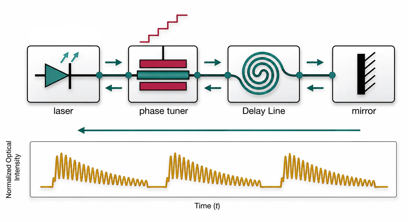
A semiconductor laser that receives a delayed reflection of its own light is a delay dynamical system. The Lang-Kobayashi model [1] describes it with the single-mode laser rate equations plus one extra term: the field emitted a round trip earlier, re-injected into the cavity with a strength and a phase . Depending on the feedback strength and phase, the laser emits a stable beam, oscillates at gigahertz frequencies, or becomes chaotic. The classification of these behaviors into five regimes by Tkach and Chraplyvy [2] is the reason optical isolators exist, and the reason back-reflection budgets matter in isolator-free photonic links.
This example builds a feedback laser from time-domain compact models:
- A custom TimeStepper implements a directly modulated laser that also accepts coherent optical injection at its output port. The rate equations are the same as in the built-in DMLaserTimeStepper; only the injection term is new.
- The external cavity is an ordinary circuit: a phase tuner, a waveguide, and a mirror. The delayed feedback term of the Lang-Kobayashi equations is not coded anywhere; it emerges from the circuit topology.
With this setup we trace the route from stable emission through relaxation-oscillation undamping to coherence collapse as the mirror reflectivity increases, and then reproduce the short-cavity bifurcation scenario reported by Heil et al. [3, 4]: sweeping the feedback phase with the intracavity tuner takes the laser from steady emission through a Hopf bifurcation and quasi-periodicity into the regular pulse package regime.
References
- Lang, R., and Kobayashi, K. “External optical feedback effects on semiconductor injection laser properties.” IEEE Journal of Quantum Electronics 1980 16 (3), 347-355, doi: 10.1109/JQE.1980.1070479.
- Tkach, R., and Chraplyvy, A. “Regimes of feedback effects in 1.5-um distributed feedback lasers.” Journal of Lightwave Technology 1986 4 (11), 1655-1661, doi: 10.1109/JLT.1986.1074666.
- Heil, T., Fischer, I., Elsaesser, W., and Gavrielides, A. “Dynamics of semiconductor lasers subject to delayed optical feedback: the short cavity regime.” Physical Review Letters 2001 87 (24), 243901, doi: 10.1103/PhysRevLett.87.243901.
- Heil, T., Fischer, I., Elsaesser, W., Krauskopf, B., Green, K., and Gavrielides, A. “Delay dynamics of semiconductor lasers with short external cavities: bifurcation scenarios and mechanisms.” Physical Review E 2003 67 (6), 066214, doi: 10.1103/PhysRevE.67.066214.
import matplotlib.pyplot as pltimport numpy as npimport photonforge as pfimport photonforge.abstract as pfaimport photonforge.typing as pft
viewer = pf.live_viewer.LiveViewer()
LiveViewer started at http://127.0.0.1:44739. Call its 'stop()' method to free the port.pf.config.default_technology = pf.basic_technology()
f0 = pf.C_0 / 1.55 # optical carrier at 1.55 umz0 = 50.0 # impedance of the electrical ports
# physical constantsq_e = 1.602176634e-19h_planck = 6.62607015e-34c_0 = 299792458.0A Laser Model that Accepts Optical Injection
Section titled “A Laser Model that Accepts Optical Injection”The built-in DMLaserTimeStepper solves the single-mode rate equations for the photon density , carrier density , and optical phase , but light arriving at its port does not enter these dynamics. For feedback studies we need a laser that feels incident light, so we write a custom TimeStepper with the same rate equations
plus coherent injection of the incident field. In terms of the emitted envelope the injection adds to , which in the variables reads
Here is the port input converted from the amplitude convention to photon-density units with the same calibration constant that scales the output, and the coupling rate follows from the output-facet reflectivity and the internal cavity round-trip time :
The product of with the (amplitude) fraction of the emitted field that
returns to the laser is the Lang-Kobayashi feedback rate . The class below
follows the same structure as the custom microring stepper in the
self-pulsing example: setup_state reads the component ports,
step_single writes the outputs for time and advances the state by one step with a
fourth-order Runge-Kutta update. The constructor arguments carry
photonforge.typing annotations (types, bounds, and units), so
components using this stepper can also be loaded and parameterized in the graphical
interface.
class FeedbackLaserTimeStepper(pf.TimeStepper):    """Single-mode laser rate equations with coherent injection at the optical port.
    Parameters follow pf.DMLaserTimeStepper (SI units). The only addition is    feedback_coupling_rate: the injection rate kappa_c in 1/s (0 disables injection).    """
    def __init__(        self,        *,        quantum_efficiency: pft.NonNegativeFloat = 0.4,        spontaneous_emission_factor: pft.NonNegativeFloat = 3.0e-5,        carrier_lifetime: pft.annotate(float, exclusiveMinimum=0, units="s") = 1.0e-9,        gain_compression_factor: pft.annotate(float, minimum=0, units="m³") = 1.0e-23,        transparency_carrier_density: pft.annotate(float, minimum=0, units="m⁻³") = 1.1e24,        differential_gain: pft.annotate(float, minimum=0, units="m³/s") = 2.5e-20,        n_group: pft.NonNegativeFloat = 3.53,        linewidth_enhancement_factor: pft.NonNegativeFloat = 5.0,        confinement_factor: pft.PositiveFloat = 0.4,        photon_lifetime: pft.annotate(float, exclusiveMinimum=0, units="s") = 3.0e-12,        active_region_volume: pft.annotate(float, exclusiveMinimum=0, units="m³") = 1.5e-16,        feedback_coupling_rate: pft.annotate(float, minimum=0, units="1/s") = 0.0,        z0: pft.Impedance = 50.0,    ):        # all parameters must be forwarded so parameterization works        super().__init__(            quantum_efficiency=quantum_efficiency,            spontaneous_emission_factor=spontaneous_emission_factor,            carrier_lifetime=carrier_lifetime,            gain_compression_factor=gain_compression_factor,            transparency_carrier_density=transparency_carrier_density,            differential_gain=differential_gain,            n_group=n_group,            linewidth_enhancement_factor=linewidth_enhancement_factor,            confinement_factor=confinement_factor,            photon_lifetime=photon_lifetime,            active_region_volume=active_region_volume,            feedback_coupling_rate=feedback_coupling_rate,            z0=z0,        )
    def setup_state(self, *, component, time_step, carrier_frequency, **kwargs):        # called once before stepping: unpack parameters, precompute constants,        # and map the component ports to input/output array indices        k = self.parametric_kwargs  # the keyword arguments passed to __init__        self.dt = time_step        self.beta = k["spontaneous_emission_factor"]        self.tau_n = k["carrier_lifetime"]        self.eps = k["gain_compression_factor"]        self.n_tr = k["transparency_carrier_density"]        self.alpha = k["linewidth_enhancement_factor"]        self.gam = k["confinement_factor"]        self.tau_p = k["photon_lifetime"]        self.v_a = k["active_region_volume"]        self.kc = k["feedback_coupling_rate"]        self.sqrt_z0 = np.sqrt(np.real(k["z0"]))  # for amplitude <-> current
        # v_g * a0: group velocity times differential gain, so that the        # stimulated rate is vg_a0 * (n - n_tr) * p (units m^3/s)        self.vg_a0 = c_0 / k["n_group"] * k["differential_gain"]        # output power calibration: P_out = c_p * p converts the internal        # photon density p to watts at the port        self.c_p = (            k["quantum_efficiency"] * h_planck * carrier_frequency * self.v_a            / (2.0 * self.gam * self.tau_p)        )        self.sqrt_c_p = np.sqrt(self.c_p)  # amplitude version of the same
        # the framework passes inputs/outputs as arrays ordered by self.keys:        # find which index is the electrical drive and which is the optical port        elec = sorted(component.select_ports("electrical"))        opt = sorted(component.select_ports("optical"))        names = sorted(list(elec) + list(opt))        self._keys = tuple(f"{name}@0" for name in names)  # e.g. ("E0@0", "P0@0")        self.i_elec = names.index(elec[0])        self.i_opt = names.index(opt[0])        self.reset()
    @property    def keys(self):        return self._keys
    def reset(self):        # initial conditions: the laser starts from an empty, unpumped cavity        # (p = n = 0) and builds up from spontaneous emission when driven        self.p = 0.0        self.n = 0.0        self.phi = 0.0
    def _derivs(self, p, n, phi, current, e_in):        # time derivatives (dp/dt, dn/dt, dphi/dt) of the rate equations,        # plus the injection term when light is present at the port        p_pos = p if p > 0.0 else 0.0        g = self.vg_a0 / (1.0 + self.eps * p_pos)  # gain, compressed at high p        stim = g * (n - self.n_tr) * p_pos  # stimulated emission rate        # photon equation: modal gain - cavity loss + spontaneous emission        dp = self.gam * stim - p / self.tau_p + self.beta * self.gam * n / self.tau_n        # carrier equation: pump - stimulated emission - recombination        dn = current / (q_e * self.v_a) - stim - n / self.tau_n        # phase equation: the alpha factor converts the deviation of the        # (uncompressed) gain from its threshold value into a frequency shift        dphi = 0.5 * self.alpha * (            self.gam * self.vg_a0 * (n - self.n_tr) - 1.0 / self.tau_p        )        if self.kc != 0.0 and e_in != 0.0:            # coherent injection, dE/dt += kc * e_in with E = sqrt(p) e^{-j phi}:            # rotate the injected field into the frame of the cavity field            inj = self.kc * e_in * np.exp(1j * phi)            sq = np.sqrt(p_pos) if p_pos > 1e-30 else 1e-15  # avoid divide by 0            # the in-phase part pumps the photon density ...            dp += 2.0 * sq * inj.real            # ... and the quadrature part pulls the optical phase            dphi += -inj.imag / sq        return dp, dn, dphi
    def step_single(self, inputs, outputs, time_index, update_state, shutdown):        # called by the circuit stepper once per time step:        # read the inputs, write the outputs for time t, then advance to t + dt        # electrical amplitude (sqrt W) -> drive current in amperes        current = inputs[self.i_elec].real / self.sqrt_z0        # optical amplitude (sqrt W) -> field in photon-density units        e_in = inputs[self.i_opt] / self.sqrt_c_p
        # write the outputs from the CURRENT state (before advancing)        outputs[self.i_elec] = 0.0  # no electrical reflection        p_pos = self.p if self.p > 0.0 else 0.0        # emitted envelope: amplitude sqrt(P_out), phase -phi (PF convention)        outputs[self.i_opt] = self.sqrt_c_p * np.sqrt(p_pos) * np.exp(-1j * self.phi)
        if update_state:            # classic fourth-order Runge-Kutta step, inputs held constant over dt            dt = self.dt            p, n, phi = self.p, self.n, self.phi            k1 = self._derivs(p, n, phi, current, e_in)  # slope at t            k2 = self._derivs(  # slope at t + dt/2, using k1                p + 0.5 * dt * k1[0], n + 0.5 * dt * k1[1], phi + 0.5 * dt * k1[2],                current, e_in,            )            k3 = self._derivs(  # slope at t + dt/2, using k2                p + 0.5 * dt * k2[0], n + 0.5 * dt * k2[1], phi + 0.5 * dt * k2[2],                current, e_in,            )            k4 = self._derivs(  # slope at t + dt, using k3                p + dt * k3[0], n + dt * k3[1], phi + dt * k3[2], current, e_in            )            # weighted average of the four slopes            self.p = p + dt / 6.0 * (k1[0] + 2 * k2[0] + 2 * k3[0] + k4[0])            self.n = n + dt / 6.0 * (k1[1] + 2 * k2[1] + 2 * k3[1] + k4[1])            self.phi = phi + dt / 6.0 * (k1[2] + 2 * k2[2] + 2 * k3[2] + k4[2])            if self.p < 0.0:                self.p = 0.0  # numerical guard, p is a density            # wrap the phase into (-pi, pi]: only exp(j phi) enters the output            if self.phi > np.pi or self.phi < -np.pi:                self.phi = (self.phi + np.pi) % (2.0 * np.pi) - np.pi
pf.register_time_stepper_class(FeedbackLaserTimeStepper)
def feedback_laser(name="Feedback Laser", **stepper_kwargs):    """Two-port laser component: electrical drive E0 and optical output P0."""    # the frequency-domain model is a placeholder, the stepper defines the dynamics    model = pf.TerminationModel(r=0)    model.time_stepper = FeedbackLaserTimeStepper(**stepper_kwargs)    # black box with one optical port, rotated so the port points to the right    comp = pf.Reference(        model.black_box_component(pf.virtual_port_spec()), rotation=180    ).transformed_component(name)    # add the electrical drive port (named E0 automatically) on the top edge    (x_min, _), (x_max, y_max) = comp.bounds()    comp.add_port(        pf.Port(            (0.5 * (x_min + x_max), y_max),            -90,            pf.virtual_port_spec(classification="electrical"),        )    )    return comp
laser = feedback_laser()viewer(laser)
The Solitary Laser
Section titled “The Solitary Laser”With nothing connected to the optical port the injection term is inactive and the model is a standard directly modulated laser. Two quick checks establish its operating point: the light-current characteristic locates the threshold near 36 mA, and a current step from below to above threshold shows the turn-on delay and the relaxation oscillations that set the internal time scale of everything that follows. The response of the built-in dm_laser, which solves the same rate equations, is plotted for comparison.
time_step = 0.5e-12  # fine enough to resolve the relaxation oscillations
def bias_link(laser_comp, source_comp, name):    # laser driven by a signal source, optical output exposed as "out"    link = pf.Component(name)    laser_ref = link.add_reference(laser_comp)    source_ref = link.add_reference(source_comp)    source_ref.connect("E0", laser_ref["E0"])    link.add_port(laser_ref["P0"], "out")    link.add_model(pf.CircuitModel(), "Circuit")    return link
# LI curve: sweep the DC current and record the settled output powerbuiltin_laser = pfa.dm_laser(seed=0)  # built-in laser, plotted for comparisonsource_c = pfa.signal_source(amplitude=0, offset=0, seed=1)  # DC current sourcesource_b = pfa.signal_source(amplitude=0, offset=0, seed=1)link_c = bias_link(laser, source_c, "li_custom")link_b = bias_link(builtin_laser, source_b, "li_builtin")
currents = np.linspace(0, 60e-3, 13)  # 0 to 60 mAli = {"custom": [], "built-in": []}for current in currents:    for tag, src, link in [("custom", source_c, link_c), ("built-in", source_b, link_b)]:        src.update(offset=current * np.sqrt(z0))  # current I maps to amplitude I sqrt(z0)        ts = link.setup_time_stepper(            time_step=time_step, carrier_frequency=f0, show_progress=False        )        # run 5 ns and read the complex envelope at the output port        a = ts.step(steps=10000, time_step=time_step, show_progress=False)["out@0"]        li[tag].append(np.abs(a[-2000:]).mean() ** 2)  # settled power (last 1 ns)
fig, ax = plt.subplots(figsize=(7, 3), tight_layout=True)ax.plot(currents * 1e3, np.array(li["custom"]) * 1e3, "o-", ms=4, label="this model")ax.plot(currents * 1e3, np.array(li["built-in"]) * 1e3, "x--", ms=6, label="dm_laser")ax.set(xlabel="Drive current (mA)", ylabel="Output power (mW)", title="LI curve")_ = ax.legend()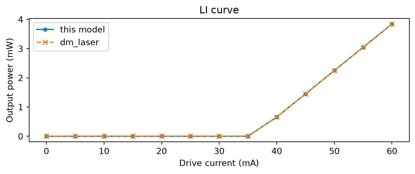
# current step from 20 mA (below threshold) to 50 mA after an 8 ns settling timei_low, i_high = 20e-3, 50e-3num_steps = 30000t = np.arange(num_steps) * time_steptraces = {}for tag, laser_comp in [("custom", laser), ("built-in", builtin_laser)]:    # slow trapezoid: hold 20 mA for 8 ns, then a sharp step to 50 mA    src = pfa.signal_source(        frequency=0.05e9,  # 20 ns period, only the first edge matters here        offset=i_low * np.sqrt(z0),        amplitude=(i_high - i_low) * np.sqrt(z0),        waveform="trapezoid",        width=0.9,        rise=0.001,        fall=0.001,        start=8e-9,  # settle at the low bias first, then step        seed=1,    )    link = bias_link(laser_comp, src, f"step_{tag}")    ts = link.setup_time_stepper(        time_step=time_step, carrier_frequency=f0, show_progress=False    )    traces[tag] = ts.step(steps=num_steps, time_step=time_step, show_progress=False)["out@0"]
fig, (ax1, ax2) = plt.subplots(2, 1, figsize=(7, 4.6), sharex=True, tight_layout=True)for tag, ls in [("custom", "-"), ("built-in", "--")]:    a = traces[tag]    ax1.plot(t * 1e9, np.abs(a) ** 2 * 1e3, ls, label=tag)    # chirp = -d(envelope phase)/dt / 2pi, the instantaneous frequency deviation    # in the exp(-jwt) convention    chirp = -np.gradient(np.unwrap(np.angle(a)), time_step) / (2 * np.pi)    ax2.plot(t * 1e9, chirp / 1e9, ls, label=tag)ax1.set(ylabel="Power (mW)", title="Turn-on: relaxation oscillations and chirp",        xlim=(7.5, 12))# below threshold the gain sits far under the cavity loss, which the phase equation# turns into a large frequency offset; the limits frame the chirp after turn-onax2.set(xlabel="Time (ns)", ylabel="Chirp (GHz)", xlim=(7.5, 12), ylim=(-20, 30))ax1.legend()_ = ax2.legend()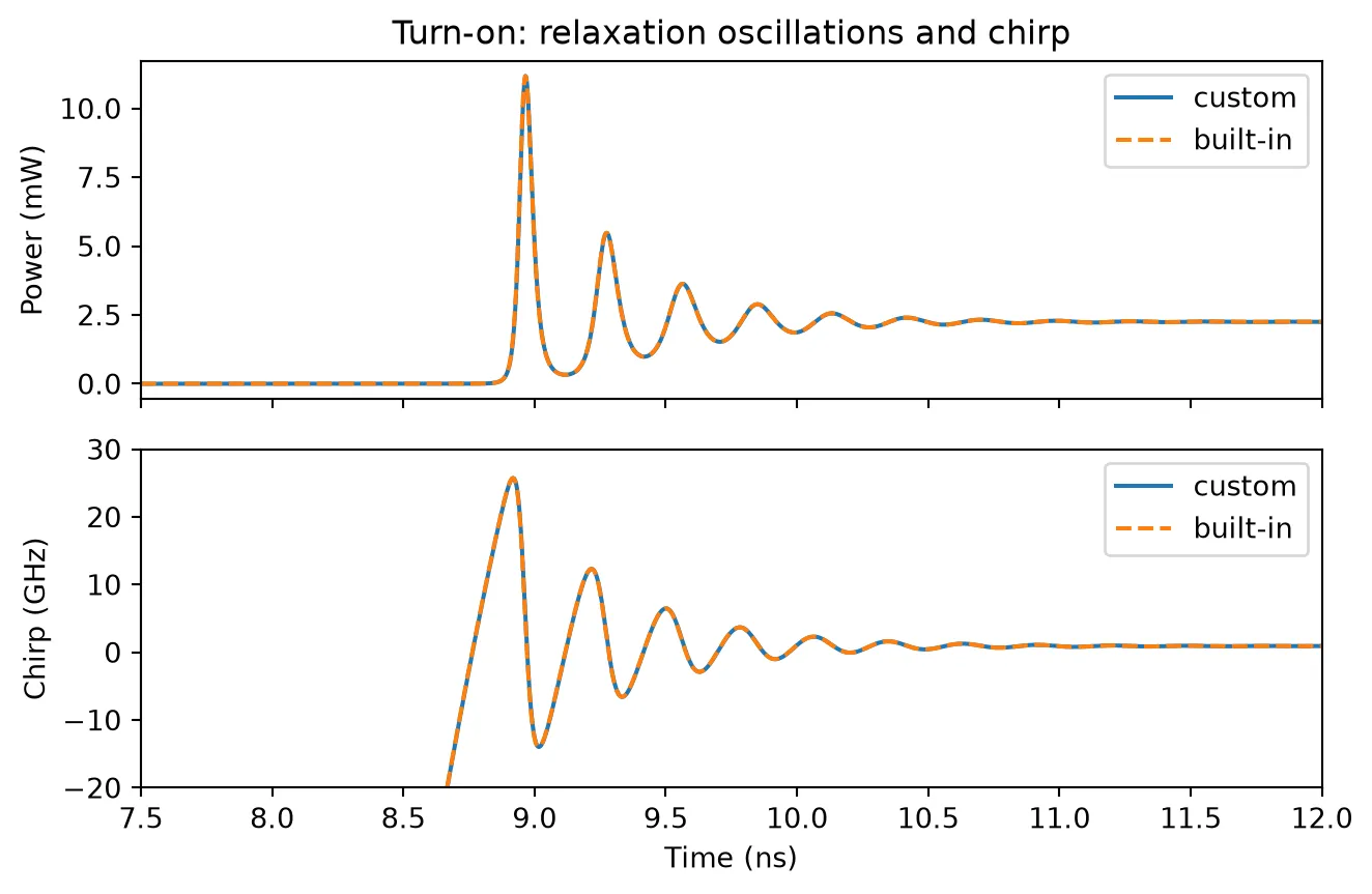
The External Cavity as a Circuit
Section titled “The External Cavity as a Circuit”The feedback path is built from two stock elements:
- A mirror: a TerminationModel with a complex reflection coefficient sets both the feedback strength and, through its phase, the feedback phase.
- A waveguide: straight provides the propagation delay and the round-trip envelope phase .
Warning. The default time stepper of the waveguide model fits the S matrix with a pole-residue expansion, and the automatic delay extraction reads the phase slope on the sampled frequency grid. The default grid spans the carrier plus or minus 1 THz with 20 GHz spacing, so delays beyond ps alias and are silently dropped. For delay lines, either pass a
frequenciesgrid finer than or attach an AnalyticWaveguideTimeStepper, which implements the group delay exactly as an integer number of time steps. Feedback dynamics generate broad spectra, so this example uses the analytic stepper.
A short pulse reflected off the assembled cavity shows the two quantities that matter for the feedback problem: the round-trip amplitude and the round-trip delay.
# external cavity for the long-cavity study: 200 ps round triptau_ext = 200e-12n_eff_wg, n_g_wg = 2.4, 4.0wg_length = tau_ext * c_0 / (2 * n_g_wg) * 1e6  # one-way length in umr_ext_probe = 0.2  # mirror used for the probe
def cavity_waveguide(length):    wg = pfa.straight(length=length, n_eff=n_eff_wg, n_group=n_g_wg, reference_frequency=f0)    # exact delay-line stepper instead of the fitted default (see warning above)    wg.active_model.time_stepper = pf.AnalyticWaveguideTimeStepper(        n_eff=n_eff_wg, length=length, n_group=n_g_wg    )    return wg
def mirror(r):    # one-port mirror: complex r sets the feedback strength and phase    return pf.TerminationModel(r=r).black_box_component(        pf.virtual_port_spec(), name="Mirror"    )
# one-port cavity: waveguide with the mirror at the far endcavity = pf.Component("external_cavity")wg_ref = cavity.add_reference(cavity_waveguide(wg_length))mr_ref = cavity.add_reference(mirror(r_ext_probe))mr_ref.connect("P0", wg_ref["P1"])cavity.add_port(wg_ref["P0"], "in")  # probe port at the near endcavity.add_model(pf.CircuitModel(), "Circuit")
# reflect a short gaussian envelope pulse off the cavitynum_probe = 1600t_probe = np.arange(num_probe) * time_steppulse = np.exp(-0.5 * ((t_probe - 100e-12) / 15e-12) ** 2).astype(complex)ts = cavity.setup_time_stepper(time_step=time_step, carrier_frequency=f0, show_progress=False)# inject the pulse into the exposed port; the output on the same port is the reflectionrefl = ts.step(    inputs=pf.TimeSeries(time_step=time_step, values={"in@0": pulse}),    show_progress=False,).values["in@0"]
fig, ax = plt.subplots(figsize=(7, 3), tight_layout=True)ax.plot(t_probe * 1e12, np.abs(pulse) ** 2, label="incident")ax.plot(t_probe * 1e12, np.abs(refl) ** 2, label="reflected")ax.set(xlabel="Time (ps)", ylabel="Power (a.u.)",       title=f"Cavity probe: power reflectance {np.abs(refl).max()**2:.3f}, "             f"round trip {tau_ext*1e12:.0f} ps")_ = ax.legend()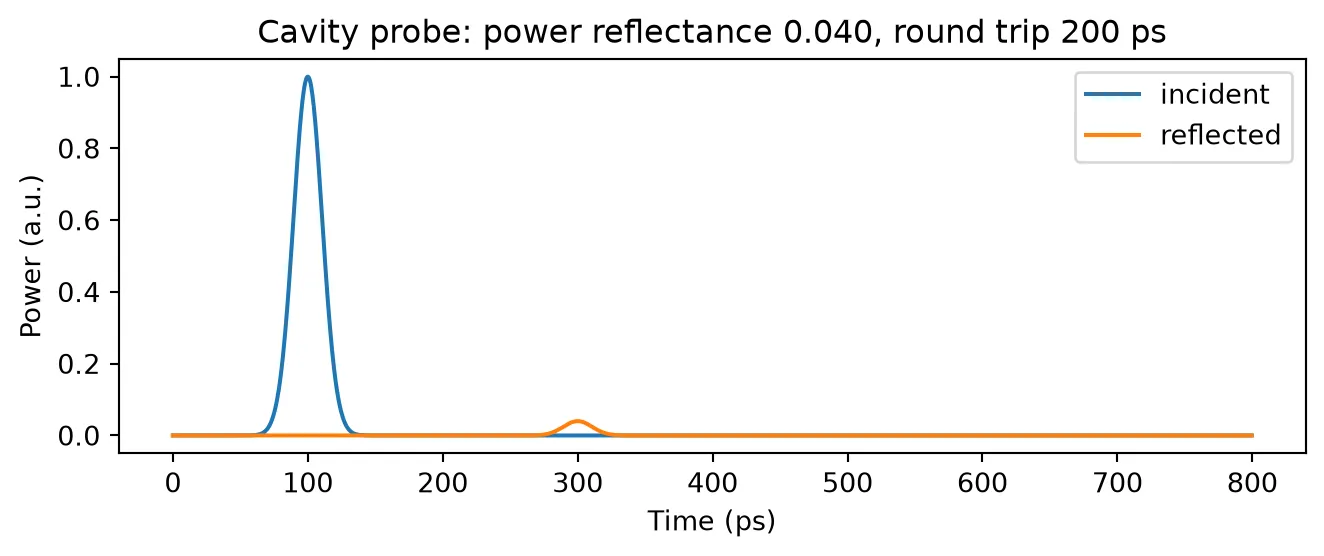
Closing the Loop: from Stable Emission to Coherence Collapse
Section titled “Closing the Loop: from Stable Emission to Coherence Collapse”Connecting the cavity to the laser closes the feedback loop. The circuit has no exposed optical port: the laser output is observed with a monitor on its port. The feedback strength is the Lang-Kobayashi rate , swept here through the mirror reflectivity at a fixed cavity length. For this laser (, ps, a typical 300 um Fabry-Perot diode) 1/s.
The sequence of behaviors follows the feedback regimes of Tkach and Chraplyvy [2]:
- At weak feedback the laser remains steady; the emission frequency shifts as the laser locks to an external-cavity mode.
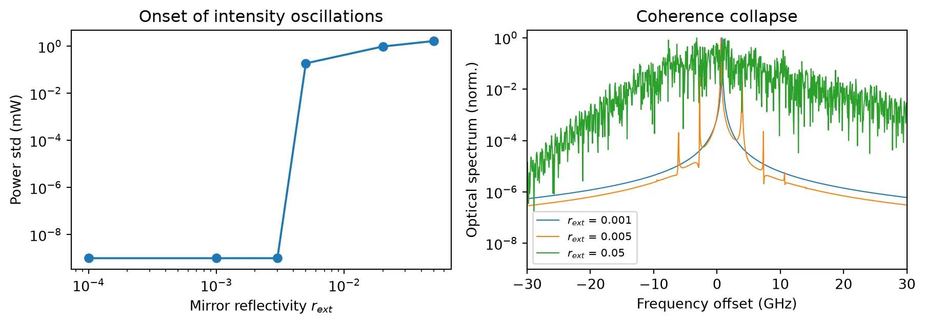
- When the feedback rate overcomes the relaxation-oscillation damping, the relaxation oscillations undamp (a Hopf bifurcation) and the output develops a gigahertz intensity oscillation.
- At strong feedback the dynamics become chaotic: coherence collapse, with intensity fluctuations of order the mean power and an optical spectrum broadened by tens of gigahertz. This is regime IV, the state that back-reflection specifications and optical isolators exist to avoid.
# coupling rate kappa_c for r2 = 0.556 and tau_in = 7.06 ps (300 um diode)kc = (1 - 0.556**2) / (0.556 * 7.06e-12)
def feedback_loop(r_ext):    # closed loop: laser -> waveguide -> mirror (no exposed optical port)    loop = pf.Component(f"loop_{r_ext:.0e}")    # laser with injection enabled, biased at 50 mA by a DC source    laser_ref = loop.add_reference(feedback_laser(feedback_coupling_rate=kc))    source_ref = loop.add_reference(        pfa.signal_source(amplitude=0, offset=50e-3 * np.sqrt(z0), seed=1)    )    source_ref.connect("E0", laser_ref["E0"])    # external cavity: waveguide from the laser port to the mirror    wg_ref = loop.add_reference(cavity_waveguide(wg_length))    wg_ref.connect("P0", laser_ref["P0"])    mr_ref = loop.add_reference(mirror(r_ext))    mr_ref.connect("P0", wg_ref["P1"])    loop.add_model(pf.CircuitModel(), "Circuit")    return loop, laser_ref
# display one assembled looploop_demo, _ = feedback_loop(5e-3)viewer(loop_demo);fill:%23221f20;font-weight:bold;font-size:1.016680px;}.terminal{fill:none;stroke:%23805080;stroke-width:0.127085;}.dashed{stroke-dasharray:0.635425,0.381255;}.port{fill:none;stroke:%23805080;stroke-width:0.254170;}.virtual-connection{fill:none;stroke:%23907090;stroke-width:0.190628;}.layer_5_0{stroke:%23998573;fill:url(%23pat-layer_5_0);fill-opacity:0.492;}.label_5_0{fill:%23998573;}.layer_3_0{stroke:%238851ad;fill:url(%23pat-layer_3_0);fill-opacity:0.492;}.label_3_0{fill:%238851ad;}.layer_4_0{stroke:%23535e59;fill:url(%23pat-layer_4_0);fill-opacity:0.492;}.label_4_0{fill:%23535e59;}.layer_1_0{stroke:%23858d89;fill:url(%23pat-layer_1_0);fill-opacity:0.492;}.label_1_0{fill:%23858d89;}.layer_2_0{stroke:%235b98b9;fill:url(%23pat-layer_2_0);fill-opacity:0.492;}.label_2_0{fill:%235b98b9;}</style><defs><path id=%22port-symbol%22 class=%22port%22 d=%22M 0,-0.508340 L 0.762510,0 0,0.508340%22 /><path id=%22ref-port-symbol%22 class=%22port%22 style=%22stroke-opacity:0.33;%22 d=%22M 0,-0.381255 C 0.508340,-0.381255 0.508340,0.381255 0,0.381255%22 /><circle id=%22port-bend-symbol%22 style=%22stroke-width:0;stroke:none;fill:%23805080;fill-opacity:1;%22 cx=%220%22 cy=%220%22 r=%220.228753%22 /><circle id=%22connection-symbol%22 style=%22stroke-width:0;stroke:none;fill:%23907090;fill-opacity:1;%22 cx=%220%22 cy=%220%22 r=%220.266879%22 /><pattern id=%22pat-layer_5_0%22 patternUnits=%22userSpaceOnUse%22 width=%220.635425%22 height=%220.635425%22 patternTransform=%22translate(0.037378,0.568538)%22><line x1=%220.635425%22 y1=%220%22 x2=%220%22 y2=%220.635425%22 style=%22stroke:%23998573;stroke-width:0.063543%22 /><line x1=%220.953137%22 y1=%220.317713%22 x2=%220.317713%22 y2=%220.953137%22 style=%22stroke:%23998573;stroke-width:0.063543%22 /><line x1=%220.317713%22 y1=%22-0.317713%22 x2=%22-0.317713%22 y2=%220.317713%22 style=%22stroke:%23998573;stroke-width:0.063543%22 /></pattern><pattern id=%22pat-layer_3_0%22 patternUnits=%22userSpaceOnUse%22 width=%220.381255%22 height=%220.381255%22 patternTransform=%22translate(0.089707,0.280925)%22><circle cx=%220.190628%22 cy=%220.190628%22 r=%220.063543%22 style=%22stroke:none;fill:%238851ad;fill-opacity:1.0%22 /></pattern><pattern id=%22pat-layer_4_0%22 patternUnits=%22userSpaceOnUse%22 width=%220.635425%22 height=%220.635425%22 patternTransform=%22translate(0.411157,0.200661)%22><line x1=%220.317713%22 y1=%220%22 x2=%220.317713%22 y2=%220.635425%22 style=%22stroke:%23535e59;stroke-width:0.063543%22 /><line x1=%220%22 y1=%220.317713%22 x2=%220.635425%22 y2=%220.317713%22 style=%22stroke:%23535e59;stroke-width:0.063543%22 /></pattern><pattern id=%22pat-layer_1_0%22 patternUnits=%22userSpaceOnUse%22 width=%220.635425%22 height=%220.635425%22 patternTransform=%22translate(0.261646,0.367878)%22><circle cx=%220.317713%22 cy=%220.317713%22 r=%220.063543%22 style=%22stroke:none;fill:%23858d89;fill-opacity:1.0%22 /></pattern><pattern id=%22pat-layer_2_0%22 patternUnits=%22userSpaceOnUse%22 width=%220.635425%22 height=%220.635425%22 patternTransform=%22translate(0.523291,0.100330)%22><line x1=%220%22 y1=%220%22 x2=%220.635425%22 y2=%220.635425%22 style=%22stroke:%235b98b9;stroke-width:0.063543%22 /><line x1=%22-0.317713%22 y1=%220.317713%22 x2=%220.317713%22 y2=%220.953137%22 style=%22stroke:%235b98b9;stroke-width:0.063543%22 /><line x1=%220.317713%22 y1=%22-0.317713%22 x2=%220.953137%22 y2=%220.317713%22 style=%22stroke:%235b98b9;stroke-width:0.063543%22 /></pattern><g id=%22C1%22 data-name=%22Feedback Laser%22><path class=%22layer_0_32767%22 d=%22M 0.000000,-7.670000 0.000000,-5.375000 0.000000,-5.125000 0.000000,0.000000 -10.980000,0.000000 -10.980000,-7.670000 z M -10.860000,-0.120000 -0.120000,-0.120000 -0.120000,-5.125000 -1.600000,-5.125000 -1.600000,-4.400000 -3.880000,-4.400000 -4.030000,-4.450000 -4.360000,-4.470000 -4.530000,-4.530000 -9.380000,-5.250000 -3.900000,-6.070000 -1.600000,-6.070000 -1.600000,-5.375000 -0.120000,-5.375000 -0.120000,-7.550000 -10.860000,-7.550000 z%22 /><path class=%22layer_0_32767%22 d=%22M -1.330000,-2.045000 -1.330000,-1.885000 -1.650000,-1.885000 -1.650000,-1.005000 -1.810000,-1.005000 -1.810000,-1.885000 -2.130000,-1.885000 -2.130000,-2.045000 z%22 /><path class=%22layer_0_32767%22 d=%22M -2.874000,-1.725000 -2.474000,-1.725000 -2.354000,-1.605000 -2.354000,-1.125000 -2.474000,-1.005000 -2.954000,-1.005000 -2.954000,-1.165000 -2.514000,-1.165000 -2.514000,-1.285000 -2.874000,-1.285000 -2.994000,-1.405000 -2.994000,-1.605000 z M -2.834000,-1.445000 -2.514000,-1.445000 -2.514000,-1.565000 -2.834000,-1.565000 z%22 /><path class=%22layer_0_32767%22 d=%22M -3.858000,-1.485000 -3.858000,-1.586000 -3.719000,-1.725000 -3.439000,-1.725000 -3.378000,-1.666000 -3.319000,-1.725000 -3.218000,-1.725000 -3.218000,-1.005000 -3.378000,-1.005000 -3.378000,-1.485000 -3.458000,-1.565000 -3.618000,-1.565000 -3.698000,-1.485000 z%22 /><path class=%22layer_0_32767%22 d=%22M -4.082000,-1.725000 -4.082000,-1.005000 -4.242000,-1.005000 -4.242000,-1.485000 -4.322000,-1.565000 -4.402000,-1.485000 -4.402000,-1.005000 -4.562000,-1.005000 -4.562000,-1.485000 -4.642000,-1.565000 -4.722000,-1.485000 -4.722000,-1.005000 -4.882000,-1.005000 -4.882000,-1.546000 -4.703000,-1.725000 -4.583000,-1.725000 -4.482000,-1.626000 -4.383000,-1.725000 z%22 /><path class=%22layer_0_32767%22 d=%22M -5.106000,-1.565000 -5.106000,-1.005000 -5.266000,-1.005000 -5.266000,-1.565000 z%22 /><path class=%22layer_0_32767%22 d=%22M -5.106000,-1.885000 -5.106000,-1.725000 -5.266000,-1.725000 -5.266000,-1.885000 z%22 /><path class=%22layer_0_32767%22 d=%22M -5.490000,-1.725000 -5.490000,-1.005000 -5.650000,-1.005000 -5.650000,-1.485000 -5.730000,-1.565000 -5.810000,-1.565000 -5.890000,-1.485000 -5.890000,-1.005000 -6.050000,-1.005000 -6.050000,-1.546000 -5.871000,-1.725000 -5.711000,-1.725000 -5.650000,-1.666000 -5.591000,-1.725000 z%22 /><path class=%22layer_0_32767%22 d=%22M -6.834000,-1.725000 -6.354000,-1.725000 -6.274000,-1.645000 -6.274000,-1.565000 -6.754000,-1.565000 -6.754000,-1.445000 -6.394000,-1.445000 -6.274000,-1.325000 -6.274000,-1.125000 -6.394000,-1.005000 -6.914000,-1.005000 -6.914000,-1.645000 z M -6.754000,-1.165000 -6.434000,-1.165000 -6.434000,-1.285000 -6.754000,-1.285000 z%22 /><path class=%22layer_0_32767%22 d=%22M -7.618000,-1.165000 -7.458000,-1.165000 -7.458000,-1.645000 -7.618000,-1.645000 -7.618000,-1.805000 -7.458000,-1.805000 -7.458000,-2.045000 -7.298000,-2.045000 -7.298000,-1.805000 -7.138000,-1.805000 -7.138000,-1.645000 -7.298000,-1.645000 -7.298000,-1.125000 -7.418000,-1.005000 -7.618000,-1.005000 z%22 /><path class=%22layer_0_32767%22 d=%22M -7.842000,-1.565000 -7.842000,-1.005000 -8.002000,-1.005000 -8.002000,-1.565000 z%22 /><path class=%22layer_0_32767%22 d=%22M -7.842000,-1.885000 -7.842000,-1.725000 -8.002000,-1.725000 -8.002000,-1.885000 z%22 /><path class=%22layer_0_32767%22 d=%22M -8.687000,-1.725000 -8.407000,-1.725000 -8.226000,-1.546000 -8.226000,-1.186000 -8.407000,-1.005000 -8.687000,-1.005000 -8.866000,-1.186000 -8.866000,-1.546000 z M -8.706000,-1.245000 -8.626000,-1.165000 -8.466000,-1.165000 -8.386000,-1.245000 -8.386000,-1.485000 -8.466000,-1.565000 -8.626000,-1.565000 -8.706000,-1.485000 z%22 /><path class=%22layer_0_32767%22 d=%22M -9.090000,-1.725000 -9.090000,-1.005000 -9.250000,-1.005000 -9.250000,-1.485000 -9.330000,-1.565000 -9.410000,-1.565000 -9.490000,-1.485000 -9.490000,-1.005000 -9.650000,-1.005000 -9.650000,-1.546000 -9.471000,-1.725000 -9.311000,-1.725000 -9.250000,-1.666000 -9.191000,-1.725000 z%22 /></g><g id=%22C2%22 data-name=%22Source%22><path class=%22layer_0_32767%22 d=%22M 0.000000,9.700000 0.000000,0.000000 11.640000,0.000000 11.640000,6.125000 11.640000,6.375000 11.640000,9.700000 z M 11.520000,6.375000 5.880000,6.375000 5.880000,8.100000 3.650000,8.100000 3.620000,8.080000 3.620000,4.820000 3.600000,4.800000 1.720000,4.800000 1.720000,4.420000 3.620000,4.420000 3.650000,4.400000 4.020000,4.420000 4.020000,7.700000 4.050000,7.720000 5.450000,7.720000 5.500000,7.680000 5.500000,4.800000 5.480000,4.780000 5.500000,4.400000 5.850000,4.400000 5.880000,4.420000 9.920000,4.420000 9.920000,4.800000 5.900000,4.800000 5.880000,4.820000 5.880000,6.125000 11.520000,6.125000 11.520000,0.120000 0.120000,0.120000 0.120000,9.580000 11.520000,9.580000 z%22 /><path class=%22layer_0_32767%22 d=%22M 1.460000,2.026000 1.281000,2.205000 0.921000,2.205000 0.740000,2.026000 0.740000,1.805000 0.940000,1.605000 1.220000,1.605000 1.300000,1.525000 1.300000,1.405000 1.220000,1.325000 0.980000,1.325000 0.881000,1.426000 0.740000,1.426000 0.740000,1.346000 0.921000,1.165000 1.281000,1.165000 1.460000,1.346000 1.460000,1.565000 1.260000,1.765000 0.980000,1.765000 0.900000,1.845000 0.900000,1.965000 0.980000,2.045000 1.220000,2.045000 1.321000,1.946000 1.460000,1.946000 z%22 /><path class=%22layer_0_32767%22 d=%22M 1.684000,1.725000 1.684000,1.165000 1.844000,1.165000 1.844000,1.725000 z%22 /><path class=%22layer_0_32767%22 d=%22M 1.684000,2.045000 1.684000,1.885000 1.844000,1.885000 1.844000,2.045000 z%22 /><path class=%22layer_0_32767%22 d=%22M 2.249000,1.885000 2.068000,1.706000 2.068000,1.346000 2.249000,1.165000 2.548000,1.165000 2.548000,1.005000 2.228000,1.005000 2.228000,0.845000 2.588000,0.845000 2.708000,0.965000 2.708000,1.885000 z M 2.548000,1.325000 2.308000,1.325000 2.228000,1.405000 2.228000,1.645000 2.308000,1.725000 2.548000,1.725000 z%22 /><path class=%22layer_0_32767%22 d=%22M 2.932000,1.885000 2.932000,1.165000 3.092000,1.165000 3.092000,1.645000 3.172000,1.725000 3.252000,1.725000 3.332000,1.645000 3.332000,1.165000 3.492000,1.165000 3.492000,1.706000 3.313000,1.885000 3.153000,1.885000 3.092000,1.826000 3.033000,1.885000 z%22 /><path class=%22layer_0_32767%22 d=%22M 4.276000,1.885000 3.796000,1.885000 3.716000,1.805000 3.716000,1.725000 4.196000,1.725000 4.196000,1.605000 3.836000,1.605000 3.716000,1.485000 3.716000,1.285000 3.836000,1.165000 4.356000,1.165000 4.356000,1.805000 z M 4.196000,1.325000 3.876000,1.325000 3.876000,1.445000 4.196000,1.445000 z%22 /><path class=%22layer_0_32767%22 d=%22M 4.900000,1.325000 4.740000,1.325000 4.740000,2.205000 4.580000,2.205000 4.580000,1.285000 4.700000,1.165000 4.900000,1.165000 z%22 /><path class=%22layer_0_32767%22 d=%22M 6.100000,1.165000 6.540000,1.165000 6.660000,1.285000 6.660000,1.485000 6.540000,1.605000 6.180000,1.605000 6.180000,1.725000 6.660000,1.725000 6.660000,1.805000 6.580000,1.885000 6.100000,1.885000 6.020000,1.805000 6.020000,1.565000 6.140000,1.445000 6.500000,1.445000 6.500000,1.325000 6.020000,1.325000 6.020000,1.245000 z%22 /><path class=%22layer_0_32767%22 d=%22M 7.345000,1.885000 7.065000,1.885000 6.884000,1.706000 6.884000,1.346000 7.065000,1.165000 7.345000,1.165000 7.524000,1.346000 7.524000,1.706000 z M 7.364000,1.405000 7.284000,1.325000 7.124000,1.325000 7.044000,1.405000 7.044000,1.645000 7.124000,1.725000 7.284000,1.725000 7.364000,1.645000 z%22 /><path class=%22layer_0_32767%22 d=%22M 8.308000,1.165000 8.308000,1.885000 8.148000,1.885000 8.148000,1.405000 8.068000,1.325000 7.988000,1.325000 7.908000,1.405000 7.908000,1.885000 7.748000,1.885000 7.748000,1.346000 7.929000,1.165000 8.089000,1.165000 8.148000,1.226000 8.209000,1.165000 z%22 /><path class=%22layer_0_32767%22 d=%22M 9.172000,1.645000 9.172000,1.746000 9.033000,1.885000 8.753000,1.885000 8.692000,1.826000 8.633000,1.885000 8.532000,1.885000 8.532000,1.165000 8.692000,1.165000 8.692000,1.645000 8.772000,1.725000 8.932000,1.725000 9.012000,1.645000 z%22 /><path class=%22layer_0_32767%22 d=%22M 10.036000,1.426000 9.897000,1.426000 9.796000,1.325000 9.636000,1.325000 9.556000,1.405000 9.556000,1.645000 9.636000,1.725000 9.796000,1.725000 9.897000,1.626000 10.036000,1.626000 10.036000,1.706000 9.857000,1.885000 9.577000,1.885000 9.396000,1.706000 9.396000,1.346000 9.577000,1.165000 9.857000,1.165000 10.036000,1.346000 z%22 /><path class=%22layer_0_32767%22 d=%22M 10.780000,1.885000 10.380000,1.885000 10.260000,1.765000 10.260000,1.285000 10.380000,1.165000 10.860000,1.165000 10.860000,1.325000 10.420000,1.325000 10.420000,1.445000 10.780000,1.445000 10.900000,1.565000 10.900000,1.765000 z M 10.740000,1.605000 10.420000,1.605000 10.420000,1.725000 10.740000,1.725000 z%22 /></g><g id=%22C3%22 data-name=%22WG%22><path class=%22layer_0_32767%22 d=%22M 0.000000,7.300000 0.000000,5.175000 0.000000,4.925000 0.000000,0.000000 10.050000,0.000000 10.050000,4.925000 10.050000,5.175000 10.050000,7.300000 z M 9.930000,5.175000 8.450000,5.175000 8.450000,5.700000 1.600000,5.700000 1.600000,5.175000 0.120000,5.175000 0.120000,7.180000 9.930000,7.180000 z M 9.930000,0.120000 0.120000,0.120000 0.120000,4.925000 1.600000,4.925000 1.600000,4.400000 8.450000,4.400000 8.450000,4.925000 9.930000,4.925000 z%22 /><path class=%22layer_0_32767%22 d=%22M 1.409000,1.165000 1.590000,1.165000 1.889000,1.466000 2.190000,1.165000 2.369000,1.165000 2.369000,2.205000 2.209000,2.205000 2.209000,1.485000 2.129000,1.485000 1.889000,1.725000 1.649000,1.485000 1.569000,1.485000 1.569000,2.205000 1.409000,2.205000 z%22 /><path class=%22layer_0_32767%22 d=%22M 3.153000,1.885000 2.673000,1.885000 2.593000,1.805000 2.593000,1.725000 3.073000,1.725000 3.073000,1.605000 2.713000,1.605000 2.593000,1.485000 2.593000,1.285000 2.713000,1.165000 3.233000,1.165000 3.233000,1.805000 z M 3.073000,1.325000 2.753000,1.325000 2.753000,1.445000 3.073000,1.445000 z%22 /><path class=%22layer_0_32767%22 d=%22M 4.017000,1.805000 4.017000,1.885000 3.857000,1.885000 3.777000,1.325000 3.697000,1.325000 3.617000,1.885000 3.457000,1.885000 3.457000,1.805000 3.558000,1.165000 3.918000,1.165000 z%22 /><path class=%22layer_0_32767%22 d=%22M 4.761000,1.885000 4.361000,1.885000 4.241000,1.765000 4.241000,1.285000 4.361000,1.165000 4.841000,1.165000 4.841000,1.325000 4.401000,1.325000 4.401000,1.445000 4.761000,1.445000 4.881000,1.565000 4.881000,1.765000 z M 4.721000,1.605000 4.401000,1.605000 4.401000,1.725000 4.721000,1.725000 z%22 /><path class=%22layer_0_32767%22 d=%22M 5.286000,1.885000 5.105000,1.706000 5.105000,1.346000 5.286000,1.165000 5.585000,1.165000 5.585000,1.005000 5.265000,1.005000 5.265000,0.845000 5.625000,0.845000 5.745000,0.965000 5.745000,1.885000 z M 5.585000,1.325000 5.345000,1.325000 5.265000,1.405000 5.265000,1.645000 5.345000,1.725000 5.585000,1.725000 z%22 /><path class=%22layer_0_32767%22 d=%22M 6.529000,1.165000 6.529000,1.885000 6.369000,1.885000 6.369000,1.405000 6.289000,1.325000 6.209000,1.325000 6.129000,1.405000 6.129000,1.885000 5.969000,1.885000 5.969000,1.346000 6.150000,1.165000 6.310000,1.165000 6.369000,1.226000 6.430000,1.165000 z%22 /><path class=%22layer_0_32767%22 d=%22M 6.753000,1.725000 6.753000,1.165000 6.913000,1.165000 6.913000,1.725000 z%22 /><path class=%22layer_0_32767%22 d=%22M 6.753000,2.045000 6.753000,1.885000 6.913000,1.885000 6.913000,2.045000 z%22 /><path class=%22layer_0_32767%22 d=%22M 7.617000,2.205000 7.617000,1.845000 7.318000,1.845000 7.137000,1.666000 7.137000,1.346000 7.318000,1.165000 7.777000,1.165000 7.777000,2.205000 z M 7.617000,1.325000 7.377000,1.325000 7.297000,1.405000 7.297000,1.605000 7.377000,1.685000 7.617000,1.685000 z%22 /><path class=%22layer_0_32767%22 d=%22M 8.521000,1.885000 8.121000,1.885000 8.001000,1.765000 8.001000,1.285000 8.121000,1.165000 8.601000,1.165000 8.601000,1.325000 8.161000,1.325000 8.161000,1.445000 8.521000,1.445000 8.641000,1.565000 8.641000,1.765000 z M 8.481000,1.605000 8.161000,1.605000 8.161000,1.725000 8.481000,1.725000 z%22 /></g><g id=%22C4%22 data-name=%22Mirror%22><path class=%22layer_0_32767%22 d=%22M 0.000000,7.670000 0.000000,5.375000 0.000000,5.125000 0.000000,0.000000 10.980000,0.000000 10.980000,7.670000 z M 10.860000,0.120000 0.120000,0.120000 0.120000,5.125000 1.600000,5.125000 1.600000,4.400000 3.880000,4.400000 4.030000,4.450000 4.360000,4.470000 4.530000,4.530000 9.380000,5.250000 3.900000,6.070000 1.600000,6.070000 1.600000,5.375000 0.120000,5.375000 0.120000,7.550000 10.860000,7.550000 z%22 /><path class=%22layer_0_32767%22 d=%22M 1.330000,2.045000 1.330000,1.885000 1.650000,1.885000 1.650000,1.005000 1.810000,1.005000 1.810000,1.885000 2.130000,1.885000 2.130000,2.045000 z%22 /><path class=%22layer_0_32767%22 d=%22M 2.874000,1.725000 2.474000,1.725000 2.354000,1.605000 2.354000,1.125000 2.474000,1.005000 2.954000,1.005000 2.954000,1.165000 2.514000,1.165000 2.514000,1.285000 2.874000,1.285000 2.994000,1.405000 2.994000,1.605000 z M 2.834000,1.445000 2.514000,1.445000 2.514000,1.565000 2.834000,1.565000 z%22 /><path class=%22layer_0_32767%22 d=%22M 3.858000,1.485000 3.858000,1.586000 3.719000,1.725000 3.439000,1.725000 3.378000,1.666000 3.319000,1.725000 3.218000,1.725000 3.218000,1.005000 3.378000,1.005000 3.378000,1.485000 3.458000,1.565000 3.618000,1.565000 3.698000,1.485000 z%22 /><path class=%22layer_0_32767%22 d=%22M 4.082000,1.725000 4.082000,1.005000 4.242000,1.005000 4.242000,1.485000 4.322000,1.565000 4.402000,1.485000 4.402000,1.005000 4.562000,1.005000 4.562000,1.485000 4.642000,1.565000 4.722000,1.485000 4.722000,1.005000 4.882000,1.005000 4.882000,1.546000 4.703000,1.725000 4.583000,1.725000 4.482000,1.626000 4.383000,1.725000 z%22 /><path class=%22layer_0_32767%22 d=%22M 5.106000,1.565000 5.106000,1.005000 5.266000,1.005000 5.266000,1.565000 z%22 /><path class=%22layer_0_32767%22 d=%22M 5.106000,1.885000 5.106000,1.725000 5.266000,1.725000 5.266000,1.885000 z%22 /><path class=%22layer_0_32767%22 d=%22M 5.490000,1.725000 5.490000,1.005000 5.650000,1.005000 5.650000,1.485000 5.730000,1.565000 5.810000,1.565000 5.890000,1.485000 5.890000,1.005000 6.050000,1.005000 6.050000,1.546000 5.871000,1.725000 5.711000,1.725000 5.650000,1.666000 5.591000,1.725000 z%22 /><path class=%22layer_0_32767%22 d=%22M 6.834000,1.725000 6.354000,1.725000 6.274000,1.645000 6.274000,1.565000 6.754000,1.565000 6.754000,1.445000 6.394000,1.445000 6.274000,1.325000 6.274000,1.125000 6.394000,1.005000 6.914000,1.005000 6.914000,1.645000 z M 6.754000,1.165000 6.434000,1.165000 6.434000,1.285000 6.754000,1.285000 z%22 /><path class=%22layer_0_32767%22 d=%22M 7.618000,1.165000 7.458000,1.165000 7.458000,1.645000 7.618000,1.645000 7.618000,1.805000 7.458000,1.805000 7.458000,2.045000 7.298000,2.045000 7.298000,1.805000 7.138000,1.805000 7.138000,1.645000 7.298000,1.645000 7.298000,1.125000 7.418000,1.005000 7.618000,1.005000 z%22 /><path class=%22layer_0_32767%22 d=%22M 7.842000,1.565000 7.842000,1.005000 8.002000,1.005000 8.002000,1.565000 z%22 /><path class=%22layer_0_32767%22 d=%22M 7.842000,1.885000 7.842000,1.725000 8.002000,1.725000 8.002000,1.885000 z%22 /><path class=%22layer_0_32767%22 d=%22M 8.687000,1.725000 8.407000,1.725000 8.226000,1.546000 8.226000,1.186000 8.407000,1.005000 8.687000,1.005000 8.866000,1.186000 8.866000,1.546000 z M 8.706000,1.245000 8.626000,1.165000 8.466000,1.165000 8.386000,1.245000 8.386000,1.485000 8.466000,1.565000 8.626000,1.565000 8.706000,1.485000 z%22 /><path class=%22layer_0_32767%22 d=%22M 9.090000,1.725000 9.090000,1.005000 9.250000,1.005000 9.250000,1.485000 9.330000,1.565000 9.410000,1.565000 9.490000,1.485000 9.490000,1.005000 9.650000,1.005000 9.650000,1.546000 9.471000,1.725000 9.311000,1.725000 9.250000,1.666000 9.191000,1.725000 z%22 /></g></defs><g transform=%22scale(1 -1)%22><g id=%22C0%22 data-name=%22loop_5e-03%22><use transform=%22translate(0.000000 0.000000)%22 href=%22%23C1%22 /><use transform=%22translate(-11.740000 11.640000) rotate(-90.000000)%22 href=%22%23C2%22 /><use transform=%22translate(0.000000 -10.300000)%22 href=%22%23C3%22 /><use transform=%22translate(10.050000 -10.500000)%22 href=%22%23C4%22 /></g></g></svg>)
%22><rect x=%22-30.00%22 y=%22-30.00%22 width=%2260.00%22 height=%2260.00%22 fill=%22%23f4f5f7%22 stroke=%22%23232530%22 stroke-width=%221%22/><use href=%22%23g-laser%22 transform=%22translate(-30.00 -30.00) scale(1.2)%22/><circle cx=%2230.00%22 cy=%220.00%22 r=%224%22 fill=%22%2300643c%22 stroke=%22%2300643c%22 stroke-width=%221%22/><circle cx=%220.00%22 cy=%22-30.00%22 r=%224%22 fill=%22%23f44e6a%22 stroke=%22%23f44e6a%22 stroke-width=%221%22/></g><text x=%22192.00%22 y=%2231.80%22 font-size=%229%22 fill=%22%23232530%22 font-weight=%22400%22 text-anchor=%22middle%22 dominant-baseline=%22hanging%22 stroke=%22%23ffffff%22 stroke-width=%223.15%22 stroke-linejoin=%22round%22 paint-order=%22stroke%22>Feedback_Laser_1</text><g transform=%22matrix(6.12323e-17 1 -1 6.12323e-17 0.000 0.000)%22><rect x=%22-30.00%22 y=%22-30.00%22 width=%2260.00%22 height=%2260.00%22 fill=%22%23f4f5f7%22 stroke=%22%23232530%22 stroke-width=%221%22/><use href=%22%23g-source%22 transform=%22translate(-30.00 -30.00) scale(1.2)%22/><circle cx=%2230.00%22 cy=%220.00%22 r=%224%22 fill=%22%23f44e6a%22 stroke=%22%23f44e6a%22 stroke-width=%221%22/></g><text x=%220.00%22 y=%2235.80%22 font-size=%229%22 fill=%22%23232530%22 font-weight=%22400%22 text-anchor=%22middle%22 dominant-baseline=%22hanging%22 stroke=%22%23ffffff%22 stroke-width=%223.15%22 stroke-linejoin=%22round%22 paint-order=%22stroke%22>Source_1</text><g transform=%22matrix(1 -0 0 1 384.000 0.000)%22><use href=%22%23g-wg%22 transform=%22translate(-30.00 -30.00) scale(1.2)%22/><circle cx=%22-30.00%22 cy=%220.00%22 r=%224%22 fill=%22%2300643c%22 stroke=%22%2300643c%22 stroke-width=%221%22/><circle cx=%2230.00%22 cy=%220.00%22 r=%224%22 fill=%22%2300643c%22 stroke=%22%2300643c%22 stroke-width=%221%22/></g><text x=%22384.00%22 y=%2231.80%22 font-size=%229%22 fill=%22%23232530%22 font-weight=%22400%22 text-anchor=%22middle%22 dominant-baseline=%22hanging%22 stroke=%22%23ffffff%22 stroke-width=%223.15%22 stroke-linejoin=%22round%22 paint-order=%22stroke%22>WG_1</text><g transform=%22matrix(1 -0 0 1 576.000 0.000)%22><use href=%22%23g-termination%22 transform=%22translate(-30.00 -30.00) scale(1.2)%22/><circle cx=%22-30.00%22 cy=%220.00%22 r=%224%22 fill=%22%2300643c%22 stroke=%22%2300643c%22 stroke-width=%221%22/></g><text x=%22576.00%22 y=%2231.80%22 font-size=%229%22 fill=%22%23232530%22 font-weight=%22400%22 text-anchor=%22middle%22 dominant-baseline=%22hanging%22 stroke=%22%23ffffff%22 stroke-width=%223.15%22 stroke-linejoin=%22round%22 paint-order=%22stroke%22>Mirror_1</text><g fill=%22none%22 stroke-width=%222%22></g></svg>)
# sweep the mirror reflectivity across the Hopf bifurcation into chaosr_values = [1e-4, 1e-3, 3e-3, 5e-3, 2e-2, 5e-2]num_steps = 80000  # 40 ns at 0.5 ps per stept = np.arange(num_steps) * time_steptail = slice(num_steps - 30000, None)  # settled part used for statisticsloops = {}for r_ext in r_values:    loop, laser_ref = feedback_loop(r_ext)    # a monitor on the laser port records the emitted and the returning wave    ts = loop.setup_time_stepper(        time_step=time_step, carrier_frequency=f0, show_progress=False,        time_stepper_kwargs={"monitors": {"laser": laser_ref["P0"]}},    )    out = ts.step(steps=num_steps, time_step=time_step, show_progress=False)    # keep the emitted wave: the direction with the larger mean power    a_plus, a_minus = out.values["laser@0+"], out.values["laser@0-"]    emitted = a_plus if np.mean(np.abs(a_plus) ** 2) > np.mean(np.abs(a_minus) ** 2) else a_minus    loops[r_ext] = emitted
# time traces for three representative feedback levelsfig, axes = plt.subplots(3, 1, figsize=(7.5, 6), sharex=True, tight_layout=True)for ax, r_ext, label in [    (axes[0], 1e-3, "weak feedback: steady emission"),    (axes[1], 5e-3, "past the Hopf bifurcation: relaxation-oscillation limit cycle"),    (axes[2], 5e-2, "strong feedback: coherence collapse"),]:    p = np.abs(loops[r_ext]) ** 2 * 1e3    ax.plot(t[tail] * 1e9, p[tail], lw=0.8)    ax.set(ylabel="Power (mW)", title=f"$r_{{ext}}$ = {r_ext:g}: {label}")axes[0].set_ylim(2.0, 2.6)  # steady emission: avoid an offset-notation axisaxes[0].ticklabel_format(useOffset=False, axis="y")axes[2].set(xlabel="Time (ns)")plt.show()
# oscillation amplitude vs feedback strength: the Hopf threshold stands outfig, (ax1, ax2) = plt.subplots(1, 2, figsize=(9.5, 3.4), tight_layout=True)stds = [(np.abs(loops[r]) ** 2)[tail].std() * 1e3 for r in r_values]ax1.loglog(r_values, np.maximum(stds, 1e-9), "o-")ax1.set(xlabel="Mirror reflectivity $r_{ext}$", ylabel="Power std (mW)",        title="Onset of intensity oscillations")
# optical spectra of the same three states shown in the time traces:# discrete external-cavity lines appear, then dissolve into a broad pedestal# physical frequency offsets: the exp(-jwt) convention reverses the FFT axisfreqs = -np.fft.fftshift(np.fft.fftfreq(len(t[tail]), time_step))for r_ext in [1e-3, 5e-3, 5e-2]:    # spectrum of the complex envelope = optical spectrum around the carrier    spec = np.fft.fftshift(np.abs(np.fft.fft(loops[r_ext][tail])) ** 2)    ax2.semilogy(freqs / 1e9, spec / spec.max(), lw=0.8, label=f"$r_{{ext}}$ = {r_ext:g}")ax2.set(xlabel="Frequency offset (GHz)", ylabel="Optical spectrum (norm.)",        xlim=(-30, 30), ylim=(1e-9, 2), title="Coherence collapse")_ = ax2.legend(fontsize=8)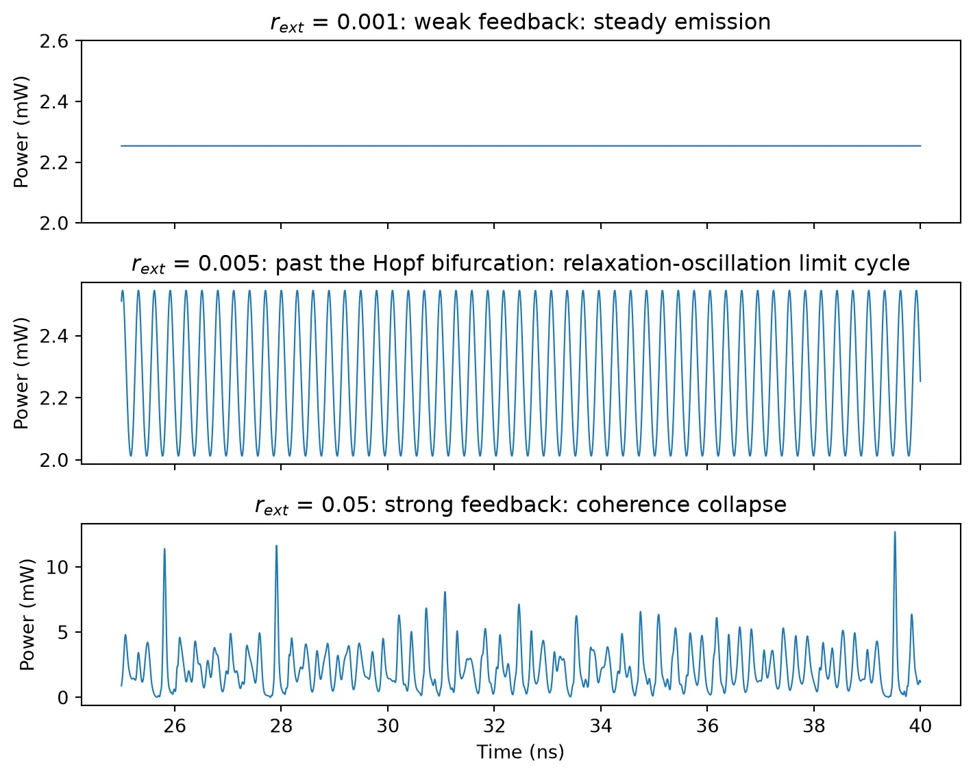
Short-Cavity Regime: Regular Pulse Packages
Section titled “Short-Cavity Regime: Regular Pulse Packages”When the external round trip is shorter than the relaxation-oscillation period the dynamics change character. Heil et al. studied this regime experimentally and with the Lang-Kobayashi equations [3, 4] and found a robust state built around regular pulse packages (RPP): bursts of pulses spaced by the cavity round trip, repeating with a slower envelope period, highly sensitive to the feedback phase .
Their model uses dimensionless parameters. The table below maps the values of Ref. [4] (Figs. 5 to 7) onto this circuit; time is measured in photon lifetimes, so fixes , the pump parameter fixes the drive current, and the feedback strength fixes the product of coupling rate and mirror reflectivity.
| Ref. [4] | Value | Physical quantity here |
|---|---|---|
| 1710 | ps | |
| 0.8 | mA | |
| 70 | round trip ps (1.5 mm of on-chip path) | |
| 0.115 | 1/s | |
| 5.0 | linewidth enhancement factor | |
| swept | round-trip envelope phase, set by the tuner voltage |
Two details of the mapping: the reference model has no gain compression and no spontaneous emission, so those are set to (numerically) zero; and the feedback facet is antireflection coated in the experiment, consistent with the larger coupling rate used here ().
The feedback phase is actuated by a phase tuner inside the cavity: a 1 mm phase_modulator with V cm. Light passes it twice per round trip, so the phase shifts by per round trip and one of drive covers a full cycle of , with the delay unchanged. All lengths are chosen so that every delay is an exact multiple of the time step.
# dimensionless targets from Ref. [4]alpha_h = 5.0t_ratio = 1710.0p_pump = 0.8tau_dim = 70.0eta_fb = 0.115
# laser parameters mapped to physical valuestau_n = 1.0e-9  # carrier lifetime, sets the time unit of Ref. [4] (1/gamma)tau_p = tau_n / t_ratio  # photon lifetime from T = tau_n / tau_p: 0.585 psn_tr = 1.1e24  # transparency carrier density (default laser value)vg_a0 = c_0 / 3.53 * 2.5e-20  # v_g * a0 of the laser modelgam = 0.4  # confinement factorv_a = 1.5e-16  # active volume (m^3)# threshold carrier density: where modal gain equals the cavity loss 1/tau_pn_th = n_tr + 1.0 / (gam * vg_a0 * tau_p)# drive current: threshold current plus the excess pump set by Pi_heil = q_e * v_a * (n_th / tau_n + 2 * p_pump / (tau_n * tau_p * gam * vg_a0))
# feedback coupling: eta = tau_p * kappa_c * r_ext fixes the product of the# facet coupling rate (AR-coated facet, r2 = 0.32) and the mirror reflectivityr2_ar = 0.32kc_heil = (1 - r2_ar**2) / (r2_ar * 7.06e-12)  # kappa_c for the AR facetr_ext_heil = eta_fb / tau_p / kc_heil  # mirror reflectivity: 0.49
# time step: 10 steps per photon lifetime; round trip = 70 tau_p = 700 stepsdt = 0.1 * tau_p
# phase tuner: 1 mm, V_pi L = 0.8 V cm; its length is chosen so that the# group delay is exactly 240 time steps (delays must be integer steps)v_pil = 8000.0  # V_pi L in V um (0.8 V cm)n_g_pm = 4.2  # tuner group indexpm_steps = 240pm_length = pm_steps * dt * c_0 / n_g_pm * 1e6  # umv_pi = v_pil / pm_length  # 8 V for this length
# waveguide making up the rest of the 350-step one-way pathwg_steps = int(round(tau_dim * tau_p / dt / 2)) - pm_steps  # 350 - 240 = 110 stepswg_heil_length = wg_steps * dt * c_0 / n_g_wg * 1e6  # um
print(f"tau_p = {tau_p*1e12:.3f} ps, I = {i_heil*1e3:.1f} mA, "      f"r_ext = {r_ext_heil:.2f}, V_pi = {v_pi:.1f} V")print(f"tuner {pm_length:.0f} um + waveguide {wg_heil_length:.0f} um: "      f"round trip {2*(pm_steps+wg_steps)*dt*1e12:.2f} ps")
def phase_tuner():    return pfa.phase_modulator(        length=pm_length, n_eff=2.4, n_group=n_g_pm, reference_frequency=f0,        v_piL=v_pil, z0=z0, f_3dB=0,    )
# calibrate the static round-trip phase with a pulse probe, then cancel it with the# mirror phase so that C_p = (2 pi / v_pi) * V exactlyprobe = pf.Component("heil_cavity_probe")# same cavity as the loop below, with the laser replaced by a probe portcavity = pf.reference_chain(    {"pm": phase_tuner(), "wg": cavity_waveguide(wg_heil_length), "mr": mirror(r_ext_heil)},    "P0:pm:P1 - wg - mr",  # the tuner's optical ports, since its E0 port would come first)probe.add(*cavity)pm_ref = cavity[0]src_ref = probe.add_reference(pfa.signal_source(amplitude=0, offset=0, seed=1))src_ref.connect("E0", pm_ref["E0"])  # tuner held at 0 Vprobe.add_port(pm_ref["P0"], "in")probe.add_model(pf.CircuitModel(), "Circuit")
# reflect a short pulse and read the round-trip phase from the complex rationum_probe = 2 * (pm_steps + wg_steps) + 3000t_pp = np.arange(num_probe) * dtpulse = np.exp(-0.5 * ((t_pp - 40e-12) / 8e-12) ** 2).astype(complex)ts = probe.setup_time_stepper(time_step=dt, carrier_frequency=f0, show_progress=False)refl = ts.step(    inputs=pf.TimeSeries(time_step=dt, values={"in@0": pulse}), show_progress=False).values["in@0"]mirror_phase = -np.angle(refl.sum() / pulse.sum())  # cancels the static phaseprint(f"mirror phase offset: {mirror_phase:+.4f} rad")
tau_p = 0.585 ps, I = 152.2 mA, r_ext = 0.49, V_pi = 8.0 Vtuner 1002 um + waveguide 482 um: round trip 40.94 psmirror phase offset: -2.5882 radWith the cavity calibrated, the loop is assembled once and stepped in segments: the tuner voltage is fed as a staircase, so the attractor state carries over from one feedback phase to the next, the same continuation protocol as in Ref. [4]. First a single run at shows the regular pulse packages themselves.
def heil_loop():    # closed loop: laser -> phase tuner -> waveguide -> mirror    loop = pf.Component("heil_loop")    # laser mapped to the reference parameter set (see the table above)    laser_ref = loop.add_reference(        feedback_laser(            spontaneous_emission_factor=1e-8,  # tiny seed, the reference model has none            gain_compression_factor=0.0,  # the reference model has none            photon_lifetime=tau_p,            linewidth_enhancement_factor=alpha_h,            feedback_coupling_rate=kc_heil,        )    )    # DC bias at the mapped pump current    source_ref = loop.add_reference(        pfa.signal_source(amplitude=0, offset=i_heil * np.sqrt(z0), seed=1)    )    source_ref.connect("E0", laser_ref["E0"])    # cavity elements, in order from the laser to the mirror    cavity = pf.reference_chain(        {            "pm": phase_tuner(),            "wg": cavity_waveguide(wg_heil_length),            "mr": mirror(r_ext_heil * np.exp(1j * mirror_phase)),        },        "P0:pm:P1 - wg - mr",        start=laser_ref["P0"],    )    loop.add(*cavity)    # the tuner drive is the only exposed port: it will receive the C_p staircase    loop.add_port(cavity[0]["E0"], "vp")    loop.add_model(pf.CircuitModel(), "Circuit")    return loop, laser_ref
# display the assembled loopheil_demo, _ = heil_loop()viewer(heil_demo);fill:%23221f20;font-weight:bold;font-size:1.107720px;}.terminal{fill:none;stroke:%23805080;stroke-width:0.138465;}.dashed{stroke-dasharray:0.692325,0.415395;}.port{fill:none;stroke:%23805080;stroke-width:0.276930;}.virtual-connection{fill:none;stroke:%23907090;stroke-width:0.207698;}.layer_5_0{stroke:%23998573;fill:url(%23pat-layer_5_0);fill-opacity:0.492;}.label_5_0{fill:%23998573;}.layer_3_0{stroke:%238851ad;fill:url(%23pat-layer_3_0);fill-opacity:0.492;}.label_3_0{fill:%238851ad;}.layer_4_0{stroke:%23535e59;fill:url(%23pat-layer_4_0);fill-opacity:0.492;}.label_4_0{fill:%23535e59;}.layer_1_0{stroke:%23858d89;fill:url(%23pat-layer_1_0);fill-opacity:0.492;}.label_1_0{fill:%23858d89;}.layer_2_0{stroke:%235b98b9;fill:url(%23pat-layer_2_0);fill-opacity:0.492;}.label_2_0{fill:%235b98b9;}</style><defs><path id=%22port-symbol%22 class=%22port%22 d=%22M 0,-0.553860 L 0.830790,0 0,0.553860%22 /><path id=%22ref-port-symbol%22 class=%22port%22 style=%22stroke-opacity:0.33;%22 d=%22M 0,-0.415395 C 0.553860,-0.415395 0.553860,0.415395 0,0.415395%22 /><circle id=%22port-bend-symbol%22 style=%22stroke-width:0;stroke:none;fill:%23805080;fill-opacity:1;%22 cx=%220%22 cy=%220%22 r=%220.249237%22 /><circle id=%22connection-symbol%22 style=%22stroke-width:0;stroke:none;fill:%23907090;fill-opacity:1;%22 cx=%220%22 cy=%220%22 r=%220.290777%22 /><pattern id=%22pat-layer_5_0%22 patternUnits=%22userSpaceOnUse%22 width=%220.692325%22 height=%220.692325%22 patternTransform=%22translate(0.040725,0.619449)%22><line x1=%220.692325%22 y1=%220%22 x2=%220%22 y2=%220.692325%22 style=%22stroke:%23998573;stroke-width:0.069233%22 /><line x1=%221.038488%22 y1=%220.346163%22 x2=%220.346163%22 y2=%221.038488%22 style=%22stroke:%23998573;stroke-width:0.069233%22 /><line x1=%220.346163%22 y1=%22-0.346163%22 x2=%22-0.346163%22 y2=%220.346163%22 style=%22stroke:%23998573;stroke-width:0.069233%22 /></pattern><pattern id=%22pat-layer_3_0%22 patternUnits=%22userSpaceOnUse%22 width=%220.415395%22 height=%220.415395%22 patternTransform=%22translate(0.097740,0.306081)%22><circle cx=%220.207698%22 cy=%220.207698%22 r=%220.069233%22 style=%22stroke:none;fill:%238851ad;fill-opacity:1.0%22 /></pattern><pattern id=%22pat-layer_4_0%22 patternUnits=%22userSpaceOnUse%22 width=%220.692325%22 height=%220.692325%22 patternTransform=%22translate(0.447975,0.218629)%22><line x1=%220.346163%22 y1=%220%22 x2=%220.346163%22 y2=%220.692325%22 style=%22stroke:%23535e59;stroke-width:0.069233%22 /><line x1=%220%22 y1=%220.346163%22 x2=%220.692325%22 y2=%220.346163%22 style=%22stroke:%23535e59;stroke-width:0.069233%22 /></pattern><pattern id=%22pat-layer_1_0%22 patternUnits=%22userSpaceOnUse%22 width=%220.692325%22 height=%220.692325%22 patternTransform=%22translate(0.285075,0.400820)%22><circle cx=%220.346163%22 cy=%220.346163%22 r=%220.069233%22 style=%22stroke:none;fill:%23858d89;fill-opacity:1.0%22 /></pattern><pattern id=%22pat-layer_2_0%22 patternUnits=%22userSpaceOnUse%22 width=%220.692325%22 height=%220.692325%22 patternTransform=%22translate(0.570150,0.109314)%22><line x1=%220%22 y1=%220%22 x2=%220.692325%22 y2=%220.692325%22 style=%22stroke:%235b98b9;stroke-width:0.069233%22 /><line x1=%22-0.346163%22 y1=%220.346163%22 x2=%220.346163%22 y2=%221.038488%22 style=%22stroke:%235b98b9;stroke-width:0.069233%22 /><line x1=%220.346163%22 y1=%22-0.346163%22 x2=%221.038488%22 y2=%220.346163%22 style=%22stroke:%235b98b9;stroke-width:0.069233%22 /></pattern><g id=%22C1%22 data-name=%22Feedback Laser%22><path class=%22layer_0_32767%22 d=%22M 0.000000,-7.670000 0.000000,-5.375000 0.000000,-5.125000 0.000000,0.000000 -10.980000,0.000000 -10.980000,-7.670000 z M -10.860000,-0.120000 -0.120000,-0.120000 -0.120000,-5.125000 -1.600000,-5.125000 -1.600000,-4.400000 -3.880000,-4.400000 -4.030000,-4.450000 -4.360000,-4.470000 -4.530000,-4.530000 -9.380000,-5.250000 -3.900000,-6.070000 -1.600000,-6.070000 -1.600000,-5.375000 -0.120000,-5.375000 -0.120000,-7.550000 -10.860000,-7.550000 z%22 /><path class=%22layer_0_32767%22 d=%22M -1.330000,-2.045000 -1.330000,-1.885000 -1.650000,-1.885000 -1.650000,-1.005000 -1.810000,-1.005000 -1.810000,-1.885000 -2.130000,-1.885000 -2.130000,-2.045000 z%22 /><path class=%22layer_0_32767%22 d=%22M -2.874000,-1.725000 -2.474000,-1.725000 -2.354000,-1.605000 -2.354000,-1.125000 -2.474000,-1.005000 -2.954000,-1.005000 -2.954000,-1.165000 -2.514000,-1.165000 -2.514000,-1.285000 -2.874000,-1.285000 -2.994000,-1.405000 -2.994000,-1.605000 z M -2.834000,-1.445000 -2.514000,-1.445000 -2.514000,-1.565000 -2.834000,-1.565000 z%22 /><path class=%22layer_0_32767%22 d=%22M -3.858000,-1.485000 -3.858000,-1.586000 -3.719000,-1.725000 -3.439000,-1.725000 -3.378000,-1.666000 -3.319000,-1.725000 -3.218000,-1.725000 -3.218000,-1.005000 -3.378000,-1.005000 -3.378000,-1.485000 -3.458000,-1.565000 -3.618000,-1.565000 -3.698000,-1.485000 z%22 /><path class=%22layer_0_32767%22 d=%22M -4.082000,-1.725000 -4.082000,-1.005000 -4.242000,-1.005000 -4.242000,-1.485000 -4.322000,-1.565000 -4.402000,-1.485000 -4.402000,-1.005000 -4.562000,-1.005000 -4.562000,-1.485000 -4.642000,-1.565000 -4.722000,-1.485000 -4.722000,-1.005000 -4.882000,-1.005000 -4.882000,-1.546000 -4.703000,-1.725000 -4.583000,-1.725000 -4.482000,-1.626000 -4.383000,-1.725000 z%22 /><path class=%22layer_0_32767%22 d=%22M -5.106000,-1.565000 -5.106000,-1.005000 -5.266000,-1.005000 -5.266000,-1.565000 z%22 /><path class=%22layer_0_32767%22 d=%22M -5.106000,-1.885000 -5.106000,-1.725000 -5.266000,-1.725000 -5.266000,-1.885000 z%22 /><path class=%22layer_0_32767%22 d=%22M -5.490000,-1.725000 -5.490000,-1.005000 -5.650000,-1.005000 -5.650000,-1.485000 -5.730000,-1.565000 -5.810000,-1.565000 -5.890000,-1.485000 -5.890000,-1.005000 -6.050000,-1.005000 -6.050000,-1.546000 -5.871000,-1.725000 -5.711000,-1.725000 -5.650000,-1.666000 -5.591000,-1.725000 z%22 /><path class=%22layer_0_32767%22 d=%22M -6.834000,-1.725000 -6.354000,-1.725000 -6.274000,-1.645000 -6.274000,-1.565000 -6.754000,-1.565000 -6.754000,-1.445000 -6.394000,-1.445000 -6.274000,-1.325000 -6.274000,-1.125000 -6.394000,-1.005000 -6.914000,-1.005000 -6.914000,-1.645000 z M -6.754000,-1.165000 -6.434000,-1.165000 -6.434000,-1.285000 -6.754000,-1.285000 z%22 /><path class=%22layer_0_32767%22 d=%22M -7.618000,-1.165000 -7.458000,-1.165000 -7.458000,-1.645000 -7.618000,-1.645000 -7.618000,-1.805000 -7.458000,-1.805000 -7.458000,-2.045000 -7.298000,-2.045000 -7.298000,-1.805000 -7.138000,-1.805000 -7.138000,-1.645000 -7.298000,-1.645000 -7.298000,-1.125000 -7.418000,-1.005000 -7.618000,-1.005000 z%22 /><path class=%22layer_0_32767%22 d=%22M -7.842000,-1.565000 -7.842000,-1.005000 -8.002000,-1.005000 -8.002000,-1.565000 z%22 /><path class=%22layer_0_32767%22 d=%22M -7.842000,-1.885000 -7.842000,-1.725000 -8.002000,-1.725000 -8.002000,-1.885000 z%22 /><path class=%22layer_0_32767%22 d=%22M -8.687000,-1.725000 -8.407000,-1.725000 -8.226000,-1.546000 -8.226000,-1.186000 -8.407000,-1.005000 -8.687000,-1.005000 -8.866000,-1.186000 -8.866000,-1.546000 z M -8.706000,-1.245000 -8.626000,-1.165000 -8.466000,-1.165000 -8.386000,-1.245000 -8.386000,-1.485000 -8.466000,-1.565000 -8.626000,-1.565000 -8.706000,-1.485000 z%22 /><path class=%22layer_0_32767%22 d=%22M -9.090000,-1.725000 -9.090000,-1.005000 -9.250000,-1.005000 -9.250000,-1.485000 -9.330000,-1.565000 -9.410000,-1.565000 -9.490000,-1.485000 -9.490000,-1.005000 -9.650000,-1.005000 -9.650000,-1.546000 -9.471000,-1.725000 -9.311000,-1.725000 -9.250000,-1.666000 -9.191000,-1.725000 z%22 /></g><g id=%22C2%22 data-name=%22Source%22><path class=%22layer_0_32767%22 d=%22M 0.000000,9.700000 0.000000,0.000000 11.640000,0.000000 11.640000,6.125000 11.640000,6.375000 11.640000,9.700000 z M 11.520000,6.375000 5.880000,6.375000 5.880000,8.100000 3.650000,8.100000 3.620000,8.080000 3.620000,4.820000 3.600000,4.800000 1.720000,4.800000 1.720000,4.420000 3.620000,4.420000 3.650000,4.400000 4.020000,4.420000 4.020000,7.700000 4.050000,7.720000 5.450000,7.720000 5.500000,7.680000 5.500000,4.800000 5.480000,4.780000 5.500000,4.400000 5.850000,4.400000 5.880000,4.420000 9.920000,4.420000 9.920000,4.800000 5.900000,4.800000 5.880000,4.820000 5.880000,6.125000 11.520000,6.125000 11.520000,0.120000 0.120000,0.120000 0.120000,9.580000 11.520000,9.580000 z%22 /><path class=%22layer_0_32767%22 d=%22M 1.460000,2.026000 1.281000,2.205000 0.921000,2.205000 0.740000,2.026000 0.740000,1.805000 0.940000,1.605000 1.220000,1.605000 1.300000,1.525000 1.300000,1.405000 1.220000,1.325000 0.980000,1.325000 0.881000,1.426000 0.740000,1.426000 0.740000,1.346000 0.921000,1.165000 1.281000,1.165000 1.460000,1.346000 1.460000,1.565000 1.260000,1.765000 0.980000,1.765000 0.900000,1.845000 0.900000,1.965000 0.980000,2.045000 1.220000,2.045000 1.321000,1.946000 1.460000,1.946000 z%22 /><path class=%22layer_0_32767%22 d=%22M 1.684000,1.725000 1.684000,1.165000 1.844000,1.165000 1.844000,1.725000 z%22 /><path class=%22layer_0_32767%22 d=%22M 1.684000,2.045000 1.684000,1.885000 1.844000,1.885000 1.844000,2.045000 z%22 /><path class=%22layer_0_32767%22 d=%22M 2.249000,1.885000 2.068000,1.706000 2.068000,1.346000 2.249000,1.165000 2.548000,1.165000 2.548000,1.005000 2.228000,1.005000 2.228000,0.845000 2.588000,0.845000 2.708000,0.965000 2.708000,1.885000 z M 2.548000,1.325000 2.308000,1.325000 2.228000,1.405000 2.228000,1.645000 2.308000,1.725000 2.548000,1.725000 z%22 /><path class=%22layer_0_32767%22 d=%22M 2.932000,1.885000 2.932000,1.165000 3.092000,1.165000 3.092000,1.645000 3.172000,1.725000 3.252000,1.725000 3.332000,1.645000 3.332000,1.165000 3.492000,1.165000 3.492000,1.706000 3.313000,1.885000 3.153000,1.885000 3.092000,1.826000 3.033000,1.885000 z%22 /><path class=%22layer_0_32767%22 d=%22M 4.276000,1.885000 3.796000,1.885000 3.716000,1.805000 3.716000,1.725000 4.196000,1.725000 4.196000,1.605000 3.836000,1.605000 3.716000,1.485000 3.716000,1.285000 3.836000,1.165000 4.356000,1.165000 4.356000,1.805000 z M 4.196000,1.325000 3.876000,1.325000 3.876000,1.445000 4.196000,1.445000 z%22 /><path class=%22layer_0_32767%22 d=%22M 4.900000,1.325000 4.740000,1.325000 4.740000,2.205000 4.580000,2.205000 4.580000,1.285000 4.700000,1.165000 4.900000,1.165000 z%22 /><path class=%22layer_0_32767%22 d=%22M 6.100000,1.165000 6.540000,1.165000 6.660000,1.285000 6.660000,1.485000 6.540000,1.605000 6.180000,1.605000 6.180000,1.725000 6.660000,1.725000 6.660000,1.805000 6.580000,1.885000 6.100000,1.885000 6.020000,1.805000 6.020000,1.565000 6.140000,1.445000 6.500000,1.445000 6.500000,1.325000 6.020000,1.325000 6.020000,1.245000 z%22 /><path class=%22layer_0_32767%22 d=%22M 7.345000,1.885000 7.065000,1.885000 6.884000,1.706000 6.884000,1.346000 7.065000,1.165000 7.345000,1.165000 7.524000,1.346000 7.524000,1.706000 z M 7.364000,1.405000 7.284000,1.325000 7.124000,1.325000 7.044000,1.405000 7.044000,1.645000 7.124000,1.725000 7.284000,1.725000 7.364000,1.645000 z%22 /><path class=%22layer_0_32767%22 d=%22M 8.308000,1.165000 8.308000,1.885000 8.148000,1.885000 8.148000,1.405000 8.068000,1.325000 7.988000,1.325000 7.908000,1.405000 7.908000,1.885000 7.748000,1.885000 7.748000,1.346000 7.929000,1.165000 8.089000,1.165000 8.148000,1.226000 8.209000,1.165000 z%22 /><path class=%22layer_0_32767%22 d=%22M 9.172000,1.645000 9.172000,1.746000 9.033000,1.885000 8.753000,1.885000 8.692000,1.826000 8.633000,1.885000 8.532000,1.885000 8.532000,1.165000 8.692000,1.165000 8.692000,1.645000 8.772000,1.725000 8.932000,1.725000 9.012000,1.645000 z%22 /><path class=%22layer_0_32767%22 d=%22M 10.036000,1.426000 9.897000,1.426000 9.796000,1.325000 9.636000,1.325000 9.556000,1.405000 9.556000,1.645000 9.636000,1.725000 9.796000,1.725000 9.897000,1.626000 10.036000,1.626000 10.036000,1.706000 9.857000,1.885000 9.577000,1.885000 9.396000,1.706000 9.396000,1.346000 9.577000,1.165000 9.857000,1.165000 10.036000,1.346000 z%22 /><path class=%22layer_0_32767%22 d=%22M 10.780000,1.885000 10.380000,1.885000 10.260000,1.765000 10.260000,1.285000 10.380000,1.165000 10.860000,1.165000 10.860000,1.325000 10.420000,1.325000 10.420000,1.445000 10.780000,1.445000 10.900000,1.565000 10.900000,1.765000 z M 10.740000,1.605000 10.420000,1.605000 10.420000,1.725000 10.740000,1.725000 z%22 /></g><g id=%22C3%22 data-name=%22Phase Modulator%22><path class=%22layer_0_32767%22 d=%22M 5.165000,10.180000 4.915000,10.180000 0.000000,10.180000 0.000000,6.645000 0.000000,6.395000 0.000000,0.000000 10.060000,0.000000 10.060000,6.395000 10.060000,6.645000 10.060000,10.180000 z M 9.940000,6.645000 8.460000,6.645000 8.460000,7.180000 6.080000,7.180000 6.060000,7.200000 6.080000,7.400000 8.460000,7.400000 8.460000,8.580000 5.165000,8.580000 5.165000,10.060000 9.940000,10.060000 z M 6.130000,6.230000 6.080000,6.180000 5.980000,6.280000 5.880000,6.180000 5.830000,6.230000 5.830000,6.800000 5.880000,6.860000 5.980000,6.760000 6.080000,6.860000 6.130000,6.800000 z M 6.130000,7.560000 6.080000,7.500000 5.980000,7.600000 5.880000,7.500000 5.830000,7.560000 5.830000,8.430000 5.880000,8.480000 5.980000,8.380000 6.080000,8.480000 6.130000,8.430000 z M 5.860000,7.180000 1.600000,7.180000 1.600000,6.645000 0.120000,6.645000 0.120000,10.060000 4.915000,10.060000 4.915000,8.580000 1.600000,8.580000 1.600000,7.400000 5.860000,7.400000 5.880000,7.380000 z M 4.230000,8.280000 4.180000,8.230000 3.980000,8.230000 3.930000,8.280000 3.930000,8.430000 3.980000,8.480000 4.080000,8.380000 4.180000,8.480000 4.230000,8.430000 z M 9.940000,0.120000 0.120000,0.120000 0.120000,6.395000 1.600000,6.395000 1.600000,5.860000 5.860000,5.860000 5.880000,5.830000 5.860000,5.630000 1.600000,5.630000 1.600000,4.400000 8.460000,4.400000 8.460000,5.630000 6.080000,5.630000 6.060000,5.660000 6.080000,5.860000 8.460000,5.860000 8.460000,6.395000 9.940000,6.395000 z M 6.130000,5.230000 6.080000,5.180000 5.880000,5.180000 5.830000,5.230000 5.830000,5.480000 5.880000,5.530000 5.980000,5.430000 6.080000,5.530000 6.130000,5.480000 z%22 /><path class=%22layer_0_32767%22 d=%22M 1.467000,2.045000 0.926000,2.045000 0.926000,1.005000 1.086000,1.005000 1.086000,1.405000 1.467000,1.405000 1.646000,1.586000 1.646000,1.866000 z M 1.486000,1.645000 1.406000,1.565000 1.086000,1.565000 1.086000,1.885000 1.406000,1.885000 1.486000,1.805000 z%22 /><path class=%22layer_0_32767%22 d=%22M 2.510000,1.005000 2.510000,1.426000 2.331000,1.605000 2.030000,1.605000 2.030000,2.045000 1.870000,2.045000 1.870000,1.005000 2.030000,1.005000 2.030000,1.445000 2.270000,1.445000 2.350000,1.365000 2.350000,1.005000 z%22 /><path class=%22layer_0_32767%22 d=%22M 3.294000,1.725000 2.814000,1.725000 2.734000,1.645000 2.734000,1.565000 3.214000,1.565000 3.214000,1.445000 2.854000,1.445000 2.734000,1.325000 2.734000,1.125000 2.854000,1.005000 3.374000,1.005000 3.374000,1.645000 z M 3.214000,1.165000 2.894000,1.165000 2.894000,1.285000 3.214000,1.285000 z%22 /><path class=%22layer_0_32767%22 d=%22M 3.678000,1.005000 4.118000,1.005000 4.238000,1.125000 4.238000,1.325000 4.118000,1.445000 3.758000,1.445000 3.758000,1.565000 4.238000,1.565000 4.238000,1.645000 4.158000,1.725000 3.678000,1.725000 3.598000,1.645000 3.598000,1.405000 3.718000,1.285000 4.078000,1.285000 4.078000,1.165000 3.598000,1.165000 3.598000,1.085000 z%22 /><path class=%22layer_0_32767%22 d=%22M 4.982000,1.725000 4.582000,1.725000 4.462000,1.605000 4.462000,1.125000 4.582000,1.005000 5.062000,1.005000 5.062000,1.165000 4.622000,1.165000 4.622000,1.285000 4.982000,1.285000 5.102000,1.405000 5.102000,1.605000 z M 4.942000,1.445000 4.622000,1.445000 4.622000,1.565000 4.942000,1.565000 z%22 /><path class=%22layer_0_32767%22 d=%22M 6.222000,1.725000 6.222000,1.005000 6.382000,1.005000 6.382000,1.485000 6.462000,1.565000 6.542000,1.485000 6.542000,1.005000 6.702000,1.005000 6.702000,1.485000 6.782000,1.565000 6.862000,1.485000 6.862000,1.005000 7.022000,1.005000 7.022000,1.546000 6.843000,1.725000 6.723000,1.725000 6.622000,1.626000 6.523000,1.725000 z%22 /><path class=%22layer_0_32767%22 d=%22M 7.707000,1.725000 7.427000,1.725000 7.246000,1.546000 7.246000,1.186000 7.427000,1.005000 7.707000,1.005000 7.886000,1.186000 7.886000,1.546000 z M 7.726000,1.245000 7.646000,1.165000 7.486000,1.165000 7.406000,1.245000 7.406000,1.485000 7.486000,1.565000 7.646000,1.565000 7.726000,1.485000 z%22 /><path class=%22layer_0_32767%22 d=%22M 8.590000,2.045000 8.590000,1.685000 8.291000,1.685000 8.110000,1.506000 8.110000,1.186000 8.291000,1.005000 8.750000,1.005000 8.750000,2.045000 z M 8.590000,1.165000 8.350000,1.165000 8.270000,1.245000 8.270000,1.445000 8.350000,1.525000 8.590000,1.525000 z%22 /><path class=%22layer_0_32767%22 d=%22M 8.974000,1.165000 8.974000,1.005000 9.134000,1.005000 9.134000,1.165000 z%22 /></g><g id=%22C4%22 data-name=%22WG%22><path class=%22layer_0_32767%22 d=%22M 0.000000,7.300000 0.000000,5.175000 0.000000,4.925000 0.000000,0.000000 10.050000,0.000000 10.050000,4.925000 10.050000,5.175000 10.050000,7.300000 z M 9.930000,5.175000 8.450000,5.175000 8.450000,5.700000 1.600000,5.700000 1.600000,5.175000 0.120000,5.175000 0.120000,7.180000 9.930000,7.180000 z M 9.930000,0.120000 0.120000,0.120000 0.120000,4.925000 1.600000,4.925000 1.600000,4.400000 8.450000,4.400000 8.450000,4.925000 9.930000,4.925000 z%22 /><path class=%22layer_0_32767%22 d=%22M 1.409000,1.165000 1.590000,1.165000 1.889000,1.466000 2.190000,1.165000 2.369000,1.165000 2.369000,2.205000 2.209000,2.205000 2.209000,1.485000 2.129000,1.485000 1.889000,1.725000 1.649000,1.485000 1.569000,1.485000 1.569000,2.205000 1.409000,2.205000 z%22 /><path class=%22layer_0_32767%22 d=%22M 3.153000,1.885000 2.673000,1.885000 2.593000,1.805000 2.593000,1.725000 3.073000,1.725000 3.073000,1.605000 2.713000,1.605000 2.593000,1.485000 2.593000,1.285000 2.713000,1.165000 3.233000,1.165000 3.233000,1.805000 z M 3.073000,1.325000 2.753000,1.325000 2.753000,1.445000 3.073000,1.445000 z%22 /><path class=%22layer_0_32767%22 d=%22M 4.017000,1.805000 4.017000,1.885000 3.857000,1.885000 3.777000,1.325000 3.697000,1.325000 3.617000,1.885000 3.457000,1.885000 3.457000,1.805000 3.558000,1.165000 3.918000,1.165000 z%22 /><path class=%22layer_0_32767%22 d=%22M 4.761000,1.885000 4.361000,1.885000 4.241000,1.765000 4.241000,1.285000 4.361000,1.165000 4.841000,1.165000 4.841000,1.325000 4.401000,1.325000 4.401000,1.445000 4.761000,1.445000 4.881000,1.565000 4.881000,1.765000 z M 4.721000,1.605000 4.401000,1.605000 4.401000,1.725000 4.721000,1.725000 z%22 /><path class=%22layer_0_32767%22 d=%22M 5.286000,1.885000 5.105000,1.706000 5.105000,1.346000 5.286000,1.165000 5.585000,1.165000 5.585000,1.005000 5.265000,1.005000 5.265000,0.845000 5.625000,0.845000 5.745000,0.965000 5.745000,1.885000 z M 5.585000,1.325000 5.345000,1.325000 5.265000,1.405000 5.265000,1.645000 5.345000,1.725000 5.585000,1.725000 z%22 /><path class=%22layer_0_32767%22 d=%22M 6.529000,1.165000 6.529000,1.885000 6.369000,1.885000 6.369000,1.405000 6.289000,1.325000 6.209000,1.325000 6.129000,1.405000 6.129000,1.885000 5.969000,1.885000 5.969000,1.346000 6.150000,1.165000 6.310000,1.165000 6.369000,1.226000 6.430000,1.165000 z%22 /><path class=%22layer_0_32767%22 d=%22M 6.753000,1.725000 6.753000,1.165000 6.913000,1.165000 6.913000,1.725000 z%22 /><path class=%22layer_0_32767%22 d=%22M 6.753000,2.045000 6.753000,1.885000 6.913000,1.885000 6.913000,2.045000 z%22 /><path class=%22layer_0_32767%22 d=%22M 7.617000,2.205000 7.617000,1.845000 7.318000,1.845000 7.137000,1.666000 7.137000,1.346000 7.318000,1.165000 7.777000,1.165000 7.777000,2.205000 z M 7.617000,1.325000 7.377000,1.325000 7.297000,1.405000 7.297000,1.605000 7.377000,1.685000 7.617000,1.685000 z%22 /><path class=%22layer_0_32767%22 d=%22M 8.521000,1.885000 8.121000,1.885000 8.001000,1.765000 8.001000,1.285000 8.121000,1.165000 8.601000,1.165000 8.601000,1.325000 8.161000,1.325000 8.161000,1.445000 8.521000,1.445000 8.641000,1.565000 8.641000,1.765000 z M 8.481000,1.605000 8.161000,1.605000 8.161000,1.725000 8.481000,1.725000 z%22 /></g><g id=%22C5%22 data-name=%22Mirror%22><path class=%22layer_0_32767%22 d=%22M 0.000000,7.670000 0.000000,5.375000 0.000000,5.125000 0.000000,0.000000 10.980000,0.000000 10.980000,7.670000 z M 10.860000,0.120000 0.120000,0.120000 0.120000,5.125000 1.600000,5.125000 1.600000,4.400000 3.880000,4.400000 4.030000,4.450000 4.360000,4.470000 4.530000,4.530000 9.380000,5.250000 3.900000,6.070000 1.600000,6.070000 1.600000,5.375000 0.120000,5.375000 0.120000,7.550000 10.860000,7.550000 z%22 /><path class=%22layer_0_32767%22 d=%22M 1.330000,2.045000 1.330000,1.885000 1.650000,1.885000 1.650000,1.005000 1.810000,1.005000 1.810000,1.885000 2.130000,1.885000 2.130000,2.045000 z%22 /><path class=%22layer_0_32767%22 d=%22M 2.874000,1.725000 2.474000,1.725000 2.354000,1.605000 2.354000,1.125000 2.474000,1.005000 2.954000,1.005000 2.954000,1.165000 2.514000,1.165000 2.514000,1.285000 2.874000,1.285000 2.994000,1.405000 2.994000,1.605000 z M 2.834000,1.445000 2.514000,1.445000 2.514000,1.565000 2.834000,1.565000 z%22 /><path class=%22layer_0_32767%22 d=%22M 3.858000,1.485000 3.858000,1.586000 3.719000,1.725000 3.439000,1.725000 3.378000,1.666000 3.319000,1.725000 3.218000,1.725000 3.218000,1.005000 3.378000,1.005000 3.378000,1.485000 3.458000,1.565000 3.618000,1.565000 3.698000,1.485000 z%22 /><path class=%22layer_0_32767%22 d=%22M 4.082000,1.725000 4.082000,1.005000 4.242000,1.005000 4.242000,1.485000 4.322000,1.565000 4.402000,1.485000 4.402000,1.005000 4.562000,1.005000 4.562000,1.485000 4.642000,1.565000 4.722000,1.485000 4.722000,1.005000 4.882000,1.005000 4.882000,1.546000 4.703000,1.725000 4.583000,1.725000 4.482000,1.626000 4.383000,1.725000 z%22 /><path class=%22layer_0_32767%22 d=%22M 5.106000,1.565000 5.106000,1.005000 5.266000,1.005000 5.266000,1.565000 z%22 /><path class=%22layer_0_32767%22 d=%22M 5.106000,1.885000 5.106000,1.725000 5.266000,1.725000 5.266000,1.885000 z%22 /><path class=%22layer_0_32767%22 d=%22M 5.490000,1.725000 5.490000,1.005000 5.650000,1.005000 5.650000,1.485000 5.730000,1.565000 5.810000,1.565000 5.890000,1.485000 5.890000,1.005000 6.050000,1.005000 6.050000,1.546000 5.871000,1.725000 5.711000,1.725000 5.650000,1.666000 5.591000,1.725000 z%22 /><path class=%22layer_0_32767%22 d=%22M 6.834000,1.725000 6.354000,1.725000 6.274000,1.645000 6.274000,1.565000 6.754000,1.565000 6.754000,1.445000 6.394000,1.445000 6.274000,1.325000 6.274000,1.125000 6.394000,1.005000 6.914000,1.005000 6.914000,1.645000 z M 6.754000,1.165000 6.434000,1.165000 6.434000,1.285000 6.754000,1.285000 z%22 /><path class=%22layer_0_32767%22 d=%22M 7.618000,1.165000 7.458000,1.165000 7.458000,1.645000 7.618000,1.645000 7.618000,1.805000 7.458000,1.805000 7.458000,2.045000 7.298000,2.045000 7.298000,1.805000 7.138000,1.805000 7.138000,1.645000 7.298000,1.645000 7.298000,1.125000 7.418000,1.005000 7.618000,1.005000 z%22 /><path class=%22layer_0_32767%22 d=%22M 7.842000,1.565000 7.842000,1.005000 8.002000,1.005000 8.002000,1.565000 z%22 /><path class=%22layer_0_32767%22 d=%22M 7.842000,1.885000 7.842000,1.725000 8.002000,1.725000 8.002000,1.885000 z%22 /><path class=%22layer_0_32767%22 d=%22M 8.687000,1.725000 8.407000,1.725000 8.226000,1.546000 8.226000,1.186000 8.407000,1.005000 8.687000,1.005000 8.866000,1.186000 8.866000,1.546000 z M 8.706000,1.245000 8.626000,1.165000 8.466000,1.165000 8.386000,1.245000 8.386000,1.485000 8.466000,1.565000 8.626000,1.565000 8.706000,1.485000 z%22 /><path class=%22layer_0_32767%22 d=%22M 9.090000,1.725000 9.090000,1.005000 9.250000,1.005000 9.250000,1.485000 9.330000,1.565000 9.410000,1.565000 9.490000,1.485000 9.490000,1.005000 9.650000,1.005000 9.650000,1.546000 9.471000,1.725000 9.311000,1.725000 9.250000,1.666000 9.191000,1.725000 z%22 /></g></defs><g transform=%22scale(1 -1)%22><g id=%22C0%22 data-name=%22heil_loop%22><use transform=%22translate(0.000000 0.000000)%22 href=%22%23C1%22 /><use transform=%22translate(-11.740000 11.640000) rotate(-90.000000)%22 href=%22%23C2%22 /><use transform=%22translate(0.000000 -11.770000)%22 href=%22%23C3%22 /><use transform=%22translate(10.060000 -10.300000)%22 href=%22%23C4%22 /><use transform=%22translate(20.110000 -10.500000)%22 href=%22%23C5%22 /><g transform=%22translate(5.040000 -1.590000) rotate(-90.000000)%22><path class=%22port%22 d=%22M 0,-0.500000 V 0.500000%22 /><use href=%22%23port-symbol%22 /></g><text class=%22label%22 text-anchor=%22end%22 dominant-baseline=%22text-before-edge%22 x=%225.040000%22 y=%221.590000%22>vp</text></g></g></svg>)
%22><rect x=%22-30.00%22 y=%22-30.00%22 width=%2260.00%22 height=%2260.00%22 fill=%22%23f4f5f7%22 stroke=%22%23232530%22 stroke-width=%221%22/><use href=%22%23g-laser%22 transform=%22translate(-30.00 -30.00) scale(1.2)%22/><circle cx=%2230.00%22 cy=%220.00%22 r=%224%22 fill=%22%2300643c%22 stroke=%22%2300643c%22 stroke-width=%221%22/><circle cx=%220.00%22 cy=%22-30.00%22 r=%224%22 fill=%22%23f44e6a%22 stroke=%22%23f44e6a%22 stroke-width=%221%22/></g><text x=%22192.00%22 y=%2231.80%22 font-size=%229%22 fill=%22%23232530%22 font-weight=%22400%22 text-anchor=%22middle%22 dominant-baseline=%22hanging%22 stroke=%22%23ffffff%22 stroke-width=%223.15%22 stroke-linejoin=%22round%22 paint-order=%22stroke%22>Feedback_Laser_1</text><g transform=%22matrix(6.12323e-17 1 -1 6.12323e-17 0.000 0.000)%22><rect x=%22-30.00%22 y=%22-30.00%22 width=%2260.00%22 height=%2260.00%22 fill=%22%23f4f5f7%22 stroke=%22%23232530%22 stroke-width=%221%22/><use href=%22%23g-source%22 transform=%22translate(-30.00 -30.00) scale(1.2)%22/><circle cx=%2230.00%22 cy=%220.00%22 r=%224%22 fill=%22%23f44e6a%22 stroke=%22%23f44e6a%22 stroke-width=%221%22/></g><text x=%220.00%22 y=%2235.80%22 font-size=%229%22 fill=%22%23232530%22 font-weight=%22400%22 text-anchor=%22middle%22 dominant-baseline=%22hanging%22 stroke=%22%23ffffff%22 stroke-width=%223.15%22 stroke-linejoin=%22round%22 paint-order=%22stroke%22>Source_1</text><g transform=%22matrix(1 -0 0 1 384.000 0.000)%22><rect x=%22-30.00%22 y=%22-30.00%22 width=%2260.00%22 height=%2260.00%22 fill=%22%23f4f5f7%22 stroke=%22%23232530%22 stroke-width=%221%22/><use href=%22%23g-eo_ps%22 transform=%22translate(-30.00 -30.00) scale(1.2)%22/><circle cx=%22-30.00%22 cy=%220.00%22 r=%224%22 fill=%22%2300643c%22 stroke=%22%2300643c%22 stroke-width=%221%22/><circle cx=%2230.00%22 cy=%220.00%22 r=%224%22 fill=%22%2300643c%22 stroke=%22%2300643c%22 stroke-width=%221%22/><circle cx=%220.00%22 cy=%22-30.00%22 r=%224%22 fill=%22%23f44e6a%22 stroke=%22%23f44e6a%22 stroke-width=%221%22/></g><text x=%22384.00%22 y=%2231.80%22 font-size=%229%22 fill=%22%23232530%22 font-weight=%22400%22 text-anchor=%22middle%22 dominant-baseline=%22hanging%22 stroke=%22%23ffffff%22 stroke-width=%223.15%22 stroke-linejoin=%22round%22 paint-order=%22stroke%22>Phase_Modulator_1</text><text x=%22384.00%22 y=%22-42.00%22 font-size=%2210%22 fill=%22%23b8461c%22 font-weight=%22700%22 text-anchor=%22middle%22 dominant-baseline=%22auto%22 stroke=%22%23ffffff%22 stroke-width=%223.50%22 stroke-linejoin=%22round%22 paint-order=%22stroke%22>vp</text><g transform=%22matrix(1 -0 0 1 576.000 0.000)%22><use href=%22%23g-wg%22 transform=%22translate(-30.00 -30.00) scale(1.2)%22/><circle cx=%22-30.00%22 cy=%220.00%22 r=%224%22 fill=%22%2300643c%22 stroke=%22%2300643c%22 stroke-width=%221%22/><circle cx=%2230.00%22 cy=%220.00%22 r=%224%22 fill=%22%2300643c%22 stroke=%22%2300643c%22 stroke-width=%221%22/></g><text x=%22576.00%22 y=%2231.80%22 font-size=%229%22 fill=%22%23232530%22 font-weight=%22400%22 text-anchor=%22middle%22 dominant-baseline=%22hanging%22 stroke=%22%23ffffff%22 stroke-width=%223.15%22 stroke-linejoin=%22round%22 paint-order=%22stroke%22>WG_1</text><g transform=%22matrix(1 -0 0 1 768.000 0.000)%22><use href=%22%23g-termination%22 transform=%22translate(-30.00 -30.00) scale(1.2)%22/><circle cx=%22-30.00%22 cy=%220.00%22 r=%224%22 fill=%22%2300643c%22 stroke=%22%2300643c%22 stroke-width=%221%22/></g><text x=%22768.00%22 y=%2231.80%22 font-size=%229%22 fill=%22%23232530%22 font-weight=%22400%22 text-anchor=%22middle%22 dominant-baseline=%22hanging%22 stroke=%22%23ffffff%22 stroke-width=%223.15%22 stroke-linejoin=%22round%22 paint-order=%22stroke%22>Mirror_1</text><g fill=%22none%22 stroke-width=%222%22></g></svg>)
def heil_stepper():    # time stepper with a monitor on the laser port (emitted + returning wave)    loop, laser_ref = heil_loop()    return loop.setup_time_stepper(        time_step=dt, carrier_frequency=f0, show_progress=False,        time_stepper_kwargs={"monitors": {"laser": laser_ref["P0"]}},    )
def run_segment(ts, volt, num):    # hold the tuner at a constant voltage for num steps; the internal state    # persists between calls, so consecutive segments continue the same run    out = ts.step(        inputs=pf.TimeSeries(            time_step=dt, values={"vp@0": np.full(num, volt / np.sqrt(z0), complex)}        ),        show_progress=False,    )    # return the emitted wave (the monitor direction with larger mean power)    a_plus, a_minus = out.values["laser@0+"], out.values["laser@0-"]    return a_plus if np.mean(np.abs(a_plus) ** 2) > np.mean(np.abs(a_minus) ** 2) else a_minus
# regular pulse packages at C_p = pits = heil_stepper()v_cp_pi = np.pi * v_pi / (2 * np.pi)  # tuner voltage for C_p = pirun_segment(ts, v_cp_pi, 200000)  # discard the turn-on transient (20000 tau_p)emitted = run_segment(ts, v_cp_pi, 50000)  # keep 5000 tau_p for the plot
t_rpp = np.arange(len(emitted)) * dtfig, ax = plt.subplots(figsize=(8, 3.2), tight_layout=True)ax.plot(t_rpp * 1e9, np.abs(emitted) ** 2 * 1e3, lw=0.7)ax.set(xlabel="Time (ns)", ylabel="Power (mW)",       title=r"Regular pulse packages at $C_p = \pi$: pulses spaced by the 41 ps "             "round trip under a slower package envelope")plt.show()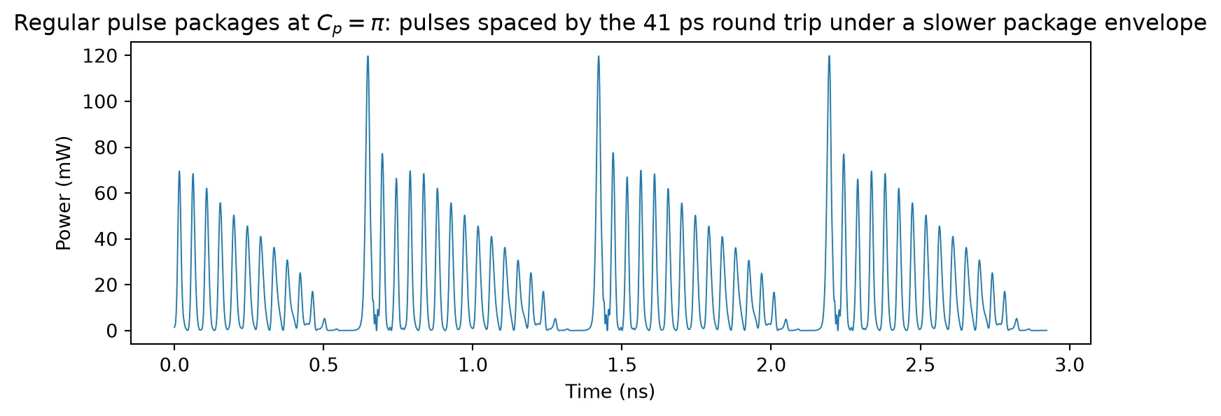
Bifurcation Scenario versus Feedback Phase
Section titled “Bifurcation Scenario versus Feedback Phase”Finally, the tuner voltage is stepped so that walks from down to and then back up. At each phase the first 5000 photon lifetimes are discarded and the extrema of the normalized field amplitude are collected over the next 200; sweeping in both directions catches the hysteresis between coexisting states. This is the recipe behind Fig. 7 of Ref. [4], and the resulting diagram reproduces the cyclic scenario reported there:
- a steady plateau (the maximum-gain mode) for ,
- a Hopf bifurcation near with a limit cycle that grows as the phase decreases,
- quasi-periodic (torus) bands below ,
- and the abrupt appearance of pulse packages near , whose extrema fill a broad band; on the return sweep the pulse packages persist well into the region where the steady mode also exists before the laser falls back onto it.
# conversion from monitor amplitude (sqrt W) to the normalized field amplitudec_p_cal = 0.4 * h_planck * f0 * v_a / (2 * gam * tau_p)  # W per photon densitya2p = tau_n * vg_a0 / 2.0  # |A|^2 = a2p * p
cp_down = np.linspace(np.pi, -np.pi, 97)n_transient = 50000  # 5000 photon lifetimesn_record = 2000  # 200 photon lifetimes
diagram = []for cp_values in [cp_down, cp_down[::-1]]:  # sweep down, then back up    ts = heil_stepper()  # fresh loop for each sweep direction    # let the cold-started laser turn on and settle at the first phase value    run_segment(ts, cp_values[0] * v_pi / (2 * np.pi), 150000)    for cp in cp_values:        volt = cp * v_pi / (2 * np.pi)  # staircase level for this C_p        run_segment(ts, volt, n_transient)  # transient, discarded        emitted = run_segment(ts, volt, n_record)  # recorded segment        # monitor amplitude -> photon density -> normalized field amplitude        r_norm = np.sqrt(a2p * np.abs(emitted) ** 2 / c_p_cal) / np.sqrt(p_pump) - 1.0        # local maxima and minima of the recorded trace        dm = np.diff(r_norm)        idx_max = np.where((dm[:-1] > 0) & (dm[1:] <= 0))[0] + 1        idx_min = np.where((dm[:-1] < 0) & (dm[1:] >= 0))[0] + 1        extrema = np.concatenate([r_norm[idx_max], r_norm[idx_min]])        if len(extrema) == 0:            extrema = r_norm[-1:]  # steady state: keep the level itself        diagram.append((cp, extrema))
fig, ax = plt.subplots(figsize=(8, 5), tight_layout=True)for cp, extrema in diagram:    if len(extrema) > 60:        extrema = extrema[:: len(extrema) // 60]    ax.plot(np.full(len(extrema), cp), extrema, ".", color="k", ms=1.4, alpha=0.6)ax.set(xlabel="Feedback phase $C_p$", ylabel=r"Field amplitude $R/\sqrt{P} - 1$",       xlim=(-np.pi, np.pi), ylim=(-1.05, 2.5),       title="Extrema of the field amplitude vs feedback phase, compare with "             "Fig. 7 of Ref. [4]")plt.show()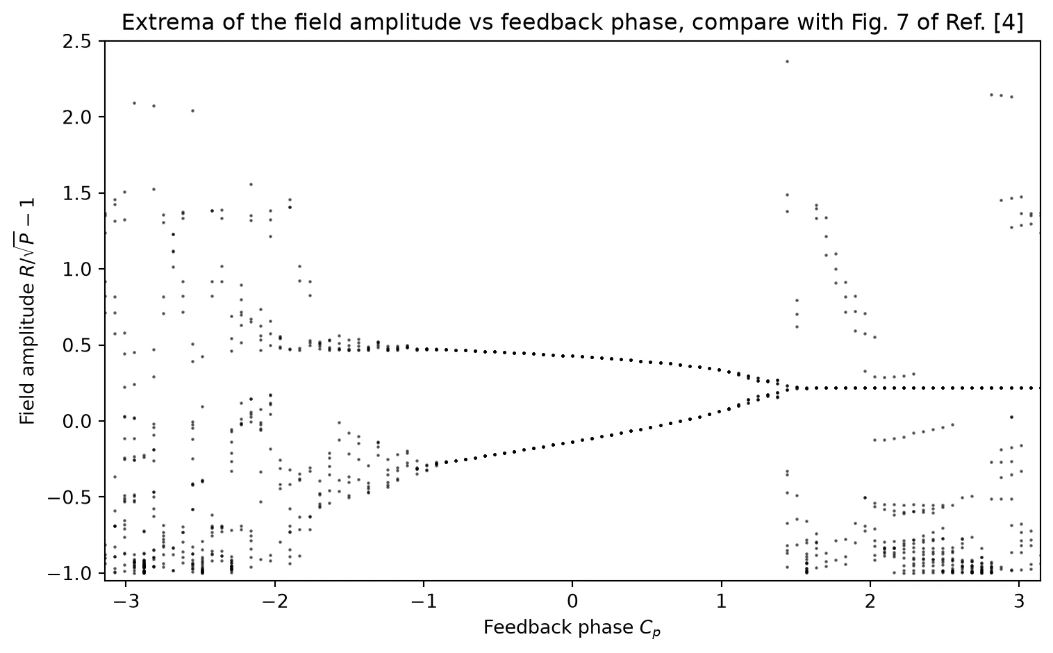
Conclusion
Section titled “Conclusion”The laser built here is not a special case: it is an ordinary PhotonForge model. Every
model in a circuit provides its dynamics through the same
TimeStepper interface, so a user-defined
subclass that implements setup_state, keys, and step_single enters a simulation on
the same footing as the built-in lasers, modulators, and photodiodes: it can be
parameterized, driven by sources, observed with monitors, and wired into any topology,
while the circuit stepper takes care of every connection around it. Writing one is a
matter of typing in the device physics, as done here and in the
self-pulsing microring example.
That flexibility is what carried this study:
- The Lang-Kobayashi delayed term was never written in this notebook. The laser model only knows how incident light couples into its rate equations; the delay, strength, and phase of the feedback all come from ordinary circuit elements. Any modification of the feedback path (two mirrors, a filtered reflector, another laser instead of the mirror) is a change of netlist, not of model code.
- The same setup quantifies engineering questions directly: the Hopf threshold found in the reflectivity sweep is the tolerable back-reflection level for this laser, and its dependence on bias, linewidth enhancement factor, and cavity length can be swept with a few lines.
- The two knobs of the short-cavity experiment, feedback strength and feedback phase, map onto a mirror parameter and a tuner voltage. Stepping the tuner voltage while the simulation runs preserves the attractor, which is what resolves hysteresis between coexisting states.
The same recipe extends beyond this example: any device whose physics can be written as differential equations driven by its port signals, from saturable absorbers to mutually coupled lasers, can be dropped into a PhotonForge circuit the same way and explored against everything else in the model library.