

Automated Routing of a Ring Filter Bank
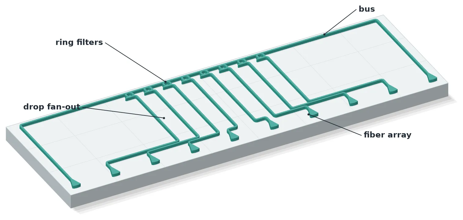
This example lays out an 8 channel ring filter bank, a wavelength division multiplexing (WDM) demultiplexer [1], and connects it to a fiber array with a single call to route_auto. The Auto Routing guide covers the arguments of the router; here they are used on a complete chip.
Eight add-drop rings sit in a row on one straight bus at a 60 um pitch. The fiber array is centered below them on the standard 127 um pitch, so the eight drop waveguides have to fan out by more than a factor of two. Because the channel order along the array follows the ring order along the bus, the fan-out nests without a single crossing, and every turn on the chip is a 90 degree bend.
After the main route, each section below changes one thing on the same bank to show one more feature of the router:
- reading the routing report that
diagnostics=Trueattaches to the result, - S bends and 45 degree bends,
- obstacles and the
collision_layersthat decide what blocks a route, - waveguide crossings,
- what happens when a net cannot be routed, and how to find it,
- path length matching: equal lengths, one target per net, a mirror-symmetric layout, and
the three
bendssettings, - scaling the same call to more channels.
A table at the end lists the remaining arguments of route_auto.
Only the layout is built here. Every number printed below is measured from the geometry.
References
- De Heyn, Peter, et al. “Fabrication-tolerant four-channel wavelength-division-multiplexing filter based on collectively tuned Si microrings.” Journal of Lightwave Technology 2013 31 (16), 2785-2792, doi: 10.1109/JLT.2013.2273391.
- Chrostowski, Lukas, et al. “Silicon photonic circuit design using rapid prototyping foundry process design kits.” IEEE Journal of Selected Topics in Quantum Electronics 2019 25 (5), 8201326, doi: 10.1109/JSTQE.2019.2917501.
Loading the technology and defaults
Section titled “Loading the technology and defaults”The SiEPIC OpenEBL technology [2] is loaded through the siepic_forge module. Every parametric call in this notebook inherits the default arguments below, the routing call included.
import json
import photonforge as pfimport siepic_forge as siepic
# Use the SiEPIC OpenEBL technology for every component belowpf.config.default_technology = siepic.ebeam()
# Set the defaults inherited by every parametric call, the routing call includedpf.config.default_kwargs = { "port_spec": "TE_1550_500", # Port specification: 500 nm Si strip, TE at 1550 nm "radius": 9.0, # Bend radius (μm) "euler_fraction": 0.5, # Fraction of each bend drawn as an Euler curve}
# Leave the labels out of the SVG previews of componentspf.config.svg_labels = False
# Open the live viewer that displays each layout belowviewer = pf.live_viewer.LiveViewer()LiveViewer started at http://127.0.0.1:39305. Call its 'stop()' method to free the port.Defining the ring filter
Section titled “Defining the ring filter”Each channel is an add-drop ring: a ring between two parallel bus waveguides. Light at the
resonance of the ring couples from the input bus into the ring and out through the second
bus, so the channel leaves through the drop port while every other wavelength continues
to the through port.
The component is two ring_coupler
halves, the second rotated by 180 degrees so that the two half rings close into a full ring.
Note that coupling_distance is the distance between the two waveguide centers, not the gap
between their edges: 0.7 um is a 200 nm gap for a 500 nm wide waveguide.
The drop bus ends in a 90 degree bend, with the same radius as the routes, so that the drop port points away from the ring. In the bank below, that makes every drop port face the fiber array.
# Load the TE grating coupler at 1550 nm from the SiEPIC PDKgrating = siepic.component("ebeam_gc_te1550")
# Load the terminator that closes the unused add portsterminator = siepic.component("ebeam_terminator_te1550")
# Define the add-drop ring as a parametric component@pf.parametric_componentdef ring_filter(*, radius=10.0, coupling_distance=0.7, bus_length=6.0): # Create the parent component of the ring c = pf.Component()
# Create one half of the ring together with its straight bus half = pf.parametric.ring_coupler( radius=radius, # Ring radius (μm) coupling_distance=coupling_distance, # Bus to ring center distance (μm) coupling_length=0.0, # Length of the straight coupling section (μm) bus_length=bus_length, # Length of the bus on each side of the ring (μm) )
# Add the bottom half, which carries the input bus bottom = c.add_reference(half)
# Add the top half, which carries the drop bus top = c.add_reference(half)
# Rotate the top half so that the two halves close into a full ring top.rotate(180)
# End the drop bus in a 90 degree bend that points away from the ring turn = c.add_reference(pf.parametric.bend()).connect("P1", top["P2"])
# Expose the ports of the input bus, below the ring c.add_port(bottom["P0"], "in") # Input port of the bus c.add_port(bottom["P2"], "through") # Port for the wavelengths the ring passes
# Expose the ports of the drop bus, above the ring c.add_port(turn["P0"], "drop") # Port for the wavelength the ring drops c.add_port(top["P0"], "add") # Add port, closed by a terminator in the bank
# Simulate the ring as a circuit of its two halves and the bend c.add_model(pf.CircuitModel()) return c
# Create the ring with its default parametersring = ring_filter()
# Show the ring in the live viewerviewer(ring);fill:%23221f20;font-weight:bold;font-size:1.370600px;}.terminal{fill:none;stroke:%23805080;stroke-width:0.171325;}.dashed{stroke-dasharray:0.856625,0.513975;}.port{fill:none;stroke:%23805080;stroke-width:0.342650;}.virtual-connection{fill:none;stroke:%23907090;stroke-width:0.256988;}.layer_31_0{stroke:%238c78ef;fill:url(%23pat-layer_31_0);fill-opacity:0.492;}.label_31_0{fill:%238c78ef;}.layer_33_0{stroke:%238c78ef;fill:url(%23pat-layer_33_0);fill-opacity:0.492;}.label_33_0{fill:%238c78ef;}.layer_102_0{stroke:%238c78ef;fill:url(%23pat-layer_102_0);fill-opacity:0.492;}.label_102_0{fill:%238c78ef;}.layer_110_0{stroke:%238c78ef;fill:url(%23pat-layer_110_0);fill-opacity:0.492;}.label_110_0{fill:%238c78ef;}.layer_189_0{stroke:%23000000;fill:none;}.label_189_0{fill:%23000000;}.layer_201_0{stroke:%2300ee00;fill:url(%23pat-layer_201_0);fill-opacity:0.492;}.label_201_0{fill:%2300ee00;}.layer_401_0{stroke:%236a8ad2;fill:url(%23pat-layer_401_0);fill-opacity:0.492;}.label_401_0{fill:%236a8ad2;}.layer_202_0{stroke:%23007600;fill:url(%23pat-layer_202_0);fill-opacity:0.492;}.label_202_0{fill:%23007600;}.layer_68_0{stroke:%23008000;fill:url(%23pat-layer_68_0);fill-opacity:0.492;}.label_68_0{fill:%23008000;}.layer_5_0{stroke:%236a8ad2;fill:url(%23pat-layer_5_0);fill-opacity:0.492;}.label_5_0{fill:%236a8ad2;}.layer_998_0{stroke:%23000000;fill:none;}.label_998_0{fill:%23000000;}.layer_312_1{stroke:%2300b8b8;fill:url(%23pat-layer_312_1);fill-opacity:0.492;}.label_312_1{fill:%2300b8b8;}.layer_312_0{stroke:%2300b8b8;fill:url(%23pat-layer_312_0);fill-opacity:0.492;}.label_312_0{fill:%2300b8b8;}.layer_402_0{stroke:%23ff0000;fill:url(%23pat-layer_402_0);fill-opacity:0.492;}.label_402_0{fill:%23ff0000;}.layer_401_4{stroke:%236a8ad2;fill:url(%23pat-layer_401_4);fill-opacity:0.492;}.label_401_4{fill:%236a8ad2;}.layer_389_0{stroke:%23ff00ff;fill:url(%23pat-layer_389_0);fill-opacity:0.492;}.label_389_0{fill:%23ff00ff;}.layer_402_1{stroke:%23ff0000;fill:url(%23pat-layer_402_1);fill-opacity:0.492;}.label_402_1{fill:%23ff0000;}.layer_350_1{stroke:%23697a00;fill:url(%23pat-layer_350_1);fill-opacity:0.492;}.label_350_1{fill:%23697a00;}.layer_401_1{stroke:%236a8ad2;fill:url(%23pat-layer_401_1);fill-opacity:0.492;}.label_401_1{fill:%236a8ad2;}.layer_313_2{stroke:%2301d95b;fill:url(%23pat-layer_313_2);fill-opacity:0.492;}.label_313_2{fill:%2301d95b;}.layer_313_1{stroke:%2301d95b;fill:url(%23pat-layer_313_1);fill-opacity:0.492;}.label_313_1{fill:%2301d95b;}.layer_313_0{stroke:%2301d95b;fill:url(%23pat-layer_313_0);fill-opacity:0.492;}.label_313_0{fill:%2301d95b;}.layer_400_0{stroke:%23a96868;fill:url(%23pat-layer_400_0);fill-opacity:0.492;}.label_400_0{fill:%23a96868;}.layer_312_3{stroke:%2300b8b8;fill:url(%23pat-layer_312_3);fill-opacity:0.492;}.label_312_3{fill:%2300b8b8;}.layer_389_1{stroke:%23ff00ff;fill:url(%23pat-layer_389_1);fill-opacity:0.492;}.label_389_1{fill:%23ff00ff;}.layer_401_3{stroke:%236a8ad2;fill:url(%23pat-layer_401_3);fill-opacity:0.492;}.label_401_3{fill:%236a8ad2;}.layer_403_2{stroke:%23500080;fill:url(%23pat-layer_403_2);fill-opacity:0.492;}.label_403_2{fill:%23500080;}.layer_403_3{stroke:%23500080;fill:url(%23pat-layer_403_3);fill-opacity:0.492;}.label_403_3{fill:%23500080;}.layer_403_1{stroke:%23500080;fill:url(%23pat-layer_403_1);fill-opacity:0.492;}.label_403_1{fill:%23500080;}.layer_403_0{stroke:%23500080;fill:url(%23pat-layer_403_0);fill-opacity:0.492;}.label_403_0{fill:%23500080;}.layer_311_1{stroke:%23ac6c56;fill:url(%23pat-layer_311_1);fill-opacity:0.492;}.label_311_1{fill:%23ac6c56;}.layer_311_0{stroke:%23ac6c56;fill:url(%23pat-layer_311_0);fill-opacity:0.492;}.label_311_0{fill:%23ac6c56;}.layer_301_1{stroke:%23800057;fill:url(%23pat-layer_301_1);fill-opacity:0.492;}.label_301_1{fill:%23800057;}.layer_301_0{stroke:%23800057;fill:url(%23pat-layer_301_0);fill-opacity:0.492;}.label_301_0{fill:%23800057;}.layer_305_1{stroke:%23808080;fill:url(%23pat-layer_305_1);fill-opacity:0.492;}.label_305_1{fill:%23808080;}.layer_305_0{stroke:%23808080;fill:url(%23pat-layer_305_0);fill-opacity:0.492;}.label_305_0{fill:%23808080;}.layer_999_0{stroke:%230000ff;fill:url(%23pat-layer_999_0);fill-opacity:0.492;}.label_999_0{fill:%230000ff;}.layer_81_0{stroke:%23808080;fill:url(%23pat-layer_81_0);fill-opacity:0.492;}.label_81_0{fill:%23808080;}.layer_290_0{stroke:%23a46eda;fill:none;}.label_290_0{fill:%23a46eda;}.layer_205_0{stroke:%2349b203;fill:url(%23pat-layer_205_0);fill-opacity:0.492;}.label_205_0{fill:%2349b203;}.layer_11_0{stroke:%230000ff;fill:url(%23pat-layer_11_0);fill-opacity:0.492;}.label_11_0{fill:%230000ff;}.layer_12_0{stroke:%23a57b00;fill:url(%23pat-layer_12_0);fill-opacity:0.492;}.label_12_0{fill:%23a57b00;}.layer_13_0{stroke:%23800057;fill:url(%23pat-layer_13_0);fill-opacity:0.492;}.label_13_0{fill:%23800057;}.layer_6_0{stroke:%23ff0000;fill:url(%23pat-layer_6_0);fill-opacity:0.492;}.label_6_0{fill:%23ff0000;}.layer_1_10{stroke:%23c96585;fill:url(%23pat-layer_1_10);fill-opacity:0.492;}.label_1_10{fill:%23c96585;}.layer_1_11{stroke:%23800000;fill:url(%23pat-layer_1_11);fill-opacity:0.492;}.label_1_11{fill:%23800000;}.layer_200_0{stroke:%23ff0000;fill:url(%23pat-layer_200_0);fill-opacity:0.492;}.label_200_0{fill:%23ff0000;}.layer_1_0{stroke:%23c96585;fill:url(%23pat-layer_1_0);fill-opacity:0.492;}.label_1_0{fill:%23c96585;}.layer_2_0{stroke:%23a46eda;fill:url(%23pat-layer_2_0);fill-opacity:0.492;}.label_2_0{fill:%23a46eda;}.layer_20_0{stroke:%2353793d;fill:url(%23pat-layer_20_0);fill-opacity:0.492;}.label_20_0{fill:%2353793d;}.layer_22_0{stroke:%23ec7600;fill:url(%23pat-layer_22_0);fill-opacity:0.492;}.label_22_0{fill:%23ec7600;}.layer_24_0{stroke:%2300b8b8;fill:url(%23pat-layer_24_0);fill-opacity:0.492;}.label_24_0{fill:%2300b8b8;}.layer_21_0{stroke:%23736264;fill:url(%23pat-layer_21_0);fill-opacity:0.492;}.label_21_0{fill:%23736264;}.layer_23_0{stroke:%23697a00;fill:url(%23pat-layer_23_0);fill-opacity:0.492;}.label_23_0{fill:%23697a00;}.layer_25_0{stroke:%23008000;fill:url(%23pat-layer_25_0);fill-opacity:0.492;}.label_25_0{fill:%23008000;}.layer_350_0{stroke:%23697a00;fill:url(%23pat-layer_350_0);fill-opacity:0.492;}.label_350_0{fill:%23697a00;}.layer_10_0{stroke:%23000000;fill:none;}.label_10_0{fill:%23000000;}.layer_203_0{stroke:%23008000;fill:url(%23pat-layer_203_0);fill-opacity:0.492;}.label_203_0{fill:%23008000;}.layer_40_0{stroke:%230000ff;fill:url(%23pat-layer_40_0);fill-opacity:0.492;}.label_40_0{fill:%230000ff;}.layer_401_2{stroke:%236a8ad2;fill:url(%23pat-layer_401_2);fill-opacity:0.492;}.label_401_2{fill:%236a8ad2;}.layer_301_2{stroke:%23800057;fill:url(%23pat-layer_301_2);fill-opacity:0.492;}.label_301_2{fill:%23800057;}</style><defs><path id=%22port-symbol%22 class=%22port%22 d=%22M 0,-0.685300 L 1.027950,0 0,0.685300%22 /><path id=%22ref-port-symbol%22 class=%22port%22 style=%22stroke-opacity:0.33;%22 d=%22M 0,-0.513975 C 0.685300,-0.513975 0.685300,0.513975 0,0.513975%22 /><circle id=%22port-bend-symbol%22 style=%22stroke-width:0;stroke:none;fill:%23805080;fill-opacity:1;%22 cx=%220%22 cy=%220%22 r=%220.308385%22 /><circle id=%22connection-symbol%22 style=%22stroke-width:0;stroke:none;fill:%23907090;fill-opacity:1;%22 cx=%220%22 cy=%220%22 r=%220.359783%22 /><pattern id=%22pat-layer_31_0%22 patternUnits=%22userSpaceOnUse%22 width=%220.856625%22 height=%220.856625%22 patternTransform=%22translate(0.655066,0.811539)%22><line x1=%220%22 y1=%220%22 x2=%220.856625%22 y2=%220.856625%22 style=%22stroke:%238c78ef;stroke-width:0.085663%22 /><line x1=%22-0.428313%22 y1=%220.428313%22 x2=%220.428313%22 y2=%221.284938%22 style=%22stroke:%238c78ef;stroke-width:0.085663%22 /><line x1=%220.428313%22 y1=%22-0.428313%22 x2=%221.284938%22 y2=%220.428313%22 style=%22stroke:%238c78ef;stroke-width:0.085663%22 /></pattern><pattern id=%22pat-layer_33_0%22 patternUnits=%22userSpaceOnUse%22 width=%220.856625%22 height=%220.856625%22 patternTransform=%22translate(0.503897,0.090171)%22><line x1=%220%22 y1=%220%22 x2=%220.856625%22 y2=%220.856625%22 style=%22stroke:%238c78ef;stroke-width:0.085663%22 /><line x1=%22-0.428313%22 y1=%220.428313%22 x2=%220.428313%22 y2=%221.284938%22 style=%22stroke:%238c78ef;stroke-width:0.085663%22 /><line x1=%220.428313%22 y1=%22-0.428313%22 x2=%221.284938%22 y2=%220.428313%22 style=%22stroke:%238c78ef;stroke-width:0.085663%22 /></pattern><pattern id=%22pat-layer_102_0%22 patternUnits=%22userSpaceOnUse%22 width=%220.856625%22 height=%220.856625%22 patternTransform=%22translate(0.000000,0.045086)%22><line x1=%220%22 y1=%220%22 x2=%220.856625%22 y2=%220.856625%22 style=%22stroke:%238c78ef;stroke-width:0.085663%22 /><line x1=%22-0.428313%22 y1=%220.428313%22 x2=%220.428313%22 y2=%221.284938%22 style=%22stroke:%238c78ef;stroke-width:0.085663%22 /><line x1=%220.428313%22 y1=%22-0.428313%22 x2=%221.284938%22 y2=%220.428313%22 style=%22stroke:%238c78ef;stroke-width:0.085663%22 /></pattern><pattern id=%22pat-layer_110_0%22 patternUnits=%22userSpaceOnUse%22 width=%220.856625%22 height=%220.856625%22 patternTransform=%22translate(0.251949,0.586112)%22><line x1=%220%22 y1=%220%22 x2=%220.856625%22 y2=%220.856625%22 style=%22stroke:%238c78ef;stroke-width:0.085663%22 /><line x1=%22-0.428313%22 y1=%220.428313%22 x2=%220.428313%22 y2=%221.284938%22 style=%22stroke:%238c78ef;stroke-width:0.085663%22 /><line x1=%220.428313%22 y1=%22-0.428313%22 x2=%221.284938%22 y2=%220.428313%22 style=%22stroke:%238c78ef;stroke-width:0.085663%22 /></pattern><pattern id=%22pat-layer_201_0%22 patternUnits=%22userSpaceOnUse%22 width=%220.856625%22 height=%220.856625%22 patternTransform=%22translate(0.655066,0.315599)%22><circle cx=%220.428313%22 cy=%220.428313%22 r=%220.085663%22 style=%22stroke:none;fill:%2300ee00;fill-opacity:1.0%22 /></pattern><pattern id=%22pat-layer_401_0%22 patternUnits=%22userSpaceOnUse%22 width=%220.513975%22 height=%220.513975%22 patternTransform=%22translate(0.060468,0.081154)%22><line x1=%220%22 y1=%220%22 x2=%220.513975%22 y2=%220.513975%22 style=%22stroke:%236a8ad2;stroke-width:0.085663%22 /><line x1=%22-0.256988%22 y1=%220.256988%22 x2=%220.256988%22 y2=%220.770963%22 style=%22stroke:%236a8ad2;stroke-width:0.085663%22 /><line x1=%220.256988%22 y1=%22-0.256988%22 x2=%220.770963%22 y2=%220.256988%22 style=%22stroke:%236a8ad2;stroke-width:0.085663%22 /><line x1=%220.513975%22 y1=%220%22 x2=%220%22 y2=%220.513975%22 style=%22stroke:%236a8ad2;stroke-width:0.085663%22 /><line x1=%220.770963%22 y1=%220.256988%22 x2=%220.256988%22 y2=%220.770963%22 style=%22stroke:%236a8ad2;stroke-width:0.085663%22 /><line x1=%220.256988%22 y1=%22-0.256988%22 x2=%22-0.256988%22 y2=%220.256988%22 style=%22stroke:%236a8ad2;stroke-width:0.085663%22 /></pattern><pattern id=%22pat-layer_202_0%22 patternUnits=%22userSpaceOnUse%22 width=%220.513975%22 height=%220.513975%22 patternTransform=%22translate(0.090701,0.486924)%22><circle cx=%220.256988%22 cy=%220.256988%22 r=%220.085663%22 style=%22stroke:none;fill:%23007600;fill-opacity:1.0%22 /></pattern><pattern id=%22pat-layer_68_0%22 patternUnits=%22userSpaceOnUse%22 width=%220.856625%22 height=%220.856625%22 patternTransform=%22translate(0.000000,0.315599)%22><circle cx=%220.428313%22 cy=%220.428313%22 r=%220.085663%22 style=%22stroke:none;fill:%23008000;fill-opacity:1.0%22 /></pattern><pattern id=%22pat-layer_5_0%22 patternUnits=%22userSpaceOnUse%22 width=%220.513975%22 height=%220.513975%22 patternTransform=%22translate(0.030234,0.459872)%22><line x1=%220.256988%22 y1=%220%22 x2=%220.256988%22 y2=%220.513975%22 style=%22stroke:%236a8ad2;stroke-width:0.085663%22 /></pattern><pattern id=%22pat-layer_312_1%22 patternUnits=%22userSpaceOnUse%22 width=%220.513975%22 height=%220.513975%22 patternTransform=%22translate(0.120935,0.405770)%22><line x1=%220%22 y1=%220%22 x2=%220.513975%22 y2=%220.513975%22 style=%22stroke:%2300b8b8;stroke-width:0.085663%22 /><line x1=%22-0.256988%22 y1=%220.256988%22 x2=%220.256988%22 y2=%220.770963%22 style=%22stroke:%2300b8b8;stroke-width:0.085663%22 /><line x1=%220.256988%22 y1=%22-0.256988%22 x2=%220.770963%22 y2=%220.256988%22 style=%22stroke:%2300b8b8;stroke-width:0.085663%22 /></pattern><pattern id=%22pat-layer_312_0%22 patternUnits=%22userSpaceOnUse%22 width=%220.856625%22 height=%220.856625%22 patternTransform=%22translate(0.403118,0.541026)%22><line x1=%220.428313%22 y1=%220%22 x2=%220.428313%22 y2=%220.856625%22 style=%22stroke:%2300b8b8;stroke-width:0.085663%22 /></pattern><pattern id=%22pat-layer_402_0%22 patternUnits=%22userSpaceOnUse%22 width=%220.856625%22 height=%220.856625%22 patternTransform=%22translate(0.453507,0.631197)%22><line x1=%220.428313%22 y1=%220%22 x2=%220.428313%22 y2=%220.856625%22 style=%22stroke:%23ff0000;stroke-width:0.085663%22 /><line x1=%220%22 y1=%220.428313%22 x2=%220.856625%22 y2=%220.428313%22 style=%22stroke:%23ff0000;stroke-width:0.085663%22 /></pattern><pattern id=%22pat-layer_401_4%22 patternUnits=%22userSpaceOnUse%22 width=%220.513975%22 height=%220.513975%22 patternTransform=%22translate(0.090701,0.405770)%22><line x1=%220.256988%22 y1=%220%22 x2=%220.256988%22 y2=%220.513975%22 style=%22stroke:%236a8ad2;stroke-width:0.085663%22 /></pattern><pattern id=%22pat-layer_389_0%22 patternUnits=%22userSpaceOnUse%22 width=%220.513975%22 height=%220.513975%22 patternTransform=%22translate(0.090701,0.108205)%22><line x1=%220.256988%22 y1=%220%22 x2=%220.256988%22 y2=%220.513975%22 style=%22stroke:%23ff00ff;stroke-width:0.085663%22 /><line x1=%220%22 y1=%220.256988%22 x2=%220.513975%22 y2=%220.256988%22 style=%22stroke:%23ff00ff;stroke-width:0.085663%22 /></pattern><pattern id=%22pat-layer_402_1%22 patternUnits=%22userSpaceOnUse%22 width=%220.513975%22 height=%220.513975%22 patternTransform=%22translate(0.151169,0.459872)%22><line x1=%220%22 y1=%220%22 x2=%220.513975%22 y2=%220.513975%22 style=%22stroke:%23ff0000;stroke-width:0.085663%22 /><line x1=%22-0.256988%22 y1=%220.256988%22 x2=%220.256988%22 y2=%220.770963%22 style=%22stroke:%23ff0000;stroke-width:0.085663%22 /><line x1=%220.256988%22 y1=%22-0.256988%22 x2=%220.770963%22 y2=%220.256988%22 style=%22stroke:%23ff0000;stroke-width:0.085663%22 /><line x1=%220.513975%22 y1=%220%22 x2=%220%22 y2=%220.513975%22 style=%22stroke:%23ff0000;stroke-width:0.085663%22 /><line x1=%220.770963%22 y1=%220.256988%22 x2=%220.256988%22 y2=%220.770963%22 style=%22stroke:%23ff0000;stroke-width:0.085663%22 /><line x1=%220.256988%22 y1=%22-0.256988%22 x2=%22-0.256988%22 y2=%220.256988%22 style=%22stroke:%23ff0000;stroke-width:0.085663%22 /></pattern><pattern id=%22pat-layer_350_1%22 patternUnits=%22userSpaceOnUse%22 width=%220.513975%22 height=%220.513975%22 patternTransform=%22translate(0.453507,0.405770)%22><circle cx=%220.256988%22 cy=%220.256988%22 r=%220.085663%22 style=%22stroke:none;fill:%23697a00;fill-opacity:1.0%22 /></pattern><pattern id=%22pat-layer_401_1%22 patternUnits=%22userSpaceOnUse%22 width=%220.856625%22 height=%220.856625%22 patternTransform=%22translate(0.755846,0.270513)%22><line x1=%220%22 y1=%220%22 x2=%220.856625%22 y2=%220.856625%22 style=%22stroke:%236a8ad2;stroke-width:0.085663%22 /><line x1=%22-0.428313%22 y1=%220.428313%22 x2=%220.428313%22 y2=%221.284938%22 style=%22stroke:%236a8ad2;stroke-width:0.085663%22 /><line x1=%220.428313%22 y1=%22-0.428313%22 x2=%221.284938%22 y2=%220.428313%22 style=%22stroke:%236a8ad2;stroke-width:0.085663%22 /><line x1=%220.856625%22 y1=%220%22 x2=%220%22 y2=%220.856625%22 style=%22stroke:%236a8ad2;stroke-width:0.085663%22 /><line x1=%221.284938%22 y1=%220.428313%22 x2=%220.428313%22 y2=%221.284938%22 style=%22stroke:%236a8ad2;stroke-width:0.085663%22 /><line x1=%220.428313%22 y1=%22-0.428313%22 x2=%22-0.428313%22 y2=%220.428313%22 style=%22stroke:%236a8ad2;stroke-width:0.085663%22 /></pattern><pattern id=%22pat-layer_313_2%22 patternUnits=%22userSpaceOnUse%22 width=%220.513975%22 height=%220.513975%22 patternTransform=%22translate(0.211637,0.270513)%22><line x1=%220%22 y1=%220%22 x2=%220.513975%22 y2=%220.513975%22 style=%22stroke:%2301d95b;stroke-width:0.085663%22 /><line x1=%22-0.256988%22 y1=%220.256988%22 x2=%220.256988%22 y2=%220.770963%22 style=%22stroke:%2301d95b;stroke-width:0.085663%22 /><line x1=%220.256988%22 y1=%22-0.256988%22 x2=%220.770963%22 y2=%220.256988%22 style=%22stroke:%2301d95b;stroke-width:0.085663%22 /></pattern><pattern id=%22pat-layer_313_1%22 patternUnits=%22userSpaceOnUse%22 width=%220.856625%22 height=%220.856625%22 patternTransform=%22translate(0.554287,0.315599)%22><line x1=%220.428313%22 y1=%220%22 x2=%220.428313%22 y2=%220.856625%22 style=%22stroke:%2301d95b;stroke-width:0.085663%22 /></pattern><pattern id=%22pat-layer_313_0%22 patternUnits=%22userSpaceOnUse%22 width=%220.513975%22 height=%220.513975%22 patternTransform=%22translate(0.453507,0.108205)%22><line x1=%220.256988%22 y1=%220%22 x2=%220.256988%22 y2=%220.513975%22 style=%22stroke:%2301d95b;stroke-width:0.085663%22 /></pattern><pattern id=%22pat-layer_400_0%22 patternUnits=%22userSpaceOnUse%22 width=%220.856625%22 height=%220.856625%22 patternTransform=%22translate(0.604676,0.495941)%22><line x1=%220%22 y1=%220%22 x2=%220.856625%22 y2=%220.856625%22 style=%22stroke:%23a96868;stroke-width:0.085663%22 /><line x1=%22-0.428313%22 y1=%220.428313%22 x2=%220.428313%22 y2=%221.284938%22 style=%22stroke:%23a96868;stroke-width:0.085663%22 /><line x1=%220.428313%22 y1=%22-0.428313%22 x2=%221.284938%22 y2=%220.428313%22 style=%22stroke:%23a96868;stroke-width:0.085663%22 /><line x1=%220.856625%22 y1=%220%22 x2=%220%22 y2=%220.856625%22 style=%22stroke:%23a96868;stroke-width:0.085663%22 /><line x1=%221.284938%22 y1=%220.428313%22 x2=%220.428313%22 y2=%221.284938%22 style=%22stroke:%23a96868;stroke-width:0.085663%22 /><line x1=%220.428313%22 y1=%22-0.428313%22 x2=%22-0.428313%22 y2=%220.428313%22 style=%22stroke:%23a96868;stroke-width:0.085663%22 /></pattern><pattern id=%22pat-layer_312_3%22 patternUnits=%22userSpaceOnUse%22 width=%220.513975%22 height=%220.513975%22 patternTransform=%22translate(0.393040,0.054103)%22><line x1=%220.513975%22 y1=%220%22 x2=%220%22 y2=%220.513975%22 style=%22stroke:%2300b8b8;stroke-width:0.085663%22 /><line x1=%220.770963%22 y1=%220.256988%22 x2=%220.256988%22 y2=%220.770963%22 style=%22stroke:%2300b8b8;stroke-width:0.085663%22 /><line x1=%220.256988%22 y1=%22-0.256988%22 x2=%22-0.256988%22 y2=%220.256988%22 style=%22stroke:%2300b8b8;stroke-width:0.085663%22 /></pattern><pattern id=%22pat-layer_389_1%22 patternUnits=%22userSpaceOnUse%22 width=%220.856625%22 height=%220.856625%22 patternTransform=%22translate(0.806235,0.315599)%22><line x1=%220.428313%22 y1=%220%22 x2=%220.428313%22 y2=%220.856625%22 style=%22stroke:%23ff00ff;stroke-width:0.085663%22 /><line x1=%220%22 y1=%220.428313%22 x2=%220.856625%22 y2=%220.428313%22 style=%22stroke:%23ff00ff;stroke-width:0.085663%22 /></pattern><pattern id=%22pat-layer_401_3%22 patternUnits=%22userSpaceOnUse%22 width=%220.856625%22 height=%220.856625%22 patternTransform=%22translate(0.352728,0.541026)%22><line x1=%220%22 y1=%220.428313%22 x2=%220.856625%22 y2=%220.428313%22 style=%22stroke:%236a8ad2;stroke-width:0.085663%22 /></pattern><pattern id=%22pat-layer_403_2%22 patternUnits=%22userSpaceOnUse%22 width=%220.513975%22 height=%220.513975%22 patternTransform=%22translate(0.241871,0.324616)%22><line x1=%220%22 y1=%220%22 x2=%220.513975%22 y2=%220.513975%22 style=%22stroke:%23500080;stroke-width:0.085663%22 /><line x1=%22-0.256988%22 y1=%220.256988%22 x2=%220.256988%22 y2=%220.770963%22 style=%22stroke:%23500080;stroke-width:0.085663%22 /><line x1=%220.256988%22 y1=%22-0.256988%22 x2=%220.770963%22 y2=%220.256988%22 style=%22stroke:%23500080;stroke-width:0.085663%22 /><line x1=%220.513975%22 y1=%220%22 x2=%220%22 y2=%220.513975%22 style=%22stroke:%23500080;stroke-width:0.085663%22 /><line x1=%220.770963%22 y1=%220.256988%22 x2=%220.256988%22 y2=%220.770963%22 style=%22stroke:%23500080;stroke-width:0.085663%22 /><line x1=%220.256988%22 y1=%22-0.256988%22 x2=%22-0.256988%22 y2=%220.256988%22 style=%22stroke:%23500080;stroke-width:0.085663%22 /></pattern><pattern id=%22pat-layer_403_3%22 patternUnits=%22userSpaceOnUse%22 width=%220.856625%22 height=%220.856625%22 patternTransform=%22translate(0.201559,0.676283)%22><line x1=%220%22 y1=%220%22 x2=%220.856625%22 y2=%220.856625%22 style=%22stroke:%23500080;stroke-width:0.085663%22 /><line x1=%22-0.428313%22 y1=%220.428313%22 x2=%220.428313%22 y2=%221.284938%22 style=%22stroke:%23500080;stroke-width:0.085663%22 /><line x1=%220.428313%22 y1=%22-0.428313%22 x2=%221.284938%22 y2=%220.428313%22 style=%22stroke:%23500080;stroke-width:0.085663%22 /><line x1=%220.856625%22 y1=%220%22 x2=%220%22 y2=%220.856625%22 style=%22stroke:%23500080;stroke-width:0.085663%22 /><line x1=%221.284938%22 y1=%220.428313%22 x2=%220.428313%22 y2=%221.284938%22 style=%22stroke:%23500080;stroke-width:0.085663%22 /><line x1=%220.428313%22 y1=%22-0.428313%22 x2=%22-0.428313%22 y2=%220.428313%22 style=%22stroke:%23500080;stroke-width:0.085663%22 /></pattern><pattern id=%22pat-layer_403_1%22 patternUnits=%22userSpaceOnUse%22 width=%220.856625%22 height=%220.856625%22 patternTransform=%22translate(0.604676,0.405770)%22><line x1=%220.428313%22 y1=%220%22 x2=%220.428313%22 y2=%220.856625%22 style=%22stroke:%23500080;stroke-width:0.085663%22 /><line x1=%220%22 y1=%220.428313%22 x2=%220.856625%22 y2=%220.428313%22 style=%22stroke:%23500080;stroke-width:0.085663%22 /></pattern><pattern id=%22pat-layer_403_0%22 patternUnits=%22userSpaceOnUse%22 width=%220.513975%22 height=%220.513975%22 patternTransform=%22translate(0.483741,0.162308)%22><line x1=%220.256988%22 y1=%220%22 x2=%220.256988%22 y2=%220.513975%22 style=%22stroke:%23500080;stroke-width:0.085663%22 /><line x1=%220%22 y1=%220.256988%22 x2=%220.513975%22 y2=%220.256988%22 style=%22stroke:%23500080;stroke-width:0.085663%22 /></pattern><pattern id=%22pat-layer_311_1%22 patternUnits=%22userSpaceOnUse%22 width=%220.856625%22 height=%220.856625%22 patternTransform=%22translate(0.705456,0.180342)%22><line x1=%220%22 y1=%220%22 x2=%220.856625%22 y2=%220.856625%22 style=%22stroke:%23ac6c56;stroke-width:0.085663%22 /><line x1=%22-0.428313%22 y1=%220.428313%22 x2=%220.428313%22 y2=%221.284938%22 style=%22stroke:%23ac6c56;stroke-width:0.085663%22 /><line x1=%220.428313%22 y1=%22-0.428313%22 x2=%221.284938%22 y2=%220.428313%22 style=%22stroke:%23ac6c56;stroke-width:0.085663%22 /></pattern><pattern id=%22pat-layer_311_0%22 patternUnits=%22userSpaceOnUse%22 width=%220.513975%22 height=%220.513975%22 patternTransform=%22translate(0.030234,0.027051)%22><line x1=%220%22 y1=%220%22 x2=%220.513975%22 y2=%220.513975%22 style=%22stroke:%23ac6c56;stroke-width:0.085663%22 /><line x1=%22-0.256988%22 y1=%220.256988%22 x2=%220.256988%22 y2=%220.770963%22 style=%22stroke:%23ac6c56;stroke-width:0.085663%22 /><line x1=%220.256988%22 y1=%22-0.256988%22 x2=%220.770963%22 y2=%220.256988%22 style=%22stroke:%23ac6c56;stroke-width:0.085663%22 /></pattern><pattern id=%22pat-layer_301_1%22 patternUnits=%22userSpaceOnUse%22 width=%220.856625%22 height=%220.856625%22 patternTransform=%22translate(0.604676,0.360684)%22><line x1=%220%22 y1=%220.428313%22 x2=%220.856625%22 y2=%220.428313%22 style=%22stroke:%23800057;stroke-width:0.085663%22 /></pattern><pattern id=%22pat-layer_301_0%22 patternUnits=%22userSpaceOnUse%22 width=%220.513975%22 height=%220.513975%22 patternTransform=%22translate(0.483741,0.135257)%22><line x1=%220%22 y1=%220.256988%22 x2=%220.513975%22 y2=%220.256988%22 style=%22stroke:%23800057;stroke-width:0.085663%22 /></pattern><pattern id=%22pat-layer_305_1%22 patternUnits=%22userSpaceOnUse%22 width=%220.856625%22 height=%220.856625%22 patternTransform=%22translate(0.302338,0.631197)%22><line x1=%220.428313%22 y1=%220%22 x2=%220.428313%22 y2=%220.856625%22 style=%22stroke:%23808080;stroke-width:0.085663%22 /><line x1=%220%22 y1=%220.428313%22 x2=%220.856625%22 y2=%220.428313%22 style=%22stroke:%23808080;stroke-width:0.085663%22 /></pattern><pattern id=%22pat-layer_305_0%22 patternUnits=%22userSpaceOnUse%22 width=%220.513975%22 height=%220.513975%22 patternTransform=%22translate(0.302338,0.297564)%22><line x1=%220.256988%22 y1=%220%22 x2=%220.256988%22 y2=%220.513975%22 style=%22stroke:%23808080;stroke-width:0.085663%22 /><line x1=%220%22 y1=%220.256988%22 x2=%220.513975%22 y2=%220.256988%22 style=%22stroke:%23808080;stroke-width:0.085663%22 /></pattern><pattern id=%22pat-layer_999_0%22 patternUnits=%22userSpaceOnUse%22 width=%220.513975%22 height=%220.513975%22 patternTransform=%22translate(0.181403,0.189359)%22><line x1=%220.256988%22 y1=%220%22 x2=%220.256988%22 y2=%220.513975%22 style=%22stroke:%230000ff;stroke-width:0.085663%22 /></pattern><pattern id=%22pat-layer_81_0%22 patternUnits=%22userSpaceOnUse%22 width=%220.513975%22 height=%220.513975%22 patternTransform=%22translate(0.181403,0.459872)%22><line x1=%220.256988%22 y1=%220%22 x2=%220.256988%22 y2=%220.513975%22 style=%22stroke:%23808080;stroke-width:0.085663%22 /><line x1=%220%22 y1=%220.256988%22 x2=%220.513975%22 y2=%220.256988%22 style=%22stroke:%23808080;stroke-width:0.085663%22 /></pattern><pattern id=%22pat-layer_205_0%22 patternUnits=%22userSpaceOnUse%22 width=%220.513975%22 height=%220.513975%22 patternTransform=%22translate(0.211637,0.351667)%22><line x1=%220%22 y1=%220%22 x2=%220.513975%22 y2=%220.513975%22 style=%22stroke:%2349b203;stroke-width:0.085663%22 /><line x1=%22-0.256988%22 y1=%220.256988%22 x2=%220.256988%22 y2=%220.770963%22 style=%22stroke:%2349b203;stroke-width:0.085663%22 /><line x1=%220.256988%22 y1=%22-0.256988%22 x2=%220.770963%22 y2=%220.256988%22 style=%22stroke:%2349b203;stroke-width:0.085663%22 /><line x1=%220.513975%22 y1=%220%22 x2=%220%22 y2=%220.513975%22 style=%22stroke:%2349b203;stroke-width:0.085663%22 /><line x1=%220.770963%22 y1=%220.256988%22 x2=%220.256988%22 y2=%220.770963%22 style=%22stroke:%2349b203;stroke-width:0.085663%22 /><line x1=%220.256988%22 y1=%22-0.256988%22 x2=%22-0.256988%22 y2=%220.256988%22 style=%22stroke:%2349b203;stroke-width:0.085663%22 /></pattern><pattern id=%22pat-layer_11_0%22 patternUnits=%22userSpaceOnUse%22 width=%220.513975%22 height=%220.513975%22 patternTransform=%22translate(0.272104,0.189359)%22><line x1=%220.513975%22 y1=%220%22 x2=%220%22 y2=%220.513975%22 style=%22stroke:%230000ff;stroke-width:0.085663%22 /><line x1=%220.770963%22 y1=%220.256988%22 x2=%220.256988%22 y2=%220.770963%22 style=%22stroke:%230000ff;stroke-width:0.085663%22 /><line x1=%220.256988%22 y1=%22-0.256988%22 x2=%22-0.256988%22 y2=%220.256988%22 style=%22stroke:%230000ff;stroke-width:0.085663%22 /></pattern><pattern id=%22pat-layer_12_0%22 patternUnits=%22userSpaceOnUse%22 width=%220.513975%22 height=%220.513975%22 patternTransform=%22translate(0.483741,0.486924)%22><line x1=%220%22 y1=%220%22 x2=%220.513975%22 y2=%220.513975%22 style=%22stroke:%23a57b00;stroke-width:0.085663%22 /><line x1=%22-0.256988%22 y1=%220.256988%22 x2=%220.256988%22 y2=%220.770963%22 style=%22stroke:%23a57b00;stroke-width:0.085663%22 /><line x1=%220.256988%22 y1=%22-0.256988%22 x2=%220.770963%22 y2=%220.256988%22 style=%22stroke:%23a57b00;stroke-width:0.085663%22 /></pattern><pattern id=%22pat-layer_13_0%22 patternUnits=%22userSpaceOnUse%22 width=%220.513975%22 height=%220.513975%22 patternTransform=%22translate(0.181403,0.270513)%22><line x1=%220.513975%22 y1=%220%22 x2=%220%22 y2=%220.513975%22 style=%22stroke:%23800057;stroke-width:0.085663%22 /><line x1=%220.770963%22 y1=%220.256988%22 x2=%220.256988%22 y2=%220.770963%22 style=%22stroke:%23800057;stroke-width:0.085663%22 /><line x1=%220.256988%22 y1=%22-0.256988%22 x2=%22-0.256988%22 y2=%220.256988%22 style=%22stroke:%23800057;stroke-width:0.085663%22 /></pattern><pattern id=%22pat-layer_6_0%22 patternUnits=%22userSpaceOnUse%22 width=%220.856625%22 height=%220.856625%22 patternTransform=%22translate(0.403118,0.405770)%22><line x1=%220%22 y1=%220.428313%22 x2=%220.856625%22 y2=%220.428313%22 style=%22stroke:%23ff0000;stroke-width:0.085663%22 /></pattern><pattern id=%22pat-layer_1_10%22 patternUnits=%22userSpaceOnUse%22 width=%220.513975%22 height=%220.513975%22 patternTransform=%22translate(0.030234,0.081154)%22><line x1=%220%22 y1=%220%22 x2=%220.513975%22 y2=%220.513975%22 style=%22stroke:%23c96585;stroke-width:0.085663%22 /><line x1=%22-0.256988%22 y1=%220.256988%22 x2=%220.256988%22 y2=%220.770963%22 style=%22stroke:%23c96585;stroke-width:0.085663%22 /><line x1=%220.256988%22 y1=%22-0.256988%22 x2=%220.770963%22 y2=%220.256988%22 style=%22stroke:%23c96585;stroke-width:0.085663%22 /><line x1=%220.513975%22 y1=%220%22 x2=%220%22 y2=%220.513975%22 style=%22stroke:%23c96585;stroke-width:0.085663%22 /><line x1=%220.770963%22 y1=%220.256988%22 x2=%220.256988%22 y2=%220.770963%22 style=%22stroke:%23c96585;stroke-width:0.085663%22 /><line x1=%220.256988%22 y1=%22-0.256988%22 x2=%22-0.256988%22 y2=%220.256988%22 style=%22stroke:%23c96585;stroke-width:0.085663%22 /></pattern><pattern id=%22pat-layer_1_11%22 patternUnits=%22userSpaceOnUse%22 width=%220.856625%22 height=%220.856625%22 patternTransform=%22translate(0.705456,0.270513)%22><line x1=%220.428313%22 y1=%220%22 x2=%220.428313%22 y2=%220.856625%22 style=%22stroke:%23800000;stroke-width:0.085663%22 /><line x1=%220%22 y1=%220.428313%22 x2=%220.856625%22 y2=%220.428313%22 style=%22stroke:%23800000;stroke-width:0.085663%22 /></pattern><pattern id=%22pat-layer_200_0%22 patternUnits=%22userSpaceOnUse%22 width=%220.856625%22 height=%220.856625%22 patternTransform=%22translate(0.302338,0.676283)%22><line x1=%220%22 y1=%220%22 x2=%220.856625%22 y2=%220.856625%22 style=%22stroke:%23ff0000;stroke-width:0.085663%22 /><line x1=%22-0.428313%22 y1=%220.428313%22 x2=%220.428313%22 y2=%221.284938%22 style=%22stroke:%23ff0000;stroke-width:0.085663%22 /><line x1=%220.428313%22 y1=%22-0.428313%22 x2=%221.284938%22 y2=%220.428313%22 style=%22stroke:%23ff0000;stroke-width:0.085663%22 /><line x1=%220.856625%22 y1=%220%22 x2=%220%22 y2=%220.856625%22 style=%22stroke:%23ff0000;stroke-width:0.085663%22 /><line x1=%221.284938%22 y1=%220.428313%22 x2=%220.428313%22 y2=%221.284938%22 style=%22stroke:%23ff0000;stroke-width:0.085663%22 /><line x1=%220.428313%22 y1=%22-0.428313%22 x2=%22-0.428313%22 y2=%220.428313%22 style=%22stroke:%23ff0000;stroke-width:0.085663%22 /></pattern><pattern id=%22pat-layer_1_0%22 patternUnits=%22userSpaceOnUse%22 width=%220.513975%22 height=%220.513975%22 patternTransform=%22translate(0.211637,0.297564)%22><line x1=%220.513975%22 y1=%220%22 x2=%220%22 y2=%220.513975%22 style=%22stroke:%23c96585;stroke-width:0.085663%22 /><line x1=%220.770963%22 y1=%220.256988%22 x2=%220.256988%22 y2=%220.770963%22 style=%22stroke:%23c96585;stroke-width:0.085663%22 /><line x1=%220.256988%22 y1=%22-0.256988%22 x2=%22-0.256988%22 y2=%220.256988%22 style=%22stroke:%23c96585;stroke-width:0.085663%22 /></pattern><pattern id=%22pat-layer_2_0%22 patternUnits=%22userSpaceOnUse%22 width=%220.856625%22 height=%220.856625%22 patternTransform=%22translate(0.705456,0.135257)%22><line x1=%220%22 y1=%220%22 x2=%220.856625%22 y2=%220.856625%22 style=%22stroke:%23a46eda;stroke-width:0.085663%22 /><line x1=%22-0.428313%22 y1=%220.428313%22 x2=%220.428313%22 y2=%221.284938%22 style=%22stroke:%23a46eda;stroke-width:0.085663%22 /><line x1=%220.428313%22 y1=%22-0.428313%22 x2=%221.284938%22 y2=%220.428313%22 style=%22stroke:%23a46eda;stroke-width:0.085663%22 /></pattern><pattern id=%22pat-layer_20_0%22 patternUnits=%22userSpaceOnUse%22 width=%220.856625%22 height=%220.856625%22 patternTransform=%22translate(0.201559,0.495941)%22><line x1=%220%22 y1=%220.428313%22 x2=%220.856625%22 y2=%220.428313%22 style=%22stroke:%2353793d;stroke-width:0.085663%22 /></pattern><pattern id=%22pat-layer_22_0%22 patternUnits=%22userSpaceOnUse%22 width=%220.856625%22 height=%220.856625%22 patternTransform=%22translate(0.050390,0.631197)%22><line x1=%220%22 y1=%220%22 x2=%220.856625%22 y2=%220.856625%22 style=%22stroke:%23ec7600;stroke-width:0.085663%22 /><line x1=%22-0.428313%22 y1=%220.428313%22 x2=%220.428313%22 y2=%221.284938%22 style=%22stroke:%23ec7600;stroke-width:0.085663%22 /><line x1=%220.428313%22 y1=%22-0.428313%22 x2=%221.284938%22 y2=%220.428313%22 style=%22stroke:%23ec7600;stroke-width:0.085663%22 /><line x1=%220.856625%22 y1=%220%22 x2=%220%22 y2=%220.856625%22 style=%22stroke:%23ec7600;stroke-width:0.085663%22 /><line x1=%221.284938%22 y1=%220.428313%22 x2=%220.428313%22 y2=%221.284938%22 style=%22stroke:%23ec7600;stroke-width:0.085663%22 /><line x1=%220.428313%22 y1=%22-0.428313%22 x2=%22-0.428313%22 y2=%220.428313%22 style=%22stroke:%23ec7600;stroke-width:0.085663%22 /></pattern><pattern id=%22pat-layer_24_0%22 patternUnits=%22userSpaceOnUse%22 width=%220.856625%22 height=%220.856625%22 patternTransform=%22translate(0.755846,0.766454)%22><line x1=%220.428313%22 y1=%220%22 x2=%220.428313%22 y2=%220.856625%22 style=%22stroke:%2300b8b8;stroke-width:0.085663%22 /><line x1=%220%22 y1=%220.428313%22 x2=%220.856625%22 y2=%220.428313%22 style=%22stroke:%2300b8b8;stroke-width:0.085663%22 /></pattern><pattern id=%22pat-layer_21_0%22 patternUnits=%22userSpaceOnUse%22 width=%220.513975%22 height=%220.513975%22 patternTransform=%22translate(0.332572,0.081154)%22><line x1=%220%22 y1=%220.256988%22 x2=%220.513975%22 y2=%220.256988%22 style=%22stroke:%23736264;stroke-width:0.085663%22 /></pattern><pattern id=%22pat-layer_23_0%22 patternUnits=%22userSpaceOnUse%22 width=%220.513975%22 height=%220.513975%22 patternTransform=%22translate(0.241871,0.162308)%22><line x1=%220%22 y1=%220%22 x2=%220.513975%22 y2=%220.513975%22 style=%22stroke:%23697a00;stroke-width:0.085663%22 /><line x1=%22-0.256988%22 y1=%220.256988%22 x2=%220.256988%22 y2=%220.770963%22 style=%22stroke:%23697a00;stroke-width:0.085663%22 /><line x1=%220.256988%22 y1=%22-0.256988%22 x2=%220.770963%22 y2=%220.256988%22 style=%22stroke:%23697a00;stroke-width:0.085663%22 /><line x1=%220.513975%22 y1=%220%22 x2=%220%22 y2=%220.513975%22 style=%22stroke:%23697a00;stroke-width:0.085663%22 /><line x1=%220.770963%22 y1=%220.256988%22 x2=%220.256988%22 y2=%220.770963%22 style=%22stroke:%23697a00;stroke-width:0.085663%22 /><line x1=%220.256988%22 y1=%22-0.256988%22 x2=%22-0.256988%22 y2=%220.256988%22 style=%22stroke:%23697a00;stroke-width:0.085663%22 /></pattern><pattern id=%22pat-layer_25_0%22 patternUnits=%22userSpaceOnUse%22 width=%220.513975%22 height=%220.513975%22 patternTransform=%22translate(0.151169,0.243462)%22><line x1=%220.256988%22 y1=%220%22 x2=%220.256988%22 y2=%220.513975%22 style=%22stroke:%23008000;stroke-width:0.085663%22 /><line x1=%220%22 y1=%220.256988%22 x2=%220.513975%22 y2=%220.256988%22 style=%22stroke:%23008000;stroke-width:0.085663%22 /></pattern><pattern id=%22pat-layer_350_0%22 patternUnits=%22userSpaceOnUse%22 width=%220.856625%22 height=%220.856625%22 patternTransform=%22translate(0.100779,0.541026)%22><line x1=%220.856625%22 y1=%220%22 x2=%220%22 y2=%220.856625%22 style=%22stroke:%23697a00;stroke-width:0.085663%22 /><line x1=%221.284938%22 y1=%220.428313%22 x2=%220.428313%22 y2=%221.284938%22 style=%22stroke:%23697a00;stroke-width:0.085663%22 /><line x1=%220.428313%22 y1=%22-0.428313%22 x2=%22-0.428313%22 y2=%220.428313%22 style=%22stroke:%23697a00;stroke-width:0.085663%22 /></pattern><pattern id=%22pat-layer_203_0%22 patternUnits=%22userSpaceOnUse%22 width=%220.856625%22 height=%220.856625%22 patternTransform=%22translate(0.503897,0.450855)%22><line x1=%220.856625%22 y1=%220%22 x2=%220%22 y2=%220.856625%22 style=%22stroke:%23008000;stroke-width:0.085663%22 /><line x1=%221.284938%22 y1=%220.428313%22 x2=%220.428313%22 y2=%221.284938%22 style=%22stroke:%23008000;stroke-width:0.085663%22 /><line x1=%220.428313%22 y1=%22-0.428313%22 x2=%22-0.428313%22 y2=%220.428313%22 style=%22stroke:%23008000;stroke-width:0.085663%22 /></pattern><pattern id=%22pat-layer_40_0%22 patternUnits=%22userSpaceOnUse%22 width=%220.856625%22 height=%220.856625%22 patternTransform=%22translate(0.403118,0.135257)%22><circle cx=%220.428313%22 cy=%220.428313%22 r=%220.085663%22 style=%22stroke:none;fill:%230000ff;fill-opacity:1.0%22 /></pattern><pattern id=%22pat-layer_401_2%22 patternUnits=%22userSpaceOnUse%22 width=%220.513975%22 height=%220.513975%22 patternTransform=%22translate(0.332572,0.243462)%22><line x1=%220%22 y1=%220.256988%22 x2=%220.513975%22 y2=%220.256988%22 style=%22stroke:%236a8ad2;stroke-width:0.085663%22 /></pattern><pattern id=%22pat-layer_301_2%22 patternUnits=%22userSpaceOnUse%22 width=%220.513975%22 height=%220.513975%22 patternTransform=%22translate(0.241871,0.297564)%22><line x1=%220.256988%22 y1=%220%22 x2=%220.256988%22 y2=%220.513975%22 style=%22stroke:%23800057;stroke-width:0.085663%22 /></pattern><g id=%22C1%22 data-name=%22ring_coupler__UL4ATM2CBSBHCMNIIHSP7NGX64WX3N57SZWSYNTMW5DRE4NXK5SQ%22><path class=%22layer_1_0%22 d=%22M -6.000000,-10.950000 6.000000,-10.950000 6.000000,-10.450000 -6.000000,-10.450000 z%22 /><path class=%22layer_1_0%22 d=%22M 9.750000,0.000000 9.745000,-1.036000 9.734000,-1.552000 9.712000,-2.065000 9.676000,-2.576000 9.623000,-3.084000 9.549000,-3.587000 9.451000,-4.084000 9.326000,-4.574000 9.172000,-5.053000 8.985000,-5.519000 8.765000,-5.969000 8.513000,-6.402000 8.229000,-6.816000 7.916000,-7.207000 7.575000,-7.575000 7.207000,-7.916000 6.816000,-8.229000 6.402000,-8.513000 5.969000,-8.765000 5.519000,-8.985000 5.053000,-9.172000 4.574000,-9.326000 4.084000,-9.451000 3.587000,-9.549000 3.084000,-9.623000 2.576000,-9.676000 2.065000,-9.712000 1.552000,-9.734000 0.519000,-9.749000 0.000000,-9.750000 -1.036000,-9.745000 -1.552000,-9.734000 -2.065000,-9.712000 -2.576000,-9.676000 -3.084000,-9.623000 -3.587000,-9.549000 -4.084000,-9.451000 -4.574000,-9.326000 -5.053000,-9.172000 -5.519000,-8.985000 -5.969000,-8.765000 -6.402000,-8.513000 -6.816000,-8.229000 -7.207000,-7.916000 -7.575000,-7.575000 -7.916000,-7.207000 -8.229000,-6.816000 -8.513000,-6.402000 -8.765000,-5.969000 -8.985000,-5.519000 -9.172000,-5.053000 -9.326000,-4.574000 -9.451000,-4.084000 -9.549000,-3.587000 -9.623000,-3.084000 -9.676000,-2.576000 -9.712000,-2.065000 -9.734000,-1.552000 -9.749000,-0.519000 -9.750000,0.000000 -10.250000,0.000000 -10.248000,-0.782000 -10.224000,-1.830000 -10.195000,-2.356000 -10.149000,-2.882000 -10.083000,-3.409000 -9.994000,-3.933000 -9.877000,-4.453000 -9.729000,-4.968000 -9.547000,-5.473000 -9.329000,-5.965000 -9.075000,-6.440000 -8.787000,-6.895000 -8.467000,-7.327000 -8.115000,-7.734000 -7.734000,-8.115000 -7.327000,-8.467000 -6.895000,-8.787000 -6.440000,-9.075000 -5.965000,-9.329000 -5.473000,-9.547000 -5.222000,-9.642000 -4.712000,-9.807000 -4.194000,-9.939000 -3.671000,-10.042000 -3.146000,-10.119000 -2.619000,-10.174000 -2.093000,-10.211000 -1.567000,-10.234000 -1.043000,-10.245000 0.000000,-10.250000 0.782000,-10.248000 1.830000,-10.224000 2.356000,-10.195000 2.882000,-10.149000 3.409000,-10.083000 3.933000,-9.994000 4.453000,-9.877000 4.968000,-9.729000 5.473000,-9.547000 5.965000,-9.329000 6.440000,-9.075000 6.895000,-8.787000 7.327000,-8.467000 7.734000,-8.115000 8.115000,-7.734000 8.467000,-7.327000 8.787000,-6.895000 9.075000,-6.440000 9.329000,-5.965000 9.547000,-5.473000 9.642000,-5.222000 9.807000,-4.712000 9.939000,-4.194000 10.042000,-3.671000 10.119000,-3.146000 10.174000,-2.619000 10.211000,-2.093000 10.234000,-1.567000 10.245000,-1.043000 10.250000,0.000000 z%22 /></g><g id=%22C2%22 data-name=%22bend%22><path class=%22layer_1_0%22 d=%22M 0.000000,-0.250000 0.939000,-0.246000 1.885000,-0.215000 2.359000,-0.182000 2.834000,-0.132000 3.308000,-0.062000 3.780000,0.031000 4.247000,0.150000 4.708000,0.299000 5.159000,0.479000 5.596000,0.692000 6.016000,0.937000 6.417000,1.212000 6.797000,1.516000 7.153000,1.847000 7.484000,2.203000 7.788000,2.583000 8.063000,2.984000 8.308000,3.404000 8.521000,3.841000 8.701000,4.292000 8.850000,4.753000 8.969000,5.220000 9.062000,5.692000 9.132000,6.166000 9.182000,6.641000 9.215000,7.115000 9.246000,8.061000 9.250000,9.000000 8.750000,9.000000 8.749000,8.533000 8.736000,7.604000 8.716000,7.143000 8.684000,6.684000 8.636000,6.228000 8.569000,5.776000 8.481000,5.330000 8.369000,4.891000 8.231000,4.461000 8.064000,4.043000 7.867000,3.639000 7.640000,3.251000 7.386000,2.881000 7.105000,2.530000 6.800000,2.200000 6.470000,1.895000 6.119000,1.614000 5.749000,1.360000 5.361000,1.133000 4.957000,0.936000 4.539000,0.769000 4.109000,0.631000 3.670000,0.519000 3.224000,0.431000 2.772000,0.364000 2.316000,0.316000 1.857000,0.284000 1.396000,0.264000 0.932000,0.254000 0.000000,0.250000 z%22 /></g></defs><g transform=%22scale(1 -1)%22><g id=%22C0%22 data-name=%22ring_filter_b_6P0_c_0P7_r_10P0%22><use transform=%22translate(0.000000 0.000000)%22 href=%22%23C1%22 /><use transform=%22translate(0.000000 0.000000) rotate(180.000000)%22 href=%22%23C1%22 /><use transform=%22translate(-15.000000 19.700000) rotate(270.000000)%22 href=%22%23C2%22 /><g transform=%22translate(6.000000 10.700000) rotate(180.000000)%22><path class=%22port%22 d=%22M 0,-0.750000 V 0.750000%22 /><use href=%22%23port-symbol%22 /></g><text class=%22label%22 text-anchor=%22end%22 dominant-baseline=%22text-before-edge%22 x=%226.000000%22 y=%22-10.700000%22>add</text><g transform=%22translate(-15.000000 19.700000) rotate(270.000000)%22><path class=%22port%22 d=%22M 0,-0.750000 V 0.750000%22 /><use href=%22%23port-symbol%22 /></g><text class=%22label%22 text-anchor=%22start%22 dominant-baseline=%22text-before-edge%22 x=%22-15.000000%22 y=%22-19.700000%22>drop</text><g transform=%22translate(-6.000000 -10.700000) rotate(0.000000)%22><path class=%22port%22 d=%22M 0,-0.750000 V 0.750000%22 /><use href=%22%23port-symbol%22 /></g><text class=%22label%22 text-anchor=%22start%22 dominant-baseline=%22text-after-edge%22 x=%22-6.000000%22 y=%2210.700000%22>in</text><g transform=%22translate(6.000000 -10.700000) rotate(180.000000)%22><path class=%22port%22 d=%22M 0,-0.750000 V 0.750000%22 /><use href=%22%23port-symbol%22 /></g><text class=%22label%22 text-anchor=%22end%22 dominant-baseline=%22text-before-edge%22 x=%226.000000%22 y=%2210.700000%22>through</text></g></g></svg>)
%22><rect x=%22-30.00%22 y=%22-30.00%22 width=%2260.00%22 height=%2260.00%22 fill=%22%23f4f5f7%22 stroke=%22%23232530%22 stroke-width=%221%22/><use href=%22%23g-dc%22 transform=%22translate(-30.00 -30.00) scale(1.2)%22/><circle cx=%22-15.00%22 cy=%2230.00%22 r=%224%22 fill=%22%2300643c%22 stroke=%22%2300643c%22 stroke-width=%221%22/><circle cx=%2215.00%22 cy=%2230.00%22 r=%224%22 fill=%22%2300643c%22 stroke=%22%2300643c%22 stroke-width=%221%22/><circle cx=%22-15.00%22 cy=%22-30.00%22 r=%224%22 fill=%22%2300643c%22 stroke=%22%2300643c%22 stroke-width=%221%22/><circle cx=%2215.00%22 cy=%22-30.00%22 r=%224%22 fill=%22%2300643c%22 stroke=%22%2300643c%22 stroke-width=%221%22/></g><text x=%220.00%22 y=%2295.80%22 font-size=%229%22 fill=%22%23232530%22 font-weight=%22400%22 text-anchor=%22middle%22 dominant-baseline=%22hanging%22 stroke=%22%23ffffff%22 stroke-width=%223.15%22 stroke-linejoin=%22round%22 paint-order=%22stroke%22>ring_coupler_1</text><text x=%22-15.00%22 y=%22102.00%22 font-size=%2210%22 fill=%22%23b8461c%22 font-weight=%22700%22 text-anchor=%22middle%22 dominant-baseline=%22hanging%22 stroke=%22%23ffffff%22 stroke-width=%223.50%22 stroke-linejoin=%22round%22 paint-order=%22stroke%22>in</text><text x=%2215.00%22 y=%22102.00%22 font-size=%2210%22 fill=%22%23b8461c%22 font-weight=%22700%22 text-anchor=%22middle%22 dominant-baseline=%22hanging%22 stroke=%22%23ffffff%22 stroke-width=%223.50%22 stroke-linejoin=%22round%22 paint-order=%22stroke%22>through</text><g transform=%22matrix(-1 -1.22465e-16 1.22465e-16 -1 192.000 60.000)%22><rect x=%22-30.00%22 y=%22-30.00%22 width=%2260.00%22 height=%2260.00%22 fill=%22%23f4f5f7%22 stroke=%22%23232530%22 stroke-width=%221%22/><use href=%22%23g-dc%22 transform=%22translate(-30.00 -30.00) scale(1.2)%22/><circle cx=%22-15.00%22 cy=%2230.00%22 r=%224%22 fill=%22%2300643c%22 stroke=%22%2300643c%22 stroke-width=%221%22/><circle cx=%2215.00%22 cy=%2230.00%22 r=%224%22 fill=%22%2300643c%22 stroke=%22%2300643c%22 stroke-width=%221%22/><circle cx=%22-15.00%22 cy=%22-30.00%22 r=%224%22 fill=%22%2300643c%22 stroke=%22%2300643c%22 stroke-width=%221%22/><circle cx=%2215.00%22 cy=%22-30.00%22 r=%224%22 fill=%22%2300643c%22 stroke=%22%2300643c%22 stroke-width=%221%22/></g><text x=%22192.00%22 y=%2295.80%22 font-size=%229%22 fill=%22%23232530%22 font-weight=%22400%22 text-anchor=%22middle%22 dominant-baseline=%22hanging%22 stroke=%22%23ffffff%22 stroke-width=%223.15%22 stroke-linejoin=%22round%22 paint-order=%22stroke%22>ring_coupler_2</text><text x=%22207.00%22 y=%2218.00%22 font-size=%2210%22 fill=%22%23b8461c%22 font-weight=%22700%22 text-anchor=%22middle%22 dominant-baseline=%22auto%22 stroke=%22%23ffffff%22 stroke-width=%223.50%22 stroke-linejoin=%22round%22 paint-order=%22stroke%22>add</text><g transform=%22matrix(-1.83697e-16 1 -1 -1.83697e-16 0.000 -60.000)%22><use href=%22%23g-bend%22 transform=%22translate(-30.00 -30.00) scale(1.2)%22/><circle cx=%22-30.00%22 cy=%228.00%22 r=%224%22 fill=%22%2300643c%22 stroke=%22%2300643c%22 stroke-width=%221%22/><circle cx=%226.00%22 cy=%22-30.00%22 r=%224%22 fill=%22%2300643c%22 stroke=%22%2300643c%22 stroke-width=%221%22/></g><text x=%220.00%22 y=%22-28.20%22 font-size=%229%22 fill=%22%23232530%22 font-weight=%22400%22 text-anchor=%22middle%22 dominant-baseline=%22hanging%22 stroke=%22%23ffffff%22 stroke-width=%223.15%22 stroke-linejoin=%22round%22 paint-order=%22stroke%22>bend_1</text><text x=%22-8.00%22 y=%22-102.00%22 font-size=%2210%22 fill=%22%23b8461c%22 font-weight=%22700%22 text-anchor=%22middle%22 dominant-baseline=%22auto%22 stroke=%22%23ffffff%22 stroke-width=%223.50%22 stroke-linejoin=%22round%22 paint-order=%22stroke%22>drop</text><g fill=%22none%22 stroke-width=%222%22></g></svg>)
Placing the bank and the fiber array
Section titled “Placing the bank and the fiber array”The rings are placed in a row along x, 60 um apart, and every ring reference is rotated by
180 degrees. That puts the input bus on top, where the through port of one ring faces the
in port of the next, so the bus is one straight line across the bank; and it puts the drop
bus underneath, where its bend turns every drop port toward the fiber array below. Light
travels along the bus from east to west: ring 0 is the easternmost.
The ten grating couplers form one row centered under the eight drop ports. The two outer channels carry the bus, channel 0 in at the east end and channel 9 out at the west end, and channels 1 to 8 take the drops in ring order. The drop fan is therefore a mirror image of itself about the center of the row. Each drop port sits at the east end of its ring, so the row is 15 um east of the bank’s center, and the two bus ends differ in length by 30 um.
The unused add port of every ring is closed with a terminator from the SiEPIC OpenEBL
process design kit (PDK) [2].
channels = 8 # Number of rings in the bankring_pitch = 60.0 # Ring to ring distance along the bus (μm)fiber_pitch = 127.0 # Grating coupler pitch of the fiber array (μm)row_y = -300.0 # Vertical position of the fiber row, with the bus at y = 0 (μm)
# Place the rings, terminators, and grating couplers, and list the nets between themdef place_bank(n_channels, row_y=row_y): # Create the parent component of the bank bank = pf.Component(f"ring_filter_bank_{n_channels}")
# Place the rings in a row centered on x = 0, ring 0 at the east end rings = [ bank.add_reference( pf.Reference( ring, origin=((0.5 * (n_channels - 1) - i) * ring_pitch, 0), rotation=180, ) ) for i in range(n_channels) ]
# Close the add port of every ring with a terminator for ref in rings: bank.add_reference(terminator).connect("P0", ref["add"])
# Find the x position of every drop port drop_x = [ref["drop"].center[0] for ref in rings]
# Center the fiber row on the drop ports row_center = (min(drop_x) + max(drop_x)) / 2
# Place the grating couplers in one row facing the rings, channel 0 at the east end fibers = [ bank.add_reference( pf.Reference( grating, origin=(row_center + (0.5 * (n_channels + 1) - c) * fiber_pitch, row_y), rotation=90, ) ) for c in range(n_channels + 2) ]
# Add the bus input net, from the first fiber to ring 0 port1 = [(fibers[0], "P0")] port2 = [(rings[0], "in")]
# Add the hops along the bus, from each through port to the input of the next ring for i in range(n_channels - 1): port1.append((rings[i], "through")) port2.append((rings[i + 1], "in"))
# Add the bus output net, from the last ring to the last fiber port1.append((rings[-1], "through")) port2.append((fibers[-1], "P0"))
# Add the drop nets, in ring order, to the fibers between the two bus fibers for k in range(n_channels): port1.append((rings[k], "drop")) port2.append((fibers[k + 1], "P0"))
return bank, rings, fibers, port1, port2
# Place the 8 channel bankchip, rings, fibers, port1, port2 = place_bank(channels)
# Print the number of nets and the size of the placementprint(f"{len(port1)} nets, placement {chip.size()[0]:.0f} x {chip.size()[1]:.0f} um")
# Show the placement before routingviewer(chip)17 nets, placement 1170 x 351 um;fill:%23221f20;font-weight:bold;font-size:18.717436px;}.terminal{fill:none;stroke:%23805080;stroke-width:2.339680;}.dashed{stroke-dasharray:11.698398,7.019039;}.port{fill:none;stroke:%23805080;stroke-width:4.679359;}.virtual-connection{fill:none;stroke:%23907090;stroke-width:3.509519;}.layer_31_0{stroke:%238c78ef;fill:url(%23pat-layer_31_0);fill-opacity:0.492;}.label_31_0{fill:%238c78ef;}.layer_33_0{stroke:%238c78ef;fill:url(%23pat-layer_33_0);fill-opacity:0.492;}.label_33_0{fill:%238c78ef;}.layer_102_0{stroke:%238c78ef;fill:url(%23pat-layer_102_0);fill-opacity:0.492;}.label_102_0{fill:%238c78ef;}.layer_110_0{stroke:%238c78ef;fill:url(%23pat-layer_110_0);fill-opacity:0.492;}.label_110_0{fill:%238c78ef;}.layer_189_0{stroke:%23000000;fill:none;}.label_189_0{fill:%23000000;}.layer_201_0{stroke:%2300ee00;fill:url(%23pat-layer_201_0);fill-opacity:0.492;}.label_201_0{fill:%2300ee00;}.layer_401_0{stroke:%236a8ad2;fill:url(%23pat-layer_401_0);fill-opacity:0.492;}.label_401_0{fill:%236a8ad2;}.layer_202_0{stroke:%23007600;fill:url(%23pat-layer_202_0);fill-opacity:0.492;}.label_202_0{fill:%23007600;}.layer_68_0{stroke:%23008000;fill:url(%23pat-layer_68_0);fill-opacity:0.492;}.label_68_0{fill:%23008000;}.layer_5_0{stroke:%236a8ad2;fill:url(%23pat-layer_5_0);fill-opacity:0.492;}.label_5_0{fill:%236a8ad2;}.layer_998_0{stroke:%23000000;fill:none;}.label_998_0{fill:%23000000;}.layer_312_1{stroke:%2300b8b8;fill:url(%23pat-layer_312_1);fill-opacity:0.492;}.label_312_1{fill:%2300b8b8;}.layer_312_0{stroke:%2300b8b8;fill:url(%23pat-layer_312_0);fill-opacity:0.492;}.label_312_0{fill:%2300b8b8;}.layer_402_0{stroke:%23ff0000;fill:url(%23pat-layer_402_0);fill-opacity:0.492;}.label_402_0{fill:%23ff0000;}.layer_401_4{stroke:%236a8ad2;fill:url(%23pat-layer_401_4);fill-opacity:0.492;}.label_401_4{fill:%236a8ad2;}.layer_389_0{stroke:%23ff00ff;fill:url(%23pat-layer_389_0);fill-opacity:0.492;}.label_389_0{fill:%23ff00ff;}.layer_402_1{stroke:%23ff0000;fill:url(%23pat-layer_402_1);fill-opacity:0.492;}.label_402_1{fill:%23ff0000;}.layer_350_1{stroke:%23697a00;fill:url(%23pat-layer_350_1);fill-opacity:0.492;}.label_350_1{fill:%23697a00;}.layer_401_1{stroke:%236a8ad2;fill:url(%23pat-layer_401_1);fill-opacity:0.492;}.label_401_1{fill:%236a8ad2;}.layer_313_2{stroke:%2301d95b;fill:url(%23pat-layer_313_2);fill-opacity:0.492;}.label_313_2{fill:%2301d95b;}.layer_313_1{stroke:%2301d95b;fill:url(%23pat-layer_313_1);fill-opacity:0.492;}.label_313_1{fill:%2301d95b;}.layer_313_0{stroke:%2301d95b;fill:url(%23pat-layer_313_0);fill-opacity:0.492;}.label_313_0{fill:%2301d95b;}.layer_400_0{stroke:%23a96868;fill:url(%23pat-layer_400_0);fill-opacity:0.492;}.label_400_0{fill:%23a96868;}.layer_312_3{stroke:%2300b8b8;fill:url(%23pat-layer_312_3);fill-opacity:0.492;}.label_312_3{fill:%2300b8b8;}.layer_389_1{stroke:%23ff00ff;fill:url(%23pat-layer_389_1);fill-opacity:0.492;}.label_389_1{fill:%23ff00ff;}.layer_401_3{stroke:%236a8ad2;fill:url(%23pat-layer_401_3);fill-opacity:0.492;}.label_401_3{fill:%236a8ad2;}.layer_403_2{stroke:%23500080;fill:url(%23pat-layer_403_2);fill-opacity:0.492;}.label_403_2{fill:%23500080;}.layer_403_3{stroke:%23500080;fill:url(%23pat-layer_403_3);fill-opacity:0.492;}.label_403_3{fill:%23500080;}.layer_403_1{stroke:%23500080;fill:url(%23pat-layer_403_1);fill-opacity:0.492;}.label_403_1{fill:%23500080;}.layer_403_0{stroke:%23500080;fill:url(%23pat-layer_403_0);fill-opacity:0.492;}.label_403_0{fill:%23500080;}.layer_311_1{stroke:%23ac6c56;fill:url(%23pat-layer_311_1);fill-opacity:0.492;}.label_311_1{fill:%23ac6c56;}.layer_311_0{stroke:%23ac6c56;fill:url(%23pat-layer_311_0);fill-opacity:0.492;}.label_311_0{fill:%23ac6c56;}.layer_301_1{stroke:%23800057;fill:url(%23pat-layer_301_1);fill-opacity:0.492;}.label_301_1{fill:%23800057;}.layer_301_0{stroke:%23800057;fill:url(%23pat-layer_301_0);fill-opacity:0.492;}.label_301_0{fill:%23800057;}.layer_305_1{stroke:%23808080;fill:url(%23pat-layer_305_1);fill-opacity:0.492;}.label_305_1{fill:%23808080;}.layer_305_0{stroke:%23808080;fill:url(%23pat-layer_305_0);fill-opacity:0.492;}.label_305_0{fill:%23808080;}.layer_999_0{stroke:%230000ff;fill:url(%23pat-layer_999_0);fill-opacity:0.492;}.label_999_0{fill:%230000ff;}.layer_81_0{stroke:%23808080;fill:url(%23pat-layer_81_0);fill-opacity:0.492;}.label_81_0{fill:%23808080;}.layer_290_0{stroke:%23a46eda;fill:none;}.label_290_0{fill:%23a46eda;}.layer_205_0{stroke:%2349b203;fill:url(%23pat-layer_205_0);fill-opacity:0.492;}.label_205_0{fill:%2349b203;}.layer_11_0{stroke:%230000ff;fill:url(%23pat-layer_11_0);fill-opacity:0.492;}.label_11_0{fill:%230000ff;}.layer_12_0{stroke:%23a57b00;fill:url(%23pat-layer_12_0);fill-opacity:0.492;}.label_12_0{fill:%23a57b00;}.layer_13_0{stroke:%23800057;fill:url(%23pat-layer_13_0);fill-opacity:0.492;}.label_13_0{fill:%23800057;}.layer_6_0{stroke:%23ff0000;fill:url(%23pat-layer_6_0);fill-opacity:0.492;}.label_6_0{fill:%23ff0000;}.layer_1_10{stroke:%23c96585;fill:url(%23pat-layer_1_10);fill-opacity:0.492;}.label_1_10{fill:%23c96585;}.layer_1_11{stroke:%23800000;fill:url(%23pat-layer_1_11);fill-opacity:0.492;}.label_1_11{fill:%23800000;}.layer_200_0{stroke:%23ff0000;fill:url(%23pat-layer_200_0);fill-opacity:0.492;}.label_200_0{fill:%23ff0000;}.layer_1_0{stroke:%23c96585;fill:url(%23pat-layer_1_0);fill-opacity:0.492;}.label_1_0{fill:%23c96585;}.layer_2_0{stroke:%23a46eda;fill:url(%23pat-layer_2_0);fill-opacity:0.492;}.label_2_0{fill:%23a46eda;}.layer_20_0{stroke:%2353793d;fill:url(%23pat-layer_20_0);fill-opacity:0.492;}.label_20_0{fill:%2353793d;}.layer_22_0{stroke:%23ec7600;fill:url(%23pat-layer_22_0);fill-opacity:0.492;}.label_22_0{fill:%23ec7600;}.layer_24_0{stroke:%2300b8b8;fill:url(%23pat-layer_24_0);fill-opacity:0.492;}.label_24_0{fill:%2300b8b8;}.layer_21_0{stroke:%23736264;fill:url(%23pat-layer_21_0);fill-opacity:0.492;}.label_21_0{fill:%23736264;}.layer_23_0{stroke:%23697a00;fill:url(%23pat-layer_23_0);fill-opacity:0.492;}.label_23_0{fill:%23697a00;}.layer_25_0{stroke:%23008000;fill:url(%23pat-layer_25_0);fill-opacity:0.492;}.label_25_0{fill:%23008000;}.layer_350_0{stroke:%23697a00;fill:url(%23pat-layer_350_0);fill-opacity:0.492;}.label_350_0{fill:%23697a00;}.layer_10_0{stroke:%23000000;fill:none;}.label_10_0{fill:%23000000;}.layer_203_0{stroke:%23008000;fill:url(%23pat-layer_203_0);fill-opacity:0.492;}.label_203_0{fill:%23008000;}.layer_40_0{stroke:%230000ff;fill:url(%23pat-layer_40_0);fill-opacity:0.492;}.label_40_0{fill:%230000ff;}.layer_401_2{stroke:%236a8ad2;fill:url(%23pat-layer_401_2);fill-opacity:0.492;}.label_401_2{fill:%236a8ad2;}.layer_301_2{stroke:%23800057;fill:url(%23pat-layer_301_2);fill-opacity:0.492;}.label_301_2{fill:%23800057;}</style><defs><path id=%22port-symbol%22 class=%22port%22 d=%22M 0,-9.358718 L 14.038077,0 0,9.358718%22 /><path id=%22ref-port-symbol%22 class=%22port%22 style=%22stroke-opacity:0.33;%22 d=%22M 0,-7.019039 C 9.358718,-7.019039 9.358718,7.019039 0,7.019039%22 /><circle id=%22port-bend-symbol%22 style=%22stroke-width:0;stroke:none;fill:%23805080;fill-opacity:1;%22 cx=%220%22 cy=%220%22 r=%224.211423%22 /><circle id=%22connection-symbol%22 style=%22stroke-width:0;stroke:none;fill:%23907090;fill-opacity:1;%22 cx=%220%22 cy=%220%22 r=%224.913327%22 /><pattern id=%22pat-layer_31_0%22 patternUnits=%22userSpaceOnUse%22 width=%2211.698398%22 height=%2211.698398%22 patternTransform=%22translate(8.945833,11.082692)%22><line x1=%220%22 y1=%220%22 x2=%2211.698398%22 y2=%2211.698398%22 style=%22stroke:%238c78ef;stroke-width:1.169840%22 /><line x1=%22-5.849199%22 y1=%225.849199%22 x2=%225.849199%22 y2=%2217.547596%22 style=%22stroke:%238c78ef;stroke-width:1.169840%22 /><line x1=%225.849199%22 y1=%22-5.849199%22 x2=%2217.547596%22 y2=%225.849199%22 style=%22stroke:%238c78ef;stroke-width:1.169840%22 /></pattern><pattern id=%22pat-layer_33_0%22 patternUnits=%22userSpaceOnUse%22 width=%2211.698398%22 height=%2211.698398%22 patternTransform=%22translate(6.881410,1.231410)%22><line x1=%220%22 y1=%220%22 x2=%2211.698398%22 y2=%2211.698398%22 style=%22stroke:%238c78ef;stroke-width:1.169840%22 /><line x1=%22-5.849199%22 y1=%225.849199%22 x2=%225.849199%22 y2=%2217.547596%22 style=%22stroke:%238c78ef;stroke-width:1.169840%22 /><line x1=%225.849199%22 y1=%22-5.849199%22 x2=%2217.547596%22 y2=%225.849199%22 style=%22stroke:%238c78ef;stroke-width:1.169840%22 /></pattern><pattern id=%22pat-layer_102_0%22 patternUnits=%22userSpaceOnUse%22 width=%2211.698398%22 height=%2211.698398%22 patternTransform=%22translate(0.000000,0.615705)%22><line x1=%220%22 y1=%220%22 x2=%2211.698398%22 y2=%2211.698398%22 style=%22stroke:%238c78ef;stroke-width:1.169840%22 /><line x1=%22-5.849199%22 y1=%225.849199%22 x2=%225.849199%22 y2=%2217.547596%22 style=%22stroke:%238c78ef;stroke-width:1.169840%22 /><line x1=%225.849199%22 y1=%22-5.849199%22 x2=%2217.547596%22 y2=%225.849199%22 style=%22stroke:%238c78ef;stroke-width:1.169840%22 /></pattern><pattern id=%22pat-layer_110_0%22 patternUnits=%22userSpaceOnUse%22 width=%2211.698398%22 height=%2211.698398%22 patternTransform=%22translate(3.440705,8.004167)%22><line x1=%220%22 y1=%220%22 x2=%2211.698398%22 y2=%2211.698398%22 style=%22stroke:%238c78ef;stroke-width:1.169840%22 /><line x1=%22-5.849199%22 y1=%225.849199%22 x2=%225.849199%22 y2=%2217.547596%22 style=%22stroke:%238c78ef;stroke-width:1.169840%22 /><line x1=%225.849199%22 y1=%22-5.849199%22 x2=%2217.547596%22 y2=%225.849199%22 style=%22stroke:%238c78ef;stroke-width:1.169840%22 /></pattern><pattern id=%22pat-layer_201_0%22 patternUnits=%22userSpaceOnUse%22 width=%2211.698398%22 height=%2211.698398%22 patternTransform=%22translate(8.945833,4.309936)%22><circle cx=%225.849199%22 cy=%225.849199%22 r=%221.169840%22 style=%22stroke:none;fill:%2300ee00;fill-opacity:1.0%22 /></pattern><pattern id=%22pat-layer_401_0%22 patternUnits=%22userSpaceOnUse%22 width=%227.019039%22 height=%227.019039%22 patternTransform=%22translate(0.825769,1.108269)%22><line x1=%220%22 y1=%220%22 x2=%227.019039%22 y2=%227.019039%22 style=%22stroke:%236a8ad2;stroke-width:1.169840%22 /><line x1=%22-3.509519%22 y1=%223.509519%22 x2=%223.509519%22 y2=%2210.528558%22 style=%22stroke:%236a8ad2;stroke-width:1.169840%22 /><line x1=%223.509519%22 y1=%22-3.509519%22 x2=%2210.528558%22 y2=%223.509519%22 style=%22stroke:%236a8ad2;stroke-width:1.169840%22 /><line x1=%227.019039%22 y1=%220%22 x2=%220%22 y2=%227.019039%22 style=%22stroke:%236a8ad2;stroke-width:1.169840%22 /><line x1=%2210.528558%22 y1=%223.509519%22 x2=%223.509519%22 y2=%2210.528558%22 style=%22stroke:%236a8ad2;stroke-width:1.169840%22 /><line x1=%223.509519%22 y1=%22-3.509519%22 x2=%22-3.509519%22 y2=%223.509519%22 style=%22stroke:%236a8ad2;stroke-width:1.169840%22 /></pattern><pattern id=%22pat-layer_202_0%22 patternUnits=%22userSpaceOnUse%22 width=%227.019039%22 height=%227.019039%22 patternTransform=%22translate(1.238654,6.649615)%22><circle cx=%223.509519%22 cy=%223.509519%22 r=%221.169840%22 style=%22stroke:none;fill:%23007600;fill-opacity:1.0%22 /></pattern><pattern id=%22pat-layer_68_0%22 patternUnits=%22userSpaceOnUse%22 width=%2211.698398%22 height=%2211.698398%22 patternTransform=%22translate(0.000000,4.309936)%22><circle cx=%225.849199%22 cy=%225.849199%22 r=%221.169840%22 style=%22stroke:none;fill:%23008000;fill-opacity:1.0%22 /></pattern><pattern id=%22pat-layer_5_0%22 patternUnits=%22userSpaceOnUse%22 width=%227.019039%22 height=%227.019039%22 patternTransform=%22translate(0.412885,6.280192)%22><line x1=%223.509519%22 y1=%220%22 x2=%223.509519%22 y2=%227.019039%22 style=%22stroke:%236a8ad2;stroke-width:1.169840%22 /></pattern><pattern id=%22pat-layer_312_1%22 patternUnits=%22userSpaceOnUse%22 width=%227.019039%22 height=%227.019039%22 patternTransform=%22translate(1.651538,5.541346)%22><line x1=%220%22 y1=%220%22 x2=%227.019039%22 y2=%227.019039%22 style=%22stroke:%2300b8b8;stroke-width:1.169840%22 /><line x1=%22-3.509519%22 y1=%223.509519%22 x2=%223.509519%22 y2=%2210.528558%22 style=%22stroke:%2300b8b8;stroke-width:1.169840%22 /><line x1=%223.509519%22 y1=%22-3.509519%22 x2=%2210.528558%22 y2=%223.509519%22 style=%22stroke:%2300b8b8;stroke-width:1.169840%22 /></pattern><pattern id=%22pat-layer_312_0%22 patternUnits=%22userSpaceOnUse%22 width=%2211.698398%22 height=%2211.698398%22 patternTransform=%22translate(5.505128,7.388462)%22><line x1=%225.849199%22 y1=%220%22 x2=%225.849199%22 y2=%2211.698398%22 style=%22stroke:%2300b8b8;stroke-width:1.169840%22 /></pattern><pattern id=%22pat-layer_402_0%22 patternUnits=%22userSpaceOnUse%22 width=%2211.698398%22 height=%2211.698398%22 patternTransform=%22translate(6.193269,8.619872)%22><line x1=%225.849199%22 y1=%220%22 x2=%225.849199%22 y2=%2211.698398%22 style=%22stroke:%23ff0000;stroke-width:1.169840%22 /><line x1=%220%22 y1=%225.849199%22 x2=%2211.698398%22 y2=%225.849199%22 style=%22stroke:%23ff0000;stroke-width:1.169840%22 /></pattern><pattern id=%22pat-layer_401_4%22 patternUnits=%22userSpaceOnUse%22 width=%227.019039%22 height=%227.019039%22 patternTransform=%22translate(1.238654,5.541346)%22><line x1=%223.509519%22 y1=%220%22 x2=%223.509519%22 y2=%227.019039%22 style=%22stroke:%236a8ad2;stroke-width:1.169840%22 /></pattern><pattern id=%22pat-layer_389_0%22 patternUnits=%22userSpaceOnUse%22 width=%227.019039%22 height=%227.019039%22 patternTransform=%22translate(1.238654,1.477692)%22><line x1=%223.509519%22 y1=%220%22 x2=%223.509519%22 y2=%227.019039%22 style=%22stroke:%23ff00ff;stroke-width:1.169840%22 /><line x1=%220%22 y1=%223.509519%22 x2=%227.019039%22 y2=%223.509519%22 style=%22stroke:%23ff00ff;stroke-width:1.169840%22 /></pattern><pattern id=%22pat-layer_402_1%22 patternUnits=%22userSpaceOnUse%22 width=%227.019039%22 height=%227.019039%22 patternTransform=%22translate(2.064423,6.280192)%22><line x1=%220%22 y1=%220%22 x2=%227.019039%22 y2=%227.019039%22 style=%22stroke:%23ff0000;stroke-width:1.169840%22 /><line x1=%22-3.509519%22 y1=%223.509519%22 x2=%223.509519%22 y2=%2210.528558%22 style=%22stroke:%23ff0000;stroke-width:1.169840%22 /><line x1=%223.509519%22 y1=%22-3.509519%22 x2=%2210.528558%22 y2=%223.509519%22 style=%22stroke:%23ff0000;stroke-width:1.169840%22 /><line x1=%227.019039%22 y1=%220%22 x2=%220%22 y2=%227.019039%22 style=%22stroke:%23ff0000;stroke-width:1.169840%22 /><line x1=%2210.528558%22 y1=%223.509519%22 x2=%223.509519%22 y2=%2210.528558%22 style=%22stroke:%23ff0000;stroke-width:1.169840%22 /><line x1=%223.509519%22 y1=%22-3.509519%22 x2=%22-3.509519%22 y2=%223.509519%22 style=%22stroke:%23ff0000;stroke-width:1.169840%22 /></pattern><pattern id=%22pat-layer_350_1%22 patternUnits=%22userSpaceOnUse%22 width=%227.019039%22 height=%227.019039%22 patternTransform=%22translate(6.193269,5.541346)%22><circle cx=%223.509519%22 cy=%223.509519%22 r=%221.169840%22 style=%22stroke:none;fill:%23697a00;fill-opacity:1.0%22 /></pattern><pattern id=%22pat-layer_401_1%22 patternUnits=%22userSpaceOnUse%22 width=%2211.698398%22 height=%2211.698398%22 patternTransform=%22translate(10.322115,3.694231)%22><line x1=%220%22 y1=%220%22 x2=%2211.698398%22 y2=%2211.698398%22 style=%22stroke:%236a8ad2;stroke-width:1.169840%22 /><line x1=%22-5.849199%22 y1=%225.849199%22 x2=%225.849199%22 y2=%2217.547596%22 style=%22stroke:%236a8ad2;stroke-width:1.169840%22 /><line x1=%225.849199%22 y1=%22-5.849199%22 x2=%2217.547596%22 y2=%225.849199%22 style=%22stroke:%236a8ad2;stroke-width:1.169840%22 /><line x1=%2211.698398%22 y1=%220%22 x2=%220%22 y2=%2211.698398%22 style=%22stroke:%236a8ad2;stroke-width:1.169840%22 /><line x1=%2217.547596%22 y1=%225.849199%22 x2=%225.849199%22 y2=%2217.547596%22 style=%22stroke:%236a8ad2;stroke-width:1.169840%22 /><line x1=%225.849199%22 y1=%22-5.849199%22 x2=%22-5.849199%22 y2=%225.849199%22 style=%22stroke:%236a8ad2;stroke-width:1.169840%22 /></pattern><pattern id=%22pat-layer_313_2%22 patternUnits=%22userSpaceOnUse%22 width=%227.019039%22 height=%227.019039%22 patternTransform=%22translate(2.890192,3.694231)%22><line x1=%220%22 y1=%220%22 x2=%227.019039%22 y2=%227.019039%22 style=%22stroke:%2301d95b;stroke-width:1.169840%22 /><line x1=%22-3.509519%22 y1=%223.509519%22 x2=%223.509519%22 y2=%2210.528558%22 style=%22stroke:%2301d95b;stroke-width:1.169840%22 /><line x1=%223.509519%22 y1=%22-3.509519%22 x2=%2210.528558%22 y2=%223.509519%22 style=%22stroke:%2301d95b;stroke-width:1.169840%22 /></pattern><pattern id=%22pat-layer_313_1%22 patternUnits=%22userSpaceOnUse%22 width=%2211.698398%22 height=%2211.698398%22 patternTransform=%22translate(7.569551,4.309936)%22><line x1=%225.849199%22 y1=%220%22 x2=%225.849199%22 y2=%2211.698398%22 style=%22stroke:%2301d95b;stroke-width:1.169840%22 /></pattern><pattern id=%22pat-layer_313_0%22 patternUnits=%22userSpaceOnUse%22 width=%227.019039%22 height=%227.019039%22 patternTransform=%22translate(6.193269,1.477692)%22><line x1=%223.509519%22 y1=%220%22 x2=%223.509519%22 y2=%227.019039%22 style=%22stroke:%2301d95b;stroke-width:1.169840%22 /></pattern><pattern id=%22pat-layer_400_0%22 patternUnits=%22userSpaceOnUse%22 width=%2211.698398%22 height=%2211.698398%22 patternTransform=%22translate(8.257692,6.772756)%22><line x1=%220%22 y1=%220%22 x2=%2211.698398%22 y2=%2211.698398%22 style=%22stroke:%23a96868;stroke-width:1.169840%22 /><line x1=%22-5.849199%22 y1=%225.849199%22 x2=%225.849199%22 y2=%2217.547596%22 style=%22stroke:%23a96868;stroke-width:1.169840%22 /><line x1=%225.849199%22 y1=%22-5.849199%22 x2=%2217.547596%22 y2=%225.849199%22 style=%22stroke:%23a96868;stroke-width:1.169840%22 /><line x1=%2211.698398%22 y1=%220%22 x2=%220%22 y2=%2211.698398%22 style=%22stroke:%23a96868;stroke-width:1.169840%22 /><line x1=%2217.547596%22 y1=%225.849199%22 x2=%225.849199%22 y2=%2217.547596%22 style=%22stroke:%23a96868;stroke-width:1.169840%22 /><line x1=%225.849199%22 y1=%22-5.849199%22 x2=%22-5.849199%22 y2=%225.849199%22 style=%22stroke:%23a96868;stroke-width:1.169840%22 /></pattern><pattern id=%22pat-layer_312_3%22 patternUnits=%22userSpaceOnUse%22 width=%227.019039%22 height=%227.019039%22 patternTransform=%22translate(5.367500,0.738846)%22><line x1=%227.019039%22 y1=%220%22 x2=%220%22 y2=%227.019039%22 style=%22stroke:%2300b8b8;stroke-width:1.169840%22 /><line x1=%2210.528558%22 y1=%223.509519%22 x2=%223.509519%22 y2=%2210.528558%22 style=%22stroke:%2300b8b8;stroke-width:1.169840%22 /><line x1=%223.509519%22 y1=%22-3.509519%22 x2=%22-3.509519%22 y2=%223.509519%22 style=%22stroke:%2300b8b8;stroke-width:1.169840%22 /></pattern><pattern id=%22pat-layer_389_1%22 patternUnits=%22userSpaceOnUse%22 width=%2211.698398%22 height=%2211.698398%22 patternTransform=%22translate(11.010256,4.309936)%22><line x1=%225.849199%22 y1=%220%22 x2=%225.849199%22 y2=%2211.698398%22 style=%22stroke:%23ff00ff;stroke-width:1.169840%22 /><line x1=%220%22 y1=%225.849199%22 x2=%2211.698398%22 y2=%225.849199%22 style=%22stroke:%23ff00ff;stroke-width:1.169840%22 /></pattern><pattern id=%22pat-layer_401_3%22 patternUnits=%22userSpaceOnUse%22 width=%2211.698398%22 height=%2211.698398%22 patternTransform=%22translate(4.816987,7.388462)%22><line x1=%220%22 y1=%225.849199%22 x2=%2211.698398%22 y2=%225.849199%22 style=%22stroke:%236a8ad2;stroke-width:1.169840%22 /></pattern><pattern id=%22pat-layer_403_2%22 patternUnits=%22userSpaceOnUse%22 width=%227.019039%22 height=%227.019039%22 patternTransform=%22translate(3.303077,4.433077)%22><line x1=%220%22 y1=%220%22 x2=%227.019039%22 y2=%227.019039%22 style=%22stroke:%23500080;stroke-width:1.169840%22 /><line x1=%22-3.509519%22 y1=%223.509519%22 x2=%223.509519%22 y2=%2210.528558%22 style=%22stroke:%23500080;stroke-width:1.169840%22 /><line x1=%223.509519%22 y1=%22-3.509519%22 x2=%2210.528558%22 y2=%223.509519%22 style=%22stroke:%23500080;stroke-width:1.169840%22 /><line x1=%227.019039%22 y1=%220%22 x2=%220%22 y2=%227.019039%22 style=%22stroke:%23500080;stroke-width:1.169840%22 /><line x1=%2210.528558%22 y1=%223.509519%22 x2=%223.509519%22 y2=%2210.528558%22 style=%22stroke:%23500080;stroke-width:1.169840%22 /><line x1=%223.509519%22 y1=%22-3.509519%22 x2=%22-3.509519%22 y2=%223.509519%22 style=%22stroke:%23500080;stroke-width:1.169840%22 /></pattern><pattern id=%22pat-layer_403_3%22 patternUnits=%22userSpaceOnUse%22 width=%2211.698398%22 height=%2211.698398%22 patternTransform=%22translate(2.752564,9.235577)%22><line x1=%220%22 y1=%220%22 x2=%2211.698398%22 y2=%2211.698398%22 style=%22stroke:%23500080;stroke-width:1.169840%22 /><line x1=%22-5.849199%22 y1=%225.849199%22 x2=%225.849199%22 y2=%2217.547596%22 style=%22stroke:%23500080;stroke-width:1.169840%22 /><line x1=%225.849199%22 y1=%22-5.849199%22 x2=%2217.547596%22 y2=%225.849199%22 style=%22stroke:%23500080;stroke-width:1.169840%22 /><line x1=%2211.698398%22 y1=%220%22 x2=%220%22 y2=%2211.698398%22 style=%22stroke:%23500080;stroke-width:1.169840%22 /><line x1=%2217.547596%22 y1=%225.849199%22 x2=%225.849199%22 y2=%2217.547596%22 style=%22stroke:%23500080;stroke-width:1.169840%22 /><line x1=%225.849199%22 y1=%22-5.849199%22 x2=%22-5.849199%22 y2=%225.849199%22 style=%22stroke:%23500080;stroke-width:1.169840%22 /></pattern><pattern id=%22pat-layer_403_1%22 patternUnits=%22userSpaceOnUse%22 width=%2211.698398%22 height=%2211.698398%22 patternTransform=%22translate(8.257692,5.541346)%22><line x1=%225.849199%22 y1=%220%22 x2=%225.849199%22 y2=%2211.698398%22 style=%22stroke:%23500080;stroke-width:1.169840%22 /><line x1=%220%22 y1=%225.849199%22 x2=%2211.698398%22 y2=%225.849199%22 style=%22stroke:%23500080;stroke-width:1.169840%22 /></pattern><pattern id=%22pat-layer_403_0%22 patternUnits=%22userSpaceOnUse%22 width=%227.019039%22 height=%227.019039%22 patternTransform=%22translate(6.606154,2.216538)%22><line x1=%223.509519%22 y1=%220%22 x2=%223.509519%22 y2=%227.019039%22 style=%22stroke:%23500080;stroke-width:1.169840%22 /><line x1=%220%22 y1=%223.509519%22 x2=%227.019039%22 y2=%223.509519%22 style=%22stroke:%23500080;stroke-width:1.169840%22 /></pattern><pattern id=%22pat-layer_311_1%22 patternUnits=%22userSpaceOnUse%22 width=%2211.698398%22 height=%2211.698398%22 patternTransform=%22translate(9.633974,2.462821)%22><line x1=%220%22 y1=%220%22 x2=%2211.698398%22 y2=%2211.698398%22 style=%22stroke:%23ac6c56;stroke-width:1.169840%22 /><line x1=%22-5.849199%22 y1=%225.849199%22 x2=%225.849199%22 y2=%2217.547596%22 style=%22stroke:%23ac6c56;stroke-width:1.169840%22 /><line x1=%225.849199%22 y1=%22-5.849199%22 x2=%2217.547596%22 y2=%225.849199%22 style=%22stroke:%23ac6c56;stroke-width:1.169840%22 /></pattern><pattern id=%22pat-layer_311_0%22 patternUnits=%22userSpaceOnUse%22 width=%227.019039%22 height=%227.019039%22 patternTransform=%22translate(0.412885,0.369423)%22><line x1=%220%22 y1=%220%22 x2=%227.019039%22 y2=%227.019039%22 style=%22stroke:%23ac6c56;stroke-width:1.169840%22 /><line x1=%22-3.509519%22 y1=%223.509519%22 x2=%223.509519%22 y2=%2210.528558%22 style=%22stroke:%23ac6c56;stroke-width:1.169840%22 /><line x1=%223.509519%22 y1=%22-3.509519%22 x2=%2210.528558%22 y2=%223.509519%22 style=%22stroke:%23ac6c56;stroke-width:1.169840%22 /></pattern><pattern id=%22pat-layer_301_1%22 patternUnits=%22userSpaceOnUse%22 width=%2211.698398%22 height=%2211.698398%22 patternTransform=%22translate(8.257692,4.925641)%22><line x1=%220%22 y1=%225.849199%22 x2=%2211.698398%22 y2=%225.849199%22 style=%22stroke:%23800057;stroke-width:1.169840%22 /></pattern><pattern id=%22pat-layer_301_0%22 patternUnits=%22userSpaceOnUse%22 width=%227.019039%22 height=%227.019039%22 patternTransform=%22translate(6.606154,1.847115)%22><line x1=%220%22 y1=%223.509519%22 x2=%227.019039%22 y2=%223.509519%22 style=%22stroke:%23800057;stroke-width:1.169840%22 /></pattern><pattern id=%22pat-layer_305_1%22 patternUnits=%22userSpaceOnUse%22 width=%2211.698398%22 height=%2211.698398%22 patternTransform=%22translate(4.128846,8.619872)%22><line x1=%225.849199%22 y1=%220%22 x2=%225.849199%22 y2=%2211.698398%22 style=%22stroke:%23808080;stroke-width:1.169840%22 /><line x1=%220%22 y1=%225.849199%22 x2=%2211.698398%22 y2=%225.849199%22 style=%22stroke:%23808080;stroke-width:1.169840%22 /></pattern><pattern id=%22pat-layer_305_0%22 patternUnits=%22userSpaceOnUse%22 width=%227.019039%22 height=%227.019039%22 patternTransform=%22translate(4.128846,4.063654)%22><line x1=%223.509519%22 y1=%220%22 x2=%223.509519%22 y2=%227.019039%22 style=%22stroke:%23808080;stroke-width:1.169840%22 /><line x1=%220%22 y1=%223.509519%22 x2=%227.019039%22 y2=%223.509519%22 style=%22stroke:%23808080;stroke-width:1.169840%22 /></pattern><pattern id=%22pat-layer_999_0%22 patternUnits=%22userSpaceOnUse%22 width=%227.019039%22 height=%227.019039%22 patternTransform=%22translate(2.477308,2.585962)%22><line x1=%223.509519%22 y1=%220%22 x2=%223.509519%22 y2=%227.019039%22 style=%22stroke:%230000ff;stroke-width:1.169840%22 /></pattern><pattern id=%22pat-layer_81_0%22 patternUnits=%22userSpaceOnUse%22 width=%227.019039%22 height=%227.019039%22 patternTransform=%22translate(2.477308,6.280192)%22><line x1=%223.509519%22 y1=%220%22 x2=%223.509519%22 y2=%227.019039%22 style=%22stroke:%23808080;stroke-width:1.169840%22 /><line x1=%220%22 y1=%223.509519%22 x2=%227.019039%22 y2=%223.509519%22 style=%22stroke:%23808080;stroke-width:1.169840%22 /></pattern><pattern id=%22pat-layer_205_0%22 patternUnits=%22userSpaceOnUse%22 width=%227.019039%22 height=%227.019039%22 patternTransform=%22translate(2.890192,4.802500)%22><line x1=%220%22 y1=%220%22 x2=%227.019039%22 y2=%227.019039%22 style=%22stroke:%2349b203;stroke-width:1.169840%22 /><line x1=%22-3.509519%22 y1=%223.509519%22 x2=%223.509519%22 y2=%2210.528558%22 style=%22stroke:%2349b203;stroke-width:1.169840%22 /><line x1=%223.509519%22 y1=%22-3.509519%22 x2=%2210.528558%22 y2=%223.509519%22 style=%22stroke:%2349b203;stroke-width:1.169840%22 /><line x1=%227.019039%22 y1=%220%22 x2=%220%22 y2=%227.019039%22 style=%22stroke:%2349b203;stroke-width:1.169840%22 /><line x1=%2210.528558%22 y1=%223.509519%22 x2=%223.509519%22 y2=%2210.528558%22 style=%22stroke:%2349b203;stroke-width:1.169840%22 /><line x1=%223.509519%22 y1=%22-3.509519%22 x2=%22-3.509519%22 y2=%223.509519%22 style=%22stroke:%2349b203;stroke-width:1.169840%22 /></pattern><pattern id=%22pat-layer_11_0%22 patternUnits=%22userSpaceOnUse%22 width=%227.019039%22 height=%227.019039%22 patternTransform=%22translate(3.715962,2.585962)%22><line x1=%227.019039%22 y1=%220%22 x2=%220%22 y2=%227.019039%22 style=%22stroke:%230000ff;stroke-width:1.169840%22 /><line x1=%2210.528558%22 y1=%223.509519%22 x2=%223.509519%22 y2=%2210.528558%22 style=%22stroke:%230000ff;stroke-width:1.169840%22 /><line x1=%223.509519%22 y1=%22-3.509519%22 x2=%22-3.509519%22 y2=%223.509519%22 style=%22stroke:%230000ff;stroke-width:1.169840%22 /></pattern><pattern id=%22pat-layer_12_0%22 patternUnits=%22userSpaceOnUse%22 width=%227.019039%22 height=%227.019039%22 patternTransform=%22translate(6.606154,6.649615)%22><line x1=%220%22 y1=%220%22 x2=%227.019039%22 y2=%227.019039%22 style=%22stroke:%23a57b00;stroke-width:1.169840%22 /><line x1=%22-3.509519%22 y1=%223.509519%22 x2=%223.509519%22 y2=%2210.528558%22 style=%22stroke:%23a57b00;stroke-width:1.169840%22 /><line x1=%223.509519%22 y1=%22-3.509519%22 x2=%2210.528558%22 y2=%223.509519%22 style=%22stroke:%23a57b00;stroke-width:1.169840%22 /></pattern><pattern id=%22pat-layer_13_0%22 patternUnits=%22userSpaceOnUse%22 width=%227.019039%22 height=%227.019039%22 patternTransform=%22translate(2.477308,3.694231)%22><line x1=%227.019039%22 y1=%220%22 x2=%220%22 y2=%227.019039%22 style=%22stroke:%23800057;stroke-width:1.169840%22 /><line x1=%2210.528558%22 y1=%223.509519%22 x2=%223.509519%22 y2=%2210.528558%22 style=%22stroke:%23800057;stroke-width:1.169840%22 /><line x1=%223.509519%22 y1=%22-3.509519%22 x2=%22-3.509519%22 y2=%223.509519%22 style=%22stroke:%23800057;stroke-width:1.169840%22 /></pattern><pattern id=%22pat-layer_6_0%22 patternUnits=%22userSpaceOnUse%22 width=%2211.698398%22 height=%2211.698398%22 patternTransform=%22translate(5.505128,5.541346)%22><line x1=%220%22 y1=%225.849199%22 x2=%2211.698398%22 y2=%225.849199%22 style=%22stroke:%23ff0000;stroke-width:1.169840%22 /></pattern><pattern id=%22pat-layer_1_10%22 patternUnits=%22userSpaceOnUse%22 width=%227.019039%22 height=%227.019039%22 patternTransform=%22translate(0.412885,1.108269)%22><line x1=%220%22 y1=%220%22 x2=%227.019039%22 y2=%227.019039%22 style=%22stroke:%23c96585;stroke-width:1.169840%22 /><line x1=%22-3.509519%22 y1=%223.509519%22 x2=%223.509519%22 y2=%2210.528558%22 style=%22stroke:%23c96585;stroke-width:1.169840%22 /><line x1=%223.509519%22 y1=%22-3.509519%22 x2=%2210.528558%22 y2=%223.509519%22 style=%22stroke:%23c96585;stroke-width:1.169840%22 /><line x1=%227.019039%22 y1=%220%22 x2=%220%22 y2=%227.019039%22 style=%22stroke:%23c96585;stroke-width:1.169840%22 /><line x1=%2210.528558%22 y1=%223.509519%22 x2=%223.509519%22 y2=%2210.528558%22 style=%22stroke:%23c96585;stroke-width:1.169840%22 /><line x1=%223.509519%22 y1=%22-3.509519%22 x2=%22-3.509519%22 y2=%223.509519%22 style=%22stroke:%23c96585;stroke-width:1.169840%22 /></pattern><pattern id=%22pat-layer_1_11%22 patternUnits=%22userSpaceOnUse%22 width=%2211.698398%22 height=%2211.698398%22 patternTransform=%22translate(9.633974,3.694231)%22><line x1=%225.849199%22 y1=%220%22 x2=%225.849199%22 y2=%2211.698398%22 style=%22stroke:%23800000;stroke-width:1.169840%22 /><line x1=%220%22 y1=%225.849199%22 x2=%2211.698398%22 y2=%225.849199%22 style=%22stroke:%23800000;stroke-width:1.169840%22 /></pattern><pattern id=%22pat-layer_200_0%22 patternUnits=%22userSpaceOnUse%22 width=%2211.698398%22 height=%2211.698398%22 patternTransform=%22translate(4.128846,9.235577)%22><line x1=%220%22 y1=%220%22 x2=%2211.698398%22 y2=%2211.698398%22 style=%22stroke:%23ff0000;stroke-width:1.169840%22 /><line x1=%22-5.849199%22 y1=%225.849199%22 x2=%225.849199%22 y2=%2217.547596%22 style=%22stroke:%23ff0000;stroke-width:1.169840%22 /><line x1=%225.849199%22 y1=%22-5.849199%22 x2=%2217.547596%22 y2=%225.849199%22 style=%22stroke:%23ff0000;stroke-width:1.169840%22 /><line x1=%2211.698398%22 y1=%220%22 x2=%220%22 y2=%2211.698398%22 style=%22stroke:%23ff0000;stroke-width:1.169840%22 /><line x1=%2217.547596%22 y1=%225.849199%22 x2=%225.849199%22 y2=%2217.547596%22 style=%22stroke:%23ff0000;stroke-width:1.169840%22 /><line x1=%225.849199%22 y1=%22-5.849199%22 x2=%22-5.849199%22 y2=%225.849199%22 style=%22stroke:%23ff0000;stroke-width:1.169840%22 /></pattern><pattern id=%22pat-layer_1_0%22 patternUnits=%22userSpaceOnUse%22 width=%227.019039%22 height=%227.019039%22 patternTransform=%22translate(2.890192,4.063654)%22><line x1=%227.019039%22 y1=%220%22 x2=%220%22 y2=%227.019039%22 style=%22stroke:%23c96585;stroke-width:1.169840%22 /><line x1=%2210.528558%22 y1=%223.509519%22 x2=%223.509519%22 y2=%2210.528558%22 style=%22stroke:%23c96585;stroke-width:1.169840%22 /><line x1=%223.509519%22 y1=%22-3.509519%22 x2=%22-3.509519%22 y2=%223.509519%22 style=%22stroke:%23c96585;stroke-width:1.169840%22 /></pattern><pattern id=%22pat-layer_2_0%22 patternUnits=%22userSpaceOnUse%22 width=%2211.698398%22 height=%2211.698398%22 patternTransform=%22translate(9.633974,1.847115)%22><line x1=%220%22 y1=%220%22 x2=%2211.698398%22 y2=%2211.698398%22 style=%22stroke:%23a46eda;stroke-width:1.169840%22 /><line x1=%22-5.849199%22 y1=%225.849199%22 x2=%225.849199%22 y2=%2217.547596%22 style=%22stroke:%23a46eda;stroke-width:1.169840%22 /><line x1=%225.849199%22 y1=%22-5.849199%22 x2=%2217.547596%22 y2=%225.849199%22 style=%22stroke:%23a46eda;stroke-width:1.169840%22 /></pattern><pattern id=%22pat-layer_20_0%22 patternUnits=%22userSpaceOnUse%22 width=%2211.698398%22 height=%2211.698398%22 patternTransform=%22translate(2.752564,6.772756)%22><line x1=%220%22 y1=%225.849199%22 x2=%2211.698398%22 y2=%225.849199%22 style=%22stroke:%2353793d;stroke-width:1.169840%22 /></pattern><pattern id=%22pat-layer_22_0%22 patternUnits=%22userSpaceOnUse%22 width=%2211.698398%22 height=%2211.698398%22 patternTransform=%22translate(0.688141,8.619872)%22><line x1=%220%22 y1=%220%22 x2=%2211.698398%22 y2=%2211.698398%22 style=%22stroke:%23ec7600;stroke-width:1.169840%22 /><line x1=%22-5.849199%22 y1=%225.849199%22 x2=%225.849199%22 y2=%2217.547596%22 style=%22stroke:%23ec7600;stroke-width:1.169840%22 /><line x1=%225.849199%22 y1=%22-5.849199%22 x2=%2217.547596%22 y2=%225.849199%22 style=%22stroke:%23ec7600;stroke-width:1.169840%22 /><line x1=%2211.698398%22 y1=%220%22 x2=%220%22 y2=%2211.698398%22 style=%22stroke:%23ec7600;stroke-width:1.169840%22 /><line x1=%2217.547596%22 y1=%225.849199%22 x2=%225.849199%22 y2=%2217.547596%22 style=%22stroke:%23ec7600;stroke-width:1.169840%22 /><line x1=%225.849199%22 y1=%22-5.849199%22 x2=%22-5.849199%22 y2=%225.849199%22 style=%22stroke:%23ec7600;stroke-width:1.169840%22 /></pattern><pattern id=%22pat-layer_24_0%22 patternUnits=%22userSpaceOnUse%22 width=%2211.698398%22 height=%2211.698398%22 patternTransform=%22translate(10.322115,10.466987)%22><line x1=%225.849199%22 y1=%220%22 x2=%225.849199%22 y2=%2211.698398%22 style=%22stroke:%2300b8b8;stroke-width:1.169840%22 /><line x1=%220%22 y1=%225.849199%22 x2=%2211.698398%22 y2=%225.849199%22 style=%22stroke:%2300b8b8;stroke-width:1.169840%22 /></pattern><pattern id=%22pat-layer_21_0%22 patternUnits=%22userSpaceOnUse%22 width=%227.019039%22 height=%227.019039%22 patternTransform=%22translate(4.541731,1.108269)%22><line x1=%220%22 y1=%223.509519%22 x2=%227.019039%22 y2=%223.509519%22 style=%22stroke:%23736264;stroke-width:1.169840%22 /></pattern><pattern id=%22pat-layer_23_0%22 patternUnits=%22userSpaceOnUse%22 width=%227.019039%22 height=%227.019039%22 patternTransform=%22translate(3.303077,2.216538)%22><line x1=%220%22 y1=%220%22 x2=%227.019039%22 y2=%227.019039%22 style=%22stroke:%23697a00;stroke-width:1.169840%22 /><line x1=%22-3.509519%22 y1=%223.509519%22 x2=%223.509519%22 y2=%2210.528558%22 style=%22stroke:%23697a00;stroke-width:1.169840%22 /><line x1=%223.509519%22 y1=%22-3.509519%22 x2=%2210.528558%22 y2=%223.509519%22 style=%22stroke:%23697a00;stroke-width:1.169840%22 /><line x1=%227.019039%22 y1=%220%22 x2=%220%22 y2=%227.019039%22 style=%22stroke:%23697a00;stroke-width:1.169840%22 /><line x1=%2210.528558%22 y1=%223.509519%22 x2=%223.509519%22 y2=%2210.528558%22 style=%22stroke:%23697a00;stroke-width:1.169840%22 /><line x1=%223.509519%22 y1=%22-3.509519%22 x2=%22-3.509519%22 y2=%223.509519%22 style=%22stroke:%23697a00;stroke-width:1.169840%22 /></pattern><pattern id=%22pat-layer_25_0%22 patternUnits=%22userSpaceOnUse%22 width=%227.019039%22 height=%227.019039%22 patternTransform=%22translate(2.064423,3.324808)%22><line x1=%223.509519%22 y1=%220%22 x2=%223.509519%22 y2=%227.019039%22 style=%22stroke:%23008000;stroke-width:1.169840%22 /><line x1=%220%22 y1=%223.509519%22 x2=%227.019039%22 y2=%223.509519%22 style=%22stroke:%23008000;stroke-width:1.169840%22 /></pattern><pattern id=%22pat-layer_350_0%22 patternUnits=%22userSpaceOnUse%22 width=%2211.698398%22 height=%2211.698398%22 patternTransform=%22translate(1.376282,7.388462)%22><line x1=%2211.698398%22 y1=%220%22 x2=%220%22 y2=%2211.698398%22 style=%22stroke:%23697a00;stroke-width:1.169840%22 /><line x1=%2217.547596%22 y1=%225.849199%22 x2=%225.849199%22 y2=%2217.547596%22 style=%22stroke:%23697a00;stroke-width:1.169840%22 /><line x1=%225.849199%22 y1=%22-5.849199%22 x2=%22-5.849199%22 y2=%225.849199%22 style=%22stroke:%23697a00;stroke-width:1.169840%22 /></pattern><pattern id=%22pat-layer_203_0%22 patternUnits=%22userSpaceOnUse%22 width=%2211.698398%22 height=%2211.698398%22 patternTransform=%22translate(6.881410,6.157051)%22><line x1=%2211.698398%22 y1=%220%22 x2=%220%22 y2=%2211.698398%22 style=%22stroke:%23008000;stroke-width:1.169840%22 /><line x1=%2217.547596%22 y1=%225.849199%22 x2=%225.849199%22 y2=%2217.547596%22 style=%22stroke:%23008000;stroke-width:1.169840%22 /><line x1=%225.849199%22 y1=%22-5.849199%22 x2=%22-5.849199%22 y2=%225.849199%22 style=%22stroke:%23008000;stroke-width:1.169840%22 /></pattern><pattern id=%22pat-layer_40_0%22 patternUnits=%22userSpaceOnUse%22 width=%2211.698398%22 height=%2211.698398%22 patternTransform=%22translate(5.505128,1.847115)%22><circle cx=%225.849199%22 cy=%225.849199%22 r=%221.169840%22 style=%22stroke:none;fill:%230000ff;fill-opacity:1.0%22 /></pattern><pattern id=%22pat-layer_401_2%22 patternUnits=%22userSpaceOnUse%22 width=%227.019039%22 height=%227.019039%22 patternTransform=%22translate(4.541731,3.324808)%22><line x1=%220%22 y1=%223.509519%22 x2=%227.019039%22 y2=%223.509519%22 style=%22stroke:%236a8ad2;stroke-width:1.169840%22 /></pattern><pattern id=%22pat-layer_301_2%22 patternUnits=%22userSpaceOnUse%22 width=%227.019039%22 height=%227.019039%22 patternTransform=%22translate(3.303077,4.063654)%22><line x1=%223.509519%22 y1=%220%22 x2=%223.509519%22 y2=%227.019039%22 style=%22stroke:%23800057;stroke-width:1.169840%22 /></pattern><g id=%22C1%22 data-name=%22ring_filter_b_6P0_c_0P7_r_10P0%22><use transform=%22translate(0.000000 0.000000)%22 href=%22%23C4%22 /><use transform=%22translate(0.000000 0.000000) rotate(180.000000)%22 href=%22%23C4%22 /><use transform=%22translate(-15.000000 19.700000) rotate(270.000000)%22 href=%22%23C5%22 /></g><g id=%22C2%22 data-name=%22ebeam_terminator_te1550%22><path class=%22layer_1_0%22 d=%22M -0.005000,0.250000 -10.005000,0.035000 -10.005000,-0.035000 -0.005000,-0.250000 z%22 /><rect class=%22layer_1_0%22 x=%22-0.005000%22 y=%22-0.250000%22 width=%220.005000%22 height=%220.500000%22 /><path class=%22layer_1_10%22 d=%22M -0.005000,-0.250000 0.005000,-0.250000 0.005000,0.250000 -0.005000,0.250000 z%22 /><rect class=%22layer_68_0%22 x=%22-10.900000%22 y=%22-0.750000%22 width=%2210.900000%22 height=%221.500000%22 /></g><g id=%22C3%22 data-name=%22ebeam_gc_te1550%22><use transform=%22translate(0.000000 0.000000)%22 href=%22%23C6%22 /><use transform=%22translate(-32.000000 4.000000)%22 href=%22%23C7%22 /><use transform=%22translate(-32.000000 3.000000)%22 href=%22%23C8%22 /><rect class=%22layer_1_0%22 x=%22-0.001000%22 y=%22-0.001000%22 width=%220.002000%22 height=%220.002000%22 /><path class=%22layer_1_10%22 d=%22M -0.050000,-0.250000 0.050000,-0.250000 0.050000,0.250000 -0.050000,0.250000 z%22 /><path class=%22layer_68_0%22 d=%22M -22.977000,-8.414000 -22.804000,-8.354000 -22.796000,-8.351000 -14.109000,-5.360000 0.000000,-0.750000 0.000000,0.750000 -14.109000,5.360000 -14.109000,5.361000 -22.800000,8.353000 -37.546000,13.669000 -37.550000,13.659000 -37.580000,13.574000 -37.611000,13.490000 -37.671000,13.322000 -37.730000,13.153000 -37.760000,13.069000 -37.790000,12.984000 -37.933000,12.561000 -37.961000,12.475000 -38.016000,12.306000 -38.045000,12.220000 -38.071000,12.135000 -38.099000,12.049000 -38.126000,11.965000 -38.153000,11.879000 -38.179000,11.794000 -38.285000,11.451000 -38.411000,11.022000 -38.436000,10.936000 -38.460000,10.849000 -38.508000,10.678000 -38.532000,10.591000 -38.557000,10.505000 -38.603000,10.331000 -38.627000,10.245000 -38.649000,10.159000 -38.672000,10.072000 -38.695000,9.986000 -38.805000,9.551000 -38.826000,9.464000 -38.848000,9.376000 -38.890000,9.203000 -38.910000,9.116000 -38.931000,9.028000 -38.950000,8.941000 -38.971000,8.854000 -38.991000,8.766000 -39.011000,8.679000 -39.030000,8.591000 -39.049000,8.504000 -39.087000,8.328000 -39.105000,8.241000 -39.143000,8.065000 -39.248000,7.537000 -39.331000,7.097000 -39.346000,7.009000 -39.362000,6.920000 -39.378000,6.832000 -39.393000,6.744000 -39.408000,6.655000 -39.423000,6.567000 -39.438000,6.478000 -39.452000,6.390000 -39.466000,6.301000 -39.481000,6.213000 -39.495000,6.124000 -39.508000,6.036000 -39.536000,5.858000 -39.549000,5.770000 -39.561000,5.680000 -39.574000,5.591000 -39.586000,5.502000 -39.599000,5.414000 -39.611000,5.325000 -39.622000,5.236000 -39.647000,5.058000 -39.691000,4.701000 -39.701000,4.612000 -39.712000,4.523000 -39.741000,4.256000 -39.750000,4.167000 -39.760000,4.078000 -39.769000,3.989000 -39.778000,3.898000 -39.795000,3.720000 -39.803000,3.631000 -39.812000,3.541000 -39.835000,3.274000 -39.841000,3.183000 -39.849000,3.094000 -39.856000,3.005000 -39.862000,2.915000 -39.869000,2.826000 -39.875000,2.736000 -39.881000,2.647000 -39.886000,2.556000 -39.893000,2.467000 -39.899000,2.378000 -39.903000,2.288000 -39.908000,2.199000 -39.913000,2.109000 -39.918000,2.020000 -39.923000,1.929000 -39.927000,1.840000 -39.930000,1.750000 -39.935000,1.661000 -39.941000,1.481000 -39.945000,1.392000 -39.948000,1.301000 -39.950000,1.212000 -39.954000,1.122000 -39.956000,1.033000 -39.962000,0.763000 -39.963000,0.673000 -39.965000,0.584000 -39.967000,0.404000 -39.968000,0.315000 -39.969000,0.224000 -39.969000,-0.224000 -39.968000,-0.315000 -39.967000,-0.404000 -39.965000,-0.584000 -39.963000,-0.673000 -39.962000,-0.763000 -39.956000,-1.033000 -39.954000,-1.122000 -39.950000,-1.212000 -39.948000,-1.301000 -39.945000,-1.392000 -39.941000,-1.481000 -39.935000,-1.661000 -39.930000,-1.750000 -39.927000,-1.840000 -39.923000,-1.929000 -39.918000,-2.020000 -39.913000,-2.109000 -39.908000,-2.199000 -39.903000,-2.288000 -39.899000,-2.378000 -39.893000,-2.467000 -39.886000,-2.556000 -39.881000,-2.647000 -39.875000,-2.736000 -39.869000,-2.826000 -39.862000,-2.915000 -39.856000,-3.005000 -39.849000,-3.094000 -39.841000,-3.183000 -39.835000,-3.274000 -39.812000,-3.541000 -39.803000,-3.631000 -39.795000,-3.720000 -39.778000,-3.898000 -39.769000,-3.989000 -39.760000,-4.078000 -39.750000,-4.167000 -39.741000,-4.256000 -39.712000,-4.523000 -39.701000,-4.612000 -39.691000,-4.701000 -39.647000,-5.058000 -39.622000,-5.236000 -39.611000,-5.325000 -39.599000,-5.414000 -39.586000,-5.502000 -39.574000,-5.591000 -39.561000,-5.680000 -39.549000,-5.770000 -39.536000,-5.858000 -39.508000,-6.036000 -39.495000,-6.124000 -39.481000,-6.213000 -39.466000,-6.301000 -39.452000,-6.390000 -39.438000,-6.478000 -39.423000,-6.567000 -39.408000,-6.655000 -39.393000,-6.744000 -39.378000,-6.832000 -39.362000,-6.920000 -39.346000,-7.009000 -39.331000,-7.097000 -39.248000,-7.537000 -39.143000,-8.065000 -39.105000,-8.241000 -39.087000,-8.328000 -39.049000,-8.504000 -39.030000,-8.591000 -39.011000,-8.679000 -38.991000,-8.766000 -38.971000,-8.854000 -38.950000,-8.941000 -38.931000,-9.028000 -38.910000,-9.116000 -38.890000,-9.203000 -38.848000,-9.376000 -38.826000,-9.464000 -38.805000,-9.551000 -38.695000,-9.986000 -38.672000,-10.072000 -38.649000,-10.159000 -38.627000,-10.245000 -38.603000,-10.331000 -38.557000,-10.505000 -38.532000,-10.591000 -38.508000,-10.678000 -38.460000,-10.849000 -38.436000,-10.936000 -38.411000,-11.022000 -38.285000,-11.451000 -38.179000,-11.794000 -38.153000,-11.879000 -38.126000,-11.965000 -38.099000,-12.049000 -38.071000,-12.135000 -38.045000,-12.220000 -38.016000,-12.306000 -37.961000,-12.475000 -37.933000,-12.561000 -37.790000,-12.984000 -37.760000,-13.069000 -37.730000,-13.153000 -37.671000,-13.322000 -37.611000,-13.490000 -37.607000,-13.500000 z%22 /><path class=%22layer_81_0%22 d=%22M -20.179000,-4.500000 -19.739000,-4.457000 -19.305000,-4.370000 -18.882000,-4.242000 -18.474000,-4.073000 -18.084000,-3.864000 -17.716000,-3.619000 -17.374000,-3.338000 -17.062000,-3.026000 -16.781000,-2.684000 -16.536000,-2.316000 -16.327000,-1.926000 -16.158000,-1.518000 -16.030000,-1.095000 -15.943000,-0.661000 -15.900000,-0.221000 -15.900000,0.221000 -15.943000,0.661000 -16.030000,1.095000 -16.158000,1.518000 -16.327000,1.926000 -16.536000,2.316000 -16.781000,2.684000 -17.062000,3.026000 -17.374000,3.338000 -17.716000,3.619000 -18.084000,3.864000 -18.474000,4.073000 -18.882000,4.242000 -19.305000,4.370000 -19.739000,4.457000 -20.179000,4.500000 -20.621000,4.500000 -21.061000,4.457000 -21.495000,4.370000 -21.918000,4.242000 -22.326000,4.073000 -22.716000,3.864000 -23.084000,3.619000 -23.426000,3.338000 -23.738000,3.026000 -24.019000,2.684000 -24.264000,2.316000 -24.473000,1.926000 -24.642000,1.518000 -24.770000,1.095000 -24.857000,0.661000 -24.900000,0.221000 -24.900000,-0.221000 -24.857000,-0.661000 -24.770000,-1.095000 -24.642000,-1.518000 -24.473000,-1.926000 -24.264000,-2.316000 -24.019000,-2.684000 -23.738000,-3.026000 -23.426000,-3.338000 -23.084000,-3.619000 -22.716000,-3.864000 -22.326000,-4.073000 -21.918000,-4.242000 -21.495000,-4.370000 -21.061000,-4.457000 -20.621000,-4.500000 z%22 /><g transform=%22translate(-20.400000 0.000000) rotate(180.000000)%22><use href=%22%23ref-port-symbol%22 /></g></g><g id=%22C4%22 data-name=%22ring_coupler__UL4ATM2CBSBHCMNIIHSP7NGX64WX3N57SZWSYNTMW5DRE4NXK5SQ%22><path class=%22layer_1_0%22 d=%22M -6.000000,-10.950000 6.000000,-10.950000 6.000000,-10.450000 -6.000000,-10.450000 z%22 /><path class=%22layer_1_0%22 d=%22M 9.750000,0.000000 9.745000,-1.036000 9.734000,-1.552000 9.712000,-2.065000 9.676000,-2.576000 9.623000,-3.084000 9.549000,-3.587000 9.451000,-4.084000 9.326000,-4.574000 9.172000,-5.053000 8.985000,-5.519000 8.765000,-5.969000 8.513000,-6.402000 8.229000,-6.816000 7.916000,-7.207000 7.575000,-7.575000 7.207000,-7.916000 6.816000,-8.229000 6.402000,-8.513000 5.969000,-8.765000 5.519000,-8.985000 5.053000,-9.172000 4.574000,-9.326000 4.084000,-9.451000 3.587000,-9.549000 3.084000,-9.623000 2.576000,-9.676000 2.065000,-9.712000 1.552000,-9.734000 0.519000,-9.749000 0.000000,-9.750000 -1.036000,-9.745000 -1.552000,-9.734000 -2.065000,-9.712000 -2.576000,-9.676000 -3.084000,-9.623000 -3.587000,-9.549000 -4.084000,-9.451000 -4.574000,-9.326000 -5.053000,-9.172000 -5.519000,-8.985000 -5.969000,-8.765000 -6.402000,-8.513000 -6.816000,-8.229000 -7.207000,-7.916000 -7.575000,-7.575000 -7.916000,-7.207000 -8.229000,-6.816000 -8.513000,-6.402000 -8.765000,-5.969000 -8.985000,-5.519000 -9.172000,-5.053000 -9.326000,-4.574000 -9.451000,-4.084000 -9.549000,-3.587000 -9.623000,-3.084000 -9.676000,-2.576000 -9.712000,-2.065000 -9.734000,-1.552000 -9.749000,-0.519000 -9.750000,0.000000 -10.250000,0.000000 -10.248000,-0.782000 -10.224000,-1.830000 -10.195000,-2.356000 -10.149000,-2.882000 -10.083000,-3.409000 -9.994000,-3.933000 -9.877000,-4.453000 -9.729000,-4.968000 -9.547000,-5.473000 -9.329000,-5.965000 -9.075000,-6.440000 -8.787000,-6.895000 -8.467000,-7.327000 -8.115000,-7.734000 -7.734000,-8.115000 -7.327000,-8.467000 -6.895000,-8.787000 -6.440000,-9.075000 -5.965000,-9.329000 -5.473000,-9.547000 -5.222000,-9.642000 -4.712000,-9.807000 -4.194000,-9.939000 -3.671000,-10.042000 -3.146000,-10.119000 -2.619000,-10.174000 -2.093000,-10.211000 -1.567000,-10.234000 -1.043000,-10.245000 0.000000,-10.250000 0.782000,-10.248000 1.830000,-10.224000 2.356000,-10.195000 2.882000,-10.149000 3.409000,-10.083000 3.933000,-9.994000 4.453000,-9.877000 4.968000,-9.729000 5.473000,-9.547000 5.965000,-9.329000 6.440000,-9.075000 6.895000,-8.787000 7.327000,-8.467000 7.734000,-8.115000 8.115000,-7.734000 8.467000,-7.327000 8.787000,-6.895000 9.075000,-6.440000 9.329000,-5.965000 9.547000,-5.473000 9.642000,-5.222000 9.807000,-4.712000 9.939000,-4.194000 10.042000,-3.671000 10.119000,-3.146000 10.174000,-2.619000 10.211000,-2.093000 10.234000,-1.567000 10.245000,-1.043000 10.250000,0.000000 z%22 /></g><g id=%22C5%22 data-name=%22bend%22><path class=%22layer_1_0%22 d=%22M 0.000000,-0.250000 0.939000,-0.246000 1.885000,-0.215000 2.359000,-0.182000 2.834000,-0.132000 3.308000,-0.062000 3.780000,0.031000 4.247000,0.150000 4.708000,0.299000 5.159000,0.479000 5.596000,0.692000 6.016000,0.937000 6.417000,1.212000 6.797000,1.516000 7.153000,1.847000 7.484000,2.203000 7.788000,2.583000 8.063000,2.984000 8.308000,3.404000 8.521000,3.841000 8.701000,4.292000 8.850000,4.753000 8.969000,5.220000 9.062000,5.692000 9.132000,6.166000 9.182000,6.641000 9.215000,7.115000 9.246000,8.061000 9.250000,9.000000 8.750000,9.000000 8.749000,8.533000 8.736000,7.604000 8.716000,7.143000 8.684000,6.684000 8.636000,6.228000 8.569000,5.776000 8.481000,5.330000 8.369000,4.891000 8.231000,4.461000 8.064000,4.043000 7.867000,3.639000 7.640000,3.251000 7.386000,2.881000 7.105000,2.530000 6.800000,2.200000 6.470000,1.895000 6.119000,1.614000 5.749000,1.360000 5.361000,1.133000 4.957000,0.936000 4.539000,0.769000 4.109000,0.631000 3.670000,0.519000 3.224000,0.431000 2.772000,0.364000 2.316000,0.316000 1.857000,0.284000 1.396000,0.264000 0.932000,0.254000 0.000000,0.250000 z%22 /></g><g id=%22C6%22 data-name=%22TE1550_SubGC_neg31_oxide%22><path class=%22layer_1_0%22 d=%22M -17.481000,-5.680000 -17.496000,-5.624000 -17.524000,-5.512000 -17.537000,-5.456000 -17.551000,-5.399000 -17.565000,-5.343000 -17.604000,-5.175000 -17.617000,-5.118000 -17.643000,-5.006000 -17.655000,-4.949000 -17.668000,-4.893000 -17.680000,-4.837000 -17.692000,-4.780000 -17.704000,-4.724000 -17.716000,-4.667000 -17.727000,-4.611000 -17.739000,-4.555000 -17.750000,-4.498000 -17.762000,-4.442000 -17.784000,-4.329000 -17.794000,-4.272000 -17.805000,-4.215000 -17.815000,-4.159000 -17.826000,-4.102000 -17.836000,-4.046000 -17.876000,-3.819000 -17.894000,-3.706000 -17.904000,-3.649000 -17.922000,-3.536000 -17.930000,-3.479000 -17.948000,-3.365000 -17.996000,-3.024000 -18.010000,-2.911000 -18.018000,-2.854000 -18.032000,-2.740000 -18.038000,-2.683000 -18.045000,-2.626000 -18.051000,-2.569000 -18.058000,-2.512000 -18.082000,-2.284000 -18.087000,-2.227000 -18.093000,-2.170000 -18.098000,-2.113000 -18.104000,-2.056000 -18.109000,-1.999000 -18.113000,-1.942000 -18.123000,-1.828000 -18.127000,-1.771000 -18.132000,-1.714000 -18.148000,-1.486000 -18.151000,-1.429000 -18.155000,-1.371000 -18.161000,-1.257000 -18.165000,-1.200000 -18.167000,-1.143000 -18.173000,-1.029000 -18.175000,-0.972000 -18.178000,-0.914000 -18.186000,-0.686000 -18.187000,-0.629000 -18.189000,-0.572000 -18.195000,-0.229000 -18.195000,-0.171000 -18.196000,-0.114000 -18.196000,0.114000 -18.195000,0.171000 -18.195000,0.229000 -18.189000,0.572000 -18.187000,0.629000 -18.186000,0.686000 -18.178000,0.914000 -18.175000,0.972000 -18.173000,1.029000 -18.167000,1.143000 -18.165000,1.200000 -18.161000,1.257000 -18.155000,1.371000 -18.151000,1.429000 -18.148000,1.486000 -18.132000,1.714000 -18.127000,1.771000 -18.123000,1.828000 -18.113000,1.942000 -18.109000,1.999000 -18.104000,2.056000 -18.098000,2.113000 -18.093000,2.170000 -18.087000,2.227000 -18.082000,2.284000 -18.058000,2.512000 -18.051000,2.569000 -18.045000,2.626000 -18.038000,2.683000 -18.032000,2.740000 -18.018000,2.854000 -18.010000,2.911000 -17.996000,3.024000 -17.948000,3.365000 -17.930000,3.479000 -17.922000,3.536000 -17.904000,3.649000 -17.894000,3.706000 -17.876000,3.819000 -17.836000,4.046000 -17.826000,4.102000 -17.815000,4.159000 -17.805000,4.215000 -17.794000,4.272000 -17.784000,4.329000 -17.762000,4.442000 -17.750000,4.498000 -17.739000,4.555000 -17.727000,4.611000 -17.716000,4.667000 -17.704000,4.724000 -17.692000,4.780000 -17.680000,4.837000 -17.668000,4.893000 -17.655000,4.949000 -17.643000,5.006000 -17.617000,5.118000 -17.604000,5.175000 -17.565000,5.343000 -17.551000,5.399000 -17.537000,5.456000 -17.524000,5.512000 -17.496000,5.624000 -17.481000,5.680000 -17.556000,5.704000 -17.584000,5.592000 -17.598000,5.535000 -17.612000,5.479000 -17.626000,5.422000 -17.639000,5.366000 -17.653000,5.310000 -17.666000,5.253000 -17.679000,5.197000 -17.692000,5.140000 -17.705000,5.084000 -17.718000,5.027000 -17.730000,4.970000 -17.743000,4.914000 -17.755000,4.857000 -17.767000,4.801000 -17.791000,4.687000 -17.803000,4.631000 -17.814000,4.574000 -17.826000,4.517000 -17.837000,4.461000 -17.881000,4.233000 -17.891000,4.177000 -17.902000,4.120000 -17.952000,3.835000 -17.961000,3.779000 -17.971000,3.722000 -18.016000,3.437000 -18.024000,3.380000 -18.033000,3.323000 -18.065000,3.094000 -18.072000,3.037000 -18.080000,2.980000 -18.087000,2.923000 -18.095000,2.866000 -18.109000,2.752000 -18.115000,2.694000 -18.129000,2.580000 -18.165000,2.237000 -18.170000,2.180000 -18.176000,2.122000 -18.195000,1.905000 -18.201000,1.836000 -18.209000,1.721000 -18.214000,1.664000 -18.222000,1.549000 -18.225000,1.492000 -18.233000,1.377000 -18.251000,1.033000 -18.253000,0.976000 -18.256000,0.918000 -18.264000,0.689000 -18.265000,0.631000 -18.267000,0.574000 -18.273000,0.230000 -18.273000,0.172000 -18.274000,0.115000 -18.274000,-0.115000 -18.273000,-0.172000 -18.273000,-0.230000 -18.267000,-0.574000 -18.265000,-0.631000 -18.264000,-0.689000 -18.256000,-0.918000 -18.253000,-0.976000 -18.251000,-1.033000 -18.233000,-1.377000 -18.225000,-1.492000 -18.222000,-1.549000 -18.214000,-1.664000 -18.209000,-1.721000 -18.201000,-1.836000 -18.195000,-1.905000 -18.176000,-2.122000 -18.170000,-2.180000 -18.165000,-2.237000 -18.129000,-2.580000 -18.115000,-2.694000 -18.109000,-2.752000 -18.095000,-2.866000 -18.087000,-2.923000 -18.080000,-2.980000 -18.072000,-3.037000 -18.065000,-3.094000 -18.033000,-3.323000 -18.024000,-3.380000 -18.016000,-3.437000 -17.971000,-3.722000 -17.961000,-3.779000 -17.952000,-3.835000 -17.902000,-4.120000 -17.891000,-4.177000 -17.881000,-4.233000 -17.837000,-4.461000 -17.826000,-4.517000 -17.814000,-4.574000 -17.803000,-4.631000 -17.791000,-4.687000 -17.767000,-4.801000 -17.755000,-4.857000 -17.743000,-4.914000 -17.730000,-4.970000 -17.718000,-5.027000 -17.705000,-5.084000 -17.692000,-5.140000 -17.679000,-5.197000 -17.666000,-5.253000 -17.653000,-5.310000 -17.639000,-5.366000 -17.626000,-5.422000 -17.612000,-5.479000 -17.598000,-5.535000 -17.584000,-5.592000 -17.556000,-5.704000 z%22 /><path class=%22layer_1_0%22 d=%22M -17.659000,-5.738000 -17.674000,-5.681000 -17.688000,-5.625000 -17.730000,-5.454000 -17.744000,-5.398000 -17.757000,-5.341000 -17.771000,-5.284000 -17.797000,-5.170000 -17.810000,-5.114000 -17.823000,-5.057000 -17.835000,-5.000000 -17.848000,-4.943000 -17.860000,-4.886000 -17.873000,-4.829000 -17.897000,-4.715000 -17.908000,-4.658000 -17.932000,-4.544000 -17.987000,-4.259000 -17.998000,-4.201000 -18.018000,-4.087000 -18.029000,-4.030000 -18.049000,-3.915000 -18.058000,-3.858000 -18.068000,-3.801000 -18.077000,-3.744000 -18.087000,-3.686000 -18.123000,-3.457000 -18.131000,-3.400000 -18.140000,-3.342000 -18.188000,-2.998000 -18.237000,-2.595000 -18.279000,-2.193000 -18.314000,-1.789000 -18.338000,-1.443000 -18.341000,-1.386000 -18.345000,-1.328000 -18.360000,-1.039000 -18.364000,-0.924000 -18.367000,-0.866000 -18.373000,-0.693000 -18.374000,-0.635000 -18.376000,-0.577000 -18.382000,-0.231000 -18.382000,-0.173000 -18.383000,-0.116000 -18.383000,0.116000 -18.382000,0.173000 -18.382000,0.231000 -18.376000,0.577000 -18.374000,0.635000 -18.373000,0.693000 -18.367000,0.866000 -18.364000,0.924000 -18.360000,1.039000 -18.345000,1.328000 -18.341000,1.386000 -18.338000,1.443000 -18.314000,1.789000 -18.279000,2.193000 -18.237000,2.595000 -18.188000,2.998000 -18.140000,3.342000 -18.131000,3.400000 -18.123000,3.457000 -18.087000,3.686000 -18.077000,3.744000 -18.068000,3.801000 -18.058000,3.858000 -18.049000,3.915000 -18.029000,4.030000 -18.018000,4.087000 -17.998000,4.201000 -17.987000,4.259000 -17.932000,4.544000 -17.908000,4.658000 -17.897000,4.715000 -17.873000,4.829000 -17.860000,4.886000 -17.848000,4.943000 -17.835000,5.000000 -17.823000,5.057000 -17.810000,5.114000 -17.797000,5.170000 -17.771000,5.284000 -17.757000,5.341000 -17.744000,5.398000 -17.730000,5.454000 -17.688000,5.625000 -17.674000,5.681000 -17.659000,5.738000 -17.906000,5.818000 -17.921000,5.761000 -17.936000,5.703000 -17.950000,5.646000 -17.964000,5.588000 -17.978000,5.531000 -17.992000,5.473000 -18.006000,5.416000 -18.020000,5.358000 -18.033000,5.301000 -18.047000,5.243000 -18.060000,5.185000 -18.073000,5.128000 -18.086000,5.070000 -18.098000,5.012000 -18.111000,4.955000 -18.124000,4.897000 -18.148000,4.781000 -18.160000,4.724000 -18.184000,4.608000 -18.195000,4.550000 -18.207000,4.492000 -18.240000,4.318000 -18.251000,4.261000 -18.261000,4.203000 -18.272000,4.145000 -18.282000,4.087000 -18.293000,4.029000 -18.313000,3.913000 -18.322000,3.854000 -18.342000,3.738000 -18.382000,3.480000 -18.387000,3.448000 -18.395000,3.389000 -18.404000,3.331000 -18.452000,2.982000 -18.501000,2.574000 -18.537000,2.224000 -18.542000,2.165000 -18.548000,2.107000 -18.568000,1.873000 -18.572000,1.814000 -18.577000,1.756000 -18.601000,1.405000 -18.607000,1.288000 -18.611000,1.230000 -18.614000,1.171000 -18.616000,1.113000 -18.622000,0.995000 -18.626000,0.878000 -18.629000,0.820000 -18.631000,0.761000 -18.632000,0.703000 -18.636000,0.586000 -18.642000,0.234000 -18.642000,0.176000 -18.643000,0.117000 -18.643000,-0.117000 -18.642000,-0.176000 -18.642000,-0.234000 -18.636000,-0.586000 -18.632000,-0.703000 -18.631000,-0.761000 -18.629000,-0.820000 -18.626000,-0.878000 -18.622000,-0.995000 -18.616000,-1.113000 -18.614000,-1.171000 -18.611000,-1.230000 -18.607000,-1.288000 -18.601000,-1.405000 -18.577000,-1.756000 -18.572000,-1.814000 -18.568000,-1.873000 -18.548000,-2.107000 -18.542000,-2.165000 -18.537000,-2.224000 -18.501000,-2.574000 -18.452000,-2.982000 -18.404000,-3.331000 -18.395000,-3.389000 -18.387000,-3.448000 -18.382000,-3.480000 -18.342000,-3.738000 -18.322000,-3.854000 -18.313000,-3.913000 -18.293000,-4.029000 -18.282000,-4.087000 -18.272000,-4.145000 -18.261000,-4.203000 -18.251000,-4.261000 -18.240000,-4.318000 -18.207000,-4.492000 -18.195000,-4.550000 -18.184000,-4.608000 -18.160000,-4.724000 -18.148000,-4.781000 -18.124000,-4.897000 -18.111000,-4.955000 -18.098000,-5.012000 -18.086000,-5.070000 -18.073000,-5.128000 -18.060000,-5.185000 -18.047000,-5.243000 -18.033000,-5.301000 -18.020000,-5.358000 -18.006000,-5.416000 -17.992000,-5.473000 -17.978000,-5.531000 -17.964000,-5.588000 -17.950000,-5.646000 -17.936000,-5.703000 -17.921000,-5.761000 -17.906000,-5.818000 z%22 /><path class=%22layer_1_0%22 d=%22M -18.010000,-5.852000 -18.040000,-5.736000 -18.054000,-5.679000 -18.068000,-5.621000 -18.083000,-5.563000 -18.111000,-5.447000 -18.124000,-5.389000 -18.138000,-5.331000 -18.151000,-5.273000 -18.165000,-5.215000 -18.204000,-5.041000 -18.216000,-4.983000 -18.229000,-4.925000 -18.253000,-4.809000 -18.266000,-4.751000 -18.277000,-4.693000 -18.301000,-4.577000 -18.312000,-4.518000 -18.324000,-4.460000 -18.368000,-4.227000 -18.378000,-4.169000 -18.389000,-4.110000 -18.409000,-3.994000 -18.439000,-3.818000 -18.448000,-3.760000 -18.458000,-3.702000 -18.503000,-3.409000 -18.511000,-3.351000 -18.520000,-3.292000 -18.552000,-3.058000 -18.559000,-2.999000 -18.567000,-2.941000 -18.609000,-2.589000 -18.651000,-2.178000 -18.681000,-1.825000 -18.685000,-1.766000 -18.690000,-1.707000 -18.706000,-1.472000 -18.709000,-1.413000 -18.713000,-1.354000 -18.731000,-1.001000 -18.745000,-0.589000 -18.751000,-0.236000 -18.751000,-0.177000 -18.752000,-0.118000 -18.752000,0.118000 -18.751000,0.177000 -18.751000,0.236000 -18.745000,0.589000 -18.731000,1.001000 -18.713000,1.354000 -18.709000,1.413000 -18.706000,1.472000 -18.690000,1.707000 -18.685000,1.766000 -18.681000,1.825000 -18.651000,2.178000 -18.609000,2.589000 -18.567000,2.941000 -18.559000,2.999000 -18.552000,3.058000 -18.520000,3.292000 -18.511000,3.351000 -18.503000,3.409000 -18.458000,3.702000 -18.448000,3.760000 -18.439000,3.818000 -18.409000,3.994000 -18.389000,4.110000 -18.378000,4.169000 -18.368000,4.227000 -18.324000,4.460000 -18.312000,4.518000 -18.301000,4.577000 -18.277000,4.693000 -18.266000,4.751000 -18.253000,4.809000 -18.229000,4.925000 -18.216000,4.983000 -18.204000,5.041000 -18.165000,5.215000 -18.151000,5.273000 -18.138000,5.331000 -18.124000,5.389000 -18.111000,5.447000 -18.083000,5.563000 -18.068000,5.621000 -18.054000,5.679000 -18.040000,5.736000 -18.010000,5.852000 -18.084000,5.876000 -18.114000,5.760000 -18.128000,5.702000 -18.143000,5.644000 -18.199000,5.412000 -18.213000,5.353000 -18.226000,5.295000 -18.240000,5.237000 -18.266000,5.121000 -18.279000,5.062000 -18.291000,5.004000 -18.304000,4.946000 -18.317000,4.887000 -18.341000,4.771000 -18.353000,4.712000 -18.365000,4.654000 -18.377000,4.595000 -18.388000,4.537000 -18.400000,4.479000 -18.444000,4.245000 -18.454000,4.186000 -18.465000,4.127000 -18.485000,4.010000 -18.496000,3.952000 -18.505000,3.893000 -18.525000,3.776000 -18.534000,3.717000 -18.544000,3.658000 -18.553000,3.600000 -18.571000,3.482000 -18.579000,3.423000 -18.588000,3.365000 -18.596000,3.306000 -18.605000,3.247000 -18.629000,3.071000 -18.636000,3.012000 -18.644000,2.953000 -18.686000,2.600000 -18.692000,2.541000 -18.699000,2.482000 -18.717000,2.305000 -18.722000,2.246000 -18.728000,2.187000 -18.733000,2.128000 -18.739000,2.069000 -18.751000,1.927000 -18.754000,1.892000 -18.758000,1.833000 -18.763000,1.774000 -18.767000,1.715000 -18.772000,1.656000 -18.780000,1.537000 -18.783000,1.478000 -18.791000,1.360000 -18.806000,1.065000 -18.808000,1.005000 -18.811000,0.946000 -18.823000,0.592000 -18.829000,0.237000 -18.829000,0.177000 -18.830000,0.118000 -18.830000,-0.118000 -18.829000,-0.177000 -18.829000,-0.237000 -18.823000,-0.592000 -18.811000,-0.946000 -18.808000,-1.005000 -18.806000,-1.065000 -18.791000,-1.360000 -18.783000,-1.478000 -18.780000,-1.537000 -18.772000,-1.656000 -18.767000,-1.715000 -18.763000,-1.774000 -18.758000,-1.833000 -18.754000,-1.892000 -18.751000,-1.927000 -18.739000,-2.069000 -18.733000,-2.128000 -18.728000,-2.187000 -18.722000,-2.246000 -18.717000,-2.305000 -18.699000,-2.482000 -18.692000,-2.541000 -18.686000,-2.600000 -18.644000,-2.953000 -18.636000,-3.012000 -18.629000,-3.071000 -18.605000,-3.247000 -18.596000,-3.306000 -18.588000,-3.365000 -18.579000,-3.423000 -18.571000,-3.482000 -18.553000,-3.600000 -18.544000,-3.658000 -18.534000,-3.717000 -18.525000,-3.776000 -18.505000,-3.893000 -18.496000,-3.952000 -18.485000,-4.010000 -18.465000,-4.127000 -18.454000,-4.186000 -18.444000,-4.245000 -18.400000,-4.479000 -18.388000,-4.537000 -18.377000,-4.595000 -18.365000,-4.654000 -18.353000,-4.712000 -18.341000,-4.771000 -18.317000,-4.887000 -18.304000,-4.946000 -18.291000,-5.004000 -18.279000,-5.062000 -18.266000,-5.121000 -18.240000,-5.237000 -18.226000,-5.295000 -18.213000,-5.353000 -18.199000,-5.412000 -18.143000,-5.644000 -18.128000,-5.702000 -18.114000,-5.760000 -18.084000,-5.876000 z%22 /><path class=%22layer_1_0%22 d=%22M -18.188000,-5.910000 -18.203000,-5.851000 -18.218000,-5.793000 -18.232000,-5.735000 -18.247000,-5.676000 -18.261000,-5.618000 -18.276000,-5.559000 -18.290000,-5.501000 -18.303000,-5.443000 -18.317000,-5.384000 -18.331000,-5.326000 -18.344000,-5.267000 -18.358000,-5.209000 -18.384000,-5.091000 -18.397000,-5.033000 -18.409000,-4.974000 -18.422000,-4.915000 -18.434000,-4.857000 -18.446000,-4.798000 -18.459000,-4.739000 -18.471000,-4.681000 -18.482000,-4.622000 -18.494000,-4.563000 -18.505000,-4.504000 -18.517000,-4.445000 -18.528000,-4.387000 -18.561000,-4.210000 -18.571000,-4.151000 -18.582000,-4.092000 -18.632000,-3.797000 -18.641000,-3.738000 -18.651000,-3.679000 -18.687000,-3.443000 -18.695000,-3.384000 -18.704000,-3.325000 -18.744000,-3.029000 -18.751000,-2.970000 -18.759000,-2.911000 -18.794000,-2.615000 -18.800000,-2.555000 -18.807000,-2.496000 -18.831000,-2.259000 -18.836000,-2.199000 -18.842000,-2.140000 -18.867000,-1.843000 -18.871000,-1.784000 -18.876000,-1.724000 -18.896000,-1.427000 -18.899000,-1.368000 -18.903000,-1.309000 -18.915000,-1.071000 -18.917000,-1.011000 -18.920000,-0.952000 -18.930000,-0.654000 -18.931000,-0.595000 -18.933000,-0.535000 -18.938000,-0.238000 -18.938000,-0.178000 -18.939000,-0.119000 -18.939000,0.119000 -18.938000,0.178000 -18.938000,0.238000 -18.933000,0.535000 -18.931000,0.595000 -18.930000,0.654000 -18.920000,0.952000 -18.917000,1.011000 -18.915000,1.071000 -18.903000,1.309000 -18.899000,1.368000 -18.896000,1.427000 -18.876000,1.724000 -18.871000,1.784000 -18.867000,1.843000 -18.842000,2.140000 -18.836000,2.199000 -18.831000,2.259000 -18.807000,2.496000 -18.800000,2.555000 -18.794000,2.615000 -18.759000,2.911000 -18.751000,2.970000 -18.744000,3.029000 -18.704000,3.325000 -18.695000,3.384000 -18.687000,3.443000 -18.651000,3.679000 -18.641000,3.738000 -18.632000,3.797000 -18.582000,4.092000 -18.571000,4.151000 -18.561000,4.210000 -18.528000,4.387000 -18.517000,4.445000 -18.505000,4.504000 -18.494000,4.563000 -18.482000,4.622000 -18.471000,4.681000 -18.459000,4.739000 -18.446000,4.798000 -18.434000,4.857000 -18.422000,4.915000 -18.409000,4.974000 -18.397000,5.033000 -18.384000,5.091000 -18.358000,5.209000 -18.344000,5.267000 -18.331000,5.326000 -18.317000,5.384000 -18.303000,5.443000 -18.290000,5.501000 -18.276000,5.559000 -18.261000,5.618000 -18.247000,5.676000 -18.232000,5.735000 -18.218000,5.793000 -18.203000,5.851000 -18.188000,5.910000 -18.435000,5.990000 -18.450000,5.931000 -18.466000,5.872000 -18.480000,5.813000 -18.495000,5.754000 -18.510000,5.694000 -18.524000,5.635000 -18.539000,5.576000 -18.553000,5.517000 -18.567000,5.457000 -18.581000,5.398000 -18.594000,5.339000 -18.608000,5.279000 -18.634000,5.161000 -18.647000,5.101000 -18.660000,5.042000 -18.673000,4.982000 -18.686000,4.923000 -18.710000,4.804000 -18.723000,4.744000 -18.735000,4.685000 -18.746000,4.625000 -18.770000,4.506000 -18.781000,4.447000 -18.803000,4.327000 -18.814000,4.268000 -18.836000,4.148000 -18.856000,4.029000 -18.867000,3.969000 -18.877000,3.909000 -18.886000,3.849000 -18.906000,3.730000 -18.938000,3.517000 -18.960000,3.370000 -18.976000,3.251000 -18.985000,3.191000 -19.001000,3.071000 -19.008000,3.011000 -19.016000,2.951000 -19.030000,2.831000 -19.038000,2.770000 -19.044000,2.710000 -19.058000,2.590000 -19.064000,2.530000 -19.071000,2.470000 -19.095000,2.230000 -19.100000,2.169000 -19.106000,2.109000 -19.126000,1.869000 -19.130000,1.808000 -19.135000,1.748000 -19.159000,1.387000 -19.177000,1.025000 -19.179000,0.965000 -19.182000,0.905000 -19.190000,0.663000 -19.191000,0.603000 -19.193000,0.543000 -19.198000,0.241000 -19.198000,0.181000 -19.199000,0.121000 -19.199000,-0.121000 -19.198000,-0.181000 -19.198000,-0.241000 -19.193000,-0.543000 -19.191000,-0.603000 -19.190000,-0.663000 -19.182000,-0.905000 -19.179000,-0.965000 -19.177000,-1.025000 -19.159000,-1.387000 -19.135000,-1.748000 -19.130000,-1.808000 -19.126000,-1.869000 -19.106000,-2.109000 -19.100000,-2.169000 -19.095000,-2.230000 -19.071000,-2.470000 -19.064000,-2.530000 -19.058000,-2.590000 -19.044000,-2.710000 -19.038000,-2.770000 -19.030000,-2.831000 -19.016000,-2.951000 -19.008000,-3.011000 -19.001000,-3.071000 -18.985000,-3.191000 -18.976000,-3.251000 -18.960000,-3.370000 -18.938000,-3.517000 -18.906000,-3.730000 -18.886000,-3.849000 -18.877000,-3.909000 -18.867000,-3.969000 -18.856000,-4.029000 -18.836000,-4.148000 -18.814000,-4.268000 -18.803000,-4.327000 -18.781000,-4.447000 -18.770000,-4.506000 -18.746000,-4.625000 -18.735000,-4.685000 -18.723000,-4.744000 -18.710000,-4.804000 -18.686000,-4.923000 -18.673000,-4.982000 -18.660000,-5.042000 -18.647000,-5.101000 -18.634000,-5.161000 -18.608000,-5.279000 -18.594000,-5.339000 -18.581000,-5.398000 -18.567000,-5.457000 -18.553000,-5.517000 -18.539000,-5.576000 -18.524000,-5.635000 -18.510000,-5.694000 -18.495000,-5.754000 -18.480000,-5.813000 -18.466000,-5.872000 -18.450000,-5.931000 -18.435000,-5.990000 z%22 /><path class=%22layer_1_0%22 d=%22M -18.539000,-6.024000 -18.554000,-5.964000 -18.569000,-5.905000 -18.584000,-5.845000 -18.599000,-5.786000 -18.614000,-5.726000 -18.629000,-5.667000 -18.643000,-5.607000 -18.657000,-5.548000 -18.671000,-5.488000 -18.685000,-5.429000 -18.713000,-5.309000 -18.726000,-5.250000 -18.739000,-5.190000 -18.753000,-5.130000 -18.766000,-5.070000 -18.778000,-5.011000 -18.804000,-4.891000 -18.852000,-4.651000 -18.876000,-4.532000 -18.898000,-4.412000 -18.910000,-4.352000 -18.921000,-4.292000 -18.931000,-4.232000 -18.953000,-4.112000 -18.963000,-4.051000 -19.013000,-3.751000 -19.076000,-3.329000 -19.116000,-3.028000 -19.123000,-2.967000 -19.131000,-2.907000 -19.166000,-2.605000 -19.172000,-2.545000 -19.179000,-2.484000 -19.203000,-2.242000 -19.208000,-2.182000 -19.214000,-2.121000 -19.239000,-1.819000 -19.243000,-1.758000 -19.248000,-1.697000 -19.264000,-1.455000 -19.267000,-1.395000 -19.271000,-1.334000 -19.286000,-1.031000 -19.288000,-0.970000 -19.291000,-0.910000 -19.299000,-0.667000 -19.300000,-0.607000 -19.302000,-0.546000 -19.307000,-0.243000 -19.307000,-0.182000 -19.308000,-0.121000 -19.308000,0.121000 -19.307000,0.182000 -19.307000,0.243000 -19.302000,0.546000 -19.300000,0.607000 -19.299000,0.667000 -19.291000,0.910000 -19.288000,0.970000 -19.286000,1.031000 -19.271000,1.334000 -19.267000,1.395000 -19.264000,1.455000 -19.248000,1.697000 -19.243000,1.758000 -19.239000,1.819000 -19.214000,2.121000 -19.208000,2.182000 -19.203000,2.242000 -19.179000,2.484000 -19.172000,2.545000 -19.166000,2.605000 -19.131000,2.907000 -19.123000,2.967000 -19.116000,3.028000 -19.076000,3.329000 -19.013000,3.751000 -18.963000,4.051000 -18.953000,4.112000 -18.931000,4.232000 -18.921000,4.292000 -18.910000,4.352000 -18.898000,4.412000 -18.876000,4.532000 -18.852000,4.651000 -18.804000,4.891000 -18.778000,5.011000 -18.766000,5.070000 -18.753000,5.130000 -18.739000,5.190000 -18.726000,5.250000 -18.713000,5.309000 -18.685000,5.429000 -18.671000,5.488000 -18.657000,5.548000 -18.643000,5.607000 -18.629000,5.667000 -18.614000,5.726000 -18.599000,5.786000 -18.584000,5.845000 -18.569000,5.905000 -18.554000,5.964000 -18.539000,6.024000 -18.613000,6.048000 -18.629000,5.988000 -18.644000,5.928000 -18.659000,5.869000 -18.689000,5.749000 -18.703000,5.690000 -18.718000,5.630000 -18.774000,5.390000 -18.788000,5.331000 -18.801000,5.271000 -18.815000,5.211000 -18.854000,5.031000 -18.866000,4.971000 -18.892000,4.851000 -18.904000,4.790000 -18.940000,4.610000 -18.951000,4.550000 -18.963000,4.490000 -18.974000,4.429000 -18.986000,4.369000 -18.997000,4.309000 -19.007000,4.249000 -19.029000,4.128000 -19.039000,4.068000 -19.050000,4.007000 -19.070000,3.887000 -19.079000,3.826000 -19.099000,3.705000 -19.117000,3.585000 -19.144000,3.403000 -19.152000,3.343000 -19.161000,3.282000 -19.201000,2.979000 -19.215000,2.858000 -19.223000,2.797000 -19.230000,2.737000 -19.236000,2.676000 -19.250000,2.555000 -19.262000,2.433000 -19.269000,2.373000 -19.274000,2.312000 -19.286000,2.191000 -19.291000,2.130000 -19.297000,2.069000 -19.307000,1.948000 -19.312000,1.887000 -19.316000,1.826000 -19.321000,1.765000 -19.325000,1.704000 -19.330000,1.644000 -19.338000,1.522000 -19.341000,1.461000 -19.349000,1.339000 -19.364000,1.035000 -19.366000,0.974000 -19.369000,0.913000 -19.377000,0.670000 -19.378000,0.609000 -19.380000,0.548000 -19.385000,0.244000 -19.385000,0.183000 -19.386000,0.122000 -19.386000,-0.122000 -19.385000,-0.183000 -19.385000,-0.244000 -19.380000,-0.548000 -19.378000,-0.609000 -19.377000,-0.670000 -19.369000,-0.913000 -19.366000,-0.974000 -19.364000,-1.035000 -19.349000,-1.339000 -19.341000,-1.461000 -19.338000,-1.522000 -19.330000,-1.644000 -19.325000,-1.704000 -19.321000,-1.765000 -19.316000,-1.826000 -19.312000,-1.887000 -19.307000,-1.948000 -19.297000,-2.069000 -19.291000,-2.130000 -19.286000,-2.191000 -19.274000,-2.312000 -19.269000,-2.373000 -19.262000,-2.433000 -19.250000,-2.555000 -19.236000,-2.676000 -19.230000,-2.737000 -19.223000,-2.797000 -19.215000,-2.858000 -19.201000,-2.979000 -19.161000,-3.282000 -19.152000,-3.343000 -19.144000,-3.403000 -19.117000,-3.585000 -19.099000,-3.705000 -19.079000,-3.826000 -19.070000,-3.887000 -19.050000,-4.007000 -19.039000,-4.068000 -19.029000,-4.128000 -19.007000,-4.249000 -18.997000,-4.309000 -18.986000,-4.369000 -18.974000,-4.429000 -18.963000,-4.490000 -18.951000,-4.550000 -18.940000,-4.610000 -18.904000,-4.790000 -18.892000,-4.851000 -18.866000,-4.971000 -18.854000,-5.031000 -18.815000,-5.211000 -18.801000,-5.271000 -18.788000,-5.331000 -18.774000,-5.390000 -18.718000,-5.630000 -18.703000,-5.690000 -18.689000,-5.749000 -18.659000,-5.869000 -18.644000,-5.928000 -18.629000,-5.988000 -18.613000,-6.048000 z%22 /><path class=%22layer_1_0%22 d=%22M -18.717000,-6.081000 -18.732000,-6.021000 -18.748000,-5.962000 -18.763000,-5.901000 -18.793000,-5.781000 -18.807000,-5.721000 -18.822000,-5.661000 -18.836000,-5.601000 -18.851000,-5.541000 -18.879000,-5.421000 -18.892000,-5.360000 -18.920000,-5.240000 -18.933000,-5.179000 -18.959000,-5.059000 -18.972000,-4.998000 -18.985000,-4.938000 -19.009000,-4.817000 -19.022000,-4.757000 -19.046000,-4.636000 -19.057000,-4.575000 -19.069000,-4.515000 -19.080000,-4.454000 -19.092000,-4.394000 -19.114000,-4.272000 -19.125000,-4.212000 -19.135000,-4.151000 -19.146000,-4.091000 -19.176000,-3.908000 -19.186000,-3.848000 -19.206000,-3.726000 -19.260000,-3.361000 -19.268000,-3.300000 -19.277000,-3.240000 -19.301000,-3.057000 -19.308000,-2.996000 -19.316000,-2.935000 -19.330000,-2.813000 -19.338000,-2.752000 -19.344000,-2.691000 -19.358000,-2.569000 -19.364000,-2.508000 -19.371000,-2.447000 -19.389000,-2.264000 -19.394000,-2.203000 -19.400000,-2.142000 -19.430000,-1.775000 -19.454000,-1.408000 -19.457000,-1.347000 -19.461000,-1.286000 -19.470000,-1.102000 -19.472000,-1.041000 -19.475000,-0.980000 -19.477000,-0.919000 -19.480000,-0.857000 -19.486000,-0.674000 -19.487000,-0.612000 -19.489000,-0.551000 -19.494000,-0.245000 -19.494000,-0.184000 -19.495000,-0.122000 -19.495000,0.122000 -19.494000,0.184000 -19.494000,0.245000 -19.489000,0.551000 -19.487000,0.612000 -19.486000,0.674000 -19.480000,0.857000 -19.477000,0.919000 -19.475000,0.980000 -19.472000,1.041000 -19.470000,1.102000 -19.461000,1.286000 -19.457000,1.347000 -19.454000,1.408000 -19.430000,1.775000 -19.400000,2.142000 -19.394000,2.203000 -19.389000,2.264000 -19.371000,2.447000 -19.364000,2.508000 -19.358000,2.569000 -19.344000,2.691000 -19.338000,2.752000 -19.330000,2.813000 -19.316000,2.935000 -19.308000,2.996000 -19.301000,3.057000 -19.277000,3.240000 -19.268000,3.300000 -19.260000,3.361000 -19.206000,3.726000 -19.186000,3.848000 -19.176000,3.908000 -19.146000,4.091000 -19.135000,4.151000 -19.125000,4.212000 -19.114000,4.272000 -19.092000,4.394000 -19.080000,4.454000 -19.069000,4.515000 -19.057000,4.575000 -19.046000,4.636000 -19.022000,4.757000 -19.009000,4.817000 -18.985000,4.938000 -18.972000,4.998000 -18.959000,5.059000 -18.933000,5.179000 -18.920000,5.240000 -18.892000,5.360000 -18.879000,5.421000 -18.851000,5.541000 -18.836000,5.601000 -18.822000,5.661000 -18.807000,5.721000 -18.793000,5.781000 -18.763000,5.901000 -18.748000,5.962000 -18.732000,6.021000 -18.717000,6.081000 -18.964000,6.162000 -18.980000,6.101000 -18.995000,6.040000 -19.011000,5.980000 -19.086000,5.675000 -19.114000,5.553000 -19.129000,5.492000 -19.143000,5.431000 -19.156000,5.370000 -19.184000,5.248000 -19.223000,5.065000 -19.236000,5.003000 -19.262000,4.881000 -19.286000,4.759000 -19.298000,4.697000 -19.322000,4.575000 -19.334000,4.513000 -19.356000,4.391000 -19.368000,4.329000 -19.379000,4.268000 -19.389000,4.206000 -19.411000,4.083000 -19.461000,3.776000 -19.470000,3.714000 -19.480000,3.653000 -19.494000,3.557000 -19.516000,3.406000 -19.524000,3.344000 -19.533000,3.283000 -19.573000,2.974000 -19.580000,2.912000 -19.588000,2.851000 -19.616000,2.603000 -19.622000,2.542000 -19.629000,2.480000 -19.653000,2.232000 -19.658000,2.170000 -19.664000,2.108000 -19.689000,1.799000 -19.697000,1.675000 -19.702000,1.613000 -19.706000,1.551000 -19.709000,1.489000 -19.717000,1.365000 -19.735000,0.993000 -19.739000,0.869000 -19.742000,0.807000 -19.744000,0.745000 -19.745000,0.683000 -19.749000,0.559000 -19.754000,0.248000 -19.754000,0.186000 -19.755000,0.124000 -19.755000,-0.124000 -19.754000,-0.186000 -19.754000,-0.248000 -19.749000,-0.559000 -19.745000,-0.683000 -19.744000,-0.745000 -19.742000,-0.807000 -19.739000,-0.869000 -19.735000,-0.993000 -19.717000,-1.365000 -19.709000,-1.489000 -19.706000,-1.551000 -19.702000,-1.613000 -19.697000,-1.675000 -19.689000,-1.799000 -19.664000,-2.108000 -19.658000,-2.170000 -19.653000,-2.232000 -19.629000,-2.480000 -19.622000,-2.542000 -19.616000,-2.603000 -19.588000,-2.851000 -19.580000,-2.912000 -19.573000,-2.974000 -19.533000,-3.283000 -19.524000,-3.344000 -19.516000,-3.406000 -19.494000,-3.557000 -19.480000,-3.653000 -19.470000,-3.714000 -19.461000,-3.776000 -19.411000,-4.083000 -19.389000,-4.206000 -19.379000,-4.268000 -19.368000,-4.329000 -19.356000,-4.391000 -19.334000,-4.513000 -19.322000,-4.575000 -19.298000,-4.697000 -19.286000,-4.759000 -19.262000,-4.881000 -19.236000,-5.003000 -19.223000,-5.065000 -19.184000,-5.248000 -19.156000,-5.370000 -19.143000,-5.431000 -19.129000,-5.492000 -19.114000,-5.553000 -19.086000,-5.675000 -19.011000,-5.980000 -18.995000,-6.040000 -18.980000,-6.101000 -18.964000,-6.162000 z%22 /><path class=%22layer_1_0%22 d=%22M -19.068000,-6.195000 -19.084000,-6.134000 -19.099000,-6.073000 -19.115000,-6.012000 -19.160000,-5.829000 -19.175000,-5.767000 -19.205000,-5.645000 -19.219000,-5.584000 -19.233000,-5.522000 -19.261000,-5.400000 -19.275000,-5.338000 -19.289000,-5.277000 -19.302000,-5.215000 -19.316000,-5.154000 -19.329000,-5.092000 -19.342000,-5.031000 -19.355000,-4.969000 -19.367000,-4.908000 -19.380000,-4.846000 -19.392000,-4.785000 -19.440000,-4.538000 -19.451000,-4.476000 -19.463000,-4.415000 -19.496000,-4.229000 -19.507000,-4.168000 -19.517000,-4.106000 -19.528000,-4.044000 -19.558000,-3.858000 -19.568000,-3.797000 -19.577000,-3.735000 -19.587000,-3.673000 -19.632000,-3.363000 -19.640000,-3.301000 -19.649000,-3.239000 -19.681000,-2.990000 -19.688000,-2.928000 -19.696000,-2.866000 -19.724000,-2.618000 -19.730000,-2.556000 -19.737000,-2.493000 -19.761000,-2.244000 -19.766000,-2.182000 -19.772000,-2.120000 -19.782000,-1.995000 -19.788000,-1.933000 -19.792000,-1.871000 -19.802000,-1.746000 -19.822000,-1.435000 -19.825000,-1.372000 -19.829000,-1.310000 -19.844000,-0.998000 -19.848000,-0.874000 -19.851000,-0.811000 -19.853000,-0.749000 -19.854000,-0.686000 -19.858000,-0.562000 -19.863000,-0.250000 -19.863000,-0.187000 -19.864000,-0.125000 -19.864000,0.125000 -19.863000,0.187000 -19.863000,0.250000 -19.858000,0.562000 -19.854000,0.686000 -19.853000,0.749000 -19.851000,0.811000 -19.848000,0.874000 -19.844000,0.998000 -19.829000,1.310000 -19.825000,1.372000 -19.822000,1.435000 -19.802000,1.746000 -19.792000,1.871000 -19.788000,1.933000 -19.782000,1.995000 -19.772000,2.120000 -19.766000,2.182000 -19.761000,2.244000 -19.737000,2.493000 -19.730000,2.556000 -19.724000,2.618000 -19.696000,2.866000 -19.688000,2.928000 -19.681000,2.990000 -19.649000,3.239000 -19.640000,3.301000 -19.632000,3.363000 -19.587000,3.673000 -19.577000,3.735000 -19.568000,3.797000 -19.558000,3.858000 -19.528000,4.044000 -19.517000,4.106000 -19.507000,4.168000 -19.496000,4.229000 -19.463000,4.415000 -19.451000,4.476000 -19.440000,4.538000 -19.392000,4.785000 -19.380000,4.846000 -19.367000,4.908000 -19.355000,4.969000 -19.342000,5.031000 -19.329000,5.092000 -19.316000,5.154000 -19.302000,5.215000 -19.289000,5.277000 -19.275000,5.338000 -19.261000,5.400000 -19.233000,5.522000 -19.219000,5.584000 -19.205000,5.645000 -19.175000,5.767000 -19.160000,5.829000 -19.115000,6.012000 -19.099000,6.073000 -19.084000,6.134000 -19.068000,6.195000 -19.142000,6.220000 -19.158000,6.158000 -19.174000,6.097000 -19.189000,6.036000 -19.205000,5.974000 -19.220000,5.913000 -19.235000,5.851000 -19.250000,5.790000 -19.265000,5.728000 -19.280000,5.667000 -19.294000,5.605000 -19.308000,5.544000 -19.323000,5.482000 -19.337000,5.421000 -19.350000,5.359000 -19.364000,5.297000 -19.378000,5.236000 -19.404000,5.112000 -19.417000,5.051000 -19.443000,4.927000 -19.455000,4.865000 -19.468000,4.803000 -19.480000,4.742000 -19.516000,4.556000 -19.527000,4.494000 -19.539000,4.432000 -19.594000,4.122000 -19.614000,3.998000 -19.625000,3.936000 -19.635000,3.874000 -19.644000,3.811000 -19.664000,3.687000 -19.709000,3.376000 -19.717000,3.314000 -19.726000,3.251000 -19.758000,3.002000 -19.765000,2.940000 -19.773000,2.877000 -19.808000,2.566000 -19.820000,2.441000 -19.827000,2.378000 -19.833000,2.316000 -19.838000,2.253000 -19.850000,2.128000 -19.863000,1.966000 -19.875000,1.816000 -19.879000,1.753000 -19.884000,1.691000 -19.900000,1.440000 -19.903000,1.378000 -19.907000,1.315000 -19.919000,1.065000 -19.921000,1.002000 -19.924000,0.940000 -19.934000,0.626000 -19.935000,0.564000 -19.937000,0.501000 -19.941000,0.251000 -19.941000,0.188000 -19.942000,0.125000 -19.942000,-0.125000 -19.941000,-0.188000 -19.941000,-0.251000 -19.937000,-0.501000 -19.935000,-0.564000 -19.934000,-0.626000 -19.924000,-0.940000 -19.921000,-1.002000 -19.919000,-1.065000 -19.907000,-1.315000 -19.903000,-1.378000 -19.900000,-1.440000 -19.884000,-1.691000 -19.879000,-1.753000 -19.875000,-1.816000 -19.863000,-1.966000 -19.850000,-2.128000 -19.838000,-2.253000 -19.833000,-2.316000 -19.827000,-2.378000 -19.820000,-2.441000 -19.808000,-2.566000 -19.773000,-2.877000 -19.765000,-2.940000 -19.758000,-3.002000 -19.726000,-3.251000 -19.717000,-3.314000 -19.709000,-3.376000 -19.664000,-3.687000 -19.644000,-3.811000 -19.635000,-3.874000 -19.625000,-3.936000 -19.614000,-3.998000 -19.594000,-4.122000 -19.539000,-4.432000 -19.527000,-4.494000 -19.516000,-4.556000 -19.480000,-4.742000 -19.468000,-4.803000 -19.455000,-4.865000 -19.443000,-4.927000 -19.417000,-5.051000 -19.404000,-5.112000 -19.378000,-5.236000 -19.364000,-5.297000 -19.350000,-5.359000 -19.337000,-5.421000 -19.323000,-5.482000 -19.308000,-5.544000 -19.294000,-5.605000 -19.280000,-5.667000 -19.265000,-5.728000 -19.250000,-5.790000 -19.235000,-5.851000 -19.220000,-5.913000 -19.205000,-5.974000 -19.189000,-6.036000 -19.174000,-6.097000 -19.158000,-6.158000 -19.142000,-6.220000 z%22 /><path class=%22layer_1_0%22 d=%22M -19.246000,-6.253000 -19.262000,-6.192000 -19.277000,-6.130000 -19.293000,-6.068000 -19.309000,-6.007000 -19.354000,-5.821000 -19.369000,-5.760000 -19.399000,-5.636000 -19.483000,-5.264000 -19.496000,-5.202000 -19.510000,-5.140000 -19.536000,-5.016000 -19.548000,-4.954000 -19.561000,-4.892000 -19.574000,-4.829000 -19.622000,-4.581000 -19.634000,-4.518000 -19.656000,-4.394000 -19.668000,-4.331000 -19.690000,-4.207000 -19.700000,-4.144000 -19.711000,-4.082000 -19.731000,-3.957000 -19.742000,-3.895000 -19.751000,-3.832000 -19.771000,-3.707000 -19.789000,-3.582000 -19.799000,-3.520000 -19.807000,-3.457000 -19.825000,-3.332000 -19.833000,-3.269000 -19.842000,-3.207000 -19.866000,-3.019000 -19.873000,-2.956000 -19.881000,-2.893000 -19.916000,-2.580000 -19.922000,-2.517000 -19.929000,-2.454000 -19.947000,-2.266000 -19.952000,-2.203000 -19.958000,-2.140000 -19.963000,-2.077000 -19.969000,-2.014000 -19.979000,-1.889000 -19.983000,-1.826000 -19.988000,-1.763000 -19.992000,-1.700000 -19.997000,-1.637000 -20.005000,-1.511000 -20.008000,-1.448000 -20.012000,-1.385000 -20.015000,-1.322000 -20.019000,-1.259000 -20.028000,-1.071000 -20.030000,-1.008000 -20.033000,-0.945000 -20.043000,-0.630000 -20.044000,-0.567000 -20.046000,-0.504000 -20.050000,-0.252000 -20.050000,-0.189000 -20.051000,-0.126000 -20.051000,0.126000 -20.050000,0.189000 -20.050000,0.252000 -20.046000,0.504000 -20.044000,0.567000 -20.043000,0.630000 -20.033000,0.945000 -20.030000,1.008000 -20.028000,1.071000 -20.019000,1.259000 -20.015000,1.322000 -20.012000,1.385000 -20.008000,1.448000 -20.005000,1.511000 -19.997000,1.637000 -19.992000,1.700000 -19.988000,1.763000 -19.983000,1.826000 -19.979000,1.889000 -19.969000,2.014000 -19.963000,2.077000 -19.958000,2.140000 -19.952000,2.203000 -19.947000,2.266000 -19.929000,2.454000 -19.922000,2.517000 -19.916000,2.580000 -19.881000,2.893000 -19.873000,2.956000 -19.866000,3.019000 -19.842000,3.207000 -19.833000,3.269000 -19.825000,3.332000 -19.807000,3.457000 -19.799000,3.520000 -19.789000,3.582000 -19.771000,3.707000 -19.751000,3.832000 -19.742000,3.895000 -19.731000,3.957000 -19.711000,4.082000 -19.700000,4.144000 -19.690000,4.207000 -19.668000,4.331000 -19.656000,4.394000 -19.634000,4.518000 -19.622000,4.581000 -19.574000,4.829000 -19.561000,4.892000 -19.548000,4.954000 -19.536000,5.016000 -19.510000,5.140000 -19.496000,5.202000 -19.483000,5.264000 -19.399000,5.636000 -19.369000,5.760000 -19.354000,5.821000 -19.309000,6.007000 -19.293000,6.068000 -19.277000,6.130000 -19.262000,6.192000 -19.246000,6.253000 -19.493000,6.334000 -19.509000,6.271000 -19.525000,6.209000 -19.541000,6.146000 -19.557000,6.084000 -19.573000,6.021000 -19.588000,5.959000 -19.603000,5.896000 -19.619000,5.834000 -19.634000,5.771000 -19.648000,5.708000 -19.663000,5.646000 -19.678000,5.583000 -19.692000,5.520000 -19.706000,5.458000 -19.734000,5.332000 -19.747000,5.269000 -19.761000,5.206000 -19.774000,5.143000 -19.787000,5.081000 -19.839000,4.829000 -19.899000,4.514000 -19.910000,4.450000 -19.922000,4.387000 -19.955000,4.198000 -19.965000,4.135000 -19.976000,4.071000 -19.986000,4.008000 -19.997000,3.945000 -20.017000,3.818000 -20.026000,3.755000 -20.036000,3.692000 -20.045000,3.628000 -20.050000,3.596000 -20.055000,3.565000 -20.073000,3.438000 -20.081000,3.375000 -20.090000,3.311000 -20.098000,3.248000 -20.107000,3.185000 -20.123000,3.058000 -20.130000,2.994000 -20.138000,2.931000 -20.145000,2.867000 -20.153000,2.804000 -20.174000,2.613000 -20.180000,2.549000 -20.187000,2.486000 -20.211000,2.231000 -20.216000,2.168000 -20.222000,2.104000 -20.247000,1.786000 -20.251000,1.722000 -20.256000,1.658000 -20.268000,1.467000 -20.271000,1.403000 -20.275000,1.340000 -20.293000,0.957000 -20.303000,0.638000 -20.304000,0.574000 -20.306000,0.510000 -20.310000,0.255000 -20.310000,0.191000 -20.311000,0.128000 -20.311000,-0.128000 -20.310000,-0.191000 -20.310000,-0.255000 -20.306000,-0.510000 -20.304000,-0.574000 -20.303000,-0.638000 -20.293000,-0.957000 -20.275000,-1.340000 -20.271000,-1.403000 -20.268000,-1.467000 -20.256000,-1.658000 -20.251000,-1.722000 -20.247000,-1.786000 -20.222000,-2.104000 -20.216000,-2.168000 -20.211000,-2.231000 -20.187000,-2.486000 -20.180000,-2.549000 -20.174000,-2.613000 -20.153000,-2.804000 -20.145000,-2.867000 -20.138000,-2.931000 -20.130000,-2.994000 -20.123000,-3.058000 -20.107000,-3.185000 -20.098000,-3.248000 -20.090000,-3.311000 -20.081000,-3.375000 -20.073000,-3.438000 -20.055000,-3.565000 -20.050000,-3.596000 -20.045000,-3.628000 -20.036000,-3.692000 -20.026000,-3.755000 -20.017000,-3.818000 -19.997000,-3.945000 -19.986000,-4.008000 -19.976000,-4.071000 -19.965000,-4.135000 -19.955000,-4.198000 -19.922000,-4.387000 -19.910000,-4.450000 -19.899000,-4.514000 -19.839000,-4.829000 -19.787000,-5.081000 -19.774000,-5.143000 -19.761000,-5.206000 -19.747000,-5.269000 -19.734000,-5.332000 -19.706000,-5.458000 -19.692000,-5.520000 -19.678000,-5.583000 -19.663000,-5.646000 -19.648000,-5.708000 -19.634000,-5.771000 -19.619000,-5.834000 -19.603000,-5.896000 -19.588000,-5.959000 -19.573000,-6.021000 -19.557000,-6.084000 -19.541000,-6.146000 -19.525000,-6.209000 -19.509000,-6.271000 -19.493000,-6.334000 z%22 /><path class=%22layer_1_0%22 d=%22M -19.597000,-6.367000 -19.613000,-6.305000 -19.677000,-6.053000 -19.692000,-5.991000 -19.708000,-5.928000 -19.768000,-5.676000 -19.782000,-5.613000 -19.797000,-5.550000 -19.825000,-5.424000 -19.839000,-5.360000 -19.853000,-5.297000 -19.866000,-5.234000 -19.880000,-5.171000 -19.893000,-5.108000 -19.906000,-5.044000 -19.932000,-4.918000 -19.944000,-4.855000 -19.957000,-4.791000 -20.005000,-4.538000 -20.017000,-4.474000 -20.083000,-4.093000 -20.093000,-4.030000 -20.104000,-3.966000 -20.124000,-3.839000 -20.133000,-3.775000 -20.153000,-3.648000 -20.189000,-3.393000 -20.197000,-3.329000 -20.206000,-3.265000 -20.246000,-2.946000 -20.253000,-2.882000 -20.261000,-2.819000 -20.282000,-2.627000 -20.288000,-2.563000 -20.295000,-2.499000 -20.325000,-2.179000 -20.330000,-2.115000 -20.336000,-2.051000 -20.351000,-1.859000 -20.355000,-1.795000 -20.360000,-1.731000 -20.364000,-1.667000 -20.369000,-1.603000 -20.373000,-1.539000 -20.376000,-1.475000 -20.384000,-1.347000 -20.399000,-1.026000 -20.401000,-0.962000 -20.404000,-0.898000 -20.412000,-0.641000 -20.413000,-0.577000 -20.415000,-0.513000 -20.419000,-0.257000 -20.419000,-0.192000 -20.420000,-0.128000 -20.420000,0.128000 -20.419000,0.192000 -20.419000,0.257000 -20.415000,0.513000 -20.413000,0.577000 -20.412000,0.641000 -20.404000,0.898000 -20.401000,0.962000 -20.399000,1.026000 -20.384000,1.347000 -20.376000,1.475000 -20.373000,1.539000 -20.369000,1.603000 -20.364000,1.667000 -20.360000,1.731000 -20.355000,1.795000 -20.351000,1.859000 -20.336000,2.051000 -20.330000,2.115000 -20.325000,2.179000 -20.295000,2.499000 -20.288000,2.563000 -20.282000,2.627000 -20.261000,2.819000 -20.253000,2.882000 -20.246000,2.946000 -20.206000,3.265000 -20.197000,3.329000 -20.189000,3.393000 -20.153000,3.648000 -20.133000,3.775000 -20.124000,3.839000 -20.104000,3.966000 -20.093000,4.030000 -20.083000,4.093000 -20.017000,4.474000 -20.005000,4.538000 -19.957000,4.791000 -19.944000,4.855000 -19.932000,4.918000 -19.906000,5.044000 -19.893000,5.108000 -19.880000,5.171000 -19.866000,5.234000 -19.853000,5.297000 -19.839000,5.360000 -19.825000,5.424000 -19.797000,5.550000 -19.782000,5.613000 -19.768000,5.676000 -19.708000,5.928000 -19.692000,5.991000 -19.677000,6.053000 -19.613000,6.305000 -19.597000,6.367000 -19.671000,6.391000 -19.703000,6.265000 -19.720000,6.202000 -19.736000,6.139000 -19.751000,6.076000 -19.783000,5.950000 -19.828000,5.761000 -19.843000,5.697000 -19.857000,5.634000 -19.872000,5.571000 -19.886000,5.507000 -19.914000,5.381000 -19.928000,5.317000 -19.942000,5.254000 -19.955000,5.191000 -19.969000,5.127000 -19.982000,5.064000 -19.995000,5.000000 -20.008000,4.937000 -20.020000,4.873000 -20.033000,4.809000 -20.069000,4.619000 -20.093000,4.491000 -20.104000,4.428000 -20.116000,4.364000 -20.138000,4.236000 -20.149000,4.173000 -20.159000,4.109000 -20.170000,4.045000 -20.220000,3.726000 -20.229000,3.662000 -20.239000,3.598000 -20.266000,3.406000 -20.274000,3.342000 -20.283000,3.278000 -20.323000,2.958000 -20.331000,2.893000 -20.366000,2.573000 -20.372000,2.509000 -20.379000,2.444000 -20.397000,2.252000 -20.402000,2.188000 -20.408000,2.123000 -20.418000,1.995000 -20.419000,1.984000 -20.424000,1.931000 -20.428000,1.866000 -20.438000,1.738000 -20.458000,1.416000 -20.461000,1.352000 -20.465000,1.288000 -20.477000,1.030000 -20.479000,0.966000 -20.482000,0.901000 -20.490000,0.644000 -20.491000,0.580000 -20.493000,0.515000 -20.497000,0.258000 -20.497000,0.193000 -20.498000,0.129000 -20.498000,-0.129000 -20.497000,-0.193000 -20.497000,-0.258000 -20.493000,-0.515000 -20.491000,-0.580000 -20.490000,-0.644000 -20.482000,-0.901000 -20.479000,-0.966000 -20.477000,-1.030000 -20.465000,-1.288000 -20.461000,-1.352000 -20.458000,-1.416000 -20.438000,-1.738000 -20.428000,-1.866000 -20.424000,-1.931000 -20.419000,-1.984000 -20.418000,-1.995000 -20.408000,-2.123000 -20.402000,-2.188000 -20.397000,-2.252000 -20.379000,-2.444000 -20.372000,-2.509000 -20.366000,-2.573000 -20.331000,-2.893000 -20.323000,-2.958000 -20.283000,-3.278000 -20.274000,-3.342000 -20.266000,-3.406000 -20.239000,-3.598000 -20.229000,-3.662000 -20.220000,-3.726000 -20.170000,-4.045000 -20.159000,-4.109000 -20.149000,-4.173000 -20.138000,-4.236000 -20.116000,-4.364000 -20.104000,-4.428000 -20.093000,-4.491000 -20.069000,-4.619000 -20.033000,-4.809000 -20.020000,-4.873000 -20.008000,-4.937000 -19.995000,-5.000000 -19.982000,-5.064000 -19.969000,-5.127000 -19.955000,-5.191000 -19.942000,-5.254000 -19.928000,-5.317000 -19.914000,-5.381000 -19.886000,-5.507000 -19.872000,-5.571000 -19.857000,-5.634000 -19.843000,-5.697000 -19.828000,-5.761000 -19.783000,-5.950000 -19.751000,-6.076000 -19.736000,-6.139000 -19.720000,-6.202000 -19.703000,-6.265000 -19.671000,-6.391000 z%22 /><path class=%22layer_1_0%22 d=%22M -19.774000,-6.425000 -19.791000,-6.362000 -19.807000,-6.298000 -19.824000,-6.235000 -19.840000,-6.172000 -19.856000,-6.108000 -19.871000,-6.045000 -19.887000,-5.981000 -19.902000,-5.918000 -19.918000,-5.854000 -19.933000,-5.791000 -19.948000,-5.727000 -19.962000,-5.664000 -19.977000,-5.600000 -19.991000,-5.537000 -20.005000,-5.473000 -20.020000,-5.409000 -20.033000,-5.345000 -20.047000,-5.282000 -20.061000,-5.218000 -20.087000,-5.090000 -20.100000,-5.027000 -20.139000,-4.835000 -20.211000,-4.451000 -20.266000,-4.131000 -20.277000,-4.066000 -20.317000,-3.810000 -20.337000,-3.681000 -20.382000,-3.360000 -20.390000,-3.295000 -20.399000,-3.231000 -20.431000,-2.973000 -20.438000,-2.909000 -20.446000,-2.844000 -20.474000,-2.586000 -20.480000,-2.522000 -20.487000,-2.457000 -20.511000,-2.199000 -20.516000,-2.135000 -20.522000,-2.070000 -20.542000,-1.812000 -20.546000,-1.747000 -20.551000,-1.682000 -20.567000,-1.424000 -20.570000,-1.359000 -20.574000,-1.294000 -20.586000,-1.036000 -20.588000,-0.971000 -20.591000,-0.906000 -20.599000,-0.647000 -20.600000,-0.583000 -20.602000,-0.518000 -20.606000,-0.259000 -20.606000,-0.194000 -20.607000,-0.129000 -20.607000,0.129000 -20.606000,0.194000 -20.606000,0.259000 -20.602000,0.518000 -20.600000,0.583000 -20.599000,0.647000 -20.591000,0.906000 -20.588000,0.971000 -20.586000,1.036000 -20.574000,1.294000 -20.570000,1.359000 -20.567000,1.424000 -20.551000,1.682000 -20.546000,1.747000 -20.542000,1.812000 -20.522000,2.070000 -20.516000,2.135000 -20.511000,2.199000 -20.487000,2.457000 -20.480000,2.522000 -20.474000,2.586000 -20.446000,2.844000 -20.438000,2.909000 -20.431000,2.973000 -20.399000,3.231000 -20.390000,3.295000 -20.382000,3.360000 -20.337000,3.681000 -20.317000,3.810000 -20.277000,4.066000 -20.266000,4.131000 -20.211000,4.451000 -20.139000,4.835000 -20.100000,5.027000 -20.087000,5.090000 -20.061000,5.218000 -20.047000,5.282000 -20.033000,5.345000 -20.020000,5.409000 -20.005000,5.473000 -19.991000,5.537000 -19.977000,5.600000 -19.962000,5.664000 -19.948000,5.727000 -19.933000,5.791000 -19.918000,5.854000 -19.902000,5.918000 -19.887000,5.981000 -19.871000,6.045000 -19.856000,6.108000 -19.840000,6.172000 -19.824000,6.235000 -19.807000,6.298000 -19.791000,6.362000 -19.774000,6.425000 -20.022000,6.505000 -20.038000,6.441000 -20.072000,6.313000 -20.120000,6.121000 -20.136000,6.056000 -20.152000,5.992000 -20.167000,5.928000 -20.182000,5.863000 -20.212000,5.735000 -20.227000,5.670000 -20.242000,5.606000 -20.256000,5.541000 -20.271000,5.477000 -20.285000,5.413000 -20.299000,5.348000 -20.312000,5.283000 -20.326000,5.219000 -20.339000,5.154000 -20.353000,5.090000 -20.379000,4.960000 -20.392000,4.896000 -20.404000,4.831000 -20.417000,4.766000 -20.465000,4.507000 -20.476000,4.442000 -20.488000,4.377000 -20.521000,4.182000 -20.532000,4.118000 -20.552000,3.988000 -20.563000,3.923000 -20.583000,3.792000 -20.592000,3.727000 -20.602000,3.662000 -20.606000,3.633000 -20.611000,3.597000 -20.621000,3.532000 -20.630000,3.467000 -20.638000,3.402000 -20.656000,3.272000 -20.696000,2.945000 -20.703000,2.880000 -20.711000,2.815000 -20.732000,2.619000 -20.738000,2.554000 -20.745000,2.488000 -20.775000,2.162000 -20.780000,2.096000 -20.786000,2.031000 -20.801000,1.834000 -20.805000,1.769000 -20.810000,1.704000 -20.830000,1.376000 -20.836000,1.245000 -20.840000,1.180000 -20.843000,1.114000 -20.845000,1.049000 -20.848000,0.983000 -20.850000,0.918000 -20.853000,0.852000 -20.859000,0.656000 -20.860000,0.590000 -20.862000,0.524000 -20.866000,0.262000 -20.866000,0.197000 -20.867000,0.131000 -20.867000,-0.131000 -20.866000,-0.197000 -20.866000,-0.262000 -20.862000,-0.524000 -20.860000,-0.590000 -20.859000,-0.656000 -20.853000,-0.852000 -20.850000,-0.918000 -20.848000,-0.983000 -20.845000,-1.049000 -20.843000,-1.114000 -20.840000,-1.180000 -20.836000,-1.245000 -20.830000,-1.376000 -20.810000,-1.704000 -20.805000,-1.769000 -20.801000,-1.834000 -20.786000,-2.031000 -20.780000,-2.096000 -20.775000,-2.162000 -20.745000,-2.488000 -20.738000,-2.554000 -20.732000,-2.619000 -20.711000,-2.815000 -20.703000,-2.880000 -20.696000,-2.945000 -20.656000,-3.272000 -20.638000,-3.402000 -20.630000,-3.467000 -20.621000,-3.532000 -20.611000,-3.597000 -20.606000,-3.633000 -20.602000,-3.662000 -20.592000,-3.727000 -20.583000,-3.792000 -20.563000,-3.923000 -20.552000,-3.988000 -20.532000,-4.118000 -20.521000,-4.182000 -20.488000,-4.377000 -20.476000,-4.442000 -20.465000,-4.507000 -20.417000,-4.766000 -20.404000,-4.831000 -20.392000,-4.896000 -20.379000,-4.960000 -20.353000,-5.090000 -20.339000,-5.154000 -20.326000,-5.219000 -20.312000,-5.283000 -20.299000,-5.348000 -20.285000,-5.413000 -20.271000,-5.477000 -20.256000,-5.541000 -20.242000,-5.606000 -20.227000,-5.670000 -20.212000,-5.735000 -20.182000,-5.863000 -20.167000,-5.928000 -20.152000,-5.992000 -20.136000,-6.056000 -20.120000,-6.121000 -20.072000,-6.313000 -20.038000,-6.441000 -20.022000,-6.505000 z%22 /><path class=%22layer_1_0%22 d=%22M -20.125000,-6.539000 -20.142000,-6.475000 -20.159000,-6.410000 -20.176000,-6.346000 -20.192000,-6.281000 -20.208000,-6.217000 -20.224000,-6.152000 -20.240000,-6.088000 -20.256000,-6.023000 -20.272000,-5.959000 -20.302000,-5.829000 -20.317000,-5.765000 -20.347000,-5.635000 -20.361000,-5.570000 -20.376000,-5.505000 -20.390000,-5.441000 -20.432000,-5.246000 -20.458000,-5.116000 -20.472000,-5.051000 -20.498000,-4.921000 -20.510000,-4.856000 -20.523000,-4.791000 -20.559000,-4.596000 -20.583000,-4.465000 -20.605000,-4.335000 -20.617000,-4.269000 -20.628000,-4.204000 -20.638000,-4.139000 -20.649000,-4.074000 -20.659000,-4.008000 -20.670000,-3.943000 -20.700000,-3.747000 -20.709000,-3.681000 -20.719000,-3.616000 -20.755000,-3.354000 -20.763000,-3.289000 -20.772000,-3.223000 -20.804000,-2.961000 -20.811000,-2.895000 -20.819000,-2.830000 -20.847000,-2.567000 -20.853000,-2.501000 -20.860000,-2.436000 -20.878000,-2.239000 -20.883000,-2.173000 -20.889000,-2.107000 -20.914000,-1.778000 -20.918000,-1.712000 -20.923000,-1.647000 -20.935000,-1.449000 -20.938000,-1.383000 -20.942000,-1.318000 -20.957000,-0.988000 -20.959000,-0.922000 -20.962000,-0.857000 -20.966000,-0.725000 -20.967000,-0.659000 -20.971000,-0.527000 -20.975000,-0.264000 -20.975000,-0.198000 -20.976000,-0.132000 -20.976000,0.132000 -20.975000,0.198000 -20.975000,0.264000 -20.971000,0.527000 -20.967000,0.659000 -20.966000,0.725000 -20.962000,0.857000 -20.959000,0.922000 -20.957000,0.988000 -20.942000,1.318000 -20.938000,1.383000 -20.935000,1.449000 -20.923000,1.647000 -20.918000,1.712000 -20.914000,1.778000 -20.889000,2.107000 -20.883000,2.173000 -20.878000,2.239000 -20.860000,2.436000 -20.853000,2.501000 -20.847000,2.567000 -20.819000,2.830000 -20.811000,2.895000 -20.804000,2.961000 -20.772000,3.223000 -20.763000,3.289000 -20.755000,3.354000 -20.719000,3.616000 -20.709000,3.681000 -20.700000,3.747000 -20.670000,3.943000 -20.659000,4.008000 -20.649000,4.074000 -20.638000,4.139000 -20.628000,4.204000 -20.617000,4.269000 -20.605000,4.335000 -20.583000,4.465000 -20.559000,4.596000 -20.523000,4.791000 -20.510000,4.856000 -20.498000,4.921000 -20.472000,5.051000 -20.458000,5.116000 -20.432000,5.246000 -20.390000,5.441000 -20.376000,5.505000 -20.361000,5.570000 -20.347000,5.635000 -20.317000,5.765000 -20.302000,5.829000 -20.272000,5.959000 -20.256000,6.023000 -20.240000,6.088000 -20.224000,6.152000 -20.208000,6.217000 -20.192000,6.281000 -20.176000,6.346000 -20.159000,6.410000 -20.142000,6.475000 -20.125000,6.539000 -20.199000,6.563000 -20.216000,6.499000 -20.250000,6.369000 -20.266000,6.305000 -20.283000,6.240000 -20.331000,6.045000 -20.346000,5.981000 -20.362000,5.916000 -20.437000,5.591000 -20.479000,5.396000 -20.493000,5.330000 -20.521000,5.200000 -20.547000,5.070000 -20.560000,5.004000 -20.599000,4.809000 -20.611000,4.743000 -20.659000,4.482000 -20.670000,4.416000 -20.682000,4.351000 -20.726000,4.089000 -20.746000,3.958000 -20.757000,3.892000 -20.767000,3.826000 -20.776000,3.761000 -20.796000,3.629000 -20.832000,3.367000 -20.840000,3.301000 -20.849000,3.235000 -20.889000,2.906000 -20.931000,2.511000 -20.961000,2.181000 -20.966000,2.115000 -20.972000,2.049000 -20.975000,2.009000 -20.992000,1.785000 -20.996000,1.719000 -21.001000,1.653000 -21.013000,1.455000 -21.016000,1.389000 -21.020000,1.322000 -21.035000,0.992000 -21.037000,0.926000 -21.040000,0.860000 -21.044000,0.728000 -21.045000,0.661000 -21.047000,0.595000 -21.048000,0.529000 -21.050000,0.463000 -21.053000,0.265000 -21.053000,0.198000 -21.054000,0.132000 -21.054000,-0.132000 -21.053000,-0.198000 -21.053000,-0.265000 -21.050000,-0.463000 -21.048000,-0.529000 -21.047000,-0.595000 -21.045000,-0.661000 -21.044000,-0.728000 -21.040000,-0.860000 -21.037000,-0.926000 -21.035000,-0.992000 -21.020000,-1.322000 -21.016000,-1.389000 -21.013000,-1.455000 -21.001000,-1.653000 -20.996000,-1.719000 -20.992000,-1.785000 -20.975000,-2.009000 -20.972000,-2.049000 -20.966000,-2.115000 -20.961000,-2.181000 -20.931000,-2.511000 -20.889000,-2.906000 -20.849000,-3.235000 -20.840000,-3.301000 -20.832000,-3.367000 -20.796000,-3.629000 -20.776000,-3.761000 -20.767000,-3.826000 -20.757000,-3.892000 -20.746000,-3.958000 -20.726000,-4.089000 -20.682000,-4.351000 -20.670000,-4.416000 -20.659000,-4.482000 -20.611000,-4.743000 -20.599000,-4.809000 -20.560000,-5.004000 -20.547000,-5.070000 -20.521000,-5.200000 -20.493000,-5.330000 -20.479000,-5.396000 -20.437000,-5.591000 -20.362000,-5.916000 -20.346000,-5.981000 -20.331000,-6.045000 -20.283000,-6.240000 -20.266000,-6.305000 -20.250000,-6.369000 -20.216000,-6.499000 -20.199000,-6.563000 z%22 /><path class=%22layer_1_0%22 d=%22M -20.303000,-6.597000 -20.371000,-6.337000 -20.419000,-6.142000 -20.435000,-6.076000 -20.467000,-5.946000 -20.497000,-5.816000 -20.512000,-5.750000 -20.542000,-5.620000 -20.556000,-5.554000 -20.571000,-5.489000 -20.585000,-5.423000 -20.599000,-5.358000 -20.613000,-5.292000 -20.626000,-5.227000 -20.640000,-5.161000 -20.679000,-4.965000 -20.705000,-4.833000 -20.717000,-4.768000 -20.730000,-4.702000 -20.754000,-4.571000 -20.765000,-4.505000 -20.777000,-4.439000 -20.788000,-4.373000 -20.800000,-4.307000 -20.822000,-4.176000 -20.832000,-4.110000 -20.843000,-4.044000 -20.853000,-3.978000 -20.864000,-3.912000 -20.884000,-3.780000 -20.893000,-3.714000 -20.903000,-3.648000 -20.957000,-3.252000 -20.997000,-2.921000 -21.039000,-2.524000 -21.045000,-2.457000 -21.052000,-2.391000 -21.064000,-2.258000 -21.069000,-2.192000 -21.075000,-2.126000 -21.080000,-2.060000 -21.086000,-1.993000 -21.096000,-1.860000 -21.100000,-1.794000 -21.105000,-1.728000 -21.129000,-1.329000 -21.144000,-0.997000 -21.148000,-0.864000 -21.151000,-0.798000 -21.153000,-0.731000 -21.154000,-0.665000 -21.156000,-0.598000 -21.157000,-0.532000 -21.159000,-0.465000 -21.162000,-0.266000 -21.162000,-0.199000 -21.163000,-0.133000 -21.163000,0.133000 -21.162000,0.199000 -21.162000,0.266000 -21.159000,0.465000 -21.157000,0.532000 -21.156000,0.598000 -21.154000,0.665000 -21.153000,0.731000 -21.151000,0.798000 -21.148000,0.864000 -21.144000,0.997000 -21.129000,1.329000 -21.105000,1.728000 -21.100000,1.794000 -21.096000,1.860000 -21.086000,1.993000 -21.080000,2.060000 -21.075000,2.126000 -21.069000,2.192000 -21.064000,2.258000 -21.052000,2.391000 -21.045000,2.457000 -21.039000,2.524000 -20.997000,2.921000 -20.957000,3.252000 -20.903000,3.648000 -20.893000,3.714000 -20.884000,3.780000 -20.864000,3.912000 -20.853000,3.978000 -20.843000,4.044000 -20.832000,4.110000 -20.822000,4.176000 -20.800000,4.307000 -20.788000,4.373000 -20.777000,4.439000 -20.765000,4.505000 -20.754000,4.571000 -20.730000,4.702000 -20.717000,4.768000 -20.705000,4.833000 -20.679000,4.965000 -20.640000,5.161000 -20.626000,5.227000 -20.613000,5.292000 -20.599000,5.358000 -20.585000,5.423000 -20.571000,5.489000 -20.556000,5.554000 -20.542000,5.620000 -20.512000,5.750000 -20.497000,5.816000 -20.467000,5.946000 -20.435000,6.076000 -20.419000,6.142000 -20.371000,6.337000 -20.303000,6.597000 -20.550000,6.677000 -20.568000,6.612000 -20.636000,6.348000 -20.652000,6.282000 -20.668000,6.217000 -20.732000,5.953000 -20.747000,5.887000 -20.763000,5.820000 -20.793000,5.688000 -20.807000,5.622000 -20.822000,5.556000 -20.836000,5.490000 -20.851000,5.423000 -20.865000,5.357000 -20.878000,5.291000 -20.892000,5.224000 -20.906000,5.158000 -20.958000,4.893000 -20.971000,4.826000 -20.995000,4.693000 -21.008000,4.626000 -21.020000,4.560000 -21.031000,4.493000 -21.043000,4.427000 -21.054000,4.360000 -21.066000,4.293000 -21.088000,4.160000 -21.098000,4.093000 -21.109000,4.027000 -21.162000,3.673000 -21.169000,3.626000 -21.196000,3.425000 -21.205000,3.359000 -21.213000,3.292000 -21.222000,3.225000 -21.262000,2.890000 -21.304000,2.488000 -21.334000,2.152000 -21.344000,2.018000 -21.350000,1.950000 -21.355000,1.883000 -21.359000,1.816000 -21.364000,1.749000 -21.368000,1.682000 -21.373000,1.615000 -21.381000,1.480000 -21.384000,1.413000 -21.388000,1.346000 -21.391000,1.278000 -21.395000,1.211000 -21.401000,1.077000 -21.403000,1.009000 -21.406000,0.942000 -21.416000,0.606000 -21.417000,0.538000 -21.419000,0.471000 -21.422000,0.269000 -21.422000,0.202000 -21.423000,0.135000 -21.423000,-0.135000 -21.422000,-0.202000 -21.422000,-0.269000 -21.419000,-0.471000 -21.417000,-0.538000 -21.416000,-0.606000 -21.406000,-0.942000 -21.403000,-1.009000 -21.401000,-1.077000 -21.395000,-1.211000 -21.391000,-1.278000 -21.388000,-1.346000 -21.384000,-1.413000 -21.381000,-1.480000 -21.373000,-1.615000 -21.368000,-1.682000 -21.364000,-1.749000 -21.359000,-1.816000 -21.355000,-1.883000 -21.350000,-1.950000 -21.344000,-2.018000 -21.334000,-2.152000 -21.304000,-2.488000 -21.262000,-2.890000 -21.222000,-3.225000 -21.213000,-3.292000 -21.205000,-3.359000 -21.196000,-3.425000 -21.169000,-3.626000 -21.162000,-3.673000 -21.109000,-4.027000 -21.098000,-4.093000 -21.088000,-4.160000 -21.066000,-4.293000 -21.054000,-4.360000 -21.043000,-4.427000 -21.031000,-4.493000 -21.020000,-4.560000 -21.008000,-4.626000 -20.995000,-4.693000 -20.971000,-4.826000 -20.958000,-4.893000 -20.906000,-5.158000 -20.892000,-5.224000 -20.878000,-5.291000 -20.865000,-5.357000 -20.851000,-5.423000 -20.836000,-5.490000 -20.822000,-5.556000 -20.807000,-5.622000 -20.793000,-5.688000 -20.763000,-5.820000 -20.747000,-5.887000 -20.732000,-5.953000 -20.668000,-6.217000 -20.652000,-6.282000 -20.636000,-6.348000 -20.568000,-6.612000 -20.550000,-6.677000 z%22 /><path class=%22layer_1_0%22 d=%22M -20.654000,-6.711000 -20.672000,-6.645000 -20.723000,-6.447000 -20.740000,-6.380000 -20.756000,-6.314000 -20.773000,-6.248000 -20.789000,-6.182000 -20.805000,-6.115000 -20.837000,-5.983000 -20.852000,-5.916000 -20.868000,-5.850000 -20.883000,-5.783000 -20.898000,-5.717000 -20.913000,-5.650000 -20.927000,-5.584000 -20.942000,-5.517000 -20.956000,-5.451000 -20.970000,-5.384000 -20.984000,-5.318000 -20.998000,-5.251000 -21.011000,-5.184000 -21.025000,-5.118000 -21.077000,-4.850000 -21.089000,-4.784000 -21.102000,-4.717000 -21.150000,-4.449000 -21.172000,-4.315000 -21.184000,-4.248000 -21.195000,-4.181000 -21.205000,-4.114000 -21.216000,-4.047000 -21.226000,-3.980000 -21.237000,-3.913000 -21.257000,-3.779000 -21.266000,-3.712000 -21.276000,-3.644000 -21.285000,-3.577000 -21.295000,-3.510000 -21.304000,-3.443000 -21.312000,-3.376000 -21.330000,-3.241000 -21.370000,-2.904000 -21.384000,-2.770000 -21.392000,-2.702000 -21.398000,-2.635000 -21.412000,-2.500000 -21.448000,-2.095000 -21.473000,-1.758000 -21.481000,-1.623000 -21.486000,-1.555000 -21.489000,-1.488000 -21.497000,-1.352000 -21.500000,-1.285000 -21.504000,-1.217000 -21.507000,-1.150000 -21.509000,-1.082000 -21.515000,-0.947000 -21.525000,-0.609000 -21.526000,-0.541000 -21.528000,-0.473000 -21.531000,-0.271000 -21.531000,-0.203000 -21.532000,-0.135000 -21.532000,0.135000 -21.531000,0.203000 -21.531000,0.271000 -21.528000,0.473000 -21.526000,0.541000 -21.525000,0.609000 -21.515000,0.947000 -21.509000,1.082000 -21.507000,1.150000 -21.504000,1.217000 -21.500000,1.285000 -21.497000,1.352000 -21.489000,1.488000 -21.486000,1.555000 -21.481000,1.623000 -21.473000,1.758000 -21.448000,2.095000 -21.412000,2.500000 -21.398000,2.635000 -21.392000,2.702000 -21.384000,2.770000 -21.370000,2.904000 -21.330000,3.241000 -21.312000,3.376000 -21.304000,3.443000 -21.295000,3.510000 -21.285000,3.577000 -21.276000,3.644000 -21.266000,3.712000 -21.257000,3.779000 -21.237000,3.913000 -21.226000,3.980000 -21.216000,4.047000 -21.205000,4.114000 -21.195000,4.181000 -21.184000,4.248000 -21.172000,4.315000 -21.150000,4.449000 -21.102000,4.717000 -21.089000,4.784000 -21.077000,4.850000 -21.025000,5.118000 -21.011000,5.184000 -20.998000,5.251000 -20.984000,5.318000 -20.970000,5.384000 -20.956000,5.451000 -20.942000,5.517000 -20.927000,5.584000 -20.913000,5.650000 -20.898000,5.717000 -20.883000,5.783000 -20.868000,5.850000 -20.852000,5.916000 -20.837000,5.983000 -20.805000,6.115000 -20.789000,6.182000 -20.773000,6.248000 -20.756000,6.314000 -20.740000,6.380000 -20.723000,6.447000 -20.672000,6.645000 -20.654000,6.711000 -20.728000,6.735000 -20.746000,6.669000 -20.763000,6.602000 -20.797000,6.470000 -20.814000,6.403000 -20.831000,6.337000 -20.847000,6.270000 -20.864000,6.204000 -20.880000,6.137000 -20.896000,6.071000 -20.912000,6.004000 -20.927000,5.938000 -20.943000,5.871000 -20.958000,5.804000 -20.973000,5.738000 -21.003000,5.604000 -21.031000,5.470000 -21.046000,5.404000 -21.074000,5.270000 -21.087000,5.203000 -21.101000,5.136000 -21.153000,4.868000 -21.165000,4.801000 -21.178000,4.734000 -21.226000,4.465000 -21.237000,4.398000 -21.249000,4.331000 -21.293000,4.062000 -21.353000,3.658000 -21.362000,3.590000 -21.372000,3.523000 -21.390000,3.388000 -21.398000,3.320000 -21.407000,3.253000 -21.447000,2.915000 -21.454000,2.847000 -21.462000,2.780000 -21.483000,2.577000 -21.489000,2.509000 -21.496000,2.442000 -21.520000,2.171000 -21.525000,2.103000 -21.531000,2.035000 -21.546000,1.832000 -21.550000,1.764000 -21.555000,1.696000 -21.575000,1.357000 -21.593000,0.950000 -21.603000,0.611000 -21.604000,0.543000 -21.606000,0.475000 -21.609000,0.272000 -21.609000,0.204000 -21.610000,0.136000 -21.610000,-0.136000 -21.609000,-0.204000 -21.609000,-0.272000 -21.606000,-0.475000 -21.604000,-0.543000 -21.603000,-0.611000 -21.593000,-0.950000 -21.575000,-1.357000 -21.555000,-1.696000 -21.550000,-1.764000 -21.546000,-1.832000 -21.531000,-2.035000 -21.525000,-2.103000 -21.520000,-2.171000 -21.496000,-2.442000 -21.489000,-2.509000 -21.483000,-2.577000 -21.462000,-2.780000 -21.454000,-2.847000 -21.447000,-2.915000 -21.407000,-3.253000 -21.398000,-3.320000 -21.390000,-3.388000 -21.372000,-3.523000 -21.362000,-3.590000 -21.353000,-3.658000 -21.293000,-4.062000 -21.249000,-4.331000 -21.237000,-4.398000 -21.226000,-4.465000 -21.178000,-4.734000 -21.165000,-4.801000 -21.153000,-4.868000 -21.101000,-5.136000 -21.087000,-5.203000 -21.074000,-5.270000 -21.046000,-5.404000 -21.031000,-5.470000 -21.003000,-5.604000 -20.973000,-5.738000 -20.958000,-5.804000 -20.943000,-5.871000 -20.927000,-5.938000 -20.912000,-6.004000 -20.896000,-6.071000 -20.880000,-6.137000 -20.864000,-6.204000 -20.847000,-6.270000 -20.831000,-6.337000 -20.814000,-6.403000 -20.797000,-6.470000 -20.763000,-6.602000 -20.746000,-6.669000 -20.728000,-6.735000 z%22 /><path class=%22layer_1_0%22 d=%22M -20.832000,-6.769000 -20.850000,-6.702000 -20.867000,-6.635000 -20.884000,-6.569000 -20.918000,-6.435000 -20.935000,-6.369000 -20.952000,-6.302000 -21.048000,-5.900000 -21.123000,-5.565000 -21.165000,-5.364000 -21.179000,-5.296000 -21.207000,-5.162000 -21.220000,-5.094000 -21.272000,-4.825000 -21.284000,-4.758000 -21.297000,-4.690000 -21.333000,-4.488000 -21.344000,-4.420000 -21.356000,-4.353000 -21.400000,-4.082000 -21.410000,-4.015000 -21.421000,-3.947000 -21.451000,-3.744000 -21.460000,-3.676000 -21.470000,-3.608000 -21.515000,-3.269000 -21.555000,-2.930000 -21.562000,-2.862000 -21.570000,-2.794000 -21.598000,-2.522000 -21.634000,-2.114000 -21.664000,-1.705000 -21.680000,-1.432000 -21.683000,-1.364000 -21.687000,-1.296000 -21.702000,-0.955000 -21.712000,-0.614000 -21.713000,-0.546000 -21.715000,-0.478000 -21.718000,-0.273000 -21.718000,-0.205000 -21.719000,-0.136000 -21.719000,0.136000 -21.718000,0.205000 -21.718000,0.273000 -21.715000,0.478000 -21.713000,0.546000 -21.712000,0.614000 -21.702000,0.955000 -21.687000,1.296000 -21.683000,1.364000 -21.680000,1.432000 -21.664000,1.705000 -21.634000,2.114000 -21.598000,2.522000 -21.570000,2.794000 -21.562000,2.862000 -21.555000,2.930000 -21.515000,3.269000 -21.470000,3.608000 -21.460000,3.676000 -21.451000,3.744000 -21.421000,3.947000 -21.410000,4.015000 -21.400000,4.082000 -21.356000,4.353000 -21.344000,4.420000 -21.333000,4.488000 -21.297000,4.690000 -21.284000,4.758000 -21.272000,4.825000 -21.220000,5.094000 -21.207000,5.162000 -21.179000,5.296000 -21.165000,5.364000 -21.123000,5.565000 -21.048000,5.900000 -20.952000,6.302000 -20.935000,6.369000 -20.918000,6.435000 -20.884000,6.569000 -20.867000,6.635000 -20.850000,6.702000 -20.832000,6.769000 -21.079000,6.849000 -21.097000,6.782000 -21.115000,6.714000 -21.132000,6.647000 -21.150000,6.579000 -21.167000,6.512000 -21.184000,6.444000 -21.201000,6.377000 -21.217000,6.309000 -21.234000,6.241000 -21.250000,6.174000 -21.282000,6.038000 -21.298000,5.971000 -21.313000,5.903000 -21.329000,5.835000 -21.389000,5.563000 -21.417000,5.427000 -21.432000,5.359000 -21.445000,5.291000 -21.473000,5.155000 -21.525000,4.883000 -21.551000,4.746000 -21.599000,4.473000 -21.610000,4.405000 -21.622000,4.336000 -21.666000,4.062000 -21.676000,3.994000 -21.687000,3.925000 -21.717000,3.720000 -21.726000,3.651000 -21.736000,3.583000 -21.772000,3.308000 -21.780000,3.240000 -21.789000,3.171000 -21.813000,2.965000 -21.820000,2.896000 -21.828000,2.827000 -21.856000,2.552000 -21.862000,2.483000 -21.869000,2.414000 -21.887000,2.208000 -21.892000,2.139000 -21.898000,2.070000 -21.923000,1.725000 -21.943000,1.381000 -21.946000,1.312000 -21.950000,1.243000 -21.959000,1.036000 -21.961000,0.967000 -21.964000,0.898000 -21.972000,0.621000 -21.973000,0.552000 -21.975000,0.483000 -21.978000,0.276000 -21.978000,0.207000 -21.979000,0.138000 -21.979000,-0.138000 -21.978000,-0.207000 -21.978000,-0.276000 -21.975000,-0.483000 -21.973000,-0.552000 -21.972000,-0.621000 -21.964000,-0.898000 -21.961000,-0.967000 -21.959000,-1.036000 -21.950000,-1.243000 -21.946000,-1.312000 -21.943000,-1.381000 -21.923000,-1.725000 -21.898000,-2.070000 -21.892000,-2.139000 -21.887000,-2.208000 -21.869000,-2.414000 -21.862000,-2.483000 -21.856000,-2.552000 -21.828000,-2.827000 -21.820000,-2.896000 -21.813000,-2.965000 -21.789000,-3.171000 -21.780000,-3.240000 -21.772000,-3.308000 -21.736000,-3.583000 -21.726000,-3.651000 -21.717000,-3.720000 -21.687000,-3.925000 -21.676000,-3.994000 -21.666000,-4.062000 -21.622000,-4.336000 -21.610000,-4.405000 -21.599000,-4.473000 -21.551000,-4.746000 -21.525000,-4.883000 -21.473000,-5.155000 -21.445000,-5.291000 -21.432000,-5.359000 -21.417000,-5.427000 -21.389000,-5.563000 -21.329000,-5.835000 -21.313000,-5.903000 -21.298000,-5.971000 -21.282000,-6.038000 -21.250000,-6.174000 -21.234000,-6.241000 -21.217000,-6.309000 -21.201000,-6.377000 -21.184000,-6.444000 -21.167000,-6.512000 -21.150000,-6.579000 -21.132000,-6.647000 -21.115000,-6.714000 -21.097000,-6.782000 -21.079000,-6.849000 z%22 /><path class=%22layer_1_0%22 d=%22M -21.183000,-6.883000 -21.219000,-6.747000 -21.236000,-6.680000 -21.254000,-6.612000 -21.322000,-6.340000 -21.338000,-6.272000 -21.355000,-6.204000 -21.419000,-5.932000 -21.434000,-5.864000 -21.449000,-5.795000 -21.494000,-5.591000 -21.509000,-5.522000 -21.537000,-5.386000 -21.551000,-5.317000 -21.579000,-5.181000 -21.592000,-5.112000 -21.606000,-5.044000 -21.632000,-4.907000 -21.644000,-4.838000 -21.657000,-4.770000 -21.669000,-4.701000 -21.682000,-4.632000 -21.706000,-4.495000 -21.717000,-4.426000 -21.729000,-4.358000 -21.762000,-4.151000 -21.773000,-4.083000 -21.783000,-4.014000 -21.794000,-3.945000 -21.834000,-3.669000 -21.843000,-3.600000 -21.853000,-3.532000 -21.871000,-3.394000 -21.879000,-3.325000 -21.888000,-3.256000 -21.896000,-3.187000 -21.905000,-3.117000 -21.921000,-2.979000 -21.928000,-2.910000 -21.936000,-2.841000 -21.971000,-2.495000 -22.001000,-2.149000 -22.006000,-2.080000 -22.012000,-2.011000 -22.027000,-1.803000 -22.031000,-1.734000 -22.036000,-1.665000 -22.052000,-1.387000 -22.055000,-1.318000 -22.059000,-1.249000 -22.068000,-1.041000 -22.070000,-0.971000 -22.073000,-0.902000 -22.081000,-0.624000 -22.082000,-0.555000 -22.084000,-0.486000 -22.087000,-0.278000 -22.087000,-0.208000 -22.088000,-0.139000 -22.088000,0.139000 -22.087000,0.208000 -22.087000,0.278000 -22.084000,0.486000 -22.082000,0.555000 -22.081000,0.624000 -22.073000,0.902000 -22.070000,0.971000 -22.068000,1.041000 -22.059000,1.249000 -22.055000,1.318000 -22.052000,1.387000 -22.036000,1.665000 -22.031000,1.734000 -22.027000,1.803000 -22.012000,2.011000 -22.006000,2.080000 -22.001000,2.149000 -21.971000,2.495000 -21.936000,2.841000 -21.928000,2.910000 -21.921000,2.979000 -21.905000,3.117000 -21.896000,3.187000 -21.888000,3.256000 -21.879000,3.325000 -21.871000,3.394000 -21.853000,3.532000 -21.843000,3.600000 -21.834000,3.669000 -21.794000,3.945000 -21.783000,4.014000 -21.773000,4.083000 -21.762000,4.151000 -21.729000,4.358000 -21.717000,4.426000 -21.706000,4.495000 -21.682000,4.632000 -21.669000,4.701000 -21.657000,4.770000 -21.644000,4.838000 -21.632000,4.907000 -21.606000,5.044000 -21.592000,5.112000 -21.579000,5.181000 -21.551000,5.317000 -21.537000,5.386000 -21.509000,5.522000 -21.494000,5.591000 -21.449000,5.795000 -21.434000,5.864000 -21.419000,5.932000 -21.355000,6.204000 -21.338000,6.272000 -21.322000,6.340000 -21.254000,6.612000 -21.236000,6.680000 -21.219000,6.747000 -21.183000,6.883000 -21.257000,6.907000 -21.311000,6.703000 -21.328000,6.635000 -21.346000,6.567000 -21.380000,6.431000 -21.397000,6.362000 -21.413000,6.294000 -21.430000,6.226000 -21.446000,6.158000 -21.462000,6.089000 -21.494000,5.953000 -21.509000,5.884000 -21.525000,5.816000 -21.540000,5.747000 -21.555000,5.679000 -21.570000,5.610000 -21.584000,5.542000 -21.599000,5.473000 -21.613000,5.405000 -21.641000,5.267000 -21.655000,5.199000 -21.668000,5.130000 -21.682000,5.061000 -21.695000,4.993000 -21.721000,4.855000 -21.733000,4.786000 -21.746000,4.717000 -21.758000,4.649000 -21.794000,4.442000 -21.805000,4.373000 -21.817000,4.304000 -21.850000,4.097000 -21.860000,4.028000 -21.871000,3.959000 -21.911000,3.682000 -21.920000,3.613000 -21.930000,3.544000 -21.957000,3.336000 -21.965000,3.267000 -21.974000,3.198000 -22.006000,2.921000 -22.013000,2.851000 -22.021000,2.782000 -22.042000,2.574000 -22.048000,2.504000 -22.055000,2.435000 -22.079000,2.157000 -22.084000,2.088000 -22.090000,2.018000 -22.105000,1.810000 -22.109000,1.740000 -22.114000,1.670000 -22.130000,1.392000 -22.133000,1.323000 -22.137000,1.253000 -22.146000,1.044000 -22.148000,0.975000 -22.151000,0.905000 -22.159000,0.627000 -22.160000,0.557000 -22.162000,0.487000 -22.165000,0.279000 -22.165000,0.209000 -22.166000,0.139000 -22.166000,-0.139000 -22.165000,-0.209000 -22.165000,-0.279000 -22.162000,-0.487000 -22.160000,-0.557000 -22.159000,-0.627000 -22.151000,-0.905000 -22.148000,-0.975000 -22.146000,-1.044000 -22.137000,-1.253000 -22.133000,-1.323000 -22.130000,-1.392000 -22.114000,-1.670000 -22.109000,-1.740000 -22.105000,-1.810000 -22.090000,-2.018000 -22.084000,-2.088000 -22.079000,-2.157000 -22.055000,-2.435000 -22.048000,-2.504000 -22.042000,-2.574000 -22.021000,-2.782000 -22.013000,-2.851000 -22.006000,-2.921000 -21.974000,-3.198000 -21.965000,-3.267000 -21.957000,-3.336000 -21.930000,-3.544000 -21.920000,-3.613000 -21.911000,-3.682000 -21.871000,-3.959000 -21.860000,-4.028000 -21.850000,-4.097000 -21.817000,-4.304000 -21.805000,-4.373000 -21.794000,-4.442000 -21.758000,-4.649000 -21.746000,-4.717000 -21.733000,-4.786000 -21.721000,-4.855000 -21.695000,-4.993000 -21.682000,-5.061000 -21.668000,-5.130000 -21.655000,-5.199000 -21.641000,-5.267000 -21.613000,-5.405000 -21.599000,-5.473000 -21.584000,-5.542000 -21.570000,-5.610000 -21.555000,-5.679000 -21.540000,-5.747000 -21.525000,-5.816000 -21.509000,-5.884000 -21.494000,-5.953000 -21.462000,-6.089000 -21.446000,-6.158000 -21.430000,-6.226000 -21.413000,-6.294000 -21.397000,-6.362000 -21.380000,-6.431000 -21.346000,-6.567000 -21.328000,-6.635000 -21.311000,-6.703000 -21.257000,-6.907000 z%22 /><path class=%22layer_1_0%22 d=%22M -21.361000,-6.941000 -21.379000,-6.872000 -21.415000,-6.736000 -21.432000,-6.667000 -21.450000,-6.599000 -21.467000,-6.530000 -21.484000,-6.462000 -21.501000,-6.393000 -21.518000,-6.325000 -21.534000,-6.256000 -21.551000,-6.188000 -21.583000,-6.050000 -21.599000,-5.982000 -21.614000,-5.913000 -21.630000,-5.844000 -21.645000,-5.775000 -21.660000,-5.707000 -21.690000,-5.569000 -21.704000,-5.500000 -21.719000,-5.431000 -21.761000,-5.224000 -21.774000,-5.155000 -21.788000,-5.086000 -21.840000,-4.810000 -21.864000,-4.671000 -21.877000,-4.602000 -21.889000,-4.533000 -21.900000,-4.464000 -21.912000,-4.394000 -21.923000,-4.325000 -21.935000,-4.256000 -21.957000,-4.117000 -21.967000,-4.048000 -21.978000,-3.978000 -22.028000,-3.631000 -22.073000,-3.283000 -22.081000,-3.213000 -22.090000,-3.144000 -22.114000,-2.935000 -22.121000,-2.865000 -22.129000,-2.795000 -22.150000,-2.586000 -22.156000,-2.517000 -22.163000,-2.447000 -22.193000,-2.098000 -22.218000,-1.749000 -22.222000,-1.679000 -22.227000,-1.609000 -22.235000,-1.469000 -22.238000,-1.399000 -22.242000,-1.329000 -22.245000,-1.259000 -22.249000,-1.189000 -22.252000,-1.119000 -22.254000,-1.049000 -22.260000,-0.910000 -22.268000,-0.630000 -22.270000,-0.490000 -22.272000,-0.420000 -22.273000,-0.350000 -22.273000,-0.280000 -22.275000,-0.140000 -22.275000,0.140000 -22.273000,0.280000 -22.273000,0.350000 -22.272000,0.420000 -22.270000,0.490000 -22.268000,0.630000 -22.260000,0.910000 -22.254000,1.049000 -22.252000,1.119000 -22.249000,1.189000 -22.245000,1.259000 -22.242000,1.329000 -22.238000,1.399000 -22.235000,1.469000 -22.227000,1.609000 -22.222000,1.679000 -22.218000,1.749000 -22.193000,2.098000 -22.163000,2.447000 -22.156000,2.517000 -22.150000,2.586000 -22.129000,2.795000 -22.121000,2.865000 -22.114000,2.935000 -22.090000,3.144000 -22.081000,3.213000 -22.073000,3.283000 -22.028000,3.631000 -21.978000,3.978000 -21.967000,4.048000 -21.957000,4.117000 -21.935000,4.256000 -21.923000,4.325000 -21.912000,4.394000 -21.900000,4.464000 -21.889000,4.533000 -21.877000,4.602000 -21.864000,4.671000 -21.840000,4.810000 -21.788000,5.086000 -21.774000,5.155000 -21.761000,5.224000 -21.719000,5.431000 -21.704000,5.500000 -21.690000,5.569000 -21.660000,5.707000 -21.645000,5.775000 -21.630000,5.844000 -21.614000,5.913000 -21.599000,5.982000 -21.583000,6.050000 -21.551000,6.188000 -21.534000,6.256000 -21.518000,6.325000 -21.501000,6.393000 -21.484000,6.462000 -21.467000,6.530000 -21.450000,6.599000 -21.432000,6.667000 -21.415000,6.736000 -21.379000,6.872000 -21.361000,6.941000 -21.608000,7.021000 -21.626000,6.952000 -21.645000,6.883000 -21.663000,6.814000 -21.681000,6.744000 -21.698000,6.675000 -21.716000,6.606000 -21.750000,6.468000 -21.767000,6.398000 -21.784000,6.329000 -21.801000,6.259000 -21.833000,6.121000 -21.849000,6.051000 -21.865000,5.982000 -21.881000,5.912000 -21.896000,5.843000 -21.912000,5.773000 -21.927000,5.703000 -21.942000,5.634000 -21.956000,5.564000 -21.971000,5.494000 -21.985000,5.425000 -22.041000,5.145000 -22.054000,5.075000 -22.068000,5.006000 -22.094000,4.866000 -22.106000,4.796000 -22.119000,4.726000 -22.155000,4.516000 -22.179000,4.375000 -22.234000,4.025000 -22.254000,3.884000 -22.265000,3.814000 -22.273000,3.751000 -22.274000,3.743000 -22.294000,3.603000 -22.339000,3.251000 -22.355000,3.110000 -22.364000,3.040000 -22.371000,2.969000 -22.387000,2.828000 -22.415000,2.546000 -22.421000,2.475000 -22.428000,2.405000 -22.452000,2.122000 -22.482000,1.698000 -22.498000,1.415000 -22.501000,1.345000 -22.505000,1.274000 -22.517000,0.991000 -22.519000,0.920000 -22.522000,0.849000 -22.526000,0.708000 -22.527000,0.637000 -22.529000,0.566000 -22.530000,0.496000 -22.532000,0.425000 -22.533000,0.354000 -22.533000,0.283000 -22.535000,0.142000 -22.535000,-0.142000 -22.533000,-0.283000 -22.533000,-0.354000 -22.532000,-0.425000 -22.530000,-0.496000 -22.529000,-0.566000 -22.527000,-0.637000 -22.526000,-0.708000 -22.522000,-0.849000 -22.519000,-0.920000 -22.517000,-0.991000 -22.505000,-1.274000 -22.501000,-1.345000 -22.498000,-1.415000 -22.482000,-1.698000 -22.452000,-2.122000 -22.428000,-2.405000 -22.421000,-2.475000 -22.415000,-2.546000 -22.387000,-2.828000 -22.371000,-2.969000 -22.364000,-3.040000 -22.355000,-3.110000 -22.339000,-3.251000 -22.294000,-3.603000 -22.274000,-3.743000 -22.273000,-3.751000 -22.265000,-3.814000 -22.254000,-3.884000 -22.234000,-4.025000 -22.179000,-4.375000 -22.155000,-4.516000 -22.119000,-4.726000 -22.106000,-4.796000 -22.094000,-4.866000 -22.068000,-5.006000 -22.054000,-5.075000 -22.041000,-5.145000 -21.985000,-5.425000 -21.971000,-5.494000 -21.956000,-5.564000 -21.942000,-5.634000 -21.927000,-5.703000 -21.912000,-5.773000 -21.896000,-5.843000 -21.881000,-5.912000 -21.865000,-5.982000 -21.849000,-6.051000 -21.833000,-6.121000 -21.801000,-6.259000 -21.784000,-6.329000 -21.767000,-6.398000 -21.750000,-6.468000 -21.716000,-6.606000 -21.698000,-6.675000 -21.681000,-6.744000 -21.663000,-6.814000 -21.645000,-6.883000 -21.626000,-6.952000 -21.608000,-7.021000 z%22 /><path class=%22layer_1_0%22 d=%22M -21.712000,-7.055000 -21.730000,-6.985000 -21.749000,-6.916000 -21.767000,-6.846000 -21.785000,-6.777000 -21.803000,-6.707000 -21.820000,-6.638000 -21.838000,-6.568000 -21.855000,-6.499000 -21.889000,-6.359000 -21.905000,-6.290000 -21.922000,-6.220000 -21.970000,-6.010000 -21.986000,-5.941000 -22.002000,-5.871000 -22.077000,-5.521000 -22.105000,-5.381000 -22.119000,-5.310000 -22.161000,-5.100000 -22.213000,-4.819000 -22.225000,-4.748000 -22.238000,-4.678000 -22.274000,-4.467000 -22.285000,-4.396000 -22.297000,-4.326000 -22.308000,-4.256000 -22.330000,-4.114000 -22.341000,-4.044000 -22.351000,-3.973000 -22.362000,-3.903000 -22.392000,-3.691000 -22.401000,-3.620000 -22.411000,-3.550000 -22.447000,-3.267000 -22.463000,-3.125000 -22.472000,-3.054000 -22.479000,-2.983000 -22.495000,-2.842000 -22.530000,-2.487000 -22.566000,-2.062000 -22.586000,-1.778000 -22.590000,-1.706000 -22.595000,-1.635000 -22.607000,-1.422000 -22.610000,-1.351000 -22.614000,-1.280000 -22.626000,-0.996000 -22.628000,-0.925000 -22.631000,-0.854000 -22.635000,-0.711000 -22.636000,-0.640000 -22.638000,-0.569000 -22.639000,-0.498000 -22.641000,-0.427000 -22.642000,-0.356000 -22.642000,-0.285000 -22.644000,-0.142000 -22.644000,0.142000 -22.642000,0.285000 -22.642000,0.356000 -22.641000,0.427000 -22.639000,0.498000 -22.638000,0.569000 -22.636000,0.640000 -22.635000,0.711000 -22.631000,0.854000 -22.628000,0.925000 -22.626000,0.996000 -22.614000,1.280000 -22.610000,1.351000 -22.607000,1.422000 -22.595000,1.635000 -22.590000,1.706000 -22.586000,1.778000 -22.566000,2.062000 -22.530000,2.487000 -22.495000,2.842000 -22.479000,2.983000 -22.472000,3.054000 -22.463000,3.125000 -22.447000,3.267000 -22.411000,3.550000 -22.401000,3.620000 -22.392000,3.691000 -22.362000,3.903000 -22.351000,3.973000 -22.341000,4.044000 -22.330000,4.114000 -22.308000,4.256000 -22.297000,4.326000 -22.285000,4.396000 -22.274000,4.467000 -22.238000,4.678000 -22.225000,4.748000 -22.213000,4.819000 -22.161000,5.100000 -22.119000,5.310000 -22.105000,5.381000 -22.077000,5.521000 -22.002000,5.871000 -21.986000,5.941000 -21.970000,6.010000 -21.922000,6.220000 -21.905000,6.290000 -21.889000,6.359000 -21.855000,6.499000 -21.838000,6.568000 -21.820000,6.638000 -21.803000,6.707000 -21.785000,6.777000 -21.767000,6.846000 -21.749000,6.916000 -21.730000,6.985000 -21.712000,7.055000 -21.786000,7.079000 -21.804000,7.009000 -21.823000,6.939000 -21.841000,6.870000 -21.895000,6.660000 -21.912000,6.591000 -21.930000,6.521000 -21.964000,6.381000 -21.980000,6.311000 -21.997000,6.241000 -22.013000,6.171000 -22.030000,6.101000 -22.046000,6.031000 -22.061000,5.961000 -22.077000,5.891000 -22.092000,5.821000 -22.108000,5.750000 -22.138000,5.610000 -22.152000,5.540000 -22.167000,5.469000 -22.195000,5.329000 -22.237000,5.117000 -22.302000,4.765000 -22.374000,4.341000 -22.418000,4.058000 -22.428000,3.987000 -22.439000,3.916000 -22.469000,3.704000 -22.478000,3.633000 -22.488000,3.562000 -22.524000,3.278000 -22.532000,3.207000 -22.541000,3.136000 -22.565000,2.923000 -22.572000,2.852000 -22.580000,2.780000 -22.601000,2.567000 -22.607000,2.496000 -22.614000,2.425000 -22.638000,2.140000 -22.642000,2.083000 -22.643000,2.069000 -22.649000,1.997000 -22.659000,1.855000 -22.663000,1.784000 -22.668000,1.712000 -22.672000,1.641000 -22.677000,1.570000 -22.681000,1.498000 -22.684000,1.427000 -22.692000,1.285000 -22.704000,0.999000 -22.708000,0.856000 -22.711000,0.785000 -22.713000,0.714000 -22.714000,0.642000 -22.716000,0.571000 -22.717000,0.500000 -22.719000,0.428000 -22.720000,0.357000 -22.720000,0.286000 -22.722000,0.143000 -22.722000,-0.143000 -22.720000,-0.286000 -22.720000,-0.357000 -22.719000,-0.428000 -22.717000,-0.500000 -22.716000,-0.571000 -22.714000,-0.642000 -22.713000,-0.714000 -22.711000,-0.785000 -22.708000,-0.856000 -22.704000,-0.999000 -22.692000,-1.285000 -22.684000,-1.427000 -22.681000,-1.498000 -22.677000,-1.570000 -22.672000,-1.641000 -22.668000,-1.712000 -22.663000,-1.784000 -22.659000,-1.855000 -22.649000,-1.997000 -22.643000,-2.069000 -22.642000,-2.083000 -22.638000,-2.140000 -22.614000,-2.425000 -22.607000,-2.496000 -22.601000,-2.567000 -22.580000,-2.780000 -22.572000,-2.852000 -22.565000,-2.923000 -22.541000,-3.136000 -22.532000,-3.207000 -22.524000,-3.278000 -22.488000,-3.562000 -22.478000,-3.633000 -22.469000,-3.704000 -22.439000,-3.916000 -22.428000,-3.987000 -22.418000,-4.058000 -22.374000,-4.341000 -22.302000,-4.765000 -22.237000,-5.117000 -22.195000,-5.329000 -22.167000,-5.469000 -22.152000,-5.540000 -22.138000,-5.610000 -22.108000,-5.750000 -22.092000,-5.821000 -22.077000,-5.891000 -22.061000,-5.961000 -22.046000,-6.031000 -22.030000,-6.101000 -22.013000,-6.171000 -21.997000,-6.241000 -21.980000,-6.311000 -21.964000,-6.381000 -21.930000,-6.521000 -21.912000,-6.591000 -21.895000,-6.660000 -21.841000,-6.870000 -21.823000,-6.939000 -21.804000,-7.009000 -21.786000,-7.079000 z%22 /><path class=%22layer_1_0%22 d=%22M -21.890000,-7.112000 -21.908000,-7.042000 -21.927000,-6.972000 -22.017000,-6.622000 -22.051000,-6.482000 -22.068000,-6.411000 -22.102000,-6.271000 -22.118000,-6.201000 -22.135000,-6.130000 -22.151000,-6.060000 -22.167000,-5.989000 -22.182000,-5.919000 -22.198000,-5.848000 -22.213000,-5.778000 -22.228000,-5.707000 -22.243000,-5.637000 -22.273000,-5.495000 -22.287000,-5.425000 -22.343000,-5.142000 -22.356000,-5.071000 -22.370000,-5.000000 -22.396000,-4.858000 -22.408000,-4.788000 -22.421000,-4.717000 -22.481000,-4.362000 -22.536000,-4.006000 -22.596000,-3.579000 -22.632000,-3.294000 -22.640000,-3.222000 -22.649000,-3.151000 -22.673000,-2.937000 -22.680000,-2.865000 -22.688000,-2.794000 -22.716000,-2.508000 -22.728000,-2.365000 -22.735000,-2.293000 -22.740000,-2.222000 -22.752000,-2.079000 -22.777000,-1.721000 -22.797000,-1.362000 -22.800000,-1.291000 -22.804000,-1.219000 -22.810000,-1.076000 -22.812000,-1.004000 -22.815000,-0.932000 -22.817000,-0.861000 -22.820000,-0.789000 -22.822000,-0.717000 -22.823000,-0.645000 -22.825000,-0.574000 -22.826000,-0.502000 -22.828000,-0.430000 -22.829000,-0.359000 -22.829000,-0.287000 -22.831000,-0.143000 -22.831000,0.143000 -22.829000,0.287000 -22.829000,0.359000 -22.828000,0.430000 -22.826000,0.502000 -22.825000,0.574000 -22.823000,0.645000 -22.822000,0.717000 -22.820000,0.789000 -22.817000,0.861000 -22.815000,0.932000 -22.812000,1.004000 -22.810000,1.076000 -22.804000,1.219000 -22.800000,1.291000 -22.797000,1.362000 -22.777000,1.721000 -22.752000,2.079000 -22.740000,2.222000 -22.735000,2.293000 -22.728000,2.365000 -22.716000,2.508000 -22.688000,2.794000 -22.680000,2.865000 -22.673000,2.937000 -22.649000,3.151000 -22.640000,3.222000 -22.632000,3.294000 -22.596000,3.579000 -22.536000,4.006000 -22.481000,4.362000 -22.421000,4.717000 -22.408000,4.788000 -22.396000,4.858000 -22.370000,5.000000 -22.356000,5.071000 -22.343000,5.142000 -22.287000,5.425000 -22.273000,5.495000 -22.243000,5.637000 -22.228000,5.707000 -22.213000,5.778000 -22.198000,5.848000 -22.182000,5.919000 -22.167000,5.989000 -22.151000,6.060000 -22.135000,6.130000 -22.118000,6.201000 -22.102000,6.271000 -22.068000,6.411000 -22.051000,6.482000 -22.017000,6.622000 -21.927000,6.972000 -21.908000,7.042000 -21.890000,7.112000 -22.137000,7.193000 -22.175000,7.051000 -22.193000,6.980000 -22.212000,6.910000 -22.266000,6.697000 -22.283000,6.626000 -22.301000,6.555000 -22.369000,6.271000 -22.385000,6.200000 -22.401000,6.128000 -22.418000,6.057000 -22.433000,5.986000 -22.449000,5.915000 -22.465000,5.843000 -22.495000,5.701000 -22.510000,5.629000 -22.525000,5.558000 -22.540000,5.486000 -22.610000,5.129000 -22.623000,5.057000 -22.637000,4.985000 -22.650000,4.914000 -22.662000,4.842000 -22.688000,4.698000 -22.700000,4.627000 -22.736000,4.411000 -22.747000,4.339000 -22.759000,4.267000 -22.792000,4.052000 -22.802000,3.980000 -22.813000,3.908000 -22.829000,3.793000 -22.843000,3.692000 -22.852000,3.619000 -22.862000,3.547000 -22.898000,3.259000 -22.914000,3.114000 -22.923000,3.042000 -22.930000,2.970000 -22.946000,2.826000 -22.981000,2.464000 -23.011000,2.102000 -23.036000,1.740000 -23.040000,1.668000 -23.045000,1.595000 -23.053000,1.450000 -23.056000,1.378000 -23.060000,1.305000 -23.063000,1.233000 -23.067000,1.160000 -23.069000,1.088000 -23.075000,0.943000 -23.085000,0.580000 -23.086000,0.508000 -23.088000,0.435000 -23.089000,0.363000 -23.089000,0.290000 -23.091000,0.145000 -23.091000,-0.145000 -23.089000,-0.290000 -23.089000,-0.363000 -23.088000,-0.435000 -23.086000,-0.508000 -23.085000,-0.580000 -23.075000,-0.943000 -23.069000,-1.088000 -23.067000,-1.160000 -23.063000,-1.233000 -23.060000,-1.305000 -23.056000,-1.378000 -23.053000,-1.450000 -23.045000,-1.595000 -23.040000,-1.668000 -23.036000,-1.740000 -23.011000,-2.102000 -22.981000,-2.464000 -22.946000,-2.826000 -22.930000,-2.970000 -22.923000,-3.042000 -22.914000,-3.114000 -22.898000,-3.259000 -22.862000,-3.547000 -22.852000,-3.619000 -22.843000,-3.692000 -22.829000,-3.793000 -22.813000,-3.908000 -22.802000,-3.980000 -22.792000,-4.052000 -22.759000,-4.267000 -22.747000,-4.339000 -22.736000,-4.411000 -22.700000,-4.627000 -22.688000,-4.698000 -22.662000,-4.842000 -22.650000,-4.914000 -22.637000,-4.985000 -22.623000,-5.057000 -22.610000,-5.129000 -22.540000,-5.486000 -22.525000,-5.558000 -22.510000,-5.629000 -22.495000,-5.701000 -22.465000,-5.843000 -22.449000,-5.915000 -22.433000,-5.986000 -22.418000,-6.057000 -22.401000,-6.128000 -22.385000,-6.200000 -22.369000,-6.271000 -22.301000,-6.555000 -22.283000,-6.626000 -22.266000,-6.697000 -22.212000,-6.910000 -22.193000,-6.980000 -22.175000,-7.051000 -22.137000,-7.193000 z%22 /><path class=%22layer_1_0%22 d=%22M -22.240000,-7.226000 -22.260000,-7.155000 -22.278000,-7.084000 -22.316000,-6.942000 -22.352000,-6.800000 -22.370000,-6.728000 -22.388000,-6.657000 -22.405000,-6.586000 -22.423000,-6.514000 -22.457000,-6.372000 -22.474000,-6.300000 -22.490000,-6.229000 -22.507000,-6.157000 -22.523000,-6.086000 -22.555000,-5.942000 -22.570000,-5.871000 -22.586000,-5.799000 -22.601000,-5.727000 -22.616000,-5.656000 -22.646000,-5.512000 -22.688000,-5.296000 -22.702000,-5.225000 -22.730000,-5.081000 -22.782000,-4.793000 -22.794000,-4.720000 -22.807000,-4.648000 -22.843000,-4.432000 -22.854000,-4.360000 -22.866000,-4.287000 -22.899000,-4.071000 -22.910000,-3.998000 -22.960000,-3.637000 -22.969000,-3.564000 -22.979000,-3.492000 -23.006000,-3.274000 -23.022000,-3.129000 -23.031000,-3.057000 -23.039000,-2.984000 -23.046000,-2.911000 -23.054000,-2.839000 -23.061000,-2.766000 -23.069000,-2.694000 -23.076000,-2.621000 -23.082000,-2.548000 -23.089000,-2.476000 -23.095000,-2.403000 -23.102000,-2.330000 -23.114000,-2.185000 -23.119000,-2.112000 -23.125000,-2.039000 -23.145000,-1.748000 -23.153000,-1.603000 -23.158000,-1.530000 -23.162000,-1.457000 -23.165000,-1.384000 -23.169000,-1.312000 -23.184000,-0.947000 -23.194000,-0.583000 -23.195000,-0.510000 -23.197000,-0.437000 -23.198000,-0.364000 -23.198000,-0.292000 -23.200000,-0.146000 -23.200000,0.146000 -23.198000,0.292000 -23.198000,0.364000 -23.197000,0.437000 -23.195000,0.510000 -23.194000,0.583000 -23.184000,0.947000 -23.169000,1.312000 -23.165000,1.384000 -23.162000,1.457000 -23.158000,1.530000 -23.153000,1.603000 -23.145000,1.748000 -23.125000,2.039000 -23.119000,2.112000 -23.114000,2.185000 -23.102000,2.330000 -23.095000,2.403000 -23.089000,2.476000 -23.082000,2.548000 -23.076000,2.621000 -23.069000,2.694000 -23.061000,2.766000 -23.054000,2.839000 -23.046000,2.911000 -23.039000,2.984000 -23.031000,3.057000 -23.022000,3.129000 -23.006000,3.274000 -22.979000,3.492000 -22.969000,3.564000 -22.960000,3.637000 -22.910000,3.998000 -22.899000,4.071000 -22.866000,4.287000 -22.854000,4.360000 -22.843000,4.432000 -22.807000,4.648000 -22.794000,4.720000 -22.782000,4.793000 -22.730000,5.081000 -22.702000,5.225000 -22.688000,5.296000 -22.646000,5.512000 -22.616000,5.656000 -22.601000,5.727000 -22.586000,5.799000 -22.570000,5.871000 -22.555000,5.942000 -22.523000,6.086000 -22.507000,6.157000 -22.490000,6.229000 -22.474000,6.300000 -22.457000,6.372000 -22.423000,6.514000 -22.405000,6.586000 -22.388000,6.657000 -22.370000,6.728000 -22.352000,6.800000 -22.316000,6.942000 -22.278000,7.084000 -22.260000,7.155000 -22.240000,7.226000 -22.315000,7.250000 -22.372000,7.037000 -22.390000,6.965000 -22.408000,6.894000 -22.427000,6.822000 -22.445000,6.751000 -22.463000,6.679000 -22.480000,6.608000 -22.498000,6.536000 -22.515000,6.465000 -22.549000,6.321000 -22.565000,6.249000 -22.582000,6.178000 -22.646000,5.890000 -22.661000,5.818000 -22.677000,5.746000 -22.692000,5.675000 -22.707000,5.603000 -22.721000,5.530000 -22.736000,5.458000 -22.806000,5.098000 -22.819000,5.025000 -22.858000,4.809000 -22.871000,4.736000 -22.895000,4.592000 -22.931000,4.374000 -22.942000,4.302000 -22.954000,4.229000 -22.976000,4.084000 -22.986000,4.012000 -22.997000,3.939000 -23.047000,3.576000 -23.083000,3.285000 -23.091000,3.212000 -23.100000,3.140000 -23.124000,2.921000 -23.131000,2.848000 -23.139000,2.776000 -23.167000,2.484000 -23.197000,2.119000 -23.198000,2.104000 -23.202000,2.046000 -23.208000,1.973000 -23.218000,1.827000 -23.222000,1.754000 -23.227000,1.681000 -23.247000,1.316000 -23.262000,0.951000 -23.272000,0.585000 -23.274000,0.439000 -23.276000,0.366000 -23.276000,0.293000 -23.278000,0.146000 -23.278000,-0.146000 -23.276000,-0.293000 -23.276000,-0.366000 -23.274000,-0.439000 -23.272000,-0.585000 -23.262000,-0.951000 -23.247000,-1.316000 -23.227000,-1.681000 -23.222000,-1.754000 -23.218000,-1.827000 -23.208000,-1.973000 -23.202000,-2.046000 -23.198000,-2.104000 -23.197000,-2.119000 -23.167000,-2.484000 -23.139000,-2.776000 -23.131000,-2.848000 -23.124000,-2.921000 -23.100000,-3.140000 -23.091000,-3.212000 -23.083000,-3.285000 -23.047000,-3.576000 -22.997000,-3.939000 -22.986000,-4.012000 -22.976000,-4.084000 -22.954000,-4.229000 -22.942000,-4.302000 -22.931000,-4.374000 -22.895000,-4.592000 -22.871000,-4.736000 -22.858000,-4.809000 -22.819000,-5.025000 -22.806000,-5.098000 -22.736000,-5.458000 -22.721000,-5.530000 -22.707000,-5.603000 -22.692000,-5.675000 -22.677000,-5.746000 -22.661000,-5.818000 -22.646000,-5.890000 -22.582000,-6.178000 -22.565000,-6.249000 -22.549000,-6.321000 -22.515000,-6.465000 -22.498000,-6.536000 -22.480000,-6.608000 -22.463000,-6.679000 -22.445000,-6.751000 -22.427000,-6.822000 -22.408000,-6.894000 -22.390000,-6.965000 -22.372000,-7.037000 -22.315000,-7.250000 z%22 /><path class=%22layer_1_0%22 d=%22M -22.418000,-7.284000 -22.438000,-7.213000 -22.476000,-7.069000 -22.494000,-6.998000 -22.513000,-6.926000 -22.585000,-6.638000 -22.602000,-6.567000 -22.620000,-6.495000 -22.654000,-6.351000 -22.670000,-6.279000 -22.687000,-6.206000 -22.767000,-5.846000 -22.782000,-5.773000 -22.812000,-5.629000 -22.827000,-5.556000 -22.842000,-5.484000 -22.856000,-5.411000 -22.871000,-5.339000 -22.885000,-5.267000 -22.898000,-5.194000 -22.926000,-5.049000 -22.978000,-4.758000 -22.990000,-4.686000 -23.014000,-4.540000 -23.026000,-4.468000 -23.050000,-4.322000 -23.083000,-4.103000 -23.094000,-4.031000 -23.104000,-3.958000 -23.115000,-3.885000 -23.145000,-3.666000 -23.154000,-3.593000 -23.164000,-3.520000 -23.191000,-3.301000 -23.199000,-3.227000 -23.208000,-3.154000 -23.240000,-2.862000 -23.275000,-2.496000 -23.281000,-2.422000 -23.288000,-2.349000 -23.300000,-2.202000 -23.305000,-2.129000 -23.311000,-2.056000 -23.336000,-1.689000 -23.356000,-1.322000 -23.371000,-0.955000 -23.381000,-0.588000 -23.383000,-0.441000 -23.385000,-0.367000 -23.385000,-0.294000 -23.387000,-0.147000 -23.387000,0.147000 -23.385000,0.294000 -23.385000,0.367000 -23.383000,0.441000 -23.381000,0.588000 -23.371000,0.955000 -23.356000,1.322000 -23.336000,1.689000 -23.311000,2.056000 -23.305000,2.129000 -23.300000,2.202000 -23.288000,2.349000 -23.281000,2.422000 -23.275000,2.496000 -23.240000,2.862000 -23.208000,3.154000 -23.199000,3.227000 -23.191000,3.301000 -23.164000,3.520000 -23.154000,3.593000 -23.145000,3.666000 -23.115000,3.885000 -23.104000,3.958000 -23.094000,4.031000 -23.083000,4.103000 -23.050000,4.322000 -23.026000,4.468000 -23.014000,4.540000 -22.990000,4.686000 -22.978000,4.758000 -22.926000,5.049000 -22.898000,5.194000 -22.885000,5.267000 -22.871000,5.339000 -22.856000,5.411000 -22.842000,5.484000 -22.827000,5.556000 -22.812000,5.629000 -22.782000,5.773000 -22.767000,5.846000 -22.687000,6.206000 -22.670000,6.279000 -22.654000,6.351000 -22.620000,6.495000 -22.602000,6.567000 -22.585000,6.638000 -22.513000,6.926000 -22.494000,6.998000 -22.476000,7.069000 -22.438000,7.213000 -22.418000,7.284000 -22.666000,7.364000 -22.704000,7.220000 -22.724000,7.147000 -22.742000,7.075000 -22.761000,7.002000 -22.780000,6.930000 -22.816000,6.784000 -22.834000,6.712000 -22.852000,6.639000 -22.869000,6.566000 -22.887000,6.494000 -22.938000,6.275000 -22.954000,6.202000 -22.971000,6.129000 -23.019000,5.910000 -23.034000,5.837000 -23.050000,5.764000 -23.095000,5.545000 -23.109000,5.471000 -23.124000,5.398000 -23.180000,5.105000 -23.193000,5.031000 -23.245000,4.738000 -23.257000,4.664000 -23.270000,4.591000 -23.282000,4.517000 -23.293000,4.443000 -23.317000,4.296000 -23.328000,4.223000 -23.361000,4.001000 -23.381000,3.854000 -23.385000,3.827000 -23.392000,3.780000 -23.401000,3.706000 -23.421000,3.559000 -23.457000,3.263000 -23.465000,3.189000 -23.474000,3.115000 -23.498000,2.893000 -23.505000,2.819000 -23.513000,2.745000 -23.527000,2.597000 -23.533000,2.523000 -23.540000,2.449000 -23.546000,2.375000 -23.553000,2.301000 -23.559000,2.227000 -23.564000,2.153000 -23.570000,2.079000 -23.575000,2.005000 -23.581000,1.930000 -23.586000,1.856000 -23.590000,1.782000 -23.595000,1.708000 -23.599000,1.634000 -23.604000,1.559000 -23.612000,1.411000 -23.615000,1.337000 -23.619000,1.263000 -23.628000,1.040000 -23.630000,0.966000 -23.633000,0.891000 -23.641000,0.594000 -23.643000,0.446000 -23.645000,0.371000 -23.645000,0.297000 -23.647000,0.149000 -23.647000,-0.149000 -23.645000,-0.297000 -23.645000,-0.371000 -23.643000,-0.446000 -23.641000,-0.594000 -23.633000,-0.891000 -23.630000,-0.966000 -23.628000,-1.040000 -23.619000,-1.263000 -23.615000,-1.337000 -23.612000,-1.411000 -23.604000,-1.559000 -23.599000,-1.634000 -23.595000,-1.708000 -23.590000,-1.782000 -23.586000,-1.856000 -23.581000,-1.930000 -23.575000,-2.005000 -23.570000,-2.079000 -23.564000,-2.153000 -23.559000,-2.227000 -23.553000,-2.301000 -23.546000,-2.375000 -23.540000,-2.449000 -23.533000,-2.523000 -23.527000,-2.597000 -23.513000,-2.745000 -23.505000,-2.819000 -23.498000,-2.893000 -23.474000,-3.115000 -23.465000,-3.189000 -23.457000,-3.263000 -23.421000,-3.559000 -23.401000,-3.706000 -23.392000,-3.780000 -23.385000,-3.827000 -23.381000,-3.854000 -23.361000,-4.001000 -23.328000,-4.223000 -23.317000,-4.296000 -23.293000,-4.443000 -23.282000,-4.517000 -23.270000,-4.591000 -23.257000,-4.664000 -23.245000,-4.738000 -23.193000,-5.031000 -23.180000,-5.105000 -23.124000,-5.398000 -23.109000,-5.471000 -23.095000,-5.545000 -23.050000,-5.764000 -23.034000,-5.837000 -23.019000,-5.910000 -22.971000,-6.129000 -22.954000,-6.202000 -22.938000,-6.275000 -22.887000,-6.494000 -22.869000,-6.566000 -22.852000,-6.639000 -22.834000,-6.712000 -22.816000,-6.784000 -22.780000,-6.930000 -22.761000,-7.002000 -22.742000,-7.075000 -22.724000,-7.147000 -22.704000,-7.220000 -22.666000,-7.364000 z%22 /><path class=%22layer_1_0%22 d=%22M -22.769000,-7.398000 -22.789000,-7.325000 -22.808000,-7.253000 -22.828000,-7.180000 -22.847000,-7.107000 -22.865000,-7.034000 -22.884000,-6.961000 -22.902000,-6.888000 -22.921000,-6.816000 -22.957000,-6.670000 -22.974000,-6.596000 -22.992000,-6.523000 -23.060000,-6.231000 -23.076000,-6.157000 -23.108000,-6.011000 -23.124000,-5.937000 -23.140000,-5.864000 -23.155000,-5.790000 -23.171000,-5.717000 -23.201000,-5.570000 -23.215000,-5.496000 -23.230000,-5.423000 -23.286000,-5.128000 -23.299000,-5.055000 -23.313000,-4.981000 -23.352000,-4.759000 -23.376000,-4.612000 -23.389000,-4.538000 -23.401000,-4.464000 -23.412000,-4.390000 -23.424000,-4.316000 -23.479000,-3.946000 -23.519000,-3.649000 -23.528000,-3.575000 -23.538000,-3.501000 -23.565000,-3.278000 -23.573000,-3.204000 -23.582000,-3.130000 -23.606000,-2.907000 -23.613000,-2.832000 -23.621000,-2.758000 -23.642000,-2.535000 -23.648000,-2.461000 -23.655000,-2.386000 -23.679000,-2.088000 -23.704000,-1.716000 -23.724000,-1.343000 -23.727000,-1.268000 -23.731000,-1.194000 -23.737000,-1.045000 -23.739000,-0.970000 -23.742000,-0.895000 -23.750000,-0.597000 -23.756000,-0.149000 -23.756000,0.149000 -23.750000,0.597000 -23.742000,0.895000 -23.739000,0.970000 -23.737000,1.045000 -23.731000,1.194000 -23.727000,1.268000 -23.724000,1.343000 -23.704000,1.716000 -23.679000,2.088000 -23.655000,2.386000 -23.648000,2.461000 -23.642000,2.535000 -23.621000,2.758000 -23.613000,2.832000 -23.606000,2.907000 -23.582000,3.130000 -23.573000,3.204000 -23.565000,3.278000 -23.538000,3.501000 -23.528000,3.575000 -23.519000,3.649000 -23.479000,3.946000 -23.424000,4.316000 -23.412000,4.390000 -23.401000,4.464000 -23.389000,4.538000 -23.376000,4.612000 -23.352000,4.759000 -23.313000,4.981000 -23.299000,5.055000 -23.286000,5.128000 -23.230000,5.423000 -23.215000,5.496000 -23.201000,5.570000 -23.171000,5.717000 -23.155000,5.790000 -23.140000,5.864000 -23.124000,5.937000 -23.108000,6.011000 -23.076000,6.157000 -23.060000,6.231000 -22.992000,6.523000 -22.974000,6.596000 -22.957000,6.670000 -22.921000,6.816000 -22.902000,6.888000 -22.884000,6.961000 -22.865000,7.034000 -22.847000,7.107000 -22.828000,7.180000 -22.808000,7.253000 -22.789000,7.325000 -22.769000,7.398000 -22.843000,7.422000 -22.883000,7.276000 -22.959000,6.984000 -22.995000,6.838000 -23.014000,6.765000 -23.031000,6.691000 -23.067000,6.545000 -23.084000,6.471000 -23.101000,6.398000 -23.118000,6.324000 -23.135000,6.251000 -23.151000,6.177000 -23.168000,6.104000 -23.184000,6.030000 -23.200000,5.957000 -23.216000,5.883000 -23.246000,5.736000 -23.262000,5.662000 -23.277000,5.588000 -23.291000,5.514000 -23.306000,5.441000 -23.376000,5.071000 -23.441000,4.701000 -23.501000,4.330000 -23.556000,3.959000 -23.606000,3.587000 -23.651000,3.215000 -23.691000,2.842000 -23.705000,2.693000 -23.713000,2.618000 -23.719000,2.543000 -23.726000,2.469000 -23.732000,2.394000 -23.739000,2.319000 -23.751000,2.170000 -23.756000,2.095000 -23.762000,2.020000 -23.782000,1.721000 -23.802000,1.347000 -23.805000,1.273000 -23.809000,1.198000 -23.815000,1.048000 -23.817000,0.973000 -23.820000,0.898000 -23.828000,0.599000 -23.834000,0.150000 -23.834000,-0.150000 -23.828000,-0.599000 -23.820000,-0.898000 -23.817000,-0.973000 -23.815000,-1.048000 -23.809000,-1.198000 -23.805000,-1.273000 -23.802000,-1.347000 -23.782000,-1.721000 -23.762000,-2.020000 -23.756000,-2.095000 -23.751000,-2.170000 -23.739000,-2.319000 -23.732000,-2.394000 -23.726000,-2.469000 -23.719000,-2.543000 -23.713000,-2.618000 -23.705000,-2.693000 -23.691000,-2.842000 -23.651000,-3.215000 -23.606000,-3.587000 -23.556000,-3.959000 -23.501000,-4.330000 -23.441000,-4.701000 -23.376000,-5.071000 -23.306000,-5.441000 -23.291000,-5.514000 -23.277000,-5.588000 -23.262000,-5.662000 -23.246000,-5.736000 -23.216000,-5.883000 -23.200000,-5.957000 -23.184000,-6.030000 -23.168000,-6.104000 -23.151000,-6.177000 -23.135000,-6.251000 -23.118000,-6.324000 -23.101000,-6.398000 -23.084000,-6.471000 -23.067000,-6.545000 -23.031000,-6.691000 -23.014000,-6.765000 -22.995000,-6.838000 -22.959000,-6.984000 -22.883000,-7.276000 -22.843000,-7.422000 z%22 /><path class=%22layer_1_0%22 d=%22M -22.947000,-7.456000 -22.967000,-7.383000 -22.986000,-7.309000 -23.006000,-7.236000 -23.025000,-7.163000 -23.044000,-7.089000 -23.063000,-7.016000 -23.082000,-6.942000 -23.100000,-6.869000 -23.118000,-6.795000 -23.136000,-6.722000 -23.172000,-6.574000 -23.189000,-6.501000 -23.240000,-6.279000 -23.257000,-6.206000 -23.337000,-5.836000 -23.352000,-5.762000 -23.368000,-5.688000 -23.383000,-5.614000 -23.397000,-5.540000 -23.412000,-5.465000 -23.426000,-5.391000 -23.441000,-5.317000 -23.469000,-5.168000 -23.482000,-5.094000 -23.496000,-5.020000 -23.535000,-4.797000 -23.547000,-4.722000 -23.560000,-4.648000 -23.608000,-4.350000 -23.630000,-4.201000 -23.642000,-4.126000 -23.652000,-4.051000 -23.663000,-3.977000 -23.673000,-3.902000 -23.684000,-3.827000 -23.704000,-3.678000 -23.713000,-3.603000 -23.723000,-3.528000 -23.759000,-3.229000 -23.807000,-2.780000 -23.828000,-2.555000 -23.834000,-2.480000 -23.841000,-2.405000 -23.865000,-2.105000 -23.870000,-2.030000 -23.876000,-1.955000 -23.886000,-1.804000 -23.890000,-1.729000 -23.895000,-1.654000 -23.911000,-1.354000 -23.917000,-1.203000 -23.921000,-1.128000 -23.923000,-1.053000 -23.929000,-0.903000 -23.937000,-0.602000 -23.943000,-0.150000 -23.943000,0.150000 -23.937000,0.602000 -23.929000,0.903000 -23.923000,1.053000 -23.921000,1.128000 -23.917000,1.203000 -23.911000,1.354000 -23.895000,1.654000 -23.890000,1.729000 -23.886000,1.804000 -23.876000,1.955000 -23.870000,2.030000 -23.865000,2.105000 -23.841000,2.405000 -23.834000,2.480000 -23.828000,2.555000 -23.807000,2.780000 -23.759000,3.229000 -23.723000,3.528000 -23.713000,3.603000 -23.704000,3.678000 -23.684000,3.827000 -23.673000,3.902000 -23.663000,3.977000 -23.652000,4.051000 -23.642000,4.126000 -23.630000,4.201000 -23.608000,4.350000 -23.560000,4.648000 -23.547000,4.722000 -23.535000,4.797000 -23.496000,5.020000 -23.482000,5.094000 -23.469000,5.168000 -23.441000,5.317000 -23.426000,5.391000 -23.412000,5.465000 -23.397000,5.540000 -23.383000,5.614000 -23.368000,5.688000 -23.352000,5.762000 -23.337000,5.836000 -23.257000,6.206000 -23.240000,6.279000 -23.189000,6.501000 -23.172000,6.574000 -23.136000,6.722000 -23.118000,6.795000 -23.100000,6.869000 -23.082000,6.942000 -23.063000,7.016000 -23.044000,7.089000 -23.025000,7.163000 -23.006000,7.236000 -22.986000,7.309000 -22.967000,7.383000 -22.947000,7.456000 -23.194000,7.536000 -23.254000,7.314000 -23.273000,7.240000 -23.293000,7.166000 -23.312000,7.092000 -23.330000,7.017000 -23.368000,6.869000 -23.386000,6.794000 -23.404000,6.720000 -23.422000,6.645000 -23.439000,6.571000 -23.457000,6.496000 -23.474000,6.422000 -23.491000,6.347000 -23.508000,6.273000 -23.525000,6.198000 -23.557000,6.048000 -23.573000,5.974000 -23.605000,5.824000 -23.665000,5.524000 -23.680000,5.450000 -23.708000,5.299000 -23.750000,5.074000 -23.763000,4.999000 -23.777000,4.924000 -23.790000,4.849000 -23.802000,4.773000 -23.815000,4.698000 -23.827000,4.623000 -23.840000,4.548000 -23.852000,4.472000 -23.863000,4.397000 -23.875000,4.322000 -23.886000,4.246000 -23.898000,4.171000 -23.909000,4.095000 -23.919000,4.020000 -23.930000,3.944000 -23.940000,3.869000 -23.943000,3.848000 -23.951000,3.793000 -23.961000,3.718000 -23.970000,3.642000 -23.980000,3.567000 -23.989000,3.491000 -23.999000,3.415000 -24.008000,3.340000 -24.016000,3.264000 -24.025000,3.189000 -24.065000,2.810000 -24.100000,2.431000 -24.124000,2.128000 -24.129000,2.052000 -24.135000,1.976000 -24.150000,1.748000 -24.158000,1.596000 -24.163000,1.520000 -24.167000,1.444000 -24.170000,1.368000 -24.174000,1.292000 -24.186000,0.988000 -24.188000,0.912000 -24.191000,0.836000 -24.195000,0.684000 -24.196000,0.608000 -24.198000,0.532000 -24.203000,0.152000 -24.203000,-0.152000 -24.198000,-0.532000 -24.196000,-0.608000 -24.195000,-0.684000 -24.191000,-0.836000 -24.188000,-0.912000 -24.186000,-0.988000 -24.174000,-1.292000 -24.170000,-1.368000 -24.167000,-1.444000 -24.163000,-1.520000 -24.158000,-1.596000 -24.150000,-1.748000 -24.135000,-1.976000 -24.129000,-2.052000 -24.124000,-2.128000 -24.100000,-2.431000 -24.065000,-2.810000 -24.025000,-3.189000 -24.016000,-3.264000 -24.008000,-3.340000 -23.999000,-3.415000 -23.989000,-3.491000 -23.980000,-3.567000 -23.970000,-3.642000 -23.961000,-3.718000 -23.951000,-3.793000 -23.943000,-3.848000 -23.940000,-3.869000 -23.930000,-3.944000 -23.919000,-4.020000 -23.909000,-4.095000 -23.898000,-4.171000 -23.886000,-4.246000 -23.875000,-4.322000 -23.863000,-4.397000 -23.852000,-4.472000 -23.840000,-4.548000 -23.827000,-4.623000 -23.815000,-4.698000 -23.802000,-4.773000 -23.790000,-4.849000 -23.777000,-4.924000 -23.763000,-4.999000 -23.750000,-5.074000 -23.708000,-5.299000 -23.680000,-5.450000 -23.665000,-5.524000 -23.605000,-5.824000 -23.573000,-5.974000 -23.557000,-6.048000 -23.525000,-6.198000 -23.508000,-6.273000 -23.491000,-6.347000 -23.474000,-6.422000 -23.457000,-6.496000 -23.439000,-6.571000 -23.422000,-6.645000 -23.404000,-6.720000 -23.386000,-6.794000 -23.368000,-6.869000 -23.330000,-7.017000 -23.312000,-7.092000 -23.293000,-7.166000 -23.273000,-7.240000 -23.254000,-7.314000 -23.194000,-7.536000 z%22 /><path class=%22layer_1_0%22 d=%22M -23.298000,-7.570000 -23.318000,-7.496000 -23.338000,-7.421000 -23.358000,-7.347000 -23.377000,-7.272000 -23.397000,-7.198000 -23.416000,-7.123000 -23.435000,-7.049000 -23.454000,-6.974000 -23.472000,-6.899000 -23.491000,-6.825000 -23.527000,-6.675000 -23.544000,-6.600000 -23.562000,-6.525000 -23.579000,-6.451000 -23.630000,-6.226000 -23.646000,-6.151000 -23.663000,-6.076000 -23.679000,-6.000000 -23.711000,-5.850000 -23.756000,-5.625000 -23.771000,-5.549000 -23.801000,-5.399000 -23.857000,-5.097000 -23.870000,-5.022000 -23.922000,-4.719000 -23.934000,-4.644000 -23.947000,-4.568000 -23.971000,-4.417000 -23.982000,-4.341000 -23.994000,-4.265000 -24.005000,-4.190000 -24.038000,-3.962000 -24.088000,-3.583000 -24.133000,-3.203000 -24.141000,-3.127000 -24.150000,-3.051000 -24.158000,-2.975000 -24.165000,-2.899000 -24.173000,-2.823000 -24.180000,-2.746000 -24.188000,-2.670000 -24.195000,-2.594000 -24.201000,-2.518000 -24.208000,-2.442000 -24.214000,-2.366000 -24.221000,-2.290000 -24.227000,-2.213000 -24.232000,-2.137000 -24.238000,-2.061000 -24.243000,-1.985000 -24.249000,-1.908000 -24.253000,-1.832000 -24.263000,-1.680000 -24.283000,-1.298000 -24.295000,-0.993000 -24.297000,-0.916000 -24.300000,-0.840000 -24.304000,-0.687000 -24.305000,-0.611000 -24.307000,-0.535000 -24.312000,-0.153000 -24.312000,0.153000 -24.307000,0.535000 -24.305000,0.611000 -24.304000,0.687000 -24.300000,0.840000 -24.297000,0.916000 -24.295000,0.993000 -24.283000,1.298000 -24.263000,1.680000 -24.253000,1.832000 -24.249000,1.908000 -24.243000,1.985000 -24.238000,2.061000 -24.232000,2.137000 -24.227000,2.213000 -24.221000,2.290000 -24.214000,2.366000 -24.208000,2.442000 -24.201000,2.518000 -24.195000,2.594000 -24.188000,2.670000 -24.180000,2.746000 -24.173000,2.823000 -24.165000,2.899000 -24.158000,2.975000 -24.150000,3.051000 -24.141000,3.127000 -24.133000,3.203000 -24.088000,3.583000 -24.038000,3.962000 -24.005000,4.190000 -23.994000,4.265000 -23.982000,4.341000 -23.971000,4.417000 -23.947000,4.568000 -23.934000,4.644000 -23.922000,4.719000 -23.870000,5.022000 -23.857000,5.097000 -23.801000,5.399000 -23.771000,5.549000 -23.756000,5.625000 -23.711000,5.850000 -23.679000,6.000000 -23.663000,6.076000 -23.646000,6.151000 -23.630000,6.226000 -23.579000,6.451000 -23.562000,6.525000 -23.544000,6.600000 -23.527000,6.675000 -23.491000,6.825000 -23.472000,6.899000 -23.454000,6.974000 -23.435000,7.049000 -23.416000,7.123000 -23.397000,7.198000 -23.377000,7.272000 -23.358000,7.347000 -23.338000,7.421000 -23.318000,7.496000 -23.298000,7.570000 -23.372000,7.594000 -23.392000,7.519000 -23.412000,7.445000 -23.452000,7.295000 -23.471000,7.221000 -23.491000,7.146000 -23.510000,7.071000 -23.528000,6.996000 -23.547000,6.921000 -23.565000,6.846000 -23.584000,6.771000 -23.602000,6.696000 -23.619000,6.621000 -23.637000,6.546000 -23.654000,6.471000 -23.672000,6.396000 -23.689000,6.321000 -23.705000,6.246000 -23.722000,6.170000 -23.738000,6.095000 -23.755000,6.020000 -23.770000,5.944000 -23.786000,5.869000 -23.802000,5.793000 -23.832000,5.643000 -23.862000,5.491000 -23.877000,5.416000 -23.933000,5.113000 -23.946000,5.038000 -23.960000,4.962000 -23.986000,4.810000 -23.998000,4.734000 -24.011000,4.659000 -24.071000,4.279000 -24.115000,3.975000 -24.165000,3.594000 -24.174000,3.518000 -24.184000,3.442000 -24.202000,3.289000 -24.210000,3.213000 -24.219000,3.137000 -24.243000,2.908000 -24.250000,2.832000 -24.258000,2.755000 -24.286000,2.450000 -24.312000,2.118000 -24.316000,2.067000 -24.341000,1.685000 -24.361000,1.302000 -24.373000,0.996000 -24.375000,0.919000 -24.378000,0.843000 -24.382000,0.690000 -24.383000,0.613000 -24.385000,0.536000 -24.390000,0.153000 -24.390000,-0.153000 -24.385000,-0.536000 -24.383000,-0.613000 -24.382000,-0.690000 -24.378000,-0.843000 -24.375000,-0.919000 -24.373000,-0.996000 -24.361000,-1.302000 -24.341000,-1.685000 -24.316000,-2.067000 -24.312000,-2.118000 -24.286000,-2.450000 -24.258000,-2.755000 -24.250000,-2.832000 -24.243000,-2.908000 -24.219000,-3.137000 -24.210000,-3.213000 -24.202000,-3.289000 -24.184000,-3.442000 -24.174000,-3.518000 -24.165000,-3.594000 -24.115000,-3.975000 -24.071000,-4.279000 -24.011000,-4.659000 -23.998000,-4.734000 -23.986000,-4.810000 -23.960000,-4.962000 -23.946000,-5.038000 -23.933000,-5.113000 -23.877000,-5.416000 -23.862000,-5.491000 -23.832000,-5.643000 -23.802000,-5.793000 -23.786000,-5.869000 -23.770000,-5.944000 -23.755000,-6.020000 -23.738000,-6.095000 -23.722000,-6.170000 -23.705000,-6.246000 -23.689000,-6.321000 -23.672000,-6.396000 -23.654000,-6.471000 -23.637000,-6.546000 -23.619000,-6.621000 -23.602000,-6.696000 -23.584000,-6.771000 -23.565000,-6.846000 -23.547000,-6.921000 -23.528000,-6.996000 -23.510000,-7.071000 -23.491000,-7.146000 -23.471000,-7.221000 -23.452000,-7.295000 -23.412000,-7.445000 -23.392000,-7.519000 -23.372000,-7.594000 z%22 /><path class=%22layer_1_0%22 d=%22M -23.476000,-7.628000 -23.576000,-7.253000 -23.595000,-7.178000 -23.614000,-7.102000 -23.652000,-6.952000 -23.670000,-6.877000 -23.688000,-6.801000 -23.724000,-6.651000 -23.742000,-6.575000 -23.760000,-6.500000 -23.777000,-6.424000 -23.794000,-6.349000 -23.811000,-6.273000 -23.827000,-6.198000 -23.844000,-6.122000 -23.860000,-6.046000 -23.876000,-5.971000 -23.908000,-5.819000 -23.938000,-5.668000 -23.983000,-5.440000 -23.997000,-5.364000 -24.012000,-5.288000 -24.026000,-5.212000 -24.039000,-5.136000 -24.053000,-5.060000 -24.066000,-4.984000 -24.080000,-4.908000 -24.093000,-4.832000 -24.105000,-4.756000 -24.118000,-4.679000 -24.130000,-4.603000 -24.143000,-4.527000 -24.155000,-4.451000 -24.166000,-4.374000 -24.178000,-4.298000 -24.233000,-3.916000 -24.273000,-3.610000 -24.282000,-3.534000 -24.292000,-3.457000 -24.310000,-3.304000 -24.318000,-3.227000 -24.327000,-3.151000 -24.359000,-2.844000 -24.366000,-2.768000 -24.374000,-2.691000 -24.381000,-2.614000 -24.387000,-2.537000 -24.401000,-2.384000 -24.419000,-2.154000 -24.424000,-2.077000 -24.430000,-2.000000 -24.445000,-1.769000 -24.449000,-1.693000 -24.454000,-1.616000 -24.466000,-1.385000 -24.469000,-1.308000 -24.473000,-1.231000 -24.482000,-1.000000 -24.484000,-0.923000 -24.487000,-0.847000 -24.491000,-0.693000 -24.492000,-0.616000 -24.494000,-0.539000 -24.499000,-0.154000 -24.499000,0.154000 -24.494000,0.539000 -24.492000,0.616000 -24.491000,0.693000 -24.487000,0.847000 -24.484000,0.923000 -24.482000,1.000000 -24.473000,1.231000 -24.469000,1.308000 -24.466000,1.385000 -24.454000,1.616000 -24.449000,1.693000 -24.445000,1.769000 -24.430000,2.000000 -24.424000,2.077000 -24.419000,2.154000 -24.401000,2.384000 -24.387000,2.537000 -24.381000,2.614000 -24.374000,2.691000 -24.366000,2.768000 -24.359000,2.844000 -24.327000,3.151000 -24.318000,3.227000 -24.310000,3.304000 -24.292000,3.457000 -24.282000,3.534000 -24.273000,3.610000 -24.233000,3.916000 -24.178000,4.298000 -24.166000,4.374000 -24.155000,4.451000 -24.143000,4.527000 -24.130000,4.603000 -24.118000,4.679000 -24.105000,4.756000 -24.093000,4.832000 -24.080000,4.908000 -24.066000,4.984000 -24.053000,5.060000 -24.039000,5.136000 -24.026000,5.212000 -24.012000,5.288000 -23.997000,5.364000 -23.983000,5.440000 -23.938000,5.668000 -23.908000,5.819000 -23.876000,5.971000 -23.860000,6.046000 -23.844000,6.122000 -23.827000,6.198000 -23.811000,6.273000 -23.794000,6.349000 -23.777000,6.424000 -23.760000,6.500000 -23.742000,6.575000 -23.724000,6.651000 -23.688000,6.801000 -23.670000,6.877000 -23.652000,6.952000 -23.614000,7.102000 -23.595000,7.178000 -23.576000,7.253000 -23.476000,7.628000 -23.723000,7.708000 -23.744000,7.632000 -23.764000,7.557000 -23.844000,7.253000 -23.920000,6.949000 -23.938000,6.873000 -23.957000,6.797000 -23.993000,6.645000 -24.010000,6.568000 -24.028000,6.492000 -24.062000,6.340000 -24.079000,6.263000 -24.096000,6.187000 -24.112000,6.110000 -24.128000,6.034000 -24.145000,5.957000 -24.160000,5.881000 -24.176000,5.804000 -24.191000,5.728000 -24.207000,5.651000 -24.222000,5.574000 -24.236000,5.497000 -24.251000,5.421000 -24.265000,5.344000 -24.280000,5.267000 -24.294000,5.190000 -24.307000,5.114000 -24.321000,5.037000 -24.334000,4.960000 -24.348000,4.883000 -24.360000,4.806000 -24.386000,4.652000 -24.434000,4.344000 -24.445000,4.266000 -24.457000,4.189000 -24.479000,4.035000 -24.489000,3.958000 -24.499000,3.887000 -24.500000,3.880000 -24.540000,3.571000 -24.585000,3.184000 -24.625000,2.797000 -24.653000,2.487000 -24.659000,2.409000 -24.666000,2.332000 -24.678000,2.176000 -24.683000,2.099000 -24.689000,2.021000 -24.709000,1.710000 -24.717000,1.555000 -24.722000,1.477000 -24.725000,1.400000 -24.729000,1.322000 -24.732000,1.244000 -24.736000,1.167000 -24.739000,1.089000 -24.741000,1.011000 -24.744000,0.933000 -24.746000,0.856000 -24.749000,0.778000 -24.751000,0.700000 -24.752000,0.622000 -24.754000,0.544000 -24.759000,0.156000 -24.759000,-0.156000 -24.754000,-0.544000 -24.752000,-0.622000 -24.751000,-0.700000 -24.749000,-0.778000 -24.746000,-0.856000 -24.744000,-0.933000 -24.741000,-1.011000 -24.739000,-1.089000 -24.736000,-1.167000 -24.732000,-1.244000 -24.729000,-1.322000 -24.725000,-1.400000 -24.722000,-1.477000 -24.717000,-1.555000 -24.709000,-1.710000 -24.689000,-2.021000 -24.683000,-2.099000 -24.678000,-2.176000 -24.666000,-2.332000 -24.659000,-2.409000 -24.653000,-2.487000 -24.625000,-2.797000 -24.585000,-3.184000 -24.540000,-3.571000 -24.500000,-3.880000 -24.499000,-3.887000 -24.489000,-3.958000 -24.479000,-4.035000 -24.457000,-4.189000 -24.445000,-4.266000 -24.434000,-4.344000 -24.386000,-4.652000 -24.360000,-4.806000 -24.348000,-4.883000 -24.334000,-4.960000 -24.321000,-5.037000 -24.307000,-5.114000 -24.294000,-5.190000 -24.280000,-5.267000 -24.265000,-5.344000 -24.251000,-5.421000 -24.236000,-5.497000 -24.222000,-5.574000 -24.207000,-5.651000 -24.191000,-5.728000 -24.176000,-5.804000 -24.160000,-5.881000 -24.145000,-5.957000 -24.128000,-6.034000 -24.112000,-6.110000 -24.096000,-6.187000 -24.079000,-6.263000 -24.062000,-6.340000 -24.028000,-6.492000 -24.010000,-6.568000 -23.993000,-6.645000 -23.957000,-6.797000 -23.938000,-6.873000 -23.920000,-6.949000 -23.844000,-7.253000 -23.764000,-7.557000 -23.744000,-7.632000 -23.723000,-7.708000 z%22 /><path class=%22layer_1_0%22 d=%22M -23.827000,-7.742000 -23.848000,-7.666000 -23.888000,-7.514000 -23.908000,-7.437000 -23.948000,-7.285000 -23.967000,-7.209000 -23.987000,-7.132000 -24.006000,-7.056000 -24.024000,-6.980000 -24.043000,-6.903000 -24.061000,-6.827000 -24.080000,-6.750000 -24.098000,-6.674000 -24.115000,-6.597000 -24.133000,-6.521000 -24.150000,-6.444000 -24.168000,-6.367000 -24.185000,-6.291000 -24.201000,-6.214000 -24.218000,-6.137000 -24.250000,-5.983000 -24.266000,-5.907000 -24.282000,-5.830000 -24.297000,-5.753000 -24.313000,-5.676000 -24.343000,-5.522000 -24.357000,-5.445000 -24.372000,-5.367000 -24.428000,-5.059000 -24.480000,-4.750000 -24.493000,-4.672000 -24.541000,-4.363000 -24.553000,-4.285000 -24.597000,-3.975000 -24.607000,-3.897000 -24.618000,-3.820000 -24.638000,-3.665000 -24.647000,-3.587000 -24.657000,-3.509000 -24.693000,-3.198000 -24.733000,-2.809000 -24.768000,-2.420000 -24.792000,-2.108000 -24.797000,-2.030000 -24.803000,-1.952000 -24.818000,-1.718000 -24.838000,-1.328000 -24.841000,-1.250000 -24.845000,-1.172000 -24.848000,-1.094000 -24.850000,-1.015000 -24.853000,-0.937000 -24.855000,-0.859000 -24.858000,-0.781000 -24.860000,-0.703000 -24.861000,-0.625000 -24.863000,-0.547000 -24.868000,-0.156000 -24.868000,0.156000 -24.863000,0.547000 -24.861000,0.625000 -24.860000,0.703000 -24.858000,0.781000 -24.855000,0.859000 -24.853000,0.937000 -24.850000,1.015000 -24.848000,1.094000 -24.845000,1.172000 -24.841000,1.250000 -24.838000,1.328000 -24.818000,1.718000 -24.803000,1.952000 -24.797000,2.030000 -24.792000,2.108000 -24.768000,2.420000 -24.733000,2.809000 -24.693000,3.198000 -24.657000,3.509000 -24.647000,3.587000 -24.638000,3.665000 -24.618000,3.820000 -24.607000,3.897000 -24.597000,3.975000 -24.553000,4.285000 -24.541000,4.363000 -24.493000,4.672000 -24.480000,4.750000 -24.428000,5.059000 -24.372000,5.367000 -24.357000,5.445000 -24.343000,5.522000 -24.313000,5.676000 -24.297000,5.753000 -24.282000,5.830000 -24.266000,5.907000 -24.250000,5.983000 -24.218000,6.137000 -24.201000,6.214000 -24.185000,6.291000 -24.168000,6.367000 -24.150000,6.444000 -24.133000,6.521000 -24.115000,6.597000 -24.098000,6.674000 -24.080000,6.750000 -24.061000,6.827000 -24.043000,6.903000 -24.024000,6.980000 -24.006000,7.056000 -23.987000,7.132000 -23.967000,7.209000 -23.948000,7.285000 -23.908000,7.437000 -23.888000,7.514000 -23.848000,7.666000 -23.827000,7.742000 -23.901000,7.766000 -23.922000,7.690000 -23.942000,7.613000 -23.963000,7.537000 -23.983000,7.461000 -24.003000,7.384000 -24.022000,7.308000 -24.042000,7.231000 -24.061000,7.155000 -24.080000,7.078000 -24.099000,7.002000 -24.137000,6.848000 -24.155000,6.771000 -24.173000,6.695000 -24.191000,6.618000 -24.208000,6.541000 -24.226000,6.464000 -24.277000,6.233000 -24.293000,6.156000 -24.310000,6.079000 -24.358000,5.848000 -24.373000,5.771000 -24.389000,5.693000 -24.434000,5.462000 -24.462000,5.307000 -24.477000,5.229000 -24.490000,5.152000 -24.518000,4.997000 -24.531000,4.920000 -24.557000,4.764000 -24.569000,4.687000 -24.582000,4.609000 -24.594000,4.532000 -24.618000,4.376000 -24.630000,4.299000 -24.674000,3.987000 -24.684000,3.910000 -24.695000,3.832000 -24.725000,3.598000 -24.743000,3.442000 -24.753000,3.364000 -24.761000,3.286000 -24.779000,3.130000 -24.803000,2.896000 -24.810000,2.818000 -24.818000,2.740000 -24.839000,2.506000 -24.845000,2.427000 -24.852000,2.349000 -24.870000,2.115000 -24.875000,2.036000 -24.881000,1.958000 -24.891000,1.802000 -24.895000,1.723000 -24.900000,1.645000 -24.916000,1.332000 -24.931000,0.940000 -24.941000,0.549000 -24.946000,0.157000 -24.946000,-0.157000 -24.941000,-0.549000 -24.931000,-0.940000 -24.916000,-1.332000 -24.900000,-1.645000 -24.895000,-1.723000 -24.891000,-1.802000 -24.881000,-1.958000 -24.875000,-2.036000 -24.870000,-2.115000 -24.852000,-2.349000 -24.845000,-2.427000 -24.839000,-2.506000 -24.818000,-2.740000 -24.810000,-2.818000 -24.803000,-2.896000 -24.779000,-3.130000 -24.761000,-3.286000 -24.753000,-3.364000 -24.743000,-3.442000 -24.725000,-3.598000 -24.695000,-3.832000 -24.684000,-3.910000 -24.674000,-3.987000 -24.630000,-4.299000 -24.618000,-4.376000 -24.594000,-4.532000 -24.582000,-4.609000 -24.569000,-4.687000 -24.557000,-4.764000 -24.531000,-4.920000 -24.518000,-4.997000 -24.490000,-5.152000 -24.477000,-5.229000 -24.462000,-5.307000 -24.434000,-5.462000 -24.389000,-5.693000 -24.373000,-5.771000 -24.358000,-5.848000 -24.310000,-6.079000 -24.293000,-6.156000 -24.277000,-6.233000 -24.226000,-6.464000 -24.208000,-6.541000 -24.191000,-6.618000 -24.173000,-6.695000 -24.155000,-6.771000 -24.137000,-6.848000 -24.099000,-7.002000 -24.080000,-7.078000 -24.061000,-7.155000 -24.042000,-7.231000 -24.022000,-7.308000 -24.003000,-7.384000 -23.983000,-7.461000 -23.963000,-7.537000 -23.942000,-7.613000 -23.922000,-7.690000 -23.901000,-7.766000 z%22 /><path class=%22layer_1_0%22 d=%22M -24.005000,-7.800000 -24.026000,-7.723000 -24.046000,-7.646000 -24.067000,-7.570000 -24.127000,-7.339000 -24.146000,-7.263000 -24.166000,-7.186000 -24.223000,-6.955000 -24.241000,-6.878000 -24.260000,-6.801000 -24.296000,-6.647000 -24.314000,-6.569000 -24.348000,-6.415000 -24.366000,-6.338000 -24.382000,-6.260000 -24.416000,-6.106000 -24.432000,-6.028000 -24.448000,-5.951000 -24.464000,-5.873000 -24.479000,-5.796000 -24.495000,-5.718000 -24.510000,-5.641000 -24.540000,-5.485000 -24.555000,-5.408000 -24.597000,-5.174000 -24.611000,-5.097000 -24.624000,-5.019000 -24.638000,-4.941000 -24.677000,-4.707000 -24.737000,-4.317000 -24.748000,-4.239000 -24.760000,-4.161000 -24.782000,-4.005000 -24.792000,-3.927000 -24.803000,-3.848000 -24.823000,-3.692000 -24.832000,-3.614000 -24.842000,-3.536000 -24.851000,-3.457000 -24.861000,-3.379000 -24.869000,-3.301000 -24.887000,-3.144000 -24.919000,-2.830000 -24.954000,-2.438000 -24.960000,-2.359000 -24.967000,-2.281000 -24.973000,-2.202000 -24.978000,-2.124000 -24.984000,-2.045000 -25.009000,-1.652000 -25.025000,-1.338000 -25.040000,-0.944000 -25.050000,-0.551000 -25.055000,-0.157000 -25.055000,0.157000 -25.050000,0.551000 -25.040000,0.944000 -25.025000,1.338000 -25.009000,1.652000 -24.984000,2.045000 -24.978000,2.124000 -24.973000,2.202000 -24.967000,2.281000 -24.960000,2.359000 -24.954000,2.438000 -24.919000,2.830000 -24.887000,3.144000 -24.869000,3.301000 -24.861000,3.379000 -24.851000,3.457000 -24.842000,3.536000 -24.832000,3.614000 -24.823000,3.692000 -24.803000,3.848000 -24.792000,3.927000 -24.782000,4.005000 -24.760000,4.161000 -24.748000,4.239000 -24.737000,4.317000 -24.677000,4.707000 -24.638000,4.941000 -24.624000,5.019000 -24.611000,5.097000 -24.597000,5.174000 -24.555000,5.408000 -24.540000,5.485000 -24.510000,5.641000 -24.495000,5.718000 -24.479000,5.796000 -24.464000,5.873000 -24.448000,5.951000 -24.432000,6.028000 -24.416000,6.106000 -24.382000,6.260000 -24.366000,6.338000 -24.348000,6.415000 -24.314000,6.569000 -24.296000,6.647000 -24.260000,6.801000 -24.241000,6.878000 -24.223000,6.955000 -24.166000,7.186000 -24.146000,7.263000 -24.127000,7.339000 -24.067000,7.570000 -24.046000,7.646000 -24.026000,7.723000 -24.005000,7.800000 -24.252000,7.880000 -24.273000,7.803000 -24.294000,7.725000 -24.315000,7.648000 -24.335000,7.570000 -24.355000,7.493000 -24.376000,7.415000 -24.395000,7.338000 -24.415000,7.260000 -24.434000,7.182000 -24.454000,7.104000 -24.473000,7.027000 -24.491000,6.949000 -24.510000,6.871000 -24.528000,6.793000 -24.547000,6.715000 -24.565000,6.637000 -24.582000,6.559000 -24.600000,6.481000 -24.668000,6.169000 -24.684000,6.090000 -24.701000,6.012000 -24.717000,5.934000 -24.732000,5.856000 -24.764000,5.699000 -24.794000,5.542000 -24.808000,5.464000 -24.823000,5.385000 -24.837000,5.307000 -24.852000,5.228000 -24.865000,5.149000 -24.893000,4.992000 -24.945000,4.677000 -25.005000,4.283000 -25.049000,3.967000 -25.055000,3.920000 -25.059000,3.888000 -25.070000,3.809000 -25.090000,3.651000 -25.099000,3.572000 -25.109000,3.493000 -25.145000,3.177000 -25.185000,2.780000 -25.213000,2.463000 -25.225000,2.305000 -25.232000,2.225000 -25.237000,2.146000 -25.243000,2.066000 -25.248000,1.987000 -25.254000,1.908000 -25.259000,1.828000 -25.263000,1.749000 -25.268000,1.669000 -25.272000,1.590000 -25.277000,1.511000 -25.280000,1.431000 -25.288000,1.272000 -25.300000,0.954000 -25.310000,0.557000 -25.315000,0.159000 -25.315000,-0.159000 -25.310000,-0.557000 -25.300000,-0.954000 -25.288000,-1.272000 -25.280000,-1.431000 -25.277000,-1.511000 -25.272000,-1.590000 -25.268000,-1.669000 -25.263000,-1.749000 -25.259000,-1.828000 -25.254000,-1.908000 -25.248000,-1.987000 -25.243000,-2.066000 -25.237000,-2.146000 -25.232000,-2.225000 -25.225000,-2.305000 -25.213000,-2.463000 -25.185000,-2.780000 -25.145000,-3.177000 -25.109000,-3.493000 -25.099000,-3.572000 -25.090000,-3.651000 -25.070000,-3.809000 -25.059000,-3.888000 -25.055000,-3.920000 -25.049000,-3.967000 -25.005000,-4.283000 -24.945000,-4.677000 -24.893000,-4.992000 -24.865000,-5.149000 -24.852000,-5.228000 -24.837000,-5.307000 -24.823000,-5.385000 -24.808000,-5.464000 -24.794000,-5.542000 -24.764000,-5.699000 -24.732000,-5.856000 -24.717000,-5.934000 -24.701000,-6.012000 -24.684000,-6.090000 -24.668000,-6.169000 -24.600000,-6.481000 -24.582000,-6.559000 -24.565000,-6.637000 -24.547000,-6.715000 -24.528000,-6.793000 -24.510000,-6.871000 -24.491000,-6.949000 -24.473000,-7.027000 -24.454000,-7.104000 -24.434000,-7.182000 -24.415000,-7.260000 -24.395000,-7.338000 -24.376000,-7.415000 -24.355000,-7.493000 -24.335000,-7.570000 -24.315000,-7.648000 -24.294000,-7.725000 -24.273000,-7.803000 -24.252000,-7.880000 z%22 /><path class=%22layer_1_0%22 d=%22M -24.356000,-7.914000 -24.419000,-7.680000 -24.439000,-7.603000 -24.460000,-7.525000 -24.500000,-7.369000 -24.519000,-7.291000 -24.539000,-7.213000 -24.596000,-6.979000 -24.615000,-6.900000 -24.634000,-6.822000 -24.670000,-6.666000 -24.688000,-6.587000 -24.705000,-6.509000 -24.723000,-6.431000 -24.740000,-6.352000 -24.757000,-6.274000 -24.774000,-6.195000 -24.806000,-6.038000 -24.823000,-5.959000 -24.839000,-5.881000 -24.854000,-5.802000 -24.870000,-5.723000 -24.885000,-5.645000 -24.930000,-5.408000 -24.972000,-5.171000 -25.000000,-5.014000 -25.052000,-4.697000 -25.064000,-4.618000 -25.077000,-4.539000 -25.089000,-4.460000 -25.100000,-4.381000 -25.124000,-4.222000 -25.157000,-3.984000 -25.167000,-3.905000 -25.178000,-3.826000 -25.198000,-3.667000 -25.207000,-3.588000 -25.217000,-3.508000 -25.253000,-3.190000 -25.269000,-3.031000 -25.278000,-2.952000 -25.285000,-2.872000 -25.293000,-2.792000 -25.328000,-2.394000 -25.352000,-2.075000 -25.377000,-1.677000 -25.397000,-1.278000 -25.409000,-0.958000 -25.419000,-0.559000 -25.424000,-0.160000 -25.424000,0.160000 -25.419000,0.559000 -25.409000,0.958000 -25.397000,1.278000 -25.377000,1.677000 -25.352000,2.075000 -25.328000,2.394000 -25.293000,2.792000 -25.285000,2.872000 -25.278000,2.952000 -25.269000,3.031000 -25.253000,3.190000 -25.217000,3.508000 -25.207000,3.588000 -25.198000,3.667000 -25.178000,3.826000 -25.167000,3.905000 -25.157000,3.984000 -25.124000,4.222000 -25.100000,4.381000 -25.089000,4.460000 -25.077000,4.539000 -25.064000,4.618000 -25.052000,4.697000 -25.000000,5.014000 -24.972000,5.171000 -24.930000,5.408000 -24.885000,5.645000 -24.870000,5.723000 -24.854000,5.802000 -24.839000,5.881000 -24.823000,5.959000 -24.806000,6.038000 -24.774000,6.195000 -24.757000,6.274000 -24.740000,6.352000 -24.723000,6.431000 -24.705000,6.509000 -24.688000,6.587000 -24.670000,6.666000 -24.634000,6.822000 -24.615000,6.900000 -24.596000,6.979000 -24.539000,7.213000 -24.519000,7.291000 -24.500000,7.369000 -24.460000,7.525000 -24.439000,7.603000 -24.419000,7.680000 -24.356000,7.914000 -24.430000,7.938000 -24.514000,7.626000 -24.554000,7.470000 -24.574000,7.391000 -24.614000,7.235000 -24.633000,7.157000 -24.652000,7.078000 -24.671000,7.000000 -24.690000,6.921000 -24.709000,6.843000 -24.727000,6.765000 -24.763000,6.607000 -24.781000,6.529000 -24.798000,6.450000 -24.815000,6.372000 -24.866000,6.135000 -24.898000,5.978000 -24.946000,5.741000 -25.006000,5.425000 -25.020000,5.346000 -25.035000,5.266000 -25.049000,5.187000 -25.062000,5.108000 -25.076000,5.029000 -25.089000,4.950000 -25.103000,4.870000 -25.116000,4.791000 -25.128000,4.712000 -25.141000,4.632000 -25.189000,4.315000 -25.200000,4.235000 -25.212000,4.156000 -25.234000,3.997000 -25.244000,3.917000 -25.255000,3.837000 -25.285000,3.599000 -25.303000,3.439000 -25.313000,3.359000 -25.322000,3.280000 -25.330000,3.200000 -25.339000,3.120000 -25.363000,2.881000 -25.370000,2.801000 -25.378000,2.721000 -25.399000,2.481000 -25.405000,2.402000 -25.412000,2.322000 -25.424000,2.162000 -25.429000,2.082000 -25.435000,2.002000 -25.455000,1.682000 -25.471000,1.362000 -25.474000,1.282000 -25.478000,1.202000 -25.484000,1.041000 -25.486000,0.961000 -25.489000,0.881000 -25.497000,0.561000 -25.502000,0.160000 -25.502000,-0.160000 -25.497000,-0.561000 -25.489000,-0.881000 -25.486000,-0.961000 -25.484000,-1.041000 -25.478000,-1.202000 -25.474000,-1.282000 -25.471000,-1.362000 -25.455000,-1.682000 -25.435000,-2.002000 -25.429000,-2.082000 -25.424000,-2.162000 -25.412000,-2.322000 -25.405000,-2.402000 -25.399000,-2.481000 -25.378000,-2.721000 -25.370000,-2.801000 -25.363000,-2.881000 -25.339000,-3.120000 -25.330000,-3.200000 -25.322000,-3.280000 -25.313000,-3.359000 -25.303000,-3.439000 -25.285000,-3.599000 -25.255000,-3.837000 -25.244000,-3.917000 -25.234000,-3.997000 -25.212000,-4.156000 -25.200000,-4.235000 -25.189000,-4.315000 -25.141000,-4.632000 -25.128000,-4.712000 -25.116000,-4.791000 -25.103000,-4.870000 -25.089000,-4.950000 -25.076000,-5.029000 -25.062000,-5.108000 -25.049000,-5.187000 -25.035000,-5.266000 -25.020000,-5.346000 -25.006000,-5.425000 -24.946000,-5.741000 -24.898000,-5.978000 -24.866000,-6.135000 -24.815000,-6.372000 -24.798000,-6.450000 -24.781000,-6.529000 -24.763000,-6.607000 -24.727000,-6.765000 -24.709000,-6.843000 -24.690000,-6.921000 -24.671000,-7.000000 -24.652000,-7.078000 -24.633000,-7.157000 -24.614000,-7.235000 -24.574000,-7.391000 -24.554000,-7.470000 -24.514000,-7.626000 -24.430000,-7.938000 z%22 /><path class=%22layer_1_0%22 d=%22M -24.533000,-7.971000 -24.555000,-7.893000 -24.597000,-7.737000 -24.618000,-7.658000 -24.638000,-7.580000 -24.659000,-7.501000 -24.679000,-7.423000 -24.699000,-7.344000 -24.718000,-7.266000 -24.738000,-7.187000 -24.757000,-7.108000 -24.776000,-7.030000 -24.814000,-6.872000 -24.850000,-6.714000 -24.868000,-6.636000 -24.904000,-6.478000 -24.938000,-6.320000 -24.955000,-6.240000 -24.972000,-6.161000 -25.004000,-6.003000 -25.021000,-5.924000 -25.036000,-5.845000 -25.052000,-5.765000 -25.067000,-5.686000 -25.083000,-5.607000 -25.098000,-5.527000 -25.112000,-5.448000 -25.127000,-5.368000 -25.183000,-5.050000 -25.196000,-4.971000 -25.210000,-4.891000 -25.236000,-4.732000 -25.248000,-4.652000 -25.261000,-4.572000 -25.285000,-4.413000 -25.296000,-4.333000 -25.308000,-4.253000 -25.352000,-3.934000 -25.362000,-3.854000 -25.373000,-3.774000 -25.393000,-3.614000 -25.411000,-3.454000 -25.421000,-3.374000 -25.430000,-3.294000 -25.438000,-3.214000 -25.447000,-3.133000 -25.479000,-2.813000 -25.514000,-2.412000 -25.544000,-2.010000 -25.559000,-1.769000 -25.563000,-1.689000 -25.568000,-1.609000 -25.580000,-1.367000 -25.583000,-1.287000 -25.587000,-1.207000 -25.593000,-1.046000 -25.595000,-0.965000 -25.598000,-0.885000 -25.606000,-0.563000 -25.611000,-0.161000 -25.611000,0.161000 -25.606000,0.563000 -25.598000,0.885000 -25.595000,0.965000 -25.593000,1.046000 -25.587000,1.207000 -25.583000,1.287000 -25.580000,1.367000 -25.568000,1.609000 -25.563000,1.689000 -25.559000,1.769000 -25.544000,2.010000 -25.514000,2.412000 -25.479000,2.813000 -25.447000,3.133000 -25.438000,3.214000 -25.430000,3.294000 -25.421000,3.374000 -25.411000,3.454000 -25.393000,3.614000 -25.373000,3.774000 -25.362000,3.854000 -25.352000,3.934000 -25.308000,4.253000 -25.296000,4.333000 -25.285000,4.413000 -25.261000,4.572000 -25.248000,4.652000 -25.236000,4.732000 -25.210000,4.891000 -25.196000,4.971000 -25.183000,5.050000 -25.127000,5.368000 -25.112000,5.448000 -25.098000,5.527000 -25.083000,5.607000 -25.067000,5.686000 -25.052000,5.765000 -25.036000,5.845000 -25.021000,5.924000 -25.004000,6.003000 -24.972000,6.161000 -24.955000,6.240000 -24.938000,6.320000 -24.904000,6.478000 -24.868000,6.636000 -24.850000,6.714000 -24.814000,6.872000 -24.776000,7.030000 -24.757000,7.108000 -24.738000,7.187000 -24.718000,7.266000 -24.699000,7.344000 -24.679000,7.423000 -24.659000,7.501000 -24.638000,7.580000 -24.618000,7.658000 -24.597000,7.737000 -24.555000,7.893000 -24.533000,7.971000 -24.781000,8.052000 -24.802000,7.973000 -24.824000,7.894000 -24.845000,7.815000 -24.866000,7.735000 -24.887000,7.656000 -24.907000,7.577000 -24.928000,7.498000 -24.948000,7.418000 -24.988000,7.260000 -25.007000,7.180000 -25.026000,7.101000 -25.045000,7.021000 -25.064000,6.942000 -25.083000,6.862000 -25.101000,6.782000 -25.120000,6.703000 -25.138000,6.623000 -25.155000,6.543000 -25.173000,6.463000 -25.190000,6.383000 -25.207000,6.304000 -25.241000,6.144000 -25.257000,6.064000 -25.274000,5.984000 -25.290000,5.904000 -25.305000,5.824000 -25.321000,5.743000 -25.381000,5.423000 -25.396000,5.342000 -25.424000,5.182000 -25.438000,5.101000 -25.451000,5.021000 -25.465000,4.941000 -25.504000,4.699000 -25.516000,4.619000 -25.529000,4.538000 -25.553000,4.377000 -25.564000,4.296000 -25.576000,4.216000 -25.609000,3.974000 -25.611000,3.958000 -25.619000,3.893000 -25.630000,3.812000 -25.660000,3.570000 -25.705000,3.165000 -25.713000,3.084000 -25.722000,3.003000 -25.729000,2.922000 -25.745000,2.760000 -25.773000,2.436000 -25.803000,2.031000 -25.823000,1.706000 -25.827000,1.625000 -25.832000,1.544000 -25.836000,1.463000 -25.839000,1.381000 -25.843000,1.300000 -25.846000,1.219000 -25.850000,1.138000 -25.853000,1.056000 -25.855000,0.975000 -25.858000,0.894000 -25.866000,0.569000 -25.871000,0.163000 -25.871000,-0.163000 -25.866000,-0.569000 -25.858000,-0.894000 -25.855000,-0.975000 -25.853000,-1.056000 -25.850000,-1.138000 -25.846000,-1.219000 -25.843000,-1.300000 -25.839000,-1.381000 -25.836000,-1.463000 -25.832000,-1.544000 -25.827000,-1.625000 -25.823000,-1.706000 -25.803000,-2.031000 -25.773000,-2.436000 -25.745000,-2.760000 -25.729000,-2.922000 -25.722000,-3.003000 -25.713000,-3.084000 -25.705000,-3.165000 -25.660000,-3.570000 -25.630000,-3.812000 -25.619000,-3.893000 -25.611000,-3.958000 -25.609000,-3.974000 -25.576000,-4.216000 -25.564000,-4.296000 -25.553000,-4.377000 -25.529000,-4.538000 -25.516000,-4.619000 -25.504000,-4.699000 -25.465000,-4.941000 -25.451000,-5.021000 -25.438000,-5.101000 -25.424000,-5.182000 -25.396000,-5.342000 -25.381000,-5.423000 -25.321000,-5.743000 -25.305000,-5.824000 -25.290000,-5.904000 -25.274000,-5.984000 -25.257000,-6.064000 -25.241000,-6.144000 -25.207000,-6.304000 -25.190000,-6.383000 -25.173000,-6.463000 -25.155000,-6.543000 -25.138000,-6.623000 -25.120000,-6.703000 -25.101000,-6.782000 -25.083000,-6.862000 -25.064000,-6.942000 -25.045000,-7.021000 -25.026000,-7.101000 -25.007000,-7.180000 -24.988000,-7.260000 -24.948000,-7.418000 -24.928000,-7.498000 -24.907000,-7.577000 -24.887000,-7.656000 -24.866000,-7.735000 -24.845000,-7.815000 -24.824000,-7.894000 -24.802000,-7.973000 -24.781000,-8.052000 z%22 /><path class=%22layer_1_0%22 d=%22M -24.884000,-8.085000 -24.928000,-7.927000 -24.949000,-7.847000 -24.970000,-7.768000 -24.991000,-7.688000 -25.012000,-7.609000 -25.052000,-7.449000 -25.072000,-7.370000 -25.112000,-7.210000 -25.131000,-7.130000 -25.150000,-7.051000 -25.207000,-6.811000 -25.261000,-6.571000 -25.278000,-6.490000 -25.296000,-6.410000 -25.330000,-6.250000 -25.347000,-6.169000 -25.363000,-6.089000 -25.380000,-6.009000 -25.412000,-5.848000 -25.427000,-5.768000 -25.443000,-5.687000 -25.458000,-5.607000 -25.488000,-5.445000 -25.502000,-5.365000 -25.517000,-5.284000 -25.545000,-5.123000 -25.558000,-5.042000 -25.572000,-4.961000 -25.585000,-4.881000 -25.624000,-4.638000 -25.672000,-4.314000 -25.683000,-4.233000 -25.695000,-4.152000 -25.717000,-3.990000 -25.727000,-3.909000 -25.738000,-3.828000 -25.768000,-3.585000 -25.786000,-3.422000 -25.796000,-3.341000 -25.804000,-3.260000 -25.822000,-3.097000 -25.846000,-2.853000 -25.860000,-2.691000 -25.868000,-2.609000 -25.875000,-2.528000 -25.881000,-2.446000 -25.888000,-2.365000 -25.906000,-2.121000 -25.911000,-2.039000 -25.917000,-1.958000 -25.932000,-1.713000 -25.952000,-1.306000 -25.967000,-0.898000 -25.975000,-0.571000 -25.980000,-0.163000 -25.980000,0.163000 -25.975000,0.571000 -25.967000,0.898000 -25.952000,1.306000 -25.932000,1.713000 -25.917000,1.958000 -25.911000,2.039000 -25.906000,2.121000 -25.888000,2.365000 -25.881000,2.446000 -25.875000,2.528000 -25.868000,2.609000 -25.860000,2.691000 -25.846000,2.853000 -25.822000,3.097000 -25.804000,3.260000 -25.796000,3.341000 -25.786000,3.422000 -25.768000,3.585000 -25.738000,3.828000 -25.727000,3.909000 -25.717000,3.990000 -25.695000,4.152000 -25.683000,4.233000 -25.672000,4.314000 -25.624000,4.638000 -25.585000,4.881000 -25.572000,4.961000 -25.558000,5.042000 -25.545000,5.123000 -25.517000,5.284000 -25.502000,5.365000 -25.488000,5.445000 -25.458000,5.607000 -25.443000,5.687000 -25.427000,5.768000 -25.412000,5.848000 -25.380000,6.009000 -25.363000,6.089000 -25.347000,6.169000 -25.330000,6.250000 -25.296000,6.410000 -25.278000,6.490000 -25.261000,6.571000 -25.207000,6.811000 -25.150000,7.051000 -25.131000,7.130000 -25.112000,7.210000 -25.072000,7.370000 -25.052000,7.449000 -25.012000,7.609000 -24.991000,7.688000 -24.970000,7.768000 -24.949000,7.847000 -24.928000,7.927000 -24.884000,8.085000 -24.959000,8.110000 -24.980000,8.030000 -25.002000,7.950000 -25.023000,7.871000 -25.045000,7.791000 -25.066000,7.711000 -25.086000,7.631000 -25.107000,7.552000 -25.187000,7.232000 -25.225000,7.072000 -25.245000,6.991000 -25.263000,6.911000 -25.282000,6.831000 -25.300000,6.751000 -25.318000,6.670000 -25.354000,6.510000 -25.371000,6.429000 -25.389000,6.349000 -25.406000,6.268000 -25.423000,6.188000 -25.455000,6.027000 -25.472000,5.946000 -25.488000,5.866000 -25.503000,5.785000 -25.519000,5.704000 -25.579000,5.381000 -25.635000,5.057000 -25.648000,4.976000 -25.662000,4.895000 -25.688000,4.733000 -25.700000,4.652000 -25.713000,4.571000 -25.749000,4.327000 -25.760000,4.246000 -25.772000,4.165000 -25.794000,4.002000 -25.804000,3.921000 -25.815000,3.840000 -25.845000,3.595000 -25.854000,3.514000 -25.864000,3.433000 -25.891000,3.188000 -25.931000,2.780000 -25.959000,2.454000 -25.965000,2.372000 -25.972000,2.290000 -25.980000,2.181000 -25.984000,2.127000 -25.989000,2.045000 -25.995000,1.964000 -26.005000,1.800000 -26.009000,1.718000 -26.014000,1.637000 -26.030000,1.310000 -26.045000,0.900000 -26.053000,0.573000 -26.058000,0.164000 -26.058000,-0.164000 -26.053000,-0.573000 -26.045000,-0.900000 -26.030000,-1.310000 -26.014000,-1.637000 -26.009000,-1.718000 -26.005000,-1.800000 -25.995000,-1.964000 -25.989000,-2.045000 -25.984000,-2.127000 -25.980000,-2.181000 -25.972000,-2.290000 -25.965000,-2.372000 -25.959000,-2.454000 -25.931000,-2.780000 -25.891000,-3.188000 -25.864000,-3.433000 -25.854000,-3.514000 -25.845000,-3.595000 -25.815000,-3.840000 -25.804000,-3.921000 -25.794000,-4.002000 -25.772000,-4.165000 -25.760000,-4.246000 -25.749000,-4.327000 -25.713000,-4.571000 -25.700000,-4.652000 -25.688000,-4.733000 -25.662000,-4.895000 -25.648000,-4.976000 -25.635000,-5.057000 -25.579000,-5.381000 -25.519000,-5.704000 -25.503000,-5.785000 -25.488000,-5.866000 -25.472000,-5.946000 -25.455000,-6.027000 -25.423000,-6.188000 -25.406000,-6.268000 -25.389000,-6.349000 -25.371000,-6.429000 -25.354000,-6.510000 -25.318000,-6.670000 -25.300000,-6.751000 -25.282000,-6.831000 -25.263000,-6.911000 -25.245000,-6.991000 -25.225000,-7.072000 -25.187000,-7.232000 -25.107000,-7.552000 -25.086000,-7.631000 -25.066000,-7.711000 -25.045000,-7.791000 -25.023000,-7.871000 -25.002000,-7.950000 -24.980000,-8.030000 -24.959000,-8.110000 z%22 /><path class=%22layer_1_0%22 d=%22M -25.062000,-8.143000 -25.106000,-7.983000 -25.127000,-7.903000 -25.149000,-7.823000 -25.191000,-7.663000 -25.211000,-7.583000 -25.232000,-7.503000 -25.252000,-7.422000 -25.292000,-7.262000 -25.311000,-7.181000 -25.330000,-7.101000 -25.350000,-7.021000 -25.368000,-6.940000 -25.387000,-6.859000 -25.406000,-6.779000 -25.424000,-6.698000 -25.442000,-6.618000 -25.460000,-6.537000 -25.494000,-6.375000 -25.512000,-6.295000 -25.528000,-6.214000 -25.562000,-6.052000 -25.610000,-5.809000 -25.625000,-5.728000 -25.641000,-5.647000 -25.671000,-5.485000 -25.685000,-5.403000 -25.700000,-5.322000 -25.728000,-5.160000 -25.742000,-5.078000 -25.755000,-4.997000 -25.769000,-4.916000 -25.808000,-4.671000 -25.868000,-4.264000 -25.923000,-3.856000 -25.953000,-3.610000 -25.962000,-3.529000 -25.972000,-3.447000 -25.999000,-3.201000 -26.007000,-3.120000 -26.016000,-3.038000 -26.024000,-2.956000 -26.031000,-2.874000 -26.039000,-2.792000 -26.046000,-2.710000 -26.054000,-2.628000 -26.061000,-2.546000 -26.067000,-2.464000 -26.074000,-2.382000 -26.098000,-2.054000 -26.123000,-1.644000 -26.139000,-1.315000 -26.154000,-0.904000 -26.162000,-0.575000 -26.167000,-0.164000 -26.167000,0.164000 -26.162000,0.575000 -26.154000,0.904000 -26.139000,1.315000 -26.123000,1.644000 -26.098000,2.054000 -26.074000,2.382000 -26.067000,2.464000 -26.061000,2.546000 -26.054000,2.628000 -26.046000,2.710000 -26.039000,2.792000 -26.031000,2.874000 -26.024000,2.956000 -26.016000,3.038000 -26.007000,3.120000 -25.999000,3.201000 -25.972000,3.447000 -25.962000,3.529000 -25.953000,3.610000 -25.923000,3.856000 -25.868000,4.264000 -25.808000,4.671000 -25.769000,4.916000 -25.755000,4.997000 -25.742000,5.078000 -25.728000,5.160000 -25.700000,5.322000 -25.685000,5.403000 -25.671000,5.485000 -25.641000,5.647000 -25.625000,5.728000 -25.610000,5.809000 -25.562000,6.052000 -25.528000,6.214000 -25.512000,6.295000 -25.494000,6.375000 -25.460000,6.537000 -25.442000,6.618000 -25.424000,6.698000 -25.406000,6.779000 -25.387000,6.859000 -25.368000,6.940000 -25.350000,7.021000 -25.330000,7.101000 -25.311000,7.181000 -25.292000,7.262000 -25.252000,7.422000 -25.232000,7.503000 -25.211000,7.583000 -25.191000,7.663000 -25.149000,7.823000 -25.127000,7.903000 -25.106000,7.983000 -25.062000,8.143000 -25.310000,8.224000 -25.354000,8.062000 -25.375000,7.981000 -25.397000,7.901000 -25.481000,7.577000 -25.501000,7.496000 -25.522000,7.415000 -25.542000,7.334000 -25.561000,7.252000 -25.581000,7.171000 -25.619000,7.009000 -25.638000,6.927000 -25.657000,6.846000 -25.675000,6.764000 -25.711000,6.602000 -25.747000,6.438000 -25.764000,6.357000 -25.781000,6.275000 -25.798000,6.194000 -25.815000,6.112000 -25.863000,5.866000 -25.879000,5.785000 -25.894000,5.703000 -25.910000,5.621000 -25.940000,5.457000 -25.954000,5.375000 -25.969000,5.293000 -26.011000,5.047000 -26.024000,4.964000 -26.038000,4.882000 -26.051000,4.800000 -26.063000,4.718000 -26.089000,4.553000 -26.113000,4.389000 -26.124000,4.306000 -26.136000,4.224000 -26.167000,3.991000 -26.180000,3.894000 -26.230000,3.481000 -26.257000,3.233000 -26.265000,3.151000 -26.274000,3.068000 -26.298000,2.820000 -26.333000,2.406000 -26.357000,2.074000 -26.362000,1.991000 -26.368000,1.909000 -26.378000,1.743000 -26.382000,1.660000 -26.387000,1.577000 -26.395000,1.411000 -26.398000,1.328000 -26.402000,1.245000 -26.411000,0.996000 -26.413000,0.913000 -26.416000,0.830000 -26.420000,0.664000 -26.421000,0.581000 -26.423000,0.498000 -26.427000,0.166000 -26.427000,-0.166000 -26.423000,-0.498000 -26.421000,-0.581000 -26.420000,-0.664000 -26.416000,-0.830000 -26.413000,-0.913000 -26.411000,-0.996000 -26.402000,-1.245000 -26.398000,-1.328000 -26.395000,-1.411000 -26.387000,-1.577000 -26.382000,-1.660000 -26.378000,-1.743000 -26.368000,-1.909000 -26.362000,-1.991000 -26.357000,-2.074000 -26.333000,-2.406000 -26.298000,-2.820000 -26.274000,-3.068000 -26.265000,-3.151000 -26.257000,-3.233000 -26.230000,-3.481000 -26.180000,-3.894000 -26.167000,-3.991000 -26.136000,-4.224000 -26.124000,-4.306000 -26.113000,-4.389000 -26.089000,-4.553000 -26.063000,-4.718000 -26.051000,-4.800000 -26.038000,-4.882000 -26.024000,-4.964000 -26.011000,-5.047000 -25.969000,-5.293000 -25.954000,-5.375000 -25.940000,-5.457000 -25.910000,-5.621000 -25.894000,-5.703000 -25.879000,-5.785000 -25.863000,-5.866000 -25.815000,-6.112000 -25.798000,-6.194000 -25.781000,-6.275000 -25.764000,-6.357000 -25.747000,-6.438000 -25.711000,-6.602000 -25.675000,-6.764000 -25.657000,-6.846000 -25.638000,-6.927000 -25.619000,-7.009000 -25.581000,-7.171000 -25.561000,-7.252000 -25.542000,-7.334000 -25.522000,-7.415000 -25.501000,-7.496000 -25.481000,-7.577000 -25.397000,-7.901000 -25.375000,-7.981000 -25.354000,-8.062000 -25.310000,-8.224000 z%22 /><path class=%22layer_1_0%22 d=%22M -25.413000,-8.257000 -25.435000,-8.176000 -25.458000,-8.095000 -25.479000,-8.014000 -25.501000,-7.933000 -25.522000,-7.852000 -25.544000,-7.770000 -25.565000,-7.689000 -25.585000,-7.608000 -25.606000,-7.527000 -25.626000,-7.445000 -25.646000,-7.364000 -25.666000,-7.282000 -25.686000,-7.201000 -25.724000,-7.037000 -25.743000,-6.956000 -25.781000,-6.792000 -25.799000,-6.710000 -25.817000,-6.629000 -25.835000,-6.547000 -25.852000,-6.465000 -25.870000,-6.383000 -25.921000,-6.137000 -25.969000,-5.891000 -26.001000,-5.726000 -26.031000,-5.562000 -26.046000,-5.479000 -26.076000,-5.315000 -26.118000,-5.067000 -26.131000,-4.985000 -26.145000,-4.902000 -26.171000,-4.737000 -26.183000,-4.655000 -26.196000,-4.572000 -26.244000,-4.241000 -26.288000,-3.910000 -26.338000,-3.495000 -26.374000,-3.164000 -26.406000,-2.831000 -26.413000,-2.748000 -26.421000,-2.665000 -26.435000,-2.499000 -26.441000,-2.416000 -26.448000,-2.332000 -26.466000,-2.083000 -26.476000,-1.916000 -26.482000,-1.833000 -26.486000,-1.750000 -26.491000,-1.667000 -26.495000,-1.583000 -26.500000,-1.500000 -26.503000,-1.417000 -26.511000,-1.250000 -26.520000,-1.000000 -26.522000,-0.917000 -26.525000,-0.834000 -26.529000,-0.667000 -26.530000,-0.584000 -26.532000,-0.500000 -26.536000,-0.167000 -26.536000,0.167000 -26.532000,0.500000 -26.530000,0.584000 -26.529000,0.667000 -26.525000,0.834000 -26.522000,0.917000 -26.520000,1.000000 -26.511000,1.250000 -26.503000,1.417000 -26.500000,1.500000 -26.495000,1.583000 -26.491000,1.667000 -26.486000,1.750000 -26.482000,1.833000 -26.476000,1.916000 -26.466000,2.083000 -26.448000,2.332000 -26.441000,2.416000 -26.435000,2.499000 -26.421000,2.665000 -26.413000,2.748000 -26.406000,2.831000 -26.374000,3.164000 -26.338000,3.495000 -26.288000,3.910000 -26.244000,4.241000 -26.196000,4.572000 -26.183000,4.655000 -26.171000,4.737000 -26.145000,4.902000 -26.131000,4.985000 -26.118000,5.067000 -26.076000,5.315000 -26.046000,5.479000 -26.031000,5.562000 -26.001000,5.726000 -25.969000,5.891000 -25.921000,6.137000 -25.870000,6.383000 -25.852000,6.465000 -25.835000,6.547000 -25.817000,6.629000 -25.799000,6.710000 -25.781000,6.792000 -25.743000,6.956000 -25.724000,7.037000 -25.686000,7.201000 -25.666000,7.282000 -25.646000,7.364000 -25.626000,7.445000 -25.606000,7.527000 -25.585000,7.608000 -25.565000,7.689000 -25.544000,7.770000 -25.522000,7.852000 -25.501000,7.933000 -25.479000,8.014000 -25.458000,8.095000 -25.435000,8.176000 -25.413000,8.257000 -25.487000,8.281000 -25.510000,8.200000 -25.532000,8.119000 -25.554000,8.037000 -25.576000,7.956000 -25.597000,7.875000 -25.618000,7.793000 -25.639000,7.712000 -25.660000,7.630000 -25.681000,7.549000 -25.741000,7.303000 -25.761000,7.222000 -25.780000,7.140000 -25.800000,7.058000 -25.819000,6.976000 -25.837000,6.894000 -25.856000,6.812000 -25.946000,6.402000 -25.963000,6.319000 -25.997000,6.155000 -26.029000,5.990000 -26.046000,5.908000 -26.061000,5.825000 -26.093000,5.660000 -26.123000,5.495000 -26.137000,5.413000 -26.152000,5.330000 -26.166000,5.248000 -26.208000,4.999000 -26.221000,4.917000 -26.235000,4.834000 -26.247000,4.751000 -26.273000,4.585000 -26.321000,4.254000 -26.365000,3.921000 -26.385000,3.755000 -26.396000,3.672000 -26.405000,3.589000 -26.415000,3.506000 -26.451000,3.173000 -26.459000,3.090000 -26.468000,3.006000 -26.484000,2.840000 -26.498000,2.673000 -26.506000,2.590000 -26.512000,2.506000 -26.519000,2.423000 -26.525000,2.339000 -26.532000,2.256000 -26.538000,2.172000 -26.543000,2.089000 -26.549000,2.006000 -26.569000,1.672000 -26.589000,1.254000 -26.598000,1.003000 -26.600000,0.920000 -26.603000,0.836000 -26.607000,0.669000 -26.608000,0.585000 -26.610000,0.502000 -26.614000,0.167000 -26.614000,-0.167000 -26.610000,-0.502000 -26.608000,-0.585000 -26.607000,-0.669000 -26.603000,-0.836000 -26.600000,-0.920000 -26.598000,-1.003000 -26.589000,-1.254000 -26.569000,-1.672000 -26.549000,-2.006000 -26.543000,-2.089000 -26.538000,-2.172000 -26.532000,-2.256000 -26.525000,-2.339000 -26.519000,-2.423000 -26.512000,-2.506000 -26.506000,-2.590000 -26.498000,-2.673000 -26.484000,-2.840000 -26.468000,-3.006000 -26.459000,-3.090000 -26.451000,-3.173000 -26.415000,-3.506000 -26.405000,-3.589000 -26.396000,-3.672000 -26.385000,-3.755000 -26.365000,-3.921000 -26.321000,-4.254000 -26.273000,-4.585000 -26.247000,-4.751000 -26.235000,-4.834000 -26.221000,-4.917000 -26.208000,-4.999000 -26.166000,-5.248000 -26.152000,-5.330000 -26.137000,-5.413000 -26.123000,-5.495000 -26.093000,-5.660000 -26.061000,-5.825000 -26.046000,-5.908000 -26.029000,-5.990000 -25.997000,-6.155000 -25.963000,-6.319000 -25.946000,-6.402000 -25.856000,-6.812000 -25.837000,-6.894000 -25.819000,-6.976000 -25.800000,-7.058000 -25.780000,-7.140000 -25.761000,-7.222000 -25.741000,-7.303000 -25.681000,-7.549000 -25.660000,-7.630000 -25.639000,-7.712000 -25.618000,-7.793000 -25.597000,-7.875000 -25.576000,-7.956000 -25.554000,-8.037000 -25.532000,-8.119000 -25.510000,-8.200000 -25.487000,-8.281000 z%22 /><path class=%22layer_1_0%22 d=%22M -25.591000,-8.315000 -25.614000,-8.233000 -25.636000,-8.152000 -25.680000,-7.988000 -25.701000,-7.907000 -25.723000,-7.825000 -25.765000,-7.661000 -25.785000,-7.579000 -25.806000,-7.497000 -25.866000,-7.251000 -25.885000,-7.169000 -25.905000,-7.087000 -25.924000,-7.004000 -25.943000,-6.922000 -25.961000,-6.840000 -25.980000,-6.758000 -25.998000,-6.675000 -26.016000,-6.593000 -26.034000,-6.510000 -26.051000,-6.428000 -26.069000,-6.345000 -26.086000,-6.263000 -26.103000,-6.180000 -26.119000,-6.097000 -26.136000,-6.015000 -26.184000,-5.766000 -26.199000,-5.684000 -26.259000,-5.352000 -26.315000,-5.020000 -26.328000,-4.937000 -26.342000,-4.854000 -26.368000,-4.687000 -26.392000,-4.521000 -26.405000,-4.438000 -26.416000,-4.354000 -26.440000,-4.188000 -26.473000,-3.937000 -26.523000,-3.520000 -26.532000,-3.437000 -26.542000,-3.353000 -26.551000,-3.269000 -26.559000,-3.186000 -26.568000,-3.102000 -26.592000,-2.851000 -26.599000,-2.768000 -26.607000,-2.684000 -26.628000,-2.433000 -26.658000,-2.014000 -26.678000,-1.678000 -26.694000,-1.343000 -26.697000,-1.259000 -26.701000,-1.175000 -26.707000,-1.007000 -26.709000,-0.923000 -26.712000,-0.839000 -26.716000,-0.672000 -26.717000,-0.588000 -26.719000,-0.504000 -26.723000,-0.168000 -26.723000,0.168000 -26.719000,0.504000 -26.717000,0.588000 -26.716000,0.672000 -26.712000,0.839000 -26.709000,0.923000 -26.707000,1.007000 -26.701000,1.175000 -26.697000,1.259000 -26.694000,1.343000 -26.678000,1.678000 -26.658000,2.014000 -26.628000,2.433000 -26.607000,2.684000 -26.599000,2.768000 -26.592000,2.851000 -26.568000,3.102000 -26.559000,3.186000 -26.551000,3.269000 -26.542000,3.353000 -26.532000,3.437000 -26.523000,3.520000 -26.473000,3.937000 -26.440000,4.188000 -26.416000,4.354000 -26.405000,4.438000 -26.392000,4.521000 -26.368000,4.687000 -26.342000,4.854000 -26.328000,4.937000 -26.315000,5.020000 -26.259000,5.352000 -26.199000,5.684000 -26.184000,5.766000 -26.136000,6.015000 -26.119000,6.097000 -26.103000,6.180000 -26.086000,6.263000 -26.069000,6.345000 -26.051000,6.428000 -26.034000,6.510000 -26.016000,6.593000 -25.998000,6.675000 -25.980000,6.758000 -25.961000,6.840000 -25.943000,6.922000 -25.924000,7.004000 -25.905000,7.087000 -25.885000,7.169000 -25.866000,7.251000 -25.806000,7.497000 -25.785000,7.579000 -25.765000,7.661000 -25.723000,7.825000 -25.701000,7.907000 -25.680000,7.988000 -25.636000,8.152000 -25.614000,8.233000 -25.591000,8.315000 -25.838000,8.395000 -25.884000,8.231000 -25.906000,8.148000 -25.928000,8.066000 -25.950000,7.983000 -25.971000,7.901000 -25.993000,7.818000 -26.014000,7.735000 -26.035000,7.653000 -26.055000,7.570000 -26.076000,7.487000 -26.156000,7.155000 -26.213000,6.906000 -26.231000,6.823000 -26.250000,6.740000 -26.268000,6.657000 -26.286000,6.573000 -26.304000,6.490000 -26.321000,6.407000 -26.339000,6.323000 -26.356000,6.240000 -26.372000,6.156000 -26.389000,6.073000 -26.405000,5.989000 -26.422000,5.906000 -26.437000,5.822000 -26.469000,5.655000 -26.514000,5.404000 -26.542000,5.236000 -26.557000,5.152000 -26.570000,5.069000 -26.584000,4.985000 -26.597000,4.901000 -26.611000,4.817000 -26.624000,4.733000 -26.636000,4.649000 -26.649000,4.565000 -26.685000,4.312000 -26.696000,4.228000 -26.708000,4.144000 -26.723000,4.029000 -26.730000,3.976000 -26.740000,3.891000 -26.751000,3.807000 -26.781000,3.554000 -26.790000,3.470000 -26.800000,3.386000 -26.809000,3.301000 -26.817000,3.217000 -26.826000,3.132000 -26.834000,3.048000 -26.843000,2.963000 -26.850000,2.879000 -26.866000,2.710000 -26.887000,2.456000 -26.917000,2.033000 -26.942000,1.610000 -26.954000,1.356000 -26.960000,1.187000 -26.964000,1.102000 -26.966000,1.017000 -26.969000,0.932000 -26.971000,0.848000 -26.974000,0.763000 -26.976000,0.678000 -26.977000,0.593000 -26.979000,0.509000 -26.983000,0.170000 -26.983000,-0.170000 -26.979000,-0.509000 -26.977000,-0.593000 -26.976000,-0.678000 -26.974000,-0.763000 -26.971000,-0.848000 -26.969000,-0.932000 -26.966000,-1.017000 -26.964000,-1.102000 -26.960000,-1.187000 -26.954000,-1.356000 -26.942000,-1.610000 -26.917000,-2.033000 -26.887000,-2.456000 -26.866000,-2.710000 -26.850000,-2.879000 -26.843000,-2.963000 -26.834000,-3.048000 -26.826000,-3.132000 -26.817000,-3.217000 -26.809000,-3.301000 -26.800000,-3.386000 -26.790000,-3.470000 -26.781000,-3.554000 -26.751000,-3.807000 -26.740000,-3.891000 -26.730000,-3.976000 -26.723000,-4.029000 -26.708000,-4.144000 -26.696000,-4.228000 -26.685000,-4.312000 -26.649000,-4.565000 -26.636000,-4.649000 -26.624000,-4.733000 -26.611000,-4.817000 -26.597000,-4.901000 -26.584000,-4.985000 -26.570000,-5.069000 -26.557000,-5.152000 -26.542000,-5.236000 -26.514000,-5.404000 -26.469000,-5.655000 -26.437000,-5.822000 -26.422000,-5.906000 -26.405000,-5.989000 -26.389000,-6.073000 -26.372000,-6.156000 -26.356000,-6.240000 -26.339000,-6.323000 -26.321000,-6.407000 -26.304000,-6.490000 -26.286000,-6.573000 -26.268000,-6.657000 -26.250000,-6.740000 -26.231000,-6.823000 -26.213000,-6.906000 -26.156000,-7.155000 -26.076000,-7.487000 -26.055000,-7.570000 -26.035000,-7.653000 -26.014000,-7.735000 -25.993000,-7.818000 -25.971000,-7.901000 -25.950000,-7.983000 -25.928000,-8.066000 -25.906000,-8.148000 -25.884000,-8.231000 -25.838000,-8.395000 z%22 /><path class=%22layer_1_0%22 d=%22M -25.942000,-8.429000 -25.965000,-8.346000 -25.987000,-8.264000 -26.010000,-8.181000 -26.076000,-7.932000 -26.181000,-7.517000 -26.221000,-7.351000 -26.241000,-7.267000 -26.261000,-7.184000 -26.280000,-7.101000 -26.299000,-7.017000 -26.318000,-6.934000 -26.337000,-6.850000 -26.355000,-6.767000 -26.374000,-6.683000 -26.392000,-6.600000 -26.410000,-6.516000 -26.427000,-6.432000 -26.445000,-6.349000 -26.479000,-6.181000 -26.495000,-6.097000 -26.512000,-6.014000 -26.560000,-5.762000 -26.590000,-5.594000 -26.606000,-5.510000 -26.620000,-5.426000 -26.635000,-5.342000 -26.649000,-5.257000 -26.664000,-5.173000 -26.677000,-5.089000 -26.705000,-4.920000 -26.744000,-4.668000 -26.768000,-4.499000 -26.781000,-4.414000 -26.792000,-4.330000 -26.804000,-4.245000 -26.815000,-4.161000 -26.827000,-4.076000 -26.838000,-3.992000 -26.848000,-3.907000 -26.859000,-3.823000 -26.889000,-3.569000 -26.898000,-3.484000 -26.908000,-3.399000 -26.926000,-3.230000 -26.934000,-3.145000 -26.943000,-3.060000 -26.967000,-2.806000 -27.002000,-2.381000 -27.026000,-2.042000 -27.046000,-1.702000 -27.050000,-1.617000 -27.055000,-1.532000 -27.059000,-1.446000 -27.062000,-1.361000 -27.066000,-1.276000 -27.078000,-0.936000 -27.080000,-0.851000 -27.083000,-0.766000 -27.085000,-0.681000 -27.086000,-0.596000 -27.088000,-0.511000 -27.091000,-0.255000 -27.091000,-0.170000 -27.092000,-0.085000 -27.092000,0.085000 -27.091000,0.170000 -27.091000,0.255000 -27.088000,0.511000 -27.086000,0.596000 -27.085000,0.681000 -27.083000,0.766000 -27.080000,0.851000 -27.078000,0.936000 -27.066000,1.276000 -27.062000,1.361000 -27.059000,1.446000 -27.055000,1.532000 -27.050000,1.617000 -27.046000,1.702000 -27.026000,2.042000 -27.002000,2.381000 -26.967000,2.806000 -26.943000,3.060000 -26.934000,3.145000 -26.926000,3.230000 -26.908000,3.399000 -26.898000,3.484000 -26.889000,3.569000 -26.859000,3.823000 -26.848000,3.907000 -26.838000,3.992000 -26.827000,4.076000 -26.815000,4.161000 -26.804000,4.245000 -26.792000,4.330000 -26.781000,4.414000 -26.768000,4.499000 -26.744000,4.668000 -26.705000,4.920000 -26.677000,5.089000 -26.664000,5.173000 -26.649000,5.257000 -26.635000,5.342000 -26.620000,5.426000 -26.606000,5.510000 -26.590000,5.594000 -26.560000,5.762000 -26.512000,6.014000 -26.495000,6.097000 -26.479000,6.181000 -26.445000,6.349000 -26.427000,6.432000 -26.410000,6.516000 -26.392000,6.600000 -26.374000,6.683000 -26.355000,6.767000 -26.337000,6.850000 -26.318000,6.934000 -26.299000,7.017000 -26.280000,7.101000 -26.261000,7.184000 -26.241000,7.267000 -26.221000,7.351000 -26.181000,7.517000 -26.076000,7.932000 -26.010000,8.181000 -25.987000,8.264000 -25.965000,8.346000 -25.942000,8.429000 -26.016000,8.453000 -26.062000,8.287000 -26.172000,7.872000 -26.193000,7.789000 -26.214000,7.705000 -26.256000,7.539000 -26.276000,7.455000 -26.296000,7.372000 -26.316000,7.288000 -26.336000,7.205000 -26.355000,7.121000 -26.375000,7.037000 -26.394000,6.954000 -26.412000,6.870000 -26.431000,6.786000 -26.449000,6.703000 -26.503000,6.451000 -26.520000,6.367000 -26.538000,6.283000 -26.555000,6.199000 -26.571000,6.115000 -26.588000,6.031000 -26.620000,5.863000 -26.636000,5.778000 -26.651000,5.694000 -26.667000,5.610000 -26.697000,5.441000 -26.711000,5.357000 -26.726000,5.272000 -26.754000,5.104000 -26.768000,5.019000 -26.781000,4.935000 -26.795000,4.850000 -26.808000,4.766000 -26.820000,4.681000 -26.833000,4.596000 -26.845000,4.512000 -26.858000,4.427000 -26.869000,4.342000 -26.893000,4.173000 -26.915000,4.003000 -26.925000,3.918000 -26.936000,3.834000 -26.976000,3.494000 -27.012000,3.154000 -27.052000,2.729000 -27.073000,2.473000 -27.079000,2.388000 -27.086000,2.303000 -27.091000,2.232000 -27.098000,2.133000 -27.103000,2.047000 -27.109000,1.962000 -27.124000,1.706000 -27.128000,1.621000 -27.133000,1.536000 -27.137000,1.451000 -27.140000,1.365000 -27.144000,1.280000 -27.156000,0.939000 -27.158000,0.853000 -27.161000,0.768000 -27.163000,0.683000 -27.164000,0.597000 -27.166000,0.512000 -27.169000,0.256000 -27.169000,0.171000 -27.170000,0.085000 -27.170000,-0.085000 -27.169000,-0.171000 -27.169000,-0.256000 -27.166000,-0.512000 -27.164000,-0.597000 -27.163000,-0.683000 -27.161000,-0.768000 -27.158000,-0.853000 -27.156000,-0.939000 -27.144000,-1.280000 -27.140000,-1.365000 -27.137000,-1.451000 -27.133000,-1.536000 -27.128000,-1.621000 -27.124000,-1.706000 -27.109000,-1.962000 -27.103000,-2.047000 -27.098000,-2.133000 -27.091000,-2.232000 -27.086000,-2.303000 -27.079000,-2.388000 -27.073000,-2.473000 -27.052000,-2.729000 -27.012000,-3.154000 -26.976000,-3.494000 -26.936000,-3.834000 -26.925000,-3.918000 -26.915000,-4.003000 -26.893000,-4.173000 -26.869000,-4.342000 -26.858000,-4.427000 -26.845000,-4.512000 -26.833000,-4.596000 -26.820000,-4.681000 -26.808000,-4.766000 -26.795000,-4.850000 -26.781000,-4.935000 -26.768000,-5.019000 -26.754000,-5.104000 -26.726000,-5.272000 -26.711000,-5.357000 -26.697000,-5.441000 -26.667000,-5.610000 -26.651000,-5.694000 -26.636000,-5.778000 -26.620000,-5.863000 -26.588000,-6.031000 -26.571000,-6.115000 -26.555000,-6.199000 -26.538000,-6.283000 -26.520000,-6.367000 -26.503000,-6.451000 -26.449000,-6.703000 -26.431000,-6.786000 -26.412000,-6.870000 -26.394000,-6.954000 -26.375000,-7.037000 -26.355000,-7.121000 -26.336000,-7.205000 -26.316000,-7.288000 -26.296000,-7.372000 -26.276000,-7.455000 -26.256000,-7.539000 -26.214000,-7.705000 -26.193000,-7.789000 -26.172000,-7.872000 -26.062000,-8.287000 -26.016000,-8.453000 z%22 /><path class=%22layer_1_0%22 d=%22M -26.120000,-8.487000 -26.143000,-8.404000 -26.166000,-8.320000 -26.188000,-8.237000 -26.211000,-8.154000 -26.233000,-8.070000 -26.255000,-7.987000 -26.276000,-7.903000 -26.298000,-7.820000 -26.340000,-7.652000 -26.360000,-7.569000 -26.381000,-7.485000 -26.441000,-7.233000 -26.461000,-7.150000 -26.518000,-6.898000 -26.537000,-6.813000 -26.609000,-6.477000 -26.626000,-6.392000 -26.644000,-6.308000 -26.661000,-6.224000 -26.677000,-6.139000 -26.694000,-6.055000 -26.710000,-5.970000 -26.727000,-5.886000 -26.742000,-5.801000 -26.758000,-5.717000 -26.773000,-5.632000 -26.789000,-5.548000 -26.804000,-5.463000 -26.818000,-5.378000 -26.833000,-5.294000 -26.889000,-4.954000 -26.928000,-4.700000 -26.940000,-4.615000 -26.953000,-4.530000 -26.989000,-4.275000 -27.011000,-4.104000 -27.023000,-4.019000 -27.033000,-3.934000 -27.044000,-3.849000 -27.084000,-3.508000 -27.120000,-3.167000 -27.128000,-3.081000 -27.137000,-2.996000 -27.153000,-2.825000 -27.188000,-2.398000 -27.218000,-1.970000 -27.233000,-1.713000 -27.253000,-1.285000 -27.265000,-0.943000 -27.267000,-0.857000 -27.270000,-0.771000 -27.272000,-0.686000 -27.273000,-0.600000 -27.275000,-0.514000 -27.278000,-0.257000 -27.278000,-0.171000 -27.279000,-0.086000 -27.279000,0.086000 -27.278000,0.171000 -27.278000,0.257000 -27.275000,0.514000 -27.273000,0.600000 -27.272000,0.686000 -27.270000,0.771000 -27.267000,0.857000 -27.265000,0.943000 -27.253000,1.285000 -27.233000,1.713000 -27.218000,1.970000 -27.188000,2.398000 -27.153000,2.825000 -27.137000,2.996000 -27.128000,3.081000 -27.120000,3.167000 -27.084000,3.508000 -27.044000,3.849000 -27.033000,3.934000 -27.023000,4.019000 -27.011000,4.104000 -26.989000,4.275000 -26.953000,4.530000 -26.940000,4.615000 -26.928000,4.700000 -26.889000,4.954000 -26.833000,5.294000 -26.818000,5.378000 -26.804000,5.463000 -26.789000,5.548000 -26.773000,5.632000 -26.758000,5.717000 -26.742000,5.801000 -26.727000,5.886000 -26.710000,5.970000 -26.694000,6.055000 -26.677000,6.139000 -26.661000,6.224000 -26.644000,6.308000 -26.626000,6.392000 -26.609000,6.477000 -26.537000,6.813000 -26.518000,6.898000 -26.461000,7.150000 -26.441000,7.233000 -26.381000,7.485000 -26.360000,7.569000 -26.340000,7.652000 -26.298000,7.820000 -26.276000,7.903000 -26.255000,7.987000 -26.233000,8.070000 -26.211000,8.154000 -26.188000,8.237000 -26.166000,8.320000 -26.143000,8.404000 -26.120000,8.487000 -26.367000,8.567000 -26.459000,8.231000 -26.481000,8.147000 -26.503000,8.062000 -26.547000,7.894000 -26.568000,7.809000 -26.589000,7.725000 -26.610000,7.640000 -26.631000,7.556000 -26.652000,7.471000 -26.672000,7.387000 -26.712000,7.217000 -26.731000,7.133000 -26.750000,7.048000 -26.770000,6.963000 -26.788000,6.878000 -26.807000,6.793000 -26.825000,6.708000 -26.844000,6.623000 -26.861000,6.538000 -26.897000,6.368000 -26.931000,6.198000 -26.948000,6.112000 -26.996000,5.857000 -27.028000,5.686000 -27.088000,5.344000 -27.102000,5.258000 -27.117000,5.173000 -27.130000,5.087000 -27.158000,4.916000 -27.184000,4.744000 -27.197000,4.659000 -27.209000,4.573000 -27.222000,4.487000 -27.246000,4.315000 -27.257000,4.229000 -27.269000,4.143000 -27.278000,4.073000 -27.291000,3.972000 -27.301000,3.886000 -27.312000,3.800000 -27.342000,3.541000 -27.387000,3.111000 -27.419000,2.766000 -27.447000,2.421000 -27.453000,2.334000 -27.460000,2.248000 -27.466000,2.162000 -27.471000,2.075000 -27.477000,1.989000 -27.497000,1.643000 -27.513000,1.297000 -27.525000,0.952000 -27.535000,0.519000 -27.538000,0.260000 -27.538000,0.173000 -27.539000,0.087000 -27.539000,-0.087000 -27.538000,-0.173000 -27.538000,-0.260000 -27.535000,-0.519000 -27.525000,-0.952000 -27.513000,-1.297000 -27.497000,-1.643000 -27.477000,-1.989000 -27.471000,-2.075000 -27.466000,-2.162000 -27.460000,-2.248000 -27.453000,-2.334000 -27.447000,-2.421000 -27.419000,-2.766000 -27.387000,-3.111000 -27.342000,-3.541000 -27.312000,-3.800000 -27.301000,-3.886000 -27.291000,-3.972000 -27.278000,-4.073000 -27.269000,-4.143000 -27.257000,-4.229000 -27.246000,-4.315000 -27.222000,-4.487000 -27.209000,-4.573000 -27.197000,-4.659000 -27.184000,-4.744000 -27.158000,-4.916000 -27.130000,-5.087000 -27.117000,-5.173000 -27.102000,-5.258000 -27.088000,-5.344000 -27.028000,-5.686000 -26.996000,-5.857000 -26.948000,-6.112000 -26.931000,-6.198000 -26.897000,-6.368000 -26.861000,-6.538000 -26.844000,-6.623000 -26.825000,-6.708000 -26.807000,-6.793000 -26.788000,-6.878000 -26.770000,-6.963000 -26.750000,-7.048000 -26.731000,-7.133000 -26.712000,-7.217000 -26.672000,-7.387000 -26.652000,-7.471000 -26.631000,-7.556000 -26.610000,-7.640000 -26.589000,-7.725000 -26.568000,-7.809000 -26.547000,-7.894000 -26.503000,-8.062000 -26.481000,-8.147000 -26.459000,-8.231000 -26.367000,-8.567000 z%22 /><path class=%22layer_1_0%22 d=%22M -26.471000,-8.601000 -26.494000,-8.517000 -26.517000,-8.432000 -26.540000,-8.348000 -26.563000,-8.263000 -26.585000,-8.179000 -26.608000,-8.094000 -26.630000,-8.010000 -26.651000,-7.925000 -26.673000,-7.840000 -26.694000,-7.755000 -26.715000,-7.671000 -26.736000,-7.586000 -26.756000,-7.501000 -26.777000,-7.416000 -26.817000,-7.246000 -26.836000,-7.161000 -26.856000,-7.076000 -26.875000,-6.990000 -26.913000,-6.820000 -26.931000,-6.735000 -26.949000,-6.649000 -26.985000,-6.479000 -27.003000,-6.393000 -27.071000,-6.051000 -27.135000,-5.708000 -27.195000,-5.365000 -27.209000,-5.279000 -27.224000,-5.193000 -27.238000,-5.107000 -27.251000,-5.021000 -27.265000,-4.935000 -27.317000,-4.591000 -27.365000,-4.246000 -27.420000,-3.815000 -27.450000,-3.555000 -27.459000,-3.469000 -27.469000,-3.382000 -27.487000,-3.209000 -27.503000,-3.036000 -27.512000,-2.950000 -27.520000,-2.863000 -27.527000,-2.777000 -27.535000,-2.690000 -27.549000,-2.517000 -27.555000,-2.430000 -27.562000,-2.344000 -27.586000,-1.997000 -27.601000,-1.736000 -27.605000,-1.650000 -27.610000,-1.563000 -27.618000,-1.389000 -27.621000,-1.303000 -27.625000,-1.216000 -27.634000,-0.955000 -27.644000,-0.521000 -27.647000,-0.261000 -27.647000,-0.174000 -27.648000,-0.087000 -27.648000,0.087000 -27.647000,0.174000 -27.647000,0.261000 -27.644000,0.521000 -27.634000,0.955000 -27.625000,1.216000 -27.621000,1.303000 -27.618000,1.389000 -27.610000,1.563000 -27.605000,1.650000 -27.601000,1.736000 -27.586000,1.997000 -27.562000,2.344000 -27.555000,2.430000 -27.549000,2.517000 -27.535000,2.690000 -27.527000,2.777000 -27.520000,2.863000 -27.512000,2.950000 -27.503000,3.036000 -27.487000,3.209000 -27.469000,3.382000 -27.459000,3.469000 -27.450000,3.555000 -27.420000,3.815000 -27.365000,4.246000 -27.317000,4.591000 -27.265000,4.935000 -27.251000,5.021000 -27.238000,5.107000 -27.224000,5.193000 -27.209000,5.279000 -27.195000,5.365000 -27.135000,5.708000 -27.071000,6.051000 -27.003000,6.393000 -26.985000,6.479000 -26.949000,6.649000 -26.931000,6.735000 -26.913000,6.820000 -26.875000,6.990000 -26.856000,7.076000 -26.836000,7.161000 -26.817000,7.246000 -26.777000,7.416000 -26.756000,7.501000 -26.736000,7.586000 -26.715000,7.671000 -26.694000,7.755000 -26.673000,7.840000 -26.651000,7.925000 -26.630000,8.010000 -26.608000,8.094000 -26.585000,8.179000 -26.563000,8.263000 -26.540000,8.348000 -26.517000,8.432000 -26.494000,8.517000 -26.471000,8.601000 -26.545000,8.625000 -26.568000,8.540000 -26.592000,8.456000 -26.615000,8.371000 -26.637000,8.286000 -26.660000,8.202000 -26.748000,7.862000 -26.832000,7.522000 -26.852000,7.437000 -26.872000,7.351000 -26.912000,7.181000 -26.931000,7.095000 -26.951000,7.010000 -26.970000,6.925000 -26.988000,6.839000 -27.007000,6.754000 -27.043000,6.582000 -27.061000,6.497000 -27.079000,6.411000 -27.147000,6.068000 -27.211000,5.724000 -27.226000,5.638000 -27.242000,5.552000 -27.257000,5.466000 -27.271000,5.380000 -27.286000,5.294000 -27.342000,4.949000 -27.394000,4.604000 -27.442000,4.258000 -27.453000,4.172000 -27.465000,4.085000 -27.476000,3.998000 -27.486000,3.912000 -27.497000,3.825000 -27.537000,3.479000 -27.573000,3.132000 -27.605000,2.785000 -27.640000,2.350000 -27.647000,2.248000 -27.658000,2.089000 -27.663000,2.002000 -27.669000,1.915000 -27.679000,1.741000 -27.683000,1.654000 -27.688000,1.567000 -27.696000,1.393000 -27.699000,1.306000 -27.703000,1.219000 -27.712000,0.958000 -27.722000,0.523000 -27.725000,0.261000 -27.725000,0.174000 -27.726000,0.087000 -27.726000,-0.087000 -27.725000,-0.174000 -27.725000,-0.261000 -27.722000,-0.523000 -27.712000,-0.958000 -27.703000,-1.219000 -27.699000,-1.306000 -27.696000,-1.393000 -27.688000,-1.567000 -27.683000,-1.654000 -27.679000,-1.741000 -27.669000,-1.915000 -27.663000,-2.002000 -27.658000,-2.089000 -27.647000,-2.248000 -27.640000,-2.350000 -27.605000,-2.785000 -27.573000,-3.132000 -27.537000,-3.479000 -27.497000,-3.825000 -27.486000,-3.912000 -27.476000,-3.998000 -27.465000,-4.085000 -27.453000,-4.172000 -27.442000,-4.258000 -27.394000,-4.604000 -27.342000,-4.949000 -27.286000,-5.294000 -27.271000,-5.380000 -27.257000,-5.466000 -27.242000,-5.552000 -27.226000,-5.638000 -27.211000,-5.724000 -27.147000,-6.068000 -27.079000,-6.411000 -27.061000,-6.497000 -27.043000,-6.582000 -27.007000,-6.754000 -26.988000,-6.839000 -26.970000,-6.925000 -26.951000,-7.010000 -26.931000,-7.095000 -26.912000,-7.181000 -26.872000,-7.351000 -26.852000,-7.437000 -26.832000,-7.522000 -26.748000,-7.862000 -26.660000,-8.202000 -26.637000,-8.286000 -26.615000,-8.371000 -26.592000,-8.456000 -26.568000,-8.540000 -26.545000,-8.625000 z%22 /><path class=%22layer_1_0%22 d=%22M -26.649000,-8.659000 -26.695000,-8.489000 -26.719000,-8.404000 -26.741000,-8.319000 -26.764000,-8.234000 -26.786000,-8.149000 -26.809000,-8.063000 -26.830000,-7.978000 -26.874000,-7.808000 -26.895000,-7.722000 -26.916000,-7.637000 -26.937000,-7.551000 -26.957000,-7.466000 -26.977000,-7.380000 -26.997000,-7.295000 -27.037000,-7.123000 -27.056000,-7.037000 -27.075000,-6.952000 -27.113000,-6.780000 -27.185000,-6.436000 -27.270000,-6.006000 -27.286000,-5.919000 -27.318000,-5.747000 -27.333000,-5.660000 -27.393000,-5.315000 -27.449000,-4.969000 -27.462000,-4.882000 -27.476000,-4.795000 -27.488000,-4.709000 -27.514000,-4.535000 -27.550000,-4.275000 -27.572000,-4.101000 -27.584000,-4.014000 -27.594000,-3.927000 -27.605000,-3.840000 -27.645000,-3.492000 -27.681000,-3.144000 -27.689000,-3.057000 -27.698000,-2.970000 -27.706000,-2.883000 -27.713000,-2.795000 -27.721000,-2.708000 -27.742000,-2.447000 -27.748000,-2.359000 -27.755000,-2.272000 -27.761000,-2.185000 -27.766000,-2.098000 -27.772000,-2.010000 -27.777000,-1.923000 -27.783000,-1.836000 -27.787000,-1.748000 -27.792000,-1.661000 -27.796000,-1.574000 -27.801000,-1.486000 -27.805000,-1.399000 -27.808000,-1.311000 -27.812000,-1.224000 -27.821000,-0.962000 -27.831000,-0.525000 -27.834000,-0.262000 -27.834000,-0.175000 -27.835000,-0.087000 -27.835000,0.087000 -27.834000,0.175000 -27.834000,0.262000 -27.831000,0.525000 -27.821000,0.962000 -27.812000,1.224000 -27.808000,1.311000 -27.805000,1.399000 -27.801000,1.486000 -27.796000,1.574000 -27.792000,1.661000 -27.787000,1.748000 -27.783000,1.836000 -27.777000,1.923000 -27.772000,2.010000 -27.766000,2.098000 -27.761000,2.185000 -27.755000,2.272000 -27.748000,2.359000 -27.742000,2.447000 -27.721000,2.708000 -27.713000,2.795000 -27.706000,2.883000 -27.698000,2.970000 -27.689000,3.057000 -27.681000,3.144000 -27.645000,3.492000 -27.605000,3.840000 -27.594000,3.927000 -27.584000,4.014000 -27.572000,4.101000 -27.550000,4.275000 -27.514000,4.535000 -27.488000,4.709000 -27.476000,4.795000 -27.462000,4.882000 -27.449000,4.969000 -27.393000,5.315000 -27.333000,5.660000 -27.318000,5.747000 -27.286000,5.919000 -27.270000,6.006000 -27.185000,6.436000 -27.113000,6.780000 -27.075000,6.952000 -27.056000,7.037000 -27.037000,7.123000 -26.997000,7.295000 -26.977000,7.380000 -26.957000,7.466000 -26.937000,7.551000 -26.916000,7.637000 -26.895000,7.722000 -26.874000,7.808000 -26.830000,7.978000 -26.809000,8.063000 -26.786000,8.149000 -26.764000,8.234000 -26.741000,8.319000 -26.719000,8.404000 -26.695000,8.489000 -26.649000,8.659000 -26.896000,8.739000 -26.920000,8.653000 -26.943000,8.568000 -26.967000,8.482000 -27.013000,8.310000 -27.035000,8.224000 -27.058000,8.138000 -27.102000,7.966000 -27.123000,7.880000 -27.145000,7.794000 -27.166000,7.708000 -27.187000,7.621000 -27.208000,7.535000 -27.228000,7.449000 -27.248000,7.362000 -27.268000,7.276000 -27.288000,7.189000 -27.308000,7.103000 -27.327000,7.016000 -27.346000,6.930000 -27.365000,6.843000 -27.383000,6.756000 -27.402000,6.670000 -27.438000,6.496000 -27.455000,6.409000 -27.473000,6.322000 -27.507000,6.148000 -27.523000,6.061000 -27.540000,5.974000 -27.588000,5.713000 -27.633000,5.452000 -27.663000,5.277000 -27.705000,5.015000 -27.718000,4.927000 -27.732000,4.840000 -27.758000,4.665000 -27.770000,4.577000 -27.783000,4.490000 -27.807000,4.315000 -27.818000,4.227000 -27.830000,4.139000 -27.834000,4.107000 -27.852000,3.964000 -27.862000,3.876000 -27.873000,3.788000 -27.903000,3.525000 -27.948000,3.085000 -27.972000,2.822000 -27.979000,2.734000 -27.987000,2.646000 -28.001000,2.469000 -28.007000,2.381000 -28.014000,2.293000 -28.026000,2.117000 -28.031000,2.029000 -28.037000,1.941000 -28.052000,1.676000 -28.068000,1.324000 -28.071000,1.235000 -28.075000,1.147000 -28.078000,1.059000 -28.080000,0.971000 -28.083000,0.883000 -28.091000,0.530000 -28.094000,0.265000 -28.094000,0.177000 -28.095000,0.088000 -28.095000,-0.088000 -28.094000,-0.177000 -28.094000,-0.265000 -28.091000,-0.530000 -28.083000,-0.883000 -28.080000,-0.971000 -28.078000,-1.059000 -28.075000,-1.147000 -28.071000,-1.235000 -28.068000,-1.324000 -28.052000,-1.676000 -28.037000,-1.941000 -28.031000,-2.029000 -28.026000,-2.117000 -28.014000,-2.293000 -28.007000,-2.381000 -28.001000,-2.469000 -27.987000,-2.646000 -27.979000,-2.734000 -27.972000,-2.822000 -27.948000,-3.085000 -27.903000,-3.525000 -27.873000,-3.788000 -27.862000,-3.876000 -27.852000,-3.964000 -27.834000,-4.107000 -27.830000,-4.139000 -27.818000,-4.227000 -27.807000,-4.315000 -27.783000,-4.490000 -27.770000,-4.577000 -27.758000,-4.665000 -27.732000,-4.840000 -27.718000,-4.927000 -27.705000,-5.015000 -27.663000,-5.277000 -27.633000,-5.452000 -27.588000,-5.713000 -27.540000,-5.974000 -27.523000,-6.061000 -27.507000,-6.148000 -27.473000,-6.322000 -27.455000,-6.409000 -27.438000,-6.496000 -27.402000,-6.670000 -27.383000,-6.756000 -27.365000,-6.843000 -27.346000,-6.930000 -27.327000,-7.016000 -27.308000,-7.103000 -27.288000,-7.189000 -27.268000,-7.276000 -27.248000,-7.362000 -27.228000,-7.449000 -27.208000,-7.535000 -27.187000,-7.621000 -27.166000,-7.708000 -27.145000,-7.794000 -27.123000,-7.880000 -27.102000,-7.966000 -27.058000,-8.138000 -27.035000,-8.224000 -27.013000,-8.310000 -26.967000,-8.482000 -26.943000,-8.568000 -26.920000,-8.653000 -26.896000,-8.739000 z%22 /><path class=%22layer_1_0%22 d=%22M -27.000000,-8.773000 -27.023000,-8.687000 -27.071000,-8.515000 -27.094000,-8.428000 -27.117000,-8.342000 -27.139000,-8.256000 -27.162000,-8.170000 -27.184000,-8.083000 -27.206000,-7.997000 -27.228000,-7.910000 -27.249000,-7.824000 -27.271000,-7.737000 -27.292000,-7.651000 -27.313000,-7.564000 -27.333000,-7.478000 -27.354000,-7.391000 -27.394000,-7.217000 -27.413000,-7.130000 -27.433000,-7.043000 -27.452000,-6.957000 -27.471000,-6.870000 -27.489000,-6.783000 -27.508000,-6.695000 -27.544000,-6.521000 -27.561000,-6.434000 -27.579000,-6.347000 -27.630000,-6.085000 -27.646000,-5.998000 -27.663000,-5.910000 -27.679000,-5.823000 -27.694000,-5.735000 -27.710000,-5.648000 -27.770000,-5.297000 -27.784000,-5.210000 -27.826000,-4.946000 -27.839000,-4.859000 -27.878000,-4.595000 -27.926000,-4.243000 -27.937000,-4.155000 -27.949000,-4.067000 -27.960000,-3.979000 -27.970000,-3.891000 -27.981000,-3.803000 -28.011000,-3.539000 -28.020000,-3.450000 -28.030000,-3.362000 -28.048000,-3.186000 -28.064000,-3.009000 -28.073000,-2.921000 -28.080000,-2.832000 -28.088000,-2.744000 -28.116000,-2.391000 -28.122000,-2.302000 -28.129000,-2.214000 -28.134000,-2.125000 -28.146000,-1.948000 -28.156000,-1.771000 -28.160000,-1.683000 -28.165000,-1.594000 -28.177000,-1.329000 -28.180000,-1.240000 -28.184000,-1.152000 -28.187000,-1.063000 -28.189000,-0.975000 -28.192000,-0.886000 -28.200000,-0.532000 -28.203000,-0.266000 -28.203000,-0.177000 -28.204000,-0.089000 -28.204000,0.089000 -28.203000,0.177000 -28.203000,0.266000 -28.200000,0.532000 -28.192000,0.886000 -28.189000,0.975000 -28.187000,1.063000 -28.184000,1.152000 -28.180000,1.240000 -28.177000,1.329000 -28.165000,1.594000 -28.160000,1.683000 -28.156000,1.771000 -28.146000,1.948000 -28.134000,2.125000 -28.129000,2.214000 -28.122000,2.302000 -28.116000,2.391000 -28.088000,2.744000 -28.080000,2.832000 -28.073000,2.921000 -28.064000,3.009000 -28.048000,3.186000 -28.030000,3.362000 -28.020000,3.450000 -28.011000,3.539000 -27.981000,3.803000 -27.970000,3.891000 -27.960000,3.979000 -27.949000,4.067000 -27.937000,4.155000 -27.926000,4.243000 -27.878000,4.595000 -27.839000,4.859000 -27.826000,4.946000 -27.784000,5.210000 -27.770000,5.297000 -27.710000,5.648000 -27.694000,5.735000 -27.679000,5.823000 -27.663000,5.910000 -27.646000,5.998000 -27.630000,6.085000 -27.579000,6.347000 -27.561000,6.434000 -27.544000,6.521000 -27.508000,6.695000 -27.489000,6.783000 -27.471000,6.870000 -27.452000,6.957000 -27.433000,7.043000 -27.413000,7.130000 -27.394000,7.217000 -27.354000,7.391000 -27.333000,7.478000 -27.313000,7.564000 -27.292000,7.651000 -27.271000,7.737000 -27.249000,7.824000 -27.228000,7.910000 -27.206000,7.997000 -27.184000,8.083000 -27.162000,8.170000 -27.139000,8.256000 -27.117000,8.342000 -27.094000,8.428000 -27.071000,8.515000 -27.023000,8.687000 -27.000000,8.773000 -27.074000,8.797000 -27.098000,8.711000 -27.121000,8.624000 -27.145000,8.538000 -27.168000,8.452000 -27.191000,8.365000 -27.214000,8.279000 -27.237000,8.192000 -27.259000,8.106000 -27.303000,7.932000 -27.324000,7.845000 -27.346000,7.759000 -27.388000,7.585000 -27.408000,7.498000 -27.429000,7.411000 -27.489000,7.150000 -27.527000,6.976000 -27.546000,6.888000 -27.565000,6.801000 -27.583000,6.714000 -27.602000,6.627000 -27.620000,6.539000 -27.637000,6.452000 -27.655000,6.364000 -27.723000,6.014000 -27.771000,5.751000 -27.786000,5.663000 -27.802000,5.576000 -27.832000,5.400000 -27.846000,5.312000 -27.861000,5.224000 -27.889000,5.048000 -27.902000,4.960000 -27.916000,4.872000 -27.955000,4.608000 -28.015000,4.167000 -28.048000,3.902000 -28.098000,3.460000 -28.134000,3.106000 -28.166000,2.752000 -28.194000,2.397000 -28.203000,2.264000 -28.218000,2.042000 -28.223000,1.954000 -28.229000,1.865000 -28.234000,1.776000 -28.238000,1.688000 -28.243000,1.599000 -28.255000,1.332000 -28.261000,1.155000 -28.265000,1.066000 -28.267000,0.977000 -28.270000,0.888000 -28.278000,0.533000 -28.281000,0.267000 -28.281000,0.178000 -28.282000,0.089000 -28.282000,-0.089000 -28.281000,-0.178000 -28.281000,-0.267000 -28.278000,-0.533000 -28.270000,-0.888000 -28.267000,-0.977000 -28.265000,-1.066000 -28.261000,-1.155000 -28.255000,-1.332000 -28.243000,-1.599000 -28.238000,-1.688000 -28.234000,-1.776000 -28.229000,-1.865000 -28.223000,-1.954000 -28.218000,-2.042000 -28.203000,-2.264000 -28.194000,-2.397000 -28.166000,-2.752000 -28.134000,-3.106000 -28.098000,-3.460000 -28.048000,-3.902000 -28.015000,-4.167000 -27.955000,-4.608000 -27.916000,-4.872000 -27.902000,-4.960000 -27.889000,-5.048000 -27.861000,-5.224000 -27.846000,-5.312000 -27.832000,-5.400000 -27.802000,-5.576000 -27.786000,-5.663000 -27.771000,-5.751000 -27.723000,-6.014000 -27.655000,-6.364000 -27.637000,-6.452000 -27.620000,-6.539000 -27.602000,-6.627000 -27.583000,-6.714000 -27.565000,-6.801000 -27.546000,-6.888000 -27.527000,-6.976000 -27.489000,-7.150000 -27.429000,-7.411000 -27.408000,-7.498000 -27.388000,-7.585000 -27.346000,-7.759000 -27.324000,-7.845000 -27.303000,-7.932000 -27.259000,-8.106000 -27.237000,-8.192000 -27.214000,-8.279000 -27.191000,-8.365000 -27.168000,-8.452000 -27.145000,-8.538000 -27.121000,-8.624000 -27.098000,-8.711000 -27.074000,-8.797000 z%22 /><path class=%22layer_1_0%22 d=%22M -27.177000,-8.830000 -27.201000,-8.744000 -27.225000,-8.657000 -27.249000,-8.571000 -27.318000,-8.310000 -27.341000,-8.224000 -27.363000,-8.137000 -27.386000,-8.050000 -27.408000,-7.963000 -27.429000,-7.876000 -27.451000,-7.788000 -27.514000,-7.527000 -27.534000,-7.440000 -27.554000,-7.352000 -27.574000,-7.265000 -27.594000,-7.177000 -27.614000,-7.090000 -27.633000,-7.002000 -27.652000,-6.915000 -27.671000,-6.827000 -27.689000,-6.740000 -27.708000,-6.652000 -27.726000,-6.564000 -27.744000,-6.477000 -27.761000,-6.389000 -27.779000,-6.301000 -27.796000,-6.213000 -27.812000,-6.125000 -27.846000,-5.949000 -27.878000,-5.773000 -27.893000,-5.685000 -27.909000,-5.597000 -27.939000,-5.421000 -27.953000,-5.332000 -27.968000,-5.244000 -27.996000,-5.068000 -28.010000,-4.979000 -28.023000,-4.891000 -28.037000,-4.802000 -28.050000,-4.714000 -28.062000,-4.626000 -28.075000,-4.537000 -28.111000,-4.271000 -28.122000,-4.183000 -28.134000,-4.094000 -28.156000,-3.917000 -28.176000,-3.740000 -28.187000,-3.651000 -28.196000,-3.562000 -28.206000,-3.473000 -28.242000,-3.118000 -28.250000,-3.029000 -28.259000,-2.940000 -28.266000,-2.851000 -28.282000,-2.673000 -28.296000,-2.495000 -28.302000,-2.406000 -28.309000,-2.317000 -28.327000,-2.050000 -28.352000,-1.605000 -28.364000,-1.338000 -28.379000,-0.892000 -28.387000,-0.535000 -28.390000,-0.268000 -28.390000,-0.178000 -28.391000,-0.089000 -28.391000,0.089000 -28.390000,0.178000 -28.390000,0.268000 -28.387000,0.535000 -28.379000,0.892000 -28.364000,1.338000 -28.352000,1.605000 -28.327000,2.050000 -28.309000,2.317000 -28.302000,2.406000 -28.296000,2.495000 -28.282000,2.673000 -28.266000,2.851000 -28.259000,2.940000 -28.250000,3.029000 -28.242000,3.118000 -28.206000,3.473000 -28.196000,3.562000 -28.187000,3.651000 -28.176000,3.740000 -28.156000,3.917000 -28.134000,4.094000 -28.122000,4.183000 -28.111000,4.271000 -28.075000,4.537000 -28.062000,4.626000 -28.050000,4.714000 -28.037000,4.802000 -28.023000,4.891000 -28.010000,4.979000 -27.996000,5.068000 -27.968000,5.244000 -27.953000,5.332000 -27.939000,5.421000 -27.909000,5.597000 -27.893000,5.685000 -27.878000,5.773000 -27.846000,5.949000 -27.812000,6.125000 -27.796000,6.213000 -27.779000,6.301000 -27.761000,6.389000 -27.744000,6.477000 -27.726000,6.564000 -27.708000,6.652000 -27.689000,6.740000 -27.671000,6.827000 -27.652000,6.915000 -27.633000,7.002000 -27.614000,7.090000 -27.594000,7.177000 -27.574000,7.265000 -27.554000,7.352000 -27.534000,7.440000 -27.514000,7.527000 -27.451000,7.788000 -27.429000,7.876000 -27.408000,7.963000 -27.386000,8.050000 -27.363000,8.137000 -27.341000,8.224000 -27.318000,8.310000 -27.249000,8.571000 -27.225000,8.657000 -27.201000,8.744000 -27.177000,8.830000 -27.425000,8.911000 -27.449000,8.823000 -27.497000,8.649000 -27.521000,8.561000 -27.544000,8.474000 -27.590000,8.298000 -27.613000,8.211000 -27.701000,7.859000 -27.722000,7.771000 -27.743000,7.684000 -27.764000,7.595000 -27.806000,7.419000 -27.846000,7.243000 -27.865000,7.155000 -27.885000,7.066000 -27.923000,6.890000 -27.942000,6.801000 -27.960000,6.713000 -27.979000,6.624000 -28.015000,6.447000 -28.083000,6.092000 -28.100000,6.004000 -28.164000,5.648000 -28.209000,5.381000 -28.223000,5.292000 -28.238000,5.203000 -28.266000,5.025000 -28.279000,4.936000 -28.293000,4.846000 -28.319000,4.668000 -28.331000,4.579000 -28.344000,4.489000 -28.380000,4.221000 -28.390000,4.140000 -28.424000,3.863000 -28.474000,3.415000 -28.492000,3.236000 -28.500000,3.146000 -28.509000,3.057000 -28.533000,2.788000 -28.540000,2.698000 -28.548000,2.608000 -28.555000,2.518000 -28.561000,2.428000 -28.568000,2.339000 -28.586000,2.069000 -28.591000,1.979000 -28.597000,1.889000 -28.607000,1.710000 -28.627000,1.260000 -28.639000,0.900000 -28.647000,0.540000 -28.650000,0.270000 -28.650000,0.180000 -28.651000,0.090000 -28.651000,-0.090000 -28.650000,-0.180000 -28.650000,-0.270000 -28.647000,-0.540000 -28.639000,-0.900000 -28.627000,-1.260000 -28.607000,-1.710000 -28.597000,-1.889000 -28.591000,-1.979000 -28.586000,-2.069000 -28.568000,-2.339000 -28.561000,-2.428000 -28.555000,-2.518000 -28.548000,-2.608000 -28.540000,-2.698000 -28.533000,-2.788000 -28.509000,-3.057000 -28.500000,-3.146000 -28.492000,-3.236000 -28.474000,-3.415000 -28.424000,-3.863000 -28.390000,-4.140000 -28.380000,-4.221000 -28.344000,-4.489000 -28.331000,-4.579000 -28.319000,-4.668000 -28.293000,-4.846000 -28.279000,-4.936000 -28.266000,-5.025000 -28.238000,-5.203000 -28.223000,-5.292000 -28.209000,-5.381000 -28.164000,-5.648000 -28.100000,-6.004000 -28.083000,-6.092000 -28.015000,-6.447000 -27.979000,-6.624000 -27.960000,-6.713000 -27.942000,-6.801000 -27.923000,-6.890000 -27.885000,-7.066000 -27.865000,-7.155000 -27.846000,-7.243000 -27.806000,-7.419000 -27.764000,-7.595000 -27.743000,-7.684000 -27.722000,-7.771000 -27.701000,-7.859000 -27.613000,-8.211000 -27.590000,-8.298000 -27.544000,-8.474000 -27.521000,-8.561000 -27.497000,-8.649000 -27.449000,-8.823000 -27.425000,-8.911000 z%22 /><path class=%22layer_1_0%22 d=%22M -27.528000,-8.944000 -27.553000,-8.857000 -27.601000,-8.681000 -27.625000,-8.594000 -27.740000,-8.154000 -27.762000,-8.066000 -27.784000,-7.977000 -27.806000,-7.889000 -27.848000,-7.713000 -27.870000,-7.624000 -27.890000,-7.536000 -27.911000,-7.447000 -27.931000,-7.359000 -27.951000,-7.270000 -27.971000,-7.182000 -27.991000,-7.093000 -28.010000,-7.004000 -28.029000,-6.916000 -28.048000,-6.827000 -28.066000,-6.738000 -28.085000,-6.649000 -28.121000,-6.472000 -28.138000,-6.383000 -28.156000,-6.294000 -28.190000,-6.115000 -28.206000,-6.026000 -28.223000,-5.937000 -28.255000,-5.759000 -28.270000,-5.670000 -28.286000,-5.580000 -28.316000,-5.402000 -28.331000,-5.312000 -28.387000,-4.954000 -28.452000,-4.506000 -28.476000,-4.327000 -28.487000,-4.237000 -28.499000,-4.147000 -28.532000,-3.878000 -28.542000,-3.788000 -28.553000,-3.698000 -28.563000,-3.608000 -28.572000,-3.518000 -28.582000,-3.428000 -28.609000,-3.158000 -28.617000,-3.068000 -28.626000,-2.978000 -28.634000,-2.888000 -28.641000,-2.798000 -28.649000,-2.708000 -28.677000,-2.348000 -28.695000,-2.077000 -28.700000,-1.987000 -28.706000,-1.897000 -28.711000,-1.806000 -28.715000,-1.716000 -28.720000,-1.626000 -28.736000,-1.265000 -28.748000,-0.903000 -28.756000,-0.542000 -28.759000,-0.271000 -28.759000,-0.181000 -28.760000,-0.090000 -28.760000,0.090000 -28.759000,0.181000 -28.759000,0.271000 -28.756000,0.542000 -28.748000,0.903000 -28.736000,1.265000 -28.720000,1.626000 -28.715000,1.716000 -28.711000,1.806000 -28.706000,1.897000 -28.700000,1.987000 -28.695000,2.077000 -28.677000,2.348000 -28.649000,2.708000 -28.641000,2.798000 -28.634000,2.888000 -28.626000,2.978000 -28.617000,3.068000 -28.609000,3.158000 -28.582000,3.428000 -28.572000,3.518000 -28.563000,3.608000 -28.553000,3.698000 -28.542000,3.788000 -28.532000,3.878000 -28.499000,4.147000 -28.487000,4.237000 -28.476000,4.327000 -28.452000,4.506000 -28.387000,4.954000 -28.331000,5.312000 -28.316000,5.402000 -28.286000,5.580000 -28.270000,5.670000 -28.255000,5.759000 -28.223000,5.937000 -28.206000,6.026000 -28.190000,6.115000 -28.156000,6.294000 -28.138000,6.383000 -28.121000,6.472000 -28.085000,6.649000 -28.066000,6.738000 -28.048000,6.827000 -28.029000,6.916000 -28.010000,7.004000 -27.991000,7.093000 -27.971000,7.182000 -27.951000,7.270000 -27.931000,7.359000 -27.911000,7.447000 -27.890000,7.536000 -27.870000,7.624000 -27.848000,7.713000 -27.806000,7.889000 -27.784000,7.977000 -27.762000,8.066000 -27.740000,8.154000 -27.625000,8.594000 -27.601000,8.681000 -27.553000,8.857000 -27.528000,8.944000 -27.603000,8.969000 -27.723000,8.529000 -27.746000,8.440000 -27.792000,8.264000 -27.814000,8.176000 -27.837000,8.087000 -27.859000,7.999000 -27.881000,7.910000 -27.902000,7.822000 -27.924000,7.733000 -27.945000,7.645000 -27.966000,7.556000 -27.986000,7.467000 -28.007000,7.379000 -28.047000,7.201000 -28.066000,7.112000 -28.086000,7.023000 -28.124000,6.845000 -28.142000,6.756000 -28.161000,6.667000 -28.197000,6.489000 -28.214000,6.400000 -28.232000,6.311000 -28.249000,6.221000 -28.283000,6.043000 -28.347000,5.685000 -28.362000,5.595000 -28.378000,5.506000 -28.393000,5.416000 -28.407000,5.327000 -28.422000,5.237000 -28.450000,5.057000 -28.464000,4.968000 -28.529000,4.518000 -28.565000,4.249000 -28.620000,3.798000 -28.650000,3.528000 -28.668000,3.347000 -28.678000,3.257000 -28.686000,3.167000 -28.695000,3.077000 -28.727000,2.715000 -28.748000,2.444000 -28.754000,2.354000 -28.759000,2.290000 -28.761000,2.264000 -28.767000,2.173000 -28.772000,2.083000 -28.778000,1.992000 -28.798000,1.630000 -28.814000,1.268000 -28.826000,0.906000 -28.834000,0.544000 -28.837000,0.272000 -28.837000,0.181000 -28.838000,0.091000 -28.838000,-0.091000 -28.837000,-0.181000 -28.837000,-0.272000 -28.834000,-0.544000 -28.826000,-0.906000 -28.814000,-1.268000 -28.798000,-1.630000 -28.778000,-1.992000 -28.772000,-2.083000 -28.767000,-2.173000 -28.761000,-2.264000 -28.759000,-2.290000 -28.754000,-2.354000 -28.748000,-2.444000 -28.727000,-2.715000 -28.695000,-3.077000 -28.686000,-3.167000 -28.678000,-3.257000 -28.668000,-3.347000 -28.650000,-3.528000 -28.620000,-3.798000 -28.565000,-4.249000 -28.529000,-4.518000 -28.464000,-4.968000 -28.450000,-5.057000 -28.422000,-5.237000 -28.407000,-5.327000 -28.393000,-5.416000 -28.378000,-5.506000 -28.362000,-5.595000 -28.347000,-5.685000 -28.283000,-6.043000 -28.249000,-6.221000 -28.232000,-6.311000 -28.214000,-6.400000 -28.197000,-6.489000 -28.161000,-6.667000 -28.142000,-6.756000 -28.124000,-6.845000 -28.086000,-7.023000 -28.066000,-7.112000 -28.047000,-7.201000 -28.007000,-7.379000 -27.986000,-7.467000 -27.966000,-7.556000 -27.945000,-7.645000 -27.924000,-7.733000 -27.902000,-7.822000 -27.881000,-7.910000 -27.859000,-7.999000 -27.837000,-8.087000 -27.814000,-8.176000 -27.792000,-8.264000 -27.746000,-8.440000 -27.723000,-8.529000 -27.603000,-8.969000 z%22 /><path class=%22layer_1_0%22 d=%22M -27.706000,-9.002000 -27.731000,-8.914000 -27.755000,-8.826000 -27.779000,-8.737000 -27.827000,-8.561000 -27.850000,-8.472000 -27.873000,-8.384000 -27.919000,-8.206000 -27.941000,-8.118000 -27.964000,-8.029000 -27.986000,-7.940000 -28.007000,-7.851000 -28.029000,-7.763000 -28.092000,-7.496000 -28.112000,-7.407000 -28.132000,-7.317000 -28.172000,-7.139000 -28.191000,-7.050000 -28.211000,-6.961000 -28.230000,-6.871000 -28.248000,-6.782000 -28.267000,-6.692000 -28.321000,-6.424000 -28.389000,-6.065000 -28.406000,-5.976000 -28.454000,-5.706000 -28.469000,-5.616000 -28.485000,-5.527000 -28.500000,-5.437000 -28.514000,-5.347000 -28.529000,-5.257000 -28.585000,-4.896000 -28.624000,-4.626000 -28.636000,-4.536000 -28.649000,-4.445000 -28.661000,-4.355000 -28.672000,-4.265000 -28.684000,-4.174000 -28.728000,-3.813000 -28.758000,-3.541000 -28.767000,-3.451000 -28.777000,-3.360000 -28.795000,-3.179000 -28.803000,-3.088000 -28.812000,-2.998000 -28.820000,-2.907000 -28.827000,-2.816000 -28.835000,-2.726000 -28.863000,-2.363000 -28.887000,-2.000000 -28.907000,-1.636000 -28.923000,-1.273000 -28.935000,-0.909000 -28.941000,-0.637000 -28.942000,-0.546000 -28.944000,-0.455000 -28.946000,-0.273000 -28.946000,-0.182000 -28.947000,-0.091000 -28.947000,0.091000 -28.946000,0.182000 -28.946000,0.273000 -28.944000,0.455000 -28.942000,0.546000 -28.941000,0.637000 -28.935000,0.909000 -28.923000,1.273000 -28.907000,1.636000 -28.887000,2.000000 -28.863000,2.363000 -28.835000,2.726000 -28.827000,2.816000 -28.820000,2.907000 -28.812000,2.998000 -28.803000,3.088000 -28.795000,3.179000 -28.777000,3.360000 -28.767000,3.451000 -28.758000,3.541000 -28.728000,3.813000 -28.684000,4.174000 -28.672000,4.265000 -28.661000,4.355000 -28.649000,4.445000 -28.636000,4.536000 -28.624000,4.626000 -28.585000,4.896000 -28.529000,5.257000 -28.514000,5.347000 -28.500000,5.437000 -28.485000,5.527000 -28.469000,5.616000 -28.454000,5.706000 -28.406000,5.976000 -28.389000,6.065000 -28.321000,6.424000 -28.267000,6.692000 -28.248000,6.782000 -28.230000,6.871000 -28.211000,6.961000 -28.191000,7.050000 -28.172000,7.139000 -28.132000,7.317000 -28.112000,7.407000 -28.092000,7.496000 -28.029000,7.763000 -28.007000,7.851000 -27.986000,7.940000 -27.964000,8.029000 -27.941000,8.118000 -27.919000,8.206000 -27.873000,8.384000 -27.850000,8.472000 -27.827000,8.561000 -27.779000,8.737000 -27.755000,8.826000 -27.731000,8.914000 -27.706000,9.002000 -27.953000,9.083000 -28.003000,8.905000 -28.027000,8.815000 -28.052000,8.726000 -28.075000,8.637000 -28.099000,8.548000 -28.122000,8.459000 -28.146000,8.369000 -28.168000,8.280000 -28.191000,8.190000 -28.214000,8.101000 -28.236000,8.011000 -28.258000,7.922000 -28.279000,7.832000 -28.301000,7.742000 -28.322000,7.652000 -28.343000,7.563000 -28.363000,7.473000 -28.384000,7.383000 -28.444000,7.113000 -28.501000,6.843000 -28.520000,6.752000 -28.592000,6.391000 -28.609000,6.301000 -28.627000,6.210000 -28.643000,6.120000 -28.677000,5.939000 -28.709000,5.757000 -28.724000,5.667000 -28.740000,5.576000 -28.785000,5.304000 -28.841000,4.940000 -28.893000,4.576000 -28.905000,4.485000 -28.918000,4.394000 -28.930000,4.303000 -28.941000,4.212000 -28.946000,4.174000 -28.953000,4.121000 -28.975000,3.938000 -28.985000,3.847000 -28.996000,3.756000 -29.026000,3.482000 -29.062000,3.116000 -29.094000,2.750000 -29.122000,2.384000 -29.128000,2.292000 -29.135000,2.201000 -29.140000,2.109000 -29.152000,1.926000 -29.162000,1.743000 -29.166000,1.651000 -29.171000,1.559000 -29.179000,1.376000 -29.182000,1.284000 -29.186000,1.193000 -29.192000,1.009000 -29.194000,0.917000 -29.197000,0.826000 -29.201000,0.642000 -29.202000,0.551000 -29.204000,0.459000 -29.206000,0.275000 -29.206000,0.184000 -29.207000,0.092000 -29.207000,-0.092000 -29.206000,-0.184000 -29.206000,-0.275000 -29.204000,-0.459000 -29.202000,-0.551000 -29.201000,-0.642000 -29.197000,-0.826000 -29.194000,-0.917000 -29.192000,-1.009000 -29.186000,-1.193000 -29.182000,-1.284000 -29.179000,-1.376000 -29.171000,-1.559000 -29.166000,-1.651000 -29.162000,-1.743000 -29.152000,-1.926000 -29.140000,-2.109000 -29.135000,-2.201000 -29.128000,-2.292000 -29.122000,-2.384000 -29.094000,-2.750000 -29.062000,-3.116000 -29.026000,-3.482000 -28.996000,-3.756000 -28.985000,-3.847000 -28.975000,-3.938000 -28.953000,-4.121000 -28.946000,-4.174000 -28.941000,-4.212000 -28.930000,-4.303000 -28.918000,-4.394000 -28.905000,-4.485000 -28.893000,-4.576000 -28.841000,-4.940000 -28.785000,-5.304000 -28.740000,-5.576000 -28.724000,-5.667000 -28.709000,-5.757000 -28.677000,-5.939000 -28.643000,-6.120000 -28.627000,-6.210000 -28.609000,-6.301000 -28.592000,-6.391000 -28.520000,-6.752000 -28.501000,-6.843000 -28.444000,-7.113000 -28.384000,-7.383000 -28.363000,-7.473000 -28.343000,-7.563000 -28.322000,-7.652000 -28.301000,-7.742000 -28.279000,-7.832000 -28.258000,-7.922000 -28.236000,-8.011000 -28.214000,-8.101000 -28.191000,-8.190000 -28.168000,-8.280000 -28.146000,-8.369000 -28.122000,-8.459000 -28.099000,-8.548000 -28.075000,-8.637000 -28.052000,-8.726000 -28.027000,-8.815000 -28.003000,-8.905000 -27.953000,-9.083000 z%22 /><path class=%22layer_1_0%22 d=%22M -28.057000,-9.116000 -28.107000,-8.938000 -28.131000,-8.848000 -28.156000,-8.759000 -28.180000,-8.669000 -28.203000,-8.580000 -28.227000,-8.490000 -28.273000,-8.310000 -28.296000,-8.221000 -28.318000,-8.131000 -28.341000,-8.041000 -28.363000,-7.951000 -28.384000,-7.861000 -28.406000,-7.771000 -28.469000,-7.501000 -28.489000,-7.410000 -28.510000,-7.320000 -28.530000,-7.230000 -28.549000,-7.139000 -28.569000,-7.049000 -28.588000,-6.958000 -28.607000,-6.868000 -28.626000,-6.777000 -28.644000,-6.687000 -28.663000,-6.596000 -28.681000,-6.506000 -28.698000,-6.415000 -28.716000,-6.324000 -28.750000,-6.142000 -28.767000,-6.052000 -28.783000,-5.961000 -28.800000,-5.870000 -28.816000,-5.779000 -28.831000,-5.688000 -28.847000,-5.597000 -28.877000,-5.415000 -28.892000,-5.323000 -28.906000,-5.232000 -28.921000,-5.141000 -28.934000,-5.050000 -28.962000,-4.867000 -29.001000,-4.593000 -29.061000,-4.136000 -29.083000,-3.953000 -29.093000,-3.861000 -29.104000,-3.770000 -29.134000,-3.495000 -29.179000,-3.036000 -29.195000,-2.852000 -29.202000,-2.760000 -29.210000,-2.669000 -29.231000,-2.393000 -29.255000,-2.025000 -29.275000,-1.657000 -29.279000,-1.565000 -29.284000,-1.473000 -29.288000,-1.381000 -29.291000,-1.289000 -29.295000,-1.197000 -29.301000,-1.013000 -29.303000,-0.921000 -29.306000,-0.829000 -29.310000,-0.645000 -29.311000,-0.553000 -29.313000,-0.460000 -29.315000,-0.276000 -29.315000,-0.184000 -29.316000,-0.092000 -29.316000,0.092000 -29.315000,0.184000 -29.315000,0.276000 -29.313000,0.460000 -29.311000,0.553000 -29.310000,0.645000 -29.306000,0.829000 -29.303000,0.921000 -29.301000,1.013000 -29.295000,1.197000 -29.291000,1.289000 -29.288000,1.381000 -29.284000,1.473000 -29.279000,1.565000 -29.275000,1.657000 -29.255000,2.025000 -29.231000,2.393000 -29.210000,2.669000 -29.202000,2.760000 -29.195000,2.852000 -29.179000,3.036000 -29.134000,3.495000 -29.104000,3.770000 -29.093000,3.861000 -29.083000,3.953000 -29.061000,4.136000 -29.001000,4.593000 -28.962000,4.867000 -28.934000,5.050000 -28.921000,5.141000 -28.906000,5.232000 -28.892000,5.323000 -28.877000,5.415000 -28.847000,5.597000 -28.831000,5.688000 -28.816000,5.779000 -28.800000,5.870000 -28.783000,5.961000 -28.767000,6.052000 -28.750000,6.142000 -28.716000,6.324000 -28.698000,6.415000 -28.681000,6.506000 -28.663000,6.596000 -28.644000,6.687000 -28.626000,6.777000 -28.607000,6.868000 -28.588000,6.958000 -28.569000,7.049000 -28.549000,7.139000 -28.530000,7.230000 -28.510000,7.320000 -28.489000,7.410000 -28.469000,7.501000 -28.406000,7.771000 -28.384000,7.861000 -28.363000,7.951000 -28.341000,8.041000 -28.318000,8.131000 -28.296000,8.221000 -28.273000,8.310000 -28.227000,8.490000 -28.203000,8.580000 -28.180000,8.669000 -28.156000,8.759000 -28.131000,8.848000 -28.107000,8.938000 -28.057000,9.116000 -28.131000,9.140000 -28.156000,9.051000 -28.181000,8.961000 -28.206000,8.872000 -28.302000,8.512000 -28.371000,8.242000 -28.393000,8.152000 -28.416000,8.062000 -28.438000,7.972000 -28.459000,7.882000 -28.481000,7.792000 -28.502000,7.701000 -28.523000,7.611000 -28.544000,7.520000 -28.565000,7.430000 -28.585000,7.339000 -28.605000,7.249000 -28.625000,7.158000 -28.645000,7.068000 -28.702000,6.795000 -28.720000,6.705000 -28.739000,6.614000 -28.757000,6.523000 -28.774000,6.432000 -28.792000,6.341000 -28.860000,5.977000 -28.876000,5.885000 -28.908000,5.703000 -28.923000,5.612000 -28.939000,5.520000 -28.954000,5.429000 -28.968000,5.338000 -28.983000,5.246000 -29.039000,4.880000 -29.078000,4.605000 -29.138000,4.147000 -29.171000,3.871000 -29.181000,3.780000 -29.192000,3.688000 -29.202000,3.596000 -29.211000,3.504000 -29.221000,3.412000 -29.248000,3.136000 -29.288000,2.676000 -29.302000,2.491000 -29.308000,2.399000 -29.315000,2.307000 -29.333000,2.031000 -29.353000,1.662000 -29.357000,1.569000 -29.362000,1.477000 -29.365000,1.385000 -29.373000,1.200000 -29.379000,1.016000 -29.381000,0.923000 -29.384000,0.831000 -29.388000,0.646000 -29.389000,0.554000 -29.391000,0.462000 -29.393000,0.277000 -29.393000,0.185000 -29.394000,0.092000 -29.394000,-0.092000 -29.393000,-0.185000 -29.393000,-0.277000 -29.391000,-0.462000 -29.389000,-0.554000 -29.388000,-0.646000 -29.384000,-0.831000 -29.381000,-0.923000 -29.379000,-1.016000 -29.373000,-1.200000 -29.365000,-1.385000 -29.362000,-1.477000 -29.357000,-1.569000 -29.353000,-1.662000 -29.333000,-2.031000 -29.315000,-2.307000 -29.308000,-2.399000 -29.302000,-2.491000 -29.288000,-2.676000 -29.248000,-3.136000 -29.221000,-3.412000 -29.211000,-3.504000 -29.202000,-3.596000 -29.192000,-3.688000 -29.181000,-3.780000 -29.171000,-3.871000 -29.138000,-4.147000 -29.078000,-4.605000 -29.039000,-4.880000 -28.983000,-5.246000 -28.968000,-5.338000 -28.954000,-5.429000 -28.939000,-5.520000 -28.923000,-5.612000 -28.908000,-5.703000 -28.876000,-5.885000 -28.860000,-5.977000 -28.792000,-6.341000 -28.774000,-6.432000 -28.757000,-6.523000 -28.739000,-6.614000 -28.720000,-6.705000 -28.702000,-6.795000 -28.645000,-7.068000 -28.625000,-7.158000 -28.605000,-7.249000 -28.585000,-7.339000 -28.565000,-7.430000 -28.544000,-7.520000 -28.523000,-7.611000 -28.502000,-7.701000 -28.481000,-7.792000 -28.459000,-7.882000 -28.438000,-7.972000 -28.416000,-8.062000 -28.393000,-8.152000 -28.371000,-8.242000 -28.302000,-8.512000 -28.206000,-8.872000 -28.181000,-8.961000 -28.156000,-9.051000 -28.131000,-9.140000 z%22 /><path class=%22layer_1_0%22 d=%22M -28.235000,-9.174000 -28.310000,-8.904000 -28.406000,-8.544000 -28.429000,-8.454000 -28.452000,-8.363000 -28.475000,-8.273000 -28.498000,-8.182000 -28.520000,-8.092000 -28.543000,-8.001000 -28.565000,-7.911000 -28.586000,-7.820000 -28.608000,-7.730000 -28.650000,-7.548000 -28.670000,-7.457000 -28.691000,-7.367000 -28.731000,-7.185000 -28.750000,-7.094000 -28.770000,-7.003000 -28.789000,-6.912000 -28.808000,-6.820000 -28.826000,-6.729000 -28.845000,-6.638000 -28.881000,-6.456000 -28.898000,-6.364000 -28.916000,-6.273000 -28.950000,-6.090000 -28.966000,-5.999000 -28.983000,-5.907000 -29.015000,-5.724000 -29.030000,-5.632000 -29.046000,-5.541000 -29.076000,-5.357000 -29.090000,-5.266000 -29.105000,-5.174000 -29.133000,-4.990000 -29.159000,-4.806000 -29.173000,-4.714000 -29.185000,-4.623000 -29.198000,-4.531000 -29.246000,-4.162000 -29.279000,-3.886000 -29.289000,-3.794000 -29.300000,-3.701000 -29.310000,-3.609000 -29.319000,-3.517000 -29.329000,-3.425000 -29.365000,-3.055000 -29.389000,-2.778000 -29.424000,-2.316000 -29.436000,-2.131000 -29.441000,-2.038000 -29.447000,-1.946000 -29.462000,-1.668000 -29.478000,-1.297000 -29.481000,-1.205000 -29.485000,-1.112000 -29.488000,-1.019000 -29.490000,-0.927000 -29.493000,-0.834000 -29.497000,-0.649000 -29.498000,-0.556000 -29.500000,-0.463000 -29.502000,-0.278000 -29.502000,-0.185000 -29.503000,-0.093000 -29.503000,0.093000 -29.502000,0.185000 -29.502000,0.278000 -29.500000,0.463000 -29.498000,0.556000 -29.497000,0.649000 -29.493000,0.834000 -29.490000,0.927000 -29.488000,1.019000 -29.485000,1.112000 -29.481000,1.205000 -29.478000,1.297000 -29.462000,1.668000 -29.447000,1.946000 -29.441000,2.038000 -29.436000,2.131000 -29.424000,2.316000 -29.389000,2.778000 -29.365000,3.055000 -29.329000,3.425000 -29.319000,3.517000 -29.310000,3.609000 -29.300000,3.701000 -29.289000,3.794000 -29.279000,3.886000 -29.246000,4.162000 -29.198000,4.531000 -29.185000,4.623000 -29.173000,4.714000 -29.159000,4.806000 -29.133000,4.990000 -29.105000,5.174000 -29.090000,5.266000 -29.076000,5.357000 -29.046000,5.541000 -29.030000,5.632000 -29.015000,5.724000 -28.983000,5.907000 -28.966000,5.999000 -28.950000,6.090000 -28.916000,6.273000 -28.898000,6.364000 -28.881000,6.456000 -28.845000,6.638000 -28.826000,6.729000 -28.808000,6.820000 -28.789000,6.912000 -28.770000,7.003000 -28.750000,7.094000 -28.731000,7.185000 -28.691000,7.367000 -28.670000,7.457000 -28.650000,7.548000 -28.608000,7.730000 -28.586000,7.820000 -28.565000,7.911000 -28.543000,8.001000 -28.520000,8.092000 -28.498000,8.182000 -28.475000,8.273000 -28.452000,8.363000 -28.429000,8.454000 -28.406000,8.544000 -28.310000,8.904000 -28.235000,9.174000 -28.482000,9.254000 -28.508000,9.164000 -28.558000,8.982000 -28.582000,8.891000 -28.607000,8.801000 -28.679000,8.528000 -28.702000,8.437000 -28.725000,8.345000 -28.771000,8.163000 -28.793000,8.072000 -28.815000,7.980000 -28.837000,7.889000 -28.859000,7.797000 -28.880000,7.706000 -28.901000,7.614000 -28.922000,7.523000 -28.943000,7.431000 -28.963000,7.339000 -28.983000,7.248000 -29.003000,7.156000 -29.022000,7.064000 -29.042000,6.972000 -29.080000,6.788000 -29.098000,6.696000 -29.117000,6.604000 -29.135000,6.512000 -29.152000,6.420000 -29.170000,6.328000 -29.238000,5.959000 -29.286000,5.682000 -29.361000,5.219000 -29.403000,4.941000 -29.416000,4.849000 -29.455000,4.570000 -29.502000,4.207000 -29.503000,4.199000 -29.514000,4.106000 -29.526000,4.013000 -29.537000,3.920000 -29.547000,3.827000 -29.558000,3.734000 -29.578000,3.548000 -29.587000,3.455000 -29.597000,3.362000 -29.615000,3.175000 -29.623000,3.082000 -29.632000,2.989000 -29.640000,2.896000 -29.647000,2.803000 -29.655000,2.709000 -29.683000,2.336000 -29.701000,2.056000 -29.706000,1.963000 -29.712000,1.869000 -29.717000,1.776000 -29.721000,1.682000 -29.726000,1.589000 -29.738000,1.309000 -29.753000,0.841000 -29.757000,0.654000 -29.758000,0.561000 -29.760000,0.468000 -29.762000,0.281000 -29.762000,0.187000 -29.763000,0.094000 -29.763000,-0.094000 -29.762000,-0.187000 -29.762000,-0.281000 -29.760000,-0.468000 -29.758000,-0.561000 -29.757000,-0.654000 -29.753000,-0.841000 -29.738000,-1.309000 -29.726000,-1.589000 -29.721000,-1.682000 -29.717000,-1.776000 -29.712000,-1.869000 -29.706000,-1.963000 -29.701000,-2.056000 -29.683000,-2.336000 -29.655000,-2.709000 -29.647000,-2.803000 -29.640000,-2.896000 -29.632000,-2.989000 -29.623000,-3.082000 -29.615000,-3.175000 -29.597000,-3.362000 -29.587000,-3.455000 -29.578000,-3.548000 -29.558000,-3.734000 -29.547000,-3.827000 -29.537000,-3.920000 -29.526000,-4.013000 -29.514000,-4.106000 -29.503000,-4.199000 -29.502000,-4.207000 -29.455000,-4.570000 -29.416000,-4.849000 -29.403000,-4.941000 -29.361000,-5.219000 -29.286000,-5.682000 -29.238000,-5.959000 -29.170000,-6.328000 -29.152000,-6.420000 -29.135000,-6.512000 -29.117000,-6.604000 -29.098000,-6.696000 -29.080000,-6.788000 -29.042000,-6.972000 -29.022000,-7.064000 -29.003000,-7.156000 -28.983000,-7.248000 -28.963000,-7.339000 -28.943000,-7.431000 -28.922000,-7.523000 -28.901000,-7.614000 -28.880000,-7.706000 -28.859000,-7.797000 -28.837000,-7.889000 -28.815000,-7.980000 -28.793000,-8.072000 -28.771000,-8.163000 -28.725000,-8.345000 -28.702000,-8.437000 -28.679000,-8.528000 -28.607000,-8.801000 -28.582000,-8.891000 -28.558000,-8.982000 -28.508000,-9.164000 -28.482000,-9.254000 z%22 /><path class=%22layer_1_0%22 d=%22M -28.586000,-9.288000 -28.611000,-9.197000 -28.637000,-9.106000 -28.662000,-9.015000 -28.686000,-8.924000 -28.711000,-8.833000 -28.735000,-8.741000 -28.783000,-8.559000 -28.806000,-8.467000 -28.830000,-8.376000 -28.853000,-8.284000 -28.875000,-8.193000 -28.898000,-8.101000 -28.920000,-8.009000 -28.942000,-7.918000 -28.964000,-7.826000 -29.069000,-7.366000 -29.109000,-7.182000 -29.128000,-7.090000 -29.148000,-6.998000 -29.167000,-6.906000 -29.186000,-6.813000 -29.204000,-6.721000 -29.223000,-6.629000 -29.259000,-6.444000 -29.276000,-6.351000 -29.294000,-6.259000 -29.328000,-6.073000 -29.344000,-5.981000 -29.361000,-5.888000 -29.393000,-5.703000 -29.408000,-5.610000 -29.424000,-5.517000 -29.439000,-5.424000 -29.453000,-5.331000 -29.468000,-5.238000 -29.524000,-4.866000 -29.563000,-4.587000 -29.611000,-4.214000 -29.622000,-4.121000 -29.634000,-4.028000 -29.645000,-3.934000 -29.655000,-3.841000 -29.666000,-3.748000 -29.696000,-3.467000 -29.732000,-3.093000 -29.764000,-2.719000 -29.785000,-2.438000 -29.791000,-2.345000 -29.798000,-2.251000 -29.810000,-2.064000 -29.835000,-1.595000 -29.847000,-1.314000 -29.862000,-0.845000 -29.866000,-0.657000 -29.867000,-0.563000 -29.869000,-0.469000 -29.871000,-0.282000 -29.871000,-0.188000 -29.872000,-0.094000 -29.872000,0.094000 -29.871000,0.188000 -29.871000,0.282000 -29.869000,0.469000 -29.867000,0.563000 -29.866000,0.657000 -29.862000,0.845000 -29.847000,1.314000 -29.835000,1.595000 -29.810000,2.064000 -29.798000,2.251000 -29.791000,2.345000 -29.785000,2.438000 -29.764000,2.719000 -29.732000,3.093000 -29.696000,3.467000 -29.666000,3.748000 -29.655000,3.841000 -29.645000,3.934000 -29.634000,4.028000 -29.622000,4.121000 -29.611000,4.214000 -29.563000,4.587000 -29.524000,4.866000 -29.468000,5.238000 -29.453000,5.331000 -29.439000,5.424000 -29.424000,5.517000 -29.408000,5.610000 -29.393000,5.703000 -29.361000,5.888000 -29.344000,5.981000 -29.328000,6.073000 -29.294000,6.259000 -29.276000,6.351000 -29.259000,6.444000 -29.223000,6.629000 -29.204000,6.721000 -29.186000,6.813000 -29.167000,6.906000 -29.148000,6.998000 -29.128000,7.090000 -29.109000,7.182000 -29.069000,7.366000 -28.964000,7.826000 -28.942000,7.918000 -28.920000,8.009000 -28.898000,8.101000 -28.875000,8.193000 -28.853000,8.284000 -28.830000,8.376000 -28.806000,8.467000 -28.783000,8.559000 -28.735000,8.741000 -28.711000,8.833000 -28.686000,8.924000 -28.662000,9.015000 -28.637000,9.106000 -28.611000,9.197000 -28.586000,9.288000 -28.660000,9.312000 -28.686000,9.221000 -28.711000,9.130000 -28.736000,9.038000 -28.786000,8.856000 -28.810000,8.764000 -28.834000,8.673000 -28.858000,8.581000 -28.881000,8.489000 -28.905000,8.398000 -28.928000,8.306000 -28.950000,8.214000 -28.973000,8.122000 -29.061000,7.754000 -29.124000,7.478000 -29.144000,7.385000 -29.184000,7.201000 -29.204000,7.108000 -29.224000,7.016000 -29.243000,6.923000 -29.262000,6.831000 -29.280000,6.738000 -29.299000,6.646000 -29.335000,6.460000 -29.353000,6.368000 -29.421000,5.996000 -29.437000,5.904000 -29.485000,5.625000 -29.500000,5.531000 -29.545000,5.252000 -29.601000,4.879000 -29.640000,4.599000 -29.700000,4.132000 -29.733000,3.851000 -29.773000,3.476000 -29.782000,3.383000 -29.792000,3.289000 -29.801000,3.195000 -29.809000,3.102000 -29.818000,3.008000 -29.834000,2.820000 -29.841000,2.726000 -29.849000,2.632000 -29.863000,2.445000 -29.871000,2.320000 -29.875000,2.257000 -29.882000,2.163000 -29.887000,2.069000 -29.893000,1.975000 -29.913000,1.599000 -29.925000,1.317000 -29.937000,0.941000 -29.939000,0.847000 -29.942000,0.753000 -29.944000,0.659000 -29.945000,0.565000 -29.947000,0.470000 -29.949000,0.282000 -29.949000,0.188000 -29.950000,0.094000 -29.950000,-0.094000 -29.949000,-0.188000 -29.949000,-0.282000 -29.947000,-0.470000 -29.945000,-0.565000 -29.944000,-0.659000 -29.942000,-0.753000 -29.939000,-0.847000 -29.937000,-0.941000 -29.925000,-1.317000 -29.913000,-1.599000 -29.893000,-1.975000 -29.887000,-2.069000 -29.882000,-2.163000 -29.875000,-2.257000 -29.871000,-2.320000 -29.863000,-2.445000 -29.849000,-2.632000 -29.841000,-2.726000 -29.834000,-2.820000 -29.818000,-3.008000 -29.809000,-3.102000 -29.801000,-3.195000 -29.792000,-3.289000 -29.782000,-3.383000 -29.773000,-3.476000 -29.733000,-3.851000 -29.700000,-4.132000 -29.640000,-4.599000 -29.601000,-4.879000 -29.545000,-5.252000 -29.500000,-5.531000 -29.485000,-5.625000 -29.437000,-5.904000 -29.421000,-5.996000 -29.353000,-6.368000 -29.335000,-6.460000 -29.299000,-6.646000 -29.280000,-6.738000 -29.262000,-6.831000 -29.243000,-6.923000 -29.224000,-7.016000 -29.204000,-7.108000 -29.184000,-7.201000 -29.144000,-7.385000 -29.124000,-7.478000 -29.061000,-7.754000 -28.973000,-8.122000 -28.950000,-8.214000 -28.928000,-8.306000 -28.905000,-8.398000 -28.881000,-8.489000 -28.858000,-8.581000 -28.834000,-8.673000 -28.810000,-8.764000 -28.786000,-8.856000 -28.736000,-9.038000 -28.711000,-9.130000 -28.686000,-9.221000 -28.660000,-9.312000 z%22 /><path class=%22layer_1_0%22 d=%22M -28.764000,-9.346000 -28.789000,-9.254000 -28.815000,-9.163000 -28.865000,-8.979000 -28.890000,-8.888000 -28.986000,-8.520000 -29.078000,-8.152000 -29.100000,-8.059000 -29.144000,-7.875000 -29.166000,-7.782000 -29.187000,-7.690000 -29.208000,-7.597000 -29.229000,-7.505000 -29.250000,-7.412000 -29.270000,-7.320000 -29.330000,-7.041000 -29.349000,-6.949000 -29.387000,-6.763000 -29.477000,-6.298000 -29.528000,-6.018000 -29.592000,-5.645000 -29.652000,-5.271000 -29.666000,-5.178000 -29.681000,-5.084000 -29.694000,-4.990000 -29.708000,-4.897000 -29.721000,-4.803000 -29.735000,-4.709000 -29.747000,-4.616000 -29.760000,-4.522000 -29.808000,-4.147000 -29.841000,-3.865000 -29.851000,-3.771000 -29.862000,-3.677000 -29.872000,-3.583000 -29.881000,-3.489000 -29.891000,-3.395000 -29.918000,-3.113000 -29.950000,-2.736000 -29.978000,-2.359000 -30.002000,-1.982000 -30.017000,-1.699000 -30.021000,-1.605000 -30.026000,-1.511000 -30.034000,-1.322000 -30.046000,-0.944000 -30.048000,-0.850000 -30.051000,-0.755000 -30.053000,-0.661000 -30.054000,-0.567000 -30.056000,-0.472000 -30.058000,-0.283000 -30.058000,-0.189000 -30.059000,-0.094000 -30.059000,0.094000 -30.058000,0.189000 -30.058000,0.283000 -30.056000,0.472000 -30.054000,0.567000 -30.053000,0.661000 -30.051000,0.755000 -30.048000,0.850000 -30.046000,0.944000 -30.034000,1.322000 -30.026000,1.511000 -30.021000,1.605000 -30.017000,1.699000 -30.002000,1.982000 -29.978000,2.359000 -29.950000,2.736000 -29.918000,3.113000 -29.891000,3.395000 -29.881000,3.489000 -29.872000,3.583000 -29.862000,3.677000 -29.851000,3.771000 -29.841000,3.865000 -29.808000,4.147000 -29.760000,4.522000 -29.747000,4.616000 -29.735000,4.709000 -29.721000,4.803000 -29.708000,4.897000 -29.694000,4.990000 -29.681000,5.084000 -29.666000,5.178000 -29.652000,5.271000 -29.592000,5.645000 -29.528000,6.018000 -29.477000,6.298000 -29.387000,6.763000 -29.349000,6.949000 -29.330000,7.041000 -29.270000,7.320000 -29.250000,7.412000 -29.229000,7.505000 -29.208000,7.597000 -29.187000,7.690000 -29.166000,7.782000 -29.144000,7.875000 -29.100000,8.059000 -29.078000,8.152000 -28.986000,8.520000 -28.890000,8.888000 -28.865000,8.979000 -28.815000,9.163000 -28.789000,9.254000 -28.764000,9.346000 -29.011000,9.426000 -29.063000,9.242000 -29.088000,9.149000 -29.113000,9.057000 -29.163000,8.871000 -29.187000,8.779000 -29.235000,8.593000 -29.259000,8.501000 -29.351000,8.129000 -29.373000,8.036000 -29.395000,7.942000 -29.439000,7.756000 -29.460000,7.663000 -29.481000,7.569000 -29.502000,7.476000 -29.522000,7.383000 -29.543000,7.289000 -29.563000,7.196000 -29.582000,7.102000 -29.602000,7.008000 -29.621000,6.915000 -29.659000,6.727000 -29.677000,6.634000 -29.731000,6.352000 -29.799000,5.976000 -29.847000,5.694000 -29.863000,5.599000 -29.908000,5.317000 -29.923000,5.222000 -29.965000,4.939000 -30.017000,4.561000 -30.029000,4.466000 -30.042000,4.372000 -30.054000,4.277000 -30.058000,4.243000 -30.065000,4.183000 -30.077000,4.088000 -30.099000,3.898000 -30.109000,3.804000 -30.120000,3.709000 -30.130000,3.614000 -30.139000,3.519000 -30.149000,3.424000 -30.185000,3.045000 -30.209000,2.760000 -30.237000,2.380000 -30.243000,2.285000 -30.250000,2.190000 -30.255000,2.094000 -30.267000,1.904000 -30.272000,1.809000 -30.276000,1.714000 -30.281000,1.619000 -30.297000,1.238000 -30.306000,0.952000 -30.308000,0.857000 -30.311000,0.762000 -30.313000,0.667000 -30.314000,0.571000 -30.316000,0.476000 -30.318000,0.286000 -30.318000,0.190000 -30.319000,0.095000 -30.319000,-0.095000 -30.318000,-0.190000 -30.318000,-0.286000 -30.316000,-0.476000 -30.314000,-0.571000 -30.313000,-0.667000 -30.311000,-0.762000 -30.308000,-0.857000 -30.306000,-0.952000 -30.297000,-1.238000 -30.281000,-1.619000 -30.276000,-1.714000 -30.272000,-1.809000 -30.267000,-1.904000 -30.255000,-2.094000 -30.250000,-2.190000 -30.243000,-2.285000 -30.237000,-2.380000 -30.209000,-2.760000 -30.185000,-3.045000 -30.149000,-3.424000 -30.139000,-3.519000 -30.130000,-3.614000 -30.120000,-3.709000 -30.109000,-3.804000 -30.099000,-3.898000 -30.077000,-4.088000 -30.065000,-4.183000 -30.058000,-4.243000 -30.054000,-4.277000 -30.042000,-4.372000 -30.029000,-4.466000 -30.017000,-4.561000 -29.965000,-4.939000 -29.923000,-5.222000 -29.908000,-5.317000 -29.863000,-5.599000 -29.847000,-5.694000 -29.799000,-5.976000 -29.731000,-6.352000 -29.677000,-6.634000 -29.659000,-6.727000 -29.621000,-6.915000 -29.602000,-7.008000 -29.582000,-7.102000 -29.563000,-7.196000 -29.543000,-7.289000 -29.522000,-7.383000 -29.502000,-7.476000 -29.481000,-7.569000 -29.460000,-7.663000 -29.439000,-7.756000 -29.395000,-7.942000 -29.373000,-8.036000 -29.351000,-8.129000 -29.259000,-8.501000 -29.235000,-8.593000 -29.187000,-8.779000 -29.163000,-8.871000 -29.113000,-9.057000 -29.088000,-9.149000 -29.063000,-9.242000 -29.011000,-9.426000 z%22 /><path class=%22layer_1_0%22 d=%22M -29.115000,-9.460000 -29.141000,-9.367000 -29.167000,-9.275000 -29.292000,-8.810000 -29.364000,-8.531000 -29.387000,-8.438000 -29.410000,-8.344000 -29.456000,-8.158000 -29.478000,-8.064000 -29.501000,-7.971000 -29.522000,-7.877000 -29.544000,-7.784000 -29.566000,-7.690000 -29.587000,-7.597000 -29.608000,-7.503000 -29.648000,-7.315000 -29.669000,-7.221000 -29.688000,-7.128000 -29.708000,-7.034000 -29.765000,-6.752000 -29.784000,-6.657000 -29.838000,-6.375000 -29.906000,-5.997000 -29.970000,-5.620000 -30.030000,-5.241000 -30.086000,-4.862000 -30.125000,-4.577000 -30.137000,-4.483000 -30.185000,-4.103000 -30.207000,-3.912000 -30.217000,-3.817000 -30.228000,-3.722000 -30.248000,-3.532000 -30.257000,-3.437000 -30.267000,-3.341000 -30.285000,-3.151000 -30.325000,-2.674000 -30.346000,-2.388000 -30.370000,-2.007000 -30.390000,-1.625000 -30.406000,-1.242000 -30.415000,-0.956000 -30.417000,-0.860000 -30.420000,-0.765000 -30.422000,-0.669000 -30.423000,-0.574000 -30.425000,-0.478000 -30.427000,-0.287000 -30.427000,-0.191000 -30.428000,-0.096000 -30.428000,0.096000 -30.427000,0.191000 -30.427000,0.287000 -30.425000,0.478000 -30.423000,0.574000 -30.422000,0.669000 -30.420000,0.765000 -30.417000,0.860000 -30.415000,0.956000 -30.406000,1.242000 -30.390000,1.625000 -30.370000,2.007000 -30.346000,2.388000 -30.325000,2.674000 -30.285000,3.151000 -30.267000,3.341000 -30.257000,3.437000 -30.248000,3.532000 -30.228000,3.722000 -30.217000,3.817000 -30.207000,3.912000 -30.185000,4.103000 -30.137000,4.483000 -30.125000,4.577000 -30.086000,4.862000 -30.030000,5.241000 -29.970000,5.620000 -29.906000,5.997000 -29.838000,6.375000 -29.784000,6.657000 -29.765000,6.752000 -29.708000,7.034000 -29.688000,7.128000 -29.669000,7.221000 -29.648000,7.315000 -29.608000,7.503000 -29.587000,7.597000 -29.566000,7.690000 -29.544000,7.784000 -29.522000,7.877000 -29.501000,7.971000 -29.478000,8.064000 -29.456000,8.158000 -29.410000,8.344000 -29.387000,8.438000 -29.364000,8.531000 -29.292000,8.810000 -29.167000,9.275000 -29.141000,9.367000 -29.115000,9.460000 -29.189000,9.484000 -29.267000,9.205000 -29.342000,8.926000 -29.366000,8.833000 -29.391000,8.739000 -29.439000,8.553000 -29.462000,8.459000 -29.485000,8.366000 -29.508000,8.272000 -29.531000,8.179000 -29.554000,8.085000 -29.576000,7.991000 -29.598000,7.898000 -29.620000,7.804000 -29.704000,7.428000 -29.784000,7.052000 -29.803000,6.957000 -29.841000,6.769000 -29.860000,6.674000 -29.896000,6.486000 -29.914000,6.391000 -29.931000,6.297000 -29.949000,6.202000 -29.966000,6.107000 -29.982000,6.013000 -29.999000,5.918000 -30.047000,5.634000 -30.107000,5.254000 -30.121000,5.160000 -30.163000,4.874000 -30.202000,4.589000 -30.214000,4.494000 -30.227000,4.399000 -30.239000,4.304000 -30.250000,4.208000 -30.262000,4.113000 -30.295000,3.827000 -30.335000,3.445000 -30.371000,3.064000 -30.395000,2.777000 -30.402000,2.681000 -30.410000,2.586000 -30.417000,2.490000 -30.423000,2.394000 -30.427000,2.340000 -30.430000,2.299000 -30.448000,2.012000 -30.468000,1.629000 -30.484000,1.246000 -30.493000,0.958000 -30.495000,0.862000 -30.498000,0.767000 -30.499000,0.671000 -30.503000,0.479000 -30.505000,0.288000 -30.505000,0.192000 -30.506000,0.096000 -30.506000,-0.096000 -30.505000,-0.192000 -30.505000,-0.288000 -30.503000,-0.479000 -30.499000,-0.671000 -30.498000,-0.767000 -30.495000,-0.862000 -30.493000,-0.958000 -30.484000,-1.246000 -30.468000,-1.629000 -30.448000,-2.012000 -30.430000,-2.299000 -30.427000,-2.340000 -30.423000,-2.394000 -30.417000,-2.490000 -30.410000,-2.586000 -30.402000,-2.681000 -30.395000,-2.777000 -30.371000,-3.064000 -30.335000,-3.445000 -30.295000,-3.827000 -30.262000,-4.113000 -30.250000,-4.208000 -30.239000,-4.304000 -30.227000,-4.399000 -30.214000,-4.494000 -30.202000,-4.589000 -30.163000,-4.874000 -30.121000,-5.160000 -30.107000,-5.254000 -30.047000,-5.634000 -29.999000,-5.918000 -29.982000,-6.013000 -29.966000,-6.107000 -29.949000,-6.202000 -29.931000,-6.297000 -29.914000,-6.391000 -29.896000,-6.486000 -29.860000,-6.674000 -29.841000,-6.769000 -29.803000,-6.957000 -29.784000,-7.052000 -29.704000,-7.428000 -29.620000,-7.804000 -29.598000,-7.898000 -29.576000,-7.991000 -29.554000,-8.085000 -29.531000,-8.179000 -29.508000,-8.272000 -29.485000,-8.366000 -29.462000,-8.459000 -29.439000,-8.553000 -29.391000,-8.739000 -29.366000,-8.833000 -29.342000,-8.926000 -29.267000,-9.205000 -29.189000,-9.484000 z%22 /><path class=%22layer_1_0%22 d=%22M -29.293000,-9.518000 -29.319000,-9.425000 -29.345000,-9.331000 -29.370000,-9.238000 -29.396000,-9.145000 -29.421000,-9.051000 -29.446000,-8.958000 -29.471000,-8.864000 -29.495000,-8.770000 -29.519000,-8.677000 -29.567000,-8.489000 -29.590000,-8.396000 -29.659000,-8.114000 -29.703000,-7.926000 -29.725000,-7.831000 -29.746000,-7.737000 -29.768000,-7.643000 -29.789000,-7.549000 -29.810000,-7.454000 -29.850000,-7.266000 -29.870000,-7.171000 -29.890000,-7.077000 -29.909000,-6.982000 -29.929000,-6.888000 -29.947000,-6.793000 -29.966000,-6.698000 -29.984000,-6.603000 -30.003000,-6.509000 -30.020000,-6.414000 -30.038000,-6.319000 -30.106000,-5.939000 -30.154000,-5.654000 -30.169000,-5.559000 -30.185000,-5.464000 -30.199000,-5.368000 -30.229000,-5.178000 -30.257000,-4.987000 -30.270000,-4.892000 -30.284000,-4.796000 -30.310000,-4.606000 -30.322000,-4.510000 -30.335000,-4.415000 -30.347000,-4.319000 -30.358000,-4.223000 -30.370000,-4.128000 -30.403000,-3.841000 -30.413000,-3.745000 -30.424000,-3.649000 -30.433000,-3.554000 -30.453000,-3.362000 -30.471000,-3.170000 -30.479000,-3.074000 -30.488000,-2.979000 -30.496000,-2.883000 -30.503000,-2.787000 -30.511000,-2.691000 -30.539000,-2.307000 -30.551000,-2.115000 -30.556000,-2.019000 -30.562000,-1.923000 -30.577000,-1.635000 -30.593000,-1.250000 -30.602000,-0.962000 -30.612000,-0.481000 -30.614000,-0.289000 -30.614000,-0.192000 -30.615000,-0.096000 -30.615000,0.096000 -30.614000,0.192000 -30.614000,0.289000 -30.612000,0.481000 -30.602000,0.962000 -30.593000,1.250000 -30.577000,1.635000 -30.562000,1.923000 -30.556000,2.019000 -30.551000,2.115000 -30.539000,2.307000 -30.511000,2.691000 -30.503000,2.787000 -30.496000,2.883000 -30.488000,2.979000 -30.479000,3.074000 -30.471000,3.170000 -30.453000,3.362000 -30.433000,3.554000 -30.424000,3.649000 -30.413000,3.745000 -30.403000,3.841000 -30.370000,4.128000 -30.358000,4.223000 -30.347000,4.319000 -30.335000,4.415000 -30.322000,4.510000 -30.310000,4.606000 -30.284000,4.796000 -30.270000,4.892000 -30.257000,4.987000 -30.229000,5.178000 -30.199000,5.368000 -30.185000,5.464000 -30.169000,5.559000 -30.154000,5.654000 -30.106000,5.939000 -30.038000,6.319000 -30.020000,6.414000 -30.003000,6.509000 -29.984000,6.603000 -29.966000,6.698000 -29.947000,6.793000 -29.929000,6.888000 -29.909000,6.982000 -29.890000,7.077000 -29.870000,7.171000 -29.850000,7.266000 -29.810000,7.454000 -29.789000,7.549000 -29.768000,7.643000 -29.746000,7.737000 -29.725000,7.831000 -29.703000,7.926000 -29.659000,8.114000 -29.590000,8.396000 -29.567000,8.489000 -29.519000,8.677000 -29.495000,8.770000 -29.471000,8.864000 -29.446000,8.958000 -29.421000,9.051000 -29.396000,9.145000 -29.370000,9.238000 -29.345000,9.331000 -29.319000,9.425000 -29.293000,9.518000 -29.540000,9.598000 -29.566000,9.504000 -29.593000,9.410000 -29.619000,9.316000 -29.644000,9.222000 -29.670000,9.128000 -29.695000,9.033000 -29.720000,8.939000 -29.744000,8.845000 -29.769000,8.750000 -29.793000,8.656000 -29.817000,8.561000 -29.840000,8.466000 -29.864000,8.372000 -29.910000,8.182000 -29.932000,8.088000 -30.020000,7.708000 -30.062000,7.518000 -30.082000,7.422000 -30.103000,7.327000 -30.143000,7.137000 -30.163000,7.041000 -30.220000,6.755000 -30.238000,6.659000 -30.257000,6.564000 -30.275000,6.468000 -30.292000,6.373000 -30.310000,6.277000 -30.344000,6.085000 -30.361000,5.990000 -30.425000,5.606000 -30.485000,5.222000 -30.527000,4.933000 -30.540000,4.837000 -30.554000,4.741000 -30.567000,4.645000 -30.579000,4.548000 -30.592000,4.452000 -30.614000,4.275000 -30.628000,4.163000 -30.661000,3.873000 -30.671000,3.777000 -30.682000,3.680000 -30.702000,3.487000 -30.738000,3.101000 -30.770000,2.714000 -30.798000,2.327000 -30.816000,2.036000 -30.821000,1.939000 -30.827000,1.842000 -30.832000,1.745000 -30.836000,1.648000 -30.841000,1.552000 -30.849000,1.358000 -30.852000,1.261000 -30.856000,1.164000 -30.862000,0.970000 -30.872000,0.485000 -30.874000,0.291000 -30.874000,0.194000 -30.875000,0.097000 -30.875000,-0.097000 -30.874000,-0.194000 -30.874000,-0.291000 -30.872000,-0.485000 -30.862000,-0.970000 -30.856000,-1.164000 -30.852000,-1.261000 -30.849000,-1.358000 -30.841000,-1.552000 -30.836000,-1.648000 -30.832000,-1.745000 -30.827000,-1.842000 -30.821000,-1.939000 -30.816000,-2.036000 -30.798000,-2.327000 -30.770000,-2.714000 -30.738000,-3.101000 -30.702000,-3.487000 -30.682000,-3.680000 -30.671000,-3.777000 -30.661000,-3.873000 -30.628000,-4.163000 -30.614000,-4.275000 -30.592000,-4.452000 -30.579000,-4.548000 -30.567000,-4.645000 -30.554000,-4.741000 -30.540000,-4.837000 -30.527000,-4.933000 -30.485000,-5.222000 -30.425000,-5.606000 -30.361000,-5.990000 -30.344000,-6.085000 -30.310000,-6.277000 -30.292000,-6.373000 -30.275000,-6.468000 -30.257000,-6.564000 -30.238000,-6.659000 -30.220000,-6.755000 -30.163000,-7.041000 -30.143000,-7.137000 -30.103000,-7.327000 -30.082000,-7.422000 -30.062000,-7.518000 -30.020000,-7.708000 -29.932000,-8.088000 -29.910000,-8.182000 -29.864000,-8.372000 -29.840000,-8.466000 -29.817000,-8.561000 -29.793000,-8.656000 -29.769000,-8.750000 -29.744000,-8.845000 -29.720000,-8.939000 -29.695000,-9.033000 -29.670000,-9.128000 -29.644000,-9.222000 -29.619000,-9.316000 -29.593000,-9.410000 -29.566000,-9.504000 -29.540000,-9.598000 z%22 /><path class=%22layer_1_0%22 d=%22M -29.643000,-9.632000 -29.670000,-9.537000 -29.722000,-9.349000 -29.748000,-9.254000 -29.774000,-9.160000 -29.824000,-8.970000 -29.849000,-8.876000 -29.873000,-8.781000 -29.898000,-8.686000 -29.922000,-8.591000 -29.945000,-8.496000 -29.969000,-8.401000 -30.015000,-8.211000 -30.037000,-8.116000 -30.060000,-8.021000 -30.082000,-7.925000 -30.104000,-7.830000 -30.125000,-7.735000 -30.146000,-7.639000 -30.168000,-7.544000 -30.188000,-7.448000 -30.209000,-7.353000 -30.229000,-7.257000 -30.249000,-7.162000 -30.269000,-7.066000 -30.345000,-6.683000 -30.417000,-6.299000 -30.468000,-6.011000 -30.484000,-5.915000 -30.501000,-5.818000 -30.516000,-5.722000 -30.548000,-5.529000 -30.578000,-5.337000 -30.592000,-5.240000 -30.607000,-5.144000 -30.635000,-4.951000 -30.700000,-4.468000 -30.736000,-4.177000 -30.780000,-3.790000 -30.810000,-3.499000 -30.819000,-3.402000 -30.829000,-3.306000 -30.838000,-3.209000 -30.846000,-3.112000 -30.855000,-3.014000 -30.879000,-2.723000 -30.907000,-2.335000 -30.925000,-2.043000 -30.950000,-1.557000 -30.958000,-1.362000 -30.961000,-1.265000 -30.965000,-1.168000 -30.971000,-0.973000 -30.981000,-0.487000 -30.983000,-0.292000 -30.983000,-0.195000 -30.984000,-0.097000 -30.984000,0.097000 -30.983000,0.195000 -30.983000,0.292000 -30.981000,0.487000 -30.971000,0.973000 -30.965000,1.168000 -30.961000,1.265000 -30.958000,1.362000 -30.950000,1.557000 -30.925000,2.043000 -30.907000,2.335000 -30.879000,2.723000 -30.855000,3.014000 -30.846000,3.112000 -30.838000,3.209000 -30.829000,3.306000 -30.819000,3.402000 -30.810000,3.499000 -30.780000,3.790000 -30.736000,4.177000 -30.700000,4.468000 -30.635000,4.951000 -30.607000,5.144000 -30.592000,5.240000 -30.578000,5.337000 -30.548000,5.529000 -30.516000,5.722000 -30.501000,5.818000 -30.484000,5.915000 -30.468000,6.011000 -30.417000,6.299000 -30.345000,6.683000 -30.269000,7.066000 -30.249000,7.162000 -30.229000,7.257000 -30.209000,7.353000 -30.188000,7.448000 -30.168000,7.544000 -30.146000,7.639000 -30.125000,7.735000 -30.104000,7.830000 -30.082000,7.925000 -30.060000,8.021000 -30.037000,8.116000 -30.015000,8.211000 -29.969000,8.401000 -29.945000,8.496000 -29.922000,8.591000 -29.898000,8.686000 -29.873000,8.781000 -29.849000,8.876000 -29.824000,8.970000 -29.774000,9.160000 -29.748000,9.254000 -29.722000,9.349000 -29.670000,9.537000 -29.643000,9.632000 -29.718000,9.656000 -29.744000,9.561000 -29.771000,9.467000 -29.823000,9.277000 -29.848000,9.183000 -29.874000,9.088000 -29.924000,8.898000 -29.972000,8.708000 -29.997000,8.613000 -30.020000,8.518000 -30.044000,8.422000 -30.090000,8.232000 -30.113000,8.136000 -30.135000,8.041000 -30.157000,7.945000 -30.179000,7.850000 -30.201000,7.754000 -30.222000,7.659000 -30.285000,7.371000 -30.305000,7.276000 -30.345000,7.084000 -30.421000,6.700000 -30.439000,6.603000 -30.458000,6.507000 -30.475000,6.411000 -30.493000,6.315000 -30.561000,5.929000 -30.609000,5.640000 -30.624000,5.543000 -30.640000,5.447000 -30.654000,5.350000 -30.684000,5.157000 -30.712000,4.963000 -30.738000,4.770000 -30.752000,4.673000 -30.764000,4.576000 -30.777000,4.479000 -30.813000,4.188000 -30.857000,3.800000 -30.897000,3.411000 -30.924000,3.119000 -30.932000,3.022000 -30.941000,2.925000 -30.949000,2.827000 -30.956000,2.730000 -30.964000,2.633000 -30.978000,2.438000 -30.983000,2.357000 -30.984000,2.341000 -30.991000,2.243000 -31.003000,2.048000 -31.023000,1.658000 -31.027000,1.561000 -31.032000,1.463000 -31.036000,1.366000 -31.039000,1.268000 -31.043000,1.171000 -31.046000,1.073000 -31.048000,0.976000 -31.051000,0.878000 -31.059000,0.488000 -31.061000,0.293000 -31.061000,0.195000 -31.062000,0.098000 -31.062000,-0.098000 -31.061000,-0.195000 -31.061000,-0.293000 -31.059000,-0.488000 -31.051000,-0.878000 -31.048000,-0.976000 -31.046000,-1.073000 -31.043000,-1.171000 -31.039000,-1.268000 -31.036000,-1.366000 -31.032000,-1.463000 -31.027000,-1.561000 -31.023000,-1.658000 -31.003000,-2.048000 -30.991000,-2.243000 -30.984000,-2.341000 -30.983000,-2.357000 -30.978000,-2.438000 -30.964000,-2.633000 -30.956000,-2.730000 -30.949000,-2.827000 -30.941000,-2.925000 -30.932000,-3.022000 -30.924000,-3.119000 -30.897000,-3.411000 -30.857000,-3.800000 -30.813000,-4.188000 -30.777000,-4.479000 -30.764000,-4.576000 -30.752000,-4.673000 -30.738000,-4.770000 -30.712000,-4.963000 -30.684000,-5.157000 -30.654000,-5.350000 -30.640000,-5.447000 -30.624000,-5.543000 -30.609000,-5.640000 -30.561000,-5.929000 -30.493000,-6.315000 -30.475000,-6.411000 -30.458000,-6.507000 -30.439000,-6.603000 -30.421000,-6.700000 -30.345000,-7.084000 -30.305000,-7.276000 -30.285000,-7.371000 -30.222000,-7.659000 -30.201000,-7.754000 -30.179000,-7.850000 -30.157000,-7.945000 -30.135000,-8.041000 -30.113000,-8.136000 -30.090000,-8.232000 -30.044000,-8.422000 -30.020000,-8.518000 -29.997000,-8.613000 -29.972000,-8.708000 -29.924000,-8.898000 -29.874000,-9.088000 -29.848000,-9.183000 -29.823000,-9.277000 -29.771000,-9.467000 -29.744000,-9.561000 -29.718000,-9.656000 z%22 /><path class=%22layer_1_0%22 d=%22M -29.821000,-9.690000 -29.875000,-9.500000 -29.953000,-9.215000 -29.978000,-9.119000 -30.053000,-8.834000 -30.077000,-8.738000 -30.101000,-8.643000 -30.125000,-8.547000 -30.149000,-8.452000 -30.195000,-8.260000 -30.218000,-8.165000 -30.240000,-8.069000 -30.263000,-7.973000 -30.285000,-7.877000 -30.306000,-7.781000 -30.328000,-7.685000 -30.370000,-7.493000 -30.390000,-7.397000 -30.411000,-7.301000 -30.451000,-7.109000 -30.470000,-7.012000 -30.490000,-6.916000 -30.509000,-6.819000 -30.527000,-6.723000 -30.546000,-6.627000 -30.600000,-6.337000 -30.668000,-5.950000 -30.732000,-5.563000 -30.777000,-5.272000 -30.819000,-4.981000 -30.833000,-4.883000 -30.885000,-4.495000 -30.921000,-4.203000 -30.932000,-4.105000 -30.944000,-4.008000 -30.954000,-3.910000 -30.976000,-3.716000 -30.996000,-3.521000 -31.005000,-3.423000 -31.015000,-3.325000 -31.024000,-3.228000 -31.032000,-3.130000 -31.041000,-3.033000 -31.065000,-2.740000 -31.093000,-2.349000 -31.117000,-1.958000 -31.132000,-1.664000 -31.136000,-1.566000 -31.141000,-1.469000 -31.144000,-1.371000 -31.148000,-1.273000 -31.151000,-1.175000 -31.155000,-1.077000 -31.157000,-0.979000 -31.160000,-0.881000 -31.168000,-0.490000 -31.170000,-0.294000 -31.170000,-0.196000 -31.171000,-0.098000 -31.171000,0.098000 -31.170000,0.196000 -31.170000,0.294000 -31.168000,0.490000 -31.160000,0.881000 -31.157000,0.979000 -31.155000,1.077000 -31.151000,1.175000 -31.148000,1.273000 -31.144000,1.371000 -31.141000,1.469000 -31.136000,1.566000 -31.132000,1.664000 -31.117000,1.958000 -31.093000,2.349000 -31.065000,2.740000 -31.041000,3.033000 -31.032000,3.130000 -31.024000,3.228000 -31.015000,3.325000 -31.005000,3.423000 -30.996000,3.521000 -30.976000,3.716000 -30.954000,3.910000 -30.944000,4.008000 -30.932000,4.105000 -30.921000,4.203000 -30.885000,4.495000 -30.833000,4.883000 -30.819000,4.981000 -30.777000,5.272000 -30.732000,5.563000 -30.668000,5.950000 -30.600000,6.337000 -30.546000,6.627000 -30.527000,6.723000 -30.509000,6.819000 -30.490000,6.916000 -30.470000,7.012000 -30.451000,7.109000 -30.411000,7.301000 -30.390000,7.397000 -30.370000,7.493000 -30.328000,7.685000 -30.306000,7.781000 -30.285000,7.877000 -30.263000,7.973000 -30.240000,8.069000 -30.218000,8.165000 -30.195000,8.260000 -30.149000,8.452000 -30.125000,8.547000 -30.101000,8.643000 -30.077000,8.738000 -30.053000,8.834000 -29.978000,9.119000 -29.953000,9.215000 -29.875000,9.500000 -29.821000,9.690000 -30.069000,9.770000 -30.096000,9.674000 -30.122000,9.579000 -30.149000,9.483000 -30.227000,9.195000 -30.327000,8.811000 -30.351000,8.715000 -30.375000,8.618000 -30.399000,8.522000 -30.423000,8.425000 -30.469000,8.233000 -30.492000,8.136000 -30.514000,8.039000 -30.536000,7.943000 -30.580000,7.749000 -30.601000,7.652000 -30.622000,7.556000 -30.664000,7.362000 -30.724000,7.071000 -30.743000,6.973000 -30.800000,6.682000 -30.818000,6.584000 -30.837000,6.487000 -30.854000,6.390000 -30.872000,6.292000 -30.940000,5.902000 -30.972000,5.707000 -30.987000,5.609000 -31.003000,5.511000 -31.033000,5.316000 -31.047000,5.218000 -31.062000,5.120000 -31.090000,4.924000 -31.142000,4.532000 -31.154000,4.434000 -31.167000,4.336000 -31.170000,4.309000 -31.178000,4.238000 -31.190000,4.139000 -31.234000,3.747000 -31.264000,3.452000 -31.300000,3.058000 -31.324000,2.763000 -31.331000,2.664000 -31.339000,2.565000 -31.346000,2.467000 -31.352000,2.368000 -31.359000,2.270000 -31.371000,2.073000 -31.376000,1.974000 -31.382000,1.875000 -31.387000,1.777000 -31.391000,1.678000 -31.396000,1.579000 -31.408000,1.283000 -31.420000,0.889000 -31.428000,0.494000 -31.430000,0.296000 -31.430000,0.197000 -31.431000,0.099000 -31.431000,-0.099000 -31.430000,-0.197000 -31.430000,-0.296000 -31.428000,-0.494000 -31.420000,-0.889000 -31.408000,-1.283000 -31.396000,-1.579000 -31.391000,-1.678000 -31.387000,-1.777000 -31.382000,-1.875000 -31.376000,-1.974000 -31.371000,-2.073000 -31.359000,-2.270000 -31.352000,-2.368000 -31.346000,-2.467000 -31.339000,-2.565000 -31.331000,-2.664000 -31.324000,-2.763000 -31.300000,-3.058000 -31.264000,-3.452000 -31.234000,-3.747000 -31.190000,-4.139000 -31.178000,-4.238000 -31.170000,-4.309000 -31.167000,-4.336000 -31.154000,-4.434000 -31.142000,-4.532000 -31.090000,-4.924000 -31.062000,-5.120000 -31.047000,-5.218000 -31.033000,-5.316000 -31.003000,-5.511000 -30.987000,-5.609000 -30.972000,-5.707000 -30.940000,-5.902000 -30.872000,-6.292000 -30.854000,-6.390000 -30.837000,-6.487000 -30.818000,-6.584000 -30.800000,-6.682000 -30.743000,-6.973000 -30.724000,-7.071000 -30.664000,-7.362000 -30.622000,-7.556000 -30.601000,-7.652000 -30.580000,-7.749000 -30.536000,-7.943000 -30.514000,-8.039000 -30.492000,-8.136000 -30.469000,-8.233000 -30.423000,-8.425000 -30.399000,-8.522000 -30.375000,-8.618000 -30.351000,-8.715000 -30.327000,-8.811000 -30.227000,-9.195000 -30.149000,-9.483000 -30.122000,-9.579000 -30.096000,-9.674000 -30.069000,-9.770000 z%22 /><path class=%22layer_1_0%22 d=%22M -30.172000,-9.804000 -30.226000,-9.612000 -30.253000,-9.515000 -30.357000,-9.131000 -30.382000,-9.034000 -30.407000,-8.938000 -30.432000,-8.841000 -30.456000,-8.745000 -30.504000,-8.551000 -30.528000,-8.455000 -30.597000,-8.164000 -30.619000,-8.067000 -30.642000,-7.970000 -30.664000,-7.873000 -30.685000,-7.776000 -30.707000,-7.679000 -30.728000,-7.582000 -30.749000,-7.484000 -30.770000,-7.387000 -30.790000,-7.290000 -30.810000,-7.192000 -30.830000,-7.095000 -30.849000,-6.998000 -30.869000,-6.900000 -30.907000,-6.705000 -30.979000,-6.314000 -31.047000,-5.922000 -31.095000,-5.628000 -31.155000,-5.236000 -31.211000,-4.843000 -31.250000,-4.548000 -31.262000,-4.449000 -31.275000,-4.351000 -31.286000,-4.252000 -31.298000,-4.154000 -31.309000,-4.055000 -31.321000,-3.957000 -31.331000,-3.858000 -31.342000,-3.759000 -31.372000,-3.463000 -31.381000,-3.365000 -31.391000,-3.266000 -31.400000,-3.167000 -31.408000,-3.069000 -31.417000,-2.970000 -31.425000,-2.871000 -31.432000,-2.772000 -31.440000,-2.673000 -31.461000,-2.377000 -31.467000,-2.278000 -31.474000,-2.179000 -31.479000,-2.080000 -31.485000,-1.981000 -31.490000,-1.882000 -31.496000,-1.783000 -31.500000,-1.684000 -31.505000,-1.585000 -31.517000,-1.288000 -31.529000,-0.892000 -31.537000,-0.495000 -31.539000,-0.297000 -31.539000,-0.198000 -31.540000,-0.099000 -31.540000,0.099000 -31.539000,0.198000 -31.539000,0.297000 -31.537000,0.495000 -31.529000,0.892000 -31.517000,1.288000 -31.505000,1.585000 -31.500000,1.684000 -31.496000,1.783000 -31.490000,1.882000 -31.485000,1.981000 -31.479000,2.080000 -31.474000,2.179000 -31.467000,2.278000 -31.461000,2.377000 -31.440000,2.673000 -31.432000,2.772000 -31.425000,2.871000 -31.417000,2.970000 -31.408000,3.069000 -31.400000,3.167000 -31.391000,3.266000 -31.381000,3.365000 -31.372000,3.463000 -31.342000,3.759000 -31.331000,3.858000 -31.321000,3.957000 -31.309000,4.055000 -31.298000,4.154000 -31.286000,4.252000 -31.275000,4.351000 -31.262000,4.449000 -31.250000,4.548000 -31.211000,4.843000 -31.155000,5.236000 -31.095000,5.628000 -31.047000,5.922000 -30.979000,6.314000 -30.907000,6.705000 -30.869000,6.900000 -30.849000,6.998000 -30.830000,7.095000 -30.810000,7.192000 -30.790000,7.290000 -30.770000,7.387000 -30.749000,7.484000 -30.728000,7.582000 -30.707000,7.679000 -30.685000,7.776000 -30.664000,7.873000 -30.642000,7.970000 -30.619000,8.067000 -30.597000,8.164000 -30.528000,8.455000 -30.504000,8.551000 -30.456000,8.745000 -30.432000,8.841000 -30.407000,8.938000 -30.382000,9.034000 -30.357000,9.131000 -30.253000,9.515000 -30.226000,9.612000 -30.172000,9.804000 -30.246000,9.828000 -30.274000,9.731000 -30.301000,9.635000 -30.327000,9.539000 -30.354000,9.442000 -30.406000,9.250000 -30.431000,9.153000 -30.457000,9.056000 -30.482000,8.960000 -30.506000,8.863000 -30.531000,8.766000 -30.603000,8.475000 -30.695000,8.087000 -30.717000,7.990000 -30.739000,7.892000 -30.783000,7.698000 -30.804000,7.600000 -30.825000,7.503000 -30.845000,7.405000 -30.866000,7.308000 -30.906000,7.112000 -30.926000,7.015000 -30.983000,6.721000 -31.001000,6.623000 -31.020000,6.526000 -31.038000,6.428000 -31.055000,6.330000 -31.073000,6.231000 -31.107000,6.035000 -31.123000,5.937000 -31.140000,5.839000 -31.156000,5.741000 -31.171000,5.642000 -31.187000,5.544000 -31.232000,5.249000 -31.288000,4.855000 -31.340000,4.460000 -31.364000,4.263000 -31.375000,4.164000 -31.387000,4.065000 -31.409000,3.868000 -31.419000,3.769000 -31.430000,3.670000 -31.450000,3.472000 -31.486000,3.076000 -31.518000,2.680000 -31.539000,2.382000 -31.563000,1.986000 -31.583000,1.589000 -31.595000,1.291000 -31.607000,0.894000 -31.615000,0.497000 -31.617000,0.298000 -31.617000,0.199000 -31.618000,0.099000 -31.618000,-0.099000 -31.617000,-0.199000 -31.617000,-0.298000 -31.615000,-0.497000 -31.607000,-0.894000 -31.595000,-1.291000 -31.583000,-1.589000 -31.563000,-1.986000 -31.539000,-2.382000 -31.518000,-2.680000 -31.486000,-3.076000 -31.450000,-3.472000 -31.430000,-3.670000 -31.419000,-3.769000 -31.409000,-3.868000 -31.387000,-4.065000 -31.375000,-4.164000 -31.364000,-4.263000 -31.340000,-4.460000 -31.288000,-4.855000 -31.232000,-5.249000 -31.187000,-5.544000 -31.171000,-5.642000 -31.156000,-5.741000 -31.140000,-5.839000 -31.123000,-5.937000 -31.107000,-6.035000 -31.073000,-6.231000 -31.055000,-6.330000 -31.038000,-6.428000 -31.020000,-6.526000 -31.001000,-6.623000 -30.983000,-6.721000 -30.926000,-7.015000 -30.906000,-7.112000 -30.866000,-7.308000 -30.845000,-7.405000 -30.825000,-7.503000 -30.804000,-7.600000 -30.783000,-7.698000 -30.739000,-7.892000 -30.717000,-7.990000 -30.695000,-8.087000 -30.603000,-8.475000 -30.531000,-8.766000 -30.506000,-8.863000 -30.482000,-8.960000 -30.457000,-9.056000 -30.431000,-9.153000 -30.406000,-9.250000 -30.354000,-9.442000 -30.327000,-9.539000 -30.301000,-9.635000 -30.274000,-9.731000 -30.246000,-9.828000 z%22 /><path class=%22layer_1_0%22 d=%22M -30.350000,-9.861000 -30.377000,-9.765000 -30.404000,-9.668000 -30.431000,-9.572000 -30.458000,-9.475000 -30.536000,-9.184000 -30.636000,-8.796000 -30.684000,-8.602000 -30.708000,-8.504000 -30.731000,-8.407000 -30.755000,-8.310000 -30.778000,-8.212000 -30.800000,-8.115000 -30.823000,-8.017000 -30.845000,-7.920000 -30.867000,-7.822000 -30.888000,-7.724000 -30.910000,-7.626000 -30.931000,-7.529000 -30.951000,-7.431000 -30.972000,-7.333000 -31.032000,-7.039000 -31.108000,-6.646000 -31.180000,-6.253000 -31.214000,-6.056000 -31.230000,-5.958000 -31.247000,-5.859000 -31.279000,-5.662000 -31.294000,-5.563000 -31.310000,-5.464000 -31.325000,-5.366000 -31.339000,-5.267000 -31.354000,-5.168000 -31.396000,-4.872000 -31.435000,-4.575000 -31.447000,-4.476000 -31.460000,-4.377000 -31.472000,-4.278000 -31.483000,-4.178000 -31.495000,-4.079000 -31.528000,-3.782000 -31.558000,-3.484000 -31.567000,-3.385000 -31.577000,-3.285000 -31.586000,-3.186000 -31.594000,-3.087000 -31.603000,-2.987000 -31.619000,-2.789000 -31.626000,-2.689000 -31.634000,-2.590000 -31.641000,-2.490000 -31.647000,-2.391000 -31.654000,-2.291000 -31.672000,-1.993000 -31.692000,-1.594000 -31.704000,-1.296000 -31.716000,-0.897000 -31.724000,-0.498000 -31.726000,-0.299000 -31.726000,-0.199000 -31.727000,-0.100000 -31.727000,0.100000 -31.726000,0.199000 -31.726000,0.299000 -31.724000,0.498000 -31.716000,0.897000 -31.704000,1.296000 -31.692000,1.594000 -31.672000,1.993000 -31.654000,2.291000 -31.647000,2.391000 -31.641000,2.490000 -31.634000,2.590000 -31.626000,2.689000 -31.619000,2.789000 -31.603000,2.987000 -31.594000,3.087000 -31.586000,3.186000 -31.577000,3.285000 -31.567000,3.385000 -31.558000,3.484000 -31.528000,3.782000 -31.495000,4.079000 -31.483000,4.178000 -31.472000,4.278000 -31.460000,4.377000 -31.447000,4.476000 -31.435000,4.575000 -31.396000,4.872000 -31.354000,5.168000 -31.339000,5.267000 -31.325000,5.366000 -31.310000,5.464000 -31.294000,5.563000 -31.279000,5.662000 -31.247000,5.859000 -31.230000,5.958000 -31.214000,6.056000 -31.180000,6.253000 -31.108000,6.646000 -31.032000,7.039000 -30.972000,7.333000 -30.951000,7.431000 -30.931000,7.529000 -30.910000,7.626000 -30.888000,7.724000 -30.867000,7.822000 -30.845000,7.920000 -30.823000,8.017000 -30.800000,8.115000 -30.778000,8.212000 -30.755000,8.310000 -30.731000,8.407000 -30.708000,8.504000 -30.684000,8.602000 -30.636000,8.796000 -30.536000,9.184000 -30.458000,9.475000 -30.431000,9.572000 -30.404000,9.668000 -30.377000,9.765000 -30.350000,9.861000 -30.597000,9.942000 -30.625000,9.844000 -30.679000,9.650000 -30.706000,9.552000 -30.733000,9.455000 -30.785000,9.259000 -30.810000,9.162000 -30.836000,9.064000 -30.886000,8.868000 -31.006000,8.378000 -31.029000,8.279000 -31.052000,8.181000 -31.074000,8.083000 -31.097000,7.984000 -31.119000,7.886000 -31.141000,7.787000 -31.162000,7.689000 -31.204000,7.491000 -31.225000,7.393000 -31.245000,7.294000 -31.266000,7.195000 -31.285000,7.096000 -31.305000,6.998000 -31.362000,6.701000 -31.381000,6.601000 -31.417000,6.403000 -31.434000,6.304000 -31.452000,6.205000 -31.486000,6.006000 -31.502000,5.907000 -31.519000,5.807000 -31.535000,5.708000 -31.550000,5.609000 -31.566000,5.509000 -31.596000,5.310000 -31.610000,5.210000 -31.625000,5.111000 -31.653000,4.911000 -31.705000,4.512000 -31.726000,4.337000 -31.753000,4.113000 -31.786000,3.813000 -31.826000,3.412000 -31.862000,3.012000 -31.878000,2.811000 -31.885000,2.711000 -31.893000,2.611000 -31.907000,2.410000 -31.913000,2.310000 -31.920000,2.210000 -31.926000,2.109000 -31.931000,2.009000 -31.937000,1.909000 -31.947000,1.708000 -31.951000,1.607000 -31.956000,1.507000 -31.960000,1.407000 -31.963000,1.306000 -31.967000,1.206000 -31.976000,0.904000 -31.982000,0.603000 -31.983000,0.502000 -31.985000,0.402000 -31.986000,0.301000 -31.986000,0.201000 -31.987000,0.100000 -31.987000,-0.100000 -31.986000,-0.201000 -31.986000,-0.301000 -31.985000,-0.402000 -31.983000,-0.502000 -31.982000,-0.603000 -31.976000,-0.904000 -31.967000,-1.206000 -31.963000,-1.306000 -31.960000,-1.407000 -31.956000,-1.507000 -31.951000,-1.607000 -31.947000,-1.708000 -31.937000,-1.909000 -31.931000,-2.009000 -31.926000,-2.109000 -31.920000,-2.210000 -31.913000,-2.310000 -31.907000,-2.410000 -31.893000,-2.611000 -31.885000,-2.711000 -31.878000,-2.811000 -31.862000,-3.012000 -31.826000,-3.412000 -31.786000,-3.813000 -31.753000,-4.113000 -31.726000,-4.337000 -31.705000,-4.512000 -31.653000,-4.911000 -31.625000,-5.111000 -31.610000,-5.210000 -31.596000,-5.310000 -31.566000,-5.509000 -31.550000,-5.609000 -31.535000,-5.708000 -31.519000,-5.807000 -31.502000,-5.907000 -31.486000,-6.006000 -31.452000,-6.205000 -31.434000,-6.304000 -31.417000,-6.403000 -31.381000,-6.601000 -31.362000,-6.701000 -31.305000,-6.998000 -31.285000,-7.096000 -31.266000,-7.195000 -31.245000,-7.294000 -31.225000,-7.393000 -31.204000,-7.491000 -31.162000,-7.689000 -31.141000,-7.787000 -31.119000,-7.886000 -31.097000,-7.984000 -31.074000,-8.083000 -31.052000,-8.181000 -31.029000,-8.279000 -31.006000,-8.378000 -30.886000,-8.868000 -30.836000,-9.064000 -30.810000,-9.162000 -30.785000,-9.259000 -30.733000,-9.455000 -30.706000,-9.552000 -30.679000,-9.650000 -30.625000,-9.844000 -30.597000,-9.942000 z%22 /><path class=%22layer_1_0%22 d=%22M -30.701000,-9.975000 -30.729000,-9.878000 -30.810000,-9.584000 -30.837000,-9.487000 -30.915000,-9.193000 -30.940000,-9.094000 -31.015000,-8.800000 -31.039000,-8.701000 -31.087000,-8.505000 -31.111000,-8.406000 -31.134000,-8.307000 -31.157000,-8.209000 -31.180000,-8.110000 -31.202000,-8.011000 -31.224000,-7.913000 -31.268000,-7.715000 -31.352000,-7.319000 -31.392000,-7.121000 -31.411000,-7.021000 -31.431000,-6.922000 -31.469000,-6.723000 -31.487000,-6.624000 -31.506000,-6.524000 -31.524000,-6.425000 -31.541000,-6.325000 -31.559000,-6.226000 -31.593000,-6.027000 -31.609000,-5.927000 -31.626000,-5.827000 -31.658000,-5.628000 -31.718000,-5.228000 -31.774000,-4.828000 -31.813000,-4.528000 -31.861000,-4.127000 -31.894000,-3.826000 -31.904000,-3.725000 -31.915000,-3.625000 -31.925000,-3.525000 -31.934000,-3.424000 -31.944000,-3.324000 -31.962000,-3.123000 -31.994000,-2.720000 -32.001000,-2.620000 -32.009000,-2.519000 -32.015000,-2.418000 -32.022000,-2.318000 -32.040000,-2.016000 -32.045000,-1.915000 -32.051000,-1.814000 -32.056000,-1.714000 -32.064000,-1.512000 -32.069000,-1.411000 -32.072000,-1.311000 -32.076000,-1.210000 -32.085000,-0.907000 -32.091000,-0.605000 -32.092000,-0.504000 -32.094000,-0.403000 -32.095000,-0.302000 -32.095000,-0.202000 -32.096000,-0.101000 -32.096000,0.101000 -32.095000,0.202000 -32.095000,0.302000 -32.094000,0.403000 -32.092000,0.504000 -32.091000,0.605000 -32.085000,0.907000 -32.076000,1.210000 -32.072000,1.311000 -32.069000,1.411000 -32.064000,1.512000 -32.056000,1.714000 -32.051000,1.814000 -32.045000,1.915000 -32.040000,2.016000 -32.022000,2.318000 -32.015000,2.418000 -32.009000,2.519000 -32.001000,2.620000 -31.994000,2.720000 -31.962000,3.123000 -31.944000,3.324000 -31.934000,3.424000 -31.925000,3.525000 -31.915000,3.625000 -31.904000,3.725000 -31.894000,3.826000 -31.861000,4.127000 -31.813000,4.528000 -31.774000,4.828000 -31.718000,5.228000 -31.658000,5.628000 -31.626000,5.827000 -31.609000,5.927000 -31.593000,6.027000 -31.559000,6.226000 -31.541000,6.325000 -31.524000,6.425000 -31.506000,6.524000 -31.487000,6.624000 -31.469000,6.723000 -31.431000,6.922000 -31.411000,7.021000 -31.392000,7.121000 -31.352000,7.319000 -31.268000,7.715000 -31.224000,7.913000 -31.202000,8.011000 -31.180000,8.110000 -31.157000,8.209000 -31.134000,8.307000 -31.111000,8.406000 -31.087000,8.505000 -31.039000,8.701000 -31.015000,8.800000 -30.940000,9.094000 -30.915000,9.193000 -30.837000,9.487000 -30.810000,9.584000 -30.729000,9.878000 -30.701000,9.975000 -30.775000,9.999000 -30.803000,9.902000 -30.830000,9.804000 -30.858000,9.706000 -30.885000,9.608000 -30.911000,9.510000 -30.938000,9.411000 -30.990000,9.215000 -31.015000,9.116000 -31.065000,8.920000 -31.090000,8.821000 -31.114000,8.722000 -31.139000,8.624000 -31.163000,8.525000 -31.186000,8.426000 -31.209000,8.328000 -31.233000,8.229000 -31.255000,8.130000 -31.278000,8.031000 -31.344000,7.734000 -31.365000,7.634000 -31.428000,7.337000 -31.488000,7.038000 -31.564000,6.640000 -31.618000,6.341000 -31.686000,5.941000 -31.702000,5.841000 -31.719000,5.741000 -31.734000,5.641000 -31.750000,5.541000 -31.795000,5.241000 -31.851000,4.840000 -31.890000,4.539000 -31.902000,4.438000 -31.915000,4.338000 -31.927000,4.237000 -31.938000,4.137000 -31.950000,4.036000 -31.961000,3.936000 -31.971000,3.835000 -31.982000,3.734000 -32.012000,3.432000 -32.048000,3.029000 -32.072000,2.727000 -32.095000,2.395000 -32.100000,2.323000 -32.118000,2.021000 -32.123000,1.920000 -32.129000,1.819000 -32.133000,1.718000 -32.138000,1.617000 -32.154000,1.213000 -32.163000,0.910000 -32.169000,0.606000 -32.170000,0.505000 -32.172000,0.404000 -32.173000,0.303000 -32.173000,0.202000 -32.174000,0.101000 -32.174000,-0.101000 -32.173000,-0.202000 -32.173000,-0.303000 -32.172000,-0.404000 -32.170000,-0.505000 -32.169000,-0.606000 -32.163000,-0.910000 -32.154000,-1.213000 -32.138000,-1.617000 -32.133000,-1.718000 -32.129000,-1.819000 -32.123000,-1.920000 -32.118000,-2.021000 -32.100000,-2.323000 -32.095000,-2.395000 -32.072000,-2.727000 -32.048000,-3.029000 -32.012000,-3.432000 -31.982000,-3.734000 -31.971000,-3.835000 -31.961000,-3.936000 -31.950000,-4.036000 -31.938000,-4.137000 -31.927000,-4.237000 -31.915000,-4.338000 -31.902000,-4.438000 -31.890000,-4.539000 -31.851000,-4.840000 -31.795000,-5.241000 -31.750000,-5.541000 -31.734000,-5.641000 -31.719000,-5.741000 -31.702000,-5.841000 -31.686000,-5.941000 -31.618000,-6.341000 -31.564000,-6.640000 -31.488000,-7.038000 -31.428000,-7.337000 -31.365000,-7.634000 -31.344000,-7.734000 -31.278000,-8.031000 -31.255000,-8.130000 -31.233000,-8.229000 -31.209000,-8.328000 -31.186000,-8.426000 -31.163000,-8.525000 -31.139000,-8.624000 -31.114000,-8.722000 -31.090000,-8.821000 -31.065000,-8.920000 -31.015000,-9.116000 -30.990000,-9.215000 -30.938000,-9.411000 -30.911000,-9.510000 -30.885000,-9.608000 -30.858000,-9.706000 -30.830000,-9.804000 -30.803000,-9.902000 -30.775000,-9.999000 z%22 /><path class=%22layer_1_0%22 d=%22M -30.879000,-10.033000 -30.907000,-9.935000 -30.934000,-9.837000 -30.962000,-9.738000 -30.989000,-9.640000 -31.015000,-9.542000 -31.042000,-9.443000 -31.068000,-9.345000 -31.120000,-9.147000 -31.145000,-9.048000 -31.170000,-8.950000 -31.195000,-8.851000 -31.219000,-8.752000 -31.244000,-8.653000 -31.268000,-8.554000 -31.291000,-8.455000 -31.315000,-8.356000 -31.338000,-8.256000 -31.361000,-8.157000 -31.383000,-8.058000 -31.406000,-7.959000 -31.428000,-7.859000 -31.449000,-7.760000 -31.471000,-7.660000 -31.492000,-7.561000 -31.534000,-7.361000 -31.554000,-7.262000 -31.594000,-7.062000 -31.613000,-6.962000 -31.633000,-6.862000 -31.652000,-6.762000 -31.670000,-6.662000 -31.689000,-6.562000 -31.725000,-6.362000 -31.776000,-6.062000 -31.810000,-5.861000 -31.842000,-5.660000 -31.857000,-5.560000 -31.873000,-5.460000 -31.888000,-5.359000 -31.902000,-5.259000 -31.917000,-5.158000 -31.959000,-4.856000 -31.998000,-4.554000 -32.010000,-4.453000 -32.023000,-4.352000 -32.035000,-4.252000 -32.046000,-4.151000 -32.058000,-4.050000 -32.080000,-3.848000 -32.090000,-3.747000 -32.101000,-3.646000 -32.110000,-3.545000 -32.130000,-3.343000 -32.148000,-3.141000 -32.156000,-3.040000 -32.165000,-2.939000 -32.173000,-2.837000 -32.180000,-2.736000 -32.188000,-2.635000 -32.202000,-2.433000 -32.208000,-2.331000 -32.215000,-2.230000 -32.227000,-2.028000 -32.247000,-1.622000 -32.263000,-1.217000 -32.272000,-0.913000 -32.278000,-0.608000 -32.279000,-0.507000 -32.281000,-0.406000 -32.282000,-0.304000 -32.282000,-0.203000 -32.283000,-0.101000 -32.283000,0.101000 -32.282000,0.203000 -32.282000,0.304000 -32.281000,0.406000 -32.279000,0.507000 -32.278000,0.608000 -32.272000,0.913000 -32.263000,1.217000 -32.247000,1.622000 -32.227000,2.028000 -32.215000,2.230000 -32.208000,2.331000 -32.202000,2.433000 -32.188000,2.635000 -32.180000,2.736000 -32.173000,2.837000 -32.165000,2.939000 -32.156000,3.040000 -32.148000,3.141000 -32.130000,3.343000 -32.110000,3.545000 -32.101000,3.646000 -32.090000,3.747000 -32.080000,3.848000 -32.058000,4.050000 -32.046000,4.151000 -32.035000,4.252000 -32.023000,4.352000 -32.010000,4.453000 -31.998000,4.554000 -31.959000,4.856000 -31.917000,5.158000 -31.902000,5.259000 -31.888000,5.359000 -31.873000,5.460000 -31.857000,5.560000 -31.842000,5.660000 -31.810000,5.861000 -31.776000,6.062000 -31.725000,6.362000 -31.689000,6.562000 -31.670000,6.662000 -31.652000,6.762000 -31.633000,6.862000 -31.613000,6.962000 -31.594000,7.062000 -31.554000,7.262000 -31.534000,7.361000 -31.492000,7.561000 -31.471000,7.660000 -31.449000,7.760000 -31.428000,7.859000 -31.406000,7.959000 -31.383000,8.058000 -31.361000,8.157000 -31.338000,8.256000 -31.315000,8.356000 -31.291000,8.455000 -31.268000,8.554000 -31.244000,8.653000 -31.219000,8.752000 -31.195000,8.851000 -31.170000,8.950000 -31.145000,9.048000 -31.120000,9.147000 -31.068000,9.345000 -31.042000,9.443000 -31.015000,9.542000 -30.989000,9.640000 -30.962000,9.738000 -30.934000,9.837000 -30.907000,9.935000 -30.879000,10.033000 -31.126000,10.114000 -31.182000,9.916000 -31.210000,9.816000 -31.291000,9.519000 -31.317000,9.419000 -31.369000,9.221000 -31.395000,9.121000 -31.420000,9.021000 -31.445000,8.922000 -31.470000,8.822000 -31.518000,8.622000 -31.542000,8.523000 -31.566000,8.423000 -31.635000,8.123000 -31.658000,8.022000 -31.724000,7.722000 -31.745000,7.621000 -31.766000,7.521000 -31.787000,7.420000 -31.807000,7.320000 -31.828000,7.219000 -31.848000,7.119000 -31.867000,7.018000 -31.887000,6.917000 -31.925000,6.716000 -31.943000,6.615000 -31.962000,6.514000 -31.980000,6.413000 -31.997000,6.312000 -32.015000,6.211000 -32.049000,6.009000 -32.065000,5.908000 -32.082000,5.807000 -32.098000,5.706000 -32.113000,5.605000 -32.129000,5.503000 -32.174000,5.199000 -32.216000,4.895000 -32.268000,4.489000 -32.282000,4.370000 -32.316000,4.082000 -32.338000,3.879000 -32.348000,3.777000 -32.359000,3.675000 -32.379000,3.472000 -32.415000,3.064000 -32.423000,2.962000 -32.432000,2.860000 -32.439000,2.758000 -32.447000,2.656000 -32.468000,2.350000 -32.492000,1.942000 -32.507000,1.635000 -32.519000,1.329000 -32.522000,1.227000 -32.526000,1.124000 -32.529000,1.022000 -32.531000,0.920000 -32.534000,0.818000 -32.538000,0.613000 -32.539000,0.511000 -32.541000,0.409000 -32.542000,0.307000 -32.542000,0.204000 -32.543000,0.102000 -32.543000,-0.102000 -32.542000,-0.204000 -32.542000,-0.307000 -32.541000,-0.409000 -32.539000,-0.511000 -32.538000,-0.613000 -32.534000,-0.818000 -32.531000,-0.920000 -32.529000,-1.022000 -32.526000,-1.124000 -32.522000,-1.227000 -32.519000,-1.329000 -32.507000,-1.635000 -32.492000,-1.942000 -32.468000,-2.350000 -32.447000,-2.656000 -32.439000,-2.758000 -32.432000,-2.860000 -32.423000,-2.962000 -32.415000,-3.064000 -32.379000,-3.472000 -32.359000,-3.675000 -32.348000,-3.777000 -32.338000,-3.879000 -32.316000,-4.082000 -32.282000,-4.370000 -32.268000,-4.489000 -32.216000,-4.895000 -32.174000,-5.199000 -32.129000,-5.503000 -32.113000,-5.605000 -32.098000,-5.706000 -32.082000,-5.807000 -32.065000,-5.908000 -32.049000,-6.009000 -32.015000,-6.211000 -31.997000,-6.312000 -31.980000,-6.413000 -31.962000,-6.514000 -31.943000,-6.615000 -31.925000,-6.716000 -31.887000,-6.917000 -31.867000,-7.018000 -31.848000,-7.119000 -31.828000,-7.219000 -31.807000,-7.320000 -31.787000,-7.420000 -31.766000,-7.521000 -31.745000,-7.621000 -31.724000,-7.722000 -31.658000,-8.022000 -31.635000,-8.123000 -31.566000,-8.423000 -31.542000,-8.523000 -31.518000,-8.622000 -31.470000,-8.822000 -31.445000,-8.922000 -31.420000,-9.021000 -31.395000,-9.121000 -31.369000,-9.221000 -31.317000,-9.419000 -31.291000,-9.519000 -31.210000,-9.816000 -31.182000,-9.916000 -31.126000,-10.114000 z%22 /><path class=%22layer_1_0%22 d=%22M 0.000000,-0.250000 0.000000,0.250000 -17.378000,5.646000 -17.392000,5.591000 -17.420000,5.479000 -17.433000,5.423000 -17.447000,5.367000 -17.460000,5.312000 -17.474000,5.256000 -17.513000,5.088000 -17.525000,5.032000 -17.538000,4.976000 -17.550000,4.920000 -17.563000,4.864000 -17.599000,4.696000 -17.610000,4.640000 -17.622000,4.584000 -17.633000,4.527000 -17.645000,4.471000 -17.678000,4.303000 -17.688000,4.247000 -17.699000,4.190000 -17.709000,4.134000 -17.720000,4.078000 -17.730000,4.022000 -17.740000,3.965000 -17.750000,3.909000 -17.759000,3.853000 -17.769000,3.796000 -17.778000,3.740000 -17.788000,3.684000 -17.797000,3.627000 -17.806000,3.571000 -17.815000,3.514000 -17.823000,3.458000 -17.832000,3.402000 -17.840000,3.345000 -17.849000,3.289000 -17.857000,3.232000 -17.865000,3.176000 -17.873000,3.119000 -17.880000,3.063000 -17.888000,3.006000 -17.895000,2.950000 -17.903000,2.893000 -17.910000,2.837000 -17.917000,2.780000 -17.924000,2.724000 -17.931000,2.667000 -17.937000,2.610000 -17.944000,2.554000 -17.950000,2.497000 -17.956000,2.441000 -17.968000,2.327000 -17.974000,2.271000 -17.979000,2.214000 -17.985000,2.157000 -17.990000,2.101000 -18.000000,1.987000 -18.005000,1.931000 -18.010000,1.874000 -18.014000,1.817000 -18.019000,1.760000 -18.023000,1.704000 -18.035000,1.533000 -18.039000,1.477000 -18.043000,1.420000 -18.046000,1.363000 -18.050000,1.306000 -18.053000,1.250000 -18.059000,1.136000 -18.061000,1.079000 -18.064000,1.023000 -18.067000,0.966000 -18.073000,0.795000 -18.075000,0.739000 -18.077000,0.682000 -18.078000,0.625000 -18.080000,0.568000 -18.081000,0.511000 -18.082000,0.455000 -18.086000,0.227000 -18.086000,0.170000 -18.087000,0.114000 -18.087000,-0.114000 -18.086000,-0.170000 -18.086000,-0.227000 -18.082000,-0.455000 -18.081000,-0.511000 -18.080000,-0.568000 -18.078000,-0.625000 -18.077000,-0.682000 -18.075000,-0.739000 -18.073000,-0.795000 -18.067000,-0.966000 -18.064000,-1.023000 -18.061000,-1.079000 -18.059000,-1.136000 -18.053000,-1.250000 -18.050000,-1.306000 -18.046000,-1.363000 -18.043000,-1.420000 -18.039000,-1.477000 -18.035000,-1.533000 -18.023000,-1.704000 -18.019000,-1.760000 -18.014000,-1.817000 -18.010000,-1.874000 -18.005000,-1.931000 -18.000000,-1.987000 -17.990000,-2.101000 -17.985000,-2.157000 -17.979000,-2.214000 -17.974000,-2.271000 -17.968000,-2.327000 -17.956000,-2.441000 -17.950000,-2.497000 -17.944000,-2.554000 -17.937000,-2.610000 -17.931000,-2.667000 -17.924000,-2.724000 -17.917000,-2.780000 -17.910000,-2.837000 -17.903000,-2.893000 -17.895000,-2.950000 -17.888000,-3.006000 -17.880000,-3.063000 -17.873000,-3.119000 -17.865000,-3.176000 -17.857000,-3.232000 -17.849000,-3.289000 -17.840000,-3.345000 -17.832000,-3.402000 -17.823000,-3.458000 -17.815000,-3.514000 -17.806000,-3.571000 -17.797000,-3.627000 -17.788000,-3.684000 -17.778000,-3.740000 -17.769000,-3.796000 -17.759000,-3.853000 -17.750000,-3.909000 -17.740000,-3.965000 -17.730000,-4.022000 -17.720000,-4.078000 -17.709000,-4.134000 -17.699000,-4.190000 -17.688000,-4.247000 -17.678000,-4.303000 -17.645000,-4.471000 -17.633000,-4.527000 -17.622000,-4.584000 -17.610000,-4.640000 -17.599000,-4.696000 -17.563000,-4.864000 -17.550000,-4.920000 -17.538000,-4.976000 -17.525000,-5.032000 -17.513000,-5.088000 -17.474000,-5.256000 -17.460000,-5.312000 -17.447000,-5.367000 -17.433000,-5.423000 -17.420000,-5.479000 -17.392000,-5.591000 -17.378000,-5.646000 z%22 /></g><g id=%22C7%22 data-name=%22TEXT%22><path class=%22layer_998_0%22 d=%22M 0.800000,0.000000 1.000000,0.200000 1.000000,0.600000 0.700000,0.600000 0.800000,0.500000 0.800000,0.300000 0.700000,0.200000 0.200000,0.200000 0.200000,0.600000 1.000000,0.600000 0.900000,0.700000 1.000000,0.800000 1.000000,1.200000 0.700000,1.200000 0.800000,1.100000 0.800000,0.900000 0.700000,0.800000 0.200000,0.800000 0.200000,1.200000 1.000000,1.200000 0.800000,1.400000 0.000000,1.400000 0.000000,0.000000 z%22 /><path class=%22layer_998_0%22 d=%22M 2.200000,0.000000 2.200000,0.200000 1.400000,0.200000 1.400000,1.400000 1.200000,1.400000 1.200000,0.000000 z%22 /><path class=%22layer_998_0%22 d=%22M 2.600000,0.000000 2.600000,0.500000 3.200000,0.500000 3.200000,0.000000 3.400000,0.000000 3.400000,1.100000 3.300000,1.200000 3.000000,1.200000 3.200000,1.000000 3.200000,0.700000 2.600000,0.700000 2.600000,1.000000 2.800000,1.200000 3.300000,1.200000 3.100000,1.400000 2.700000,1.400000 2.400000,1.100000 2.400000,0.000000 z%22 /><path class=%22layer_998_0%22 d=%22M 4.400000,0.000000 4.600000,0.200000 4.600000,0.400000 4.400000,0.400000 4.400000,0.300000 4.300000,0.200000 3.900000,0.200000 3.800000,0.300000 3.800000,1.100000 3.900000,1.200000 4.300000,1.200000 4.400000,1.100000 4.400000,1.000000 4.600000,1.000000 4.600000,1.200000 4.400000,1.400000 3.800000,1.400000 3.600000,1.200000 3.600000,0.200000 3.800000,0.000000 z%22 /><path class=%22layer_998_0%22 d=%22M 5.000000,0.000000 5.000000,0.600000 5.200000,0.600000 5.600000,0.200000 5.600000,0.000000 5.800000,0.000000 5.800000,0.300000 5.400000,0.700000 5.800000,1.100000 5.800000,1.400000 5.600000,1.400000 5.600000,1.200000 5.200000,0.800000 5.000000,0.800000 5.000000,1.400000 4.800000,1.400000 4.800000,0.000000 z%22 /><path class=%22layer_998_0%22 d=%22M 8.000000,0.000000 8.200000,0.200000 8.200000,0.600000 7.900000,0.600000 8.000000,0.500000 8.000000,0.300000 7.900000,0.200000 7.400000,0.200000 7.400000,0.600000 8.200000,0.600000 8.100000,0.700000 8.200000,0.800000 8.200000,1.200000 7.900000,1.200000 8.000000,1.100000 8.000000,0.900000 7.900000,0.800000 7.400000,0.800000 7.400000,1.200000 8.200000,1.200000 8.000000,1.400000 7.200000,1.400000 7.200000,0.000000 z%22 /><path class=%22layer_998_0%22 d=%22M 9.200000,0.000000 9.400000,0.200000 9.400000,0.700000 9.200000,0.700000 9.200000,0.300000 9.100000,0.200000 8.700000,0.200000 8.600000,0.300000 8.600000,1.100000 8.700000,1.200000 9.100000,1.200000 9.200000,1.100000 9.200000,0.700000 9.400000,0.700000 9.400000,1.200000 9.200000,1.400000 8.600000,1.400000 8.400000,1.200000 8.400000,0.200000 8.600000,0.000000 z%22 /><path class=%22layer_998_0%22 d=%22M 9.800000,0.000000 9.800000,0.200000 10.100000,0.500000 10.400000,0.200000 10.400000,0.000000 10.600000,0.000000 10.600000,0.300000 10.300000,0.600000 10.300000,0.800000 10.600000,1.100000 10.600000,1.400000 10.400000,1.400000 10.400000,1.200000 10.100000,0.900000 9.800000,1.200000 9.800000,1.400000 9.600000,1.400000 9.600000,1.100000 9.900000,0.800000 9.900000,0.600000 9.600000,0.300000 9.600000,0.000000 z%22 /><path class=%22layer_998_0%22 d=%22M 12.800000,0.000000 13.000000,0.200000 13.000000,0.400000 12.800000,0.400000 12.800000,0.300000 12.700000,0.200000 12.300000,0.200000 12.200000,0.300000 12.200000,1.100000 12.300000,1.200000 12.700000,1.200000 12.800000,1.100000 12.800000,1.000000 13.000000,1.000000 13.000000,1.200000 12.800000,1.400000 12.200000,1.400000 12.000000,1.200000 12.000000,0.200000 12.200000,0.000000 z%22 /><path class=%22layer_998_0%22 d=%22M 14.200000,0.000000 14.200000,0.200000 13.400000,0.200000 13.400000,0.600000 13.800000,0.600000 13.800000,0.800000 13.400000,0.800000 13.400000,1.200000 14.200000,1.200000 14.200000,1.400000 13.200000,1.400000 13.200000,0.000000 z%22 /><path class=%22layer_998_0%22 d=%22M 15.400000,0.000000 15.400000,0.200000 14.600000,0.200000 14.600000,1.400000 14.400000,1.400000 14.400000,0.000000 z%22 /><path class=%22layer_998_0%22 d=%22M 16.600000,0.000000 16.600000,0.200000 15.800000,0.200000 15.800000,1.400000 15.600000,1.400000 15.600000,0.000000 z%22 /></g><g id=%22C8%22 data-name=%22TEXT$2%22><path class=%22layer_998_0%22 d=%22M 0.150000,0.000000 0.150000,0.300000 0.250000,0.300000 0.250000,0.350000 0.000000,0.350000 0.000000,0.300000 0.100000,0.300000 0.100000,0.000000 z%22 /><path class=%22layer_998_0%22 d=%22M 0.500000,0.000000 0.550000,0.050000 0.550000,0.175000 0.500000,0.175000 0.500000,0.075000 0.475000,0.050000 0.375000,0.050000 0.350000,0.075000 0.350000,0.275000 0.375000,0.300000 0.475000,0.300000 0.500000,0.275000 0.500000,0.175000 0.550000,0.175000 0.550000,0.300000 0.500000,0.350000 0.350000,0.350000 0.300000,0.300000 0.300000,0.050000 0.350000,0.000000 z%22 /><path class=%22layer_998_0%22 d=%22M 1.100000,0.000000 1.150000,0.050000 1.150000,0.150000 1.075000,0.150000 1.100000,0.125000 1.100000,0.075000 1.075000,0.050000 0.950000,0.050000 0.950000,0.150000 1.150000,0.150000 1.125000,0.175000 1.150000,0.200000 1.150000,0.300000 1.075000,0.300000 1.100000,0.275000 1.100000,0.225000 1.075000,0.200000 0.950000,0.200000 0.950000,0.300000 1.150000,0.300000 1.100000,0.350000 0.900000,0.350000 0.900000,0.000000 z%22 /><path class=%22layer_998_0%22 d=%22M 1.450000,0.000000 1.450000,0.050000 1.250000,0.050000 1.250000,0.150000 1.350000,0.150000 1.350000,0.200000 1.250000,0.200000 1.250000,0.300000 1.450000,0.300000 1.450000,0.350000 1.200000,0.350000 1.200000,0.000000 z%22 /><path class=%22layer_998_0%22 d=%22M 1.850000,0.000000 1.850000,0.150000 1.900000,0.150000 2.000000,0.050000 2.000000,0.000000 2.050000,0.000000 2.050000,0.075000 2.000000,0.125000 2.000000,0.150000 2.050000,0.200000 2.050000,0.300000 1.975000,0.300000 2.000000,0.275000 2.000000,0.225000 1.975000,0.200000 1.850000,0.200000 1.850000,0.300000 2.050000,0.300000 2.000000,0.350000 1.800000,0.350000 1.800000,0.000000 z%22 /><path class=%22layer_998_0%22 d=%22M 2.350000,0.000000 2.350000,0.050000 2.150000,0.050000 2.150000,0.150000 2.250000,0.150000 2.250000,0.200000 2.150000,0.200000 2.150000,0.300000 2.350000,0.300000 2.350000,0.350000 2.100000,0.350000 2.100000,0.000000 z%22 /><path class=%22layer_998_0%22 d=%22M 2.450000,0.000000 2.450000,0.300000 2.575000,0.300000 2.600000,0.275000 2.600000,0.225000 2.575000,0.200000 2.450000,0.200000 2.450000,0.150000 2.600000,0.150000 2.650000,0.200000 2.650000,0.300000 2.600000,0.350000 2.400000,0.350000 2.400000,0.000000 z%22 /><path class=%22layer_998_0%22 d=%22M 2.950000,0.000000 2.950000,0.050000 2.750000,0.050000 2.750000,0.350000 2.700000,0.350000 2.700000,0.000000 z%22 /><path class=%22layer_998_0%22 d=%22M 3.050000,0.000000 3.050000,0.125000 3.200000,0.125000 3.200000,0.000000 3.250000,0.000000 3.250000,0.275000 3.225000,0.300000 3.150000,0.300000 3.200000,0.250000 3.200000,0.175000 3.050000,0.175000 3.050000,0.250000 3.100000,0.300000 3.225000,0.300000 3.175000,0.350000 3.075000,0.350000 3.000000,0.275000 3.000000,0.000000 z%22 /><path class=%22layer_998_0%22 d=%22M 3.500000,0.000000 3.550000,0.050000 3.550000,0.100000 3.500000,0.100000 3.500000,0.075000 3.475000,0.050000 3.375000,0.050000 3.350000,0.075000 3.350000,0.275000 3.375000,0.300000 3.475000,0.300000 3.500000,0.275000 3.500000,0.250000 3.550000,0.250000 3.550000,0.300000 3.500000,0.350000 3.350000,0.350000 3.300000,0.300000 3.300000,0.050000 3.350000,0.000000 z%22 /><path class=%22layer_998_0%22 d=%22M 3.850000,0.000000 3.850000,0.050000 3.650000,0.050000 3.650000,0.150000 3.750000,0.150000 3.750000,0.200000 3.650000,0.200000 3.650000,0.300000 3.850000,0.300000 3.850000,0.350000 3.600000,0.350000 3.600000,0.000000 z%22 /><path class=%22layer_998_0%22 d=%22M 4.075000,0.000000 4.150000,0.075000 4.150000,0.275000 4.125000,0.300000 4.050000,0.300000 4.100000,0.250000 4.100000,0.100000 4.050000,0.050000 3.950000,0.050000 3.950000,0.300000 4.125000,0.300000 4.075000,0.350000 3.900000,0.350000 3.900000,0.000000 z%22 /><path class=%22layer_998_0%22 d=%22M 4.700000,0.000000 4.750000,0.050000 4.750000,0.150000 4.675000,0.150000 4.700000,0.125000 4.700000,0.075000 4.675000,0.050000 4.550000,0.050000 4.550000,0.150000 4.750000,0.150000 4.725000,0.175000 4.750000,0.200000 4.750000,0.300000 4.675000,0.300000 4.700000,0.275000 4.700000,0.225000 4.675000,0.200000 4.550000,0.200000 4.550000,0.300000 4.750000,0.300000 4.700000,0.350000 4.500000,0.350000 4.500000,0.000000 z%22 /><path class=%22layer_998_0%22 d=%22M 4.950000,0.000000 4.950000,0.175000 5.050000,0.275000 5.050000,0.350000 5.000000,0.350000 5.000000,0.300000 4.925000,0.225000 4.850000,0.300000 4.850000,0.350000 4.800000,0.350000 4.800000,0.275000 4.900000,0.175000 4.900000,0.000000 z%22 /><path class=%22layer_998_0%22 d=%22M 5.450000,0.000000 5.450000,0.150000 5.550000,0.150000 5.550000,0.200000 5.450000,0.200000 5.450000,0.300000 5.650000,0.300000 5.650000,0.350000 5.400000,0.350000 5.400000,0.000000 z%22 /><path class=%22layer_998_0%22 d=%22M 5.900000,0.000000 5.950000,0.050000 5.950000,0.175000 5.900000,0.175000 5.900000,0.075000 5.875000,0.050000 5.775000,0.050000 5.750000,0.075000 5.750000,0.275000 5.775000,0.300000 5.875000,0.300000 5.900000,0.275000 5.900000,0.175000 5.950000,0.175000 5.950000,0.300000 5.900000,0.350000 5.750000,0.350000 5.700000,0.300000 5.700000,0.050000 5.750000,0.000000 z%22 /><path class=%22layer_998_0%22 d=%22M 6.200000,0.000000 6.250000,0.050000 6.250000,0.350000 6.200000,0.350000 6.200000,0.075000 6.175000,0.050000 6.075000,0.050000 6.050000,0.075000 6.050000,0.350000 6.000000,0.350000 6.000000,0.050000 6.050000,0.000000 z%22 /><path class=%22layer_998_0%22 d=%22M 6.350000,0.000000 6.350000,0.250000 6.375000,0.250000 6.500000,0.125000 6.500000,0.000000 6.550000,0.000000 6.550000,0.350000 6.500000,0.350000 6.500000,0.225000 6.475000,0.225000 6.350000,0.350000 6.300000,0.350000 6.300000,0.000000 z%22 /><path class=%22layer_998_0%22 d=%22M 6.775000,0.000000 6.850000,0.075000 6.850000,0.275000 6.825000,0.300000 6.750000,0.300000 6.800000,0.250000 6.800000,0.100000 6.750000,0.050000 6.650000,0.050000 6.650000,0.300000 6.825000,0.300000 6.775000,0.350000 6.600000,0.350000 6.600000,0.000000 z%22 /><path class=%22layer_998_0%22 d=%22M 6.950000,0.000000 6.950000,0.150000 7.000000,0.150000 7.100000,0.050000 7.100000,0.000000 7.150000,0.000000 7.150000,0.075000 7.100000,0.125000 7.100000,0.150000 7.150000,0.200000 7.150000,0.300000 7.075000,0.300000 7.100000,0.275000 7.100000,0.225000 7.075000,0.200000 6.950000,0.200000 6.950000,0.300000 7.150000,0.300000 7.100000,0.350000 6.900000,0.350000 6.900000,0.000000 z%22 /><path class=%22layer_998_0%22 d=%22M 7.350000,0.000000 7.350000,0.175000 7.450000,0.275000 7.450000,0.350000 7.400000,0.350000 7.400000,0.300000 7.325000,0.225000 7.250000,0.300000 7.250000,0.350000 7.200000,0.350000 7.200000,0.275000 7.300000,0.175000 7.300000,0.000000 z%22 /><path class=%22layer_998_0%22 d=%22M 7.950000,0.000000 7.950000,0.300000 8.050000,0.300000 8.050000,0.350000 7.800000,0.350000 7.800000,0.300000 7.900000,0.300000 7.900000,0.000000 z%22 /><path class=%22layer_998_0%22 d=%22M 8.300000,0.000000 8.350000,0.050000 8.350000,0.175000 8.300000,0.175000 8.300000,0.075000 8.275000,0.050000 8.175000,0.050000 8.150000,0.075000 8.150000,0.275000 8.175000,0.300000 8.275000,0.300000 8.300000,0.275000 8.300000,0.175000 8.350000,0.175000 8.350000,0.300000 8.300000,0.350000 8.150000,0.350000 8.100000,0.300000 8.100000,0.050000 8.150000,0.000000 z%22 /><path class=%22layer_998_0%22 d=%22M 8.750000,0.000000 8.750000,0.125000 8.900000,0.125000 8.900000,0.000000 8.950000,0.000000 8.950000,0.275000 8.925000,0.300000 8.850000,0.300000 8.900000,0.250000 8.900000,0.175000 8.750000,0.175000 8.750000,0.250000 8.800000,0.300000 8.925000,0.300000 8.875000,0.350000 8.775000,0.350000 8.700000,0.275000 8.700000,0.000000 z%22 /><path class=%22layer_998_0%22 d=%22M 9.200000,0.000000 9.250000,0.050000 9.250000,0.100000 9.200000,0.100000 9.200000,0.075000 9.175000,0.050000 9.075000,0.050000 9.050000,0.075000 9.050000,0.275000 9.075000,0.300000 9.175000,0.300000 9.200000,0.275000 9.200000,0.250000 9.250000,0.250000 9.250000,0.300000 9.200000,0.350000 9.050000,0.350000 9.000000,0.300000 9.000000,0.050000 9.050000,0.000000 z%22 /><path class=%22layer_998_0%22 d=%22M 9.500000,0.000000 9.550000,0.050000 9.550000,0.100000 9.500000,0.100000 9.500000,0.075000 9.475000,0.050000 9.375000,0.050000 9.350000,0.075000 9.350000,0.275000 9.375000,0.300000 9.475000,0.300000 9.500000,0.275000 9.500000,0.250000 9.550000,0.250000 9.550000,0.300000 9.500000,0.350000 9.350000,0.350000 9.300000,0.300000 9.300000,0.050000 9.350000,0.000000 z%22 /><path class=%22layer_998_0%22 d=%22M 9.800000,0.000000 9.850000,0.050000 9.850000,0.175000 9.800000,0.175000 9.800000,0.075000 9.775000,0.050000 9.675000,0.050000 9.650000,0.075000 9.650000,0.275000 9.675000,0.300000 9.775000,0.300000 9.800000,0.275000 9.800000,0.175000 9.850000,0.175000 9.850000,0.300000 9.800000,0.350000 9.650000,0.350000 9.600000,0.300000 9.600000,0.050000 9.650000,0.000000 z%22 /><path class=%22layer_998_0%22 d=%22M 10.100000,0.000000 10.150000,0.050000 10.150000,0.350000 10.100000,0.350000 10.100000,0.075000 10.075000,0.050000 9.975000,0.050000 9.950000,0.075000 9.950000,0.350000 9.900000,0.350000 9.900000,0.050000 9.950000,0.000000 z%22 /><path class=%22layer_998_0%22 d=%22M 10.250000,0.000000 10.250000,0.250000 10.275000,0.250000 10.400000,0.125000 10.400000,0.000000 10.450000,0.000000 10.450000,0.350000 10.400000,0.350000 10.400000,0.225000 10.375000,0.225000 10.250000,0.350000 10.200000,0.350000 10.200000,0.000000 z%22 /><path class=%22layer_998_0%22 d=%22M 10.650000,0.000000 10.650000,0.300000 10.750000,0.300000 10.750000,0.350000 10.500000,0.350000 10.500000,0.300000 10.600000,0.300000 10.600000,0.000000 z%22 /><path class=%22layer_998_0%22 d=%22M 11.150000,0.000000 11.150000,0.150000 11.250000,0.150000 11.250000,0.200000 11.150000,0.200000 11.150000,0.300000 11.350000,0.300000 11.350000,0.350000 11.100000,0.350000 11.100000,0.000000 z%22 /><path class=%22layer_998_0%22 d=%22M 11.600000,0.000000 11.650000,0.050000 11.650000,0.175000 11.600000,0.175000 11.600000,0.075000 11.575000,0.050000 11.475000,0.050000 11.450000,0.075000 11.450000,0.275000 11.475000,0.300000 11.575000,0.300000 11.600000,0.275000 11.600000,0.175000 11.650000,0.175000 11.650000,0.300000 11.600000,0.350000 11.450000,0.350000 11.400000,0.300000 11.400000,0.050000 11.450000,0.000000 z%22 /><path class=%22layer_998_0%22 d=%22M 11.750000,0.000000 11.750000,0.150000 11.800000,0.150000 11.900000,0.050000 11.900000,0.000000 11.950000,0.000000 11.950000,0.075000 11.900000,0.125000 11.900000,0.150000 11.950000,0.200000 11.950000,0.300000 11.875000,0.300000 11.900000,0.275000 11.900000,0.225000 11.875000,0.200000 11.750000,0.200000 11.750000,0.300000 11.950000,0.300000 11.900000,0.350000 11.700000,0.350000 11.700000,0.000000 z%22 /><path class=%22layer_998_0%22 d=%22M 12.350000,0.000000 12.350000,0.300000 12.475000,0.300000 12.500000,0.275000 12.500000,0.225000 12.475000,0.200000 12.350000,0.200000 12.350000,0.150000 12.500000,0.150000 12.550000,0.200000 12.550000,0.300000 12.500000,0.350000 12.300000,0.350000 12.300000,0.000000 z%22 /><path class=%22layer_998_0%22 d=%22M 12.650000,0.000000 12.650000,0.150000 12.700000,0.150000 12.800000,0.050000 12.800000,0.000000 12.850000,0.000000 12.850000,0.075000 12.800000,0.125000 12.800000,0.150000 12.850000,0.200000 12.850000,0.300000 12.775000,0.300000 12.800000,0.275000 12.800000,0.225000 12.775000,0.200000 12.650000,0.200000 12.650000,0.300000 12.850000,0.300000 12.800000,0.350000 12.600000,0.350000 12.600000,0.000000 z%22 /><path class=%22layer_998_0%22 d=%22M 13.100000,0.000000 13.150000,0.050000 13.150000,0.175000 13.100000,0.175000 13.100000,0.075000 13.075000,0.050000 12.975000,0.050000 12.950000,0.075000 12.950000,0.275000 12.975000,0.300000 13.075000,0.300000 13.100000,0.275000 13.100000,0.175000 13.150000,0.175000 13.150000,0.300000 13.100000,0.350000 12.950000,0.350000 12.900000,0.300000 12.900000,0.050000 12.950000,0.000000 z%22 /><path class=%22layer_998_0%22 d=%22M 13.400000,0.000000 13.450000,0.050000 13.450000,0.100000 13.400000,0.100000 13.400000,0.075000 13.375000,0.050000 13.275000,0.050000 13.250000,0.075000 13.250000,0.275000 13.275000,0.300000 13.375000,0.300000 13.400000,0.275000 13.400000,0.250000 13.450000,0.250000 13.450000,0.300000 13.400000,0.350000 13.250000,0.350000 13.200000,0.300000 13.200000,0.050000 13.250000,0.000000 z%22 /><path class=%22layer_998_0%22 d=%22M 13.750000,0.000000 13.750000,0.050000 13.550000,0.050000 13.550000,0.150000 13.650000,0.150000 13.650000,0.200000 13.550000,0.200000 13.550000,0.300000 13.750000,0.300000 13.750000,0.350000 13.500000,0.350000 13.500000,0.000000 z%22 /><path class=%22layer_998_0%22 d=%22M 14.000000,0.000000 14.050000,0.050000 14.050000,0.150000 14.000000,0.200000 13.875000,0.200000 13.850000,0.225000 13.850000,0.275000 13.875000,0.300000 13.975000,0.300000 14.000000,0.275000 14.000000,0.250000 14.050000,0.250000 14.050000,0.300000 14.000000,0.350000 13.850000,0.350000 13.800000,0.300000 13.800000,0.200000 13.850000,0.150000 13.975000,0.150000 14.000000,0.125000 14.000000,0.075000 13.975000,0.050000 13.875000,0.050000 13.850000,0.075000 13.850000,0.100000 13.800000,0.100000 13.800000,0.050000 13.850000,0.000000 z%22 /><path class=%22layer_998_0%22 d=%22M 14.300000,0.000000 14.350000,0.050000 14.350000,0.150000 14.300000,0.200000 14.175000,0.200000 14.150000,0.225000 14.150000,0.275000 14.175000,0.300000 14.275000,0.300000 14.300000,0.275000 14.300000,0.250000 14.350000,0.250000 14.350000,0.300000 14.300000,0.350000 14.150000,0.350000 14.100000,0.300000 14.100000,0.200000 14.150000,0.150000 14.275000,0.150000 14.300000,0.125000 14.300000,0.075000 14.275000,0.050000 14.175000,0.050000 14.150000,0.075000 14.150000,0.100000 14.100000,0.100000 14.100000,0.050000 14.150000,0.000000 z%22 /><path class=%22layer_998_0%22 d=%22M 14.900000,0.000000 14.950000,0.050000 14.950000,0.150000 14.875000,0.150000 14.900000,0.125000 14.900000,0.075000 14.875000,0.050000 14.750000,0.050000 14.750000,0.150000 14.950000,0.150000 14.925000,0.175000 14.950000,0.200000 14.950000,0.300000 14.875000,0.300000 14.900000,0.275000 14.900000,0.225000 14.875000,0.200000 14.750000,0.200000 14.750000,0.300000 14.950000,0.300000 14.900000,0.350000 14.700000,0.350000 14.700000,0.000000 z%22 /><path class=%22layer_998_0%22 d=%22M 15.175000,0.000000 15.175000,0.050000 15.150000,0.050000 15.150000,0.300000 15.175000,0.300000 15.175000,0.350000 15.075000,0.350000 15.075000,0.300000 15.100000,0.300000 15.100000,0.050000 15.075000,0.050000 15.075000,0.000000 z%22 /><path class=%22layer_998_0%22 d=%22M 15.350000,0.000000 15.350000,0.125000 15.500000,0.125000 15.500000,0.000000 15.550000,0.000000 15.550000,0.275000 15.525000,0.300000 15.450000,0.300000 15.500000,0.250000 15.500000,0.175000 15.350000,0.175000 15.350000,0.250000 15.400000,0.300000 15.525000,0.300000 15.475000,0.350000 15.375000,0.350000 15.300000,0.275000 15.300000,0.000000 z%22 /><path class=%22layer_998_0%22 d=%22M 15.800000,0.000000 15.850000,0.050000 15.850000,0.150000 15.800000,0.200000 15.675000,0.200000 15.650000,0.225000 15.650000,0.275000 15.675000,0.300000 15.775000,0.300000 15.800000,0.275000 15.800000,0.250000 15.850000,0.250000 15.850000,0.300000 15.800000,0.350000 15.650000,0.350000 15.600000,0.300000 15.600000,0.200000 15.650000,0.150000 15.775000,0.150000 15.800000,0.125000 15.800000,0.075000 15.775000,0.050000 15.675000,0.050000 15.650000,0.075000 15.650000,0.100000 15.600000,0.100000 15.600000,0.050000 15.650000,0.000000 z%22 /></g></defs><g transform=%22scale(1 -1)%22><g id=%22C0%22 data-name=%22ring_filter_bank_8%22><use transform=%22translate(210.000000 0.000000) rotate(180.000000)%22 href=%22%23C1%22 /><use transform=%22translate(150.000000 0.000000) rotate(180.000000)%22 href=%22%23C1%22 /><use transform=%22translate(90.000000 0.000000) rotate(180.000000)%22 href=%22%23C1%22 /><use transform=%22translate(30.000000 0.000000) rotate(180.000000)%22 href=%22%23C1%22 /><use transform=%22translate(-30.000000 0.000000) rotate(180.000000)%22 href=%22%23C1%22 /><use transform=%22translate(-90.000000 0.000000) rotate(180.000000)%22 href=%22%23C1%22 /><use transform=%22translate(-150.000000 0.000000) rotate(180.000000)%22 href=%22%23C1%22 /><use transform=%22translate(-210.000000 0.000000) rotate(180.000000)%22 href=%22%23C1%22 /><use transform=%22translate(204.000000 -10.700000)%22 href=%22%23C2%22 /><use transform=%22translate(144.000000 -10.700000)%22 href=%22%23C2%22 /><use transform=%22translate(84.000000 -10.700000)%22 href=%22%23C2%22 /><use transform=%22translate(24.000000 -10.700000)%22 href=%22%23C2%22 /><use transform=%22translate(-36.000000 -10.700000)%22 href=%22%23C2%22 /><use transform=%22translate(-96.000000 -10.700000)%22 href=%22%23C2%22 /><use transform=%22translate(-156.000000 -10.700000)%22 href=%22%23C2%22 /><use transform=%22translate(-216.000000 -10.700000)%22 href=%22%23C2%22 /><use transform=%22translate(586.500000 -300.000000) rotate(90.000000)%22 href=%22%23C3%22 /><use transform=%22translate(459.500000 -300.000000) rotate(90.000000)%22 href=%22%23C3%22 /><use transform=%22translate(332.500000 -300.000000) rotate(90.000000)%22 href=%22%23C3%22 /><use transform=%22translate(205.500000 -300.000000) rotate(90.000000)%22 href=%22%23C3%22 /><use transform=%22translate(78.500000 -300.000000) rotate(90.000000)%22 href=%22%23C3%22 /><use transform=%22translate(-48.500000 -300.000000) rotate(90.000000)%22 href=%22%23C3%22 /><use transform=%22translate(-175.500000 -300.000000) rotate(90.000000)%22 href=%22%23C3%22 /><use transform=%22translate(-302.500000 -300.000000) rotate(90.000000)%22 href=%22%23C3%22 /><use transform=%22translate(-429.500000 -300.000000) rotate(90.000000)%22 href=%22%23C3%22 /><use transform=%22translate(-556.500000 -300.000000) rotate(90.000000)%22 href=%22%23C3%22 /></g></g></svg>)
Routing the bank
Section titled “Routing the bank”The router takes the nets as two lists and connects them index by index, so port1[i] is
wired to port2[i]. Each entry is a tuple of a reference and a port name, which lets the
router use the position of the port after placement and the geometry around it.
Seventeen nets describe the whole chip: the bus input, seven hops from ring to ring, the bus
output, and eight drops. allow_s_bend=False and allow_diagonals=False restrict every turn
to a 90 degree bend, and collision_layers=["Si"] makes only silicon block a route, not the
device-recognition boxes of the PDK cells. grid_size=4.5 sets the routing grid to
half the bend radius, which is also the default of the router; it is written out here
because every call below uses the same value.
# Route all 17 nets in one callroutes = pf.parametric.route_auto( port1=port1, # First port of every net port2=port2, # Second port of every net grid_size=4.5, # Routing grid size (μm) collision_layers=["Si"], # Layers that block a route allow_s_bend=False, # Whether the router may use S bends allow_diagonals=False, # Whether the router may use 45 degree bends diagnostics=True, # Whether to attach the routing report to the result show_progress=False, # Whether to show a progress bar)
# Copy the placement, sharing its devices instead of duplicating thembank = chip.copy(deep=False)
# Add the routes to the copybank.add_reference(routes)
# Read the routing report from the properties of the resultreport = json.loads(routes.properties.get("route_auto"))
# Count the 90 degree bends of every netbends = [net["num_bends_90"] for net in report["routes"]]
# Measure the length of every routelengths = [pf.route_length(ref.component) for ref in routes.references]
# Print the number of routed nets, the total length, and the total number of bendsprint( f"{report['successful_nets']} of {report['total_nets']} nets routed, " f"{pf.route_length(routes):.0f} um of waveguide, {sum(bends)} bends of 90 degrees")
# Print the lengths of the two bus endsprint(f"bus in / out: {lengths[0]:.1f} / {lengths[channels]:.1f} um")
# Print the length and the number of bends of every dropprint(f"{'drop':>6}{'length (um)':>13}{'bends':>7}")for k in range(channels): print(f"{k:>6}{lengths[channels + 1 + k]:>13.1f}{bends[channels + 1 + k]:>7}")
# Print the size of the routed chipprint(f"chip: {bank.size()[0]:.0f} x {bank.size()[1]:.0f} um")
# Show the routed chipviewer(bank)17 of 17 nets routed, 4928 um of waveguide, 18 bends of 90 degreesbus in / out: 678.2 / 648.2 um drop length (um) bends 0 508.7 2 1 441.7 2 2 374.7 2 3 307.7 2 4 307.7 2 5 374.7 2 6 441.7 2 7 508.7 2chip: 1170 x 351 um;fill:%23221f20;font-weight:bold;font-size:18.717436px;}.terminal{fill:none;stroke:%23805080;stroke-width:2.339680;}.dashed{stroke-dasharray:11.698398,7.019039;}.port{fill:none;stroke:%23805080;stroke-width:4.679359;}.virtual-connection{fill:none;stroke:%23907090;stroke-width:3.509519;}.layer_31_0{stroke:%238c78ef;fill:url(%23pat-layer_31_0);fill-opacity:0.492;}.label_31_0{fill:%238c78ef;}.layer_33_0{stroke:%238c78ef;fill:url(%23pat-layer_33_0);fill-opacity:0.492;}.label_33_0{fill:%238c78ef;}.layer_102_0{stroke:%238c78ef;fill:url(%23pat-layer_102_0);fill-opacity:0.492;}.label_102_0{fill:%238c78ef;}.layer_110_0{stroke:%238c78ef;fill:url(%23pat-layer_110_0);fill-opacity:0.492;}.label_110_0{fill:%238c78ef;}.layer_189_0{stroke:%23000000;fill:none;}.label_189_0{fill:%23000000;}.layer_201_0{stroke:%2300ee00;fill:url(%23pat-layer_201_0);fill-opacity:0.492;}.label_201_0{fill:%2300ee00;}.layer_401_0{stroke:%236a8ad2;fill:url(%23pat-layer_401_0);fill-opacity:0.492;}.label_401_0{fill:%236a8ad2;}.layer_202_0{stroke:%23007600;fill:url(%23pat-layer_202_0);fill-opacity:0.492;}.label_202_0{fill:%23007600;}.layer_68_0{stroke:%23008000;fill:url(%23pat-layer_68_0);fill-opacity:0.492;}.label_68_0{fill:%23008000;}.layer_5_0{stroke:%236a8ad2;fill:url(%23pat-layer_5_0);fill-opacity:0.492;}.label_5_0{fill:%236a8ad2;}.layer_998_0{stroke:%23000000;fill:none;}.label_998_0{fill:%23000000;}.layer_312_1{stroke:%2300b8b8;fill:url(%23pat-layer_312_1);fill-opacity:0.492;}.label_312_1{fill:%2300b8b8;}.layer_312_0{stroke:%2300b8b8;fill:url(%23pat-layer_312_0);fill-opacity:0.492;}.label_312_0{fill:%2300b8b8;}.layer_402_0{stroke:%23ff0000;fill:url(%23pat-layer_402_0);fill-opacity:0.492;}.label_402_0{fill:%23ff0000;}.layer_401_4{stroke:%236a8ad2;fill:url(%23pat-layer_401_4);fill-opacity:0.492;}.label_401_4{fill:%236a8ad2;}.layer_389_0{stroke:%23ff00ff;fill:url(%23pat-layer_389_0);fill-opacity:0.492;}.label_389_0{fill:%23ff00ff;}.layer_402_1{stroke:%23ff0000;fill:url(%23pat-layer_402_1);fill-opacity:0.492;}.label_402_1{fill:%23ff0000;}.layer_350_1{stroke:%23697a00;fill:url(%23pat-layer_350_1);fill-opacity:0.492;}.label_350_1{fill:%23697a00;}.layer_401_1{stroke:%236a8ad2;fill:url(%23pat-layer_401_1);fill-opacity:0.492;}.label_401_1{fill:%236a8ad2;}.layer_313_2{stroke:%2301d95b;fill:url(%23pat-layer_313_2);fill-opacity:0.492;}.label_313_2{fill:%2301d95b;}.layer_313_1{stroke:%2301d95b;fill:url(%23pat-layer_313_1);fill-opacity:0.492;}.label_313_1{fill:%2301d95b;}.layer_313_0{stroke:%2301d95b;fill:url(%23pat-layer_313_0);fill-opacity:0.492;}.label_313_0{fill:%2301d95b;}.layer_400_0{stroke:%23a96868;fill:url(%23pat-layer_400_0);fill-opacity:0.492;}.label_400_0{fill:%23a96868;}.layer_312_3{stroke:%2300b8b8;fill:url(%23pat-layer_312_3);fill-opacity:0.492;}.label_312_3{fill:%2300b8b8;}.layer_389_1{stroke:%23ff00ff;fill:url(%23pat-layer_389_1);fill-opacity:0.492;}.label_389_1{fill:%23ff00ff;}.layer_401_3{stroke:%236a8ad2;fill:url(%23pat-layer_401_3);fill-opacity:0.492;}.label_401_3{fill:%236a8ad2;}.layer_403_2{stroke:%23500080;fill:url(%23pat-layer_403_2);fill-opacity:0.492;}.label_403_2{fill:%23500080;}.layer_403_3{stroke:%23500080;fill:url(%23pat-layer_403_3);fill-opacity:0.492;}.label_403_3{fill:%23500080;}.layer_403_1{stroke:%23500080;fill:url(%23pat-layer_403_1);fill-opacity:0.492;}.label_403_1{fill:%23500080;}.layer_403_0{stroke:%23500080;fill:url(%23pat-layer_403_0);fill-opacity:0.492;}.label_403_0{fill:%23500080;}.layer_311_1{stroke:%23ac6c56;fill:url(%23pat-layer_311_1);fill-opacity:0.492;}.label_311_1{fill:%23ac6c56;}.layer_311_0{stroke:%23ac6c56;fill:url(%23pat-layer_311_0);fill-opacity:0.492;}.label_311_0{fill:%23ac6c56;}.layer_301_1{stroke:%23800057;fill:url(%23pat-layer_301_1);fill-opacity:0.492;}.label_301_1{fill:%23800057;}.layer_301_0{stroke:%23800057;fill:url(%23pat-layer_301_0);fill-opacity:0.492;}.label_301_0{fill:%23800057;}.layer_305_1{stroke:%23808080;fill:url(%23pat-layer_305_1);fill-opacity:0.492;}.label_305_1{fill:%23808080;}.layer_305_0{stroke:%23808080;fill:url(%23pat-layer_305_0);fill-opacity:0.492;}.label_305_0{fill:%23808080;}.layer_999_0{stroke:%230000ff;fill:url(%23pat-layer_999_0);fill-opacity:0.492;}.label_999_0{fill:%230000ff;}.layer_81_0{stroke:%23808080;fill:url(%23pat-layer_81_0);fill-opacity:0.492;}.label_81_0{fill:%23808080;}.layer_290_0{stroke:%23a46eda;fill:none;}.label_290_0{fill:%23a46eda;}.layer_205_0{stroke:%2349b203;fill:url(%23pat-layer_205_0);fill-opacity:0.492;}.label_205_0{fill:%2349b203;}.layer_11_0{stroke:%230000ff;fill:url(%23pat-layer_11_0);fill-opacity:0.492;}.label_11_0{fill:%230000ff;}.layer_12_0{stroke:%23a57b00;fill:url(%23pat-layer_12_0);fill-opacity:0.492;}.label_12_0{fill:%23a57b00;}.layer_13_0{stroke:%23800057;fill:url(%23pat-layer_13_0);fill-opacity:0.492;}.label_13_0{fill:%23800057;}.layer_6_0{stroke:%23ff0000;fill:url(%23pat-layer_6_0);fill-opacity:0.492;}.label_6_0{fill:%23ff0000;}.layer_1_10{stroke:%23c96585;fill:url(%23pat-layer_1_10);fill-opacity:0.492;}.label_1_10{fill:%23c96585;}.layer_1_11{stroke:%23800000;fill:url(%23pat-layer_1_11);fill-opacity:0.492;}.label_1_11{fill:%23800000;}.layer_200_0{stroke:%23ff0000;fill:url(%23pat-layer_200_0);fill-opacity:0.492;}.label_200_0{fill:%23ff0000;}.layer_1_0{stroke:%23c96585;fill:url(%23pat-layer_1_0);fill-opacity:0.492;}.label_1_0{fill:%23c96585;}.layer_2_0{stroke:%23a46eda;fill:url(%23pat-layer_2_0);fill-opacity:0.492;}.label_2_0{fill:%23a46eda;}.layer_20_0{stroke:%2353793d;fill:url(%23pat-layer_20_0);fill-opacity:0.492;}.label_20_0{fill:%2353793d;}.layer_22_0{stroke:%23ec7600;fill:url(%23pat-layer_22_0);fill-opacity:0.492;}.label_22_0{fill:%23ec7600;}.layer_24_0{stroke:%2300b8b8;fill:url(%23pat-layer_24_0);fill-opacity:0.492;}.label_24_0{fill:%2300b8b8;}.layer_21_0{stroke:%23736264;fill:url(%23pat-layer_21_0);fill-opacity:0.492;}.label_21_0{fill:%23736264;}.layer_23_0{stroke:%23697a00;fill:url(%23pat-layer_23_0);fill-opacity:0.492;}.label_23_0{fill:%23697a00;}.layer_25_0{stroke:%23008000;fill:url(%23pat-layer_25_0);fill-opacity:0.492;}.label_25_0{fill:%23008000;}.layer_350_0{stroke:%23697a00;fill:url(%23pat-layer_350_0);fill-opacity:0.492;}.label_350_0{fill:%23697a00;}.layer_10_0{stroke:%23000000;fill:none;}.label_10_0{fill:%23000000;}.layer_203_0{stroke:%23008000;fill:url(%23pat-layer_203_0);fill-opacity:0.492;}.label_203_0{fill:%23008000;}.layer_40_0{stroke:%230000ff;fill:url(%23pat-layer_40_0);fill-opacity:0.492;}.label_40_0{fill:%230000ff;}.layer_401_2{stroke:%236a8ad2;fill:url(%23pat-layer_401_2);fill-opacity:0.492;}.label_401_2{fill:%236a8ad2;}.layer_301_2{stroke:%23800057;fill:url(%23pat-layer_301_2);fill-opacity:0.492;}.label_301_2{fill:%23800057;}</style><defs><path id=%22port-symbol%22 class=%22port%22 d=%22M 0,-9.358718 L 14.038077,0 0,9.358718%22 /><path id=%22ref-port-symbol%22 class=%22port%22 style=%22stroke-opacity:0.33;%22 d=%22M 0,-7.019039 C 9.358718,-7.019039 9.358718,7.019039 0,7.019039%22 /><circle id=%22port-bend-symbol%22 style=%22stroke-width:0;stroke:none;fill:%23805080;fill-opacity:1;%22 cx=%220%22 cy=%220%22 r=%224.211423%22 /><circle id=%22connection-symbol%22 style=%22stroke-width:0;stroke:none;fill:%23907090;fill-opacity:1;%22 cx=%220%22 cy=%220%22 r=%224.913327%22 /><pattern id=%22pat-layer_31_0%22 patternUnits=%22userSpaceOnUse%22 width=%2211.698398%22 height=%2211.698398%22 patternTransform=%22translate(8.945833,11.082692)%22><line x1=%220%22 y1=%220%22 x2=%2211.698398%22 y2=%2211.698398%22 style=%22stroke:%238c78ef;stroke-width:1.169840%22 /><line x1=%22-5.849199%22 y1=%225.849199%22 x2=%225.849199%22 y2=%2217.547596%22 style=%22stroke:%238c78ef;stroke-width:1.169840%22 /><line x1=%225.849199%22 y1=%22-5.849199%22 x2=%2217.547596%22 y2=%225.849199%22 style=%22stroke:%238c78ef;stroke-width:1.169840%22 /></pattern><pattern id=%22pat-layer_33_0%22 patternUnits=%22userSpaceOnUse%22 width=%2211.698398%22 height=%2211.698398%22 patternTransform=%22translate(6.881410,1.231410)%22><line x1=%220%22 y1=%220%22 x2=%2211.698398%22 y2=%2211.698398%22 style=%22stroke:%238c78ef;stroke-width:1.169840%22 /><line x1=%22-5.849199%22 y1=%225.849199%22 x2=%225.849199%22 y2=%2217.547596%22 style=%22stroke:%238c78ef;stroke-width:1.169840%22 /><line x1=%225.849199%22 y1=%22-5.849199%22 x2=%2217.547596%22 y2=%225.849199%22 style=%22stroke:%238c78ef;stroke-width:1.169840%22 /></pattern><pattern id=%22pat-layer_102_0%22 patternUnits=%22userSpaceOnUse%22 width=%2211.698398%22 height=%2211.698398%22 patternTransform=%22translate(0.000000,0.615705)%22><line x1=%220%22 y1=%220%22 x2=%2211.698398%22 y2=%2211.698398%22 style=%22stroke:%238c78ef;stroke-width:1.169840%22 /><line x1=%22-5.849199%22 y1=%225.849199%22 x2=%225.849199%22 y2=%2217.547596%22 style=%22stroke:%238c78ef;stroke-width:1.169840%22 /><line x1=%225.849199%22 y1=%22-5.849199%22 x2=%2217.547596%22 y2=%225.849199%22 style=%22stroke:%238c78ef;stroke-width:1.169840%22 /></pattern><pattern id=%22pat-layer_110_0%22 patternUnits=%22userSpaceOnUse%22 width=%2211.698398%22 height=%2211.698398%22 patternTransform=%22translate(3.440705,8.004167)%22><line x1=%220%22 y1=%220%22 x2=%2211.698398%22 y2=%2211.698398%22 style=%22stroke:%238c78ef;stroke-width:1.169840%22 /><line x1=%22-5.849199%22 y1=%225.849199%22 x2=%225.849199%22 y2=%2217.547596%22 style=%22stroke:%238c78ef;stroke-width:1.169840%22 /><line x1=%225.849199%22 y1=%22-5.849199%22 x2=%2217.547596%22 y2=%225.849199%22 style=%22stroke:%238c78ef;stroke-width:1.169840%22 /></pattern><pattern id=%22pat-layer_201_0%22 patternUnits=%22userSpaceOnUse%22 width=%2211.698398%22 height=%2211.698398%22 patternTransform=%22translate(8.945833,4.309936)%22><circle cx=%225.849199%22 cy=%225.849199%22 r=%221.169840%22 style=%22stroke:none;fill:%2300ee00;fill-opacity:1.0%22 /></pattern><pattern id=%22pat-layer_401_0%22 patternUnits=%22userSpaceOnUse%22 width=%227.019039%22 height=%227.019039%22 patternTransform=%22translate(0.825769,1.108269)%22><line x1=%220%22 y1=%220%22 x2=%227.019039%22 y2=%227.019039%22 style=%22stroke:%236a8ad2;stroke-width:1.169840%22 /><line x1=%22-3.509519%22 y1=%223.509519%22 x2=%223.509519%22 y2=%2210.528558%22 style=%22stroke:%236a8ad2;stroke-width:1.169840%22 /><line x1=%223.509519%22 y1=%22-3.509519%22 x2=%2210.528558%22 y2=%223.509519%22 style=%22stroke:%236a8ad2;stroke-width:1.169840%22 /><line x1=%227.019039%22 y1=%220%22 x2=%220%22 y2=%227.019039%22 style=%22stroke:%236a8ad2;stroke-width:1.169840%22 /><line x1=%2210.528558%22 y1=%223.509519%22 x2=%223.509519%22 y2=%2210.528558%22 style=%22stroke:%236a8ad2;stroke-width:1.169840%22 /><line x1=%223.509519%22 y1=%22-3.509519%22 x2=%22-3.509519%22 y2=%223.509519%22 style=%22stroke:%236a8ad2;stroke-width:1.169840%22 /></pattern><pattern id=%22pat-layer_202_0%22 patternUnits=%22userSpaceOnUse%22 width=%227.019039%22 height=%227.019039%22 patternTransform=%22translate(1.238654,6.649615)%22><circle cx=%223.509519%22 cy=%223.509519%22 r=%221.169840%22 style=%22stroke:none;fill:%23007600;fill-opacity:1.0%22 /></pattern><pattern id=%22pat-layer_68_0%22 patternUnits=%22userSpaceOnUse%22 width=%2211.698398%22 height=%2211.698398%22 patternTransform=%22translate(0.000000,4.309936)%22><circle cx=%225.849199%22 cy=%225.849199%22 r=%221.169840%22 style=%22stroke:none;fill:%23008000;fill-opacity:1.0%22 /></pattern><pattern id=%22pat-layer_5_0%22 patternUnits=%22userSpaceOnUse%22 width=%227.019039%22 height=%227.019039%22 patternTransform=%22translate(0.412885,6.280192)%22><line x1=%223.509519%22 y1=%220%22 x2=%223.509519%22 y2=%227.019039%22 style=%22stroke:%236a8ad2;stroke-width:1.169840%22 /></pattern><pattern id=%22pat-layer_312_1%22 patternUnits=%22userSpaceOnUse%22 width=%227.019039%22 height=%227.019039%22 patternTransform=%22translate(1.651538,5.541346)%22><line x1=%220%22 y1=%220%22 x2=%227.019039%22 y2=%227.019039%22 style=%22stroke:%2300b8b8;stroke-width:1.169840%22 /><line x1=%22-3.509519%22 y1=%223.509519%22 x2=%223.509519%22 y2=%2210.528558%22 style=%22stroke:%2300b8b8;stroke-width:1.169840%22 /><line x1=%223.509519%22 y1=%22-3.509519%22 x2=%2210.528558%22 y2=%223.509519%22 style=%22stroke:%2300b8b8;stroke-width:1.169840%22 /></pattern><pattern id=%22pat-layer_312_0%22 patternUnits=%22userSpaceOnUse%22 width=%2211.698398%22 height=%2211.698398%22 patternTransform=%22translate(5.505128,7.388462)%22><line x1=%225.849199%22 y1=%220%22 x2=%225.849199%22 y2=%2211.698398%22 style=%22stroke:%2300b8b8;stroke-width:1.169840%22 /></pattern><pattern id=%22pat-layer_402_0%22 patternUnits=%22userSpaceOnUse%22 width=%2211.698398%22 height=%2211.698398%22 patternTransform=%22translate(6.193269,8.619872)%22><line x1=%225.849199%22 y1=%220%22 x2=%225.849199%22 y2=%2211.698398%22 style=%22stroke:%23ff0000;stroke-width:1.169840%22 /><line x1=%220%22 y1=%225.849199%22 x2=%2211.698398%22 y2=%225.849199%22 style=%22stroke:%23ff0000;stroke-width:1.169840%22 /></pattern><pattern id=%22pat-layer_401_4%22 patternUnits=%22userSpaceOnUse%22 width=%227.019039%22 height=%227.019039%22 patternTransform=%22translate(1.238654,5.541346)%22><line x1=%223.509519%22 y1=%220%22 x2=%223.509519%22 y2=%227.019039%22 style=%22stroke:%236a8ad2;stroke-width:1.169840%22 /></pattern><pattern id=%22pat-layer_389_0%22 patternUnits=%22userSpaceOnUse%22 width=%227.019039%22 height=%227.019039%22 patternTransform=%22translate(1.238654,1.477692)%22><line x1=%223.509519%22 y1=%220%22 x2=%223.509519%22 y2=%227.019039%22 style=%22stroke:%23ff00ff;stroke-width:1.169840%22 /><line x1=%220%22 y1=%223.509519%22 x2=%227.019039%22 y2=%223.509519%22 style=%22stroke:%23ff00ff;stroke-width:1.169840%22 /></pattern><pattern id=%22pat-layer_402_1%22 patternUnits=%22userSpaceOnUse%22 width=%227.019039%22 height=%227.019039%22 patternTransform=%22translate(2.064423,6.280192)%22><line x1=%220%22 y1=%220%22 x2=%227.019039%22 y2=%227.019039%22 style=%22stroke:%23ff0000;stroke-width:1.169840%22 /><line x1=%22-3.509519%22 y1=%223.509519%22 x2=%223.509519%22 y2=%2210.528558%22 style=%22stroke:%23ff0000;stroke-width:1.169840%22 /><line x1=%223.509519%22 y1=%22-3.509519%22 x2=%2210.528558%22 y2=%223.509519%22 style=%22stroke:%23ff0000;stroke-width:1.169840%22 /><line x1=%227.019039%22 y1=%220%22 x2=%220%22 y2=%227.019039%22 style=%22stroke:%23ff0000;stroke-width:1.169840%22 /><line x1=%2210.528558%22 y1=%223.509519%22 x2=%223.509519%22 y2=%2210.528558%22 style=%22stroke:%23ff0000;stroke-width:1.169840%22 /><line x1=%223.509519%22 y1=%22-3.509519%22 x2=%22-3.509519%22 y2=%223.509519%22 style=%22stroke:%23ff0000;stroke-width:1.169840%22 /></pattern><pattern id=%22pat-layer_350_1%22 patternUnits=%22userSpaceOnUse%22 width=%227.019039%22 height=%227.019039%22 patternTransform=%22translate(6.193269,5.541346)%22><circle cx=%223.509519%22 cy=%223.509519%22 r=%221.169840%22 style=%22stroke:none;fill:%23697a00;fill-opacity:1.0%22 /></pattern><pattern id=%22pat-layer_401_1%22 patternUnits=%22userSpaceOnUse%22 width=%2211.698398%22 height=%2211.698398%22 patternTransform=%22translate(10.322115,3.694231)%22><line x1=%220%22 y1=%220%22 x2=%2211.698398%22 y2=%2211.698398%22 style=%22stroke:%236a8ad2;stroke-width:1.169840%22 /><line x1=%22-5.849199%22 y1=%225.849199%22 x2=%225.849199%22 y2=%2217.547596%22 style=%22stroke:%236a8ad2;stroke-width:1.169840%22 /><line x1=%225.849199%22 y1=%22-5.849199%22 x2=%2217.547596%22 y2=%225.849199%22 style=%22stroke:%236a8ad2;stroke-width:1.169840%22 /><line x1=%2211.698398%22 y1=%220%22 x2=%220%22 y2=%2211.698398%22 style=%22stroke:%236a8ad2;stroke-width:1.169840%22 /><line x1=%2217.547596%22 y1=%225.849199%22 x2=%225.849199%22 y2=%2217.547596%22 style=%22stroke:%236a8ad2;stroke-width:1.169840%22 /><line x1=%225.849199%22 y1=%22-5.849199%22 x2=%22-5.849199%22 y2=%225.849199%22 style=%22stroke:%236a8ad2;stroke-width:1.169840%22 /></pattern><pattern id=%22pat-layer_313_2%22 patternUnits=%22userSpaceOnUse%22 width=%227.019039%22 height=%227.019039%22 patternTransform=%22translate(2.890192,3.694231)%22><line x1=%220%22 y1=%220%22 x2=%227.019039%22 y2=%227.019039%22 style=%22stroke:%2301d95b;stroke-width:1.169840%22 /><line x1=%22-3.509519%22 y1=%223.509519%22 x2=%223.509519%22 y2=%2210.528558%22 style=%22stroke:%2301d95b;stroke-width:1.169840%22 /><line x1=%223.509519%22 y1=%22-3.509519%22 x2=%2210.528558%22 y2=%223.509519%22 style=%22stroke:%2301d95b;stroke-width:1.169840%22 /></pattern><pattern id=%22pat-layer_313_1%22 patternUnits=%22userSpaceOnUse%22 width=%2211.698398%22 height=%2211.698398%22 patternTransform=%22translate(7.569551,4.309936)%22><line x1=%225.849199%22 y1=%220%22 x2=%225.849199%22 y2=%2211.698398%22 style=%22stroke:%2301d95b;stroke-width:1.169840%22 /></pattern><pattern id=%22pat-layer_313_0%22 patternUnits=%22userSpaceOnUse%22 width=%227.019039%22 height=%227.019039%22 patternTransform=%22translate(6.193269,1.477692)%22><line x1=%223.509519%22 y1=%220%22 x2=%223.509519%22 y2=%227.019039%22 style=%22stroke:%2301d95b;stroke-width:1.169840%22 /></pattern><pattern id=%22pat-layer_400_0%22 patternUnits=%22userSpaceOnUse%22 width=%2211.698398%22 height=%2211.698398%22 patternTransform=%22translate(8.257692,6.772756)%22><line x1=%220%22 y1=%220%22 x2=%2211.698398%22 y2=%2211.698398%22 style=%22stroke:%23a96868;stroke-width:1.169840%22 /><line x1=%22-5.849199%22 y1=%225.849199%22 x2=%225.849199%22 y2=%2217.547596%22 style=%22stroke:%23a96868;stroke-width:1.169840%22 /><line x1=%225.849199%22 y1=%22-5.849199%22 x2=%2217.547596%22 y2=%225.849199%22 style=%22stroke:%23a96868;stroke-width:1.169840%22 /><line x1=%2211.698398%22 y1=%220%22 x2=%220%22 y2=%2211.698398%22 style=%22stroke:%23a96868;stroke-width:1.169840%22 /><line x1=%2217.547596%22 y1=%225.849199%22 x2=%225.849199%22 y2=%2217.547596%22 style=%22stroke:%23a96868;stroke-width:1.169840%22 /><line x1=%225.849199%22 y1=%22-5.849199%22 x2=%22-5.849199%22 y2=%225.849199%22 style=%22stroke:%23a96868;stroke-width:1.169840%22 /></pattern><pattern id=%22pat-layer_312_3%22 patternUnits=%22userSpaceOnUse%22 width=%227.019039%22 height=%227.019039%22 patternTransform=%22translate(5.367500,0.738846)%22><line x1=%227.019039%22 y1=%220%22 x2=%220%22 y2=%227.019039%22 style=%22stroke:%2300b8b8;stroke-width:1.169840%22 /><line x1=%2210.528558%22 y1=%223.509519%22 x2=%223.509519%22 y2=%2210.528558%22 style=%22stroke:%2300b8b8;stroke-width:1.169840%22 /><line x1=%223.509519%22 y1=%22-3.509519%22 x2=%22-3.509519%22 y2=%223.509519%22 style=%22stroke:%2300b8b8;stroke-width:1.169840%22 /></pattern><pattern id=%22pat-layer_389_1%22 patternUnits=%22userSpaceOnUse%22 width=%2211.698398%22 height=%2211.698398%22 patternTransform=%22translate(11.010256,4.309936)%22><line x1=%225.849199%22 y1=%220%22 x2=%225.849199%22 y2=%2211.698398%22 style=%22stroke:%23ff00ff;stroke-width:1.169840%22 /><line x1=%220%22 y1=%225.849199%22 x2=%2211.698398%22 y2=%225.849199%22 style=%22stroke:%23ff00ff;stroke-width:1.169840%22 /></pattern><pattern id=%22pat-layer_401_3%22 patternUnits=%22userSpaceOnUse%22 width=%2211.698398%22 height=%2211.698398%22 patternTransform=%22translate(4.816987,7.388462)%22><line x1=%220%22 y1=%225.849199%22 x2=%2211.698398%22 y2=%225.849199%22 style=%22stroke:%236a8ad2;stroke-width:1.169840%22 /></pattern><pattern id=%22pat-layer_403_2%22 patternUnits=%22userSpaceOnUse%22 width=%227.019039%22 height=%227.019039%22 patternTransform=%22translate(3.303077,4.433077)%22><line x1=%220%22 y1=%220%22 x2=%227.019039%22 y2=%227.019039%22 style=%22stroke:%23500080;stroke-width:1.169840%22 /><line x1=%22-3.509519%22 y1=%223.509519%22 x2=%223.509519%22 y2=%2210.528558%22 style=%22stroke:%23500080;stroke-width:1.169840%22 /><line x1=%223.509519%22 y1=%22-3.509519%22 x2=%2210.528558%22 y2=%223.509519%22 style=%22stroke:%23500080;stroke-width:1.169840%22 /><line x1=%227.019039%22 y1=%220%22 x2=%220%22 y2=%227.019039%22 style=%22stroke:%23500080;stroke-width:1.169840%22 /><line x1=%2210.528558%22 y1=%223.509519%22 x2=%223.509519%22 y2=%2210.528558%22 style=%22stroke:%23500080;stroke-width:1.169840%22 /><line x1=%223.509519%22 y1=%22-3.509519%22 x2=%22-3.509519%22 y2=%223.509519%22 style=%22stroke:%23500080;stroke-width:1.169840%22 /></pattern><pattern id=%22pat-layer_403_3%22 patternUnits=%22userSpaceOnUse%22 width=%2211.698398%22 height=%2211.698398%22 patternTransform=%22translate(2.752564,9.235577)%22><line x1=%220%22 y1=%220%22 x2=%2211.698398%22 y2=%2211.698398%22 style=%22stroke:%23500080;stroke-width:1.169840%22 /><line x1=%22-5.849199%22 y1=%225.849199%22 x2=%225.849199%22 y2=%2217.547596%22 style=%22stroke:%23500080;stroke-width:1.169840%22 /><line x1=%225.849199%22 y1=%22-5.849199%22 x2=%2217.547596%22 y2=%225.849199%22 style=%22stroke:%23500080;stroke-width:1.169840%22 /><line x1=%2211.698398%22 y1=%220%22 x2=%220%22 y2=%2211.698398%22 style=%22stroke:%23500080;stroke-width:1.169840%22 /><line x1=%2217.547596%22 y1=%225.849199%22 x2=%225.849199%22 y2=%2217.547596%22 style=%22stroke:%23500080;stroke-width:1.169840%22 /><line x1=%225.849199%22 y1=%22-5.849199%22 x2=%22-5.849199%22 y2=%225.849199%22 style=%22stroke:%23500080;stroke-width:1.169840%22 /></pattern><pattern id=%22pat-layer_403_1%22 patternUnits=%22userSpaceOnUse%22 width=%2211.698398%22 height=%2211.698398%22 patternTransform=%22translate(8.257692,5.541346)%22><line x1=%225.849199%22 y1=%220%22 x2=%225.849199%22 y2=%2211.698398%22 style=%22stroke:%23500080;stroke-width:1.169840%22 /><line x1=%220%22 y1=%225.849199%22 x2=%2211.698398%22 y2=%225.849199%22 style=%22stroke:%23500080;stroke-width:1.169840%22 /></pattern><pattern id=%22pat-layer_403_0%22 patternUnits=%22userSpaceOnUse%22 width=%227.019039%22 height=%227.019039%22 patternTransform=%22translate(6.606154,2.216538)%22><line x1=%223.509519%22 y1=%220%22 x2=%223.509519%22 y2=%227.019039%22 style=%22stroke:%23500080;stroke-width:1.169840%22 /><line x1=%220%22 y1=%223.509519%22 x2=%227.019039%22 y2=%223.509519%22 style=%22stroke:%23500080;stroke-width:1.169840%22 /></pattern><pattern id=%22pat-layer_311_1%22 patternUnits=%22userSpaceOnUse%22 width=%2211.698398%22 height=%2211.698398%22 patternTransform=%22translate(9.633974,2.462821)%22><line x1=%220%22 y1=%220%22 x2=%2211.698398%22 y2=%2211.698398%22 style=%22stroke:%23ac6c56;stroke-width:1.169840%22 /><line x1=%22-5.849199%22 y1=%225.849199%22 x2=%225.849199%22 y2=%2217.547596%22 style=%22stroke:%23ac6c56;stroke-width:1.169840%22 /><line x1=%225.849199%22 y1=%22-5.849199%22 x2=%2217.547596%22 y2=%225.849199%22 style=%22stroke:%23ac6c56;stroke-width:1.169840%22 /></pattern><pattern id=%22pat-layer_311_0%22 patternUnits=%22userSpaceOnUse%22 width=%227.019039%22 height=%227.019039%22 patternTransform=%22translate(0.412885,0.369423)%22><line x1=%220%22 y1=%220%22 x2=%227.019039%22 y2=%227.019039%22 style=%22stroke:%23ac6c56;stroke-width:1.169840%22 /><line x1=%22-3.509519%22 y1=%223.509519%22 x2=%223.509519%22 y2=%2210.528558%22 style=%22stroke:%23ac6c56;stroke-width:1.169840%22 /><line x1=%223.509519%22 y1=%22-3.509519%22 x2=%2210.528558%22 y2=%223.509519%22 style=%22stroke:%23ac6c56;stroke-width:1.169840%22 /></pattern><pattern id=%22pat-layer_301_1%22 patternUnits=%22userSpaceOnUse%22 width=%2211.698398%22 height=%2211.698398%22 patternTransform=%22translate(8.257692,4.925641)%22><line x1=%220%22 y1=%225.849199%22 x2=%2211.698398%22 y2=%225.849199%22 style=%22stroke:%23800057;stroke-width:1.169840%22 /></pattern><pattern id=%22pat-layer_301_0%22 patternUnits=%22userSpaceOnUse%22 width=%227.019039%22 height=%227.019039%22 patternTransform=%22translate(6.606154,1.847115)%22><line x1=%220%22 y1=%223.509519%22 x2=%227.019039%22 y2=%223.509519%22 style=%22stroke:%23800057;stroke-width:1.169840%22 /></pattern><pattern id=%22pat-layer_305_1%22 patternUnits=%22userSpaceOnUse%22 width=%2211.698398%22 height=%2211.698398%22 patternTransform=%22translate(4.128846,8.619872)%22><line x1=%225.849199%22 y1=%220%22 x2=%225.849199%22 y2=%2211.698398%22 style=%22stroke:%23808080;stroke-width:1.169840%22 /><line x1=%220%22 y1=%225.849199%22 x2=%2211.698398%22 y2=%225.849199%22 style=%22stroke:%23808080;stroke-width:1.169840%22 /></pattern><pattern id=%22pat-layer_305_0%22 patternUnits=%22userSpaceOnUse%22 width=%227.019039%22 height=%227.019039%22 patternTransform=%22translate(4.128846,4.063654)%22><line x1=%223.509519%22 y1=%220%22 x2=%223.509519%22 y2=%227.019039%22 style=%22stroke:%23808080;stroke-width:1.169840%22 /><line x1=%220%22 y1=%223.509519%22 x2=%227.019039%22 y2=%223.509519%22 style=%22stroke:%23808080;stroke-width:1.169840%22 /></pattern><pattern id=%22pat-layer_999_0%22 patternUnits=%22userSpaceOnUse%22 width=%227.019039%22 height=%227.019039%22 patternTransform=%22translate(2.477308,2.585962)%22><line x1=%223.509519%22 y1=%220%22 x2=%223.509519%22 y2=%227.019039%22 style=%22stroke:%230000ff;stroke-width:1.169840%22 /></pattern><pattern id=%22pat-layer_81_0%22 patternUnits=%22userSpaceOnUse%22 width=%227.019039%22 height=%227.019039%22 patternTransform=%22translate(2.477308,6.280192)%22><line x1=%223.509519%22 y1=%220%22 x2=%223.509519%22 y2=%227.019039%22 style=%22stroke:%23808080;stroke-width:1.169840%22 /><line x1=%220%22 y1=%223.509519%22 x2=%227.019039%22 y2=%223.509519%22 style=%22stroke:%23808080;stroke-width:1.169840%22 /></pattern><pattern id=%22pat-layer_205_0%22 patternUnits=%22userSpaceOnUse%22 width=%227.019039%22 height=%227.019039%22 patternTransform=%22translate(2.890192,4.802500)%22><line x1=%220%22 y1=%220%22 x2=%227.019039%22 y2=%227.019039%22 style=%22stroke:%2349b203;stroke-width:1.169840%22 /><line x1=%22-3.509519%22 y1=%223.509519%22 x2=%223.509519%22 y2=%2210.528558%22 style=%22stroke:%2349b203;stroke-width:1.169840%22 /><line x1=%223.509519%22 y1=%22-3.509519%22 x2=%2210.528558%22 y2=%223.509519%22 style=%22stroke:%2349b203;stroke-width:1.169840%22 /><line x1=%227.019039%22 y1=%220%22 x2=%220%22 y2=%227.019039%22 style=%22stroke:%2349b203;stroke-width:1.169840%22 /><line x1=%2210.528558%22 y1=%223.509519%22 x2=%223.509519%22 y2=%2210.528558%22 style=%22stroke:%2349b203;stroke-width:1.169840%22 /><line x1=%223.509519%22 y1=%22-3.509519%22 x2=%22-3.509519%22 y2=%223.509519%22 style=%22stroke:%2349b203;stroke-width:1.169840%22 /></pattern><pattern id=%22pat-layer_11_0%22 patternUnits=%22userSpaceOnUse%22 width=%227.019039%22 height=%227.019039%22 patternTransform=%22translate(3.715962,2.585962)%22><line x1=%227.019039%22 y1=%220%22 x2=%220%22 y2=%227.019039%22 style=%22stroke:%230000ff;stroke-width:1.169840%22 /><line x1=%2210.528558%22 y1=%223.509519%22 x2=%223.509519%22 y2=%2210.528558%22 style=%22stroke:%230000ff;stroke-width:1.169840%22 /><line x1=%223.509519%22 y1=%22-3.509519%22 x2=%22-3.509519%22 y2=%223.509519%22 style=%22stroke:%230000ff;stroke-width:1.169840%22 /></pattern><pattern id=%22pat-layer_12_0%22 patternUnits=%22userSpaceOnUse%22 width=%227.019039%22 height=%227.019039%22 patternTransform=%22translate(6.606154,6.649615)%22><line x1=%220%22 y1=%220%22 x2=%227.019039%22 y2=%227.019039%22 style=%22stroke:%23a57b00;stroke-width:1.169840%22 /><line x1=%22-3.509519%22 y1=%223.509519%22 x2=%223.509519%22 y2=%2210.528558%22 style=%22stroke:%23a57b00;stroke-width:1.169840%22 /><line x1=%223.509519%22 y1=%22-3.509519%22 x2=%2210.528558%22 y2=%223.509519%22 style=%22stroke:%23a57b00;stroke-width:1.169840%22 /></pattern><pattern id=%22pat-layer_13_0%22 patternUnits=%22userSpaceOnUse%22 width=%227.019039%22 height=%227.019039%22 patternTransform=%22translate(2.477308,3.694231)%22><line x1=%227.019039%22 y1=%220%22 x2=%220%22 y2=%227.019039%22 style=%22stroke:%23800057;stroke-width:1.169840%22 /><line x1=%2210.528558%22 y1=%223.509519%22 x2=%223.509519%22 y2=%2210.528558%22 style=%22stroke:%23800057;stroke-width:1.169840%22 /><line x1=%223.509519%22 y1=%22-3.509519%22 x2=%22-3.509519%22 y2=%223.509519%22 style=%22stroke:%23800057;stroke-width:1.169840%22 /></pattern><pattern id=%22pat-layer_6_0%22 patternUnits=%22userSpaceOnUse%22 width=%2211.698398%22 height=%2211.698398%22 patternTransform=%22translate(5.505128,5.541346)%22><line x1=%220%22 y1=%225.849199%22 x2=%2211.698398%22 y2=%225.849199%22 style=%22stroke:%23ff0000;stroke-width:1.169840%22 /></pattern><pattern id=%22pat-layer_1_10%22 patternUnits=%22userSpaceOnUse%22 width=%227.019039%22 height=%227.019039%22 patternTransform=%22translate(0.412885,1.108269)%22><line x1=%220%22 y1=%220%22 x2=%227.019039%22 y2=%227.019039%22 style=%22stroke:%23c96585;stroke-width:1.169840%22 /><line x1=%22-3.509519%22 y1=%223.509519%22 x2=%223.509519%22 y2=%2210.528558%22 style=%22stroke:%23c96585;stroke-width:1.169840%22 /><line x1=%223.509519%22 y1=%22-3.509519%22 x2=%2210.528558%22 y2=%223.509519%22 style=%22stroke:%23c96585;stroke-width:1.169840%22 /><line x1=%227.019039%22 y1=%220%22 x2=%220%22 y2=%227.019039%22 style=%22stroke:%23c96585;stroke-width:1.169840%22 /><line x1=%2210.528558%22 y1=%223.509519%22 x2=%223.509519%22 y2=%2210.528558%22 style=%22stroke:%23c96585;stroke-width:1.169840%22 /><line x1=%223.509519%22 y1=%22-3.509519%22 x2=%22-3.509519%22 y2=%223.509519%22 style=%22stroke:%23c96585;stroke-width:1.169840%22 /></pattern><pattern id=%22pat-layer_1_11%22 patternUnits=%22userSpaceOnUse%22 width=%2211.698398%22 height=%2211.698398%22 patternTransform=%22translate(9.633974,3.694231)%22><line x1=%225.849199%22 y1=%220%22 x2=%225.849199%22 y2=%2211.698398%22 style=%22stroke:%23800000;stroke-width:1.169840%22 /><line x1=%220%22 y1=%225.849199%22 x2=%2211.698398%22 y2=%225.849199%22 style=%22stroke:%23800000;stroke-width:1.169840%22 /></pattern><pattern id=%22pat-layer_200_0%22 patternUnits=%22userSpaceOnUse%22 width=%2211.698398%22 height=%2211.698398%22 patternTransform=%22translate(4.128846,9.235577)%22><line x1=%220%22 y1=%220%22 x2=%2211.698398%22 y2=%2211.698398%22 style=%22stroke:%23ff0000;stroke-width:1.169840%22 /><line x1=%22-5.849199%22 y1=%225.849199%22 x2=%225.849199%22 y2=%2217.547596%22 style=%22stroke:%23ff0000;stroke-width:1.169840%22 /><line x1=%225.849199%22 y1=%22-5.849199%22 x2=%2217.547596%22 y2=%225.849199%22 style=%22stroke:%23ff0000;stroke-width:1.169840%22 /><line x1=%2211.698398%22 y1=%220%22 x2=%220%22 y2=%2211.698398%22 style=%22stroke:%23ff0000;stroke-width:1.169840%22 /><line x1=%2217.547596%22 y1=%225.849199%22 x2=%225.849199%22 y2=%2217.547596%22 style=%22stroke:%23ff0000;stroke-width:1.169840%22 /><line x1=%225.849199%22 y1=%22-5.849199%22 x2=%22-5.849199%22 y2=%225.849199%22 style=%22stroke:%23ff0000;stroke-width:1.169840%22 /></pattern><pattern id=%22pat-layer_1_0%22 patternUnits=%22userSpaceOnUse%22 width=%227.019039%22 height=%227.019039%22 patternTransform=%22translate(2.890192,4.063654)%22><line x1=%227.019039%22 y1=%220%22 x2=%220%22 y2=%227.019039%22 style=%22stroke:%23c96585;stroke-width:1.169840%22 /><line x1=%2210.528558%22 y1=%223.509519%22 x2=%223.509519%22 y2=%2210.528558%22 style=%22stroke:%23c96585;stroke-width:1.169840%22 /><line x1=%223.509519%22 y1=%22-3.509519%22 x2=%22-3.509519%22 y2=%223.509519%22 style=%22stroke:%23c96585;stroke-width:1.169840%22 /></pattern><pattern id=%22pat-layer_2_0%22 patternUnits=%22userSpaceOnUse%22 width=%2211.698398%22 height=%2211.698398%22 patternTransform=%22translate(9.633974,1.847115)%22><line x1=%220%22 y1=%220%22 x2=%2211.698398%22 y2=%2211.698398%22 style=%22stroke:%23a46eda;stroke-width:1.169840%22 /><line x1=%22-5.849199%22 y1=%225.849199%22 x2=%225.849199%22 y2=%2217.547596%22 style=%22stroke:%23a46eda;stroke-width:1.169840%22 /><line x1=%225.849199%22 y1=%22-5.849199%22 x2=%2217.547596%22 y2=%225.849199%22 style=%22stroke:%23a46eda;stroke-width:1.169840%22 /></pattern><pattern id=%22pat-layer_20_0%22 patternUnits=%22userSpaceOnUse%22 width=%2211.698398%22 height=%2211.698398%22 patternTransform=%22translate(2.752564,6.772756)%22><line x1=%220%22 y1=%225.849199%22 x2=%2211.698398%22 y2=%225.849199%22 style=%22stroke:%2353793d;stroke-width:1.169840%22 /></pattern><pattern id=%22pat-layer_22_0%22 patternUnits=%22userSpaceOnUse%22 width=%2211.698398%22 height=%2211.698398%22 patternTransform=%22translate(0.688141,8.619872)%22><line x1=%220%22 y1=%220%22 x2=%2211.698398%22 y2=%2211.698398%22 style=%22stroke:%23ec7600;stroke-width:1.169840%22 /><line x1=%22-5.849199%22 y1=%225.849199%22 x2=%225.849199%22 y2=%2217.547596%22 style=%22stroke:%23ec7600;stroke-width:1.169840%22 /><line x1=%225.849199%22 y1=%22-5.849199%22 x2=%2217.547596%22 y2=%225.849199%22 style=%22stroke:%23ec7600;stroke-width:1.169840%22 /><line x1=%2211.698398%22 y1=%220%22 x2=%220%22 y2=%2211.698398%22 style=%22stroke:%23ec7600;stroke-width:1.169840%22 /><line x1=%2217.547596%22 y1=%225.849199%22 x2=%225.849199%22 y2=%2217.547596%22 style=%22stroke:%23ec7600;stroke-width:1.169840%22 /><line x1=%225.849199%22 y1=%22-5.849199%22 x2=%22-5.849199%22 y2=%225.849199%22 style=%22stroke:%23ec7600;stroke-width:1.169840%22 /></pattern><pattern id=%22pat-layer_24_0%22 patternUnits=%22userSpaceOnUse%22 width=%2211.698398%22 height=%2211.698398%22 patternTransform=%22translate(10.322115,10.466987)%22><line x1=%225.849199%22 y1=%220%22 x2=%225.849199%22 y2=%2211.698398%22 style=%22stroke:%2300b8b8;stroke-width:1.169840%22 /><line x1=%220%22 y1=%225.849199%22 x2=%2211.698398%22 y2=%225.849199%22 style=%22stroke:%2300b8b8;stroke-width:1.169840%22 /></pattern><pattern id=%22pat-layer_21_0%22 patternUnits=%22userSpaceOnUse%22 width=%227.019039%22 height=%227.019039%22 patternTransform=%22translate(4.541731,1.108269)%22><line x1=%220%22 y1=%223.509519%22 x2=%227.019039%22 y2=%223.509519%22 style=%22stroke:%23736264;stroke-width:1.169840%22 /></pattern><pattern id=%22pat-layer_23_0%22 patternUnits=%22userSpaceOnUse%22 width=%227.019039%22 height=%227.019039%22 patternTransform=%22translate(3.303077,2.216538)%22><line x1=%220%22 y1=%220%22 x2=%227.019039%22 y2=%227.019039%22 style=%22stroke:%23697a00;stroke-width:1.169840%22 /><line x1=%22-3.509519%22 y1=%223.509519%22 x2=%223.509519%22 y2=%2210.528558%22 style=%22stroke:%23697a00;stroke-width:1.169840%22 /><line x1=%223.509519%22 y1=%22-3.509519%22 x2=%2210.528558%22 y2=%223.509519%22 style=%22stroke:%23697a00;stroke-width:1.169840%22 /><line x1=%227.019039%22 y1=%220%22 x2=%220%22 y2=%227.019039%22 style=%22stroke:%23697a00;stroke-width:1.169840%22 /><line x1=%2210.528558%22 y1=%223.509519%22 x2=%223.509519%22 y2=%2210.528558%22 style=%22stroke:%23697a00;stroke-width:1.169840%22 /><line x1=%223.509519%22 y1=%22-3.509519%22 x2=%22-3.509519%22 y2=%223.509519%22 style=%22stroke:%23697a00;stroke-width:1.169840%22 /></pattern><pattern id=%22pat-layer_25_0%22 patternUnits=%22userSpaceOnUse%22 width=%227.019039%22 height=%227.019039%22 patternTransform=%22translate(2.064423,3.324808)%22><line x1=%223.509519%22 y1=%220%22 x2=%223.509519%22 y2=%227.019039%22 style=%22stroke:%23008000;stroke-width:1.169840%22 /><line x1=%220%22 y1=%223.509519%22 x2=%227.019039%22 y2=%223.509519%22 style=%22stroke:%23008000;stroke-width:1.169840%22 /></pattern><pattern id=%22pat-layer_350_0%22 patternUnits=%22userSpaceOnUse%22 width=%2211.698398%22 height=%2211.698398%22 patternTransform=%22translate(1.376282,7.388462)%22><line x1=%2211.698398%22 y1=%220%22 x2=%220%22 y2=%2211.698398%22 style=%22stroke:%23697a00;stroke-width:1.169840%22 /><line x1=%2217.547596%22 y1=%225.849199%22 x2=%225.849199%22 y2=%2217.547596%22 style=%22stroke:%23697a00;stroke-width:1.169840%22 /><line x1=%225.849199%22 y1=%22-5.849199%22 x2=%22-5.849199%22 y2=%225.849199%22 style=%22stroke:%23697a00;stroke-width:1.169840%22 /></pattern><pattern id=%22pat-layer_203_0%22 patternUnits=%22userSpaceOnUse%22 width=%2211.698398%22 height=%2211.698398%22 patternTransform=%22translate(6.881410,6.157051)%22><line x1=%2211.698398%22 y1=%220%22 x2=%220%22 y2=%2211.698398%22 style=%22stroke:%23008000;stroke-width:1.169840%22 /><line x1=%2217.547596%22 y1=%225.849199%22 x2=%225.849199%22 y2=%2217.547596%22 style=%22stroke:%23008000;stroke-width:1.169840%22 /><line x1=%225.849199%22 y1=%22-5.849199%22 x2=%22-5.849199%22 y2=%225.849199%22 style=%22stroke:%23008000;stroke-width:1.169840%22 /></pattern><pattern id=%22pat-layer_40_0%22 patternUnits=%22userSpaceOnUse%22 width=%2211.698398%22 height=%2211.698398%22 patternTransform=%22translate(5.505128,1.847115)%22><circle cx=%225.849199%22 cy=%225.849199%22 r=%221.169840%22 style=%22stroke:none;fill:%230000ff;fill-opacity:1.0%22 /></pattern><pattern id=%22pat-layer_401_2%22 patternUnits=%22userSpaceOnUse%22 width=%227.019039%22 height=%227.019039%22 patternTransform=%22translate(4.541731,3.324808)%22><line x1=%220%22 y1=%223.509519%22 x2=%227.019039%22 y2=%223.509519%22 style=%22stroke:%236a8ad2;stroke-width:1.169840%22 /></pattern><pattern id=%22pat-layer_301_2%22 patternUnits=%22userSpaceOnUse%22 width=%227.019039%22 height=%227.019039%22 patternTransform=%22translate(3.303077,4.063654)%22><line x1=%223.509519%22 y1=%220%22 x2=%223.509519%22 y2=%227.019039%22 style=%22stroke:%23800057;stroke-width:1.169840%22 /></pattern><g id=%22C1%22 data-name=%22ring_filter_b_6P0_c_0P7_r_10P0%22><use transform=%22translate(0.000000 0.000000)%22 href=%22%23C5%22 /><use transform=%22translate(0.000000 0.000000) rotate(180.000000)%22 href=%22%23C5%22 /><use transform=%22translate(-15.000000 19.700000) rotate(270.000000)%22 href=%22%23C6%22 /></g><g id=%22C2%22 data-name=%22ebeam_terminator_te1550%22><path class=%22layer_1_0%22 d=%22M -0.005000,0.250000 -10.005000,0.035000 -10.005000,-0.035000 -0.005000,-0.250000 z%22 /><rect class=%22layer_1_0%22 x=%22-0.005000%22 y=%22-0.250000%22 width=%220.005000%22 height=%220.500000%22 /><path class=%22layer_1_10%22 d=%22M -0.005000,-0.250000 0.005000,-0.250000 0.005000,0.250000 -0.005000,0.250000 z%22 /><rect class=%22layer_68_0%22 x=%22-10.900000%22 y=%22-0.750000%22 width=%2210.900000%22 height=%221.500000%22 /></g><g id=%22C3%22 data-name=%22ebeam_gc_te1550%22><use transform=%22translate(0.000000 0.000000)%22 href=%22%23C7%22 /><use transform=%22translate(-32.000000 4.000000)%22 href=%22%23C8%22 /><use transform=%22translate(-32.000000 3.000000)%22 href=%22%23C9%22 /><rect class=%22layer_1_0%22 x=%22-0.001000%22 y=%22-0.001000%22 width=%220.002000%22 height=%220.002000%22 /><path class=%22layer_1_10%22 d=%22M -0.050000,-0.250000 0.050000,-0.250000 0.050000,0.250000 -0.050000,0.250000 z%22 /><path class=%22layer_68_0%22 d=%22M -22.977000,-8.414000 -22.804000,-8.354000 -22.796000,-8.351000 -14.109000,-5.360000 0.000000,-0.750000 0.000000,0.750000 -14.109000,5.360000 -14.109000,5.361000 -22.800000,8.353000 -37.546000,13.669000 -37.550000,13.659000 -37.580000,13.574000 -37.611000,13.490000 -37.671000,13.322000 -37.730000,13.153000 -37.760000,13.069000 -37.790000,12.984000 -37.933000,12.561000 -37.961000,12.475000 -38.016000,12.306000 -38.045000,12.220000 -38.071000,12.135000 -38.099000,12.049000 -38.126000,11.965000 -38.153000,11.879000 -38.179000,11.794000 -38.285000,11.451000 -38.411000,11.022000 -38.436000,10.936000 -38.460000,10.849000 -38.508000,10.678000 -38.532000,10.591000 -38.557000,10.505000 -38.603000,10.331000 -38.627000,10.245000 -38.649000,10.159000 -38.672000,10.072000 -38.695000,9.986000 -38.805000,9.551000 -38.826000,9.464000 -38.848000,9.376000 -38.890000,9.203000 -38.910000,9.116000 -38.931000,9.028000 -38.950000,8.941000 -38.971000,8.854000 -38.991000,8.766000 -39.011000,8.679000 -39.030000,8.591000 -39.049000,8.504000 -39.087000,8.328000 -39.105000,8.241000 -39.143000,8.065000 -39.248000,7.537000 -39.331000,7.097000 -39.346000,7.009000 -39.362000,6.920000 -39.378000,6.832000 -39.393000,6.744000 -39.408000,6.655000 -39.423000,6.567000 -39.438000,6.478000 -39.452000,6.390000 -39.466000,6.301000 -39.481000,6.213000 -39.495000,6.124000 -39.508000,6.036000 -39.536000,5.858000 -39.549000,5.770000 -39.561000,5.680000 -39.574000,5.591000 -39.586000,5.502000 -39.599000,5.414000 -39.611000,5.325000 -39.622000,5.236000 -39.647000,5.058000 -39.691000,4.701000 -39.701000,4.612000 -39.712000,4.523000 -39.741000,4.256000 -39.750000,4.167000 -39.760000,4.078000 -39.769000,3.989000 -39.778000,3.898000 -39.795000,3.720000 -39.803000,3.631000 -39.812000,3.541000 -39.835000,3.274000 -39.841000,3.183000 -39.849000,3.094000 -39.856000,3.005000 -39.862000,2.915000 -39.869000,2.826000 -39.875000,2.736000 -39.881000,2.647000 -39.886000,2.556000 -39.893000,2.467000 -39.899000,2.378000 -39.903000,2.288000 -39.908000,2.199000 -39.913000,2.109000 -39.918000,2.020000 -39.923000,1.929000 -39.927000,1.840000 -39.930000,1.750000 -39.935000,1.661000 -39.941000,1.481000 -39.945000,1.392000 -39.948000,1.301000 -39.950000,1.212000 -39.954000,1.122000 -39.956000,1.033000 -39.962000,0.763000 -39.963000,0.673000 -39.965000,0.584000 -39.967000,0.404000 -39.968000,0.315000 -39.969000,0.224000 -39.969000,-0.224000 -39.968000,-0.315000 -39.967000,-0.404000 -39.965000,-0.584000 -39.963000,-0.673000 -39.962000,-0.763000 -39.956000,-1.033000 -39.954000,-1.122000 -39.950000,-1.212000 -39.948000,-1.301000 -39.945000,-1.392000 -39.941000,-1.481000 -39.935000,-1.661000 -39.930000,-1.750000 -39.927000,-1.840000 -39.923000,-1.929000 -39.918000,-2.020000 -39.913000,-2.109000 -39.908000,-2.199000 -39.903000,-2.288000 -39.899000,-2.378000 -39.893000,-2.467000 -39.886000,-2.556000 -39.881000,-2.647000 -39.875000,-2.736000 -39.869000,-2.826000 -39.862000,-2.915000 -39.856000,-3.005000 -39.849000,-3.094000 -39.841000,-3.183000 -39.835000,-3.274000 -39.812000,-3.541000 -39.803000,-3.631000 -39.795000,-3.720000 -39.778000,-3.898000 -39.769000,-3.989000 -39.760000,-4.078000 -39.750000,-4.167000 -39.741000,-4.256000 -39.712000,-4.523000 -39.701000,-4.612000 -39.691000,-4.701000 -39.647000,-5.058000 -39.622000,-5.236000 -39.611000,-5.325000 -39.599000,-5.414000 -39.586000,-5.502000 -39.574000,-5.591000 -39.561000,-5.680000 -39.549000,-5.770000 -39.536000,-5.858000 -39.508000,-6.036000 -39.495000,-6.124000 -39.481000,-6.213000 -39.466000,-6.301000 -39.452000,-6.390000 -39.438000,-6.478000 -39.423000,-6.567000 -39.408000,-6.655000 -39.393000,-6.744000 -39.378000,-6.832000 -39.362000,-6.920000 -39.346000,-7.009000 -39.331000,-7.097000 -39.248000,-7.537000 -39.143000,-8.065000 -39.105000,-8.241000 -39.087000,-8.328000 -39.049000,-8.504000 -39.030000,-8.591000 -39.011000,-8.679000 -38.991000,-8.766000 -38.971000,-8.854000 -38.950000,-8.941000 -38.931000,-9.028000 -38.910000,-9.116000 -38.890000,-9.203000 -38.848000,-9.376000 -38.826000,-9.464000 -38.805000,-9.551000 -38.695000,-9.986000 -38.672000,-10.072000 -38.649000,-10.159000 -38.627000,-10.245000 -38.603000,-10.331000 -38.557000,-10.505000 -38.532000,-10.591000 -38.508000,-10.678000 -38.460000,-10.849000 -38.436000,-10.936000 -38.411000,-11.022000 -38.285000,-11.451000 -38.179000,-11.794000 -38.153000,-11.879000 -38.126000,-11.965000 -38.099000,-12.049000 -38.071000,-12.135000 -38.045000,-12.220000 -38.016000,-12.306000 -37.961000,-12.475000 -37.933000,-12.561000 -37.790000,-12.984000 -37.760000,-13.069000 -37.730000,-13.153000 -37.671000,-13.322000 -37.611000,-13.490000 -37.607000,-13.500000 z%22 /><path class=%22layer_81_0%22 d=%22M -20.179000,-4.500000 -19.739000,-4.457000 -19.305000,-4.370000 -18.882000,-4.242000 -18.474000,-4.073000 -18.084000,-3.864000 -17.716000,-3.619000 -17.374000,-3.338000 -17.062000,-3.026000 -16.781000,-2.684000 -16.536000,-2.316000 -16.327000,-1.926000 -16.158000,-1.518000 -16.030000,-1.095000 -15.943000,-0.661000 -15.900000,-0.221000 -15.900000,0.221000 -15.943000,0.661000 -16.030000,1.095000 -16.158000,1.518000 -16.327000,1.926000 -16.536000,2.316000 -16.781000,2.684000 -17.062000,3.026000 -17.374000,3.338000 -17.716000,3.619000 -18.084000,3.864000 -18.474000,4.073000 -18.882000,4.242000 -19.305000,4.370000 -19.739000,4.457000 -20.179000,4.500000 -20.621000,4.500000 -21.061000,4.457000 -21.495000,4.370000 -21.918000,4.242000 -22.326000,4.073000 -22.716000,3.864000 -23.084000,3.619000 -23.426000,3.338000 -23.738000,3.026000 -24.019000,2.684000 -24.264000,2.316000 -24.473000,1.926000 -24.642000,1.518000 -24.770000,1.095000 -24.857000,0.661000 -24.900000,0.221000 -24.900000,-0.221000 -24.857000,-0.661000 -24.770000,-1.095000 -24.642000,-1.518000 -24.473000,-1.926000 -24.264000,-2.316000 -24.019000,-2.684000 -23.738000,-3.026000 -23.426000,-3.338000 -23.084000,-3.619000 -22.716000,-3.864000 -22.326000,-4.073000 -21.918000,-4.242000 -21.495000,-4.370000 -21.061000,-4.457000 -20.621000,-4.500000 z%22 /><g transform=%22translate(-20.400000 0.000000) rotate(180.000000)%22><use href=%22%23ref-port-symbol%22 /></g></g><g id=%22C4%22 data-name=%22route_auto__PK2YT4DGCB2D7U6QGLK73E7KQWD5HYIYGOUZSNWTW5AEFQNFQWXA%22><use transform=%22translate(0.000000 0.000000)%22 href=%22%23C10%22 /><use transform=%22translate(0.000000 0.000000)%22 href=%22%23C11%22 /><use transform=%22translate(0.000000 0.000000)%22 href=%22%23C12%22 /><use transform=%22translate(0.000000 0.000000)%22 href=%22%23C13%22 /><use transform=%22translate(0.000000 0.000000)%22 href=%22%23C14%22 /><use transform=%22translate(0.000000 0.000000)%22 href=%22%23C15%22 /><use transform=%22translate(0.000000 0.000000)%22 href=%22%23C16%22 /><use transform=%22translate(0.000000 0.000000)%22 href=%22%23C17%22 /><use transform=%22translate(0.000000 0.000000)%22 href=%22%23C18%22 /><use transform=%22translate(0.000000 0.000000)%22 href=%22%23C19%22 /><use transform=%22translate(0.000000 0.000000)%22 href=%22%23C20%22 /><use transform=%22translate(0.000000 0.000000)%22 href=%22%23C21%22 /><use transform=%22translate(0.000000 0.000000)%22 href=%22%23C22%22 /><use transform=%22translate(0.000000 0.000000)%22 href=%22%23C23%22 /><use transform=%22translate(0.000000 0.000000)%22 href=%22%23C24%22 /><use transform=%22translate(0.000000 0.000000)%22 href=%22%23C25%22 /><use transform=%22translate(0.000000 0.000000)%22 href=%22%23C26%22 /></g><g id=%22C10%22 data-name=%22route_auto_0__586P5_N300__216_10P7%22><use transform=%22translate(586.500000 -300.000000)%22 href=%22%23C27%22 /><use transform=%22translate(586.500000 1.700000) rotate(90.000000)%22 href=%22%23C28%22 /><use transform=%22translate(586.500000 -292.500000)%22 href=%22%23C29%22 /><use transform=%22translate(577.500000 10.700000)%22 href=%22%23C30%22 /><use transform=%22translate(234.000000 10.700000)%22 href=%22%23C31%22 /></g><g id=%22C11%22 data-name=%22route_auto_1__204_10P7__156_10P7%22><use transform=%22translate(204.000000 10.700000)%22 href=%22%23C32%22 /><use transform=%22translate(189.000000 10.700000)%22 href=%22%23C33%22 /><use transform=%22translate(175.500000 10.700000)%22 href=%22%23C34%22 /></g><g id=%22C12%22 data-name=%22route_auto_2__144_10P7__96_10P7%22><use transform=%22translate(144.000000 10.700000)%22 href=%22%23C33%22 /><use transform=%22translate(130.500000 10.700000)%22 href=%22%23C33%22 /><use transform=%22translate(117.000000 10.700000)%22 href=%22%23C35%22 /></g><g id=%22C13%22 data-name=%22route_auto_3__84_10P7__36_10P7%22><use transform=%22translate(84.000000 10.700000)%22 href=%22%23C36%22 /><use transform=%22translate(72.000000 10.700000)%22 href=%22%23C31%22 /><use transform=%22translate(54.000000 10.700000)%22 href=%22%23C31%22 /></g><g id=%22C14%22 data-name=%22route_auto_4__24_10P7__N24_10P7%22><use transform=%22translate(24.000000 10.700000)%22 href=%22%23C32%22 /><use transform=%22translate(9.000000 10.700000)%22 href=%22%23C33%22 /><use transform=%22translate(-4.500000 10.700000)%22 href=%22%23C34%22 /></g><g id=%22C15%22 data-name=%22route_auto_5__N36_10P7__N84_10P7%22><use transform=%22translate(-36.000000 10.700000)%22 href=%22%23C33%22 /><use transform=%22translate(-49.500000 10.700000)%22 href=%22%23C33%22 /><use transform=%22translate(-63.000000 10.700000)%22 href=%22%23C35%22 /></g><g id=%22C16%22 data-name=%22route_auto_6__N96_10P7__N144_10P7%22><use transform=%22translate(-96.000000 10.700000)%22 href=%22%23C36%22 /><use transform=%22translate(-108.000000 10.700000)%22 href=%22%23C31%22 /><use transform=%22translate(-126.000000 10.700000)%22 href=%22%23C31%22 /></g><g id=%22C17%22 data-name=%22route_auto_7__N156_10P7__N204_10P7%22><use transform=%22translate(-156.000000 10.700000)%22 href=%22%23C32%22 /><use transform=%22translate(-171.000000 10.700000)%22 href=%22%23C33%22 /><use transform=%22translate(-184.500000 10.700000)%22 href=%22%23C34%22 /></g><g id=%22C18%22 data-name=%22route_auto_8__N216_10P7__N556P5_N300%22><use transform=%22translate(-216.000000 10.700000)%22 href=%22%23C33%22 /><use transform=%22translate(-547.500000 10.700000) rotate(180.000000)%22 href=%22%23C28%22 /><use transform=%22translate(-229.500000 10.700000)%22 href=%22%23C37%22 /><use transform=%22translate(-556.500000 1.700000)%22 href=%22%23C38%22 /><use transform=%22translate(-556.500000 -292.500000) rotate(360.000000)%22 href=%22%23C39%22 /></g><g id=%22C19%22 data-name=%22route_auto_9__225_N19P7__459P5_N300%22><use transform=%22translate(225.000000 -19.700000) rotate(360.000000)%22 href=%22%23C40%22 /><use transform=%22translate(225.000000 -256.500000) rotate(270.000000)%22 href=%22%23C28%22 /><use transform=%22translate(225.000000 -22.500000) rotate(360.000000)%22 href=%22%23C41%22 /><use transform=%22translate(450.500000 -265.500000) scale(1 -1)%22 href=%22%23C28%22 /><use transform=%22translate(234.000000 -265.500000)%22 href=%22%23C42%22 /><use transform=%22translate(459.500000 -274.500000)%22 href=%22%23C43%22 /><use transform=%22translate(459.500000 -292.500000) rotate(360.000000)%22 href=%22%23C39%22 /></g><g id=%22C20%22 data-name=%22route_auto_10__165_N19P7__332P5_N300%22><use transform=%22translate(165.000000 -19.700000) rotate(360.000000)%22 href=%22%23C44%22 /><use transform=%22translate(165.000000 -265.500000) rotate(270.000000)%22 href=%22%23C28%22 /><use transform=%22translate(165.000000 -27.000000) rotate(360.000000)%22 href=%22%23C45%22 /><use transform=%22translate(323.500000 -274.500000) scale(1 -1)%22 href=%22%23C28%22 /><use transform=%22translate(174.000000 -274.500000)%22 href=%22%23C46%22 /><use transform=%22translate(332.500000 -283.500000)%22 href=%22%23C47%22 /><use transform=%22translate(332.500000 -292.500000) rotate(360.000000)%22 href=%22%23C39%22 /></g><g id=%22C21%22 data-name=%22route_auto_11__105_N19P7__205P5_N300%22><use transform=%22translate(105.000000 -19.700000) rotate(360.000000)%22 href=%22%23C44%22 /><use transform=%22translate(105.000000 -274.500000) rotate(270.000000)%22 href=%22%23C28%22 /><use transform=%22translate(105.000000 -27.000000) rotate(360.000000)%22 href=%22%23C48%22 /><use transform=%22translate(196.500000 -283.500000) scale(1 -1)%22 href=%22%23C28%22 /><use transform=%22translate(114.000000 -283.500000)%22 href=%22%23C49%22 /><use transform=%22translate(205.500000 -292.500000) rotate(360.000000)%22 href=%22%23C39%22 /></g><g id=%22C22%22 data-name=%22route_auto_12__45_N19P7__78P5_N300%22><use transform=%22translate(45.000000 -19.700000) rotate(360.000000)%22 href=%22%23C40%22 /><use transform=%22translate(45.000000 -270.000000) rotate(270.000000)%22 href=%22%23C28%22 /><use transform=%22translate(45.000000 -22.500000) rotate(360.000000)%22 href=%22%23C48%22 /><use transform=%22translate(69.500000 -279.000000) scale(1 -1)%22 href=%22%23C28%22 /><use transform=%22translate(54.000000 -279.000000)%22 href=%22%23C50%22 /><use transform=%22translate(78.500000 -288.000000) rotate(360.000000)%22 href=%22%23C51%22 /></g><g id=%22C23%22 data-name=%22route_auto_13__N15_N19P7__N48P5_N300%22><use transform=%22translate(-15.000000 -19.700000) rotate(360.000000)%22 href=%22%23C44%22 /><use transform=%22translate(-15.000000 -274.500000) rotate(270.000000) scale(1 -1)%22 href=%22%23C28%22 /><use transform=%22translate(-15.000000 -27.000000) rotate(360.000000)%22 href=%22%23C48%22 /><use transform=%22translate(-39.500000 -283.500000) rotate(180.000000)%22 href=%22%23C28%22 /><use transform=%22translate(-24.000000 -283.500000)%22 href=%22%23C52%22 /><use transform=%22translate(-48.500000 -292.500000) rotate(360.000000)%22 href=%22%23C39%22 /></g><g id=%22C24%22 data-name=%22route_auto_14__N75_N19P7__N175P5_N300%22><use transform=%22translate(-75.000000 -19.700000) rotate(360.000000)%22 href=%22%23C44%22 /><use transform=%22translate(-75.000000 -279.000000) rotate(270.000000) scale(1 -1)%22 href=%22%23C28%22 /><use transform=%22translate(-75.000000 -27.000000) rotate(360.000000)%22 href=%22%23C53%22 /><use transform=%22translate(-166.500000 -288.000000) rotate(180.000000)%22 href=%22%23C28%22 /><use transform=%22translate(-84.000000 -288.000000)%22 href=%22%23C54%22 /><use transform=%22translate(-175.500000 -297.000000) rotate(360.000000)%22 href=%22%23C55%22 /></g><g id=%22C25%22 data-name=%22route_auto_15__N135_N19P7__N302P5_N300%22><use transform=%22translate(-135.000000 -19.700000) rotate(360.000000)%22 href=%22%23C40%22 /><use transform=%22translate(-135.000000 -270.000000) rotate(270.000000) scale(1 -1)%22 href=%22%23C28%22 /><use transform=%22translate(-135.000000 -22.500000) rotate(360.000000)%22 href=%22%23C48%22 /><use transform=%22translate(-293.500000 -279.000000) rotate(180.000000)%22 href=%22%23C28%22 /><use transform=%22translate(-144.000000 -279.000000)%22 href=%22%23C56%22 /><use transform=%22translate(-302.500000 -288.000000)%22 href=%22%23C57%22 /><use transform=%22translate(-302.500000 -292.500000) rotate(360.000000)%22 href=%22%23C39%22 /></g><g id=%22C26%22 data-name=%22route_auto_16__N195_N19P7__N429P5_N300%22><use transform=%22translate(-195.000000 -19.700000) rotate(360.000000)%22 href=%22%23C44%22 /><use transform=%22translate(-195.000000 -261.000000) rotate(270.000000) scale(1 -1)%22 href=%22%23C28%22 /><use transform=%22translate(-195.000000 -27.000000) rotate(360.000000)%22 href=%22%23C41%22 /><use transform=%22translate(-420.500000 -270.000000) rotate(180.000000)%22 href=%22%23C28%22 /><use transform=%22translate(-204.000000 -270.000000)%22 href=%22%23C58%22 /><use transform=%22translate(-429.500000 -279.000000)%22 href=%22%23C47%22 /><use transform=%22translate(-429.500000 -288.000000) rotate(360.000000)%22 href=%22%23C51%22 /></g><g id=%22C5%22 data-name=%22ring_coupler__UL4ATM2CBSBHCMNIIHSP7NGX64WX3N57SZWSYNTMW5DRE4NXK5SQ%22><path class=%22layer_1_0%22 d=%22M -6.000000,-10.950000 6.000000,-10.950000 6.000000,-10.450000 -6.000000,-10.450000 z%22 /><path class=%22layer_1_0%22 d=%22M 9.750000,0.000000 9.745000,-1.036000 9.734000,-1.552000 9.712000,-2.065000 9.676000,-2.576000 9.623000,-3.084000 9.549000,-3.587000 9.451000,-4.084000 9.326000,-4.574000 9.172000,-5.053000 8.985000,-5.519000 8.765000,-5.969000 8.513000,-6.402000 8.229000,-6.816000 7.916000,-7.207000 7.575000,-7.575000 7.207000,-7.916000 6.816000,-8.229000 6.402000,-8.513000 5.969000,-8.765000 5.519000,-8.985000 5.053000,-9.172000 4.574000,-9.326000 4.084000,-9.451000 3.587000,-9.549000 3.084000,-9.623000 2.576000,-9.676000 2.065000,-9.712000 1.552000,-9.734000 0.519000,-9.749000 0.000000,-9.750000 -1.036000,-9.745000 -1.552000,-9.734000 -2.065000,-9.712000 -2.576000,-9.676000 -3.084000,-9.623000 -3.587000,-9.549000 -4.084000,-9.451000 -4.574000,-9.326000 -5.053000,-9.172000 -5.519000,-8.985000 -5.969000,-8.765000 -6.402000,-8.513000 -6.816000,-8.229000 -7.207000,-7.916000 -7.575000,-7.575000 -7.916000,-7.207000 -8.229000,-6.816000 -8.513000,-6.402000 -8.765000,-5.969000 -8.985000,-5.519000 -9.172000,-5.053000 -9.326000,-4.574000 -9.451000,-4.084000 -9.549000,-3.587000 -9.623000,-3.084000 -9.676000,-2.576000 -9.712000,-2.065000 -9.734000,-1.552000 -9.749000,-0.519000 -9.750000,0.000000 -10.250000,0.000000 -10.248000,-0.782000 -10.224000,-1.830000 -10.195000,-2.356000 -10.149000,-2.882000 -10.083000,-3.409000 -9.994000,-3.933000 -9.877000,-4.453000 -9.729000,-4.968000 -9.547000,-5.473000 -9.329000,-5.965000 -9.075000,-6.440000 -8.787000,-6.895000 -8.467000,-7.327000 -8.115000,-7.734000 -7.734000,-8.115000 -7.327000,-8.467000 -6.895000,-8.787000 -6.440000,-9.075000 -5.965000,-9.329000 -5.473000,-9.547000 -5.222000,-9.642000 -4.712000,-9.807000 -4.194000,-9.939000 -3.671000,-10.042000 -3.146000,-10.119000 -2.619000,-10.174000 -2.093000,-10.211000 -1.567000,-10.234000 -1.043000,-10.245000 0.000000,-10.250000 0.782000,-10.248000 1.830000,-10.224000 2.356000,-10.195000 2.882000,-10.149000 3.409000,-10.083000 3.933000,-9.994000 4.453000,-9.877000 4.968000,-9.729000 5.473000,-9.547000 5.965000,-9.329000 6.440000,-9.075000 6.895000,-8.787000 7.327000,-8.467000 7.734000,-8.115000 8.115000,-7.734000 8.467000,-7.327000 8.787000,-6.895000 9.075000,-6.440000 9.329000,-5.965000 9.547000,-5.473000 9.642000,-5.222000 9.807000,-4.712000 9.939000,-4.194000 10.042000,-3.671000 10.119000,-3.146000 10.174000,-2.619000 10.211000,-2.093000 10.234000,-1.567000 10.245000,-1.043000 10.250000,0.000000 z%22 /></g><g id=%22C6%22 data-name=%22bend%22><path class=%22layer_1_0%22 d=%22M 0.000000,-0.250000 0.939000,-0.246000 1.885000,-0.215000 2.359000,-0.182000 2.834000,-0.132000 3.308000,-0.062000 3.780000,0.031000 4.247000,0.150000 4.708000,0.299000 5.159000,0.479000 5.596000,0.692000 6.016000,0.937000 6.417000,1.212000 6.797000,1.516000 7.153000,1.847000 7.484000,2.203000 7.788000,2.583000 8.063000,2.984000 8.308000,3.404000 8.521000,3.841000 8.701000,4.292000 8.850000,4.753000 8.969000,5.220000 9.062000,5.692000 9.132000,6.166000 9.182000,6.641000 9.215000,7.115000 9.246000,8.061000 9.250000,9.000000 8.750000,9.000000 8.749000,8.533000 8.736000,7.604000 8.716000,7.143000 8.684000,6.684000 8.636000,6.228000 8.569000,5.776000 8.481000,5.330000 8.369000,4.891000 8.231000,4.461000 8.064000,4.043000 7.867000,3.639000 7.640000,3.251000 7.386000,2.881000 7.105000,2.530000 6.800000,2.200000 6.470000,1.895000 6.119000,1.614000 5.749000,1.360000 5.361000,1.133000 4.957000,0.936000 4.539000,0.769000 4.109000,0.631000 3.670000,0.519000 3.224000,0.431000 2.772000,0.364000 2.316000,0.316000 1.857000,0.284000 1.396000,0.264000 0.932000,0.254000 0.000000,0.250000 z%22 /></g><g id=%22C7%22 data-name=%22TE1550_SubGC_neg31_oxide%22><path class=%22layer_1_0%22 d=%22M -17.481000,-5.680000 -17.496000,-5.624000 -17.524000,-5.512000 -17.537000,-5.456000 -17.551000,-5.399000 -17.565000,-5.343000 -17.604000,-5.175000 -17.617000,-5.118000 -17.643000,-5.006000 -17.655000,-4.949000 -17.668000,-4.893000 -17.680000,-4.837000 -17.692000,-4.780000 -17.704000,-4.724000 -17.716000,-4.667000 -17.727000,-4.611000 -17.739000,-4.555000 -17.750000,-4.498000 -17.762000,-4.442000 -17.784000,-4.329000 -17.794000,-4.272000 -17.805000,-4.215000 -17.815000,-4.159000 -17.826000,-4.102000 -17.836000,-4.046000 -17.876000,-3.819000 -17.894000,-3.706000 -17.904000,-3.649000 -17.922000,-3.536000 -17.930000,-3.479000 -17.948000,-3.365000 -17.996000,-3.024000 -18.010000,-2.911000 -18.018000,-2.854000 -18.032000,-2.740000 -18.038000,-2.683000 -18.045000,-2.626000 -18.051000,-2.569000 -18.058000,-2.512000 -18.082000,-2.284000 -18.087000,-2.227000 -18.093000,-2.170000 -18.098000,-2.113000 -18.104000,-2.056000 -18.109000,-1.999000 -18.113000,-1.942000 -18.123000,-1.828000 -18.127000,-1.771000 -18.132000,-1.714000 -18.148000,-1.486000 -18.151000,-1.429000 -18.155000,-1.371000 -18.161000,-1.257000 -18.165000,-1.200000 -18.167000,-1.143000 -18.173000,-1.029000 -18.175000,-0.972000 -18.178000,-0.914000 -18.186000,-0.686000 -18.187000,-0.629000 -18.189000,-0.572000 -18.195000,-0.229000 -18.195000,-0.171000 -18.196000,-0.114000 -18.196000,0.114000 -18.195000,0.171000 -18.195000,0.229000 -18.189000,0.572000 -18.187000,0.629000 -18.186000,0.686000 -18.178000,0.914000 -18.175000,0.972000 -18.173000,1.029000 -18.167000,1.143000 -18.165000,1.200000 -18.161000,1.257000 -18.155000,1.371000 -18.151000,1.429000 -18.148000,1.486000 -18.132000,1.714000 -18.127000,1.771000 -18.123000,1.828000 -18.113000,1.942000 -18.109000,1.999000 -18.104000,2.056000 -18.098000,2.113000 -18.093000,2.170000 -18.087000,2.227000 -18.082000,2.284000 -18.058000,2.512000 -18.051000,2.569000 -18.045000,2.626000 -18.038000,2.683000 -18.032000,2.740000 -18.018000,2.854000 -18.010000,2.911000 -17.996000,3.024000 -17.948000,3.365000 -17.930000,3.479000 -17.922000,3.536000 -17.904000,3.649000 -17.894000,3.706000 -17.876000,3.819000 -17.836000,4.046000 -17.826000,4.102000 -17.815000,4.159000 -17.805000,4.215000 -17.794000,4.272000 -17.784000,4.329000 -17.762000,4.442000 -17.750000,4.498000 -17.739000,4.555000 -17.727000,4.611000 -17.716000,4.667000 -17.704000,4.724000 -17.692000,4.780000 -17.680000,4.837000 -17.668000,4.893000 -17.655000,4.949000 -17.643000,5.006000 -17.617000,5.118000 -17.604000,5.175000 -17.565000,5.343000 -17.551000,5.399000 -17.537000,5.456000 -17.524000,5.512000 -17.496000,5.624000 -17.481000,5.680000 -17.556000,5.704000 -17.584000,5.592000 -17.598000,5.535000 -17.612000,5.479000 -17.626000,5.422000 -17.639000,5.366000 -17.653000,5.310000 -17.666000,5.253000 -17.679000,5.197000 -17.692000,5.140000 -17.705000,5.084000 -17.718000,5.027000 -17.730000,4.970000 -17.743000,4.914000 -17.755000,4.857000 -17.767000,4.801000 -17.791000,4.687000 -17.803000,4.631000 -17.814000,4.574000 -17.826000,4.517000 -17.837000,4.461000 -17.881000,4.233000 -17.891000,4.177000 -17.902000,4.120000 -17.952000,3.835000 -17.961000,3.779000 -17.971000,3.722000 -18.016000,3.437000 -18.024000,3.380000 -18.033000,3.323000 -18.065000,3.094000 -18.072000,3.037000 -18.080000,2.980000 -18.087000,2.923000 -18.095000,2.866000 -18.109000,2.752000 -18.115000,2.694000 -18.129000,2.580000 -18.165000,2.237000 -18.170000,2.180000 -18.176000,2.122000 -18.195000,1.905000 -18.201000,1.836000 -18.209000,1.721000 -18.214000,1.664000 -18.222000,1.549000 -18.225000,1.492000 -18.233000,1.377000 -18.251000,1.033000 -18.253000,0.976000 -18.256000,0.918000 -18.264000,0.689000 -18.265000,0.631000 -18.267000,0.574000 -18.273000,0.230000 -18.273000,0.172000 -18.274000,0.115000 -18.274000,-0.115000 -18.273000,-0.172000 -18.273000,-0.230000 -18.267000,-0.574000 -18.265000,-0.631000 -18.264000,-0.689000 -18.256000,-0.918000 -18.253000,-0.976000 -18.251000,-1.033000 -18.233000,-1.377000 -18.225000,-1.492000 -18.222000,-1.549000 -18.214000,-1.664000 -18.209000,-1.721000 -18.201000,-1.836000 -18.195000,-1.905000 -18.176000,-2.122000 -18.170000,-2.180000 -18.165000,-2.237000 -18.129000,-2.580000 -18.115000,-2.694000 -18.109000,-2.752000 -18.095000,-2.866000 -18.087000,-2.923000 -18.080000,-2.980000 -18.072000,-3.037000 -18.065000,-3.094000 -18.033000,-3.323000 -18.024000,-3.380000 -18.016000,-3.437000 -17.971000,-3.722000 -17.961000,-3.779000 -17.952000,-3.835000 -17.902000,-4.120000 -17.891000,-4.177000 -17.881000,-4.233000 -17.837000,-4.461000 -17.826000,-4.517000 -17.814000,-4.574000 -17.803000,-4.631000 -17.791000,-4.687000 -17.767000,-4.801000 -17.755000,-4.857000 -17.743000,-4.914000 -17.730000,-4.970000 -17.718000,-5.027000 -17.705000,-5.084000 -17.692000,-5.140000 -17.679000,-5.197000 -17.666000,-5.253000 -17.653000,-5.310000 -17.639000,-5.366000 -17.626000,-5.422000 -17.612000,-5.479000 -17.598000,-5.535000 -17.584000,-5.592000 -17.556000,-5.704000 z%22 /><path class=%22layer_1_0%22 d=%22M -17.659000,-5.738000 -17.674000,-5.681000 -17.688000,-5.625000 -17.730000,-5.454000 -17.744000,-5.398000 -17.757000,-5.341000 -17.771000,-5.284000 -17.797000,-5.170000 -17.810000,-5.114000 -17.823000,-5.057000 -17.835000,-5.000000 -17.848000,-4.943000 -17.860000,-4.886000 -17.873000,-4.829000 -17.897000,-4.715000 -17.908000,-4.658000 -17.932000,-4.544000 -17.987000,-4.259000 -17.998000,-4.201000 -18.018000,-4.087000 -18.029000,-4.030000 -18.049000,-3.915000 -18.058000,-3.858000 -18.068000,-3.801000 -18.077000,-3.744000 -18.087000,-3.686000 -18.123000,-3.457000 -18.131000,-3.400000 -18.140000,-3.342000 -18.188000,-2.998000 -18.237000,-2.595000 -18.279000,-2.193000 -18.314000,-1.789000 -18.338000,-1.443000 -18.341000,-1.386000 -18.345000,-1.328000 -18.360000,-1.039000 -18.364000,-0.924000 -18.367000,-0.866000 -18.373000,-0.693000 -18.374000,-0.635000 -18.376000,-0.577000 -18.382000,-0.231000 -18.382000,-0.173000 -18.383000,-0.116000 -18.383000,0.116000 -18.382000,0.173000 -18.382000,0.231000 -18.376000,0.577000 -18.374000,0.635000 -18.373000,0.693000 -18.367000,0.866000 -18.364000,0.924000 -18.360000,1.039000 -18.345000,1.328000 -18.341000,1.386000 -18.338000,1.443000 -18.314000,1.789000 -18.279000,2.193000 -18.237000,2.595000 -18.188000,2.998000 -18.140000,3.342000 -18.131000,3.400000 -18.123000,3.457000 -18.087000,3.686000 -18.077000,3.744000 -18.068000,3.801000 -18.058000,3.858000 -18.049000,3.915000 -18.029000,4.030000 -18.018000,4.087000 -17.998000,4.201000 -17.987000,4.259000 -17.932000,4.544000 -17.908000,4.658000 -17.897000,4.715000 -17.873000,4.829000 -17.860000,4.886000 -17.848000,4.943000 -17.835000,5.000000 -17.823000,5.057000 -17.810000,5.114000 -17.797000,5.170000 -17.771000,5.284000 -17.757000,5.341000 -17.744000,5.398000 -17.730000,5.454000 -17.688000,5.625000 -17.674000,5.681000 -17.659000,5.738000 -17.906000,5.818000 -17.921000,5.761000 -17.936000,5.703000 -17.950000,5.646000 -17.964000,5.588000 -17.978000,5.531000 -17.992000,5.473000 -18.006000,5.416000 -18.020000,5.358000 -18.033000,5.301000 -18.047000,5.243000 -18.060000,5.185000 -18.073000,5.128000 -18.086000,5.070000 -18.098000,5.012000 -18.111000,4.955000 -18.124000,4.897000 -18.148000,4.781000 -18.160000,4.724000 -18.184000,4.608000 -18.195000,4.550000 -18.207000,4.492000 -18.240000,4.318000 -18.251000,4.261000 -18.261000,4.203000 -18.272000,4.145000 -18.282000,4.087000 -18.293000,4.029000 -18.313000,3.913000 -18.322000,3.854000 -18.342000,3.738000 -18.382000,3.480000 -18.387000,3.448000 -18.395000,3.389000 -18.404000,3.331000 -18.452000,2.982000 -18.501000,2.574000 -18.537000,2.224000 -18.542000,2.165000 -18.548000,2.107000 -18.568000,1.873000 -18.572000,1.814000 -18.577000,1.756000 -18.601000,1.405000 -18.607000,1.288000 -18.611000,1.230000 -18.614000,1.171000 -18.616000,1.113000 -18.622000,0.995000 -18.626000,0.878000 -18.629000,0.820000 -18.631000,0.761000 -18.632000,0.703000 -18.636000,0.586000 -18.642000,0.234000 -18.642000,0.176000 -18.643000,0.117000 -18.643000,-0.117000 -18.642000,-0.176000 -18.642000,-0.234000 -18.636000,-0.586000 -18.632000,-0.703000 -18.631000,-0.761000 -18.629000,-0.820000 -18.626000,-0.878000 -18.622000,-0.995000 -18.616000,-1.113000 -18.614000,-1.171000 -18.611000,-1.230000 -18.607000,-1.288000 -18.601000,-1.405000 -18.577000,-1.756000 -18.572000,-1.814000 -18.568000,-1.873000 -18.548000,-2.107000 -18.542000,-2.165000 -18.537000,-2.224000 -18.501000,-2.574000 -18.452000,-2.982000 -18.404000,-3.331000 -18.395000,-3.389000 -18.387000,-3.448000 -18.382000,-3.480000 -18.342000,-3.738000 -18.322000,-3.854000 -18.313000,-3.913000 -18.293000,-4.029000 -18.282000,-4.087000 -18.272000,-4.145000 -18.261000,-4.203000 -18.251000,-4.261000 -18.240000,-4.318000 -18.207000,-4.492000 -18.195000,-4.550000 -18.184000,-4.608000 -18.160000,-4.724000 -18.148000,-4.781000 -18.124000,-4.897000 -18.111000,-4.955000 -18.098000,-5.012000 -18.086000,-5.070000 -18.073000,-5.128000 -18.060000,-5.185000 -18.047000,-5.243000 -18.033000,-5.301000 -18.020000,-5.358000 -18.006000,-5.416000 -17.992000,-5.473000 -17.978000,-5.531000 -17.964000,-5.588000 -17.950000,-5.646000 -17.936000,-5.703000 -17.921000,-5.761000 -17.906000,-5.818000 z%22 /><path class=%22layer_1_0%22 d=%22M -18.010000,-5.852000 -18.040000,-5.736000 -18.054000,-5.679000 -18.068000,-5.621000 -18.083000,-5.563000 -18.111000,-5.447000 -18.124000,-5.389000 -18.138000,-5.331000 -18.151000,-5.273000 -18.165000,-5.215000 -18.204000,-5.041000 -18.216000,-4.983000 -18.229000,-4.925000 -18.253000,-4.809000 -18.266000,-4.751000 -18.277000,-4.693000 -18.301000,-4.577000 -18.312000,-4.518000 -18.324000,-4.460000 -18.368000,-4.227000 -18.378000,-4.169000 -18.389000,-4.110000 -18.409000,-3.994000 -18.439000,-3.818000 -18.448000,-3.760000 -18.458000,-3.702000 -18.503000,-3.409000 -18.511000,-3.351000 -18.520000,-3.292000 -18.552000,-3.058000 -18.559000,-2.999000 -18.567000,-2.941000 -18.609000,-2.589000 -18.651000,-2.178000 -18.681000,-1.825000 -18.685000,-1.766000 -18.690000,-1.707000 -18.706000,-1.472000 -18.709000,-1.413000 -18.713000,-1.354000 -18.731000,-1.001000 -18.745000,-0.589000 -18.751000,-0.236000 -18.751000,-0.177000 -18.752000,-0.118000 -18.752000,0.118000 -18.751000,0.177000 -18.751000,0.236000 -18.745000,0.589000 -18.731000,1.001000 -18.713000,1.354000 -18.709000,1.413000 -18.706000,1.472000 -18.690000,1.707000 -18.685000,1.766000 -18.681000,1.825000 -18.651000,2.178000 -18.609000,2.589000 -18.567000,2.941000 -18.559000,2.999000 -18.552000,3.058000 -18.520000,3.292000 -18.511000,3.351000 -18.503000,3.409000 -18.458000,3.702000 -18.448000,3.760000 -18.439000,3.818000 -18.409000,3.994000 -18.389000,4.110000 -18.378000,4.169000 -18.368000,4.227000 -18.324000,4.460000 -18.312000,4.518000 -18.301000,4.577000 -18.277000,4.693000 -18.266000,4.751000 -18.253000,4.809000 -18.229000,4.925000 -18.216000,4.983000 -18.204000,5.041000 -18.165000,5.215000 -18.151000,5.273000 -18.138000,5.331000 -18.124000,5.389000 -18.111000,5.447000 -18.083000,5.563000 -18.068000,5.621000 -18.054000,5.679000 -18.040000,5.736000 -18.010000,5.852000 -18.084000,5.876000 -18.114000,5.760000 -18.128000,5.702000 -18.143000,5.644000 -18.199000,5.412000 -18.213000,5.353000 -18.226000,5.295000 -18.240000,5.237000 -18.266000,5.121000 -18.279000,5.062000 -18.291000,5.004000 -18.304000,4.946000 -18.317000,4.887000 -18.341000,4.771000 -18.353000,4.712000 -18.365000,4.654000 -18.377000,4.595000 -18.388000,4.537000 -18.400000,4.479000 -18.444000,4.245000 -18.454000,4.186000 -18.465000,4.127000 -18.485000,4.010000 -18.496000,3.952000 -18.505000,3.893000 -18.525000,3.776000 -18.534000,3.717000 -18.544000,3.658000 -18.553000,3.600000 -18.571000,3.482000 -18.579000,3.423000 -18.588000,3.365000 -18.596000,3.306000 -18.605000,3.247000 -18.629000,3.071000 -18.636000,3.012000 -18.644000,2.953000 -18.686000,2.600000 -18.692000,2.541000 -18.699000,2.482000 -18.717000,2.305000 -18.722000,2.246000 -18.728000,2.187000 -18.733000,2.128000 -18.739000,2.069000 -18.751000,1.927000 -18.754000,1.892000 -18.758000,1.833000 -18.763000,1.774000 -18.767000,1.715000 -18.772000,1.656000 -18.780000,1.537000 -18.783000,1.478000 -18.791000,1.360000 -18.806000,1.065000 -18.808000,1.005000 -18.811000,0.946000 -18.823000,0.592000 -18.829000,0.237000 -18.829000,0.177000 -18.830000,0.118000 -18.830000,-0.118000 -18.829000,-0.177000 -18.829000,-0.237000 -18.823000,-0.592000 -18.811000,-0.946000 -18.808000,-1.005000 -18.806000,-1.065000 -18.791000,-1.360000 -18.783000,-1.478000 -18.780000,-1.537000 -18.772000,-1.656000 -18.767000,-1.715000 -18.763000,-1.774000 -18.758000,-1.833000 -18.754000,-1.892000 -18.751000,-1.927000 -18.739000,-2.069000 -18.733000,-2.128000 -18.728000,-2.187000 -18.722000,-2.246000 -18.717000,-2.305000 -18.699000,-2.482000 -18.692000,-2.541000 -18.686000,-2.600000 -18.644000,-2.953000 -18.636000,-3.012000 -18.629000,-3.071000 -18.605000,-3.247000 -18.596000,-3.306000 -18.588000,-3.365000 -18.579000,-3.423000 -18.571000,-3.482000 -18.553000,-3.600000 -18.544000,-3.658000 -18.534000,-3.717000 -18.525000,-3.776000 -18.505000,-3.893000 -18.496000,-3.952000 -18.485000,-4.010000 -18.465000,-4.127000 -18.454000,-4.186000 -18.444000,-4.245000 -18.400000,-4.479000 -18.388000,-4.537000 -18.377000,-4.595000 -18.365000,-4.654000 -18.353000,-4.712000 -18.341000,-4.771000 -18.317000,-4.887000 -18.304000,-4.946000 -18.291000,-5.004000 -18.279000,-5.062000 -18.266000,-5.121000 -18.240000,-5.237000 -18.226000,-5.295000 -18.213000,-5.353000 -18.199000,-5.412000 -18.143000,-5.644000 -18.128000,-5.702000 -18.114000,-5.760000 -18.084000,-5.876000 z%22 /><path class=%22layer_1_0%22 d=%22M -18.188000,-5.910000 -18.203000,-5.851000 -18.218000,-5.793000 -18.232000,-5.735000 -18.247000,-5.676000 -18.261000,-5.618000 -18.276000,-5.559000 -18.290000,-5.501000 -18.303000,-5.443000 -18.317000,-5.384000 -18.331000,-5.326000 -18.344000,-5.267000 -18.358000,-5.209000 -18.384000,-5.091000 -18.397000,-5.033000 -18.409000,-4.974000 -18.422000,-4.915000 -18.434000,-4.857000 -18.446000,-4.798000 -18.459000,-4.739000 -18.471000,-4.681000 -18.482000,-4.622000 -18.494000,-4.563000 -18.505000,-4.504000 -18.517000,-4.445000 -18.528000,-4.387000 -18.561000,-4.210000 -18.571000,-4.151000 -18.582000,-4.092000 -18.632000,-3.797000 -18.641000,-3.738000 -18.651000,-3.679000 -18.687000,-3.443000 -18.695000,-3.384000 -18.704000,-3.325000 -18.744000,-3.029000 -18.751000,-2.970000 -18.759000,-2.911000 -18.794000,-2.615000 -18.800000,-2.555000 -18.807000,-2.496000 -18.831000,-2.259000 -18.836000,-2.199000 -18.842000,-2.140000 -18.867000,-1.843000 -18.871000,-1.784000 -18.876000,-1.724000 -18.896000,-1.427000 -18.899000,-1.368000 -18.903000,-1.309000 -18.915000,-1.071000 -18.917000,-1.011000 -18.920000,-0.952000 -18.930000,-0.654000 -18.931000,-0.595000 -18.933000,-0.535000 -18.938000,-0.238000 -18.938000,-0.178000 -18.939000,-0.119000 -18.939000,0.119000 -18.938000,0.178000 -18.938000,0.238000 -18.933000,0.535000 -18.931000,0.595000 -18.930000,0.654000 -18.920000,0.952000 -18.917000,1.011000 -18.915000,1.071000 -18.903000,1.309000 -18.899000,1.368000 -18.896000,1.427000 -18.876000,1.724000 -18.871000,1.784000 -18.867000,1.843000 -18.842000,2.140000 -18.836000,2.199000 -18.831000,2.259000 -18.807000,2.496000 -18.800000,2.555000 -18.794000,2.615000 -18.759000,2.911000 -18.751000,2.970000 -18.744000,3.029000 -18.704000,3.325000 -18.695000,3.384000 -18.687000,3.443000 -18.651000,3.679000 -18.641000,3.738000 -18.632000,3.797000 -18.582000,4.092000 -18.571000,4.151000 -18.561000,4.210000 -18.528000,4.387000 -18.517000,4.445000 -18.505000,4.504000 -18.494000,4.563000 -18.482000,4.622000 -18.471000,4.681000 -18.459000,4.739000 -18.446000,4.798000 -18.434000,4.857000 -18.422000,4.915000 -18.409000,4.974000 -18.397000,5.033000 -18.384000,5.091000 -18.358000,5.209000 -18.344000,5.267000 -18.331000,5.326000 -18.317000,5.384000 -18.303000,5.443000 -18.290000,5.501000 -18.276000,5.559000 -18.261000,5.618000 -18.247000,5.676000 -18.232000,5.735000 -18.218000,5.793000 -18.203000,5.851000 -18.188000,5.910000 -18.435000,5.990000 -18.450000,5.931000 -18.466000,5.872000 -18.480000,5.813000 -18.495000,5.754000 -18.510000,5.694000 -18.524000,5.635000 -18.539000,5.576000 -18.553000,5.517000 -18.567000,5.457000 -18.581000,5.398000 -18.594000,5.339000 -18.608000,5.279000 -18.634000,5.161000 -18.647000,5.101000 -18.660000,5.042000 -18.673000,4.982000 -18.686000,4.923000 -18.710000,4.804000 -18.723000,4.744000 -18.735000,4.685000 -18.746000,4.625000 -18.770000,4.506000 -18.781000,4.447000 -18.803000,4.327000 -18.814000,4.268000 -18.836000,4.148000 -18.856000,4.029000 -18.867000,3.969000 -18.877000,3.909000 -18.886000,3.849000 -18.906000,3.730000 -18.938000,3.517000 -18.960000,3.370000 -18.976000,3.251000 -18.985000,3.191000 -19.001000,3.071000 -19.008000,3.011000 -19.016000,2.951000 -19.030000,2.831000 -19.038000,2.770000 -19.044000,2.710000 -19.058000,2.590000 -19.064000,2.530000 -19.071000,2.470000 -19.095000,2.230000 -19.100000,2.169000 -19.106000,2.109000 -19.126000,1.869000 -19.130000,1.808000 -19.135000,1.748000 -19.159000,1.387000 -19.177000,1.025000 -19.179000,0.965000 -19.182000,0.905000 -19.190000,0.663000 -19.191000,0.603000 -19.193000,0.543000 -19.198000,0.241000 -19.198000,0.181000 -19.199000,0.121000 -19.199000,-0.121000 -19.198000,-0.181000 -19.198000,-0.241000 -19.193000,-0.543000 -19.191000,-0.603000 -19.190000,-0.663000 -19.182000,-0.905000 -19.179000,-0.965000 -19.177000,-1.025000 -19.159000,-1.387000 -19.135000,-1.748000 -19.130000,-1.808000 -19.126000,-1.869000 -19.106000,-2.109000 -19.100000,-2.169000 -19.095000,-2.230000 -19.071000,-2.470000 -19.064000,-2.530000 -19.058000,-2.590000 -19.044000,-2.710000 -19.038000,-2.770000 -19.030000,-2.831000 -19.016000,-2.951000 -19.008000,-3.011000 -19.001000,-3.071000 -18.985000,-3.191000 -18.976000,-3.251000 -18.960000,-3.370000 -18.938000,-3.517000 -18.906000,-3.730000 -18.886000,-3.849000 -18.877000,-3.909000 -18.867000,-3.969000 -18.856000,-4.029000 -18.836000,-4.148000 -18.814000,-4.268000 -18.803000,-4.327000 -18.781000,-4.447000 -18.770000,-4.506000 -18.746000,-4.625000 -18.735000,-4.685000 -18.723000,-4.744000 -18.710000,-4.804000 -18.686000,-4.923000 -18.673000,-4.982000 -18.660000,-5.042000 -18.647000,-5.101000 -18.634000,-5.161000 -18.608000,-5.279000 -18.594000,-5.339000 -18.581000,-5.398000 -18.567000,-5.457000 -18.553000,-5.517000 -18.539000,-5.576000 -18.524000,-5.635000 -18.510000,-5.694000 -18.495000,-5.754000 -18.480000,-5.813000 -18.466000,-5.872000 -18.450000,-5.931000 -18.435000,-5.990000 z%22 /><path class=%22layer_1_0%22 d=%22M -18.539000,-6.024000 -18.554000,-5.964000 -18.569000,-5.905000 -18.584000,-5.845000 -18.599000,-5.786000 -18.614000,-5.726000 -18.629000,-5.667000 -18.643000,-5.607000 -18.657000,-5.548000 -18.671000,-5.488000 -18.685000,-5.429000 -18.713000,-5.309000 -18.726000,-5.250000 -18.739000,-5.190000 -18.753000,-5.130000 -18.766000,-5.070000 -18.778000,-5.011000 -18.804000,-4.891000 -18.852000,-4.651000 -18.876000,-4.532000 -18.898000,-4.412000 -18.910000,-4.352000 -18.921000,-4.292000 -18.931000,-4.232000 -18.953000,-4.112000 -18.963000,-4.051000 -19.013000,-3.751000 -19.076000,-3.329000 -19.116000,-3.028000 -19.123000,-2.967000 -19.131000,-2.907000 -19.166000,-2.605000 -19.172000,-2.545000 -19.179000,-2.484000 -19.203000,-2.242000 -19.208000,-2.182000 -19.214000,-2.121000 -19.239000,-1.819000 -19.243000,-1.758000 -19.248000,-1.697000 -19.264000,-1.455000 -19.267000,-1.395000 -19.271000,-1.334000 -19.286000,-1.031000 -19.288000,-0.970000 -19.291000,-0.910000 -19.299000,-0.667000 -19.300000,-0.607000 -19.302000,-0.546000 -19.307000,-0.243000 -19.307000,-0.182000 -19.308000,-0.121000 -19.308000,0.121000 -19.307000,0.182000 -19.307000,0.243000 -19.302000,0.546000 -19.300000,0.607000 -19.299000,0.667000 -19.291000,0.910000 -19.288000,0.970000 -19.286000,1.031000 -19.271000,1.334000 -19.267000,1.395000 -19.264000,1.455000 -19.248000,1.697000 -19.243000,1.758000 -19.239000,1.819000 -19.214000,2.121000 -19.208000,2.182000 -19.203000,2.242000 -19.179000,2.484000 -19.172000,2.545000 -19.166000,2.605000 -19.131000,2.907000 -19.123000,2.967000 -19.116000,3.028000 -19.076000,3.329000 -19.013000,3.751000 -18.963000,4.051000 -18.953000,4.112000 -18.931000,4.232000 -18.921000,4.292000 -18.910000,4.352000 -18.898000,4.412000 -18.876000,4.532000 -18.852000,4.651000 -18.804000,4.891000 -18.778000,5.011000 -18.766000,5.070000 -18.753000,5.130000 -18.739000,5.190000 -18.726000,5.250000 -18.713000,5.309000 -18.685000,5.429000 -18.671000,5.488000 -18.657000,5.548000 -18.643000,5.607000 -18.629000,5.667000 -18.614000,5.726000 -18.599000,5.786000 -18.584000,5.845000 -18.569000,5.905000 -18.554000,5.964000 -18.539000,6.024000 -18.613000,6.048000 -18.629000,5.988000 -18.644000,5.928000 -18.659000,5.869000 -18.689000,5.749000 -18.703000,5.690000 -18.718000,5.630000 -18.774000,5.390000 -18.788000,5.331000 -18.801000,5.271000 -18.815000,5.211000 -18.854000,5.031000 -18.866000,4.971000 -18.892000,4.851000 -18.904000,4.790000 -18.940000,4.610000 -18.951000,4.550000 -18.963000,4.490000 -18.974000,4.429000 -18.986000,4.369000 -18.997000,4.309000 -19.007000,4.249000 -19.029000,4.128000 -19.039000,4.068000 -19.050000,4.007000 -19.070000,3.887000 -19.079000,3.826000 -19.099000,3.705000 -19.117000,3.585000 -19.144000,3.403000 -19.152000,3.343000 -19.161000,3.282000 -19.201000,2.979000 -19.215000,2.858000 -19.223000,2.797000 -19.230000,2.737000 -19.236000,2.676000 -19.250000,2.555000 -19.262000,2.433000 -19.269000,2.373000 -19.274000,2.312000 -19.286000,2.191000 -19.291000,2.130000 -19.297000,2.069000 -19.307000,1.948000 -19.312000,1.887000 -19.316000,1.826000 -19.321000,1.765000 -19.325000,1.704000 -19.330000,1.644000 -19.338000,1.522000 -19.341000,1.461000 -19.349000,1.339000 -19.364000,1.035000 -19.366000,0.974000 -19.369000,0.913000 -19.377000,0.670000 -19.378000,0.609000 -19.380000,0.548000 -19.385000,0.244000 -19.385000,0.183000 -19.386000,0.122000 -19.386000,-0.122000 -19.385000,-0.183000 -19.385000,-0.244000 -19.380000,-0.548000 -19.378000,-0.609000 -19.377000,-0.670000 -19.369000,-0.913000 -19.366000,-0.974000 -19.364000,-1.035000 -19.349000,-1.339000 -19.341000,-1.461000 -19.338000,-1.522000 -19.330000,-1.644000 -19.325000,-1.704000 -19.321000,-1.765000 -19.316000,-1.826000 -19.312000,-1.887000 -19.307000,-1.948000 -19.297000,-2.069000 -19.291000,-2.130000 -19.286000,-2.191000 -19.274000,-2.312000 -19.269000,-2.373000 -19.262000,-2.433000 -19.250000,-2.555000 -19.236000,-2.676000 -19.230000,-2.737000 -19.223000,-2.797000 -19.215000,-2.858000 -19.201000,-2.979000 -19.161000,-3.282000 -19.152000,-3.343000 -19.144000,-3.403000 -19.117000,-3.585000 -19.099000,-3.705000 -19.079000,-3.826000 -19.070000,-3.887000 -19.050000,-4.007000 -19.039000,-4.068000 -19.029000,-4.128000 -19.007000,-4.249000 -18.997000,-4.309000 -18.986000,-4.369000 -18.974000,-4.429000 -18.963000,-4.490000 -18.951000,-4.550000 -18.940000,-4.610000 -18.904000,-4.790000 -18.892000,-4.851000 -18.866000,-4.971000 -18.854000,-5.031000 -18.815000,-5.211000 -18.801000,-5.271000 -18.788000,-5.331000 -18.774000,-5.390000 -18.718000,-5.630000 -18.703000,-5.690000 -18.689000,-5.749000 -18.659000,-5.869000 -18.644000,-5.928000 -18.629000,-5.988000 -18.613000,-6.048000 z%22 /><path class=%22layer_1_0%22 d=%22M -18.717000,-6.081000 -18.732000,-6.021000 -18.748000,-5.962000 -18.763000,-5.901000 -18.793000,-5.781000 -18.807000,-5.721000 -18.822000,-5.661000 -18.836000,-5.601000 -18.851000,-5.541000 -18.879000,-5.421000 -18.892000,-5.360000 -18.920000,-5.240000 -18.933000,-5.179000 -18.959000,-5.059000 -18.972000,-4.998000 -18.985000,-4.938000 -19.009000,-4.817000 -19.022000,-4.757000 -19.046000,-4.636000 -19.057000,-4.575000 -19.069000,-4.515000 -19.080000,-4.454000 -19.092000,-4.394000 -19.114000,-4.272000 -19.125000,-4.212000 -19.135000,-4.151000 -19.146000,-4.091000 -19.176000,-3.908000 -19.186000,-3.848000 -19.206000,-3.726000 -19.260000,-3.361000 -19.268000,-3.300000 -19.277000,-3.240000 -19.301000,-3.057000 -19.308000,-2.996000 -19.316000,-2.935000 -19.330000,-2.813000 -19.338000,-2.752000 -19.344000,-2.691000 -19.358000,-2.569000 -19.364000,-2.508000 -19.371000,-2.447000 -19.389000,-2.264000 -19.394000,-2.203000 -19.400000,-2.142000 -19.430000,-1.775000 -19.454000,-1.408000 -19.457000,-1.347000 -19.461000,-1.286000 -19.470000,-1.102000 -19.472000,-1.041000 -19.475000,-0.980000 -19.477000,-0.919000 -19.480000,-0.857000 -19.486000,-0.674000 -19.487000,-0.612000 -19.489000,-0.551000 -19.494000,-0.245000 -19.494000,-0.184000 -19.495000,-0.122000 -19.495000,0.122000 -19.494000,0.184000 -19.494000,0.245000 -19.489000,0.551000 -19.487000,0.612000 -19.486000,0.674000 -19.480000,0.857000 -19.477000,0.919000 -19.475000,0.980000 -19.472000,1.041000 -19.470000,1.102000 -19.461000,1.286000 -19.457000,1.347000 -19.454000,1.408000 -19.430000,1.775000 -19.400000,2.142000 -19.394000,2.203000 -19.389000,2.264000 -19.371000,2.447000 -19.364000,2.508000 -19.358000,2.569000 -19.344000,2.691000 -19.338000,2.752000 -19.330000,2.813000 -19.316000,2.935000 -19.308000,2.996000 -19.301000,3.057000 -19.277000,3.240000 -19.268000,3.300000 -19.260000,3.361000 -19.206000,3.726000 -19.186000,3.848000 -19.176000,3.908000 -19.146000,4.091000 -19.135000,4.151000 -19.125000,4.212000 -19.114000,4.272000 -19.092000,4.394000 -19.080000,4.454000 -19.069000,4.515000 -19.057000,4.575000 -19.046000,4.636000 -19.022000,4.757000 -19.009000,4.817000 -18.985000,4.938000 -18.972000,4.998000 -18.959000,5.059000 -18.933000,5.179000 -18.920000,5.240000 -18.892000,5.360000 -18.879000,5.421000 -18.851000,5.541000 -18.836000,5.601000 -18.822000,5.661000 -18.807000,5.721000 -18.793000,5.781000 -18.763000,5.901000 -18.748000,5.962000 -18.732000,6.021000 -18.717000,6.081000 -18.964000,6.162000 -18.980000,6.101000 -18.995000,6.040000 -19.011000,5.980000 -19.086000,5.675000 -19.114000,5.553000 -19.129000,5.492000 -19.143000,5.431000 -19.156000,5.370000 -19.184000,5.248000 -19.223000,5.065000 -19.236000,5.003000 -19.262000,4.881000 -19.286000,4.759000 -19.298000,4.697000 -19.322000,4.575000 -19.334000,4.513000 -19.356000,4.391000 -19.368000,4.329000 -19.379000,4.268000 -19.389000,4.206000 -19.411000,4.083000 -19.461000,3.776000 -19.470000,3.714000 -19.480000,3.653000 -19.494000,3.557000 -19.516000,3.406000 -19.524000,3.344000 -19.533000,3.283000 -19.573000,2.974000 -19.580000,2.912000 -19.588000,2.851000 -19.616000,2.603000 -19.622000,2.542000 -19.629000,2.480000 -19.653000,2.232000 -19.658000,2.170000 -19.664000,2.108000 -19.689000,1.799000 -19.697000,1.675000 -19.702000,1.613000 -19.706000,1.551000 -19.709000,1.489000 -19.717000,1.365000 -19.735000,0.993000 -19.739000,0.869000 -19.742000,0.807000 -19.744000,0.745000 -19.745000,0.683000 -19.749000,0.559000 -19.754000,0.248000 -19.754000,0.186000 -19.755000,0.124000 -19.755000,-0.124000 -19.754000,-0.186000 -19.754000,-0.248000 -19.749000,-0.559000 -19.745000,-0.683000 -19.744000,-0.745000 -19.742000,-0.807000 -19.739000,-0.869000 -19.735000,-0.993000 -19.717000,-1.365000 -19.709000,-1.489000 -19.706000,-1.551000 -19.702000,-1.613000 -19.697000,-1.675000 -19.689000,-1.799000 -19.664000,-2.108000 -19.658000,-2.170000 -19.653000,-2.232000 -19.629000,-2.480000 -19.622000,-2.542000 -19.616000,-2.603000 -19.588000,-2.851000 -19.580000,-2.912000 -19.573000,-2.974000 -19.533000,-3.283000 -19.524000,-3.344000 -19.516000,-3.406000 -19.494000,-3.557000 -19.480000,-3.653000 -19.470000,-3.714000 -19.461000,-3.776000 -19.411000,-4.083000 -19.389000,-4.206000 -19.379000,-4.268000 -19.368000,-4.329000 -19.356000,-4.391000 -19.334000,-4.513000 -19.322000,-4.575000 -19.298000,-4.697000 -19.286000,-4.759000 -19.262000,-4.881000 -19.236000,-5.003000 -19.223000,-5.065000 -19.184000,-5.248000 -19.156000,-5.370000 -19.143000,-5.431000 -19.129000,-5.492000 -19.114000,-5.553000 -19.086000,-5.675000 -19.011000,-5.980000 -18.995000,-6.040000 -18.980000,-6.101000 -18.964000,-6.162000 z%22 /><path class=%22layer_1_0%22 d=%22M -19.068000,-6.195000 -19.084000,-6.134000 -19.099000,-6.073000 -19.115000,-6.012000 -19.160000,-5.829000 -19.175000,-5.767000 -19.205000,-5.645000 -19.219000,-5.584000 -19.233000,-5.522000 -19.261000,-5.400000 -19.275000,-5.338000 -19.289000,-5.277000 -19.302000,-5.215000 -19.316000,-5.154000 -19.329000,-5.092000 -19.342000,-5.031000 -19.355000,-4.969000 -19.367000,-4.908000 -19.380000,-4.846000 -19.392000,-4.785000 -19.440000,-4.538000 -19.451000,-4.476000 -19.463000,-4.415000 -19.496000,-4.229000 -19.507000,-4.168000 -19.517000,-4.106000 -19.528000,-4.044000 -19.558000,-3.858000 -19.568000,-3.797000 -19.577000,-3.735000 -19.587000,-3.673000 -19.632000,-3.363000 -19.640000,-3.301000 -19.649000,-3.239000 -19.681000,-2.990000 -19.688000,-2.928000 -19.696000,-2.866000 -19.724000,-2.618000 -19.730000,-2.556000 -19.737000,-2.493000 -19.761000,-2.244000 -19.766000,-2.182000 -19.772000,-2.120000 -19.782000,-1.995000 -19.788000,-1.933000 -19.792000,-1.871000 -19.802000,-1.746000 -19.822000,-1.435000 -19.825000,-1.372000 -19.829000,-1.310000 -19.844000,-0.998000 -19.848000,-0.874000 -19.851000,-0.811000 -19.853000,-0.749000 -19.854000,-0.686000 -19.858000,-0.562000 -19.863000,-0.250000 -19.863000,-0.187000 -19.864000,-0.125000 -19.864000,0.125000 -19.863000,0.187000 -19.863000,0.250000 -19.858000,0.562000 -19.854000,0.686000 -19.853000,0.749000 -19.851000,0.811000 -19.848000,0.874000 -19.844000,0.998000 -19.829000,1.310000 -19.825000,1.372000 -19.822000,1.435000 -19.802000,1.746000 -19.792000,1.871000 -19.788000,1.933000 -19.782000,1.995000 -19.772000,2.120000 -19.766000,2.182000 -19.761000,2.244000 -19.737000,2.493000 -19.730000,2.556000 -19.724000,2.618000 -19.696000,2.866000 -19.688000,2.928000 -19.681000,2.990000 -19.649000,3.239000 -19.640000,3.301000 -19.632000,3.363000 -19.587000,3.673000 -19.577000,3.735000 -19.568000,3.797000 -19.558000,3.858000 -19.528000,4.044000 -19.517000,4.106000 -19.507000,4.168000 -19.496000,4.229000 -19.463000,4.415000 -19.451000,4.476000 -19.440000,4.538000 -19.392000,4.785000 -19.380000,4.846000 -19.367000,4.908000 -19.355000,4.969000 -19.342000,5.031000 -19.329000,5.092000 -19.316000,5.154000 -19.302000,5.215000 -19.289000,5.277000 -19.275000,5.338000 -19.261000,5.400000 -19.233000,5.522000 -19.219000,5.584000 -19.205000,5.645000 -19.175000,5.767000 -19.160000,5.829000 -19.115000,6.012000 -19.099000,6.073000 -19.084000,6.134000 -19.068000,6.195000 -19.142000,6.220000 -19.158000,6.158000 -19.174000,6.097000 -19.189000,6.036000 -19.205000,5.974000 -19.220000,5.913000 -19.235000,5.851000 -19.250000,5.790000 -19.265000,5.728000 -19.280000,5.667000 -19.294000,5.605000 -19.308000,5.544000 -19.323000,5.482000 -19.337000,5.421000 -19.350000,5.359000 -19.364000,5.297000 -19.378000,5.236000 -19.404000,5.112000 -19.417000,5.051000 -19.443000,4.927000 -19.455000,4.865000 -19.468000,4.803000 -19.480000,4.742000 -19.516000,4.556000 -19.527000,4.494000 -19.539000,4.432000 -19.594000,4.122000 -19.614000,3.998000 -19.625000,3.936000 -19.635000,3.874000 -19.644000,3.811000 -19.664000,3.687000 -19.709000,3.376000 -19.717000,3.314000 -19.726000,3.251000 -19.758000,3.002000 -19.765000,2.940000 -19.773000,2.877000 -19.808000,2.566000 -19.820000,2.441000 -19.827000,2.378000 -19.833000,2.316000 -19.838000,2.253000 -19.850000,2.128000 -19.863000,1.966000 -19.875000,1.816000 -19.879000,1.753000 -19.884000,1.691000 -19.900000,1.440000 -19.903000,1.378000 -19.907000,1.315000 -19.919000,1.065000 -19.921000,1.002000 -19.924000,0.940000 -19.934000,0.626000 -19.935000,0.564000 -19.937000,0.501000 -19.941000,0.251000 -19.941000,0.188000 -19.942000,0.125000 -19.942000,-0.125000 -19.941000,-0.188000 -19.941000,-0.251000 -19.937000,-0.501000 -19.935000,-0.564000 -19.934000,-0.626000 -19.924000,-0.940000 -19.921000,-1.002000 -19.919000,-1.065000 -19.907000,-1.315000 -19.903000,-1.378000 -19.900000,-1.440000 -19.884000,-1.691000 -19.879000,-1.753000 -19.875000,-1.816000 -19.863000,-1.966000 -19.850000,-2.128000 -19.838000,-2.253000 -19.833000,-2.316000 -19.827000,-2.378000 -19.820000,-2.441000 -19.808000,-2.566000 -19.773000,-2.877000 -19.765000,-2.940000 -19.758000,-3.002000 -19.726000,-3.251000 -19.717000,-3.314000 -19.709000,-3.376000 -19.664000,-3.687000 -19.644000,-3.811000 -19.635000,-3.874000 -19.625000,-3.936000 -19.614000,-3.998000 -19.594000,-4.122000 -19.539000,-4.432000 -19.527000,-4.494000 -19.516000,-4.556000 -19.480000,-4.742000 -19.468000,-4.803000 -19.455000,-4.865000 -19.443000,-4.927000 -19.417000,-5.051000 -19.404000,-5.112000 -19.378000,-5.236000 -19.364000,-5.297000 -19.350000,-5.359000 -19.337000,-5.421000 -19.323000,-5.482000 -19.308000,-5.544000 -19.294000,-5.605000 -19.280000,-5.667000 -19.265000,-5.728000 -19.250000,-5.790000 -19.235000,-5.851000 -19.220000,-5.913000 -19.205000,-5.974000 -19.189000,-6.036000 -19.174000,-6.097000 -19.158000,-6.158000 -19.142000,-6.220000 z%22 /><path class=%22layer_1_0%22 d=%22M -19.246000,-6.253000 -19.262000,-6.192000 -19.277000,-6.130000 -19.293000,-6.068000 -19.309000,-6.007000 -19.354000,-5.821000 -19.369000,-5.760000 -19.399000,-5.636000 -19.483000,-5.264000 -19.496000,-5.202000 -19.510000,-5.140000 -19.536000,-5.016000 -19.548000,-4.954000 -19.561000,-4.892000 -19.574000,-4.829000 -19.622000,-4.581000 -19.634000,-4.518000 -19.656000,-4.394000 -19.668000,-4.331000 -19.690000,-4.207000 -19.700000,-4.144000 -19.711000,-4.082000 -19.731000,-3.957000 -19.742000,-3.895000 -19.751000,-3.832000 -19.771000,-3.707000 -19.789000,-3.582000 -19.799000,-3.520000 -19.807000,-3.457000 -19.825000,-3.332000 -19.833000,-3.269000 -19.842000,-3.207000 -19.866000,-3.019000 -19.873000,-2.956000 -19.881000,-2.893000 -19.916000,-2.580000 -19.922000,-2.517000 -19.929000,-2.454000 -19.947000,-2.266000 -19.952000,-2.203000 -19.958000,-2.140000 -19.963000,-2.077000 -19.969000,-2.014000 -19.979000,-1.889000 -19.983000,-1.826000 -19.988000,-1.763000 -19.992000,-1.700000 -19.997000,-1.637000 -20.005000,-1.511000 -20.008000,-1.448000 -20.012000,-1.385000 -20.015000,-1.322000 -20.019000,-1.259000 -20.028000,-1.071000 -20.030000,-1.008000 -20.033000,-0.945000 -20.043000,-0.630000 -20.044000,-0.567000 -20.046000,-0.504000 -20.050000,-0.252000 -20.050000,-0.189000 -20.051000,-0.126000 -20.051000,0.126000 -20.050000,0.189000 -20.050000,0.252000 -20.046000,0.504000 -20.044000,0.567000 -20.043000,0.630000 -20.033000,0.945000 -20.030000,1.008000 -20.028000,1.071000 -20.019000,1.259000 -20.015000,1.322000 -20.012000,1.385000 -20.008000,1.448000 -20.005000,1.511000 -19.997000,1.637000 -19.992000,1.700000 -19.988000,1.763000 -19.983000,1.826000 -19.979000,1.889000 -19.969000,2.014000 -19.963000,2.077000 -19.958000,2.140000 -19.952000,2.203000 -19.947000,2.266000 -19.929000,2.454000 -19.922000,2.517000 -19.916000,2.580000 -19.881000,2.893000 -19.873000,2.956000 -19.866000,3.019000 -19.842000,3.207000 -19.833000,3.269000 -19.825000,3.332000 -19.807000,3.457000 -19.799000,3.520000 -19.789000,3.582000 -19.771000,3.707000 -19.751000,3.832000 -19.742000,3.895000 -19.731000,3.957000 -19.711000,4.082000 -19.700000,4.144000 -19.690000,4.207000 -19.668000,4.331000 -19.656000,4.394000 -19.634000,4.518000 -19.622000,4.581000 -19.574000,4.829000 -19.561000,4.892000 -19.548000,4.954000 -19.536000,5.016000 -19.510000,5.140000 -19.496000,5.202000 -19.483000,5.264000 -19.399000,5.636000 -19.369000,5.760000 -19.354000,5.821000 -19.309000,6.007000 -19.293000,6.068000 -19.277000,6.130000 -19.262000,6.192000 -19.246000,6.253000 -19.493000,6.334000 -19.509000,6.271000 -19.525000,6.209000 -19.541000,6.146000 -19.557000,6.084000 -19.573000,6.021000 -19.588000,5.959000 -19.603000,5.896000 -19.619000,5.834000 -19.634000,5.771000 -19.648000,5.708000 -19.663000,5.646000 -19.678000,5.583000 -19.692000,5.520000 -19.706000,5.458000 -19.734000,5.332000 -19.747000,5.269000 -19.761000,5.206000 -19.774000,5.143000 -19.787000,5.081000 -19.839000,4.829000 -19.899000,4.514000 -19.910000,4.450000 -19.922000,4.387000 -19.955000,4.198000 -19.965000,4.135000 -19.976000,4.071000 -19.986000,4.008000 -19.997000,3.945000 -20.017000,3.818000 -20.026000,3.755000 -20.036000,3.692000 -20.045000,3.628000 -20.050000,3.596000 -20.055000,3.565000 -20.073000,3.438000 -20.081000,3.375000 -20.090000,3.311000 -20.098000,3.248000 -20.107000,3.185000 -20.123000,3.058000 -20.130000,2.994000 -20.138000,2.931000 -20.145000,2.867000 -20.153000,2.804000 -20.174000,2.613000 -20.180000,2.549000 -20.187000,2.486000 -20.211000,2.231000 -20.216000,2.168000 -20.222000,2.104000 -20.247000,1.786000 -20.251000,1.722000 -20.256000,1.658000 -20.268000,1.467000 -20.271000,1.403000 -20.275000,1.340000 -20.293000,0.957000 -20.303000,0.638000 -20.304000,0.574000 -20.306000,0.510000 -20.310000,0.255000 -20.310000,0.191000 -20.311000,0.128000 -20.311000,-0.128000 -20.310000,-0.191000 -20.310000,-0.255000 -20.306000,-0.510000 -20.304000,-0.574000 -20.303000,-0.638000 -20.293000,-0.957000 -20.275000,-1.340000 -20.271000,-1.403000 -20.268000,-1.467000 -20.256000,-1.658000 -20.251000,-1.722000 -20.247000,-1.786000 -20.222000,-2.104000 -20.216000,-2.168000 -20.211000,-2.231000 -20.187000,-2.486000 -20.180000,-2.549000 -20.174000,-2.613000 -20.153000,-2.804000 -20.145000,-2.867000 -20.138000,-2.931000 -20.130000,-2.994000 -20.123000,-3.058000 -20.107000,-3.185000 -20.098000,-3.248000 -20.090000,-3.311000 -20.081000,-3.375000 -20.073000,-3.438000 -20.055000,-3.565000 -20.050000,-3.596000 -20.045000,-3.628000 -20.036000,-3.692000 -20.026000,-3.755000 -20.017000,-3.818000 -19.997000,-3.945000 -19.986000,-4.008000 -19.976000,-4.071000 -19.965000,-4.135000 -19.955000,-4.198000 -19.922000,-4.387000 -19.910000,-4.450000 -19.899000,-4.514000 -19.839000,-4.829000 -19.787000,-5.081000 -19.774000,-5.143000 -19.761000,-5.206000 -19.747000,-5.269000 -19.734000,-5.332000 -19.706000,-5.458000 -19.692000,-5.520000 -19.678000,-5.583000 -19.663000,-5.646000 -19.648000,-5.708000 -19.634000,-5.771000 -19.619000,-5.834000 -19.603000,-5.896000 -19.588000,-5.959000 -19.573000,-6.021000 -19.557000,-6.084000 -19.541000,-6.146000 -19.525000,-6.209000 -19.509000,-6.271000 -19.493000,-6.334000 z%22 /><path class=%22layer_1_0%22 d=%22M -19.597000,-6.367000 -19.613000,-6.305000 -19.677000,-6.053000 -19.692000,-5.991000 -19.708000,-5.928000 -19.768000,-5.676000 -19.782000,-5.613000 -19.797000,-5.550000 -19.825000,-5.424000 -19.839000,-5.360000 -19.853000,-5.297000 -19.866000,-5.234000 -19.880000,-5.171000 -19.893000,-5.108000 -19.906000,-5.044000 -19.932000,-4.918000 -19.944000,-4.855000 -19.957000,-4.791000 -20.005000,-4.538000 -20.017000,-4.474000 -20.083000,-4.093000 -20.093000,-4.030000 -20.104000,-3.966000 -20.124000,-3.839000 -20.133000,-3.775000 -20.153000,-3.648000 -20.189000,-3.393000 -20.197000,-3.329000 -20.206000,-3.265000 -20.246000,-2.946000 -20.253000,-2.882000 -20.261000,-2.819000 -20.282000,-2.627000 -20.288000,-2.563000 -20.295000,-2.499000 -20.325000,-2.179000 -20.330000,-2.115000 -20.336000,-2.051000 -20.351000,-1.859000 -20.355000,-1.795000 -20.360000,-1.731000 -20.364000,-1.667000 -20.369000,-1.603000 -20.373000,-1.539000 -20.376000,-1.475000 -20.384000,-1.347000 -20.399000,-1.026000 -20.401000,-0.962000 -20.404000,-0.898000 -20.412000,-0.641000 -20.413000,-0.577000 -20.415000,-0.513000 -20.419000,-0.257000 -20.419000,-0.192000 -20.420000,-0.128000 -20.420000,0.128000 -20.419000,0.192000 -20.419000,0.257000 -20.415000,0.513000 -20.413000,0.577000 -20.412000,0.641000 -20.404000,0.898000 -20.401000,0.962000 -20.399000,1.026000 -20.384000,1.347000 -20.376000,1.475000 -20.373000,1.539000 -20.369000,1.603000 -20.364000,1.667000 -20.360000,1.731000 -20.355000,1.795000 -20.351000,1.859000 -20.336000,2.051000 -20.330000,2.115000 -20.325000,2.179000 -20.295000,2.499000 -20.288000,2.563000 -20.282000,2.627000 -20.261000,2.819000 -20.253000,2.882000 -20.246000,2.946000 -20.206000,3.265000 -20.197000,3.329000 -20.189000,3.393000 -20.153000,3.648000 -20.133000,3.775000 -20.124000,3.839000 -20.104000,3.966000 -20.093000,4.030000 -20.083000,4.093000 -20.017000,4.474000 -20.005000,4.538000 -19.957000,4.791000 -19.944000,4.855000 -19.932000,4.918000 -19.906000,5.044000 -19.893000,5.108000 -19.880000,5.171000 -19.866000,5.234000 -19.853000,5.297000 -19.839000,5.360000 -19.825000,5.424000 -19.797000,5.550000 -19.782000,5.613000 -19.768000,5.676000 -19.708000,5.928000 -19.692000,5.991000 -19.677000,6.053000 -19.613000,6.305000 -19.597000,6.367000 -19.671000,6.391000 -19.703000,6.265000 -19.720000,6.202000 -19.736000,6.139000 -19.751000,6.076000 -19.783000,5.950000 -19.828000,5.761000 -19.843000,5.697000 -19.857000,5.634000 -19.872000,5.571000 -19.886000,5.507000 -19.914000,5.381000 -19.928000,5.317000 -19.942000,5.254000 -19.955000,5.191000 -19.969000,5.127000 -19.982000,5.064000 -19.995000,5.000000 -20.008000,4.937000 -20.020000,4.873000 -20.033000,4.809000 -20.069000,4.619000 -20.093000,4.491000 -20.104000,4.428000 -20.116000,4.364000 -20.138000,4.236000 -20.149000,4.173000 -20.159000,4.109000 -20.170000,4.045000 -20.220000,3.726000 -20.229000,3.662000 -20.239000,3.598000 -20.266000,3.406000 -20.274000,3.342000 -20.283000,3.278000 -20.323000,2.958000 -20.331000,2.893000 -20.366000,2.573000 -20.372000,2.509000 -20.379000,2.444000 -20.397000,2.252000 -20.402000,2.188000 -20.408000,2.123000 -20.418000,1.995000 -20.419000,1.984000 -20.424000,1.931000 -20.428000,1.866000 -20.438000,1.738000 -20.458000,1.416000 -20.461000,1.352000 -20.465000,1.288000 -20.477000,1.030000 -20.479000,0.966000 -20.482000,0.901000 -20.490000,0.644000 -20.491000,0.580000 -20.493000,0.515000 -20.497000,0.258000 -20.497000,0.193000 -20.498000,0.129000 -20.498000,-0.129000 -20.497000,-0.193000 -20.497000,-0.258000 -20.493000,-0.515000 -20.491000,-0.580000 -20.490000,-0.644000 -20.482000,-0.901000 -20.479000,-0.966000 -20.477000,-1.030000 -20.465000,-1.288000 -20.461000,-1.352000 -20.458000,-1.416000 -20.438000,-1.738000 -20.428000,-1.866000 -20.424000,-1.931000 -20.419000,-1.984000 -20.418000,-1.995000 -20.408000,-2.123000 -20.402000,-2.188000 -20.397000,-2.252000 -20.379000,-2.444000 -20.372000,-2.509000 -20.366000,-2.573000 -20.331000,-2.893000 -20.323000,-2.958000 -20.283000,-3.278000 -20.274000,-3.342000 -20.266000,-3.406000 -20.239000,-3.598000 -20.229000,-3.662000 -20.220000,-3.726000 -20.170000,-4.045000 -20.159000,-4.109000 -20.149000,-4.173000 -20.138000,-4.236000 -20.116000,-4.364000 -20.104000,-4.428000 -20.093000,-4.491000 -20.069000,-4.619000 -20.033000,-4.809000 -20.020000,-4.873000 -20.008000,-4.937000 -19.995000,-5.000000 -19.982000,-5.064000 -19.969000,-5.127000 -19.955000,-5.191000 -19.942000,-5.254000 -19.928000,-5.317000 -19.914000,-5.381000 -19.886000,-5.507000 -19.872000,-5.571000 -19.857000,-5.634000 -19.843000,-5.697000 -19.828000,-5.761000 -19.783000,-5.950000 -19.751000,-6.076000 -19.736000,-6.139000 -19.720000,-6.202000 -19.703000,-6.265000 -19.671000,-6.391000 z%22 /><path class=%22layer_1_0%22 d=%22M -19.774000,-6.425000 -19.791000,-6.362000 -19.807000,-6.298000 -19.824000,-6.235000 -19.840000,-6.172000 -19.856000,-6.108000 -19.871000,-6.045000 -19.887000,-5.981000 -19.902000,-5.918000 -19.918000,-5.854000 -19.933000,-5.791000 -19.948000,-5.727000 -19.962000,-5.664000 -19.977000,-5.600000 -19.991000,-5.537000 -20.005000,-5.473000 -20.020000,-5.409000 -20.033000,-5.345000 -20.047000,-5.282000 -20.061000,-5.218000 -20.087000,-5.090000 -20.100000,-5.027000 -20.139000,-4.835000 -20.211000,-4.451000 -20.266000,-4.131000 -20.277000,-4.066000 -20.317000,-3.810000 -20.337000,-3.681000 -20.382000,-3.360000 -20.390000,-3.295000 -20.399000,-3.231000 -20.431000,-2.973000 -20.438000,-2.909000 -20.446000,-2.844000 -20.474000,-2.586000 -20.480000,-2.522000 -20.487000,-2.457000 -20.511000,-2.199000 -20.516000,-2.135000 -20.522000,-2.070000 -20.542000,-1.812000 -20.546000,-1.747000 -20.551000,-1.682000 -20.567000,-1.424000 -20.570000,-1.359000 -20.574000,-1.294000 -20.586000,-1.036000 -20.588000,-0.971000 -20.591000,-0.906000 -20.599000,-0.647000 -20.600000,-0.583000 -20.602000,-0.518000 -20.606000,-0.259000 -20.606000,-0.194000 -20.607000,-0.129000 -20.607000,0.129000 -20.606000,0.194000 -20.606000,0.259000 -20.602000,0.518000 -20.600000,0.583000 -20.599000,0.647000 -20.591000,0.906000 -20.588000,0.971000 -20.586000,1.036000 -20.574000,1.294000 -20.570000,1.359000 -20.567000,1.424000 -20.551000,1.682000 -20.546000,1.747000 -20.542000,1.812000 -20.522000,2.070000 -20.516000,2.135000 -20.511000,2.199000 -20.487000,2.457000 -20.480000,2.522000 -20.474000,2.586000 -20.446000,2.844000 -20.438000,2.909000 -20.431000,2.973000 -20.399000,3.231000 -20.390000,3.295000 -20.382000,3.360000 -20.337000,3.681000 -20.317000,3.810000 -20.277000,4.066000 -20.266000,4.131000 -20.211000,4.451000 -20.139000,4.835000 -20.100000,5.027000 -20.087000,5.090000 -20.061000,5.218000 -20.047000,5.282000 -20.033000,5.345000 -20.020000,5.409000 -20.005000,5.473000 -19.991000,5.537000 -19.977000,5.600000 -19.962000,5.664000 -19.948000,5.727000 -19.933000,5.791000 -19.918000,5.854000 -19.902000,5.918000 -19.887000,5.981000 -19.871000,6.045000 -19.856000,6.108000 -19.840000,6.172000 -19.824000,6.235000 -19.807000,6.298000 -19.791000,6.362000 -19.774000,6.425000 -20.022000,6.505000 -20.038000,6.441000 -20.072000,6.313000 -20.120000,6.121000 -20.136000,6.056000 -20.152000,5.992000 -20.167000,5.928000 -20.182000,5.863000 -20.212000,5.735000 -20.227000,5.670000 -20.242000,5.606000 -20.256000,5.541000 -20.271000,5.477000 -20.285000,5.413000 -20.299000,5.348000 -20.312000,5.283000 -20.326000,5.219000 -20.339000,5.154000 -20.353000,5.090000 -20.379000,4.960000 -20.392000,4.896000 -20.404000,4.831000 -20.417000,4.766000 -20.465000,4.507000 -20.476000,4.442000 -20.488000,4.377000 -20.521000,4.182000 -20.532000,4.118000 -20.552000,3.988000 -20.563000,3.923000 -20.583000,3.792000 -20.592000,3.727000 -20.602000,3.662000 -20.606000,3.633000 -20.611000,3.597000 -20.621000,3.532000 -20.630000,3.467000 -20.638000,3.402000 -20.656000,3.272000 -20.696000,2.945000 -20.703000,2.880000 -20.711000,2.815000 -20.732000,2.619000 -20.738000,2.554000 -20.745000,2.488000 -20.775000,2.162000 -20.780000,2.096000 -20.786000,2.031000 -20.801000,1.834000 -20.805000,1.769000 -20.810000,1.704000 -20.830000,1.376000 -20.836000,1.245000 -20.840000,1.180000 -20.843000,1.114000 -20.845000,1.049000 -20.848000,0.983000 -20.850000,0.918000 -20.853000,0.852000 -20.859000,0.656000 -20.860000,0.590000 -20.862000,0.524000 -20.866000,0.262000 -20.866000,0.197000 -20.867000,0.131000 -20.867000,-0.131000 -20.866000,-0.197000 -20.866000,-0.262000 -20.862000,-0.524000 -20.860000,-0.590000 -20.859000,-0.656000 -20.853000,-0.852000 -20.850000,-0.918000 -20.848000,-0.983000 -20.845000,-1.049000 -20.843000,-1.114000 -20.840000,-1.180000 -20.836000,-1.245000 -20.830000,-1.376000 -20.810000,-1.704000 -20.805000,-1.769000 -20.801000,-1.834000 -20.786000,-2.031000 -20.780000,-2.096000 -20.775000,-2.162000 -20.745000,-2.488000 -20.738000,-2.554000 -20.732000,-2.619000 -20.711000,-2.815000 -20.703000,-2.880000 -20.696000,-2.945000 -20.656000,-3.272000 -20.638000,-3.402000 -20.630000,-3.467000 -20.621000,-3.532000 -20.611000,-3.597000 -20.606000,-3.633000 -20.602000,-3.662000 -20.592000,-3.727000 -20.583000,-3.792000 -20.563000,-3.923000 -20.552000,-3.988000 -20.532000,-4.118000 -20.521000,-4.182000 -20.488000,-4.377000 -20.476000,-4.442000 -20.465000,-4.507000 -20.417000,-4.766000 -20.404000,-4.831000 -20.392000,-4.896000 -20.379000,-4.960000 -20.353000,-5.090000 -20.339000,-5.154000 -20.326000,-5.219000 -20.312000,-5.283000 -20.299000,-5.348000 -20.285000,-5.413000 -20.271000,-5.477000 -20.256000,-5.541000 -20.242000,-5.606000 -20.227000,-5.670000 -20.212000,-5.735000 -20.182000,-5.863000 -20.167000,-5.928000 -20.152000,-5.992000 -20.136000,-6.056000 -20.120000,-6.121000 -20.072000,-6.313000 -20.038000,-6.441000 -20.022000,-6.505000 z%22 /><path class=%22layer_1_0%22 d=%22M -20.125000,-6.539000 -20.142000,-6.475000 -20.159000,-6.410000 -20.176000,-6.346000 -20.192000,-6.281000 -20.208000,-6.217000 -20.224000,-6.152000 -20.240000,-6.088000 -20.256000,-6.023000 -20.272000,-5.959000 -20.302000,-5.829000 -20.317000,-5.765000 -20.347000,-5.635000 -20.361000,-5.570000 -20.376000,-5.505000 -20.390000,-5.441000 -20.432000,-5.246000 -20.458000,-5.116000 -20.472000,-5.051000 -20.498000,-4.921000 -20.510000,-4.856000 -20.523000,-4.791000 -20.559000,-4.596000 -20.583000,-4.465000 -20.605000,-4.335000 -20.617000,-4.269000 -20.628000,-4.204000 -20.638000,-4.139000 -20.649000,-4.074000 -20.659000,-4.008000 -20.670000,-3.943000 -20.700000,-3.747000 -20.709000,-3.681000 -20.719000,-3.616000 -20.755000,-3.354000 -20.763000,-3.289000 -20.772000,-3.223000 -20.804000,-2.961000 -20.811000,-2.895000 -20.819000,-2.830000 -20.847000,-2.567000 -20.853000,-2.501000 -20.860000,-2.436000 -20.878000,-2.239000 -20.883000,-2.173000 -20.889000,-2.107000 -20.914000,-1.778000 -20.918000,-1.712000 -20.923000,-1.647000 -20.935000,-1.449000 -20.938000,-1.383000 -20.942000,-1.318000 -20.957000,-0.988000 -20.959000,-0.922000 -20.962000,-0.857000 -20.966000,-0.725000 -20.967000,-0.659000 -20.971000,-0.527000 -20.975000,-0.264000 -20.975000,-0.198000 -20.976000,-0.132000 -20.976000,0.132000 -20.975000,0.198000 -20.975000,0.264000 -20.971000,0.527000 -20.967000,0.659000 -20.966000,0.725000 -20.962000,0.857000 -20.959000,0.922000 -20.957000,0.988000 -20.942000,1.318000 -20.938000,1.383000 -20.935000,1.449000 -20.923000,1.647000 -20.918000,1.712000 -20.914000,1.778000 -20.889000,2.107000 -20.883000,2.173000 -20.878000,2.239000 -20.860000,2.436000 -20.853000,2.501000 -20.847000,2.567000 -20.819000,2.830000 -20.811000,2.895000 -20.804000,2.961000 -20.772000,3.223000 -20.763000,3.289000 -20.755000,3.354000 -20.719000,3.616000 -20.709000,3.681000 -20.700000,3.747000 -20.670000,3.943000 -20.659000,4.008000 -20.649000,4.074000 -20.638000,4.139000 -20.628000,4.204000 -20.617000,4.269000 -20.605000,4.335000 -20.583000,4.465000 -20.559000,4.596000 -20.523000,4.791000 -20.510000,4.856000 -20.498000,4.921000 -20.472000,5.051000 -20.458000,5.116000 -20.432000,5.246000 -20.390000,5.441000 -20.376000,5.505000 -20.361000,5.570000 -20.347000,5.635000 -20.317000,5.765000 -20.302000,5.829000 -20.272000,5.959000 -20.256000,6.023000 -20.240000,6.088000 -20.224000,6.152000 -20.208000,6.217000 -20.192000,6.281000 -20.176000,6.346000 -20.159000,6.410000 -20.142000,6.475000 -20.125000,6.539000 -20.199000,6.563000 -20.216000,6.499000 -20.250000,6.369000 -20.266000,6.305000 -20.283000,6.240000 -20.331000,6.045000 -20.346000,5.981000 -20.362000,5.916000 -20.437000,5.591000 -20.479000,5.396000 -20.493000,5.330000 -20.521000,5.200000 -20.547000,5.070000 -20.560000,5.004000 -20.599000,4.809000 -20.611000,4.743000 -20.659000,4.482000 -20.670000,4.416000 -20.682000,4.351000 -20.726000,4.089000 -20.746000,3.958000 -20.757000,3.892000 -20.767000,3.826000 -20.776000,3.761000 -20.796000,3.629000 -20.832000,3.367000 -20.840000,3.301000 -20.849000,3.235000 -20.889000,2.906000 -20.931000,2.511000 -20.961000,2.181000 -20.966000,2.115000 -20.972000,2.049000 -20.975000,2.009000 -20.992000,1.785000 -20.996000,1.719000 -21.001000,1.653000 -21.013000,1.455000 -21.016000,1.389000 -21.020000,1.322000 -21.035000,0.992000 -21.037000,0.926000 -21.040000,0.860000 -21.044000,0.728000 -21.045000,0.661000 -21.047000,0.595000 -21.048000,0.529000 -21.050000,0.463000 -21.053000,0.265000 -21.053000,0.198000 -21.054000,0.132000 -21.054000,-0.132000 -21.053000,-0.198000 -21.053000,-0.265000 -21.050000,-0.463000 -21.048000,-0.529000 -21.047000,-0.595000 -21.045000,-0.661000 -21.044000,-0.728000 -21.040000,-0.860000 -21.037000,-0.926000 -21.035000,-0.992000 -21.020000,-1.322000 -21.016000,-1.389000 -21.013000,-1.455000 -21.001000,-1.653000 -20.996000,-1.719000 -20.992000,-1.785000 -20.975000,-2.009000 -20.972000,-2.049000 -20.966000,-2.115000 -20.961000,-2.181000 -20.931000,-2.511000 -20.889000,-2.906000 -20.849000,-3.235000 -20.840000,-3.301000 -20.832000,-3.367000 -20.796000,-3.629000 -20.776000,-3.761000 -20.767000,-3.826000 -20.757000,-3.892000 -20.746000,-3.958000 -20.726000,-4.089000 -20.682000,-4.351000 -20.670000,-4.416000 -20.659000,-4.482000 -20.611000,-4.743000 -20.599000,-4.809000 -20.560000,-5.004000 -20.547000,-5.070000 -20.521000,-5.200000 -20.493000,-5.330000 -20.479000,-5.396000 -20.437000,-5.591000 -20.362000,-5.916000 -20.346000,-5.981000 -20.331000,-6.045000 -20.283000,-6.240000 -20.266000,-6.305000 -20.250000,-6.369000 -20.216000,-6.499000 -20.199000,-6.563000 z%22 /><path class=%22layer_1_0%22 d=%22M -20.303000,-6.597000 -20.371000,-6.337000 -20.419000,-6.142000 -20.435000,-6.076000 -20.467000,-5.946000 -20.497000,-5.816000 -20.512000,-5.750000 -20.542000,-5.620000 -20.556000,-5.554000 -20.571000,-5.489000 -20.585000,-5.423000 -20.599000,-5.358000 -20.613000,-5.292000 -20.626000,-5.227000 -20.640000,-5.161000 -20.679000,-4.965000 -20.705000,-4.833000 -20.717000,-4.768000 -20.730000,-4.702000 -20.754000,-4.571000 -20.765000,-4.505000 -20.777000,-4.439000 -20.788000,-4.373000 -20.800000,-4.307000 -20.822000,-4.176000 -20.832000,-4.110000 -20.843000,-4.044000 -20.853000,-3.978000 -20.864000,-3.912000 -20.884000,-3.780000 -20.893000,-3.714000 -20.903000,-3.648000 -20.957000,-3.252000 -20.997000,-2.921000 -21.039000,-2.524000 -21.045000,-2.457000 -21.052000,-2.391000 -21.064000,-2.258000 -21.069000,-2.192000 -21.075000,-2.126000 -21.080000,-2.060000 -21.086000,-1.993000 -21.096000,-1.860000 -21.100000,-1.794000 -21.105000,-1.728000 -21.129000,-1.329000 -21.144000,-0.997000 -21.148000,-0.864000 -21.151000,-0.798000 -21.153000,-0.731000 -21.154000,-0.665000 -21.156000,-0.598000 -21.157000,-0.532000 -21.159000,-0.465000 -21.162000,-0.266000 -21.162000,-0.199000 -21.163000,-0.133000 -21.163000,0.133000 -21.162000,0.199000 -21.162000,0.266000 -21.159000,0.465000 -21.157000,0.532000 -21.156000,0.598000 -21.154000,0.665000 -21.153000,0.731000 -21.151000,0.798000 -21.148000,0.864000 -21.144000,0.997000 -21.129000,1.329000 -21.105000,1.728000 -21.100000,1.794000 -21.096000,1.860000 -21.086000,1.993000 -21.080000,2.060000 -21.075000,2.126000 -21.069000,2.192000 -21.064000,2.258000 -21.052000,2.391000 -21.045000,2.457000 -21.039000,2.524000 -20.997000,2.921000 -20.957000,3.252000 -20.903000,3.648000 -20.893000,3.714000 -20.884000,3.780000 -20.864000,3.912000 -20.853000,3.978000 -20.843000,4.044000 -20.832000,4.110000 -20.822000,4.176000 -20.800000,4.307000 -20.788000,4.373000 -20.777000,4.439000 -20.765000,4.505000 -20.754000,4.571000 -20.730000,4.702000 -20.717000,4.768000 -20.705000,4.833000 -20.679000,4.965000 -20.640000,5.161000 -20.626000,5.227000 -20.613000,5.292000 -20.599000,5.358000 -20.585000,5.423000 -20.571000,5.489000 -20.556000,5.554000 -20.542000,5.620000 -20.512000,5.750000 -20.497000,5.816000 -20.467000,5.946000 -20.435000,6.076000 -20.419000,6.142000 -20.371000,6.337000 -20.303000,6.597000 -20.550000,6.677000 -20.568000,6.612000 -20.636000,6.348000 -20.652000,6.282000 -20.668000,6.217000 -20.732000,5.953000 -20.747000,5.887000 -20.763000,5.820000 -20.793000,5.688000 -20.807000,5.622000 -20.822000,5.556000 -20.836000,5.490000 -20.851000,5.423000 -20.865000,5.357000 -20.878000,5.291000 -20.892000,5.224000 -20.906000,5.158000 -20.958000,4.893000 -20.971000,4.826000 -20.995000,4.693000 -21.008000,4.626000 -21.020000,4.560000 -21.031000,4.493000 -21.043000,4.427000 -21.054000,4.360000 -21.066000,4.293000 -21.088000,4.160000 -21.098000,4.093000 -21.109000,4.027000 -21.162000,3.673000 -21.169000,3.626000 -21.196000,3.425000 -21.205000,3.359000 -21.213000,3.292000 -21.222000,3.225000 -21.262000,2.890000 -21.304000,2.488000 -21.334000,2.152000 -21.344000,2.018000 -21.350000,1.950000 -21.355000,1.883000 -21.359000,1.816000 -21.364000,1.749000 -21.368000,1.682000 -21.373000,1.615000 -21.381000,1.480000 -21.384000,1.413000 -21.388000,1.346000 -21.391000,1.278000 -21.395000,1.211000 -21.401000,1.077000 -21.403000,1.009000 -21.406000,0.942000 -21.416000,0.606000 -21.417000,0.538000 -21.419000,0.471000 -21.422000,0.269000 -21.422000,0.202000 -21.423000,0.135000 -21.423000,-0.135000 -21.422000,-0.202000 -21.422000,-0.269000 -21.419000,-0.471000 -21.417000,-0.538000 -21.416000,-0.606000 -21.406000,-0.942000 -21.403000,-1.009000 -21.401000,-1.077000 -21.395000,-1.211000 -21.391000,-1.278000 -21.388000,-1.346000 -21.384000,-1.413000 -21.381000,-1.480000 -21.373000,-1.615000 -21.368000,-1.682000 -21.364000,-1.749000 -21.359000,-1.816000 -21.355000,-1.883000 -21.350000,-1.950000 -21.344000,-2.018000 -21.334000,-2.152000 -21.304000,-2.488000 -21.262000,-2.890000 -21.222000,-3.225000 -21.213000,-3.292000 -21.205000,-3.359000 -21.196000,-3.425000 -21.169000,-3.626000 -21.162000,-3.673000 -21.109000,-4.027000 -21.098000,-4.093000 -21.088000,-4.160000 -21.066000,-4.293000 -21.054000,-4.360000 -21.043000,-4.427000 -21.031000,-4.493000 -21.020000,-4.560000 -21.008000,-4.626000 -20.995000,-4.693000 -20.971000,-4.826000 -20.958000,-4.893000 -20.906000,-5.158000 -20.892000,-5.224000 -20.878000,-5.291000 -20.865000,-5.357000 -20.851000,-5.423000 -20.836000,-5.490000 -20.822000,-5.556000 -20.807000,-5.622000 -20.793000,-5.688000 -20.763000,-5.820000 -20.747000,-5.887000 -20.732000,-5.953000 -20.668000,-6.217000 -20.652000,-6.282000 -20.636000,-6.348000 -20.568000,-6.612000 -20.550000,-6.677000 z%22 /><path class=%22layer_1_0%22 d=%22M -20.654000,-6.711000 -20.672000,-6.645000 -20.723000,-6.447000 -20.740000,-6.380000 -20.756000,-6.314000 -20.773000,-6.248000 -20.789000,-6.182000 -20.805000,-6.115000 -20.837000,-5.983000 -20.852000,-5.916000 -20.868000,-5.850000 -20.883000,-5.783000 -20.898000,-5.717000 -20.913000,-5.650000 -20.927000,-5.584000 -20.942000,-5.517000 -20.956000,-5.451000 -20.970000,-5.384000 -20.984000,-5.318000 -20.998000,-5.251000 -21.011000,-5.184000 -21.025000,-5.118000 -21.077000,-4.850000 -21.089000,-4.784000 -21.102000,-4.717000 -21.150000,-4.449000 -21.172000,-4.315000 -21.184000,-4.248000 -21.195000,-4.181000 -21.205000,-4.114000 -21.216000,-4.047000 -21.226000,-3.980000 -21.237000,-3.913000 -21.257000,-3.779000 -21.266000,-3.712000 -21.276000,-3.644000 -21.285000,-3.577000 -21.295000,-3.510000 -21.304000,-3.443000 -21.312000,-3.376000 -21.330000,-3.241000 -21.370000,-2.904000 -21.384000,-2.770000 -21.392000,-2.702000 -21.398000,-2.635000 -21.412000,-2.500000 -21.448000,-2.095000 -21.473000,-1.758000 -21.481000,-1.623000 -21.486000,-1.555000 -21.489000,-1.488000 -21.497000,-1.352000 -21.500000,-1.285000 -21.504000,-1.217000 -21.507000,-1.150000 -21.509000,-1.082000 -21.515000,-0.947000 -21.525000,-0.609000 -21.526000,-0.541000 -21.528000,-0.473000 -21.531000,-0.271000 -21.531000,-0.203000 -21.532000,-0.135000 -21.532000,0.135000 -21.531000,0.203000 -21.531000,0.271000 -21.528000,0.473000 -21.526000,0.541000 -21.525000,0.609000 -21.515000,0.947000 -21.509000,1.082000 -21.507000,1.150000 -21.504000,1.217000 -21.500000,1.285000 -21.497000,1.352000 -21.489000,1.488000 -21.486000,1.555000 -21.481000,1.623000 -21.473000,1.758000 -21.448000,2.095000 -21.412000,2.500000 -21.398000,2.635000 -21.392000,2.702000 -21.384000,2.770000 -21.370000,2.904000 -21.330000,3.241000 -21.312000,3.376000 -21.304000,3.443000 -21.295000,3.510000 -21.285000,3.577000 -21.276000,3.644000 -21.266000,3.712000 -21.257000,3.779000 -21.237000,3.913000 -21.226000,3.980000 -21.216000,4.047000 -21.205000,4.114000 -21.195000,4.181000 -21.184000,4.248000 -21.172000,4.315000 -21.150000,4.449000 -21.102000,4.717000 -21.089000,4.784000 -21.077000,4.850000 -21.025000,5.118000 -21.011000,5.184000 -20.998000,5.251000 -20.984000,5.318000 -20.970000,5.384000 -20.956000,5.451000 -20.942000,5.517000 -20.927000,5.584000 -20.913000,5.650000 -20.898000,5.717000 -20.883000,5.783000 -20.868000,5.850000 -20.852000,5.916000 -20.837000,5.983000 -20.805000,6.115000 -20.789000,6.182000 -20.773000,6.248000 -20.756000,6.314000 -20.740000,6.380000 -20.723000,6.447000 -20.672000,6.645000 -20.654000,6.711000 -20.728000,6.735000 -20.746000,6.669000 -20.763000,6.602000 -20.797000,6.470000 -20.814000,6.403000 -20.831000,6.337000 -20.847000,6.270000 -20.864000,6.204000 -20.880000,6.137000 -20.896000,6.071000 -20.912000,6.004000 -20.927000,5.938000 -20.943000,5.871000 -20.958000,5.804000 -20.973000,5.738000 -21.003000,5.604000 -21.031000,5.470000 -21.046000,5.404000 -21.074000,5.270000 -21.087000,5.203000 -21.101000,5.136000 -21.153000,4.868000 -21.165000,4.801000 -21.178000,4.734000 -21.226000,4.465000 -21.237000,4.398000 -21.249000,4.331000 -21.293000,4.062000 -21.353000,3.658000 -21.362000,3.590000 -21.372000,3.523000 -21.390000,3.388000 -21.398000,3.320000 -21.407000,3.253000 -21.447000,2.915000 -21.454000,2.847000 -21.462000,2.780000 -21.483000,2.577000 -21.489000,2.509000 -21.496000,2.442000 -21.520000,2.171000 -21.525000,2.103000 -21.531000,2.035000 -21.546000,1.832000 -21.550000,1.764000 -21.555000,1.696000 -21.575000,1.357000 -21.593000,0.950000 -21.603000,0.611000 -21.604000,0.543000 -21.606000,0.475000 -21.609000,0.272000 -21.609000,0.204000 -21.610000,0.136000 -21.610000,-0.136000 -21.609000,-0.204000 -21.609000,-0.272000 -21.606000,-0.475000 -21.604000,-0.543000 -21.603000,-0.611000 -21.593000,-0.950000 -21.575000,-1.357000 -21.555000,-1.696000 -21.550000,-1.764000 -21.546000,-1.832000 -21.531000,-2.035000 -21.525000,-2.103000 -21.520000,-2.171000 -21.496000,-2.442000 -21.489000,-2.509000 -21.483000,-2.577000 -21.462000,-2.780000 -21.454000,-2.847000 -21.447000,-2.915000 -21.407000,-3.253000 -21.398000,-3.320000 -21.390000,-3.388000 -21.372000,-3.523000 -21.362000,-3.590000 -21.353000,-3.658000 -21.293000,-4.062000 -21.249000,-4.331000 -21.237000,-4.398000 -21.226000,-4.465000 -21.178000,-4.734000 -21.165000,-4.801000 -21.153000,-4.868000 -21.101000,-5.136000 -21.087000,-5.203000 -21.074000,-5.270000 -21.046000,-5.404000 -21.031000,-5.470000 -21.003000,-5.604000 -20.973000,-5.738000 -20.958000,-5.804000 -20.943000,-5.871000 -20.927000,-5.938000 -20.912000,-6.004000 -20.896000,-6.071000 -20.880000,-6.137000 -20.864000,-6.204000 -20.847000,-6.270000 -20.831000,-6.337000 -20.814000,-6.403000 -20.797000,-6.470000 -20.763000,-6.602000 -20.746000,-6.669000 -20.728000,-6.735000 z%22 /><path class=%22layer_1_0%22 d=%22M -20.832000,-6.769000 -20.850000,-6.702000 -20.867000,-6.635000 -20.884000,-6.569000 -20.918000,-6.435000 -20.935000,-6.369000 -20.952000,-6.302000 -21.048000,-5.900000 -21.123000,-5.565000 -21.165000,-5.364000 -21.179000,-5.296000 -21.207000,-5.162000 -21.220000,-5.094000 -21.272000,-4.825000 -21.284000,-4.758000 -21.297000,-4.690000 -21.333000,-4.488000 -21.344000,-4.420000 -21.356000,-4.353000 -21.400000,-4.082000 -21.410000,-4.015000 -21.421000,-3.947000 -21.451000,-3.744000 -21.460000,-3.676000 -21.470000,-3.608000 -21.515000,-3.269000 -21.555000,-2.930000 -21.562000,-2.862000 -21.570000,-2.794000 -21.598000,-2.522000 -21.634000,-2.114000 -21.664000,-1.705000 -21.680000,-1.432000 -21.683000,-1.364000 -21.687000,-1.296000 -21.702000,-0.955000 -21.712000,-0.614000 -21.713000,-0.546000 -21.715000,-0.478000 -21.718000,-0.273000 -21.718000,-0.205000 -21.719000,-0.136000 -21.719000,0.136000 -21.718000,0.205000 -21.718000,0.273000 -21.715000,0.478000 -21.713000,0.546000 -21.712000,0.614000 -21.702000,0.955000 -21.687000,1.296000 -21.683000,1.364000 -21.680000,1.432000 -21.664000,1.705000 -21.634000,2.114000 -21.598000,2.522000 -21.570000,2.794000 -21.562000,2.862000 -21.555000,2.930000 -21.515000,3.269000 -21.470000,3.608000 -21.460000,3.676000 -21.451000,3.744000 -21.421000,3.947000 -21.410000,4.015000 -21.400000,4.082000 -21.356000,4.353000 -21.344000,4.420000 -21.333000,4.488000 -21.297000,4.690000 -21.284000,4.758000 -21.272000,4.825000 -21.220000,5.094000 -21.207000,5.162000 -21.179000,5.296000 -21.165000,5.364000 -21.123000,5.565000 -21.048000,5.900000 -20.952000,6.302000 -20.935000,6.369000 -20.918000,6.435000 -20.884000,6.569000 -20.867000,6.635000 -20.850000,6.702000 -20.832000,6.769000 -21.079000,6.849000 -21.097000,6.782000 -21.115000,6.714000 -21.132000,6.647000 -21.150000,6.579000 -21.167000,6.512000 -21.184000,6.444000 -21.201000,6.377000 -21.217000,6.309000 -21.234000,6.241000 -21.250000,6.174000 -21.282000,6.038000 -21.298000,5.971000 -21.313000,5.903000 -21.329000,5.835000 -21.389000,5.563000 -21.417000,5.427000 -21.432000,5.359000 -21.445000,5.291000 -21.473000,5.155000 -21.525000,4.883000 -21.551000,4.746000 -21.599000,4.473000 -21.610000,4.405000 -21.622000,4.336000 -21.666000,4.062000 -21.676000,3.994000 -21.687000,3.925000 -21.717000,3.720000 -21.726000,3.651000 -21.736000,3.583000 -21.772000,3.308000 -21.780000,3.240000 -21.789000,3.171000 -21.813000,2.965000 -21.820000,2.896000 -21.828000,2.827000 -21.856000,2.552000 -21.862000,2.483000 -21.869000,2.414000 -21.887000,2.208000 -21.892000,2.139000 -21.898000,2.070000 -21.923000,1.725000 -21.943000,1.381000 -21.946000,1.312000 -21.950000,1.243000 -21.959000,1.036000 -21.961000,0.967000 -21.964000,0.898000 -21.972000,0.621000 -21.973000,0.552000 -21.975000,0.483000 -21.978000,0.276000 -21.978000,0.207000 -21.979000,0.138000 -21.979000,-0.138000 -21.978000,-0.207000 -21.978000,-0.276000 -21.975000,-0.483000 -21.973000,-0.552000 -21.972000,-0.621000 -21.964000,-0.898000 -21.961000,-0.967000 -21.959000,-1.036000 -21.950000,-1.243000 -21.946000,-1.312000 -21.943000,-1.381000 -21.923000,-1.725000 -21.898000,-2.070000 -21.892000,-2.139000 -21.887000,-2.208000 -21.869000,-2.414000 -21.862000,-2.483000 -21.856000,-2.552000 -21.828000,-2.827000 -21.820000,-2.896000 -21.813000,-2.965000 -21.789000,-3.171000 -21.780000,-3.240000 -21.772000,-3.308000 -21.736000,-3.583000 -21.726000,-3.651000 -21.717000,-3.720000 -21.687000,-3.925000 -21.676000,-3.994000 -21.666000,-4.062000 -21.622000,-4.336000 -21.610000,-4.405000 -21.599000,-4.473000 -21.551000,-4.746000 -21.525000,-4.883000 -21.473000,-5.155000 -21.445000,-5.291000 -21.432000,-5.359000 -21.417000,-5.427000 -21.389000,-5.563000 -21.329000,-5.835000 -21.313000,-5.903000 -21.298000,-5.971000 -21.282000,-6.038000 -21.250000,-6.174000 -21.234000,-6.241000 -21.217000,-6.309000 -21.201000,-6.377000 -21.184000,-6.444000 -21.167000,-6.512000 -21.150000,-6.579000 -21.132000,-6.647000 -21.115000,-6.714000 -21.097000,-6.782000 -21.079000,-6.849000 z%22 /><path class=%22layer_1_0%22 d=%22M -21.183000,-6.883000 -21.219000,-6.747000 -21.236000,-6.680000 -21.254000,-6.612000 -21.322000,-6.340000 -21.338000,-6.272000 -21.355000,-6.204000 -21.419000,-5.932000 -21.434000,-5.864000 -21.449000,-5.795000 -21.494000,-5.591000 -21.509000,-5.522000 -21.537000,-5.386000 -21.551000,-5.317000 -21.579000,-5.181000 -21.592000,-5.112000 -21.606000,-5.044000 -21.632000,-4.907000 -21.644000,-4.838000 -21.657000,-4.770000 -21.669000,-4.701000 -21.682000,-4.632000 -21.706000,-4.495000 -21.717000,-4.426000 -21.729000,-4.358000 -21.762000,-4.151000 -21.773000,-4.083000 -21.783000,-4.014000 -21.794000,-3.945000 -21.834000,-3.669000 -21.843000,-3.600000 -21.853000,-3.532000 -21.871000,-3.394000 -21.879000,-3.325000 -21.888000,-3.256000 -21.896000,-3.187000 -21.905000,-3.117000 -21.921000,-2.979000 -21.928000,-2.910000 -21.936000,-2.841000 -21.971000,-2.495000 -22.001000,-2.149000 -22.006000,-2.080000 -22.012000,-2.011000 -22.027000,-1.803000 -22.031000,-1.734000 -22.036000,-1.665000 -22.052000,-1.387000 -22.055000,-1.318000 -22.059000,-1.249000 -22.068000,-1.041000 -22.070000,-0.971000 -22.073000,-0.902000 -22.081000,-0.624000 -22.082000,-0.555000 -22.084000,-0.486000 -22.087000,-0.278000 -22.087000,-0.208000 -22.088000,-0.139000 -22.088000,0.139000 -22.087000,0.208000 -22.087000,0.278000 -22.084000,0.486000 -22.082000,0.555000 -22.081000,0.624000 -22.073000,0.902000 -22.070000,0.971000 -22.068000,1.041000 -22.059000,1.249000 -22.055000,1.318000 -22.052000,1.387000 -22.036000,1.665000 -22.031000,1.734000 -22.027000,1.803000 -22.012000,2.011000 -22.006000,2.080000 -22.001000,2.149000 -21.971000,2.495000 -21.936000,2.841000 -21.928000,2.910000 -21.921000,2.979000 -21.905000,3.117000 -21.896000,3.187000 -21.888000,3.256000 -21.879000,3.325000 -21.871000,3.394000 -21.853000,3.532000 -21.843000,3.600000 -21.834000,3.669000 -21.794000,3.945000 -21.783000,4.014000 -21.773000,4.083000 -21.762000,4.151000 -21.729000,4.358000 -21.717000,4.426000 -21.706000,4.495000 -21.682000,4.632000 -21.669000,4.701000 -21.657000,4.770000 -21.644000,4.838000 -21.632000,4.907000 -21.606000,5.044000 -21.592000,5.112000 -21.579000,5.181000 -21.551000,5.317000 -21.537000,5.386000 -21.509000,5.522000 -21.494000,5.591000 -21.449000,5.795000 -21.434000,5.864000 -21.419000,5.932000 -21.355000,6.204000 -21.338000,6.272000 -21.322000,6.340000 -21.254000,6.612000 -21.236000,6.680000 -21.219000,6.747000 -21.183000,6.883000 -21.257000,6.907000 -21.311000,6.703000 -21.328000,6.635000 -21.346000,6.567000 -21.380000,6.431000 -21.397000,6.362000 -21.413000,6.294000 -21.430000,6.226000 -21.446000,6.158000 -21.462000,6.089000 -21.494000,5.953000 -21.509000,5.884000 -21.525000,5.816000 -21.540000,5.747000 -21.555000,5.679000 -21.570000,5.610000 -21.584000,5.542000 -21.599000,5.473000 -21.613000,5.405000 -21.641000,5.267000 -21.655000,5.199000 -21.668000,5.130000 -21.682000,5.061000 -21.695000,4.993000 -21.721000,4.855000 -21.733000,4.786000 -21.746000,4.717000 -21.758000,4.649000 -21.794000,4.442000 -21.805000,4.373000 -21.817000,4.304000 -21.850000,4.097000 -21.860000,4.028000 -21.871000,3.959000 -21.911000,3.682000 -21.920000,3.613000 -21.930000,3.544000 -21.957000,3.336000 -21.965000,3.267000 -21.974000,3.198000 -22.006000,2.921000 -22.013000,2.851000 -22.021000,2.782000 -22.042000,2.574000 -22.048000,2.504000 -22.055000,2.435000 -22.079000,2.157000 -22.084000,2.088000 -22.090000,2.018000 -22.105000,1.810000 -22.109000,1.740000 -22.114000,1.670000 -22.130000,1.392000 -22.133000,1.323000 -22.137000,1.253000 -22.146000,1.044000 -22.148000,0.975000 -22.151000,0.905000 -22.159000,0.627000 -22.160000,0.557000 -22.162000,0.487000 -22.165000,0.279000 -22.165000,0.209000 -22.166000,0.139000 -22.166000,-0.139000 -22.165000,-0.209000 -22.165000,-0.279000 -22.162000,-0.487000 -22.160000,-0.557000 -22.159000,-0.627000 -22.151000,-0.905000 -22.148000,-0.975000 -22.146000,-1.044000 -22.137000,-1.253000 -22.133000,-1.323000 -22.130000,-1.392000 -22.114000,-1.670000 -22.109000,-1.740000 -22.105000,-1.810000 -22.090000,-2.018000 -22.084000,-2.088000 -22.079000,-2.157000 -22.055000,-2.435000 -22.048000,-2.504000 -22.042000,-2.574000 -22.021000,-2.782000 -22.013000,-2.851000 -22.006000,-2.921000 -21.974000,-3.198000 -21.965000,-3.267000 -21.957000,-3.336000 -21.930000,-3.544000 -21.920000,-3.613000 -21.911000,-3.682000 -21.871000,-3.959000 -21.860000,-4.028000 -21.850000,-4.097000 -21.817000,-4.304000 -21.805000,-4.373000 -21.794000,-4.442000 -21.758000,-4.649000 -21.746000,-4.717000 -21.733000,-4.786000 -21.721000,-4.855000 -21.695000,-4.993000 -21.682000,-5.061000 -21.668000,-5.130000 -21.655000,-5.199000 -21.641000,-5.267000 -21.613000,-5.405000 -21.599000,-5.473000 -21.584000,-5.542000 -21.570000,-5.610000 -21.555000,-5.679000 -21.540000,-5.747000 -21.525000,-5.816000 -21.509000,-5.884000 -21.494000,-5.953000 -21.462000,-6.089000 -21.446000,-6.158000 -21.430000,-6.226000 -21.413000,-6.294000 -21.397000,-6.362000 -21.380000,-6.431000 -21.346000,-6.567000 -21.328000,-6.635000 -21.311000,-6.703000 -21.257000,-6.907000 z%22 /><path class=%22layer_1_0%22 d=%22M -21.361000,-6.941000 -21.379000,-6.872000 -21.415000,-6.736000 -21.432000,-6.667000 -21.450000,-6.599000 -21.467000,-6.530000 -21.484000,-6.462000 -21.501000,-6.393000 -21.518000,-6.325000 -21.534000,-6.256000 -21.551000,-6.188000 -21.583000,-6.050000 -21.599000,-5.982000 -21.614000,-5.913000 -21.630000,-5.844000 -21.645000,-5.775000 -21.660000,-5.707000 -21.690000,-5.569000 -21.704000,-5.500000 -21.719000,-5.431000 -21.761000,-5.224000 -21.774000,-5.155000 -21.788000,-5.086000 -21.840000,-4.810000 -21.864000,-4.671000 -21.877000,-4.602000 -21.889000,-4.533000 -21.900000,-4.464000 -21.912000,-4.394000 -21.923000,-4.325000 -21.935000,-4.256000 -21.957000,-4.117000 -21.967000,-4.048000 -21.978000,-3.978000 -22.028000,-3.631000 -22.073000,-3.283000 -22.081000,-3.213000 -22.090000,-3.144000 -22.114000,-2.935000 -22.121000,-2.865000 -22.129000,-2.795000 -22.150000,-2.586000 -22.156000,-2.517000 -22.163000,-2.447000 -22.193000,-2.098000 -22.218000,-1.749000 -22.222000,-1.679000 -22.227000,-1.609000 -22.235000,-1.469000 -22.238000,-1.399000 -22.242000,-1.329000 -22.245000,-1.259000 -22.249000,-1.189000 -22.252000,-1.119000 -22.254000,-1.049000 -22.260000,-0.910000 -22.268000,-0.630000 -22.270000,-0.490000 -22.272000,-0.420000 -22.273000,-0.350000 -22.273000,-0.280000 -22.275000,-0.140000 -22.275000,0.140000 -22.273000,0.280000 -22.273000,0.350000 -22.272000,0.420000 -22.270000,0.490000 -22.268000,0.630000 -22.260000,0.910000 -22.254000,1.049000 -22.252000,1.119000 -22.249000,1.189000 -22.245000,1.259000 -22.242000,1.329000 -22.238000,1.399000 -22.235000,1.469000 -22.227000,1.609000 -22.222000,1.679000 -22.218000,1.749000 -22.193000,2.098000 -22.163000,2.447000 -22.156000,2.517000 -22.150000,2.586000 -22.129000,2.795000 -22.121000,2.865000 -22.114000,2.935000 -22.090000,3.144000 -22.081000,3.213000 -22.073000,3.283000 -22.028000,3.631000 -21.978000,3.978000 -21.967000,4.048000 -21.957000,4.117000 -21.935000,4.256000 -21.923000,4.325000 -21.912000,4.394000 -21.900000,4.464000 -21.889000,4.533000 -21.877000,4.602000 -21.864000,4.671000 -21.840000,4.810000 -21.788000,5.086000 -21.774000,5.155000 -21.761000,5.224000 -21.719000,5.431000 -21.704000,5.500000 -21.690000,5.569000 -21.660000,5.707000 -21.645000,5.775000 -21.630000,5.844000 -21.614000,5.913000 -21.599000,5.982000 -21.583000,6.050000 -21.551000,6.188000 -21.534000,6.256000 -21.518000,6.325000 -21.501000,6.393000 -21.484000,6.462000 -21.467000,6.530000 -21.450000,6.599000 -21.432000,6.667000 -21.415000,6.736000 -21.379000,6.872000 -21.361000,6.941000 -21.608000,7.021000 -21.626000,6.952000 -21.645000,6.883000 -21.663000,6.814000 -21.681000,6.744000 -21.698000,6.675000 -21.716000,6.606000 -21.750000,6.468000 -21.767000,6.398000 -21.784000,6.329000 -21.801000,6.259000 -21.833000,6.121000 -21.849000,6.051000 -21.865000,5.982000 -21.881000,5.912000 -21.896000,5.843000 -21.912000,5.773000 -21.927000,5.703000 -21.942000,5.634000 -21.956000,5.564000 -21.971000,5.494000 -21.985000,5.425000 -22.041000,5.145000 -22.054000,5.075000 -22.068000,5.006000 -22.094000,4.866000 -22.106000,4.796000 -22.119000,4.726000 -22.155000,4.516000 -22.179000,4.375000 -22.234000,4.025000 -22.254000,3.884000 -22.265000,3.814000 -22.273000,3.751000 -22.274000,3.743000 -22.294000,3.603000 -22.339000,3.251000 -22.355000,3.110000 -22.364000,3.040000 -22.371000,2.969000 -22.387000,2.828000 -22.415000,2.546000 -22.421000,2.475000 -22.428000,2.405000 -22.452000,2.122000 -22.482000,1.698000 -22.498000,1.415000 -22.501000,1.345000 -22.505000,1.274000 -22.517000,0.991000 -22.519000,0.920000 -22.522000,0.849000 -22.526000,0.708000 -22.527000,0.637000 -22.529000,0.566000 -22.530000,0.496000 -22.532000,0.425000 -22.533000,0.354000 -22.533000,0.283000 -22.535000,0.142000 -22.535000,-0.142000 -22.533000,-0.283000 -22.533000,-0.354000 -22.532000,-0.425000 -22.530000,-0.496000 -22.529000,-0.566000 -22.527000,-0.637000 -22.526000,-0.708000 -22.522000,-0.849000 -22.519000,-0.920000 -22.517000,-0.991000 -22.505000,-1.274000 -22.501000,-1.345000 -22.498000,-1.415000 -22.482000,-1.698000 -22.452000,-2.122000 -22.428000,-2.405000 -22.421000,-2.475000 -22.415000,-2.546000 -22.387000,-2.828000 -22.371000,-2.969000 -22.364000,-3.040000 -22.355000,-3.110000 -22.339000,-3.251000 -22.294000,-3.603000 -22.274000,-3.743000 -22.273000,-3.751000 -22.265000,-3.814000 -22.254000,-3.884000 -22.234000,-4.025000 -22.179000,-4.375000 -22.155000,-4.516000 -22.119000,-4.726000 -22.106000,-4.796000 -22.094000,-4.866000 -22.068000,-5.006000 -22.054000,-5.075000 -22.041000,-5.145000 -21.985000,-5.425000 -21.971000,-5.494000 -21.956000,-5.564000 -21.942000,-5.634000 -21.927000,-5.703000 -21.912000,-5.773000 -21.896000,-5.843000 -21.881000,-5.912000 -21.865000,-5.982000 -21.849000,-6.051000 -21.833000,-6.121000 -21.801000,-6.259000 -21.784000,-6.329000 -21.767000,-6.398000 -21.750000,-6.468000 -21.716000,-6.606000 -21.698000,-6.675000 -21.681000,-6.744000 -21.663000,-6.814000 -21.645000,-6.883000 -21.626000,-6.952000 -21.608000,-7.021000 z%22 /><path class=%22layer_1_0%22 d=%22M -21.712000,-7.055000 -21.730000,-6.985000 -21.749000,-6.916000 -21.767000,-6.846000 -21.785000,-6.777000 -21.803000,-6.707000 -21.820000,-6.638000 -21.838000,-6.568000 -21.855000,-6.499000 -21.889000,-6.359000 -21.905000,-6.290000 -21.922000,-6.220000 -21.970000,-6.010000 -21.986000,-5.941000 -22.002000,-5.871000 -22.077000,-5.521000 -22.105000,-5.381000 -22.119000,-5.310000 -22.161000,-5.100000 -22.213000,-4.819000 -22.225000,-4.748000 -22.238000,-4.678000 -22.274000,-4.467000 -22.285000,-4.396000 -22.297000,-4.326000 -22.308000,-4.256000 -22.330000,-4.114000 -22.341000,-4.044000 -22.351000,-3.973000 -22.362000,-3.903000 -22.392000,-3.691000 -22.401000,-3.620000 -22.411000,-3.550000 -22.447000,-3.267000 -22.463000,-3.125000 -22.472000,-3.054000 -22.479000,-2.983000 -22.495000,-2.842000 -22.530000,-2.487000 -22.566000,-2.062000 -22.586000,-1.778000 -22.590000,-1.706000 -22.595000,-1.635000 -22.607000,-1.422000 -22.610000,-1.351000 -22.614000,-1.280000 -22.626000,-0.996000 -22.628000,-0.925000 -22.631000,-0.854000 -22.635000,-0.711000 -22.636000,-0.640000 -22.638000,-0.569000 -22.639000,-0.498000 -22.641000,-0.427000 -22.642000,-0.356000 -22.642000,-0.285000 -22.644000,-0.142000 -22.644000,0.142000 -22.642000,0.285000 -22.642000,0.356000 -22.641000,0.427000 -22.639000,0.498000 -22.638000,0.569000 -22.636000,0.640000 -22.635000,0.711000 -22.631000,0.854000 -22.628000,0.925000 -22.626000,0.996000 -22.614000,1.280000 -22.610000,1.351000 -22.607000,1.422000 -22.595000,1.635000 -22.590000,1.706000 -22.586000,1.778000 -22.566000,2.062000 -22.530000,2.487000 -22.495000,2.842000 -22.479000,2.983000 -22.472000,3.054000 -22.463000,3.125000 -22.447000,3.267000 -22.411000,3.550000 -22.401000,3.620000 -22.392000,3.691000 -22.362000,3.903000 -22.351000,3.973000 -22.341000,4.044000 -22.330000,4.114000 -22.308000,4.256000 -22.297000,4.326000 -22.285000,4.396000 -22.274000,4.467000 -22.238000,4.678000 -22.225000,4.748000 -22.213000,4.819000 -22.161000,5.100000 -22.119000,5.310000 -22.105000,5.381000 -22.077000,5.521000 -22.002000,5.871000 -21.986000,5.941000 -21.970000,6.010000 -21.922000,6.220000 -21.905000,6.290000 -21.889000,6.359000 -21.855000,6.499000 -21.838000,6.568000 -21.820000,6.638000 -21.803000,6.707000 -21.785000,6.777000 -21.767000,6.846000 -21.749000,6.916000 -21.730000,6.985000 -21.712000,7.055000 -21.786000,7.079000 -21.804000,7.009000 -21.823000,6.939000 -21.841000,6.870000 -21.895000,6.660000 -21.912000,6.591000 -21.930000,6.521000 -21.964000,6.381000 -21.980000,6.311000 -21.997000,6.241000 -22.013000,6.171000 -22.030000,6.101000 -22.046000,6.031000 -22.061000,5.961000 -22.077000,5.891000 -22.092000,5.821000 -22.108000,5.750000 -22.138000,5.610000 -22.152000,5.540000 -22.167000,5.469000 -22.195000,5.329000 -22.237000,5.117000 -22.302000,4.765000 -22.374000,4.341000 -22.418000,4.058000 -22.428000,3.987000 -22.439000,3.916000 -22.469000,3.704000 -22.478000,3.633000 -22.488000,3.562000 -22.524000,3.278000 -22.532000,3.207000 -22.541000,3.136000 -22.565000,2.923000 -22.572000,2.852000 -22.580000,2.780000 -22.601000,2.567000 -22.607000,2.496000 -22.614000,2.425000 -22.638000,2.140000 -22.642000,2.083000 -22.643000,2.069000 -22.649000,1.997000 -22.659000,1.855000 -22.663000,1.784000 -22.668000,1.712000 -22.672000,1.641000 -22.677000,1.570000 -22.681000,1.498000 -22.684000,1.427000 -22.692000,1.285000 -22.704000,0.999000 -22.708000,0.856000 -22.711000,0.785000 -22.713000,0.714000 -22.714000,0.642000 -22.716000,0.571000 -22.717000,0.500000 -22.719000,0.428000 -22.720000,0.357000 -22.720000,0.286000 -22.722000,0.143000 -22.722000,-0.143000 -22.720000,-0.286000 -22.720000,-0.357000 -22.719000,-0.428000 -22.717000,-0.500000 -22.716000,-0.571000 -22.714000,-0.642000 -22.713000,-0.714000 -22.711000,-0.785000 -22.708000,-0.856000 -22.704000,-0.999000 -22.692000,-1.285000 -22.684000,-1.427000 -22.681000,-1.498000 -22.677000,-1.570000 -22.672000,-1.641000 -22.668000,-1.712000 -22.663000,-1.784000 -22.659000,-1.855000 -22.649000,-1.997000 -22.643000,-2.069000 -22.642000,-2.083000 -22.638000,-2.140000 -22.614000,-2.425000 -22.607000,-2.496000 -22.601000,-2.567000 -22.580000,-2.780000 -22.572000,-2.852000 -22.565000,-2.923000 -22.541000,-3.136000 -22.532000,-3.207000 -22.524000,-3.278000 -22.488000,-3.562000 -22.478000,-3.633000 -22.469000,-3.704000 -22.439000,-3.916000 -22.428000,-3.987000 -22.418000,-4.058000 -22.374000,-4.341000 -22.302000,-4.765000 -22.237000,-5.117000 -22.195000,-5.329000 -22.167000,-5.469000 -22.152000,-5.540000 -22.138000,-5.610000 -22.108000,-5.750000 -22.092000,-5.821000 -22.077000,-5.891000 -22.061000,-5.961000 -22.046000,-6.031000 -22.030000,-6.101000 -22.013000,-6.171000 -21.997000,-6.241000 -21.980000,-6.311000 -21.964000,-6.381000 -21.930000,-6.521000 -21.912000,-6.591000 -21.895000,-6.660000 -21.841000,-6.870000 -21.823000,-6.939000 -21.804000,-7.009000 -21.786000,-7.079000 z%22 /><path class=%22layer_1_0%22 d=%22M -21.890000,-7.112000 -21.908000,-7.042000 -21.927000,-6.972000 -22.017000,-6.622000 -22.051000,-6.482000 -22.068000,-6.411000 -22.102000,-6.271000 -22.118000,-6.201000 -22.135000,-6.130000 -22.151000,-6.060000 -22.167000,-5.989000 -22.182000,-5.919000 -22.198000,-5.848000 -22.213000,-5.778000 -22.228000,-5.707000 -22.243000,-5.637000 -22.273000,-5.495000 -22.287000,-5.425000 -22.343000,-5.142000 -22.356000,-5.071000 -22.370000,-5.000000 -22.396000,-4.858000 -22.408000,-4.788000 -22.421000,-4.717000 -22.481000,-4.362000 -22.536000,-4.006000 -22.596000,-3.579000 -22.632000,-3.294000 -22.640000,-3.222000 -22.649000,-3.151000 -22.673000,-2.937000 -22.680000,-2.865000 -22.688000,-2.794000 -22.716000,-2.508000 -22.728000,-2.365000 -22.735000,-2.293000 -22.740000,-2.222000 -22.752000,-2.079000 -22.777000,-1.721000 -22.797000,-1.362000 -22.800000,-1.291000 -22.804000,-1.219000 -22.810000,-1.076000 -22.812000,-1.004000 -22.815000,-0.932000 -22.817000,-0.861000 -22.820000,-0.789000 -22.822000,-0.717000 -22.823000,-0.645000 -22.825000,-0.574000 -22.826000,-0.502000 -22.828000,-0.430000 -22.829000,-0.359000 -22.829000,-0.287000 -22.831000,-0.143000 -22.831000,0.143000 -22.829000,0.287000 -22.829000,0.359000 -22.828000,0.430000 -22.826000,0.502000 -22.825000,0.574000 -22.823000,0.645000 -22.822000,0.717000 -22.820000,0.789000 -22.817000,0.861000 -22.815000,0.932000 -22.812000,1.004000 -22.810000,1.076000 -22.804000,1.219000 -22.800000,1.291000 -22.797000,1.362000 -22.777000,1.721000 -22.752000,2.079000 -22.740000,2.222000 -22.735000,2.293000 -22.728000,2.365000 -22.716000,2.508000 -22.688000,2.794000 -22.680000,2.865000 -22.673000,2.937000 -22.649000,3.151000 -22.640000,3.222000 -22.632000,3.294000 -22.596000,3.579000 -22.536000,4.006000 -22.481000,4.362000 -22.421000,4.717000 -22.408000,4.788000 -22.396000,4.858000 -22.370000,5.000000 -22.356000,5.071000 -22.343000,5.142000 -22.287000,5.425000 -22.273000,5.495000 -22.243000,5.637000 -22.228000,5.707000 -22.213000,5.778000 -22.198000,5.848000 -22.182000,5.919000 -22.167000,5.989000 -22.151000,6.060000 -22.135000,6.130000 -22.118000,6.201000 -22.102000,6.271000 -22.068000,6.411000 -22.051000,6.482000 -22.017000,6.622000 -21.927000,6.972000 -21.908000,7.042000 -21.890000,7.112000 -22.137000,7.193000 -22.175000,7.051000 -22.193000,6.980000 -22.212000,6.910000 -22.266000,6.697000 -22.283000,6.626000 -22.301000,6.555000 -22.369000,6.271000 -22.385000,6.200000 -22.401000,6.128000 -22.418000,6.057000 -22.433000,5.986000 -22.449000,5.915000 -22.465000,5.843000 -22.495000,5.701000 -22.510000,5.629000 -22.525000,5.558000 -22.540000,5.486000 -22.610000,5.129000 -22.623000,5.057000 -22.637000,4.985000 -22.650000,4.914000 -22.662000,4.842000 -22.688000,4.698000 -22.700000,4.627000 -22.736000,4.411000 -22.747000,4.339000 -22.759000,4.267000 -22.792000,4.052000 -22.802000,3.980000 -22.813000,3.908000 -22.829000,3.793000 -22.843000,3.692000 -22.852000,3.619000 -22.862000,3.547000 -22.898000,3.259000 -22.914000,3.114000 -22.923000,3.042000 -22.930000,2.970000 -22.946000,2.826000 -22.981000,2.464000 -23.011000,2.102000 -23.036000,1.740000 -23.040000,1.668000 -23.045000,1.595000 -23.053000,1.450000 -23.056000,1.378000 -23.060000,1.305000 -23.063000,1.233000 -23.067000,1.160000 -23.069000,1.088000 -23.075000,0.943000 -23.085000,0.580000 -23.086000,0.508000 -23.088000,0.435000 -23.089000,0.363000 -23.089000,0.290000 -23.091000,0.145000 -23.091000,-0.145000 -23.089000,-0.290000 -23.089000,-0.363000 -23.088000,-0.435000 -23.086000,-0.508000 -23.085000,-0.580000 -23.075000,-0.943000 -23.069000,-1.088000 -23.067000,-1.160000 -23.063000,-1.233000 -23.060000,-1.305000 -23.056000,-1.378000 -23.053000,-1.450000 -23.045000,-1.595000 -23.040000,-1.668000 -23.036000,-1.740000 -23.011000,-2.102000 -22.981000,-2.464000 -22.946000,-2.826000 -22.930000,-2.970000 -22.923000,-3.042000 -22.914000,-3.114000 -22.898000,-3.259000 -22.862000,-3.547000 -22.852000,-3.619000 -22.843000,-3.692000 -22.829000,-3.793000 -22.813000,-3.908000 -22.802000,-3.980000 -22.792000,-4.052000 -22.759000,-4.267000 -22.747000,-4.339000 -22.736000,-4.411000 -22.700000,-4.627000 -22.688000,-4.698000 -22.662000,-4.842000 -22.650000,-4.914000 -22.637000,-4.985000 -22.623000,-5.057000 -22.610000,-5.129000 -22.540000,-5.486000 -22.525000,-5.558000 -22.510000,-5.629000 -22.495000,-5.701000 -22.465000,-5.843000 -22.449000,-5.915000 -22.433000,-5.986000 -22.418000,-6.057000 -22.401000,-6.128000 -22.385000,-6.200000 -22.369000,-6.271000 -22.301000,-6.555000 -22.283000,-6.626000 -22.266000,-6.697000 -22.212000,-6.910000 -22.193000,-6.980000 -22.175000,-7.051000 -22.137000,-7.193000 z%22 /><path class=%22layer_1_0%22 d=%22M -22.240000,-7.226000 -22.260000,-7.155000 -22.278000,-7.084000 -22.316000,-6.942000 -22.352000,-6.800000 -22.370000,-6.728000 -22.388000,-6.657000 -22.405000,-6.586000 -22.423000,-6.514000 -22.457000,-6.372000 -22.474000,-6.300000 -22.490000,-6.229000 -22.507000,-6.157000 -22.523000,-6.086000 -22.555000,-5.942000 -22.570000,-5.871000 -22.586000,-5.799000 -22.601000,-5.727000 -22.616000,-5.656000 -22.646000,-5.512000 -22.688000,-5.296000 -22.702000,-5.225000 -22.730000,-5.081000 -22.782000,-4.793000 -22.794000,-4.720000 -22.807000,-4.648000 -22.843000,-4.432000 -22.854000,-4.360000 -22.866000,-4.287000 -22.899000,-4.071000 -22.910000,-3.998000 -22.960000,-3.637000 -22.969000,-3.564000 -22.979000,-3.492000 -23.006000,-3.274000 -23.022000,-3.129000 -23.031000,-3.057000 -23.039000,-2.984000 -23.046000,-2.911000 -23.054000,-2.839000 -23.061000,-2.766000 -23.069000,-2.694000 -23.076000,-2.621000 -23.082000,-2.548000 -23.089000,-2.476000 -23.095000,-2.403000 -23.102000,-2.330000 -23.114000,-2.185000 -23.119000,-2.112000 -23.125000,-2.039000 -23.145000,-1.748000 -23.153000,-1.603000 -23.158000,-1.530000 -23.162000,-1.457000 -23.165000,-1.384000 -23.169000,-1.312000 -23.184000,-0.947000 -23.194000,-0.583000 -23.195000,-0.510000 -23.197000,-0.437000 -23.198000,-0.364000 -23.198000,-0.292000 -23.200000,-0.146000 -23.200000,0.146000 -23.198000,0.292000 -23.198000,0.364000 -23.197000,0.437000 -23.195000,0.510000 -23.194000,0.583000 -23.184000,0.947000 -23.169000,1.312000 -23.165000,1.384000 -23.162000,1.457000 -23.158000,1.530000 -23.153000,1.603000 -23.145000,1.748000 -23.125000,2.039000 -23.119000,2.112000 -23.114000,2.185000 -23.102000,2.330000 -23.095000,2.403000 -23.089000,2.476000 -23.082000,2.548000 -23.076000,2.621000 -23.069000,2.694000 -23.061000,2.766000 -23.054000,2.839000 -23.046000,2.911000 -23.039000,2.984000 -23.031000,3.057000 -23.022000,3.129000 -23.006000,3.274000 -22.979000,3.492000 -22.969000,3.564000 -22.960000,3.637000 -22.910000,3.998000 -22.899000,4.071000 -22.866000,4.287000 -22.854000,4.360000 -22.843000,4.432000 -22.807000,4.648000 -22.794000,4.720000 -22.782000,4.793000 -22.730000,5.081000 -22.702000,5.225000 -22.688000,5.296000 -22.646000,5.512000 -22.616000,5.656000 -22.601000,5.727000 -22.586000,5.799000 -22.570000,5.871000 -22.555000,5.942000 -22.523000,6.086000 -22.507000,6.157000 -22.490000,6.229000 -22.474000,6.300000 -22.457000,6.372000 -22.423000,6.514000 -22.405000,6.586000 -22.388000,6.657000 -22.370000,6.728000 -22.352000,6.800000 -22.316000,6.942000 -22.278000,7.084000 -22.260000,7.155000 -22.240000,7.226000 -22.315000,7.250000 -22.372000,7.037000 -22.390000,6.965000 -22.408000,6.894000 -22.427000,6.822000 -22.445000,6.751000 -22.463000,6.679000 -22.480000,6.608000 -22.498000,6.536000 -22.515000,6.465000 -22.549000,6.321000 -22.565000,6.249000 -22.582000,6.178000 -22.646000,5.890000 -22.661000,5.818000 -22.677000,5.746000 -22.692000,5.675000 -22.707000,5.603000 -22.721000,5.530000 -22.736000,5.458000 -22.806000,5.098000 -22.819000,5.025000 -22.858000,4.809000 -22.871000,4.736000 -22.895000,4.592000 -22.931000,4.374000 -22.942000,4.302000 -22.954000,4.229000 -22.976000,4.084000 -22.986000,4.012000 -22.997000,3.939000 -23.047000,3.576000 -23.083000,3.285000 -23.091000,3.212000 -23.100000,3.140000 -23.124000,2.921000 -23.131000,2.848000 -23.139000,2.776000 -23.167000,2.484000 -23.197000,2.119000 -23.198000,2.104000 -23.202000,2.046000 -23.208000,1.973000 -23.218000,1.827000 -23.222000,1.754000 -23.227000,1.681000 -23.247000,1.316000 -23.262000,0.951000 -23.272000,0.585000 -23.274000,0.439000 -23.276000,0.366000 -23.276000,0.293000 -23.278000,0.146000 -23.278000,-0.146000 -23.276000,-0.293000 -23.276000,-0.366000 -23.274000,-0.439000 -23.272000,-0.585000 -23.262000,-0.951000 -23.247000,-1.316000 -23.227000,-1.681000 -23.222000,-1.754000 -23.218000,-1.827000 -23.208000,-1.973000 -23.202000,-2.046000 -23.198000,-2.104000 -23.197000,-2.119000 -23.167000,-2.484000 -23.139000,-2.776000 -23.131000,-2.848000 -23.124000,-2.921000 -23.100000,-3.140000 -23.091000,-3.212000 -23.083000,-3.285000 -23.047000,-3.576000 -22.997000,-3.939000 -22.986000,-4.012000 -22.976000,-4.084000 -22.954000,-4.229000 -22.942000,-4.302000 -22.931000,-4.374000 -22.895000,-4.592000 -22.871000,-4.736000 -22.858000,-4.809000 -22.819000,-5.025000 -22.806000,-5.098000 -22.736000,-5.458000 -22.721000,-5.530000 -22.707000,-5.603000 -22.692000,-5.675000 -22.677000,-5.746000 -22.661000,-5.818000 -22.646000,-5.890000 -22.582000,-6.178000 -22.565000,-6.249000 -22.549000,-6.321000 -22.515000,-6.465000 -22.498000,-6.536000 -22.480000,-6.608000 -22.463000,-6.679000 -22.445000,-6.751000 -22.427000,-6.822000 -22.408000,-6.894000 -22.390000,-6.965000 -22.372000,-7.037000 -22.315000,-7.250000 z%22 /><path class=%22layer_1_0%22 d=%22M -22.418000,-7.284000 -22.438000,-7.213000 -22.476000,-7.069000 -22.494000,-6.998000 -22.513000,-6.926000 -22.585000,-6.638000 -22.602000,-6.567000 -22.620000,-6.495000 -22.654000,-6.351000 -22.670000,-6.279000 -22.687000,-6.206000 -22.767000,-5.846000 -22.782000,-5.773000 -22.812000,-5.629000 -22.827000,-5.556000 -22.842000,-5.484000 -22.856000,-5.411000 -22.871000,-5.339000 -22.885000,-5.267000 -22.898000,-5.194000 -22.926000,-5.049000 -22.978000,-4.758000 -22.990000,-4.686000 -23.014000,-4.540000 -23.026000,-4.468000 -23.050000,-4.322000 -23.083000,-4.103000 -23.094000,-4.031000 -23.104000,-3.958000 -23.115000,-3.885000 -23.145000,-3.666000 -23.154000,-3.593000 -23.164000,-3.520000 -23.191000,-3.301000 -23.199000,-3.227000 -23.208000,-3.154000 -23.240000,-2.862000 -23.275000,-2.496000 -23.281000,-2.422000 -23.288000,-2.349000 -23.300000,-2.202000 -23.305000,-2.129000 -23.311000,-2.056000 -23.336000,-1.689000 -23.356000,-1.322000 -23.371000,-0.955000 -23.381000,-0.588000 -23.383000,-0.441000 -23.385000,-0.367000 -23.385000,-0.294000 -23.387000,-0.147000 -23.387000,0.147000 -23.385000,0.294000 -23.385000,0.367000 -23.383000,0.441000 -23.381000,0.588000 -23.371000,0.955000 -23.356000,1.322000 -23.336000,1.689000 -23.311000,2.056000 -23.305000,2.129000 -23.300000,2.202000 -23.288000,2.349000 -23.281000,2.422000 -23.275000,2.496000 -23.240000,2.862000 -23.208000,3.154000 -23.199000,3.227000 -23.191000,3.301000 -23.164000,3.520000 -23.154000,3.593000 -23.145000,3.666000 -23.115000,3.885000 -23.104000,3.958000 -23.094000,4.031000 -23.083000,4.103000 -23.050000,4.322000 -23.026000,4.468000 -23.014000,4.540000 -22.990000,4.686000 -22.978000,4.758000 -22.926000,5.049000 -22.898000,5.194000 -22.885000,5.267000 -22.871000,5.339000 -22.856000,5.411000 -22.842000,5.484000 -22.827000,5.556000 -22.812000,5.629000 -22.782000,5.773000 -22.767000,5.846000 -22.687000,6.206000 -22.670000,6.279000 -22.654000,6.351000 -22.620000,6.495000 -22.602000,6.567000 -22.585000,6.638000 -22.513000,6.926000 -22.494000,6.998000 -22.476000,7.069000 -22.438000,7.213000 -22.418000,7.284000 -22.666000,7.364000 -22.704000,7.220000 -22.724000,7.147000 -22.742000,7.075000 -22.761000,7.002000 -22.780000,6.930000 -22.816000,6.784000 -22.834000,6.712000 -22.852000,6.639000 -22.869000,6.566000 -22.887000,6.494000 -22.938000,6.275000 -22.954000,6.202000 -22.971000,6.129000 -23.019000,5.910000 -23.034000,5.837000 -23.050000,5.764000 -23.095000,5.545000 -23.109000,5.471000 -23.124000,5.398000 -23.180000,5.105000 -23.193000,5.031000 -23.245000,4.738000 -23.257000,4.664000 -23.270000,4.591000 -23.282000,4.517000 -23.293000,4.443000 -23.317000,4.296000 -23.328000,4.223000 -23.361000,4.001000 -23.381000,3.854000 -23.385000,3.827000 -23.392000,3.780000 -23.401000,3.706000 -23.421000,3.559000 -23.457000,3.263000 -23.465000,3.189000 -23.474000,3.115000 -23.498000,2.893000 -23.505000,2.819000 -23.513000,2.745000 -23.527000,2.597000 -23.533000,2.523000 -23.540000,2.449000 -23.546000,2.375000 -23.553000,2.301000 -23.559000,2.227000 -23.564000,2.153000 -23.570000,2.079000 -23.575000,2.005000 -23.581000,1.930000 -23.586000,1.856000 -23.590000,1.782000 -23.595000,1.708000 -23.599000,1.634000 -23.604000,1.559000 -23.612000,1.411000 -23.615000,1.337000 -23.619000,1.263000 -23.628000,1.040000 -23.630000,0.966000 -23.633000,0.891000 -23.641000,0.594000 -23.643000,0.446000 -23.645000,0.371000 -23.645000,0.297000 -23.647000,0.149000 -23.647000,-0.149000 -23.645000,-0.297000 -23.645000,-0.371000 -23.643000,-0.446000 -23.641000,-0.594000 -23.633000,-0.891000 -23.630000,-0.966000 -23.628000,-1.040000 -23.619000,-1.263000 -23.615000,-1.337000 -23.612000,-1.411000 -23.604000,-1.559000 -23.599000,-1.634000 -23.595000,-1.708000 -23.590000,-1.782000 -23.586000,-1.856000 -23.581000,-1.930000 -23.575000,-2.005000 -23.570000,-2.079000 -23.564000,-2.153000 -23.559000,-2.227000 -23.553000,-2.301000 -23.546000,-2.375000 -23.540000,-2.449000 -23.533000,-2.523000 -23.527000,-2.597000 -23.513000,-2.745000 -23.505000,-2.819000 -23.498000,-2.893000 -23.474000,-3.115000 -23.465000,-3.189000 -23.457000,-3.263000 -23.421000,-3.559000 -23.401000,-3.706000 -23.392000,-3.780000 -23.385000,-3.827000 -23.381000,-3.854000 -23.361000,-4.001000 -23.328000,-4.223000 -23.317000,-4.296000 -23.293000,-4.443000 -23.282000,-4.517000 -23.270000,-4.591000 -23.257000,-4.664000 -23.245000,-4.738000 -23.193000,-5.031000 -23.180000,-5.105000 -23.124000,-5.398000 -23.109000,-5.471000 -23.095000,-5.545000 -23.050000,-5.764000 -23.034000,-5.837000 -23.019000,-5.910000 -22.971000,-6.129000 -22.954000,-6.202000 -22.938000,-6.275000 -22.887000,-6.494000 -22.869000,-6.566000 -22.852000,-6.639000 -22.834000,-6.712000 -22.816000,-6.784000 -22.780000,-6.930000 -22.761000,-7.002000 -22.742000,-7.075000 -22.724000,-7.147000 -22.704000,-7.220000 -22.666000,-7.364000 z%22 /><path class=%22layer_1_0%22 d=%22M -22.769000,-7.398000 -22.789000,-7.325000 -22.808000,-7.253000 -22.828000,-7.180000 -22.847000,-7.107000 -22.865000,-7.034000 -22.884000,-6.961000 -22.902000,-6.888000 -22.921000,-6.816000 -22.957000,-6.670000 -22.974000,-6.596000 -22.992000,-6.523000 -23.060000,-6.231000 -23.076000,-6.157000 -23.108000,-6.011000 -23.124000,-5.937000 -23.140000,-5.864000 -23.155000,-5.790000 -23.171000,-5.717000 -23.201000,-5.570000 -23.215000,-5.496000 -23.230000,-5.423000 -23.286000,-5.128000 -23.299000,-5.055000 -23.313000,-4.981000 -23.352000,-4.759000 -23.376000,-4.612000 -23.389000,-4.538000 -23.401000,-4.464000 -23.412000,-4.390000 -23.424000,-4.316000 -23.479000,-3.946000 -23.519000,-3.649000 -23.528000,-3.575000 -23.538000,-3.501000 -23.565000,-3.278000 -23.573000,-3.204000 -23.582000,-3.130000 -23.606000,-2.907000 -23.613000,-2.832000 -23.621000,-2.758000 -23.642000,-2.535000 -23.648000,-2.461000 -23.655000,-2.386000 -23.679000,-2.088000 -23.704000,-1.716000 -23.724000,-1.343000 -23.727000,-1.268000 -23.731000,-1.194000 -23.737000,-1.045000 -23.739000,-0.970000 -23.742000,-0.895000 -23.750000,-0.597000 -23.756000,-0.149000 -23.756000,0.149000 -23.750000,0.597000 -23.742000,0.895000 -23.739000,0.970000 -23.737000,1.045000 -23.731000,1.194000 -23.727000,1.268000 -23.724000,1.343000 -23.704000,1.716000 -23.679000,2.088000 -23.655000,2.386000 -23.648000,2.461000 -23.642000,2.535000 -23.621000,2.758000 -23.613000,2.832000 -23.606000,2.907000 -23.582000,3.130000 -23.573000,3.204000 -23.565000,3.278000 -23.538000,3.501000 -23.528000,3.575000 -23.519000,3.649000 -23.479000,3.946000 -23.424000,4.316000 -23.412000,4.390000 -23.401000,4.464000 -23.389000,4.538000 -23.376000,4.612000 -23.352000,4.759000 -23.313000,4.981000 -23.299000,5.055000 -23.286000,5.128000 -23.230000,5.423000 -23.215000,5.496000 -23.201000,5.570000 -23.171000,5.717000 -23.155000,5.790000 -23.140000,5.864000 -23.124000,5.937000 -23.108000,6.011000 -23.076000,6.157000 -23.060000,6.231000 -22.992000,6.523000 -22.974000,6.596000 -22.957000,6.670000 -22.921000,6.816000 -22.902000,6.888000 -22.884000,6.961000 -22.865000,7.034000 -22.847000,7.107000 -22.828000,7.180000 -22.808000,7.253000 -22.789000,7.325000 -22.769000,7.398000 -22.843000,7.422000 -22.883000,7.276000 -22.959000,6.984000 -22.995000,6.838000 -23.014000,6.765000 -23.031000,6.691000 -23.067000,6.545000 -23.084000,6.471000 -23.101000,6.398000 -23.118000,6.324000 -23.135000,6.251000 -23.151000,6.177000 -23.168000,6.104000 -23.184000,6.030000 -23.200000,5.957000 -23.216000,5.883000 -23.246000,5.736000 -23.262000,5.662000 -23.277000,5.588000 -23.291000,5.514000 -23.306000,5.441000 -23.376000,5.071000 -23.441000,4.701000 -23.501000,4.330000 -23.556000,3.959000 -23.606000,3.587000 -23.651000,3.215000 -23.691000,2.842000 -23.705000,2.693000 -23.713000,2.618000 -23.719000,2.543000 -23.726000,2.469000 -23.732000,2.394000 -23.739000,2.319000 -23.751000,2.170000 -23.756000,2.095000 -23.762000,2.020000 -23.782000,1.721000 -23.802000,1.347000 -23.805000,1.273000 -23.809000,1.198000 -23.815000,1.048000 -23.817000,0.973000 -23.820000,0.898000 -23.828000,0.599000 -23.834000,0.150000 -23.834000,-0.150000 -23.828000,-0.599000 -23.820000,-0.898000 -23.817000,-0.973000 -23.815000,-1.048000 -23.809000,-1.198000 -23.805000,-1.273000 -23.802000,-1.347000 -23.782000,-1.721000 -23.762000,-2.020000 -23.756000,-2.095000 -23.751000,-2.170000 -23.739000,-2.319000 -23.732000,-2.394000 -23.726000,-2.469000 -23.719000,-2.543000 -23.713000,-2.618000 -23.705000,-2.693000 -23.691000,-2.842000 -23.651000,-3.215000 -23.606000,-3.587000 -23.556000,-3.959000 -23.501000,-4.330000 -23.441000,-4.701000 -23.376000,-5.071000 -23.306000,-5.441000 -23.291000,-5.514000 -23.277000,-5.588000 -23.262000,-5.662000 -23.246000,-5.736000 -23.216000,-5.883000 -23.200000,-5.957000 -23.184000,-6.030000 -23.168000,-6.104000 -23.151000,-6.177000 -23.135000,-6.251000 -23.118000,-6.324000 -23.101000,-6.398000 -23.084000,-6.471000 -23.067000,-6.545000 -23.031000,-6.691000 -23.014000,-6.765000 -22.995000,-6.838000 -22.959000,-6.984000 -22.883000,-7.276000 -22.843000,-7.422000 z%22 /><path class=%22layer_1_0%22 d=%22M -22.947000,-7.456000 -22.967000,-7.383000 -22.986000,-7.309000 -23.006000,-7.236000 -23.025000,-7.163000 -23.044000,-7.089000 -23.063000,-7.016000 -23.082000,-6.942000 -23.100000,-6.869000 -23.118000,-6.795000 -23.136000,-6.722000 -23.172000,-6.574000 -23.189000,-6.501000 -23.240000,-6.279000 -23.257000,-6.206000 -23.337000,-5.836000 -23.352000,-5.762000 -23.368000,-5.688000 -23.383000,-5.614000 -23.397000,-5.540000 -23.412000,-5.465000 -23.426000,-5.391000 -23.441000,-5.317000 -23.469000,-5.168000 -23.482000,-5.094000 -23.496000,-5.020000 -23.535000,-4.797000 -23.547000,-4.722000 -23.560000,-4.648000 -23.608000,-4.350000 -23.630000,-4.201000 -23.642000,-4.126000 -23.652000,-4.051000 -23.663000,-3.977000 -23.673000,-3.902000 -23.684000,-3.827000 -23.704000,-3.678000 -23.713000,-3.603000 -23.723000,-3.528000 -23.759000,-3.229000 -23.807000,-2.780000 -23.828000,-2.555000 -23.834000,-2.480000 -23.841000,-2.405000 -23.865000,-2.105000 -23.870000,-2.030000 -23.876000,-1.955000 -23.886000,-1.804000 -23.890000,-1.729000 -23.895000,-1.654000 -23.911000,-1.354000 -23.917000,-1.203000 -23.921000,-1.128000 -23.923000,-1.053000 -23.929000,-0.903000 -23.937000,-0.602000 -23.943000,-0.150000 -23.943000,0.150000 -23.937000,0.602000 -23.929000,0.903000 -23.923000,1.053000 -23.921000,1.128000 -23.917000,1.203000 -23.911000,1.354000 -23.895000,1.654000 -23.890000,1.729000 -23.886000,1.804000 -23.876000,1.955000 -23.870000,2.030000 -23.865000,2.105000 -23.841000,2.405000 -23.834000,2.480000 -23.828000,2.555000 -23.807000,2.780000 -23.759000,3.229000 -23.723000,3.528000 -23.713000,3.603000 -23.704000,3.678000 -23.684000,3.827000 -23.673000,3.902000 -23.663000,3.977000 -23.652000,4.051000 -23.642000,4.126000 -23.630000,4.201000 -23.608000,4.350000 -23.560000,4.648000 -23.547000,4.722000 -23.535000,4.797000 -23.496000,5.020000 -23.482000,5.094000 -23.469000,5.168000 -23.441000,5.317000 -23.426000,5.391000 -23.412000,5.465000 -23.397000,5.540000 -23.383000,5.614000 -23.368000,5.688000 -23.352000,5.762000 -23.337000,5.836000 -23.257000,6.206000 -23.240000,6.279000 -23.189000,6.501000 -23.172000,6.574000 -23.136000,6.722000 -23.118000,6.795000 -23.100000,6.869000 -23.082000,6.942000 -23.063000,7.016000 -23.044000,7.089000 -23.025000,7.163000 -23.006000,7.236000 -22.986000,7.309000 -22.967000,7.383000 -22.947000,7.456000 -23.194000,7.536000 -23.254000,7.314000 -23.273000,7.240000 -23.293000,7.166000 -23.312000,7.092000 -23.330000,7.017000 -23.368000,6.869000 -23.386000,6.794000 -23.404000,6.720000 -23.422000,6.645000 -23.439000,6.571000 -23.457000,6.496000 -23.474000,6.422000 -23.491000,6.347000 -23.508000,6.273000 -23.525000,6.198000 -23.557000,6.048000 -23.573000,5.974000 -23.605000,5.824000 -23.665000,5.524000 -23.680000,5.450000 -23.708000,5.299000 -23.750000,5.074000 -23.763000,4.999000 -23.777000,4.924000 -23.790000,4.849000 -23.802000,4.773000 -23.815000,4.698000 -23.827000,4.623000 -23.840000,4.548000 -23.852000,4.472000 -23.863000,4.397000 -23.875000,4.322000 -23.886000,4.246000 -23.898000,4.171000 -23.909000,4.095000 -23.919000,4.020000 -23.930000,3.944000 -23.940000,3.869000 -23.943000,3.848000 -23.951000,3.793000 -23.961000,3.718000 -23.970000,3.642000 -23.980000,3.567000 -23.989000,3.491000 -23.999000,3.415000 -24.008000,3.340000 -24.016000,3.264000 -24.025000,3.189000 -24.065000,2.810000 -24.100000,2.431000 -24.124000,2.128000 -24.129000,2.052000 -24.135000,1.976000 -24.150000,1.748000 -24.158000,1.596000 -24.163000,1.520000 -24.167000,1.444000 -24.170000,1.368000 -24.174000,1.292000 -24.186000,0.988000 -24.188000,0.912000 -24.191000,0.836000 -24.195000,0.684000 -24.196000,0.608000 -24.198000,0.532000 -24.203000,0.152000 -24.203000,-0.152000 -24.198000,-0.532000 -24.196000,-0.608000 -24.195000,-0.684000 -24.191000,-0.836000 -24.188000,-0.912000 -24.186000,-0.988000 -24.174000,-1.292000 -24.170000,-1.368000 -24.167000,-1.444000 -24.163000,-1.520000 -24.158000,-1.596000 -24.150000,-1.748000 -24.135000,-1.976000 -24.129000,-2.052000 -24.124000,-2.128000 -24.100000,-2.431000 -24.065000,-2.810000 -24.025000,-3.189000 -24.016000,-3.264000 -24.008000,-3.340000 -23.999000,-3.415000 -23.989000,-3.491000 -23.980000,-3.567000 -23.970000,-3.642000 -23.961000,-3.718000 -23.951000,-3.793000 -23.943000,-3.848000 -23.940000,-3.869000 -23.930000,-3.944000 -23.919000,-4.020000 -23.909000,-4.095000 -23.898000,-4.171000 -23.886000,-4.246000 -23.875000,-4.322000 -23.863000,-4.397000 -23.852000,-4.472000 -23.840000,-4.548000 -23.827000,-4.623000 -23.815000,-4.698000 -23.802000,-4.773000 -23.790000,-4.849000 -23.777000,-4.924000 -23.763000,-4.999000 -23.750000,-5.074000 -23.708000,-5.299000 -23.680000,-5.450000 -23.665000,-5.524000 -23.605000,-5.824000 -23.573000,-5.974000 -23.557000,-6.048000 -23.525000,-6.198000 -23.508000,-6.273000 -23.491000,-6.347000 -23.474000,-6.422000 -23.457000,-6.496000 -23.439000,-6.571000 -23.422000,-6.645000 -23.404000,-6.720000 -23.386000,-6.794000 -23.368000,-6.869000 -23.330000,-7.017000 -23.312000,-7.092000 -23.293000,-7.166000 -23.273000,-7.240000 -23.254000,-7.314000 -23.194000,-7.536000 z%22 /><path class=%22layer_1_0%22 d=%22M -23.298000,-7.570000 -23.318000,-7.496000 -23.338000,-7.421000 -23.358000,-7.347000 -23.377000,-7.272000 -23.397000,-7.198000 -23.416000,-7.123000 -23.435000,-7.049000 -23.454000,-6.974000 -23.472000,-6.899000 -23.491000,-6.825000 -23.527000,-6.675000 -23.544000,-6.600000 -23.562000,-6.525000 -23.579000,-6.451000 -23.630000,-6.226000 -23.646000,-6.151000 -23.663000,-6.076000 -23.679000,-6.000000 -23.711000,-5.850000 -23.756000,-5.625000 -23.771000,-5.549000 -23.801000,-5.399000 -23.857000,-5.097000 -23.870000,-5.022000 -23.922000,-4.719000 -23.934000,-4.644000 -23.947000,-4.568000 -23.971000,-4.417000 -23.982000,-4.341000 -23.994000,-4.265000 -24.005000,-4.190000 -24.038000,-3.962000 -24.088000,-3.583000 -24.133000,-3.203000 -24.141000,-3.127000 -24.150000,-3.051000 -24.158000,-2.975000 -24.165000,-2.899000 -24.173000,-2.823000 -24.180000,-2.746000 -24.188000,-2.670000 -24.195000,-2.594000 -24.201000,-2.518000 -24.208000,-2.442000 -24.214000,-2.366000 -24.221000,-2.290000 -24.227000,-2.213000 -24.232000,-2.137000 -24.238000,-2.061000 -24.243000,-1.985000 -24.249000,-1.908000 -24.253000,-1.832000 -24.263000,-1.680000 -24.283000,-1.298000 -24.295000,-0.993000 -24.297000,-0.916000 -24.300000,-0.840000 -24.304000,-0.687000 -24.305000,-0.611000 -24.307000,-0.535000 -24.312000,-0.153000 -24.312000,0.153000 -24.307000,0.535000 -24.305000,0.611000 -24.304000,0.687000 -24.300000,0.840000 -24.297000,0.916000 -24.295000,0.993000 -24.283000,1.298000 -24.263000,1.680000 -24.253000,1.832000 -24.249000,1.908000 -24.243000,1.985000 -24.238000,2.061000 -24.232000,2.137000 -24.227000,2.213000 -24.221000,2.290000 -24.214000,2.366000 -24.208000,2.442000 -24.201000,2.518000 -24.195000,2.594000 -24.188000,2.670000 -24.180000,2.746000 -24.173000,2.823000 -24.165000,2.899000 -24.158000,2.975000 -24.150000,3.051000 -24.141000,3.127000 -24.133000,3.203000 -24.088000,3.583000 -24.038000,3.962000 -24.005000,4.190000 -23.994000,4.265000 -23.982000,4.341000 -23.971000,4.417000 -23.947000,4.568000 -23.934000,4.644000 -23.922000,4.719000 -23.870000,5.022000 -23.857000,5.097000 -23.801000,5.399000 -23.771000,5.549000 -23.756000,5.625000 -23.711000,5.850000 -23.679000,6.000000 -23.663000,6.076000 -23.646000,6.151000 -23.630000,6.226000 -23.579000,6.451000 -23.562000,6.525000 -23.544000,6.600000 -23.527000,6.675000 -23.491000,6.825000 -23.472000,6.899000 -23.454000,6.974000 -23.435000,7.049000 -23.416000,7.123000 -23.397000,7.198000 -23.377000,7.272000 -23.358000,7.347000 -23.338000,7.421000 -23.318000,7.496000 -23.298000,7.570000 -23.372000,7.594000 -23.392000,7.519000 -23.412000,7.445000 -23.452000,7.295000 -23.471000,7.221000 -23.491000,7.146000 -23.510000,7.071000 -23.528000,6.996000 -23.547000,6.921000 -23.565000,6.846000 -23.584000,6.771000 -23.602000,6.696000 -23.619000,6.621000 -23.637000,6.546000 -23.654000,6.471000 -23.672000,6.396000 -23.689000,6.321000 -23.705000,6.246000 -23.722000,6.170000 -23.738000,6.095000 -23.755000,6.020000 -23.770000,5.944000 -23.786000,5.869000 -23.802000,5.793000 -23.832000,5.643000 -23.862000,5.491000 -23.877000,5.416000 -23.933000,5.113000 -23.946000,5.038000 -23.960000,4.962000 -23.986000,4.810000 -23.998000,4.734000 -24.011000,4.659000 -24.071000,4.279000 -24.115000,3.975000 -24.165000,3.594000 -24.174000,3.518000 -24.184000,3.442000 -24.202000,3.289000 -24.210000,3.213000 -24.219000,3.137000 -24.243000,2.908000 -24.250000,2.832000 -24.258000,2.755000 -24.286000,2.450000 -24.312000,2.118000 -24.316000,2.067000 -24.341000,1.685000 -24.361000,1.302000 -24.373000,0.996000 -24.375000,0.919000 -24.378000,0.843000 -24.382000,0.690000 -24.383000,0.613000 -24.385000,0.536000 -24.390000,0.153000 -24.390000,-0.153000 -24.385000,-0.536000 -24.383000,-0.613000 -24.382000,-0.690000 -24.378000,-0.843000 -24.375000,-0.919000 -24.373000,-0.996000 -24.361000,-1.302000 -24.341000,-1.685000 -24.316000,-2.067000 -24.312000,-2.118000 -24.286000,-2.450000 -24.258000,-2.755000 -24.250000,-2.832000 -24.243000,-2.908000 -24.219000,-3.137000 -24.210000,-3.213000 -24.202000,-3.289000 -24.184000,-3.442000 -24.174000,-3.518000 -24.165000,-3.594000 -24.115000,-3.975000 -24.071000,-4.279000 -24.011000,-4.659000 -23.998000,-4.734000 -23.986000,-4.810000 -23.960000,-4.962000 -23.946000,-5.038000 -23.933000,-5.113000 -23.877000,-5.416000 -23.862000,-5.491000 -23.832000,-5.643000 -23.802000,-5.793000 -23.786000,-5.869000 -23.770000,-5.944000 -23.755000,-6.020000 -23.738000,-6.095000 -23.722000,-6.170000 -23.705000,-6.246000 -23.689000,-6.321000 -23.672000,-6.396000 -23.654000,-6.471000 -23.637000,-6.546000 -23.619000,-6.621000 -23.602000,-6.696000 -23.584000,-6.771000 -23.565000,-6.846000 -23.547000,-6.921000 -23.528000,-6.996000 -23.510000,-7.071000 -23.491000,-7.146000 -23.471000,-7.221000 -23.452000,-7.295000 -23.412000,-7.445000 -23.392000,-7.519000 -23.372000,-7.594000 z%22 /><path class=%22layer_1_0%22 d=%22M -23.476000,-7.628000 -23.576000,-7.253000 -23.595000,-7.178000 -23.614000,-7.102000 -23.652000,-6.952000 -23.670000,-6.877000 -23.688000,-6.801000 -23.724000,-6.651000 -23.742000,-6.575000 -23.760000,-6.500000 -23.777000,-6.424000 -23.794000,-6.349000 -23.811000,-6.273000 -23.827000,-6.198000 -23.844000,-6.122000 -23.860000,-6.046000 -23.876000,-5.971000 -23.908000,-5.819000 -23.938000,-5.668000 -23.983000,-5.440000 -23.997000,-5.364000 -24.012000,-5.288000 -24.026000,-5.212000 -24.039000,-5.136000 -24.053000,-5.060000 -24.066000,-4.984000 -24.080000,-4.908000 -24.093000,-4.832000 -24.105000,-4.756000 -24.118000,-4.679000 -24.130000,-4.603000 -24.143000,-4.527000 -24.155000,-4.451000 -24.166000,-4.374000 -24.178000,-4.298000 -24.233000,-3.916000 -24.273000,-3.610000 -24.282000,-3.534000 -24.292000,-3.457000 -24.310000,-3.304000 -24.318000,-3.227000 -24.327000,-3.151000 -24.359000,-2.844000 -24.366000,-2.768000 -24.374000,-2.691000 -24.381000,-2.614000 -24.387000,-2.537000 -24.401000,-2.384000 -24.419000,-2.154000 -24.424000,-2.077000 -24.430000,-2.000000 -24.445000,-1.769000 -24.449000,-1.693000 -24.454000,-1.616000 -24.466000,-1.385000 -24.469000,-1.308000 -24.473000,-1.231000 -24.482000,-1.000000 -24.484000,-0.923000 -24.487000,-0.847000 -24.491000,-0.693000 -24.492000,-0.616000 -24.494000,-0.539000 -24.499000,-0.154000 -24.499000,0.154000 -24.494000,0.539000 -24.492000,0.616000 -24.491000,0.693000 -24.487000,0.847000 -24.484000,0.923000 -24.482000,1.000000 -24.473000,1.231000 -24.469000,1.308000 -24.466000,1.385000 -24.454000,1.616000 -24.449000,1.693000 -24.445000,1.769000 -24.430000,2.000000 -24.424000,2.077000 -24.419000,2.154000 -24.401000,2.384000 -24.387000,2.537000 -24.381000,2.614000 -24.374000,2.691000 -24.366000,2.768000 -24.359000,2.844000 -24.327000,3.151000 -24.318000,3.227000 -24.310000,3.304000 -24.292000,3.457000 -24.282000,3.534000 -24.273000,3.610000 -24.233000,3.916000 -24.178000,4.298000 -24.166000,4.374000 -24.155000,4.451000 -24.143000,4.527000 -24.130000,4.603000 -24.118000,4.679000 -24.105000,4.756000 -24.093000,4.832000 -24.080000,4.908000 -24.066000,4.984000 -24.053000,5.060000 -24.039000,5.136000 -24.026000,5.212000 -24.012000,5.288000 -23.997000,5.364000 -23.983000,5.440000 -23.938000,5.668000 -23.908000,5.819000 -23.876000,5.971000 -23.860000,6.046000 -23.844000,6.122000 -23.827000,6.198000 -23.811000,6.273000 -23.794000,6.349000 -23.777000,6.424000 -23.760000,6.500000 -23.742000,6.575000 -23.724000,6.651000 -23.688000,6.801000 -23.670000,6.877000 -23.652000,6.952000 -23.614000,7.102000 -23.595000,7.178000 -23.576000,7.253000 -23.476000,7.628000 -23.723000,7.708000 -23.744000,7.632000 -23.764000,7.557000 -23.844000,7.253000 -23.920000,6.949000 -23.938000,6.873000 -23.957000,6.797000 -23.993000,6.645000 -24.010000,6.568000 -24.028000,6.492000 -24.062000,6.340000 -24.079000,6.263000 -24.096000,6.187000 -24.112000,6.110000 -24.128000,6.034000 -24.145000,5.957000 -24.160000,5.881000 -24.176000,5.804000 -24.191000,5.728000 -24.207000,5.651000 -24.222000,5.574000 -24.236000,5.497000 -24.251000,5.421000 -24.265000,5.344000 -24.280000,5.267000 -24.294000,5.190000 -24.307000,5.114000 -24.321000,5.037000 -24.334000,4.960000 -24.348000,4.883000 -24.360000,4.806000 -24.386000,4.652000 -24.434000,4.344000 -24.445000,4.266000 -24.457000,4.189000 -24.479000,4.035000 -24.489000,3.958000 -24.499000,3.887000 -24.500000,3.880000 -24.540000,3.571000 -24.585000,3.184000 -24.625000,2.797000 -24.653000,2.487000 -24.659000,2.409000 -24.666000,2.332000 -24.678000,2.176000 -24.683000,2.099000 -24.689000,2.021000 -24.709000,1.710000 -24.717000,1.555000 -24.722000,1.477000 -24.725000,1.400000 -24.729000,1.322000 -24.732000,1.244000 -24.736000,1.167000 -24.739000,1.089000 -24.741000,1.011000 -24.744000,0.933000 -24.746000,0.856000 -24.749000,0.778000 -24.751000,0.700000 -24.752000,0.622000 -24.754000,0.544000 -24.759000,0.156000 -24.759000,-0.156000 -24.754000,-0.544000 -24.752000,-0.622000 -24.751000,-0.700000 -24.749000,-0.778000 -24.746000,-0.856000 -24.744000,-0.933000 -24.741000,-1.011000 -24.739000,-1.089000 -24.736000,-1.167000 -24.732000,-1.244000 -24.729000,-1.322000 -24.725000,-1.400000 -24.722000,-1.477000 -24.717000,-1.555000 -24.709000,-1.710000 -24.689000,-2.021000 -24.683000,-2.099000 -24.678000,-2.176000 -24.666000,-2.332000 -24.659000,-2.409000 -24.653000,-2.487000 -24.625000,-2.797000 -24.585000,-3.184000 -24.540000,-3.571000 -24.500000,-3.880000 -24.499000,-3.887000 -24.489000,-3.958000 -24.479000,-4.035000 -24.457000,-4.189000 -24.445000,-4.266000 -24.434000,-4.344000 -24.386000,-4.652000 -24.360000,-4.806000 -24.348000,-4.883000 -24.334000,-4.960000 -24.321000,-5.037000 -24.307000,-5.114000 -24.294000,-5.190000 -24.280000,-5.267000 -24.265000,-5.344000 -24.251000,-5.421000 -24.236000,-5.497000 -24.222000,-5.574000 -24.207000,-5.651000 -24.191000,-5.728000 -24.176000,-5.804000 -24.160000,-5.881000 -24.145000,-5.957000 -24.128000,-6.034000 -24.112000,-6.110000 -24.096000,-6.187000 -24.079000,-6.263000 -24.062000,-6.340000 -24.028000,-6.492000 -24.010000,-6.568000 -23.993000,-6.645000 -23.957000,-6.797000 -23.938000,-6.873000 -23.920000,-6.949000 -23.844000,-7.253000 -23.764000,-7.557000 -23.744000,-7.632000 -23.723000,-7.708000 z%22 /><path class=%22layer_1_0%22 d=%22M -23.827000,-7.742000 -23.848000,-7.666000 -23.888000,-7.514000 -23.908000,-7.437000 -23.948000,-7.285000 -23.967000,-7.209000 -23.987000,-7.132000 -24.006000,-7.056000 -24.024000,-6.980000 -24.043000,-6.903000 -24.061000,-6.827000 -24.080000,-6.750000 -24.098000,-6.674000 -24.115000,-6.597000 -24.133000,-6.521000 -24.150000,-6.444000 -24.168000,-6.367000 -24.185000,-6.291000 -24.201000,-6.214000 -24.218000,-6.137000 -24.250000,-5.983000 -24.266000,-5.907000 -24.282000,-5.830000 -24.297000,-5.753000 -24.313000,-5.676000 -24.343000,-5.522000 -24.357000,-5.445000 -24.372000,-5.367000 -24.428000,-5.059000 -24.480000,-4.750000 -24.493000,-4.672000 -24.541000,-4.363000 -24.553000,-4.285000 -24.597000,-3.975000 -24.607000,-3.897000 -24.618000,-3.820000 -24.638000,-3.665000 -24.647000,-3.587000 -24.657000,-3.509000 -24.693000,-3.198000 -24.733000,-2.809000 -24.768000,-2.420000 -24.792000,-2.108000 -24.797000,-2.030000 -24.803000,-1.952000 -24.818000,-1.718000 -24.838000,-1.328000 -24.841000,-1.250000 -24.845000,-1.172000 -24.848000,-1.094000 -24.850000,-1.015000 -24.853000,-0.937000 -24.855000,-0.859000 -24.858000,-0.781000 -24.860000,-0.703000 -24.861000,-0.625000 -24.863000,-0.547000 -24.868000,-0.156000 -24.868000,0.156000 -24.863000,0.547000 -24.861000,0.625000 -24.860000,0.703000 -24.858000,0.781000 -24.855000,0.859000 -24.853000,0.937000 -24.850000,1.015000 -24.848000,1.094000 -24.845000,1.172000 -24.841000,1.250000 -24.838000,1.328000 -24.818000,1.718000 -24.803000,1.952000 -24.797000,2.030000 -24.792000,2.108000 -24.768000,2.420000 -24.733000,2.809000 -24.693000,3.198000 -24.657000,3.509000 -24.647000,3.587000 -24.638000,3.665000 -24.618000,3.820000 -24.607000,3.897000 -24.597000,3.975000 -24.553000,4.285000 -24.541000,4.363000 -24.493000,4.672000 -24.480000,4.750000 -24.428000,5.059000 -24.372000,5.367000 -24.357000,5.445000 -24.343000,5.522000 -24.313000,5.676000 -24.297000,5.753000 -24.282000,5.830000 -24.266000,5.907000 -24.250000,5.983000 -24.218000,6.137000 -24.201000,6.214000 -24.185000,6.291000 -24.168000,6.367000 -24.150000,6.444000 -24.133000,6.521000 -24.115000,6.597000 -24.098000,6.674000 -24.080000,6.750000 -24.061000,6.827000 -24.043000,6.903000 -24.024000,6.980000 -24.006000,7.056000 -23.987000,7.132000 -23.967000,7.209000 -23.948000,7.285000 -23.908000,7.437000 -23.888000,7.514000 -23.848000,7.666000 -23.827000,7.742000 -23.901000,7.766000 -23.922000,7.690000 -23.942000,7.613000 -23.963000,7.537000 -23.983000,7.461000 -24.003000,7.384000 -24.022000,7.308000 -24.042000,7.231000 -24.061000,7.155000 -24.080000,7.078000 -24.099000,7.002000 -24.137000,6.848000 -24.155000,6.771000 -24.173000,6.695000 -24.191000,6.618000 -24.208000,6.541000 -24.226000,6.464000 -24.277000,6.233000 -24.293000,6.156000 -24.310000,6.079000 -24.358000,5.848000 -24.373000,5.771000 -24.389000,5.693000 -24.434000,5.462000 -24.462000,5.307000 -24.477000,5.229000 -24.490000,5.152000 -24.518000,4.997000 -24.531000,4.920000 -24.557000,4.764000 -24.569000,4.687000 -24.582000,4.609000 -24.594000,4.532000 -24.618000,4.376000 -24.630000,4.299000 -24.674000,3.987000 -24.684000,3.910000 -24.695000,3.832000 -24.725000,3.598000 -24.743000,3.442000 -24.753000,3.364000 -24.761000,3.286000 -24.779000,3.130000 -24.803000,2.896000 -24.810000,2.818000 -24.818000,2.740000 -24.839000,2.506000 -24.845000,2.427000 -24.852000,2.349000 -24.870000,2.115000 -24.875000,2.036000 -24.881000,1.958000 -24.891000,1.802000 -24.895000,1.723000 -24.900000,1.645000 -24.916000,1.332000 -24.931000,0.940000 -24.941000,0.549000 -24.946000,0.157000 -24.946000,-0.157000 -24.941000,-0.549000 -24.931000,-0.940000 -24.916000,-1.332000 -24.900000,-1.645000 -24.895000,-1.723000 -24.891000,-1.802000 -24.881000,-1.958000 -24.875000,-2.036000 -24.870000,-2.115000 -24.852000,-2.349000 -24.845000,-2.427000 -24.839000,-2.506000 -24.818000,-2.740000 -24.810000,-2.818000 -24.803000,-2.896000 -24.779000,-3.130000 -24.761000,-3.286000 -24.753000,-3.364000 -24.743000,-3.442000 -24.725000,-3.598000 -24.695000,-3.832000 -24.684000,-3.910000 -24.674000,-3.987000 -24.630000,-4.299000 -24.618000,-4.376000 -24.594000,-4.532000 -24.582000,-4.609000 -24.569000,-4.687000 -24.557000,-4.764000 -24.531000,-4.920000 -24.518000,-4.997000 -24.490000,-5.152000 -24.477000,-5.229000 -24.462000,-5.307000 -24.434000,-5.462000 -24.389000,-5.693000 -24.373000,-5.771000 -24.358000,-5.848000 -24.310000,-6.079000 -24.293000,-6.156000 -24.277000,-6.233000 -24.226000,-6.464000 -24.208000,-6.541000 -24.191000,-6.618000 -24.173000,-6.695000 -24.155000,-6.771000 -24.137000,-6.848000 -24.099000,-7.002000 -24.080000,-7.078000 -24.061000,-7.155000 -24.042000,-7.231000 -24.022000,-7.308000 -24.003000,-7.384000 -23.983000,-7.461000 -23.963000,-7.537000 -23.942000,-7.613000 -23.922000,-7.690000 -23.901000,-7.766000 z%22 /><path class=%22layer_1_0%22 d=%22M -24.005000,-7.800000 -24.026000,-7.723000 -24.046000,-7.646000 -24.067000,-7.570000 -24.127000,-7.339000 -24.146000,-7.263000 -24.166000,-7.186000 -24.223000,-6.955000 -24.241000,-6.878000 -24.260000,-6.801000 -24.296000,-6.647000 -24.314000,-6.569000 -24.348000,-6.415000 -24.366000,-6.338000 -24.382000,-6.260000 -24.416000,-6.106000 -24.432000,-6.028000 -24.448000,-5.951000 -24.464000,-5.873000 -24.479000,-5.796000 -24.495000,-5.718000 -24.510000,-5.641000 -24.540000,-5.485000 -24.555000,-5.408000 -24.597000,-5.174000 -24.611000,-5.097000 -24.624000,-5.019000 -24.638000,-4.941000 -24.677000,-4.707000 -24.737000,-4.317000 -24.748000,-4.239000 -24.760000,-4.161000 -24.782000,-4.005000 -24.792000,-3.927000 -24.803000,-3.848000 -24.823000,-3.692000 -24.832000,-3.614000 -24.842000,-3.536000 -24.851000,-3.457000 -24.861000,-3.379000 -24.869000,-3.301000 -24.887000,-3.144000 -24.919000,-2.830000 -24.954000,-2.438000 -24.960000,-2.359000 -24.967000,-2.281000 -24.973000,-2.202000 -24.978000,-2.124000 -24.984000,-2.045000 -25.009000,-1.652000 -25.025000,-1.338000 -25.040000,-0.944000 -25.050000,-0.551000 -25.055000,-0.157000 -25.055000,0.157000 -25.050000,0.551000 -25.040000,0.944000 -25.025000,1.338000 -25.009000,1.652000 -24.984000,2.045000 -24.978000,2.124000 -24.973000,2.202000 -24.967000,2.281000 -24.960000,2.359000 -24.954000,2.438000 -24.919000,2.830000 -24.887000,3.144000 -24.869000,3.301000 -24.861000,3.379000 -24.851000,3.457000 -24.842000,3.536000 -24.832000,3.614000 -24.823000,3.692000 -24.803000,3.848000 -24.792000,3.927000 -24.782000,4.005000 -24.760000,4.161000 -24.748000,4.239000 -24.737000,4.317000 -24.677000,4.707000 -24.638000,4.941000 -24.624000,5.019000 -24.611000,5.097000 -24.597000,5.174000 -24.555000,5.408000 -24.540000,5.485000 -24.510000,5.641000 -24.495000,5.718000 -24.479000,5.796000 -24.464000,5.873000 -24.448000,5.951000 -24.432000,6.028000 -24.416000,6.106000 -24.382000,6.260000 -24.366000,6.338000 -24.348000,6.415000 -24.314000,6.569000 -24.296000,6.647000 -24.260000,6.801000 -24.241000,6.878000 -24.223000,6.955000 -24.166000,7.186000 -24.146000,7.263000 -24.127000,7.339000 -24.067000,7.570000 -24.046000,7.646000 -24.026000,7.723000 -24.005000,7.800000 -24.252000,7.880000 -24.273000,7.803000 -24.294000,7.725000 -24.315000,7.648000 -24.335000,7.570000 -24.355000,7.493000 -24.376000,7.415000 -24.395000,7.338000 -24.415000,7.260000 -24.434000,7.182000 -24.454000,7.104000 -24.473000,7.027000 -24.491000,6.949000 -24.510000,6.871000 -24.528000,6.793000 -24.547000,6.715000 -24.565000,6.637000 -24.582000,6.559000 -24.600000,6.481000 -24.668000,6.169000 -24.684000,6.090000 -24.701000,6.012000 -24.717000,5.934000 -24.732000,5.856000 -24.764000,5.699000 -24.794000,5.542000 -24.808000,5.464000 -24.823000,5.385000 -24.837000,5.307000 -24.852000,5.228000 -24.865000,5.149000 -24.893000,4.992000 -24.945000,4.677000 -25.005000,4.283000 -25.049000,3.967000 -25.055000,3.920000 -25.059000,3.888000 -25.070000,3.809000 -25.090000,3.651000 -25.099000,3.572000 -25.109000,3.493000 -25.145000,3.177000 -25.185000,2.780000 -25.213000,2.463000 -25.225000,2.305000 -25.232000,2.225000 -25.237000,2.146000 -25.243000,2.066000 -25.248000,1.987000 -25.254000,1.908000 -25.259000,1.828000 -25.263000,1.749000 -25.268000,1.669000 -25.272000,1.590000 -25.277000,1.511000 -25.280000,1.431000 -25.288000,1.272000 -25.300000,0.954000 -25.310000,0.557000 -25.315000,0.159000 -25.315000,-0.159000 -25.310000,-0.557000 -25.300000,-0.954000 -25.288000,-1.272000 -25.280000,-1.431000 -25.277000,-1.511000 -25.272000,-1.590000 -25.268000,-1.669000 -25.263000,-1.749000 -25.259000,-1.828000 -25.254000,-1.908000 -25.248000,-1.987000 -25.243000,-2.066000 -25.237000,-2.146000 -25.232000,-2.225000 -25.225000,-2.305000 -25.213000,-2.463000 -25.185000,-2.780000 -25.145000,-3.177000 -25.109000,-3.493000 -25.099000,-3.572000 -25.090000,-3.651000 -25.070000,-3.809000 -25.059000,-3.888000 -25.055000,-3.920000 -25.049000,-3.967000 -25.005000,-4.283000 -24.945000,-4.677000 -24.893000,-4.992000 -24.865000,-5.149000 -24.852000,-5.228000 -24.837000,-5.307000 -24.823000,-5.385000 -24.808000,-5.464000 -24.794000,-5.542000 -24.764000,-5.699000 -24.732000,-5.856000 -24.717000,-5.934000 -24.701000,-6.012000 -24.684000,-6.090000 -24.668000,-6.169000 -24.600000,-6.481000 -24.582000,-6.559000 -24.565000,-6.637000 -24.547000,-6.715000 -24.528000,-6.793000 -24.510000,-6.871000 -24.491000,-6.949000 -24.473000,-7.027000 -24.454000,-7.104000 -24.434000,-7.182000 -24.415000,-7.260000 -24.395000,-7.338000 -24.376000,-7.415000 -24.355000,-7.493000 -24.335000,-7.570000 -24.315000,-7.648000 -24.294000,-7.725000 -24.273000,-7.803000 -24.252000,-7.880000 z%22 /><path class=%22layer_1_0%22 d=%22M -24.356000,-7.914000 -24.419000,-7.680000 -24.439000,-7.603000 -24.460000,-7.525000 -24.500000,-7.369000 -24.519000,-7.291000 -24.539000,-7.213000 -24.596000,-6.979000 -24.615000,-6.900000 -24.634000,-6.822000 -24.670000,-6.666000 -24.688000,-6.587000 -24.705000,-6.509000 -24.723000,-6.431000 -24.740000,-6.352000 -24.757000,-6.274000 -24.774000,-6.195000 -24.806000,-6.038000 -24.823000,-5.959000 -24.839000,-5.881000 -24.854000,-5.802000 -24.870000,-5.723000 -24.885000,-5.645000 -24.930000,-5.408000 -24.972000,-5.171000 -25.000000,-5.014000 -25.052000,-4.697000 -25.064000,-4.618000 -25.077000,-4.539000 -25.089000,-4.460000 -25.100000,-4.381000 -25.124000,-4.222000 -25.157000,-3.984000 -25.167000,-3.905000 -25.178000,-3.826000 -25.198000,-3.667000 -25.207000,-3.588000 -25.217000,-3.508000 -25.253000,-3.190000 -25.269000,-3.031000 -25.278000,-2.952000 -25.285000,-2.872000 -25.293000,-2.792000 -25.328000,-2.394000 -25.352000,-2.075000 -25.377000,-1.677000 -25.397000,-1.278000 -25.409000,-0.958000 -25.419000,-0.559000 -25.424000,-0.160000 -25.424000,0.160000 -25.419000,0.559000 -25.409000,0.958000 -25.397000,1.278000 -25.377000,1.677000 -25.352000,2.075000 -25.328000,2.394000 -25.293000,2.792000 -25.285000,2.872000 -25.278000,2.952000 -25.269000,3.031000 -25.253000,3.190000 -25.217000,3.508000 -25.207000,3.588000 -25.198000,3.667000 -25.178000,3.826000 -25.167000,3.905000 -25.157000,3.984000 -25.124000,4.222000 -25.100000,4.381000 -25.089000,4.460000 -25.077000,4.539000 -25.064000,4.618000 -25.052000,4.697000 -25.000000,5.014000 -24.972000,5.171000 -24.930000,5.408000 -24.885000,5.645000 -24.870000,5.723000 -24.854000,5.802000 -24.839000,5.881000 -24.823000,5.959000 -24.806000,6.038000 -24.774000,6.195000 -24.757000,6.274000 -24.740000,6.352000 -24.723000,6.431000 -24.705000,6.509000 -24.688000,6.587000 -24.670000,6.666000 -24.634000,6.822000 -24.615000,6.900000 -24.596000,6.979000 -24.539000,7.213000 -24.519000,7.291000 -24.500000,7.369000 -24.460000,7.525000 -24.439000,7.603000 -24.419000,7.680000 -24.356000,7.914000 -24.430000,7.938000 -24.514000,7.626000 -24.554000,7.470000 -24.574000,7.391000 -24.614000,7.235000 -24.633000,7.157000 -24.652000,7.078000 -24.671000,7.000000 -24.690000,6.921000 -24.709000,6.843000 -24.727000,6.765000 -24.763000,6.607000 -24.781000,6.529000 -24.798000,6.450000 -24.815000,6.372000 -24.866000,6.135000 -24.898000,5.978000 -24.946000,5.741000 -25.006000,5.425000 -25.020000,5.346000 -25.035000,5.266000 -25.049000,5.187000 -25.062000,5.108000 -25.076000,5.029000 -25.089000,4.950000 -25.103000,4.870000 -25.116000,4.791000 -25.128000,4.712000 -25.141000,4.632000 -25.189000,4.315000 -25.200000,4.235000 -25.212000,4.156000 -25.234000,3.997000 -25.244000,3.917000 -25.255000,3.837000 -25.285000,3.599000 -25.303000,3.439000 -25.313000,3.359000 -25.322000,3.280000 -25.330000,3.200000 -25.339000,3.120000 -25.363000,2.881000 -25.370000,2.801000 -25.378000,2.721000 -25.399000,2.481000 -25.405000,2.402000 -25.412000,2.322000 -25.424000,2.162000 -25.429000,2.082000 -25.435000,2.002000 -25.455000,1.682000 -25.471000,1.362000 -25.474000,1.282000 -25.478000,1.202000 -25.484000,1.041000 -25.486000,0.961000 -25.489000,0.881000 -25.497000,0.561000 -25.502000,0.160000 -25.502000,-0.160000 -25.497000,-0.561000 -25.489000,-0.881000 -25.486000,-0.961000 -25.484000,-1.041000 -25.478000,-1.202000 -25.474000,-1.282000 -25.471000,-1.362000 -25.455000,-1.682000 -25.435000,-2.002000 -25.429000,-2.082000 -25.424000,-2.162000 -25.412000,-2.322000 -25.405000,-2.402000 -25.399000,-2.481000 -25.378000,-2.721000 -25.370000,-2.801000 -25.363000,-2.881000 -25.339000,-3.120000 -25.330000,-3.200000 -25.322000,-3.280000 -25.313000,-3.359000 -25.303000,-3.439000 -25.285000,-3.599000 -25.255000,-3.837000 -25.244000,-3.917000 -25.234000,-3.997000 -25.212000,-4.156000 -25.200000,-4.235000 -25.189000,-4.315000 -25.141000,-4.632000 -25.128000,-4.712000 -25.116000,-4.791000 -25.103000,-4.870000 -25.089000,-4.950000 -25.076000,-5.029000 -25.062000,-5.108000 -25.049000,-5.187000 -25.035000,-5.266000 -25.020000,-5.346000 -25.006000,-5.425000 -24.946000,-5.741000 -24.898000,-5.978000 -24.866000,-6.135000 -24.815000,-6.372000 -24.798000,-6.450000 -24.781000,-6.529000 -24.763000,-6.607000 -24.727000,-6.765000 -24.709000,-6.843000 -24.690000,-6.921000 -24.671000,-7.000000 -24.652000,-7.078000 -24.633000,-7.157000 -24.614000,-7.235000 -24.574000,-7.391000 -24.554000,-7.470000 -24.514000,-7.626000 -24.430000,-7.938000 z%22 /><path class=%22layer_1_0%22 d=%22M -24.533000,-7.971000 -24.555000,-7.893000 -24.597000,-7.737000 -24.618000,-7.658000 -24.638000,-7.580000 -24.659000,-7.501000 -24.679000,-7.423000 -24.699000,-7.344000 -24.718000,-7.266000 -24.738000,-7.187000 -24.757000,-7.108000 -24.776000,-7.030000 -24.814000,-6.872000 -24.850000,-6.714000 -24.868000,-6.636000 -24.904000,-6.478000 -24.938000,-6.320000 -24.955000,-6.240000 -24.972000,-6.161000 -25.004000,-6.003000 -25.021000,-5.924000 -25.036000,-5.845000 -25.052000,-5.765000 -25.067000,-5.686000 -25.083000,-5.607000 -25.098000,-5.527000 -25.112000,-5.448000 -25.127000,-5.368000 -25.183000,-5.050000 -25.196000,-4.971000 -25.210000,-4.891000 -25.236000,-4.732000 -25.248000,-4.652000 -25.261000,-4.572000 -25.285000,-4.413000 -25.296000,-4.333000 -25.308000,-4.253000 -25.352000,-3.934000 -25.362000,-3.854000 -25.373000,-3.774000 -25.393000,-3.614000 -25.411000,-3.454000 -25.421000,-3.374000 -25.430000,-3.294000 -25.438000,-3.214000 -25.447000,-3.133000 -25.479000,-2.813000 -25.514000,-2.412000 -25.544000,-2.010000 -25.559000,-1.769000 -25.563000,-1.689000 -25.568000,-1.609000 -25.580000,-1.367000 -25.583000,-1.287000 -25.587000,-1.207000 -25.593000,-1.046000 -25.595000,-0.965000 -25.598000,-0.885000 -25.606000,-0.563000 -25.611000,-0.161000 -25.611000,0.161000 -25.606000,0.563000 -25.598000,0.885000 -25.595000,0.965000 -25.593000,1.046000 -25.587000,1.207000 -25.583000,1.287000 -25.580000,1.367000 -25.568000,1.609000 -25.563000,1.689000 -25.559000,1.769000 -25.544000,2.010000 -25.514000,2.412000 -25.479000,2.813000 -25.447000,3.133000 -25.438000,3.214000 -25.430000,3.294000 -25.421000,3.374000 -25.411000,3.454000 -25.393000,3.614000 -25.373000,3.774000 -25.362000,3.854000 -25.352000,3.934000 -25.308000,4.253000 -25.296000,4.333000 -25.285000,4.413000 -25.261000,4.572000 -25.248000,4.652000 -25.236000,4.732000 -25.210000,4.891000 -25.196000,4.971000 -25.183000,5.050000 -25.127000,5.368000 -25.112000,5.448000 -25.098000,5.527000 -25.083000,5.607000 -25.067000,5.686000 -25.052000,5.765000 -25.036000,5.845000 -25.021000,5.924000 -25.004000,6.003000 -24.972000,6.161000 -24.955000,6.240000 -24.938000,6.320000 -24.904000,6.478000 -24.868000,6.636000 -24.850000,6.714000 -24.814000,6.872000 -24.776000,7.030000 -24.757000,7.108000 -24.738000,7.187000 -24.718000,7.266000 -24.699000,7.344000 -24.679000,7.423000 -24.659000,7.501000 -24.638000,7.580000 -24.618000,7.658000 -24.597000,7.737000 -24.555000,7.893000 -24.533000,7.971000 -24.781000,8.052000 -24.802000,7.973000 -24.824000,7.894000 -24.845000,7.815000 -24.866000,7.735000 -24.887000,7.656000 -24.907000,7.577000 -24.928000,7.498000 -24.948000,7.418000 -24.988000,7.260000 -25.007000,7.180000 -25.026000,7.101000 -25.045000,7.021000 -25.064000,6.942000 -25.083000,6.862000 -25.101000,6.782000 -25.120000,6.703000 -25.138000,6.623000 -25.155000,6.543000 -25.173000,6.463000 -25.190000,6.383000 -25.207000,6.304000 -25.241000,6.144000 -25.257000,6.064000 -25.274000,5.984000 -25.290000,5.904000 -25.305000,5.824000 -25.321000,5.743000 -25.381000,5.423000 -25.396000,5.342000 -25.424000,5.182000 -25.438000,5.101000 -25.451000,5.021000 -25.465000,4.941000 -25.504000,4.699000 -25.516000,4.619000 -25.529000,4.538000 -25.553000,4.377000 -25.564000,4.296000 -25.576000,4.216000 -25.609000,3.974000 -25.611000,3.958000 -25.619000,3.893000 -25.630000,3.812000 -25.660000,3.570000 -25.705000,3.165000 -25.713000,3.084000 -25.722000,3.003000 -25.729000,2.922000 -25.745000,2.760000 -25.773000,2.436000 -25.803000,2.031000 -25.823000,1.706000 -25.827000,1.625000 -25.832000,1.544000 -25.836000,1.463000 -25.839000,1.381000 -25.843000,1.300000 -25.846000,1.219000 -25.850000,1.138000 -25.853000,1.056000 -25.855000,0.975000 -25.858000,0.894000 -25.866000,0.569000 -25.871000,0.163000 -25.871000,-0.163000 -25.866000,-0.569000 -25.858000,-0.894000 -25.855000,-0.975000 -25.853000,-1.056000 -25.850000,-1.138000 -25.846000,-1.219000 -25.843000,-1.300000 -25.839000,-1.381000 -25.836000,-1.463000 -25.832000,-1.544000 -25.827000,-1.625000 -25.823000,-1.706000 -25.803000,-2.031000 -25.773000,-2.436000 -25.745000,-2.760000 -25.729000,-2.922000 -25.722000,-3.003000 -25.713000,-3.084000 -25.705000,-3.165000 -25.660000,-3.570000 -25.630000,-3.812000 -25.619000,-3.893000 -25.611000,-3.958000 -25.609000,-3.974000 -25.576000,-4.216000 -25.564000,-4.296000 -25.553000,-4.377000 -25.529000,-4.538000 -25.516000,-4.619000 -25.504000,-4.699000 -25.465000,-4.941000 -25.451000,-5.021000 -25.438000,-5.101000 -25.424000,-5.182000 -25.396000,-5.342000 -25.381000,-5.423000 -25.321000,-5.743000 -25.305000,-5.824000 -25.290000,-5.904000 -25.274000,-5.984000 -25.257000,-6.064000 -25.241000,-6.144000 -25.207000,-6.304000 -25.190000,-6.383000 -25.173000,-6.463000 -25.155000,-6.543000 -25.138000,-6.623000 -25.120000,-6.703000 -25.101000,-6.782000 -25.083000,-6.862000 -25.064000,-6.942000 -25.045000,-7.021000 -25.026000,-7.101000 -25.007000,-7.180000 -24.988000,-7.260000 -24.948000,-7.418000 -24.928000,-7.498000 -24.907000,-7.577000 -24.887000,-7.656000 -24.866000,-7.735000 -24.845000,-7.815000 -24.824000,-7.894000 -24.802000,-7.973000 -24.781000,-8.052000 z%22 /><path class=%22layer_1_0%22 d=%22M -24.884000,-8.085000 -24.928000,-7.927000 -24.949000,-7.847000 -24.970000,-7.768000 -24.991000,-7.688000 -25.012000,-7.609000 -25.052000,-7.449000 -25.072000,-7.370000 -25.112000,-7.210000 -25.131000,-7.130000 -25.150000,-7.051000 -25.207000,-6.811000 -25.261000,-6.571000 -25.278000,-6.490000 -25.296000,-6.410000 -25.330000,-6.250000 -25.347000,-6.169000 -25.363000,-6.089000 -25.380000,-6.009000 -25.412000,-5.848000 -25.427000,-5.768000 -25.443000,-5.687000 -25.458000,-5.607000 -25.488000,-5.445000 -25.502000,-5.365000 -25.517000,-5.284000 -25.545000,-5.123000 -25.558000,-5.042000 -25.572000,-4.961000 -25.585000,-4.881000 -25.624000,-4.638000 -25.672000,-4.314000 -25.683000,-4.233000 -25.695000,-4.152000 -25.717000,-3.990000 -25.727000,-3.909000 -25.738000,-3.828000 -25.768000,-3.585000 -25.786000,-3.422000 -25.796000,-3.341000 -25.804000,-3.260000 -25.822000,-3.097000 -25.846000,-2.853000 -25.860000,-2.691000 -25.868000,-2.609000 -25.875000,-2.528000 -25.881000,-2.446000 -25.888000,-2.365000 -25.906000,-2.121000 -25.911000,-2.039000 -25.917000,-1.958000 -25.932000,-1.713000 -25.952000,-1.306000 -25.967000,-0.898000 -25.975000,-0.571000 -25.980000,-0.163000 -25.980000,0.163000 -25.975000,0.571000 -25.967000,0.898000 -25.952000,1.306000 -25.932000,1.713000 -25.917000,1.958000 -25.911000,2.039000 -25.906000,2.121000 -25.888000,2.365000 -25.881000,2.446000 -25.875000,2.528000 -25.868000,2.609000 -25.860000,2.691000 -25.846000,2.853000 -25.822000,3.097000 -25.804000,3.260000 -25.796000,3.341000 -25.786000,3.422000 -25.768000,3.585000 -25.738000,3.828000 -25.727000,3.909000 -25.717000,3.990000 -25.695000,4.152000 -25.683000,4.233000 -25.672000,4.314000 -25.624000,4.638000 -25.585000,4.881000 -25.572000,4.961000 -25.558000,5.042000 -25.545000,5.123000 -25.517000,5.284000 -25.502000,5.365000 -25.488000,5.445000 -25.458000,5.607000 -25.443000,5.687000 -25.427000,5.768000 -25.412000,5.848000 -25.380000,6.009000 -25.363000,6.089000 -25.347000,6.169000 -25.330000,6.250000 -25.296000,6.410000 -25.278000,6.490000 -25.261000,6.571000 -25.207000,6.811000 -25.150000,7.051000 -25.131000,7.130000 -25.112000,7.210000 -25.072000,7.370000 -25.052000,7.449000 -25.012000,7.609000 -24.991000,7.688000 -24.970000,7.768000 -24.949000,7.847000 -24.928000,7.927000 -24.884000,8.085000 -24.959000,8.110000 -24.980000,8.030000 -25.002000,7.950000 -25.023000,7.871000 -25.045000,7.791000 -25.066000,7.711000 -25.086000,7.631000 -25.107000,7.552000 -25.187000,7.232000 -25.225000,7.072000 -25.245000,6.991000 -25.263000,6.911000 -25.282000,6.831000 -25.300000,6.751000 -25.318000,6.670000 -25.354000,6.510000 -25.371000,6.429000 -25.389000,6.349000 -25.406000,6.268000 -25.423000,6.188000 -25.455000,6.027000 -25.472000,5.946000 -25.488000,5.866000 -25.503000,5.785000 -25.519000,5.704000 -25.579000,5.381000 -25.635000,5.057000 -25.648000,4.976000 -25.662000,4.895000 -25.688000,4.733000 -25.700000,4.652000 -25.713000,4.571000 -25.749000,4.327000 -25.760000,4.246000 -25.772000,4.165000 -25.794000,4.002000 -25.804000,3.921000 -25.815000,3.840000 -25.845000,3.595000 -25.854000,3.514000 -25.864000,3.433000 -25.891000,3.188000 -25.931000,2.780000 -25.959000,2.454000 -25.965000,2.372000 -25.972000,2.290000 -25.980000,2.181000 -25.984000,2.127000 -25.989000,2.045000 -25.995000,1.964000 -26.005000,1.800000 -26.009000,1.718000 -26.014000,1.637000 -26.030000,1.310000 -26.045000,0.900000 -26.053000,0.573000 -26.058000,0.164000 -26.058000,-0.164000 -26.053000,-0.573000 -26.045000,-0.900000 -26.030000,-1.310000 -26.014000,-1.637000 -26.009000,-1.718000 -26.005000,-1.800000 -25.995000,-1.964000 -25.989000,-2.045000 -25.984000,-2.127000 -25.980000,-2.181000 -25.972000,-2.290000 -25.965000,-2.372000 -25.959000,-2.454000 -25.931000,-2.780000 -25.891000,-3.188000 -25.864000,-3.433000 -25.854000,-3.514000 -25.845000,-3.595000 -25.815000,-3.840000 -25.804000,-3.921000 -25.794000,-4.002000 -25.772000,-4.165000 -25.760000,-4.246000 -25.749000,-4.327000 -25.713000,-4.571000 -25.700000,-4.652000 -25.688000,-4.733000 -25.662000,-4.895000 -25.648000,-4.976000 -25.635000,-5.057000 -25.579000,-5.381000 -25.519000,-5.704000 -25.503000,-5.785000 -25.488000,-5.866000 -25.472000,-5.946000 -25.455000,-6.027000 -25.423000,-6.188000 -25.406000,-6.268000 -25.389000,-6.349000 -25.371000,-6.429000 -25.354000,-6.510000 -25.318000,-6.670000 -25.300000,-6.751000 -25.282000,-6.831000 -25.263000,-6.911000 -25.245000,-6.991000 -25.225000,-7.072000 -25.187000,-7.232000 -25.107000,-7.552000 -25.086000,-7.631000 -25.066000,-7.711000 -25.045000,-7.791000 -25.023000,-7.871000 -25.002000,-7.950000 -24.980000,-8.030000 -24.959000,-8.110000 z%22 /><path class=%22layer_1_0%22 d=%22M -25.062000,-8.143000 -25.106000,-7.983000 -25.127000,-7.903000 -25.149000,-7.823000 -25.191000,-7.663000 -25.211000,-7.583000 -25.232000,-7.503000 -25.252000,-7.422000 -25.292000,-7.262000 -25.311000,-7.181000 -25.330000,-7.101000 -25.350000,-7.021000 -25.368000,-6.940000 -25.387000,-6.859000 -25.406000,-6.779000 -25.424000,-6.698000 -25.442000,-6.618000 -25.460000,-6.537000 -25.494000,-6.375000 -25.512000,-6.295000 -25.528000,-6.214000 -25.562000,-6.052000 -25.610000,-5.809000 -25.625000,-5.728000 -25.641000,-5.647000 -25.671000,-5.485000 -25.685000,-5.403000 -25.700000,-5.322000 -25.728000,-5.160000 -25.742000,-5.078000 -25.755000,-4.997000 -25.769000,-4.916000 -25.808000,-4.671000 -25.868000,-4.264000 -25.923000,-3.856000 -25.953000,-3.610000 -25.962000,-3.529000 -25.972000,-3.447000 -25.999000,-3.201000 -26.007000,-3.120000 -26.016000,-3.038000 -26.024000,-2.956000 -26.031000,-2.874000 -26.039000,-2.792000 -26.046000,-2.710000 -26.054000,-2.628000 -26.061000,-2.546000 -26.067000,-2.464000 -26.074000,-2.382000 -26.098000,-2.054000 -26.123000,-1.644000 -26.139000,-1.315000 -26.154000,-0.904000 -26.162000,-0.575000 -26.167000,-0.164000 -26.167000,0.164000 -26.162000,0.575000 -26.154000,0.904000 -26.139000,1.315000 -26.123000,1.644000 -26.098000,2.054000 -26.074000,2.382000 -26.067000,2.464000 -26.061000,2.546000 -26.054000,2.628000 -26.046000,2.710000 -26.039000,2.792000 -26.031000,2.874000 -26.024000,2.956000 -26.016000,3.038000 -26.007000,3.120000 -25.999000,3.201000 -25.972000,3.447000 -25.962000,3.529000 -25.953000,3.610000 -25.923000,3.856000 -25.868000,4.264000 -25.808000,4.671000 -25.769000,4.916000 -25.755000,4.997000 -25.742000,5.078000 -25.728000,5.160000 -25.700000,5.322000 -25.685000,5.403000 -25.671000,5.485000 -25.641000,5.647000 -25.625000,5.728000 -25.610000,5.809000 -25.562000,6.052000 -25.528000,6.214000 -25.512000,6.295000 -25.494000,6.375000 -25.460000,6.537000 -25.442000,6.618000 -25.424000,6.698000 -25.406000,6.779000 -25.387000,6.859000 -25.368000,6.940000 -25.350000,7.021000 -25.330000,7.101000 -25.311000,7.181000 -25.292000,7.262000 -25.252000,7.422000 -25.232000,7.503000 -25.211000,7.583000 -25.191000,7.663000 -25.149000,7.823000 -25.127000,7.903000 -25.106000,7.983000 -25.062000,8.143000 -25.310000,8.224000 -25.354000,8.062000 -25.375000,7.981000 -25.397000,7.901000 -25.481000,7.577000 -25.501000,7.496000 -25.522000,7.415000 -25.542000,7.334000 -25.561000,7.252000 -25.581000,7.171000 -25.619000,7.009000 -25.638000,6.927000 -25.657000,6.846000 -25.675000,6.764000 -25.711000,6.602000 -25.747000,6.438000 -25.764000,6.357000 -25.781000,6.275000 -25.798000,6.194000 -25.815000,6.112000 -25.863000,5.866000 -25.879000,5.785000 -25.894000,5.703000 -25.910000,5.621000 -25.940000,5.457000 -25.954000,5.375000 -25.969000,5.293000 -26.011000,5.047000 -26.024000,4.964000 -26.038000,4.882000 -26.051000,4.800000 -26.063000,4.718000 -26.089000,4.553000 -26.113000,4.389000 -26.124000,4.306000 -26.136000,4.224000 -26.167000,3.991000 -26.180000,3.894000 -26.230000,3.481000 -26.257000,3.233000 -26.265000,3.151000 -26.274000,3.068000 -26.298000,2.820000 -26.333000,2.406000 -26.357000,2.074000 -26.362000,1.991000 -26.368000,1.909000 -26.378000,1.743000 -26.382000,1.660000 -26.387000,1.577000 -26.395000,1.411000 -26.398000,1.328000 -26.402000,1.245000 -26.411000,0.996000 -26.413000,0.913000 -26.416000,0.830000 -26.420000,0.664000 -26.421000,0.581000 -26.423000,0.498000 -26.427000,0.166000 -26.427000,-0.166000 -26.423000,-0.498000 -26.421000,-0.581000 -26.420000,-0.664000 -26.416000,-0.830000 -26.413000,-0.913000 -26.411000,-0.996000 -26.402000,-1.245000 -26.398000,-1.328000 -26.395000,-1.411000 -26.387000,-1.577000 -26.382000,-1.660000 -26.378000,-1.743000 -26.368000,-1.909000 -26.362000,-1.991000 -26.357000,-2.074000 -26.333000,-2.406000 -26.298000,-2.820000 -26.274000,-3.068000 -26.265000,-3.151000 -26.257000,-3.233000 -26.230000,-3.481000 -26.180000,-3.894000 -26.167000,-3.991000 -26.136000,-4.224000 -26.124000,-4.306000 -26.113000,-4.389000 -26.089000,-4.553000 -26.063000,-4.718000 -26.051000,-4.800000 -26.038000,-4.882000 -26.024000,-4.964000 -26.011000,-5.047000 -25.969000,-5.293000 -25.954000,-5.375000 -25.940000,-5.457000 -25.910000,-5.621000 -25.894000,-5.703000 -25.879000,-5.785000 -25.863000,-5.866000 -25.815000,-6.112000 -25.798000,-6.194000 -25.781000,-6.275000 -25.764000,-6.357000 -25.747000,-6.438000 -25.711000,-6.602000 -25.675000,-6.764000 -25.657000,-6.846000 -25.638000,-6.927000 -25.619000,-7.009000 -25.581000,-7.171000 -25.561000,-7.252000 -25.542000,-7.334000 -25.522000,-7.415000 -25.501000,-7.496000 -25.481000,-7.577000 -25.397000,-7.901000 -25.375000,-7.981000 -25.354000,-8.062000 -25.310000,-8.224000 z%22 /><path class=%22layer_1_0%22 d=%22M -25.413000,-8.257000 -25.435000,-8.176000 -25.458000,-8.095000 -25.479000,-8.014000 -25.501000,-7.933000 -25.522000,-7.852000 -25.544000,-7.770000 -25.565000,-7.689000 -25.585000,-7.608000 -25.606000,-7.527000 -25.626000,-7.445000 -25.646000,-7.364000 -25.666000,-7.282000 -25.686000,-7.201000 -25.724000,-7.037000 -25.743000,-6.956000 -25.781000,-6.792000 -25.799000,-6.710000 -25.817000,-6.629000 -25.835000,-6.547000 -25.852000,-6.465000 -25.870000,-6.383000 -25.921000,-6.137000 -25.969000,-5.891000 -26.001000,-5.726000 -26.031000,-5.562000 -26.046000,-5.479000 -26.076000,-5.315000 -26.118000,-5.067000 -26.131000,-4.985000 -26.145000,-4.902000 -26.171000,-4.737000 -26.183000,-4.655000 -26.196000,-4.572000 -26.244000,-4.241000 -26.288000,-3.910000 -26.338000,-3.495000 -26.374000,-3.164000 -26.406000,-2.831000 -26.413000,-2.748000 -26.421000,-2.665000 -26.435000,-2.499000 -26.441000,-2.416000 -26.448000,-2.332000 -26.466000,-2.083000 -26.476000,-1.916000 -26.482000,-1.833000 -26.486000,-1.750000 -26.491000,-1.667000 -26.495000,-1.583000 -26.500000,-1.500000 -26.503000,-1.417000 -26.511000,-1.250000 -26.520000,-1.000000 -26.522000,-0.917000 -26.525000,-0.834000 -26.529000,-0.667000 -26.530000,-0.584000 -26.532000,-0.500000 -26.536000,-0.167000 -26.536000,0.167000 -26.532000,0.500000 -26.530000,0.584000 -26.529000,0.667000 -26.525000,0.834000 -26.522000,0.917000 -26.520000,1.000000 -26.511000,1.250000 -26.503000,1.417000 -26.500000,1.500000 -26.495000,1.583000 -26.491000,1.667000 -26.486000,1.750000 -26.482000,1.833000 -26.476000,1.916000 -26.466000,2.083000 -26.448000,2.332000 -26.441000,2.416000 -26.435000,2.499000 -26.421000,2.665000 -26.413000,2.748000 -26.406000,2.831000 -26.374000,3.164000 -26.338000,3.495000 -26.288000,3.910000 -26.244000,4.241000 -26.196000,4.572000 -26.183000,4.655000 -26.171000,4.737000 -26.145000,4.902000 -26.131000,4.985000 -26.118000,5.067000 -26.076000,5.315000 -26.046000,5.479000 -26.031000,5.562000 -26.001000,5.726000 -25.969000,5.891000 -25.921000,6.137000 -25.870000,6.383000 -25.852000,6.465000 -25.835000,6.547000 -25.817000,6.629000 -25.799000,6.710000 -25.781000,6.792000 -25.743000,6.956000 -25.724000,7.037000 -25.686000,7.201000 -25.666000,7.282000 -25.646000,7.364000 -25.626000,7.445000 -25.606000,7.527000 -25.585000,7.608000 -25.565000,7.689000 -25.544000,7.770000 -25.522000,7.852000 -25.501000,7.933000 -25.479000,8.014000 -25.458000,8.095000 -25.435000,8.176000 -25.413000,8.257000 -25.487000,8.281000 -25.510000,8.200000 -25.532000,8.119000 -25.554000,8.037000 -25.576000,7.956000 -25.597000,7.875000 -25.618000,7.793000 -25.639000,7.712000 -25.660000,7.630000 -25.681000,7.549000 -25.741000,7.303000 -25.761000,7.222000 -25.780000,7.140000 -25.800000,7.058000 -25.819000,6.976000 -25.837000,6.894000 -25.856000,6.812000 -25.946000,6.402000 -25.963000,6.319000 -25.997000,6.155000 -26.029000,5.990000 -26.046000,5.908000 -26.061000,5.825000 -26.093000,5.660000 -26.123000,5.495000 -26.137000,5.413000 -26.152000,5.330000 -26.166000,5.248000 -26.208000,4.999000 -26.221000,4.917000 -26.235000,4.834000 -26.247000,4.751000 -26.273000,4.585000 -26.321000,4.254000 -26.365000,3.921000 -26.385000,3.755000 -26.396000,3.672000 -26.405000,3.589000 -26.415000,3.506000 -26.451000,3.173000 -26.459000,3.090000 -26.468000,3.006000 -26.484000,2.840000 -26.498000,2.673000 -26.506000,2.590000 -26.512000,2.506000 -26.519000,2.423000 -26.525000,2.339000 -26.532000,2.256000 -26.538000,2.172000 -26.543000,2.089000 -26.549000,2.006000 -26.569000,1.672000 -26.589000,1.254000 -26.598000,1.003000 -26.600000,0.920000 -26.603000,0.836000 -26.607000,0.669000 -26.608000,0.585000 -26.610000,0.502000 -26.614000,0.167000 -26.614000,-0.167000 -26.610000,-0.502000 -26.608000,-0.585000 -26.607000,-0.669000 -26.603000,-0.836000 -26.600000,-0.920000 -26.598000,-1.003000 -26.589000,-1.254000 -26.569000,-1.672000 -26.549000,-2.006000 -26.543000,-2.089000 -26.538000,-2.172000 -26.532000,-2.256000 -26.525000,-2.339000 -26.519000,-2.423000 -26.512000,-2.506000 -26.506000,-2.590000 -26.498000,-2.673000 -26.484000,-2.840000 -26.468000,-3.006000 -26.459000,-3.090000 -26.451000,-3.173000 -26.415000,-3.506000 -26.405000,-3.589000 -26.396000,-3.672000 -26.385000,-3.755000 -26.365000,-3.921000 -26.321000,-4.254000 -26.273000,-4.585000 -26.247000,-4.751000 -26.235000,-4.834000 -26.221000,-4.917000 -26.208000,-4.999000 -26.166000,-5.248000 -26.152000,-5.330000 -26.137000,-5.413000 -26.123000,-5.495000 -26.093000,-5.660000 -26.061000,-5.825000 -26.046000,-5.908000 -26.029000,-5.990000 -25.997000,-6.155000 -25.963000,-6.319000 -25.946000,-6.402000 -25.856000,-6.812000 -25.837000,-6.894000 -25.819000,-6.976000 -25.800000,-7.058000 -25.780000,-7.140000 -25.761000,-7.222000 -25.741000,-7.303000 -25.681000,-7.549000 -25.660000,-7.630000 -25.639000,-7.712000 -25.618000,-7.793000 -25.597000,-7.875000 -25.576000,-7.956000 -25.554000,-8.037000 -25.532000,-8.119000 -25.510000,-8.200000 -25.487000,-8.281000 z%22 /><path class=%22layer_1_0%22 d=%22M -25.591000,-8.315000 -25.614000,-8.233000 -25.636000,-8.152000 -25.680000,-7.988000 -25.701000,-7.907000 -25.723000,-7.825000 -25.765000,-7.661000 -25.785000,-7.579000 -25.806000,-7.497000 -25.866000,-7.251000 -25.885000,-7.169000 -25.905000,-7.087000 -25.924000,-7.004000 -25.943000,-6.922000 -25.961000,-6.840000 -25.980000,-6.758000 -25.998000,-6.675000 -26.016000,-6.593000 -26.034000,-6.510000 -26.051000,-6.428000 -26.069000,-6.345000 -26.086000,-6.263000 -26.103000,-6.180000 -26.119000,-6.097000 -26.136000,-6.015000 -26.184000,-5.766000 -26.199000,-5.684000 -26.259000,-5.352000 -26.315000,-5.020000 -26.328000,-4.937000 -26.342000,-4.854000 -26.368000,-4.687000 -26.392000,-4.521000 -26.405000,-4.438000 -26.416000,-4.354000 -26.440000,-4.188000 -26.473000,-3.937000 -26.523000,-3.520000 -26.532000,-3.437000 -26.542000,-3.353000 -26.551000,-3.269000 -26.559000,-3.186000 -26.568000,-3.102000 -26.592000,-2.851000 -26.599000,-2.768000 -26.607000,-2.684000 -26.628000,-2.433000 -26.658000,-2.014000 -26.678000,-1.678000 -26.694000,-1.343000 -26.697000,-1.259000 -26.701000,-1.175000 -26.707000,-1.007000 -26.709000,-0.923000 -26.712000,-0.839000 -26.716000,-0.672000 -26.717000,-0.588000 -26.719000,-0.504000 -26.723000,-0.168000 -26.723000,0.168000 -26.719000,0.504000 -26.717000,0.588000 -26.716000,0.672000 -26.712000,0.839000 -26.709000,0.923000 -26.707000,1.007000 -26.701000,1.175000 -26.697000,1.259000 -26.694000,1.343000 -26.678000,1.678000 -26.658000,2.014000 -26.628000,2.433000 -26.607000,2.684000 -26.599000,2.768000 -26.592000,2.851000 -26.568000,3.102000 -26.559000,3.186000 -26.551000,3.269000 -26.542000,3.353000 -26.532000,3.437000 -26.523000,3.520000 -26.473000,3.937000 -26.440000,4.188000 -26.416000,4.354000 -26.405000,4.438000 -26.392000,4.521000 -26.368000,4.687000 -26.342000,4.854000 -26.328000,4.937000 -26.315000,5.020000 -26.259000,5.352000 -26.199000,5.684000 -26.184000,5.766000 -26.136000,6.015000 -26.119000,6.097000 -26.103000,6.180000 -26.086000,6.263000 -26.069000,6.345000 -26.051000,6.428000 -26.034000,6.510000 -26.016000,6.593000 -25.998000,6.675000 -25.980000,6.758000 -25.961000,6.840000 -25.943000,6.922000 -25.924000,7.004000 -25.905000,7.087000 -25.885000,7.169000 -25.866000,7.251000 -25.806000,7.497000 -25.785000,7.579000 -25.765000,7.661000 -25.723000,7.825000 -25.701000,7.907000 -25.680000,7.988000 -25.636000,8.152000 -25.614000,8.233000 -25.591000,8.315000 -25.838000,8.395000 -25.884000,8.231000 -25.906000,8.148000 -25.928000,8.066000 -25.950000,7.983000 -25.971000,7.901000 -25.993000,7.818000 -26.014000,7.735000 -26.035000,7.653000 -26.055000,7.570000 -26.076000,7.487000 -26.156000,7.155000 -26.213000,6.906000 -26.231000,6.823000 -26.250000,6.740000 -26.268000,6.657000 -26.286000,6.573000 -26.304000,6.490000 -26.321000,6.407000 -26.339000,6.323000 -26.356000,6.240000 -26.372000,6.156000 -26.389000,6.073000 -26.405000,5.989000 -26.422000,5.906000 -26.437000,5.822000 -26.469000,5.655000 -26.514000,5.404000 -26.542000,5.236000 -26.557000,5.152000 -26.570000,5.069000 -26.584000,4.985000 -26.597000,4.901000 -26.611000,4.817000 -26.624000,4.733000 -26.636000,4.649000 -26.649000,4.565000 -26.685000,4.312000 -26.696000,4.228000 -26.708000,4.144000 -26.723000,4.029000 -26.730000,3.976000 -26.740000,3.891000 -26.751000,3.807000 -26.781000,3.554000 -26.790000,3.470000 -26.800000,3.386000 -26.809000,3.301000 -26.817000,3.217000 -26.826000,3.132000 -26.834000,3.048000 -26.843000,2.963000 -26.850000,2.879000 -26.866000,2.710000 -26.887000,2.456000 -26.917000,2.033000 -26.942000,1.610000 -26.954000,1.356000 -26.960000,1.187000 -26.964000,1.102000 -26.966000,1.017000 -26.969000,0.932000 -26.971000,0.848000 -26.974000,0.763000 -26.976000,0.678000 -26.977000,0.593000 -26.979000,0.509000 -26.983000,0.170000 -26.983000,-0.170000 -26.979000,-0.509000 -26.977000,-0.593000 -26.976000,-0.678000 -26.974000,-0.763000 -26.971000,-0.848000 -26.969000,-0.932000 -26.966000,-1.017000 -26.964000,-1.102000 -26.960000,-1.187000 -26.954000,-1.356000 -26.942000,-1.610000 -26.917000,-2.033000 -26.887000,-2.456000 -26.866000,-2.710000 -26.850000,-2.879000 -26.843000,-2.963000 -26.834000,-3.048000 -26.826000,-3.132000 -26.817000,-3.217000 -26.809000,-3.301000 -26.800000,-3.386000 -26.790000,-3.470000 -26.781000,-3.554000 -26.751000,-3.807000 -26.740000,-3.891000 -26.730000,-3.976000 -26.723000,-4.029000 -26.708000,-4.144000 -26.696000,-4.228000 -26.685000,-4.312000 -26.649000,-4.565000 -26.636000,-4.649000 -26.624000,-4.733000 -26.611000,-4.817000 -26.597000,-4.901000 -26.584000,-4.985000 -26.570000,-5.069000 -26.557000,-5.152000 -26.542000,-5.236000 -26.514000,-5.404000 -26.469000,-5.655000 -26.437000,-5.822000 -26.422000,-5.906000 -26.405000,-5.989000 -26.389000,-6.073000 -26.372000,-6.156000 -26.356000,-6.240000 -26.339000,-6.323000 -26.321000,-6.407000 -26.304000,-6.490000 -26.286000,-6.573000 -26.268000,-6.657000 -26.250000,-6.740000 -26.231000,-6.823000 -26.213000,-6.906000 -26.156000,-7.155000 -26.076000,-7.487000 -26.055000,-7.570000 -26.035000,-7.653000 -26.014000,-7.735000 -25.993000,-7.818000 -25.971000,-7.901000 -25.950000,-7.983000 -25.928000,-8.066000 -25.906000,-8.148000 -25.884000,-8.231000 -25.838000,-8.395000 z%22 /><path class=%22layer_1_0%22 d=%22M -25.942000,-8.429000 -25.965000,-8.346000 -25.987000,-8.264000 -26.010000,-8.181000 -26.076000,-7.932000 -26.181000,-7.517000 -26.221000,-7.351000 -26.241000,-7.267000 -26.261000,-7.184000 -26.280000,-7.101000 -26.299000,-7.017000 -26.318000,-6.934000 -26.337000,-6.850000 -26.355000,-6.767000 -26.374000,-6.683000 -26.392000,-6.600000 -26.410000,-6.516000 -26.427000,-6.432000 -26.445000,-6.349000 -26.479000,-6.181000 -26.495000,-6.097000 -26.512000,-6.014000 -26.560000,-5.762000 -26.590000,-5.594000 -26.606000,-5.510000 -26.620000,-5.426000 -26.635000,-5.342000 -26.649000,-5.257000 -26.664000,-5.173000 -26.677000,-5.089000 -26.705000,-4.920000 -26.744000,-4.668000 -26.768000,-4.499000 -26.781000,-4.414000 -26.792000,-4.330000 -26.804000,-4.245000 -26.815000,-4.161000 -26.827000,-4.076000 -26.838000,-3.992000 -26.848000,-3.907000 -26.859000,-3.823000 -26.889000,-3.569000 -26.898000,-3.484000 -26.908000,-3.399000 -26.926000,-3.230000 -26.934000,-3.145000 -26.943000,-3.060000 -26.967000,-2.806000 -27.002000,-2.381000 -27.026000,-2.042000 -27.046000,-1.702000 -27.050000,-1.617000 -27.055000,-1.532000 -27.059000,-1.446000 -27.062000,-1.361000 -27.066000,-1.276000 -27.078000,-0.936000 -27.080000,-0.851000 -27.083000,-0.766000 -27.085000,-0.681000 -27.086000,-0.596000 -27.088000,-0.511000 -27.091000,-0.255000 -27.091000,-0.170000 -27.092000,-0.085000 -27.092000,0.085000 -27.091000,0.170000 -27.091000,0.255000 -27.088000,0.511000 -27.086000,0.596000 -27.085000,0.681000 -27.083000,0.766000 -27.080000,0.851000 -27.078000,0.936000 -27.066000,1.276000 -27.062000,1.361000 -27.059000,1.446000 -27.055000,1.532000 -27.050000,1.617000 -27.046000,1.702000 -27.026000,2.042000 -27.002000,2.381000 -26.967000,2.806000 -26.943000,3.060000 -26.934000,3.145000 -26.926000,3.230000 -26.908000,3.399000 -26.898000,3.484000 -26.889000,3.569000 -26.859000,3.823000 -26.848000,3.907000 -26.838000,3.992000 -26.827000,4.076000 -26.815000,4.161000 -26.804000,4.245000 -26.792000,4.330000 -26.781000,4.414000 -26.768000,4.499000 -26.744000,4.668000 -26.705000,4.920000 -26.677000,5.089000 -26.664000,5.173000 -26.649000,5.257000 -26.635000,5.342000 -26.620000,5.426000 -26.606000,5.510000 -26.590000,5.594000 -26.560000,5.762000 -26.512000,6.014000 -26.495000,6.097000 -26.479000,6.181000 -26.445000,6.349000 -26.427000,6.432000 -26.410000,6.516000 -26.392000,6.600000 -26.374000,6.683000 -26.355000,6.767000 -26.337000,6.850000 -26.318000,6.934000 -26.299000,7.017000 -26.280000,7.101000 -26.261000,7.184000 -26.241000,7.267000 -26.221000,7.351000 -26.181000,7.517000 -26.076000,7.932000 -26.010000,8.181000 -25.987000,8.264000 -25.965000,8.346000 -25.942000,8.429000 -26.016000,8.453000 -26.062000,8.287000 -26.172000,7.872000 -26.193000,7.789000 -26.214000,7.705000 -26.256000,7.539000 -26.276000,7.455000 -26.296000,7.372000 -26.316000,7.288000 -26.336000,7.205000 -26.355000,7.121000 -26.375000,7.037000 -26.394000,6.954000 -26.412000,6.870000 -26.431000,6.786000 -26.449000,6.703000 -26.503000,6.451000 -26.520000,6.367000 -26.538000,6.283000 -26.555000,6.199000 -26.571000,6.115000 -26.588000,6.031000 -26.620000,5.863000 -26.636000,5.778000 -26.651000,5.694000 -26.667000,5.610000 -26.697000,5.441000 -26.711000,5.357000 -26.726000,5.272000 -26.754000,5.104000 -26.768000,5.019000 -26.781000,4.935000 -26.795000,4.850000 -26.808000,4.766000 -26.820000,4.681000 -26.833000,4.596000 -26.845000,4.512000 -26.858000,4.427000 -26.869000,4.342000 -26.893000,4.173000 -26.915000,4.003000 -26.925000,3.918000 -26.936000,3.834000 -26.976000,3.494000 -27.012000,3.154000 -27.052000,2.729000 -27.073000,2.473000 -27.079000,2.388000 -27.086000,2.303000 -27.091000,2.232000 -27.098000,2.133000 -27.103000,2.047000 -27.109000,1.962000 -27.124000,1.706000 -27.128000,1.621000 -27.133000,1.536000 -27.137000,1.451000 -27.140000,1.365000 -27.144000,1.280000 -27.156000,0.939000 -27.158000,0.853000 -27.161000,0.768000 -27.163000,0.683000 -27.164000,0.597000 -27.166000,0.512000 -27.169000,0.256000 -27.169000,0.171000 -27.170000,0.085000 -27.170000,-0.085000 -27.169000,-0.171000 -27.169000,-0.256000 -27.166000,-0.512000 -27.164000,-0.597000 -27.163000,-0.683000 -27.161000,-0.768000 -27.158000,-0.853000 -27.156000,-0.939000 -27.144000,-1.280000 -27.140000,-1.365000 -27.137000,-1.451000 -27.133000,-1.536000 -27.128000,-1.621000 -27.124000,-1.706000 -27.109000,-1.962000 -27.103000,-2.047000 -27.098000,-2.133000 -27.091000,-2.232000 -27.086000,-2.303000 -27.079000,-2.388000 -27.073000,-2.473000 -27.052000,-2.729000 -27.012000,-3.154000 -26.976000,-3.494000 -26.936000,-3.834000 -26.925000,-3.918000 -26.915000,-4.003000 -26.893000,-4.173000 -26.869000,-4.342000 -26.858000,-4.427000 -26.845000,-4.512000 -26.833000,-4.596000 -26.820000,-4.681000 -26.808000,-4.766000 -26.795000,-4.850000 -26.781000,-4.935000 -26.768000,-5.019000 -26.754000,-5.104000 -26.726000,-5.272000 -26.711000,-5.357000 -26.697000,-5.441000 -26.667000,-5.610000 -26.651000,-5.694000 -26.636000,-5.778000 -26.620000,-5.863000 -26.588000,-6.031000 -26.571000,-6.115000 -26.555000,-6.199000 -26.538000,-6.283000 -26.520000,-6.367000 -26.503000,-6.451000 -26.449000,-6.703000 -26.431000,-6.786000 -26.412000,-6.870000 -26.394000,-6.954000 -26.375000,-7.037000 -26.355000,-7.121000 -26.336000,-7.205000 -26.316000,-7.288000 -26.296000,-7.372000 -26.276000,-7.455000 -26.256000,-7.539000 -26.214000,-7.705000 -26.193000,-7.789000 -26.172000,-7.872000 -26.062000,-8.287000 -26.016000,-8.453000 z%22 /><path class=%22layer_1_0%22 d=%22M -26.120000,-8.487000 -26.143000,-8.404000 -26.166000,-8.320000 -26.188000,-8.237000 -26.211000,-8.154000 -26.233000,-8.070000 -26.255000,-7.987000 -26.276000,-7.903000 -26.298000,-7.820000 -26.340000,-7.652000 -26.360000,-7.569000 -26.381000,-7.485000 -26.441000,-7.233000 -26.461000,-7.150000 -26.518000,-6.898000 -26.537000,-6.813000 -26.609000,-6.477000 -26.626000,-6.392000 -26.644000,-6.308000 -26.661000,-6.224000 -26.677000,-6.139000 -26.694000,-6.055000 -26.710000,-5.970000 -26.727000,-5.886000 -26.742000,-5.801000 -26.758000,-5.717000 -26.773000,-5.632000 -26.789000,-5.548000 -26.804000,-5.463000 -26.818000,-5.378000 -26.833000,-5.294000 -26.889000,-4.954000 -26.928000,-4.700000 -26.940000,-4.615000 -26.953000,-4.530000 -26.989000,-4.275000 -27.011000,-4.104000 -27.023000,-4.019000 -27.033000,-3.934000 -27.044000,-3.849000 -27.084000,-3.508000 -27.120000,-3.167000 -27.128000,-3.081000 -27.137000,-2.996000 -27.153000,-2.825000 -27.188000,-2.398000 -27.218000,-1.970000 -27.233000,-1.713000 -27.253000,-1.285000 -27.265000,-0.943000 -27.267000,-0.857000 -27.270000,-0.771000 -27.272000,-0.686000 -27.273000,-0.600000 -27.275000,-0.514000 -27.278000,-0.257000 -27.278000,-0.171000 -27.279000,-0.086000 -27.279000,0.086000 -27.278000,0.171000 -27.278000,0.257000 -27.275000,0.514000 -27.273000,0.600000 -27.272000,0.686000 -27.270000,0.771000 -27.267000,0.857000 -27.265000,0.943000 -27.253000,1.285000 -27.233000,1.713000 -27.218000,1.970000 -27.188000,2.398000 -27.153000,2.825000 -27.137000,2.996000 -27.128000,3.081000 -27.120000,3.167000 -27.084000,3.508000 -27.044000,3.849000 -27.033000,3.934000 -27.023000,4.019000 -27.011000,4.104000 -26.989000,4.275000 -26.953000,4.530000 -26.940000,4.615000 -26.928000,4.700000 -26.889000,4.954000 -26.833000,5.294000 -26.818000,5.378000 -26.804000,5.463000 -26.789000,5.548000 -26.773000,5.632000 -26.758000,5.717000 -26.742000,5.801000 -26.727000,5.886000 -26.710000,5.970000 -26.694000,6.055000 -26.677000,6.139000 -26.661000,6.224000 -26.644000,6.308000 -26.626000,6.392000 -26.609000,6.477000 -26.537000,6.813000 -26.518000,6.898000 -26.461000,7.150000 -26.441000,7.233000 -26.381000,7.485000 -26.360000,7.569000 -26.340000,7.652000 -26.298000,7.820000 -26.276000,7.903000 -26.255000,7.987000 -26.233000,8.070000 -26.211000,8.154000 -26.188000,8.237000 -26.166000,8.320000 -26.143000,8.404000 -26.120000,8.487000 -26.367000,8.567000 -26.459000,8.231000 -26.481000,8.147000 -26.503000,8.062000 -26.547000,7.894000 -26.568000,7.809000 -26.589000,7.725000 -26.610000,7.640000 -26.631000,7.556000 -26.652000,7.471000 -26.672000,7.387000 -26.712000,7.217000 -26.731000,7.133000 -26.750000,7.048000 -26.770000,6.963000 -26.788000,6.878000 -26.807000,6.793000 -26.825000,6.708000 -26.844000,6.623000 -26.861000,6.538000 -26.897000,6.368000 -26.931000,6.198000 -26.948000,6.112000 -26.996000,5.857000 -27.028000,5.686000 -27.088000,5.344000 -27.102000,5.258000 -27.117000,5.173000 -27.130000,5.087000 -27.158000,4.916000 -27.184000,4.744000 -27.197000,4.659000 -27.209000,4.573000 -27.222000,4.487000 -27.246000,4.315000 -27.257000,4.229000 -27.269000,4.143000 -27.278000,4.073000 -27.291000,3.972000 -27.301000,3.886000 -27.312000,3.800000 -27.342000,3.541000 -27.387000,3.111000 -27.419000,2.766000 -27.447000,2.421000 -27.453000,2.334000 -27.460000,2.248000 -27.466000,2.162000 -27.471000,2.075000 -27.477000,1.989000 -27.497000,1.643000 -27.513000,1.297000 -27.525000,0.952000 -27.535000,0.519000 -27.538000,0.260000 -27.538000,0.173000 -27.539000,0.087000 -27.539000,-0.087000 -27.538000,-0.173000 -27.538000,-0.260000 -27.535000,-0.519000 -27.525000,-0.952000 -27.513000,-1.297000 -27.497000,-1.643000 -27.477000,-1.989000 -27.471000,-2.075000 -27.466000,-2.162000 -27.460000,-2.248000 -27.453000,-2.334000 -27.447000,-2.421000 -27.419000,-2.766000 -27.387000,-3.111000 -27.342000,-3.541000 -27.312000,-3.800000 -27.301000,-3.886000 -27.291000,-3.972000 -27.278000,-4.073000 -27.269000,-4.143000 -27.257000,-4.229000 -27.246000,-4.315000 -27.222000,-4.487000 -27.209000,-4.573000 -27.197000,-4.659000 -27.184000,-4.744000 -27.158000,-4.916000 -27.130000,-5.087000 -27.117000,-5.173000 -27.102000,-5.258000 -27.088000,-5.344000 -27.028000,-5.686000 -26.996000,-5.857000 -26.948000,-6.112000 -26.931000,-6.198000 -26.897000,-6.368000 -26.861000,-6.538000 -26.844000,-6.623000 -26.825000,-6.708000 -26.807000,-6.793000 -26.788000,-6.878000 -26.770000,-6.963000 -26.750000,-7.048000 -26.731000,-7.133000 -26.712000,-7.217000 -26.672000,-7.387000 -26.652000,-7.471000 -26.631000,-7.556000 -26.610000,-7.640000 -26.589000,-7.725000 -26.568000,-7.809000 -26.547000,-7.894000 -26.503000,-8.062000 -26.481000,-8.147000 -26.459000,-8.231000 -26.367000,-8.567000 z%22 /><path class=%22layer_1_0%22 d=%22M -26.471000,-8.601000 -26.494000,-8.517000 -26.517000,-8.432000 -26.540000,-8.348000 -26.563000,-8.263000 -26.585000,-8.179000 -26.608000,-8.094000 -26.630000,-8.010000 -26.651000,-7.925000 -26.673000,-7.840000 -26.694000,-7.755000 -26.715000,-7.671000 -26.736000,-7.586000 -26.756000,-7.501000 -26.777000,-7.416000 -26.817000,-7.246000 -26.836000,-7.161000 -26.856000,-7.076000 -26.875000,-6.990000 -26.913000,-6.820000 -26.931000,-6.735000 -26.949000,-6.649000 -26.985000,-6.479000 -27.003000,-6.393000 -27.071000,-6.051000 -27.135000,-5.708000 -27.195000,-5.365000 -27.209000,-5.279000 -27.224000,-5.193000 -27.238000,-5.107000 -27.251000,-5.021000 -27.265000,-4.935000 -27.317000,-4.591000 -27.365000,-4.246000 -27.420000,-3.815000 -27.450000,-3.555000 -27.459000,-3.469000 -27.469000,-3.382000 -27.487000,-3.209000 -27.503000,-3.036000 -27.512000,-2.950000 -27.520000,-2.863000 -27.527000,-2.777000 -27.535000,-2.690000 -27.549000,-2.517000 -27.555000,-2.430000 -27.562000,-2.344000 -27.586000,-1.997000 -27.601000,-1.736000 -27.605000,-1.650000 -27.610000,-1.563000 -27.618000,-1.389000 -27.621000,-1.303000 -27.625000,-1.216000 -27.634000,-0.955000 -27.644000,-0.521000 -27.647000,-0.261000 -27.647000,-0.174000 -27.648000,-0.087000 -27.648000,0.087000 -27.647000,0.174000 -27.647000,0.261000 -27.644000,0.521000 -27.634000,0.955000 -27.625000,1.216000 -27.621000,1.303000 -27.618000,1.389000 -27.610000,1.563000 -27.605000,1.650000 -27.601000,1.736000 -27.586000,1.997000 -27.562000,2.344000 -27.555000,2.430000 -27.549000,2.517000 -27.535000,2.690000 -27.527000,2.777000 -27.520000,2.863000 -27.512000,2.950000 -27.503000,3.036000 -27.487000,3.209000 -27.469000,3.382000 -27.459000,3.469000 -27.450000,3.555000 -27.420000,3.815000 -27.365000,4.246000 -27.317000,4.591000 -27.265000,4.935000 -27.251000,5.021000 -27.238000,5.107000 -27.224000,5.193000 -27.209000,5.279000 -27.195000,5.365000 -27.135000,5.708000 -27.071000,6.051000 -27.003000,6.393000 -26.985000,6.479000 -26.949000,6.649000 -26.931000,6.735000 -26.913000,6.820000 -26.875000,6.990000 -26.856000,7.076000 -26.836000,7.161000 -26.817000,7.246000 -26.777000,7.416000 -26.756000,7.501000 -26.736000,7.586000 -26.715000,7.671000 -26.694000,7.755000 -26.673000,7.840000 -26.651000,7.925000 -26.630000,8.010000 -26.608000,8.094000 -26.585000,8.179000 -26.563000,8.263000 -26.540000,8.348000 -26.517000,8.432000 -26.494000,8.517000 -26.471000,8.601000 -26.545000,8.625000 -26.568000,8.540000 -26.592000,8.456000 -26.615000,8.371000 -26.637000,8.286000 -26.660000,8.202000 -26.748000,7.862000 -26.832000,7.522000 -26.852000,7.437000 -26.872000,7.351000 -26.912000,7.181000 -26.931000,7.095000 -26.951000,7.010000 -26.970000,6.925000 -26.988000,6.839000 -27.007000,6.754000 -27.043000,6.582000 -27.061000,6.497000 -27.079000,6.411000 -27.147000,6.068000 -27.211000,5.724000 -27.226000,5.638000 -27.242000,5.552000 -27.257000,5.466000 -27.271000,5.380000 -27.286000,5.294000 -27.342000,4.949000 -27.394000,4.604000 -27.442000,4.258000 -27.453000,4.172000 -27.465000,4.085000 -27.476000,3.998000 -27.486000,3.912000 -27.497000,3.825000 -27.537000,3.479000 -27.573000,3.132000 -27.605000,2.785000 -27.640000,2.350000 -27.647000,2.248000 -27.658000,2.089000 -27.663000,2.002000 -27.669000,1.915000 -27.679000,1.741000 -27.683000,1.654000 -27.688000,1.567000 -27.696000,1.393000 -27.699000,1.306000 -27.703000,1.219000 -27.712000,0.958000 -27.722000,0.523000 -27.725000,0.261000 -27.725000,0.174000 -27.726000,0.087000 -27.726000,-0.087000 -27.725000,-0.174000 -27.725000,-0.261000 -27.722000,-0.523000 -27.712000,-0.958000 -27.703000,-1.219000 -27.699000,-1.306000 -27.696000,-1.393000 -27.688000,-1.567000 -27.683000,-1.654000 -27.679000,-1.741000 -27.669000,-1.915000 -27.663000,-2.002000 -27.658000,-2.089000 -27.647000,-2.248000 -27.640000,-2.350000 -27.605000,-2.785000 -27.573000,-3.132000 -27.537000,-3.479000 -27.497000,-3.825000 -27.486000,-3.912000 -27.476000,-3.998000 -27.465000,-4.085000 -27.453000,-4.172000 -27.442000,-4.258000 -27.394000,-4.604000 -27.342000,-4.949000 -27.286000,-5.294000 -27.271000,-5.380000 -27.257000,-5.466000 -27.242000,-5.552000 -27.226000,-5.638000 -27.211000,-5.724000 -27.147000,-6.068000 -27.079000,-6.411000 -27.061000,-6.497000 -27.043000,-6.582000 -27.007000,-6.754000 -26.988000,-6.839000 -26.970000,-6.925000 -26.951000,-7.010000 -26.931000,-7.095000 -26.912000,-7.181000 -26.872000,-7.351000 -26.852000,-7.437000 -26.832000,-7.522000 -26.748000,-7.862000 -26.660000,-8.202000 -26.637000,-8.286000 -26.615000,-8.371000 -26.592000,-8.456000 -26.568000,-8.540000 -26.545000,-8.625000 z%22 /><path class=%22layer_1_0%22 d=%22M -26.649000,-8.659000 -26.695000,-8.489000 -26.719000,-8.404000 -26.741000,-8.319000 -26.764000,-8.234000 -26.786000,-8.149000 -26.809000,-8.063000 -26.830000,-7.978000 -26.874000,-7.808000 -26.895000,-7.722000 -26.916000,-7.637000 -26.937000,-7.551000 -26.957000,-7.466000 -26.977000,-7.380000 -26.997000,-7.295000 -27.037000,-7.123000 -27.056000,-7.037000 -27.075000,-6.952000 -27.113000,-6.780000 -27.185000,-6.436000 -27.270000,-6.006000 -27.286000,-5.919000 -27.318000,-5.747000 -27.333000,-5.660000 -27.393000,-5.315000 -27.449000,-4.969000 -27.462000,-4.882000 -27.476000,-4.795000 -27.488000,-4.709000 -27.514000,-4.535000 -27.550000,-4.275000 -27.572000,-4.101000 -27.584000,-4.014000 -27.594000,-3.927000 -27.605000,-3.840000 -27.645000,-3.492000 -27.681000,-3.144000 -27.689000,-3.057000 -27.698000,-2.970000 -27.706000,-2.883000 -27.713000,-2.795000 -27.721000,-2.708000 -27.742000,-2.447000 -27.748000,-2.359000 -27.755000,-2.272000 -27.761000,-2.185000 -27.766000,-2.098000 -27.772000,-2.010000 -27.777000,-1.923000 -27.783000,-1.836000 -27.787000,-1.748000 -27.792000,-1.661000 -27.796000,-1.574000 -27.801000,-1.486000 -27.805000,-1.399000 -27.808000,-1.311000 -27.812000,-1.224000 -27.821000,-0.962000 -27.831000,-0.525000 -27.834000,-0.262000 -27.834000,-0.175000 -27.835000,-0.087000 -27.835000,0.087000 -27.834000,0.175000 -27.834000,0.262000 -27.831000,0.525000 -27.821000,0.962000 -27.812000,1.224000 -27.808000,1.311000 -27.805000,1.399000 -27.801000,1.486000 -27.796000,1.574000 -27.792000,1.661000 -27.787000,1.748000 -27.783000,1.836000 -27.777000,1.923000 -27.772000,2.010000 -27.766000,2.098000 -27.761000,2.185000 -27.755000,2.272000 -27.748000,2.359000 -27.742000,2.447000 -27.721000,2.708000 -27.713000,2.795000 -27.706000,2.883000 -27.698000,2.970000 -27.689000,3.057000 -27.681000,3.144000 -27.645000,3.492000 -27.605000,3.840000 -27.594000,3.927000 -27.584000,4.014000 -27.572000,4.101000 -27.550000,4.275000 -27.514000,4.535000 -27.488000,4.709000 -27.476000,4.795000 -27.462000,4.882000 -27.449000,4.969000 -27.393000,5.315000 -27.333000,5.660000 -27.318000,5.747000 -27.286000,5.919000 -27.270000,6.006000 -27.185000,6.436000 -27.113000,6.780000 -27.075000,6.952000 -27.056000,7.037000 -27.037000,7.123000 -26.997000,7.295000 -26.977000,7.380000 -26.957000,7.466000 -26.937000,7.551000 -26.916000,7.637000 -26.895000,7.722000 -26.874000,7.808000 -26.830000,7.978000 -26.809000,8.063000 -26.786000,8.149000 -26.764000,8.234000 -26.741000,8.319000 -26.719000,8.404000 -26.695000,8.489000 -26.649000,8.659000 -26.896000,8.739000 -26.920000,8.653000 -26.943000,8.568000 -26.967000,8.482000 -27.013000,8.310000 -27.035000,8.224000 -27.058000,8.138000 -27.102000,7.966000 -27.123000,7.880000 -27.145000,7.794000 -27.166000,7.708000 -27.187000,7.621000 -27.208000,7.535000 -27.228000,7.449000 -27.248000,7.362000 -27.268000,7.276000 -27.288000,7.189000 -27.308000,7.103000 -27.327000,7.016000 -27.346000,6.930000 -27.365000,6.843000 -27.383000,6.756000 -27.402000,6.670000 -27.438000,6.496000 -27.455000,6.409000 -27.473000,6.322000 -27.507000,6.148000 -27.523000,6.061000 -27.540000,5.974000 -27.588000,5.713000 -27.633000,5.452000 -27.663000,5.277000 -27.705000,5.015000 -27.718000,4.927000 -27.732000,4.840000 -27.758000,4.665000 -27.770000,4.577000 -27.783000,4.490000 -27.807000,4.315000 -27.818000,4.227000 -27.830000,4.139000 -27.834000,4.107000 -27.852000,3.964000 -27.862000,3.876000 -27.873000,3.788000 -27.903000,3.525000 -27.948000,3.085000 -27.972000,2.822000 -27.979000,2.734000 -27.987000,2.646000 -28.001000,2.469000 -28.007000,2.381000 -28.014000,2.293000 -28.026000,2.117000 -28.031000,2.029000 -28.037000,1.941000 -28.052000,1.676000 -28.068000,1.324000 -28.071000,1.235000 -28.075000,1.147000 -28.078000,1.059000 -28.080000,0.971000 -28.083000,0.883000 -28.091000,0.530000 -28.094000,0.265000 -28.094000,0.177000 -28.095000,0.088000 -28.095000,-0.088000 -28.094000,-0.177000 -28.094000,-0.265000 -28.091000,-0.530000 -28.083000,-0.883000 -28.080000,-0.971000 -28.078000,-1.059000 -28.075000,-1.147000 -28.071000,-1.235000 -28.068000,-1.324000 -28.052000,-1.676000 -28.037000,-1.941000 -28.031000,-2.029000 -28.026000,-2.117000 -28.014000,-2.293000 -28.007000,-2.381000 -28.001000,-2.469000 -27.987000,-2.646000 -27.979000,-2.734000 -27.972000,-2.822000 -27.948000,-3.085000 -27.903000,-3.525000 -27.873000,-3.788000 -27.862000,-3.876000 -27.852000,-3.964000 -27.834000,-4.107000 -27.830000,-4.139000 -27.818000,-4.227000 -27.807000,-4.315000 -27.783000,-4.490000 -27.770000,-4.577000 -27.758000,-4.665000 -27.732000,-4.840000 -27.718000,-4.927000 -27.705000,-5.015000 -27.663000,-5.277000 -27.633000,-5.452000 -27.588000,-5.713000 -27.540000,-5.974000 -27.523000,-6.061000 -27.507000,-6.148000 -27.473000,-6.322000 -27.455000,-6.409000 -27.438000,-6.496000 -27.402000,-6.670000 -27.383000,-6.756000 -27.365000,-6.843000 -27.346000,-6.930000 -27.327000,-7.016000 -27.308000,-7.103000 -27.288000,-7.189000 -27.268000,-7.276000 -27.248000,-7.362000 -27.228000,-7.449000 -27.208000,-7.535000 -27.187000,-7.621000 -27.166000,-7.708000 -27.145000,-7.794000 -27.123000,-7.880000 -27.102000,-7.966000 -27.058000,-8.138000 -27.035000,-8.224000 -27.013000,-8.310000 -26.967000,-8.482000 -26.943000,-8.568000 -26.920000,-8.653000 -26.896000,-8.739000 z%22 /><path class=%22layer_1_0%22 d=%22M -27.000000,-8.773000 -27.023000,-8.687000 -27.071000,-8.515000 -27.094000,-8.428000 -27.117000,-8.342000 -27.139000,-8.256000 -27.162000,-8.170000 -27.184000,-8.083000 -27.206000,-7.997000 -27.228000,-7.910000 -27.249000,-7.824000 -27.271000,-7.737000 -27.292000,-7.651000 -27.313000,-7.564000 -27.333000,-7.478000 -27.354000,-7.391000 -27.394000,-7.217000 -27.413000,-7.130000 -27.433000,-7.043000 -27.452000,-6.957000 -27.471000,-6.870000 -27.489000,-6.783000 -27.508000,-6.695000 -27.544000,-6.521000 -27.561000,-6.434000 -27.579000,-6.347000 -27.630000,-6.085000 -27.646000,-5.998000 -27.663000,-5.910000 -27.679000,-5.823000 -27.694000,-5.735000 -27.710000,-5.648000 -27.770000,-5.297000 -27.784000,-5.210000 -27.826000,-4.946000 -27.839000,-4.859000 -27.878000,-4.595000 -27.926000,-4.243000 -27.937000,-4.155000 -27.949000,-4.067000 -27.960000,-3.979000 -27.970000,-3.891000 -27.981000,-3.803000 -28.011000,-3.539000 -28.020000,-3.450000 -28.030000,-3.362000 -28.048000,-3.186000 -28.064000,-3.009000 -28.073000,-2.921000 -28.080000,-2.832000 -28.088000,-2.744000 -28.116000,-2.391000 -28.122000,-2.302000 -28.129000,-2.214000 -28.134000,-2.125000 -28.146000,-1.948000 -28.156000,-1.771000 -28.160000,-1.683000 -28.165000,-1.594000 -28.177000,-1.329000 -28.180000,-1.240000 -28.184000,-1.152000 -28.187000,-1.063000 -28.189000,-0.975000 -28.192000,-0.886000 -28.200000,-0.532000 -28.203000,-0.266000 -28.203000,-0.177000 -28.204000,-0.089000 -28.204000,0.089000 -28.203000,0.177000 -28.203000,0.266000 -28.200000,0.532000 -28.192000,0.886000 -28.189000,0.975000 -28.187000,1.063000 -28.184000,1.152000 -28.180000,1.240000 -28.177000,1.329000 -28.165000,1.594000 -28.160000,1.683000 -28.156000,1.771000 -28.146000,1.948000 -28.134000,2.125000 -28.129000,2.214000 -28.122000,2.302000 -28.116000,2.391000 -28.088000,2.744000 -28.080000,2.832000 -28.073000,2.921000 -28.064000,3.009000 -28.048000,3.186000 -28.030000,3.362000 -28.020000,3.450000 -28.011000,3.539000 -27.981000,3.803000 -27.970000,3.891000 -27.960000,3.979000 -27.949000,4.067000 -27.937000,4.155000 -27.926000,4.243000 -27.878000,4.595000 -27.839000,4.859000 -27.826000,4.946000 -27.784000,5.210000 -27.770000,5.297000 -27.710000,5.648000 -27.694000,5.735000 -27.679000,5.823000 -27.663000,5.910000 -27.646000,5.998000 -27.630000,6.085000 -27.579000,6.347000 -27.561000,6.434000 -27.544000,6.521000 -27.508000,6.695000 -27.489000,6.783000 -27.471000,6.870000 -27.452000,6.957000 -27.433000,7.043000 -27.413000,7.130000 -27.394000,7.217000 -27.354000,7.391000 -27.333000,7.478000 -27.313000,7.564000 -27.292000,7.651000 -27.271000,7.737000 -27.249000,7.824000 -27.228000,7.910000 -27.206000,7.997000 -27.184000,8.083000 -27.162000,8.170000 -27.139000,8.256000 -27.117000,8.342000 -27.094000,8.428000 -27.071000,8.515000 -27.023000,8.687000 -27.000000,8.773000 -27.074000,8.797000 -27.098000,8.711000 -27.121000,8.624000 -27.145000,8.538000 -27.168000,8.452000 -27.191000,8.365000 -27.214000,8.279000 -27.237000,8.192000 -27.259000,8.106000 -27.303000,7.932000 -27.324000,7.845000 -27.346000,7.759000 -27.388000,7.585000 -27.408000,7.498000 -27.429000,7.411000 -27.489000,7.150000 -27.527000,6.976000 -27.546000,6.888000 -27.565000,6.801000 -27.583000,6.714000 -27.602000,6.627000 -27.620000,6.539000 -27.637000,6.452000 -27.655000,6.364000 -27.723000,6.014000 -27.771000,5.751000 -27.786000,5.663000 -27.802000,5.576000 -27.832000,5.400000 -27.846000,5.312000 -27.861000,5.224000 -27.889000,5.048000 -27.902000,4.960000 -27.916000,4.872000 -27.955000,4.608000 -28.015000,4.167000 -28.048000,3.902000 -28.098000,3.460000 -28.134000,3.106000 -28.166000,2.752000 -28.194000,2.397000 -28.203000,2.264000 -28.218000,2.042000 -28.223000,1.954000 -28.229000,1.865000 -28.234000,1.776000 -28.238000,1.688000 -28.243000,1.599000 -28.255000,1.332000 -28.261000,1.155000 -28.265000,1.066000 -28.267000,0.977000 -28.270000,0.888000 -28.278000,0.533000 -28.281000,0.267000 -28.281000,0.178000 -28.282000,0.089000 -28.282000,-0.089000 -28.281000,-0.178000 -28.281000,-0.267000 -28.278000,-0.533000 -28.270000,-0.888000 -28.267000,-0.977000 -28.265000,-1.066000 -28.261000,-1.155000 -28.255000,-1.332000 -28.243000,-1.599000 -28.238000,-1.688000 -28.234000,-1.776000 -28.229000,-1.865000 -28.223000,-1.954000 -28.218000,-2.042000 -28.203000,-2.264000 -28.194000,-2.397000 -28.166000,-2.752000 -28.134000,-3.106000 -28.098000,-3.460000 -28.048000,-3.902000 -28.015000,-4.167000 -27.955000,-4.608000 -27.916000,-4.872000 -27.902000,-4.960000 -27.889000,-5.048000 -27.861000,-5.224000 -27.846000,-5.312000 -27.832000,-5.400000 -27.802000,-5.576000 -27.786000,-5.663000 -27.771000,-5.751000 -27.723000,-6.014000 -27.655000,-6.364000 -27.637000,-6.452000 -27.620000,-6.539000 -27.602000,-6.627000 -27.583000,-6.714000 -27.565000,-6.801000 -27.546000,-6.888000 -27.527000,-6.976000 -27.489000,-7.150000 -27.429000,-7.411000 -27.408000,-7.498000 -27.388000,-7.585000 -27.346000,-7.759000 -27.324000,-7.845000 -27.303000,-7.932000 -27.259000,-8.106000 -27.237000,-8.192000 -27.214000,-8.279000 -27.191000,-8.365000 -27.168000,-8.452000 -27.145000,-8.538000 -27.121000,-8.624000 -27.098000,-8.711000 -27.074000,-8.797000 z%22 /><path class=%22layer_1_0%22 d=%22M -27.177000,-8.830000 -27.201000,-8.744000 -27.225000,-8.657000 -27.249000,-8.571000 -27.318000,-8.310000 -27.341000,-8.224000 -27.363000,-8.137000 -27.386000,-8.050000 -27.408000,-7.963000 -27.429000,-7.876000 -27.451000,-7.788000 -27.514000,-7.527000 -27.534000,-7.440000 -27.554000,-7.352000 -27.574000,-7.265000 -27.594000,-7.177000 -27.614000,-7.090000 -27.633000,-7.002000 -27.652000,-6.915000 -27.671000,-6.827000 -27.689000,-6.740000 -27.708000,-6.652000 -27.726000,-6.564000 -27.744000,-6.477000 -27.761000,-6.389000 -27.779000,-6.301000 -27.796000,-6.213000 -27.812000,-6.125000 -27.846000,-5.949000 -27.878000,-5.773000 -27.893000,-5.685000 -27.909000,-5.597000 -27.939000,-5.421000 -27.953000,-5.332000 -27.968000,-5.244000 -27.996000,-5.068000 -28.010000,-4.979000 -28.023000,-4.891000 -28.037000,-4.802000 -28.050000,-4.714000 -28.062000,-4.626000 -28.075000,-4.537000 -28.111000,-4.271000 -28.122000,-4.183000 -28.134000,-4.094000 -28.156000,-3.917000 -28.176000,-3.740000 -28.187000,-3.651000 -28.196000,-3.562000 -28.206000,-3.473000 -28.242000,-3.118000 -28.250000,-3.029000 -28.259000,-2.940000 -28.266000,-2.851000 -28.282000,-2.673000 -28.296000,-2.495000 -28.302000,-2.406000 -28.309000,-2.317000 -28.327000,-2.050000 -28.352000,-1.605000 -28.364000,-1.338000 -28.379000,-0.892000 -28.387000,-0.535000 -28.390000,-0.268000 -28.390000,-0.178000 -28.391000,-0.089000 -28.391000,0.089000 -28.390000,0.178000 -28.390000,0.268000 -28.387000,0.535000 -28.379000,0.892000 -28.364000,1.338000 -28.352000,1.605000 -28.327000,2.050000 -28.309000,2.317000 -28.302000,2.406000 -28.296000,2.495000 -28.282000,2.673000 -28.266000,2.851000 -28.259000,2.940000 -28.250000,3.029000 -28.242000,3.118000 -28.206000,3.473000 -28.196000,3.562000 -28.187000,3.651000 -28.176000,3.740000 -28.156000,3.917000 -28.134000,4.094000 -28.122000,4.183000 -28.111000,4.271000 -28.075000,4.537000 -28.062000,4.626000 -28.050000,4.714000 -28.037000,4.802000 -28.023000,4.891000 -28.010000,4.979000 -27.996000,5.068000 -27.968000,5.244000 -27.953000,5.332000 -27.939000,5.421000 -27.909000,5.597000 -27.893000,5.685000 -27.878000,5.773000 -27.846000,5.949000 -27.812000,6.125000 -27.796000,6.213000 -27.779000,6.301000 -27.761000,6.389000 -27.744000,6.477000 -27.726000,6.564000 -27.708000,6.652000 -27.689000,6.740000 -27.671000,6.827000 -27.652000,6.915000 -27.633000,7.002000 -27.614000,7.090000 -27.594000,7.177000 -27.574000,7.265000 -27.554000,7.352000 -27.534000,7.440000 -27.514000,7.527000 -27.451000,7.788000 -27.429000,7.876000 -27.408000,7.963000 -27.386000,8.050000 -27.363000,8.137000 -27.341000,8.224000 -27.318000,8.310000 -27.249000,8.571000 -27.225000,8.657000 -27.201000,8.744000 -27.177000,8.830000 -27.425000,8.911000 -27.449000,8.823000 -27.497000,8.649000 -27.521000,8.561000 -27.544000,8.474000 -27.590000,8.298000 -27.613000,8.211000 -27.701000,7.859000 -27.722000,7.771000 -27.743000,7.684000 -27.764000,7.595000 -27.806000,7.419000 -27.846000,7.243000 -27.865000,7.155000 -27.885000,7.066000 -27.923000,6.890000 -27.942000,6.801000 -27.960000,6.713000 -27.979000,6.624000 -28.015000,6.447000 -28.083000,6.092000 -28.100000,6.004000 -28.164000,5.648000 -28.209000,5.381000 -28.223000,5.292000 -28.238000,5.203000 -28.266000,5.025000 -28.279000,4.936000 -28.293000,4.846000 -28.319000,4.668000 -28.331000,4.579000 -28.344000,4.489000 -28.380000,4.221000 -28.390000,4.140000 -28.424000,3.863000 -28.474000,3.415000 -28.492000,3.236000 -28.500000,3.146000 -28.509000,3.057000 -28.533000,2.788000 -28.540000,2.698000 -28.548000,2.608000 -28.555000,2.518000 -28.561000,2.428000 -28.568000,2.339000 -28.586000,2.069000 -28.591000,1.979000 -28.597000,1.889000 -28.607000,1.710000 -28.627000,1.260000 -28.639000,0.900000 -28.647000,0.540000 -28.650000,0.270000 -28.650000,0.180000 -28.651000,0.090000 -28.651000,-0.090000 -28.650000,-0.180000 -28.650000,-0.270000 -28.647000,-0.540000 -28.639000,-0.900000 -28.627000,-1.260000 -28.607000,-1.710000 -28.597000,-1.889000 -28.591000,-1.979000 -28.586000,-2.069000 -28.568000,-2.339000 -28.561000,-2.428000 -28.555000,-2.518000 -28.548000,-2.608000 -28.540000,-2.698000 -28.533000,-2.788000 -28.509000,-3.057000 -28.500000,-3.146000 -28.492000,-3.236000 -28.474000,-3.415000 -28.424000,-3.863000 -28.390000,-4.140000 -28.380000,-4.221000 -28.344000,-4.489000 -28.331000,-4.579000 -28.319000,-4.668000 -28.293000,-4.846000 -28.279000,-4.936000 -28.266000,-5.025000 -28.238000,-5.203000 -28.223000,-5.292000 -28.209000,-5.381000 -28.164000,-5.648000 -28.100000,-6.004000 -28.083000,-6.092000 -28.015000,-6.447000 -27.979000,-6.624000 -27.960000,-6.713000 -27.942000,-6.801000 -27.923000,-6.890000 -27.885000,-7.066000 -27.865000,-7.155000 -27.846000,-7.243000 -27.806000,-7.419000 -27.764000,-7.595000 -27.743000,-7.684000 -27.722000,-7.771000 -27.701000,-7.859000 -27.613000,-8.211000 -27.590000,-8.298000 -27.544000,-8.474000 -27.521000,-8.561000 -27.497000,-8.649000 -27.449000,-8.823000 -27.425000,-8.911000 z%22 /><path class=%22layer_1_0%22 d=%22M -27.528000,-8.944000 -27.553000,-8.857000 -27.601000,-8.681000 -27.625000,-8.594000 -27.740000,-8.154000 -27.762000,-8.066000 -27.784000,-7.977000 -27.806000,-7.889000 -27.848000,-7.713000 -27.870000,-7.624000 -27.890000,-7.536000 -27.911000,-7.447000 -27.931000,-7.359000 -27.951000,-7.270000 -27.971000,-7.182000 -27.991000,-7.093000 -28.010000,-7.004000 -28.029000,-6.916000 -28.048000,-6.827000 -28.066000,-6.738000 -28.085000,-6.649000 -28.121000,-6.472000 -28.138000,-6.383000 -28.156000,-6.294000 -28.190000,-6.115000 -28.206000,-6.026000 -28.223000,-5.937000 -28.255000,-5.759000 -28.270000,-5.670000 -28.286000,-5.580000 -28.316000,-5.402000 -28.331000,-5.312000 -28.387000,-4.954000 -28.452000,-4.506000 -28.476000,-4.327000 -28.487000,-4.237000 -28.499000,-4.147000 -28.532000,-3.878000 -28.542000,-3.788000 -28.553000,-3.698000 -28.563000,-3.608000 -28.572000,-3.518000 -28.582000,-3.428000 -28.609000,-3.158000 -28.617000,-3.068000 -28.626000,-2.978000 -28.634000,-2.888000 -28.641000,-2.798000 -28.649000,-2.708000 -28.677000,-2.348000 -28.695000,-2.077000 -28.700000,-1.987000 -28.706000,-1.897000 -28.711000,-1.806000 -28.715000,-1.716000 -28.720000,-1.626000 -28.736000,-1.265000 -28.748000,-0.903000 -28.756000,-0.542000 -28.759000,-0.271000 -28.759000,-0.181000 -28.760000,-0.090000 -28.760000,0.090000 -28.759000,0.181000 -28.759000,0.271000 -28.756000,0.542000 -28.748000,0.903000 -28.736000,1.265000 -28.720000,1.626000 -28.715000,1.716000 -28.711000,1.806000 -28.706000,1.897000 -28.700000,1.987000 -28.695000,2.077000 -28.677000,2.348000 -28.649000,2.708000 -28.641000,2.798000 -28.634000,2.888000 -28.626000,2.978000 -28.617000,3.068000 -28.609000,3.158000 -28.582000,3.428000 -28.572000,3.518000 -28.563000,3.608000 -28.553000,3.698000 -28.542000,3.788000 -28.532000,3.878000 -28.499000,4.147000 -28.487000,4.237000 -28.476000,4.327000 -28.452000,4.506000 -28.387000,4.954000 -28.331000,5.312000 -28.316000,5.402000 -28.286000,5.580000 -28.270000,5.670000 -28.255000,5.759000 -28.223000,5.937000 -28.206000,6.026000 -28.190000,6.115000 -28.156000,6.294000 -28.138000,6.383000 -28.121000,6.472000 -28.085000,6.649000 -28.066000,6.738000 -28.048000,6.827000 -28.029000,6.916000 -28.010000,7.004000 -27.991000,7.093000 -27.971000,7.182000 -27.951000,7.270000 -27.931000,7.359000 -27.911000,7.447000 -27.890000,7.536000 -27.870000,7.624000 -27.848000,7.713000 -27.806000,7.889000 -27.784000,7.977000 -27.762000,8.066000 -27.740000,8.154000 -27.625000,8.594000 -27.601000,8.681000 -27.553000,8.857000 -27.528000,8.944000 -27.603000,8.969000 -27.723000,8.529000 -27.746000,8.440000 -27.792000,8.264000 -27.814000,8.176000 -27.837000,8.087000 -27.859000,7.999000 -27.881000,7.910000 -27.902000,7.822000 -27.924000,7.733000 -27.945000,7.645000 -27.966000,7.556000 -27.986000,7.467000 -28.007000,7.379000 -28.047000,7.201000 -28.066000,7.112000 -28.086000,7.023000 -28.124000,6.845000 -28.142000,6.756000 -28.161000,6.667000 -28.197000,6.489000 -28.214000,6.400000 -28.232000,6.311000 -28.249000,6.221000 -28.283000,6.043000 -28.347000,5.685000 -28.362000,5.595000 -28.378000,5.506000 -28.393000,5.416000 -28.407000,5.327000 -28.422000,5.237000 -28.450000,5.057000 -28.464000,4.968000 -28.529000,4.518000 -28.565000,4.249000 -28.620000,3.798000 -28.650000,3.528000 -28.668000,3.347000 -28.678000,3.257000 -28.686000,3.167000 -28.695000,3.077000 -28.727000,2.715000 -28.748000,2.444000 -28.754000,2.354000 -28.759000,2.290000 -28.761000,2.264000 -28.767000,2.173000 -28.772000,2.083000 -28.778000,1.992000 -28.798000,1.630000 -28.814000,1.268000 -28.826000,0.906000 -28.834000,0.544000 -28.837000,0.272000 -28.837000,0.181000 -28.838000,0.091000 -28.838000,-0.091000 -28.837000,-0.181000 -28.837000,-0.272000 -28.834000,-0.544000 -28.826000,-0.906000 -28.814000,-1.268000 -28.798000,-1.630000 -28.778000,-1.992000 -28.772000,-2.083000 -28.767000,-2.173000 -28.761000,-2.264000 -28.759000,-2.290000 -28.754000,-2.354000 -28.748000,-2.444000 -28.727000,-2.715000 -28.695000,-3.077000 -28.686000,-3.167000 -28.678000,-3.257000 -28.668000,-3.347000 -28.650000,-3.528000 -28.620000,-3.798000 -28.565000,-4.249000 -28.529000,-4.518000 -28.464000,-4.968000 -28.450000,-5.057000 -28.422000,-5.237000 -28.407000,-5.327000 -28.393000,-5.416000 -28.378000,-5.506000 -28.362000,-5.595000 -28.347000,-5.685000 -28.283000,-6.043000 -28.249000,-6.221000 -28.232000,-6.311000 -28.214000,-6.400000 -28.197000,-6.489000 -28.161000,-6.667000 -28.142000,-6.756000 -28.124000,-6.845000 -28.086000,-7.023000 -28.066000,-7.112000 -28.047000,-7.201000 -28.007000,-7.379000 -27.986000,-7.467000 -27.966000,-7.556000 -27.945000,-7.645000 -27.924000,-7.733000 -27.902000,-7.822000 -27.881000,-7.910000 -27.859000,-7.999000 -27.837000,-8.087000 -27.814000,-8.176000 -27.792000,-8.264000 -27.746000,-8.440000 -27.723000,-8.529000 -27.603000,-8.969000 z%22 /><path class=%22layer_1_0%22 d=%22M -27.706000,-9.002000 -27.731000,-8.914000 -27.755000,-8.826000 -27.779000,-8.737000 -27.827000,-8.561000 -27.850000,-8.472000 -27.873000,-8.384000 -27.919000,-8.206000 -27.941000,-8.118000 -27.964000,-8.029000 -27.986000,-7.940000 -28.007000,-7.851000 -28.029000,-7.763000 -28.092000,-7.496000 -28.112000,-7.407000 -28.132000,-7.317000 -28.172000,-7.139000 -28.191000,-7.050000 -28.211000,-6.961000 -28.230000,-6.871000 -28.248000,-6.782000 -28.267000,-6.692000 -28.321000,-6.424000 -28.389000,-6.065000 -28.406000,-5.976000 -28.454000,-5.706000 -28.469000,-5.616000 -28.485000,-5.527000 -28.500000,-5.437000 -28.514000,-5.347000 -28.529000,-5.257000 -28.585000,-4.896000 -28.624000,-4.626000 -28.636000,-4.536000 -28.649000,-4.445000 -28.661000,-4.355000 -28.672000,-4.265000 -28.684000,-4.174000 -28.728000,-3.813000 -28.758000,-3.541000 -28.767000,-3.451000 -28.777000,-3.360000 -28.795000,-3.179000 -28.803000,-3.088000 -28.812000,-2.998000 -28.820000,-2.907000 -28.827000,-2.816000 -28.835000,-2.726000 -28.863000,-2.363000 -28.887000,-2.000000 -28.907000,-1.636000 -28.923000,-1.273000 -28.935000,-0.909000 -28.941000,-0.637000 -28.942000,-0.546000 -28.944000,-0.455000 -28.946000,-0.273000 -28.946000,-0.182000 -28.947000,-0.091000 -28.947000,0.091000 -28.946000,0.182000 -28.946000,0.273000 -28.944000,0.455000 -28.942000,0.546000 -28.941000,0.637000 -28.935000,0.909000 -28.923000,1.273000 -28.907000,1.636000 -28.887000,2.000000 -28.863000,2.363000 -28.835000,2.726000 -28.827000,2.816000 -28.820000,2.907000 -28.812000,2.998000 -28.803000,3.088000 -28.795000,3.179000 -28.777000,3.360000 -28.767000,3.451000 -28.758000,3.541000 -28.728000,3.813000 -28.684000,4.174000 -28.672000,4.265000 -28.661000,4.355000 -28.649000,4.445000 -28.636000,4.536000 -28.624000,4.626000 -28.585000,4.896000 -28.529000,5.257000 -28.514000,5.347000 -28.500000,5.437000 -28.485000,5.527000 -28.469000,5.616000 -28.454000,5.706000 -28.406000,5.976000 -28.389000,6.065000 -28.321000,6.424000 -28.267000,6.692000 -28.248000,6.782000 -28.230000,6.871000 -28.211000,6.961000 -28.191000,7.050000 -28.172000,7.139000 -28.132000,7.317000 -28.112000,7.407000 -28.092000,7.496000 -28.029000,7.763000 -28.007000,7.851000 -27.986000,7.940000 -27.964000,8.029000 -27.941000,8.118000 -27.919000,8.206000 -27.873000,8.384000 -27.850000,8.472000 -27.827000,8.561000 -27.779000,8.737000 -27.755000,8.826000 -27.731000,8.914000 -27.706000,9.002000 -27.953000,9.083000 -28.003000,8.905000 -28.027000,8.815000 -28.052000,8.726000 -28.075000,8.637000 -28.099000,8.548000 -28.122000,8.459000 -28.146000,8.369000 -28.168000,8.280000 -28.191000,8.190000 -28.214000,8.101000 -28.236000,8.011000 -28.258000,7.922000 -28.279000,7.832000 -28.301000,7.742000 -28.322000,7.652000 -28.343000,7.563000 -28.363000,7.473000 -28.384000,7.383000 -28.444000,7.113000 -28.501000,6.843000 -28.520000,6.752000 -28.592000,6.391000 -28.609000,6.301000 -28.627000,6.210000 -28.643000,6.120000 -28.677000,5.939000 -28.709000,5.757000 -28.724000,5.667000 -28.740000,5.576000 -28.785000,5.304000 -28.841000,4.940000 -28.893000,4.576000 -28.905000,4.485000 -28.918000,4.394000 -28.930000,4.303000 -28.941000,4.212000 -28.946000,4.174000 -28.953000,4.121000 -28.975000,3.938000 -28.985000,3.847000 -28.996000,3.756000 -29.026000,3.482000 -29.062000,3.116000 -29.094000,2.750000 -29.122000,2.384000 -29.128000,2.292000 -29.135000,2.201000 -29.140000,2.109000 -29.152000,1.926000 -29.162000,1.743000 -29.166000,1.651000 -29.171000,1.559000 -29.179000,1.376000 -29.182000,1.284000 -29.186000,1.193000 -29.192000,1.009000 -29.194000,0.917000 -29.197000,0.826000 -29.201000,0.642000 -29.202000,0.551000 -29.204000,0.459000 -29.206000,0.275000 -29.206000,0.184000 -29.207000,0.092000 -29.207000,-0.092000 -29.206000,-0.184000 -29.206000,-0.275000 -29.204000,-0.459000 -29.202000,-0.551000 -29.201000,-0.642000 -29.197000,-0.826000 -29.194000,-0.917000 -29.192000,-1.009000 -29.186000,-1.193000 -29.182000,-1.284000 -29.179000,-1.376000 -29.171000,-1.559000 -29.166000,-1.651000 -29.162000,-1.743000 -29.152000,-1.926000 -29.140000,-2.109000 -29.135000,-2.201000 -29.128000,-2.292000 -29.122000,-2.384000 -29.094000,-2.750000 -29.062000,-3.116000 -29.026000,-3.482000 -28.996000,-3.756000 -28.985000,-3.847000 -28.975000,-3.938000 -28.953000,-4.121000 -28.946000,-4.174000 -28.941000,-4.212000 -28.930000,-4.303000 -28.918000,-4.394000 -28.905000,-4.485000 -28.893000,-4.576000 -28.841000,-4.940000 -28.785000,-5.304000 -28.740000,-5.576000 -28.724000,-5.667000 -28.709000,-5.757000 -28.677000,-5.939000 -28.643000,-6.120000 -28.627000,-6.210000 -28.609000,-6.301000 -28.592000,-6.391000 -28.520000,-6.752000 -28.501000,-6.843000 -28.444000,-7.113000 -28.384000,-7.383000 -28.363000,-7.473000 -28.343000,-7.563000 -28.322000,-7.652000 -28.301000,-7.742000 -28.279000,-7.832000 -28.258000,-7.922000 -28.236000,-8.011000 -28.214000,-8.101000 -28.191000,-8.190000 -28.168000,-8.280000 -28.146000,-8.369000 -28.122000,-8.459000 -28.099000,-8.548000 -28.075000,-8.637000 -28.052000,-8.726000 -28.027000,-8.815000 -28.003000,-8.905000 -27.953000,-9.083000 z%22 /><path class=%22layer_1_0%22 d=%22M -28.057000,-9.116000 -28.107000,-8.938000 -28.131000,-8.848000 -28.156000,-8.759000 -28.180000,-8.669000 -28.203000,-8.580000 -28.227000,-8.490000 -28.273000,-8.310000 -28.296000,-8.221000 -28.318000,-8.131000 -28.341000,-8.041000 -28.363000,-7.951000 -28.384000,-7.861000 -28.406000,-7.771000 -28.469000,-7.501000 -28.489000,-7.410000 -28.510000,-7.320000 -28.530000,-7.230000 -28.549000,-7.139000 -28.569000,-7.049000 -28.588000,-6.958000 -28.607000,-6.868000 -28.626000,-6.777000 -28.644000,-6.687000 -28.663000,-6.596000 -28.681000,-6.506000 -28.698000,-6.415000 -28.716000,-6.324000 -28.750000,-6.142000 -28.767000,-6.052000 -28.783000,-5.961000 -28.800000,-5.870000 -28.816000,-5.779000 -28.831000,-5.688000 -28.847000,-5.597000 -28.877000,-5.415000 -28.892000,-5.323000 -28.906000,-5.232000 -28.921000,-5.141000 -28.934000,-5.050000 -28.962000,-4.867000 -29.001000,-4.593000 -29.061000,-4.136000 -29.083000,-3.953000 -29.093000,-3.861000 -29.104000,-3.770000 -29.134000,-3.495000 -29.179000,-3.036000 -29.195000,-2.852000 -29.202000,-2.760000 -29.210000,-2.669000 -29.231000,-2.393000 -29.255000,-2.025000 -29.275000,-1.657000 -29.279000,-1.565000 -29.284000,-1.473000 -29.288000,-1.381000 -29.291000,-1.289000 -29.295000,-1.197000 -29.301000,-1.013000 -29.303000,-0.921000 -29.306000,-0.829000 -29.310000,-0.645000 -29.311000,-0.553000 -29.313000,-0.460000 -29.315000,-0.276000 -29.315000,-0.184000 -29.316000,-0.092000 -29.316000,0.092000 -29.315000,0.184000 -29.315000,0.276000 -29.313000,0.460000 -29.311000,0.553000 -29.310000,0.645000 -29.306000,0.829000 -29.303000,0.921000 -29.301000,1.013000 -29.295000,1.197000 -29.291000,1.289000 -29.288000,1.381000 -29.284000,1.473000 -29.279000,1.565000 -29.275000,1.657000 -29.255000,2.025000 -29.231000,2.393000 -29.210000,2.669000 -29.202000,2.760000 -29.195000,2.852000 -29.179000,3.036000 -29.134000,3.495000 -29.104000,3.770000 -29.093000,3.861000 -29.083000,3.953000 -29.061000,4.136000 -29.001000,4.593000 -28.962000,4.867000 -28.934000,5.050000 -28.921000,5.141000 -28.906000,5.232000 -28.892000,5.323000 -28.877000,5.415000 -28.847000,5.597000 -28.831000,5.688000 -28.816000,5.779000 -28.800000,5.870000 -28.783000,5.961000 -28.767000,6.052000 -28.750000,6.142000 -28.716000,6.324000 -28.698000,6.415000 -28.681000,6.506000 -28.663000,6.596000 -28.644000,6.687000 -28.626000,6.777000 -28.607000,6.868000 -28.588000,6.958000 -28.569000,7.049000 -28.549000,7.139000 -28.530000,7.230000 -28.510000,7.320000 -28.489000,7.410000 -28.469000,7.501000 -28.406000,7.771000 -28.384000,7.861000 -28.363000,7.951000 -28.341000,8.041000 -28.318000,8.131000 -28.296000,8.221000 -28.273000,8.310000 -28.227000,8.490000 -28.203000,8.580000 -28.180000,8.669000 -28.156000,8.759000 -28.131000,8.848000 -28.107000,8.938000 -28.057000,9.116000 -28.131000,9.140000 -28.156000,9.051000 -28.181000,8.961000 -28.206000,8.872000 -28.302000,8.512000 -28.371000,8.242000 -28.393000,8.152000 -28.416000,8.062000 -28.438000,7.972000 -28.459000,7.882000 -28.481000,7.792000 -28.502000,7.701000 -28.523000,7.611000 -28.544000,7.520000 -28.565000,7.430000 -28.585000,7.339000 -28.605000,7.249000 -28.625000,7.158000 -28.645000,7.068000 -28.702000,6.795000 -28.720000,6.705000 -28.739000,6.614000 -28.757000,6.523000 -28.774000,6.432000 -28.792000,6.341000 -28.860000,5.977000 -28.876000,5.885000 -28.908000,5.703000 -28.923000,5.612000 -28.939000,5.520000 -28.954000,5.429000 -28.968000,5.338000 -28.983000,5.246000 -29.039000,4.880000 -29.078000,4.605000 -29.138000,4.147000 -29.171000,3.871000 -29.181000,3.780000 -29.192000,3.688000 -29.202000,3.596000 -29.211000,3.504000 -29.221000,3.412000 -29.248000,3.136000 -29.288000,2.676000 -29.302000,2.491000 -29.308000,2.399000 -29.315000,2.307000 -29.333000,2.031000 -29.353000,1.662000 -29.357000,1.569000 -29.362000,1.477000 -29.365000,1.385000 -29.373000,1.200000 -29.379000,1.016000 -29.381000,0.923000 -29.384000,0.831000 -29.388000,0.646000 -29.389000,0.554000 -29.391000,0.462000 -29.393000,0.277000 -29.393000,0.185000 -29.394000,0.092000 -29.394000,-0.092000 -29.393000,-0.185000 -29.393000,-0.277000 -29.391000,-0.462000 -29.389000,-0.554000 -29.388000,-0.646000 -29.384000,-0.831000 -29.381000,-0.923000 -29.379000,-1.016000 -29.373000,-1.200000 -29.365000,-1.385000 -29.362000,-1.477000 -29.357000,-1.569000 -29.353000,-1.662000 -29.333000,-2.031000 -29.315000,-2.307000 -29.308000,-2.399000 -29.302000,-2.491000 -29.288000,-2.676000 -29.248000,-3.136000 -29.221000,-3.412000 -29.211000,-3.504000 -29.202000,-3.596000 -29.192000,-3.688000 -29.181000,-3.780000 -29.171000,-3.871000 -29.138000,-4.147000 -29.078000,-4.605000 -29.039000,-4.880000 -28.983000,-5.246000 -28.968000,-5.338000 -28.954000,-5.429000 -28.939000,-5.520000 -28.923000,-5.612000 -28.908000,-5.703000 -28.876000,-5.885000 -28.860000,-5.977000 -28.792000,-6.341000 -28.774000,-6.432000 -28.757000,-6.523000 -28.739000,-6.614000 -28.720000,-6.705000 -28.702000,-6.795000 -28.645000,-7.068000 -28.625000,-7.158000 -28.605000,-7.249000 -28.585000,-7.339000 -28.565000,-7.430000 -28.544000,-7.520000 -28.523000,-7.611000 -28.502000,-7.701000 -28.481000,-7.792000 -28.459000,-7.882000 -28.438000,-7.972000 -28.416000,-8.062000 -28.393000,-8.152000 -28.371000,-8.242000 -28.302000,-8.512000 -28.206000,-8.872000 -28.181000,-8.961000 -28.156000,-9.051000 -28.131000,-9.140000 z%22 /><path class=%22layer_1_0%22 d=%22M -28.235000,-9.174000 -28.310000,-8.904000 -28.406000,-8.544000 -28.429000,-8.454000 -28.452000,-8.363000 -28.475000,-8.273000 -28.498000,-8.182000 -28.520000,-8.092000 -28.543000,-8.001000 -28.565000,-7.911000 -28.586000,-7.820000 -28.608000,-7.730000 -28.650000,-7.548000 -28.670000,-7.457000 -28.691000,-7.367000 -28.731000,-7.185000 -28.750000,-7.094000 -28.770000,-7.003000 -28.789000,-6.912000 -28.808000,-6.820000 -28.826000,-6.729000 -28.845000,-6.638000 -28.881000,-6.456000 -28.898000,-6.364000 -28.916000,-6.273000 -28.950000,-6.090000 -28.966000,-5.999000 -28.983000,-5.907000 -29.015000,-5.724000 -29.030000,-5.632000 -29.046000,-5.541000 -29.076000,-5.357000 -29.090000,-5.266000 -29.105000,-5.174000 -29.133000,-4.990000 -29.159000,-4.806000 -29.173000,-4.714000 -29.185000,-4.623000 -29.198000,-4.531000 -29.246000,-4.162000 -29.279000,-3.886000 -29.289000,-3.794000 -29.300000,-3.701000 -29.310000,-3.609000 -29.319000,-3.517000 -29.329000,-3.425000 -29.365000,-3.055000 -29.389000,-2.778000 -29.424000,-2.316000 -29.436000,-2.131000 -29.441000,-2.038000 -29.447000,-1.946000 -29.462000,-1.668000 -29.478000,-1.297000 -29.481000,-1.205000 -29.485000,-1.112000 -29.488000,-1.019000 -29.490000,-0.927000 -29.493000,-0.834000 -29.497000,-0.649000 -29.498000,-0.556000 -29.500000,-0.463000 -29.502000,-0.278000 -29.502000,-0.185000 -29.503000,-0.093000 -29.503000,0.093000 -29.502000,0.185000 -29.502000,0.278000 -29.500000,0.463000 -29.498000,0.556000 -29.497000,0.649000 -29.493000,0.834000 -29.490000,0.927000 -29.488000,1.019000 -29.485000,1.112000 -29.481000,1.205000 -29.478000,1.297000 -29.462000,1.668000 -29.447000,1.946000 -29.441000,2.038000 -29.436000,2.131000 -29.424000,2.316000 -29.389000,2.778000 -29.365000,3.055000 -29.329000,3.425000 -29.319000,3.517000 -29.310000,3.609000 -29.300000,3.701000 -29.289000,3.794000 -29.279000,3.886000 -29.246000,4.162000 -29.198000,4.531000 -29.185000,4.623000 -29.173000,4.714000 -29.159000,4.806000 -29.133000,4.990000 -29.105000,5.174000 -29.090000,5.266000 -29.076000,5.357000 -29.046000,5.541000 -29.030000,5.632000 -29.015000,5.724000 -28.983000,5.907000 -28.966000,5.999000 -28.950000,6.090000 -28.916000,6.273000 -28.898000,6.364000 -28.881000,6.456000 -28.845000,6.638000 -28.826000,6.729000 -28.808000,6.820000 -28.789000,6.912000 -28.770000,7.003000 -28.750000,7.094000 -28.731000,7.185000 -28.691000,7.367000 -28.670000,7.457000 -28.650000,7.548000 -28.608000,7.730000 -28.586000,7.820000 -28.565000,7.911000 -28.543000,8.001000 -28.520000,8.092000 -28.498000,8.182000 -28.475000,8.273000 -28.452000,8.363000 -28.429000,8.454000 -28.406000,8.544000 -28.310000,8.904000 -28.235000,9.174000 -28.482000,9.254000 -28.508000,9.164000 -28.558000,8.982000 -28.582000,8.891000 -28.607000,8.801000 -28.679000,8.528000 -28.702000,8.437000 -28.725000,8.345000 -28.771000,8.163000 -28.793000,8.072000 -28.815000,7.980000 -28.837000,7.889000 -28.859000,7.797000 -28.880000,7.706000 -28.901000,7.614000 -28.922000,7.523000 -28.943000,7.431000 -28.963000,7.339000 -28.983000,7.248000 -29.003000,7.156000 -29.022000,7.064000 -29.042000,6.972000 -29.080000,6.788000 -29.098000,6.696000 -29.117000,6.604000 -29.135000,6.512000 -29.152000,6.420000 -29.170000,6.328000 -29.238000,5.959000 -29.286000,5.682000 -29.361000,5.219000 -29.403000,4.941000 -29.416000,4.849000 -29.455000,4.570000 -29.502000,4.207000 -29.503000,4.199000 -29.514000,4.106000 -29.526000,4.013000 -29.537000,3.920000 -29.547000,3.827000 -29.558000,3.734000 -29.578000,3.548000 -29.587000,3.455000 -29.597000,3.362000 -29.615000,3.175000 -29.623000,3.082000 -29.632000,2.989000 -29.640000,2.896000 -29.647000,2.803000 -29.655000,2.709000 -29.683000,2.336000 -29.701000,2.056000 -29.706000,1.963000 -29.712000,1.869000 -29.717000,1.776000 -29.721000,1.682000 -29.726000,1.589000 -29.738000,1.309000 -29.753000,0.841000 -29.757000,0.654000 -29.758000,0.561000 -29.760000,0.468000 -29.762000,0.281000 -29.762000,0.187000 -29.763000,0.094000 -29.763000,-0.094000 -29.762000,-0.187000 -29.762000,-0.281000 -29.760000,-0.468000 -29.758000,-0.561000 -29.757000,-0.654000 -29.753000,-0.841000 -29.738000,-1.309000 -29.726000,-1.589000 -29.721000,-1.682000 -29.717000,-1.776000 -29.712000,-1.869000 -29.706000,-1.963000 -29.701000,-2.056000 -29.683000,-2.336000 -29.655000,-2.709000 -29.647000,-2.803000 -29.640000,-2.896000 -29.632000,-2.989000 -29.623000,-3.082000 -29.615000,-3.175000 -29.597000,-3.362000 -29.587000,-3.455000 -29.578000,-3.548000 -29.558000,-3.734000 -29.547000,-3.827000 -29.537000,-3.920000 -29.526000,-4.013000 -29.514000,-4.106000 -29.503000,-4.199000 -29.502000,-4.207000 -29.455000,-4.570000 -29.416000,-4.849000 -29.403000,-4.941000 -29.361000,-5.219000 -29.286000,-5.682000 -29.238000,-5.959000 -29.170000,-6.328000 -29.152000,-6.420000 -29.135000,-6.512000 -29.117000,-6.604000 -29.098000,-6.696000 -29.080000,-6.788000 -29.042000,-6.972000 -29.022000,-7.064000 -29.003000,-7.156000 -28.983000,-7.248000 -28.963000,-7.339000 -28.943000,-7.431000 -28.922000,-7.523000 -28.901000,-7.614000 -28.880000,-7.706000 -28.859000,-7.797000 -28.837000,-7.889000 -28.815000,-7.980000 -28.793000,-8.072000 -28.771000,-8.163000 -28.725000,-8.345000 -28.702000,-8.437000 -28.679000,-8.528000 -28.607000,-8.801000 -28.582000,-8.891000 -28.558000,-8.982000 -28.508000,-9.164000 -28.482000,-9.254000 z%22 /><path class=%22layer_1_0%22 d=%22M -28.586000,-9.288000 -28.611000,-9.197000 -28.637000,-9.106000 -28.662000,-9.015000 -28.686000,-8.924000 -28.711000,-8.833000 -28.735000,-8.741000 -28.783000,-8.559000 -28.806000,-8.467000 -28.830000,-8.376000 -28.853000,-8.284000 -28.875000,-8.193000 -28.898000,-8.101000 -28.920000,-8.009000 -28.942000,-7.918000 -28.964000,-7.826000 -29.069000,-7.366000 -29.109000,-7.182000 -29.128000,-7.090000 -29.148000,-6.998000 -29.167000,-6.906000 -29.186000,-6.813000 -29.204000,-6.721000 -29.223000,-6.629000 -29.259000,-6.444000 -29.276000,-6.351000 -29.294000,-6.259000 -29.328000,-6.073000 -29.344000,-5.981000 -29.361000,-5.888000 -29.393000,-5.703000 -29.408000,-5.610000 -29.424000,-5.517000 -29.439000,-5.424000 -29.453000,-5.331000 -29.468000,-5.238000 -29.524000,-4.866000 -29.563000,-4.587000 -29.611000,-4.214000 -29.622000,-4.121000 -29.634000,-4.028000 -29.645000,-3.934000 -29.655000,-3.841000 -29.666000,-3.748000 -29.696000,-3.467000 -29.732000,-3.093000 -29.764000,-2.719000 -29.785000,-2.438000 -29.791000,-2.345000 -29.798000,-2.251000 -29.810000,-2.064000 -29.835000,-1.595000 -29.847000,-1.314000 -29.862000,-0.845000 -29.866000,-0.657000 -29.867000,-0.563000 -29.869000,-0.469000 -29.871000,-0.282000 -29.871000,-0.188000 -29.872000,-0.094000 -29.872000,0.094000 -29.871000,0.188000 -29.871000,0.282000 -29.869000,0.469000 -29.867000,0.563000 -29.866000,0.657000 -29.862000,0.845000 -29.847000,1.314000 -29.835000,1.595000 -29.810000,2.064000 -29.798000,2.251000 -29.791000,2.345000 -29.785000,2.438000 -29.764000,2.719000 -29.732000,3.093000 -29.696000,3.467000 -29.666000,3.748000 -29.655000,3.841000 -29.645000,3.934000 -29.634000,4.028000 -29.622000,4.121000 -29.611000,4.214000 -29.563000,4.587000 -29.524000,4.866000 -29.468000,5.238000 -29.453000,5.331000 -29.439000,5.424000 -29.424000,5.517000 -29.408000,5.610000 -29.393000,5.703000 -29.361000,5.888000 -29.344000,5.981000 -29.328000,6.073000 -29.294000,6.259000 -29.276000,6.351000 -29.259000,6.444000 -29.223000,6.629000 -29.204000,6.721000 -29.186000,6.813000 -29.167000,6.906000 -29.148000,6.998000 -29.128000,7.090000 -29.109000,7.182000 -29.069000,7.366000 -28.964000,7.826000 -28.942000,7.918000 -28.920000,8.009000 -28.898000,8.101000 -28.875000,8.193000 -28.853000,8.284000 -28.830000,8.376000 -28.806000,8.467000 -28.783000,8.559000 -28.735000,8.741000 -28.711000,8.833000 -28.686000,8.924000 -28.662000,9.015000 -28.637000,9.106000 -28.611000,9.197000 -28.586000,9.288000 -28.660000,9.312000 -28.686000,9.221000 -28.711000,9.130000 -28.736000,9.038000 -28.786000,8.856000 -28.810000,8.764000 -28.834000,8.673000 -28.858000,8.581000 -28.881000,8.489000 -28.905000,8.398000 -28.928000,8.306000 -28.950000,8.214000 -28.973000,8.122000 -29.061000,7.754000 -29.124000,7.478000 -29.144000,7.385000 -29.184000,7.201000 -29.204000,7.108000 -29.224000,7.016000 -29.243000,6.923000 -29.262000,6.831000 -29.280000,6.738000 -29.299000,6.646000 -29.335000,6.460000 -29.353000,6.368000 -29.421000,5.996000 -29.437000,5.904000 -29.485000,5.625000 -29.500000,5.531000 -29.545000,5.252000 -29.601000,4.879000 -29.640000,4.599000 -29.700000,4.132000 -29.733000,3.851000 -29.773000,3.476000 -29.782000,3.383000 -29.792000,3.289000 -29.801000,3.195000 -29.809000,3.102000 -29.818000,3.008000 -29.834000,2.820000 -29.841000,2.726000 -29.849000,2.632000 -29.863000,2.445000 -29.871000,2.320000 -29.875000,2.257000 -29.882000,2.163000 -29.887000,2.069000 -29.893000,1.975000 -29.913000,1.599000 -29.925000,1.317000 -29.937000,0.941000 -29.939000,0.847000 -29.942000,0.753000 -29.944000,0.659000 -29.945000,0.565000 -29.947000,0.470000 -29.949000,0.282000 -29.949000,0.188000 -29.950000,0.094000 -29.950000,-0.094000 -29.949000,-0.188000 -29.949000,-0.282000 -29.947000,-0.470000 -29.945000,-0.565000 -29.944000,-0.659000 -29.942000,-0.753000 -29.939000,-0.847000 -29.937000,-0.941000 -29.925000,-1.317000 -29.913000,-1.599000 -29.893000,-1.975000 -29.887000,-2.069000 -29.882000,-2.163000 -29.875000,-2.257000 -29.871000,-2.320000 -29.863000,-2.445000 -29.849000,-2.632000 -29.841000,-2.726000 -29.834000,-2.820000 -29.818000,-3.008000 -29.809000,-3.102000 -29.801000,-3.195000 -29.792000,-3.289000 -29.782000,-3.383000 -29.773000,-3.476000 -29.733000,-3.851000 -29.700000,-4.132000 -29.640000,-4.599000 -29.601000,-4.879000 -29.545000,-5.252000 -29.500000,-5.531000 -29.485000,-5.625000 -29.437000,-5.904000 -29.421000,-5.996000 -29.353000,-6.368000 -29.335000,-6.460000 -29.299000,-6.646000 -29.280000,-6.738000 -29.262000,-6.831000 -29.243000,-6.923000 -29.224000,-7.016000 -29.204000,-7.108000 -29.184000,-7.201000 -29.144000,-7.385000 -29.124000,-7.478000 -29.061000,-7.754000 -28.973000,-8.122000 -28.950000,-8.214000 -28.928000,-8.306000 -28.905000,-8.398000 -28.881000,-8.489000 -28.858000,-8.581000 -28.834000,-8.673000 -28.810000,-8.764000 -28.786000,-8.856000 -28.736000,-9.038000 -28.711000,-9.130000 -28.686000,-9.221000 -28.660000,-9.312000 z%22 /><path class=%22layer_1_0%22 d=%22M -28.764000,-9.346000 -28.789000,-9.254000 -28.815000,-9.163000 -28.865000,-8.979000 -28.890000,-8.888000 -28.986000,-8.520000 -29.078000,-8.152000 -29.100000,-8.059000 -29.144000,-7.875000 -29.166000,-7.782000 -29.187000,-7.690000 -29.208000,-7.597000 -29.229000,-7.505000 -29.250000,-7.412000 -29.270000,-7.320000 -29.330000,-7.041000 -29.349000,-6.949000 -29.387000,-6.763000 -29.477000,-6.298000 -29.528000,-6.018000 -29.592000,-5.645000 -29.652000,-5.271000 -29.666000,-5.178000 -29.681000,-5.084000 -29.694000,-4.990000 -29.708000,-4.897000 -29.721000,-4.803000 -29.735000,-4.709000 -29.747000,-4.616000 -29.760000,-4.522000 -29.808000,-4.147000 -29.841000,-3.865000 -29.851000,-3.771000 -29.862000,-3.677000 -29.872000,-3.583000 -29.881000,-3.489000 -29.891000,-3.395000 -29.918000,-3.113000 -29.950000,-2.736000 -29.978000,-2.359000 -30.002000,-1.982000 -30.017000,-1.699000 -30.021000,-1.605000 -30.026000,-1.511000 -30.034000,-1.322000 -30.046000,-0.944000 -30.048000,-0.850000 -30.051000,-0.755000 -30.053000,-0.661000 -30.054000,-0.567000 -30.056000,-0.472000 -30.058000,-0.283000 -30.058000,-0.189000 -30.059000,-0.094000 -30.059000,0.094000 -30.058000,0.189000 -30.058000,0.283000 -30.056000,0.472000 -30.054000,0.567000 -30.053000,0.661000 -30.051000,0.755000 -30.048000,0.850000 -30.046000,0.944000 -30.034000,1.322000 -30.026000,1.511000 -30.021000,1.605000 -30.017000,1.699000 -30.002000,1.982000 -29.978000,2.359000 -29.950000,2.736000 -29.918000,3.113000 -29.891000,3.395000 -29.881000,3.489000 -29.872000,3.583000 -29.862000,3.677000 -29.851000,3.771000 -29.841000,3.865000 -29.808000,4.147000 -29.760000,4.522000 -29.747000,4.616000 -29.735000,4.709000 -29.721000,4.803000 -29.708000,4.897000 -29.694000,4.990000 -29.681000,5.084000 -29.666000,5.178000 -29.652000,5.271000 -29.592000,5.645000 -29.528000,6.018000 -29.477000,6.298000 -29.387000,6.763000 -29.349000,6.949000 -29.330000,7.041000 -29.270000,7.320000 -29.250000,7.412000 -29.229000,7.505000 -29.208000,7.597000 -29.187000,7.690000 -29.166000,7.782000 -29.144000,7.875000 -29.100000,8.059000 -29.078000,8.152000 -28.986000,8.520000 -28.890000,8.888000 -28.865000,8.979000 -28.815000,9.163000 -28.789000,9.254000 -28.764000,9.346000 -29.011000,9.426000 -29.063000,9.242000 -29.088000,9.149000 -29.113000,9.057000 -29.163000,8.871000 -29.187000,8.779000 -29.235000,8.593000 -29.259000,8.501000 -29.351000,8.129000 -29.373000,8.036000 -29.395000,7.942000 -29.439000,7.756000 -29.460000,7.663000 -29.481000,7.569000 -29.502000,7.476000 -29.522000,7.383000 -29.543000,7.289000 -29.563000,7.196000 -29.582000,7.102000 -29.602000,7.008000 -29.621000,6.915000 -29.659000,6.727000 -29.677000,6.634000 -29.731000,6.352000 -29.799000,5.976000 -29.847000,5.694000 -29.863000,5.599000 -29.908000,5.317000 -29.923000,5.222000 -29.965000,4.939000 -30.017000,4.561000 -30.029000,4.466000 -30.042000,4.372000 -30.054000,4.277000 -30.058000,4.243000 -30.065000,4.183000 -30.077000,4.088000 -30.099000,3.898000 -30.109000,3.804000 -30.120000,3.709000 -30.130000,3.614000 -30.139000,3.519000 -30.149000,3.424000 -30.185000,3.045000 -30.209000,2.760000 -30.237000,2.380000 -30.243000,2.285000 -30.250000,2.190000 -30.255000,2.094000 -30.267000,1.904000 -30.272000,1.809000 -30.276000,1.714000 -30.281000,1.619000 -30.297000,1.238000 -30.306000,0.952000 -30.308000,0.857000 -30.311000,0.762000 -30.313000,0.667000 -30.314000,0.571000 -30.316000,0.476000 -30.318000,0.286000 -30.318000,0.190000 -30.319000,0.095000 -30.319000,-0.095000 -30.318000,-0.190000 -30.318000,-0.286000 -30.316000,-0.476000 -30.314000,-0.571000 -30.313000,-0.667000 -30.311000,-0.762000 -30.308000,-0.857000 -30.306000,-0.952000 -30.297000,-1.238000 -30.281000,-1.619000 -30.276000,-1.714000 -30.272000,-1.809000 -30.267000,-1.904000 -30.255000,-2.094000 -30.250000,-2.190000 -30.243000,-2.285000 -30.237000,-2.380000 -30.209000,-2.760000 -30.185000,-3.045000 -30.149000,-3.424000 -30.139000,-3.519000 -30.130000,-3.614000 -30.120000,-3.709000 -30.109000,-3.804000 -30.099000,-3.898000 -30.077000,-4.088000 -30.065000,-4.183000 -30.058000,-4.243000 -30.054000,-4.277000 -30.042000,-4.372000 -30.029000,-4.466000 -30.017000,-4.561000 -29.965000,-4.939000 -29.923000,-5.222000 -29.908000,-5.317000 -29.863000,-5.599000 -29.847000,-5.694000 -29.799000,-5.976000 -29.731000,-6.352000 -29.677000,-6.634000 -29.659000,-6.727000 -29.621000,-6.915000 -29.602000,-7.008000 -29.582000,-7.102000 -29.563000,-7.196000 -29.543000,-7.289000 -29.522000,-7.383000 -29.502000,-7.476000 -29.481000,-7.569000 -29.460000,-7.663000 -29.439000,-7.756000 -29.395000,-7.942000 -29.373000,-8.036000 -29.351000,-8.129000 -29.259000,-8.501000 -29.235000,-8.593000 -29.187000,-8.779000 -29.163000,-8.871000 -29.113000,-9.057000 -29.088000,-9.149000 -29.063000,-9.242000 -29.011000,-9.426000 z%22 /><path class=%22layer_1_0%22 d=%22M -29.115000,-9.460000 -29.141000,-9.367000 -29.167000,-9.275000 -29.292000,-8.810000 -29.364000,-8.531000 -29.387000,-8.438000 -29.410000,-8.344000 -29.456000,-8.158000 -29.478000,-8.064000 -29.501000,-7.971000 -29.522000,-7.877000 -29.544000,-7.784000 -29.566000,-7.690000 -29.587000,-7.597000 -29.608000,-7.503000 -29.648000,-7.315000 -29.669000,-7.221000 -29.688000,-7.128000 -29.708000,-7.034000 -29.765000,-6.752000 -29.784000,-6.657000 -29.838000,-6.375000 -29.906000,-5.997000 -29.970000,-5.620000 -30.030000,-5.241000 -30.086000,-4.862000 -30.125000,-4.577000 -30.137000,-4.483000 -30.185000,-4.103000 -30.207000,-3.912000 -30.217000,-3.817000 -30.228000,-3.722000 -30.248000,-3.532000 -30.257000,-3.437000 -30.267000,-3.341000 -30.285000,-3.151000 -30.325000,-2.674000 -30.346000,-2.388000 -30.370000,-2.007000 -30.390000,-1.625000 -30.406000,-1.242000 -30.415000,-0.956000 -30.417000,-0.860000 -30.420000,-0.765000 -30.422000,-0.669000 -30.423000,-0.574000 -30.425000,-0.478000 -30.427000,-0.287000 -30.427000,-0.191000 -30.428000,-0.096000 -30.428000,0.096000 -30.427000,0.191000 -30.427000,0.287000 -30.425000,0.478000 -30.423000,0.574000 -30.422000,0.669000 -30.420000,0.765000 -30.417000,0.860000 -30.415000,0.956000 -30.406000,1.242000 -30.390000,1.625000 -30.370000,2.007000 -30.346000,2.388000 -30.325000,2.674000 -30.285000,3.151000 -30.267000,3.341000 -30.257000,3.437000 -30.248000,3.532000 -30.228000,3.722000 -30.217000,3.817000 -30.207000,3.912000 -30.185000,4.103000 -30.137000,4.483000 -30.125000,4.577000 -30.086000,4.862000 -30.030000,5.241000 -29.970000,5.620000 -29.906000,5.997000 -29.838000,6.375000 -29.784000,6.657000 -29.765000,6.752000 -29.708000,7.034000 -29.688000,7.128000 -29.669000,7.221000 -29.648000,7.315000 -29.608000,7.503000 -29.587000,7.597000 -29.566000,7.690000 -29.544000,7.784000 -29.522000,7.877000 -29.501000,7.971000 -29.478000,8.064000 -29.456000,8.158000 -29.410000,8.344000 -29.387000,8.438000 -29.364000,8.531000 -29.292000,8.810000 -29.167000,9.275000 -29.141000,9.367000 -29.115000,9.460000 -29.189000,9.484000 -29.267000,9.205000 -29.342000,8.926000 -29.366000,8.833000 -29.391000,8.739000 -29.439000,8.553000 -29.462000,8.459000 -29.485000,8.366000 -29.508000,8.272000 -29.531000,8.179000 -29.554000,8.085000 -29.576000,7.991000 -29.598000,7.898000 -29.620000,7.804000 -29.704000,7.428000 -29.784000,7.052000 -29.803000,6.957000 -29.841000,6.769000 -29.860000,6.674000 -29.896000,6.486000 -29.914000,6.391000 -29.931000,6.297000 -29.949000,6.202000 -29.966000,6.107000 -29.982000,6.013000 -29.999000,5.918000 -30.047000,5.634000 -30.107000,5.254000 -30.121000,5.160000 -30.163000,4.874000 -30.202000,4.589000 -30.214000,4.494000 -30.227000,4.399000 -30.239000,4.304000 -30.250000,4.208000 -30.262000,4.113000 -30.295000,3.827000 -30.335000,3.445000 -30.371000,3.064000 -30.395000,2.777000 -30.402000,2.681000 -30.410000,2.586000 -30.417000,2.490000 -30.423000,2.394000 -30.427000,2.340000 -30.430000,2.299000 -30.448000,2.012000 -30.468000,1.629000 -30.484000,1.246000 -30.493000,0.958000 -30.495000,0.862000 -30.498000,0.767000 -30.499000,0.671000 -30.503000,0.479000 -30.505000,0.288000 -30.505000,0.192000 -30.506000,0.096000 -30.506000,-0.096000 -30.505000,-0.192000 -30.505000,-0.288000 -30.503000,-0.479000 -30.499000,-0.671000 -30.498000,-0.767000 -30.495000,-0.862000 -30.493000,-0.958000 -30.484000,-1.246000 -30.468000,-1.629000 -30.448000,-2.012000 -30.430000,-2.299000 -30.427000,-2.340000 -30.423000,-2.394000 -30.417000,-2.490000 -30.410000,-2.586000 -30.402000,-2.681000 -30.395000,-2.777000 -30.371000,-3.064000 -30.335000,-3.445000 -30.295000,-3.827000 -30.262000,-4.113000 -30.250000,-4.208000 -30.239000,-4.304000 -30.227000,-4.399000 -30.214000,-4.494000 -30.202000,-4.589000 -30.163000,-4.874000 -30.121000,-5.160000 -30.107000,-5.254000 -30.047000,-5.634000 -29.999000,-5.918000 -29.982000,-6.013000 -29.966000,-6.107000 -29.949000,-6.202000 -29.931000,-6.297000 -29.914000,-6.391000 -29.896000,-6.486000 -29.860000,-6.674000 -29.841000,-6.769000 -29.803000,-6.957000 -29.784000,-7.052000 -29.704000,-7.428000 -29.620000,-7.804000 -29.598000,-7.898000 -29.576000,-7.991000 -29.554000,-8.085000 -29.531000,-8.179000 -29.508000,-8.272000 -29.485000,-8.366000 -29.462000,-8.459000 -29.439000,-8.553000 -29.391000,-8.739000 -29.366000,-8.833000 -29.342000,-8.926000 -29.267000,-9.205000 -29.189000,-9.484000 z%22 /><path class=%22layer_1_0%22 d=%22M -29.293000,-9.518000 -29.319000,-9.425000 -29.345000,-9.331000 -29.370000,-9.238000 -29.396000,-9.145000 -29.421000,-9.051000 -29.446000,-8.958000 -29.471000,-8.864000 -29.495000,-8.770000 -29.519000,-8.677000 -29.567000,-8.489000 -29.590000,-8.396000 -29.659000,-8.114000 -29.703000,-7.926000 -29.725000,-7.831000 -29.746000,-7.737000 -29.768000,-7.643000 -29.789000,-7.549000 -29.810000,-7.454000 -29.850000,-7.266000 -29.870000,-7.171000 -29.890000,-7.077000 -29.909000,-6.982000 -29.929000,-6.888000 -29.947000,-6.793000 -29.966000,-6.698000 -29.984000,-6.603000 -30.003000,-6.509000 -30.020000,-6.414000 -30.038000,-6.319000 -30.106000,-5.939000 -30.154000,-5.654000 -30.169000,-5.559000 -30.185000,-5.464000 -30.199000,-5.368000 -30.229000,-5.178000 -30.257000,-4.987000 -30.270000,-4.892000 -30.284000,-4.796000 -30.310000,-4.606000 -30.322000,-4.510000 -30.335000,-4.415000 -30.347000,-4.319000 -30.358000,-4.223000 -30.370000,-4.128000 -30.403000,-3.841000 -30.413000,-3.745000 -30.424000,-3.649000 -30.433000,-3.554000 -30.453000,-3.362000 -30.471000,-3.170000 -30.479000,-3.074000 -30.488000,-2.979000 -30.496000,-2.883000 -30.503000,-2.787000 -30.511000,-2.691000 -30.539000,-2.307000 -30.551000,-2.115000 -30.556000,-2.019000 -30.562000,-1.923000 -30.577000,-1.635000 -30.593000,-1.250000 -30.602000,-0.962000 -30.612000,-0.481000 -30.614000,-0.289000 -30.614000,-0.192000 -30.615000,-0.096000 -30.615000,0.096000 -30.614000,0.192000 -30.614000,0.289000 -30.612000,0.481000 -30.602000,0.962000 -30.593000,1.250000 -30.577000,1.635000 -30.562000,1.923000 -30.556000,2.019000 -30.551000,2.115000 -30.539000,2.307000 -30.511000,2.691000 -30.503000,2.787000 -30.496000,2.883000 -30.488000,2.979000 -30.479000,3.074000 -30.471000,3.170000 -30.453000,3.362000 -30.433000,3.554000 -30.424000,3.649000 -30.413000,3.745000 -30.403000,3.841000 -30.370000,4.128000 -30.358000,4.223000 -30.347000,4.319000 -30.335000,4.415000 -30.322000,4.510000 -30.310000,4.606000 -30.284000,4.796000 -30.270000,4.892000 -30.257000,4.987000 -30.229000,5.178000 -30.199000,5.368000 -30.185000,5.464000 -30.169000,5.559000 -30.154000,5.654000 -30.106000,5.939000 -30.038000,6.319000 -30.020000,6.414000 -30.003000,6.509000 -29.984000,6.603000 -29.966000,6.698000 -29.947000,6.793000 -29.929000,6.888000 -29.909000,6.982000 -29.890000,7.077000 -29.870000,7.171000 -29.850000,7.266000 -29.810000,7.454000 -29.789000,7.549000 -29.768000,7.643000 -29.746000,7.737000 -29.725000,7.831000 -29.703000,7.926000 -29.659000,8.114000 -29.590000,8.396000 -29.567000,8.489000 -29.519000,8.677000 -29.495000,8.770000 -29.471000,8.864000 -29.446000,8.958000 -29.421000,9.051000 -29.396000,9.145000 -29.370000,9.238000 -29.345000,9.331000 -29.319000,9.425000 -29.293000,9.518000 -29.540000,9.598000 -29.566000,9.504000 -29.593000,9.410000 -29.619000,9.316000 -29.644000,9.222000 -29.670000,9.128000 -29.695000,9.033000 -29.720000,8.939000 -29.744000,8.845000 -29.769000,8.750000 -29.793000,8.656000 -29.817000,8.561000 -29.840000,8.466000 -29.864000,8.372000 -29.910000,8.182000 -29.932000,8.088000 -30.020000,7.708000 -30.062000,7.518000 -30.082000,7.422000 -30.103000,7.327000 -30.143000,7.137000 -30.163000,7.041000 -30.220000,6.755000 -30.238000,6.659000 -30.257000,6.564000 -30.275000,6.468000 -30.292000,6.373000 -30.310000,6.277000 -30.344000,6.085000 -30.361000,5.990000 -30.425000,5.606000 -30.485000,5.222000 -30.527000,4.933000 -30.540000,4.837000 -30.554000,4.741000 -30.567000,4.645000 -30.579000,4.548000 -30.592000,4.452000 -30.614000,4.275000 -30.628000,4.163000 -30.661000,3.873000 -30.671000,3.777000 -30.682000,3.680000 -30.702000,3.487000 -30.738000,3.101000 -30.770000,2.714000 -30.798000,2.327000 -30.816000,2.036000 -30.821000,1.939000 -30.827000,1.842000 -30.832000,1.745000 -30.836000,1.648000 -30.841000,1.552000 -30.849000,1.358000 -30.852000,1.261000 -30.856000,1.164000 -30.862000,0.970000 -30.872000,0.485000 -30.874000,0.291000 -30.874000,0.194000 -30.875000,0.097000 -30.875000,-0.097000 -30.874000,-0.194000 -30.874000,-0.291000 -30.872000,-0.485000 -30.862000,-0.970000 -30.856000,-1.164000 -30.852000,-1.261000 -30.849000,-1.358000 -30.841000,-1.552000 -30.836000,-1.648000 -30.832000,-1.745000 -30.827000,-1.842000 -30.821000,-1.939000 -30.816000,-2.036000 -30.798000,-2.327000 -30.770000,-2.714000 -30.738000,-3.101000 -30.702000,-3.487000 -30.682000,-3.680000 -30.671000,-3.777000 -30.661000,-3.873000 -30.628000,-4.163000 -30.614000,-4.275000 -30.592000,-4.452000 -30.579000,-4.548000 -30.567000,-4.645000 -30.554000,-4.741000 -30.540000,-4.837000 -30.527000,-4.933000 -30.485000,-5.222000 -30.425000,-5.606000 -30.361000,-5.990000 -30.344000,-6.085000 -30.310000,-6.277000 -30.292000,-6.373000 -30.275000,-6.468000 -30.257000,-6.564000 -30.238000,-6.659000 -30.220000,-6.755000 -30.163000,-7.041000 -30.143000,-7.137000 -30.103000,-7.327000 -30.082000,-7.422000 -30.062000,-7.518000 -30.020000,-7.708000 -29.932000,-8.088000 -29.910000,-8.182000 -29.864000,-8.372000 -29.840000,-8.466000 -29.817000,-8.561000 -29.793000,-8.656000 -29.769000,-8.750000 -29.744000,-8.845000 -29.720000,-8.939000 -29.695000,-9.033000 -29.670000,-9.128000 -29.644000,-9.222000 -29.619000,-9.316000 -29.593000,-9.410000 -29.566000,-9.504000 -29.540000,-9.598000 z%22 /><path class=%22layer_1_0%22 d=%22M -29.643000,-9.632000 -29.670000,-9.537000 -29.722000,-9.349000 -29.748000,-9.254000 -29.774000,-9.160000 -29.824000,-8.970000 -29.849000,-8.876000 -29.873000,-8.781000 -29.898000,-8.686000 -29.922000,-8.591000 -29.945000,-8.496000 -29.969000,-8.401000 -30.015000,-8.211000 -30.037000,-8.116000 -30.060000,-8.021000 -30.082000,-7.925000 -30.104000,-7.830000 -30.125000,-7.735000 -30.146000,-7.639000 -30.168000,-7.544000 -30.188000,-7.448000 -30.209000,-7.353000 -30.229000,-7.257000 -30.249000,-7.162000 -30.269000,-7.066000 -30.345000,-6.683000 -30.417000,-6.299000 -30.468000,-6.011000 -30.484000,-5.915000 -30.501000,-5.818000 -30.516000,-5.722000 -30.548000,-5.529000 -30.578000,-5.337000 -30.592000,-5.240000 -30.607000,-5.144000 -30.635000,-4.951000 -30.700000,-4.468000 -30.736000,-4.177000 -30.780000,-3.790000 -30.810000,-3.499000 -30.819000,-3.402000 -30.829000,-3.306000 -30.838000,-3.209000 -30.846000,-3.112000 -30.855000,-3.014000 -30.879000,-2.723000 -30.907000,-2.335000 -30.925000,-2.043000 -30.950000,-1.557000 -30.958000,-1.362000 -30.961000,-1.265000 -30.965000,-1.168000 -30.971000,-0.973000 -30.981000,-0.487000 -30.983000,-0.292000 -30.983000,-0.195000 -30.984000,-0.097000 -30.984000,0.097000 -30.983000,0.195000 -30.983000,0.292000 -30.981000,0.487000 -30.971000,0.973000 -30.965000,1.168000 -30.961000,1.265000 -30.958000,1.362000 -30.950000,1.557000 -30.925000,2.043000 -30.907000,2.335000 -30.879000,2.723000 -30.855000,3.014000 -30.846000,3.112000 -30.838000,3.209000 -30.829000,3.306000 -30.819000,3.402000 -30.810000,3.499000 -30.780000,3.790000 -30.736000,4.177000 -30.700000,4.468000 -30.635000,4.951000 -30.607000,5.144000 -30.592000,5.240000 -30.578000,5.337000 -30.548000,5.529000 -30.516000,5.722000 -30.501000,5.818000 -30.484000,5.915000 -30.468000,6.011000 -30.417000,6.299000 -30.345000,6.683000 -30.269000,7.066000 -30.249000,7.162000 -30.229000,7.257000 -30.209000,7.353000 -30.188000,7.448000 -30.168000,7.544000 -30.146000,7.639000 -30.125000,7.735000 -30.104000,7.830000 -30.082000,7.925000 -30.060000,8.021000 -30.037000,8.116000 -30.015000,8.211000 -29.969000,8.401000 -29.945000,8.496000 -29.922000,8.591000 -29.898000,8.686000 -29.873000,8.781000 -29.849000,8.876000 -29.824000,8.970000 -29.774000,9.160000 -29.748000,9.254000 -29.722000,9.349000 -29.670000,9.537000 -29.643000,9.632000 -29.718000,9.656000 -29.744000,9.561000 -29.771000,9.467000 -29.823000,9.277000 -29.848000,9.183000 -29.874000,9.088000 -29.924000,8.898000 -29.972000,8.708000 -29.997000,8.613000 -30.020000,8.518000 -30.044000,8.422000 -30.090000,8.232000 -30.113000,8.136000 -30.135000,8.041000 -30.157000,7.945000 -30.179000,7.850000 -30.201000,7.754000 -30.222000,7.659000 -30.285000,7.371000 -30.305000,7.276000 -30.345000,7.084000 -30.421000,6.700000 -30.439000,6.603000 -30.458000,6.507000 -30.475000,6.411000 -30.493000,6.315000 -30.561000,5.929000 -30.609000,5.640000 -30.624000,5.543000 -30.640000,5.447000 -30.654000,5.350000 -30.684000,5.157000 -30.712000,4.963000 -30.738000,4.770000 -30.752000,4.673000 -30.764000,4.576000 -30.777000,4.479000 -30.813000,4.188000 -30.857000,3.800000 -30.897000,3.411000 -30.924000,3.119000 -30.932000,3.022000 -30.941000,2.925000 -30.949000,2.827000 -30.956000,2.730000 -30.964000,2.633000 -30.978000,2.438000 -30.983000,2.357000 -30.984000,2.341000 -30.991000,2.243000 -31.003000,2.048000 -31.023000,1.658000 -31.027000,1.561000 -31.032000,1.463000 -31.036000,1.366000 -31.039000,1.268000 -31.043000,1.171000 -31.046000,1.073000 -31.048000,0.976000 -31.051000,0.878000 -31.059000,0.488000 -31.061000,0.293000 -31.061000,0.195000 -31.062000,0.098000 -31.062000,-0.098000 -31.061000,-0.195000 -31.061000,-0.293000 -31.059000,-0.488000 -31.051000,-0.878000 -31.048000,-0.976000 -31.046000,-1.073000 -31.043000,-1.171000 -31.039000,-1.268000 -31.036000,-1.366000 -31.032000,-1.463000 -31.027000,-1.561000 -31.023000,-1.658000 -31.003000,-2.048000 -30.991000,-2.243000 -30.984000,-2.341000 -30.983000,-2.357000 -30.978000,-2.438000 -30.964000,-2.633000 -30.956000,-2.730000 -30.949000,-2.827000 -30.941000,-2.925000 -30.932000,-3.022000 -30.924000,-3.119000 -30.897000,-3.411000 -30.857000,-3.800000 -30.813000,-4.188000 -30.777000,-4.479000 -30.764000,-4.576000 -30.752000,-4.673000 -30.738000,-4.770000 -30.712000,-4.963000 -30.684000,-5.157000 -30.654000,-5.350000 -30.640000,-5.447000 -30.624000,-5.543000 -30.609000,-5.640000 -30.561000,-5.929000 -30.493000,-6.315000 -30.475000,-6.411000 -30.458000,-6.507000 -30.439000,-6.603000 -30.421000,-6.700000 -30.345000,-7.084000 -30.305000,-7.276000 -30.285000,-7.371000 -30.222000,-7.659000 -30.201000,-7.754000 -30.179000,-7.850000 -30.157000,-7.945000 -30.135000,-8.041000 -30.113000,-8.136000 -30.090000,-8.232000 -30.044000,-8.422000 -30.020000,-8.518000 -29.997000,-8.613000 -29.972000,-8.708000 -29.924000,-8.898000 -29.874000,-9.088000 -29.848000,-9.183000 -29.823000,-9.277000 -29.771000,-9.467000 -29.744000,-9.561000 -29.718000,-9.656000 z%22 /><path class=%22layer_1_0%22 d=%22M -29.821000,-9.690000 -29.875000,-9.500000 -29.953000,-9.215000 -29.978000,-9.119000 -30.053000,-8.834000 -30.077000,-8.738000 -30.101000,-8.643000 -30.125000,-8.547000 -30.149000,-8.452000 -30.195000,-8.260000 -30.218000,-8.165000 -30.240000,-8.069000 -30.263000,-7.973000 -30.285000,-7.877000 -30.306000,-7.781000 -30.328000,-7.685000 -30.370000,-7.493000 -30.390000,-7.397000 -30.411000,-7.301000 -30.451000,-7.109000 -30.470000,-7.012000 -30.490000,-6.916000 -30.509000,-6.819000 -30.527000,-6.723000 -30.546000,-6.627000 -30.600000,-6.337000 -30.668000,-5.950000 -30.732000,-5.563000 -30.777000,-5.272000 -30.819000,-4.981000 -30.833000,-4.883000 -30.885000,-4.495000 -30.921000,-4.203000 -30.932000,-4.105000 -30.944000,-4.008000 -30.954000,-3.910000 -30.976000,-3.716000 -30.996000,-3.521000 -31.005000,-3.423000 -31.015000,-3.325000 -31.024000,-3.228000 -31.032000,-3.130000 -31.041000,-3.033000 -31.065000,-2.740000 -31.093000,-2.349000 -31.117000,-1.958000 -31.132000,-1.664000 -31.136000,-1.566000 -31.141000,-1.469000 -31.144000,-1.371000 -31.148000,-1.273000 -31.151000,-1.175000 -31.155000,-1.077000 -31.157000,-0.979000 -31.160000,-0.881000 -31.168000,-0.490000 -31.170000,-0.294000 -31.170000,-0.196000 -31.171000,-0.098000 -31.171000,0.098000 -31.170000,0.196000 -31.170000,0.294000 -31.168000,0.490000 -31.160000,0.881000 -31.157000,0.979000 -31.155000,1.077000 -31.151000,1.175000 -31.148000,1.273000 -31.144000,1.371000 -31.141000,1.469000 -31.136000,1.566000 -31.132000,1.664000 -31.117000,1.958000 -31.093000,2.349000 -31.065000,2.740000 -31.041000,3.033000 -31.032000,3.130000 -31.024000,3.228000 -31.015000,3.325000 -31.005000,3.423000 -30.996000,3.521000 -30.976000,3.716000 -30.954000,3.910000 -30.944000,4.008000 -30.932000,4.105000 -30.921000,4.203000 -30.885000,4.495000 -30.833000,4.883000 -30.819000,4.981000 -30.777000,5.272000 -30.732000,5.563000 -30.668000,5.950000 -30.600000,6.337000 -30.546000,6.627000 -30.527000,6.723000 -30.509000,6.819000 -30.490000,6.916000 -30.470000,7.012000 -30.451000,7.109000 -30.411000,7.301000 -30.390000,7.397000 -30.370000,7.493000 -30.328000,7.685000 -30.306000,7.781000 -30.285000,7.877000 -30.263000,7.973000 -30.240000,8.069000 -30.218000,8.165000 -30.195000,8.260000 -30.149000,8.452000 -30.125000,8.547000 -30.101000,8.643000 -30.077000,8.738000 -30.053000,8.834000 -29.978000,9.119000 -29.953000,9.215000 -29.875000,9.500000 -29.821000,9.690000 -30.069000,9.770000 -30.096000,9.674000 -30.122000,9.579000 -30.149000,9.483000 -30.227000,9.195000 -30.327000,8.811000 -30.351000,8.715000 -30.375000,8.618000 -30.399000,8.522000 -30.423000,8.425000 -30.469000,8.233000 -30.492000,8.136000 -30.514000,8.039000 -30.536000,7.943000 -30.580000,7.749000 -30.601000,7.652000 -30.622000,7.556000 -30.664000,7.362000 -30.724000,7.071000 -30.743000,6.973000 -30.800000,6.682000 -30.818000,6.584000 -30.837000,6.487000 -30.854000,6.390000 -30.872000,6.292000 -30.940000,5.902000 -30.972000,5.707000 -30.987000,5.609000 -31.003000,5.511000 -31.033000,5.316000 -31.047000,5.218000 -31.062000,5.120000 -31.090000,4.924000 -31.142000,4.532000 -31.154000,4.434000 -31.167000,4.336000 -31.170000,4.309000 -31.178000,4.238000 -31.190000,4.139000 -31.234000,3.747000 -31.264000,3.452000 -31.300000,3.058000 -31.324000,2.763000 -31.331000,2.664000 -31.339000,2.565000 -31.346000,2.467000 -31.352000,2.368000 -31.359000,2.270000 -31.371000,2.073000 -31.376000,1.974000 -31.382000,1.875000 -31.387000,1.777000 -31.391000,1.678000 -31.396000,1.579000 -31.408000,1.283000 -31.420000,0.889000 -31.428000,0.494000 -31.430000,0.296000 -31.430000,0.197000 -31.431000,0.099000 -31.431000,-0.099000 -31.430000,-0.197000 -31.430000,-0.296000 -31.428000,-0.494000 -31.420000,-0.889000 -31.408000,-1.283000 -31.396000,-1.579000 -31.391000,-1.678000 -31.387000,-1.777000 -31.382000,-1.875000 -31.376000,-1.974000 -31.371000,-2.073000 -31.359000,-2.270000 -31.352000,-2.368000 -31.346000,-2.467000 -31.339000,-2.565000 -31.331000,-2.664000 -31.324000,-2.763000 -31.300000,-3.058000 -31.264000,-3.452000 -31.234000,-3.747000 -31.190000,-4.139000 -31.178000,-4.238000 -31.170000,-4.309000 -31.167000,-4.336000 -31.154000,-4.434000 -31.142000,-4.532000 -31.090000,-4.924000 -31.062000,-5.120000 -31.047000,-5.218000 -31.033000,-5.316000 -31.003000,-5.511000 -30.987000,-5.609000 -30.972000,-5.707000 -30.940000,-5.902000 -30.872000,-6.292000 -30.854000,-6.390000 -30.837000,-6.487000 -30.818000,-6.584000 -30.800000,-6.682000 -30.743000,-6.973000 -30.724000,-7.071000 -30.664000,-7.362000 -30.622000,-7.556000 -30.601000,-7.652000 -30.580000,-7.749000 -30.536000,-7.943000 -30.514000,-8.039000 -30.492000,-8.136000 -30.469000,-8.233000 -30.423000,-8.425000 -30.399000,-8.522000 -30.375000,-8.618000 -30.351000,-8.715000 -30.327000,-8.811000 -30.227000,-9.195000 -30.149000,-9.483000 -30.122000,-9.579000 -30.096000,-9.674000 -30.069000,-9.770000 z%22 /><path class=%22layer_1_0%22 d=%22M -30.172000,-9.804000 -30.226000,-9.612000 -30.253000,-9.515000 -30.357000,-9.131000 -30.382000,-9.034000 -30.407000,-8.938000 -30.432000,-8.841000 -30.456000,-8.745000 -30.504000,-8.551000 -30.528000,-8.455000 -30.597000,-8.164000 -30.619000,-8.067000 -30.642000,-7.970000 -30.664000,-7.873000 -30.685000,-7.776000 -30.707000,-7.679000 -30.728000,-7.582000 -30.749000,-7.484000 -30.770000,-7.387000 -30.790000,-7.290000 -30.810000,-7.192000 -30.830000,-7.095000 -30.849000,-6.998000 -30.869000,-6.900000 -30.907000,-6.705000 -30.979000,-6.314000 -31.047000,-5.922000 -31.095000,-5.628000 -31.155000,-5.236000 -31.211000,-4.843000 -31.250000,-4.548000 -31.262000,-4.449000 -31.275000,-4.351000 -31.286000,-4.252000 -31.298000,-4.154000 -31.309000,-4.055000 -31.321000,-3.957000 -31.331000,-3.858000 -31.342000,-3.759000 -31.372000,-3.463000 -31.381000,-3.365000 -31.391000,-3.266000 -31.400000,-3.167000 -31.408000,-3.069000 -31.417000,-2.970000 -31.425000,-2.871000 -31.432000,-2.772000 -31.440000,-2.673000 -31.461000,-2.377000 -31.467000,-2.278000 -31.474000,-2.179000 -31.479000,-2.080000 -31.485000,-1.981000 -31.490000,-1.882000 -31.496000,-1.783000 -31.500000,-1.684000 -31.505000,-1.585000 -31.517000,-1.288000 -31.529000,-0.892000 -31.537000,-0.495000 -31.539000,-0.297000 -31.539000,-0.198000 -31.540000,-0.099000 -31.540000,0.099000 -31.539000,0.198000 -31.539000,0.297000 -31.537000,0.495000 -31.529000,0.892000 -31.517000,1.288000 -31.505000,1.585000 -31.500000,1.684000 -31.496000,1.783000 -31.490000,1.882000 -31.485000,1.981000 -31.479000,2.080000 -31.474000,2.179000 -31.467000,2.278000 -31.461000,2.377000 -31.440000,2.673000 -31.432000,2.772000 -31.425000,2.871000 -31.417000,2.970000 -31.408000,3.069000 -31.400000,3.167000 -31.391000,3.266000 -31.381000,3.365000 -31.372000,3.463000 -31.342000,3.759000 -31.331000,3.858000 -31.321000,3.957000 -31.309000,4.055000 -31.298000,4.154000 -31.286000,4.252000 -31.275000,4.351000 -31.262000,4.449000 -31.250000,4.548000 -31.211000,4.843000 -31.155000,5.236000 -31.095000,5.628000 -31.047000,5.922000 -30.979000,6.314000 -30.907000,6.705000 -30.869000,6.900000 -30.849000,6.998000 -30.830000,7.095000 -30.810000,7.192000 -30.790000,7.290000 -30.770000,7.387000 -30.749000,7.484000 -30.728000,7.582000 -30.707000,7.679000 -30.685000,7.776000 -30.664000,7.873000 -30.642000,7.970000 -30.619000,8.067000 -30.597000,8.164000 -30.528000,8.455000 -30.504000,8.551000 -30.456000,8.745000 -30.432000,8.841000 -30.407000,8.938000 -30.382000,9.034000 -30.357000,9.131000 -30.253000,9.515000 -30.226000,9.612000 -30.172000,9.804000 -30.246000,9.828000 -30.274000,9.731000 -30.301000,9.635000 -30.327000,9.539000 -30.354000,9.442000 -30.406000,9.250000 -30.431000,9.153000 -30.457000,9.056000 -30.482000,8.960000 -30.506000,8.863000 -30.531000,8.766000 -30.603000,8.475000 -30.695000,8.087000 -30.717000,7.990000 -30.739000,7.892000 -30.783000,7.698000 -30.804000,7.600000 -30.825000,7.503000 -30.845000,7.405000 -30.866000,7.308000 -30.906000,7.112000 -30.926000,7.015000 -30.983000,6.721000 -31.001000,6.623000 -31.020000,6.526000 -31.038000,6.428000 -31.055000,6.330000 -31.073000,6.231000 -31.107000,6.035000 -31.123000,5.937000 -31.140000,5.839000 -31.156000,5.741000 -31.171000,5.642000 -31.187000,5.544000 -31.232000,5.249000 -31.288000,4.855000 -31.340000,4.460000 -31.364000,4.263000 -31.375000,4.164000 -31.387000,4.065000 -31.409000,3.868000 -31.419000,3.769000 -31.430000,3.670000 -31.450000,3.472000 -31.486000,3.076000 -31.518000,2.680000 -31.539000,2.382000 -31.563000,1.986000 -31.583000,1.589000 -31.595000,1.291000 -31.607000,0.894000 -31.615000,0.497000 -31.617000,0.298000 -31.617000,0.199000 -31.618000,0.099000 -31.618000,-0.099000 -31.617000,-0.199000 -31.617000,-0.298000 -31.615000,-0.497000 -31.607000,-0.894000 -31.595000,-1.291000 -31.583000,-1.589000 -31.563000,-1.986000 -31.539000,-2.382000 -31.518000,-2.680000 -31.486000,-3.076000 -31.450000,-3.472000 -31.430000,-3.670000 -31.419000,-3.769000 -31.409000,-3.868000 -31.387000,-4.065000 -31.375000,-4.164000 -31.364000,-4.263000 -31.340000,-4.460000 -31.288000,-4.855000 -31.232000,-5.249000 -31.187000,-5.544000 -31.171000,-5.642000 -31.156000,-5.741000 -31.140000,-5.839000 -31.123000,-5.937000 -31.107000,-6.035000 -31.073000,-6.231000 -31.055000,-6.330000 -31.038000,-6.428000 -31.020000,-6.526000 -31.001000,-6.623000 -30.983000,-6.721000 -30.926000,-7.015000 -30.906000,-7.112000 -30.866000,-7.308000 -30.845000,-7.405000 -30.825000,-7.503000 -30.804000,-7.600000 -30.783000,-7.698000 -30.739000,-7.892000 -30.717000,-7.990000 -30.695000,-8.087000 -30.603000,-8.475000 -30.531000,-8.766000 -30.506000,-8.863000 -30.482000,-8.960000 -30.457000,-9.056000 -30.431000,-9.153000 -30.406000,-9.250000 -30.354000,-9.442000 -30.327000,-9.539000 -30.301000,-9.635000 -30.274000,-9.731000 -30.246000,-9.828000 z%22 /><path class=%22layer_1_0%22 d=%22M -30.350000,-9.861000 -30.377000,-9.765000 -30.404000,-9.668000 -30.431000,-9.572000 -30.458000,-9.475000 -30.536000,-9.184000 -30.636000,-8.796000 -30.684000,-8.602000 -30.708000,-8.504000 -30.731000,-8.407000 -30.755000,-8.310000 -30.778000,-8.212000 -30.800000,-8.115000 -30.823000,-8.017000 -30.845000,-7.920000 -30.867000,-7.822000 -30.888000,-7.724000 -30.910000,-7.626000 -30.931000,-7.529000 -30.951000,-7.431000 -30.972000,-7.333000 -31.032000,-7.039000 -31.108000,-6.646000 -31.180000,-6.253000 -31.214000,-6.056000 -31.230000,-5.958000 -31.247000,-5.859000 -31.279000,-5.662000 -31.294000,-5.563000 -31.310000,-5.464000 -31.325000,-5.366000 -31.339000,-5.267000 -31.354000,-5.168000 -31.396000,-4.872000 -31.435000,-4.575000 -31.447000,-4.476000 -31.460000,-4.377000 -31.472000,-4.278000 -31.483000,-4.178000 -31.495000,-4.079000 -31.528000,-3.782000 -31.558000,-3.484000 -31.567000,-3.385000 -31.577000,-3.285000 -31.586000,-3.186000 -31.594000,-3.087000 -31.603000,-2.987000 -31.619000,-2.789000 -31.626000,-2.689000 -31.634000,-2.590000 -31.641000,-2.490000 -31.647000,-2.391000 -31.654000,-2.291000 -31.672000,-1.993000 -31.692000,-1.594000 -31.704000,-1.296000 -31.716000,-0.897000 -31.724000,-0.498000 -31.726000,-0.299000 -31.726000,-0.199000 -31.727000,-0.100000 -31.727000,0.100000 -31.726000,0.199000 -31.726000,0.299000 -31.724000,0.498000 -31.716000,0.897000 -31.704000,1.296000 -31.692000,1.594000 -31.672000,1.993000 -31.654000,2.291000 -31.647000,2.391000 -31.641000,2.490000 -31.634000,2.590000 -31.626000,2.689000 -31.619000,2.789000 -31.603000,2.987000 -31.594000,3.087000 -31.586000,3.186000 -31.577000,3.285000 -31.567000,3.385000 -31.558000,3.484000 -31.528000,3.782000 -31.495000,4.079000 -31.483000,4.178000 -31.472000,4.278000 -31.460000,4.377000 -31.447000,4.476000 -31.435000,4.575000 -31.396000,4.872000 -31.354000,5.168000 -31.339000,5.267000 -31.325000,5.366000 -31.310000,5.464000 -31.294000,5.563000 -31.279000,5.662000 -31.247000,5.859000 -31.230000,5.958000 -31.214000,6.056000 -31.180000,6.253000 -31.108000,6.646000 -31.032000,7.039000 -30.972000,7.333000 -30.951000,7.431000 -30.931000,7.529000 -30.910000,7.626000 -30.888000,7.724000 -30.867000,7.822000 -30.845000,7.920000 -30.823000,8.017000 -30.800000,8.115000 -30.778000,8.212000 -30.755000,8.310000 -30.731000,8.407000 -30.708000,8.504000 -30.684000,8.602000 -30.636000,8.796000 -30.536000,9.184000 -30.458000,9.475000 -30.431000,9.572000 -30.404000,9.668000 -30.377000,9.765000 -30.350000,9.861000 -30.597000,9.942000 -30.625000,9.844000 -30.679000,9.650000 -30.706000,9.552000 -30.733000,9.455000 -30.785000,9.259000 -30.810000,9.162000 -30.836000,9.064000 -30.886000,8.868000 -31.006000,8.378000 -31.029000,8.279000 -31.052000,8.181000 -31.074000,8.083000 -31.097000,7.984000 -31.119000,7.886000 -31.141000,7.787000 -31.162000,7.689000 -31.204000,7.491000 -31.225000,7.393000 -31.245000,7.294000 -31.266000,7.195000 -31.285000,7.096000 -31.305000,6.998000 -31.362000,6.701000 -31.381000,6.601000 -31.417000,6.403000 -31.434000,6.304000 -31.452000,6.205000 -31.486000,6.006000 -31.502000,5.907000 -31.519000,5.807000 -31.535000,5.708000 -31.550000,5.609000 -31.566000,5.509000 -31.596000,5.310000 -31.610000,5.210000 -31.625000,5.111000 -31.653000,4.911000 -31.705000,4.512000 -31.726000,4.337000 -31.753000,4.113000 -31.786000,3.813000 -31.826000,3.412000 -31.862000,3.012000 -31.878000,2.811000 -31.885000,2.711000 -31.893000,2.611000 -31.907000,2.410000 -31.913000,2.310000 -31.920000,2.210000 -31.926000,2.109000 -31.931000,2.009000 -31.937000,1.909000 -31.947000,1.708000 -31.951000,1.607000 -31.956000,1.507000 -31.960000,1.407000 -31.963000,1.306000 -31.967000,1.206000 -31.976000,0.904000 -31.982000,0.603000 -31.983000,0.502000 -31.985000,0.402000 -31.986000,0.301000 -31.986000,0.201000 -31.987000,0.100000 -31.987000,-0.100000 -31.986000,-0.201000 -31.986000,-0.301000 -31.985000,-0.402000 -31.983000,-0.502000 -31.982000,-0.603000 -31.976000,-0.904000 -31.967000,-1.206000 -31.963000,-1.306000 -31.960000,-1.407000 -31.956000,-1.507000 -31.951000,-1.607000 -31.947000,-1.708000 -31.937000,-1.909000 -31.931000,-2.009000 -31.926000,-2.109000 -31.920000,-2.210000 -31.913000,-2.310000 -31.907000,-2.410000 -31.893000,-2.611000 -31.885000,-2.711000 -31.878000,-2.811000 -31.862000,-3.012000 -31.826000,-3.412000 -31.786000,-3.813000 -31.753000,-4.113000 -31.726000,-4.337000 -31.705000,-4.512000 -31.653000,-4.911000 -31.625000,-5.111000 -31.610000,-5.210000 -31.596000,-5.310000 -31.566000,-5.509000 -31.550000,-5.609000 -31.535000,-5.708000 -31.519000,-5.807000 -31.502000,-5.907000 -31.486000,-6.006000 -31.452000,-6.205000 -31.434000,-6.304000 -31.417000,-6.403000 -31.381000,-6.601000 -31.362000,-6.701000 -31.305000,-6.998000 -31.285000,-7.096000 -31.266000,-7.195000 -31.245000,-7.294000 -31.225000,-7.393000 -31.204000,-7.491000 -31.162000,-7.689000 -31.141000,-7.787000 -31.119000,-7.886000 -31.097000,-7.984000 -31.074000,-8.083000 -31.052000,-8.181000 -31.029000,-8.279000 -31.006000,-8.378000 -30.886000,-8.868000 -30.836000,-9.064000 -30.810000,-9.162000 -30.785000,-9.259000 -30.733000,-9.455000 -30.706000,-9.552000 -30.679000,-9.650000 -30.625000,-9.844000 -30.597000,-9.942000 z%22 /><path class=%22layer_1_0%22 d=%22M -30.701000,-9.975000 -30.729000,-9.878000 -30.810000,-9.584000 -30.837000,-9.487000 -30.915000,-9.193000 -30.940000,-9.094000 -31.015000,-8.800000 -31.039000,-8.701000 -31.087000,-8.505000 -31.111000,-8.406000 -31.134000,-8.307000 -31.157000,-8.209000 -31.180000,-8.110000 -31.202000,-8.011000 -31.224000,-7.913000 -31.268000,-7.715000 -31.352000,-7.319000 -31.392000,-7.121000 -31.411000,-7.021000 -31.431000,-6.922000 -31.469000,-6.723000 -31.487000,-6.624000 -31.506000,-6.524000 -31.524000,-6.425000 -31.541000,-6.325000 -31.559000,-6.226000 -31.593000,-6.027000 -31.609000,-5.927000 -31.626000,-5.827000 -31.658000,-5.628000 -31.718000,-5.228000 -31.774000,-4.828000 -31.813000,-4.528000 -31.861000,-4.127000 -31.894000,-3.826000 -31.904000,-3.725000 -31.915000,-3.625000 -31.925000,-3.525000 -31.934000,-3.424000 -31.944000,-3.324000 -31.962000,-3.123000 -31.994000,-2.720000 -32.001000,-2.620000 -32.009000,-2.519000 -32.015000,-2.418000 -32.022000,-2.318000 -32.040000,-2.016000 -32.045000,-1.915000 -32.051000,-1.814000 -32.056000,-1.714000 -32.064000,-1.512000 -32.069000,-1.411000 -32.072000,-1.311000 -32.076000,-1.210000 -32.085000,-0.907000 -32.091000,-0.605000 -32.092000,-0.504000 -32.094000,-0.403000 -32.095000,-0.302000 -32.095000,-0.202000 -32.096000,-0.101000 -32.096000,0.101000 -32.095000,0.202000 -32.095000,0.302000 -32.094000,0.403000 -32.092000,0.504000 -32.091000,0.605000 -32.085000,0.907000 -32.076000,1.210000 -32.072000,1.311000 -32.069000,1.411000 -32.064000,1.512000 -32.056000,1.714000 -32.051000,1.814000 -32.045000,1.915000 -32.040000,2.016000 -32.022000,2.318000 -32.015000,2.418000 -32.009000,2.519000 -32.001000,2.620000 -31.994000,2.720000 -31.962000,3.123000 -31.944000,3.324000 -31.934000,3.424000 -31.925000,3.525000 -31.915000,3.625000 -31.904000,3.725000 -31.894000,3.826000 -31.861000,4.127000 -31.813000,4.528000 -31.774000,4.828000 -31.718000,5.228000 -31.658000,5.628000 -31.626000,5.827000 -31.609000,5.927000 -31.593000,6.027000 -31.559000,6.226000 -31.541000,6.325000 -31.524000,6.425000 -31.506000,6.524000 -31.487000,6.624000 -31.469000,6.723000 -31.431000,6.922000 -31.411000,7.021000 -31.392000,7.121000 -31.352000,7.319000 -31.268000,7.715000 -31.224000,7.913000 -31.202000,8.011000 -31.180000,8.110000 -31.157000,8.209000 -31.134000,8.307000 -31.111000,8.406000 -31.087000,8.505000 -31.039000,8.701000 -31.015000,8.800000 -30.940000,9.094000 -30.915000,9.193000 -30.837000,9.487000 -30.810000,9.584000 -30.729000,9.878000 -30.701000,9.975000 -30.775000,9.999000 -30.803000,9.902000 -30.830000,9.804000 -30.858000,9.706000 -30.885000,9.608000 -30.911000,9.510000 -30.938000,9.411000 -30.990000,9.215000 -31.015000,9.116000 -31.065000,8.920000 -31.090000,8.821000 -31.114000,8.722000 -31.139000,8.624000 -31.163000,8.525000 -31.186000,8.426000 -31.209000,8.328000 -31.233000,8.229000 -31.255000,8.130000 -31.278000,8.031000 -31.344000,7.734000 -31.365000,7.634000 -31.428000,7.337000 -31.488000,7.038000 -31.564000,6.640000 -31.618000,6.341000 -31.686000,5.941000 -31.702000,5.841000 -31.719000,5.741000 -31.734000,5.641000 -31.750000,5.541000 -31.795000,5.241000 -31.851000,4.840000 -31.890000,4.539000 -31.902000,4.438000 -31.915000,4.338000 -31.927000,4.237000 -31.938000,4.137000 -31.950000,4.036000 -31.961000,3.936000 -31.971000,3.835000 -31.982000,3.734000 -32.012000,3.432000 -32.048000,3.029000 -32.072000,2.727000 -32.095000,2.395000 -32.100000,2.323000 -32.118000,2.021000 -32.123000,1.920000 -32.129000,1.819000 -32.133000,1.718000 -32.138000,1.617000 -32.154000,1.213000 -32.163000,0.910000 -32.169000,0.606000 -32.170000,0.505000 -32.172000,0.404000 -32.173000,0.303000 -32.173000,0.202000 -32.174000,0.101000 -32.174000,-0.101000 -32.173000,-0.202000 -32.173000,-0.303000 -32.172000,-0.404000 -32.170000,-0.505000 -32.169000,-0.606000 -32.163000,-0.910000 -32.154000,-1.213000 -32.138000,-1.617000 -32.133000,-1.718000 -32.129000,-1.819000 -32.123000,-1.920000 -32.118000,-2.021000 -32.100000,-2.323000 -32.095000,-2.395000 -32.072000,-2.727000 -32.048000,-3.029000 -32.012000,-3.432000 -31.982000,-3.734000 -31.971000,-3.835000 -31.961000,-3.936000 -31.950000,-4.036000 -31.938000,-4.137000 -31.927000,-4.237000 -31.915000,-4.338000 -31.902000,-4.438000 -31.890000,-4.539000 -31.851000,-4.840000 -31.795000,-5.241000 -31.750000,-5.541000 -31.734000,-5.641000 -31.719000,-5.741000 -31.702000,-5.841000 -31.686000,-5.941000 -31.618000,-6.341000 -31.564000,-6.640000 -31.488000,-7.038000 -31.428000,-7.337000 -31.365000,-7.634000 -31.344000,-7.734000 -31.278000,-8.031000 -31.255000,-8.130000 -31.233000,-8.229000 -31.209000,-8.328000 -31.186000,-8.426000 -31.163000,-8.525000 -31.139000,-8.624000 -31.114000,-8.722000 -31.090000,-8.821000 -31.065000,-8.920000 -31.015000,-9.116000 -30.990000,-9.215000 -30.938000,-9.411000 -30.911000,-9.510000 -30.885000,-9.608000 -30.858000,-9.706000 -30.830000,-9.804000 -30.803000,-9.902000 -30.775000,-9.999000 z%22 /><path class=%22layer_1_0%22 d=%22M -30.879000,-10.033000 -30.907000,-9.935000 -30.934000,-9.837000 -30.962000,-9.738000 -30.989000,-9.640000 -31.015000,-9.542000 -31.042000,-9.443000 -31.068000,-9.345000 -31.120000,-9.147000 -31.145000,-9.048000 -31.170000,-8.950000 -31.195000,-8.851000 -31.219000,-8.752000 -31.244000,-8.653000 -31.268000,-8.554000 -31.291000,-8.455000 -31.315000,-8.356000 -31.338000,-8.256000 -31.361000,-8.157000 -31.383000,-8.058000 -31.406000,-7.959000 -31.428000,-7.859000 -31.449000,-7.760000 -31.471000,-7.660000 -31.492000,-7.561000 -31.534000,-7.361000 -31.554000,-7.262000 -31.594000,-7.062000 -31.613000,-6.962000 -31.633000,-6.862000 -31.652000,-6.762000 -31.670000,-6.662000 -31.689000,-6.562000 -31.725000,-6.362000 -31.776000,-6.062000 -31.810000,-5.861000 -31.842000,-5.660000 -31.857000,-5.560000 -31.873000,-5.460000 -31.888000,-5.359000 -31.902000,-5.259000 -31.917000,-5.158000 -31.959000,-4.856000 -31.998000,-4.554000 -32.010000,-4.453000 -32.023000,-4.352000 -32.035000,-4.252000 -32.046000,-4.151000 -32.058000,-4.050000 -32.080000,-3.848000 -32.090000,-3.747000 -32.101000,-3.646000 -32.110000,-3.545000 -32.130000,-3.343000 -32.148000,-3.141000 -32.156000,-3.040000 -32.165000,-2.939000 -32.173000,-2.837000 -32.180000,-2.736000 -32.188000,-2.635000 -32.202000,-2.433000 -32.208000,-2.331000 -32.215000,-2.230000 -32.227000,-2.028000 -32.247000,-1.622000 -32.263000,-1.217000 -32.272000,-0.913000 -32.278000,-0.608000 -32.279000,-0.507000 -32.281000,-0.406000 -32.282000,-0.304000 -32.282000,-0.203000 -32.283000,-0.101000 -32.283000,0.101000 -32.282000,0.203000 -32.282000,0.304000 -32.281000,0.406000 -32.279000,0.507000 -32.278000,0.608000 -32.272000,0.913000 -32.263000,1.217000 -32.247000,1.622000 -32.227000,2.028000 -32.215000,2.230000 -32.208000,2.331000 -32.202000,2.433000 -32.188000,2.635000 -32.180000,2.736000 -32.173000,2.837000 -32.165000,2.939000 -32.156000,3.040000 -32.148000,3.141000 -32.130000,3.343000 -32.110000,3.545000 -32.101000,3.646000 -32.090000,3.747000 -32.080000,3.848000 -32.058000,4.050000 -32.046000,4.151000 -32.035000,4.252000 -32.023000,4.352000 -32.010000,4.453000 -31.998000,4.554000 -31.959000,4.856000 -31.917000,5.158000 -31.902000,5.259000 -31.888000,5.359000 -31.873000,5.460000 -31.857000,5.560000 -31.842000,5.660000 -31.810000,5.861000 -31.776000,6.062000 -31.725000,6.362000 -31.689000,6.562000 -31.670000,6.662000 -31.652000,6.762000 -31.633000,6.862000 -31.613000,6.962000 -31.594000,7.062000 -31.554000,7.262000 -31.534000,7.361000 -31.492000,7.561000 -31.471000,7.660000 -31.449000,7.760000 -31.428000,7.859000 -31.406000,7.959000 -31.383000,8.058000 -31.361000,8.157000 -31.338000,8.256000 -31.315000,8.356000 -31.291000,8.455000 -31.268000,8.554000 -31.244000,8.653000 -31.219000,8.752000 -31.195000,8.851000 -31.170000,8.950000 -31.145000,9.048000 -31.120000,9.147000 -31.068000,9.345000 -31.042000,9.443000 -31.015000,9.542000 -30.989000,9.640000 -30.962000,9.738000 -30.934000,9.837000 -30.907000,9.935000 -30.879000,10.033000 -31.126000,10.114000 -31.182000,9.916000 -31.210000,9.816000 -31.291000,9.519000 -31.317000,9.419000 -31.369000,9.221000 -31.395000,9.121000 -31.420000,9.021000 -31.445000,8.922000 -31.470000,8.822000 -31.518000,8.622000 -31.542000,8.523000 -31.566000,8.423000 -31.635000,8.123000 -31.658000,8.022000 -31.724000,7.722000 -31.745000,7.621000 -31.766000,7.521000 -31.787000,7.420000 -31.807000,7.320000 -31.828000,7.219000 -31.848000,7.119000 -31.867000,7.018000 -31.887000,6.917000 -31.925000,6.716000 -31.943000,6.615000 -31.962000,6.514000 -31.980000,6.413000 -31.997000,6.312000 -32.015000,6.211000 -32.049000,6.009000 -32.065000,5.908000 -32.082000,5.807000 -32.098000,5.706000 -32.113000,5.605000 -32.129000,5.503000 -32.174000,5.199000 -32.216000,4.895000 -32.268000,4.489000 -32.282000,4.370000 -32.316000,4.082000 -32.338000,3.879000 -32.348000,3.777000 -32.359000,3.675000 -32.379000,3.472000 -32.415000,3.064000 -32.423000,2.962000 -32.432000,2.860000 -32.439000,2.758000 -32.447000,2.656000 -32.468000,2.350000 -32.492000,1.942000 -32.507000,1.635000 -32.519000,1.329000 -32.522000,1.227000 -32.526000,1.124000 -32.529000,1.022000 -32.531000,0.920000 -32.534000,0.818000 -32.538000,0.613000 -32.539000,0.511000 -32.541000,0.409000 -32.542000,0.307000 -32.542000,0.204000 -32.543000,0.102000 -32.543000,-0.102000 -32.542000,-0.204000 -32.542000,-0.307000 -32.541000,-0.409000 -32.539000,-0.511000 -32.538000,-0.613000 -32.534000,-0.818000 -32.531000,-0.920000 -32.529000,-1.022000 -32.526000,-1.124000 -32.522000,-1.227000 -32.519000,-1.329000 -32.507000,-1.635000 -32.492000,-1.942000 -32.468000,-2.350000 -32.447000,-2.656000 -32.439000,-2.758000 -32.432000,-2.860000 -32.423000,-2.962000 -32.415000,-3.064000 -32.379000,-3.472000 -32.359000,-3.675000 -32.348000,-3.777000 -32.338000,-3.879000 -32.316000,-4.082000 -32.282000,-4.370000 -32.268000,-4.489000 -32.216000,-4.895000 -32.174000,-5.199000 -32.129000,-5.503000 -32.113000,-5.605000 -32.098000,-5.706000 -32.082000,-5.807000 -32.065000,-5.908000 -32.049000,-6.009000 -32.015000,-6.211000 -31.997000,-6.312000 -31.980000,-6.413000 -31.962000,-6.514000 -31.943000,-6.615000 -31.925000,-6.716000 -31.887000,-6.917000 -31.867000,-7.018000 -31.848000,-7.119000 -31.828000,-7.219000 -31.807000,-7.320000 -31.787000,-7.420000 -31.766000,-7.521000 -31.745000,-7.621000 -31.724000,-7.722000 -31.658000,-8.022000 -31.635000,-8.123000 -31.566000,-8.423000 -31.542000,-8.523000 -31.518000,-8.622000 -31.470000,-8.822000 -31.445000,-8.922000 -31.420000,-9.021000 -31.395000,-9.121000 -31.369000,-9.221000 -31.317000,-9.419000 -31.291000,-9.519000 -31.210000,-9.816000 -31.182000,-9.916000 -31.126000,-10.114000 z%22 /><path class=%22layer_1_0%22 d=%22M 0.000000,-0.250000 0.000000,0.250000 -17.378000,5.646000 -17.392000,5.591000 -17.420000,5.479000 -17.433000,5.423000 -17.447000,5.367000 -17.460000,5.312000 -17.474000,5.256000 -17.513000,5.088000 -17.525000,5.032000 -17.538000,4.976000 -17.550000,4.920000 -17.563000,4.864000 -17.599000,4.696000 -17.610000,4.640000 -17.622000,4.584000 -17.633000,4.527000 -17.645000,4.471000 -17.678000,4.303000 -17.688000,4.247000 -17.699000,4.190000 -17.709000,4.134000 -17.720000,4.078000 -17.730000,4.022000 -17.740000,3.965000 -17.750000,3.909000 -17.759000,3.853000 -17.769000,3.796000 -17.778000,3.740000 -17.788000,3.684000 -17.797000,3.627000 -17.806000,3.571000 -17.815000,3.514000 -17.823000,3.458000 -17.832000,3.402000 -17.840000,3.345000 -17.849000,3.289000 -17.857000,3.232000 -17.865000,3.176000 -17.873000,3.119000 -17.880000,3.063000 -17.888000,3.006000 -17.895000,2.950000 -17.903000,2.893000 -17.910000,2.837000 -17.917000,2.780000 -17.924000,2.724000 -17.931000,2.667000 -17.937000,2.610000 -17.944000,2.554000 -17.950000,2.497000 -17.956000,2.441000 -17.968000,2.327000 -17.974000,2.271000 -17.979000,2.214000 -17.985000,2.157000 -17.990000,2.101000 -18.000000,1.987000 -18.005000,1.931000 -18.010000,1.874000 -18.014000,1.817000 -18.019000,1.760000 -18.023000,1.704000 -18.035000,1.533000 -18.039000,1.477000 -18.043000,1.420000 -18.046000,1.363000 -18.050000,1.306000 -18.053000,1.250000 -18.059000,1.136000 -18.061000,1.079000 -18.064000,1.023000 -18.067000,0.966000 -18.073000,0.795000 -18.075000,0.739000 -18.077000,0.682000 -18.078000,0.625000 -18.080000,0.568000 -18.081000,0.511000 -18.082000,0.455000 -18.086000,0.227000 -18.086000,0.170000 -18.087000,0.114000 -18.087000,-0.114000 -18.086000,-0.170000 -18.086000,-0.227000 -18.082000,-0.455000 -18.081000,-0.511000 -18.080000,-0.568000 -18.078000,-0.625000 -18.077000,-0.682000 -18.075000,-0.739000 -18.073000,-0.795000 -18.067000,-0.966000 -18.064000,-1.023000 -18.061000,-1.079000 -18.059000,-1.136000 -18.053000,-1.250000 -18.050000,-1.306000 -18.046000,-1.363000 -18.043000,-1.420000 -18.039000,-1.477000 -18.035000,-1.533000 -18.023000,-1.704000 -18.019000,-1.760000 -18.014000,-1.817000 -18.010000,-1.874000 -18.005000,-1.931000 -18.000000,-1.987000 -17.990000,-2.101000 -17.985000,-2.157000 -17.979000,-2.214000 -17.974000,-2.271000 -17.968000,-2.327000 -17.956000,-2.441000 -17.950000,-2.497000 -17.944000,-2.554000 -17.937000,-2.610000 -17.931000,-2.667000 -17.924000,-2.724000 -17.917000,-2.780000 -17.910000,-2.837000 -17.903000,-2.893000 -17.895000,-2.950000 -17.888000,-3.006000 -17.880000,-3.063000 -17.873000,-3.119000 -17.865000,-3.176000 -17.857000,-3.232000 -17.849000,-3.289000 -17.840000,-3.345000 -17.832000,-3.402000 -17.823000,-3.458000 -17.815000,-3.514000 -17.806000,-3.571000 -17.797000,-3.627000 -17.788000,-3.684000 -17.778000,-3.740000 -17.769000,-3.796000 -17.759000,-3.853000 -17.750000,-3.909000 -17.740000,-3.965000 -17.730000,-4.022000 -17.720000,-4.078000 -17.709000,-4.134000 -17.699000,-4.190000 -17.688000,-4.247000 -17.678000,-4.303000 -17.645000,-4.471000 -17.633000,-4.527000 -17.622000,-4.584000 -17.610000,-4.640000 -17.599000,-4.696000 -17.563000,-4.864000 -17.550000,-4.920000 -17.538000,-4.976000 -17.525000,-5.032000 -17.513000,-5.088000 -17.474000,-5.256000 -17.460000,-5.312000 -17.447000,-5.367000 -17.433000,-5.423000 -17.420000,-5.479000 -17.392000,-5.591000 -17.378000,-5.646000 z%22 /></g><g id=%22C8%22 data-name=%22TEXT%22><path class=%22layer_998_0%22 d=%22M 0.800000,0.000000 1.000000,0.200000 1.000000,0.600000 0.700000,0.600000 0.800000,0.500000 0.800000,0.300000 0.700000,0.200000 0.200000,0.200000 0.200000,0.600000 1.000000,0.600000 0.900000,0.700000 1.000000,0.800000 1.000000,1.200000 0.700000,1.200000 0.800000,1.100000 0.800000,0.900000 0.700000,0.800000 0.200000,0.800000 0.200000,1.200000 1.000000,1.200000 0.800000,1.400000 0.000000,1.400000 0.000000,0.000000 z%22 /><path class=%22layer_998_0%22 d=%22M 2.200000,0.000000 2.200000,0.200000 1.400000,0.200000 1.400000,1.400000 1.200000,1.400000 1.200000,0.000000 z%22 /><path class=%22layer_998_0%22 d=%22M 2.600000,0.000000 2.600000,0.500000 3.200000,0.500000 3.200000,0.000000 3.400000,0.000000 3.400000,1.100000 3.300000,1.200000 3.000000,1.200000 3.200000,1.000000 3.200000,0.700000 2.600000,0.700000 2.600000,1.000000 2.800000,1.200000 3.300000,1.200000 3.100000,1.400000 2.700000,1.400000 2.400000,1.100000 2.400000,0.000000 z%22 /><path class=%22layer_998_0%22 d=%22M 4.400000,0.000000 4.600000,0.200000 4.600000,0.400000 4.400000,0.400000 4.400000,0.300000 4.300000,0.200000 3.900000,0.200000 3.800000,0.300000 3.800000,1.100000 3.900000,1.200000 4.300000,1.200000 4.400000,1.100000 4.400000,1.000000 4.600000,1.000000 4.600000,1.200000 4.400000,1.400000 3.800000,1.400000 3.600000,1.200000 3.600000,0.200000 3.800000,0.000000 z%22 /><path class=%22layer_998_0%22 d=%22M 5.000000,0.000000 5.000000,0.600000 5.200000,0.600000 5.600000,0.200000 5.600000,0.000000 5.800000,0.000000 5.800000,0.300000 5.400000,0.700000 5.800000,1.100000 5.800000,1.400000 5.600000,1.400000 5.600000,1.200000 5.200000,0.800000 5.000000,0.800000 5.000000,1.400000 4.800000,1.400000 4.800000,0.000000 z%22 /><path class=%22layer_998_0%22 d=%22M 8.000000,0.000000 8.200000,0.200000 8.200000,0.600000 7.900000,0.600000 8.000000,0.500000 8.000000,0.300000 7.900000,0.200000 7.400000,0.200000 7.400000,0.600000 8.200000,0.600000 8.100000,0.700000 8.200000,0.800000 8.200000,1.200000 7.900000,1.200000 8.000000,1.100000 8.000000,0.900000 7.900000,0.800000 7.400000,0.800000 7.400000,1.200000 8.200000,1.200000 8.000000,1.400000 7.200000,1.400000 7.200000,0.000000 z%22 /><path class=%22layer_998_0%22 d=%22M 9.200000,0.000000 9.400000,0.200000 9.400000,0.700000 9.200000,0.700000 9.200000,0.300000 9.100000,0.200000 8.700000,0.200000 8.600000,0.300000 8.600000,1.100000 8.700000,1.200000 9.100000,1.200000 9.200000,1.100000 9.200000,0.700000 9.400000,0.700000 9.400000,1.200000 9.200000,1.400000 8.600000,1.400000 8.400000,1.200000 8.400000,0.200000 8.600000,0.000000 z%22 /><path class=%22layer_998_0%22 d=%22M 9.800000,0.000000 9.800000,0.200000 10.100000,0.500000 10.400000,0.200000 10.400000,0.000000 10.600000,0.000000 10.600000,0.300000 10.300000,0.600000 10.300000,0.800000 10.600000,1.100000 10.600000,1.400000 10.400000,1.400000 10.400000,1.200000 10.100000,0.900000 9.800000,1.200000 9.800000,1.400000 9.600000,1.400000 9.600000,1.100000 9.900000,0.800000 9.900000,0.600000 9.600000,0.300000 9.600000,0.000000 z%22 /><path class=%22layer_998_0%22 d=%22M 12.800000,0.000000 13.000000,0.200000 13.000000,0.400000 12.800000,0.400000 12.800000,0.300000 12.700000,0.200000 12.300000,0.200000 12.200000,0.300000 12.200000,1.100000 12.300000,1.200000 12.700000,1.200000 12.800000,1.100000 12.800000,1.000000 13.000000,1.000000 13.000000,1.200000 12.800000,1.400000 12.200000,1.400000 12.000000,1.200000 12.000000,0.200000 12.200000,0.000000 z%22 /><path class=%22layer_998_0%22 d=%22M 14.200000,0.000000 14.200000,0.200000 13.400000,0.200000 13.400000,0.600000 13.800000,0.600000 13.800000,0.800000 13.400000,0.800000 13.400000,1.200000 14.200000,1.200000 14.200000,1.400000 13.200000,1.400000 13.200000,0.000000 z%22 /><path class=%22layer_998_0%22 d=%22M 15.400000,0.000000 15.400000,0.200000 14.600000,0.200000 14.600000,1.400000 14.400000,1.400000 14.400000,0.000000 z%22 /><path class=%22layer_998_0%22 d=%22M 16.600000,0.000000 16.600000,0.200000 15.800000,0.200000 15.800000,1.400000 15.600000,1.400000 15.600000,0.000000 z%22 /></g><g id=%22C9%22 data-name=%22TEXT$2%22><path class=%22layer_998_0%22 d=%22M 0.150000,0.000000 0.150000,0.300000 0.250000,0.300000 0.250000,0.350000 0.000000,0.350000 0.000000,0.300000 0.100000,0.300000 0.100000,0.000000 z%22 /><path class=%22layer_998_0%22 d=%22M 0.500000,0.000000 0.550000,0.050000 0.550000,0.175000 0.500000,0.175000 0.500000,0.075000 0.475000,0.050000 0.375000,0.050000 0.350000,0.075000 0.350000,0.275000 0.375000,0.300000 0.475000,0.300000 0.500000,0.275000 0.500000,0.175000 0.550000,0.175000 0.550000,0.300000 0.500000,0.350000 0.350000,0.350000 0.300000,0.300000 0.300000,0.050000 0.350000,0.000000 z%22 /><path class=%22layer_998_0%22 d=%22M 1.100000,0.000000 1.150000,0.050000 1.150000,0.150000 1.075000,0.150000 1.100000,0.125000 1.100000,0.075000 1.075000,0.050000 0.950000,0.050000 0.950000,0.150000 1.150000,0.150000 1.125000,0.175000 1.150000,0.200000 1.150000,0.300000 1.075000,0.300000 1.100000,0.275000 1.100000,0.225000 1.075000,0.200000 0.950000,0.200000 0.950000,0.300000 1.150000,0.300000 1.100000,0.350000 0.900000,0.350000 0.900000,0.000000 z%22 /><path class=%22layer_998_0%22 d=%22M 1.450000,0.000000 1.450000,0.050000 1.250000,0.050000 1.250000,0.150000 1.350000,0.150000 1.350000,0.200000 1.250000,0.200000 1.250000,0.300000 1.450000,0.300000 1.450000,0.350000 1.200000,0.350000 1.200000,0.000000 z%22 /><path class=%22layer_998_0%22 d=%22M 1.850000,0.000000 1.850000,0.150000 1.900000,0.150000 2.000000,0.050000 2.000000,0.000000 2.050000,0.000000 2.050000,0.075000 2.000000,0.125000 2.000000,0.150000 2.050000,0.200000 2.050000,0.300000 1.975000,0.300000 2.000000,0.275000 2.000000,0.225000 1.975000,0.200000 1.850000,0.200000 1.850000,0.300000 2.050000,0.300000 2.000000,0.350000 1.800000,0.350000 1.800000,0.000000 z%22 /><path class=%22layer_998_0%22 d=%22M 2.350000,0.000000 2.350000,0.050000 2.150000,0.050000 2.150000,0.150000 2.250000,0.150000 2.250000,0.200000 2.150000,0.200000 2.150000,0.300000 2.350000,0.300000 2.350000,0.350000 2.100000,0.350000 2.100000,0.000000 z%22 /><path class=%22layer_998_0%22 d=%22M 2.450000,0.000000 2.450000,0.300000 2.575000,0.300000 2.600000,0.275000 2.600000,0.225000 2.575000,0.200000 2.450000,0.200000 2.450000,0.150000 2.600000,0.150000 2.650000,0.200000 2.650000,0.300000 2.600000,0.350000 2.400000,0.350000 2.400000,0.000000 z%22 /><path class=%22layer_998_0%22 d=%22M 2.950000,0.000000 2.950000,0.050000 2.750000,0.050000 2.750000,0.350000 2.700000,0.350000 2.700000,0.000000 z%22 /><path class=%22layer_998_0%22 d=%22M 3.050000,0.000000 3.050000,0.125000 3.200000,0.125000 3.200000,0.000000 3.250000,0.000000 3.250000,0.275000 3.225000,0.300000 3.150000,0.300000 3.200000,0.250000 3.200000,0.175000 3.050000,0.175000 3.050000,0.250000 3.100000,0.300000 3.225000,0.300000 3.175000,0.350000 3.075000,0.350000 3.000000,0.275000 3.000000,0.000000 z%22 /><path class=%22layer_998_0%22 d=%22M 3.500000,0.000000 3.550000,0.050000 3.550000,0.100000 3.500000,0.100000 3.500000,0.075000 3.475000,0.050000 3.375000,0.050000 3.350000,0.075000 3.350000,0.275000 3.375000,0.300000 3.475000,0.300000 3.500000,0.275000 3.500000,0.250000 3.550000,0.250000 3.550000,0.300000 3.500000,0.350000 3.350000,0.350000 3.300000,0.300000 3.300000,0.050000 3.350000,0.000000 z%22 /><path class=%22layer_998_0%22 d=%22M 3.850000,0.000000 3.850000,0.050000 3.650000,0.050000 3.650000,0.150000 3.750000,0.150000 3.750000,0.200000 3.650000,0.200000 3.650000,0.300000 3.850000,0.300000 3.850000,0.350000 3.600000,0.350000 3.600000,0.000000 z%22 /><path class=%22layer_998_0%22 d=%22M 4.075000,0.000000 4.150000,0.075000 4.150000,0.275000 4.125000,0.300000 4.050000,0.300000 4.100000,0.250000 4.100000,0.100000 4.050000,0.050000 3.950000,0.050000 3.950000,0.300000 4.125000,0.300000 4.075000,0.350000 3.900000,0.350000 3.900000,0.000000 z%22 /><path class=%22layer_998_0%22 d=%22M 4.700000,0.000000 4.750000,0.050000 4.750000,0.150000 4.675000,0.150000 4.700000,0.125000 4.700000,0.075000 4.675000,0.050000 4.550000,0.050000 4.550000,0.150000 4.750000,0.150000 4.725000,0.175000 4.750000,0.200000 4.750000,0.300000 4.675000,0.300000 4.700000,0.275000 4.700000,0.225000 4.675000,0.200000 4.550000,0.200000 4.550000,0.300000 4.750000,0.300000 4.700000,0.350000 4.500000,0.350000 4.500000,0.000000 z%22 /><path class=%22layer_998_0%22 d=%22M 4.950000,0.000000 4.950000,0.175000 5.050000,0.275000 5.050000,0.350000 5.000000,0.350000 5.000000,0.300000 4.925000,0.225000 4.850000,0.300000 4.850000,0.350000 4.800000,0.350000 4.800000,0.275000 4.900000,0.175000 4.900000,0.000000 z%22 /><path class=%22layer_998_0%22 d=%22M 5.450000,0.000000 5.450000,0.150000 5.550000,0.150000 5.550000,0.200000 5.450000,0.200000 5.450000,0.300000 5.650000,0.300000 5.650000,0.350000 5.400000,0.350000 5.400000,0.000000 z%22 /><path class=%22layer_998_0%22 d=%22M 5.900000,0.000000 5.950000,0.050000 5.950000,0.175000 5.900000,0.175000 5.900000,0.075000 5.875000,0.050000 5.775000,0.050000 5.750000,0.075000 5.750000,0.275000 5.775000,0.300000 5.875000,0.300000 5.900000,0.275000 5.900000,0.175000 5.950000,0.175000 5.950000,0.300000 5.900000,0.350000 5.750000,0.350000 5.700000,0.300000 5.700000,0.050000 5.750000,0.000000 z%22 /><path class=%22layer_998_0%22 d=%22M 6.200000,0.000000 6.250000,0.050000 6.250000,0.350000 6.200000,0.350000 6.200000,0.075000 6.175000,0.050000 6.075000,0.050000 6.050000,0.075000 6.050000,0.350000 6.000000,0.350000 6.000000,0.050000 6.050000,0.000000 z%22 /><path class=%22layer_998_0%22 d=%22M 6.350000,0.000000 6.350000,0.250000 6.375000,0.250000 6.500000,0.125000 6.500000,0.000000 6.550000,0.000000 6.550000,0.350000 6.500000,0.350000 6.500000,0.225000 6.475000,0.225000 6.350000,0.350000 6.300000,0.350000 6.300000,0.000000 z%22 /><path class=%22layer_998_0%22 d=%22M 6.775000,0.000000 6.850000,0.075000 6.850000,0.275000 6.825000,0.300000 6.750000,0.300000 6.800000,0.250000 6.800000,0.100000 6.750000,0.050000 6.650000,0.050000 6.650000,0.300000 6.825000,0.300000 6.775000,0.350000 6.600000,0.350000 6.600000,0.000000 z%22 /><path class=%22layer_998_0%22 d=%22M 6.950000,0.000000 6.950000,0.150000 7.000000,0.150000 7.100000,0.050000 7.100000,0.000000 7.150000,0.000000 7.150000,0.075000 7.100000,0.125000 7.100000,0.150000 7.150000,0.200000 7.150000,0.300000 7.075000,0.300000 7.100000,0.275000 7.100000,0.225000 7.075000,0.200000 6.950000,0.200000 6.950000,0.300000 7.150000,0.300000 7.100000,0.350000 6.900000,0.350000 6.900000,0.000000 z%22 /><path class=%22layer_998_0%22 d=%22M 7.350000,0.000000 7.350000,0.175000 7.450000,0.275000 7.450000,0.350000 7.400000,0.350000 7.400000,0.300000 7.325000,0.225000 7.250000,0.300000 7.250000,0.350000 7.200000,0.350000 7.200000,0.275000 7.300000,0.175000 7.300000,0.000000 z%22 /><path class=%22layer_998_0%22 d=%22M 7.950000,0.000000 7.950000,0.300000 8.050000,0.300000 8.050000,0.350000 7.800000,0.350000 7.800000,0.300000 7.900000,0.300000 7.900000,0.000000 z%22 /><path class=%22layer_998_0%22 d=%22M 8.300000,0.000000 8.350000,0.050000 8.350000,0.175000 8.300000,0.175000 8.300000,0.075000 8.275000,0.050000 8.175000,0.050000 8.150000,0.075000 8.150000,0.275000 8.175000,0.300000 8.275000,0.300000 8.300000,0.275000 8.300000,0.175000 8.350000,0.175000 8.350000,0.300000 8.300000,0.350000 8.150000,0.350000 8.100000,0.300000 8.100000,0.050000 8.150000,0.000000 z%22 /><path class=%22layer_998_0%22 d=%22M 8.750000,0.000000 8.750000,0.125000 8.900000,0.125000 8.900000,0.000000 8.950000,0.000000 8.950000,0.275000 8.925000,0.300000 8.850000,0.300000 8.900000,0.250000 8.900000,0.175000 8.750000,0.175000 8.750000,0.250000 8.800000,0.300000 8.925000,0.300000 8.875000,0.350000 8.775000,0.350000 8.700000,0.275000 8.700000,0.000000 z%22 /><path class=%22layer_998_0%22 d=%22M 9.200000,0.000000 9.250000,0.050000 9.250000,0.100000 9.200000,0.100000 9.200000,0.075000 9.175000,0.050000 9.075000,0.050000 9.050000,0.075000 9.050000,0.275000 9.075000,0.300000 9.175000,0.300000 9.200000,0.275000 9.200000,0.250000 9.250000,0.250000 9.250000,0.300000 9.200000,0.350000 9.050000,0.350000 9.000000,0.300000 9.000000,0.050000 9.050000,0.000000 z%22 /><path class=%22layer_998_0%22 d=%22M 9.500000,0.000000 9.550000,0.050000 9.550000,0.100000 9.500000,0.100000 9.500000,0.075000 9.475000,0.050000 9.375000,0.050000 9.350000,0.075000 9.350000,0.275000 9.375000,0.300000 9.475000,0.300000 9.500000,0.275000 9.500000,0.250000 9.550000,0.250000 9.550000,0.300000 9.500000,0.350000 9.350000,0.350000 9.300000,0.300000 9.300000,0.050000 9.350000,0.000000 z%22 /><path class=%22layer_998_0%22 d=%22M 9.800000,0.000000 9.850000,0.050000 9.850000,0.175000 9.800000,0.175000 9.800000,0.075000 9.775000,0.050000 9.675000,0.050000 9.650000,0.075000 9.650000,0.275000 9.675000,0.300000 9.775000,0.300000 9.800000,0.275000 9.800000,0.175000 9.850000,0.175000 9.850000,0.300000 9.800000,0.350000 9.650000,0.350000 9.600000,0.300000 9.600000,0.050000 9.650000,0.000000 z%22 /><path class=%22layer_998_0%22 d=%22M 10.100000,0.000000 10.150000,0.050000 10.150000,0.350000 10.100000,0.350000 10.100000,0.075000 10.075000,0.050000 9.975000,0.050000 9.950000,0.075000 9.950000,0.350000 9.900000,0.350000 9.900000,0.050000 9.950000,0.000000 z%22 /><path class=%22layer_998_0%22 d=%22M 10.250000,0.000000 10.250000,0.250000 10.275000,0.250000 10.400000,0.125000 10.400000,0.000000 10.450000,0.000000 10.450000,0.350000 10.400000,0.350000 10.400000,0.225000 10.375000,0.225000 10.250000,0.350000 10.200000,0.350000 10.200000,0.000000 z%22 /><path class=%22layer_998_0%22 d=%22M 10.650000,0.000000 10.650000,0.300000 10.750000,0.300000 10.750000,0.350000 10.500000,0.350000 10.500000,0.300000 10.600000,0.300000 10.600000,0.000000 z%22 /><path class=%22layer_998_0%22 d=%22M 11.150000,0.000000 11.150000,0.150000 11.250000,0.150000 11.250000,0.200000 11.150000,0.200000 11.150000,0.300000 11.350000,0.300000 11.350000,0.350000 11.100000,0.350000 11.100000,0.000000 z%22 /><path class=%22layer_998_0%22 d=%22M 11.600000,0.000000 11.650000,0.050000 11.650000,0.175000 11.600000,0.175000 11.600000,0.075000 11.575000,0.050000 11.475000,0.050000 11.450000,0.075000 11.450000,0.275000 11.475000,0.300000 11.575000,0.300000 11.600000,0.275000 11.600000,0.175000 11.650000,0.175000 11.650000,0.300000 11.600000,0.350000 11.450000,0.350000 11.400000,0.300000 11.400000,0.050000 11.450000,0.000000 z%22 /><path class=%22layer_998_0%22 d=%22M 11.750000,0.000000 11.750000,0.150000 11.800000,0.150000 11.900000,0.050000 11.900000,0.000000 11.950000,0.000000 11.950000,0.075000 11.900000,0.125000 11.900000,0.150000 11.950000,0.200000 11.950000,0.300000 11.875000,0.300000 11.900000,0.275000 11.900000,0.225000 11.875000,0.200000 11.750000,0.200000 11.750000,0.300000 11.950000,0.300000 11.900000,0.350000 11.700000,0.350000 11.700000,0.000000 z%22 /><path class=%22layer_998_0%22 d=%22M 12.350000,0.000000 12.350000,0.300000 12.475000,0.300000 12.500000,0.275000 12.500000,0.225000 12.475000,0.200000 12.350000,0.200000 12.350000,0.150000 12.500000,0.150000 12.550000,0.200000 12.550000,0.300000 12.500000,0.350000 12.300000,0.350000 12.300000,0.000000 z%22 /><path class=%22layer_998_0%22 d=%22M 12.650000,0.000000 12.650000,0.150000 12.700000,0.150000 12.800000,0.050000 12.800000,0.000000 12.850000,0.000000 12.850000,0.075000 12.800000,0.125000 12.800000,0.150000 12.850000,0.200000 12.850000,0.300000 12.775000,0.300000 12.800000,0.275000 12.800000,0.225000 12.775000,0.200000 12.650000,0.200000 12.650000,0.300000 12.850000,0.300000 12.800000,0.350000 12.600000,0.350000 12.600000,0.000000 z%22 /><path class=%22layer_998_0%22 d=%22M 13.100000,0.000000 13.150000,0.050000 13.150000,0.175000 13.100000,0.175000 13.100000,0.075000 13.075000,0.050000 12.975000,0.050000 12.950000,0.075000 12.950000,0.275000 12.975000,0.300000 13.075000,0.300000 13.100000,0.275000 13.100000,0.175000 13.150000,0.175000 13.150000,0.300000 13.100000,0.350000 12.950000,0.350000 12.900000,0.300000 12.900000,0.050000 12.950000,0.000000 z%22 /><path class=%22layer_998_0%22 d=%22M 13.400000,0.000000 13.450000,0.050000 13.450000,0.100000 13.400000,0.100000 13.400000,0.075000 13.375000,0.050000 13.275000,0.050000 13.250000,0.075000 13.250000,0.275000 13.275000,0.300000 13.375000,0.300000 13.400000,0.275000 13.400000,0.250000 13.450000,0.250000 13.450000,0.300000 13.400000,0.350000 13.250000,0.350000 13.200000,0.300000 13.200000,0.050000 13.250000,0.000000 z%22 /><path class=%22layer_998_0%22 d=%22M 13.750000,0.000000 13.750000,0.050000 13.550000,0.050000 13.550000,0.150000 13.650000,0.150000 13.650000,0.200000 13.550000,0.200000 13.550000,0.300000 13.750000,0.300000 13.750000,0.350000 13.500000,0.350000 13.500000,0.000000 z%22 /><path class=%22layer_998_0%22 d=%22M 14.000000,0.000000 14.050000,0.050000 14.050000,0.150000 14.000000,0.200000 13.875000,0.200000 13.850000,0.225000 13.850000,0.275000 13.875000,0.300000 13.975000,0.300000 14.000000,0.275000 14.000000,0.250000 14.050000,0.250000 14.050000,0.300000 14.000000,0.350000 13.850000,0.350000 13.800000,0.300000 13.800000,0.200000 13.850000,0.150000 13.975000,0.150000 14.000000,0.125000 14.000000,0.075000 13.975000,0.050000 13.875000,0.050000 13.850000,0.075000 13.850000,0.100000 13.800000,0.100000 13.800000,0.050000 13.850000,0.000000 z%22 /><path class=%22layer_998_0%22 d=%22M 14.300000,0.000000 14.350000,0.050000 14.350000,0.150000 14.300000,0.200000 14.175000,0.200000 14.150000,0.225000 14.150000,0.275000 14.175000,0.300000 14.275000,0.300000 14.300000,0.275000 14.300000,0.250000 14.350000,0.250000 14.350000,0.300000 14.300000,0.350000 14.150000,0.350000 14.100000,0.300000 14.100000,0.200000 14.150000,0.150000 14.275000,0.150000 14.300000,0.125000 14.300000,0.075000 14.275000,0.050000 14.175000,0.050000 14.150000,0.075000 14.150000,0.100000 14.100000,0.100000 14.100000,0.050000 14.150000,0.000000 z%22 /><path class=%22layer_998_0%22 d=%22M 14.900000,0.000000 14.950000,0.050000 14.950000,0.150000 14.875000,0.150000 14.900000,0.125000 14.900000,0.075000 14.875000,0.050000 14.750000,0.050000 14.750000,0.150000 14.950000,0.150000 14.925000,0.175000 14.950000,0.200000 14.950000,0.300000 14.875000,0.300000 14.900000,0.275000 14.900000,0.225000 14.875000,0.200000 14.750000,0.200000 14.750000,0.300000 14.950000,0.300000 14.900000,0.350000 14.700000,0.350000 14.700000,0.000000 z%22 /><path class=%22layer_998_0%22 d=%22M 15.175000,0.000000 15.175000,0.050000 15.150000,0.050000 15.150000,0.300000 15.175000,0.300000 15.175000,0.350000 15.075000,0.350000 15.075000,0.300000 15.100000,0.300000 15.100000,0.050000 15.075000,0.050000 15.075000,0.000000 z%22 /><path class=%22layer_998_0%22 d=%22M 15.350000,0.000000 15.350000,0.125000 15.500000,0.125000 15.500000,0.000000 15.550000,0.000000 15.550000,0.275000 15.525000,0.300000 15.450000,0.300000 15.500000,0.250000 15.500000,0.175000 15.350000,0.175000 15.350000,0.250000 15.400000,0.300000 15.525000,0.300000 15.475000,0.350000 15.375000,0.350000 15.300000,0.275000 15.300000,0.000000 z%22 /><path class=%22layer_998_0%22 d=%22M 15.800000,0.000000 15.850000,0.050000 15.850000,0.150000 15.800000,0.200000 15.675000,0.200000 15.650000,0.225000 15.650000,0.275000 15.675000,0.300000 15.775000,0.300000 15.800000,0.275000 15.800000,0.250000 15.850000,0.250000 15.850000,0.300000 15.800000,0.350000 15.650000,0.350000 15.600000,0.300000 15.600000,0.200000 15.650000,0.150000 15.775000,0.150000 15.800000,0.125000 15.800000,0.075000 15.775000,0.050000 15.675000,0.050000 15.650000,0.075000 15.650000,0.100000 15.600000,0.100000 15.600000,0.050000 15.650000,0.000000 z%22 /></g><g id=%22C27%22 data-name=%22straight__C5H22XOD53AGIQR2GE6KXJQCLDXPFEXUOTFB7S5Q2Z7N34FXY77Q%22><path class=%22layer_1_0%22 d=%22M 0.250000,0.000000 0.250000,7.500000 -0.250000,7.500000 -0.250000,0.000000 z%22 /></g><g id=%22C28%22 data-name=%22bend__F3MOC4NO4GYWQE45ZZ3EF2GIV2C4ZYC37BM22DX2QBDHEEIYRF5Q%22><path class=%22layer_1_0%22 d=%22M 0.000000,-0.250000 0.939000,-0.246000 1.885000,-0.215000 2.359000,-0.182000 2.834000,-0.132000 3.308000,-0.062000 3.780000,0.031000 4.247000,0.150000 4.708000,0.299000 5.159000,0.479000 5.596000,0.692000 6.016000,0.937000 6.417000,1.212000 6.797000,1.516000 7.153000,1.847000 7.484000,2.203000 7.788000,2.583000 8.063000,2.984000 8.308000,3.404000 8.521000,3.841000 8.701000,4.292000 8.850000,4.753000 8.969000,5.220000 9.062000,5.692000 9.132000,6.166000 9.182000,6.641000 9.215000,7.115000 9.246000,8.061000 9.250000,9.000000 8.750000,9.000000 8.749000,8.533000 8.736000,7.604000 8.716000,7.143000 8.684000,6.684000 8.636000,6.228000 8.569000,5.776000 8.481000,5.330000 8.369000,4.891000 8.231000,4.461000 8.064000,4.043000 7.867000,3.639000 7.640000,3.251000 7.386000,2.881000 7.105000,2.530000 6.800000,2.200000 6.470000,1.895000 6.119000,1.614000 5.749000,1.360000 5.361000,1.133000 4.957000,0.936000 4.539000,0.769000 4.109000,0.631000 3.670000,0.519000 3.224000,0.431000 2.772000,0.364000 2.316000,0.316000 1.857000,0.284000 1.396000,0.264000 0.932000,0.254000 0.000000,0.250000 z%22 /></g><g id=%22C29%22 data-name=%22straight__6ZDB24CZF7MHF323HDTXFOJI3W7IXODX4YDJMAWVLTFEHVUFPOIA%22><path class=%22layer_1_0%22 d=%22M 0.250000,0.000000 0.250000,294.200000 -0.250000,294.200000 -0.250000,0.000000 z%22 /></g><g id=%22C30%22 data-name=%22straight__DETTYY4Y2H3M4YU4UZWVUXM6KPYB63FPYQ64BCN3TLLWEVOOKWWA%22><path class=%22layer_1_0%22 d=%22M 0.000000,0.250000 -343.500000,0.250000 -343.500000,-0.250000 0.000000,-0.250000 z%22 /></g><g id=%22C31%22 data-name=%22straight__LFUZWN225OPEXUJKZG5NJVNPL2DI4E6KDFVQX4KUWSMXDDJZ5B5A%22><path class=%22layer_1_0%22 d=%22M 0.000000,0.250000 -18.000000,0.250000 -18.000000,-0.250000 0.000000,-0.250000 z%22 /></g><g id=%22C32%22 data-name=%22straight__65DDUN5I2ONNGE635D54A5ISPAQDLEW2AMEBZK42XDYGPCOAD75A%22><path class=%22layer_1_0%22 d=%22M 0.000000,0.250000 -15.000000,0.250000 -15.000000,-0.250000 0.000000,-0.250000 z%22 /></g><g id=%22C33%22 data-name=%22straight__MXMFV4WDLSVCBELUGMTTTICGZVFQKFDI4NYEIR3HV6UDLO3XOJFQ%22><path class=%22layer_1_0%22 d=%22M 0.000000,0.250000 -13.500000,0.250000 -13.500000,-0.250000 0.000000,-0.250000 z%22 /></g><g id=%22C34%22 data-name=%22straight__OZVDVJES4XQLQKGPWSQWTZ6RWG4J3MY6CFLDAUMU2PM4MFYXIM6A%22><path class=%22layer_1_0%22 d=%22M 0.000000,0.250000 -19.500000,0.250000 -19.500000,-0.250000 0.000000,-0.250000 z%22 /></g><g id=%22C35%22 data-name=%22straight__5XAWAD2MME5PUYNHJK6ZID3Q75MBYI5JVKANBREU257TKSTO6CDQ%22><path class=%22layer_1_0%22 d=%22M 0.000000,0.250000 -21.000000,0.250000 -21.000000,-0.250000 0.000000,-0.250000 z%22 /></g><g id=%22C36%22 data-name=%22straight__I6GQTDER4COQMKQ6ZNJXL3FOURAXWQPFTQGOGODY7PP5TJE6GDDQ%22><path class=%22layer_1_0%22 d=%22M 0.000000,0.250000 -12.000000,0.250000 -12.000000,-0.250000 0.000000,-0.250000 z%22 /></g><g id=%22C37%22 data-name=%22straight__DE4I2ZJRGVDAHGDJQUZ75NQYWCXNFH6DFIQITDWBFCYEII6A56QQ%22><path class=%22layer_1_0%22 d=%22M 0.000000,0.250000 -318.000000,0.250000 -318.000000,-0.250000 0.000000,-0.250000 z%22 /></g><g id=%22C38%22 data-name=%22straight__RL7ZKZCAP4N4ROLHNHB4TJURIDM3HWZEXE25OT6CK5X3SKCXIHMA%22><path class=%22layer_1_0%22 d=%22M -0.250000,0.000000 -0.250000,-294.200000 0.250000,-294.200000 0.250000,0.000000 z%22 /></g><g id=%22C39%22 data-name=%22straight__6AYBA2C66Y5WIBVADRD7EZ22CI2IBH5TRGBNIWOOKNJDPTZ4GRHQ%22><path class=%22layer_1_0%22 d=%22M -0.250000,0.000000 -0.250000,-7.500000 0.250000,-7.500000 0.250000,0.000000 z%22 /></g><g id=%22C40%22 data-name=%22straight__GQD2Q3JXSBXU2Y3G5J3MMDIU6U2ZXSL6JHZRCEVFWHZUBX3YJ6FQ%22><path class=%22layer_1_0%22 d=%22M -0.250000,0.000000 -0.250000,-2.800000 0.250000,-2.800000 0.250000,0.000000 z%22 /></g><g id=%22C41%22 data-name=%22straight__ZFP4ECB7WORHNNZHCZCUC2EP4PLRSWQ6WUBLHDCPQ3FNSQ2ITKUQ%22><path class=%22layer_1_0%22 d=%22M -0.250000,0.000000 -0.250000,-234.000000 0.250000,-234.000000 0.250000,0.000000 z%22 /></g><g id=%22C42%22 data-name=%22straight__R6JD2BQTFCZIZTHY3NVSZOFM4GIAWU3K4FMQLWLRK3ACCPLQ6EHA%22><path class=%22layer_1_0%22 d=%22M 0.000000,-0.250000 216.500000,-0.250000 216.500000,0.250000 0.000000,0.250000 z%22 /></g><g id=%22C43%22 data-name=%22straight__YSUNKE7UC2GD3LQXMJNXZMNTK7VEPECQ2ZLSYRHZUCLSR3TRK7EQ%22><path class=%22layer_1_0%22 d=%22M -0.250000,0.000000 -0.250000,-18.000000 0.250000,-18.000000 0.250000,0.000000 z%22 /></g><g id=%22C44%22 data-name=%22straight__ORS5MRHHJAK2KRRD7ZFXWH3OJDLKSO6RZEN3B3RRKWX4JXBMDUIA%22><path class=%22layer_1_0%22 d=%22M -0.250000,0.000000 -0.250000,-7.300000 0.250000,-7.300000 0.250000,0.000000 z%22 /></g><g id=%22C45%22 data-name=%22straight__MG5VXVXWTAAVE7C5E53HAWLCWBPQAXKBQGW7QXDLR3PQJNE3PLZA%22><path class=%22layer_1_0%22 d=%22M -0.250000,0.000000 -0.250000,-238.500000 0.250000,-238.500000 0.250000,0.000000 z%22 /></g><g id=%22C46%22 data-name=%22straight__YO5MBONHOFG4P25CGLHJQ7NBKX5KMT4L33VNOYS37Q6IEOVOK4JQ%22><path class=%22layer_1_0%22 d=%22M 0.000000,-0.250000 149.500000,-0.250000 149.500000,0.250000 0.000000,0.250000 z%22 /></g><g id=%22C47%22 data-name=%22straight__AGXGZIGXAOFDUKUKZLFCEXP3BKGQYERKCETOMPQTKPNNFHGG4Y4A%22><path class=%22layer_1_0%22 d=%22M -0.250000,0.000000 -0.250000,-9.000000 0.250000,-9.000000 0.250000,0.000000 z%22 /></g><g id=%22C48%22 data-name=%22straight__TZZBU3TRH7EOKWONTVCFFY5Q5U7EY7QNQ22XWXT2GILUCG6MS3NA%22><path class=%22layer_1_0%22 d=%22M -0.250000,0.000000 -0.250000,-247.500000 0.250000,-247.500000 0.250000,0.000000 z%22 /></g><g id=%22C49%22 data-name=%22straight__MBLLUMYLE6DNJW76JPCCYGRK3SJILOZIMFODRPTZOBSLZ32YKMQQ%22><path class=%22layer_1_0%22 d=%22M 0.000000,-0.250000 82.500000,-0.250000 82.500000,0.250000 0.000000,0.250000 z%22 /></g><g id=%22C50%22 data-name=%22straight__ZHSQQY32RT3GPJVOYC3JNJ2QZBBHXIAEX65BITVNGOR6OZC2LZTQ%22><path class=%22layer_1_0%22 d=%22M 0.000000,-0.250000 15.500000,-0.250000 15.500000,0.250000 0.000000,0.250000 z%22 /></g><g id=%22C51%22 data-name=%22straight__TFPIV23ILPXB2FY4Q5JDTHX3D5BWUHTZFZEENUXMUGN73WZRFK2A%22><path class=%22layer_1_0%22 d=%22M -0.250000,0.000000 -0.250000,-12.000000 0.250000,-12.000000 0.250000,0.000000 z%22 /></g><g id=%22C52%22 data-name=%22straight__JM2BZLPMOA2ZLN5RP7PXH22N6IIIKSCLAIFZCHT3J6N5F4YSLJPQ%22><path class=%22layer_1_0%22 d=%22M 0.000000,0.250000 -15.500000,0.250000 -15.500000,-0.250000 0.000000,-0.250000 z%22 /></g><g id=%22C53%22 data-name=%22straight__TYST6DEWPKJ73INIUQL247D44IBAK72OEG2WEUW3U7YHPOI5KBWQ%22><path class=%22layer_1_0%22 d=%22M -0.250000,0.000000 -0.250000,-252.000000 0.250000,-252.000000 0.250000,0.000000 z%22 /></g><g id=%22C54%22 data-name=%22straight__YIDRXVYKWSLWBSDNI6X7ZP6NAVU6L6IQ5ME7DR4P4WR4H4CICBBA%22><path class=%22layer_1_0%22 d=%22M 0.000000,0.250000 -82.500000,0.250000 -82.500000,-0.250000 0.000000,-0.250000 z%22 /></g><g id=%22C55%22 data-name=%22straight__ERRKKKFJZQC74DVJSUXM66XGOJ62WJLJLACICJGCOMQ45WE3IH6A%22><path class=%22layer_1_0%22 d=%22M -0.250000,0.000000 -0.250000,-3.000000 0.250000,-3.000000 0.250000,0.000000 z%22 /></g><g id=%22C56%22 data-name=%22straight__YPKNDULHRPYPUKUUYHWFXUUSCOVU5HB6VBJIG672G5G2WQIDTKQA%22><path class=%22layer_1_0%22 d=%22M 0.000000,0.250000 -149.500000,0.250000 -149.500000,-0.250000 0.000000,-0.250000 z%22 /></g><g id=%22C57%22 data-name=%22straight__HUQP4BWQZHMEGXXXTB7M27VB5UNBNZN5E7RYGXTUB4OJZOGY7TNQ%22><path class=%22layer_1_0%22 d=%22M -0.250000,0.000000 -0.250000,-4.500000 0.250000,-4.500000 0.250000,0.000000 z%22 /></g><g id=%22C58%22 data-name=%22straight__2JP5LLGDIWYAUKXNWTZASGFILX72HYIPCQIQJVM45FLKBRMP267Q%22><path class=%22layer_1_0%22 d=%22M 0.000000,0.250000 -216.500000,0.250000 -216.500000,-0.250000 0.000000,-0.250000 z%22 /></g></defs><g transform=%22scale(1 -1)%22><g id=%22C0%22 data-name=%22ring_filter_bank_8%22><use transform=%22translate(210.000000 0.000000) rotate(180.000000)%22 href=%22%23C1%22 /><use transform=%22translate(150.000000 0.000000) rotate(180.000000)%22 href=%22%23C1%22 /><use transform=%22translate(90.000000 0.000000) rotate(180.000000)%22 href=%22%23C1%22 /><use transform=%22translate(30.000000 0.000000) rotate(180.000000)%22 href=%22%23C1%22 /><use transform=%22translate(-30.000000 0.000000) rotate(180.000000)%22 href=%22%23C1%22 /><use transform=%22translate(-90.000000 0.000000) rotate(180.000000)%22 href=%22%23C1%22 /><use transform=%22translate(-150.000000 0.000000) rotate(180.000000)%22 href=%22%23C1%22 /><use transform=%22translate(-210.000000 0.000000) rotate(180.000000)%22 href=%22%23C1%22 /><use transform=%22translate(204.000000 -10.700000)%22 href=%22%23C2%22 /><use transform=%22translate(144.000000 -10.700000)%22 href=%22%23C2%22 /><use transform=%22translate(84.000000 -10.700000)%22 href=%22%23C2%22 /><use transform=%22translate(24.000000 -10.700000)%22 href=%22%23C2%22 /><use transform=%22translate(-36.000000 -10.700000)%22 href=%22%23C2%22 /><use transform=%22translate(-96.000000 -10.700000)%22 href=%22%23C2%22 /><use transform=%22translate(-156.000000 -10.700000)%22 href=%22%23C2%22 /><use transform=%22translate(-216.000000 -10.700000)%22 href=%22%23C2%22 /><use transform=%22translate(586.500000 -300.000000) rotate(90.000000)%22 href=%22%23C3%22 /><use transform=%22translate(459.500000 -300.000000) rotate(90.000000)%22 href=%22%23C3%22 /><use transform=%22translate(332.500000 -300.000000) rotate(90.000000)%22 href=%22%23C3%22 /><use transform=%22translate(205.500000 -300.000000) rotate(90.000000)%22 href=%22%23C3%22 /><use transform=%22translate(78.500000 -300.000000) rotate(90.000000)%22 href=%22%23C3%22 /><use transform=%22translate(-48.500000 -300.000000) rotate(90.000000)%22 href=%22%23C3%22 /><use transform=%22translate(-175.500000 -300.000000) rotate(90.000000)%22 href=%22%23C3%22 /><use transform=%22translate(-302.500000 -300.000000) rotate(90.000000)%22 href=%22%23C3%22 /><use transform=%22translate(-429.500000 -300.000000) rotate(90.000000)%22 href=%22%23C3%22 /><use transform=%22translate(-556.500000 -300.000000) rotate(90.000000)%22 href=%22%23C3%22 /><use transform=%22translate(0.000000 0.000000)%22 href=%22%23C4%22 /></g></g></svg>)
The hops along the bus need no bends at all, because those ports already face each other, and each bus end turns once toward its fiber. Every drop descends from its ring, jogs sideways once toward its channel, and turns down into it: two bends per drop. The drops nearest the center of the array are the shortest, the length grows toward both ends, and mirrored drops have exactly the same length.
Reading the routing report
Section titled “Reading the routing report”With diagnostics=True the router stores a JSON report in the route_auto property of the
result. The top level summarizes the whole call; routes holds one entry per net, in the
order of port1 and port2. The fields most worth checking are success and
failure_message, the bend and crossing counts, and iterations, the number of search steps
the net took.
# Collect the top level of the report, leaving out the entries of the netssummary = {key: value for key, value in report.items() if key != "routes"}
# Print the summary of the whole callprint(json.dumps(summary, indent=2))
# Select the entry of the bus output, net 8net = report["routes"][channels]
# Print the fields of that entry most worth checkingfor key in ( "net_key", "success", "failure_message", "num_bends_90", "num_bends_45", "num_crossings", "iterations",): print(f"{key:>16}: {net[key]!r}"){ "total_nets": 17, "successful_nets": 17, "failed_nets": 0, "total_crossings": 0, "total_cost": 0.046061999999999936, "worst_net_cost": 0.006533999999999989, "route_all_time_us": 75703, "prepare_time_us": 0, "initial_route_time_us": 74617, "reroute_time_us": 2, "cleanup_time_us": 0} net_key: 8 success: True failure_message: '' num_bends_90: 1 num_bends_45: 0 num_crossings: 0 iterations: 220Comparing 90 degree, S, and 45 degree bends
Section titled “Comparing 90 degree, S, and 45 degree bends”By default, and in every call above, the router turns with 90 degree bends only. Two flags add other shapes:
allow_s_bend=Truelets a net step sideways with one S bend where it would otherwise need two 90 degree bends.allow_diagonals=Trueadds 45 degree bends. The 45 degree bend is derived from the 90 degree one, so it uses the same radius and waveguide; a custom one can be passed asbend45.
The cell below routes the same 17 nets three ways and compares them.
# Set the bend flags of the three variantsvariants = { "90 degree bends only": {"allow_s_bend": False, "allow_diagonals": False}, "with S bends": {"allow_s_bend": True, "allow_diagonals": False}, "with 45 degree bends": {"allow_s_bend": False, "allow_diagonals": True},}
# Print the header of the comparison tableprint(f"{'':>22}{'length (um)':>13}{'90 deg':>8}{'45 deg':>8}")
# Route the same nets with each variantfor label, flags in variants.items(): # Route all nets with the bend flags of this variant bundle = pf.parametric.route_auto( port1=port1, port2=port2, grid_size=4.5, collision_layers=["Si"], diagnostics=True, show_progress=False, **flags, )
# Read the routing report of this variant bundle_report = json.loads(bundle.properties.get("route_auto"))
# Print the total length and the numbers of 90 and 45 degree bends print( f"{label:>22}{pf.route_length(bundle):>13.0f}" f"{sum(net['num_bends_90'] for net in bundle_report['routes']):>8}" f"{sum(net['num_bends_45'] for net in bundle_report['routes']):>8}" )
# Copy the placement, sharing its devicesdiagonal = chip.copy(deep=False)
# Add the routes of the last variant, the one with 45 degree bendsdiagonal.add_reference(bundle)
# Show the layout with 45 degree bendsviewer(diagonal) length (um) 90 deg 45 deg 90 degree bends only 4928 18 0 with S bends 4922 18 0 with 45 degree bends 4000 0 20;fill:%23221f20;font-weight:bold;font-size:18.717436px;}.terminal{fill:none;stroke:%23805080;stroke-width:2.339680;}.dashed{stroke-dasharray:11.698398,7.019039;}.port{fill:none;stroke:%23805080;stroke-width:4.679359;}.virtual-connection{fill:none;stroke:%23907090;stroke-width:3.509519;}.layer_31_0{stroke:%238c78ef;fill:url(%23pat-layer_31_0);fill-opacity:0.492;}.label_31_0{fill:%238c78ef;}.layer_33_0{stroke:%238c78ef;fill:url(%23pat-layer_33_0);fill-opacity:0.492;}.label_33_0{fill:%238c78ef;}.layer_102_0{stroke:%238c78ef;fill:url(%23pat-layer_102_0);fill-opacity:0.492;}.label_102_0{fill:%238c78ef;}.layer_110_0{stroke:%238c78ef;fill:url(%23pat-layer_110_0);fill-opacity:0.492;}.label_110_0{fill:%238c78ef;}.layer_189_0{stroke:%23000000;fill:none;}.label_189_0{fill:%23000000;}.layer_201_0{stroke:%2300ee00;fill:url(%23pat-layer_201_0);fill-opacity:0.492;}.label_201_0{fill:%2300ee00;}.layer_401_0{stroke:%236a8ad2;fill:url(%23pat-layer_401_0);fill-opacity:0.492;}.label_401_0{fill:%236a8ad2;}.layer_202_0{stroke:%23007600;fill:url(%23pat-layer_202_0);fill-opacity:0.492;}.label_202_0{fill:%23007600;}.layer_68_0{stroke:%23008000;fill:url(%23pat-layer_68_0);fill-opacity:0.492;}.label_68_0{fill:%23008000;}.layer_5_0{stroke:%236a8ad2;fill:url(%23pat-layer_5_0);fill-opacity:0.492;}.label_5_0{fill:%236a8ad2;}.layer_998_0{stroke:%23000000;fill:none;}.label_998_0{fill:%23000000;}.layer_312_1{stroke:%2300b8b8;fill:url(%23pat-layer_312_1);fill-opacity:0.492;}.label_312_1{fill:%2300b8b8;}.layer_312_0{stroke:%2300b8b8;fill:url(%23pat-layer_312_0);fill-opacity:0.492;}.label_312_0{fill:%2300b8b8;}.layer_402_0{stroke:%23ff0000;fill:url(%23pat-layer_402_0);fill-opacity:0.492;}.label_402_0{fill:%23ff0000;}.layer_401_4{stroke:%236a8ad2;fill:url(%23pat-layer_401_4);fill-opacity:0.492;}.label_401_4{fill:%236a8ad2;}.layer_389_0{stroke:%23ff00ff;fill:url(%23pat-layer_389_0);fill-opacity:0.492;}.label_389_0{fill:%23ff00ff;}.layer_402_1{stroke:%23ff0000;fill:url(%23pat-layer_402_1);fill-opacity:0.492;}.label_402_1{fill:%23ff0000;}.layer_350_1{stroke:%23697a00;fill:url(%23pat-layer_350_1);fill-opacity:0.492;}.label_350_1{fill:%23697a00;}.layer_401_1{stroke:%236a8ad2;fill:url(%23pat-layer_401_1);fill-opacity:0.492;}.label_401_1{fill:%236a8ad2;}.layer_313_2{stroke:%2301d95b;fill:url(%23pat-layer_313_2);fill-opacity:0.492;}.label_313_2{fill:%2301d95b;}.layer_313_1{stroke:%2301d95b;fill:url(%23pat-layer_313_1);fill-opacity:0.492;}.label_313_1{fill:%2301d95b;}.layer_313_0{stroke:%2301d95b;fill:url(%23pat-layer_313_0);fill-opacity:0.492;}.label_313_0{fill:%2301d95b;}.layer_400_0{stroke:%23a96868;fill:url(%23pat-layer_400_0);fill-opacity:0.492;}.label_400_0{fill:%23a96868;}.layer_312_3{stroke:%2300b8b8;fill:url(%23pat-layer_312_3);fill-opacity:0.492;}.label_312_3{fill:%2300b8b8;}.layer_389_1{stroke:%23ff00ff;fill:url(%23pat-layer_389_1);fill-opacity:0.492;}.label_389_1{fill:%23ff00ff;}.layer_401_3{stroke:%236a8ad2;fill:url(%23pat-layer_401_3);fill-opacity:0.492;}.label_401_3{fill:%236a8ad2;}.layer_403_2{stroke:%23500080;fill:url(%23pat-layer_403_2);fill-opacity:0.492;}.label_403_2{fill:%23500080;}.layer_403_3{stroke:%23500080;fill:url(%23pat-layer_403_3);fill-opacity:0.492;}.label_403_3{fill:%23500080;}.layer_403_1{stroke:%23500080;fill:url(%23pat-layer_403_1);fill-opacity:0.492;}.label_403_1{fill:%23500080;}.layer_403_0{stroke:%23500080;fill:url(%23pat-layer_403_0);fill-opacity:0.492;}.label_403_0{fill:%23500080;}.layer_311_1{stroke:%23ac6c56;fill:url(%23pat-layer_311_1);fill-opacity:0.492;}.label_311_1{fill:%23ac6c56;}.layer_311_0{stroke:%23ac6c56;fill:url(%23pat-layer_311_0);fill-opacity:0.492;}.label_311_0{fill:%23ac6c56;}.layer_301_1{stroke:%23800057;fill:url(%23pat-layer_301_1);fill-opacity:0.492;}.label_301_1{fill:%23800057;}.layer_301_0{stroke:%23800057;fill:url(%23pat-layer_301_0);fill-opacity:0.492;}.label_301_0{fill:%23800057;}.layer_305_1{stroke:%23808080;fill:url(%23pat-layer_305_1);fill-opacity:0.492;}.label_305_1{fill:%23808080;}.layer_305_0{stroke:%23808080;fill:url(%23pat-layer_305_0);fill-opacity:0.492;}.label_305_0{fill:%23808080;}.layer_999_0{stroke:%230000ff;fill:url(%23pat-layer_999_0);fill-opacity:0.492;}.label_999_0{fill:%230000ff;}.layer_81_0{stroke:%23808080;fill:url(%23pat-layer_81_0);fill-opacity:0.492;}.label_81_0{fill:%23808080;}.layer_290_0{stroke:%23a46eda;fill:none;}.label_290_0{fill:%23a46eda;}.layer_205_0{stroke:%2349b203;fill:url(%23pat-layer_205_0);fill-opacity:0.492;}.label_205_0{fill:%2349b203;}.layer_11_0{stroke:%230000ff;fill:url(%23pat-layer_11_0);fill-opacity:0.492;}.label_11_0{fill:%230000ff;}.layer_12_0{stroke:%23a57b00;fill:url(%23pat-layer_12_0);fill-opacity:0.492;}.label_12_0{fill:%23a57b00;}.layer_13_0{stroke:%23800057;fill:url(%23pat-layer_13_0);fill-opacity:0.492;}.label_13_0{fill:%23800057;}.layer_6_0{stroke:%23ff0000;fill:url(%23pat-layer_6_0);fill-opacity:0.492;}.label_6_0{fill:%23ff0000;}.layer_1_10{stroke:%23c96585;fill:url(%23pat-layer_1_10);fill-opacity:0.492;}.label_1_10{fill:%23c96585;}.layer_1_11{stroke:%23800000;fill:url(%23pat-layer_1_11);fill-opacity:0.492;}.label_1_11{fill:%23800000;}.layer_200_0{stroke:%23ff0000;fill:url(%23pat-layer_200_0);fill-opacity:0.492;}.label_200_0{fill:%23ff0000;}.layer_1_0{stroke:%23c96585;fill:url(%23pat-layer_1_0);fill-opacity:0.492;}.label_1_0{fill:%23c96585;}.layer_2_0{stroke:%23a46eda;fill:url(%23pat-layer_2_0);fill-opacity:0.492;}.label_2_0{fill:%23a46eda;}.layer_20_0{stroke:%2353793d;fill:url(%23pat-layer_20_0);fill-opacity:0.492;}.label_20_0{fill:%2353793d;}.layer_22_0{stroke:%23ec7600;fill:url(%23pat-layer_22_0);fill-opacity:0.492;}.label_22_0{fill:%23ec7600;}.layer_24_0{stroke:%2300b8b8;fill:url(%23pat-layer_24_0);fill-opacity:0.492;}.label_24_0{fill:%2300b8b8;}.layer_21_0{stroke:%23736264;fill:url(%23pat-layer_21_0);fill-opacity:0.492;}.label_21_0{fill:%23736264;}.layer_23_0{stroke:%23697a00;fill:url(%23pat-layer_23_0);fill-opacity:0.492;}.label_23_0{fill:%23697a00;}.layer_25_0{stroke:%23008000;fill:url(%23pat-layer_25_0);fill-opacity:0.492;}.label_25_0{fill:%23008000;}.layer_350_0{stroke:%23697a00;fill:url(%23pat-layer_350_0);fill-opacity:0.492;}.label_350_0{fill:%23697a00;}.layer_10_0{stroke:%23000000;fill:none;}.label_10_0{fill:%23000000;}.layer_203_0{stroke:%23008000;fill:url(%23pat-layer_203_0);fill-opacity:0.492;}.label_203_0{fill:%23008000;}.layer_40_0{stroke:%230000ff;fill:url(%23pat-layer_40_0);fill-opacity:0.492;}.label_40_0{fill:%230000ff;}.layer_401_2{stroke:%236a8ad2;fill:url(%23pat-layer_401_2);fill-opacity:0.492;}.label_401_2{fill:%236a8ad2;}.layer_301_2{stroke:%23800057;fill:url(%23pat-layer_301_2);fill-opacity:0.492;}.label_301_2{fill:%23800057;}</style><defs><path id=%22port-symbol%22 class=%22port%22 d=%22M 0,-9.358718 L 14.038077,0 0,9.358718%22 /><path id=%22ref-port-symbol%22 class=%22port%22 style=%22stroke-opacity:0.33;%22 d=%22M 0,-7.019039 C 9.358718,-7.019039 9.358718,7.019039 0,7.019039%22 /><circle id=%22port-bend-symbol%22 style=%22stroke-width:0;stroke:none;fill:%23805080;fill-opacity:1;%22 cx=%220%22 cy=%220%22 r=%224.211423%22 /><circle id=%22connection-symbol%22 style=%22stroke-width:0;stroke:none;fill:%23907090;fill-opacity:1;%22 cx=%220%22 cy=%220%22 r=%224.913327%22 /><pattern id=%22pat-layer_31_0%22 patternUnits=%22userSpaceOnUse%22 width=%2211.698398%22 height=%2211.698398%22 patternTransform=%22translate(8.945833,11.082692)%22><line x1=%220%22 y1=%220%22 x2=%2211.698398%22 y2=%2211.698398%22 style=%22stroke:%238c78ef;stroke-width:1.169840%22 /><line x1=%22-5.849199%22 y1=%225.849199%22 x2=%225.849199%22 y2=%2217.547596%22 style=%22stroke:%238c78ef;stroke-width:1.169840%22 /><line x1=%225.849199%22 y1=%22-5.849199%22 x2=%2217.547596%22 y2=%225.849199%22 style=%22stroke:%238c78ef;stroke-width:1.169840%22 /></pattern><pattern id=%22pat-layer_33_0%22 patternUnits=%22userSpaceOnUse%22 width=%2211.698398%22 height=%2211.698398%22 patternTransform=%22translate(6.881410,1.231410)%22><line x1=%220%22 y1=%220%22 x2=%2211.698398%22 y2=%2211.698398%22 style=%22stroke:%238c78ef;stroke-width:1.169840%22 /><line x1=%22-5.849199%22 y1=%225.849199%22 x2=%225.849199%22 y2=%2217.547596%22 style=%22stroke:%238c78ef;stroke-width:1.169840%22 /><line x1=%225.849199%22 y1=%22-5.849199%22 x2=%2217.547596%22 y2=%225.849199%22 style=%22stroke:%238c78ef;stroke-width:1.169840%22 /></pattern><pattern id=%22pat-layer_102_0%22 patternUnits=%22userSpaceOnUse%22 width=%2211.698398%22 height=%2211.698398%22 patternTransform=%22translate(0.000000,0.615705)%22><line x1=%220%22 y1=%220%22 x2=%2211.698398%22 y2=%2211.698398%22 style=%22stroke:%238c78ef;stroke-width:1.169840%22 /><line x1=%22-5.849199%22 y1=%225.849199%22 x2=%225.849199%22 y2=%2217.547596%22 style=%22stroke:%238c78ef;stroke-width:1.169840%22 /><line x1=%225.849199%22 y1=%22-5.849199%22 x2=%2217.547596%22 y2=%225.849199%22 style=%22stroke:%238c78ef;stroke-width:1.169840%22 /></pattern><pattern id=%22pat-layer_110_0%22 patternUnits=%22userSpaceOnUse%22 width=%2211.698398%22 height=%2211.698398%22 patternTransform=%22translate(3.440705,8.004167)%22><line x1=%220%22 y1=%220%22 x2=%2211.698398%22 y2=%2211.698398%22 style=%22stroke:%238c78ef;stroke-width:1.169840%22 /><line x1=%22-5.849199%22 y1=%225.849199%22 x2=%225.849199%22 y2=%2217.547596%22 style=%22stroke:%238c78ef;stroke-width:1.169840%22 /><line x1=%225.849199%22 y1=%22-5.849199%22 x2=%2217.547596%22 y2=%225.849199%22 style=%22stroke:%238c78ef;stroke-width:1.169840%22 /></pattern><pattern id=%22pat-layer_201_0%22 patternUnits=%22userSpaceOnUse%22 width=%2211.698398%22 height=%2211.698398%22 patternTransform=%22translate(8.945833,4.309936)%22><circle cx=%225.849199%22 cy=%225.849199%22 r=%221.169840%22 style=%22stroke:none;fill:%2300ee00;fill-opacity:1.0%22 /></pattern><pattern id=%22pat-layer_401_0%22 patternUnits=%22userSpaceOnUse%22 width=%227.019039%22 height=%227.019039%22 patternTransform=%22translate(0.825769,1.108269)%22><line x1=%220%22 y1=%220%22 x2=%227.019039%22 y2=%227.019039%22 style=%22stroke:%236a8ad2;stroke-width:1.169840%22 /><line x1=%22-3.509519%22 y1=%223.509519%22 x2=%223.509519%22 y2=%2210.528558%22 style=%22stroke:%236a8ad2;stroke-width:1.169840%22 /><line x1=%223.509519%22 y1=%22-3.509519%22 x2=%2210.528558%22 y2=%223.509519%22 style=%22stroke:%236a8ad2;stroke-width:1.169840%22 /><line x1=%227.019039%22 y1=%220%22 x2=%220%22 y2=%227.019039%22 style=%22stroke:%236a8ad2;stroke-width:1.169840%22 /><line x1=%2210.528558%22 y1=%223.509519%22 x2=%223.509519%22 y2=%2210.528558%22 style=%22stroke:%236a8ad2;stroke-width:1.169840%22 /><line x1=%223.509519%22 y1=%22-3.509519%22 x2=%22-3.509519%22 y2=%223.509519%22 style=%22stroke:%236a8ad2;stroke-width:1.169840%22 /></pattern><pattern id=%22pat-layer_202_0%22 patternUnits=%22userSpaceOnUse%22 width=%227.019039%22 height=%227.019039%22 patternTransform=%22translate(1.238654,6.649615)%22><circle cx=%223.509519%22 cy=%223.509519%22 r=%221.169840%22 style=%22stroke:none;fill:%23007600;fill-opacity:1.0%22 /></pattern><pattern id=%22pat-layer_68_0%22 patternUnits=%22userSpaceOnUse%22 width=%2211.698398%22 height=%2211.698398%22 patternTransform=%22translate(0.000000,4.309936)%22><circle cx=%225.849199%22 cy=%225.849199%22 r=%221.169840%22 style=%22stroke:none;fill:%23008000;fill-opacity:1.0%22 /></pattern><pattern id=%22pat-layer_5_0%22 patternUnits=%22userSpaceOnUse%22 width=%227.019039%22 height=%227.019039%22 patternTransform=%22translate(0.412885,6.280192)%22><line x1=%223.509519%22 y1=%220%22 x2=%223.509519%22 y2=%227.019039%22 style=%22stroke:%236a8ad2;stroke-width:1.169840%22 /></pattern><pattern id=%22pat-layer_312_1%22 patternUnits=%22userSpaceOnUse%22 width=%227.019039%22 height=%227.019039%22 patternTransform=%22translate(1.651538,5.541346)%22><line x1=%220%22 y1=%220%22 x2=%227.019039%22 y2=%227.019039%22 style=%22stroke:%2300b8b8;stroke-width:1.169840%22 /><line x1=%22-3.509519%22 y1=%223.509519%22 x2=%223.509519%22 y2=%2210.528558%22 style=%22stroke:%2300b8b8;stroke-width:1.169840%22 /><line x1=%223.509519%22 y1=%22-3.509519%22 x2=%2210.528558%22 y2=%223.509519%22 style=%22stroke:%2300b8b8;stroke-width:1.169840%22 /></pattern><pattern id=%22pat-layer_312_0%22 patternUnits=%22userSpaceOnUse%22 width=%2211.698398%22 height=%2211.698398%22 patternTransform=%22translate(5.505128,7.388462)%22><line x1=%225.849199%22 y1=%220%22 x2=%225.849199%22 y2=%2211.698398%22 style=%22stroke:%2300b8b8;stroke-width:1.169840%22 /></pattern><pattern id=%22pat-layer_402_0%22 patternUnits=%22userSpaceOnUse%22 width=%2211.698398%22 height=%2211.698398%22 patternTransform=%22translate(6.193269,8.619872)%22><line x1=%225.849199%22 y1=%220%22 x2=%225.849199%22 y2=%2211.698398%22 style=%22stroke:%23ff0000;stroke-width:1.169840%22 /><line x1=%220%22 y1=%225.849199%22 x2=%2211.698398%22 y2=%225.849199%22 style=%22stroke:%23ff0000;stroke-width:1.169840%22 /></pattern><pattern id=%22pat-layer_401_4%22 patternUnits=%22userSpaceOnUse%22 width=%227.019039%22 height=%227.019039%22 patternTransform=%22translate(1.238654,5.541346)%22><line x1=%223.509519%22 y1=%220%22 x2=%223.509519%22 y2=%227.019039%22 style=%22stroke:%236a8ad2;stroke-width:1.169840%22 /></pattern><pattern id=%22pat-layer_389_0%22 patternUnits=%22userSpaceOnUse%22 width=%227.019039%22 height=%227.019039%22 patternTransform=%22translate(1.238654,1.477692)%22><line x1=%223.509519%22 y1=%220%22 x2=%223.509519%22 y2=%227.019039%22 style=%22stroke:%23ff00ff;stroke-width:1.169840%22 /><line x1=%220%22 y1=%223.509519%22 x2=%227.019039%22 y2=%223.509519%22 style=%22stroke:%23ff00ff;stroke-width:1.169840%22 /></pattern><pattern id=%22pat-layer_402_1%22 patternUnits=%22userSpaceOnUse%22 width=%227.019039%22 height=%227.019039%22 patternTransform=%22translate(2.064423,6.280192)%22><line x1=%220%22 y1=%220%22 x2=%227.019039%22 y2=%227.019039%22 style=%22stroke:%23ff0000;stroke-width:1.169840%22 /><line x1=%22-3.509519%22 y1=%223.509519%22 x2=%223.509519%22 y2=%2210.528558%22 style=%22stroke:%23ff0000;stroke-width:1.169840%22 /><line x1=%223.509519%22 y1=%22-3.509519%22 x2=%2210.528558%22 y2=%223.509519%22 style=%22stroke:%23ff0000;stroke-width:1.169840%22 /><line x1=%227.019039%22 y1=%220%22 x2=%220%22 y2=%227.019039%22 style=%22stroke:%23ff0000;stroke-width:1.169840%22 /><line x1=%2210.528558%22 y1=%223.509519%22 x2=%223.509519%22 y2=%2210.528558%22 style=%22stroke:%23ff0000;stroke-width:1.169840%22 /><line x1=%223.509519%22 y1=%22-3.509519%22 x2=%22-3.509519%22 y2=%223.509519%22 style=%22stroke:%23ff0000;stroke-width:1.169840%22 /></pattern><pattern id=%22pat-layer_350_1%22 patternUnits=%22userSpaceOnUse%22 width=%227.019039%22 height=%227.019039%22 patternTransform=%22translate(6.193269,5.541346)%22><circle cx=%223.509519%22 cy=%223.509519%22 r=%221.169840%22 style=%22stroke:none;fill:%23697a00;fill-opacity:1.0%22 /></pattern><pattern id=%22pat-layer_401_1%22 patternUnits=%22userSpaceOnUse%22 width=%2211.698398%22 height=%2211.698398%22 patternTransform=%22translate(10.322115,3.694231)%22><line x1=%220%22 y1=%220%22 x2=%2211.698398%22 y2=%2211.698398%22 style=%22stroke:%236a8ad2;stroke-width:1.169840%22 /><line x1=%22-5.849199%22 y1=%225.849199%22 x2=%225.849199%22 y2=%2217.547596%22 style=%22stroke:%236a8ad2;stroke-width:1.169840%22 /><line x1=%225.849199%22 y1=%22-5.849199%22 x2=%2217.547596%22 y2=%225.849199%22 style=%22stroke:%236a8ad2;stroke-width:1.169840%22 /><line x1=%2211.698398%22 y1=%220%22 x2=%220%22 y2=%2211.698398%22 style=%22stroke:%236a8ad2;stroke-width:1.169840%22 /><line x1=%2217.547596%22 y1=%225.849199%22 x2=%225.849199%22 y2=%2217.547596%22 style=%22stroke:%236a8ad2;stroke-width:1.169840%22 /><line x1=%225.849199%22 y1=%22-5.849199%22 x2=%22-5.849199%22 y2=%225.849199%22 style=%22stroke:%236a8ad2;stroke-width:1.169840%22 /></pattern><pattern id=%22pat-layer_313_2%22 patternUnits=%22userSpaceOnUse%22 width=%227.019039%22 height=%227.019039%22 patternTransform=%22translate(2.890192,3.694231)%22><line x1=%220%22 y1=%220%22 x2=%227.019039%22 y2=%227.019039%22 style=%22stroke:%2301d95b;stroke-width:1.169840%22 /><line x1=%22-3.509519%22 y1=%223.509519%22 x2=%223.509519%22 y2=%2210.528558%22 style=%22stroke:%2301d95b;stroke-width:1.169840%22 /><line x1=%223.509519%22 y1=%22-3.509519%22 x2=%2210.528558%22 y2=%223.509519%22 style=%22stroke:%2301d95b;stroke-width:1.169840%22 /></pattern><pattern id=%22pat-layer_313_1%22 patternUnits=%22userSpaceOnUse%22 width=%2211.698398%22 height=%2211.698398%22 patternTransform=%22translate(7.569551,4.309936)%22><line x1=%225.849199%22 y1=%220%22 x2=%225.849199%22 y2=%2211.698398%22 style=%22stroke:%2301d95b;stroke-width:1.169840%22 /></pattern><pattern id=%22pat-layer_313_0%22 patternUnits=%22userSpaceOnUse%22 width=%227.019039%22 height=%227.019039%22 patternTransform=%22translate(6.193269,1.477692)%22><line x1=%223.509519%22 y1=%220%22 x2=%223.509519%22 y2=%227.019039%22 style=%22stroke:%2301d95b;stroke-width:1.169840%22 /></pattern><pattern id=%22pat-layer_400_0%22 patternUnits=%22userSpaceOnUse%22 width=%2211.698398%22 height=%2211.698398%22 patternTransform=%22translate(8.257692,6.772756)%22><line x1=%220%22 y1=%220%22 x2=%2211.698398%22 y2=%2211.698398%22 style=%22stroke:%23a96868;stroke-width:1.169840%22 /><line x1=%22-5.849199%22 y1=%225.849199%22 x2=%225.849199%22 y2=%2217.547596%22 style=%22stroke:%23a96868;stroke-width:1.169840%22 /><line x1=%225.849199%22 y1=%22-5.849199%22 x2=%2217.547596%22 y2=%225.849199%22 style=%22stroke:%23a96868;stroke-width:1.169840%22 /><line x1=%2211.698398%22 y1=%220%22 x2=%220%22 y2=%2211.698398%22 style=%22stroke:%23a96868;stroke-width:1.169840%22 /><line x1=%2217.547596%22 y1=%225.849199%22 x2=%225.849199%22 y2=%2217.547596%22 style=%22stroke:%23a96868;stroke-width:1.169840%22 /><line x1=%225.849199%22 y1=%22-5.849199%22 x2=%22-5.849199%22 y2=%225.849199%22 style=%22stroke:%23a96868;stroke-width:1.169840%22 /></pattern><pattern id=%22pat-layer_312_3%22 patternUnits=%22userSpaceOnUse%22 width=%227.019039%22 height=%227.019039%22 patternTransform=%22translate(5.367500,0.738846)%22><line x1=%227.019039%22 y1=%220%22 x2=%220%22 y2=%227.019039%22 style=%22stroke:%2300b8b8;stroke-width:1.169840%22 /><line x1=%2210.528558%22 y1=%223.509519%22 x2=%223.509519%22 y2=%2210.528558%22 style=%22stroke:%2300b8b8;stroke-width:1.169840%22 /><line x1=%223.509519%22 y1=%22-3.509519%22 x2=%22-3.509519%22 y2=%223.509519%22 style=%22stroke:%2300b8b8;stroke-width:1.169840%22 /></pattern><pattern id=%22pat-layer_389_1%22 patternUnits=%22userSpaceOnUse%22 width=%2211.698398%22 height=%2211.698398%22 patternTransform=%22translate(11.010256,4.309936)%22><line x1=%225.849199%22 y1=%220%22 x2=%225.849199%22 y2=%2211.698398%22 style=%22stroke:%23ff00ff;stroke-width:1.169840%22 /><line x1=%220%22 y1=%225.849199%22 x2=%2211.698398%22 y2=%225.849199%22 style=%22stroke:%23ff00ff;stroke-width:1.169840%22 /></pattern><pattern id=%22pat-layer_401_3%22 patternUnits=%22userSpaceOnUse%22 width=%2211.698398%22 height=%2211.698398%22 patternTransform=%22translate(4.816987,7.388462)%22><line x1=%220%22 y1=%225.849199%22 x2=%2211.698398%22 y2=%225.849199%22 style=%22stroke:%236a8ad2;stroke-width:1.169840%22 /></pattern><pattern id=%22pat-layer_403_2%22 patternUnits=%22userSpaceOnUse%22 width=%227.019039%22 height=%227.019039%22 patternTransform=%22translate(3.303077,4.433077)%22><line x1=%220%22 y1=%220%22 x2=%227.019039%22 y2=%227.019039%22 style=%22stroke:%23500080;stroke-width:1.169840%22 /><line x1=%22-3.509519%22 y1=%223.509519%22 x2=%223.509519%22 y2=%2210.528558%22 style=%22stroke:%23500080;stroke-width:1.169840%22 /><line x1=%223.509519%22 y1=%22-3.509519%22 x2=%2210.528558%22 y2=%223.509519%22 style=%22stroke:%23500080;stroke-width:1.169840%22 /><line x1=%227.019039%22 y1=%220%22 x2=%220%22 y2=%227.019039%22 style=%22stroke:%23500080;stroke-width:1.169840%22 /><line x1=%2210.528558%22 y1=%223.509519%22 x2=%223.509519%22 y2=%2210.528558%22 style=%22stroke:%23500080;stroke-width:1.169840%22 /><line x1=%223.509519%22 y1=%22-3.509519%22 x2=%22-3.509519%22 y2=%223.509519%22 style=%22stroke:%23500080;stroke-width:1.169840%22 /></pattern><pattern id=%22pat-layer_403_3%22 patternUnits=%22userSpaceOnUse%22 width=%2211.698398%22 height=%2211.698398%22 patternTransform=%22translate(2.752564,9.235577)%22><line x1=%220%22 y1=%220%22 x2=%2211.698398%22 y2=%2211.698398%22 style=%22stroke:%23500080;stroke-width:1.169840%22 /><line x1=%22-5.849199%22 y1=%225.849199%22 x2=%225.849199%22 y2=%2217.547596%22 style=%22stroke:%23500080;stroke-width:1.169840%22 /><line x1=%225.849199%22 y1=%22-5.849199%22 x2=%2217.547596%22 y2=%225.849199%22 style=%22stroke:%23500080;stroke-width:1.169840%22 /><line x1=%2211.698398%22 y1=%220%22 x2=%220%22 y2=%2211.698398%22 style=%22stroke:%23500080;stroke-width:1.169840%22 /><line x1=%2217.547596%22 y1=%225.849199%22 x2=%225.849199%22 y2=%2217.547596%22 style=%22stroke:%23500080;stroke-width:1.169840%22 /><line x1=%225.849199%22 y1=%22-5.849199%22 x2=%22-5.849199%22 y2=%225.849199%22 style=%22stroke:%23500080;stroke-width:1.169840%22 /></pattern><pattern id=%22pat-layer_403_1%22 patternUnits=%22userSpaceOnUse%22 width=%2211.698398%22 height=%2211.698398%22 patternTransform=%22translate(8.257692,5.541346)%22><line x1=%225.849199%22 y1=%220%22 x2=%225.849199%22 y2=%2211.698398%22 style=%22stroke:%23500080;stroke-width:1.169840%22 /><line x1=%220%22 y1=%225.849199%22 x2=%2211.698398%22 y2=%225.849199%22 style=%22stroke:%23500080;stroke-width:1.169840%22 /></pattern><pattern id=%22pat-layer_403_0%22 patternUnits=%22userSpaceOnUse%22 width=%227.019039%22 height=%227.019039%22 patternTransform=%22translate(6.606154,2.216538)%22><line x1=%223.509519%22 y1=%220%22 x2=%223.509519%22 y2=%227.019039%22 style=%22stroke:%23500080;stroke-width:1.169840%22 /><line x1=%220%22 y1=%223.509519%22 x2=%227.019039%22 y2=%223.509519%22 style=%22stroke:%23500080;stroke-width:1.169840%22 /></pattern><pattern id=%22pat-layer_311_1%22 patternUnits=%22userSpaceOnUse%22 width=%2211.698398%22 height=%2211.698398%22 patternTransform=%22translate(9.633974,2.462821)%22><line x1=%220%22 y1=%220%22 x2=%2211.698398%22 y2=%2211.698398%22 style=%22stroke:%23ac6c56;stroke-width:1.169840%22 /><line x1=%22-5.849199%22 y1=%225.849199%22 x2=%225.849199%22 y2=%2217.547596%22 style=%22stroke:%23ac6c56;stroke-width:1.169840%22 /><line x1=%225.849199%22 y1=%22-5.849199%22 x2=%2217.547596%22 y2=%225.849199%22 style=%22stroke:%23ac6c56;stroke-width:1.169840%22 /></pattern><pattern id=%22pat-layer_311_0%22 patternUnits=%22userSpaceOnUse%22 width=%227.019039%22 height=%227.019039%22 patternTransform=%22translate(0.412885,0.369423)%22><line x1=%220%22 y1=%220%22 x2=%227.019039%22 y2=%227.019039%22 style=%22stroke:%23ac6c56;stroke-width:1.169840%22 /><line x1=%22-3.509519%22 y1=%223.509519%22 x2=%223.509519%22 y2=%2210.528558%22 style=%22stroke:%23ac6c56;stroke-width:1.169840%22 /><line x1=%223.509519%22 y1=%22-3.509519%22 x2=%2210.528558%22 y2=%223.509519%22 style=%22stroke:%23ac6c56;stroke-width:1.169840%22 /></pattern><pattern id=%22pat-layer_301_1%22 patternUnits=%22userSpaceOnUse%22 width=%2211.698398%22 height=%2211.698398%22 patternTransform=%22translate(8.257692,4.925641)%22><line x1=%220%22 y1=%225.849199%22 x2=%2211.698398%22 y2=%225.849199%22 style=%22stroke:%23800057;stroke-width:1.169840%22 /></pattern><pattern id=%22pat-layer_301_0%22 patternUnits=%22userSpaceOnUse%22 width=%227.019039%22 height=%227.019039%22 patternTransform=%22translate(6.606154,1.847115)%22><line x1=%220%22 y1=%223.509519%22 x2=%227.019039%22 y2=%223.509519%22 style=%22stroke:%23800057;stroke-width:1.169840%22 /></pattern><pattern id=%22pat-layer_305_1%22 patternUnits=%22userSpaceOnUse%22 width=%2211.698398%22 height=%2211.698398%22 patternTransform=%22translate(4.128846,8.619872)%22><line x1=%225.849199%22 y1=%220%22 x2=%225.849199%22 y2=%2211.698398%22 style=%22stroke:%23808080;stroke-width:1.169840%22 /><line x1=%220%22 y1=%225.849199%22 x2=%2211.698398%22 y2=%225.849199%22 style=%22stroke:%23808080;stroke-width:1.169840%22 /></pattern><pattern id=%22pat-layer_305_0%22 patternUnits=%22userSpaceOnUse%22 width=%227.019039%22 height=%227.019039%22 patternTransform=%22translate(4.128846,4.063654)%22><line x1=%223.509519%22 y1=%220%22 x2=%223.509519%22 y2=%227.019039%22 style=%22stroke:%23808080;stroke-width:1.169840%22 /><line x1=%220%22 y1=%223.509519%22 x2=%227.019039%22 y2=%223.509519%22 style=%22stroke:%23808080;stroke-width:1.169840%22 /></pattern><pattern id=%22pat-layer_999_0%22 patternUnits=%22userSpaceOnUse%22 width=%227.019039%22 height=%227.019039%22 patternTransform=%22translate(2.477308,2.585962)%22><line x1=%223.509519%22 y1=%220%22 x2=%223.509519%22 y2=%227.019039%22 style=%22stroke:%230000ff;stroke-width:1.169840%22 /></pattern><pattern id=%22pat-layer_81_0%22 patternUnits=%22userSpaceOnUse%22 width=%227.019039%22 height=%227.019039%22 patternTransform=%22translate(2.477308,6.280192)%22><line x1=%223.509519%22 y1=%220%22 x2=%223.509519%22 y2=%227.019039%22 style=%22stroke:%23808080;stroke-width:1.169840%22 /><line x1=%220%22 y1=%223.509519%22 x2=%227.019039%22 y2=%223.509519%22 style=%22stroke:%23808080;stroke-width:1.169840%22 /></pattern><pattern id=%22pat-layer_205_0%22 patternUnits=%22userSpaceOnUse%22 width=%227.019039%22 height=%227.019039%22 patternTransform=%22translate(2.890192,4.802500)%22><line x1=%220%22 y1=%220%22 x2=%227.019039%22 y2=%227.019039%22 style=%22stroke:%2349b203;stroke-width:1.169840%22 /><line x1=%22-3.509519%22 y1=%223.509519%22 x2=%223.509519%22 y2=%2210.528558%22 style=%22stroke:%2349b203;stroke-width:1.169840%22 /><line x1=%223.509519%22 y1=%22-3.509519%22 x2=%2210.528558%22 y2=%223.509519%22 style=%22stroke:%2349b203;stroke-width:1.169840%22 /><line x1=%227.019039%22 y1=%220%22 x2=%220%22 y2=%227.019039%22 style=%22stroke:%2349b203;stroke-width:1.169840%22 /><line x1=%2210.528558%22 y1=%223.509519%22 x2=%223.509519%22 y2=%2210.528558%22 style=%22stroke:%2349b203;stroke-width:1.169840%22 /><line x1=%223.509519%22 y1=%22-3.509519%22 x2=%22-3.509519%22 y2=%223.509519%22 style=%22stroke:%2349b203;stroke-width:1.169840%22 /></pattern><pattern id=%22pat-layer_11_0%22 patternUnits=%22userSpaceOnUse%22 width=%227.019039%22 height=%227.019039%22 patternTransform=%22translate(3.715962,2.585962)%22><line x1=%227.019039%22 y1=%220%22 x2=%220%22 y2=%227.019039%22 style=%22stroke:%230000ff;stroke-width:1.169840%22 /><line x1=%2210.528558%22 y1=%223.509519%22 x2=%223.509519%22 y2=%2210.528558%22 style=%22stroke:%230000ff;stroke-width:1.169840%22 /><line x1=%223.509519%22 y1=%22-3.509519%22 x2=%22-3.509519%22 y2=%223.509519%22 style=%22stroke:%230000ff;stroke-width:1.169840%22 /></pattern><pattern id=%22pat-layer_12_0%22 patternUnits=%22userSpaceOnUse%22 width=%227.019039%22 height=%227.019039%22 patternTransform=%22translate(6.606154,6.649615)%22><line x1=%220%22 y1=%220%22 x2=%227.019039%22 y2=%227.019039%22 style=%22stroke:%23a57b00;stroke-width:1.169840%22 /><line x1=%22-3.509519%22 y1=%223.509519%22 x2=%223.509519%22 y2=%2210.528558%22 style=%22stroke:%23a57b00;stroke-width:1.169840%22 /><line x1=%223.509519%22 y1=%22-3.509519%22 x2=%2210.528558%22 y2=%223.509519%22 style=%22stroke:%23a57b00;stroke-width:1.169840%22 /></pattern><pattern id=%22pat-layer_13_0%22 patternUnits=%22userSpaceOnUse%22 width=%227.019039%22 height=%227.019039%22 patternTransform=%22translate(2.477308,3.694231)%22><line x1=%227.019039%22 y1=%220%22 x2=%220%22 y2=%227.019039%22 style=%22stroke:%23800057;stroke-width:1.169840%22 /><line x1=%2210.528558%22 y1=%223.509519%22 x2=%223.509519%22 y2=%2210.528558%22 style=%22stroke:%23800057;stroke-width:1.169840%22 /><line x1=%223.509519%22 y1=%22-3.509519%22 x2=%22-3.509519%22 y2=%223.509519%22 style=%22stroke:%23800057;stroke-width:1.169840%22 /></pattern><pattern id=%22pat-layer_6_0%22 patternUnits=%22userSpaceOnUse%22 width=%2211.698398%22 height=%2211.698398%22 patternTransform=%22translate(5.505128,5.541346)%22><line x1=%220%22 y1=%225.849199%22 x2=%2211.698398%22 y2=%225.849199%22 style=%22stroke:%23ff0000;stroke-width:1.169840%22 /></pattern><pattern id=%22pat-layer_1_10%22 patternUnits=%22userSpaceOnUse%22 width=%227.019039%22 height=%227.019039%22 patternTransform=%22translate(0.412885,1.108269)%22><line x1=%220%22 y1=%220%22 x2=%227.019039%22 y2=%227.019039%22 style=%22stroke:%23c96585;stroke-width:1.169840%22 /><line x1=%22-3.509519%22 y1=%223.509519%22 x2=%223.509519%22 y2=%2210.528558%22 style=%22stroke:%23c96585;stroke-width:1.169840%22 /><line x1=%223.509519%22 y1=%22-3.509519%22 x2=%2210.528558%22 y2=%223.509519%22 style=%22stroke:%23c96585;stroke-width:1.169840%22 /><line x1=%227.019039%22 y1=%220%22 x2=%220%22 y2=%227.019039%22 style=%22stroke:%23c96585;stroke-width:1.169840%22 /><line x1=%2210.528558%22 y1=%223.509519%22 x2=%223.509519%22 y2=%2210.528558%22 style=%22stroke:%23c96585;stroke-width:1.169840%22 /><line x1=%223.509519%22 y1=%22-3.509519%22 x2=%22-3.509519%22 y2=%223.509519%22 style=%22stroke:%23c96585;stroke-width:1.169840%22 /></pattern><pattern id=%22pat-layer_1_11%22 patternUnits=%22userSpaceOnUse%22 width=%2211.698398%22 height=%2211.698398%22 patternTransform=%22translate(9.633974,3.694231)%22><line x1=%225.849199%22 y1=%220%22 x2=%225.849199%22 y2=%2211.698398%22 style=%22stroke:%23800000;stroke-width:1.169840%22 /><line x1=%220%22 y1=%225.849199%22 x2=%2211.698398%22 y2=%225.849199%22 style=%22stroke:%23800000;stroke-width:1.169840%22 /></pattern><pattern id=%22pat-layer_200_0%22 patternUnits=%22userSpaceOnUse%22 width=%2211.698398%22 height=%2211.698398%22 patternTransform=%22translate(4.128846,9.235577)%22><line x1=%220%22 y1=%220%22 x2=%2211.698398%22 y2=%2211.698398%22 style=%22stroke:%23ff0000;stroke-width:1.169840%22 /><line x1=%22-5.849199%22 y1=%225.849199%22 x2=%225.849199%22 y2=%2217.547596%22 style=%22stroke:%23ff0000;stroke-width:1.169840%22 /><line x1=%225.849199%22 y1=%22-5.849199%22 x2=%2217.547596%22 y2=%225.849199%22 style=%22stroke:%23ff0000;stroke-width:1.169840%22 /><line x1=%2211.698398%22 y1=%220%22 x2=%220%22 y2=%2211.698398%22 style=%22stroke:%23ff0000;stroke-width:1.169840%22 /><line x1=%2217.547596%22 y1=%225.849199%22 x2=%225.849199%22 y2=%2217.547596%22 style=%22stroke:%23ff0000;stroke-width:1.169840%22 /><line x1=%225.849199%22 y1=%22-5.849199%22 x2=%22-5.849199%22 y2=%225.849199%22 style=%22stroke:%23ff0000;stroke-width:1.169840%22 /></pattern><pattern id=%22pat-layer_1_0%22 patternUnits=%22userSpaceOnUse%22 width=%227.019039%22 height=%227.019039%22 patternTransform=%22translate(2.890192,4.063654)%22><line x1=%227.019039%22 y1=%220%22 x2=%220%22 y2=%227.019039%22 style=%22stroke:%23c96585;stroke-width:1.169840%22 /><line x1=%2210.528558%22 y1=%223.509519%22 x2=%223.509519%22 y2=%2210.528558%22 style=%22stroke:%23c96585;stroke-width:1.169840%22 /><line x1=%223.509519%22 y1=%22-3.509519%22 x2=%22-3.509519%22 y2=%223.509519%22 style=%22stroke:%23c96585;stroke-width:1.169840%22 /></pattern><pattern id=%22pat-layer_2_0%22 patternUnits=%22userSpaceOnUse%22 width=%2211.698398%22 height=%2211.698398%22 patternTransform=%22translate(9.633974,1.847115)%22><line x1=%220%22 y1=%220%22 x2=%2211.698398%22 y2=%2211.698398%22 style=%22stroke:%23a46eda;stroke-width:1.169840%22 /><line x1=%22-5.849199%22 y1=%225.849199%22 x2=%225.849199%22 y2=%2217.547596%22 style=%22stroke:%23a46eda;stroke-width:1.169840%22 /><line x1=%225.849199%22 y1=%22-5.849199%22 x2=%2217.547596%22 y2=%225.849199%22 style=%22stroke:%23a46eda;stroke-width:1.169840%22 /></pattern><pattern id=%22pat-layer_20_0%22 patternUnits=%22userSpaceOnUse%22 width=%2211.698398%22 height=%2211.698398%22 patternTransform=%22translate(2.752564,6.772756)%22><line x1=%220%22 y1=%225.849199%22 x2=%2211.698398%22 y2=%225.849199%22 style=%22stroke:%2353793d;stroke-width:1.169840%22 /></pattern><pattern id=%22pat-layer_22_0%22 patternUnits=%22userSpaceOnUse%22 width=%2211.698398%22 height=%2211.698398%22 patternTransform=%22translate(0.688141,8.619872)%22><line x1=%220%22 y1=%220%22 x2=%2211.698398%22 y2=%2211.698398%22 style=%22stroke:%23ec7600;stroke-width:1.169840%22 /><line x1=%22-5.849199%22 y1=%225.849199%22 x2=%225.849199%22 y2=%2217.547596%22 style=%22stroke:%23ec7600;stroke-width:1.169840%22 /><line x1=%225.849199%22 y1=%22-5.849199%22 x2=%2217.547596%22 y2=%225.849199%22 style=%22stroke:%23ec7600;stroke-width:1.169840%22 /><line x1=%2211.698398%22 y1=%220%22 x2=%220%22 y2=%2211.698398%22 style=%22stroke:%23ec7600;stroke-width:1.169840%22 /><line x1=%2217.547596%22 y1=%225.849199%22 x2=%225.849199%22 y2=%2217.547596%22 style=%22stroke:%23ec7600;stroke-width:1.169840%22 /><line x1=%225.849199%22 y1=%22-5.849199%22 x2=%22-5.849199%22 y2=%225.849199%22 style=%22stroke:%23ec7600;stroke-width:1.169840%22 /></pattern><pattern id=%22pat-layer_24_0%22 patternUnits=%22userSpaceOnUse%22 width=%2211.698398%22 height=%2211.698398%22 patternTransform=%22translate(10.322115,10.466987)%22><line x1=%225.849199%22 y1=%220%22 x2=%225.849199%22 y2=%2211.698398%22 style=%22stroke:%2300b8b8;stroke-width:1.169840%22 /><line x1=%220%22 y1=%225.849199%22 x2=%2211.698398%22 y2=%225.849199%22 style=%22stroke:%2300b8b8;stroke-width:1.169840%22 /></pattern><pattern id=%22pat-layer_21_0%22 patternUnits=%22userSpaceOnUse%22 width=%227.019039%22 height=%227.019039%22 patternTransform=%22translate(4.541731,1.108269)%22><line x1=%220%22 y1=%223.509519%22 x2=%227.019039%22 y2=%223.509519%22 style=%22stroke:%23736264;stroke-width:1.169840%22 /></pattern><pattern id=%22pat-layer_23_0%22 patternUnits=%22userSpaceOnUse%22 width=%227.019039%22 height=%227.019039%22 patternTransform=%22translate(3.303077,2.216538)%22><line x1=%220%22 y1=%220%22 x2=%227.019039%22 y2=%227.019039%22 style=%22stroke:%23697a00;stroke-width:1.169840%22 /><line x1=%22-3.509519%22 y1=%223.509519%22 x2=%223.509519%22 y2=%2210.528558%22 style=%22stroke:%23697a00;stroke-width:1.169840%22 /><line x1=%223.509519%22 y1=%22-3.509519%22 x2=%2210.528558%22 y2=%223.509519%22 style=%22stroke:%23697a00;stroke-width:1.169840%22 /><line x1=%227.019039%22 y1=%220%22 x2=%220%22 y2=%227.019039%22 style=%22stroke:%23697a00;stroke-width:1.169840%22 /><line x1=%2210.528558%22 y1=%223.509519%22 x2=%223.509519%22 y2=%2210.528558%22 style=%22stroke:%23697a00;stroke-width:1.169840%22 /><line x1=%223.509519%22 y1=%22-3.509519%22 x2=%22-3.509519%22 y2=%223.509519%22 style=%22stroke:%23697a00;stroke-width:1.169840%22 /></pattern><pattern id=%22pat-layer_25_0%22 patternUnits=%22userSpaceOnUse%22 width=%227.019039%22 height=%227.019039%22 patternTransform=%22translate(2.064423,3.324808)%22><line x1=%223.509519%22 y1=%220%22 x2=%223.509519%22 y2=%227.019039%22 style=%22stroke:%23008000;stroke-width:1.169840%22 /><line x1=%220%22 y1=%223.509519%22 x2=%227.019039%22 y2=%223.509519%22 style=%22stroke:%23008000;stroke-width:1.169840%22 /></pattern><pattern id=%22pat-layer_350_0%22 patternUnits=%22userSpaceOnUse%22 width=%2211.698398%22 height=%2211.698398%22 patternTransform=%22translate(1.376282,7.388462)%22><line x1=%2211.698398%22 y1=%220%22 x2=%220%22 y2=%2211.698398%22 style=%22stroke:%23697a00;stroke-width:1.169840%22 /><line x1=%2217.547596%22 y1=%225.849199%22 x2=%225.849199%22 y2=%2217.547596%22 style=%22stroke:%23697a00;stroke-width:1.169840%22 /><line x1=%225.849199%22 y1=%22-5.849199%22 x2=%22-5.849199%22 y2=%225.849199%22 style=%22stroke:%23697a00;stroke-width:1.169840%22 /></pattern><pattern id=%22pat-layer_203_0%22 patternUnits=%22userSpaceOnUse%22 width=%2211.698398%22 height=%2211.698398%22 patternTransform=%22translate(6.881410,6.157051)%22><line x1=%2211.698398%22 y1=%220%22 x2=%220%22 y2=%2211.698398%22 style=%22stroke:%23008000;stroke-width:1.169840%22 /><line x1=%2217.547596%22 y1=%225.849199%22 x2=%225.849199%22 y2=%2217.547596%22 style=%22stroke:%23008000;stroke-width:1.169840%22 /><line x1=%225.849199%22 y1=%22-5.849199%22 x2=%22-5.849199%22 y2=%225.849199%22 style=%22stroke:%23008000;stroke-width:1.169840%22 /></pattern><pattern id=%22pat-layer_40_0%22 patternUnits=%22userSpaceOnUse%22 width=%2211.698398%22 height=%2211.698398%22 patternTransform=%22translate(5.505128,1.847115)%22><circle cx=%225.849199%22 cy=%225.849199%22 r=%221.169840%22 style=%22stroke:none;fill:%230000ff;fill-opacity:1.0%22 /></pattern><pattern id=%22pat-layer_401_2%22 patternUnits=%22userSpaceOnUse%22 width=%227.019039%22 height=%227.019039%22 patternTransform=%22translate(4.541731,3.324808)%22><line x1=%220%22 y1=%223.509519%22 x2=%227.019039%22 y2=%223.509519%22 style=%22stroke:%236a8ad2;stroke-width:1.169840%22 /></pattern><pattern id=%22pat-layer_301_2%22 patternUnits=%22userSpaceOnUse%22 width=%227.019039%22 height=%227.019039%22 patternTransform=%22translate(3.303077,4.063654)%22><line x1=%223.509519%22 y1=%220%22 x2=%223.509519%22 y2=%227.019039%22 style=%22stroke:%23800057;stroke-width:1.169840%22 /></pattern><g id=%22C1%22 data-name=%22ring_filter_b_6P0_c_0P7_r_10P0%22><use transform=%22translate(0.000000 0.000000)%22 href=%22%23C5%22 /><use transform=%22translate(0.000000 0.000000) rotate(180.000000)%22 href=%22%23C5%22 /><use transform=%22translate(-15.000000 19.700000) rotate(270.000000)%22 href=%22%23C6%22 /></g><g id=%22C2%22 data-name=%22ebeam_terminator_te1550%22><path class=%22layer_1_0%22 d=%22M -0.005000,0.250000 -10.005000,0.035000 -10.005000,-0.035000 -0.005000,-0.250000 z%22 /><rect class=%22layer_1_0%22 x=%22-0.005000%22 y=%22-0.250000%22 width=%220.005000%22 height=%220.500000%22 /><path class=%22layer_1_10%22 d=%22M -0.005000,-0.250000 0.005000,-0.250000 0.005000,0.250000 -0.005000,0.250000 z%22 /><rect class=%22layer_68_0%22 x=%22-10.900000%22 y=%22-0.750000%22 width=%2210.900000%22 height=%221.500000%22 /></g><g id=%22C3%22 data-name=%22ebeam_gc_te1550%22><use transform=%22translate(0.000000 0.000000)%22 href=%22%23C7%22 /><use transform=%22translate(-32.000000 4.000000)%22 href=%22%23C8%22 /><use transform=%22translate(-32.000000 3.000000)%22 href=%22%23C9%22 /><rect class=%22layer_1_0%22 x=%22-0.001000%22 y=%22-0.001000%22 width=%220.002000%22 height=%220.002000%22 /><path class=%22layer_1_10%22 d=%22M -0.050000,-0.250000 0.050000,-0.250000 0.050000,0.250000 -0.050000,0.250000 z%22 /><path class=%22layer_68_0%22 d=%22M -22.977000,-8.414000 -22.804000,-8.354000 -22.796000,-8.351000 -14.109000,-5.360000 0.000000,-0.750000 0.000000,0.750000 -14.109000,5.360000 -14.109000,5.361000 -22.800000,8.353000 -37.546000,13.669000 -37.550000,13.659000 -37.580000,13.574000 -37.611000,13.490000 -37.671000,13.322000 -37.730000,13.153000 -37.760000,13.069000 -37.790000,12.984000 -37.933000,12.561000 -37.961000,12.475000 -38.016000,12.306000 -38.045000,12.220000 -38.071000,12.135000 -38.099000,12.049000 -38.126000,11.965000 -38.153000,11.879000 -38.179000,11.794000 -38.285000,11.451000 -38.411000,11.022000 -38.436000,10.936000 -38.460000,10.849000 -38.508000,10.678000 -38.532000,10.591000 -38.557000,10.505000 -38.603000,10.331000 -38.627000,10.245000 -38.649000,10.159000 -38.672000,10.072000 -38.695000,9.986000 -38.805000,9.551000 -38.826000,9.464000 -38.848000,9.376000 -38.890000,9.203000 -38.910000,9.116000 -38.931000,9.028000 -38.950000,8.941000 -38.971000,8.854000 -38.991000,8.766000 -39.011000,8.679000 -39.030000,8.591000 -39.049000,8.504000 -39.087000,8.328000 -39.105000,8.241000 -39.143000,8.065000 -39.248000,7.537000 -39.331000,7.097000 -39.346000,7.009000 -39.362000,6.920000 -39.378000,6.832000 -39.393000,6.744000 -39.408000,6.655000 -39.423000,6.567000 -39.438000,6.478000 -39.452000,6.390000 -39.466000,6.301000 -39.481000,6.213000 -39.495000,6.124000 -39.508000,6.036000 -39.536000,5.858000 -39.549000,5.770000 -39.561000,5.680000 -39.574000,5.591000 -39.586000,5.502000 -39.599000,5.414000 -39.611000,5.325000 -39.622000,5.236000 -39.647000,5.058000 -39.691000,4.701000 -39.701000,4.612000 -39.712000,4.523000 -39.741000,4.256000 -39.750000,4.167000 -39.760000,4.078000 -39.769000,3.989000 -39.778000,3.898000 -39.795000,3.720000 -39.803000,3.631000 -39.812000,3.541000 -39.835000,3.274000 -39.841000,3.183000 -39.849000,3.094000 -39.856000,3.005000 -39.862000,2.915000 -39.869000,2.826000 -39.875000,2.736000 -39.881000,2.647000 -39.886000,2.556000 -39.893000,2.467000 -39.899000,2.378000 -39.903000,2.288000 -39.908000,2.199000 -39.913000,2.109000 -39.918000,2.020000 -39.923000,1.929000 -39.927000,1.840000 -39.930000,1.750000 -39.935000,1.661000 -39.941000,1.481000 -39.945000,1.392000 -39.948000,1.301000 -39.950000,1.212000 -39.954000,1.122000 -39.956000,1.033000 -39.962000,0.763000 -39.963000,0.673000 -39.965000,0.584000 -39.967000,0.404000 -39.968000,0.315000 -39.969000,0.224000 -39.969000,-0.224000 -39.968000,-0.315000 -39.967000,-0.404000 -39.965000,-0.584000 -39.963000,-0.673000 -39.962000,-0.763000 -39.956000,-1.033000 -39.954000,-1.122000 -39.950000,-1.212000 -39.948000,-1.301000 -39.945000,-1.392000 -39.941000,-1.481000 -39.935000,-1.661000 -39.930000,-1.750000 -39.927000,-1.840000 -39.923000,-1.929000 -39.918000,-2.020000 -39.913000,-2.109000 -39.908000,-2.199000 -39.903000,-2.288000 -39.899000,-2.378000 -39.893000,-2.467000 -39.886000,-2.556000 -39.881000,-2.647000 -39.875000,-2.736000 -39.869000,-2.826000 -39.862000,-2.915000 -39.856000,-3.005000 -39.849000,-3.094000 -39.841000,-3.183000 -39.835000,-3.274000 -39.812000,-3.541000 -39.803000,-3.631000 -39.795000,-3.720000 -39.778000,-3.898000 -39.769000,-3.989000 -39.760000,-4.078000 -39.750000,-4.167000 -39.741000,-4.256000 -39.712000,-4.523000 -39.701000,-4.612000 -39.691000,-4.701000 -39.647000,-5.058000 -39.622000,-5.236000 -39.611000,-5.325000 -39.599000,-5.414000 -39.586000,-5.502000 -39.574000,-5.591000 -39.561000,-5.680000 -39.549000,-5.770000 -39.536000,-5.858000 -39.508000,-6.036000 -39.495000,-6.124000 -39.481000,-6.213000 -39.466000,-6.301000 -39.452000,-6.390000 -39.438000,-6.478000 -39.423000,-6.567000 -39.408000,-6.655000 -39.393000,-6.744000 -39.378000,-6.832000 -39.362000,-6.920000 -39.346000,-7.009000 -39.331000,-7.097000 -39.248000,-7.537000 -39.143000,-8.065000 -39.105000,-8.241000 -39.087000,-8.328000 -39.049000,-8.504000 -39.030000,-8.591000 -39.011000,-8.679000 -38.991000,-8.766000 -38.971000,-8.854000 -38.950000,-8.941000 -38.931000,-9.028000 -38.910000,-9.116000 -38.890000,-9.203000 -38.848000,-9.376000 -38.826000,-9.464000 -38.805000,-9.551000 -38.695000,-9.986000 -38.672000,-10.072000 -38.649000,-10.159000 -38.627000,-10.245000 -38.603000,-10.331000 -38.557000,-10.505000 -38.532000,-10.591000 -38.508000,-10.678000 -38.460000,-10.849000 -38.436000,-10.936000 -38.411000,-11.022000 -38.285000,-11.451000 -38.179000,-11.794000 -38.153000,-11.879000 -38.126000,-11.965000 -38.099000,-12.049000 -38.071000,-12.135000 -38.045000,-12.220000 -38.016000,-12.306000 -37.961000,-12.475000 -37.933000,-12.561000 -37.790000,-12.984000 -37.760000,-13.069000 -37.730000,-13.153000 -37.671000,-13.322000 -37.611000,-13.490000 -37.607000,-13.500000 z%22 /><path class=%22layer_81_0%22 d=%22M -20.179000,-4.500000 -19.739000,-4.457000 -19.305000,-4.370000 -18.882000,-4.242000 -18.474000,-4.073000 -18.084000,-3.864000 -17.716000,-3.619000 -17.374000,-3.338000 -17.062000,-3.026000 -16.781000,-2.684000 -16.536000,-2.316000 -16.327000,-1.926000 -16.158000,-1.518000 -16.030000,-1.095000 -15.943000,-0.661000 -15.900000,-0.221000 -15.900000,0.221000 -15.943000,0.661000 -16.030000,1.095000 -16.158000,1.518000 -16.327000,1.926000 -16.536000,2.316000 -16.781000,2.684000 -17.062000,3.026000 -17.374000,3.338000 -17.716000,3.619000 -18.084000,3.864000 -18.474000,4.073000 -18.882000,4.242000 -19.305000,4.370000 -19.739000,4.457000 -20.179000,4.500000 -20.621000,4.500000 -21.061000,4.457000 -21.495000,4.370000 -21.918000,4.242000 -22.326000,4.073000 -22.716000,3.864000 -23.084000,3.619000 -23.426000,3.338000 -23.738000,3.026000 -24.019000,2.684000 -24.264000,2.316000 -24.473000,1.926000 -24.642000,1.518000 -24.770000,1.095000 -24.857000,0.661000 -24.900000,0.221000 -24.900000,-0.221000 -24.857000,-0.661000 -24.770000,-1.095000 -24.642000,-1.518000 -24.473000,-1.926000 -24.264000,-2.316000 -24.019000,-2.684000 -23.738000,-3.026000 -23.426000,-3.338000 -23.084000,-3.619000 -22.716000,-3.864000 -22.326000,-4.073000 -21.918000,-4.242000 -21.495000,-4.370000 -21.061000,-4.457000 -20.621000,-4.500000 z%22 /><g transform=%22translate(-20.400000 0.000000) rotate(180.000000)%22><use href=%22%23ref-port-symbol%22 /></g></g><g id=%22C4%22 data-name=%22route_auto__YBCHL3VSX735Y3726A7J6LWQH2FUCOOJ2N7O7C3QIESWU56VTOKQ%22><use transform=%22translate(0.000000 0.000000)%22 href=%22%23C10%22 /><use transform=%22translate(0.000000 0.000000)%22 href=%22%23C11%22 /><use transform=%22translate(0.000000 0.000000)%22 href=%22%23C12%22 /><use transform=%22translate(0.000000 0.000000)%22 href=%22%23C13%22 /><use transform=%22translate(0.000000 0.000000)%22 href=%22%23C14%22 /><use transform=%22translate(0.000000 0.000000)%22 href=%22%23C15%22 /><use transform=%22translate(0.000000 0.000000)%22 href=%22%23C16%22 /><use transform=%22translate(0.000000 0.000000)%22 href=%22%23C17%22 /><use transform=%22translate(0.000000 0.000000)%22 href=%22%23C18%22 /><use transform=%22translate(0.000000 0.000000)%22 href=%22%23C19%22 /><use transform=%22translate(0.000000 0.000000)%22 href=%22%23C20%22 /><use transform=%22translate(0.000000 0.000000)%22 href=%22%23C21%22 /><use transform=%22translate(0.000000 0.000000)%22 href=%22%23C22%22 /><use transform=%22translate(0.000000 0.000000)%22 href=%22%23C23%22 /><use transform=%22translate(0.000000 0.000000)%22 href=%22%23C24%22 /><use transform=%22translate(0.000000 0.000000)%22 href=%22%23C25%22 /><use transform=%22translate(0.000000 0.000000)%22 href=%22%23C26%22 /></g><g id=%22C10%22 data-name=%22route_auto_0__586P5_N300__216_10P7%22><use transform=%22translate(586.500000 -300.000000) rotate(90.000000)%22 href=%22%23C27%22 /><use transform=%22translate(585.000000 -291.728000) rotate(90.000000)%22 href=%22%23C28%22 /><use transform=%22translate(585.000000 -292.500000)%22 href=%22%23C29%22 /><use transform=%22translate(284.272000 9.000000) scale(1 -1)%22 href=%22%23C28%22 /><use transform=%22translate(582.364000 -285.364000)%22 href=%22%23C30%22 /><use transform=%22translate(284.272000 9.000000)%22 href=%22%23C31%22 /><use transform=%22translate(234.000000 9.000000) rotate(180.000000)%22 href=%22%23C32%22 /></g><g id=%22C11%22 data-name=%22route_auto_1__204_10P7__156_10P7%22><use transform=%22translate(204.000000 10.700000)%22 href=%22%23C33%22 /><use transform=%22translate(189.000000 10.700000)%22 href=%22%23C34%22 /><use transform=%22translate(175.500000 10.700000)%22 href=%22%23C35%22 /></g><g id=%22C12%22 data-name=%22route_auto_2__144_10P7__96_10P7%22><use transform=%22translate(144.000000 10.700000)%22 href=%22%23C34%22 /><use transform=%22translate(130.500000 10.700000)%22 href=%22%23C34%22 /><use transform=%22translate(117.000000 10.700000)%22 href=%22%23C36%22 /></g><g id=%22C13%22 data-name=%22route_auto_3__84_10P7__36_10P7%22><use transform=%22translate(84.000000 10.700000)%22 href=%22%23C37%22 /><use transform=%22translate(72.000000 10.700000)%22 href=%22%23C38%22 /><use transform=%22translate(54.000000 10.700000)%22 href=%22%23C38%22 /></g><g id=%22C14%22 data-name=%22route_auto_4__24_10P7__N24_10P7%22><use transform=%22translate(24.000000 10.700000)%22 href=%22%23C33%22 /><use transform=%22translate(9.000000 10.700000)%22 href=%22%23C34%22 /><use transform=%22translate(-4.500000 10.700000)%22 href=%22%23C35%22 /></g><g id=%22C15%22 data-name=%22route_auto_5__N36_10P7__N84_10P7%22><use transform=%22translate(-36.000000 10.700000)%22 href=%22%23C34%22 /><use transform=%22translate(-49.500000 10.700000)%22 href=%22%23C34%22 /><use transform=%22translate(-63.000000 10.700000)%22 href=%22%23C36%22 /></g><g id=%22C16%22 data-name=%22route_auto_6__N96_10P7__N144_10P7%22><use transform=%22translate(-96.000000 10.700000)%22 href=%22%23C37%22 /><use transform=%22translate(-108.000000 10.700000)%22 href=%22%23C38%22 /><use transform=%22translate(-126.000000 10.700000)%22 href=%22%23C38%22 /></g><g id=%22C17%22 data-name=%22route_auto_7__N156_10P7__N204_10P7%22><use transform=%22translate(-156.000000 10.700000)%22 href=%22%23C33%22 /><use transform=%22translate(-171.000000 10.700000)%22 href=%22%23C34%22 /><use transform=%22translate(-184.500000 10.700000)%22 href=%22%23C35%22 /></g><g id=%22C18%22 data-name=%22route_auto_8__N216_10P7__N556P5_N300%22><use transform=%22translate(-216.000000 10.700000) rotate(180.000000)%22 href=%22%23C39%22 /><use transform=%22translate(-257.272000 9.000000) rotate(180.000000)%22 href=%22%23C28%22 /><use transform=%22translate(-229.500000 9.000000)%22 href=%22%23C40%22 /><use transform=%22translate(-558.000000 -291.728000) rotate(90.000000) scale(1 -1)%22 href=%22%23C28%22 /><use transform=%22translate(-263.636000 6.364000)%22 href=%22%23C41%22 /><use transform=%22translate(-558.000000 -291.728000)%22 href=%22%23C42%22 /><use transform=%22translate(-558.000000 -292.500000) rotate(270.000000)%22 href=%22%23C27%22 /></g><g id=%22C19%22 data-name=%22route_auto_9__225_N19P7__459P5_N300%22><use transform=%22translate(225.000000 -19.700000) rotate(360.000000)%22 href=%22%23C43%22 /><use transform=%22translate(225.000000 -36.772000) rotate(270.000000)%22 href=%22%23C28%22 /><use transform=%22translate(225.000000 -22.500000) rotate(360.000000)%22 href=%22%23C44%22 /><use transform=%22translate(459.000000 -278.228000) rotate(90.000000)%22 href=%22%23C28%22 /><use transform=%22translate(227.636000 -43.136000)%22 href=%22%23C45%22 /><use transform=%22translate(459.000000 -278.228000)%22 href=%22%23C44%22 /><use transform=%22translate(459.000000 -292.500000) rotate(270.000000)%22 href=%22%23C46%22 /></g><g id=%22C20%22 data-name=%22route_auto_10__165_N19P7__332P5_N300%22><use transform=%22translate(165.000000 -19.700000) rotate(270.000000)%22 href=%22%23C47%22 /><use transform=%22translate(166.500000 -41.272000) rotate(270.000000)%22 href=%22%23C28%22 /><use transform=%22translate(166.500000 -27.000000) rotate(360.000000)%22 href=%22%23C44%22 /><use transform=%22translate(333.000000 -215.228000) rotate(90.000000)%22 href=%22%23C28%22 /><use transform=%22translate(169.136000 -47.636000)%22 href=%22%23C48%22 /><use transform=%22translate(333.000000 -215.228000)%22 href=%22%23C49%22 /><use transform=%22translate(333.000000 -292.500000) rotate(270.000000)%22 href=%22%23C50%22 /></g><g id=%22C21%22 data-name=%22route_auto_11__105_N19P7__205P5_N300%22><use transform=%22translate(105.000000 -19.700000) rotate(270.000000)%22 href=%22%23C51%22 /><use transform=%22translate(103.500000 -54.772000) rotate(270.000000)%22 href=%22%23C28%22 /><use transform=%22translate(103.500000 -27.000000) rotate(360.000000)%22 href=%22%23C52%22 /><use transform=%22translate(207.000000 -165.728000) rotate(90.000000)%22 href=%22%23C28%22 /><use transform=%22translate(106.136000 -61.136000)%22 href=%22%23C53%22 /><use transform=%22translate(207.000000 -165.728000)%22 href=%22%23C54%22 /><use transform=%22translate(207.000000 -292.500000) rotate(270.000000)%22 href=%22%23C55%22 /></g><g id=%22C22%22 data-name=%22route_auto_12__45_N19P7__78P5_N300%22><use transform=%22translate(45.000000 -19.700000) rotate(360.000000)%22 href=%22%23C43%22 /><use transform=%22translate(45.000000 -248.272000) rotate(270.000000)%22 href=%22%23C28%22 /><use transform=%22translate(45.000000 -22.500000) rotate(360.000000)%22 href=%22%23C56%22 /><use transform=%22translate(76.500000 -287.228000) rotate(90.000000)%22 href=%22%23C28%22 /><use transform=%22translate(47.636000 -254.636000)%22 href=%22%23C57%22 /><use transform=%22translate(76.500000 -287.228000)%22 href=%22%23C42%22 /><use transform=%22translate(76.500000 -288.000000) rotate(270.000000)%22 href=%22%23C58%22 /></g><g id=%22C23%22 data-name=%22route_auto_13__N15_N19P7__N48P5_N300%22><use transform=%22translate(-15.000000 -19.700000) rotate(270.000000)%22 href=%22%23C47%22 /><use transform=%22translate(-13.500000 -248.272000) rotate(270.000000) scale(1 -1)%22 href=%22%23C28%22 /><use transform=%22translate(-13.500000 -27.000000) rotate(360.000000)%22 href=%22%23C59%22 /><use transform=%22translate(-49.500000 -291.728000) rotate(90.000000) scale(1 -1)%22 href=%22%23C28%22 /><use transform=%22translate(-16.136000 -254.636000) rotate(360.000000)%22 href=%22%23C60%22 /><use transform=%22translate(-49.500000 -291.728000)%22 href=%22%23C42%22 /><use transform=%22translate(-49.500000 -292.500000) rotate(270.000000)%22 href=%22%23C61%22 /></g><g id=%22C24%22 data-name=%22route_auto_14__N75_N19P7__N175P5_N300%22><use transform=%22translate(-75.000000 -19.700000) rotate(270.000000)%22 href=%22%23C51%22 /><use transform=%22translate(-76.500000 -36.772000) rotate(270.000000) scale(1 -1)%22 href=%22%23C28%22 /><use transform=%22translate(-76.500000 -27.000000) rotate(360.000000)%22 href=%22%23C62%22 /><use transform=%22translate(-175.500000 -143.228000) rotate(90.000000) scale(1 -1)%22 href=%22%23C28%22 /><use transform=%22translate(-79.136000 -43.136000) rotate(360.000000)%22 href=%22%23C63%22 /><use transform=%22translate(-175.500000 -143.228000)%22 href=%22%23C64%22 /><use transform=%22translate(-175.500000 -297.000000) rotate(360.000000)%22 href=%22%23C65%22 /></g><g id=%22C25%22 data-name=%22route_auto_15__N135_N19P7__N302P5_N300%22><use transform=%22translate(-135.000000 -19.700000) rotate(360.000000)%22 href=%22%23C43%22 /><use transform=%22translate(-135.000000 -36.772000) rotate(270.000000) scale(1 -1)%22 href=%22%23C28%22 /><use transform=%22translate(-135.000000 -22.500000) rotate(360.000000)%22 href=%22%23C44%22 /><use transform=%22translate(-301.500000 -210.728000) rotate(90.000000) scale(1 -1)%22 href=%22%23C28%22 /><use transform=%22translate(-137.636000 -43.136000) rotate(360.000000)%22 href=%22%23C66%22 /><use transform=%22translate(-301.500000 -210.728000)%22 href=%22%23C67%22 /><use transform=%22translate(-301.500000 -292.500000) rotate(270.000000)%22 href=%22%23C68%22 /></g><g id=%22C26%22 data-name=%22route_auto_16__N195_N19P7__N429P5_N300%22><use transform=%22translate(-195.000000 -19.700000) rotate(270.000000)%22 href=%22%23C47%22 /><use transform=%22translate(-193.500000 -41.272000) rotate(270.000000) scale(1 -1)%22 href=%22%23C28%22 /><use transform=%22translate(-193.500000 -27.000000) rotate(360.000000)%22 href=%22%23C44%22 /><use transform=%22translate(-427.500000 -282.728000) rotate(90.000000) scale(1 -1)%22 href=%22%23C28%22 /><use transform=%22translate(-196.136000 -47.636000) rotate(360.000000)%22 href=%22%23C69%22 /><use transform=%22translate(-427.500000 -282.728000)%22 href=%22%23C70%22 /><use transform=%22translate(-427.500000 -288.000000) rotate(270.000000)%22 href=%22%23C71%22 /></g><g id=%22C5%22 data-name=%22ring_coupler__UL4ATM2CBSBHCMNIIHSP7NGX64WX3N57SZWSYNTMW5DRE4NXK5SQ%22><path class=%22layer_1_0%22 d=%22M -6.000000,-10.950000 6.000000,-10.950000 6.000000,-10.450000 -6.000000,-10.450000 z%22 /><path class=%22layer_1_0%22 d=%22M 9.750000,0.000000 9.745000,-1.036000 9.734000,-1.552000 9.712000,-2.065000 9.676000,-2.576000 9.623000,-3.084000 9.549000,-3.587000 9.451000,-4.084000 9.326000,-4.574000 9.172000,-5.053000 8.985000,-5.519000 8.765000,-5.969000 8.513000,-6.402000 8.229000,-6.816000 7.916000,-7.207000 7.575000,-7.575000 7.207000,-7.916000 6.816000,-8.229000 6.402000,-8.513000 5.969000,-8.765000 5.519000,-8.985000 5.053000,-9.172000 4.574000,-9.326000 4.084000,-9.451000 3.587000,-9.549000 3.084000,-9.623000 2.576000,-9.676000 2.065000,-9.712000 1.552000,-9.734000 0.519000,-9.749000 0.000000,-9.750000 -1.036000,-9.745000 -1.552000,-9.734000 -2.065000,-9.712000 -2.576000,-9.676000 -3.084000,-9.623000 -3.587000,-9.549000 -4.084000,-9.451000 -4.574000,-9.326000 -5.053000,-9.172000 -5.519000,-8.985000 -5.969000,-8.765000 -6.402000,-8.513000 -6.816000,-8.229000 -7.207000,-7.916000 -7.575000,-7.575000 -7.916000,-7.207000 -8.229000,-6.816000 -8.513000,-6.402000 -8.765000,-5.969000 -8.985000,-5.519000 -9.172000,-5.053000 -9.326000,-4.574000 -9.451000,-4.084000 -9.549000,-3.587000 -9.623000,-3.084000 -9.676000,-2.576000 -9.712000,-2.065000 -9.734000,-1.552000 -9.749000,-0.519000 -9.750000,0.000000 -10.250000,0.000000 -10.248000,-0.782000 -10.224000,-1.830000 -10.195000,-2.356000 -10.149000,-2.882000 -10.083000,-3.409000 -9.994000,-3.933000 -9.877000,-4.453000 -9.729000,-4.968000 -9.547000,-5.473000 -9.329000,-5.965000 -9.075000,-6.440000 -8.787000,-6.895000 -8.467000,-7.327000 -8.115000,-7.734000 -7.734000,-8.115000 -7.327000,-8.467000 -6.895000,-8.787000 -6.440000,-9.075000 -5.965000,-9.329000 -5.473000,-9.547000 -5.222000,-9.642000 -4.712000,-9.807000 -4.194000,-9.939000 -3.671000,-10.042000 -3.146000,-10.119000 -2.619000,-10.174000 -2.093000,-10.211000 -1.567000,-10.234000 -1.043000,-10.245000 0.000000,-10.250000 0.782000,-10.248000 1.830000,-10.224000 2.356000,-10.195000 2.882000,-10.149000 3.409000,-10.083000 3.933000,-9.994000 4.453000,-9.877000 4.968000,-9.729000 5.473000,-9.547000 5.965000,-9.329000 6.440000,-9.075000 6.895000,-8.787000 7.327000,-8.467000 7.734000,-8.115000 8.115000,-7.734000 8.467000,-7.327000 8.787000,-6.895000 9.075000,-6.440000 9.329000,-5.965000 9.547000,-5.473000 9.642000,-5.222000 9.807000,-4.712000 9.939000,-4.194000 10.042000,-3.671000 10.119000,-3.146000 10.174000,-2.619000 10.211000,-2.093000 10.234000,-1.567000 10.245000,-1.043000 10.250000,0.000000 z%22 /></g><g id=%22C6%22 data-name=%22bend%22><path class=%22layer_1_0%22 d=%22M 0.000000,-0.250000 0.939000,-0.246000 1.885000,-0.215000 2.359000,-0.182000 2.834000,-0.132000 3.308000,-0.062000 3.780000,0.031000 4.247000,0.150000 4.708000,0.299000 5.159000,0.479000 5.596000,0.692000 6.016000,0.937000 6.417000,1.212000 6.797000,1.516000 7.153000,1.847000 7.484000,2.203000 7.788000,2.583000 8.063000,2.984000 8.308000,3.404000 8.521000,3.841000 8.701000,4.292000 8.850000,4.753000 8.969000,5.220000 9.062000,5.692000 9.132000,6.166000 9.182000,6.641000 9.215000,7.115000 9.246000,8.061000 9.250000,9.000000 8.750000,9.000000 8.749000,8.533000 8.736000,7.604000 8.716000,7.143000 8.684000,6.684000 8.636000,6.228000 8.569000,5.776000 8.481000,5.330000 8.369000,4.891000 8.231000,4.461000 8.064000,4.043000 7.867000,3.639000 7.640000,3.251000 7.386000,2.881000 7.105000,2.530000 6.800000,2.200000 6.470000,1.895000 6.119000,1.614000 5.749000,1.360000 5.361000,1.133000 4.957000,0.936000 4.539000,0.769000 4.109000,0.631000 3.670000,0.519000 3.224000,0.431000 2.772000,0.364000 2.316000,0.316000 1.857000,0.284000 1.396000,0.264000 0.932000,0.254000 0.000000,0.250000 z%22 /></g><g id=%22C7%22 data-name=%22TE1550_SubGC_neg31_oxide%22><path class=%22layer_1_0%22 d=%22M -17.481000,-5.680000 -17.496000,-5.624000 -17.524000,-5.512000 -17.537000,-5.456000 -17.551000,-5.399000 -17.565000,-5.343000 -17.604000,-5.175000 -17.617000,-5.118000 -17.643000,-5.006000 -17.655000,-4.949000 -17.668000,-4.893000 -17.680000,-4.837000 -17.692000,-4.780000 -17.704000,-4.724000 -17.716000,-4.667000 -17.727000,-4.611000 -17.739000,-4.555000 -17.750000,-4.498000 -17.762000,-4.442000 -17.784000,-4.329000 -17.794000,-4.272000 -17.805000,-4.215000 -17.815000,-4.159000 -17.826000,-4.102000 -17.836000,-4.046000 -17.876000,-3.819000 -17.894000,-3.706000 -17.904000,-3.649000 -17.922000,-3.536000 -17.930000,-3.479000 -17.948000,-3.365000 -17.996000,-3.024000 -18.010000,-2.911000 -18.018000,-2.854000 -18.032000,-2.740000 -18.038000,-2.683000 -18.045000,-2.626000 -18.051000,-2.569000 -18.058000,-2.512000 -18.082000,-2.284000 -18.087000,-2.227000 -18.093000,-2.170000 -18.098000,-2.113000 -18.104000,-2.056000 -18.109000,-1.999000 -18.113000,-1.942000 -18.123000,-1.828000 -18.127000,-1.771000 -18.132000,-1.714000 -18.148000,-1.486000 -18.151000,-1.429000 -18.155000,-1.371000 -18.161000,-1.257000 -18.165000,-1.200000 -18.167000,-1.143000 -18.173000,-1.029000 -18.175000,-0.972000 -18.178000,-0.914000 -18.186000,-0.686000 -18.187000,-0.629000 -18.189000,-0.572000 -18.195000,-0.229000 -18.195000,-0.171000 -18.196000,-0.114000 -18.196000,0.114000 -18.195000,0.171000 -18.195000,0.229000 -18.189000,0.572000 -18.187000,0.629000 -18.186000,0.686000 -18.178000,0.914000 -18.175000,0.972000 -18.173000,1.029000 -18.167000,1.143000 -18.165000,1.200000 -18.161000,1.257000 -18.155000,1.371000 -18.151000,1.429000 -18.148000,1.486000 -18.132000,1.714000 -18.127000,1.771000 -18.123000,1.828000 -18.113000,1.942000 -18.109000,1.999000 -18.104000,2.056000 -18.098000,2.113000 -18.093000,2.170000 -18.087000,2.227000 -18.082000,2.284000 -18.058000,2.512000 -18.051000,2.569000 -18.045000,2.626000 -18.038000,2.683000 -18.032000,2.740000 -18.018000,2.854000 -18.010000,2.911000 -17.996000,3.024000 -17.948000,3.365000 -17.930000,3.479000 -17.922000,3.536000 -17.904000,3.649000 -17.894000,3.706000 -17.876000,3.819000 -17.836000,4.046000 -17.826000,4.102000 -17.815000,4.159000 -17.805000,4.215000 -17.794000,4.272000 -17.784000,4.329000 -17.762000,4.442000 -17.750000,4.498000 -17.739000,4.555000 -17.727000,4.611000 -17.716000,4.667000 -17.704000,4.724000 -17.692000,4.780000 -17.680000,4.837000 -17.668000,4.893000 -17.655000,4.949000 -17.643000,5.006000 -17.617000,5.118000 -17.604000,5.175000 -17.565000,5.343000 -17.551000,5.399000 -17.537000,5.456000 -17.524000,5.512000 -17.496000,5.624000 -17.481000,5.680000 -17.556000,5.704000 -17.584000,5.592000 -17.598000,5.535000 -17.612000,5.479000 -17.626000,5.422000 -17.639000,5.366000 -17.653000,5.310000 -17.666000,5.253000 -17.679000,5.197000 -17.692000,5.140000 -17.705000,5.084000 -17.718000,5.027000 -17.730000,4.970000 -17.743000,4.914000 -17.755000,4.857000 -17.767000,4.801000 -17.791000,4.687000 -17.803000,4.631000 -17.814000,4.574000 -17.826000,4.517000 -17.837000,4.461000 -17.881000,4.233000 -17.891000,4.177000 -17.902000,4.120000 -17.952000,3.835000 -17.961000,3.779000 -17.971000,3.722000 -18.016000,3.437000 -18.024000,3.380000 -18.033000,3.323000 -18.065000,3.094000 -18.072000,3.037000 -18.080000,2.980000 -18.087000,2.923000 -18.095000,2.866000 -18.109000,2.752000 -18.115000,2.694000 -18.129000,2.580000 -18.165000,2.237000 -18.170000,2.180000 -18.176000,2.122000 -18.195000,1.905000 -18.201000,1.836000 -18.209000,1.721000 -18.214000,1.664000 -18.222000,1.549000 -18.225000,1.492000 -18.233000,1.377000 -18.251000,1.033000 -18.253000,0.976000 -18.256000,0.918000 -18.264000,0.689000 -18.265000,0.631000 -18.267000,0.574000 -18.273000,0.230000 -18.273000,0.172000 -18.274000,0.115000 -18.274000,-0.115000 -18.273000,-0.172000 -18.273000,-0.230000 -18.267000,-0.574000 -18.265000,-0.631000 -18.264000,-0.689000 -18.256000,-0.918000 -18.253000,-0.976000 -18.251000,-1.033000 -18.233000,-1.377000 -18.225000,-1.492000 -18.222000,-1.549000 -18.214000,-1.664000 -18.209000,-1.721000 -18.201000,-1.836000 -18.195000,-1.905000 -18.176000,-2.122000 -18.170000,-2.180000 -18.165000,-2.237000 -18.129000,-2.580000 -18.115000,-2.694000 -18.109000,-2.752000 -18.095000,-2.866000 -18.087000,-2.923000 -18.080000,-2.980000 -18.072000,-3.037000 -18.065000,-3.094000 -18.033000,-3.323000 -18.024000,-3.380000 -18.016000,-3.437000 -17.971000,-3.722000 -17.961000,-3.779000 -17.952000,-3.835000 -17.902000,-4.120000 -17.891000,-4.177000 -17.881000,-4.233000 -17.837000,-4.461000 -17.826000,-4.517000 -17.814000,-4.574000 -17.803000,-4.631000 -17.791000,-4.687000 -17.767000,-4.801000 -17.755000,-4.857000 -17.743000,-4.914000 -17.730000,-4.970000 -17.718000,-5.027000 -17.705000,-5.084000 -17.692000,-5.140000 -17.679000,-5.197000 -17.666000,-5.253000 -17.653000,-5.310000 -17.639000,-5.366000 -17.626000,-5.422000 -17.612000,-5.479000 -17.598000,-5.535000 -17.584000,-5.592000 -17.556000,-5.704000 z%22 /><path class=%22layer_1_0%22 d=%22M -17.659000,-5.738000 -17.674000,-5.681000 -17.688000,-5.625000 -17.730000,-5.454000 -17.744000,-5.398000 -17.757000,-5.341000 -17.771000,-5.284000 -17.797000,-5.170000 -17.810000,-5.114000 -17.823000,-5.057000 -17.835000,-5.000000 -17.848000,-4.943000 -17.860000,-4.886000 -17.873000,-4.829000 -17.897000,-4.715000 -17.908000,-4.658000 -17.932000,-4.544000 -17.987000,-4.259000 -17.998000,-4.201000 -18.018000,-4.087000 -18.029000,-4.030000 -18.049000,-3.915000 -18.058000,-3.858000 -18.068000,-3.801000 -18.077000,-3.744000 -18.087000,-3.686000 -18.123000,-3.457000 -18.131000,-3.400000 -18.140000,-3.342000 -18.188000,-2.998000 -18.237000,-2.595000 -18.279000,-2.193000 -18.314000,-1.789000 -18.338000,-1.443000 -18.341000,-1.386000 -18.345000,-1.328000 -18.360000,-1.039000 -18.364000,-0.924000 -18.367000,-0.866000 -18.373000,-0.693000 -18.374000,-0.635000 -18.376000,-0.577000 -18.382000,-0.231000 -18.382000,-0.173000 -18.383000,-0.116000 -18.383000,0.116000 -18.382000,0.173000 -18.382000,0.231000 -18.376000,0.577000 -18.374000,0.635000 -18.373000,0.693000 -18.367000,0.866000 -18.364000,0.924000 -18.360000,1.039000 -18.345000,1.328000 -18.341000,1.386000 -18.338000,1.443000 -18.314000,1.789000 -18.279000,2.193000 -18.237000,2.595000 -18.188000,2.998000 -18.140000,3.342000 -18.131000,3.400000 -18.123000,3.457000 -18.087000,3.686000 -18.077000,3.744000 -18.068000,3.801000 -18.058000,3.858000 -18.049000,3.915000 -18.029000,4.030000 -18.018000,4.087000 -17.998000,4.201000 -17.987000,4.259000 -17.932000,4.544000 -17.908000,4.658000 -17.897000,4.715000 -17.873000,4.829000 -17.860000,4.886000 -17.848000,4.943000 -17.835000,5.000000 -17.823000,5.057000 -17.810000,5.114000 -17.797000,5.170000 -17.771000,5.284000 -17.757000,5.341000 -17.744000,5.398000 -17.730000,5.454000 -17.688000,5.625000 -17.674000,5.681000 -17.659000,5.738000 -17.906000,5.818000 -17.921000,5.761000 -17.936000,5.703000 -17.950000,5.646000 -17.964000,5.588000 -17.978000,5.531000 -17.992000,5.473000 -18.006000,5.416000 -18.020000,5.358000 -18.033000,5.301000 -18.047000,5.243000 -18.060000,5.185000 -18.073000,5.128000 -18.086000,5.070000 -18.098000,5.012000 -18.111000,4.955000 -18.124000,4.897000 -18.148000,4.781000 -18.160000,4.724000 -18.184000,4.608000 -18.195000,4.550000 -18.207000,4.492000 -18.240000,4.318000 -18.251000,4.261000 -18.261000,4.203000 -18.272000,4.145000 -18.282000,4.087000 -18.293000,4.029000 -18.313000,3.913000 -18.322000,3.854000 -18.342000,3.738000 -18.382000,3.480000 -18.387000,3.448000 -18.395000,3.389000 -18.404000,3.331000 -18.452000,2.982000 -18.501000,2.574000 -18.537000,2.224000 -18.542000,2.165000 -18.548000,2.107000 -18.568000,1.873000 -18.572000,1.814000 -18.577000,1.756000 -18.601000,1.405000 -18.607000,1.288000 -18.611000,1.230000 -18.614000,1.171000 -18.616000,1.113000 -18.622000,0.995000 -18.626000,0.878000 -18.629000,0.820000 -18.631000,0.761000 -18.632000,0.703000 -18.636000,0.586000 -18.642000,0.234000 -18.642000,0.176000 -18.643000,0.117000 -18.643000,-0.117000 -18.642000,-0.176000 -18.642000,-0.234000 -18.636000,-0.586000 -18.632000,-0.703000 -18.631000,-0.761000 -18.629000,-0.820000 -18.626000,-0.878000 -18.622000,-0.995000 -18.616000,-1.113000 -18.614000,-1.171000 -18.611000,-1.230000 -18.607000,-1.288000 -18.601000,-1.405000 -18.577000,-1.756000 -18.572000,-1.814000 -18.568000,-1.873000 -18.548000,-2.107000 -18.542000,-2.165000 -18.537000,-2.224000 -18.501000,-2.574000 -18.452000,-2.982000 -18.404000,-3.331000 -18.395000,-3.389000 -18.387000,-3.448000 -18.382000,-3.480000 -18.342000,-3.738000 -18.322000,-3.854000 -18.313000,-3.913000 -18.293000,-4.029000 -18.282000,-4.087000 -18.272000,-4.145000 -18.261000,-4.203000 -18.251000,-4.261000 -18.240000,-4.318000 -18.207000,-4.492000 -18.195000,-4.550000 -18.184000,-4.608000 -18.160000,-4.724000 -18.148000,-4.781000 -18.124000,-4.897000 -18.111000,-4.955000 -18.098000,-5.012000 -18.086000,-5.070000 -18.073000,-5.128000 -18.060000,-5.185000 -18.047000,-5.243000 -18.033000,-5.301000 -18.020000,-5.358000 -18.006000,-5.416000 -17.992000,-5.473000 -17.978000,-5.531000 -17.964000,-5.588000 -17.950000,-5.646000 -17.936000,-5.703000 -17.921000,-5.761000 -17.906000,-5.818000 z%22 /><path class=%22layer_1_0%22 d=%22M -18.010000,-5.852000 -18.040000,-5.736000 -18.054000,-5.679000 -18.068000,-5.621000 -18.083000,-5.563000 -18.111000,-5.447000 -18.124000,-5.389000 -18.138000,-5.331000 -18.151000,-5.273000 -18.165000,-5.215000 -18.204000,-5.041000 -18.216000,-4.983000 -18.229000,-4.925000 -18.253000,-4.809000 -18.266000,-4.751000 -18.277000,-4.693000 -18.301000,-4.577000 -18.312000,-4.518000 -18.324000,-4.460000 -18.368000,-4.227000 -18.378000,-4.169000 -18.389000,-4.110000 -18.409000,-3.994000 -18.439000,-3.818000 -18.448000,-3.760000 -18.458000,-3.702000 -18.503000,-3.409000 -18.511000,-3.351000 -18.520000,-3.292000 -18.552000,-3.058000 -18.559000,-2.999000 -18.567000,-2.941000 -18.609000,-2.589000 -18.651000,-2.178000 -18.681000,-1.825000 -18.685000,-1.766000 -18.690000,-1.707000 -18.706000,-1.472000 -18.709000,-1.413000 -18.713000,-1.354000 -18.731000,-1.001000 -18.745000,-0.589000 -18.751000,-0.236000 -18.751000,-0.177000 -18.752000,-0.118000 -18.752000,0.118000 -18.751000,0.177000 -18.751000,0.236000 -18.745000,0.589000 -18.731000,1.001000 -18.713000,1.354000 -18.709000,1.413000 -18.706000,1.472000 -18.690000,1.707000 -18.685000,1.766000 -18.681000,1.825000 -18.651000,2.178000 -18.609000,2.589000 -18.567000,2.941000 -18.559000,2.999000 -18.552000,3.058000 -18.520000,3.292000 -18.511000,3.351000 -18.503000,3.409000 -18.458000,3.702000 -18.448000,3.760000 -18.439000,3.818000 -18.409000,3.994000 -18.389000,4.110000 -18.378000,4.169000 -18.368000,4.227000 -18.324000,4.460000 -18.312000,4.518000 -18.301000,4.577000 -18.277000,4.693000 -18.266000,4.751000 -18.253000,4.809000 -18.229000,4.925000 -18.216000,4.983000 -18.204000,5.041000 -18.165000,5.215000 -18.151000,5.273000 -18.138000,5.331000 -18.124000,5.389000 -18.111000,5.447000 -18.083000,5.563000 -18.068000,5.621000 -18.054000,5.679000 -18.040000,5.736000 -18.010000,5.852000 -18.084000,5.876000 -18.114000,5.760000 -18.128000,5.702000 -18.143000,5.644000 -18.199000,5.412000 -18.213000,5.353000 -18.226000,5.295000 -18.240000,5.237000 -18.266000,5.121000 -18.279000,5.062000 -18.291000,5.004000 -18.304000,4.946000 -18.317000,4.887000 -18.341000,4.771000 -18.353000,4.712000 -18.365000,4.654000 -18.377000,4.595000 -18.388000,4.537000 -18.400000,4.479000 -18.444000,4.245000 -18.454000,4.186000 -18.465000,4.127000 -18.485000,4.010000 -18.496000,3.952000 -18.505000,3.893000 -18.525000,3.776000 -18.534000,3.717000 -18.544000,3.658000 -18.553000,3.600000 -18.571000,3.482000 -18.579000,3.423000 -18.588000,3.365000 -18.596000,3.306000 -18.605000,3.247000 -18.629000,3.071000 -18.636000,3.012000 -18.644000,2.953000 -18.686000,2.600000 -18.692000,2.541000 -18.699000,2.482000 -18.717000,2.305000 -18.722000,2.246000 -18.728000,2.187000 -18.733000,2.128000 -18.739000,2.069000 -18.751000,1.927000 -18.754000,1.892000 -18.758000,1.833000 -18.763000,1.774000 -18.767000,1.715000 -18.772000,1.656000 -18.780000,1.537000 -18.783000,1.478000 -18.791000,1.360000 -18.806000,1.065000 -18.808000,1.005000 -18.811000,0.946000 -18.823000,0.592000 -18.829000,0.237000 -18.829000,0.177000 -18.830000,0.118000 -18.830000,-0.118000 -18.829000,-0.177000 -18.829000,-0.237000 -18.823000,-0.592000 -18.811000,-0.946000 -18.808000,-1.005000 -18.806000,-1.065000 -18.791000,-1.360000 -18.783000,-1.478000 -18.780000,-1.537000 -18.772000,-1.656000 -18.767000,-1.715000 -18.763000,-1.774000 -18.758000,-1.833000 -18.754000,-1.892000 -18.751000,-1.927000 -18.739000,-2.069000 -18.733000,-2.128000 -18.728000,-2.187000 -18.722000,-2.246000 -18.717000,-2.305000 -18.699000,-2.482000 -18.692000,-2.541000 -18.686000,-2.600000 -18.644000,-2.953000 -18.636000,-3.012000 -18.629000,-3.071000 -18.605000,-3.247000 -18.596000,-3.306000 -18.588000,-3.365000 -18.579000,-3.423000 -18.571000,-3.482000 -18.553000,-3.600000 -18.544000,-3.658000 -18.534000,-3.717000 -18.525000,-3.776000 -18.505000,-3.893000 -18.496000,-3.952000 -18.485000,-4.010000 -18.465000,-4.127000 -18.454000,-4.186000 -18.444000,-4.245000 -18.400000,-4.479000 -18.388000,-4.537000 -18.377000,-4.595000 -18.365000,-4.654000 -18.353000,-4.712000 -18.341000,-4.771000 -18.317000,-4.887000 -18.304000,-4.946000 -18.291000,-5.004000 -18.279000,-5.062000 -18.266000,-5.121000 -18.240000,-5.237000 -18.226000,-5.295000 -18.213000,-5.353000 -18.199000,-5.412000 -18.143000,-5.644000 -18.128000,-5.702000 -18.114000,-5.760000 -18.084000,-5.876000 z%22 /><path class=%22layer_1_0%22 d=%22M -18.188000,-5.910000 -18.203000,-5.851000 -18.218000,-5.793000 -18.232000,-5.735000 -18.247000,-5.676000 -18.261000,-5.618000 -18.276000,-5.559000 -18.290000,-5.501000 -18.303000,-5.443000 -18.317000,-5.384000 -18.331000,-5.326000 -18.344000,-5.267000 -18.358000,-5.209000 -18.384000,-5.091000 -18.397000,-5.033000 -18.409000,-4.974000 -18.422000,-4.915000 -18.434000,-4.857000 -18.446000,-4.798000 -18.459000,-4.739000 -18.471000,-4.681000 -18.482000,-4.622000 -18.494000,-4.563000 -18.505000,-4.504000 -18.517000,-4.445000 -18.528000,-4.387000 -18.561000,-4.210000 -18.571000,-4.151000 -18.582000,-4.092000 -18.632000,-3.797000 -18.641000,-3.738000 -18.651000,-3.679000 -18.687000,-3.443000 -18.695000,-3.384000 -18.704000,-3.325000 -18.744000,-3.029000 -18.751000,-2.970000 -18.759000,-2.911000 -18.794000,-2.615000 -18.800000,-2.555000 -18.807000,-2.496000 -18.831000,-2.259000 -18.836000,-2.199000 -18.842000,-2.140000 -18.867000,-1.843000 -18.871000,-1.784000 -18.876000,-1.724000 -18.896000,-1.427000 -18.899000,-1.368000 -18.903000,-1.309000 -18.915000,-1.071000 -18.917000,-1.011000 -18.920000,-0.952000 -18.930000,-0.654000 -18.931000,-0.595000 -18.933000,-0.535000 -18.938000,-0.238000 -18.938000,-0.178000 -18.939000,-0.119000 -18.939000,0.119000 -18.938000,0.178000 -18.938000,0.238000 -18.933000,0.535000 -18.931000,0.595000 -18.930000,0.654000 -18.920000,0.952000 -18.917000,1.011000 -18.915000,1.071000 -18.903000,1.309000 -18.899000,1.368000 -18.896000,1.427000 -18.876000,1.724000 -18.871000,1.784000 -18.867000,1.843000 -18.842000,2.140000 -18.836000,2.199000 -18.831000,2.259000 -18.807000,2.496000 -18.800000,2.555000 -18.794000,2.615000 -18.759000,2.911000 -18.751000,2.970000 -18.744000,3.029000 -18.704000,3.325000 -18.695000,3.384000 -18.687000,3.443000 -18.651000,3.679000 -18.641000,3.738000 -18.632000,3.797000 -18.582000,4.092000 -18.571000,4.151000 -18.561000,4.210000 -18.528000,4.387000 -18.517000,4.445000 -18.505000,4.504000 -18.494000,4.563000 -18.482000,4.622000 -18.471000,4.681000 -18.459000,4.739000 -18.446000,4.798000 -18.434000,4.857000 -18.422000,4.915000 -18.409000,4.974000 -18.397000,5.033000 -18.384000,5.091000 -18.358000,5.209000 -18.344000,5.267000 -18.331000,5.326000 -18.317000,5.384000 -18.303000,5.443000 -18.290000,5.501000 -18.276000,5.559000 -18.261000,5.618000 -18.247000,5.676000 -18.232000,5.735000 -18.218000,5.793000 -18.203000,5.851000 -18.188000,5.910000 -18.435000,5.990000 -18.450000,5.931000 -18.466000,5.872000 -18.480000,5.813000 -18.495000,5.754000 -18.510000,5.694000 -18.524000,5.635000 -18.539000,5.576000 -18.553000,5.517000 -18.567000,5.457000 -18.581000,5.398000 -18.594000,5.339000 -18.608000,5.279000 -18.634000,5.161000 -18.647000,5.101000 -18.660000,5.042000 -18.673000,4.982000 -18.686000,4.923000 -18.710000,4.804000 -18.723000,4.744000 -18.735000,4.685000 -18.746000,4.625000 -18.770000,4.506000 -18.781000,4.447000 -18.803000,4.327000 -18.814000,4.268000 -18.836000,4.148000 -18.856000,4.029000 -18.867000,3.969000 -18.877000,3.909000 -18.886000,3.849000 -18.906000,3.730000 -18.938000,3.517000 -18.960000,3.370000 -18.976000,3.251000 -18.985000,3.191000 -19.001000,3.071000 -19.008000,3.011000 -19.016000,2.951000 -19.030000,2.831000 -19.038000,2.770000 -19.044000,2.710000 -19.058000,2.590000 -19.064000,2.530000 -19.071000,2.470000 -19.095000,2.230000 -19.100000,2.169000 -19.106000,2.109000 -19.126000,1.869000 -19.130000,1.808000 -19.135000,1.748000 -19.159000,1.387000 -19.177000,1.025000 -19.179000,0.965000 -19.182000,0.905000 -19.190000,0.663000 -19.191000,0.603000 -19.193000,0.543000 -19.198000,0.241000 -19.198000,0.181000 -19.199000,0.121000 -19.199000,-0.121000 -19.198000,-0.181000 -19.198000,-0.241000 -19.193000,-0.543000 -19.191000,-0.603000 -19.190000,-0.663000 -19.182000,-0.905000 -19.179000,-0.965000 -19.177000,-1.025000 -19.159000,-1.387000 -19.135000,-1.748000 -19.130000,-1.808000 -19.126000,-1.869000 -19.106000,-2.109000 -19.100000,-2.169000 -19.095000,-2.230000 -19.071000,-2.470000 -19.064000,-2.530000 -19.058000,-2.590000 -19.044000,-2.710000 -19.038000,-2.770000 -19.030000,-2.831000 -19.016000,-2.951000 -19.008000,-3.011000 -19.001000,-3.071000 -18.985000,-3.191000 -18.976000,-3.251000 -18.960000,-3.370000 -18.938000,-3.517000 -18.906000,-3.730000 -18.886000,-3.849000 -18.877000,-3.909000 -18.867000,-3.969000 -18.856000,-4.029000 -18.836000,-4.148000 -18.814000,-4.268000 -18.803000,-4.327000 -18.781000,-4.447000 -18.770000,-4.506000 -18.746000,-4.625000 -18.735000,-4.685000 -18.723000,-4.744000 -18.710000,-4.804000 -18.686000,-4.923000 -18.673000,-4.982000 -18.660000,-5.042000 -18.647000,-5.101000 -18.634000,-5.161000 -18.608000,-5.279000 -18.594000,-5.339000 -18.581000,-5.398000 -18.567000,-5.457000 -18.553000,-5.517000 -18.539000,-5.576000 -18.524000,-5.635000 -18.510000,-5.694000 -18.495000,-5.754000 -18.480000,-5.813000 -18.466000,-5.872000 -18.450000,-5.931000 -18.435000,-5.990000 z%22 /><path class=%22layer_1_0%22 d=%22M -18.539000,-6.024000 -18.554000,-5.964000 -18.569000,-5.905000 -18.584000,-5.845000 -18.599000,-5.786000 -18.614000,-5.726000 -18.629000,-5.667000 -18.643000,-5.607000 -18.657000,-5.548000 -18.671000,-5.488000 -18.685000,-5.429000 -18.713000,-5.309000 -18.726000,-5.250000 -18.739000,-5.190000 -18.753000,-5.130000 -18.766000,-5.070000 -18.778000,-5.011000 -18.804000,-4.891000 -18.852000,-4.651000 -18.876000,-4.532000 -18.898000,-4.412000 -18.910000,-4.352000 -18.921000,-4.292000 -18.931000,-4.232000 -18.953000,-4.112000 -18.963000,-4.051000 -19.013000,-3.751000 -19.076000,-3.329000 -19.116000,-3.028000 -19.123000,-2.967000 -19.131000,-2.907000 -19.166000,-2.605000 -19.172000,-2.545000 -19.179000,-2.484000 -19.203000,-2.242000 -19.208000,-2.182000 -19.214000,-2.121000 -19.239000,-1.819000 -19.243000,-1.758000 -19.248000,-1.697000 -19.264000,-1.455000 -19.267000,-1.395000 -19.271000,-1.334000 -19.286000,-1.031000 -19.288000,-0.970000 -19.291000,-0.910000 -19.299000,-0.667000 -19.300000,-0.607000 -19.302000,-0.546000 -19.307000,-0.243000 -19.307000,-0.182000 -19.308000,-0.121000 -19.308000,0.121000 -19.307000,0.182000 -19.307000,0.243000 -19.302000,0.546000 -19.300000,0.607000 -19.299000,0.667000 -19.291000,0.910000 -19.288000,0.970000 -19.286000,1.031000 -19.271000,1.334000 -19.267000,1.395000 -19.264000,1.455000 -19.248000,1.697000 -19.243000,1.758000 -19.239000,1.819000 -19.214000,2.121000 -19.208000,2.182000 -19.203000,2.242000 -19.179000,2.484000 -19.172000,2.545000 -19.166000,2.605000 -19.131000,2.907000 -19.123000,2.967000 -19.116000,3.028000 -19.076000,3.329000 -19.013000,3.751000 -18.963000,4.051000 -18.953000,4.112000 -18.931000,4.232000 -18.921000,4.292000 -18.910000,4.352000 -18.898000,4.412000 -18.876000,4.532000 -18.852000,4.651000 -18.804000,4.891000 -18.778000,5.011000 -18.766000,5.070000 -18.753000,5.130000 -18.739000,5.190000 -18.726000,5.250000 -18.713000,5.309000 -18.685000,5.429000 -18.671000,5.488000 -18.657000,5.548000 -18.643000,5.607000 -18.629000,5.667000 -18.614000,5.726000 -18.599000,5.786000 -18.584000,5.845000 -18.569000,5.905000 -18.554000,5.964000 -18.539000,6.024000 -18.613000,6.048000 -18.629000,5.988000 -18.644000,5.928000 -18.659000,5.869000 -18.689000,5.749000 -18.703000,5.690000 -18.718000,5.630000 -18.774000,5.390000 -18.788000,5.331000 -18.801000,5.271000 -18.815000,5.211000 -18.854000,5.031000 -18.866000,4.971000 -18.892000,4.851000 -18.904000,4.790000 -18.940000,4.610000 -18.951000,4.550000 -18.963000,4.490000 -18.974000,4.429000 -18.986000,4.369000 -18.997000,4.309000 -19.007000,4.249000 -19.029000,4.128000 -19.039000,4.068000 -19.050000,4.007000 -19.070000,3.887000 -19.079000,3.826000 -19.099000,3.705000 -19.117000,3.585000 -19.144000,3.403000 -19.152000,3.343000 -19.161000,3.282000 -19.201000,2.979000 -19.215000,2.858000 -19.223000,2.797000 -19.230000,2.737000 -19.236000,2.676000 -19.250000,2.555000 -19.262000,2.433000 -19.269000,2.373000 -19.274000,2.312000 -19.286000,2.191000 -19.291000,2.130000 -19.297000,2.069000 -19.307000,1.948000 -19.312000,1.887000 -19.316000,1.826000 -19.321000,1.765000 -19.325000,1.704000 -19.330000,1.644000 -19.338000,1.522000 -19.341000,1.461000 -19.349000,1.339000 -19.364000,1.035000 -19.366000,0.974000 -19.369000,0.913000 -19.377000,0.670000 -19.378000,0.609000 -19.380000,0.548000 -19.385000,0.244000 -19.385000,0.183000 -19.386000,0.122000 -19.386000,-0.122000 -19.385000,-0.183000 -19.385000,-0.244000 -19.380000,-0.548000 -19.378000,-0.609000 -19.377000,-0.670000 -19.369000,-0.913000 -19.366000,-0.974000 -19.364000,-1.035000 -19.349000,-1.339000 -19.341000,-1.461000 -19.338000,-1.522000 -19.330000,-1.644000 -19.325000,-1.704000 -19.321000,-1.765000 -19.316000,-1.826000 -19.312000,-1.887000 -19.307000,-1.948000 -19.297000,-2.069000 -19.291000,-2.130000 -19.286000,-2.191000 -19.274000,-2.312000 -19.269000,-2.373000 -19.262000,-2.433000 -19.250000,-2.555000 -19.236000,-2.676000 -19.230000,-2.737000 -19.223000,-2.797000 -19.215000,-2.858000 -19.201000,-2.979000 -19.161000,-3.282000 -19.152000,-3.343000 -19.144000,-3.403000 -19.117000,-3.585000 -19.099000,-3.705000 -19.079000,-3.826000 -19.070000,-3.887000 -19.050000,-4.007000 -19.039000,-4.068000 -19.029000,-4.128000 -19.007000,-4.249000 -18.997000,-4.309000 -18.986000,-4.369000 -18.974000,-4.429000 -18.963000,-4.490000 -18.951000,-4.550000 -18.940000,-4.610000 -18.904000,-4.790000 -18.892000,-4.851000 -18.866000,-4.971000 -18.854000,-5.031000 -18.815000,-5.211000 -18.801000,-5.271000 -18.788000,-5.331000 -18.774000,-5.390000 -18.718000,-5.630000 -18.703000,-5.690000 -18.689000,-5.749000 -18.659000,-5.869000 -18.644000,-5.928000 -18.629000,-5.988000 -18.613000,-6.048000 z%22 /><path class=%22layer_1_0%22 d=%22M -18.717000,-6.081000 -18.732000,-6.021000 -18.748000,-5.962000 -18.763000,-5.901000 -18.793000,-5.781000 -18.807000,-5.721000 -18.822000,-5.661000 -18.836000,-5.601000 -18.851000,-5.541000 -18.879000,-5.421000 -18.892000,-5.360000 -18.920000,-5.240000 -18.933000,-5.179000 -18.959000,-5.059000 -18.972000,-4.998000 -18.985000,-4.938000 -19.009000,-4.817000 -19.022000,-4.757000 -19.046000,-4.636000 -19.057000,-4.575000 -19.069000,-4.515000 -19.080000,-4.454000 -19.092000,-4.394000 -19.114000,-4.272000 -19.125000,-4.212000 -19.135000,-4.151000 -19.146000,-4.091000 -19.176000,-3.908000 -19.186000,-3.848000 -19.206000,-3.726000 -19.260000,-3.361000 -19.268000,-3.300000 -19.277000,-3.240000 -19.301000,-3.057000 -19.308000,-2.996000 -19.316000,-2.935000 -19.330000,-2.813000 -19.338000,-2.752000 -19.344000,-2.691000 -19.358000,-2.569000 -19.364000,-2.508000 -19.371000,-2.447000 -19.389000,-2.264000 -19.394000,-2.203000 -19.400000,-2.142000 -19.430000,-1.775000 -19.454000,-1.408000 -19.457000,-1.347000 -19.461000,-1.286000 -19.470000,-1.102000 -19.472000,-1.041000 -19.475000,-0.980000 -19.477000,-0.919000 -19.480000,-0.857000 -19.486000,-0.674000 -19.487000,-0.612000 -19.489000,-0.551000 -19.494000,-0.245000 -19.494000,-0.184000 -19.495000,-0.122000 -19.495000,0.122000 -19.494000,0.184000 -19.494000,0.245000 -19.489000,0.551000 -19.487000,0.612000 -19.486000,0.674000 -19.480000,0.857000 -19.477000,0.919000 -19.475000,0.980000 -19.472000,1.041000 -19.470000,1.102000 -19.461000,1.286000 -19.457000,1.347000 -19.454000,1.408000 -19.430000,1.775000 -19.400000,2.142000 -19.394000,2.203000 -19.389000,2.264000 -19.371000,2.447000 -19.364000,2.508000 -19.358000,2.569000 -19.344000,2.691000 -19.338000,2.752000 -19.330000,2.813000 -19.316000,2.935000 -19.308000,2.996000 -19.301000,3.057000 -19.277000,3.240000 -19.268000,3.300000 -19.260000,3.361000 -19.206000,3.726000 -19.186000,3.848000 -19.176000,3.908000 -19.146000,4.091000 -19.135000,4.151000 -19.125000,4.212000 -19.114000,4.272000 -19.092000,4.394000 -19.080000,4.454000 -19.069000,4.515000 -19.057000,4.575000 -19.046000,4.636000 -19.022000,4.757000 -19.009000,4.817000 -18.985000,4.938000 -18.972000,4.998000 -18.959000,5.059000 -18.933000,5.179000 -18.920000,5.240000 -18.892000,5.360000 -18.879000,5.421000 -18.851000,5.541000 -18.836000,5.601000 -18.822000,5.661000 -18.807000,5.721000 -18.793000,5.781000 -18.763000,5.901000 -18.748000,5.962000 -18.732000,6.021000 -18.717000,6.081000 -18.964000,6.162000 -18.980000,6.101000 -18.995000,6.040000 -19.011000,5.980000 -19.086000,5.675000 -19.114000,5.553000 -19.129000,5.492000 -19.143000,5.431000 -19.156000,5.370000 -19.184000,5.248000 -19.223000,5.065000 -19.236000,5.003000 -19.262000,4.881000 -19.286000,4.759000 -19.298000,4.697000 -19.322000,4.575000 -19.334000,4.513000 -19.356000,4.391000 -19.368000,4.329000 -19.379000,4.268000 -19.389000,4.206000 -19.411000,4.083000 -19.461000,3.776000 -19.470000,3.714000 -19.480000,3.653000 -19.494000,3.557000 -19.516000,3.406000 -19.524000,3.344000 -19.533000,3.283000 -19.573000,2.974000 -19.580000,2.912000 -19.588000,2.851000 -19.616000,2.603000 -19.622000,2.542000 -19.629000,2.480000 -19.653000,2.232000 -19.658000,2.170000 -19.664000,2.108000 -19.689000,1.799000 -19.697000,1.675000 -19.702000,1.613000 -19.706000,1.551000 -19.709000,1.489000 -19.717000,1.365000 -19.735000,0.993000 -19.739000,0.869000 -19.742000,0.807000 -19.744000,0.745000 -19.745000,0.683000 -19.749000,0.559000 -19.754000,0.248000 -19.754000,0.186000 -19.755000,0.124000 -19.755000,-0.124000 -19.754000,-0.186000 -19.754000,-0.248000 -19.749000,-0.559000 -19.745000,-0.683000 -19.744000,-0.745000 -19.742000,-0.807000 -19.739000,-0.869000 -19.735000,-0.993000 -19.717000,-1.365000 -19.709000,-1.489000 -19.706000,-1.551000 -19.702000,-1.613000 -19.697000,-1.675000 -19.689000,-1.799000 -19.664000,-2.108000 -19.658000,-2.170000 -19.653000,-2.232000 -19.629000,-2.480000 -19.622000,-2.542000 -19.616000,-2.603000 -19.588000,-2.851000 -19.580000,-2.912000 -19.573000,-2.974000 -19.533000,-3.283000 -19.524000,-3.344000 -19.516000,-3.406000 -19.494000,-3.557000 -19.480000,-3.653000 -19.470000,-3.714000 -19.461000,-3.776000 -19.411000,-4.083000 -19.389000,-4.206000 -19.379000,-4.268000 -19.368000,-4.329000 -19.356000,-4.391000 -19.334000,-4.513000 -19.322000,-4.575000 -19.298000,-4.697000 -19.286000,-4.759000 -19.262000,-4.881000 -19.236000,-5.003000 -19.223000,-5.065000 -19.184000,-5.248000 -19.156000,-5.370000 -19.143000,-5.431000 -19.129000,-5.492000 -19.114000,-5.553000 -19.086000,-5.675000 -19.011000,-5.980000 -18.995000,-6.040000 -18.980000,-6.101000 -18.964000,-6.162000 z%22 /><path class=%22layer_1_0%22 d=%22M -19.068000,-6.195000 -19.084000,-6.134000 -19.099000,-6.073000 -19.115000,-6.012000 -19.160000,-5.829000 -19.175000,-5.767000 -19.205000,-5.645000 -19.219000,-5.584000 -19.233000,-5.522000 -19.261000,-5.400000 -19.275000,-5.338000 -19.289000,-5.277000 -19.302000,-5.215000 -19.316000,-5.154000 -19.329000,-5.092000 -19.342000,-5.031000 -19.355000,-4.969000 -19.367000,-4.908000 -19.380000,-4.846000 -19.392000,-4.785000 -19.440000,-4.538000 -19.451000,-4.476000 -19.463000,-4.415000 -19.496000,-4.229000 -19.507000,-4.168000 -19.517000,-4.106000 -19.528000,-4.044000 -19.558000,-3.858000 -19.568000,-3.797000 -19.577000,-3.735000 -19.587000,-3.673000 -19.632000,-3.363000 -19.640000,-3.301000 -19.649000,-3.239000 -19.681000,-2.990000 -19.688000,-2.928000 -19.696000,-2.866000 -19.724000,-2.618000 -19.730000,-2.556000 -19.737000,-2.493000 -19.761000,-2.244000 -19.766000,-2.182000 -19.772000,-2.120000 -19.782000,-1.995000 -19.788000,-1.933000 -19.792000,-1.871000 -19.802000,-1.746000 -19.822000,-1.435000 -19.825000,-1.372000 -19.829000,-1.310000 -19.844000,-0.998000 -19.848000,-0.874000 -19.851000,-0.811000 -19.853000,-0.749000 -19.854000,-0.686000 -19.858000,-0.562000 -19.863000,-0.250000 -19.863000,-0.187000 -19.864000,-0.125000 -19.864000,0.125000 -19.863000,0.187000 -19.863000,0.250000 -19.858000,0.562000 -19.854000,0.686000 -19.853000,0.749000 -19.851000,0.811000 -19.848000,0.874000 -19.844000,0.998000 -19.829000,1.310000 -19.825000,1.372000 -19.822000,1.435000 -19.802000,1.746000 -19.792000,1.871000 -19.788000,1.933000 -19.782000,1.995000 -19.772000,2.120000 -19.766000,2.182000 -19.761000,2.244000 -19.737000,2.493000 -19.730000,2.556000 -19.724000,2.618000 -19.696000,2.866000 -19.688000,2.928000 -19.681000,2.990000 -19.649000,3.239000 -19.640000,3.301000 -19.632000,3.363000 -19.587000,3.673000 -19.577000,3.735000 -19.568000,3.797000 -19.558000,3.858000 -19.528000,4.044000 -19.517000,4.106000 -19.507000,4.168000 -19.496000,4.229000 -19.463000,4.415000 -19.451000,4.476000 -19.440000,4.538000 -19.392000,4.785000 -19.380000,4.846000 -19.367000,4.908000 -19.355000,4.969000 -19.342000,5.031000 -19.329000,5.092000 -19.316000,5.154000 -19.302000,5.215000 -19.289000,5.277000 -19.275000,5.338000 -19.261000,5.400000 -19.233000,5.522000 -19.219000,5.584000 -19.205000,5.645000 -19.175000,5.767000 -19.160000,5.829000 -19.115000,6.012000 -19.099000,6.073000 -19.084000,6.134000 -19.068000,6.195000 -19.142000,6.220000 -19.158000,6.158000 -19.174000,6.097000 -19.189000,6.036000 -19.205000,5.974000 -19.220000,5.913000 -19.235000,5.851000 -19.250000,5.790000 -19.265000,5.728000 -19.280000,5.667000 -19.294000,5.605000 -19.308000,5.544000 -19.323000,5.482000 -19.337000,5.421000 -19.350000,5.359000 -19.364000,5.297000 -19.378000,5.236000 -19.404000,5.112000 -19.417000,5.051000 -19.443000,4.927000 -19.455000,4.865000 -19.468000,4.803000 -19.480000,4.742000 -19.516000,4.556000 -19.527000,4.494000 -19.539000,4.432000 -19.594000,4.122000 -19.614000,3.998000 -19.625000,3.936000 -19.635000,3.874000 -19.644000,3.811000 -19.664000,3.687000 -19.709000,3.376000 -19.717000,3.314000 -19.726000,3.251000 -19.758000,3.002000 -19.765000,2.940000 -19.773000,2.877000 -19.808000,2.566000 -19.820000,2.441000 -19.827000,2.378000 -19.833000,2.316000 -19.838000,2.253000 -19.850000,2.128000 -19.863000,1.966000 -19.875000,1.816000 -19.879000,1.753000 -19.884000,1.691000 -19.900000,1.440000 -19.903000,1.378000 -19.907000,1.315000 -19.919000,1.065000 -19.921000,1.002000 -19.924000,0.940000 -19.934000,0.626000 -19.935000,0.564000 -19.937000,0.501000 -19.941000,0.251000 -19.941000,0.188000 -19.942000,0.125000 -19.942000,-0.125000 -19.941000,-0.188000 -19.941000,-0.251000 -19.937000,-0.501000 -19.935000,-0.564000 -19.934000,-0.626000 -19.924000,-0.940000 -19.921000,-1.002000 -19.919000,-1.065000 -19.907000,-1.315000 -19.903000,-1.378000 -19.900000,-1.440000 -19.884000,-1.691000 -19.879000,-1.753000 -19.875000,-1.816000 -19.863000,-1.966000 -19.850000,-2.128000 -19.838000,-2.253000 -19.833000,-2.316000 -19.827000,-2.378000 -19.820000,-2.441000 -19.808000,-2.566000 -19.773000,-2.877000 -19.765000,-2.940000 -19.758000,-3.002000 -19.726000,-3.251000 -19.717000,-3.314000 -19.709000,-3.376000 -19.664000,-3.687000 -19.644000,-3.811000 -19.635000,-3.874000 -19.625000,-3.936000 -19.614000,-3.998000 -19.594000,-4.122000 -19.539000,-4.432000 -19.527000,-4.494000 -19.516000,-4.556000 -19.480000,-4.742000 -19.468000,-4.803000 -19.455000,-4.865000 -19.443000,-4.927000 -19.417000,-5.051000 -19.404000,-5.112000 -19.378000,-5.236000 -19.364000,-5.297000 -19.350000,-5.359000 -19.337000,-5.421000 -19.323000,-5.482000 -19.308000,-5.544000 -19.294000,-5.605000 -19.280000,-5.667000 -19.265000,-5.728000 -19.250000,-5.790000 -19.235000,-5.851000 -19.220000,-5.913000 -19.205000,-5.974000 -19.189000,-6.036000 -19.174000,-6.097000 -19.158000,-6.158000 -19.142000,-6.220000 z%22 /><path class=%22layer_1_0%22 d=%22M -19.246000,-6.253000 -19.262000,-6.192000 -19.277000,-6.130000 -19.293000,-6.068000 -19.309000,-6.007000 -19.354000,-5.821000 -19.369000,-5.760000 -19.399000,-5.636000 -19.483000,-5.264000 -19.496000,-5.202000 -19.510000,-5.140000 -19.536000,-5.016000 -19.548000,-4.954000 -19.561000,-4.892000 -19.574000,-4.829000 -19.622000,-4.581000 -19.634000,-4.518000 -19.656000,-4.394000 -19.668000,-4.331000 -19.690000,-4.207000 -19.700000,-4.144000 -19.711000,-4.082000 -19.731000,-3.957000 -19.742000,-3.895000 -19.751000,-3.832000 -19.771000,-3.707000 -19.789000,-3.582000 -19.799000,-3.520000 -19.807000,-3.457000 -19.825000,-3.332000 -19.833000,-3.269000 -19.842000,-3.207000 -19.866000,-3.019000 -19.873000,-2.956000 -19.881000,-2.893000 -19.916000,-2.580000 -19.922000,-2.517000 -19.929000,-2.454000 -19.947000,-2.266000 -19.952000,-2.203000 -19.958000,-2.140000 -19.963000,-2.077000 -19.969000,-2.014000 -19.979000,-1.889000 -19.983000,-1.826000 -19.988000,-1.763000 -19.992000,-1.700000 -19.997000,-1.637000 -20.005000,-1.511000 -20.008000,-1.448000 -20.012000,-1.385000 -20.015000,-1.322000 -20.019000,-1.259000 -20.028000,-1.071000 -20.030000,-1.008000 -20.033000,-0.945000 -20.043000,-0.630000 -20.044000,-0.567000 -20.046000,-0.504000 -20.050000,-0.252000 -20.050000,-0.189000 -20.051000,-0.126000 -20.051000,0.126000 -20.050000,0.189000 -20.050000,0.252000 -20.046000,0.504000 -20.044000,0.567000 -20.043000,0.630000 -20.033000,0.945000 -20.030000,1.008000 -20.028000,1.071000 -20.019000,1.259000 -20.015000,1.322000 -20.012000,1.385000 -20.008000,1.448000 -20.005000,1.511000 -19.997000,1.637000 -19.992000,1.700000 -19.988000,1.763000 -19.983000,1.826000 -19.979000,1.889000 -19.969000,2.014000 -19.963000,2.077000 -19.958000,2.140000 -19.952000,2.203000 -19.947000,2.266000 -19.929000,2.454000 -19.922000,2.517000 -19.916000,2.580000 -19.881000,2.893000 -19.873000,2.956000 -19.866000,3.019000 -19.842000,3.207000 -19.833000,3.269000 -19.825000,3.332000 -19.807000,3.457000 -19.799000,3.520000 -19.789000,3.582000 -19.771000,3.707000 -19.751000,3.832000 -19.742000,3.895000 -19.731000,3.957000 -19.711000,4.082000 -19.700000,4.144000 -19.690000,4.207000 -19.668000,4.331000 -19.656000,4.394000 -19.634000,4.518000 -19.622000,4.581000 -19.574000,4.829000 -19.561000,4.892000 -19.548000,4.954000 -19.536000,5.016000 -19.510000,5.140000 -19.496000,5.202000 -19.483000,5.264000 -19.399000,5.636000 -19.369000,5.760000 -19.354000,5.821000 -19.309000,6.007000 -19.293000,6.068000 -19.277000,6.130000 -19.262000,6.192000 -19.246000,6.253000 -19.493000,6.334000 -19.509000,6.271000 -19.525000,6.209000 -19.541000,6.146000 -19.557000,6.084000 -19.573000,6.021000 -19.588000,5.959000 -19.603000,5.896000 -19.619000,5.834000 -19.634000,5.771000 -19.648000,5.708000 -19.663000,5.646000 -19.678000,5.583000 -19.692000,5.520000 -19.706000,5.458000 -19.734000,5.332000 -19.747000,5.269000 -19.761000,5.206000 -19.774000,5.143000 -19.787000,5.081000 -19.839000,4.829000 -19.899000,4.514000 -19.910000,4.450000 -19.922000,4.387000 -19.955000,4.198000 -19.965000,4.135000 -19.976000,4.071000 -19.986000,4.008000 -19.997000,3.945000 -20.017000,3.818000 -20.026000,3.755000 -20.036000,3.692000 -20.045000,3.628000 -20.050000,3.596000 -20.055000,3.565000 -20.073000,3.438000 -20.081000,3.375000 -20.090000,3.311000 -20.098000,3.248000 -20.107000,3.185000 -20.123000,3.058000 -20.130000,2.994000 -20.138000,2.931000 -20.145000,2.867000 -20.153000,2.804000 -20.174000,2.613000 -20.180000,2.549000 -20.187000,2.486000 -20.211000,2.231000 -20.216000,2.168000 -20.222000,2.104000 -20.247000,1.786000 -20.251000,1.722000 -20.256000,1.658000 -20.268000,1.467000 -20.271000,1.403000 -20.275000,1.340000 -20.293000,0.957000 -20.303000,0.638000 -20.304000,0.574000 -20.306000,0.510000 -20.310000,0.255000 -20.310000,0.191000 -20.311000,0.128000 -20.311000,-0.128000 -20.310000,-0.191000 -20.310000,-0.255000 -20.306000,-0.510000 -20.304000,-0.574000 -20.303000,-0.638000 -20.293000,-0.957000 -20.275000,-1.340000 -20.271000,-1.403000 -20.268000,-1.467000 -20.256000,-1.658000 -20.251000,-1.722000 -20.247000,-1.786000 -20.222000,-2.104000 -20.216000,-2.168000 -20.211000,-2.231000 -20.187000,-2.486000 -20.180000,-2.549000 -20.174000,-2.613000 -20.153000,-2.804000 -20.145000,-2.867000 -20.138000,-2.931000 -20.130000,-2.994000 -20.123000,-3.058000 -20.107000,-3.185000 -20.098000,-3.248000 -20.090000,-3.311000 -20.081000,-3.375000 -20.073000,-3.438000 -20.055000,-3.565000 -20.050000,-3.596000 -20.045000,-3.628000 -20.036000,-3.692000 -20.026000,-3.755000 -20.017000,-3.818000 -19.997000,-3.945000 -19.986000,-4.008000 -19.976000,-4.071000 -19.965000,-4.135000 -19.955000,-4.198000 -19.922000,-4.387000 -19.910000,-4.450000 -19.899000,-4.514000 -19.839000,-4.829000 -19.787000,-5.081000 -19.774000,-5.143000 -19.761000,-5.206000 -19.747000,-5.269000 -19.734000,-5.332000 -19.706000,-5.458000 -19.692000,-5.520000 -19.678000,-5.583000 -19.663000,-5.646000 -19.648000,-5.708000 -19.634000,-5.771000 -19.619000,-5.834000 -19.603000,-5.896000 -19.588000,-5.959000 -19.573000,-6.021000 -19.557000,-6.084000 -19.541000,-6.146000 -19.525000,-6.209000 -19.509000,-6.271000 -19.493000,-6.334000 z%22 /><path class=%22layer_1_0%22 d=%22M -19.597000,-6.367000 -19.613000,-6.305000 -19.677000,-6.053000 -19.692000,-5.991000 -19.708000,-5.928000 -19.768000,-5.676000 -19.782000,-5.613000 -19.797000,-5.550000 -19.825000,-5.424000 -19.839000,-5.360000 -19.853000,-5.297000 -19.866000,-5.234000 -19.880000,-5.171000 -19.893000,-5.108000 -19.906000,-5.044000 -19.932000,-4.918000 -19.944000,-4.855000 -19.957000,-4.791000 -20.005000,-4.538000 -20.017000,-4.474000 -20.083000,-4.093000 -20.093000,-4.030000 -20.104000,-3.966000 -20.124000,-3.839000 -20.133000,-3.775000 -20.153000,-3.648000 -20.189000,-3.393000 -20.197000,-3.329000 -20.206000,-3.265000 -20.246000,-2.946000 -20.253000,-2.882000 -20.261000,-2.819000 -20.282000,-2.627000 -20.288000,-2.563000 -20.295000,-2.499000 -20.325000,-2.179000 -20.330000,-2.115000 -20.336000,-2.051000 -20.351000,-1.859000 -20.355000,-1.795000 -20.360000,-1.731000 -20.364000,-1.667000 -20.369000,-1.603000 -20.373000,-1.539000 -20.376000,-1.475000 -20.384000,-1.347000 -20.399000,-1.026000 -20.401000,-0.962000 -20.404000,-0.898000 -20.412000,-0.641000 -20.413000,-0.577000 -20.415000,-0.513000 -20.419000,-0.257000 -20.419000,-0.192000 -20.420000,-0.128000 -20.420000,0.128000 -20.419000,0.192000 -20.419000,0.257000 -20.415000,0.513000 -20.413000,0.577000 -20.412000,0.641000 -20.404000,0.898000 -20.401000,0.962000 -20.399000,1.026000 -20.384000,1.347000 -20.376000,1.475000 -20.373000,1.539000 -20.369000,1.603000 -20.364000,1.667000 -20.360000,1.731000 -20.355000,1.795000 -20.351000,1.859000 -20.336000,2.051000 -20.330000,2.115000 -20.325000,2.179000 -20.295000,2.499000 -20.288000,2.563000 -20.282000,2.627000 -20.261000,2.819000 -20.253000,2.882000 -20.246000,2.946000 -20.206000,3.265000 -20.197000,3.329000 -20.189000,3.393000 -20.153000,3.648000 -20.133000,3.775000 -20.124000,3.839000 -20.104000,3.966000 -20.093000,4.030000 -20.083000,4.093000 -20.017000,4.474000 -20.005000,4.538000 -19.957000,4.791000 -19.944000,4.855000 -19.932000,4.918000 -19.906000,5.044000 -19.893000,5.108000 -19.880000,5.171000 -19.866000,5.234000 -19.853000,5.297000 -19.839000,5.360000 -19.825000,5.424000 -19.797000,5.550000 -19.782000,5.613000 -19.768000,5.676000 -19.708000,5.928000 -19.692000,5.991000 -19.677000,6.053000 -19.613000,6.305000 -19.597000,6.367000 -19.671000,6.391000 -19.703000,6.265000 -19.720000,6.202000 -19.736000,6.139000 -19.751000,6.076000 -19.783000,5.950000 -19.828000,5.761000 -19.843000,5.697000 -19.857000,5.634000 -19.872000,5.571000 -19.886000,5.507000 -19.914000,5.381000 -19.928000,5.317000 -19.942000,5.254000 -19.955000,5.191000 -19.969000,5.127000 -19.982000,5.064000 -19.995000,5.000000 -20.008000,4.937000 -20.020000,4.873000 -20.033000,4.809000 -20.069000,4.619000 -20.093000,4.491000 -20.104000,4.428000 -20.116000,4.364000 -20.138000,4.236000 -20.149000,4.173000 -20.159000,4.109000 -20.170000,4.045000 -20.220000,3.726000 -20.229000,3.662000 -20.239000,3.598000 -20.266000,3.406000 -20.274000,3.342000 -20.283000,3.278000 -20.323000,2.958000 -20.331000,2.893000 -20.366000,2.573000 -20.372000,2.509000 -20.379000,2.444000 -20.397000,2.252000 -20.402000,2.188000 -20.408000,2.123000 -20.418000,1.995000 -20.419000,1.984000 -20.424000,1.931000 -20.428000,1.866000 -20.438000,1.738000 -20.458000,1.416000 -20.461000,1.352000 -20.465000,1.288000 -20.477000,1.030000 -20.479000,0.966000 -20.482000,0.901000 -20.490000,0.644000 -20.491000,0.580000 -20.493000,0.515000 -20.497000,0.258000 -20.497000,0.193000 -20.498000,0.129000 -20.498000,-0.129000 -20.497000,-0.193000 -20.497000,-0.258000 -20.493000,-0.515000 -20.491000,-0.580000 -20.490000,-0.644000 -20.482000,-0.901000 -20.479000,-0.966000 -20.477000,-1.030000 -20.465000,-1.288000 -20.461000,-1.352000 -20.458000,-1.416000 -20.438000,-1.738000 -20.428000,-1.866000 -20.424000,-1.931000 -20.419000,-1.984000 -20.418000,-1.995000 -20.408000,-2.123000 -20.402000,-2.188000 -20.397000,-2.252000 -20.379000,-2.444000 -20.372000,-2.509000 -20.366000,-2.573000 -20.331000,-2.893000 -20.323000,-2.958000 -20.283000,-3.278000 -20.274000,-3.342000 -20.266000,-3.406000 -20.239000,-3.598000 -20.229000,-3.662000 -20.220000,-3.726000 -20.170000,-4.045000 -20.159000,-4.109000 -20.149000,-4.173000 -20.138000,-4.236000 -20.116000,-4.364000 -20.104000,-4.428000 -20.093000,-4.491000 -20.069000,-4.619000 -20.033000,-4.809000 -20.020000,-4.873000 -20.008000,-4.937000 -19.995000,-5.000000 -19.982000,-5.064000 -19.969000,-5.127000 -19.955000,-5.191000 -19.942000,-5.254000 -19.928000,-5.317000 -19.914000,-5.381000 -19.886000,-5.507000 -19.872000,-5.571000 -19.857000,-5.634000 -19.843000,-5.697000 -19.828000,-5.761000 -19.783000,-5.950000 -19.751000,-6.076000 -19.736000,-6.139000 -19.720000,-6.202000 -19.703000,-6.265000 -19.671000,-6.391000 z%22 /><path class=%22layer_1_0%22 d=%22M -19.774000,-6.425000 -19.791000,-6.362000 -19.807000,-6.298000 -19.824000,-6.235000 -19.840000,-6.172000 -19.856000,-6.108000 -19.871000,-6.045000 -19.887000,-5.981000 -19.902000,-5.918000 -19.918000,-5.854000 -19.933000,-5.791000 -19.948000,-5.727000 -19.962000,-5.664000 -19.977000,-5.600000 -19.991000,-5.537000 -20.005000,-5.473000 -20.020000,-5.409000 -20.033000,-5.345000 -20.047000,-5.282000 -20.061000,-5.218000 -20.087000,-5.090000 -20.100000,-5.027000 -20.139000,-4.835000 -20.211000,-4.451000 -20.266000,-4.131000 -20.277000,-4.066000 -20.317000,-3.810000 -20.337000,-3.681000 -20.382000,-3.360000 -20.390000,-3.295000 -20.399000,-3.231000 -20.431000,-2.973000 -20.438000,-2.909000 -20.446000,-2.844000 -20.474000,-2.586000 -20.480000,-2.522000 -20.487000,-2.457000 -20.511000,-2.199000 -20.516000,-2.135000 -20.522000,-2.070000 -20.542000,-1.812000 -20.546000,-1.747000 -20.551000,-1.682000 -20.567000,-1.424000 -20.570000,-1.359000 -20.574000,-1.294000 -20.586000,-1.036000 -20.588000,-0.971000 -20.591000,-0.906000 -20.599000,-0.647000 -20.600000,-0.583000 -20.602000,-0.518000 -20.606000,-0.259000 -20.606000,-0.194000 -20.607000,-0.129000 -20.607000,0.129000 -20.606000,0.194000 -20.606000,0.259000 -20.602000,0.518000 -20.600000,0.583000 -20.599000,0.647000 -20.591000,0.906000 -20.588000,0.971000 -20.586000,1.036000 -20.574000,1.294000 -20.570000,1.359000 -20.567000,1.424000 -20.551000,1.682000 -20.546000,1.747000 -20.542000,1.812000 -20.522000,2.070000 -20.516000,2.135000 -20.511000,2.199000 -20.487000,2.457000 -20.480000,2.522000 -20.474000,2.586000 -20.446000,2.844000 -20.438000,2.909000 -20.431000,2.973000 -20.399000,3.231000 -20.390000,3.295000 -20.382000,3.360000 -20.337000,3.681000 -20.317000,3.810000 -20.277000,4.066000 -20.266000,4.131000 -20.211000,4.451000 -20.139000,4.835000 -20.100000,5.027000 -20.087000,5.090000 -20.061000,5.218000 -20.047000,5.282000 -20.033000,5.345000 -20.020000,5.409000 -20.005000,5.473000 -19.991000,5.537000 -19.977000,5.600000 -19.962000,5.664000 -19.948000,5.727000 -19.933000,5.791000 -19.918000,5.854000 -19.902000,5.918000 -19.887000,5.981000 -19.871000,6.045000 -19.856000,6.108000 -19.840000,6.172000 -19.824000,6.235000 -19.807000,6.298000 -19.791000,6.362000 -19.774000,6.425000 -20.022000,6.505000 -20.038000,6.441000 -20.072000,6.313000 -20.120000,6.121000 -20.136000,6.056000 -20.152000,5.992000 -20.167000,5.928000 -20.182000,5.863000 -20.212000,5.735000 -20.227000,5.670000 -20.242000,5.606000 -20.256000,5.541000 -20.271000,5.477000 -20.285000,5.413000 -20.299000,5.348000 -20.312000,5.283000 -20.326000,5.219000 -20.339000,5.154000 -20.353000,5.090000 -20.379000,4.960000 -20.392000,4.896000 -20.404000,4.831000 -20.417000,4.766000 -20.465000,4.507000 -20.476000,4.442000 -20.488000,4.377000 -20.521000,4.182000 -20.532000,4.118000 -20.552000,3.988000 -20.563000,3.923000 -20.583000,3.792000 -20.592000,3.727000 -20.602000,3.662000 -20.606000,3.633000 -20.611000,3.597000 -20.621000,3.532000 -20.630000,3.467000 -20.638000,3.402000 -20.656000,3.272000 -20.696000,2.945000 -20.703000,2.880000 -20.711000,2.815000 -20.732000,2.619000 -20.738000,2.554000 -20.745000,2.488000 -20.775000,2.162000 -20.780000,2.096000 -20.786000,2.031000 -20.801000,1.834000 -20.805000,1.769000 -20.810000,1.704000 -20.830000,1.376000 -20.836000,1.245000 -20.840000,1.180000 -20.843000,1.114000 -20.845000,1.049000 -20.848000,0.983000 -20.850000,0.918000 -20.853000,0.852000 -20.859000,0.656000 -20.860000,0.590000 -20.862000,0.524000 -20.866000,0.262000 -20.866000,0.197000 -20.867000,0.131000 -20.867000,-0.131000 -20.866000,-0.197000 -20.866000,-0.262000 -20.862000,-0.524000 -20.860000,-0.590000 -20.859000,-0.656000 -20.853000,-0.852000 -20.850000,-0.918000 -20.848000,-0.983000 -20.845000,-1.049000 -20.843000,-1.114000 -20.840000,-1.180000 -20.836000,-1.245000 -20.830000,-1.376000 -20.810000,-1.704000 -20.805000,-1.769000 -20.801000,-1.834000 -20.786000,-2.031000 -20.780000,-2.096000 -20.775000,-2.162000 -20.745000,-2.488000 -20.738000,-2.554000 -20.732000,-2.619000 -20.711000,-2.815000 -20.703000,-2.880000 -20.696000,-2.945000 -20.656000,-3.272000 -20.638000,-3.402000 -20.630000,-3.467000 -20.621000,-3.532000 -20.611000,-3.597000 -20.606000,-3.633000 -20.602000,-3.662000 -20.592000,-3.727000 -20.583000,-3.792000 -20.563000,-3.923000 -20.552000,-3.988000 -20.532000,-4.118000 -20.521000,-4.182000 -20.488000,-4.377000 -20.476000,-4.442000 -20.465000,-4.507000 -20.417000,-4.766000 -20.404000,-4.831000 -20.392000,-4.896000 -20.379000,-4.960000 -20.353000,-5.090000 -20.339000,-5.154000 -20.326000,-5.219000 -20.312000,-5.283000 -20.299000,-5.348000 -20.285000,-5.413000 -20.271000,-5.477000 -20.256000,-5.541000 -20.242000,-5.606000 -20.227000,-5.670000 -20.212000,-5.735000 -20.182000,-5.863000 -20.167000,-5.928000 -20.152000,-5.992000 -20.136000,-6.056000 -20.120000,-6.121000 -20.072000,-6.313000 -20.038000,-6.441000 -20.022000,-6.505000 z%22 /><path class=%22layer_1_0%22 d=%22M -20.125000,-6.539000 -20.142000,-6.475000 -20.159000,-6.410000 -20.176000,-6.346000 -20.192000,-6.281000 -20.208000,-6.217000 -20.224000,-6.152000 -20.240000,-6.088000 -20.256000,-6.023000 -20.272000,-5.959000 -20.302000,-5.829000 -20.317000,-5.765000 -20.347000,-5.635000 -20.361000,-5.570000 -20.376000,-5.505000 -20.390000,-5.441000 -20.432000,-5.246000 -20.458000,-5.116000 -20.472000,-5.051000 -20.498000,-4.921000 -20.510000,-4.856000 -20.523000,-4.791000 -20.559000,-4.596000 -20.583000,-4.465000 -20.605000,-4.335000 -20.617000,-4.269000 -20.628000,-4.204000 -20.638000,-4.139000 -20.649000,-4.074000 -20.659000,-4.008000 -20.670000,-3.943000 -20.700000,-3.747000 -20.709000,-3.681000 -20.719000,-3.616000 -20.755000,-3.354000 -20.763000,-3.289000 -20.772000,-3.223000 -20.804000,-2.961000 -20.811000,-2.895000 -20.819000,-2.830000 -20.847000,-2.567000 -20.853000,-2.501000 -20.860000,-2.436000 -20.878000,-2.239000 -20.883000,-2.173000 -20.889000,-2.107000 -20.914000,-1.778000 -20.918000,-1.712000 -20.923000,-1.647000 -20.935000,-1.449000 -20.938000,-1.383000 -20.942000,-1.318000 -20.957000,-0.988000 -20.959000,-0.922000 -20.962000,-0.857000 -20.966000,-0.725000 -20.967000,-0.659000 -20.971000,-0.527000 -20.975000,-0.264000 -20.975000,-0.198000 -20.976000,-0.132000 -20.976000,0.132000 -20.975000,0.198000 -20.975000,0.264000 -20.971000,0.527000 -20.967000,0.659000 -20.966000,0.725000 -20.962000,0.857000 -20.959000,0.922000 -20.957000,0.988000 -20.942000,1.318000 -20.938000,1.383000 -20.935000,1.449000 -20.923000,1.647000 -20.918000,1.712000 -20.914000,1.778000 -20.889000,2.107000 -20.883000,2.173000 -20.878000,2.239000 -20.860000,2.436000 -20.853000,2.501000 -20.847000,2.567000 -20.819000,2.830000 -20.811000,2.895000 -20.804000,2.961000 -20.772000,3.223000 -20.763000,3.289000 -20.755000,3.354000 -20.719000,3.616000 -20.709000,3.681000 -20.700000,3.747000 -20.670000,3.943000 -20.659000,4.008000 -20.649000,4.074000 -20.638000,4.139000 -20.628000,4.204000 -20.617000,4.269000 -20.605000,4.335000 -20.583000,4.465000 -20.559000,4.596000 -20.523000,4.791000 -20.510000,4.856000 -20.498000,4.921000 -20.472000,5.051000 -20.458000,5.116000 -20.432000,5.246000 -20.390000,5.441000 -20.376000,5.505000 -20.361000,5.570000 -20.347000,5.635000 -20.317000,5.765000 -20.302000,5.829000 -20.272000,5.959000 -20.256000,6.023000 -20.240000,6.088000 -20.224000,6.152000 -20.208000,6.217000 -20.192000,6.281000 -20.176000,6.346000 -20.159000,6.410000 -20.142000,6.475000 -20.125000,6.539000 -20.199000,6.563000 -20.216000,6.499000 -20.250000,6.369000 -20.266000,6.305000 -20.283000,6.240000 -20.331000,6.045000 -20.346000,5.981000 -20.362000,5.916000 -20.437000,5.591000 -20.479000,5.396000 -20.493000,5.330000 -20.521000,5.200000 -20.547000,5.070000 -20.560000,5.004000 -20.599000,4.809000 -20.611000,4.743000 -20.659000,4.482000 -20.670000,4.416000 -20.682000,4.351000 -20.726000,4.089000 -20.746000,3.958000 -20.757000,3.892000 -20.767000,3.826000 -20.776000,3.761000 -20.796000,3.629000 -20.832000,3.367000 -20.840000,3.301000 -20.849000,3.235000 -20.889000,2.906000 -20.931000,2.511000 -20.961000,2.181000 -20.966000,2.115000 -20.972000,2.049000 -20.975000,2.009000 -20.992000,1.785000 -20.996000,1.719000 -21.001000,1.653000 -21.013000,1.455000 -21.016000,1.389000 -21.020000,1.322000 -21.035000,0.992000 -21.037000,0.926000 -21.040000,0.860000 -21.044000,0.728000 -21.045000,0.661000 -21.047000,0.595000 -21.048000,0.529000 -21.050000,0.463000 -21.053000,0.265000 -21.053000,0.198000 -21.054000,0.132000 -21.054000,-0.132000 -21.053000,-0.198000 -21.053000,-0.265000 -21.050000,-0.463000 -21.048000,-0.529000 -21.047000,-0.595000 -21.045000,-0.661000 -21.044000,-0.728000 -21.040000,-0.860000 -21.037000,-0.926000 -21.035000,-0.992000 -21.020000,-1.322000 -21.016000,-1.389000 -21.013000,-1.455000 -21.001000,-1.653000 -20.996000,-1.719000 -20.992000,-1.785000 -20.975000,-2.009000 -20.972000,-2.049000 -20.966000,-2.115000 -20.961000,-2.181000 -20.931000,-2.511000 -20.889000,-2.906000 -20.849000,-3.235000 -20.840000,-3.301000 -20.832000,-3.367000 -20.796000,-3.629000 -20.776000,-3.761000 -20.767000,-3.826000 -20.757000,-3.892000 -20.746000,-3.958000 -20.726000,-4.089000 -20.682000,-4.351000 -20.670000,-4.416000 -20.659000,-4.482000 -20.611000,-4.743000 -20.599000,-4.809000 -20.560000,-5.004000 -20.547000,-5.070000 -20.521000,-5.200000 -20.493000,-5.330000 -20.479000,-5.396000 -20.437000,-5.591000 -20.362000,-5.916000 -20.346000,-5.981000 -20.331000,-6.045000 -20.283000,-6.240000 -20.266000,-6.305000 -20.250000,-6.369000 -20.216000,-6.499000 -20.199000,-6.563000 z%22 /><path class=%22layer_1_0%22 d=%22M -20.303000,-6.597000 -20.371000,-6.337000 -20.419000,-6.142000 -20.435000,-6.076000 -20.467000,-5.946000 -20.497000,-5.816000 -20.512000,-5.750000 -20.542000,-5.620000 -20.556000,-5.554000 -20.571000,-5.489000 -20.585000,-5.423000 -20.599000,-5.358000 -20.613000,-5.292000 -20.626000,-5.227000 -20.640000,-5.161000 -20.679000,-4.965000 -20.705000,-4.833000 -20.717000,-4.768000 -20.730000,-4.702000 -20.754000,-4.571000 -20.765000,-4.505000 -20.777000,-4.439000 -20.788000,-4.373000 -20.800000,-4.307000 -20.822000,-4.176000 -20.832000,-4.110000 -20.843000,-4.044000 -20.853000,-3.978000 -20.864000,-3.912000 -20.884000,-3.780000 -20.893000,-3.714000 -20.903000,-3.648000 -20.957000,-3.252000 -20.997000,-2.921000 -21.039000,-2.524000 -21.045000,-2.457000 -21.052000,-2.391000 -21.064000,-2.258000 -21.069000,-2.192000 -21.075000,-2.126000 -21.080000,-2.060000 -21.086000,-1.993000 -21.096000,-1.860000 -21.100000,-1.794000 -21.105000,-1.728000 -21.129000,-1.329000 -21.144000,-0.997000 -21.148000,-0.864000 -21.151000,-0.798000 -21.153000,-0.731000 -21.154000,-0.665000 -21.156000,-0.598000 -21.157000,-0.532000 -21.159000,-0.465000 -21.162000,-0.266000 -21.162000,-0.199000 -21.163000,-0.133000 -21.163000,0.133000 -21.162000,0.199000 -21.162000,0.266000 -21.159000,0.465000 -21.157000,0.532000 -21.156000,0.598000 -21.154000,0.665000 -21.153000,0.731000 -21.151000,0.798000 -21.148000,0.864000 -21.144000,0.997000 -21.129000,1.329000 -21.105000,1.728000 -21.100000,1.794000 -21.096000,1.860000 -21.086000,1.993000 -21.080000,2.060000 -21.075000,2.126000 -21.069000,2.192000 -21.064000,2.258000 -21.052000,2.391000 -21.045000,2.457000 -21.039000,2.524000 -20.997000,2.921000 -20.957000,3.252000 -20.903000,3.648000 -20.893000,3.714000 -20.884000,3.780000 -20.864000,3.912000 -20.853000,3.978000 -20.843000,4.044000 -20.832000,4.110000 -20.822000,4.176000 -20.800000,4.307000 -20.788000,4.373000 -20.777000,4.439000 -20.765000,4.505000 -20.754000,4.571000 -20.730000,4.702000 -20.717000,4.768000 -20.705000,4.833000 -20.679000,4.965000 -20.640000,5.161000 -20.626000,5.227000 -20.613000,5.292000 -20.599000,5.358000 -20.585000,5.423000 -20.571000,5.489000 -20.556000,5.554000 -20.542000,5.620000 -20.512000,5.750000 -20.497000,5.816000 -20.467000,5.946000 -20.435000,6.076000 -20.419000,6.142000 -20.371000,6.337000 -20.303000,6.597000 -20.550000,6.677000 -20.568000,6.612000 -20.636000,6.348000 -20.652000,6.282000 -20.668000,6.217000 -20.732000,5.953000 -20.747000,5.887000 -20.763000,5.820000 -20.793000,5.688000 -20.807000,5.622000 -20.822000,5.556000 -20.836000,5.490000 -20.851000,5.423000 -20.865000,5.357000 -20.878000,5.291000 -20.892000,5.224000 -20.906000,5.158000 -20.958000,4.893000 -20.971000,4.826000 -20.995000,4.693000 -21.008000,4.626000 -21.020000,4.560000 -21.031000,4.493000 -21.043000,4.427000 -21.054000,4.360000 -21.066000,4.293000 -21.088000,4.160000 -21.098000,4.093000 -21.109000,4.027000 -21.162000,3.673000 -21.169000,3.626000 -21.196000,3.425000 -21.205000,3.359000 -21.213000,3.292000 -21.222000,3.225000 -21.262000,2.890000 -21.304000,2.488000 -21.334000,2.152000 -21.344000,2.018000 -21.350000,1.950000 -21.355000,1.883000 -21.359000,1.816000 -21.364000,1.749000 -21.368000,1.682000 -21.373000,1.615000 -21.381000,1.480000 -21.384000,1.413000 -21.388000,1.346000 -21.391000,1.278000 -21.395000,1.211000 -21.401000,1.077000 -21.403000,1.009000 -21.406000,0.942000 -21.416000,0.606000 -21.417000,0.538000 -21.419000,0.471000 -21.422000,0.269000 -21.422000,0.202000 -21.423000,0.135000 -21.423000,-0.135000 -21.422000,-0.202000 -21.422000,-0.269000 -21.419000,-0.471000 -21.417000,-0.538000 -21.416000,-0.606000 -21.406000,-0.942000 -21.403000,-1.009000 -21.401000,-1.077000 -21.395000,-1.211000 -21.391000,-1.278000 -21.388000,-1.346000 -21.384000,-1.413000 -21.381000,-1.480000 -21.373000,-1.615000 -21.368000,-1.682000 -21.364000,-1.749000 -21.359000,-1.816000 -21.355000,-1.883000 -21.350000,-1.950000 -21.344000,-2.018000 -21.334000,-2.152000 -21.304000,-2.488000 -21.262000,-2.890000 -21.222000,-3.225000 -21.213000,-3.292000 -21.205000,-3.359000 -21.196000,-3.425000 -21.169000,-3.626000 -21.162000,-3.673000 -21.109000,-4.027000 -21.098000,-4.093000 -21.088000,-4.160000 -21.066000,-4.293000 -21.054000,-4.360000 -21.043000,-4.427000 -21.031000,-4.493000 -21.020000,-4.560000 -21.008000,-4.626000 -20.995000,-4.693000 -20.971000,-4.826000 -20.958000,-4.893000 -20.906000,-5.158000 -20.892000,-5.224000 -20.878000,-5.291000 -20.865000,-5.357000 -20.851000,-5.423000 -20.836000,-5.490000 -20.822000,-5.556000 -20.807000,-5.622000 -20.793000,-5.688000 -20.763000,-5.820000 -20.747000,-5.887000 -20.732000,-5.953000 -20.668000,-6.217000 -20.652000,-6.282000 -20.636000,-6.348000 -20.568000,-6.612000 -20.550000,-6.677000 z%22 /><path class=%22layer_1_0%22 d=%22M -20.654000,-6.711000 -20.672000,-6.645000 -20.723000,-6.447000 -20.740000,-6.380000 -20.756000,-6.314000 -20.773000,-6.248000 -20.789000,-6.182000 -20.805000,-6.115000 -20.837000,-5.983000 -20.852000,-5.916000 -20.868000,-5.850000 -20.883000,-5.783000 -20.898000,-5.717000 -20.913000,-5.650000 -20.927000,-5.584000 -20.942000,-5.517000 -20.956000,-5.451000 -20.970000,-5.384000 -20.984000,-5.318000 -20.998000,-5.251000 -21.011000,-5.184000 -21.025000,-5.118000 -21.077000,-4.850000 -21.089000,-4.784000 -21.102000,-4.717000 -21.150000,-4.449000 -21.172000,-4.315000 -21.184000,-4.248000 -21.195000,-4.181000 -21.205000,-4.114000 -21.216000,-4.047000 -21.226000,-3.980000 -21.237000,-3.913000 -21.257000,-3.779000 -21.266000,-3.712000 -21.276000,-3.644000 -21.285000,-3.577000 -21.295000,-3.510000 -21.304000,-3.443000 -21.312000,-3.376000 -21.330000,-3.241000 -21.370000,-2.904000 -21.384000,-2.770000 -21.392000,-2.702000 -21.398000,-2.635000 -21.412000,-2.500000 -21.448000,-2.095000 -21.473000,-1.758000 -21.481000,-1.623000 -21.486000,-1.555000 -21.489000,-1.488000 -21.497000,-1.352000 -21.500000,-1.285000 -21.504000,-1.217000 -21.507000,-1.150000 -21.509000,-1.082000 -21.515000,-0.947000 -21.525000,-0.609000 -21.526000,-0.541000 -21.528000,-0.473000 -21.531000,-0.271000 -21.531000,-0.203000 -21.532000,-0.135000 -21.532000,0.135000 -21.531000,0.203000 -21.531000,0.271000 -21.528000,0.473000 -21.526000,0.541000 -21.525000,0.609000 -21.515000,0.947000 -21.509000,1.082000 -21.507000,1.150000 -21.504000,1.217000 -21.500000,1.285000 -21.497000,1.352000 -21.489000,1.488000 -21.486000,1.555000 -21.481000,1.623000 -21.473000,1.758000 -21.448000,2.095000 -21.412000,2.500000 -21.398000,2.635000 -21.392000,2.702000 -21.384000,2.770000 -21.370000,2.904000 -21.330000,3.241000 -21.312000,3.376000 -21.304000,3.443000 -21.295000,3.510000 -21.285000,3.577000 -21.276000,3.644000 -21.266000,3.712000 -21.257000,3.779000 -21.237000,3.913000 -21.226000,3.980000 -21.216000,4.047000 -21.205000,4.114000 -21.195000,4.181000 -21.184000,4.248000 -21.172000,4.315000 -21.150000,4.449000 -21.102000,4.717000 -21.089000,4.784000 -21.077000,4.850000 -21.025000,5.118000 -21.011000,5.184000 -20.998000,5.251000 -20.984000,5.318000 -20.970000,5.384000 -20.956000,5.451000 -20.942000,5.517000 -20.927000,5.584000 -20.913000,5.650000 -20.898000,5.717000 -20.883000,5.783000 -20.868000,5.850000 -20.852000,5.916000 -20.837000,5.983000 -20.805000,6.115000 -20.789000,6.182000 -20.773000,6.248000 -20.756000,6.314000 -20.740000,6.380000 -20.723000,6.447000 -20.672000,6.645000 -20.654000,6.711000 -20.728000,6.735000 -20.746000,6.669000 -20.763000,6.602000 -20.797000,6.470000 -20.814000,6.403000 -20.831000,6.337000 -20.847000,6.270000 -20.864000,6.204000 -20.880000,6.137000 -20.896000,6.071000 -20.912000,6.004000 -20.927000,5.938000 -20.943000,5.871000 -20.958000,5.804000 -20.973000,5.738000 -21.003000,5.604000 -21.031000,5.470000 -21.046000,5.404000 -21.074000,5.270000 -21.087000,5.203000 -21.101000,5.136000 -21.153000,4.868000 -21.165000,4.801000 -21.178000,4.734000 -21.226000,4.465000 -21.237000,4.398000 -21.249000,4.331000 -21.293000,4.062000 -21.353000,3.658000 -21.362000,3.590000 -21.372000,3.523000 -21.390000,3.388000 -21.398000,3.320000 -21.407000,3.253000 -21.447000,2.915000 -21.454000,2.847000 -21.462000,2.780000 -21.483000,2.577000 -21.489000,2.509000 -21.496000,2.442000 -21.520000,2.171000 -21.525000,2.103000 -21.531000,2.035000 -21.546000,1.832000 -21.550000,1.764000 -21.555000,1.696000 -21.575000,1.357000 -21.593000,0.950000 -21.603000,0.611000 -21.604000,0.543000 -21.606000,0.475000 -21.609000,0.272000 -21.609000,0.204000 -21.610000,0.136000 -21.610000,-0.136000 -21.609000,-0.204000 -21.609000,-0.272000 -21.606000,-0.475000 -21.604000,-0.543000 -21.603000,-0.611000 -21.593000,-0.950000 -21.575000,-1.357000 -21.555000,-1.696000 -21.550000,-1.764000 -21.546000,-1.832000 -21.531000,-2.035000 -21.525000,-2.103000 -21.520000,-2.171000 -21.496000,-2.442000 -21.489000,-2.509000 -21.483000,-2.577000 -21.462000,-2.780000 -21.454000,-2.847000 -21.447000,-2.915000 -21.407000,-3.253000 -21.398000,-3.320000 -21.390000,-3.388000 -21.372000,-3.523000 -21.362000,-3.590000 -21.353000,-3.658000 -21.293000,-4.062000 -21.249000,-4.331000 -21.237000,-4.398000 -21.226000,-4.465000 -21.178000,-4.734000 -21.165000,-4.801000 -21.153000,-4.868000 -21.101000,-5.136000 -21.087000,-5.203000 -21.074000,-5.270000 -21.046000,-5.404000 -21.031000,-5.470000 -21.003000,-5.604000 -20.973000,-5.738000 -20.958000,-5.804000 -20.943000,-5.871000 -20.927000,-5.938000 -20.912000,-6.004000 -20.896000,-6.071000 -20.880000,-6.137000 -20.864000,-6.204000 -20.847000,-6.270000 -20.831000,-6.337000 -20.814000,-6.403000 -20.797000,-6.470000 -20.763000,-6.602000 -20.746000,-6.669000 -20.728000,-6.735000 z%22 /><path class=%22layer_1_0%22 d=%22M -20.832000,-6.769000 -20.850000,-6.702000 -20.867000,-6.635000 -20.884000,-6.569000 -20.918000,-6.435000 -20.935000,-6.369000 -20.952000,-6.302000 -21.048000,-5.900000 -21.123000,-5.565000 -21.165000,-5.364000 -21.179000,-5.296000 -21.207000,-5.162000 -21.220000,-5.094000 -21.272000,-4.825000 -21.284000,-4.758000 -21.297000,-4.690000 -21.333000,-4.488000 -21.344000,-4.420000 -21.356000,-4.353000 -21.400000,-4.082000 -21.410000,-4.015000 -21.421000,-3.947000 -21.451000,-3.744000 -21.460000,-3.676000 -21.470000,-3.608000 -21.515000,-3.269000 -21.555000,-2.930000 -21.562000,-2.862000 -21.570000,-2.794000 -21.598000,-2.522000 -21.634000,-2.114000 -21.664000,-1.705000 -21.680000,-1.432000 -21.683000,-1.364000 -21.687000,-1.296000 -21.702000,-0.955000 -21.712000,-0.614000 -21.713000,-0.546000 -21.715000,-0.478000 -21.718000,-0.273000 -21.718000,-0.205000 -21.719000,-0.136000 -21.719000,0.136000 -21.718000,0.205000 -21.718000,0.273000 -21.715000,0.478000 -21.713000,0.546000 -21.712000,0.614000 -21.702000,0.955000 -21.687000,1.296000 -21.683000,1.364000 -21.680000,1.432000 -21.664000,1.705000 -21.634000,2.114000 -21.598000,2.522000 -21.570000,2.794000 -21.562000,2.862000 -21.555000,2.930000 -21.515000,3.269000 -21.470000,3.608000 -21.460000,3.676000 -21.451000,3.744000 -21.421000,3.947000 -21.410000,4.015000 -21.400000,4.082000 -21.356000,4.353000 -21.344000,4.420000 -21.333000,4.488000 -21.297000,4.690000 -21.284000,4.758000 -21.272000,4.825000 -21.220000,5.094000 -21.207000,5.162000 -21.179000,5.296000 -21.165000,5.364000 -21.123000,5.565000 -21.048000,5.900000 -20.952000,6.302000 -20.935000,6.369000 -20.918000,6.435000 -20.884000,6.569000 -20.867000,6.635000 -20.850000,6.702000 -20.832000,6.769000 -21.079000,6.849000 -21.097000,6.782000 -21.115000,6.714000 -21.132000,6.647000 -21.150000,6.579000 -21.167000,6.512000 -21.184000,6.444000 -21.201000,6.377000 -21.217000,6.309000 -21.234000,6.241000 -21.250000,6.174000 -21.282000,6.038000 -21.298000,5.971000 -21.313000,5.903000 -21.329000,5.835000 -21.389000,5.563000 -21.417000,5.427000 -21.432000,5.359000 -21.445000,5.291000 -21.473000,5.155000 -21.525000,4.883000 -21.551000,4.746000 -21.599000,4.473000 -21.610000,4.405000 -21.622000,4.336000 -21.666000,4.062000 -21.676000,3.994000 -21.687000,3.925000 -21.717000,3.720000 -21.726000,3.651000 -21.736000,3.583000 -21.772000,3.308000 -21.780000,3.240000 -21.789000,3.171000 -21.813000,2.965000 -21.820000,2.896000 -21.828000,2.827000 -21.856000,2.552000 -21.862000,2.483000 -21.869000,2.414000 -21.887000,2.208000 -21.892000,2.139000 -21.898000,2.070000 -21.923000,1.725000 -21.943000,1.381000 -21.946000,1.312000 -21.950000,1.243000 -21.959000,1.036000 -21.961000,0.967000 -21.964000,0.898000 -21.972000,0.621000 -21.973000,0.552000 -21.975000,0.483000 -21.978000,0.276000 -21.978000,0.207000 -21.979000,0.138000 -21.979000,-0.138000 -21.978000,-0.207000 -21.978000,-0.276000 -21.975000,-0.483000 -21.973000,-0.552000 -21.972000,-0.621000 -21.964000,-0.898000 -21.961000,-0.967000 -21.959000,-1.036000 -21.950000,-1.243000 -21.946000,-1.312000 -21.943000,-1.381000 -21.923000,-1.725000 -21.898000,-2.070000 -21.892000,-2.139000 -21.887000,-2.208000 -21.869000,-2.414000 -21.862000,-2.483000 -21.856000,-2.552000 -21.828000,-2.827000 -21.820000,-2.896000 -21.813000,-2.965000 -21.789000,-3.171000 -21.780000,-3.240000 -21.772000,-3.308000 -21.736000,-3.583000 -21.726000,-3.651000 -21.717000,-3.720000 -21.687000,-3.925000 -21.676000,-3.994000 -21.666000,-4.062000 -21.622000,-4.336000 -21.610000,-4.405000 -21.599000,-4.473000 -21.551000,-4.746000 -21.525000,-4.883000 -21.473000,-5.155000 -21.445000,-5.291000 -21.432000,-5.359000 -21.417000,-5.427000 -21.389000,-5.563000 -21.329000,-5.835000 -21.313000,-5.903000 -21.298000,-5.971000 -21.282000,-6.038000 -21.250000,-6.174000 -21.234000,-6.241000 -21.217000,-6.309000 -21.201000,-6.377000 -21.184000,-6.444000 -21.167000,-6.512000 -21.150000,-6.579000 -21.132000,-6.647000 -21.115000,-6.714000 -21.097000,-6.782000 -21.079000,-6.849000 z%22 /><path class=%22layer_1_0%22 d=%22M -21.183000,-6.883000 -21.219000,-6.747000 -21.236000,-6.680000 -21.254000,-6.612000 -21.322000,-6.340000 -21.338000,-6.272000 -21.355000,-6.204000 -21.419000,-5.932000 -21.434000,-5.864000 -21.449000,-5.795000 -21.494000,-5.591000 -21.509000,-5.522000 -21.537000,-5.386000 -21.551000,-5.317000 -21.579000,-5.181000 -21.592000,-5.112000 -21.606000,-5.044000 -21.632000,-4.907000 -21.644000,-4.838000 -21.657000,-4.770000 -21.669000,-4.701000 -21.682000,-4.632000 -21.706000,-4.495000 -21.717000,-4.426000 -21.729000,-4.358000 -21.762000,-4.151000 -21.773000,-4.083000 -21.783000,-4.014000 -21.794000,-3.945000 -21.834000,-3.669000 -21.843000,-3.600000 -21.853000,-3.532000 -21.871000,-3.394000 -21.879000,-3.325000 -21.888000,-3.256000 -21.896000,-3.187000 -21.905000,-3.117000 -21.921000,-2.979000 -21.928000,-2.910000 -21.936000,-2.841000 -21.971000,-2.495000 -22.001000,-2.149000 -22.006000,-2.080000 -22.012000,-2.011000 -22.027000,-1.803000 -22.031000,-1.734000 -22.036000,-1.665000 -22.052000,-1.387000 -22.055000,-1.318000 -22.059000,-1.249000 -22.068000,-1.041000 -22.070000,-0.971000 -22.073000,-0.902000 -22.081000,-0.624000 -22.082000,-0.555000 -22.084000,-0.486000 -22.087000,-0.278000 -22.087000,-0.208000 -22.088000,-0.139000 -22.088000,0.139000 -22.087000,0.208000 -22.087000,0.278000 -22.084000,0.486000 -22.082000,0.555000 -22.081000,0.624000 -22.073000,0.902000 -22.070000,0.971000 -22.068000,1.041000 -22.059000,1.249000 -22.055000,1.318000 -22.052000,1.387000 -22.036000,1.665000 -22.031000,1.734000 -22.027000,1.803000 -22.012000,2.011000 -22.006000,2.080000 -22.001000,2.149000 -21.971000,2.495000 -21.936000,2.841000 -21.928000,2.910000 -21.921000,2.979000 -21.905000,3.117000 -21.896000,3.187000 -21.888000,3.256000 -21.879000,3.325000 -21.871000,3.394000 -21.853000,3.532000 -21.843000,3.600000 -21.834000,3.669000 -21.794000,3.945000 -21.783000,4.014000 -21.773000,4.083000 -21.762000,4.151000 -21.729000,4.358000 -21.717000,4.426000 -21.706000,4.495000 -21.682000,4.632000 -21.669000,4.701000 -21.657000,4.770000 -21.644000,4.838000 -21.632000,4.907000 -21.606000,5.044000 -21.592000,5.112000 -21.579000,5.181000 -21.551000,5.317000 -21.537000,5.386000 -21.509000,5.522000 -21.494000,5.591000 -21.449000,5.795000 -21.434000,5.864000 -21.419000,5.932000 -21.355000,6.204000 -21.338000,6.272000 -21.322000,6.340000 -21.254000,6.612000 -21.236000,6.680000 -21.219000,6.747000 -21.183000,6.883000 -21.257000,6.907000 -21.311000,6.703000 -21.328000,6.635000 -21.346000,6.567000 -21.380000,6.431000 -21.397000,6.362000 -21.413000,6.294000 -21.430000,6.226000 -21.446000,6.158000 -21.462000,6.089000 -21.494000,5.953000 -21.509000,5.884000 -21.525000,5.816000 -21.540000,5.747000 -21.555000,5.679000 -21.570000,5.610000 -21.584000,5.542000 -21.599000,5.473000 -21.613000,5.405000 -21.641000,5.267000 -21.655000,5.199000 -21.668000,5.130000 -21.682000,5.061000 -21.695000,4.993000 -21.721000,4.855000 -21.733000,4.786000 -21.746000,4.717000 -21.758000,4.649000 -21.794000,4.442000 -21.805000,4.373000 -21.817000,4.304000 -21.850000,4.097000 -21.860000,4.028000 -21.871000,3.959000 -21.911000,3.682000 -21.920000,3.613000 -21.930000,3.544000 -21.957000,3.336000 -21.965000,3.267000 -21.974000,3.198000 -22.006000,2.921000 -22.013000,2.851000 -22.021000,2.782000 -22.042000,2.574000 -22.048000,2.504000 -22.055000,2.435000 -22.079000,2.157000 -22.084000,2.088000 -22.090000,2.018000 -22.105000,1.810000 -22.109000,1.740000 -22.114000,1.670000 -22.130000,1.392000 -22.133000,1.323000 -22.137000,1.253000 -22.146000,1.044000 -22.148000,0.975000 -22.151000,0.905000 -22.159000,0.627000 -22.160000,0.557000 -22.162000,0.487000 -22.165000,0.279000 -22.165000,0.209000 -22.166000,0.139000 -22.166000,-0.139000 -22.165000,-0.209000 -22.165000,-0.279000 -22.162000,-0.487000 -22.160000,-0.557000 -22.159000,-0.627000 -22.151000,-0.905000 -22.148000,-0.975000 -22.146000,-1.044000 -22.137000,-1.253000 -22.133000,-1.323000 -22.130000,-1.392000 -22.114000,-1.670000 -22.109000,-1.740000 -22.105000,-1.810000 -22.090000,-2.018000 -22.084000,-2.088000 -22.079000,-2.157000 -22.055000,-2.435000 -22.048000,-2.504000 -22.042000,-2.574000 -22.021000,-2.782000 -22.013000,-2.851000 -22.006000,-2.921000 -21.974000,-3.198000 -21.965000,-3.267000 -21.957000,-3.336000 -21.930000,-3.544000 -21.920000,-3.613000 -21.911000,-3.682000 -21.871000,-3.959000 -21.860000,-4.028000 -21.850000,-4.097000 -21.817000,-4.304000 -21.805000,-4.373000 -21.794000,-4.442000 -21.758000,-4.649000 -21.746000,-4.717000 -21.733000,-4.786000 -21.721000,-4.855000 -21.695000,-4.993000 -21.682000,-5.061000 -21.668000,-5.130000 -21.655000,-5.199000 -21.641000,-5.267000 -21.613000,-5.405000 -21.599000,-5.473000 -21.584000,-5.542000 -21.570000,-5.610000 -21.555000,-5.679000 -21.540000,-5.747000 -21.525000,-5.816000 -21.509000,-5.884000 -21.494000,-5.953000 -21.462000,-6.089000 -21.446000,-6.158000 -21.430000,-6.226000 -21.413000,-6.294000 -21.397000,-6.362000 -21.380000,-6.431000 -21.346000,-6.567000 -21.328000,-6.635000 -21.311000,-6.703000 -21.257000,-6.907000 z%22 /><path class=%22layer_1_0%22 d=%22M -21.361000,-6.941000 -21.379000,-6.872000 -21.415000,-6.736000 -21.432000,-6.667000 -21.450000,-6.599000 -21.467000,-6.530000 -21.484000,-6.462000 -21.501000,-6.393000 -21.518000,-6.325000 -21.534000,-6.256000 -21.551000,-6.188000 -21.583000,-6.050000 -21.599000,-5.982000 -21.614000,-5.913000 -21.630000,-5.844000 -21.645000,-5.775000 -21.660000,-5.707000 -21.690000,-5.569000 -21.704000,-5.500000 -21.719000,-5.431000 -21.761000,-5.224000 -21.774000,-5.155000 -21.788000,-5.086000 -21.840000,-4.810000 -21.864000,-4.671000 -21.877000,-4.602000 -21.889000,-4.533000 -21.900000,-4.464000 -21.912000,-4.394000 -21.923000,-4.325000 -21.935000,-4.256000 -21.957000,-4.117000 -21.967000,-4.048000 -21.978000,-3.978000 -22.028000,-3.631000 -22.073000,-3.283000 -22.081000,-3.213000 -22.090000,-3.144000 -22.114000,-2.935000 -22.121000,-2.865000 -22.129000,-2.795000 -22.150000,-2.586000 -22.156000,-2.517000 -22.163000,-2.447000 -22.193000,-2.098000 -22.218000,-1.749000 -22.222000,-1.679000 -22.227000,-1.609000 -22.235000,-1.469000 -22.238000,-1.399000 -22.242000,-1.329000 -22.245000,-1.259000 -22.249000,-1.189000 -22.252000,-1.119000 -22.254000,-1.049000 -22.260000,-0.910000 -22.268000,-0.630000 -22.270000,-0.490000 -22.272000,-0.420000 -22.273000,-0.350000 -22.273000,-0.280000 -22.275000,-0.140000 -22.275000,0.140000 -22.273000,0.280000 -22.273000,0.350000 -22.272000,0.420000 -22.270000,0.490000 -22.268000,0.630000 -22.260000,0.910000 -22.254000,1.049000 -22.252000,1.119000 -22.249000,1.189000 -22.245000,1.259000 -22.242000,1.329000 -22.238000,1.399000 -22.235000,1.469000 -22.227000,1.609000 -22.222000,1.679000 -22.218000,1.749000 -22.193000,2.098000 -22.163000,2.447000 -22.156000,2.517000 -22.150000,2.586000 -22.129000,2.795000 -22.121000,2.865000 -22.114000,2.935000 -22.090000,3.144000 -22.081000,3.213000 -22.073000,3.283000 -22.028000,3.631000 -21.978000,3.978000 -21.967000,4.048000 -21.957000,4.117000 -21.935000,4.256000 -21.923000,4.325000 -21.912000,4.394000 -21.900000,4.464000 -21.889000,4.533000 -21.877000,4.602000 -21.864000,4.671000 -21.840000,4.810000 -21.788000,5.086000 -21.774000,5.155000 -21.761000,5.224000 -21.719000,5.431000 -21.704000,5.500000 -21.690000,5.569000 -21.660000,5.707000 -21.645000,5.775000 -21.630000,5.844000 -21.614000,5.913000 -21.599000,5.982000 -21.583000,6.050000 -21.551000,6.188000 -21.534000,6.256000 -21.518000,6.325000 -21.501000,6.393000 -21.484000,6.462000 -21.467000,6.530000 -21.450000,6.599000 -21.432000,6.667000 -21.415000,6.736000 -21.379000,6.872000 -21.361000,6.941000 -21.608000,7.021000 -21.626000,6.952000 -21.645000,6.883000 -21.663000,6.814000 -21.681000,6.744000 -21.698000,6.675000 -21.716000,6.606000 -21.750000,6.468000 -21.767000,6.398000 -21.784000,6.329000 -21.801000,6.259000 -21.833000,6.121000 -21.849000,6.051000 -21.865000,5.982000 -21.881000,5.912000 -21.896000,5.843000 -21.912000,5.773000 -21.927000,5.703000 -21.942000,5.634000 -21.956000,5.564000 -21.971000,5.494000 -21.985000,5.425000 -22.041000,5.145000 -22.054000,5.075000 -22.068000,5.006000 -22.094000,4.866000 -22.106000,4.796000 -22.119000,4.726000 -22.155000,4.516000 -22.179000,4.375000 -22.234000,4.025000 -22.254000,3.884000 -22.265000,3.814000 -22.273000,3.751000 -22.274000,3.743000 -22.294000,3.603000 -22.339000,3.251000 -22.355000,3.110000 -22.364000,3.040000 -22.371000,2.969000 -22.387000,2.828000 -22.415000,2.546000 -22.421000,2.475000 -22.428000,2.405000 -22.452000,2.122000 -22.482000,1.698000 -22.498000,1.415000 -22.501000,1.345000 -22.505000,1.274000 -22.517000,0.991000 -22.519000,0.920000 -22.522000,0.849000 -22.526000,0.708000 -22.527000,0.637000 -22.529000,0.566000 -22.530000,0.496000 -22.532000,0.425000 -22.533000,0.354000 -22.533000,0.283000 -22.535000,0.142000 -22.535000,-0.142000 -22.533000,-0.283000 -22.533000,-0.354000 -22.532000,-0.425000 -22.530000,-0.496000 -22.529000,-0.566000 -22.527000,-0.637000 -22.526000,-0.708000 -22.522000,-0.849000 -22.519000,-0.920000 -22.517000,-0.991000 -22.505000,-1.274000 -22.501000,-1.345000 -22.498000,-1.415000 -22.482000,-1.698000 -22.452000,-2.122000 -22.428000,-2.405000 -22.421000,-2.475000 -22.415000,-2.546000 -22.387000,-2.828000 -22.371000,-2.969000 -22.364000,-3.040000 -22.355000,-3.110000 -22.339000,-3.251000 -22.294000,-3.603000 -22.274000,-3.743000 -22.273000,-3.751000 -22.265000,-3.814000 -22.254000,-3.884000 -22.234000,-4.025000 -22.179000,-4.375000 -22.155000,-4.516000 -22.119000,-4.726000 -22.106000,-4.796000 -22.094000,-4.866000 -22.068000,-5.006000 -22.054000,-5.075000 -22.041000,-5.145000 -21.985000,-5.425000 -21.971000,-5.494000 -21.956000,-5.564000 -21.942000,-5.634000 -21.927000,-5.703000 -21.912000,-5.773000 -21.896000,-5.843000 -21.881000,-5.912000 -21.865000,-5.982000 -21.849000,-6.051000 -21.833000,-6.121000 -21.801000,-6.259000 -21.784000,-6.329000 -21.767000,-6.398000 -21.750000,-6.468000 -21.716000,-6.606000 -21.698000,-6.675000 -21.681000,-6.744000 -21.663000,-6.814000 -21.645000,-6.883000 -21.626000,-6.952000 -21.608000,-7.021000 z%22 /><path class=%22layer_1_0%22 d=%22M -21.712000,-7.055000 -21.730000,-6.985000 -21.749000,-6.916000 -21.767000,-6.846000 -21.785000,-6.777000 -21.803000,-6.707000 -21.820000,-6.638000 -21.838000,-6.568000 -21.855000,-6.499000 -21.889000,-6.359000 -21.905000,-6.290000 -21.922000,-6.220000 -21.970000,-6.010000 -21.986000,-5.941000 -22.002000,-5.871000 -22.077000,-5.521000 -22.105000,-5.381000 -22.119000,-5.310000 -22.161000,-5.100000 -22.213000,-4.819000 -22.225000,-4.748000 -22.238000,-4.678000 -22.274000,-4.467000 -22.285000,-4.396000 -22.297000,-4.326000 -22.308000,-4.256000 -22.330000,-4.114000 -22.341000,-4.044000 -22.351000,-3.973000 -22.362000,-3.903000 -22.392000,-3.691000 -22.401000,-3.620000 -22.411000,-3.550000 -22.447000,-3.267000 -22.463000,-3.125000 -22.472000,-3.054000 -22.479000,-2.983000 -22.495000,-2.842000 -22.530000,-2.487000 -22.566000,-2.062000 -22.586000,-1.778000 -22.590000,-1.706000 -22.595000,-1.635000 -22.607000,-1.422000 -22.610000,-1.351000 -22.614000,-1.280000 -22.626000,-0.996000 -22.628000,-0.925000 -22.631000,-0.854000 -22.635000,-0.711000 -22.636000,-0.640000 -22.638000,-0.569000 -22.639000,-0.498000 -22.641000,-0.427000 -22.642000,-0.356000 -22.642000,-0.285000 -22.644000,-0.142000 -22.644000,0.142000 -22.642000,0.285000 -22.642000,0.356000 -22.641000,0.427000 -22.639000,0.498000 -22.638000,0.569000 -22.636000,0.640000 -22.635000,0.711000 -22.631000,0.854000 -22.628000,0.925000 -22.626000,0.996000 -22.614000,1.280000 -22.610000,1.351000 -22.607000,1.422000 -22.595000,1.635000 -22.590000,1.706000 -22.586000,1.778000 -22.566000,2.062000 -22.530000,2.487000 -22.495000,2.842000 -22.479000,2.983000 -22.472000,3.054000 -22.463000,3.125000 -22.447000,3.267000 -22.411000,3.550000 -22.401000,3.620000 -22.392000,3.691000 -22.362000,3.903000 -22.351000,3.973000 -22.341000,4.044000 -22.330000,4.114000 -22.308000,4.256000 -22.297000,4.326000 -22.285000,4.396000 -22.274000,4.467000 -22.238000,4.678000 -22.225000,4.748000 -22.213000,4.819000 -22.161000,5.100000 -22.119000,5.310000 -22.105000,5.381000 -22.077000,5.521000 -22.002000,5.871000 -21.986000,5.941000 -21.970000,6.010000 -21.922000,6.220000 -21.905000,6.290000 -21.889000,6.359000 -21.855000,6.499000 -21.838000,6.568000 -21.820000,6.638000 -21.803000,6.707000 -21.785000,6.777000 -21.767000,6.846000 -21.749000,6.916000 -21.730000,6.985000 -21.712000,7.055000 -21.786000,7.079000 -21.804000,7.009000 -21.823000,6.939000 -21.841000,6.870000 -21.895000,6.660000 -21.912000,6.591000 -21.930000,6.521000 -21.964000,6.381000 -21.980000,6.311000 -21.997000,6.241000 -22.013000,6.171000 -22.030000,6.101000 -22.046000,6.031000 -22.061000,5.961000 -22.077000,5.891000 -22.092000,5.821000 -22.108000,5.750000 -22.138000,5.610000 -22.152000,5.540000 -22.167000,5.469000 -22.195000,5.329000 -22.237000,5.117000 -22.302000,4.765000 -22.374000,4.341000 -22.418000,4.058000 -22.428000,3.987000 -22.439000,3.916000 -22.469000,3.704000 -22.478000,3.633000 -22.488000,3.562000 -22.524000,3.278000 -22.532000,3.207000 -22.541000,3.136000 -22.565000,2.923000 -22.572000,2.852000 -22.580000,2.780000 -22.601000,2.567000 -22.607000,2.496000 -22.614000,2.425000 -22.638000,2.140000 -22.642000,2.083000 -22.643000,2.069000 -22.649000,1.997000 -22.659000,1.855000 -22.663000,1.784000 -22.668000,1.712000 -22.672000,1.641000 -22.677000,1.570000 -22.681000,1.498000 -22.684000,1.427000 -22.692000,1.285000 -22.704000,0.999000 -22.708000,0.856000 -22.711000,0.785000 -22.713000,0.714000 -22.714000,0.642000 -22.716000,0.571000 -22.717000,0.500000 -22.719000,0.428000 -22.720000,0.357000 -22.720000,0.286000 -22.722000,0.143000 -22.722000,-0.143000 -22.720000,-0.286000 -22.720000,-0.357000 -22.719000,-0.428000 -22.717000,-0.500000 -22.716000,-0.571000 -22.714000,-0.642000 -22.713000,-0.714000 -22.711000,-0.785000 -22.708000,-0.856000 -22.704000,-0.999000 -22.692000,-1.285000 -22.684000,-1.427000 -22.681000,-1.498000 -22.677000,-1.570000 -22.672000,-1.641000 -22.668000,-1.712000 -22.663000,-1.784000 -22.659000,-1.855000 -22.649000,-1.997000 -22.643000,-2.069000 -22.642000,-2.083000 -22.638000,-2.140000 -22.614000,-2.425000 -22.607000,-2.496000 -22.601000,-2.567000 -22.580000,-2.780000 -22.572000,-2.852000 -22.565000,-2.923000 -22.541000,-3.136000 -22.532000,-3.207000 -22.524000,-3.278000 -22.488000,-3.562000 -22.478000,-3.633000 -22.469000,-3.704000 -22.439000,-3.916000 -22.428000,-3.987000 -22.418000,-4.058000 -22.374000,-4.341000 -22.302000,-4.765000 -22.237000,-5.117000 -22.195000,-5.329000 -22.167000,-5.469000 -22.152000,-5.540000 -22.138000,-5.610000 -22.108000,-5.750000 -22.092000,-5.821000 -22.077000,-5.891000 -22.061000,-5.961000 -22.046000,-6.031000 -22.030000,-6.101000 -22.013000,-6.171000 -21.997000,-6.241000 -21.980000,-6.311000 -21.964000,-6.381000 -21.930000,-6.521000 -21.912000,-6.591000 -21.895000,-6.660000 -21.841000,-6.870000 -21.823000,-6.939000 -21.804000,-7.009000 -21.786000,-7.079000 z%22 /><path class=%22layer_1_0%22 d=%22M -21.890000,-7.112000 -21.908000,-7.042000 -21.927000,-6.972000 -22.017000,-6.622000 -22.051000,-6.482000 -22.068000,-6.411000 -22.102000,-6.271000 -22.118000,-6.201000 -22.135000,-6.130000 -22.151000,-6.060000 -22.167000,-5.989000 -22.182000,-5.919000 -22.198000,-5.848000 -22.213000,-5.778000 -22.228000,-5.707000 -22.243000,-5.637000 -22.273000,-5.495000 -22.287000,-5.425000 -22.343000,-5.142000 -22.356000,-5.071000 -22.370000,-5.000000 -22.396000,-4.858000 -22.408000,-4.788000 -22.421000,-4.717000 -22.481000,-4.362000 -22.536000,-4.006000 -22.596000,-3.579000 -22.632000,-3.294000 -22.640000,-3.222000 -22.649000,-3.151000 -22.673000,-2.937000 -22.680000,-2.865000 -22.688000,-2.794000 -22.716000,-2.508000 -22.728000,-2.365000 -22.735000,-2.293000 -22.740000,-2.222000 -22.752000,-2.079000 -22.777000,-1.721000 -22.797000,-1.362000 -22.800000,-1.291000 -22.804000,-1.219000 -22.810000,-1.076000 -22.812000,-1.004000 -22.815000,-0.932000 -22.817000,-0.861000 -22.820000,-0.789000 -22.822000,-0.717000 -22.823000,-0.645000 -22.825000,-0.574000 -22.826000,-0.502000 -22.828000,-0.430000 -22.829000,-0.359000 -22.829000,-0.287000 -22.831000,-0.143000 -22.831000,0.143000 -22.829000,0.287000 -22.829000,0.359000 -22.828000,0.430000 -22.826000,0.502000 -22.825000,0.574000 -22.823000,0.645000 -22.822000,0.717000 -22.820000,0.789000 -22.817000,0.861000 -22.815000,0.932000 -22.812000,1.004000 -22.810000,1.076000 -22.804000,1.219000 -22.800000,1.291000 -22.797000,1.362000 -22.777000,1.721000 -22.752000,2.079000 -22.740000,2.222000 -22.735000,2.293000 -22.728000,2.365000 -22.716000,2.508000 -22.688000,2.794000 -22.680000,2.865000 -22.673000,2.937000 -22.649000,3.151000 -22.640000,3.222000 -22.632000,3.294000 -22.596000,3.579000 -22.536000,4.006000 -22.481000,4.362000 -22.421000,4.717000 -22.408000,4.788000 -22.396000,4.858000 -22.370000,5.000000 -22.356000,5.071000 -22.343000,5.142000 -22.287000,5.425000 -22.273000,5.495000 -22.243000,5.637000 -22.228000,5.707000 -22.213000,5.778000 -22.198000,5.848000 -22.182000,5.919000 -22.167000,5.989000 -22.151000,6.060000 -22.135000,6.130000 -22.118000,6.201000 -22.102000,6.271000 -22.068000,6.411000 -22.051000,6.482000 -22.017000,6.622000 -21.927000,6.972000 -21.908000,7.042000 -21.890000,7.112000 -22.137000,7.193000 -22.175000,7.051000 -22.193000,6.980000 -22.212000,6.910000 -22.266000,6.697000 -22.283000,6.626000 -22.301000,6.555000 -22.369000,6.271000 -22.385000,6.200000 -22.401000,6.128000 -22.418000,6.057000 -22.433000,5.986000 -22.449000,5.915000 -22.465000,5.843000 -22.495000,5.701000 -22.510000,5.629000 -22.525000,5.558000 -22.540000,5.486000 -22.610000,5.129000 -22.623000,5.057000 -22.637000,4.985000 -22.650000,4.914000 -22.662000,4.842000 -22.688000,4.698000 -22.700000,4.627000 -22.736000,4.411000 -22.747000,4.339000 -22.759000,4.267000 -22.792000,4.052000 -22.802000,3.980000 -22.813000,3.908000 -22.829000,3.793000 -22.843000,3.692000 -22.852000,3.619000 -22.862000,3.547000 -22.898000,3.259000 -22.914000,3.114000 -22.923000,3.042000 -22.930000,2.970000 -22.946000,2.826000 -22.981000,2.464000 -23.011000,2.102000 -23.036000,1.740000 -23.040000,1.668000 -23.045000,1.595000 -23.053000,1.450000 -23.056000,1.378000 -23.060000,1.305000 -23.063000,1.233000 -23.067000,1.160000 -23.069000,1.088000 -23.075000,0.943000 -23.085000,0.580000 -23.086000,0.508000 -23.088000,0.435000 -23.089000,0.363000 -23.089000,0.290000 -23.091000,0.145000 -23.091000,-0.145000 -23.089000,-0.290000 -23.089000,-0.363000 -23.088000,-0.435000 -23.086000,-0.508000 -23.085000,-0.580000 -23.075000,-0.943000 -23.069000,-1.088000 -23.067000,-1.160000 -23.063000,-1.233000 -23.060000,-1.305000 -23.056000,-1.378000 -23.053000,-1.450000 -23.045000,-1.595000 -23.040000,-1.668000 -23.036000,-1.740000 -23.011000,-2.102000 -22.981000,-2.464000 -22.946000,-2.826000 -22.930000,-2.970000 -22.923000,-3.042000 -22.914000,-3.114000 -22.898000,-3.259000 -22.862000,-3.547000 -22.852000,-3.619000 -22.843000,-3.692000 -22.829000,-3.793000 -22.813000,-3.908000 -22.802000,-3.980000 -22.792000,-4.052000 -22.759000,-4.267000 -22.747000,-4.339000 -22.736000,-4.411000 -22.700000,-4.627000 -22.688000,-4.698000 -22.662000,-4.842000 -22.650000,-4.914000 -22.637000,-4.985000 -22.623000,-5.057000 -22.610000,-5.129000 -22.540000,-5.486000 -22.525000,-5.558000 -22.510000,-5.629000 -22.495000,-5.701000 -22.465000,-5.843000 -22.449000,-5.915000 -22.433000,-5.986000 -22.418000,-6.057000 -22.401000,-6.128000 -22.385000,-6.200000 -22.369000,-6.271000 -22.301000,-6.555000 -22.283000,-6.626000 -22.266000,-6.697000 -22.212000,-6.910000 -22.193000,-6.980000 -22.175000,-7.051000 -22.137000,-7.193000 z%22 /><path class=%22layer_1_0%22 d=%22M -22.240000,-7.226000 -22.260000,-7.155000 -22.278000,-7.084000 -22.316000,-6.942000 -22.352000,-6.800000 -22.370000,-6.728000 -22.388000,-6.657000 -22.405000,-6.586000 -22.423000,-6.514000 -22.457000,-6.372000 -22.474000,-6.300000 -22.490000,-6.229000 -22.507000,-6.157000 -22.523000,-6.086000 -22.555000,-5.942000 -22.570000,-5.871000 -22.586000,-5.799000 -22.601000,-5.727000 -22.616000,-5.656000 -22.646000,-5.512000 -22.688000,-5.296000 -22.702000,-5.225000 -22.730000,-5.081000 -22.782000,-4.793000 -22.794000,-4.720000 -22.807000,-4.648000 -22.843000,-4.432000 -22.854000,-4.360000 -22.866000,-4.287000 -22.899000,-4.071000 -22.910000,-3.998000 -22.960000,-3.637000 -22.969000,-3.564000 -22.979000,-3.492000 -23.006000,-3.274000 -23.022000,-3.129000 -23.031000,-3.057000 -23.039000,-2.984000 -23.046000,-2.911000 -23.054000,-2.839000 -23.061000,-2.766000 -23.069000,-2.694000 -23.076000,-2.621000 -23.082000,-2.548000 -23.089000,-2.476000 -23.095000,-2.403000 -23.102000,-2.330000 -23.114000,-2.185000 -23.119000,-2.112000 -23.125000,-2.039000 -23.145000,-1.748000 -23.153000,-1.603000 -23.158000,-1.530000 -23.162000,-1.457000 -23.165000,-1.384000 -23.169000,-1.312000 -23.184000,-0.947000 -23.194000,-0.583000 -23.195000,-0.510000 -23.197000,-0.437000 -23.198000,-0.364000 -23.198000,-0.292000 -23.200000,-0.146000 -23.200000,0.146000 -23.198000,0.292000 -23.198000,0.364000 -23.197000,0.437000 -23.195000,0.510000 -23.194000,0.583000 -23.184000,0.947000 -23.169000,1.312000 -23.165000,1.384000 -23.162000,1.457000 -23.158000,1.530000 -23.153000,1.603000 -23.145000,1.748000 -23.125000,2.039000 -23.119000,2.112000 -23.114000,2.185000 -23.102000,2.330000 -23.095000,2.403000 -23.089000,2.476000 -23.082000,2.548000 -23.076000,2.621000 -23.069000,2.694000 -23.061000,2.766000 -23.054000,2.839000 -23.046000,2.911000 -23.039000,2.984000 -23.031000,3.057000 -23.022000,3.129000 -23.006000,3.274000 -22.979000,3.492000 -22.969000,3.564000 -22.960000,3.637000 -22.910000,3.998000 -22.899000,4.071000 -22.866000,4.287000 -22.854000,4.360000 -22.843000,4.432000 -22.807000,4.648000 -22.794000,4.720000 -22.782000,4.793000 -22.730000,5.081000 -22.702000,5.225000 -22.688000,5.296000 -22.646000,5.512000 -22.616000,5.656000 -22.601000,5.727000 -22.586000,5.799000 -22.570000,5.871000 -22.555000,5.942000 -22.523000,6.086000 -22.507000,6.157000 -22.490000,6.229000 -22.474000,6.300000 -22.457000,6.372000 -22.423000,6.514000 -22.405000,6.586000 -22.388000,6.657000 -22.370000,6.728000 -22.352000,6.800000 -22.316000,6.942000 -22.278000,7.084000 -22.260000,7.155000 -22.240000,7.226000 -22.315000,7.250000 -22.372000,7.037000 -22.390000,6.965000 -22.408000,6.894000 -22.427000,6.822000 -22.445000,6.751000 -22.463000,6.679000 -22.480000,6.608000 -22.498000,6.536000 -22.515000,6.465000 -22.549000,6.321000 -22.565000,6.249000 -22.582000,6.178000 -22.646000,5.890000 -22.661000,5.818000 -22.677000,5.746000 -22.692000,5.675000 -22.707000,5.603000 -22.721000,5.530000 -22.736000,5.458000 -22.806000,5.098000 -22.819000,5.025000 -22.858000,4.809000 -22.871000,4.736000 -22.895000,4.592000 -22.931000,4.374000 -22.942000,4.302000 -22.954000,4.229000 -22.976000,4.084000 -22.986000,4.012000 -22.997000,3.939000 -23.047000,3.576000 -23.083000,3.285000 -23.091000,3.212000 -23.100000,3.140000 -23.124000,2.921000 -23.131000,2.848000 -23.139000,2.776000 -23.167000,2.484000 -23.197000,2.119000 -23.198000,2.104000 -23.202000,2.046000 -23.208000,1.973000 -23.218000,1.827000 -23.222000,1.754000 -23.227000,1.681000 -23.247000,1.316000 -23.262000,0.951000 -23.272000,0.585000 -23.274000,0.439000 -23.276000,0.366000 -23.276000,0.293000 -23.278000,0.146000 -23.278000,-0.146000 -23.276000,-0.293000 -23.276000,-0.366000 -23.274000,-0.439000 -23.272000,-0.585000 -23.262000,-0.951000 -23.247000,-1.316000 -23.227000,-1.681000 -23.222000,-1.754000 -23.218000,-1.827000 -23.208000,-1.973000 -23.202000,-2.046000 -23.198000,-2.104000 -23.197000,-2.119000 -23.167000,-2.484000 -23.139000,-2.776000 -23.131000,-2.848000 -23.124000,-2.921000 -23.100000,-3.140000 -23.091000,-3.212000 -23.083000,-3.285000 -23.047000,-3.576000 -22.997000,-3.939000 -22.986000,-4.012000 -22.976000,-4.084000 -22.954000,-4.229000 -22.942000,-4.302000 -22.931000,-4.374000 -22.895000,-4.592000 -22.871000,-4.736000 -22.858000,-4.809000 -22.819000,-5.025000 -22.806000,-5.098000 -22.736000,-5.458000 -22.721000,-5.530000 -22.707000,-5.603000 -22.692000,-5.675000 -22.677000,-5.746000 -22.661000,-5.818000 -22.646000,-5.890000 -22.582000,-6.178000 -22.565000,-6.249000 -22.549000,-6.321000 -22.515000,-6.465000 -22.498000,-6.536000 -22.480000,-6.608000 -22.463000,-6.679000 -22.445000,-6.751000 -22.427000,-6.822000 -22.408000,-6.894000 -22.390000,-6.965000 -22.372000,-7.037000 -22.315000,-7.250000 z%22 /><path class=%22layer_1_0%22 d=%22M -22.418000,-7.284000 -22.438000,-7.213000 -22.476000,-7.069000 -22.494000,-6.998000 -22.513000,-6.926000 -22.585000,-6.638000 -22.602000,-6.567000 -22.620000,-6.495000 -22.654000,-6.351000 -22.670000,-6.279000 -22.687000,-6.206000 -22.767000,-5.846000 -22.782000,-5.773000 -22.812000,-5.629000 -22.827000,-5.556000 -22.842000,-5.484000 -22.856000,-5.411000 -22.871000,-5.339000 -22.885000,-5.267000 -22.898000,-5.194000 -22.926000,-5.049000 -22.978000,-4.758000 -22.990000,-4.686000 -23.014000,-4.540000 -23.026000,-4.468000 -23.050000,-4.322000 -23.083000,-4.103000 -23.094000,-4.031000 -23.104000,-3.958000 -23.115000,-3.885000 -23.145000,-3.666000 -23.154000,-3.593000 -23.164000,-3.520000 -23.191000,-3.301000 -23.199000,-3.227000 -23.208000,-3.154000 -23.240000,-2.862000 -23.275000,-2.496000 -23.281000,-2.422000 -23.288000,-2.349000 -23.300000,-2.202000 -23.305000,-2.129000 -23.311000,-2.056000 -23.336000,-1.689000 -23.356000,-1.322000 -23.371000,-0.955000 -23.381000,-0.588000 -23.383000,-0.441000 -23.385000,-0.367000 -23.385000,-0.294000 -23.387000,-0.147000 -23.387000,0.147000 -23.385000,0.294000 -23.385000,0.367000 -23.383000,0.441000 -23.381000,0.588000 -23.371000,0.955000 -23.356000,1.322000 -23.336000,1.689000 -23.311000,2.056000 -23.305000,2.129000 -23.300000,2.202000 -23.288000,2.349000 -23.281000,2.422000 -23.275000,2.496000 -23.240000,2.862000 -23.208000,3.154000 -23.199000,3.227000 -23.191000,3.301000 -23.164000,3.520000 -23.154000,3.593000 -23.145000,3.666000 -23.115000,3.885000 -23.104000,3.958000 -23.094000,4.031000 -23.083000,4.103000 -23.050000,4.322000 -23.026000,4.468000 -23.014000,4.540000 -22.990000,4.686000 -22.978000,4.758000 -22.926000,5.049000 -22.898000,5.194000 -22.885000,5.267000 -22.871000,5.339000 -22.856000,5.411000 -22.842000,5.484000 -22.827000,5.556000 -22.812000,5.629000 -22.782000,5.773000 -22.767000,5.846000 -22.687000,6.206000 -22.670000,6.279000 -22.654000,6.351000 -22.620000,6.495000 -22.602000,6.567000 -22.585000,6.638000 -22.513000,6.926000 -22.494000,6.998000 -22.476000,7.069000 -22.438000,7.213000 -22.418000,7.284000 -22.666000,7.364000 -22.704000,7.220000 -22.724000,7.147000 -22.742000,7.075000 -22.761000,7.002000 -22.780000,6.930000 -22.816000,6.784000 -22.834000,6.712000 -22.852000,6.639000 -22.869000,6.566000 -22.887000,6.494000 -22.938000,6.275000 -22.954000,6.202000 -22.971000,6.129000 -23.019000,5.910000 -23.034000,5.837000 -23.050000,5.764000 -23.095000,5.545000 -23.109000,5.471000 -23.124000,5.398000 -23.180000,5.105000 -23.193000,5.031000 -23.245000,4.738000 -23.257000,4.664000 -23.270000,4.591000 -23.282000,4.517000 -23.293000,4.443000 -23.317000,4.296000 -23.328000,4.223000 -23.361000,4.001000 -23.381000,3.854000 -23.385000,3.827000 -23.392000,3.780000 -23.401000,3.706000 -23.421000,3.559000 -23.457000,3.263000 -23.465000,3.189000 -23.474000,3.115000 -23.498000,2.893000 -23.505000,2.819000 -23.513000,2.745000 -23.527000,2.597000 -23.533000,2.523000 -23.540000,2.449000 -23.546000,2.375000 -23.553000,2.301000 -23.559000,2.227000 -23.564000,2.153000 -23.570000,2.079000 -23.575000,2.005000 -23.581000,1.930000 -23.586000,1.856000 -23.590000,1.782000 -23.595000,1.708000 -23.599000,1.634000 -23.604000,1.559000 -23.612000,1.411000 -23.615000,1.337000 -23.619000,1.263000 -23.628000,1.040000 -23.630000,0.966000 -23.633000,0.891000 -23.641000,0.594000 -23.643000,0.446000 -23.645000,0.371000 -23.645000,0.297000 -23.647000,0.149000 -23.647000,-0.149000 -23.645000,-0.297000 -23.645000,-0.371000 -23.643000,-0.446000 -23.641000,-0.594000 -23.633000,-0.891000 -23.630000,-0.966000 -23.628000,-1.040000 -23.619000,-1.263000 -23.615000,-1.337000 -23.612000,-1.411000 -23.604000,-1.559000 -23.599000,-1.634000 -23.595000,-1.708000 -23.590000,-1.782000 -23.586000,-1.856000 -23.581000,-1.930000 -23.575000,-2.005000 -23.570000,-2.079000 -23.564000,-2.153000 -23.559000,-2.227000 -23.553000,-2.301000 -23.546000,-2.375000 -23.540000,-2.449000 -23.533000,-2.523000 -23.527000,-2.597000 -23.513000,-2.745000 -23.505000,-2.819000 -23.498000,-2.893000 -23.474000,-3.115000 -23.465000,-3.189000 -23.457000,-3.263000 -23.421000,-3.559000 -23.401000,-3.706000 -23.392000,-3.780000 -23.385000,-3.827000 -23.381000,-3.854000 -23.361000,-4.001000 -23.328000,-4.223000 -23.317000,-4.296000 -23.293000,-4.443000 -23.282000,-4.517000 -23.270000,-4.591000 -23.257000,-4.664000 -23.245000,-4.738000 -23.193000,-5.031000 -23.180000,-5.105000 -23.124000,-5.398000 -23.109000,-5.471000 -23.095000,-5.545000 -23.050000,-5.764000 -23.034000,-5.837000 -23.019000,-5.910000 -22.971000,-6.129000 -22.954000,-6.202000 -22.938000,-6.275000 -22.887000,-6.494000 -22.869000,-6.566000 -22.852000,-6.639000 -22.834000,-6.712000 -22.816000,-6.784000 -22.780000,-6.930000 -22.761000,-7.002000 -22.742000,-7.075000 -22.724000,-7.147000 -22.704000,-7.220000 -22.666000,-7.364000 z%22 /><path class=%22layer_1_0%22 d=%22M -22.769000,-7.398000 -22.789000,-7.325000 -22.808000,-7.253000 -22.828000,-7.180000 -22.847000,-7.107000 -22.865000,-7.034000 -22.884000,-6.961000 -22.902000,-6.888000 -22.921000,-6.816000 -22.957000,-6.670000 -22.974000,-6.596000 -22.992000,-6.523000 -23.060000,-6.231000 -23.076000,-6.157000 -23.108000,-6.011000 -23.124000,-5.937000 -23.140000,-5.864000 -23.155000,-5.790000 -23.171000,-5.717000 -23.201000,-5.570000 -23.215000,-5.496000 -23.230000,-5.423000 -23.286000,-5.128000 -23.299000,-5.055000 -23.313000,-4.981000 -23.352000,-4.759000 -23.376000,-4.612000 -23.389000,-4.538000 -23.401000,-4.464000 -23.412000,-4.390000 -23.424000,-4.316000 -23.479000,-3.946000 -23.519000,-3.649000 -23.528000,-3.575000 -23.538000,-3.501000 -23.565000,-3.278000 -23.573000,-3.204000 -23.582000,-3.130000 -23.606000,-2.907000 -23.613000,-2.832000 -23.621000,-2.758000 -23.642000,-2.535000 -23.648000,-2.461000 -23.655000,-2.386000 -23.679000,-2.088000 -23.704000,-1.716000 -23.724000,-1.343000 -23.727000,-1.268000 -23.731000,-1.194000 -23.737000,-1.045000 -23.739000,-0.970000 -23.742000,-0.895000 -23.750000,-0.597000 -23.756000,-0.149000 -23.756000,0.149000 -23.750000,0.597000 -23.742000,0.895000 -23.739000,0.970000 -23.737000,1.045000 -23.731000,1.194000 -23.727000,1.268000 -23.724000,1.343000 -23.704000,1.716000 -23.679000,2.088000 -23.655000,2.386000 -23.648000,2.461000 -23.642000,2.535000 -23.621000,2.758000 -23.613000,2.832000 -23.606000,2.907000 -23.582000,3.130000 -23.573000,3.204000 -23.565000,3.278000 -23.538000,3.501000 -23.528000,3.575000 -23.519000,3.649000 -23.479000,3.946000 -23.424000,4.316000 -23.412000,4.390000 -23.401000,4.464000 -23.389000,4.538000 -23.376000,4.612000 -23.352000,4.759000 -23.313000,4.981000 -23.299000,5.055000 -23.286000,5.128000 -23.230000,5.423000 -23.215000,5.496000 -23.201000,5.570000 -23.171000,5.717000 -23.155000,5.790000 -23.140000,5.864000 -23.124000,5.937000 -23.108000,6.011000 -23.076000,6.157000 -23.060000,6.231000 -22.992000,6.523000 -22.974000,6.596000 -22.957000,6.670000 -22.921000,6.816000 -22.902000,6.888000 -22.884000,6.961000 -22.865000,7.034000 -22.847000,7.107000 -22.828000,7.180000 -22.808000,7.253000 -22.789000,7.325000 -22.769000,7.398000 -22.843000,7.422000 -22.883000,7.276000 -22.959000,6.984000 -22.995000,6.838000 -23.014000,6.765000 -23.031000,6.691000 -23.067000,6.545000 -23.084000,6.471000 -23.101000,6.398000 -23.118000,6.324000 -23.135000,6.251000 -23.151000,6.177000 -23.168000,6.104000 -23.184000,6.030000 -23.200000,5.957000 -23.216000,5.883000 -23.246000,5.736000 -23.262000,5.662000 -23.277000,5.588000 -23.291000,5.514000 -23.306000,5.441000 -23.376000,5.071000 -23.441000,4.701000 -23.501000,4.330000 -23.556000,3.959000 -23.606000,3.587000 -23.651000,3.215000 -23.691000,2.842000 -23.705000,2.693000 -23.713000,2.618000 -23.719000,2.543000 -23.726000,2.469000 -23.732000,2.394000 -23.739000,2.319000 -23.751000,2.170000 -23.756000,2.095000 -23.762000,2.020000 -23.782000,1.721000 -23.802000,1.347000 -23.805000,1.273000 -23.809000,1.198000 -23.815000,1.048000 -23.817000,0.973000 -23.820000,0.898000 -23.828000,0.599000 -23.834000,0.150000 -23.834000,-0.150000 -23.828000,-0.599000 -23.820000,-0.898000 -23.817000,-0.973000 -23.815000,-1.048000 -23.809000,-1.198000 -23.805000,-1.273000 -23.802000,-1.347000 -23.782000,-1.721000 -23.762000,-2.020000 -23.756000,-2.095000 -23.751000,-2.170000 -23.739000,-2.319000 -23.732000,-2.394000 -23.726000,-2.469000 -23.719000,-2.543000 -23.713000,-2.618000 -23.705000,-2.693000 -23.691000,-2.842000 -23.651000,-3.215000 -23.606000,-3.587000 -23.556000,-3.959000 -23.501000,-4.330000 -23.441000,-4.701000 -23.376000,-5.071000 -23.306000,-5.441000 -23.291000,-5.514000 -23.277000,-5.588000 -23.262000,-5.662000 -23.246000,-5.736000 -23.216000,-5.883000 -23.200000,-5.957000 -23.184000,-6.030000 -23.168000,-6.104000 -23.151000,-6.177000 -23.135000,-6.251000 -23.118000,-6.324000 -23.101000,-6.398000 -23.084000,-6.471000 -23.067000,-6.545000 -23.031000,-6.691000 -23.014000,-6.765000 -22.995000,-6.838000 -22.959000,-6.984000 -22.883000,-7.276000 -22.843000,-7.422000 z%22 /><path class=%22layer_1_0%22 d=%22M -22.947000,-7.456000 -22.967000,-7.383000 -22.986000,-7.309000 -23.006000,-7.236000 -23.025000,-7.163000 -23.044000,-7.089000 -23.063000,-7.016000 -23.082000,-6.942000 -23.100000,-6.869000 -23.118000,-6.795000 -23.136000,-6.722000 -23.172000,-6.574000 -23.189000,-6.501000 -23.240000,-6.279000 -23.257000,-6.206000 -23.337000,-5.836000 -23.352000,-5.762000 -23.368000,-5.688000 -23.383000,-5.614000 -23.397000,-5.540000 -23.412000,-5.465000 -23.426000,-5.391000 -23.441000,-5.317000 -23.469000,-5.168000 -23.482000,-5.094000 -23.496000,-5.020000 -23.535000,-4.797000 -23.547000,-4.722000 -23.560000,-4.648000 -23.608000,-4.350000 -23.630000,-4.201000 -23.642000,-4.126000 -23.652000,-4.051000 -23.663000,-3.977000 -23.673000,-3.902000 -23.684000,-3.827000 -23.704000,-3.678000 -23.713000,-3.603000 -23.723000,-3.528000 -23.759000,-3.229000 -23.807000,-2.780000 -23.828000,-2.555000 -23.834000,-2.480000 -23.841000,-2.405000 -23.865000,-2.105000 -23.870000,-2.030000 -23.876000,-1.955000 -23.886000,-1.804000 -23.890000,-1.729000 -23.895000,-1.654000 -23.911000,-1.354000 -23.917000,-1.203000 -23.921000,-1.128000 -23.923000,-1.053000 -23.929000,-0.903000 -23.937000,-0.602000 -23.943000,-0.150000 -23.943000,0.150000 -23.937000,0.602000 -23.929000,0.903000 -23.923000,1.053000 -23.921000,1.128000 -23.917000,1.203000 -23.911000,1.354000 -23.895000,1.654000 -23.890000,1.729000 -23.886000,1.804000 -23.876000,1.955000 -23.870000,2.030000 -23.865000,2.105000 -23.841000,2.405000 -23.834000,2.480000 -23.828000,2.555000 -23.807000,2.780000 -23.759000,3.229000 -23.723000,3.528000 -23.713000,3.603000 -23.704000,3.678000 -23.684000,3.827000 -23.673000,3.902000 -23.663000,3.977000 -23.652000,4.051000 -23.642000,4.126000 -23.630000,4.201000 -23.608000,4.350000 -23.560000,4.648000 -23.547000,4.722000 -23.535000,4.797000 -23.496000,5.020000 -23.482000,5.094000 -23.469000,5.168000 -23.441000,5.317000 -23.426000,5.391000 -23.412000,5.465000 -23.397000,5.540000 -23.383000,5.614000 -23.368000,5.688000 -23.352000,5.762000 -23.337000,5.836000 -23.257000,6.206000 -23.240000,6.279000 -23.189000,6.501000 -23.172000,6.574000 -23.136000,6.722000 -23.118000,6.795000 -23.100000,6.869000 -23.082000,6.942000 -23.063000,7.016000 -23.044000,7.089000 -23.025000,7.163000 -23.006000,7.236000 -22.986000,7.309000 -22.967000,7.383000 -22.947000,7.456000 -23.194000,7.536000 -23.254000,7.314000 -23.273000,7.240000 -23.293000,7.166000 -23.312000,7.092000 -23.330000,7.017000 -23.368000,6.869000 -23.386000,6.794000 -23.404000,6.720000 -23.422000,6.645000 -23.439000,6.571000 -23.457000,6.496000 -23.474000,6.422000 -23.491000,6.347000 -23.508000,6.273000 -23.525000,6.198000 -23.557000,6.048000 -23.573000,5.974000 -23.605000,5.824000 -23.665000,5.524000 -23.680000,5.450000 -23.708000,5.299000 -23.750000,5.074000 -23.763000,4.999000 -23.777000,4.924000 -23.790000,4.849000 -23.802000,4.773000 -23.815000,4.698000 -23.827000,4.623000 -23.840000,4.548000 -23.852000,4.472000 -23.863000,4.397000 -23.875000,4.322000 -23.886000,4.246000 -23.898000,4.171000 -23.909000,4.095000 -23.919000,4.020000 -23.930000,3.944000 -23.940000,3.869000 -23.943000,3.848000 -23.951000,3.793000 -23.961000,3.718000 -23.970000,3.642000 -23.980000,3.567000 -23.989000,3.491000 -23.999000,3.415000 -24.008000,3.340000 -24.016000,3.264000 -24.025000,3.189000 -24.065000,2.810000 -24.100000,2.431000 -24.124000,2.128000 -24.129000,2.052000 -24.135000,1.976000 -24.150000,1.748000 -24.158000,1.596000 -24.163000,1.520000 -24.167000,1.444000 -24.170000,1.368000 -24.174000,1.292000 -24.186000,0.988000 -24.188000,0.912000 -24.191000,0.836000 -24.195000,0.684000 -24.196000,0.608000 -24.198000,0.532000 -24.203000,0.152000 -24.203000,-0.152000 -24.198000,-0.532000 -24.196000,-0.608000 -24.195000,-0.684000 -24.191000,-0.836000 -24.188000,-0.912000 -24.186000,-0.988000 -24.174000,-1.292000 -24.170000,-1.368000 -24.167000,-1.444000 -24.163000,-1.520000 -24.158000,-1.596000 -24.150000,-1.748000 -24.135000,-1.976000 -24.129000,-2.052000 -24.124000,-2.128000 -24.100000,-2.431000 -24.065000,-2.810000 -24.025000,-3.189000 -24.016000,-3.264000 -24.008000,-3.340000 -23.999000,-3.415000 -23.989000,-3.491000 -23.980000,-3.567000 -23.970000,-3.642000 -23.961000,-3.718000 -23.951000,-3.793000 -23.943000,-3.848000 -23.940000,-3.869000 -23.930000,-3.944000 -23.919000,-4.020000 -23.909000,-4.095000 -23.898000,-4.171000 -23.886000,-4.246000 -23.875000,-4.322000 -23.863000,-4.397000 -23.852000,-4.472000 -23.840000,-4.548000 -23.827000,-4.623000 -23.815000,-4.698000 -23.802000,-4.773000 -23.790000,-4.849000 -23.777000,-4.924000 -23.763000,-4.999000 -23.750000,-5.074000 -23.708000,-5.299000 -23.680000,-5.450000 -23.665000,-5.524000 -23.605000,-5.824000 -23.573000,-5.974000 -23.557000,-6.048000 -23.525000,-6.198000 -23.508000,-6.273000 -23.491000,-6.347000 -23.474000,-6.422000 -23.457000,-6.496000 -23.439000,-6.571000 -23.422000,-6.645000 -23.404000,-6.720000 -23.386000,-6.794000 -23.368000,-6.869000 -23.330000,-7.017000 -23.312000,-7.092000 -23.293000,-7.166000 -23.273000,-7.240000 -23.254000,-7.314000 -23.194000,-7.536000 z%22 /><path class=%22layer_1_0%22 d=%22M -23.298000,-7.570000 -23.318000,-7.496000 -23.338000,-7.421000 -23.358000,-7.347000 -23.377000,-7.272000 -23.397000,-7.198000 -23.416000,-7.123000 -23.435000,-7.049000 -23.454000,-6.974000 -23.472000,-6.899000 -23.491000,-6.825000 -23.527000,-6.675000 -23.544000,-6.600000 -23.562000,-6.525000 -23.579000,-6.451000 -23.630000,-6.226000 -23.646000,-6.151000 -23.663000,-6.076000 -23.679000,-6.000000 -23.711000,-5.850000 -23.756000,-5.625000 -23.771000,-5.549000 -23.801000,-5.399000 -23.857000,-5.097000 -23.870000,-5.022000 -23.922000,-4.719000 -23.934000,-4.644000 -23.947000,-4.568000 -23.971000,-4.417000 -23.982000,-4.341000 -23.994000,-4.265000 -24.005000,-4.190000 -24.038000,-3.962000 -24.088000,-3.583000 -24.133000,-3.203000 -24.141000,-3.127000 -24.150000,-3.051000 -24.158000,-2.975000 -24.165000,-2.899000 -24.173000,-2.823000 -24.180000,-2.746000 -24.188000,-2.670000 -24.195000,-2.594000 -24.201000,-2.518000 -24.208000,-2.442000 -24.214000,-2.366000 -24.221000,-2.290000 -24.227000,-2.213000 -24.232000,-2.137000 -24.238000,-2.061000 -24.243000,-1.985000 -24.249000,-1.908000 -24.253000,-1.832000 -24.263000,-1.680000 -24.283000,-1.298000 -24.295000,-0.993000 -24.297000,-0.916000 -24.300000,-0.840000 -24.304000,-0.687000 -24.305000,-0.611000 -24.307000,-0.535000 -24.312000,-0.153000 -24.312000,0.153000 -24.307000,0.535000 -24.305000,0.611000 -24.304000,0.687000 -24.300000,0.840000 -24.297000,0.916000 -24.295000,0.993000 -24.283000,1.298000 -24.263000,1.680000 -24.253000,1.832000 -24.249000,1.908000 -24.243000,1.985000 -24.238000,2.061000 -24.232000,2.137000 -24.227000,2.213000 -24.221000,2.290000 -24.214000,2.366000 -24.208000,2.442000 -24.201000,2.518000 -24.195000,2.594000 -24.188000,2.670000 -24.180000,2.746000 -24.173000,2.823000 -24.165000,2.899000 -24.158000,2.975000 -24.150000,3.051000 -24.141000,3.127000 -24.133000,3.203000 -24.088000,3.583000 -24.038000,3.962000 -24.005000,4.190000 -23.994000,4.265000 -23.982000,4.341000 -23.971000,4.417000 -23.947000,4.568000 -23.934000,4.644000 -23.922000,4.719000 -23.870000,5.022000 -23.857000,5.097000 -23.801000,5.399000 -23.771000,5.549000 -23.756000,5.625000 -23.711000,5.850000 -23.679000,6.000000 -23.663000,6.076000 -23.646000,6.151000 -23.630000,6.226000 -23.579000,6.451000 -23.562000,6.525000 -23.544000,6.600000 -23.527000,6.675000 -23.491000,6.825000 -23.472000,6.899000 -23.454000,6.974000 -23.435000,7.049000 -23.416000,7.123000 -23.397000,7.198000 -23.377000,7.272000 -23.358000,7.347000 -23.338000,7.421000 -23.318000,7.496000 -23.298000,7.570000 -23.372000,7.594000 -23.392000,7.519000 -23.412000,7.445000 -23.452000,7.295000 -23.471000,7.221000 -23.491000,7.146000 -23.510000,7.071000 -23.528000,6.996000 -23.547000,6.921000 -23.565000,6.846000 -23.584000,6.771000 -23.602000,6.696000 -23.619000,6.621000 -23.637000,6.546000 -23.654000,6.471000 -23.672000,6.396000 -23.689000,6.321000 -23.705000,6.246000 -23.722000,6.170000 -23.738000,6.095000 -23.755000,6.020000 -23.770000,5.944000 -23.786000,5.869000 -23.802000,5.793000 -23.832000,5.643000 -23.862000,5.491000 -23.877000,5.416000 -23.933000,5.113000 -23.946000,5.038000 -23.960000,4.962000 -23.986000,4.810000 -23.998000,4.734000 -24.011000,4.659000 -24.071000,4.279000 -24.115000,3.975000 -24.165000,3.594000 -24.174000,3.518000 -24.184000,3.442000 -24.202000,3.289000 -24.210000,3.213000 -24.219000,3.137000 -24.243000,2.908000 -24.250000,2.832000 -24.258000,2.755000 -24.286000,2.450000 -24.312000,2.118000 -24.316000,2.067000 -24.341000,1.685000 -24.361000,1.302000 -24.373000,0.996000 -24.375000,0.919000 -24.378000,0.843000 -24.382000,0.690000 -24.383000,0.613000 -24.385000,0.536000 -24.390000,0.153000 -24.390000,-0.153000 -24.385000,-0.536000 -24.383000,-0.613000 -24.382000,-0.690000 -24.378000,-0.843000 -24.375000,-0.919000 -24.373000,-0.996000 -24.361000,-1.302000 -24.341000,-1.685000 -24.316000,-2.067000 -24.312000,-2.118000 -24.286000,-2.450000 -24.258000,-2.755000 -24.250000,-2.832000 -24.243000,-2.908000 -24.219000,-3.137000 -24.210000,-3.213000 -24.202000,-3.289000 -24.184000,-3.442000 -24.174000,-3.518000 -24.165000,-3.594000 -24.115000,-3.975000 -24.071000,-4.279000 -24.011000,-4.659000 -23.998000,-4.734000 -23.986000,-4.810000 -23.960000,-4.962000 -23.946000,-5.038000 -23.933000,-5.113000 -23.877000,-5.416000 -23.862000,-5.491000 -23.832000,-5.643000 -23.802000,-5.793000 -23.786000,-5.869000 -23.770000,-5.944000 -23.755000,-6.020000 -23.738000,-6.095000 -23.722000,-6.170000 -23.705000,-6.246000 -23.689000,-6.321000 -23.672000,-6.396000 -23.654000,-6.471000 -23.637000,-6.546000 -23.619000,-6.621000 -23.602000,-6.696000 -23.584000,-6.771000 -23.565000,-6.846000 -23.547000,-6.921000 -23.528000,-6.996000 -23.510000,-7.071000 -23.491000,-7.146000 -23.471000,-7.221000 -23.452000,-7.295000 -23.412000,-7.445000 -23.392000,-7.519000 -23.372000,-7.594000 z%22 /><path class=%22layer_1_0%22 d=%22M -23.476000,-7.628000 -23.576000,-7.253000 -23.595000,-7.178000 -23.614000,-7.102000 -23.652000,-6.952000 -23.670000,-6.877000 -23.688000,-6.801000 -23.724000,-6.651000 -23.742000,-6.575000 -23.760000,-6.500000 -23.777000,-6.424000 -23.794000,-6.349000 -23.811000,-6.273000 -23.827000,-6.198000 -23.844000,-6.122000 -23.860000,-6.046000 -23.876000,-5.971000 -23.908000,-5.819000 -23.938000,-5.668000 -23.983000,-5.440000 -23.997000,-5.364000 -24.012000,-5.288000 -24.026000,-5.212000 -24.039000,-5.136000 -24.053000,-5.060000 -24.066000,-4.984000 -24.080000,-4.908000 -24.093000,-4.832000 -24.105000,-4.756000 -24.118000,-4.679000 -24.130000,-4.603000 -24.143000,-4.527000 -24.155000,-4.451000 -24.166000,-4.374000 -24.178000,-4.298000 -24.233000,-3.916000 -24.273000,-3.610000 -24.282000,-3.534000 -24.292000,-3.457000 -24.310000,-3.304000 -24.318000,-3.227000 -24.327000,-3.151000 -24.359000,-2.844000 -24.366000,-2.768000 -24.374000,-2.691000 -24.381000,-2.614000 -24.387000,-2.537000 -24.401000,-2.384000 -24.419000,-2.154000 -24.424000,-2.077000 -24.430000,-2.000000 -24.445000,-1.769000 -24.449000,-1.693000 -24.454000,-1.616000 -24.466000,-1.385000 -24.469000,-1.308000 -24.473000,-1.231000 -24.482000,-1.000000 -24.484000,-0.923000 -24.487000,-0.847000 -24.491000,-0.693000 -24.492000,-0.616000 -24.494000,-0.539000 -24.499000,-0.154000 -24.499000,0.154000 -24.494000,0.539000 -24.492000,0.616000 -24.491000,0.693000 -24.487000,0.847000 -24.484000,0.923000 -24.482000,1.000000 -24.473000,1.231000 -24.469000,1.308000 -24.466000,1.385000 -24.454000,1.616000 -24.449000,1.693000 -24.445000,1.769000 -24.430000,2.000000 -24.424000,2.077000 -24.419000,2.154000 -24.401000,2.384000 -24.387000,2.537000 -24.381000,2.614000 -24.374000,2.691000 -24.366000,2.768000 -24.359000,2.844000 -24.327000,3.151000 -24.318000,3.227000 -24.310000,3.304000 -24.292000,3.457000 -24.282000,3.534000 -24.273000,3.610000 -24.233000,3.916000 -24.178000,4.298000 -24.166000,4.374000 -24.155000,4.451000 -24.143000,4.527000 -24.130000,4.603000 -24.118000,4.679000 -24.105000,4.756000 -24.093000,4.832000 -24.080000,4.908000 -24.066000,4.984000 -24.053000,5.060000 -24.039000,5.136000 -24.026000,5.212000 -24.012000,5.288000 -23.997000,5.364000 -23.983000,5.440000 -23.938000,5.668000 -23.908000,5.819000 -23.876000,5.971000 -23.860000,6.046000 -23.844000,6.122000 -23.827000,6.198000 -23.811000,6.273000 -23.794000,6.349000 -23.777000,6.424000 -23.760000,6.500000 -23.742000,6.575000 -23.724000,6.651000 -23.688000,6.801000 -23.670000,6.877000 -23.652000,6.952000 -23.614000,7.102000 -23.595000,7.178000 -23.576000,7.253000 -23.476000,7.628000 -23.723000,7.708000 -23.744000,7.632000 -23.764000,7.557000 -23.844000,7.253000 -23.920000,6.949000 -23.938000,6.873000 -23.957000,6.797000 -23.993000,6.645000 -24.010000,6.568000 -24.028000,6.492000 -24.062000,6.340000 -24.079000,6.263000 -24.096000,6.187000 -24.112000,6.110000 -24.128000,6.034000 -24.145000,5.957000 -24.160000,5.881000 -24.176000,5.804000 -24.191000,5.728000 -24.207000,5.651000 -24.222000,5.574000 -24.236000,5.497000 -24.251000,5.421000 -24.265000,5.344000 -24.280000,5.267000 -24.294000,5.190000 -24.307000,5.114000 -24.321000,5.037000 -24.334000,4.960000 -24.348000,4.883000 -24.360000,4.806000 -24.386000,4.652000 -24.434000,4.344000 -24.445000,4.266000 -24.457000,4.189000 -24.479000,4.035000 -24.489000,3.958000 -24.499000,3.887000 -24.500000,3.880000 -24.540000,3.571000 -24.585000,3.184000 -24.625000,2.797000 -24.653000,2.487000 -24.659000,2.409000 -24.666000,2.332000 -24.678000,2.176000 -24.683000,2.099000 -24.689000,2.021000 -24.709000,1.710000 -24.717000,1.555000 -24.722000,1.477000 -24.725000,1.400000 -24.729000,1.322000 -24.732000,1.244000 -24.736000,1.167000 -24.739000,1.089000 -24.741000,1.011000 -24.744000,0.933000 -24.746000,0.856000 -24.749000,0.778000 -24.751000,0.700000 -24.752000,0.622000 -24.754000,0.544000 -24.759000,0.156000 -24.759000,-0.156000 -24.754000,-0.544000 -24.752000,-0.622000 -24.751000,-0.700000 -24.749000,-0.778000 -24.746000,-0.856000 -24.744000,-0.933000 -24.741000,-1.011000 -24.739000,-1.089000 -24.736000,-1.167000 -24.732000,-1.244000 -24.729000,-1.322000 -24.725000,-1.400000 -24.722000,-1.477000 -24.717000,-1.555000 -24.709000,-1.710000 -24.689000,-2.021000 -24.683000,-2.099000 -24.678000,-2.176000 -24.666000,-2.332000 -24.659000,-2.409000 -24.653000,-2.487000 -24.625000,-2.797000 -24.585000,-3.184000 -24.540000,-3.571000 -24.500000,-3.880000 -24.499000,-3.887000 -24.489000,-3.958000 -24.479000,-4.035000 -24.457000,-4.189000 -24.445000,-4.266000 -24.434000,-4.344000 -24.386000,-4.652000 -24.360000,-4.806000 -24.348000,-4.883000 -24.334000,-4.960000 -24.321000,-5.037000 -24.307000,-5.114000 -24.294000,-5.190000 -24.280000,-5.267000 -24.265000,-5.344000 -24.251000,-5.421000 -24.236000,-5.497000 -24.222000,-5.574000 -24.207000,-5.651000 -24.191000,-5.728000 -24.176000,-5.804000 -24.160000,-5.881000 -24.145000,-5.957000 -24.128000,-6.034000 -24.112000,-6.110000 -24.096000,-6.187000 -24.079000,-6.263000 -24.062000,-6.340000 -24.028000,-6.492000 -24.010000,-6.568000 -23.993000,-6.645000 -23.957000,-6.797000 -23.938000,-6.873000 -23.920000,-6.949000 -23.844000,-7.253000 -23.764000,-7.557000 -23.744000,-7.632000 -23.723000,-7.708000 z%22 /><path class=%22layer_1_0%22 d=%22M -23.827000,-7.742000 -23.848000,-7.666000 -23.888000,-7.514000 -23.908000,-7.437000 -23.948000,-7.285000 -23.967000,-7.209000 -23.987000,-7.132000 -24.006000,-7.056000 -24.024000,-6.980000 -24.043000,-6.903000 -24.061000,-6.827000 -24.080000,-6.750000 -24.098000,-6.674000 -24.115000,-6.597000 -24.133000,-6.521000 -24.150000,-6.444000 -24.168000,-6.367000 -24.185000,-6.291000 -24.201000,-6.214000 -24.218000,-6.137000 -24.250000,-5.983000 -24.266000,-5.907000 -24.282000,-5.830000 -24.297000,-5.753000 -24.313000,-5.676000 -24.343000,-5.522000 -24.357000,-5.445000 -24.372000,-5.367000 -24.428000,-5.059000 -24.480000,-4.750000 -24.493000,-4.672000 -24.541000,-4.363000 -24.553000,-4.285000 -24.597000,-3.975000 -24.607000,-3.897000 -24.618000,-3.820000 -24.638000,-3.665000 -24.647000,-3.587000 -24.657000,-3.509000 -24.693000,-3.198000 -24.733000,-2.809000 -24.768000,-2.420000 -24.792000,-2.108000 -24.797000,-2.030000 -24.803000,-1.952000 -24.818000,-1.718000 -24.838000,-1.328000 -24.841000,-1.250000 -24.845000,-1.172000 -24.848000,-1.094000 -24.850000,-1.015000 -24.853000,-0.937000 -24.855000,-0.859000 -24.858000,-0.781000 -24.860000,-0.703000 -24.861000,-0.625000 -24.863000,-0.547000 -24.868000,-0.156000 -24.868000,0.156000 -24.863000,0.547000 -24.861000,0.625000 -24.860000,0.703000 -24.858000,0.781000 -24.855000,0.859000 -24.853000,0.937000 -24.850000,1.015000 -24.848000,1.094000 -24.845000,1.172000 -24.841000,1.250000 -24.838000,1.328000 -24.818000,1.718000 -24.803000,1.952000 -24.797000,2.030000 -24.792000,2.108000 -24.768000,2.420000 -24.733000,2.809000 -24.693000,3.198000 -24.657000,3.509000 -24.647000,3.587000 -24.638000,3.665000 -24.618000,3.820000 -24.607000,3.897000 -24.597000,3.975000 -24.553000,4.285000 -24.541000,4.363000 -24.493000,4.672000 -24.480000,4.750000 -24.428000,5.059000 -24.372000,5.367000 -24.357000,5.445000 -24.343000,5.522000 -24.313000,5.676000 -24.297000,5.753000 -24.282000,5.830000 -24.266000,5.907000 -24.250000,5.983000 -24.218000,6.137000 -24.201000,6.214000 -24.185000,6.291000 -24.168000,6.367000 -24.150000,6.444000 -24.133000,6.521000 -24.115000,6.597000 -24.098000,6.674000 -24.080000,6.750000 -24.061000,6.827000 -24.043000,6.903000 -24.024000,6.980000 -24.006000,7.056000 -23.987000,7.132000 -23.967000,7.209000 -23.948000,7.285000 -23.908000,7.437000 -23.888000,7.514000 -23.848000,7.666000 -23.827000,7.742000 -23.901000,7.766000 -23.922000,7.690000 -23.942000,7.613000 -23.963000,7.537000 -23.983000,7.461000 -24.003000,7.384000 -24.022000,7.308000 -24.042000,7.231000 -24.061000,7.155000 -24.080000,7.078000 -24.099000,7.002000 -24.137000,6.848000 -24.155000,6.771000 -24.173000,6.695000 -24.191000,6.618000 -24.208000,6.541000 -24.226000,6.464000 -24.277000,6.233000 -24.293000,6.156000 -24.310000,6.079000 -24.358000,5.848000 -24.373000,5.771000 -24.389000,5.693000 -24.434000,5.462000 -24.462000,5.307000 -24.477000,5.229000 -24.490000,5.152000 -24.518000,4.997000 -24.531000,4.920000 -24.557000,4.764000 -24.569000,4.687000 -24.582000,4.609000 -24.594000,4.532000 -24.618000,4.376000 -24.630000,4.299000 -24.674000,3.987000 -24.684000,3.910000 -24.695000,3.832000 -24.725000,3.598000 -24.743000,3.442000 -24.753000,3.364000 -24.761000,3.286000 -24.779000,3.130000 -24.803000,2.896000 -24.810000,2.818000 -24.818000,2.740000 -24.839000,2.506000 -24.845000,2.427000 -24.852000,2.349000 -24.870000,2.115000 -24.875000,2.036000 -24.881000,1.958000 -24.891000,1.802000 -24.895000,1.723000 -24.900000,1.645000 -24.916000,1.332000 -24.931000,0.940000 -24.941000,0.549000 -24.946000,0.157000 -24.946000,-0.157000 -24.941000,-0.549000 -24.931000,-0.940000 -24.916000,-1.332000 -24.900000,-1.645000 -24.895000,-1.723000 -24.891000,-1.802000 -24.881000,-1.958000 -24.875000,-2.036000 -24.870000,-2.115000 -24.852000,-2.349000 -24.845000,-2.427000 -24.839000,-2.506000 -24.818000,-2.740000 -24.810000,-2.818000 -24.803000,-2.896000 -24.779000,-3.130000 -24.761000,-3.286000 -24.753000,-3.364000 -24.743000,-3.442000 -24.725000,-3.598000 -24.695000,-3.832000 -24.684000,-3.910000 -24.674000,-3.987000 -24.630000,-4.299000 -24.618000,-4.376000 -24.594000,-4.532000 -24.582000,-4.609000 -24.569000,-4.687000 -24.557000,-4.764000 -24.531000,-4.920000 -24.518000,-4.997000 -24.490000,-5.152000 -24.477000,-5.229000 -24.462000,-5.307000 -24.434000,-5.462000 -24.389000,-5.693000 -24.373000,-5.771000 -24.358000,-5.848000 -24.310000,-6.079000 -24.293000,-6.156000 -24.277000,-6.233000 -24.226000,-6.464000 -24.208000,-6.541000 -24.191000,-6.618000 -24.173000,-6.695000 -24.155000,-6.771000 -24.137000,-6.848000 -24.099000,-7.002000 -24.080000,-7.078000 -24.061000,-7.155000 -24.042000,-7.231000 -24.022000,-7.308000 -24.003000,-7.384000 -23.983000,-7.461000 -23.963000,-7.537000 -23.942000,-7.613000 -23.922000,-7.690000 -23.901000,-7.766000 z%22 /><path class=%22layer_1_0%22 d=%22M -24.005000,-7.800000 -24.026000,-7.723000 -24.046000,-7.646000 -24.067000,-7.570000 -24.127000,-7.339000 -24.146000,-7.263000 -24.166000,-7.186000 -24.223000,-6.955000 -24.241000,-6.878000 -24.260000,-6.801000 -24.296000,-6.647000 -24.314000,-6.569000 -24.348000,-6.415000 -24.366000,-6.338000 -24.382000,-6.260000 -24.416000,-6.106000 -24.432000,-6.028000 -24.448000,-5.951000 -24.464000,-5.873000 -24.479000,-5.796000 -24.495000,-5.718000 -24.510000,-5.641000 -24.540000,-5.485000 -24.555000,-5.408000 -24.597000,-5.174000 -24.611000,-5.097000 -24.624000,-5.019000 -24.638000,-4.941000 -24.677000,-4.707000 -24.737000,-4.317000 -24.748000,-4.239000 -24.760000,-4.161000 -24.782000,-4.005000 -24.792000,-3.927000 -24.803000,-3.848000 -24.823000,-3.692000 -24.832000,-3.614000 -24.842000,-3.536000 -24.851000,-3.457000 -24.861000,-3.379000 -24.869000,-3.301000 -24.887000,-3.144000 -24.919000,-2.830000 -24.954000,-2.438000 -24.960000,-2.359000 -24.967000,-2.281000 -24.973000,-2.202000 -24.978000,-2.124000 -24.984000,-2.045000 -25.009000,-1.652000 -25.025000,-1.338000 -25.040000,-0.944000 -25.050000,-0.551000 -25.055000,-0.157000 -25.055000,0.157000 -25.050000,0.551000 -25.040000,0.944000 -25.025000,1.338000 -25.009000,1.652000 -24.984000,2.045000 -24.978000,2.124000 -24.973000,2.202000 -24.967000,2.281000 -24.960000,2.359000 -24.954000,2.438000 -24.919000,2.830000 -24.887000,3.144000 -24.869000,3.301000 -24.861000,3.379000 -24.851000,3.457000 -24.842000,3.536000 -24.832000,3.614000 -24.823000,3.692000 -24.803000,3.848000 -24.792000,3.927000 -24.782000,4.005000 -24.760000,4.161000 -24.748000,4.239000 -24.737000,4.317000 -24.677000,4.707000 -24.638000,4.941000 -24.624000,5.019000 -24.611000,5.097000 -24.597000,5.174000 -24.555000,5.408000 -24.540000,5.485000 -24.510000,5.641000 -24.495000,5.718000 -24.479000,5.796000 -24.464000,5.873000 -24.448000,5.951000 -24.432000,6.028000 -24.416000,6.106000 -24.382000,6.260000 -24.366000,6.338000 -24.348000,6.415000 -24.314000,6.569000 -24.296000,6.647000 -24.260000,6.801000 -24.241000,6.878000 -24.223000,6.955000 -24.166000,7.186000 -24.146000,7.263000 -24.127000,7.339000 -24.067000,7.570000 -24.046000,7.646000 -24.026000,7.723000 -24.005000,7.800000 -24.252000,7.880000 -24.273000,7.803000 -24.294000,7.725000 -24.315000,7.648000 -24.335000,7.570000 -24.355000,7.493000 -24.376000,7.415000 -24.395000,7.338000 -24.415000,7.260000 -24.434000,7.182000 -24.454000,7.104000 -24.473000,7.027000 -24.491000,6.949000 -24.510000,6.871000 -24.528000,6.793000 -24.547000,6.715000 -24.565000,6.637000 -24.582000,6.559000 -24.600000,6.481000 -24.668000,6.169000 -24.684000,6.090000 -24.701000,6.012000 -24.717000,5.934000 -24.732000,5.856000 -24.764000,5.699000 -24.794000,5.542000 -24.808000,5.464000 -24.823000,5.385000 -24.837000,5.307000 -24.852000,5.228000 -24.865000,5.149000 -24.893000,4.992000 -24.945000,4.677000 -25.005000,4.283000 -25.049000,3.967000 -25.055000,3.920000 -25.059000,3.888000 -25.070000,3.809000 -25.090000,3.651000 -25.099000,3.572000 -25.109000,3.493000 -25.145000,3.177000 -25.185000,2.780000 -25.213000,2.463000 -25.225000,2.305000 -25.232000,2.225000 -25.237000,2.146000 -25.243000,2.066000 -25.248000,1.987000 -25.254000,1.908000 -25.259000,1.828000 -25.263000,1.749000 -25.268000,1.669000 -25.272000,1.590000 -25.277000,1.511000 -25.280000,1.431000 -25.288000,1.272000 -25.300000,0.954000 -25.310000,0.557000 -25.315000,0.159000 -25.315000,-0.159000 -25.310000,-0.557000 -25.300000,-0.954000 -25.288000,-1.272000 -25.280000,-1.431000 -25.277000,-1.511000 -25.272000,-1.590000 -25.268000,-1.669000 -25.263000,-1.749000 -25.259000,-1.828000 -25.254000,-1.908000 -25.248000,-1.987000 -25.243000,-2.066000 -25.237000,-2.146000 -25.232000,-2.225000 -25.225000,-2.305000 -25.213000,-2.463000 -25.185000,-2.780000 -25.145000,-3.177000 -25.109000,-3.493000 -25.099000,-3.572000 -25.090000,-3.651000 -25.070000,-3.809000 -25.059000,-3.888000 -25.055000,-3.920000 -25.049000,-3.967000 -25.005000,-4.283000 -24.945000,-4.677000 -24.893000,-4.992000 -24.865000,-5.149000 -24.852000,-5.228000 -24.837000,-5.307000 -24.823000,-5.385000 -24.808000,-5.464000 -24.794000,-5.542000 -24.764000,-5.699000 -24.732000,-5.856000 -24.717000,-5.934000 -24.701000,-6.012000 -24.684000,-6.090000 -24.668000,-6.169000 -24.600000,-6.481000 -24.582000,-6.559000 -24.565000,-6.637000 -24.547000,-6.715000 -24.528000,-6.793000 -24.510000,-6.871000 -24.491000,-6.949000 -24.473000,-7.027000 -24.454000,-7.104000 -24.434000,-7.182000 -24.415000,-7.260000 -24.395000,-7.338000 -24.376000,-7.415000 -24.355000,-7.493000 -24.335000,-7.570000 -24.315000,-7.648000 -24.294000,-7.725000 -24.273000,-7.803000 -24.252000,-7.880000 z%22 /><path class=%22layer_1_0%22 d=%22M -24.356000,-7.914000 -24.419000,-7.680000 -24.439000,-7.603000 -24.460000,-7.525000 -24.500000,-7.369000 -24.519000,-7.291000 -24.539000,-7.213000 -24.596000,-6.979000 -24.615000,-6.900000 -24.634000,-6.822000 -24.670000,-6.666000 -24.688000,-6.587000 -24.705000,-6.509000 -24.723000,-6.431000 -24.740000,-6.352000 -24.757000,-6.274000 -24.774000,-6.195000 -24.806000,-6.038000 -24.823000,-5.959000 -24.839000,-5.881000 -24.854000,-5.802000 -24.870000,-5.723000 -24.885000,-5.645000 -24.930000,-5.408000 -24.972000,-5.171000 -25.000000,-5.014000 -25.052000,-4.697000 -25.064000,-4.618000 -25.077000,-4.539000 -25.089000,-4.460000 -25.100000,-4.381000 -25.124000,-4.222000 -25.157000,-3.984000 -25.167000,-3.905000 -25.178000,-3.826000 -25.198000,-3.667000 -25.207000,-3.588000 -25.217000,-3.508000 -25.253000,-3.190000 -25.269000,-3.031000 -25.278000,-2.952000 -25.285000,-2.872000 -25.293000,-2.792000 -25.328000,-2.394000 -25.352000,-2.075000 -25.377000,-1.677000 -25.397000,-1.278000 -25.409000,-0.958000 -25.419000,-0.559000 -25.424000,-0.160000 -25.424000,0.160000 -25.419000,0.559000 -25.409000,0.958000 -25.397000,1.278000 -25.377000,1.677000 -25.352000,2.075000 -25.328000,2.394000 -25.293000,2.792000 -25.285000,2.872000 -25.278000,2.952000 -25.269000,3.031000 -25.253000,3.190000 -25.217000,3.508000 -25.207000,3.588000 -25.198000,3.667000 -25.178000,3.826000 -25.167000,3.905000 -25.157000,3.984000 -25.124000,4.222000 -25.100000,4.381000 -25.089000,4.460000 -25.077000,4.539000 -25.064000,4.618000 -25.052000,4.697000 -25.000000,5.014000 -24.972000,5.171000 -24.930000,5.408000 -24.885000,5.645000 -24.870000,5.723000 -24.854000,5.802000 -24.839000,5.881000 -24.823000,5.959000 -24.806000,6.038000 -24.774000,6.195000 -24.757000,6.274000 -24.740000,6.352000 -24.723000,6.431000 -24.705000,6.509000 -24.688000,6.587000 -24.670000,6.666000 -24.634000,6.822000 -24.615000,6.900000 -24.596000,6.979000 -24.539000,7.213000 -24.519000,7.291000 -24.500000,7.369000 -24.460000,7.525000 -24.439000,7.603000 -24.419000,7.680000 -24.356000,7.914000 -24.430000,7.938000 -24.514000,7.626000 -24.554000,7.470000 -24.574000,7.391000 -24.614000,7.235000 -24.633000,7.157000 -24.652000,7.078000 -24.671000,7.000000 -24.690000,6.921000 -24.709000,6.843000 -24.727000,6.765000 -24.763000,6.607000 -24.781000,6.529000 -24.798000,6.450000 -24.815000,6.372000 -24.866000,6.135000 -24.898000,5.978000 -24.946000,5.741000 -25.006000,5.425000 -25.020000,5.346000 -25.035000,5.266000 -25.049000,5.187000 -25.062000,5.108000 -25.076000,5.029000 -25.089000,4.950000 -25.103000,4.870000 -25.116000,4.791000 -25.128000,4.712000 -25.141000,4.632000 -25.189000,4.315000 -25.200000,4.235000 -25.212000,4.156000 -25.234000,3.997000 -25.244000,3.917000 -25.255000,3.837000 -25.285000,3.599000 -25.303000,3.439000 -25.313000,3.359000 -25.322000,3.280000 -25.330000,3.200000 -25.339000,3.120000 -25.363000,2.881000 -25.370000,2.801000 -25.378000,2.721000 -25.399000,2.481000 -25.405000,2.402000 -25.412000,2.322000 -25.424000,2.162000 -25.429000,2.082000 -25.435000,2.002000 -25.455000,1.682000 -25.471000,1.362000 -25.474000,1.282000 -25.478000,1.202000 -25.484000,1.041000 -25.486000,0.961000 -25.489000,0.881000 -25.497000,0.561000 -25.502000,0.160000 -25.502000,-0.160000 -25.497000,-0.561000 -25.489000,-0.881000 -25.486000,-0.961000 -25.484000,-1.041000 -25.478000,-1.202000 -25.474000,-1.282000 -25.471000,-1.362000 -25.455000,-1.682000 -25.435000,-2.002000 -25.429000,-2.082000 -25.424000,-2.162000 -25.412000,-2.322000 -25.405000,-2.402000 -25.399000,-2.481000 -25.378000,-2.721000 -25.370000,-2.801000 -25.363000,-2.881000 -25.339000,-3.120000 -25.330000,-3.200000 -25.322000,-3.280000 -25.313000,-3.359000 -25.303000,-3.439000 -25.285000,-3.599000 -25.255000,-3.837000 -25.244000,-3.917000 -25.234000,-3.997000 -25.212000,-4.156000 -25.200000,-4.235000 -25.189000,-4.315000 -25.141000,-4.632000 -25.128000,-4.712000 -25.116000,-4.791000 -25.103000,-4.870000 -25.089000,-4.950000 -25.076000,-5.029000 -25.062000,-5.108000 -25.049000,-5.187000 -25.035000,-5.266000 -25.020000,-5.346000 -25.006000,-5.425000 -24.946000,-5.741000 -24.898000,-5.978000 -24.866000,-6.135000 -24.815000,-6.372000 -24.798000,-6.450000 -24.781000,-6.529000 -24.763000,-6.607000 -24.727000,-6.765000 -24.709000,-6.843000 -24.690000,-6.921000 -24.671000,-7.000000 -24.652000,-7.078000 -24.633000,-7.157000 -24.614000,-7.235000 -24.574000,-7.391000 -24.554000,-7.470000 -24.514000,-7.626000 -24.430000,-7.938000 z%22 /><path class=%22layer_1_0%22 d=%22M -24.533000,-7.971000 -24.555000,-7.893000 -24.597000,-7.737000 -24.618000,-7.658000 -24.638000,-7.580000 -24.659000,-7.501000 -24.679000,-7.423000 -24.699000,-7.344000 -24.718000,-7.266000 -24.738000,-7.187000 -24.757000,-7.108000 -24.776000,-7.030000 -24.814000,-6.872000 -24.850000,-6.714000 -24.868000,-6.636000 -24.904000,-6.478000 -24.938000,-6.320000 -24.955000,-6.240000 -24.972000,-6.161000 -25.004000,-6.003000 -25.021000,-5.924000 -25.036000,-5.845000 -25.052000,-5.765000 -25.067000,-5.686000 -25.083000,-5.607000 -25.098000,-5.527000 -25.112000,-5.448000 -25.127000,-5.368000 -25.183000,-5.050000 -25.196000,-4.971000 -25.210000,-4.891000 -25.236000,-4.732000 -25.248000,-4.652000 -25.261000,-4.572000 -25.285000,-4.413000 -25.296000,-4.333000 -25.308000,-4.253000 -25.352000,-3.934000 -25.362000,-3.854000 -25.373000,-3.774000 -25.393000,-3.614000 -25.411000,-3.454000 -25.421000,-3.374000 -25.430000,-3.294000 -25.438000,-3.214000 -25.447000,-3.133000 -25.479000,-2.813000 -25.514000,-2.412000 -25.544000,-2.010000 -25.559000,-1.769000 -25.563000,-1.689000 -25.568000,-1.609000 -25.580000,-1.367000 -25.583000,-1.287000 -25.587000,-1.207000 -25.593000,-1.046000 -25.595000,-0.965000 -25.598000,-0.885000 -25.606000,-0.563000 -25.611000,-0.161000 -25.611000,0.161000 -25.606000,0.563000 -25.598000,0.885000 -25.595000,0.965000 -25.593000,1.046000 -25.587000,1.207000 -25.583000,1.287000 -25.580000,1.367000 -25.568000,1.609000 -25.563000,1.689000 -25.559000,1.769000 -25.544000,2.010000 -25.514000,2.412000 -25.479000,2.813000 -25.447000,3.133000 -25.438000,3.214000 -25.430000,3.294000 -25.421000,3.374000 -25.411000,3.454000 -25.393000,3.614000 -25.373000,3.774000 -25.362000,3.854000 -25.352000,3.934000 -25.308000,4.253000 -25.296000,4.333000 -25.285000,4.413000 -25.261000,4.572000 -25.248000,4.652000 -25.236000,4.732000 -25.210000,4.891000 -25.196000,4.971000 -25.183000,5.050000 -25.127000,5.368000 -25.112000,5.448000 -25.098000,5.527000 -25.083000,5.607000 -25.067000,5.686000 -25.052000,5.765000 -25.036000,5.845000 -25.021000,5.924000 -25.004000,6.003000 -24.972000,6.161000 -24.955000,6.240000 -24.938000,6.320000 -24.904000,6.478000 -24.868000,6.636000 -24.850000,6.714000 -24.814000,6.872000 -24.776000,7.030000 -24.757000,7.108000 -24.738000,7.187000 -24.718000,7.266000 -24.699000,7.344000 -24.679000,7.423000 -24.659000,7.501000 -24.638000,7.580000 -24.618000,7.658000 -24.597000,7.737000 -24.555000,7.893000 -24.533000,7.971000 -24.781000,8.052000 -24.802000,7.973000 -24.824000,7.894000 -24.845000,7.815000 -24.866000,7.735000 -24.887000,7.656000 -24.907000,7.577000 -24.928000,7.498000 -24.948000,7.418000 -24.988000,7.260000 -25.007000,7.180000 -25.026000,7.101000 -25.045000,7.021000 -25.064000,6.942000 -25.083000,6.862000 -25.101000,6.782000 -25.120000,6.703000 -25.138000,6.623000 -25.155000,6.543000 -25.173000,6.463000 -25.190000,6.383000 -25.207000,6.304000 -25.241000,6.144000 -25.257000,6.064000 -25.274000,5.984000 -25.290000,5.904000 -25.305000,5.824000 -25.321000,5.743000 -25.381000,5.423000 -25.396000,5.342000 -25.424000,5.182000 -25.438000,5.101000 -25.451000,5.021000 -25.465000,4.941000 -25.504000,4.699000 -25.516000,4.619000 -25.529000,4.538000 -25.553000,4.377000 -25.564000,4.296000 -25.576000,4.216000 -25.609000,3.974000 -25.611000,3.958000 -25.619000,3.893000 -25.630000,3.812000 -25.660000,3.570000 -25.705000,3.165000 -25.713000,3.084000 -25.722000,3.003000 -25.729000,2.922000 -25.745000,2.760000 -25.773000,2.436000 -25.803000,2.031000 -25.823000,1.706000 -25.827000,1.625000 -25.832000,1.544000 -25.836000,1.463000 -25.839000,1.381000 -25.843000,1.300000 -25.846000,1.219000 -25.850000,1.138000 -25.853000,1.056000 -25.855000,0.975000 -25.858000,0.894000 -25.866000,0.569000 -25.871000,0.163000 -25.871000,-0.163000 -25.866000,-0.569000 -25.858000,-0.894000 -25.855000,-0.975000 -25.853000,-1.056000 -25.850000,-1.138000 -25.846000,-1.219000 -25.843000,-1.300000 -25.839000,-1.381000 -25.836000,-1.463000 -25.832000,-1.544000 -25.827000,-1.625000 -25.823000,-1.706000 -25.803000,-2.031000 -25.773000,-2.436000 -25.745000,-2.760000 -25.729000,-2.922000 -25.722000,-3.003000 -25.713000,-3.084000 -25.705000,-3.165000 -25.660000,-3.570000 -25.630000,-3.812000 -25.619000,-3.893000 -25.611000,-3.958000 -25.609000,-3.974000 -25.576000,-4.216000 -25.564000,-4.296000 -25.553000,-4.377000 -25.529000,-4.538000 -25.516000,-4.619000 -25.504000,-4.699000 -25.465000,-4.941000 -25.451000,-5.021000 -25.438000,-5.101000 -25.424000,-5.182000 -25.396000,-5.342000 -25.381000,-5.423000 -25.321000,-5.743000 -25.305000,-5.824000 -25.290000,-5.904000 -25.274000,-5.984000 -25.257000,-6.064000 -25.241000,-6.144000 -25.207000,-6.304000 -25.190000,-6.383000 -25.173000,-6.463000 -25.155000,-6.543000 -25.138000,-6.623000 -25.120000,-6.703000 -25.101000,-6.782000 -25.083000,-6.862000 -25.064000,-6.942000 -25.045000,-7.021000 -25.026000,-7.101000 -25.007000,-7.180000 -24.988000,-7.260000 -24.948000,-7.418000 -24.928000,-7.498000 -24.907000,-7.577000 -24.887000,-7.656000 -24.866000,-7.735000 -24.845000,-7.815000 -24.824000,-7.894000 -24.802000,-7.973000 -24.781000,-8.052000 z%22 /><path class=%22layer_1_0%22 d=%22M -24.884000,-8.085000 -24.928000,-7.927000 -24.949000,-7.847000 -24.970000,-7.768000 -24.991000,-7.688000 -25.012000,-7.609000 -25.052000,-7.449000 -25.072000,-7.370000 -25.112000,-7.210000 -25.131000,-7.130000 -25.150000,-7.051000 -25.207000,-6.811000 -25.261000,-6.571000 -25.278000,-6.490000 -25.296000,-6.410000 -25.330000,-6.250000 -25.347000,-6.169000 -25.363000,-6.089000 -25.380000,-6.009000 -25.412000,-5.848000 -25.427000,-5.768000 -25.443000,-5.687000 -25.458000,-5.607000 -25.488000,-5.445000 -25.502000,-5.365000 -25.517000,-5.284000 -25.545000,-5.123000 -25.558000,-5.042000 -25.572000,-4.961000 -25.585000,-4.881000 -25.624000,-4.638000 -25.672000,-4.314000 -25.683000,-4.233000 -25.695000,-4.152000 -25.717000,-3.990000 -25.727000,-3.909000 -25.738000,-3.828000 -25.768000,-3.585000 -25.786000,-3.422000 -25.796000,-3.341000 -25.804000,-3.260000 -25.822000,-3.097000 -25.846000,-2.853000 -25.860000,-2.691000 -25.868000,-2.609000 -25.875000,-2.528000 -25.881000,-2.446000 -25.888000,-2.365000 -25.906000,-2.121000 -25.911000,-2.039000 -25.917000,-1.958000 -25.932000,-1.713000 -25.952000,-1.306000 -25.967000,-0.898000 -25.975000,-0.571000 -25.980000,-0.163000 -25.980000,0.163000 -25.975000,0.571000 -25.967000,0.898000 -25.952000,1.306000 -25.932000,1.713000 -25.917000,1.958000 -25.911000,2.039000 -25.906000,2.121000 -25.888000,2.365000 -25.881000,2.446000 -25.875000,2.528000 -25.868000,2.609000 -25.860000,2.691000 -25.846000,2.853000 -25.822000,3.097000 -25.804000,3.260000 -25.796000,3.341000 -25.786000,3.422000 -25.768000,3.585000 -25.738000,3.828000 -25.727000,3.909000 -25.717000,3.990000 -25.695000,4.152000 -25.683000,4.233000 -25.672000,4.314000 -25.624000,4.638000 -25.585000,4.881000 -25.572000,4.961000 -25.558000,5.042000 -25.545000,5.123000 -25.517000,5.284000 -25.502000,5.365000 -25.488000,5.445000 -25.458000,5.607000 -25.443000,5.687000 -25.427000,5.768000 -25.412000,5.848000 -25.380000,6.009000 -25.363000,6.089000 -25.347000,6.169000 -25.330000,6.250000 -25.296000,6.410000 -25.278000,6.490000 -25.261000,6.571000 -25.207000,6.811000 -25.150000,7.051000 -25.131000,7.130000 -25.112000,7.210000 -25.072000,7.370000 -25.052000,7.449000 -25.012000,7.609000 -24.991000,7.688000 -24.970000,7.768000 -24.949000,7.847000 -24.928000,7.927000 -24.884000,8.085000 -24.959000,8.110000 -24.980000,8.030000 -25.002000,7.950000 -25.023000,7.871000 -25.045000,7.791000 -25.066000,7.711000 -25.086000,7.631000 -25.107000,7.552000 -25.187000,7.232000 -25.225000,7.072000 -25.245000,6.991000 -25.263000,6.911000 -25.282000,6.831000 -25.300000,6.751000 -25.318000,6.670000 -25.354000,6.510000 -25.371000,6.429000 -25.389000,6.349000 -25.406000,6.268000 -25.423000,6.188000 -25.455000,6.027000 -25.472000,5.946000 -25.488000,5.866000 -25.503000,5.785000 -25.519000,5.704000 -25.579000,5.381000 -25.635000,5.057000 -25.648000,4.976000 -25.662000,4.895000 -25.688000,4.733000 -25.700000,4.652000 -25.713000,4.571000 -25.749000,4.327000 -25.760000,4.246000 -25.772000,4.165000 -25.794000,4.002000 -25.804000,3.921000 -25.815000,3.840000 -25.845000,3.595000 -25.854000,3.514000 -25.864000,3.433000 -25.891000,3.188000 -25.931000,2.780000 -25.959000,2.454000 -25.965000,2.372000 -25.972000,2.290000 -25.980000,2.181000 -25.984000,2.127000 -25.989000,2.045000 -25.995000,1.964000 -26.005000,1.800000 -26.009000,1.718000 -26.014000,1.637000 -26.030000,1.310000 -26.045000,0.900000 -26.053000,0.573000 -26.058000,0.164000 -26.058000,-0.164000 -26.053000,-0.573000 -26.045000,-0.900000 -26.030000,-1.310000 -26.014000,-1.637000 -26.009000,-1.718000 -26.005000,-1.800000 -25.995000,-1.964000 -25.989000,-2.045000 -25.984000,-2.127000 -25.980000,-2.181000 -25.972000,-2.290000 -25.965000,-2.372000 -25.959000,-2.454000 -25.931000,-2.780000 -25.891000,-3.188000 -25.864000,-3.433000 -25.854000,-3.514000 -25.845000,-3.595000 -25.815000,-3.840000 -25.804000,-3.921000 -25.794000,-4.002000 -25.772000,-4.165000 -25.760000,-4.246000 -25.749000,-4.327000 -25.713000,-4.571000 -25.700000,-4.652000 -25.688000,-4.733000 -25.662000,-4.895000 -25.648000,-4.976000 -25.635000,-5.057000 -25.579000,-5.381000 -25.519000,-5.704000 -25.503000,-5.785000 -25.488000,-5.866000 -25.472000,-5.946000 -25.455000,-6.027000 -25.423000,-6.188000 -25.406000,-6.268000 -25.389000,-6.349000 -25.371000,-6.429000 -25.354000,-6.510000 -25.318000,-6.670000 -25.300000,-6.751000 -25.282000,-6.831000 -25.263000,-6.911000 -25.245000,-6.991000 -25.225000,-7.072000 -25.187000,-7.232000 -25.107000,-7.552000 -25.086000,-7.631000 -25.066000,-7.711000 -25.045000,-7.791000 -25.023000,-7.871000 -25.002000,-7.950000 -24.980000,-8.030000 -24.959000,-8.110000 z%22 /><path class=%22layer_1_0%22 d=%22M -25.062000,-8.143000 -25.106000,-7.983000 -25.127000,-7.903000 -25.149000,-7.823000 -25.191000,-7.663000 -25.211000,-7.583000 -25.232000,-7.503000 -25.252000,-7.422000 -25.292000,-7.262000 -25.311000,-7.181000 -25.330000,-7.101000 -25.350000,-7.021000 -25.368000,-6.940000 -25.387000,-6.859000 -25.406000,-6.779000 -25.424000,-6.698000 -25.442000,-6.618000 -25.460000,-6.537000 -25.494000,-6.375000 -25.512000,-6.295000 -25.528000,-6.214000 -25.562000,-6.052000 -25.610000,-5.809000 -25.625000,-5.728000 -25.641000,-5.647000 -25.671000,-5.485000 -25.685000,-5.403000 -25.700000,-5.322000 -25.728000,-5.160000 -25.742000,-5.078000 -25.755000,-4.997000 -25.769000,-4.916000 -25.808000,-4.671000 -25.868000,-4.264000 -25.923000,-3.856000 -25.953000,-3.610000 -25.962000,-3.529000 -25.972000,-3.447000 -25.999000,-3.201000 -26.007000,-3.120000 -26.016000,-3.038000 -26.024000,-2.956000 -26.031000,-2.874000 -26.039000,-2.792000 -26.046000,-2.710000 -26.054000,-2.628000 -26.061000,-2.546000 -26.067000,-2.464000 -26.074000,-2.382000 -26.098000,-2.054000 -26.123000,-1.644000 -26.139000,-1.315000 -26.154000,-0.904000 -26.162000,-0.575000 -26.167000,-0.164000 -26.167000,0.164000 -26.162000,0.575000 -26.154000,0.904000 -26.139000,1.315000 -26.123000,1.644000 -26.098000,2.054000 -26.074000,2.382000 -26.067000,2.464000 -26.061000,2.546000 -26.054000,2.628000 -26.046000,2.710000 -26.039000,2.792000 -26.031000,2.874000 -26.024000,2.956000 -26.016000,3.038000 -26.007000,3.120000 -25.999000,3.201000 -25.972000,3.447000 -25.962000,3.529000 -25.953000,3.610000 -25.923000,3.856000 -25.868000,4.264000 -25.808000,4.671000 -25.769000,4.916000 -25.755000,4.997000 -25.742000,5.078000 -25.728000,5.160000 -25.700000,5.322000 -25.685000,5.403000 -25.671000,5.485000 -25.641000,5.647000 -25.625000,5.728000 -25.610000,5.809000 -25.562000,6.052000 -25.528000,6.214000 -25.512000,6.295000 -25.494000,6.375000 -25.460000,6.537000 -25.442000,6.618000 -25.424000,6.698000 -25.406000,6.779000 -25.387000,6.859000 -25.368000,6.940000 -25.350000,7.021000 -25.330000,7.101000 -25.311000,7.181000 -25.292000,7.262000 -25.252000,7.422000 -25.232000,7.503000 -25.211000,7.583000 -25.191000,7.663000 -25.149000,7.823000 -25.127000,7.903000 -25.106000,7.983000 -25.062000,8.143000 -25.310000,8.224000 -25.354000,8.062000 -25.375000,7.981000 -25.397000,7.901000 -25.481000,7.577000 -25.501000,7.496000 -25.522000,7.415000 -25.542000,7.334000 -25.561000,7.252000 -25.581000,7.171000 -25.619000,7.009000 -25.638000,6.927000 -25.657000,6.846000 -25.675000,6.764000 -25.711000,6.602000 -25.747000,6.438000 -25.764000,6.357000 -25.781000,6.275000 -25.798000,6.194000 -25.815000,6.112000 -25.863000,5.866000 -25.879000,5.785000 -25.894000,5.703000 -25.910000,5.621000 -25.940000,5.457000 -25.954000,5.375000 -25.969000,5.293000 -26.011000,5.047000 -26.024000,4.964000 -26.038000,4.882000 -26.051000,4.800000 -26.063000,4.718000 -26.089000,4.553000 -26.113000,4.389000 -26.124000,4.306000 -26.136000,4.224000 -26.167000,3.991000 -26.180000,3.894000 -26.230000,3.481000 -26.257000,3.233000 -26.265000,3.151000 -26.274000,3.068000 -26.298000,2.820000 -26.333000,2.406000 -26.357000,2.074000 -26.362000,1.991000 -26.368000,1.909000 -26.378000,1.743000 -26.382000,1.660000 -26.387000,1.577000 -26.395000,1.411000 -26.398000,1.328000 -26.402000,1.245000 -26.411000,0.996000 -26.413000,0.913000 -26.416000,0.830000 -26.420000,0.664000 -26.421000,0.581000 -26.423000,0.498000 -26.427000,0.166000 -26.427000,-0.166000 -26.423000,-0.498000 -26.421000,-0.581000 -26.420000,-0.664000 -26.416000,-0.830000 -26.413000,-0.913000 -26.411000,-0.996000 -26.402000,-1.245000 -26.398000,-1.328000 -26.395000,-1.411000 -26.387000,-1.577000 -26.382000,-1.660000 -26.378000,-1.743000 -26.368000,-1.909000 -26.362000,-1.991000 -26.357000,-2.074000 -26.333000,-2.406000 -26.298000,-2.820000 -26.274000,-3.068000 -26.265000,-3.151000 -26.257000,-3.233000 -26.230000,-3.481000 -26.180000,-3.894000 -26.167000,-3.991000 -26.136000,-4.224000 -26.124000,-4.306000 -26.113000,-4.389000 -26.089000,-4.553000 -26.063000,-4.718000 -26.051000,-4.800000 -26.038000,-4.882000 -26.024000,-4.964000 -26.011000,-5.047000 -25.969000,-5.293000 -25.954000,-5.375000 -25.940000,-5.457000 -25.910000,-5.621000 -25.894000,-5.703000 -25.879000,-5.785000 -25.863000,-5.866000 -25.815000,-6.112000 -25.798000,-6.194000 -25.781000,-6.275000 -25.764000,-6.357000 -25.747000,-6.438000 -25.711000,-6.602000 -25.675000,-6.764000 -25.657000,-6.846000 -25.638000,-6.927000 -25.619000,-7.009000 -25.581000,-7.171000 -25.561000,-7.252000 -25.542000,-7.334000 -25.522000,-7.415000 -25.501000,-7.496000 -25.481000,-7.577000 -25.397000,-7.901000 -25.375000,-7.981000 -25.354000,-8.062000 -25.310000,-8.224000 z%22 /><path class=%22layer_1_0%22 d=%22M -25.413000,-8.257000 -25.435000,-8.176000 -25.458000,-8.095000 -25.479000,-8.014000 -25.501000,-7.933000 -25.522000,-7.852000 -25.544000,-7.770000 -25.565000,-7.689000 -25.585000,-7.608000 -25.606000,-7.527000 -25.626000,-7.445000 -25.646000,-7.364000 -25.666000,-7.282000 -25.686000,-7.201000 -25.724000,-7.037000 -25.743000,-6.956000 -25.781000,-6.792000 -25.799000,-6.710000 -25.817000,-6.629000 -25.835000,-6.547000 -25.852000,-6.465000 -25.870000,-6.383000 -25.921000,-6.137000 -25.969000,-5.891000 -26.001000,-5.726000 -26.031000,-5.562000 -26.046000,-5.479000 -26.076000,-5.315000 -26.118000,-5.067000 -26.131000,-4.985000 -26.145000,-4.902000 -26.171000,-4.737000 -26.183000,-4.655000 -26.196000,-4.572000 -26.244000,-4.241000 -26.288000,-3.910000 -26.338000,-3.495000 -26.374000,-3.164000 -26.406000,-2.831000 -26.413000,-2.748000 -26.421000,-2.665000 -26.435000,-2.499000 -26.441000,-2.416000 -26.448000,-2.332000 -26.466000,-2.083000 -26.476000,-1.916000 -26.482000,-1.833000 -26.486000,-1.750000 -26.491000,-1.667000 -26.495000,-1.583000 -26.500000,-1.500000 -26.503000,-1.417000 -26.511000,-1.250000 -26.520000,-1.000000 -26.522000,-0.917000 -26.525000,-0.834000 -26.529000,-0.667000 -26.530000,-0.584000 -26.532000,-0.500000 -26.536000,-0.167000 -26.536000,0.167000 -26.532000,0.500000 -26.530000,0.584000 -26.529000,0.667000 -26.525000,0.834000 -26.522000,0.917000 -26.520000,1.000000 -26.511000,1.250000 -26.503000,1.417000 -26.500000,1.500000 -26.495000,1.583000 -26.491000,1.667000 -26.486000,1.750000 -26.482000,1.833000 -26.476000,1.916000 -26.466000,2.083000 -26.448000,2.332000 -26.441000,2.416000 -26.435000,2.499000 -26.421000,2.665000 -26.413000,2.748000 -26.406000,2.831000 -26.374000,3.164000 -26.338000,3.495000 -26.288000,3.910000 -26.244000,4.241000 -26.196000,4.572000 -26.183000,4.655000 -26.171000,4.737000 -26.145000,4.902000 -26.131000,4.985000 -26.118000,5.067000 -26.076000,5.315000 -26.046000,5.479000 -26.031000,5.562000 -26.001000,5.726000 -25.969000,5.891000 -25.921000,6.137000 -25.870000,6.383000 -25.852000,6.465000 -25.835000,6.547000 -25.817000,6.629000 -25.799000,6.710000 -25.781000,6.792000 -25.743000,6.956000 -25.724000,7.037000 -25.686000,7.201000 -25.666000,7.282000 -25.646000,7.364000 -25.626000,7.445000 -25.606000,7.527000 -25.585000,7.608000 -25.565000,7.689000 -25.544000,7.770000 -25.522000,7.852000 -25.501000,7.933000 -25.479000,8.014000 -25.458000,8.095000 -25.435000,8.176000 -25.413000,8.257000 -25.487000,8.281000 -25.510000,8.200000 -25.532000,8.119000 -25.554000,8.037000 -25.576000,7.956000 -25.597000,7.875000 -25.618000,7.793000 -25.639000,7.712000 -25.660000,7.630000 -25.681000,7.549000 -25.741000,7.303000 -25.761000,7.222000 -25.780000,7.140000 -25.800000,7.058000 -25.819000,6.976000 -25.837000,6.894000 -25.856000,6.812000 -25.946000,6.402000 -25.963000,6.319000 -25.997000,6.155000 -26.029000,5.990000 -26.046000,5.908000 -26.061000,5.825000 -26.093000,5.660000 -26.123000,5.495000 -26.137000,5.413000 -26.152000,5.330000 -26.166000,5.248000 -26.208000,4.999000 -26.221000,4.917000 -26.235000,4.834000 -26.247000,4.751000 -26.273000,4.585000 -26.321000,4.254000 -26.365000,3.921000 -26.385000,3.755000 -26.396000,3.672000 -26.405000,3.589000 -26.415000,3.506000 -26.451000,3.173000 -26.459000,3.090000 -26.468000,3.006000 -26.484000,2.840000 -26.498000,2.673000 -26.506000,2.590000 -26.512000,2.506000 -26.519000,2.423000 -26.525000,2.339000 -26.532000,2.256000 -26.538000,2.172000 -26.543000,2.089000 -26.549000,2.006000 -26.569000,1.672000 -26.589000,1.254000 -26.598000,1.003000 -26.600000,0.920000 -26.603000,0.836000 -26.607000,0.669000 -26.608000,0.585000 -26.610000,0.502000 -26.614000,0.167000 -26.614000,-0.167000 -26.610000,-0.502000 -26.608000,-0.585000 -26.607000,-0.669000 -26.603000,-0.836000 -26.600000,-0.920000 -26.598000,-1.003000 -26.589000,-1.254000 -26.569000,-1.672000 -26.549000,-2.006000 -26.543000,-2.089000 -26.538000,-2.172000 -26.532000,-2.256000 -26.525000,-2.339000 -26.519000,-2.423000 -26.512000,-2.506000 -26.506000,-2.590000 -26.498000,-2.673000 -26.484000,-2.840000 -26.468000,-3.006000 -26.459000,-3.090000 -26.451000,-3.173000 -26.415000,-3.506000 -26.405000,-3.589000 -26.396000,-3.672000 -26.385000,-3.755000 -26.365000,-3.921000 -26.321000,-4.254000 -26.273000,-4.585000 -26.247000,-4.751000 -26.235000,-4.834000 -26.221000,-4.917000 -26.208000,-4.999000 -26.166000,-5.248000 -26.152000,-5.330000 -26.137000,-5.413000 -26.123000,-5.495000 -26.093000,-5.660000 -26.061000,-5.825000 -26.046000,-5.908000 -26.029000,-5.990000 -25.997000,-6.155000 -25.963000,-6.319000 -25.946000,-6.402000 -25.856000,-6.812000 -25.837000,-6.894000 -25.819000,-6.976000 -25.800000,-7.058000 -25.780000,-7.140000 -25.761000,-7.222000 -25.741000,-7.303000 -25.681000,-7.549000 -25.660000,-7.630000 -25.639000,-7.712000 -25.618000,-7.793000 -25.597000,-7.875000 -25.576000,-7.956000 -25.554000,-8.037000 -25.532000,-8.119000 -25.510000,-8.200000 -25.487000,-8.281000 z%22 /><path class=%22layer_1_0%22 d=%22M -25.591000,-8.315000 -25.614000,-8.233000 -25.636000,-8.152000 -25.680000,-7.988000 -25.701000,-7.907000 -25.723000,-7.825000 -25.765000,-7.661000 -25.785000,-7.579000 -25.806000,-7.497000 -25.866000,-7.251000 -25.885000,-7.169000 -25.905000,-7.087000 -25.924000,-7.004000 -25.943000,-6.922000 -25.961000,-6.840000 -25.980000,-6.758000 -25.998000,-6.675000 -26.016000,-6.593000 -26.034000,-6.510000 -26.051000,-6.428000 -26.069000,-6.345000 -26.086000,-6.263000 -26.103000,-6.180000 -26.119000,-6.097000 -26.136000,-6.015000 -26.184000,-5.766000 -26.199000,-5.684000 -26.259000,-5.352000 -26.315000,-5.020000 -26.328000,-4.937000 -26.342000,-4.854000 -26.368000,-4.687000 -26.392000,-4.521000 -26.405000,-4.438000 -26.416000,-4.354000 -26.440000,-4.188000 -26.473000,-3.937000 -26.523000,-3.520000 -26.532000,-3.437000 -26.542000,-3.353000 -26.551000,-3.269000 -26.559000,-3.186000 -26.568000,-3.102000 -26.592000,-2.851000 -26.599000,-2.768000 -26.607000,-2.684000 -26.628000,-2.433000 -26.658000,-2.014000 -26.678000,-1.678000 -26.694000,-1.343000 -26.697000,-1.259000 -26.701000,-1.175000 -26.707000,-1.007000 -26.709000,-0.923000 -26.712000,-0.839000 -26.716000,-0.672000 -26.717000,-0.588000 -26.719000,-0.504000 -26.723000,-0.168000 -26.723000,0.168000 -26.719000,0.504000 -26.717000,0.588000 -26.716000,0.672000 -26.712000,0.839000 -26.709000,0.923000 -26.707000,1.007000 -26.701000,1.175000 -26.697000,1.259000 -26.694000,1.343000 -26.678000,1.678000 -26.658000,2.014000 -26.628000,2.433000 -26.607000,2.684000 -26.599000,2.768000 -26.592000,2.851000 -26.568000,3.102000 -26.559000,3.186000 -26.551000,3.269000 -26.542000,3.353000 -26.532000,3.437000 -26.523000,3.520000 -26.473000,3.937000 -26.440000,4.188000 -26.416000,4.354000 -26.405000,4.438000 -26.392000,4.521000 -26.368000,4.687000 -26.342000,4.854000 -26.328000,4.937000 -26.315000,5.020000 -26.259000,5.352000 -26.199000,5.684000 -26.184000,5.766000 -26.136000,6.015000 -26.119000,6.097000 -26.103000,6.180000 -26.086000,6.263000 -26.069000,6.345000 -26.051000,6.428000 -26.034000,6.510000 -26.016000,6.593000 -25.998000,6.675000 -25.980000,6.758000 -25.961000,6.840000 -25.943000,6.922000 -25.924000,7.004000 -25.905000,7.087000 -25.885000,7.169000 -25.866000,7.251000 -25.806000,7.497000 -25.785000,7.579000 -25.765000,7.661000 -25.723000,7.825000 -25.701000,7.907000 -25.680000,7.988000 -25.636000,8.152000 -25.614000,8.233000 -25.591000,8.315000 -25.838000,8.395000 -25.884000,8.231000 -25.906000,8.148000 -25.928000,8.066000 -25.950000,7.983000 -25.971000,7.901000 -25.993000,7.818000 -26.014000,7.735000 -26.035000,7.653000 -26.055000,7.570000 -26.076000,7.487000 -26.156000,7.155000 -26.213000,6.906000 -26.231000,6.823000 -26.250000,6.740000 -26.268000,6.657000 -26.286000,6.573000 -26.304000,6.490000 -26.321000,6.407000 -26.339000,6.323000 -26.356000,6.240000 -26.372000,6.156000 -26.389000,6.073000 -26.405000,5.989000 -26.422000,5.906000 -26.437000,5.822000 -26.469000,5.655000 -26.514000,5.404000 -26.542000,5.236000 -26.557000,5.152000 -26.570000,5.069000 -26.584000,4.985000 -26.597000,4.901000 -26.611000,4.817000 -26.624000,4.733000 -26.636000,4.649000 -26.649000,4.565000 -26.685000,4.312000 -26.696000,4.228000 -26.708000,4.144000 -26.723000,4.029000 -26.730000,3.976000 -26.740000,3.891000 -26.751000,3.807000 -26.781000,3.554000 -26.790000,3.470000 -26.800000,3.386000 -26.809000,3.301000 -26.817000,3.217000 -26.826000,3.132000 -26.834000,3.048000 -26.843000,2.963000 -26.850000,2.879000 -26.866000,2.710000 -26.887000,2.456000 -26.917000,2.033000 -26.942000,1.610000 -26.954000,1.356000 -26.960000,1.187000 -26.964000,1.102000 -26.966000,1.017000 -26.969000,0.932000 -26.971000,0.848000 -26.974000,0.763000 -26.976000,0.678000 -26.977000,0.593000 -26.979000,0.509000 -26.983000,0.170000 -26.983000,-0.170000 -26.979000,-0.509000 -26.977000,-0.593000 -26.976000,-0.678000 -26.974000,-0.763000 -26.971000,-0.848000 -26.969000,-0.932000 -26.966000,-1.017000 -26.964000,-1.102000 -26.960000,-1.187000 -26.954000,-1.356000 -26.942000,-1.610000 -26.917000,-2.033000 -26.887000,-2.456000 -26.866000,-2.710000 -26.850000,-2.879000 -26.843000,-2.963000 -26.834000,-3.048000 -26.826000,-3.132000 -26.817000,-3.217000 -26.809000,-3.301000 -26.800000,-3.386000 -26.790000,-3.470000 -26.781000,-3.554000 -26.751000,-3.807000 -26.740000,-3.891000 -26.730000,-3.976000 -26.723000,-4.029000 -26.708000,-4.144000 -26.696000,-4.228000 -26.685000,-4.312000 -26.649000,-4.565000 -26.636000,-4.649000 -26.624000,-4.733000 -26.611000,-4.817000 -26.597000,-4.901000 -26.584000,-4.985000 -26.570000,-5.069000 -26.557000,-5.152000 -26.542000,-5.236000 -26.514000,-5.404000 -26.469000,-5.655000 -26.437000,-5.822000 -26.422000,-5.906000 -26.405000,-5.989000 -26.389000,-6.073000 -26.372000,-6.156000 -26.356000,-6.240000 -26.339000,-6.323000 -26.321000,-6.407000 -26.304000,-6.490000 -26.286000,-6.573000 -26.268000,-6.657000 -26.250000,-6.740000 -26.231000,-6.823000 -26.213000,-6.906000 -26.156000,-7.155000 -26.076000,-7.487000 -26.055000,-7.570000 -26.035000,-7.653000 -26.014000,-7.735000 -25.993000,-7.818000 -25.971000,-7.901000 -25.950000,-7.983000 -25.928000,-8.066000 -25.906000,-8.148000 -25.884000,-8.231000 -25.838000,-8.395000 z%22 /><path class=%22layer_1_0%22 d=%22M -25.942000,-8.429000 -25.965000,-8.346000 -25.987000,-8.264000 -26.010000,-8.181000 -26.076000,-7.932000 -26.181000,-7.517000 -26.221000,-7.351000 -26.241000,-7.267000 -26.261000,-7.184000 -26.280000,-7.101000 -26.299000,-7.017000 -26.318000,-6.934000 -26.337000,-6.850000 -26.355000,-6.767000 -26.374000,-6.683000 -26.392000,-6.600000 -26.410000,-6.516000 -26.427000,-6.432000 -26.445000,-6.349000 -26.479000,-6.181000 -26.495000,-6.097000 -26.512000,-6.014000 -26.560000,-5.762000 -26.590000,-5.594000 -26.606000,-5.510000 -26.620000,-5.426000 -26.635000,-5.342000 -26.649000,-5.257000 -26.664000,-5.173000 -26.677000,-5.089000 -26.705000,-4.920000 -26.744000,-4.668000 -26.768000,-4.499000 -26.781000,-4.414000 -26.792000,-4.330000 -26.804000,-4.245000 -26.815000,-4.161000 -26.827000,-4.076000 -26.838000,-3.992000 -26.848000,-3.907000 -26.859000,-3.823000 -26.889000,-3.569000 -26.898000,-3.484000 -26.908000,-3.399000 -26.926000,-3.230000 -26.934000,-3.145000 -26.943000,-3.060000 -26.967000,-2.806000 -27.002000,-2.381000 -27.026000,-2.042000 -27.046000,-1.702000 -27.050000,-1.617000 -27.055000,-1.532000 -27.059000,-1.446000 -27.062000,-1.361000 -27.066000,-1.276000 -27.078000,-0.936000 -27.080000,-0.851000 -27.083000,-0.766000 -27.085000,-0.681000 -27.086000,-0.596000 -27.088000,-0.511000 -27.091000,-0.255000 -27.091000,-0.170000 -27.092000,-0.085000 -27.092000,0.085000 -27.091000,0.170000 -27.091000,0.255000 -27.088000,0.511000 -27.086000,0.596000 -27.085000,0.681000 -27.083000,0.766000 -27.080000,0.851000 -27.078000,0.936000 -27.066000,1.276000 -27.062000,1.361000 -27.059000,1.446000 -27.055000,1.532000 -27.050000,1.617000 -27.046000,1.702000 -27.026000,2.042000 -27.002000,2.381000 -26.967000,2.806000 -26.943000,3.060000 -26.934000,3.145000 -26.926000,3.230000 -26.908000,3.399000 -26.898000,3.484000 -26.889000,3.569000 -26.859000,3.823000 -26.848000,3.907000 -26.838000,3.992000 -26.827000,4.076000 -26.815000,4.161000 -26.804000,4.245000 -26.792000,4.330000 -26.781000,4.414000 -26.768000,4.499000 -26.744000,4.668000 -26.705000,4.920000 -26.677000,5.089000 -26.664000,5.173000 -26.649000,5.257000 -26.635000,5.342000 -26.620000,5.426000 -26.606000,5.510000 -26.590000,5.594000 -26.560000,5.762000 -26.512000,6.014000 -26.495000,6.097000 -26.479000,6.181000 -26.445000,6.349000 -26.427000,6.432000 -26.410000,6.516000 -26.392000,6.600000 -26.374000,6.683000 -26.355000,6.767000 -26.337000,6.850000 -26.318000,6.934000 -26.299000,7.017000 -26.280000,7.101000 -26.261000,7.184000 -26.241000,7.267000 -26.221000,7.351000 -26.181000,7.517000 -26.076000,7.932000 -26.010000,8.181000 -25.987000,8.264000 -25.965000,8.346000 -25.942000,8.429000 -26.016000,8.453000 -26.062000,8.287000 -26.172000,7.872000 -26.193000,7.789000 -26.214000,7.705000 -26.256000,7.539000 -26.276000,7.455000 -26.296000,7.372000 -26.316000,7.288000 -26.336000,7.205000 -26.355000,7.121000 -26.375000,7.037000 -26.394000,6.954000 -26.412000,6.870000 -26.431000,6.786000 -26.449000,6.703000 -26.503000,6.451000 -26.520000,6.367000 -26.538000,6.283000 -26.555000,6.199000 -26.571000,6.115000 -26.588000,6.031000 -26.620000,5.863000 -26.636000,5.778000 -26.651000,5.694000 -26.667000,5.610000 -26.697000,5.441000 -26.711000,5.357000 -26.726000,5.272000 -26.754000,5.104000 -26.768000,5.019000 -26.781000,4.935000 -26.795000,4.850000 -26.808000,4.766000 -26.820000,4.681000 -26.833000,4.596000 -26.845000,4.512000 -26.858000,4.427000 -26.869000,4.342000 -26.893000,4.173000 -26.915000,4.003000 -26.925000,3.918000 -26.936000,3.834000 -26.976000,3.494000 -27.012000,3.154000 -27.052000,2.729000 -27.073000,2.473000 -27.079000,2.388000 -27.086000,2.303000 -27.091000,2.232000 -27.098000,2.133000 -27.103000,2.047000 -27.109000,1.962000 -27.124000,1.706000 -27.128000,1.621000 -27.133000,1.536000 -27.137000,1.451000 -27.140000,1.365000 -27.144000,1.280000 -27.156000,0.939000 -27.158000,0.853000 -27.161000,0.768000 -27.163000,0.683000 -27.164000,0.597000 -27.166000,0.512000 -27.169000,0.256000 -27.169000,0.171000 -27.170000,0.085000 -27.170000,-0.085000 -27.169000,-0.171000 -27.169000,-0.256000 -27.166000,-0.512000 -27.164000,-0.597000 -27.163000,-0.683000 -27.161000,-0.768000 -27.158000,-0.853000 -27.156000,-0.939000 -27.144000,-1.280000 -27.140000,-1.365000 -27.137000,-1.451000 -27.133000,-1.536000 -27.128000,-1.621000 -27.124000,-1.706000 -27.109000,-1.962000 -27.103000,-2.047000 -27.098000,-2.133000 -27.091000,-2.232000 -27.086000,-2.303000 -27.079000,-2.388000 -27.073000,-2.473000 -27.052000,-2.729000 -27.012000,-3.154000 -26.976000,-3.494000 -26.936000,-3.834000 -26.925000,-3.918000 -26.915000,-4.003000 -26.893000,-4.173000 -26.869000,-4.342000 -26.858000,-4.427000 -26.845000,-4.512000 -26.833000,-4.596000 -26.820000,-4.681000 -26.808000,-4.766000 -26.795000,-4.850000 -26.781000,-4.935000 -26.768000,-5.019000 -26.754000,-5.104000 -26.726000,-5.272000 -26.711000,-5.357000 -26.697000,-5.441000 -26.667000,-5.610000 -26.651000,-5.694000 -26.636000,-5.778000 -26.620000,-5.863000 -26.588000,-6.031000 -26.571000,-6.115000 -26.555000,-6.199000 -26.538000,-6.283000 -26.520000,-6.367000 -26.503000,-6.451000 -26.449000,-6.703000 -26.431000,-6.786000 -26.412000,-6.870000 -26.394000,-6.954000 -26.375000,-7.037000 -26.355000,-7.121000 -26.336000,-7.205000 -26.316000,-7.288000 -26.296000,-7.372000 -26.276000,-7.455000 -26.256000,-7.539000 -26.214000,-7.705000 -26.193000,-7.789000 -26.172000,-7.872000 -26.062000,-8.287000 -26.016000,-8.453000 z%22 /><path class=%22layer_1_0%22 d=%22M -26.120000,-8.487000 -26.143000,-8.404000 -26.166000,-8.320000 -26.188000,-8.237000 -26.211000,-8.154000 -26.233000,-8.070000 -26.255000,-7.987000 -26.276000,-7.903000 -26.298000,-7.820000 -26.340000,-7.652000 -26.360000,-7.569000 -26.381000,-7.485000 -26.441000,-7.233000 -26.461000,-7.150000 -26.518000,-6.898000 -26.537000,-6.813000 -26.609000,-6.477000 -26.626000,-6.392000 -26.644000,-6.308000 -26.661000,-6.224000 -26.677000,-6.139000 -26.694000,-6.055000 -26.710000,-5.970000 -26.727000,-5.886000 -26.742000,-5.801000 -26.758000,-5.717000 -26.773000,-5.632000 -26.789000,-5.548000 -26.804000,-5.463000 -26.818000,-5.378000 -26.833000,-5.294000 -26.889000,-4.954000 -26.928000,-4.700000 -26.940000,-4.615000 -26.953000,-4.530000 -26.989000,-4.275000 -27.011000,-4.104000 -27.023000,-4.019000 -27.033000,-3.934000 -27.044000,-3.849000 -27.084000,-3.508000 -27.120000,-3.167000 -27.128000,-3.081000 -27.137000,-2.996000 -27.153000,-2.825000 -27.188000,-2.398000 -27.218000,-1.970000 -27.233000,-1.713000 -27.253000,-1.285000 -27.265000,-0.943000 -27.267000,-0.857000 -27.270000,-0.771000 -27.272000,-0.686000 -27.273000,-0.600000 -27.275000,-0.514000 -27.278000,-0.257000 -27.278000,-0.171000 -27.279000,-0.086000 -27.279000,0.086000 -27.278000,0.171000 -27.278000,0.257000 -27.275000,0.514000 -27.273000,0.600000 -27.272000,0.686000 -27.270000,0.771000 -27.267000,0.857000 -27.265000,0.943000 -27.253000,1.285000 -27.233000,1.713000 -27.218000,1.970000 -27.188000,2.398000 -27.153000,2.825000 -27.137000,2.996000 -27.128000,3.081000 -27.120000,3.167000 -27.084000,3.508000 -27.044000,3.849000 -27.033000,3.934000 -27.023000,4.019000 -27.011000,4.104000 -26.989000,4.275000 -26.953000,4.530000 -26.940000,4.615000 -26.928000,4.700000 -26.889000,4.954000 -26.833000,5.294000 -26.818000,5.378000 -26.804000,5.463000 -26.789000,5.548000 -26.773000,5.632000 -26.758000,5.717000 -26.742000,5.801000 -26.727000,5.886000 -26.710000,5.970000 -26.694000,6.055000 -26.677000,6.139000 -26.661000,6.224000 -26.644000,6.308000 -26.626000,6.392000 -26.609000,6.477000 -26.537000,6.813000 -26.518000,6.898000 -26.461000,7.150000 -26.441000,7.233000 -26.381000,7.485000 -26.360000,7.569000 -26.340000,7.652000 -26.298000,7.820000 -26.276000,7.903000 -26.255000,7.987000 -26.233000,8.070000 -26.211000,8.154000 -26.188000,8.237000 -26.166000,8.320000 -26.143000,8.404000 -26.120000,8.487000 -26.367000,8.567000 -26.459000,8.231000 -26.481000,8.147000 -26.503000,8.062000 -26.547000,7.894000 -26.568000,7.809000 -26.589000,7.725000 -26.610000,7.640000 -26.631000,7.556000 -26.652000,7.471000 -26.672000,7.387000 -26.712000,7.217000 -26.731000,7.133000 -26.750000,7.048000 -26.770000,6.963000 -26.788000,6.878000 -26.807000,6.793000 -26.825000,6.708000 -26.844000,6.623000 -26.861000,6.538000 -26.897000,6.368000 -26.931000,6.198000 -26.948000,6.112000 -26.996000,5.857000 -27.028000,5.686000 -27.088000,5.344000 -27.102000,5.258000 -27.117000,5.173000 -27.130000,5.087000 -27.158000,4.916000 -27.184000,4.744000 -27.197000,4.659000 -27.209000,4.573000 -27.222000,4.487000 -27.246000,4.315000 -27.257000,4.229000 -27.269000,4.143000 -27.278000,4.073000 -27.291000,3.972000 -27.301000,3.886000 -27.312000,3.800000 -27.342000,3.541000 -27.387000,3.111000 -27.419000,2.766000 -27.447000,2.421000 -27.453000,2.334000 -27.460000,2.248000 -27.466000,2.162000 -27.471000,2.075000 -27.477000,1.989000 -27.497000,1.643000 -27.513000,1.297000 -27.525000,0.952000 -27.535000,0.519000 -27.538000,0.260000 -27.538000,0.173000 -27.539000,0.087000 -27.539000,-0.087000 -27.538000,-0.173000 -27.538000,-0.260000 -27.535000,-0.519000 -27.525000,-0.952000 -27.513000,-1.297000 -27.497000,-1.643000 -27.477000,-1.989000 -27.471000,-2.075000 -27.466000,-2.162000 -27.460000,-2.248000 -27.453000,-2.334000 -27.447000,-2.421000 -27.419000,-2.766000 -27.387000,-3.111000 -27.342000,-3.541000 -27.312000,-3.800000 -27.301000,-3.886000 -27.291000,-3.972000 -27.278000,-4.073000 -27.269000,-4.143000 -27.257000,-4.229000 -27.246000,-4.315000 -27.222000,-4.487000 -27.209000,-4.573000 -27.197000,-4.659000 -27.184000,-4.744000 -27.158000,-4.916000 -27.130000,-5.087000 -27.117000,-5.173000 -27.102000,-5.258000 -27.088000,-5.344000 -27.028000,-5.686000 -26.996000,-5.857000 -26.948000,-6.112000 -26.931000,-6.198000 -26.897000,-6.368000 -26.861000,-6.538000 -26.844000,-6.623000 -26.825000,-6.708000 -26.807000,-6.793000 -26.788000,-6.878000 -26.770000,-6.963000 -26.750000,-7.048000 -26.731000,-7.133000 -26.712000,-7.217000 -26.672000,-7.387000 -26.652000,-7.471000 -26.631000,-7.556000 -26.610000,-7.640000 -26.589000,-7.725000 -26.568000,-7.809000 -26.547000,-7.894000 -26.503000,-8.062000 -26.481000,-8.147000 -26.459000,-8.231000 -26.367000,-8.567000 z%22 /><path class=%22layer_1_0%22 d=%22M -26.471000,-8.601000 -26.494000,-8.517000 -26.517000,-8.432000 -26.540000,-8.348000 -26.563000,-8.263000 -26.585000,-8.179000 -26.608000,-8.094000 -26.630000,-8.010000 -26.651000,-7.925000 -26.673000,-7.840000 -26.694000,-7.755000 -26.715000,-7.671000 -26.736000,-7.586000 -26.756000,-7.501000 -26.777000,-7.416000 -26.817000,-7.246000 -26.836000,-7.161000 -26.856000,-7.076000 -26.875000,-6.990000 -26.913000,-6.820000 -26.931000,-6.735000 -26.949000,-6.649000 -26.985000,-6.479000 -27.003000,-6.393000 -27.071000,-6.051000 -27.135000,-5.708000 -27.195000,-5.365000 -27.209000,-5.279000 -27.224000,-5.193000 -27.238000,-5.107000 -27.251000,-5.021000 -27.265000,-4.935000 -27.317000,-4.591000 -27.365000,-4.246000 -27.420000,-3.815000 -27.450000,-3.555000 -27.459000,-3.469000 -27.469000,-3.382000 -27.487000,-3.209000 -27.503000,-3.036000 -27.512000,-2.950000 -27.520000,-2.863000 -27.527000,-2.777000 -27.535000,-2.690000 -27.549000,-2.517000 -27.555000,-2.430000 -27.562000,-2.344000 -27.586000,-1.997000 -27.601000,-1.736000 -27.605000,-1.650000 -27.610000,-1.563000 -27.618000,-1.389000 -27.621000,-1.303000 -27.625000,-1.216000 -27.634000,-0.955000 -27.644000,-0.521000 -27.647000,-0.261000 -27.647000,-0.174000 -27.648000,-0.087000 -27.648000,0.087000 -27.647000,0.174000 -27.647000,0.261000 -27.644000,0.521000 -27.634000,0.955000 -27.625000,1.216000 -27.621000,1.303000 -27.618000,1.389000 -27.610000,1.563000 -27.605000,1.650000 -27.601000,1.736000 -27.586000,1.997000 -27.562000,2.344000 -27.555000,2.430000 -27.549000,2.517000 -27.535000,2.690000 -27.527000,2.777000 -27.520000,2.863000 -27.512000,2.950000 -27.503000,3.036000 -27.487000,3.209000 -27.469000,3.382000 -27.459000,3.469000 -27.450000,3.555000 -27.420000,3.815000 -27.365000,4.246000 -27.317000,4.591000 -27.265000,4.935000 -27.251000,5.021000 -27.238000,5.107000 -27.224000,5.193000 -27.209000,5.279000 -27.195000,5.365000 -27.135000,5.708000 -27.071000,6.051000 -27.003000,6.393000 -26.985000,6.479000 -26.949000,6.649000 -26.931000,6.735000 -26.913000,6.820000 -26.875000,6.990000 -26.856000,7.076000 -26.836000,7.161000 -26.817000,7.246000 -26.777000,7.416000 -26.756000,7.501000 -26.736000,7.586000 -26.715000,7.671000 -26.694000,7.755000 -26.673000,7.840000 -26.651000,7.925000 -26.630000,8.010000 -26.608000,8.094000 -26.585000,8.179000 -26.563000,8.263000 -26.540000,8.348000 -26.517000,8.432000 -26.494000,8.517000 -26.471000,8.601000 -26.545000,8.625000 -26.568000,8.540000 -26.592000,8.456000 -26.615000,8.371000 -26.637000,8.286000 -26.660000,8.202000 -26.748000,7.862000 -26.832000,7.522000 -26.852000,7.437000 -26.872000,7.351000 -26.912000,7.181000 -26.931000,7.095000 -26.951000,7.010000 -26.970000,6.925000 -26.988000,6.839000 -27.007000,6.754000 -27.043000,6.582000 -27.061000,6.497000 -27.079000,6.411000 -27.147000,6.068000 -27.211000,5.724000 -27.226000,5.638000 -27.242000,5.552000 -27.257000,5.466000 -27.271000,5.380000 -27.286000,5.294000 -27.342000,4.949000 -27.394000,4.604000 -27.442000,4.258000 -27.453000,4.172000 -27.465000,4.085000 -27.476000,3.998000 -27.486000,3.912000 -27.497000,3.825000 -27.537000,3.479000 -27.573000,3.132000 -27.605000,2.785000 -27.640000,2.350000 -27.647000,2.248000 -27.658000,2.089000 -27.663000,2.002000 -27.669000,1.915000 -27.679000,1.741000 -27.683000,1.654000 -27.688000,1.567000 -27.696000,1.393000 -27.699000,1.306000 -27.703000,1.219000 -27.712000,0.958000 -27.722000,0.523000 -27.725000,0.261000 -27.725000,0.174000 -27.726000,0.087000 -27.726000,-0.087000 -27.725000,-0.174000 -27.725000,-0.261000 -27.722000,-0.523000 -27.712000,-0.958000 -27.703000,-1.219000 -27.699000,-1.306000 -27.696000,-1.393000 -27.688000,-1.567000 -27.683000,-1.654000 -27.679000,-1.741000 -27.669000,-1.915000 -27.663000,-2.002000 -27.658000,-2.089000 -27.647000,-2.248000 -27.640000,-2.350000 -27.605000,-2.785000 -27.573000,-3.132000 -27.537000,-3.479000 -27.497000,-3.825000 -27.486000,-3.912000 -27.476000,-3.998000 -27.465000,-4.085000 -27.453000,-4.172000 -27.442000,-4.258000 -27.394000,-4.604000 -27.342000,-4.949000 -27.286000,-5.294000 -27.271000,-5.380000 -27.257000,-5.466000 -27.242000,-5.552000 -27.226000,-5.638000 -27.211000,-5.724000 -27.147000,-6.068000 -27.079000,-6.411000 -27.061000,-6.497000 -27.043000,-6.582000 -27.007000,-6.754000 -26.988000,-6.839000 -26.970000,-6.925000 -26.951000,-7.010000 -26.931000,-7.095000 -26.912000,-7.181000 -26.872000,-7.351000 -26.852000,-7.437000 -26.832000,-7.522000 -26.748000,-7.862000 -26.660000,-8.202000 -26.637000,-8.286000 -26.615000,-8.371000 -26.592000,-8.456000 -26.568000,-8.540000 -26.545000,-8.625000 z%22 /><path class=%22layer_1_0%22 d=%22M -26.649000,-8.659000 -26.695000,-8.489000 -26.719000,-8.404000 -26.741000,-8.319000 -26.764000,-8.234000 -26.786000,-8.149000 -26.809000,-8.063000 -26.830000,-7.978000 -26.874000,-7.808000 -26.895000,-7.722000 -26.916000,-7.637000 -26.937000,-7.551000 -26.957000,-7.466000 -26.977000,-7.380000 -26.997000,-7.295000 -27.037000,-7.123000 -27.056000,-7.037000 -27.075000,-6.952000 -27.113000,-6.780000 -27.185000,-6.436000 -27.270000,-6.006000 -27.286000,-5.919000 -27.318000,-5.747000 -27.333000,-5.660000 -27.393000,-5.315000 -27.449000,-4.969000 -27.462000,-4.882000 -27.476000,-4.795000 -27.488000,-4.709000 -27.514000,-4.535000 -27.550000,-4.275000 -27.572000,-4.101000 -27.584000,-4.014000 -27.594000,-3.927000 -27.605000,-3.840000 -27.645000,-3.492000 -27.681000,-3.144000 -27.689000,-3.057000 -27.698000,-2.970000 -27.706000,-2.883000 -27.713000,-2.795000 -27.721000,-2.708000 -27.742000,-2.447000 -27.748000,-2.359000 -27.755000,-2.272000 -27.761000,-2.185000 -27.766000,-2.098000 -27.772000,-2.010000 -27.777000,-1.923000 -27.783000,-1.836000 -27.787000,-1.748000 -27.792000,-1.661000 -27.796000,-1.574000 -27.801000,-1.486000 -27.805000,-1.399000 -27.808000,-1.311000 -27.812000,-1.224000 -27.821000,-0.962000 -27.831000,-0.525000 -27.834000,-0.262000 -27.834000,-0.175000 -27.835000,-0.087000 -27.835000,0.087000 -27.834000,0.175000 -27.834000,0.262000 -27.831000,0.525000 -27.821000,0.962000 -27.812000,1.224000 -27.808000,1.311000 -27.805000,1.399000 -27.801000,1.486000 -27.796000,1.574000 -27.792000,1.661000 -27.787000,1.748000 -27.783000,1.836000 -27.777000,1.923000 -27.772000,2.010000 -27.766000,2.098000 -27.761000,2.185000 -27.755000,2.272000 -27.748000,2.359000 -27.742000,2.447000 -27.721000,2.708000 -27.713000,2.795000 -27.706000,2.883000 -27.698000,2.970000 -27.689000,3.057000 -27.681000,3.144000 -27.645000,3.492000 -27.605000,3.840000 -27.594000,3.927000 -27.584000,4.014000 -27.572000,4.101000 -27.550000,4.275000 -27.514000,4.535000 -27.488000,4.709000 -27.476000,4.795000 -27.462000,4.882000 -27.449000,4.969000 -27.393000,5.315000 -27.333000,5.660000 -27.318000,5.747000 -27.286000,5.919000 -27.270000,6.006000 -27.185000,6.436000 -27.113000,6.780000 -27.075000,6.952000 -27.056000,7.037000 -27.037000,7.123000 -26.997000,7.295000 -26.977000,7.380000 -26.957000,7.466000 -26.937000,7.551000 -26.916000,7.637000 -26.895000,7.722000 -26.874000,7.808000 -26.830000,7.978000 -26.809000,8.063000 -26.786000,8.149000 -26.764000,8.234000 -26.741000,8.319000 -26.719000,8.404000 -26.695000,8.489000 -26.649000,8.659000 -26.896000,8.739000 -26.920000,8.653000 -26.943000,8.568000 -26.967000,8.482000 -27.013000,8.310000 -27.035000,8.224000 -27.058000,8.138000 -27.102000,7.966000 -27.123000,7.880000 -27.145000,7.794000 -27.166000,7.708000 -27.187000,7.621000 -27.208000,7.535000 -27.228000,7.449000 -27.248000,7.362000 -27.268000,7.276000 -27.288000,7.189000 -27.308000,7.103000 -27.327000,7.016000 -27.346000,6.930000 -27.365000,6.843000 -27.383000,6.756000 -27.402000,6.670000 -27.438000,6.496000 -27.455000,6.409000 -27.473000,6.322000 -27.507000,6.148000 -27.523000,6.061000 -27.540000,5.974000 -27.588000,5.713000 -27.633000,5.452000 -27.663000,5.277000 -27.705000,5.015000 -27.718000,4.927000 -27.732000,4.840000 -27.758000,4.665000 -27.770000,4.577000 -27.783000,4.490000 -27.807000,4.315000 -27.818000,4.227000 -27.830000,4.139000 -27.834000,4.107000 -27.852000,3.964000 -27.862000,3.876000 -27.873000,3.788000 -27.903000,3.525000 -27.948000,3.085000 -27.972000,2.822000 -27.979000,2.734000 -27.987000,2.646000 -28.001000,2.469000 -28.007000,2.381000 -28.014000,2.293000 -28.026000,2.117000 -28.031000,2.029000 -28.037000,1.941000 -28.052000,1.676000 -28.068000,1.324000 -28.071000,1.235000 -28.075000,1.147000 -28.078000,1.059000 -28.080000,0.971000 -28.083000,0.883000 -28.091000,0.530000 -28.094000,0.265000 -28.094000,0.177000 -28.095000,0.088000 -28.095000,-0.088000 -28.094000,-0.177000 -28.094000,-0.265000 -28.091000,-0.530000 -28.083000,-0.883000 -28.080000,-0.971000 -28.078000,-1.059000 -28.075000,-1.147000 -28.071000,-1.235000 -28.068000,-1.324000 -28.052000,-1.676000 -28.037000,-1.941000 -28.031000,-2.029000 -28.026000,-2.117000 -28.014000,-2.293000 -28.007000,-2.381000 -28.001000,-2.469000 -27.987000,-2.646000 -27.979000,-2.734000 -27.972000,-2.822000 -27.948000,-3.085000 -27.903000,-3.525000 -27.873000,-3.788000 -27.862000,-3.876000 -27.852000,-3.964000 -27.834000,-4.107000 -27.830000,-4.139000 -27.818000,-4.227000 -27.807000,-4.315000 -27.783000,-4.490000 -27.770000,-4.577000 -27.758000,-4.665000 -27.732000,-4.840000 -27.718000,-4.927000 -27.705000,-5.015000 -27.663000,-5.277000 -27.633000,-5.452000 -27.588000,-5.713000 -27.540000,-5.974000 -27.523000,-6.061000 -27.507000,-6.148000 -27.473000,-6.322000 -27.455000,-6.409000 -27.438000,-6.496000 -27.402000,-6.670000 -27.383000,-6.756000 -27.365000,-6.843000 -27.346000,-6.930000 -27.327000,-7.016000 -27.308000,-7.103000 -27.288000,-7.189000 -27.268000,-7.276000 -27.248000,-7.362000 -27.228000,-7.449000 -27.208000,-7.535000 -27.187000,-7.621000 -27.166000,-7.708000 -27.145000,-7.794000 -27.123000,-7.880000 -27.102000,-7.966000 -27.058000,-8.138000 -27.035000,-8.224000 -27.013000,-8.310000 -26.967000,-8.482000 -26.943000,-8.568000 -26.920000,-8.653000 -26.896000,-8.739000 z%22 /><path class=%22layer_1_0%22 d=%22M -27.000000,-8.773000 -27.023000,-8.687000 -27.071000,-8.515000 -27.094000,-8.428000 -27.117000,-8.342000 -27.139000,-8.256000 -27.162000,-8.170000 -27.184000,-8.083000 -27.206000,-7.997000 -27.228000,-7.910000 -27.249000,-7.824000 -27.271000,-7.737000 -27.292000,-7.651000 -27.313000,-7.564000 -27.333000,-7.478000 -27.354000,-7.391000 -27.394000,-7.217000 -27.413000,-7.130000 -27.433000,-7.043000 -27.452000,-6.957000 -27.471000,-6.870000 -27.489000,-6.783000 -27.508000,-6.695000 -27.544000,-6.521000 -27.561000,-6.434000 -27.579000,-6.347000 -27.630000,-6.085000 -27.646000,-5.998000 -27.663000,-5.910000 -27.679000,-5.823000 -27.694000,-5.735000 -27.710000,-5.648000 -27.770000,-5.297000 -27.784000,-5.210000 -27.826000,-4.946000 -27.839000,-4.859000 -27.878000,-4.595000 -27.926000,-4.243000 -27.937000,-4.155000 -27.949000,-4.067000 -27.960000,-3.979000 -27.970000,-3.891000 -27.981000,-3.803000 -28.011000,-3.539000 -28.020000,-3.450000 -28.030000,-3.362000 -28.048000,-3.186000 -28.064000,-3.009000 -28.073000,-2.921000 -28.080000,-2.832000 -28.088000,-2.744000 -28.116000,-2.391000 -28.122000,-2.302000 -28.129000,-2.214000 -28.134000,-2.125000 -28.146000,-1.948000 -28.156000,-1.771000 -28.160000,-1.683000 -28.165000,-1.594000 -28.177000,-1.329000 -28.180000,-1.240000 -28.184000,-1.152000 -28.187000,-1.063000 -28.189000,-0.975000 -28.192000,-0.886000 -28.200000,-0.532000 -28.203000,-0.266000 -28.203000,-0.177000 -28.204000,-0.089000 -28.204000,0.089000 -28.203000,0.177000 -28.203000,0.266000 -28.200000,0.532000 -28.192000,0.886000 -28.189000,0.975000 -28.187000,1.063000 -28.184000,1.152000 -28.180000,1.240000 -28.177000,1.329000 -28.165000,1.594000 -28.160000,1.683000 -28.156000,1.771000 -28.146000,1.948000 -28.134000,2.125000 -28.129000,2.214000 -28.122000,2.302000 -28.116000,2.391000 -28.088000,2.744000 -28.080000,2.832000 -28.073000,2.921000 -28.064000,3.009000 -28.048000,3.186000 -28.030000,3.362000 -28.020000,3.450000 -28.011000,3.539000 -27.981000,3.803000 -27.970000,3.891000 -27.960000,3.979000 -27.949000,4.067000 -27.937000,4.155000 -27.926000,4.243000 -27.878000,4.595000 -27.839000,4.859000 -27.826000,4.946000 -27.784000,5.210000 -27.770000,5.297000 -27.710000,5.648000 -27.694000,5.735000 -27.679000,5.823000 -27.663000,5.910000 -27.646000,5.998000 -27.630000,6.085000 -27.579000,6.347000 -27.561000,6.434000 -27.544000,6.521000 -27.508000,6.695000 -27.489000,6.783000 -27.471000,6.870000 -27.452000,6.957000 -27.433000,7.043000 -27.413000,7.130000 -27.394000,7.217000 -27.354000,7.391000 -27.333000,7.478000 -27.313000,7.564000 -27.292000,7.651000 -27.271000,7.737000 -27.249000,7.824000 -27.228000,7.910000 -27.206000,7.997000 -27.184000,8.083000 -27.162000,8.170000 -27.139000,8.256000 -27.117000,8.342000 -27.094000,8.428000 -27.071000,8.515000 -27.023000,8.687000 -27.000000,8.773000 -27.074000,8.797000 -27.098000,8.711000 -27.121000,8.624000 -27.145000,8.538000 -27.168000,8.452000 -27.191000,8.365000 -27.214000,8.279000 -27.237000,8.192000 -27.259000,8.106000 -27.303000,7.932000 -27.324000,7.845000 -27.346000,7.759000 -27.388000,7.585000 -27.408000,7.498000 -27.429000,7.411000 -27.489000,7.150000 -27.527000,6.976000 -27.546000,6.888000 -27.565000,6.801000 -27.583000,6.714000 -27.602000,6.627000 -27.620000,6.539000 -27.637000,6.452000 -27.655000,6.364000 -27.723000,6.014000 -27.771000,5.751000 -27.786000,5.663000 -27.802000,5.576000 -27.832000,5.400000 -27.846000,5.312000 -27.861000,5.224000 -27.889000,5.048000 -27.902000,4.960000 -27.916000,4.872000 -27.955000,4.608000 -28.015000,4.167000 -28.048000,3.902000 -28.098000,3.460000 -28.134000,3.106000 -28.166000,2.752000 -28.194000,2.397000 -28.203000,2.264000 -28.218000,2.042000 -28.223000,1.954000 -28.229000,1.865000 -28.234000,1.776000 -28.238000,1.688000 -28.243000,1.599000 -28.255000,1.332000 -28.261000,1.155000 -28.265000,1.066000 -28.267000,0.977000 -28.270000,0.888000 -28.278000,0.533000 -28.281000,0.267000 -28.281000,0.178000 -28.282000,0.089000 -28.282000,-0.089000 -28.281000,-0.178000 -28.281000,-0.267000 -28.278000,-0.533000 -28.270000,-0.888000 -28.267000,-0.977000 -28.265000,-1.066000 -28.261000,-1.155000 -28.255000,-1.332000 -28.243000,-1.599000 -28.238000,-1.688000 -28.234000,-1.776000 -28.229000,-1.865000 -28.223000,-1.954000 -28.218000,-2.042000 -28.203000,-2.264000 -28.194000,-2.397000 -28.166000,-2.752000 -28.134000,-3.106000 -28.098000,-3.460000 -28.048000,-3.902000 -28.015000,-4.167000 -27.955000,-4.608000 -27.916000,-4.872000 -27.902000,-4.960000 -27.889000,-5.048000 -27.861000,-5.224000 -27.846000,-5.312000 -27.832000,-5.400000 -27.802000,-5.576000 -27.786000,-5.663000 -27.771000,-5.751000 -27.723000,-6.014000 -27.655000,-6.364000 -27.637000,-6.452000 -27.620000,-6.539000 -27.602000,-6.627000 -27.583000,-6.714000 -27.565000,-6.801000 -27.546000,-6.888000 -27.527000,-6.976000 -27.489000,-7.150000 -27.429000,-7.411000 -27.408000,-7.498000 -27.388000,-7.585000 -27.346000,-7.759000 -27.324000,-7.845000 -27.303000,-7.932000 -27.259000,-8.106000 -27.237000,-8.192000 -27.214000,-8.279000 -27.191000,-8.365000 -27.168000,-8.452000 -27.145000,-8.538000 -27.121000,-8.624000 -27.098000,-8.711000 -27.074000,-8.797000 z%22 /><path class=%22layer_1_0%22 d=%22M -27.177000,-8.830000 -27.201000,-8.744000 -27.225000,-8.657000 -27.249000,-8.571000 -27.318000,-8.310000 -27.341000,-8.224000 -27.363000,-8.137000 -27.386000,-8.050000 -27.408000,-7.963000 -27.429000,-7.876000 -27.451000,-7.788000 -27.514000,-7.527000 -27.534000,-7.440000 -27.554000,-7.352000 -27.574000,-7.265000 -27.594000,-7.177000 -27.614000,-7.090000 -27.633000,-7.002000 -27.652000,-6.915000 -27.671000,-6.827000 -27.689000,-6.740000 -27.708000,-6.652000 -27.726000,-6.564000 -27.744000,-6.477000 -27.761000,-6.389000 -27.779000,-6.301000 -27.796000,-6.213000 -27.812000,-6.125000 -27.846000,-5.949000 -27.878000,-5.773000 -27.893000,-5.685000 -27.909000,-5.597000 -27.939000,-5.421000 -27.953000,-5.332000 -27.968000,-5.244000 -27.996000,-5.068000 -28.010000,-4.979000 -28.023000,-4.891000 -28.037000,-4.802000 -28.050000,-4.714000 -28.062000,-4.626000 -28.075000,-4.537000 -28.111000,-4.271000 -28.122000,-4.183000 -28.134000,-4.094000 -28.156000,-3.917000 -28.176000,-3.740000 -28.187000,-3.651000 -28.196000,-3.562000 -28.206000,-3.473000 -28.242000,-3.118000 -28.250000,-3.029000 -28.259000,-2.940000 -28.266000,-2.851000 -28.282000,-2.673000 -28.296000,-2.495000 -28.302000,-2.406000 -28.309000,-2.317000 -28.327000,-2.050000 -28.352000,-1.605000 -28.364000,-1.338000 -28.379000,-0.892000 -28.387000,-0.535000 -28.390000,-0.268000 -28.390000,-0.178000 -28.391000,-0.089000 -28.391000,0.089000 -28.390000,0.178000 -28.390000,0.268000 -28.387000,0.535000 -28.379000,0.892000 -28.364000,1.338000 -28.352000,1.605000 -28.327000,2.050000 -28.309000,2.317000 -28.302000,2.406000 -28.296000,2.495000 -28.282000,2.673000 -28.266000,2.851000 -28.259000,2.940000 -28.250000,3.029000 -28.242000,3.118000 -28.206000,3.473000 -28.196000,3.562000 -28.187000,3.651000 -28.176000,3.740000 -28.156000,3.917000 -28.134000,4.094000 -28.122000,4.183000 -28.111000,4.271000 -28.075000,4.537000 -28.062000,4.626000 -28.050000,4.714000 -28.037000,4.802000 -28.023000,4.891000 -28.010000,4.979000 -27.996000,5.068000 -27.968000,5.244000 -27.953000,5.332000 -27.939000,5.421000 -27.909000,5.597000 -27.893000,5.685000 -27.878000,5.773000 -27.846000,5.949000 -27.812000,6.125000 -27.796000,6.213000 -27.779000,6.301000 -27.761000,6.389000 -27.744000,6.477000 -27.726000,6.564000 -27.708000,6.652000 -27.689000,6.740000 -27.671000,6.827000 -27.652000,6.915000 -27.633000,7.002000 -27.614000,7.090000 -27.594000,7.177000 -27.574000,7.265000 -27.554000,7.352000 -27.534000,7.440000 -27.514000,7.527000 -27.451000,7.788000 -27.429000,7.876000 -27.408000,7.963000 -27.386000,8.050000 -27.363000,8.137000 -27.341000,8.224000 -27.318000,8.310000 -27.249000,8.571000 -27.225000,8.657000 -27.201000,8.744000 -27.177000,8.830000 -27.425000,8.911000 -27.449000,8.823000 -27.497000,8.649000 -27.521000,8.561000 -27.544000,8.474000 -27.590000,8.298000 -27.613000,8.211000 -27.701000,7.859000 -27.722000,7.771000 -27.743000,7.684000 -27.764000,7.595000 -27.806000,7.419000 -27.846000,7.243000 -27.865000,7.155000 -27.885000,7.066000 -27.923000,6.890000 -27.942000,6.801000 -27.960000,6.713000 -27.979000,6.624000 -28.015000,6.447000 -28.083000,6.092000 -28.100000,6.004000 -28.164000,5.648000 -28.209000,5.381000 -28.223000,5.292000 -28.238000,5.203000 -28.266000,5.025000 -28.279000,4.936000 -28.293000,4.846000 -28.319000,4.668000 -28.331000,4.579000 -28.344000,4.489000 -28.380000,4.221000 -28.390000,4.140000 -28.424000,3.863000 -28.474000,3.415000 -28.492000,3.236000 -28.500000,3.146000 -28.509000,3.057000 -28.533000,2.788000 -28.540000,2.698000 -28.548000,2.608000 -28.555000,2.518000 -28.561000,2.428000 -28.568000,2.339000 -28.586000,2.069000 -28.591000,1.979000 -28.597000,1.889000 -28.607000,1.710000 -28.627000,1.260000 -28.639000,0.900000 -28.647000,0.540000 -28.650000,0.270000 -28.650000,0.180000 -28.651000,0.090000 -28.651000,-0.090000 -28.650000,-0.180000 -28.650000,-0.270000 -28.647000,-0.540000 -28.639000,-0.900000 -28.627000,-1.260000 -28.607000,-1.710000 -28.597000,-1.889000 -28.591000,-1.979000 -28.586000,-2.069000 -28.568000,-2.339000 -28.561000,-2.428000 -28.555000,-2.518000 -28.548000,-2.608000 -28.540000,-2.698000 -28.533000,-2.788000 -28.509000,-3.057000 -28.500000,-3.146000 -28.492000,-3.236000 -28.474000,-3.415000 -28.424000,-3.863000 -28.390000,-4.140000 -28.380000,-4.221000 -28.344000,-4.489000 -28.331000,-4.579000 -28.319000,-4.668000 -28.293000,-4.846000 -28.279000,-4.936000 -28.266000,-5.025000 -28.238000,-5.203000 -28.223000,-5.292000 -28.209000,-5.381000 -28.164000,-5.648000 -28.100000,-6.004000 -28.083000,-6.092000 -28.015000,-6.447000 -27.979000,-6.624000 -27.960000,-6.713000 -27.942000,-6.801000 -27.923000,-6.890000 -27.885000,-7.066000 -27.865000,-7.155000 -27.846000,-7.243000 -27.806000,-7.419000 -27.764000,-7.595000 -27.743000,-7.684000 -27.722000,-7.771000 -27.701000,-7.859000 -27.613000,-8.211000 -27.590000,-8.298000 -27.544000,-8.474000 -27.521000,-8.561000 -27.497000,-8.649000 -27.449000,-8.823000 -27.425000,-8.911000 z%22 /><path class=%22layer_1_0%22 d=%22M -27.528000,-8.944000 -27.553000,-8.857000 -27.601000,-8.681000 -27.625000,-8.594000 -27.740000,-8.154000 -27.762000,-8.066000 -27.784000,-7.977000 -27.806000,-7.889000 -27.848000,-7.713000 -27.870000,-7.624000 -27.890000,-7.536000 -27.911000,-7.447000 -27.931000,-7.359000 -27.951000,-7.270000 -27.971000,-7.182000 -27.991000,-7.093000 -28.010000,-7.004000 -28.029000,-6.916000 -28.048000,-6.827000 -28.066000,-6.738000 -28.085000,-6.649000 -28.121000,-6.472000 -28.138000,-6.383000 -28.156000,-6.294000 -28.190000,-6.115000 -28.206000,-6.026000 -28.223000,-5.937000 -28.255000,-5.759000 -28.270000,-5.670000 -28.286000,-5.580000 -28.316000,-5.402000 -28.331000,-5.312000 -28.387000,-4.954000 -28.452000,-4.506000 -28.476000,-4.327000 -28.487000,-4.237000 -28.499000,-4.147000 -28.532000,-3.878000 -28.542000,-3.788000 -28.553000,-3.698000 -28.563000,-3.608000 -28.572000,-3.518000 -28.582000,-3.428000 -28.609000,-3.158000 -28.617000,-3.068000 -28.626000,-2.978000 -28.634000,-2.888000 -28.641000,-2.798000 -28.649000,-2.708000 -28.677000,-2.348000 -28.695000,-2.077000 -28.700000,-1.987000 -28.706000,-1.897000 -28.711000,-1.806000 -28.715000,-1.716000 -28.720000,-1.626000 -28.736000,-1.265000 -28.748000,-0.903000 -28.756000,-0.542000 -28.759000,-0.271000 -28.759000,-0.181000 -28.760000,-0.090000 -28.760000,0.090000 -28.759000,0.181000 -28.759000,0.271000 -28.756000,0.542000 -28.748000,0.903000 -28.736000,1.265000 -28.720000,1.626000 -28.715000,1.716000 -28.711000,1.806000 -28.706000,1.897000 -28.700000,1.987000 -28.695000,2.077000 -28.677000,2.348000 -28.649000,2.708000 -28.641000,2.798000 -28.634000,2.888000 -28.626000,2.978000 -28.617000,3.068000 -28.609000,3.158000 -28.582000,3.428000 -28.572000,3.518000 -28.563000,3.608000 -28.553000,3.698000 -28.542000,3.788000 -28.532000,3.878000 -28.499000,4.147000 -28.487000,4.237000 -28.476000,4.327000 -28.452000,4.506000 -28.387000,4.954000 -28.331000,5.312000 -28.316000,5.402000 -28.286000,5.580000 -28.270000,5.670000 -28.255000,5.759000 -28.223000,5.937000 -28.206000,6.026000 -28.190000,6.115000 -28.156000,6.294000 -28.138000,6.383000 -28.121000,6.472000 -28.085000,6.649000 -28.066000,6.738000 -28.048000,6.827000 -28.029000,6.916000 -28.010000,7.004000 -27.991000,7.093000 -27.971000,7.182000 -27.951000,7.270000 -27.931000,7.359000 -27.911000,7.447000 -27.890000,7.536000 -27.870000,7.624000 -27.848000,7.713000 -27.806000,7.889000 -27.784000,7.977000 -27.762000,8.066000 -27.740000,8.154000 -27.625000,8.594000 -27.601000,8.681000 -27.553000,8.857000 -27.528000,8.944000 -27.603000,8.969000 -27.723000,8.529000 -27.746000,8.440000 -27.792000,8.264000 -27.814000,8.176000 -27.837000,8.087000 -27.859000,7.999000 -27.881000,7.910000 -27.902000,7.822000 -27.924000,7.733000 -27.945000,7.645000 -27.966000,7.556000 -27.986000,7.467000 -28.007000,7.379000 -28.047000,7.201000 -28.066000,7.112000 -28.086000,7.023000 -28.124000,6.845000 -28.142000,6.756000 -28.161000,6.667000 -28.197000,6.489000 -28.214000,6.400000 -28.232000,6.311000 -28.249000,6.221000 -28.283000,6.043000 -28.347000,5.685000 -28.362000,5.595000 -28.378000,5.506000 -28.393000,5.416000 -28.407000,5.327000 -28.422000,5.237000 -28.450000,5.057000 -28.464000,4.968000 -28.529000,4.518000 -28.565000,4.249000 -28.620000,3.798000 -28.650000,3.528000 -28.668000,3.347000 -28.678000,3.257000 -28.686000,3.167000 -28.695000,3.077000 -28.727000,2.715000 -28.748000,2.444000 -28.754000,2.354000 -28.759000,2.290000 -28.761000,2.264000 -28.767000,2.173000 -28.772000,2.083000 -28.778000,1.992000 -28.798000,1.630000 -28.814000,1.268000 -28.826000,0.906000 -28.834000,0.544000 -28.837000,0.272000 -28.837000,0.181000 -28.838000,0.091000 -28.838000,-0.091000 -28.837000,-0.181000 -28.837000,-0.272000 -28.834000,-0.544000 -28.826000,-0.906000 -28.814000,-1.268000 -28.798000,-1.630000 -28.778000,-1.992000 -28.772000,-2.083000 -28.767000,-2.173000 -28.761000,-2.264000 -28.759000,-2.290000 -28.754000,-2.354000 -28.748000,-2.444000 -28.727000,-2.715000 -28.695000,-3.077000 -28.686000,-3.167000 -28.678000,-3.257000 -28.668000,-3.347000 -28.650000,-3.528000 -28.620000,-3.798000 -28.565000,-4.249000 -28.529000,-4.518000 -28.464000,-4.968000 -28.450000,-5.057000 -28.422000,-5.237000 -28.407000,-5.327000 -28.393000,-5.416000 -28.378000,-5.506000 -28.362000,-5.595000 -28.347000,-5.685000 -28.283000,-6.043000 -28.249000,-6.221000 -28.232000,-6.311000 -28.214000,-6.400000 -28.197000,-6.489000 -28.161000,-6.667000 -28.142000,-6.756000 -28.124000,-6.845000 -28.086000,-7.023000 -28.066000,-7.112000 -28.047000,-7.201000 -28.007000,-7.379000 -27.986000,-7.467000 -27.966000,-7.556000 -27.945000,-7.645000 -27.924000,-7.733000 -27.902000,-7.822000 -27.881000,-7.910000 -27.859000,-7.999000 -27.837000,-8.087000 -27.814000,-8.176000 -27.792000,-8.264000 -27.746000,-8.440000 -27.723000,-8.529000 -27.603000,-8.969000 z%22 /><path class=%22layer_1_0%22 d=%22M -27.706000,-9.002000 -27.731000,-8.914000 -27.755000,-8.826000 -27.779000,-8.737000 -27.827000,-8.561000 -27.850000,-8.472000 -27.873000,-8.384000 -27.919000,-8.206000 -27.941000,-8.118000 -27.964000,-8.029000 -27.986000,-7.940000 -28.007000,-7.851000 -28.029000,-7.763000 -28.092000,-7.496000 -28.112000,-7.407000 -28.132000,-7.317000 -28.172000,-7.139000 -28.191000,-7.050000 -28.211000,-6.961000 -28.230000,-6.871000 -28.248000,-6.782000 -28.267000,-6.692000 -28.321000,-6.424000 -28.389000,-6.065000 -28.406000,-5.976000 -28.454000,-5.706000 -28.469000,-5.616000 -28.485000,-5.527000 -28.500000,-5.437000 -28.514000,-5.347000 -28.529000,-5.257000 -28.585000,-4.896000 -28.624000,-4.626000 -28.636000,-4.536000 -28.649000,-4.445000 -28.661000,-4.355000 -28.672000,-4.265000 -28.684000,-4.174000 -28.728000,-3.813000 -28.758000,-3.541000 -28.767000,-3.451000 -28.777000,-3.360000 -28.795000,-3.179000 -28.803000,-3.088000 -28.812000,-2.998000 -28.820000,-2.907000 -28.827000,-2.816000 -28.835000,-2.726000 -28.863000,-2.363000 -28.887000,-2.000000 -28.907000,-1.636000 -28.923000,-1.273000 -28.935000,-0.909000 -28.941000,-0.637000 -28.942000,-0.546000 -28.944000,-0.455000 -28.946000,-0.273000 -28.946000,-0.182000 -28.947000,-0.091000 -28.947000,0.091000 -28.946000,0.182000 -28.946000,0.273000 -28.944000,0.455000 -28.942000,0.546000 -28.941000,0.637000 -28.935000,0.909000 -28.923000,1.273000 -28.907000,1.636000 -28.887000,2.000000 -28.863000,2.363000 -28.835000,2.726000 -28.827000,2.816000 -28.820000,2.907000 -28.812000,2.998000 -28.803000,3.088000 -28.795000,3.179000 -28.777000,3.360000 -28.767000,3.451000 -28.758000,3.541000 -28.728000,3.813000 -28.684000,4.174000 -28.672000,4.265000 -28.661000,4.355000 -28.649000,4.445000 -28.636000,4.536000 -28.624000,4.626000 -28.585000,4.896000 -28.529000,5.257000 -28.514000,5.347000 -28.500000,5.437000 -28.485000,5.527000 -28.469000,5.616000 -28.454000,5.706000 -28.406000,5.976000 -28.389000,6.065000 -28.321000,6.424000 -28.267000,6.692000 -28.248000,6.782000 -28.230000,6.871000 -28.211000,6.961000 -28.191000,7.050000 -28.172000,7.139000 -28.132000,7.317000 -28.112000,7.407000 -28.092000,7.496000 -28.029000,7.763000 -28.007000,7.851000 -27.986000,7.940000 -27.964000,8.029000 -27.941000,8.118000 -27.919000,8.206000 -27.873000,8.384000 -27.850000,8.472000 -27.827000,8.561000 -27.779000,8.737000 -27.755000,8.826000 -27.731000,8.914000 -27.706000,9.002000 -27.953000,9.083000 -28.003000,8.905000 -28.027000,8.815000 -28.052000,8.726000 -28.075000,8.637000 -28.099000,8.548000 -28.122000,8.459000 -28.146000,8.369000 -28.168000,8.280000 -28.191000,8.190000 -28.214000,8.101000 -28.236000,8.011000 -28.258000,7.922000 -28.279000,7.832000 -28.301000,7.742000 -28.322000,7.652000 -28.343000,7.563000 -28.363000,7.473000 -28.384000,7.383000 -28.444000,7.113000 -28.501000,6.843000 -28.520000,6.752000 -28.592000,6.391000 -28.609000,6.301000 -28.627000,6.210000 -28.643000,6.120000 -28.677000,5.939000 -28.709000,5.757000 -28.724000,5.667000 -28.740000,5.576000 -28.785000,5.304000 -28.841000,4.940000 -28.893000,4.576000 -28.905000,4.485000 -28.918000,4.394000 -28.930000,4.303000 -28.941000,4.212000 -28.946000,4.174000 -28.953000,4.121000 -28.975000,3.938000 -28.985000,3.847000 -28.996000,3.756000 -29.026000,3.482000 -29.062000,3.116000 -29.094000,2.750000 -29.122000,2.384000 -29.128000,2.292000 -29.135000,2.201000 -29.140000,2.109000 -29.152000,1.926000 -29.162000,1.743000 -29.166000,1.651000 -29.171000,1.559000 -29.179000,1.376000 -29.182000,1.284000 -29.186000,1.193000 -29.192000,1.009000 -29.194000,0.917000 -29.197000,0.826000 -29.201000,0.642000 -29.202000,0.551000 -29.204000,0.459000 -29.206000,0.275000 -29.206000,0.184000 -29.207000,0.092000 -29.207000,-0.092000 -29.206000,-0.184000 -29.206000,-0.275000 -29.204000,-0.459000 -29.202000,-0.551000 -29.201000,-0.642000 -29.197000,-0.826000 -29.194000,-0.917000 -29.192000,-1.009000 -29.186000,-1.193000 -29.182000,-1.284000 -29.179000,-1.376000 -29.171000,-1.559000 -29.166000,-1.651000 -29.162000,-1.743000 -29.152000,-1.926000 -29.140000,-2.109000 -29.135000,-2.201000 -29.128000,-2.292000 -29.122000,-2.384000 -29.094000,-2.750000 -29.062000,-3.116000 -29.026000,-3.482000 -28.996000,-3.756000 -28.985000,-3.847000 -28.975000,-3.938000 -28.953000,-4.121000 -28.946000,-4.174000 -28.941000,-4.212000 -28.930000,-4.303000 -28.918000,-4.394000 -28.905000,-4.485000 -28.893000,-4.576000 -28.841000,-4.940000 -28.785000,-5.304000 -28.740000,-5.576000 -28.724000,-5.667000 -28.709000,-5.757000 -28.677000,-5.939000 -28.643000,-6.120000 -28.627000,-6.210000 -28.609000,-6.301000 -28.592000,-6.391000 -28.520000,-6.752000 -28.501000,-6.843000 -28.444000,-7.113000 -28.384000,-7.383000 -28.363000,-7.473000 -28.343000,-7.563000 -28.322000,-7.652000 -28.301000,-7.742000 -28.279000,-7.832000 -28.258000,-7.922000 -28.236000,-8.011000 -28.214000,-8.101000 -28.191000,-8.190000 -28.168000,-8.280000 -28.146000,-8.369000 -28.122000,-8.459000 -28.099000,-8.548000 -28.075000,-8.637000 -28.052000,-8.726000 -28.027000,-8.815000 -28.003000,-8.905000 -27.953000,-9.083000 z%22 /><path class=%22layer_1_0%22 d=%22M -28.057000,-9.116000 -28.107000,-8.938000 -28.131000,-8.848000 -28.156000,-8.759000 -28.180000,-8.669000 -28.203000,-8.580000 -28.227000,-8.490000 -28.273000,-8.310000 -28.296000,-8.221000 -28.318000,-8.131000 -28.341000,-8.041000 -28.363000,-7.951000 -28.384000,-7.861000 -28.406000,-7.771000 -28.469000,-7.501000 -28.489000,-7.410000 -28.510000,-7.320000 -28.530000,-7.230000 -28.549000,-7.139000 -28.569000,-7.049000 -28.588000,-6.958000 -28.607000,-6.868000 -28.626000,-6.777000 -28.644000,-6.687000 -28.663000,-6.596000 -28.681000,-6.506000 -28.698000,-6.415000 -28.716000,-6.324000 -28.750000,-6.142000 -28.767000,-6.052000 -28.783000,-5.961000 -28.800000,-5.870000 -28.816000,-5.779000 -28.831000,-5.688000 -28.847000,-5.597000 -28.877000,-5.415000 -28.892000,-5.323000 -28.906000,-5.232000 -28.921000,-5.141000 -28.934000,-5.050000 -28.962000,-4.867000 -29.001000,-4.593000 -29.061000,-4.136000 -29.083000,-3.953000 -29.093000,-3.861000 -29.104000,-3.770000 -29.134000,-3.495000 -29.179000,-3.036000 -29.195000,-2.852000 -29.202000,-2.760000 -29.210000,-2.669000 -29.231000,-2.393000 -29.255000,-2.025000 -29.275000,-1.657000 -29.279000,-1.565000 -29.284000,-1.473000 -29.288000,-1.381000 -29.291000,-1.289000 -29.295000,-1.197000 -29.301000,-1.013000 -29.303000,-0.921000 -29.306000,-0.829000 -29.310000,-0.645000 -29.311000,-0.553000 -29.313000,-0.460000 -29.315000,-0.276000 -29.315000,-0.184000 -29.316000,-0.092000 -29.316000,0.092000 -29.315000,0.184000 -29.315000,0.276000 -29.313000,0.460000 -29.311000,0.553000 -29.310000,0.645000 -29.306000,0.829000 -29.303000,0.921000 -29.301000,1.013000 -29.295000,1.197000 -29.291000,1.289000 -29.288000,1.381000 -29.284000,1.473000 -29.279000,1.565000 -29.275000,1.657000 -29.255000,2.025000 -29.231000,2.393000 -29.210000,2.669000 -29.202000,2.760000 -29.195000,2.852000 -29.179000,3.036000 -29.134000,3.495000 -29.104000,3.770000 -29.093000,3.861000 -29.083000,3.953000 -29.061000,4.136000 -29.001000,4.593000 -28.962000,4.867000 -28.934000,5.050000 -28.921000,5.141000 -28.906000,5.232000 -28.892000,5.323000 -28.877000,5.415000 -28.847000,5.597000 -28.831000,5.688000 -28.816000,5.779000 -28.800000,5.870000 -28.783000,5.961000 -28.767000,6.052000 -28.750000,6.142000 -28.716000,6.324000 -28.698000,6.415000 -28.681000,6.506000 -28.663000,6.596000 -28.644000,6.687000 -28.626000,6.777000 -28.607000,6.868000 -28.588000,6.958000 -28.569000,7.049000 -28.549000,7.139000 -28.530000,7.230000 -28.510000,7.320000 -28.489000,7.410000 -28.469000,7.501000 -28.406000,7.771000 -28.384000,7.861000 -28.363000,7.951000 -28.341000,8.041000 -28.318000,8.131000 -28.296000,8.221000 -28.273000,8.310000 -28.227000,8.490000 -28.203000,8.580000 -28.180000,8.669000 -28.156000,8.759000 -28.131000,8.848000 -28.107000,8.938000 -28.057000,9.116000 -28.131000,9.140000 -28.156000,9.051000 -28.181000,8.961000 -28.206000,8.872000 -28.302000,8.512000 -28.371000,8.242000 -28.393000,8.152000 -28.416000,8.062000 -28.438000,7.972000 -28.459000,7.882000 -28.481000,7.792000 -28.502000,7.701000 -28.523000,7.611000 -28.544000,7.520000 -28.565000,7.430000 -28.585000,7.339000 -28.605000,7.249000 -28.625000,7.158000 -28.645000,7.068000 -28.702000,6.795000 -28.720000,6.705000 -28.739000,6.614000 -28.757000,6.523000 -28.774000,6.432000 -28.792000,6.341000 -28.860000,5.977000 -28.876000,5.885000 -28.908000,5.703000 -28.923000,5.612000 -28.939000,5.520000 -28.954000,5.429000 -28.968000,5.338000 -28.983000,5.246000 -29.039000,4.880000 -29.078000,4.605000 -29.138000,4.147000 -29.171000,3.871000 -29.181000,3.780000 -29.192000,3.688000 -29.202000,3.596000 -29.211000,3.504000 -29.221000,3.412000 -29.248000,3.136000 -29.288000,2.676000 -29.302000,2.491000 -29.308000,2.399000 -29.315000,2.307000 -29.333000,2.031000 -29.353000,1.662000 -29.357000,1.569000 -29.362000,1.477000 -29.365000,1.385000 -29.373000,1.200000 -29.379000,1.016000 -29.381000,0.923000 -29.384000,0.831000 -29.388000,0.646000 -29.389000,0.554000 -29.391000,0.462000 -29.393000,0.277000 -29.393000,0.185000 -29.394000,0.092000 -29.394000,-0.092000 -29.393000,-0.185000 -29.393000,-0.277000 -29.391000,-0.462000 -29.389000,-0.554000 -29.388000,-0.646000 -29.384000,-0.831000 -29.381000,-0.923000 -29.379000,-1.016000 -29.373000,-1.200000 -29.365000,-1.385000 -29.362000,-1.477000 -29.357000,-1.569000 -29.353000,-1.662000 -29.333000,-2.031000 -29.315000,-2.307000 -29.308000,-2.399000 -29.302000,-2.491000 -29.288000,-2.676000 -29.248000,-3.136000 -29.221000,-3.412000 -29.211000,-3.504000 -29.202000,-3.596000 -29.192000,-3.688000 -29.181000,-3.780000 -29.171000,-3.871000 -29.138000,-4.147000 -29.078000,-4.605000 -29.039000,-4.880000 -28.983000,-5.246000 -28.968000,-5.338000 -28.954000,-5.429000 -28.939000,-5.520000 -28.923000,-5.612000 -28.908000,-5.703000 -28.876000,-5.885000 -28.860000,-5.977000 -28.792000,-6.341000 -28.774000,-6.432000 -28.757000,-6.523000 -28.739000,-6.614000 -28.720000,-6.705000 -28.702000,-6.795000 -28.645000,-7.068000 -28.625000,-7.158000 -28.605000,-7.249000 -28.585000,-7.339000 -28.565000,-7.430000 -28.544000,-7.520000 -28.523000,-7.611000 -28.502000,-7.701000 -28.481000,-7.792000 -28.459000,-7.882000 -28.438000,-7.972000 -28.416000,-8.062000 -28.393000,-8.152000 -28.371000,-8.242000 -28.302000,-8.512000 -28.206000,-8.872000 -28.181000,-8.961000 -28.156000,-9.051000 -28.131000,-9.140000 z%22 /><path class=%22layer_1_0%22 d=%22M -28.235000,-9.174000 -28.310000,-8.904000 -28.406000,-8.544000 -28.429000,-8.454000 -28.452000,-8.363000 -28.475000,-8.273000 -28.498000,-8.182000 -28.520000,-8.092000 -28.543000,-8.001000 -28.565000,-7.911000 -28.586000,-7.820000 -28.608000,-7.730000 -28.650000,-7.548000 -28.670000,-7.457000 -28.691000,-7.367000 -28.731000,-7.185000 -28.750000,-7.094000 -28.770000,-7.003000 -28.789000,-6.912000 -28.808000,-6.820000 -28.826000,-6.729000 -28.845000,-6.638000 -28.881000,-6.456000 -28.898000,-6.364000 -28.916000,-6.273000 -28.950000,-6.090000 -28.966000,-5.999000 -28.983000,-5.907000 -29.015000,-5.724000 -29.030000,-5.632000 -29.046000,-5.541000 -29.076000,-5.357000 -29.090000,-5.266000 -29.105000,-5.174000 -29.133000,-4.990000 -29.159000,-4.806000 -29.173000,-4.714000 -29.185000,-4.623000 -29.198000,-4.531000 -29.246000,-4.162000 -29.279000,-3.886000 -29.289000,-3.794000 -29.300000,-3.701000 -29.310000,-3.609000 -29.319000,-3.517000 -29.329000,-3.425000 -29.365000,-3.055000 -29.389000,-2.778000 -29.424000,-2.316000 -29.436000,-2.131000 -29.441000,-2.038000 -29.447000,-1.946000 -29.462000,-1.668000 -29.478000,-1.297000 -29.481000,-1.205000 -29.485000,-1.112000 -29.488000,-1.019000 -29.490000,-0.927000 -29.493000,-0.834000 -29.497000,-0.649000 -29.498000,-0.556000 -29.500000,-0.463000 -29.502000,-0.278000 -29.502000,-0.185000 -29.503000,-0.093000 -29.503000,0.093000 -29.502000,0.185000 -29.502000,0.278000 -29.500000,0.463000 -29.498000,0.556000 -29.497000,0.649000 -29.493000,0.834000 -29.490000,0.927000 -29.488000,1.019000 -29.485000,1.112000 -29.481000,1.205000 -29.478000,1.297000 -29.462000,1.668000 -29.447000,1.946000 -29.441000,2.038000 -29.436000,2.131000 -29.424000,2.316000 -29.389000,2.778000 -29.365000,3.055000 -29.329000,3.425000 -29.319000,3.517000 -29.310000,3.609000 -29.300000,3.701000 -29.289000,3.794000 -29.279000,3.886000 -29.246000,4.162000 -29.198000,4.531000 -29.185000,4.623000 -29.173000,4.714000 -29.159000,4.806000 -29.133000,4.990000 -29.105000,5.174000 -29.090000,5.266000 -29.076000,5.357000 -29.046000,5.541000 -29.030000,5.632000 -29.015000,5.724000 -28.983000,5.907000 -28.966000,5.999000 -28.950000,6.090000 -28.916000,6.273000 -28.898000,6.364000 -28.881000,6.456000 -28.845000,6.638000 -28.826000,6.729000 -28.808000,6.820000 -28.789000,6.912000 -28.770000,7.003000 -28.750000,7.094000 -28.731000,7.185000 -28.691000,7.367000 -28.670000,7.457000 -28.650000,7.548000 -28.608000,7.730000 -28.586000,7.820000 -28.565000,7.911000 -28.543000,8.001000 -28.520000,8.092000 -28.498000,8.182000 -28.475000,8.273000 -28.452000,8.363000 -28.429000,8.454000 -28.406000,8.544000 -28.310000,8.904000 -28.235000,9.174000 -28.482000,9.254000 -28.508000,9.164000 -28.558000,8.982000 -28.582000,8.891000 -28.607000,8.801000 -28.679000,8.528000 -28.702000,8.437000 -28.725000,8.345000 -28.771000,8.163000 -28.793000,8.072000 -28.815000,7.980000 -28.837000,7.889000 -28.859000,7.797000 -28.880000,7.706000 -28.901000,7.614000 -28.922000,7.523000 -28.943000,7.431000 -28.963000,7.339000 -28.983000,7.248000 -29.003000,7.156000 -29.022000,7.064000 -29.042000,6.972000 -29.080000,6.788000 -29.098000,6.696000 -29.117000,6.604000 -29.135000,6.512000 -29.152000,6.420000 -29.170000,6.328000 -29.238000,5.959000 -29.286000,5.682000 -29.361000,5.219000 -29.403000,4.941000 -29.416000,4.849000 -29.455000,4.570000 -29.502000,4.207000 -29.503000,4.199000 -29.514000,4.106000 -29.526000,4.013000 -29.537000,3.920000 -29.547000,3.827000 -29.558000,3.734000 -29.578000,3.548000 -29.587000,3.455000 -29.597000,3.362000 -29.615000,3.175000 -29.623000,3.082000 -29.632000,2.989000 -29.640000,2.896000 -29.647000,2.803000 -29.655000,2.709000 -29.683000,2.336000 -29.701000,2.056000 -29.706000,1.963000 -29.712000,1.869000 -29.717000,1.776000 -29.721000,1.682000 -29.726000,1.589000 -29.738000,1.309000 -29.753000,0.841000 -29.757000,0.654000 -29.758000,0.561000 -29.760000,0.468000 -29.762000,0.281000 -29.762000,0.187000 -29.763000,0.094000 -29.763000,-0.094000 -29.762000,-0.187000 -29.762000,-0.281000 -29.760000,-0.468000 -29.758000,-0.561000 -29.757000,-0.654000 -29.753000,-0.841000 -29.738000,-1.309000 -29.726000,-1.589000 -29.721000,-1.682000 -29.717000,-1.776000 -29.712000,-1.869000 -29.706000,-1.963000 -29.701000,-2.056000 -29.683000,-2.336000 -29.655000,-2.709000 -29.647000,-2.803000 -29.640000,-2.896000 -29.632000,-2.989000 -29.623000,-3.082000 -29.615000,-3.175000 -29.597000,-3.362000 -29.587000,-3.455000 -29.578000,-3.548000 -29.558000,-3.734000 -29.547000,-3.827000 -29.537000,-3.920000 -29.526000,-4.013000 -29.514000,-4.106000 -29.503000,-4.199000 -29.502000,-4.207000 -29.455000,-4.570000 -29.416000,-4.849000 -29.403000,-4.941000 -29.361000,-5.219000 -29.286000,-5.682000 -29.238000,-5.959000 -29.170000,-6.328000 -29.152000,-6.420000 -29.135000,-6.512000 -29.117000,-6.604000 -29.098000,-6.696000 -29.080000,-6.788000 -29.042000,-6.972000 -29.022000,-7.064000 -29.003000,-7.156000 -28.983000,-7.248000 -28.963000,-7.339000 -28.943000,-7.431000 -28.922000,-7.523000 -28.901000,-7.614000 -28.880000,-7.706000 -28.859000,-7.797000 -28.837000,-7.889000 -28.815000,-7.980000 -28.793000,-8.072000 -28.771000,-8.163000 -28.725000,-8.345000 -28.702000,-8.437000 -28.679000,-8.528000 -28.607000,-8.801000 -28.582000,-8.891000 -28.558000,-8.982000 -28.508000,-9.164000 -28.482000,-9.254000 z%22 /><path class=%22layer_1_0%22 d=%22M -28.586000,-9.288000 -28.611000,-9.197000 -28.637000,-9.106000 -28.662000,-9.015000 -28.686000,-8.924000 -28.711000,-8.833000 -28.735000,-8.741000 -28.783000,-8.559000 -28.806000,-8.467000 -28.830000,-8.376000 -28.853000,-8.284000 -28.875000,-8.193000 -28.898000,-8.101000 -28.920000,-8.009000 -28.942000,-7.918000 -28.964000,-7.826000 -29.069000,-7.366000 -29.109000,-7.182000 -29.128000,-7.090000 -29.148000,-6.998000 -29.167000,-6.906000 -29.186000,-6.813000 -29.204000,-6.721000 -29.223000,-6.629000 -29.259000,-6.444000 -29.276000,-6.351000 -29.294000,-6.259000 -29.328000,-6.073000 -29.344000,-5.981000 -29.361000,-5.888000 -29.393000,-5.703000 -29.408000,-5.610000 -29.424000,-5.517000 -29.439000,-5.424000 -29.453000,-5.331000 -29.468000,-5.238000 -29.524000,-4.866000 -29.563000,-4.587000 -29.611000,-4.214000 -29.622000,-4.121000 -29.634000,-4.028000 -29.645000,-3.934000 -29.655000,-3.841000 -29.666000,-3.748000 -29.696000,-3.467000 -29.732000,-3.093000 -29.764000,-2.719000 -29.785000,-2.438000 -29.791000,-2.345000 -29.798000,-2.251000 -29.810000,-2.064000 -29.835000,-1.595000 -29.847000,-1.314000 -29.862000,-0.845000 -29.866000,-0.657000 -29.867000,-0.563000 -29.869000,-0.469000 -29.871000,-0.282000 -29.871000,-0.188000 -29.872000,-0.094000 -29.872000,0.094000 -29.871000,0.188000 -29.871000,0.282000 -29.869000,0.469000 -29.867000,0.563000 -29.866000,0.657000 -29.862000,0.845000 -29.847000,1.314000 -29.835000,1.595000 -29.810000,2.064000 -29.798000,2.251000 -29.791000,2.345000 -29.785000,2.438000 -29.764000,2.719000 -29.732000,3.093000 -29.696000,3.467000 -29.666000,3.748000 -29.655000,3.841000 -29.645000,3.934000 -29.634000,4.028000 -29.622000,4.121000 -29.611000,4.214000 -29.563000,4.587000 -29.524000,4.866000 -29.468000,5.238000 -29.453000,5.331000 -29.439000,5.424000 -29.424000,5.517000 -29.408000,5.610000 -29.393000,5.703000 -29.361000,5.888000 -29.344000,5.981000 -29.328000,6.073000 -29.294000,6.259000 -29.276000,6.351000 -29.259000,6.444000 -29.223000,6.629000 -29.204000,6.721000 -29.186000,6.813000 -29.167000,6.906000 -29.148000,6.998000 -29.128000,7.090000 -29.109000,7.182000 -29.069000,7.366000 -28.964000,7.826000 -28.942000,7.918000 -28.920000,8.009000 -28.898000,8.101000 -28.875000,8.193000 -28.853000,8.284000 -28.830000,8.376000 -28.806000,8.467000 -28.783000,8.559000 -28.735000,8.741000 -28.711000,8.833000 -28.686000,8.924000 -28.662000,9.015000 -28.637000,9.106000 -28.611000,9.197000 -28.586000,9.288000 -28.660000,9.312000 -28.686000,9.221000 -28.711000,9.130000 -28.736000,9.038000 -28.786000,8.856000 -28.810000,8.764000 -28.834000,8.673000 -28.858000,8.581000 -28.881000,8.489000 -28.905000,8.398000 -28.928000,8.306000 -28.950000,8.214000 -28.973000,8.122000 -29.061000,7.754000 -29.124000,7.478000 -29.144000,7.385000 -29.184000,7.201000 -29.204000,7.108000 -29.224000,7.016000 -29.243000,6.923000 -29.262000,6.831000 -29.280000,6.738000 -29.299000,6.646000 -29.335000,6.460000 -29.353000,6.368000 -29.421000,5.996000 -29.437000,5.904000 -29.485000,5.625000 -29.500000,5.531000 -29.545000,5.252000 -29.601000,4.879000 -29.640000,4.599000 -29.700000,4.132000 -29.733000,3.851000 -29.773000,3.476000 -29.782000,3.383000 -29.792000,3.289000 -29.801000,3.195000 -29.809000,3.102000 -29.818000,3.008000 -29.834000,2.820000 -29.841000,2.726000 -29.849000,2.632000 -29.863000,2.445000 -29.871000,2.320000 -29.875000,2.257000 -29.882000,2.163000 -29.887000,2.069000 -29.893000,1.975000 -29.913000,1.599000 -29.925000,1.317000 -29.937000,0.941000 -29.939000,0.847000 -29.942000,0.753000 -29.944000,0.659000 -29.945000,0.565000 -29.947000,0.470000 -29.949000,0.282000 -29.949000,0.188000 -29.950000,0.094000 -29.950000,-0.094000 -29.949000,-0.188000 -29.949000,-0.282000 -29.947000,-0.470000 -29.945000,-0.565000 -29.944000,-0.659000 -29.942000,-0.753000 -29.939000,-0.847000 -29.937000,-0.941000 -29.925000,-1.317000 -29.913000,-1.599000 -29.893000,-1.975000 -29.887000,-2.069000 -29.882000,-2.163000 -29.875000,-2.257000 -29.871000,-2.320000 -29.863000,-2.445000 -29.849000,-2.632000 -29.841000,-2.726000 -29.834000,-2.820000 -29.818000,-3.008000 -29.809000,-3.102000 -29.801000,-3.195000 -29.792000,-3.289000 -29.782000,-3.383000 -29.773000,-3.476000 -29.733000,-3.851000 -29.700000,-4.132000 -29.640000,-4.599000 -29.601000,-4.879000 -29.545000,-5.252000 -29.500000,-5.531000 -29.485000,-5.625000 -29.437000,-5.904000 -29.421000,-5.996000 -29.353000,-6.368000 -29.335000,-6.460000 -29.299000,-6.646000 -29.280000,-6.738000 -29.262000,-6.831000 -29.243000,-6.923000 -29.224000,-7.016000 -29.204000,-7.108000 -29.184000,-7.201000 -29.144000,-7.385000 -29.124000,-7.478000 -29.061000,-7.754000 -28.973000,-8.122000 -28.950000,-8.214000 -28.928000,-8.306000 -28.905000,-8.398000 -28.881000,-8.489000 -28.858000,-8.581000 -28.834000,-8.673000 -28.810000,-8.764000 -28.786000,-8.856000 -28.736000,-9.038000 -28.711000,-9.130000 -28.686000,-9.221000 -28.660000,-9.312000 z%22 /><path class=%22layer_1_0%22 d=%22M -28.764000,-9.346000 -28.789000,-9.254000 -28.815000,-9.163000 -28.865000,-8.979000 -28.890000,-8.888000 -28.986000,-8.520000 -29.078000,-8.152000 -29.100000,-8.059000 -29.144000,-7.875000 -29.166000,-7.782000 -29.187000,-7.690000 -29.208000,-7.597000 -29.229000,-7.505000 -29.250000,-7.412000 -29.270000,-7.320000 -29.330000,-7.041000 -29.349000,-6.949000 -29.387000,-6.763000 -29.477000,-6.298000 -29.528000,-6.018000 -29.592000,-5.645000 -29.652000,-5.271000 -29.666000,-5.178000 -29.681000,-5.084000 -29.694000,-4.990000 -29.708000,-4.897000 -29.721000,-4.803000 -29.735000,-4.709000 -29.747000,-4.616000 -29.760000,-4.522000 -29.808000,-4.147000 -29.841000,-3.865000 -29.851000,-3.771000 -29.862000,-3.677000 -29.872000,-3.583000 -29.881000,-3.489000 -29.891000,-3.395000 -29.918000,-3.113000 -29.950000,-2.736000 -29.978000,-2.359000 -30.002000,-1.982000 -30.017000,-1.699000 -30.021000,-1.605000 -30.026000,-1.511000 -30.034000,-1.322000 -30.046000,-0.944000 -30.048000,-0.850000 -30.051000,-0.755000 -30.053000,-0.661000 -30.054000,-0.567000 -30.056000,-0.472000 -30.058000,-0.283000 -30.058000,-0.189000 -30.059000,-0.094000 -30.059000,0.094000 -30.058000,0.189000 -30.058000,0.283000 -30.056000,0.472000 -30.054000,0.567000 -30.053000,0.661000 -30.051000,0.755000 -30.048000,0.850000 -30.046000,0.944000 -30.034000,1.322000 -30.026000,1.511000 -30.021000,1.605000 -30.017000,1.699000 -30.002000,1.982000 -29.978000,2.359000 -29.950000,2.736000 -29.918000,3.113000 -29.891000,3.395000 -29.881000,3.489000 -29.872000,3.583000 -29.862000,3.677000 -29.851000,3.771000 -29.841000,3.865000 -29.808000,4.147000 -29.760000,4.522000 -29.747000,4.616000 -29.735000,4.709000 -29.721000,4.803000 -29.708000,4.897000 -29.694000,4.990000 -29.681000,5.084000 -29.666000,5.178000 -29.652000,5.271000 -29.592000,5.645000 -29.528000,6.018000 -29.477000,6.298000 -29.387000,6.763000 -29.349000,6.949000 -29.330000,7.041000 -29.270000,7.320000 -29.250000,7.412000 -29.229000,7.505000 -29.208000,7.597000 -29.187000,7.690000 -29.166000,7.782000 -29.144000,7.875000 -29.100000,8.059000 -29.078000,8.152000 -28.986000,8.520000 -28.890000,8.888000 -28.865000,8.979000 -28.815000,9.163000 -28.789000,9.254000 -28.764000,9.346000 -29.011000,9.426000 -29.063000,9.242000 -29.088000,9.149000 -29.113000,9.057000 -29.163000,8.871000 -29.187000,8.779000 -29.235000,8.593000 -29.259000,8.501000 -29.351000,8.129000 -29.373000,8.036000 -29.395000,7.942000 -29.439000,7.756000 -29.460000,7.663000 -29.481000,7.569000 -29.502000,7.476000 -29.522000,7.383000 -29.543000,7.289000 -29.563000,7.196000 -29.582000,7.102000 -29.602000,7.008000 -29.621000,6.915000 -29.659000,6.727000 -29.677000,6.634000 -29.731000,6.352000 -29.799000,5.976000 -29.847000,5.694000 -29.863000,5.599000 -29.908000,5.317000 -29.923000,5.222000 -29.965000,4.939000 -30.017000,4.561000 -30.029000,4.466000 -30.042000,4.372000 -30.054000,4.277000 -30.058000,4.243000 -30.065000,4.183000 -30.077000,4.088000 -30.099000,3.898000 -30.109000,3.804000 -30.120000,3.709000 -30.130000,3.614000 -30.139000,3.519000 -30.149000,3.424000 -30.185000,3.045000 -30.209000,2.760000 -30.237000,2.380000 -30.243000,2.285000 -30.250000,2.190000 -30.255000,2.094000 -30.267000,1.904000 -30.272000,1.809000 -30.276000,1.714000 -30.281000,1.619000 -30.297000,1.238000 -30.306000,0.952000 -30.308000,0.857000 -30.311000,0.762000 -30.313000,0.667000 -30.314000,0.571000 -30.316000,0.476000 -30.318000,0.286000 -30.318000,0.190000 -30.319000,0.095000 -30.319000,-0.095000 -30.318000,-0.190000 -30.318000,-0.286000 -30.316000,-0.476000 -30.314000,-0.571000 -30.313000,-0.667000 -30.311000,-0.762000 -30.308000,-0.857000 -30.306000,-0.952000 -30.297000,-1.238000 -30.281000,-1.619000 -30.276000,-1.714000 -30.272000,-1.809000 -30.267000,-1.904000 -30.255000,-2.094000 -30.250000,-2.190000 -30.243000,-2.285000 -30.237000,-2.380000 -30.209000,-2.760000 -30.185000,-3.045000 -30.149000,-3.424000 -30.139000,-3.519000 -30.130000,-3.614000 -30.120000,-3.709000 -30.109000,-3.804000 -30.099000,-3.898000 -30.077000,-4.088000 -30.065000,-4.183000 -30.058000,-4.243000 -30.054000,-4.277000 -30.042000,-4.372000 -30.029000,-4.466000 -30.017000,-4.561000 -29.965000,-4.939000 -29.923000,-5.222000 -29.908000,-5.317000 -29.863000,-5.599000 -29.847000,-5.694000 -29.799000,-5.976000 -29.731000,-6.352000 -29.677000,-6.634000 -29.659000,-6.727000 -29.621000,-6.915000 -29.602000,-7.008000 -29.582000,-7.102000 -29.563000,-7.196000 -29.543000,-7.289000 -29.522000,-7.383000 -29.502000,-7.476000 -29.481000,-7.569000 -29.460000,-7.663000 -29.439000,-7.756000 -29.395000,-7.942000 -29.373000,-8.036000 -29.351000,-8.129000 -29.259000,-8.501000 -29.235000,-8.593000 -29.187000,-8.779000 -29.163000,-8.871000 -29.113000,-9.057000 -29.088000,-9.149000 -29.063000,-9.242000 -29.011000,-9.426000 z%22 /><path class=%22layer_1_0%22 d=%22M -29.115000,-9.460000 -29.141000,-9.367000 -29.167000,-9.275000 -29.292000,-8.810000 -29.364000,-8.531000 -29.387000,-8.438000 -29.410000,-8.344000 -29.456000,-8.158000 -29.478000,-8.064000 -29.501000,-7.971000 -29.522000,-7.877000 -29.544000,-7.784000 -29.566000,-7.690000 -29.587000,-7.597000 -29.608000,-7.503000 -29.648000,-7.315000 -29.669000,-7.221000 -29.688000,-7.128000 -29.708000,-7.034000 -29.765000,-6.752000 -29.784000,-6.657000 -29.838000,-6.375000 -29.906000,-5.997000 -29.970000,-5.620000 -30.030000,-5.241000 -30.086000,-4.862000 -30.125000,-4.577000 -30.137000,-4.483000 -30.185000,-4.103000 -30.207000,-3.912000 -30.217000,-3.817000 -30.228000,-3.722000 -30.248000,-3.532000 -30.257000,-3.437000 -30.267000,-3.341000 -30.285000,-3.151000 -30.325000,-2.674000 -30.346000,-2.388000 -30.370000,-2.007000 -30.390000,-1.625000 -30.406000,-1.242000 -30.415000,-0.956000 -30.417000,-0.860000 -30.420000,-0.765000 -30.422000,-0.669000 -30.423000,-0.574000 -30.425000,-0.478000 -30.427000,-0.287000 -30.427000,-0.191000 -30.428000,-0.096000 -30.428000,0.096000 -30.427000,0.191000 -30.427000,0.287000 -30.425000,0.478000 -30.423000,0.574000 -30.422000,0.669000 -30.420000,0.765000 -30.417000,0.860000 -30.415000,0.956000 -30.406000,1.242000 -30.390000,1.625000 -30.370000,2.007000 -30.346000,2.388000 -30.325000,2.674000 -30.285000,3.151000 -30.267000,3.341000 -30.257000,3.437000 -30.248000,3.532000 -30.228000,3.722000 -30.217000,3.817000 -30.207000,3.912000 -30.185000,4.103000 -30.137000,4.483000 -30.125000,4.577000 -30.086000,4.862000 -30.030000,5.241000 -29.970000,5.620000 -29.906000,5.997000 -29.838000,6.375000 -29.784000,6.657000 -29.765000,6.752000 -29.708000,7.034000 -29.688000,7.128000 -29.669000,7.221000 -29.648000,7.315000 -29.608000,7.503000 -29.587000,7.597000 -29.566000,7.690000 -29.544000,7.784000 -29.522000,7.877000 -29.501000,7.971000 -29.478000,8.064000 -29.456000,8.158000 -29.410000,8.344000 -29.387000,8.438000 -29.364000,8.531000 -29.292000,8.810000 -29.167000,9.275000 -29.141000,9.367000 -29.115000,9.460000 -29.189000,9.484000 -29.267000,9.205000 -29.342000,8.926000 -29.366000,8.833000 -29.391000,8.739000 -29.439000,8.553000 -29.462000,8.459000 -29.485000,8.366000 -29.508000,8.272000 -29.531000,8.179000 -29.554000,8.085000 -29.576000,7.991000 -29.598000,7.898000 -29.620000,7.804000 -29.704000,7.428000 -29.784000,7.052000 -29.803000,6.957000 -29.841000,6.769000 -29.860000,6.674000 -29.896000,6.486000 -29.914000,6.391000 -29.931000,6.297000 -29.949000,6.202000 -29.966000,6.107000 -29.982000,6.013000 -29.999000,5.918000 -30.047000,5.634000 -30.107000,5.254000 -30.121000,5.160000 -30.163000,4.874000 -30.202000,4.589000 -30.214000,4.494000 -30.227000,4.399000 -30.239000,4.304000 -30.250000,4.208000 -30.262000,4.113000 -30.295000,3.827000 -30.335000,3.445000 -30.371000,3.064000 -30.395000,2.777000 -30.402000,2.681000 -30.410000,2.586000 -30.417000,2.490000 -30.423000,2.394000 -30.427000,2.340000 -30.430000,2.299000 -30.448000,2.012000 -30.468000,1.629000 -30.484000,1.246000 -30.493000,0.958000 -30.495000,0.862000 -30.498000,0.767000 -30.499000,0.671000 -30.503000,0.479000 -30.505000,0.288000 -30.505000,0.192000 -30.506000,0.096000 -30.506000,-0.096000 -30.505000,-0.192000 -30.505000,-0.288000 -30.503000,-0.479000 -30.499000,-0.671000 -30.498000,-0.767000 -30.495000,-0.862000 -30.493000,-0.958000 -30.484000,-1.246000 -30.468000,-1.629000 -30.448000,-2.012000 -30.430000,-2.299000 -30.427000,-2.340000 -30.423000,-2.394000 -30.417000,-2.490000 -30.410000,-2.586000 -30.402000,-2.681000 -30.395000,-2.777000 -30.371000,-3.064000 -30.335000,-3.445000 -30.295000,-3.827000 -30.262000,-4.113000 -30.250000,-4.208000 -30.239000,-4.304000 -30.227000,-4.399000 -30.214000,-4.494000 -30.202000,-4.589000 -30.163000,-4.874000 -30.121000,-5.160000 -30.107000,-5.254000 -30.047000,-5.634000 -29.999000,-5.918000 -29.982000,-6.013000 -29.966000,-6.107000 -29.949000,-6.202000 -29.931000,-6.297000 -29.914000,-6.391000 -29.896000,-6.486000 -29.860000,-6.674000 -29.841000,-6.769000 -29.803000,-6.957000 -29.784000,-7.052000 -29.704000,-7.428000 -29.620000,-7.804000 -29.598000,-7.898000 -29.576000,-7.991000 -29.554000,-8.085000 -29.531000,-8.179000 -29.508000,-8.272000 -29.485000,-8.366000 -29.462000,-8.459000 -29.439000,-8.553000 -29.391000,-8.739000 -29.366000,-8.833000 -29.342000,-8.926000 -29.267000,-9.205000 -29.189000,-9.484000 z%22 /><path class=%22layer_1_0%22 d=%22M -29.293000,-9.518000 -29.319000,-9.425000 -29.345000,-9.331000 -29.370000,-9.238000 -29.396000,-9.145000 -29.421000,-9.051000 -29.446000,-8.958000 -29.471000,-8.864000 -29.495000,-8.770000 -29.519000,-8.677000 -29.567000,-8.489000 -29.590000,-8.396000 -29.659000,-8.114000 -29.703000,-7.926000 -29.725000,-7.831000 -29.746000,-7.737000 -29.768000,-7.643000 -29.789000,-7.549000 -29.810000,-7.454000 -29.850000,-7.266000 -29.870000,-7.171000 -29.890000,-7.077000 -29.909000,-6.982000 -29.929000,-6.888000 -29.947000,-6.793000 -29.966000,-6.698000 -29.984000,-6.603000 -30.003000,-6.509000 -30.020000,-6.414000 -30.038000,-6.319000 -30.106000,-5.939000 -30.154000,-5.654000 -30.169000,-5.559000 -30.185000,-5.464000 -30.199000,-5.368000 -30.229000,-5.178000 -30.257000,-4.987000 -30.270000,-4.892000 -30.284000,-4.796000 -30.310000,-4.606000 -30.322000,-4.510000 -30.335000,-4.415000 -30.347000,-4.319000 -30.358000,-4.223000 -30.370000,-4.128000 -30.403000,-3.841000 -30.413000,-3.745000 -30.424000,-3.649000 -30.433000,-3.554000 -30.453000,-3.362000 -30.471000,-3.170000 -30.479000,-3.074000 -30.488000,-2.979000 -30.496000,-2.883000 -30.503000,-2.787000 -30.511000,-2.691000 -30.539000,-2.307000 -30.551000,-2.115000 -30.556000,-2.019000 -30.562000,-1.923000 -30.577000,-1.635000 -30.593000,-1.250000 -30.602000,-0.962000 -30.612000,-0.481000 -30.614000,-0.289000 -30.614000,-0.192000 -30.615000,-0.096000 -30.615000,0.096000 -30.614000,0.192000 -30.614000,0.289000 -30.612000,0.481000 -30.602000,0.962000 -30.593000,1.250000 -30.577000,1.635000 -30.562000,1.923000 -30.556000,2.019000 -30.551000,2.115000 -30.539000,2.307000 -30.511000,2.691000 -30.503000,2.787000 -30.496000,2.883000 -30.488000,2.979000 -30.479000,3.074000 -30.471000,3.170000 -30.453000,3.362000 -30.433000,3.554000 -30.424000,3.649000 -30.413000,3.745000 -30.403000,3.841000 -30.370000,4.128000 -30.358000,4.223000 -30.347000,4.319000 -30.335000,4.415000 -30.322000,4.510000 -30.310000,4.606000 -30.284000,4.796000 -30.270000,4.892000 -30.257000,4.987000 -30.229000,5.178000 -30.199000,5.368000 -30.185000,5.464000 -30.169000,5.559000 -30.154000,5.654000 -30.106000,5.939000 -30.038000,6.319000 -30.020000,6.414000 -30.003000,6.509000 -29.984000,6.603000 -29.966000,6.698000 -29.947000,6.793000 -29.929000,6.888000 -29.909000,6.982000 -29.890000,7.077000 -29.870000,7.171000 -29.850000,7.266000 -29.810000,7.454000 -29.789000,7.549000 -29.768000,7.643000 -29.746000,7.737000 -29.725000,7.831000 -29.703000,7.926000 -29.659000,8.114000 -29.590000,8.396000 -29.567000,8.489000 -29.519000,8.677000 -29.495000,8.770000 -29.471000,8.864000 -29.446000,8.958000 -29.421000,9.051000 -29.396000,9.145000 -29.370000,9.238000 -29.345000,9.331000 -29.319000,9.425000 -29.293000,9.518000 -29.540000,9.598000 -29.566000,9.504000 -29.593000,9.410000 -29.619000,9.316000 -29.644000,9.222000 -29.670000,9.128000 -29.695000,9.033000 -29.720000,8.939000 -29.744000,8.845000 -29.769000,8.750000 -29.793000,8.656000 -29.817000,8.561000 -29.840000,8.466000 -29.864000,8.372000 -29.910000,8.182000 -29.932000,8.088000 -30.020000,7.708000 -30.062000,7.518000 -30.082000,7.422000 -30.103000,7.327000 -30.143000,7.137000 -30.163000,7.041000 -30.220000,6.755000 -30.238000,6.659000 -30.257000,6.564000 -30.275000,6.468000 -30.292000,6.373000 -30.310000,6.277000 -30.344000,6.085000 -30.361000,5.990000 -30.425000,5.606000 -30.485000,5.222000 -30.527000,4.933000 -30.540000,4.837000 -30.554000,4.741000 -30.567000,4.645000 -30.579000,4.548000 -30.592000,4.452000 -30.614000,4.275000 -30.628000,4.163000 -30.661000,3.873000 -30.671000,3.777000 -30.682000,3.680000 -30.702000,3.487000 -30.738000,3.101000 -30.770000,2.714000 -30.798000,2.327000 -30.816000,2.036000 -30.821000,1.939000 -30.827000,1.842000 -30.832000,1.745000 -30.836000,1.648000 -30.841000,1.552000 -30.849000,1.358000 -30.852000,1.261000 -30.856000,1.164000 -30.862000,0.970000 -30.872000,0.485000 -30.874000,0.291000 -30.874000,0.194000 -30.875000,0.097000 -30.875000,-0.097000 -30.874000,-0.194000 -30.874000,-0.291000 -30.872000,-0.485000 -30.862000,-0.970000 -30.856000,-1.164000 -30.852000,-1.261000 -30.849000,-1.358000 -30.841000,-1.552000 -30.836000,-1.648000 -30.832000,-1.745000 -30.827000,-1.842000 -30.821000,-1.939000 -30.816000,-2.036000 -30.798000,-2.327000 -30.770000,-2.714000 -30.738000,-3.101000 -30.702000,-3.487000 -30.682000,-3.680000 -30.671000,-3.777000 -30.661000,-3.873000 -30.628000,-4.163000 -30.614000,-4.275000 -30.592000,-4.452000 -30.579000,-4.548000 -30.567000,-4.645000 -30.554000,-4.741000 -30.540000,-4.837000 -30.527000,-4.933000 -30.485000,-5.222000 -30.425000,-5.606000 -30.361000,-5.990000 -30.344000,-6.085000 -30.310000,-6.277000 -30.292000,-6.373000 -30.275000,-6.468000 -30.257000,-6.564000 -30.238000,-6.659000 -30.220000,-6.755000 -30.163000,-7.041000 -30.143000,-7.137000 -30.103000,-7.327000 -30.082000,-7.422000 -30.062000,-7.518000 -30.020000,-7.708000 -29.932000,-8.088000 -29.910000,-8.182000 -29.864000,-8.372000 -29.840000,-8.466000 -29.817000,-8.561000 -29.793000,-8.656000 -29.769000,-8.750000 -29.744000,-8.845000 -29.720000,-8.939000 -29.695000,-9.033000 -29.670000,-9.128000 -29.644000,-9.222000 -29.619000,-9.316000 -29.593000,-9.410000 -29.566000,-9.504000 -29.540000,-9.598000 z%22 /><path class=%22layer_1_0%22 d=%22M -29.643000,-9.632000 -29.670000,-9.537000 -29.722000,-9.349000 -29.748000,-9.254000 -29.774000,-9.160000 -29.824000,-8.970000 -29.849000,-8.876000 -29.873000,-8.781000 -29.898000,-8.686000 -29.922000,-8.591000 -29.945000,-8.496000 -29.969000,-8.401000 -30.015000,-8.211000 -30.037000,-8.116000 -30.060000,-8.021000 -30.082000,-7.925000 -30.104000,-7.830000 -30.125000,-7.735000 -30.146000,-7.639000 -30.168000,-7.544000 -30.188000,-7.448000 -30.209000,-7.353000 -30.229000,-7.257000 -30.249000,-7.162000 -30.269000,-7.066000 -30.345000,-6.683000 -30.417000,-6.299000 -30.468000,-6.011000 -30.484000,-5.915000 -30.501000,-5.818000 -30.516000,-5.722000 -30.548000,-5.529000 -30.578000,-5.337000 -30.592000,-5.240000 -30.607000,-5.144000 -30.635000,-4.951000 -30.700000,-4.468000 -30.736000,-4.177000 -30.780000,-3.790000 -30.810000,-3.499000 -30.819000,-3.402000 -30.829000,-3.306000 -30.838000,-3.209000 -30.846000,-3.112000 -30.855000,-3.014000 -30.879000,-2.723000 -30.907000,-2.335000 -30.925000,-2.043000 -30.950000,-1.557000 -30.958000,-1.362000 -30.961000,-1.265000 -30.965000,-1.168000 -30.971000,-0.973000 -30.981000,-0.487000 -30.983000,-0.292000 -30.983000,-0.195000 -30.984000,-0.097000 -30.984000,0.097000 -30.983000,0.195000 -30.983000,0.292000 -30.981000,0.487000 -30.971000,0.973000 -30.965000,1.168000 -30.961000,1.265000 -30.958000,1.362000 -30.950000,1.557000 -30.925000,2.043000 -30.907000,2.335000 -30.879000,2.723000 -30.855000,3.014000 -30.846000,3.112000 -30.838000,3.209000 -30.829000,3.306000 -30.819000,3.402000 -30.810000,3.499000 -30.780000,3.790000 -30.736000,4.177000 -30.700000,4.468000 -30.635000,4.951000 -30.607000,5.144000 -30.592000,5.240000 -30.578000,5.337000 -30.548000,5.529000 -30.516000,5.722000 -30.501000,5.818000 -30.484000,5.915000 -30.468000,6.011000 -30.417000,6.299000 -30.345000,6.683000 -30.269000,7.066000 -30.249000,7.162000 -30.229000,7.257000 -30.209000,7.353000 -30.188000,7.448000 -30.168000,7.544000 -30.146000,7.639000 -30.125000,7.735000 -30.104000,7.830000 -30.082000,7.925000 -30.060000,8.021000 -30.037000,8.116000 -30.015000,8.211000 -29.969000,8.401000 -29.945000,8.496000 -29.922000,8.591000 -29.898000,8.686000 -29.873000,8.781000 -29.849000,8.876000 -29.824000,8.970000 -29.774000,9.160000 -29.748000,9.254000 -29.722000,9.349000 -29.670000,9.537000 -29.643000,9.632000 -29.718000,9.656000 -29.744000,9.561000 -29.771000,9.467000 -29.823000,9.277000 -29.848000,9.183000 -29.874000,9.088000 -29.924000,8.898000 -29.972000,8.708000 -29.997000,8.613000 -30.020000,8.518000 -30.044000,8.422000 -30.090000,8.232000 -30.113000,8.136000 -30.135000,8.041000 -30.157000,7.945000 -30.179000,7.850000 -30.201000,7.754000 -30.222000,7.659000 -30.285000,7.371000 -30.305000,7.276000 -30.345000,7.084000 -30.421000,6.700000 -30.439000,6.603000 -30.458000,6.507000 -30.475000,6.411000 -30.493000,6.315000 -30.561000,5.929000 -30.609000,5.640000 -30.624000,5.543000 -30.640000,5.447000 -30.654000,5.350000 -30.684000,5.157000 -30.712000,4.963000 -30.738000,4.770000 -30.752000,4.673000 -30.764000,4.576000 -30.777000,4.479000 -30.813000,4.188000 -30.857000,3.800000 -30.897000,3.411000 -30.924000,3.119000 -30.932000,3.022000 -30.941000,2.925000 -30.949000,2.827000 -30.956000,2.730000 -30.964000,2.633000 -30.978000,2.438000 -30.983000,2.357000 -30.984000,2.341000 -30.991000,2.243000 -31.003000,2.048000 -31.023000,1.658000 -31.027000,1.561000 -31.032000,1.463000 -31.036000,1.366000 -31.039000,1.268000 -31.043000,1.171000 -31.046000,1.073000 -31.048000,0.976000 -31.051000,0.878000 -31.059000,0.488000 -31.061000,0.293000 -31.061000,0.195000 -31.062000,0.098000 -31.062000,-0.098000 -31.061000,-0.195000 -31.061000,-0.293000 -31.059000,-0.488000 -31.051000,-0.878000 -31.048000,-0.976000 -31.046000,-1.073000 -31.043000,-1.171000 -31.039000,-1.268000 -31.036000,-1.366000 -31.032000,-1.463000 -31.027000,-1.561000 -31.023000,-1.658000 -31.003000,-2.048000 -30.991000,-2.243000 -30.984000,-2.341000 -30.983000,-2.357000 -30.978000,-2.438000 -30.964000,-2.633000 -30.956000,-2.730000 -30.949000,-2.827000 -30.941000,-2.925000 -30.932000,-3.022000 -30.924000,-3.119000 -30.897000,-3.411000 -30.857000,-3.800000 -30.813000,-4.188000 -30.777000,-4.479000 -30.764000,-4.576000 -30.752000,-4.673000 -30.738000,-4.770000 -30.712000,-4.963000 -30.684000,-5.157000 -30.654000,-5.350000 -30.640000,-5.447000 -30.624000,-5.543000 -30.609000,-5.640000 -30.561000,-5.929000 -30.493000,-6.315000 -30.475000,-6.411000 -30.458000,-6.507000 -30.439000,-6.603000 -30.421000,-6.700000 -30.345000,-7.084000 -30.305000,-7.276000 -30.285000,-7.371000 -30.222000,-7.659000 -30.201000,-7.754000 -30.179000,-7.850000 -30.157000,-7.945000 -30.135000,-8.041000 -30.113000,-8.136000 -30.090000,-8.232000 -30.044000,-8.422000 -30.020000,-8.518000 -29.997000,-8.613000 -29.972000,-8.708000 -29.924000,-8.898000 -29.874000,-9.088000 -29.848000,-9.183000 -29.823000,-9.277000 -29.771000,-9.467000 -29.744000,-9.561000 -29.718000,-9.656000 z%22 /><path class=%22layer_1_0%22 d=%22M -29.821000,-9.690000 -29.875000,-9.500000 -29.953000,-9.215000 -29.978000,-9.119000 -30.053000,-8.834000 -30.077000,-8.738000 -30.101000,-8.643000 -30.125000,-8.547000 -30.149000,-8.452000 -30.195000,-8.260000 -30.218000,-8.165000 -30.240000,-8.069000 -30.263000,-7.973000 -30.285000,-7.877000 -30.306000,-7.781000 -30.328000,-7.685000 -30.370000,-7.493000 -30.390000,-7.397000 -30.411000,-7.301000 -30.451000,-7.109000 -30.470000,-7.012000 -30.490000,-6.916000 -30.509000,-6.819000 -30.527000,-6.723000 -30.546000,-6.627000 -30.600000,-6.337000 -30.668000,-5.950000 -30.732000,-5.563000 -30.777000,-5.272000 -30.819000,-4.981000 -30.833000,-4.883000 -30.885000,-4.495000 -30.921000,-4.203000 -30.932000,-4.105000 -30.944000,-4.008000 -30.954000,-3.910000 -30.976000,-3.716000 -30.996000,-3.521000 -31.005000,-3.423000 -31.015000,-3.325000 -31.024000,-3.228000 -31.032000,-3.130000 -31.041000,-3.033000 -31.065000,-2.740000 -31.093000,-2.349000 -31.117000,-1.958000 -31.132000,-1.664000 -31.136000,-1.566000 -31.141000,-1.469000 -31.144000,-1.371000 -31.148000,-1.273000 -31.151000,-1.175000 -31.155000,-1.077000 -31.157000,-0.979000 -31.160000,-0.881000 -31.168000,-0.490000 -31.170000,-0.294000 -31.170000,-0.196000 -31.171000,-0.098000 -31.171000,0.098000 -31.170000,0.196000 -31.170000,0.294000 -31.168000,0.490000 -31.160000,0.881000 -31.157000,0.979000 -31.155000,1.077000 -31.151000,1.175000 -31.148000,1.273000 -31.144000,1.371000 -31.141000,1.469000 -31.136000,1.566000 -31.132000,1.664000 -31.117000,1.958000 -31.093000,2.349000 -31.065000,2.740000 -31.041000,3.033000 -31.032000,3.130000 -31.024000,3.228000 -31.015000,3.325000 -31.005000,3.423000 -30.996000,3.521000 -30.976000,3.716000 -30.954000,3.910000 -30.944000,4.008000 -30.932000,4.105000 -30.921000,4.203000 -30.885000,4.495000 -30.833000,4.883000 -30.819000,4.981000 -30.777000,5.272000 -30.732000,5.563000 -30.668000,5.950000 -30.600000,6.337000 -30.546000,6.627000 -30.527000,6.723000 -30.509000,6.819000 -30.490000,6.916000 -30.470000,7.012000 -30.451000,7.109000 -30.411000,7.301000 -30.390000,7.397000 -30.370000,7.493000 -30.328000,7.685000 -30.306000,7.781000 -30.285000,7.877000 -30.263000,7.973000 -30.240000,8.069000 -30.218000,8.165000 -30.195000,8.260000 -30.149000,8.452000 -30.125000,8.547000 -30.101000,8.643000 -30.077000,8.738000 -30.053000,8.834000 -29.978000,9.119000 -29.953000,9.215000 -29.875000,9.500000 -29.821000,9.690000 -30.069000,9.770000 -30.096000,9.674000 -30.122000,9.579000 -30.149000,9.483000 -30.227000,9.195000 -30.327000,8.811000 -30.351000,8.715000 -30.375000,8.618000 -30.399000,8.522000 -30.423000,8.425000 -30.469000,8.233000 -30.492000,8.136000 -30.514000,8.039000 -30.536000,7.943000 -30.580000,7.749000 -30.601000,7.652000 -30.622000,7.556000 -30.664000,7.362000 -30.724000,7.071000 -30.743000,6.973000 -30.800000,6.682000 -30.818000,6.584000 -30.837000,6.487000 -30.854000,6.390000 -30.872000,6.292000 -30.940000,5.902000 -30.972000,5.707000 -30.987000,5.609000 -31.003000,5.511000 -31.033000,5.316000 -31.047000,5.218000 -31.062000,5.120000 -31.090000,4.924000 -31.142000,4.532000 -31.154000,4.434000 -31.167000,4.336000 -31.170000,4.309000 -31.178000,4.238000 -31.190000,4.139000 -31.234000,3.747000 -31.264000,3.452000 -31.300000,3.058000 -31.324000,2.763000 -31.331000,2.664000 -31.339000,2.565000 -31.346000,2.467000 -31.352000,2.368000 -31.359000,2.270000 -31.371000,2.073000 -31.376000,1.974000 -31.382000,1.875000 -31.387000,1.777000 -31.391000,1.678000 -31.396000,1.579000 -31.408000,1.283000 -31.420000,0.889000 -31.428000,0.494000 -31.430000,0.296000 -31.430000,0.197000 -31.431000,0.099000 -31.431000,-0.099000 -31.430000,-0.197000 -31.430000,-0.296000 -31.428000,-0.494000 -31.420000,-0.889000 -31.408000,-1.283000 -31.396000,-1.579000 -31.391000,-1.678000 -31.387000,-1.777000 -31.382000,-1.875000 -31.376000,-1.974000 -31.371000,-2.073000 -31.359000,-2.270000 -31.352000,-2.368000 -31.346000,-2.467000 -31.339000,-2.565000 -31.331000,-2.664000 -31.324000,-2.763000 -31.300000,-3.058000 -31.264000,-3.452000 -31.234000,-3.747000 -31.190000,-4.139000 -31.178000,-4.238000 -31.170000,-4.309000 -31.167000,-4.336000 -31.154000,-4.434000 -31.142000,-4.532000 -31.090000,-4.924000 -31.062000,-5.120000 -31.047000,-5.218000 -31.033000,-5.316000 -31.003000,-5.511000 -30.987000,-5.609000 -30.972000,-5.707000 -30.940000,-5.902000 -30.872000,-6.292000 -30.854000,-6.390000 -30.837000,-6.487000 -30.818000,-6.584000 -30.800000,-6.682000 -30.743000,-6.973000 -30.724000,-7.071000 -30.664000,-7.362000 -30.622000,-7.556000 -30.601000,-7.652000 -30.580000,-7.749000 -30.536000,-7.943000 -30.514000,-8.039000 -30.492000,-8.136000 -30.469000,-8.233000 -30.423000,-8.425000 -30.399000,-8.522000 -30.375000,-8.618000 -30.351000,-8.715000 -30.327000,-8.811000 -30.227000,-9.195000 -30.149000,-9.483000 -30.122000,-9.579000 -30.096000,-9.674000 -30.069000,-9.770000 z%22 /><path class=%22layer_1_0%22 d=%22M -30.172000,-9.804000 -30.226000,-9.612000 -30.253000,-9.515000 -30.357000,-9.131000 -30.382000,-9.034000 -30.407000,-8.938000 -30.432000,-8.841000 -30.456000,-8.745000 -30.504000,-8.551000 -30.528000,-8.455000 -30.597000,-8.164000 -30.619000,-8.067000 -30.642000,-7.970000 -30.664000,-7.873000 -30.685000,-7.776000 -30.707000,-7.679000 -30.728000,-7.582000 -30.749000,-7.484000 -30.770000,-7.387000 -30.790000,-7.290000 -30.810000,-7.192000 -30.830000,-7.095000 -30.849000,-6.998000 -30.869000,-6.900000 -30.907000,-6.705000 -30.979000,-6.314000 -31.047000,-5.922000 -31.095000,-5.628000 -31.155000,-5.236000 -31.211000,-4.843000 -31.250000,-4.548000 -31.262000,-4.449000 -31.275000,-4.351000 -31.286000,-4.252000 -31.298000,-4.154000 -31.309000,-4.055000 -31.321000,-3.957000 -31.331000,-3.858000 -31.342000,-3.759000 -31.372000,-3.463000 -31.381000,-3.365000 -31.391000,-3.266000 -31.400000,-3.167000 -31.408000,-3.069000 -31.417000,-2.970000 -31.425000,-2.871000 -31.432000,-2.772000 -31.440000,-2.673000 -31.461000,-2.377000 -31.467000,-2.278000 -31.474000,-2.179000 -31.479000,-2.080000 -31.485000,-1.981000 -31.490000,-1.882000 -31.496000,-1.783000 -31.500000,-1.684000 -31.505000,-1.585000 -31.517000,-1.288000 -31.529000,-0.892000 -31.537000,-0.495000 -31.539000,-0.297000 -31.539000,-0.198000 -31.540000,-0.099000 -31.540000,0.099000 -31.539000,0.198000 -31.539000,0.297000 -31.537000,0.495000 -31.529000,0.892000 -31.517000,1.288000 -31.505000,1.585000 -31.500000,1.684000 -31.496000,1.783000 -31.490000,1.882000 -31.485000,1.981000 -31.479000,2.080000 -31.474000,2.179000 -31.467000,2.278000 -31.461000,2.377000 -31.440000,2.673000 -31.432000,2.772000 -31.425000,2.871000 -31.417000,2.970000 -31.408000,3.069000 -31.400000,3.167000 -31.391000,3.266000 -31.381000,3.365000 -31.372000,3.463000 -31.342000,3.759000 -31.331000,3.858000 -31.321000,3.957000 -31.309000,4.055000 -31.298000,4.154000 -31.286000,4.252000 -31.275000,4.351000 -31.262000,4.449000 -31.250000,4.548000 -31.211000,4.843000 -31.155000,5.236000 -31.095000,5.628000 -31.047000,5.922000 -30.979000,6.314000 -30.907000,6.705000 -30.869000,6.900000 -30.849000,6.998000 -30.830000,7.095000 -30.810000,7.192000 -30.790000,7.290000 -30.770000,7.387000 -30.749000,7.484000 -30.728000,7.582000 -30.707000,7.679000 -30.685000,7.776000 -30.664000,7.873000 -30.642000,7.970000 -30.619000,8.067000 -30.597000,8.164000 -30.528000,8.455000 -30.504000,8.551000 -30.456000,8.745000 -30.432000,8.841000 -30.407000,8.938000 -30.382000,9.034000 -30.357000,9.131000 -30.253000,9.515000 -30.226000,9.612000 -30.172000,9.804000 -30.246000,9.828000 -30.274000,9.731000 -30.301000,9.635000 -30.327000,9.539000 -30.354000,9.442000 -30.406000,9.250000 -30.431000,9.153000 -30.457000,9.056000 -30.482000,8.960000 -30.506000,8.863000 -30.531000,8.766000 -30.603000,8.475000 -30.695000,8.087000 -30.717000,7.990000 -30.739000,7.892000 -30.783000,7.698000 -30.804000,7.600000 -30.825000,7.503000 -30.845000,7.405000 -30.866000,7.308000 -30.906000,7.112000 -30.926000,7.015000 -30.983000,6.721000 -31.001000,6.623000 -31.020000,6.526000 -31.038000,6.428000 -31.055000,6.330000 -31.073000,6.231000 -31.107000,6.035000 -31.123000,5.937000 -31.140000,5.839000 -31.156000,5.741000 -31.171000,5.642000 -31.187000,5.544000 -31.232000,5.249000 -31.288000,4.855000 -31.340000,4.460000 -31.364000,4.263000 -31.375000,4.164000 -31.387000,4.065000 -31.409000,3.868000 -31.419000,3.769000 -31.430000,3.670000 -31.450000,3.472000 -31.486000,3.076000 -31.518000,2.680000 -31.539000,2.382000 -31.563000,1.986000 -31.583000,1.589000 -31.595000,1.291000 -31.607000,0.894000 -31.615000,0.497000 -31.617000,0.298000 -31.617000,0.199000 -31.618000,0.099000 -31.618000,-0.099000 -31.617000,-0.199000 -31.617000,-0.298000 -31.615000,-0.497000 -31.607000,-0.894000 -31.595000,-1.291000 -31.583000,-1.589000 -31.563000,-1.986000 -31.539000,-2.382000 -31.518000,-2.680000 -31.486000,-3.076000 -31.450000,-3.472000 -31.430000,-3.670000 -31.419000,-3.769000 -31.409000,-3.868000 -31.387000,-4.065000 -31.375000,-4.164000 -31.364000,-4.263000 -31.340000,-4.460000 -31.288000,-4.855000 -31.232000,-5.249000 -31.187000,-5.544000 -31.171000,-5.642000 -31.156000,-5.741000 -31.140000,-5.839000 -31.123000,-5.937000 -31.107000,-6.035000 -31.073000,-6.231000 -31.055000,-6.330000 -31.038000,-6.428000 -31.020000,-6.526000 -31.001000,-6.623000 -30.983000,-6.721000 -30.926000,-7.015000 -30.906000,-7.112000 -30.866000,-7.308000 -30.845000,-7.405000 -30.825000,-7.503000 -30.804000,-7.600000 -30.783000,-7.698000 -30.739000,-7.892000 -30.717000,-7.990000 -30.695000,-8.087000 -30.603000,-8.475000 -30.531000,-8.766000 -30.506000,-8.863000 -30.482000,-8.960000 -30.457000,-9.056000 -30.431000,-9.153000 -30.406000,-9.250000 -30.354000,-9.442000 -30.327000,-9.539000 -30.301000,-9.635000 -30.274000,-9.731000 -30.246000,-9.828000 z%22 /><path class=%22layer_1_0%22 d=%22M -30.350000,-9.861000 -30.377000,-9.765000 -30.404000,-9.668000 -30.431000,-9.572000 -30.458000,-9.475000 -30.536000,-9.184000 -30.636000,-8.796000 -30.684000,-8.602000 -30.708000,-8.504000 -30.731000,-8.407000 -30.755000,-8.310000 -30.778000,-8.212000 -30.800000,-8.115000 -30.823000,-8.017000 -30.845000,-7.920000 -30.867000,-7.822000 -30.888000,-7.724000 -30.910000,-7.626000 -30.931000,-7.529000 -30.951000,-7.431000 -30.972000,-7.333000 -31.032000,-7.039000 -31.108000,-6.646000 -31.180000,-6.253000 -31.214000,-6.056000 -31.230000,-5.958000 -31.247000,-5.859000 -31.279000,-5.662000 -31.294000,-5.563000 -31.310000,-5.464000 -31.325000,-5.366000 -31.339000,-5.267000 -31.354000,-5.168000 -31.396000,-4.872000 -31.435000,-4.575000 -31.447000,-4.476000 -31.460000,-4.377000 -31.472000,-4.278000 -31.483000,-4.178000 -31.495000,-4.079000 -31.528000,-3.782000 -31.558000,-3.484000 -31.567000,-3.385000 -31.577000,-3.285000 -31.586000,-3.186000 -31.594000,-3.087000 -31.603000,-2.987000 -31.619000,-2.789000 -31.626000,-2.689000 -31.634000,-2.590000 -31.641000,-2.490000 -31.647000,-2.391000 -31.654000,-2.291000 -31.672000,-1.993000 -31.692000,-1.594000 -31.704000,-1.296000 -31.716000,-0.897000 -31.724000,-0.498000 -31.726000,-0.299000 -31.726000,-0.199000 -31.727000,-0.100000 -31.727000,0.100000 -31.726000,0.199000 -31.726000,0.299000 -31.724000,0.498000 -31.716000,0.897000 -31.704000,1.296000 -31.692000,1.594000 -31.672000,1.993000 -31.654000,2.291000 -31.647000,2.391000 -31.641000,2.490000 -31.634000,2.590000 -31.626000,2.689000 -31.619000,2.789000 -31.603000,2.987000 -31.594000,3.087000 -31.586000,3.186000 -31.577000,3.285000 -31.567000,3.385000 -31.558000,3.484000 -31.528000,3.782000 -31.495000,4.079000 -31.483000,4.178000 -31.472000,4.278000 -31.460000,4.377000 -31.447000,4.476000 -31.435000,4.575000 -31.396000,4.872000 -31.354000,5.168000 -31.339000,5.267000 -31.325000,5.366000 -31.310000,5.464000 -31.294000,5.563000 -31.279000,5.662000 -31.247000,5.859000 -31.230000,5.958000 -31.214000,6.056000 -31.180000,6.253000 -31.108000,6.646000 -31.032000,7.039000 -30.972000,7.333000 -30.951000,7.431000 -30.931000,7.529000 -30.910000,7.626000 -30.888000,7.724000 -30.867000,7.822000 -30.845000,7.920000 -30.823000,8.017000 -30.800000,8.115000 -30.778000,8.212000 -30.755000,8.310000 -30.731000,8.407000 -30.708000,8.504000 -30.684000,8.602000 -30.636000,8.796000 -30.536000,9.184000 -30.458000,9.475000 -30.431000,9.572000 -30.404000,9.668000 -30.377000,9.765000 -30.350000,9.861000 -30.597000,9.942000 -30.625000,9.844000 -30.679000,9.650000 -30.706000,9.552000 -30.733000,9.455000 -30.785000,9.259000 -30.810000,9.162000 -30.836000,9.064000 -30.886000,8.868000 -31.006000,8.378000 -31.029000,8.279000 -31.052000,8.181000 -31.074000,8.083000 -31.097000,7.984000 -31.119000,7.886000 -31.141000,7.787000 -31.162000,7.689000 -31.204000,7.491000 -31.225000,7.393000 -31.245000,7.294000 -31.266000,7.195000 -31.285000,7.096000 -31.305000,6.998000 -31.362000,6.701000 -31.381000,6.601000 -31.417000,6.403000 -31.434000,6.304000 -31.452000,6.205000 -31.486000,6.006000 -31.502000,5.907000 -31.519000,5.807000 -31.535000,5.708000 -31.550000,5.609000 -31.566000,5.509000 -31.596000,5.310000 -31.610000,5.210000 -31.625000,5.111000 -31.653000,4.911000 -31.705000,4.512000 -31.726000,4.337000 -31.753000,4.113000 -31.786000,3.813000 -31.826000,3.412000 -31.862000,3.012000 -31.878000,2.811000 -31.885000,2.711000 -31.893000,2.611000 -31.907000,2.410000 -31.913000,2.310000 -31.920000,2.210000 -31.926000,2.109000 -31.931000,2.009000 -31.937000,1.909000 -31.947000,1.708000 -31.951000,1.607000 -31.956000,1.507000 -31.960000,1.407000 -31.963000,1.306000 -31.967000,1.206000 -31.976000,0.904000 -31.982000,0.603000 -31.983000,0.502000 -31.985000,0.402000 -31.986000,0.301000 -31.986000,0.201000 -31.987000,0.100000 -31.987000,-0.100000 -31.986000,-0.201000 -31.986000,-0.301000 -31.985000,-0.402000 -31.983000,-0.502000 -31.982000,-0.603000 -31.976000,-0.904000 -31.967000,-1.206000 -31.963000,-1.306000 -31.960000,-1.407000 -31.956000,-1.507000 -31.951000,-1.607000 -31.947000,-1.708000 -31.937000,-1.909000 -31.931000,-2.009000 -31.926000,-2.109000 -31.920000,-2.210000 -31.913000,-2.310000 -31.907000,-2.410000 -31.893000,-2.611000 -31.885000,-2.711000 -31.878000,-2.811000 -31.862000,-3.012000 -31.826000,-3.412000 -31.786000,-3.813000 -31.753000,-4.113000 -31.726000,-4.337000 -31.705000,-4.512000 -31.653000,-4.911000 -31.625000,-5.111000 -31.610000,-5.210000 -31.596000,-5.310000 -31.566000,-5.509000 -31.550000,-5.609000 -31.535000,-5.708000 -31.519000,-5.807000 -31.502000,-5.907000 -31.486000,-6.006000 -31.452000,-6.205000 -31.434000,-6.304000 -31.417000,-6.403000 -31.381000,-6.601000 -31.362000,-6.701000 -31.305000,-6.998000 -31.285000,-7.096000 -31.266000,-7.195000 -31.245000,-7.294000 -31.225000,-7.393000 -31.204000,-7.491000 -31.162000,-7.689000 -31.141000,-7.787000 -31.119000,-7.886000 -31.097000,-7.984000 -31.074000,-8.083000 -31.052000,-8.181000 -31.029000,-8.279000 -31.006000,-8.378000 -30.886000,-8.868000 -30.836000,-9.064000 -30.810000,-9.162000 -30.785000,-9.259000 -30.733000,-9.455000 -30.706000,-9.552000 -30.679000,-9.650000 -30.625000,-9.844000 -30.597000,-9.942000 z%22 /><path class=%22layer_1_0%22 d=%22M -30.701000,-9.975000 -30.729000,-9.878000 -30.810000,-9.584000 -30.837000,-9.487000 -30.915000,-9.193000 -30.940000,-9.094000 -31.015000,-8.800000 -31.039000,-8.701000 -31.087000,-8.505000 -31.111000,-8.406000 -31.134000,-8.307000 -31.157000,-8.209000 -31.180000,-8.110000 -31.202000,-8.011000 -31.224000,-7.913000 -31.268000,-7.715000 -31.352000,-7.319000 -31.392000,-7.121000 -31.411000,-7.021000 -31.431000,-6.922000 -31.469000,-6.723000 -31.487000,-6.624000 -31.506000,-6.524000 -31.524000,-6.425000 -31.541000,-6.325000 -31.559000,-6.226000 -31.593000,-6.027000 -31.609000,-5.927000 -31.626000,-5.827000 -31.658000,-5.628000 -31.718000,-5.228000 -31.774000,-4.828000 -31.813000,-4.528000 -31.861000,-4.127000 -31.894000,-3.826000 -31.904000,-3.725000 -31.915000,-3.625000 -31.925000,-3.525000 -31.934000,-3.424000 -31.944000,-3.324000 -31.962000,-3.123000 -31.994000,-2.720000 -32.001000,-2.620000 -32.009000,-2.519000 -32.015000,-2.418000 -32.022000,-2.318000 -32.040000,-2.016000 -32.045000,-1.915000 -32.051000,-1.814000 -32.056000,-1.714000 -32.064000,-1.512000 -32.069000,-1.411000 -32.072000,-1.311000 -32.076000,-1.210000 -32.085000,-0.907000 -32.091000,-0.605000 -32.092000,-0.504000 -32.094000,-0.403000 -32.095000,-0.302000 -32.095000,-0.202000 -32.096000,-0.101000 -32.096000,0.101000 -32.095000,0.202000 -32.095000,0.302000 -32.094000,0.403000 -32.092000,0.504000 -32.091000,0.605000 -32.085000,0.907000 -32.076000,1.210000 -32.072000,1.311000 -32.069000,1.411000 -32.064000,1.512000 -32.056000,1.714000 -32.051000,1.814000 -32.045000,1.915000 -32.040000,2.016000 -32.022000,2.318000 -32.015000,2.418000 -32.009000,2.519000 -32.001000,2.620000 -31.994000,2.720000 -31.962000,3.123000 -31.944000,3.324000 -31.934000,3.424000 -31.925000,3.525000 -31.915000,3.625000 -31.904000,3.725000 -31.894000,3.826000 -31.861000,4.127000 -31.813000,4.528000 -31.774000,4.828000 -31.718000,5.228000 -31.658000,5.628000 -31.626000,5.827000 -31.609000,5.927000 -31.593000,6.027000 -31.559000,6.226000 -31.541000,6.325000 -31.524000,6.425000 -31.506000,6.524000 -31.487000,6.624000 -31.469000,6.723000 -31.431000,6.922000 -31.411000,7.021000 -31.392000,7.121000 -31.352000,7.319000 -31.268000,7.715000 -31.224000,7.913000 -31.202000,8.011000 -31.180000,8.110000 -31.157000,8.209000 -31.134000,8.307000 -31.111000,8.406000 -31.087000,8.505000 -31.039000,8.701000 -31.015000,8.800000 -30.940000,9.094000 -30.915000,9.193000 -30.837000,9.487000 -30.810000,9.584000 -30.729000,9.878000 -30.701000,9.975000 -30.775000,9.999000 -30.803000,9.902000 -30.830000,9.804000 -30.858000,9.706000 -30.885000,9.608000 -30.911000,9.510000 -30.938000,9.411000 -30.990000,9.215000 -31.015000,9.116000 -31.065000,8.920000 -31.090000,8.821000 -31.114000,8.722000 -31.139000,8.624000 -31.163000,8.525000 -31.186000,8.426000 -31.209000,8.328000 -31.233000,8.229000 -31.255000,8.130000 -31.278000,8.031000 -31.344000,7.734000 -31.365000,7.634000 -31.428000,7.337000 -31.488000,7.038000 -31.564000,6.640000 -31.618000,6.341000 -31.686000,5.941000 -31.702000,5.841000 -31.719000,5.741000 -31.734000,5.641000 -31.750000,5.541000 -31.795000,5.241000 -31.851000,4.840000 -31.890000,4.539000 -31.902000,4.438000 -31.915000,4.338000 -31.927000,4.237000 -31.938000,4.137000 -31.950000,4.036000 -31.961000,3.936000 -31.971000,3.835000 -31.982000,3.734000 -32.012000,3.432000 -32.048000,3.029000 -32.072000,2.727000 -32.095000,2.395000 -32.100000,2.323000 -32.118000,2.021000 -32.123000,1.920000 -32.129000,1.819000 -32.133000,1.718000 -32.138000,1.617000 -32.154000,1.213000 -32.163000,0.910000 -32.169000,0.606000 -32.170000,0.505000 -32.172000,0.404000 -32.173000,0.303000 -32.173000,0.202000 -32.174000,0.101000 -32.174000,-0.101000 -32.173000,-0.202000 -32.173000,-0.303000 -32.172000,-0.404000 -32.170000,-0.505000 -32.169000,-0.606000 -32.163000,-0.910000 -32.154000,-1.213000 -32.138000,-1.617000 -32.133000,-1.718000 -32.129000,-1.819000 -32.123000,-1.920000 -32.118000,-2.021000 -32.100000,-2.323000 -32.095000,-2.395000 -32.072000,-2.727000 -32.048000,-3.029000 -32.012000,-3.432000 -31.982000,-3.734000 -31.971000,-3.835000 -31.961000,-3.936000 -31.950000,-4.036000 -31.938000,-4.137000 -31.927000,-4.237000 -31.915000,-4.338000 -31.902000,-4.438000 -31.890000,-4.539000 -31.851000,-4.840000 -31.795000,-5.241000 -31.750000,-5.541000 -31.734000,-5.641000 -31.719000,-5.741000 -31.702000,-5.841000 -31.686000,-5.941000 -31.618000,-6.341000 -31.564000,-6.640000 -31.488000,-7.038000 -31.428000,-7.337000 -31.365000,-7.634000 -31.344000,-7.734000 -31.278000,-8.031000 -31.255000,-8.130000 -31.233000,-8.229000 -31.209000,-8.328000 -31.186000,-8.426000 -31.163000,-8.525000 -31.139000,-8.624000 -31.114000,-8.722000 -31.090000,-8.821000 -31.065000,-8.920000 -31.015000,-9.116000 -30.990000,-9.215000 -30.938000,-9.411000 -30.911000,-9.510000 -30.885000,-9.608000 -30.858000,-9.706000 -30.830000,-9.804000 -30.803000,-9.902000 -30.775000,-9.999000 z%22 /><path class=%22layer_1_0%22 d=%22M -30.879000,-10.033000 -30.907000,-9.935000 -30.934000,-9.837000 -30.962000,-9.738000 -30.989000,-9.640000 -31.015000,-9.542000 -31.042000,-9.443000 -31.068000,-9.345000 -31.120000,-9.147000 -31.145000,-9.048000 -31.170000,-8.950000 -31.195000,-8.851000 -31.219000,-8.752000 -31.244000,-8.653000 -31.268000,-8.554000 -31.291000,-8.455000 -31.315000,-8.356000 -31.338000,-8.256000 -31.361000,-8.157000 -31.383000,-8.058000 -31.406000,-7.959000 -31.428000,-7.859000 -31.449000,-7.760000 -31.471000,-7.660000 -31.492000,-7.561000 -31.534000,-7.361000 -31.554000,-7.262000 -31.594000,-7.062000 -31.613000,-6.962000 -31.633000,-6.862000 -31.652000,-6.762000 -31.670000,-6.662000 -31.689000,-6.562000 -31.725000,-6.362000 -31.776000,-6.062000 -31.810000,-5.861000 -31.842000,-5.660000 -31.857000,-5.560000 -31.873000,-5.460000 -31.888000,-5.359000 -31.902000,-5.259000 -31.917000,-5.158000 -31.959000,-4.856000 -31.998000,-4.554000 -32.010000,-4.453000 -32.023000,-4.352000 -32.035000,-4.252000 -32.046000,-4.151000 -32.058000,-4.050000 -32.080000,-3.848000 -32.090000,-3.747000 -32.101000,-3.646000 -32.110000,-3.545000 -32.130000,-3.343000 -32.148000,-3.141000 -32.156000,-3.040000 -32.165000,-2.939000 -32.173000,-2.837000 -32.180000,-2.736000 -32.188000,-2.635000 -32.202000,-2.433000 -32.208000,-2.331000 -32.215000,-2.230000 -32.227000,-2.028000 -32.247000,-1.622000 -32.263000,-1.217000 -32.272000,-0.913000 -32.278000,-0.608000 -32.279000,-0.507000 -32.281000,-0.406000 -32.282000,-0.304000 -32.282000,-0.203000 -32.283000,-0.101000 -32.283000,0.101000 -32.282000,0.203000 -32.282000,0.304000 -32.281000,0.406000 -32.279000,0.507000 -32.278000,0.608000 -32.272000,0.913000 -32.263000,1.217000 -32.247000,1.622000 -32.227000,2.028000 -32.215000,2.230000 -32.208000,2.331000 -32.202000,2.433000 -32.188000,2.635000 -32.180000,2.736000 -32.173000,2.837000 -32.165000,2.939000 -32.156000,3.040000 -32.148000,3.141000 -32.130000,3.343000 -32.110000,3.545000 -32.101000,3.646000 -32.090000,3.747000 -32.080000,3.848000 -32.058000,4.050000 -32.046000,4.151000 -32.035000,4.252000 -32.023000,4.352000 -32.010000,4.453000 -31.998000,4.554000 -31.959000,4.856000 -31.917000,5.158000 -31.902000,5.259000 -31.888000,5.359000 -31.873000,5.460000 -31.857000,5.560000 -31.842000,5.660000 -31.810000,5.861000 -31.776000,6.062000 -31.725000,6.362000 -31.689000,6.562000 -31.670000,6.662000 -31.652000,6.762000 -31.633000,6.862000 -31.613000,6.962000 -31.594000,7.062000 -31.554000,7.262000 -31.534000,7.361000 -31.492000,7.561000 -31.471000,7.660000 -31.449000,7.760000 -31.428000,7.859000 -31.406000,7.959000 -31.383000,8.058000 -31.361000,8.157000 -31.338000,8.256000 -31.315000,8.356000 -31.291000,8.455000 -31.268000,8.554000 -31.244000,8.653000 -31.219000,8.752000 -31.195000,8.851000 -31.170000,8.950000 -31.145000,9.048000 -31.120000,9.147000 -31.068000,9.345000 -31.042000,9.443000 -31.015000,9.542000 -30.989000,9.640000 -30.962000,9.738000 -30.934000,9.837000 -30.907000,9.935000 -30.879000,10.033000 -31.126000,10.114000 -31.182000,9.916000 -31.210000,9.816000 -31.291000,9.519000 -31.317000,9.419000 -31.369000,9.221000 -31.395000,9.121000 -31.420000,9.021000 -31.445000,8.922000 -31.470000,8.822000 -31.518000,8.622000 -31.542000,8.523000 -31.566000,8.423000 -31.635000,8.123000 -31.658000,8.022000 -31.724000,7.722000 -31.745000,7.621000 -31.766000,7.521000 -31.787000,7.420000 -31.807000,7.320000 -31.828000,7.219000 -31.848000,7.119000 -31.867000,7.018000 -31.887000,6.917000 -31.925000,6.716000 -31.943000,6.615000 -31.962000,6.514000 -31.980000,6.413000 -31.997000,6.312000 -32.015000,6.211000 -32.049000,6.009000 -32.065000,5.908000 -32.082000,5.807000 -32.098000,5.706000 -32.113000,5.605000 -32.129000,5.503000 -32.174000,5.199000 -32.216000,4.895000 -32.268000,4.489000 -32.282000,4.370000 -32.316000,4.082000 -32.338000,3.879000 -32.348000,3.777000 -32.359000,3.675000 -32.379000,3.472000 -32.415000,3.064000 -32.423000,2.962000 -32.432000,2.860000 -32.439000,2.758000 -32.447000,2.656000 -32.468000,2.350000 -32.492000,1.942000 -32.507000,1.635000 -32.519000,1.329000 -32.522000,1.227000 -32.526000,1.124000 -32.529000,1.022000 -32.531000,0.920000 -32.534000,0.818000 -32.538000,0.613000 -32.539000,0.511000 -32.541000,0.409000 -32.542000,0.307000 -32.542000,0.204000 -32.543000,0.102000 -32.543000,-0.102000 -32.542000,-0.204000 -32.542000,-0.307000 -32.541000,-0.409000 -32.539000,-0.511000 -32.538000,-0.613000 -32.534000,-0.818000 -32.531000,-0.920000 -32.529000,-1.022000 -32.526000,-1.124000 -32.522000,-1.227000 -32.519000,-1.329000 -32.507000,-1.635000 -32.492000,-1.942000 -32.468000,-2.350000 -32.447000,-2.656000 -32.439000,-2.758000 -32.432000,-2.860000 -32.423000,-2.962000 -32.415000,-3.064000 -32.379000,-3.472000 -32.359000,-3.675000 -32.348000,-3.777000 -32.338000,-3.879000 -32.316000,-4.082000 -32.282000,-4.370000 -32.268000,-4.489000 -32.216000,-4.895000 -32.174000,-5.199000 -32.129000,-5.503000 -32.113000,-5.605000 -32.098000,-5.706000 -32.082000,-5.807000 -32.065000,-5.908000 -32.049000,-6.009000 -32.015000,-6.211000 -31.997000,-6.312000 -31.980000,-6.413000 -31.962000,-6.514000 -31.943000,-6.615000 -31.925000,-6.716000 -31.887000,-6.917000 -31.867000,-7.018000 -31.848000,-7.119000 -31.828000,-7.219000 -31.807000,-7.320000 -31.787000,-7.420000 -31.766000,-7.521000 -31.745000,-7.621000 -31.724000,-7.722000 -31.658000,-8.022000 -31.635000,-8.123000 -31.566000,-8.423000 -31.542000,-8.523000 -31.518000,-8.622000 -31.470000,-8.822000 -31.445000,-8.922000 -31.420000,-9.021000 -31.395000,-9.121000 -31.369000,-9.221000 -31.317000,-9.419000 -31.291000,-9.519000 -31.210000,-9.816000 -31.182000,-9.916000 -31.126000,-10.114000 z%22 /><path class=%22layer_1_0%22 d=%22M 0.000000,-0.250000 0.000000,0.250000 -17.378000,5.646000 -17.392000,5.591000 -17.420000,5.479000 -17.433000,5.423000 -17.447000,5.367000 -17.460000,5.312000 -17.474000,5.256000 -17.513000,5.088000 -17.525000,5.032000 -17.538000,4.976000 -17.550000,4.920000 -17.563000,4.864000 -17.599000,4.696000 -17.610000,4.640000 -17.622000,4.584000 -17.633000,4.527000 -17.645000,4.471000 -17.678000,4.303000 -17.688000,4.247000 -17.699000,4.190000 -17.709000,4.134000 -17.720000,4.078000 -17.730000,4.022000 -17.740000,3.965000 -17.750000,3.909000 -17.759000,3.853000 -17.769000,3.796000 -17.778000,3.740000 -17.788000,3.684000 -17.797000,3.627000 -17.806000,3.571000 -17.815000,3.514000 -17.823000,3.458000 -17.832000,3.402000 -17.840000,3.345000 -17.849000,3.289000 -17.857000,3.232000 -17.865000,3.176000 -17.873000,3.119000 -17.880000,3.063000 -17.888000,3.006000 -17.895000,2.950000 -17.903000,2.893000 -17.910000,2.837000 -17.917000,2.780000 -17.924000,2.724000 -17.931000,2.667000 -17.937000,2.610000 -17.944000,2.554000 -17.950000,2.497000 -17.956000,2.441000 -17.968000,2.327000 -17.974000,2.271000 -17.979000,2.214000 -17.985000,2.157000 -17.990000,2.101000 -18.000000,1.987000 -18.005000,1.931000 -18.010000,1.874000 -18.014000,1.817000 -18.019000,1.760000 -18.023000,1.704000 -18.035000,1.533000 -18.039000,1.477000 -18.043000,1.420000 -18.046000,1.363000 -18.050000,1.306000 -18.053000,1.250000 -18.059000,1.136000 -18.061000,1.079000 -18.064000,1.023000 -18.067000,0.966000 -18.073000,0.795000 -18.075000,0.739000 -18.077000,0.682000 -18.078000,0.625000 -18.080000,0.568000 -18.081000,0.511000 -18.082000,0.455000 -18.086000,0.227000 -18.086000,0.170000 -18.087000,0.114000 -18.087000,-0.114000 -18.086000,-0.170000 -18.086000,-0.227000 -18.082000,-0.455000 -18.081000,-0.511000 -18.080000,-0.568000 -18.078000,-0.625000 -18.077000,-0.682000 -18.075000,-0.739000 -18.073000,-0.795000 -18.067000,-0.966000 -18.064000,-1.023000 -18.061000,-1.079000 -18.059000,-1.136000 -18.053000,-1.250000 -18.050000,-1.306000 -18.046000,-1.363000 -18.043000,-1.420000 -18.039000,-1.477000 -18.035000,-1.533000 -18.023000,-1.704000 -18.019000,-1.760000 -18.014000,-1.817000 -18.010000,-1.874000 -18.005000,-1.931000 -18.000000,-1.987000 -17.990000,-2.101000 -17.985000,-2.157000 -17.979000,-2.214000 -17.974000,-2.271000 -17.968000,-2.327000 -17.956000,-2.441000 -17.950000,-2.497000 -17.944000,-2.554000 -17.937000,-2.610000 -17.931000,-2.667000 -17.924000,-2.724000 -17.917000,-2.780000 -17.910000,-2.837000 -17.903000,-2.893000 -17.895000,-2.950000 -17.888000,-3.006000 -17.880000,-3.063000 -17.873000,-3.119000 -17.865000,-3.176000 -17.857000,-3.232000 -17.849000,-3.289000 -17.840000,-3.345000 -17.832000,-3.402000 -17.823000,-3.458000 -17.815000,-3.514000 -17.806000,-3.571000 -17.797000,-3.627000 -17.788000,-3.684000 -17.778000,-3.740000 -17.769000,-3.796000 -17.759000,-3.853000 -17.750000,-3.909000 -17.740000,-3.965000 -17.730000,-4.022000 -17.720000,-4.078000 -17.709000,-4.134000 -17.699000,-4.190000 -17.688000,-4.247000 -17.678000,-4.303000 -17.645000,-4.471000 -17.633000,-4.527000 -17.622000,-4.584000 -17.610000,-4.640000 -17.599000,-4.696000 -17.563000,-4.864000 -17.550000,-4.920000 -17.538000,-4.976000 -17.525000,-5.032000 -17.513000,-5.088000 -17.474000,-5.256000 -17.460000,-5.312000 -17.447000,-5.367000 -17.433000,-5.423000 -17.420000,-5.479000 -17.392000,-5.591000 -17.378000,-5.646000 z%22 /></g><g id=%22C8%22 data-name=%22TEXT%22><path class=%22layer_998_0%22 d=%22M 0.800000,0.000000 1.000000,0.200000 1.000000,0.600000 0.700000,0.600000 0.800000,0.500000 0.800000,0.300000 0.700000,0.200000 0.200000,0.200000 0.200000,0.600000 1.000000,0.600000 0.900000,0.700000 1.000000,0.800000 1.000000,1.200000 0.700000,1.200000 0.800000,1.100000 0.800000,0.900000 0.700000,0.800000 0.200000,0.800000 0.200000,1.200000 1.000000,1.200000 0.800000,1.400000 0.000000,1.400000 0.000000,0.000000 z%22 /><path class=%22layer_998_0%22 d=%22M 2.200000,0.000000 2.200000,0.200000 1.400000,0.200000 1.400000,1.400000 1.200000,1.400000 1.200000,0.000000 z%22 /><path class=%22layer_998_0%22 d=%22M 2.600000,0.000000 2.600000,0.500000 3.200000,0.500000 3.200000,0.000000 3.400000,0.000000 3.400000,1.100000 3.300000,1.200000 3.000000,1.200000 3.200000,1.000000 3.200000,0.700000 2.600000,0.700000 2.600000,1.000000 2.800000,1.200000 3.300000,1.200000 3.100000,1.400000 2.700000,1.400000 2.400000,1.100000 2.400000,0.000000 z%22 /><path class=%22layer_998_0%22 d=%22M 4.400000,0.000000 4.600000,0.200000 4.600000,0.400000 4.400000,0.400000 4.400000,0.300000 4.300000,0.200000 3.900000,0.200000 3.800000,0.300000 3.800000,1.100000 3.900000,1.200000 4.300000,1.200000 4.400000,1.100000 4.400000,1.000000 4.600000,1.000000 4.600000,1.200000 4.400000,1.400000 3.800000,1.400000 3.600000,1.200000 3.600000,0.200000 3.800000,0.000000 z%22 /><path class=%22layer_998_0%22 d=%22M 5.000000,0.000000 5.000000,0.600000 5.200000,0.600000 5.600000,0.200000 5.600000,0.000000 5.800000,0.000000 5.800000,0.300000 5.400000,0.700000 5.800000,1.100000 5.800000,1.400000 5.600000,1.400000 5.600000,1.200000 5.200000,0.800000 5.000000,0.800000 5.000000,1.400000 4.800000,1.400000 4.800000,0.000000 z%22 /><path class=%22layer_998_0%22 d=%22M 8.000000,0.000000 8.200000,0.200000 8.200000,0.600000 7.900000,0.600000 8.000000,0.500000 8.000000,0.300000 7.900000,0.200000 7.400000,0.200000 7.400000,0.600000 8.200000,0.600000 8.100000,0.700000 8.200000,0.800000 8.200000,1.200000 7.900000,1.200000 8.000000,1.100000 8.000000,0.900000 7.900000,0.800000 7.400000,0.800000 7.400000,1.200000 8.200000,1.200000 8.000000,1.400000 7.200000,1.400000 7.200000,0.000000 z%22 /><path class=%22layer_998_0%22 d=%22M 9.200000,0.000000 9.400000,0.200000 9.400000,0.700000 9.200000,0.700000 9.200000,0.300000 9.100000,0.200000 8.700000,0.200000 8.600000,0.300000 8.600000,1.100000 8.700000,1.200000 9.100000,1.200000 9.200000,1.100000 9.200000,0.700000 9.400000,0.700000 9.400000,1.200000 9.200000,1.400000 8.600000,1.400000 8.400000,1.200000 8.400000,0.200000 8.600000,0.000000 z%22 /><path class=%22layer_998_0%22 d=%22M 9.800000,0.000000 9.800000,0.200000 10.100000,0.500000 10.400000,0.200000 10.400000,0.000000 10.600000,0.000000 10.600000,0.300000 10.300000,0.600000 10.300000,0.800000 10.600000,1.100000 10.600000,1.400000 10.400000,1.400000 10.400000,1.200000 10.100000,0.900000 9.800000,1.200000 9.800000,1.400000 9.600000,1.400000 9.600000,1.100000 9.900000,0.800000 9.900000,0.600000 9.600000,0.300000 9.600000,0.000000 z%22 /><path class=%22layer_998_0%22 d=%22M 12.800000,0.000000 13.000000,0.200000 13.000000,0.400000 12.800000,0.400000 12.800000,0.300000 12.700000,0.200000 12.300000,0.200000 12.200000,0.300000 12.200000,1.100000 12.300000,1.200000 12.700000,1.200000 12.800000,1.100000 12.800000,1.000000 13.000000,1.000000 13.000000,1.200000 12.800000,1.400000 12.200000,1.400000 12.000000,1.200000 12.000000,0.200000 12.200000,0.000000 z%22 /><path class=%22layer_998_0%22 d=%22M 14.200000,0.000000 14.200000,0.200000 13.400000,0.200000 13.400000,0.600000 13.800000,0.600000 13.800000,0.800000 13.400000,0.800000 13.400000,1.200000 14.200000,1.200000 14.200000,1.400000 13.200000,1.400000 13.200000,0.000000 z%22 /><path class=%22layer_998_0%22 d=%22M 15.400000,0.000000 15.400000,0.200000 14.600000,0.200000 14.600000,1.400000 14.400000,1.400000 14.400000,0.000000 z%22 /><path class=%22layer_998_0%22 d=%22M 16.600000,0.000000 16.600000,0.200000 15.800000,0.200000 15.800000,1.400000 15.600000,1.400000 15.600000,0.000000 z%22 /></g><g id=%22C9%22 data-name=%22TEXT$2%22><path class=%22layer_998_0%22 d=%22M 0.150000,0.000000 0.150000,0.300000 0.250000,0.300000 0.250000,0.350000 0.000000,0.350000 0.000000,0.300000 0.100000,0.300000 0.100000,0.000000 z%22 /><path class=%22layer_998_0%22 d=%22M 0.500000,0.000000 0.550000,0.050000 0.550000,0.175000 0.500000,0.175000 0.500000,0.075000 0.475000,0.050000 0.375000,0.050000 0.350000,0.075000 0.350000,0.275000 0.375000,0.300000 0.475000,0.300000 0.500000,0.275000 0.500000,0.175000 0.550000,0.175000 0.550000,0.300000 0.500000,0.350000 0.350000,0.350000 0.300000,0.300000 0.300000,0.050000 0.350000,0.000000 z%22 /><path class=%22layer_998_0%22 d=%22M 1.100000,0.000000 1.150000,0.050000 1.150000,0.150000 1.075000,0.150000 1.100000,0.125000 1.100000,0.075000 1.075000,0.050000 0.950000,0.050000 0.950000,0.150000 1.150000,0.150000 1.125000,0.175000 1.150000,0.200000 1.150000,0.300000 1.075000,0.300000 1.100000,0.275000 1.100000,0.225000 1.075000,0.200000 0.950000,0.200000 0.950000,0.300000 1.150000,0.300000 1.100000,0.350000 0.900000,0.350000 0.900000,0.000000 z%22 /><path class=%22layer_998_0%22 d=%22M 1.450000,0.000000 1.450000,0.050000 1.250000,0.050000 1.250000,0.150000 1.350000,0.150000 1.350000,0.200000 1.250000,0.200000 1.250000,0.300000 1.450000,0.300000 1.450000,0.350000 1.200000,0.350000 1.200000,0.000000 z%22 /><path class=%22layer_998_0%22 d=%22M 1.850000,0.000000 1.850000,0.150000 1.900000,0.150000 2.000000,0.050000 2.000000,0.000000 2.050000,0.000000 2.050000,0.075000 2.000000,0.125000 2.000000,0.150000 2.050000,0.200000 2.050000,0.300000 1.975000,0.300000 2.000000,0.275000 2.000000,0.225000 1.975000,0.200000 1.850000,0.200000 1.850000,0.300000 2.050000,0.300000 2.000000,0.350000 1.800000,0.350000 1.800000,0.000000 z%22 /><path class=%22layer_998_0%22 d=%22M 2.350000,0.000000 2.350000,0.050000 2.150000,0.050000 2.150000,0.150000 2.250000,0.150000 2.250000,0.200000 2.150000,0.200000 2.150000,0.300000 2.350000,0.300000 2.350000,0.350000 2.100000,0.350000 2.100000,0.000000 z%22 /><path class=%22layer_998_0%22 d=%22M 2.450000,0.000000 2.450000,0.300000 2.575000,0.300000 2.600000,0.275000 2.600000,0.225000 2.575000,0.200000 2.450000,0.200000 2.450000,0.150000 2.600000,0.150000 2.650000,0.200000 2.650000,0.300000 2.600000,0.350000 2.400000,0.350000 2.400000,0.000000 z%22 /><path class=%22layer_998_0%22 d=%22M 2.950000,0.000000 2.950000,0.050000 2.750000,0.050000 2.750000,0.350000 2.700000,0.350000 2.700000,0.000000 z%22 /><path class=%22layer_998_0%22 d=%22M 3.050000,0.000000 3.050000,0.125000 3.200000,0.125000 3.200000,0.000000 3.250000,0.000000 3.250000,0.275000 3.225000,0.300000 3.150000,0.300000 3.200000,0.250000 3.200000,0.175000 3.050000,0.175000 3.050000,0.250000 3.100000,0.300000 3.225000,0.300000 3.175000,0.350000 3.075000,0.350000 3.000000,0.275000 3.000000,0.000000 z%22 /><path class=%22layer_998_0%22 d=%22M 3.500000,0.000000 3.550000,0.050000 3.550000,0.100000 3.500000,0.100000 3.500000,0.075000 3.475000,0.050000 3.375000,0.050000 3.350000,0.075000 3.350000,0.275000 3.375000,0.300000 3.475000,0.300000 3.500000,0.275000 3.500000,0.250000 3.550000,0.250000 3.550000,0.300000 3.500000,0.350000 3.350000,0.350000 3.300000,0.300000 3.300000,0.050000 3.350000,0.000000 z%22 /><path class=%22layer_998_0%22 d=%22M 3.850000,0.000000 3.850000,0.050000 3.650000,0.050000 3.650000,0.150000 3.750000,0.150000 3.750000,0.200000 3.650000,0.200000 3.650000,0.300000 3.850000,0.300000 3.850000,0.350000 3.600000,0.350000 3.600000,0.000000 z%22 /><path class=%22layer_998_0%22 d=%22M 4.075000,0.000000 4.150000,0.075000 4.150000,0.275000 4.125000,0.300000 4.050000,0.300000 4.100000,0.250000 4.100000,0.100000 4.050000,0.050000 3.950000,0.050000 3.950000,0.300000 4.125000,0.300000 4.075000,0.350000 3.900000,0.350000 3.900000,0.000000 z%22 /><path class=%22layer_998_0%22 d=%22M 4.700000,0.000000 4.750000,0.050000 4.750000,0.150000 4.675000,0.150000 4.700000,0.125000 4.700000,0.075000 4.675000,0.050000 4.550000,0.050000 4.550000,0.150000 4.750000,0.150000 4.725000,0.175000 4.750000,0.200000 4.750000,0.300000 4.675000,0.300000 4.700000,0.275000 4.700000,0.225000 4.675000,0.200000 4.550000,0.200000 4.550000,0.300000 4.750000,0.300000 4.700000,0.350000 4.500000,0.350000 4.500000,0.000000 z%22 /><path class=%22layer_998_0%22 d=%22M 4.950000,0.000000 4.950000,0.175000 5.050000,0.275000 5.050000,0.350000 5.000000,0.350000 5.000000,0.300000 4.925000,0.225000 4.850000,0.300000 4.850000,0.350000 4.800000,0.350000 4.800000,0.275000 4.900000,0.175000 4.900000,0.000000 z%22 /><path class=%22layer_998_0%22 d=%22M 5.450000,0.000000 5.450000,0.150000 5.550000,0.150000 5.550000,0.200000 5.450000,0.200000 5.450000,0.300000 5.650000,0.300000 5.650000,0.350000 5.400000,0.350000 5.400000,0.000000 z%22 /><path class=%22layer_998_0%22 d=%22M 5.900000,0.000000 5.950000,0.050000 5.950000,0.175000 5.900000,0.175000 5.900000,0.075000 5.875000,0.050000 5.775000,0.050000 5.750000,0.075000 5.750000,0.275000 5.775000,0.300000 5.875000,0.300000 5.900000,0.275000 5.900000,0.175000 5.950000,0.175000 5.950000,0.300000 5.900000,0.350000 5.750000,0.350000 5.700000,0.300000 5.700000,0.050000 5.750000,0.000000 z%22 /><path class=%22layer_998_0%22 d=%22M 6.200000,0.000000 6.250000,0.050000 6.250000,0.350000 6.200000,0.350000 6.200000,0.075000 6.175000,0.050000 6.075000,0.050000 6.050000,0.075000 6.050000,0.350000 6.000000,0.350000 6.000000,0.050000 6.050000,0.000000 z%22 /><path class=%22layer_998_0%22 d=%22M 6.350000,0.000000 6.350000,0.250000 6.375000,0.250000 6.500000,0.125000 6.500000,0.000000 6.550000,0.000000 6.550000,0.350000 6.500000,0.350000 6.500000,0.225000 6.475000,0.225000 6.350000,0.350000 6.300000,0.350000 6.300000,0.000000 z%22 /><path class=%22layer_998_0%22 d=%22M 6.775000,0.000000 6.850000,0.075000 6.850000,0.275000 6.825000,0.300000 6.750000,0.300000 6.800000,0.250000 6.800000,0.100000 6.750000,0.050000 6.650000,0.050000 6.650000,0.300000 6.825000,0.300000 6.775000,0.350000 6.600000,0.350000 6.600000,0.000000 z%22 /><path class=%22layer_998_0%22 d=%22M 6.950000,0.000000 6.950000,0.150000 7.000000,0.150000 7.100000,0.050000 7.100000,0.000000 7.150000,0.000000 7.150000,0.075000 7.100000,0.125000 7.100000,0.150000 7.150000,0.200000 7.150000,0.300000 7.075000,0.300000 7.100000,0.275000 7.100000,0.225000 7.075000,0.200000 6.950000,0.200000 6.950000,0.300000 7.150000,0.300000 7.100000,0.350000 6.900000,0.350000 6.900000,0.000000 z%22 /><path class=%22layer_998_0%22 d=%22M 7.350000,0.000000 7.350000,0.175000 7.450000,0.275000 7.450000,0.350000 7.400000,0.350000 7.400000,0.300000 7.325000,0.225000 7.250000,0.300000 7.250000,0.350000 7.200000,0.350000 7.200000,0.275000 7.300000,0.175000 7.300000,0.000000 z%22 /><path class=%22layer_998_0%22 d=%22M 7.950000,0.000000 7.950000,0.300000 8.050000,0.300000 8.050000,0.350000 7.800000,0.350000 7.800000,0.300000 7.900000,0.300000 7.900000,0.000000 z%22 /><path class=%22layer_998_0%22 d=%22M 8.300000,0.000000 8.350000,0.050000 8.350000,0.175000 8.300000,0.175000 8.300000,0.075000 8.275000,0.050000 8.175000,0.050000 8.150000,0.075000 8.150000,0.275000 8.175000,0.300000 8.275000,0.300000 8.300000,0.275000 8.300000,0.175000 8.350000,0.175000 8.350000,0.300000 8.300000,0.350000 8.150000,0.350000 8.100000,0.300000 8.100000,0.050000 8.150000,0.000000 z%22 /><path class=%22layer_998_0%22 d=%22M 8.750000,0.000000 8.750000,0.125000 8.900000,0.125000 8.900000,0.000000 8.950000,0.000000 8.950000,0.275000 8.925000,0.300000 8.850000,0.300000 8.900000,0.250000 8.900000,0.175000 8.750000,0.175000 8.750000,0.250000 8.800000,0.300000 8.925000,0.300000 8.875000,0.350000 8.775000,0.350000 8.700000,0.275000 8.700000,0.000000 z%22 /><path class=%22layer_998_0%22 d=%22M 9.200000,0.000000 9.250000,0.050000 9.250000,0.100000 9.200000,0.100000 9.200000,0.075000 9.175000,0.050000 9.075000,0.050000 9.050000,0.075000 9.050000,0.275000 9.075000,0.300000 9.175000,0.300000 9.200000,0.275000 9.200000,0.250000 9.250000,0.250000 9.250000,0.300000 9.200000,0.350000 9.050000,0.350000 9.000000,0.300000 9.000000,0.050000 9.050000,0.000000 z%22 /><path class=%22layer_998_0%22 d=%22M 9.500000,0.000000 9.550000,0.050000 9.550000,0.100000 9.500000,0.100000 9.500000,0.075000 9.475000,0.050000 9.375000,0.050000 9.350000,0.075000 9.350000,0.275000 9.375000,0.300000 9.475000,0.300000 9.500000,0.275000 9.500000,0.250000 9.550000,0.250000 9.550000,0.300000 9.500000,0.350000 9.350000,0.350000 9.300000,0.300000 9.300000,0.050000 9.350000,0.000000 z%22 /><path class=%22layer_998_0%22 d=%22M 9.800000,0.000000 9.850000,0.050000 9.850000,0.175000 9.800000,0.175000 9.800000,0.075000 9.775000,0.050000 9.675000,0.050000 9.650000,0.075000 9.650000,0.275000 9.675000,0.300000 9.775000,0.300000 9.800000,0.275000 9.800000,0.175000 9.850000,0.175000 9.850000,0.300000 9.800000,0.350000 9.650000,0.350000 9.600000,0.300000 9.600000,0.050000 9.650000,0.000000 z%22 /><path class=%22layer_998_0%22 d=%22M 10.100000,0.000000 10.150000,0.050000 10.150000,0.350000 10.100000,0.350000 10.100000,0.075000 10.075000,0.050000 9.975000,0.050000 9.950000,0.075000 9.950000,0.350000 9.900000,0.350000 9.900000,0.050000 9.950000,0.000000 z%22 /><path class=%22layer_998_0%22 d=%22M 10.250000,0.000000 10.250000,0.250000 10.275000,0.250000 10.400000,0.125000 10.400000,0.000000 10.450000,0.000000 10.450000,0.350000 10.400000,0.350000 10.400000,0.225000 10.375000,0.225000 10.250000,0.350000 10.200000,0.350000 10.200000,0.000000 z%22 /><path class=%22layer_998_0%22 d=%22M 10.650000,0.000000 10.650000,0.300000 10.750000,0.300000 10.750000,0.350000 10.500000,0.350000 10.500000,0.300000 10.600000,0.300000 10.600000,0.000000 z%22 /><path class=%22layer_998_0%22 d=%22M 11.150000,0.000000 11.150000,0.150000 11.250000,0.150000 11.250000,0.200000 11.150000,0.200000 11.150000,0.300000 11.350000,0.300000 11.350000,0.350000 11.100000,0.350000 11.100000,0.000000 z%22 /><path class=%22layer_998_0%22 d=%22M 11.600000,0.000000 11.650000,0.050000 11.650000,0.175000 11.600000,0.175000 11.600000,0.075000 11.575000,0.050000 11.475000,0.050000 11.450000,0.075000 11.450000,0.275000 11.475000,0.300000 11.575000,0.300000 11.600000,0.275000 11.600000,0.175000 11.650000,0.175000 11.650000,0.300000 11.600000,0.350000 11.450000,0.350000 11.400000,0.300000 11.400000,0.050000 11.450000,0.000000 z%22 /><path class=%22layer_998_0%22 d=%22M 11.750000,0.000000 11.750000,0.150000 11.800000,0.150000 11.900000,0.050000 11.900000,0.000000 11.950000,0.000000 11.950000,0.075000 11.900000,0.125000 11.900000,0.150000 11.950000,0.200000 11.950000,0.300000 11.875000,0.300000 11.900000,0.275000 11.900000,0.225000 11.875000,0.200000 11.750000,0.200000 11.750000,0.300000 11.950000,0.300000 11.900000,0.350000 11.700000,0.350000 11.700000,0.000000 z%22 /><path class=%22layer_998_0%22 d=%22M 12.350000,0.000000 12.350000,0.300000 12.475000,0.300000 12.500000,0.275000 12.500000,0.225000 12.475000,0.200000 12.350000,0.200000 12.350000,0.150000 12.500000,0.150000 12.550000,0.200000 12.550000,0.300000 12.500000,0.350000 12.300000,0.350000 12.300000,0.000000 z%22 /><path class=%22layer_998_0%22 d=%22M 12.650000,0.000000 12.650000,0.150000 12.700000,0.150000 12.800000,0.050000 12.800000,0.000000 12.850000,0.000000 12.850000,0.075000 12.800000,0.125000 12.800000,0.150000 12.850000,0.200000 12.850000,0.300000 12.775000,0.300000 12.800000,0.275000 12.800000,0.225000 12.775000,0.200000 12.650000,0.200000 12.650000,0.300000 12.850000,0.300000 12.800000,0.350000 12.600000,0.350000 12.600000,0.000000 z%22 /><path class=%22layer_998_0%22 d=%22M 13.100000,0.000000 13.150000,0.050000 13.150000,0.175000 13.100000,0.175000 13.100000,0.075000 13.075000,0.050000 12.975000,0.050000 12.950000,0.075000 12.950000,0.275000 12.975000,0.300000 13.075000,0.300000 13.100000,0.275000 13.100000,0.175000 13.150000,0.175000 13.150000,0.300000 13.100000,0.350000 12.950000,0.350000 12.900000,0.300000 12.900000,0.050000 12.950000,0.000000 z%22 /><path class=%22layer_998_0%22 d=%22M 13.400000,0.000000 13.450000,0.050000 13.450000,0.100000 13.400000,0.100000 13.400000,0.075000 13.375000,0.050000 13.275000,0.050000 13.250000,0.075000 13.250000,0.275000 13.275000,0.300000 13.375000,0.300000 13.400000,0.275000 13.400000,0.250000 13.450000,0.250000 13.450000,0.300000 13.400000,0.350000 13.250000,0.350000 13.200000,0.300000 13.200000,0.050000 13.250000,0.000000 z%22 /><path class=%22layer_998_0%22 d=%22M 13.750000,0.000000 13.750000,0.050000 13.550000,0.050000 13.550000,0.150000 13.650000,0.150000 13.650000,0.200000 13.550000,0.200000 13.550000,0.300000 13.750000,0.300000 13.750000,0.350000 13.500000,0.350000 13.500000,0.000000 z%22 /><path class=%22layer_998_0%22 d=%22M 14.000000,0.000000 14.050000,0.050000 14.050000,0.150000 14.000000,0.200000 13.875000,0.200000 13.850000,0.225000 13.850000,0.275000 13.875000,0.300000 13.975000,0.300000 14.000000,0.275000 14.000000,0.250000 14.050000,0.250000 14.050000,0.300000 14.000000,0.350000 13.850000,0.350000 13.800000,0.300000 13.800000,0.200000 13.850000,0.150000 13.975000,0.150000 14.000000,0.125000 14.000000,0.075000 13.975000,0.050000 13.875000,0.050000 13.850000,0.075000 13.850000,0.100000 13.800000,0.100000 13.800000,0.050000 13.850000,0.000000 z%22 /><path class=%22layer_998_0%22 d=%22M 14.300000,0.000000 14.350000,0.050000 14.350000,0.150000 14.300000,0.200000 14.175000,0.200000 14.150000,0.225000 14.150000,0.275000 14.175000,0.300000 14.275000,0.300000 14.300000,0.275000 14.300000,0.250000 14.350000,0.250000 14.350000,0.300000 14.300000,0.350000 14.150000,0.350000 14.100000,0.300000 14.100000,0.200000 14.150000,0.150000 14.275000,0.150000 14.300000,0.125000 14.300000,0.075000 14.275000,0.050000 14.175000,0.050000 14.150000,0.075000 14.150000,0.100000 14.100000,0.100000 14.100000,0.050000 14.150000,0.000000 z%22 /><path class=%22layer_998_0%22 d=%22M 14.900000,0.000000 14.950000,0.050000 14.950000,0.150000 14.875000,0.150000 14.900000,0.125000 14.900000,0.075000 14.875000,0.050000 14.750000,0.050000 14.750000,0.150000 14.950000,0.150000 14.925000,0.175000 14.950000,0.200000 14.950000,0.300000 14.875000,0.300000 14.900000,0.275000 14.900000,0.225000 14.875000,0.200000 14.750000,0.200000 14.750000,0.300000 14.950000,0.300000 14.900000,0.350000 14.700000,0.350000 14.700000,0.000000 z%22 /><path class=%22layer_998_0%22 d=%22M 15.175000,0.000000 15.175000,0.050000 15.150000,0.050000 15.150000,0.300000 15.175000,0.300000 15.175000,0.350000 15.075000,0.350000 15.075000,0.300000 15.100000,0.300000 15.100000,0.050000 15.075000,0.050000 15.075000,0.000000 z%22 /><path class=%22layer_998_0%22 d=%22M 15.350000,0.000000 15.350000,0.125000 15.500000,0.125000 15.500000,0.000000 15.550000,0.000000 15.550000,0.275000 15.525000,0.300000 15.450000,0.300000 15.500000,0.250000 15.500000,0.175000 15.350000,0.175000 15.350000,0.250000 15.400000,0.300000 15.525000,0.300000 15.475000,0.350000 15.375000,0.350000 15.300000,0.275000 15.300000,0.000000 z%22 /><path class=%22layer_998_0%22 d=%22M 15.800000,0.000000 15.850000,0.050000 15.850000,0.150000 15.800000,0.200000 15.675000,0.200000 15.650000,0.225000 15.650000,0.275000 15.675000,0.300000 15.775000,0.300000 15.800000,0.275000 15.800000,0.250000 15.850000,0.250000 15.850000,0.300000 15.800000,0.350000 15.650000,0.350000 15.600000,0.300000 15.600000,0.200000 15.650000,0.150000 15.775000,0.150000 15.800000,0.125000 15.800000,0.075000 15.775000,0.050000 15.675000,0.050000 15.650000,0.075000 15.650000,0.100000 15.600000,0.100000 15.600000,0.050000 15.650000,0.000000 z%22 /></g><g id=%22C27%22 data-name=%22s_bend__RH4UTEFV5DKIOMJR5IENGJWP6BBB3PXKVAUO2RFIJAG5ZXKBGITA%22><path class=%22layer_1_0%22 d=%22M 0.000000,-0.250000 0.486000,-0.248000 0.979000,-0.232000 1.477000,-0.188000 1.972000,-0.108000 2.459000,0.009000 2.935000,0.159000 3.396000,0.334000 3.846000,0.519000 4.289000,0.702000 4.731000,0.869000 5.175000,1.010000 5.626000,1.118000 6.085000,1.192000 6.549000,1.233000 7.021000,1.248000 7.500000,1.250000 7.500000,1.750000 6.768000,1.742000 6.272000,1.714000 5.775000,1.653000 5.528000,1.608000 5.041000,1.492000 4.565000,1.341000 4.104000,1.166000 3.654000,0.981000 3.211000,0.798000 2.769000,0.631000 2.325000,0.490000 1.874000,0.382000 1.415000,0.308000 0.951000,0.267000 0.479000,0.252000 0.000000,0.250000 z%22 /></g><g id=%22C28%22 data-name=%22bend__6K3JOPYDGNUBELMJ6UTMVZEB3Z7P4Z7KRPQYLJDFRAELS4ZJWB7Q%22><path class=%22layer_1_0%22 d=%22M 0.000000,-0.250000 0.902000,-0.242000 1.358000,-0.222000 1.817000,-0.183000 2.275000,-0.118000 2.731000,-0.021000 3.179000,0.109000 3.616000,0.271000 4.039000,0.465000 4.448000,0.690000 4.838000,0.944000 5.209000,1.222000 5.560000,1.519000 5.897000,1.827000 6.541000,2.459000 6.187000,2.813000 5.553000,2.190000 5.229000,1.894000 4.896000,1.613000 4.551000,1.353000 4.191000,1.119000 3.815000,0.912000 3.424000,0.733000 3.022000,0.583000 2.610000,0.464000 2.189000,0.375000 1.761000,0.314000 1.327000,0.277000 0.889000,0.258000 0.000000,0.250000 z%22 /></g><g id=%22C29%22 data-name=%22straight__QJ7YA4RUGXWXGCUYQHGSBCHMKEZ6IFQETBPRK5VHXSGMUGE5FQDA%22><path class=%22layer_1_0%22 d=%22M 0.250000,0.000000 0.250000,0.772000 -0.250000,0.772000 -0.250000,0.000000 z%22 /></g><g id=%22C30%22 data-name=%22straight__VKRTRJKTW7FTQKXGI3I6ZTLVJPLGGSDH5RCVXCEGDV63M3TVPRPQ%22><path class=%22layer_1_0%22 d=%22M 0.177000,0.177000 -291.551000,291.905000 -291.905000,291.551000 -0.177000,-0.177000 z%22 /></g><g id=%22C31%22 data-name=%22straight__UJQCPLVSSTUIMSRRRTIONIZWVSTDRKVO5AKOD2JNDEIQL4CWYL7A%22><path class=%22layer_1_0%22 d=%22M 0.000000,0.250000 -50.272000,0.250000 -50.272000,-0.250000 0.000000,-0.250000 z%22 /></g><g id=%22C32%22 data-name=%22s_bend__7GDOR6MXPSRTBALMVNAFKN5KUCCJ2O2FKDBXX34RF3HPGI7BXLCA%22><path class=%22layer_1_0%22 d=%22M 0.000000,-0.250000 1.131000,-0.252000 2.258000,-0.270000 3.382000,-0.317000 4.502000,-0.403000 5.619000,-0.528000 6.731000,-0.692000 7.842000,-0.886000 8.953000,-1.096000 10.068000,-1.305000 11.188000,-1.501000 12.317000,-1.668000 13.451000,-1.795000 14.019000,-1.844000 15.159000,-1.911000 16.298000,-1.942000 18.000000,-1.950000 18.000000,-1.450000 16.869000,-1.448000 15.742000,-1.430000 14.618000,-1.383000 13.498000,-1.297000 12.381000,-1.172000 11.269000,-1.008000 10.158000,-0.814000 9.047000,-0.604000 7.932000,-0.395000 6.812000,-0.199000 5.683000,-0.032000 5.117000,0.036000 3.981000,0.144000 3.411000,0.182000 2.272000,0.230000 1.134000,0.248000 0.000000,0.250000 z%22 /></g><g id=%22C33%22 data-name=%22straight__65DDUN5I2ONNGE635D54A5ISPAQDLEW2AMEBZK42XDYGPCOAD75A%22><path class=%22layer_1_0%22 d=%22M 0.000000,0.250000 -15.000000,0.250000 -15.000000,-0.250000 0.000000,-0.250000 z%22 /></g><g id=%22C34%22 data-name=%22straight__MXMFV4WDLSVCBELUGMTTTICGZVFQKFDI4NYEIR3HV6UDLO3XOJFQ%22><path class=%22layer_1_0%22 d=%22M 0.000000,0.250000 -13.500000,0.250000 -13.500000,-0.250000 0.000000,-0.250000 z%22 /></g><g id=%22C35%22 data-name=%22straight__OZVDVJES4XQLQKGPWSQWTZ6RWG4J3MY6CFLDAUMU2PM4MFYXIM6A%22><path class=%22layer_1_0%22 d=%22M 0.000000,0.250000 -19.500000,0.250000 -19.500000,-0.250000 0.000000,-0.250000 z%22 /></g><g id=%22C36%22 data-name=%22straight__5XAWAD2MME5PUYNHJK6ZID3Q75MBYI5JVKANBREU257TKSTO6CDQ%22><path class=%22layer_1_0%22 d=%22M 0.000000,0.250000 -21.000000,0.250000 -21.000000,-0.250000 0.000000,-0.250000 z%22 /></g><g id=%22C37%22 data-name=%22straight__I6GQTDER4COQMKQ6ZNJXL3FOURAXWQPFTQGOGODY7PP5TJE6GDDQ%22><path class=%22layer_1_0%22 d=%22M 0.000000,0.250000 -12.000000,0.250000 -12.000000,-0.250000 0.000000,-0.250000 z%22 /></g><g id=%22C38%22 data-name=%22straight__LFUZWN225OPEXUJKZG5NJVNPL2DI4E6KDFVQX4KUWSMXDDJZ5B5A%22><path class=%22layer_1_0%22 d=%22M 0.000000,0.250000 -18.000000,0.250000 -18.000000,-0.250000 0.000000,-0.250000 z%22 /></g><g id=%22C39%22 data-name=%22s_bend__5AUE3IUWKPFKOG77YL457KYQLDVNS5F7BYWXPZ4W2LWID532G72Q%22><path class=%22layer_1_0%22 d=%22M 0.000000,-0.250000 0.856000,-0.247000 1.716000,-0.230000 2.579000,-0.182000 3.010000,-0.143000 3.440000,-0.094000 3.869000,-0.035000 4.722000,0.114000 5.564000,0.297000 6.812000,0.608000 7.638000,0.817000 8.462000,1.010000 9.289000,1.173000 10.122000,1.298000 10.960000,1.383000 11.801000,1.430000 12.648000,1.448000 13.500000,1.450000 13.500000,1.950000 12.644000,1.947000 11.784000,1.930000 10.921000,1.882000 10.490000,1.843000 10.060000,1.794000 9.631000,1.735000 9.204000,1.665000 8.356000,1.498000 7.518000,1.302000 6.688000,1.092000 5.862000,0.883000 5.038000,0.690000 4.211000,0.527000 3.378000,0.402000 2.540000,0.317000 1.699000,0.270000 0.852000,0.253000 0.000000,0.250000 z%22 /></g><g id=%22C40%22 data-name=%22straight__X53J3NIDO2SGZ6CZD5NRYYZ2BB4XQDR5T64M3MIGTEITXURMCEBA%22><path class=%22layer_1_0%22 d=%22M 0.000000,0.250000 -27.772000,0.250000 -27.772000,-0.250000 0.000000,-0.250000 z%22 /></g><g id=%22C41%22 data-name=%22straight__FXGGOOIWKD3BKYHTJBICYWIA5FKLNTXFGSU5OI3IKYNKZZXCEQNA%22><path class=%22layer_1_0%22 d=%22M -0.177000,0.177000 -291.905000,-291.551000 -291.551000,-291.905000 0.177000,-0.177000 z%22 /></g><g id=%22C42%22 data-name=%22straight__DB6YOPU464GKJ5R2SZ5HVDT27KE776DXJCQGTPVOKMDQ334BDRFA%22><path class=%22layer_1_0%22 d=%22M -0.250000,0.000000 -0.250000,-0.772000 0.250000,-0.772000 0.250000,0.000000 z%22 /></g><g id=%22C43%22 data-name=%22straight__GQD2Q3JXSBXU2Y3G5J3MMDIU6U2ZXSL6JHZRCEVFWHZUBX3YJ6FQ%22><path class=%22layer_1_0%22 d=%22M -0.250000,0.000000 -0.250000,-2.800000 0.250000,-2.800000 0.250000,0.000000 z%22 /></g><g id=%22C44%22 data-name=%22straight__OQ6YIYDPS65GEOEJRMHQLHBT5KWTW7TX7ZF2JJD2VQJZ7A5RIKOQ%22><path class=%22layer_1_0%22 d=%22M -0.250000,0.000000 -0.250000,-14.272000 0.250000,-14.272000 0.250000,0.000000 z%22 /></g><g id=%22C45%22 data-name=%22straight__XKZHYVZKZGT6GTUJE3FQ5KLVI7TOV5F4BRGDFXBQWOWQYZFEHH7Q%22><path class=%22layer_1_0%22 d=%22M -0.177000,-0.177000 228.551000,-228.905000 228.905000,-228.551000 0.177000,0.177000 z%22 /></g><g id=%22C46%22 data-name=%22s_bend__GWDJ4JHLYUGANS4OO7ESSWFXNAGBGSG2YGGPKU243IMHRPXY243Q%22><path class=%22layer_1_0%22 d=%22M 0.000000,-0.250000 0.945000,-0.244000 1.421000,-0.230000 1.897000,-0.204000 2.372000,-0.167000 3.316000,-0.060000 3.783000,0.002000 4.712000,0.121000 5.174000,0.169000 5.636000,0.205000 6.100000,0.230000 7.031000,0.249000 7.500000,0.250000 7.500000,0.750000 7.029000,0.749000 6.079000,0.730000 5.603000,0.704000 5.128000,0.667000 4.655000,0.617000 3.717000,0.498000 3.252000,0.436000 2.326000,0.331000 1.864000,0.295000 1.400000,0.270000 0.936000,0.256000 0.000000,0.250000 z%22 /></g><g id=%22C47%22 data-name=%22s_bend__N6J4O6FKWVIGXZI5HQSRTWU2SSVMR7NSXHMXA67LV5LHV6VKN65A%22><path class=%22layer_1_0%22 d=%22M 0.000000,-0.250000 0.474000,-0.248000 0.955000,-0.232000 1.441000,-0.188000 1.924000,-0.108000 2.400000,0.009000 2.864000,0.160000 3.312000,0.335000 3.749000,0.520000 4.179000,0.702000 4.607000,0.870000 5.038000,1.010000 5.476000,1.118000 5.922000,1.192000 6.373000,1.233000 6.833000,1.248000 7.300000,1.250000 7.300000,1.750000 6.826000,1.748000 6.345000,1.732000 5.859000,1.688000 5.376000,1.608000 4.900000,1.491000 4.436000,1.340000 3.988000,1.165000 3.551000,0.980000 3.121000,0.798000 2.693000,0.630000 2.262000,0.490000 1.824000,0.382000 1.378000,0.308000 0.927000,0.267000 0.467000,0.252000 0.000000,0.250000 z%22 /></g><g id=%22C48%22 data-name=%22straight__CCD46SQJJ3WLSLCTZWKO3R5D3IZTK72DPRUTVKEN5S5ZA4FDA5BQ%22><path class=%22layer_1_0%22 d=%22M -0.177000,-0.177000 161.051000,-161.405000 161.405000,-161.051000 0.177000,0.177000 z%22 /></g><g id=%22C49%22 data-name=%22straight__I7FPTYADTDI52ABX53Z5F6WNNPTBC5EE2FGCRSLPYT35LDOC5TBA%22><path class=%22layer_1_0%22 d=%22M -0.250000,0.000000 -0.250000,-77.272000 0.250000,-77.272000 0.250000,0.000000 z%22 /></g><g id=%22C50%22 data-name=%22s_bend__4JBYL5TZB5K3NMPFAYMB6GT4QYZJAN7DJD3OXAYP7UQTYFONFWWQ%22><path class=%22layer_1_0%22 d=%22M 0.000000,-0.250000 0.936000,-0.256000 1.400000,-0.270000 1.864000,-0.295000 2.326000,-0.331000 3.252000,-0.436000 3.717000,-0.498000 4.655000,-0.617000 5.128000,-0.667000 5.603000,-0.704000 6.079000,-0.730000 7.029000,-0.749000 7.500000,-0.750000 7.500000,-0.250000 7.031000,-0.249000 6.100000,-0.230000 5.636000,-0.205000 5.174000,-0.169000 4.712000,-0.121000 3.783000,-0.002000 3.316000,0.060000 2.372000,0.167000 1.897000,0.204000 1.421000,0.230000 0.945000,0.244000 0.000000,0.250000 z%22 /></g><g id=%22C51%22 data-name=%22s_bend__4UJNVOPCSZMMO4BV25TT4X4TP5AJRGW2FV45X4K24JNVMY6ZL6QA%22><path class=%22layer_1_0%22 d=%22M 0.000000,-0.250000 0.467000,-0.252000 0.927000,-0.267000 1.378000,-0.308000 1.824000,-0.382000 2.262000,-0.490000 2.693000,-0.630000 3.121000,-0.798000 3.551000,-0.980000 3.988000,-1.165000 4.436000,-1.340000 4.900000,-1.491000 5.376000,-1.608000 5.859000,-1.688000 6.345000,-1.732000 6.826000,-1.748000 7.300000,-1.750000 7.300000,-1.250000 6.833000,-1.248000 6.373000,-1.233000 5.922000,-1.192000 5.476000,-1.118000 5.038000,-1.010000 4.607000,-0.870000 4.179000,-0.702000 3.749000,-0.520000 3.312000,-0.335000 2.864000,-0.160000 2.400000,-0.009000 1.924000,0.108000 1.441000,0.188000 0.955000,0.232000 0.474000,0.248000 0.000000,0.250000 z%22 /></g><g id=%22C52%22 data-name=%22straight__DLATXMQ232T64WBMMKK7KARILXZAQASMFI3F3SLLPXNYLQBPP56Q%22><path class=%22layer_1_0%22 d=%22M -0.250000,0.000000 -0.250000,-27.772000 0.250000,-27.772000 0.250000,0.000000 z%22 /></g><g id=%22C53%22 data-name=%22straight__3X45L4SZ3F4WVWU5GAIPREZTS54EA6QFACRODPY37XLRQ6H5EDVA%22><path class=%22layer_1_0%22 d=%22M -0.177000,-0.177000 98.051000,-98.405000 98.405000,-98.051000 0.177000,0.177000 z%22 /></g><g id=%22C54%22 data-name=%22straight__DOX2OTYYNVJAMRR34PGLKKIFEOJ36RRRIGSDVHEO77Z6SYDKAACQ%22><path class=%22layer_1_0%22 d=%22M -0.250000,0.000000 -0.250000,-126.772000 0.250000,-126.772000 0.250000,0.000000 z%22 /></g><g id=%22C55%22 data-name=%22s_bend__SRWCIF7OJLT2Q6FFL3KDYLNHFDNGCLHPQKABBYASZQ6AJ6IFQW3Q%22><path class=%22layer_1_0%22 d=%22M 0.000000,-0.250000 0.479000,-0.252000 0.951000,-0.267000 1.415000,-0.308000 1.874000,-0.382000 2.325000,-0.490000 2.769000,-0.631000 3.211000,-0.798000 3.654000,-0.981000 4.104000,-1.166000 4.565000,-1.341000 5.041000,-1.491000 5.528000,-1.608000 6.023000,-1.688000 6.521000,-1.732000 7.014000,-1.748000 7.500000,-1.750000 7.500000,-1.250000 7.021000,-1.248000 6.549000,-1.233000 6.085000,-1.192000 5.626000,-1.118000 5.175000,-1.010000 4.731000,-0.869000 4.289000,-0.702000 3.846000,-0.519000 3.396000,-0.334000 2.935000,-0.159000 2.459000,-0.008000 2.216000,0.054000 1.725000,0.153000 1.477000,0.188000 0.979000,0.232000 0.486000,0.248000 0.000000,0.250000 z%22 /></g><g id=%22C56%22 data-name=%22straight__2IDPOLZ4LSJOQ4INSRYNCW33PLBGYQURFL5PFGBZFRYHVFFZVWXA%22><path class=%22layer_1_0%22 d=%22M -0.250000,0.000000 -0.250000,-225.772000 0.250000,-225.772000 0.250000,0.000000 z%22 /></g><g id=%22C57%22 data-name=%22straight__IXYJEPYJ77MRCKUPTELNA6TEEIO7I6HSIXVVY4LCEWB476GP5PXA%22><path class=%22layer_1_0%22 d=%22M -0.177000,-0.177000 26.051000,-26.405000 26.405000,-26.051000 0.177000,0.177000 z%22 /></g><g id=%22C58%22 data-name=%22s_bend__YOUX2QNAQ46PZBWRUN33JTVYHF2X2S44BSFFC5L7EZG3W767OKEA%22><path class=%22layer_1_0%22 d=%22M 0.000000,-0.250000 0.769000,-0.247000 1.543000,-0.226000 1.931000,-0.203000 2.320000,-0.169000 2.708000,-0.123000 3.094000,-0.064000 3.478000,0.006000 3.860000,0.088000 4.239000,0.182000 4.985000,0.399000 6.081000,0.764000 6.804000,1.008000 7.526000,1.234000 7.888000,1.335000 8.253000,1.425000 8.619000,1.504000 8.988000,1.571000 9.359000,1.627000 9.731000,1.671000 10.105000,1.704000 10.481000,1.727000 11.237000,1.747000 12.000000,1.750000 12.000000,2.250000 10.845000,2.240000 10.069000,2.203000 9.680000,2.169000 9.292000,2.123000 8.906000,2.064000 8.522000,1.994000 8.140000,1.912000 7.761000,1.818000 7.386000,1.714000 6.647000,1.483000 5.919000,1.236000 4.836000,0.876000 4.112000,0.665000 3.747000,0.575000 3.381000,0.496000 3.012000,0.429000 2.641000,0.373000 2.269000,0.329000 1.895000,0.296000 1.519000,0.273000 0.763000,0.253000 0.000000,0.250000 z%22 /></g><g id=%22C59%22 data-name=%22straight__25S26QGICXW53HHPC5KSDMRETJCJU3UCAK5X22YKM3LPMHGG6ZVQ%22><path class=%22layer_1_0%22 d=%22M -0.250000,0.000000 -0.250000,-221.272000 0.250000,-221.272000 0.250000,0.000000 z%22 /></g><g id=%22C60%22 data-name=%22straight__U45HMNTE5VYACA7YYM4G64DHJ6QCEYVA37PX3HTVNWKHMMYWUGXA%22><path class=%22layer_1_0%22 d=%22M -0.177000,0.177000 -30.905000,-30.551000 -30.551000,-30.905000 0.177000,-0.177000 z%22 /></g><g id=%22C61%22 data-name=%22s_bend__KUW34KPKDO2H6TUXD5Q4VPFQPWFKVCOQO6W2VGS3VF432NQQUNTQ%22><path class=%22layer_1_0%22 d=%22M 0.000000,-0.250000 0.959000,-0.238000 1.445000,-0.209000 1.929000,-0.157000 2.411000,-0.081000 2.887000,0.019000 3.816000,0.259000 4.726000,0.494000 5.180000,0.589000 5.637000,0.661000 6.097000,0.711000 6.559000,0.738000 7.027000,0.749000 7.500000,0.750000 7.500000,1.250000 6.541000,1.238000 6.055000,1.209000 5.571000,1.157000 5.089000,1.081000 4.613000,0.981000 3.685000,0.741000 2.774000,0.506000 2.320000,0.411000 1.863000,0.339000 1.403000,0.289000 0.941000,0.262000 0.473000,0.251000 0.000000,0.250000 z%22 /></g><g id=%22C62%22 data-name=%22straight__ODQJSVHK4ECD6JQCFH2KWU6LRTAVU6ADYZUD7I5PMIVZHNEI2N2Q%22><path class=%22layer_1_0%22 d=%22M -0.250000,0.000000 -0.250000,-9.772000 0.250000,-9.772000 0.250000,0.000000 z%22 /></g><g id=%22C63%22 data-name=%22straight__ZQIL5PIULTHKYL7NP2MUN7WXSHPHL7B5T2GLWJCR23IO5444CZYA%22><path class=%22layer_1_0%22 d=%22M -0.177000,0.177000 -93.905000,-93.551000 -93.551000,-93.905000 0.177000,-0.177000 z%22 /></g><g id=%22C64%22 data-name=%22straight__AQJSIFGX5EIJAM76XXA3XFZ3BFCO5ZILNSU4DVMEJJCIHGK2G6HQ%22><path class=%22layer_1_0%22 d=%22M -0.250000,0.000000 -0.250000,-153.772000 0.250000,-153.772000 0.250000,0.000000 z%22 /></g><g id=%22C65%22 data-name=%22straight__ERRKKKFJZQC74DVJSUXM66XGOJ62WJLJLACICJGCOMQ45WE3IH6A%22><path class=%22layer_1_0%22 d=%22M -0.250000,0.000000 -0.250000,-3.000000 0.250000,-3.000000 0.250000,0.000000 z%22 /></g><g id=%22C66%22 data-name=%22straight__AISNWL4GOVDV4DUFNN7J6BQLIBIGEA3R23ZW4SJPTYESRBT6GEHA%22><path class=%22layer_1_0%22 d=%22M -0.177000,0.177000 -161.405000,-161.051000 -161.051000,-161.405000 0.177000,-0.177000 z%22 /></g><g id=%22C67%22 data-name=%22straight__QWFH27RD5QPBILXSIUWEA5ZQ4O7IBZVC74KUGOITII6WDTXZ6UEA%22><path class=%22layer_1_0%22 d=%22M -0.250000,0.000000 -0.250000,-81.772000 0.250000,-81.772000 0.250000,0.000000 z%22 /></g><g id=%22C68%22 data-name=%22s_bend__BHKPXPYW6MWZH6TC3RAW7BWPQRTHILYLUFGXWBBAVV7QDU7LLG2Q%22><path class=%22layer_1_0%22 d=%22M 0.000000,-0.250000 0.473000,-0.251000 0.941000,-0.262000 1.403000,-0.289000 1.863000,-0.339000 2.320000,-0.411000 2.774000,-0.506000 3.685000,-0.741000 4.613000,-0.981000 5.089000,-1.081000 5.571000,-1.157000 6.055000,-1.209000 6.541000,-1.238000 7.500000,-1.250000 7.500000,-0.750000 7.027000,-0.749000 6.559000,-0.738000 6.097000,-0.711000 5.637000,-0.661000 5.180000,-0.589000 4.726000,-0.494000 3.816000,-0.259000 2.887000,-0.019000 2.411000,0.081000 1.929000,0.157000 1.445000,0.209000 0.959000,0.238000 0.000000,0.250000 z%22 /></g><g id=%22C69%22 data-name=%22straight__LYO6EMPX5YEIDVI5PDILWXO4PN5DDKBKK7B3JSN5VGXHCOYPENSQ%22><path class=%22layer_1_0%22 d=%22M -0.177000,0.177000 -228.905000,-228.551000 -228.551000,-228.905000 0.177000,-0.177000 z%22 /></g><g id=%22C70%22 data-name=%22straight__5NSO7V4TMKWOJWEB57UL4WJOXSN3IEM5W7XFAIVCKPHXYJBJU47Q%22><path class=%22layer_1_0%22 d=%22M -0.250000,0.000000 -0.250000,-5.272000 0.250000,-5.272000 0.250000,0.000000 z%22 /></g><g id=%22C71%22 data-name=%22s_bend__COITFH3BZKJAMAMMUXU7LIECPYKCXOLGMBYF7X72UG25E5KQ7ZCA%22><path class=%22layer_1_0%22 d=%22M 0.000000,-0.250000 0.763000,-0.253000 1.519000,-0.273000 1.895000,-0.296000 2.269000,-0.329000 2.641000,-0.373000 3.012000,-0.429000 3.381000,-0.496000 3.747000,-0.575000 4.112000,-0.665000 4.836000,-0.876000 5.919000,-1.236000 6.647000,-1.483000 7.386000,-1.714000 7.761000,-1.818000 8.140000,-1.912000 8.522000,-1.994000 8.906000,-2.064000 9.292000,-2.123000 9.680000,-2.169000 10.069000,-2.203000 10.845000,-2.240000 12.000000,-2.250000 12.000000,-1.750000 11.237000,-1.747000 10.481000,-1.727000 10.105000,-1.704000 9.731000,-1.671000 9.359000,-1.627000 8.988000,-1.571000 8.619000,-1.504000 8.253000,-1.425000 7.888000,-1.335000 7.526000,-1.234000 6.804000,-1.008000 6.081000,-0.764000 4.985000,-0.398000 4.239000,-0.182000 3.860000,-0.088000 3.478000,-0.006000 3.094000,0.064000 2.708000,0.123000 2.320000,0.169000 1.931000,0.203000 1.543000,0.226000 0.769000,0.247000 0.000000,0.250000 z%22 /></g></defs><g transform=%22scale(1 -1)%22><g id=%22C0%22 data-name=%22ring_filter_bank_8%22><use transform=%22translate(210.000000 0.000000) rotate(180.000000)%22 href=%22%23C1%22 /><use transform=%22translate(150.000000 0.000000) rotate(180.000000)%22 href=%22%23C1%22 /><use transform=%22translate(90.000000 0.000000) rotate(180.000000)%22 href=%22%23C1%22 /><use transform=%22translate(30.000000 0.000000) rotate(180.000000)%22 href=%22%23C1%22 /><use transform=%22translate(-30.000000 0.000000) rotate(180.000000)%22 href=%22%23C1%22 /><use transform=%22translate(-90.000000 0.000000) rotate(180.000000)%22 href=%22%23C1%22 /><use transform=%22translate(-150.000000 0.000000) rotate(180.000000)%22 href=%22%23C1%22 /><use transform=%22translate(-210.000000 0.000000) rotate(180.000000)%22 href=%22%23C1%22 /><use transform=%22translate(204.000000 -10.700000)%22 href=%22%23C2%22 /><use transform=%22translate(144.000000 -10.700000)%22 href=%22%23C2%22 /><use transform=%22translate(84.000000 -10.700000)%22 href=%22%23C2%22 /><use transform=%22translate(24.000000 -10.700000)%22 href=%22%23C2%22 /><use transform=%22translate(-36.000000 -10.700000)%22 href=%22%23C2%22 /><use transform=%22translate(-96.000000 -10.700000)%22 href=%22%23C2%22 /><use transform=%22translate(-156.000000 -10.700000)%22 href=%22%23C2%22 /><use transform=%22translate(-216.000000 -10.700000)%22 href=%22%23C2%22 /><use transform=%22translate(586.500000 -300.000000) rotate(90.000000)%22 href=%22%23C3%22 /><use transform=%22translate(459.500000 -300.000000) rotate(90.000000)%22 href=%22%23C3%22 /><use transform=%22translate(332.500000 -300.000000) rotate(90.000000)%22 href=%22%23C3%22 /><use transform=%22translate(205.500000 -300.000000) rotate(90.000000)%22 href=%22%23C3%22 /><use transform=%22translate(78.500000 -300.000000) rotate(90.000000)%22 href=%22%23C3%22 /><use transform=%22translate(-48.500000 -300.000000) rotate(90.000000)%22 href=%22%23C3%22 /><use transform=%22translate(-175.500000 -300.000000) rotate(90.000000)%22 href=%22%23C3%22 /><use transform=%22translate(-302.500000 -300.000000) rotate(90.000000)%22 href=%22%23C3%22 /><use transform=%22translate(-429.500000 -300.000000) rotate(90.000000)%22 href=%22%23C3%22 /><use transform=%22translate(-556.500000 -300.000000) rotate(90.000000)%22 href=%22%23C3%22 /><use transform=%22translate(0.000000 0.000000)%22 href=%22%23C4%22 /></g></g></svg>)
With 45 degree bends the fan-out runs diagonally from the 60 um ring pitch to the 127 um fiber pitch, which removes every right angle and cuts the waveguide length by nearly a fifth. The rest of this notebook keeps 90 degree bends only, so that each section changes one thing.
Routing around a probe pad
Section titled “Routing around a probe pad”The router sees the devices it connects, but nothing else on the chip. Any other geometry it
must avoid is passed through obstacles, which takes 2D structures, components, and
references, several at once.
Here a 75 um probe pad on the M2_router metal layer is placed on the way down of drop 3.
collision_layers sets which layers block a route: with only "Si", the router would draw
the silicon waveguide straight under the metal, so "M2_router" is added to it. The pad is
also added to the layout, not only to the router.
# Create the probe pad componentprobe_pad = pf.Component("probe_pad")
# Draw the pad as a 75 μm square on the router metal layerprobe_pad.add("M2_router", pf.Rectangle(center=(0, 0), size=(75.0, 75.0)))
# Place the pad on the way down of drop 3, 130 μm below the buspad = pf.Reference(probe_pad, origin=(rings[3]["drop"].center[0], -130.0))
# Route all nets around the padaround = pf.parametric.route_auto( port1=port1, port2=port2, grid_size=4.5, obstacles=[pad], # Geometry the routes must avoid collision_layers=["Si", "M2_router"], # Layers that block a route, metal included allow_s_bend=False, allow_diagonals=False, diagnostics=True, show_progress=False,)
# Copy the placement, sharing its deviceswith_pad = chip.copy(deep=False)
# Add the pad to the layout, not only to the routerwith_pad.add_reference(pad)
# Add the routes around the padwith_pad.add_reference(around)
# Read the routing reportaround_report = json.loads(around.properties.get("route_auto"))
# Find the overlaps between the routes and the padoverlaps, _ = pf.routing_collisions( around, obstacles=[pad], collision_layers=["Si", "M2_router"])
# Print the routed nets, the bends with and without the pad, and the overlapsprint( f"{around_report['successful_nets']} of {around_report['total_nets']} nets routed, " f"{sum(net['num_bends_90'] for net in around_report['routes'])} bends of 90 degrees " f"(without the pad: {sum(bends)}), " f"{sum(polygon.area() > 1e-3 for polygon in overlaps)} overlaps with the pad")
# Show the layout with the padviewer(with_pad)17 of 17 nets routed, 20 bends of 90 degrees (without the pad: 18), 0 overlaps with the pad;fill:%23221f20;font-weight:bold;font-size:18.717436px;}.terminal{fill:none;stroke:%23805080;stroke-width:2.339680;}.dashed{stroke-dasharray:11.698398,7.019039;}.port{fill:none;stroke:%23805080;stroke-width:4.679359;}.virtual-connection{fill:none;stroke:%23907090;stroke-width:3.509519;}.layer_31_0{stroke:%238c78ef;fill:url(%23pat-layer_31_0);fill-opacity:0.492;}.label_31_0{fill:%238c78ef;}.layer_33_0{stroke:%238c78ef;fill:url(%23pat-layer_33_0);fill-opacity:0.492;}.label_33_0{fill:%238c78ef;}.layer_102_0{stroke:%238c78ef;fill:url(%23pat-layer_102_0);fill-opacity:0.492;}.label_102_0{fill:%238c78ef;}.layer_110_0{stroke:%238c78ef;fill:url(%23pat-layer_110_0);fill-opacity:0.492;}.label_110_0{fill:%238c78ef;}.layer_189_0{stroke:%23000000;fill:none;}.label_189_0{fill:%23000000;}.layer_201_0{stroke:%2300ee00;fill:url(%23pat-layer_201_0);fill-opacity:0.492;}.label_201_0{fill:%2300ee00;}.layer_401_0{stroke:%236a8ad2;fill:url(%23pat-layer_401_0);fill-opacity:0.492;}.label_401_0{fill:%236a8ad2;}.layer_202_0{stroke:%23007600;fill:url(%23pat-layer_202_0);fill-opacity:0.492;}.label_202_0{fill:%23007600;}.layer_68_0{stroke:%23008000;fill:url(%23pat-layer_68_0);fill-opacity:0.492;}.label_68_0{fill:%23008000;}.layer_5_0{stroke:%236a8ad2;fill:url(%23pat-layer_5_0);fill-opacity:0.492;}.label_5_0{fill:%236a8ad2;}.layer_998_0{stroke:%23000000;fill:none;}.label_998_0{fill:%23000000;}.layer_312_1{stroke:%2300b8b8;fill:url(%23pat-layer_312_1);fill-opacity:0.492;}.label_312_1{fill:%2300b8b8;}.layer_312_0{stroke:%2300b8b8;fill:url(%23pat-layer_312_0);fill-opacity:0.492;}.label_312_0{fill:%2300b8b8;}.layer_402_0{stroke:%23ff0000;fill:url(%23pat-layer_402_0);fill-opacity:0.492;}.label_402_0{fill:%23ff0000;}.layer_401_4{stroke:%236a8ad2;fill:url(%23pat-layer_401_4);fill-opacity:0.492;}.label_401_4{fill:%236a8ad2;}.layer_389_0{stroke:%23ff00ff;fill:url(%23pat-layer_389_0);fill-opacity:0.492;}.label_389_0{fill:%23ff00ff;}.layer_402_1{stroke:%23ff0000;fill:url(%23pat-layer_402_1);fill-opacity:0.492;}.label_402_1{fill:%23ff0000;}.layer_350_1{stroke:%23697a00;fill:url(%23pat-layer_350_1);fill-opacity:0.492;}.label_350_1{fill:%23697a00;}.layer_401_1{stroke:%236a8ad2;fill:url(%23pat-layer_401_1);fill-opacity:0.492;}.label_401_1{fill:%236a8ad2;}.layer_313_2{stroke:%2301d95b;fill:url(%23pat-layer_313_2);fill-opacity:0.492;}.label_313_2{fill:%2301d95b;}.layer_313_1{stroke:%2301d95b;fill:url(%23pat-layer_313_1);fill-opacity:0.492;}.label_313_1{fill:%2301d95b;}.layer_313_0{stroke:%2301d95b;fill:url(%23pat-layer_313_0);fill-opacity:0.492;}.label_313_0{fill:%2301d95b;}.layer_400_0{stroke:%23a96868;fill:url(%23pat-layer_400_0);fill-opacity:0.492;}.label_400_0{fill:%23a96868;}.layer_312_3{stroke:%2300b8b8;fill:url(%23pat-layer_312_3);fill-opacity:0.492;}.label_312_3{fill:%2300b8b8;}.layer_389_1{stroke:%23ff00ff;fill:url(%23pat-layer_389_1);fill-opacity:0.492;}.label_389_1{fill:%23ff00ff;}.layer_401_3{stroke:%236a8ad2;fill:url(%23pat-layer_401_3);fill-opacity:0.492;}.label_401_3{fill:%236a8ad2;}.layer_403_2{stroke:%23500080;fill:url(%23pat-layer_403_2);fill-opacity:0.492;}.label_403_2{fill:%23500080;}.layer_403_3{stroke:%23500080;fill:url(%23pat-layer_403_3);fill-opacity:0.492;}.label_403_3{fill:%23500080;}.layer_403_1{stroke:%23500080;fill:url(%23pat-layer_403_1);fill-opacity:0.492;}.label_403_1{fill:%23500080;}.layer_403_0{stroke:%23500080;fill:url(%23pat-layer_403_0);fill-opacity:0.492;}.label_403_0{fill:%23500080;}.layer_311_1{stroke:%23ac6c56;fill:url(%23pat-layer_311_1);fill-opacity:0.492;}.label_311_1{fill:%23ac6c56;}.layer_311_0{stroke:%23ac6c56;fill:url(%23pat-layer_311_0);fill-opacity:0.492;}.label_311_0{fill:%23ac6c56;}.layer_301_1{stroke:%23800057;fill:url(%23pat-layer_301_1);fill-opacity:0.492;}.label_301_1{fill:%23800057;}.layer_301_0{stroke:%23800057;fill:url(%23pat-layer_301_0);fill-opacity:0.492;}.label_301_0{fill:%23800057;}.layer_305_1{stroke:%23808080;fill:url(%23pat-layer_305_1);fill-opacity:0.492;}.label_305_1{fill:%23808080;}.layer_305_0{stroke:%23808080;fill:url(%23pat-layer_305_0);fill-opacity:0.492;}.label_305_0{fill:%23808080;}.layer_999_0{stroke:%230000ff;fill:url(%23pat-layer_999_0);fill-opacity:0.492;}.label_999_0{fill:%230000ff;}.layer_81_0{stroke:%23808080;fill:url(%23pat-layer_81_0);fill-opacity:0.492;}.label_81_0{fill:%23808080;}.layer_290_0{stroke:%23a46eda;fill:none;}.label_290_0{fill:%23a46eda;}.layer_205_0{stroke:%2349b203;fill:url(%23pat-layer_205_0);fill-opacity:0.492;}.label_205_0{fill:%2349b203;}.layer_11_0{stroke:%230000ff;fill:url(%23pat-layer_11_0);fill-opacity:0.492;}.label_11_0{fill:%230000ff;}.layer_12_0{stroke:%23a57b00;fill:url(%23pat-layer_12_0);fill-opacity:0.492;}.label_12_0{fill:%23a57b00;}.layer_13_0{stroke:%23800057;fill:url(%23pat-layer_13_0);fill-opacity:0.492;}.label_13_0{fill:%23800057;}.layer_6_0{stroke:%23ff0000;fill:url(%23pat-layer_6_0);fill-opacity:0.492;}.label_6_0{fill:%23ff0000;}.layer_1_10{stroke:%23c96585;fill:url(%23pat-layer_1_10);fill-opacity:0.492;}.label_1_10{fill:%23c96585;}.layer_1_11{stroke:%23800000;fill:url(%23pat-layer_1_11);fill-opacity:0.492;}.label_1_11{fill:%23800000;}.layer_200_0{stroke:%23ff0000;fill:url(%23pat-layer_200_0);fill-opacity:0.492;}.label_200_0{fill:%23ff0000;}.layer_1_0{stroke:%23c96585;fill:url(%23pat-layer_1_0);fill-opacity:0.492;}.label_1_0{fill:%23c96585;}.layer_2_0{stroke:%23a46eda;fill:url(%23pat-layer_2_0);fill-opacity:0.492;}.label_2_0{fill:%23a46eda;}.layer_20_0{stroke:%2353793d;fill:url(%23pat-layer_20_0);fill-opacity:0.492;}.label_20_0{fill:%2353793d;}.layer_22_0{stroke:%23ec7600;fill:url(%23pat-layer_22_0);fill-opacity:0.492;}.label_22_0{fill:%23ec7600;}.layer_24_0{stroke:%2300b8b8;fill:url(%23pat-layer_24_0);fill-opacity:0.492;}.label_24_0{fill:%2300b8b8;}.layer_21_0{stroke:%23736264;fill:url(%23pat-layer_21_0);fill-opacity:0.492;}.label_21_0{fill:%23736264;}.layer_23_0{stroke:%23697a00;fill:url(%23pat-layer_23_0);fill-opacity:0.492;}.label_23_0{fill:%23697a00;}.layer_25_0{stroke:%23008000;fill:url(%23pat-layer_25_0);fill-opacity:0.492;}.label_25_0{fill:%23008000;}.layer_350_0{stroke:%23697a00;fill:url(%23pat-layer_350_0);fill-opacity:0.492;}.label_350_0{fill:%23697a00;}.layer_10_0{stroke:%23000000;fill:none;}.label_10_0{fill:%23000000;}.layer_203_0{stroke:%23008000;fill:url(%23pat-layer_203_0);fill-opacity:0.492;}.label_203_0{fill:%23008000;}.layer_40_0{stroke:%230000ff;fill:url(%23pat-layer_40_0);fill-opacity:0.492;}.label_40_0{fill:%230000ff;}.layer_401_2{stroke:%236a8ad2;fill:url(%23pat-layer_401_2);fill-opacity:0.492;}.label_401_2{fill:%236a8ad2;}.layer_301_2{stroke:%23800057;fill:url(%23pat-layer_301_2);fill-opacity:0.492;}.label_301_2{fill:%23800057;}</style><defs><path id=%22port-symbol%22 class=%22port%22 d=%22M 0,-9.358718 L 14.038077,0 0,9.358718%22 /><path id=%22ref-port-symbol%22 class=%22port%22 style=%22stroke-opacity:0.33;%22 d=%22M 0,-7.019039 C 9.358718,-7.019039 9.358718,7.019039 0,7.019039%22 /><circle id=%22port-bend-symbol%22 style=%22stroke-width:0;stroke:none;fill:%23805080;fill-opacity:1;%22 cx=%220%22 cy=%220%22 r=%224.211423%22 /><circle id=%22connection-symbol%22 style=%22stroke-width:0;stroke:none;fill:%23907090;fill-opacity:1;%22 cx=%220%22 cy=%220%22 r=%224.913327%22 /><pattern id=%22pat-layer_31_0%22 patternUnits=%22userSpaceOnUse%22 width=%2211.698398%22 height=%2211.698398%22 patternTransform=%22translate(8.945833,11.082692)%22><line x1=%220%22 y1=%220%22 x2=%2211.698398%22 y2=%2211.698398%22 style=%22stroke:%238c78ef;stroke-width:1.169840%22 /><line x1=%22-5.849199%22 y1=%225.849199%22 x2=%225.849199%22 y2=%2217.547596%22 style=%22stroke:%238c78ef;stroke-width:1.169840%22 /><line x1=%225.849199%22 y1=%22-5.849199%22 x2=%2217.547596%22 y2=%225.849199%22 style=%22stroke:%238c78ef;stroke-width:1.169840%22 /></pattern><pattern id=%22pat-layer_33_0%22 patternUnits=%22userSpaceOnUse%22 width=%2211.698398%22 height=%2211.698398%22 patternTransform=%22translate(6.881410,1.231410)%22><line x1=%220%22 y1=%220%22 x2=%2211.698398%22 y2=%2211.698398%22 style=%22stroke:%238c78ef;stroke-width:1.169840%22 /><line x1=%22-5.849199%22 y1=%225.849199%22 x2=%225.849199%22 y2=%2217.547596%22 style=%22stroke:%238c78ef;stroke-width:1.169840%22 /><line x1=%225.849199%22 y1=%22-5.849199%22 x2=%2217.547596%22 y2=%225.849199%22 style=%22stroke:%238c78ef;stroke-width:1.169840%22 /></pattern><pattern id=%22pat-layer_102_0%22 patternUnits=%22userSpaceOnUse%22 width=%2211.698398%22 height=%2211.698398%22 patternTransform=%22translate(0.000000,0.615705)%22><line x1=%220%22 y1=%220%22 x2=%2211.698398%22 y2=%2211.698398%22 style=%22stroke:%238c78ef;stroke-width:1.169840%22 /><line x1=%22-5.849199%22 y1=%225.849199%22 x2=%225.849199%22 y2=%2217.547596%22 style=%22stroke:%238c78ef;stroke-width:1.169840%22 /><line x1=%225.849199%22 y1=%22-5.849199%22 x2=%2217.547596%22 y2=%225.849199%22 style=%22stroke:%238c78ef;stroke-width:1.169840%22 /></pattern><pattern id=%22pat-layer_110_0%22 patternUnits=%22userSpaceOnUse%22 width=%2211.698398%22 height=%2211.698398%22 patternTransform=%22translate(3.440705,8.004167)%22><line x1=%220%22 y1=%220%22 x2=%2211.698398%22 y2=%2211.698398%22 style=%22stroke:%238c78ef;stroke-width:1.169840%22 /><line x1=%22-5.849199%22 y1=%225.849199%22 x2=%225.849199%22 y2=%2217.547596%22 style=%22stroke:%238c78ef;stroke-width:1.169840%22 /><line x1=%225.849199%22 y1=%22-5.849199%22 x2=%2217.547596%22 y2=%225.849199%22 style=%22stroke:%238c78ef;stroke-width:1.169840%22 /></pattern><pattern id=%22pat-layer_201_0%22 patternUnits=%22userSpaceOnUse%22 width=%2211.698398%22 height=%2211.698398%22 patternTransform=%22translate(8.945833,4.309936)%22><circle cx=%225.849199%22 cy=%225.849199%22 r=%221.169840%22 style=%22stroke:none;fill:%2300ee00;fill-opacity:1.0%22 /></pattern><pattern id=%22pat-layer_401_0%22 patternUnits=%22userSpaceOnUse%22 width=%227.019039%22 height=%227.019039%22 patternTransform=%22translate(0.825769,1.108269)%22><line x1=%220%22 y1=%220%22 x2=%227.019039%22 y2=%227.019039%22 style=%22stroke:%236a8ad2;stroke-width:1.169840%22 /><line x1=%22-3.509519%22 y1=%223.509519%22 x2=%223.509519%22 y2=%2210.528558%22 style=%22stroke:%236a8ad2;stroke-width:1.169840%22 /><line x1=%223.509519%22 y1=%22-3.509519%22 x2=%2210.528558%22 y2=%223.509519%22 style=%22stroke:%236a8ad2;stroke-width:1.169840%22 /><line x1=%227.019039%22 y1=%220%22 x2=%220%22 y2=%227.019039%22 style=%22stroke:%236a8ad2;stroke-width:1.169840%22 /><line x1=%2210.528558%22 y1=%223.509519%22 x2=%223.509519%22 y2=%2210.528558%22 style=%22stroke:%236a8ad2;stroke-width:1.169840%22 /><line x1=%223.509519%22 y1=%22-3.509519%22 x2=%22-3.509519%22 y2=%223.509519%22 style=%22stroke:%236a8ad2;stroke-width:1.169840%22 /></pattern><pattern id=%22pat-layer_202_0%22 patternUnits=%22userSpaceOnUse%22 width=%227.019039%22 height=%227.019039%22 patternTransform=%22translate(1.238654,6.649615)%22><circle cx=%223.509519%22 cy=%223.509519%22 r=%221.169840%22 style=%22stroke:none;fill:%23007600;fill-opacity:1.0%22 /></pattern><pattern id=%22pat-layer_68_0%22 patternUnits=%22userSpaceOnUse%22 width=%2211.698398%22 height=%2211.698398%22 patternTransform=%22translate(0.000000,4.309936)%22><circle cx=%225.849199%22 cy=%225.849199%22 r=%221.169840%22 style=%22stroke:none;fill:%23008000;fill-opacity:1.0%22 /></pattern><pattern id=%22pat-layer_5_0%22 patternUnits=%22userSpaceOnUse%22 width=%227.019039%22 height=%227.019039%22 patternTransform=%22translate(0.412885,6.280192)%22><line x1=%223.509519%22 y1=%220%22 x2=%223.509519%22 y2=%227.019039%22 style=%22stroke:%236a8ad2;stroke-width:1.169840%22 /></pattern><pattern id=%22pat-layer_312_1%22 patternUnits=%22userSpaceOnUse%22 width=%227.019039%22 height=%227.019039%22 patternTransform=%22translate(1.651538,5.541346)%22><line x1=%220%22 y1=%220%22 x2=%227.019039%22 y2=%227.019039%22 style=%22stroke:%2300b8b8;stroke-width:1.169840%22 /><line x1=%22-3.509519%22 y1=%223.509519%22 x2=%223.509519%22 y2=%2210.528558%22 style=%22stroke:%2300b8b8;stroke-width:1.169840%22 /><line x1=%223.509519%22 y1=%22-3.509519%22 x2=%2210.528558%22 y2=%223.509519%22 style=%22stroke:%2300b8b8;stroke-width:1.169840%22 /></pattern><pattern id=%22pat-layer_312_0%22 patternUnits=%22userSpaceOnUse%22 width=%2211.698398%22 height=%2211.698398%22 patternTransform=%22translate(5.505128,7.388462)%22><line x1=%225.849199%22 y1=%220%22 x2=%225.849199%22 y2=%2211.698398%22 style=%22stroke:%2300b8b8;stroke-width:1.169840%22 /></pattern><pattern id=%22pat-layer_402_0%22 patternUnits=%22userSpaceOnUse%22 width=%2211.698398%22 height=%2211.698398%22 patternTransform=%22translate(6.193269,8.619872)%22><line x1=%225.849199%22 y1=%220%22 x2=%225.849199%22 y2=%2211.698398%22 style=%22stroke:%23ff0000;stroke-width:1.169840%22 /><line x1=%220%22 y1=%225.849199%22 x2=%2211.698398%22 y2=%225.849199%22 style=%22stroke:%23ff0000;stroke-width:1.169840%22 /></pattern><pattern id=%22pat-layer_401_4%22 patternUnits=%22userSpaceOnUse%22 width=%227.019039%22 height=%227.019039%22 patternTransform=%22translate(1.238654,5.541346)%22><line x1=%223.509519%22 y1=%220%22 x2=%223.509519%22 y2=%227.019039%22 style=%22stroke:%236a8ad2;stroke-width:1.169840%22 /></pattern><pattern id=%22pat-layer_389_0%22 patternUnits=%22userSpaceOnUse%22 width=%227.019039%22 height=%227.019039%22 patternTransform=%22translate(1.238654,1.477692)%22><line x1=%223.509519%22 y1=%220%22 x2=%223.509519%22 y2=%227.019039%22 style=%22stroke:%23ff00ff;stroke-width:1.169840%22 /><line x1=%220%22 y1=%223.509519%22 x2=%227.019039%22 y2=%223.509519%22 style=%22stroke:%23ff00ff;stroke-width:1.169840%22 /></pattern><pattern id=%22pat-layer_402_1%22 patternUnits=%22userSpaceOnUse%22 width=%227.019039%22 height=%227.019039%22 patternTransform=%22translate(2.064423,6.280192)%22><line x1=%220%22 y1=%220%22 x2=%227.019039%22 y2=%227.019039%22 style=%22stroke:%23ff0000;stroke-width:1.169840%22 /><line x1=%22-3.509519%22 y1=%223.509519%22 x2=%223.509519%22 y2=%2210.528558%22 style=%22stroke:%23ff0000;stroke-width:1.169840%22 /><line x1=%223.509519%22 y1=%22-3.509519%22 x2=%2210.528558%22 y2=%223.509519%22 style=%22stroke:%23ff0000;stroke-width:1.169840%22 /><line x1=%227.019039%22 y1=%220%22 x2=%220%22 y2=%227.019039%22 style=%22stroke:%23ff0000;stroke-width:1.169840%22 /><line x1=%2210.528558%22 y1=%223.509519%22 x2=%223.509519%22 y2=%2210.528558%22 style=%22stroke:%23ff0000;stroke-width:1.169840%22 /><line x1=%223.509519%22 y1=%22-3.509519%22 x2=%22-3.509519%22 y2=%223.509519%22 style=%22stroke:%23ff0000;stroke-width:1.169840%22 /></pattern><pattern id=%22pat-layer_350_1%22 patternUnits=%22userSpaceOnUse%22 width=%227.019039%22 height=%227.019039%22 patternTransform=%22translate(6.193269,5.541346)%22><circle cx=%223.509519%22 cy=%223.509519%22 r=%221.169840%22 style=%22stroke:none;fill:%23697a00;fill-opacity:1.0%22 /></pattern><pattern id=%22pat-layer_401_1%22 patternUnits=%22userSpaceOnUse%22 width=%2211.698398%22 height=%2211.698398%22 patternTransform=%22translate(10.322115,3.694231)%22><line x1=%220%22 y1=%220%22 x2=%2211.698398%22 y2=%2211.698398%22 style=%22stroke:%236a8ad2;stroke-width:1.169840%22 /><line x1=%22-5.849199%22 y1=%225.849199%22 x2=%225.849199%22 y2=%2217.547596%22 style=%22stroke:%236a8ad2;stroke-width:1.169840%22 /><line x1=%225.849199%22 y1=%22-5.849199%22 x2=%2217.547596%22 y2=%225.849199%22 style=%22stroke:%236a8ad2;stroke-width:1.169840%22 /><line x1=%2211.698398%22 y1=%220%22 x2=%220%22 y2=%2211.698398%22 style=%22stroke:%236a8ad2;stroke-width:1.169840%22 /><line x1=%2217.547596%22 y1=%225.849199%22 x2=%225.849199%22 y2=%2217.547596%22 style=%22stroke:%236a8ad2;stroke-width:1.169840%22 /><line x1=%225.849199%22 y1=%22-5.849199%22 x2=%22-5.849199%22 y2=%225.849199%22 style=%22stroke:%236a8ad2;stroke-width:1.169840%22 /></pattern><pattern id=%22pat-layer_313_2%22 patternUnits=%22userSpaceOnUse%22 width=%227.019039%22 height=%227.019039%22 patternTransform=%22translate(2.890192,3.694231)%22><line x1=%220%22 y1=%220%22 x2=%227.019039%22 y2=%227.019039%22 style=%22stroke:%2301d95b;stroke-width:1.169840%22 /><line x1=%22-3.509519%22 y1=%223.509519%22 x2=%223.509519%22 y2=%2210.528558%22 style=%22stroke:%2301d95b;stroke-width:1.169840%22 /><line x1=%223.509519%22 y1=%22-3.509519%22 x2=%2210.528558%22 y2=%223.509519%22 style=%22stroke:%2301d95b;stroke-width:1.169840%22 /></pattern><pattern id=%22pat-layer_313_1%22 patternUnits=%22userSpaceOnUse%22 width=%2211.698398%22 height=%2211.698398%22 patternTransform=%22translate(7.569551,4.309936)%22><line x1=%225.849199%22 y1=%220%22 x2=%225.849199%22 y2=%2211.698398%22 style=%22stroke:%2301d95b;stroke-width:1.169840%22 /></pattern><pattern id=%22pat-layer_313_0%22 patternUnits=%22userSpaceOnUse%22 width=%227.019039%22 height=%227.019039%22 patternTransform=%22translate(6.193269,1.477692)%22><line x1=%223.509519%22 y1=%220%22 x2=%223.509519%22 y2=%227.019039%22 style=%22stroke:%2301d95b;stroke-width:1.169840%22 /></pattern><pattern id=%22pat-layer_400_0%22 patternUnits=%22userSpaceOnUse%22 width=%2211.698398%22 height=%2211.698398%22 patternTransform=%22translate(8.257692,6.772756)%22><line x1=%220%22 y1=%220%22 x2=%2211.698398%22 y2=%2211.698398%22 style=%22stroke:%23a96868;stroke-width:1.169840%22 /><line x1=%22-5.849199%22 y1=%225.849199%22 x2=%225.849199%22 y2=%2217.547596%22 style=%22stroke:%23a96868;stroke-width:1.169840%22 /><line x1=%225.849199%22 y1=%22-5.849199%22 x2=%2217.547596%22 y2=%225.849199%22 style=%22stroke:%23a96868;stroke-width:1.169840%22 /><line x1=%2211.698398%22 y1=%220%22 x2=%220%22 y2=%2211.698398%22 style=%22stroke:%23a96868;stroke-width:1.169840%22 /><line x1=%2217.547596%22 y1=%225.849199%22 x2=%225.849199%22 y2=%2217.547596%22 style=%22stroke:%23a96868;stroke-width:1.169840%22 /><line x1=%225.849199%22 y1=%22-5.849199%22 x2=%22-5.849199%22 y2=%225.849199%22 style=%22stroke:%23a96868;stroke-width:1.169840%22 /></pattern><pattern id=%22pat-layer_312_3%22 patternUnits=%22userSpaceOnUse%22 width=%227.019039%22 height=%227.019039%22 patternTransform=%22translate(5.367500,0.738846)%22><line x1=%227.019039%22 y1=%220%22 x2=%220%22 y2=%227.019039%22 style=%22stroke:%2300b8b8;stroke-width:1.169840%22 /><line x1=%2210.528558%22 y1=%223.509519%22 x2=%223.509519%22 y2=%2210.528558%22 style=%22stroke:%2300b8b8;stroke-width:1.169840%22 /><line x1=%223.509519%22 y1=%22-3.509519%22 x2=%22-3.509519%22 y2=%223.509519%22 style=%22stroke:%2300b8b8;stroke-width:1.169840%22 /></pattern><pattern id=%22pat-layer_389_1%22 patternUnits=%22userSpaceOnUse%22 width=%2211.698398%22 height=%2211.698398%22 patternTransform=%22translate(11.010256,4.309936)%22><line x1=%225.849199%22 y1=%220%22 x2=%225.849199%22 y2=%2211.698398%22 style=%22stroke:%23ff00ff;stroke-width:1.169840%22 /><line x1=%220%22 y1=%225.849199%22 x2=%2211.698398%22 y2=%225.849199%22 style=%22stroke:%23ff00ff;stroke-width:1.169840%22 /></pattern><pattern id=%22pat-layer_401_3%22 patternUnits=%22userSpaceOnUse%22 width=%2211.698398%22 height=%2211.698398%22 patternTransform=%22translate(4.816987,7.388462)%22><line x1=%220%22 y1=%225.849199%22 x2=%2211.698398%22 y2=%225.849199%22 style=%22stroke:%236a8ad2;stroke-width:1.169840%22 /></pattern><pattern id=%22pat-layer_403_2%22 patternUnits=%22userSpaceOnUse%22 width=%227.019039%22 height=%227.019039%22 patternTransform=%22translate(3.303077,4.433077)%22><line x1=%220%22 y1=%220%22 x2=%227.019039%22 y2=%227.019039%22 style=%22stroke:%23500080;stroke-width:1.169840%22 /><line x1=%22-3.509519%22 y1=%223.509519%22 x2=%223.509519%22 y2=%2210.528558%22 style=%22stroke:%23500080;stroke-width:1.169840%22 /><line x1=%223.509519%22 y1=%22-3.509519%22 x2=%2210.528558%22 y2=%223.509519%22 style=%22stroke:%23500080;stroke-width:1.169840%22 /><line x1=%227.019039%22 y1=%220%22 x2=%220%22 y2=%227.019039%22 style=%22stroke:%23500080;stroke-width:1.169840%22 /><line x1=%2210.528558%22 y1=%223.509519%22 x2=%223.509519%22 y2=%2210.528558%22 style=%22stroke:%23500080;stroke-width:1.169840%22 /><line x1=%223.509519%22 y1=%22-3.509519%22 x2=%22-3.509519%22 y2=%223.509519%22 style=%22stroke:%23500080;stroke-width:1.169840%22 /></pattern><pattern id=%22pat-layer_403_3%22 patternUnits=%22userSpaceOnUse%22 width=%2211.698398%22 height=%2211.698398%22 patternTransform=%22translate(2.752564,9.235577)%22><line x1=%220%22 y1=%220%22 x2=%2211.698398%22 y2=%2211.698398%22 style=%22stroke:%23500080;stroke-width:1.169840%22 /><line x1=%22-5.849199%22 y1=%225.849199%22 x2=%225.849199%22 y2=%2217.547596%22 style=%22stroke:%23500080;stroke-width:1.169840%22 /><line x1=%225.849199%22 y1=%22-5.849199%22 x2=%2217.547596%22 y2=%225.849199%22 style=%22stroke:%23500080;stroke-width:1.169840%22 /><line x1=%2211.698398%22 y1=%220%22 x2=%220%22 y2=%2211.698398%22 style=%22stroke:%23500080;stroke-width:1.169840%22 /><line x1=%2217.547596%22 y1=%225.849199%22 x2=%225.849199%22 y2=%2217.547596%22 style=%22stroke:%23500080;stroke-width:1.169840%22 /><line x1=%225.849199%22 y1=%22-5.849199%22 x2=%22-5.849199%22 y2=%225.849199%22 style=%22stroke:%23500080;stroke-width:1.169840%22 /></pattern><pattern id=%22pat-layer_403_1%22 patternUnits=%22userSpaceOnUse%22 width=%2211.698398%22 height=%2211.698398%22 patternTransform=%22translate(8.257692,5.541346)%22><line x1=%225.849199%22 y1=%220%22 x2=%225.849199%22 y2=%2211.698398%22 style=%22stroke:%23500080;stroke-width:1.169840%22 /><line x1=%220%22 y1=%225.849199%22 x2=%2211.698398%22 y2=%225.849199%22 style=%22stroke:%23500080;stroke-width:1.169840%22 /></pattern><pattern id=%22pat-layer_403_0%22 patternUnits=%22userSpaceOnUse%22 width=%227.019039%22 height=%227.019039%22 patternTransform=%22translate(6.606154,2.216538)%22><line x1=%223.509519%22 y1=%220%22 x2=%223.509519%22 y2=%227.019039%22 style=%22stroke:%23500080;stroke-width:1.169840%22 /><line x1=%220%22 y1=%223.509519%22 x2=%227.019039%22 y2=%223.509519%22 style=%22stroke:%23500080;stroke-width:1.169840%22 /></pattern><pattern id=%22pat-layer_311_1%22 patternUnits=%22userSpaceOnUse%22 width=%2211.698398%22 height=%2211.698398%22 patternTransform=%22translate(9.633974,2.462821)%22><line x1=%220%22 y1=%220%22 x2=%2211.698398%22 y2=%2211.698398%22 style=%22stroke:%23ac6c56;stroke-width:1.169840%22 /><line x1=%22-5.849199%22 y1=%225.849199%22 x2=%225.849199%22 y2=%2217.547596%22 style=%22stroke:%23ac6c56;stroke-width:1.169840%22 /><line x1=%225.849199%22 y1=%22-5.849199%22 x2=%2217.547596%22 y2=%225.849199%22 style=%22stroke:%23ac6c56;stroke-width:1.169840%22 /></pattern><pattern id=%22pat-layer_311_0%22 patternUnits=%22userSpaceOnUse%22 width=%227.019039%22 height=%227.019039%22 patternTransform=%22translate(0.412885,0.369423)%22><line x1=%220%22 y1=%220%22 x2=%227.019039%22 y2=%227.019039%22 style=%22stroke:%23ac6c56;stroke-width:1.169840%22 /><line x1=%22-3.509519%22 y1=%223.509519%22 x2=%223.509519%22 y2=%2210.528558%22 style=%22stroke:%23ac6c56;stroke-width:1.169840%22 /><line x1=%223.509519%22 y1=%22-3.509519%22 x2=%2210.528558%22 y2=%223.509519%22 style=%22stroke:%23ac6c56;stroke-width:1.169840%22 /></pattern><pattern id=%22pat-layer_301_1%22 patternUnits=%22userSpaceOnUse%22 width=%2211.698398%22 height=%2211.698398%22 patternTransform=%22translate(8.257692,4.925641)%22><line x1=%220%22 y1=%225.849199%22 x2=%2211.698398%22 y2=%225.849199%22 style=%22stroke:%23800057;stroke-width:1.169840%22 /></pattern><pattern id=%22pat-layer_301_0%22 patternUnits=%22userSpaceOnUse%22 width=%227.019039%22 height=%227.019039%22 patternTransform=%22translate(6.606154,1.847115)%22><line x1=%220%22 y1=%223.509519%22 x2=%227.019039%22 y2=%223.509519%22 style=%22stroke:%23800057;stroke-width:1.169840%22 /></pattern><pattern id=%22pat-layer_305_1%22 patternUnits=%22userSpaceOnUse%22 width=%2211.698398%22 height=%2211.698398%22 patternTransform=%22translate(4.128846,8.619872)%22><line x1=%225.849199%22 y1=%220%22 x2=%225.849199%22 y2=%2211.698398%22 style=%22stroke:%23808080;stroke-width:1.169840%22 /><line x1=%220%22 y1=%225.849199%22 x2=%2211.698398%22 y2=%225.849199%22 style=%22stroke:%23808080;stroke-width:1.169840%22 /></pattern><pattern id=%22pat-layer_305_0%22 patternUnits=%22userSpaceOnUse%22 width=%227.019039%22 height=%227.019039%22 patternTransform=%22translate(4.128846,4.063654)%22><line x1=%223.509519%22 y1=%220%22 x2=%223.509519%22 y2=%227.019039%22 style=%22stroke:%23808080;stroke-width:1.169840%22 /><line x1=%220%22 y1=%223.509519%22 x2=%227.019039%22 y2=%223.509519%22 style=%22stroke:%23808080;stroke-width:1.169840%22 /></pattern><pattern id=%22pat-layer_999_0%22 patternUnits=%22userSpaceOnUse%22 width=%227.019039%22 height=%227.019039%22 patternTransform=%22translate(2.477308,2.585962)%22><line x1=%223.509519%22 y1=%220%22 x2=%223.509519%22 y2=%227.019039%22 style=%22stroke:%230000ff;stroke-width:1.169840%22 /></pattern><pattern id=%22pat-layer_81_0%22 patternUnits=%22userSpaceOnUse%22 width=%227.019039%22 height=%227.019039%22 patternTransform=%22translate(2.477308,6.280192)%22><line x1=%223.509519%22 y1=%220%22 x2=%223.509519%22 y2=%227.019039%22 style=%22stroke:%23808080;stroke-width:1.169840%22 /><line x1=%220%22 y1=%223.509519%22 x2=%227.019039%22 y2=%223.509519%22 style=%22stroke:%23808080;stroke-width:1.169840%22 /></pattern><pattern id=%22pat-layer_205_0%22 patternUnits=%22userSpaceOnUse%22 width=%227.019039%22 height=%227.019039%22 patternTransform=%22translate(2.890192,4.802500)%22><line x1=%220%22 y1=%220%22 x2=%227.019039%22 y2=%227.019039%22 style=%22stroke:%2349b203;stroke-width:1.169840%22 /><line x1=%22-3.509519%22 y1=%223.509519%22 x2=%223.509519%22 y2=%2210.528558%22 style=%22stroke:%2349b203;stroke-width:1.169840%22 /><line x1=%223.509519%22 y1=%22-3.509519%22 x2=%2210.528558%22 y2=%223.509519%22 style=%22stroke:%2349b203;stroke-width:1.169840%22 /><line x1=%227.019039%22 y1=%220%22 x2=%220%22 y2=%227.019039%22 style=%22stroke:%2349b203;stroke-width:1.169840%22 /><line x1=%2210.528558%22 y1=%223.509519%22 x2=%223.509519%22 y2=%2210.528558%22 style=%22stroke:%2349b203;stroke-width:1.169840%22 /><line x1=%223.509519%22 y1=%22-3.509519%22 x2=%22-3.509519%22 y2=%223.509519%22 style=%22stroke:%2349b203;stroke-width:1.169840%22 /></pattern><pattern id=%22pat-layer_11_0%22 patternUnits=%22userSpaceOnUse%22 width=%227.019039%22 height=%227.019039%22 patternTransform=%22translate(3.715962,2.585962)%22><line x1=%227.019039%22 y1=%220%22 x2=%220%22 y2=%227.019039%22 style=%22stroke:%230000ff;stroke-width:1.169840%22 /><line x1=%2210.528558%22 y1=%223.509519%22 x2=%223.509519%22 y2=%2210.528558%22 style=%22stroke:%230000ff;stroke-width:1.169840%22 /><line x1=%223.509519%22 y1=%22-3.509519%22 x2=%22-3.509519%22 y2=%223.509519%22 style=%22stroke:%230000ff;stroke-width:1.169840%22 /></pattern><pattern id=%22pat-layer_12_0%22 patternUnits=%22userSpaceOnUse%22 width=%227.019039%22 height=%227.019039%22 patternTransform=%22translate(6.606154,6.649615)%22><line x1=%220%22 y1=%220%22 x2=%227.019039%22 y2=%227.019039%22 style=%22stroke:%23a57b00;stroke-width:1.169840%22 /><line x1=%22-3.509519%22 y1=%223.509519%22 x2=%223.509519%22 y2=%2210.528558%22 style=%22stroke:%23a57b00;stroke-width:1.169840%22 /><line x1=%223.509519%22 y1=%22-3.509519%22 x2=%2210.528558%22 y2=%223.509519%22 style=%22stroke:%23a57b00;stroke-width:1.169840%22 /></pattern><pattern id=%22pat-layer_13_0%22 patternUnits=%22userSpaceOnUse%22 width=%227.019039%22 height=%227.019039%22 patternTransform=%22translate(2.477308,3.694231)%22><line x1=%227.019039%22 y1=%220%22 x2=%220%22 y2=%227.019039%22 style=%22stroke:%23800057;stroke-width:1.169840%22 /><line x1=%2210.528558%22 y1=%223.509519%22 x2=%223.509519%22 y2=%2210.528558%22 style=%22stroke:%23800057;stroke-width:1.169840%22 /><line x1=%223.509519%22 y1=%22-3.509519%22 x2=%22-3.509519%22 y2=%223.509519%22 style=%22stroke:%23800057;stroke-width:1.169840%22 /></pattern><pattern id=%22pat-layer_6_0%22 patternUnits=%22userSpaceOnUse%22 width=%2211.698398%22 height=%2211.698398%22 patternTransform=%22translate(5.505128,5.541346)%22><line x1=%220%22 y1=%225.849199%22 x2=%2211.698398%22 y2=%225.849199%22 style=%22stroke:%23ff0000;stroke-width:1.169840%22 /></pattern><pattern id=%22pat-layer_1_10%22 patternUnits=%22userSpaceOnUse%22 width=%227.019039%22 height=%227.019039%22 patternTransform=%22translate(0.412885,1.108269)%22><line x1=%220%22 y1=%220%22 x2=%227.019039%22 y2=%227.019039%22 style=%22stroke:%23c96585;stroke-width:1.169840%22 /><line x1=%22-3.509519%22 y1=%223.509519%22 x2=%223.509519%22 y2=%2210.528558%22 style=%22stroke:%23c96585;stroke-width:1.169840%22 /><line x1=%223.509519%22 y1=%22-3.509519%22 x2=%2210.528558%22 y2=%223.509519%22 style=%22stroke:%23c96585;stroke-width:1.169840%22 /><line x1=%227.019039%22 y1=%220%22 x2=%220%22 y2=%227.019039%22 style=%22stroke:%23c96585;stroke-width:1.169840%22 /><line x1=%2210.528558%22 y1=%223.509519%22 x2=%223.509519%22 y2=%2210.528558%22 style=%22stroke:%23c96585;stroke-width:1.169840%22 /><line x1=%223.509519%22 y1=%22-3.509519%22 x2=%22-3.509519%22 y2=%223.509519%22 style=%22stroke:%23c96585;stroke-width:1.169840%22 /></pattern><pattern id=%22pat-layer_1_11%22 patternUnits=%22userSpaceOnUse%22 width=%2211.698398%22 height=%2211.698398%22 patternTransform=%22translate(9.633974,3.694231)%22><line x1=%225.849199%22 y1=%220%22 x2=%225.849199%22 y2=%2211.698398%22 style=%22stroke:%23800000;stroke-width:1.169840%22 /><line x1=%220%22 y1=%225.849199%22 x2=%2211.698398%22 y2=%225.849199%22 style=%22stroke:%23800000;stroke-width:1.169840%22 /></pattern><pattern id=%22pat-layer_200_0%22 patternUnits=%22userSpaceOnUse%22 width=%2211.698398%22 height=%2211.698398%22 patternTransform=%22translate(4.128846,9.235577)%22><line x1=%220%22 y1=%220%22 x2=%2211.698398%22 y2=%2211.698398%22 style=%22stroke:%23ff0000;stroke-width:1.169840%22 /><line x1=%22-5.849199%22 y1=%225.849199%22 x2=%225.849199%22 y2=%2217.547596%22 style=%22stroke:%23ff0000;stroke-width:1.169840%22 /><line x1=%225.849199%22 y1=%22-5.849199%22 x2=%2217.547596%22 y2=%225.849199%22 style=%22stroke:%23ff0000;stroke-width:1.169840%22 /><line x1=%2211.698398%22 y1=%220%22 x2=%220%22 y2=%2211.698398%22 style=%22stroke:%23ff0000;stroke-width:1.169840%22 /><line x1=%2217.547596%22 y1=%225.849199%22 x2=%225.849199%22 y2=%2217.547596%22 style=%22stroke:%23ff0000;stroke-width:1.169840%22 /><line x1=%225.849199%22 y1=%22-5.849199%22 x2=%22-5.849199%22 y2=%225.849199%22 style=%22stroke:%23ff0000;stroke-width:1.169840%22 /></pattern><pattern id=%22pat-layer_1_0%22 patternUnits=%22userSpaceOnUse%22 width=%227.019039%22 height=%227.019039%22 patternTransform=%22translate(2.890192,4.063654)%22><line x1=%227.019039%22 y1=%220%22 x2=%220%22 y2=%227.019039%22 style=%22stroke:%23c96585;stroke-width:1.169840%22 /><line x1=%2210.528558%22 y1=%223.509519%22 x2=%223.509519%22 y2=%2210.528558%22 style=%22stroke:%23c96585;stroke-width:1.169840%22 /><line x1=%223.509519%22 y1=%22-3.509519%22 x2=%22-3.509519%22 y2=%223.509519%22 style=%22stroke:%23c96585;stroke-width:1.169840%22 /></pattern><pattern id=%22pat-layer_2_0%22 patternUnits=%22userSpaceOnUse%22 width=%2211.698398%22 height=%2211.698398%22 patternTransform=%22translate(9.633974,1.847115)%22><line x1=%220%22 y1=%220%22 x2=%2211.698398%22 y2=%2211.698398%22 style=%22stroke:%23a46eda;stroke-width:1.169840%22 /><line x1=%22-5.849199%22 y1=%225.849199%22 x2=%225.849199%22 y2=%2217.547596%22 style=%22stroke:%23a46eda;stroke-width:1.169840%22 /><line x1=%225.849199%22 y1=%22-5.849199%22 x2=%2217.547596%22 y2=%225.849199%22 style=%22stroke:%23a46eda;stroke-width:1.169840%22 /></pattern><pattern id=%22pat-layer_20_0%22 patternUnits=%22userSpaceOnUse%22 width=%2211.698398%22 height=%2211.698398%22 patternTransform=%22translate(2.752564,6.772756)%22><line x1=%220%22 y1=%225.849199%22 x2=%2211.698398%22 y2=%225.849199%22 style=%22stroke:%2353793d;stroke-width:1.169840%22 /></pattern><pattern id=%22pat-layer_22_0%22 patternUnits=%22userSpaceOnUse%22 width=%2211.698398%22 height=%2211.698398%22 patternTransform=%22translate(0.688141,8.619872)%22><line x1=%220%22 y1=%220%22 x2=%2211.698398%22 y2=%2211.698398%22 style=%22stroke:%23ec7600;stroke-width:1.169840%22 /><line x1=%22-5.849199%22 y1=%225.849199%22 x2=%225.849199%22 y2=%2217.547596%22 style=%22stroke:%23ec7600;stroke-width:1.169840%22 /><line x1=%225.849199%22 y1=%22-5.849199%22 x2=%2217.547596%22 y2=%225.849199%22 style=%22stroke:%23ec7600;stroke-width:1.169840%22 /><line x1=%2211.698398%22 y1=%220%22 x2=%220%22 y2=%2211.698398%22 style=%22stroke:%23ec7600;stroke-width:1.169840%22 /><line x1=%2217.547596%22 y1=%225.849199%22 x2=%225.849199%22 y2=%2217.547596%22 style=%22stroke:%23ec7600;stroke-width:1.169840%22 /><line x1=%225.849199%22 y1=%22-5.849199%22 x2=%22-5.849199%22 y2=%225.849199%22 style=%22stroke:%23ec7600;stroke-width:1.169840%22 /></pattern><pattern id=%22pat-layer_24_0%22 patternUnits=%22userSpaceOnUse%22 width=%2211.698398%22 height=%2211.698398%22 patternTransform=%22translate(10.322115,10.466987)%22><line x1=%225.849199%22 y1=%220%22 x2=%225.849199%22 y2=%2211.698398%22 style=%22stroke:%2300b8b8;stroke-width:1.169840%22 /><line x1=%220%22 y1=%225.849199%22 x2=%2211.698398%22 y2=%225.849199%22 style=%22stroke:%2300b8b8;stroke-width:1.169840%22 /></pattern><pattern id=%22pat-layer_21_0%22 patternUnits=%22userSpaceOnUse%22 width=%227.019039%22 height=%227.019039%22 patternTransform=%22translate(4.541731,1.108269)%22><line x1=%220%22 y1=%223.509519%22 x2=%227.019039%22 y2=%223.509519%22 style=%22stroke:%23736264;stroke-width:1.169840%22 /></pattern><pattern id=%22pat-layer_23_0%22 patternUnits=%22userSpaceOnUse%22 width=%227.019039%22 height=%227.019039%22 patternTransform=%22translate(3.303077,2.216538)%22><line x1=%220%22 y1=%220%22 x2=%227.019039%22 y2=%227.019039%22 style=%22stroke:%23697a00;stroke-width:1.169840%22 /><line x1=%22-3.509519%22 y1=%223.509519%22 x2=%223.509519%22 y2=%2210.528558%22 style=%22stroke:%23697a00;stroke-width:1.169840%22 /><line x1=%223.509519%22 y1=%22-3.509519%22 x2=%2210.528558%22 y2=%223.509519%22 style=%22stroke:%23697a00;stroke-width:1.169840%22 /><line x1=%227.019039%22 y1=%220%22 x2=%220%22 y2=%227.019039%22 style=%22stroke:%23697a00;stroke-width:1.169840%22 /><line x1=%2210.528558%22 y1=%223.509519%22 x2=%223.509519%22 y2=%2210.528558%22 style=%22stroke:%23697a00;stroke-width:1.169840%22 /><line x1=%223.509519%22 y1=%22-3.509519%22 x2=%22-3.509519%22 y2=%223.509519%22 style=%22stroke:%23697a00;stroke-width:1.169840%22 /></pattern><pattern id=%22pat-layer_25_0%22 patternUnits=%22userSpaceOnUse%22 width=%227.019039%22 height=%227.019039%22 patternTransform=%22translate(2.064423,3.324808)%22><line x1=%223.509519%22 y1=%220%22 x2=%223.509519%22 y2=%227.019039%22 style=%22stroke:%23008000;stroke-width:1.169840%22 /><line x1=%220%22 y1=%223.509519%22 x2=%227.019039%22 y2=%223.509519%22 style=%22stroke:%23008000;stroke-width:1.169840%22 /></pattern><pattern id=%22pat-layer_350_0%22 patternUnits=%22userSpaceOnUse%22 width=%2211.698398%22 height=%2211.698398%22 patternTransform=%22translate(1.376282,7.388462)%22><line x1=%2211.698398%22 y1=%220%22 x2=%220%22 y2=%2211.698398%22 style=%22stroke:%23697a00;stroke-width:1.169840%22 /><line x1=%2217.547596%22 y1=%225.849199%22 x2=%225.849199%22 y2=%2217.547596%22 style=%22stroke:%23697a00;stroke-width:1.169840%22 /><line x1=%225.849199%22 y1=%22-5.849199%22 x2=%22-5.849199%22 y2=%225.849199%22 style=%22stroke:%23697a00;stroke-width:1.169840%22 /></pattern><pattern id=%22pat-layer_203_0%22 patternUnits=%22userSpaceOnUse%22 width=%2211.698398%22 height=%2211.698398%22 patternTransform=%22translate(6.881410,6.157051)%22><line x1=%2211.698398%22 y1=%220%22 x2=%220%22 y2=%2211.698398%22 style=%22stroke:%23008000;stroke-width:1.169840%22 /><line x1=%2217.547596%22 y1=%225.849199%22 x2=%225.849199%22 y2=%2217.547596%22 style=%22stroke:%23008000;stroke-width:1.169840%22 /><line x1=%225.849199%22 y1=%22-5.849199%22 x2=%22-5.849199%22 y2=%225.849199%22 style=%22stroke:%23008000;stroke-width:1.169840%22 /></pattern><pattern id=%22pat-layer_40_0%22 patternUnits=%22userSpaceOnUse%22 width=%2211.698398%22 height=%2211.698398%22 patternTransform=%22translate(5.505128,1.847115)%22><circle cx=%225.849199%22 cy=%225.849199%22 r=%221.169840%22 style=%22stroke:none;fill:%230000ff;fill-opacity:1.0%22 /></pattern><pattern id=%22pat-layer_401_2%22 patternUnits=%22userSpaceOnUse%22 width=%227.019039%22 height=%227.019039%22 patternTransform=%22translate(4.541731,3.324808)%22><line x1=%220%22 y1=%223.509519%22 x2=%227.019039%22 y2=%223.509519%22 style=%22stroke:%236a8ad2;stroke-width:1.169840%22 /></pattern><pattern id=%22pat-layer_301_2%22 patternUnits=%22userSpaceOnUse%22 width=%227.019039%22 height=%227.019039%22 patternTransform=%22translate(3.303077,4.063654)%22><line x1=%223.509519%22 y1=%220%22 x2=%223.509519%22 y2=%227.019039%22 style=%22stroke:%23800057;stroke-width:1.169840%22 /></pattern><g id=%22C1%22 data-name=%22ring_filter_b_6P0_c_0P7_r_10P0%22><use transform=%22translate(0.000000 0.000000)%22 href=%22%23C6%22 /><use transform=%22translate(0.000000 0.000000) rotate(180.000000)%22 href=%22%23C6%22 /><use transform=%22translate(-15.000000 19.700000) rotate(270.000000)%22 href=%22%23C7%22 /></g><g id=%22C2%22 data-name=%22ebeam_terminator_te1550%22><path class=%22layer_1_0%22 d=%22M -0.005000,0.250000 -10.005000,0.035000 -10.005000,-0.035000 -0.005000,-0.250000 z%22 /><rect class=%22layer_1_0%22 x=%22-0.005000%22 y=%22-0.250000%22 width=%220.005000%22 height=%220.500000%22 /><path class=%22layer_1_10%22 d=%22M -0.005000,-0.250000 0.005000,-0.250000 0.005000,0.250000 -0.005000,0.250000 z%22 /><rect class=%22layer_68_0%22 x=%22-10.900000%22 y=%22-0.750000%22 width=%2210.900000%22 height=%221.500000%22 /></g><g id=%22C3%22 data-name=%22ebeam_gc_te1550%22><use transform=%22translate(0.000000 0.000000)%22 href=%22%23C8%22 /><use transform=%22translate(-32.000000 4.000000)%22 href=%22%23C9%22 /><use transform=%22translate(-32.000000 3.000000)%22 href=%22%23C10%22 /><rect class=%22layer_1_0%22 x=%22-0.001000%22 y=%22-0.001000%22 width=%220.002000%22 height=%220.002000%22 /><path class=%22layer_1_10%22 d=%22M -0.050000,-0.250000 0.050000,-0.250000 0.050000,0.250000 -0.050000,0.250000 z%22 /><path class=%22layer_68_0%22 d=%22M -22.977000,-8.414000 -22.804000,-8.354000 -22.796000,-8.351000 -14.109000,-5.360000 0.000000,-0.750000 0.000000,0.750000 -14.109000,5.360000 -14.109000,5.361000 -22.800000,8.353000 -37.546000,13.669000 -37.550000,13.659000 -37.580000,13.574000 -37.611000,13.490000 -37.671000,13.322000 -37.730000,13.153000 -37.760000,13.069000 -37.790000,12.984000 -37.933000,12.561000 -37.961000,12.475000 -38.016000,12.306000 -38.045000,12.220000 -38.071000,12.135000 -38.099000,12.049000 -38.126000,11.965000 -38.153000,11.879000 -38.179000,11.794000 -38.285000,11.451000 -38.411000,11.022000 -38.436000,10.936000 -38.460000,10.849000 -38.508000,10.678000 -38.532000,10.591000 -38.557000,10.505000 -38.603000,10.331000 -38.627000,10.245000 -38.649000,10.159000 -38.672000,10.072000 -38.695000,9.986000 -38.805000,9.551000 -38.826000,9.464000 -38.848000,9.376000 -38.890000,9.203000 -38.910000,9.116000 -38.931000,9.028000 -38.950000,8.941000 -38.971000,8.854000 -38.991000,8.766000 -39.011000,8.679000 -39.030000,8.591000 -39.049000,8.504000 -39.087000,8.328000 -39.105000,8.241000 -39.143000,8.065000 -39.248000,7.537000 -39.331000,7.097000 -39.346000,7.009000 -39.362000,6.920000 -39.378000,6.832000 -39.393000,6.744000 -39.408000,6.655000 -39.423000,6.567000 -39.438000,6.478000 -39.452000,6.390000 -39.466000,6.301000 -39.481000,6.213000 -39.495000,6.124000 -39.508000,6.036000 -39.536000,5.858000 -39.549000,5.770000 -39.561000,5.680000 -39.574000,5.591000 -39.586000,5.502000 -39.599000,5.414000 -39.611000,5.325000 -39.622000,5.236000 -39.647000,5.058000 -39.691000,4.701000 -39.701000,4.612000 -39.712000,4.523000 -39.741000,4.256000 -39.750000,4.167000 -39.760000,4.078000 -39.769000,3.989000 -39.778000,3.898000 -39.795000,3.720000 -39.803000,3.631000 -39.812000,3.541000 -39.835000,3.274000 -39.841000,3.183000 -39.849000,3.094000 -39.856000,3.005000 -39.862000,2.915000 -39.869000,2.826000 -39.875000,2.736000 -39.881000,2.647000 -39.886000,2.556000 -39.893000,2.467000 -39.899000,2.378000 -39.903000,2.288000 -39.908000,2.199000 -39.913000,2.109000 -39.918000,2.020000 -39.923000,1.929000 -39.927000,1.840000 -39.930000,1.750000 -39.935000,1.661000 -39.941000,1.481000 -39.945000,1.392000 -39.948000,1.301000 -39.950000,1.212000 -39.954000,1.122000 -39.956000,1.033000 -39.962000,0.763000 -39.963000,0.673000 -39.965000,0.584000 -39.967000,0.404000 -39.968000,0.315000 -39.969000,0.224000 -39.969000,-0.224000 -39.968000,-0.315000 -39.967000,-0.404000 -39.965000,-0.584000 -39.963000,-0.673000 -39.962000,-0.763000 -39.956000,-1.033000 -39.954000,-1.122000 -39.950000,-1.212000 -39.948000,-1.301000 -39.945000,-1.392000 -39.941000,-1.481000 -39.935000,-1.661000 -39.930000,-1.750000 -39.927000,-1.840000 -39.923000,-1.929000 -39.918000,-2.020000 -39.913000,-2.109000 -39.908000,-2.199000 -39.903000,-2.288000 -39.899000,-2.378000 -39.893000,-2.467000 -39.886000,-2.556000 -39.881000,-2.647000 -39.875000,-2.736000 -39.869000,-2.826000 -39.862000,-2.915000 -39.856000,-3.005000 -39.849000,-3.094000 -39.841000,-3.183000 -39.835000,-3.274000 -39.812000,-3.541000 -39.803000,-3.631000 -39.795000,-3.720000 -39.778000,-3.898000 -39.769000,-3.989000 -39.760000,-4.078000 -39.750000,-4.167000 -39.741000,-4.256000 -39.712000,-4.523000 -39.701000,-4.612000 -39.691000,-4.701000 -39.647000,-5.058000 -39.622000,-5.236000 -39.611000,-5.325000 -39.599000,-5.414000 -39.586000,-5.502000 -39.574000,-5.591000 -39.561000,-5.680000 -39.549000,-5.770000 -39.536000,-5.858000 -39.508000,-6.036000 -39.495000,-6.124000 -39.481000,-6.213000 -39.466000,-6.301000 -39.452000,-6.390000 -39.438000,-6.478000 -39.423000,-6.567000 -39.408000,-6.655000 -39.393000,-6.744000 -39.378000,-6.832000 -39.362000,-6.920000 -39.346000,-7.009000 -39.331000,-7.097000 -39.248000,-7.537000 -39.143000,-8.065000 -39.105000,-8.241000 -39.087000,-8.328000 -39.049000,-8.504000 -39.030000,-8.591000 -39.011000,-8.679000 -38.991000,-8.766000 -38.971000,-8.854000 -38.950000,-8.941000 -38.931000,-9.028000 -38.910000,-9.116000 -38.890000,-9.203000 -38.848000,-9.376000 -38.826000,-9.464000 -38.805000,-9.551000 -38.695000,-9.986000 -38.672000,-10.072000 -38.649000,-10.159000 -38.627000,-10.245000 -38.603000,-10.331000 -38.557000,-10.505000 -38.532000,-10.591000 -38.508000,-10.678000 -38.460000,-10.849000 -38.436000,-10.936000 -38.411000,-11.022000 -38.285000,-11.451000 -38.179000,-11.794000 -38.153000,-11.879000 -38.126000,-11.965000 -38.099000,-12.049000 -38.071000,-12.135000 -38.045000,-12.220000 -38.016000,-12.306000 -37.961000,-12.475000 -37.933000,-12.561000 -37.790000,-12.984000 -37.760000,-13.069000 -37.730000,-13.153000 -37.671000,-13.322000 -37.611000,-13.490000 -37.607000,-13.500000 z%22 /><path class=%22layer_81_0%22 d=%22M -20.179000,-4.500000 -19.739000,-4.457000 -19.305000,-4.370000 -18.882000,-4.242000 -18.474000,-4.073000 -18.084000,-3.864000 -17.716000,-3.619000 -17.374000,-3.338000 -17.062000,-3.026000 -16.781000,-2.684000 -16.536000,-2.316000 -16.327000,-1.926000 -16.158000,-1.518000 -16.030000,-1.095000 -15.943000,-0.661000 -15.900000,-0.221000 -15.900000,0.221000 -15.943000,0.661000 -16.030000,1.095000 -16.158000,1.518000 -16.327000,1.926000 -16.536000,2.316000 -16.781000,2.684000 -17.062000,3.026000 -17.374000,3.338000 -17.716000,3.619000 -18.084000,3.864000 -18.474000,4.073000 -18.882000,4.242000 -19.305000,4.370000 -19.739000,4.457000 -20.179000,4.500000 -20.621000,4.500000 -21.061000,4.457000 -21.495000,4.370000 -21.918000,4.242000 -22.326000,4.073000 -22.716000,3.864000 -23.084000,3.619000 -23.426000,3.338000 -23.738000,3.026000 -24.019000,2.684000 -24.264000,2.316000 -24.473000,1.926000 -24.642000,1.518000 -24.770000,1.095000 -24.857000,0.661000 -24.900000,0.221000 -24.900000,-0.221000 -24.857000,-0.661000 -24.770000,-1.095000 -24.642000,-1.518000 -24.473000,-1.926000 -24.264000,-2.316000 -24.019000,-2.684000 -23.738000,-3.026000 -23.426000,-3.338000 -23.084000,-3.619000 -22.716000,-3.864000 -22.326000,-4.073000 -21.918000,-4.242000 -21.495000,-4.370000 -21.061000,-4.457000 -20.621000,-4.500000 z%22 /><g transform=%22translate(-20.400000 0.000000) rotate(180.000000)%22><use href=%22%23ref-port-symbol%22 /></g></g><g id=%22C4%22 data-name=%22probe_pad%22><rect class=%22layer_12_0%22 x=%22-37.500000%22 y=%22-37.500000%22 width=%2275.000000%22 height=%2275.000000%22 /></g><g id=%22C5%22 data-name=%22route_auto__GDZOYB4AYHYAGRRTV7ZDB2NASEHEJJX32TGPUUIC36V5VQIYTDZA%22><use transform=%22translate(0.000000 0.000000)%22 href=%22%23C11%22 /><use transform=%22translate(0.000000 0.000000)%22 href=%22%23C12%22 /><use transform=%22translate(0.000000 0.000000)%22 href=%22%23C13%22 /><use transform=%22translate(0.000000 0.000000)%22 href=%22%23C14%22 /><use transform=%22translate(0.000000 0.000000)%22 href=%22%23C15%22 /><use transform=%22translate(0.000000 0.000000)%22 href=%22%23C16%22 /><use transform=%22translate(0.000000 0.000000)%22 href=%22%23C17%22 /><use transform=%22translate(0.000000 0.000000)%22 href=%22%23C18%22 /><use transform=%22translate(0.000000 0.000000)%22 href=%22%23C19%22 /><use transform=%22translate(0.000000 0.000000)%22 href=%22%23C20%22 /><use transform=%22translate(0.000000 0.000000)%22 href=%22%23C21%22 /><use transform=%22translate(0.000000 0.000000)%22 href=%22%23C22%22 /><use transform=%22translate(0.000000 0.000000)%22 href=%22%23C23%22 /><use transform=%22translate(0.000000 0.000000)%22 href=%22%23C24%22 /><use transform=%22translate(0.000000 0.000000)%22 href=%22%23C25%22 /><use transform=%22translate(0.000000 0.000000)%22 href=%22%23C26%22 /><use transform=%22translate(0.000000 0.000000)%22 href=%22%23C27%22 /></g><g id=%22C10%22 data-name=%22TEXT$2%22><path class=%22layer_998_0%22 d=%22M 0.150000,0.000000 0.150000,0.300000 0.250000,0.300000 0.250000,0.350000 0.000000,0.350000 0.000000,0.300000 0.100000,0.300000 0.100000,0.000000 z%22 /><path class=%22layer_998_0%22 d=%22M 0.500000,0.000000 0.550000,0.050000 0.550000,0.175000 0.500000,0.175000 0.500000,0.075000 0.475000,0.050000 0.375000,0.050000 0.350000,0.075000 0.350000,0.275000 0.375000,0.300000 0.475000,0.300000 0.500000,0.275000 0.500000,0.175000 0.550000,0.175000 0.550000,0.300000 0.500000,0.350000 0.350000,0.350000 0.300000,0.300000 0.300000,0.050000 0.350000,0.000000 z%22 /><path class=%22layer_998_0%22 d=%22M 1.100000,0.000000 1.150000,0.050000 1.150000,0.150000 1.075000,0.150000 1.100000,0.125000 1.100000,0.075000 1.075000,0.050000 0.950000,0.050000 0.950000,0.150000 1.150000,0.150000 1.125000,0.175000 1.150000,0.200000 1.150000,0.300000 1.075000,0.300000 1.100000,0.275000 1.100000,0.225000 1.075000,0.200000 0.950000,0.200000 0.950000,0.300000 1.150000,0.300000 1.100000,0.350000 0.900000,0.350000 0.900000,0.000000 z%22 /><path class=%22layer_998_0%22 d=%22M 1.450000,0.000000 1.450000,0.050000 1.250000,0.050000 1.250000,0.150000 1.350000,0.150000 1.350000,0.200000 1.250000,0.200000 1.250000,0.300000 1.450000,0.300000 1.450000,0.350000 1.200000,0.350000 1.200000,0.000000 z%22 /><path class=%22layer_998_0%22 d=%22M 1.850000,0.000000 1.850000,0.150000 1.900000,0.150000 2.000000,0.050000 2.000000,0.000000 2.050000,0.000000 2.050000,0.075000 2.000000,0.125000 2.000000,0.150000 2.050000,0.200000 2.050000,0.300000 1.975000,0.300000 2.000000,0.275000 2.000000,0.225000 1.975000,0.200000 1.850000,0.200000 1.850000,0.300000 2.050000,0.300000 2.000000,0.350000 1.800000,0.350000 1.800000,0.000000 z%22 /><path class=%22layer_998_0%22 d=%22M 2.350000,0.000000 2.350000,0.050000 2.150000,0.050000 2.150000,0.150000 2.250000,0.150000 2.250000,0.200000 2.150000,0.200000 2.150000,0.300000 2.350000,0.300000 2.350000,0.350000 2.100000,0.350000 2.100000,0.000000 z%22 /><path class=%22layer_998_0%22 d=%22M 2.450000,0.000000 2.450000,0.300000 2.575000,0.300000 2.600000,0.275000 2.600000,0.225000 2.575000,0.200000 2.450000,0.200000 2.450000,0.150000 2.600000,0.150000 2.650000,0.200000 2.650000,0.300000 2.600000,0.350000 2.400000,0.350000 2.400000,0.000000 z%22 /><path class=%22layer_998_0%22 d=%22M 2.950000,0.000000 2.950000,0.050000 2.750000,0.050000 2.750000,0.350000 2.700000,0.350000 2.700000,0.000000 z%22 /><path class=%22layer_998_0%22 d=%22M 3.050000,0.000000 3.050000,0.125000 3.200000,0.125000 3.200000,0.000000 3.250000,0.000000 3.250000,0.275000 3.225000,0.300000 3.150000,0.300000 3.200000,0.250000 3.200000,0.175000 3.050000,0.175000 3.050000,0.250000 3.100000,0.300000 3.225000,0.300000 3.175000,0.350000 3.075000,0.350000 3.000000,0.275000 3.000000,0.000000 z%22 /><path class=%22layer_998_0%22 d=%22M 3.500000,0.000000 3.550000,0.050000 3.550000,0.100000 3.500000,0.100000 3.500000,0.075000 3.475000,0.050000 3.375000,0.050000 3.350000,0.075000 3.350000,0.275000 3.375000,0.300000 3.475000,0.300000 3.500000,0.275000 3.500000,0.250000 3.550000,0.250000 3.550000,0.300000 3.500000,0.350000 3.350000,0.350000 3.300000,0.300000 3.300000,0.050000 3.350000,0.000000 z%22 /><path class=%22layer_998_0%22 d=%22M 3.850000,0.000000 3.850000,0.050000 3.650000,0.050000 3.650000,0.150000 3.750000,0.150000 3.750000,0.200000 3.650000,0.200000 3.650000,0.300000 3.850000,0.300000 3.850000,0.350000 3.600000,0.350000 3.600000,0.000000 z%22 /><path class=%22layer_998_0%22 d=%22M 4.075000,0.000000 4.150000,0.075000 4.150000,0.275000 4.125000,0.300000 4.050000,0.300000 4.100000,0.250000 4.100000,0.100000 4.050000,0.050000 3.950000,0.050000 3.950000,0.300000 4.125000,0.300000 4.075000,0.350000 3.900000,0.350000 3.900000,0.000000 z%22 /><path class=%22layer_998_0%22 d=%22M 4.700000,0.000000 4.750000,0.050000 4.750000,0.150000 4.675000,0.150000 4.700000,0.125000 4.700000,0.075000 4.675000,0.050000 4.550000,0.050000 4.550000,0.150000 4.750000,0.150000 4.725000,0.175000 4.750000,0.200000 4.750000,0.300000 4.675000,0.300000 4.700000,0.275000 4.700000,0.225000 4.675000,0.200000 4.550000,0.200000 4.550000,0.300000 4.750000,0.300000 4.700000,0.350000 4.500000,0.350000 4.500000,0.000000 z%22 /><path class=%22layer_998_0%22 d=%22M 4.950000,0.000000 4.950000,0.175000 5.050000,0.275000 5.050000,0.350000 5.000000,0.350000 5.000000,0.300000 4.925000,0.225000 4.850000,0.300000 4.850000,0.350000 4.800000,0.350000 4.800000,0.275000 4.900000,0.175000 4.900000,0.000000 z%22 /><path class=%22layer_998_0%22 d=%22M 5.450000,0.000000 5.450000,0.150000 5.550000,0.150000 5.550000,0.200000 5.450000,0.200000 5.450000,0.300000 5.650000,0.300000 5.650000,0.350000 5.400000,0.350000 5.400000,0.000000 z%22 /><path class=%22layer_998_0%22 d=%22M 5.900000,0.000000 5.950000,0.050000 5.950000,0.175000 5.900000,0.175000 5.900000,0.075000 5.875000,0.050000 5.775000,0.050000 5.750000,0.075000 5.750000,0.275000 5.775000,0.300000 5.875000,0.300000 5.900000,0.275000 5.900000,0.175000 5.950000,0.175000 5.950000,0.300000 5.900000,0.350000 5.750000,0.350000 5.700000,0.300000 5.700000,0.050000 5.750000,0.000000 z%22 /><path class=%22layer_998_0%22 d=%22M 6.200000,0.000000 6.250000,0.050000 6.250000,0.350000 6.200000,0.350000 6.200000,0.075000 6.175000,0.050000 6.075000,0.050000 6.050000,0.075000 6.050000,0.350000 6.000000,0.350000 6.000000,0.050000 6.050000,0.000000 z%22 /><path class=%22layer_998_0%22 d=%22M 6.350000,0.000000 6.350000,0.250000 6.375000,0.250000 6.500000,0.125000 6.500000,0.000000 6.550000,0.000000 6.550000,0.350000 6.500000,0.350000 6.500000,0.225000 6.475000,0.225000 6.350000,0.350000 6.300000,0.350000 6.300000,0.000000 z%22 /><path class=%22layer_998_0%22 d=%22M 6.775000,0.000000 6.850000,0.075000 6.850000,0.275000 6.825000,0.300000 6.750000,0.300000 6.800000,0.250000 6.800000,0.100000 6.750000,0.050000 6.650000,0.050000 6.650000,0.300000 6.825000,0.300000 6.775000,0.350000 6.600000,0.350000 6.600000,0.000000 z%22 /><path class=%22layer_998_0%22 d=%22M 6.950000,0.000000 6.950000,0.150000 7.000000,0.150000 7.100000,0.050000 7.100000,0.000000 7.150000,0.000000 7.150000,0.075000 7.100000,0.125000 7.100000,0.150000 7.150000,0.200000 7.150000,0.300000 7.075000,0.300000 7.100000,0.275000 7.100000,0.225000 7.075000,0.200000 6.950000,0.200000 6.950000,0.300000 7.150000,0.300000 7.100000,0.350000 6.900000,0.350000 6.900000,0.000000 z%22 /><path class=%22layer_998_0%22 d=%22M 7.350000,0.000000 7.350000,0.175000 7.450000,0.275000 7.450000,0.350000 7.400000,0.350000 7.400000,0.300000 7.325000,0.225000 7.250000,0.300000 7.250000,0.350000 7.200000,0.350000 7.200000,0.275000 7.300000,0.175000 7.300000,0.000000 z%22 /><path class=%22layer_998_0%22 d=%22M 7.950000,0.000000 7.950000,0.300000 8.050000,0.300000 8.050000,0.350000 7.800000,0.350000 7.800000,0.300000 7.900000,0.300000 7.900000,0.000000 z%22 /><path class=%22layer_998_0%22 d=%22M 8.300000,0.000000 8.350000,0.050000 8.350000,0.175000 8.300000,0.175000 8.300000,0.075000 8.275000,0.050000 8.175000,0.050000 8.150000,0.075000 8.150000,0.275000 8.175000,0.300000 8.275000,0.300000 8.300000,0.275000 8.300000,0.175000 8.350000,0.175000 8.350000,0.300000 8.300000,0.350000 8.150000,0.350000 8.100000,0.300000 8.100000,0.050000 8.150000,0.000000 z%22 /><path class=%22layer_998_0%22 d=%22M 8.750000,0.000000 8.750000,0.125000 8.900000,0.125000 8.900000,0.000000 8.950000,0.000000 8.950000,0.275000 8.925000,0.300000 8.850000,0.300000 8.900000,0.250000 8.900000,0.175000 8.750000,0.175000 8.750000,0.250000 8.800000,0.300000 8.925000,0.300000 8.875000,0.350000 8.775000,0.350000 8.700000,0.275000 8.700000,0.000000 z%22 /><path class=%22layer_998_0%22 d=%22M 9.200000,0.000000 9.250000,0.050000 9.250000,0.100000 9.200000,0.100000 9.200000,0.075000 9.175000,0.050000 9.075000,0.050000 9.050000,0.075000 9.050000,0.275000 9.075000,0.300000 9.175000,0.300000 9.200000,0.275000 9.200000,0.250000 9.250000,0.250000 9.250000,0.300000 9.200000,0.350000 9.050000,0.350000 9.000000,0.300000 9.000000,0.050000 9.050000,0.000000 z%22 /><path class=%22layer_998_0%22 d=%22M 9.500000,0.000000 9.550000,0.050000 9.550000,0.100000 9.500000,0.100000 9.500000,0.075000 9.475000,0.050000 9.375000,0.050000 9.350000,0.075000 9.350000,0.275000 9.375000,0.300000 9.475000,0.300000 9.500000,0.275000 9.500000,0.250000 9.550000,0.250000 9.550000,0.300000 9.500000,0.350000 9.350000,0.350000 9.300000,0.300000 9.300000,0.050000 9.350000,0.000000 z%22 /><path class=%22layer_998_0%22 d=%22M 9.800000,0.000000 9.850000,0.050000 9.850000,0.175000 9.800000,0.175000 9.800000,0.075000 9.775000,0.050000 9.675000,0.050000 9.650000,0.075000 9.650000,0.275000 9.675000,0.300000 9.775000,0.300000 9.800000,0.275000 9.800000,0.175000 9.850000,0.175000 9.850000,0.300000 9.800000,0.350000 9.650000,0.350000 9.600000,0.300000 9.600000,0.050000 9.650000,0.000000 z%22 /><path class=%22layer_998_0%22 d=%22M 10.100000,0.000000 10.150000,0.050000 10.150000,0.350000 10.100000,0.350000 10.100000,0.075000 10.075000,0.050000 9.975000,0.050000 9.950000,0.075000 9.950000,0.350000 9.900000,0.350000 9.900000,0.050000 9.950000,0.000000 z%22 /><path class=%22layer_998_0%22 d=%22M 10.250000,0.000000 10.250000,0.250000 10.275000,0.250000 10.400000,0.125000 10.400000,0.000000 10.450000,0.000000 10.450000,0.350000 10.400000,0.350000 10.400000,0.225000 10.375000,0.225000 10.250000,0.350000 10.200000,0.350000 10.200000,0.000000 z%22 /><path class=%22layer_998_0%22 d=%22M 10.650000,0.000000 10.650000,0.300000 10.750000,0.300000 10.750000,0.350000 10.500000,0.350000 10.500000,0.300000 10.600000,0.300000 10.600000,0.000000 z%22 /><path class=%22layer_998_0%22 d=%22M 11.150000,0.000000 11.150000,0.150000 11.250000,0.150000 11.250000,0.200000 11.150000,0.200000 11.150000,0.300000 11.350000,0.300000 11.350000,0.350000 11.100000,0.350000 11.100000,0.000000 z%22 /><path class=%22layer_998_0%22 d=%22M 11.600000,0.000000 11.650000,0.050000 11.650000,0.175000 11.600000,0.175000 11.600000,0.075000 11.575000,0.050000 11.475000,0.050000 11.450000,0.075000 11.450000,0.275000 11.475000,0.300000 11.575000,0.300000 11.600000,0.275000 11.600000,0.175000 11.650000,0.175000 11.650000,0.300000 11.600000,0.350000 11.450000,0.350000 11.400000,0.300000 11.400000,0.050000 11.450000,0.000000 z%22 /><path class=%22layer_998_0%22 d=%22M 11.750000,0.000000 11.750000,0.150000 11.800000,0.150000 11.900000,0.050000 11.900000,0.000000 11.950000,0.000000 11.950000,0.075000 11.900000,0.125000 11.900000,0.150000 11.950000,0.200000 11.950000,0.300000 11.875000,0.300000 11.900000,0.275000 11.900000,0.225000 11.875000,0.200000 11.750000,0.200000 11.750000,0.300000 11.950000,0.300000 11.900000,0.350000 11.700000,0.350000 11.700000,0.000000 z%22 /><path class=%22layer_998_0%22 d=%22M 12.350000,0.000000 12.350000,0.300000 12.475000,0.300000 12.500000,0.275000 12.500000,0.225000 12.475000,0.200000 12.350000,0.200000 12.350000,0.150000 12.500000,0.150000 12.550000,0.200000 12.550000,0.300000 12.500000,0.350000 12.300000,0.350000 12.300000,0.000000 z%22 /><path class=%22layer_998_0%22 d=%22M 12.650000,0.000000 12.650000,0.150000 12.700000,0.150000 12.800000,0.050000 12.800000,0.000000 12.850000,0.000000 12.850000,0.075000 12.800000,0.125000 12.800000,0.150000 12.850000,0.200000 12.850000,0.300000 12.775000,0.300000 12.800000,0.275000 12.800000,0.225000 12.775000,0.200000 12.650000,0.200000 12.650000,0.300000 12.850000,0.300000 12.800000,0.350000 12.600000,0.350000 12.600000,0.000000 z%22 /><path class=%22layer_998_0%22 d=%22M 13.100000,0.000000 13.150000,0.050000 13.150000,0.175000 13.100000,0.175000 13.100000,0.075000 13.075000,0.050000 12.975000,0.050000 12.950000,0.075000 12.950000,0.275000 12.975000,0.300000 13.075000,0.300000 13.100000,0.275000 13.100000,0.175000 13.150000,0.175000 13.150000,0.300000 13.100000,0.350000 12.950000,0.350000 12.900000,0.300000 12.900000,0.050000 12.950000,0.000000 z%22 /><path class=%22layer_998_0%22 d=%22M 13.400000,0.000000 13.450000,0.050000 13.450000,0.100000 13.400000,0.100000 13.400000,0.075000 13.375000,0.050000 13.275000,0.050000 13.250000,0.075000 13.250000,0.275000 13.275000,0.300000 13.375000,0.300000 13.400000,0.275000 13.400000,0.250000 13.450000,0.250000 13.450000,0.300000 13.400000,0.350000 13.250000,0.350000 13.200000,0.300000 13.200000,0.050000 13.250000,0.000000 z%22 /><path class=%22layer_998_0%22 d=%22M 13.750000,0.000000 13.750000,0.050000 13.550000,0.050000 13.550000,0.150000 13.650000,0.150000 13.650000,0.200000 13.550000,0.200000 13.550000,0.300000 13.750000,0.300000 13.750000,0.350000 13.500000,0.350000 13.500000,0.000000 z%22 /><path class=%22layer_998_0%22 d=%22M 14.000000,0.000000 14.050000,0.050000 14.050000,0.150000 14.000000,0.200000 13.875000,0.200000 13.850000,0.225000 13.850000,0.275000 13.875000,0.300000 13.975000,0.300000 14.000000,0.275000 14.000000,0.250000 14.050000,0.250000 14.050000,0.300000 14.000000,0.350000 13.850000,0.350000 13.800000,0.300000 13.800000,0.200000 13.850000,0.150000 13.975000,0.150000 14.000000,0.125000 14.000000,0.075000 13.975000,0.050000 13.875000,0.050000 13.850000,0.075000 13.850000,0.100000 13.800000,0.100000 13.800000,0.050000 13.850000,0.000000 z%22 /><path class=%22layer_998_0%22 d=%22M 14.300000,0.000000 14.350000,0.050000 14.350000,0.150000 14.300000,0.200000 14.175000,0.200000 14.150000,0.225000 14.150000,0.275000 14.175000,0.300000 14.275000,0.300000 14.300000,0.275000 14.300000,0.250000 14.350000,0.250000 14.350000,0.300000 14.300000,0.350000 14.150000,0.350000 14.100000,0.300000 14.100000,0.200000 14.150000,0.150000 14.275000,0.150000 14.300000,0.125000 14.300000,0.075000 14.275000,0.050000 14.175000,0.050000 14.150000,0.075000 14.150000,0.100000 14.100000,0.100000 14.100000,0.050000 14.150000,0.000000 z%22 /><path class=%22layer_998_0%22 d=%22M 14.900000,0.000000 14.950000,0.050000 14.950000,0.150000 14.875000,0.150000 14.900000,0.125000 14.900000,0.075000 14.875000,0.050000 14.750000,0.050000 14.750000,0.150000 14.950000,0.150000 14.925000,0.175000 14.950000,0.200000 14.950000,0.300000 14.875000,0.300000 14.900000,0.275000 14.900000,0.225000 14.875000,0.200000 14.750000,0.200000 14.750000,0.300000 14.950000,0.300000 14.900000,0.350000 14.700000,0.350000 14.700000,0.000000 z%22 /><path class=%22layer_998_0%22 d=%22M 15.175000,0.000000 15.175000,0.050000 15.150000,0.050000 15.150000,0.300000 15.175000,0.300000 15.175000,0.350000 15.075000,0.350000 15.075000,0.300000 15.100000,0.300000 15.100000,0.050000 15.075000,0.050000 15.075000,0.000000 z%22 /><path class=%22layer_998_0%22 d=%22M 15.350000,0.000000 15.350000,0.125000 15.500000,0.125000 15.500000,0.000000 15.550000,0.000000 15.550000,0.275000 15.525000,0.300000 15.450000,0.300000 15.500000,0.250000 15.500000,0.175000 15.350000,0.175000 15.350000,0.250000 15.400000,0.300000 15.525000,0.300000 15.475000,0.350000 15.375000,0.350000 15.300000,0.275000 15.300000,0.000000 z%22 /><path class=%22layer_998_0%22 d=%22M 15.800000,0.000000 15.850000,0.050000 15.850000,0.150000 15.800000,0.200000 15.675000,0.200000 15.650000,0.225000 15.650000,0.275000 15.675000,0.300000 15.775000,0.300000 15.800000,0.275000 15.800000,0.250000 15.850000,0.250000 15.850000,0.300000 15.800000,0.350000 15.650000,0.350000 15.600000,0.300000 15.600000,0.200000 15.650000,0.150000 15.775000,0.150000 15.800000,0.125000 15.800000,0.075000 15.775000,0.050000 15.675000,0.050000 15.650000,0.075000 15.650000,0.100000 15.600000,0.100000 15.600000,0.050000 15.650000,0.000000 z%22 /></g><g id=%22C11%22 data-name=%22route_auto_0__586P5_N300__216_10P7%22><use transform=%22translate(586.500000 -300.000000)%22 href=%22%23C28%22 /><use transform=%22translate(586.500000 1.700000) rotate(90.000000)%22 href=%22%23C29%22 /><use transform=%22translate(586.500000 -292.500000)%22 href=%22%23C30%22 /><use transform=%22translate(577.500000 10.700000)%22 href=%22%23C31%22 /><use transform=%22translate(234.000000 10.700000)%22 href=%22%23C32%22 /></g><g id=%22C12%22 data-name=%22route_auto_1__204_10P7__156_10P7%22><use transform=%22translate(204.000000 10.700000)%22 href=%22%23C33%22 /><use transform=%22translate(189.000000 10.700000)%22 href=%22%23C34%22 /><use transform=%22translate(175.500000 10.700000)%22 href=%22%23C35%22 /></g><g id=%22C13%22 data-name=%22route_auto_2__144_10P7__96_10P7%22><use transform=%22translate(144.000000 10.700000)%22 href=%22%23C34%22 /><use transform=%22translate(130.500000 10.700000)%22 href=%22%23C34%22 /><use transform=%22translate(117.000000 10.700000)%22 href=%22%23C36%22 /></g><g id=%22C14%22 data-name=%22route_auto_3__84_10P7__36_10P7%22><use transform=%22translate(84.000000 10.700000)%22 href=%22%23C37%22 /><use transform=%22translate(72.000000 10.700000)%22 href=%22%23C32%22 /><use transform=%22translate(54.000000 10.700000)%22 href=%22%23C32%22 /></g><g id=%22C15%22 data-name=%22route_auto_4__24_10P7__N24_10P7%22><use transform=%22translate(24.000000 10.700000)%22 href=%22%23C33%22 /><use transform=%22translate(9.000000 10.700000)%22 href=%22%23C34%22 /><use transform=%22translate(-4.500000 10.700000)%22 href=%22%23C35%22 /></g><g id=%22C16%22 data-name=%22route_auto_5__N36_10P7__N84_10P7%22><use transform=%22translate(-36.000000 10.700000)%22 href=%22%23C34%22 /><use transform=%22translate(-49.500000 10.700000)%22 href=%22%23C34%22 /><use transform=%22translate(-63.000000 10.700000)%22 href=%22%23C36%22 /></g><g id=%22C17%22 data-name=%22route_auto_6__N96_10P7__N144_10P7%22><use transform=%22translate(-96.000000 10.700000)%22 href=%22%23C37%22 /><use transform=%22translate(-108.000000 10.700000)%22 href=%22%23C32%22 /><use transform=%22translate(-126.000000 10.700000)%22 href=%22%23C32%22 /></g><g id=%22C18%22 data-name=%22route_auto_7__N156_10P7__N204_10P7%22><use transform=%22translate(-156.000000 10.700000)%22 href=%22%23C33%22 /><use transform=%22translate(-171.000000 10.700000)%22 href=%22%23C34%22 /><use transform=%22translate(-184.500000 10.700000)%22 href=%22%23C35%22 /></g><g id=%22C19%22 data-name=%22route_auto_8__N216_10P7__N556P5_N300%22><use transform=%22translate(-216.000000 10.700000)%22 href=%22%23C34%22 /><use transform=%22translate(-547.500000 10.700000) rotate(180.000000)%22 href=%22%23C29%22 /><use transform=%22translate(-229.500000 10.700000)%22 href=%22%23C38%22 /><use transform=%22translate(-556.500000 1.700000)%22 href=%22%23C39%22 /><use transform=%22translate(-556.500000 -292.500000) rotate(360.000000)%22 href=%22%23C40%22 /></g><g id=%22C20%22 data-name=%22route_auto_9__225_N19P7__459P5_N300%22><use transform=%22translate(225.000000 -19.700000) rotate(360.000000)%22 href=%22%23C41%22 /><use transform=%22translate(225.000000 -256.500000) rotate(270.000000)%22 href=%22%23C29%22 /><use transform=%22translate(225.000000 -22.500000) rotate(360.000000)%22 href=%22%23C42%22 /><use transform=%22translate(450.500000 -265.500000) scale(1 -1)%22 href=%22%23C29%22 /><use transform=%22translate(234.000000 -265.500000)%22 href=%22%23C43%22 /><use transform=%22translate(459.500000 -274.500000)%22 href=%22%23C44%22 /><use transform=%22translate(459.500000 -292.500000) rotate(360.000000)%22 href=%22%23C40%22 /></g><g id=%22C21%22 data-name=%22route_auto_10__165_N19P7__332P5_N300%22><use transform=%22translate(165.000000 -19.700000) rotate(360.000000)%22 href=%22%23C45%22 /><use transform=%22translate(165.000000 -265.500000) rotate(270.000000)%22 href=%22%23C29%22 /><use transform=%22translate(165.000000 -27.000000) rotate(360.000000)%22 href=%22%23C46%22 /><use transform=%22translate(323.500000 -274.500000) scale(1 -1)%22 href=%22%23C29%22 /><use transform=%22translate(174.000000 -274.500000)%22 href=%22%23C47%22 /><use transform=%22translate(332.500000 -283.500000)%22 href=%22%23C48%22 /><use transform=%22translate(332.500000 -292.500000) rotate(360.000000)%22 href=%22%23C40%22 /></g><g id=%22C22%22 data-name=%22route_auto_11__105_N19P7__205P5_N300%22><use transform=%22translate(105.000000 -19.700000) rotate(360.000000)%22 href=%22%23C45%22 /><use transform=%22translate(105.000000 -274.500000) rotate(270.000000)%22 href=%22%23C29%22 /><use transform=%22translate(105.000000 -27.000000) rotate(360.000000)%22 href=%22%23C49%22 /><use transform=%22translate(196.500000 -283.500000) scale(1 -1)%22 href=%22%23C29%22 /><use transform=%22translate(114.000000 -283.500000)%22 href=%22%23C50%22 /><use transform=%22translate(205.500000 -292.500000) rotate(360.000000)%22 href=%22%23C40%22 /></g><g id=%22C23%22 data-name=%22route_auto_12__45_N19P7__78P5_N300%22><use transform=%22translate(45.000000 -19.700000) rotate(360.000000)%22 href=%22%23C41%22 /><use transform=%22translate(45.000000 -49.500000) rotate(270.000000)%22 href=%22%23C29%22 /><use transform=%22translate(45.000000 -22.500000) rotate(360.000000)%22 href=%22%23C51%22 /><use transform=%22translate(85.500000 -58.500000) scale(1 -1)%22 href=%22%23C29%22 /><use transform=%22translate(54.000000 -58.500000)%22 href=%22%23C52%22 /><use transform=%22translate(94.500000 -270.000000) rotate(270.000000) scale(1 -1)%22 href=%22%23C29%22 /><use transform=%22translate(94.500000 -67.500000)%22 href=%22%23C53%22 /><use transform=%22translate(85.500000 -279.000000) rotate(180.000000)%22 href=%22%23C29%22 /><use transform=%22translate(76.500000 -288.000000) rotate(270.000000)%22 href=%22%23C54%22 /></g><g id=%22C24%22 data-name=%22route_auto_13__N15_N19P7__N48P5_N300%22><use transform=%22translate(-15.000000 -19.700000) rotate(360.000000)%22 href=%22%23C45%22 /><use transform=%22translate(-15.000000 -274.500000) rotate(270.000000) scale(1 -1)%22 href=%22%23C29%22 /><use transform=%22translate(-15.000000 -27.000000) rotate(360.000000)%22 href=%22%23C49%22 /><use transform=%22translate(-39.500000 -283.500000) rotate(180.000000)%22 href=%22%23C29%22 /><use transform=%22translate(-24.000000 -283.500000)%22 href=%22%23C55%22 /><use transform=%22translate(-48.500000 -292.500000) rotate(360.000000)%22 href=%22%23C40%22 /></g><g id=%22C25%22 data-name=%22route_auto_14__N75_N19P7__N175P5_N300%22><use transform=%22translate(-75.000000 -19.700000) rotate(360.000000)%22 href=%22%23C45%22 /><use transform=%22translate(-75.000000 -279.000000) rotate(270.000000) scale(1 -1)%22 href=%22%23C29%22 /><use transform=%22translate(-75.000000 -27.000000) rotate(360.000000)%22 href=%22%23C56%22 /><use transform=%22translate(-166.500000 -288.000000) rotate(180.000000)%22 href=%22%23C29%22 /><use transform=%22translate(-84.000000 -288.000000)%22 href=%22%23C57%22 /><use transform=%22translate(-175.500000 -297.000000) rotate(360.000000)%22 href=%22%23C58%22 /></g><g id=%22C26%22 data-name=%22route_auto_15__N135_N19P7__N302P5_N300%22><use transform=%22translate(-135.000000 -19.700000) rotate(360.000000)%22 href=%22%23C41%22 /><use transform=%22translate(-135.000000 -270.000000) rotate(270.000000) scale(1 -1)%22 href=%22%23C29%22 /><use transform=%22translate(-135.000000 -22.500000) rotate(360.000000)%22 href=%22%23C49%22 /><use transform=%22translate(-293.500000 -279.000000) rotate(180.000000)%22 href=%22%23C29%22 /><use transform=%22translate(-144.000000 -279.000000)%22 href=%22%23C59%22 /><use transform=%22translate(-302.500000 -288.000000)%22 href=%22%23C60%22 /><use transform=%22translate(-302.500000 -292.500000) rotate(360.000000)%22 href=%22%23C40%22 /></g><g id=%22C27%22 data-name=%22route_auto_16__N195_N19P7__N429P5_N300%22><use transform=%22translate(-195.000000 -19.700000) rotate(360.000000)%22 href=%22%23C45%22 /><use transform=%22translate(-195.000000 -261.000000) rotate(270.000000) scale(1 -1)%22 href=%22%23C29%22 /><use transform=%22translate(-195.000000 -27.000000) rotate(360.000000)%22 href=%22%23C42%22 /><use transform=%22translate(-420.500000 -270.000000) rotate(180.000000)%22 href=%22%23C29%22 /><use transform=%22translate(-204.000000 -270.000000)%22 href=%22%23C61%22 /><use transform=%22translate(-429.500000 -279.000000)%22 href=%22%23C48%22 /><use transform=%22translate(-429.500000 -288.000000) rotate(360.000000)%22 href=%22%23C62%22 /></g><g id=%22C6%22 data-name=%22ring_coupler__UL4ATM2CBSBHCMNIIHSP7NGX64WX3N57SZWSYNTMW5DRE4NXK5SQ%22><path class=%22layer_1_0%22 d=%22M -6.000000,-10.950000 6.000000,-10.950000 6.000000,-10.450000 -6.000000,-10.450000 z%22 /><path class=%22layer_1_0%22 d=%22M 9.750000,0.000000 9.745000,-1.036000 9.734000,-1.552000 9.712000,-2.065000 9.676000,-2.576000 9.623000,-3.084000 9.549000,-3.587000 9.451000,-4.084000 9.326000,-4.574000 9.172000,-5.053000 8.985000,-5.519000 8.765000,-5.969000 8.513000,-6.402000 8.229000,-6.816000 7.916000,-7.207000 7.575000,-7.575000 7.207000,-7.916000 6.816000,-8.229000 6.402000,-8.513000 5.969000,-8.765000 5.519000,-8.985000 5.053000,-9.172000 4.574000,-9.326000 4.084000,-9.451000 3.587000,-9.549000 3.084000,-9.623000 2.576000,-9.676000 2.065000,-9.712000 1.552000,-9.734000 0.519000,-9.749000 0.000000,-9.750000 -1.036000,-9.745000 -1.552000,-9.734000 -2.065000,-9.712000 -2.576000,-9.676000 -3.084000,-9.623000 -3.587000,-9.549000 -4.084000,-9.451000 -4.574000,-9.326000 -5.053000,-9.172000 -5.519000,-8.985000 -5.969000,-8.765000 -6.402000,-8.513000 -6.816000,-8.229000 -7.207000,-7.916000 -7.575000,-7.575000 -7.916000,-7.207000 -8.229000,-6.816000 -8.513000,-6.402000 -8.765000,-5.969000 -8.985000,-5.519000 -9.172000,-5.053000 -9.326000,-4.574000 -9.451000,-4.084000 -9.549000,-3.587000 -9.623000,-3.084000 -9.676000,-2.576000 -9.712000,-2.065000 -9.734000,-1.552000 -9.749000,-0.519000 -9.750000,0.000000 -10.250000,0.000000 -10.248000,-0.782000 -10.224000,-1.830000 -10.195000,-2.356000 -10.149000,-2.882000 -10.083000,-3.409000 -9.994000,-3.933000 -9.877000,-4.453000 -9.729000,-4.968000 -9.547000,-5.473000 -9.329000,-5.965000 -9.075000,-6.440000 -8.787000,-6.895000 -8.467000,-7.327000 -8.115000,-7.734000 -7.734000,-8.115000 -7.327000,-8.467000 -6.895000,-8.787000 -6.440000,-9.075000 -5.965000,-9.329000 -5.473000,-9.547000 -5.222000,-9.642000 -4.712000,-9.807000 -4.194000,-9.939000 -3.671000,-10.042000 -3.146000,-10.119000 -2.619000,-10.174000 -2.093000,-10.211000 -1.567000,-10.234000 -1.043000,-10.245000 0.000000,-10.250000 0.782000,-10.248000 1.830000,-10.224000 2.356000,-10.195000 2.882000,-10.149000 3.409000,-10.083000 3.933000,-9.994000 4.453000,-9.877000 4.968000,-9.729000 5.473000,-9.547000 5.965000,-9.329000 6.440000,-9.075000 6.895000,-8.787000 7.327000,-8.467000 7.734000,-8.115000 8.115000,-7.734000 8.467000,-7.327000 8.787000,-6.895000 9.075000,-6.440000 9.329000,-5.965000 9.547000,-5.473000 9.642000,-5.222000 9.807000,-4.712000 9.939000,-4.194000 10.042000,-3.671000 10.119000,-3.146000 10.174000,-2.619000 10.211000,-2.093000 10.234000,-1.567000 10.245000,-1.043000 10.250000,0.000000 z%22 /></g><g id=%22C7%22 data-name=%22bend%22><path class=%22layer_1_0%22 d=%22M 0.000000,-0.250000 0.939000,-0.246000 1.885000,-0.215000 2.359000,-0.182000 2.834000,-0.132000 3.308000,-0.062000 3.780000,0.031000 4.247000,0.150000 4.708000,0.299000 5.159000,0.479000 5.596000,0.692000 6.016000,0.937000 6.417000,1.212000 6.797000,1.516000 7.153000,1.847000 7.484000,2.203000 7.788000,2.583000 8.063000,2.984000 8.308000,3.404000 8.521000,3.841000 8.701000,4.292000 8.850000,4.753000 8.969000,5.220000 9.062000,5.692000 9.132000,6.166000 9.182000,6.641000 9.215000,7.115000 9.246000,8.061000 9.250000,9.000000 8.750000,9.000000 8.749000,8.533000 8.736000,7.604000 8.716000,7.143000 8.684000,6.684000 8.636000,6.228000 8.569000,5.776000 8.481000,5.330000 8.369000,4.891000 8.231000,4.461000 8.064000,4.043000 7.867000,3.639000 7.640000,3.251000 7.386000,2.881000 7.105000,2.530000 6.800000,2.200000 6.470000,1.895000 6.119000,1.614000 5.749000,1.360000 5.361000,1.133000 4.957000,0.936000 4.539000,0.769000 4.109000,0.631000 3.670000,0.519000 3.224000,0.431000 2.772000,0.364000 2.316000,0.316000 1.857000,0.284000 1.396000,0.264000 0.932000,0.254000 0.000000,0.250000 z%22 /></g><g id=%22C8%22 data-name=%22TE1550_SubGC_neg31_oxide%22><path class=%22layer_1_0%22 d=%22M -17.481000,-5.680000 -17.496000,-5.624000 -17.524000,-5.512000 -17.537000,-5.456000 -17.551000,-5.399000 -17.565000,-5.343000 -17.604000,-5.175000 -17.617000,-5.118000 -17.643000,-5.006000 -17.655000,-4.949000 -17.668000,-4.893000 -17.680000,-4.837000 -17.692000,-4.780000 -17.704000,-4.724000 -17.716000,-4.667000 -17.727000,-4.611000 -17.739000,-4.555000 -17.750000,-4.498000 -17.762000,-4.442000 -17.784000,-4.329000 -17.794000,-4.272000 -17.805000,-4.215000 -17.815000,-4.159000 -17.826000,-4.102000 -17.836000,-4.046000 -17.876000,-3.819000 -17.894000,-3.706000 -17.904000,-3.649000 -17.922000,-3.536000 -17.930000,-3.479000 -17.948000,-3.365000 -17.996000,-3.024000 -18.010000,-2.911000 -18.018000,-2.854000 -18.032000,-2.740000 -18.038000,-2.683000 -18.045000,-2.626000 -18.051000,-2.569000 -18.058000,-2.512000 -18.082000,-2.284000 -18.087000,-2.227000 -18.093000,-2.170000 -18.098000,-2.113000 -18.104000,-2.056000 -18.109000,-1.999000 -18.113000,-1.942000 -18.123000,-1.828000 -18.127000,-1.771000 -18.132000,-1.714000 -18.148000,-1.486000 -18.151000,-1.429000 -18.155000,-1.371000 -18.161000,-1.257000 -18.165000,-1.200000 -18.167000,-1.143000 -18.173000,-1.029000 -18.175000,-0.972000 -18.178000,-0.914000 -18.186000,-0.686000 -18.187000,-0.629000 -18.189000,-0.572000 -18.195000,-0.229000 -18.195000,-0.171000 -18.196000,-0.114000 -18.196000,0.114000 -18.195000,0.171000 -18.195000,0.229000 -18.189000,0.572000 -18.187000,0.629000 -18.186000,0.686000 -18.178000,0.914000 -18.175000,0.972000 -18.173000,1.029000 -18.167000,1.143000 -18.165000,1.200000 -18.161000,1.257000 -18.155000,1.371000 -18.151000,1.429000 -18.148000,1.486000 -18.132000,1.714000 -18.127000,1.771000 -18.123000,1.828000 -18.113000,1.942000 -18.109000,1.999000 -18.104000,2.056000 -18.098000,2.113000 -18.093000,2.170000 -18.087000,2.227000 -18.082000,2.284000 -18.058000,2.512000 -18.051000,2.569000 -18.045000,2.626000 -18.038000,2.683000 -18.032000,2.740000 -18.018000,2.854000 -18.010000,2.911000 -17.996000,3.024000 -17.948000,3.365000 -17.930000,3.479000 -17.922000,3.536000 -17.904000,3.649000 -17.894000,3.706000 -17.876000,3.819000 -17.836000,4.046000 -17.826000,4.102000 -17.815000,4.159000 -17.805000,4.215000 -17.794000,4.272000 -17.784000,4.329000 -17.762000,4.442000 -17.750000,4.498000 -17.739000,4.555000 -17.727000,4.611000 -17.716000,4.667000 -17.704000,4.724000 -17.692000,4.780000 -17.680000,4.837000 -17.668000,4.893000 -17.655000,4.949000 -17.643000,5.006000 -17.617000,5.118000 -17.604000,5.175000 -17.565000,5.343000 -17.551000,5.399000 -17.537000,5.456000 -17.524000,5.512000 -17.496000,5.624000 -17.481000,5.680000 -17.556000,5.704000 -17.584000,5.592000 -17.598000,5.535000 -17.612000,5.479000 -17.626000,5.422000 -17.639000,5.366000 -17.653000,5.310000 -17.666000,5.253000 -17.679000,5.197000 -17.692000,5.140000 -17.705000,5.084000 -17.718000,5.027000 -17.730000,4.970000 -17.743000,4.914000 -17.755000,4.857000 -17.767000,4.801000 -17.791000,4.687000 -17.803000,4.631000 -17.814000,4.574000 -17.826000,4.517000 -17.837000,4.461000 -17.881000,4.233000 -17.891000,4.177000 -17.902000,4.120000 -17.952000,3.835000 -17.961000,3.779000 -17.971000,3.722000 -18.016000,3.437000 -18.024000,3.380000 -18.033000,3.323000 -18.065000,3.094000 -18.072000,3.037000 -18.080000,2.980000 -18.087000,2.923000 -18.095000,2.866000 -18.109000,2.752000 -18.115000,2.694000 -18.129000,2.580000 -18.165000,2.237000 -18.170000,2.180000 -18.176000,2.122000 -18.195000,1.905000 -18.201000,1.836000 -18.209000,1.721000 -18.214000,1.664000 -18.222000,1.549000 -18.225000,1.492000 -18.233000,1.377000 -18.251000,1.033000 -18.253000,0.976000 -18.256000,0.918000 -18.264000,0.689000 -18.265000,0.631000 -18.267000,0.574000 -18.273000,0.230000 -18.273000,0.172000 -18.274000,0.115000 -18.274000,-0.115000 -18.273000,-0.172000 -18.273000,-0.230000 -18.267000,-0.574000 -18.265000,-0.631000 -18.264000,-0.689000 -18.256000,-0.918000 -18.253000,-0.976000 -18.251000,-1.033000 -18.233000,-1.377000 -18.225000,-1.492000 -18.222000,-1.549000 -18.214000,-1.664000 -18.209000,-1.721000 -18.201000,-1.836000 -18.195000,-1.905000 -18.176000,-2.122000 -18.170000,-2.180000 -18.165000,-2.237000 -18.129000,-2.580000 -18.115000,-2.694000 -18.109000,-2.752000 -18.095000,-2.866000 -18.087000,-2.923000 -18.080000,-2.980000 -18.072000,-3.037000 -18.065000,-3.094000 -18.033000,-3.323000 -18.024000,-3.380000 -18.016000,-3.437000 -17.971000,-3.722000 -17.961000,-3.779000 -17.952000,-3.835000 -17.902000,-4.120000 -17.891000,-4.177000 -17.881000,-4.233000 -17.837000,-4.461000 -17.826000,-4.517000 -17.814000,-4.574000 -17.803000,-4.631000 -17.791000,-4.687000 -17.767000,-4.801000 -17.755000,-4.857000 -17.743000,-4.914000 -17.730000,-4.970000 -17.718000,-5.027000 -17.705000,-5.084000 -17.692000,-5.140000 -17.679000,-5.197000 -17.666000,-5.253000 -17.653000,-5.310000 -17.639000,-5.366000 -17.626000,-5.422000 -17.612000,-5.479000 -17.598000,-5.535000 -17.584000,-5.592000 -17.556000,-5.704000 z%22 /><path class=%22layer_1_0%22 d=%22M -17.659000,-5.738000 -17.674000,-5.681000 -17.688000,-5.625000 -17.730000,-5.454000 -17.744000,-5.398000 -17.757000,-5.341000 -17.771000,-5.284000 -17.797000,-5.170000 -17.810000,-5.114000 -17.823000,-5.057000 -17.835000,-5.000000 -17.848000,-4.943000 -17.860000,-4.886000 -17.873000,-4.829000 -17.897000,-4.715000 -17.908000,-4.658000 -17.932000,-4.544000 -17.987000,-4.259000 -17.998000,-4.201000 -18.018000,-4.087000 -18.029000,-4.030000 -18.049000,-3.915000 -18.058000,-3.858000 -18.068000,-3.801000 -18.077000,-3.744000 -18.087000,-3.686000 -18.123000,-3.457000 -18.131000,-3.400000 -18.140000,-3.342000 -18.188000,-2.998000 -18.237000,-2.595000 -18.279000,-2.193000 -18.314000,-1.789000 -18.338000,-1.443000 -18.341000,-1.386000 -18.345000,-1.328000 -18.360000,-1.039000 -18.364000,-0.924000 -18.367000,-0.866000 -18.373000,-0.693000 -18.374000,-0.635000 -18.376000,-0.577000 -18.382000,-0.231000 -18.382000,-0.173000 -18.383000,-0.116000 -18.383000,0.116000 -18.382000,0.173000 -18.382000,0.231000 -18.376000,0.577000 -18.374000,0.635000 -18.373000,0.693000 -18.367000,0.866000 -18.364000,0.924000 -18.360000,1.039000 -18.345000,1.328000 -18.341000,1.386000 -18.338000,1.443000 -18.314000,1.789000 -18.279000,2.193000 -18.237000,2.595000 -18.188000,2.998000 -18.140000,3.342000 -18.131000,3.400000 -18.123000,3.457000 -18.087000,3.686000 -18.077000,3.744000 -18.068000,3.801000 -18.058000,3.858000 -18.049000,3.915000 -18.029000,4.030000 -18.018000,4.087000 -17.998000,4.201000 -17.987000,4.259000 -17.932000,4.544000 -17.908000,4.658000 -17.897000,4.715000 -17.873000,4.829000 -17.860000,4.886000 -17.848000,4.943000 -17.835000,5.000000 -17.823000,5.057000 -17.810000,5.114000 -17.797000,5.170000 -17.771000,5.284000 -17.757000,5.341000 -17.744000,5.398000 -17.730000,5.454000 -17.688000,5.625000 -17.674000,5.681000 -17.659000,5.738000 -17.906000,5.818000 -17.921000,5.761000 -17.936000,5.703000 -17.950000,5.646000 -17.964000,5.588000 -17.978000,5.531000 -17.992000,5.473000 -18.006000,5.416000 -18.020000,5.358000 -18.033000,5.301000 -18.047000,5.243000 -18.060000,5.185000 -18.073000,5.128000 -18.086000,5.070000 -18.098000,5.012000 -18.111000,4.955000 -18.124000,4.897000 -18.148000,4.781000 -18.160000,4.724000 -18.184000,4.608000 -18.195000,4.550000 -18.207000,4.492000 -18.240000,4.318000 -18.251000,4.261000 -18.261000,4.203000 -18.272000,4.145000 -18.282000,4.087000 -18.293000,4.029000 -18.313000,3.913000 -18.322000,3.854000 -18.342000,3.738000 -18.382000,3.480000 -18.387000,3.448000 -18.395000,3.389000 -18.404000,3.331000 -18.452000,2.982000 -18.501000,2.574000 -18.537000,2.224000 -18.542000,2.165000 -18.548000,2.107000 -18.568000,1.873000 -18.572000,1.814000 -18.577000,1.756000 -18.601000,1.405000 -18.607000,1.288000 -18.611000,1.230000 -18.614000,1.171000 -18.616000,1.113000 -18.622000,0.995000 -18.626000,0.878000 -18.629000,0.820000 -18.631000,0.761000 -18.632000,0.703000 -18.636000,0.586000 -18.642000,0.234000 -18.642000,0.176000 -18.643000,0.117000 -18.643000,-0.117000 -18.642000,-0.176000 -18.642000,-0.234000 -18.636000,-0.586000 -18.632000,-0.703000 -18.631000,-0.761000 -18.629000,-0.820000 -18.626000,-0.878000 -18.622000,-0.995000 -18.616000,-1.113000 -18.614000,-1.171000 -18.611000,-1.230000 -18.607000,-1.288000 -18.601000,-1.405000 -18.577000,-1.756000 -18.572000,-1.814000 -18.568000,-1.873000 -18.548000,-2.107000 -18.542000,-2.165000 -18.537000,-2.224000 -18.501000,-2.574000 -18.452000,-2.982000 -18.404000,-3.331000 -18.395000,-3.389000 -18.387000,-3.448000 -18.382000,-3.480000 -18.342000,-3.738000 -18.322000,-3.854000 -18.313000,-3.913000 -18.293000,-4.029000 -18.282000,-4.087000 -18.272000,-4.145000 -18.261000,-4.203000 -18.251000,-4.261000 -18.240000,-4.318000 -18.207000,-4.492000 -18.195000,-4.550000 -18.184000,-4.608000 -18.160000,-4.724000 -18.148000,-4.781000 -18.124000,-4.897000 -18.111000,-4.955000 -18.098000,-5.012000 -18.086000,-5.070000 -18.073000,-5.128000 -18.060000,-5.185000 -18.047000,-5.243000 -18.033000,-5.301000 -18.020000,-5.358000 -18.006000,-5.416000 -17.992000,-5.473000 -17.978000,-5.531000 -17.964000,-5.588000 -17.950000,-5.646000 -17.936000,-5.703000 -17.921000,-5.761000 -17.906000,-5.818000 z%22 /><path class=%22layer_1_0%22 d=%22M -18.010000,-5.852000 -18.040000,-5.736000 -18.054000,-5.679000 -18.068000,-5.621000 -18.083000,-5.563000 -18.111000,-5.447000 -18.124000,-5.389000 -18.138000,-5.331000 -18.151000,-5.273000 -18.165000,-5.215000 -18.204000,-5.041000 -18.216000,-4.983000 -18.229000,-4.925000 -18.253000,-4.809000 -18.266000,-4.751000 -18.277000,-4.693000 -18.301000,-4.577000 -18.312000,-4.518000 -18.324000,-4.460000 -18.368000,-4.227000 -18.378000,-4.169000 -18.389000,-4.110000 -18.409000,-3.994000 -18.439000,-3.818000 -18.448000,-3.760000 -18.458000,-3.702000 -18.503000,-3.409000 -18.511000,-3.351000 -18.520000,-3.292000 -18.552000,-3.058000 -18.559000,-2.999000 -18.567000,-2.941000 -18.609000,-2.589000 -18.651000,-2.178000 -18.681000,-1.825000 -18.685000,-1.766000 -18.690000,-1.707000 -18.706000,-1.472000 -18.709000,-1.413000 -18.713000,-1.354000 -18.731000,-1.001000 -18.745000,-0.589000 -18.751000,-0.236000 -18.751000,-0.177000 -18.752000,-0.118000 -18.752000,0.118000 -18.751000,0.177000 -18.751000,0.236000 -18.745000,0.589000 -18.731000,1.001000 -18.713000,1.354000 -18.709000,1.413000 -18.706000,1.472000 -18.690000,1.707000 -18.685000,1.766000 -18.681000,1.825000 -18.651000,2.178000 -18.609000,2.589000 -18.567000,2.941000 -18.559000,2.999000 -18.552000,3.058000 -18.520000,3.292000 -18.511000,3.351000 -18.503000,3.409000 -18.458000,3.702000 -18.448000,3.760000 -18.439000,3.818000 -18.409000,3.994000 -18.389000,4.110000 -18.378000,4.169000 -18.368000,4.227000 -18.324000,4.460000 -18.312000,4.518000 -18.301000,4.577000 -18.277000,4.693000 -18.266000,4.751000 -18.253000,4.809000 -18.229000,4.925000 -18.216000,4.983000 -18.204000,5.041000 -18.165000,5.215000 -18.151000,5.273000 -18.138000,5.331000 -18.124000,5.389000 -18.111000,5.447000 -18.083000,5.563000 -18.068000,5.621000 -18.054000,5.679000 -18.040000,5.736000 -18.010000,5.852000 -18.084000,5.876000 -18.114000,5.760000 -18.128000,5.702000 -18.143000,5.644000 -18.199000,5.412000 -18.213000,5.353000 -18.226000,5.295000 -18.240000,5.237000 -18.266000,5.121000 -18.279000,5.062000 -18.291000,5.004000 -18.304000,4.946000 -18.317000,4.887000 -18.341000,4.771000 -18.353000,4.712000 -18.365000,4.654000 -18.377000,4.595000 -18.388000,4.537000 -18.400000,4.479000 -18.444000,4.245000 -18.454000,4.186000 -18.465000,4.127000 -18.485000,4.010000 -18.496000,3.952000 -18.505000,3.893000 -18.525000,3.776000 -18.534000,3.717000 -18.544000,3.658000 -18.553000,3.600000 -18.571000,3.482000 -18.579000,3.423000 -18.588000,3.365000 -18.596000,3.306000 -18.605000,3.247000 -18.629000,3.071000 -18.636000,3.012000 -18.644000,2.953000 -18.686000,2.600000 -18.692000,2.541000 -18.699000,2.482000 -18.717000,2.305000 -18.722000,2.246000 -18.728000,2.187000 -18.733000,2.128000 -18.739000,2.069000 -18.751000,1.927000 -18.754000,1.892000 -18.758000,1.833000 -18.763000,1.774000 -18.767000,1.715000 -18.772000,1.656000 -18.780000,1.537000 -18.783000,1.478000 -18.791000,1.360000 -18.806000,1.065000 -18.808000,1.005000 -18.811000,0.946000 -18.823000,0.592000 -18.829000,0.237000 -18.829000,0.177000 -18.830000,0.118000 -18.830000,-0.118000 -18.829000,-0.177000 -18.829000,-0.237000 -18.823000,-0.592000 -18.811000,-0.946000 -18.808000,-1.005000 -18.806000,-1.065000 -18.791000,-1.360000 -18.783000,-1.478000 -18.780000,-1.537000 -18.772000,-1.656000 -18.767000,-1.715000 -18.763000,-1.774000 -18.758000,-1.833000 -18.754000,-1.892000 -18.751000,-1.927000 -18.739000,-2.069000 -18.733000,-2.128000 -18.728000,-2.187000 -18.722000,-2.246000 -18.717000,-2.305000 -18.699000,-2.482000 -18.692000,-2.541000 -18.686000,-2.600000 -18.644000,-2.953000 -18.636000,-3.012000 -18.629000,-3.071000 -18.605000,-3.247000 -18.596000,-3.306000 -18.588000,-3.365000 -18.579000,-3.423000 -18.571000,-3.482000 -18.553000,-3.600000 -18.544000,-3.658000 -18.534000,-3.717000 -18.525000,-3.776000 -18.505000,-3.893000 -18.496000,-3.952000 -18.485000,-4.010000 -18.465000,-4.127000 -18.454000,-4.186000 -18.444000,-4.245000 -18.400000,-4.479000 -18.388000,-4.537000 -18.377000,-4.595000 -18.365000,-4.654000 -18.353000,-4.712000 -18.341000,-4.771000 -18.317000,-4.887000 -18.304000,-4.946000 -18.291000,-5.004000 -18.279000,-5.062000 -18.266000,-5.121000 -18.240000,-5.237000 -18.226000,-5.295000 -18.213000,-5.353000 -18.199000,-5.412000 -18.143000,-5.644000 -18.128000,-5.702000 -18.114000,-5.760000 -18.084000,-5.876000 z%22 /><path class=%22layer_1_0%22 d=%22M -18.188000,-5.910000 -18.203000,-5.851000 -18.218000,-5.793000 -18.232000,-5.735000 -18.247000,-5.676000 -18.261000,-5.618000 -18.276000,-5.559000 -18.290000,-5.501000 -18.303000,-5.443000 -18.317000,-5.384000 -18.331000,-5.326000 -18.344000,-5.267000 -18.358000,-5.209000 -18.384000,-5.091000 -18.397000,-5.033000 -18.409000,-4.974000 -18.422000,-4.915000 -18.434000,-4.857000 -18.446000,-4.798000 -18.459000,-4.739000 -18.471000,-4.681000 -18.482000,-4.622000 -18.494000,-4.563000 -18.505000,-4.504000 -18.517000,-4.445000 -18.528000,-4.387000 -18.561000,-4.210000 -18.571000,-4.151000 -18.582000,-4.092000 -18.632000,-3.797000 -18.641000,-3.738000 -18.651000,-3.679000 -18.687000,-3.443000 -18.695000,-3.384000 -18.704000,-3.325000 -18.744000,-3.029000 -18.751000,-2.970000 -18.759000,-2.911000 -18.794000,-2.615000 -18.800000,-2.555000 -18.807000,-2.496000 -18.831000,-2.259000 -18.836000,-2.199000 -18.842000,-2.140000 -18.867000,-1.843000 -18.871000,-1.784000 -18.876000,-1.724000 -18.896000,-1.427000 -18.899000,-1.368000 -18.903000,-1.309000 -18.915000,-1.071000 -18.917000,-1.011000 -18.920000,-0.952000 -18.930000,-0.654000 -18.931000,-0.595000 -18.933000,-0.535000 -18.938000,-0.238000 -18.938000,-0.178000 -18.939000,-0.119000 -18.939000,0.119000 -18.938000,0.178000 -18.938000,0.238000 -18.933000,0.535000 -18.931000,0.595000 -18.930000,0.654000 -18.920000,0.952000 -18.917000,1.011000 -18.915000,1.071000 -18.903000,1.309000 -18.899000,1.368000 -18.896000,1.427000 -18.876000,1.724000 -18.871000,1.784000 -18.867000,1.843000 -18.842000,2.140000 -18.836000,2.199000 -18.831000,2.259000 -18.807000,2.496000 -18.800000,2.555000 -18.794000,2.615000 -18.759000,2.911000 -18.751000,2.970000 -18.744000,3.029000 -18.704000,3.325000 -18.695000,3.384000 -18.687000,3.443000 -18.651000,3.679000 -18.641000,3.738000 -18.632000,3.797000 -18.582000,4.092000 -18.571000,4.151000 -18.561000,4.210000 -18.528000,4.387000 -18.517000,4.445000 -18.505000,4.504000 -18.494000,4.563000 -18.482000,4.622000 -18.471000,4.681000 -18.459000,4.739000 -18.446000,4.798000 -18.434000,4.857000 -18.422000,4.915000 -18.409000,4.974000 -18.397000,5.033000 -18.384000,5.091000 -18.358000,5.209000 -18.344000,5.267000 -18.331000,5.326000 -18.317000,5.384000 -18.303000,5.443000 -18.290000,5.501000 -18.276000,5.559000 -18.261000,5.618000 -18.247000,5.676000 -18.232000,5.735000 -18.218000,5.793000 -18.203000,5.851000 -18.188000,5.910000 -18.435000,5.990000 -18.450000,5.931000 -18.466000,5.872000 -18.480000,5.813000 -18.495000,5.754000 -18.510000,5.694000 -18.524000,5.635000 -18.539000,5.576000 -18.553000,5.517000 -18.567000,5.457000 -18.581000,5.398000 -18.594000,5.339000 -18.608000,5.279000 -18.634000,5.161000 -18.647000,5.101000 -18.660000,5.042000 -18.673000,4.982000 -18.686000,4.923000 -18.710000,4.804000 -18.723000,4.744000 -18.735000,4.685000 -18.746000,4.625000 -18.770000,4.506000 -18.781000,4.447000 -18.803000,4.327000 -18.814000,4.268000 -18.836000,4.148000 -18.856000,4.029000 -18.867000,3.969000 -18.877000,3.909000 -18.886000,3.849000 -18.906000,3.730000 -18.938000,3.517000 -18.960000,3.370000 -18.976000,3.251000 -18.985000,3.191000 -19.001000,3.071000 -19.008000,3.011000 -19.016000,2.951000 -19.030000,2.831000 -19.038000,2.770000 -19.044000,2.710000 -19.058000,2.590000 -19.064000,2.530000 -19.071000,2.470000 -19.095000,2.230000 -19.100000,2.169000 -19.106000,2.109000 -19.126000,1.869000 -19.130000,1.808000 -19.135000,1.748000 -19.159000,1.387000 -19.177000,1.025000 -19.179000,0.965000 -19.182000,0.905000 -19.190000,0.663000 -19.191000,0.603000 -19.193000,0.543000 -19.198000,0.241000 -19.198000,0.181000 -19.199000,0.121000 -19.199000,-0.121000 -19.198000,-0.181000 -19.198000,-0.241000 -19.193000,-0.543000 -19.191000,-0.603000 -19.190000,-0.663000 -19.182000,-0.905000 -19.179000,-0.965000 -19.177000,-1.025000 -19.159000,-1.387000 -19.135000,-1.748000 -19.130000,-1.808000 -19.126000,-1.869000 -19.106000,-2.109000 -19.100000,-2.169000 -19.095000,-2.230000 -19.071000,-2.470000 -19.064000,-2.530000 -19.058000,-2.590000 -19.044000,-2.710000 -19.038000,-2.770000 -19.030000,-2.831000 -19.016000,-2.951000 -19.008000,-3.011000 -19.001000,-3.071000 -18.985000,-3.191000 -18.976000,-3.251000 -18.960000,-3.370000 -18.938000,-3.517000 -18.906000,-3.730000 -18.886000,-3.849000 -18.877000,-3.909000 -18.867000,-3.969000 -18.856000,-4.029000 -18.836000,-4.148000 -18.814000,-4.268000 -18.803000,-4.327000 -18.781000,-4.447000 -18.770000,-4.506000 -18.746000,-4.625000 -18.735000,-4.685000 -18.723000,-4.744000 -18.710000,-4.804000 -18.686000,-4.923000 -18.673000,-4.982000 -18.660000,-5.042000 -18.647000,-5.101000 -18.634000,-5.161000 -18.608000,-5.279000 -18.594000,-5.339000 -18.581000,-5.398000 -18.567000,-5.457000 -18.553000,-5.517000 -18.539000,-5.576000 -18.524000,-5.635000 -18.510000,-5.694000 -18.495000,-5.754000 -18.480000,-5.813000 -18.466000,-5.872000 -18.450000,-5.931000 -18.435000,-5.990000 z%22 /><path class=%22layer_1_0%22 d=%22M -18.539000,-6.024000 -18.554000,-5.964000 -18.569000,-5.905000 -18.584000,-5.845000 -18.599000,-5.786000 -18.614000,-5.726000 -18.629000,-5.667000 -18.643000,-5.607000 -18.657000,-5.548000 -18.671000,-5.488000 -18.685000,-5.429000 -18.713000,-5.309000 -18.726000,-5.250000 -18.739000,-5.190000 -18.753000,-5.130000 -18.766000,-5.070000 -18.778000,-5.011000 -18.804000,-4.891000 -18.852000,-4.651000 -18.876000,-4.532000 -18.898000,-4.412000 -18.910000,-4.352000 -18.921000,-4.292000 -18.931000,-4.232000 -18.953000,-4.112000 -18.963000,-4.051000 -19.013000,-3.751000 -19.076000,-3.329000 -19.116000,-3.028000 -19.123000,-2.967000 -19.131000,-2.907000 -19.166000,-2.605000 -19.172000,-2.545000 -19.179000,-2.484000 -19.203000,-2.242000 -19.208000,-2.182000 -19.214000,-2.121000 -19.239000,-1.819000 -19.243000,-1.758000 -19.248000,-1.697000 -19.264000,-1.455000 -19.267000,-1.395000 -19.271000,-1.334000 -19.286000,-1.031000 -19.288000,-0.970000 -19.291000,-0.910000 -19.299000,-0.667000 -19.300000,-0.607000 -19.302000,-0.546000 -19.307000,-0.243000 -19.307000,-0.182000 -19.308000,-0.121000 -19.308000,0.121000 -19.307000,0.182000 -19.307000,0.243000 -19.302000,0.546000 -19.300000,0.607000 -19.299000,0.667000 -19.291000,0.910000 -19.288000,0.970000 -19.286000,1.031000 -19.271000,1.334000 -19.267000,1.395000 -19.264000,1.455000 -19.248000,1.697000 -19.243000,1.758000 -19.239000,1.819000 -19.214000,2.121000 -19.208000,2.182000 -19.203000,2.242000 -19.179000,2.484000 -19.172000,2.545000 -19.166000,2.605000 -19.131000,2.907000 -19.123000,2.967000 -19.116000,3.028000 -19.076000,3.329000 -19.013000,3.751000 -18.963000,4.051000 -18.953000,4.112000 -18.931000,4.232000 -18.921000,4.292000 -18.910000,4.352000 -18.898000,4.412000 -18.876000,4.532000 -18.852000,4.651000 -18.804000,4.891000 -18.778000,5.011000 -18.766000,5.070000 -18.753000,5.130000 -18.739000,5.190000 -18.726000,5.250000 -18.713000,5.309000 -18.685000,5.429000 -18.671000,5.488000 -18.657000,5.548000 -18.643000,5.607000 -18.629000,5.667000 -18.614000,5.726000 -18.599000,5.786000 -18.584000,5.845000 -18.569000,5.905000 -18.554000,5.964000 -18.539000,6.024000 -18.613000,6.048000 -18.629000,5.988000 -18.644000,5.928000 -18.659000,5.869000 -18.689000,5.749000 -18.703000,5.690000 -18.718000,5.630000 -18.774000,5.390000 -18.788000,5.331000 -18.801000,5.271000 -18.815000,5.211000 -18.854000,5.031000 -18.866000,4.971000 -18.892000,4.851000 -18.904000,4.790000 -18.940000,4.610000 -18.951000,4.550000 -18.963000,4.490000 -18.974000,4.429000 -18.986000,4.369000 -18.997000,4.309000 -19.007000,4.249000 -19.029000,4.128000 -19.039000,4.068000 -19.050000,4.007000 -19.070000,3.887000 -19.079000,3.826000 -19.099000,3.705000 -19.117000,3.585000 -19.144000,3.403000 -19.152000,3.343000 -19.161000,3.282000 -19.201000,2.979000 -19.215000,2.858000 -19.223000,2.797000 -19.230000,2.737000 -19.236000,2.676000 -19.250000,2.555000 -19.262000,2.433000 -19.269000,2.373000 -19.274000,2.312000 -19.286000,2.191000 -19.291000,2.130000 -19.297000,2.069000 -19.307000,1.948000 -19.312000,1.887000 -19.316000,1.826000 -19.321000,1.765000 -19.325000,1.704000 -19.330000,1.644000 -19.338000,1.522000 -19.341000,1.461000 -19.349000,1.339000 -19.364000,1.035000 -19.366000,0.974000 -19.369000,0.913000 -19.377000,0.670000 -19.378000,0.609000 -19.380000,0.548000 -19.385000,0.244000 -19.385000,0.183000 -19.386000,0.122000 -19.386000,-0.122000 -19.385000,-0.183000 -19.385000,-0.244000 -19.380000,-0.548000 -19.378000,-0.609000 -19.377000,-0.670000 -19.369000,-0.913000 -19.366000,-0.974000 -19.364000,-1.035000 -19.349000,-1.339000 -19.341000,-1.461000 -19.338000,-1.522000 -19.330000,-1.644000 -19.325000,-1.704000 -19.321000,-1.765000 -19.316000,-1.826000 -19.312000,-1.887000 -19.307000,-1.948000 -19.297000,-2.069000 -19.291000,-2.130000 -19.286000,-2.191000 -19.274000,-2.312000 -19.269000,-2.373000 -19.262000,-2.433000 -19.250000,-2.555000 -19.236000,-2.676000 -19.230000,-2.737000 -19.223000,-2.797000 -19.215000,-2.858000 -19.201000,-2.979000 -19.161000,-3.282000 -19.152000,-3.343000 -19.144000,-3.403000 -19.117000,-3.585000 -19.099000,-3.705000 -19.079000,-3.826000 -19.070000,-3.887000 -19.050000,-4.007000 -19.039000,-4.068000 -19.029000,-4.128000 -19.007000,-4.249000 -18.997000,-4.309000 -18.986000,-4.369000 -18.974000,-4.429000 -18.963000,-4.490000 -18.951000,-4.550000 -18.940000,-4.610000 -18.904000,-4.790000 -18.892000,-4.851000 -18.866000,-4.971000 -18.854000,-5.031000 -18.815000,-5.211000 -18.801000,-5.271000 -18.788000,-5.331000 -18.774000,-5.390000 -18.718000,-5.630000 -18.703000,-5.690000 -18.689000,-5.749000 -18.659000,-5.869000 -18.644000,-5.928000 -18.629000,-5.988000 -18.613000,-6.048000 z%22 /><path class=%22layer_1_0%22 d=%22M -18.717000,-6.081000 -18.732000,-6.021000 -18.748000,-5.962000 -18.763000,-5.901000 -18.793000,-5.781000 -18.807000,-5.721000 -18.822000,-5.661000 -18.836000,-5.601000 -18.851000,-5.541000 -18.879000,-5.421000 -18.892000,-5.360000 -18.920000,-5.240000 -18.933000,-5.179000 -18.959000,-5.059000 -18.972000,-4.998000 -18.985000,-4.938000 -19.009000,-4.817000 -19.022000,-4.757000 -19.046000,-4.636000 -19.057000,-4.575000 -19.069000,-4.515000 -19.080000,-4.454000 -19.092000,-4.394000 -19.114000,-4.272000 -19.125000,-4.212000 -19.135000,-4.151000 -19.146000,-4.091000 -19.176000,-3.908000 -19.186000,-3.848000 -19.206000,-3.726000 -19.260000,-3.361000 -19.268000,-3.300000 -19.277000,-3.240000 -19.301000,-3.057000 -19.308000,-2.996000 -19.316000,-2.935000 -19.330000,-2.813000 -19.338000,-2.752000 -19.344000,-2.691000 -19.358000,-2.569000 -19.364000,-2.508000 -19.371000,-2.447000 -19.389000,-2.264000 -19.394000,-2.203000 -19.400000,-2.142000 -19.430000,-1.775000 -19.454000,-1.408000 -19.457000,-1.347000 -19.461000,-1.286000 -19.470000,-1.102000 -19.472000,-1.041000 -19.475000,-0.980000 -19.477000,-0.919000 -19.480000,-0.857000 -19.486000,-0.674000 -19.487000,-0.612000 -19.489000,-0.551000 -19.494000,-0.245000 -19.494000,-0.184000 -19.495000,-0.122000 -19.495000,0.122000 -19.494000,0.184000 -19.494000,0.245000 -19.489000,0.551000 -19.487000,0.612000 -19.486000,0.674000 -19.480000,0.857000 -19.477000,0.919000 -19.475000,0.980000 -19.472000,1.041000 -19.470000,1.102000 -19.461000,1.286000 -19.457000,1.347000 -19.454000,1.408000 -19.430000,1.775000 -19.400000,2.142000 -19.394000,2.203000 -19.389000,2.264000 -19.371000,2.447000 -19.364000,2.508000 -19.358000,2.569000 -19.344000,2.691000 -19.338000,2.752000 -19.330000,2.813000 -19.316000,2.935000 -19.308000,2.996000 -19.301000,3.057000 -19.277000,3.240000 -19.268000,3.300000 -19.260000,3.361000 -19.206000,3.726000 -19.186000,3.848000 -19.176000,3.908000 -19.146000,4.091000 -19.135000,4.151000 -19.125000,4.212000 -19.114000,4.272000 -19.092000,4.394000 -19.080000,4.454000 -19.069000,4.515000 -19.057000,4.575000 -19.046000,4.636000 -19.022000,4.757000 -19.009000,4.817000 -18.985000,4.938000 -18.972000,4.998000 -18.959000,5.059000 -18.933000,5.179000 -18.920000,5.240000 -18.892000,5.360000 -18.879000,5.421000 -18.851000,5.541000 -18.836000,5.601000 -18.822000,5.661000 -18.807000,5.721000 -18.793000,5.781000 -18.763000,5.901000 -18.748000,5.962000 -18.732000,6.021000 -18.717000,6.081000 -18.964000,6.162000 -18.980000,6.101000 -18.995000,6.040000 -19.011000,5.980000 -19.086000,5.675000 -19.114000,5.553000 -19.129000,5.492000 -19.143000,5.431000 -19.156000,5.370000 -19.184000,5.248000 -19.223000,5.065000 -19.236000,5.003000 -19.262000,4.881000 -19.286000,4.759000 -19.298000,4.697000 -19.322000,4.575000 -19.334000,4.513000 -19.356000,4.391000 -19.368000,4.329000 -19.379000,4.268000 -19.389000,4.206000 -19.411000,4.083000 -19.461000,3.776000 -19.470000,3.714000 -19.480000,3.653000 -19.494000,3.557000 -19.516000,3.406000 -19.524000,3.344000 -19.533000,3.283000 -19.573000,2.974000 -19.580000,2.912000 -19.588000,2.851000 -19.616000,2.603000 -19.622000,2.542000 -19.629000,2.480000 -19.653000,2.232000 -19.658000,2.170000 -19.664000,2.108000 -19.689000,1.799000 -19.697000,1.675000 -19.702000,1.613000 -19.706000,1.551000 -19.709000,1.489000 -19.717000,1.365000 -19.735000,0.993000 -19.739000,0.869000 -19.742000,0.807000 -19.744000,0.745000 -19.745000,0.683000 -19.749000,0.559000 -19.754000,0.248000 -19.754000,0.186000 -19.755000,0.124000 -19.755000,-0.124000 -19.754000,-0.186000 -19.754000,-0.248000 -19.749000,-0.559000 -19.745000,-0.683000 -19.744000,-0.745000 -19.742000,-0.807000 -19.739000,-0.869000 -19.735000,-0.993000 -19.717000,-1.365000 -19.709000,-1.489000 -19.706000,-1.551000 -19.702000,-1.613000 -19.697000,-1.675000 -19.689000,-1.799000 -19.664000,-2.108000 -19.658000,-2.170000 -19.653000,-2.232000 -19.629000,-2.480000 -19.622000,-2.542000 -19.616000,-2.603000 -19.588000,-2.851000 -19.580000,-2.912000 -19.573000,-2.974000 -19.533000,-3.283000 -19.524000,-3.344000 -19.516000,-3.406000 -19.494000,-3.557000 -19.480000,-3.653000 -19.470000,-3.714000 -19.461000,-3.776000 -19.411000,-4.083000 -19.389000,-4.206000 -19.379000,-4.268000 -19.368000,-4.329000 -19.356000,-4.391000 -19.334000,-4.513000 -19.322000,-4.575000 -19.298000,-4.697000 -19.286000,-4.759000 -19.262000,-4.881000 -19.236000,-5.003000 -19.223000,-5.065000 -19.184000,-5.248000 -19.156000,-5.370000 -19.143000,-5.431000 -19.129000,-5.492000 -19.114000,-5.553000 -19.086000,-5.675000 -19.011000,-5.980000 -18.995000,-6.040000 -18.980000,-6.101000 -18.964000,-6.162000 z%22 /><path class=%22layer_1_0%22 d=%22M -19.068000,-6.195000 -19.084000,-6.134000 -19.099000,-6.073000 -19.115000,-6.012000 -19.160000,-5.829000 -19.175000,-5.767000 -19.205000,-5.645000 -19.219000,-5.584000 -19.233000,-5.522000 -19.261000,-5.400000 -19.275000,-5.338000 -19.289000,-5.277000 -19.302000,-5.215000 -19.316000,-5.154000 -19.329000,-5.092000 -19.342000,-5.031000 -19.355000,-4.969000 -19.367000,-4.908000 -19.380000,-4.846000 -19.392000,-4.785000 -19.440000,-4.538000 -19.451000,-4.476000 -19.463000,-4.415000 -19.496000,-4.229000 -19.507000,-4.168000 -19.517000,-4.106000 -19.528000,-4.044000 -19.558000,-3.858000 -19.568000,-3.797000 -19.577000,-3.735000 -19.587000,-3.673000 -19.632000,-3.363000 -19.640000,-3.301000 -19.649000,-3.239000 -19.681000,-2.990000 -19.688000,-2.928000 -19.696000,-2.866000 -19.724000,-2.618000 -19.730000,-2.556000 -19.737000,-2.493000 -19.761000,-2.244000 -19.766000,-2.182000 -19.772000,-2.120000 -19.782000,-1.995000 -19.788000,-1.933000 -19.792000,-1.871000 -19.802000,-1.746000 -19.822000,-1.435000 -19.825000,-1.372000 -19.829000,-1.310000 -19.844000,-0.998000 -19.848000,-0.874000 -19.851000,-0.811000 -19.853000,-0.749000 -19.854000,-0.686000 -19.858000,-0.562000 -19.863000,-0.250000 -19.863000,-0.187000 -19.864000,-0.125000 -19.864000,0.125000 -19.863000,0.187000 -19.863000,0.250000 -19.858000,0.562000 -19.854000,0.686000 -19.853000,0.749000 -19.851000,0.811000 -19.848000,0.874000 -19.844000,0.998000 -19.829000,1.310000 -19.825000,1.372000 -19.822000,1.435000 -19.802000,1.746000 -19.792000,1.871000 -19.788000,1.933000 -19.782000,1.995000 -19.772000,2.120000 -19.766000,2.182000 -19.761000,2.244000 -19.737000,2.493000 -19.730000,2.556000 -19.724000,2.618000 -19.696000,2.866000 -19.688000,2.928000 -19.681000,2.990000 -19.649000,3.239000 -19.640000,3.301000 -19.632000,3.363000 -19.587000,3.673000 -19.577000,3.735000 -19.568000,3.797000 -19.558000,3.858000 -19.528000,4.044000 -19.517000,4.106000 -19.507000,4.168000 -19.496000,4.229000 -19.463000,4.415000 -19.451000,4.476000 -19.440000,4.538000 -19.392000,4.785000 -19.380000,4.846000 -19.367000,4.908000 -19.355000,4.969000 -19.342000,5.031000 -19.329000,5.092000 -19.316000,5.154000 -19.302000,5.215000 -19.289000,5.277000 -19.275000,5.338000 -19.261000,5.400000 -19.233000,5.522000 -19.219000,5.584000 -19.205000,5.645000 -19.175000,5.767000 -19.160000,5.829000 -19.115000,6.012000 -19.099000,6.073000 -19.084000,6.134000 -19.068000,6.195000 -19.142000,6.220000 -19.158000,6.158000 -19.174000,6.097000 -19.189000,6.036000 -19.205000,5.974000 -19.220000,5.913000 -19.235000,5.851000 -19.250000,5.790000 -19.265000,5.728000 -19.280000,5.667000 -19.294000,5.605000 -19.308000,5.544000 -19.323000,5.482000 -19.337000,5.421000 -19.350000,5.359000 -19.364000,5.297000 -19.378000,5.236000 -19.404000,5.112000 -19.417000,5.051000 -19.443000,4.927000 -19.455000,4.865000 -19.468000,4.803000 -19.480000,4.742000 -19.516000,4.556000 -19.527000,4.494000 -19.539000,4.432000 -19.594000,4.122000 -19.614000,3.998000 -19.625000,3.936000 -19.635000,3.874000 -19.644000,3.811000 -19.664000,3.687000 -19.709000,3.376000 -19.717000,3.314000 -19.726000,3.251000 -19.758000,3.002000 -19.765000,2.940000 -19.773000,2.877000 -19.808000,2.566000 -19.820000,2.441000 -19.827000,2.378000 -19.833000,2.316000 -19.838000,2.253000 -19.850000,2.128000 -19.863000,1.966000 -19.875000,1.816000 -19.879000,1.753000 -19.884000,1.691000 -19.900000,1.440000 -19.903000,1.378000 -19.907000,1.315000 -19.919000,1.065000 -19.921000,1.002000 -19.924000,0.940000 -19.934000,0.626000 -19.935000,0.564000 -19.937000,0.501000 -19.941000,0.251000 -19.941000,0.188000 -19.942000,0.125000 -19.942000,-0.125000 -19.941000,-0.188000 -19.941000,-0.251000 -19.937000,-0.501000 -19.935000,-0.564000 -19.934000,-0.626000 -19.924000,-0.940000 -19.921000,-1.002000 -19.919000,-1.065000 -19.907000,-1.315000 -19.903000,-1.378000 -19.900000,-1.440000 -19.884000,-1.691000 -19.879000,-1.753000 -19.875000,-1.816000 -19.863000,-1.966000 -19.850000,-2.128000 -19.838000,-2.253000 -19.833000,-2.316000 -19.827000,-2.378000 -19.820000,-2.441000 -19.808000,-2.566000 -19.773000,-2.877000 -19.765000,-2.940000 -19.758000,-3.002000 -19.726000,-3.251000 -19.717000,-3.314000 -19.709000,-3.376000 -19.664000,-3.687000 -19.644000,-3.811000 -19.635000,-3.874000 -19.625000,-3.936000 -19.614000,-3.998000 -19.594000,-4.122000 -19.539000,-4.432000 -19.527000,-4.494000 -19.516000,-4.556000 -19.480000,-4.742000 -19.468000,-4.803000 -19.455000,-4.865000 -19.443000,-4.927000 -19.417000,-5.051000 -19.404000,-5.112000 -19.378000,-5.236000 -19.364000,-5.297000 -19.350000,-5.359000 -19.337000,-5.421000 -19.323000,-5.482000 -19.308000,-5.544000 -19.294000,-5.605000 -19.280000,-5.667000 -19.265000,-5.728000 -19.250000,-5.790000 -19.235000,-5.851000 -19.220000,-5.913000 -19.205000,-5.974000 -19.189000,-6.036000 -19.174000,-6.097000 -19.158000,-6.158000 -19.142000,-6.220000 z%22 /><path class=%22layer_1_0%22 d=%22M -19.246000,-6.253000 -19.262000,-6.192000 -19.277000,-6.130000 -19.293000,-6.068000 -19.309000,-6.007000 -19.354000,-5.821000 -19.369000,-5.760000 -19.399000,-5.636000 -19.483000,-5.264000 -19.496000,-5.202000 -19.510000,-5.140000 -19.536000,-5.016000 -19.548000,-4.954000 -19.561000,-4.892000 -19.574000,-4.829000 -19.622000,-4.581000 -19.634000,-4.518000 -19.656000,-4.394000 -19.668000,-4.331000 -19.690000,-4.207000 -19.700000,-4.144000 -19.711000,-4.082000 -19.731000,-3.957000 -19.742000,-3.895000 -19.751000,-3.832000 -19.771000,-3.707000 -19.789000,-3.582000 -19.799000,-3.520000 -19.807000,-3.457000 -19.825000,-3.332000 -19.833000,-3.269000 -19.842000,-3.207000 -19.866000,-3.019000 -19.873000,-2.956000 -19.881000,-2.893000 -19.916000,-2.580000 -19.922000,-2.517000 -19.929000,-2.454000 -19.947000,-2.266000 -19.952000,-2.203000 -19.958000,-2.140000 -19.963000,-2.077000 -19.969000,-2.014000 -19.979000,-1.889000 -19.983000,-1.826000 -19.988000,-1.763000 -19.992000,-1.700000 -19.997000,-1.637000 -20.005000,-1.511000 -20.008000,-1.448000 -20.012000,-1.385000 -20.015000,-1.322000 -20.019000,-1.259000 -20.028000,-1.071000 -20.030000,-1.008000 -20.033000,-0.945000 -20.043000,-0.630000 -20.044000,-0.567000 -20.046000,-0.504000 -20.050000,-0.252000 -20.050000,-0.189000 -20.051000,-0.126000 -20.051000,0.126000 -20.050000,0.189000 -20.050000,0.252000 -20.046000,0.504000 -20.044000,0.567000 -20.043000,0.630000 -20.033000,0.945000 -20.030000,1.008000 -20.028000,1.071000 -20.019000,1.259000 -20.015000,1.322000 -20.012000,1.385000 -20.008000,1.448000 -20.005000,1.511000 -19.997000,1.637000 -19.992000,1.700000 -19.988000,1.763000 -19.983000,1.826000 -19.979000,1.889000 -19.969000,2.014000 -19.963000,2.077000 -19.958000,2.140000 -19.952000,2.203000 -19.947000,2.266000 -19.929000,2.454000 -19.922000,2.517000 -19.916000,2.580000 -19.881000,2.893000 -19.873000,2.956000 -19.866000,3.019000 -19.842000,3.207000 -19.833000,3.269000 -19.825000,3.332000 -19.807000,3.457000 -19.799000,3.520000 -19.789000,3.582000 -19.771000,3.707000 -19.751000,3.832000 -19.742000,3.895000 -19.731000,3.957000 -19.711000,4.082000 -19.700000,4.144000 -19.690000,4.207000 -19.668000,4.331000 -19.656000,4.394000 -19.634000,4.518000 -19.622000,4.581000 -19.574000,4.829000 -19.561000,4.892000 -19.548000,4.954000 -19.536000,5.016000 -19.510000,5.140000 -19.496000,5.202000 -19.483000,5.264000 -19.399000,5.636000 -19.369000,5.760000 -19.354000,5.821000 -19.309000,6.007000 -19.293000,6.068000 -19.277000,6.130000 -19.262000,6.192000 -19.246000,6.253000 -19.493000,6.334000 -19.509000,6.271000 -19.525000,6.209000 -19.541000,6.146000 -19.557000,6.084000 -19.573000,6.021000 -19.588000,5.959000 -19.603000,5.896000 -19.619000,5.834000 -19.634000,5.771000 -19.648000,5.708000 -19.663000,5.646000 -19.678000,5.583000 -19.692000,5.520000 -19.706000,5.458000 -19.734000,5.332000 -19.747000,5.269000 -19.761000,5.206000 -19.774000,5.143000 -19.787000,5.081000 -19.839000,4.829000 -19.899000,4.514000 -19.910000,4.450000 -19.922000,4.387000 -19.955000,4.198000 -19.965000,4.135000 -19.976000,4.071000 -19.986000,4.008000 -19.997000,3.945000 -20.017000,3.818000 -20.026000,3.755000 -20.036000,3.692000 -20.045000,3.628000 -20.050000,3.596000 -20.055000,3.565000 -20.073000,3.438000 -20.081000,3.375000 -20.090000,3.311000 -20.098000,3.248000 -20.107000,3.185000 -20.123000,3.058000 -20.130000,2.994000 -20.138000,2.931000 -20.145000,2.867000 -20.153000,2.804000 -20.174000,2.613000 -20.180000,2.549000 -20.187000,2.486000 -20.211000,2.231000 -20.216000,2.168000 -20.222000,2.104000 -20.247000,1.786000 -20.251000,1.722000 -20.256000,1.658000 -20.268000,1.467000 -20.271000,1.403000 -20.275000,1.340000 -20.293000,0.957000 -20.303000,0.638000 -20.304000,0.574000 -20.306000,0.510000 -20.310000,0.255000 -20.310000,0.191000 -20.311000,0.128000 -20.311000,-0.128000 -20.310000,-0.191000 -20.310000,-0.255000 -20.306000,-0.510000 -20.304000,-0.574000 -20.303000,-0.638000 -20.293000,-0.957000 -20.275000,-1.340000 -20.271000,-1.403000 -20.268000,-1.467000 -20.256000,-1.658000 -20.251000,-1.722000 -20.247000,-1.786000 -20.222000,-2.104000 -20.216000,-2.168000 -20.211000,-2.231000 -20.187000,-2.486000 -20.180000,-2.549000 -20.174000,-2.613000 -20.153000,-2.804000 -20.145000,-2.867000 -20.138000,-2.931000 -20.130000,-2.994000 -20.123000,-3.058000 -20.107000,-3.185000 -20.098000,-3.248000 -20.090000,-3.311000 -20.081000,-3.375000 -20.073000,-3.438000 -20.055000,-3.565000 -20.050000,-3.596000 -20.045000,-3.628000 -20.036000,-3.692000 -20.026000,-3.755000 -20.017000,-3.818000 -19.997000,-3.945000 -19.986000,-4.008000 -19.976000,-4.071000 -19.965000,-4.135000 -19.955000,-4.198000 -19.922000,-4.387000 -19.910000,-4.450000 -19.899000,-4.514000 -19.839000,-4.829000 -19.787000,-5.081000 -19.774000,-5.143000 -19.761000,-5.206000 -19.747000,-5.269000 -19.734000,-5.332000 -19.706000,-5.458000 -19.692000,-5.520000 -19.678000,-5.583000 -19.663000,-5.646000 -19.648000,-5.708000 -19.634000,-5.771000 -19.619000,-5.834000 -19.603000,-5.896000 -19.588000,-5.959000 -19.573000,-6.021000 -19.557000,-6.084000 -19.541000,-6.146000 -19.525000,-6.209000 -19.509000,-6.271000 -19.493000,-6.334000 z%22 /><path class=%22layer_1_0%22 d=%22M -19.597000,-6.367000 -19.613000,-6.305000 -19.677000,-6.053000 -19.692000,-5.991000 -19.708000,-5.928000 -19.768000,-5.676000 -19.782000,-5.613000 -19.797000,-5.550000 -19.825000,-5.424000 -19.839000,-5.360000 -19.853000,-5.297000 -19.866000,-5.234000 -19.880000,-5.171000 -19.893000,-5.108000 -19.906000,-5.044000 -19.932000,-4.918000 -19.944000,-4.855000 -19.957000,-4.791000 -20.005000,-4.538000 -20.017000,-4.474000 -20.083000,-4.093000 -20.093000,-4.030000 -20.104000,-3.966000 -20.124000,-3.839000 -20.133000,-3.775000 -20.153000,-3.648000 -20.189000,-3.393000 -20.197000,-3.329000 -20.206000,-3.265000 -20.246000,-2.946000 -20.253000,-2.882000 -20.261000,-2.819000 -20.282000,-2.627000 -20.288000,-2.563000 -20.295000,-2.499000 -20.325000,-2.179000 -20.330000,-2.115000 -20.336000,-2.051000 -20.351000,-1.859000 -20.355000,-1.795000 -20.360000,-1.731000 -20.364000,-1.667000 -20.369000,-1.603000 -20.373000,-1.539000 -20.376000,-1.475000 -20.384000,-1.347000 -20.399000,-1.026000 -20.401000,-0.962000 -20.404000,-0.898000 -20.412000,-0.641000 -20.413000,-0.577000 -20.415000,-0.513000 -20.419000,-0.257000 -20.419000,-0.192000 -20.420000,-0.128000 -20.420000,0.128000 -20.419000,0.192000 -20.419000,0.257000 -20.415000,0.513000 -20.413000,0.577000 -20.412000,0.641000 -20.404000,0.898000 -20.401000,0.962000 -20.399000,1.026000 -20.384000,1.347000 -20.376000,1.475000 -20.373000,1.539000 -20.369000,1.603000 -20.364000,1.667000 -20.360000,1.731000 -20.355000,1.795000 -20.351000,1.859000 -20.336000,2.051000 -20.330000,2.115000 -20.325000,2.179000 -20.295000,2.499000 -20.288000,2.563000 -20.282000,2.627000 -20.261000,2.819000 -20.253000,2.882000 -20.246000,2.946000 -20.206000,3.265000 -20.197000,3.329000 -20.189000,3.393000 -20.153000,3.648000 -20.133000,3.775000 -20.124000,3.839000 -20.104000,3.966000 -20.093000,4.030000 -20.083000,4.093000 -20.017000,4.474000 -20.005000,4.538000 -19.957000,4.791000 -19.944000,4.855000 -19.932000,4.918000 -19.906000,5.044000 -19.893000,5.108000 -19.880000,5.171000 -19.866000,5.234000 -19.853000,5.297000 -19.839000,5.360000 -19.825000,5.424000 -19.797000,5.550000 -19.782000,5.613000 -19.768000,5.676000 -19.708000,5.928000 -19.692000,5.991000 -19.677000,6.053000 -19.613000,6.305000 -19.597000,6.367000 -19.671000,6.391000 -19.703000,6.265000 -19.720000,6.202000 -19.736000,6.139000 -19.751000,6.076000 -19.783000,5.950000 -19.828000,5.761000 -19.843000,5.697000 -19.857000,5.634000 -19.872000,5.571000 -19.886000,5.507000 -19.914000,5.381000 -19.928000,5.317000 -19.942000,5.254000 -19.955000,5.191000 -19.969000,5.127000 -19.982000,5.064000 -19.995000,5.000000 -20.008000,4.937000 -20.020000,4.873000 -20.033000,4.809000 -20.069000,4.619000 -20.093000,4.491000 -20.104000,4.428000 -20.116000,4.364000 -20.138000,4.236000 -20.149000,4.173000 -20.159000,4.109000 -20.170000,4.045000 -20.220000,3.726000 -20.229000,3.662000 -20.239000,3.598000 -20.266000,3.406000 -20.274000,3.342000 -20.283000,3.278000 -20.323000,2.958000 -20.331000,2.893000 -20.366000,2.573000 -20.372000,2.509000 -20.379000,2.444000 -20.397000,2.252000 -20.402000,2.188000 -20.408000,2.123000 -20.418000,1.995000 -20.419000,1.984000 -20.424000,1.931000 -20.428000,1.866000 -20.438000,1.738000 -20.458000,1.416000 -20.461000,1.352000 -20.465000,1.288000 -20.477000,1.030000 -20.479000,0.966000 -20.482000,0.901000 -20.490000,0.644000 -20.491000,0.580000 -20.493000,0.515000 -20.497000,0.258000 -20.497000,0.193000 -20.498000,0.129000 -20.498000,-0.129000 -20.497000,-0.193000 -20.497000,-0.258000 -20.493000,-0.515000 -20.491000,-0.580000 -20.490000,-0.644000 -20.482000,-0.901000 -20.479000,-0.966000 -20.477000,-1.030000 -20.465000,-1.288000 -20.461000,-1.352000 -20.458000,-1.416000 -20.438000,-1.738000 -20.428000,-1.866000 -20.424000,-1.931000 -20.419000,-1.984000 -20.418000,-1.995000 -20.408000,-2.123000 -20.402000,-2.188000 -20.397000,-2.252000 -20.379000,-2.444000 -20.372000,-2.509000 -20.366000,-2.573000 -20.331000,-2.893000 -20.323000,-2.958000 -20.283000,-3.278000 -20.274000,-3.342000 -20.266000,-3.406000 -20.239000,-3.598000 -20.229000,-3.662000 -20.220000,-3.726000 -20.170000,-4.045000 -20.159000,-4.109000 -20.149000,-4.173000 -20.138000,-4.236000 -20.116000,-4.364000 -20.104000,-4.428000 -20.093000,-4.491000 -20.069000,-4.619000 -20.033000,-4.809000 -20.020000,-4.873000 -20.008000,-4.937000 -19.995000,-5.000000 -19.982000,-5.064000 -19.969000,-5.127000 -19.955000,-5.191000 -19.942000,-5.254000 -19.928000,-5.317000 -19.914000,-5.381000 -19.886000,-5.507000 -19.872000,-5.571000 -19.857000,-5.634000 -19.843000,-5.697000 -19.828000,-5.761000 -19.783000,-5.950000 -19.751000,-6.076000 -19.736000,-6.139000 -19.720000,-6.202000 -19.703000,-6.265000 -19.671000,-6.391000 z%22 /><path class=%22layer_1_0%22 d=%22M -19.774000,-6.425000 -19.791000,-6.362000 -19.807000,-6.298000 -19.824000,-6.235000 -19.840000,-6.172000 -19.856000,-6.108000 -19.871000,-6.045000 -19.887000,-5.981000 -19.902000,-5.918000 -19.918000,-5.854000 -19.933000,-5.791000 -19.948000,-5.727000 -19.962000,-5.664000 -19.977000,-5.600000 -19.991000,-5.537000 -20.005000,-5.473000 -20.020000,-5.409000 -20.033000,-5.345000 -20.047000,-5.282000 -20.061000,-5.218000 -20.087000,-5.090000 -20.100000,-5.027000 -20.139000,-4.835000 -20.211000,-4.451000 -20.266000,-4.131000 -20.277000,-4.066000 -20.317000,-3.810000 -20.337000,-3.681000 -20.382000,-3.360000 -20.390000,-3.295000 -20.399000,-3.231000 -20.431000,-2.973000 -20.438000,-2.909000 -20.446000,-2.844000 -20.474000,-2.586000 -20.480000,-2.522000 -20.487000,-2.457000 -20.511000,-2.199000 -20.516000,-2.135000 -20.522000,-2.070000 -20.542000,-1.812000 -20.546000,-1.747000 -20.551000,-1.682000 -20.567000,-1.424000 -20.570000,-1.359000 -20.574000,-1.294000 -20.586000,-1.036000 -20.588000,-0.971000 -20.591000,-0.906000 -20.599000,-0.647000 -20.600000,-0.583000 -20.602000,-0.518000 -20.606000,-0.259000 -20.606000,-0.194000 -20.607000,-0.129000 -20.607000,0.129000 -20.606000,0.194000 -20.606000,0.259000 -20.602000,0.518000 -20.600000,0.583000 -20.599000,0.647000 -20.591000,0.906000 -20.588000,0.971000 -20.586000,1.036000 -20.574000,1.294000 -20.570000,1.359000 -20.567000,1.424000 -20.551000,1.682000 -20.546000,1.747000 -20.542000,1.812000 -20.522000,2.070000 -20.516000,2.135000 -20.511000,2.199000 -20.487000,2.457000 -20.480000,2.522000 -20.474000,2.586000 -20.446000,2.844000 -20.438000,2.909000 -20.431000,2.973000 -20.399000,3.231000 -20.390000,3.295000 -20.382000,3.360000 -20.337000,3.681000 -20.317000,3.810000 -20.277000,4.066000 -20.266000,4.131000 -20.211000,4.451000 -20.139000,4.835000 -20.100000,5.027000 -20.087000,5.090000 -20.061000,5.218000 -20.047000,5.282000 -20.033000,5.345000 -20.020000,5.409000 -20.005000,5.473000 -19.991000,5.537000 -19.977000,5.600000 -19.962000,5.664000 -19.948000,5.727000 -19.933000,5.791000 -19.918000,5.854000 -19.902000,5.918000 -19.887000,5.981000 -19.871000,6.045000 -19.856000,6.108000 -19.840000,6.172000 -19.824000,6.235000 -19.807000,6.298000 -19.791000,6.362000 -19.774000,6.425000 -20.022000,6.505000 -20.038000,6.441000 -20.072000,6.313000 -20.120000,6.121000 -20.136000,6.056000 -20.152000,5.992000 -20.167000,5.928000 -20.182000,5.863000 -20.212000,5.735000 -20.227000,5.670000 -20.242000,5.606000 -20.256000,5.541000 -20.271000,5.477000 -20.285000,5.413000 -20.299000,5.348000 -20.312000,5.283000 -20.326000,5.219000 -20.339000,5.154000 -20.353000,5.090000 -20.379000,4.960000 -20.392000,4.896000 -20.404000,4.831000 -20.417000,4.766000 -20.465000,4.507000 -20.476000,4.442000 -20.488000,4.377000 -20.521000,4.182000 -20.532000,4.118000 -20.552000,3.988000 -20.563000,3.923000 -20.583000,3.792000 -20.592000,3.727000 -20.602000,3.662000 -20.606000,3.633000 -20.611000,3.597000 -20.621000,3.532000 -20.630000,3.467000 -20.638000,3.402000 -20.656000,3.272000 -20.696000,2.945000 -20.703000,2.880000 -20.711000,2.815000 -20.732000,2.619000 -20.738000,2.554000 -20.745000,2.488000 -20.775000,2.162000 -20.780000,2.096000 -20.786000,2.031000 -20.801000,1.834000 -20.805000,1.769000 -20.810000,1.704000 -20.830000,1.376000 -20.836000,1.245000 -20.840000,1.180000 -20.843000,1.114000 -20.845000,1.049000 -20.848000,0.983000 -20.850000,0.918000 -20.853000,0.852000 -20.859000,0.656000 -20.860000,0.590000 -20.862000,0.524000 -20.866000,0.262000 -20.866000,0.197000 -20.867000,0.131000 -20.867000,-0.131000 -20.866000,-0.197000 -20.866000,-0.262000 -20.862000,-0.524000 -20.860000,-0.590000 -20.859000,-0.656000 -20.853000,-0.852000 -20.850000,-0.918000 -20.848000,-0.983000 -20.845000,-1.049000 -20.843000,-1.114000 -20.840000,-1.180000 -20.836000,-1.245000 -20.830000,-1.376000 -20.810000,-1.704000 -20.805000,-1.769000 -20.801000,-1.834000 -20.786000,-2.031000 -20.780000,-2.096000 -20.775000,-2.162000 -20.745000,-2.488000 -20.738000,-2.554000 -20.732000,-2.619000 -20.711000,-2.815000 -20.703000,-2.880000 -20.696000,-2.945000 -20.656000,-3.272000 -20.638000,-3.402000 -20.630000,-3.467000 -20.621000,-3.532000 -20.611000,-3.597000 -20.606000,-3.633000 -20.602000,-3.662000 -20.592000,-3.727000 -20.583000,-3.792000 -20.563000,-3.923000 -20.552000,-3.988000 -20.532000,-4.118000 -20.521000,-4.182000 -20.488000,-4.377000 -20.476000,-4.442000 -20.465000,-4.507000 -20.417000,-4.766000 -20.404000,-4.831000 -20.392000,-4.896000 -20.379000,-4.960000 -20.353000,-5.090000 -20.339000,-5.154000 -20.326000,-5.219000 -20.312000,-5.283000 -20.299000,-5.348000 -20.285000,-5.413000 -20.271000,-5.477000 -20.256000,-5.541000 -20.242000,-5.606000 -20.227000,-5.670000 -20.212000,-5.735000 -20.182000,-5.863000 -20.167000,-5.928000 -20.152000,-5.992000 -20.136000,-6.056000 -20.120000,-6.121000 -20.072000,-6.313000 -20.038000,-6.441000 -20.022000,-6.505000 z%22 /><path class=%22layer_1_0%22 d=%22M -20.125000,-6.539000 -20.142000,-6.475000 -20.159000,-6.410000 -20.176000,-6.346000 -20.192000,-6.281000 -20.208000,-6.217000 -20.224000,-6.152000 -20.240000,-6.088000 -20.256000,-6.023000 -20.272000,-5.959000 -20.302000,-5.829000 -20.317000,-5.765000 -20.347000,-5.635000 -20.361000,-5.570000 -20.376000,-5.505000 -20.390000,-5.441000 -20.432000,-5.246000 -20.458000,-5.116000 -20.472000,-5.051000 -20.498000,-4.921000 -20.510000,-4.856000 -20.523000,-4.791000 -20.559000,-4.596000 -20.583000,-4.465000 -20.605000,-4.335000 -20.617000,-4.269000 -20.628000,-4.204000 -20.638000,-4.139000 -20.649000,-4.074000 -20.659000,-4.008000 -20.670000,-3.943000 -20.700000,-3.747000 -20.709000,-3.681000 -20.719000,-3.616000 -20.755000,-3.354000 -20.763000,-3.289000 -20.772000,-3.223000 -20.804000,-2.961000 -20.811000,-2.895000 -20.819000,-2.830000 -20.847000,-2.567000 -20.853000,-2.501000 -20.860000,-2.436000 -20.878000,-2.239000 -20.883000,-2.173000 -20.889000,-2.107000 -20.914000,-1.778000 -20.918000,-1.712000 -20.923000,-1.647000 -20.935000,-1.449000 -20.938000,-1.383000 -20.942000,-1.318000 -20.957000,-0.988000 -20.959000,-0.922000 -20.962000,-0.857000 -20.966000,-0.725000 -20.967000,-0.659000 -20.971000,-0.527000 -20.975000,-0.264000 -20.975000,-0.198000 -20.976000,-0.132000 -20.976000,0.132000 -20.975000,0.198000 -20.975000,0.264000 -20.971000,0.527000 -20.967000,0.659000 -20.966000,0.725000 -20.962000,0.857000 -20.959000,0.922000 -20.957000,0.988000 -20.942000,1.318000 -20.938000,1.383000 -20.935000,1.449000 -20.923000,1.647000 -20.918000,1.712000 -20.914000,1.778000 -20.889000,2.107000 -20.883000,2.173000 -20.878000,2.239000 -20.860000,2.436000 -20.853000,2.501000 -20.847000,2.567000 -20.819000,2.830000 -20.811000,2.895000 -20.804000,2.961000 -20.772000,3.223000 -20.763000,3.289000 -20.755000,3.354000 -20.719000,3.616000 -20.709000,3.681000 -20.700000,3.747000 -20.670000,3.943000 -20.659000,4.008000 -20.649000,4.074000 -20.638000,4.139000 -20.628000,4.204000 -20.617000,4.269000 -20.605000,4.335000 -20.583000,4.465000 -20.559000,4.596000 -20.523000,4.791000 -20.510000,4.856000 -20.498000,4.921000 -20.472000,5.051000 -20.458000,5.116000 -20.432000,5.246000 -20.390000,5.441000 -20.376000,5.505000 -20.361000,5.570000 -20.347000,5.635000 -20.317000,5.765000 -20.302000,5.829000 -20.272000,5.959000 -20.256000,6.023000 -20.240000,6.088000 -20.224000,6.152000 -20.208000,6.217000 -20.192000,6.281000 -20.176000,6.346000 -20.159000,6.410000 -20.142000,6.475000 -20.125000,6.539000 -20.199000,6.563000 -20.216000,6.499000 -20.250000,6.369000 -20.266000,6.305000 -20.283000,6.240000 -20.331000,6.045000 -20.346000,5.981000 -20.362000,5.916000 -20.437000,5.591000 -20.479000,5.396000 -20.493000,5.330000 -20.521000,5.200000 -20.547000,5.070000 -20.560000,5.004000 -20.599000,4.809000 -20.611000,4.743000 -20.659000,4.482000 -20.670000,4.416000 -20.682000,4.351000 -20.726000,4.089000 -20.746000,3.958000 -20.757000,3.892000 -20.767000,3.826000 -20.776000,3.761000 -20.796000,3.629000 -20.832000,3.367000 -20.840000,3.301000 -20.849000,3.235000 -20.889000,2.906000 -20.931000,2.511000 -20.961000,2.181000 -20.966000,2.115000 -20.972000,2.049000 -20.975000,2.009000 -20.992000,1.785000 -20.996000,1.719000 -21.001000,1.653000 -21.013000,1.455000 -21.016000,1.389000 -21.020000,1.322000 -21.035000,0.992000 -21.037000,0.926000 -21.040000,0.860000 -21.044000,0.728000 -21.045000,0.661000 -21.047000,0.595000 -21.048000,0.529000 -21.050000,0.463000 -21.053000,0.265000 -21.053000,0.198000 -21.054000,0.132000 -21.054000,-0.132000 -21.053000,-0.198000 -21.053000,-0.265000 -21.050000,-0.463000 -21.048000,-0.529000 -21.047000,-0.595000 -21.045000,-0.661000 -21.044000,-0.728000 -21.040000,-0.860000 -21.037000,-0.926000 -21.035000,-0.992000 -21.020000,-1.322000 -21.016000,-1.389000 -21.013000,-1.455000 -21.001000,-1.653000 -20.996000,-1.719000 -20.992000,-1.785000 -20.975000,-2.009000 -20.972000,-2.049000 -20.966000,-2.115000 -20.961000,-2.181000 -20.931000,-2.511000 -20.889000,-2.906000 -20.849000,-3.235000 -20.840000,-3.301000 -20.832000,-3.367000 -20.796000,-3.629000 -20.776000,-3.761000 -20.767000,-3.826000 -20.757000,-3.892000 -20.746000,-3.958000 -20.726000,-4.089000 -20.682000,-4.351000 -20.670000,-4.416000 -20.659000,-4.482000 -20.611000,-4.743000 -20.599000,-4.809000 -20.560000,-5.004000 -20.547000,-5.070000 -20.521000,-5.200000 -20.493000,-5.330000 -20.479000,-5.396000 -20.437000,-5.591000 -20.362000,-5.916000 -20.346000,-5.981000 -20.331000,-6.045000 -20.283000,-6.240000 -20.266000,-6.305000 -20.250000,-6.369000 -20.216000,-6.499000 -20.199000,-6.563000 z%22 /><path class=%22layer_1_0%22 d=%22M -20.303000,-6.597000 -20.371000,-6.337000 -20.419000,-6.142000 -20.435000,-6.076000 -20.467000,-5.946000 -20.497000,-5.816000 -20.512000,-5.750000 -20.542000,-5.620000 -20.556000,-5.554000 -20.571000,-5.489000 -20.585000,-5.423000 -20.599000,-5.358000 -20.613000,-5.292000 -20.626000,-5.227000 -20.640000,-5.161000 -20.679000,-4.965000 -20.705000,-4.833000 -20.717000,-4.768000 -20.730000,-4.702000 -20.754000,-4.571000 -20.765000,-4.505000 -20.777000,-4.439000 -20.788000,-4.373000 -20.800000,-4.307000 -20.822000,-4.176000 -20.832000,-4.110000 -20.843000,-4.044000 -20.853000,-3.978000 -20.864000,-3.912000 -20.884000,-3.780000 -20.893000,-3.714000 -20.903000,-3.648000 -20.957000,-3.252000 -20.997000,-2.921000 -21.039000,-2.524000 -21.045000,-2.457000 -21.052000,-2.391000 -21.064000,-2.258000 -21.069000,-2.192000 -21.075000,-2.126000 -21.080000,-2.060000 -21.086000,-1.993000 -21.096000,-1.860000 -21.100000,-1.794000 -21.105000,-1.728000 -21.129000,-1.329000 -21.144000,-0.997000 -21.148000,-0.864000 -21.151000,-0.798000 -21.153000,-0.731000 -21.154000,-0.665000 -21.156000,-0.598000 -21.157000,-0.532000 -21.159000,-0.465000 -21.162000,-0.266000 -21.162000,-0.199000 -21.163000,-0.133000 -21.163000,0.133000 -21.162000,0.199000 -21.162000,0.266000 -21.159000,0.465000 -21.157000,0.532000 -21.156000,0.598000 -21.154000,0.665000 -21.153000,0.731000 -21.151000,0.798000 -21.148000,0.864000 -21.144000,0.997000 -21.129000,1.329000 -21.105000,1.728000 -21.100000,1.794000 -21.096000,1.860000 -21.086000,1.993000 -21.080000,2.060000 -21.075000,2.126000 -21.069000,2.192000 -21.064000,2.258000 -21.052000,2.391000 -21.045000,2.457000 -21.039000,2.524000 -20.997000,2.921000 -20.957000,3.252000 -20.903000,3.648000 -20.893000,3.714000 -20.884000,3.780000 -20.864000,3.912000 -20.853000,3.978000 -20.843000,4.044000 -20.832000,4.110000 -20.822000,4.176000 -20.800000,4.307000 -20.788000,4.373000 -20.777000,4.439000 -20.765000,4.505000 -20.754000,4.571000 -20.730000,4.702000 -20.717000,4.768000 -20.705000,4.833000 -20.679000,4.965000 -20.640000,5.161000 -20.626000,5.227000 -20.613000,5.292000 -20.599000,5.358000 -20.585000,5.423000 -20.571000,5.489000 -20.556000,5.554000 -20.542000,5.620000 -20.512000,5.750000 -20.497000,5.816000 -20.467000,5.946000 -20.435000,6.076000 -20.419000,6.142000 -20.371000,6.337000 -20.303000,6.597000 -20.550000,6.677000 -20.568000,6.612000 -20.636000,6.348000 -20.652000,6.282000 -20.668000,6.217000 -20.732000,5.953000 -20.747000,5.887000 -20.763000,5.820000 -20.793000,5.688000 -20.807000,5.622000 -20.822000,5.556000 -20.836000,5.490000 -20.851000,5.423000 -20.865000,5.357000 -20.878000,5.291000 -20.892000,5.224000 -20.906000,5.158000 -20.958000,4.893000 -20.971000,4.826000 -20.995000,4.693000 -21.008000,4.626000 -21.020000,4.560000 -21.031000,4.493000 -21.043000,4.427000 -21.054000,4.360000 -21.066000,4.293000 -21.088000,4.160000 -21.098000,4.093000 -21.109000,4.027000 -21.162000,3.673000 -21.169000,3.626000 -21.196000,3.425000 -21.205000,3.359000 -21.213000,3.292000 -21.222000,3.225000 -21.262000,2.890000 -21.304000,2.488000 -21.334000,2.152000 -21.344000,2.018000 -21.350000,1.950000 -21.355000,1.883000 -21.359000,1.816000 -21.364000,1.749000 -21.368000,1.682000 -21.373000,1.615000 -21.381000,1.480000 -21.384000,1.413000 -21.388000,1.346000 -21.391000,1.278000 -21.395000,1.211000 -21.401000,1.077000 -21.403000,1.009000 -21.406000,0.942000 -21.416000,0.606000 -21.417000,0.538000 -21.419000,0.471000 -21.422000,0.269000 -21.422000,0.202000 -21.423000,0.135000 -21.423000,-0.135000 -21.422000,-0.202000 -21.422000,-0.269000 -21.419000,-0.471000 -21.417000,-0.538000 -21.416000,-0.606000 -21.406000,-0.942000 -21.403000,-1.009000 -21.401000,-1.077000 -21.395000,-1.211000 -21.391000,-1.278000 -21.388000,-1.346000 -21.384000,-1.413000 -21.381000,-1.480000 -21.373000,-1.615000 -21.368000,-1.682000 -21.364000,-1.749000 -21.359000,-1.816000 -21.355000,-1.883000 -21.350000,-1.950000 -21.344000,-2.018000 -21.334000,-2.152000 -21.304000,-2.488000 -21.262000,-2.890000 -21.222000,-3.225000 -21.213000,-3.292000 -21.205000,-3.359000 -21.196000,-3.425000 -21.169000,-3.626000 -21.162000,-3.673000 -21.109000,-4.027000 -21.098000,-4.093000 -21.088000,-4.160000 -21.066000,-4.293000 -21.054000,-4.360000 -21.043000,-4.427000 -21.031000,-4.493000 -21.020000,-4.560000 -21.008000,-4.626000 -20.995000,-4.693000 -20.971000,-4.826000 -20.958000,-4.893000 -20.906000,-5.158000 -20.892000,-5.224000 -20.878000,-5.291000 -20.865000,-5.357000 -20.851000,-5.423000 -20.836000,-5.490000 -20.822000,-5.556000 -20.807000,-5.622000 -20.793000,-5.688000 -20.763000,-5.820000 -20.747000,-5.887000 -20.732000,-5.953000 -20.668000,-6.217000 -20.652000,-6.282000 -20.636000,-6.348000 -20.568000,-6.612000 -20.550000,-6.677000 z%22 /><path class=%22layer_1_0%22 d=%22M -20.654000,-6.711000 -20.672000,-6.645000 -20.723000,-6.447000 -20.740000,-6.380000 -20.756000,-6.314000 -20.773000,-6.248000 -20.789000,-6.182000 -20.805000,-6.115000 -20.837000,-5.983000 -20.852000,-5.916000 -20.868000,-5.850000 -20.883000,-5.783000 -20.898000,-5.717000 -20.913000,-5.650000 -20.927000,-5.584000 -20.942000,-5.517000 -20.956000,-5.451000 -20.970000,-5.384000 -20.984000,-5.318000 -20.998000,-5.251000 -21.011000,-5.184000 -21.025000,-5.118000 -21.077000,-4.850000 -21.089000,-4.784000 -21.102000,-4.717000 -21.150000,-4.449000 -21.172000,-4.315000 -21.184000,-4.248000 -21.195000,-4.181000 -21.205000,-4.114000 -21.216000,-4.047000 -21.226000,-3.980000 -21.237000,-3.913000 -21.257000,-3.779000 -21.266000,-3.712000 -21.276000,-3.644000 -21.285000,-3.577000 -21.295000,-3.510000 -21.304000,-3.443000 -21.312000,-3.376000 -21.330000,-3.241000 -21.370000,-2.904000 -21.384000,-2.770000 -21.392000,-2.702000 -21.398000,-2.635000 -21.412000,-2.500000 -21.448000,-2.095000 -21.473000,-1.758000 -21.481000,-1.623000 -21.486000,-1.555000 -21.489000,-1.488000 -21.497000,-1.352000 -21.500000,-1.285000 -21.504000,-1.217000 -21.507000,-1.150000 -21.509000,-1.082000 -21.515000,-0.947000 -21.525000,-0.609000 -21.526000,-0.541000 -21.528000,-0.473000 -21.531000,-0.271000 -21.531000,-0.203000 -21.532000,-0.135000 -21.532000,0.135000 -21.531000,0.203000 -21.531000,0.271000 -21.528000,0.473000 -21.526000,0.541000 -21.525000,0.609000 -21.515000,0.947000 -21.509000,1.082000 -21.507000,1.150000 -21.504000,1.217000 -21.500000,1.285000 -21.497000,1.352000 -21.489000,1.488000 -21.486000,1.555000 -21.481000,1.623000 -21.473000,1.758000 -21.448000,2.095000 -21.412000,2.500000 -21.398000,2.635000 -21.392000,2.702000 -21.384000,2.770000 -21.370000,2.904000 -21.330000,3.241000 -21.312000,3.376000 -21.304000,3.443000 -21.295000,3.510000 -21.285000,3.577000 -21.276000,3.644000 -21.266000,3.712000 -21.257000,3.779000 -21.237000,3.913000 -21.226000,3.980000 -21.216000,4.047000 -21.205000,4.114000 -21.195000,4.181000 -21.184000,4.248000 -21.172000,4.315000 -21.150000,4.449000 -21.102000,4.717000 -21.089000,4.784000 -21.077000,4.850000 -21.025000,5.118000 -21.011000,5.184000 -20.998000,5.251000 -20.984000,5.318000 -20.970000,5.384000 -20.956000,5.451000 -20.942000,5.517000 -20.927000,5.584000 -20.913000,5.650000 -20.898000,5.717000 -20.883000,5.783000 -20.868000,5.850000 -20.852000,5.916000 -20.837000,5.983000 -20.805000,6.115000 -20.789000,6.182000 -20.773000,6.248000 -20.756000,6.314000 -20.740000,6.380000 -20.723000,6.447000 -20.672000,6.645000 -20.654000,6.711000 -20.728000,6.735000 -20.746000,6.669000 -20.763000,6.602000 -20.797000,6.470000 -20.814000,6.403000 -20.831000,6.337000 -20.847000,6.270000 -20.864000,6.204000 -20.880000,6.137000 -20.896000,6.071000 -20.912000,6.004000 -20.927000,5.938000 -20.943000,5.871000 -20.958000,5.804000 -20.973000,5.738000 -21.003000,5.604000 -21.031000,5.470000 -21.046000,5.404000 -21.074000,5.270000 -21.087000,5.203000 -21.101000,5.136000 -21.153000,4.868000 -21.165000,4.801000 -21.178000,4.734000 -21.226000,4.465000 -21.237000,4.398000 -21.249000,4.331000 -21.293000,4.062000 -21.353000,3.658000 -21.362000,3.590000 -21.372000,3.523000 -21.390000,3.388000 -21.398000,3.320000 -21.407000,3.253000 -21.447000,2.915000 -21.454000,2.847000 -21.462000,2.780000 -21.483000,2.577000 -21.489000,2.509000 -21.496000,2.442000 -21.520000,2.171000 -21.525000,2.103000 -21.531000,2.035000 -21.546000,1.832000 -21.550000,1.764000 -21.555000,1.696000 -21.575000,1.357000 -21.593000,0.950000 -21.603000,0.611000 -21.604000,0.543000 -21.606000,0.475000 -21.609000,0.272000 -21.609000,0.204000 -21.610000,0.136000 -21.610000,-0.136000 -21.609000,-0.204000 -21.609000,-0.272000 -21.606000,-0.475000 -21.604000,-0.543000 -21.603000,-0.611000 -21.593000,-0.950000 -21.575000,-1.357000 -21.555000,-1.696000 -21.550000,-1.764000 -21.546000,-1.832000 -21.531000,-2.035000 -21.525000,-2.103000 -21.520000,-2.171000 -21.496000,-2.442000 -21.489000,-2.509000 -21.483000,-2.577000 -21.462000,-2.780000 -21.454000,-2.847000 -21.447000,-2.915000 -21.407000,-3.253000 -21.398000,-3.320000 -21.390000,-3.388000 -21.372000,-3.523000 -21.362000,-3.590000 -21.353000,-3.658000 -21.293000,-4.062000 -21.249000,-4.331000 -21.237000,-4.398000 -21.226000,-4.465000 -21.178000,-4.734000 -21.165000,-4.801000 -21.153000,-4.868000 -21.101000,-5.136000 -21.087000,-5.203000 -21.074000,-5.270000 -21.046000,-5.404000 -21.031000,-5.470000 -21.003000,-5.604000 -20.973000,-5.738000 -20.958000,-5.804000 -20.943000,-5.871000 -20.927000,-5.938000 -20.912000,-6.004000 -20.896000,-6.071000 -20.880000,-6.137000 -20.864000,-6.204000 -20.847000,-6.270000 -20.831000,-6.337000 -20.814000,-6.403000 -20.797000,-6.470000 -20.763000,-6.602000 -20.746000,-6.669000 -20.728000,-6.735000 z%22 /><path class=%22layer_1_0%22 d=%22M -20.832000,-6.769000 -20.850000,-6.702000 -20.867000,-6.635000 -20.884000,-6.569000 -20.918000,-6.435000 -20.935000,-6.369000 -20.952000,-6.302000 -21.048000,-5.900000 -21.123000,-5.565000 -21.165000,-5.364000 -21.179000,-5.296000 -21.207000,-5.162000 -21.220000,-5.094000 -21.272000,-4.825000 -21.284000,-4.758000 -21.297000,-4.690000 -21.333000,-4.488000 -21.344000,-4.420000 -21.356000,-4.353000 -21.400000,-4.082000 -21.410000,-4.015000 -21.421000,-3.947000 -21.451000,-3.744000 -21.460000,-3.676000 -21.470000,-3.608000 -21.515000,-3.269000 -21.555000,-2.930000 -21.562000,-2.862000 -21.570000,-2.794000 -21.598000,-2.522000 -21.634000,-2.114000 -21.664000,-1.705000 -21.680000,-1.432000 -21.683000,-1.364000 -21.687000,-1.296000 -21.702000,-0.955000 -21.712000,-0.614000 -21.713000,-0.546000 -21.715000,-0.478000 -21.718000,-0.273000 -21.718000,-0.205000 -21.719000,-0.136000 -21.719000,0.136000 -21.718000,0.205000 -21.718000,0.273000 -21.715000,0.478000 -21.713000,0.546000 -21.712000,0.614000 -21.702000,0.955000 -21.687000,1.296000 -21.683000,1.364000 -21.680000,1.432000 -21.664000,1.705000 -21.634000,2.114000 -21.598000,2.522000 -21.570000,2.794000 -21.562000,2.862000 -21.555000,2.930000 -21.515000,3.269000 -21.470000,3.608000 -21.460000,3.676000 -21.451000,3.744000 -21.421000,3.947000 -21.410000,4.015000 -21.400000,4.082000 -21.356000,4.353000 -21.344000,4.420000 -21.333000,4.488000 -21.297000,4.690000 -21.284000,4.758000 -21.272000,4.825000 -21.220000,5.094000 -21.207000,5.162000 -21.179000,5.296000 -21.165000,5.364000 -21.123000,5.565000 -21.048000,5.900000 -20.952000,6.302000 -20.935000,6.369000 -20.918000,6.435000 -20.884000,6.569000 -20.867000,6.635000 -20.850000,6.702000 -20.832000,6.769000 -21.079000,6.849000 -21.097000,6.782000 -21.115000,6.714000 -21.132000,6.647000 -21.150000,6.579000 -21.167000,6.512000 -21.184000,6.444000 -21.201000,6.377000 -21.217000,6.309000 -21.234000,6.241000 -21.250000,6.174000 -21.282000,6.038000 -21.298000,5.971000 -21.313000,5.903000 -21.329000,5.835000 -21.389000,5.563000 -21.417000,5.427000 -21.432000,5.359000 -21.445000,5.291000 -21.473000,5.155000 -21.525000,4.883000 -21.551000,4.746000 -21.599000,4.473000 -21.610000,4.405000 -21.622000,4.336000 -21.666000,4.062000 -21.676000,3.994000 -21.687000,3.925000 -21.717000,3.720000 -21.726000,3.651000 -21.736000,3.583000 -21.772000,3.308000 -21.780000,3.240000 -21.789000,3.171000 -21.813000,2.965000 -21.820000,2.896000 -21.828000,2.827000 -21.856000,2.552000 -21.862000,2.483000 -21.869000,2.414000 -21.887000,2.208000 -21.892000,2.139000 -21.898000,2.070000 -21.923000,1.725000 -21.943000,1.381000 -21.946000,1.312000 -21.950000,1.243000 -21.959000,1.036000 -21.961000,0.967000 -21.964000,0.898000 -21.972000,0.621000 -21.973000,0.552000 -21.975000,0.483000 -21.978000,0.276000 -21.978000,0.207000 -21.979000,0.138000 -21.979000,-0.138000 -21.978000,-0.207000 -21.978000,-0.276000 -21.975000,-0.483000 -21.973000,-0.552000 -21.972000,-0.621000 -21.964000,-0.898000 -21.961000,-0.967000 -21.959000,-1.036000 -21.950000,-1.243000 -21.946000,-1.312000 -21.943000,-1.381000 -21.923000,-1.725000 -21.898000,-2.070000 -21.892000,-2.139000 -21.887000,-2.208000 -21.869000,-2.414000 -21.862000,-2.483000 -21.856000,-2.552000 -21.828000,-2.827000 -21.820000,-2.896000 -21.813000,-2.965000 -21.789000,-3.171000 -21.780000,-3.240000 -21.772000,-3.308000 -21.736000,-3.583000 -21.726000,-3.651000 -21.717000,-3.720000 -21.687000,-3.925000 -21.676000,-3.994000 -21.666000,-4.062000 -21.622000,-4.336000 -21.610000,-4.405000 -21.599000,-4.473000 -21.551000,-4.746000 -21.525000,-4.883000 -21.473000,-5.155000 -21.445000,-5.291000 -21.432000,-5.359000 -21.417000,-5.427000 -21.389000,-5.563000 -21.329000,-5.835000 -21.313000,-5.903000 -21.298000,-5.971000 -21.282000,-6.038000 -21.250000,-6.174000 -21.234000,-6.241000 -21.217000,-6.309000 -21.201000,-6.377000 -21.184000,-6.444000 -21.167000,-6.512000 -21.150000,-6.579000 -21.132000,-6.647000 -21.115000,-6.714000 -21.097000,-6.782000 -21.079000,-6.849000 z%22 /><path class=%22layer_1_0%22 d=%22M -21.183000,-6.883000 -21.219000,-6.747000 -21.236000,-6.680000 -21.254000,-6.612000 -21.322000,-6.340000 -21.338000,-6.272000 -21.355000,-6.204000 -21.419000,-5.932000 -21.434000,-5.864000 -21.449000,-5.795000 -21.494000,-5.591000 -21.509000,-5.522000 -21.537000,-5.386000 -21.551000,-5.317000 -21.579000,-5.181000 -21.592000,-5.112000 -21.606000,-5.044000 -21.632000,-4.907000 -21.644000,-4.838000 -21.657000,-4.770000 -21.669000,-4.701000 -21.682000,-4.632000 -21.706000,-4.495000 -21.717000,-4.426000 -21.729000,-4.358000 -21.762000,-4.151000 -21.773000,-4.083000 -21.783000,-4.014000 -21.794000,-3.945000 -21.834000,-3.669000 -21.843000,-3.600000 -21.853000,-3.532000 -21.871000,-3.394000 -21.879000,-3.325000 -21.888000,-3.256000 -21.896000,-3.187000 -21.905000,-3.117000 -21.921000,-2.979000 -21.928000,-2.910000 -21.936000,-2.841000 -21.971000,-2.495000 -22.001000,-2.149000 -22.006000,-2.080000 -22.012000,-2.011000 -22.027000,-1.803000 -22.031000,-1.734000 -22.036000,-1.665000 -22.052000,-1.387000 -22.055000,-1.318000 -22.059000,-1.249000 -22.068000,-1.041000 -22.070000,-0.971000 -22.073000,-0.902000 -22.081000,-0.624000 -22.082000,-0.555000 -22.084000,-0.486000 -22.087000,-0.278000 -22.087000,-0.208000 -22.088000,-0.139000 -22.088000,0.139000 -22.087000,0.208000 -22.087000,0.278000 -22.084000,0.486000 -22.082000,0.555000 -22.081000,0.624000 -22.073000,0.902000 -22.070000,0.971000 -22.068000,1.041000 -22.059000,1.249000 -22.055000,1.318000 -22.052000,1.387000 -22.036000,1.665000 -22.031000,1.734000 -22.027000,1.803000 -22.012000,2.011000 -22.006000,2.080000 -22.001000,2.149000 -21.971000,2.495000 -21.936000,2.841000 -21.928000,2.910000 -21.921000,2.979000 -21.905000,3.117000 -21.896000,3.187000 -21.888000,3.256000 -21.879000,3.325000 -21.871000,3.394000 -21.853000,3.532000 -21.843000,3.600000 -21.834000,3.669000 -21.794000,3.945000 -21.783000,4.014000 -21.773000,4.083000 -21.762000,4.151000 -21.729000,4.358000 -21.717000,4.426000 -21.706000,4.495000 -21.682000,4.632000 -21.669000,4.701000 -21.657000,4.770000 -21.644000,4.838000 -21.632000,4.907000 -21.606000,5.044000 -21.592000,5.112000 -21.579000,5.181000 -21.551000,5.317000 -21.537000,5.386000 -21.509000,5.522000 -21.494000,5.591000 -21.449000,5.795000 -21.434000,5.864000 -21.419000,5.932000 -21.355000,6.204000 -21.338000,6.272000 -21.322000,6.340000 -21.254000,6.612000 -21.236000,6.680000 -21.219000,6.747000 -21.183000,6.883000 -21.257000,6.907000 -21.311000,6.703000 -21.328000,6.635000 -21.346000,6.567000 -21.380000,6.431000 -21.397000,6.362000 -21.413000,6.294000 -21.430000,6.226000 -21.446000,6.158000 -21.462000,6.089000 -21.494000,5.953000 -21.509000,5.884000 -21.525000,5.816000 -21.540000,5.747000 -21.555000,5.679000 -21.570000,5.610000 -21.584000,5.542000 -21.599000,5.473000 -21.613000,5.405000 -21.641000,5.267000 -21.655000,5.199000 -21.668000,5.130000 -21.682000,5.061000 -21.695000,4.993000 -21.721000,4.855000 -21.733000,4.786000 -21.746000,4.717000 -21.758000,4.649000 -21.794000,4.442000 -21.805000,4.373000 -21.817000,4.304000 -21.850000,4.097000 -21.860000,4.028000 -21.871000,3.959000 -21.911000,3.682000 -21.920000,3.613000 -21.930000,3.544000 -21.957000,3.336000 -21.965000,3.267000 -21.974000,3.198000 -22.006000,2.921000 -22.013000,2.851000 -22.021000,2.782000 -22.042000,2.574000 -22.048000,2.504000 -22.055000,2.435000 -22.079000,2.157000 -22.084000,2.088000 -22.090000,2.018000 -22.105000,1.810000 -22.109000,1.740000 -22.114000,1.670000 -22.130000,1.392000 -22.133000,1.323000 -22.137000,1.253000 -22.146000,1.044000 -22.148000,0.975000 -22.151000,0.905000 -22.159000,0.627000 -22.160000,0.557000 -22.162000,0.487000 -22.165000,0.279000 -22.165000,0.209000 -22.166000,0.139000 -22.166000,-0.139000 -22.165000,-0.209000 -22.165000,-0.279000 -22.162000,-0.487000 -22.160000,-0.557000 -22.159000,-0.627000 -22.151000,-0.905000 -22.148000,-0.975000 -22.146000,-1.044000 -22.137000,-1.253000 -22.133000,-1.323000 -22.130000,-1.392000 -22.114000,-1.670000 -22.109000,-1.740000 -22.105000,-1.810000 -22.090000,-2.018000 -22.084000,-2.088000 -22.079000,-2.157000 -22.055000,-2.435000 -22.048000,-2.504000 -22.042000,-2.574000 -22.021000,-2.782000 -22.013000,-2.851000 -22.006000,-2.921000 -21.974000,-3.198000 -21.965000,-3.267000 -21.957000,-3.336000 -21.930000,-3.544000 -21.920000,-3.613000 -21.911000,-3.682000 -21.871000,-3.959000 -21.860000,-4.028000 -21.850000,-4.097000 -21.817000,-4.304000 -21.805000,-4.373000 -21.794000,-4.442000 -21.758000,-4.649000 -21.746000,-4.717000 -21.733000,-4.786000 -21.721000,-4.855000 -21.695000,-4.993000 -21.682000,-5.061000 -21.668000,-5.130000 -21.655000,-5.199000 -21.641000,-5.267000 -21.613000,-5.405000 -21.599000,-5.473000 -21.584000,-5.542000 -21.570000,-5.610000 -21.555000,-5.679000 -21.540000,-5.747000 -21.525000,-5.816000 -21.509000,-5.884000 -21.494000,-5.953000 -21.462000,-6.089000 -21.446000,-6.158000 -21.430000,-6.226000 -21.413000,-6.294000 -21.397000,-6.362000 -21.380000,-6.431000 -21.346000,-6.567000 -21.328000,-6.635000 -21.311000,-6.703000 -21.257000,-6.907000 z%22 /><path class=%22layer_1_0%22 d=%22M -21.361000,-6.941000 -21.379000,-6.872000 -21.415000,-6.736000 -21.432000,-6.667000 -21.450000,-6.599000 -21.467000,-6.530000 -21.484000,-6.462000 -21.501000,-6.393000 -21.518000,-6.325000 -21.534000,-6.256000 -21.551000,-6.188000 -21.583000,-6.050000 -21.599000,-5.982000 -21.614000,-5.913000 -21.630000,-5.844000 -21.645000,-5.775000 -21.660000,-5.707000 -21.690000,-5.569000 -21.704000,-5.500000 -21.719000,-5.431000 -21.761000,-5.224000 -21.774000,-5.155000 -21.788000,-5.086000 -21.840000,-4.810000 -21.864000,-4.671000 -21.877000,-4.602000 -21.889000,-4.533000 -21.900000,-4.464000 -21.912000,-4.394000 -21.923000,-4.325000 -21.935000,-4.256000 -21.957000,-4.117000 -21.967000,-4.048000 -21.978000,-3.978000 -22.028000,-3.631000 -22.073000,-3.283000 -22.081000,-3.213000 -22.090000,-3.144000 -22.114000,-2.935000 -22.121000,-2.865000 -22.129000,-2.795000 -22.150000,-2.586000 -22.156000,-2.517000 -22.163000,-2.447000 -22.193000,-2.098000 -22.218000,-1.749000 -22.222000,-1.679000 -22.227000,-1.609000 -22.235000,-1.469000 -22.238000,-1.399000 -22.242000,-1.329000 -22.245000,-1.259000 -22.249000,-1.189000 -22.252000,-1.119000 -22.254000,-1.049000 -22.260000,-0.910000 -22.268000,-0.630000 -22.270000,-0.490000 -22.272000,-0.420000 -22.273000,-0.350000 -22.273000,-0.280000 -22.275000,-0.140000 -22.275000,0.140000 -22.273000,0.280000 -22.273000,0.350000 -22.272000,0.420000 -22.270000,0.490000 -22.268000,0.630000 -22.260000,0.910000 -22.254000,1.049000 -22.252000,1.119000 -22.249000,1.189000 -22.245000,1.259000 -22.242000,1.329000 -22.238000,1.399000 -22.235000,1.469000 -22.227000,1.609000 -22.222000,1.679000 -22.218000,1.749000 -22.193000,2.098000 -22.163000,2.447000 -22.156000,2.517000 -22.150000,2.586000 -22.129000,2.795000 -22.121000,2.865000 -22.114000,2.935000 -22.090000,3.144000 -22.081000,3.213000 -22.073000,3.283000 -22.028000,3.631000 -21.978000,3.978000 -21.967000,4.048000 -21.957000,4.117000 -21.935000,4.256000 -21.923000,4.325000 -21.912000,4.394000 -21.900000,4.464000 -21.889000,4.533000 -21.877000,4.602000 -21.864000,4.671000 -21.840000,4.810000 -21.788000,5.086000 -21.774000,5.155000 -21.761000,5.224000 -21.719000,5.431000 -21.704000,5.500000 -21.690000,5.569000 -21.660000,5.707000 -21.645000,5.775000 -21.630000,5.844000 -21.614000,5.913000 -21.599000,5.982000 -21.583000,6.050000 -21.551000,6.188000 -21.534000,6.256000 -21.518000,6.325000 -21.501000,6.393000 -21.484000,6.462000 -21.467000,6.530000 -21.450000,6.599000 -21.432000,6.667000 -21.415000,6.736000 -21.379000,6.872000 -21.361000,6.941000 -21.608000,7.021000 -21.626000,6.952000 -21.645000,6.883000 -21.663000,6.814000 -21.681000,6.744000 -21.698000,6.675000 -21.716000,6.606000 -21.750000,6.468000 -21.767000,6.398000 -21.784000,6.329000 -21.801000,6.259000 -21.833000,6.121000 -21.849000,6.051000 -21.865000,5.982000 -21.881000,5.912000 -21.896000,5.843000 -21.912000,5.773000 -21.927000,5.703000 -21.942000,5.634000 -21.956000,5.564000 -21.971000,5.494000 -21.985000,5.425000 -22.041000,5.145000 -22.054000,5.075000 -22.068000,5.006000 -22.094000,4.866000 -22.106000,4.796000 -22.119000,4.726000 -22.155000,4.516000 -22.179000,4.375000 -22.234000,4.025000 -22.254000,3.884000 -22.265000,3.814000 -22.273000,3.751000 -22.274000,3.743000 -22.294000,3.603000 -22.339000,3.251000 -22.355000,3.110000 -22.364000,3.040000 -22.371000,2.969000 -22.387000,2.828000 -22.415000,2.546000 -22.421000,2.475000 -22.428000,2.405000 -22.452000,2.122000 -22.482000,1.698000 -22.498000,1.415000 -22.501000,1.345000 -22.505000,1.274000 -22.517000,0.991000 -22.519000,0.920000 -22.522000,0.849000 -22.526000,0.708000 -22.527000,0.637000 -22.529000,0.566000 -22.530000,0.496000 -22.532000,0.425000 -22.533000,0.354000 -22.533000,0.283000 -22.535000,0.142000 -22.535000,-0.142000 -22.533000,-0.283000 -22.533000,-0.354000 -22.532000,-0.425000 -22.530000,-0.496000 -22.529000,-0.566000 -22.527000,-0.637000 -22.526000,-0.708000 -22.522000,-0.849000 -22.519000,-0.920000 -22.517000,-0.991000 -22.505000,-1.274000 -22.501000,-1.345000 -22.498000,-1.415000 -22.482000,-1.698000 -22.452000,-2.122000 -22.428000,-2.405000 -22.421000,-2.475000 -22.415000,-2.546000 -22.387000,-2.828000 -22.371000,-2.969000 -22.364000,-3.040000 -22.355000,-3.110000 -22.339000,-3.251000 -22.294000,-3.603000 -22.274000,-3.743000 -22.273000,-3.751000 -22.265000,-3.814000 -22.254000,-3.884000 -22.234000,-4.025000 -22.179000,-4.375000 -22.155000,-4.516000 -22.119000,-4.726000 -22.106000,-4.796000 -22.094000,-4.866000 -22.068000,-5.006000 -22.054000,-5.075000 -22.041000,-5.145000 -21.985000,-5.425000 -21.971000,-5.494000 -21.956000,-5.564000 -21.942000,-5.634000 -21.927000,-5.703000 -21.912000,-5.773000 -21.896000,-5.843000 -21.881000,-5.912000 -21.865000,-5.982000 -21.849000,-6.051000 -21.833000,-6.121000 -21.801000,-6.259000 -21.784000,-6.329000 -21.767000,-6.398000 -21.750000,-6.468000 -21.716000,-6.606000 -21.698000,-6.675000 -21.681000,-6.744000 -21.663000,-6.814000 -21.645000,-6.883000 -21.626000,-6.952000 -21.608000,-7.021000 z%22 /><path class=%22layer_1_0%22 d=%22M -21.712000,-7.055000 -21.730000,-6.985000 -21.749000,-6.916000 -21.767000,-6.846000 -21.785000,-6.777000 -21.803000,-6.707000 -21.820000,-6.638000 -21.838000,-6.568000 -21.855000,-6.499000 -21.889000,-6.359000 -21.905000,-6.290000 -21.922000,-6.220000 -21.970000,-6.010000 -21.986000,-5.941000 -22.002000,-5.871000 -22.077000,-5.521000 -22.105000,-5.381000 -22.119000,-5.310000 -22.161000,-5.100000 -22.213000,-4.819000 -22.225000,-4.748000 -22.238000,-4.678000 -22.274000,-4.467000 -22.285000,-4.396000 -22.297000,-4.326000 -22.308000,-4.256000 -22.330000,-4.114000 -22.341000,-4.044000 -22.351000,-3.973000 -22.362000,-3.903000 -22.392000,-3.691000 -22.401000,-3.620000 -22.411000,-3.550000 -22.447000,-3.267000 -22.463000,-3.125000 -22.472000,-3.054000 -22.479000,-2.983000 -22.495000,-2.842000 -22.530000,-2.487000 -22.566000,-2.062000 -22.586000,-1.778000 -22.590000,-1.706000 -22.595000,-1.635000 -22.607000,-1.422000 -22.610000,-1.351000 -22.614000,-1.280000 -22.626000,-0.996000 -22.628000,-0.925000 -22.631000,-0.854000 -22.635000,-0.711000 -22.636000,-0.640000 -22.638000,-0.569000 -22.639000,-0.498000 -22.641000,-0.427000 -22.642000,-0.356000 -22.642000,-0.285000 -22.644000,-0.142000 -22.644000,0.142000 -22.642000,0.285000 -22.642000,0.356000 -22.641000,0.427000 -22.639000,0.498000 -22.638000,0.569000 -22.636000,0.640000 -22.635000,0.711000 -22.631000,0.854000 -22.628000,0.925000 -22.626000,0.996000 -22.614000,1.280000 -22.610000,1.351000 -22.607000,1.422000 -22.595000,1.635000 -22.590000,1.706000 -22.586000,1.778000 -22.566000,2.062000 -22.530000,2.487000 -22.495000,2.842000 -22.479000,2.983000 -22.472000,3.054000 -22.463000,3.125000 -22.447000,3.267000 -22.411000,3.550000 -22.401000,3.620000 -22.392000,3.691000 -22.362000,3.903000 -22.351000,3.973000 -22.341000,4.044000 -22.330000,4.114000 -22.308000,4.256000 -22.297000,4.326000 -22.285000,4.396000 -22.274000,4.467000 -22.238000,4.678000 -22.225000,4.748000 -22.213000,4.819000 -22.161000,5.100000 -22.119000,5.310000 -22.105000,5.381000 -22.077000,5.521000 -22.002000,5.871000 -21.986000,5.941000 -21.970000,6.010000 -21.922000,6.220000 -21.905000,6.290000 -21.889000,6.359000 -21.855000,6.499000 -21.838000,6.568000 -21.820000,6.638000 -21.803000,6.707000 -21.785000,6.777000 -21.767000,6.846000 -21.749000,6.916000 -21.730000,6.985000 -21.712000,7.055000 -21.786000,7.079000 -21.804000,7.009000 -21.823000,6.939000 -21.841000,6.870000 -21.895000,6.660000 -21.912000,6.591000 -21.930000,6.521000 -21.964000,6.381000 -21.980000,6.311000 -21.997000,6.241000 -22.013000,6.171000 -22.030000,6.101000 -22.046000,6.031000 -22.061000,5.961000 -22.077000,5.891000 -22.092000,5.821000 -22.108000,5.750000 -22.138000,5.610000 -22.152000,5.540000 -22.167000,5.469000 -22.195000,5.329000 -22.237000,5.117000 -22.302000,4.765000 -22.374000,4.341000 -22.418000,4.058000 -22.428000,3.987000 -22.439000,3.916000 -22.469000,3.704000 -22.478000,3.633000 -22.488000,3.562000 -22.524000,3.278000 -22.532000,3.207000 -22.541000,3.136000 -22.565000,2.923000 -22.572000,2.852000 -22.580000,2.780000 -22.601000,2.567000 -22.607000,2.496000 -22.614000,2.425000 -22.638000,2.140000 -22.642000,2.083000 -22.643000,2.069000 -22.649000,1.997000 -22.659000,1.855000 -22.663000,1.784000 -22.668000,1.712000 -22.672000,1.641000 -22.677000,1.570000 -22.681000,1.498000 -22.684000,1.427000 -22.692000,1.285000 -22.704000,0.999000 -22.708000,0.856000 -22.711000,0.785000 -22.713000,0.714000 -22.714000,0.642000 -22.716000,0.571000 -22.717000,0.500000 -22.719000,0.428000 -22.720000,0.357000 -22.720000,0.286000 -22.722000,0.143000 -22.722000,-0.143000 -22.720000,-0.286000 -22.720000,-0.357000 -22.719000,-0.428000 -22.717000,-0.500000 -22.716000,-0.571000 -22.714000,-0.642000 -22.713000,-0.714000 -22.711000,-0.785000 -22.708000,-0.856000 -22.704000,-0.999000 -22.692000,-1.285000 -22.684000,-1.427000 -22.681000,-1.498000 -22.677000,-1.570000 -22.672000,-1.641000 -22.668000,-1.712000 -22.663000,-1.784000 -22.659000,-1.855000 -22.649000,-1.997000 -22.643000,-2.069000 -22.642000,-2.083000 -22.638000,-2.140000 -22.614000,-2.425000 -22.607000,-2.496000 -22.601000,-2.567000 -22.580000,-2.780000 -22.572000,-2.852000 -22.565000,-2.923000 -22.541000,-3.136000 -22.532000,-3.207000 -22.524000,-3.278000 -22.488000,-3.562000 -22.478000,-3.633000 -22.469000,-3.704000 -22.439000,-3.916000 -22.428000,-3.987000 -22.418000,-4.058000 -22.374000,-4.341000 -22.302000,-4.765000 -22.237000,-5.117000 -22.195000,-5.329000 -22.167000,-5.469000 -22.152000,-5.540000 -22.138000,-5.610000 -22.108000,-5.750000 -22.092000,-5.821000 -22.077000,-5.891000 -22.061000,-5.961000 -22.046000,-6.031000 -22.030000,-6.101000 -22.013000,-6.171000 -21.997000,-6.241000 -21.980000,-6.311000 -21.964000,-6.381000 -21.930000,-6.521000 -21.912000,-6.591000 -21.895000,-6.660000 -21.841000,-6.870000 -21.823000,-6.939000 -21.804000,-7.009000 -21.786000,-7.079000 z%22 /><path class=%22layer_1_0%22 d=%22M -21.890000,-7.112000 -21.908000,-7.042000 -21.927000,-6.972000 -22.017000,-6.622000 -22.051000,-6.482000 -22.068000,-6.411000 -22.102000,-6.271000 -22.118000,-6.201000 -22.135000,-6.130000 -22.151000,-6.060000 -22.167000,-5.989000 -22.182000,-5.919000 -22.198000,-5.848000 -22.213000,-5.778000 -22.228000,-5.707000 -22.243000,-5.637000 -22.273000,-5.495000 -22.287000,-5.425000 -22.343000,-5.142000 -22.356000,-5.071000 -22.370000,-5.000000 -22.396000,-4.858000 -22.408000,-4.788000 -22.421000,-4.717000 -22.481000,-4.362000 -22.536000,-4.006000 -22.596000,-3.579000 -22.632000,-3.294000 -22.640000,-3.222000 -22.649000,-3.151000 -22.673000,-2.937000 -22.680000,-2.865000 -22.688000,-2.794000 -22.716000,-2.508000 -22.728000,-2.365000 -22.735000,-2.293000 -22.740000,-2.222000 -22.752000,-2.079000 -22.777000,-1.721000 -22.797000,-1.362000 -22.800000,-1.291000 -22.804000,-1.219000 -22.810000,-1.076000 -22.812000,-1.004000 -22.815000,-0.932000 -22.817000,-0.861000 -22.820000,-0.789000 -22.822000,-0.717000 -22.823000,-0.645000 -22.825000,-0.574000 -22.826000,-0.502000 -22.828000,-0.430000 -22.829000,-0.359000 -22.829000,-0.287000 -22.831000,-0.143000 -22.831000,0.143000 -22.829000,0.287000 -22.829000,0.359000 -22.828000,0.430000 -22.826000,0.502000 -22.825000,0.574000 -22.823000,0.645000 -22.822000,0.717000 -22.820000,0.789000 -22.817000,0.861000 -22.815000,0.932000 -22.812000,1.004000 -22.810000,1.076000 -22.804000,1.219000 -22.800000,1.291000 -22.797000,1.362000 -22.777000,1.721000 -22.752000,2.079000 -22.740000,2.222000 -22.735000,2.293000 -22.728000,2.365000 -22.716000,2.508000 -22.688000,2.794000 -22.680000,2.865000 -22.673000,2.937000 -22.649000,3.151000 -22.640000,3.222000 -22.632000,3.294000 -22.596000,3.579000 -22.536000,4.006000 -22.481000,4.362000 -22.421000,4.717000 -22.408000,4.788000 -22.396000,4.858000 -22.370000,5.000000 -22.356000,5.071000 -22.343000,5.142000 -22.287000,5.425000 -22.273000,5.495000 -22.243000,5.637000 -22.228000,5.707000 -22.213000,5.778000 -22.198000,5.848000 -22.182000,5.919000 -22.167000,5.989000 -22.151000,6.060000 -22.135000,6.130000 -22.118000,6.201000 -22.102000,6.271000 -22.068000,6.411000 -22.051000,6.482000 -22.017000,6.622000 -21.927000,6.972000 -21.908000,7.042000 -21.890000,7.112000 -22.137000,7.193000 -22.175000,7.051000 -22.193000,6.980000 -22.212000,6.910000 -22.266000,6.697000 -22.283000,6.626000 -22.301000,6.555000 -22.369000,6.271000 -22.385000,6.200000 -22.401000,6.128000 -22.418000,6.057000 -22.433000,5.986000 -22.449000,5.915000 -22.465000,5.843000 -22.495000,5.701000 -22.510000,5.629000 -22.525000,5.558000 -22.540000,5.486000 -22.610000,5.129000 -22.623000,5.057000 -22.637000,4.985000 -22.650000,4.914000 -22.662000,4.842000 -22.688000,4.698000 -22.700000,4.627000 -22.736000,4.411000 -22.747000,4.339000 -22.759000,4.267000 -22.792000,4.052000 -22.802000,3.980000 -22.813000,3.908000 -22.829000,3.793000 -22.843000,3.692000 -22.852000,3.619000 -22.862000,3.547000 -22.898000,3.259000 -22.914000,3.114000 -22.923000,3.042000 -22.930000,2.970000 -22.946000,2.826000 -22.981000,2.464000 -23.011000,2.102000 -23.036000,1.740000 -23.040000,1.668000 -23.045000,1.595000 -23.053000,1.450000 -23.056000,1.378000 -23.060000,1.305000 -23.063000,1.233000 -23.067000,1.160000 -23.069000,1.088000 -23.075000,0.943000 -23.085000,0.580000 -23.086000,0.508000 -23.088000,0.435000 -23.089000,0.363000 -23.089000,0.290000 -23.091000,0.145000 -23.091000,-0.145000 -23.089000,-0.290000 -23.089000,-0.363000 -23.088000,-0.435000 -23.086000,-0.508000 -23.085000,-0.580000 -23.075000,-0.943000 -23.069000,-1.088000 -23.067000,-1.160000 -23.063000,-1.233000 -23.060000,-1.305000 -23.056000,-1.378000 -23.053000,-1.450000 -23.045000,-1.595000 -23.040000,-1.668000 -23.036000,-1.740000 -23.011000,-2.102000 -22.981000,-2.464000 -22.946000,-2.826000 -22.930000,-2.970000 -22.923000,-3.042000 -22.914000,-3.114000 -22.898000,-3.259000 -22.862000,-3.547000 -22.852000,-3.619000 -22.843000,-3.692000 -22.829000,-3.793000 -22.813000,-3.908000 -22.802000,-3.980000 -22.792000,-4.052000 -22.759000,-4.267000 -22.747000,-4.339000 -22.736000,-4.411000 -22.700000,-4.627000 -22.688000,-4.698000 -22.662000,-4.842000 -22.650000,-4.914000 -22.637000,-4.985000 -22.623000,-5.057000 -22.610000,-5.129000 -22.540000,-5.486000 -22.525000,-5.558000 -22.510000,-5.629000 -22.495000,-5.701000 -22.465000,-5.843000 -22.449000,-5.915000 -22.433000,-5.986000 -22.418000,-6.057000 -22.401000,-6.128000 -22.385000,-6.200000 -22.369000,-6.271000 -22.301000,-6.555000 -22.283000,-6.626000 -22.266000,-6.697000 -22.212000,-6.910000 -22.193000,-6.980000 -22.175000,-7.051000 -22.137000,-7.193000 z%22 /><path class=%22layer_1_0%22 d=%22M -22.240000,-7.226000 -22.260000,-7.155000 -22.278000,-7.084000 -22.316000,-6.942000 -22.352000,-6.800000 -22.370000,-6.728000 -22.388000,-6.657000 -22.405000,-6.586000 -22.423000,-6.514000 -22.457000,-6.372000 -22.474000,-6.300000 -22.490000,-6.229000 -22.507000,-6.157000 -22.523000,-6.086000 -22.555000,-5.942000 -22.570000,-5.871000 -22.586000,-5.799000 -22.601000,-5.727000 -22.616000,-5.656000 -22.646000,-5.512000 -22.688000,-5.296000 -22.702000,-5.225000 -22.730000,-5.081000 -22.782000,-4.793000 -22.794000,-4.720000 -22.807000,-4.648000 -22.843000,-4.432000 -22.854000,-4.360000 -22.866000,-4.287000 -22.899000,-4.071000 -22.910000,-3.998000 -22.960000,-3.637000 -22.969000,-3.564000 -22.979000,-3.492000 -23.006000,-3.274000 -23.022000,-3.129000 -23.031000,-3.057000 -23.039000,-2.984000 -23.046000,-2.911000 -23.054000,-2.839000 -23.061000,-2.766000 -23.069000,-2.694000 -23.076000,-2.621000 -23.082000,-2.548000 -23.089000,-2.476000 -23.095000,-2.403000 -23.102000,-2.330000 -23.114000,-2.185000 -23.119000,-2.112000 -23.125000,-2.039000 -23.145000,-1.748000 -23.153000,-1.603000 -23.158000,-1.530000 -23.162000,-1.457000 -23.165000,-1.384000 -23.169000,-1.312000 -23.184000,-0.947000 -23.194000,-0.583000 -23.195000,-0.510000 -23.197000,-0.437000 -23.198000,-0.364000 -23.198000,-0.292000 -23.200000,-0.146000 -23.200000,0.146000 -23.198000,0.292000 -23.198000,0.364000 -23.197000,0.437000 -23.195000,0.510000 -23.194000,0.583000 -23.184000,0.947000 -23.169000,1.312000 -23.165000,1.384000 -23.162000,1.457000 -23.158000,1.530000 -23.153000,1.603000 -23.145000,1.748000 -23.125000,2.039000 -23.119000,2.112000 -23.114000,2.185000 -23.102000,2.330000 -23.095000,2.403000 -23.089000,2.476000 -23.082000,2.548000 -23.076000,2.621000 -23.069000,2.694000 -23.061000,2.766000 -23.054000,2.839000 -23.046000,2.911000 -23.039000,2.984000 -23.031000,3.057000 -23.022000,3.129000 -23.006000,3.274000 -22.979000,3.492000 -22.969000,3.564000 -22.960000,3.637000 -22.910000,3.998000 -22.899000,4.071000 -22.866000,4.287000 -22.854000,4.360000 -22.843000,4.432000 -22.807000,4.648000 -22.794000,4.720000 -22.782000,4.793000 -22.730000,5.081000 -22.702000,5.225000 -22.688000,5.296000 -22.646000,5.512000 -22.616000,5.656000 -22.601000,5.727000 -22.586000,5.799000 -22.570000,5.871000 -22.555000,5.942000 -22.523000,6.086000 -22.507000,6.157000 -22.490000,6.229000 -22.474000,6.300000 -22.457000,6.372000 -22.423000,6.514000 -22.405000,6.586000 -22.388000,6.657000 -22.370000,6.728000 -22.352000,6.800000 -22.316000,6.942000 -22.278000,7.084000 -22.260000,7.155000 -22.240000,7.226000 -22.315000,7.250000 -22.372000,7.037000 -22.390000,6.965000 -22.408000,6.894000 -22.427000,6.822000 -22.445000,6.751000 -22.463000,6.679000 -22.480000,6.608000 -22.498000,6.536000 -22.515000,6.465000 -22.549000,6.321000 -22.565000,6.249000 -22.582000,6.178000 -22.646000,5.890000 -22.661000,5.818000 -22.677000,5.746000 -22.692000,5.675000 -22.707000,5.603000 -22.721000,5.530000 -22.736000,5.458000 -22.806000,5.098000 -22.819000,5.025000 -22.858000,4.809000 -22.871000,4.736000 -22.895000,4.592000 -22.931000,4.374000 -22.942000,4.302000 -22.954000,4.229000 -22.976000,4.084000 -22.986000,4.012000 -22.997000,3.939000 -23.047000,3.576000 -23.083000,3.285000 -23.091000,3.212000 -23.100000,3.140000 -23.124000,2.921000 -23.131000,2.848000 -23.139000,2.776000 -23.167000,2.484000 -23.197000,2.119000 -23.198000,2.104000 -23.202000,2.046000 -23.208000,1.973000 -23.218000,1.827000 -23.222000,1.754000 -23.227000,1.681000 -23.247000,1.316000 -23.262000,0.951000 -23.272000,0.585000 -23.274000,0.439000 -23.276000,0.366000 -23.276000,0.293000 -23.278000,0.146000 -23.278000,-0.146000 -23.276000,-0.293000 -23.276000,-0.366000 -23.274000,-0.439000 -23.272000,-0.585000 -23.262000,-0.951000 -23.247000,-1.316000 -23.227000,-1.681000 -23.222000,-1.754000 -23.218000,-1.827000 -23.208000,-1.973000 -23.202000,-2.046000 -23.198000,-2.104000 -23.197000,-2.119000 -23.167000,-2.484000 -23.139000,-2.776000 -23.131000,-2.848000 -23.124000,-2.921000 -23.100000,-3.140000 -23.091000,-3.212000 -23.083000,-3.285000 -23.047000,-3.576000 -22.997000,-3.939000 -22.986000,-4.012000 -22.976000,-4.084000 -22.954000,-4.229000 -22.942000,-4.302000 -22.931000,-4.374000 -22.895000,-4.592000 -22.871000,-4.736000 -22.858000,-4.809000 -22.819000,-5.025000 -22.806000,-5.098000 -22.736000,-5.458000 -22.721000,-5.530000 -22.707000,-5.603000 -22.692000,-5.675000 -22.677000,-5.746000 -22.661000,-5.818000 -22.646000,-5.890000 -22.582000,-6.178000 -22.565000,-6.249000 -22.549000,-6.321000 -22.515000,-6.465000 -22.498000,-6.536000 -22.480000,-6.608000 -22.463000,-6.679000 -22.445000,-6.751000 -22.427000,-6.822000 -22.408000,-6.894000 -22.390000,-6.965000 -22.372000,-7.037000 -22.315000,-7.250000 z%22 /><path class=%22layer_1_0%22 d=%22M -22.418000,-7.284000 -22.438000,-7.213000 -22.476000,-7.069000 -22.494000,-6.998000 -22.513000,-6.926000 -22.585000,-6.638000 -22.602000,-6.567000 -22.620000,-6.495000 -22.654000,-6.351000 -22.670000,-6.279000 -22.687000,-6.206000 -22.767000,-5.846000 -22.782000,-5.773000 -22.812000,-5.629000 -22.827000,-5.556000 -22.842000,-5.484000 -22.856000,-5.411000 -22.871000,-5.339000 -22.885000,-5.267000 -22.898000,-5.194000 -22.926000,-5.049000 -22.978000,-4.758000 -22.990000,-4.686000 -23.014000,-4.540000 -23.026000,-4.468000 -23.050000,-4.322000 -23.083000,-4.103000 -23.094000,-4.031000 -23.104000,-3.958000 -23.115000,-3.885000 -23.145000,-3.666000 -23.154000,-3.593000 -23.164000,-3.520000 -23.191000,-3.301000 -23.199000,-3.227000 -23.208000,-3.154000 -23.240000,-2.862000 -23.275000,-2.496000 -23.281000,-2.422000 -23.288000,-2.349000 -23.300000,-2.202000 -23.305000,-2.129000 -23.311000,-2.056000 -23.336000,-1.689000 -23.356000,-1.322000 -23.371000,-0.955000 -23.381000,-0.588000 -23.383000,-0.441000 -23.385000,-0.367000 -23.385000,-0.294000 -23.387000,-0.147000 -23.387000,0.147000 -23.385000,0.294000 -23.385000,0.367000 -23.383000,0.441000 -23.381000,0.588000 -23.371000,0.955000 -23.356000,1.322000 -23.336000,1.689000 -23.311000,2.056000 -23.305000,2.129000 -23.300000,2.202000 -23.288000,2.349000 -23.281000,2.422000 -23.275000,2.496000 -23.240000,2.862000 -23.208000,3.154000 -23.199000,3.227000 -23.191000,3.301000 -23.164000,3.520000 -23.154000,3.593000 -23.145000,3.666000 -23.115000,3.885000 -23.104000,3.958000 -23.094000,4.031000 -23.083000,4.103000 -23.050000,4.322000 -23.026000,4.468000 -23.014000,4.540000 -22.990000,4.686000 -22.978000,4.758000 -22.926000,5.049000 -22.898000,5.194000 -22.885000,5.267000 -22.871000,5.339000 -22.856000,5.411000 -22.842000,5.484000 -22.827000,5.556000 -22.812000,5.629000 -22.782000,5.773000 -22.767000,5.846000 -22.687000,6.206000 -22.670000,6.279000 -22.654000,6.351000 -22.620000,6.495000 -22.602000,6.567000 -22.585000,6.638000 -22.513000,6.926000 -22.494000,6.998000 -22.476000,7.069000 -22.438000,7.213000 -22.418000,7.284000 -22.666000,7.364000 -22.704000,7.220000 -22.724000,7.147000 -22.742000,7.075000 -22.761000,7.002000 -22.780000,6.930000 -22.816000,6.784000 -22.834000,6.712000 -22.852000,6.639000 -22.869000,6.566000 -22.887000,6.494000 -22.938000,6.275000 -22.954000,6.202000 -22.971000,6.129000 -23.019000,5.910000 -23.034000,5.837000 -23.050000,5.764000 -23.095000,5.545000 -23.109000,5.471000 -23.124000,5.398000 -23.180000,5.105000 -23.193000,5.031000 -23.245000,4.738000 -23.257000,4.664000 -23.270000,4.591000 -23.282000,4.517000 -23.293000,4.443000 -23.317000,4.296000 -23.328000,4.223000 -23.361000,4.001000 -23.381000,3.854000 -23.385000,3.827000 -23.392000,3.780000 -23.401000,3.706000 -23.421000,3.559000 -23.457000,3.263000 -23.465000,3.189000 -23.474000,3.115000 -23.498000,2.893000 -23.505000,2.819000 -23.513000,2.745000 -23.527000,2.597000 -23.533000,2.523000 -23.540000,2.449000 -23.546000,2.375000 -23.553000,2.301000 -23.559000,2.227000 -23.564000,2.153000 -23.570000,2.079000 -23.575000,2.005000 -23.581000,1.930000 -23.586000,1.856000 -23.590000,1.782000 -23.595000,1.708000 -23.599000,1.634000 -23.604000,1.559000 -23.612000,1.411000 -23.615000,1.337000 -23.619000,1.263000 -23.628000,1.040000 -23.630000,0.966000 -23.633000,0.891000 -23.641000,0.594000 -23.643000,0.446000 -23.645000,0.371000 -23.645000,0.297000 -23.647000,0.149000 -23.647000,-0.149000 -23.645000,-0.297000 -23.645000,-0.371000 -23.643000,-0.446000 -23.641000,-0.594000 -23.633000,-0.891000 -23.630000,-0.966000 -23.628000,-1.040000 -23.619000,-1.263000 -23.615000,-1.337000 -23.612000,-1.411000 -23.604000,-1.559000 -23.599000,-1.634000 -23.595000,-1.708000 -23.590000,-1.782000 -23.586000,-1.856000 -23.581000,-1.930000 -23.575000,-2.005000 -23.570000,-2.079000 -23.564000,-2.153000 -23.559000,-2.227000 -23.553000,-2.301000 -23.546000,-2.375000 -23.540000,-2.449000 -23.533000,-2.523000 -23.527000,-2.597000 -23.513000,-2.745000 -23.505000,-2.819000 -23.498000,-2.893000 -23.474000,-3.115000 -23.465000,-3.189000 -23.457000,-3.263000 -23.421000,-3.559000 -23.401000,-3.706000 -23.392000,-3.780000 -23.385000,-3.827000 -23.381000,-3.854000 -23.361000,-4.001000 -23.328000,-4.223000 -23.317000,-4.296000 -23.293000,-4.443000 -23.282000,-4.517000 -23.270000,-4.591000 -23.257000,-4.664000 -23.245000,-4.738000 -23.193000,-5.031000 -23.180000,-5.105000 -23.124000,-5.398000 -23.109000,-5.471000 -23.095000,-5.545000 -23.050000,-5.764000 -23.034000,-5.837000 -23.019000,-5.910000 -22.971000,-6.129000 -22.954000,-6.202000 -22.938000,-6.275000 -22.887000,-6.494000 -22.869000,-6.566000 -22.852000,-6.639000 -22.834000,-6.712000 -22.816000,-6.784000 -22.780000,-6.930000 -22.761000,-7.002000 -22.742000,-7.075000 -22.724000,-7.147000 -22.704000,-7.220000 -22.666000,-7.364000 z%22 /><path class=%22layer_1_0%22 d=%22M -22.769000,-7.398000 -22.789000,-7.325000 -22.808000,-7.253000 -22.828000,-7.180000 -22.847000,-7.107000 -22.865000,-7.034000 -22.884000,-6.961000 -22.902000,-6.888000 -22.921000,-6.816000 -22.957000,-6.670000 -22.974000,-6.596000 -22.992000,-6.523000 -23.060000,-6.231000 -23.076000,-6.157000 -23.108000,-6.011000 -23.124000,-5.937000 -23.140000,-5.864000 -23.155000,-5.790000 -23.171000,-5.717000 -23.201000,-5.570000 -23.215000,-5.496000 -23.230000,-5.423000 -23.286000,-5.128000 -23.299000,-5.055000 -23.313000,-4.981000 -23.352000,-4.759000 -23.376000,-4.612000 -23.389000,-4.538000 -23.401000,-4.464000 -23.412000,-4.390000 -23.424000,-4.316000 -23.479000,-3.946000 -23.519000,-3.649000 -23.528000,-3.575000 -23.538000,-3.501000 -23.565000,-3.278000 -23.573000,-3.204000 -23.582000,-3.130000 -23.606000,-2.907000 -23.613000,-2.832000 -23.621000,-2.758000 -23.642000,-2.535000 -23.648000,-2.461000 -23.655000,-2.386000 -23.679000,-2.088000 -23.704000,-1.716000 -23.724000,-1.343000 -23.727000,-1.268000 -23.731000,-1.194000 -23.737000,-1.045000 -23.739000,-0.970000 -23.742000,-0.895000 -23.750000,-0.597000 -23.756000,-0.149000 -23.756000,0.149000 -23.750000,0.597000 -23.742000,0.895000 -23.739000,0.970000 -23.737000,1.045000 -23.731000,1.194000 -23.727000,1.268000 -23.724000,1.343000 -23.704000,1.716000 -23.679000,2.088000 -23.655000,2.386000 -23.648000,2.461000 -23.642000,2.535000 -23.621000,2.758000 -23.613000,2.832000 -23.606000,2.907000 -23.582000,3.130000 -23.573000,3.204000 -23.565000,3.278000 -23.538000,3.501000 -23.528000,3.575000 -23.519000,3.649000 -23.479000,3.946000 -23.424000,4.316000 -23.412000,4.390000 -23.401000,4.464000 -23.389000,4.538000 -23.376000,4.612000 -23.352000,4.759000 -23.313000,4.981000 -23.299000,5.055000 -23.286000,5.128000 -23.230000,5.423000 -23.215000,5.496000 -23.201000,5.570000 -23.171000,5.717000 -23.155000,5.790000 -23.140000,5.864000 -23.124000,5.937000 -23.108000,6.011000 -23.076000,6.157000 -23.060000,6.231000 -22.992000,6.523000 -22.974000,6.596000 -22.957000,6.670000 -22.921000,6.816000 -22.902000,6.888000 -22.884000,6.961000 -22.865000,7.034000 -22.847000,7.107000 -22.828000,7.180000 -22.808000,7.253000 -22.789000,7.325000 -22.769000,7.398000 -22.843000,7.422000 -22.883000,7.276000 -22.959000,6.984000 -22.995000,6.838000 -23.014000,6.765000 -23.031000,6.691000 -23.067000,6.545000 -23.084000,6.471000 -23.101000,6.398000 -23.118000,6.324000 -23.135000,6.251000 -23.151000,6.177000 -23.168000,6.104000 -23.184000,6.030000 -23.200000,5.957000 -23.216000,5.883000 -23.246000,5.736000 -23.262000,5.662000 -23.277000,5.588000 -23.291000,5.514000 -23.306000,5.441000 -23.376000,5.071000 -23.441000,4.701000 -23.501000,4.330000 -23.556000,3.959000 -23.606000,3.587000 -23.651000,3.215000 -23.691000,2.842000 -23.705000,2.693000 -23.713000,2.618000 -23.719000,2.543000 -23.726000,2.469000 -23.732000,2.394000 -23.739000,2.319000 -23.751000,2.170000 -23.756000,2.095000 -23.762000,2.020000 -23.782000,1.721000 -23.802000,1.347000 -23.805000,1.273000 -23.809000,1.198000 -23.815000,1.048000 -23.817000,0.973000 -23.820000,0.898000 -23.828000,0.599000 -23.834000,0.150000 -23.834000,-0.150000 -23.828000,-0.599000 -23.820000,-0.898000 -23.817000,-0.973000 -23.815000,-1.048000 -23.809000,-1.198000 -23.805000,-1.273000 -23.802000,-1.347000 -23.782000,-1.721000 -23.762000,-2.020000 -23.756000,-2.095000 -23.751000,-2.170000 -23.739000,-2.319000 -23.732000,-2.394000 -23.726000,-2.469000 -23.719000,-2.543000 -23.713000,-2.618000 -23.705000,-2.693000 -23.691000,-2.842000 -23.651000,-3.215000 -23.606000,-3.587000 -23.556000,-3.959000 -23.501000,-4.330000 -23.441000,-4.701000 -23.376000,-5.071000 -23.306000,-5.441000 -23.291000,-5.514000 -23.277000,-5.588000 -23.262000,-5.662000 -23.246000,-5.736000 -23.216000,-5.883000 -23.200000,-5.957000 -23.184000,-6.030000 -23.168000,-6.104000 -23.151000,-6.177000 -23.135000,-6.251000 -23.118000,-6.324000 -23.101000,-6.398000 -23.084000,-6.471000 -23.067000,-6.545000 -23.031000,-6.691000 -23.014000,-6.765000 -22.995000,-6.838000 -22.959000,-6.984000 -22.883000,-7.276000 -22.843000,-7.422000 z%22 /><path class=%22layer_1_0%22 d=%22M -22.947000,-7.456000 -22.967000,-7.383000 -22.986000,-7.309000 -23.006000,-7.236000 -23.025000,-7.163000 -23.044000,-7.089000 -23.063000,-7.016000 -23.082000,-6.942000 -23.100000,-6.869000 -23.118000,-6.795000 -23.136000,-6.722000 -23.172000,-6.574000 -23.189000,-6.501000 -23.240000,-6.279000 -23.257000,-6.206000 -23.337000,-5.836000 -23.352000,-5.762000 -23.368000,-5.688000 -23.383000,-5.614000 -23.397000,-5.540000 -23.412000,-5.465000 -23.426000,-5.391000 -23.441000,-5.317000 -23.469000,-5.168000 -23.482000,-5.094000 -23.496000,-5.020000 -23.535000,-4.797000 -23.547000,-4.722000 -23.560000,-4.648000 -23.608000,-4.350000 -23.630000,-4.201000 -23.642000,-4.126000 -23.652000,-4.051000 -23.663000,-3.977000 -23.673000,-3.902000 -23.684000,-3.827000 -23.704000,-3.678000 -23.713000,-3.603000 -23.723000,-3.528000 -23.759000,-3.229000 -23.807000,-2.780000 -23.828000,-2.555000 -23.834000,-2.480000 -23.841000,-2.405000 -23.865000,-2.105000 -23.870000,-2.030000 -23.876000,-1.955000 -23.886000,-1.804000 -23.890000,-1.729000 -23.895000,-1.654000 -23.911000,-1.354000 -23.917000,-1.203000 -23.921000,-1.128000 -23.923000,-1.053000 -23.929000,-0.903000 -23.937000,-0.602000 -23.943000,-0.150000 -23.943000,0.150000 -23.937000,0.602000 -23.929000,0.903000 -23.923000,1.053000 -23.921000,1.128000 -23.917000,1.203000 -23.911000,1.354000 -23.895000,1.654000 -23.890000,1.729000 -23.886000,1.804000 -23.876000,1.955000 -23.870000,2.030000 -23.865000,2.105000 -23.841000,2.405000 -23.834000,2.480000 -23.828000,2.555000 -23.807000,2.780000 -23.759000,3.229000 -23.723000,3.528000 -23.713000,3.603000 -23.704000,3.678000 -23.684000,3.827000 -23.673000,3.902000 -23.663000,3.977000 -23.652000,4.051000 -23.642000,4.126000 -23.630000,4.201000 -23.608000,4.350000 -23.560000,4.648000 -23.547000,4.722000 -23.535000,4.797000 -23.496000,5.020000 -23.482000,5.094000 -23.469000,5.168000 -23.441000,5.317000 -23.426000,5.391000 -23.412000,5.465000 -23.397000,5.540000 -23.383000,5.614000 -23.368000,5.688000 -23.352000,5.762000 -23.337000,5.836000 -23.257000,6.206000 -23.240000,6.279000 -23.189000,6.501000 -23.172000,6.574000 -23.136000,6.722000 -23.118000,6.795000 -23.100000,6.869000 -23.082000,6.942000 -23.063000,7.016000 -23.044000,7.089000 -23.025000,7.163000 -23.006000,7.236000 -22.986000,7.309000 -22.967000,7.383000 -22.947000,7.456000 -23.194000,7.536000 -23.254000,7.314000 -23.273000,7.240000 -23.293000,7.166000 -23.312000,7.092000 -23.330000,7.017000 -23.368000,6.869000 -23.386000,6.794000 -23.404000,6.720000 -23.422000,6.645000 -23.439000,6.571000 -23.457000,6.496000 -23.474000,6.422000 -23.491000,6.347000 -23.508000,6.273000 -23.525000,6.198000 -23.557000,6.048000 -23.573000,5.974000 -23.605000,5.824000 -23.665000,5.524000 -23.680000,5.450000 -23.708000,5.299000 -23.750000,5.074000 -23.763000,4.999000 -23.777000,4.924000 -23.790000,4.849000 -23.802000,4.773000 -23.815000,4.698000 -23.827000,4.623000 -23.840000,4.548000 -23.852000,4.472000 -23.863000,4.397000 -23.875000,4.322000 -23.886000,4.246000 -23.898000,4.171000 -23.909000,4.095000 -23.919000,4.020000 -23.930000,3.944000 -23.940000,3.869000 -23.943000,3.848000 -23.951000,3.793000 -23.961000,3.718000 -23.970000,3.642000 -23.980000,3.567000 -23.989000,3.491000 -23.999000,3.415000 -24.008000,3.340000 -24.016000,3.264000 -24.025000,3.189000 -24.065000,2.810000 -24.100000,2.431000 -24.124000,2.128000 -24.129000,2.052000 -24.135000,1.976000 -24.150000,1.748000 -24.158000,1.596000 -24.163000,1.520000 -24.167000,1.444000 -24.170000,1.368000 -24.174000,1.292000 -24.186000,0.988000 -24.188000,0.912000 -24.191000,0.836000 -24.195000,0.684000 -24.196000,0.608000 -24.198000,0.532000 -24.203000,0.152000 -24.203000,-0.152000 -24.198000,-0.532000 -24.196000,-0.608000 -24.195000,-0.684000 -24.191000,-0.836000 -24.188000,-0.912000 -24.186000,-0.988000 -24.174000,-1.292000 -24.170000,-1.368000 -24.167000,-1.444000 -24.163000,-1.520000 -24.158000,-1.596000 -24.150000,-1.748000 -24.135000,-1.976000 -24.129000,-2.052000 -24.124000,-2.128000 -24.100000,-2.431000 -24.065000,-2.810000 -24.025000,-3.189000 -24.016000,-3.264000 -24.008000,-3.340000 -23.999000,-3.415000 -23.989000,-3.491000 -23.980000,-3.567000 -23.970000,-3.642000 -23.961000,-3.718000 -23.951000,-3.793000 -23.943000,-3.848000 -23.940000,-3.869000 -23.930000,-3.944000 -23.919000,-4.020000 -23.909000,-4.095000 -23.898000,-4.171000 -23.886000,-4.246000 -23.875000,-4.322000 -23.863000,-4.397000 -23.852000,-4.472000 -23.840000,-4.548000 -23.827000,-4.623000 -23.815000,-4.698000 -23.802000,-4.773000 -23.790000,-4.849000 -23.777000,-4.924000 -23.763000,-4.999000 -23.750000,-5.074000 -23.708000,-5.299000 -23.680000,-5.450000 -23.665000,-5.524000 -23.605000,-5.824000 -23.573000,-5.974000 -23.557000,-6.048000 -23.525000,-6.198000 -23.508000,-6.273000 -23.491000,-6.347000 -23.474000,-6.422000 -23.457000,-6.496000 -23.439000,-6.571000 -23.422000,-6.645000 -23.404000,-6.720000 -23.386000,-6.794000 -23.368000,-6.869000 -23.330000,-7.017000 -23.312000,-7.092000 -23.293000,-7.166000 -23.273000,-7.240000 -23.254000,-7.314000 -23.194000,-7.536000 z%22 /><path class=%22layer_1_0%22 d=%22M -23.298000,-7.570000 -23.318000,-7.496000 -23.338000,-7.421000 -23.358000,-7.347000 -23.377000,-7.272000 -23.397000,-7.198000 -23.416000,-7.123000 -23.435000,-7.049000 -23.454000,-6.974000 -23.472000,-6.899000 -23.491000,-6.825000 -23.527000,-6.675000 -23.544000,-6.600000 -23.562000,-6.525000 -23.579000,-6.451000 -23.630000,-6.226000 -23.646000,-6.151000 -23.663000,-6.076000 -23.679000,-6.000000 -23.711000,-5.850000 -23.756000,-5.625000 -23.771000,-5.549000 -23.801000,-5.399000 -23.857000,-5.097000 -23.870000,-5.022000 -23.922000,-4.719000 -23.934000,-4.644000 -23.947000,-4.568000 -23.971000,-4.417000 -23.982000,-4.341000 -23.994000,-4.265000 -24.005000,-4.190000 -24.038000,-3.962000 -24.088000,-3.583000 -24.133000,-3.203000 -24.141000,-3.127000 -24.150000,-3.051000 -24.158000,-2.975000 -24.165000,-2.899000 -24.173000,-2.823000 -24.180000,-2.746000 -24.188000,-2.670000 -24.195000,-2.594000 -24.201000,-2.518000 -24.208000,-2.442000 -24.214000,-2.366000 -24.221000,-2.290000 -24.227000,-2.213000 -24.232000,-2.137000 -24.238000,-2.061000 -24.243000,-1.985000 -24.249000,-1.908000 -24.253000,-1.832000 -24.263000,-1.680000 -24.283000,-1.298000 -24.295000,-0.993000 -24.297000,-0.916000 -24.300000,-0.840000 -24.304000,-0.687000 -24.305000,-0.611000 -24.307000,-0.535000 -24.312000,-0.153000 -24.312000,0.153000 -24.307000,0.535000 -24.305000,0.611000 -24.304000,0.687000 -24.300000,0.840000 -24.297000,0.916000 -24.295000,0.993000 -24.283000,1.298000 -24.263000,1.680000 -24.253000,1.832000 -24.249000,1.908000 -24.243000,1.985000 -24.238000,2.061000 -24.232000,2.137000 -24.227000,2.213000 -24.221000,2.290000 -24.214000,2.366000 -24.208000,2.442000 -24.201000,2.518000 -24.195000,2.594000 -24.188000,2.670000 -24.180000,2.746000 -24.173000,2.823000 -24.165000,2.899000 -24.158000,2.975000 -24.150000,3.051000 -24.141000,3.127000 -24.133000,3.203000 -24.088000,3.583000 -24.038000,3.962000 -24.005000,4.190000 -23.994000,4.265000 -23.982000,4.341000 -23.971000,4.417000 -23.947000,4.568000 -23.934000,4.644000 -23.922000,4.719000 -23.870000,5.022000 -23.857000,5.097000 -23.801000,5.399000 -23.771000,5.549000 -23.756000,5.625000 -23.711000,5.850000 -23.679000,6.000000 -23.663000,6.076000 -23.646000,6.151000 -23.630000,6.226000 -23.579000,6.451000 -23.562000,6.525000 -23.544000,6.600000 -23.527000,6.675000 -23.491000,6.825000 -23.472000,6.899000 -23.454000,6.974000 -23.435000,7.049000 -23.416000,7.123000 -23.397000,7.198000 -23.377000,7.272000 -23.358000,7.347000 -23.338000,7.421000 -23.318000,7.496000 -23.298000,7.570000 -23.372000,7.594000 -23.392000,7.519000 -23.412000,7.445000 -23.452000,7.295000 -23.471000,7.221000 -23.491000,7.146000 -23.510000,7.071000 -23.528000,6.996000 -23.547000,6.921000 -23.565000,6.846000 -23.584000,6.771000 -23.602000,6.696000 -23.619000,6.621000 -23.637000,6.546000 -23.654000,6.471000 -23.672000,6.396000 -23.689000,6.321000 -23.705000,6.246000 -23.722000,6.170000 -23.738000,6.095000 -23.755000,6.020000 -23.770000,5.944000 -23.786000,5.869000 -23.802000,5.793000 -23.832000,5.643000 -23.862000,5.491000 -23.877000,5.416000 -23.933000,5.113000 -23.946000,5.038000 -23.960000,4.962000 -23.986000,4.810000 -23.998000,4.734000 -24.011000,4.659000 -24.071000,4.279000 -24.115000,3.975000 -24.165000,3.594000 -24.174000,3.518000 -24.184000,3.442000 -24.202000,3.289000 -24.210000,3.213000 -24.219000,3.137000 -24.243000,2.908000 -24.250000,2.832000 -24.258000,2.755000 -24.286000,2.450000 -24.312000,2.118000 -24.316000,2.067000 -24.341000,1.685000 -24.361000,1.302000 -24.373000,0.996000 -24.375000,0.919000 -24.378000,0.843000 -24.382000,0.690000 -24.383000,0.613000 -24.385000,0.536000 -24.390000,0.153000 -24.390000,-0.153000 -24.385000,-0.536000 -24.383000,-0.613000 -24.382000,-0.690000 -24.378000,-0.843000 -24.375000,-0.919000 -24.373000,-0.996000 -24.361000,-1.302000 -24.341000,-1.685000 -24.316000,-2.067000 -24.312000,-2.118000 -24.286000,-2.450000 -24.258000,-2.755000 -24.250000,-2.832000 -24.243000,-2.908000 -24.219000,-3.137000 -24.210000,-3.213000 -24.202000,-3.289000 -24.184000,-3.442000 -24.174000,-3.518000 -24.165000,-3.594000 -24.115000,-3.975000 -24.071000,-4.279000 -24.011000,-4.659000 -23.998000,-4.734000 -23.986000,-4.810000 -23.960000,-4.962000 -23.946000,-5.038000 -23.933000,-5.113000 -23.877000,-5.416000 -23.862000,-5.491000 -23.832000,-5.643000 -23.802000,-5.793000 -23.786000,-5.869000 -23.770000,-5.944000 -23.755000,-6.020000 -23.738000,-6.095000 -23.722000,-6.170000 -23.705000,-6.246000 -23.689000,-6.321000 -23.672000,-6.396000 -23.654000,-6.471000 -23.637000,-6.546000 -23.619000,-6.621000 -23.602000,-6.696000 -23.584000,-6.771000 -23.565000,-6.846000 -23.547000,-6.921000 -23.528000,-6.996000 -23.510000,-7.071000 -23.491000,-7.146000 -23.471000,-7.221000 -23.452000,-7.295000 -23.412000,-7.445000 -23.392000,-7.519000 -23.372000,-7.594000 z%22 /><path class=%22layer_1_0%22 d=%22M -23.476000,-7.628000 -23.576000,-7.253000 -23.595000,-7.178000 -23.614000,-7.102000 -23.652000,-6.952000 -23.670000,-6.877000 -23.688000,-6.801000 -23.724000,-6.651000 -23.742000,-6.575000 -23.760000,-6.500000 -23.777000,-6.424000 -23.794000,-6.349000 -23.811000,-6.273000 -23.827000,-6.198000 -23.844000,-6.122000 -23.860000,-6.046000 -23.876000,-5.971000 -23.908000,-5.819000 -23.938000,-5.668000 -23.983000,-5.440000 -23.997000,-5.364000 -24.012000,-5.288000 -24.026000,-5.212000 -24.039000,-5.136000 -24.053000,-5.060000 -24.066000,-4.984000 -24.080000,-4.908000 -24.093000,-4.832000 -24.105000,-4.756000 -24.118000,-4.679000 -24.130000,-4.603000 -24.143000,-4.527000 -24.155000,-4.451000 -24.166000,-4.374000 -24.178000,-4.298000 -24.233000,-3.916000 -24.273000,-3.610000 -24.282000,-3.534000 -24.292000,-3.457000 -24.310000,-3.304000 -24.318000,-3.227000 -24.327000,-3.151000 -24.359000,-2.844000 -24.366000,-2.768000 -24.374000,-2.691000 -24.381000,-2.614000 -24.387000,-2.537000 -24.401000,-2.384000 -24.419000,-2.154000 -24.424000,-2.077000 -24.430000,-2.000000 -24.445000,-1.769000 -24.449000,-1.693000 -24.454000,-1.616000 -24.466000,-1.385000 -24.469000,-1.308000 -24.473000,-1.231000 -24.482000,-1.000000 -24.484000,-0.923000 -24.487000,-0.847000 -24.491000,-0.693000 -24.492000,-0.616000 -24.494000,-0.539000 -24.499000,-0.154000 -24.499000,0.154000 -24.494000,0.539000 -24.492000,0.616000 -24.491000,0.693000 -24.487000,0.847000 -24.484000,0.923000 -24.482000,1.000000 -24.473000,1.231000 -24.469000,1.308000 -24.466000,1.385000 -24.454000,1.616000 -24.449000,1.693000 -24.445000,1.769000 -24.430000,2.000000 -24.424000,2.077000 -24.419000,2.154000 -24.401000,2.384000 -24.387000,2.537000 -24.381000,2.614000 -24.374000,2.691000 -24.366000,2.768000 -24.359000,2.844000 -24.327000,3.151000 -24.318000,3.227000 -24.310000,3.304000 -24.292000,3.457000 -24.282000,3.534000 -24.273000,3.610000 -24.233000,3.916000 -24.178000,4.298000 -24.166000,4.374000 -24.155000,4.451000 -24.143000,4.527000 -24.130000,4.603000 -24.118000,4.679000 -24.105000,4.756000 -24.093000,4.832000 -24.080000,4.908000 -24.066000,4.984000 -24.053000,5.060000 -24.039000,5.136000 -24.026000,5.212000 -24.012000,5.288000 -23.997000,5.364000 -23.983000,5.440000 -23.938000,5.668000 -23.908000,5.819000 -23.876000,5.971000 -23.860000,6.046000 -23.844000,6.122000 -23.827000,6.198000 -23.811000,6.273000 -23.794000,6.349000 -23.777000,6.424000 -23.760000,6.500000 -23.742000,6.575000 -23.724000,6.651000 -23.688000,6.801000 -23.670000,6.877000 -23.652000,6.952000 -23.614000,7.102000 -23.595000,7.178000 -23.576000,7.253000 -23.476000,7.628000 -23.723000,7.708000 -23.744000,7.632000 -23.764000,7.557000 -23.844000,7.253000 -23.920000,6.949000 -23.938000,6.873000 -23.957000,6.797000 -23.993000,6.645000 -24.010000,6.568000 -24.028000,6.492000 -24.062000,6.340000 -24.079000,6.263000 -24.096000,6.187000 -24.112000,6.110000 -24.128000,6.034000 -24.145000,5.957000 -24.160000,5.881000 -24.176000,5.804000 -24.191000,5.728000 -24.207000,5.651000 -24.222000,5.574000 -24.236000,5.497000 -24.251000,5.421000 -24.265000,5.344000 -24.280000,5.267000 -24.294000,5.190000 -24.307000,5.114000 -24.321000,5.037000 -24.334000,4.960000 -24.348000,4.883000 -24.360000,4.806000 -24.386000,4.652000 -24.434000,4.344000 -24.445000,4.266000 -24.457000,4.189000 -24.479000,4.035000 -24.489000,3.958000 -24.499000,3.887000 -24.500000,3.880000 -24.540000,3.571000 -24.585000,3.184000 -24.625000,2.797000 -24.653000,2.487000 -24.659000,2.409000 -24.666000,2.332000 -24.678000,2.176000 -24.683000,2.099000 -24.689000,2.021000 -24.709000,1.710000 -24.717000,1.555000 -24.722000,1.477000 -24.725000,1.400000 -24.729000,1.322000 -24.732000,1.244000 -24.736000,1.167000 -24.739000,1.089000 -24.741000,1.011000 -24.744000,0.933000 -24.746000,0.856000 -24.749000,0.778000 -24.751000,0.700000 -24.752000,0.622000 -24.754000,0.544000 -24.759000,0.156000 -24.759000,-0.156000 -24.754000,-0.544000 -24.752000,-0.622000 -24.751000,-0.700000 -24.749000,-0.778000 -24.746000,-0.856000 -24.744000,-0.933000 -24.741000,-1.011000 -24.739000,-1.089000 -24.736000,-1.167000 -24.732000,-1.244000 -24.729000,-1.322000 -24.725000,-1.400000 -24.722000,-1.477000 -24.717000,-1.555000 -24.709000,-1.710000 -24.689000,-2.021000 -24.683000,-2.099000 -24.678000,-2.176000 -24.666000,-2.332000 -24.659000,-2.409000 -24.653000,-2.487000 -24.625000,-2.797000 -24.585000,-3.184000 -24.540000,-3.571000 -24.500000,-3.880000 -24.499000,-3.887000 -24.489000,-3.958000 -24.479000,-4.035000 -24.457000,-4.189000 -24.445000,-4.266000 -24.434000,-4.344000 -24.386000,-4.652000 -24.360000,-4.806000 -24.348000,-4.883000 -24.334000,-4.960000 -24.321000,-5.037000 -24.307000,-5.114000 -24.294000,-5.190000 -24.280000,-5.267000 -24.265000,-5.344000 -24.251000,-5.421000 -24.236000,-5.497000 -24.222000,-5.574000 -24.207000,-5.651000 -24.191000,-5.728000 -24.176000,-5.804000 -24.160000,-5.881000 -24.145000,-5.957000 -24.128000,-6.034000 -24.112000,-6.110000 -24.096000,-6.187000 -24.079000,-6.263000 -24.062000,-6.340000 -24.028000,-6.492000 -24.010000,-6.568000 -23.993000,-6.645000 -23.957000,-6.797000 -23.938000,-6.873000 -23.920000,-6.949000 -23.844000,-7.253000 -23.764000,-7.557000 -23.744000,-7.632000 -23.723000,-7.708000 z%22 /><path class=%22layer_1_0%22 d=%22M -23.827000,-7.742000 -23.848000,-7.666000 -23.888000,-7.514000 -23.908000,-7.437000 -23.948000,-7.285000 -23.967000,-7.209000 -23.987000,-7.132000 -24.006000,-7.056000 -24.024000,-6.980000 -24.043000,-6.903000 -24.061000,-6.827000 -24.080000,-6.750000 -24.098000,-6.674000 -24.115000,-6.597000 -24.133000,-6.521000 -24.150000,-6.444000 -24.168000,-6.367000 -24.185000,-6.291000 -24.201000,-6.214000 -24.218000,-6.137000 -24.250000,-5.983000 -24.266000,-5.907000 -24.282000,-5.830000 -24.297000,-5.753000 -24.313000,-5.676000 -24.343000,-5.522000 -24.357000,-5.445000 -24.372000,-5.367000 -24.428000,-5.059000 -24.480000,-4.750000 -24.493000,-4.672000 -24.541000,-4.363000 -24.553000,-4.285000 -24.597000,-3.975000 -24.607000,-3.897000 -24.618000,-3.820000 -24.638000,-3.665000 -24.647000,-3.587000 -24.657000,-3.509000 -24.693000,-3.198000 -24.733000,-2.809000 -24.768000,-2.420000 -24.792000,-2.108000 -24.797000,-2.030000 -24.803000,-1.952000 -24.818000,-1.718000 -24.838000,-1.328000 -24.841000,-1.250000 -24.845000,-1.172000 -24.848000,-1.094000 -24.850000,-1.015000 -24.853000,-0.937000 -24.855000,-0.859000 -24.858000,-0.781000 -24.860000,-0.703000 -24.861000,-0.625000 -24.863000,-0.547000 -24.868000,-0.156000 -24.868000,0.156000 -24.863000,0.547000 -24.861000,0.625000 -24.860000,0.703000 -24.858000,0.781000 -24.855000,0.859000 -24.853000,0.937000 -24.850000,1.015000 -24.848000,1.094000 -24.845000,1.172000 -24.841000,1.250000 -24.838000,1.328000 -24.818000,1.718000 -24.803000,1.952000 -24.797000,2.030000 -24.792000,2.108000 -24.768000,2.420000 -24.733000,2.809000 -24.693000,3.198000 -24.657000,3.509000 -24.647000,3.587000 -24.638000,3.665000 -24.618000,3.820000 -24.607000,3.897000 -24.597000,3.975000 -24.553000,4.285000 -24.541000,4.363000 -24.493000,4.672000 -24.480000,4.750000 -24.428000,5.059000 -24.372000,5.367000 -24.357000,5.445000 -24.343000,5.522000 -24.313000,5.676000 -24.297000,5.753000 -24.282000,5.830000 -24.266000,5.907000 -24.250000,5.983000 -24.218000,6.137000 -24.201000,6.214000 -24.185000,6.291000 -24.168000,6.367000 -24.150000,6.444000 -24.133000,6.521000 -24.115000,6.597000 -24.098000,6.674000 -24.080000,6.750000 -24.061000,6.827000 -24.043000,6.903000 -24.024000,6.980000 -24.006000,7.056000 -23.987000,7.132000 -23.967000,7.209000 -23.948000,7.285000 -23.908000,7.437000 -23.888000,7.514000 -23.848000,7.666000 -23.827000,7.742000 -23.901000,7.766000 -23.922000,7.690000 -23.942000,7.613000 -23.963000,7.537000 -23.983000,7.461000 -24.003000,7.384000 -24.022000,7.308000 -24.042000,7.231000 -24.061000,7.155000 -24.080000,7.078000 -24.099000,7.002000 -24.137000,6.848000 -24.155000,6.771000 -24.173000,6.695000 -24.191000,6.618000 -24.208000,6.541000 -24.226000,6.464000 -24.277000,6.233000 -24.293000,6.156000 -24.310000,6.079000 -24.358000,5.848000 -24.373000,5.771000 -24.389000,5.693000 -24.434000,5.462000 -24.462000,5.307000 -24.477000,5.229000 -24.490000,5.152000 -24.518000,4.997000 -24.531000,4.920000 -24.557000,4.764000 -24.569000,4.687000 -24.582000,4.609000 -24.594000,4.532000 -24.618000,4.376000 -24.630000,4.299000 -24.674000,3.987000 -24.684000,3.910000 -24.695000,3.832000 -24.725000,3.598000 -24.743000,3.442000 -24.753000,3.364000 -24.761000,3.286000 -24.779000,3.130000 -24.803000,2.896000 -24.810000,2.818000 -24.818000,2.740000 -24.839000,2.506000 -24.845000,2.427000 -24.852000,2.349000 -24.870000,2.115000 -24.875000,2.036000 -24.881000,1.958000 -24.891000,1.802000 -24.895000,1.723000 -24.900000,1.645000 -24.916000,1.332000 -24.931000,0.940000 -24.941000,0.549000 -24.946000,0.157000 -24.946000,-0.157000 -24.941000,-0.549000 -24.931000,-0.940000 -24.916000,-1.332000 -24.900000,-1.645000 -24.895000,-1.723000 -24.891000,-1.802000 -24.881000,-1.958000 -24.875000,-2.036000 -24.870000,-2.115000 -24.852000,-2.349000 -24.845000,-2.427000 -24.839000,-2.506000 -24.818000,-2.740000 -24.810000,-2.818000 -24.803000,-2.896000 -24.779000,-3.130000 -24.761000,-3.286000 -24.753000,-3.364000 -24.743000,-3.442000 -24.725000,-3.598000 -24.695000,-3.832000 -24.684000,-3.910000 -24.674000,-3.987000 -24.630000,-4.299000 -24.618000,-4.376000 -24.594000,-4.532000 -24.582000,-4.609000 -24.569000,-4.687000 -24.557000,-4.764000 -24.531000,-4.920000 -24.518000,-4.997000 -24.490000,-5.152000 -24.477000,-5.229000 -24.462000,-5.307000 -24.434000,-5.462000 -24.389000,-5.693000 -24.373000,-5.771000 -24.358000,-5.848000 -24.310000,-6.079000 -24.293000,-6.156000 -24.277000,-6.233000 -24.226000,-6.464000 -24.208000,-6.541000 -24.191000,-6.618000 -24.173000,-6.695000 -24.155000,-6.771000 -24.137000,-6.848000 -24.099000,-7.002000 -24.080000,-7.078000 -24.061000,-7.155000 -24.042000,-7.231000 -24.022000,-7.308000 -24.003000,-7.384000 -23.983000,-7.461000 -23.963000,-7.537000 -23.942000,-7.613000 -23.922000,-7.690000 -23.901000,-7.766000 z%22 /><path class=%22layer_1_0%22 d=%22M -24.005000,-7.800000 -24.026000,-7.723000 -24.046000,-7.646000 -24.067000,-7.570000 -24.127000,-7.339000 -24.146000,-7.263000 -24.166000,-7.186000 -24.223000,-6.955000 -24.241000,-6.878000 -24.260000,-6.801000 -24.296000,-6.647000 -24.314000,-6.569000 -24.348000,-6.415000 -24.366000,-6.338000 -24.382000,-6.260000 -24.416000,-6.106000 -24.432000,-6.028000 -24.448000,-5.951000 -24.464000,-5.873000 -24.479000,-5.796000 -24.495000,-5.718000 -24.510000,-5.641000 -24.540000,-5.485000 -24.555000,-5.408000 -24.597000,-5.174000 -24.611000,-5.097000 -24.624000,-5.019000 -24.638000,-4.941000 -24.677000,-4.707000 -24.737000,-4.317000 -24.748000,-4.239000 -24.760000,-4.161000 -24.782000,-4.005000 -24.792000,-3.927000 -24.803000,-3.848000 -24.823000,-3.692000 -24.832000,-3.614000 -24.842000,-3.536000 -24.851000,-3.457000 -24.861000,-3.379000 -24.869000,-3.301000 -24.887000,-3.144000 -24.919000,-2.830000 -24.954000,-2.438000 -24.960000,-2.359000 -24.967000,-2.281000 -24.973000,-2.202000 -24.978000,-2.124000 -24.984000,-2.045000 -25.009000,-1.652000 -25.025000,-1.338000 -25.040000,-0.944000 -25.050000,-0.551000 -25.055000,-0.157000 -25.055000,0.157000 -25.050000,0.551000 -25.040000,0.944000 -25.025000,1.338000 -25.009000,1.652000 -24.984000,2.045000 -24.978000,2.124000 -24.973000,2.202000 -24.967000,2.281000 -24.960000,2.359000 -24.954000,2.438000 -24.919000,2.830000 -24.887000,3.144000 -24.869000,3.301000 -24.861000,3.379000 -24.851000,3.457000 -24.842000,3.536000 -24.832000,3.614000 -24.823000,3.692000 -24.803000,3.848000 -24.792000,3.927000 -24.782000,4.005000 -24.760000,4.161000 -24.748000,4.239000 -24.737000,4.317000 -24.677000,4.707000 -24.638000,4.941000 -24.624000,5.019000 -24.611000,5.097000 -24.597000,5.174000 -24.555000,5.408000 -24.540000,5.485000 -24.510000,5.641000 -24.495000,5.718000 -24.479000,5.796000 -24.464000,5.873000 -24.448000,5.951000 -24.432000,6.028000 -24.416000,6.106000 -24.382000,6.260000 -24.366000,6.338000 -24.348000,6.415000 -24.314000,6.569000 -24.296000,6.647000 -24.260000,6.801000 -24.241000,6.878000 -24.223000,6.955000 -24.166000,7.186000 -24.146000,7.263000 -24.127000,7.339000 -24.067000,7.570000 -24.046000,7.646000 -24.026000,7.723000 -24.005000,7.800000 -24.252000,7.880000 -24.273000,7.803000 -24.294000,7.725000 -24.315000,7.648000 -24.335000,7.570000 -24.355000,7.493000 -24.376000,7.415000 -24.395000,7.338000 -24.415000,7.260000 -24.434000,7.182000 -24.454000,7.104000 -24.473000,7.027000 -24.491000,6.949000 -24.510000,6.871000 -24.528000,6.793000 -24.547000,6.715000 -24.565000,6.637000 -24.582000,6.559000 -24.600000,6.481000 -24.668000,6.169000 -24.684000,6.090000 -24.701000,6.012000 -24.717000,5.934000 -24.732000,5.856000 -24.764000,5.699000 -24.794000,5.542000 -24.808000,5.464000 -24.823000,5.385000 -24.837000,5.307000 -24.852000,5.228000 -24.865000,5.149000 -24.893000,4.992000 -24.945000,4.677000 -25.005000,4.283000 -25.049000,3.967000 -25.055000,3.920000 -25.059000,3.888000 -25.070000,3.809000 -25.090000,3.651000 -25.099000,3.572000 -25.109000,3.493000 -25.145000,3.177000 -25.185000,2.780000 -25.213000,2.463000 -25.225000,2.305000 -25.232000,2.225000 -25.237000,2.146000 -25.243000,2.066000 -25.248000,1.987000 -25.254000,1.908000 -25.259000,1.828000 -25.263000,1.749000 -25.268000,1.669000 -25.272000,1.590000 -25.277000,1.511000 -25.280000,1.431000 -25.288000,1.272000 -25.300000,0.954000 -25.310000,0.557000 -25.315000,0.159000 -25.315000,-0.159000 -25.310000,-0.557000 -25.300000,-0.954000 -25.288000,-1.272000 -25.280000,-1.431000 -25.277000,-1.511000 -25.272000,-1.590000 -25.268000,-1.669000 -25.263000,-1.749000 -25.259000,-1.828000 -25.254000,-1.908000 -25.248000,-1.987000 -25.243000,-2.066000 -25.237000,-2.146000 -25.232000,-2.225000 -25.225000,-2.305000 -25.213000,-2.463000 -25.185000,-2.780000 -25.145000,-3.177000 -25.109000,-3.493000 -25.099000,-3.572000 -25.090000,-3.651000 -25.070000,-3.809000 -25.059000,-3.888000 -25.055000,-3.920000 -25.049000,-3.967000 -25.005000,-4.283000 -24.945000,-4.677000 -24.893000,-4.992000 -24.865000,-5.149000 -24.852000,-5.228000 -24.837000,-5.307000 -24.823000,-5.385000 -24.808000,-5.464000 -24.794000,-5.542000 -24.764000,-5.699000 -24.732000,-5.856000 -24.717000,-5.934000 -24.701000,-6.012000 -24.684000,-6.090000 -24.668000,-6.169000 -24.600000,-6.481000 -24.582000,-6.559000 -24.565000,-6.637000 -24.547000,-6.715000 -24.528000,-6.793000 -24.510000,-6.871000 -24.491000,-6.949000 -24.473000,-7.027000 -24.454000,-7.104000 -24.434000,-7.182000 -24.415000,-7.260000 -24.395000,-7.338000 -24.376000,-7.415000 -24.355000,-7.493000 -24.335000,-7.570000 -24.315000,-7.648000 -24.294000,-7.725000 -24.273000,-7.803000 -24.252000,-7.880000 z%22 /><path class=%22layer_1_0%22 d=%22M -24.356000,-7.914000 -24.419000,-7.680000 -24.439000,-7.603000 -24.460000,-7.525000 -24.500000,-7.369000 -24.519000,-7.291000 -24.539000,-7.213000 -24.596000,-6.979000 -24.615000,-6.900000 -24.634000,-6.822000 -24.670000,-6.666000 -24.688000,-6.587000 -24.705000,-6.509000 -24.723000,-6.431000 -24.740000,-6.352000 -24.757000,-6.274000 -24.774000,-6.195000 -24.806000,-6.038000 -24.823000,-5.959000 -24.839000,-5.881000 -24.854000,-5.802000 -24.870000,-5.723000 -24.885000,-5.645000 -24.930000,-5.408000 -24.972000,-5.171000 -25.000000,-5.014000 -25.052000,-4.697000 -25.064000,-4.618000 -25.077000,-4.539000 -25.089000,-4.460000 -25.100000,-4.381000 -25.124000,-4.222000 -25.157000,-3.984000 -25.167000,-3.905000 -25.178000,-3.826000 -25.198000,-3.667000 -25.207000,-3.588000 -25.217000,-3.508000 -25.253000,-3.190000 -25.269000,-3.031000 -25.278000,-2.952000 -25.285000,-2.872000 -25.293000,-2.792000 -25.328000,-2.394000 -25.352000,-2.075000 -25.377000,-1.677000 -25.397000,-1.278000 -25.409000,-0.958000 -25.419000,-0.559000 -25.424000,-0.160000 -25.424000,0.160000 -25.419000,0.559000 -25.409000,0.958000 -25.397000,1.278000 -25.377000,1.677000 -25.352000,2.075000 -25.328000,2.394000 -25.293000,2.792000 -25.285000,2.872000 -25.278000,2.952000 -25.269000,3.031000 -25.253000,3.190000 -25.217000,3.508000 -25.207000,3.588000 -25.198000,3.667000 -25.178000,3.826000 -25.167000,3.905000 -25.157000,3.984000 -25.124000,4.222000 -25.100000,4.381000 -25.089000,4.460000 -25.077000,4.539000 -25.064000,4.618000 -25.052000,4.697000 -25.000000,5.014000 -24.972000,5.171000 -24.930000,5.408000 -24.885000,5.645000 -24.870000,5.723000 -24.854000,5.802000 -24.839000,5.881000 -24.823000,5.959000 -24.806000,6.038000 -24.774000,6.195000 -24.757000,6.274000 -24.740000,6.352000 -24.723000,6.431000 -24.705000,6.509000 -24.688000,6.587000 -24.670000,6.666000 -24.634000,6.822000 -24.615000,6.900000 -24.596000,6.979000 -24.539000,7.213000 -24.519000,7.291000 -24.500000,7.369000 -24.460000,7.525000 -24.439000,7.603000 -24.419000,7.680000 -24.356000,7.914000 -24.430000,7.938000 -24.514000,7.626000 -24.554000,7.470000 -24.574000,7.391000 -24.614000,7.235000 -24.633000,7.157000 -24.652000,7.078000 -24.671000,7.000000 -24.690000,6.921000 -24.709000,6.843000 -24.727000,6.765000 -24.763000,6.607000 -24.781000,6.529000 -24.798000,6.450000 -24.815000,6.372000 -24.866000,6.135000 -24.898000,5.978000 -24.946000,5.741000 -25.006000,5.425000 -25.020000,5.346000 -25.035000,5.266000 -25.049000,5.187000 -25.062000,5.108000 -25.076000,5.029000 -25.089000,4.950000 -25.103000,4.870000 -25.116000,4.791000 -25.128000,4.712000 -25.141000,4.632000 -25.189000,4.315000 -25.200000,4.235000 -25.212000,4.156000 -25.234000,3.997000 -25.244000,3.917000 -25.255000,3.837000 -25.285000,3.599000 -25.303000,3.439000 -25.313000,3.359000 -25.322000,3.280000 -25.330000,3.200000 -25.339000,3.120000 -25.363000,2.881000 -25.370000,2.801000 -25.378000,2.721000 -25.399000,2.481000 -25.405000,2.402000 -25.412000,2.322000 -25.424000,2.162000 -25.429000,2.082000 -25.435000,2.002000 -25.455000,1.682000 -25.471000,1.362000 -25.474000,1.282000 -25.478000,1.202000 -25.484000,1.041000 -25.486000,0.961000 -25.489000,0.881000 -25.497000,0.561000 -25.502000,0.160000 -25.502000,-0.160000 -25.497000,-0.561000 -25.489000,-0.881000 -25.486000,-0.961000 -25.484000,-1.041000 -25.478000,-1.202000 -25.474000,-1.282000 -25.471000,-1.362000 -25.455000,-1.682000 -25.435000,-2.002000 -25.429000,-2.082000 -25.424000,-2.162000 -25.412000,-2.322000 -25.405000,-2.402000 -25.399000,-2.481000 -25.378000,-2.721000 -25.370000,-2.801000 -25.363000,-2.881000 -25.339000,-3.120000 -25.330000,-3.200000 -25.322000,-3.280000 -25.313000,-3.359000 -25.303000,-3.439000 -25.285000,-3.599000 -25.255000,-3.837000 -25.244000,-3.917000 -25.234000,-3.997000 -25.212000,-4.156000 -25.200000,-4.235000 -25.189000,-4.315000 -25.141000,-4.632000 -25.128000,-4.712000 -25.116000,-4.791000 -25.103000,-4.870000 -25.089000,-4.950000 -25.076000,-5.029000 -25.062000,-5.108000 -25.049000,-5.187000 -25.035000,-5.266000 -25.020000,-5.346000 -25.006000,-5.425000 -24.946000,-5.741000 -24.898000,-5.978000 -24.866000,-6.135000 -24.815000,-6.372000 -24.798000,-6.450000 -24.781000,-6.529000 -24.763000,-6.607000 -24.727000,-6.765000 -24.709000,-6.843000 -24.690000,-6.921000 -24.671000,-7.000000 -24.652000,-7.078000 -24.633000,-7.157000 -24.614000,-7.235000 -24.574000,-7.391000 -24.554000,-7.470000 -24.514000,-7.626000 -24.430000,-7.938000 z%22 /><path class=%22layer_1_0%22 d=%22M -24.533000,-7.971000 -24.555000,-7.893000 -24.597000,-7.737000 -24.618000,-7.658000 -24.638000,-7.580000 -24.659000,-7.501000 -24.679000,-7.423000 -24.699000,-7.344000 -24.718000,-7.266000 -24.738000,-7.187000 -24.757000,-7.108000 -24.776000,-7.030000 -24.814000,-6.872000 -24.850000,-6.714000 -24.868000,-6.636000 -24.904000,-6.478000 -24.938000,-6.320000 -24.955000,-6.240000 -24.972000,-6.161000 -25.004000,-6.003000 -25.021000,-5.924000 -25.036000,-5.845000 -25.052000,-5.765000 -25.067000,-5.686000 -25.083000,-5.607000 -25.098000,-5.527000 -25.112000,-5.448000 -25.127000,-5.368000 -25.183000,-5.050000 -25.196000,-4.971000 -25.210000,-4.891000 -25.236000,-4.732000 -25.248000,-4.652000 -25.261000,-4.572000 -25.285000,-4.413000 -25.296000,-4.333000 -25.308000,-4.253000 -25.352000,-3.934000 -25.362000,-3.854000 -25.373000,-3.774000 -25.393000,-3.614000 -25.411000,-3.454000 -25.421000,-3.374000 -25.430000,-3.294000 -25.438000,-3.214000 -25.447000,-3.133000 -25.479000,-2.813000 -25.514000,-2.412000 -25.544000,-2.010000 -25.559000,-1.769000 -25.563000,-1.689000 -25.568000,-1.609000 -25.580000,-1.367000 -25.583000,-1.287000 -25.587000,-1.207000 -25.593000,-1.046000 -25.595000,-0.965000 -25.598000,-0.885000 -25.606000,-0.563000 -25.611000,-0.161000 -25.611000,0.161000 -25.606000,0.563000 -25.598000,0.885000 -25.595000,0.965000 -25.593000,1.046000 -25.587000,1.207000 -25.583000,1.287000 -25.580000,1.367000 -25.568000,1.609000 -25.563000,1.689000 -25.559000,1.769000 -25.544000,2.010000 -25.514000,2.412000 -25.479000,2.813000 -25.447000,3.133000 -25.438000,3.214000 -25.430000,3.294000 -25.421000,3.374000 -25.411000,3.454000 -25.393000,3.614000 -25.373000,3.774000 -25.362000,3.854000 -25.352000,3.934000 -25.308000,4.253000 -25.296000,4.333000 -25.285000,4.413000 -25.261000,4.572000 -25.248000,4.652000 -25.236000,4.732000 -25.210000,4.891000 -25.196000,4.971000 -25.183000,5.050000 -25.127000,5.368000 -25.112000,5.448000 -25.098000,5.527000 -25.083000,5.607000 -25.067000,5.686000 -25.052000,5.765000 -25.036000,5.845000 -25.021000,5.924000 -25.004000,6.003000 -24.972000,6.161000 -24.955000,6.240000 -24.938000,6.320000 -24.904000,6.478000 -24.868000,6.636000 -24.850000,6.714000 -24.814000,6.872000 -24.776000,7.030000 -24.757000,7.108000 -24.738000,7.187000 -24.718000,7.266000 -24.699000,7.344000 -24.679000,7.423000 -24.659000,7.501000 -24.638000,7.580000 -24.618000,7.658000 -24.597000,7.737000 -24.555000,7.893000 -24.533000,7.971000 -24.781000,8.052000 -24.802000,7.973000 -24.824000,7.894000 -24.845000,7.815000 -24.866000,7.735000 -24.887000,7.656000 -24.907000,7.577000 -24.928000,7.498000 -24.948000,7.418000 -24.988000,7.260000 -25.007000,7.180000 -25.026000,7.101000 -25.045000,7.021000 -25.064000,6.942000 -25.083000,6.862000 -25.101000,6.782000 -25.120000,6.703000 -25.138000,6.623000 -25.155000,6.543000 -25.173000,6.463000 -25.190000,6.383000 -25.207000,6.304000 -25.241000,6.144000 -25.257000,6.064000 -25.274000,5.984000 -25.290000,5.904000 -25.305000,5.824000 -25.321000,5.743000 -25.381000,5.423000 -25.396000,5.342000 -25.424000,5.182000 -25.438000,5.101000 -25.451000,5.021000 -25.465000,4.941000 -25.504000,4.699000 -25.516000,4.619000 -25.529000,4.538000 -25.553000,4.377000 -25.564000,4.296000 -25.576000,4.216000 -25.609000,3.974000 -25.611000,3.958000 -25.619000,3.893000 -25.630000,3.812000 -25.660000,3.570000 -25.705000,3.165000 -25.713000,3.084000 -25.722000,3.003000 -25.729000,2.922000 -25.745000,2.760000 -25.773000,2.436000 -25.803000,2.031000 -25.823000,1.706000 -25.827000,1.625000 -25.832000,1.544000 -25.836000,1.463000 -25.839000,1.381000 -25.843000,1.300000 -25.846000,1.219000 -25.850000,1.138000 -25.853000,1.056000 -25.855000,0.975000 -25.858000,0.894000 -25.866000,0.569000 -25.871000,0.163000 -25.871000,-0.163000 -25.866000,-0.569000 -25.858000,-0.894000 -25.855000,-0.975000 -25.853000,-1.056000 -25.850000,-1.138000 -25.846000,-1.219000 -25.843000,-1.300000 -25.839000,-1.381000 -25.836000,-1.463000 -25.832000,-1.544000 -25.827000,-1.625000 -25.823000,-1.706000 -25.803000,-2.031000 -25.773000,-2.436000 -25.745000,-2.760000 -25.729000,-2.922000 -25.722000,-3.003000 -25.713000,-3.084000 -25.705000,-3.165000 -25.660000,-3.570000 -25.630000,-3.812000 -25.619000,-3.893000 -25.611000,-3.958000 -25.609000,-3.974000 -25.576000,-4.216000 -25.564000,-4.296000 -25.553000,-4.377000 -25.529000,-4.538000 -25.516000,-4.619000 -25.504000,-4.699000 -25.465000,-4.941000 -25.451000,-5.021000 -25.438000,-5.101000 -25.424000,-5.182000 -25.396000,-5.342000 -25.381000,-5.423000 -25.321000,-5.743000 -25.305000,-5.824000 -25.290000,-5.904000 -25.274000,-5.984000 -25.257000,-6.064000 -25.241000,-6.144000 -25.207000,-6.304000 -25.190000,-6.383000 -25.173000,-6.463000 -25.155000,-6.543000 -25.138000,-6.623000 -25.120000,-6.703000 -25.101000,-6.782000 -25.083000,-6.862000 -25.064000,-6.942000 -25.045000,-7.021000 -25.026000,-7.101000 -25.007000,-7.180000 -24.988000,-7.260000 -24.948000,-7.418000 -24.928000,-7.498000 -24.907000,-7.577000 -24.887000,-7.656000 -24.866000,-7.735000 -24.845000,-7.815000 -24.824000,-7.894000 -24.802000,-7.973000 -24.781000,-8.052000 z%22 /><path class=%22layer_1_0%22 d=%22M -24.884000,-8.085000 -24.928000,-7.927000 -24.949000,-7.847000 -24.970000,-7.768000 -24.991000,-7.688000 -25.012000,-7.609000 -25.052000,-7.449000 -25.072000,-7.370000 -25.112000,-7.210000 -25.131000,-7.130000 -25.150000,-7.051000 -25.207000,-6.811000 -25.261000,-6.571000 -25.278000,-6.490000 -25.296000,-6.410000 -25.330000,-6.250000 -25.347000,-6.169000 -25.363000,-6.089000 -25.380000,-6.009000 -25.412000,-5.848000 -25.427000,-5.768000 -25.443000,-5.687000 -25.458000,-5.607000 -25.488000,-5.445000 -25.502000,-5.365000 -25.517000,-5.284000 -25.545000,-5.123000 -25.558000,-5.042000 -25.572000,-4.961000 -25.585000,-4.881000 -25.624000,-4.638000 -25.672000,-4.314000 -25.683000,-4.233000 -25.695000,-4.152000 -25.717000,-3.990000 -25.727000,-3.909000 -25.738000,-3.828000 -25.768000,-3.585000 -25.786000,-3.422000 -25.796000,-3.341000 -25.804000,-3.260000 -25.822000,-3.097000 -25.846000,-2.853000 -25.860000,-2.691000 -25.868000,-2.609000 -25.875000,-2.528000 -25.881000,-2.446000 -25.888000,-2.365000 -25.906000,-2.121000 -25.911000,-2.039000 -25.917000,-1.958000 -25.932000,-1.713000 -25.952000,-1.306000 -25.967000,-0.898000 -25.975000,-0.571000 -25.980000,-0.163000 -25.980000,0.163000 -25.975000,0.571000 -25.967000,0.898000 -25.952000,1.306000 -25.932000,1.713000 -25.917000,1.958000 -25.911000,2.039000 -25.906000,2.121000 -25.888000,2.365000 -25.881000,2.446000 -25.875000,2.528000 -25.868000,2.609000 -25.860000,2.691000 -25.846000,2.853000 -25.822000,3.097000 -25.804000,3.260000 -25.796000,3.341000 -25.786000,3.422000 -25.768000,3.585000 -25.738000,3.828000 -25.727000,3.909000 -25.717000,3.990000 -25.695000,4.152000 -25.683000,4.233000 -25.672000,4.314000 -25.624000,4.638000 -25.585000,4.881000 -25.572000,4.961000 -25.558000,5.042000 -25.545000,5.123000 -25.517000,5.284000 -25.502000,5.365000 -25.488000,5.445000 -25.458000,5.607000 -25.443000,5.687000 -25.427000,5.768000 -25.412000,5.848000 -25.380000,6.009000 -25.363000,6.089000 -25.347000,6.169000 -25.330000,6.250000 -25.296000,6.410000 -25.278000,6.490000 -25.261000,6.571000 -25.207000,6.811000 -25.150000,7.051000 -25.131000,7.130000 -25.112000,7.210000 -25.072000,7.370000 -25.052000,7.449000 -25.012000,7.609000 -24.991000,7.688000 -24.970000,7.768000 -24.949000,7.847000 -24.928000,7.927000 -24.884000,8.085000 -24.959000,8.110000 -24.980000,8.030000 -25.002000,7.950000 -25.023000,7.871000 -25.045000,7.791000 -25.066000,7.711000 -25.086000,7.631000 -25.107000,7.552000 -25.187000,7.232000 -25.225000,7.072000 -25.245000,6.991000 -25.263000,6.911000 -25.282000,6.831000 -25.300000,6.751000 -25.318000,6.670000 -25.354000,6.510000 -25.371000,6.429000 -25.389000,6.349000 -25.406000,6.268000 -25.423000,6.188000 -25.455000,6.027000 -25.472000,5.946000 -25.488000,5.866000 -25.503000,5.785000 -25.519000,5.704000 -25.579000,5.381000 -25.635000,5.057000 -25.648000,4.976000 -25.662000,4.895000 -25.688000,4.733000 -25.700000,4.652000 -25.713000,4.571000 -25.749000,4.327000 -25.760000,4.246000 -25.772000,4.165000 -25.794000,4.002000 -25.804000,3.921000 -25.815000,3.840000 -25.845000,3.595000 -25.854000,3.514000 -25.864000,3.433000 -25.891000,3.188000 -25.931000,2.780000 -25.959000,2.454000 -25.965000,2.372000 -25.972000,2.290000 -25.980000,2.181000 -25.984000,2.127000 -25.989000,2.045000 -25.995000,1.964000 -26.005000,1.800000 -26.009000,1.718000 -26.014000,1.637000 -26.030000,1.310000 -26.045000,0.900000 -26.053000,0.573000 -26.058000,0.164000 -26.058000,-0.164000 -26.053000,-0.573000 -26.045000,-0.900000 -26.030000,-1.310000 -26.014000,-1.637000 -26.009000,-1.718000 -26.005000,-1.800000 -25.995000,-1.964000 -25.989000,-2.045000 -25.984000,-2.127000 -25.980000,-2.181000 -25.972000,-2.290000 -25.965000,-2.372000 -25.959000,-2.454000 -25.931000,-2.780000 -25.891000,-3.188000 -25.864000,-3.433000 -25.854000,-3.514000 -25.845000,-3.595000 -25.815000,-3.840000 -25.804000,-3.921000 -25.794000,-4.002000 -25.772000,-4.165000 -25.760000,-4.246000 -25.749000,-4.327000 -25.713000,-4.571000 -25.700000,-4.652000 -25.688000,-4.733000 -25.662000,-4.895000 -25.648000,-4.976000 -25.635000,-5.057000 -25.579000,-5.381000 -25.519000,-5.704000 -25.503000,-5.785000 -25.488000,-5.866000 -25.472000,-5.946000 -25.455000,-6.027000 -25.423000,-6.188000 -25.406000,-6.268000 -25.389000,-6.349000 -25.371000,-6.429000 -25.354000,-6.510000 -25.318000,-6.670000 -25.300000,-6.751000 -25.282000,-6.831000 -25.263000,-6.911000 -25.245000,-6.991000 -25.225000,-7.072000 -25.187000,-7.232000 -25.107000,-7.552000 -25.086000,-7.631000 -25.066000,-7.711000 -25.045000,-7.791000 -25.023000,-7.871000 -25.002000,-7.950000 -24.980000,-8.030000 -24.959000,-8.110000 z%22 /><path class=%22layer_1_0%22 d=%22M -25.062000,-8.143000 -25.106000,-7.983000 -25.127000,-7.903000 -25.149000,-7.823000 -25.191000,-7.663000 -25.211000,-7.583000 -25.232000,-7.503000 -25.252000,-7.422000 -25.292000,-7.262000 -25.311000,-7.181000 -25.330000,-7.101000 -25.350000,-7.021000 -25.368000,-6.940000 -25.387000,-6.859000 -25.406000,-6.779000 -25.424000,-6.698000 -25.442000,-6.618000 -25.460000,-6.537000 -25.494000,-6.375000 -25.512000,-6.295000 -25.528000,-6.214000 -25.562000,-6.052000 -25.610000,-5.809000 -25.625000,-5.728000 -25.641000,-5.647000 -25.671000,-5.485000 -25.685000,-5.403000 -25.700000,-5.322000 -25.728000,-5.160000 -25.742000,-5.078000 -25.755000,-4.997000 -25.769000,-4.916000 -25.808000,-4.671000 -25.868000,-4.264000 -25.923000,-3.856000 -25.953000,-3.610000 -25.962000,-3.529000 -25.972000,-3.447000 -25.999000,-3.201000 -26.007000,-3.120000 -26.016000,-3.038000 -26.024000,-2.956000 -26.031000,-2.874000 -26.039000,-2.792000 -26.046000,-2.710000 -26.054000,-2.628000 -26.061000,-2.546000 -26.067000,-2.464000 -26.074000,-2.382000 -26.098000,-2.054000 -26.123000,-1.644000 -26.139000,-1.315000 -26.154000,-0.904000 -26.162000,-0.575000 -26.167000,-0.164000 -26.167000,0.164000 -26.162000,0.575000 -26.154000,0.904000 -26.139000,1.315000 -26.123000,1.644000 -26.098000,2.054000 -26.074000,2.382000 -26.067000,2.464000 -26.061000,2.546000 -26.054000,2.628000 -26.046000,2.710000 -26.039000,2.792000 -26.031000,2.874000 -26.024000,2.956000 -26.016000,3.038000 -26.007000,3.120000 -25.999000,3.201000 -25.972000,3.447000 -25.962000,3.529000 -25.953000,3.610000 -25.923000,3.856000 -25.868000,4.264000 -25.808000,4.671000 -25.769000,4.916000 -25.755000,4.997000 -25.742000,5.078000 -25.728000,5.160000 -25.700000,5.322000 -25.685000,5.403000 -25.671000,5.485000 -25.641000,5.647000 -25.625000,5.728000 -25.610000,5.809000 -25.562000,6.052000 -25.528000,6.214000 -25.512000,6.295000 -25.494000,6.375000 -25.460000,6.537000 -25.442000,6.618000 -25.424000,6.698000 -25.406000,6.779000 -25.387000,6.859000 -25.368000,6.940000 -25.350000,7.021000 -25.330000,7.101000 -25.311000,7.181000 -25.292000,7.262000 -25.252000,7.422000 -25.232000,7.503000 -25.211000,7.583000 -25.191000,7.663000 -25.149000,7.823000 -25.127000,7.903000 -25.106000,7.983000 -25.062000,8.143000 -25.310000,8.224000 -25.354000,8.062000 -25.375000,7.981000 -25.397000,7.901000 -25.481000,7.577000 -25.501000,7.496000 -25.522000,7.415000 -25.542000,7.334000 -25.561000,7.252000 -25.581000,7.171000 -25.619000,7.009000 -25.638000,6.927000 -25.657000,6.846000 -25.675000,6.764000 -25.711000,6.602000 -25.747000,6.438000 -25.764000,6.357000 -25.781000,6.275000 -25.798000,6.194000 -25.815000,6.112000 -25.863000,5.866000 -25.879000,5.785000 -25.894000,5.703000 -25.910000,5.621000 -25.940000,5.457000 -25.954000,5.375000 -25.969000,5.293000 -26.011000,5.047000 -26.024000,4.964000 -26.038000,4.882000 -26.051000,4.800000 -26.063000,4.718000 -26.089000,4.553000 -26.113000,4.389000 -26.124000,4.306000 -26.136000,4.224000 -26.167000,3.991000 -26.180000,3.894000 -26.230000,3.481000 -26.257000,3.233000 -26.265000,3.151000 -26.274000,3.068000 -26.298000,2.820000 -26.333000,2.406000 -26.357000,2.074000 -26.362000,1.991000 -26.368000,1.909000 -26.378000,1.743000 -26.382000,1.660000 -26.387000,1.577000 -26.395000,1.411000 -26.398000,1.328000 -26.402000,1.245000 -26.411000,0.996000 -26.413000,0.913000 -26.416000,0.830000 -26.420000,0.664000 -26.421000,0.581000 -26.423000,0.498000 -26.427000,0.166000 -26.427000,-0.166000 -26.423000,-0.498000 -26.421000,-0.581000 -26.420000,-0.664000 -26.416000,-0.830000 -26.413000,-0.913000 -26.411000,-0.996000 -26.402000,-1.245000 -26.398000,-1.328000 -26.395000,-1.411000 -26.387000,-1.577000 -26.382000,-1.660000 -26.378000,-1.743000 -26.368000,-1.909000 -26.362000,-1.991000 -26.357000,-2.074000 -26.333000,-2.406000 -26.298000,-2.820000 -26.274000,-3.068000 -26.265000,-3.151000 -26.257000,-3.233000 -26.230000,-3.481000 -26.180000,-3.894000 -26.167000,-3.991000 -26.136000,-4.224000 -26.124000,-4.306000 -26.113000,-4.389000 -26.089000,-4.553000 -26.063000,-4.718000 -26.051000,-4.800000 -26.038000,-4.882000 -26.024000,-4.964000 -26.011000,-5.047000 -25.969000,-5.293000 -25.954000,-5.375000 -25.940000,-5.457000 -25.910000,-5.621000 -25.894000,-5.703000 -25.879000,-5.785000 -25.863000,-5.866000 -25.815000,-6.112000 -25.798000,-6.194000 -25.781000,-6.275000 -25.764000,-6.357000 -25.747000,-6.438000 -25.711000,-6.602000 -25.675000,-6.764000 -25.657000,-6.846000 -25.638000,-6.927000 -25.619000,-7.009000 -25.581000,-7.171000 -25.561000,-7.252000 -25.542000,-7.334000 -25.522000,-7.415000 -25.501000,-7.496000 -25.481000,-7.577000 -25.397000,-7.901000 -25.375000,-7.981000 -25.354000,-8.062000 -25.310000,-8.224000 z%22 /><path class=%22layer_1_0%22 d=%22M -25.413000,-8.257000 -25.435000,-8.176000 -25.458000,-8.095000 -25.479000,-8.014000 -25.501000,-7.933000 -25.522000,-7.852000 -25.544000,-7.770000 -25.565000,-7.689000 -25.585000,-7.608000 -25.606000,-7.527000 -25.626000,-7.445000 -25.646000,-7.364000 -25.666000,-7.282000 -25.686000,-7.201000 -25.724000,-7.037000 -25.743000,-6.956000 -25.781000,-6.792000 -25.799000,-6.710000 -25.817000,-6.629000 -25.835000,-6.547000 -25.852000,-6.465000 -25.870000,-6.383000 -25.921000,-6.137000 -25.969000,-5.891000 -26.001000,-5.726000 -26.031000,-5.562000 -26.046000,-5.479000 -26.076000,-5.315000 -26.118000,-5.067000 -26.131000,-4.985000 -26.145000,-4.902000 -26.171000,-4.737000 -26.183000,-4.655000 -26.196000,-4.572000 -26.244000,-4.241000 -26.288000,-3.910000 -26.338000,-3.495000 -26.374000,-3.164000 -26.406000,-2.831000 -26.413000,-2.748000 -26.421000,-2.665000 -26.435000,-2.499000 -26.441000,-2.416000 -26.448000,-2.332000 -26.466000,-2.083000 -26.476000,-1.916000 -26.482000,-1.833000 -26.486000,-1.750000 -26.491000,-1.667000 -26.495000,-1.583000 -26.500000,-1.500000 -26.503000,-1.417000 -26.511000,-1.250000 -26.520000,-1.000000 -26.522000,-0.917000 -26.525000,-0.834000 -26.529000,-0.667000 -26.530000,-0.584000 -26.532000,-0.500000 -26.536000,-0.167000 -26.536000,0.167000 -26.532000,0.500000 -26.530000,0.584000 -26.529000,0.667000 -26.525000,0.834000 -26.522000,0.917000 -26.520000,1.000000 -26.511000,1.250000 -26.503000,1.417000 -26.500000,1.500000 -26.495000,1.583000 -26.491000,1.667000 -26.486000,1.750000 -26.482000,1.833000 -26.476000,1.916000 -26.466000,2.083000 -26.448000,2.332000 -26.441000,2.416000 -26.435000,2.499000 -26.421000,2.665000 -26.413000,2.748000 -26.406000,2.831000 -26.374000,3.164000 -26.338000,3.495000 -26.288000,3.910000 -26.244000,4.241000 -26.196000,4.572000 -26.183000,4.655000 -26.171000,4.737000 -26.145000,4.902000 -26.131000,4.985000 -26.118000,5.067000 -26.076000,5.315000 -26.046000,5.479000 -26.031000,5.562000 -26.001000,5.726000 -25.969000,5.891000 -25.921000,6.137000 -25.870000,6.383000 -25.852000,6.465000 -25.835000,6.547000 -25.817000,6.629000 -25.799000,6.710000 -25.781000,6.792000 -25.743000,6.956000 -25.724000,7.037000 -25.686000,7.201000 -25.666000,7.282000 -25.646000,7.364000 -25.626000,7.445000 -25.606000,7.527000 -25.585000,7.608000 -25.565000,7.689000 -25.544000,7.770000 -25.522000,7.852000 -25.501000,7.933000 -25.479000,8.014000 -25.458000,8.095000 -25.435000,8.176000 -25.413000,8.257000 -25.487000,8.281000 -25.510000,8.200000 -25.532000,8.119000 -25.554000,8.037000 -25.576000,7.956000 -25.597000,7.875000 -25.618000,7.793000 -25.639000,7.712000 -25.660000,7.630000 -25.681000,7.549000 -25.741000,7.303000 -25.761000,7.222000 -25.780000,7.140000 -25.800000,7.058000 -25.819000,6.976000 -25.837000,6.894000 -25.856000,6.812000 -25.946000,6.402000 -25.963000,6.319000 -25.997000,6.155000 -26.029000,5.990000 -26.046000,5.908000 -26.061000,5.825000 -26.093000,5.660000 -26.123000,5.495000 -26.137000,5.413000 -26.152000,5.330000 -26.166000,5.248000 -26.208000,4.999000 -26.221000,4.917000 -26.235000,4.834000 -26.247000,4.751000 -26.273000,4.585000 -26.321000,4.254000 -26.365000,3.921000 -26.385000,3.755000 -26.396000,3.672000 -26.405000,3.589000 -26.415000,3.506000 -26.451000,3.173000 -26.459000,3.090000 -26.468000,3.006000 -26.484000,2.840000 -26.498000,2.673000 -26.506000,2.590000 -26.512000,2.506000 -26.519000,2.423000 -26.525000,2.339000 -26.532000,2.256000 -26.538000,2.172000 -26.543000,2.089000 -26.549000,2.006000 -26.569000,1.672000 -26.589000,1.254000 -26.598000,1.003000 -26.600000,0.920000 -26.603000,0.836000 -26.607000,0.669000 -26.608000,0.585000 -26.610000,0.502000 -26.614000,0.167000 -26.614000,-0.167000 -26.610000,-0.502000 -26.608000,-0.585000 -26.607000,-0.669000 -26.603000,-0.836000 -26.600000,-0.920000 -26.598000,-1.003000 -26.589000,-1.254000 -26.569000,-1.672000 -26.549000,-2.006000 -26.543000,-2.089000 -26.538000,-2.172000 -26.532000,-2.256000 -26.525000,-2.339000 -26.519000,-2.423000 -26.512000,-2.506000 -26.506000,-2.590000 -26.498000,-2.673000 -26.484000,-2.840000 -26.468000,-3.006000 -26.459000,-3.090000 -26.451000,-3.173000 -26.415000,-3.506000 -26.405000,-3.589000 -26.396000,-3.672000 -26.385000,-3.755000 -26.365000,-3.921000 -26.321000,-4.254000 -26.273000,-4.585000 -26.247000,-4.751000 -26.235000,-4.834000 -26.221000,-4.917000 -26.208000,-4.999000 -26.166000,-5.248000 -26.152000,-5.330000 -26.137000,-5.413000 -26.123000,-5.495000 -26.093000,-5.660000 -26.061000,-5.825000 -26.046000,-5.908000 -26.029000,-5.990000 -25.997000,-6.155000 -25.963000,-6.319000 -25.946000,-6.402000 -25.856000,-6.812000 -25.837000,-6.894000 -25.819000,-6.976000 -25.800000,-7.058000 -25.780000,-7.140000 -25.761000,-7.222000 -25.741000,-7.303000 -25.681000,-7.549000 -25.660000,-7.630000 -25.639000,-7.712000 -25.618000,-7.793000 -25.597000,-7.875000 -25.576000,-7.956000 -25.554000,-8.037000 -25.532000,-8.119000 -25.510000,-8.200000 -25.487000,-8.281000 z%22 /><path class=%22layer_1_0%22 d=%22M -25.591000,-8.315000 -25.614000,-8.233000 -25.636000,-8.152000 -25.680000,-7.988000 -25.701000,-7.907000 -25.723000,-7.825000 -25.765000,-7.661000 -25.785000,-7.579000 -25.806000,-7.497000 -25.866000,-7.251000 -25.885000,-7.169000 -25.905000,-7.087000 -25.924000,-7.004000 -25.943000,-6.922000 -25.961000,-6.840000 -25.980000,-6.758000 -25.998000,-6.675000 -26.016000,-6.593000 -26.034000,-6.510000 -26.051000,-6.428000 -26.069000,-6.345000 -26.086000,-6.263000 -26.103000,-6.180000 -26.119000,-6.097000 -26.136000,-6.015000 -26.184000,-5.766000 -26.199000,-5.684000 -26.259000,-5.352000 -26.315000,-5.020000 -26.328000,-4.937000 -26.342000,-4.854000 -26.368000,-4.687000 -26.392000,-4.521000 -26.405000,-4.438000 -26.416000,-4.354000 -26.440000,-4.188000 -26.473000,-3.937000 -26.523000,-3.520000 -26.532000,-3.437000 -26.542000,-3.353000 -26.551000,-3.269000 -26.559000,-3.186000 -26.568000,-3.102000 -26.592000,-2.851000 -26.599000,-2.768000 -26.607000,-2.684000 -26.628000,-2.433000 -26.658000,-2.014000 -26.678000,-1.678000 -26.694000,-1.343000 -26.697000,-1.259000 -26.701000,-1.175000 -26.707000,-1.007000 -26.709000,-0.923000 -26.712000,-0.839000 -26.716000,-0.672000 -26.717000,-0.588000 -26.719000,-0.504000 -26.723000,-0.168000 -26.723000,0.168000 -26.719000,0.504000 -26.717000,0.588000 -26.716000,0.672000 -26.712000,0.839000 -26.709000,0.923000 -26.707000,1.007000 -26.701000,1.175000 -26.697000,1.259000 -26.694000,1.343000 -26.678000,1.678000 -26.658000,2.014000 -26.628000,2.433000 -26.607000,2.684000 -26.599000,2.768000 -26.592000,2.851000 -26.568000,3.102000 -26.559000,3.186000 -26.551000,3.269000 -26.542000,3.353000 -26.532000,3.437000 -26.523000,3.520000 -26.473000,3.937000 -26.440000,4.188000 -26.416000,4.354000 -26.405000,4.438000 -26.392000,4.521000 -26.368000,4.687000 -26.342000,4.854000 -26.328000,4.937000 -26.315000,5.020000 -26.259000,5.352000 -26.199000,5.684000 -26.184000,5.766000 -26.136000,6.015000 -26.119000,6.097000 -26.103000,6.180000 -26.086000,6.263000 -26.069000,6.345000 -26.051000,6.428000 -26.034000,6.510000 -26.016000,6.593000 -25.998000,6.675000 -25.980000,6.758000 -25.961000,6.840000 -25.943000,6.922000 -25.924000,7.004000 -25.905000,7.087000 -25.885000,7.169000 -25.866000,7.251000 -25.806000,7.497000 -25.785000,7.579000 -25.765000,7.661000 -25.723000,7.825000 -25.701000,7.907000 -25.680000,7.988000 -25.636000,8.152000 -25.614000,8.233000 -25.591000,8.315000 -25.838000,8.395000 -25.884000,8.231000 -25.906000,8.148000 -25.928000,8.066000 -25.950000,7.983000 -25.971000,7.901000 -25.993000,7.818000 -26.014000,7.735000 -26.035000,7.653000 -26.055000,7.570000 -26.076000,7.487000 -26.156000,7.155000 -26.213000,6.906000 -26.231000,6.823000 -26.250000,6.740000 -26.268000,6.657000 -26.286000,6.573000 -26.304000,6.490000 -26.321000,6.407000 -26.339000,6.323000 -26.356000,6.240000 -26.372000,6.156000 -26.389000,6.073000 -26.405000,5.989000 -26.422000,5.906000 -26.437000,5.822000 -26.469000,5.655000 -26.514000,5.404000 -26.542000,5.236000 -26.557000,5.152000 -26.570000,5.069000 -26.584000,4.985000 -26.597000,4.901000 -26.611000,4.817000 -26.624000,4.733000 -26.636000,4.649000 -26.649000,4.565000 -26.685000,4.312000 -26.696000,4.228000 -26.708000,4.144000 -26.723000,4.029000 -26.730000,3.976000 -26.740000,3.891000 -26.751000,3.807000 -26.781000,3.554000 -26.790000,3.470000 -26.800000,3.386000 -26.809000,3.301000 -26.817000,3.217000 -26.826000,3.132000 -26.834000,3.048000 -26.843000,2.963000 -26.850000,2.879000 -26.866000,2.710000 -26.887000,2.456000 -26.917000,2.033000 -26.942000,1.610000 -26.954000,1.356000 -26.960000,1.187000 -26.964000,1.102000 -26.966000,1.017000 -26.969000,0.932000 -26.971000,0.848000 -26.974000,0.763000 -26.976000,0.678000 -26.977000,0.593000 -26.979000,0.509000 -26.983000,0.170000 -26.983000,-0.170000 -26.979000,-0.509000 -26.977000,-0.593000 -26.976000,-0.678000 -26.974000,-0.763000 -26.971000,-0.848000 -26.969000,-0.932000 -26.966000,-1.017000 -26.964000,-1.102000 -26.960000,-1.187000 -26.954000,-1.356000 -26.942000,-1.610000 -26.917000,-2.033000 -26.887000,-2.456000 -26.866000,-2.710000 -26.850000,-2.879000 -26.843000,-2.963000 -26.834000,-3.048000 -26.826000,-3.132000 -26.817000,-3.217000 -26.809000,-3.301000 -26.800000,-3.386000 -26.790000,-3.470000 -26.781000,-3.554000 -26.751000,-3.807000 -26.740000,-3.891000 -26.730000,-3.976000 -26.723000,-4.029000 -26.708000,-4.144000 -26.696000,-4.228000 -26.685000,-4.312000 -26.649000,-4.565000 -26.636000,-4.649000 -26.624000,-4.733000 -26.611000,-4.817000 -26.597000,-4.901000 -26.584000,-4.985000 -26.570000,-5.069000 -26.557000,-5.152000 -26.542000,-5.236000 -26.514000,-5.404000 -26.469000,-5.655000 -26.437000,-5.822000 -26.422000,-5.906000 -26.405000,-5.989000 -26.389000,-6.073000 -26.372000,-6.156000 -26.356000,-6.240000 -26.339000,-6.323000 -26.321000,-6.407000 -26.304000,-6.490000 -26.286000,-6.573000 -26.268000,-6.657000 -26.250000,-6.740000 -26.231000,-6.823000 -26.213000,-6.906000 -26.156000,-7.155000 -26.076000,-7.487000 -26.055000,-7.570000 -26.035000,-7.653000 -26.014000,-7.735000 -25.993000,-7.818000 -25.971000,-7.901000 -25.950000,-7.983000 -25.928000,-8.066000 -25.906000,-8.148000 -25.884000,-8.231000 -25.838000,-8.395000 z%22 /><path class=%22layer_1_0%22 d=%22M -25.942000,-8.429000 -25.965000,-8.346000 -25.987000,-8.264000 -26.010000,-8.181000 -26.076000,-7.932000 -26.181000,-7.517000 -26.221000,-7.351000 -26.241000,-7.267000 -26.261000,-7.184000 -26.280000,-7.101000 -26.299000,-7.017000 -26.318000,-6.934000 -26.337000,-6.850000 -26.355000,-6.767000 -26.374000,-6.683000 -26.392000,-6.600000 -26.410000,-6.516000 -26.427000,-6.432000 -26.445000,-6.349000 -26.479000,-6.181000 -26.495000,-6.097000 -26.512000,-6.014000 -26.560000,-5.762000 -26.590000,-5.594000 -26.606000,-5.510000 -26.620000,-5.426000 -26.635000,-5.342000 -26.649000,-5.257000 -26.664000,-5.173000 -26.677000,-5.089000 -26.705000,-4.920000 -26.744000,-4.668000 -26.768000,-4.499000 -26.781000,-4.414000 -26.792000,-4.330000 -26.804000,-4.245000 -26.815000,-4.161000 -26.827000,-4.076000 -26.838000,-3.992000 -26.848000,-3.907000 -26.859000,-3.823000 -26.889000,-3.569000 -26.898000,-3.484000 -26.908000,-3.399000 -26.926000,-3.230000 -26.934000,-3.145000 -26.943000,-3.060000 -26.967000,-2.806000 -27.002000,-2.381000 -27.026000,-2.042000 -27.046000,-1.702000 -27.050000,-1.617000 -27.055000,-1.532000 -27.059000,-1.446000 -27.062000,-1.361000 -27.066000,-1.276000 -27.078000,-0.936000 -27.080000,-0.851000 -27.083000,-0.766000 -27.085000,-0.681000 -27.086000,-0.596000 -27.088000,-0.511000 -27.091000,-0.255000 -27.091000,-0.170000 -27.092000,-0.085000 -27.092000,0.085000 -27.091000,0.170000 -27.091000,0.255000 -27.088000,0.511000 -27.086000,0.596000 -27.085000,0.681000 -27.083000,0.766000 -27.080000,0.851000 -27.078000,0.936000 -27.066000,1.276000 -27.062000,1.361000 -27.059000,1.446000 -27.055000,1.532000 -27.050000,1.617000 -27.046000,1.702000 -27.026000,2.042000 -27.002000,2.381000 -26.967000,2.806000 -26.943000,3.060000 -26.934000,3.145000 -26.926000,3.230000 -26.908000,3.399000 -26.898000,3.484000 -26.889000,3.569000 -26.859000,3.823000 -26.848000,3.907000 -26.838000,3.992000 -26.827000,4.076000 -26.815000,4.161000 -26.804000,4.245000 -26.792000,4.330000 -26.781000,4.414000 -26.768000,4.499000 -26.744000,4.668000 -26.705000,4.920000 -26.677000,5.089000 -26.664000,5.173000 -26.649000,5.257000 -26.635000,5.342000 -26.620000,5.426000 -26.606000,5.510000 -26.590000,5.594000 -26.560000,5.762000 -26.512000,6.014000 -26.495000,6.097000 -26.479000,6.181000 -26.445000,6.349000 -26.427000,6.432000 -26.410000,6.516000 -26.392000,6.600000 -26.374000,6.683000 -26.355000,6.767000 -26.337000,6.850000 -26.318000,6.934000 -26.299000,7.017000 -26.280000,7.101000 -26.261000,7.184000 -26.241000,7.267000 -26.221000,7.351000 -26.181000,7.517000 -26.076000,7.932000 -26.010000,8.181000 -25.987000,8.264000 -25.965000,8.346000 -25.942000,8.429000 -26.016000,8.453000 -26.062000,8.287000 -26.172000,7.872000 -26.193000,7.789000 -26.214000,7.705000 -26.256000,7.539000 -26.276000,7.455000 -26.296000,7.372000 -26.316000,7.288000 -26.336000,7.205000 -26.355000,7.121000 -26.375000,7.037000 -26.394000,6.954000 -26.412000,6.870000 -26.431000,6.786000 -26.449000,6.703000 -26.503000,6.451000 -26.520000,6.367000 -26.538000,6.283000 -26.555000,6.199000 -26.571000,6.115000 -26.588000,6.031000 -26.620000,5.863000 -26.636000,5.778000 -26.651000,5.694000 -26.667000,5.610000 -26.697000,5.441000 -26.711000,5.357000 -26.726000,5.272000 -26.754000,5.104000 -26.768000,5.019000 -26.781000,4.935000 -26.795000,4.850000 -26.808000,4.766000 -26.820000,4.681000 -26.833000,4.596000 -26.845000,4.512000 -26.858000,4.427000 -26.869000,4.342000 -26.893000,4.173000 -26.915000,4.003000 -26.925000,3.918000 -26.936000,3.834000 -26.976000,3.494000 -27.012000,3.154000 -27.052000,2.729000 -27.073000,2.473000 -27.079000,2.388000 -27.086000,2.303000 -27.091000,2.232000 -27.098000,2.133000 -27.103000,2.047000 -27.109000,1.962000 -27.124000,1.706000 -27.128000,1.621000 -27.133000,1.536000 -27.137000,1.451000 -27.140000,1.365000 -27.144000,1.280000 -27.156000,0.939000 -27.158000,0.853000 -27.161000,0.768000 -27.163000,0.683000 -27.164000,0.597000 -27.166000,0.512000 -27.169000,0.256000 -27.169000,0.171000 -27.170000,0.085000 -27.170000,-0.085000 -27.169000,-0.171000 -27.169000,-0.256000 -27.166000,-0.512000 -27.164000,-0.597000 -27.163000,-0.683000 -27.161000,-0.768000 -27.158000,-0.853000 -27.156000,-0.939000 -27.144000,-1.280000 -27.140000,-1.365000 -27.137000,-1.451000 -27.133000,-1.536000 -27.128000,-1.621000 -27.124000,-1.706000 -27.109000,-1.962000 -27.103000,-2.047000 -27.098000,-2.133000 -27.091000,-2.232000 -27.086000,-2.303000 -27.079000,-2.388000 -27.073000,-2.473000 -27.052000,-2.729000 -27.012000,-3.154000 -26.976000,-3.494000 -26.936000,-3.834000 -26.925000,-3.918000 -26.915000,-4.003000 -26.893000,-4.173000 -26.869000,-4.342000 -26.858000,-4.427000 -26.845000,-4.512000 -26.833000,-4.596000 -26.820000,-4.681000 -26.808000,-4.766000 -26.795000,-4.850000 -26.781000,-4.935000 -26.768000,-5.019000 -26.754000,-5.104000 -26.726000,-5.272000 -26.711000,-5.357000 -26.697000,-5.441000 -26.667000,-5.610000 -26.651000,-5.694000 -26.636000,-5.778000 -26.620000,-5.863000 -26.588000,-6.031000 -26.571000,-6.115000 -26.555000,-6.199000 -26.538000,-6.283000 -26.520000,-6.367000 -26.503000,-6.451000 -26.449000,-6.703000 -26.431000,-6.786000 -26.412000,-6.870000 -26.394000,-6.954000 -26.375000,-7.037000 -26.355000,-7.121000 -26.336000,-7.205000 -26.316000,-7.288000 -26.296000,-7.372000 -26.276000,-7.455000 -26.256000,-7.539000 -26.214000,-7.705000 -26.193000,-7.789000 -26.172000,-7.872000 -26.062000,-8.287000 -26.016000,-8.453000 z%22 /><path class=%22layer_1_0%22 d=%22M -26.120000,-8.487000 -26.143000,-8.404000 -26.166000,-8.320000 -26.188000,-8.237000 -26.211000,-8.154000 -26.233000,-8.070000 -26.255000,-7.987000 -26.276000,-7.903000 -26.298000,-7.820000 -26.340000,-7.652000 -26.360000,-7.569000 -26.381000,-7.485000 -26.441000,-7.233000 -26.461000,-7.150000 -26.518000,-6.898000 -26.537000,-6.813000 -26.609000,-6.477000 -26.626000,-6.392000 -26.644000,-6.308000 -26.661000,-6.224000 -26.677000,-6.139000 -26.694000,-6.055000 -26.710000,-5.970000 -26.727000,-5.886000 -26.742000,-5.801000 -26.758000,-5.717000 -26.773000,-5.632000 -26.789000,-5.548000 -26.804000,-5.463000 -26.818000,-5.378000 -26.833000,-5.294000 -26.889000,-4.954000 -26.928000,-4.700000 -26.940000,-4.615000 -26.953000,-4.530000 -26.989000,-4.275000 -27.011000,-4.104000 -27.023000,-4.019000 -27.033000,-3.934000 -27.044000,-3.849000 -27.084000,-3.508000 -27.120000,-3.167000 -27.128000,-3.081000 -27.137000,-2.996000 -27.153000,-2.825000 -27.188000,-2.398000 -27.218000,-1.970000 -27.233000,-1.713000 -27.253000,-1.285000 -27.265000,-0.943000 -27.267000,-0.857000 -27.270000,-0.771000 -27.272000,-0.686000 -27.273000,-0.600000 -27.275000,-0.514000 -27.278000,-0.257000 -27.278000,-0.171000 -27.279000,-0.086000 -27.279000,0.086000 -27.278000,0.171000 -27.278000,0.257000 -27.275000,0.514000 -27.273000,0.600000 -27.272000,0.686000 -27.270000,0.771000 -27.267000,0.857000 -27.265000,0.943000 -27.253000,1.285000 -27.233000,1.713000 -27.218000,1.970000 -27.188000,2.398000 -27.153000,2.825000 -27.137000,2.996000 -27.128000,3.081000 -27.120000,3.167000 -27.084000,3.508000 -27.044000,3.849000 -27.033000,3.934000 -27.023000,4.019000 -27.011000,4.104000 -26.989000,4.275000 -26.953000,4.530000 -26.940000,4.615000 -26.928000,4.700000 -26.889000,4.954000 -26.833000,5.294000 -26.818000,5.378000 -26.804000,5.463000 -26.789000,5.548000 -26.773000,5.632000 -26.758000,5.717000 -26.742000,5.801000 -26.727000,5.886000 -26.710000,5.970000 -26.694000,6.055000 -26.677000,6.139000 -26.661000,6.224000 -26.644000,6.308000 -26.626000,6.392000 -26.609000,6.477000 -26.537000,6.813000 -26.518000,6.898000 -26.461000,7.150000 -26.441000,7.233000 -26.381000,7.485000 -26.360000,7.569000 -26.340000,7.652000 -26.298000,7.820000 -26.276000,7.903000 -26.255000,7.987000 -26.233000,8.070000 -26.211000,8.154000 -26.188000,8.237000 -26.166000,8.320000 -26.143000,8.404000 -26.120000,8.487000 -26.367000,8.567000 -26.459000,8.231000 -26.481000,8.147000 -26.503000,8.062000 -26.547000,7.894000 -26.568000,7.809000 -26.589000,7.725000 -26.610000,7.640000 -26.631000,7.556000 -26.652000,7.471000 -26.672000,7.387000 -26.712000,7.217000 -26.731000,7.133000 -26.750000,7.048000 -26.770000,6.963000 -26.788000,6.878000 -26.807000,6.793000 -26.825000,6.708000 -26.844000,6.623000 -26.861000,6.538000 -26.897000,6.368000 -26.931000,6.198000 -26.948000,6.112000 -26.996000,5.857000 -27.028000,5.686000 -27.088000,5.344000 -27.102000,5.258000 -27.117000,5.173000 -27.130000,5.087000 -27.158000,4.916000 -27.184000,4.744000 -27.197000,4.659000 -27.209000,4.573000 -27.222000,4.487000 -27.246000,4.315000 -27.257000,4.229000 -27.269000,4.143000 -27.278000,4.073000 -27.291000,3.972000 -27.301000,3.886000 -27.312000,3.800000 -27.342000,3.541000 -27.387000,3.111000 -27.419000,2.766000 -27.447000,2.421000 -27.453000,2.334000 -27.460000,2.248000 -27.466000,2.162000 -27.471000,2.075000 -27.477000,1.989000 -27.497000,1.643000 -27.513000,1.297000 -27.525000,0.952000 -27.535000,0.519000 -27.538000,0.260000 -27.538000,0.173000 -27.539000,0.087000 -27.539000,-0.087000 -27.538000,-0.173000 -27.538000,-0.260000 -27.535000,-0.519000 -27.525000,-0.952000 -27.513000,-1.297000 -27.497000,-1.643000 -27.477000,-1.989000 -27.471000,-2.075000 -27.466000,-2.162000 -27.460000,-2.248000 -27.453000,-2.334000 -27.447000,-2.421000 -27.419000,-2.766000 -27.387000,-3.111000 -27.342000,-3.541000 -27.312000,-3.800000 -27.301000,-3.886000 -27.291000,-3.972000 -27.278000,-4.073000 -27.269000,-4.143000 -27.257000,-4.229000 -27.246000,-4.315000 -27.222000,-4.487000 -27.209000,-4.573000 -27.197000,-4.659000 -27.184000,-4.744000 -27.158000,-4.916000 -27.130000,-5.087000 -27.117000,-5.173000 -27.102000,-5.258000 -27.088000,-5.344000 -27.028000,-5.686000 -26.996000,-5.857000 -26.948000,-6.112000 -26.931000,-6.198000 -26.897000,-6.368000 -26.861000,-6.538000 -26.844000,-6.623000 -26.825000,-6.708000 -26.807000,-6.793000 -26.788000,-6.878000 -26.770000,-6.963000 -26.750000,-7.048000 -26.731000,-7.133000 -26.712000,-7.217000 -26.672000,-7.387000 -26.652000,-7.471000 -26.631000,-7.556000 -26.610000,-7.640000 -26.589000,-7.725000 -26.568000,-7.809000 -26.547000,-7.894000 -26.503000,-8.062000 -26.481000,-8.147000 -26.459000,-8.231000 -26.367000,-8.567000 z%22 /><path class=%22layer_1_0%22 d=%22M -26.471000,-8.601000 -26.494000,-8.517000 -26.517000,-8.432000 -26.540000,-8.348000 -26.563000,-8.263000 -26.585000,-8.179000 -26.608000,-8.094000 -26.630000,-8.010000 -26.651000,-7.925000 -26.673000,-7.840000 -26.694000,-7.755000 -26.715000,-7.671000 -26.736000,-7.586000 -26.756000,-7.501000 -26.777000,-7.416000 -26.817000,-7.246000 -26.836000,-7.161000 -26.856000,-7.076000 -26.875000,-6.990000 -26.913000,-6.820000 -26.931000,-6.735000 -26.949000,-6.649000 -26.985000,-6.479000 -27.003000,-6.393000 -27.071000,-6.051000 -27.135000,-5.708000 -27.195000,-5.365000 -27.209000,-5.279000 -27.224000,-5.193000 -27.238000,-5.107000 -27.251000,-5.021000 -27.265000,-4.935000 -27.317000,-4.591000 -27.365000,-4.246000 -27.420000,-3.815000 -27.450000,-3.555000 -27.459000,-3.469000 -27.469000,-3.382000 -27.487000,-3.209000 -27.503000,-3.036000 -27.512000,-2.950000 -27.520000,-2.863000 -27.527000,-2.777000 -27.535000,-2.690000 -27.549000,-2.517000 -27.555000,-2.430000 -27.562000,-2.344000 -27.586000,-1.997000 -27.601000,-1.736000 -27.605000,-1.650000 -27.610000,-1.563000 -27.618000,-1.389000 -27.621000,-1.303000 -27.625000,-1.216000 -27.634000,-0.955000 -27.644000,-0.521000 -27.647000,-0.261000 -27.647000,-0.174000 -27.648000,-0.087000 -27.648000,0.087000 -27.647000,0.174000 -27.647000,0.261000 -27.644000,0.521000 -27.634000,0.955000 -27.625000,1.216000 -27.621000,1.303000 -27.618000,1.389000 -27.610000,1.563000 -27.605000,1.650000 -27.601000,1.736000 -27.586000,1.997000 -27.562000,2.344000 -27.555000,2.430000 -27.549000,2.517000 -27.535000,2.690000 -27.527000,2.777000 -27.520000,2.863000 -27.512000,2.950000 -27.503000,3.036000 -27.487000,3.209000 -27.469000,3.382000 -27.459000,3.469000 -27.450000,3.555000 -27.420000,3.815000 -27.365000,4.246000 -27.317000,4.591000 -27.265000,4.935000 -27.251000,5.021000 -27.238000,5.107000 -27.224000,5.193000 -27.209000,5.279000 -27.195000,5.365000 -27.135000,5.708000 -27.071000,6.051000 -27.003000,6.393000 -26.985000,6.479000 -26.949000,6.649000 -26.931000,6.735000 -26.913000,6.820000 -26.875000,6.990000 -26.856000,7.076000 -26.836000,7.161000 -26.817000,7.246000 -26.777000,7.416000 -26.756000,7.501000 -26.736000,7.586000 -26.715000,7.671000 -26.694000,7.755000 -26.673000,7.840000 -26.651000,7.925000 -26.630000,8.010000 -26.608000,8.094000 -26.585000,8.179000 -26.563000,8.263000 -26.540000,8.348000 -26.517000,8.432000 -26.494000,8.517000 -26.471000,8.601000 -26.545000,8.625000 -26.568000,8.540000 -26.592000,8.456000 -26.615000,8.371000 -26.637000,8.286000 -26.660000,8.202000 -26.748000,7.862000 -26.832000,7.522000 -26.852000,7.437000 -26.872000,7.351000 -26.912000,7.181000 -26.931000,7.095000 -26.951000,7.010000 -26.970000,6.925000 -26.988000,6.839000 -27.007000,6.754000 -27.043000,6.582000 -27.061000,6.497000 -27.079000,6.411000 -27.147000,6.068000 -27.211000,5.724000 -27.226000,5.638000 -27.242000,5.552000 -27.257000,5.466000 -27.271000,5.380000 -27.286000,5.294000 -27.342000,4.949000 -27.394000,4.604000 -27.442000,4.258000 -27.453000,4.172000 -27.465000,4.085000 -27.476000,3.998000 -27.486000,3.912000 -27.497000,3.825000 -27.537000,3.479000 -27.573000,3.132000 -27.605000,2.785000 -27.640000,2.350000 -27.647000,2.248000 -27.658000,2.089000 -27.663000,2.002000 -27.669000,1.915000 -27.679000,1.741000 -27.683000,1.654000 -27.688000,1.567000 -27.696000,1.393000 -27.699000,1.306000 -27.703000,1.219000 -27.712000,0.958000 -27.722000,0.523000 -27.725000,0.261000 -27.725000,0.174000 -27.726000,0.087000 -27.726000,-0.087000 -27.725000,-0.174000 -27.725000,-0.261000 -27.722000,-0.523000 -27.712000,-0.958000 -27.703000,-1.219000 -27.699000,-1.306000 -27.696000,-1.393000 -27.688000,-1.567000 -27.683000,-1.654000 -27.679000,-1.741000 -27.669000,-1.915000 -27.663000,-2.002000 -27.658000,-2.089000 -27.647000,-2.248000 -27.640000,-2.350000 -27.605000,-2.785000 -27.573000,-3.132000 -27.537000,-3.479000 -27.497000,-3.825000 -27.486000,-3.912000 -27.476000,-3.998000 -27.465000,-4.085000 -27.453000,-4.172000 -27.442000,-4.258000 -27.394000,-4.604000 -27.342000,-4.949000 -27.286000,-5.294000 -27.271000,-5.380000 -27.257000,-5.466000 -27.242000,-5.552000 -27.226000,-5.638000 -27.211000,-5.724000 -27.147000,-6.068000 -27.079000,-6.411000 -27.061000,-6.497000 -27.043000,-6.582000 -27.007000,-6.754000 -26.988000,-6.839000 -26.970000,-6.925000 -26.951000,-7.010000 -26.931000,-7.095000 -26.912000,-7.181000 -26.872000,-7.351000 -26.852000,-7.437000 -26.832000,-7.522000 -26.748000,-7.862000 -26.660000,-8.202000 -26.637000,-8.286000 -26.615000,-8.371000 -26.592000,-8.456000 -26.568000,-8.540000 -26.545000,-8.625000 z%22 /><path class=%22layer_1_0%22 d=%22M -26.649000,-8.659000 -26.695000,-8.489000 -26.719000,-8.404000 -26.741000,-8.319000 -26.764000,-8.234000 -26.786000,-8.149000 -26.809000,-8.063000 -26.830000,-7.978000 -26.874000,-7.808000 -26.895000,-7.722000 -26.916000,-7.637000 -26.937000,-7.551000 -26.957000,-7.466000 -26.977000,-7.380000 -26.997000,-7.295000 -27.037000,-7.123000 -27.056000,-7.037000 -27.075000,-6.952000 -27.113000,-6.780000 -27.185000,-6.436000 -27.270000,-6.006000 -27.286000,-5.919000 -27.318000,-5.747000 -27.333000,-5.660000 -27.393000,-5.315000 -27.449000,-4.969000 -27.462000,-4.882000 -27.476000,-4.795000 -27.488000,-4.709000 -27.514000,-4.535000 -27.550000,-4.275000 -27.572000,-4.101000 -27.584000,-4.014000 -27.594000,-3.927000 -27.605000,-3.840000 -27.645000,-3.492000 -27.681000,-3.144000 -27.689000,-3.057000 -27.698000,-2.970000 -27.706000,-2.883000 -27.713000,-2.795000 -27.721000,-2.708000 -27.742000,-2.447000 -27.748000,-2.359000 -27.755000,-2.272000 -27.761000,-2.185000 -27.766000,-2.098000 -27.772000,-2.010000 -27.777000,-1.923000 -27.783000,-1.836000 -27.787000,-1.748000 -27.792000,-1.661000 -27.796000,-1.574000 -27.801000,-1.486000 -27.805000,-1.399000 -27.808000,-1.311000 -27.812000,-1.224000 -27.821000,-0.962000 -27.831000,-0.525000 -27.834000,-0.262000 -27.834000,-0.175000 -27.835000,-0.087000 -27.835000,0.087000 -27.834000,0.175000 -27.834000,0.262000 -27.831000,0.525000 -27.821000,0.962000 -27.812000,1.224000 -27.808000,1.311000 -27.805000,1.399000 -27.801000,1.486000 -27.796000,1.574000 -27.792000,1.661000 -27.787000,1.748000 -27.783000,1.836000 -27.777000,1.923000 -27.772000,2.010000 -27.766000,2.098000 -27.761000,2.185000 -27.755000,2.272000 -27.748000,2.359000 -27.742000,2.447000 -27.721000,2.708000 -27.713000,2.795000 -27.706000,2.883000 -27.698000,2.970000 -27.689000,3.057000 -27.681000,3.144000 -27.645000,3.492000 -27.605000,3.840000 -27.594000,3.927000 -27.584000,4.014000 -27.572000,4.101000 -27.550000,4.275000 -27.514000,4.535000 -27.488000,4.709000 -27.476000,4.795000 -27.462000,4.882000 -27.449000,4.969000 -27.393000,5.315000 -27.333000,5.660000 -27.318000,5.747000 -27.286000,5.919000 -27.270000,6.006000 -27.185000,6.436000 -27.113000,6.780000 -27.075000,6.952000 -27.056000,7.037000 -27.037000,7.123000 -26.997000,7.295000 -26.977000,7.380000 -26.957000,7.466000 -26.937000,7.551000 -26.916000,7.637000 -26.895000,7.722000 -26.874000,7.808000 -26.830000,7.978000 -26.809000,8.063000 -26.786000,8.149000 -26.764000,8.234000 -26.741000,8.319000 -26.719000,8.404000 -26.695000,8.489000 -26.649000,8.659000 -26.896000,8.739000 -26.920000,8.653000 -26.943000,8.568000 -26.967000,8.482000 -27.013000,8.310000 -27.035000,8.224000 -27.058000,8.138000 -27.102000,7.966000 -27.123000,7.880000 -27.145000,7.794000 -27.166000,7.708000 -27.187000,7.621000 -27.208000,7.535000 -27.228000,7.449000 -27.248000,7.362000 -27.268000,7.276000 -27.288000,7.189000 -27.308000,7.103000 -27.327000,7.016000 -27.346000,6.930000 -27.365000,6.843000 -27.383000,6.756000 -27.402000,6.670000 -27.438000,6.496000 -27.455000,6.409000 -27.473000,6.322000 -27.507000,6.148000 -27.523000,6.061000 -27.540000,5.974000 -27.588000,5.713000 -27.633000,5.452000 -27.663000,5.277000 -27.705000,5.015000 -27.718000,4.927000 -27.732000,4.840000 -27.758000,4.665000 -27.770000,4.577000 -27.783000,4.490000 -27.807000,4.315000 -27.818000,4.227000 -27.830000,4.139000 -27.834000,4.107000 -27.852000,3.964000 -27.862000,3.876000 -27.873000,3.788000 -27.903000,3.525000 -27.948000,3.085000 -27.972000,2.822000 -27.979000,2.734000 -27.987000,2.646000 -28.001000,2.469000 -28.007000,2.381000 -28.014000,2.293000 -28.026000,2.117000 -28.031000,2.029000 -28.037000,1.941000 -28.052000,1.676000 -28.068000,1.324000 -28.071000,1.235000 -28.075000,1.147000 -28.078000,1.059000 -28.080000,0.971000 -28.083000,0.883000 -28.091000,0.530000 -28.094000,0.265000 -28.094000,0.177000 -28.095000,0.088000 -28.095000,-0.088000 -28.094000,-0.177000 -28.094000,-0.265000 -28.091000,-0.530000 -28.083000,-0.883000 -28.080000,-0.971000 -28.078000,-1.059000 -28.075000,-1.147000 -28.071000,-1.235000 -28.068000,-1.324000 -28.052000,-1.676000 -28.037000,-1.941000 -28.031000,-2.029000 -28.026000,-2.117000 -28.014000,-2.293000 -28.007000,-2.381000 -28.001000,-2.469000 -27.987000,-2.646000 -27.979000,-2.734000 -27.972000,-2.822000 -27.948000,-3.085000 -27.903000,-3.525000 -27.873000,-3.788000 -27.862000,-3.876000 -27.852000,-3.964000 -27.834000,-4.107000 -27.830000,-4.139000 -27.818000,-4.227000 -27.807000,-4.315000 -27.783000,-4.490000 -27.770000,-4.577000 -27.758000,-4.665000 -27.732000,-4.840000 -27.718000,-4.927000 -27.705000,-5.015000 -27.663000,-5.277000 -27.633000,-5.452000 -27.588000,-5.713000 -27.540000,-5.974000 -27.523000,-6.061000 -27.507000,-6.148000 -27.473000,-6.322000 -27.455000,-6.409000 -27.438000,-6.496000 -27.402000,-6.670000 -27.383000,-6.756000 -27.365000,-6.843000 -27.346000,-6.930000 -27.327000,-7.016000 -27.308000,-7.103000 -27.288000,-7.189000 -27.268000,-7.276000 -27.248000,-7.362000 -27.228000,-7.449000 -27.208000,-7.535000 -27.187000,-7.621000 -27.166000,-7.708000 -27.145000,-7.794000 -27.123000,-7.880000 -27.102000,-7.966000 -27.058000,-8.138000 -27.035000,-8.224000 -27.013000,-8.310000 -26.967000,-8.482000 -26.943000,-8.568000 -26.920000,-8.653000 -26.896000,-8.739000 z%22 /><path class=%22layer_1_0%22 d=%22M -27.000000,-8.773000 -27.023000,-8.687000 -27.071000,-8.515000 -27.094000,-8.428000 -27.117000,-8.342000 -27.139000,-8.256000 -27.162000,-8.170000 -27.184000,-8.083000 -27.206000,-7.997000 -27.228000,-7.910000 -27.249000,-7.824000 -27.271000,-7.737000 -27.292000,-7.651000 -27.313000,-7.564000 -27.333000,-7.478000 -27.354000,-7.391000 -27.394000,-7.217000 -27.413000,-7.130000 -27.433000,-7.043000 -27.452000,-6.957000 -27.471000,-6.870000 -27.489000,-6.783000 -27.508000,-6.695000 -27.544000,-6.521000 -27.561000,-6.434000 -27.579000,-6.347000 -27.630000,-6.085000 -27.646000,-5.998000 -27.663000,-5.910000 -27.679000,-5.823000 -27.694000,-5.735000 -27.710000,-5.648000 -27.770000,-5.297000 -27.784000,-5.210000 -27.826000,-4.946000 -27.839000,-4.859000 -27.878000,-4.595000 -27.926000,-4.243000 -27.937000,-4.155000 -27.949000,-4.067000 -27.960000,-3.979000 -27.970000,-3.891000 -27.981000,-3.803000 -28.011000,-3.539000 -28.020000,-3.450000 -28.030000,-3.362000 -28.048000,-3.186000 -28.064000,-3.009000 -28.073000,-2.921000 -28.080000,-2.832000 -28.088000,-2.744000 -28.116000,-2.391000 -28.122000,-2.302000 -28.129000,-2.214000 -28.134000,-2.125000 -28.146000,-1.948000 -28.156000,-1.771000 -28.160000,-1.683000 -28.165000,-1.594000 -28.177000,-1.329000 -28.180000,-1.240000 -28.184000,-1.152000 -28.187000,-1.063000 -28.189000,-0.975000 -28.192000,-0.886000 -28.200000,-0.532000 -28.203000,-0.266000 -28.203000,-0.177000 -28.204000,-0.089000 -28.204000,0.089000 -28.203000,0.177000 -28.203000,0.266000 -28.200000,0.532000 -28.192000,0.886000 -28.189000,0.975000 -28.187000,1.063000 -28.184000,1.152000 -28.180000,1.240000 -28.177000,1.329000 -28.165000,1.594000 -28.160000,1.683000 -28.156000,1.771000 -28.146000,1.948000 -28.134000,2.125000 -28.129000,2.214000 -28.122000,2.302000 -28.116000,2.391000 -28.088000,2.744000 -28.080000,2.832000 -28.073000,2.921000 -28.064000,3.009000 -28.048000,3.186000 -28.030000,3.362000 -28.020000,3.450000 -28.011000,3.539000 -27.981000,3.803000 -27.970000,3.891000 -27.960000,3.979000 -27.949000,4.067000 -27.937000,4.155000 -27.926000,4.243000 -27.878000,4.595000 -27.839000,4.859000 -27.826000,4.946000 -27.784000,5.210000 -27.770000,5.297000 -27.710000,5.648000 -27.694000,5.735000 -27.679000,5.823000 -27.663000,5.910000 -27.646000,5.998000 -27.630000,6.085000 -27.579000,6.347000 -27.561000,6.434000 -27.544000,6.521000 -27.508000,6.695000 -27.489000,6.783000 -27.471000,6.870000 -27.452000,6.957000 -27.433000,7.043000 -27.413000,7.130000 -27.394000,7.217000 -27.354000,7.391000 -27.333000,7.478000 -27.313000,7.564000 -27.292000,7.651000 -27.271000,7.737000 -27.249000,7.824000 -27.228000,7.910000 -27.206000,7.997000 -27.184000,8.083000 -27.162000,8.170000 -27.139000,8.256000 -27.117000,8.342000 -27.094000,8.428000 -27.071000,8.515000 -27.023000,8.687000 -27.000000,8.773000 -27.074000,8.797000 -27.098000,8.711000 -27.121000,8.624000 -27.145000,8.538000 -27.168000,8.452000 -27.191000,8.365000 -27.214000,8.279000 -27.237000,8.192000 -27.259000,8.106000 -27.303000,7.932000 -27.324000,7.845000 -27.346000,7.759000 -27.388000,7.585000 -27.408000,7.498000 -27.429000,7.411000 -27.489000,7.150000 -27.527000,6.976000 -27.546000,6.888000 -27.565000,6.801000 -27.583000,6.714000 -27.602000,6.627000 -27.620000,6.539000 -27.637000,6.452000 -27.655000,6.364000 -27.723000,6.014000 -27.771000,5.751000 -27.786000,5.663000 -27.802000,5.576000 -27.832000,5.400000 -27.846000,5.312000 -27.861000,5.224000 -27.889000,5.048000 -27.902000,4.960000 -27.916000,4.872000 -27.955000,4.608000 -28.015000,4.167000 -28.048000,3.902000 -28.098000,3.460000 -28.134000,3.106000 -28.166000,2.752000 -28.194000,2.397000 -28.203000,2.264000 -28.218000,2.042000 -28.223000,1.954000 -28.229000,1.865000 -28.234000,1.776000 -28.238000,1.688000 -28.243000,1.599000 -28.255000,1.332000 -28.261000,1.155000 -28.265000,1.066000 -28.267000,0.977000 -28.270000,0.888000 -28.278000,0.533000 -28.281000,0.267000 -28.281000,0.178000 -28.282000,0.089000 -28.282000,-0.089000 -28.281000,-0.178000 -28.281000,-0.267000 -28.278000,-0.533000 -28.270000,-0.888000 -28.267000,-0.977000 -28.265000,-1.066000 -28.261000,-1.155000 -28.255000,-1.332000 -28.243000,-1.599000 -28.238000,-1.688000 -28.234000,-1.776000 -28.229000,-1.865000 -28.223000,-1.954000 -28.218000,-2.042000 -28.203000,-2.264000 -28.194000,-2.397000 -28.166000,-2.752000 -28.134000,-3.106000 -28.098000,-3.460000 -28.048000,-3.902000 -28.015000,-4.167000 -27.955000,-4.608000 -27.916000,-4.872000 -27.902000,-4.960000 -27.889000,-5.048000 -27.861000,-5.224000 -27.846000,-5.312000 -27.832000,-5.400000 -27.802000,-5.576000 -27.786000,-5.663000 -27.771000,-5.751000 -27.723000,-6.014000 -27.655000,-6.364000 -27.637000,-6.452000 -27.620000,-6.539000 -27.602000,-6.627000 -27.583000,-6.714000 -27.565000,-6.801000 -27.546000,-6.888000 -27.527000,-6.976000 -27.489000,-7.150000 -27.429000,-7.411000 -27.408000,-7.498000 -27.388000,-7.585000 -27.346000,-7.759000 -27.324000,-7.845000 -27.303000,-7.932000 -27.259000,-8.106000 -27.237000,-8.192000 -27.214000,-8.279000 -27.191000,-8.365000 -27.168000,-8.452000 -27.145000,-8.538000 -27.121000,-8.624000 -27.098000,-8.711000 -27.074000,-8.797000 z%22 /><path class=%22layer_1_0%22 d=%22M -27.177000,-8.830000 -27.201000,-8.744000 -27.225000,-8.657000 -27.249000,-8.571000 -27.318000,-8.310000 -27.341000,-8.224000 -27.363000,-8.137000 -27.386000,-8.050000 -27.408000,-7.963000 -27.429000,-7.876000 -27.451000,-7.788000 -27.514000,-7.527000 -27.534000,-7.440000 -27.554000,-7.352000 -27.574000,-7.265000 -27.594000,-7.177000 -27.614000,-7.090000 -27.633000,-7.002000 -27.652000,-6.915000 -27.671000,-6.827000 -27.689000,-6.740000 -27.708000,-6.652000 -27.726000,-6.564000 -27.744000,-6.477000 -27.761000,-6.389000 -27.779000,-6.301000 -27.796000,-6.213000 -27.812000,-6.125000 -27.846000,-5.949000 -27.878000,-5.773000 -27.893000,-5.685000 -27.909000,-5.597000 -27.939000,-5.421000 -27.953000,-5.332000 -27.968000,-5.244000 -27.996000,-5.068000 -28.010000,-4.979000 -28.023000,-4.891000 -28.037000,-4.802000 -28.050000,-4.714000 -28.062000,-4.626000 -28.075000,-4.537000 -28.111000,-4.271000 -28.122000,-4.183000 -28.134000,-4.094000 -28.156000,-3.917000 -28.176000,-3.740000 -28.187000,-3.651000 -28.196000,-3.562000 -28.206000,-3.473000 -28.242000,-3.118000 -28.250000,-3.029000 -28.259000,-2.940000 -28.266000,-2.851000 -28.282000,-2.673000 -28.296000,-2.495000 -28.302000,-2.406000 -28.309000,-2.317000 -28.327000,-2.050000 -28.352000,-1.605000 -28.364000,-1.338000 -28.379000,-0.892000 -28.387000,-0.535000 -28.390000,-0.268000 -28.390000,-0.178000 -28.391000,-0.089000 -28.391000,0.089000 -28.390000,0.178000 -28.390000,0.268000 -28.387000,0.535000 -28.379000,0.892000 -28.364000,1.338000 -28.352000,1.605000 -28.327000,2.050000 -28.309000,2.317000 -28.302000,2.406000 -28.296000,2.495000 -28.282000,2.673000 -28.266000,2.851000 -28.259000,2.940000 -28.250000,3.029000 -28.242000,3.118000 -28.206000,3.473000 -28.196000,3.562000 -28.187000,3.651000 -28.176000,3.740000 -28.156000,3.917000 -28.134000,4.094000 -28.122000,4.183000 -28.111000,4.271000 -28.075000,4.537000 -28.062000,4.626000 -28.050000,4.714000 -28.037000,4.802000 -28.023000,4.891000 -28.010000,4.979000 -27.996000,5.068000 -27.968000,5.244000 -27.953000,5.332000 -27.939000,5.421000 -27.909000,5.597000 -27.893000,5.685000 -27.878000,5.773000 -27.846000,5.949000 -27.812000,6.125000 -27.796000,6.213000 -27.779000,6.301000 -27.761000,6.389000 -27.744000,6.477000 -27.726000,6.564000 -27.708000,6.652000 -27.689000,6.740000 -27.671000,6.827000 -27.652000,6.915000 -27.633000,7.002000 -27.614000,7.090000 -27.594000,7.177000 -27.574000,7.265000 -27.554000,7.352000 -27.534000,7.440000 -27.514000,7.527000 -27.451000,7.788000 -27.429000,7.876000 -27.408000,7.963000 -27.386000,8.050000 -27.363000,8.137000 -27.341000,8.224000 -27.318000,8.310000 -27.249000,8.571000 -27.225000,8.657000 -27.201000,8.744000 -27.177000,8.830000 -27.425000,8.911000 -27.449000,8.823000 -27.497000,8.649000 -27.521000,8.561000 -27.544000,8.474000 -27.590000,8.298000 -27.613000,8.211000 -27.701000,7.859000 -27.722000,7.771000 -27.743000,7.684000 -27.764000,7.595000 -27.806000,7.419000 -27.846000,7.243000 -27.865000,7.155000 -27.885000,7.066000 -27.923000,6.890000 -27.942000,6.801000 -27.960000,6.713000 -27.979000,6.624000 -28.015000,6.447000 -28.083000,6.092000 -28.100000,6.004000 -28.164000,5.648000 -28.209000,5.381000 -28.223000,5.292000 -28.238000,5.203000 -28.266000,5.025000 -28.279000,4.936000 -28.293000,4.846000 -28.319000,4.668000 -28.331000,4.579000 -28.344000,4.489000 -28.380000,4.221000 -28.390000,4.140000 -28.424000,3.863000 -28.474000,3.415000 -28.492000,3.236000 -28.500000,3.146000 -28.509000,3.057000 -28.533000,2.788000 -28.540000,2.698000 -28.548000,2.608000 -28.555000,2.518000 -28.561000,2.428000 -28.568000,2.339000 -28.586000,2.069000 -28.591000,1.979000 -28.597000,1.889000 -28.607000,1.710000 -28.627000,1.260000 -28.639000,0.900000 -28.647000,0.540000 -28.650000,0.270000 -28.650000,0.180000 -28.651000,0.090000 -28.651000,-0.090000 -28.650000,-0.180000 -28.650000,-0.270000 -28.647000,-0.540000 -28.639000,-0.900000 -28.627000,-1.260000 -28.607000,-1.710000 -28.597000,-1.889000 -28.591000,-1.979000 -28.586000,-2.069000 -28.568000,-2.339000 -28.561000,-2.428000 -28.555000,-2.518000 -28.548000,-2.608000 -28.540000,-2.698000 -28.533000,-2.788000 -28.509000,-3.057000 -28.500000,-3.146000 -28.492000,-3.236000 -28.474000,-3.415000 -28.424000,-3.863000 -28.390000,-4.140000 -28.380000,-4.221000 -28.344000,-4.489000 -28.331000,-4.579000 -28.319000,-4.668000 -28.293000,-4.846000 -28.279000,-4.936000 -28.266000,-5.025000 -28.238000,-5.203000 -28.223000,-5.292000 -28.209000,-5.381000 -28.164000,-5.648000 -28.100000,-6.004000 -28.083000,-6.092000 -28.015000,-6.447000 -27.979000,-6.624000 -27.960000,-6.713000 -27.942000,-6.801000 -27.923000,-6.890000 -27.885000,-7.066000 -27.865000,-7.155000 -27.846000,-7.243000 -27.806000,-7.419000 -27.764000,-7.595000 -27.743000,-7.684000 -27.722000,-7.771000 -27.701000,-7.859000 -27.613000,-8.211000 -27.590000,-8.298000 -27.544000,-8.474000 -27.521000,-8.561000 -27.497000,-8.649000 -27.449000,-8.823000 -27.425000,-8.911000 z%22 /><path class=%22layer_1_0%22 d=%22M -27.528000,-8.944000 -27.553000,-8.857000 -27.601000,-8.681000 -27.625000,-8.594000 -27.740000,-8.154000 -27.762000,-8.066000 -27.784000,-7.977000 -27.806000,-7.889000 -27.848000,-7.713000 -27.870000,-7.624000 -27.890000,-7.536000 -27.911000,-7.447000 -27.931000,-7.359000 -27.951000,-7.270000 -27.971000,-7.182000 -27.991000,-7.093000 -28.010000,-7.004000 -28.029000,-6.916000 -28.048000,-6.827000 -28.066000,-6.738000 -28.085000,-6.649000 -28.121000,-6.472000 -28.138000,-6.383000 -28.156000,-6.294000 -28.190000,-6.115000 -28.206000,-6.026000 -28.223000,-5.937000 -28.255000,-5.759000 -28.270000,-5.670000 -28.286000,-5.580000 -28.316000,-5.402000 -28.331000,-5.312000 -28.387000,-4.954000 -28.452000,-4.506000 -28.476000,-4.327000 -28.487000,-4.237000 -28.499000,-4.147000 -28.532000,-3.878000 -28.542000,-3.788000 -28.553000,-3.698000 -28.563000,-3.608000 -28.572000,-3.518000 -28.582000,-3.428000 -28.609000,-3.158000 -28.617000,-3.068000 -28.626000,-2.978000 -28.634000,-2.888000 -28.641000,-2.798000 -28.649000,-2.708000 -28.677000,-2.348000 -28.695000,-2.077000 -28.700000,-1.987000 -28.706000,-1.897000 -28.711000,-1.806000 -28.715000,-1.716000 -28.720000,-1.626000 -28.736000,-1.265000 -28.748000,-0.903000 -28.756000,-0.542000 -28.759000,-0.271000 -28.759000,-0.181000 -28.760000,-0.090000 -28.760000,0.090000 -28.759000,0.181000 -28.759000,0.271000 -28.756000,0.542000 -28.748000,0.903000 -28.736000,1.265000 -28.720000,1.626000 -28.715000,1.716000 -28.711000,1.806000 -28.706000,1.897000 -28.700000,1.987000 -28.695000,2.077000 -28.677000,2.348000 -28.649000,2.708000 -28.641000,2.798000 -28.634000,2.888000 -28.626000,2.978000 -28.617000,3.068000 -28.609000,3.158000 -28.582000,3.428000 -28.572000,3.518000 -28.563000,3.608000 -28.553000,3.698000 -28.542000,3.788000 -28.532000,3.878000 -28.499000,4.147000 -28.487000,4.237000 -28.476000,4.327000 -28.452000,4.506000 -28.387000,4.954000 -28.331000,5.312000 -28.316000,5.402000 -28.286000,5.580000 -28.270000,5.670000 -28.255000,5.759000 -28.223000,5.937000 -28.206000,6.026000 -28.190000,6.115000 -28.156000,6.294000 -28.138000,6.383000 -28.121000,6.472000 -28.085000,6.649000 -28.066000,6.738000 -28.048000,6.827000 -28.029000,6.916000 -28.010000,7.004000 -27.991000,7.093000 -27.971000,7.182000 -27.951000,7.270000 -27.931000,7.359000 -27.911000,7.447000 -27.890000,7.536000 -27.870000,7.624000 -27.848000,7.713000 -27.806000,7.889000 -27.784000,7.977000 -27.762000,8.066000 -27.740000,8.154000 -27.625000,8.594000 -27.601000,8.681000 -27.553000,8.857000 -27.528000,8.944000 -27.603000,8.969000 -27.723000,8.529000 -27.746000,8.440000 -27.792000,8.264000 -27.814000,8.176000 -27.837000,8.087000 -27.859000,7.999000 -27.881000,7.910000 -27.902000,7.822000 -27.924000,7.733000 -27.945000,7.645000 -27.966000,7.556000 -27.986000,7.467000 -28.007000,7.379000 -28.047000,7.201000 -28.066000,7.112000 -28.086000,7.023000 -28.124000,6.845000 -28.142000,6.756000 -28.161000,6.667000 -28.197000,6.489000 -28.214000,6.400000 -28.232000,6.311000 -28.249000,6.221000 -28.283000,6.043000 -28.347000,5.685000 -28.362000,5.595000 -28.378000,5.506000 -28.393000,5.416000 -28.407000,5.327000 -28.422000,5.237000 -28.450000,5.057000 -28.464000,4.968000 -28.529000,4.518000 -28.565000,4.249000 -28.620000,3.798000 -28.650000,3.528000 -28.668000,3.347000 -28.678000,3.257000 -28.686000,3.167000 -28.695000,3.077000 -28.727000,2.715000 -28.748000,2.444000 -28.754000,2.354000 -28.759000,2.290000 -28.761000,2.264000 -28.767000,2.173000 -28.772000,2.083000 -28.778000,1.992000 -28.798000,1.630000 -28.814000,1.268000 -28.826000,0.906000 -28.834000,0.544000 -28.837000,0.272000 -28.837000,0.181000 -28.838000,0.091000 -28.838000,-0.091000 -28.837000,-0.181000 -28.837000,-0.272000 -28.834000,-0.544000 -28.826000,-0.906000 -28.814000,-1.268000 -28.798000,-1.630000 -28.778000,-1.992000 -28.772000,-2.083000 -28.767000,-2.173000 -28.761000,-2.264000 -28.759000,-2.290000 -28.754000,-2.354000 -28.748000,-2.444000 -28.727000,-2.715000 -28.695000,-3.077000 -28.686000,-3.167000 -28.678000,-3.257000 -28.668000,-3.347000 -28.650000,-3.528000 -28.620000,-3.798000 -28.565000,-4.249000 -28.529000,-4.518000 -28.464000,-4.968000 -28.450000,-5.057000 -28.422000,-5.237000 -28.407000,-5.327000 -28.393000,-5.416000 -28.378000,-5.506000 -28.362000,-5.595000 -28.347000,-5.685000 -28.283000,-6.043000 -28.249000,-6.221000 -28.232000,-6.311000 -28.214000,-6.400000 -28.197000,-6.489000 -28.161000,-6.667000 -28.142000,-6.756000 -28.124000,-6.845000 -28.086000,-7.023000 -28.066000,-7.112000 -28.047000,-7.201000 -28.007000,-7.379000 -27.986000,-7.467000 -27.966000,-7.556000 -27.945000,-7.645000 -27.924000,-7.733000 -27.902000,-7.822000 -27.881000,-7.910000 -27.859000,-7.999000 -27.837000,-8.087000 -27.814000,-8.176000 -27.792000,-8.264000 -27.746000,-8.440000 -27.723000,-8.529000 -27.603000,-8.969000 z%22 /><path class=%22layer_1_0%22 d=%22M -27.706000,-9.002000 -27.731000,-8.914000 -27.755000,-8.826000 -27.779000,-8.737000 -27.827000,-8.561000 -27.850000,-8.472000 -27.873000,-8.384000 -27.919000,-8.206000 -27.941000,-8.118000 -27.964000,-8.029000 -27.986000,-7.940000 -28.007000,-7.851000 -28.029000,-7.763000 -28.092000,-7.496000 -28.112000,-7.407000 -28.132000,-7.317000 -28.172000,-7.139000 -28.191000,-7.050000 -28.211000,-6.961000 -28.230000,-6.871000 -28.248000,-6.782000 -28.267000,-6.692000 -28.321000,-6.424000 -28.389000,-6.065000 -28.406000,-5.976000 -28.454000,-5.706000 -28.469000,-5.616000 -28.485000,-5.527000 -28.500000,-5.437000 -28.514000,-5.347000 -28.529000,-5.257000 -28.585000,-4.896000 -28.624000,-4.626000 -28.636000,-4.536000 -28.649000,-4.445000 -28.661000,-4.355000 -28.672000,-4.265000 -28.684000,-4.174000 -28.728000,-3.813000 -28.758000,-3.541000 -28.767000,-3.451000 -28.777000,-3.360000 -28.795000,-3.179000 -28.803000,-3.088000 -28.812000,-2.998000 -28.820000,-2.907000 -28.827000,-2.816000 -28.835000,-2.726000 -28.863000,-2.363000 -28.887000,-2.000000 -28.907000,-1.636000 -28.923000,-1.273000 -28.935000,-0.909000 -28.941000,-0.637000 -28.942000,-0.546000 -28.944000,-0.455000 -28.946000,-0.273000 -28.946000,-0.182000 -28.947000,-0.091000 -28.947000,0.091000 -28.946000,0.182000 -28.946000,0.273000 -28.944000,0.455000 -28.942000,0.546000 -28.941000,0.637000 -28.935000,0.909000 -28.923000,1.273000 -28.907000,1.636000 -28.887000,2.000000 -28.863000,2.363000 -28.835000,2.726000 -28.827000,2.816000 -28.820000,2.907000 -28.812000,2.998000 -28.803000,3.088000 -28.795000,3.179000 -28.777000,3.360000 -28.767000,3.451000 -28.758000,3.541000 -28.728000,3.813000 -28.684000,4.174000 -28.672000,4.265000 -28.661000,4.355000 -28.649000,4.445000 -28.636000,4.536000 -28.624000,4.626000 -28.585000,4.896000 -28.529000,5.257000 -28.514000,5.347000 -28.500000,5.437000 -28.485000,5.527000 -28.469000,5.616000 -28.454000,5.706000 -28.406000,5.976000 -28.389000,6.065000 -28.321000,6.424000 -28.267000,6.692000 -28.248000,6.782000 -28.230000,6.871000 -28.211000,6.961000 -28.191000,7.050000 -28.172000,7.139000 -28.132000,7.317000 -28.112000,7.407000 -28.092000,7.496000 -28.029000,7.763000 -28.007000,7.851000 -27.986000,7.940000 -27.964000,8.029000 -27.941000,8.118000 -27.919000,8.206000 -27.873000,8.384000 -27.850000,8.472000 -27.827000,8.561000 -27.779000,8.737000 -27.755000,8.826000 -27.731000,8.914000 -27.706000,9.002000 -27.953000,9.083000 -28.003000,8.905000 -28.027000,8.815000 -28.052000,8.726000 -28.075000,8.637000 -28.099000,8.548000 -28.122000,8.459000 -28.146000,8.369000 -28.168000,8.280000 -28.191000,8.190000 -28.214000,8.101000 -28.236000,8.011000 -28.258000,7.922000 -28.279000,7.832000 -28.301000,7.742000 -28.322000,7.652000 -28.343000,7.563000 -28.363000,7.473000 -28.384000,7.383000 -28.444000,7.113000 -28.501000,6.843000 -28.520000,6.752000 -28.592000,6.391000 -28.609000,6.301000 -28.627000,6.210000 -28.643000,6.120000 -28.677000,5.939000 -28.709000,5.757000 -28.724000,5.667000 -28.740000,5.576000 -28.785000,5.304000 -28.841000,4.940000 -28.893000,4.576000 -28.905000,4.485000 -28.918000,4.394000 -28.930000,4.303000 -28.941000,4.212000 -28.946000,4.174000 -28.953000,4.121000 -28.975000,3.938000 -28.985000,3.847000 -28.996000,3.756000 -29.026000,3.482000 -29.062000,3.116000 -29.094000,2.750000 -29.122000,2.384000 -29.128000,2.292000 -29.135000,2.201000 -29.140000,2.109000 -29.152000,1.926000 -29.162000,1.743000 -29.166000,1.651000 -29.171000,1.559000 -29.179000,1.376000 -29.182000,1.284000 -29.186000,1.193000 -29.192000,1.009000 -29.194000,0.917000 -29.197000,0.826000 -29.201000,0.642000 -29.202000,0.551000 -29.204000,0.459000 -29.206000,0.275000 -29.206000,0.184000 -29.207000,0.092000 -29.207000,-0.092000 -29.206000,-0.184000 -29.206000,-0.275000 -29.204000,-0.459000 -29.202000,-0.551000 -29.201000,-0.642000 -29.197000,-0.826000 -29.194000,-0.917000 -29.192000,-1.009000 -29.186000,-1.193000 -29.182000,-1.284000 -29.179000,-1.376000 -29.171000,-1.559000 -29.166000,-1.651000 -29.162000,-1.743000 -29.152000,-1.926000 -29.140000,-2.109000 -29.135000,-2.201000 -29.128000,-2.292000 -29.122000,-2.384000 -29.094000,-2.750000 -29.062000,-3.116000 -29.026000,-3.482000 -28.996000,-3.756000 -28.985000,-3.847000 -28.975000,-3.938000 -28.953000,-4.121000 -28.946000,-4.174000 -28.941000,-4.212000 -28.930000,-4.303000 -28.918000,-4.394000 -28.905000,-4.485000 -28.893000,-4.576000 -28.841000,-4.940000 -28.785000,-5.304000 -28.740000,-5.576000 -28.724000,-5.667000 -28.709000,-5.757000 -28.677000,-5.939000 -28.643000,-6.120000 -28.627000,-6.210000 -28.609000,-6.301000 -28.592000,-6.391000 -28.520000,-6.752000 -28.501000,-6.843000 -28.444000,-7.113000 -28.384000,-7.383000 -28.363000,-7.473000 -28.343000,-7.563000 -28.322000,-7.652000 -28.301000,-7.742000 -28.279000,-7.832000 -28.258000,-7.922000 -28.236000,-8.011000 -28.214000,-8.101000 -28.191000,-8.190000 -28.168000,-8.280000 -28.146000,-8.369000 -28.122000,-8.459000 -28.099000,-8.548000 -28.075000,-8.637000 -28.052000,-8.726000 -28.027000,-8.815000 -28.003000,-8.905000 -27.953000,-9.083000 z%22 /><path class=%22layer_1_0%22 d=%22M -28.057000,-9.116000 -28.107000,-8.938000 -28.131000,-8.848000 -28.156000,-8.759000 -28.180000,-8.669000 -28.203000,-8.580000 -28.227000,-8.490000 -28.273000,-8.310000 -28.296000,-8.221000 -28.318000,-8.131000 -28.341000,-8.041000 -28.363000,-7.951000 -28.384000,-7.861000 -28.406000,-7.771000 -28.469000,-7.501000 -28.489000,-7.410000 -28.510000,-7.320000 -28.530000,-7.230000 -28.549000,-7.139000 -28.569000,-7.049000 -28.588000,-6.958000 -28.607000,-6.868000 -28.626000,-6.777000 -28.644000,-6.687000 -28.663000,-6.596000 -28.681000,-6.506000 -28.698000,-6.415000 -28.716000,-6.324000 -28.750000,-6.142000 -28.767000,-6.052000 -28.783000,-5.961000 -28.800000,-5.870000 -28.816000,-5.779000 -28.831000,-5.688000 -28.847000,-5.597000 -28.877000,-5.415000 -28.892000,-5.323000 -28.906000,-5.232000 -28.921000,-5.141000 -28.934000,-5.050000 -28.962000,-4.867000 -29.001000,-4.593000 -29.061000,-4.136000 -29.083000,-3.953000 -29.093000,-3.861000 -29.104000,-3.770000 -29.134000,-3.495000 -29.179000,-3.036000 -29.195000,-2.852000 -29.202000,-2.760000 -29.210000,-2.669000 -29.231000,-2.393000 -29.255000,-2.025000 -29.275000,-1.657000 -29.279000,-1.565000 -29.284000,-1.473000 -29.288000,-1.381000 -29.291000,-1.289000 -29.295000,-1.197000 -29.301000,-1.013000 -29.303000,-0.921000 -29.306000,-0.829000 -29.310000,-0.645000 -29.311000,-0.553000 -29.313000,-0.460000 -29.315000,-0.276000 -29.315000,-0.184000 -29.316000,-0.092000 -29.316000,0.092000 -29.315000,0.184000 -29.315000,0.276000 -29.313000,0.460000 -29.311000,0.553000 -29.310000,0.645000 -29.306000,0.829000 -29.303000,0.921000 -29.301000,1.013000 -29.295000,1.197000 -29.291000,1.289000 -29.288000,1.381000 -29.284000,1.473000 -29.279000,1.565000 -29.275000,1.657000 -29.255000,2.025000 -29.231000,2.393000 -29.210000,2.669000 -29.202000,2.760000 -29.195000,2.852000 -29.179000,3.036000 -29.134000,3.495000 -29.104000,3.770000 -29.093000,3.861000 -29.083000,3.953000 -29.061000,4.136000 -29.001000,4.593000 -28.962000,4.867000 -28.934000,5.050000 -28.921000,5.141000 -28.906000,5.232000 -28.892000,5.323000 -28.877000,5.415000 -28.847000,5.597000 -28.831000,5.688000 -28.816000,5.779000 -28.800000,5.870000 -28.783000,5.961000 -28.767000,6.052000 -28.750000,6.142000 -28.716000,6.324000 -28.698000,6.415000 -28.681000,6.506000 -28.663000,6.596000 -28.644000,6.687000 -28.626000,6.777000 -28.607000,6.868000 -28.588000,6.958000 -28.569000,7.049000 -28.549000,7.139000 -28.530000,7.230000 -28.510000,7.320000 -28.489000,7.410000 -28.469000,7.501000 -28.406000,7.771000 -28.384000,7.861000 -28.363000,7.951000 -28.341000,8.041000 -28.318000,8.131000 -28.296000,8.221000 -28.273000,8.310000 -28.227000,8.490000 -28.203000,8.580000 -28.180000,8.669000 -28.156000,8.759000 -28.131000,8.848000 -28.107000,8.938000 -28.057000,9.116000 -28.131000,9.140000 -28.156000,9.051000 -28.181000,8.961000 -28.206000,8.872000 -28.302000,8.512000 -28.371000,8.242000 -28.393000,8.152000 -28.416000,8.062000 -28.438000,7.972000 -28.459000,7.882000 -28.481000,7.792000 -28.502000,7.701000 -28.523000,7.611000 -28.544000,7.520000 -28.565000,7.430000 -28.585000,7.339000 -28.605000,7.249000 -28.625000,7.158000 -28.645000,7.068000 -28.702000,6.795000 -28.720000,6.705000 -28.739000,6.614000 -28.757000,6.523000 -28.774000,6.432000 -28.792000,6.341000 -28.860000,5.977000 -28.876000,5.885000 -28.908000,5.703000 -28.923000,5.612000 -28.939000,5.520000 -28.954000,5.429000 -28.968000,5.338000 -28.983000,5.246000 -29.039000,4.880000 -29.078000,4.605000 -29.138000,4.147000 -29.171000,3.871000 -29.181000,3.780000 -29.192000,3.688000 -29.202000,3.596000 -29.211000,3.504000 -29.221000,3.412000 -29.248000,3.136000 -29.288000,2.676000 -29.302000,2.491000 -29.308000,2.399000 -29.315000,2.307000 -29.333000,2.031000 -29.353000,1.662000 -29.357000,1.569000 -29.362000,1.477000 -29.365000,1.385000 -29.373000,1.200000 -29.379000,1.016000 -29.381000,0.923000 -29.384000,0.831000 -29.388000,0.646000 -29.389000,0.554000 -29.391000,0.462000 -29.393000,0.277000 -29.393000,0.185000 -29.394000,0.092000 -29.394000,-0.092000 -29.393000,-0.185000 -29.393000,-0.277000 -29.391000,-0.462000 -29.389000,-0.554000 -29.388000,-0.646000 -29.384000,-0.831000 -29.381000,-0.923000 -29.379000,-1.016000 -29.373000,-1.200000 -29.365000,-1.385000 -29.362000,-1.477000 -29.357000,-1.569000 -29.353000,-1.662000 -29.333000,-2.031000 -29.315000,-2.307000 -29.308000,-2.399000 -29.302000,-2.491000 -29.288000,-2.676000 -29.248000,-3.136000 -29.221000,-3.412000 -29.211000,-3.504000 -29.202000,-3.596000 -29.192000,-3.688000 -29.181000,-3.780000 -29.171000,-3.871000 -29.138000,-4.147000 -29.078000,-4.605000 -29.039000,-4.880000 -28.983000,-5.246000 -28.968000,-5.338000 -28.954000,-5.429000 -28.939000,-5.520000 -28.923000,-5.612000 -28.908000,-5.703000 -28.876000,-5.885000 -28.860000,-5.977000 -28.792000,-6.341000 -28.774000,-6.432000 -28.757000,-6.523000 -28.739000,-6.614000 -28.720000,-6.705000 -28.702000,-6.795000 -28.645000,-7.068000 -28.625000,-7.158000 -28.605000,-7.249000 -28.585000,-7.339000 -28.565000,-7.430000 -28.544000,-7.520000 -28.523000,-7.611000 -28.502000,-7.701000 -28.481000,-7.792000 -28.459000,-7.882000 -28.438000,-7.972000 -28.416000,-8.062000 -28.393000,-8.152000 -28.371000,-8.242000 -28.302000,-8.512000 -28.206000,-8.872000 -28.181000,-8.961000 -28.156000,-9.051000 -28.131000,-9.140000 z%22 /><path class=%22layer_1_0%22 d=%22M -28.235000,-9.174000 -28.310000,-8.904000 -28.406000,-8.544000 -28.429000,-8.454000 -28.452000,-8.363000 -28.475000,-8.273000 -28.498000,-8.182000 -28.520000,-8.092000 -28.543000,-8.001000 -28.565000,-7.911000 -28.586000,-7.820000 -28.608000,-7.730000 -28.650000,-7.548000 -28.670000,-7.457000 -28.691000,-7.367000 -28.731000,-7.185000 -28.750000,-7.094000 -28.770000,-7.003000 -28.789000,-6.912000 -28.808000,-6.820000 -28.826000,-6.729000 -28.845000,-6.638000 -28.881000,-6.456000 -28.898000,-6.364000 -28.916000,-6.273000 -28.950000,-6.090000 -28.966000,-5.999000 -28.983000,-5.907000 -29.015000,-5.724000 -29.030000,-5.632000 -29.046000,-5.541000 -29.076000,-5.357000 -29.090000,-5.266000 -29.105000,-5.174000 -29.133000,-4.990000 -29.159000,-4.806000 -29.173000,-4.714000 -29.185000,-4.623000 -29.198000,-4.531000 -29.246000,-4.162000 -29.279000,-3.886000 -29.289000,-3.794000 -29.300000,-3.701000 -29.310000,-3.609000 -29.319000,-3.517000 -29.329000,-3.425000 -29.365000,-3.055000 -29.389000,-2.778000 -29.424000,-2.316000 -29.436000,-2.131000 -29.441000,-2.038000 -29.447000,-1.946000 -29.462000,-1.668000 -29.478000,-1.297000 -29.481000,-1.205000 -29.485000,-1.112000 -29.488000,-1.019000 -29.490000,-0.927000 -29.493000,-0.834000 -29.497000,-0.649000 -29.498000,-0.556000 -29.500000,-0.463000 -29.502000,-0.278000 -29.502000,-0.185000 -29.503000,-0.093000 -29.503000,0.093000 -29.502000,0.185000 -29.502000,0.278000 -29.500000,0.463000 -29.498000,0.556000 -29.497000,0.649000 -29.493000,0.834000 -29.490000,0.927000 -29.488000,1.019000 -29.485000,1.112000 -29.481000,1.205000 -29.478000,1.297000 -29.462000,1.668000 -29.447000,1.946000 -29.441000,2.038000 -29.436000,2.131000 -29.424000,2.316000 -29.389000,2.778000 -29.365000,3.055000 -29.329000,3.425000 -29.319000,3.517000 -29.310000,3.609000 -29.300000,3.701000 -29.289000,3.794000 -29.279000,3.886000 -29.246000,4.162000 -29.198000,4.531000 -29.185000,4.623000 -29.173000,4.714000 -29.159000,4.806000 -29.133000,4.990000 -29.105000,5.174000 -29.090000,5.266000 -29.076000,5.357000 -29.046000,5.541000 -29.030000,5.632000 -29.015000,5.724000 -28.983000,5.907000 -28.966000,5.999000 -28.950000,6.090000 -28.916000,6.273000 -28.898000,6.364000 -28.881000,6.456000 -28.845000,6.638000 -28.826000,6.729000 -28.808000,6.820000 -28.789000,6.912000 -28.770000,7.003000 -28.750000,7.094000 -28.731000,7.185000 -28.691000,7.367000 -28.670000,7.457000 -28.650000,7.548000 -28.608000,7.730000 -28.586000,7.820000 -28.565000,7.911000 -28.543000,8.001000 -28.520000,8.092000 -28.498000,8.182000 -28.475000,8.273000 -28.452000,8.363000 -28.429000,8.454000 -28.406000,8.544000 -28.310000,8.904000 -28.235000,9.174000 -28.482000,9.254000 -28.508000,9.164000 -28.558000,8.982000 -28.582000,8.891000 -28.607000,8.801000 -28.679000,8.528000 -28.702000,8.437000 -28.725000,8.345000 -28.771000,8.163000 -28.793000,8.072000 -28.815000,7.980000 -28.837000,7.889000 -28.859000,7.797000 -28.880000,7.706000 -28.901000,7.614000 -28.922000,7.523000 -28.943000,7.431000 -28.963000,7.339000 -28.983000,7.248000 -29.003000,7.156000 -29.022000,7.064000 -29.042000,6.972000 -29.080000,6.788000 -29.098000,6.696000 -29.117000,6.604000 -29.135000,6.512000 -29.152000,6.420000 -29.170000,6.328000 -29.238000,5.959000 -29.286000,5.682000 -29.361000,5.219000 -29.403000,4.941000 -29.416000,4.849000 -29.455000,4.570000 -29.502000,4.207000 -29.503000,4.199000 -29.514000,4.106000 -29.526000,4.013000 -29.537000,3.920000 -29.547000,3.827000 -29.558000,3.734000 -29.578000,3.548000 -29.587000,3.455000 -29.597000,3.362000 -29.615000,3.175000 -29.623000,3.082000 -29.632000,2.989000 -29.640000,2.896000 -29.647000,2.803000 -29.655000,2.709000 -29.683000,2.336000 -29.701000,2.056000 -29.706000,1.963000 -29.712000,1.869000 -29.717000,1.776000 -29.721000,1.682000 -29.726000,1.589000 -29.738000,1.309000 -29.753000,0.841000 -29.757000,0.654000 -29.758000,0.561000 -29.760000,0.468000 -29.762000,0.281000 -29.762000,0.187000 -29.763000,0.094000 -29.763000,-0.094000 -29.762000,-0.187000 -29.762000,-0.281000 -29.760000,-0.468000 -29.758000,-0.561000 -29.757000,-0.654000 -29.753000,-0.841000 -29.738000,-1.309000 -29.726000,-1.589000 -29.721000,-1.682000 -29.717000,-1.776000 -29.712000,-1.869000 -29.706000,-1.963000 -29.701000,-2.056000 -29.683000,-2.336000 -29.655000,-2.709000 -29.647000,-2.803000 -29.640000,-2.896000 -29.632000,-2.989000 -29.623000,-3.082000 -29.615000,-3.175000 -29.597000,-3.362000 -29.587000,-3.455000 -29.578000,-3.548000 -29.558000,-3.734000 -29.547000,-3.827000 -29.537000,-3.920000 -29.526000,-4.013000 -29.514000,-4.106000 -29.503000,-4.199000 -29.502000,-4.207000 -29.455000,-4.570000 -29.416000,-4.849000 -29.403000,-4.941000 -29.361000,-5.219000 -29.286000,-5.682000 -29.238000,-5.959000 -29.170000,-6.328000 -29.152000,-6.420000 -29.135000,-6.512000 -29.117000,-6.604000 -29.098000,-6.696000 -29.080000,-6.788000 -29.042000,-6.972000 -29.022000,-7.064000 -29.003000,-7.156000 -28.983000,-7.248000 -28.963000,-7.339000 -28.943000,-7.431000 -28.922000,-7.523000 -28.901000,-7.614000 -28.880000,-7.706000 -28.859000,-7.797000 -28.837000,-7.889000 -28.815000,-7.980000 -28.793000,-8.072000 -28.771000,-8.163000 -28.725000,-8.345000 -28.702000,-8.437000 -28.679000,-8.528000 -28.607000,-8.801000 -28.582000,-8.891000 -28.558000,-8.982000 -28.508000,-9.164000 -28.482000,-9.254000 z%22 /><path class=%22layer_1_0%22 d=%22M -28.586000,-9.288000 -28.611000,-9.197000 -28.637000,-9.106000 -28.662000,-9.015000 -28.686000,-8.924000 -28.711000,-8.833000 -28.735000,-8.741000 -28.783000,-8.559000 -28.806000,-8.467000 -28.830000,-8.376000 -28.853000,-8.284000 -28.875000,-8.193000 -28.898000,-8.101000 -28.920000,-8.009000 -28.942000,-7.918000 -28.964000,-7.826000 -29.069000,-7.366000 -29.109000,-7.182000 -29.128000,-7.090000 -29.148000,-6.998000 -29.167000,-6.906000 -29.186000,-6.813000 -29.204000,-6.721000 -29.223000,-6.629000 -29.259000,-6.444000 -29.276000,-6.351000 -29.294000,-6.259000 -29.328000,-6.073000 -29.344000,-5.981000 -29.361000,-5.888000 -29.393000,-5.703000 -29.408000,-5.610000 -29.424000,-5.517000 -29.439000,-5.424000 -29.453000,-5.331000 -29.468000,-5.238000 -29.524000,-4.866000 -29.563000,-4.587000 -29.611000,-4.214000 -29.622000,-4.121000 -29.634000,-4.028000 -29.645000,-3.934000 -29.655000,-3.841000 -29.666000,-3.748000 -29.696000,-3.467000 -29.732000,-3.093000 -29.764000,-2.719000 -29.785000,-2.438000 -29.791000,-2.345000 -29.798000,-2.251000 -29.810000,-2.064000 -29.835000,-1.595000 -29.847000,-1.314000 -29.862000,-0.845000 -29.866000,-0.657000 -29.867000,-0.563000 -29.869000,-0.469000 -29.871000,-0.282000 -29.871000,-0.188000 -29.872000,-0.094000 -29.872000,0.094000 -29.871000,0.188000 -29.871000,0.282000 -29.869000,0.469000 -29.867000,0.563000 -29.866000,0.657000 -29.862000,0.845000 -29.847000,1.314000 -29.835000,1.595000 -29.810000,2.064000 -29.798000,2.251000 -29.791000,2.345000 -29.785000,2.438000 -29.764000,2.719000 -29.732000,3.093000 -29.696000,3.467000 -29.666000,3.748000 -29.655000,3.841000 -29.645000,3.934000 -29.634000,4.028000 -29.622000,4.121000 -29.611000,4.214000 -29.563000,4.587000 -29.524000,4.866000 -29.468000,5.238000 -29.453000,5.331000 -29.439000,5.424000 -29.424000,5.517000 -29.408000,5.610000 -29.393000,5.703000 -29.361000,5.888000 -29.344000,5.981000 -29.328000,6.073000 -29.294000,6.259000 -29.276000,6.351000 -29.259000,6.444000 -29.223000,6.629000 -29.204000,6.721000 -29.186000,6.813000 -29.167000,6.906000 -29.148000,6.998000 -29.128000,7.090000 -29.109000,7.182000 -29.069000,7.366000 -28.964000,7.826000 -28.942000,7.918000 -28.920000,8.009000 -28.898000,8.101000 -28.875000,8.193000 -28.853000,8.284000 -28.830000,8.376000 -28.806000,8.467000 -28.783000,8.559000 -28.735000,8.741000 -28.711000,8.833000 -28.686000,8.924000 -28.662000,9.015000 -28.637000,9.106000 -28.611000,9.197000 -28.586000,9.288000 -28.660000,9.312000 -28.686000,9.221000 -28.711000,9.130000 -28.736000,9.038000 -28.786000,8.856000 -28.810000,8.764000 -28.834000,8.673000 -28.858000,8.581000 -28.881000,8.489000 -28.905000,8.398000 -28.928000,8.306000 -28.950000,8.214000 -28.973000,8.122000 -29.061000,7.754000 -29.124000,7.478000 -29.144000,7.385000 -29.184000,7.201000 -29.204000,7.108000 -29.224000,7.016000 -29.243000,6.923000 -29.262000,6.831000 -29.280000,6.738000 -29.299000,6.646000 -29.335000,6.460000 -29.353000,6.368000 -29.421000,5.996000 -29.437000,5.904000 -29.485000,5.625000 -29.500000,5.531000 -29.545000,5.252000 -29.601000,4.879000 -29.640000,4.599000 -29.700000,4.132000 -29.733000,3.851000 -29.773000,3.476000 -29.782000,3.383000 -29.792000,3.289000 -29.801000,3.195000 -29.809000,3.102000 -29.818000,3.008000 -29.834000,2.820000 -29.841000,2.726000 -29.849000,2.632000 -29.863000,2.445000 -29.871000,2.320000 -29.875000,2.257000 -29.882000,2.163000 -29.887000,2.069000 -29.893000,1.975000 -29.913000,1.599000 -29.925000,1.317000 -29.937000,0.941000 -29.939000,0.847000 -29.942000,0.753000 -29.944000,0.659000 -29.945000,0.565000 -29.947000,0.470000 -29.949000,0.282000 -29.949000,0.188000 -29.950000,0.094000 -29.950000,-0.094000 -29.949000,-0.188000 -29.949000,-0.282000 -29.947000,-0.470000 -29.945000,-0.565000 -29.944000,-0.659000 -29.942000,-0.753000 -29.939000,-0.847000 -29.937000,-0.941000 -29.925000,-1.317000 -29.913000,-1.599000 -29.893000,-1.975000 -29.887000,-2.069000 -29.882000,-2.163000 -29.875000,-2.257000 -29.871000,-2.320000 -29.863000,-2.445000 -29.849000,-2.632000 -29.841000,-2.726000 -29.834000,-2.820000 -29.818000,-3.008000 -29.809000,-3.102000 -29.801000,-3.195000 -29.792000,-3.289000 -29.782000,-3.383000 -29.773000,-3.476000 -29.733000,-3.851000 -29.700000,-4.132000 -29.640000,-4.599000 -29.601000,-4.879000 -29.545000,-5.252000 -29.500000,-5.531000 -29.485000,-5.625000 -29.437000,-5.904000 -29.421000,-5.996000 -29.353000,-6.368000 -29.335000,-6.460000 -29.299000,-6.646000 -29.280000,-6.738000 -29.262000,-6.831000 -29.243000,-6.923000 -29.224000,-7.016000 -29.204000,-7.108000 -29.184000,-7.201000 -29.144000,-7.385000 -29.124000,-7.478000 -29.061000,-7.754000 -28.973000,-8.122000 -28.950000,-8.214000 -28.928000,-8.306000 -28.905000,-8.398000 -28.881000,-8.489000 -28.858000,-8.581000 -28.834000,-8.673000 -28.810000,-8.764000 -28.786000,-8.856000 -28.736000,-9.038000 -28.711000,-9.130000 -28.686000,-9.221000 -28.660000,-9.312000 z%22 /><path class=%22layer_1_0%22 d=%22M -28.764000,-9.346000 -28.789000,-9.254000 -28.815000,-9.163000 -28.865000,-8.979000 -28.890000,-8.888000 -28.986000,-8.520000 -29.078000,-8.152000 -29.100000,-8.059000 -29.144000,-7.875000 -29.166000,-7.782000 -29.187000,-7.690000 -29.208000,-7.597000 -29.229000,-7.505000 -29.250000,-7.412000 -29.270000,-7.320000 -29.330000,-7.041000 -29.349000,-6.949000 -29.387000,-6.763000 -29.477000,-6.298000 -29.528000,-6.018000 -29.592000,-5.645000 -29.652000,-5.271000 -29.666000,-5.178000 -29.681000,-5.084000 -29.694000,-4.990000 -29.708000,-4.897000 -29.721000,-4.803000 -29.735000,-4.709000 -29.747000,-4.616000 -29.760000,-4.522000 -29.808000,-4.147000 -29.841000,-3.865000 -29.851000,-3.771000 -29.862000,-3.677000 -29.872000,-3.583000 -29.881000,-3.489000 -29.891000,-3.395000 -29.918000,-3.113000 -29.950000,-2.736000 -29.978000,-2.359000 -30.002000,-1.982000 -30.017000,-1.699000 -30.021000,-1.605000 -30.026000,-1.511000 -30.034000,-1.322000 -30.046000,-0.944000 -30.048000,-0.850000 -30.051000,-0.755000 -30.053000,-0.661000 -30.054000,-0.567000 -30.056000,-0.472000 -30.058000,-0.283000 -30.058000,-0.189000 -30.059000,-0.094000 -30.059000,0.094000 -30.058000,0.189000 -30.058000,0.283000 -30.056000,0.472000 -30.054000,0.567000 -30.053000,0.661000 -30.051000,0.755000 -30.048000,0.850000 -30.046000,0.944000 -30.034000,1.322000 -30.026000,1.511000 -30.021000,1.605000 -30.017000,1.699000 -30.002000,1.982000 -29.978000,2.359000 -29.950000,2.736000 -29.918000,3.113000 -29.891000,3.395000 -29.881000,3.489000 -29.872000,3.583000 -29.862000,3.677000 -29.851000,3.771000 -29.841000,3.865000 -29.808000,4.147000 -29.760000,4.522000 -29.747000,4.616000 -29.735000,4.709000 -29.721000,4.803000 -29.708000,4.897000 -29.694000,4.990000 -29.681000,5.084000 -29.666000,5.178000 -29.652000,5.271000 -29.592000,5.645000 -29.528000,6.018000 -29.477000,6.298000 -29.387000,6.763000 -29.349000,6.949000 -29.330000,7.041000 -29.270000,7.320000 -29.250000,7.412000 -29.229000,7.505000 -29.208000,7.597000 -29.187000,7.690000 -29.166000,7.782000 -29.144000,7.875000 -29.100000,8.059000 -29.078000,8.152000 -28.986000,8.520000 -28.890000,8.888000 -28.865000,8.979000 -28.815000,9.163000 -28.789000,9.254000 -28.764000,9.346000 -29.011000,9.426000 -29.063000,9.242000 -29.088000,9.149000 -29.113000,9.057000 -29.163000,8.871000 -29.187000,8.779000 -29.235000,8.593000 -29.259000,8.501000 -29.351000,8.129000 -29.373000,8.036000 -29.395000,7.942000 -29.439000,7.756000 -29.460000,7.663000 -29.481000,7.569000 -29.502000,7.476000 -29.522000,7.383000 -29.543000,7.289000 -29.563000,7.196000 -29.582000,7.102000 -29.602000,7.008000 -29.621000,6.915000 -29.659000,6.727000 -29.677000,6.634000 -29.731000,6.352000 -29.799000,5.976000 -29.847000,5.694000 -29.863000,5.599000 -29.908000,5.317000 -29.923000,5.222000 -29.965000,4.939000 -30.017000,4.561000 -30.029000,4.466000 -30.042000,4.372000 -30.054000,4.277000 -30.058000,4.243000 -30.065000,4.183000 -30.077000,4.088000 -30.099000,3.898000 -30.109000,3.804000 -30.120000,3.709000 -30.130000,3.614000 -30.139000,3.519000 -30.149000,3.424000 -30.185000,3.045000 -30.209000,2.760000 -30.237000,2.380000 -30.243000,2.285000 -30.250000,2.190000 -30.255000,2.094000 -30.267000,1.904000 -30.272000,1.809000 -30.276000,1.714000 -30.281000,1.619000 -30.297000,1.238000 -30.306000,0.952000 -30.308000,0.857000 -30.311000,0.762000 -30.313000,0.667000 -30.314000,0.571000 -30.316000,0.476000 -30.318000,0.286000 -30.318000,0.190000 -30.319000,0.095000 -30.319000,-0.095000 -30.318000,-0.190000 -30.318000,-0.286000 -30.316000,-0.476000 -30.314000,-0.571000 -30.313000,-0.667000 -30.311000,-0.762000 -30.308000,-0.857000 -30.306000,-0.952000 -30.297000,-1.238000 -30.281000,-1.619000 -30.276000,-1.714000 -30.272000,-1.809000 -30.267000,-1.904000 -30.255000,-2.094000 -30.250000,-2.190000 -30.243000,-2.285000 -30.237000,-2.380000 -30.209000,-2.760000 -30.185000,-3.045000 -30.149000,-3.424000 -30.139000,-3.519000 -30.130000,-3.614000 -30.120000,-3.709000 -30.109000,-3.804000 -30.099000,-3.898000 -30.077000,-4.088000 -30.065000,-4.183000 -30.058000,-4.243000 -30.054000,-4.277000 -30.042000,-4.372000 -30.029000,-4.466000 -30.017000,-4.561000 -29.965000,-4.939000 -29.923000,-5.222000 -29.908000,-5.317000 -29.863000,-5.599000 -29.847000,-5.694000 -29.799000,-5.976000 -29.731000,-6.352000 -29.677000,-6.634000 -29.659000,-6.727000 -29.621000,-6.915000 -29.602000,-7.008000 -29.582000,-7.102000 -29.563000,-7.196000 -29.543000,-7.289000 -29.522000,-7.383000 -29.502000,-7.476000 -29.481000,-7.569000 -29.460000,-7.663000 -29.439000,-7.756000 -29.395000,-7.942000 -29.373000,-8.036000 -29.351000,-8.129000 -29.259000,-8.501000 -29.235000,-8.593000 -29.187000,-8.779000 -29.163000,-8.871000 -29.113000,-9.057000 -29.088000,-9.149000 -29.063000,-9.242000 -29.011000,-9.426000 z%22 /><path class=%22layer_1_0%22 d=%22M -29.115000,-9.460000 -29.141000,-9.367000 -29.167000,-9.275000 -29.292000,-8.810000 -29.364000,-8.531000 -29.387000,-8.438000 -29.410000,-8.344000 -29.456000,-8.158000 -29.478000,-8.064000 -29.501000,-7.971000 -29.522000,-7.877000 -29.544000,-7.784000 -29.566000,-7.690000 -29.587000,-7.597000 -29.608000,-7.503000 -29.648000,-7.315000 -29.669000,-7.221000 -29.688000,-7.128000 -29.708000,-7.034000 -29.765000,-6.752000 -29.784000,-6.657000 -29.838000,-6.375000 -29.906000,-5.997000 -29.970000,-5.620000 -30.030000,-5.241000 -30.086000,-4.862000 -30.125000,-4.577000 -30.137000,-4.483000 -30.185000,-4.103000 -30.207000,-3.912000 -30.217000,-3.817000 -30.228000,-3.722000 -30.248000,-3.532000 -30.257000,-3.437000 -30.267000,-3.341000 -30.285000,-3.151000 -30.325000,-2.674000 -30.346000,-2.388000 -30.370000,-2.007000 -30.390000,-1.625000 -30.406000,-1.242000 -30.415000,-0.956000 -30.417000,-0.860000 -30.420000,-0.765000 -30.422000,-0.669000 -30.423000,-0.574000 -30.425000,-0.478000 -30.427000,-0.287000 -30.427000,-0.191000 -30.428000,-0.096000 -30.428000,0.096000 -30.427000,0.191000 -30.427000,0.287000 -30.425000,0.478000 -30.423000,0.574000 -30.422000,0.669000 -30.420000,0.765000 -30.417000,0.860000 -30.415000,0.956000 -30.406000,1.242000 -30.390000,1.625000 -30.370000,2.007000 -30.346000,2.388000 -30.325000,2.674000 -30.285000,3.151000 -30.267000,3.341000 -30.257000,3.437000 -30.248000,3.532000 -30.228000,3.722000 -30.217000,3.817000 -30.207000,3.912000 -30.185000,4.103000 -30.137000,4.483000 -30.125000,4.577000 -30.086000,4.862000 -30.030000,5.241000 -29.970000,5.620000 -29.906000,5.997000 -29.838000,6.375000 -29.784000,6.657000 -29.765000,6.752000 -29.708000,7.034000 -29.688000,7.128000 -29.669000,7.221000 -29.648000,7.315000 -29.608000,7.503000 -29.587000,7.597000 -29.566000,7.690000 -29.544000,7.784000 -29.522000,7.877000 -29.501000,7.971000 -29.478000,8.064000 -29.456000,8.158000 -29.410000,8.344000 -29.387000,8.438000 -29.364000,8.531000 -29.292000,8.810000 -29.167000,9.275000 -29.141000,9.367000 -29.115000,9.460000 -29.189000,9.484000 -29.267000,9.205000 -29.342000,8.926000 -29.366000,8.833000 -29.391000,8.739000 -29.439000,8.553000 -29.462000,8.459000 -29.485000,8.366000 -29.508000,8.272000 -29.531000,8.179000 -29.554000,8.085000 -29.576000,7.991000 -29.598000,7.898000 -29.620000,7.804000 -29.704000,7.428000 -29.784000,7.052000 -29.803000,6.957000 -29.841000,6.769000 -29.860000,6.674000 -29.896000,6.486000 -29.914000,6.391000 -29.931000,6.297000 -29.949000,6.202000 -29.966000,6.107000 -29.982000,6.013000 -29.999000,5.918000 -30.047000,5.634000 -30.107000,5.254000 -30.121000,5.160000 -30.163000,4.874000 -30.202000,4.589000 -30.214000,4.494000 -30.227000,4.399000 -30.239000,4.304000 -30.250000,4.208000 -30.262000,4.113000 -30.295000,3.827000 -30.335000,3.445000 -30.371000,3.064000 -30.395000,2.777000 -30.402000,2.681000 -30.410000,2.586000 -30.417000,2.490000 -30.423000,2.394000 -30.427000,2.340000 -30.430000,2.299000 -30.448000,2.012000 -30.468000,1.629000 -30.484000,1.246000 -30.493000,0.958000 -30.495000,0.862000 -30.498000,0.767000 -30.499000,0.671000 -30.503000,0.479000 -30.505000,0.288000 -30.505000,0.192000 -30.506000,0.096000 -30.506000,-0.096000 -30.505000,-0.192000 -30.505000,-0.288000 -30.503000,-0.479000 -30.499000,-0.671000 -30.498000,-0.767000 -30.495000,-0.862000 -30.493000,-0.958000 -30.484000,-1.246000 -30.468000,-1.629000 -30.448000,-2.012000 -30.430000,-2.299000 -30.427000,-2.340000 -30.423000,-2.394000 -30.417000,-2.490000 -30.410000,-2.586000 -30.402000,-2.681000 -30.395000,-2.777000 -30.371000,-3.064000 -30.335000,-3.445000 -30.295000,-3.827000 -30.262000,-4.113000 -30.250000,-4.208000 -30.239000,-4.304000 -30.227000,-4.399000 -30.214000,-4.494000 -30.202000,-4.589000 -30.163000,-4.874000 -30.121000,-5.160000 -30.107000,-5.254000 -30.047000,-5.634000 -29.999000,-5.918000 -29.982000,-6.013000 -29.966000,-6.107000 -29.949000,-6.202000 -29.931000,-6.297000 -29.914000,-6.391000 -29.896000,-6.486000 -29.860000,-6.674000 -29.841000,-6.769000 -29.803000,-6.957000 -29.784000,-7.052000 -29.704000,-7.428000 -29.620000,-7.804000 -29.598000,-7.898000 -29.576000,-7.991000 -29.554000,-8.085000 -29.531000,-8.179000 -29.508000,-8.272000 -29.485000,-8.366000 -29.462000,-8.459000 -29.439000,-8.553000 -29.391000,-8.739000 -29.366000,-8.833000 -29.342000,-8.926000 -29.267000,-9.205000 -29.189000,-9.484000 z%22 /><path class=%22layer_1_0%22 d=%22M -29.293000,-9.518000 -29.319000,-9.425000 -29.345000,-9.331000 -29.370000,-9.238000 -29.396000,-9.145000 -29.421000,-9.051000 -29.446000,-8.958000 -29.471000,-8.864000 -29.495000,-8.770000 -29.519000,-8.677000 -29.567000,-8.489000 -29.590000,-8.396000 -29.659000,-8.114000 -29.703000,-7.926000 -29.725000,-7.831000 -29.746000,-7.737000 -29.768000,-7.643000 -29.789000,-7.549000 -29.810000,-7.454000 -29.850000,-7.266000 -29.870000,-7.171000 -29.890000,-7.077000 -29.909000,-6.982000 -29.929000,-6.888000 -29.947000,-6.793000 -29.966000,-6.698000 -29.984000,-6.603000 -30.003000,-6.509000 -30.020000,-6.414000 -30.038000,-6.319000 -30.106000,-5.939000 -30.154000,-5.654000 -30.169000,-5.559000 -30.185000,-5.464000 -30.199000,-5.368000 -30.229000,-5.178000 -30.257000,-4.987000 -30.270000,-4.892000 -30.284000,-4.796000 -30.310000,-4.606000 -30.322000,-4.510000 -30.335000,-4.415000 -30.347000,-4.319000 -30.358000,-4.223000 -30.370000,-4.128000 -30.403000,-3.841000 -30.413000,-3.745000 -30.424000,-3.649000 -30.433000,-3.554000 -30.453000,-3.362000 -30.471000,-3.170000 -30.479000,-3.074000 -30.488000,-2.979000 -30.496000,-2.883000 -30.503000,-2.787000 -30.511000,-2.691000 -30.539000,-2.307000 -30.551000,-2.115000 -30.556000,-2.019000 -30.562000,-1.923000 -30.577000,-1.635000 -30.593000,-1.250000 -30.602000,-0.962000 -30.612000,-0.481000 -30.614000,-0.289000 -30.614000,-0.192000 -30.615000,-0.096000 -30.615000,0.096000 -30.614000,0.192000 -30.614000,0.289000 -30.612000,0.481000 -30.602000,0.962000 -30.593000,1.250000 -30.577000,1.635000 -30.562000,1.923000 -30.556000,2.019000 -30.551000,2.115000 -30.539000,2.307000 -30.511000,2.691000 -30.503000,2.787000 -30.496000,2.883000 -30.488000,2.979000 -30.479000,3.074000 -30.471000,3.170000 -30.453000,3.362000 -30.433000,3.554000 -30.424000,3.649000 -30.413000,3.745000 -30.403000,3.841000 -30.370000,4.128000 -30.358000,4.223000 -30.347000,4.319000 -30.335000,4.415000 -30.322000,4.510000 -30.310000,4.606000 -30.284000,4.796000 -30.270000,4.892000 -30.257000,4.987000 -30.229000,5.178000 -30.199000,5.368000 -30.185000,5.464000 -30.169000,5.559000 -30.154000,5.654000 -30.106000,5.939000 -30.038000,6.319000 -30.020000,6.414000 -30.003000,6.509000 -29.984000,6.603000 -29.966000,6.698000 -29.947000,6.793000 -29.929000,6.888000 -29.909000,6.982000 -29.890000,7.077000 -29.870000,7.171000 -29.850000,7.266000 -29.810000,7.454000 -29.789000,7.549000 -29.768000,7.643000 -29.746000,7.737000 -29.725000,7.831000 -29.703000,7.926000 -29.659000,8.114000 -29.590000,8.396000 -29.567000,8.489000 -29.519000,8.677000 -29.495000,8.770000 -29.471000,8.864000 -29.446000,8.958000 -29.421000,9.051000 -29.396000,9.145000 -29.370000,9.238000 -29.345000,9.331000 -29.319000,9.425000 -29.293000,9.518000 -29.540000,9.598000 -29.566000,9.504000 -29.593000,9.410000 -29.619000,9.316000 -29.644000,9.222000 -29.670000,9.128000 -29.695000,9.033000 -29.720000,8.939000 -29.744000,8.845000 -29.769000,8.750000 -29.793000,8.656000 -29.817000,8.561000 -29.840000,8.466000 -29.864000,8.372000 -29.910000,8.182000 -29.932000,8.088000 -30.020000,7.708000 -30.062000,7.518000 -30.082000,7.422000 -30.103000,7.327000 -30.143000,7.137000 -30.163000,7.041000 -30.220000,6.755000 -30.238000,6.659000 -30.257000,6.564000 -30.275000,6.468000 -30.292000,6.373000 -30.310000,6.277000 -30.344000,6.085000 -30.361000,5.990000 -30.425000,5.606000 -30.485000,5.222000 -30.527000,4.933000 -30.540000,4.837000 -30.554000,4.741000 -30.567000,4.645000 -30.579000,4.548000 -30.592000,4.452000 -30.614000,4.275000 -30.628000,4.163000 -30.661000,3.873000 -30.671000,3.777000 -30.682000,3.680000 -30.702000,3.487000 -30.738000,3.101000 -30.770000,2.714000 -30.798000,2.327000 -30.816000,2.036000 -30.821000,1.939000 -30.827000,1.842000 -30.832000,1.745000 -30.836000,1.648000 -30.841000,1.552000 -30.849000,1.358000 -30.852000,1.261000 -30.856000,1.164000 -30.862000,0.970000 -30.872000,0.485000 -30.874000,0.291000 -30.874000,0.194000 -30.875000,0.097000 -30.875000,-0.097000 -30.874000,-0.194000 -30.874000,-0.291000 -30.872000,-0.485000 -30.862000,-0.970000 -30.856000,-1.164000 -30.852000,-1.261000 -30.849000,-1.358000 -30.841000,-1.552000 -30.836000,-1.648000 -30.832000,-1.745000 -30.827000,-1.842000 -30.821000,-1.939000 -30.816000,-2.036000 -30.798000,-2.327000 -30.770000,-2.714000 -30.738000,-3.101000 -30.702000,-3.487000 -30.682000,-3.680000 -30.671000,-3.777000 -30.661000,-3.873000 -30.628000,-4.163000 -30.614000,-4.275000 -30.592000,-4.452000 -30.579000,-4.548000 -30.567000,-4.645000 -30.554000,-4.741000 -30.540000,-4.837000 -30.527000,-4.933000 -30.485000,-5.222000 -30.425000,-5.606000 -30.361000,-5.990000 -30.344000,-6.085000 -30.310000,-6.277000 -30.292000,-6.373000 -30.275000,-6.468000 -30.257000,-6.564000 -30.238000,-6.659000 -30.220000,-6.755000 -30.163000,-7.041000 -30.143000,-7.137000 -30.103000,-7.327000 -30.082000,-7.422000 -30.062000,-7.518000 -30.020000,-7.708000 -29.932000,-8.088000 -29.910000,-8.182000 -29.864000,-8.372000 -29.840000,-8.466000 -29.817000,-8.561000 -29.793000,-8.656000 -29.769000,-8.750000 -29.744000,-8.845000 -29.720000,-8.939000 -29.695000,-9.033000 -29.670000,-9.128000 -29.644000,-9.222000 -29.619000,-9.316000 -29.593000,-9.410000 -29.566000,-9.504000 -29.540000,-9.598000 z%22 /><path class=%22layer_1_0%22 d=%22M -29.643000,-9.632000 -29.670000,-9.537000 -29.722000,-9.349000 -29.748000,-9.254000 -29.774000,-9.160000 -29.824000,-8.970000 -29.849000,-8.876000 -29.873000,-8.781000 -29.898000,-8.686000 -29.922000,-8.591000 -29.945000,-8.496000 -29.969000,-8.401000 -30.015000,-8.211000 -30.037000,-8.116000 -30.060000,-8.021000 -30.082000,-7.925000 -30.104000,-7.830000 -30.125000,-7.735000 -30.146000,-7.639000 -30.168000,-7.544000 -30.188000,-7.448000 -30.209000,-7.353000 -30.229000,-7.257000 -30.249000,-7.162000 -30.269000,-7.066000 -30.345000,-6.683000 -30.417000,-6.299000 -30.468000,-6.011000 -30.484000,-5.915000 -30.501000,-5.818000 -30.516000,-5.722000 -30.548000,-5.529000 -30.578000,-5.337000 -30.592000,-5.240000 -30.607000,-5.144000 -30.635000,-4.951000 -30.700000,-4.468000 -30.736000,-4.177000 -30.780000,-3.790000 -30.810000,-3.499000 -30.819000,-3.402000 -30.829000,-3.306000 -30.838000,-3.209000 -30.846000,-3.112000 -30.855000,-3.014000 -30.879000,-2.723000 -30.907000,-2.335000 -30.925000,-2.043000 -30.950000,-1.557000 -30.958000,-1.362000 -30.961000,-1.265000 -30.965000,-1.168000 -30.971000,-0.973000 -30.981000,-0.487000 -30.983000,-0.292000 -30.983000,-0.195000 -30.984000,-0.097000 -30.984000,0.097000 -30.983000,0.195000 -30.983000,0.292000 -30.981000,0.487000 -30.971000,0.973000 -30.965000,1.168000 -30.961000,1.265000 -30.958000,1.362000 -30.950000,1.557000 -30.925000,2.043000 -30.907000,2.335000 -30.879000,2.723000 -30.855000,3.014000 -30.846000,3.112000 -30.838000,3.209000 -30.829000,3.306000 -30.819000,3.402000 -30.810000,3.499000 -30.780000,3.790000 -30.736000,4.177000 -30.700000,4.468000 -30.635000,4.951000 -30.607000,5.144000 -30.592000,5.240000 -30.578000,5.337000 -30.548000,5.529000 -30.516000,5.722000 -30.501000,5.818000 -30.484000,5.915000 -30.468000,6.011000 -30.417000,6.299000 -30.345000,6.683000 -30.269000,7.066000 -30.249000,7.162000 -30.229000,7.257000 -30.209000,7.353000 -30.188000,7.448000 -30.168000,7.544000 -30.146000,7.639000 -30.125000,7.735000 -30.104000,7.830000 -30.082000,7.925000 -30.060000,8.021000 -30.037000,8.116000 -30.015000,8.211000 -29.969000,8.401000 -29.945000,8.496000 -29.922000,8.591000 -29.898000,8.686000 -29.873000,8.781000 -29.849000,8.876000 -29.824000,8.970000 -29.774000,9.160000 -29.748000,9.254000 -29.722000,9.349000 -29.670000,9.537000 -29.643000,9.632000 -29.718000,9.656000 -29.744000,9.561000 -29.771000,9.467000 -29.823000,9.277000 -29.848000,9.183000 -29.874000,9.088000 -29.924000,8.898000 -29.972000,8.708000 -29.997000,8.613000 -30.020000,8.518000 -30.044000,8.422000 -30.090000,8.232000 -30.113000,8.136000 -30.135000,8.041000 -30.157000,7.945000 -30.179000,7.850000 -30.201000,7.754000 -30.222000,7.659000 -30.285000,7.371000 -30.305000,7.276000 -30.345000,7.084000 -30.421000,6.700000 -30.439000,6.603000 -30.458000,6.507000 -30.475000,6.411000 -30.493000,6.315000 -30.561000,5.929000 -30.609000,5.640000 -30.624000,5.543000 -30.640000,5.447000 -30.654000,5.350000 -30.684000,5.157000 -30.712000,4.963000 -30.738000,4.770000 -30.752000,4.673000 -30.764000,4.576000 -30.777000,4.479000 -30.813000,4.188000 -30.857000,3.800000 -30.897000,3.411000 -30.924000,3.119000 -30.932000,3.022000 -30.941000,2.925000 -30.949000,2.827000 -30.956000,2.730000 -30.964000,2.633000 -30.978000,2.438000 -30.983000,2.357000 -30.984000,2.341000 -30.991000,2.243000 -31.003000,2.048000 -31.023000,1.658000 -31.027000,1.561000 -31.032000,1.463000 -31.036000,1.366000 -31.039000,1.268000 -31.043000,1.171000 -31.046000,1.073000 -31.048000,0.976000 -31.051000,0.878000 -31.059000,0.488000 -31.061000,0.293000 -31.061000,0.195000 -31.062000,0.098000 -31.062000,-0.098000 -31.061000,-0.195000 -31.061000,-0.293000 -31.059000,-0.488000 -31.051000,-0.878000 -31.048000,-0.976000 -31.046000,-1.073000 -31.043000,-1.171000 -31.039000,-1.268000 -31.036000,-1.366000 -31.032000,-1.463000 -31.027000,-1.561000 -31.023000,-1.658000 -31.003000,-2.048000 -30.991000,-2.243000 -30.984000,-2.341000 -30.983000,-2.357000 -30.978000,-2.438000 -30.964000,-2.633000 -30.956000,-2.730000 -30.949000,-2.827000 -30.941000,-2.925000 -30.932000,-3.022000 -30.924000,-3.119000 -30.897000,-3.411000 -30.857000,-3.800000 -30.813000,-4.188000 -30.777000,-4.479000 -30.764000,-4.576000 -30.752000,-4.673000 -30.738000,-4.770000 -30.712000,-4.963000 -30.684000,-5.157000 -30.654000,-5.350000 -30.640000,-5.447000 -30.624000,-5.543000 -30.609000,-5.640000 -30.561000,-5.929000 -30.493000,-6.315000 -30.475000,-6.411000 -30.458000,-6.507000 -30.439000,-6.603000 -30.421000,-6.700000 -30.345000,-7.084000 -30.305000,-7.276000 -30.285000,-7.371000 -30.222000,-7.659000 -30.201000,-7.754000 -30.179000,-7.850000 -30.157000,-7.945000 -30.135000,-8.041000 -30.113000,-8.136000 -30.090000,-8.232000 -30.044000,-8.422000 -30.020000,-8.518000 -29.997000,-8.613000 -29.972000,-8.708000 -29.924000,-8.898000 -29.874000,-9.088000 -29.848000,-9.183000 -29.823000,-9.277000 -29.771000,-9.467000 -29.744000,-9.561000 -29.718000,-9.656000 z%22 /><path class=%22layer_1_0%22 d=%22M -29.821000,-9.690000 -29.875000,-9.500000 -29.953000,-9.215000 -29.978000,-9.119000 -30.053000,-8.834000 -30.077000,-8.738000 -30.101000,-8.643000 -30.125000,-8.547000 -30.149000,-8.452000 -30.195000,-8.260000 -30.218000,-8.165000 -30.240000,-8.069000 -30.263000,-7.973000 -30.285000,-7.877000 -30.306000,-7.781000 -30.328000,-7.685000 -30.370000,-7.493000 -30.390000,-7.397000 -30.411000,-7.301000 -30.451000,-7.109000 -30.470000,-7.012000 -30.490000,-6.916000 -30.509000,-6.819000 -30.527000,-6.723000 -30.546000,-6.627000 -30.600000,-6.337000 -30.668000,-5.950000 -30.732000,-5.563000 -30.777000,-5.272000 -30.819000,-4.981000 -30.833000,-4.883000 -30.885000,-4.495000 -30.921000,-4.203000 -30.932000,-4.105000 -30.944000,-4.008000 -30.954000,-3.910000 -30.976000,-3.716000 -30.996000,-3.521000 -31.005000,-3.423000 -31.015000,-3.325000 -31.024000,-3.228000 -31.032000,-3.130000 -31.041000,-3.033000 -31.065000,-2.740000 -31.093000,-2.349000 -31.117000,-1.958000 -31.132000,-1.664000 -31.136000,-1.566000 -31.141000,-1.469000 -31.144000,-1.371000 -31.148000,-1.273000 -31.151000,-1.175000 -31.155000,-1.077000 -31.157000,-0.979000 -31.160000,-0.881000 -31.168000,-0.490000 -31.170000,-0.294000 -31.170000,-0.196000 -31.171000,-0.098000 -31.171000,0.098000 -31.170000,0.196000 -31.170000,0.294000 -31.168000,0.490000 -31.160000,0.881000 -31.157000,0.979000 -31.155000,1.077000 -31.151000,1.175000 -31.148000,1.273000 -31.144000,1.371000 -31.141000,1.469000 -31.136000,1.566000 -31.132000,1.664000 -31.117000,1.958000 -31.093000,2.349000 -31.065000,2.740000 -31.041000,3.033000 -31.032000,3.130000 -31.024000,3.228000 -31.015000,3.325000 -31.005000,3.423000 -30.996000,3.521000 -30.976000,3.716000 -30.954000,3.910000 -30.944000,4.008000 -30.932000,4.105000 -30.921000,4.203000 -30.885000,4.495000 -30.833000,4.883000 -30.819000,4.981000 -30.777000,5.272000 -30.732000,5.563000 -30.668000,5.950000 -30.600000,6.337000 -30.546000,6.627000 -30.527000,6.723000 -30.509000,6.819000 -30.490000,6.916000 -30.470000,7.012000 -30.451000,7.109000 -30.411000,7.301000 -30.390000,7.397000 -30.370000,7.493000 -30.328000,7.685000 -30.306000,7.781000 -30.285000,7.877000 -30.263000,7.973000 -30.240000,8.069000 -30.218000,8.165000 -30.195000,8.260000 -30.149000,8.452000 -30.125000,8.547000 -30.101000,8.643000 -30.077000,8.738000 -30.053000,8.834000 -29.978000,9.119000 -29.953000,9.215000 -29.875000,9.500000 -29.821000,9.690000 -30.069000,9.770000 -30.096000,9.674000 -30.122000,9.579000 -30.149000,9.483000 -30.227000,9.195000 -30.327000,8.811000 -30.351000,8.715000 -30.375000,8.618000 -30.399000,8.522000 -30.423000,8.425000 -30.469000,8.233000 -30.492000,8.136000 -30.514000,8.039000 -30.536000,7.943000 -30.580000,7.749000 -30.601000,7.652000 -30.622000,7.556000 -30.664000,7.362000 -30.724000,7.071000 -30.743000,6.973000 -30.800000,6.682000 -30.818000,6.584000 -30.837000,6.487000 -30.854000,6.390000 -30.872000,6.292000 -30.940000,5.902000 -30.972000,5.707000 -30.987000,5.609000 -31.003000,5.511000 -31.033000,5.316000 -31.047000,5.218000 -31.062000,5.120000 -31.090000,4.924000 -31.142000,4.532000 -31.154000,4.434000 -31.167000,4.336000 -31.170000,4.309000 -31.178000,4.238000 -31.190000,4.139000 -31.234000,3.747000 -31.264000,3.452000 -31.300000,3.058000 -31.324000,2.763000 -31.331000,2.664000 -31.339000,2.565000 -31.346000,2.467000 -31.352000,2.368000 -31.359000,2.270000 -31.371000,2.073000 -31.376000,1.974000 -31.382000,1.875000 -31.387000,1.777000 -31.391000,1.678000 -31.396000,1.579000 -31.408000,1.283000 -31.420000,0.889000 -31.428000,0.494000 -31.430000,0.296000 -31.430000,0.197000 -31.431000,0.099000 -31.431000,-0.099000 -31.430000,-0.197000 -31.430000,-0.296000 -31.428000,-0.494000 -31.420000,-0.889000 -31.408000,-1.283000 -31.396000,-1.579000 -31.391000,-1.678000 -31.387000,-1.777000 -31.382000,-1.875000 -31.376000,-1.974000 -31.371000,-2.073000 -31.359000,-2.270000 -31.352000,-2.368000 -31.346000,-2.467000 -31.339000,-2.565000 -31.331000,-2.664000 -31.324000,-2.763000 -31.300000,-3.058000 -31.264000,-3.452000 -31.234000,-3.747000 -31.190000,-4.139000 -31.178000,-4.238000 -31.170000,-4.309000 -31.167000,-4.336000 -31.154000,-4.434000 -31.142000,-4.532000 -31.090000,-4.924000 -31.062000,-5.120000 -31.047000,-5.218000 -31.033000,-5.316000 -31.003000,-5.511000 -30.987000,-5.609000 -30.972000,-5.707000 -30.940000,-5.902000 -30.872000,-6.292000 -30.854000,-6.390000 -30.837000,-6.487000 -30.818000,-6.584000 -30.800000,-6.682000 -30.743000,-6.973000 -30.724000,-7.071000 -30.664000,-7.362000 -30.622000,-7.556000 -30.601000,-7.652000 -30.580000,-7.749000 -30.536000,-7.943000 -30.514000,-8.039000 -30.492000,-8.136000 -30.469000,-8.233000 -30.423000,-8.425000 -30.399000,-8.522000 -30.375000,-8.618000 -30.351000,-8.715000 -30.327000,-8.811000 -30.227000,-9.195000 -30.149000,-9.483000 -30.122000,-9.579000 -30.096000,-9.674000 -30.069000,-9.770000 z%22 /><path class=%22layer_1_0%22 d=%22M -30.172000,-9.804000 -30.226000,-9.612000 -30.253000,-9.515000 -30.357000,-9.131000 -30.382000,-9.034000 -30.407000,-8.938000 -30.432000,-8.841000 -30.456000,-8.745000 -30.504000,-8.551000 -30.528000,-8.455000 -30.597000,-8.164000 -30.619000,-8.067000 -30.642000,-7.970000 -30.664000,-7.873000 -30.685000,-7.776000 -30.707000,-7.679000 -30.728000,-7.582000 -30.749000,-7.484000 -30.770000,-7.387000 -30.790000,-7.290000 -30.810000,-7.192000 -30.830000,-7.095000 -30.849000,-6.998000 -30.869000,-6.900000 -30.907000,-6.705000 -30.979000,-6.314000 -31.047000,-5.922000 -31.095000,-5.628000 -31.155000,-5.236000 -31.211000,-4.843000 -31.250000,-4.548000 -31.262000,-4.449000 -31.275000,-4.351000 -31.286000,-4.252000 -31.298000,-4.154000 -31.309000,-4.055000 -31.321000,-3.957000 -31.331000,-3.858000 -31.342000,-3.759000 -31.372000,-3.463000 -31.381000,-3.365000 -31.391000,-3.266000 -31.400000,-3.167000 -31.408000,-3.069000 -31.417000,-2.970000 -31.425000,-2.871000 -31.432000,-2.772000 -31.440000,-2.673000 -31.461000,-2.377000 -31.467000,-2.278000 -31.474000,-2.179000 -31.479000,-2.080000 -31.485000,-1.981000 -31.490000,-1.882000 -31.496000,-1.783000 -31.500000,-1.684000 -31.505000,-1.585000 -31.517000,-1.288000 -31.529000,-0.892000 -31.537000,-0.495000 -31.539000,-0.297000 -31.539000,-0.198000 -31.540000,-0.099000 -31.540000,0.099000 -31.539000,0.198000 -31.539000,0.297000 -31.537000,0.495000 -31.529000,0.892000 -31.517000,1.288000 -31.505000,1.585000 -31.500000,1.684000 -31.496000,1.783000 -31.490000,1.882000 -31.485000,1.981000 -31.479000,2.080000 -31.474000,2.179000 -31.467000,2.278000 -31.461000,2.377000 -31.440000,2.673000 -31.432000,2.772000 -31.425000,2.871000 -31.417000,2.970000 -31.408000,3.069000 -31.400000,3.167000 -31.391000,3.266000 -31.381000,3.365000 -31.372000,3.463000 -31.342000,3.759000 -31.331000,3.858000 -31.321000,3.957000 -31.309000,4.055000 -31.298000,4.154000 -31.286000,4.252000 -31.275000,4.351000 -31.262000,4.449000 -31.250000,4.548000 -31.211000,4.843000 -31.155000,5.236000 -31.095000,5.628000 -31.047000,5.922000 -30.979000,6.314000 -30.907000,6.705000 -30.869000,6.900000 -30.849000,6.998000 -30.830000,7.095000 -30.810000,7.192000 -30.790000,7.290000 -30.770000,7.387000 -30.749000,7.484000 -30.728000,7.582000 -30.707000,7.679000 -30.685000,7.776000 -30.664000,7.873000 -30.642000,7.970000 -30.619000,8.067000 -30.597000,8.164000 -30.528000,8.455000 -30.504000,8.551000 -30.456000,8.745000 -30.432000,8.841000 -30.407000,8.938000 -30.382000,9.034000 -30.357000,9.131000 -30.253000,9.515000 -30.226000,9.612000 -30.172000,9.804000 -30.246000,9.828000 -30.274000,9.731000 -30.301000,9.635000 -30.327000,9.539000 -30.354000,9.442000 -30.406000,9.250000 -30.431000,9.153000 -30.457000,9.056000 -30.482000,8.960000 -30.506000,8.863000 -30.531000,8.766000 -30.603000,8.475000 -30.695000,8.087000 -30.717000,7.990000 -30.739000,7.892000 -30.783000,7.698000 -30.804000,7.600000 -30.825000,7.503000 -30.845000,7.405000 -30.866000,7.308000 -30.906000,7.112000 -30.926000,7.015000 -30.983000,6.721000 -31.001000,6.623000 -31.020000,6.526000 -31.038000,6.428000 -31.055000,6.330000 -31.073000,6.231000 -31.107000,6.035000 -31.123000,5.937000 -31.140000,5.839000 -31.156000,5.741000 -31.171000,5.642000 -31.187000,5.544000 -31.232000,5.249000 -31.288000,4.855000 -31.340000,4.460000 -31.364000,4.263000 -31.375000,4.164000 -31.387000,4.065000 -31.409000,3.868000 -31.419000,3.769000 -31.430000,3.670000 -31.450000,3.472000 -31.486000,3.076000 -31.518000,2.680000 -31.539000,2.382000 -31.563000,1.986000 -31.583000,1.589000 -31.595000,1.291000 -31.607000,0.894000 -31.615000,0.497000 -31.617000,0.298000 -31.617000,0.199000 -31.618000,0.099000 -31.618000,-0.099000 -31.617000,-0.199000 -31.617000,-0.298000 -31.615000,-0.497000 -31.607000,-0.894000 -31.595000,-1.291000 -31.583000,-1.589000 -31.563000,-1.986000 -31.539000,-2.382000 -31.518000,-2.680000 -31.486000,-3.076000 -31.450000,-3.472000 -31.430000,-3.670000 -31.419000,-3.769000 -31.409000,-3.868000 -31.387000,-4.065000 -31.375000,-4.164000 -31.364000,-4.263000 -31.340000,-4.460000 -31.288000,-4.855000 -31.232000,-5.249000 -31.187000,-5.544000 -31.171000,-5.642000 -31.156000,-5.741000 -31.140000,-5.839000 -31.123000,-5.937000 -31.107000,-6.035000 -31.073000,-6.231000 -31.055000,-6.330000 -31.038000,-6.428000 -31.020000,-6.526000 -31.001000,-6.623000 -30.983000,-6.721000 -30.926000,-7.015000 -30.906000,-7.112000 -30.866000,-7.308000 -30.845000,-7.405000 -30.825000,-7.503000 -30.804000,-7.600000 -30.783000,-7.698000 -30.739000,-7.892000 -30.717000,-7.990000 -30.695000,-8.087000 -30.603000,-8.475000 -30.531000,-8.766000 -30.506000,-8.863000 -30.482000,-8.960000 -30.457000,-9.056000 -30.431000,-9.153000 -30.406000,-9.250000 -30.354000,-9.442000 -30.327000,-9.539000 -30.301000,-9.635000 -30.274000,-9.731000 -30.246000,-9.828000 z%22 /><path class=%22layer_1_0%22 d=%22M -30.350000,-9.861000 -30.377000,-9.765000 -30.404000,-9.668000 -30.431000,-9.572000 -30.458000,-9.475000 -30.536000,-9.184000 -30.636000,-8.796000 -30.684000,-8.602000 -30.708000,-8.504000 -30.731000,-8.407000 -30.755000,-8.310000 -30.778000,-8.212000 -30.800000,-8.115000 -30.823000,-8.017000 -30.845000,-7.920000 -30.867000,-7.822000 -30.888000,-7.724000 -30.910000,-7.626000 -30.931000,-7.529000 -30.951000,-7.431000 -30.972000,-7.333000 -31.032000,-7.039000 -31.108000,-6.646000 -31.180000,-6.253000 -31.214000,-6.056000 -31.230000,-5.958000 -31.247000,-5.859000 -31.279000,-5.662000 -31.294000,-5.563000 -31.310000,-5.464000 -31.325000,-5.366000 -31.339000,-5.267000 -31.354000,-5.168000 -31.396000,-4.872000 -31.435000,-4.575000 -31.447000,-4.476000 -31.460000,-4.377000 -31.472000,-4.278000 -31.483000,-4.178000 -31.495000,-4.079000 -31.528000,-3.782000 -31.558000,-3.484000 -31.567000,-3.385000 -31.577000,-3.285000 -31.586000,-3.186000 -31.594000,-3.087000 -31.603000,-2.987000 -31.619000,-2.789000 -31.626000,-2.689000 -31.634000,-2.590000 -31.641000,-2.490000 -31.647000,-2.391000 -31.654000,-2.291000 -31.672000,-1.993000 -31.692000,-1.594000 -31.704000,-1.296000 -31.716000,-0.897000 -31.724000,-0.498000 -31.726000,-0.299000 -31.726000,-0.199000 -31.727000,-0.100000 -31.727000,0.100000 -31.726000,0.199000 -31.726000,0.299000 -31.724000,0.498000 -31.716000,0.897000 -31.704000,1.296000 -31.692000,1.594000 -31.672000,1.993000 -31.654000,2.291000 -31.647000,2.391000 -31.641000,2.490000 -31.634000,2.590000 -31.626000,2.689000 -31.619000,2.789000 -31.603000,2.987000 -31.594000,3.087000 -31.586000,3.186000 -31.577000,3.285000 -31.567000,3.385000 -31.558000,3.484000 -31.528000,3.782000 -31.495000,4.079000 -31.483000,4.178000 -31.472000,4.278000 -31.460000,4.377000 -31.447000,4.476000 -31.435000,4.575000 -31.396000,4.872000 -31.354000,5.168000 -31.339000,5.267000 -31.325000,5.366000 -31.310000,5.464000 -31.294000,5.563000 -31.279000,5.662000 -31.247000,5.859000 -31.230000,5.958000 -31.214000,6.056000 -31.180000,6.253000 -31.108000,6.646000 -31.032000,7.039000 -30.972000,7.333000 -30.951000,7.431000 -30.931000,7.529000 -30.910000,7.626000 -30.888000,7.724000 -30.867000,7.822000 -30.845000,7.920000 -30.823000,8.017000 -30.800000,8.115000 -30.778000,8.212000 -30.755000,8.310000 -30.731000,8.407000 -30.708000,8.504000 -30.684000,8.602000 -30.636000,8.796000 -30.536000,9.184000 -30.458000,9.475000 -30.431000,9.572000 -30.404000,9.668000 -30.377000,9.765000 -30.350000,9.861000 -30.597000,9.942000 -30.625000,9.844000 -30.679000,9.650000 -30.706000,9.552000 -30.733000,9.455000 -30.785000,9.259000 -30.810000,9.162000 -30.836000,9.064000 -30.886000,8.868000 -31.006000,8.378000 -31.029000,8.279000 -31.052000,8.181000 -31.074000,8.083000 -31.097000,7.984000 -31.119000,7.886000 -31.141000,7.787000 -31.162000,7.689000 -31.204000,7.491000 -31.225000,7.393000 -31.245000,7.294000 -31.266000,7.195000 -31.285000,7.096000 -31.305000,6.998000 -31.362000,6.701000 -31.381000,6.601000 -31.417000,6.403000 -31.434000,6.304000 -31.452000,6.205000 -31.486000,6.006000 -31.502000,5.907000 -31.519000,5.807000 -31.535000,5.708000 -31.550000,5.609000 -31.566000,5.509000 -31.596000,5.310000 -31.610000,5.210000 -31.625000,5.111000 -31.653000,4.911000 -31.705000,4.512000 -31.726000,4.337000 -31.753000,4.113000 -31.786000,3.813000 -31.826000,3.412000 -31.862000,3.012000 -31.878000,2.811000 -31.885000,2.711000 -31.893000,2.611000 -31.907000,2.410000 -31.913000,2.310000 -31.920000,2.210000 -31.926000,2.109000 -31.931000,2.009000 -31.937000,1.909000 -31.947000,1.708000 -31.951000,1.607000 -31.956000,1.507000 -31.960000,1.407000 -31.963000,1.306000 -31.967000,1.206000 -31.976000,0.904000 -31.982000,0.603000 -31.983000,0.502000 -31.985000,0.402000 -31.986000,0.301000 -31.986000,0.201000 -31.987000,0.100000 -31.987000,-0.100000 -31.986000,-0.201000 -31.986000,-0.301000 -31.985000,-0.402000 -31.983000,-0.502000 -31.982000,-0.603000 -31.976000,-0.904000 -31.967000,-1.206000 -31.963000,-1.306000 -31.960000,-1.407000 -31.956000,-1.507000 -31.951000,-1.607000 -31.947000,-1.708000 -31.937000,-1.909000 -31.931000,-2.009000 -31.926000,-2.109000 -31.920000,-2.210000 -31.913000,-2.310000 -31.907000,-2.410000 -31.893000,-2.611000 -31.885000,-2.711000 -31.878000,-2.811000 -31.862000,-3.012000 -31.826000,-3.412000 -31.786000,-3.813000 -31.753000,-4.113000 -31.726000,-4.337000 -31.705000,-4.512000 -31.653000,-4.911000 -31.625000,-5.111000 -31.610000,-5.210000 -31.596000,-5.310000 -31.566000,-5.509000 -31.550000,-5.609000 -31.535000,-5.708000 -31.519000,-5.807000 -31.502000,-5.907000 -31.486000,-6.006000 -31.452000,-6.205000 -31.434000,-6.304000 -31.417000,-6.403000 -31.381000,-6.601000 -31.362000,-6.701000 -31.305000,-6.998000 -31.285000,-7.096000 -31.266000,-7.195000 -31.245000,-7.294000 -31.225000,-7.393000 -31.204000,-7.491000 -31.162000,-7.689000 -31.141000,-7.787000 -31.119000,-7.886000 -31.097000,-7.984000 -31.074000,-8.083000 -31.052000,-8.181000 -31.029000,-8.279000 -31.006000,-8.378000 -30.886000,-8.868000 -30.836000,-9.064000 -30.810000,-9.162000 -30.785000,-9.259000 -30.733000,-9.455000 -30.706000,-9.552000 -30.679000,-9.650000 -30.625000,-9.844000 -30.597000,-9.942000 z%22 /><path class=%22layer_1_0%22 d=%22M -30.701000,-9.975000 -30.729000,-9.878000 -30.810000,-9.584000 -30.837000,-9.487000 -30.915000,-9.193000 -30.940000,-9.094000 -31.015000,-8.800000 -31.039000,-8.701000 -31.087000,-8.505000 -31.111000,-8.406000 -31.134000,-8.307000 -31.157000,-8.209000 -31.180000,-8.110000 -31.202000,-8.011000 -31.224000,-7.913000 -31.268000,-7.715000 -31.352000,-7.319000 -31.392000,-7.121000 -31.411000,-7.021000 -31.431000,-6.922000 -31.469000,-6.723000 -31.487000,-6.624000 -31.506000,-6.524000 -31.524000,-6.425000 -31.541000,-6.325000 -31.559000,-6.226000 -31.593000,-6.027000 -31.609000,-5.927000 -31.626000,-5.827000 -31.658000,-5.628000 -31.718000,-5.228000 -31.774000,-4.828000 -31.813000,-4.528000 -31.861000,-4.127000 -31.894000,-3.826000 -31.904000,-3.725000 -31.915000,-3.625000 -31.925000,-3.525000 -31.934000,-3.424000 -31.944000,-3.324000 -31.962000,-3.123000 -31.994000,-2.720000 -32.001000,-2.620000 -32.009000,-2.519000 -32.015000,-2.418000 -32.022000,-2.318000 -32.040000,-2.016000 -32.045000,-1.915000 -32.051000,-1.814000 -32.056000,-1.714000 -32.064000,-1.512000 -32.069000,-1.411000 -32.072000,-1.311000 -32.076000,-1.210000 -32.085000,-0.907000 -32.091000,-0.605000 -32.092000,-0.504000 -32.094000,-0.403000 -32.095000,-0.302000 -32.095000,-0.202000 -32.096000,-0.101000 -32.096000,0.101000 -32.095000,0.202000 -32.095000,0.302000 -32.094000,0.403000 -32.092000,0.504000 -32.091000,0.605000 -32.085000,0.907000 -32.076000,1.210000 -32.072000,1.311000 -32.069000,1.411000 -32.064000,1.512000 -32.056000,1.714000 -32.051000,1.814000 -32.045000,1.915000 -32.040000,2.016000 -32.022000,2.318000 -32.015000,2.418000 -32.009000,2.519000 -32.001000,2.620000 -31.994000,2.720000 -31.962000,3.123000 -31.944000,3.324000 -31.934000,3.424000 -31.925000,3.525000 -31.915000,3.625000 -31.904000,3.725000 -31.894000,3.826000 -31.861000,4.127000 -31.813000,4.528000 -31.774000,4.828000 -31.718000,5.228000 -31.658000,5.628000 -31.626000,5.827000 -31.609000,5.927000 -31.593000,6.027000 -31.559000,6.226000 -31.541000,6.325000 -31.524000,6.425000 -31.506000,6.524000 -31.487000,6.624000 -31.469000,6.723000 -31.431000,6.922000 -31.411000,7.021000 -31.392000,7.121000 -31.352000,7.319000 -31.268000,7.715000 -31.224000,7.913000 -31.202000,8.011000 -31.180000,8.110000 -31.157000,8.209000 -31.134000,8.307000 -31.111000,8.406000 -31.087000,8.505000 -31.039000,8.701000 -31.015000,8.800000 -30.940000,9.094000 -30.915000,9.193000 -30.837000,9.487000 -30.810000,9.584000 -30.729000,9.878000 -30.701000,9.975000 -30.775000,9.999000 -30.803000,9.902000 -30.830000,9.804000 -30.858000,9.706000 -30.885000,9.608000 -30.911000,9.510000 -30.938000,9.411000 -30.990000,9.215000 -31.015000,9.116000 -31.065000,8.920000 -31.090000,8.821000 -31.114000,8.722000 -31.139000,8.624000 -31.163000,8.525000 -31.186000,8.426000 -31.209000,8.328000 -31.233000,8.229000 -31.255000,8.130000 -31.278000,8.031000 -31.344000,7.734000 -31.365000,7.634000 -31.428000,7.337000 -31.488000,7.038000 -31.564000,6.640000 -31.618000,6.341000 -31.686000,5.941000 -31.702000,5.841000 -31.719000,5.741000 -31.734000,5.641000 -31.750000,5.541000 -31.795000,5.241000 -31.851000,4.840000 -31.890000,4.539000 -31.902000,4.438000 -31.915000,4.338000 -31.927000,4.237000 -31.938000,4.137000 -31.950000,4.036000 -31.961000,3.936000 -31.971000,3.835000 -31.982000,3.734000 -32.012000,3.432000 -32.048000,3.029000 -32.072000,2.727000 -32.095000,2.395000 -32.100000,2.323000 -32.118000,2.021000 -32.123000,1.920000 -32.129000,1.819000 -32.133000,1.718000 -32.138000,1.617000 -32.154000,1.213000 -32.163000,0.910000 -32.169000,0.606000 -32.170000,0.505000 -32.172000,0.404000 -32.173000,0.303000 -32.173000,0.202000 -32.174000,0.101000 -32.174000,-0.101000 -32.173000,-0.202000 -32.173000,-0.303000 -32.172000,-0.404000 -32.170000,-0.505000 -32.169000,-0.606000 -32.163000,-0.910000 -32.154000,-1.213000 -32.138000,-1.617000 -32.133000,-1.718000 -32.129000,-1.819000 -32.123000,-1.920000 -32.118000,-2.021000 -32.100000,-2.323000 -32.095000,-2.395000 -32.072000,-2.727000 -32.048000,-3.029000 -32.012000,-3.432000 -31.982000,-3.734000 -31.971000,-3.835000 -31.961000,-3.936000 -31.950000,-4.036000 -31.938000,-4.137000 -31.927000,-4.237000 -31.915000,-4.338000 -31.902000,-4.438000 -31.890000,-4.539000 -31.851000,-4.840000 -31.795000,-5.241000 -31.750000,-5.541000 -31.734000,-5.641000 -31.719000,-5.741000 -31.702000,-5.841000 -31.686000,-5.941000 -31.618000,-6.341000 -31.564000,-6.640000 -31.488000,-7.038000 -31.428000,-7.337000 -31.365000,-7.634000 -31.344000,-7.734000 -31.278000,-8.031000 -31.255000,-8.130000 -31.233000,-8.229000 -31.209000,-8.328000 -31.186000,-8.426000 -31.163000,-8.525000 -31.139000,-8.624000 -31.114000,-8.722000 -31.090000,-8.821000 -31.065000,-8.920000 -31.015000,-9.116000 -30.990000,-9.215000 -30.938000,-9.411000 -30.911000,-9.510000 -30.885000,-9.608000 -30.858000,-9.706000 -30.830000,-9.804000 -30.803000,-9.902000 -30.775000,-9.999000 z%22 /><path class=%22layer_1_0%22 d=%22M -30.879000,-10.033000 -30.907000,-9.935000 -30.934000,-9.837000 -30.962000,-9.738000 -30.989000,-9.640000 -31.015000,-9.542000 -31.042000,-9.443000 -31.068000,-9.345000 -31.120000,-9.147000 -31.145000,-9.048000 -31.170000,-8.950000 -31.195000,-8.851000 -31.219000,-8.752000 -31.244000,-8.653000 -31.268000,-8.554000 -31.291000,-8.455000 -31.315000,-8.356000 -31.338000,-8.256000 -31.361000,-8.157000 -31.383000,-8.058000 -31.406000,-7.959000 -31.428000,-7.859000 -31.449000,-7.760000 -31.471000,-7.660000 -31.492000,-7.561000 -31.534000,-7.361000 -31.554000,-7.262000 -31.594000,-7.062000 -31.613000,-6.962000 -31.633000,-6.862000 -31.652000,-6.762000 -31.670000,-6.662000 -31.689000,-6.562000 -31.725000,-6.362000 -31.776000,-6.062000 -31.810000,-5.861000 -31.842000,-5.660000 -31.857000,-5.560000 -31.873000,-5.460000 -31.888000,-5.359000 -31.902000,-5.259000 -31.917000,-5.158000 -31.959000,-4.856000 -31.998000,-4.554000 -32.010000,-4.453000 -32.023000,-4.352000 -32.035000,-4.252000 -32.046000,-4.151000 -32.058000,-4.050000 -32.080000,-3.848000 -32.090000,-3.747000 -32.101000,-3.646000 -32.110000,-3.545000 -32.130000,-3.343000 -32.148000,-3.141000 -32.156000,-3.040000 -32.165000,-2.939000 -32.173000,-2.837000 -32.180000,-2.736000 -32.188000,-2.635000 -32.202000,-2.433000 -32.208000,-2.331000 -32.215000,-2.230000 -32.227000,-2.028000 -32.247000,-1.622000 -32.263000,-1.217000 -32.272000,-0.913000 -32.278000,-0.608000 -32.279000,-0.507000 -32.281000,-0.406000 -32.282000,-0.304000 -32.282000,-0.203000 -32.283000,-0.101000 -32.283000,0.101000 -32.282000,0.203000 -32.282000,0.304000 -32.281000,0.406000 -32.279000,0.507000 -32.278000,0.608000 -32.272000,0.913000 -32.263000,1.217000 -32.247000,1.622000 -32.227000,2.028000 -32.215000,2.230000 -32.208000,2.331000 -32.202000,2.433000 -32.188000,2.635000 -32.180000,2.736000 -32.173000,2.837000 -32.165000,2.939000 -32.156000,3.040000 -32.148000,3.141000 -32.130000,3.343000 -32.110000,3.545000 -32.101000,3.646000 -32.090000,3.747000 -32.080000,3.848000 -32.058000,4.050000 -32.046000,4.151000 -32.035000,4.252000 -32.023000,4.352000 -32.010000,4.453000 -31.998000,4.554000 -31.959000,4.856000 -31.917000,5.158000 -31.902000,5.259000 -31.888000,5.359000 -31.873000,5.460000 -31.857000,5.560000 -31.842000,5.660000 -31.810000,5.861000 -31.776000,6.062000 -31.725000,6.362000 -31.689000,6.562000 -31.670000,6.662000 -31.652000,6.762000 -31.633000,6.862000 -31.613000,6.962000 -31.594000,7.062000 -31.554000,7.262000 -31.534000,7.361000 -31.492000,7.561000 -31.471000,7.660000 -31.449000,7.760000 -31.428000,7.859000 -31.406000,7.959000 -31.383000,8.058000 -31.361000,8.157000 -31.338000,8.256000 -31.315000,8.356000 -31.291000,8.455000 -31.268000,8.554000 -31.244000,8.653000 -31.219000,8.752000 -31.195000,8.851000 -31.170000,8.950000 -31.145000,9.048000 -31.120000,9.147000 -31.068000,9.345000 -31.042000,9.443000 -31.015000,9.542000 -30.989000,9.640000 -30.962000,9.738000 -30.934000,9.837000 -30.907000,9.935000 -30.879000,10.033000 -31.126000,10.114000 -31.182000,9.916000 -31.210000,9.816000 -31.291000,9.519000 -31.317000,9.419000 -31.369000,9.221000 -31.395000,9.121000 -31.420000,9.021000 -31.445000,8.922000 -31.470000,8.822000 -31.518000,8.622000 -31.542000,8.523000 -31.566000,8.423000 -31.635000,8.123000 -31.658000,8.022000 -31.724000,7.722000 -31.745000,7.621000 -31.766000,7.521000 -31.787000,7.420000 -31.807000,7.320000 -31.828000,7.219000 -31.848000,7.119000 -31.867000,7.018000 -31.887000,6.917000 -31.925000,6.716000 -31.943000,6.615000 -31.962000,6.514000 -31.980000,6.413000 -31.997000,6.312000 -32.015000,6.211000 -32.049000,6.009000 -32.065000,5.908000 -32.082000,5.807000 -32.098000,5.706000 -32.113000,5.605000 -32.129000,5.503000 -32.174000,5.199000 -32.216000,4.895000 -32.268000,4.489000 -32.282000,4.370000 -32.316000,4.082000 -32.338000,3.879000 -32.348000,3.777000 -32.359000,3.675000 -32.379000,3.472000 -32.415000,3.064000 -32.423000,2.962000 -32.432000,2.860000 -32.439000,2.758000 -32.447000,2.656000 -32.468000,2.350000 -32.492000,1.942000 -32.507000,1.635000 -32.519000,1.329000 -32.522000,1.227000 -32.526000,1.124000 -32.529000,1.022000 -32.531000,0.920000 -32.534000,0.818000 -32.538000,0.613000 -32.539000,0.511000 -32.541000,0.409000 -32.542000,0.307000 -32.542000,0.204000 -32.543000,0.102000 -32.543000,-0.102000 -32.542000,-0.204000 -32.542000,-0.307000 -32.541000,-0.409000 -32.539000,-0.511000 -32.538000,-0.613000 -32.534000,-0.818000 -32.531000,-0.920000 -32.529000,-1.022000 -32.526000,-1.124000 -32.522000,-1.227000 -32.519000,-1.329000 -32.507000,-1.635000 -32.492000,-1.942000 -32.468000,-2.350000 -32.447000,-2.656000 -32.439000,-2.758000 -32.432000,-2.860000 -32.423000,-2.962000 -32.415000,-3.064000 -32.379000,-3.472000 -32.359000,-3.675000 -32.348000,-3.777000 -32.338000,-3.879000 -32.316000,-4.082000 -32.282000,-4.370000 -32.268000,-4.489000 -32.216000,-4.895000 -32.174000,-5.199000 -32.129000,-5.503000 -32.113000,-5.605000 -32.098000,-5.706000 -32.082000,-5.807000 -32.065000,-5.908000 -32.049000,-6.009000 -32.015000,-6.211000 -31.997000,-6.312000 -31.980000,-6.413000 -31.962000,-6.514000 -31.943000,-6.615000 -31.925000,-6.716000 -31.887000,-6.917000 -31.867000,-7.018000 -31.848000,-7.119000 -31.828000,-7.219000 -31.807000,-7.320000 -31.787000,-7.420000 -31.766000,-7.521000 -31.745000,-7.621000 -31.724000,-7.722000 -31.658000,-8.022000 -31.635000,-8.123000 -31.566000,-8.423000 -31.542000,-8.523000 -31.518000,-8.622000 -31.470000,-8.822000 -31.445000,-8.922000 -31.420000,-9.021000 -31.395000,-9.121000 -31.369000,-9.221000 -31.317000,-9.419000 -31.291000,-9.519000 -31.210000,-9.816000 -31.182000,-9.916000 -31.126000,-10.114000 z%22 /><path class=%22layer_1_0%22 d=%22M 0.000000,-0.250000 0.000000,0.250000 -17.378000,5.646000 -17.392000,5.591000 -17.420000,5.479000 -17.433000,5.423000 -17.447000,5.367000 -17.460000,5.312000 -17.474000,5.256000 -17.513000,5.088000 -17.525000,5.032000 -17.538000,4.976000 -17.550000,4.920000 -17.563000,4.864000 -17.599000,4.696000 -17.610000,4.640000 -17.622000,4.584000 -17.633000,4.527000 -17.645000,4.471000 -17.678000,4.303000 -17.688000,4.247000 -17.699000,4.190000 -17.709000,4.134000 -17.720000,4.078000 -17.730000,4.022000 -17.740000,3.965000 -17.750000,3.909000 -17.759000,3.853000 -17.769000,3.796000 -17.778000,3.740000 -17.788000,3.684000 -17.797000,3.627000 -17.806000,3.571000 -17.815000,3.514000 -17.823000,3.458000 -17.832000,3.402000 -17.840000,3.345000 -17.849000,3.289000 -17.857000,3.232000 -17.865000,3.176000 -17.873000,3.119000 -17.880000,3.063000 -17.888000,3.006000 -17.895000,2.950000 -17.903000,2.893000 -17.910000,2.837000 -17.917000,2.780000 -17.924000,2.724000 -17.931000,2.667000 -17.937000,2.610000 -17.944000,2.554000 -17.950000,2.497000 -17.956000,2.441000 -17.968000,2.327000 -17.974000,2.271000 -17.979000,2.214000 -17.985000,2.157000 -17.990000,2.101000 -18.000000,1.987000 -18.005000,1.931000 -18.010000,1.874000 -18.014000,1.817000 -18.019000,1.760000 -18.023000,1.704000 -18.035000,1.533000 -18.039000,1.477000 -18.043000,1.420000 -18.046000,1.363000 -18.050000,1.306000 -18.053000,1.250000 -18.059000,1.136000 -18.061000,1.079000 -18.064000,1.023000 -18.067000,0.966000 -18.073000,0.795000 -18.075000,0.739000 -18.077000,0.682000 -18.078000,0.625000 -18.080000,0.568000 -18.081000,0.511000 -18.082000,0.455000 -18.086000,0.227000 -18.086000,0.170000 -18.087000,0.114000 -18.087000,-0.114000 -18.086000,-0.170000 -18.086000,-0.227000 -18.082000,-0.455000 -18.081000,-0.511000 -18.080000,-0.568000 -18.078000,-0.625000 -18.077000,-0.682000 -18.075000,-0.739000 -18.073000,-0.795000 -18.067000,-0.966000 -18.064000,-1.023000 -18.061000,-1.079000 -18.059000,-1.136000 -18.053000,-1.250000 -18.050000,-1.306000 -18.046000,-1.363000 -18.043000,-1.420000 -18.039000,-1.477000 -18.035000,-1.533000 -18.023000,-1.704000 -18.019000,-1.760000 -18.014000,-1.817000 -18.010000,-1.874000 -18.005000,-1.931000 -18.000000,-1.987000 -17.990000,-2.101000 -17.985000,-2.157000 -17.979000,-2.214000 -17.974000,-2.271000 -17.968000,-2.327000 -17.956000,-2.441000 -17.950000,-2.497000 -17.944000,-2.554000 -17.937000,-2.610000 -17.931000,-2.667000 -17.924000,-2.724000 -17.917000,-2.780000 -17.910000,-2.837000 -17.903000,-2.893000 -17.895000,-2.950000 -17.888000,-3.006000 -17.880000,-3.063000 -17.873000,-3.119000 -17.865000,-3.176000 -17.857000,-3.232000 -17.849000,-3.289000 -17.840000,-3.345000 -17.832000,-3.402000 -17.823000,-3.458000 -17.815000,-3.514000 -17.806000,-3.571000 -17.797000,-3.627000 -17.788000,-3.684000 -17.778000,-3.740000 -17.769000,-3.796000 -17.759000,-3.853000 -17.750000,-3.909000 -17.740000,-3.965000 -17.730000,-4.022000 -17.720000,-4.078000 -17.709000,-4.134000 -17.699000,-4.190000 -17.688000,-4.247000 -17.678000,-4.303000 -17.645000,-4.471000 -17.633000,-4.527000 -17.622000,-4.584000 -17.610000,-4.640000 -17.599000,-4.696000 -17.563000,-4.864000 -17.550000,-4.920000 -17.538000,-4.976000 -17.525000,-5.032000 -17.513000,-5.088000 -17.474000,-5.256000 -17.460000,-5.312000 -17.447000,-5.367000 -17.433000,-5.423000 -17.420000,-5.479000 -17.392000,-5.591000 -17.378000,-5.646000 z%22 /></g><g id=%22C9%22 data-name=%22TEXT%22><path class=%22layer_998_0%22 d=%22M 0.800000,0.000000 1.000000,0.200000 1.000000,0.600000 0.700000,0.600000 0.800000,0.500000 0.800000,0.300000 0.700000,0.200000 0.200000,0.200000 0.200000,0.600000 1.000000,0.600000 0.900000,0.700000 1.000000,0.800000 1.000000,1.200000 0.700000,1.200000 0.800000,1.100000 0.800000,0.900000 0.700000,0.800000 0.200000,0.800000 0.200000,1.200000 1.000000,1.200000 0.800000,1.400000 0.000000,1.400000 0.000000,0.000000 z%22 /><path class=%22layer_998_0%22 d=%22M 2.200000,0.000000 2.200000,0.200000 1.400000,0.200000 1.400000,1.400000 1.200000,1.400000 1.200000,0.000000 z%22 /><path class=%22layer_998_0%22 d=%22M 2.600000,0.000000 2.600000,0.500000 3.200000,0.500000 3.200000,0.000000 3.400000,0.000000 3.400000,1.100000 3.300000,1.200000 3.000000,1.200000 3.200000,1.000000 3.200000,0.700000 2.600000,0.700000 2.600000,1.000000 2.800000,1.200000 3.300000,1.200000 3.100000,1.400000 2.700000,1.400000 2.400000,1.100000 2.400000,0.000000 z%22 /><path class=%22layer_998_0%22 d=%22M 4.400000,0.000000 4.600000,0.200000 4.600000,0.400000 4.400000,0.400000 4.400000,0.300000 4.300000,0.200000 3.900000,0.200000 3.800000,0.300000 3.800000,1.100000 3.900000,1.200000 4.300000,1.200000 4.400000,1.100000 4.400000,1.000000 4.600000,1.000000 4.600000,1.200000 4.400000,1.400000 3.800000,1.400000 3.600000,1.200000 3.600000,0.200000 3.800000,0.000000 z%22 /><path class=%22layer_998_0%22 d=%22M 5.000000,0.000000 5.000000,0.600000 5.200000,0.600000 5.600000,0.200000 5.600000,0.000000 5.800000,0.000000 5.800000,0.300000 5.400000,0.700000 5.800000,1.100000 5.800000,1.400000 5.600000,1.400000 5.600000,1.200000 5.200000,0.800000 5.000000,0.800000 5.000000,1.400000 4.800000,1.400000 4.800000,0.000000 z%22 /><path class=%22layer_998_0%22 d=%22M 8.000000,0.000000 8.200000,0.200000 8.200000,0.600000 7.900000,0.600000 8.000000,0.500000 8.000000,0.300000 7.900000,0.200000 7.400000,0.200000 7.400000,0.600000 8.200000,0.600000 8.100000,0.700000 8.200000,0.800000 8.200000,1.200000 7.900000,1.200000 8.000000,1.100000 8.000000,0.900000 7.900000,0.800000 7.400000,0.800000 7.400000,1.200000 8.200000,1.200000 8.000000,1.400000 7.200000,1.400000 7.200000,0.000000 z%22 /><path class=%22layer_998_0%22 d=%22M 9.200000,0.000000 9.400000,0.200000 9.400000,0.700000 9.200000,0.700000 9.200000,0.300000 9.100000,0.200000 8.700000,0.200000 8.600000,0.300000 8.600000,1.100000 8.700000,1.200000 9.100000,1.200000 9.200000,1.100000 9.200000,0.700000 9.400000,0.700000 9.400000,1.200000 9.200000,1.400000 8.600000,1.400000 8.400000,1.200000 8.400000,0.200000 8.600000,0.000000 z%22 /><path class=%22layer_998_0%22 d=%22M 9.800000,0.000000 9.800000,0.200000 10.100000,0.500000 10.400000,0.200000 10.400000,0.000000 10.600000,0.000000 10.600000,0.300000 10.300000,0.600000 10.300000,0.800000 10.600000,1.100000 10.600000,1.400000 10.400000,1.400000 10.400000,1.200000 10.100000,0.900000 9.800000,1.200000 9.800000,1.400000 9.600000,1.400000 9.600000,1.100000 9.900000,0.800000 9.900000,0.600000 9.600000,0.300000 9.600000,0.000000 z%22 /><path class=%22layer_998_0%22 d=%22M 12.800000,0.000000 13.000000,0.200000 13.000000,0.400000 12.800000,0.400000 12.800000,0.300000 12.700000,0.200000 12.300000,0.200000 12.200000,0.300000 12.200000,1.100000 12.300000,1.200000 12.700000,1.200000 12.800000,1.100000 12.800000,1.000000 13.000000,1.000000 13.000000,1.200000 12.800000,1.400000 12.200000,1.400000 12.000000,1.200000 12.000000,0.200000 12.200000,0.000000 z%22 /><path class=%22layer_998_0%22 d=%22M 14.200000,0.000000 14.200000,0.200000 13.400000,0.200000 13.400000,0.600000 13.800000,0.600000 13.800000,0.800000 13.400000,0.800000 13.400000,1.200000 14.200000,1.200000 14.200000,1.400000 13.200000,1.400000 13.200000,0.000000 z%22 /><path class=%22layer_998_0%22 d=%22M 15.400000,0.000000 15.400000,0.200000 14.600000,0.200000 14.600000,1.400000 14.400000,1.400000 14.400000,0.000000 z%22 /><path class=%22layer_998_0%22 d=%22M 16.600000,0.000000 16.600000,0.200000 15.800000,0.200000 15.800000,1.400000 15.600000,1.400000 15.600000,0.000000 z%22 /></g><g id=%22C28%22 data-name=%22straight__C5H22XOD53AGIQR2GE6KXJQCLDXPFEXUOTFB7S5Q2Z7N34FXY77Q%22><path class=%22layer_1_0%22 d=%22M 0.250000,0.000000 0.250000,7.500000 -0.250000,7.500000 -0.250000,0.000000 z%22 /></g><g id=%22C29%22 data-name=%22bend__F3MOC4NO4GYWQE45ZZ3EF2GIV2C4ZYC37BM22DX2QBDHEEIYRF5Q%22><path class=%22layer_1_0%22 d=%22M 0.000000,-0.250000 0.939000,-0.246000 1.885000,-0.215000 2.359000,-0.182000 2.834000,-0.132000 3.308000,-0.062000 3.780000,0.031000 4.247000,0.150000 4.708000,0.299000 5.159000,0.479000 5.596000,0.692000 6.016000,0.937000 6.417000,1.212000 6.797000,1.516000 7.153000,1.847000 7.484000,2.203000 7.788000,2.583000 8.063000,2.984000 8.308000,3.404000 8.521000,3.841000 8.701000,4.292000 8.850000,4.753000 8.969000,5.220000 9.062000,5.692000 9.132000,6.166000 9.182000,6.641000 9.215000,7.115000 9.246000,8.061000 9.250000,9.000000 8.750000,9.000000 8.749000,8.533000 8.736000,7.604000 8.716000,7.143000 8.684000,6.684000 8.636000,6.228000 8.569000,5.776000 8.481000,5.330000 8.369000,4.891000 8.231000,4.461000 8.064000,4.043000 7.867000,3.639000 7.640000,3.251000 7.386000,2.881000 7.105000,2.530000 6.800000,2.200000 6.470000,1.895000 6.119000,1.614000 5.749000,1.360000 5.361000,1.133000 4.957000,0.936000 4.539000,0.769000 4.109000,0.631000 3.670000,0.519000 3.224000,0.431000 2.772000,0.364000 2.316000,0.316000 1.857000,0.284000 1.396000,0.264000 0.932000,0.254000 0.000000,0.250000 z%22 /></g><g id=%22C30%22 data-name=%22straight__6ZDB24CZF7MHF323HDTXFOJI3W7IXODX4YDJMAWVLTFEHVUFPOIA%22><path class=%22layer_1_0%22 d=%22M 0.250000,0.000000 0.250000,294.200000 -0.250000,294.200000 -0.250000,0.000000 z%22 /></g><g id=%22C31%22 data-name=%22straight__DETTYY4Y2H3M4YU4UZWVUXM6KPYB63FPYQ64BCN3TLLWEVOOKWWA%22><path class=%22layer_1_0%22 d=%22M 0.000000,0.250000 -343.500000,0.250000 -343.500000,-0.250000 0.000000,-0.250000 z%22 /></g><g id=%22C32%22 data-name=%22straight__LFUZWN225OPEXUJKZG5NJVNPL2DI4E6KDFVQX4KUWSMXDDJZ5B5A%22><path class=%22layer_1_0%22 d=%22M 0.000000,0.250000 -18.000000,0.250000 -18.000000,-0.250000 0.000000,-0.250000 z%22 /></g><g id=%22C33%22 data-name=%22straight__65DDUN5I2ONNGE635D54A5ISPAQDLEW2AMEBZK42XDYGPCOAD75A%22><path class=%22layer_1_0%22 d=%22M 0.000000,0.250000 -15.000000,0.250000 -15.000000,-0.250000 0.000000,-0.250000 z%22 /></g><g id=%22C34%22 data-name=%22straight__MXMFV4WDLSVCBELUGMTTTICGZVFQKFDI4NYEIR3HV6UDLO3XOJFQ%22><path class=%22layer_1_0%22 d=%22M 0.000000,0.250000 -13.500000,0.250000 -13.500000,-0.250000 0.000000,-0.250000 z%22 /></g><g id=%22C35%22 data-name=%22straight__OZVDVJES4XQLQKGPWSQWTZ6RWG4J3MY6CFLDAUMU2PM4MFYXIM6A%22><path class=%22layer_1_0%22 d=%22M 0.000000,0.250000 -19.500000,0.250000 -19.500000,-0.250000 0.000000,-0.250000 z%22 /></g><g id=%22C36%22 data-name=%22straight__5XAWAD2MME5PUYNHJK6ZID3Q75MBYI5JVKANBREU257TKSTO6CDQ%22><path class=%22layer_1_0%22 d=%22M 0.000000,0.250000 -21.000000,0.250000 -21.000000,-0.250000 0.000000,-0.250000 z%22 /></g><g id=%22C37%22 data-name=%22straight__I6GQTDER4COQMKQ6ZNJXL3FOURAXWQPFTQGOGODY7PP5TJE6GDDQ%22><path class=%22layer_1_0%22 d=%22M 0.000000,0.250000 -12.000000,0.250000 -12.000000,-0.250000 0.000000,-0.250000 z%22 /></g><g id=%22C38%22 data-name=%22straight__DE4I2ZJRGVDAHGDJQUZ75NQYWCXNFH6DFIQITDWBFCYEII6A56QQ%22><path class=%22layer_1_0%22 d=%22M 0.000000,0.250000 -318.000000,0.250000 -318.000000,-0.250000 0.000000,-0.250000 z%22 /></g><g id=%22C39%22 data-name=%22straight__RL7ZKZCAP4N4ROLHNHB4TJURIDM3HWZEXE25OT6CK5X3SKCXIHMA%22><path class=%22layer_1_0%22 d=%22M -0.250000,0.000000 -0.250000,-294.200000 0.250000,-294.200000 0.250000,0.000000 z%22 /></g><g id=%22C40%22 data-name=%22straight__6AYBA2C66Y5WIBVADRD7EZ22CI2IBH5TRGBNIWOOKNJDPTZ4GRHQ%22><path class=%22layer_1_0%22 d=%22M -0.250000,0.000000 -0.250000,-7.500000 0.250000,-7.500000 0.250000,0.000000 z%22 /></g><g id=%22C41%22 data-name=%22straight__GQD2Q3JXSBXU2Y3G5J3MMDIU6U2ZXSL6JHZRCEVFWHZUBX3YJ6FQ%22><path class=%22layer_1_0%22 d=%22M -0.250000,0.000000 -0.250000,-2.800000 0.250000,-2.800000 0.250000,0.000000 z%22 /></g><g id=%22C42%22 data-name=%22straight__ZFP4ECB7WORHNNZHCZCUC2EP4PLRSWQ6WUBLHDCPQ3FNSQ2ITKUQ%22><path class=%22layer_1_0%22 d=%22M -0.250000,0.000000 -0.250000,-234.000000 0.250000,-234.000000 0.250000,0.000000 z%22 /></g><g id=%22C43%22 data-name=%22straight__R6JD2BQTFCZIZTHY3NVSZOFM4GIAWU3K4FMQLWLRK3ACCPLQ6EHA%22><path class=%22layer_1_0%22 d=%22M 0.000000,-0.250000 216.500000,-0.250000 216.500000,0.250000 0.000000,0.250000 z%22 /></g><g id=%22C44%22 data-name=%22straight__YSUNKE7UC2GD3LQXMJNXZMNTK7VEPECQ2ZLSYRHZUCLSR3TRK7EQ%22><path class=%22layer_1_0%22 d=%22M -0.250000,0.000000 -0.250000,-18.000000 0.250000,-18.000000 0.250000,0.000000 z%22 /></g><g id=%22C45%22 data-name=%22straight__ORS5MRHHJAK2KRRD7ZFXWH3OJDLKSO6RZEN3B3RRKWX4JXBMDUIA%22><path class=%22layer_1_0%22 d=%22M -0.250000,0.000000 -0.250000,-7.300000 0.250000,-7.300000 0.250000,0.000000 z%22 /></g><g id=%22C46%22 data-name=%22straight__MG5VXVXWTAAVE7C5E53HAWLCWBPQAXKBQGW7QXDLR3PQJNE3PLZA%22><path class=%22layer_1_0%22 d=%22M -0.250000,0.000000 -0.250000,-238.500000 0.250000,-238.500000 0.250000,0.000000 z%22 /></g><g id=%22C47%22 data-name=%22straight__YO5MBONHOFG4P25CGLHJQ7NBKX5KMT4L33VNOYS37Q6IEOVOK4JQ%22><path class=%22layer_1_0%22 d=%22M 0.000000,-0.250000 149.500000,-0.250000 149.500000,0.250000 0.000000,0.250000 z%22 /></g><g id=%22C48%22 data-name=%22straight__AGXGZIGXAOFDUKUKZLFCEXP3BKGQYERKCETOMPQTKPNNFHGG4Y4A%22><path class=%22layer_1_0%22 d=%22M -0.250000,0.000000 -0.250000,-9.000000 0.250000,-9.000000 0.250000,0.000000 z%22 /></g><g id=%22C49%22 data-name=%22straight__TZZBU3TRH7EOKWONTVCFFY5Q5U7EY7QNQ22XWXT2GILUCG6MS3NA%22><path class=%22layer_1_0%22 d=%22M -0.250000,0.000000 -0.250000,-247.500000 0.250000,-247.500000 0.250000,0.000000 z%22 /></g><g id=%22C50%22 data-name=%22straight__MBLLUMYLE6DNJW76JPCCYGRK3SJILOZIMFODRPTZOBSLZ32YKMQQ%22><path class=%22layer_1_0%22 d=%22M 0.000000,-0.250000 82.500000,-0.250000 82.500000,0.250000 0.000000,0.250000 z%22 /></g><g id=%22C51%22 data-name=%22straight__TXY7KPAE3ECQDP2JDASD7CRN37L4C2XK4WAP6ILGPT37ZBWDQUTQ%22><path class=%22layer_1_0%22 d=%22M -0.250000,0.000000 -0.250000,-27.000000 0.250000,-27.000000 0.250000,0.000000 z%22 /></g><g id=%22C52%22 data-name=%22straight__MGN6AJP7TUZ6526ND3N63Y7Z26FC2JYU6K2DRFXCLFXLN7M4HKRA%22><path class=%22layer_1_0%22 d=%22M 0.000000,-0.250000 31.500000,-0.250000 31.500000,0.250000 0.000000,0.250000 z%22 /></g><g id=%22C53%22 data-name=%22straight__WUABYDKO4NW7YLAR6NYJRNVW7KVC5XK6RWL5HSHNLCVXWKMGTEAA%22><path class=%22layer_1_0%22 d=%22M -0.250000,0.000000 -0.250000,-202.500000 0.250000,-202.500000 0.250000,0.000000 z%22 /></g><g id=%22C54%22 data-name=%22s_bend__YOUX2QNAQ46PZBWRUN33JTVYHF2X2S44BSFFC5L7EZG3W767OKEA%22><path class=%22layer_1_0%22 d=%22M 0.000000,-0.250000 0.769000,-0.247000 1.543000,-0.226000 1.931000,-0.203000 2.320000,-0.169000 2.708000,-0.123000 3.094000,-0.064000 3.478000,0.006000 3.860000,0.088000 4.239000,0.182000 4.985000,0.399000 6.081000,0.764000 6.804000,1.008000 7.526000,1.234000 7.888000,1.335000 8.253000,1.425000 8.619000,1.504000 8.988000,1.571000 9.359000,1.627000 9.731000,1.671000 10.105000,1.704000 10.481000,1.727000 11.237000,1.747000 12.000000,1.750000 12.000000,2.250000 10.845000,2.240000 10.069000,2.203000 9.680000,2.169000 9.292000,2.123000 8.906000,2.064000 8.522000,1.994000 8.140000,1.912000 7.761000,1.818000 7.386000,1.714000 6.647000,1.483000 5.919000,1.236000 4.836000,0.876000 4.112000,0.665000 3.747000,0.575000 3.381000,0.496000 3.012000,0.429000 2.641000,0.373000 2.269000,0.329000 1.895000,0.296000 1.519000,0.273000 0.763000,0.253000 0.000000,0.250000 z%22 /></g><g id=%22C55%22 data-name=%22straight__JM2BZLPMOA2ZLN5RP7PXH22N6IIIKSCLAIFZCHT3J6N5F4YSLJPQ%22><path class=%22layer_1_0%22 d=%22M 0.000000,0.250000 -15.500000,0.250000 -15.500000,-0.250000 0.000000,-0.250000 z%22 /></g><g id=%22C56%22 data-name=%22straight__TYST6DEWPKJ73INIUQL247D44IBAK72OEG2WEUW3U7YHPOI5KBWQ%22><path class=%22layer_1_0%22 d=%22M -0.250000,0.000000 -0.250000,-252.000000 0.250000,-252.000000 0.250000,0.000000 z%22 /></g><g id=%22C57%22 data-name=%22straight__YIDRXVYKWSLWBSDNI6X7ZP6NAVU6L6IQ5ME7DR4P4WR4H4CICBBA%22><path class=%22layer_1_0%22 d=%22M 0.000000,0.250000 -82.500000,0.250000 -82.500000,-0.250000 0.000000,-0.250000 z%22 /></g><g id=%22C58%22 data-name=%22straight__ERRKKKFJZQC74DVJSUXM66XGOJ62WJLJLACICJGCOMQ45WE3IH6A%22><path class=%22layer_1_0%22 d=%22M -0.250000,0.000000 -0.250000,-3.000000 0.250000,-3.000000 0.250000,0.000000 z%22 /></g><g id=%22C59%22 data-name=%22straight__YPKNDULHRPYPUKUUYHWFXUUSCOVU5HB6VBJIG672G5G2WQIDTKQA%22><path class=%22layer_1_0%22 d=%22M 0.000000,0.250000 -149.500000,0.250000 -149.500000,-0.250000 0.000000,-0.250000 z%22 /></g><g id=%22C60%22 data-name=%22straight__HUQP4BWQZHMEGXXXTB7M27VB5UNBNZN5E7RYGXTUB4OJZOGY7TNQ%22><path class=%22layer_1_0%22 d=%22M -0.250000,0.000000 -0.250000,-4.500000 0.250000,-4.500000 0.250000,0.000000 z%22 /></g><g id=%22C61%22 data-name=%22straight__2JP5LLGDIWYAUKXNWTZASGFILX72HYIPCQIQJVM45FLKBRMP267Q%22><path class=%22layer_1_0%22 d=%22M 0.000000,0.250000 -216.500000,0.250000 -216.500000,-0.250000 0.000000,-0.250000 z%22 /></g><g id=%22C62%22 data-name=%22straight__TFPIV23ILPXB2FY4Q5JDTHX3D5BWUHTZFZEENUXMUGN73WZRFK2A%22><path class=%22layer_1_0%22 d=%22M -0.250000,0.000000 -0.250000,-12.000000 0.250000,-12.000000 0.250000,0.000000 z%22 /></g></defs><g transform=%22scale(1 -1)%22><g id=%22C0%22 data-name=%22ring_filter_bank_8%22><use transform=%22translate(210.000000 0.000000) rotate(180.000000)%22 href=%22%23C1%22 /><use transform=%22translate(150.000000 0.000000) rotate(180.000000)%22 href=%22%23C1%22 /><use transform=%22translate(90.000000 0.000000) rotate(180.000000)%22 href=%22%23C1%22 /><use transform=%22translate(30.000000 0.000000) rotate(180.000000)%22 href=%22%23C1%22 /><use transform=%22translate(-30.000000 0.000000) rotate(180.000000)%22 href=%22%23C1%22 /><use transform=%22translate(-90.000000 0.000000) rotate(180.000000)%22 href=%22%23C1%22 /><use transform=%22translate(-150.000000 0.000000) rotate(180.000000)%22 href=%22%23C1%22 /><use transform=%22translate(-210.000000 0.000000) rotate(180.000000)%22 href=%22%23C1%22 /><use transform=%22translate(204.000000 -10.700000)%22 href=%22%23C2%22 /><use transform=%22translate(144.000000 -10.700000)%22 href=%22%23C2%22 /><use transform=%22translate(84.000000 -10.700000)%22 href=%22%23C2%22 /><use transform=%22translate(24.000000 -10.700000)%22 href=%22%23C2%22 /><use transform=%22translate(-36.000000 -10.700000)%22 href=%22%23C2%22 /><use transform=%22translate(-96.000000 -10.700000)%22 href=%22%23C2%22 /><use transform=%22translate(-156.000000 -10.700000)%22 href=%22%23C2%22 /><use transform=%22translate(-216.000000 -10.700000)%22 href=%22%23C2%22 /><use transform=%22translate(586.500000 -300.000000) rotate(90.000000)%22 href=%22%23C3%22 /><use transform=%22translate(459.500000 -300.000000) rotate(90.000000)%22 href=%22%23C3%22 /><use transform=%22translate(332.500000 -300.000000) rotate(90.000000)%22 href=%22%23C3%22 /><use transform=%22translate(205.500000 -300.000000) rotate(90.000000)%22 href=%22%23C3%22 /><use transform=%22translate(78.500000 -300.000000) rotate(90.000000)%22 href=%22%23C3%22 /><use transform=%22translate(-48.500000 -300.000000) rotate(90.000000)%22 href=%22%23C3%22 /><use transform=%22translate(-175.500000 -300.000000) rotate(90.000000)%22 href=%22%23C3%22 /><use transform=%22translate(-302.500000 -300.000000) rotate(90.000000)%22 href=%22%23C3%22 /><use transform=%22translate(-429.500000 -300.000000) rotate(90.000000)%22 href=%22%23C3%22 /><use transform=%22translate(-556.500000 -300.000000) rotate(90.000000)%22 href=%22%23C3%22 /><use transform=%22translate(45.000000 -130.000000)%22 href=%22%23C4%22 /><use transform=%22translate(0.000000 0.000000)%22 href=%22%23C5%22 /></g></g></svg>)
Inserting a waveguide crossing
Section titled “Inserting a waveguide crossing”The channel order used so far lets every net reach its fiber without crossing another. Suppose instead that the package fixes the fiber order so that channels 4 and 5 are exchanged. Drops 3 and 4 then have to cross.
A crossing component is passed through cross, and the router inserts it where two nets meet.
cross_cost sets how much a crossing costs against extra length and bends, and
max_crossings limits the crossings per net (0 forbids them).
# Load the waveguide crossing from the SiEPIC PDKcrossing = siepic.component("ebeam_crossing4")
# Copy the list of second portsswapped = list(port2)
# Find the net indices of drops 3 and 4i3, i4 = channels + 1 + 3, channels + 1 + 4
# Exchange the fibers of drops 3 and 4swapped[i3], swapped[i4] = port2[i4], port2[i3]
# Route all nets with the exchanged fiberscrossed = pf.parametric.route_auto( port1=port1, port2=swapped, # Second ports, with the fibers of drops 3 and 4 exchanged grid_size=4.5, collision_layers=["Si"], cross=crossing, # Crossing component inserted where two nets meet allow_s_bend=False, allow_diagonals=False, diagnostics=True, show_progress=False,)
# Copy the placement, sharing its deviceswith_crossing = chip.copy(deep=False)
# Add the routes with the crossingwith_crossing.add_reference(crossed)
# Read the routing reportcrossed_report = json.loads(crossed.properties.get("route_auto"))
# Print the number of routed nets and of inserted crossingsprint( f"{crossed_report['successful_nets']} of {crossed_report['total_nets']} nets routed, " f"{crossed_report['total_crossings']} crossing inserted")
# Show the layout with the crossingviewer(with_crossing)17 of 17 nets routed, 1 crossing inserted;fill:%23221f20;font-weight:bold;font-size:18.717436px;}.terminal{fill:none;stroke:%23805080;stroke-width:2.339680;}.dashed{stroke-dasharray:11.698398,7.019039;}.port{fill:none;stroke:%23805080;stroke-width:4.679359;}.virtual-connection{fill:none;stroke:%23907090;stroke-width:3.509519;}.layer_31_0{stroke:%238c78ef;fill:url(%23pat-layer_31_0);fill-opacity:0.492;}.label_31_0{fill:%238c78ef;}.layer_33_0{stroke:%238c78ef;fill:url(%23pat-layer_33_0);fill-opacity:0.492;}.label_33_0{fill:%238c78ef;}.layer_102_0{stroke:%238c78ef;fill:url(%23pat-layer_102_0);fill-opacity:0.492;}.label_102_0{fill:%238c78ef;}.layer_110_0{stroke:%238c78ef;fill:url(%23pat-layer_110_0);fill-opacity:0.492;}.label_110_0{fill:%238c78ef;}.layer_189_0{stroke:%23000000;fill:none;}.label_189_0{fill:%23000000;}.layer_201_0{stroke:%2300ee00;fill:url(%23pat-layer_201_0);fill-opacity:0.492;}.label_201_0{fill:%2300ee00;}.layer_401_0{stroke:%236a8ad2;fill:url(%23pat-layer_401_0);fill-opacity:0.492;}.label_401_0{fill:%236a8ad2;}.layer_202_0{stroke:%23007600;fill:url(%23pat-layer_202_0);fill-opacity:0.492;}.label_202_0{fill:%23007600;}.layer_68_0{stroke:%23008000;fill:url(%23pat-layer_68_0);fill-opacity:0.492;}.label_68_0{fill:%23008000;}.layer_5_0{stroke:%236a8ad2;fill:url(%23pat-layer_5_0);fill-opacity:0.492;}.label_5_0{fill:%236a8ad2;}.layer_998_0{stroke:%23000000;fill:none;}.label_998_0{fill:%23000000;}.layer_312_1{stroke:%2300b8b8;fill:url(%23pat-layer_312_1);fill-opacity:0.492;}.label_312_1{fill:%2300b8b8;}.layer_312_0{stroke:%2300b8b8;fill:url(%23pat-layer_312_0);fill-opacity:0.492;}.label_312_0{fill:%2300b8b8;}.layer_402_0{stroke:%23ff0000;fill:url(%23pat-layer_402_0);fill-opacity:0.492;}.label_402_0{fill:%23ff0000;}.layer_401_4{stroke:%236a8ad2;fill:url(%23pat-layer_401_4);fill-opacity:0.492;}.label_401_4{fill:%236a8ad2;}.layer_389_0{stroke:%23ff00ff;fill:url(%23pat-layer_389_0);fill-opacity:0.492;}.label_389_0{fill:%23ff00ff;}.layer_402_1{stroke:%23ff0000;fill:url(%23pat-layer_402_1);fill-opacity:0.492;}.label_402_1{fill:%23ff0000;}.layer_350_1{stroke:%23697a00;fill:url(%23pat-layer_350_1);fill-opacity:0.492;}.label_350_1{fill:%23697a00;}.layer_401_1{stroke:%236a8ad2;fill:url(%23pat-layer_401_1);fill-opacity:0.492;}.label_401_1{fill:%236a8ad2;}.layer_313_2{stroke:%2301d95b;fill:url(%23pat-layer_313_2);fill-opacity:0.492;}.label_313_2{fill:%2301d95b;}.layer_313_1{stroke:%2301d95b;fill:url(%23pat-layer_313_1);fill-opacity:0.492;}.label_313_1{fill:%2301d95b;}.layer_313_0{stroke:%2301d95b;fill:url(%23pat-layer_313_0);fill-opacity:0.492;}.label_313_0{fill:%2301d95b;}.layer_400_0{stroke:%23a96868;fill:url(%23pat-layer_400_0);fill-opacity:0.492;}.label_400_0{fill:%23a96868;}.layer_312_3{stroke:%2300b8b8;fill:url(%23pat-layer_312_3);fill-opacity:0.492;}.label_312_3{fill:%2300b8b8;}.layer_389_1{stroke:%23ff00ff;fill:url(%23pat-layer_389_1);fill-opacity:0.492;}.label_389_1{fill:%23ff00ff;}.layer_401_3{stroke:%236a8ad2;fill:url(%23pat-layer_401_3);fill-opacity:0.492;}.label_401_3{fill:%236a8ad2;}.layer_403_2{stroke:%23500080;fill:url(%23pat-layer_403_2);fill-opacity:0.492;}.label_403_2{fill:%23500080;}.layer_403_3{stroke:%23500080;fill:url(%23pat-layer_403_3);fill-opacity:0.492;}.label_403_3{fill:%23500080;}.layer_403_1{stroke:%23500080;fill:url(%23pat-layer_403_1);fill-opacity:0.492;}.label_403_1{fill:%23500080;}.layer_403_0{stroke:%23500080;fill:url(%23pat-layer_403_0);fill-opacity:0.492;}.label_403_0{fill:%23500080;}.layer_311_1{stroke:%23ac6c56;fill:url(%23pat-layer_311_1);fill-opacity:0.492;}.label_311_1{fill:%23ac6c56;}.layer_311_0{stroke:%23ac6c56;fill:url(%23pat-layer_311_0);fill-opacity:0.492;}.label_311_0{fill:%23ac6c56;}.layer_301_1{stroke:%23800057;fill:url(%23pat-layer_301_1);fill-opacity:0.492;}.label_301_1{fill:%23800057;}.layer_301_0{stroke:%23800057;fill:url(%23pat-layer_301_0);fill-opacity:0.492;}.label_301_0{fill:%23800057;}.layer_305_1{stroke:%23808080;fill:url(%23pat-layer_305_1);fill-opacity:0.492;}.label_305_1{fill:%23808080;}.layer_305_0{stroke:%23808080;fill:url(%23pat-layer_305_0);fill-opacity:0.492;}.label_305_0{fill:%23808080;}.layer_999_0{stroke:%230000ff;fill:url(%23pat-layer_999_0);fill-opacity:0.492;}.label_999_0{fill:%230000ff;}.layer_81_0{stroke:%23808080;fill:url(%23pat-layer_81_0);fill-opacity:0.492;}.label_81_0{fill:%23808080;}.layer_290_0{stroke:%23a46eda;fill:none;}.label_290_0{fill:%23a46eda;}.layer_205_0{stroke:%2349b203;fill:url(%23pat-layer_205_0);fill-opacity:0.492;}.label_205_0{fill:%2349b203;}.layer_11_0{stroke:%230000ff;fill:url(%23pat-layer_11_0);fill-opacity:0.492;}.label_11_0{fill:%230000ff;}.layer_12_0{stroke:%23a57b00;fill:url(%23pat-layer_12_0);fill-opacity:0.492;}.label_12_0{fill:%23a57b00;}.layer_13_0{stroke:%23800057;fill:url(%23pat-layer_13_0);fill-opacity:0.492;}.label_13_0{fill:%23800057;}.layer_6_0{stroke:%23ff0000;fill:url(%23pat-layer_6_0);fill-opacity:0.492;}.label_6_0{fill:%23ff0000;}.layer_1_10{stroke:%23c96585;fill:url(%23pat-layer_1_10);fill-opacity:0.492;}.label_1_10{fill:%23c96585;}.layer_1_11{stroke:%23800000;fill:url(%23pat-layer_1_11);fill-opacity:0.492;}.label_1_11{fill:%23800000;}.layer_200_0{stroke:%23ff0000;fill:url(%23pat-layer_200_0);fill-opacity:0.492;}.label_200_0{fill:%23ff0000;}.layer_1_0{stroke:%23c96585;fill:url(%23pat-layer_1_0);fill-opacity:0.492;}.label_1_0{fill:%23c96585;}.layer_2_0{stroke:%23a46eda;fill:url(%23pat-layer_2_0);fill-opacity:0.492;}.label_2_0{fill:%23a46eda;}.layer_20_0{stroke:%2353793d;fill:url(%23pat-layer_20_0);fill-opacity:0.492;}.label_20_0{fill:%2353793d;}.layer_22_0{stroke:%23ec7600;fill:url(%23pat-layer_22_0);fill-opacity:0.492;}.label_22_0{fill:%23ec7600;}.layer_24_0{stroke:%2300b8b8;fill:url(%23pat-layer_24_0);fill-opacity:0.492;}.label_24_0{fill:%2300b8b8;}.layer_21_0{stroke:%23736264;fill:url(%23pat-layer_21_0);fill-opacity:0.492;}.label_21_0{fill:%23736264;}.layer_23_0{stroke:%23697a00;fill:url(%23pat-layer_23_0);fill-opacity:0.492;}.label_23_0{fill:%23697a00;}.layer_25_0{stroke:%23008000;fill:url(%23pat-layer_25_0);fill-opacity:0.492;}.label_25_0{fill:%23008000;}.layer_350_0{stroke:%23697a00;fill:url(%23pat-layer_350_0);fill-opacity:0.492;}.label_350_0{fill:%23697a00;}.layer_10_0{stroke:%23000000;fill:none;}.label_10_0{fill:%23000000;}.layer_203_0{stroke:%23008000;fill:url(%23pat-layer_203_0);fill-opacity:0.492;}.label_203_0{fill:%23008000;}.layer_40_0{stroke:%230000ff;fill:url(%23pat-layer_40_0);fill-opacity:0.492;}.label_40_0{fill:%230000ff;}.layer_401_2{stroke:%236a8ad2;fill:url(%23pat-layer_401_2);fill-opacity:0.492;}.label_401_2{fill:%236a8ad2;}.layer_301_2{stroke:%23800057;fill:url(%23pat-layer_301_2);fill-opacity:0.492;}.label_301_2{fill:%23800057;}</style><defs><path id=%22port-symbol%22 class=%22port%22 d=%22M 0,-9.358718 L 14.038077,0 0,9.358718%22 /><path id=%22ref-port-symbol%22 class=%22port%22 style=%22stroke-opacity:0.33;%22 d=%22M 0,-7.019039 C 9.358718,-7.019039 9.358718,7.019039 0,7.019039%22 /><circle id=%22port-bend-symbol%22 style=%22stroke-width:0;stroke:none;fill:%23805080;fill-opacity:1;%22 cx=%220%22 cy=%220%22 r=%224.211423%22 /><circle id=%22connection-symbol%22 style=%22stroke-width:0;stroke:none;fill:%23907090;fill-opacity:1;%22 cx=%220%22 cy=%220%22 r=%224.913327%22 /><pattern id=%22pat-layer_31_0%22 patternUnits=%22userSpaceOnUse%22 width=%2211.698398%22 height=%2211.698398%22 patternTransform=%22translate(8.945833,11.082692)%22><line x1=%220%22 y1=%220%22 x2=%2211.698398%22 y2=%2211.698398%22 style=%22stroke:%238c78ef;stroke-width:1.169840%22 /><line x1=%22-5.849199%22 y1=%225.849199%22 x2=%225.849199%22 y2=%2217.547596%22 style=%22stroke:%238c78ef;stroke-width:1.169840%22 /><line x1=%225.849199%22 y1=%22-5.849199%22 x2=%2217.547596%22 y2=%225.849199%22 style=%22stroke:%238c78ef;stroke-width:1.169840%22 /></pattern><pattern id=%22pat-layer_33_0%22 patternUnits=%22userSpaceOnUse%22 width=%2211.698398%22 height=%2211.698398%22 patternTransform=%22translate(6.881410,1.231410)%22><line x1=%220%22 y1=%220%22 x2=%2211.698398%22 y2=%2211.698398%22 style=%22stroke:%238c78ef;stroke-width:1.169840%22 /><line x1=%22-5.849199%22 y1=%225.849199%22 x2=%225.849199%22 y2=%2217.547596%22 style=%22stroke:%238c78ef;stroke-width:1.169840%22 /><line x1=%225.849199%22 y1=%22-5.849199%22 x2=%2217.547596%22 y2=%225.849199%22 style=%22stroke:%238c78ef;stroke-width:1.169840%22 /></pattern><pattern id=%22pat-layer_102_0%22 patternUnits=%22userSpaceOnUse%22 width=%2211.698398%22 height=%2211.698398%22 patternTransform=%22translate(0.000000,0.615705)%22><line x1=%220%22 y1=%220%22 x2=%2211.698398%22 y2=%2211.698398%22 style=%22stroke:%238c78ef;stroke-width:1.169840%22 /><line x1=%22-5.849199%22 y1=%225.849199%22 x2=%225.849199%22 y2=%2217.547596%22 style=%22stroke:%238c78ef;stroke-width:1.169840%22 /><line x1=%225.849199%22 y1=%22-5.849199%22 x2=%2217.547596%22 y2=%225.849199%22 style=%22stroke:%238c78ef;stroke-width:1.169840%22 /></pattern><pattern id=%22pat-layer_110_0%22 patternUnits=%22userSpaceOnUse%22 width=%2211.698398%22 height=%2211.698398%22 patternTransform=%22translate(3.440705,8.004167)%22><line x1=%220%22 y1=%220%22 x2=%2211.698398%22 y2=%2211.698398%22 style=%22stroke:%238c78ef;stroke-width:1.169840%22 /><line x1=%22-5.849199%22 y1=%225.849199%22 x2=%225.849199%22 y2=%2217.547596%22 style=%22stroke:%238c78ef;stroke-width:1.169840%22 /><line x1=%225.849199%22 y1=%22-5.849199%22 x2=%2217.547596%22 y2=%225.849199%22 style=%22stroke:%238c78ef;stroke-width:1.169840%22 /></pattern><pattern id=%22pat-layer_201_0%22 patternUnits=%22userSpaceOnUse%22 width=%2211.698398%22 height=%2211.698398%22 patternTransform=%22translate(8.945833,4.309936)%22><circle cx=%225.849199%22 cy=%225.849199%22 r=%221.169840%22 style=%22stroke:none;fill:%2300ee00;fill-opacity:1.0%22 /></pattern><pattern id=%22pat-layer_401_0%22 patternUnits=%22userSpaceOnUse%22 width=%227.019039%22 height=%227.019039%22 patternTransform=%22translate(0.825769,1.108269)%22><line x1=%220%22 y1=%220%22 x2=%227.019039%22 y2=%227.019039%22 style=%22stroke:%236a8ad2;stroke-width:1.169840%22 /><line x1=%22-3.509519%22 y1=%223.509519%22 x2=%223.509519%22 y2=%2210.528558%22 style=%22stroke:%236a8ad2;stroke-width:1.169840%22 /><line x1=%223.509519%22 y1=%22-3.509519%22 x2=%2210.528558%22 y2=%223.509519%22 style=%22stroke:%236a8ad2;stroke-width:1.169840%22 /><line x1=%227.019039%22 y1=%220%22 x2=%220%22 y2=%227.019039%22 style=%22stroke:%236a8ad2;stroke-width:1.169840%22 /><line x1=%2210.528558%22 y1=%223.509519%22 x2=%223.509519%22 y2=%2210.528558%22 style=%22stroke:%236a8ad2;stroke-width:1.169840%22 /><line x1=%223.509519%22 y1=%22-3.509519%22 x2=%22-3.509519%22 y2=%223.509519%22 style=%22stroke:%236a8ad2;stroke-width:1.169840%22 /></pattern><pattern id=%22pat-layer_202_0%22 patternUnits=%22userSpaceOnUse%22 width=%227.019039%22 height=%227.019039%22 patternTransform=%22translate(1.238654,6.649615)%22><circle cx=%223.509519%22 cy=%223.509519%22 r=%221.169840%22 style=%22stroke:none;fill:%23007600;fill-opacity:1.0%22 /></pattern><pattern id=%22pat-layer_68_0%22 patternUnits=%22userSpaceOnUse%22 width=%2211.698398%22 height=%2211.698398%22 patternTransform=%22translate(0.000000,4.309936)%22><circle cx=%225.849199%22 cy=%225.849199%22 r=%221.169840%22 style=%22stroke:none;fill:%23008000;fill-opacity:1.0%22 /></pattern><pattern id=%22pat-layer_5_0%22 patternUnits=%22userSpaceOnUse%22 width=%227.019039%22 height=%227.019039%22 patternTransform=%22translate(0.412885,6.280192)%22><line x1=%223.509519%22 y1=%220%22 x2=%223.509519%22 y2=%227.019039%22 style=%22stroke:%236a8ad2;stroke-width:1.169840%22 /></pattern><pattern id=%22pat-layer_312_1%22 patternUnits=%22userSpaceOnUse%22 width=%227.019039%22 height=%227.019039%22 patternTransform=%22translate(1.651538,5.541346)%22><line x1=%220%22 y1=%220%22 x2=%227.019039%22 y2=%227.019039%22 style=%22stroke:%2300b8b8;stroke-width:1.169840%22 /><line x1=%22-3.509519%22 y1=%223.509519%22 x2=%223.509519%22 y2=%2210.528558%22 style=%22stroke:%2300b8b8;stroke-width:1.169840%22 /><line x1=%223.509519%22 y1=%22-3.509519%22 x2=%2210.528558%22 y2=%223.509519%22 style=%22stroke:%2300b8b8;stroke-width:1.169840%22 /></pattern><pattern id=%22pat-layer_312_0%22 patternUnits=%22userSpaceOnUse%22 width=%2211.698398%22 height=%2211.698398%22 patternTransform=%22translate(5.505128,7.388462)%22><line x1=%225.849199%22 y1=%220%22 x2=%225.849199%22 y2=%2211.698398%22 style=%22stroke:%2300b8b8;stroke-width:1.169840%22 /></pattern><pattern id=%22pat-layer_402_0%22 patternUnits=%22userSpaceOnUse%22 width=%2211.698398%22 height=%2211.698398%22 patternTransform=%22translate(6.193269,8.619872)%22><line x1=%225.849199%22 y1=%220%22 x2=%225.849199%22 y2=%2211.698398%22 style=%22stroke:%23ff0000;stroke-width:1.169840%22 /><line x1=%220%22 y1=%225.849199%22 x2=%2211.698398%22 y2=%225.849199%22 style=%22stroke:%23ff0000;stroke-width:1.169840%22 /></pattern><pattern id=%22pat-layer_401_4%22 patternUnits=%22userSpaceOnUse%22 width=%227.019039%22 height=%227.019039%22 patternTransform=%22translate(1.238654,5.541346)%22><line x1=%223.509519%22 y1=%220%22 x2=%223.509519%22 y2=%227.019039%22 style=%22stroke:%236a8ad2;stroke-width:1.169840%22 /></pattern><pattern id=%22pat-layer_389_0%22 patternUnits=%22userSpaceOnUse%22 width=%227.019039%22 height=%227.019039%22 patternTransform=%22translate(1.238654,1.477692)%22><line x1=%223.509519%22 y1=%220%22 x2=%223.509519%22 y2=%227.019039%22 style=%22stroke:%23ff00ff;stroke-width:1.169840%22 /><line x1=%220%22 y1=%223.509519%22 x2=%227.019039%22 y2=%223.509519%22 style=%22stroke:%23ff00ff;stroke-width:1.169840%22 /></pattern><pattern id=%22pat-layer_402_1%22 patternUnits=%22userSpaceOnUse%22 width=%227.019039%22 height=%227.019039%22 patternTransform=%22translate(2.064423,6.280192)%22><line x1=%220%22 y1=%220%22 x2=%227.019039%22 y2=%227.019039%22 style=%22stroke:%23ff0000;stroke-width:1.169840%22 /><line x1=%22-3.509519%22 y1=%223.509519%22 x2=%223.509519%22 y2=%2210.528558%22 style=%22stroke:%23ff0000;stroke-width:1.169840%22 /><line x1=%223.509519%22 y1=%22-3.509519%22 x2=%2210.528558%22 y2=%223.509519%22 style=%22stroke:%23ff0000;stroke-width:1.169840%22 /><line x1=%227.019039%22 y1=%220%22 x2=%220%22 y2=%227.019039%22 style=%22stroke:%23ff0000;stroke-width:1.169840%22 /><line x1=%2210.528558%22 y1=%223.509519%22 x2=%223.509519%22 y2=%2210.528558%22 style=%22stroke:%23ff0000;stroke-width:1.169840%22 /><line x1=%223.509519%22 y1=%22-3.509519%22 x2=%22-3.509519%22 y2=%223.509519%22 style=%22stroke:%23ff0000;stroke-width:1.169840%22 /></pattern><pattern id=%22pat-layer_350_1%22 patternUnits=%22userSpaceOnUse%22 width=%227.019039%22 height=%227.019039%22 patternTransform=%22translate(6.193269,5.541346)%22><circle cx=%223.509519%22 cy=%223.509519%22 r=%221.169840%22 style=%22stroke:none;fill:%23697a00;fill-opacity:1.0%22 /></pattern><pattern id=%22pat-layer_401_1%22 patternUnits=%22userSpaceOnUse%22 width=%2211.698398%22 height=%2211.698398%22 patternTransform=%22translate(10.322115,3.694231)%22><line x1=%220%22 y1=%220%22 x2=%2211.698398%22 y2=%2211.698398%22 style=%22stroke:%236a8ad2;stroke-width:1.169840%22 /><line x1=%22-5.849199%22 y1=%225.849199%22 x2=%225.849199%22 y2=%2217.547596%22 style=%22stroke:%236a8ad2;stroke-width:1.169840%22 /><line x1=%225.849199%22 y1=%22-5.849199%22 x2=%2217.547596%22 y2=%225.849199%22 style=%22stroke:%236a8ad2;stroke-width:1.169840%22 /><line x1=%2211.698398%22 y1=%220%22 x2=%220%22 y2=%2211.698398%22 style=%22stroke:%236a8ad2;stroke-width:1.169840%22 /><line x1=%2217.547596%22 y1=%225.849199%22 x2=%225.849199%22 y2=%2217.547596%22 style=%22stroke:%236a8ad2;stroke-width:1.169840%22 /><line x1=%225.849199%22 y1=%22-5.849199%22 x2=%22-5.849199%22 y2=%225.849199%22 style=%22stroke:%236a8ad2;stroke-width:1.169840%22 /></pattern><pattern id=%22pat-layer_313_2%22 patternUnits=%22userSpaceOnUse%22 width=%227.019039%22 height=%227.019039%22 patternTransform=%22translate(2.890192,3.694231)%22><line x1=%220%22 y1=%220%22 x2=%227.019039%22 y2=%227.019039%22 style=%22stroke:%2301d95b;stroke-width:1.169840%22 /><line x1=%22-3.509519%22 y1=%223.509519%22 x2=%223.509519%22 y2=%2210.528558%22 style=%22stroke:%2301d95b;stroke-width:1.169840%22 /><line x1=%223.509519%22 y1=%22-3.509519%22 x2=%2210.528558%22 y2=%223.509519%22 style=%22stroke:%2301d95b;stroke-width:1.169840%22 /></pattern><pattern id=%22pat-layer_313_1%22 patternUnits=%22userSpaceOnUse%22 width=%2211.698398%22 height=%2211.698398%22 patternTransform=%22translate(7.569551,4.309936)%22><line x1=%225.849199%22 y1=%220%22 x2=%225.849199%22 y2=%2211.698398%22 style=%22stroke:%2301d95b;stroke-width:1.169840%22 /></pattern><pattern id=%22pat-layer_313_0%22 patternUnits=%22userSpaceOnUse%22 width=%227.019039%22 height=%227.019039%22 patternTransform=%22translate(6.193269,1.477692)%22><line x1=%223.509519%22 y1=%220%22 x2=%223.509519%22 y2=%227.019039%22 style=%22stroke:%2301d95b;stroke-width:1.169840%22 /></pattern><pattern id=%22pat-layer_400_0%22 patternUnits=%22userSpaceOnUse%22 width=%2211.698398%22 height=%2211.698398%22 patternTransform=%22translate(8.257692,6.772756)%22><line x1=%220%22 y1=%220%22 x2=%2211.698398%22 y2=%2211.698398%22 style=%22stroke:%23a96868;stroke-width:1.169840%22 /><line x1=%22-5.849199%22 y1=%225.849199%22 x2=%225.849199%22 y2=%2217.547596%22 style=%22stroke:%23a96868;stroke-width:1.169840%22 /><line x1=%225.849199%22 y1=%22-5.849199%22 x2=%2217.547596%22 y2=%225.849199%22 style=%22stroke:%23a96868;stroke-width:1.169840%22 /><line x1=%2211.698398%22 y1=%220%22 x2=%220%22 y2=%2211.698398%22 style=%22stroke:%23a96868;stroke-width:1.169840%22 /><line x1=%2217.547596%22 y1=%225.849199%22 x2=%225.849199%22 y2=%2217.547596%22 style=%22stroke:%23a96868;stroke-width:1.169840%22 /><line x1=%225.849199%22 y1=%22-5.849199%22 x2=%22-5.849199%22 y2=%225.849199%22 style=%22stroke:%23a96868;stroke-width:1.169840%22 /></pattern><pattern id=%22pat-layer_312_3%22 patternUnits=%22userSpaceOnUse%22 width=%227.019039%22 height=%227.019039%22 patternTransform=%22translate(5.367500,0.738846)%22><line x1=%227.019039%22 y1=%220%22 x2=%220%22 y2=%227.019039%22 style=%22stroke:%2300b8b8;stroke-width:1.169840%22 /><line x1=%2210.528558%22 y1=%223.509519%22 x2=%223.509519%22 y2=%2210.528558%22 style=%22stroke:%2300b8b8;stroke-width:1.169840%22 /><line x1=%223.509519%22 y1=%22-3.509519%22 x2=%22-3.509519%22 y2=%223.509519%22 style=%22stroke:%2300b8b8;stroke-width:1.169840%22 /></pattern><pattern id=%22pat-layer_389_1%22 patternUnits=%22userSpaceOnUse%22 width=%2211.698398%22 height=%2211.698398%22 patternTransform=%22translate(11.010256,4.309936)%22><line x1=%225.849199%22 y1=%220%22 x2=%225.849199%22 y2=%2211.698398%22 style=%22stroke:%23ff00ff;stroke-width:1.169840%22 /><line x1=%220%22 y1=%225.849199%22 x2=%2211.698398%22 y2=%225.849199%22 style=%22stroke:%23ff00ff;stroke-width:1.169840%22 /></pattern><pattern id=%22pat-layer_401_3%22 patternUnits=%22userSpaceOnUse%22 width=%2211.698398%22 height=%2211.698398%22 patternTransform=%22translate(4.816987,7.388462)%22><line x1=%220%22 y1=%225.849199%22 x2=%2211.698398%22 y2=%225.849199%22 style=%22stroke:%236a8ad2;stroke-width:1.169840%22 /></pattern><pattern id=%22pat-layer_403_2%22 patternUnits=%22userSpaceOnUse%22 width=%227.019039%22 height=%227.019039%22 patternTransform=%22translate(3.303077,4.433077)%22><line x1=%220%22 y1=%220%22 x2=%227.019039%22 y2=%227.019039%22 style=%22stroke:%23500080;stroke-width:1.169840%22 /><line x1=%22-3.509519%22 y1=%223.509519%22 x2=%223.509519%22 y2=%2210.528558%22 style=%22stroke:%23500080;stroke-width:1.169840%22 /><line x1=%223.509519%22 y1=%22-3.509519%22 x2=%2210.528558%22 y2=%223.509519%22 style=%22stroke:%23500080;stroke-width:1.169840%22 /><line x1=%227.019039%22 y1=%220%22 x2=%220%22 y2=%227.019039%22 style=%22stroke:%23500080;stroke-width:1.169840%22 /><line x1=%2210.528558%22 y1=%223.509519%22 x2=%223.509519%22 y2=%2210.528558%22 style=%22stroke:%23500080;stroke-width:1.169840%22 /><line x1=%223.509519%22 y1=%22-3.509519%22 x2=%22-3.509519%22 y2=%223.509519%22 style=%22stroke:%23500080;stroke-width:1.169840%22 /></pattern><pattern id=%22pat-layer_403_3%22 patternUnits=%22userSpaceOnUse%22 width=%2211.698398%22 height=%2211.698398%22 patternTransform=%22translate(2.752564,9.235577)%22><line x1=%220%22 y1=%220%22 x2=%2211.698398%22 y2=%2211.698398%22 style=%22stroke:%23500080;stroke-width:1.169840%22 /><line x1=%22-5.849199%22 y1=%225.849199%22 x2=%225.849199%22 y2=%2217.547596%22 style=%22stroke:%23500080;stroke-width:1.169840%22 /><line x1=%225.849199%22 y1=%22-5.849199%22 x2=%2217.547596%22 y2=%225.849199%22 style=%22stroke:%23500080;stroke-width:1.169840%22 /><line x1=%2211.698398%22 y1=%220%22 x2=%220%22 y2=%2211.698398%22 style=%22stroke:%23500080;stroke-width:1.169840%22 /><line x1=%2217.547596%22 y1=%225.849199%22 x2=%225.849199%22 y2=%2217.547596%22 style=%22stroke:%23500080;stroke-width:1.169840%22 /><line x1=%225.849199%22 y1=%22-5.849199%22 x2=%22-5.849199%22 y2=%225.849199%22 style=%22stroke:%23500080;stroke-width:1.169840%22 /></pattern><pattern id=%22pat-layer_403_1%22 patternUnits=%22userSpaceOnUse%22 width=%2211.698398%22 height=%2211.698398%22 patternTransform=%22translate(8.257692,5.541346)%22><line x1=%225.849199%22 y1=%220%22 x2=%225.849199%22 y2=%2211.698398%22 style=%22stroke:%23500080;stroke-width:1.169840%22 /><line x1=%220%22 y1=%225.849199%22 x2=%2211.698398%22 y2=%225.849199%22 style=%22stroke:%23500080;stroke-width:1.169840%22 /></pattern><pattern id=%22pat-layer_403_0%22 patternUnits=%22userSpaceOnUse%22 width=%227.019039%22 height=%227.019039%22 patternTransform=%22translate(6.606154,2.216538)%22><line x1=%223.509519%22 y1=%220%22 x2=%223.509519%22 y2=%227.019039%22 style=%22stroke:%23500080;stroke-width:1.169840%22 /><line x1=%220%22 y1=%223.509519%22 x2=%227.019039%22 y2=%223.509519%22 style=%22stroke:%23500080;stroke-width:1.169840%22 /></pattern><pattern id=%22pat-layer_311_1%22 patternUnits=%22userSpaceOnUse%22 width=%2211.698398%22 height=%2211.698398%22 patternTransform=%22translate(9.633974,2.462821)%22><line x1=%220%22 y1=%220%22 x2=%2211.698398%22 y2=%2211.698398%22 style=%22stroke:%23ac6c56;stroke-width:1.169840%22 /><line x1=%22-5.849199%22 y1=%225.849199%22 x2=%225.849199%22 y2=%2217.547596%22 style=%22stroke:%23ac6c56;stroke-width:1.169840%22 /><line x1=%225.849199%22 y1=%22-5.849199%22 x2=%2217.547596%22 y2=%225.849199%22 style=%22stroke:%23ac6c56;stroke-width:1.169840%22 /></pattern><pattern id=%22pat-layer_311_0%22 patternUnits=%22userSpaceOnUse%22 width=%227.019039%22 height=%227.019039%22 patternTransform=%22translate(0.412885,0.369423)%22><line x1=%220%22 y1=%220%22 x2=%227.019039%22 y2=%227.019039%22 style=%22stroke:%23ac6c56;stroke-width:1.169840%22 /><line x1=%22-3.509519%22 y1=%223.509519%22 x2=%223.509519%22 y2=%2210.528558%22 style=%22stroke:%23ac6c56;stroke-width:1.169840%22 /><line x1=%223.509519%22 y1=%22-3.509519%22 x2=%2210.528558%22 y2=%223.509519%22 style=%22stroke:%23ac6c56;stroke-width:1.169840%22 /></pattern><pattern id=%22pat-layer_301_1%22 patternUnits=%22userSpaceOnUse%22 width=%2211.698398%22 height=%2211.698398%22 patternTransform=%22translate(8.257692,4.925641)%22><line x1=%220%22 y1=%225.849199%22 x2=%2211.698398%22 y2=%225.849199%22 style=%22stroke:%23800057;stroke-width:1.169840%22 /></pattern><pattern id=%22pat-layer_301_0%22 patternUnits=%22userSpaceOnUse%22 width=%227.019039%22 height=%227.019039%22 patternTransform=%22translate(6.606154,1.847115)%22><line x1=%220%22 y1=%223.509519%22 x2=%227.019039%22 y2=%223.509519%22 style=%22stroke:%23800057;stroke-width:1.169840%22 /></pattern><pattern id=%22pat-layer_305_1%22 patternUnits=%22userSpaceOnUse%22 width=%2211.698398%22 height=%2211.698398%22 patternTransform=%22translate(4.128846,8.619872)%22><line x1=%225.849199%22 y1=%220%22 x2=%225.849199%22 y2=%2211.698398%22 style=%22stroke:%23808080;stroke-width:1.169840%22 /><line x1=%220%22 y1=%225.849199%22 x2=%2211.698398%22 y2=%225.849199%22 style=%22stroke:%23808080;stroke-width:1.169840%22 /></pattern><pattern id=%22pat-layer_305_0%22 patternUnits=%22userSpaceOnUse%22 width=%227.019039%22 height=%227.019039%22 patternTransform=%22translate(4.128846,4.063654)%22><line x1=%223.509519%22 y1=%220%22 x2=%223.509519%22 y2=%227.019039%22 style=%22stroke:%23808080;stroke-width:1.169840%22 /><line x1=%220%22 y1=%223.509519%22 x2=%227.019039%22 y2=%223.509519%22 style=%22stroke:%23808080;stroke-width:1.169840%22 /></pattern><pattern id=%22pat-layer_999_0%22 patternUnits=%22userSpaceOnUse%22 width=%227.019039%22 height=%227.019039%22 patternTransform=%22translate(2.477308,2.585962)%22><line x1=%223.509519%22 y1=%220%22 x2=%223.509519%22 y2=%227.019039%22 style=%22stroke:%230000ff;stroke-width:1.169840%22 /></pattern><pattern id=%22pat-layer_81_0%22 patternUnits=%22userSpaceOnUse%22 width=%227.019039%22 height=%227.019039%22 patternTransform=%22translate(2.477308,6.280192)%22><line x1=%223.509519%22 y1=%220%22 x2=%223.509519%22 y2=%227.019039%22 style=%22stroke:%23808080;stroke-width:1.169840%22 /><line x1=%220%22 y1=%223.509519%22 x2=%227.019039%22 y2=%223.509519%22 style=%22stroke:%23808080;stroke-width:1.169840%22 /></pattern><pattern id=%22pat-layer_205_0%22 patternUnits=%22userSpaceOnUse%22 width=%227.019039%22 height=%227.019039%22 patternTransform=%22translate(2.890192,4.802500)%22><line x1=%220%22 y1=%220%22 x2=%227.019039%22 y2=%227.019039%22 style=%22stroke:%2349b203;stroke-width:1.169840%22 /><line x1=%22-3.509519%22 y1=%223.509519%22 x2=%223.509519%22 y2=%2210.528558%22 style=%22stroke:%2349b203;stroke-width:1.169840%22 /><line x1=%223.509519%22 y1=%22-3.509519%22 x2=%2210.528558%22 y2=%223.509519%22 style=%22stroke:%2349b203;stroke-width:1.169840%22 /><line x1=%227.019039%22 y1=%220%22 x2=%220%22 y2=%227.019039%22 style=%22stroke:%2349b203;stroke-width:1.169840%22 /><line x1=%2210.528558%22 y1=%223.509519%22 x2=%223.509519%22 y2=%2210.528558%22 style=%22stroke:%2349b203;stroke-width:1.169840%22 /><line x1=%223.509519%22 y1=%22-3.509519%22 x2=%22-3.509519%22 y2=%223.509519%22 style=%22stroke:%2349b203;stroke-width:1.169840%22 /></pattern><pattern id=%22pat-layer_11_0%22 patternUnits=%22userSpaceOnUse%22 width=%227.019039%22 height=%227.019039%22 patternTransform=%22translate(3.715962,2.585962)%22><line x1=%227.019039%22 y1=%220%22 x2=%220%22 y2=%227.019039%22 style=%22stroke:%230000ff;stroke-width:1.169840%22 /><line x1=%2210.528558%22 y1=%223.509519%22 x2=%223.509519%22 y2=%2210.528558%22 style=%22stroke:%230000ff;stroke-width:1.169840%22 /><line x1=%223.509519%22 y1=%22-3.509519%22 x2=%22-3.509519%22 y2=%223.509519%22 style=%22stroke:%230000ff;stroke-width:1.169840%22 /></pattern><pattern id=%22pat-layer_12_0%22 patternUnits=%22userSpaceOnUse%22 width=%227.019039%22 height=%227.019039%22 patternTransform=%22translate(6.606154,6.649615)%22><line x1=%220%22 y1=%220%22 x2=%227.019039%22 y2=%227.019039%22 style=%22stroke:%23a57b00;stroke-width:1.169840%22 /><line x1=%22-3.509519%22 y1=%223.509519%22 x2=%223.509519%22 y2=%2210.528558%22 style=%22stroke:%23a57b00;stroke-width:1.169840%22 /><line x1=%223.509519%22 y1=%22-3.509519%22 x2=%2210.528558%22 y2=%223.509519%22 style=%22stroke:%23a57b00;stroke-width:1.169840%22 /></pattern><pattern id=%22pat-layer_13_0%22 patternUnits=%22userSpaceOnUse%22 width=%227.019039%22 height=%227.019039%22 patternTransform=%22translate(2.477308,3.694231)%22><line x1=%227.019039%22 y1=%220%22 x2=%220%22 y2=%227.019039%22 style=%22stroke:%23800057;stroke-width:1.169840%22 /><line x1=%2210.528558%22 y1=%223.509519%22 x2=%223.509519%22 y2=%2210.528558%22 style=%22stroke:%23800057;stroke-width:1.169840%22 /><line x1=%223.509519%22 y1=%22-3.509519%22 x2=%22-3.509519%22 y2=%223.509519%22 style=%22stroke:%23800057;stroke-width:1.169840%22 /></pattern><pattern id=%22pat-layer_6_0%22 patternUnits=%22userSpaceOnUse%22 width=%2211.698398%22 height=%2211.698398%22 patternTransform=%22translate(5.505128,5.541346)%22><line x1=%220%22 y1=%225.849199%22 x2=%2211.698398%22 y2=%225.849199%22 style=%22stroke:%23ff0000;stroke-width:1.169840%22 /></pattern><pattern id=%22pat-layer_1_10%22 patternUnits=%22userSpaceOnUse%22 width=%227.019039%22 height=%227.019039%22 patternTransform=%22translate(0.412885,1.108269)%22><line x1=%220%22 y1=%220%22 x2=%227.019039%22 y2=%227.019039%22 style=%22stroke:%23c96585;stroke-width:1.169840%22 /><line x1=%22-3.509519%22 y1=%223.509519%22 x2=%223.509519%22 y2=%2210.528558%22 style=%22stroke:%23c96585;stroke-width:1.169840%22 /><line x1=%223.509519%22 y1=%22-3.509519%22 x2=%2210.528558%22 y2=%223.509519%22 style=%22stroke:%23c96585;stroke-width:1.169840%22 /><line x1=%227.019039%22 y1=%220%22 x2=%220%22 y2=%227.019039%22 style=%22stroke:%23c96585;stroke-width:1.169840%22 /><line x1=%2210.528558%22 y1=%223.509519%22 x2=%223.509519%22 y2=%2210.528558%22 style=%22stroke:%23c96585;stroke-width:1.169840%22 /><line x1=%223.509519%22 y1=%22-3.509519%22 x2=%22-3.509519%22 y2=%223.509519%22 style=%22stroke:%23c96585;stroke-width:1.169840%22 /></pattern><pattern id=%22pat-layer_1_11%22 patternUnits=%22userSpaceOnUse%22 width=%2211.698398%22 height=%2211.698398%22 patternTransform=%22translate(9.633974,3.694231)%22><line x1=%225.849199%22 y1=%220%22 x2=%225.849199%22 y2=%2211.698398%22 style=%22stroke:%23800000;stroke-width:1.169840%22 /><line x1=%220%22 y1=%225.849199%22 x2=%2211.698398%22 y2=%225.849199%22 style=%22stroke:%23800000;stroke-width:1.169840%22 /></pattern><pattern id=%22pat-layer_200_0%22 patternUnits=%22userSpaceOnUse%22 width=%2211.698398%22 height=%2211.698398%22 patternTransform=%22translate(4.128846,9.235577)%22><line x1=%220%22 y1=%220%22 x2=%2211.698398%22 y2=%2211.698398%22 style=%22stroke:%23ff0000;stroke-width:1.169840%22 /><line x1=%22-5.849199%22 y1=%225.849199%22 x2=%225.849199%22 y2=%2217.547596%22 style=%22stroke:%23ff0000;stroke-width:1.169840%22 /><line x1=%225.849199%22 y1=%22-5.849199%22 x2=%2217.547596%22 y2=%225.849199%22 style=%22stroke:%23ff0000;stroke-width:1.169840%22 /><line x1=%2211.698398%22 y1=%220%22 x2=%220%22 y2=%2211.698398%22 style=%22stroke:%23ff0000;stroke-width:1.169840%22 /><line x1=%2217.547596%22 y1=%225.849199%22 x2=%225.849199%22 y2=%2217.547596%22 style=%22stroke:%23ff0000;stroke-width:1.169840%22 /><line x1=%225.849199%22 y1=%22-5.849199%22 x2=%22-5.849199%22 y2=%225.849199%22 style=%22stroke:%23ff0000;stroke-width:1.169840%22 /></pattern><pattern id=%22pat-layer_1_0%22 patternUnits=%22userSpaceOnUse%22 width=%227.019039%22 height=%227.019039%22 patternTransform=%22translate(2.890192,4.063654)%22><line x1=%227.019039%22 y1=%220%22 x2=%220%22 y2=%227.019039%22 style=%22stroke:%23c96585;stroke-width:1.169840%22 /><line x1=%2210.528558%22 y1=%223.509519%22 x2=%223.509519%22 y2=%2210.528558%22 style=%22stroke:%23c96585;stroke-width:1.169840%22 /><line x1=%223.509519%22 y1=%22-3.509519%22 x2=%22-3.509519%22 y2=%223.509519%22 style=%22stroke:%23c96585;stroke-width:1.169840%22 /></pattern><pattern id=%22pat-layer_2_0%22 patternUnits=%22userSpaceOnUse%22 width=%2211.698398%22 height=%2211.698398%22 patternTransform=%22translate(9.633974,1.847115)%22><line x1=%220%22 y1=%220%22 x2=%2211.698398%22 y2=%2211.698398%22 style=%22stroke:%23a46eda;stroke-width:1.169840%22 /><line x1=%22-5.849199%22 y1=%225.849199%22 x2=%225.849199%22 y2=%2217.547596%22 style=%22stroke:%23a46eda;stroke-width:1.169840%22 /><line x1=%225.849199%22 y1=%22-5.849199%22 x2=%2217.547596%22 y2=%225.849199%22 style=%22stroke:%23a46eda;stroke-width:1.169840%22 /></pattern><pattern id=%22pat-layer_20_0%22 patternUnits=%22userSpaceOnUse%22 width=%2211.698398%22 height=%2211.698398%22 patternTransform=%22translate(2.752564,6.772756)%22><line x1=%220%22 y1=%225.849199%22 x2=%2211.698398%22 y2=%225.849199%22 style=%22stroke:%2353793d;stroke-width:1.169840%22 /></pattern><pattern id=%22pat-layer_22_0%22 patternUnits=%22userSpaceOnUse%22 width=%2211.698398%22 height=%2211.698398%22 patternTransform=%22translate(0.688141,8.619872)%22><line x1=%220%22 y1=%220%22 x2=%2211.698398%22 y2=%2211.698398%22 style=%22stroke:%23ec7600;stroke-width:1.169840%22 /><line x1=%22-5.849199%22 y1=%225.849199%22 x2=%225.849199%22 y2=%2217.547596%22 style=%22stroke:%23ec7600;stroke-width:1.169840%22 /><line x1=%225.849199%22 y1=%22-5.849199%22 x2=%2217.547596%22 y2=%225.849199%22 style=%22stroke:%23ec7600;stroke-width:1.169840%22 /><line x1=%2211.698398%22 y1=%220%22 x2=%220%22 y2=%2211.698398%22 style=%22stroke:%23ec7600;stroke-width:1.169840%22 /><line x1=%2217.547596%22 y1=%225.849199%22 x2=%225.849199%22 y2=%2217.547596%22 style=%22stroke:%23ec7600;stroke-width:1.169840%22 /><line x1=%225.849199%22 y1=%22-5.849199%22 x2=%22-5.849199%22 y2=%225.849199%22 style=%22stroke:%23ec7600;stroke-width:1.169840%22 /></pattern><pattern id=%22pat-layer_24_0%22 patternUnits=%22userSpaceOnUse%22 width=%2211.698398%22 height=%2211.698398%22 patternTransform=%22translate(10.322115,10.466987)%22><line x1=%225.849199%22 y1=%220%22 x2=%225.849199%22 y2=%2211.698398%22 style=%22stroke:%2300b8b8;stroke-width:1.169840%22 /><line x1=%220%22 y1=%225.849199%22 x2=%2211.698398%22 y2=%225.849199%22 style=%22stroke:%2300b8b8;stroke-width:1.169840%22 /></pattern><pattern id=%22pat-layer_21_0%22 patternUnits=%22userSpaceOnUse%22 width=%227.019039%22 height=%227.019039%22 patternTransform=%22translate(4.541731,1.108269)%22><line x1=%220%22 y1=%223.509519%22 x2=%227.019039%22 y2=%223.509519%22 style=%22stroke:%23736264;stroke-width:1.169840%22 /></pattern><pattern id=%22pat-layer_23_0%22 patternUnits=%22userSpaceOnUse%22 width=%227.019039%22 height=%227.019039%22 patternTransform=%22translate(3.303077,2.216538)%22><line x1=%220%22 y1=%220%22 x2=%227.019039%22 y2=%227.019039%22 style=%22stroke:%23697a00;stroke-width:1.169840%22 /><line x1=%22-3.509519%22 y1=%223.509519%22 x2=%223.509519%22 y2=%2210.528558%22 style=%22stroke:%23697a00;stroke-width:1.169840%22 /><line x1=%223.509519%22 y1=%22-3.509519%22 x2=%2210.528558%22 y2=%223.509519%22 style=%22stroke:%23697a00;stroke-width:1.169840%22 /><line x1=%227.019039%22 y1=%220%22 x2=%220%22 y2=%227.019039%22 style=%22stroke:%23697a00;stroke-width:1.169840%22 /><line x1=%2210.528558%22 y1=%223.509519%22 x2=%223.509519%22 y2=%2210.528558%22 style=%22stroke:%23697a00;stroke-width:1.169840%22 /><line x1=%223.509519%22 y1=%22-3.509519%22 x2=%22-3.509519%22 y2=%223.509519%22 style=%22stroke:%23697a00;stroke-width:1.169840%22 /></pattern><pattern id=%22pat-layer_25_0%22 patternUnits=%22userSpaceOnUse%22 width=%227.019039%22 height=%227.019039%22 patternTransform=%22translate(2.064423,3.324808)%22><line x1=%223.509519%22 y1=%220%22 x2=%223.509519%22 y2=%227.019039%22 style=%22stroke:%23008000;stroke-width:1.169840%22 /><line x1=%220%22 y1=%223.509519%22 x2=%227.019039%22 y2=%223.509519%22 style=%22stroke:%23008000;stroke-width:1.169840%22 /></pattern><pattern id=%22pat-layer_350_0%22 patternUnits=%22userSpaceOnUse%22 width=%2211.698398%22 height=%2211.698398%22 patternTransform=%22translate(1.376282,7.388462)%22><line x1=%2211.698398%22 y1=%220%22 x2=%220%22 y2=%2211.698398%22 style=%22stroke:%23697a00;stroke-width:1.169840%22 /><line x1=%2217.547596%22 y1=%225.849199%22 x2=%225.849199%22 y2=%2217.547596%22 style=%22stroke:%23697a00;stroke-width:1.169840%22 /><line x1=%225.849199%22 y1=%22-5.849199%22 x2=%22-5.849199%22 y2=%225.849199%22 style=%22stroke:%23697a00;stroke-width:1.169840%22 /></pattern><pattern id=%22pat-layer_203_0%22 patternUnits=%22userSpaceOnUse%22 width=%2211.698398%22 height=%2211.698398%22 patternTransform=%22translate(6.881410,6.157051)%22><line x1=%2211.698398%22 y1=%220%22 x2=%220%22 y2=%2211.698398%22 style=%22stroke:%23008000;stroke-width:1.169840%22 /><line x1=%2217.547596%22 y1=%225.849199%22 x2=%225.849199%22 y2=%2217.547596%22 style=%22stroke:%23008000;stroke-width:1.169840%22 /><line x1=%225.849199%22 y1=%22-5.849199%22 x2=%22-5.849199%22 y2=%225.849199%22 style=%22stroke:%23008000;stroke-width:1.169840%22 /></pattern><pattern id=%22pat-layer_40_0%22 patternUnits=%22userSpaceOnUse%22 width=%2211.698398%22 height=%2211.698398%22 patternTransform=%22translate(5.505128,1.847115)%22><circle cx=%225.849199%22 cy=%225.849199%22 r=%221.169840%22 style=%22stroke:none;fill:%230000ff;fill-opacity:1.0%22 /></pattern><pattern id=%22pat-layer_401_2%22 patternUnits=%22userSpaceOnUse%22 width=%227.019039%22 height=%227.019039%22 patternTransform=%22translate(4.541731,3.324808)%22><line x1=%220%22 y1=%223.509519%22 x2=%227.019039%22 y2=%223.509519%22 style=%22stroke:%236a8ad2;stroke-width:1.169840%22 /></pattern><pattern id=%22pat-layer_301_2%22 patternUnits=%22userSpaceOnUse%22 width=%227.019039%22 height=%227.019039%22 patternTransform=%22translate(3.303077,4.063654)%22><line x1=%223.509519%22 y1=%220%22 x2=%223.509519%22 y2=%227.019039%22 style=%22stroke:%23800057;stroke-width:1.169840%22 /></pattern><g id=%22C1%22 data-name=%22ring_filter_b_6P0_c_0P7_r_10P0%22><use transform=%22translate(0.000000 0.000000)%22 href=%22%23C5%22 /><use transform=%22translate(0.000000 0.000000) rotate(180.000000)%22 href=%22%23C5%22 /><use transform=%22translate(-15.000000 19.700000) rotate(270.000000)%22 href=%22%23C6%22 /></g><g id=%22C2%22 data-name=%22ebeam_terminator_te1550%22><path class=%22layer_1_0%22 d=%22M -0.005000,0.250000 -10.005000,0.035000 -10.005000,-0.035000 -0.005000,-0.250000 z%22 /><rect class=%22layer_1_0%22 x=%22-0.005000%22 y=%22-0.250000%22 width=%220.005000%22 height=%220.500000%22 /><path class=%22layer_1_10%22 d=%22M -0.005000,-0.250000 0.005000,-0.250000 0.005000,0.250000 -0.005000,0.250000 z%22 /><rect class=%22layer_68_0%22 x=%22-10.900000%22 y=%22-0.750000%22 width=%2210.900000%22 height=%221.500000%22 /></g><g id=%22C3%22 data-name=%22ebeam_gc_te1550%22><use transform=%22translate(0.000000 0.000000)%22 href=%22%23C7%22 /><use transform=%22translate(-32.000000 4.000000)%22 href=%22%23C8%22 /><use transform=%22translate(-32.000000 3.000000)%22 href=%22%23C9%22 /><rect class=%22layer_1_0%22 x=%22-0.001000%22 y=%22-0.001000%22 width=%220.002000%22 height=%220.002000%22 /><path class=%22layer_1_10%22 d=%22M -0.050000,-0.250000 0.050000,-0.250000 0.050000,0.250000 -0.050000,0.250000 z%22 /><path class=%22layer_68_0%22 d=%22M -22.977000,-8.414000 -22.804000,-8.354000 -22.796000,-8.351000 -14.109000,-5.360000 0.000000,-0.750000 0.000000,0.750000 -14.109000,5.360000 -14.109000,5.361000 -22.800000,8.353000 -37.546000,13.669000 -37.550000,13.659000 -37.580000,13.574000 -37.611000,13.490000 -37.671000,13.322000 -37.730000,13.153000 -37.760000,13.069000 -37.790000,12.984000 -37.933000,12.561000 -37.961000,12.475000 -38.016000,12.306000 -38.045000,12.220000 -38.071000,12.135000 -38.099000,12.049000 -38.126000,11.965000 -38.153000,11.879000 -38.179000,11.794000 -38.285000,11.451000 -38.411000,11.022000 -38.436000,10.936000 -38.460000,10.849000 -38.508000,10.678000 -38.532000,10.591000 -38.557000,10.505000 -38.603000,10.331000 -38.627000,10.245000 -38.649000,10.159000 -38.672000,10.072000 -38.695000,9.986000 -38.805000,9.551000 -38.826000,9.464000 -38.848000,9.376000 -38.890000,9.203000 -38.910000,9.116000 -38.931000,9.028000 -38.950000,8.941000 -38.971000,8.854000 -38.991000,8.766000 -39.011000,8.679000 -39.030000,8.591000 -39.049000,8.504000 -39.087000,8.328000 -39.105000,8.241000 -39.143000,8.065000 -39.248000,7.537000 -39.331000,7.097000 -39.346000,7.009000 -39.362000,6.920000 -39.378000,6.832000 -39.393000,6.744000 -39.408000,6.655000 -39.423000,6.567000 -39.438000,6.478000 -39.452000,6.390000 -39.466000,6.301000 -39.481000,6.213000 -39.495000,6.124000 -39.508000,6.036000 -39.536000,5.858000 -39.549000,5.770000 -39.561000,5.680000 -39.574000,5.591000 -39.586000,5.502000 -39.599000,5.414000 -39.611000,5.325000 -39.622000,5.236000 -39.647000,5.058000 -39.691000,4.701000 -39.701000,4.612000 -39.712000,4.523000 -39.741000,4.256000 -39.750000,4.167000 -39.760000,4.078000 -39.769000,3.989000 -39.778000,3.898000 -39.795000,3.720000 -39.803000,3.631000 -39.812000,3.541000 -39.835000,3.274000 -39.841000,3.183000 -39.849000,3.094000 -39.856000,3.005000 -39.862000,2.915000 -39.869000,2.826000 -39.875000,2.736000 -39.881000,2.647000 -39.886000,2.556000 -39.893000,2.467000 -39.899000,2.378000 -39.903000,2.288000 -39.908000,2.199000 -39.913000,2.109000 -39.918000,2.020000 -39.923000,1.929000 -39.927000,1.840000 -39.930000,1.750000 -39.935000,1.661000 -39.941000,1.481000 -39.945000,1.392000 -39.948000,1.301000 -39.950000,1.212000 -39.954000,1.122000 -39.956000,1.033000 -39.962000,0.763000 -39.963000,0.673000 -39.965000,0.584000 -39.967000,0.404000 -39.968000,0.315000 -39.969000,0.224000 -39.969000,-0.224000 -39.968000,-0.315000 -39.967000,-0.404000 -39.965000,-0.584000 -39.963000,-0.673000 -39.962000,-0.763000 -39.956000,-1.033000 -39.954000,-1.122000 -39.950000,-1.212000 -39.948000,-1.301000 -39.945000,-1.392000 -39.941000,-1.481000 -39.935000,-1.661000 -39.930000,-1.750000 -39.927000,-1.840000 -39.923000,-1.929000 -39.918000,-2.020000 -39.913000,-2.109000 -39.908000,-2.199000 -39.903000,-2.288000 -39.899000,-2.378000 -39.893000,-2.467000 -39.886000,-2.556000 -39.881000,-2.647000 -39.875000,-2.736000 -39.869000,-2.826000 -39.862000,-2.915000 -39.856000,-3.005000 -39.849000,-3.094000 -39.841000,-3.183000 -39.835000,-3.274000 -39.812000,-3.541000 -39.803000,-3.631000 -39.795000,-3.720000 -39.778000,-3.898000 -39.769000,-3.989000 -39.760000,-4.078000 -39.750000,-4.167000 -39.741000,-4.256000 -39.712000,-4.523000 -39.701000,-4.612000 -39.691000,-4.701000 -39.647000,-5.058000 -39.622000,-5.236000 -39.611000,-5.325000 -39.599000,-5.414000 -39.586000,-5.502000 -39.574000,-5.591000 -39.561000,-5.680000 -39.549000,-5.770000 -39.536000,-5.858000 -39.508000,-6.036000 -39.495000,-6.124000 -39.481000,-6.213000 -39.466000,-6.301000 -39.452000,-6.390000 -39.438000,-6.478000 -39.423000,-6.567000 -39.408000,-6.655000 -39.393000,-6.744000 -39.378000,-6.832000 -39.362000,-6.920000 -39.346000,-7.009000 -39.331000,-7.097000 -39.248000,-7.537000 -39.143000,-8.065000 -39.105000,-8.241000 -39.087000,-8.328000 -39.049000,-8.504000 -39.030000,-8.591000 -39.011000,-8.679000 -38.991000,-8.766000 -38.971000,-8.854000 -38.950000,-8.941000 -38.931000,-9.028000 -38.910000,-9.116000 -38.890000,-9.203000 -38.848000,-9.376000 -38.826000,-9.464000 -38.805000,-9.551000 -38.695000,-9.986000 -38.672000,-10.072000 -38.649000,-10.159000 -38.627000,-10.245000 -38.603000,-10.331000 -38.557000,-10.505000 -38.532000,-10.591000 -38.508000,-10.678000 -38.460000,-10.849000 -38.436000,-10.936000 -38.411000,-11.022000 -38.285000,-11.451000 -38.179000,-11.794000 -38.153000,-11.879000 -38.126000,-11.965000 -38.099000,-12.049000 -38.071000,-12.135000 -38.045000,-12.220000 -38.016000,-12.306000 -37.961000,-12.475000 -37.933000,-12.561000 -37.790000,-12.984000 -37.760000,-13.069000 -37.730000,-13.153000 -37.671000,-13.322000 -37.611000,-13.490000 -37.607000,-13.500000 z%22 /><path class=%22layer_81_0%22 d=%22M -20.179000,-4.500000 -19.739000,-4.457000 -19.305000,-4.370000 -18.882000,-4.242000 -18.474000,-4.073000 -18.084000,-3.864000 -17.716000,-3.619000 -17.374000,-3.338000 -17.062000,-3.026000 -16.781000,-2.684000 -16.536000,-2.316000 -16.327000,-1.926000 -16.158000,-1.518000 -16.030000,-1.095000 -15.943000,-0.661000 -15.900000,-0.221000 -15.900000,0.221000 -15.943000,0.661000 -16.030000,1.095000 -16.158000,1.518000 -16.327000,1.926000 -16.536000,2.316000 -16.781000,2.684000 -17.062000,3.026000 -17.374000,3.338000 -17.716000,3.619000 -18.084000,3.864000 -18.474000,4.073000 -18.882000,4.242000 -19.305000,4.370000 -19.739000,4.457000 -20.179000,4.500000 -20.621000,4.500000 -21.061000,4.457000 -21.495000,4.370000 -21.918000,4.242000 -22.326000,4.073000 -22.716000,3.864000 -23.084000,3.619000 -23.426000,3.338000 -23.738000,3.026000 -24.019000,2.684000 -24.264000,2.316000 -24.473000,1.926000 -24.642000,1.518000 -24.770000,1.095000 -24.857000,0.661000 -24.900000,0.221000 -24.900000,-0.221000 -24.857000,-0.661000 -24.770000,-1.095000 -24.642000,-1.518000 -24.473000,-1.926000 -24.264000,-2.316000 -24.019000,-2.684000 -23.738000,-3.026000 -23.426000,-3.338000 -23.084000,-3.619000 -22.716000,-3.864000 -22.326000,-4.073000 -21.918000,-4.242000 -21.495000,-4.370000 -21.061000,-4.457000 -20.621000,-4.500000 z%22 /><g transform=%22translate(-20.400000 0.000000) rotate(180.000000)%22><use href=%22%23ref-port-symbol%22 /></g></g><g id=%22C4%22 data-name=%22route_auto__O4I7WEBOT7OD73HTVVGVRZYIK2347TFAQ6ZOHL3JHFQGXOWXMFHQ%22><use transform=%22translate(-13.500000 -252.000000)%22 href=%22%23C10%22 /><use transform=%22translate(0.000000 0.000000)%22 href=%22%23C11%22 /><use transform=%22translate(0.000000 0.000000)%22 href=%22%23C12%22 /><use transform=%22translate(0.000000 0.000000)%22 href=%22%23C13%22 /><use transform=%22translate(0.000000 0.000000)%22 href=%22%23C14%22 /><use transform=%22translate(0.000000 0.000000)%22 href=%22%23C15%22 /><use transform=%22translate(0.000000 0.000000)%22 href=%22%23C16%22 /><use transform=%22translate(0.000000 0.000000)%22 href=%22%23C17%22 /><use transform=%22translate(0.000000 0.000000)%22 href=%22%23C18%22 /><use transform=%22translate(0.000000 0.000000)%22 href=%22%23C19%22 /><use transform=%22translate(0.000000 0.000000)%22 href=%22%23C20%22 /><use transform=%22translate(0.000000 0.000000)%22 href=%22%23C21%22 /><use transform=%22translate(0.000000 0.000000)%22 href=%22%23C22%22 /><use transform=%22translate(0.000000 0.000000)%22 href=%22%23C23%22 /><use transform=%22translate(0.000000 0.000000)%22 href=%22%23C24%22 /><use transform=%22translate(0.000000 0.000000)%22 href=%22%23C25%22 /><use transform=%22translate(0.000000 0.000000)%22 href=%22%23C26%22 /><use transform=%22translate(0.000000 0.000000)%22 href=%22%23C27%22 /><use transform=%22translate(0.000000 0.000000)%22 href=%22%23C28%22 /><use transform=%22translate(0.000000 0.000000)%22 href=%22%23C29%22 /></g><g id=%22C10%22 data-name=%22ebeam_crossing4%22><path class=%22layer_1_0%22 d=%22M 0.250000,-4.800000 0.250000,-3.000000 0.460000,-2.750000 0.550000,-2.500000 0.590000,-2.250000 0.600000,-2.000000 0.600000,-1.750000 0.620000,-1.500000 0.720000,-1.000000 0.740000,-0.750000 1.000000,-0.720000 1.500000,-0.620000 1.750000,-0.600000 2.000000,-0.600000 2.250000,-0.590000 2.500000,-0.550000 2.750000,-0.460000 3.000000,-0.250000 4.800000,-0.250000 4.800000,0.250000 3.000000,0.250000 2.750000,0.460000 2.500000,0.550000 2.250000,0.590000 2.000000,0.600000 1.750000,0.600000 1.500000,0.620000 1.000000,0.720000 0.740000,0.750000 0.720000,1.000000 0.620000,1.500000 0.600000,1.750000 0.600000,2.000000 0.590000,2.250000 0.550000,2.500000 0.460000,2.750000 0.250000,3.000000 0.250000,4.800000 -0.250000,4.800000 -0.250000,3.000000 -0.460000,2.750000 -0.550000,2.500000 -0.590000,2.250000 -0.600000,2.000000 -0.600000,1.750000 -0.620000,1.500000 -0.720000,1.000000 -0.750000,0.740000 -1.000000,0.720000 -1.500000,0.620000 -1.750000,0.600000 -2.000000,0.600000 -2.250000,0.590000 -2.500000,0.550000 -2.750000,0.460000 -3.000000,0.250000 -4.800000,0.250000 -4.800000,-0.250000 -3.000000,-0.250000 -2.750000,-0.460000 -2.500000,-0.550000 -2.250000,-0.590000 -2.000000,-0.600000 -1.750000,-0.600000 -1.500000,-0.620000 -1.000000,-0.720000 -0.750000,-0.740000 -0.720000,-1.000000 -0.620000,-1.500000 -0.600000,-1.750000 -0.600000,-2.000000 -0.590000,-2.250000 -0.550000,-2.500000 -0.460000,-2.750000 -0.250000,-3.000000 -0.250000,-4.800000 z%22 /><path class=%22layer_1_10%22 d=%22M -4.750000,0.250000 -4.850000,0.250000 -4.850000,-0.250000 -4.750000,-0.250000 z%22 /><path class=%22layer_1_10%22 d=%22M 4.750000,-0.250000 4.850000,-0.250000 4.850000,0.250000 4.750000,0.250000 z%22 /><path class=%22layer_1_10%22 d=%22M -0.250000,-4.750000 -0.250000,-4.850000 0.250000,-4.850000 0.250000,-4.750000 z%22 /><path class=%22layer_1_10%22 d=%22M 0.250000,4.750000 0.250000,4.850000 -0.250000,4.850000 -0.250000,4.750000 z%22 /><rect class=%22layer_68_0%22 x=%22-4.800000%22 y=%22-4.800000%22 width=%229.600000%22 height=%229.600000%22 /></g><g id=%22C11%22 data-name=%22route_auto_0__586P5_N300__216_10P7%22><use transform=%22translate(586.500000 -300.000000)%22 href=%22%23C30%22 /><use transform=%22translate(586.500000 1.700000) rotate(90.000000)%22 href=%22%23C31%22 /><use transform=%22translate(586.500000 -292.500000)%22 href=%22%23C32%22 /><use transform=%22translate(577.500000 10.700000)%22 href=%22%23C33%22 /><use transform=%22translate(234.000000 10.700000)%22 href=%22%23C34%22 /></g><g id=%22C12%22 data-name=%22route_auto_1__204_10P7__156_10P7%22><use transform=%22translate(204.000000 10.700000)%22 href=%22%23C35%22 /><use transform=%22translate(189.000000 10.700000)%22 href=%22%23C36%22 /><use transform=%22translate(175.500000 10.700000)%22 href=%22%23C37%22 /></g><g id=%22C13%22 data-name=%22route_auto_2__144_10P7__96_10P7%22><use transform=%22translate(144.000000 10.700000)%22 href=%22%23C36%22 /><use transform=%22translate(130.500000 10.700000)%22 href=%22%23C36%22 /><use transform=%22translate(117.000000 10.700000)%22 href=%22%23C38%22 /></g><g id=%22C14%22 data-name=%22route_auto_3__84_10P7__36_10P7%22><use transform=%22translate(84.000000 10.700000)%22 href=%22%23C39%22 /><use transform=%22translate(72.000000 10.700000)%22 href=%22%23C34%22 /><use transform=%22translate(54.000000 10.700000)%22 href=%22%23C34%22 /></g><g id=%22C15%22 data-name=%22route_auto_4__24_10P7__N24_10P7%22><use transform=%22translate(24.000000 10.700000)%22 href=%22%23C35%22 /><use transform=%22translate(9.000000 10.700000)%22 href=%22%23C36%22 /><use transform=%22translate(-4.500000 10.700000)%22 href=%22%23C37%22 /></g><g id=%22C16%22 data-name=%22route_auto_5__N36_10P7__N84_10P7%22><use transform=%22translate(-36.000000 10.700000)%22 href=%22%23C36%22 /><use transform=%22translate(-49.500000 10.700000)%22 href=%22%23C36%22 /><use transform=%22translate(-63.000000 10.700000)%22 href=%22%23C38%22 /></g><g id=%22C17%22 data-name=%22route_auto_6__N96_10P7__N144_10P7%22><use transform=%22translate(-96.000000 10.700000)%22 href=%22%23C39%22 /><use transform=%22translate(-108.000000 10.700000)%22 href=%22%23C34%22 /><use transform=%22translate(-126.000000 10.700000)%22 href=%22%23C34%22 /></g><g id=%22C18%22 data-name=%22route_auto_7__N156_10P7__N204_10P7%22><use transform=%22translate(-156.000000 10.700000)%22 href=%22%23C35%22 /><use transform=%22translate(-171.000000 10.700000)%22 href=%22%23C36%22 /><use transform=%22translate(-184.500000 10.700000)%22 href=%22%23C37%22 /></g><g id=%22C19%22 data-name=%22route_auto_8__N216_10P7__N556P5_N300%22><use transform=%22translate(-216.000000 10.700000)%22 href=%22%23C36%22 /><use transform=%22translate(-547.500000 10.700000) rotate(180.000000)%22 href=%22%23C31%22 /><use transform=%22translate(-229.500000 10.700000)%22 href=%22%23C40%22 /><use transform=%22translate(-556.500000 1.700000)%22 href=%22%23C41%22 /><use transform=%22translate(-556.500000 -292.500000) rotate(360.000000)%22 href=%22%23C42%22 /></g><g id=%22C20%22 data-name=%22route_auto_9__225_N19P7__459P5_N300%22><use transform=%22translate(225.000000 -19.700000) rotate(360.000000)%22 href=%22%23C43%22 /><use transform=%22translate(225.000000 -220.500000) rotate(270.000000)%22 href=%22%23C31%22 /><use transform=%22translate(225.000000 -22.500000) rotate(360.000000)%22 href=%22%23C44%22 /><use transform=%22translate(450.500000 -229.500000) scale(1 -1)%22 href=%22%23C31%22 /><use transform=%22translate(234.000000 -229.500000)%22 href=%22%23C45%22 /><use transform=%22translate(459.500000 -238.500000)%22 href=%22%23C46%22 /><use transform=%22translate(459.500000 -292.500000) rotate(360.000000)%22 href=%22%23C42%22 /></g><g id=%22C21%22 data-name=%22route_auto_10__165_N19P7__332P5_N300%22><use transform=%22translate(165.000000 -19.700000) rotate(360.000000)%22 href=%22%23C47%22 /><use transform=%22translate(165.000000 -247.500000) rotate(270.000000)%22 href=%22%23C31%22 /><use transform=%22translate(165.000000 -27.000000) rotate(360.000000)%22 href=%22%23C48%22 /><use transform=%22translate(323.500000 -256.500000) scale(1 -1)%22 href=%22%23C31%22 /><use transform=%22translate(174.000000 -256.500000)%22 href=%22%23C49%22 /><use transform=%22translate(332.500000 -265.500000)%22 href=%22%23C50%22 /><use transform=%22translate(332.500000 -292.500000) rotate(360.000000)%22 href=%22%23C42%22 /></g><g id=%22C22%22 data-name=%22route_auto_11__105_N19P7__205P5_N300%22><use transform=%22translate(105.000000 -19.700000) rotate(360.000000)%22 href=%22%23C47%22 /><use transform=%22translate(105.000000 -274.500000) rotate(270.000000)%22 href=%22%23C31%22 /><use transform=%22translate(105.000000 -27.000000) rotate(360.000000)%22 href=%22%23C51%22 /><use transform=%22translate(196.500000 -283.500000) scale(1 -1)%22 href=%22%23C31%22 /><use transform=%22translate(114.000000 -283.500000)%22 href=%22%23C52%22 /><use transform=%22translate(205.500000 -292.500000) rotate(360.000000)%22 href=%22%23C42%22 /></g><g id=%22C23%22 data-name=%22route_auto_12__45_N19P7__N8P7_N252%22><use transform=%22translate(45.000000 -19.700000) rotate(360.000000)%22 href=%22%23C43%22 /><use transform=%22translate(45.000000 -243.000000) rotate(270.000000) scale(1 -1)%22 href=%22%23C31%22 /><use transform=%22translate(45.000000 -22.500000) rotate(360.000000)%22 href=%22%23C48%22 /><use transform=%22translate(36.000000 -252.000000)%22 href=%22%23C53%22 /></g><g id=%22C24%22 data-name=%22route_auto_12_1__N18P3_N252__N48P5_N300%22><use transform=%22translate(-39.500000 -252.000000) rotate(180.000000)%22 href=%22%23C31%22 /><use transform=%22translate(-18.300000 -252.000000)%22 href=%22%23C54%22 /><use transform=%22translate(-48.500000 -261.000000)%22 href=%22%23C55%22 /><use transform=%22translate(-48.500000 -292.500000) rotate(360.000000)%22 href=%22%23C42%22 /></g><g id=%22C25%22 data-name=%22route_auto_13__N15_N19P7__N13P5_N247P2%22><use transform=%22translate(-15.000000 -19.700000) rotate(270.000000)%22 href=%22%23C56%22 /><use transform=%22translate(-13.500000 -27.000000) rotate(360.000000)%22 href=%22%23C57%22 /></g><g id=%22C26%22 data-name=%22route_auto_13_1__N13P5_N256P8__78P5_N300%22><use transform=%22translate(-13.500000 -270.000000) rotate(270.000000)%22 href=%22%23C31%22 /><use transform=%22translate(-13.500000 -256.800000)%22 href=%22%23C58%22 /><use transform=%22translate(69.500000 -279.000000) scale(1 -1)%22 href=%22%23C31%22 /><use transform=%22translate(-4.500000 -279.000000)%22 href=%22%23C59%22 /><use transform=%22translate(78.500000 -288.000000) rotate(360.000000)%22 href=%22%23C60%22 /></g><g id=%22C27%22 data-name=%22route_auto_14__N75_N19P7__N175P5_N300%22><use transform=%22translate(-75.000000 -19.700000) rotate(360.000000)%22 href=%22%23C47%22 /><use transform=%22translate(-75.000000 -279.000000) rotate(270.000000) scale(1 -1)%22 href=%22%23C31%22 /><use transform=%22translate(-75.000000 -27.000000) rotate(360.000000)%22 href=%22%23C61%22 /><use transform=%22translate(-166.500000 -288.000000) rotate(180.000000)%22 href=%22%23C31%22 /><use transform=%22translate(-84.000000 -288.000000)%22 href=%22%23C62%22 /><use transform=%22translate(-175.500000 -297.000000) rotate(360.000000)%22 href=%22%23C63%22 /></g><g id=%22C28%22 data-name=%22route_auto_15__N135_N19P7__N302P5_N300%22><use transform=%22translate(-135.000000 -19.700000) rotate(360.000000)%22 href=%22%23C43%22 /><use transform=%22translate(-135.000000 -252.000000) rotate(270.000000) scale(1 -1)%22 href=%22%23C31%22 /><use transform=%22translate(-135.000000 -22.500000) rotate(360.000000)%22 href=%22%23C64%22 /><use transform=%22translate(-293.500000 -261.000000) rotate(180.000000)%22 href=%22%23C31%22 /><use transform=%22translate(-144.000000 -261.000000)%22 href=%22%23C65%22 /><use transform=%22translate(-302.500000 -270.000000)%22 href=%22%23C66%22 /><use transform=%22translate(-302.500000 -292.500000) rotate(360.000000)%22 href=%22%23C42%22 /></g><g id=%22C29%22 data-name=%22route_auto_16__N195_N19P7__N429P5_N300%22><use transform=%22translate(-195.000000 -19.700000) rotate(360.000000)%22 href=%22%23C47%22 /><use transform=%22translate(-195.000000 -225.000000) rotate(270.000000) scale(1 -1)%22 href=%22%23C31%22 /><use transform=%22translate(-195.000000 -27.000000) rotate(360.000000)%22 href=%22%23C44%22 /><use transform=%22translate(-420.500000 -234.000000) rotate(180.000000)%22 href=%22%23C31%22 /><use transform=%22translate(-204.000000 -234.000000)%22 href=%22%23C67%22 /><use transform=%22translate(-429.500000 -243.000000)%22 href=%22%23C68%22 /><use transform=%22translate(-429.500000 -288.000000) rotate(360.000000)%22 href=%22%23C60%22 /></g><g id=%22C5%22 data-name=%22ring_coupler__UL4ATM2CBSBHCMNIIHSP7NGX64WX3N57SZWSYNTMW5DRE4NXK5SQ%22><path class=%22layer_1_0%22 d=%22M -6.000000,-10.950000 6.000000,-10.950000 6.000000,-10.450000 -6.000000,-10.450000 z%22 /><path class=%22layer_1_0%22 d=%22M 9.750000,0.000000 9.745000,-1.036000 9.734000,-1.552000 9.712000,-2.065000 9.676000,-2.576000 9.623000,-3.084000 9.549000,-3.587000 9.451000,-4.084000 9.326000,-4.574000 9.172000,-5.053000 8.985000,-5.519000 8.765000,-5.969000 8.513000,-6.402000 8.229000,-6.816000 7.916000,-7.207000 7.575000,-7.575000 7.207000,-7.916000 6.816000,-8.229000 6.402000,-8.513000 5.969000,-8.765000 5.519000,-8.985000 5.053000,-9.172000 4.574000,-9.326000 4.084000,-9.451000 3.587000,-9.549000 3.084000,-9.623000 2.576000,-9.676000 2.065000,-9.712000 1.552000,-9.734000 0.519000,-9.749000 0.000000,-9.750000 -1.036000,-9.745000 -1.552000,-9.734000 -2.065000,-9.712000 -2.576000,-9.676000 -3.084000,-9.623000 -3.587000,-9.549000 -4.084000,-9.451000 -4.574000,-9.326000 -5.053000,-9.172000 -5.519000,-8.985000 -5.969000,-8.765000 -6.402000,-8.513000 -6.816000,-8.229000 -7.207000,-7.916000 -7.575000,-7.575000 -7.916000,-7.207000 -8.229000,-6.816000 -8.513000,-6.402000 -8.765000,-5.969000 -8.985000,-5.519000 -9.172000,-5.053000 -9.326000,-4.574000 -9.451000,-4.084000 -9.549000,-3.587000 -9.623000,-3.084000 -9.676000,-2.576000 -9.712000,-2.065000 -9.734000,-1.552000 -9.749000,-0.519000 -9.750000,0.000000 -10.250000,0.000000 -10.248000,-0.782000 -10.224000,-1.830000 -10.195000,-2.356000 -10.149000,-2.882000 -10.083000,-3.409000 -9.994000,-3.933000 -9.877000,-4.453000 -9.729000,-4.968000 -9.547000,-5.473000 -9.329000,-5.965000 -9.075000,-6.440000 -8.787000,-6.895000 -8.467000,-7.327000 -8.115000,-7.734000 -7.734000,-8.115000 -7.327000,-8.467000 -6.895000,-8.787000 -6.440000,-9.075000 -5.965000,-9.329000 -5.473000,-9.547000 -5.222000,-9.642000 -4.712000,-9.807000 -4.194000,-9.939000 -3.671000,-10.042000 -3.146000,-10.119000 -2.619000,-10.174000 -2.093000,-10.211000 -1.567000,-10.234000 -1.043000,-10.245000 0.000000,-10.250000 0.782000,-10.248000 1.830000,-10.224000 2.356000,-10.195000 2.882000,-10.149000 3.409000,-10.083000 3.933000,-9.994000 4.453000,-9.877000 4.968000,-9.729000 5.473000,-9.547000 5.965000,-9.329000 6.440000,-9.075000 6.895000,-8.787000 7.327000,-8.467000 7.734000,-8.115000 8.115000,-7.734000 8.467000,-7.327000 8.787000,-6.895000 9.075000,-6.440000 9.329000,-5.965000 9.547000,-5.473000 9.642000,-5.222000 9.807000,-4.712000 9.939000,-4.194000 10.042000,-3.671000 10.119000,-3.146000 10.174000,-2.619000 10.211000,-2.093000 10.234000,-1.567000 10.245000,-1.043000 10.250000,0.000000 z%22 /></g><g id=%22C6%22 data-name=%22bend%22><path class=%22layer_1_0%22 d=%22M 0.000000,-0.250000 0.939000,-0.246000 1.885000,-0.215000 2.359000,-0.182000 2.834000,-0.132000 3.308000,-0.062000 3.780000,0.031000 4.247000,0.150000 4.708000,0.299000 5.159000,0.479000 5.596000,0.692000 6.016000,0.937000 6.417000,1.212000 6.797000,1.516000 7.153000,1.847000 7.484000,2.203000 7.788000,2.583000 8.063000,2.984000 8.308000,3.404000 8.521000,3.841000 8.701000,4.292000 8.850000,4.753000 8.969000,5.220000 9.062000,5.692000 9.132000,6.166000 9.182000,6.641000 9.215000,7.115000 9.246000,8.061000 9.250000,9.000000 8.750000,9.000000 8.749000,8.533000 8.736000,7.604000 8.716000,7.143000 8.684000,6.684000 8.636000,6.228000 8.569000,5.776000 8.481000,5.330000 8.369000,4.891000 8.231000,4.461000 8.064000,4.043000 7.867000,3.639000 7.640000,3.251000 7.386000,2.881000 7.105000,2.530000 6.800000,2.200000 6.470000,1.895000 6.119000,1.614000 5.749000,1.360000 5.361000,1.133000 4.957000,0.936000 4.539000,0.769000 4.109000,0.631000 3.670000,0.519000 3.224000,0.431000 2.772000,0.364000 2.316000,0.316000 1.857000,0.284000 1.396000,0.264000 0.932000,0.254000 0.000000,0.250000 z%22 /></g><g id=%22C7%22 data-name=%22TE1550_SubGC_neg31_oxide%22><path class=%22layer_1_0%22 d=%22M -17.481000,-5.680000 -17.496000,-5.624000 -17.524000,-5.512000 -17.537000,-5.456000 -17.551000,-5.399000 -17.565000,-5.343000 -17.604000,-5.175000 -17.617000,-5.118000 -17.643000,-5.006000 -17.655000,-4.949000 -17.668000,-4.893000 -17.680000,-4.837000 -17.692000,-4.780000 -17.704000,-4.724000 -17.716000,-4.667000 -17.727000,-4.611000 -17.739000,-4.555000 -17.750000,-4.498000 -17.762000,-4.442000 -17.784000,-4.329000 -17.794000,-4.272000 -17.805000,-4.215000 -17.815000,-4.159000 -17.826000,-4.102000 -17.836000,-4.046000 -17.876000,-3.819000 -17.894000,-3.706000 -17.904000,-3.649000 -17.922000,-3.536000 -17.930000,-3.479000 -17.948000,-3.365000 -17.996000,-3.024000 -18.010000,-2.911000 -18.018000,-2.854000 -18.032000,-2.740000 -18.038000,-2.683000 -18.045000,-2.626000 -18.051000,-2.569000 -18.058000,-2.512000 -18.082000,-2.284000 -18.087000,-2.227000 -18.093000,-2.170000 -18.098000,-2.113000 -18.104000,-2.056000 -18.109000,-1.999000 -18.113000,-1.942000 -18.123000,-1.828000 -18.127000,-1.771000 -18.132000,-1.714000 -18.148000,-1.486000 -18.151000,-1.429000 -18.155000,-1.371000 -18.161000,-1.257000 -18.165000,-1.200000 -18.167000,-1.143000 -18.173000,-1.029000 -18.175000,-0.972000 -18.178000,-0.914000 -18.186000,-0.686000 -18.187000,-0.629000 -18.189000,-0.572000 -18.195000,-0.229000 -18.195000,-0.171000 -18.196000,-0.114000 -18.196000,0.114000 -18.195000,0.171000 -18.195000,0.229000 -18.189000,0.572000 -18.187000,0.629000 -18.186000,0.686000 -18.178000,0.914000 -18.175000,0.972000 -18.173000,1.029000 -18.167000,1.143000 -18.165000,1.200000 -18.161000,1.257000 -18.155000,1.371000 -18.151000,1.429000 -18.148000,1.486000 -18.132000,1.714000 -18.127000,1.771000 -18.123000,1.828000 -18.113000,1.942000 -18.109000,1.999000 -18.104000,2.056000 -18.098000,2.113000 -18.093000,2.170000 -18.087000,2.227000 -18.082000,2.284000 -18.058000,2.512000 -18.051000,2.569000 -18.045000,2.626000 -18.038000,2.683000 -18.032000,2.740000 -18.018000,2.854000 -18.010000,2.911000 -17.996000,3.024000 -17.948000,3.365000 -17.930000,3.479000 -17.922000,3.536000 -17.904000,3.649000 -17.894000,3.706000 -17.876000,3.819000 -17.836000,4.046000 -17.826000,4.102000 -17.815000,4.159000 -17.805000,4.215000 -17.794000,4.272000 -17.784000,4.329000 -17.762000,4.442000 -17.750000,4.498000 -17.739000,4.555000 -17.727000,4.611000 -17.716000,4.667000 -17.704000,4.724000 -17.692000,4.780000 -17.680000,4.837000 -17.668000,4.893000 -17.655000,4.949000 -17.643000,5.006000 -17.617000,5.118000 -17.604000,5.175000 -17.565000,5.343000 -17.551000,5.399000 -17.537000,5.456000 -17.524000,5.512000 -17.496000,5.624000 -17.481000,5.680000 -17.556000,5.704000 -17.584000,5.592000 -17.598000,5.535000 -17.612000,5.479000 -17.626000,5.422000 -17.639000,5.366000 -17.653000,5.310000 -17.666000,5.253000 -17.679000,5.197000 -17.692000,5.140000 -17.705000,5.084000 -17.718000,5.027000 -17.730000,4.970000 -17.743000,4.914000 -17.755000,4.857000 -17.767000,4.801000 -17.791000,4.687000 -17.803000,4.631000 -17.814000,4.574000 -17.826000,4.517000 -17.837000,4.461000 -17.881000,4.233000 -17.891000,4.177000 -17.902000,4.120000 -17.952000,3.835000 -17.961000,3.779000 -17.971000,3.722000 -18.016000,3.437000 -18.024000,3.380000 -18.033000,3.323000 -18.065000,3.094000 -18.072000,3.037000 -18.080000,2.980000 -18.087000,2.923000 -18.095000,2.866000 -18.109000,2.752000 -18.115000,2.694000 -18.129000,2.580000 -18.165000,2.237000 -18.170000,2.180000 -18.176000,2.122000 -18.195000,1.905000 -18.201000,1.836000 -18.209000,1.721000 -18.214000,1.664000 -18.222000,1.549000 -18.225000,1.492000 -18.233000,1.377000 -18.251000,1.033000 -18.253000,0.976000 -18.256000,0.918000 -18.264000,0.689000 -18.265000,0.631000 -18.267000,0.574000 -18.273000,0.230000 -18.273000,0.172000 -18.274000,0.115000 -18.274000,-0.115000 -18.273000,-0.172000 -18.273000,-0.230000 -18.267000,-0.574000 -18.265000,-0.631000 -18.264000,-0.689000 -18.256000,-0.918000 -18.253000,-0.976000 -18.251000,-1.033000 -18.233000,-1.377000 -18.225000,-1.492000 -18.222000,-1.549000 -18.214000,-1.664000 -18.209000,-1.721000 -18.201000,-1.836000 -18.195000,-1.905000 -18.176000,-2.122000 -18.170000,-2.180000 -18.165000,-2.237000 -18.129000,-2.580000 -18.115000,-2.694000 -18.109000,-2.752000 -18.095000,-2.866000 -18.087000,-2.923000 -18.080000,-2.980000 -18.072000,-3.037000 -18.065000,-3.094000 -18.033000,-3.323000 -18.024000,-3.380000 -18.016000,-3.437000 -17.971000,-3.722000 -17.961000,-3.779000 -17.952000,-3.835000 -17.902000,-4.120000 -17.891000,-4.177000 -17.881000,-4.233000 -17.837000,-4.461000 -17.826000,-4.517000 -17.814000,-4.574000 -17.803000,-4.631000 -17.791000,-4.687000 -17.767000,-4.801000 -17.755000,-4.857000 -17.743000,-4.914000 -17.730000,-4.970000 -17.718000,-5.027000 -17.705000,-5.084000 -17.692000,-5.140000 -17.679000,-5.197000 -17.666000,-5.253000 -17.653000,-5.310000 -17.639000,-5.366000 -17.626000,-5.422000 -17.612000,-5.479000 -17.598000,-5.535000 -17.584000,-5.592000 -17.556000,-5.704000 z%22 /><path class=%22layer_1_0%22 d=%22M -17.659000,-5.738000 -17.674000,-5.681000 -17.688000,-5.625000 -17.730000,-5.454000 -17.744000,-5.398000 -17.757000,-5.341000 -17.771000,-5.284000 -17.797000,-5.170000 -17.810000,-5.114000 -17.823000,-5.057000 -17.835000,-5.000000 -17.848000,-4.943000 -17.860000,-4.886000 -17.873000,-4.829000 -17.897000,-4.715000 -17.908000,-4.658000 -17.932000,-4.544000 -17.987000,-4.259000 -17.998000,-4.201000 -18.018000,-4.087000 -18.029000,-4.030000 -18.049000,-3.915000 -18.058000,-3.858000 -18.068000,-3.801000 -18.077000,-3.744000 -18.087000,-3.686000 -18.123000,-3.457000 -18.131000,-3.400000 -18.140000,-3.342000 -18.188000,-2.998000 -18.237000,-2.595000 -18.279000,-2.193000 -18.314000,-1.789000 -18.338000,-1.443000 -18.341000,-1.386000 -18.345000,-1.328000 -18.360000,-1.039000 -18.364000,-0.924000 -18.367000,-0.866000 -18.373000,-0.693000 -18.374000,-0.635000 -18.376000,-0.577000 -18.382000,-0.231000 -18.382000,-0.173000 -18.383000,-0.116000 -18.383000,0.116000 -18.382000,0.173000 -18.382000,0.231000 -18.376000,0.577000 -18.374000,0.635000 -18.373000,0.693000 -18.367000,0.866000 -18.364000,0.924000 -18.360000,1.039000 -18.345000,1.328000 -18.341000,1.386000 -18.338000,1.443000 -18.314000,1.789000 -18.279000,2.193000 -18.237000,2.595000 -18.188000,2.998000 -18.140000,3.342000 -18.131000,3.400000 -18.123000,3.457000 -18.087000,3.686000 -18.077000,3.744000 -18.068000,3.801000 -18.058000,3.858000 -18.049000,3.915000 -18.029000,4.030000 -18.018000,4.087000 -17.998000,4.201000 -17.987000,4.259000 -17.932000,4.544000 -17.908000,4.658000 -17.897000,4.715000 -17.873000,4.829000 -17.860000,4.886000 -17.848000,4.943000 -17.835000,5.000000 -17.823000,5.057000 -17.810000,5.114000 -17.797000,5.170000 -17.771000,5.284000 -17.757000,5.341000 -17.744000,5.398000 -17.730000,5.454000 -17.688000,5.625000 -17.674000,5.681000 -17.659000,5.738000 -17.906000,5.818000 -17.921000,5.761000 -17.936000,5.703000 -17.950000,5.646000 -17.964000,5.588000 -17.978000,5.531000 -17.992000,5.473000 -18.006000,5.416000 -18.020000,5.358000 -18.033000,5.301000 -18.047000,5.243000 -18.060000,5.185000 -18.073000,5.128000 -18.086000,5.070000 -18.098000,5.012000 -18.111000,4.955000 -18.124000,4.897000 -18.148000,4.781000 -18.160000,4.724000 -18.184000,4.608000 -18.195000,4.550000 -18.207000,4.492000 -18.240000,4.318000 -18.251000,4.261000 -18.261000,4.203000 -18.272000,4.145000 -18.282000,4.087000 -18.293000,4.029000 -18.313000,3.913000 -18.322000,3.854000 -18.342000,3.738000 -18.382000,3.480000 -18.387000,3.448000 -18.395000,3.389000 -18.404000,3.331000 -18.452000,2.982000 -18.501000,2.574000 -18.537000,2.224000 -18.542000,2.165000 -18.548000,2.107000 -18.568000,1.873000 -18.572000,1.814000 -18.577000,1.756000 -18.601000,1.405000 -18.607000,1.288000 -18.611000,1.230000 -18.614000,1.171000 -18.616000,1.113000 -18.622000,0.995000 -18.626000,0.878000 -18.629000,0.820000 -18.631000,0.761000 -18.632000,0.703000 -18.636000,0.586000 -18.642000,0.234000 -18.642000,0.176000 -18.643000,0.117000 -18.643000,-0.117000 -18.642000,-0.176000 -18.642000,-0.234000 -18.636000,-0.586000 -18.632000,-0.703000 -18.631000,-0.761000 -18.629000,-0.820000 -18.626000,-0.878000 -18.622000,-0.995000 -18.616000,-1.113000 -18.614000,-1.171000 -18.611000,-1.230000 -18.607000,-1.288000 -18.601000,-1.405000 -18.577000,-1.756000 -18.572000,-1.814000 -18.568000,-1.873000 -18.548000,-2.107000 -18.542000,-2.165000 -18.537000,-2.224000 -18.501000,-2.574000 -18.452000,-2.982000 -18.404000,-3.331000 -18.395000,-3.389000 -18.387000,-3.448000 -18.382000,-3.480000 -18.342000,-3.738000 -18.322000,-3.854000 -18.313000,-3.913000 -18.293000,-4.029000 -18.282000,-4.087000 -18.272000,-4.145000 -18.261000,-4.203000 -18.251000,-4.261000 -18.240000,-4.318000 -18.207000,-4.492000 -18.195000,-4.550000 -18.184000,-4.608000 -18.160000,-4.724000 -18.148000,-4.781000 -18.124000,-4.897000 -18.111000,-4.955000 -18.098000,-5.012000 -18.086000,-5.070000 -18.073000,-5.128000 -18.060000,-5.185000 -18.047000,-5.243000 -18.033000,-5.301000 -18.020000,-5.358000 -18.006000,-5.416000 -17.992000,-5.473000 -17.978000,-5.531000 -17.964000,-5.588000 -17.950000,-5.646000 -17.936000,-5.703000 -17.921000,-5.761000 -17.906000,-5.818000 z%22 /><path class=%22layer_1_0%22 d=%22M -18.010000,-5.852000 -18.040000,-5.736000 -18.054000,-5.679000 -18.068000,-5.621000 -18.083000,-5.563000 -18.111000,-5.447000 -18.124000,-5.389000 -18.138000,-5.331000 -18.151000,-5.273000 -18.165000,-5.215000 -18.204000,-5.041000 -18.216000,-4.983000 -18.229000,-4.925000 -18.253000,-4.809000 -18.266000,-4.751000 -18.277000,-4.693000 -18.301000,-4.577000 -18.312000,-4.518000 -18.324000,-4.460000 -18.368000,-4.227000 -18.378000,-4.169000 -18.389000,-4.110000 -18.409000,-3.994000 -18.439000,-3.818000 -18.448000,-3.760000 -18.458000,-3.702000 -18.503000,-3.409000 -18.511000,-3.351000 -18.520000,-3.292000 -18.552000,-3.058000 -18.559000,-2.999000 -18.567000,-2.941000 -18.609000,-2.589000 -18.651000,-2.178000 -18.681000,-1.825000 -18.685000,-1.766000 -18.690000,-1.707000 -18.706000,-1.472000 -18.709000,-1.413000 -18.713000,-1.354000 -18.731000,-1.001000 -18.745000,-0.589000 -18.751000,-0.236000 -18.751000,-0.177000 -18.752000,-0.118000 -18.752000,0.118000 -18.751000,0.177000 -18.751000,0.236000 -18.745000,0.589000 -18.731000,1.001000 -18.713000,1.354000 -18.709000,1.413000 -18.706000,1.472000 -18.690000,1.707000 -18.685000,1.766000 -18.681000,1.825000 -18.651000,2.178000 -18.609000,2.589000 -18.567000,2.941000 -18.559000,2.999000 -18.552000,3.058000 -18.520000,3.292000 -18.511000,3.351000 -18.503000,3.409000 -18.458000,3.702000 -18.448000,3.760000 -18.439000,3.818000 -18.409000,3.994000 -18.389000,4.110000 -18.378000,4.169000 -18.368000,4.227000 -18.324000,4.460000 -18.312000,4.518000 -18.301000,4.577000 -18.277000,4.693000 -18.266000,4.751000 -18.253000,4.809000 -18.229000,4.925000 -18.216000,4.983000 -18.204000,5.041000 -18.165000,5.215000 -18.151000,5.273000 -18.138000,5.331000 -18.124000,5.389000 -18.111000,5.447000 -18.083000,5.563000 -18.068000,5.621000 -18.054000,5.679000 -18.040000,5.736000 -18.010000,5.852000 -18.084000,5.876000 -18.114000,5.760000 -18.128000,5.702000 -18.143000,5.644000 -18.199000,5.412000 -18.213000,5.353000 -18.226000,5.295000 -18.240000,5.237000 -18.266000,5.121000 -18.279000,5.062000 -18.291000,5.004000 -18.304000,4.946000 -18.317000,4.887000 -18.341000,4.771000 -18.353000,4.712000 -18.365000,4.654000 -18.377000,4.595000 -18.388000,4.537000 -18.400000,4.479000 -18.444000,4.245000 -18.454000,4.186000 -18.465000,4.127000 -18.485000,4.010000 -18.496000,3.952000 -18.505000,3.893000 -18.525000,3.776000 -18.534000,3.717000 -18.544000,3.658000 -18.553000,3.600000 -18.571000,3.482000 -18.579000,3.423000 -18.588000,3.365000 -18.596000,3.306000 -18.605000,3.247000 -18.629000,3.071000 -18.636000,3.012000 -18.644000,2.953000 -18.686000,2.600000 -18.692000,2.541000 -18.699000,2.482000 -18.717000,2.305000 -18.722000,2.246000 -18.728000,2.187000 -18.733000,2.128000 -18.739000,2.069000 -18.751000,1.927000 -18.754000,1.892000 -18.758000,1.833000 -18.763000,1.774000 -18.767000,1.715000 -18.772000,1.656000 -18.780000,1.537000 -18.783000,1.478000 -18.791000,1.360000 -18.806000,1.065000 -18.808000,1.005000 -18.811000,0.946000 -18.823000,0.592000 -18.829000,0.237000 -18.829000,0.177000 -18.830000,0.118000 -18.830000,-0.118000 -18.829000,-0.177000 -18.829000,-0.237000 -18.823000,-0.592000 -18.811000,-0.946000 -18.808000,-1.005000 -18.806000,-1.065000 -18.791000,-1.360000 -18.783000,-1.478000 -18.780000,-1.537000 -18.772000,-1.656000 -18.767000,-1.715000 -18.763000,-1.774000 -18.758000,-1.833000 -18.754000,-1.892000 -18.751000,-1.927000 -18.739000,-2.069000 -18.733000,-2.128000 -18.728000,-2.187000 -18.722000,-2.246000 -18.717000,-2.305000 -18.699000,-2.482000 -18.692000,-2.541000 -18.686000,-2.600000 -18.644000,-2.953000 -18.636000,-3.012000 -18.629000,-3.071000 -18.605000,-3.247000 -18.596000,-3.306000 -18.588000,-3.365000 -18.579000,-3.423000 -18.571000,-3.482000 -18.553000,-3.600000 -18.544000,-3.658000 -18.534000,-3.717000 -18.525000,-3.776000 -18.505000,-3.893000 -18.496000,-3.952000 -18.485000,-4.010000 -18.465000,-4.127000 -18.454000,-4.186000 -18.444000,-4.245000 -18.400000,-4.479000 -18.388000,-4.537000 -18.377000,-4.595000 -18.365000,-4.654000 -18.353000,-4.712000 -18.341000,-4.771000 -18.317000,-4.887000 -18.304000,-4.946000 -18.291000,-5.004000 -18.279000,-5.062000 -18.266000,-5.121000 -18.240000,-5.237000 -18.226000,-5.295000 -18.213000,-5.353000 -18.199000,-5.412000 -18.143000,-5.644000 -18.128000,-5.702000 -18.114000,-5.760000 -18.084000,-5.876000 z%22 /><path class=%22layer_1_0%22 d=%22M -18.188000,-5.910000 -18.203000,-5.851000 -18.218000,-5.793000 -18.232000,-5.735000 -18.247000,-5.676000 -18.261000,-5.618000 -18.276000,-5.559000 -18.290000,-5.501000 -18.303000,-5.443000 -18.317000,-5.384000 -18.331000,-5.326000 -18.344000,-5.267000 -18.358000,-5.209000 -18.384000,-5.091000 -18.397000,-5.033000 -18.409000,-4.974000 -18.422000,-4.915000 -18.434000,-4.857000 -18.446000,-4.798000 -18.459000,-4.739000 -18.471000,-4.681000 -18.482000,-4.622000 -18.494000,-4.563000 -18.505000,-4.504000 -18.517000,-4.445000 -18.528000,-4.387000 -18.561000,-4.210000 -18.571000,-4.151000 -18.582000,-4.092000 -18.632000,-3.797000 -18.641000,-3.738000 -18.651000,-3.679000 -18.687000,-3.443000 -18.695000,-3.384000 -18.704000,-3.325000 -18.744000,-3.029000 -18.751000,-2.970000 -18.759000,-2.911000 -18.794000,-2.615000 -18.800000,-2.555000 -18.807000,-2.496000 -18.831000,-2.259000 -18.836000,-2.199000 -18.842000,-2.140000 -18.867000,-1.843000 -18.871000,-1.784000 -18.876000,-1.724000 -18.896000,-1.427000 -18.899000,-1.368000 -18.903000,-1.309000 -18.915000,-1.071000 -18.917000,-1.011000 -18.920000,-0.952000 -18.930000,-0.654000 -18.931000,-0.595000 -18.933000,-0.535000 -18.938000,-0.238000 -18.938000,-0.178000 -18.939000,-0.119000 -18.939000,0.119000 -18.938000,0.178000 -18.938000,0.238000 -18.933000,0.535000 -18.931000,0.595000 -18.930000,0.654000 -18.920000,0.952000 -18.917000,1.011000 -18.915000,1.071000 -18.903000,1.309000 -18.899000,1.368000 -18.896000,1.427000 -18.876000,1.724000 -18.871000,1.784000 -18.867000,1.843000 -18.842000,2.140000 -18.836000,2.199000 -18.831000,2.259000 -18.807000,2.496000 -18.800000,2.555000 -18.794000,2.615000 -18.759000,2.911000 -18.751000,2.970000 -18.744000,3.029000 -18.704000,3.325000 -18.695000,3.384000 -18.687000,3.443000 -18.651000,3.679000 -18.641000,3.738000 -18.632000,3.797000 -18.582000,4.092000 -18.571000,4.151000 -18.561000,4.210000 -18.528000,4.387000 -18.517000,4.445000 -18.505000,4.504000 -18.494000,4.563000 -18.482000,4.622000 -18.471000,4.681000 -18.459000,4.739000 -18.446000,4.798000 -18.434000,4.857000 -18.422000,4.915000 -18.409000,4.974000 -18.397000,5.033000 -18.384000,5.091000 -18.358000,5.209000 -18.344000,5.267000 -18.331000,5.326000 -18.317000,5.384000 -18.303000,5.443000 -18.290000,5.501000 -18.276000,5.559000 -18.261000,5.618000 -18.247000,5.676000 -18.232000,5.735000 -18.218000,5.793000 -18.203000,5.851000 -18.188000,5.910000 -18.435000,5.990000 -18.450000,5.931000 -18.466000,5.872000 -18.480000,5.813000 -18.495000,5.754000 -18.510000,5.694000 -18.524000,5.635000 -18.539000,5.576000 -18.553000,5.517000 -18.567000,5.457000 -18.581000,5.398000 -18.594000,5.339000 -18.608000,5.279000 -18.634000,5.161000 -18.647000,5.101000 -18.660000,5.042000 -18.673000,4.982000 -18.686000,4.923000 -18.710000,4.804000 -18.723000,4.744000 -18.735000,4.685000 -18.746000,4.625000 -18.770000,4.506000 -18.781000,4.447000 -18.803000,4.327000 -18.814000,4.268000 -18.836000,4.148000 -18.856000,4.029000 -18.867000,3.969000 -18.877000,3.909000 -18.886000,3.849000 -18.906000,3.730000 -18.938000,3.517000 -18.960000,3.370000 -18.976000,3.251000 -18.985000,3.191000 -19.001000,3.071000 -19.008000,3.011000 -19.016000,2.951000 -19.030000,2.831000 -19.038000,2.770000 -19.044000,2.710000 -19.058000,2.590000 -19.064000,2.530000 -19.071000,2.470000 -19.095000,2.230000 -19.100000,2.169000 -19.106000,2.109000 -19.126000,1.869000 -19.130000,1.808000 -19.135000,1.748000 -19.159000,1.387000 -19.177000,1.025000 -19.179000,0.965000 -19.182000,0.905000 -19.190000,0.663000 -19.191000,0.603000 -19.193000,0.543000 -19.198000,0.241000 -19.198000,0.181000 -19.199000,0.121000 -19.199000,-0.121000 -19.198000,-0.181000 -19.198000,-0.241000 -19.193000,-0.543000 -19.191000,-0.603000 -19.190000,-0.663000 -19.182000,-0.905000 -19.179000,-0.965000 -19.177000,-1.025000 -19.159000,-1.387000 -19.135000,-1.748000 -19.130000,-1.808000 -19.126000,-1.869000 -19.106000,-2.109000 -19.100000,-2.169000 -19.095000,-2.230000 -19.071000,-2.470000 -19.064000,-2.530000 -19.058000,-2.590000 -19.044000,-2.710000 -19.038000,-2.770000 -19.030000,-2.831000 -19.016000,-2.951000 -19.008000,-3.011000 -19.001000,-3.071000 -18.985000,-3.191000 -18.976000,-3.251000 -18.960000,-3.370000 -18.938000,-3.517000 -18.906000,-3.730000 -18.886000,-3.849000 -18.877000,-3.909000 -18.867000,-3.969000 -18.856000,-4.029000 -18.836000,-4.148000 -18.814000,-4.268000 -18.803000,-4.327000 -18.781000,-4.447000 -18.770000,-4.506000 -18.746000,-4.625000 -18.735000,-4.685000 -18.723000,-4.744000 -18.710000,-4.804000 -18.686000,-4.923000 -18.673000,-4.982000 -18.660000,-5.042000 -18.647000,-5.101000 -18.634000,-5.161000 -18.608000,-5.279000 -18.594000,-5.339000 -18.581000,-5.398000 -18.567000,-5.457000 -18.553000,-5.517000 -18.539000,-5.576000 -18.524000,-5.635000 -18.510000,-5.694000 -18.495000,-5.754000 -18.480000,-5.813000 -18.466000,-5.872000 -18.450000,-5.931000 -18.435000,-5.990000 z%22 /><path class=%22layer_1_0%22 d=%22M -18.539000,-6.024000 -18.554000,-5.964000 -18.569000,-5.905000 -18.584000,-5.845000 -18.599000,-5.786000 -18.614000,-5.726000 -18.629000,-5.667000 -18.643000,-5.607000 -18.657000,-5.548000 -18.671000,-5.488000 -18.685000,-5.429000 -18.713000,-5.309000 -18.726000,-5.250000 -18.739000,-5.190000 -18.753000,-5.130000 -18.766000,-5.070000 -18.778000,-5.011000 -18.804000,-4.891000 -18.852000,-4.651000 -18.876000,-4.532000 -18.898000,-4.412000 -18.910000,-4.352000 -18.921000,-4.292000 -18.931000,-4.232000 -18.953000,-4.112000 -18.963000,-4.051000 -19.013000,-3.751000 -19.076000,-3.329000 -19.116000,-3.028000 -19.123000,-2.967000 -19.131000,-2.907000 -19.166000,-2.605000 -19.172000,-2.545000 -19.179000,-2.484000 -19.203000,-2.242000 -19.208000,-2.182000 -19.214000,-2.121000 -19.239000,-1.819000 -19.243000,-1.758000 -19.248000,-1.697000 -19.264000,-1.455000 -19.267000,-1.395000 -19.271000,-1.334000 -19.286000,-1.031000 -19.288000,-0.970000 -19.291000,-0.910000 -19.299000,-0.667000 -19.300000,-0.607000 -19.302000,-0.546000 -19.307000,-0.243000 -19.307000,-0.182000 -19.308000,-0.121000 -19.308000,0.121000 -19.307000,0.182000 -19.307000,0.243000 -19.302000,0.546000 -19.300000,0.607000 -19.299000,0.667000 -19.291000,0.910000 -19.288000,0.970000 -19.286000,1.031000 -19.271000,1.334000 -19.267000,1.395000 -19.264000,1.455000 -19.248000,1.697000 -19.243000,1.758000 -19.239000,1.819000 -19.214000,2.121000 -19.208000,2.182000 -19.203000,2.242000 -19.179000,2.484000 -19.172000,2.545000 -19.166000,2.605000 -19.131000,2.907000 -19.123000,2.967000 -19.116000,3.028000 -19.076000,3.329000 -19.013000,3.751000 -18.963000,4.051000 -18.953000,4.112000 -18.931000,4.232000 -18.921000,4.292000 -18.910000,4.352000 -18.898000,4.412000 -18.876000,4.532000 -18.852000,4.651000 -18.804000,4.891000 -18.778000,5.011000 -18.766000,5.070000 -18.753000,5.130000 -18.739000,5.190000 -18.726000,5.250000 -18.713000,5.309000 -18.685000,5.429000 -18.671000,5.488000 -18.657000,5.548000 -18.643000,5.607000 -18.629000,5.667000 -18.614000,5.726000 -18.599000,5.786000 -18.584000,5.845000 -18.569000,5.905000 -18.554000,5.964000 -18.539000,6.024000 -18.613000,6.048000 -18.629000,5.988000 -18.644000,5.928000 -18.659000,5.869000 -18.689000,5.749000 -18.703000,5.690000 -18.718000,5.630000 -18.774000,5.390000 -18.788000,5.331000 -18.801000,5.271000 -18.815000,5.211000 -18.854000,5.031000 -18.866000,4.971000 -18.892000,4.851000 -18.904000,4.790000 -18.940000,4.610000 -18.951000,4.550000 -18.963000,4.490000 -18.974000,4.429000 -18.986000,4.369000 -18.997000,4.309000 -19.007000,4.249000 -19.029000,4.128000 -19.039000,4.068000 -19.050000,4.007000 -19.070000,3.887000 -19.079000,3.826000 -19.099000,3.705000 -19.117000,3.585000 -19.144000,3.403000 -19.152000,3.343000 -19.161000,3.282000 -19.201000,2.979000 -19.215000,2.858000 -19.223000,2.797000 -19.230000,2.737000 -19.236000,2.676000 -19.250000,2.555000 -19.262000,2.433000 -19.269000,2.373000 -19.274000,2.312000 -19.286000,2.191000 -19.291000,2.130000 -19.297000,2.069000 -19.307000,1.948000 -19.312000,1.887000 -19.316000,1.826000 -19.321000,1.765000 -19.325000,1.704000 -19.330000,1.644000 -19.338000,1.522000 -19.341000,1.461000 -19.349000,1.339000 -19.364000,1.035000 -19.366000,0.974000 -19.369000,0.913000 -19.377000,0.670000 -19.378000,0.609000 -19.380000,0.548000 -19.385000,0.244000 -19.385000,0.183000 -19.386000,0.122000 -19.386000,-0.122000 -19.385000,-0.183000 -19.385000,-0.244000 -19.380000,-0.548000 -19.378000,-0.609000 -19.377000,-0.670000 -19.369000,-0.913000 -19.366000,-0.974000 -19.364000,-1.035000 -19.349000,-1.339000 -19.341000,-1.461000 -19.338000,-1.522000 -19.330000,-1.644000 -19.325000,-1.704000 -19.321000,-1.765000 -19.316000,-1.826000 -19.312000,-1.887000 -19.307000,-1.948000 -19.297000,-2.069000 -19.291000,-2.130000 -19.286000,-2.191000 -19.274000,-2.312000 -19.269000,-2.373000 -19.262000,-2.433000 -19.250000,-2.555000 -19.236000,-2.676000 -19.230000,-2.737000 -19.223000,-2.797000 -19.215000,-2.858000 -19.201000,-2.979000 -19.161000,-3.282000 -19.152000,-3.343000 -19.144000,-3.403000 -19.117000,-3.585000 -19.099000,-3.705000 -19.079000,-3.826000 -19.070000,-3.887000 -19.050000,-4.007000 -19.039000,-4.068000 -19.029000,-4.128000 -19.007000,-4.249000 -18.997000,-4.309000 -18.986000,-4.369000 -18.974000,-4.429000 -18.963000,-4.490000 -18.951000,-4.550000 -18.940000,-4.610000 -18.904000,-4.790000 -18.892000,-4.851000 -18.866000,-4.971000 -18.854000,-5.031000 -18.815000,-5.211000 -18.801000,-5.271000 -18.788000,-5.331000 -18.774000,-5.390000 -18.718000,-5.630000 -18.703000,-5.690000 -18.689000,-5.749000 -18.659000,-5.869000 -18.644000,-5.928000 -18.629000,-5.988000 -18.613000,-6.048000 z%22 /><path class=%22layer_1_0%22 d=%22M -18.717000,-6.081000 -18.732000,-6.021000 -18.748000,-5.962000 -18.763000,-5.901000 -18.793000,-5.781000 -18.807000,-5.721000 -18.822000,-5.661000 -18.836000,-5.601000 -18.851000,-5.541000 -18.879000,-5.421000 -18.892000,-5.360000 -18.920000,-5.240000 -18.933000,-5.179000 -18.959000,-5.059000 -18.972000,-4.998000 -18.985000,-4.938000 -19.009000,-4.817000 -19.022000,-4.757000 -19.046000,-4.636000 -19.057000,-4.575000 -19.069000,-4.515000 -19.080000,-4.454000 -19.092000,-4.394000 -19.114000,-4.272000 -19.125000,-4.212000 -19.135000,-4.151000 -19.146000,-4.091000 -19.176000,-3.908000 -19.186000,-3.848000 -19.206000,-3.726000 -19.260000,-3.361000 -19.268000,-3.300000 -19.277000,-3.240000 -19.301000,-3.057000 -19.308000,-2.996000 -19.316000,-2.935000 -19.330000,-2.813000 -19.338000,-2.752000 -19.344000,-2.691000 -19.358000,-2.569000 -19.364000,-2.508000 -19.371000,-2.447000 -19.389000,-2.264000 -19.394000,-2.203000 -19.400000,-2.142000 -19.430000,-1.775000 -19.454000,-1.408000 -19.457000,-1.347000 -19.461000,-1.286000 -19.470000,-1.102000 -19.472000,-1.041000 -19.475000,-0.980000 -19.477000,-0.919000 -19.480000,-0.857000 -19.486000,-0.674000 -19.487000,-0.612000 -19.489000,-0.551000 -19.494000,-0.245000 -19.494000,-0.184000 -19.495000,-0.122000 -19.495000,0.122000 -19.494000,0.184000 -19.494000,0.245000 -19.489000,0.551000 -19.487000,0.612000 -19.486000,0.674000 -19.480000,0.857000 -19.477000,0.919000 -19.475000,0.980000 -19.472000,1.041000 -19.470000,1.102000 -19.461000,1.286000 -19.457000,1.347000 -19.454000,1.408000 -19.430000,1.775000 -19.400000,2.142000 -19.394000,2.203000 -19.389000,2.264000 -19.371000,2.447000 -19.364000,2.508000 -19.358000,2.569000 -19.344000,2.691000 -19.338000,2.752000 -19.330000,2.813000 -19.316000,2.935000 -19.308000,2.996000 -19.301000,3.057000 -19.277000,3.240000 -19.268000,3.300000 -19.260000,3.361000 -19.206000,3.726000 -19.186000,3.848000 -19.176000,3.908000 -19.146000,4.091000 -19.135000,4.151000 -19.125000,4.212000 -19.114000,4.272000 -19.092000,4.394000 -19.080000,4.454000 -19.069000,4.515000 -19.057000,4.575000 -19.046000,4.636000 -19.022000,4.757000 -19.009000,4.817000 -18.985000,4.938000 -18.972000,4.998000 -18.959000,5.059000 -18.933000,5.179000 -18.920000,5.240000 -18.892000,5.360000 -18.879000,5.421000 -18.851000,5.541000 -18.836000,5.601000 -18.822000,5.661000 -18.807000,5.721000 -18.793000,5.781000 -18.763000,5.901000 -18.748000,5.962000 -18.732000,6.021000 -18.717000,6.081000 -18.964000,6.162000 -18.980000,6.101000 -18.995000,6.040000 -19.011000,5.980000 -19.086000,5.675000 -19.114000,5.553000 -19.129000,5.492000 -19.143000,5.431000 -19.156000,5.370000 -19.184000,5.248000 -19.223000,5.065000 -19.236000,5.003000 -19.262000,4.881000 -19.286000,4.759000 -19.298000,4.697000 -19.322000,4.575000 -19.334000,4.513000 -19.356000,4.391000 -19.368000,4.329000 -19.379000,4.268000 -19.389000,4.206000 -19.411000,4.083000 -19.461000,3.776000 -19.470000,3.714000 -19.480000,3.653000 -19.494000,3.557000 -19.516000,3.406000 -19.524000,3.344000 -19.533000,3.283000 -19.573000,2.974000 -19.580000,2.912000 -19.588000,2.851000 -19.616000,2.603000 -19.622000,2.542000 -19.629000,2.480000 -19.653000,2.232000 -19.658000,2.170000 -19.664000,2.108000 -19.689000,1.799000 -19.697000,1.675000 -19.702000,1.613000 -19.706000,1.551000 -19.709000,1.489000 -19.717000,1.365000 -19.735000,0.993000 -19.739000,0.869000 -19.742000,0.807000 -19.744000,0.745000 -19.745000,0.683000 -19.749000,0.559000 -19.754000,0.248000 -19.754000,0.186000 -19.755000,0.124000 -19.755000,-0.124000 -19.754000,-0.186000 -19.754000,-0.248000 -19.749000,-0.559000 -19.745000,-0.683000 -19.744000,-0.745000 -19.742000,-0.807000 -19.739000,-0.869000 -19.735000,-0.993000 -19.717000,-1.365000 -19.709000,-1.489000 -19.706000,-1.551000 -19.702000,-1.613000 -19.697000,-1.675000 -19.689000,-1.799000 -19.664000,-2.108000 -19.658000,-2.170000 -19.653000,-2.232000 -19.629000,-2.480000 -19.622000,-2.542000 -19.616000,-2.603000 -19.588000,-2.851000 -19.580000,-2.912000 -19.573000,-2.974000 -19.533000,-3.283000 -19.524000,-3.344000 -19.516000,-3.406000 -19.494000,-3.557000 -19.480000,-3.653000 -19.470000,-3.714000 -19.461000,-3.776000 -19.411000,-4.083000 -19.389000,-4.206000 -19.379000,-4.268000 -19.368000,-4.329000 -19.356000,-4.391000 -19.334000,-4.513000 -19.322000,-4.575000 -19.298000,-4.697000 -19.286000,-4.759000 -19.262000,-4.881000 -19.236000,-5.003000 -19.223000,-5.065000 -19.184000,-5.248000 -19.156000,-5.370000 -19.143000,-5.431000 -19.129000,-5.492000 -19.114000,-5.553000 -19.086000,-5.675000 -19.011000,-5.980000 -18.995000,-6.040000 -18.980000,-6.101000 -18.964000,-6.162000 z%22 /><path class=%22layer_1_0%22 d=%22M -19.068000,-6.195000 -19.084000,-6.134000 -19.099000,-6.073000 -19.115000,-6.012000 -19.160000,-5.829000 -19.175000,-5.767000 -19.205000,-5.645000 -19.219000,-5.584000 -19.233000,-5.522000 -19.261000,-5.400000 -19.275000,-5.338000 -19.289000,-5.277000 -19.302000,-5.215000 -19.316000,-5.154000 -19.329000,-5.092000 -19.342000,-5.031000 -19.355000,-4.969000 -19.367000,-4.908000 -19.380000,-4.846000 -19.392000,-4.785000 -19.440000,-4.538000 -19.451000,-4.476000 -19.463000,-4.415000 -19.496000,-4.229000 -19.507000,-4.168000 -19.517000,-4.106000 -19.528000,-4.044000 -19.558000,-3.858000 -19.568000,-3.797000 -19.577000,-3.735000 -19.587000,-3.673000 -19.632000,-3.363000 -19.640000,-3.301000 -19.649000,-3.239000 -19.681000,-2.990000 -19.688000,-2.928000 -19.696000,-2.866000 -19.724000,-2.618000 -19.730000,-2.556000 -19.737000,-2.493000 -19.761000,-2.244000 -19.766000,-2.182000 -19.772000,-2.120000 -19.782000,-1.995000 -19.788000,-1.933000 -19.792000,-1.871000 -19.802000,-1.746000 -19.822000,-1.435000 -19.825000,-1.372000 -19.829000,-1.310000 -19.844000,-0.998000 -19.848000,-0.874000 -19.851000,-0.811000 -19.853000,-0.749000 -19.854000,-0.686000 -19.858000,-0.562000 -19.863000,-0.250000 -19.863000,-0.187000 -19.864000,-0.125000 -19.864000,0.125000 -19.863000,0.187000 -19.863000,0.250000 -19.858000,0.562000 -19.854000,0.686000 -19.853000,0.749000 -19.851000,0.811000 -19.848000,0.874000 -19.844000,0.998000 -19.829000,1.310000 -19.825000,1.372000 -19.822000,1.435000 -19.802000,1.746000 -19.792000,1.871000 -19.788000,1.933000 -19.782000,1.995000 -19.772000,2.120000 -19.766000,2.182000 -19.761000,2.244000 -19.737000,2.493000 -19.730000,2.556000 -19.724000,2.618000 -19.696000,2.866000 -19.688000,2.928000 -19.681000,2.990000 -19.649000,3.239000 -19.640000,3.301000 -19.632000,3.363000 -19.587000,3.673000 -19.577000,3.735000 -19.568000,3.797000 -19.558000,3.858000 -19.528000,4.044000 -19.517000,4.106000 -19.507000,4.168000 -19.496000,4.229000 -19.463000,4.415000 -19.451000,4.476000 -19.440000,4.538000 -19.392000,4.785000 -19.380000,4.846000 -19.367000,4.908000 -19.355000,4.969000 -19.342000,5.031000 -19.329000,5.092000 -19.316000,5.154000 -19.302000,5.215000 -19.289000,5.277000 -19.275000,5.338000 -19.261000,5.400000 -19.233000,5.522000 -19.219000,5.584000 -19.205000,5.645000 -19.175000,5.767000 -19.160000,5.829000 -19.115000,6.012000 -19.099000,6.073000 -19.084000,6.134000 -19.068000,6.195000 -19.142000,6.220000 -19.158000,6.158000 -19.174000,6.097000 -19.189000,6.036000 -19.205000,5.974000 -19.220000,5.913000 -19.235000,5.851000 -19.250000,5.790000 -19.265000,5.728000 -19.280000,5.667000 -19.294000,5.605000 -19.308000,5.544000 -19.323000,5.482000 -19.337000,5.421000 -19.350000,5.359000 -19.364000,5.297000 -19.378000,5.236000 -19.404000,5.112000 -19.417000,5.051000 -19.443000,4.927000 -19.455000,4.865000 -19.468000,4.803000 -19.480000,4.742000 -19.516000,4.556000 -19.527000,4.494000 -19.539000,4.432000 -19.594000,4.122000 -19.614000,3.998000 -19.625000,3.936000 -19.635000,3.874000 -19.644000,3.811000 -19.664000,3.687000 -19.709000,3.376000 -19.717000,3.314000 -19.726000,3.251000 -19.758000,3.002000 -19.765000,2.940000 -19.773000,2.877000 -19.808000,2.566000 -19.820000,2.441000 -19.827000,2.378000 -19.833000,2.316000 -19.838000,2.253000 -19.850000,2.128000 -19.863000,1.966000 -19.875000,1.816000 -19.879000,1.753000 -19.884000,1.691000 -19.900000,1.440000 -19.903000,1.378000 -19.907000,1.315000 -19.919000,1.065000 -19.921000,1.002000 -19.924000,0.940000 -19.934000,0.626000 -19.935000,0.564000 -19.937000,0.501000 -19.941000,0.251000 -19.941000,0.188000 -19.942000,0.125000 -19.942000,-0.125000 -19.941000,-0.188000 -19.941000,-0.251000 -19.937000,-0.501000 -19.935000,-0.564000 -19.934000,-0.626000 -19.924000,-0.940000 -19.921000,-1.002000 -19.919000,-1.065000 -19.907000,-1.315000 -19.903000,-1.378000 -19.900000,-1.440000 -19.884000,-1.691000 -19.879000,-1.753000 -19.875000,-1.816000 -19.863000,-1.966000 -19.850000,-2.128000 -19.838000,-2.253000 -19.833000,-2.316000 -19.827000,-2.378000 -19.820000,-2.441000 -19.808000,-2.566000 -19.773000,-2.877000 -19.765000,-2.940000 -19.758000,-3.002000 -19.726000,-3.251000 -19.717000,-3.314000 -19.709000,-3.376000 -19.664000,-3.687000 -19.644000,-3.811000 -19.635000,-3.874000 -19.625000,-3.936000 -19.614000,-3.998000 -19.594000,-4.122000 -19.539000,-4.432000 -19.527000,-4.494000 -19.516000,-4.556000 -19.480000,-4.742000 -19.468000,-4.803000 -19.455000,-4.865000 -19.443000,-4.927000 -19.417000,-5.051000 -19.404000,-5.112000 -19.378000,-5.236000 -19.364000,-5.297000 -19.350000,-5.359000 -19.337000,-5.421000 -19.323000,-5.482000 -19.308000,-5.544000 -19.294000,-5.605000 -19.280000,-5.667000 -19.265000,-5.728000 -19.250000,-5.790000 -19.235000,-5.851000 -19.220000,-5.913000 -19.205000,-5.974000 -19.189000,-6.036000 -19.174000,-6.097000 -19.158000,-6.158000 -19.142000,-6.220000 z%22 /><path class=%22layer_1_0%22 d=%22M -19.246000,-6.253000 -19.262000,-6.192000 -19.277000,-6.130000 -19.293000,-6.068000 -19.309000,-6.007000 -19.354000,-5.821000 -19.369000,-5.760000 -19.399000,-5.636000 -19.483000,-5.264000 -19.496000,-5.202000 -19.510000,-5.140000 -19.536000,-5.016000 -19.548000,-4.954000 -19.561000,-4.892000 -19.574000,-4.829000 -19.622000,-4.581000 -19.634000,-4.518000 -19.656000,-4.394000 -19.668000,-4.331000 -19.690000,-4.207000 -19.700000,-4.144000 -19.711000,-4.082000 -19.731000,-3.957000 -19.742000,-3.895000 -19.751000,-3.832000 -19.771000,-3.707000 -19.789000,-3.582000 -19.799000,-3.520000 -19.807000,-3.457000 -19.825000,-3.332000 -19.833000,-3.269000 -19.842000,-3.207000 -19.866000,-3.019000 -19.873000,-2.956000 -19.881000,-2.893000 -19.916000,-2.580000 -19.922000,-2.517000 -19.929000,-2.454000 -19.947000,-2.266000 -19.952000,-2.203000 -19.958000,-2.140000 -19.963000,-2.077000 -19.969000,-2.014000 -19.979000,-1.889000 -19.983000,-1.826000 -19.988000,-1.763000 -19.992000,-1.700000 -19.997000,-1.637000 -20.005000,-1.511000 -20.008000,-1.448000 -20.012000,-1.385000 -20.015000,-1.322000 -20.019000,-1.259000 -20.028000,-1.071000 -20.030000,-1.008000 -20.033000,-0.945000 -20.043000,-0.630000 -20.044000,-0.567000 -20.046000,-0.504000 -20.050000,-0.252000 -20.050000,-0.189000 -20.051000,-0.126000 -20.051000,0.126000 -20.050000,0.189000 -20.050000,0.252000 -20.046000,0.504000 -20.044000,0.567000 -20.043000,0.630000 -20.033000,0.945000 -20.030000,1.008000 -20.028000,1.071000 -20.019000,1.259000 -20.015000,1.322000 -20.012000,1.385000 -20.008000,1.448000 -20.005000,1.511000 -19.997000,1.637000 -19.992000,1.700000 -19.988000,1.763000 -19.983000,1.826000 -19.979000,1.889000 -19.969000,2.014000 -19.963000,2.077000 -19.958000,2.140000 -19.952000,2.203000 -19.947000,2.266000 -19.929000,2.454000 -19.922000,2.517000 -19.916000,2.580000 -19.881000,2.893000 -19.873000,2.956000 -19.866000,3.019000 -19.842000,3.207000 -19.833000,3.269000 -19.825000,3.332000 -19.807000,3.457000 -19.799000,3.520000 -19.789000,3.582000 -19.771000,3.707000 -19.751000,3.832000 -19.742000,3.895000 -19.731000,3.957000 -19.711000,4.082000 -19.700000,4.144000 -19.690000,4.207000 -19.668000,4.331000 -19.656000,4.394000 -19.634000,4.518000 -19.622000,4.581000 -19.574000,4.829000 -19.561000,4.892000 -19.548000,4.954000 -19.536000,5.016000 -19.510000,5.140000 -19.496000,5.202000 -19.483000,5.264000 -19.399000,5.636000 -19.369000,5.760000 -19.354000,5.821000 -19.309000,6.007000 -19.293000,6.068000 -19.277000,6.130000 -19.262000,6.192000 -19.246000,6.253000 -19.493000,6.334000 -19.509000,6.271000 -19.525000,6.209000 -19.541000,6.146000 -19.557000,6.084000 -19.573000,6.021000 -19.588000,5.959000 -19.603000,5.896000 -19.619000,5.834000 -19.634000,5.771000 -19.648000,5.708000 -19.663000,5.646000 -19.678000,5.583000 -19.692000,5.520000 -19.706000,5.458000 -19.734000,5.332000 -19.747000,5.269000 -19.761000,5.206000 -19.774000,5.143000 -19.787000,5.081000 -19.839000,4.829000 -19.899000,4.514000 -19.910000,4.450000 -19.922000,4.387000 -19.955000,4.198000 -19.965000,4.135000 -19.976000,4.071000 -19.986000,4.008000 -19.997000,3.945000 -20.017000,3.818000 -20.026000,3.755000 -20.036000,3.692000 -20.045000,3.628000 -20.050000,3.596000 -20.055000,3.565000 -20.073000,3.438000 -20.081000,3.375000 -20.090000,3.311000 -20.098000,3.248000 -20.107000,3.185000 -20.123000,3.058000 -20.130000,2.994000 -20.138000,2.931000 -20.145000,2.867000 -20.153000,2.804000 -20.174000,2.613000 -20.180000,2.549000 -20.187000,2.486000 -20.211000,2.231000 -20.216000,2.168000 -20.222000,2.104000 -20.247000,1.786000 -20.251000,1.722000 -20.256000,1.658000 -20.268000,1.467000 -20.271000,1.403000 -20.275000,1.340000 -20.293000,0.957000 -20.303000,0.638000 -20.304000,0.574000 -20.306000,0.510000 -20.310000,0.255000 -20.310000,0.191000 -20.311000,0.128000 -20.311000,-0.128000 -20.310000,-0.191000 -20.310000,-0.255000 -20.306000,-0.510000 -20.304000,-0.574000 -20.303000,-0.638000 -20.293000,-0.957000 -20.275000,-1.340000 -20.271000,-1.403000 -20.268000,-1.467000 -20.256000,-1.658000 -20.251000,-1.722000 -20.247000,-1.786000 -20.222000,-2.104000 -20.216000,-2.168000 -20.211000,-2.231000 -20.187000,-2.486000 -20.180000,-2.549000 -20.174000,-2.613000 -20.153000,-2.804000 -20.145000,-2.867000 -20.138000,-2.931000 -20.130000,-2.994000 -20.123000,-3.058000 -20.107000,-3.185000 -20.098000,-3.248000 -20.090000,-3.311000 -20.081000,-3.375000 -20.073000,-3.438000 -20.055000,-3.565000 -20.050000,-3.596000 -20.045000,-3.628000 -20.036000,-3.692000 -20.026000,-3.755000 -20.017000,-3.818000 -19.997000,-3.945000 -19.986000,-4.008000 -19.976000,-4.071000 -19.965000,-4.135000 -19.955000,-4.198000 -19.922000,-4.387000 -19.910000,-4.450000 -19.899000,-4.514000 -19.839000,-4.829000 -19.787000,-5.081000 -19.774000,-5.143000 -19.761000,-5.206000 -19.747000,-5.269000 -19.734000,-5.332000 -19.706000,-5.458000 -19.692000,-5.520000 -19.678000,-5.583000 -19.663000,-5.646000 -19.648000,-5.708000 -19.634000,-5.771000 -19.619000,-5.834000 -19.603000,-5.896000 -19.588000,-5.959000 -19.573000,-6.021000 -19.557000,-6.084000 -19.541000,-6.146000 -19.525000,-6.209000 -19.509000,-6.271000 -19.493000,-6.334000 z%22 /><path class=%22layer_1_0%22 d=%22M -19.597000,-6.367000 -19.613000,-6.305000 -19.677000,-6.053000 -19.692000,-5.991000 -19.708000,-5.928000 -19.768000,-5.676000 -19.782000,-5.613000 -19.797000,-5.550000 -19.825000,-5.424000 -19.839000,-5.360000 -19.853000,-5.297000 -19.866000,-5.234000 -19.880000,-5.171000 -19.893000,-5.108000 -19.906000,-5.044000 -19.932000,-4.918000 -19.944000,-4.855000 -19.957000,-4.791000 -20.005000,-4.538000 -20.017000,-4.474000 -20.083000,-4.093000 -20.093000,-4.030000 -20.104000,-3.966000 -20.124000,-3.839000 -20.133000,-3.775000 -20.153000,-3.648000 -20.189000,-3.393000 -20.197000,-3.329000 -20.206000,-3.265000 -20.246000,-2.946000 -20.253000,-2.882000 -20.261000,-2.819000 -20.282000,-2.627000 -20.288000,-2.563000 -20.295000,-2.499000 -20.325000,-2.179000 -20.330000,-2.115000 -20.336000,-2.051000 -20.351000,-1.859000 -20.355000,-1.795000 -20.360000,-1.731000 -20.364000,-1.667000 -20.369000,-1.603000 -20.373000,-1.539000 -20.376000,-1.475000 -20.384000,-1.347000 -20.399000,-1.026000 -20.401000,-0.962000 -20.404000,-0.898000 -20.412000,-0.641000 -20.413000,-0.577000 -20.415000,-0.513000 -20.419000,-0.257000 -20.419000,-0.192000 -20.420000,-0.128000 -20.420000,0.128000 -20.419000,0.192000 -20.419000,0.257000 -20.415000,0.513000 -20.413000,0.577000 -20.412000,0.641000 -20.404000,0.898000 -20.401000,0.962000 -20.399000,1.026000 -20.384000,1.347000 -20.376000,1.475000 -20.373000,1.539000 -20.369000,1.603000 -20.364000,1.667000 -20.360000,1.731000 -20.355000,1.795000 -20.351000,1.859000 -20.336000,2.051000 -20.330000,2.115000 -20.325000,2.179000 -20.295000,2.499000 -20.288000,2.563000 -20.282000,2.627000 -20.261000,2.819000 -20.253000,2.882000 -20.246000,2.946000 -20.206000,3.265000 -20.197000,3.329000 -20.189000,3.393000 -20.153000,3.648000 -20.133000,3.775000 -20.124000,3.839000 -20.104000,3.966000 -20.093000,4.030000 -20.083000,4.093000 -20.017000,4.474000 -20.005000,4.538000 -19.957000,4.791000 -19.944000,4.855000 -19.932000,4.918000 -19.906000,5.044000 -19.893000,5.108000 -19.880000,5.171000 -19.866000,5.234000 -19.853000,5.297000 -19.839000,5.360000 -19.825000,5.424000 -19.797000,5.550000 -19.782000,5.613000 -19.768000,5.676000 -19.708000,5.928000 -19.692000,5.991000 -19.677000,6.053000 -19.613000,6.305000 -19.597000,6.367000 -19.671000,6.391000 -19.703000,6.265000 -19.720000,6.202000 -19.736000,6.139000 -19.751000,6.076000 -19.783000,5.950000 -19.828000,5.761000 -19.843000,5.697000 -19.857000,5.634000 -19.872000,5.571000 -19.886000,5.507000 -19.914000,5.381000 -19.928000,5.317000 -19.942000,5.254000 -19.955000,5.191000 -19.969000,5.127000 -19.982000,5.064000 -19.995000,5.000000 -20.008000,4.937000 -20.020000,4.873000 -20.033000,4.809000 -20.069000,4.619000 -20.093000,4.491000 -20.104000,4.428000 -20.116000,4.364000 -20.138000,4.236000 -20.149000,4.173000 -20.159000,4.109000 -20.170000,4.045000 -20.220000,3.726000 -20.229000,3.662000 -20.239000,3.598000 -20.266000,3.406000 -20.274000,3.342000 -20.283000,3.278000 -20.323000,2.958000 -20.331000,2.893000 -20.366000,2.573000 -20.372000,2.509000 -20.379000,2.444000 -20.397000,2.252000 -20.402000,2.188000 -20.408000,2.123000 -20.418000,1.995000 -20.419000,1.984000 -20.424000,1.931000 -20.428000,1.866000 -20.438000,1.738000 -20.458000,1.416000 -20.461000,1.352000 -20.465000,1.288000 -20.477000,1.030000 -20.479000,0.966000 -20.482000,0.901000 -20.490000,0.644000 -20.491000,0.580000 -20.493000,0.515000 -20.497000,0.258000 -20.497000,0.193000 -20.498000,0.129000 -20.498000,-0.129000 -20.497000,-0.193000 -20.497000,-0.258000 -20.493000,-0.515000 -20.491000,-0.580000 -20.490000,-0.644000 -20.482000,-0.901000 -20.479000,-0.966000 -20.477000,-1.030000 -20.465000,-1.288000 -20.461000,-1.352000 -20.458000,-1.416000 -20.438000,-1.738000 -20.428000,-1.866000 -20.424000,-1.931000 -20.419000,-1.984000 -20.418000,-1.995000 -20.408000,-2.123000 -20.402000,-2.188000 -20.397000,-2.252000 -20.379000,-2.444000 -20.372000,-2.509000 -20.366000,-2.573000 -20.331000,-2.893000 -20.323000,-2.958000 -20.283000,-3.278000 -20.274000,-3.342000 -20.266000,-3.406000 -20.239000,-3.598000 -20.229000,-3.662000 -20.220000,-3.726000 -20.170000,-4.045000 -20.159000,-4.109000 -20.149000,-4.173000 -20.138000,-4.236000 -20.116000,-4.364000 -20.104000,-4.428000 -20.093000,-4.491000 -20.069000,-4.619000 -20.033000,-4.809000 -20.020000,-4.873000 -20.008000,-4.937000 -19.995000,-5.000000 -19.982000,-5.064000 -19.969000,-5.127000 -19.955000,-5.191000 -19.942000,-5.254000 -19.928000,-5.317000 -19.914000,-5.381000 -19.886000,-5.507000 -19.872000,-5.571000 -19.857000,-5.634000 -19.843000,-5.697000 -19.828000,-5.761000 -19.783000,-5.950000 -19.751000,-6.076000 -19.736000,-6.139000 -19.720000,-6.202000 -19.703000,-6.265000 -19.671000,-6.391000 z%22 /><path class=%22layer_1_0%22 d=%22M -19.774000,-6.425000 -19.791000,-6.362000 -19.807000,-6.298000 -19.824000,-6.235000 -19.840000,-6.172000 -19.856000,-6.108000 -19.871000,-6.045000 -19.887000,-5.981000 -19.902000,-5.918000 -19.918000,-5.854000 -19.933000,-5.791000 -19.948000,-5.727000 -19.962000,-5.664000 -19.977000,-5.600000 -19.991000,-5.537000 -20.005000,-5.473000 -20.020000,-5.409000 -20.033000,-5.345000 -20.047000,-5.282000 -20.061000,-5.218000 -20.087000,-5.090000 -20.100000,-5.027000 -20.139000,-4.835000 -20.211000,-4.451000 -20.266000,-4.131000 -20.277000,-4.066000 -20.317000,-3.810000 -20.337000,-3.681000 -20.382000,-3.360000 -20.390000,-3.295000 -20.399000,-3.231000 -20.431000,-2.973000 -20.438000,-2.909000 -20.446000,-2.844000 -20.474000,-2.586000 -20.480000,-2.522000 -20.487000,-2.457000 -20.511000,-2.199000 -20.516000,-2.135000 -20.522000,-2.070000 -20.542000,-1.812000 -20.546000,-1.747000 -20.551000,-1.682000 -20.567000,-1.424000 -20.570000,-1.359000 -20.574000,-1.294000 -20.586000,-1.036000 -20.588000,-0.971000 -20.591000,-0.906000 -20.599000,-0.647000 -20.600000,-0.583000 -20.602000,-0.518000 -20.606000,-0.259000 -20.606000,-0.194000 -20.607000,-0.129000 -20.607000,0.129000 -20.606000,0.194000 -20.606000,0.259000 -20.602000,0.518000 -20.600000,0.583000 -20.599000,0.647000 -20.591000,0.906000 -20.588000,0.971000 -20.586000,1.036000 -20.574000,1.294000 -20.570000,1.359000 -20.567000,1.424000 -20.551000,1.682000 -20.546000,1.747000 -20.542000,1.812000 -20.522000,2.070000 -20.516000,2.135000 -20.511000,2.199000 -20.487000,2.457000 -20.480000,2.522000 -20.474000,2.586000 -20.446000,2.844000 -20.438000,2.909000 -20.431000,2.973000 -20.399000,3.231000 -20.390000,3.295000 -20.382000,3.360000 -20.337000,3.681000 -20.317000,3.810000 -20.277000,4.066000 -20.266000,4.131000 -20.211000,4.451000 -20.139000,4.835000 -20.100000,5.027000 -20.087000,5.090000 -20.061000,5.218000 -20.047000,5.282000 -20.033000,5.345000 -20.020000,5.409000 -20.005000,5.473000 -19.991000,5.537000 -19.977000,5.600000 -19.962000,5.664000 -19.948000,5.727000 -19.933000,5.791000 -19.918000,5.854000 -19.902000,5.918000 -19.887000,5.981000 -19.871000,6.045000 -19.856000,6.108000 -19.840000,6.172000 -19.824000,6.235000 -19.807000,6.298000 -19.791000,6.362000 -19.774000,6.425000 -20.022000,6.505000 -20.038000,6.441000 -20.072000,6.313000 -20.120000,6.121000 -20.136000,6.056000 -20.152000,5.992000 -20.167000,5.928000 -20.182000,5.863000 -20.212000,5.735000 -20.227000,5.670000 -20.242000,5.606000 -20.256000,5.541000 -20.271000,5.477000 -20.285000,5.413000 -20.299000,5.348000 -20.312000,5.283000 -20.326000,5.219000 -20.339000,5.154000 -20.353000,5.090000 -20.379000,4.960000 -20.392000,4.896000 -20.404000,4.831000 -20.417000,4.766000 -20.465000,4.507000 -20.476000,4.442000 -20.488000,4.377000 -20.521000,4.182000 -20.532000,4.118000 -20.552000,3.988000 -20.563000,3.923000 -20.583000,3.792000 -20.592000,3.727000 -20.602000,3.662000 -20.606000,3.633000 -20.611000,3.597000 -20.621000,3.532000 -20.630000,3.467000 -20.638000,3.402000 -20.656000,3.272000 -20.696000,2.945000 -20.703000,2.880000 -20.711000,2.815000 -20.732000,2.619000 -20.738000,2.554000 -20.745000,2.488000 -20.775000,2.162000 -20.780000,2.096000 -20.786000,2.031000 -20.801000,1.834000 -20.805000,1.769000 -20.810000,1.704000 -20.830000,1.376000 -20.836000,1.245000 -20.840000,1.180000 -20.843000,1.114000 -20.845000,1.049000 -20.848000,0.983000 -20.850000,0.918000 -20.853000,0.852000 -20.859000,0.656000 -20.860000,0.590000 -20.862000,0.524000 -20.866000,0.262000 -20.866000,0.197000 -20.867000,0.131000 -20.867000,-0.131000 -20.866000,-0.197000 -20.866000,-0.262000 -20.862000,-0.524000 -20.860000,-0.590000 -20.859000,-0.656000 -20.853000,-0.852000 -20.850000,-0.918000 -20.848000,-0.983000 -20.845000,-1.049000 -20.843000,-1.114000 -20.840000,-1.180000 -20.836000,-1.245000 -20.830000,-1.376000 -20.810000,-1.704000 -20.805000,-1.769000 -20.801000,-1.834000 -20.786000,-2.031000 -20.780000,-2.096000 -20.775000,-2.162000 -20.745000,-2.488000 -20.738000,-2.554000 -20.732000,-2.619000 -20.711000,-2.815000 -20.703000,-2.880000 -20.696000,-2.945000 -20.656000,-3.272000 -20.638000,-3.402000 -20.630000,-3.467000 -20.621000,-3.532000 -20.611000,-3.597000 -20.606000,-3.633000 -20.602000,-3.662000 -20.592000,-3.727000 -20.583000,-3.792000 -20.563000,-3.923000 -20.552000,-3.988000 -20.532000,-4.118000 -20.521000,-4.182000 -20.488000,-4.377000 -20.476000,-4.442000 -20.465000,-4.507000 -20.417000,-4.766000 -20.404000,-4.831000 -20.392000,-4.896000 -20.379000,-4.960000 -20.353000,-5.090000 -20.339000,-5.154000 -20.326000,-5.219000 -20.312000,-5.283000 -20.299000,-5.348000 -20.285000,-5.413000 -20.271000,-5.477000 -20.256000,-5.541000 -20.242000,-5.606000 -20.227000,-5.670000 -20.212000,-5.735000 -20.182000,-5.863000 -20.167000,-5.928000 -20.152000,-5.992000 -20.136000,-6.056000 -20.120000,-6.121000 -20.072000,-6.313000 -20.038000,-6.441000 -20.022000,-6.505000 z%22 /><path class=%22layer_1_0%22 d=%22M -20.125000,-6.539000 -20.142000,-6.475000 -20.159000,-6.410000 -20.176000,-6.346000 -20.192000,-6.281000 -20.208000,-6.217000 -20.224000,-6.152000 -20.240000,-6.088000 -20.256000,-6.023000 -20.272000,-5.959000 -20.302000,-5.829000 -20.317000,-5.765000 -20.347000,-5.635000 -20.361000,-5.570000 -20.376000,-5.505000 -20.390000,-5.441000 -20.432000,-5.246000 -20.458000,-5.116000 -20.472000,-5.051000 -20.498000,-4.921000 -20.510000,-4.856000 -20.523000,-4.791000 -20.559000,-4.596000 -20.583000,-4.465000 -20.605000,-4.335000 -20.617000,-4.269000 -20.628000,-4.204000 -20.638000,-4.139000 -20.649000,-4.074000 -20.659000,-4.008000 -20.670000,-3.943000 -20.700000,-3.747000 -20.709000,-3.681000 -20.719000,-3.616000 -20.755000,-3.354000 -20.763000,-3.289000 -20.772000,-3.223000 -20.804000,-2.961000 -20.811000,-2.895000 -20.819000,-2.830000 -20.847000,-2.567000 -20.853000,-2.501000 -20.860000,-2.436000 -20.878000,-2.239000 -20.883000,-2.173000 -20.889000,-2.107000 -20.914000,-1.778000 -20.918000,-1.712000 -20.923000,-1.647000 -20.935000,-1.449000 -20.938000,-1.383000 -20.942000,-1.318000 -20.957000,-0.988000 -20.959000,-0.922000 -20.962000,-0.857000 -20.966000,-0.725000 -20.967000,-0.659000 -20.971000,-0.527000 -20.975000,-0.264000 -20.975000,-0.198000 -20.976000,-0.132000 -20.976000,0.132000 -20.975000,0.198000 -20.975000,0.264000 -20.971000,0.527000 -20.967000,0.659000 -20.966000,0.725000 -20.962000,0.857000 -20.959000,0.922000 -20.957000,0.988000 -20.942000,1.318000 -20.938000,1.383000 -20.935000,1.449000 -20.923000,1.647000 -20.918000,1.712000 -20.914000,1.778000 -20.889000,2.107000 -20.883000,2.173000 -20.878000,2.239000 -20.860000,2.436000 -20.853000,2.501000 -20.847000,2.567000 -20.819000,2.830000 -20.811000,2.895000 -20.804000,2.961000 -20.772000,3.223000 -20.763000,3.289000 -20.755000,3.354000 -20.719000,3.616000 -20.709000,3.681000 -20.700000,3.747000 -20.670000,3.943000 -20.659000,4.008000 -20.649000,4.074000 -20.638000,4.139000 -20.628000,4.204000 -20.617000,4.269000 -20.605000,4.335000 -20.583000,4.465000 -20.559000,4.596000 -20.523000,4.791000 -20.510000,4.856000 -20.498000,4.921000 -20.472000,5.051000 -20.458000,5.116000 -20.432000,5.246000 -20.390000,5.441000 -20.376000,5.505000 -20.361000,5.570000 -20.347000,5.635000 -20.317000,5.765000 -20.302000,5.829000 -20.272000,5.959000 -20.256000,6.023000 -20.240000,6.088000 -20.224000,6.152000 -20.208000,6.217000 -20.192000,6.281000 -20.176000,6.346000 -20.159000,6.410000 -20.142000,6.475000 -20.125000,6.539000 -20.199000,6.563000 -20.216000,6.499000 -20.250000,6.369000 -20.266000,6.305000 -20.283000,6.240000 -20.331000,6.045000 -20.346000,5.981000 -20.362000,5.916000 -20.437000,5.591000 -20.479000,5.396000 -20.493000,5.330000 -20.521000,5.200000 -20.547000,5.070000 -20.560000,5.004000 -20.599000,4.809000 -20.611000,4.743000 -20.659000,4.482000 -20.670000,4.416000 -20.682000,4.351000 -20.726000,4.089000 -20.746000,3.958000 -20.757000,3.892000 -20.767000,3.826000 -20.776000,3.761000 -20.796000,3.629000 -20.832000,3.367000 -20.840000,3.301000 -20.849000,3.235000 -20.889000,2.906000 -20.931000,2.511000 -20.961000,2.181000 -20.966000,2.115000 -20.972000,2.049000 -20.975000,2.009000 -20.992000,1.785000 -20.996000,1.719000 -21.001000,1.653000 -21.013000,1.455000 -21.016000,1.389000 -21.020000,1.322000 -21.035000,0.992000 -21.037000,0.926000 -21.040000,0.860000 -21.044000,0.728000 -21.045000,0.661000 -21.047000,0.595000 -21.048000,0.529000 -21.050000,0.463000 -21.053000,0.265000 -21.053000,0.198000 -21.054000,0.132000 -21.054000,-0.132000 -21.053000,-0.198000 -21.053000,-0.265000 -21.050000,-0.463000 -21.048000,-0.529000 -21.047000,-0.595000 -21.045000,-0.661000 -21.044000,-0.728000 -21.040000,-0.860000 -21.037000,-0.926000 -21.035000,-0.992000 -21.020000,-1.322000 -21.016000,-1.389000 -21.013000,-1.455000 -21.001000,-1.653000 -20.996000,-1.719000 -20.992000,-1.785000 -20.975000,-2.009000 -20.972000,-2.049000 -20.966000,-2.115000 -20.961000,-2.181000 -20.931000,-2.511000 -20.889000,-2.906000 -20.849000,-3.235000 -20.840000,-3.301000 -20.832000,-3.367000 -20.796000,-3.629000 -20.776000,-3.761000 -20.767000,-3.826000 -20.757000,-3.892000 -20.746000,-3.958000 -20.726000,-4.089000 -20.682000,-4.351000 -20.670000,-4.416000 -20.659000,-4.482000 -20.611000,-4.743000 -20.599000,-4.809000 -20.560000,-5.004000 -20.547000,-5.070000 -20.521000,-5.200000 -20.493000,-5.330000 -20.479000,-5.396000 -20.437000,-5.591000 -20.362000,-5.916000 -20.346000,-5.981000 -20.331000,-6.045000 -20.283000,-6.240000 -20.266000,-6.305000 -20.250000,-6.369000 -20.216000,-6.499000 -20.199000,-6.563000 z%22 /><path class=%22layer_1_0%22 d=%22M -20.303000,-6.597000 -20.371000,-6.337000 -20.419000,-6.142000 -20.435000,-6.076000 -20.467000,-5.946000 -20.497000,-5.816000 -20.512000,-5.750000 -20.542000,-5.620000 -20.556000,-5.554000 -20.571000,-5.489000 -20.585000,-5.423000 -20.599000,-5.358000 -20.613000,-5.292000 -20.626000,-5.227000 -20.640000,-5.161000 -20.679000,-4.965000 -20.705000,-4.833000 -20.717000,-4.768000 -20.730000,-4.702000 -20.754000,-4.571000 -20.765000,-4.505000 -20.777000,-4.439000 -20.788000,-4.373000 -20.800000,-4.307000 -20.822000,-4.176000 -20.832000,-4.110000 -20.843000,-4.044000 -20.853000,-3.978000 -20.864000,-3.912000 -20.884000,-3.780000 -20.893000,-3.714000 -20.903000,-3.648000 -20.957000,-3.252000 -20.997000,-2.921000 -21.039000,-2.524000 -21.045000,-2.457000 -21.052000,-2.391000 -21.064000,-2.258000 -21.069000,-2.192000 -21.075000,-2.126000 -21.080000,-2.060000 -21.086000,-1.993000 -21.096000,-1.860000 -21.100000,-1.794000 -21.105000,-1.728000 -21.129000,-1.329000 -21.144000,-0.997000 -21.148000,-0.864000 -21.151000,-0.798000 -21.153000,-0.731000 -21.154000,-0.665000 -21.156000,-0.598000 -21.157000,-0.532000 -21.159000,-0.465000 -21.162000,-0.266000 -21.162000,-0.199000 -21.163000,-0.133000 -21.163000,0.133000 -21.162000,0.199000 -21.162000,0.266000 -21.159000,0.465000 -21.157000,0.532000 -21.156000,0.598000 -21.154000,0.665000 -21.153000,0.731000 -21.151000,0.798000 -21.148000,0.864000 -21.144000,0.997000 -21.129000,1.329000 -21.105000,1.728000 -21.100000,1.794000 -21.096000,1.860000 -21.086000,1.993000 -21.080000,2.060000 -21.075000,2.126000 -21.069000,2.192000 -21.064000,2.258000 -21.052000,2.391000 -21.045000,2.457000 -21.039000,2.524000 -20.997000,2.921000 -20.957000,3.252000 -20.903000,3.648000 -20.893000,3.714000 -20.884000,3.780000 -20.864000,3.912000 -20.853000,3.978000 -20.843000,4.044000 -20.832000,4.110000 -20.822000,4.176000 -20.800000,4.307000 -20.788000,4.373000 -20.777000,4.439000 -20.765000,4.505000 -20.754000,4.571000 -20.730000,4.702000 -20.717000,4.768000 -20.705000,4.833000 -20.679000,4.965000 -20.640000,5.161000 -20.626000,5.227000 -20.613000,5.292000 -20.599000,5.358000 -20.585000,5.423000 -20.571000,5.489000 -20.556000,5.554000 -20.542000,5.620000 -20.512000,5.750000 -20.497000,5.816000 -20.467000,5.946000 -20.435000,6.076000 -20.419000,6.142000 -20.371000,6.337000 -20.303000,6.597000 -20.550000,6.677000 -20.568000,6.612000 -20.636000,6.348000 -20.652000,6.282000 -20.668000,6.217000 -20.732000,5.953000 -20.747000,5.887000 -20.763000,5.820000 -20.793000,5.688000 -20.807000,5.622000 -20.822000,5.556000 -20.836000,5.490000 -20.851000,5.423000 -20.865000,5.357000 -20.878000,5.291000 -20.892000,5.224000 -20.906000,5.158000 -20.958000,4.893000 -20.971000,4.826000 -20.995000,4.693000 -21.008000,4.626000 -21.020000,4.560000 -21.031000,4.493000 -21.043000,4.427000 -21.054000,4.360000 -21.066000,4.293000 -21.088000,4.160000 -21.098000,4.093000 -21.109000,4.027000 -21.162000,3.673000 -21.169000,3.626000 -21.196000,3.425000 -21.205000,3.359000 -21.213000,3.292000 -21.222000,3.225000 -21.262000,2.890000 -21.304000,2.488000 -21.334000,2.152000 -21.344000,2.018000 -21.350000,1.950000 -21.355000,1.883000 -21.359000,1.816000 -21.364000,1.749000 -21.368000,1.682000 -21.373000,1.615000 -21.381000,1.480000 -21.384000,1.413000 -21.388000,1.346000 -21.391000,1.278000 -21.395000,1.211000 -21.401000,1.077000 -21.403000,1.009000 -21.406000,0.942000 -21.416000,0.606000 -21.417000,0.538000 -21.419000,0.471000 -21.422000,0.269000 -21.422000,0.202000 -21.423000,0.135000 -21.423000,-0.135000 -21.422000,-0.202000 -21.422000,-0.269000 -21.419000,-0.471000 -21.417000,-0.538000 -21.416000,-0.606000 -21.406000,-0.942000 -21.403000,-1.009000 -21.401000,-1.077000 -21.395000,-1.211000 -21.391000,-1.278000 -21.388000,-1.346000 -21.384000,-1.413000 -21.381000,-1.480000 -21.373000,-1.615000 -21.368000,-1.682000 -21.364000,-1.749000 -21.359000,-1.816000 -21.355000,-1.883000 -21.350000,-1.950000 -21.344000,-2.018000 -21.334000,-2.152000 -21.304000,-2.488000 -21.262000,-2.890000 -21.222000,-3.225000 -21.213000,-3.292000 -21.205000,-3.359000 -21.196000,-3.425000 -21.169000,-3.626000 -21.162000,-3.673000 -21.109000,-4.027000 -21.098000,-4.093000 -21.088000,-4.160000 -21.066000,-4.293000 -21.054000,-4.360000 -21.043000,-4.427000 -21.031000,-4.493000 -21.020000,-4.560000 -21.008000,-4.626000 -20.995000,-4.693000 -20.971000,-4.826000 -20.958000,-4.893000 -20.906000,-5.158000 -20.892000,-5.224000 -20.878000,-5.291000 -20.865000,-5.357000 -20.851000,-5.423000 -20.836000,-5.490000 -20.822000,-5.556000 -20.807000,-5.622000 -20.793000,-5.688000 -20.763000,-5.820000 -20.747000,-5.887000 -20.732000,-5.953000 -20.668000,-6.217000 -20.652000,-6.282000 -20.636000,-6.348000 -20.568000,-6.612000 -20.550000,-6.677000 z%22 /><path class=%22layer_1_0%22 d=%22M -20.654000,-6.711000 -20.672000,-6.645000 -20.723000,-6.447000 -20.740000,-6.380000 -20.756000,-6.314000 -20.773000,-6.248000 -20.789000,-6.182000 -20.805000,-6.115000 -20.837000,-5.983000 -20.852000,-5.916000 -20.868000,-5.850000 -20.883000,-5.783000 -20.898000,-5.717000 -20.913000,-5.650000 -20.927000,-5.584000 -20.942000,-5.517000 -20.956000,-5.451000 -20.970000,-5.384000 -20.984000,-5.318000 -20.998000,-5.251000 -21.011000,-5.184000 -21.025000,-5.118000 -21.077000,-4.850000 -21.089000,-4.784000 -21.102000,-4.717000 -21.150000,-4.449000 -21.172000,-4.315000 -21.184000,-4.248000 -21.195000,-4.181000 -21.205000,-4.114000 -21.216000,-4.047000 -21.226000,-3.980000 -21.237000,-3.913000 -21.257000,-3.779000 -21.266000,-3.712000 -21.276000,-3.644000 -21.285000,-3.577000 -21.295000,-3.510000 -21.304000,-3.443000 -21.312000,-3.376000 -21.330000,-3.241000 -21.370000,-2.904000 -21.384000,-2.770000 -21.392000,-2.702000 -21.398000,-2.635000 -21.412000,-2.500000 -21.448000,-2.095000 -21.473000,-1.758000 -21.481000,-1.623000 -21.486000,-1.555000 -21.489000,-1.488000 -21.497000,-1.352000 -21.500000,-1.285000 -21.504000,-1.217000 -21.507000,-1.150000 -21.509000,-1.082000 -21.515000,-0.947000 -21.525000,-0.609000 -21.526000,-0.541000 -21.528000,-0.473000 -21.531000,-0.271000 -21.531000,-0.203000 -21.532000,-0.135000 -21.532000,0.135000 -21.531000,0.203000 -21.531000,0.271000 -21.528000,0.473000 -21.526000,0.541000 -21.525000,0.609000 -21.515000,0.947000 -21.509000,1.082000 -21.507000,1.150000 -21.504000,1.217000 -21.500000,1.285000 -21.497000,1.352000 -21.489000,1.488000 -21.486000,1.555000 -21.481000,1.623000 -21.473000,1.758000 -21.448000,2.095000 -21.412000,2.500000 -21.398000,2.635000 -21.392000,2.702000 -21.384000,2.770000 -21.370000,2.904000 -21.330000,3.241000 -21.312000,3.376000 -21.304000,3.443000 -21.295000,3.510000 -21.285000,3.577000 -21.276000,3.644000 -21.266000,3.712000 -21.257000,3.779000 -21.237000,3.913000 -21.226000,3.980000 -21.216000,4.047000 -21.205000,4.114000 -21.195000,4.181000 -21.184000,4.248000 -21.172000,4.315000 -21.150000,4.449000 -21.102000,4.717000 -21.089000,4.784000 -21.077000,4.850000 -21.025000,5.118000 -21.011000,5.184000 -20.998000,5.251000 -20.984000,5.318000 -20.970000,5.384000 -20.956000,5.451000 -20.942000,5.517000 -20.927000,5.584000 -20.913000,5.650000 -20.898000,5.717000 -20.883000,5.783000 -20.868000,5.850000 -20.852000,5.916000 -20.837000,5.983000 -20.805000,6.115000 -20.789000,6.182000 -20.773000,6.248000 -20.756000,6.314000 -20.740000,6.380000 -20.723000,6.447000 -20.672000,6.645000 -20.654000,6.711000 -20.728000,6.735000 -20.746000,6.669000 -20.763000,6.602000 -20.797000,6.470000 -20.814000,6.403000 -20.831000,6.337000 -20.847000,6.270000 -20.864000,6.204000 -20.880000,6.137000 -20.896000,6.071000 -20.912000,6.004000 -20.927000,5.938000 -20.943000,5.871000 -20.958000,5.804000 -20.973000,5.738000 -21.003000,5.604000 -21.031000,5.470000 -21.046000,5.404000 -21.074000,5.270000 -21.087000,5.203000 -21.101000,5.136000 -21.153000,4.868000 -21.165000,4.801000 -21.178000,4.734000 -21.226000,4.465000 -21.237000,4.398000 -21.249000,4.331000 -21.293000,4.062000 -21.353000,3.658000 -21.362000,3.590000 -21.372000,3.523000 -21.390000,3.388000 -21.398000,3.320000 -21.407000,3.253000 -21.447000,2.915000 -21.454000,2.847000 -21.462000,2.780000 -21.483000,2.577000 -21.489000,2.509000 -21.496000,2.442000 -21.520000,2.171000 -21.525000,2.103000 -21.531000,2.035000 -21.546000,1.832000 -21.550000,1.764000 -21.555000,1.696000 -21.575000,1.357000 -21.593000,0.950000 -21.603000,0.611000 -21.604000,0.543000 -21.606000,0.475000 -21.609000,0.272000 -21.609000,0.204000 -21.610000,0.136000 -21.610000,-0.136000 -21.609000,-0.204000 -21.609000,-0.272000 -21.606000,-0.475000 -21.604000,-0.543000 -21.603000,-0.611000 -21.593000,-0.950000 -21.575000,-1.357000 -21.555000,-1.696000 -21.550000,-1.764000 -21.546000,-1.832000 -21.531000,-2.035000 -21.525000,-2.103000 -21.520000,-2.171000 -21.496000,-2.442000 -21.489000,-2.509000 -21.483000,-2.577000 -21.462000,-2.780000 -21.454000,-2.847000 -21.447000,-2.915000 -21.407000,-3.253000 -21.398000,-3.320000 -21.390000,-3.388000 -21.372000,-3.523000 -21.362000,-3.590000 -21.353000,-3.658000 -21.293000,-4.062000 -21.249000,-4.331000 -21.237000,-4.398000 -21.226000,-4.465000 -21.178000,-4.734000 -21.165000,-4.801000 -21.153000,-4.868000 -21.101000,-5.136000 -21.087000,-5.203000 -21.074000,-5.270000 -21.046000,-5.404000 -21.031000,-5.470000 -21.003000,-5.604000 -20.973000,-5.738000 -20.958000,-5.804000 -20.943000,-5.871000 -20.927000,-5.938000 -20.912000,-6.004000 -20.896000,-6.071000 -20.880000,-6.137000 -20.864000,-6.204000 -20.847000,-6.270000 -20.831000,-6.337000 -20.814000,-6.403000 -20.797000,-6.470000 -20.763000,-6.602000 -20.746000,-6.669000 -20.728000,-6.735000 z%22 /><path class=%22layer_1_0%22 d=%22M -20.832000,-6.769000 -20.850000,-6.702000 -20.867000,-6.635000 -20.884000,-6.569000 -20.918000,-6.435000 -20.935000,-6.369000 -20.952000,-6.302000 -21.048000,-5.900000 -21.123000,-5.565000 -21.165000,-5.364000 -21.179000,-5.296000 -21.207000,-5.162000 -21.220000,-5.094000 -21.272000,-4.825000 -21.284000,-4.758000 -21.297000,-4.690000 -21.333000,-4.488000 -21.344000,-4.420000 -21.356000,-4.353000 -21.400000,-4.082000 -21.410000,-4.015000 -21.421000,-3.947000 -21.451000,-3.744000 -21.460000,-3.676000 -21.470000,-3.608000 -21.515000,-3.269000 -21.555000,-2.930000 -21.562000,-2.862000 -21.570000,-2.794000 -21.598000,-2.522000 -21.634000,-2.114000 -21.664000,-1.705000 -21.680000,-1.432000 -21.683000,-1.364000 -21.687000,-1.296000 -21.702000,-0.955000 -21.712000,-0.614000 -21.713000,-0.546000 -21.715000,-0.478000 -21.718000,-0.273000 -21.718000,-0.205000 -21.719000,-0.136000 -21.719000,0.136000 -21.718000,0.205000 -21.718000,0.273000 -21.715000,0.478000 -21.713000,0.546000 -21.712000,0.614000 -21.702000,0.955000 -21.687000,1.296000 -21.683000,1.364000 -21.680000,1.432000 -21.664000,1.705000 -21.634000,2.114000 -21.598000,2.522000 -21.570000,2.794000 -21.562000,2.862000 -21.555000,2.930000 -21.515000,3.269000 -21.470000,3.608000 -21.460000,3.676000 -21.451000,3.744000 -21.421000,3.947000 -21.410000,4.015000 -21.400000,4.082000 -21.356000,4.353000 -21.344000,4.420000 -21.333000,4.488000 -21.297000,4.690000 -21.284000,4.758000 -21.272000,4.825000 -21.220000,5.094000 -21.207000,5.162000 -21.179000,5.296000 -21.165000,5.364000 -21.123000,5.565000 -21.048000,5.900000 -20.952000,6.302000 -20.935000,6.369000 -20.918000,6.435000 -20.884000,6.569000 -20.867000,6.635000 -20.850000,6.702000 -20.832000,6.769000 -21.079000,6.849000 -21.097000,6.782000 -21.115000,6.714000 -21.132000,6.647000 -21.150000,6.579000 -21.167000,6.512000 -21.184000,6.444000 -21.201000,6.377000 -21.217000,6.309000 -21.234000,6.241000 -21.250000,6.174000 -21.282000,6.038000 -21.298000,5.971000 -21.313000,5.903000 -21.329000,5.835000 -21.389000,5.563000 -21.417000,5.427000 -21.432000,5.359000 -21.445000,5.291000 -21.473000,5.155000 -21.525000,4.883000 -21.551000,4.746000 -21.599000,4.473000 -21.610000,4.405000 -21.622000,4.336000 -21.666000,4.062000 -21.676000,3.994000 -21.687000,3.925000 -21.717000,3.720000 -21.726000,3.651000 -21.736000,3.583000 -21.772000,3.308000 -21.780000,3.240000 -21.789000,3.171000 -21.813000,2.965000 -21.820000,2.896000 -21.828000,2.827000 -21.856000,2.552000 -21.862000,2.483000 -21.869000,2.414000 -21.887000,2.208000 -21.892000,2.139000 -21.898000,2.070000 -21.923000,1.725000 -21.943000,1.381000 -21.946000,1.312000 -21.950000,1.243000 -21.959000,1.036000 -21.961000,0.967000 -21.964000,0.898000 -21.972000,0.621000 -21.973000,0.552000 -21.975000,0.483000 -21.978000,0.276000 -21.978000,0.207000 -21.979000,0.138000 -21.979000,-0.138000 -21.978000,-0.207000 -21.978000,-0.276000 -21.975000,-0.483000 -21.973000,-0.552000 -21.972000,-0.621000 -21.964000,-0.898000 -21.961000,-0.967000 -21.959000,-1.036000 -21.950000,-1.243000 -21.946000,-1.312000 -21.943000,-1.381000 -21.923000,-1.725000 -21.898000,-2.070000 -21.892000,-2.139000 -21.887000,-2.208000 -21.869000,-2.414000 -21.862000,-2.483000 -21.856000,-2.552000 -21.828000,-2.827000 -21.820000,-2.896000 -21.813000,-2.965000 -21.789000,-3.171000 -21.780000,-3.240000 -21.772000,-3.308000 -21.736000,-3.583000 -21.726000,-3.651000 -21.717000,-3.720000 -21.687000,-3.925000 -21.676000,-3.994000 -21.666000,-4.062000 -21.622000,-4.336000 -21.610000,-4.405000 -21.599000,-4.473000 -21.551000,-4.746000 -21.525000,-4.883000 -21.473000,-5.155000 -21.445000,-5.291000 -21.432000,-5.359000 -21.417000,-5.427000 -21.389000,-5.563000 -21.329000,-5.835000 -21.313000,-5.903000 -21.298000,-5.971000 -21.282000,-6.038000 -21.250000,-6.174000 -21.234000,-6.241000 -21.217000,-6.309000 -21.201000,-6.377000 -21.184000,-6.444000 -21.167000,-6.512000 -21.150000,-6.579000 -21.132000,-6.647000 -21.115000,-6.714000 -21.097000,-6.782000 -21.079000,-6.849000 z%22 /><path class=%22layer_1_0%22 d=%22M -21.183000,-6.883000 -21.219000,-6.747000 -21.236000,-6.680000 -21.254000,-6.612000 -21.322000,-6.340000 -21.338000,-6.272000 -21.355000,-6.204000 -21.419000,-5.932000 -21.434000,-5.864000 -21.449000,-5.795000 -21.494000,-5.591000 -21.509000,-5.522000 -21.537000,-5.386000 -21.551000,-5.317000 -21.579000,-5.181000 -21.592000,-5.112000 -21.606000,-5.044000 -21.632000,-4.907000 -21.644000,-4.838000 -21.657000,-4.770000 -21.669000,-4.701000 -21.682000,-4.632000 -21.706000,-4.495000 -21.717000,-4.426000 -21.729000,-4.358000 -21.762000,-4.151000 -21.773000,-4.083000 -21.783000,-4.014000 -21.794000,-3.945000 -21.834000,-3.669000 -21.843000,-3.600000 -21.853000,-3.532000 -21.871000,-3.394000 -21.879000,-3.325000 -21.888000,-3.256000 -21.896000,-3.187000 -21.905000,-3.117000 -21.921000,-2.979000 -21.928000,-2.910000 -21.936000,-2.841000 -21.971000,-2.495000 -22.001000,-2.149000 -22.006000,-2.080000 -22.012000,-2.011000 -22.027000,-1.803000 -22.031000,-1.734000 -22.036000,-1.665000 -22.052000,-1.387000 -22.055000,-1.318000 -22.059000,-1.249000 -22.068000,-1.041000 -22.070000,-0.971000 -22.073000,-0.902000 -22.081000,-0.624000 -22.082000,-0.555000 -22.084000,-0.486000 -22.087000,-0.278000 -22.087000,-0.208000 -22.088000,-0.139000 -22.088000,0.139000 -22.087000,0.208000 -22.087000,0.278000 -22.084000,0.486000 -22.082000,0.555000 -22.081000,0.624000 -22.073000,0.902000 -22.070000,0.971000 -22.068000,1.041000 -22.059000,1.249000 -22.055000,1.318000 -22.052000,1.387000 -22.036000,1.665000 -22.031000,1.734000 -22.027000,1.803000 -22.012000,2.011000 -22.006000,2.080000 -22.001000,2.149000 -21.971000,2.495000 -21.936000,2.841000 -21.928000,2.910000 -21.921000,2.979000 -21.905000,3.117000 -21.896000,3.187000 -21.888000,3.256000 -21.879000,3.325000 -21.871000,3.394000 -21.853000,3.532000 -21.843000,3.600000 -21.834000,3.669000 -21.794000,3.945000 -21.783000,4.014000 -21.773000,4.083000 -21.762000,4.151000 -21.729000,4.358000 -21.717000,4.426000 -21.706000,4.495000 -21.682000,4.632000 -21.669000,4.701000 -21.657000,4.770000 -21.644000,4.838000 -21.632000,4.907000 -21.606000,5.044000 -21.592000,5.112000 -21.579000,5.181000 -21.551000,5.317000 -21.537000,5.386000 -21.509000,5.522000 -21.494000,5.591000 -21.449000,5.795000 -21.434000,5.864000 -21.419000,5.932000 -21.355000,6.204000 -21.338000,6.272000 -21.322000,6.340000 -21.254000,6.612000 -21.236000,6.680000 -21.219000,6.747000 -21.183000,6.883000 -21.257000,6.907000 -21.311000,6.703000 -21.328000,6.635000 -21.346000,6.567000 -21.380000,6.431000 -21.397000,6.362000 -21.413000,6.294000 -21.430000,6.226000 -21.446000,6.158000 -21.462000,6.089000 -21.494000,5.953000 -21.509000,5.884000 -21.525000,5.816000 -21.540000,5.747000 -21.555000,5.679000 -21.570000,5.610000 -21.584000,5.542000 -21.599000,5.473000 -21.613000,5.405000 -21.641000,5.267000 -21.655000,5.199000 -21.668000,5.130000 -21.682000,5.061000 -21.695000,4.993000 -21.721000,4.855000 -21.733000,4.786000 -21.746000,4.717000 -21.758000,4.649000 -21.794000,4.442000 -21.805000,4.373000 -21.817000,4.304000 -21.850000,4.097000 -21.860000,4.028000 -21.871000,3.959000 -21.911000,3.682000 -21.920000,3.613000 -21.930000,3.544000 -21.957000,3.336000 -21.965000,3.267000 -21.974000,3.198000 -22.006000,2.921000 -22.013000,2.851000 -22.021000,2.782000 -22.042000,2.574000 -22.048000,2.504000 -22.055000,2.435000 -22.079000,2.157000 -22.084000,2.088000 -22.090000,2.018000 -22.105000,1.810000 -22.109000,1.740000 -22.114000,1.670000 -22.130000,1.392000 -22.133000,1.323000 -22.137000,1.253000 -22.146000,1.044000 -22.148000,0.975000 -22.151000,0.905000 -22.159000,0.627000 -22.160000,0.557000 -22.162000,0.487000 -22.165000,0.279000 -22.165000,0.209000 -22.166000,0.139000 -22.166000,-0.139000 -22.165000,-0.209000 -22.165000,-0.279000 -22.162000,-0.487000 -22.160000,-0.557000 -22.159000,-0.627000 -22.151000,-0.905000 -22.148000,-0.975000 -22.146000,-1.044000 -22.137000,-1.253000 -22.133000,-1.323000 -22.130000,-1.392000 -22.114000,-1.670000 -22.109000,-1.740000 -22.105000,-1.810000 -22.090000,-2.018000 -22.084000,-2.088000 -22.079000,-2.157000 -22.055000,-2.435000 -22.048000,-2.504000 -22.042000,-2.574000 -22.021000,-2.782000 -22.013000,-2.851000 -22.006000,-2.921000 -21.974000,-3.198000 -21.965000,-3.267000 -21.957000,-3.336000 -21.930000,-3.544000 -21.920000,-3.613000 -21.911000,-3.682000 -21.871000,-3.959000 -21.860000,-4.028000 -21.850000,-4.097000 -21.817000,-4.304000 -21.805000,-4.373000 -21.794000,-4.442000 -21.758000,-4.649000 -21.746000,-4.717000 -21.733000,-4.786000 -21.721000,-4.855000 -21.695000,-4.993000 -21.682000,-5.061000 -21.668000,-5.130000 -21.655000,-5.199000 -21.641000,-5.267000 -21.613000,-5.405000 -21.599000,-5.473000 -21.584000,-5.542000 -21.570000,-5.610000 -21.555000,-5.679000 -21.540000,-5.747000 -21.525000,-5.816000 -21.509000,-5.884000 -21.494000,-5.953000 -21.462000,-6.089000 -21.446000,-6.158000 -21.430000,-6.226000 -21.413000,-6.294000 -21.397000,-6.362000 -21.380000,-6.431000 -21.346000,-6.567000 -21.328000,-6.635000 -21.311000,-6.703000 -21.257000,-6.907000 z%22 /><path class=%22layer_1_0%22 d=%22M -21.361000,-6.941000 -21.379000,-6.872000 -21.415000,-6.736000 -21.432000,-6.667000 -21.450000,-6.599000 -21.467000,-6.530000 -21.484000,-6.462000 -21.501000,-6.393000 -21.518000,-6.325000 -21.534000,-6.256000 -21.551000,-6.188000 -21.583000,-6.050000 -21.599000,-5.982000 -21.614000,-5.913000 -21.630000,-5.844000 -21.645000,-5.775000 -21.660000,-5.707000 -21.690000,-5.569000 -21.704000,-5.500000 -21.719000,-5.431000 -21.761000,-5.224000 -21.774000,-5.155000 -21.788000,-5.086000 -21.840000,-4.810000 -21.864000,-4.671000 -21.877000,-4.602000 -21.889000,-4.533000 -21.900000,-4.464000 -21.912000,-4.394000 -21.923000,-4.325000 -21.935000,-4.256000 -21.957000,-4.117000 -21.967000,-4.048000 -21.978000,-3.978000 -22.028000,-3.631000 -22.073000,-3.283000 -22.081000,-3.213000 -22.090000,-3.144000 -22.114000,-2.935000 -22.121000,-2.865000 -22.129000,-2.795000 -22.150000,-2.586000 -22.156000,-2.517000 -22.163000,-2.447000 -22.193000,-2.098000 -22.218000,-1.749000 -22.222000,-1.679000 -22.227000,-1.609000 -22.235000,-1.469000 -22.238000,-1.399000 -22.242000,-1.329000 -22.245000,-1.259000 -22.249000,-1.189000 -22.252000,-1.119000 -22.254000,-1.049000 -22.260000,-0.910000 -22.268000,-0.630000 -22.270000,-0.490000 -22.272000,-0.420000 -22.273000,-0.350000 -22.273000,-0.280000 -22.275000,-0.140000 -22.275000,0.140000 -22.273000,0.280000 -22.273000,0.350000 -22.272000,0.420000 -22.270000,0.490000 -22.268000,0.630000 -22.260000,0.910000 -22.254000,1.049000 -22.252000,1.119000 -22.249000,1.189000 -22.245000,1.259000 -22.242000,1.329000 -22.238000,1.399000 -22.235000,1.469000 -22.227000,1.609000 -22.222000,1.679000 -22.218000,1.749000 -22.193000,2.098000 -22.163000,2.447000 -22.156000,2.517000 -22.150000,2.586000 -22.129000,2.795000 -22.121000,2.865000 -22.114000,2.935000 -22.090000,3.144000 -22.081000,3.213000 -22.073000,3.283000 -22.028000,3.631000 -21.978000,3.978000 -21.967000,4.048000 -21.957000,4.117000 -21.935000,4.256000 -21.923000,4.325000 -21.912000,4.394000 -21.900000,4.464000 -21.889000,4.533000 -21.877000,4.602000 -21.864000,4.671000 -21.840000,4.810000 -21.788000,5.086000 -21.774000,5.155000 -21.761000,5.224000 -21.719000,5.431000 -21.704000,5.500000 -21.690000,5.569000 -21.660000,5.707000 -21.645000,5.775000 -21.630000,5.844000 -21.614000,5.913000 -21.599000,5.982000 -21.583000,6.050000 -21.551000,6.188000 -21.534000,6.256000 -21.518000,6.325000 -21.501000,6.393000 -21.484000,6.462000 -21.467000,6.530000 -21.450000,6.599000 -21.432000,6.667000 -21.415000,6.736000 -21.379000,6.872000 -21.361000,6.941000 -21.608000,7.021000 -21.626000,6.952000 -21.645000,6.883000 -21.663000,6.814000 -21.681000,6.744000 -21.698000,6.675000 -21.716000,6.606000 -21.750000,6.468000 -21.767000,6.398000 -21.784000,6.329000 -21.801000,6.259000 -21.833000,6.121000 -21.849000,6.051000 -21.865000,5.982000 -21.881000,5.912000 -21.896000,5.843000 -21.912000,5.773000 -21.927000,5.703000 -21.942000,5.634000 -21.956000,5.564000 -21.971000,5.494000 -21.985000,5.425000 -22.041000,5.145000 -22.054000,5.075000 -22.068000,5.006000 -22.094000,4.866000 -22.106000,4.796000 -22.119000,4.726000 -22.155000,4.516000 -22.179000,4.375000 -22.234000,4.025000 -22.254000,3.884000 -22.265000,3.814000 -22.273000,3.751000 -22.274000,3.743000 -22.294000,3.603000 -22.339000,3.251000 -22.355000,3.110000 -22.364000,3.040000 -22.371000,2.969000 -22.387000,2.828000 -22.415000,2.546000 -22.421000,2.475000 -22.428000,2.405000 -22.452000,2.122000 -22.482000,1.698000 -22.498000,1.415000 -22.501000,1.345000 -22.505000,1.274000 -22.517000,0.991000 -22.519000,0.920000 -22.522000,0.849000 -22.526000,0.708000 -22.527000,0.637000 -22.529000,0.566000 -22.530000,0.496000 -22.532000,0.425000 -22.533000,0.354000 -22.533000,0.283000 -22.535000,0.142000 -22.535000,-0.142000 -22.533000,-0.283000 -22.533000,-0.354000 -22.532000,-0.425000 -22.530000,-0.496000 -22.529000,-0.566000 -22.527000,-0.637000 -22.526000,-0.708000 -22.522000,-0.849000 -22.519000,-0.920000 -22.517000,-0.991000 -22.505000,-1.274000 -22.501000,-1.345000 -22.498000,-1.415000 -22.482000,-1.698000 -22.452000,-2.122000 -22.428000,-2.405000 -22.421000,-2.475000 -22.415000,-2.546000 -22.387000,-2.828000 -22.371000,-2.969000 -22.364000,-3.040000 -22.355000,-3.110000 -22.339000,-3.251000 -22.294000,-3.603000 -22.274000,-3.743000 -22.273000,-3.751000 -22.265000,-3.814000 -22.254000,-3.884000 -22.234000,-4.025000 -22.179000,-4.375000 -22.155000,-4.516000 -22.119000,-4.726000 -22.106000,-4.796000 -22.094000,-4.866000 -22.068000,-5.006000 -22.054000,-5.075000 -22.041000,-5.145000 -21.985000,-5.425000 -21.971000,-5.494000 -21.956000,-5.564000 -21.942000,-5.634000 -21.927000,-5.703000 -21.912000,-5.773000 -21.896000,-5.843000 -21.881000,-5.912000 -21.865000,-5.982000 -21.849000,-6.051000 -21.833000,-6.121000 -21.801000,-6.259000 -21.784000,-6.329000 -21.767000,-6.398000 -21.750000,-6.468000 -21.716000,-6.606000 -21.698000,-6.675000 -21.681000,-6.744000 -21.663000,-6.814000 -21.645000,-6.883000 -21.626000,-6.952000 -21.608000,-7.021000 z%22 /><path class=%22layer_1_0%22 d=%22M -21.712000,-7.055000 -21.730000,-6.985000 -21.749000,-6.916000 -21.767000,-6.846000 -21.785000,-6.777000 -21.803000,-6.707000 -21.820000,-6.638000 -21.838000,-6.568000 -21.855000,-6.499000 -21.889000,-6.359000 -21.905000,-6.290000 -21.922000,-6.220000 -21.970000,-6.010000 -21.986000,-5.941000 -22.002000,-5.871000 -22.077000,-5.521000 -22.105000,-5.381000 -22.119000,-5.310000 -22.161000,-5.100000 -22.213000,-4.819000 -22.225000,-4.748000 -22.238000,-4.678000 -22.274000,-4.467000 -22.285000,-4.396000 -22.297000,-4.326000 -22.308000,-4.256000 -22.330000,-4.114000 -22.341000,-4.044000 -22.351000,-3.973000 -22.362000,-3.903000 -22.392000,-3.691000 -22.401000,-3.620000 -22.411000,-3.550000 -22.447000,-3.267000 -22.463000,-3.125000 -22.472000,-3.054000 -22.479000,-2.983000 -22.495000,-2.842000 -22.530000,-2.487000 -22.566000,-2.062000 -22.586000,-1.778000 -22.590000,-1.706000 -22.595000,-1.635000 -22.607000,-1.422000 -22.610000,-1.351000 -22.614000,-1.280000 -22.626000,-0.996000 -22.628000,-0.925000 -22.631000,-0.854000 -22.635000,-0.711000 -22.636000,-0.640000 -22.638000,-0.569000 -22.639000,-0.498000 -22.641000,-0.427000 -22.642000,-0.356000 -22.642000,-0.285000 -22.644000,-0.142000 -22.644000,0.142000 -22.642000,0.285000 -22.642000,0.356000 -22.641000,0.427000 -22.639000,0.498000 -22.638000,0.569000 -22.636000,0.640000 -22.635000,0.711000 -22.631000,0.854000 -22.628000,0.925000 -22.626000,0.996000 -22.614000,1.280000 -22.610000,1.351000 -22.607000,1.422000 -22.595000,1.635000 -22.590000,1.706000 -22.586000,1.778000 -22.566000,2.062000 -22.530000,2.487000 -22.495000,2.842000 -22.479000,2.983000 -22.472000,3.054000 -22.463000,3.125000 -22.447000,3.267000 -22.411000,3.550000 -22.401000,3.620000 -22.392000,3.691000 -22.362000,3.903000 -22.351000,3.973000 -22.341000,4.044000 -22.330000,4.114000 -22.308000,4.256000 -22.297000,4.326000 -22.285000,4.396000 -22.274000,4.467000 -22.238000,4.678000 -22.225000,4.748000 -22.213000,4.819000 -22.161000,5.100000 -22.119000,5.310000 -22.105000,5.381000 -22.077000,5.521000 -22.002000,5.871000 -21.986000,5.941000 -21.970000,6.010000 -21.922000,6.220000 -21.905000,6.290000 -21.889000,6.359000 -21.855000,6.499000 -21.838000,6.568000 -21.820000,6.638000 -21.803000,6.707000 -21.785000,6.777000 -21.767000,6.846000 -21.749000,6.916000 -21.730000,6.985000 -21.712000,7.055000 -21.786000,7.079000 -21.804000,7.009000 -21.823000,6.939000 -21.841000,6.870000 -21.895000,6.660000 -21.912000,6.591000 -21.930000,6.521000 -21.964000,6.381000 -21.980000,6.311000 -21.997000,6.241000 -22.013000,6.171000 -22.030000,6.101000 -22.046000,6.031000 -22.061000,5.961000 -22.077000,5.891000 -22.092000,5.821000 -22.108000,5.750000 -22.138000,5.610000 -22.152000,5.540000 -22.167000,5.469000 -22.195000,5.329000 -22.237000,5.117000 -22.302000,4.765000 -22.374000,4.341000 -22.418000,4.058000 -22.428000,3.987000 -22.439000,3.916000 -22.469000,3.704000 -22.478000,3.633000 -22.488000,3.562000 -22.524000,3.278000 -22.532000,3.207000 -22.541000,3.136000 -22.565000,2.923000 -22.572000,2.852000 -22.580000,2.780000 -22.601000,2.567000 -22.607000,2.496000 -22.614000,2.425000 -22.638000,2.140000 -22.642000,2.083000 -22.643000,2.069000 -22.649000,1.997000 -22.659000,1.855000 -22.663000,1.784000 -22.668000,1.712000 -22.672000,1.641000 -22.677000,1.570000 -22.681000,1.498000 -22.684000,1.427000 -22.692000,1.285000 -22.704000,0.999000 -22.708000,0.856000 -22.711000,0.785000 -22.713000,0.714000 -22.714000,0.642000 -22.716000,0.571000 -22.717000,0.500000 -22.719000,0.428000 -22.720000,0.357000 -22.720000,0.286000 -22.722000,0.143000 -22.722000,-0.143000 -22.720000,-0.286000 -22.720000,-0.357000 -22.719000,-0.428000 -22.717000,-0.500000 -22.716000,-0.571000 -22.714000,-0.642000 -22.713000,-0.714000 -22.711000,-0.785000 -22.708000,-0.856000 -22.704000,-0.999000 -22.692000,-1.285000 -22.684000,-1.427000 -22.681000,-1.498000 -22.677000,-1.570000 -22.672000,-1.641000 -22.668000,-1.712000 -22.663000,-1.784000 -22.659000,-1.855000 -22.649000,-1.997000 -22.643000,-2.069000 -22.642000,-2.083000 -22.638000,-2.140000 -22.614000,-2.425000 -22.607000,-2.496000 -22.601000,-2.567000 -22.580000,-2.780000 -22.572000,-2.852000 -22.565000,-2.923000 -22.541000,-3.136000 -22.532000,-3.207000 -22.524000,-3.278000 -22.488000,-3.562000 -22.478000,-3.633000 -22.469000,-3.704000 -22.439000,-3.916000 -22.428000,-3.987000 -22.418000,-4.058000 -22.374000,-4.341000 -22.302000,-4.765000 -22.237000,-5.117000 -22.195000,-5.329000 -22.167000,-5.469000 -22.152000,-5.540000 -22.138000,-5.610000 -22.108000,-5.750000 -22.092000,-5.821000 -22.077000,-5.891000 -22.061000,-5.961000 -22.046000,-6.031000 -22.030000,-6.101000 -22.013000,-6.171000 -21.997000,-6.241000 -21.980000,-6.311000 -21.964000,-6.381000 -21.930000,-6.521000 -21.912000,-6.591000 -21.895000,-6.660000 -21.841000,-6.870000 -21.823000,-6.939000 -21.804000,-7.009000 -21.786000,-7.079000 z%22 /><path class=%22layer_1_0%22 d=%22M -21.890000,-7.112000 -21.908000,-7.042000 -21.927000,-6.972000 -22.017000,-6.622000 -22.051000,-6.482000 -22.068000,-6.411000 -22.102000,-6.271000 -22.118000,-6.201000 -22.135000,-6.130000 -22.151000,-6.060000 -22.167000,-5.989000 -22.182000,-5.919000 -22.198000,-5.848000 -22.213000,-5.778000 -22.228000,-5.707000 -22.243000,-5.637000 -22.273000,-5.495000 -22.287000,-5.425000 -22.343000,-5.142000 -22.356000,-5.071000 -22.370000,-5.000000 -22.396000,-4.858000 -22.408000,-4.788000 -22.421000,-4.717000 -22.481000,-4.362000 -22.536000,-4.006000 -22.596000,-3.579000 -22.632000,-3.294000 -22.640000,-3.222000 -22.649000,-3.151000 -22.673000,-2.937000 -22.680000,-2.865000 -22.688000,-2.794000 -22.716000,-2.508000 -22.728000,-2.365000 -22.735000,-2.293000 -22.740000,-2.222000 -22.752000,-2.079000 -22.777000,-1.721000 -22.797000,-1.362000 -22.800000,-1.291000 -22.804000,-1.219000 -22.810000,-1.076000 -22.812000,-1.004000 -22.815000,-0.932000 -22.817000,-0.861000 -22.820000,-0.789000 -22.822000,-0.717000 -22.823000,-0.645000 -22.825000,-0.574000 -22.826000,-0.502000 -22.828000,-0.430000 -22.829000,-0.359000 -22.829000,-0.287000 -22.831000,-0.143000 -22.831000,0.143000 -22.829000,0.287000 -22.829000,0.359000 -22.828000,0.430000 -22.826000,0.502000 -22.825000,0.574000 -22.823000,0.645000 -22.822000,0.717000 -22.820000,0.789000 -22.817000,0.861000 -22.815000,0.932000 -22.812000,1.004000 -22.810000,1.076000 -22.804000,1.219000 -22.800000,1.291000 -22.797000,1.362000 -22.777000,1.721000 -22.752000,2.079000 -22.740000,2.222000 -22.735000,2.293000 -22.728000,2.365000 -22.716000,2.508000 -22.688000,2.794000 -22.680000,2.865000 -22.673000,2.937000 -22.649000,3.151000 -22.640000,3.222000 -22.632000,3.294000 -22.596000,3.579000 -22.536000,4.006000 -22.481000,4.362000 -22.421000,4.717000 -22.408000,4.788000 -22.396000,4.858000 -22.370000,5.000000 -22.356000,5.071000 -22.343000,5.142000 -22.287000,5.425000 -22.273000,5.495000 -22.243000,5.637000 -22.228000,5.707000 -22.213000,5.778000 -22.198000,5.848000 -22.182000,5.919000 -22.167000,5.989000 -22.151000,6.060000 -22.135000,6.130000 -22.118000,6.201000 -22.102000,6.271000 -22.068000,6.411000 -22.051000,6.482000 -22.017000,6.622000 -21.927000,6.972000 -21.908000,7.042000 -21.890000,7.112000 -22.137000,7.193000 -22.175000,7.051000 -22.193000,6.980000 -22.212000,6.910000 -22.266000,6.697000 -22.283000,6.626000 -22.301000,6.555000 -22.369000,6.271000 -22.385000,6.200000 -22.401000,6.128000 -22.418000,6.057000 -22.433000,5.986000 -22.449000,5.915000 -22.465000,5.843000 -22.495000,5.701000 -22.510000,5.629000 -22.525000,5.558000 -22.540000,5.486000 -22.610000,5.129000 -22.623000,5.057000 -22.637000,4.985000 -22.650000,4.914000 -22.662000,4.842000 -22.688000,4.698000 -22.700000,4.627000 -22.736000,4.411000 -22.747000,4.339000 -22.759000,4.267000 -22.792000,4.052000 -22.802000,3.980000 -22.813000,3.908000 -22.829000,3.793000 -22.843000,3.692000 -22.852000,3.619000 -22.862000,3.547000 -22.898000,3.259000 -22.914000,3.114000 -22.923000,3.042000 -22.930000,2.970000 -22.946000,2.826000 -22.981000,2.464000 -23.011000,2.102000 -23.036000,1.740000 -23.040000,1.668000 -23.045000,1.595000 -23.053000,1.450000 -23.056000,1.378000 -23.060000,1.305000 -23.063000,1.233000 -23.067000,1.160000 -23.069000,1.088000 -23.075000,0.943000 -23.085000,0.580000 -23.086000,0.508000 -23.088000,0.435000 -23.089000,0.363000 -23.089000,0.290000 -23.091000,0.145000 -23.091000,-0.145000 -23.089000,-0.290000 -23.089000,-0.363000 -23.088000,-0.435000 -23.086000,-0.508000 -23.085000,-0.580000 -23.075000,-0.943000 -23.069000,-1.088000 -23.067000,-1.160000 -23.063000,-1.233000 -23.060000,-1.305000 -23.056000,-1.378000 -23.053000,-1.450000 -23.045000,-1.595000 -23.040000,-1.668000 -23.036000,-1.740000 -23.011000,-2.102000 -22.981000,-2.464000 -22.946000,-2.826000 -22.930000,-2.970000 -22.923000,-3.042000 -22.914000,-3.114000 -22.898000,-3.259000 -22.862000,-3.547000 -22.852000,-3.619000 -22.843000,-3.692000 -22.829000,-3.793000 -22.813000,-3.908000 -22.802000,-3.980000 -22.792000,-4.052000 -22.759000,-4.267000 -22.747000,-4.339000 -22.736000,-4.411000 -22.700000,-4.627000 -22.688000,-4.698000 -22.662000,-4.842000 -22.650000,-4.914000 -22.637000,-4.985000 -22.623000,-5.057000 -22.610000,-5.129000 -22.540000,-5.486000 -22.525000,-5.558000 -22.510000,-5.629000 -22.495000,-5.701000 -22.465000,-5.843000 -22.449000,-5.915000 -22.433000,-5.986000 -22.418000,-6.057000 -22.401000,-6.128000 -22.385000,-6.200000 -22.369000,-6.271000 -22.301000,-6.555000 -22.283000,-6.626000 -22.266000,-6.697000 -22.212000,-6.910000 -22.193000,-6.980000 -22.175000,-7.051000 -22.137000,-7.193000 z%22 /><path class=%22layer_1_0%22 d=%22M -22.240000,-7.226000 -22.260000,-7.155000 -22.278000,-7.084000 -22.316000,-6.942000 -22.352000,-6.800000 -22.370000,-6.728000 -22.388000,-6.657000 -22.405000,-6.586000 -22.423000,-6.514000 -22.457000,-6.372000 -22.474000,-6.300000 -22.490000,-6.229000 -22.507000,-6.157000 -22.523000,-6.086000 -22.555000,-5.942000 -22.570000,-5.871000 -22.586000,-5.799000 -22.601000,-5.727000 -22.616000,-5.656000 -22.646000,-5.512000 -22.688000,-5.296000 -22.702000,-5.225000 -22.730000,-5.081000 -22.782000,-4.793000 -22.794000,-4.720000 -22.807000,-4.648000 -22.843000,-4.432000 -22.854000,-4.360000 -22.866000,-4.287000 -22.899000,-4.071000 -22.910000,-3.998000 -22.960000,-3.637000 -22.969000,-3.564000 -22.979000,-3.492000 -23.006000,-3.274000 -23.022000,-3.129000 -23.031000,-3.057000 -23.039000,-2.984000 -23.046000,-2.911000 -23.054000,-2.839000 -23.061000,-2.766000 -23.069000,-2.694000 -23.076000,-2.621000 -23.082000,-2.548000 -23.089000,-2.476000 -23.095000,-2.403000 -23.102000,-2.330000 -23.114000,-2.185000 -23.119000,-2.112000 -23.125000,-2.039000 -23.145000,-1.748000 -23.153000,-1.603000 -23.158000,-1.530000 -23.162000,-1.457000 -23.165000,-1.384000 -23.169000,-1.312000 -23.184000,-0.947000 -23.194000,-0.583000 -23.195000,-0.510000 -23.197000,-0.437000 -23.198000,-0.364000 -23.198000,-0.292000 -23.200000,-0.146000 -23.200000,0.146000 -23.198000,0.292000 -23.198000,0.364000 -23.197000,0.437000 -23.195000,0.510000 -23.194000,0.583000 -23.184000,0.947000 -23.169000,1.312000 -23.165000,1.384000 -23.162000,1.457000 -23.158000,1.530000 -23.153000,1.603000 -23.145000,1.748000 -23.125000,2.039000 -23.119000,2.112000 -23.114000,2.185000 -23.102000,2.330000 -23.095000,2.403000 -23.089000,2.476000 -23.082000,2.548000 -23.076000,2.621000 -23.069000,2.694000 -23.061000,2.766000 -23.054000,2.839000 -23.046000,2.911000 -23.039000,2.984000 -23.031000,3.057000 -23.022000,3.129000 -23.006000,3.274000 -22.979000,3.492000 -22.969000,3.564000 -22.960000,3.637000 -22.910000,3.998000 -22.899000,4.071000 -22.866000,4.287000 -22.854000,4.360000 -22.843000,4.432000 -22.807000,4.648000 -22.794000,4.720000 -22.782000,4.793000 -22.730000,5.081000 -22.702000,5.225000 -22.688000,5.296000 -22.646000,5.512000 -22.616000,5.656000 -22.601000,5.727000 -22.586000,5.799000 -22.570000,5.871000 -22.555000,5.942000 -22.523000,6.086000 -22.507000,6.157000 -22.490000,6.229000 -22.474000,6.300000 -22.457000,6.372000 -22.423000,6.514000 -22.405000,6.586000 -22.388000,6.657000 -22.370000,6.728000 -22.352000,6.800000 -22.316000,6.942000 -22.278000,7.084000 -22.260000,7.155000 -22.240000,7.226000 -22.315000,7.250000 -22.372000,7.037000 -22.390000,6.965000 -22.408000,6.894000 -22.427000,6.822000 -22.445000,6.751000 -22.463000,6.679000 -22.480000,6.608000 -22.498000,6.536000 -22.515000,6.465000 -22.549000,6.321000 -22.565000,6.249000 -22.582000,6.178000 -22.646000,5.890000 -22.661000,5.818000 -22.677000,5.746000 -22.692000,5.675000 -22.707000,5.603000 -22.721000,5.530000 -22.736000,5.458000 -22.806000,5.098000 -22.819000,5.025000 -22.858000,4.809000 -22.871000,4.736000 -22.895000,4.592000 -22.931000,4.374000 -22.942000,4.302000 -22.954000,4.229000 -22.976000,4.084000 -22.986000,4.012000 -22.997000,3.939000 -23.047000,3.576000 -23.083000,3.285000 -23.091000,3.212000 -23.100000,3.140000 -23.124000,2.921000 -23.131000,2.848000 -23.139000,2.776000 -23.167000,2.484000 -23.197000,2.119000 -23.198000,2.104000 -23.202000,2.046000 -23.208000,1.973000 -23.218000,1.827000 -23.222000,1.754000 -23.227000,1.681000 -23.247000,1.316000 -23.262000,0.951000 -23.272000,0.585000 -23.274000,0.439000 -23.276000,0.366000 -23.276000,0.293000 -23.278000,0.146000 -23.278000,-0.146000 -23.276000,-0.293000 -23.276000,-0.366000 -23.274000,-0.439000 -23.272000,-0.585000 -23.262000,-0.951000 -23.247000,-1.316000 -23.227000,-1.681000 -23.222000,-1.754000 -23.218000,-1.827000 -23.208000,-1.973000 -23.202000,-2.046000 -23.198000,-2.104000 -23.197000,-2.119000 -23.167000,-2.484000 -23.139000,-2.776000 -23.131000,-2.848000 -23.124000,-2.921000 -23.100000,-3.140000 -23.091000,-3.212000 -23.083000,-3.285000 -23.047000,-3.576000 -22.997000,-3.939000 -22.986000,-4.012000 -22.976000,-4.084000 -22.954000,-4.229000 -22.942000,-4.302000 -22.931000,-4.374000 -22.895000,-4.592000 -22.871000,-4.736000 -22.858000,-4.809000 -22.819000,-5.025000 -22.806000,-5.098000 -22.736000,-5.458000 -22.721000,-5.530000 -22.707000,-5.603000 -22.692000,-5.675000 -22.677000,-5.746000 -22.661000,-5.818000 -22.646000,-5.890000 -22.582000,-6.178000 -22.565000,-6.249000 -22.549000,-6.321000 -22.515000,-6.465000 -22.498000,-6.536000 -22.480000,-6.608000 -22.463000,-6.679000 -22.445000,-6.751000 -22.427000,-6.822000 -22.408000,-6.894000 -22.390000,-6.965000 -22.372000,-7.037000 -22.315000,-7.250000 z%22 /><path class=%22layer_1_0%22 d=%22M -22.418000,-7.284000 -22.438000,-7.213000 -22.476000,-7.069000 -22.494000,-6.998000 -22.513000,-6.926000 -22.585000,-6.638000 -22.602000,-6.567000 -22.620000,-6.495000 -22.654000,-6.351000 -22.670000,-6.279000 -22.687000,-6.206000 -22.767000,-5.846000 -22.782000,-5.773000 -22.812000,-5.629000 -22.827000,-5.556000 -22.842000,-5.484000 -22.856000,-5.411000 -22.871000,-5.339000 -22.885000,-5.267000 -22.898000,-5.194000 -22.926000,-5.049000 -22.978000,-4.758000 -22.990000,-4.686000 -23.014000,-4.540000 -23.026000,-4.468000 -23.050000,-4.322000 -23.083000,-4.103000 -23.094000,-4.031000 -23.104000,-3.958000 -23.115000,-3.885000 -23.145000,-3.666000 -23.154000,-3.593000 -23.164000,-3.520000 -23.191000,-3.301000 -23.199000,-3.227000 -23.208000,-3.154000 -23.240000,-2.862000 -23.275000,-2.496000 -23.281000,-2.422000 -23.288000,-2.349000 -23.300000,-2.202000 -23.305000,-2.129000 -23.311000,-2.056000 -23.336000,-1.689000 -23.356000,-1.322000 -23.371000,-0.955000 -23.381000,-0.588000 -23.383000,-0.441000 -23.385000,-0.367000 -23.385000,-0.294000 -23.387000,-0.147000 -23.387000,0.147000 -23.385000,0.294000 -23.385000,0.367000 -23.383000,0.441000 -23.381000,0.588000 -23.371000,0.955000 -23.356000,1.322000 -23.336000,1.689000 -23.311000,2.056000 -23.305000,2.129000 -23.300000,2.202000 -23.288000,2.349000 -23.281000,2.422000 -23.275000,2.496000 -23.240000,2.862000 -23.208000,3.154000 -23.199000,3.227000 -23.191000,3.301000 -23.164000,3.520000 -23.154000,3.593000 -23.145000,3.666000 -23.115000,3.885000 -23.104000,3.958000 -23.094000,4.031000 -23.083000,4.103000 -23.050000,4.322000 -23.026000,4.468000 -23.014000,4.540000 -22.990000,4.686000 -22.978000,4.758000 -22.926000,5.049000 -22.898000,5.194000 -22.885000,5.267000 -22.871000,5.339000 -22.856000,5.411000 -22.842000,5.484000 -22.827000,5.556000 -22.812000,5.629000 -22.782000,5.773000 -22.767000,5.846000 -22.687000,6.206000 -22.670000,6.279000 -22.654000,6.351000 -22.620000,6.495000 -22.602000,6.567000 -22.585000,6.638000 -22.513000,6.926000 -22.494000,6.998000 -22.476000,7.069000 -22.438000,7.213000 -22.418000,7.284000 -22.666000,7.364000 -22.704000,7.220000 -22.724000,7.147000 -22.742000,7.075000 -22.761000,7.002000 -22.780000,6.930000 -22.816000,6.784000 -22.834000,6.712000 -22.852000,6.639000 -22.869000,6.566000 -22.887000,6.494000 -22.938000,6.275000 -22.954000,6.202000 -22.971000,6.129000 -23.019000,5.910000 -23.034000,5.837000 -23.050000,5.764000 -23.095000,5.545000 -23.109000,5.471000 -23.124000,5.398000 -23.180000,5.105000 -23.193000,5.031000 -23.245000,4.738000 -23.257000,4.664000 -23.270000,4.591000 -23.282000,4.517000 -23.293000,4.443000 -23.317000,4.296000 -23.328000,4.223000 -23.361000,4.001000 -23.381000,3.854000 -23.385000,3.827000 -23.392000,3.780000 -23.401000,3.706000 -23.421000,3.559000 -23.457000,3.263000 -23.465000,3.189000 -23.474000,3.115000 -23.498000,2.893000 -23.505000,2.819000 -23.513000,2.745000 -23.527000,2.597000 -23.533000,2.523000 -23.540000,2.449000 -23.546000,2.375000 -23.553000,2.301000 -23.559000,2.227000 -23.564000,2.153000 -23.570000,2.079000 -23.575000,2.005000 -23.581000,1.930000 -23.586000,1.856000 -23.590000,1.782000 -23.595000,1.708000 -23.599000,1.634000 -23.604000,1.559000 -23.612000,1.411000 -23.615000,1.337000 -23.619000,1.263000 -23.628000,1.040000 -23.630000,0.966000 -23.633000,0.891000 -23.641000,0.594000 -23.643000,0.446000 -23.645000,0.371000 -23.645000,0.297000 -23.647000,0.149000 -23.647000,-0.149000 -23.645000,-0.297000 -23.645000,-0.371000 -23.643000,-0.446000 -23.641000,-0.594000 -23.633000,-0.891000 -23.630000,-0.966000 -23.628000,-1.040000 -23.619000,-1.263000 -23.615000,-1.337000 -23.612000,-1.411000 -23.604000,-1.559000 -23.599000,-1.634000 -23.595000,-1.708000 -23.590000,-1.782000 -23.586000,-1.856000 -23.581000,-1.930000 -23.575000,-2.005000 -23.570000,-2.079000 -23.564000,-2.153000 -23.559000,-2.227000 -23.553000,-2.301000 -23.546000,-2.375000 -23.540000,-2.449000 -23.533000,-2.523000 -23.527000,-2.597000 -23.513000,-2.745000 -23.505000,-2.819000 -23.498000,-2.893000 -23.474000,-3.115000 -23.465000,-3.189000 -23.457000,-3.263000 -23.421000,-3.559000 -23.401000,-3.706000 -23.392000,-3.780000 -23.385000,-3.827000 -23.381000,-3.854000 -23.361000,-4.001000 -23.328000,-4.223000 -23.317000,-4.296000 -23.293000,-4.443000 -23.282000,-4.517000 -23.270000,-4.591000 -23.257000,-4.664000 -23.245000,-4.738000 -23.193000,-5.031000 -23.180000,-5.105000 -23.124000,-5.398000 -23.109000,-5.471000 -23.095000,-5.545000 -23.050000,-5.764000 -23.034000,-5.837000 -23.019000,-5.910000 -22.971000,-6.129000 -22.954000,-6.202000 -22.938000,-6.275000 -22.887000,-6.494000 -22.869000,-6.566000 -22.852000,-6.639000 -22.834000,-6.712000 -22.816000,-6.784000 -22.780000,-6.930000 -22.761000,-7.002000 -22.742000,-7.075000 -22.724000,-7.147000 -22.704000,-7.220000 -22.666000,-7.364000 z%22 /><path class=%22layer_1_0%22 d=%22M -22.769000,-7.398000 -22.789000,-7.325000 -22.808000,-7.253000 -22.828000,-7.180000 -22.847000,-7.107000 -22.865000,-7.034000 -22.884000,-6.961000 -22.902000,-6.888000 -22.921000,-6.816000 -22.957000,-6.670000 -22.974000,-6.596000 -22.992000,-6.523000 -23.060000,-6.231000 -23.076000,-6.157000 -23.108000,-6.011000 -23.124000,-5.937000 -23.140000,-5.864000 -23.155000,-5.790000 -23.171000,-5.717000 -23.201000,-5.570000 -23.215000,-5.496000 -23.230000,-5.423000 -23.286000,-5.128000 -23.299000,-5.055000 -23.313000,-4.981000 -23.352000,-4.759000 -23.376000,-4.612000 -23.389000,-4.538000 -23.401000,-4.464000 -23.412000,-4.390000 -23.424000,-4.316000 -23.479000,-3.946000 -23.519000,-3.649000 -23.528000,-3.575000 -23.538000,-3.501000 -23.565000,-3.278000 -23.573000,-3.204000 -23.582000,-3.130000 -23.606000,-2.907000 -23.613000,-2.832000 -23.621000,-2.758000 -23.642000,-2.535000 -23.648000,-2.461000 -23.655000,-2.386000 -23.679000,-2.088000 -23.704000,-1.716000 -23.724000,-1.343000 -23.727000,-1.268000 -23.731000,-1.194000 -23.737000,-1.045000 -23.739000,-0.970000 -23.742000,-0.895000 -23.750000,-0.597000 -23.756000,-0.149000 -23.756000,0.149000 -23.750000,0.597000 -23.742000,0.895000 -23.739000,0.970000 -23.737000,1.045000 -23.731000,1.194000 -23.727000,1.268000 -23.724000,1.343000 -23.704000,1.716000 -23.679000,2.088000 -23.655000,2.386000 -23.648000,2.461000 -23.642000,2.535000 -23.621000,2.758000 -23.613000,2.832000 -23.606000,2.907000 -23.582000,3.130000 -23.573000,3.204000 -23.565000,3.278000 -23.538000,3.501000 -23.528000,3.575000 -23.519000,3.649000 -23.479000,3.946000 -23.424000,4.316000 -23.412000,4.390000 -23.401000,4.464000 -23.389000,4.538000 -23.376000,4.612000 -23.352000,4.759000 -23.313000,4.981000 -23.299000,5.055000 -23.286000,5.128000 -23.230000,5.423000 -23.215000,5.496000 -23.201000,5.570000 -23.171000,5.717000 -23.155000,5.790000 -23.140000,5.864000 -23.124000,5.937000 -23.108000,6.011000 -23.076000,6.157000 -23.060000,6.231000 -22.992000,6.523000 -22.974000,6.596000 -22.957000,6.670000 -22.921000,6.816000 -22.902000,6.888000 -22.884000,6.961000 -22.865000,7.034000 -22.847000,7.107000 -22.828000,7.180000 -22.808000,7.253000 -22.789000,7.325000 -22.769000,7.398000 -22.843000,7.422000 -22.883000,7.276000 -22.959000,6.984000 -22.995000,6.838000 -23.014000,6.765000 -23.031000,6.691000 -23.067000,6.545000 -23.084000,6.471000 -23.101000,6.398000 -23.118000,6.324000 -23.135000,6.251000 -23.151000,6.177000 -23.168000,6.104000 -23.184000,6.030000 -23.200000,5.957000 -23.216000,5.883000 -23.246000,5.736000 -23.262000,5.662000 -23.277000,5.588000 -23.291000,5.514000 -23.306000,5.441000 -23.376000,5.071000 -23.441000,4.701000 -23.501000,4.330000 -23.556000,3.959000 -23.606000,3.587000 -23.651000,3.215000 -23.691000,2.842000 -23.705000,2.693000 -23.713000,2.618000 -23.719000,2.543000 -23.726000,2.469000 -23.732000,2.394000 -23.739000,2.319000 -23.751000,2.170000 -23.756000,2.095000 -23.762000,2.020000 -23.782000,1.721000 -23.802000,1.347000 -23.805000,1.273000 -23.809000,1.198000 -23.815000,1.048000 -23.817000,0.973000 -23.820000,0.898000 -23.828000,0.599000 -23.834000,0.150000 -23.834000,-0.150000 -23.828000,-0.599000 -23.820000,-0.898000 -23.817000,-0.973000 -23.815000,-1.048000 -23.809000,-1.198000 -23.805000,-1.273000 -23.802000,-1.347000 -23.782000,-1.721000 -23.762000,-2.020000 -23.756000,-2.095000 -23.751000,-2.170000 -23.739000,-2.319000 -23.732000,-2.394000 -23.726000,-2.469000 -23.719000,-2.543000 -23.713000,-2.618000 -23.705000,-2.693000 -23.691000,-2.842000 -23.651000,-3.215000 -23.606000,-3.587000 -23.556000,-3.959000 -23.501000,-4.330000 -23.441000,-4.701000 -23.376000,-5.071000 -23.306000,-5.441000 -23.291000,-5.514000 -23.277000,-5.588000 -23.262000,-5.662000 -23.246000,-5.736000 -23.216000,-5.883000 -23.200000,-5.957000 -23.184000,-6.030000 -23.168000,-6.104000 -23.151000,-6.177000 -23.135000,-6.251000 -23.118000,-6.324000 -23.101000,-6.398000 -23.084000,-6.471000 -23.067000,-6.545000 -23.031000,-6.691000 -23.014000,-6.765000 -22.995000,-6.838000 -22.959000,-6.984000 -22.883000,-7.276000 -22.843000,-7.422000 z%22 /><path class=%22layer_1_0%22 d=%22M -22.947000,-7.456000 -22.967000,-7.383000 -22.986000,-7.309000 -23.006000,-7.236000 -23.025000,-7.163000 -23.044000,-7.089000 -23.063000,-7.016000 -23.082000,-6.942000 -23.100000,-6.869000 -23.118000,-6.795000 -23.136000,-6.722000 -23.172000,-6.574000 -23.189000,-6.501000 -23.240000,-6.279000 -23.257000,-6.206000 -23.337000,-5.836000 -23.352000,-5.762000 -23.368000,-5.688000 -23.383000,-5.614000 -23.397000,-5.540000 -23.412000,-5.465000 -23.426000,-5.391000 -23.441000,-5.317000 -23.469000,-5.168000 -23.482000,-5.094000 -23.496000,-5.020000 -23.535000,-4.797000 -23.547000,-4.722000 -23.560000,-4.648000 -23.608000,-4.350000 -23.630000,-4.201000 -23.642000,-4.126000 -23.652000,-4.051000 -23.663000,-3.977000 -23.673000,-3.902000 -23.684000,-3.827000 -23.704000,-3.678000 -23.713000,-3.603000 -23.723000,-3.528000 -23.759000,-3.229000 -23.807000,-2.780000 -23.828000,-2.555000 -23.834000,-2.480000 -23.841000,-2.405000 -23.865000,-2.105000 -23.870000,-2.030000 -23.876000,-1.955000 -23.886000,-1.804000 -23.890000,-1.729000 -23.895000,-1.654000 -23.911000,-1.354000 -23.917000,-1.203000 -23.921000,-1.128000 -23.923000,-1.053000 -23.929000,-0.903000 -23.937000,-0.602000 -23.943000,-0.150000 -23.943000,0.150000 -23.937000,0.602000 -23.929000,0.903000 -23.923000,1.053000 -23.921000,1.128000 -23.917000,1.203000 -23.911000,1.354000 -23.895000,1.654000 -23.890000,1.729000 -23.886000,1.804000 -23.876000,1.955000 -23.870000,2.030000 -23.865000,2.105000 -23.841000,2.405000 -23.834000,2.480000 -23.828000,2.555000 -23.807000,2.780000 -23.759000,3.229000 -23.723000,3.528000 -23.713000,3.603000 -23.704000,3.678000 -23.684000,3.827000 -23.673000,3.902000 -23.663000,3.977000 -23.652000,4.051000 -23.642000,4.126000 -23.630000,4.201000 -23.608000,4.350000 -23.560000,4.648000 -23.547000,4.722000 -23.535000,4.797000 -23.496000,5.020000 -23.482000,5.094000 -23.469000,5.168000 -23.441000,5.317000 -23.426000,5.391000 -23.412000,5.465000 -23.397000,5.540000 -23.383000,5.614000 -23.368000,5.688000 -23.352000,5.762000 -23.337000,5.836000 -23.257000,6.206000 -23.240000,6.279000 -23.189000,6.501000 -23.172000,6.574000 -23.136000,6.722000 -23.118000,6.795000 -23.100000,6.869000 -23.082000,6.942000 -23.063000,7.016000 -23.044000,7.089000 -23.025000,7.163000 -23.006000,7.236000 -22.986000,7.309000 -22.967000,7.383000 -22.947000,7.456000 -23.194000,7.536000 -23.254000,7.314000 -23.273000,7.240000 -23.293000,7.166000 -23.312000,7.092000 -23.330000,7.017000 -23.368000,6.869000 -23.386000,6.794000 -23.404000,6.720000 -23.422000,6.645000 -23.439000,6.571000 -23.457000,6.496000 -23.474000,6.422000 -23.491000,6.347000 -23.508000,6.273000 -23.525000,6.198000 -23.557000,6.048000 -23.573000,5.974000 -23.605000,5.824000 -23.665000,5.524000 -23.680000,5.450000 -23.708000,5.299000 -23.750000,5.074000 -23.763000,4.999000 -23.777000,4.924000 -23.790000,4.849000 -23.802000,4.773000 -23.815000,4.698000 -23.827000,4.623000 -23.840000,4.548000 -23.852000,4.472000 -23.863000,4.397000 -23.875000,4.322000 -23.886000,4.246000 -23.898000,4.171000 -23.909000,4.095000 -23.919000,4.020000 -23.930000,3.944000 -23.940000,3.869000 -23.943000,3.848000 -23.951000,3.793000 -23.961000,3.718000 -23.970000,3.642000 -23.980000,3.567000 -23.989000,3.491000 -23.999000,3.415000 -24.008000,3.340000 -24.016000,3.264000 -24.025000,3.189000 -24.065000,2.810000 -24.100000,2.431000 -24.124000,2.128000 -24.129000,2.052000 -24.135000,1.976000 -24.150000,1.748000 -24.158000,1.596000 -24.163000,1.520000 -24.167000,1.444000 -24.170000,1.368000 -24.174000,1.292000 -24.186000,0.988000 -24.188000,0.912000 -24.191000,0.836000 -24.195000,0.684000 -24.196000,0.608000 -24.198000,0.532000 -24.203000,0.152000 -24.203000,-0.152000 -24.198000,-0.532000 -24.196000,-0.608000 -24.195000,-0.684000 -24.191000,-0.836000 -24.188000,-0.912000 -24.186000,-0.988000 -24.174000,-1.292000 -24.170000,-1.368000 -24.167000,-1.444000 -24.163000,-1.520000 -24.158000,-1.596000 -24.150000,-1.748000 -24.135000,-1.976000 -24.129000,-2.052000 -24.124000,-2.128000 -24.100000,-2.431000 -24.065000,-2.810000 -24.025000,-3.189000 -24.016000,-3.264000 -24.008000,-3.340000 -23.999000,-3.415000 -23.989000,-3.491000 -23.980000,-3.567000 -23.970000,-3.642000 -23.961000,-3.718000 -23.951000,-3.793000 -23.943000,-3.848000 -23.940000,-3.869000 -23.930000,-3.944000 -23.919000,-4.020000 -23.909000,-4.095000 -23.898000,-4.171000 -23.886000,-4.246000 -23.875000,-4.322000 -23.863000,-4.397000 -23.852000,-4.472000 -23.840000,-4.548000 -23.827000,-4.623000 -23.815000,-4.698000 -23.802000,-4.773000 -23.790000,-4.849000 -23.777000,-4.924000 -23.763000,-4.999000 -23.750000,-5.074000 -23.708000,-5.299000 -23.680000,-5.450000 -23.665000,-5.524000 -23.605000,-5.824000 -23.573000,-5.974000 -23.557000,-6.048000 -23.525000,-6.198000 -23.508000,-6.273000 -23.491000,-6.347000 -23.474000,-6.422000 -23.457000,-6.496000 -23.439000,-6.571000 -23.422000,-6.645000 -23.404000,-6.720000 -23.386000,-6.794000 -23.368000,-6.869000 -23.330000,-7.017000 -23.312000,-7.092000 -23.293000,-7.166000 -23.273000,-7.240000 -23.254000,-7.314000 -23.194000,-7.536000 z%22 /><path class=%22layer_1_0%22 d=%22M -23.298000,-7.570000 -23.318000,-7.496000 -23.338000,-7.421000 -23.358000,-7.347000 -23.377000,-7.272000 -23.397000,-7.198000 -23.416000,-7.123000 -23.435000,-7.049000 -23.454000,-6.974000 -23.472000,-6.899000 -23.491000,-6.825000 -23.527000,-6.675000 -23.544000,-6.600000 -23.562000,-6.525000 -23.579000,-6.451000 -23.630000,-6.226000 -23.646000,-6.151000 -23.663000,-6.076000 -23.679000,-6.000000 -23.711000,-5.850000 -23.756000,-5.625000 -23.771000,-5.549000 -23.801000,-5.399000 -23.857000,-5.097000 -23.870000,-5.022000 -23.922000,-4.719000 -23.934000,-4.644000 -23.947000,-4.568000 -23.971000,-4.417000 -23.982000,-4.341000 -23.994000,-4.265000 -24.005000,-4.190000 -24.038000,-3.962000 -24.088000,-3.583000 -24.133000,-3.203000 -24.141000,-3.127000 -24.150000,-3.051000 -24.158000,-2.975000 -24.165000,-2.899000 -24.173000,-2.823000 -24.180000,-2.746000 -24.188000,-2.670000 -24.195000,-2.594000 -24.201000,-2.518000 -24.208000,-2.442000 -24.214000,-2.366000 -24.221000,-2.290000 -24.227000,-2.213000 -24.232000,-2.137000 -24.238000,-2.061000 -24.243000,-1.985000 -24.249000,-1.908000 -24.253000,-1.832000 -24.263000,-1.680000 -24.283000,-1.298000 -24.295000,-0.993000 -24.297000,-0.916000 -24.300000,-0.840000 -24.304000,-0.687000 -24.305000,-0.611000 -24.307000,-0.535000 -24.312000,-0.153000 -24.312000,0.153000 -24.307000,0.535000 -24.305000,0.611000 -24.304000,0.687000 -24.300000,0.840000 -24.297000,0.916000 -24.295000,0.993000 -24.283000,1.298000 -24.263000,1.680000 -24.253000,1.832000 -24.249000,1.908000 -24.243000,1.985000 -24.238000,2.061000 -24.232000,2.137000 -24.227000,2.213000 -24.221000,2.290000 -24.214000,2.366000 -24.208000,2.442000 -24.201000,2.518000 -24.195000,2.594000 -24.188000,2.670000 -24.180000,2.746000 -24.173000,2.823000 -24.165000,2.899000 -24.158000,2.975000 -24.150000,3.051000 -24.141000,3.127000 -24.133000,3.203000 -24.088000,3.583000 -24.038000,3.962000 -24.005000,4.190000 -23.994000,4.265000 -23.982000,4.341000 -23.971000,4.417000 -23.947000,4.568000 -23.934000,4.644000 -23.922000,4.719000 -23.870000,5.022000 -23.857000,5.097000 -23.801000,5.399000 -23.771000,5.549000 -23.756000,5.625000 -23.711000,5.850000 -23.679000,6.000000 -23.663000,6.076000 -23.646000,6.151000 -23.630000,6.226000 -23.579000,6.451000 -23.562000,6.525000 -23.544000,6.600000 -23.527000,6.675000 -23.491000,6.825000 -23.472000,6.899000 -23.454000,6.974000 -23.435000,7.049000 -23.416000,7.123000 -23.397000,7.198000 -23.377000,7.272000 -23.358000,7.347000 -23.338000,7.421000 -23.318000,7.496000 -23.298000,7.570000 -23.372000,7.594000 -23.392000,7.519000 -23.412000,7.445000 -23.452000,7.295000 -23.471000,7.221000 -23.491000,7.146000 -23.510000,7.071000 -23.528000,6.996000 -23.547000,6.921000 -23.565000,6.846000 -23.584000,6.771000 -23.602000,6.696000 -23.619000,6.621000 -23.637000,6.546000 -23.654000,6.471000 -23.672000,6.396000 -23.689000,6.321000 -23.705000,6.246000 -23.722000,6.170000 -23.738000,6.095000 -23.755000,6.020000 -23.770000,5.944000 -23.786000,5.869000 -23.802000,5.793000 -23.832000,5.643000 -23.862000,5.491000 -23.877000,5.416000 -23.933000,5.113000 -23.946000,5.038000 -23.960000,4.962000 -23.986000,4.810000 -23.998000,4.734000 -24.011000,4.659000 -24.071000,4.279000 -24.115000,3.975000 -24.165000,3.594000 -24.174000,3.518000 -24.184000,3.442000 -24.202000,3.289000 -24.210000,3.213000 -24.219000,3.137000 -24.243000,2.908000 -24.250000,2.832000 -24.258000,2.755000 -24.286000,2.450000 -24.312000,2.118000 -24.316000,2.067000 -24.341000,1.685000 -24.361000,1.302000 -24.373000,0.996000 -24.375000,0.919000 -24.378000,0.843000 -24.382000,0.690000 -24.383000,0.613000 -24.385000,0.536000 -24.390000,0.153000 -24.390000,-0.153000 -24.385000,-0.536000 -24.383000,-0.613000 -24.382000,-0.690000 -24.378000,-0.843000 -24.375000,-0.919000 -24.373000,-0.996000 -24.361000,-1.302000 -24.341000,-1.685000 -24.316000,-2.067000 -24.312000,-2.118000 -24.286000,-2.450000 -24.258000,-2.755000 -24.250000,-2.832000 -24.243000,-2.908000 -24.219000,-3.137000 -24.210000,-3.213000 -24.202000,-3.289000 -24.184000,-3.442000 -24.174000,-3.518000 -24.165000,-3.594000 -24.115000,-3.975000 -24.071000,-4.279000 -24.011000,-4.659000 -23.998000,-4.734000 -23.986000,-4.810000 -23.960000,-4.962000 -23.946000,-5.038000 -23.933000,-5.113000 -23.877000,-5.416000 -23.862000,-5.491000 -23.832000,-5.643000 -23.802000,-5.793000 -23.786000,-5.869000 -23.770000,-5.944000 -23.755000,-6.020000 -23.738000,-6.095000 -23.722000,-6.170000 -23.705000,-6.246000 -23.689000,-6.321000 -23.672000,-6.396000 -23.654000,-6.471000 -23.637000,-6.546000 -23.619000,-6.621000 -23.602000,-6.696000 -23.584000,-6.771000 -23.565000,-6.846000 -23.547000,-6.921000 -23.528000,-6.996000 -23.510000,-7.071000 -23.491000,-7.146000 -23.471000,-7.221000 -23.452000,-7.295000 -23.412000,-7.445000 -23.392000,-7.519000 -23.372000,-7.594000 z%22 /><path class=%22layer_1_0%22 d=%22M -23.476000,-7.628000 -23.576000,-7.253000 -23.595000,-7.178000 -23.614000,-7.102000 -23.652000,-6.952000 -23.670000,-6.877000 -23.688000,-6.801000 -23.724000,-6.651000 -23.742000,-6.575000 -23.760000,-6.500000 -23.777000,-6.424000 -23.794000,-6.349000 -23.811000,-6.273000 -23.827000,-6.198000 -23.844000,-6.122000 -23.860000,-6.046000 -23.876000,-5.971000 -23.908000,-5.819000 -23.938000,-5.668000 -23.983000,-5.440000 -23.997000,-5.364000 -24.012000,-5.288000 -24.026000,-5.212000 -24.039000,-5.136000 -24.053000,-5.060000 -24.066000,-4.984000 -24.080000,-4.908000 -24.093000,-4.832000 -24.105000,-4.756000 -24.118000,-4.679000 -24.130000,-4.603000 -24.143000,-4.527000 -24.155000,-4.451000 -24.166000,-4.374000 -24.178000,-4.298000 -24.233000,-3.916000 -24.273000,-3.610000 -24.282000,-3.534000 -24.292000,-3.457000 -24.310000,-3.304000 -24.318000,-3.227000 -24.327000,-3.151000 -24.359000,-2.844000 -24.366000,-2.768000 -24.374000,-2.691000 -24.381000,-2.614000 -24.387000,-2.537000 -24.401000,-2.384000 -24.419000,-2.154000 -24.424000,-2.077000 -24.430000,-2.000000 -24.445000,-1.769000 -24.449000,-1.693000 -24.454000,-1.616000 -24.466000,-1.385000 -24.469000,-1.308000 -24.473000,-1.231000 -24.482000,-1.000000 -24.484000,-0.923000 -24.487000,-0.847000 -24.491000,-0.693000 -24.492000,-0.616000 -24.494000,-0.539000 -24.499000,-0.154000 -24.499000,0.154000 -24.494000,0.539000 -24.492000,0.616000 -24.491000,0.693000 -24.487000,0.847000 -24.484000,0.923000 -24.482000,1.000000 -24.473000,1.231000 -24.469000,1.308000 -24.466000,1.385000 -24.454000,1.616000 -24.449000,1.693000 -24.445000,1.769000 -24.430000,2.000000 -24.424000,2.077000 -24.419000,2.154000 -24.401000,2.384000 -24.387000,2.537000 -24.381000,2.614000 -24.374000,2.691000 -24.366000,2.768000 -24.359000,2.844000 -24.327000,3.151000 -24.318000,3.227000 -24.310000,3.304000 -24.292000,3.457000 -24.282000,3.534000 -24.273000,3.610000 -24.233000,3.916000 -24.178000,4.298000 -24.166000,4.374000 -24.155000,4.451000 -24.143000,4.527000 -24.130000,4.603000 -24.118000,4.679000 -24.105000,4.756000 -24.093000,4.832000 -24.080000,4.908000 -24.066000,4.984000 -24.053000,5.060000 -24.039000,5.136000 -24.026000,5.212000 -24.012000,5.288000 -23.997000,5.364000 -23.983000,5.440000 -23.938000,5.668000 -23.908000,5.819000 -23.876000,5.971000 -23.860000,6.046000 -23.844000,6.122000 -23.827000,6.198000 -23.811000,6.273000 -23.794000,6.349000 -23.777000,6.424000 -23.760000,6.500000 -23.742000,6.575000 -23.724000,6.651000 -23.688000,6.801000 -23.670000,6.877000 -23.652000,6.952000 -23.614000,7.102000 -23.595000,7.178000 -23.576000,7.253000 -23.476000,7.628000 -23.723000,7.708000 -23.744000,7.632000 -23.764000,7.557000 -23.844000,7.253000 -23.920000,6.949000 -23.938000,6.873000 -23.957000,6.797000 -23.993000,6.645000 -24.010000,6.568000 -24.028000,6.492000 -24.062000,6.340000 -24.079000,6.263000 -24.096000,6.187000 -24.112000,6.110000 -24.128000,6.034000 -24.145000,5.957000 -24.160000,5.881000 -24.176000,5.804000 -24.191000,5.728000 -24.207000,5.651000 -24.222000,5.574000 -24.236000,5.497000 -24.251000,5.421000 -24.265000,5.344000 -24.280000,5.267000 -24.294000,5.190000 -24.307000,5.114000 -24.321000,5.037000 -24.334000,4.960000 -24.348000,4.883000 -24.360000,4.806000 -24.386000,4.652000 -24.434000,4.344000 -24.445000,4.266000 -24.457000,4.189000 -24.479000,4.035000 -24.489000,3.958000 -24.499000,3.887000 -24.500000,3.880000 -24.540000,3.571000 -24.585000,3.184000 -24.625000,2.797000 -24.653000,2.487000 -24.659000,2.409000 -24.666000,2.332000 -24.678000,2.176000 -24.683000,2.099000 -24.689000,2.021000 -24.709000,1.710000 -24.717000,1.555000 -24.722000,1.477000 -24.725000,1.400000 -24.729000,1.322000 -24.732000,1.244000 -24.736000,1.167000 -24.739000,1.089000 -24.741000,1.011000 -24.744000,0.933000 -24.746000,0.856000 -24.749000,0.778000 -24.751000,0.700000 -24.752000,0.622000 -24.754000,0.544000 -24.759000,0.156000 -24.759000,-0.156000 -24.754000,-0.544000 -24.752000,-0.622000 -24.751000,-0.700000 -24.749000,-0.778000 -24.746000,-0.856000 -24.744000,-0.933000 -24.741000,-1.011000 -24.739000,-1.089000 -24.736000,-1.167000 -24.732000,-1.244000 -24.729000,-1.322000 -24.725000,-1.400000 -24.722000,-1.477000 -24.717000,-1.555000 -24.709000,-1.710000 -24.689000,-2.021000 -24.683000,-2.099000 -24.678000,-2.176000 -24.666000,-2.332000 -24.659000,-2.409000 -24.653000,-2.487000 -24.625000,-2.797000 -24.585000,-3.184000 -24.540000,-3.571000 -24.500000,-3.880000 -24.499000,-3.887000 -24.489000,-3.958000 -24.479000,-4.035000 -24.457000,-4.189000 -24.445000,-4.266000 -24.434000,-4.344000 -24.386000,-4.652000 -24.360000,-4.806000 -24.348000,-4.883000 -24.334000,-4.960000 -24.321000,-5.037000 -24.307000,-5.114000 -24.294000,-5.190000 -24.280000,-5.267000 -24.265000,-5.344000 -24.251000,-5.421000 -24.236000,-5.497000 -24.222000,-5.574000 -24.207000,-5.651000 -24.191000,-5.728000 -24.176000,-5.804000 -24.160000,-5.881000 -24.145000,-5.957000 -24.128000,-6.034000 -24.112000,-6.110000 -24.096000,-6.187000 -24.079000,-6.263000 -24.062000,-6.340000 -24.028000,-6.492000 -24.010000,-6.568000 -23.993000,-6.645000 -23.957000,-6.797000 -23.938000,-6.873000 -23.920000,-6.949000 -23.844000,-7.253000 -23.764000,-7.557000 -23.744000,-7.632000 -23.723000,-7.708000 z%22 /><path class=%22layer_1_0%22 d=%22M -23.827000,-7.742000 -23.848000,-7.666000 -23.888000,-7.514000 -23.908000,-7.437000 -23.948000,-7.285000 -23.967000,-7.209000 -23.987000,-7.132000 -24.006000,-7.056000 -24.024000,-6.980000 -24.043000,-6.903000 -24.061000,-6.827000 -24.080000,-6.750000 -24.098000,-6.674000 -24.115000,-6.597000 -24.133000,-6.521000 -24.150000,-6.444000 -24.168000,-6.367000 -24.185000,-6.291000 -24.201000,-6.214000 -24.218000,-6.137000 -24.250000,-5.983000 -24.266000,-5.907000 -24.282000,-5.830000 -24.297000,-5.753000 -24.313000,-5.676000 -24.343000,-5.522000 -24.357000,-5.445000 -24.372000,-5.367000 -24.428000,-5.059000 -24.480000,-4.750000 -24.493000,-4.672000 -24.541000,-4.363000 -24.553000,-4.285000 -24.597000,-3.975000 -24.607000,-3.897000 -24.618000,-3.820000 -24.638000,-3.665000 -24.647000,-3.587000 -24.657000,-3.509000 -24.693000,-3.198000 -24.733000,-2.809000 -24.768000,-2.420000 -24.792000,-2.108000 -24.797000,-2.030000 -24.803000,-1.952000 -24.818000,-1.718000 -24.838000,-1.328000 -24.841000,-1.250000 -24.845000,-1.172000 -24.848000,-1.094000 -24.850000,-1.015000 -24.853000,-0.937000 -24.855000,-0.859000 -24.858000,-0.781000 -24.860000,-0.703000 -24.861000,-0.625000 -24.863000,-0.547000 -24.868000,-0.156000 -24.868000,0.156000 -24.863000,0.547000 -24.861000,0.625000 -24.860000,0.703000 -24.858000,0.781000 -24.855000,0.859000 -24.853000,0.937000 -24.850000,1.015000 -24.848000,1.094000 -24.845000,1.172000 -24.841000,1.250000 -24.838000,1.328000 -24.818000,1.718000 -24.803000,1.952000 -24.797000,2.030000 -24.792000,2.108000 -24.768000,2.420000 -24.733000,2.809000 -24.693000,3.198000 -24.657000,3.509000 -24.647000,3.587000 -24.638000,3.665000 -24.618000,3.820000 -24.607000,3.897000 -24.597000,3.975000 -24.553000,4.285000 -24.541000,4.363000 -24.493000,4.672000 -24.480000,4.750000 -24.428000,5.059000 -24.372000,5.367000 -24.357000,5.445000 -24.343000,5.522000 -24.313000,5.676000 -24.297000,5.753000 -24.282000,5.830000 -24.266000,5.907000 -24.250000,5.983000 -24.218000,6.137000 -24.201000,6.214000 -24.185000,6.291000 -24.168000,6.367000 -24.150000,6.444000 -24.133000,6.521000 -24.115000,6.597000 -24.098000,6.674000 -24.080000,6.750000 -24.061000,6.827000 -24.043000,6.903000 -24.024000,6.980000 -24.006000,7.056000 -23.987000,7.132000 -23.967000,7.209000 -23.948000,7.285000 -23.908000,7.437000 -23.888000,7.514000 -23.848000,7.666000 -23.827000,7.742000 -23.901000,7.766000 -23.922000,7.690000 -23.942000,7.613000 -23.963000,7.537000 -23.983000,7.461000 -24.003000,7.384000 -24.022000,7.308000 -24.042000,7.231000 -24.061000,7.155000 -24.080000,7.078000 -24.099000,7.002000 -24.137000,6.848000 -24.155000,6.771000 -24.173000,6.695000 -24.191000,6.618000 -24.208000,6.541000 -24.226000,6.464000 -24.277000,6.233000 -24.293000,6.156000 -24.310000,6.079000 -24.358000,5.848000 -24.373000,5.771000 -24.389000,5.693000 -24.434000,5.462000 -24.462000,5.307000 -24.477000,5.229000 -24.490000,5.152000 -24.518000,4.997000 -24.531000,4.920000 -24.557000,4.764000 -24.569000,4.687000 -24.582000,4.609000 -24.594000,4.532000 -24.618000,4.376000 -24.630000,4.299000 -24.674000,3.987000 -24.684000,3.910000 -24.695000,3.832000 -24.725000,3.598000 -24.743000,3.442000 -24.753000,3.364000 -24.761000,3.286000 -24.779000,3.130000 -24.803000,2.896000 -24.810000,2.818000 -24.818000,2.740000 -24.839000,2.506000 -24.845000,2.427000 -24.852000,2.349000 -24.870000,2.115000 -24.875000,2.036000 -24.881000,1.958000 -24.891000,1.802000 -24.895000,1.723000 -24.900000,1.645000 -24.916000,1.332000 -24.931000,0.940000 -24.941000,0.549000 -24.946000,0.157000 -24.946000,-0.157000 -24.941000,-0.549000 -24.931000,-0.940000 -24.916000,-1.332000 -24.900000,-1.645000 -24.895000,-1.723000 -24.891000,-1.802000 -24.881000,-1.958000 -24.875000,-2.036000 -24.870000,-2.115000 -24.852000,-2.349000 -24.845000,-2.427000 -24.839000,-2.506000 -24.818000,-2.740000 -24.810000,-2.818000 -24.803000,-2.896000 -24.779000,-3.130000 -24.761000,-3.286000 -24.753000,-3.364000 -24.743000,-3.442000 -24.725000,-3.598000 -24.695000,-3.832000 -24.684000,-3.910000 -24.674000,-3.987000 -24.630000,-4.299000 -24.618000,-4.376000 -24.594000,-4.532000 -24.582000,-4.609000 -24.569000,-4.687000 -24.557000,-4.764000 -24.531000,-4.920000 -24.518000,-4.997000 -24.490000,-5.152000 -24.477000,-5.229000 -24.462000,-5.307000 -24.434000,-5.462000 -24.389000,-5.693000 -24.373000,-5.771000 -24.358000,-5.848000 -24.310000,-6.079000 -24.293000,-6.156000 -24.277000,-6.233000 -24.226000,-6.464000 -24.208000,-6.541000 -24.191000,-6.618000 -24.173000,-6.695000 -24.155000,-6.771000 -24.137000,-6.848000 -24.099000,-7.002000 -24.080000,-7.078000 -24.061000,-7.155000 -24.042000,-7.231000 -24.022000,-7.308000 -24.003000,-7.384000 -23.983000,-7.461000 -23.963000,-7.537000 -23.942000,-7.613000 -23.922000,-7.690000 -23.901000,-7.766000 z%22 /><path class=%22layer_1_0%22 d=%22M -24.005000,-7.800000 -24.026000,-7.723000 -24.046000,-7.646000 -24.067000,-7.570000 -24.127000,-7.339000 -24.146000,-7.263000 -24.166000,-7.186000 -24.223000,-6.955000 -24.241000,-6.878000 -24.260000,-6.801000 -24.296000,-6.647000 -24.314000,-6.569000 -24.348000,-6.415000 -24.366000,-6.338000 -24.382000,-6.260000 -24.416000,-6.106000 -24.432000,-6.028000 -24.448000,-5.951000 -24.464000,-5.873000 -24.479000,-5.796000 -24.495000,-5.718000 -24.510000,-5.641000 -24.540000,-5.485000 -24.555000,-5.408000 -24.597000,-5.174000 -24.611000,-5.097000 -24.624000,-5.019000 -24.638000,-4.941000 -24.677000,-4.707000 -24.737000,-4.317000 -24.748000,-4.239000 -24.760000,-4.161000 -24.782000,-4.005000 -24.792000,-3.927000 -24.803000,-3.848000 -24.823000,-3.692000 -24.832000,-3.614000 -24.842000,-3.536000 -24.851000,-3.457000 -24.861000,-3.379000 -24.869000,-3.301000 -24.887000,-3.144000 -24.919000,-2.830000 -24.954000,-2.438000 -24.960000,-2.359000 -24.967000,-2.281000 -24.973000,-2.202000 -24.978000,-2.124000 -24.984000,-2.045000 -25.009000,-1.652000 -25.025000,-1.338000 -25.040000,-0.944000 -25.050000,-0.551000 -25.055000,-0.157000 -25.055000,0.157000 -25.050000,0.551000 -25.040000,0.944000 -25.025000,1.338000 -25.009000,1.652000 -24.984000,2.045000 -24.978000,2.124000 -24.973000,2.202000 -24.967000,2.281000 -24.960000,2.359000 -24.954000,2.438000 -24.919000,2.830000 -24.887000,3.144000 -24.869000,3.301000 -24.861000,3.379000 -24.851000,3.457000 -24.842000,3.536000 -24.832000,3.614000 -24.823000,3.692000 -24.803000,3.848000 -24.792000,3.927000 -24.782000,4.005000 -24.760000,4.161000 -24.748000,4.239000 -24.737000,4.317000 -24.677000,4.707000 -24.638000,4.941000 -24.624000,5.019000 -24.611000,5.097000 -24.597000,5.174000 -24.555000,5.408000 -24.540000,5.485000 -24.510000,5.641000 -24.495000,5.718000 -24.479000,5.796000 -24.464000,5.873000 -24.448000,5.951000 -24.432000,6.028000 -24.416000,6.106000 -24.382000,6.260000 -24.366000,6.338000 -24.348000,6.415000 -24.314000,6.569000 -24.296000,6.647000 -24.260000,6.801000 -24.241000,6.878000 -24.223000,6.955000 -24.166000,7.186000 -24.146000,7.263000 -24.127000,7.339000 -24.067000,7.570000 -24.046000,7.646000 -24.026000,7.723000 -24.005000,7.800000 -24.252000,7.880000 -24.273000,7.803000 -24.294000,7.725000 -24.315000,7.648000 -24.335000,7.570000 -24.355000,7.493000 -24.376000,7.415000 -24.395000,7.338000 -24.415000,7.260000 -24.434000,7.182000 -24.454000,7.104000 -24.473000,7.027000 -24.491000,6.949000 -24.510000,6.871000 -24.528000,6.793000 -24.547000,6.715000 -24.565000,6.637000 -24.582000,6.559000 -24.600000,6.481000 -24.668000,6.169000 -24.684000,6.090000 -24.701000,6.012000 -24.717000,5.934000 -24.732000,5.856000 -24.764000,5.699000 -24.794000,5.542000 -24.808000,5.464000 -24.823000,5.385000 -24.837000,5.307000 -24.852000,5.228000 -24.865000,5.149000 -24.893000,4.992000 -24.945000,4.677000 -25.005000,4.283000 -25.049000,3.967000 -25.055000,3.920000 -25.059000,3.888000 -25.070000,3.809000 -25.090000,3.651000 -25.099000,3.572000 -25.109000,3.493000 -25.145000,3.177000 -25.185000,2.780000 -25.213000,2.463000 -25.225000,2.305000 -25.232000,2.225000 -25.237000,2.146000 -25.243000,2.066000 -25.248000,1.987000 -25.254000,1.908000 -25.259000,1.828000 -25.263000,1.749000 -25.268000,1.669000 -25.272000,1.590000 -25.277000,1.511000 -25.280000,1.431000 -25.288000,1.272000 -25.300000,0.954000 -25.310000,0.557000 -25.315000,0.159000 -25.315000,-0.159000 -25.310000,-0.557000 -25.300000,-0.954000 -25.288000,-1.272000 -25.280000,-1.431000 -25.277000,-1.511000 -25.272000,-1.590000 -25.268000,-1.669000 -25.263000,-1.749000 -25.259000,-1.828000 -25.254000,-1.908000 -25.248000,-1.987000 -25.243000,-2.066000 -25.237000,-2.146000 -25.232000,-2.225000 -25.225000,-2.305000 -25.213000,-2.463000 -25.185000,-2.780000 -25.145000,-3.177000 -25.109000,-3.493000 -25.099000,-3.572000 -25.090000,-3.651000 -25.070000,-3.809000 -25.059000,-3.888000 -25.055000,-3.920000 -25.049000,-3.967000 -25.005000,-4.283000 -24.945000,-4.677000 -24.893000,-4.992000 -24.865000,-5.149000 -24.852000,-5.228000 -24.837000,-5.307000 -24.823000,-5.385000 -24.808000,-5.464000 -24.794000,-5.542000 -24.764000,-5.699000 -24.732000,-5.856000 -24.717000,-5.934000 -24.701000,-6.012000 -24.684000,-6.090000 -24.668000,-6.169000 -24.600000,-6.481000 -24.582000,-6.559000 -24.565000,-6.637000 -24.547000,-6.715000 -24.528000,-6.793000 -24.510000,-6.871000 -24.491000,-6.949000 -24.473000,-7.027000 -24.454000,-7.104000 -24.434000,-7.182000 -24.415000,-7.260000 -24.395000,-7.338000 -24.376000,-7.415000 -24.355000,-7.493000 -24.335000,-7.570000 -24.315000,-7.648000 -24.294000,-7.725000 -24.273000,-7.803000 -24.252000,-7.880000 z%22 /><path class=%22layer_1_0%22 d=%22M -24.356000,-7.914000 -24.419000,-7.680000 -24.439000,-7.603000 -24.460000,-7.525000 -24.500000,-7.369000 -24.519000,-7.291000 -24.539000,-7.213000 -24.596000,-6.979000 -24.615000,-6.900000 -24.634000,-6.822000 -24.670000,-6.666000 -24.688000,-6.587000 -24.705000,-6.509000 -24.723000,-6.431000 -24.740000,-6.352000 -24.757000,-6.274000 -24.774000,-6.195000 -24.806000,-6.038000 -24.823000,-5.959000 -24.839000,-5.881000 -24.854000,-5.802000 -24.870000,-5.723000 -24.885000,-5.645000 -24.930000,-5.408000 -24.972000,-5.171000 -25.000000,-5.014000 -25.052000,-4.697000 -25.064000,-4.618000 -25.077000,-4.539000 -25.089000,-4.460000 -25.100000,-4.381000 -25.124000,-4.222000 -25.157000,-3.984000 -25.167000,-3.905000 -25.178000,-3.826000 -25.198000,-3.667000 -25.207000,-3.588000 -25.217000,-3.508000 -25.253000,-3.190000 -25.269000,-3.031000 -25.278000,-2.952000 -25.285000,-2.872000 -25.293000,-2.792000 -25.328000,-2.394000 -25.352000,-2.075000 -25.377000,-1.677000 -25.397000,-1.278000 -25.409000,-0.958000 -25.419000,-0.559000 -25.424000,-0.160000 -25.424000,0.160000 -25.419000,0.559000 -25.409000,0.958000 -25.397000,1.278000 -25.377000,1.677000 -25.352000,2.075000 -25.328000,2.394000 -25.293000,2.792000 -25.285000,2.872000 -25.278000,2.952000 -25.269000,3.031000 -25.253000,3.190000 -25.217000,3.508000 -25.207000,3.588000 -25.198000,3.667000 -25.178000,3.826000 -25.167000,3.905000 -25.157000,3.984000 -25.124000,4.222000 -25.100000,4.381000 -25.089000,4.460000 -25.077000,4.539000 -25.064000,4.618000 -25.052000,4.697000 -25.000000,5.014000 -24.972000,5.171000 -24.930000,5.408000 -24.885000,5.645000 -24.870000,5.723000 -24.854000,5.802000 -24.839000,5.881000 -24.823000,5.959000 -24.806000,6.038000 -24.774000,6.195000 -24.757000,6.274000 -24.740000,6.352000 -24.723000,6.431000 -24.705000,6.509000 -24.688000,6.587000 -24.670000,6.666000 -24.634000,6.822000 -24.615000,6.900000 -24.596000,6.979000 -24.539000,7.213000 -24.519000,7.291000 -24.500000,7.369000 -24.460000,7.525000 -24.439000,7.603000 -24.419000,7.680000 -24.356000,7.914000 -24.430000,7.938000 -24.514000,7.626000 -24.554000,7.470000 -24.574000,7.391000 -24.614000,7.235000 -24.633000,7.157000 -24.652000,7.078000 -24.671000,7.000000 -24.690000,6.921000 -24.709000,6.843000 -24.727000,6.765000 -24.763000,6.607000 -24.781000,6.529000 -24.798000,6.450000 -24.815000,6.372000 -24.866000,6.135000 -24.898000,5.978000 -24.946000,5.741000 -25.006000,5.425000 -25.020000,5.346000 -25.035000,5.266000 -25.049000,5.187000 -25.062000,5.108000 -25.076000,5.029000 -25.089000,4.950000 -25.103000,4.870000 -25.116000,4.791000 -25.128000,4.712000 -25.141000,4.632000 -25.189000,4.315000 -25.200000,4.235000 -25.212000,4.156000 -25.234000,3.997000 -25.244000,3.917000 -25.255000,3.837000 -25.285000,3.599000 -25.303000,3.439000 -25.313000,3.359000 -25.322000,3.280000 -25.330000,3.200000 -25.339000,3.120000 -25.363000,2.881000 -25.370000,2.801000 -25.378000,2.721000 -25.399000,2.481000 -25.405000,2.402000 -25.412000,2.322000 -25.424000,2.162000 -25.429000,2.082000 -25.435000,2.002000 -25.455000,1.682000 -25.471000,1.362000 -25.474000,1.282000 -25.478000,1.202000 -25.484000,1.041000 -25.486000,0.961000 -25.489000,0.881000 -25.497000,0.561000 -25.502000,0.160000 -25.502000,-0.160000 -25.497000,-0.561000 -25.489000,-0.881000 -25.486000,-0.961000 -25.484000,-1.041000 -25.478000,-1.202000 -25.474000,-1.282000 -25.471000,-1.362000 -25.455000,-1.682000 -25.435000,-2.002000 -25.429000,-2.082000 -25.424000,-2.162000 -25.412000,-2.322000 -25.405000,-2.402000 -25.399000,-2.481000 -25.378000,-2.721000 -25.370000,-2.801000 -25.363000,-2.881000 -25.339000,-3.120000 -25.330000,-3.200000 -25.322000,-3.280000 -25.313000,-3.359000 -25.303000,-3.439000 -25.285000,-3.599000 -25.255000,-3.837000 -25.244000,-3.917000 -25.234000,-3.997000 -25.212000,-4.156000 -25.200000,-4.235000 -25.189000,-4.315000 -25.141000,-4.632000 -25.128000,-4.712000 -25.116000,-4.791000 -25.103000,-4.870000 -25.089000,-4.950000 -25.076000,-5.029000 -25.062000,-5.108000 -25.049000,-5.187000 -25.035000,-5.266000 -25.020000,-5.346000 -25.006000,-5.425000 -24.946000,-5.741000 -24.898000,-5.978000 -24.866000,-6.135000 -24.815000,-6.372000 -24.798000,-6.450000 -24.781000,-6.529000 -24.763000,-6.607000 -24.727000,-6.765000 -24.709000,-6.843000 -24.690000,-6.921000 -24.671000,-7.000000 -24.652000,-7.078000 -24.633000,-7.157000 -24.614000,-7.235000 -24.574000,-7.391000 -24.554000,-7.470000 -24.514000,-7.626000 -24.430000,-7.938000 z%22 /><path class=%22layer_1_0%22 d=%22M -24.533000,-7.971000 -24.555000,-7.893000 -24.597000,-7.737000 -24.618000,-7.658000 -24.638000,-7.580000 -24.659000,-7.501000 -24.679000,-7.423000 -24.699000,-7.344000 -24.718000,-7.266000 -24.738000,-7.187000 -24.757000,-7.108000 -24.776000,-7.030000 -24.814000,-6.872000 -24.850000,-6.714000 -24.868000,-6.636000 -24.904000,-6.478000 -24.938000,-6.320000 -24.955000,-6.240000 -24.972000,-6.161000 -25.004000,-6.003000 -25.021000,-5.924000 -25.036000,-5.845000 -25.052000,-5.765000 -25.067000,-5.686000 -25.083000,-5.607000 -25.098000,-5.527000 -25.112000,-5.448000 -25.127000,-5.368000 -25.183000,-5.050000 -25.196000,-4.971000 -25.210000,-4.891000 -25.236000,-4.732000 -25.248000,-4.652000 -25.261000,-4.572000 -25.285000,-4.413000 -25.296000,-4.333000 -25.308000,-4.253000 -25.352000,-3.934000 -25.362000,-3.854000 -25.373000,-3.774000 -25.393000,-3.614000 -25.411000,-3.454000 -25.421000,-3.374000 -25.430000,-3.294000 -25.438000,-3.214000 -25.447000,-3.133000 -25.479000,-2.813000 -25.514000,-2.412000 -25.544000,-2.010000 -25.559000,-1.769000 -25.563000,-1.689000 -25.568000,-1.609000 -25.580000,-1.367000 -25.583000,-1.287000 -25.587000,-1.207000 -25.593000,-1.046000 -25.595000,-0.965000 -25.598000,-0.885000 -25.606000,-0.563000 -25.611000,-0.161000 -25.611000,0.161000 -25.606000,0.563000 -25.598000,0.885000 -25.595000,0.965000 -25.593000,1.046000 -25.587000,1.207000 -25.583000,1.287000 -25.580000,1.367000 -25.568000,1.609000 -25.563000,1.689000 -25.559000,1.769000 -25.544000,2.010000 -25.514000,2.412000 -25.479000,2.813000 -25.447000,3.133000 -25.438000,3.214000 -25.430000,3.294000 -25.421000,3.374000 -25.411000,3.454000 -25.393000,3.614000 -25.373000,3.774000 -25.362000,3.854000 -25.352000,3.934000 -25.308000,4.253000 -25.296000,4.333000 -25.285000,4.413000 -25.261000,4.572000 -25.248000,4.652000 -25.236000,4.732000 -25.210000,4.891000 -25.196000,4.971000 -25.183000,5.050000 -25.127000,5.368000 -25.112000,5.448000 -25.098000,5.527000 -25.083000,5.607000 -25.067000,5.686000 -25.052000,5.765000 -25.036000,5.845000 -25.021000,5.924000 -25.004000,6.003000 -24.972000,6.161000 -24.955000,6.240000 -24.938000,6.320000 -24.904000,6.478000 -24.868000,6.636000 -24.850000,6.714000 -24.814000,6.872000 -24.776000,7.030000 -24.757000,7.108000 -24.738000,7.187000 -24.718000,7.266000 -24.699000,7.344000 -24.679000,7.423000 -24.659000,7.501000 -24.638000,7.580000 -24.618000,7.658000 -24.597000,7.737000 -24.555000,7.893000 -24.533000,7.971000 -24.781000,8.052000 -24.802000,7.973000 -24.824000,7.894000 -24.845000,7.815000 -24.866000,7.735000 -24.887000,7.656000 -24.907000,7.577000 -24.928000,7.498000 -24.948000,7.418000 -24.988000,7.260000 -25.007000,7.180000 -25.026000,7.101000 -25.045000,7.021000 -25.064000,6.942000 -25.083000,6.862000 -25.101000,6.782000 -25.120000,6.703000 -25.138000,6.623000 -25.155000,6.543000 -25.173000,6.463000 -25.190000,6.383000 -25.207000,6.304000 -25.241000,6.144000 -25.257000,6.064000 -25.274000,5.984000 -25.290000,5.904000 -25.305000,5.824000 -25.321000,5.743000 -25.381000,5.423000 -25.396000,5.342000 -25.424000,5.182000 -25.438000,5.101000 -25.451000,5.021000 -25.465000,4.941000 -25.504000,4.699000 -25.516000,4.619000 -25.529000,4.538000 -25.553000,4.377000 -25.564000,4.296000 -25.576000,4.216000 -25.609000,3.974000 -25.611000,3.958000 -25.619000,3.893000 -25.630000,3.812000 -25.660000,3.570000 -25.705000,3.165000 -25.713000,3.084000 -25.722000,3.003000 -25.729000,2.922000 -25.745000,2.760000 -25.773000,2.436000 -25.803000,2.031000 -25.823000,1.706000 -25.827000,1.625000 -25.832000,1.544000 -25.836000,1.463000 -25.839000,1.381000 -25.843000,1.300000 -25.846000,1.219000 -25.850000,1.138000 -25.853000,1.056000 -25.855000,0.975000 -25.858000,0.894000 -25.866000,0.569000 -25.871000,0.163000 -25.871000,-0.163000 -25.866000,-0.569000 -25.858000,-0.894000 -25.855000,-0.975000 -25.853000,-1.056000 -25.850000,-1.138000 -25.846000,-1.219000 -25.843000,-1.300000 -25.839000,-1.381000 -25.836000,-1.463000 -25.832000,-1.544000 -25.827000,-1.625000 -25.823000,-1.706000 -25.803000,-2.031000 -25.773000,-2.436000 -25.745000,-2.760000 -25.729000,-2.922000 -25.722000,-3.003000 -25.713000,-3.084000 -25.705000,-3.165000 -25.660000,-3.570000 -25.630000,-3.812000 -25.619000,-3.893000 -25.611000,-3.958000 -25.609000,-3.974000 -25.576000,-4.216000 -25.564000,-4.296000 -25.553000,-4.377000 -25.529000,-4.538000 -25.516000,-4.619000 -25.504000,-4.699000 -25.465000,-4.941000 -25.451000,-5.021000 -25.438000,-5.101000 -25.424000,-5.182000 -25.396000,-5.342000 -25.381000,-5.423000 -25.321000,-5.743000 -25.305000,-5.824000 -25.290000,-5.904000 -25.274000,-5.984000 -25.257000,-6.064000 -25.241000,-6.144000 -25.207000,-6.304000 -25.190000,-6.383000 -25.173000,-6.463000 -25.155000,-6.543000 -25.138000,-6.623000 -25.120000,-6.703000 -25.101000,-6.782000 -25.083000,-6.862000 -25.064000,-6.942000 -25.045000,-7.021000 -25.026000,-7.101000 -25.007000,-7.180000 -24.988000,-7.260000 -24.948000,-7.418000 -24.928000,-7.498000 -24.907000,-7.577000 -24.887000,-7.656000 -24.866000,-7.735000 -24.845000,-7.815000 -24.824000,-7.894000 -24.802000,-7.973000 -24.781000,-8.052000 z%22 /><path class=%22layer_1_0%22 d=%22M -24.884000,-8.085000 -24.928000,-7.927000 -24.949000,-7.847000 -24.970000,-7.768000 -24.991000,-7.688000 -25.012000,-7.609000 -25.052000,-7.449000 -25.072000,-7.370000 -25.112000,-7.210000 -25.131000,-7.130000 -25.150000,-7.051000 -25.207000,-6.811000 -25.261000,-6.571000 -25.278000,-6.490000 -25.296000,-6.410000 -25.330000,-6.250000 -25.347000,-6.169000 -25.363000,-6.089000 -25.380000,-6.009000 -25.412000,-5.848000 -25.427000,-5.768000 -25.443000,-5.687000 -25.458000,-5.607000 -25.488000,-5.445000 -25.502000,-5.365000 -25.517000,-5.284000 -25.545000,-5.123000 -25.558000,-5.042000 -25.572000,-4.961000 -25.585000,-4.881000 -25.624000,-4.638000 -25.672000,-4.314000 -25.683000,-4.233000 -25.695000,-4.152000 -25.717000,-3.990000 -25.727000,-3.909000 -25.738000,-3.828000 -25.768000,-3.585000 -25.786000,-3.422000 -25.796000,-3.341000 -25.804000,-3.260000 -25.822000,-3.097000 -25.846000,-2.853000 -25.860000,-2.691000 -25.868000,-2.609000 -25.875000,-2.528000 -25.881000,-2.446000 -25.888000,-2.365000 -25.906000,-2.121000 -25.911000,-2.039000 -25.917000,-1.958000 -25.932000,-1.713000 -25.952000,-1.306000 -25.967000,-0.898000 -25.975000,-0.571000 -25.980000,-0.163000 -25.980000,0.163000 -25.975000,0.571000 -25.967000,0.898000 -25.952000,1.306000 -25.932000,1.713000 -25.917000,1.958000 -25.911000,2.039000 -25.906000,2.121000 -25.888000,2.365000 -25.881000,2.446000 -25.875000,2.528000 -25.868000,2.609000 -25.860000,2.691000 -25.846000,2.853000 -25.822000,3.097000 -25.804000,3.260000 -25.796000,3.341000 -25.786000,3.422000 -25.768000,3.585000 -25.738000,3.828000 -25.727000,3.909000 -25.717000,3.990000 -25.695000,4.152000 -25.683000,4.233000 -25.672000,4.314000 -25.624000,4.638000 -25.585000,4.881000 -25.572000,4.961000 -25.558000,5.042000 -25.545000,5.123000 -25.517000,5.284000 -25.502000,5.365000 -25.488000,5.445000 -25.458000,5.607000 -25.443000,5.687000 -25.427000,5.768000 -25.412000,5.848000 -25.380000,6.009000 -25.363000,6.089000 -25.347000,6.169000 -25.330000,6.250000 -25.296000,6.410000 -25.278000,6.490000 -25.261000,6.571000 -25.207000,6.811000 -25.150000,7.051000 -25.131000,7.130000 -25.112000,7.210000 -25.072000,7.370000 -25.052000,7.449000 -25.012000,7.609000 -24.991000,7.688000 -24.970000,7.768000 -24.949000,7.847000 -24.928000,7.927000 -24.884000,8.085000 -24.959000,8.110000 -24.980000,8.030000 -25.002000,7.950000 -25.023000,7.871000 -25.045000,7.791000 -25.066000,7.711000 -25.086000,7.631000 -25.107000,7.552000 -25.187000,7.232000 -25.225000,7.072000 -25.245000,6.991000 -25.263000,6.911000 -25.282000,6.831000 -25.300000,6.751000 -25.318000,6.670000 -25.354000,6.510000 -25.371000,6.429000 -25.389000,6.349000 -25.406000,6.268000 -25.423000,6.188000 -25.455000,6.027000 -25.472000,5.946000 -25.488000,5.866000 -25.503000,5.785000 -25.519000,5.704000 -25.579000,5.381000 -25.635000,5.057000 -25.648000,4.976000 -25.662000,4.895000 -25.688000,4.733000 -25.700000,4.652000 -25.713000,4.571000 -25.749000,4.327000 -25.760000,4.246000 -25.772000,4.165000 -25.794000,4.002000 -25.804000,3.921000 -25.815000,3.840000 -25.845000,3.595000 -25.854000,3.514000 -25.864000,3.433000 -25.891000,3.188000 -25.931000,2.780000 -25.959000,2.454000 -25.965000,2.372000 -25.972000,2.290000 -25.980000,2.181000 -25.984000,2.127000 -25.989000,2.045000 -25.995000,1.964000 -26.005000,1.800000 -26.009000,1.718000 -26.014000,1.637000 -26.030000,1.310000 -26.045000,0.900000 -26.053000,0.573000 -26.058000,0.164000 -26.058000,-0.164000 -26.053000,-0.573000 -26.045000,-0.900000 -26.030000,-1.310000 -26.014000,-1.637000 -26.009000,-1.718000 -26.005000,-1.800000 -25.995000,-1.964000 -25.989000,-2.045000 -25.984000,-2.127000 -25.980000,-2.181000 -25.972000,-2.290000 -25.965000,-2.372000 -25.959000,-2.454000 -25.931000,-2.780000 -25.891000,-3.188000 -25.864000,-3.433000 -25.854000,-3.514000 -25.845000,-3.595000 -25.815000,-3.840000 -25.804000,-3.921000 -25.794000,-4.002000 -25.772000,-4.165000 -25.760000,-4.246000 -25.749000,-4.327000 -25.713000,-4.571000 -25.700000,-4.652000 -25.688000,-4.733000 -25.662000,-4.895000 -25.648000,-4.976000 -25.635000,-5.057000 -25.579000,-5.381000 -25.519000,-5.704000 -25.503000,-5.785000 -25.488000,-5.866000 -25.472000,-5.946000 -25.455000,-6.027000 -25.423000,-6.188000 -25.406000,-6.268000 -25.389000,-6.349000 -25.371000,-6.429000 -25.354000,-6.510000 -25.318000,-6.670000 -25.300000,-6.751000 -25.282000,-6.831000 -25.263000,-6.911000 -25.245000,-6.991000 -25.225000,-7.072000 -25.187000,-7.232000 -25.107000,-7.552000 -25.086000,-7.631000 -25.066000,-7.711000 -25.045000,-7.791000 -25.023000,-7.871000 -25.002000,-7.950000 -24.980000,-8.030000 -24.959000,-8.110000 z%22 /><path class=%22layer_1_0%22 d=%22M -25.062000,-8.143000 -25.106000,-7.983000 -25.127000,-7.903000 -25.149000,-7.823000 -25.191000,-7.663000 -25.211000,-7.583000 -25.232000,-7.503000 -25.252000,-7.422000 -25.292000,-7.262000 -25.311000,-7.181000 -25.330000,-7.101000 -25.350000,-7.021000 -25.368000,-6.940000 -25.387000,-6.859000 -25.406000,-6.779000 -25.424000,-6.698000 -25.442000,-6.618000 -25.460000,-6.537000 -25.494000,-6.375000 -25.512000,-6.295000 -25.528000,-6.214000 -25.562000,-6.052000 -25.610000,-5.809000 -25.625000,-5.728000 -25.641000,-5.647000 -25.671000,-5.485000 -25.685000,-5.403000 -25.700000,-5.322000 -25.728000,-5.160000 -25.742000,-5.078000 -25.755000,-4.997000 -25.769000,-4.916000 -25.808000,-4.671000 -25.868000,-4.264000 -25.923000,-3.856000 -25.953000,-3.610000 -25.962000,-3.529000 -25.972000,-3.447000 -25.999000,-3.201000 -26.007000,-3.120000 -26.016000,-3.038000 -26.024000,-2.956000 -26.031000,-2.874000 -26.039000,-2.792000 -26.046000,-2.710000 -26.054000,-2.628000 -26.061000,-2.546000 -26.067000,-2.464000 -26.074000,-2.382000 -26.098000,-2.054000 -26.123000,-1.644000 -26.139000,-1.315000 -26.154000,-0.904000 -26.162000,-0.575000 -26.167000,-0.164000 -26.167000,0.164000 -26.162000,0.575000 -26.154000,0.904000 -26.139000,1.315000 -26.123000,1.644000 -26.098000,2.054000 -26.074000,2.382000 -26.067000,2.464000 -26.061000,2.546000 -26.054000,2.628000 -26.046000,2.710000 -26.039000,2.792000 -26.031000,2.874000 -26.024000,2.956000 -26.016000,3.038000 -26.007000,3.120000 -25.999000,3.201000 -25.972000,3.447000 -25.962000,3.529000 -25.953000,3.610000 -25.923000,3.856000 -25.868000,4.264000 -25.808000,4.671000 -25.769000,4.916000 -25.755000,4.997000 -25.742000,5.078000 -25.728000,5.160000 -25.700000,5.322000 -25.685000,5.403000 -25.671000,5.485000 -25.641000,5.647000 -25.625000,5.728000 -25.610000,5.809000 -25.562000,6.052000 -25.528000,6.214000 -25.512000,6.295000 -25.494000,6.375000 -25.460000,6.537000 -25.442000,6.618000 -25.424000,6.698000 -25.406000,6.779000 -25.387000,6.859000 -25.368000,6.940000 -25.350000,7.021000 -25.330000,7.101000 -25.311000,7.181000 -25.292000,7.262000 -25.252000,7.422000 -25.232000,7.503000 -25.211000,7.583000 -25.191000,7.663000 -25.149000,7.823000 -25.127000,7.903000 -25.106000,7.983000 -25.062000,8.143000 -25.310000,8.224000 -25.354000,8.062000 -25.375000,7.981000 -25.397000,7.901000 -25.481000,7.577000 -25.501000,7.496000 -25.522000,7.415000 -25.542000,7.334000 -25.561000,7.252000 -25.581000,7.171000 -25.619000,7.009000 -25.638000,6.927000 -25.657000,6.846000 -25.675000,6.764000 -25.711000,6.602000 -25.747000,6.438000 -25.764000,6.357000 -25.781000,6.275000 -25.798000,6.194000 -25.815000,6.112000 -25.863000,5.866000 -25.879000,5.785000 -25.894000,5.703000 -25.910000,5.621000 -25.940000,5.457000 -25.954000,5.375000 -25.969000,5.293000 -26.011000,5.047000 -26.024000,4.964000 -26.038000,4.882000 -26.051000,4.800000 -26.063000,4.718000 -26.089000,4.553000 -26.113000,4.389000 -26.124000,4.306000 -26.136000,4.224000 -26.167000,3.991000 -26.180000,3.894000 -26.230000,3.481000 -26.257000,3.233000 -26.265000,3.151000 -26.274000,3.068000 -26.298000,2.820000 -26.333000,2.406000 -26.357000,2.074000 -26.362000,1.991000 -26.368000,1.909000 -26.378000,1.743000 -26.382000,1.660000 -26.387000,1.577000 -26.395000,1.411000 -26.398000,1.328000 -26.402000,1.245000 -26.411000,0.996000 -26.413000,0.913000 -26.416000,0.830000 -26.420000,0.664000 -26.421000,0.581000 -26.423000,0.498000 -26.427000,0.166000 -26.427000,-0.166000 -26.423000,-0.498000 -26.421000,-0.581000 -26.420000,-0.664000 -26.416000,-0.830000 -26.413000,-0.913000 -26.411000,-0.996000 -26.402000,-1.245000 -26.398000,-1.328000 -26.395000,-1.411000 -26.387000,-1.577000 -26.382000,-1.660000 -26.378000,-1.743000 -26.368000,-1.909000 -26.362000,-1.991000 -26.357000,-2.074000 -26.333000,-2.406000 -26.298000,-2.820000 -26.274000,-3.068000 -26.265000,-3.151000 -26.257000,-3.233000 -26.230000,-3.481000 -26.180000,-3.894000 -26.167000,-3.991000 -26.136000,-4.224000 -26.124000,-4.306000 -26.113000,-4.389000 -26.089000,-4.553000 -26.063000,-4.718000 -26.051000,-4.800000 -26.038000,-4.882000 -26.024000,-4.964000 -26.011000,-5.047000 -25.969000,-5.293000 -25.954000,-5.375000 -25.940000,-5.457000 -25.910000,-5.621000 -25.894000,-5.703000 -25.879000,-5.785000 -25.863000,-5.866000 -25.815000,-6.112000 -25.798000,-6.194000 -25.781000,-6.275000 -25.764000,-6.357000 -25.747000,-6.438000 -25.711000,-6.602000 -25.675000,-6.764000 -25.657000,-6.846000 -25.638000,-6.927000 -25.619000,-7.009000 -25.581000,-7.171000 -25.561000,-7.252000 -25.542000,-7.334000 -25.522000,-7.415000 -25.501000,-7.496000 -25.481000,-7.577000 -25.397000,-7.901000 -25.375000,-7.981000 -25.354000,-8.062000 -25.310000,-8.224000 z%22 /><path class=%22layer_1_0%22 d=%22M -25.413000,-8.257000 -25.435000,-8.176000 -25.458000,-8.095000 -25.479000,-8.014000 -25.501000,-7.933000 -25.522000,-7.852000 -25.544000,-7.770000 -25.565000,-7.689000 -25.585000,-7.608000 -25.606000,-7.527000 -25.626000,-7.445000 -25.646000,-7.364000 -25.666000,-7.282000 -25.686000,-7.201000 -25.724000,-7.037000 -25.743000,-6.956000 -25.781000,-6.792000 -25.799000,-6.710000 -25.817000,-6.629000 -25.835000,-6.547000 -25.852000,-6.465000 -25.870000,-6.383000 -25.921000,-6.137000 -25.969000,-5.891000 -26.001000,-5.726000 -26.031000,-5.562000 -26.046000,-5.479000 -26.076000,-5.315000 -26.118000,-5.067000 -26.131000,-4.985000 -26.145000,-4.902000 -26.171000,-4.737000 -26.183000,-4.655000 -26.196000,-4.572000 -26.244000,-4.241000 -26.288000,-3.910000 -26.338000,-3.495000 -26.374000,-3.164000 -26.406000,-2.831000 -26.413000,-2.748000 -26.421000,-2.665000 -26.435000,-2.499000 -26.441000,-2.416000 -26.448000,-2.332000 -26.466000,-2.083000 -26.476000,-1.916000 -26.482000,-1.833000 -26.486000,-1.750000 -26.491000,-1.667000 -26.495000,-1.583000 -26.500000,-1.500000 -26.503000,-1.417000 -26.511000,-1.250000 -26.520000,-1.000000 -26.522000,-0.917000 -26.525000,-0.834000 -26.529000,-0.667000 -26.530000,-0.584000 -26.532000,-0.500000 -26.536000,-0.167000 -26.536000,0.167000 -26.532000,0.500000 -26.530000,0.584000 -26.529000,0.667000 -26.525000,0.834000 -26.522000,0.917000 -26.520000,1.000000 -26.511000,1.250000 -26.503000,1.417000 -26.500000,1.500000 -26.495000,1.583000 -26.491000,1.667000 -26.486000,1.750000 -26.482000,1.833000 -26.476000,1.916000 -26.466000,2.083000 -26.448000,2.332000 -26.441000,2.416000 -26.435000,2.499000 -26.421000,2.665000 -26.413000,2.748000 -26.406000,2.831000 -26.374000,3.164000 -26.338000,3.495000 -26.288000,3.910000 -26.244000,4.241000 -26.196000,4.572000 -26.183000,4.655000 -26.171000,4.737000 -26.145000,4.902000 -26.131000,4.985000 -26.118000,5.067000 -26.076000,5.315000 -26.046000,5.479000 -26.031000,5.562000 -26.001000,5.726000 -25.969000,5.891000 -25.921000,6.137000 -25.870000,6.383000 -25.852000,6.465000 -25.835000,6.547000 -25.817000,6.629000 -25.799000,6.710000 -25.781000,6.792000 -25.743000,6.956000 -25.724000,7.037000 -25.686000,7.201000 -25.666000,7.282000 -25.646000,7.364000 -25.626000,7.445000 -25.606000,7.527000 -25.585000,7.608000 -25.565000,7.689000 -25.544000,7.770000 -25.522000,7.852000 -25.501000,7.933000 -25.479000,8.014000 -25.458000,8.095000 -25.435000,8.176000 -25.413000,8.257000 -25.487000,8.281000 -25.510000,8.200000 -25.532000,8.119000 -25.554000,8.037000 -25.576000,7.956000 -25.597000,7.875000 -25.618000,7.793000 -25.639000,7.712000 -25.660000,7.630000 -25.681000,7.549000 -25.741000,7.303000 -25.761000,7.222000 -25.780000,7.140000 -25.800000,7.058000 -25.819000,6.976000 -25.837000,6.894000 -25.856000,6.812000 -25.946000,6.402000 -25.963000,6.319000 -25.997000,6.155000 -26.029000,5.990000 -26.046000,5.908000 -26.061000,5.825000 -26.093000,5.660000 -26.123000,5.495000 -26.137000,5.413000 -26.152000,5.330000 -26.166000,5.248000 -26.208000,4.999000 -26.221000,4.917000 -26.235000,4.834000 -26.247000,4.751000 -26.273000,4.585000 -26.321000,4.254000 -26.365000,3.921000 -26.385000,3.755000 -26.396000,3.672000 -26.405000,3.589000 -26.415000,3.506000 -26.451000,3.173000 -26.459000,3.090000 -26.468000,3.006000 -26.484000,2.840000 -26.498000,2.673000 -26.506000,2.590000 -26.512000,2.506000 -26.519000,2.423000 -26.525000,2.339000 -26.532000,2.256000 -26.538000,2.172000 -26.543000,2.089000 -26.549000,2.006000 -26.569000,1.672000 -26.589000,1.254000 -26.598000,1.003000 -26.600000,0.920000 -26.603000,0.836000 -26.607000,0.669000 -26.608000,0.585000 -26.610000,0.502000 -26.614000,0.167000 -26.614000,-0.167000 -26.610000,-0.502000 -26.608000,-0.585000 -26.607000,-0.669000 -26.603000,-0.836000 -26.600000,-0.920000 -26.598000,-1.003000 -26.589000,-1.254000 -26.569000,-1.672000 -26.549000,-2.006000 -26.543000,-2.089000 -26.538000,-2.172000 -26.532000,-2.256000 -26.525000,-2.339000 -26.519000,-2.423000 -26.512000,-2.506000 -26.506000,-2.590000 -26.498000,-2.673000 -26.484000,-2.840000 -26.468000,-3.006000 -26.459000,-3.090000 -26.451000,-3.173000 -26.415000,-3.506000 -26.405000,-3.589000 -26.396000,-3.672000 -26.385000,-3.755000 -26.365000,-3.921000 -26.321000,-4.254000 -26.273000,-4.585000 -26.247000,-4.751000 -26.235000,-4.834000 -26.221000,-4.917000 -26.208000,-4.999000 -26.166000,-5.248000 -26.152000,-5.330000 -26.137000,-5.413000 -26.123000,-5.495000 -26.093000,-5.660000 -26.061000,-5.825000 -26.046000,-5.908000 -26.029000,-5.990000 -25.997000,-6.155000 -25.963000,-6.319000 -25.946000,-6.402000 -25.856000,-6.812000 -25.837000,-6.894000 -25.819000,-6.976000 -25.800000,-7.058000 -25.780000,-7.140000 -25.761000,-7.222000 -25.741000,-7.303000 -25.681000,-7.549000 -25.660000,-7.630000 -25.639000,-7.712000 -25.618000,-7.793000 -25.597000,-7.875000 -25.576000,-7.956000 -25.554000,-8.037000 -25.532000,-8.119000 -25.510000,-8.200000 -25.487000,-8.281000 z%22 /><path class=%22layer_1_0%22 d=%22M -25.591000,-8.315000 -25.614000,-8.233000 -25.636000,-8.152000 -25.680000,-7.988000 -25.701000,-7.907000 -25.723000,-7.825000 -25.765000,-7.661000 -25.785000,-7.579000 -25.806000,-7.497000 -25.866000,-7.251000 -25.885000,-7.169000 -25.905000,-7.087000 -25.924000,-7.004000 -25.943000,-6.922000 -25.961000,-6.840000 -25.980000,-6.758000 -25.998000,-6.675000 -26.016000,-6.593000 -26.034000,-6.510000 -26.051000,-6.428000 -26.069000,-6.345000 -26.086000,-6.263000 -26.103000,-6.180000 -26.119000,-6.097000 -26.136000,-6.015000 -26.184000,-5.766000 -26.199000,-5.684000 -26.259000,-5.352000 -26.315000,-5.020000 -26.328000,-4.937000 -26.342000,-4.854000 -26.368000,-4.687000 -26.392000,-4.521000 -26.405000,-4.438000 -26.416000,-4.354000 -26.440000,-4.188000 -26.473000,-3.937000 -26.523000,-3.520000 -26.532000,-3.437000 -26.542000,-3.353000 -26.551000,-3.269000 -26.559000,-3.186000 -26.568000,-3.102000 -26.592000,-2.851000 -26.599000,-2.768000 -26.607000,-2.684000 -26.628000,-2.433000 -26.658000,-2.014000 -26.678000,-1.678000 -26.694000,-1.343000 -26.697000,-1.259000 -26.701000,-1.175000 -26.707000,-1.007000 -26.709000,-0.923000 -26.712000,-0.839000 -26.716000,-0.672000 -26.717000,-0.588000 -26.719000,-0.504000 -26.723000,-0.168000 -26.723000,0.168000 -26.719000,0.504000 -26.717000,0.588000 -26.716000,0.672000 -26.712000,0.839000 -26.709000,0.923000 -26.707000,1.007000 -26.701000,1.175000 -26.697000,1.259000 -26.694000,1.343000 -26.678000,1.678000 -26.658000,2.014000 -26.628000,2.433000 -26.607000,2.684000 -26.599000,2.768000 -26.592000,2.851000 -26.568000,3.102000 -26.559000,3.186000 -26.551000,3.269000 -26.542000,3.353000 -26.532000,3.437000 -26.523000,3.520000 -26.473000,3.937000 -26.440000,4.188000 -26.416000,4.354000 -26.405000,4.438000 -26.392000,4.521000 -26.368000,4.687000 -26.342000,4.854000 -26.328000,4.937000 -26.315000,5.020000 -26.259000,5.352000 -26.199000,5.684000 -26.184000,5.766000 -26.136000,6.015000 -26.119000,6.097000 -26.103000,6.180000 -26.086000,6.263000 -26.069000,6.345000 -26.051000,6.428000 -26.034000,6.510000 -26.016000,6.593000 -25.998000,6.675000 -25.980000,6.758000 -25.961000,6.840000 -25.943000,6.922000 -25.924000,7.004000 -25.905000,7.087000 -25.885000,7.169000 -25.866000,7.251000 -25.806000,7.497000 -25.785000,7.579000 -25.765000,7.661000 -25.723000,7.825000 -25.701000,7.907000 -25.680000,7.988000 -25.636000,8.152000 -25.614000,8.233000 -25.591000,8.315000 -25.838000,8.395000 -25.884000,8.231000 -25.906000,8.148000 -25.928000,8.066000 -25.950000,7.983000 -25.971000,7.901000 -25.993000,7.818000 -26.014000,7.735000 -26.035000,7.653000 -26.055000,7.570000 -26.076000,7.487000 -26.156000,7.155000 -26.213000,6.906000 -26.231000,6.823000 -26.250000,6.740000 -26.268000,6.657000 -26.286000,6.573000 -26.304000,6.490000 -26.321000,6.407000 -26.339000,6.323000 -26.356000,6.240000 -26.372000,6.156000 -26.389000,6.073000 -26.405000,5.989000 -26.422000,5.906000 -26.437000,5.822000 -26.469000,5.655000 -26.514000,5.404000 -26.542000,5.236000 -26.557000,5.152000 -26.570000,5.069000 -26.584000,4.985000 -26.597000,4.901000 -26.611000,4.817000 -26.624000,4.733000 -26.636000,4.649000 -26.649000,4.565000 -26.685000,4.312000 -26.696000,4.228000 -26.708000,4.144000 -26.723000,4.029000 -26.730000,3.976000 -26.740000,3.891000 -26.751000,3.807000 -26.781000,3.554000 -26.790000,3.470000 -26.800000,3.386000 -26.809000,3.301000 -26.817000,3.217000 -26.826000,3.132000 -26.834000,3.048000 -26.843000,2.963000 -26.850000,2.879000 -26.866000,2.710000 -26.887000,2.456000 -26.917000,2.033000 -26.942000,1.610000 -26.954000,1.356000 -26.960000,1.187000 -26.964000,1.102000 -26.966000,1.017000 -26.969000,0.932000 -26.971000,0.848000 -26.974000,0.763000 -26.976000,0.678000 -26.977000,0.593000 -26.979000,0.509000 -26.983000,0.170000 -26.983000,-0.170000 -26.979000,-0.509000 -26.977000,-0.593000 -26.976000,-0.678000 -26.974000,-0.763000 -26.971000,-0.848000 -26.969000,-0.932000 -26.966000,-1.017000 -26.964000,-1.102000 -26.960000,-1.187000 -26.954000,-1.356000 -26.942000,-1.610000 -26.917000,-2.033000 -26.887000,-2.456000 -26.866000,-2.710000 -26.850000,-2.879000 -26.843000,-2.963000 -26.834000,-3.048000 -26.826000,-3.132000 -26.817000,-3.217000 -26.809000,-3.301000 -26.800000,-3.386000 -26.790000,-3.470000 -26.781000,-3.554000 -26.751000,-3.807000 -26.740000,-3.891000 -26.730000,-3.976000 -26.723000,-4.029000 -26.708000,-4.144000 -26.696000,-4.228000 -26.685000,-4.312000 -26.649000,-4.565000 -26.636000,-4.649000 -26.624000,-4.733000 -26.611000,-4.817000 -26.597000,-4.901000 -26.584000,-4.985000 -26.570000,-5.069000 -26.557000,-5.152000 -26.542000,-5.236000 -26.514000,-5.404000 -26.469000,-5.655000 -26.437000,-5.822000 -26.422000,-5.906000 -26.405000,-5.989000 -26.389000,-6.073000 -26.372000,-6.156000 -26.356000,-6.240000 -26.339000,-6.323000 -26.321000,-6.407000 -26.304000,-6.490000 -26.286000,-6.573000 -26.268000,-6.657000 -26.250000,-6.740000 -26.231000,-6.823000 -26.213000,-6.906000 -26.156000,-7.155000 -26.076000,-7.487000 -26.055000,-7.570000 -26.035000,-7.653000 -26.014000,-7.735000 -25.993000,-7.818000 -25.971000,-7.901000 -25.950000,-7.983000 -25.928000,-8.066000 -25.906000,-8.148000 -25.884000,-8.231000 -25.838000,-8.395000 z%22 /><path class=%22layer_1_0%22 d=%22M -25.942000,-8.429000 -25.965000,-8.346000 -25.987000,-8.264000 -26.010000,-8.181000 -26.076000,-7.932000 -26.181000,-7.517000 -26.221000,-7.351000 -26.241000,-7.267000 -26.261000,-7.184000 -26.280000,-7.101000 -26.299000,-7.017000 -26.318000,-6.934000 -26.337000,-6.850000 -26.355000,-6.767000 -26.374000,-6.683000 -26.392000,-6.600000 -26.410000,-6.516000 -26.427000,-6.432000 -26.445000,-6.349000 -26.479000,-6.181000 -26.495000,-6.097000 -26.512000,-6.014000 -26.560000,-5.762000 -26.590000,-5.594000 -26.606000,-5.510000 -26.620000,-5.426000 -26.635000,-5.342000 -26.649000,-5.257000 -26.664000,-5.173000 -26.677000,-5.089000 -26.705000,-4.920000 -26.744000,-4.668000 -26.768000,-4.499000 -26.781000,-4.414000 -26.792000,-4.330000 -26.804000,-4.245000 -26.815000,-4.161000 -26.827000,-4.076000 -26.838000,-3.992000 -26.848000,-3.907000 -26.859000,-3.823000 -26.889000,-3.569000 -26.898000,-3.484000 -26.908000,-3.399000 -26.926000,-3.230000 -26.934000,-3.145000 -26.943000,-3.060000 -26.967000,-2.806000 -27.002000,-2.381000 -27.026000,-2.042000 -27.046000,-1.702000 -27.050000,-1.617000 -27.055000,-1.532000 -27.059000,-1.446000 -27.062000,-1.361000 -27.066000,-1.276000 -27.078000,-0.936000 -27.080000,-0.851000 -27.083000,-0.766000 -27.085000,-0.681000 -27.086000,-0.596000 -27.088000,-0.511000 -27.091000,-0.255000 -27.091000,-0.170000 -27.092000,-0.085000 -27.092000,0.085000 -27.091000,0.170000 -27.091000,0.255000 -27.088000,0.511000 -27.086000,0.596000 -27.085000,0.681000 -27.083000,0.766000 -27.080000,0.851000 -27.078000,0.936000 -27.066000,1.276000 -27.062000,1.361000 -27.059000,1.446000 -27.055000,1.532000 -27.050000,1.617000 -27.046000,1.702000 -27.026000,2.042000 -27.002000,2.381000 -26.967000,2.806000 -26.943000,3.060000 -26.934000,3.145000 -26.926000,3.230000 -26.908000,3.399000 -26.898000,3.484000 -26.889000,3.569000 -26.859000,3.823000 -26.848000,3.907000 -26.838000,3.992000 -26.827000,4.076000 -26.815000,4.161000 -26.804000,4.245000 -26.792000,4.330000 -26.781000,4.414000 -26.768000,4.499000 -26.744000,4.668000 -26.705000,4.920000 -26.677000,5.089000 -26.664000,5.173000 -26.649000,5.257000 -26.635000,5.342000 -26.620000,5.426000 -26.606000,5.510000 -26.590000,5.594000 -26.560000,5.762000 -26.512000,6.014000 -26.495000,6.097000 -26.479000,6.181000 -26.445000,6.349000 -26.427000,6.432000 -26.410000,6.516000 -26.392000,6.600000 -26.374000,6.683000 -26.355000,6.767000 -26.337000,6.850000 -26.318000,6.934000 -26.299000,7.017000 -26.280000,7.101000 -26.261000,7.184000 -26.241000,7.267000 -26.221000,7.351000 -26.181000,7.517000 -26.076000,7.932000 -26.010000,8.181000 -25.987000,8.264000 -25.965000,8.346000 -25.942000,8.429000 -26.016000,8.453000 -26.062000,8.287000 -26.172000,7.872000 -26.193000,7.789000 -26.214000,7.705000 -26.256000,7.539000 -26.276000,7.455000 -26.296000,7.372000 -26.316000,7.288000 -26.336000,7.205000 -26.355000,7.121000 -26.375000,7.037000 -26.394000,6.954000 -26.412000,6.870000 -26.431000,6.786000 -26.449000,6.703000 -26.503000,6.451000 -26.520000,6.367000 -26.538000,6.283000 -26.555000,6.199000 -26.571000,6.115000 -26.588000,6.031000 -26.620000,5.863000 -26.636000,5.778000 -26.651000,5.694000 -26.667000,5.610000 -26.697000,5.441000 -26.711000,5.357000 -26.726000,5.272000 -26.754000,5.104000 -26.768000,5.019000 -26.781000,4.935000 -26.795000,4.850000 -26.808000,4.766000 -26.820000,4.681000 -26.833000,4.596000 -26.845000,4.512000 -26.858000,4.427000 -26.869000,4.342000 -26.893000,4.173000 -26.915000,4.003000 -26.925000,3.918000 -26.936000,3.834000 -26.976000,3.494000 -27.012000,3.154000 -27.052000,2.729000 -27.073000,2.473000 -27.079000,2.388000 -27.086000,2.303000 -27.091000,2.232000 -27.098000,2.133000 -27.103000,2.047000 -27.109000,1.962000 -27.124000,1.706000 -27.128000,1.621000 -27.133000,1.536000 -27.137000,1.451000 -27.140000,1.365000 -27.144000,1.280000 -27.156000,0.939000 -27.158000,0.853000 -27.161000,0.768000 -27.163000,0.683000 -27.164000,0.597000 -27.166000,0.512000 -27.169000,0.256000 -27.169000,0.171000 -27.170000,0.085000 -27.170000,-0.085000 -27.169000,-0.171000 -27.169000,-0.256000 -27.166000,-0.512000 -27.164000,-0.597000 -27.163000,-0.683000 -27.161000,-0.768000 -27.158000,-0.853000 -27.156000,-0.939000 -27.144000,-1.280000 -27.140000,-1.365000 -27.137000,-1.451000 -27.133000,-1.536000 -27.128000,-1.621000 -27.124000,-1.706000 -27.109000,-1.962000 -27.103000,-2.047000 -27.098000,-2.133000 -27.091000,-2.232000 -27.086000,-2.303000 -27.079000,-2.388000 -27.073000,-2.473000 -27.052000,-2.729000 -27.012000,-3.154000 -26.976000,-3.494000 -26.936000,-3.834000 -26.925000,-3.918000 -26.915000,-4.003000 -26.893000,-4.173000 -26.869000,-4.342000 -26.858000,-4.427000 -26.845000,-4.512000 -26.833000,-4.596000 -26.820000,-4.681000 -26.808000,-4.766000 -26.795000,-4.850000 -26.781000,-4.935000 -26.768000,-5.019000 -26.754000,-5.104000 -26.726000,-5.272000 -26.711000,-5.357000 -26.697000,-5.441000 -26.667000,-5.610000 -26.651000,-5.694000 -26.636000,-5.778000 -26.620000,-5.863000 -26.588000,-6.031000 -26.571000,-6.115000 -26.555000,-6.199000 -26.538000,-6.283000 -26.520000,-6.367000 -26.503000,-6.451000 -26.449000,-6.703000 -26.431000,-6.786000 -26.412000,-6.870000 -26.394000,-6.954000 -26.375000,-7.037000 -26.355000,-7.121000 -26.336000,-7.205000 -26.316000,-7.288000 -26.296000,-7.372000 -26.276000,-7.455000 -26.256000,-7.539000 -26.214000,-7.705000 -26.193000,-7.789000 -26.172000,-7.872000 -26.062000,-8.287000 -26.016000,-8.453000 z%22 /><path class=%22layer_1_0%22 d=%22M -26.120000,-8.487000 -26.143000,-8.404000 -26.166000,-8.320000 -26.188000,-8.237000 -26.211000,-8.154000 -26.233000,-8.070000 -26.255000,-7.987000 -26.276000,-7.903000 -26.298000,-7.820000 -26.340000,-7.652000 -26.360000,-7.569000 -26.381000,-7.485000 -26.441000,-7.233000 -26.461000,-7.150000 -26.518000,-6.898000 -26.537000,-6.813000 -26.609000,-6.477000 -26.626000,-6.392000 -26.644000,-6.308000 -26.661000,-6.224000 -26.677000,-6.139000 -26.694000,-6.055000 -26.710000,-5.970000 -26.727000,-5.886000 -26.742000,-5.801000 -26.758000,-5.717000 -26.773000,-5.632000 -26.789000,-5.548000 -26.804000,-5.463000 -26.818000,-5.378000 -26.833000,-5.294000 -26.889000,-4.954000 -26.928000,-4.700000 -26.940000,-4.615000 -26.953000,-4.530000 -26.989000,-4.275000 -27.011000,-4.104000 -27.023000,-4.019000 -27.033000,-3.934000 -27.044000,-3.849000 -27.084000,-3.508000 -27.120000,-3.167000 -27.128000,-3.081000 -27.137000,-2.996000 -27.153000,-2.825000 -27.188000,-2.398000 -27.218000,-1.970000 -27.233000,-1.713000 -27.253000,-1.285000 -27.265000,-0.943000 -27.267000,-0.857000 -27.270000,-0.771000 -27.272000,-0.686000 -27.273000,-0.600000 -27.275000,-0.514000 -27.278000,-0.257000 -27.278000,-0.171000 -27.279000,-0.086000 -27.279000,0.086000 -27.278000,0.171000 -27.278000,0.257000 -27.275000,0.514000 -27.273000,0.600000 -27.272000,0.686000 -27.270000,0.771000 -27.267000,0.857000 -27.265000,0.943000 -27.253000,1.285000 -27.233000,1.713000 -27.218000,1.970000 -27.188000,2.398000 -27.153000,2.825000 -27.137000,2.996000 -27.128000,3.081000 -27.120000,3.167000 -27.084000,3.508000 -27.044000,3.849000 -27.033000,3.934000 -27.023000,4.019000 -27.011000,4.104000 -26.989000,4.275000 -26.953000,4.530000 -26.940000,4.615000 -26.928000,4.700000 -26.889000,4.954000 -26.833000,5.294000 -26.818000,5.378000 -26.804000,5.463000 -26.789000,5.548000 -26.773000,5.632000 -26.758000,5.717000 -26.742000,5.801000 -26.727000,5.886000 -26.710000,5.970000 -26.694000,6.055000 -26.677000,6.139000 -26.661000,6.224000 -26.644000,6.308000 -26.626000,6.392000 -26.609000,6.477000 -26.537000,6.813000 -26.518000,6.898000 -26.461000,7.150000 -26.441000,7.233000 -26.381000,7.485000 -26.360000,7.569000 -26.340000,7.652000 -26.298000,7.820000 -26.276000,7.903000 -26.255000,7.987000 -26.233000,8.070000 -26.211000,8.154000 -26.188000,8.237000 -26.166000,8.320000 -26.143000,8.404000 -26.120000,8.487000 -26.367000,8.567000 -26.459000,8.231000 -26.481000,8.147000 -26.503000,8.062000 -26.547000,7.894000 -26.568000,7.809000 -26.589000,7.725000 -26.610000,7.640000 -26.631000,7.556000 -26.652000,7.471000 -26.672000,7.387000 -26.712000,7.217000 -26.731000,7.133000 -26.750000,7.048000 -26.770000,6.963000 -26.788000,6.878000 -26.807000,6.793000 -26.825000,6.708000 -26.844000,6.623000 -26.861000,6.538000 -26.897000,6.368000 -26.931000,6.198000 -26.948000,6.112000 -26.996000,5.857000 -27.028000,5.686000 -27.088000,5.344000 -27.102000,5.258000 -27.117000,5.173000 -27.130000,5.087000 -27.158000,4.916000 -27.184000,4.744000 -27.197000,4.659000 -27.209000,4.573000 -27.222000,4.487000 -27.246000,4.315000 -27.257000,4.229000 -27.269000,4.143000 -27.278000,4.073000 -27.291000,3.972000 -27.301000,3.886000 -27.312000,3.800000 -27.342000,3.541000 -27.387000,3.111000 -27.419000,2.766000 -27.447000,2.421000 -27.453000,2.334000 -27.460000,2.248000 -27.466000,2.162000 -27.471000,2.075000 -27.477000,1.989000 -27.497000,1.643000 -27.513000,1.297000 -27.525000,0.952000 -27.535000,0.519000 -27.538000,0.260000 -27.538000,0.173000 -27.539000,0.087000 -27.539000,-0.087000 -27.538000,-0.173000 -27.538000,-0.260000 -27.535000,-0.519000 -27.525000,-0.952000 -27.513000,-1.297000 -27.497000,-1.643000 -27.477000,-1.989000 -27.471000,-2.075000 -27.466000,-2.162000 -27.460000,-2.248000 -27.453000,-2.334000 -27.447000,-2.421000 -27.419000,-2.766000 -27.387000,-3.111000 -27.342000,-3.541000 -27.312000,-3.800000 -27.301000,-3.886000 -27.291000,-3.972000 -27.278000,-4.073000 -27.269000,-4.143000 -27.257000,-4.229000 -27.246000,-4.315000 -27.222000,-4.487000 -27.209000,-4.573000 -27.197000,-4.659000 -27.184000,-4.744000 -27.158000,-4.916000 -27.130000,-5.087000 -27.117000,-5.173000 -27.102000,-5.258000 -27.088000,-5.344000 -27.028000,-5.686000 -26.996000,-5.857000 -26.948000,-6.112000 -26.931000,-6.198000 -26.897000,-6.368000 -26.861000,-6.538000 -26.844000,-6.623000 -26.825000,-6.708000 -26.807000,-6.793000 -26.788000,-6.878000 -26.770000,-6.963000 -26.750000,-7.048000 -26.731000,-7.133000 -26.712000,-7.217000 -26.672000,-7.387000 -26.652000,-7.471000 -26.631000,-7.556000 -26.610000,-7.640000 -26.589000,-7.725000 -26.568000,-7.809000 -26.547000,-7.894000 -26.503000,-8.062000 -26.481000,-8.147000 -26.459000,-8.231000 -26.367000,-8.567000 z%22 /><path class=%22layer_1_0%22 d=%22M -26.471000,-8.601000 -26.494000,-8.517000 -26.517000,-8.432000 -26.540000,-8.348000 -26.563000,-8.263000 -26.585000,-8.179000 -26.608000,-8.094000 -26.630000,-8.010000 -26.651000,-7.925000 -26.673000,-7.840000 -26.694000,-7.755000 -26.715000,-7.671000 -26.736000,-7.586000 -26.756000,-7.501000 -26.777000,-7.416000 -26.817000,-7.246000 -26.836000,-7.161000 -26.856000,-7.076000 -26.875000,-6.990000 -26.913000,-6.820000 -26.931000,-6.735000 -26.949000,-6.649000 -26.985000,-6.479000 -27.003000,-6.393000 -27.071000,-6.051000 -27.135000,-5.708000 -27.195000,-5.365000 -27.209000,-5.279000 -27.224000,-5.193000 -27.238000,-5.107000 -27.251000,-5.021000 -27.265000,-4.935000 -27.317000,-4.591000 -27.365000,-4.246000 -27.420000,-3.815000 -27.450000,-3.555000 -27.459000,-3.469000 -27.469000,-3.382000 -27.487000,-3.209000 -27.503000,-3.036000 -27.512000,-2.950000 -27.520000,-2.863000 -27.527000,-2.777000 -27.535000,-2.690000 -27.549000,-2.517000 -27.555000,-2.430000 -27.562000,-2.344000 -27.586000,-1.997000 -27.601000,-1.736000 -27.605000,-1.650000 -27.610000,-1.563000 -27.618000,-1.389000 -27.621000,-1.303000 -27.625000,-1.216000 -27.634000,-0.955000 -27.644000,-0.521000 -27.647000,-0.261000 -27.647000,-0.174000 -27.648000,-0.087000 -27.648000,0.087000 -27.647000,0.174000 -27.647000,0.261000 -27.644000,0.521000 -27.634000,0.955000 -27.625000,1.216000 -27.621000,1.303000 -27.618000,1.389000 -27.610000,1.563000 -27.605000,1.650000 -27.601000,1.736000 -27.586000,1.997000 -27.562000,2.344000 -27.555000,2.430000 -27.549000,2.517000 -27.535000,2.690000 -27.527000,2.777000 -27.520000,2.863000 -27.512000,2.950000 -27.503000,3.036000 -27.487000,3.209000 -27.469000,3.382000 -27.459000,3.469000 -27.450000,3.555000 -27.420000,3.815000 -27.365000,4.246000 -27.317000,4.591000 -27.265000,4.935000 -27.251000,5.021000 -27.238000,5.107000 -27.224000,5.193000 -27.209000,5.279000 -27.195000,5.365000 -27.135000,5.708000 -27.071000,6.051000 -27.003000,6.393000 -26.985000,6.479000 -26.949000,6.649000 -26.931000,6.735000 -26.913000,6.820000 -26.875000,6.990000 -26.856000,7.076000 -26.836000,7.161000 -26.817000,7.246000 -26.777000,7.416000 -26.756000,7.501000 -26.736000,7.586000 -26.715000,7.671000 -26.694000,7.755000 -26.673000,7.840000 -26.651000,7.925000 -26.630000,8.010000 -26.608000,8.094000 -26.585000,8.179000 -26.563000,8.263000 -26.540000,8.348000 -26.517000,8.432000 -26.494000,8.517000 -26.471000,8.601000 -26.545000,8.625000 -26.568000,8.540000 -26.592000,8.456000 -26.615000,8.371000 -26.637000,8.286000 -26.660000,8.202000 -26.748000,7.862000 -26.832000,7.522000 -26.852000,7.437000 -26.872000,7.351000 -26.912000,7.181000 -26.931000,7.095000 -26.951000,7.010000 -26.970000,6.925000 -26.988000,6.839000 -27.007000,6.754000 -27.043000,6.582000 -27.061000,6.497000 -27.079000,6.411000 -27.147000,6.068000 -27.211000,5.724000 -27.226000,5.638000 -27.242000,5.552000 -27.257000,5.466000 -27.271000,5.380000 -27.286000,5.294000 -27.342000,4.949000 -27.394000,4.604000 -27.442000,4.258000 -27.453000,4.172000 -27.465000,4.085000 -27.476000,3.998000 -27.486000,3.912000 -27.497000,3.825000 -27.537000,3.479000 -27.573000,3.132000 -27.605000,2.785000 -27.640000,2.350000 -27.647000,2.248000 -27.658000,2.089000 -27.663000,2.002000 -27.669000,1.915000 -27.679000,1.741000 -27.683000,1.654000 -27.688000,1.567000 -27.696000,1.393000 -27.699000,1.306000 -27.703000,1.219000 -27.712000,0.958000 -27.722000,0.523000 -27.725000,0.261000 -27.725000,0.174000 -27.726000,0.087000 -27.726000,-0.087000 -27.725000,-0.174000 -27.725000,-0.261000 -27.722000,-0.523000 -27.712000,-0.958000 -27.703000,-1.219000 -27.699000,-1.306000 -27.696000,-1.393000 -27.688000,-1.567000 -27.683000,-1.654000 -27.679000,-1.741000 -27.669000,-1.915000 -27.663000,-2.002000 -27.658000,-2.089000 -27.647000,-2.248000 -27.640000,-2.350000 -27.605000,-2.785000 -27.573000,-3.132000 -27.537000,-3.479000 -27.497000,-3.825000 -27.486000,-3.912000 -27.476000,-3.998000 -27.465000,-4.085000 -27.453000,-4.172000 -27.442000,-4.258000 -27.394000,-4.604000 -27.342000,-4.949000 -27.286000,-5.294000 -27.271000,-5.380000 -27.257000,-5.466000 -27.242000,-5.552000 -27.226000,-5.638000 -27.211000,-5.724000 -27.147000,-6.068000 -27.079000,-6.411000 -27.061000,-6.497000 -27.043000,-6.582000 -27.007000,-6.754000 -26.988000,-6.839000 -26.970000,-6.925000 -26.951000,-7.010000 -26.931000,-7.095000 -26.912000,-7.181000 -26.872000,-7.351000 -26.852000,-7.437000 -26.832000,-7.522000 -26.748000,-7.862000 -26.660000,-8.202000 -26.637000,-8.286000 -26.615000,-8.371000 -26.592000,-8.456000 -26.568000,-8.540000 -26.545000,-8.625000 z%22 /><path class=%22layer_1_0%22 d=%22M -26.649000,-8.659000 -26.695000,-8.489000 -26.719000,-8.404000 -26.741000,-8.319000 -26.764000,-8.234000 -26.786000,-8.149000 -26.809000,-8.063000 -26.830000,-7.978000 -26.874000,-7.808000 -26.895000,-7.722000 -26.916000,-7.637000 -26.937000,-7.551000 -26.957000,-7.466000 -26.977000,-7.380000 -26.997000,-7.295000 -27.037000,-7.123000 -27.056000,-7.037000 -27.075000,-6.952000 -27.113000,-6.780000 -27.185000,-6.436000 -27.270000,-6.006000 -27.286000,-5.919000 -27.318000,-5.747000 -27.333000,-5.660000 -27.393000,-5.315000 -27.449000,-4.969000 -27.462000,-4.882000 -27.476000,-4.795000 -27.488000,-4.709000 -27.514000,-4.535000 -27.550000,-4.275000 -27.572000,-4.101000 -27.584000,-4.014000 -27.594000,-3.927000 -27.605000,-3.840000 -27.645000,-3.492000 -27.681000,-3.144000 -27.689000,-3.057000 -27.698000,-2.970000 -27.706000,-2.883000 -27.713000,-2.795000 -27.721000,-2.708000 -27.742000,-2.447000 -27.748000,-2.359000 -27.755000,-2.272000 -27.761000,-2.185000 -27.766000,-2.098000 -27.772000,-2.010000 -27.777000,-1.923000 -27.783000,-1.836000 -27.787000,-1.748000 -27.792000,-1.661000 -27.796000,-1.574000 -27.801000,-1.486000 -27.805000,-1.399000 -27.808000,-1.311000 -27.812000,-1.224000 -27.821000,-0.962000 -27.831000,-0.525000 -27.834000,-0.262000 -27.834000,-0.175000 -27.835000,-0.087000 -27.835000,0.087000 -27.834000,0.175000 -27.834000,0.262000 -27.831000,0.525000 -27.821000,0.962000 -27.812000,1.224000 -27.808000,1.311000 -27.805000,1.399000 -27.801000,1.486000 -27.796000,1.574000 -27.792000,1.661000 -27.787000,1.748000 -27.783000,1.836000 -27.777000,1.923000 -27.772000,2.010000 -27.766000,2.098000 -27.761000,2.185000 -27.755000,2.272000 -27.748000,2.359000 -27.742000,2.447000 -27.721000,2.708000 -27.713000,2.795000 -27.706000,2.883000 -27.698000,2.970000 -27.689000,3.057000 -27.681000,3.144000 -27.645000,3.492000 -27.605000,3.840000 -27.594000,3.927000 -27.584000,4.014000 -27.572000,4.101000 -27.550000,4.275000 -27.514000,4.535000 -27.488000,4.709000 -27.476000,4.795000 -27.462000,4.882000 -27.449000,4.969000 -27.393000,5.315000 -27.333000,5.660000 -27.318000,5.747000 -27.286000,5.919000 -27.270000,6.006000 -27.185000,6.436000 -27.113000,6.780000 -27.075000,6.952000 -27.056000,7.037000 -27.037000,7.123000 -26.997000,7.295000 -26.977000,7.380000 -26.957000,7.466000 -26.937000,7.551000 -26.916000,7.637000 -26.895000,7.722000 -26.874000,7.808000 -26.830000,7.978000 -26.809000,8.063000 -26.786000,8.149000 -26.764000,8.234000 -26.741000,8.319000 -26.719000,8.404000 -26.695000,8.489000 -26.649000,8.659000 -26.896000,8.739000 -26.920000,8.653000 -26.943000,8.568000 -26.967000,8.482000 -27.013000,8.310000 -27.035000,8.224000 -27.058000,8.138000 -27.102000,7.966000 -27.123000,7.880000 -27.145000,7.794000 -27.166000,7.708000 -27.187000,7.621000 -27.208000,7.535000 -27.228000,7.449000 -27.248000,7.362000 -27.268000,7.276000 -27.288000,7.189000 -27.308000,7.103000 -27.327000,7.016000 -27.346000,6.930000 -27.365000,6.843000 -27.383000,6.756000 -27.402000,6.670000 -27.438000,6.496000 -27.455000,6.409000 -27.473000,6.322000 -27.507000,6.148000 -27.523000,6.061000 -27.540000,5.974000 -27.588000,5.713000 -27.633000,5.452000 -27.663000,5.277000 -27.705000,5.015000 -27.718000,4.927000 -27.732000,4.840000 -27.758000,4.665000 -27.770000,4.577000 -27.783000,4.490000 -27.807000,4.315000 -27.818000,4.227000 -27.830000,4.139000 -27.834000,4.107000 -27.852000,3.964000 -27.862000,3.876000 -27.873000,3.788000 -27.903000,3.525000 -27.948000,3.085000 -27.972000,2.822000 -27.979000,2.734000 -27.987000,2.646000 -28.001000,2.469000 -28.007000,2.381000 -28.014000,2.293000 -28.026000,2.117000 -28.031000,2.029000 -28.037000,1.941000 -28.052000,1.676000 -28.068000,1.324000 -28.071000,1.235000 -28.075000,1.147000 -28.078000,1.059000 -28.080000,0.971000 -28.083000,0.883000 -28.091000,0.530000 -28.094000,0.265000 -28.094000,0.177000 -28.095000,0.088000 -28.095000,-0.088000 -28.094000,-0.177000 -28.094000,-0.265000 -28.091000,-0.530000 -28.083000,-0.883000 -28.080000,-0.971000 -28.078000,-1.059000 -28.075000,-1.147000 -28.071000,-1.235000 -28.068000,-1.324000 -28.052000,-1.676000 -28.037000,-1.941000 -28.031000,-2.029000 -28.026000,-2.117000 -28.014000,-2.293000 -28.007000,-2.381000 -28.001000,-2.469000 -27.987000,-2.646000 -27.979000,-2.734000 -27.972000,-2.822000 -27.948000,-3.085000 -27.903000,-3.525000 -27.873000,-3.788000 -27.862000,-3.876000 -27.852000,-3.964000 -27.834000,-4.107000 -27.830000,-4.139000 -27.818000,-4.227000 -27.807000,-4.315000 -27.783000,-4.490000 -27.770000,-4.577000 -27.758000,-4.665000 -27.732000,-4.840000 -27.718000,-4.927000 -27.705000,-5.015000 -27.663000,-5.277000 -27.633000,-5.452000 -27.588000,-5.713000 -27.540000,-5.974000 -27.523000,-6.061000 -27.507000,-6.148000 -27.473000,-6.322000 -27.455000,-6.409000 -27.438000,-6.496000 -27.402000,-6.670000 -27.383000,-6.756000 -27.365000,-6.843000 -27.346000,-6.930000 -27.327000,-7.016000 -27.308000,-7.103000 -27.288000,-7.189000 -27.268000,-7.276000 -27.248000,-7.362000 -27.228000,-7.449000 -27.208000,-7.535000 -27.187000,-7.621000 -27.166000,-7.708000 -27.145000,-7.794000 -27.123000,-7.880000 -27.102000,-7.966000 -27.058000,-8.138000 -27.035000,-8.224000 -27.013000,-8.310000 -26.967000,-8.482000 -26.943000,-8.568000 -26.920000,-8.653000 -26.896000,-8.739000 z%22 /><path class=%22layer_1_0%22 d=%22M -27.000000,-8.773000 -27.023000,-8.687000 -27.071000,-8.515000 -27.094000,-8.428000 -27.117000,-8.342000 -27.139000,-8.256000 -27.162000,-8.170000 -27.184000,-8.083000 -27.206000,-7.997000 -27.228000,-7.910000 -27.249000,-7.824000 -27.271000,-7.737000 -27.292000,-7.651000 -27.313000,-7.564000 -27.333000,-7.478000 -27.354000,-7.391000 -27.394000,-7.217000 -27.413000,-7.130000 -27.433000,-7.043000 -27.452000,-6.957000 -27.471000,-6.870000 -27.489000,-6.783000 -27.508000,-6.695000 -27.544000,-6.521000 -27.561000,-6.434000 -27.579000,-6.347000 -27.630000,-6.085000 -27.646000,-5.998000 -27.663000,-5.910000 -27.679000,-5.823000 -27.694000,-5.735000 -27.710000,-5.648000 -27.770000,-5.297000 -27.784000,-5.210000 -27.826000,-4.946000 -27.839000,-4.859000 -27.878000,-4.595000 -27.926000,-4.243000 -27.937000,-4.155000 -27.949000,-4.067000 -27.960000,-3.979000 -27.970000,-3.891000 -27.981000,-3.803000 -28.011000,-3.539000 -28.020000,-3.450000 -28.030000,-3.362000 -28.048000,-3.186000 -28.064000,-3.009000 -28.073000,-2.921000 -28.080000,-2.832000 -28.088000,-2.744000 -28.116000,-2.391000 -28.122000,-2.302000 -28.129000,-2.214000 -28.134000,-2.125000 -28.146000,-1.948000 -28.156000,-1.771000 -28.160000,-1.683000 -28.165000,-1.594000 -28.177000,-1.329000 -28.180000,-1.240000 -28.184000,-1.152000 -28.187000,-1.063000 -28.189000,-0.975000 -28.192000,-0.886000 -28.200000,-0.532000 -28.203000,-0.266000 -28.203000,-0.177000 -28.204000,-0.089000 -28.204000,0.089000 -28.203000,0.177000 -28.203000,0.266000 -28.200000,0.532000 -28.192000,0.886000 -28.189000,0.975000 -28.187000,1.063000 -28.184000,1.152000 -28.180000,1.240000 -28.177000,1.329000 -28.165000,1.594000 -28.160000,1.683000 -28.156000,1.771000 -28.146000,1.948000 -28.134000,2.125000 -28.129000,2.214000 -28.122000,2.302000 -28.116000,2.391000 -28.088000,2.744000 -28.080000,2.832000 -28.073000,2.921000 -28.064000,3.009000 -28.048000,3.186000 -28.030000,3.362000 -28.020000,3.450000 -28.011000,3.539000 -27.981000,3.803000 -27.970000,3.891000 -27.960000,3.979000 -27.949000,4.067000 -27.937000,4.155000 -27.926000,4.243000 -27.878000,4.595000 -27.839000,4.859000 -27.826000,4.946000 -27.784000,5.210000 -27.770000,5.297000 -27.710000,5.648000 -27.694000,5.735000 -27.679000,5.823000 -27.663000,5.910000 -27.646000,5.998000 -27.630000,6.085000 -27.579000,6.347000 -27.561000,6.434000 -27.544000,6.521000 -27.508000,6.695000 -27.489000,6.783000 -27.471000,6.870000 -27.452000,6.957000 -27.433000,7.043000 -27.413000,7.130000 -27.394000,7.217000 -27.354000,7.391000 -27.333000,7.478000 -27.313000,7.564000 -27.292000,7.651000 -27.271000,7.737000 -27.249000,7.824000 -27.228000,7.910000 -27.206000,7.997000 -27.184000,8.083000 -27.162000,8.170000 -27.139000,8.256000 -27.117000,8.342000 -27.094000,8.428000 -27.071000,8.515000 -27.023000,8.687000 -27.000000,8.773000 -27.074000,8.797000 -27.098000,8.711000 -27.121000,8.624000 -27.145000,8.538000 -27.168000,8.452000 -27.191000,8.365000 -27.214000,8.279000 -27.237000,8.192000 -27.259000,8.106000 -27.303000,7.932000 -27.324000,7.845000 -27.346000,7.759000 -27.388000,7.585000 -27.408000,7.498000 -27.429000,7.411000 -27.489000,7.150000 -27.527000,6.976000 -27.546000,6.888000 -27.565000,6.801000 -27.583000,6.714000 -27.602000,6.627000 -27.620000,6.539000 -27.637000,6.452000 -27.655000,6.364000 -27.723000,6.014000 -27.771000,5.751000 -27.786000,5.663000 -27.802000,5.576000 -27.832000,5.400000 -27.846000,5.312000 -27.861000,5.224000 -27.889000,5.048000 -27.902000,4.960000 -27.916000,4.872000 -27.955000,4.608000 -28.015000,4.167000 -28.048000,3.902000 -28.098000,3.460000 -28.134000,3.106000 -28.166000,2.752000 -28.194000,2.397000 -28.203000,2.264000 -28.218000,2.042000 -28.223000,1.954000 -28.229000,1.865000 -28.234000,1.776000 -28.238000,1.688000 -28.243000,1.599000 -28.255000,1.332000 -28.261000,1.155000 -28.265000,1.066000 -28.267000,0.977000 -28.270000,0.888000 -28.278000,0.533000 -28.281000,0.267000 -28.281000,0.178000 -28.282000,0.089000 -28.282000,-0.089000 -28.281000,-0.178000 -28.281000,-0.267000 -28.278000,-0.533000 -28.270000,-0.888000 -28.267000,-0.977000 -28.265000,-1.066000 -28.261000,-1.155000 -28.255000,-1.332000 -28.243000,-1.599000 -28.238000,-1.688000 -28.234000,-1.776000 -28.229000,-1.865000 -28.223000,-1.954000 -28.218000,-2.042000 -28.203000,-2.264000 -28.194000,-2.397000 -28.166000,-2.752000 -28.134000,-3.106000 -28.098000,-3.460000 -28.048000,-3.902000 -28.015000,-4.167000 -27.955000,-4.608000 -27.916000,-4.872000 -27.902000,-4.960000 -27.889000,-5.048000 -27.861000,-5.224000 -27.846000,-5.312000 -27.832000,-5.400000 -27.802000,-5.576000 -27.786000,-5.663000 -27.771000,-5.751000 -27.723000,-6.014000 -27.655000,-6.364000 -27.637000,-6.452000 -27.620000,-6.539000 -27.602000,-6.627000 -27.583000,-6.714000 -27.565000,-6.801000 -27.546000,-6.888000 -27.527000,-6.976000 -27.489000,-7.150000 -27.429000,-7.411000 -27.408000,-7.498000 -27.388000,-7.585000 -27.346000,-7.759000 -27.324000,-7.845000 -27.303000,-7.932000 -27.259000,-8.106000 -27.237000,-8.192000 -27.214000,-8.279000 -27.191000,-8.365000 -27.168000,-8.452000 -27.145000,-8.538000 -27.121000,-8.624000 -27.098000,-8.711000 -27.074000,-8.797000 z%22 /><path class=%22layer_1_0%22 d=%22M -27.177000,-8.830000 -27.201000,-8.744000 -27.225000,-8.657000 -27.249000,-8.571000 -27.318000,-8.310000 -27.341000,-8.224000 -27.363000,-8.137000 -27.386000,-8.050000 -27.408000,-7.963000 -27.429000,-7.876000 -27.451000,-7.788000 -27.514000,-7.527000 -27.534000,-7.440000 -27.554000,-7.352000 -27.574000,-7.265000 -27.594000,-7.177000 -27.614000,-7.090000 -27.633000,-7.002000 -27.652000,-6.915000 -27.671000,-6.827000 -27.689000,-6.740000 -27.708000,-6.652000 -27.726000,-6.564000 -27.744000,-6.477000 -27.761000,-6.389000 -27.779000,-6.301000 -27.796000,-6.213000 -27.812000,-6.125000 -27.846000,-5.949000 -27.878000,-5.773000 -27.893000,-5.685000 -27.909000,-5.597000 -27.939000,-5.421000 -27.953000,-5.332000 -27.968000,-5.244000 -27.996000,-5.068000 -28.010000,-4.979000 -28.023000,-4.891000 -28.037000,-4.802000 -28.050000,-4.714000 -28.062000,-4.626000 -28.075000,-4.537000 -28.111000,-4.271000 -28.122000,-4.183000 -28.134000,-4.094000 -28.156000,-3.917000 -28.176000,-3.740000 -28.187000,-3.651000 -28.196000,-3.562000 -28.206000,-3.473000 -28.242000,-3.118000 -28.250000,-3.029000 -28.259000,-2.940000 -28.266000,-2.851000 -28.282000,-2.673000 -28.296000,-2.495000 -28.302000,-2.406000 -28.309000,-2.317000 -28.327000,-2.050000 -28.352000,-1.605000 -28.364000,-1.338000 -28.379000,-0.892000 -28.387000,-0.535000 -28.390000,-0.268000 -28.390000,-0.178000 -28.391000,-0.089000 -28.391000,0.089000 -28.390000,0.178000 -28.390000,0.268000 -28.387000,0.535000 -28.379000,0.892000 -28.364000,1.338000 -28.352000,1.605000 -28.327000,2.050000 -28.309000,2.317000 -28.302000,2.406000 -28.296000,2.495000 -28.282000,2.673000 -28.266000,2.851000 -28.259000,2.940000 -28.250000,3.029000 -28.242000,3.118000 -28.206000,3.473000 -28.196000,3.562000 -28.187000,3.651000 -28.176000,3.740000 -28.156000,3.917000 -28.134000,4.094000 -28.122000,4.183000 -28.111000,4.271000 -28.075000,4.537000 -28.062000,4.626000 -28.050000,4.714000 -28.037000,4.802000 -28.023000,4.891000 -28.010000,4.979000 -27.996000,5.068000 -27.968000,5.244000 -27.953000,5.332000 -27.939000,5.421000 -27.909000,5.597000 -27.893000,5.685000 -27.878000,5.773000 -27.846000,5.949000 -27.812000,6.125000 -27.796000,6.213000 -27.779000,6.301000 -27.761000,6.389000 -27.744000,6.477000 -27.726000,6.564000 -27.708000,6.652000 -27.689000,6.740000 -27.671000,6.827000 -27.652000,6.915000 -27.633000,7.002000 -27.614000,7.090000 -27.594000,7.177000 -27.574000,7.265000 -27.554000,7.352000 -27.534000,7.440000 -27.514000,7.527000 -27.451000,7.788000 -27.429000,7.876000 -27.408000,7.963000 -27.386000,8.050000 -27.363000,8.137000 -27.341000,8.224000 -27.318000,8.310000 -27.249000,8.571000 -27.225000,8.657000 -27.201000,8.744000 -27.177000,8.830000 -27.425000,8.911000 -27.449000,8.823000 -27.497000,8.649000 -27.521000,8.561000 -27.544000,8.474000 -27.590000,8.298000 -27.613000,8.211000 -27.701000,7.859000 -27.722000,7.771000 -27.743000,7.684000 -27.764000,7.595000 -27.806000,7.419000 -27.846000,7.243000 -27.865000,7.155000 -27.885000,7.066000 -27.923000,6.890000 -27.942000,6.801000 -27.960000,6.713000 -27.979000,6.624000 -28.015000,6.447000 -28.083000,6.092000 -28.100000,6.004000 -28.164000,5.648000 -28.209000,5.381000 -28.223000,5.292000 -28.238000,5.203000 -28.266000,5.025000 -28.279000,4.936000 -28.293000,4.846000 -28.319000,4.668000 -28.331000,4.579000 -28.344000,4.489000 -28.380000,4.221000 -28.390000,4.140000 -28.424000,3.863000 -28.474000,3.415000 -28.492000,3.236000 -28.500000,3.146000 -28.509000,3.057000 -28.533000,2.788000 -28.540000,2.698000 -28.548000,2.608000 -28.555000,2.518000 -28.561000,2.428000 -28.568000,2.339000 -28.586000,2.069000 -28.591000,1.979000 -28.597000,1.889000 -28.607000,1.710000 -28.627000,1.260000 -28.639000,0.900000 -28.647000,0.540000 -28.650000,0.270000 -28.650000,0.180000 -28.651000,0.090000 -28.651000,-0.090000 -28.650000,-0.180000 -28.650000,-0.270000 -28.647000,-0.540000 -28.639000,-0.900000 -28.627000,-1.260000 -28.607000,-1.710000 -28.597000,-1.889000 -28.591000,-1.979000 -28.586000,-2.069000 -28.568000,-2.339000 -28.561000,-2.428000 -28.555000,-2.518000 -28.548000,-2.608000 -28.540000,-2.698000 -28.533000,-2.788000 -28.509000,-3.057000 -28.500000,-3.146000 -28.492000,-3.236000 -28.474000,-3.415000 -28.424000,-3.863000 -28.390000,-4.140000 -28.380000,-4.221000 -28.344000,-4.489000 -28.331000,-4.579000 -28.319000,-4.668000 -28.293000,-4.846000 -28.279000,-4.936000 -28.266000,-5.025000 -28.238000,-5.203000 -28.223000,-5.292000 -28.209000,-5.381000 -28.164000,-5.648000 -28.100000,-6.004000 -28.083000,-6.092000 -28.015000,-6.447000 -27.979000,-6.624000 -27.960000,-6.713000 -27.942000,-6.801000 -27.923000,-6.890000 -27.885000,-7.066000 -27.865000,-7.155000 -27.846000,-7.243000 -27.806000,-7.419000 -27.764000,-7.595000 -27.743000,-7.684000 -27.722000,-7.771000 -27.701000,-7.859000 -27.613000,-8.211000 -27.590000,-8.298000 -27.544000,-8.474000 -27.521000,-8.561000 -27.497000,-8.649000 -27.449000,-8.823000 -27.425000,-8.911000 z%22 /><path class=%22layer_1_0%22 d=%22M -27.528000,-8.944000 -27.553000,-8.857000 -27.601000,-8.681000 -27.625000,-8.594000 -27.740000,-8.154000 -27.762000,-8.066000 -27.784000,-7.977000 -27.806000,-7.889000 -27.848000,-7.713000 -27.870000,-7.624000 -27.890000,-7.536000 -27.911000,-7.447000 -27.931000,-7.359000 -27.951000,-7.270000 -27.971000,-7.182000 -27.991000,-7.093000 -28.010000,-7.004000 -28.029000,-6.916000 -28.048000,-6.827000 -28.066000,-6.738000 -28.085000,-6.649000 -28.121000,-6.472000 -28.138000,-6.383000 -28.156000,-6.294000 -28.190000,-6.115000 -28.206000,-6.026000 -28.223000,-5.937000 -28.255000,-5.759000 -28.270000,-5.670000 -28.286000,-5.580000 -28.316000,-5.402000 -28.331000,-5.312000 -28.387000,-4.954000 -28.452000,-4.506000 -28.476000,-4.327000 -28.487000,-4.237000 -28.499000,-4.147000 -28.532000,-3.878000 -28.542000,-3.788000 -28.553000,-3.698000 -28.563000,-3.608000 -28.572000,-3.518000 -28.582000,-3.428000 -28.609000,-3.158000 -28.617000,-3.068000 -28.626000,-2.978000 -28.634000,-2.888000 -28.641000,-2.798000 -28.649000,-2.708000 -28.677000,-2.348000 -28.695000,-2.077000 -28.700000,-1.987000 -28.706000,-1.897000 -28.711000,-1.806000 -28.715000,-1.716000 -28.720000,-1.626000 -28.736000,-1.265000 -28.748000,-0.903000 -28.756000,-0.542000 -28.759000,-0.271000 -28.759000,-0.181000 -28.760000,-0.090000 -28.760000,0.090000 -28.759000,0.181000 -28.759000,0.271000 -28.756000,0.542000 -28.748000,0.903000 -28.736000,1.265000 -28.720000,1.626000 -28.715000,1.716000 -28.711000,1.806000 -28.706000,1.897000 -28.700000,1.987000 -28.695000,2.077000 -28.677000,2.348000 -28.649000,2.708000 -28.641000,2.798000 -28.634000,2.888000 -28.626000,2.978000 -28.617000,3.068000 -28.609000,3.158000 -28.582000,3.428000 -28.572000,3.518000 -28.563000,3.608000 -28.553000,3.698000 -28.542000,3.788000 -28.532000,3.878000 -28.499000,4.147000 -28.487000,4.237000 -28.476000,4.327000 -28.452000,4.506000 -28.387000,4.954000 -28.331000,5.312000 -28.316000,5.402000 -28.286000,5.580000 -28.270000,5.670000 -28.255000,5.759000 -28.223000,5.937000 -28.206000,6.026000 -28.190000,6.115000 -28.156000,6.294000 -28.138000,6.383000 -28.121000,6.472000 -28.085000,6.649000 -28.066000,6.738000 -28.048000,6.827000 -28.029000,6.916000 -28.010000,7.004000 -27.991000,7.093000 -27.971000,7.182000 -27.951000,7.270000 -27.931000,7.359000 -27.911000,7.447000 -27.890000,7.536000 -27.870000,7.624000 -27.848000,7.713000 -27.806000,7.889000 -27.784000,7.977000 -27.762000,8.066000 -27.740000,8.154000 -27.625000,8.594000 -27.601000,8.681000 -27.553000,8.857000 -27.528000,8.944000 -27.603000,8.969000 -27.723000,8.529000 -27.746000,8.440000 -27.792000,8.264000 -27.814000,8.176000 -27.837000,8.087000 -27.859000,7.999000 -27.881000,7.910000 -27.902000,7.822000 -27.924000,7.733000 -27.945000,7.645000 -27.966000,7.556000 -27.986000,7.467000 -28.007000,7.379000 -28.047000,7.201000 -28.066000,7.112000 -28.086000,7.023000 -28.124000,6.845000 -28.142000,6.756000 -28.161000,6.667000 -28.197000,6.489000 -28.214000,6.400000 -28.232000,6.311000 -28.249000,6.221000 -28.283000,6.043000 -28.347000,5.685000 -28.362000,5.595000 -28.378000,5.506000 -28.393000,5.416000 -28.407000,5.327000 -28.422000,5.237000 -28.450000,5.057000 -28.464000,4.968000 -28.529000,4.518000 -28.565000,4.249000 -28.620000,3.798000 -28.650000,3.528000 -28.668000,3.347000 -28.678000,3.257000 -28.686000,3.167000 -28.695000,3.077000 -28.727000,2.715000 -28.748000,2.444000 -28.754000,2.354000 -28.759000,2.290000 -28.761000,2.264000 -28.767000,2.173000 -28.772000,2.083000 -28.778000,1.992000 -28.798000,1.630000 -28.814000,1.268000 -28.826000,0.906000 -28.834000,0.544000 -28.837000,0.272000 -28.837000,0.181000 -28.838000,0.091000 -28.838000,-0.091000 -28.837000,-0.181000 -28.837000,-0.272000 -28.834000,-0.544000 -28.826000,-0.906000 -28.814000,-1.268000 -28.798000,-1.630000 -28.778000,-1.992000 -28.772000,-2.083000 -28.767000,-2.173000 -28.761000,-2.264000 -28.759000,-2.290000 -28.754000,-2.354000 -28.748000,-2.444000 -28.727000,-2.715000 -28.695000,-3.077000 -28.686000,-3.167000 -28.678000,-3.257000 -28.668000,-3.347000 -28.650000,-3.528000 -28.620000,-3.798000 -28.565000,-4.249000 -28.529000,-4.518000 -28.464000,-4.968000 -28.450000,-5.057000 -28.422000,-5.237000 -28.407000,-5.327000 -28.393000,-5.416000 -28.378000,-5.506000 -28.362000,-5.595000 -28.347000,-5.685000 -28.283000,-6.043000 -28.249000,-6.221000 -28.232000,-6.311000 -28.214000,-6.400000 -28.197000,-6.489000 -28.161000,-6.667000 -28.142000,-6.756000 -28.124000,-6.845000 -28.086000,-7.023000 -28.066000,-7.112000 -28.047000,-7.201000 -28.007000,-7.379000 -27.986000,-7.467000 -27.966000,-7.556000 -27.945000,-7.645000 -27.924000,-7.733000 -27.902000,-7.822000 -27.881000,-7.910000 -27.859000,-7.999000 -27.837000,-8.087000 -27.814000,-8.176000 -27.792000,-8.264000 -27.746000,-8.440000 -27.723000,-8.529000 -27.603000,-8.969000 z%22 /><path class=%22layer_1_0%22 d=%22M -27.706000,-9.002000 -27.731000,-8.914000 -27.755000,-8.826000 -27.779000,-8.737000 -27.827000,-8.561000 -27.850000,-8.472000 -27.873000,-8.384000 -27.919000,-8.206000 -27.941000,-8.118000 -27.964000,-8.029000 -27.986000,-7.940000 -28.007000,-7.851000 -28.029000,-7.763000 -28.092000,-7.496000 -28.112000,-7.407000 -28.132000,-7.317000 -28.172000,-7.139000 -28.191000,-7.050000 -28.211000,-6.961000 -28.230000,-6.871000 -28.248000,-6.782000 -28.267000,-6.692000 -28.321000,-6.424000 -28.389000,-6.065000 -28.406000,-5.976000 -28.454000,-5.706000 -28.469000,-5.616000 -28.485000,-5.527000 -28.500000,-5.437000 -28.514000,-5.347000 -28.529000,-5.257000 -28.585000,-4.896000 -28.624000,-4.626000 -28.636000,-4.536000 -28.649000,-4.445000 -28.661000,-4.355000 -28.672000,-4.265000 -28.684000,-4.174000 -28.728000,-3.813000 -28.758000,-3.541000 -28.767000,-3.451000 -28.777000,-3.360000 -28.795000,-3.179000 -28.803000,-3.088000 -28.812000,-2.998000 -28.820000,-2.907000 -28.827000,-2.816000 -28.835000,-2.726000 -28.863000,-2.363000 -28.887000,-2.000000 -28.907000,-1.636000 -28.923000,-1.273000 -28.935000,-0.909000 -28.941000,-0.637000 -28.942000,-0.546000 -28.944000,-0.455000 -28.946000,-0.273000 -28.946000,-0.182000 -28.947000,-0.091000 -28.947000,0.091000 -28.946000,0.182000 -28.946000,0.273000 -28.944000,0.455000 -28.942000,0.546000 -28.941000,0.637000 -28.935000,0.909000 -28.923000,1.273000 -28.907000,1.636000 -28.887000,2.000000 -28.863000,2.363000 -28.835000,2.726000 -28.827000,2.816000 -28.820000,2.907000 -28.812000,2.998000 -28.803000,3.088000 -28.795000,3.179000 -28.777000,3.360000 -28.767000,3.451000 -28.758000,3.541000 -28.728000,3.813000 -28.684000,4.174000 -28.672000,4.265000 -28.661000,4.355000 -28.649000,4.445000 -28.636000,4.536000 -28.624000,4.626000 -28.585000,4.896000 -28.529000,5.257000 -28.514000,5.347000 -28.500000,5.437000 -28.485000,5.527000 -28.469000,5.616000 -28.454000,5.706000 -28.406000,5.976000 -28.389000,6.065000 -28.321000,6.424000 -28.267000,6.692000 -28.248000,6.782000 -28.230000,6.871000 -28.211000,6.961000 -28.191000,7.050000 -28.172000,7.139000 -28.132000,7.317000 -28.112000,7.407000 -28.092000,7.496000 -28.029000,7.763000 -28.007000,7.851000 -27.986000,7.940000 -27.964000,8.029000 -27.941000,8.118000 -27.919000,8.206000 -27.873000,8.384000 -27.850000,8.472000 -27.827000,8.561000 -27.779000,8.737000 -27.755000,8.826000 -27.731000,8.914000 -27.706000,9.002000 -27.953000,9.083000 -28.003000,8.905000 -28.027000,8.815000 -28.052000,8.726000 -28.075000,8.637000 -28.099000,8.548000 -28.122000,8.459000 -28.146000,8.369000 -28.168000,8.280000 -28.191000,8.190000 -28.214000,8.101000 -28.236000,8.011000 -28.258000,7.922000 -28.279000,7.832000 -28.301000,7.742000 -28.322000,7.652000 -28.343000,7.563000 -28.363000,7.473000 -28.384000,7.383000 -28.444000,7.113000 -28.501000,6.843000 -28.520000,6.752000 -28.592000,6.391000 -28.609000,6.301000 -28.627000,6.210000 -28.643000,6.120000 -28.677000,5.939000 -28.709000,5.757000 -28.724000,5.667000 -28.740000,5.576000 -28.785000,5.304000 -28.841000,4.940000 -28.893000,4.576000 -28.905000,4.485000 -28.918000,4.394000 -28.930000,4.303000 -28.941000,4.212000 -28.946000,4.174000 -28.953000,4.121000 -28.975000,3.938000 -28.985000,3.847000 -28.996000,3.756000 -29.026000,3.482000 -29.062000,3.116000 -29.094000,2.750000 -29.122000,2.384000 -29.128000,2.292000 -29.135000,2.201000 -29.140000,2.109000 -29.152000,1.926000 -29.162000,1.743000 -29.166000,1.651000 -29.171000,1.559000 -29.179000,1.376000 -29.182000,1.284000 -29.186000,1.193000 -29.192000,1.009000 -29.194000,0.917000 -29.197000,0.826000 -29.201000,0.642000 -29.202000,0.551000 -29.204000,0.459000 -29.206000,0.275000 -29.206000,0.184000 -29.207000,0.092000 -29.207000,-0.092000 -29.206000,-0.184000 -29.206000,-0.275000 -29.204000,-0.459000 -29.202000,-0.551000 -29.201000,-0.642000 -29.197000,-0.826000 -29.194000,-0.917000 -29.192000,-1.009000 -29.186000,-1.193000 -29.182000,-1.284000 -29.179000,-1.376000 -29.171000,-1.559000 -29.166000,-1.651000 -29.162000,-1.743000 -29.152000,-1.926000 -29.140000,-2.109000 -29.135000,-2.201000 -29.128000,-2.292000 -29.122000,-2.384000 -29.094000,-2.750000 -29.062000,-3.116000 -29.026000,-3.482000 -28.996000,-3.756000 -28.985000,-3.847000 -28.975000,-3.938000 -28.953000,-4.121000 -28.946000,-4.174000 -28.941000,-4.212000 -28.930000,-4.303000 -28.918000,-4.394000 -28.905000,-4.485000 -28.893000,-4.576000 -28.841000,-4.940000 -28.785000,-5.304000 -28.740000,-5.576000 -28.724000,-5.667000 -28.709000,-5.757000 -28.677000,-5.939000 -28.643000,-6.120000 -28.627000,-6.210000 -28.609000,-6.301000 -28.592000,-6.391000 -28.520000,-6.752000 -28.501000,-6.843000 -28.444000,-7.113000 -28.384000,-7.383000 -28.363000,-7.473000 -28.343000,-7.563000 -28.322000,-7.652000 -28.301000,-7.742000 -28.279000,-7.832000 -28.258000,-7.922000 -28.236000,-8.011000 -28.214000,-8.101000 -28.191000,-8.190000 -28.168000,-8.280000 -28.146000,-8.369000 -28.122000,-8.459000 -28.099000,-8.548000 -28.075000,-8.637000 -28.052000,-8.726000 -28.027000,-8.815000 -28.003000,-8.905000 -27.953000,-9.083000 z%22 /><path class=%22layer_1_0%22 d=%22M -28.057000,-9.116000 -28.107000,-8.938000 -28.131000,-8.848000 -28.156000,-8.759000 -28.180000,-8.669000 -28.203000,-8.580000 -28.227000,-8.490000 -28.273000,-8.310000 -28.296000,-8.221000 -28.318000,-8.131000 -28.341000,-8.041000 -28.363000,-7.951000 -28.384000,-7.861000 -28.406000,-7.771000 -28.469000,-7.501000 -28.489000,-7.410000 -28.510000,-7.320000 -28.530000,-7.230000 -28.549000,-7.139000 -28.569000,-7.049000 -28.588000,-6.958000 -28.607000,-6.868000 -28.626000,-6.777000 -28.644000,-6.687000 -28.663000,-6.596000 -28.681000,-6.506000 -28.698000,-6.415000 -28.716000,-6.324000 -28.750000,-6.142000 -28.767000,-6.052000 -28.783000,-5.961000 -28.800000,-5.870000 -28.816000,-5.779000 -28.831000,-5.688000 -28.847000,-5.597000 -28.877000,-5.415000 -28.892000,-5.323000 -28.906000,-5.232000 -28.921000,-5.141000 -28.934000,-5.050000 -28.962000,-4.867000 -29.001000,-4.593000 -29.061000,-4.136000 -29.083000,-3.953000 -29.093000,-3.861000 -29.104000,-3.770000 -29.134000,-3.495000 -29.179000,-3.036000 -29.195000,-2.852000 -29.202000,-2.760000 -29.210000,-2.669000 -29.231000,-2.393000 -29.255000,-2.025000 -29.275000,-1.657000 -29.279000,-1.565000 -29.284000,-1.473000 -29.288000,-1.381000 -29.291000,-1.289000 -29.295000,-1.197000 -29.301000,-1.013000 -29.303000,-0.921000 -29.306000,-0.829000 -29.310000,-0.645000 -29.311000,-0.553000 -29.313000,-0.460000 -29.315000,-0.276000 -29.315000,-0.184000 -29.316000,-0.092000 -29.316000,0.092000 -29.315000,0.184000 -29.315000,0.276000 -29.313000,0.460000 -29.311000,0.553000 -29.310000,0.645000 -29.306000,0.829000 -29.303000,0.921000 -29.301000,1.013000 -29.295000,1.197000 -29.291000,1.289000 -29.288000,1.381000 -29.284000,1.473000 -29.279000,1.565000 -29.275000,1.657000 -29.255000,2.025000 -29.231000,2.393000 -29.210000,2.669000 -29.202000,2.760000 -29.195000,2.852000 -29.179000,3.036000 -29.134000,3.495000 -29.104000,3.770000 -29.093000,3.861000 -29.083000,3.953000 -29.061000,4.136000 -29.001000,4.593000 -28.962000,4.867000 -28.934000,5.050000 -28.921000,5.141000 -28.906000,5.232000 -28.892000,5.323000 -28.877000,5.415000 -28.847000,5.597000 -28.831000,5.688000 -28.816000,5.779000 -28.800000,5.870000 -28.783000,5.961000 -28.767000,6.052000 -28.750000,6.142000 -28.716000,6.324000 -28.698000,6.415000 -28.681000,6.506000 -28.663000,6.596000 -28.644000,6.687000 -28.626000,6.777000 -28.607000,6.868000 -28.588000,6.958000 -28.569000,7.049000 -28.549000,7.139000 -28.530000,7.230000 -28.510000,7.320000 -28.489000,7.410000 -28.469000,7.501000 -28.406000,7.771000 -28.384000,7.861000 -28.363000,7.951000 -28.341000,8.041000 -28.318000,8.131000 -28.296000,8.221000 -28.273000,8.310000 -28.227000,8.490000 -28.203000,8.580000 -28.180000,8.669000 -28.156000,8.759000 -28.131000,8.848000 -28.107000,8.938000 -28.057000,9.116000 -28.131000,9.140000 -28.156000,9.051000 -28.181000,8.961000 -28.206000,8.872000 -28.302000,8.512000 -28.371000,8.242000 -28.393000,8.152000 -28.416000,8.062000 -28.438000,7.972000 -28.459000,7.882000 -28.481000,7.792000 -28.502000,7.701000 -28.523000,7.611000 -28.544000,7.520000 -28.565000,7.430000 -28.585000,7.339000 -28.605000,7.249000 -28.625000,7.158000 -28.645000,7.068000 -28.702000,6.795000 -28.720000,6.705000 -28.739000,6.614000 -28.757000,6.523000 -28.774000,6.432000 -28.792000,6.341000 -28.860000,5.977000 -28.876000,5.885000 -28.908000,5.703000 -28.923000,5.612000 -28.939000,5.520000 -28.954000,5.429000 -28.968000,5.338000 -28.983000,5.246000 -29.039000,4.880000 -29.078000,4.605000 -29.138000,4.147000 -29.171000,3.871000 -29.181000,3.780000 -29.192000,3.688000 -29.202000,3.596000 -29.211000,3.504000 -29.221000,3.412000 -29.248000,3.136000 -29.288000,2.676000 -29.302000,2.491000 -29.308000,2.399000 -29.315000,2.307000 -29.333000,2.031000 -29.353000,1.662000 -29.357000,1.569000 -29.362000,1.477000 -29.365000,1.385000 -29.373000,1.200000 -29.379000,1.016000 -29.381000,0.923000 -29.384000,0.831000 -29.388000,0.646000 -29.389000,0.554000 -29.391000,0.462000 -29.393000,0.277000 -29.393000,0.185000 -29.394000,0.092000 -29.394000,-0.092000 -29.393000,-0.185000 -29.393000,-0.277000 -29.391000,-0.462000 -29.389000,-0.554000 -29.388000,-0.646000 -29.384000,-0.831000 -29.381000,-0.923000 -29.379000,-1.016000 -29.373000,-1.200000 -29.365000,-1.385000 -29.362000,-1.477000 -29.357000,-1.569000 -29.353000,-1.662000 -29.333000,-2.031000 -29.315000,-2.307000 -29.308000,-2.399000 -29.302000,-2.491000 -29.288000,-2.676000 -29.248000,-3.136000 -29.221000,-3.412000 -29.211000,-3.504000 -29.202000,-3.596000 -29.192000,-3.688000 -29.181000,-3.780000 -29.171000,-3.871000 -29.138000,-4.147000 -29.078000,-4.605000 -29.039000,-4.880000 -28.983000,-5.246000 -28.968000,-5.338000 -28.954000,-5.429000 -28.939000,-5.520000 -28.923000,-5.612000 -28.908000,-5.703000 -28.876000,-5.885000 -28.860000,-5.977000 -28.792000,-6.341000 -28.774000,-6.432000 -28.757000,-6.523000 -28.739000,-6.614000 -28.720000,-6.705000 -28.702000,-6.795000 -28.645000,-7.068000 -28.625000,-7.158000 -28.605000,-7.249000 -28.585000,-7.339000 -28.565000,-7.430000 -28.544000,-7.520000 -28.523000,-7.611000 -28.502000,-7.701000 -28.481000,-7.792000 -28.459000,-7.882000 -28.438000,-7.972000 -28.416000,-8.062000 -28.393000,-8.152000 -28.371000,-8.242000 -28.302000,-8.512000 -28.206000,-8.872000 -28.181000,-8.961000 -28.156000,-9.051000 -28.131000,-9.140000 z%22 /><path class=%22layer_1_0%22 d=%22M -28.235000,-9.174000 -28.310000,-8.904000 -28.406000,-8.544000 -28.429000,-8.454000 -28.452000,-8.363000 -28.475000,-8.273000 -28.498000,-8.182000 -28.520000,-8.092000 -28.543000,-8.001000 -28.565000,-7.911000 -28.586000,-7.820000 -28.608000,-7.730000 -28.650000,-7.548000 -28.670000,-7.457000 -28.691000,-7.367000 -28.731000,-7.185000 -28.750000,-7.094000 -28.770000,-7.003000 -28.789000,-6.912000 -28.808000,-6.820000 -28.826000,-6.729000 -28.845000,-6.638000 -28.881000,-6.456000 -28.898000,-6.364000 -28.916000,-6.273000 -28.950000,-6.090000 -28.966000,-5.999000 -28.983000,-5.907000 -29.015000,-5.724000 -29.030000,-5.632000 -29.046000,-5.541000 -29.076000,-5.357000 -29.090000,-5.266000 -29.105000,-5.174000 -29.133000,-4.990000 -29.159000,-4.806000 -29.173000,-4.714000 -29.185000,-4.623000 -29.198000,-4.531000 -29.246000,-4.162000 -29.279000,-3.886000 -29.289000,-3.794000 -29.300000,-3.701000 -29.310000,-3.609000 -29.319000,-3.517000 -29.329000,-3.425000 -29.365000,-3.055000 -29.389000,-2.778000 -29.424000,-2.316000 -29.436000,-2.131000 -29.441000,-2.038000 -29.447000,-1.946000 -29.462000,-1.668000 -29.478000,-1.297000 -29.481000,-1.205000 -29.485000,-1.112000 -29.488000,-1.019000 -29.490000,-0.927000 -29.493000,-0.834000 -29.497000,-0.649000 -29.498000,-0.556000 -29.500000,-0.463000 -29.502000,-0.278000 -29.502000,-0.185000 -29.503000,-0.093000 -29.503000,0.093000 -29.502000,0.185000 -29.502000,0.278000 -29.500000,0.463000 -29.498000,0.556000 -29.497000,0.649000 -29.493000,0.834000 -29.490000,0.927000 -29.488000,1.019000 -29.485000,1.112000 -29.481000,1.205000 -29.478000,1.297000 -29.462000,1.668000 -29.447000,1.946000 -29.441000,2.038000 -29.436000,2.131000 -29.424000,2.316000 -29.389000,2.778000 -29.365000,3.055000 -29.329000,3.425000 -29.319000,3.517000 -29.310000,3.609000 -29.300000,3.701000 -29.289000,3.794000 -29.279000,3.886000 -29.246000,4.162000 -29.198000,4.531000 -29.185000,4.623000 -29.173000,4.714000 -29.159000,4.806000 -29.133000,4.990000 -29.105000,5.174000 -29.090000,5.266000 -29.076000,5.357000 -29.046000,5.541000 -29.030000,5.632000 -29.015000,5.724000 -28.983000,5.907000 -28.966000,5.999000 -28.950000,6.090000 -28.916000,6.273000 -28.898000,6.364000 -28.881000,6.456000 -28.845000,6.638000 -28.826000,6.729000 -28.808000,6.820000 -28.789000,6.912000 -28.770000,7.003000 -28.750000,7.094000 -28.731000,7.185000 -28.691000,7.367000 -28.670000,7.457000 -28.650000,7.548000 -28.608000,7.730000 -28.586000,7.820000 -28.565000,7.911000 -28.543000,8.001000 -28.520000,8.092000 -28.498000,8.182000 -28.475000,8.273000 -28.452000,8.363000 -28.429000,8.454000 -28.406000,8.544000 -28.310000,8.904000 -28.235000,9.174000 -28.482000,9.254000 -28.508000,9.164000 -28.558000,8.982000 -28.582000,8.891000 -28.607000,8.801000 -28.679000,8.528000 -28.702000,8.437000 -28.725000,8.345000 -28.771000,8.163000 -28.793000,8.072000 -28.815000,7.980000 -28.837000,7.889000 -28.859000,7.797000 -28.880000,7.706000 -28.901000,7.614000 -28.922000,7.523000 -28.943000,7.431000 -28.963000,7.339000 -28.983000,7.248000 -29.003000,7.156000 -29.022000,7.064000 -29.042000,6.972000 -29.080000,6.788000 -29.098000,6.696000 -29.117000,6.604000 -29.135000,6.512000 -29.152000,6.420000 -29.170000,6.328000 -29.238000,5.959000 -29.286000,5.682000 -29.361000,5.219000 -29.403000,4.941000 -29.416000,4.849000 -29.455000,4.570000 -29.502000,4.207000 -29.503000,4.199000 -29.514000,4.106000 -29.526000,4.013000 -29.537000,3.920000 -29.547000,3.827000 -29.558000,3.734000 -29.578000,3.548000 -29.587000,3.455000 -29.597000,3.362000 -29.615000,3.175000 -29.623000,3.082000 -29.632000,2.989000 -29.640000,2.896000 -29.647000,2.803000 -29.655000,2.709000 -29.683000,2.336000 -29.701000,2.056000 -29.706000,1.963000 -29.712000,1.869000 -29.717000,1.776000 -29.721000,1.682000 -29.726000,1.589000 -29.738000,1.309000 -29.753000,0.841000 -29.757000,0.654000 -29.758000,0.561000 -29.760000,0.468000 -29.762000,0.281000 -29.762000,0.187000 -29.763000,0.094000 -29.763000,-0.094000 -29.762000,-0.187000 -29.762000,-0.281000 -29.760000,-0.468000 -29.758000,-0.561000 -29.757000,-0.654000 -29.753000,-0.841000 -29.738000,-1.309000 -29.726000,-1.589000 -29.721000,-1.682000 -29.717000,-1.776000 -29.712000,-1.869000 -29.706000,-1.963000 -29.701000,-2.056000 -29.683000,-2.336000 -29.655000,-2.709000 -29.647000,-2.803000 -29.640000,-2.896000 -29.632000,-2.989000 -29.623000,-3.082000 -29.615000,-3.175000 -29.597000,-3.362000 -29.587000,-3.455000 -29.578000,-3.548000 -29.558000,-3.734000 -29.547000,-3.827000 -29.537000,-3.920000 -29.526000,-4.013000 -29.514000,-4.106000 -29.503000,-4.199000 -29.502000,-4.207000 -29.455000,-4.570000 -29.416000,-4.849000 -29.403000,-4.941000 -29.361000,-5.219000 -29.286000,-5.682000 -29.238000,-5.959000 -29.170000,-6.328000 -29.152000,-6.420000 -29.135000,-6.512000 -29.117000,-6.604000 -29.098000,-6.696000 -29.080000,-6.788000 -29.042000,-6.972000 -29.022000,-7.064000 -29.003000,-7.156000 -28.983000,-7.248000 -28.963000,-7.339000 -28.943000,-7.431000 -28.922000,-7.523000 -28.901000,-7.614000 -28.880000,-7.706000 -28.859000,-7.797000 -28.837000,-7.889000 -28.815000,-7.980000 -28.793000,-8.072000 -28.771000,-8.163000 -28.725000,-8.345000 -28.702000,-8.437000 -28.679000,-8.528000 -28.607000,-8.801000 -28.582000,-8.891000 -28.558000,-8.982000 -28.508000,-9.164000 -28.482000,-9.254000 z%22 /><path class=%22layer_1_0%22 d=%22M -28.586000,-9.288000 -28.611000,-9.197000 -28.637000,-9.106000 -28.662000,-9.015000 -28.686000,-8.924000 -28.711000,-8.833000 -28.735000,-8.741000 -28.783000,-8.559000 -28.806000,-8.467000 -28.830000,-8.376000 -28.853000,-8.284000 -28.875000,-8.193000 -28.898000,-8.101000 -28.920000,-8.009000 -28.942000,-7.918000 -28.964000,-7.826000 -29.069000,-7.366000 -29.109000,-7.182000 -29.128000,-7.090000 -29.148000,-6.998000 -29.167000,-6.906000 -29.186000,-6.813000 -29.204000,-6.721000 -29.223000,-6.629000 -29.259000,-6.444000 -29.276000,-6.351000 -29.294000,-6.259000 -29.328000,-6.073000 -29.344000,-5.981000 -29.361000,-5.888000 -29.393000,-5.703000 -29.408000,-5.610000 -29.424000,-5.517000 -29.439000,-5.424000 -29.453000,-5.331000 -29.468000,-5.238000 -29.524000,-4.866000 -29.563000,-4.587000 -29.611000,-4.214000 -29.622000,-4.121000 -29.634000,-4.028000 -29.645000,-3.934000 -29.655000,-3.841000 -29.666000,-3.748000 -29.696000,-3.467000 -29.732000,-3.093000 -29.764000,-2.719000 -29.785000,-2.438000 -29.791000,-2.345000 -29.798000,-2.251000 -29.810000,-2.064000 -29.835000,-1.595000 -29.847000,-1.314000 -29.862000,-0.845000 -29.866000,-0.657000 -29.867000,-0.563000 -29.869000,-0.469000 -29.871000,-0.282000 -29.871000,-0.188000 -29.872000,-0.094000 -29.872000,0.094000 -29.871000,0.188000 -29.871000,0.282000 -29.869000,0.469000 -29.867000,0.563000 -29.866000,0.657000 -29.862000,0.845000 -29.847000,1.314000 -29.835000,1.595000 -29.810000,2.064000 -29.798000,2.251000 -29.791000,2.345000 -29.785000,2.438000 -29.764000,2.719000 -29.732000,3.093000 -29.696000,3.467000 -29.666000,3.748000 -29.655000,3.841000 -29.645000,3.934000 -29.634000,4.028000 -29.622000,4.121000 -29.611000,4.214000 -29.563000,4.587000 -29.524000,4.866000 -29.468000,5.238000 -29.453000,5.331000 -29.439000,5.424000 -29.424000,5.517000 -29.408000,5.610000 -29.393000,5.703000 -29.361000,5.888000 -29.344000,5.981000 -29.328000,6.073000 -29.294000,6.259000 -29.276000,6.351000 -29.259000,6.444000 -29.223000,6.629000 -29.204000,6.721000 -29.186000,6.813000 -29.167000,6.906000 -29.148000,6.998000 -29.128000,7.090000 -29.109000,7.182000 -29.069000,7.366000 -28.964000,7.826000 -28.942000,7.918000 -28.920000,8.009000 -28.898000,8.101000 -28.875000,8.193000 -28.853000,8.284000 -28.830000,8.376000 -28.806000,8.467000 -28.783000,8.559000 -28.735000,8.741000 -28.711000,8.833000 -28.686000,8.924000 -28.662000,9.015000 -28.637000,9.106000 -28.611000,9.197000 -28.586000,9.288000 -28.660000,9.312000 -28.686000,9.221000 -28.711000,9.130000 -28.736000,9.038000 -28.786000,8.856000 -28.810000,8.764000 -28.834000,8.673000 -28.858000,8.581000 -28.881000,8.489000 -28.905000,8.398000 -28.928000,8.306000 -28.950000,8.214000 -28.973000,8.122000 -29.061000,7.754000 -29.124000,7.478000 -29.144000,7.385000 -29.184000,7.201000 -29.204000,7.108000 -29.224000,7.016000 -29.243000,6.923000 -29.262000,6.831000 -29.280000,6.738000 -29.299000,6.646000 -29.335000,6.460000 -29.353000,6.368000 -29.421000,5.996000 -29.437000,5.904000 -29.485000,5.625000 -29.500000,5.531000 -29.545000,5.252000 -29.601000,4.879000 -29.640000,4.599000 -29.700000,4.132000 -29.733000,3.851000 -29.773000,3.476000 -29.782000,3.383000 -29.792000,3.289000 -29.801000,3.195000 -29.809000,3.102000 -29.818000,3.008000 -29.834000,2.820000 -29.841000,2.726000 -29.849000,2.632000 -29.863000,2.445000 -29.871000,2.320000 -29.875000,2.257000 -29.882000,2.163000 -29.887000,2.069000 -29.893000,1.975000 -29.913000,1.599000 -29.925000,1.317000 -29.937000,0.941000 -29.939000,0.847000 -29.942000,0.753000 -29.944000,0.659000 -29.945000,0.565000 -29.947000,0.470000 -29.949000,0.282000 -29.949000,0.188000 -29.950000,0.094000 -29.950000,-0.094000 -29.949000,-0.188000 -29.949000,-0.282000 -29.947000,-0.470000 -29.945000,-0.565000 -29.944000,-0.659000 -29.942000,-0.753000 -29.939000,-0.847000 -29.937000,-0.941000 -29.925000,-1.317000 -29.913000,-1.599000 -29.893000,-1.975000 -29.887000,-2.069000 -29.882000,-2.163000 -29.875000,-2.257000 -29.871000,-2.320000 -29.863000,-2.445000 -29.849000,-2.632000 -29.841000,-2.726000 -29.834000,-2.820000 -29.818000,-3.008000 -29.809000,-3.102000 -29.801000,-3.195000 -29.792000,-3.289000 -29.782000,-3.383000 -29.773000,-3.476000 -29.733000,-3.851000 -29.700000,-4.132000 -29.640000,-4.599000 -29.601000,-4.879000 -29.545000,-5.252000 -29.500000,-5.531000 -29.485000,-5.625000 -29.437000,-5.904000 -29.421000,-5.996000 -29.353000,-6.368000 -29.335000,-6.460000 -29.299000,-6.646000 -29.280000,-6.738000 -29.262000,-6.831000 -29.243000,-6.923000 -29.224000,-7.016000 -29.204000,-7.108000 -29.184000,-7.201000 -29.144000,-7.385000 -29.124000,-7.478000 -29.061000,-7.754000 -28.973000,-8.122000 -28.950000,-8.214000 -28.928000,-8.306000 -28.905000,-8.398000 -28.881000,-8.489000 -28.858000,-8.581000 -28.834000,-8.673000 -28.810000,-8.764000 -28.786000,-8.856000 -28.736000,-9.038000 -28.711000,-9.130000 -28.686000,-9.221000 -28.660000,-9.312000 z%22 /><path class=%22layer_1_0%22 d=%22M -28.764000,-9.346000 -28.789000,-9.254000 -28.815000,-9.163000 -28.865000,-8.979000 -28.890000,-8.888000 -28.986000,-8.520000 -29.078000,-8.152000 -29.100000,-8.059000 -29.144000,-7.875000 -29.166000,-7.782000 -29.187000,-7.690000 -29.208000,-7.597000 -29.229000,-7.505000 -29.250000,-7.412000 -29.270000,-7.320000 -29.330000,-7.041000 -29.349000,-6.949000 -29.387000,-6.763000 -29.477000,-6.298000 -29.528000,-6.018000 -29.592000,-5.645000 -29.652000,-5.271000 -29.666000,-5.178000 -29.681000,-5.084000 -29.694000,-4.990000 -29.708000,-4.897000 -29.721000,-4.803000 -29.735000,-4.709000 -29.747000,-4.616000 -29.760000,-4.522000 -29.808000,-4.147000 -29.841000,-3.865000 -29.851000,-3.771000 -29.862000,-3.677000 -29.872000,-3.583000 -29.881000,-3.489000 -29.891000,-3.395000 -29.918000,-3.113000 -29.950000,-2.736000 -29.978000,-2.359000 -30.002000,-1.982000 -30.017000,-1.699000 -30.021000,-1.605000 -30.026000,-1.511000 -30.034000,-1.322000 -30.046000,-0.944000 -30.048000,-0.850000 -30.051000,-0.755000 -30.053000,-0.661000 -30.054000,-0.567000 -30.056000,-0.472000 -30.058000,-0.283000 -30.058000,-0.189000 -30.059000,-0.094000 -30.059000,0.094000 -30.058000,0.189000 -30.058000,0.283000 -30.056000,0.472000 -30.054000,0.567000 -30.053000,0.661000 -30.051000,0.755000 -30.048000,0.850000 -30.046000,0.944000 -30.034000,1.322000 -30.026000,1.511000 -30.021000,1.605000 -30.017000,1.699000 -30.002000,1.982000 -29.978000,2.359000 -29.950000,2.736000 -29.918000,3.113000 -29.891000,3.395000 -29.881000,3.489000 -29.872000,3.583000 -29.862000,3.677000 -29.851000,3.771000 -29.841000,3.865000 -29.808000,4.147000 -29.760000,4.522000 -29.747000,4.616000 -29.735000,4.709000 -29.721000,4.803000 -29.708000,4.897000 -29.694000,4.990000 -29.681000,5.084000 -29.666000,5.178000 -29.652000,5.271000 -29.592000,5.645000 -29.528000,6.018000 -29.477000,6.298000 -29.387000,6.763000 -29.349000,6.949000 -29.330000,7.041000 -29.270000,7.320000 -29.250000,7.412000 -29.229000,7.505000 -29.208000,7.597000 -29.187000,7.690000 -29.166000,7.782000 -29.144000,7.875000 -29.100000,8.059000 -29.078000,8.152000 -28.986000,8.520000 -28.890000,8.888000 -28.865000,8.979000 -28.815000,9.163000 -28.789000,9.254000 -28.764000,9.346000 -29.011000,9.426000 -29.063000,9.242000 -29.088000,9.149000 -29.113000,9.057000 -29.163000,8.871000 -29.187000,8.779000 -29.235000,8.593000 -29.259000,8.501000 -29.351000,8.129000 -29.373000,8.036000 -29.395000,7.942000 -29.439000,7.756000 -29.460000,7.663000 -29.481000,7.569000 -29.502000,7.476000 -29.522000,7.383000 -29.543000,7.289000 -29.563000,7.196000 -29.582000,7.102000 -29.602000,7.008000 -29.621000,6.915000 -29.659000,6.727000 -29.677000,6.634000 -29.731000,6.352000 -29.799000,5.976000 -29.847000,5.694000 -29.863000,5.599000 -29.908000,5.317000 -29.923000,5.222000 -29.965000,4.939000 -30.017000,4.561000 -30.029000,4.466000 -30.042000,4.372000 -30.054000,4.277000 -30.058000,4.243000 -30.065000,4.183000 -30.077000,4.088000 -30.099000,3.898000 -30.109000,3.804000 -30.120000,3.709000 -30.130000,3.614000 -30.139000,3.519000 -30.149000,3.424000 -30.185000,3.045000 -30.209000,2.760000 -30.237000,2.380000 -30.243000,2.285000 -30.250000,2.190000 -30.255000,2.094000 -30.267000,1.904000 -30.272000,1.809000 -30.276000,1.714000 -30.281000,1.619000 -30.297000,1.238000 -30.306000,0.952000 -30.308000,0.857000 -30.311000,0.762000 -30.313000,0.667000 -30.314000,0.571000 -30.316000,0.476000 -30.318000,0.286000 -30.318000,0.190000 -30.319000,0.095000 -30.319000,-0.095000 -30.318000,-0.190000 -30.318000,-0.286000 -30.316000,-0.476000 -30.314000,-0.571000 -30.313000,-0.667000 -30.311000,-0.762000 -30.308000,-0.857000 -30.306000,-0.952000 -30.297000,-1.238000 -30.281000,-1.619000 -30.276000,-1.714000 -30.272000,-1.809000 -30.267000,-1.904000 -30.255000,-2.094000 -30.250000,-2.190000 -30.243000,-2.285000 -30.237000,-2.380000 -30.209000,-2.760000 -30.185000,-3.045000 -30.149000,-3.424000 -30.139000,-3.519000 -30.130000,-3.614000 -30.120000,-3.709000 -30.109000,-3.804000 -30.099000,-3.898000 -30.077000,-4.088000 -30.065000,-4.183000 -30.058000,-4.243000 -30.054000,-4.277000 -30.042000,-4.372000 -30.029000,-4.466000 -30.017000,-4.561000 -29.965000,-4.939000 -29.923000,-5.222000 -29.908000,-5.317000 -29.863000,-5.599000 -29.847000,-5.694000 -29.799000,-5.976000 -29.731000,-6.352000 -29.677000,-6.634000 -29.659000,-6.727000 -29.621000,-6.915000 -29.602000,-7.008000 -29.582000,-7.102000 -29.563000,-7.196000 -29.543000,-7.289000 -29.522000,-7.383000 -29.502000,-7.476000 -29.481000,-7.569000 -29.460000,-7.663000 -29.439000,-7.756000 -29.395000,-7.942000 -29.373000,-8.036000 -29.351000,-8.129000 -29.259000,-8.501000 -29.235000,-8.593000 -29.187000,-8.779000 -29.163000,-8.871000 -29.113000,-9.057000 -29.088000,-9.149000 -29.063000,-9.242000 -29.011000,-9.426000 z%22 /><path class=%22layer_1_0%22 d=%22M -29.115000,-9.460000 -29.141000,-9.367000 -29.167000,-9.275000 -29.292000,-8.810000 -29.364000,-8.531000 -29.387000,-8.438000 -29.410000,-8.344000 -29.456000,-8.158000 -29.478000,-8.064000 -29.501000,-7.971000 -29.522000,-7.877000 -29.544000,-7.784000 -29.566000,-7.690000 -29.587000,-7.597000 -29.608000,-7.503000 -29.648000,-7.315000 -29.669000,-7.221000 -29.688000,-7.128000 -29.708000,-7.034000 -29.765000,-6.752000 -29.784000,-6.657000 -29.838000,-6.375000 -29.906000,-5.997000 -29.970000,-5.620000 -30.030000,-5.241000 -30.086000,-4.862000 -30.125000,-4.577000 -30.137000,-4.483000 -30.185000,-4.103000 -30.207000,-3.912000 -30.217000,-3.817000 -30.228000,-3.722000 -30.248000,-3.532000 -30.257000,-3.437000 -30.267000,-3.341000 -30.285000,-3.151000 -30.325000,-2.674000 -30.346000,-2.388000 -30.370000,-2.007000 -30.390000,-1.625000 -30.406000,-1.242000 -30.415000,-0.956000 -30.417000,-0.860000 -30.420000,-0.765000 -30.422000,-0.669000 -30.423000,-0.574000 -30.425000,-0.478000 -30.427000,-0.287000 -30.427000,-0.191000 -30.428000,-0.096000 -30.428000,0.096000 -30.427000,0.191000 -30.427000,0.287000 -30.425000,0.478000 -30.423000,0.574000 -30.422000,0.669000 -30.420000,0.765000 -30.417000,0.860000 -30.415000,0.956000 -30.406000,1.242000 -30.390000,1.625000 -30.370000,2.007000 -30.346000,2.388000 -30.325000,2.674000 -30.285000,3.151000 -30.267000,3.341000 -30.257000,3.437000 -30.248000,3.532000 -30.228000,3.722000 -30.217000,3.817000 -30.207000,3.912000 -30.185000,4.103000 -30.137000,4.483000 -30.125000,4.577000 -30.086000,4.862000 -30.030000,5.241000 -29.970000,5.620000 -29.906000,5.997000 -29.838000,6.375000 -29.784000,6.657000 -29.765000,6.752000 -29.708000,7.034000 -29.688000,7.128000 -29.669000,7.221000 -29.648000,7.315000 -29.608000,7.503000 -29.587000,7.597000 -29.566000,7.690000 -29.544000,7.784000 -29.522000,7.877000 -29.501000,7.971000 -29.478000,8.064000 -29.456000,8.158000 -29.410000,8.344000 -29.387000,8.438000 -29.364000,8.531000 -29.292000,8.810000 -29.167000,9.275000 -29.141000,9.367000 -29.115000,9.460000 -29.189000,9.484000 -29.267000,9.205000 -29.342000,8.926000 -29.366000,8.833000 -29.391000,8.739000 -29.439000,8.553000 -29.462000,8.459000 -29.485000,8.366000 -29.508000,8.272000 -29.531000,8.179000 -29.554000,8.085000 -29.576000,7.991000 -29.598000,7.898000 -29.620000,7.804000 -29.704000,7.428000 -29.784000,7.052000 -29.803000,6.957000 -29.841000,6.769000 -29.860000,6.674000 -29.896000,6.486000 -29.914000,6.391000 -29.931000,6.297000 -29.949000,6.202000 -29.966000,6.107000 -29.982000,6.013000 -29.999000,5.918000 -30.047000,5.634000 -30.107000,5.254000 -30.121000,5.160000 -30.163000,4.874000 -30.202000,4.589000 -30.214000,4.494000 -30.227000,4.399000 -30.239000,4.304000 -30.250000,4.208000 -30.262000,4.113000 -30.295000,3.827000 -30.335000,3.445000 -30.371000,3.064000 -30.395000,2.777000 -30.402000,2.681000 -30.410000,2.586000 -30.417000,2.490000 -30.423000,2.394000 -30.427000,2.340000 -30.430000,2.299000 -30.448000,2.012000 -30.468000,1.629000 -30.484000,1.246000 -30.493000,0.958000 -30.495000,0.862000 -30.498000,0.767000 -30.499000,0.671000 -30.503000,0.479000 -30.505000,0.288000 -30.505000,0.192000 -30.506000,0.096000 -30.506000,-0.096000 -30.505000,-0.192000 -30.505000,-0.288000 -30.503000,-0.479000 -30.499000,-0.671000 -30.498000,-0.767000 -30.495000,-0.862000 -30.493000,-0.958000 -30.484000,-1.246000 -30.468000,-1.629000 -30.448000,-2.012000 -30.430000,-2.299000 -30.427000,-2.340000 -30.423000,-2.394000 -30.417000,-2.490000 -30.410000,-2.586000 -30.402000,-2.681000 -30.395000,-2.777000 -30.371000,-3.064000 -30.335000,-3.445000 -30.295000,-3.827000 -30.262000,-4.113000 -30.250000,-4.208000 -30.239000,-4.304000 -30.227000,-4.399000 -30.214000,-4.494000 -30.202000,-4.589000 -30.163000,-4.874000 -30.121000,-5.160000 -30.107000,-5.254000 -30.047000,-5.634000 -29.999000,-5.918000 -29.982000,-6.013000 -29.966000,-6.107000 -29.949000,-6.202000 -29.931000,-6.297000 -29.914000,-6.391000 -29.896000,-6.486000 -29.860000,-6.674000 -29.841000,-6.769000 -29.803000,-6.957000 -29.784000,-7.052000 -29.704000,-7.428000 -29.620000,-7.804000 -29.598000,-7.898000 -29.576000,-7.991000 -29.554000,-8.085000 -29.531000,-8.179000 -29.508000,-8.272000 -29.485000,-8.366000 -29.462000,-8.459000 -29.439000,-8.553000 -29.391000,-8.739000 -29.366000,-8.833000 -29.342000,-8.926000 -29.267000,-9.205000 -29.189000,-9.484000 z%22 /><path class=%22layer_1_0%22 d=%22M -29.293000,-9.518000 -29.319000,-9.425000 -29.345000,-9.331000 -29.370000,-9.238000 -29.396000,-9.145000 -29.421000,-9.051000 -29.446000,-8.958000 -29.471000,-8.864000 -29.495000,-8.770000 -29.519000,-8.677000 -29.567000,-8.489000 -29.590000,-8.396000 -29.659000,-8.114000 -29.703000,-7.926000 -29.725000,-7.831000 -29.746000,-7.737000 -29.768000,-7.643000 -29.789000,-7.549000 -29.810000,-7.454000 -29.850000,-7.266000 -29.870000,-7.171000 -29.890000,-7.077000 -29.909000,-6.982000 -29.929000,-6.888000 -29.947000,-6.793000 -29.966000,-6.698000 -29.984000,-6.603000 -30.003000,-6.509000 -30.020000,-6.414000 -30.038000,-6.319000 -30.106000,-5.939000 -30.154000,-5.654000 -30.169000,-5.559000 -30.185000,-5.464000 -30.199000,-5.368000 -30.229000,-5.178000 -30.257000,-4.987000 -30.270000,-4.892000 -30.284000,-4.796000 -30.310000,-4.606000 -30.322000,-4.510000 -30.335000,-4.415000 -30.347000,-4.319000 -30.358000,-4.223000 -30.370000,-4.128000 -30.403000,-3.841000 -30.413000,-3.745000 -30.424000,-3.649000 -30.433000,-3.554000 -30.453000,-3.362000 -30.471000,-3.170000 -30.479000,-3.074000 -30.488000,-2.979000 -30.496000,-2.883000 -30.503000,-2.787000 -30.511000,-2.691000 -30.539000,-2.307000 -30.551000,-2.115000 -30.556000,-2.019000 -30.562000,-1.923000 -30.577000,-1.635000 -30.593000,-1.250000 -30.602000,-0.962000 -30.612000,-0.481000 -30.614000,-0.289000 -30.614000,-0.192000 -30.615000,-0.096000 -30.615000,0.096000 -30.614000,0.192000 -30.614000,0.289000 -30.612000,0.481000 -30.602000,0.962000 -30.593000,1.250000 -30.577000,1.635000 -30.562000,1.923000 -30.556000,2.019000 -30.551000,2.115000 -30.539000,2.307000 -30.511000,2.691000 -30.503000,2.787000 -30.496000,2.883000 -30.488000,2.979000 -30.479000,3.074000 -30.471000,3.170000 -30.453000,3.362000 -30.433000,3.554000 -30.424000,3.649000 -30.413000,3.745000 -30.403000,3.841000 -30.370000,4.128000 -30.358000,4.223000 -30.347000,4.319000 -30.335000,4.415000 -30.322000,4.510000 -30.310000,4.606000 -30.284000,4.796000 -30.270000,4.892000 -30.257000,4.987000 -30.229000,5.178000 -30.199000,5.368000 -30.185000,5.464000 -30.169000,5.559000 -30.154000,5.654000 -30.106000,5.939000 -30.038000,6.319000 -30.020000,6.414000 -30.003000,6.509000 -29.984000,6.603000 -29.966000,6.698000 -29.947000,6.793000 -29.929000,6.888000 -29.909000,6.982000 -29.890000,7.077000 -29.870000,7.171000 -29.850000,7.266000 -29.810000,7.454000 -29.789000,7.549000 -29.768000,7.643000 -29.746000,7.737000 -29.725000,7.831000 -29.703000,7.926000 -29.659000,8.114000 -29.590000,8.396000 -29.567000,8.489000 -29.519000,8.677000 -29.495000,8.770000 -29.471000,8.864000 -29.446000,8.958000 -29.421000,9.051000 -29.396000,9.145000 -29.370000,9.238000 -29.345000,9.331000 -29.319000,9.425000 -29.293000,9.518000 -29.540000,9.598000 -29.566000,9.504000 -29.593000,9.410000 -29.619000,9.316000 -29.644000,9.222000 -29.670000,9.128000 -29.695000,9.033000 -29.720000,8.939000 -29.744000,8.845000 -29.769000,8.750000 -29.793000,8.656000 -29.817000,8.561000 -29.840000,8.466000 -29.864000,8.372000 -29.910000,8.182000 -29.932000,8.088000 -30.020000,7.708000 -30.062000,7.518000 -30.082000,7.422000 -30.103000,7.327000 -30.143000,7.137000 -30.163000,7.041000 -30.220000,6.755000 -30.238000,6.659000 -30.257000,6.564000 -30.275000,6.468000 -30.292000,6.373000 -30.310000,6.277000 -30.344000,6.085000 -30.361000,5.990000 -30.425000,5.606000 -30.485000,5.222000 -30.527000,4.933000 -30.540000,4.837000 -30.554000,4.741000 -30.567000,4.645000 -30.579000,4.548000 -30.592000,4.452000 -30.614000,4.275000 -30.628000,4.163000 -30.661000,3.873000 -30.671000,3.777000 -30.682000,3.680000 -30.702000,3.487000 -30.738000,3.101000 -30.770000,2.714000 -30.798000,2.327000 -30.816000,2.036000 -30.821000,1.939000 -30.827000,1.842000 -30.832000,1.745000 -30.836000,1.648000 -30.841000,1.552000 -30.849000,1.358000 -30.852000,1.261000 -30.856000,1.164000 -30.862000,0.970000 -30.872000,0.485000 -30.874000,0.291000 -30.874000,0.194000 -30.875000,0.097000 -30.875000,-0.097000 -30.874000,-0.194000 -30.874000,-0.291000 -30.872000,-0.485000 -30.862000,-0.970000 -30.856000,-1.164000 -30.852000,-1.261000 -30.849000,-1.358000 -30.841000,-1.552000 -30.836000,-1.648000 -30.832000,-1.745000 -30.827000,-1.842000 -30.821000,-1.939000 -30.816000,-2.036000 -30.798000,-2.327000 -30.770000,-2.714000 -30.738000,-3.101000 -30.702000,-3.487000 -30.682000,-3.680000 -30.671000,-3.777000 -30.661000,-3.873000 -30.628000,-4.163000 -30.614000,-4.275000 -30.592000,-4.452000 -30.579000,-4.548000 -30.567000,-4.645000 -30.554000,-4.741000 -30.540000,-4.837000 -30.527000,-4.933000 -30.485000,-5.222000 -30.425000,-5.606000 -30.361000,-5.990000 -30.344000,-6.085000 -30.310000,-6.277000 -30.292000,-6.373000 -30.275000,-6.468000 -30.257000,-6.564000 -30.238000,-6.659000 -30.220000,-6.755000 -30.163000,-7.041000 -30.143000,-7.137000 -30.103000,-7.327000 -30.082000,-7.422000 -30.062000,-7.518000 -30.020000,-7.708000 -29.932000,-8.088000 -29.910000,-8.182000 -29.864000,-8.372000 -29.840000,-8.466000 -29.817000,-8.561000 -29.793000,-8.656000 -29.769000,-8.750000 -29.744000,-8.845000 -29.720000,-8.939000 -29.695000,-9.033000 -29.670000,-9.128000 -29.644000,-9.222000 -29.619000,-9.316000 -29.593000,-9.410000 -29.566000,-9.504000 -29.540000,-9.598000 z%22 /><path class=%22layer_1_0%22 d=%22M -29.643000,-9.632000 -29.670000,-9.537000 -29.722000,-9.349000 -29.748000,-9.254000 -29.774000,-9.160000 -29.824000,-8.970000 -29.849000,-8.876000 -29.873000,-8.781000 -29.898000,-8.686000 -29.922000,-8.591000 -29.945000,-8.496000 -29.969000,-8.401000 -30.015000,-8.211000 -30.037000,-8.116000 -30.060000,-8.021000 -30.082000,-7.925000 -30.104000,-7.830000 -30.125000,-7.735000 -30.146000,-7.639000 -30.168000,-7.544000 -30.188000,-7.448000 -30.209000,-7.353000 -30.229000,-7.257000 -30.249000,-7.162000 -30.269000,-7.066000 -30.345000,-6.683000 -30.417000,-6.299000 -30.468000,-6.011000 -30.484000,-5.915000 -30.501000,-5.818000 -30.516000,-5.722000 -30.548000,-5.529000 -30.578000,-5.337000 -30.592000,-5.240000 -30.607000,-5.144000 -30.635000,-4.951000 -30.700000,-4.468000 -30.736000,-4.177000 -30.780000,-3.790000 -30.810000,-3.499000 -30.819000,-3.402000 -30.829000,-3.306000 -30.838000,-3.209000 -30.846000,-3.112000 -30.855000,-3.014000 -30.879000,-2.723000 -30.907000,-2.335000 -30.925000,-2.043000 -30.950000,-1.557000 -30.958000,-1.362000 -30.961000,-1.265000 -30.965000,-1.168000 -30.971000,-0.973000 -30.981000,-0.487000 -30.983000,-0.292000 -30.983000,-0.195000 -30.984000,-0.097000 -30.984000,0.097000 -30.983000,0.195000 -30.983000,0.292000 -30.981000,0.487000 -30.971000,0.973000 -30.965000,1.168000 -30.961000,1.265000 -30.958000,1.362000 -30.950000,1.557000 -30.925000,2.043000 -30.907000,2.335000 -30.879000,2.723000 -30.855000,3.014000 -30.846000,3.112000 -30.838000,3.209000 -30.829000,3.306000 -30.819000,3.402000 -30.810000,3.499000 -30.780000,3.790000 -30.736000,4.177000 -30.700000,4.468000 -30.635000,4.951000 -30.607000,5.144000 -30.592000,5.240000 -30.578000,5.337000 -30.548000,5.529000 -30.516000,5.722000 -30.501000,5.818000 -30.484000,5.915000 -30.468000,6.011000 -30.417000,6.299000 -30.345000,6.683000 -30.269000,7.066000 -30.249000,7.162000 -30.229000,7.257000 -30.209000,7.353000 -30.188000,7.448000 -30.168000,7.544000 -30.146000,7.639000 -30.125000,7.735000 -30.104000,7.830000 -30.082000,7.925000 -30.060000,8.021000 -30.037000,8.116000 -30.015000,8.211000 -29.969000,8.401000 -29.945000,8.496000 -29.922000,8.591000 -29.898000,8.686000 -29.873000,8.781000 -29.849000,8.876000 -29.824000,8.970000 -29.774000,9.160000 -29.748000,9.254000 -29.722000,9.349000 -29.670000,9.537000 -29.643000,9.632000 -29.718000,9.656000 -29.744000,9.561000 -29.771000,9.467000 -29.823000,9.277000 -29.848000,9.183000 -29.874000,9.088000 -29.924000,8.898000 -29.972000,8.708000 -29.997000,8.613000 -30.020000,8.518000 -30.044000,8.422000 -30.090000,8.232000 -30.113000,8.136000 -30.135000,8.041000 -30.157000,7.945000 -30.179000,7.850000 -30.201000,7.754000 -30.222000,7.659000 -30.285000,7.371000 -30.305000,7.276000 -30.345000,7.084000 -30.421000,6.700000 -30.439000,6.603000 -30.458000,6.507000 -30.475000,6.411000 -30.493000,6.315000 -30.561000,5.929000 -30.609000,5.640000 -30.624000,5.543000 -30.640000,5.447000 -30.654000,5.350000 -30.684000,5.157000 -30.712000,4.963000 -30.738000,4.770000 -30.752000,4.673000 -30.764000,4.576000 -30.777000,4.479000 -30.813000,4.188000 -30.857000,3.800000 -30.897000,3.411000 -30.924000,3.119000 -30.932000,3.022000 -30.941000,2.925000 -30.949000,2.827000 -30.956000,2.730000 -30.964000,2.633000 -30.978000,2.438000 -30.983000,2.357000 -30.984000,2.341000 -30.991000,2.243000 -31.003000,2.048000 -31.023000,1.658000 -31.027000,1.561000 -31.032000,1.463000 -31.036000,1.366000 -31.039000,1.268000 -31.043000,1.171000 -31.046000,1.073000 -31.048000,0.976000 -31.051000,0.878000 -31.059000,0.488000 -31.061000,0.293000 -31.061000,0.195000 -31.062000,0.098000 -31.062000,-0.098000 -31.061000,-0.195000 -31.061000,-0.293000 -31.059000,-0.488000 -31.051000,-0.878000 -31.048000,-0.976000 -31.046000,-1.073000 -31.043000,-1.171000 -31.039000,-1.268000 -31.036000,-1.366000 -31.032000,-1.463000 -31.027000,-1.561000 -31.023000,-1.658000 -31.003000,-2.048000 -30.991000,-2.243000 -30.984000,-2.341000 -30.983000,-2.357000 -30.978000,-2.438000 -30.964000,-2.633000 -30.956000,-2.730000 -30.949000,-2.827000 -30.941000,-2.925000 -30.932000,-3.022000 -30.924000,-3.119000 -30.897000,-3.411000 -30.857000,-3.800000 -30.813000,-4.188000 -30.777000,-4.479000 -30.764000,-4.576000 -30.752000,-4.673000 -30.738000,-4.770000 -30.712000,-4.963000 -30.684000,-5.157000 -30.654000,-5.350000 -30.640000,-5.447000 -30.624000,-5.543000 -30.609000,-5.640000 -30.561000,-5.929000 -30.493000,-6.315000 -30.475000,-6.411000 -30.458000,-6.507000 -30.439000,-6.603000 -30.421000,-6.700000 -30.345000,-7.084000 -30.305000,-7.276000 -30.285000,-7.371000 -30.222000,-7.659000 -30.201000,-7.754000 -30.179000,-7.850000 -30.157000,-7.945000 -30.135000,-8.041000 -30.113000,-8.136000 -30.090000,-8.232000 -30.044000,-8.422000 -30.020000,-8.518000 -29.997000,-8.613000 -29.972000,-8.708000 -29.924000,-8.898000 -29.874000,-9.088000 -29.848000,-9.183000 -29.823000,-9.277000 -29.771000,-9.467000 -29.744000,-9.561000 -29.718000,-9.656000 z%22 /><path class=%22layer_1_0%22 d=%22M -29.821000,-9.690000 -29.875000,-9.500000 -29.953000,-9.215000 -29.978000,-9.119000 -30.053000,-8.834000 -30.077000,-8.738000 -30.101000,-8.643000 -30.125000,-8.547000 -30.149000,-8.452000 -30.195000,-8.260000 -30.218000,-8.165000 -30.240000,-8.069000 -30.263000,-7.973000 -30.285000,-7.877000 -30.306000,-7.781000 -30.328000,-7.685000 -30.370000,-7.493000 -30.390000,-7.397000 -30.411000,-7.301000 -30.451000,-7.109000 -30.470000,-7.012000 -30.490000,-6.916000 -30.509000,-6.819000 -30.527000,-6.723000 -30.546000,-6.627000 -30.600000,-6.337000 -30.668000,-5.950000 -30.732000,-5.563000 -30.777000,-5.272000 -30.819000,-4.981000 -30.833000,-4.883000 -30.885000,-4.495000 -30.921000,-4.203000 -30.932000,-4.105000 -30.944000,-4.008000 -30.954000,-3.910000 -30.976000,-3.716000 -30.996000,-3.521000 -31.005000,-3.423000 -31.015000,-3.325000 -31.024000,-3.228000 -31.032000,-3.130000 -31.041000,-3.033000 -31.065000,-2.740000 -31.093000,-2.349000 -31.117000,-1.958000 -31.132000,-1.664000 -31.136000,-1.566000 -31.141000,-1.469000 -31.144000,-1.371000 -31.148000,-1.273000 -31.151000,-1.175000 -31.155000,-1.077000 -31.157000,-0.979000 -31.160000,-0.881000 -31.168000,-0.490000 -31.170000,-0.294000 -31.170000,-0.196000 -31.171000,-0.098000 -31.171000,0.098000 -31.170000,0.196000 -31.170000,0.294000 -31.168000,0.490000 -31.160000,0.881000 -31.157000,0.979000 -31.155000,1.077000 -31.151000,1.175000 -31.148000,1.273000 -31.144000,1.371000 -31.141000,1.469000 -31.136000,1.566000 -31.132000,1.664000 -31.117000,1.958000 -31.093000,2.349000 -31.065000,2.740000 -31.041000,3.033000 -31.032000,3.130000 -31.024000,3.228000 -31.015000,3.325000 -31.005000,3.423000 -30.996000,3.521000 -30.976000,3.716000 -30.954000,3.910000 -30.944000,4.008000 -30.932000,4.105000 -30.921000,4.203000 -30.885000,4.495000 -30.833000,4.883000 -30.819000,4.981000 -30.777000,5.272000 -30.732000,5.563000 -30.668000,5.950000 -30.600000,6.337000 -30.546000,6.627000 -30.527000,6.723000 -30.509000,6.819000 -30.490000,6.916000 -30.470000,7.012000 -30.451000,7.109000 -30.411000,7.301000 -30.390000,7.397000 -30.370000,7.493000 -30.328000,7.685000 -30.306000,7.781000 -30.285000,7.877000 -30.263000,7.973000 -30.240000,8.069000 -30.218000,8.165000 -30.195000,8.260000 -30.149000,8.452000 -30.125000,8.547000 -30.101000,8.643000 -30.077000,8.738000 -30.053000,8.834000 -29.978000,9.119000 -29.953000,9.215000 -29.875000,9.500000 -29.821000,9.690000 -30.069000,9.770000 -30.096000,9.674000 -30.122000,9.579000 -30.149000,9.483000 -30.227000,9.195000 -30.327000,8.811000 -30.351000,8.715000 -30.375000,8.618000 -30.399000,8.522000 -30.423000,8.425000 -30.469000,8.233000 -30.492000,8.136000 -30.514000,8.039000 -30.536000,7.943000 -30.580000,7.749000 -30.601000,7.652000 -30.622000,7.556000 -30.664000,7.362000 -30.724000,7.071000 -30.743000,6.973000 -30.800000,6.682000 -30.818000,6.584000 -30.837000,6.487000 -30.854000,6.390000 -30.872000,6.292000 -30.940000,5.902000 -30.972000,5.707000 -30.987000,5.609000 -31.003000,5.511000 -31.033000,5.316000 -31.047000,5.218000 -31.062000,5.120000 -31.090000,4.924000 -31.142000,4.532000 -31.154000,4.434000 -31.167000,4.336000 -31.170000,4.309000 -31.178000,4.238000 -31.190000,4.139000 -31.234000,3.747000 -31.264000,3.452000 -31.300000,3.058000 -31.324000,2.763000 -31.331000,2.664000 -31.339000,2.565000 -31.346000,2.467000 -31.352000,2.368000 -31.359000,2.270000 -31.371000,2.073000 -31.376000,1.974000 -31.382000,1.875000 -31.387000,1.777000 -31.391000,1.678000 -31.396000,1.579000 -31.408000,1.283000 -31.420000,0.889000 -31.428000,0.494000 -31.430000,0.296000 -31.430000,0.197000 -31.431000,0.099000 -31.431000,-0.099000 -31.430000,-0.197000 -31.430000,-0.296000 -31.428000,-0.494000 -31.420000,-0.889000 -31.408000,-1.283000 -31.396000,-1.579000 -31.391000,-1.678000 -31.387000,-1.777000 -31.382000,-1.875000 -31.376000,-1.974000 -31.371000,-2.073000 -31.359000,-2.270000 -31.352000,-2.368000 -31.346000,-2.467000 -31.339000,-2.565000 -31.331000,-2.664000 -31.324000,-2.763000 -31.300000,-3.058000 -31.264000,-3.452000 -31.234000,-3.747000 -31.190000,-4.139000 -31.178000,-4.238000 -31.170000,-4.309000 -31.167000,-4.336000 -31.154000,-4.434000 -31.142000,-4.532000 -31.090000,-4.924000 -31.062000,-5.120000 -31.047000,-5.218000 -31.033000,-5.316000 -31.003000,-5.511000 -30.987000,-5.609000 -30.972000,-5.707000 -30.940000,-5.902000 -30.872000,-6.292000 -30.854000,-6.390000 -30.837000,-6.487000 -30.818000,-6.584000 -30.800000,-6.682000 -30.743000,-6.973000 -30.724000,-7.071000 -30.664000,-7.362000 -30.622000,-7.556000 -30.601000,-7.652000 -30.580000,-7.749000 -30.536000,-7.943000 -30.514000,-8.039000 -30.492000,-8.136000 -30.469000,-8.233000 -30.423000,-8.425000 -30.399000,-8.522000 -30.375000,-8.618000 -30.351000,-8.715000 -30.327000,-8.811000 -30.227000,-9.195000 -30.149000,-9.483000 -30.122000,-9.579000 -30.096000,-9.674000 -30.069000,-9.770000 z%22 /><path class=%22layer_1_0%22 d=%22M -30.172000,-9.804000 -30.226000,-9.612000 -30.253000,-9.515000 -30.357000,-9.131000 -30.382000,-9.034000 -30.407000,-8.938000 -30.432000,-8.841000 -30.456000,-8.745000 -30.504000,-8.551000 -30.528000,-8.455000 -30.597000,-8.164000 -30.619000,-8.067000 -30.642000,-7.970000 -30.664000,-7.873000 -30.685000,-7.776000 -30.707000,-7.679000 -30.728000,-7.582000 -30.749000,-7.484000 -30.770000,-7.387000 -30.790000,-7.290000 -30.810000,-7.192000 -30.830000,-7.095000 -30.849000,-6.998000 -30.869000,-6.900000 -30.907000,-6.705000 -30.979000,-6.314000 -31.047000,-5.922000 -31.095000,-5.628000 -31.155000,-5.236000 -31.211000,-4.843000 -31.250000,-4.548000 -31.262000,-4.449000 -31.275000,-4.351000 -31.286000,-4.252000 -31.298000,-4.154000 -31.309000,-4.055000 -31.321000,-3.957000 -31.331000,-3.858000 -31.342000,-3.759000 -31.372000,-3.463000 -31.381000,-3.365000 -31.391000,-3.266000 -31.400000,-3.167000 -31.408000,-3.069000 -31.417000,-2.970000 -31.425000,-2.871000 -31.432000,-2.772000 -31.440000,-2.673000 -31.461000,-2.377000 -31.467000,-2.278000 -31.474000,-2.179000 -31.479000,-2.080000 -31.485000,-1.981000 -31.490000,-1.882000 -31.496000,-1.783000 -31.500000,-1.684000 -31.505000,-1.585000 -31.517000,-1.288000 -31.529000,-0.892000 -31.537000,-0.495000 -31.539000,-0.297000 -31.539000,-0.198000 -31.540000,-0.099000 -31.540000,0.099000 -31.539000,0.198000 -31.539000,0.297000 -31.537000,0.495000 -31.529000,0.892000 -31.517000,1.288000 -31.505000,1.585000 -31.500000,1.684000 -31.496000,1.783000 -31.490000,1.882000 -31.485000,1.981000 -31.479000,2.080000 -31.474000,2.179000 -31.467000,2.278000 -31.461000,2.377000 -31.440000,2.673000 -31.432000,2.772000 -31.425000,2.871000 -31.417000,2.970000 -31.408000,3.069000 -31.400000,3.167000 -31.391000,3.266000 -31.381000,3.365000 -31.372000,3.463000 -31.342000,3.759000 -31.331000,3.858000 -31.321000,3.957000 -31.309000,4.055000 -31.298000,4.154000 -31.286000,4.252000 -31.275000,4.351000 -31.262000,4.449000 -31.250000,4.548000 -31.211000,4.843000 -31.155000,5.236000 -31.095000,5.628000 -31.047000,5.922000 -30.979000,6.314000 -30.907000,6.705000 -30.869000,6.900000 -30.849000,6.998000 -30.830000,7.095000 -30.810000,7.192000 -30.790000,7.290000 -30.770000,7.387000 -30.749000,7.484000 -30.728000,7.582000 -30.707000,7.679000 -30.685000,7.776000 -30.664000,7.873000 -30.642000,7.970000 -30.619000,8.067000 -30.597000,8.164000 -30.528000,8.455000 -30.504000,8.551000 -30.456000,8.745000 -30.432000,8.841000 -30.407000,8.938000 -30.382000,9.034000 -30.357000,9.131000 -30.253000,9.515000 -30.226000,9.612000 -30.172000,9.804000 -30.246000,9.828000 -30.274000,9.731000 -30.301000,9.635000 -30.327000,9.539000 -30.354000,9.442000 -30.406000,9.250000 -30.431000,9.153000 -30.457000,9.056000 -30.482000,8.960000 -30.506000,8.863000 -30.531000,8.766000 -30.603000,8.475000 -30.695000,8.087000 -30.717000,7.990000 -30.739000,7.892000 -30.783000,7.698000 -30.804000,7.600000 -30.825000,7.503000 -30.845000,7.405000 -30.866000,7.308000 -30.906000,7.112000 -30.926000,7.015000 -30.983000,6.721000 -31.001000,6.623000 -31.020000,6.526000 -31.038000,6.428000 -31.055000,6.330000 -31.073000,6.231000 -31.107000,6.035000 -31.123000,5.937000 -31.140000,5.839000 -31.156000,5.741000 -31.171000,5.642000 -31.187000,5.544000 -31.232000,5.249000 -31.288000,4.855000 -31.340000,4.460000 -31.364000,4.263000 -31.375000,4.164000 -31.387000,4.065000 -31.409000,3.868000 -31.419000,3.769000 -31.430000,3.670000 -31.450000,3.472000 -31.486000,3.076000 -31.518000,2.680000 -31.539000,2.382000 -31.563000,1.986000 -31.583000,1.589000 -31.595000,1.291000 -31.607000,0.894000 -31.615000,0.497000 -31.617000,0.298000 -31.617000,0.199000 -31.618000,0.099000 -31.618000,-0.099000 -31.617000,-0.199000 -31.617000,-0.298000 -31.615000,-0.497000 -31.607000,-0.894000 -31.595000,-1.291000 -31.583000,-1.589000 -31.563000,-1.986000 -31.539000,-2.382000 -31.518000,-2.680000 -31.486000,-3.076000 -31.450000,-3.472000 -31.430000,-3.670000 -31.419000,-3.769000 -31.409000,-3.868000 -31.387000,-4.065000 -31.375000,-4.164000 -31.364000,-4.263000 -31.340000,-4.460000 -31.288000,-4.855000 -31.232000,-5.249000 -31.187000,-5.544000 -31.171000,-5.642000 -31.156000,-5.741000 -31.140000,-5.839000 -31.123000,-5.937000 -31.107000,-6.035000 -31.073000,-6.231000 -31.055000,-6.330000 -31.038000,-6.428000 -31.020000,-6.526000 -31.001000,-6.623000 -30.983000,-6.721000 -30.926000,-7.015000 -30.906000,-7.112000 -30.866000,-7.308000 -30.845000,-7.405000 -30.825000,-7.503000 -30.804000,-7.600000 -30.783000,-7.698000 -30.739000,-7.892000 -30.717000,-7.990000 -30.695000,-8.087000 -30.603000,-8.475000 -30.531000,-8.766000 -30.506000,-8.863000 -30.482000,-8.960000 -30.457000,-9.056000 -30.431000,-9.153000 -30.406000,-9.250000 -30.354000,-9.442000 -30.327000,-9.539000 -30.301000,-9.635000 -30.274000,-9.731000 -30.246000,-9.828000 z%22 /><path class=%22layer_1_0%22 d=%22M -30.350000,-9.861000 -30.377000,-9.765000 -30.404000,-9.668000 -30.431000,-9.572000 -30.458000,-9.475000 -30.536000,-9.184000 -30.636000,-8.796000 -30.684000,-8.602000 -30.708000,-8.504000 -30.731000,-8.407000 -30.755000,-8.310000 -30.778000,-8.212000 -30.800000,-8.115000 -30.823000,-8.017000 -30.845000,-7.920000 -30.867000,-7.822000 -30.888000,-7.724000 -30.910000,-7.626000 -30.931000,-7.529000 -30.951000,-7.431000 -30.972000,-7.333000 -31.032000,-7.039000 -31.108000,-6.646000 -31.180000,-6.253000 -31.214000,-6.056000 -31.230000,-5.958000 -31.247000,-5.859000 -31.279000,-5.662000 -31.294000,-5.563000 -31.310000,-5.464000 -31.325000,-5.366000 -31.339000,-5.267000 -31.354000,-5.168000 -31.396000,-4.872000 -31.435000,-4.575000 -31.447000,-4.476000 -31.460000,-4.377000 -31.472000,-4.278000 -31.483000,-4.178000 -31.495000,-4.079000 -31.528000,-3.782000 -31.558000,-3.484000 -31.567000,-3.385000 -31.577000,-3.285000 -31.586000,-3.186000 -31.594000,-3.087000 -31.603000,-2.987000 -31.619000,-2.789000 -31.626000,-2.689000 -31.634000,-2.590000 -31.641000,-2.490000 -31.647000,-2.391000 -31.654000,-2.291000 -31.672000,-1.993000 -31.692000,-1.594000 -31.704000,-1.296000 -31.716000,-0.897000 -31.724000,-0.498000 -31.726000,-0.299000 -31.726000,-0.199000 -31.727000,-0.100000 -31.727000,0.100000 -31.726000,0.199000 -31.726000,0.299000 -31.724000,0.498000 -31.716000,0.897000 -31.704000,1.296000 -31.692000,1.594000 -31.672000,1.993000 -31.654000,2.291000 -31.647000,2.391000 -31.641000,2.490000 -31.634000,2.590000 -31.626000,2.689000 -31.619000,2.789000 -31.603000,2.987000 -31.594000,3.087000 -31.586000,3.186000 -31.577000,3.285000 -31.567000,3.385000 -31.558000,3.484000 -31.528000,3.782000 -31.495000,4.079000 -31.483000,4.178000 -31.472000,4.278000 -31.460000,4.377000 -31.447000,4.476000 -31.435000,4.575000 -31.396000,4.872000 -31.354000,5.168000 -31.339000,5.267000 -31.325000,5.366000 -31.310000,5.464000 -31.294000,5.563000 -31.279000,5.662000 -31.247000,5.859000 -31.230000,5.958000 -31.214000,6.056000 -31.180000,6.253000 -31.108000,6.646000 -31.032000,7.039000 -30.972000,7.333000 -30.951000,7.431000 -30.931000,7.529000 -30.910000,7.626000 -30.888000,7.724000 -30.867000,7.822000 -30.845000,7.920000 -30.823000,8.017000 -30.800000,8.115000 -30.778000,8.212000 -30.755000,8.310000 -30.731000,8.407000 -30.708000,8.504000 -30.684000,8.602000 -30.636000,8.796000 -30.536000,9.184000 -30.458000,9.475000 -30.431000,9.572000 -30.404000,9.668000 -30.377000,9.765000 -30.350000,9.861000 -30.597000,9.942000 -30.625000,9.844000 -30.679000,9.650000 -30.706000,9.552000 -30.733000,9.455000 -30.785000,9.259000 -30.810000,9.162000 -30.836000,9.064000 -30.886000,8.868000 -31.006000,8.378000 -31.029000,8.279000 -31.052000,8.181000 -31.074000,8.083000 -31.097000,7.984000 -31.119000,7.886000 -31.141000,7.787000 -31.162000,7.689000 -31.204000,7.491000 -31.225000,7.393000 -31.245000,7.294000 -31.266000,7.195000 -31.285000,7.096000 -31.305000,6.998000 -31.362000,6.701000 -31.381000,6.601000 -31.417000,6.403000 -31.434000,6.304000 -31.452000,6.205000 -31.486000,6.006000 -31.502000,5.907000 -31.519000,5.807000 -31.535000,5.708000 -31.550000,5.609000 -31.566000,5.509000 -31.596000,5.310000 -31.610000,5.210000 -31.625000,5.111000 -31.653000,4.911000 -31.705000,4.512000 -31.726000,4.337000 -31.753000,4.113000 -31.786000,3.813000 -31.826000,3.412000 -31.862000,3.012000 -31.878000,2.811000 -31.885000,2.711000 -31.893000,2.611000 -31.907000,2.410000 -31.913000,2.310000 -31.920000,2.210000 -31.926000,2.109000 -31.931000,2.009000 -31.937000,1.909000 -31.947000,1.708000 -31.951000,1.607000 -31.956000,1.507000 -31.960000,1.407000 -31.963000,1.306000 -31.967000,1.206000 -31.976000,0.904000 -31.982000,0.603000 -31.983000,0.502000 -31.985000,0.402000 -31.986000,0.301000 -31.986000,0.201000 -31.987000,0.100000 -31.987000,-0.100000 -31.986000,-0.201000 -31.986000,-0.301000 -31.985000,-0.402000 -31.983000,-0.502000 -31.982000,-0.603000 -31.976000,-0.904000 -31.967000,-1.206000 -31.963000,-1.306000 -31.960000,-1.407000 -31.956000,-1.507000 -31.951000,-1.607000 -31.947000,-1.708000 -31.937000,-1.909000 -31.931000,-2.009000 -31.926000,-2.109000 -31.920000,-2.210000 -31.913000,-2.310000 -31.907000,-2.410000 -31.893000,-2.611000 -31.885000,-2.711000 -31.878000,-2.811000 -31.862000,-3.012000 -31.826000,-3.412000 -31.786000,-3.813000 -31.753000,-4.113000 -31.726000,-4.337000 -31.705000,-4.512000 -31.653000,-4.911000 -31.625000,-5.111000 -31.610000,-5.210000 -31.596000,-5.310000 -31.566000,-5.509000 -31.550000,-5.609000 -31.535000,-5.708000 -31.519000,-5.807000 -31.502000,-5.907000 -31.486000,-6.006000 -31.452000,-6.205000 -31.434000,-6.304000 -31.417000,-6.403000 -31.381000,-6.601000 -31.362000,-6.701000 -31.305000,-6.998000 -31.285000,-7.096000 -31.266000,-7.195000 -31.245000,-7.294000 -31.225000,-7.393000 -31.204000,-7.491000 -31.162000,-7.689000 -31.141000,-7.787000 -31.119000,-7.886000 -31.097000,-7.984000 -31.074000,-8.083000 -31.052000,-8.181000 -31.029000,-8.279000 -31.006000,-8.378000 -30.886000,-8.868000 -30.836000,-9.064000 -30.810000,-9.162000 -30.785000,-9.259000 -30.733000,-9.455000 -30.706000,-9.552000 -30.679000,-9.650000 -30.625000,-9.844000 -30.597000,-9.942000 z%22 /><path class=%22layer_1_0%22 d=%22M -30.701000,-9.975000 -30.729000,-9.878000 -30.810000,-9.584000 -30.837000,-9.487000 -30.915000,-9.193000 -30.940000,-9.094000 -31.015000,-8.800000 -31.039000,-8.701000 -31.087000,-8.505000 -31.111000,-8.406000 -31.134000,-8.307000 -31.157000,-8.209000 -31.180000,-8.110000 -31.202000,-8.011000 -31.224000,-7.913000 -31.268000,-7.715000 -31.352000,-7.319000 -31.392000,-7.121000 -31.411000,-7.021000 -31.431000,-6.922000 -31.469000,-6.723000 -31.487000,-6.624000 -31.506000,-6.524000 -31.524000,-6.425000 -31.541000,-6.325000 -31.559000,-6.226000 -31.593000,-6.027000 -31.609000,-5.927000 -31.626000,-5.827000 -31.658000,-5.628000 -31.718000,-5.228000 -31.774000,-4.828000 -31.813000,-4.528000 -31.861000,-4.127000 -31.894000,-3.826000 -31.904000,-3.725000 -31.915000,-3.625000 -31.925000,-3.525000 -31.934000,-3.424000 -31.944000,-3.324000 -31.962000,-3.123000 -31.994000,-2.720000 -32.001000,-2.620000 -32.009000,-2.519000 -32.015000,-2.418000 -32.022000,-2.318000 -32.040000,-2.016000 -32.045000,-1.915000 -32.051000,-1.814000 -32.056000,-1.714000 -32.064000,-1.512000 -32.069000,-1.411000 -32.072000,-1.311000 -32.076000,-1.210000 -32.085000,-0.907000 -32.091000,-0.605000 -32.092000,-0.504000 -32.094000,-0.403000 -32.095000,-0.302000 -32.095000,-0.202000 -32.096000,-0.101000 -32.096000,0.101000 -32.095000,0.202000 -32.095000,0.302000 -32.094000,0.403000 -32.092000,0.504000 -32.091000,0.605000 -32.085000,0.907000 -32.076000,1.210000 -32.072000,1.311000 -32.069000,1.411000 -32.064000,1.512000 -32.056000,1.714000 -32.051000,1.814000 -32.045000,1.915000 -32.040000,2.016000 -32.022000,2.318000 -32.015000,2.418000 -32.009000,2.519000 -32.001000,2.620000 -31.994000,2.720000 -31.962000,3.123000 -31.944000,3.324000 -31.934000,3.424000 -31.925000,3.525000 -31.915000,3.625000 -31.904000,3.725000 -31.894000,3.826000 -31.861000,4.127000 -31.813000,4.528000 -31.774000,4.828000 -31.718000,5.228000 -31.658000,5.628000 -31.626000,5.827000 -31.609000,5.927000 -31.593000,6.027000 -31.559000,6.226000 -31.541000,6.325000 -31.524000,6.425000 -31.506000,6.524000 -31.487000,6.624000 -31.469000,6.723000 -31.431000,6.922000 -31.411000,7.021000 -31.392000,7.121000 -31.352000,7.319000 -31.268000,7.715000 -31.224000,7.913000 -31.202000,8.011000 -31.180000,8.110000 -31.157000,8.209000 -31.134000,8.307000 -31.111000,8.406000 -31.087000,8.505000 -31.039000,8.701000 -31.015000,8.800000 -30.940000,9.094000 -30.915000,9.193000 -30.837000,9.487000 -30.810000,9.584000 -30.729000,9.878000 -30.701000,9.975000 -30.775000,9.999000 -30.803000,9.902000 -30.830000,9.804000 -30.858000,9.706000 -30.885000,9.608000 -30.911000,9.510000 -30.938000,9.411000 -30.990000,9.215000 -31.015000,9.116000 -31.065000,8.920000 -31.090000,8.821000 -31.114000,8.722000 -31.139000,8.624000 -31.163000,8.525000 -31.186000,8.426000 -31.209000,8.328000 -31.233000,8.229000 -31.255000,8.130000 -31.278000,8.031000 -31.344000,7.734000 -31.365000,7.634000 -31.428000,7.337000 -31.488000,7.038000 -31.564000,6.640000 -31.618000,6.341000 -31.686000,5.941000 -31.702000,5.841000 -31.719000,5.741000 -31.734000,5.641000 -31.750000,5.541000 -31.795000,5.241000 -31.851000,4.840000 -31.890000,4.539000 -31.902000,4.438000 -31.915000,4.338000 -31.927000,4.237000 -31.938000,4.137000 -31.950000,4.036000 -31.961000,3.936000 -31.971000,3.835000 -31.982000,3.734000 -32.012000,3.432000 -32.048000,3.029000 -32.072000,2.727000 -32.095000,2.395000 -32.100000,2.323000 -32.118000,2.021000 -32.123000,1.920000 -32.129000,1.819000 -32.133000,1.718000 -32.138000,1.617000 -32.154000,1.213000 -32.163000,0.910000 -32.169000,0.606000 -32.170000,0.505000 -32.172000,0.404000 -32.173000,0.303000 -32.173000,0.202000 -32.174000,0.101000 -32.174000,-0.101000 -32.173000,-0.202000 -32.173000,-0.303000 -32.172000,-0.404000 -32.170000,-0.505000 -32.169000,-0.606000 -32.163000,-0.910000 -32.154000,-1.213000 -32.138000,-1.617000 -32.133000,-1.718000 -32.129000,-1.819000 -32.123000,-1.920000 -32.118000,-2.021000 -32.100000,-2.323000 -32.095000,-2.395000 -32.072000,-2.727000 -32.048000,-3.029000 -32.012000,-3.432000 -31.982000,-3.734000 -31.971000,-3.835000 -31.961000,-3.936000 -31.950000,-4.036000 -31.938000,-4.137000 -31.927000,-4.237000 -31.915000,-4.338000 -31.902000,-4.438000 -31.890000,-4.539000 -31.851000,-4.840000 -31.795000,-5.241000 -31.750000,-5.541000 -31.734000,-5.641000 -31.719000,-5.741000 -31.702000,-5.841000 -31.686000,-5.941000 -31.618000,-6.341000 -31.564000,-6.640000 -31.488000,-7.038000 -31.428000,-7.337000 -31.365000,-7.634000 -31.344000,-7.734000 -31.278000,-8.031000 -31.255000,-8.130000 -31.233000,-8.229000 -31.209000,-8.328000 -31.186000,-8.426000 -31.163000,-8.525000 -31.139000,-8.624000 -31.114000,-8.722000 -31.090000,-8.821000 -31.065000,-8.920000 -31.015000,-9.116000 -30.990000,-9.215000 -30.938000,-9.411000 -30.911000,-9.510000 -30.885000,-9.608000 -30.858000,-9.706000 -30.830000,-9.804000 -30.803000,-9.902000 -30.775000,-9.999000 z%22 /><path class=%22layer_1_0%22 d=%22M -30.879000,-10.033000 -30.907000,-9.935000 -30.934000,-9.837000 -30.962000,-9.738000 -30.989000,-9.640000 -31.015000,-9.542000 -31.042000,-9.443000 -31.068000,-9.345000 -31.120000,-9.147000 -31.145000,-9.048000 -31.170000,-8.950000 -31.195000,-8.851000 -31.219000,-8.752000 -31.244000,-8.653000 -31.268000,-8.554000 -31.291000,-8.455000 -31.315000,-8.356000 -31.338000,-8.256000 -31.361000,-8.157000 -31.383000,-8.058000 -31.406000,-7.959000 -31.428000,-7.859000 -31.449000,-7.760000 -31.471000,-7.660000 -31.492000,-7.561000 -31.534000,-7.361000 -31.554000,-7.262000 -31.594000,-7.062000 -31.613000,-6.962000 -31.633000,-6.862000 -31.652000,-6.762000 -31.670000,-6.662000 -31.689000,-6.562000 -31.725000,-6.362000 -31.776000,-6.062000 -31.810000,-5.861000 -31.842000,-5.660000 -31.857000,-5.560000 -31.873000,-5.460000 -31.888000,-5.359000 -31.902000,-5.259000 -31.917000,-5.158000 -31.959000,-4.856000 -31.998000,-4.554000 -32.010000,-4.453000 -32.023000,-4.352000 -32.035000,-4.252000 -32.046000,-4.151000 -32.058000,-4.050000 -32.080000,-3.848000 -32.090000,-3.747000 -32.101000,-3.646000 -32.110000,-3.545000 -32.130000,-3.343000 -32.148000,-3.141000 -32.156000,-3.040000 -32.165000,-2.939000 -32.173000,-2.837000 -32.180000,-2.736000 -32.188000,-2.635000 -32.202000,-2.433000 -32.208000,-2.331000 -32.215000,-2.230000 -32.227000,-2.028000 -32.247000,-1.622000 -32.263000,-1.217000 -32.272000,-0.913000 -32.278000,-0.608000 -32.279000,-0.507000 -32.281000,-0.406000 -32.282000,-0.304000 -32.282000,-0.203000 -32.283000,-0.101000 -32.283000,0.101000 -32.282000,0.203000 -32.282000,0.304000 -32.281000,0.406000 -32.279000,0.507000 -32.278000,0.608000 -32.272000,0.913000 -32.263000,1.217000 -32.247000,1.622000 -32.227000,2.028000 -32.215000,2.230000 -32.208000,2.331000 -32.202000,2.433000 -32.188000,2.635000 -32.180000,2.736000 -32.173000,2.837000 -32.165000,2.939000 -32.156000,3.040000 -32.148000,3.141000 -32.130000,3.343000 -32.110000,3.545000 -32.101000,3.646000 -32.090000,3.747000 -32.080000,3.848000 -32.058000,4.050000 -32.046000,4.151000 -32.035000,4.252000 -32.023000,4.352000 -32.010000,4.453000 -31.998000,4.554000 -31.959000,4.856000 -31.917000,5.158000 -31.902000,5.259000 -31.888000,5.359000 -31.873000,5.460000 -31.857000,5.560000 -31.842000,5.660000 -31.810000,5.861000 -31.776000,6.062000 -31.725000,6.362000 -31.689000,6.562000 -31.670000,6.662000 -31.652000,6.762000 -31.633000,6.862000 -31.613000,6.962000 -31.594000,7.062000 -31.554000,7.262000 -31.534000,7.361000 -31.492000,7.561000 -31.471000,7.660000 -31.449000,7.760000 -31.428000,7.859000 -31.406000,7.959000 -31.383000,8.058000 -31.361000,8.157000 -31.338000,8.256000 -31.315000,8.356000 -31.291000,8.455000 -31.268000,8.554000 -31.244000,8.653000 -31.219000,8.752000 -31.195000,8.851000 -31.170000,8.950000 -31.145000,9.048000 -31.120000,9.147000 -31.068000,9.345000 -31.042000,9.443000 -31.015000,9.542000 -30.989000,9.640000 -30.962000,9.738000 -30.934000,9.837000 -30.907000,9.935000 -30.879000,10.033000 -31.126000,10.114000 -31.182000,9.916000 -31.210000,9.816000 -31.291000,9.519000 -31.317000,9.419000 -31.369000,9.221000 -31.395000,9.121000 -31.420000,9.021000 -31.445000,8.922000 -31.470000,8.822000 -31.518000,8.622000 -31.542000,8.523000 -31.566000,8.423000 -31.635000,8.123000 -31.658000,8.022000 -31.724000,7.722000 -31.745000,7.621000 -31.766000,7.521000 -31.787000,7.420000 -31.807000,7.320000 -31.828000,7.219000 -31.848000,7.119000 -31.867000,7.018000 -31.887000,6.917000 -31.925000,6.716000 -31.943000,6.615000 -31.962000,6.514000 -31.980000,6.413000 -31.997000,6.312000 -32.015000,6.211000 -32.049000,6.009000 -32.065000,5.908000 -32.082000,5.807000 -32.098000,5.706000 -32.113000,5.605000 -32.129000,5.503000 -32.174000,5.199000 -32.216000,4.895000 -32.268000,4.489000 -32.282000,4.370000 -32.316000,4.082000 -32.338000,3.879000 -32.348000,3.777000 -32.359000,3.675000 -32.379000,3.472000 -32.415000,3.064000 -32.423000,2.962000 -32.432000,2.860000 -32.439000,2.758000 -32.447000,2.656000 -32.468000,2.350000 -32.492000,1.942000 -32.507000,1.635000 -32.519000,1.329000 -32.522000,1.227000 -32.526000,1.124000 -32.529000,1.022000 -32.531000,0.920000 -32.534000,0.818000 -32.538000,0.613000 -32.539000,0.511000 -32.541000,0.409000 -32.542000,0.307000 -32.542000,0.204000 -32.543000,0.102000 -32.543000,-0.102000 -32.542000,-0.204000 -32.542000,-0.307000 -32.541000,-0.409000 -32.539000,-0.511000 -32.538000,-0.613000 -32.534000,-0.818000 -32.531000,-0.920000 -32.529000,-1.022000 -32.526000,-1.124000 -32.522000,-1.227000 -32.519000,-1.329000 -32.507000,-1.635000 -32.492000,-1.942000 -32.468000,-2.350000 -32.447000,-2.656000 -32.439000,-2.758000 -32.432000,-2.860000 -32.423000,-2.962000 -32.415000,-3.064000 -32.379000,-3.472000 -32.359000,-3.675000 -32.348000,-3.777000 -32.338000,-3.879000 -32.316000,-4.082000 -32.282000,-4.370000 -32.268000,-4.489000 -32.216000,-4.895000 -32.174000,-5.199000 -32.129000,-5.503000 -32.113000,-5.605000 -32.098000,-5.706000 -32.082000,-5.807000 -32.065000,-5.908000 -32.049000,-6.009000 -32.015000,-6.211000 -31.997000,-6.312000 -31.980000,-6.413000 -31.962000,-6.514000 -31.943000,-6.615000 -31.925000,-6.716000 -31.887000,-6.917000 -31.867000,-7.018000 -31.848000,-7.119000 -31.828000,-7.219000 -31.807000,-7.320000 -31.787000,-7.420000 -31.766000,-7.521000 -31.745000,-7.621000 -31.724000,-7.722000 -31.658000,-8.022000 -31.635000,-8.123000 -31.566000,-8.423000 -31.542000,-8.523000 -31.518000,-8.622000 -31.470000,-8.822000 -31.445000,-8.922000 -31.420000,-9.021000 -31.395000,-9.121000 -31.369000,-9.221000 -31.317000,-9.419000 -31.291000,-9.519000 -31.210000,-9.816000 -31.182000,-9.916000 -31.126000,-10.114000 z%22 /><path class=%22layer_1_0%22 d=%22M 0.000000,-0.250000 0.000000,0.250000 -17.378000,5.646000 -17.392000,5.591000 -17.420000,5.479000 -17.433000,5.423000 -17.447000,5.367000 -17.460000,5.312000 -17.474000,5.256000 -17.513000,5.088000 -17.525000,5.032000 -17.538000,4.976000 -17.550000,4.920000 -17.563000,4.864000 -17.599000,4.696000 -17.610000,4.640000 -17.622000,4.584000 -17.633000,4.527000 -17.645000,4.471000 -17.678000,4.303000 -17.688000,4.247000 -17.699000,4.190000 -17.709000,4.134000 -17.720000,4.078000 -17.730000,4.022000 -17.740000,3.965000 -17.750000,3.909000 -17.759000,3.853000 -17.769000,3.796000 -17.778000,3.740000 -17.788000,3.684000 -17.797000,3.627000 -17.806000,3.571000 -17.815000,3.514000 -17.823000,3.458000 -17.832000,3.402000 -17.840000,3.345000 -17.849000,3.289000 -17.857000,3.232000 -17.865000,3.176000 -17.873000,3.119000 -17.880000,3.063000 -17.888000,3.006000 -17.895000,2.950000 -17.903000,2.893000 -17.910000,2.837000 -17.917000,2.780000 -17.924000,2.724000 -17.931000,2.667000 -17.937000,2.610000 -17.944000,2.554000 -17.950000,2.497000 -17.956000,2.441000 -17.968000,2.327000 -17.974000,2.271000 -17.979000,2.214000 -17.985000,2.157000 -17.990000,2.101000 -18.000000,1.987000 -18.005000,1.931000 -18.010000,1.874000 -18.014000,1.817000 -18.019000,1.760000 -18.023000,1.704000 -18.035000,1.533000 -18.039000,1.477000 -18.043000,1.420000 -18.046000,1.363000 -18.050000,1.306000 -18.053000,1.250000 -18.059000,1.136000 -18.061000,1.079000 -18.064000,1.023000 -18.067000,0.966000 -18.073000,0.795000 -18.075000,0.739000 -18.077000,0.682000 -18.078000,0.625000 -18.080000,0.568000 -18.081000,0.511000 -18.082000,0.455000 -18.086000,0.227000 -18.086000,0.170000 -18.087000,0.114000 -18.087000,-0.114000 -18.086000,-0.170000 -18.086000,-0.227000 -18.082000,-0.455000 -18.081000,-0.511000 -18.080000,-0.568000 -18.078000,-0.625000 -18.077000,-0.682000 -18.075000,-0.739000 -18.073000,-0.795000 -18.067000,-0.966000 -18.064000,-1.023000 -18.061000,-1.079000 -18.059000,-1.136000 -18.053000,-1.250000 -18.050000,-1.306000 -18.046000,-1.363000 -18.043000,-1.420000 -18.039000,-1.477000 -18.035000,-1.533000 -18.023000,-1.704000 -18.019000,-1.760000 -18.014000,-1.817000 -18.010000,-1.874000 -18.005000,-1.931000 -18.000000,-1.987000 -17.990000,-2.101000 -17.985000,-2.157000 -17.979000,-2.214000 -17.974000,-2.271000 -17.968000,-2.327000 -17.956000,-2.441000 -17.950000,-2.497000 -17.944000,-2.554000 -17.937000,-2.610000 -17.931000,-2.667000 -17.924000,-2.724000 -17.917000,-2.780000 -17.910000,-2.837000 -17.903000,-2.893000 -17.895000,-2.950000 -17.888000,-3.006000 -17.880000,-3.063000 -17.873000,-3.119000 -17.865000,-3.176000 -17.857000,-3.232000 -17.849000,-3.289000 -17.840000,-3.345000 -17.832000,-3.402000 -17.823000,-3.458000 -17.815000,-3.514000 -17.806000,-3.571000 -17.797000,-3.627000 -17.788000,-3.684000 -17.778000,-3.740000 -17.769000,-3.796000 -17.759000,-3.853000 -17.750000,-3.909000 -17.740000,-3.965000 -17.730000,-4.022000 -17.720000,-4.078000 -17.709000,-4.134000 -17.699000,-4.190000 -17.688000,-4.247000 -17.678000,-4.303000 -17.645000,-4.471000 -17.633000,-4.527000 -17.622000,-4.584000 -17.610000,-4.640000 -17.599000,-4.696000 -17.563000,-4.864000 -17.550000,-4.920000 -17.538000,-4.976000 -17.525000,-5.032000 -17.513000,-5.088000 -17.474000,-5.256000 -17.460000,-5.312000 -17.447000,-5.367000 -17.433000,-5.423000 -17.420000,-5.479000 -17.392000,-5.591000 -17.378000,-5.646000 z%22 /></g><g id=%22C8%22 data-name=%22TEXT%22><path class=%22layer_998_0%22 d=%22M 0.800000,0.000000 1.000000,0.200000 1.000000,0.600000 0.700000,0.600000 0.800000,0.500000 0.800000,0.300000 0.700000,0.200000 0.200000,0.200000 0.200000,0.600000 1.000000,0.600000 0.900000,0.700000 1.000000,0.800000 1.000000,1.200000 0.700000,1.200000 0.800000,1.100000 0.800000,0.900000 0.700000,0.800000 0.200000,0.800000 0.200000,1.200000 1.000000,1.200000 0.800000,1.400000 0.000000,1.400000 0.000000,0.000000 z%22 /><path class=%22layer_998_0%22 d=%22M 2.200000,0.000000 2.200000,0.200000 1.400000,0.200000 1.400000,1.400000 1.200000,1.400000 1.200000,0.000000 z%22 /><path class=%22layer_998_0%22 d=%22M 2.600000,0.000000 2.600000,0.500000 3.200000,0.500000 3.200000,0.000000 3.400000,0.000000 3.400000,1.100000 3.300000,1.200000 3.000000,1.200000 3.200000,1.000000 3.200000,0.700000 2.600000,0.700000 2.600000,1.000000 2.800000,1.200000 3.300000,1.200000 3.100000,1.400000 2.700000,1.400000 2.400000,1.100000 2.400000,0.000000 z%22 /><path class=%22layer_998_0%22 d=%22M 4.400000,0.000000 4.600000,0.200000 4.600000,0.400000 4.400000,0.400000 4.400000,0.300000 4.300000,0.200000 3.900000,0.200000 3.800000,0.300000 3.800000,1.100000 3.900000,1.200000 4.300000,1.200000 4.400000,1.100000 4.400000,1.000000 4.600000,1.000000 4.600000,1.200000 4.400000,1.400000 3.800000,1.400000 3.600000,1.200000 3.600000,0.200000 3.800000,0.000000 z%22 /><path class=%22layer_998_0%22 d=%22M 5.000000,0.000000 5.000000,0.600000 5.200000,0.600000 5.600000,0.200000 5.600000,0.000000 5.800000,0.000000 5.800000,0.300000 5.400000,0.700000 5.800000,1.100000 5.800000,1.400000 5.600000,1.400000 5.600000,1.200000 5.200000,0.800000 5.000000,0.800000 5.000000,1.400000 4.800000,1.400000 4.800000,0.000000 z%22 /><path class=%22layer_998_0%22 d=%22M 8.000000,0.000000 8.200000,0.200000 8.200000,0.600000 7.900000,0.600000 8.000000,0.500000 8.000000,0.300000 7.900000,0.200000 7.400000,0.200000 7.400000,0.600000 8.200000,0.600000 8.100000,0.700000 8.200000,0.800000 8.200000,1.200000 7.900000,1.200000 8.000000,1.100000 8.000000,0.900000 7.900000,0.800000 7.400000,0.800000 7.400000,1.200000 8.200000,1.200000 8.000000,1.400000 7.200000,1.400000 7.200000,0.000000 z%22 /><path class=%22layer_998_0%22 d=%22M 9.200000,0.000000 9.400000,0.200000 9.400000,0.700000 9.200000,0.700000 9.200000,0.300000 9.100000,0.200000 8.700000,0.200000 8.600000,0.300000 8.600000,1.100000 8.700000,1.200000 9.100000,1.200000 9.200000,1.100000 9.200000,0.700000 9.400000,0.700000 9.400000,1.200000 9.200000,1.400000 8.600000,1.400000 8.400000,1.200000 8.400000,0.200000 8.600000,0.000000 z%22 /><path class=%22layer_998_0%22 d=%22M 9.800000,0.000000 9.800000,0.200000 10.100000,0.500000 10.400000,0.200000 10.400000,0.000000 10.600000,0.000000 10.600000,0.300000 10.300000,0.600000 10.300000,0.800000 10.600000,1.100000 10.600000,1.400000 10.400000,1.400000 10.400000,1.200000 10.100000,0.900000 9.800000,1.200000 9.800000,1.400000 9.600000,1.400000 9.600000,1.100000 9.900000,0.800000 9.900000,0.600000 9.600000,0.300000 9.600000,0.000000 z%22 /><path class=%22layer_998_0%22 d=%22M 12.800000,0.000000 13.000000,0.200000 13.000000,0.400000 12.800000,0.400000 12.800000,0.300000 12.700000,0.200000 12.300000,0.200000 12.200000,0.300000 12.200000,1.100000 12.300000,1.200000 12.700000,1.200000 12.800000,1.100000 12.800000,1.000000 13.000000,1.000000 13.000000,1.200000 12.800000,1.400000 12.200000,1.400000 12.000000,1.200000 12.000000,0.200000 12.200000,0.000000 z%22 /><path class=%22layer_998_0%22 d=%22M 14.200000,0.000000 14.200000,0.200000 13.400000,0.200000 13.400000,0.600000 13.800000,0.600000 13.800000,0.800000 13.400000,0.800000 13.400000,1.200000 14.200000,1.200000 14.200000,1.400000 13.200000,1.400000 13.200000,0.000000 z%22 /><path class=%22layer_998_0%22 d=%22M 15.400000,0.000000 15.400000,0.200000 14.600000,0.200000 14.600000,1.400000 14.400000,1.400000 14.400000,0.000000 z%22 /><path class=%22layer_998_0%22 d=%22M 16.600000,0.000000 16.600000,0.200000 15.800000,0.200000 15.800000,1.400000 15.600000,1.400000 15.600000,0.000000 z%22 /></g><g id=%22C9%22 data-name=%22TEXT$2%22><path class=%22layer_998_0%22 d=%22M 0.150000,0.000000 0.150000,0.300000 0.250000,0.300000 0.250000,0.350000 0.000000,0.350000 0.000000,0.300000 0.100000,0.300000 0.100000,0.000000 z%22 /><path class=%22layer_998_0%22 d=%22M 0.500000,0.000000 0.550000,0.050000 0.550000,0.175000 0.500000,0.175000 0.500000,0.075000 0.475000,0.050000 0.375000,0.050000 0.350000,0.075000 0.350000,0.275000 0.375000,0.300000 0.475000,0.300000 0.500000,0.275000 0.500000,0.175000 0.550000,0.175000 0.550000,0.300000 0.500000,0.350000 0.350000,0.350000 0.300000,0.300000 0.300000,0.050000 0.350000,0.000000 z%22 /><path class=%22layer_998_0%22 d=%22M 1.100000,0.000000 1.150000,0.050000 1.150000,0.150000 1.075000,0.150000 1.100000,0.125000 1.100000,0.075000 1.075000,0.050000 0.950000,0.050000 0.950000,0.150000 1.150000,0.150000 1.125000,0.175000 1.150000,0.200000 1.150000,0.300000 1.075000,0.300000 1.100000,0.275000 1.100000,0.225000 1.075000,0.200000 0.950000,0.200000 0.950000,0.300000 1.150000,0.300000 1.100000,0.350000 0.900000,0.350000 0.900000,0.000000 z%22 /><path class=%22layer_998_0%22 d=%22M 1.450000,0.000000 1.450000,0.050000 1.250000,0.050000 1.250000,0.150000 1.350000,0.150000 1.350000,0.200000 1.250000,0.200000 1.250000,0.300000 1.450000,0.300000 1.450000,0.350000 1.200000,0.350000 1.200000,0.000000 z%22 /><path class=%22layer_998_0%22 d=%22M 1.850000,0.000000 1.850000,0.150000 1.900000,0.150000 2.000000,0.050000 2.000000,0.000000 2.050000,0.000000 2.050000,0.075000 2.000000,0.125000 2.000000,0.150000 2.050000,0.200000 2.050000,0.300000 1.975000,0.300000 2.000000,0.275000 2.000000,0.225000 1.975000,0.200000 1.850000,0.200000 1.850000,0.300000 2.050000,0.300000 2.000000,0.350000 1.800000,0.350000 1.800000,0.000000 z%22 /><path class=%22layer_998_0%22 d=%22M 2.350000,0.000000 2.350000,0.050000 2.150000,0.050000 2.150000,0.150000 2.250000,0.150000 2.250000,0.200000 2.150000,0.200000 2.150000,0.300000 2.350000,0.300000 2.350000,0.350000 2.100000,0.350000 2.100000,0.000000 z%22 /><path class=%22layer_998_0%22 d=%22M 2.450000,0.000000 2.450000,0.300000 2.575000,0.300000 2.600000,0.275000 2.600000,0.225000 2.575000,0.200000 2.450000,0.200000 2.450000,0.150000 2.600000,0.150000 2.650000,0.200000 2.650000,0.300000 2.600000,0.350000 2.400000,0.350000 2.400000,0.000000 z%22 /><path class=%22layer_998_0%22 d=%22M 2.950000,0.000000 2.950000,0.050000 2.750000,0.050000 2.750000,0.350000 2.700000,0.350000 2.700000,0.000000 z%22 /><path class=%22layer_998_0%22 d=%22M 3.050000,0.000000 3.050000,0.125000 3.200000,0.125000 3.200000,0.000000 3.250000,0.000000 3.250000,0.275000 3.225000,0.300000 3.150000,0.300000 3.200000,0.250000 3.200000,0.175000 3.050000,0.175000 3.050000,0.250000 3.100000,0.300000 3.225000,0.300000 3.175000,0.350000 3.075000,0.350000 3.000000,0.275000 3.000000,0.000000 z%22 /><path class=%22layer_998_0%22 d=%22M 3.500000,0.000000 3.550000,0.050000 3.550000,0.100000 3.500000,0.100000 3.500000,0.075000 3.475000,0.050000 3.375000,0.050000 3.350000,0.075000 3.350000,0.275000 3.375000,0.300000 3.475000,0.300000 3.500000,0.275000 3.500000,0.250000 3.550000,0.250000 3.550000,0.300000 3.500000,0.350000 3.350000,0.350000 3.300000,0.300000 3.300000,0.050000 3.350000,0.000000 z%22 /><path class=%22layer_998_0%22 d=%22M 3.850000,0.000000 3.850000,0.050000 3.650000,0.050000 3.650000,0.150000 3.750000,0.150000 3.750000,0.200000 3.650000,0.200000 3.650000,0.300000 3.850000,0.300000 3.850000,0.350000 3.600000,0.350000 3.600000,0.000000 z%22 /><path class=%22layer_998_0%22 d=%22M 4.075000,0.000000 4.150000,0.075000 4.150000,0.275000 4.125000,0.300000 4.050000,0.300000 4.100000,0.250000 4.100000,0.100000 4.050000,0.050000 3.950000,0.050000 3.950000,0.300000 4.125000,0.300000 4.075000,0.350000 3.900000,0.350000 3.900000,0.000000 z%22 /><path class=%22layer_998_0%22 d=%22M 4.700000,0.000000 4.750000,0.050000 4.750000,0.150000 4.675000,0.150000 4.700000,0.125000 4.700000,0.075000 4.675000,0.050000 4.550000,0.050000 4.550000,0.150000 4.750000,0.150000 4.725000,0.175000 4.750000,0.200000 4.750000,0.300000 4.675000,0.300000 4.700000,0.275000 4.700000,0.225000 4.675000,0.200000 4.550000,0.200000 4.550000,0.300000 4.750000,0.300000 4.700000,0.350000 4.500000,0.350000 4.500000,0.000000 z%22 /><path class=%22layer_998_0%22 d=%22M 4.950000,0.000000 4.950000,0.175000 5.050000,0.275000 5.050000,0.350000 5.000000,0.350000 5.000000,0.300000 4.925000,0.225000 4.850000,0.300000 4.850000,0.350000 4.800000,0.350000 4.800000,0.275000 4.900000,0.175000 4.900000,0.000000 z%22 /><path class=%22layer_998_0%22 d=%22M 5.450000,0.000000 5.450000,0.150000 5.550000,0.150000 5.550000,0.200000 5.450000,0.200000 5.450000,0.300000 5.650000,0.300000 5.650000,0.350000 5.400000,0.350000 5.400000,0.000000 z%22 /><path class=%22layer_998_0%22 d=%22M 5.900000,0.000000 5.950000,0.050000 5.950000,0.175000 5.900000,0.175000 5.900000,0.075000 5.875000,0.050000 5.775000,0.050000 5.750000,0.075000 5.750000,0.275000 5.775000,0.300000 5.875000,0.300000 5.900000,0.275000 5.900000,0.175000 5.950000,0.175000 5.950000,0.300000 5.900000,0.350000 5.750000,0.350000 5.700000,0.300000 5.700000,0.050000 5.750000,0.000000 z%22 /><path class=%22layer_998_0%22 d=%22M 6.200000,0.000000 6.250000,0.050000 6.250000,0.350000 6.200000,0.350000 6.200000,0.075000 6.175000,0.050000 6.075000,0.050000 6.050000,0.075000 6.050000,0.350000 6.000000,0.350000 6.000000,0.050000 6.050000,0.000000 z%22 /><path class=%22layer_998_0%22 d=%22M 6.350000,0.000000 6.350000,0.250000 6.375000,0.250000 6.500000,0.125000 6.500000,0.000000 6.550000,0.000000 6.550000,0.350000 6.500000,0.350000 6.500000,0.225000 6.475000,0.225000 6.350000,0.350000 6.300000,0.350000 6.300000,0.000000 z%22 /><path class=%22layer_998_0%22 d=%22M 6.775000,0.000000 6.850000,0.075000 6.850000,0.275000 6.825000,0.300000 6.750000,0.300000 6.800000,0.250000 6.800000,0.100000 6.750000,0.050000 6.650000,0.050000 6.650000,0.300000 6.825000,0.300000 6.775000,0.350000 6.600000,0.350000 6.600000,0.000000 z%22 /><path class=%22layer_998_0%22 d=%22M 6.950000,0.000000 6.950000,0.150000 7.000000,0.150000 7.100000,0.050000 7.100000,0.000000 7.150000,0.000000 7.150000,0.075000 7.100000,0.125000 7.100000,0.150000 7.150000,0.200000 7.150000,0.300000 7.075000,0.300000 7.100000,0.275000 7.100000,0.225000 7.075000,0.200000 6.950000,0.200000 6.950000,0.300000 7.150000,0.300000 7.100000,0.350000 6.900000,0.350000 6.900000,0.000000 z%22 /><path class=%22layer_998_0%22 d=%22M 7.350000,0.000000 7.350000,0.175000 7.450000,0.275000 7.450000,0.350000 7.400000,0.350000 7.400000,0.300000 7.325000,0.225000 7.250000,0.300000 7.250000,0.350000 7.200000,0.350000 7.200000,0.275000 7.300000,0.175000 7.300000,0.000000 z%22 /><path class=%22layer_998_0%22 d=%22M 7.950000,0.000000 7.950000,0.300000 8.050000,0.300000 8.050000,0.350000 7.800000,0.350000 7.800000,0.300000 7.900000,0.300000 7.900000,0.000000 z%22 /><path class=%22layer_998_0%22 d=%22M 8.300000,0.000000 8.350000,0.050000 8.350000,0.175000 8.300000,0.175000 8.300000,0.075000 8.275000,0.050000 8.175000,0.050000 8.150000,0.075000 8.150000,0.275000 8.175000,0.300000 8.275000,0.300000 8.300000,0.275000 8.300000,0.175000 8.350000,0.175000 8.350000,0.300000 8.300000,0.350000 8.150000,0.350000 8.100000,0.300000 8.100000,0.050000 8.150000,0.000000 z%22 /><path class=%22layer_998_0%22 d=%22M 8.750000,0.000000 8.750000,0.125000 8.900000,0.125000 8.900000,0.000000 8.950000,0.000000 8.950000,0.275000 8.925000,0.300000 8.850000,0.300000 8.900000,0.250000 8.900000,0.175000 8.750000,0.175000 8.750000,0.250000 8.800000,0.300000 8.925000,0.300000 8.875000,0.350000 8.775000,0.350000 8.700000,0.275000 8.700000,0.000000 z%22 /><path class=%22layer_998_0%22 d=%22M 9.200000,0.000000 9.250000,0.050000 9.250000,0.100000 9.200000,0.100000 9.200000,0.075000 9.175000,0.050000 9.075000,0.050000 9.050000,0.075000 9.050000,0.275000 9.075000,0.300000 9.175000,0.300000 9.200000,0.275000 9.200000,0.250000 9.250000,0.250000 9.250000,0.300000 9.200000,0.350000 9.050000,0.350000 9.000000,0.300000 9.000000,0.050000 9.050000,0.000000 z%22 /><path class=%22layer_998_0%22 d=%22M 9.500000,0.000000 9.550000,0.050000 9.550000,0.100000 9.500000,0.100000 9.500000,0.075000 9.475000,0.050000 9.375000,0.050000 9.350000,0.075000 9.350000,0.275000 9.375000,0.300000 9.475000,0.300000 9.500000,0.275000 9.500000,0.250000 9.550000,0.250000 9.550000,0.300000 9.500000,0.350000 9.350000,0.350000 9.300000,0.300000 9.300000,0.050000 9.350000,0.000000 z%22 /><path class=%22layer_998_0%22 d=%22M 9.800000,0.000000 9.850000,0.050000 9.850000,0.175000 9.800000,0.175000 9.800000,0.075000 9.775000,0.050000 9.675000,0.050000 9.650000,0.075000 9.650000,0.275000 9.675000,0.300000 9.775000,0.300000 9.800000,0.275000 9.800000,0.175000 9.850000,0.175000 9.850000,0.300000 9.800000,0.350000 9.650000,0.350000 9.600000,0.300000 9.600000,0.050000 9.650000,0.000000 z%22 /><path class=%22layer_998_0%22 d=%22M 10.100000,0.000000 10.150000,0.050000 10.150000,0.350000 10.100000,0.350000 10.100000,0.075000 10.075000,0.050000 9.975000,0.050000 9.950000,0.075000 9.950000,0.350000 9.900000,0.350000 9.900000,0.050000 9.950000,0.000000 z%22 /><path class=%22layer_998_0%22 d=%22M 10.250000,0.000000 10.250000,0.250000 10.275000,0.250000 10.400000,0.125000 10.400000,0.000000 10.450000,0.000000 10.450000,0.350000 10.400000,0.350000 10.400000,0.225000 10.375000,0.225000 10.250000,0.350000 10.200000,0.350000 10.200000,0.000000 z%22 /><path class=%22layer_998_0%22 d=%22M 10.650000,0.000000 10.650000,0.300000 10.750000,0.300000 10.750000,0.350000 10.500000,0.350000 10.500000,0.300000 10.600000,0.300000 10.600000,0.000000 z%22 /><path class=%22layer_998_0%22 d=%22M 11.150000,0.000000 11.150000,0.150000 11.250000,0.150000 11.250000,0.200000 11.150000,0.200000 11.150000,0.300000 11.350000,0.300000 11.350000,0.350000 11.100000,0.350000 11.100000,0.000000 z%22 /><path class=%22layer_998_0%22 d=%22M 11.600000,0.000000 11.650000,0.050000 11.650000,0.175000 11.600000,0.175000 11.600000,0.075000 11.575000,0.050000 11.475000,0.050000 11.450000,0.075000 11.450000,0.275000 11.475000,0.300000 11.575000,0.300000 11.600000,0.275000 11.600000,0.175000 11.650000,0.175000 11.650000,0.300000 11.600000,0.350000 11.450000,0.350000 11.400000,0.300000 11.400000,0.050000 11.450000,0.000000 z%22 /><path class=%22layer_998_0%22 d=%22M 11.750000,0.000000 11.750000,0.150000 11.800000,0.150000 11.900000,0.050000 11.900000,0.000000 11.950000,0.000000 11.950000,0.075000 11.900000,0.125000 11.900000,0.150000 11.950000,0.200000 11.950000,0.300000 11.875000,0.300000 11.900000,0.275000 11.900000,0.225000 11.875000,0.200000 11.750000,0.200000 11.750000,0.300000 11.950000,0.300000 11.900000,0.350000 11.700000,0.350000 11.700000,0.000000 z%22 /><path class=%22layer_998_0%22 d=%22M 12.350000,0.000000 12.350000,0.300000 12.475000,0.300000 12.500000,0.275000 12.500000,0.225000 12.475000,0.200000 12.350000,0.200000 12.350000,0.150000 12.500000,0.150000 12.550000,0.200000 12.550000,0.300000 12.500000,0.350000 12.300000,0.350000 12.300000,0.000000 z%22 /><path class=%22layer_998_0%22 d=%22M 12.650000,0.000000 12.650000,0.150000 12.700000,0.150000 12.800000,0.050000 12.800000,0.000000 12.850000,0.000000 12.850000,0.075000 12.800000,0.125000 12.800000,0.150000 12.850000,0.200000 12.850000,0.300000 12.775000,0.300000 12.800000,0.275000 12.800000,0.225000 12.775000,0.200000 12.650000,0.200000 12.650000,0.300000 12.850000,0.300000 12.800000,0.350000 12.600000,0.350000 12.600000,0.000000 z%22 /><path class=%22layer_998_0%22 d=%22M 13.100000,0.000000 13.150000,0.050000 13.150000,0.175000 13.100000,0.175000 13.100000,0.075000 13.075000,0.050000 12.975000,0.050000 12.950000,0.075000 12.950000,0.275000 12.975000,0.300000 13.075000,0.300000 13.100000,0.275000 13.100000,0.175000 13.150000,0.175000 13.150000,0.300000 13.100000,0.350000 12.950000,0.350000 12.900000,0.300000 12.900000,0.050000 12.950000,0.000000 z%22 /><path class=%22layer_998_0%22 d=%22M 13.400000,0.000000 13.450000,0.050000 13.450000,0.100000 13.400000,0.100000 13.400000,0.075000 13.375000,0.050000 13.275000,0.050000 13.250000,0.075000 13.250000,0.275000 13.275000,0.300000 13.375000,0.300000 13.400000,0.275000 13.400000,0.250000 13.450000,0.250000 13.450000,0.300000 13.400000,0.350000 13.250000,0.350000 13.200000,0.300000 13.200000,0.050000 13.250000,0.000000 z%22 /><path class=%22layer_998_0%22 d=%22M 13.750000,0.000000 13.750000,0.050000 13.550000,0.050000 13.550000,0.150000 13.650000,0.150000 13.650000,0.200000 13.550000,0.200000 13.550000,0.300000 13.750000,0.300000 13.750000,0.350000 13.500000,0.350000 13.500000,0.000000 z%22 /><path class=%22layer_998_0%22 d=%22M 14.000000,0.000000 14.050000,0.050000 14.050000,0.150000 14.000000,0.200000 13.875000,0.200000 13.850000,0.225000 13.850000,0.275000 13.875000,0.300000 13.975000,0.300000 14.000000,0.275000 14.000000,0.250000 14.050000,0.250000 14.050000,0.300000 14.000000,0.350000 13.850000,0.350000 13.800000,0.300000 13.800000,0.200000 13.850000,0.150000 13.975000,0.150000 14.000000,0.125000 14.000000,0.075000 13.975000,0.050000 13.875000,0.050000 13.850000,0.075000 13.850000,0.100000 13.800000,0.100000 13.800000,0.050000 13.850000,0.000000 z%22 /><path class=%22layer_998_0%22 d=%22M 14.300000,0.000000 14.350000,0.050000 14.350000,0.150000 14.300000,0.200000 14.175000,0.200000 14.150000,0.225000 14.150000,0.275000 14.175000,0.300000 14.275000,0.300000 14.300000,0.275000 14.300000,0.250000 14.350000,0.250000 14.350000,0.300000 14.300000,0.350000 14.150000,0.350000 14.100000,0.300000 14.100000,0.200000 14.150000,0.150000 14.275000,0.150000 14.300000,0.125000 14.300000,0.075000 14.275000,0.050000 14.175000,0.050000 14.150000,0.075000 14.150000,0.100000 14.100000,0.100000 14.100000,0.050000 14.150000,0.000000 z%22 /><path class=%22layer_998_0%22 d=%22M 14.900000,0.000000 14.950000,0.050000 14.950000,0.150000 14.875000,0.150000 14.900000,0.125000 14.900000,0.075000 14.875000,0.050000 14.750000,0.050000 14.750000,0.150000 14.950000,0.150000 14.925000,0.175000 14.950000,0.200000 14.950000,0.300000 14.875000,0.300000 14.900000,0.275000 14.900000,0.225000 14.875000,0.200000 14.750000,0.200000 14.750000,0.300000 14.950000,0.300000 14.900000,0.350000 14.700000,0.350000 14.700000,0.000000 z%22 /><path class=%22layer_998_0%22 d=%22M 15.175000,0.000000 15.175000,0.050000 15.150000,0.050000 15.150000,0.300000 15.175000,0.300000 15.175000,0.350000 15.075000,0.350000 15.075000,0.300000 15.100000,0.300000 15.100000,0.050000 15.075000,0.050000 15.075000,0.000000 z%22 /><path class=%22layer_998_0%22 d=%22M 15.350000,0.000000 15.350000,0.125000 15.500000,0.125000 15.500000,0.000000 15.550000,0.000000 15.550000,0.275000 15.525000,0.300000 15.450000,0.300000 15.500000,0.250000 15.500000,0.175000 15.350000,0.175000 15.350000,0.250000 15.400000,0.300000 15.525000,0.300000 15.475000,0.350000 15.375000,0.350000 15.300000,0.275000 15.300000,0.000000 z%22 /><path class=%22layer_998_0%22 d=%22M 15.800000,0.000000 15.850000,0.050000 15.850000,0.150000 15.800000,0.200000 15.675000,0.200000 15.650000,0.225000 15.650000,0.275000 15.675000,0.300000 15.775000,0.300000 15.800000,0.275000 15.800000,0.250000 15.850000,0.250000 15.850000,0.300000 15.800000,0.350000 15.650000,0.350000 15.600000,0.300000 15.600000,0.200000 15.650000,0.150000 15.775000,0.150000 15.800000,0.125000 15.800000,0.075000 15.775000,0.050000 15.675000,0.050000 15.650000,0.075000 15.650000,0.100000 15.600000,0.100000 15.600000,0.050000 15.650000,0.000000 z%22 /></g><g id=%22C30%22 data-name=%22straight__C5H22XOD53AGIQR2GE6KXJQCLDXPFEXUOTFB7S5Q2Z7N34FXY77Q%22><path class=%22layer_1_0%22 d=%22M 0.250000,0.000000 0.250000,7.500000 -0.250000,7.500000 -0.250000,0.000000 z%22 /></g><g id=%22C31%22 data-name=%22bend__F3MOC4NO4GYWQE45ZZ3EF2GIV2C4ZYC37BM22DX2QBDHEEIYRF5Q%22><path class=%22layer_1_0%22 d=%22M 0.000000,-0.250000 0.939000,-0.246000 1.885000,-0.215000 2.359000,-0.182000 2.834000,-0.132000 3.308000,-0.062000 3.780000,0.031000 4.247000,0.150000 4.708000,0.299000 5.159000,0.479000 5.596000,0.692000 6.016000,0.937000 6.417000,1.212000 6.797000,1.516000 7.153000,1.847000 7.484000,2.203000 7.788000,2.583000 8.063000,2.984000 8.308000,3.404000 8.521000,3.841000 8.701000,4.292000 8.850000,4.753000 8.969000,5.220000 9.062000,5.692000 9.132000,6.166000 9.182000,6.641000 9.215000,7.115000 9.246000,8.061000 9.250000,9.000000 8.750000,9.000000 8.749000,8.533000 8.736000,7.604000 8.716000,7.143000 8.684000,6.684000 8.636000,6.228000 8.569000,5.776000 8.481000,5.330000 8.369000,4.891000 8.231000,4.461000 8.064000,4.043000 7.867000,3.639000 7.640000,3.251000 7.386000,2.881000 7.105000,2.530000 6.800000,2.200000 6.470000,1.895000 6.119000,1.614000 5.749000,1.360000 5.361000,1.133000 4.957000,0.936000 4.539000,0.769000 4.109000,0.631000 3.670000,0.519000 3.224000,0.431000 2.772000,0.364000 2.316000,0.316000 1.857000,0.284000 1.396000,0.264000 0.932000,0.254000 0.000000,0.250000 z%22 /></g><g id=%22C32%22 data-name=%22straight__6ZDB24CZF7MHF323HDTXFOJI3W7IXODX4YDJMAWVLTFEHVUFPOIA%22><path class=%22layer_1_0%22 d=%22M 0.250000,0.000000 0.250000,294.200000 -0.250000,294.200000 -0.250000,0.000000 z%22 /></g><g id=%22C33%22 data-name=%22straight__DETTYY4Y2H3M4YU4UZWVUXM6KPYB63FPYQ64BCN3TLLWEVOOKWWA%22><path class=%22layer_1_0%22 d=%22M 0.000000,0.250000 -343.500000,0.250000 -343.500000,-0.250000 0.000000,-0.250000 z%22 /></g><g id=%22C34%22 data-name=%22straight__LFUZWN225OPEXUJKZG5NJVNPL2DI4E6KDFVQX4KUWSMXDDJZ5B5A%22><path class=%22layer_1_0%22 d=%22M 0.000000,0.250000 -18.000000,0.250000 -18.000000,-0.250000 0.000000,-0.250000 z%22 /></g><g id=%22C35%22 data-name=%22straight__65DDUN5I2ONNGE635D54A5ISPAQDLEW2AMEBZK42XDYGPCOAD75A%22><path class=%22layer_1_0%22 d=%22M 0.000000,0.250000 -15.000000,0.250000 -15.000000,-0.250000 0.000000,-0.250000 z%22 /></g><g id=%22C36%22 data-name=%22straight__MXMFV4WDLSVCBELUGMTTTICGZVFQKFDI4NYEIR3HV6UDLO3XOJFQ%22><path class=%22layer_1_0%22 d=%22M 0.000000,0.250000 -13.500000,0.250000 -13.500000,-0.250000 0.000000,-0.250000 z%22 /></g><g id=%22C37%22 data-name=%22straight__OZVDVJES4XQLQKGPWSQWTZ6RWG4J3MY6CFLDAUMU2PM4MFYXIM6A%22><path class=%22layer_1_0%22 d=%22M 0.000000,0.250000 -19.500000,0.250000 -19.500000,-0.250000 0.000000,-0.250000 z%22 /></g><g id=%22C38%22 data-name=%22straight__5XAWAD2MME5PUYNHJK6ZID3Q75MBYI5JVKANBREU257TKSTO6CDQ%22><path class=%22layer_1_0%22 d=%22M 0.000000,0.250000 -21.000000,0.250000 -21.000000,-0.250000 0.000000,-0.250000 z%22 /></g><g id=%22C39%22 data-name=%22straight__I6GQTDER4COQMKQ6ZNJXL3FOURAXWQPFTQGOGODY7PP5TJE6GDDQ%22><path class=%22layer_1_0%22 d=%22M 0.000000,0.250000 -12.000000,0.250000 -12.000000,-0.250000 0.000000,-0.250000 z%22 /></g><g id=%22C40%22 data-name=%22straight__DE4I2ZJRGVDAHGDJQUZ75NQYWCXNFH6DFIQITDWBFCYEII6A56QQ%22><path class=%22layer_1_0%22 d=%22M 0.000000,0.250000 -318.000000,0.250000 -318.000000,-0.250000 0.000000,-0.250000 z%22 /></g><g id=%22C41%22 data-name=%22straight__RL7ZKZCAP4N4ROLHNHB4TJURIDM3HWZEXE25OT6CK5X3SKCXIHMA%22><path class=%22layer_1_0%22 d=%22M -0.250000,0.000000 -0.250000,-294.200000 0.250000,-294.200000 0.250000,0.000000 z%22 /></g><g id=%22C42%22 data-name=%22straight__6AYBA2C66Y5WIBVADRD7EZ22CI2IBH5TRGBNIWOOKNJDPTZ4GRHQ%22><path class=%22layer_1_0%22 d=%22M -0.250000,0.000000 -0.250000,-7.500000 0.250000,-7.500000 0.250000,0.000000 z%22 /></g><g id=%22C43%22 data-name=%22straight__GQD2Q3JXSBXU2Y3G5J3MMDIU6U2ZXSL6JHZRCEVFWHZUBX3YJ6FQ%22><path class=%22layer_1_0%22 d=%22M -0.250000,0.000000 -0.250000,-2.800000 0.250000,-2.800000 0.250000,0.000000 z%22 /></g><g id=%22C44%22 data-name=%22straight__M5I7MSI2OAL5BXE6RPXWX45GOFT6JM4SIG4PFF5MOJDVFAIV2G3A%22><path class=%22layer_1_0%22 d=%22M -0.250000,0.000000 -0.250000,-198.000000 0.250000,-198.000000 0.250000,0.000000 z%22 /></g><g id=%22C45%22 data-name=%22straight__R6JD2BQTFCZIZTHY3NVSZOFM4GIAWU3K4FMQLWLRK3ACCPLQ6EHA%22><path class=%22layer_1_0%22 d=%22M 0.000000,-0.250000 216.500000,-0.250000 216.500000,0.250000 0.000000,0.250000 z%22 /></g><g id=%22C46%22 data-name=%22straight__B5BN5BZXAFL4ETW7AWUHLZYRA27VD6HJRL5O3XNRFON672TWPLMQ%22><path class=%22layer_1_0%22 d=%22M -0.250000,0.000000 -0.250000,-54.000000 0.250000,-54.000000 0.250000,0.000000 z%22 /></g><g id=%22C47%22 data-name=%22straight__ORS5MRHHJAK2KRRD7ZFXWH3OJDLKSO6RZEN3B3RRKWX4JXBMDUIA%22><path class=%22layer_1_0%22 d=%22M -0.250000,0.000000 -0.250000,-7.300000 0.250000,-7.300000 0.250000,0.000000 z%22 /></g><g id=%22C48%22 data-name=%22straight__X2FKNNLJGQ7DEGKNGEVSO426QARLRUZZVRTXNO2CXQFI2W4B32EQ%22><path class=%22layer_1_0%22 d=%22M -0.250000,0.000000 -0.250000,-220.500000 0.250000,-220.500000 0.250000,0.000000 z%22 /></g><g id=%22C49%22 data-name=%22straight__YO5MBONHOFG4P25CGLHJQ7NBKX5KMT4L33VNOYS37Q6IEOVOK4JQ%22><path class=%22layer_1_0%22 d=%22M 0.000000,-0.250000 149.500000,-0.250000 149.500000,0.250000 0.000000,0.250000 z%22 /></g><g id=%22C50%22 data-name=%22straight__TXY7KPAE3ECQDP2JDASD7CRN37L4C2XK4WAP6ILGPT37ZBWDQUTQ%22><path class=%22layer_1_0%22 d=%22M -0.250000,0.000000 -0.250000,-27.000000 0.250000,-27.000000 0.250000,0.000000 z%22 /></g><g id=%22C51%22 data-name=%22straight__TZZBU3TRH7EOKWONTVCFFY5Q5U7EY7QNQ22XWXT2GILUCG6MS3NA%22><path class=%22layer_1_0%22 d=%22M -0.250000,0.000000 -0.250000,-247.500000 0.250000,-247.500000 0.250000,0.000000 z%22 /></g><g id=%22C52%22 data-name=%22straight__MBLLUMYLE6DNJW76JPCCYGRK3SJILOZIMFODRPTZOBSLZ32YKMQQ%22><path class=%22layer_1_0%22 d=%22M 0.000000,-0.250000 82.500000,-0.250000 82.500000,0.250000 0.000000,0.250000 z%22 /></g><g id=%22C53%22 data-name=%22straight__4YHPEMKN6QMB7NK3OERXIZ47MZYHSLLZREWY2HVPN4FAN45HGW3Q%22><path class=%22layer_1_0%22 d=%22M 0.000000,0.250000 -44.700000,0.250000 -44.700000,-0.250000 0.000000,-0.250000 z%22 /></g><g id=%22C54%22 data-name=%22straight__WSVVPVKHLH4SQRZYOKG6JU2GIB37KQPIRF57Y3E647C7MS2Z25YQ%22><path class=%22layer_1_0%22 d=%22M 0.000000,0.250000 -21.200000,0.250000 -21.200000,-0.250000 0.000000,-0.250000 z%22 /></g><g id=%22C55%22 data-name=%22straight__B7Z2UPYBGUBMZWS77PU3DGCGYPEB4S3PLKSOCCWBGBABO7PB3BCA%22><path class=%22layer_1_0%22 d=%22M -0.250000,0.000000 -0.250000,-31.500000 0.250000,-31.500000 0.250000,0.000000 z%22 /></g><g id=%22C56%22 data-name=%22s_bend__N6J4O6FKWVIGXZI5HQSRTWU2SSVMR7NSXHMXA67LV5LHV6VKN65A%22><path class=%22layer_1_0%22 d=%22M 0.000000,-0.250000 0.474000,-0.248000 0.955000,-0.232000 1.441000,-0.188000 1.924000,-0.108000 2.400000,0.009000 2.864000,0.160000 3.312000,0.335000 3.749000,0.520000 4.179000,0.702000 4.607000,0.870000 5.038000,1.010000 5.476000,1.118000 5.922000,1.192000 6.373000,1.233000 6.833000,1.248000 7.300000,1.250000 7.300000,1.750000 6.826000,1.748000 6.345000,1.732000 5.859000,1.688000 5.376000,1.608000 4.900000,1.491000 4.436000,1.340000 3.988000,1.165000 3.551000,0.980000 3.121000,0.798000 2.693000,0.630000 2.262000,0.490000 1.824000,0.382000 1.378000,0.308000 0.927000,0.267000 0.467000,0.252000 0.000000,0.250000 z%22 /></g><g id=%22C57%22 data-name=%22straight__U2YIIZI45LDSLQFNCUFC2A3QZJMBSWSHNGBTLBRNVMBHZBIB4DMQ%22><path class=%22layer_1_0%22 d=%22M -0.250000,0.000000 -0.250000,-220.200000 0.250000,-220.200000 0.250000,0.000000 z%22 /></g><g id=%22C58%22 data-name=%22straight__5HWR3GNX37TE6IL6S6E6GMREPQ7W4RRKXTY7NCLWKHCXI3S77USQ%22><path class=%22layer_1_0%22 d=%22M -0.250000,0.000000 -0.250000,-13.200000 0.250000,-13.200000 0.250000,0.000000 z%22 /></g><g id=%22C59%22 data-name=%22straight__NLP2WKXWASFGUNVJZVS6HHNOEZUII6RCDJTMCKWNXHMACXAL7RSA%22><path class=%22layer_1_0%22 d=%22M 0.000000,-0.250000 74.000000,-0.250000 74.000000,0.250000 0.000000,0.250000 z%22 /></g><g id=%22C60%22 data-name=%22straight__TFPIV23ILPXB2FY4Q5JDTHX3D5BWUHTZFZEENUXMUGN73WZRFK2A%22><path class=%22layer_1_0%22 d=%22M -0.250000,0.000000 -0.250000,-12.000000 0.250000,-12.000000 0.250000,0.000000 z%22 /></g><g id=%22C61%22 data-name=%22straight__TYST6DEWPKJ73INIUQL247D44IBAK72OEG2WEUW3U7YHPOI5KBWQ%22><path class=%22layer_1_0%22 d=%22M -0.250000,0.000000 -0.250000,-252.000000 0.250000,-252.000000 0.250000,0.000000 z%22 /></g><g id=%22C62%22 data-name=%22straight__YIDRXVYKWSLWBSDNI6X7ZP6NAVU6L6IQ5ME7DR4P4WR4H4CICBBA%22><path class=%22layer_1_0%22 d=%22M 0.000000,0.250000 -82.500000,0.250000 -82.500000,-0.250000 0.000000,-0.250000 z%22 /></g><g id=%22C63%22 data-name=%22straight__ERRKKKFJZQC74DVJSUXM66XGOJ62WJLJLACICJGCOMQ45WE3IH6A%22><path class=%22layer_1_0%22 d=%22M -0.250000,0.000000 -0.250000,-3.000000 0.250000,-3.000000 0.250000,0.000000 z%22 /></g><g id=%22C64%22 data-name=%22straight__EPPT7HXWXGTZK3YRBLMADXAX6YZOFNXSHA3UJPTY3U6RO2GXPMFQ%22><path class=%22layer_1_0%22 d=%22M -0.250000,0.000000 -0.250000,-229.500000 0.250000,-229.500000 0.250000,0.000000 z%22 /></g><g id=%22C65%22 data-name=%22straight__YPKNDULHRPYPUKUUYHWFXUUSCOVU5HB6VBJIG672G5G2WQIDTKQA%22><path class=%22layer_1_0%22 d=%22M 0.000000,0.250000 -149.500000,0.250000 -149.500000,-0.250000 0.000000,-0.250000 z%22 /></g><g id=%22C66%22 data-name=%22straight__E4ATM3KQXMU5WECYKIZMFQHAUB6PXCWOZ6FLQQ3WLVOSEQOMQPSQ%22><path class=%22layer_1_0%22 d=%22M -0.250000,0.000000 -0.250000,-22.500000 0.250000,-22.500000 0.250000,0.000000 z%22 /></g><g id=%22C67%22 data-name=%22straight__2JP5LLGDIWYAUKXNWTZASGFILX72HYIPCQIQJVM45FLKBRMP267Q%22><path class=%22layer_1_0%22 d=%22M 0.000000,0.250000 -216.500000,0.250000 -216.500000,-0.250000 0.000000,-0.250000 z%22 /></g><g id=%22C68%22 data-name=%22straight__CKTTXAL2GMU7BQJZHSTV4O2AJXDZLB2NONXQQXCAXHH6YGWHR5AA%22><path class=%22layer_1_0%22 d=%22M -0.250000,0.000000 -0.250000,-45.000000 0.250000,-45.000000 0.250000,0.000000 z%22 /></g></defs><g transform=%22scale(1 -1)%22><g id=%22C0%22 data-name=%22ring_filter_bank_8%22><use transform=%22translate(210.000000 0.000000) rotate(180.000000)%22 href=%22%23C1%22 /><use transform=%22translate(150.000000 0.000000) rotate(180.000000)%22 href=%22%23C1%22 /><use transform=%22translate(90.000000 0.000000) rotate(180.000000)%22 href=%22%23C1%22 /><use transform=%22translate(30.000000 0.000000) rotate(180.000000)%22 href=%22%23C1%22 /><use transform=%22translate(-30.000000 0.000000) rotate(180.000000)%22 href=%22%23C1%22 /><use transform=%22translate(-90.000000 0.000000) rotate(180.000000)%22 href=%22%23C1%22 /><use transform=%22translate(-150.000000 0.000000) rotate(180.000000)%22 href=%22%23C1%22 /><use transform=%22translate(-210.000000 0.000000) rotate(180.000000)%22 href=%22%23C1%22 /><use transform=%22translate(204.000000 -10.700000)%22 href=%22%23C2%22 /><use transform=%22translate(144.000000 -10.700000)%22 href=%22%23C2%22 /><use transform=%22translate(84.000000 -10.700000)%22 href=%22%23C2%22 /><use transform=%22translate(24.000000 -10.700000)%22 href=%22%23C2%22 /><use transform=%22translate(-36.000000 -10.700000)%22 href=%22%23C2%22 /><use transform=%22translate(-96.000000 -10.700000)%22 href=%22%23C2%22 /><use transform=%22translate(-156.000000 -10.700000)%22 href=%22%23C2%22 /><use transform=%22translate(-216.000000 -10.700000)%22 href=%22%23C2%22 /><use transform=%22translate(586.500000 -300.000000) rotate(90.000000)%22 href=%22%23C3%22 /><use transform=%22translate(459.500000 -300.000000) rotate(90.000000)%22 href=%22%23C3%22 /><use transform=%22translate(332.500000 -300.000000) rotate(90.000000)%22 href=%22%23C3%22 /><use transform=%22translate(205.500000 -300.000000) rotate(90.000000)%22 href=%22%23C3%22 /><use transform=%22translate(78.500000 -300.000000) rotate(90.000000)%22 href=%22%23C3%22 /><use transform=%22translate(-48.500000 -300.000000) rotate(90.000000)%22 href=%22%23C3%22 /><use transform=%22translate(-175.500000 -300.000000) rotate(90.000000)%22 href=%22%23C3%22 /><use transform=%22translate(-302.500000 -300.000000) rotate(90.000000)%22 href=%22%23C3%22 /><use transform=%22translate(-429.500000 -300.000000) rotate(90.000000)%22 href=%22%23C3%22 /><use transform=%22translate(-556.500000 -300.000000) rotate(90.000000)%22 href=%22%23C3%22 /><use transform=%22translate(0.000000 0.000000)%22 href=%22%23C4%22 /></g></g></svg>)
Finding a net that cannot be routed
Section titled “Finding a net that cannot be routed”By default a net that fails makes route_auto raise an error, after the search has used up
max_iterations steps (500 000 by default, which can take minutes). With allow_partial=True
the router returns every net it could route instead, and the report says which net failed and
why.
Below, a pad is placed by mistake on top of the grating coupler of channel 5, so drop 4 has
nowhere to land. A lower max_iterations makes the search give up quickly. With
allow_partial=True the failure is also printed as a warning rather than raised.
# Place a pad by mistake on top of the grating coupler of channel 5misplaced = pf.Reference(probe_pad, origin=fibers[5]["P0"].center + (0, 10))
# Route all nets, keeping the ones that succeedpartial = pf.parametric.route_auto( port1=port1, port2=port2, grid_size=4.5, obstacles=[misplaced], # Pad covering the grating coupler of channel 5 collision_layers=["Si", "M2_router"], allow_s_bend=False, allow_diagonals=False, allow_partial=True, # Whether to return the routed nets instead of raising an error max_iterations=20000, # Maximum number of search iterations per route diagnostics=True, show_progress=False,)
# Read the routing reportpartial_report = json.loads(partial.properties.get("route_auto"))
# Print the number of routed netsprint( f"{partial_report['successful_nets']} of {partial_report['total_nets']} nets routed")
# Print the index and the failure message of every net that failedfor net in partial_report["routes"]: if not net["success"]: print(f"net {net['net_key']} failed: {net['failure_message']}")16 of 17 nets routednet 13 failed: No path found after 20000 iterations. The target port near (-49.5, -292.5) appears to be inside or too close to an obstacle. Check endpoint placement, set 'collision_layers' to only the layers intended to block routing, or set 'include_port_references_as_obstacles' to false.Path length matching
Section titled “Path length matching”The drops above differ in length by a few hundred micrometers, set only by where each ring
sits relative to its channel. When the channels must arrive with the same optical delay or
the same propagation loss, route_auto can set their lengths in the same call. Each group of
nets to control is a PathLengthMatching
object. The router lengthens nets by splicing meanders into them, and it never draws
colliding geometry: a group it cannot match is reported as handled: False and its routes
come back unmatched (pass strict=True to raise an error instead).
The cells below show every drop matched to the same length, first to the longest drop and
then to one absolute length; one length per drop; a matched layout that stays symmetric; and
the three settings of bends.
Routing the bank with matching groups
Section titled “Routing the bank with matching groups”The helper below, route_with_matching, does what every example in this section needs: it
places the bank with the fiber row at row_y, routes all 17 nets in one route_auto call with
the given list of matching groups, and prints whether each group was handled, followed by the
length and the number of 90 degree bends of every drop and, for the drops in a group, how many
of those bends the matching added. It returns the layout.
Called with an empty list, it routes without matching. That layout, the same as the one in “Routing the bank”, is the reference for the examples below.
# Net indices of drops 0 to 7drop_nets = list(range(channels + 1, 2 * channels + 1))
def route_with_matching(matching, row_y=row_y, obstacles=()): """Route the bank with a list of matching groups and print each drop's length and bends.""" # Place a new bank with the fiber row at row_y layout, _, _, a, b = place_bank(channels, row_y=row_y)
# Route all nets with the matching groups in one call bundle = pf.parametric.route_auto( port1=a, port2=b, grid_size=4.5, obstacles=list(obstacles), collision_layers=["Si", "M2_router"], allow_s_bend=False, allow_diagonals=False, matching=matching, diagnostics=True, show_progress=False, )
# Add the obstacles to the layout for obstacle in obstacles: layout.add_reference(obstacle)
# Add the routes to the layout layout.add_reference(bundle)
added = {} # Bends added by the matching, keyed by net index
# Read the matching report, one entry per group reports = json.loads(bundle.properties.get("path_length_matching", "[]"))
# Print whether each group was handled and collect the bends it added for group, group_report in zip(matching, reports): print(f"matching group handled: {group_report['handled']}") added.update(zip(group.nets, group_report["added_bends"]))
# Read the routing report report = json.loads(bundle.properties.get("route_auto"))
# Count the 90 degree bends of every net, keyed by net index bends = {net["net_key"]: net["num_bends_90"] for net in report["routes"]}
# Measure the length of every route lengths = [pf.route_length(ref.component) for ref in bundle.references]
# Measure the size of the layout width, height = layout.size()
# Print the position of the fiber row and the size of the chip print( f"fiber row {-row_y:.0f} um below the bus, chip {width:.0f} x {height:.0f} um" )
# Print the length and the bends of every drop, then the bends the matching added print("drop " + "".join(f"{k:>9}" for k in range(channels))) print("length (um) " + "".join(f"{lengths[net]:>9.2f}" for net in drop_nets)) print("bends " + "".join(f"{bends[net]:>9}" for net in drop_nets)) if added: print( "added bends " + "".join(f"{added.get(net, '-'):>9}" for net in drop_nets) ) return layout
# Route without matching, as the reference for the examples belowviewer(route_with_matching([]))fiber row 300 um below the bus, chip 1170 x 351 umdrop 0 1 2 3 4 5 6 7length (um) 508.74 441.74 374.74 307.74 307.74 374.74 441.74 508.74bends 2 2 2 2 2 2 2 2;fill:%23221f20;font-weight:bold;font-size:18.717436px;}.terminal{fill:none;stroke:%23805080;stroke-width:2.339680;}.dashed{stroke-dasharray:11.698398,7.019039;}.port{fill:none;stroke:%23805080;stroke-width:4.679359;}.virtual-connection{fill:none;stroke:%23907090;stroke-width:3.509519;}.layer_31_0{stroke:%238c78ef;fill:url(%23pat-layer_31_0);fill-opacity:0.492;}.label_31_0{fill:%238c78ef;}.layer_33_0{stroke:%238c78ef;fill:url(%23pat-layer_33_0);fill-opacity:0.492;}.label_33_0{fill:%238c78ef;}.layer_102_0{stroke:%238c78ef;fill:url(%23pat-layer_102_0);fill-opacity:0.492;}.label_102_0{fill:%238c78ef;}.layer_110_0{stroke:%238c78ef;fill:url(%23pat-layer_110_0);fill-opacity:0.492;}.label_110_0{fill:%238c78ef;}.layer_189_0{stroke:%23000000;fill:none;}.label_189_0{fill:%23000000;}.layer_201_0{stroke:%2300ee00;fill:url(%23pat-layer_201_0);fill-opacity:0.492;}.label_201_0{fill:%2300ee00;}.layer_401_0{stroke:%236a8ad2;fill:url(%23pat-layer_401_0);fill-opacity:0.492;}.label_401_0{fill:%236a8ad2;}.layer_202_0{stroke:%23007600;fill:url(%23pat-layer_202_0);fill-opacity:0.492;}.label_202_0{fill:%23007600;}.layer_68_0{stroke:%23008000;fill:url(%23pat-layer_68_0);fill-opacity:0.492;}.label_68_0{fill:%23008000;}.layer_5_0{stroke:%236a8ad2;fill:url(%23pat-layer_5_0);fill-opacity:0.492;}.label_5_0{fill:%236a8ad2;}.layer_998_0{stroke:%23000000;fill:none;}.label_998_0{fill:%23000000;}.layer_312_1{stroke:%2300b8b8;fill:url(%23pat-layer_312_1);fill-opacity:0.492;}.label_312_1{fill:%2300b8b8;}.layer_312_0{stroke:%2300b8b8;fill:url(%23pat-layer_312_0);fill-opacity:0.492;}.label_312_0{fill:%2300b8b8;}.layer_402_0{stroke:%23ff0000;fill:url(%23pat-layer_402_0);fill-opacity:0.492;}.label_402_0{fill:%23ff0000;}.layer_401_4{stroke:%236a8ad2;fill:url(%23pat-layer_401_4);fill-opacity:0.492;}.label_401_4{fill:%236a8ad2;}.layer_389_0{stroke:%23ff00ff;fill:url(%23pat-layer_389_0);fill-opacity:0.492;}.label_389_0{fill:%23ff00ff;}.layer_402_1{stroke:%23ff0000;fill:url(%23pat-layer_402_1);fill-opacity:0.492;}.label_402_1{fill:%23ff0000;}.layer_350_1{stroke:%23697a00;fill:url(%23pat-layer_350_1);fill-opacity:0.492;}.label_350_1{fill:%23697a00;}.layer_401_1{stroke:%236a8ad2;fill:url(%23pat-layer_401_1);fill-opacity:0.492;}.label_401_1{fill:%236a8ad2;}.layer_313_2{stroke:%2301d95b;fill:url(%23pat-layer_313_2);fill-opacity:0.492;}.label_313_2{fill:%2301d95b;}.layer_313_1{stroke:%2301d95b;fill:url(%23pat-layer_313_1);fill-opacity:0.492;}.label_313_1{fill:%2301d95b;}.layer_313_0{stroke:%2301d95b;fill:url(%23pat-layer_313_0);fill-opacity:0.492;}.label_313_0{fill:%2301d95b;}.layer_400_0{stroke:%23a96868;fill:url(%23pat-layer_400_0);fill-opacity:0.492;}.label_400_0{fill:%23a96868;}.layer_312_3{stroke:%2300b8b8;fill:url(%23pat-layer_312_3);fill-opacity:0.492;}.label_312_3{fill:%2300b8b8;}.layer_389_1{stroke:%23ff00ff;fill:url(%23pat-layer_389_1);fill-opacity:0.492;}.label_389_1{fill:%23ff00ff;}.layer_401_3{stroke:%236a8ad2;fill:url(%23pat-layer_401_3);fill-opacity:0.492;}.label_401_3{fill:%236a8ad2;}.layer_403_2{stroke:%23500080;fill:url(%23pat-layer_403_2);fill-opacity:0.492;}.label_403_2{fill:%23500080;}.layer_403_3{stroke:%23500080;fill:url(%23pat-layer_403_3);fill-opacity:0.492;}.label_403_3{fill:%23500080;}.layer_403_1{stroke:%23500080;fill:url(%23pat-layer_403_1);fill-opacity:0.492;}.label_403_1{fill:%23500080;}.layer_403_0{stroke:%23500080;fill:url(%23pat-layer_403_0);fill-opacity:0.492;}.label_403_0{fill:%23500080;}.layer_311_1{stroke:%23ac6c56;fill:url(%23pat-layer_311_1);fill-opacity:0.492;}.label_311_1{fill:%23ac6c56;}.layer_311_0{stroke:%23ac6c56;fill:url(%23pat-layer_311_0);fill-opacity:0.492;}.label_311_0{fill:%23ac6c56;}.layer_301_1{stroke:%23800057;fill:url(%23pat-layer_301_1);fill-opacity:0.492;}.label_301_1{fill:%23800057;}.layer_301_0{stroke:%23800057;fill:url(%23pat-layer_301_0);fill-opacity:0.492;}.label_301_0{fill:%23800057;}.layer_305_1{stroke:%23808080;fill:url(%23pat-layer_305_1);fill-opacity:0.492;}.label_305_1{fill:%23808080;}.layer_305_0{stroke:%23808080;fill:url(%23pat-layer_305_0);fill-opacity:0.492;}.label_305_0{fill:%23808080;}.layer_999_0{stroke:%230000ff;fill:url(%23pat-layer_999_0);fill-opacity:0.492;}.label_999_0{fill:%230000ff;}.layer_81_0{stroke:%23808080;fill:url(%23pat-layer_81_0);fill-opacity:0.492;}.label_81_0{fill:%23808080;}.layer_290_0{stroke:%23a46eda;fill:none;}.label_290_0{fill:%23a46eda;}.layer_205_0{stroke:%2349b203;fill:url(%23pat-layer_205_0);fill-opacity:0.492;}.label_205_0{fill:%2349b203;}.layer_11_0{stroke:%230000ff;fill:url(%23pat-layer_11_0);fill-opacity:0.492;}.label_11_0{fill:%230000ff;}.layer_12_0{stroke:%23a57b00;fill:url(%23pat-layer_12_0);fill-opacity:0.492;}.label_12_0{fill:%23a57b00;}.layer_13_0{stroke:%23800057;fill:url(%23pat-layer_13_0);fill-opacity:0.492;}.label_13_0{fill:%23800057;}.layer_6_0{stroke:%23ff0000;fill:url(%23pat-layer_6_0);fill-opacity:0.492;}.label_6_0{fill:%23ff0000;}.layer_1_10{stroke:%23c96585;fill:url(%23pat-layer_1_10);fill-opacity:0.492;}.label_1_10{fill:%23c96585;}.layer_1_11{stroke:%23800000;fill:url(%23pat-layer_1_11);fill-opacity:0.492;}.label_1_11{fill:%23800000;}.layer_200_0{stroke:%23ff0000;fill:url(%23pat-layer_200_0);fill-opacity:0.492;}.label_200_0{fill:%23ff0000;}.layer_1_0{stroke:%23c96585;fill:url(%23pat-layer_1_0);fill-opacity:0.492;}.label_1_0{fill:%23c96585;}.layer_2_0{stroke:%23a46eda;fill:url(%23pat-layer_2_0);fill-opacity:0.492;}.label_2_0{fill:%23a46eda;}.layer_20_0{stroke:%2353793d;fill:url(%23pat-layer_20_0);fill-opacity:0.492;}.label_20_0{fill:%2353793d;}.layer_22_0{stroke:%23ec7600;fill:url(%23pat-layer_22_0);fill-opacity:0.492;}.label_22_0{fill:%23ec7600;}.layer_24_0{stroke:%2300b8b8;fill:url(%23pat-layer_24_0);fill-opacity:0.492;}.label_24_0{fill:%2300b8b8;}.layer_21_0{stroke:%23736264;fill:url(%23pat-layer_21_0);fill-opacity:0.492;}.label_21_0{fill:%23736264;}.layer_23_0{stroke:%23697a00;fill:url(%23pat-layer_23_0);fill-opacity:0.492;}.label_23_0{fill:%23697a00;}.layer_25_0{stroke:%23008000;fill:url(%23pat-layer_25_0);fill-opacity:0.492;}.label_25_0{fill:%23008000;}.layer_350_0{stroke:%23697a00;fill:url(%23pat-layer_350_0);fill-opacity:0.492;}.label_350_0{fill:%23697a00;}.layer_10_0{stroke:%23000000;fill:none;}.label_10_0{fill:%23000000;}.layer_203_0{stroke:%23008000;fill:url(%23pat-layer_203_0);fill-opacity:0.492;}.label_203_0{fill:%23008000;}.layer_40_0{stroke:%230000ff;fill:url(%23pat-layer_40_0);fill-opacity:0.492;}.label_40_0{fill:%230000ff;}.layer_401_2{stroke:%236a8ad2;fill:url(%23pat-layer_401_2);fill-opacity:0.492;}.label_401_2{fill:%236a8ad2;}.layer_301_2{stroke:%23800057;fill:url(%23pat-layer_301_2);fill-opacity:0.492;}.label_301_2{fill:%23800057;}</style><defs><path id=%22port-symbol%22 class=%22port%22 d=%22M 0,-9.358718 L 14.038077,0 0,9.358718%22 /><path id=%22ref-port-symbol%22 class=%22port%22 style=%22stroke-opacity:0.33;%22 d=%22M 0,-7.019039 C 9.358718,-7.019039 9.358718,7.019039 0,7.019039%22 /><circle id=%22port-bend-symbol%22 style=%22stroke-width:0;stroke:none;fill:%23805080;fill-opacity:1;%22 cx=%220%22 cy=%220%22 r=%224.211423%22 /><circle id=%22connection-symbol%22 style=%22stroke-width:0;stroke:none;fill:%23907090;fill-opacity:1;%22 cx=%220%22 cy=%220%22 r=%224.913327%22 /><pattern id=%22pat-layer_31_0%22 patternUnits=%22userSpaceOnUse%22 width=%2211.698398%22 height=%2211.698398%22 patternTransform=%22translate(8.945833,11.082692)%22><line x1=%220%22 y1=%220%22 x2=%2211.698398%22 y2=%2211.698398%22 style=%22stroke:%238c78ef;stroke-width:1.169840%22 /><line x1=%22-5.849199%22 y1=%225.849199%22 x2=%225.849199%22 y2=%2217.547596%22 style=%22stroke:%238c78ef;stroke-width:1.169840%22 /><line x1=%225.849199%22 y1=%22-5.849199%22 x2=%2217.547596%22 y2=%225.849199%22 style=%22stroke:%238c78ef;stroke-width:1.169840%22 /></pattern><pattern id=%22pat-layer_33_0%22 patternUnits=%22userSpaceOnUse%22 width=%2211.698398%22 height=%2211.698398%22 patternTransform=%22translate(6.881410,1.231410)%22><line x1=%220%22 y1=%220%22 x2=%2211.698398%22 y2=%2211.698398%22 style=%22stroke:%238c78ef;stroke-width:1.169840%22 /><line x1=%22-5.849199%22 y1=%225.849199%22 x2=%225.849199%22 y2=%2217.547596%22 style=%22stroke:%238c78ef;stroke-width:1.169840%22 /><line x1=%225.849199%22 y1=%22-5.849199%22 x2=%2217.547596%22 y2=%225.849199%22 style=%22stroke:%238c78ef;stroke-width:1.169840%22 /></pattern><pattern id=%22pat-layer_102_0%22 patternUnits=%22userSpaceOnUse%22 width=%2211.698398%22 height=%2211.698398%22 patternTransform=%22translate(0.000000,0.615705)%22><line x1=%220%22 y1=%220%22 x2=%2211.698398%22 y2=%2211.698398%22 style=%22stroke:%238c78ef;stroke-width:1.169840%22 /><line x1=%22-5.849199%22 y1=%225.849199%22 x2=%225.849199%22 y2=%2217.547596%22 style=%22stroke:%238c78ef;stroke-width:1.169840%22 /><line x1=%225.849199%22 y1=%22-5.849199%22 x2=%2217.547596%22 y2=%225.849199%22 style=%22stroke:%238c78ef;stroke-width:1.169840%22 /></pattern><pattern id=%22pat-layer_110_0%22 patternUnits=%22userSpaceOnUse%22 width=%2211.698398%22 height=%2211.698398%22 patternTransform=%22translate(3.440705,8.004167)%22><line x1=%220%22 y1=%220%22 x2=%2211.698398%22 y2=%2211.698398%22 style=%22stroke:%238c78ef;stroke-width:1.169840%22 /><line x1=%22-5.849199%22 y1=%225.849199%22 x2=%225.849199%22 y2=%2217.547596%22 style=%22stroke:%238c78ef;stroke-width:1.169840%22 /><line x1=%225.849199%22 y1=%22-5.849199%22 x2=%2217.547596%22 y2=%225.849199%22 style=%22stroke:%238c78ef;stroke-width:1.169840%22 /></pattern><pattern id=%22pat-layer_201_0%22 patternUnits=%22userSpaceOnUse%22 width=%2211.698398%22 height=%2211.698398%22 patternTransform=%22translate(8.945833,4.309936)%22><circle cx=%225.849199%22 cy=%225.849199%22 r=%221.169840%22 style=%22stroke:none;fill:%2300ee00;fill-opacity:1.0%22 /></pattern><pattern id=%22pat-layer_401_0%22 patternUnits=%22userSpaceOnUse%22 width=%227.019039%22 height=%227.019039%22 patternTransform=%22translate(0.825769,1.108269)%22><line x1=%220%22 y1=%220%22 x2=%227.019039%22 y2=%227.019039%22 style=%22stroke:%236a8ad2;stroke-width:1.169840%22 /><line x1=%22-3.509519%22 y1=%223.509519%22 x2=%223.509519%22 y2=%2210.528558%22 style=%22stroke:%236a8ad2;stroke-width:1.169840%22 /><line x1=%223.509519%22 y1=%22-3.509519%22 x2=%2210.528558%22 y2=%223.509519%22 style=%22stroke:%236a8ad2;stroke-width:1.169840%22 /><line x1=%227.019039%22 y1=%220%22 x2=%220%22 y2=%227.019039%22 style=%22stroke:%236a8ad2;stroke-width:1.169840%22 /><line x1=%2210.528558%22 y1=%223.509519%22 x2=%223.509519%22 y2=%2210.528558%22 style=%22stroke:%236a8ad2;stroke-width:1.169840%22 /><line x1=%223.509519%22 y1=%22-3.509519%22 x2=%22-3.509519%22 y2=%223.509519%22 style=%22stroke:%236a8ad2;stroke-width:1.169840%22 /></pattern><pattern id=%22pat-layer_202_0%22 patternUnits=%22userSpaceOnUse%22 width=%227.019039%22 height=%227.019039%22 patternTransform=%22translate(1.238654,6.649615)%22><circle cx=%223.509519%22 cy=%223.509519%22 r=%221.169840%22 style=%22stroke:none;fill:%23007600;fill-opacity:1.0%22 /></pattern><pattern id=%22pat-layer_68_0%22 patternUnits=%22userSpaceOnUse%22 width=%2211.698398%22 height=%2211.698398%22 patternTransform=%22translate(0.000000,4.309936)%22><circle cx=%225.849199%22 cy=%225.849199%22 r=%221.169840%22 style=%22stroke:none;fill:%23008000;fill-opacity:1.0%22 /></pattern><pattern id=%22pat-layer_5_0%22 patternUnits=%22userSpaceOnUse%22 width=%227.019039%22 height=%227.019039%22 patternTransform=%22translate(0.412885,6.280192)%22><line x1=%223.509519%22 y1=%220%22 x2=%223.509519%22 y2=%227.019039%22 style=%22stroke:%236a8ad2;stroke-width:1.169840%22 /></pattern><pattern id=%22pat-layer_312_1%22 patternUnits=%22userSpaceOnUse%22 width=%227.019039%22 height=%227.019039%22 patternTransform=%22translate(1.651538,5.541346)%22><line x1=%220%22 y1=%220%22 x2=%227.019039%22 y2=%227.019039%22 style=%22stroke:%2300b8b8;stroke-width:1.169840%22 /><line x1=%22-3.509519%22 y1=%223.509519%22 x2=%223.509519%22 y2=%2210.528558%22 style=%22stroke:%2300b8b8;stroke-width:1.169840%22 /><line x1=%223.509519%22 y1=%22-3.509519%22 x2=%2210.528558%22 y2=%223.509519%22 style=%22stroke:%2300b8b8;stroke-width:1.169840%22 /></pattern><pattern id=%22pat-layer_312_0%22 patternUnits=%22userSpaceOnUse%22 width=%2211.698398%22 height=%2211.698398%22 patternTransform=%22translate(5.505128,7.388462)%22><line x1=%225.849199%22 y1=%220%22 x2=%225.849199%22 y2=%2211.698398%22 style=%22stroke:%2300b8b8;stroke-width:1.169840%22 /></pattern><pattern id=%22pat-layer_402_0%22 patternUnits=%22userSpaceOnUse%22 width=%2211.698398%22 height=%2211.698398%22 patternTransform=%22translate(6.193269,8.619872)%22><line x1=%225.849199%22 y1=%220%22 x2=%225.849199%22 y2=%2211.698398%22 style=%22stroke:%23ff0000;stroke-width:1.169840%22 /><line x1=%220%22 y1=%225.849199%22 x2=%2211.698398%22 y2=%225.849199%22 style=%22stroke:%23ff0000;stroke-width:1.169840%22 /></pattern><pattern id=%22pat-layer_401_4%22 patternUnits=%22userSpaceOnUse%22 width=%227.019039%22 height=%227.019039%22 patternTransform=%22translate(1.238654,5.541346)%22><line x1=%223.509519%22 y1=%220%22 x2=%223.509519%22 y2=%227.019039%22 style=%22stroke:%236a8ad2;stroke-width:1.169840%22 /></pattern><pattern id=%22pat-layer_389_0%22 patternUnits=%22userSpaceOnUse%22 width=%227.019039%22 height=%227.019039%22 patternTransform=%22translate(1.238654,1.477692)%22><line x1=%223.509519%22 y1=%220%22 x2=%223.509519%22 y2=%227.019039%22 style=%22stroke:%23ff00ff;stroke-width:1.169840%22 /><line x1=%220%22 y1=%223.509519%22 x2=%227.019039%22 y2=%223.509519%22 style=%22stroke:%23ff00ff;stroke-width:1.169840%22 /></pattern><pattern id=%22pat-layer_402_1%22 patternUnits=%22userSpaceOnUse%22 width=%227.019039%22 height=%227.019039%22 patternTransform=%22translate(2.064423,6.280192)%22><line x1=%220%22 y1=%220%22 x2=%227.019039%22 y2=%227.019039%22 style=%22stroke:%23ff0000;stroke-width:1.169840%22 /><line x1=%22-3.509519%22 y1=%223.509519%22 x2=%223.509519%22 y2=%2210.528558%22 style=%22stroke:%23ff0000;stroke-width:1.169840%22 /><line x1=%223.509519%22 y1=%22-3.509519%22 x2=%2210.528558%22 y2=%223.509519%22 style=%22stroke:%23ff0000;stroke-width:1.169840%22 /><line x1=%227.019039%22 y1=%220%22 x2=%220%22 y2=%227.019039%22 style=%22stroke:%23ff0000;stroke-width:1.169840%22 /><line x1=%2210.528558%22 y1=%223.509519%22 x2=%223.509519%22 y2=%2210.528558%22 style=%22stroke:%23ff0000;stroke-width:1.169840%22 /><line x1=%223.509519%22 y1=%22-3.509519%22 x2=%22-3.509519%22 y2=%223.509519%22 style=%22stroke:%23ff0000;stroke-width:1.169840%22 /></pattern><pattern id=%22pat-layer_350_1%22 patternUnits=%22userSpaceOnUse%22 width=%227.019039%22 height=%227.019039%22 patternTransform=%22translate(6.193269,5.541346)%22><circle cx=%223.509519%22 cy=%223.509519%22 r=%221.169840%22 style=%22stroke:none;fill:%23697a00;fill-opacity:1.0%22 /></pattern><pattern id=%22pat-layer_401_1%22 patternUnits=%22userSpaceOnUse%22 width=%2211.698398%22 height=%2211.698398%22 patternTransform=%22translate(10.322115,3.694231)%22><line x1=%220%22 y1=%220%22 x2=%2211.698398%22 y2=%2211.698398%22 style=%22stroke:%236a8ad2;stroke-width:1.169840%22 /><line x1=%22-5.849199%22 y1=%225.849199%22 x2=%225.849199%22 y2=%2217.547596%22 style=%22stroke:%236a8ad2;stroke-width:1.169840%22 /><line x1=%225.849199%22 y1=%22-5.849199%22 x2=%2217.547596%22 y2=%225.849199%22 style=%22stroke:%236a8ad2;stroke-width:1.169840%22 /><line x1=%2211.698398%22 y1=%220%22 x2=%220%22 y2=%2211.698398%22 style=%22stroke:%236a8ad2;stroke-width:1.169840%22 /><line x1=%2217.547596%22 y1=%225.849199%22 x2=%225.849199%22 y2=%2217.547596%22 style=%22stroke:%236a8ad2;stroke-width:1.169840%22 /><line x1=%225.849199%22 y1=%22-5.849199%22 x2=%22-5.849199%22 y2=%225.849199%22 style=%22stroke:%236a8ad2;stroke-width:1.169840%22 /></pattern><pattern id=%22pat-layer_313_2%22 patternUnits=%22userSpaceOnUse%22 width=%227.019039%22 height=%227.019039%22 patternTransform=%22translate(2.890192,3.694231)%22><line x1=%220%22 y1=%220%22 x2=%227.019039%22 y2=%227.019039%22 style=%22stroke:%2301d95b;stroke-width:1.169840%22 /><line x1=%22-3.509519%22 y1=%223.509519%22 x2=%223.509519%22 y2=%2210.528558%22 style=%22stroke:%2301d95b;stroke-width:1.169840%22 /><line x1=%223.509519%22 y1=%22-3.509519%22 x2=%2210.528558%22 y2=%223.509519%22 style=%22stroke:%2301d95b;stroke-width:1.169840%22 /></pattern><pattern id=%22pat-layer_313_1%22 patternUnits=%22userSpaceOnUse%22 width=%2211.698398%22 height=%2211.698398%22 patternTransform=%22translate(7.569551,4.309936)%22><line x1=%225.849199%22 y1=%220%22 x2=%225.849199%22 y2=%2211.698398%22 style=%22stroke:%2301d95b;stroke-width:1.169840%22 /></pattern><pattern id=%22pat-layer_313_0%22 patternUnits=%22userSpaceOnUse%22 width=%227.019039%22 height=%227.019039%22 patternTransform=%22translate(6.193269,1.477692)%22><line x1=%223.509519%22 y1=%220%22 x2=%223.509519%22 y2=%227.019039%22 style=%22stroke:%2301d95b;stroke-width:1.169840%22 /></pattern><pattern id=%22pat-layer_400_0%22 patternUnits=%22userSpaceOnUse%22 width=%2211.698398%22 height=%2211.698398%22 patternTransform=%22translate(8.257692,6.772756)%22><line x1=%220%22 y1=%220%22 x2=%2211.698398%22 y2=%2211.698398%22 style=%22stroke:%23a96868;stroke-width:1.169840%22 /><line x1=%22-5.849199%22 y1=%225.849199%22 x2=%225.849199%22 y2=%2217.547596%22 style=%22stroke:%23a96868;stroke-width:1.169840%22 /><line x1=%225.849199%22 y1=%22-5.849199%22 x2=%2217.547596%22 y2=%225.849199%22 style=%22stroke:%23a96868;stroke-width:1.169840%22 /><line x1=%2211.698398%22 y1=%220%22 x2=%220%22 y2=%2211.698398%22 style=%22stroke:%23a96868;stroke-width:1.169840%22 /><line x1=%2217.547596%22 y1=%225.849199%22 x2=%225.849199%22 y2=%2217.547596%22 style=%22stroke:%23a96868;stroke-width:1.169840%22 /><line x1=%225.849199%22 y1=%22-5.849199%22 x2=%22-5.849199%22 y2=%225.849199%22 style=%22stroke:%23a96868;stroke-width:1.169840%22 /></pattern><pattern id=%22pat-layer_312_3%22 patternUnits=%22userSpaceOnUse%22 width=%227.019039%22 height=%227.019039%22 patternTransform=%22translate(5.367500,0.738846)%22><line x1=%227.019039%22 y1=%220%22 x2=%220%22 y2=%227.019039%22 style=%22stroke:%2300b8b8;stroke-width:1.169840%22 /><line x1=%2210.528558%22 y1=%223.509519%22 x2=%223.509519%22 y2=%2210.528558%22 style=%22stroke:%2300b8b8;stroke-width:1.169840%22 /><line x1=%223.509519%22 y1=%22-3.509519%22 x2=%22-3.509519%22 y2=%223.509519%22 style=%22stroke:%2300b8b8;stroke-width:1.169840%22 /></pattern><pattern id=%22pat-layer_389_1%22 patternUnits=%22userSpaceOnUse%22 width=%2211.698398%22 height=%2211.698398%22 patternTransform=%22translate(11.010256,4.309936)%22><line x1=%225.849199%22 y1=%220%22 x2=%225.849199%22 y2=%2211.698398%22 style=%22stroke:%23ff00ff;stroke-width:1.169840%22 /><line x1=%220%22 y1=%225.849199%22 x2=%2211.698398%22 y2=%225.849199%22 style=%22stroke:%23ff00ff;stroke-width:1.169840%22 /></pattern><pattern id=%22pat-layer_401_3%22 patternUnits=%22userSpaceOnUse%22 width=%2211.698398%22 height=%2211.698398%22 patternTransform=%22translate(4.816987,7.388462)%22><line x1=%220%22 y1=%225.849199%22 x2=%2211.698398%22 y2=%225.849199%22 style=%22stroke:%236a8ad2;stroke-width:1.169840%22 /></pattern><pattern id=%22pat-layer_403_2%22 patternUnits=%22userSpaceOnUse%22 width=%227.019039%22 height=%227.019039%22 patternTransform=%22translate(3.303077,4.433077)%22><line x1=%220%22 y1=%220%22 x2=%227.019039%22 y2=%227.019039%22 style=%22stroke:%23500080;stroke-width:1.169840%22 /><line x1=%22-3.509519%22 y1=%223.509519%22 x2=%223.509519%22 y2=%2210.528558%22 style=%22stroke:%23500080;stroke-width:1.169840%22 /><line x1=%223.509519%22 y1=%22-3.509519%22 x2=%2210.528558%22 y2=%223.509519%22 style=%22stroke:%23500080;stroke-width:1.169840%22 /><line x1=%227.019039%22 y1=%220%22 x2=%220%22 y2=%227.019039%22 style=%22stroke:%23500080;stroke-width:1.169840%22 /><line x1=%2210.528558%22 y1=%223.509519%22 x2=%223.509519%22 y2=%2210.528558%22 style=%22stroke:%23500080;stroke-width:1.169840%22 /><line x1=%223.509519%22 y1=%22-3.509519%22 x2=%22-3.509519%22 y2=%223.509519%22 style=%22stroke:%23500080;stroke-width:1.169840%22 /></pattern><pattern id=%22pat-layer_403_3%22 patternUnits=%22userSpaceOnUse%22 width=%2211.698398%22 height=%2211.698398%22 patternTransform=%22translate(2.752564,9.235577)%22><line x1=%220%22 y1=%220%22 x2=%2211.698398%22 y2=%2211.698398%22 style=%22stroke:%23500080;stroke-width:1.169840%22 /><line x1=%22-5.849199%22 y1=%225.849199%22 x2=%225.849199%22 y2=%2217.547596%22 style=%22stroke:%23500080;stroke-width:1.169840%22 /><line x1=%225.849199%22 y1=%22-5.849199%22 x2=%2217.547596%22 y2=%225.849199%22 style=%22stroke:%23500080;stroke-width:1.169840%22 /><line x1=%2211.698398%22 y1=%220%22 x2=%220%22 y2=%2211.698398%22 style=%22stroke:%23500080;stroke-width:1.169840%22 /><line x1=%2217.547596%22 y1=%225.849199%22 x2=%225.849199%22 y2=%2217.547596%22 style=%22stroke:%23500080;stroke-width:1.169840%22 /><line x1=%225.849199%22 y1=%22-5.849199%22 x2=%22-5.849199%22 y2=%225.849199%22 style=%22stroke:%23500080;stroke-width:1.169840%22 /></pattern><pattern id=%22pat-layer_403_1%22 patternUnits=%22userSpaceOnUse%22 width=%2211.698398%22 height=%2211.698398%22 patternTransform=%22translate(8.257692,5.541346)%22><line x1=%225.849199%22 y1=%220%22 x2=%225.849199%22 y2=%2211.698398%22 style=%22stroke:%23500080;stroke-width:1.169840%22 /><line x1=%220%22 y1=%225.849199%22 x2=%2211.698398%22 y2=%225.849199%22 style=%22stroke:%23500080;stroke-width:1.169840%22 /></pattern><pattern id=%22pat-layer_403_0%22 patternUnits=%22userSpaceOnUse%22 width=%227.019039%22 height=%227.019039%22 patternTransform=%22translate(6.606154,2.216538)%22><line x1=%223.509519%22 y1=%220%22 x2=%223.509519%22 y2=%227.019039%22 style=%22stroke:%23500080;stroke-width:1.169840%22 /><line x1=%220%22 y1=%223.509519%22 x2=%227.019039%22 y2=%223.509519%22 style=%22stroke:%23500080;stroke-width:1.169840%22 /></pattern><pattern id=%22pat-layer_311_1%22 patternUnits=%22userSpaceOnUse%22 width=%2211.698398%22 height=%2211.698398%22 patternTransform=%22translate(9.633974,2.462821)%22><line x1=%220%22 y1=%220%22 x2=%2211.698398%22 y2=%2211.698398%22 style=%22stroke:%23ac6c56;stroke-width:1.169840%22 /><line x1=%22-5.849199%22 y1=%225.849199%22 x2=%225.849199%22 y2=%2217.547596%22 style=%22stroke:%23ac6c56;stroke-width:1.169840%22 /><line x1=%225.849199%22 y1=%22-5.849199%22 x2=%2217.547596%22 y2=%225.849199%22 style=%22stroke:%23ac6c56;stroke-width:1.169840%22 /></pattern><pattern id=%22pat-layer_311_0%22 patternUnits=%22userSpaceOnUse%22 width=%227.019039%22 height=%227.019039%22 patternTransform=%22translate(0.412885,0.369423)%22><line x1=%220%22 y1=%220%22 x2=%227.019039%22 y2=%227.019039%22 style=%22stroke:%23ac6c56;stroke-width:1.169840%22 /><line x1=%22-3.509519%22 y1=%223.509519%22 x2=%223.509519%22 y2=%2210.528558%22 style=%22stroke:%23ac6c56;stroke-width:1.169840%22 /><line x1=%223.509519%22 y1=%22-3.509519%22 x2=%2210.528558%22 y2=%223.509519%22 style=%22stroke:%23ac6c56;stroke-width:1.169840%22 /></pattern><pattern id=%22pat-layer_301_1%22 patternUnits=%22userSpaceOnUse%22 width=%2211.698398%22 height=%2211.698398%22 patternTransform=%22translate(8.257692,4.925641)%22><line x1=%220%22 y1=%225.849199%22 x2=%2211.698398%22 y2=%225.849199%22 style=%22stroke:%23800057;stroke-width:1.169840%22 /></pattern><pattern id=%22pat-layer_301_0%22 patternUnits=%22userSpaceOnUse%22 width=%227.019039%22 height=%227.019039%22 patternTransform=%22translate(6.606154,1.847115)%22><line x1=%220%22 y1=%223.509519%22 x2=%227.019039%22 y2=%223.509519%22 style=%22stroke:%23800057;stroke-width:1.169840%22 /></pattern><pattern id=%22pat-layer_305_1%22 patternUnits=%22userSpaceOnUse%22 width=%2211.698398%22 height=%2211.698398%22 patternTransform=%22translate(4.128846,8.619872)%22><line x1=%225.849199%22 y1=%220%22 x2=%225.849199%22 y2=%2211.698398%22 style=%22stroke:%23808080;stroke-width:1.169840%22 /><line x1=%220%22 y1=%225.849199%22 x2=%2211.698398%22 y2=%225.849199%22 style=%22stroke:%23808080;stroke-width:1.169840%22 /></pattern><pattern id=%22pat-layer_305_0%22 patternUnits=%22userSpaceOnUse%22 width=%227.019039%22 height=%227.019039%22 patternTransform=%22translate(4.128846,4.063654)%22><line x1=%223.509519%22 y1=%220%22 x2=%223.509519%22 y2=%227.019039%22 style=%22stroke:%23808080;stroke-width:1.169840%22 /><line x1=%220%22 y1=%223.509519%22 x2=%227.019039%22 y2=%223.509519%22 style=%22stroke:%23808080;stroke-width:1.169840%22 /></pattern><pattern id=%22pat-layer_999_0%22 patternUnits=%22userSpaceOnUse%22 width=%227.019039%22 height=%227.019039%22 patternTransform=%22translate(2.477308,2.585962)%22><line x1=%223.509519%22 y1=%220%22 x2=%223.509519%22 y2=%227.019039%22 style=%22stroke:%230000ff;stroke-width:1.169840%22 /></pattern><pattern id=%22pat-layer_81_0%22 patternUnits=%22userSpaceOnUse%22 width=%227.019039%22 height=%227.019039%22 patternTransform=%22translate(2.477308,6.280192)%22><line x1=%223.509519%22 y1=%220%22 x2=%223.509519%22 y2=%227.019039%22 style=%22stroke:%23808080;stroke-width:1.169840%22 /><line x1=%220%22 y1=%223.509519%22 x2=%227.019039%22 y2=%223.509519%22 style=%22stroke:%23808080;stroke-width:1.169840%22 /></pattern><pattern id=%22pat-layer_205_0%22 patternUnits=%22userSpaceOnUse%22 width=%227.019039%22 height=%227.019039%22 patternTransform=%22translate(2.890192,4.802500)%22><line x1=%220%22 y1=%220%22 x2=%227.019039%22 y2=%227.019039%22 style=%22stroke:%2349b203;stroke-width:1.169840%22 /><line x1=%22-3.509519%22 y1=%223.509519%22 x2=%223.509519%22 y2=%2210.528558%22 style=%22stroke:%2349b203;stroke-width:1.169840%22 /><line x1=%223.509519%22 y1=%22-3.509519%22 x2=%2210.528558%22 y2=%223.509519%22 style=%22stroke:%2349b203;stroke-width:1.169840%22 /><line x1=%227.019039%22 y1=%220%22 x2=%220%22 y2=%227.019039%22 style=%22stroke:%2349b203;stroke-width:1.169840%22 /><line x1=%2210.528558%22 y1=%223.509519%22 x2=%223.509519%22 y2=%2210.528558%22 style=%22stroke:%2349b203;stroke-width:1.169840%22 /><line x1=%223.509519%22 y1=%22-3.509519%22 x2=%22-3.509519%22 y2=%223.509519%22 style=%22stroke:%2349b203;stroke-width:1.169840%22 /></pattern><pattern id=%22pat-layer_11_0%22 patternUnits=%22userSpaceOnUse%22 width=%227.019039%22 height=%227.019039%22 patternTransform=%22translate(3.715962,2.585962)%22><line x1=%227.019039%22 y1=%220%22 x2=%220%22 y2=%227.019039%22 style=%22stroke:%230000ff;stroke-width:1.169840%22 /><line x1=%2210.528558%22 y1=%223.509519%22 x2=%223.509519%22 y2=%2210.528558%22 style=%22stroke:%230000ff;stroke-width:1.169840%22 /><line x1=%223.509519%22 y1=%22-3.509519%22 x2=%22-3.509519%22 y2=%223.509519%22 style=%22stroke:%230000ff;stroke-width:1.169840%22 /></pattern><pattern id=%22pat-layer_12_0%22 patternUnits=%22userSpaceOnUse%22 width=%227.019039%22 height=%227.019039%22 patternTransform=%22translate(6.606154,6.649615)%22><line x1=%220%22 y1=%220%22 x2=%227.019039%22 y2=%227.019039%22 style=%22stroke:%23a57b00;stroke-width:1.169840%22 /><line x1=%22-3.509519%22 y1=%223.509519%22 x2=%223.509519%22 y2=%2210.528558%22 style=%22stroke:%23a57b00;stroke-width:1.169840%22 /><line x1=%223.509519%22 y1=%22-3.509519%22 x2=%2210.528558%22 y2=%223.509519%22 style=%22stroke:%23a57b00;stroke-width:1.169840%22 /></pattern><pattern id=%22pat-layer_13_0%22 patternUnits=%22userSpaceOnUse%22 width=%227.019039%22 height=%227.019039%22 patternTransform=%22translate(2.477308,3.694231)%22><line x1=%227.019039%22 y1=%220%22 x2=%220%22 y2=%227.019039%22 style=%22stroke:%23800057;stroke-width:1.169840%22 /><line x1=%2210.528558%22 y1=%223.509519%22 x2=%223.509519%22 y2=%2210.528558%22 style=%22stroke:%23800057;stroke-width:1.169840%22 /><line x1=%223.509519%22 y1=%22-3.509519%22 x2=%22-3.509519%22 y2=%223.509519%22 style=%22stroke:%23800057;stroke-width:1.169840%22 /></pattern><pattern id=%22pat-layer_6_0%22 patternUnits=%22userSpaceOnUse%22 width=%2211.698398%22 height=%2211.698398%22 patternTransform=%22translate(5.505128,5.541346)%22><line x1=%220%22 y1=%225.849199%22 x2=%2211.698398%22 y2=%225.849199%22 style=%22stroke:%23ff0000;stroke-width:1.169840%22 /></pattern><pattern id=%22pat-layer_1_10%22 patternUnits=%22userSpaceOnUse%22 width=%227.019039%22 height=%227.019039%22 patternTransform=%22translate(0.412885,1.108269)%22><line x1=%220%22 y1=%220%22 x2=%227.019039%22 y2=%227.019039%22 style=%22stroke:%23c96585;stroke-width:1.169840%22 /><line x1=%22-3.509519%22 y1=%223.509519%22 x2=%223.509519%22 y2=%2210.528558%22 style=%22stroke:%23c96585;stroke-width:1.169840%22 /><line x1=%223.509519%22 y1=%22-3.509519%22 x2=%2210.528558%22 y2=%223.509519%22 style=%22stroke:%23c96585;stroke-width:1.169840%22 /><line x1=%227.019039%22 y1=%220%22 x2=%220%22 y2=%227.019039%22 style=%22stroke:%23c96585;stroke-width:1.169840%22 /><line x1=%2210.528558%22 y1=%223.509519%22 x2=%223.509519%22 y2=%2210.528558%22 style=%22stroke:%23c96585;stroke-width:1.169840%22 /><line x1=%223.509519%22 y1=%22-3.509519%22 x2=%22-3.509519%22 y2=%223.509519%22 style=%22stroke:%23c96585;stroke-width:1.169840%22 /></pattern><pattern id=%22pat-layer_1_11%22 patternUnits=%22userSpaceOnUse%22 width=%2211.698398%22 height=%2211.698398%22 patternTransform=%22translate(9.633974,3.694231)%22><line x1=%225.849199%22 y1=%220%22 x2=%225.849199%22 y2=%2211.698398%22 style=%22stroke:%23800000;stroke-width:1.169840%22 /><line x1=%220%22 y1=%225.849199%22 x2=%2211.698398%22 y2=%225.849199%22 style=%22stroke:%23800000;stroke-width:1.169840%22 /></pattern><pattern id=%22pat-layer_200_0%22 patternUnits=%22userSpaceOnUse%22 width=%2211.698398%22 height=%2211.698398%22 patternTransform=%22translate(4.128846,9.235577)%22><line x1=%220%22 y1=%220%22 x2=%2211.698398%22 y2=%2211.698398%22 style=%22stroke:%23ff0000;stroke-width:1.169840%22 /><line x1=%22-5.849199%22 y1=%225.849199%22 x2=%225.849199%22 y2=%2217.547596%22 style=%22stroke:%23ff0000;stroke-width:1.169840%22 /><line x1=%225.849199%22 y1=%22-5.849199%22 x2=%2217.547596%22 y2=%225.849199%22 style=%22stroke:%23ff0000;stroke-width:1.169840%22 /><line x1=%2211.698398%22 y1=%220%22 x2=%220%22 y2=%2211.698398%22 style=%22stroke:%23ff0000;stroke-width:1.169840%22 /><line x1=%2217.547596%22 y1=%225.849199%22 x2=%225.849199%22 y2=%2217.547596%22 style=%22stroke:%23ff0000;stroke-width:1.169840%22 /><line x1=%225.849199%22 y1=%22-5.849199%22 x2=%22-5.849199%22 y2=%225.849199%22 style=%22stroke:%23ff0000;stroke-width:1.169840%22 /></pattern><pattern id=%22pat-layer_1_0%22 patternUnits=%22userSpaceOnUse%22 width=%227.019039%22 height=%227.019039%22 patternTransform=%22translate(2.890192,4.063654)%22><line x1=%227.019039%22 y1=%220%22 x2=%220%22 y2=%227.019039%22 style=%22stroke:%23c96585;stroke-width:1.169840%22 /><line x1=%2210.528558%22 y1=%223.509519%22 x2=%223.509519%22 y2=%2210.528558%22 style=%22stroke:%23c96585;stroke-width:1.169840%22 /><line x1=%223.509519%22 y1=%22-3.509519%22 x2=%22-3.509519%22 y2=%223.509519%22 style=%22stroke:%23c96585;stroke-width:1.169840%22 /></pattern><pattern id=%22pat-layer_2_0%22 patternUnits=%22userSpaceOnUse%22 width=%2211.698398%22 height=%2211.698398%22 patternTransform=%22translate(9.633974,1.847115)%22><line x1=%220%22 y1=%220%22 x2=%2211.698398%22 y2=%2211.698398%22 style=%22stroke:%23a46eda;stroke-width:1.169840%22 /><line x1=%22-5.849199%22 y1=%225.849199%22 x2=%225.849199%22 y2=%2217.547596%22 style=%22stroke:%23a46eda;stroke-width:1.169840%22 /><line x1=%225.849199%22 y1=%22-5.849199%22 x2=%2217.547596%22 y2=%225.849199%22 style=%22stroke:%23a46eda;stroke-width:1.169840%22 /></pattern><pattern id=%22pat-layer_20_0%22 patternUnits=%22userSpaceOnUse%22 width=%2211.698398%22 height=%2211.698398%22 patternTransform=%22translate(2.752564,6.772756)%22><line x1=%220%22 y1=%225.849199%22 x2=%2211.698398%22 y2=%225.849199%22 style=%22stroke:%2353793d;stroke-width:1.169840%22 /></pattern><pattern id=%22pat-layer_22_0%22 patternUnits=%22userSpaceOnUse%22 width=%2211.698398%22 height=%2211.698398%22 patternTransform=%22translate(0.688141,8.619872)%22><line x1=%220%22 y1=%220%22 x2=%2211.698398%22 y2=%2211.698398%22 style=%22stroke:%23ec7600;stroke-width:1.169840%22 /><line x1=%22-5.849199%22 y1=%225.849199%22 x2=%225.849199%22 y2=%2217.547596%22 style=%22stroke:%23ec7600;stroke-width:1.169840%22 /><line x1=%225.849199%22 y1=%22-5.849199%22 x2=%2217.547596%22 y2=%225.849199%22 style=%22stroke:%23ec7600;stroke-width:1.169840%22 /><line x1=%2211.698398%22 y1=%220%22 x2=%220%22 y2=%2211.698398%22 style=%22stroke:%23ec7600;stroke-width:1.169840%22 /><line x1=%2217.547596%22 y1=%225.849199%22 x2=%225.849199%22 y2=%2217.547596%22 style=%22stroke:%23ec7600;stroke-width:1.169840%22 /><line x1=%225.849199%22 y1=%22-5.849199%22 x2=%22-5.849199%22 y2=%225.849199%22 style=%22stroke:%23ec7600;stroke-width:1.169840%22 /></pattern><pattern id=%22pat-layer_24_0%22 patternUnits=%22userSpaceOnUse%22 width=%2211.698398%22 height=%2211.698398%22 patternTransform=%22translate(10.322115,10.466987)%22><line x1=%225.849199%22 y1=%220%22 x2=%225.849199%22 y2=%2211.698398%22 style=%22stroke:%2300b8b8;stroke-width:1.169840%22 /><line x1=%220%22 y1=%225.849199%22 x2=%2211.698398%22 y2=%225.849199%22 style=%22stroke:%2300b8b8;stroke-width:1.169840%22 /></pattern><pattern id=%22pat-layer_21_0%22 patternUnits=%22userSpaceOnUse%22 width=%227.019039%22 height=%227.019039%22 patternTransform=%22translate(4.541731,1.108269)%22><line x1=%220%22 y1=%223.509519%22 x2=%227.019039%22 y2=%223.509519%22 style=%22stroke:%23736264;stroke-width:1.169840%22 /></pattern><pattern id=%22pat-layer_23_0%22 patternUnits=%22userSpaceOnUse%22 width=%227.019039%22 height=%227.019039%22 patternTransform=%22translate(3.303077,2.216538)%22><line x1=%220%22 y1=%220%22 x2=%227.019039%22 y2=%227.019039%22 style=%22stroke:%23697a00;stroke-width:1.169840%22 /><line x1=%22-3.509519%22 y1=%223.509519%22 x2=%223.509519%22 y2=%2210.528558%22 style=%22stroke:%23697a00;stroke-width:1.169840%22 /><line x1=%223.509519%22 y1=%22-3.509519%22 x2=%2210.528558%22 y2=%223.509519%22 style=%22stroke:%23697a00;stroke-width:1.169840%22 /><line x1=%227.019039%22 y1=%220%22 x2=%220%22 y2=%227.019039%22 style=%22stroke:%23697a00;stroke-width:1.169840%22 /><line x1=%2210.528558%22 y1=%223.509519%22 x2=%223.509519%22 y2=%2210.528558%22 style=%22stroke:%23697a00;stroke-width:1.169840%22 /><line x1=%223.509519%22 y1=%22-3.509519%22 x2=%22-3.509519%22 y2=%223.509519%22 style=%22stroke:%23697a00;stroke-width:1.169840%22 /></pattern><pattern id=%22pat-layer_25_0%22 patternUnits=%22userSpaceOnUse%22 width=%227.019039%22 height=%227.019039%22 patternTransform=%22translate(2.064423,3.324808)%22><line x1=%223.509519%22 y1=%220%22 x2=%223.509519%22 y2=%227.019039%22 style=%22stroke:%23008000;stroke-width:1.169840%22 /><line x1=%220%22 y1=%223.509519%22 x2=%227.019039%22 y2=%223.509519%22 style=%22stroke:%23008000;stroke-width:1.169840%22 /></pattern><pattern id=%22pat-layer_350_0%22 patternUnits=%22userSpaceOnUse%22 width=%2211.698398%22 height=%2211.698398%22 patternTransform=%22translate(1.376282,7.388462)%22><line x1=%2211.698398%22 y1=%220%22 x2=%220%22 y2=%2211.698398%22 style=%22stroke:%23697a00;stroke-width:1.169840%22 /><line x1=%2217.547596%22 y1=%225.849199%22 x2=%225.849199%22 y2=%2217.547596%22 style=%22stroke:%23697a00;stroke-width:1.169840%22 /><line x1=%225.849199%22 y1=%22-5.849199%22 x2=%22-5.849199%22 y2=%225.849199%22 style=%22stroke:%23697a00;stroke-width:1.169840%22 /></pattern><pattern id=%22pat-layer_203_0%22 patternUnits=%22userSpaceOnUse%22 width=%2211.698398%22 height=%2211.698398%22 patternTransform=%22translate(6.881410,6.157051)%22><line x1=%2211.698398%22 y1=%220%22 x2=%220%22 y2=%2211.698398%22 style=%22stroke:%23008000;stroke-width:1.169840%22 /><line x1=%2217.547596%22 y1=%225.849199%22 x2=%225.849199%22 y2=%2217.547596%22 style=%22stroke:%23008000;stroke-width:1.169840%22 /><line x1=%225.849199%22 y1=%22-5.849199%22 x2=%22-5.849199%22 y2=%225.849199%22 style=%22stroke:%23008000;stroke-width:1.169840%22 /></pattern><pattern id=%22pat-layer_40_0%22 patternUnits=%22userSpaceOnUse%22 width=%2211.698398%22 height=%2211.698398%22 patternTransform=%22translate(5.505128,1.847115)%22><circle cx=%225.849199%22 cy=%225.849199%22 r=%221.169840%22 style=%22stroke:none;fill:%230000ff;fill-opacity:1.0%22 /></pattern><pattern id=%22pat-layer_401_2%22 patternUnits=%22userSpaceOnUse%22 width=%227.019039%22 height=%227.019039%22 patternTransform=%22translate(4.541731,3.324808)%22><line x1=%220%22 y1=%223.509519%22 x2=%227.019039%22 y2=%223.509519%22 style=%22stroke:%236a8ad2;stroke-width:1.169840%22 /></pattern><pattern id=%22pat-layer_301_2%22 patternUnits=%22userSpaceOnUse%22 width=%227.019039%22 height=%227.019039%22 patternTransform=%22translate(3.303077,4.063654)%22><line x1=%223.509519%22 y1=%220%22 x2=%223.509519%22 y2=%227.019039%22 style=%22stroke:%23800057;stroke-width:1.169840%22 /></pattern><g id=%22C1%22 data-name=%22ring_filter_b_6P0_c_0P7_r_10P0%22><use transform=%22translate(0.000000 0.000000)%22 href=%22%23C5%22 /><use transform=%22translate(0.000000 0.000000) rotate(180.000000)%22 href=%22%23C5%22 /><use transform=%22translate(-15.000000 19.700000) rotate(270.000000)%22 href=%22%23C6%22 /></g><g id=%22C2%22 data-name=%22ebeam_terminator_te1550%22><path class=%22layer_1_0%22 d=%22M -0.005000,0.250000 -10.005000,0.035000 -10.005000,-0.035000 -0.005000,-0.250000 z%22 /><rect class=%22layer_1_0%22 x=%22-0.005000%22 y=%22-0.250000%22 width=%220.005000%22 height=%220.500000%22 /><path class=%22layer_1_10%22 d=%22M -0.005000,-0.250000 0.005000,-0.250000 0.005000,0.250000 -0.005000,0.250000 z%22 /><rect class=%22layer_68_0%22 x=%22-10.900000%22 y=%22-0.750000%22 width=%2210.900000%22 height=%221.500000%22 /></g><g id=%22C3%22 data-name=%22ebeam_gc_te1550%22><use transform=%22translate(0.000000 0.000000)%22 href=%22%23C7%22 /><use transform=%22translate(-32.000000 4.000000)%22 href=%22%23C8%22 /><use transform=%22translate(-32.000000 3.000000)%22 href=%22%23C9%22 /><rect class=%22layer_1_0%22 x=%22-0.001000%22 y=%22-0.001000%22 width=%220.002000%22 height=%220.002000%22 /><path class=%22layer_1_10%22 d=%22M -0.050000,-0.250000 0.050000,-0.250000 0.050000,0.250000 -0.050000,0.250000 z%22 /><path class=%22layer_68_0%22 d=%22M -22.977000,-8.414000 -22.804000,-8.354000 -22.796000,-8.351000 -14.109000,-5.360000 0.000000,-0.750000 0.000000,0.750000 -14.109000,5.360000 -14.109000,5.361000 -22.800000,8.353000 -37.546000,13.669000 -37.550000,13.659000 -37.580000,13.574000 -37.611000,13.490000 -37.671000,13.322000 -37.730000,13.153000 -37.760000,13.069000 -37.790000,12.984000 -37.933000,12.561000 -37.961000,12.475000 -38.016000,12.306000 -38.045000,12.220000 -38.071000,12.135000 -38.099000,12.049000 -38.126000,11.965000 -38.153000,11.879000 -38.179000,11.794000 -38.285000,11.451000 -38.411000,11.022000 -38.436000,10.936000 -38.460000,10.849000 -38.508000,10.678000 -38.532000,10.591000 -38.557000,10.505000 -38.603000,10.331000 -38.627000,10.245000 -38.649000,10.159000 -38.672000,10.072000 -38.695000,9.986000 -38.805000,9.551000 -38.826000,9.464000 -38.848000,9.376000 -38.890000,9.203000 -38.910000,9.116000 -38.931000,9.028000 -38.950000,8.941000 -38.971000,8.854000 -38.991000,8.766000 -39.011000,8.679000 -39.030000,8.591000 -39.049000,8.504000 -39.087000,8.328000 -39.105000,8.241000 -39.143000,8.065000 -39.248000,7.537000 -39.331000,7.097000 -39.346000,7.009000 -39.362000,6.920000 -39.378000,6.832000 -39.393000,6.744000 -39.408000,6.655000 -39.423000,6.567000 -39.438000,6.478000 -39.452000,6.390000 -39.466000,6.301000 -39.481000,6.213000 -39.495000,6.124000 -39.508000,6.036000 -39.536000,5.858000 -39.549000,5.770000 -39.561000,5.680000 -39.574000,5.591000 -39.586000,5.502000 -39.599000,5.414000 -39.611000,5.325000 -39.622000,5.236000 -39.647000,5.058000 -39.691000,4.701000 -39.701000,4.612000 -39.712000,4.523000 -39.741000,4.256000 -39.750000,4.167000 -39.760000,4.078000 -39.769000,3.989000 -39.778000,3.898000 -39.795000,3.720000 -39.803000,3.631000 -39.812000,3.541000 -39.835000,3.274000 -39.841000,3.183000 -39.849000,3.094000 -39.856000,3.005000 -39.862000,2.915000 -39.869000,2.826000 -39.875000,2.736000 -39.881000,2.647000 -39.886000,2.556000 -39.893000,2.467000 -39.899000,2.378000 -39.903000,2.288000 -39.908000,2.199000 -39.913000,2.109000 -39.918000,2.020000 -39.923000,1.929000 -39.927000,1.840000 -39.930000,1.750000 -39.935000,1.661000 -39.941000,1.481000 -39.945000,1.392000 -39.948000,1.301000 -39.950000,1.212000 -39.954000,1.122000 -39.956000,1.033000 -39.962000,0.763000 -39.963000,0.673000 -39.965000,0.584000 -39.967000,0.404000 -39.968000,0.315000 -39.969000,0.224000 -39.969000,-0.224000 -39.968000,-0.315000 -39.967000,-0.404000 -39.965000,-0.584000 -39.963000,-0.673000 -39.962000,-0.763000 -39.956000,-1.033000 -39.954000,-1.122000 -39.950000,-1.212000 -39.948000,-1.301000 -39.945000,-1.392000 -39.941000,-1.481000 -39.935000,-1.661000 -39.930000,-1.750000 -39.927000,-1.840000 -39.923000,-1.929000 -39.918000,-2.020000 -39.913000,-2.109000 -39.908000,-2.199000 -39.903000,-2.288000 -39.899000,-2.378000 -39.893000,-2.467000 -39.886000,-2.556000 -39.881000,-2.647000 -39.875000,-2.736000 -39.869000,-2.826000 -39.862000,-2.915000 -39.856000,-3.005000 -39.849000,-3.094000 -39.841000,-3.183000 -39.835000,-3.274000 -39.812000,-3.541000 -39.803000,-3.631000 -39.795000,-3.720000 -39.778000,-3.898000 -39.769000,-3.989000 -39.760000,-4.078000 -39.750000,-4.167000 -39.741000,-4.256000 -39.712000,-4.523000 -39.701000,-4.612000 -39.691000,-4.701000 -39.647000,-5.058000 -39.622000,-5.236000 -39.611000,-5.325000 -39.599000,-5.414000 -39.586000,-5.502000 -39.574000,-5.591000 -39.561000,-5.680000 -39.549000,-5.770000 -39.536000,-5.858000 -39.508000,-6.036000 -39.495000,-6.124000 -39.481000,-6.213000 -39.466000,-6.301000 -39.452000,-6.390000 -39.438000,-6.478000 -39.423000,-6.567000 -39.408000,-6.655000 -39.393000,-6.744000 -39.378000,-6.832000 -39.362000,-6.920000 -39.346000,-7.009000 -39.331000,-7.097000 -39.248000,-7.537000 -39.143000,-8.065000 -39.105000,-8.241000 -39.087000,-8.328000 -39.049000,-8.504000 -39.030000,-8.591000 -39.011000,-8.679000 -38.991000,-8.766000 -38.971000,-8.854000 -38.950000,-8.941000 -38.931000,-9.028000 -38.910000,-9.116000 -38.890000,-9.203000 -38.848000,-9.376000 -38.826000,-9.464000 -38.805000,-9.551000 -38.695000,-9.986000 -38.672000,-10.072000 -38.649000,-10.159000 -38.627000,-10.245000 -38.603000,-10.331000 -38.557000,-10.505000 -38.532000,-10.591000 -38.508000,-10.678000 -38.460000,-10.849000 -38.436000,-10.936000 -38.411000,-11.022000 -38.285000,-11.451000 -38.179000,-11.794000 -38.153000,-11.879000 -38.126000,-11.965000 -38.099000,-12.049000 -38.071000,-12.135000 -38.045000,-12.220000 -38.016000,-12.306000 -37.961000,-12.475000 -37.933000,-12.561000 -37.790000,-12.984000 -37.760000,-13.069000 -37.730000,-13.153000 -37.671000,-13.322000 -37.611000,-13.490000 -37.607000,-13.500000 z%22 /><path class=%22layer_81_0%22 d=%22M -20.179000,-4.500000 -19.739000,-4.457000 -19.305000,-4.370000 -18.882000,-4.242000 -18.474000,-4.073000 -18.084000,-3.864000 -17.716000,-3.619000 -17.374000,-3.338000 -17.062000,-3.026000 -16.781000,-2.684000 -16.536000,-2.316000 -16.327000,-1.926000 -16.158000,-1.518000 -16.030000,-1.095000 -15.943000,-0.661000 -15.900000,-0.221000 -15.900000,0.221000 -15.943000,0.661000 -16.030000,1.095000 -16.158000,1.518000 -16.327000,1.926000 -16.536000,2.316000 -16.781000,2.684000 -17.062000,3.026000 -17.374000,3.338000 -17.716000,3.619000 -18.084000,3.864000 -18.474000,4.073000 -18.882000,4.242000 -19.305000,4.370000 -19.739000,4.457000 -20.179000,4.500000 -20.621000,4.500000 -21.061000,4.457000 -21.495000,4.370000 -21.918000,4.242000 -22.326000,4.073000 -22.716000,3.864000 -23.084000,3.619000 -23.426000,3.338000 -23.738000,3.026000 -24.019000,2.684000 -24.264000,2.316000 -24.473000,1.926000 -24.642000,1.518000 -24.770000,1.095000 -24.857000,0.661000 -24.900000,0.221000 -24.900000,-0.221000 -24.857000,-0.661000 -24.770000,-1.095000 -24.642000,-1.518000 -24.473000,-1.926000 -24.264000,-2.316000 -24.019000,-2.684000 -23.738000,-3.026000 -23.426000,-3.338000 -23.084000,-3.619000 -22.716000,-3.864000 -22.326000,-4.073000 -21.918000,-4.242000 -21.495000,-4.370000 -21.061000,-4.457000 -20.621000,-4.500000 z%22 /><g transform=%22translate(-20.400000 0.000000) rotate(180.000000)%22><use href=%22%23ref-port-symbol%22 /></g></g><g id=%22C4%22 data-name=%22route_auto__5PGSBB3MWVMDNVRBYAORONOGK5KKAPPV3ZWP5OMYE32MHIJTNS7A%22><use transform=%22translate(0.000000 0.000000)%22 href=%22%23C10%22 /><use transform=%22translate(0.000000 0.000000)%22 href=%22%23C11%22 /><use transform=%22translate(0.000000 0.000000)%22 href=%22%23C12%22 /><use transform=%22translate(0.000000 0.000000)%22 href=%22%23C13%22 /><use transform=%22translate(0.000000 0.000000)%22 href=%22%23C14%22 /><use transform=%22translate(0.000000 0.000000)%22 href=%22%23C15%22 /><use transform=%22translate(0.000000 0.000000)%22 href=%22%23C16%22 /><use transform=%22translate(0.000000 0.000000)%22 href=%22%23C17%22 /><use transform=%22translate(0.000000 0.000000)%22 href=%22%23C18%22 /><use transform=%22translate(0.000000 0.000000)%22 href=%22%23C19%22 /><use transform=%22translate(0.000000 0.000000)%22 href=%22%23C20%22 /><use transform=%22translate(0.000000 0.000000)%22 href=%22%23C21%22 /><use transform=%22translate(0.000000 0.000000)%22 href=%22%23C22%22 /><use transform=%22translate(0.000000 0.000000)%22 href=%22%23C23%22 /><use transform=%22translate(0.000000 0.000000)%22 href=%22%23C24%22 /><use transform=%22translate(0.000000 0.000000)%22 href=%22%23C25%22 /><use transform=%22translate(0.000000 0.000000)%22 href=%22%23C26%22 /></g><g id=%22C10%22 data-name=%22route_auto_0__586P5_N300__216_10P7%22><use transform=%22translate(586.500000 -300.000000)%22 href=%22%23C27%22 /><use transform=%22translate(586.500000 1.700000) rotate(90.000000)%22 href=%22%23C28%22 /><use transform=%22translate(586.500000 -292.500000)%22 href=%22%23C29%22 /><use transform=%22translate(577.500000 10.700000)%22 href=%22%23C30%22 /><use transform=%22translate(234.000000 10.700000)%22 href=%22%23C31%22 /></g><g id=%22C11%22 data-name=%22route_auto_1__204_10P7__156_10P7%22><use transform=%22translate(204.000000 10.700000)%22 href=%22%23C32%22 /><use transform=%22translate(189.000000 10.700000)%22 href=%22%23C33%22 /><use transform=%22translate(175.500000 10.700000)%22 href=%22%23C34%22 /></g><g id=%22C12%22 data-name=%22route_auto_2__144_10P7__96_10P7%22><use transform=%22translate(144.000000 10.700000)%22 href=%22%23C33%22 /><use transform=%22translate(130.500000 10.700000)%22 href=%22%23C33%22 /><use transform=%22translate(117.000000 10.700000)%22 href=%22%23C35%22 /></g><g id=%22C13%22 data-name=%22route_auto_3__84_10P7__36_10P7%22><use transform=%22translate(84.000000 10.700000)%22 href=%22%23C36%22 /><use transform=%22translate(72.000000 10.700000)%22 href=%22%23C31%22 /><use transform=%22translate(54.000000 10.700000)%22 href=%22%23C31%22 /></g><g id=%22C14%22 data-name=%22route_auto_4__24_10P7__N24_10P7%22><use transform=%22translate(24.000000 10.700000)%22 href=%22%23C32%22 /><use transform=%22translate(9.000000 10.700000)%22 href=%22%23C33%22 /><use transform=%22translate(-4.500000 10.700000)%22 href=%22%23C34%22 /></g><g id=%22C15%22 data-name=%22route_auto_5__N36_10P7__N84_10P7%22><use transform=%22translate(-36.000000 10.700000)%22 href=%22%23C33%22 /><use transform=%22translate(-49.500000 10.700000)%22 href=%22%23C33%22 /><use transform=%22translate(-63.000000 10.700000)%22 href=%22%23C35%22 /></g><g id=%22C16%22 data-name=%22route_auto_6__N96_10P7__N144_10P7%22><use transform=%22translate(-96.000000 10.700000)%22 href=%22%23C36%22 /><use transform=%22translate(-108.000000 10.700000)%22 href=%22%23C31%22 /><use transform=%22translate(-126.000000 10.700000)%22 href=%22%23C31%22 /></g><g id=%22C17%22 data-name=%22route_auto_7__N156_10P7__N204_10P7%22><use transform=%22translate(-156.000000 10.700000)%22 href=%22%23C32%22 /><use transform=%22translate(-171.000000 10.700000)%22 href=%22%23C33%22 /><use transform=%22translate(-184.500000 10.700000)%22 href=%22%23C34%22 /></g><g id=%22C18%22 data-name=%22route_auto_8__N216_10P7__N556P5_N300%22><use transform=%22translate(-216.000000 10.700000)%22 href=%22%23C33%22 /><use transform=%22translate(-547.500000 10.700000) rotate(180.000000)%22 href=%22%23C28%22 /><use transform=%22translate(-229.500000 10.700000)%22 href=%22%23C37%22 /><use transform=%22translate(-556.500000 1.700000)%22 href=%22%23C38%22 /><use transform=%22translate(-556.500000 -292.500000) rotate(360.000000)%22 href=%22%23C39%22 /></g><g id=%22C19%22 data-name=%22route_auto_9__225_N19P7__459P5_N300%22><use transform=%22translate(225.000000 -19.700000) rotate(360.000000)%22 href=%22%23C40%22 /><use transform=%22translate(225.000000 -256.500000) rotate(270.000000)%22 href=%22%23C28%22 /><use transform=%22translate(225.000000 -22.500000) rotate(360.000000)%22 href=%22%23C41%22 /><use transform=%22translate(450.500000 -265.500000) scale(1 -1)%22 href=%22%23C28%22 /><use transform=%22translate(234.000000 -265.500000)%22 href=%22%23C42%22 /><use transform=%22translate(459.500000 -274.500000)%22 href=%22%23C43%22 /><use transform=%22translate(459.500000 -292.500000) rotate(360.000000)%22 href=%22%23C39%22 /></g><g id=%22C20%22 data-name=%22route_auto_10__165_N19P7__332P5_N300%22><use transform=%22translate(165.000000 -19.700000) rotate(360.000000)%22 href=%22%23C44%22 /><use transform=%22translate(165.000000 -265.500000) rotate(270.000000)%22 href=%22%23C28%22 /><use transform=%22translate(165.000000 -27.000000) rotate(360.000000)%22 href=%22%23C45%22 /><use transform=%22translate(323.500000 -274.500000) scale(1 -1)%22 href=%22%23C28%22 /><use transform=%22translate(174.000000 -274.500000)%22 href=%22%23C46%22 /><use transform=%22translate(332.500000 -283.500000)%22 href=%22%23C47%22 /><use transform=%22translate(332.500000 -292.500000) rotate(360.000000)%22 href=%22%23C39%22 /></g><g id=%22C21%22 data-name=%22route_auto_11__105_N19P7__205P5_N300%22><use transform=%22translate(105.000000 -19.700000) rotate(360.000000)%22 href=%22%23C44%22 /><use transform=%22translate(105.000000 -274.500000) rotate(270.000000)%22 href=%22%23C28%22 /><use transform=%22translate(105.000000 -27.000000) rotate(360.000000)%22 href=%22%23C48%22 /><use transform=%22translate(196.500000 -283.500000) scale(1 -1)%22 href=%22%23C28%22 /><use transform=%22translate(114.000000 -283.500000)%22 href=%22%23C49%22 /><use transform=%22translate(205.500000 -292.500000) rotate(360.000000)%22 href=%22%23C39%22 /></g><g id=%22C22%22 data-name=%22route_auto_12__45_N19P7__78P5_N300%22><use transform=%22translate(45.000000 -19.700000) rotate(360.000000)%22 href=%22%23C40%22 /><use transform=%22translate(45.000000 -270.000000) rotate(270.000000)%22 href=%22%23C28%22 /><use transform=%22translate(45.000000 -22.500000) rotate(360.000000)%22 href=%22%23C48%22 /><use transform=%22translate(69.500000 -279.000000) scale(1 -1)%22 href=%22%23C28%22 /><use transform=%22translate(54.000000 -279.000000)%22 href=%22%23C50%22 /><use transform=%22translate(78.500000 -288.000000) rotate(360.000000)%22 href=%22%23C51%22 /></g><g id=%22C23%22 data-name=%22route_auto_13__N15_N19P7__N48P5_N300%22><use transform=%22translate(-15.000000 -19.700000) rotate(360.000000)%22 href=%22%23C44%22 /><use transform=%22translate(-15.000000 -274.500000) rotate(270.000000) scale(1 -1)%22 href=%22%23C28%22 /><use transform=%22translate(-15.000000 -27.000000) rotate(360.000000)%22 href=%22%23C48%22 /><use transform=%22translate(-39.500000 -283.500000) rotate(180.000000)%22 href=%22%23C28%22 /><use transform=%22translate(-24.000000 -283.500000)%22 href=%22%23C52%22 /><use transform=%22translate(-48.500000 -292.500000) rotate(360.000000)%22 href=%22%23C39%22 /></g><g id=%22C24%22 data-name=%22route_auto_14__N75_N19P7__N175P5_N300%22><use transform=%22translate(-75.000000 -19.700000) rotate(360.000000)%22 href=%22%23C44%22 /><use transform=%22translate(-75.000000 -279.000000) rotate(270.000000) scale(1 -1)%22 href=%22%23C28%22 /><use transform=%22translate(-75.000000 -27.000000) rotate(360.000000)%22 href=%22%23C53%22 /><use transform=%22translate(-166.500000 -288.000000) rotate(180.000000)%22 href=%22%23C28%22 /><use transform=%22translate(-84.000000 -288.000000)%22 href=%22%23C54%22 /><use transform=%22translate(-175.500000 -297.000000) rotate(360.000000)%22 href=%22%23C55%22 /></g><g id=%22C25%22 data-name=%22route_auto_15__N135_N19P7__N302P5_N300%22><use transform=%22translate(-135.000000 -19.700000) rotate(360.000000)%22 href=%22%23C40%22 /><use transform=%22translate(-135.000000 -270.000000) rotate(270.000000) scale(1 -1)%22 href=%22%23C28%22 /><use transform=%22translate(-135.000000 -22.500000) rotate(360.000000)%22 href=%22%23C48%22 /><use transform=%22translate(-293.500000 -279.000000) rotate(180.000000)%22 href=%22%23C28%22 /><use transform=%22translate(-144.000000 -279.000000)%22 href=%22%23C56%22 /><use transform=%22translate(-302.500000 -288.000000)%22 href=%22%23C57%22 /><use transform=%22translate(-302.500000 -292.500000) rotate(360.000000)%22 href=%22%23C39%22 /></g><g id=%22C26%22 data-name=%22route_auto_16__N195_N19P7__N429P5_N300%22><use transform=%22translate(-195.000000 -19.700000) rotate(360.000000)%22 href=%22%23C44%22 /><use transform=%22translate(-195.000000 -261.000000) rotate(270.000000) scale(1 -1)%22 href=%22%23C28%22 /><use transform=%22translate(-195.000000 -27.000000) rotate(360.000000)%22 href=%22%23C41%22 /><use transform=%22translate(-420.500000 -270.000000) rotate(180.000000)%22 href=%22%23C28%22 /><use transform=%22translate(-204.000000 -270.000000)%22 href=%22%23C58%22 /><use transform=%22translate(-429.500000 -279.000000)%22 href=%22%23C47%22 /><use transform=%22translate(-429.500000 -288.000000) rotate(360.000000)%22 href=%22%23C51%22 /></g><g id=%22C5%22 data-name=%22ring_coupler__UL4ATM2CBSBHCMNIIHSP7NGX64WX3N57SZWSYNTMW5DRE4NXK5SQ%22><path class=%22layer_1_0%22 d=%22M -6.000000,-10.950000 6.000000,-10.950000 6.000000,-10.450000 -6.000000,-10.450000 z%22 /><path class=%22layer_1_0%22 d=%22M 9.750000,0.000000 9.745000,-1.036000 9.734000,-1.552000 9.712000,-2.065000 9.676000,-2.576000 9.623000,-3.084000 9.549000,-3.587000 9.451000,-4.084000 9.326000,-4.574000 9.172000,-5.053000 8.985000,-5.519000 8.765000,-5.969000 8.513000,-6.402000 8.229000,-6.816000 7.916000,-7.207000 7.575000,-7.575000 7.207000,-7.916000 6.816000,-8.229000 6.402000,-8.513000 5.969000,-8.765000 5.519000,-8.985000 5.053000,-9.172000 4.574000,-9.326000 4.084000,-9.451000 3.587000,-9.549000 3.084000,-9.623000 2.576000,-9.676000 2.065000,-9.712000 1.552000,-9.734000 0.519000,-9.749000 0.000000,-9.750000 -1.036000,-9.745000 -1.552000,-9.734000 -2.065000,-9.712000 -2.576000,-9.676000 -3.084000,-9.623000 -3.587000,-9.549000 -4.084000,-9.451000 -4.574000,-9.326000 -5.053000,-9.172000 -5.519000,-8.985000 -5.969000,-8.765000 -6.402000,-8.513000 -6.816000,-8.229000 -7.207000,-7.916000 -7.575000,-7.575000 -7.916000,-7.207000 -8.229000,-6.816000 -8.513000,-6.402000 -8.765000,-5.969000 -8.985000,-5.519000 -9.172000,-5.053000 -9.326000,-4.574000 -9.451000,-4.084000 -9.549000,-3.587000 -9.623000,-3.084000 -9.676000,-2.576000 -9.712000,-2.065000 -9.734000,-1.552000 -9.749000,-0.519000 -9.750000,0.000000 -10.250000,0.000000 -10.248000,-0.782000 -10.224000,-1.830000 -10.195000,-2.356000 -10.149000,-2.882000 -10.083000,-3.409000 -9.994000,-3.933000 -9.877000,-4.453000 -9.729000,-4.968000 -9.547000,-5.473000 -9.329000,-5.965000 -9.075000,-6.440000 -8.787000,-6.895000 -8.467000,-7.327000 -8.115000,-7.734000 -7.734000,-8.115000 -7.327000,-8.467000 -6.895000,-8.787000 -6.440000,-9.075000 -5.965000,-9.329000 -5.473000,-9.547000 -5.222000,-9.642000 -4.712000,-9.807000 -4.194000,-9.939000 -3.671000,-10.042000 -3.146000,-10.119000 -2.619000,-10.174000 -2.093000,-10.211000 -1.567000,-10.234000 -1.043000,-10.245000 0.000000,-10.250000 0.782000,-10.248000 1.830000,-10.224000 2.356000,-10.195000 2.882000,-10.149000 3.409000,-10.083000 3.933000,-9.994000 4.453000,-9.877000 4.968000,-9.729000 5.473000,-9.547000 5.965000,-9.329000 6.440000,-9.075000 6.895000,-8.787000 7.327000,-8.467000 7.734000,-8.115000 8.115000,-7.734000 8.467000,-7.327000 8.787000,-6.895000 9.075000,-6.440000 9.329000,-5.965000 9.547000,-5.473000 9.642000,-5.222000 9.807000,-4.712000 9.939000,-4.194000 10.042000,-3.671000 10.119000,-3.146000 10.174000,-2.619000 10.211000,-2.093000 10.234000,-1.567000 10.245000,-1.043000 10.250000,0.000000 z%22 /></g><g id=%22C6%22 data-name=%22bend%22><path class=%22layer_1_0%22 d=%22M 0.000000,-0.250000 0.939000,-0.246000 1.885000,-0.215000 2.359000,-0.182000 2.834000,-0.132000 3.308000,-0.062000 3.780000,0.031000 4.247000,0.150000 4.708000,0.299000 5.159000,0.479000 5.596000,0.692000 6.016000,0.937000 6.417000,1.212000 6.797000,1.516000 7.153000,1.847000 7.484000,2.203000 7.788000,2.583000 8.063000,2.984000 8.308000,3.404000 8.521000,3.841000 8.701000,4.292000 8.850000,4.753000 8.969000,5.220000 9.062000,5.692000 9.132000,6.166000 9.182000,6.641000 9.215000,7.115000 9.246000,8.061000 9.250000,9.000000 8.750000,9.000000 8.749000,8.533000 8.736000,7.604000 8.716000,7.143000 8.684000,6.684000 8.636000,6.228000 8.569000,5.776000 8.481000,5.330000 8.369000,4.891000 8.231000,4.461000 8.064000,4.043000 7.867000,3.639000 7.640000,3.251000 7.386000,2.881000 7.105000,2.530000 6.800000,2.200000 6.470000,1.895000 6.119000,1.614000 5.749000,1.360000 5.361000,1.133000 4.957000,0.936000 4.539000,0.769000 4.109000,0.631000 3.670000,0.519000 3.224000,0.431000 2.772000,0.364000 2.316000,0.316000 1.857000,0.284000 1.396000,0.264000 0.932000,0.254000 0.000000,0.250000 z%22 /></g><g id=%22C7%22 data-name=%22TE1550_SubGC_neg31_oxide%22><path class=%22layer_1_0%22 d=%22M -17.481000,-5.680000 -17.496000,-5.624000 -17.524000,-5.512000 -17.537000,-5.456000 -17.551000,-5.399000 -17.565000,-5.343000 -17.604000,-5.175000 -17.617000,-5.118000 -17.643000,-5.006000 -17.655000,-4.949000 -17.668000,-4.893000 -17.680000,-4.837000 -17.692000,-4.780000 -17.704000,-4.724000 -17.716000,-4.667000 -17.727000,-4.611000 -17.739000,-4.555000 -17.750000,-4.498000 -17.762000,-4.442000 -17.784000,-4.329000 -17.794000,-4.272000 -17.805000,-4.215000 -17.815000,-4.159000 -17.826000,-4.102000 -17.836000,-4.046000 -17.876000,-3.819000 -17.894000,-3.706000 -17.904000,-3.649000 -17.922000,-3.536000 -17.930000,-3.479000 -17.948000,-3.365000 -17.996000,-3.024000 -18.010000,-2.911000 -18.018000,-2.854000 -18.032000,-2.740000 -18.038000,-2.683000 -18.045000,-2.626000 -18.051000,-2.569000 -18.058000,-2.512000 -18.082000,-2.284000 -18.087000,-2.227000 -18.093000,-2.170000 -18.098000,-2.113000 -18.104000,-2.056000 -18.109000,-1.999000 -18.113000,-1.942000 -18.123000,-1.828000 -18.127000,-1.771000 -18.132000,-1.714000 -18.148000,-1.486000 -18.151000,-1.429000 -18.155000,-1.371000 -18.161000,-1.257000 -18.165000,-1.200000 -18.167000,-1.143000 -18.173000,-1.029000 -18.175000,-0.972000 -18.178000,-0.914000 -18.186000,-0.686000 -18.187000,-0.629000 -18.189000,-0.572000 -18.195000,-0.229000 -18.195000,-0.171000 -18.196000,-0.114000 -18.196000,0.114000 -18.195000,0.171000 -18.195000,0.229000 -18.189000,0.572000 -18.187000,0.629000 -18.186000,0.686000 -18.178000,0.914000 -18.175000,0.972000 -18.173000,1.029000 -18.167000,1.143000 -18.165000,1.200000 -18.161000,1.257000 -18.155000,1.371000 -18.151000,1.429000 -18.148000,1.486000 -18.132000,1.714000 -18.127000,1.771000 -18.123000,1.828000 -18.113000,1.942000 -18.109000,1.999000 -18.104000,2.056000 -18.098000,2.113000 -18.093000,2.170000 -18.087000,2.227000 -18.082000,2.284000 -18.058000,2.512000 -18.051000,2.569000 -18.045000,2.626000 -18.038000,2.683000 -18.032000,2.740000 -18.018000,2.854000 -18.010000,2.911000 -17.996000,3.024000 -17.948000,3.365000 -17.930000,3.479000 -17.922000,3.536000 -17.904000,3.649000 -17.894000,3.706000 -17.876000,3.819000 -17.836000,4.046000 -17.826000,4.102000 -17.815000,4.159000 -17.805000,4.215000 -17.794000,4.272000 -17.784000,4.329000 -17.762000,4.442000 -17.750000,4.498000 -17.739000,4.555000 -17.727000,4.611000 -17.716000,4.667000 -17.704000,4.724000 -17.692000,4.780000 -17.680000,4.837000 -17.668000,4.893000 -17.655000,4.949000 -17.643000,5.006000 -17.617000,5.118000 -17.604000,5.175000 -17.565000,5.343000 -17.551000,5.399000 -17.537000,5.456000 -17.524000,5.512000 -17.496000,5.624000 -17.481000,5.680000 -17.556000,5.704000 -17.584000,5.592000 -17.598000,5.535000 -17.612000,5.479000 -17.626000,5.422000 -17.639000,5.366000 -17.653000,5.310000 -17.666000,5.253000 -17.679000,5.197000 -17.692000,5.140000 -17.705000,5.084000 -17.718000,5.027000 -17.730000,4.970000 -17.743000,4.914000 -17.755000,4.857000 -17.767000,4.801000 -17.791000,4.687000 -17.803000,4.631000 -17.814000,4.574000 -17.826000,4.517000 -17.837000,4.461000 -17.881000,4.233000 -17.891000,4.177000 -17.902000,4.120000 -17.952000,3.835000 -17.961000,3.779000 -17.971000,3.722000 -18.016000,3.437000 -18.024000,3.380000 -18.033000,3.323000 -18.065000,3.094000 -18.072000,3.037000 -18.080000,2.980000 -18.087000,2.923000 -18.095000,2.866000 -18.109000,2.752000 -18.115000,2.694000 -18.129000,2.580000 -18.165000,2.237000 -18.170000,2.180000 -18.176000,2.122000 -18.195000,1.905000 -18.201000,1.836000 -18.209000,1.721000 -18.214000,1.664000 -18.222000,1.549000 -18.225000,1.492000 -18.233000,1.377000 -18.251000,1.033000 -18.253000,0.976000 -18.256000,0.918000 -18.264000,0.689000 -18.265000,0.631000 -18.267000,0.574000 -18.273000,0.230000 -18.273000,0.172000 -18.274000,0.115000 -18.274000,-0.115000 -18.273000,-0.172000 -18.273000,-0.230000 -18.267000,-0.574000 -18.265000,-0.631000 -18.264000,-0.689000 -18.256000,-0.918000 -18.253000,-0.976000 -18.251000,-1.033000 -18.233000,-1.377000 -18.225000,-1.492000 -18.222000,-1.549000 -18.214000,-1.664000 -18.209000,-1.721000 -18.201000,-1.836000 -18.195000,-1.905000 -18.176000,-2.122000 -18.170000,-2.180000 -18.165000,-2.237000 -18.129000,-2.580000 -18.115000,-2.694000 -18.109000,-2.752000 -18.095000,-2.866000 -18.087000,-2.923000 -18.080000,-2.980000 -18.072000,-3.037000 -18.065000,-3.094000 -18.033000,-3.323000 -18.024000,-3.380000 -18.016000,-3.437000 -17.971000,-3.722000 -17.961000,-3.779000 -17.952000,-3.835000 -17.902000,-4.120000 -17.891000,-4.177000 -17.881000,-4.233000 -17.837000,-4.461000 -17.826000,-4.517000 -17.814000,-4.574000 -17.803000,-4.631000 -17.791000,-4.687000 -17.767000,-4.801000 -17.755000,-4.857000 -17.743000,-4.914000 -17.730000,-4.970000 -17.718000,-5.027000 -17.705000,-5.084000 -17.692000,-5.140000 -17.679000,-5.197000 -17.666000,-5.253000 -17.653000,-5.310000 -17.639000,-5.366000 -17.626000,-5.422000 -17.612000,-5.479000 -17.598000,-5.535000 -17.584000,-5.592000 -17.556000,-5.704000 z%22 /><path class=%22layer_1_0%22 d=%22M -17.659000,-5.738000 -17.674000,-5.681000 -17.688000,-5.625000 -17.730000,-5.454000 -17.744000,-5.398000 -17.757000,-5.341000 -17.771000,-5.284000 -17.797000,-5.170000 -17.810000,-5.114000 -17.823000,-5.057000 -17.835000,-5.000000 -17.848000,-4.943000 -17.860000,-4.886000 -17.873000,-4.829000 -17.897000,-4.715000 -17.908000,-4.658000 -17.932000,-4.544000 -17.987000,-4.259000 -17.998000,-4.201000 -18.018000,-4.087000 -18.029000,-4.030000 -18.049000,-3.915000 -18.058000,-3.858000 -18.068000,-3.801000 -18.077000,-3.744000 -18.087000,-3.686000 -18.123000,-3.457000 -18.131000,-3.400000 -18.140000,-3.342000 -18.188000,-2.998000 -18.237000,-2.595000 -18.279000,-2.193000 -18.314000,-1.789000 -18.338000,-1.443000 -18.341000,-1.386000 -18.345000,-1.328000 -18.360000,-1.039000 -18.364000,-0.924000 -18.367000,-0.866000 -18.373000,-0.693000 -18.374000,-0.635000 -18.376000,-0.577000 -18.382000,-0.231000 -18.382000,-0.173000 -18.383000,-0.116000 -18.383000,0.116000 -18.382000,0.173000 -18.382000,0.231000 -18.376000,0.577000 -18.374000,0.635000 -18.373000,0.693000 -18.367000,0.866000 -18.364000,0.924000 -18.360000,1.039000 -18.345000,1.328000 -18.341000,1.386000 -18.338000,1.443000 -18.314000,1.789000 -18.279000,2.193000 -18.237000,2.595000 -18.188000,2.998000 -18.140000,3.342000 -18.131000,3.400000 -18.123000,3.457000 -18.087000,3.686000 -18.077000,3.744000 -18.068000,3.801000 -18.058000,3.858000 -18.049000,3.915000 -18.029000,4.030000 -18.018000,4.087000 -17.998000,4.201000 -17.987000,4.259000 -17.932000,4.544000 -17.908000,4.658000 -17.897000,4.715000 -17.873000,4.829000 -17.860000,4.886000 -17.848000,4.943000 -17.835000,5.000000 -17.823000,5.057000 -17.810000,5.114000 -17.797000,5.170000 -17.771000,5.284000 -17.757000,5.341000 -17.744000,5.398000 -17.730000,5.454000 -17.688000,5.625000 -17.674000,5.681000 -17.659000,5.738000 -17.906000,5.818000 -17.921000,5.761000 -17.936000,5.703000 -17.950000,5.646000 -17.964000,5.588000 -17.978000,5.531000 -17.992000,5.473000 -18.006000,5.416000 -18.020000,5.358000 -18.033000,5.301000 -18.047000,5.243000 -18.060000,5.185000 -18.073000,5.128000 -18.086000,5.070000 -18.098000,5.012000 -18.111000,4.955000 -18.124000,4.897000 -18.148000,4.781000 -18.160000,4.724000 -18.184000,4.608000 -18.195000,4.550000 -18.207000,4.492000 -18.240000,4.318000 -18.251000,4.261000 -18.261000,4.203000 -18.272000,4.145000 -18.282000,4.087000 -18.293000,4.029000 -18.313000,3.913000 -18.322000,3.854000 -18.342000,3.738000 -18.382000,3.480000 -18.387000,3.448000 -18.395000,3.389000 -18.404000,3.331000 -18.452000,2.982000 -18.501000,2.574000 -18.537000,2.224000 -18.542000,2.165000 -18.548000,2.107000 -18.568000,1.873000 -18.572000,1.814000 -18.577000,1.756000 -18.601000,1.405000 -18.607000,1.288000 -18.611000,1.230000 -18.614000,1.171000 -18.616000,1.113000 -18.622000,0.995000 -18.626000,0.878000 -18.629000,0.820000 -18.631000,0.761000 -18.632000,0.703000 -18.636000,0.586000 -18.642000,0.234000 -18.642000,0.176000 -18.643000,0.117000 -18.643000,-0.117000 -18.642000,-0.176000 -18.642000,-0.234000 -18.636000,-0.586000 -18.632000,-0.703000 -18.631000,-0.761000 -18.629000,-0.820000 -18.626000,-0.878000 -18.622000,-0.995000 -18.616000,-1.113000 -18.614000,-1.171000 -18.611000,-1.230000 -18.607000,-1.288000 -18.601000,-1.405000 -18.577000,-1.756000 -18.572000,-1.814000 -18.568000,-1.873000 -18.548000,-2.107000 -18.542000,-2.165000 -18.537000,-2.224000 -18.501000,-2.574000 -18.452000,-2.982000 -18.404000,-3.331000 -18.395000,-3.389000 -18.387000,-3.448000 -18.382000,-3.480000 -18.342000,-3.738000 -18.322000,-3.854000 -18.313000,-3.913000 -18.293000,-4.029000 -18.282000,-4.087000 -18.272000,-4.145000 -18.261000,-4.203000 -18.251000,-4.261000 -18.240000,-4.318000 -18.207000,-4.492000 -18.195000,-4.550000 -18.184000,-4.608000 -18.160000,-4.724000 -18.148000,-4.781000 -18.124000,-4.897000 -18.111000,-4.955000 -18.098000,-5.012000 -18.086000,-5.070000 -18.073000,-5.128000 -18.060000,-5.185000 -18.047000,-5.243000 -18.033000,-5.301000 -18.020000,-5.358000 -18.006000,-5.416000 -17.992000,-5.473000 -17.978000,-5.531000 -17.964000,-5.588000 -17.950000,-5.646000 -17.936000,-5.703000 -17.921000,-5.761000 -17.906000,-5.818000 z%22 /><path class=%22layer_1_0%22 d=%22M -18.010000,-5.852000 -18.040000,-5.736000 -18.054000,-5.679000 -18.068000,-5.621000 -18.083000,-5.563000 -18.111000,-5.447000 -18.124000,-5.389000 -18.138000,-5.331000 -18.151000,-5.273000 -18.165000,-5.215000 -18.204000,-5.041000 -18.216000,-4.983000 -18.229000,-4.925000 -18.253000,-4.809000 -18.266000,-4.751000 -18.277000,-4.693000 -18.301000,-4.577000 -18.312000,-4.518000 -18.324000,-4.460000 -18.368000,-4.227000 -18.378000,-4.169000 -18.389000,-4.110000 -18.409000,-3.994000 -18.439000,-3.818000 -18.448000,-3.760000 -18.458000,-3.702000 -18.503000,-3.409000 -18.511000,-3.351000 -18.520000,-3.292000 -18.552000,-3.058000 -18.559000,-2.999000 -18.567000,-2.941000 -18.609000,-2.589000 -18.651000,-2.178000 -18.681000,-1.825000 -18.685000,-1.766000 -18.690000,-1.707000 -18.706000,-1.472000 -18.709000,-1.413000 -18.713000,-1.354000 -18.731000,-1.001000 -18.745000,-0.589000 -18.751000,-0.236000 -18.751000,-0.177000 -18.752000,-0.118000 -18.752000,0.118000 -18.751000,0.177000 -18.751000,0.236000 -18.745000,0.589000 -18.731000,1.001000 -18.713000,1.354000 -18.709000,1.413000 -18.706000,1.472000 -18.690000,1.707000 -18.685000,1.766000 -18.681000,1.825000 -18.651000,2.178000 -18.609000,2.589000 -18.567000,2.941000 -18.559000,2.999000 -18.552000,3.058000 -18.520000,3.292000 -18.511000,3.351000 -18.503000,3.409000 -18.458000,3.702000 -18.448000,3.760000 -18.439000,3.818000 -18.409000,3.994000 -18.389000,4.110000 -18.378000,4.169000 -18.368000,4.227000 -18.324000,4.460000 -18.312000,4.518000 -18.301000,4.577000 -18.277000,4.693000 -18.266000,4.751000 -18.253000,4.809000 -18.229000,4.925000 -18.216000,4.983000 -18.204000,5.041000 -18.165000,5.215000 -18.151000,5.273000 -18.138000,5.331000 -18.124000,5.389000 -18.111000,5.447000 -18.083000,5.563000 -18.068000,5.621000 -18.054000,5.679000 -18.040000,5.736000 -18.010000,5.852000 -18.084000,5.876000 -18.114000,5.760000 -18.128000,5.702000 -18.143000,5.644000 -18.199000,5.412000 -18.213000,5.353000 -18.226000,5.295000 -18.240000,5.237000 -18.266000,5.121000 -18.279000,5.062000 -18.291000,5.004000 -18.304000,4.946000 -18.317000,4.887000 -18.341000,4.771000 -18.353000,4.712000 -18.365000,4.654000 -18.377000,4.595000 -18.388000,4.537000 -18.400000,4.479000 -18.444000,4.245000 -18.454000,4.186000 -18.465000,4.127000 -18.485000,4.010000 -18.496000,3.952000 -18.505000,3.893000 -18.525000,3.776000 -18.534000,3.717000 -18.544000,3.658000 -18.553000,3.600000 -18.571000,3.482000 -18.579000,3.423000 -18.588000,3.365000 -18.596000,3.306000 -18.605000,3.247000 -18.629000,3.071000 -18.636000,3.012000 -18.644000,2.953000 -18.686000,2.600000 -18.692000,2.541000 -18.699000,2.482000 -18.717000,2.305000 -18.722000,2.246000 -18.728000,2.187000 -18.733000,2.128000 -18.739000,2.069000 -18.751000,1.927000 -18.754000,1.892000 -18.758000,1.833000 -18.763000,1.774000 -18.767000,1.715000 -18.772000,1.656000 -18.780000,1.537000 -18.783000,1.478000 -18.791000,1.360000 -18.806000,1.065000 -18.808000,1.005000 -18.811000,0.946000 -18.823000,0.592000 -18.829000,0.237000 -18.829000,0.177000 -18.830000,0.118000 -18.830000,-0.118000 -18.829000,-0.177000 -18.829000,-0.237000 -18.823000,-0.592000 -18.811000,-0.946000 -18.808000,-1.005000 -18.806000,-1.065000 -18.791000,-1.360000 -18.783000,-1.478000 -18.780000,-1.537000 -18.772000,-1.656000 -18.767000,-1.715000 -18.763000,-1.774000 -18.758000,-1.833000 -18.754000,-1.892000 -18.751000,-1.927000 -18.739000,-2.069000 -18.733000,-2.128000 -18.728000,-2.187000 -18.722000,-2.246000 -18.717000,-2.305000 -18.699000,-2.482000 -18.692000,-2.541000 -18.686000,-2.600000 -18.644000,-2.953000 -18.636000,-3.012000 -18.629000,-3.071000 -18.605000,-3.247000 -18.596000,-3.306000 -18.588000,-3.365000 -18.579000,-3.423000 -18.571000,-3.482000 -18.553000,-3.600000 -18.544000,-3.658000 -18.534000,-3.717000 -18.525000,-3.776000 -18.505000,-3.893000 -18.496000,-3.952000 -18.485000,-4.010000 -18.465000,-4.127000 -18.454000,-4.186000 -18.444000,-4.245000 -18.400000,-4.479000 -18.388000,-4.537000 -18.377000,-4.595000 -18.365000,-4.654000 -18.353000,-4.712000 -18.341000,-4.771000 -18.317000,-4.887000 -18.304000,-4.946000 -18.291000,-5.004000 -18.279000,-5.062000 -18.266000,-5.121000 -18.240000,-5.237000 -18.226000,-5.295000 -18.213000,-5.353000 -18.199000,-5.412000 -18.143000,-5.644000 -18.128000,-5.702000 -18.114000,-5.760000 -18.084000,-5.876000 z%22 /><path class=%22layer_1_0%22 d=%22M -18.188000,-5.910000 -18.203000,-5.851000 -18.218000,-5.793000 -18.232000,-5.735000 -18.247000,-5.676000 -18.261000,-5.618000 -18.276000,-5.559000 -18.290000,-5.501000 -18.303000,-5.443000 -18.317000,-5.384000 -18.331000,-5.326000 -18.344000,-5.267000 -18.358000,-5.209000 -18.384000,-5.091000 -18.397000,-5.033000 -18.409000,-4.974000 -18.422000,-4.915000 -18.434000,-4.857000 -18.446000,-4.798000 -18.459000,-4.739000 -18.471000,-4.681000 -18.482000,-4.622000 -18.494000,-4.563000 -18.505000,-4.504000 -18.517000,-4.445000 -18.528000,-4.387000 -18.561000,-4.210000 -18.571000,-4.151000 -18.582000,-4.092000 -18.632000,-3.797000 -18.641000,-3.738000 -18.651000,-3.679000 -18.687000,-3.443000 -18.695000,-3.384000 -18.704000,-3.325000 -18.744000,-3.029000 -18.751000,-2.970000 -18.759000,-2.911000 -18.794000,-2.615000 -18.800000,-2.555000 -18.807000,-2.496000 -18.831000,-2.259000 -18.836000,-2.199000 -18.842000,-2.140000 -18.867000,-1.843000 -18.871000,-1.784000 -18.876000,-1.724000 -18.896000,-1.427000 -18.899000,-1.368000 -18.903000,-1.309000 -18.915000,-1.071000 -18.917000,-1.011000 -18.920000,-0.952000 -18.930000,-0.654000 -18.931000,-0.595000 -18.933000,-0.535000 -18.938000,-0.238000 -18.938000,-0.178000 -18.939000,-0.119000 -18.939000,0.119000 -18.938000,0.178000 -18.938000,0.238000 -18.933000,0.535000 -18.931000,0.595000 -18.930000,0.654000 -18.920000,0.952000 -18.917000,1.011000 -18.915000,1.071000 -18.903000,1.309000 -18.899000,1.368000 -18.896000,1.427000 -18.876000,1.724000 -18.871000,1.784000 -18.867000,1.843000 -18.842000,2.140000 -18.836000,2.199000 -18.831000,2.259000 -18.807000,2.496000 -18.800000,2.555000 -18.794000,2.615000 -18.759000,2.911000 -18.751000,2.970000 -18.744000,3.029000 -18.704000,3.325000 -18.695000,3.384000 -18.687000,3.443000 -18.651000,3.679000 -18.641000,3.738000 -18.632000,3.797000 -18.582000,4.092000 -18.571000,4.151000 -18.561000,4.210000 -18.528000,4.387000 -18.517000,4.445000 -18.505000,4.504000 -18.494000,4.563000 -18.482000,4.622000 -18.471000,4.681000 -18.459000,4.739000 -18.446000,4.798000 -18.434000,4.857000 -18.422000,4.915000 -18.409000,4.974000 -18.397000,5.033000 -18.384000,5.091000 -18.358000,5.209000 -18.344000,5.267000 -18.331000,5.326000 -18.317000,5.384000 -18.303000,5.443000 -18.290000,5.501000 -18.276000,5.559000 -18.261000,5.618000 -18.247000,5.676000 -18.232000,5.735000 -18.218000,5.793000 -18.203000,5.851000 -18.188000,5.910000 -18.435000,5.990000 -18.450000,5.931000 -18.466000,5.872000 -18.480000,5.813000 -18.495000,5.754000 -18.510000,5.694000 -18.524000,5.635000 -18.539000,5.576000 -18.553000,5.517000 -18.567000,5.457000 -18.581000,5.398000 -18.594000,5.339000 -18.608000,5.279000 -18.634000,5.161000 -18.647000,5.101000 -18.660000,5.042000 -18.673000,4.982000 -18.686000,4.923000 -18.710000,4.804000 -18.723000,4.744000 -18.735000,4.685000 -18.746000,4.625000 -18.770000,4.506000 -18.781000,4.447000 -18.803000,4.327000 -18.814000,4.268000 -18.836000,4.148000 -18.856000,4.029000 -18.867000,3.969000 -18.877000,3.909000 -18.886000,3.849000 -18.906000,3.730000 -18.938000,3.517000 -18.960000,3.370000 -18.976000,3.251000 -18.985000,3.191000 -19.001000,3.071000 -19.008000,3.011000 -19.016000,2.951000 -19.030000,2.831000 -19.038000,2.770000 -19.044000,2.710000 -19.058000,2.590000 -19.064000,2.530000 -19.071000,2.470000 -19.095000,2.230000 -19.100000,2.169000 -19.106000,2.109000 -19.126000,1.869000 -19.130000,1.808000 -19.135000,1.748000 -19.159000,1.387000 -19.177000,1.025000 -19.179000,0.965000 -19.182000,0.905000 -19.190000,0.663000 -19.191000,0.603000 -19.193000,0.543000 -19.198000,0.241000 -19.198000,0.181000 -19.199000,0.121000 -19.199000,-0.121000 -19.198000,-0.181000 -19.198000,-0.241000 -19.193000,-0.543000 -19.191000,-0.603000 -19.190000,-0.663000 -19.182000,-0.905000 -19.179000,-0.965000 -19.177000,-1.025000 -19.159000,-1.387000 -19.135000,-1.748000 -19.130000,-1.808000 -19.126000,-1.869000 -19.106000,-2.109000 -19.100000,-2.169000 -19.095000,-2.230000 -19.071000,-2.470000 -19.064000,-2.530000 -19.058000,-2.590000 -19.044000,-2.710000 -19.038000,-2.770000 -19.030000,-2.831000 -19.016000,-2.951000 -19.008000,-3.011000 -19.001000,-3.071000 -18.985000,-3.191000 -18.976000,-3.251000 -18.960000,-3.370000 -18.938000,-3.517000 -18.906000,-3.730000 -18.886000,-3.849000 -18.877000,-3.909000 -18.867000,-3.969000 -18.856000,-4.029000 -18.836000,-4.148000 -18.814000,-4.268000 -18.803000,-4.327000 -18.781000,-4.447000 -18.770000,-4.506000 -18.746000,-4.625000 -18.735000,-4.685000 -18.723000,-4.744000 -18.710000,-4.804000 -18.686000,-4.923000 -18.673000,-4.982000 -18.660000,-5.042000 -18.647000,-5.101000 -18.634000,-5.161000 -18.608000,-5.279000 -18.594000,-5.339000 -18.581000,-5.398000 -18.567000,-5.457000 -18.553000,-5.517000 -18.539000,-5.576000 -18.524000,-5.635000 -18.510000,-5.694000 -18.495000,-5.754000 -18.480000,-5.813000 -18.466000,-5.872000 -18.450000,-5.931000 -18.435000,-5.990000 z%22 /><path class=%22layer_1_0%22 d=%22M -18.539000,-6.024000 -18.554000,-5.964000 -18.569000,-5.905000 -18.584000,-5.845000 -18.599000,-5.786000 -18.614000,-5.726000 -18.629000,-5.667000 -18.643000,-5.607000 -18.657000,-5.548000 -18.671000,-5.488000 -18.685000,-5.429000 -18.713000,-5.309000 -18.726000,-5.250000 -18.739000,-5.190000 -18.753000,-5.130000 -18.766000,-5.070000 -18.778000,-5.011000 -18.804000,-4.891000 -18.852000,-4.651000 -18.876000,-4.532000 -18.898000,-4.412000 -18.910000,-4.352000 -18.921000,-4.292000 -18.931000,-4.232000 -18.953000,-4.112000 -18.963000,-4.051000 -19.013000,-3.751000 -19.076000,-3.329000 -19.116000,-3.028000 -19.123000,-2.967000 -19.131000,-2.907000 -19.166000,-2.605000 -19.172000,-2.545000 -19.179000,-2.484000 -19.203000,-2.242000 -19.208000,-2.182000 -19.214000,-2.121000 -19.239000,-1.819000 -19.243000,-1.758000 -19.248000,-1.697000 -19.264000,-1.455000 -19.267000,-1.395000 -19.271000,-1.334000 -19.286000,-1.031000 -19.288000,-0.970000 -19.291000,-0.910000 -19.299000,-0.667000 -19.300000,-0.607000 -19.302000,-0.546000 -19.307000,-0.243000 -19.307000,-0.182000 -19.308000,-0.121000 -19.308000,0.121000 -19.307000,0.182000 -19.307000,0.243000 -19.302000,0.546000 -19.300000,0.607000 -19.299000,0.667000 -19.291000,0.910000 -19.288000,0.970000 -19.286000,1.031000 -19.271000,1.334000 -19.267000,1.395000 -19.264000,1.455000 -19.248000,1.697000 -19.243000,1.758000 -19.239000,1.819000 -19.214000,2.121000 -19.208000,2.182000 -19.203000,2.242000 -19.179000,2.484000 -19.172000,2.545000 -19.166000,2.605000 -19.131000,2.907000 -19.123000,2.967000 -19.116000,3.028000 -19.076000,3.329000 -19.013000,3.751000 -18.963000,4.051000 -18.953000,4.112000 -18.931000,4.232000 -18.921000,4.292000 -18.910000,4.352000 -18.898000,4.412000 -18.876000,4.532000 -18.852000,4.651000 -18.804000,4.891000 -18.778000,5.011000 -18.766000,5.070000 -18.753000,5.130000 -18.739000,5.190000 -18.726000,5.250000 -18.713000,5.309000 -18.685000,5.429000 -18.671000,5.488000 -18.657000,5.548000 -18.643000,5.607000 -18.629000,5.667000 -18.614000,5.726000 -18.599000,5.786000 -18.584000,5.845000 -18.569000,5.905000 -18.554000,5.964000 -18.539000,6.024000 -18.613000,6.048000 -18.629000,5.988000 -18.644000,5.928000 -18.659000,5.869000 -18.689000,5.749000 -18.703000,5.690000 -18.718000,5.630000 -18.774000,5.390000 -18.788000,5.331000 -18.801000,5.271000 -18.815000,5.211000 -18.854000,5.031000 -18.866000,4.971000 -18.892000,4.851000 -18.904000,4.790000 -18.940000,4.610000 -18.951000,4.550000 -18.963000,4.490000 -18.974000,4.429000 -18.986000,4.369000 -18.997000,4.309000 -19.007000,4.249000 -19.029000,4.128000 -19.039000,4.068000 -19.050000,4.007000 -19.070000,3.887000 -19.079000,3.826000 -19.099000,3.705000 -19.117000,3.585000 -19.144000,3.403000 -19.152000,3.343000 -19.161000,3.282000 -19.201000,2.979000 -19.215000,2.858000 -19.223000,2.797000 -19.230000,2.737000 -19.236000,2.676000 -19.250000,2.555000 -19.262000,2.433000 -19.269000,2.373000 -19.274000,2.312000 -19.286000,2.191000 -19.291000,2.130000 -19.297000,2.069000 -19.307000,1.948000 -19.312000,1.887000 -19.316000,1.826000 -19.321000,1.765000 -19.325000,1.704000 -19.330000,1.644000 -19.338000,1.522000 -19.341000,1.461000 -19.349000,1.339000 -19.364000,1.035000 -19.366000,0.974000 -19.369000,0.913000 -19.377000,0.670000 -19.378000,0.609000 -19.380000,0.548000 -19.385000,0.244000 -19.385000,0.183000 -19.386000,0.122000 -19.386000,-0.122000 -19.385000,-0.183000 -19.385000,-0.244000 -19.380000,-0.548000 -19.378000,-0.609000 -19.377000,-0.670000 -19.369000,-0.913000 -19.366000,-0.974000 -19.364000,-1.035000 -19.349000,-1.339000 -19.341000,-1.461000 -19.338000,-1.522000 -19.330000,-1.644000 -19.325000,-1.704000 -19.321000,-1.765000 -19.316000,-1.826000 -19.312000,-1.887000 -19.307000,-1.948000 -19.297000,-2.069000 -19.291000,-2.130000 -19.286000,-2.191000 -19.274000,-2.312000 -19.269000,-2.373000 -19.262000,-2.433000 -19.250000,-2.555000 -19.236000,-2.676000 -19.230000,-2.737000 -19.223000,-2.797000 -19.215000,-2.858000 -19.201000,-2.979000 -19.161000,-3.282000 -19.152000,-3.343000 -19.144000,-3.403000 -19.117000,-3.585000 -19.099000,-3.705000 -19.079000,-3.826000 -19.070000,-3.887000 -19.050000,-4.007000 -19.039000,-4.068000 -19.029000,-4.128000 -19.007000,-4.249000 -18.997000,-4.309000 -18.986000,-4.369000 -18.974000,-4.429000 -18.963000,-4.490000 -18.951000,-4.550000 -18.940000,-4.610000 -18.904000,-4.790000 -18.892000,-4.851000 -18.866000,-4.971000 -18.854000,-5.031000 -18.815000,-5.211000 -18.801000,-5.271000 -18.788000,-5.331000 -18.774000,-5.390000 -18.718000,-5.630000 -18.703000,-5.690000 -18.689000,-5.749000 -18.659000,-5.869000 -18.644000,-5.928000 -18.629000,-5.988000 -18.613000,-6.048000 z%22 /><path class=%22layer_1_0%22 d=%22M -18.717000,-6.081000 -18.732000,-6.021000 -18.748000,-5.962000 -18.763000,-5.901000 -18.793000,-5.781000 -18.807000,-5.721000 -18.822000,-5.661000 -18.836000,-5.601000 -18.851000,-5.541000 -18.879000,-5.421000 -18.892000,-5.360000 -18.920000,-5.240000 -18.933000,-5.179000 -18.959000,-5.059000 -18.972000,-4.998000 -18.985000,-4.938000 -19.009000,-4.817000 -19.022000,-4.757000 -19.046000,-4.636000 -19.057000,-4.575000 -19.069000,-4.515000 -19.080000,-4.454000 -19.092000,-4.394000 -19.114000,-4.272000 -19.125000,-4.212000 -19.135000,-4.151000 -19.146000,-4.091000 -19.176000,-3.908000 -19.186000,-3.848000 -19.206000,-3.726000 -19.260000,-3.361000 -19.268000,-3.300000 -19.277000,-3.240000 -19.301000,-3.057000 -19.308000,-2.996000 -19.316000,-2.935000 -19.330000,-2.813000 -19.338000,-2.752000 -19.344000,-2.691000 -19.358000,-2.569000 -19.364000,-2.508000 -19.371000,-2.447000 -19.389000,-2.264000 -19.394000,-2.203000 -19.400000,-2.142000 -19.430000,-1.775000 -19.454000,-1.408000 -19.457000,-1.347000 -19.461000,-1.286000 -19.470000,-1.102000 -19.472000,-1.041000 -19.475000,-0.980000 -19.477000,-0.919000 -19.480000,-0.857000 -19.486000,-0.674000 -19.487000,-0.612000 -19.489000,-0.551000 -19.494000,-0.245000 -19.494000,-0.184000 -19.495000,-0.122000 -19.495000,0.122000 -19.494000,0.184000 -19.494000,0.245000 -19.489000,0.551000 -19.487000,0.612000 -19.486000,0.674000 -19.480000,0.857000 -19.477000,0.919000 -19.475000,0.980000 -19.472000,1.041000 -19.470000,1.102000 -19.461000,1.286000 -19.457000,1.347000 -19.454000,1.408000 -19.430000,1.775000 -19.400000,2.142000 -19.394000,2.203000 -19.389000,2.264000 -19.371000,2.447000 -19.364000,2.508000 -19.358000,2.569000 -19.344000,2.691000 -19.338000,2.752000 -19.330000,2.813000 -19.316000,2.935000 -19.308000,2.996000 -19.301000,3.057000 -19.277000,3.240000 -19.268000,3.300000 -19.260000,3.361000 -19.206000,3.726000 -19.186000,3.848000 -19.176000,3.908000 -19.146000,4.091000 -19.135000,4.151000 -19.125000,4.212000 -19.114000,4.272000 -19.092000,4.394000 -19.080000,4.454000 -19.069000,4.515000 -19.057000,4.575000 -19.046000,4.636000 -19.022000,4.757000 -19.009000,4.817000 -18.985000,4.938000 -18.972000,4.998000 -18.959000,5.059000 -18.933000,5.179000 -18.920000,5.240000 -18.892000,5.360000 -18.879000,5.421000 -18.851000,5.541000 -18.836000,5.601000 -18.822000,5.661000 -18.807000,5.721000 -18.793000,5.781000 -18.763000,5.901000 -18.748000,5.962000 -18.732000,6.021000 -18.717000,6.081000 -18.964000,6.162000 -18.980000,6.101000 -18.995000,6.040000 -19.011000,5.980000 -19.086000,5.675000 -19.114000,5.553000 -19.129000,5.492000 -19.143000,5.431000 -19.156000,5.370000 -19.184000,5.248000 -19.223000,5.065000 -19.236000,5.003000 -19.262000,4.881000 -19.286000,4.759000 -19.298000,4.697000 -19.322000,4.575000 -19.334000,4.513000 -19.356000,4.391000 -19.368000,4.329000 -19.379000,4.268000 -19.389000,4.206000 -19.411000,4.083000 -19.461000,3.776000 -19.470000,3.714000 -19.480000,3.653000 -19.494000,3.557000 -19.516000,3.406000 -19.524000,3.344000 -19.533000,3.283000 -19.573000,2.974000 -19.580000,2.912000 -19.588000,2.851000 -19.616000,2.603000 -19.622000,2.542000 -19.629000,2.480000 -19.653000,2.232000 -19.658000,2.170000 -19.664000,2.108000 -19.689000,1.799000 -19.697000,1.675000 -19.702000,1.613000 -19.706000,1.551000 -19.709000,1.489000 -19.717000,1.365000 -19.735000,0.993000 -19.739000,0.869000 -19.742000,0.807000 -19.744000,0.745000 -19.745000,0.683000 -19.749000,0.559000 -19.754000,0.248000 -19.754000,0.186000 -19.755000,0.124000 -19.755000,-0.124000 -19.754000,-0.186000 -19.754000,-0.248000 -19.749000,-0.559000 -19.745000,-0.683000 -19.744000,-0.745000 -19.742000,-0.807000 -19.739000,-0.869000 -19.735000,-0.993000 -19.717000,-1.365000 -19.709000,-1.489000 -19.706000,-1.551000 -19.702000,-1.613000 -19.697000,-1.675000 -19.689000,-1.799000 -19.664000,-2.108000 -19.658000,-2.170000 -19.653000,-2.232000 -19.629000,-2.480000 -19.622000,-2.542000 -19.616000,-2.603000 -19.588000,-2.851000 -19.580000,-2.912000 -19.573000,-2.974000 -19.533000,-3.283000 -19.524000,-3.344000 -19.516000,-3.406000 -19.494000,-3.557000 -19.480000,-3.653000 -19.470000,-3.714000 -19.461000,-3.776000 -19.411000,-4.083000 -19.389000,-4.206000 -19.379000,-4.268000 -19.368000,-4.329000 -19.356000,-4.391000 -19.334000,-4.513000 -19.322000,-4.575000 -19.298000,-4.697000 -19.286000,-4.759000 -19.262000,-4.881000 -19.236000,-5.003000 -19.223000,-5.065000 -19.184000,-5.248000 -19.156000,-5.370000 -19.143000,-5.431000 -19.129000,-5.492000 -19.114000,-5.553000 -19.086000,-5.675000 -19.011000,-5.980000 -18.995000,-6.040000 -18.980000,-6.101000 -18.964000,-6.162000 z%22 /><path class=%22layer_1_0%22 d=%22M -19.068000,-6.195000 -19.084000,-6.134000 -19.099000,-6.073000 -19.115000,-6.012000 -19.160000,-5.829000 -19.175000,-5.767000 -19.205000,-5.645000 -19.219000,-5.584000 -19.233000,-5.522000 -19.261000,-5.400000 -19.275000,-5.338000 -19.289000,-5.277000 -19.302000,-5.215000 -19.316000,-5.154000 -19.329000,-5.092000 -19.342000,-5.031000 -19.355000,-4.969000 -19.367000,-4.908000 -19.380000,-4.846000 -19.392000,-4.785000 -19.440000,-4.538000 -19.451000,-4.476000 -19.463000,-4.415000 -19.496000,-4.229000 -19.507000,-4.168000 -19.517000,-4.106000 -19.528000,-4.044000 -19.558000,-3.858000 -19.568000,-3.797000 -19.577000,-3.735000 -19.587000,-3.673000 -19.632000,-3.363000 -19.640000,-3.301000 -19.649000,-3.239000 -19.681000,-2.990000 -19.688000,-2.928000 -19.696000,-2.866000 -19.724000,-2.618000 -19.730000,-2.556000 -19.737000,-2.493000 -19.761000,-2.244000 -19.766000,-2.182000 -19.772000,-2.120000 -19.782000,-1.995000 -19.788000,-1.933000 -19.792000,-1.871000 -19.802000,-1.746000 -19.822000,-1.435000 -19.825000,-1.372000 -19.829000,-1.310000 -19.844000,-0.998000 -19.848000,-0.874000 -19.851000,-0.811000 -19.853000,-0.749000 -19.854000,-0.686000 -19.858000,-0.562000 -19.863000,-0.250000 -19.863000,-0.187000 -19.864000,-0.125000 -19.864000,0.125000 -19.863000,0.187000 -19.863000,0.250000 -19.858000,0.562000 -19.854000,0.686000 -19.853000,0.749000 -19.851000,0.811000 -19.848000,0.874000 -19.844000,0.998000 -19.829000,1.310000 -19.825000,1.372000 -19.822000,1.435000 -19.802000,1.746000 -19.792000,1.871000 -19.788000,1.933000 -19.782000,1.995000 -19.772000,2.120000 -19.766000,2.182000 -19.761000,2.244000 -19.737000,2.493000 -19.730000,2.556000 -19.724000,2.618000 -19.696000,2.866000 -19.688000,2.928000 -19.681000,2.990000 -19.649000,3.239000 -19.640000,3.301000 -19.632000,3.363000 -19.587000,3.673000 -19.577000,3.735000 -19.568000,3.797000 -19.558000,3.858000 -19.528000,4.044000 -19.517000,4.106000 -19.507000,4.168000 -19.496000,4.229000 -19.463000,4.415000 -19.451000,4.476000 -19.440000,4.538000 -19.392000,4.785000 -19.380000,4.846000 -19.367000,4.908000 -19.355000,4.969000 -19.342000,5.031000 -19.329000,5.092000 -19.316000,5.154000 -19.302000,5.215000 -19.289000,5.277000 -19.275000,5.338000 -19.261000,5.400000 -19.233000,5.522000 -19.219000,5.584000 -19.205000,5.645000 -19.175000,5.767000 -19.160000,5.829000 -19.115000,6.012000 -19.099000,6.073000 -19.084000,6.134000 -19.068000,6.195000 -19.142000,6.220000 -19.158000,6.158000 -19.174000,6.097000 -19.189000,6.036000 -19.205000,5.974000 -19.220000,5.913000 -19.235000,5.851000 -19.250000,5.790000 -19.265000,5.728000 -19.280000,5.667000 -19.294000,5.605000 -19.308000,5.544000 -19.323000,5.482000 -19.337000,5.421000 -19.350000,5.359000 -19.364000,5.297000 -19.378000,5.236000 -19.404000,5.112000 -19.417000,5.051000 -19.443000,4.927000 -19.455000,4.865000 -19.468000,4.803000 -19.480000,4.742000 -19.516000,4.556000 -19.527000,4.494000 -19.539000,4.432000 -19.594000,4.122000 -19.614000,3.998000 -19.625000,3.936000 -19.635000,3.874000 -19.644000,3.811000 -19.664000,3.687000 -19.709000,3.376000 -19.717000,3.314000 -19.726000,3.251000 -19.758000,3.002000 -19.765000,2.940000 -19.773000,2.877000 -19.808000,2.566000 -19.820000,2.441000 -19.827000,2.378000 -19.833000,2.316000 -19.838000,2.253000 -19.850000,2.128000 -19.863000,1.966000 -19.875000,1.816000 -19.879000,1.753000 -19.884000,1.691000 -19.900000,1.440000 -19.903000,1.378000 -19.907000,1.315000 -19.919000,1.065000 -19.921000,1.002000 -19.924000,0.940000 -19.934000,0.626000 -19.935000,0.564000 -19.937000,0.501000 -19.941000,0.251000 -19.941000,0.188000 -19.942000,0.125000 -19.942000,-0.125000 -19.941000,-0.188000 -19.941000,-0.251000 -19.937000,-0.501000 -19.935000,-0.564000 -19.934000,-0.626000 -19.924000,-0.940000 -19.921000,-1.002000 -19.919000,-1.065000 -19.907000,-1.315000 -19.903000,-1.378000 -19.900000,-1.440000 -19.884000,-1.691000 -19.879000,-1.753000 -19.875000,-1.816000 -19.863000,-1.966000 -19.850000,-2.128000 -19.838000,-2.253000 -19.833000,-2.316000 -19.827000,-2.378000 -19.820000,-2.441000 -19.808000,-2.566000 -19.773000,-2.877000 -19.765000,-2.940000 -19.758000,-3.002000 -19.726000,-3.251000 -19.717000,-3.314000 -19.709000,-3.376000 -19.664000,-3.687000 -19.644000,-3.811000 -19.635000,-3.874000 -19.625000,-3.936000 -19.614000,-3.998000 -19.594000,-4.122000 -19.539000,-4.432000 -19.527000,-4.494000 -19.516000,-4.556000 -19.480000,-4.742000 -19.468000,-4.803000 -19.455000,-4.865000 -19.443000,-4.927000 -19.417000,-5.051000 -19.404000,-5.112000 -19.378000,-5.236000 -19.364000,-5.297000 -19.350000,-5.359000 -19.337000,-5.421000 -19.323000,-5.482000 -19.308000,-5.544000 -19.294000,-5.605000 -19.280000,-5.667000 -19.265000,-5.728000 -19.250000,-5.790000 -19.235000,-5.851000 -19.220000,-5.913000 -19.205000,-5.974000 -19.189000,-6.036000 -19.174000,-6.097000 -19.158000,-6.158000 -19.142000,-6.220000 z%22 /><path class=%22layer_1_0%22 d=%22M -19.246000,-6.253000 -19.262000,-6.192000 -19.277000,-6.130000 -19.293000,-6.068000 -19.309000,-6.007000 -19.354000,-5.821000 -19.369000,-5.760000 -19.399000,-5.636000 -19.483000,-5.264000 -19.496000,-5.202000 -19.510000,-5.140000 -19.536000,-5.016000 -19.548000,-4.954000 -19.561000,-4.892000 -19.574000,-4.829000 -19.622000,-4.581000 -19.634000,-4.518000 -19.656000,-4.394000 -19.668000,-4.331000 -19.690000,-4.207000 -19.700000,-4.144000 -19.711000,-4.082000 -19.731000,-3.957000 -19.742000,-3.895000 -19.751000,-3.832000 -19.771000,-3.707000 -19.789000,-3.582000 -19.799000,-3.520000 -19.807000,-3.457000 -19.825000,-3.332000 -19.833000,-3.269000 -19.842000,-3.207000 -19.866000,-3.019000 -19.873000,-2.956000 -19.881000,-2.893000 -19.916000,-2.580000 -19.922000,-2.517000 -19.929000,-2.454000 -19.947000,-2.266000 -19.952000,-2.203000 -19.958000,-2.140000 -19.963000,-2.077000 -19.969000,-2.014000 -19.979000,-1.889000 -19.983000,-1.826000 -19.988000,-1.763000 -19.992000,-1.700000 -19.997000,-1.637000 -20.005000,-1.511000 -20.008000,-1.448000 -20.012000,-1.385000 -20.015000,-1.322000 -20.019000,-1.259000 -20.028000,-1.071000 -20.030000,-1.008000 -20.033000,-0.945000 -20.043000,-0.630000 -20.044000,-0.567000 -20.046000,-0.504000 -20.050000,-0.252000 -20.050000,-0.189000 -20.051000,-0.126000 -20.051000,0.126000 -20.050000,0.189000 -20.050000,0.252000 -20.046000,0.504000 -20.044000,0.567000 -20.043000,0.630000 -20.033000,0.945000 -20.030000,1.008000 -20.028000,1.071000 -20.019000,1.259000 -20.015000,1.322000 -20.012000,1.385000 -20.008000,1.448000 -20.005000,1.511000 -19.997000,1.637000 -19.992000,1.700000 -19.988000,1.763000 -19.983000,1.826000 -19.979000,1.889000 -19.969000,2.014000 -19.963000,2.077000 -19.958000,2.140000 -19.952000,2.203000 -19.947000,2.266000 -19.929000,2.454000 -19.922000,2.517000 -19.916000,2.580000 -19.881000,2.893000 -19.873000,2.956000 -19.866000,3.019000 -19.842000,3.207000 -19.833000,3.269000 -19.825000,3.332000 -19.807000,3.457000 -19.799000,3.520000 -19.789000,3.582000 -19.771000,3.707000 -19.751000,3.832000 -19.742000,3.895000 -19.731000,3.957000 -19.711000,4.082000 -19.700000,4.144000 -19.690000,4.207000 -19.668000,4.331000 -19.656000,4.394000 -19.634000,4.518000 -19.622000,4.581000 -19.574000,4.829000 -19.561000,4.892000 -19.548000,4.954000 -19.536000,5.016000 -19.510000,5.140000 -19.496000,5.202000 -19.483000,5.264000 -19.399000,5.636000 -19.369000,5.760000 -19.354000,5.821000 -19.309000,6.007000 -19.293000,6.068000 -19.277000,6.130000 -19.262000,6.192000 -19.246000,6.253000 -19.493000,6.334000 -19.509000,6.271000 -19.525000,6.209000 -19.541000,6.146000 -19.557000,6.084000 -19.573000,6.021000 -19.588000,5.959000 -19.603000,5.896000 -19.619000,5.834000 -19.634000,5.771000 -19.648000,5.708000 -19.663000,5.646000 -19.678000,5.583000 -19.692000,5.520000 -19.706000,5.458000 -19.734000,5.332000 -19.747000,5.269000 -19.761000,5.206000 -19.774000,5.143000 -19.787000,5.081000 -19.839000,4.829000 -19.899000,4.514000 -19.910000,4.450000 -19.922000,4.387000 -19.955000,4.198000 -19.965000,4.135000 -19.976000,4.071000 -19.986000,4.008000 -19.997000,3.945000 -20.017000,3.818000 -20.026000,3.755000 -20.036000,3.692000 -20.045000,3.628000 -20.050000,3.596000 -20.055000,3.565000 -20.073000,3.438000 -20.081000,3.375000 -20.090000,3.311000 -20.098000,3.248000 -20.107000,3.185000 -20.123000,3.058000 -20.130000,2.994000 -20.138000,2.931000 -20.145000,2.867000 -20.153000,2.804000 -20.174000,2.613000 -20.180000,2.549000 -20.187000,2.486000 -20.211000,2.231000 -20.216000,2.168000 -20.222000,2.104000 -20.247000,1.786000 -20.251000,1.722000 -20.256000,1.658000 -20.268000,1.467000 -20.271000,1.403000 -20.275000,1.340000 -20.293000,0.957000 -20.303000,0.638000 -20.304000,0.574000 -20.306000,0.510000 -20.310000,0.255000 -20.310000,0.191000 -20.311000,0.128000 -20.311000,-0.128000 -20.310000,-0.191000 -20.310000,-0.255000 -20.306000,-0.510000 -20.304000,-0.574000 -20.303000,-0.638000 -20.293000,-0.957000 -20.275000,-1.340000 -20.271000,-1.403000 -20.268000,-1.467000 -20.256000,-1.658000 -20.251000,-1.722000 -20.247000,-1.786000 -20.222000,-2.104000 -20.216000,-2.168000 -20.211000,-2.231000 -20.187000,-2.486000 -20.180000,-2.549000 -20.174000,-2.613000 -20.153000,-2.804000 -20.145000,-2.867000 -20.138000,-2.931000 -20.130000,-2.994000 -20.123000,-3.058000 -20.107000,-3.185000 -20.098000,-3.248000 -20.090000,-3.311000 -20.081000,-3.375000 -20.073000,-3.438000 -20.055000,-3.565000 -20.050000,-3.596000 -20.045000,-3.628000 -20.036000,-3.692000 -20.026000,-3.755000 -20.017000,-3.818000 -19.997000,-3.945000 -19.986000,-4.008000 -19.976000,-4.071000 -19.965000,-4.135000 -19.955000,-4.198000 -19.922000,-4.387000 -19.910000,-4.450000 -19.899000,-4.514000 -19.839000,-4.829000 -19.787000,-5.081000 -19.774000,-5.143000 -19.761000,-5.206000 -19.747000,-5.269000 -19.734000,-5.332000 -19.706000,-5.458000 -19.692000,-5.520000 -19.678000,-5.583000 -19.663000,-5.646000 -19.648000,-5.708000 -19.634000,-5.771000 -19.619000,-5.834000 -19.603000,-5.896000 -19.588000,-5.959000 -19.573000,-6.021000 -19.557000,-6.084000 -19.541000,-6.146000 -19.525000,-6.209000 -19.509000,-6.271000 -19.493000,-6.334000 z%22 /><path class=%22layer_1_0%22 d=%22M -19.597000,-6.367000 -19.613000,-6.305000 -19.677000,-6.053000 -19.692000,-5.991000 -19.708000,-5.928000 -19.768000,-5.676000 -19.782000,-5.613000 -19.797000,-5.550000 -19.825000,-5.424000 -19.839000,-5.360000 -19.853000,-5.297000 -19.866000,-5.234000 -19.880000,-5.171000 -19.893000,-5.108000 -19.906000,-5.044000 -19.932000,-4.918000 -19.944000,-4.855000 -19.957000,-4.791000 -20.005000,-4.538000 -20.017000,-4.474000 -20.083000,-4.093000 -20.093000,-4.030000 -20.104000,-3.966000 -20.124000,-3.839000 -20.133000,-3.775000 -20.153000,-3.648000 -20.189000,-3.393000 -20.197000,-3.329000 -20.206000,-3.265000 -20.246000,-2.946000 -20.253000,-2.882000 -20.261000,-2.819000 -20.282000,-2.627000 -20.288000,-2.563000 -20.295000,-2.499000 -20.325000,-2.179000 -20.330000,-2.115000 -20.336000,-2.051000 -20.351000,-1.859000 -20.355000,-1.795000 -20.360000,-1.731000 -20.364000,-1.667000 -20.369000,-1.603000 -20.373000,-1.539000 -20.376000,-1.475000 -20.384000,-1.347000 -20.399000,-1.026000 -20.401000,-0.962000 -20.404000,-0.898000 -20.412000,-0.641000 -20.413000,-0.577000 -20.415000,-0.513000 -20.419000,-0.257000 -20.419000,-0.192000 -20.420000,-0.128000 -20.420000,0.128000 -20.419000,0.192000 -20.419000,0.257000 -20.415000,0.513000 -20.413000,0.577000 -20.412000,0.641000 -20.404000,0.898000 -20.401000,0.962000 -20.399000,1.026000 -20.384000,1.347000 -20.376000,1.475000 -20.373000,1.539000 -20.369000,1.603000 -20.364000,1.667000 -20.360000,1.731000 -20.355000,1.795000 -20.351000,1.859000 -20.336000,2.051000 -20.330000,2.115000 -20.325000,2.179000 -20.295000,2.499000 -20.288000,2.563000 -20.282000,2.627000 -20.261000,2.819000 -20.253000,2.882000 -20.246000,2.946000 -20.206000,3.265000 -20.197000,3.329000 -20.189000,3.393000 -20.153000,3.648000 -20.133000,3.775000 -20.124000,3.839000 -20.104000,3.966000 -20.093000,4.030000 -20.083000,4.093000 -20.017000,4.474000 -20.005000,4.538000 -19.957000,4.791000 -19.944000,4.855000 -19.932000,4.918000 -19.906000,5.044000 -19.893000,5.108000 -19.880000,5.171000 -19.866000,5.234000 -19.853000,5.297000 -19.839000,5.360000 -19.825000,5.424000 -19.797000,5.550000 -19.782000,5.613000 -19.768000,5.676000 -19.708000,5.928000 -19.692000,5.991000 -19.677000,6.053000 -19.613000,6.305000 -19.597000,6.367000 -19.671000,6.391000 -19.703000,6.265000 -19.720000,6.202000 -19.736000,6.139000 -19.751000,6.076000 -19.783000,5.950000 -19.828000,5.761000 -19.843000,5.697000 -19.857000,5.634000 -19.872000,5.571000 -19.886000,5.507000 -19.914000,5.381000 -19.928000,5.317000 -19.942000,5.254000 -19.955000,5.191000 -19.969000,5.127000 -19.982000,5.064000 -19.995000,5.000000 -20.008000,4.937000 -20.020000,4.873000 -20.033000,4.809000 -20.069000,4.619000 -20.093000,4.491000 -20.104000,4.428000 -20.116000,4.364000 -20.138000,4.236000 -20.149000,4.173000 -20.159000,4.109000 -20.170000,4.045000 -20.220000,3.726000 -20.229000,3.662000 -20.239000,3.598000 -20.266000,3.406000 -20.274000,3.342000 -20.283000,3.278000 -20.323000,2.958000 -20.331000,2.893000 -20.366000,2.573000 -20.372000,2.509000 -20.379000,2.444000 -20.397000,2.252000 -20.402000,2.188000 -20.408000,2.123000 -20.418000,1.995000 -20.419000,1.984000 -20.424000,1.931000 -20.428000,1.866000 -20.438000,1.738000 -20.458000,1.416000 -20.461000,1.352000 -20.465000,1.288000 -20.477000,1.030000 -20.479000,0.966000 -20.482000,0.901000 -20.490000,0.644000 -20.491000,0.580000 -20.493000,0.515000 -20.497000,0.258000 -20.497000,0.193000 -20.498000,0.129000 -20.498000,-0.129000 -20.497000,-0.193000 -20.497000,-0.258000 -20.493000,-0.515000 -20.491000,-0.580000 -20.490000,-0.644000 -20.482000,-0.901000 -20.479000,-0.966000 -20.477000,-1.030000 -20.465000,-1.288000 -20.461000,-1.352000 -20.458000,-1.416000 -20.438000,-1.738000 -20.428000,-1.866000 -20.424000,-1.931000 -20.419000,-1.984000 -20.418000,-1.995000 -20.408000,-2.123000 -20.402000,-2.188000 -20.397000,-2.252000 -20.379000,-2.444000 -20.372000,-2.509000 -20.366000,-2.573000 -20.331000,-2.893000 -20.323000,-2.958000 -20.283000,-3.278000 -20.274000,-3.342000 -20.266000,-3.406000 -20.239000,-3.598000 -20.229000,-3.662000 -20.220000,-3.726000 -20.170000,-4.045000 -20.159000,-4.109000 -20.149000,-4.173000 -20.138000,-4.236000 -20.116000,-4.364000 -20.104000,-4.428000 -20.093000,-4.491000 -20.069000,-4.619000 -20.033000,-4.809000 -20.020000,-4.873000 -20.008000,-4.937000 -19.995000,-5.000000 -19.982000,-5.064000 -19.969000,-5.127000 -19.955000,-5.191000 -19.942000,-5.254000 -19.928000,-5.317000 -19.914000,-5.381000 -19.886000,-5.507000 -19.872000,-5.571000 -19.857000,-5.634000 -19.843000,-5.697000 -19.828000,-5.761000 -19.783000,-5.950000 -19.751000,-6.076000 -19.736000,-6.139000 -19.720000,-6.202000 -19.703000,-6.265000 -19.671000,-6.391000 z%22 /><path class=%22layer_1_0%22 d=%22M -19.774000,-6.425000 -19.791000,-6.362000 -19.807000,-6.298000 -19.824000,-6.235000 -19.840000,-6.172000 -19.856000,-6.108000 -19.871000,-6.045000 -19.887000,-5.981000 -19.902000,-5.918000 -19.918000,-5.854000 -19.933000,-5.791000 -19.948000,-5.727000 -19.962000,-5.664000 -19.977000,-5.600000 -19.991000,-5.537000 -20.005000,-5.473000 -20.020000,-5.409000 -20.033000,-5.345000 -20.047000,-5.282000 -20.061000,-5.218000 -20.087000,-5.090000 -20.100000,-5.027000 -20.139000,-4.835000 -20.211000,-4.451000 -20.266000,-4.131000 -20.277000,-4.066000 -20.317000,-3.810000 -20.337000,-3.681000 -20.382000,-3.360000 -20.390000,-3.295000 -20.399000,-3.231000 -20.431000,-2.973000 -20.438000,-2.909000 -20.446000,-2.844000 -20.474000,-2.586000 -20.480000,-2.522000 -20.487000,-2.457000 -20.511000,-2.199000 -20.516000,-2.135000 -20.522000,-2.070000 -20.542000,-1.812000 -20.546000,-1.747000 -20.551000,-1.682000 -20.567000,-1.424000 -20.570000,-1.359000 -20.574000,-1.294000 -20.586000,-1.036000 -20.588000,-0.971000 -20.591000,-0.906000 -20.599000,-0.647000 -20.600000,-0.583000 -20.602000,-0.518000 -20.606000,-0.259000 -20.606000,-0.194000 -20.607000,-0.129000 -20.607000,0.129000 -20.606000,0.194000 -20.606000,0.259000 -20.602000,0.518000 -20.600000,0.583000 -20.599000,0.647000 -20.591000,0.906000 -20.588000,0.971000 -20.586000,1.036000 -20.574000,1.294000 -20.570000,1.359000 -20.567000,1.424000 -20.551000,1.682000 -20.546000,1.747000 -20.542000,1.812000 -20.522000,2.070000 -20.516000,2.135000 -20.511000,2.199000 -20.487000,2.457000 -20.480000,2.522000 -20.474000,2.586000 -20.446000,2.844000 -20.438000,2.909000 -20.431000,2.973000 -20.399000,3.231000 -20.390000,3.295000 -20.382000,3.360000 -20.337000,3.681000 -20.317000,3.810000 -20.277000,4.066000 -20.266000,4.131000 -20.211000,4.451000 -20.139000,4.835000 -20.100000,5.027000 -20.087000,5.090000 -20.061000,5.218000 -20.047000,5.282000 -20.033000,5.345000 -20.020000,5.409000 -20.005000,5.473000 -19.991000,5.537000 -19.977000,5.600000 -19.962000,5.664000 -19.948000,5.727000 -19.933000,5.791000 -19.918000,5.854000 -19.902000,5.918000 -19.887000,5.981000 -19.871000,6.045000 -19.856000,6.108000 -19.840000,6.172000 -19.824000,6.235000 -19.807000,6.298000 -19.791000,6.362000 -19.774000,6.425000 -20.022000,6.505000 -20.038000,6.441000 -20.072000,6.313000 -20.120000,6.121000 -20.136000,6.056000 -20.152000,5.992000 -20.167000,5.928000 -20.182000,5.863000 -20.212000,5.735000 -20.227000,5.670000 -20.242000,5.606000 -20.256000,5.541000 -20.271000,5.477000 -20.285000,5.413000 -20.299000,5.348000 -20.312000,5.283000 -20.326000,5.219000 -20.339000,5.154000 -20.353000,5.090000 -20.379000,4.960000 -20.392000,4.896000 -20.404000,4.831000 -20.417000,4.766000 -20.465000,4.507000 -20.476000,4.442000 -20.488000,4.377000 -20.521000,4.182000 -20.532000,4.118000 -20.552000,3.988000 -20.563000,3.923000 -20.583000,3.792000 -20.592000,3.727000 -20.602000,3.662000 -20.606000,3.633000 -20.611000,3.597000 -20.621000,3.532000 -20.630000,3.467000 -20.638000,3.402000 -20.656000,3.272000 -20.696000,2.945000 -20.703000,2.880000 -20.711000,2.815000 -20.732000,2.619000 -20.738000,2.554000 -20.745000,2.488000 -20.775000,2.162000 -20.780000,2.096000 -20.786000,2.031000 -20.801000,1.834000 -20.805000,1.769000 -20.810000,1.704000 -20.830000,1.376000 -20.836000,1.245000 -20.840000,1.180000 -20.843000,1.114000 -20.845000,1.049000 -20.848000,0.983000 -20.850000,0.918000 -20.853000,0.852000 -20.859000,0.656000 -20.860000,0.590000 -20.862000,0.524000 -20.866000,0.262000 -20.866000,0.197000 -20.867000,0.131000 -20.867000,-0.131000 -20.866000,-0.197000 -20.866000,-0.262000 -20.862000,-0.524000 -20.860000,-0.590000 -20.859000,-0.656000 -20.853000,-0.852000 -20.850000,-0.918000 -20.848000,-0.983000 -20.845000,-1.049000 -20.843000,-1.114000 -20.840000,-1.180000 -20.836000,-1.245000 -20.830000,-1.376000 -20.810000,-1.704000 -20.805000,-1.769000 -20.801000,-1.834000 -20.786000,-2.031000 -20.780000,-2.096000 -20.775000,-2.162000 -20.745000,-2.488000 -20.738000,-2.554000 -20.732000,-2.619000 -20.711000,-2.815000 -20.703000,-2.880000 -20.696000,-2.945000 -20.656000,-3.272000 -20.638000,-3.402000 -20.630000,-3.467000 -20.621000,-3.532000 -20.611000,-3.597000 -20.606000,-3.633000 -20.602000,-3.662000 -20.592000,-3.727000 -20.583000,-3.792000 -20.563000,-3.923000 -20.552000,-3.988000 -20.532000,-4.118000 -20.521000,-4.182000 -20.488000,-4.377000 -20.476000,-4.442000 -20.465000,-4.507000 -20.417000,-4.766000 -20.404000,-4.831000 -20.392000,-4.896000 -20.379000,-4.960000 -20.353000,-5.090000 -20.339000,-5.154000 -20.326000,-5.219000 -20.312000,-5.283000 -20.299000,-5.348000 -20.285000,-5.413000 -20.271000,-5.477000 -20.256000,-5.541000 -20.242000,-5.606000 -20.227000,-5.670000 -20.212000,-5.735000 -20.182000,-5.863000 -20.167000,-5.928000 -20.152000,-5.992000 -20.136000,-6.056000 -20.120000,-6.121000 -20.072000,-6.313000 -20.038000,-6.441000 -20.022000,-6.505000 z%22 /><path class=%22layer_1_0%22 d=%22M -20.125000,-6.539000 -20.142000,-6.475000 -20.159000,-6.410000 -20.176000,-6.346000 -20.192000,-6.281000 -20.208000,-6.217000 -20.224000,-6.152000 -20.240000,-6.088000 -20.256000,-6.023000 -20.272000,-5.959000 -20.302000,-5.829000 -20.317000,-5.765000 -20.347000,-5.635000 -20.361000,-5.570000 -20.376000,-5.505000 -20.390000,-5.441000 -20.432000,-5.246000 -20.458000,-5.116000 -20.472000,-5.051000 -20.498000,-4.921000 -20.510000,-4.856000 -20.523000,-4.791000 -20.559000,-4.596000 -20.583000,-4.465000 -20.605000,-4.335000 -20.617000,-4.269000 -20.628000,-4.204000 -20.638000,-4.139000 -20.649000,-4.074000 -20.659000,-4.008000 -20.670000,-3.943000 -20.700000,-3.747000 -20.709000,-3.681000 -20.719000,-3.616000 -20.755000,-3.354000 -20.763000,-3.289000 -20.772000,-3.223000 -20.804000,-2.961000 -20.811000,-2.895000 -20.819000,-2.830000 -20.847000,-2.567000 -20.853000,-2.501000 -20.860000,-2.436000 -20.878000,-2.239000 -20.883000,-2.173000 -20.889000,-2.107000 -20.914000,-1.778000 -20.918000,-1.712000 -20.923000,-1.647000 -20.935000,-1.449000 -20.938000,-1.383000 -20.942000,-1.318000 -20.957000,-0.988000 -20.959000,-0.922000 -20.962000,-0.857000 -20.966000,-0.725000 -20.967000,-0.659000 -20.971000,-0.527000 -20.975000,-0.264000 -20.975000,-0.198000 -20.976000,-0.132000 -20.976000,0.132000 -20.975000,0.198000 -20.975000,0.264000 -20.971000,0.527000 -20.967000,0.659000 -20.966000,0.725000 -20.962000,0.857000 -20.959000,0.922000 -20.957000,0.988000 -20.942000,1.318000 -20.938000,1.383000 -20.935000,1.449000 -20.923000,1.647000 -20.918000,1.712000 -20.914000,1.778000 -20.889000,2.107000 -20.883000,2.173000 -20.878000,2.239000 -20.860000,2.436000 -20.853000,2.501000 -20.847000,2.567000 -20.819000,2.830000 -20.811000,2.895000 -20.804000,2.961000 -20.772000,3.223000 -20.763000,3.289000 -20.755000,3.354000 -20.719000,3.616000 -20.709000,3.681000 -20.700000,3.747000 -20.670000,3.943000 -20.659000,4.008000 -20.649000,4.074000 -20.638000,4.139000 -20.628000,4.204000 -20.617000,4.269000 -20.605000,4.335000 -20.583000,4.465000 -20.559000,4.596000 -20.523000,4.791000 -20.510000,4.856000 -20.498000,4.921000 -20.472000,5.051000 -20.458000,5.116000 -20.432000,5.246000 -20.390000,5.441000 -20.376000,5.505000 -20.361000,5.570000 -20.347000,5.635000 -20.317000,5.765000 -20.302000,5.829000 -20.272000,5.959000 -20.256000,6.023000 -20.240000,6.088000 -20.224000,6.152000 -20.208000,6.217000 -20.192000,6.281000 -20.176000,6.346000 -20.159000,6.410000 -20.142000,6.475000 -20.125000,6.539000 -20.199000,6.563000 -20.216000,6.499000 -20.250000,6.369000 -20.266000,6.305000 -20.283000,6.240000 -20.331000,6.045000 -20.346000,5.981000 -20.362000,5.916000 -20.437000,5.591000 -20.479000,5.396000 -20.493000,5.330000 -20.521000,5.200000 -20.547000,5.070000 -20.560000,5.004000 -20.599000,4.809000 -20.611000,4.743000 -20.659000,4.482000 -20.670000,4.416000 -20.682000,4.351000 -20.726000,4.089000 -20.746000,3.958000 -20.757000,3.892000 -20.767000,3.826000 -20.776000,3.761000 -20.796000,3.629000 -20.832000,3.367000 -20.840000,3.301000 -20.849000,3.235000 -20.889000,2.906000 -20.931000,2.511000 -20.961000,2.181000 -20.966000,2.115000 -20.972000,2.049000 -20.975000,2.009000 -20.992000,1.785000 -20.996000,1.719000 -21.001000,1.653000 -21.013000,1.455000 -21.016000,1.389000 -21.020000,1.322000 -21.035000,0.992000 -21.037000,0.926000 -21.040000,0.860000 -21.044000,0.728000 -21.045000,0.661000 -21.047000,0.595000 -21.048000,0.529000 -21.050000,0.463000 -21.053000,0.265000 -21.053000,0.198000 -21.054000,0.132000 -21.054000,-0.132000 -21.053000,-0.198000 -21.053000,-0.265000 -21.050000,-0.463000 -21.048000,-0.529000 -21.047000,-0.595000 -21.045000,-0.661000 -21.044000,-0.728000 -21.040000,-0.860000 -21.037000,-0.926000 -21.035000,-0.992000 -21.020000,-1.322000 -21.016000,-1.389000 -21.013000,-1.455000 -21.001000,-1.653000 -20.996000,-1.719000 -20.992000,-1.785000 -20.975000,-2.009000 -20.972000,-2.049000 -20.966000,-2.115000 -20.961000,-2.181000 -20.931000,-2.511000 -20.889000,-2.906000 -20.849000,-3.235000 -20.840000,-3.301000 -20.832000,-3.367000 -20.796000,-3.629000 -20.776000,-3.761000 -20.767000,-3.826000 -20.757000,-3.892000 -20.746000,-3.958000 -20.726000,-4.089000 -20.682000,-4.351000 -20.670000,-4.416000 -20.659000,-4.482000 -20.611000,-4.743000 -20.599000,-4.809000 -20.560000,-5.004000 -20.547000,-5.070000 -20.521000,-5.200000 -20.493000,-5.330000 -20.479000,-5.396000 -20.437000,-5.591000 -20.362000,-5.916000 -20.346000,-5.981000 -20.331000,-6.045000 -20.283000,-6.240000 -20.266000,-6.305000 -20.250000,-6.369000 -20.216000,-6.499000 -20.199000,-6.563000 z%22 /><path class=%22layer_1_0%22 d=%22M -20.303000,-6.597000 -20.371000,-6.337000 -20.419000,-6.142000 -20.435000,-6.076000 -20.467000,-5.946000 -20.497000,-5.816000 -20.512000,-5.750000 -20.542000,-5.620000 -20.556000,-5.554000 -20.571000,-5.489000 -20.585000,-5.423000 -20.599000,-5.358000 -20.613000,-5.292000 -20.626000,-5.227000 -20.640000,-5.161000 -20.679000,-4.965000 -20.705000,-4.833000 -20.717000,-4.768000 -20.730000,-4.702000 -20.754000,-4.571000 -20.765000,-4.505000 -20.777000,-4.439000 -20.788000,-4.373000 -20.800000,-4.307000 -20.822000,-4.176000 -20.832000,-4.110000 -20.843000,-4.044000 -20.853000,-3.978000 -20.864000,-3.912000 -20.884000,-3.780000 -20.893000,-3.714000 -20.903000,-3.648000 -20.957000,-3.252000 -20.997000,-2.921000 -21.039000,-2.524000 -21.045000,-2.457000 -21.052000,-2.391000 -21.064000,-2.258000 -21.069000,-2.192000 -21.075000,-2.126000 -21.080000,-2.060000 -21.086000,-1.993000 -21.096000,-1.860000 -21.100000,-1.794000 -21.105000,-1.728000 -21.129000,-1.329000 -21.144000,-0.997000 -21.148000,-0.864000 -21.151000,-0.798000 -21.153000,-0.731000 -21.154000,-0.665000 -21.156000,-0.598000 -21.157000,-0.532000 -21.159000,-0.465000 -21.162000,-0.266000 -21.162000,-0.199000 -21.163000,-0.133000 -21.163000,0.133000 -21.162000,0.199000 -21.162000,0.266000 -21.159000,0.465000 -21.157000,0.532000 -21.156000,0.598000 -21.154000,0.665000 -21.153000,0.731000 -21.151000,0.798000 -21.148000,0.864000 -21.144000,0.997000 -21.129000,1.329000 -21.105000,1.728000 -21.100000,1.794000 -21.096000,1.860000 -21.086000,1.993000 -21.080000,2.060000 -21.075000,2.126000 -21.069000,2.192000 -21.064000,2.258000 -21.052000,2.391000 -21.045000,2.457000 -21.039000,2.524000 -20.997000,2.921000 -20.957000,3.252000 -20.903000,3.648000 -20.893000,3.714000 -20.884000,3.780000 -20.864000,3.912000 -20.853000,3.978000 -20.843000,4.044000 -20.832000,4.110000 -20.822000,4.176000 -20.800000,4.307000 -20.788000,4.373000 -20.777000,4.439000 -20.765000,4.505000 -20.754000,4.571000 -20.730000,4.702000 -20.717000,4.768000 -20.705000,4.833000 -20.679000,4.965000 -20.640000,5.161000 -20.626000,5.227000 -20.613000,5.292000 -20.599000,5.358000 -20.585000,5.423000 -20.571000,5.489000 -20.556000,5.554000 -20.542000,5.620000 -20.512000,5.750000 -20.497000,5.816000 -20.467000,5.946000 -20.435000,6.076000 -20.419000,6.142000 -20.371000,6.337000 -20.303000,6.597000 -20.550000,6.677000 -20.568000,6.612000 -20.636000,6.348000 -20.652000,6.282000 -20.668000,6.217000 -20.732000,5.953000 -20.747000,5.887000 -20.763000,5.820000 -20.793000,5.688000 -20.807000,5.622000 -20.822000,5.556000 -20.836000,5.490000 -20.851000,5.423000 -20.865000,5.357000 -20.878000,5.291000 -20.892000,5.224000 -20.906000,5.158000 -20.958000,4.893000 -20.971000,4.826000 -20.995000,4.693000 -21.008000,4.626000 -21.020000,4.560000 -21.031000,4.493000 -21.043000,4.427000 -21.054000,4.360000 -21.066000,4.293000 -21.088000,4.160000 -21.098000,4.093000 -21.109000,4.027000 -21.162000,3.673000 -21.169000,3.626000 -21.196000,3.425000 -21.205000,3.359000 -21.213000,3.292000 -21.222000,3.225000 -21.262000,2.890000 -21.304000,2.488000 -21.334000,2.152000 -21.344000,2.018000 -21.350000,1.950000 -21.355000,1.883000 -21.359000,1.816000 -21.364000,1.749000 -21.368000,1.682000 -21.373000,1.615000 -21.381000,1.480000 -21.384000,1.413000 -21.388000,1.346000 -21.391000,1.278000 -21.395000,1.211000 -21.401000,1.077000 -21.403000,1.009000 -21.406000,0.942000 -21.416000,0.606000 -21.417000,0.538000 -21.419000,0.471000 -21.422000,0.269000 -21.422000,0.202000 -21.423000,0.135000 -21.423000,-0.135000 -21.422000,-0.202000 -21.422000,-0.269000 -21.419000,-0.471000 -21.417000,-0.538000 -21.416000,-0.606000 -21.406000,-0.942000 -21.403000,-1.009000 -21.401000,-1.077000 -21.395000,-1.211000 -21.391000,-1.278000 -21.388000,-1.346000 -21.384000,-1.413000 -21.381000,-1.480000 -21.373000,-1.615000 -21.368000,-1.682000 -21.364000,-1.749000 -21.359000,-1.816000 -21.355000,-1.883000 -21.350000,-1.950000 -21.344000,-2.018000 -21.334000,-2.152000 -21.304000,-2.488000 -21.262000,-2.890000 -21.222000,-3.225000 -21.213000,-3.292000 -21.205000,-3.359000 -21.196000,-3.425000 -21.169000,-3.626000 -21.162000,-3.673000 -21.109000,-4.027000 -21.098000,-4.093000 -21.088000,-4.160000 -21.066000,-4.293000 -21.054000,-4.360000 -21.043000,-4.427000 -21.031000,-4.493000 -21.020000,-4.560000 -21.008000,-4.626000 -20.995000,-4.693000 -20.971000,-4.826000 -20.958000,-4.893000 -20.906000,-5.158000 -20.892000,-5.224000 -20.878000,-5.291000 -20.865000,-5.357000 -20.851000,-5.423000 -20.836000,-5.490000 -20.822000,-5.556000 -20.807000,-5.622000 -20.793000,-5.688000 -20.763000,-5.820000 -20.747000,-5.887000 -20.732000,-5.953000 -20.668000,-6.217000 -20.652000,-6.282000 -20.636000,-6.348000 -20.568000,-6.612000 -20.550000,-6.677000 z%22 /><path class=%22layer_1_0%22 d=%22M -20.654000,-6.711000 -20.672000,-6.645000 -20.723000,-6.447000 -20.740000,-6.380000 -20.756000,-6.314000 -20.773000,-6.248000 -20.789000,-6.182000 -20.805000,-6.115000 -20.837000,-5.983000 -20.852000,-5.916000 -20.868000,-5.850000 -20.883000,-5.783000 -20.898000,-5.717000 -20.913000,-5.650000 -20.927000,-5.584000 -20.942000,-5.517000 -20.956000,-5.451000 -20.970000,-5.384000 -20.984000,-5.318000 -20.998000,-5.251000 -21.011000,-5.184000 -21.025000,-5.118000 -21.077000,-4.850000 -21.089000,-4.784000 -21.102000,-4.717000 -21.150000,-4.449000 -21.172000,-4.315000 -21.184000,-4.248000 -21.195000,-4.181000 -21.205000,-4.114000 -21.216000,-4.047000 -21.226000,-3.980000 -21.237000,-3.913000 -21.257000,-3.779000 -21.266000,-3.712000 -21.276000,-3.644000 -21.285000,-3.577000 -21.295000,-3.510000 -21.304000,-3.443000 -21.312000,-3.376000 -21.330000,-3.241000 -21.370000,-2.904000 -21.384000,-2.770000 -21.392000,-2.702000 -21.398000,-2.635000 -21.412000,-2.500000 -21.448000,-2.095000 -21.473000,-1.758000 -21.481000,-1.623000 -21.486000,-1.555000 -21.489000,-1.488000 -21.497000,-1.352000 -21.500000,-1.285000 -21.504000,-1.217000 -21.507000,-1.150000 -21.509000,-1.082000 -21.515000,-0.947000 -21.525000,-0.609000 -21.526000,-0.541000 -21.528000,-0.473000 -21.531000,-0.271000 -21.531000,-0.203000 -21.532000,-0.135000 -21.532000,0.135000 -21.531000,0.203000 -21.531000,0.271000 -21.528000,0.473000 -21.526000,0.541000 -21.525000,0.609000 -21.515000,0.947000 -21.509000,1.082000 -21.507000,1.150000 -21.504000,1.217000 -21.500000,1.285000 -21.497000,1.352000 -21.489000,1.488000 -21.486000,1.555000 -21.481000,1.623000 -21.473000,1.758000 -21.448000,2.095000 -21.412000,2.500000 -21.398000,2.635000 -21.392000,2.702000 -21.384000,2.770000 -21.370000,2.904000 -21.330000,3.241000 -21.312000,3.376000 -21.304000,3.443000 -21.295000,3.510000 -21.285000,3.577000 -21.276000,3.644000 -21.266000,3.712000 -21.257000,3.779000 -21.237000,3.913000 -21.226000,3.980000 -21.216000,4.047000 -21.205000,4.114000 -21.195000,4.181000 -21.184000,4.248000 -21.172000,4.315000 -21.150000,4.449000 -21.102000,4.717000 -21.089000,4.784000 -21.077000,4.850000 -21.025000,5.118000 -21.011000,5.184000 -20.998000,5.251000 -20.984000,5.318000 -20.970000,5.384000 -20.956000,5.451000 -20.942000,5.517000 -20.927000,5.584000 -20.913000,5.650000 -20.898000,5.717000 -20.883000,5.783000 -20.868000,5.850000 -20.852000,5.916000 -20.837000,5.983000 -20.805000,6.115000 -20.789000,6.182000 -20.773000,6.248000 -20.756000,6.314000 -20.740000,6.380000 -20.723000,6.447000 -20.672000,6.645000 -20.654000,6.711000 -20.728000,6.735000 -20.746000,6.669000 -20.763000,6.602000 -20.797000,6.470000 -20.814000,6.403000 -20.831000,6.337000 -20.847000,6.270000 -20.864000,6.204000 -20.880000,6.137000 -20.896000,6.071000 -20.912000,6.004000 -20.927000,5.938000 -20.943000,5.871000 -20.958000,5.804000 -20.973000,5.738000 -21.003000,5.604000 -21.031000,5.470000 -21.046000,5.404000 -21.074000,5.270000 -21.087000,5.203000 -21.101000,5.136000 -21.153000,4.868000 -21.165000,4.801000 -21.178000,4.734000 -21.226000,4.465000 -21.237000,4.398000 -21.249000,4.331000 -21.293000,4.062000 -21.353000,3.658000 -21.362000,3.590000 -21.372000,3.523000 -21.390000,3.388000 -21.398000,3.320000 -21.407000,3.253000 -21.447000,2.915000 -21.454000,2.847000 -21.462000,2.780000 -21.483000,2.577000 -21.489000,2.509000 -21.496000,2.442000 -21.520000,2.171000 -21.525000,2.103000 -21.531000,2.035000 -21.546000,1.832000 -21.550000,1.764000 -21.555000,1.696000 -21.575000,1.357000 -21.593000,0.950000 -21.603000,0.611000 -21.604000,0.543000 -21.606000,0.475000 -21.609000,0.272000 -21.609000,0.204000 -21.610000,0.136000 -21.610000,-0.136000 -21.609000,-0.204000 -21.609000,-0.272000 -21.606000,-0.475000 -21.604000,-0.543000 -21.603000,-0.611000 -21.593000,-0.950000 -21.575000,-1.357000 -21.555000,-1.696000 -21.550000,-1.764000 -21.546000,-1.832000 -21.531000,-2.035000 -21.525000,-2.103000 -21.520000,-2.171000 -21.496000,-2.442000 -21.489000,-2.509000 -21.483000,-2.577000 -21.462000,-2.780000 -21.454000,-2.847000 -21.447000,-2.915000 -21.407000,-3.253000 -21.398000,-3.320000 -21.390000,-3.388000 -21.372000,-3.523000 -21.362000,-3.590000 -21.353000,-3.658000 -21.293000,-4.062000 -21.249000,-4.331000 -21.237000,-4.398000 -21.226000,-4.465000 -21.178000,-4.734000 -21.165000,-4.801000 -21.153000,-4.868000 -21.101000,-5.136000 -21.087000,-5.203000 -21.074000,-5.270000 -21.046000,-5.404000 -21.031000,-5.470000 -21.003000,-5.604000 -20.973000,-5.738000 -20.958000,-5.804000 -20.943000,-5.871000 -20.927000,-5.938000 -20.912000,-6.004000 -20.896000,-6.071000 -20.880000,-6.137000 -20.864000,-6.204000 -20.847000,-6.270000 -20.831000,-6.337000 -20.814000,-6.403000 -20.797000,-6.470000 -20.763000,-6.602000 -20.746000,-6.669000 -20.728000,-6.735000 z%22 /><path class=%22layer_1_0%22 d=%22M -20.832000,-6.769000 -20.850000,-6.702000 -20.867000,-6.635000 -20.884000,-6.569000 -20.918000,-6.435000 -20.935000,-6.369000 -20.952000,-6.302000 -21.048000,-5.900000 -21.123000,-5.565000 -21.165000,-5.364000 -21.179000,-5.296000 -21.207000,-5.162000 -21.220000,-5.094000 -21.272000,-4.825000 -21.284000,-4.758000 -21.297000,-4.690000 -21.333000,-4.488000 -21.344000,-4.420000 -21.356000,-4.353000 -21.400000,-4.082000 -21.410000,-4.015000 -21.421000,-3.947000 -21.451000,-3.744000 -21.460000,-3.676000 -21.470000,-3.608000 -21.515000,-3.269000 -21.555000,-2.930000 -21.562000,-2.862000 -21.570000,-2.794000 -21.598000,-2.522000 -21.634000,-2.114000 -21.664000,-1.705000 -21.680000,-1.432000 -21.683000,-1.364000 -21.687000,-1.296000 -21.702000,-0.955000 -21.712000,-0.614000 -21.713000,-0.546000 -21.715000,-0.478000 -21.718000,-0.273000 -21.718000,-0.205000 -21.719000,-0.136000 -21.719000,0.136000 -21.718000,0.205000 -21.718000,0.273000 -21.715000,0.478000 -21.713000,0.546000 -21.712000,0.614000 -21.702000,0.955000 -21.687000,1.296000 -21.683000,1.364000 -21.680000,1.432000 -21.664000,1.705000 -21.634000,2.114000 -21.598000,2.522000 -21.570000,2.794000 -21.562000,2.862000 -21.555000,2.930000 -21.515000,3.269000 -21.470000,3.608000 -21.460000,3.676000 -21.451000,3.744000 -21.421000,3.947000 -21.410000,4.015000 -21.400000,4.082000 -21.356000,4.353000 -21.344000,4.420000 -21.333000,4.488000 -21.297000,4.690000 -21.284000,4.758000 -21.272000,4.825000 -21.220000,5.094000 -21.207000,5.162000 -21.179000,5.296000 -21.165000,5.364000 -21.123000,5.565000 -21.048000,5.900000 -20.952000,6.302000 -20.935000,6.369000 -20.918000,6.435000 -20.884000,6.569000 -20.867000,6.635000 -20.850000,6.702000 -20.832000,6.769000 -21.079000,6.849000 -21.097000,6.782000 -21.115000,6.714000 -21.132000,6.647000 -21.150000,6.579000 -21.167000,6.512000 -21.184000,6.444000 -21.201000,6.377000 -21.217000,6.309000 -21.234000,6.241000 -21.250000,6.174000 -21.282000,6.038000 -21.298000,5.971000 -21.313000,5.903000 -21.329000,5.835000 -21.389000,5.563000 -21.417000,5.427000 -21.432000,5.359000 -21.445000,5.291000 -21.473000,5.155000 -21.525000,4.883000 -21.551000,4.746000 -21.599000,4.473000 -21.610000,4.405000 -21.622000,4.336000 -21.666000,4.062000 -21.676000,3.994000 -21.687000,3.925000 -21.717000,3.720000 -21.726000,3.651000 -21.736000,3.583000 -21.772000,3.308000 -21.780000,3.240000 -21.789000,3.171000 -21.813000,2.965000 -21.820000,2.896000 -21.828000,2.827000 -21.856000,2.552000 -21.862000,2.483000 -21.869000,2.414000 -21.887000,2.208000 -21.892000,2.139000 -21.898000,2.070000 -21.923000,1.725000 -21.943000,1.381000 -21.946000,1.312000 -21.950000,1.243000 -21.959000,1.036000 -21.961000,0.967000 -21.964000,0.898000 -21.972000,0.621000 -21.973000,0.552000 -21.975000,0.483000 -21.978000,0.276000 -21.978000,0.207000 -21.979000,0.138000 -21.979000,-0.138000 -21.978000,-0.207000 -21.978000,-0.276000 -21.975000,-0.483000 -21.973000,-0.552000 -21.972000,-0.621000 -21.964000,-0.898000 -21.961000,-0.967000 -21.959000,-1.036000 -21.950000,-1.243000 -21.946000,-1.312000 -21.943000,-1.381000 -21.923000,-1.725000 -21.898000,-2.070000 -21.892000,-2.139000 -21.887000,-2.208000 -21.869000,-2.414000 -21.862000,-2.483000 -21.856000,-2.552000 -21.828000,-2.827000 -21.820000,-2.896000 -21.813000,-2.965000 -21.789000,-3.171000 -21.780000,-3.240000 -21.772000,-3.308000 -21.736000,-3.583000 -21.726000,-3.651000 -21.717000,-3.720000 -21.687000,-3.925000 -21.676000,-3.994000 -21.666000,-4.062000 -21.622000,-4.336000 -21.610000,-4.405000 -21.599000,-4.473000 -21.551000,-4.746000 -21.525000,-4.883000 -21.473000,-5.155000 -21.445000,-5.291000 -21.432000,-5.359000 -21.417000,-5.427000 -21.389000,-5.563000 -21.329000,-5.835000 -21.313000,-5.903000 -21.298000,-5.971000 -21.282000,-6.038000 -21.250000,-6.174000 -21.234000,-6.241000 -21.217000,-6.309000 -21.201000,-6.377000 -21.184000,-6.444000 -21.167000,-6.512000 -21.150000,-6.579000 -21.132000,-6.647000 -21.115000,-6.714000 -21.097000,-6.782000 -21.079000,-6.849000 z%22 /><path class=%22layer_1_0%22 d=%22M -21.183000,-6.883000 -21.219000,-6.747000 -21.236000,-6.680000 -21.254000,-6.612000 -21.322000,-6.340000 -21.338000,-6.272000 -21.355000,-6.204000 -21.419000,-5.932000 -21.434000,-5.864000 -21.449000,-5.795000 -21.494000,-5.591000 -21.509000,-5.522000 -21.537000,-5.386000 -21.551000,-5.317000 -21.579000,-5.181000 -21.592000,-5.112000 -21.606000,-5.044000 -21.632000,-4.907000 -21.644000,-4.838000 -21.657000,-4.770000 -21.669000,-4.701000 -21.682000,-4.632000 -21.706000,-4.495000 -21.717000,-4.426000 -21.729000,-4.358000 -21.762000,-4.151000 -21.773000,-4.083000 -21.783000,-4.014000 -21.794000,-3.945000 -21.834000,-3.669000 -21.843000,-3.600000 -21.853000,-3.532000 -21.871000,-3.394000 -21.879000,-3.325000 -21.888000,-3.256000 -21.896000,-3.187000 -21.905000,-3.117000 -21.921000,-2.979000 -21.928000,-2.910000 -21.936000,-2.841000 -21.971000,-2.495000 -22.001000,-2.149000 -22.006000,-2.080000 -22.012000,-2.011000 -22.027000,-1.803000 -22.031000,-1.734000 -22.036000,-1.665000 -22.052000,-1.387000 -22.055000,-1.318000 -22.059000,-1.249000 -22.068000,-1.041000 -22.070000,-0.971000 -22.073000,-0.902000 -22.081000,-0.624000 -22.082000,-0.555000 -22.084000,-0.486000 -22.087000,-0.278000 -22.087000,-0.208000 -22.088000,-0.139000 -22.088000,0.139000 -22.087000,0.208000 -22.087000,0.278000 -22.084000,0.486000 -22.082000,0.555000 -22.081000,0.624000 -22.073000,0.902000 -22.070000,0.971000 -22.068000,1.041000 -22.059000,1.249000 -22.055000,1.318000 -22.052000,1.387000 -22.036000,1.665000 -22.031000,1.734000 -22.027000,1.803000 -22.012000,2.011000 -22.006000,2.080000 -22.001000,2.149000 -21.971000,2.495000 -21.936000,2.841000 -21.928000,2.910000 -21.921000,2.979000 -21.905000,3.117000 -21.896000,3.187000 -21.888000,3.256000 -21.879000,3.325000 -21.871000,3.394000 -21.853000,3.532000 -21.843000,3.600000 -21.834000,3.669000 -21.794000,3.945000 -21.783000,4.014000 -21.773000,4.083000 -21.762000,4.151000 -21.729000,4.358000 -21.717000,4.426000 -21.706000,4.495000 -21.682000,4.632000 -21.669000,4.701000 -21.657000,4.770000 -21.644000,4.838000 -21.632000,4.907000 -21.606000,5.044000 -21.592000,5.112000 -21.579000,5.181000 -21.551000,5.317000 -21.537000,5.386000 -21.509000,5.522000 -21.494000,5.591000 -21.449000,5.795000 -21.434000,5.864000 -21.419000,5.932000 -21.355000,6.204000 -21.338000,6.272000 -21.322000,6.340000 -21.254000,6.612000 -21.236000,6.680000 -21.219000,6.747000 -21.183000,6.883000 -21.257000,6.907000 -21.311000,6.703000 -21.328000,6.635000 -21.346000,6.567000 -21.380000,6.431000 -21.397000,6.362000 -21.413000,6.294000 -21.430000,6.226000 -21.446000,6.158000 -21.462000,6.089000 -21.494000,5.953000 -21.509000,5.884000 -21.525000,5.816000 -21.540000,5.747000 -21.555000,5.679000 -21.570000,5.610000 -21.584000,5.542000 -21.599000,5.473000 -21.613000,5.405000 -21.641000,5.267000 -21.655000,5.199000 -21.668000,5.130000 -21.682000,5.061000 -21.695000,4.993000 -21.721000,4.855000 -21.733000,4.786000 -21.746000,4.717000 -21.758000,4.649000 -21.794000,4.442000 -21.805000,4.373000 -21.817000,4.304000 -21.850000,4.097000 -21.860000,4.028000 -21.871000,3.959000 -21.911000,3.682000 -21.920000,3.613000 -21.930000,3.544000 -21.957000,3.336000 -21.965000,3.267000 -21.974000,3.198000 -22.006000,2.921000 -22.013000,2.851000 -22.021000,2.782000 -22.042000,2.574000 -22.048000,2.504000 -22.055000,2.435000 -22.079000,2.157000 -22.084000,2.088000 -22.090000,2.018000 -22.105000,1.810000 -22.109000,1.740000 -22.114000,1.670000 -22.130000,1.392000 -22.133000,1.323000 -22.137000,1.253000 -22.146000,1.044000 -22.148000,0.975000 -22.151000,0.905000 -22.159000,0.627000 -22.160000,0.557000 -22.162000,0.487000 -22.165000,0.279000 -22.165000,0.209000 -22.166000,0.139000 -22.166000,-0.139000 -22.165000,-0.209000 -22.165000,-0.279000 -22.162000,-0.487000 -22.160000,-0.557000 -22.159000,-0.627000 -22.151000,-0.905000 -22.148000,-0.975000 -22.146000,-1.044000 -22.137000,-1.253000 -22.133000,-1.323000 -22.130000,-1.392000 -22.114000,-1.670000 -22.109000,-1.740000 -22.105000,-1.810000 -22.090000,-2.018000 -22.084000,-2.088000 -22.079000,-2.157000 -22.055000,-2.435000 -22.048000,-2.504000 -22.042000,-2.574000 -22.021000,-2.782000 -22.013000,-2.851000 -22.006000,-2.921000 -21.974000,-3.198000 -21.965000,-3.267000 -21.957000,-3.336000 -21.930000,-3.544000 -21.920000,-3.613000 -21.911000,-3.682000 -21.871000,-3.959000 -21.860000,-4.028000 -21.850000,-4.097000 -21.817000,-4.304000 -21.805000,-4.373000 -21.794000,-4.442000 -21.758000,-4.649000 -21.746000,-4.717000 -21.733000,-4.786000 -21.721000,-4.855000 -21.695000,-4.993000 -21.682000,-5.061000 -21.668000,-5.130000 -21.655000,-5.199000 -21.641000,-5.267000 -21.613000,-5.405000 -21.599000,-5.473000 -21.584000,-5.542000 -21.570000,-5.610000 -21.555000,-5.679000 -21.540000,-5.747000 -21.525000,-5.816000 -21.509000,-5.884000 -21.494000,-5.953000 -21.462000,-6.089000 -21.446000,-6.158000 -21.430000,-6.226000 -21.413000,-6.294000 -21.397000,-6.362000 -21.380000,-6.431000 -21.346000,-6.567000 -21.328000,-6.635000 -21.311000,-6.703000 -21.257000,-6.907000 z%22 /><path class=%22layer_1_0%22 d=%22M -21.361000,-6.941000 -21.379000,-6.872000 -21.415000,-6.736000 -21.432000,-6.667000 -21.450000,-6.599000 -21.467000,-6.530000 -21.484000,-6.462000 -21.501000,-6.393000 -21.518000,-6.325000 -21.534000,-6.256000 -21.551000,-6.188000 -21.583000,-6.050000 -21.599000,-5.982000 -21.614000,-5.913000 -21.630000,-5.844000 -21.645000,-5.775000 -21.660000,-5.707000 -21.690000,-5.569000 -21.704000,-5.500000 -21.719000,-5.431000 -21.761000,-5.224000 -21.774000,-5.155000 -21.788000,-5.086000 -21.840000,-4.810000 -21.864000,-4.671000 -21.877000,-4.602000 -21.889000,-4.533000 -21.900000,-4.464000 -21.912000,-4.394000 -21.923000,-4.325000 -21.935000,-4.256000 -21.957000,-4.117000 -21.967000,-4.048000 -21.978000,-3.978000 -22.028000,-3.631000 -22.073000,-3.283000 -22.081000,-3.213000 -22.090000,-3.144000 -22.114000,-2.935000 -22.121000,-2.865000 -22.129000,-2.795000 -22.150000,-2.586000 -22.156000,-2.517000 -22.163000,-2.447000 -22.193000,-2.098000 -22.218000,-1.749000 -22.222000,-1.679000 -22.227000,-1.609000 -22.235000,-1.469000 -22.238000,-1.399000 -22.242000,-1.329000 -22.245000,-1.259000 -22.249000,-1.189000 -22.252000,-1.119000 -22.254000,-1.049000 -22.260000,-0.910000 -22.268000,-0.630000 -22.270000,-0.490000 -22.272000,-0.420000 -22.273000,-0.350000 -22.273000,-0.280000 -22.275000,-0.140000 -22.275000,0.140000 -22.273000,0.280000 -22.273000,0.350000 -22.272000,0.420000 -22.270000,0.490000 -22.268000,0.630000 -22.260000,0.910000 -22.254000,1.049000 -22.252000,1.119000 -22.249000,1.189000 -22.245000,1.259000 -22.242000,1.329000 -22.238000,1.399000 -22.235000,1.469000 -22.227000,1.609000 -22.222000,1.679000 -22.218000,1.749000 -22.193000,2.098000 -22.163000,2.447000 -22.156000,2.517000 -22.150000,2.586000 -22.129000,2.795000 -22.121000,2.865000 -22.114000,2.935000 -22.090000,3.144000 -22.081000,3.213000 -22.073000,3.283000 -22.028000,3.631000 -21.978000,3.978000 -21.967000,4.048000 -21.957000,4.117000 -21.935000,4.256000 -21.923000,4.325000 -21.912000,4.394000 -21.900000,4.464000 -21.889000,4.533000 -21.877000,4.602000 -21.864000,4.671000 -21.840000,4.810000 -21.788000,5.086000 -21.774000,5.155000 -21.761000,5.224000 -21.719000,5.431000 -21.704000,5.500000 -21.690000,5.569000 -21.660000,5.707000 -21.645000,5.775000 -21.630000,5.844000 -21.614000,5.913000 -21.599000,5.982000 -21.583000,6.050000 -21.551000,6.188000 -21.534000,6.256000 -21.518000,6.325000 -21.501000,6.393000 -21.484000,6.462000 -21.467000,6.530000 -21.450000,6.599000 -21.432000,6.667000 -21.415000,6.736000 -21.379000,6.872000 -21.361000,6.941000 -21.608000,7.021000 -21.626000,6.952000 -21.645000,6.883000 -21.663000,6.814000 -21.681000,6.744000 -21.698000,6.675000 -21.716000,6.606000 -21.750000,6.468000 -21.767000,6.398000 -21.784000,6.329000 -21.801000,6.259000 -21.833000,6.121000 -21.849000,6.051000 -21.865000,5.982000 -21.881000,5.912000 -21.896000,5.843000 -21.912000,5.773000 -21.927000,5.703000 -21.942000,5.634000 -21.956000,5.564000 -21.971000,5.494000 -21.985000,5.425000 -22.041000,5.145000 -22.054000,5.075000 -22.068000,5.006000 -22.094000,4.866000 -22.106000,4.796000 -22.119000,4.726000 -22.155000,4.516000 -22.179000,4.375000 -22.234000,4.025000 -22.254000,3.884000 -22.265000,3.814000 -22.273000,3.751000 -22.274000,3.743000 -22.294000,3.603000 -22.339000,3.251000 -22.355000,3.110000 -22.364000,3.040000 -22.371000,2.969000 -22.387000,2.828000 -22.415000,2.546000 -22.421000,2.475000 -22.428000,2.405000 -22.452000,2.122000 -22.482000,1.698000 -22.498000,1.415000 -22.501000,1.345000 -22.505000,1.274000 -22.517000,0.991000 -22.519000,0.920000 -22.522000,0.849000 -22.526000,0.708000 -22.527000,0.637000 -22.529000,0.566000 -22.530000,0.496000 -22.532000,0.425000 -22.533000,0.354000 -22.533000,0.283000 -22.535000,0.142000 -22.535000,-0.142000 -22.533000,-0.283000 -22.533000,-0.354000 -22.532000,-0.425000 -22.530000,-0.496000 -22.529000,-0.566000 -22.527000,-0.637000 -22.526000,-0.708000 -22.522000,-0.849000 -22.519000,-0.920000 -22.517000,-0.991000 -22.505000,-1.274000 -22.501000,-1.345000 -22.498000,-1.415000 -22.482000,-1.698000 -22.452000,-2.122000 -22.428000,-2.405000 -22.421000,-2.475000 -22.415000,-2.546000 -22.387000,-2.828000 -22.371000,-2.969000 -22.364000,-3.040000 -22.355000,-3.110000 -22.339000,-3.251000 -22.294000,-3.603000 -22.274000,-3.743000 -22.273000,-3.751000 -22.265000,-3.814000 -22.254000,-3.884000 -22.234000,-4.025000 -22.179000,-4.375000 -22.155000,-4.516000 -22.119000,-4.726000 -22.106000,-4.796000 -22.094000,-4.866000 -22.068000,-5.006000 -22.054000,-5.075000 -22.041000,-5.145000 -21.985000,-5.425000 -21.971000,-5.494000 -21.956000,-5.564000 -21.942000,-5.634000 -21.927000,-5.703000 -21.912000,-5.773000 -21.896000,-5.843000 -21.881000,-5.912000 -21.865000,-5.982000 -21.849000,-6.051000 -21.833000,-6.121000 -21.801000,-6.259000 -21.784000,-6.329000 -21.767000,-6.398000 -21.750000,-6.468000 -21.716000,-6.606000 -21.698000,-6.675000 -21.681000,-6.744000 -21.663000,-6.814000 -21.645000,-6.883000 -21.626000,-6.952000 -21.608000,-7.021000 z%22 /><path class=%22layer_1_0%22 d=%22M -21.712000,-7.055000 -21.730000,-6.985000 -21.749000,-6.916000 -21.767000,-6.846000 -21.785000,-6.777000 -21.803000,-6.707000 -21.820000,-6.638000 -21.838000,-6.568000 -21.855000,-6.499000 -21.889000,-6.359000 -21.905000,-6.290000 -21.922000,-6.220000 -21.970000,-6.010000 -21.986000,-5.941000 -22.002000,-5.871000 -22.077000,-5.521000 -22.105000,-5.381000 -22.119000,-5.310000 -22.161000,-5.100000 -22.213000,-4.819000 -22.225000,-4.748000 -22.238000,-4.678000 -22.274000,-4.467000 -22.285000,-4.396000 -22.297000,-4.326000 -22.308000,-4.256000 -22.330000,-4.114000 -22.341000,-4.044000 -22.351000,-3.973000 -22.362000,-3.903000 -22.392000,-3.691000 -22.401000,-3.620000 -22.411000,-3.550000 -22.447000,-3.267000 -22.463000,-3.125000 -22.472000,-3.054000 -22.479000,-2.983000 -22.495000,-2.842000 -22.530000,-2.487000 -22.566000,-2.062000 -22.586000,-1.778000 -22.590000,-1.706000 -22.595000,-1.635000 -22.607000,-1.422000 -22.610000,-1.351000 -22.614000,-1.280000 -22.626000,-0.996000 -22.628000,-0.925000 -22.631000,-0.854000 -22.635000,-0.711000 -22.636000,-0.640000 -22.638000,-0.569000 -22.639000,-0.498000 -22.641000,-0.427000 -22.642000,-0.356000 -22.642000,-0.285000 -22.644000,-0.142000 -22.644000,0.142000 -22.642000,0.285000 -22.642000,0.356000 -22.641000,0.427000 -22.639000,0.498000 -22.638000,0.569000 -22.636000,0.640000 -22.635000,0.711000 -22.631000,0.854000 -22.628000,0.925000 -22.626000,0.996000 -22.614000,1.280000 -22.610000,1.351000 -22.607000,1.422000 -22.595000,1.635000 -22.590000,1.706000 -22.586000,1.778000 -22.566000,2.062000 -22.530000,2.487000 -22.495000,2.842000 -22.479000,2.983000 -22.472000,3.054000 -22.463000,3.125000 -22.447000,3.267000 -22.411000,3.550000 -22.401000,3.620000 -22.392000,3.691000 -22.362000,3.903000 -22.351000,3.973000 -22.341000,4.044000 -22.330000,4.114000 -22.308000,4.256000 -22.297000,4.326000 -22.285000,4.396000 -22.274000,4.467000 -22.238000,4.678000 -22.225000,4.748000 -22.213000,4.819000 -22.161000,5.100000 -22.119000,5.310000 -22.105000,5.381000 -22.077000,5.521000 -22.002000,5.871000 -21.986000,5.941000 -21.970000,6.010000 -21.922000,6.220000 -21.905000,6.290000 -21.889000,6.359000 -21.855000,6.499000 -21.838000,6.568000 -21.820000,6.638000 -21.803000,6.707000 -21.785000,6.777000 -21.767000,6.846000 -21.749000,6.916000 -21.730000,6.985000 -21.712000,7.055000 -21.786000,7.079000 -21.804000,7.009000 -21.823000,6.939000 -21.841000,6.870000 -21.895000,6.660000 -21.912000,6.591000 -21.930000,6.521000 -21.964000,6.381000 -21.980000,6.311000 -21.997000,6.241000 -22.013000,6.171000 -22.030000,6.101000 -22.046000,6.031000 -22.061000,5.961000 -22.077000,5.891000 -22.092000,5.821000 -22.108000,5.750000 -22.138000,5.610000 -22.152000,5.540000 -22.167000,5.469000 -22.195000,5.329000 -22.237000,5.117000 -22.302000,4.765000 -22.374000,4.341000 -22.418000,4.058000 -22.428000,3.987000 -22.439000,3.916000 -22.469000,3.704000 -22.478000,3.633000 -22.488000,3.562000 -22.524000,3.278000 -22.532000,3.207000 -22.541000,3.136000 -22.565000,2.923000 -22.572000,2.852000 -22.580000,2.780000 -22.601000,2.567000 -22.607000,2.496000 -22.614000,2.425000 -22.638000,2.140000 -22.642000,2.083000 -22.643000,2.069000 -22.649000,1.997000 -22.659000,1.855000 -22.663000,1.784000 -22.668000,1.712000 -22.672000,1.641000 -22.677000,1.570000 -22.681000,1.498000 -22.684000,1.427000 -22.692000,1.285000 -22.704000,0.999000 -22.708000,0.856000 -22.711000,0.785000 -22.713000,0.714000 -22.714000,0.642000 -22.716000,0.571000 -22.717000,0.500000 -22.719000,0.428000 -22.720000,0.357000 -22.720000,0.286000 -22.722000,0.143000 -22.722000,-0.143000 -22.720000,-0.286000 -22.720000,-0.357000 -22.719000,-0.428000 -22.717000,-0.500000 -22.716000,-0.571000 -22.714000,-0.642000 -22.713000,-0.714000 -22.711000,-0.785000 -22.708000,-0.856000 -22.704000,-0.999000 -22.692000,-1.285000 -22.684000,-1.427000 -22.681000,-1.498000 -22.677000,-1.570000 -22.672000,-1.641000 -22.668000,-1.712000 -22.663000,-1.784000 -22.659000,-1.855000 -22.649000,-1.997000 -22.643000,-2.069000 -22.642000,-2.083000 -22.638000,-2.140000 -22.614000,-2.425000 -22.607000,-2.496000 -22.601000,-2.567000 -22.580000,-2.780000 -22.572000,-2.852000 -22.565000,-2.923000 -22.541000,-3.136000 -22.532000,-3.207000 -22.524000,-3.278000 -22.488000,-3.562000 -22.478000,-3.633000 -22.469000,-3.704000 -22.439000,-3.916000 -22.428000,-3.987000 -22.418000,-4.058000 -22.374000,-4.341000 -22.302000,-4.765000 -22.237000,-5.117000 -22.195000,-5.329000 -22.167000,-5.469000 -22.152000,-5.540000 -22.138000,-5.610000 -22.108000,-5.750000 -22.092000,-5.821000 -22.077000,-5.891000 -22.061000,-5.961000 -22.046000,-6.031000 -22.030000,-6.101000 -22.013000,-6.171000 -21.997000,-6.241000 -21.980000,-6.311000 -21.964000,-6.381000 -21.930000,-6.521000 -21.912000,-6.591000 -21.895000,-6.660000 -21.841000,-6.870000 -21.823000,-6.939000 -21.804000,-7.009000 -21.786000,-7.079000 z%22 /><path class=%22layer_1_0%22 d=%22M -21.890000,-7.112000 -21.908000,-7.042000 -21.927000,-6.972000 -22.017000,-6.622000 -22.051000,-6.482000 -22.068000,-6.411000 -22.102000,-6.271000 -22.118000,-6.201000 -22.135000,-6.130000 -22.151000,-6.060000 -22.167000,-5.989000 -22.182000,-5.919000 -22.198000,-5.848000 -22.213000,-5.778000 -22.228000,-5.707000 -22.243000,-5.637000 -22.273000,-5.495000 -22.287000,-5.425000 -22.343000,-5.142000 -22.356000,-5.071000 -22.370000,-5.000000 -22.396000,-4.858000 -22.408000,-4.788000 -22.421000,-4.717000 -22.481000,-4.362000 -22.536000,-4.006000 -22.596000,-3.579000 -22.632000,-3.294000 -22.640000,-3.222000 -22.649000,-3.151000 -22.673000,-2.937000 -22.680000,-2.865000 -22.688000,-2.794000 -22.716000,-2.508000 -22.728000,-2.365000 -22.735000,-2.293000 -22.740000,-2.222000 -22.752000,-2.079000 -22.777000,-1.721000 -22.797000,-1.362000 -22.800000,-1.291000 -22.804000,-1.219000 -22.810000,-1.076000 -22.812000,-1.004000 -22.815000,-0.932000 -22.817000,-0.861000 -22.820000,-0.789000 -22.822000,-0.717000 -22.823000,-0.645000 -22.825000,-0.574000 -22.826000,-0.502000 -22.828000,-0.430000 -22.829000,-0.359000 -22.829000,-0.287000 -22.831000,-0.143000 -22.831000,0.143000 -22.829000,0.287000 -22.829000,0.359000 -22.828000,0.430000 -22.826000,0.502000 -22.825000,0.574000 -22.823000,0.645000 -22.822000,0.717000 -22.820000,0.789000 -22.817000,0.861000 -22.815000,0.932000 -22.812000,1.004000 -22.810000,1.076000 -22.804000,1.219000 -22.800000,1.291000 -22.797000,1.362000 -22.777000,1.721000 -22.752000,2.079000 -22.740000,2.222000 -22.735000,2.293000 -22.728000,2.365000 -22.716000,2.508000 -22.688000,2.794000 -22.680000,2.865000 -22.673000,2.937000 -22.649000,3.151000 -22.640000,3.222000 -22.632000,3.294000 -22.596000,3.579000 -22.536000,4.006000 -22.481000,4.362000 -22.421000,4.717000 -22.408000,4.788000 -22.396000,4.858000 -22.370000,5.000000 -22.356000,5.071000 -22.343000,5.142000 -22.287000,5.425000 -22.273000,5.495000 -22.243000,5.637000 -22.228000,5.707000 -22.213000,5.778000 -22.198000,5.848000 -22.182000,5.919000 -22.167000,5.989000 -22.151000,6.060000 -22.135000,6.130000 -22.118000,6.201000 -22.102000,6.271000 -22.068000,6.411000 -22.051000,6.482000 -22.017000,6.622000 -21.927000,6.972000 -21.908000,7.042000 -21.890000,7.112000 -22.137000,7.193000 -22.175000,7.051000 -22.193000,6.980000 -22.212000,6.910000 -22.266000,6.697000 -22.283000,6.626000 -22.301000,6.555000 -22.369000,6.271000 -22.385000,6.200000 -22.401000,6.128000 -22.418000,6.057000 -22.433000,5.986000 -22.449000,5.915000 -22.465000,5.843000 -22.495000,5.701000 -22.510000,5.629000 -22.525000,5.558000 -22.540000,5.486000 -22.610000,5.129000 -22.623000,5.057000 -22.637000,4.985000 -22.650000,4.914000 -22.662000,4.842000 -22.688000,4.698000 -22.700000,4.627000 -22.736000,4.411000 -22.747000,4.339000 -22.759000,4.267000 -22.792000,4.052000 -22.802000,3.980000 -22.813000,3.908000 -22.829000,3.793000 -22.843000,3.692000 -22.852000,3.619000 -22.862000,3.547000 -22.898000,3.259000 -22.914000,3.114000 -22.923000,3.042000 -22.930000,2.970000 -22.946000,2.826000 -22.981000,2.464000 -23.011000,2.102000 -23.036000,1.740000 -23.040000,1.668000 -23.045000,1.595000 -23.053000,1.450000 -23.056000,1.378000 -23.060000,1.305000 -23.063000,1.233000 -23.067000,1.160000 -23.069000,1.088000 -23.075000,0.943000 -23.085000,0.580000 -23.086000,0.508000 -23.088000,0.435000 -23.089000,0.363000 -23.089000,0.290000 -23.091000,0.145000 -23.091000,-0.145000 -23.089000,-0.290000 -23.089000,-0.363000 -23.088000,-0.435000 -23.086000,-0.508000 -23.085000,-0.580000 -23.075000,-0.943000 -23.069000,-1.088000 -23.067000,-1.160000 -23.063000,-1.233000 -23.060000,-1.305000 -23.056000,-1.378000 -23.053000,-1.450000 -23.045000,-1.595000 -23.040000,-1.668000 -23.036000,-1.740000 -23.011000,-2.102000 -22.981000,-2.464000 -22.946000,-2.826000 -22.930000,-2.970000 -22.923000,-3.042000 -22.914000,-3.114000 -22.898000,-3.259000 -22.862000,-3.547000 -22.852000,-3.619000 -22.843000,-3.692000 -22.829000,-3.793000 -22.813000,-3.908000 -22.802000,-3.980000 -22.792000,-4.052000 -22.759000,-4.267000 -22.747000,-4.339000 -22.736000,-4.411000 -22.700000,-4.627000 -22.688000,-4.698000 -22.662000,-4.842000 -22.650000,-4.914000 -22.637000,-4.985000 -22.623000,-5.057000 -22.610000,-5.129000 -22.540000,-5.486000 -22.525000,-5.558000 -22.510000,-5.629000 -22.495000,-5.701000 -22.465000,-5.843000 -22.449000,-5.915000 -22.433000,-5.986000 -22.418000,-6.057000 -22.401000,-6.128000 -22.385000,-6.200000 -22.369000,-6.271000 -22.301000,-6.555000 -22.283000,-6.626000 -22.266000,-6.697000 -22.212000,-6.910000 -22.193000,-6.980000 -22.175000,-7.051000 -22.137000,-7.193000 z%22 /><path class=%22layer_1_0%22 d=%22M -22.240000,-7.226000 -22.260000,-7.155000 -22.278000,-7.084000 -22.316000,-6.942000 -22.352000,-6.800000 -22.370000,-6.728000 -22.388000,-6.657000 -22.405000,-6.586000 -22.423000,-6.514000 -22.457000,-6.372000 -22.474000,-6.300000 -22.490000,-6.229000 -22.507000,-6.157000 -22.523000,-6.086000 -22.555000,-5.942000 -22.570000,-5.871000 -22.586000,-5.799000 -22.601000,-5.727000 -22.616000,-5.656000 -22.646000,-5.512000 -22.688000,-5.296000 -22.702000,-5.225000 -22.730000,-5.081000 -22.782000,-4.793000 -22.794000,-4.720000 -22.807000,-4.648000 -22.843000,-4.432000 -22.854000,-4.360000 -22.866000,-4.287000 -22.899000,-4.071000 -22.910000,-3.998000 -22.960000,-3.637000 -22.969000,-3.564000 -22.979000,-3.492000 -23.006000,-3.274000 -23.022000,-3.129000 -23.031000,-3.057000 -23.039000,-2.984000 -23.046000,-2.911000 -23.054000,-2.839000 -23.061000,-2.766000 -23.069000,-2.694000 -23.076000,-2.621000 -23.082000,-2.548000 -23.089000,-2.476000 -23.095000,-2.403000 -23.102000,-2.330000 -23.114000,-2.185000 -23.119000,-2.112000 -23.125000,-2.039000 -23.145000,-1.748000 -23.153000,-1.603000 -23.158000,-1.530000 -23.162000,-1.457000 -23.165000,-1.384000 -23.169000,-1.312000 -23.184000,-0.947000 -23.194000,-0.583000 -23.195000,-0.510000 -23.197000,-0.437000 -23.198000,-0.364000 -23.198000,-0.292000 -23.200000,-0.146000 -23.200000,0.146000 -23.198000,0.292000 -23.198000,0.364000 -23.197000,0.437000 -23.195000,0.510000 -23.194000,0.583000 -23.184000,0.947000 -23.169000,1.312000 -23.165000,1.384000 -23.162000,1.457000 -23.158000,1.530000 -23.153000,1.603000 -23.145000,1.748000 -23.125000,2.039000 -23.119000,2.112000 -23.114000,2.185000 -23.102000,2.330000 -23.095000,2.403000 -23.089000,2.476000 -23.082000,2.548000 -23.076000,2.621000 -23.069000,2.694000 -23.061000,2.766000 -23.054000,2.839000 -23.046000,2.911000 -23.039000,2.984000 -23.031000,3.057000 -23.022000,3.129000 -23.006000,3.274000 -22.979000,3.492000 -22.969000,3.564000 -22.960000,3.637000 -22.910000,3.998000 -22.899000,4.071000 -22.866000,4.287000 -22.854000,4.360000 -22.843000,4.432000 -22.807000,4.648000 -22.794000,4.720000 -22.782000,4.793000 -22.730000,5.081000 -22.702000,5.225000 -22.688000,5.296000 -22.646000,5.512000 -22.616000,5.656000 -22.601000,5.727000 -22.586000,5.799000 -22.570000,5.871000 -22.555000,5.942000 -22.523000,6.086000 -22.507000,6.157000 -22.490000,6.229000 -22.474000,6.300000 -22.457000,6.372000 -22.423000,6.514000 -22.405000,6.586000 -22.388000,6.657000 -22.370000,6.728000 -22.352000,6.800000 -22.316000,6.942000 -22.278000,7.084000 -22.260000,7.155000 -22.240000,7.226000 -22.315000,7.250000 -22.372000,7.037000 -22.390000,6.965000 -22.408000,6.894000 -22.427000,6.822000 -22.445000,6.751000 -22.463000,6.679000 -22.480000,6.608000 -22.498000,6.536000 -22.515000,6.465000 -22.549000,6.321000 -22.565000,6.249000 -22.582000,6.178000 -22.646000,5.890000 -22.661000,5.818000 -22.677000,5.746000 -22.692000,5.675000 -22.707000,5.603000 -22.721000,5.530000 -22.736000,5.458000 -22.806000,5.098000 -22.819000,5.025000 -22.858000,4.809000 -22.871000,4.736000 -22.895000,4.592000 -22.931000,4.374000 -22.942000,4.302000 -22.954000,4.229000 -22.976000,4.084000 -22.986000,4.012000 -22.997000,3.939000 -23.047000,3.576000 -23.083000,3.285000 -23.091000,3.212000 -23.100000,3.140000 -23.124000,2.921000 -23.131000,2.848000 -23.139000,2.776000 -23.167000,2.484000 -23.197000,2.119000 -23.198000,2.104000 -23.202000,2.046000 -23.208000,1.973000 -23.218000,1.827000 -23.222000,1.754000 -23.227000,1.681000 -23.247000,1.316000 -23.262000,0.951000 -23.272000,0.585000 -23.274000,0.439000 -23.276000,0.366000 -23.276000,0.293000 -23.278000,0.146000 -23.278000,-0.146000 -23.276000,-0.293000 -23.276000,-0.366000 -23.274000,-0.439000 -23.272000,-0.585000 -23.262000,-0.951000 -23.247000,-1.316000 -23.227000,-1.681000 -23.222000,-1.754000 -23.218000,-1.827000 -23.208000,-1.973000 -23.202000,-2.046000 -23.198000,-2.104000 -23.197000,-2.119000 -23.167000,-2.484000 -23.139000,-2.776000 -23.131000,-2.848000 -23.124000,-2.921000 -23.100000,-3.140000 -23.091000,-3.212000 -23.083000,-3.285000 -23.047000,-3.576000 -22.997000,-3.939000 -22.986000,-4.012000 -22.976000,-4.084000 -22.954000,-4.229000 -22.942000,-4.302000 -22.931000,-4.374000 -22.895000,-4.592000 -22.871000,-4.736000 -22.858000,-4.809000 -22.819000,-5.025000 -22.806000,-5.098000 -22.736000,-5.458000 -22.721000,-5.530000 -22.707000,-5.603000 -22.692000,-5.675000 -22.677000,-5.746000 -22.661000,-5.818000 -22.646000,-5.890000 -22.582000,-6.178000 -22.565000,-6.249000 -22.549000,-6.321000 -22.515000,-6.465000 -22.498000,-6.536000 -22.480000,-6.608000 -22.463000,-6.679000 -22.445000,-6.751000 -22.427000,-6.822000 -22.408000,-6.894000 -22.390000,-6.965000 -22.372000,-7.037000 -22.315000,-7.250000 z%22 /><path class=%22layer_1_0%22 d=%22M -22.418000,-7.284000 -22.438000,-7.213000 -22.476000,-7.069000 -22.494000,-6.998000 -22.513000,-6.926000 -22.585000,-6.638000 -22.602000,-6.567000 -22.620000,-6.495000 -22.654000,-6.351000 -22.670000,-6.279000 -22.687000,-6.206000 -22.767000,-5.846000 -22.782000,-5.773000 -22.812000,-5.629000 -22.827000,-5.556000 -22.842000,-5.484000 -22.856000,-5.411000 -22.871000,-5.339000 -22.885000,-5.267000 -22.898000,-5.194000 -22.926000,-5.049000 -22.978000,-4.758000 -22.990000,-4.686000 -23.014000,-4.540000 -23.026000,-4.468000 -23.050000,-4.322000 -23.083000,-4.103000 -23.094000,-4.031000 -23.104000,-3.958000 -23.115000,-3.885000 -23.145000,-3.666000 -23.154000,-3.593000 -23.164000,-3.520000 -23.191000,-3.301000 -23.199000,-3.227000 -23.208000,-3.154000 -23.240000,-2.862000 -23.275000,-2.496000 -23.281000,-2.422000 -23.288000,-2.349000 -23.300000,-2.202000 -23.305000,-2.129000 -23.311000,-2.056000 -23.336000,-1.689000 -23.356000,-1.322000 -23.371000,-0.955000 -23.381000,-0.588000 -23.383000,-0.441000 -23.385000,-0.367000 -23.385000,-0.294000 -23.387000,-0.147000 -23.387000,0.147000 -23.385000,0.294000 -23.385000,0.367000 -23.383000,0.441000 -23.381000,0.588000 -23.371000,0.955000 -23.356000,1.322000 -23.336000,1.689000 -23.311000,2.056000 -23.305000,2.129000 -23.300000,2.202000 -23.288000,2.349000 -23.281000,2.422000 -23.275000,2.496000 -23.240000,2.862000 -23.208000,3.154000 -23.199000,3.227000 -23.191000,3.301000 -23.164000,3.520000 -23.154000,3.593000 -23.145000,3.666000 -23.115000,3.885000 -23.104000,3.958000 -23.094000,4.031000 -23.083000,4.103000 -23.050000,4.322000 -23.026000,4.468000 -23.014000,4.540000 -22.990000,4.686000 -22.978000,4.758000 -22.926000,5.049000 -22.898000,5.194000 -22.885000,5.267000 -22.871000,5.339000 -22.856000,5.411000 -22.842000,5.484000 -22.827000,5.556000 -22.812000,5.629000 -22.782000,5.773000 -22.767000,5.846000 -22.687000,6.206000 -22.670000,6.279000 -22.654000,6.351000 -22.620000,6.495000 -22.602000,6.567000 -22.585000,6.638000 -22.513000,6.926000 -22.494000,6.998000 -22.476000,7.069000 -22.438000,7.213000 -22.418000,7.284000 -22.666000,7.364000 -22.704000,7.220000 -22.724000,7.147000 -22.742000,7.075000 -22.761000,7.002000 -22.780000,6.930000 -22.816000,6.784000 -22.834000,6.712000 -22.852000,6.639000 -22.869000,6.566000 -22.887000,6.494000 -22.938000,6.275000 -22.954000,6.202000 -22.971000,6.129000 -23.019000,5.910000 -23.034000,5.837000 -23.050000,5.764000 -23.095000,5.545000 -23.109000,5.471000 -23.124000,5.398000 -23.180000,5.105000 -23.193000,5.031000 -23.245000,4.738000 -23.257000,4.664000 -23.270000,4.591000 -23.282000,4.517000 -23.293000,4.443000 -23.317000,4.296000 -23.328000,4.223000 -23.361000,4.001000 -23.381000,3.854000 -23.385000,3.827000 -23.392000,3.780000 -23.401000,3.706000 -23.421000,3.559000 -23.457000,3.263000 -23.465000,3.189000 -23.474000,3.115000 -23.498000,2.893000 -23.505000,2.819000 -23.513000,2.745000 -23.527000,2.597000 -23.533000,2.523000 -23.540000,2.449000 -23.546000,2.375000 -23.553000,2.301000 -23.559000,2.227000 -23.564000,2.153000 -23.570000,2.079000 -23.575000,2.005000 -23.581000,1.930000 -23.586000,1.856000 -23.590000,1.782000 -23.595000,1.708000 -23.599000,1.634000 -23.604000,1.559000 -23.612000,1.411000 -23.615000,1.337000 -23.619000,1.263000 -23.628000,1.040000 -23.630000,0.966000 -23.633000,0.891000 -23.641000,0.594000 -23.643000,0.446000 -23.645000,0.371000 -23.645000,0.297000 -23.647000,0.149000 -23.647000,-0.149000 -23.645000,-0.297000 -23.645000,-0.371000 -23.643000,-0.446000 -23.641000,-0.594000 -23.633000,-0.891000 -23.630000,-0.966000 -23.628000,-1.040000 -23.619000,-1.263000 -23.615000,-1.337000 -23.612000,-1.411000 -23.604000,-1.559000 -23.599000,-1.634000 -23.595000,-1.708000 -23.590000,-1.782000 -23.586000,-1.856000 -23.581000,-1.930000 -23.575000,-2.005000 -23.570000,-2.079000 -23.564000,-2.153000 -23.559000,-2.227000 -23.553000,-2.301000 -23.546000,-2.375000 -23.540000,-2.449000 -23.533000,-2.523000 -23.527000,-2.597000 -23.513000,-2.745000 -23.505000,-2.819000 -23.498000,-2.893000 -23.474000,-3.115000 -23.465000,-3.189000 -23.457000,-3.263000 -23.421000,-3.559000 -23.401000,-3.706000 -23.392000,-3.780000 -23.385000,-3.827000 -23.381000,-3.854000 -23.361000,-4.001000 -23.328000,-4.223000 -23.317000,-4.296000 -23.293000,-4.443000 -23.282000,-4.517000 -23.270000,-4.591000 -23.257000,-4.664000 -23.245000,-4.738000 -23.193000,-5.031000 -23.180000,-5.105000 -23.124000,-5.398000 -23.109000,-5.471000 -23.095000,-5.545000 -23.050000,-5.764000 -23.034000,-5.837000 -23.019000,-5.910000 -22.971000,-6.129000 -22.954000,-6.202000 -22.938000,-6.275000 -22.887000,-6.494000 -22.869000,-6.566000 -22.852000,-6.639000 -22.834000,-6.712000 -22.816000,-6.784000 -22.780000,-6.930000 -22.761000,-7.002000 -22.742000,-7.075000 -22.724000,-7.147000 -22.704000,-7.220000 -22.666000,-7.364000 z%22 /><path class=%22layer_1_0%22 d=%22M -22.769000,-7.398000 -22.789000,-7.325000 -22.808000,-7.253000 -22.828000,-7.180000 -22.847000,-7.107000 -22.865000,-7.034000 -22.884000,-6.961000 -22.902000,-6.888000 -22.921000,-6.816000 -22.957000,-6.670000 -22.974000,-6.596000 -22.992000,-6.523000 -23.060000,-6.231000 -23.076000,-6.157000 -23.108000,-6.011000 -23.124000,-5.937000 -23.140000,-5.864000 -23.155000,-5.790000 -23.171000,-5.717000 -23.201000,-5.570000 -23.215000,-5.496000 -23.230000,-5.423000 -23.286000,-5.128000 -23.299000,-5.055000 -23.313000,-4.981000 -23.352000,-4.759000 -23.376000,-4.612000 -23.389000,-4.538000 -23.401000,-4.464000 -23.412000,-4.390000 -23.424000,-4.316000 -23.479000,-3.946000 -23.519000,-3.649000 -23.528000,-3.575000 -23.538000,-3.501000 -23.565000,-3.278000 -23.573000,-3.204000 -23.582000,-3.130000 -23.606000,-2.907000 -23.613000,-2.832000 -23.621000,-2.758000 -23.642000,-2.535000 -23.648000,-2.461000 -23.655000,-2.386000 -23.679000,-2.088000 -23.704000,-1.716000 -23.724000,-1.343000 -23.727000,-1.268000 -23.731000,-1.194000 -23.737000,-1.045000 -23.739000,-0.970000 -23.742000,-0.895000 -23.750000,-0.597000 -23.756000,-0.149000 -23.756000,0.149000 -23.750000,0.597000 -23.742000,0.895000 -23.739000,0.970000 -23.737000,1.045000 -23.731000,1.194000 -23.727000,1.268000 -23.724000,1.343000 -23.704000,1.716000 -23.679000,2.088000 -23.655000,2.386000 -23.648000,2.461000 -23.642000,2.535000 -23.621000,2.758000 -23.613000,2.832000 -23.606000,2.907000 -23.582000,3.130000 -23.573000,3.204000 -23.565000,3.278000 -23.538000,3.501000 -23.528000,3.575000 -23.519000,3.649000 -23.479000,3.946000 -23.424000,4.316000 -23.412000,4.390000 -23.401000,4.464000 -23.389000,4.538000 -23.376000,4.612000 -23.352000,4.759000 -23.313000,4.981000 -23.299000,5.055000 -23.286000,5.128000 -23.230000,5.423000 -23.215000,5.496000 -23.201000,5.570000 -23.171000,5.717000 -23.155000,5.790000 -23.140000,5.864000 -23.124000,5.937000 -23.108000,6.011000 -23.076000,6.157000 -23.060000,6.231000 -22.992000,6.523000 -22.974000,6.596000 -22.957000,6.670000 -22.921000,6.816000 -22.902000,6.888000 -22.884000,6.961000 -22.865000,7.034000 -22.847000,7.107000 -22.828000,7.180000 -22.808000,7.253000 -22.789000,7.325000 -22.769000,7.398000 -22.843000,7.422000 -22.883000,7.276000 -22.959000,6.984000 -22.995000,6.838000 -23.014000,6.765000 -23.031000,6.691000 -23.067000,6.545000 -23.084000,6.471000 -23.101000,6.398000 -23.118000,6.324000 -23.135000,6.251000 -23.151000,6.177000 -23.168000,6.104000 -23.184000,6.030000 -23.200000,5.957000 -23.216000,5.883000 -23.246000,5.736000 -23.262000,5.662000 -23.277000,5.588000 -23.291000,5.514000 -23.306000,5.441000 -23.376000,5.071000 -23.441000,4.701000 -23.501000,4.330000 -23.556000,3.959000 -23.606000,3.587000 -23.651000,3.215000 -23.691000,2.842000 -23.705000,2.693000 -23.713000,2.618000 -23.719000,2.543000 -23.726000,2.469000 -23.732000,2.394000 -23.739000,2.319000 -23.751000,2.170000 -23.756000,2.095000 -23.762000,2.020000 -23.782000,1.721000 -23.802000,1.347000 -23.805000,1.273000 -23.809000,1.198000 -23.815000,1.048000 -23.817000,0.973000 -23.820000,0.898000 -23.828000,0.599000 -23.834000,0.150000 -23.834000,-0.150000 -23.828000,-0.599000 -23.820000,-0.898000 -23.817000,-0.973000 -23.815000,-1.048000 -23.809000,-1.198000 -23.805000,-1.273000 -23.802000,-1.347000 -23.782000,-1.721000 -23.762000,-2.020000 -23.756000,-2.095000 -23.751000,-2.170000 -23.739000,-2.319000 -23.732000,-2.394000 -23.726000,-2.469000 -23.719000,-2.543000 -23.713000,-2.618000 -23.705000,-2.693000 -23.691000,-2.842000 -23.651000,-3.215000 -23.606000,-3.587000 -23.556000,-3.959000 -23.501000,-4.330000 -23.441000,-4.701000 -23.376000,-5.071000 -23.306000,-5.441000 -23.291000,-5.514000 -23.277000,-5.588000 -23.262000,-5.662000 -23.246000,-5.736000 -23.216000,-5.883000 -23.200000,-5.957000 -23.184000,-6.030000 -23.168000,-6.104000 -23.151000,-6.177000 -23.135000,-6.251000 -23.118000,-6.324000 -23.101000,-6.398000 -23.084000,-6.471000 -23.067000,-6.545000 -23.031000,-6.691000 -23.014000,-6.765000 -22.995000,-6.838000 -22.959000,-6.984000 -22.883000,-7.276000 -22.843000,-7.422000 z%22 /><path class=%22layer_1_0%22 d=%22M -22.947000,-7.456000 -22.967000,-7.383000 -22.986000,-7.309000 -23.006000,-7.236000 -23.025000,-7.163000 -23.044000,-7.089000 -23.063000,-7.016000 -23.082000,-6.942000 -23.100000,-6.869000 -23.118000,-6.795000 -23.136000,-6.722000 -23.172000,-6.574000 -23.189000,-6.501000 -23.240000,-6.279000 -23.257000,-6.206000 -23.337000,-5.836000 -23.352000,-5.762000 -23.368000,-5.688000 -23.383000,-5.614000 -23.397000,-5.540000 -23.412000,-5.465000 -23.426000,-5.391000 -23.441000,-5.317000 -23.469000,-5.168000 -23.482000,-5.094000 -23.496000,-5.020000 -23.535000,-4.797000 -23.547000,-4.722000 -23.560000,-4.648000 -23.608000,-4.350000 -23.630000,-4.201000 -23.642000,-4.126000 -23.652000,-4.051000 -23.663000,-3.977000 -23.673000,-3.902000 -23.684000,-3.827000 -23.704000,-3.678000 -23.713000,-3.603000 -23.723000,-3.528000 -23.759000,-3.229000 -23.807000,-2.780000 -23.828000,-2.555000 -23.834000,-2.480000 -23.841000,-2.405000 -23.865000,-2.105000 -23.870000,-2.030000 -23.876000,-1.955000 -23.886000,-1.804000 -23.890000,-1.729000 -23.895000,-1.654000 -23.911000,-1.354000 -23.917000,-1.203000 -23.921000,-1.128000 -23.923000,-1.053000 -23.929000,-0.903000 -23.937000,-0.602000 -23.943000,-0.150000 -23.943000,0.150000 -23.937000,0.602000 -23.929000,0.903000 -23.923000,1.053000 -23.921000,1.128000 -23.917000,1.203000 -23.911000,1.354000 -23.895000,1.654000 -23.890000,1.729000 -23.886000,1.804000 -23.876000,1.955000 -23.870000,2.030000 -23.865000,2.105000 -23.841000,2.405000 -23.834000,2.480000 -23.828000,2.555000 -23.807000,2.780000 -23.759000,3.229000 -23.723000,3.528000 -23.713000,3.603000 -23.704000,3.678000 -23.684000,3.827000 -23.673000,3.902000 -23.663000,3.977000 -23.652000,4.051000 -23.642000,4.126000 -23.630000,4.201000 -23.608000,4.350000 -23.560000,4.648000 -23.547000,4.722000 -23.535000,4.797000 -23.496000,5.020000 -23.482000,5.094000 -23.469000,5.168000 -23.441000,5.317000 -23.426000,5.391000 -23.412000,5.465000 -23.397000,5.540000 -23.383000,5.614000 -23.368000,5.688000 -23.352000,5.762000 -23.337000,5.836000 -23.257000,6.206000 -23.240000,6.279000 -23.189000,6.501000 -23.172000,6.574000 -23.136000,6.722000 -23.118000,6.795000 -23.100000,6.869000 -23.082000,6.942000 -23.063000,7.016000 -23.044000,7.089000 -23.025000,7.163000 -23.006000,7.236000 -22.986000,7.309000 -22.967000,7.383000 -22.947000,7.456000 -23.194000,7.536000 -23.254000,7.314000 -23.273000,7.240000 -23.293000,7.166000 -23.312000,7.092000 -23.330000,7.017000 -23.368000,6.869000 -23.386000,6.794000 -23.404000,6.720000 -23.422000,6.645000 -23.439000,6.571000 -23.457000,6.496000 -23.474000,6.422000 -23.491000,6.347000 -23.508000,6.273000 -23.525000,6.198000 -23.557000,6.048000 -23.573000,5.974000 -23.605000,5.824000 -23.665000,5.524000 -23.680000,5.450000 -23.708000,5.299000 -23.750000,5.074000 -23.763000,4.999000 -23.777000,4.924000 -23.790000,4.849000 -23.802000,4.773000 -23.815000,4.698000 -23.827000,4.623000 -23.840000,4.548000 -23.852000,4.472000 -23.863000,4.397000 -23.875000,4.322000 -23.886000,4.246000 -23.898000,4.171000 -23.909000,4.095000 -23.919000,4.020000 -23.930000,3.944000 -23.940000,3.869000 -23.943000,3.848000 -23.951000,3.793000 -23.961000,3.718000 -23.970000,3.642000 -23.980000,3.567000 -23.989000,3.491000 -23.999000,3.415000 -24.008000,3.340000 -24.016000,3.264000 -24.025000,3.189000 -24.065000,2.810000 -24.100000,2.431000 -24.124000,2.128000 -24.129000,2.052000 -24.135000,1.976000 -24.150000,1.748000 -24.158000,1.596000 -24.163000,1.520000 -24.167000,1.444000 -24.170000,1.368000 -24.174000,1.292000 -24.186000,0.988000 -24.188000,0.912000 -24.191000,0.836000 -24.195000,0.684000 -24.196000,0.608000 -24.198000,0.532000 -24.203000,0.152000 -24.203000,-0.152000 -24.198000,-0.532000 -24.196000,-0.608000 -24.195000,-0.684000 -24.191000,-0.836000 -24.188000,-0.912000 -24.186000,-0.988000 -24.174000,-1.292000 -24.170000,-1.368000 -24.167000,-1.444000 -24.163000,-1.520000 -24.158000,-1.596000 -24.150000,-1.748000 -24.135000,-1.976000 -24.129000,-2.052000 -24.124000,-2.128000 -24.100000,-2.431000 -24.065000,-2.810000 -24.025000,-3.189000 -24.016000,-3.264000 -24.008000,-3.340000 -23.999000,-3.415000 -23.989000,-3.491000 -23.980000,-3.567000 -23.970000,-3.642000 -23.961000,-3.718000 -23.951000,-3.793000 -23.943000,-3.848000 -23.940000,-3.869000 -23.930000,-3.944000 -23.919000,-4.020000 -23.909000,-4.095000 -23.898000,-4.171000 -23.886000,-4.246000 -23.875000,-4.322000 -23.863000,-4.397000 -23.852000,-4.472000 -23.840000,-4.548000 -23.827000,-4.623000 -23.815000,-4.698000 -23.802000,-4.773000 -23.790000,-4.849000 -23.777000,-4.924000 -23.763000,-4.999000 -23.750000,-5.074000 -23.708000,-5.299000 -23.680000,-5.450000 -23.665000,-5.524000 -23.605000,-5.824000 -23.573000,-5.974000 -23.557000,-6.048000 -23.525000,-6.198000 -23.508000,-6.273000 -23.491000,-6.347000 -23.474000,-6.422000 -23.457000,-6.496000 -23.439000,-6.571000 -23.422000,-6.645000 -23.404000,-6.720000 -23.386000,-6.794000 -23.368000,-6.869000 -23.330000,-7.017000 -23.312000,-7.092000 -23.293000,-7.166000 -23.273000,-7.240000 -23.254000,-7.314000 -23.194000,-7.536000 z%22 /><path class=%22layer_1_0%22 d=%22M -23.298000,-7.570000 -23.318000,-7.496000 -23.338000,-7.421000 -23.358000,-7.347000 -23.377000,-7.272000 -23.397000,-7.198000 -23.416000,-7.123000 -23.435000,-7.049000 -23.454000,-6.974000 -23.472000,-6.899000 -23.491000,-6.825000 -23.527000,-6.675000 -23.544000,-6.600000 -23.562000,-6.525000 -23.579000,-6.451000 -23.630000,-6.226000 -23.646000,-6.151000 -23.663000,-6.076000 -23.679000,-6.000000 -23.711000,-5.850000 -23.756000,-5.625000 -23.771000,-5.549000 -23.801000,-5.399000 -23.857000,-5.097000 -23.870000,-5.022000 -23.922000,-4.719000 -23.934000,-4.644000 -23.947000,-4.568000 -23.971000,-4.417000 -23.982000,-4.341000 -23.994000,-4.265000 -24.005000,-4.190000 -24.038000,-3.962000 -24.088000,-3.583000 -24.133000,-3.203000 -24.141000,-3.127000 -24.150000,-3.051000 -24.158000,-2.975000 -24.165000,-2.899000 -24.173000,-2.823000 -24.180000,-2.746000 -24.188000,-2.670000 -24.195000,-2.594000 -24.201000,-2.518000 -24.208000,-2.442000 -24.214000,-2.366000 -24.221000,-2.290000 -24.227000,-2.213000 -24.232000,-2.137000 -24.238000,-2.061000 -24.243000,-1.985000 -24.249000,-1.908000 -24.253000,-1.832000 -24.263000,-1.680000 -24.283000,-1.298000 -24.295000,-0.993000 -24.297000,-0.916000 -24.300000,-0.840000 -24.304000,-0.687000 -24.305000,-0.611000 -24.307000,-0.535000 -24.312000,-0.153000 -24.312000,0.153000 -24.307000,0.535000 -24.305000,0.611000 -24.304000,0.687000 -24.300000,0.840000 -24.297000,0.916000 -24.295000,0.993000 -24.283000,1.298000 -24.263000,1.680000 -24.253000,1.832000 -24.249000,1.908000 -24.243000,1.985000 -24.238000,2.061000 -24.232000,2.137000 -24.227000,2.213000 -24.221000,2.290000 -24.214000,2.366000 -24.208000,2.442000 -24.201000,2.518000 -24.195000,2.594000 -24.188000,2.670000 -24.180000,2.746000 -24.173000,2.823000 -24.165000,2.899000 -24.158000,2.975000 -24.150000,3.051000 -24.141000,3.127000 -24.133000,3.203000 -24.088000,3.583000 -24.038000,3.962000 -24.005000,4.190000 -23.994000,4.265000 -23.982000,4.341000 -23.971000,4.417000 -23.947000,4.568000 -23.934000,4.644000 -23.922000,4.719000 -23.870000,5.022000 -23.857000,5.097000 -23.801000,5.399000 -23.771000,5.549000 -23.756000,5.625000 -23.711000,5.850000 -23.679000,6.000000 -23.663000,6.076000 -23.646000,6.151000 -23.630000,6.226000 -23.579000,6.451000 -23.562000,6.525000 -23.544000,6.600000 -23.527000,6.675000 -23.491000,6.825000 -23.472000,6.899000 -23.454000,6.974000 -23.435000,7.049000 -23.416000,7.123000 -23.397000,7.198000 -23.377000,7.272000 -23.358000,7.347000 -23.338000,7.421000 -23.318000,7.496000 -23.298000,7.570000 -23.372000,7.594000 -23.392000,7.519000 -23.412000,7.445000 -23.452000,7.295000 -23.471000,7.221000 -23.491000,7.146000 -23.510000,7.071000 -23.528000,6.996000 -23.547000,6.921000 -23.565000,6.846000 -23.584000,6.771000 -23.602000,6.696000 -23.619000,6.621000 -23.637000,6.546000 -23.654000,6.471000 -23.672000,6.396000 -23.689000,6.321000 -23.705000,6.246000 -23.722000,6.170000 -23.738000,6.095000 -23.755000,6.020000 -23.770000,5.944000 -23.786000,5.869000 -23.802000,5.793000 -23.832000,5.643000 -23.862000,5.491000 -23.877000,5.416000 -23.933000,5.113000 -23.946000,5.038000 -23.960000,4.962000 -23.986000,4.810000 -23.998000,4.734000 -24.011000,4.659000 -24.071000,4.279000 -24.115000,3.975000 -24.165000,3.594000 -24.174000,3.518000 -24.184000,3.442000 -24.202000,3.289000 -24.210000,3.213000 -24.219000,3.137000 -24.243000,2.908000 -24.250000,2.832000 -24.258000,2.755000 -24.286000,2.450000 -24.312000,2.118000 -24.316000,2.067000 -24.341000,1.685000 -24.361000,1.302000 -24.373000,0.996000 -24.375000,0.919000 -24.378000,0.843000 -24.382000,0.690000 -24.383000,0.613000 -24.385000,0.536000 -24.390000,0.153000 -24.390000,-0.153000 -24.385000,-0.536000 -24.383000,-0.613000 -24.382000,-0.690000 -24.378000,-0.843000 -24.375000,-0.919000 -24.373000,-0.996000 -24.361000,-1.302000 -24.341000,-1.685000 -24.316000,-2.067000 -24.312000,-2.118000 -24.286000,-2.450000 -24.258000,-2.755000 -24.250000,-2.832000 -24.243000,-2.908000 -24.219000,-3.137000 -24.210000,-3.213000 -24.202000,-3.289000 -24.184000,-3.442000 -24.174000,-3.518000 -24.165000,-3.594000 -24.115000,-3.975000 -24.071000,-4.279000 -24.011000,-4.659000 -23.998000,-4.734000 -23.986000,-4.810000 -23.960000,-4.962000 -23.946000,-5.038000 -23.933000,-5.113000 -23.877000,-5.416000 -23.862000,-5.491000 -23.832000,-5.643000 -23.802000,-5.793000 -23.786000,-5.869000 -23.770000,-5.944000 -23.755000,-6.020000 -23.738000,-6.095000 -23.722000,-6.170000 -23.705000,-6.246000 -23.689000,-6.321000 -23.672000,-6.396000 -23.654000,-6.471000 -23.637000,-6.546000 -23.619000,-6.621000 -23.602000,-6.696000 -23.584000,-6.771000 -23.565000,-6.846000 -23.547000,-6.921000 -23.528000,-6.996000 -23.510000,-7.071000 -23.491000,-7.146000 -23.471000,-7.221000 -23.452000,-7.295000 -23.412000,-7.445000 -23.392000,-7.519000 -23.372000,-7.594000 z%22 /><path class=%22layer_1_0%22 d=%22M -23.476000,-7.628000 -23.576000,-7.253000 -23.595000,-7.178000 -23.614000,-7.102000 -23.652000,-6.952000 -23.670000,-6.877000 -23.688000,-6.801000 -23.724000,-6.651000 -23.742000,-6.575000 -23.760000,-6.500000 -23.777000,-6.424000 -23.794000,-6.349000 -23.811000,-6.273000 -23.827000,-6.198000 -23.844000,-6.122000 -23.860000,-6.046000 -23.876000,-5.971000 -23.908000,-5.819000 -23.938000,-5.668000 -23.983000,-5.440000 -23.997000,-5.364000 -24.012000,-5.288000 -24.026000,-5.212000 -24.039000,-5.136000 -24.053000,-5.060000 -24.066000,-4.984000 -24.080000,-4.908000 -24.093000,-4.832000 -24.105000,-4.756000 -24.118000,-4.679000 -24.130000,-4.603000 -24.143000,-4.527000 -24.155000,-4.451000 -24.166000,-4.374000 -24.178000,-4.298000 -24.233000,-3.916000 -24.273000,-3.610000 -24.282000,-3.534000 -24.292000,-3.457000 -24.310000,-3.304000 -24.318000,-3.227000 -24.327000,-3.151000 -24.359000,-2.844000 -24.366000,-2.768000 -24.374000,-2.691000 -24.381000,-2.614000 -24.387000,-2.537000 -24.401000,-2.384000 -24.419000,-2.154000 -24.424000,-2.077000 -24.430000,-2.000000 -24.445000,-1.769000 -24.449000,-1.693000 -24.454000,-1.616000 -24.466000,-1.385000 -24.469000,-1.308000 -24.473000,-1.231000 -24.482000,-1.000000 -24.484000,-0.923000 -24.487000,-0.847000 -24.491000,-0.693000 -24.492000,-0.616000 -24.494000,-0.539000 -24.499000,-0.154000 -24.499000,0.154000 -24.494000,0.539000 -24.492000,0.616000 -24.491000,0.693000 -24.487000,0.847000 -24.484000,0.923000 -24.482000,1.000000 -24.473000,1.231000 -24.469000,1.308000 -24.466000,1.385000 -24.454000,1.616000 -24.449000,1.693000 -24.445000,1.769000 -24.430000,2.000000 -24.424000,2.077000 -24.419000,2.154000 -24.401000,2.384000 -24.387000,2.537000 -24.381000,2.614000 -24.374000,2.691000 -24.366000,2.768000 -24.359000,2.844000 -24.327000,3.151000 -24.318000,3.227000 -24.310000,3.304000 -24.292000,3.457000 -24.282000,3.534000 -24.273000,3.610000 -24.233000,3.916000 -24.178000,4.298000 -24.166000,4.374000 -24.155000,4.451000 -24.143000,4.527000 -24.130000,4.603000 -24.118000,4.679000 -24.105000,4.756000 -24.093000,4.832000 -24.080000,4.908000 -24.066000,4.984000 -24.053000,5.060000 -24.039000,5.136000 -24.026000,5.212000 -24.012000,5.288000 -23.997000,5.364000 -23.983000,5.440000 -23.938000,5.668000 -23.908000,5.819000 -23.876000,5.971000 -23.860000,6.046000 -23.844000,6.122000 -23.827000,6.198000 -23.811000,6.273000 -23.794000,6.349000 -23.777000,6.424000 -23.760000,6.500000 -23.742000,6.575000 -23.724000,6.651000 -23.688000,6.801000 -23.670000,6.877000 -23.652000,6.952000 -23.614000,7.102000 -23.595000,7.178000 -23.576000,7.253000 -23.476000,7.628000 -23.723000,7.708000 -23.744000,7.632000 -23.764000,7.557000 -23.844000,7.253000 -23.920000,6.949000 -23.938000,6.873000 -23.957000,6.797000 -23.993000,6.645000 -24.010000,6.568000 -24.028000,6.492000 -24.062000,6.340000 -24.079000,6.263000 -24.096000,6.187000 -24.112000,6.110000 -24.128000,6.034000 -24.145000,5.957000 -24.160000,5.881000 -24.176000,5.804000 -24.191000,5.728000 -24.207000,5.651000 -24.222000,5.574000 -24.236000,5.497000 -24.251000,5.421000 -24.265000,5.344000 -24.280000,5.267000 -24.294000,5.190000 -24.307000,5.114000 -24.321000,5.037000 -24.334000,4.960000 -24.348000,4.883000 -24.360000,4.806000 -24.386000,4.652000 -24.434000,4.344000 -24.445000,4.266000 -24.457000,4.189000 -24.479000,4.035000 -24.489000,3.958000 -24.499000,3.887000 -24.500000,3.880000 -24.540000,3.571000 -24.585000,3.184000 -24.625000,2.797000 -24.653000,2.487000 -24.659000,2.409000 -24.666000,2.332000 -24.678000,2.176000 -24.683000,2.099000 -24.689000,2.021000 -24.709000,1.710000 -24.717000,1.555000 -24.722000,1.477000 -24.725000,1.400000 -24.729000,1.322000 -24.732000,1.244000 -24.736000,1.167000 -24.739000,1.089000 -24.741000,1.011000 -24.744000,0.933000 -24.746000,0.856000 -24.749000,0.778000 -24.751000,0.700000 -24.752000,0.622000 -24.754000,0.544000 -24.759000,0.156000 -24.759000,-0.156000 -24.754000,-0.544000 -24.752000,-0.622000 -24.751000,-0.700000 -24.749000,-0.778000 -24.746000,-0.856000 -24.744000,-0.933000 -24.741000,-1.011000 -24.739000,-1.089000 -24.736000,-1.167000 -24.732000,-1.244000 -24.729000,-1.322000 -24.725000,-1.400000 -24.722000,-1.477000 -24.717000,-1.555000 -24.709000,-1.710000 -24.689000,-2.021000 -24.683000,-2.099000 -24.678000,-2.176000 -24.666000,-2.332000 -24.659000,-2.409000 -24.653000,-2.487000 -24.625000,-2.797000 -24.585000,-3.184000 -24.540000,-3.571000 -24.500000,-3.880000 -24.499000,-3.887000 -24.489000,-3.958000 -24.479000,-4.035000 -24.457000,-4.189000 -24.445000,-4.266000 -24.434000,-4.344000 -24.386000,-4.652000 -24.360000,-4.806000 -24.348000,-4.883000 -24.334000,-4.960000 -24.321000,-5.037000 -24.307000,-5.114000 -24.294000,-5.190000 -24.280000,-5.267000 -24.265000,-5.344000 -24.251000,-5.421000 -24.236000,-5.497000 -24.222000,-5.574000 -24.207000,-5.651000 -24.191000,-5.728000 -24.176000,-5.804000 -24.160000,-5.881000 -24.145000,-5.957000 -24.128000,-6.034000 -24.112000,-6.110000 -24.096000,-6.187000 -24.079000,-6.263000 -24.062000,-6.340000 -24.028000,-6.492000 -24.010000,-6.568000 -23.993000,-6.645000 -23.957000,-6.797000 -23.938000,-6.873000 -23.920000,-6.949000 -23.844000,-7.253000 -23.764000,-7.557000 -23.744000,-7.632000 -23.723000,-7.708000 z%22 /><path class=%22layer_1_0%22 d=%22M -23.827000,-7.742000 -23.848000,-7.666000 -23.888000,-7.514000 -23.908000,-7.437000 -23.948000,-7.285000 -23.967000,-7.209000 -23.987000,-7.132000 -24.006000,-7.056000 -24.024000,-6.980000 -24.043000,-6.903000 -24.061000,-6.827000 -24.080000,-6.750000 -24.098000,-6.674000 -24.115000,-6.597000 -24.133000,-6.521000 -24.150000,-6.444000 -24.168000,-6.367000 -24.185000,-6.291000 -24.201000,-6.214000 -24.218000,-6.137000 -24.250000,-5.983000 -24.266000,-5.907000 -24.282000,-5.830000 -24.297000,-5.753000 -24.313000,-5.676000 -24.343000,-5.522000 -24.357000,-5.445000 -24.372000,-5.367000 -24.428000,-5.059000 -24.480000,-4.750000 -24.493000,-4.672000 -24.541000,-4.363000 -24.553000,-4.285000 -24.597000,-3.975000 -24.607000,-3.897000 -24.618000,-3.820000 -24.638000,-3.665000 -24.647000,-3.587000 -24.657000,-3.509000 -24.693000,-3.198000 -24.733000,-2.809000 -24.768000,-2.420000 -24.792000,-2.108000 -24.797000,-2.030000 -24.803000,-1.952000 -24.818000,-1.718000 -24.838000,-1.328000 -24.841000,-1.250000 -24.845000,-1.172000 -24.848000,-1.094000 -24.850000,-1.015000 -24.853000,-0.937000 -24.855000,-0.859000 -24.858000,-0.781000 -24.860000,-0.703000 -24.861000,-0.625000 -24.863000,-0.547000 -24.868000,-0.156000 -24.868000,0.156000 -24.863000,0.547000 -24.861000,0.625000 -24.860000,0.703000 -24.858000,0.781000 -24.855000,0.859000 -24.853000,0.937000 -24.850000,1.015000 -24.848000,1.094000 -24.845000,1.172000 -24.841000,1.250000 -24.838000,1.328000 -24.818000,1.718000 -24.803000,1.952000 -24.797000,2.030000 -24.792000,2.108000 -24.768000,2.420000 -24.733000,2.809000 -24.693000,3.198000 -24.657000,3.509000 -24.647000,3.587000 -24.638000,3.665000 -24.618000,3.820000 -24.607000,3.897000 -24.597000,3.975000 -24.553000,4.285000 -24.541000,4.363000 -24.493000,4.672000 -24.480000,4.750000 -24.428000,5.059000 -24.372000,5.367000 -24.357000,5.445000 -24.343000,5.522000 -24.313000,5.676000 -24.297000,5.753000 -24.282000,5.830000 -24.266000,5.907000 -24.250000,5.983000 -24.218000,6.137000 -24.201000,6.214000 -24.185000,6.291000 -24.168000,6.367000 -24.150000,6.444000 -24.133000,6.521000 -24.115000,6.597000 -24.098000,6.674000 -24.080000,6.750000 -24.061000,6.827000 -24.043000,6.903000 -24.024000,6.980000 -24.006000,7.056000 -23.987000,7.132000 -23.967000,7.209000 -23.948000,7.285000 -23.908000,7.437000 -23.888000,7.514000 -23.848000,7.666000 -23.827000,7.742000 -23.901000,7.766000 -23.922000,7.690000 -23.942000,7.613000 -23.963000,7.537000 -23.983000,7.461000 -24.003000,7.384000 -24.022000,7.308000 -24.042000,7.231000 -24.061000,7.155000 -24.080000,7.078000 -24.099000,7.002000 -24.137000,6.848000 -24.155000,6.771000 -24.173000,6.695000 -24.191000,6.618000 -24.208000,6.541000 -24.226000,6.464000 -24.277000,6.233000 -24.293000,6.156000 -24.310000,6.079000 -24.358000,5.848000 -24.373000,5.771000 -24.389000,5.693000 -24.434000,5.462000 -24.462000,5.307000 -24.477000,5.229000 -24.490000,5.152000 -24.518000,4.997000 -24.531000,4.920000 -24.557000,4.764000 -24.569000,4.687000 -24.582000,4.609000 -24.594000,4.532000 -24.618000,4.376000 -24.630000,4.299000 -24.674000,3.987000 -24.684000,3.910000 -24.695000,3.832000 -24.725000,3.598000 -24.743000,3.442000 -24.753000,3.364000 -24.761000,3.286000 -24.779000,3.130000 -24.803000,2.896000 -24.810000,2.818000 -24.818000,2.740000 -24.839000,2.506000 -24.845000,2.427000 -24.852000,2.349000 -24.870000,2.115000 -24.875000,2.036000 -24.881000,1.958000 -24.891000,1.802000 -24.895000,1.723000 -24.900000,1.645000 -24.916000,1.332000 -24.931000,0.940000 -24.941000,0.549000 -24.946000,0.157000 -24.946000,-0.157000 -24.941000,-0.549000 -24.931000,-0.940000 -24.916000,-1.332000 -24.900000,-1.645000 -24.895000,-1.723000 -24.891000,-1.802000 -24.881000,-1.958000 -24.875000,-2.036000 -24.870000,-2.115000 -24.852000,-2.349000 -24.845000,-2.427000 -24.839000,-2.506000 -24.818000,-2.740000 -24.810000,-2.818000 -24.803000,-2.896000 -24.779000,-3.130000 -24.761000,-3.286000 -24.753000,-3.364000 -24.743000,-3.442000 -24.725000,-3.598000 -24.695000,-3.832000 -24.684000,-3.910000 -24.674000,-3.987000 -24.630000,-4.299000 -24.618000,-4.376000 -24.594000,-4.532000 -24.582000,-4.609000 -24.569000,-4.687000 -24.557000,-4.764000 -24.531000,-4.920000 -24.518000,-4.997000 -24.490000,-5.152000 -24.477000,-5.229000 -24.462000,-5.307000 -24.434000,-5.462000 -24.389000,-5.693000 -24.373000,-5.771000 -24.358000,-5.848000 -24.310000,-6.079000 -24.293000,-6.156000 -24.277000,-6.233000 -24.226000,-6.464000 -24.208000,-6.541000 -24.191000,-6.618000 -24.173000,-6.695000 -24.155000,-6.771000 -24.137000,-6.848000 -24.099000,-7.002000 -24.080000,-7.078000 -24.061000,-7.155000 -24.042000,-7.231000 -24.022000,-7.308000 -24.003000,-7.384000 -23.983000,-7.461000 -23.963000,-7.537000 -23.942000,-7.613000 -23.922000,-7.690000 -23.901000,-7.766000 z%22 /><path class=%22layer_1_0%22 d=%22M -24.005000,-7.800000 -24.026000,-7.723000 -24.046000,-7.646000 -24.067000,-7.570000 -24.127000,-7.339000 -24.146000,-7.263000 -24.166000,-7.186000 -24.223000,-6.955000 -24.241000,-6.878000 -24.260000,-6.801000 -24.296000,-6.647000 -24.314000,-6.569000 -24.348000,-6.415000 -24.366000,-6.338000 -24.382000,-6.260000 -24.416000,-6.106000 -24.432000,-6.028000 -24.448000,-5.951000 -24.464000,-5.873000 -24.479000,-5.796000 -24.495000,-5.718000 -24.510000,-5.641000 -24.540000,-5.485000 -24.555000,-5.408000 -24.597000,-5.174000 -24.611000,-5.097000 -24.624000,-5.019000 -24.638000,-4.941000 -24.677000,-4.707000 -24.737000,-4.317000 -24.748000,-4.239000 -24.760000,-4.161000 -24.782000,-4.005000 -24.792000,-3.927000 -24.803000,-3.848000 -24.823000,-3.692000 -24.832000,-3.614000 -24.842000,-3.536000 -24.851000,-3.457000 -24.861000,-3.379000 -24.869000,-3.301000 -24.887000,-3.144000 -24.919000,-2.830000 -24.954000,-2.438000 -24.960000,-2.359000 -24.967000,-2.281000 -24.973000,-2.202000 -24.978000,-2.124000 -24.984000,-2.045000 -25.009000,-1.652000 -25.025000,-1.338000 -25.040000,-0.944000 -25.050000,-0.551000 -25.055000,-0.157000 -25.055000,0.157000 -25.050000,0.551000 -25.040000,0.944000 -25.025000,1.338000 -25.009000,1.652000 -24.984000,2.045000 -24.978000,2.124000 -24.973000,2.202000 -24.967000,2.281000 -24.960000,2.359000 -24.954000,2.438000 -24.919000,2.830000 -24.887000,3.144000 -24.869000,3.301000 -24.861000,3.379000 -24.851000,3.457000 -24.842000,3.536000 -24.832000,3.614000 -24.823000,3.692000 -24.803000,3.848000 -24.792000,3.927000 -24.782000,4.005000 -24.760000,4.161000 -24.748000,4.239000 -24.737000,4.317000 -24.677000,4.707000 -24.638000,4.941000 -24.624000,5.019000 -24.611000,5.097000 -24.597000,5.174000 -24.555000,5.408000 -24.540000,5.485000 -24.510000,5.641000 -24.495000,5.718000 -24.479000,5.796000 -24.464000,5.873000 -24.448000,5.951000 -24.432000,6.028000 -24.416000,6.106000 -24.382000,6.260000 -24.366000,6.338000 -24.348000,6.415000 -24.314000,6.569000 -24.296000,6.647000 -24.260000,6.801000 -24.241000,6.878000 -24.223000,6.955000 -24.166000,7.186000 -24.146000,7.263000 -24.127000,7.339000 -24.067000,7.570000 -24.046000,7.646000 -24.026000,7.723000 -24.005000,7.800000 -24.252000,7.880000 -24.273000,7.803000 -24.294000,7.725000 -24.315000,7.648000 -24.335000,7.570000 -24.355000,7.493000 -24.376000,7.415000 -24.395000,7.338000 -24.415000,7.260000 -24.434000,7.182000 -24.454000,7.104000 -24.473000,7.027000 -24.491000,6.949000 -24.510000,6.871000 -24.528000,6.793000 -24.547000,6.715000 -24.565000,6.637000 -24.582000,6.559000 -24.600000,6.481000 -24.668000,6.169000 -24.684000,6.090000 -24.701000,6.012000 -24.717000,5.934000 -24.732000,5.856000 -24.764000,5.699000 -24.794000,5.542000 -24.808000,5.464000 -24.823000,5.385000 -24.837000,5.307000 -24.852000,5.228000 -24.865000,5.149000 -24.893000,4.992000 -24.945000,4.677000 -25.005000,4.283000 -25.049000,3.967000 -25.055000,3.920000 -25.059000,3.888000 -25.070000,3.809000 -25.090000,3.651000 -25.099000,3.572000 -25.109000,3.493000 -25.145000,3.177000 -25.185000,2.780000 -25.213000,2.463000 -25.225000,2.305000 -25.232000,2.225000 -25.237000,2.146000 -25.243000,2.066000 -25.248000,1.987000 -25.254000,1.908000 -25.259000,1.828000 -25.263000,1.749000 -25.268000,1.669000 -25.272000,1.590000 -25.277000,1.511000 -25.280000,1.431000 -25.288000,1.272000 -25.300000,0.954000 -25.310000,0.557000 -25.315000,0.159000 -25.315000,-0.159000 -25.310000,-0.557000 -25.300000,-0.954000 -25.288000,-1.272000 -25.280000,-1.431000 -25.277000,-1.511000 -25.272000,-1.590000 -25.268000,-1.669000 -25.263000,-1.749000 -25.259000,-1.828000 -25.254000,-1.908000 -25.248000,-1.987000 -25.243000,-2.066000 -25.237000,-2.146000 -25.232000,-2.225000 -25.225000,-2.305000 -25.213000,-2.463000 -25.185000,-2.780000 -25.145000,-3.177000 -25.109000,-3.493000 -25.099000,-3.572000 -25.090000,-3.651000 -25.070000,-3.809000 -25.059000,-3.888000 -25.055000,-3.920000 -25.049000,-3.967000 -25.005000,-4.283000 -24.945000,-4.677000 -24.893000,-4.992000 -24.865000,-5.149000 -24.852000,-5.228000 -24.837000,-5.307000 -24.823000,-5.385000 -24.808000,-5.464000 -24.794000,-5.542000 -24.764000,-5.699000 -24.732000,-5.856000 -24.717000,-5.934000 -24.701000,-6.012000 -24.684000,-6.090000 -24.668000,-6.169000 -24.600000,-6.481000 -24.582000,-6.559000 -24.565000,-6.637000 -24.547000,-6.715000 -24.528000,-6.793000 -24.510000,-6.871000 -24.491000,-6.949000 -24.473000,-7.027000 -24.454000,-7.104000 -24.434000,-7.182000 -24.415000,-7.260000 -24.395000,-7.338000 -24.376000,-7.415000 -24.355000,-7.493000 -24.335000,-7.570000 -24.315000,-7.648000 -24.294000,-7.725000 -24.273000,-7.803000 -24.252000,-7.880000 z%22 /><path class=%22layer_1_0%22 d=%22M -24.356000,-7.914000 -24.419000,-7.680000 -24.439000,-7.603000 -24.460000,-7.525000 -24.500000,-7.369000 -24.519000,-7.291000 -24.539000,-7.213000 -24.596000,-6.979000 -24.615000,-6.900000 -24.634000,-6.822000 -24.670000,-6.666000 -24.688000,-6.587000 -24.705000,-6.509000 -24.723000,-6.431000 -24.740000,-6.352000 -24.757000,-6.274000 -24.774000,-6.195000 -24.806000,-6.038000 -24.823000,-5.959000 -24.839000,-5.881000 -24.854000,-5.802000 -24.870000,-5.723000 -24.885000,-5.645000 -24.930000,-5.408000 -24.972000,-5.171000 -25.000000,-5.014000 -25.052000,-4.697000 -25.064000,-4.618000 -25.077000,-4.539000 -25.089000,-4.460000 -25.100000,-4.381000 -25.124000,-4.222000 -25.157000,-3.984000 -25.167000,-3.905000 -25.178000,-3.826000 -25.198000,-3.667000 -25.207000,-3.588000 -25.217000,-3.508000 -25.253000,-3.190000 -25.269000,-3.031000 -25.278000,-2.952000 -25.285000,-2.872000 -25.293000,-2.792000 -25.328000,-2.394000 -25.352000,-2.075000 -25.377000,-1.677000 -25.397000,-1.278000 -25.409000,-0.958000 -25.419000,-0.559000 -25.424000,-0.160000 -25.424000,0.160000 -25.419000,0.559000 -25.409000,0.958000 -25.397000,1.278000 -25.377000,1.677000 -25.352000,2.075000 -25.328000,2.394000 -25.293000,2.792000 -25.285000,2.872000 -25.278000,2.952000 -25.269000,3.031000 -25.253000,3.190000 -25.217000,3.508000 -25.207000,3.588000 -25.198000,3.667000 -25.178000,3.826000 -25.167000,3.905000 -25.157000,3.984000 -25.124000,4.222000 -25.100000,4.381000 -25.089000,4.460000 -25.077000,4.539000 -25.064000,4.618000 -25.052000,4.697000 -25.000000,5.014000 -24.972000,5.171000 -24.930000,5.408000 -24.885000,5.645000 -24.870000,5.723000 -24.854000,5.802000 -24.839000,5.881000 -24.823000,5.959000 -24.806000,6.038000 -24.774000,6.195000 -24.757000,6.274000 -24.740000,6.352000 -24.723000,6.431000 -24.705000,6.509000 -24.688000,6.587000 -24.670000,6.666000 -24.634000,6.822000 -24.615000,6.900000 -24.596000,6.979000 -24.539000,7.213000 -24.519000,7.291000 -24.500000,7.369000 -24.460000,7.525000 -24.439000,7.603000 -24.419000,7.680000 -24.356000,7.914000 -24.430000,7.938000 -24.514000,7.626000 -24.554000,7.470000 -24.574000,7.391000 -24.614000,7.235000 -24.633000,7.157000 -24.652000,7.078000 -24.671000,7.000000 -24.690000,6.921000 -24.709000,6.843000 -24.727000,6.765000 -24.763000,6.607000 -24.781000,6.529000 -24.798000,6.450000 -24.815000,6.372000 -24.866000,6.135000 -24.898000,5.978000 -24.946000,5.741000 -25.006000,5.425000 -25.020000,5.346000 -25.035000,5.266000 -25.049000,5.187000 -25.062000,5.108000 -25.076000,5.029000 -25.089000,4.950000 -25.103000,4.870000 -25.116000,4.791000 -25.128000,4.712000 -25.141000,4.632000 -25.189000,4.315000 -25.200000,4.235000 -25.212000,4.156000 -25.234000,3.997000 -25.244000,3.917000 -25.255000,3.837000 -25.285000,3.599000 -25.303000,3.439000 -25.313000,3.359000 -25.322000,3.280000 -25.330000,3.200000 -25.339000,3.120000 -25.363000,2.881000 -25.370000,2.801000 -25.378000,2.721000 -25.399000,2.481000 -25.405000,2.402000 -25.412000,2.322000 -25.424000,2.162000 -25.429000,2.082000 -25.435000,2.002000 -25.455000,1.682000 -25.471000,1.362000 -25.474000,1.282000 -25.478000,1.202000 -25.484000,1.041000 -25.486000,0.961000 -25.489000,0.881000 -25.497000,0.561000 -25.502000,0.160000 -25.502000,-0.160000 -25.497000,-0.561000 -25.489000,-0.881000 -25.486000,-0.961000 -25.484000,-1.041000 -25.478000,-1.202000 -25.474000,-1.282000 -25.471000,-1.362000 -25.455000,-1.682000 -25.435000,-2.002000 -25.429000,-2.082000 -25.424000,-2.162000 -25.412000,-2.322000 -25.405000,-2.402000 -25.399000,-2.481000 -25.378000,-2.721000 -25.370000,-2.801000 -25.363000,-2.881000 -25.339000,-3.120000 -25.330000,-3.200000 -25.322000,-3.280000 -25.313000,-3.359000 -25.303000,-3.439000 -25.285000,-3.599000 -25.255000,-3.837000 -25.244000,-3.917000 -25.234000,-3.997000 -25.212000,-4.156000 -25.200000,-4.235000 -25.189000,-4.315000 -25.141000,-4.632000 -25.128000,-4.712000 -25.116000,-4.791000 -25.103000,-4.870000 -25.089000,-4.950000 -25.076000,-5.029000 -25.062000,-5.108000 -25.049000,-5.187000 -25.035000,-5.266000 -25.020000,-5.346000 -25.006000,-5.425000 -24.946000,-5.741000 -24.898000,-5.978000 -24.866000,-6.135000 -24.815000,-6.372000 -24.798000,-6.450000 -24.781000,-6.529000 -24.763000,-6.607000 -24.727000,-6.765000 -24.709000,-6.843000 -24.690000,-6.921000 -24.671000,-7.000000 -24.652000,-7.078000 -24.633000,-7.157000 -24.614000,-7.235000 -24.574000,-7.391000 -24.554000,-7.470000 -24.514000,-7.626000 -24.430000,-7.938000 z%22 /><path class=%22layer_1_0%22 d=%22M -24.533000,-7.971000 -24.555000,-7.893000 -24.597000,-7.737000 -24.618000,-7.658000 -24.638000,-7.580000 -24.659000,-7.501000 -24.679000,-7.423000 -24.699000,-7.344000 -24.718000,-7.266000 -24.738000,-7.187000 -24.757000,-7.108000 -24.776000,-7.030000 -24.814000,-6.872000 -24.850000,-6.714000 -24.868000,-6.636000 -24.904000,-6.478000 -24.938000,-6.320000 -24.955000,-6.240000 -24.972000,-6.161000 -25.004000,-6.003000 -25.021000,-5.924000 -25.036000,-5.845000 -25.052000,-5.765000 -25.067000,-5.686000 -25.083000,-5.607000 -25.098000,-5.527000 -25.112000,-5.448000 -25.127000,-5.368000 -25.183000,-5.050000 -25.196000,-4.971000 -25.210000,-4.891000 -25.236000,-4.732000 -25.248000,-4.652000 -25.261000,-4.572000 -25.285000,-4.413000 -25.296000,-4.333000 -25.308000,-4.253000 -25.352000,-3.934000 -25.362000,-3.854000 -25.373000,-3.774000 -25.393000,-3.614000 -25.411000,-3.454000 -25.421000,-3.374000 -25.430000,-3.294000 -25.438000,-3.214000 -25.447000,-3.133000 -25.479000,-2.813000 -25.514000,-2.412000 -25.544000,-2.010000 -25.559000,-1.769000 -25.563000,-1.689000 -25.568000,-1.609000 -25.580000,-1.367000 -25.583000,-1.287000 -25.587000,-1.207000 -25.593000,-1.046000 -25.595000,-0.965000 -25.598000,-0.885000 -25.606000,-0.563000 -25.611000,-0.161000 -25.611000,0.161000 -25.606000,0.563000 -25.598000,0.885000 -25.595000,0.965000 -25.593000,1.046000 -25.587000,1.207000 -25.583000,1.287000 -25.580000,1.367000 -25.568000,1.609000 -25.563000,1.689000 -25.559000,1.769000 -25.544000,2.010000 -25.514000,2.412000 -25.479000,2.813000 -25.447000,3.133000 -25.438000,3.214000 -25.430000,3.294000 -25.421000,3.374000 -25.411000,3.454000 -25.393000,3.614000 -25.373000,3.774000 -25.362000,3.854000 -25.352000,3.934000 -25.308000,4.253000 -25.296000,4.333000 -25.285000,4.413000 -25.261000,4.572000 -25.248000,4.652000 -25.236000,4.732000 -25.210000,4.891000 -25.196000,4.971000 -25.183000,5.050000 -25.127000,5.368000 -25.112000,5.448000 -25.098000,5.527000 -25.083000,5.607000 -25.067000,5.686000 -25.052000,5.765000 -25.036000,5.845000 -25.021000,5.924000 -25.004000,6.003000 -24.972000,6.161000 -24.955000,6.240000 -24.938000,6.320000 -24.904000,6.478000 -24.868000,6.636000 -24.850000,6.714000 -24.814000,6.872000 -24.776000,7.030000 -24.757000,7.108000 -24.738000,7.187000 -24.718000,7.266000 -24.699000,7.344000 -24.679000,7.423000 -24.659000,7.501000 -24.638000,7.580000 -24.618000,7.658000 -24.597000,7.737000 -24.555000,7.893000 -24.533000,7.971000 -24.781000,8.052000 -24.802000,7.973000 -24.824000,7.894000 -24.845000,7.815000 -24.866000,7.735000 -24.887000,7.656000 -24.907000,7.577000 -24.928000,7.498000 -24.948000,7.418000 -24.988000,7.260000 -25.007000,7.180000 -25.026000,7.101000 -25.045000,7.021000 -25.064000,6.942000 -25.083000,6.862000 -25.101000,6.782000 -25.120000,6.703000 -25.138000,6.623000 -25.155000,6.543000 -25.173000,6.463000 -25.190000,6.383000 -25.207000,6.304000 -25.241000,6.144000 -25.257000,6.064000 -25.274000,5.984000 -25.290000,5.904000 -25.305000,5.824000 -25.321000,5.743000 -25.381000,5.423000 -25.396000,5.342000 -25.424000,5.182000 -25.438000,5.101000 -25.451000,5.021000 -25.465000,4.941000 -25.504000,4.699000 -25.516000,4.619000 -25.529000,4.538000 -25.553000,4.377000 -25.564000,4.296000 -25.576000,4.216000 -25.609000,3.974000 -25.611000,3.958000 -25.619000,3.893000 -25.630000,3.812000 -25.660000,3.570000 -25.705000,3.165000 -25.713000,3.084000 -25.722000,3.003000 -25.729000,2.922000 -25.745000,2.760000 -25.773000,2.436000 -25.803000,2.031000 -25.823000,1.706000 -25.827000,1.625000 -25.832000,1.544000 -25.836000,1.463000 -25.839000,1.381000 -25.843000,1.300000 -25.846000,1.219000 -25.850000,1.138000 -25.853000,1.056000 -25.855000,0.975000 -25.858000,0.894000 -25.866000,0.569000 -25.871000,0.163000 -25.871000,-0.163000 -25.866000,-0.569000 -25.858000,-0.894000 -25.855000,-0.975000 -25.853000,-1.056000 -25.850000,-1.138000 -25.846000,-1.219000 -25.843000,-1.300000 -25.839000,-1.381000 -25.836000,-1.463000 -25.832000,-1.544000 -25.827000,-1.625000 -25.823000,-1.706000 -25.803000,-2.031000 -25.773000,-2.436000 -25.745000,-2.760000 -25.729000,-2.922000 -25.722000,-3.003000 -25.713000,-3.084000 -25.705000,-3.165000 -25.660000,-3.570000 -25.630000,-3.812000 -25.619000,-3.893000 -25.611000,-3.958000 -25.609000,-3.974000 -25.576000,-4.216000 -25.564000,-4.296000 -25.553000,-4.377000 -25.529000,-4.538000 -25.516000,-4.619000 -25.504000,-4.699000 -25.465000,-4.941000 -25.451000,-5.021000 -25.438000,-5.101000 -25.424000,-5.182000 -25.396000,-5.342000 -25.381000,-5.423000 -25.321000,-5.743000 -25.305000,-5.824000 -25.290000,-5.904000 -25.274000,-5.984000 -25.257000,-6.064000 -25.241000,-6.144000 -25.207000,-6.304000 -25.190000,-6.383000 -25.173000,-6.463000 -25.155000,-6.543000 -25.138000,-6.623000 -25.120000,-6.703000 -25.101000,-6.782000 -25.083000,-6.862000 -25.064000,-6.942000 -25.045000,-7.021000 -25.026000,-7.101000 -25.007000,-7.180000 -24.988000,-7.260000 -24.948000,-7.418000 -24.928000,-7.498000 -24.907000,-7.577000 -24.887000,-7.656000 -24.866000,-7.735000 -24.845000,-7.815000 -24.824000,-7.894000 -24.802000,-7.973000 -24.781000,-8.052000 z%22 /><path class=%22layer_1_0%22 d=%22M -24.884000,-8.085000 -24.928000,-7.927000 -24.949000,-7.847000 -24.970000,-7.768000 -24.991000,-7.688000 -25.012000,-7.609000 -25.052000,-7.449000 -25.072000,-7.370000 -25.112000,-7.210000 -25.131000,-7.130000 -25.150000,-7.051000 -25.207000,-6.811000 -25.261000,-6.571000 -25.278000,-6.490000 -25.296000,-6.410000 -25.330000,-6.250000 -25.347000,-6.169000 -25.363000,-6.089000 -25.380000,-6.009000 -25.412000,-5.848000 -25.427000,-5.768000 -25.443000,-5.687000 -25.458000,-5.607000 -25.488000,-5.445000 -25.502000,-5.365000 -25.517000,-5.284000 -25.545000,-5.123000 -25.558000,-5.042000 -25.572000,-4.961000 -25.585000,-4.881000 -25.624000,-4.638000 -25.672000,-4.314000 -25.683000,-4.233000 -25.695000,-4.152000 -25.717000,-3.990000 -25.727000,-3.909000 -25.738000,-3.828000 -25.768000,-3.585000 -25.786000,-3.422000 -25.796000,-3.341000 -25.804000,-3.260000 -25.822000,-3.097000 -25.846000,-2.853000 -25.860000,-2.691000 -25.868000,-2.609000 -25.875000,-2.528000 -25.881000,-2.446000 -25.888000,-2.365000 -25.906000,-2.121000 -25.911000,-2.039000 -25.917000,-1.958000 -25.932000,-1.713000 -25.952000,-1.306000 -25.967000,-0.898000 -25.975000,-0.571000 -25.980000,-0.163000 -25.980000,0.163000 -25.975000,0.571000 -25.967000,0.898000 -25.952000,1.306000 -25.932000,1.713000 -25.917000,1.958000 -25.911000,2.039000 -25.906000,2.121000 -25.888000,2.365000 -25.881000,2.446000 -25.875000,2.528000 -25.868000,2.609000 -25.860000,2.691000 -25.846000,2.853000 -25.822000,3.097000 -25.804000,3.260000 -25.796000,3.341000 -25.786000,3.422000 -25.768000,3.585000 -25.738000,3.828000 -25.727000,3.909000 -25.717000,3.990000 -25.695000,4.152000 -25.683000,4.233000 -25.672000,4.314000 -25.624000,4.638000 -25.585000,4.881000 -25.572000,4.961000 -25.558000,5.042000 -25.545000,5.123000 -25.517000,5.284000 -25.502000,5.365000 -25.488000,5.445000 -25.458000,5.607000 -25.443000,5.687000 -25.427000,5.768000 -25.412000,5.848000 -25.380000,6.009000 -25.363000,6.089000 -25.347000,6.169000 -25.330000,6.250000 -25.296000,6.410000 -25.278000,6.490000 -25.261000,6.571000 -25.207000,6.811000 -25.150000,7.051000 -25.131000,7.130000 -25.112000,7.210000 -25.072000,7.370000 -25.052000,7.449000 -25.012000,7.609000 -24.991000,7.688000 -24.970000,7.768000 -24.949000,7.847000 -24.928000,7.927000 -24.884000,8.085000 -24.959000,8.110000 -24.980000,8.030000 -25.002000,7.950000 -25.023000,7.871000 -25.045000,7.791000 -25.066000,7.711000 -25.086000,7.631000 -25.107000,7.552000 -25.187000,7.232000 -25.225000,7.072000 -25.245000,6.991000 -25.263000,6.911000 -25.282000,6.831000 -25.300000,6.751000 -25.318000,6.670000 -25.354000,6.510000 -25.371000,6.429000 -25.389000,6.349000 -25.406000,6.268000 -25.423000,6.188000 -25.455000,6.027000 -25.472000,5.946000 -25.488000,5.866000 -25.503000,5.785000 -25.519000,5.704000 -25.579000,5.381000 -25.635000,5.057000 -25.648000,4.976000 -25.662000,4.895000 -25.688000,4.733000 -25.700000,4.652000 -25.713000,4.571000 -25.749000,4.327000 -25.760000,4.246000 -25.772000,4.165000 -25.794000,4.002000 -25.804000,3.921000 -25.815000,3.840000 -25.845000,3.595000 -25.854000,3.514000 -25.864000,3.433000 -25.891000,3.188000 -25.931000,2.780000 -25.959000,2.454000 -25.965000,2.372000 -25.972000,2.290000 -25.980000,2.181000 -25.984000,2.127000 -25.989000,2.045000 -25.995000,1.964000 -26.005000,1.800000 -26.009000,1.718000 -26.014000,1.637000 -26.030000,1.310000 -26.045000,0.900000 -26.053000,0.573000 -26.058000,0.164000 -26.058000,-0.164000 -26.053000,-0.573000 -26.045000,-0.900000 -26.030000,-1.310000 -26.014000,-1.637000 -26.009000,-1.718000 -26.005000,-1.800000 -25.995000,-1.964000 -25.989000,-2.045000 -25.984000,-2.127000 -25.980000,-2.181000 -25.972000,-2.290000 -25.965000,-2.372000 -25.959000,-2.454000 -25.931000,-2.780000 -25.891000,-3.188000 -25.864000,-3.433000 -25.854000,-3.514000 -25.845000,-3.595000 -25.815000,-3.840000 -25.804000,-3.921000 -25.794000,-4.002000 -25.772000,-4.165000 -25.760000,-4.246000 -25.749000,-4.327000 -25.713000,-4.571000 -25.700000,-4.652000 -25.688000,-4.733000 -25.662000,-4.895000 -25.648000,-4.976000 -25.635000,-5.057000 -25.579000,-5.381000 -25.519000,-5.704000 -25.503000,-5.785000 -25.488000,-5.866000 -25.472000,-5.946000 -25.455000,-6.027000 -25.423000,-6.188000 -25.406000,-6.268000 -25.389000,-6.349000 -25.371000,-6.429000 -25.354000,-6.510000 -25.318000,-6.670000 -25.300000,-6.751000 -25.282000,-6.831000 -25.263000,-6.911000 -25.245000,-6.991000 -25.225000,-7.072000 -25.187000,-7.232000 -25.107000,-7.552000 -25.086000,-7.631000 -25.066000,-7.711000 -25.045000,-7.791000 -25.023000,-7.871000 -25.002000,-7.950000 -24.980000,-8.030000 -24.959000,-8.110000 z%22 /><path class=%22layer_1_0%22 d=%22M -25.062000,-8.143000 -25.106000,-7.983000 -25.127000,-7.903000 -25.149000,-7.823000 -25.191000,-7.663000 -25.211000,-7.583000 -25.232000,-7.503000 -25.252000,-7.422000 -25.292000,-7.262000 -25.311000,-7.181000 -25.330000,-7.101000 -25.350000,-7.021000 -25.368000,-6.940000 -25.387000,-6.859000 -25.406000,-6.779000 -25.424000,-6.698000 -25.442000,-6.618000 -25.460000,-6.537000 -25.494000,-6.375000 -25.512000,-6.295000 -25.528000,-6.214000 -25.562000,-6.052000 -25.610000,-5.809000 -25.625000,-5.728000 -25.641000,-5.647000 -25.671000,-5.485000 -25.685000,-5.403000 -25.700000,-5.322000 -25.728000,-5.160000 -25.742000,-5.078000 -25.755000,-4.997000 -25.769000,-4.916000 -25.808000,-4.671000 -25.868000,-4.264000 -25.923000,-3.856000 -25.953000,-3.610000 -25.962000,-3.529000 -25.972000,-3.447000 -25.999000,-3.201000 -26.007000,-3.120000 -26.016000,-3.038000 -26.024000,-2.956000 -26.031000,-2.874000 -26.039000,-2.792000 -26.046000,-2.710000 -26.054000,-2.628000 -26.061000,-2.546000 -26.067000,-2.464000 -26.074000,-2.382000 -26.098000,-2.054000 -26.123000,-1.644000 -26.139000,-1.315000 -26.154000,-0.904000 -26.162000,-0.575000 -26.167000,-0.164000 -26.167000,0.164000 -26.162000,0.575000 -26.154000,0.904000 -26.139000,1.315000 -26.123000,1.644000 -26.098000,2.054000 -26.074000,2.382000 -26.067000,2.464000 -26.061000,2.546000 -26.054000,2.628000 -26.046000,2.710000 -26.039000,2.792000 -26.031000,2.874000 -26.024000,2.956000 -26.016000,3.038000 -26.007000,3.120000 -25.999000,3.201000 -25.972000,3.447000 -25.962000,3.529000 -25.953000,3.610000 -25.923000,3.856000 -25.868000,4.264000 -25.808000,4.671000 -25.769000,4.916000 -25.755000,4.997000 -25.742000,5.078000 -25.728000,5.160000 -25.700000,5.322000 -25.685000,5.403000 -25.671000,5.485000 -25.641000,5.647000 -25.625000,5.728000 -25.610000,5.809000 -25.562000,6.052000 -25.528000,6.214000 -25.512000,6.295000 -25.494000,6.375000 -25.460000,6.537000 -25.442000,6.618000 -25.424000,6.698000 -25.406000,6.779000 -25.387000,6.859000 -25.368000,6.940000 -25.350000,7.021000 -25.330000,7.101000 -25.311000,7.181000 -25.292000,7.262000 -25.252000,7.422000 -25.232000,7.503000 -25.211000,7.583000 -25.191000,7.663000 -25.149000,7.823000 -25.127000,7.903000 -25.106000,7.983000 -25.062000,8.143000 -25.310000,8.224000 -25.354000,8.062000 -25.375000,7.981000 -25.397000,7.901000 -25.481000,7.577000 -25.501000,7.496000 -25.522000,7.415000 -25.542000,7.334000 -25.561000,7.252000 -25.581000,7.171000 -25.619000,7.009000 -25.638000,6.927000 -25.657000,6.846000 -25.675000,6.764000 -25.711000,6.602000 -25.747000,6.438000 -25.764000,6.357000 -25.781000,6.275000 -25.798000,6.194000 -25.815000,6.112000 -25.863000,5.866000 -25.879000,5.785000 -25.894000,5.703000 -25.910000,5.621000 -25.940000,5.457000 -25.954000,5.375000 -25.969000,5.293000 -26.011000,5.047000 -26.024000,4.964000 -26.038000,4.882000 -26.051000,4.800000 -26.063000,4.718000 -26.089000,4.553000 -26.113000,4.389000 -26.124000,4.306000 -26.136000,4.224000 -26.167000,3.991000 -26.180000,3.894000 -26.230000,3.481000 -26.257000,3.233000 -26.265000,3.151000 -26.274000,3.068000 -26.298000,2.820000 -26.333000,2.406000 -26.357000,2.074000 -26.362000,1.991000 -26.368000,1.909000 -26.378000,1.743000 -26.382000,1.660000 -26.387000,1.577000 -26.395000,1.411000 -26.398000,1.328000 -26.402000,1.245000 -26.411000,0.996000 -26.413000,0.913000 -26.416000,0.830000 -26.420000,0.664000 -26.421000,0.581000 -26.423000,0.498000 -26.427000,0.166000 -26.427000,-0.166000 -26.423000,-0.498000 -26.421000,-0.581000 -26.420000,-0.664000 -26.416000,-0.830000 -26.413000,-0.913000 -26.411000,-0.996000 -26.402000,-1.245000 -26.398000,-1.328000 -26.395000,-1.411000 -26.387000,-1.577000 -26.382000,-1.660000 -26.378000,-1.743000 -26.368000,-1.909000 -26.362000,-1.991000 -26.357000,-2.074000 -26.333000,-2.406000 -26.298000,-2.820000 -26.274000,-3.068000 -26.265000,-3.151000 -26.257000,-3.233000 -26.230000,-3.481000 -26.180000,-3.894000 -26.167000,-3.991000 -26.136000,-4.224000 -26.124000,-4.306000 -26.113000,-4.389000 -26.089000,-4.553000 -26.063000,-4.718000 -26.051000,-4.800000 -26.038000,-4.882000 -26.024000,-4.964000 -26.011000,-5.047000 -25.969000,-5.293000 -25.954000,-5.375000 -25.940000,-5.457000 -25.910000,-5.621000 -25.894000,-5.703000 -25.879000,-5.785000 -25.863000,-5.866000 -25.815000,-6.112000 -25.798000,-6.194000 -25.781000,-6.275000 -25.764000,-6.357000 -25.747000,-6.438000 -25.711000,-6.602000 -25.675000,-6.764000 -25.657000,-6.846000 -25.638000,-6.927000 -25.619000,-7.009000 -25.581000,-7.171000 -25.561000,-7.252000 -25.542000,-7.334000 -25.522000,-7.415000 -25.501000,-7.496000 -25.481000,-7.577000 -25.397000,-7.901000 -25.375000,-7.981000 -25.354000,-8.062000 -25.310000,-8.224000 z%22 /><path class=%22layer_1_0%22 d=%22M -25.413000,-8.257000 -25.435000,-8.176000 -25.458000,-8.095000 -25.479000,-8.014000 -25.501000,-7.933000 -25.522000,-7.852000 -25.544000,-7.770000 -25.565000,-7.689000 -25.585000,-7.608000 -25.606000,-7.527000 -25.626000,-7.445000 -25.646000,-7.364000 -25.666000,-7.282000 -25.686000,-7.201000 -25.724000,-7.037000 -25.743000,-6.956000 -25.781000,-6.792000 -25.799000,-6.710000 -25.817000,-6.629000 -25.835000,-6.547000 -25.852000,-6.465000 -25.870000,-6.383000 -25.921000,-6.137000 -25.969000,-5.891000 -26.001000,-5.726000 -26.031000,-5.562000 -26.046000,-5.479000 -26.076000,-5.315000 -26.118000,-5.067000 -26.131000,-4.985000 -26.145000,-4.902000 -26.171000,-4.737000 -26.183000,-4.655000 -26.196000,-4.572000 -26.244000,-4.241000 -26.288000,-3.910000 -26.338000,-3.495000 -26.374000,-3.164000 -26.406000,-2.831000 -26.413000,-2.748000 -26.421000,-2.665000 -26.435000,-2.499000 -26.441000,-2.416000 -26.448000,-2.332000 -26.466000,-2.083000 -26.476000,-1.916000 -26.482000,-1.833000 -26.486000,-1.750000 -26.491000,-1.667000 -26.495000,-1.583000 -26.500000,-1.500000 -26.503000,-1.417000 -26.511000,-1.250000 -26.520000,-1.000000 -26.522000,-0.917000 -26.525000,-0.834000 -26.529000,-0.667000 -26.530000,-0.584000 -26.532000,-0.500000 -26.536000,-0.167000 -26.536000,0.167000 -26.532000,0.500000 -26.530000,0.584000 -26.529000,0.667000 -26.525000,0.834000 -26.522000,0.917000 -26.520000,1.000000 -26.511000,1.250000 -26.503000,1.417000 -26.500000,1.500000 -26.495000,1.583000 -26.491000,1.667000 -26.486000,1.750000 -26.482000,1.833000 -26.476000,1.916000 -26.466000,2.083000 -26.448000,2.332000 -26.441000,2.416000 -26.435000,2.499000 -26.421000,2.665000 -26.413000,2.748000 -26.406000,2.831000 -26.374000,3.164000 -26.338000,3.495000 -26.288000,3.910000 -26.244000,4.241000 -26.196000,4.572000 -26.183000,4.655000 -26.171000,4.737000 -26.145000,4.902000 -26.131000,4.985000 -26.118000,5.067000 -26.076000,5.315000 -26.046000,5.479000 -26.031000,5.562000 -26.001000,5.726000 -25.969000,5.891000 -25.921000,6.137000 -25.870000,6.383000 -25.852000,6.465000 -25.835000,6.547000 -25.817000,6.629000 -25.799000,6.710000 -25.781000,6.792000 -25.743000,6.956000 -25.724000,7.037000 -25.686000,7.201000 -25.666000,7.282000 -25.646000,7.364000 -25.626000,7.445000 -25.606000,7.527000 -25.585000,7.608000 -25.565000,7.689000 -25.544000,7.770000 -25.522000,7.852000 -25.501000,7.933000 -25.479000,8.014000 -25.458000,8.095000 -25.435000,8.176000 -25.413000,8.257000 -25.487000,8.281000 -25.510000,8.200000 -25.532000,8.119000 -25.554000,8.037000 -25.576000,7.956000 -25.597000,7.875000 -25.618000,7.793000 -25.639000,7.712000 -25.660000,7.630000 -25.681000,7.549000 -25.741000,7.303000 -25.761000,7.222000 -25.780000,7.140000 -25.800000,7.058000 -25.819000,6.976000 -25.837000,6.894000 -25.856000,6.812000 -25.946000,6.402000 -25.963000,6.319000 -25.997000,6.155000 -26.029000,5.990000 -26.046000,5.908000 -26.061000,5.825000 -26.093000,5.660000 -26.123000,5.495000 -26.137000,5.413000 -26.152000,5.330000 -26.166000,5.248000 -26.208000,4.999000 -26.221000,4.917000 -26.235000,4.834000 -26.247000,4.751000 -26.273000,4.585000 -26.321000,4.254000 -26.365000,3.921000 -26.385000,3.755000 -26.396000,3.672000 -26.405000,3.589000 -26.415000,3.506000 -26.451000,3.173000 -26.459000,3.090000 -26.468000,3.006000 -26.484000,2.840000 -26.498000,2.673000 -26.506000,2.590000 -26.512000,2.506000 -26.519000,2.423000 -26.525000,2.339000 -26.532000,2.256000 -26.538000,2.172000 -26.543000,2.089000 -26.549000,2.006000 -26.569000,1.672000 -26.589000,1.254000 -26.598000,1.003000 -26.600000,0.920000 -26.603000,0.836000 -26.607000,0.669000 -26.608000,0.585000 -26.610000,0.502000 -26.614000,0.167000 -26.614000,-0.167000 -26.610000,-0.502000 -26.608000,-0.585000 -26.607000,-0.669000 -26.603000,-0.836000 -26.600000,-0.920000 -26.598000,-1.003000 -26.589000,-1.254000 -26.569000,-1.672000 -26.549000,-2.006000 -26.543000,-2.089000 -26.538000,-2.172000 -26.532000,-2.256000 -26.525000,-2.339000 -26.519000,-2.423000 -26.512000,-2.506000 -26.506000,-2.590000 -26.498000,-2.673000 -26.484000,-2.840000 -26.468000,-3.006000 -26.459000,-3.090000 -26.451000,-3.173000 -26.415000,-3.506000 -26.405000,-3.589000 -26.396000,-3.672000 -26.385000,-3.755000 -26.365000,-3.921000 -26.321000,-4.254000 -26.273000,-4.585000 -26.247000,-4.751000 -26.235000,-4.834000 -26.221000,-4.917000 -26.208000,-4.999000 -26.166000,-5.248000 -26.152000,-5.330000 -26.137000,-5.413000 -26.123000,-5.495000 -26.093000,-5.660000 -26.061000,-5.825000 -26.046000,-5.908000 -26.029000,-5.990000 -25.997000,-6.155000 -25.963000,-6.319000 -25.946000,-6.402000 -25.856000,-6.812000 -25.837000,-6.894000 -25.819000,-6.976000 -25.800000,-7.058000 -25.780000,-7.140000 -25.761000,-7.222000 -25.741000,-7.303000 -25.681000,-7.549000 -25.660000,-7.630000 -25.639000,-7.712000 -25.618000,-7.793000 -25.597000,-7.875000 -25.576000,-7.956000 -25.554000,-8.037000 -25.532000,-8.119000 -25.510000,-8.200000 -25.487000,-8.281000 z%22 /><path class=%22layer_1_0%22 d=%22M -25.591000,-8.315000 -25.614000,-8.233000 -25.636000,-8.152000 -25.680000,-7.988000 -25.701000,-7.907000 -25.723000,-7.825000 -25.765000,-7.661000 -25.785000,-7.579000 -25.806000,-7.497000 -25.866000,-7.251000 -25.885000,-7.169000 -25.905000,-7.087000 -25.924000,-7.004000 -25.943000,-6.922000 -25.961000,-6.840000 -25.980000,-6.758000 -25.998000,-6.675000 -26.016000,-6.593000 -26.034000,-6.510000 -26.051000,-6.428000 -26.069000,-6.345000 -26.086000,-6.263000 -26.103000,-6.180000 -26.119000,-6.097000 -26.136000,-6.015000 -26.184000,-5.766000 -26.199000,-5.684000 -26.259000,-5.352000 -26.315000,-5.020000 -26.328000,-4.937000 -26.342000,-4.854000 -26.368000,-4.687000 -26.392000,-4.521000 -26.405000,-4.438000 -26.416000,-4.354000 -26.440000,-4.188000 -26.473000,-3.937000 -26.523000,-3.520000 -26.532000,-3.437000 -26.542000,-3.353000 -26.551000,-3.269000 -26.559000,-3.186000 -26.568000,-3.102000 -26.592000,-2.851000 -26.599000,-2.768000 -26.607000,-2.684000 -26.628000,-2.433000 -26.658000,-2.014000 -26.678000,-1.678000 -26.694000,-1.343000 -26.697000,-1.259000 -26.701000,-1.175000 -26.707000,-1.007000 -26.709000,-0.923000 -26.712000,-0.839000 -26.716000,-0.672000 -26.717000,-0.588000 -26.719000,-0.504000 -26.723000,-0.168000 -26.723000,0.168000 -26.719000,0.504000 -26.717000,0.588000 -26.716000,0.672000 -26.712000,0.839000 -26.709000,0.923000 -26.707000,1.007000 -26.701000,1.175000 -26.697000,1.259000 -26.694000,1.343000 -26.678000,1.678000 -26.658000,2.014000 -26.628000,2.433000 -26.607000,2.684000 -26.599000,2.768000 -26.592000,2.851000 -26.568000,3.102000 -26.559000,3.186000 -26.551000,3.269000 -26.542000,3.353000 -26.532000,3.437000 -26.523000,3.520000 -26.473000,3.937000 -26.440000,4.188000 -26.416000,4.354000 -26.405000,4.438000 -26.392000,4.521000 -26.368000,4.687000 -26.342000,4.854000 -26.328000,4.937000 -26.315000,5.020000 -26.259000,5.352000 -26.199000,5.684000 -26.184000,5.766000 -26.136000,6.015000 -26.119000,6.097000 -26.103000,6.180000 -26.086000,6.263000 -26.069000,6.345000 -26.051000,6.428000 -26.034000,6.510000 -26.016000,6.593000 -25.998000,6.675000 -25.980000,6.758000 -25.961000,6.840000 -25.943000,6.922000 -25.924000,7.004000 -25.905000,7.087000 -25.885000,7.169000 -25.866000,7.251000 -25.806000,7.497000 -25.785000,7.579000 -25.765000,7.661000 -25.723000,7.825000 -25.701000,7.907000 -25.680000,7.988000 -25.636000,8.152000 -25.614000,8.233000 -25.591000,8.315000 -25.838000,8.395000 -25.884000,8.231000 -25.906000,8.148000 -25.928000,8.066000 -25.950000,7.983000 -25.971000,7.901000 -25.993000,7.818000 -26.014000,7.735000 -26.035000,7.653000 -26.055000,7.570000 -26.076000,7.487000 -26.156000,7.155000 -26.213000,6.906000 -26.231000,6.823000 -26.250000,6.740000 -26.268000,6.657000 -26.286000,6.573000 -26.304000,6.490000 -26.321000,6.407000 -26.339000,6.323000 -26.356000,6.240000 -26.372000,6.156000 -26.389000,6.073000 -26.405000,5.989000 -26.422000,5.906000 -26.437000,5.822000 -26.469000,5.655000 -26.514000,5.404000 -26.542000,5.236000 -26.557000,5.152000 -26.570000,5.069000 -26.584000,4.985000 -26.597000,4.901000 -26.611000,4.817000 -26.624000,4.733000 -26.636000,4.649000 -26.649000,4.565000 -26.685000,4.312000 -26.696000,4.228000 -26.708000,4.144000 -26.723000,4.029000 -26.730000,3.976000 -26.740000,3.891000 -26.751000,3.807000 -26.781000,3.554000 -26.790000,3.470000 -26.800000,3.386000 -26.809000,3.301000 -26.817000,3.217000 -26.826000,3.132000 -26.834000,3.048000 -26.843000,2.963000 -26.850000,2.879000 -26.866000,2.710000 -26.887000,2.456000 -26.917000,2.033000 -26.942000,1.610000 -26.954000,1.356000 -26.960000,1.187000 -26.964000,1.102000 -26.966000,1.017000 -26.969000,0.932000 -26.971000,0.848000 -26.974000,0.763000 -26.976000,0.678000 -26.977000,0.593000 -26.979000,0.509000 -26.983000,0.170000 -26.983000,-0.170000 -26.979000,-0.509000 -26.977000,-0.593000 -26.976000,-0.678000 -26.974000,-0.763000 -26.971000,-0.848000 -26.969000,-0.932000 -26.966000,-1.017000 -26.964000,-1.102000 -26.960000,-1.187000 -26.954000,-1.356000 -26.942000,-1.610000 -26.917000,-2.033000 -26.887000,-2.456000 -26.866000,-2.710000 -26.850000,-2.879000 -26.843000,-2.963000 -26.834000,-3.048000 -26.826000,-3.132000 -26.817000,-3.217000 -26.809000,-3.301000 -26.800000,-3.386000 -26.790000,-3.470000 -26.781000,-3.554000 -26.751000,-3.807000 -26.740000,-3.891000 -26.730000,-3.976000 -26.723000,-4.029000 -26.708000,-4.144000 -26.696000,-4.228000 -26.685000,-4.312000 -26.649000,-4.565000 -26.636000,-4.649000 -26.624000,-4.733000 -26.611000,-4.817000 -26.597000,-4.901000 -26.584000,-4.985000 -26.570000,-5.069000 -26.557000,-5.152000 -26.542000,-5.236000 -26.514000,-5.404000 -26.469000,-5.655000 -26.437000,-5.822000 -26.422000,-5.906000 -26.405000,-5.989000 -26.389000,-6.073000 -26.372000,-6.156000 -26.356000,-6.240000 -26.339000,-6.323000 -26.321000,-6.407000 -26.304000,-6.490000 -26.286000,-6.573000 -26.268000,-6.657000 -26.250000,-6.740000 -26.231000,-6.823000 -26.213000,-6.906000 -26.156000,-7.155000 -26.076000,-7.487000 -26.055000,-7.570000 -26.035000,-7.653000 -26.014000,-7.735000 -25.993000,-7.818000 -25.971000,-7.901000 -25.950000,-7.983000 -25.928000,-8.066000 -25.906000,-8.148000 -25.884000,-8.231000 -25.838000,-8.395000 z%22 /><path class=%22layer_1_0%22 d=%22M -25.942000,-8.429000 -25.965000,-8.346000 -25.987000,-8.264000 -26.010000,-8.181000 -26.076000,-7.932000 -26.181000,-7.517000 -26.221000,-7.351000 -26.241000,-7.267000 -26.261000,-7.184000 -26.280000,-7.101000 -26.299000,-7.017000 -26.318000,-6.934000 -26.337000,-6.850000 -26.355000,-6.767000 -26.374000,-6.683000 -26.392000,-6.600000 -26.410000,-6.516000 -26.427000,-6.432000 -26.445000,-6.349000 -26.479000,-6.181000 -26.495000,-6.097000 -26.512000,-6.014000 -26.560000,-5.762000 -26.590000,-5.594000 -26.606000,-5.510000 -26.620000,-5.426000 -26.635000,-5.342000 -26.649000,-5.257000 -26.664000,-5.173000 -26.677000,-5.089000 -26.705000,-4.920000 -26.744000,-4.668000 -26.768000,-4.499000 -26.781000,-4.414000 -26.792000,-4.330000 -26.804000,-4.245000 -26.815000,-4.161000 -26.827000,-4.076000 -26.838000,-3.992000 -26.848000,-3.907000 -26.859000,-3.823000 -26.889000,-3.569000 -26.898000,-3.484000 -26.908000,-3.399000 -26.926000,-3.230000 -26.934000,-3.145000 -26.943000,-3.060000 -26.967000,-2.806000 -27.002000,-2.381000 -27.026000,-2.042000 -27.046000,-1.702000 -27.050000,-1.617000 -27.055000,-1.532000 -27.059000,-1.446000 -27.062000,-1.361000 -27.066000,-1.276000 -27.078000,-0.936000 -27.080000,-0.851000 -27.083000,-0.766000 -27.085000,-0.681000 -27.086000,-0.596000 -27.088000,-0.511000 -27.091000,-0.255000 -27.091000,-0.170000 -27.092000,-0.085000 -27.092000,0.085000 -27.091000,0.170000 -27.091000,0.255000 -27.088000,0.511000 -27.086000,0.596000 -27.085000,0.681000 -27.083000,0.766000 -27.080000,0.851000 -27.078000,0.936000 -27.066000,1.276000 -27.062000,1.361000 -27.059000,1.446000 -27.055000,1.532000 -27.050000,1.617000 -27.046000,1.702000 -27.026000,2.042000 -27.002000,2.381000 -26.967000,2.806000 -26.943000,3.060000 -26.934000,3.145000 -26.926000,3.230000 -26.908000,3.399000 -26.898000,3.484000 -26.889000,3.569000 -26.859000,3.823000 -26.848000,3.907000 -26.838000,3.992000 -26.827000,4.076000 -26.815000,4.161000 -26.804000,4.245000 -26.792000,4.330000 -26.781000,4.414000 -26.768000,4.499000 -26.744000,4.668000 -26.705000,4.920000 -26.677000,5.089000 -26.664000,5.173000 -26.649000,5.257000 -26.635000,5.342000 -26.620000,5.426000 -26.606000,5.510000 -26.590000,5.594000 -26.560000,5.762000 -26.512000,6.014000 -26.495000,6.097000 -26.479000,6.181000 -26.445000,6.349000 -26.427000,6.432000 -26.410000,6.516000 -26.392000,6.600000 -26.374000,6.683000 -26.355000,6.767000 -26.337000,6.850000 -26.318000,6.934000 -26.299000,7.017000 -26.280000,7.101000 -26.261000,7.184000 -26.241000,7.267000 -26.221000,7.351000 -26.181000,7.517000 -26.076000,7.932000 -26.010000,8.181000 -25.987000,8.264000 -25.965000,8.346000 -25.942000,8.429000 -26.016000,8.453000 -26.062000,8.287000 -26.172000,7.872000 -26.193000,7.789000 -26.214000,7.705000 -26.256000,7.539000 -26.276000,7.455000 -26.296000,7.372000 -26.316000,7.288000 -26.336000,7.205000 -26.355000,7.121000 -26.375000,7.037000 -26.394000,6.954000 -26.412000,6.870000 -26.431000,6.786000 -26.449000,6.703000 -26.503000,6.451000 -26.520000,6.367000 -26.538000,6.283000 -26.555000,6.199000 -26.571000,6.115000 -26.588000,6.031000 -26.620000,5.863000 -26.636000,5.778000 -26.651000,5.694000 -26.667000,5.610000 -26.697000,5.441000 -26.711000,5.357000 -26.726000,5.272000 -26.754000,5.104000 -26.768000,5.019000 -26.781000,4.935000 -26.795000,4.850000 -26.808000,4.766000 -26.820000,4.681000 -26.833000,4.596000 -26.845000,4.512000 -26.858000,4.427000 -26.869000,4.342000 -26.893000,4.173000 -26.915000,4.003000 -26.925000,3.918000 -26.936000,3.834000 -26.976000,3.494000 -27.012000,3.154000 -27.052000,2.729000 -27.073000,2.473000 -27.079000,2.388000 -27.086000,2.303000 -27.091000,2.232000 -27.098000,2.133000 -27.103000,2.047000 -27.109000,1.962000 -27.124000,1.706000 -27.128000,1.621000 -27.133000,1.536000 -27.137000,1.451000 -27.140000,1.365000 -27.144000,1.280000 -27.156000,0.939000 -27.158000,0.853000 -27.161000,0.768000 -27.163000,0.683000 -27.164000,0.597000 -27.166000,0.512000 -27.169000,0.256000 -27.169000,0.171000 -27.170000,0.085000 -27.170000,-0.085000 -27.169000,-0.171000 -27.169000,-0.256000 -27.166000,-0.512000 -27.164000,-0.597000 -27.163000,-0.683000 -27.161000,-0.768000 -27.158000,-0.853000 -27.156000,-0.939000 -27.144000,-1.280000 -27.140000,-1.365000 -27.137000,-1.451000 -27.133000,-1.536000 -27.128000,-1.621000 -27.124000,-1.706000 -27.109000,-1.962000 -27.103000,-2.047000 -27.098000,-2.133000 -27.091000,-2.232000 -27.086000,-2.303000 -27.079000,-2.388000 -27.073000,-2.473000 -27.052000,-2.729000 -27.012000,-3.154000 -26.976000,-3.494000 -26.936000,-3.834000 -26.925000,-3.918000 -26.915000,-4.003000 -26.893000,-4.173000 -26.869000,-4.342000 -26.858000,-4.427000 -26.845000,-4.512000 -26.833000,-4.596000 -26.820000,-4.681000 -26.808000,-4.766000 -26.795000,-4.850000 -26.781000,-4.935000 -26.768000,-5.019000 -26.754000,-5.104000 -26.726000,-5.272000 -26.711000,-5.357000 -26.697000,-5.441000 -26.667000,-5.610000 -26.651000,-5.694000 -26.636000,-5.778000 -26.620000,-5.863000 -26.588000,-6.031000 -26.571000,-6.115000 -26.555000,-6.199000 -26.538000,-6.283000 -26.520000,-6.367000 -26.503000,-6.451000 -26.449000,-6.703000 -26.431000,-6.786000 -26.412000,-6.870000 -26.394000,-6.954000 -26.375000,-7.037000 -26.355000,-7.121000 -26.336000,-7.205000 -26.316000,-7.288000 -26.296000,-7.372000 -26.276000,-7.455000 -26.256000,-7.539000 -26.214000,-7.705000 -26.193000,-7.789000 -26.172000,-7.872000 -26.062000,-8.287000 -26.016000,-8.453000 z%22 /><path class=%22layer_1_0%22 d=%22M -26.120000,-8.487000 -26.143000,-8.404000 -26.166000,-8.320000 -26.188000,-8.237000 -26.211000,-8.154000 -26.233000,-8.070000 -26.255000,-7.987000 -26.276000,-7.903000 -26.298000,-7.820000 -26.340000,-7.652000 -26.360000,-7.569000 -26.381000,-7.485000 -26.441000,-7.233000 -26.461000,-7.150000 -26.518000,-6.898000 -26.537000,-6.813000 -26.609000,-6.477000 -26.626000,-6.392000 -26.644000,-6.308000 -26.661000,-6.224000 -26.677000,-6.139000 -26.694000,-6.055000 -26.710000,-5.970000 -26.727000,-5.886000 -26.742000,-5.801000 -26.758000,-5.717000 -26.773000,-5.632000 -26.789000,-5.548000 -26.804000,-5.463000 -26.818000,-5.378000 -26.833000,-5.294000 -26.889000,-4.954000 -26.928000,-4.700000 -26.940000,-4.615000 -26.953000,-4.530000 -26.989000,-4.275000 -27.011000,-4.104000 -27.023000,-4.019000 -27.033000,-3.934000 -27.044000,-3.849000 -27.084000,-3.508000 -27.120000,-3.167000 -27.128000,-3.081000 -27.137000,-2.996000 -27.153000,-2.825000 -27.188000,-2.398000 -27.218000,-1.970000 -27.233000,-1.713000 -27.253000,-1.285000 -27.265000,-0.943000 -27.267000,-0.857000 -27.270000,-0.771000 -27.272000,-0.686000 -27.273000,-0.600000 -27.275000,-0.514000 -27.278000,-0.257000 -27.278000,-0.171000 -27.279000,-0.086000 -27.279000,0.086000 -27.278000,0.171000 -27.278000,0.257000 -27.275000,0.514000 -27.273000,0.600000 -27.272000,0.686000 -27.270000,0.771000 -27.267000,0.857000 -27.265000,0.943000 -27.253000,1.285000 -27.233000,1.713000 -27.218000,1.970000 -27.188000,2.398000 -27.153000,2.825000 -27.137000,2.996000 -27.128000,3.081000 -27.120000,3.167000 -27.084000,3.508000 -27.044000,3.849000 -27.033000,3.934000 -27.023000,4.019000 -27.011000,4.104000 -26.989000,4.275000 -26.953000,4.530000 -26.940000,4.615000 -26.928000,4.700000 -26.889000,4.954000 -26.833000,5.294000 -26.818000,5.378000 -26.804000,5.463000 -26.789000,5.548000 -26.773000,5.632000 -26.758000,5.717000 -26.742000,5.801000 -26.727000,5.886000 -26.710000,5.970000 -26.694000,6.055000 -26.677000,6.139000 -26.661000,6.224000 -26.644000,6.308000 -26.626000,6.392000 -26.609000,6.477000 -26.537000,6.813000 -26.518000,6.898000 -26.461000,7.150000 -26.441000,7.233000 -26.381000,7.485000 -26.360000,7.569000 -26.340000,7.652000 -26.298000,7.820000 -26.276000,7.903000 -26.255000,7.987000 -26.233000,8.070000 -26.211000,8.154000 -26.188000,8.237000 -26.166000,8.320000 -26.143000,8.404000 -26.120000,8.487000 -26.367000,8.567000 -26.459000,8.231000 -26.481000,8.147000 -26.503000,8.062000 -26.547000,7.894000 -26.568000,7.809000 -26.589000,7.725000 -26.610000,7.640000 -26.631000,7.556000 -26.652000,7.471000 -26.672000,7.387000 -26.712000,7.217000 -26.731000,7.133000 -26.750000,7.048000 -26.770000,6.963000 -26.788000,6.878000 -26.807000,6.793000 -26.825000,6.708000 -26.844000,6.623000 -26.861000,6.538000 -26.897000,6.368000 -26.931000,6.198000 -26.948000,6.112000 -26.996000,5.857000 -27.028000,5.686000 -27.088000,5.344000 -27.102000,5.258000 -27.117000,5.173000 -27.130000,5.087000 -27.158000,4.916000 -27.184000,4.744000 -27.197000,4.659000 -27.209000,4.573000 -27.222000,4.487000 -27.246000,4.315000 -27.257000,4.229000 -27.269000,4.143000 -27.278000,4.073000 -27.291000,3.972000 -27.301000,3.886000 -27.312000,3.800000 -27.342000,3.541000 -27.387000,3.111000 -27.419000,2.766000 -27.447000,2.421000 -27.453000,2.334000 -27.460000,2.248000 -27.466000,2.162000 -27.471000,2.075000 -27.477000,1.989000 -27.497000,1.643000 -27.513000,1.297000 -27.525000,0.952000 -27.535000,0.519000 -27.538000,0.260000 -27.538000,0.173000 -27.539000,0.087000 -27.539000,-0.087000 -27.538000,-0.173000 -27.538000,-0.260000 -27.535000,-0.519000 -27.525000,-0.952000 -27.513000,-1.297000 -27.497000,-1.643000 -27.477000,-1.989000 -27.471000,-2.075000 -27.466000,-2.162000 -27.460000,-2.248000 -27.453000,-2.334000 -27.447000,-2.421000 -27.419000,-2.766000 -27.387000,-3.111000 -27.342000,-3.541000 -27.312000,-3.800000 -27.301000,-3.886000 -27.291000,-3.972000 -27.278000,-4.073000 -27.269000,-4.143000 -27.257000,-4.229000 -27.246000,-4.315000 -27.222000,-4.487000 -27.209000,-4.573000 -27.197000,-4.659000 -27.184000,-4.744000 -27.158000,-4.916000 -27.130000,-5.087000 -27.117000,-5.173000 -27.102000,-5.258000 -27.088000,-5.344000 -27.028000,-5.686000 -26.996000,-5.857000 -26.948000,-6.112000 -26.931000,-6.198000 -26.897000,-6.368000 -26.861000,-6.538000 -26.844000,-6.623000 -26.825000,-6.708000 -26.807000,-6.793000 -26.788000,-6.878000 -26.770000,-6.963000 -26.750000,-7.048000 -26.731000,-7.133000 -26.712000,-7.217000 -26.672000,-7.387000 -26.652000,-7.471000 -26.631000,-7.556000 -26.610000,-7.640000 -26.589000,-7.725000 -26.568000,-7.809000 -26.547000,-7.894000 -26.503000,-8.062000 -26.481000,-8.147000 -26.459000,-8.231000 -26.367000,-8.567000 z%22 /><path class=%22layer_1_0%22 d=%22M -26.471000,-8.601000 -26.494000,-8.517000 -26.517000,-8.432000 -26.540000,-8.348000 -26.563000,-8.263000 -26.585000,-8.179000 -26.608000,-8.094000 -26.630000,-8.010000 -26.651000,-7.925000 -26.673000,-7.840000 -26.694000,-7.755000 -26.715000,-7.671000 -26.736000,-7.586000 -26.756000,-7.501000 -26.777000,-7.416000 -26.817000,-7.246000 -26.836000,-7.161000 -26.856000,-7.076000 -26.875000,-6.990000 -26.913000,-6.820000 -26.931000,-6.735000 -26.949000,-6.649000 -26.985000,-6.479000 -27.003000,-6.393000 -27.071000,-6.051000 -27.135000,-5.708000 -27.195000,-5.365000 -27.209000,-5.279000 -27.224000,-5.193000 -27.238000,-5.107000 -27.251000,-5.021000 -27.265000,-4.935000 -27.317000,-4.591000 -27.365000,-4.246000 -27.420000,-3.815000 -27.450000,-3.555000 -27.459000,-3.469000 -27.469000,-3.382000 -27.487000,-3.209000 -27.503000,-3.036000 -27.512000,-2.950000 -27.520000,-2.863000 -27.527000,-2.777000 -27.535000,-2.690000 -27.549000,-2.517000 -27.555000,-2.430000 -27.562000,-2.344000 -27.586000,-1.997000 -27.601000,-1.736000 -27.605000,-1.650000 -27.610000,-1.563000 -27.618000,-1.389000 -27.621000,-1.303000 -27.625000,-1.216000 -27.634000,-0.955000 -27.644000,-0.521000 -27.647000,-0.261000 -27.647000,-0.174000 -27.648000,-0.087000 -27.648000,0.087000 -27.647000,0.174000 -27.647000,0.261000 -27.644000,0.521000 -27.634000,0.955000 -27.625000,1.216000 -27.621000,1.303000 -27.618000,1.389000 -27.610000,1.563000 -27.605000,1.650000 -27.601000,1.736000 -27.586000,1.997000 -27.562000,2.344000 -27.555000,2.430000 -27.549000,2.517000 -27.535000,2.690000 -27.527000,2.777000 -27.520000,2.863000 -27.512000,2.950000 -27.503000,3.036000 -27.487000,3.209000 -27.469000,3.382000 -27.459000,3.469000 -27.450000,3.555000 -27.420000,3.815000 -27.365000,4.246000 -27.317000,4.591000 -27.265000,4.935000 -27.251000,5.021000 -27.238000,5.107000 -27.224000,5.193000 -27.209000,5.279000 -27.195000,5.365000 -27.135000,5.708000 -27.071000,6.051000 -27.003000,6.393000 -26.985000,6.479000 -26.949000,6.649000 -26.931000,6.735000 -26.913000,6.820000 -26.875000,6.990000 -26.856000,7.076000 -26.836000,7.161000 -26.817000,7.246000 -26.777000,7.416000 -26.756000,7.501000 -26.736000,7.586000 -26.715000,7.671000 -26.694000,7.755000 -26.673000,7.840000 -26.651000,7.925000 -26.630000,8.010000 -26.608000,8.094000 -26.585000,8.179000 -26.563000,8.263000 -26.540000,8.348000 -26.517000,8.432000 -26.494000,8.517000 -26.471000,8.601000 -26.545000,8.625000 -26.568000,8.540000 -26.592000,8.456000 -26.615000,8.371000 -26.637000,8.286000 -26.660000,8.202000 -26.748000,7.862000 -26.832000,7.522000 -26.852000,7.437000 -26.872000,7.351000 -26.912000,7.181000 -26.931000,7.095000 -26.951000,7.010000 -26.970000,6.925000 -26.988000,6.839000 -27.007000,6.754000 -27.043000,6.582000 -27.061000,6.497000 -27.079000,6.411000 -27.147000,6.068000 -27.211000,5.724000 -27.226000,5.638000 -27.242000,5.552000 -27.257000,5.466000 -27.271000,5.380000 -27.286000,5.294000 -27.342000,4.949000 -27.394000,4.604000 -27.442000,4.258000 -27.453000,4.172000 -27.465000,4.085000 -27.476000,3.998000 -27.486000,3.912000 -27.497000,3.825000 -27.537000,3.479000 -27.573000,3.132000 -27.605000,2.785000 -27.640000,2.350000 -27.647000,2.248000 -27.658000,2.089000 -27.663000,2.002000 -27.669000,1.915000 -27.679000,1.741000 -27.683000,1.654000 -27.688000,1.567000 -27.696000,1.393000 -27.699000,1.306000 -27.703000,1.219000 -27.712000,0.958000 -27.722000,0.523000 -27.725000,0.261000 -27.725000,0.174000 -27.726000,0.087000 -27.726000,-0.087000 -27.725000,-0.174000 -27.725000,-0.261000 -27.722000,-0.523000 -27.712000,-0.958000 -27.703000,-1.219000 -27.699000,-1.306000 -27.696000,-1.393000 -27.688000,-1.567000 -27.683000,-1.654000 -27.679000,-1.741000 -27.669000,-1.915000 -27.663000,-2.002000 -27.658000,-2.089000 -27.647000,-2.248000 -27.640000,-2.350000 -27.605000,-2.785000 -27.573000,-3.132000 -27.537000,-3.479000 -27.497000,-3.825000 -27.486000,-3.912000 -27.476000,-3.998000 -27.465000,-4.085000 -27.453000,-4.172000 -27.442000,-4.258000 -27.394000,-4.604000 -27.342000,-4.949000 -27.286000,-5.294000 -27.271000,-5.380000 -27.257000,-5.466000 -27.242000,-5.552000 -27.226000,-5.638000 -27.211000,-5.724000 -27.147000,-6.068000 -27.079000,-6.411000 -27.061000,-6.497000 -27.043000,-6.582000 -27.007000,-6.754000 -26.988000,-6.839000 -26.970000,-6.925000 -26.951000,-7.010000 -26.931000,-7.095000 -26.912000,-7.181000 -26.872000,-7.351000 -26.852000,-7.437000 -26.832000,-7.522000 -26.748000,-7.862000 -26.660000,-8.202000 -26.637000,-8.286000 -26.615000,-8.371000 -26.592000,-8.456000 -26.568000,-8.540000 -26.545000,-8.625000 z%22 /><path class=%22layer_1_0%22 d=%22M -26.649000,-8.659000 -26.695000,-8.489000 -26.719000,-8.404000 -26.741000,-8.319000 -26.764000,-8.234000 -26.786000,-8.149000 -26.809000,-8.063000 -26.830000,-7.978000 -26.874000,-7.808000 -26.895000,-7.722000 -26.916000,-7.637000 -26.937000,-7.551000 -26.957000,-7.466000 -26.977000,-7.380000 -26.997000,-7.295000 -27.037000,-7.123000 -27.056000,-7.037000 -27.075000,-6.952000 -27.113000,-6.780000 -27.185000,-6.436000 -27.270000,-6.006000 -27.286000,-5.919000 -27.318000,-5.747000 -27.333000,-5.660000 -27.393000,-5.315000 -27.449000,-4.969000 -27.462000,-4.882000 -27.476000,-4.795000 -27.488000,-4.709000 -27.514000,-4.535000 -27.550000,-4.275000 -27.572000,-4.101000 -27.584000,-4.014000 -27.594000,-3.927000 -27.605000,-3.840000 -27.645000,-3.492000 -27.681000,-3.144000 -27.689000,-3.057000 -27.698000,-2.970000 -27.706000,-2.883000 -27.713000,-2.795000 -27.721000,-2.708000 -27.742000,-2.447000 -27.748000,-2.359000 -27.755000,-2.272000 -27.761000,-2.185000 -27.766000,-2.098000 -27.772000,-2.010000 -27.777000,-1.923000 -27.783000,-1.836000 -27.787000,-1.748000 -27.792000,-1.661000 -27.796000,-1.574000 -27.801000,-1.486000 -27.805000,-1.399000 -27.808000,-1.311000 -27.812000,-1.224000 -27.821000,-0.962000 -27.831000,-0.525000 -27.834000,-0.262000 -27.834000,-0.175000 -27.835000,-0.087000 -27.835000,0.087000 -27.834000,0.175000 -27.834000,0.262000 -27.831000,0.525000 -27.821000,0.962000 -27.812000,1.224000 -27.808000,1.311000 -27.805000,1.399000 -27.801000,1.486000 -27.796000,1.574000 -27.792000,1.661000 -27.787000,1.748000 -27.783000,1.836000 -27.777000,1.923000 -27.772000,2.010000 -27.766000,2.098000 -27.761000,2.185000 -27.755000,2.272000 -27.748000,2.359000 -27.742000,2.447000 -27.721000,2.708000 -27.713000,2.795000 -27.706000,2.883000 -27.698000,2.970000 -27.689000,3.057000 -27.681000,3.144000 -27.645000,3.492000 -27.605000,3.840000 -27.594000,3.927000 -27.584000,4.014000 -27.572000,4.101000 -27.550000,4.275000 -27.514000,4.535000 -27.488000,4.709000 -27.476000,4.795000 -27.462000,4.882000 -27.449000,4.969000 -27.393000,5.315000 -27.333000,5.660000 -27.318000,5.747000 -27.286000,5.919000 -27.270000,6.006000 -27.185000,6.436000 -27.113000,6.780000 -27.075000,6.952000 -27.056000,7.037000 -27.037000,7.123000 -26.997000,7.295000 -26.977000,7.380000 -26.957000,7.466000 -26.937000,7.551000 -26.916000,7.637000 -26.895000,7.722000 -26.874000,7.808000 -26.830000,7.978000 -26.809000,8.063000 -26.786000,8.149000 -26.764000,8.234000 -26.741000,8.319000 -26.719000,8.404000 -26.695000,8.489000 -26.649000,8.659000 -26.896000,8.739000 -26.920000,8.653000 -26.943000,8.568000 -26.967000,8.482000 -27.013000,8.310000 -27.035000,8.224000 -27.058000,8.138000 -27.102000,7.966000 -27.123000,7.880000 -27.145000,7.794000 -27.166000,7.708000 -27.187000,7.621000 -27.208000,7.535000 -27.228000,7.449000 -27.248000,7.362000 -27.268000,7.276000 -27.288000,7.189000 -27.308000,7.103000 -27.327000,7.016000 -27.346000,6.930000 -27.365000,6.843000 -27.383000,6.756000 -27.402000,6.670000 -27.438000,6.496000 -27.455000,6.409000 -27.473000,6.322000 -27.507000,6.148000 -27.523000,6.061000 -27.540000,5.974000 -27.588000,5.713000 -27.633000,5.452000 -27.663000,5.277000 -27.705000,5.015000 -27.718000,4.927000 -27.732000,4.840000 -27.758000,4.665000 -27.770000,4.577000 -27.783000,4.490000 -27.807000,4.315000 -27.818000,4.227000 -27.830000,4.139000 -27.834000,4.107000 -27.852000,3.964000 -27.862000,3.876000 -27.873000,3.788000 -27.903000,3.525000 -27.948000,3.085000 -27.972000,2.822000 -27.979000,2.734000 -27.987000,2.646000 -28.001000,2.469000 -28.007000,2.381000 -28.014000,2.293000 -28.026000,2.117000 -28.031000,2.029000 -28.037000,1.941000 -28.052000,1.676000 -28.068000,1.324000 -28.071000,1.235000 -28.075000,1.147000 -28.078000,1.059000 -28.080000,0.971000 -28.083000,0.883000 -28.091000,0.530000 -28.094000,0.265000 -28.094000,0.177000 -28.095000,0.088000 -28.095000,-0.088000 -28.094000,-0.177000 -28.094000,-0.265000 -28.091000,-0.530000 -28.083000,-0.883000 -28.080000,-0.971000 -28.078000,-1.059000 -28.075000,-1.147000 -28.071000,-1.235000 -28.068000,-1.324000 -28.052000,-1.676000 -28.037000,-1.941000 -28.031000,-2.029000 -28.026000,-2.117000 -28.014000,-2.293000 -28.007000,-2.381000 -28.001000,-2.469000 -27.987000,-2.646000 -27.979000,-2.734000 -27.972000,-2.822000 -27.948000,-3.085000 -27.903000,-3.525000 -27.873000,-3.788000 -27.862000,-3.876000 -27.852000,-3.964000 -27.834000,-4.107000 -27.830000,-4.139000 -27.818000,-4.227000 -27.807000,-4.315000 -27.783000,-4.490000 -27.770000,-4.577000 -27.758000,-4.665000 -27.732000,-4.840000 -27.718000,-4.927000 -27.705000,-5.015000 -27.663000,-5.277000 -27.633000,-5.452000 -27.588000,-5.713000 -27.540000,-5.974000 -27.523000,-6.061000 -27.507000,-6.148000 -27.473000,-6.322000 -27.455000,-6.409000 -27.438000,-6.496000 -27.402000,-6.670000 -27.383000,-6.756000 -27.365000,-6.843000 -27.346000,-6.930000 -27.327000,-7.016000 -27.308000,-7.103000 -27.288000,-7.189000 -27.268000,-7.276000 -27.248000,-7.362000 -27.228000,-7.449000 -27.208000,-7.535000 -27.187000,-7.621000 -27.166000,-7.708000 -27.145000,-7.794000 -27.123000,-7.880000 -27.102000,-7.966000 -27.058000,-8.138000 -27.035000,-8.224000 -27.013000,-8.310000 -26.967000,-8.482000 -26.943000,-8.568000 -26.920000,-8.653000 -26.896000,-8.739000 z%22 /><path class=%22layer_1_0%22 d=%22M -27.000000,-8.773000 -27.023000,-8.687000 -27.071000,-8.515000 -27.094000,-8.428000 -27.117000,-8.342000 -27.139000,-8.256000 -27.162000,-8.170000 -27.184000,-8.083000 -27.206000,-7.997000 -27.228000,-7.910000 -27.249000,-7.824000 -27.271000,-7.737000 -27.292000,-7.651000 -27.313000,-7.564000 -27.333000,-7.478000 -27.354000,-7.391000 -27.394000,-7.217000 -27.413000,-7.130000 -27.433000,-7.043000 -27.452000,-6.957000 -27.471000,-6.870000 -27.489000,-6.783000 -27.508000,-6.695000 -27.544000,-6.521000 -27.561000,-6.434000 -27.579000,-6.347000 -27.630000,-6.085000 -27.646000,-5.998000 -27.663000,-5.910000 -27.679000,-5.823000 -27.694000,-5.735000 -27.710000,-5.648000 -27.770000,-5.297000 -27.784000,-5.210000 -27.826000,-4.946000 -27.839000,-4.859000 -27.878000,-4.595000 -27.926000,-4.243000 -27.937000,-4.155000 -27.949000,-4.067000 -27.960000,-3.979000 -27.970000,-3.891000 -27.981000,-3.803000 -28.011000,-3.539000 -28.020000,-3.450000 -28.030000,-3.362000 -28.048000,-3.186000 -28.064000,-3.009000 -28.073000,-2.921000 -28.080000,-2.832000 -28.088000,-2.744000 -28.116000,-2.391000 -28.122000,-2.302000 -28.129000,-2.214000 -28.134000,-2.125000 -28.146000,-1.948000 -28.156000,-1.771000 -28.160000,-1.683000 -28.165000,-1.594000 -28.177000,-1.329000 -28.180000,-1.240000 -28.184000,-1.152000 -28.187000,-1.063000 -28.189000,-0.975000 -28.192000,-0.886000 -28.200000,-0.532000 -28.203000,-0.266000 -28.203000,-0.177000 -28.204000,-0.089000 -28.204000,0.089000 -28.203000,0.177000 -28.203000,0.266000 -28.200000,0.532000 -28.192000,0.886000 -28.189000,0.975000 -28.187000,1.063000 -28.184000,1.152000 -28.180000,1.240000 -28.177000,1.329000 -28.165000,1.594000 -28.160000,1.683000 -28.156000,1.771000 -28.146000,1.948000 -28.134000,2.125000 -28.129000,2.214000 -28.122000,2.302000 -28.116000,2.391000 -28.088000,2.744000 -28.080000,2.832000 -28.073000,2.921000 -28.064000,3.009000 -28.048000,3.186000 -28.030000,3.362000 -28.020000,3.450000 -28.011000,3.539000 -27.981000,3.803000 -27.970000,3.891000 -27.960000,3.979000 -27.949000,4.067000 -27.937000,4.155000 -27.926000,4.243000 -27.878000,4.595000 -27.839000,4.859000 -27.826000,4.946000 -27.784000,5.210000 -27.770000,5.297000 -27.710000,5.648000 -27.694000,5.735000 -27.679000,5.823000 -27.663000,5.910000 -27.646000,5.998000 -27.630000,6.085000 -27.579000,6.347000 -27.561000,6.434000 -27.544000,6.521000 -27.508000,6.695000 -27.489000,6.783000 -27.471000,6.870000 -27.452000,6.957000 -27.433000,7.043000 -27.413000,7.130000 -27.394000,7.217000 -27.354000,7.391000 -27.333000,7.478000 -27.313000,7.564000 -27.292000,7.651000 -27.271000,7.737000 -27.249000,7.824000 -27.228000,7.910000 -27.206000,7.997000 -27.184000,8.083000 -27.162000,8.170000 -27.139000,8.256000 -27.117000,8.342000 -27.094000,8.428000 -27.071000,8.515000 -27.023000,8.687000 -27.000000,8.773000 -27.074000,8.797000 -27.098000,8.711000 -27.121000,8.624000 -27.145000,8.538000 -27.168000,8.452000 -27.191000,8.365000 -27.214000,8.279000 -27.237000,8.192000 -27.259000,8.106000 -27.303000,7.932000 -27.324000,7.845000 -27.346000,7.759000 -27.388000,7.585000 -27.408000,7.498000 -27.429000,7.411000 -27.489000,7.150000 -27.527000,6.976000 -27.546000,6.888000 -27.565000,6.801000 -27.583000,6.714000 -27.602000,6.627000 -27.620000,6.539000 -27.637000,6.452000 -27.655000,6.364000 -27.723000,6.014000 -27.771000,5.751000 -27.786000,5.663000 -27.802000,5.576000 -27.832000,5.400000 -27.846000,5.312000 -27.861000,5.224000 -27.889000,5.048000 -27.902000,4.960000 -27.916000,4.872000 -27.955000,4.608000 -28.015000,4.167000 -28.048000,3.902000 -28.098000,3.460000 -28.134000,3.106000 -28.166000,2.752000 -28.194000,2.397000 -28.203000,2.264000 -28.218000,2.042000 -28.223000,1.954000 -28.229000,1.865000 -28.234000,1.776000 -28.238000,1.688000 -28.243000,1.599000 -28.255000,1.332000 -28.261000,1.155000 -28.265000,1.066000 -28.267000,0.977000 -28.270000,0.888000 -28.278000,0.533000 -28.281000,0.267000 -28.281000,0.178000 -28.282000,0.089000 -28.282000,-0.089000 -28.281000,-0.178000 -28.281000,-0.267000 -28.278000,-0.533000 -28.270000,-0.888000 -28.267000,-0.977000 -28.265000,-1.066000 -28.261000,-1.155000 -28.255000,-1.332000 -28.243000,-1.599000 -28.238000,-1.688000 -28.234000,-1.776000 -28.229000,-1.865000 -28.223000,-1.954000 -28.218000,-2.042000 -28.203000,-2.264000 -28.194000,-2.397000 -28.166000,-2.752000 -28.134000,-3.106000 -28.098000,-3.460000 -28.048000,-3.902000 -28.015000,-4.167000 -27.955000,-4.608000 -27.916000,-4.872000 -27.902000,-4.960000 -27.889000,-5.048000 -27.861000,-5.224000 -27.846000,-5.312000 -27.832000,-5.400000 -27.802000,-5.576000 -27.786000,-5.663000 -27.771000,-5.751000 -27.723000,-6.014000 -27.655000,-6.364000 -27.637000,-6.452000 -27.620000,-6.539000 -27.602000,-6.627000 -27.583000,-6.714000 -27.565000,-6.801000 -27.546000,-6.888000 -27.527000,-6.976000 -27.489000,-7.150000 -27.429000,-7.411000 -27.408000,-7.498000 -27.388000,-7.585000 -27.346000,-7.759000 -27.324000,-7.845000 -27.303000,-7.932000 -27.259000,-8.106000 -27.237000,-8.192000 -27.214000,-8.279000 -27.191000,-8.365000 -27.168000,-8.452000 -27.145000,-8.538000 -27.121000,-8.624000 -27.098000,-8.711000 -27.074000,-8.797000 z%22 /><path class=%22layer_1_0%22 d=%22M -27.177000,-8.830000 -27.201000,-8.744000 -27.225000,-8.657000 -27.249000,-8.571000 -27.318000,-8.310000 -27.341000,-8.224000 -27.363000,-8.137000 -27.386000,-8.050000 -27.408000,-7.963000 -27.429000,-7.876000 -27.451000,-7.788000 -27.514000,-7.527000 -27.534000,-7.440000 -27.554000,-7.352000 -27.574000,-7.265000 -27.594000,-7.177000 -27.614000,-7.090000 -27.633000,-7.002000 -27.652000,-6.915000 -27.671000,-6.827000 -27.689000,-6.740000 -27.708000,-6.652000 -27.726000,-6.564000 -27.744000,-6.477000 -27.761000,-6.389000 -27.779000,-6.301000 -27.796000,-6.213000 -27.812000,-6.125000 -27.846000,-5.949000 -27.878000,-5.773000 -27.893000,-5.685000 -27.909000,-5.597000 -27.939000,-5.421000 -27.953000,-5.332000 -27.968000,-5.244000 -27.996000,-5.068000 -28.010000,-4.979000 -28.023000,-4.891000 -28.037000,-4.802000 -28.050000,-4.714000 -28.062000,-4.626000 -28.075000,-4.537000 -28.111000,-4.271000 -28.122000,-4.183000 -28.134000,-4.094000 -28.156000,-3.917000 -28.176000,-3.740000 -28.187000,-3.651000 -28.196000,-3.562000 -28.206000,-3.473000 -28.242000,-3.118000 -28.250000,-3.029000 -28.259000,-2.940000 -28.266000,-2.851000 -28.282000,-2.673000 -28.296000,-2.495000 -28.302000,-2.406000 -28.309000,-2.317000 -28.327000,-2.050000 -28.352000,-1.605000 -28.364000,-1.338000 -28.379000,-0.892000 -28.387000,-0.535000 -28.390000,-0.268000 -28.390000,-0.178000 -28.391000,-0.089000 -28.391000,0.089000 -28.390000,0.178000 -28.390000,0.268000 -28.387000,0.535000 -28.379000,0.892000 -28.364000,1.338000 -28.352000,1.605000 -28.327000,2.050000 -28.309000,2.317000 -28.302000,2.406000 -28.296000,2.495000 -28.282000,2.673000 -28.266000,2.851000 -28.259000,2.940000 -28.250000,3.029000 -28.242000,3.118000 -28.206000,3.473000 -28.196000,3.562000 -28.187000,3.651000 -28.176000,3.740000 -28.156000,3.917000 -28.134000,4.094000 -28.122000,4.183000 -28.111000,4.271000 -28.075000,4.537000 -28.062000,4.626000 -28.050000,4.714000 -28.037000,4.802000 -28.023000,4.891000 -28.010000,4.979000 -27.996000,5.068000 -27.968000,5.244000 -27.953000,5.332000 -27.939000,5.421000 -27.909000,5.597000 -27.893000,5.685000 -27.878000,5.773000 -27.846000,5.949000 -27.812000,6.125000 -27.796000,6.213000 -27.779000,6.301000 -27.761000,6.389000 -27.744000,6.477000 -27.726000,6.564000 -27.708000,6.652000 -27.689000,6.740000 -27.671000,6.827000 -27.652000,6.915000 -27.633000,7.002000 -27.614000,7.090000 -27.594000,7.177000 -27.574000,7.265000 -27.554000,7.352000 -27.534000,7.440000 -27.514000,7.527000 -27.451000,7.788000 -27.429000,7.876000 -27.408000,7.963000 -27.386000,8.050000 -27.363000,8.137000 -27.341000,8.224000 -27.318000,8.310000 -27.249000,8.571000 -27.225000,8.657000 -27.201000,8.744000 -27.177000,8.830000 -27.425000,8.911000 -27.449000,8.823000 -27.497000,8.649000 -27.521000,8.561000 -27.544000,8.474000 -27.590000,8.298000 -27.613000,8.211000 -27.701000,7.859000 -27.722000,7.771000 -27.743000,7.684000 -27.764000,7.595000 -27.806000,7.419000 -27.846000,7.243000 -27.865000,7.155000 -27.885000,7.066000 -27.923000,6.890000 -27.942000,6.801000 -27.960000,6.713000 -27.979000,6.624000 -28.015000,6.447000 -28.083000,6.092000 -28.100000,6.004000 -28.164000,5.648000 -28.209000,5.381000 -28.223000,5.292000 -28.238000,5.203000 -28.266000,5.025000 -28.279000,4.936000 -28.293000,4.846000 -28.319000,4.668000 -28.331000,4.579000 -28.344000,4.489000 -28.380000,4.221000 -28.390000,4.140000 -28.424000,3.863000 -28.474000,3.415000 -28.492000,3.236000 -28.500000,3.146000 -28.509000,3.057000 -28.533000,2.788000 -28.540000,2.698000 -28.548000,2.608000 -28.555000,2.518000 -28.561000,2.428000 -28.568000,2.339000 -28.586000,2.069000 -28.591000,1.979000 -28.597000,1.889000 -28.607000,1.710000 -28.627000,1.260000 -28.639000,0.900000 -28.647000,0.540000 -28.650000,0.270000 -28.650000,0.180000 -28.651000,0.090000 -28.651000,-0.090000 -28.650000,-0.180000 -28.650000,-0.270000 -28.647000,-0.540000 -28.639000,-0.900000 -28.627000,-1.260000 -28.607000,-1.710000 -28.597000,-1.889000 -28.591000,-1.979000 -28.586000,-2.069000 -28.568000,-2.339000 -28.561000,-2.428000 -28.555000,-2.518000 -28.548000,-2.608000 -28.540000,-2.698000 -28.533000,-2.788000 -28.509000,-3.057000 -28.500000,-3.146000 -28.492000,-3.236000 -28.474000,-3.415000 -28.424000,-3.863000 -28.390000,-4.140000 -28.380000,-4.221000 -28.344000,-4.489000 -28.331000,-4.579000 -28.319000,-4.668000 -28.293000,-4.846000 -28.279000,-4.936000 -28.266000,-5.025000 -28.238000,-5.203000 -28.223000,-5.292000 -28.209000,-5.381000 -28.164000,-5.648000 -28.100000,-6.004000 -28.083000,-6.092000 -28.015000,-6.447000 -27.979000,-6.624000 -27.960000,-6.713000 -27.942000,-6.801000 -27.923000,-6.890000 -27.885000,-7.066000 -27.865000,-7.155000 -27.846000,-7.243000 -27.806000,-7.419000 -27.764000,-7.595000 -27.743000,-7.684000 -27.722000,-7.771000 -27.701000,-7.859000 -27.613000,-8.211000 -27.590000,-8.298000 -27.544000,-8.474000 -27.521000,-8.561000 -27.497000,-8.649000 -27.449000,-8.823000 -27.425000,-8.911000 z%22 /><path class=%22layer_1_0%22 d=%22M -27.528000,-8.944000 -27.553000,-8.857000 -27.601000,-8.681000 -27.625000,-8.594000 -27.740000,-8.154000 -27.762000,-8.066000 -27.784000,-7.977000 -27.806000,-7.889000 -27.848000,-7.713000 -27.870000,-7.624000 -27.890000,-7.536000 -27.911000,-7.447000 -27.931000,-7.359000 -27.951000,-7.270000 -27.971000,-7.182000 -27.991000,-7.093000 -28.010000,-7.004000 -28.029000,-6.916000 -28.048000,-6.827000 -28.066000,-6.738000 -28.085000,-6.649000 -28.121000,-6.472000 -28.138000,-6.383000 -28.156000,-6.294000 -28.190000,-6.115000 -28.206000,-6.026000 -28.223000,-5.937000 -28.255000,-5.759000 -28.270000,-5.670000 -28.286000,-5.580000 -28.316000,-5.402000 -28.331000,-5.312000 -28.387000,-4.954000 -28.452000,-4.506000 -28.476000,-4.327000 -28.487000,-4.237000 -28.499000,-4.147000 -28.532000,-3.878000 -28.542000,-3.788000 -28.553000,-3.698000 -28.563000,-3.608000 -28.572000,-3.518000 -28.582000,-3.428000 -28.609000,-3.158000 -28.617000,-3.068000 -28.626000,-2.978000 -28.634000,-2.888000 -28.641000,-2.798000 -28.649000,-2.708000 -28.677000,-2.348000 -28.695000,-2.077000 -28.700000,-1.987000 -28.706000,-1.897000 -28.711000,-1.806000 -28.715000,-1.716000 -28.720000,-1.626000 -28.736000,-1.265000 -28.748000,-0.903000 -28.756000,-0.542000 -28.759000,-0.271000 -28.759000,-0.181000 -28.760000,-0.090000 -28.760000,0.090000 -28.759000,0.181000 -28.759000,0.271000 -28.756000,0.542000 -28.748000,0.903000 -28.736000,1.265000 -28.720000,1.626000 -28.715000,1.716000 -28.711000,1.806000 -28.706000,1.897000 -28.700000,1.987000 -28.695000,2.077000 -28.677000,2.348000 -28.649000,2.708000 -28.641000,2.798000 -28.634000,2.888000 -28.626000,2.978000 -28.617000,3.068000 -28.609000,3.158000 -28.582000,3.428000 -28.572000,3.518000 -28.563000,3.608000 -28.553000,3.698000 -28.542000,3.788000 -28.532000,3.878000 -28.499000,4.147000 -28.487000,4.237000 -28.476000,4.327000 -28.452000,4.506000 -28.387000,4.954000 -28.331000,5.312000 -28.316000,5.402000 -28.286000,5.580000 -28.270000,5.670000 -28.255000,5.759000 -28.223000,5.937000 -28.206000,6.026000 -28.190000,6.115000 -28.156000,6.294000 -28.138000,6.383000 -28.121000,6.472000 -28.085000,6.649000 -28.066000,6.738000 -28.048000,6.827000 -28.029000,6.916000 -28.010000,7.004000 -27.991000,7.093000 -27.971000,7.182000 -27.951000,7.270000 -27.931000,7.359000 -27.911000,7.447000 -27.890000,7.536000 -27.870000,7.624000 -27.848000,7.713000 -27.806000,7.889000 -27.784000,7.977000 -27.762000,8.066000 -27.740000,8.154000 -27.625000,8.594000 -27.601000,8.681000 -27.553000,8.857000 -27.528000,8.944000 -27.603000,8.969000 -27.723000,8.529000 -27.746000,8.440000 -27.792000,8.264000 -27.814000,8.176000 -27.837000,8.087000 -27.859000,7.999000 -27.881000,7.910000 -27.902000,7.822000 -27.924000,7.733000 -27.945000,7.645000 -27.966000,7.556000 -27.986000,7.467000 -28.007000,7.379000 -28.047000,7.201000 -28.066000,7.112000 -28.086000,7.023000 -28.124000,6.845000 -28.142000,6.756000 -28.161000,6.667000 -28.197000,6.489000 -28.214000,6.400000 -28.232000,6.311000 -28.249000,6.221000 -28.283000,6.043000 -28.347000,5.685000 -28.362000,5.595000 -28.378000,5.506000 -28.393000,5.416000 -28.407000,5.327000 -28.422000,5.237000 -28.450000,5.057000 -28.464000,4.968000 -28.529000,4.518000 -28.565000,4.249000 -28.620000,3.798000 -28.650000,3.528000 -28.668000,3.347000 -28.678000,3.257000 -28.686000,3.167000 -28.695000,3.077000 -28.727000,2.715000 -28.748000,2.444000 -28.754000,2.354000 -28.759000,2.290000 -28.761000,2.264000 -28.767000,2.173000 -28.772000,2.083000 -28.778000,1.992000 -28.798000,1.630000 -28.814000,1.268000 -28.826000,0.906000 -28.834000,0.544000 -28.837000,0.272000 -28.837000,0.181000 -28.838000,0.091000 -28.838000,-0.091000 -28.837000,-0.181000 -28.837000,-0.272000 -28.834000,-0.544000 -28.826000,-0.906000 -28.814000,-1.268000 -28.798000,-1.630000 -28.778000,-1.992000 -28.772000,-2.083000 -28.767000,-2.173000 -28.761000,-2.264000 -28.759000,-2.290000 -28.754000,-2.354000 -28.748000,-2.444000 -28.727000,-2.715000 -28.695000,-3.077000 -28.686000,-3.167000 -28.678000,-3.257000 -28.668000,-3.347000 -28.650000,-3.528000 -28.620000,-3.798000 -28.565000,-4.249000 -28.529000,-4.518000 -28.464000,-4.968000 -28.450000,-5.057000 -28.422000,-5.237000 -28.407000,-5.327000 -28.393000,-5.416000 -28.378000,-5.506000 -28.362000,-5.595000 -28.347000,-5.685000 -28.283000,-6.043000 -28.249000,-6.221000 -28.232000,-6.311000 -28.214000,-6.400000 -28.197000,-6.489000 -28.161000,-6.667000 -28.142000,-6.756000 -28.124000,-6.845000 -28.086000,-7.023000 -28.066000,-7.112000 -28.047000,-7.201000 -28.007000,-7.379000 -27.986000,-7.467000 -27.966000,-7.556000 -27.945000,-7.645000 -27.924000,-7.733000 -27.902000,-7.822000 -27.881000,-7.910000 -27.859000,-7.999000 -27.837000,-8.087000 -27.814000,-8.176000 -27.792000,-8.264000 -27.746000,-8.440000 -27.723000,-8.529000 -27.603000,-8.969000 z%22 /><path class=%22layer_1_0%22 d=%22M -27.706000,-9.002000 -27.731000,-8.914000 -27.755000,-8.826000 -27.779000,-8.737000 -27.827000,-8.561000 -27.850000,-8.472000 -27.873000,-8.384000 -27.919000,-8.206000 -27.941000,-8.118000 -27.964000,-8.029000 -27.986000,-7.940000 -28.007000,-7.851000 -28.029000,-7.763000 -28.092000,-7.496000 -28.112000,-7.407000 -28.132000,-7.317000 -28.172000,-7.139000 -28.191000,-7.050000 -28.211000,-6.961000 -28.230000,-6.871000 -28.248000,-6.782000 -28.267000,-6.692000 -28.321000,-6.424000 -28.389000,-6.065000 -28.406000,-5.976000 -28.454000,-5.706000 -28.469000,-5.616000 -28.485000,-5.527000 -28.500000,-5.437000 -28.514000,-5.347000 -28.529000,-5.257000 -28.585000,-4.896000 -28.624000,-4.626000 -28.636000,-4.536000 -28.649000,-4.445000 -28.661000,-4.355000 -28.672000,-4.265000 -28.684000,-4.174000 -28.728000,-3.813000 -28.758000,-3.541000 -28.767000,-3.451000 -28.777000,-3.360000 -28.795000,-3.179000 -28.803000,-3.088000 -28.812000,-2.998000 -28.820000,-2.907000 -28.827000,-2.816000 -28.835000,-2.726000 -28.863000,-2.363000 -28.887000,-2.000000 -28.907000,-1.636000 -28.923000,-1.273000 -28.935000,-0.909000 -28.941000,-0.637000 -28.942000,-0.546000 -28.944000,-0.455000 -28.946000,-0.273000 -28.946000,-0.182000 -28.947000,-0.091000 -28.947000,0.091000 -28.946000,0.182000 -28.946000,0.273000 -28.944000,0.455000 -28.942000,0.546000 -28.941000,0.637000 -28.935000,0.909000 -28.923000,1.273000 -28.907000,1.636000 -28.887000,2.000000 -28.863000,2.363000 -28.835000,2.726000 -28.827000,2.816000 -28.820000,2.907000 -28.812000,2.998000 -28.803000,3.088000 -28.795000,3.179000 -28.777000,3.360000 -28.767000,3.451000 -28.758000,3.541000 -28.728000,3.813000 -28.684000,4.174000 -28.672000,4.265000 -28.661000,4.355000 -28.649000,4.445000 -28.636000,4.536000 -28.624000,4.626000 -28.585000,4.896000 -28.529000,5.257000 -28.514000,5.347000 -28.500000,5.437000 -28.485000,5.527000 -28.469000,5.616000 -28.454000,5.706000 -28.406000,5.976000 -28.389000,6.065000 -28.321000,6.424000 -28.267000,6.692000 -28.248000,6.782000 -28.230000,6.871000 -28.211000,6.961000 -28.191000,7.050000 -28.172000,7.139000 -28.132000,7.317000 -28.112000,7.407000 -28.092000,7.496000 -28.029000,7.763000 -28.007000,7.851000 -27.986000,7.940000 -27.964000,8.029000 -27.941000,8.118000 -27.919000,8.206000 -27.873000,8.384000 -27.850000,8.472000 -27.827000,8.561000 -27.779000,8.737000 -27.755000,8.826000 -27.731000,8.914000 -27.706000,9.002000 -27.953000,9.083000 -28.003000,8.905000 -28.027000,8.815000 -28.052000,8.726000 -28.075000,8.637000 -28.099000,8.548000 -28.122000,8.459000 -28.146000,8.369000 -28.168000,8.280000 -28.191000,8.190000 -28.214000,8.101000 -28.236000,8.011000 -28.258000,7.922000 -28.279000,7.832000 -28.301000,7.742000 -28.322000,7.652000 -28.343000,7.563000 -28.363000,7.473000 -28.384000,7.383000 -28.444000,7.113000 -28.501000,6.843000 -28.520000,6.752000 -28.592000,6.391000 -28.609000,6.301000 -28.627000,6.210000 -28.643000,6.120000 -28.677000,5.939000 -28.709000,5.757000 -28.724000,5.667000 -28.740000,5.576000 -28.785000,5.304000 -28.841000,4.940000 -28.893000,4.576000 -28.905000,4.485000 -28.918000,4.394000 -28.930000,4.303000 -28.941000,4.212000 -28.946000,4.174000 -28.953000,4.121000 -28.975000,3.938000 -28.985000,3.847000 -28.996000,3.756000 -29.026000,3.482000 -29.062000,3.116000 -29.094000,2.750000 -29.122000,2.384000 -29.128000,2.292000 -29.135000,2.201000 -29.140000,2.109000 -29.152000,1.926000 -29.162000,1.743000 -29.166000,1.651000 -29.171000,1.559000 -29.179000,1.376000 -29.182000,1.284000 -29.186000,1.193000 -29.192000,1.009000 -29.194000,0.917000 -29.197000,0.826000 -29.201000,0.642000 -29.202000,0.551000 -29.204000,0.459000 -29.206000,0.275000 -29.206000,0.184000 -29.207000,0.092000 -29.207000,-0.092000 -29.206000,-0.184000 -29.206000,-0.275000 -29.204000,-0.459000 -29.202000,-0.551000 -29.201000,-0.642000 -29.197000,-0.826000 -29.194000,-0.917000 -29.192000,-1.009000 -29.186000,-1.193000 -29.182000,-1.284000 -29.179000,-1.376000 -29.171000,-1.559000 -29.166000,-1.651000 -29.162000,-1.743000 -29.152000,-1.926000 -29.140000,-2.109000 -29.135000,-2.201000 -29.128000,-2.292000 -29.122000,-2.384000 -29.094000,-2.750000 -29.062000,-3.116000 -29.026000,-3.482000 -28.996000,-3.756000 -28.985000,-3.847000 -28.975000,-3.938000 -28.953000,-4.121000 -28.946000,-4.174000 -28.941000,-4.212000 -28.930000,-4.303000 -28.918000,-4.394000 -28.905000,-4.485000 -28.893000,-4.576000 -28.841000,-4.940000 -28.785000,-5.304000 -28.740000,-5.576000 -28.724000,-5.667000 -28.709000,-5.757000 -28.677000,-5.939000 -28.643000,-6.120000 -28.627000,-6.210000 -28.609000,-6.301000 -28.592000,-6.391000 -28.520000,-6.752000 -28.501000,-6.843000 -28.444000,-7.113000 -28.384000,-7.383000 -28.363000,-7.473000 -28.343000,-7.563000 -28.322000,-7.652000 -28.301000,-7.742000 -28.279000,-7.832000 -28.258000,-7.922000 -28.236000,-8.011000 -28.214000,-8.101000 -28.191000,-8.190000 -28.168000,-8.280000 -28.146000,-8.369000 -28.122000,-8.459000 -28.099000,-8.548000 -28.075000,-8.637000 -28.052000,-8.726000 -28.027000,-8.815000 -28.003000,-8.905000 -27.953000,-9.083000 z%22 /><path class=%22layer_1_0%22 d=%22M -28.057000,-9.116000 -28.107000,-8.938000 -28.131000,-8.848000 -28.156000,-8.759000 -28.180000,-8.669000 -28.203000,-8.580000 -28.227000,-8.490000 -28.273000,-8.310000 -28.296000,-8.221000 -28.318000,-8.131000 -28.341000,-8.041000 -28.363000,-7.951000 -28.384000,-7.861000 -28.406000,-7.771000 -28.469000,-7.501000 -28.489000,-7.410000 -28.510000,-7.320000 -28.530000,-7.230000 -28.549000,-7.139000 -28.569000,-7.049000 -28.588000,-6.958000 -28.607000,-6.868000 -28.626000,-6.777000 -28.644000,-6.687000 -28.663000,-6.596000 -28.681000,-6.506000 -28.698000,-6.415000 -28.716000,-6.324000 -28.750000,-6.142000 -28.767000,-6.052000 -28.783000,-5.961000 -28.800000,-5.870000 -28.816000,-5.779000 -28.831000,-5.688000 -28.847000,-5.597000 -28.877000,-5.415000 -28.892000,-5.323000 -28.906000,-5.232000 -28.921000,-5.141000 -28.934000,-5.050000 -28.962000,-4.867000 -29.001000,-4.593000 -29.061000,-4.136000 -29.083000,-3.953000 -29.093000,-3.861000 -29.104000,-3.770000 -29.134000,-3.495000 -29.179000,-3.036000 -29.195000,-2.852000 -29.202000,-2.760000 -29.210000,-2.669000 -29.231000,-2.393000 -29.255000,-2.025000 -29.275000,-1.657000 -29.279000,-1.565000 -29.284000,-1.473000 -29.288000,-1.381000 -29.291000,-1.289000 -29.295000,-1.197000 -29.301000,-1.013000 -29.303000,-0.921000 -29.306000,-0.829000 -29.310000,-0.645000 -29.311000,-0.553000 -29.313000,-0.460000 -29.315000,-0.276000 -29.315000,-0.184000 -29.316000,-0.092000 -29.316000,0.092000 -29.315000,0.184000 -29.315000,0.276000 -29.313000,0.460000 -29.311000,0.553000 -29.310000,0.645000 -29.306000,0.829000 -29.303000,0.921000 -29.301000,1.013000 -29.295000,1.197000 -29.291000,1.289000 -29.288000,1.381000 -29.284000,1.473000 -29.279000,1.565000 -29.275000,1.657000 -29.255000,2.025000 -29.231000,2.393000 -29.210000,2.669000 -29.202000,2.760000 -29.195000,2.852000 -29.179000,3.036000 -29.134000,3.495000 -29.104000,3.770000 -29.093000,3.861000 -29.083000,3.953000 -29.061000,4.136000 -29.001000,4.593000 -28.962000,4.867000 -28.934000,5.050000 -28.921000,5.141000 -28.906000,5.232000 -28.892000,5.323000 -28.877000,5.415000 -28.847000,5.597000 -28.831000,5.688000 -28.816000,5.779000 -28.800000,5.870000 -28.783000,5.961000 -28.767000,6.052000 -28.750000,6.142000 -28.716000,6.324000 -28.698000,6.415000 -28.681000,6.506000 -28.663000,6.596000 -28.644000,6.687000 -28.626000,6.777000 -28.607000,6.868000 -28.588000,6.958000 -28.569000,7.049000 -28.549000,7.139000 -28.530000,7.230000 -28.510000,7.320000 -28.489000,7.410000 -28.469000,7.501000 -28.406000,7.771000 -28.384000,7.861000 -28.363000,7.951000 -28.341000,8.041000 -28.318000,8.131000 -28.296000,8.221000 -28.273000,8.310000 -28.227000,8.490000 -28.203000,8.580000 -28.180000,8.669000 -28.156000,8.759000 -28.131000,8.848000 -28.107000,8.938000 -28.057000,9.116000 -28.131000,9.140000 -28.156000,9.051000 -28.181000,8.961000 -28.206000,8.872000 -28.302000,8.512000 -28.371000,8.242000 -28.393000,8.152000 -28.416000,8.062000 -28.438000,7.972000 -28.459000,7.882000 -28.481000,7.792000 -28.502000,7.701000 -28.523000,7.611000 -28.544000,7.520000 -28.565000,7.430000 -28.585000,7.339000 -28.605000,7.249000 -28.625000,7.158000 -28.645000,7.068000 -28.702000,6.795000 -28.720000,6.705000 -28.739000,6.614000 -28.757000,6.523000 -28.774000,6.432000 -28.792000,6.341000 -28.860000,5.977000 -28.876000,5.885000 -28.908000,5.703000 -28.923000,5.612000 -28.939000,5.520000 -28.954000,5.429000 -28.968000,5.338000 -28.983000,5.246000 -29.039000,4.880000 -29.078000,4.605000 -29.138000,4.147000 -29.171000,3.871000 -29.181000,3.780000 -29.192000,3.688000 -29.202000,3.596000 -29.211000,3.504000 -29.221000,3.412000 -29.248000,3.136000 -29.288000,2.676000 -29.302000,2.491000 -29.308000,2.399000 -29.315000,2.307000 -29.333000,2.031000 -29.353000,1.662000 -29.357000,1.569000 -29.362000,1.477000 -29.365000,1.385000 -29.373000,1.200000 -29.379000,1.016000 -29.381000,0.923000 -29.384000,0.831000 -29.388000,0.646000 -29.389000,0.554000 -29.391000,0.462000 -29.393000,0.277000 -29.393000,0.185000 -29.394000,0.092000 -29.394000,-0.092000 -29.393000,-0.185000 -29.393000,-0.277000 -29.391000,-0.462000 -29.389000,-0.554000 -29.388000,-0.646000 -29.384000,-0.831000 -29.381000,-0.923000 -29.379000,-1.016000 -29.373000,-1.200000 -29.365000,-1.385000 -29.362000,-1.477000 -29.357000,-1.569000 -29.353000,-1.662000 -29.333000,-2.031000 -29.315000,-2.307000 -29.308000,-2.399000 -29.302000,-2.491000 -29.288000,-2.676000 -29.248000,-3.136000 -29.221000,-3.412000 -29.211000,-3.504000 -29.202000,-3.596000 -29.192000,-3.688000 -29.181000,-3.780000 -29.171000,-3.871000 -29.138000,-4.147000 -29.078000,-4.605000 -29.039000,-4.880000 -28.983000,-5.246000 -28.968000,-5.338000 -28.954000,-5.429000 -28.939000,-5.520000 -28.923000,-5.612000 -28.908000,-5.703000 -28.876000,-5.885000 -28.860000,-5.977000 -28.792000,-6.341000 -28.774000,-6.432000 -28.757000,-6.523000 -28.739000,-6.614000 -28.720000,-6.705000 -28.702000,-6.795000 -28.645000,-7.068000 -28.625000,-7.158000 -28.605000,-7.249000 -28.585000,-7.339000 -28.565000,-7.430000 -28.544000,-7.520000 -28.523000,-7.611000 -28.502000,-7.701000 -28.481000,-7.792000 -28.459000,-7.882000 -28.438000,-7.972000 -28.416000,-8.062000 -28.393000,-8.152000 -28.371000,-8.242000 -28.302000,-8.512000 -28.206000,-8.872000 -28.181000,-8.961000 -28.156000,-9.051000 -28.131000,-9.140000 z%22 /><path class=%22layer_1_0%22 d=%22M -28.235000,-9.174000 -28.310000,-8.904000 -28.406000,-8.544000 -28.429000,-8.454000 -28.452000,-8.363000 -28.475000,-8.273000 -28.498000,-8.182000 -28.520000,-8.092000 -28.543000,-8.001000 -28.565000,-7.911000 -28.586000,-7.820000 -28.608000,-7.730000 -28.650000,-7.548000 -28.670000,-7.457000 -28.691000,-7.367000 -28.731000,-7.185000 -28.750000,-7.094000 -28.770000,-7.003000 -28.789000,-6.912000 -28.808000,-6.820000 -28.826000,-6.729000 -28.845000,-6.638000 -28.881000,-6.456000 -28.898000,-6.364000 -28.916000,-6.273000 -28.950000,-6.090000 -28.966000,-5.999000 -28.983000,-5.907000 -29.015000,-5.724000 -29.030000,-5.632000 -29.046000,-5.541000 -29.076000,-5.357000 -29.090000,-5.266000 -29.105000,-5.174000 -29.133000,-4.990000 -29.159000,-4.806000 -29.173000,-4.714000 -29.185000,-4.623000 -29.198000,-4.531000 -29.246000,-4.162000 -29.279000,-3.886000 -29.289000,-3.794000 -29.300000,-3.701000 -29.310000,-3.609000 -29.319000,-3.517000 -29.329000,-3.425000 -29.365000,-3.055000 -29.389000,-2.778000 -29.424000,-2.316000 -29.436000,-2.131000 -29.441000,-2.038000 -29.447000,-1.946000 -29.462000,-1.668000 -29.478000,-1.297000 -29.481000,-1.205000 -29.485000,-1.112000 -29.488000,-1.019000 -29.490000,-0.927000 -29.493000,-0.834000 -29.497000,-0.649000 -29.498000,-0.556000 -29.500000,-0.463000 -29.502000,-0.278000 -29.502000,-0.185000 -29.503000,-0.093000 -29.503000,0.093000 -29.502000,0.185000 -29.502000,0.278000 -29.500000,0.463000 -29.498000,0.556000 -29.497000,0.649000 -29.493000,0.834000 -29.490000,0.927000 -29.488000,1.019000 -29.485000,1.112000 -29.481000,1.205000 -29.478000,1.297000 -29.462000,1.668000 -29.447000,1.946000 -29.441000,2.038000 -29.436000,2.131000 -29.424000,2.316000 -29.389000,2.778000 -29.365000,3.055000 -29.329000,3.425000 -29.319000,3.517000 -29.310000,3.609000 -29.300000,3.701000 -29.289000,3.794000 -29.279000,3.886000 -29.246000,4.162000 -29.198000,4.531000 -29.185000,4.623000 -29.173000,4.714000 -29.159000,4.806000 -29.133000,4.990000 -29.105000,5.174000 -29.090000,5.266000 -29.076000,5.357000 -29.046000,5.541000 -29.030000,5.632000 -29.015000,5.724000 -28.983000,5.907000 -28.966000,5.999000 -28.950000,6.090000 -28.916000,6.273000 -28.898000,6.364000 -28.881000,6.456000 -28.845000,6.638000 -28.826000,6.729000 -28.808000,6.820000 -28.789000,6.912000 -28.770000,7.003000 -28.750000,7.094000 -28.731000,7.185000 -28.691000,7.367000 -28.670000,7.457000 -28.650000,7.548000 -28.608000,7.730000 -28.586000,7.820000 -28.565000,7.911000 -28.543000,8.001000 -28.520000,8.092000 -28.498000,8.182000 -28.475000,8.273000 -28.452000,8.363000 -28.429000,8.454000 -28.406000,8.544000 -28.310000,8.904000 -28.235000,9.174000 -28.482000,9.254000 -28.508000,9.164000 -28.558000,8.982000 -28.582000,8.891000 -28.607000,8.801000 -28.679000,8.528000 -28.702000,8.437000 -28.725000,8.345000 -28.771000,8.163000 -28.793000,8.072000 -28.815000,7.980000 -28.837000,7.889000 -28.859000,7.797000 -28.880000,7.706000 -28.901000,7.614000 -28.922000,7.523000 -28.943000,7.431000 -28.963000,7.339000 -28.983000,7.248000 -29.003000,7.156000 -29.022000,7.064000 -29.042000,6.972000 -29.080000,6.788000 -29.098000,6.696000 -29.117000,6.604000 -29.135000,6.512000 -29.152000,6.420000 -29.170000,6.328000 -29.238000,5.959000 -29.286000,5.682000 -29.361000,5.219000 -29.403000,4.941000 -29.416000,4.849000 -29.455000,4.570000 -29.502000,4.207000 -29.503000,4.199000 -29.514000,4.106000 -29.526000,4.013000 -29.537000,3.920000 -29.547000,3.827000 -29.558000,3.734000 -29.578000,3.548000 -29.587000,3.455000 -29.597000,3.362000 -29.615000,3.175000 -29.623000,3.082000 -29.632000,2.989000 -29.640000,2.896000 -29.647000,2.803000 -29.655000,2.709000 -29.683000,2.336000 -29.701000,2.056000 -29.706000,1.963000 -29.712000,1.869000 -29.717000,1.776000 -29.721000,1.682000 -29.726000,1.589000 -29.738000,1.309000 -29.753000,0.841000 -29.757000,0.654000 -29.758000,0.561000 -29.760000,0.468000 -29.762000,0.281000 -29.762000,0.187000 -29.763000,0.094000 -29.763000,-0.094000 -29.762000,-0.187000 -29.762000,-0.281000 -29.760000,-0.468000 -29.758000,-0.561000 -29.757000,-0.654000 -29.753000,-0.841000 -29.738000,-1.309000 -29.726000,-1.589000 -29.721000,-1.682000 -29.717000,-1.776000 -29.712000,-1.869000 -29.706000,-1.963000 -29.701000,-2.056000 -29.683000,-2.336000 -29.655000,-2.709000 -29.647000,-2.803000 -29.640000,-2.896000 -29.632000,-2.989000 -29.623000,-3.082000 -29.615000,-3.175000 -29.597000,-3.362000 -29.587000,-3.455000 -29.578000,-3.548000 -29.558000,-3.734000 -29.547000,-3.827000 -29.537000,-3.920000 -29.526000,-4.013000 -29.514000,-4.106000 -29.503000,-4.199000 -29.502000,-4.207000 -29.455000,-4.570000 -29.416000,-4.849000 -29.403000,-4.941000 -29.361000,-5.219000 -29.286000,-5.682000 -29.238000,-5.959000 -29.170000,-6.328000 -29.152000,-6.420000 -29.135000,-6.512000 -29.117000,-6.604000 -29.098000,-6.696000 -29.080000,-6.788000 -29.042000,-6.972000 -29.022000,-7.064000 -29.003000,-7.156000 -28.983000,-7.248000 -28.963000,-7.339000 -28.943000,-7.431000 -28.922000,-7.523000 -28.901000,-7.614000 -28.880000,-7.706000 -28.859000,-7.797000 -28.837000,-7.889000 -28.815000,-7.980000 -28.793000,-8.072000 -28.771000,-8.163000 -28.725000,-8.345000 -28.702000,-8.437000 -28.679000,-8.528000 -28.607000,-8.801000 -28.582000,-8.891000 -28.558000,-8.982000 -28.508000,-9.164000 -28.482000,-9.254000 z%22 /><path class=%22layer_1_0%22 d=%22M -28.586000,-9.288000 -28.611000,-9.197000 -28.637000,-9.106000 -28.662000,-9.015000 -28.686000,-8.924000 -28.711000,-8.833000 -28.735000,-8.741000 -28.783000,-8.559000 -28.806000,-8.467000 -28.830000,-8.376000 -28.853000,-8.284000 -28.875000,-8.193000 -28.898000,-8.101000 -28.920000,-8.009000 -28.942000,-7.918000 -28.964000,-7.826000 -29.069000,-7.366000 -29.109000,-7.182000 -29.128000,-7.090000 -29.148000,-6.998000 -29.167000,-6.906000 -29.186000,-6.813000 -29.204000,-6.721000 -29.223000,-6.629000 -29.259000,-6.444000 -29.276000,-6.351000 -29.294000,-6.259000 -29.328000,-6.073000 -29.344000,-5.981000 -29.361000,-5.888000 -29.393000,-5.703000 -29.408000,-5.610000 -29.424000,-5.517000 -29.439000,-5.424000 -29.453000,-5.331000 -29.468000,-5.238000 -29.524000,-4.866000 -29.563000,-4.587000 -29.611000,-4.214000 -29.622000,-4.121000 -29.634000,-4.028000 -29.645000,-3.934000 -29.655000,-3.841000 -29.666000,-3.748000 -29.696000,-3.467000 -29.732000,-3.093000 -29.764000,-2.719000 -29.785000,-2.438000 -29.791000,-2.345000 -29.798000,-2.251000 -29.810000,-2.064000 -29.835000,-1.595000 -29.847000,-1.314000 -29.862000,-0.845000 -29.866000,-0.657000 -29.867000,-0.563000 -29.869000,-0.469000 -29.871000,-0.282000 -29.871000,-0.188000 -29.872000,-0.094000 -29.872000,0.094000 -29.871000,0.188000 -29.871000,0.282000 -29.869000,0.469000 -29.867000,0.563000 -29.866000,0.657000 -29.862000,0.845000 -29.847000,1.314000 -29.835000,1.595000 -29.810000,2.064000 -29.798000,2.251000 -29.791000,2.345000 -29.785000,2.438000 -29.764000,2.719000 -29.732000,3.093000 -29.696000,3.467000 -29.666000,3.748000 -29.655000,3.841000 -29.645000,3.934000 -29.634000,4.028000 -29.622000,4.121000 -29.611000,4.214000 -29.563000,4.587000 -29.524000,4.866000 -29.468000,5.238000 -29.453000,5.331000 -29.439000,5.424000 -29.424000,5.517000 -29.408000,5.610000 -29.393000,5.703000 -29.361000,5.888000 -29.344000,5.981000 -29.328000,6.073000 -29.294000,6.259000 -29.276000,6.351000 -29.259000,6.444000 -29.223000,6.629000 -29.204000,6.721000 -29.186000,6.813000 -29.167000,6.906000 -29.148000,6.998000 -29.128000,7.090000 -29.109000,7.182000 -29.069000,7.366000 -28.964000,7.826000 -28.942000,7.918000 -28.920000,8.009000 -28.898000,8.101000 -28.875000,8.193000 -28.853000,8.284000 -28.830000,8.376000 -28.806000,8.467000 -28.783000,8.559000 -28.735000,8.741000 -28.711000,8.833000 -28.686000,8.924000 -28.662000,9.015000 -28.637000,9.106000 -28.611000,9.197000 -28.586000,9.288000 -28.660000,9.312000 -28.686000,9.221000 -28.711000,9.130000 -28.736000,9.038000 -28.786000,8.856000 -28.810000,8.764000 -28.834000,8.673000 -28.858000,8.581000 -28.881000,8.489000 -28.905000,8.398000 -28.928000,8.306000 -28.950000,8.214000 -28.973000,8.122000 -29.061000,7.754000 -29.124000,7.478000 -29.144000,7.385000 -29.184000,7.201000 -29.204000,7.108000 -29.224000,7.016000 -29.243000,6.923000 -29.262000,6.831000 -29.280000,6.738000 -29.299000,6.646000 -29.335000,6.460000 -29.353000,6.368000 -29.421000,5.996000 -29.437000,5.904000 -29.485000,5.625000 -29.500000,5.531000 -29.545000,5.252000 -29.601000,4.879000 -29.640000,4.599000 -29.700000,4.132000 -29.733000,3.851000 -29.773000,3.476000 -29.782000,3.383000 -29.792000,3.289000 -29.801000,3.195000 -29.809000,3.102000 -29.818000,3.008000 -29.834000,2.820000 -29.841000,2.726000 -29.849000,2.632000 -29.863000,2.445000 -29.871000,2.320000 -29.875000,2.257000 -29.882000,2.163000 -29.887000,2.069000 -29.893000,1.975000 -29.913000,1.599000 -29.925000,1.317000 -29.937000,0.941000 -29.939000,0.847000 -29.942000,0.753000 -29.944000,0.659000 -29.945000,0.565000 -29.947000,0.470000 -29.949000,0.282000 -29.949000,0.188000 -29.950000,0.094000 -29.950000,-0.094000 -29.949000,-0.188000 -29.949000,-0.282000 -29.947000,-0.470000 -29.945000,-0.565000 -29.944000,-0.659000 -29.942000,-0.753000 -29.939000,-0.847000 -29.937000,-0.941000 -29.925000,-1.317000 -29.913000,-1.599000 -29.893000,-1.975000 -29.887000,-2.069000 -29.882000,-2.163000 -29.875000,-2.257000 -29.871000,-2.320000 -29.863000,-2.445000 -29.849000,-2.632000 -29.841000,-2.726000 -29.834000,-2.820000 -29.818000,-3.008000 -29.809000,-3.102000 -29.801000,-3.195000 -29.792000,-3.289000 -29.782000,-3.383000 -29.773000,-3.476000 -29.733000,-3.851000 -29.700000,-4.132000 -29.640000,-4.599000 -29.601000,-4.879000 -29.545000,-5.252000 -29.500000,-5.531000 -29.485000,-5.625000 -29.437000,-5.904000 -29.421000,-5.996000 -29.353000,-6.368000 -29.335000,-6.460000 -29.299000,-6.646000 -29.280000,-6.738000 -29.262000,-6.831000 -29.243000,-6.923000 -29.224000,-7.016000 -29.204000,-7.108000 -29.184000,-7.201000 -29.144000,-7.385000 -29.124000,-7.478000 -29.061000,-7.754000 -28.973000,-8.122000 -28.950000,-8.214000 -28.928000,-8.306000 -28.905000,-8.398000 -28.881000,-8.489000 -28.858000,-8.581000 -28.834000,-8.673000 -28.810000,-8.764000 -28.786000,-8.856000 -28.736000,-9.038000 -28.711000,-9.130000 -28.686000,-9.221000 -28.660000,-9.312000 z%22 /><path class=%22layer_1_0%22 d=%22M -28.764000,-9.346000 -28.789000,-9.254000 -28.815000,-9.163000 -28.865000,-8.979000 -28.890000,-8.888000 -28.986000,-8.520000 -29.078000,-8.152000 -29.100000,-8.059000 -29.144000,-7.875000 -29.166000,-7.782000 -29.187000,-7.690000 -29.208000,-7.597000 -29.229000,-7.505000 -29.250000,-7.412000 -29.270000,-7.320000 -29.330000,-7.041000 -29.349000,-6.949000 -29.387000,-6.763000 -29.477000,-6.298000 -29.528000,-6.018000 -29.592000,-5.645000 -29.652000,-5.271000 -29.666000,-5.178000 -29.681000,-5.084000 -29.694000,-4.990000 -29.708000,-4.897000 -29.721000,-4.803000 -29.735000,-4.709000 -29.747000,-4.616000 -29.760000,-4.522000 -29.808000,-4.147000 -29.841000,-3.865000 -29.851000,-3.771000 -29.862000,-3.677000 -29.872000,-3.583000 -29.881000,-3.489000 -29.891000,-3.395000 -29.918000,-3.113000 -29.950000,-2.736000 -29.978000,-2.359000 -30.002000,-1.982000 -30.017000,-1.699000 -30.021000,-1.605000 -30.026000,-1.511000 -30.034000,-1.322000 -30.046000,-0.944000 -30.048000,-0.850000 -30.051000,-0.755000 -30.053000,-0.661000 -30.054000,-0.567000 -30.056000,-0.472000 -30.058000,-0.283000 -30.058000,-0.189000 -30.059000,-0.094000 -30.059000,0.094000 -30.058000,0.189000 -30.058000,0.283000 -30.056000,0.472000 -30.054000,0.567000 -30.053000,0.661000 -30.051000,0.755000 -30.048000,0.850000 -30.046000,0.944000 -30.034000,1.322000 -30.026000,1.511000 -30.021000,1.605000 -30.017000,1.699000 -30.002000,1.982000 -29.978000,2.359000 -29.950000,2.736000 -29.918000,3.113000 -29.891000,3.395000 -29.881000,3.489000 -29.872000,3.583000 -29.862000,3.677000 -29.851000,3.771000 -29.841000,3.865000 -29.808000,4.147000 -29.760000,4.522000 -29.747000,4.616000 -29.735000,4.709000 -29.721000,4.803000 -29.708000,4.897000 -29.694000,4.990000 -29.681000,5.084000 -29.666000,5.178000 -29.652000,5.271000 -29.592000,5.645000 -29.528000,6.018000 -29.477000,6.298000 -29.387000,6.763000 -29.349000,6.949000 -29.330000,7.041000 -29.270000,7.320000 -29.250000,7.412000 -29.229000,7.505000 -29.208000,7.597000 -29.187000,7.690000 -29.166000,7.782000 -29.144000,7.875000 -29.100000,8.059000 -29.078000,8.152000 -28.986000,8.520000 -28.890000,8.888000 -28.865000,8.979000 -28.815000,9.163000 -28.789000,9.254000 -28.764000,9.346000 -29.011000,9.426000 -29.063000,9.242000 -29.088000,9.149000 -29.113000,9.057000 -29.163000,8.871000 -29.187000,8.779000 -29.235000,8.593000 -29.259000,8.501000 -29.351000,8.129000 -29.373000,8.036000 -29.395000,7.942000 -29.439000,7.756000 -29.460000,7.663000 -29.481000,7.569000 -29.502000,7.476000 -29.522000,7.383000 -29.543000,7.289000 -29.563000,7.196000 -29.582000,7.102000 -29.602000,7.008000 -29.621000,6.915000 -29.659000,6.727000 -29.677000,6.634000 -29.731000,6.352000 -29.799000,5.976000 -29.847000,5.694000 -29.863000,5.599000 -29.908000,5.317000 -29.923000,5.222000 -29.965000,4.939000 -30.017000,4.561000 -30.029000,4.466000 -30.042000,4.372000 -30.054000,4.277000 -30.058000,4.243000 -30.065000,4.183000 -30.077000,4.088000 -30.099000,3.898000 -30.109000,3.804000 -30.120000,3.709000 -30.130000,3.614000 -30.139000,3.519000 -30.149000,3.424000 -30.185000,3.045000 -30.209000,2.760000 -30.237000,2.380000 -30.243000,2.285000 -30.250000,2.190000 -30.255000,2.094000 -30.267000,1.904000 -30.272000,1.809000 -30.276000,1.714000 -30.281000,1.619000 -30.297000,1.238000 -30.306000,0.952000 -30.308000,0.857000 -30.311000,0.762000 -30.313000,0.667000 -30.314000,0.571000 -30.316000,0.476000 -30.318000,0.286000 -30.318000,0.190000 -30.319000,0.095000 -30.319000,-0.095000 -30.318000,-0.190000 -30.318000,-0.286000 -30.316000,-0.476000 -30.314000,-0.571000 -30.313000,-0.667000 -30.311000,-0.762000 -30.308000,-0.857000 -30.306000,-0.952000 -30.297000,-1.238000 -30.281000,-1.619000 -30.276000,-1.714000 -30.272000,-1.809000 -30.267000,-1.904000 -30.255000,-2.094000 -30.250000,-2.190000 -30.243000,-2.285000 -30.237000,-2.380000 -30.209000,-2.760000 -30.185000,-3.045000 -30.149000,-3.424000 -30.139000,-3.519000 -30.130000,-3.614000 -30.120000,-3.709000 -30.109000,-3.804000 -30.099000,-3.898000 -30.077000,-4.088000 -30.065000,-4.183000 -30.058000,-4.243000 -30.054000,-4.277000 -30.042000,-4.372000 -30.029000,-4.466000 -30.017000,-4.561000 -29.965000,-4.939000 -29.923000,-5.222000 -29.908000,-5.317000 -29.863000,-5.599000 -29.847000,-5.694000 -29.799000,-5.976000 -29.731000,-6.352000 -29.677000,-6.634000 -29.659000,-6.727000 -29.621000,-6.915000 -29.602000,-7.008000 -29.582000,-7.102000 -29.563000,-7.196000 -29.543000,-7.289000 -29.522000,-7.383000 -29.502000,-7.476000 -29.481000,-7.569000 -29.460000,-7.663000 -29.439000,-7.756000 -29.395000,-7.942000 -29.373000,-8.036000 -29.351000,-8.129000 -29.259000,-8.501000 -29.235000,-8.593000 -29.187000,-8.779000 -29.163000,-8.871000 -29.113000,-9.057000 -29.088000,-9.149000 -29.063000,-9.242000 -29.011000,-9.426000 z%22 /><path class=%22layer_1_0%22 d=%22M -29.115000,-9.460000 -29.141000,-9.367000 -29.167000,-9.275000 -29.292000,-8.810000 -29.364000,-8.531000 -29.387000,-8.438000 -29.410000,-8.344000 -29.456000,-8.158000 -29.478000,-8.064000 -29.501000,-7.971000 -29.522000,-7.877000 -29.544000,-7.784000 -29.566000,-7.690000 -29.587000,-7.597000 -29.608000,-7.503000 -29.648000,-7.315000 -29.669000,-7.221000 -29.688000,-7.128000 -29.708000,-7.034000 -29.765000,-6.752000 -29.784000,-6.657000 -29.838000,-6.375000 -29.906000,-5.997000 -29.970000,-5.620000 -30.030000,-5.241000 -30.086000,-4.862000 -30.125000,-4.577000 -30.137000,-4.483000 -30.185000,-4.103000 -30.207000,-3.912000 -30.217000,-3.817000 -30.228000,-3.722000 -30.248000,-3.532000 -30.257000,-3.437000 -30.267000,-3.341000 -30.285000,-3.151000 -30.325000,-2.674000 -30.346000,-2.388000 -30.370000,-2.007000 -30.390000,-1.625000 -30.406000,-1.242000 -30.415000,-0.956000 -30.417000,-0.860000 -30.420000,-0.765000 -30.422000,-0.669000 -30.423000,-0.574000 -30.425000,-0.478000 -30.427000,-0.287000 -30.427000,-0.191000 -30.428000,-0.096000 -30.428000,0.096000 -30.427000,0.191000 -30.427000,0.287000 -30.425000,0.478000 -30.423000,0.574000 -30.422000,0.669000 -30.420000,0.765000 -30.417000,0.860000 -30.415000,0.956000 -30.406000,1.242000 -30.390000,1.625000 -30.370000,2.007000 -30.346000,2.388000 -30.325000,2.674000 -30.285000,3.151000 -30.267000,3.341000 -30.257000,3.437000 -30.248000,3.532000 -30.228000,3.722000 -30.217000,3.817000 -30.207000,3.912000 -30.185000,4.103000 -30.137000,4.483000 -30.125000,4.577000 -30.086000,4.862000 -30.030000,5.241000 -29.970000,5.620000 -29.906000,5.997000 -29.838000,6.375000 -29.784000,6.657000 -29.765000,6.752000 -29.708000,7.034000 -29.688000,7.128000 -29.669000,7.221000 -29.648000,7.315000 -29.608000,7.503000 -29.587000,7.597000 -29.566000,7.690000 -29.544000,7.784000 -29.522000,7.877000 -29.501000,7.971000 -29.478000,8.064000 -29.456000,8.158000 -29.410000,8.344000 -29.387000,8.438000 -29.364000,8.531000 -29.292000,8.810000 -29.167000,9.275000 -29.141000,9.367000 -29.115000,9.460000 -29.189000,9.484000 -29.267000,9.205000 -29.342000,8.926000 -29.366000,8.833000 -29.391000,8.739000 -29.439000,8.553000 -29.462000,8.459000 -29.485000,8.366000 -29.508000,8.272000 -29.531000,8.179000 -29.554000,8.085000 -29.576000,7.991000 -29.598000,7.898000 -29.620000,7.804000 -29.704000,7.428000 -29.784000,7.052000 -29.803000,6.957000 -29.841000,6.769000 -29.860000,6.674000 -29.896000,6.486000 -29.914000,6.391000 -29.931000,6.297000 -29.949000,6.202000 -29.966000,6.107000 -29.982000,6.013000 -29.999000,5.918000 -30.047000,5.634000 -30.107000,5.254000 -30.121000,5.160000 -30.163000,4.874000 -30.202000,4.589000 -30.214000,4.494000 -30.227000,4.399000 -30.239000,4.304000 -30.250000,4.208000 -30.262000,4.113000 -30.295000,3.827000 -30.335000,3.445000 -30.371000,3.064000 -30.395000,2.777000 -30.402000,2.681000 -30.410000,2.586000 -30.417000,2.490000 -30.423000,2.394000 -30.427000,2.340000 -30.430000,2.299000 -30.448000,2.012000 -30.468000,1.629000 -30.484000,1.246000 -30.493000,0.958000 -30.495000,0.862000 -30.498000,0.767000 -30.499000,0.671000 -30.503000,0.479000 -30.505000,0.288000 -30.505000,0.192000 -30.506000,0.096000 -30.506000,-0.096000 -30.505000,-0.192000 -30.505000,-0.288000 -30.503000,-0.479000 -30.499000,-0.671000 -30.498000,-0.767000 -30.495000,-0.862000 -30.493000,-0.958000 -30.484000,-1.246000 -30.468000,-1.629000 -30.448000,-2.012000 -30.430000,-2.299000 -30.427000,-2.340000 -30.423000,-2.394000 -30.417000,-2.490000 -30.410000,-2.586000 -30.402000,-2.681000 -30.395000,-2.777000 -30.371000,-3.064000 -30.335000,-3.445000 -30.295000,-3.827000 -30.262000,-4.113000 -30.250000,-4.208000 -30.239000,-4.304000 -30.227000,-4.399000 -30.214000,-4.494000 -30.202000,-4.589000 -30.163000,-4.874000 -30.121000,-5.160000 -30.107000,-5.254000 -30.047000,-5.634000 -29.999000,-5.918000 -29.982000,-6.013000 -29.966000,-6.107000 -29.949000,-6.202000 -29.931000,-6.297000 -29.914000,-6.391000 -29.896000,-6.486000 -29.860000,-6.674000 -29.841000,-6.769000 -29.803000,-6.957000 -29.784000,-7.052000 -29.704000,-7.428000 -29.620000,-7.804000 -29.598000,-7.898000 -29.576000,-7.991000 -29.554000,-8.085000 -29.531000,-8.179000 -29.508000,-8.272000 -29.485000,-8.366000 -29.462000,-8.459000 -29.439000,-8.553000 -29.391000,-8.739000 -29.366000,-8.833000 -29.342000,-8.926000 -29.267000,-9.205000 -29.189000,-9.484000 z%22 /><path class=%22layer_1_0%22 d=%22M -29.293000,-9.518000 -29.319000,-9.425000 -29.345000,-9.331000 -29.370000,-9.238000 -29.396000,-9.145000 -29.421000,-9.051000 -29.446000,-8.958000 -29.471000,-8.864000 -29.495000,-8.770000 -29.519000,-8.677000 -29.567000,-8.489000 -29.590000,-8.396000 -29.659000,-8.114000 -29.703000,-7.926000 -29.725000,-7.831000 -29.746000,-7.737000 -29.768000,-7.643000 -29.789000,-7.549000 -29.810000,-7.454000 -29.850000,-7.266000 -29.870000,-7.171000 -29.890000,-7.077000 -29.909000,-6.982000 -29.929000,-6.888000 -29.947000,-6.793000 -29.966000,-6.698000 -29.984000,-6.603000 -30.003000,-6.509000 -30.020000,-6.414000 -30.038000,-6.319000 -30.106000,-5.939000 -30.154000,-5.654000 -30.169000,-5.559000 -30.185000,-5.464000 -30.199000,-5.368000 -30.229000,-5.178000 -30.257000,-4.987000 -30.270000,-4.892000 -30.284000,-4.796000 -30.310000,-4.606000 -30.322000,-4.510000 -30.335000,-4.415000 -30.347000,-4.319000 -30.358000,-4.223000 -30.370000,-4.128000 -30.403000,-3.841000 -30.413000,-3.745000 -30.424000,-3.649000 -30.433000,-3.554000 -30.453000,-3.362000 -30.471000,-3.170000 -30.479000,-3.074000 -30.488000,-2.979000 -30.496000,-2.883000 -30.503000,-2.787000 -30.511000,-2.691000 -30.539000,-2.307000 -30.551000,-2.115000 -30.556000,-2.019000 -30.562000,-1.923000 -30.577000,-1.635000 -30.593000,-1.250000 -30.602000,-0.962000 -30.612000,-0.481000 -30.614000,-0.289000 -30.614000,-0.192000 -30.615000,-0.096000 -30.615000,0.096000 -30.614000,0.192000 -30.614000,0.289000 -30.612000,0.481000 -30.602000,0.962000 -30.593000,1.250000 -30.577000,1.635000 -30.562000,1.923000 -30.556000,2.019000 -30.551000,2.115000 -30.539000,2.307000 -30.511000,2.691000 -30.503000,2.787000 -30.496000,2.883000 -30.488000,2.979000 -30.479000,3.074000 -30.471000,3.170000 -30.453000,3.362000 -30.433000,3.554000 -30.424000,3.649000 -30.413000,3.745000 -30.403000,3.841000 -30.370000,4.128000 -30.358000,4.223000 -30.347000,4.319000 -30.335000,4.415000 -30.322000,4.510000 -30.310000,4.606000 -30.284000,4.796000 -30.270000,4.892000 -30.257000,4.987000 -30.229000,5.178000 -30.199000,5.368000 -30.185000,5.464000 -30.169000,5.559000 -30.154000,5.654000 -30.106000,5.939000 -30.038000,6.319000 -30.020000,6.414000 -30.003000,6.509000 -29.984000,6.603000 -29.966000,6.698000 -29.947000,6.793000 -29.929000,6.888000 -29.909000,6.982000 -29.890000,7.077000 -29.870000,7.171000 -29.850000,7.266000 -29.810000,7.454000 -29.789000,7.549000 -29.768000,7.643000 -29.746000,7.737000 -29.725000,7.831000 -29.703000,7.926000 -29.659000,8.114000 -29.590000,8.396000 -29.567000,8.489000 -29.519000,8.677000 -29.495000,8.770000 -29.471000,8.864000 -29.446000,8.958000 -29.421000,9.051000 -29.396000,9.145000 -29.370000,9.238000 -29.345000,9.331000 -29.319000,9.425000 -29.293000,9.518000 -29.540000,9.598000 -29.566000,9.504000 -29.593000,9.410000 -29.619000,9.316000 -29.644000,9.222000 -29.670000,9.128000 -29.695000,9.033000 -29.720000,8.939000 -29.744000,8.845000 -29.769000,8.750000 -29.793000,8.656000 -29.817000,8.561000 -29.840000,8.466000 -29.864000,8.372000 -29.910000,8.182000 -29.932000,8.088000 -30.020000,7.708000 -30.062000,7.518000 -30.082000,7.422000 -30.103000,7.327000 -30.143000,7.137000 -30.163000,7.041000 -30.220000,6.755000 -30.238000,6.659000 -30.257000,6.564000 -30.275000,6.468000 -30.292000,6.373000 -30.310000,6.277000 -30.344000,6.085000 -30.361000,5.990000 -30.425000,5.606000 -30.485000,5.222000 -30.527000,4.933000 -30.540000,4.837000 -30.554000,4.741000 -30.567000,4.645000 -30.579000,4.548000 -30.592000,4.452000 -30.614000,4.275000 -30.628000,4.163000 -30.661000,3.873000 -30.671000,3.777000 -30.682000,3.680000 -30.702000,3.487000 -30.738000,3.101000 -30.770000,2.714000 -30.798000,2.327000 -30.816000,2.036000 -30.821000,1.939000 -30.827000,1.842000 -30.832000,1.745000 -30.836000,1.648000 -30.841000,1.552000 -30.849000,1.358000 -30.852000,1.261000 -30.856000,1.164000 -30.862000,0.970000 -30.872000,0.485000 -30.874000,0.291000 -30.874000,0.194000 -30.875000,0.097000 -30.875000,-0.097000 -30.874000,-0.194000 -30.874000,-0.291000 -30.872000,-0.485000 -30.862000,-0.970000 -30.856000,-1.164000 -30.852000,-1.261000 -30.849000,-1.358000 -30.841000,-1.552000 -30.836000,-1.648000 -30.832000,-1.745000 -30.827000,-1.842000 -30.821000,-1.939000 -30.816000,-2.036000 -30.798000,-2.327000 -30.770000,-2.714000 -30.738000,-3.101000 -30.702000,-3.487000 -30.682000,-3.680000 -30.671000,-3.777000 -30.661000,-3.873000 -30.628000,-4.163000 -30.614000,-4.275000 -30.592000,-4.452000 -30.579000,-4.548000 -30.567000,-4.645000 -30.554000,-4.741000 -30.540000,-4.837000 -30.527000,-4.933000 -30.485000,-5.222000 -30.425000,-5.606000 -30.361000,-5.990000 -30.344000,-6.085000 -30.310000,-6.277000 -30.292000,-6.373000 -30.275000,-6.468000 -30.257000,-6.564000 -30.238000,-6.659000 -30.220000,-6.755000 -30.163000,-7.041000 -30.143000,-7.137000 -30.103000,-7.327000 -30.082000,-7.422000 -30.062000,-7.518000 -30.020000,-7.708000 -29.932000,-8.088000 -29.910000,-8.182000 -29.864000,-8.372000 -29.840000,-8.466000 -29.817000,-8.561000 -29.793000,-8.656000 -29.769000,-8.750000 -29.744000,-8.845000 -29.720000,-8.939000 -29.695000,-9.033000 -29.670000,-9.128000 -29.644000,-9.222000 -29.619000,-9.316000 -29.593000,-9.410000 -29.566000,-9.504000 -29.540000,-9.598000 z%22 /><path class=%22layer_1_0%22 d=%22M -29.643000,-9.632000 -29.670000,-9.537000 -29.722000,-9.349000 -29.748000,-9.254000 -29.774000,-9.160000 -29.824000,-8.970000 -29.849000,-8.876000 -29.873000,-8.781000 -29.898000,-8.686000 -29.922000,-8.591000 -29.945000,-8.496000 -29.969000,-8.401000 -30.015000,-8.211000 -30.037000,-8.116000 -30.060000,-8.021000 -30.082000,-7.925000 -30.104000,-7.830000 -30.125000,-7.735000 -30.146000,-7.639000 -30.168000,-7.544000 -30.188000,-7.448000 -30.209000,-7.353000 -30.229000,-7.257000 -30.249000,-7.162000 -30.269000,-7.066000 -30.345000,-6.683000 -30.417000,-6.299000 -30.468000,-6.011000 -30.484000,-5.915000 -30.501000,-5.818000 -30.516000,-5.722000 -30.548000,-5.529000 -30.578000,-5.337000 -30.592000,-5.240000 -30.607000,-5.144000 -30.635000,-4.951000 -30.700000,-4.468000 -30.736000,-4.177000 -30.780000,-3.790000 -30.810000,-3.499000 -30.819000,-3.402000 -30.829000,-3.306000 -30.838000,-3.209000 -30.846000,-3.112000 -30.855000,-3.014000 -30.879000,-2.723000 -30.907000,-2.335000 -30.925000,-2.043000 -30.950000,-1.557000 -30.958000,-1.362000 -30.961000,-1.265000 -30.965000,-1.168000 -30.971000,-0.973000 -30.981000,-0.487000 -30.983000,-0.292000 -30.983000,-0.195000 -30.984000,-0.097000 -30.984000,0.097000 -30.983000,0.195000 -30.983000,0.292000 -30.981000,0.487000 -30.971000,0.973000 -30.965000,1.168000 -30.961000,1.265000 -30.958000,1.362000 -30.950000,1.557000 -30.925000,2.043000 -30.907000,2.335000 -30.879000,2.723000 -30.855000,3.014000 -30.846000,3.112000 -30.838000,3.209000 -30.829000,3.306000 -30.819000,3.402000 -30.810000,3.499000 -30.780000,3.790000 -30.736000,4.177000 -30.700000,4.468000 -30.635000,4.951000 -30.607000,5.144000 -30.592000,5.240000 -30.578000,5.337000 -30.548000,5.529000 -30.516000,5.722000 -30.501000,5.818000 -30.484000,5.915000 -30.468000,6.011000 -30.417000,6.299000 -30.345000,6.683000 -30.269000,7.066000 -30.249000,7.162000 -30.229000,7.257000 -30.209000,7.353000 -30.188000,7.448000 -30.168000,7.544000 -30.146000,7.639000 -30.125000,7.735000 -30.104000,7.830000 -30.082000,7.925000 -30.060000,8.021000 -30.037000,8.116000 -30.015000,8.211000 -29.969000,8.401000 -29.945000,8.496000 -29.922000,8.591000 -29.898000,8.686000 -29.873000,8.781000 -29.849000,8.876000 -29.824000,8.970000 -29.774000,9.160000 -29.748000,9.254000 -29.722000,9.349000 -29.670000,9.537000 -29.643000,9.632000 -29.718000,9.656000 -29.744000,9.561000 -29.771000,9.467000 -29.823000,9.277000 -29.848000,9.183000 -29.874000,9.088000 -29.924000,8.898000 -29.972000,8.708000 -29.997000,8.613000 -30.020000,8.518000 -30.044000,8.422000 -30.090000,8.232000 -30.113000,8.136000 -30.135000,8.041000 -30.157000,7.945000 -30.179000,7.850000 -30.201000,7.754000 -30.222000,7.659000 -30.285000,7.371000 -30.305000,7.276000 -30.345000,7.084000 -30.421000,6.700000 -30.439000,6.603000 -30.458000,6.507000 -30.475000,6.411000 -30.493000,6.315000 -30.561000,5.929000 -30.609000,5.640000 -30.624000,5.543000 -30.640000,5.447000 -30.654000,5.350000 -30.684000,5.157000 -30.712000,4.963000 -30.738000,4.770000 -30.752000,4.673000 -30.764000,4.576000 -30.777000,4.479000 -30.813000,4.188000 -30.857000,3.800000 -30.897000,3.411000 -30.924000,3.119000 -30.932000,3.022000 -30.941000,2.925000 -30.949000,2.827000 -30.956000,2.730000 -30.964000,2.633000 -30.978000,2.438000 -30.983000,2.357000 -30.984000,2.341000 -30.991000,2.243000 -31.003000,2.048000 -31.023000,1.658000 -31.027000,1.561000 -31.032000,1.463000 -31.036000,1.366000 -31.039000,1.268000 -31.043000,1.171000 -31.046000,1.073000 -31.048000,0.976000 -31.051000,0.878000 -31.059000,0.488000 -31.061000,0.293000 -31.061000,0.195000 -31.062000,0.098000 -31.062000,-0.098000 -31.061000,-0.195000 -31.061000,-0.293000 -31.059000,-0.488000 -31.051000,-0.878000 -31.048000,-0.976000 -31.046000,-1.073000 -31.043000,-1.171000 -31.039000,-1.268000 -31.036000,-1.366000 -31.032000,-1.463000 -31.027000,-1.561000 -31.023000,-1.658000 -31.003000,-2.048000 -30.991000,-2.243000 -30.984000,-2.341000 -30.983000,-2.357000 -30.978000,-2.438000 -30.964000,-2.633000 -30.956000,-2.730000 -30.949000,-2.827000 -30.941000,-2.925000 -30.932000,-3.022000 -30.924000,-3.119000 -30.897000,-3.411000 -30.857000,-3.800000 -30.813000,-4.188000 -30.777000,-4.479000 -30.764000,-4.576000 -30.752000,-4.673000 -30.738000,-4.770000 -30.712000,-4.963000 -30.684000,-5.157000 -30.654000,-5.350000 -30.640000,-5.447000 -30.624000,-5.543000 -30.609000,-5.640000 -30.561000,-5.929000 -30.493000,-6.315000 -30.475000,-6.411000 -30.458000,-6.507000 -30.439000,-6.603000 -30.421000,-6.700000 -30.345000,-7.084000 -30.305000,-7.276000 -30.285000,-7.371000 -30.222000,-7.659000 -30.201000,-7.754000 -30.179000,-7.850000 -30.157000,-7.945000 -30.135000,-8.041000 -30.113000,-8.136000 -30.090000,-8.232000 -30.044000,-8.422000 -30.020000,-8.518000 -29.997000,-8.613000 -29.972000,-8.708000 -29.924000,-8.898000 -29.874000,-9.088000 -29.848000,-9.183000 -29.823000,-9.277000 -29.771000,-9.467000 -29.744000,-9.561000 -29.718000,-9.656000 z%22 /><path class=%22layer_1_0%22 d=%22M -29.821000,-9.690000 -29.875000,-9.500000 -29.953000,-9.215000 -29.978000,-9.119000 -30.053000,-8.834000 -30.077000,-8.738000 -30.101000,-8.643000 -30.125000,-8.547000 -30.149000,-8.452000 -30.195000,-8.260000 -30.218000,-8.165000 -30.240000,-8.069000 -30.263000,-7.973000 -30.285000,-7.877000 -30.306000,-7.781000 -30.328000,-7.685000 -30.370000,-7.493000 -30.390000,-7.397000 -30.411000,-7.301000 -30.451000,-7.109000 -30.470000,-7.012000 -30.490000,-6.916000 -30.509000,-6.819000 -30.527000,-6.723000 -30.546000,-6.627000 -30.600000,-6.337000 -30.668000,-5.950000 -30.732000,-5.563000 -30.777000,-5.272000 -30.819000,-4.981000 -30.833000,-4.883000 -30.885000,-4.495000 -30.921000,-4.203000 -30.932000,-4.105000 -30.944000,-4.008000 -30.954000,-3.910000 -30.976000,-3.716000 -30.996000,-3.521000 -31.005000,-3.423000 -31.015000,-3.325000 -31.024000,-3.228000 -31.032000,-3.130000 -31.041000,-3.033000 -31.065000,-2.740000 -31.093000,-2.349000 -31.117000,-1.958000 -31.132000,-1.664000 -31.136000,-1.566000 -31.141000,-1.469000 -31.144000,-1.371000 -31.148000,-1.273000 -31.151000,-1.175000 -31.155000,-1.077000 -31.157000,-0.979000 -31.160000,-0.881000 -31.168000,-0.490000 -31.170000,-0.294000 -31.170000,-0.196000 -31.171000,-0.098000 -31.171000,0.098000 -31.170000,0.196000 -31.170000,0.294000 -31.168000,0.490000 -31.160000,0.881000 -31.157000,0.979000 -31.155000,1.077000 -31.151000,1.175000 -31.148000,1.273000 -31.144000,1.371000 -31.141000,1.469000 -31.136000,1.566000 -31.132000,1.664000 -31.117000,1.958000 -31.093000,2.349000 -31.065000,2.740000 -31.041000,3.033000 -31.032000,3.130000 -31.024000,3.228000 -31.015000,3.325000 -31.005000,3.423000 -30.996000,3.521000 -30.976000,3.716000 -30.954000,3.910000 -30.944000,4.008000 -30.932000,4.105000 -30.921000,4.203000 -30.885000,4.495000 -30.833000,4.883000 -30.819000,4.981000 -30.777000,5.272000 -30.732000,5.563000 -30.668000,5.950000 -30.600000,6.337000 -30.546000,6.627000 -30.527000,6.723000 -30.509000,6.819000 -30.490000,6.916000 -30.470000,7.012000 -30.451000,7.109000 -30.411000,7.301000 -30.390000,7.397000 -30.370000,7.493000 -30.328000,7.685000 -30.306000,7.781000 -30.285000,7.877000 -30.263000,7.973000 -30.240000,8.069000 -30.218000,8.165000 -30.195000,8.260000 -30.149000,8.452000 -30.125000,8.547000 -30.101000,8.643000 -30.077000,8.738000 -30.053000,8.834000 -29.978000,9.119000 -29.953000,9.215000 -29.875000,9.500000 -29.821000,9.690000 -30.069000,9.770000 -30.096000,9.674000 -30.122000,9.579000 -30.149000,9.483000 -30.227000,9.195000 -30.327000,8.811000 -30.351000,8.715000 -30.375000,8.618000 -30.399000,8.522000 -30.423000,8.425000 -30.469000,8.233000 -30.492000,8.136000 -30.514000,8.039000 -30.536000,7.943000 -30.580000,7.749000 -30.601000,7.652000 -30.622000,7.556000 -30.664000,7.362000 -30.724000,7.071000 -30.743000,6.973000 -30.800000,6.682000 -30.818000,6.584000 -30.837000,6.487000 -30.854000,6.390000 -30.872000,6.292000 -30.940000,5.902000 -30.972000,5.707000 -30.987000,5.609000 -31.003000,5.511000 -31.033000,5.316000 -31.047000,5.218000 -31.062000,5.120000 -31.090000,4.924000 -31.142000,4.532000 -31.154000,4.434000 -31.167000,4.336000 -31.170000,4.309000 -31.178000,4.238000 -31.190000,4.139000 -31.234000,3.747000 -31.264000,3.452000 -31.300000,3.058000 -31.324000,2.763000 -31.331000,2.664000 -31.339000,2.565000 -31.346000,2.467000 -31.352000,2.368000 -31.359000,2.270000 -31.371000,2.073000 -31.376000,1.974000 -31.382000,1.875000 -31.387000,1.777000 -31.391000,1.678000 -31.396000,1.579000 -31.408000,1.283000 -31.420000,0.889000 -31.428000,0.494000 -31.430000,0.296000 -31.430000,0.197000 -31.431000,0.099000 -31.431000,-0.099000 -31.430000,-0.197000 -31.430000,-0.296000 -31.428000,-0.494000 -31.420000,-0.889000 -31.408000,-1.283000 -31.396000,-1.579000 -31.391000,-1.678000 -31.387000,-1.777000 -31.382000,-1.875000 -31.376000,-1.974000 -31.371000,-2.073000 -31.359000,-2.270000 -31.352000,-2.368000 -31.346000,-2.467000 -31.339000,-2.565000 -31.331000,-2.664000 -31.324000,-2.763000 -31.300000,-3.058000 -31.264000,-3.452000 -31.234000,-3.747000 -31.190000,-4.139000 -31.178000,-4.238000 -31.170000,-4.309000 -31.167000,-4.336000 -31.154000,-4.434000 -31.142000,-4.532000 -31.090000,-4.924000 -31.062000,-5.120000 -31.047000,-5.218000 -31.033000,-5.316000 -31.003000,-5.511000 -30.987000,-5.609000 -30.972000,-5.707000 -30.940000,-5.902000 -30.872000,-6.292000 -30.854000,-6.390000 -30.837000,-6.487000 -30.818000,-6.584000 -30.800000,-6.682000 -30.743000,-6.973000 -30.724000,-7.071000 -30.664000,-7.362000 -30.622000,-7.556000 -30.601000,-7.652000 -30.580000,-7.749000 -30.536000,-7.943000 -30.514000,-8.039000 -30.492000,-8.136000 -30.469000,-8.233000 -30.423000,-8.425000 -30.399000,-8.522000 -30.375000,-8.618000 -30.351000,-8.715000 -30.327000,-8.811000 -30.227000,-9.195000 -30.149000,-9.483000 -30.122000,-9.579000 -30.096000,-9.674000 -30.069000,-9.770000 z%22 /><path class=%22layer_1_0%22 d=%22M -30.172000,-9.804000 -30.226000,-9.612000 -30.253000,-9.515000 -30.357000,-9.131000 -30.382000,-9.034000 -30.407000,-8.938000 -30.432000,-8.841000 -30.456000,-8.745000 -30.504000,-8.551000 -30.528000,-8.455000 -30.597000,-8.164000 -30.619000,-8.067000 -30.642000,-7.970000 -30.664000,-7.873000 -30.685000,-7.776000 -30.707000,-7.679000 -30.728000,-7.582000 -30.749000,-7.484000 -30.770000,-7.387000 -30.790000,-7.290000 -30.810000,-7.192000 -30.830000,-7.095000 -30.849000,-6.998000 -30.869000,-6.900000 -30.907000,-6.705000 -30.979000,-6.314000 -31.047000,-5.922000 -31.095000,-5.628000 -31.155000,-5.236000 -31.211000,-4.843000 -31.250000,-4.548000 -31.262000,-4.449000 -31.275000,-4.351000 -31.286000,-4.252000 -31.298000,-4.154000 -31.309000,-4.055000 -31.321000,-3.957000 -31.331000,-3.858000 -31.342000,-3.759000 -31.372000,-3.463000 -31.381000,-3.365000 -31.391000,-3.266000 -31.400000,-3.167000 -31.408000,-3.069000 -31.417000,-2.970000 -31.425000,-2.871000 -31.432000,-2.772000 -31.440000,-2.673000 -31.461000,-2.377000 -31.467000,-2.278000 -31.474000,-2.179000 -31.479000,-2.080000 -31.485000,-1.981000 -31.490000,-1.882000 -31.496000,-1.783000 -31.500000,-1.684000 -31.505000,-1.585000 -31.517000,-1.288000 -31.529000,-0.892000 -31.537000,-0.495000 -31.539000,-0.297000 -31.539000,-0.198000 -31.540000,-0.099000 -31.540000,0.099000 -31.539000,0.198000 -31.539000,0.297000 -31.537000,0.495000 -31.529000,0.892000 -31.517000,1.288000 -31.505000,1.585000 -31.500000,1.684000 -31.496000,1.783000 -31.490000,1.882000 -31.485000,1.981000 -31.479000,2.080000 -31.474000,2.179000 -31.467000,2.278000 -31.461000,2.377000 -31.440000,2.673000 -31.432000,2.772000 -31.425000,2.871000 -31.417000,2.970000 -31.408000,3.069000 -31.400000,3.167000 -31.391000,3.266000 -31.381000,3.365000 -31.372000,3.463000 -31.342000,3.759000 -31.331000,3.858000 -31.321000,3.957000 -31.309000,4.055000 -31.298000,4.154000 -31.286000,4.252000 -31.275000,4.351000 -31.262000,4.449000 -31.250000,4.548000 -31.211000,4.843000 -31.155000,5.236000 -31.095000,5.628000 -31.047000,5.922000 -30.979000,6.314000 -30.907000,6.705000 -30.869000,6.900000 -30.849000,6.998000 -30.830000,7.095000 -30.810000,7.192000 -30.790000,7.290000 -30.770000,7.387000 -30.749000,7.484000 -30.728000,7.582000 -30.707000,7.679000 -30.685000,7.776000 -30.664000,7.873000 -30.642000,7.970000 -30.619000,8.067000 -30.597000,8.164000 -30.528000,8.455000 -30.504000,8.551000 -30.456000,8.745000 -30.432000,8.841000 -30.407000,8.938000 -30.382000,9.034000 -30.357000,9.131000 -30.253000,9.515000 -30.226000,9.612000 -30.172000,9.804000 -30.246000,9.828000 -30.274000,9.731000 -30.301000,9.635000 -30.327000,9.539000 -30.354000,9.442000 -30.406000,9.250000 -30.431000,9.153000 -30.457000,9.056000 -30.482000,8.960000 -30.506000,8.863000 -30.531000,8.766000 -30.603000,8.475000 -30.695000,8.087000 -30.717000,7.990000 -30.739000,7.892000 -30.783000,7.698000 -30.804000,7.600000 -30.825000,7.503000 -30.845000,7.405000 -30.866000,7.308000 -30.906000,7.112000 -30.926000,7.015000 -30.983000,6.721000 -31.001000,6.623000 -31.020000,6.526000 -31.038000,6.428000 -31.055000,6.330000 -31.073000,6.231000 -31.107000,6.035000 -31.123000,5.937000 -31.140000,5.839000 -31.156000,5.741000 -31.171000,5.642000 -31.187000,5.544000 -31.232000,5.249000 -31.288000,4.855000 -31.340000,4.460000 -31.364000,4.263000 -31.375000,4.164000 -31.387000,4.065000 -31.409000,3.868000 -31.419000,3.769000 -31.430000,3.670000 -31.450000,3.472000 -31.486000,3.076000 -31.518000,2.680000 -31.539000,2.382000 -31.563000,1.986000 -31.583000,1.589000 -31.595000,1.291000 -31.607000,0.894000 -31.615000,0.497000 -31.617000,0.298000 -31.617000,0.199000 -31.618000,0.099000 -31.618000,-0.099000 -31.617000,-0.199000 -31.617000,-0.298000 -31.615000,-0.497000 -31.607000,-0.894000 -31.595000,-1.291000 -31.583000,-1.589000 -31.563000,-1.986000 -31.539000,-2.382000 -31.518000,-2.680000 -31.486000,-3.076000 -31.450000,-3.472000 -31.430000,-3.670000 -31.419000,-3.769000 -31.409000,-3.868000 -31.387000,-4.065000 -31.375000,-4.164000 -31.364000,-4.263000 -31.340000,-4.460000 -31.288000,-4.855000 -31.232000,-5.249000 -31.187000,-5.544000 -31.171000,-5.642000 -31.156000,-5.741000 -31.140000,-5.839000 -31.123000,-5.937000 -31.107000,-6.035000 -31.073000,-6.231000 -31.055000,-6.330000 -31.038000,-6.428000 -31.020000,-6.526000 -31.001000,-6.623000 -30.983000,-6.721000 -30.926000,-7.015000 -30.906000,-7.112000 -30.866000,-7.308000 -30.845000,-7.405000 -30.825000,-7.503000 -30.804000,-7.600000 -30.783000,-7.698000 -30.739000,-7.892000 -30.717000,-7.990000 -30.695000,-8.087000 -30.603000,-8.475000 -30.531000,-8.766000 -30.506000,-8.863000 -30.482000,-8.960000 -30.457000,-9.056000 -30.431000,-9.153000 -30.406000,-9.250000 -30.354000,-9.442000 -30.327000,-9.539000 -30.301000,-9.635000 -30.274000,-9.731000 -30.246000,-9.828000 z%22 /><path class=%22layer_1_0%22 d=%22M -30.350000,-9.861000 -30.377000,-9.765000 -30.404000,-9.668000 -30.431000,-9.572000 -30.458000,-9.475000 -30.536000,-9.184000 -30.636000,-8.796000 -30.684000,-8.602000 -30.708000,-8.504000 -30.731000,-8.407000 -30.755000,-8.310000 -30.778000,-8.212000 -30.800000,-8.115000 -30.823000,-8.017000 -30.845000,-7.920000 -30.867000,-7.822000 -30.888000,-7.724000 -30.910000,-7.626000 -30.931000,-7.529000 -30.951000,-7.431000 -30.972000,-7.333000 -31.032000,-7.039000 -31.108000,-6.646000 -31.180000,-6.253000 -31.214000,-6.056000 -31.230000,-5.958000 -31.247000,-5.859000 -31.279000,-5.662000 -31.294000,-5.563000 -31.310000,-5.464000 -31.325000,-5.366000 -31.339000,-5.267000 -31.354000,-5.168000 -31.396000,-4.872000 -31.435000,-4.575000 -31.447000,-4.476000 -31.460000,-4.377000 -31.472000,-4.278000 -31.483000,-4.178000 -31.495000,-4.079000 -31.528000,-3.782000 -31.558000,-3.484000 -31.567000,-3.385000 -31.577000,-3.285000 -31.586000,-3.186000 -31.594000,-3.087000 -31.603000,-2.987000 -31.619000,-2.789000 -31.626000,-2.689000 -31.634000,-2.590000 -31.641000,-2.490000 -31.647000,-2.391000 -31.654000,-2.291000 -31.672000,-1.993000 -31.692000,-1.594000 -31.704000,-1.296000 -31.716000,-0.897000 -31.724000,-0.498000 -31.726000,-0.299000 -31.726000,-0.199000 -31.727000,-0.100000 -31.727000,0.100000 -31.726000,0.199000 -31.726000,0.299000 -31.724000,0.498000 -31.716000,0.897000 -31.704000,1.296000 -31.692000,1.594000 -31.672000,1.993000 -31.654000,2.291000 -31.647000,2.391000 -31.641000,2.490000 -31.634000,2.590000 -31.626000,2.689000 -31.619000,2.789000 -31.603000,2.987000 -31.594000,3.087000 -31.586000,3.186000 -31.577000,3.285000 -31.567000,3.385000 -31.558000,3.484000 -31.528000,3.782000 -31.495000,4.079000 -31.483000,4.178000 -31.472000,4.278000 -31.460000,4.377000 -31.447000,4.476000 -31.435000,4.575000 -31.396000,4.872000 -31.354000,5.168000 -31.339000,5.267000 -31.325000,5.366000 -31.310000,5.464000 -31.294000,5.563000 -31.279000,5.662000 -31.247000,5.859000 -31.230000,5.958000 -31.214000,6.056000 -31.180000,6.253000 -31.108000,6.646000 -31.032000,7.039000 -30.972000,7.333000 -30.951000,7.431000 -30.931000,7.529000 -30.910000,7.626000 -30.888000,7.724000 -30.867000,7.822000 -30.845000,7.920000 -30.823000,8.017000 -30.800000,8.115000 -30.778000,8.212000 -30.755000,8.310000 -30.731000,8.407000 -30.708000,8.504000 -30.684000,8.602000 -30.636000,8.796000 -30.536000,9.184000 -30.458000,9.475000 -30.431000,9.572000 -30.404000,9.668000 -30.377000,9.765000 -30.350000,9.861000 -30.597000,9.942000 -30.625000,9.844000 -30.679000,9.650000 -30.706000,9.552000 -30.733000,9.455000 -30.785000,9.259000 -30.810000,9.162000 -30.836000,9.064000 -30.886000,8.868000 -31.006000,8.378000 -31.029000,8.279000 -31.052000,8.181000 -31.074000,8.083000 -31.097000,7.984000 -31.119000,7.886000 -31.141000,7.787000 -31.162000,7.689000 -31.204000,7.491000 -31.225000,7.393000 -31.245000,7.294000 -31.266000,7.195000 -31.285000,7.096000 -31.305000,6.998000 -31.362000,6.701000 -31.381000,6.601000 -31.417000,6.403000 -31.434000,6.304000 -31.452000,6.205000 -31.486000,6.006000 -31.502000,5.907000 -31.519000,5.807000 -31.535000,5.708000 -31.550000,5.609000 -31.566000,5.509000 -31.596000,5.310000 -31.610000,5.210000 -31.625000,5.111000 -31.653000,4.911000 -31.705000,4.512000 -31.726000,4.337000 -31.753000,4.113000 -31.786000,3.813000 -31.826000,3.412000 -31.862000,3.012000 -31.878000,2.811000 -31.885000,2.711000 -31.893000,2.611000 -31.907000,2.410000 -31.913000,2.310000 -31.920000,2.210000 -31.926000,2.109000 -31.931000,2.009000 -31.937000,1.909000 -31.947000,1.708000 -31.951000,1.607000 -31.956000,1.507000 -31.960000,1.407000 -31.963000,1.306000 -31.967000,1.206000 -31.976000,0.904000 -31.982000,0.603000 -31.983000,0.502000 -31.985000,0.402000 -31.986000,0.301000 -31.986000,0.201000 -31.987000,0.100000 -31.987000,-0.100000 -31.986000,-0.201000 -31.986000,-0.301000 -31.985000,-0.402000 -31.983000,-0.502000 -31.982000,-0.603000 -31.976000,-0.904000 -31.967000,-1.206000 -31.963000,-1.306000 -31.960000,-1.407000 -31.956000,-1.507000 -31.951000,-1.607000 -31.947000,-1.708000 -31.937000,-1.909000 -31.931000,-2.009000 -31.926000,-2.109000 -31.920000,-2.210000 -31.913000,-2.310000 -31.907000,-2.410000 -31.893000,-2.611000 -31.885000,-2.711000 -31.878000,-2.811000 -31.862000,-3.012000 -31.826000,-3.412000 -31.786000,-3.813000 -31.753000,-4.113000 -31.726000,-4.337000 -31.705000,-4.512000 -31.653000,-4.911000 -31.625000,-5.111000 -31.610000,-5.210000 -31.596000,-5.310000 -31.566000,-5.509000 -31.550000,-5.609000 -31.535000,-5.708000 -31.519000,-5.807000 -31.502000,-5.907000 -31.486000,-6.006000 -31.452000,-6.205000 -31.434000,-6.304000 -31.417000,-6.403000 -31.381000,-6.601000 -31.362000,-6.701000 -31.305000,-6.998000 -31.285000,-7.096000 -31.266000,-7.195000 -31.245000,-7.294000 -31.225000,-7.393000 -31.204000,-7.491000 -31.162000,-7.689000 -31.141000,-7.787000 -31.119000,-7.886000 -31.097000,-7.984000 -31.074000,-8.083000 -31.052000,-8.181000 -31.029000,-8.279000 -31.006000,-8.378000 -30.886000,-8.868000 -30.836000,-9.064000 -30.810000,-9.162000 -30.785000,-9.259000 -30.733000,-9.455000 -30.706000,-9.552000 -30.679000,-9.650000 -30.625000,-9.844000 -30.597000,-9.942000 z%22 /><path class=%22layer_1_0%22 d=%22M -30.701000,-9.975000 -30.729000,-9.878000 -30.810000,-9.584000 -30.837000,-9.487000 -30.915000,-9.193000 -30.940000,-9.094000 -31.015000,-8.800000 -31.039000,-8.701000 -31.087000,-8.505000 -31.111000,-8.406000 -31.134000,-8.307000 -31.157000,-8.209000 -31.180000,-8.110000 -31.202000,-8.011000 -31.224000,-7.913000 -31.268000,-7.715000 -31.352000,-7.319000 -31.392000,-7.121000 -31.411000,-7.021000 -31.431000,-6.922000 -31.469000,-6.723000 -31.487000,-6.624000 -31.506000,-6.524000 -31.524000,-6.425000 -31.541000,-6.325000 -31.559000,-6.226000 -31.593000,-6.027000 -31.609000,-5.927000 -31.626000,-5.827000 -31.658000,-5.628000 -31.718000,-5.228000 -31.774000,-4.828000 -31.813000,-4.528000 -31.861000,-4.127000 -31.894000,-3.826000 -31.904000,-3.725000 -31.915000,-3.625000 -31.925000,-3.525000 -31.934000,-3.424000 -31.944000,-3.324000 -31.962000,-3.123000 -31.994000,-2.720000 -32.001000,-2.620000 -32.009000,-2.519000 -32.015000,-2.418000 -32.022000,-2.318000 -32.040000,-2.016000 -32.045000,-1.915000 -32.051000,-1.814000 -32.056000,-1.714000 -32.064000,-1.512000 -32.069000,-1.411000 -32.072000,-1.311000 -32.076000,-1.210000 -32.085000,-0.907000 -32.091000,-0.605000 -32.092000,-0.504000 -32.094000,-0.403000 -32.095000,-0.302000 -32.095000,-0.202000 -32.096000,-0.101000 -32.096000,0.101000 -32.095000,0.202000 -32.095000,0.302000 -32.094000,0.403000 -32.092000,0.504000 -32.091000,0.605000 -32.085000,0.907000 -32.076000,1.210000 -32.072000,1.311000 -32.069000,1.411000 -32.064000,1.512000 -32.056000,1.714000 -32.051000,1.814000 -32.045000,1.915000 -32.040000,2.016000 -32.022000,2.318000 -32.015000,2.418000 -32.009000,2.519000 -32.001000,2.620000 -31.994000,2.720000 -31.962000,3.123000 -31.944000,3.324000 -31.934000,3.424000 -31.925000,3.525000 -31.915000,3.625000 -31.904000,3.725000 -31.894000,3.826000 -31.861000,4.127000 -31.813000,4.528000 -31.774000,4.828000 -31.718000,5.228000 -31.658000,5.628000 -31.626000,5.827000 -31.609000,5.927000 -31.593000,6.027000 -31.559000,6.226000 -31.541000,6.325000 -31.524000,6.425000 -31.506000,6.524000 -31.487000,6.624000 -31.469000,6.723000 -31.431000,6.922000 -31.411000,7.021000 -31.392000,7.121000 -31.352000,7.319000 -31.268000,7.715000 -31.224000,7.913000 -31.202000,8.011000 -31.180000,8.110000 -31.157000,8.209000 -31.134000,8.307000 -31.111000,8.406000 -31.087000,8.505000 -31.039000,8.701000 -31.015000,8.800000 -30.940000,9.094000 -30.915000,9.193000 -30.837000,9.487000 -30.810000,9.584000 -30.729000,9.878000 -30.701000,9.975000 -30.775000,9.999000 -30.803000,9.902000 -30.830000,9.804000 -30.858000,9.706000 -30.885000,9.608000 -30.911000,9.510000 -30.938000,9.411000 -30.990000,9.215000 -31.015000,9.116000 -31.065000,8.920000 -31.090000,8.821000 -31.114000,8.722000 -31.139000,8.624000 -31.163000,8.525000 -31.186000,8.426000 -31.209000,8.328000 -31.233000,8.229000 -31.255000,8.130000 -31.278000,8.031000 -31.344000,7.734000 -31.365000,7.634000 -31.428000,7.337000 -31.488000,7.038000 -31.564000,6.640000 -31.618000,6.341000 -31.686000,5.941000 -31.702000,5.841000 -31.719000,5.741000 -31.734000,5.641000 -31.750000,5.541000 -31.795000,5.241000 -31.851000,4.840000 -31.890000,4.539000 -31.902000,4.438000 -31.915000,4.338000 -31.927000,4.237000 -31.938000,4.137000 -31.950000,4.036000 -31.961000,3.936000 -31.971000,3.835000 -31.982000,3.734000 -32.012000,3.432000 -32.048000,3.029000 -32.072000,2.727000 -32.095000,2.395000 -32.100000,2.323000 -32.118000,2.021000 -32.123000,1.920000 -32.129000,1.819000 -32.133000,1.718000 -32.138000,1.617000 -32.154000,1.213000 -32.163000,0.910000 -32.169000,0.606000 -32.170000,0.505000 -32.172000,0.404000 -32.173000,0.303000 -32.173000,0.202000 -32.174000,0.101000 -32.174000,-0.101000 -32.173000,-0.202000 -32.173000,-0.303000 -32.172000,-0.404000 -32.170000,-0.505000 -32.169000,-0.606000 -32.163000,-0.910000 -32.154000,-1.213000 -32.138000,-1.617000 -32.133000,-1.718000 -32.129000,-1.819000 -32.123000,-1.920000 -32.118000,-2.021000 -32.100000,-2.323000 -32.095000,-2.395000 -32.072000,-2.727000 -32.048000,-3.029000 -32.012000,-3.432000 -31.982000,-3.734000 -31.971000,-3.835000 -31.961000,-3.936000 -31.950000,-4.036000 -31.938000,-4.137000 -31.927000,-4.237000 -31.915000,-4.338000 -31.902000,-4.438000 -31.890000,-4.539000 -31.851000,-4.840000 -31.795000,-5.241000 -31.750000,-5.541000 -31.734000,-5.641000 -31.719000,-5.741000 -31.702000,-5.841000 -31.686000,-5.941000 -31.618000,-6.341000 -31.564000,-6.640000 -31.488000,-7.038000 -31.428000,-7.337000 -31.365000,-7.634000 -31.344000,-7.734000 -31.278000,-8.031000 -31.255000,-8.130000 -31.233000,-8.229000 -31.209000,-8.328000 -31.186000,-8.426000 -31.163000,-8.525000 -31.139000,-8.624000 -31.114000,-8.722000 -31.090000,-8.821000 -31.065000,-8.920000 -31.015000,-9.116000 -30.990000,-9.215000 -30.938000,-9.411000 -30.911000,-9.510000 -30.885000,-9.608000 -30.858000,-9.706000 -30.830000,-9.804000 -30.803000,-9.902000 -30.775000,-9.999000 z%22 /><path class=%22layer_1_0%22 d=%22M -30.879000,-10.033000 -30.907000,-9.935000 -30.934000,-9.837000 -30.962000,-9.738000 -30.989000,-9.640000 -31.015000,-9.542000 -31.042000,-9.443000 -31.068000,-9.345000 -31.120000,-9.147000 -31.145000,-9.048000 -31.170000,-8.950000 -31.195000,-8.851000 -31.219000,-8.752000 -31.244000,-8.653000 -31.268000,-8.554000 -31.291000,-8.455000 -31.315000,-8.356000 -31.338000,-8.256000 -31.361000,-8.157000 -31.383000,-8.058000 -31.406000,-7.959000 -31.428000,-7.859000 -31.449000,-7.760000 -31.471000,-7.660000 -31.492000,-7.561000 -31.534000,-7.361000 -31.554000,-7.262000 -31.594000,-7.062000 -31.613000,-6.962000 -31.633000,-6.862000 -31.652000,-6.762000 -31.670000,-6.662000 -31.689000,-6.562000 -31.725000,-6.362000 -31.776000,-6.062000 -31.810000,-5.861000 -31.842000,-5.660000 -31.857000,-5.560000 -31.873000,-5.460000 -31.888000,-5.359000 -31.902000,-5.259000 -31.917000,-5.158000 -31.959000,-4.856000 -31.998000,-4.554000 -32.010000,-4.453000 -32.023000,-4.352000 -32.035000,-4.252000 -32.046000,-4.151000 -32.058000,-4.050000 -32.080000,-3.848000 -32.090000,-3.747000 -32.101000,-3.646000 -32.110000,-3.545000 -32.130000,-3.343000 -32.148000,-3.141000 -32.156000,-3.040000 -32.165000,-2.939000 -32.173000,-2.837000 -32.180000,-2.736000 -32.188000,-2.635000 -32.202000,-2.433000 -32.208000,-2.331000 -32.215000,-2.230000 -32.227000,-2.028000 -32.247000,-1.622000 -32.263000,-1.217000 -32.272000,-0.913000 -32.278000,-0.608000 -32.279000,-0.507000 -32.281000,-0.406000 -32.282000,-0.304000 -32.282000,-0.203000 -32.283000,-0.101000 -32.283000,0.101000 -32.282000,0.203000 -32.282000,0.304000 -32.281000,0.406000 -32.279000,0.507000 -32.278000,0.608000 -32.272000,0.913000 -32.263000,1.217000 -32.247000,1.622000 -32.227000,2.028000 -32.215000,2.230000 -32.208000,2.331000 -32.202000,2.433000 -32.188000,2.635000 -32.180000,2.736000 -32.173000,2.837000 -32.165000,2.939000 -32.156000,3.040000 -32.148000,3.141000 -32.130000,3.343000 -32.110000,3.545000 -32.101000,3.646000 -32.090000,3.747000 -32.080000,3.848000 -32.058000,4.050000 -32.046000,4.151000 -32.035000,4.252000 -32.023000,4.352000 -32.010000,4.453000 -31.998000,4.554000 -31.959000,4.856000 -31.917000,5.158000 -31.902000,5.259000 -31.888000,5.359000 -31.873000,5.460000 -31.857000,5.560000 -31.842000,5.660000 -31.810000,5.861000 -31.776000,6.062000 -31.725000,6.362000 -31.689000,6.562000 -31.670000,6.662000 -31.652000,6.762000 -31.633000,6.862000 -31.613000,6.962000 -31.594000,7.062000 -31.554000,7.262000 -31.534000,7.361000 -31.492000,7.561000 -31.471000,7.660000 -31.449000,7.760000 -31.428000,7.859000 -31.406000,7.959000 -31.383000,8.058000 -31.361000,8.157000 -31.338000,8.256000 -31.315000,8.356000 -31.291000,8.455000 -31.268000,8.554000 -31.244000,8.653000 -31.219000,8.752000 -31.195000,8.851000 -31.170000,8.950000 -31.145000,9.048000 -31.120000,9.147000 -31.068000,9.345000 -31.042000,9.443000 -31.015000,9.542000 -30.989000,9.640000 -30.962000,9.738000 -30.934000,9.837000 -30.907000,9.935000 -30.879000,10.033000 -31.126000,10.114000 -31.182000,9.916000 -31.210000,9.816000 -31.291000,9.519000 -31.317000,9.419000 -31.369000,9.221000 -31.395000,9.121000 -31.420000,9.021000 -31.445000,8.922000 -31.470000,8.822000 -31.518000,8.622000 -31.542000,8.523000 -31.566000,8.423000 -31.635000,8.123000 -31.658000,8.022000 -31.724000,7.722000 -31.745000,7.621000 -31.766000,7.521000 -31.787000,7.420000 -31.807000,7.320000 -31.828000,7.219000 -31.848000,7.119000 -31.867000,7.018000 -31.887000,6.917000 -31.925000,6.716000 -31.943000,6.615000 -31.962000,6.514000 -31.980000,6.413000 -31.997000,6.312000 -32.015000,6.211000 -32.049000,6.009000 -32.065000,5.908000 -32.082000,5.807000 -32.098000,5.706000 -32.113000,5.605000 -32.129000,5.503000 -32.174000,5.199000 -32.216000,4.895000 -32.268000,4.489000 -32.282000,4.370000 -32.316000,4.082000 -32.338000,3.879000 -32.348000,3.777000 -32.359000,3.675000 -32.379000,3.472000 -32.415000,3.064000 -32.423000,2.962000 -32.432000,2.860000 -32.439000,2.758000 -32.447000,2.656000 -32.468000,2.350000 -32.492000,1.942000 -32.507000,1.635000 -32.519000,1.329000 -32.522000,1.227000 -32.526000,1.124000 -32.529000,1.022000 -32.531000,0.920000 -32.534000,0.818000 -32.538000,0.613000 -32.539000,0.511000 -32.541000,0.409000 -32.542000,0.307000 -32.542000,0.204000 -32.543000,0.102000 -32.543000,-0.102000 -32.542000,-0.204000 -32.542000,-0.307000 -32.541000,-0.409000 -32.539000,-0.511000 -32.538000,-0.613000 -32.534000,-0.818000 -32.531000,-0.920000 -32.529000,-1.022000 -32.526000,-1.124000 -32.522000,-1.227000 -32.519000,-1.329000 -32.507000,-1.635000 -32.492000,-1.942000 -32.468000,-2.350000 -32.447000,-2.656000 -32.439000,-2.758000 -32.432000,-2.860000 -32.423000,-2.962000 -32.415000,-3.064000 -32.379000,-3.472000 -32.359000,-3.675000 -32.348000,-3.777000 -32.338000,-3.879000 -32.316000,-4.082000 -32.282000,-4.370000 -32.268000,-4.489000 -32.216000,-4.895000 -32.174000,-5.199000 -32.129000,-5.503000 -32.113000,-5.605000 -32.098000,-5.706000 -32.082000,-5.807000 -32.065000,-5.908000 -32.049000,-6.009000 -32.015000,-6.211000 -31.997000,-6.312000 -31.980000,-6.413000 -31.962000,-6.514000 -31.943000,-6.615000 -31.925000,-6.716000 -31.887000,-6.917000 -31.867000,-7.018000 -31.848000,-7.119000 -31.828000,-7.219000 -31.807000,-7.320000 -31.787000,-7.420000 -31.766000,-7.521000 -31.745000,-7.621000 -31.724000,-7.722000 -31.658000,-8.022000 -31.635000,-8.123000 -31.566000,-8.423000 -31.542000,-8.523000 -31.518000,-8.622000 -31.470000,-8.822000 -31.445000,-8.922000 -31.420000,-9.021000 -31.395000,-9.121000 -31.369000,-9.221000 -31.317000,-9.419000 -31.291000,-9.519000 -31.210000,-9.816000 -31.182000,-9.916000 -31.126000,-10.114000 z%22 /><path class=%22layer_1_0%22 d=%22M 0.000000,-0.250000 0.000000,0.250000 -17.378000,5.646000 -17.392000,5.591000 -17.420000,5.479000 -17.433000,5.423000 -17.447000,5.367000 -17.460000,5.312000 -17.474000,5.256000 -17.513000,5.088000 -17.525000,5.032000 -17.538000,4.976000 -17.550000,4.920000 -17.563000,4.864000 -17.599000,4.696000 -17.610000,4.640000 -17.622000,4.584000 -17.633000,4.527000 -17.645000,4.471000 -17.678000,4.303000 -17.688000,4.247000 -17.699000,4.190000 -17.709000,4.134000 -17.720000,4.078000 -17.730000,4.022000 -17.740000,3.965000 -17.750000,3.909000 -17.759000,3.853000 -17.769000,3.796000 -17.778000,3.740000 -17.788000,3.684000 -17.797000,3.627000 -17.806000,3.571000 -17.815000,3.514000 -17.823000,3.458000 -17.832000,3.402000 -17.840000,3.345000 -17.849000,3.289000 -17.857000,3.232000 -17.865000,3.176000 -17.873000,3.119000 -17.880000,3.063000 -17.888000,3.006000 -17.895000,2.950000 -17.903000,2.893000 -17.910000,2.837000 -17.917000,2.780000 -17.924000,2.724000 -17.931000,2.667000 -17.937000,2.610000 -17.944000,2.554000 -17.950000,2.497000 -17.956000,2.441000 -17.968000,2.327000 -17.974000,2.271000 -17.979000,2.214000 -17.985000,2.157000 -17.990000,2.101000 -18.000000,1.987000 -18.005000,1.931000 -18.010000,1.874000 -18.014000,1.817000 -18.019000,1.760000 -18.023000,1.704000 -18.035000,1.533000 -18.039000,1.477000 -18.043000,1.420000 -18.046000,1.363000 -18.050000,1.306000 -18.053000,1.250000 -18.059000,1.136000 -18.061000,1.079000 -18.064000,1.023000 -18.067000,0.966000 -18.073000,0.795000 -18.075000,0.739000 -18.077000,0.682000 -18.078000,0.625000 -18.080000,0.568000 -18.081000,0.511000 -18.082000,0.455000 -18.086000,0.227000 -18.086000,0.170000 -18.087000,0.114000 -18.087000,-0.114000 -18.086000,-0.170000 -18.086000,-0.227000 -18.082000,-0.455000 -18.081000,-0.511000 -18.080000,-0.568000 -18.078000,-0.625000 -18.077000,-0.682000 -18.075000,-0.739000 -18.073000,-0.795000 -18.067000,-0.966000 -18.064000,-1.023000 -18.061000,-1.079000 -18.059000,-1.136000 -18.053000,-1.250000 -18.050000,-1.306000 -18.046000,-1.363000 -18.043000,-1.420000 -18.039000,-1.477000 -18.035000,-1.533000 -18.023000,-1.704000 -18.019000,-1.760000 -18.014000,-1.817000 -18.010000,-1.874000 -18.005000,-1.931000 -18.000000,-1.987000 -17.990000,-2.101000 -17.985000,-2.157000 -17.979000,-2.214000 -17.974000,-2.271000 -17.968000,-2.327000 -17.956000,-2.441000 -17.950000,-2.497000 -17.944000,-2.554000 -17.937000,-2.610000 -17.931000,-2.667000 -17.924000,-2.724000 -17.917000,-2.780000 -17.910000,-2.837000 -17.903000,-2.893000 -17.895000,-2.950000 -17.888000,-3.006000 -17.880000,-3.063000 -17.873000,-3.119000 -17.865000,-3.176000 -17.857000,-3.232000 -17.849000,-3.289000 -17.840000,-3.345000 -17.832000,-3.402000 -17.823000,-3.458000 -17.815000,-3.514000 -17.806000,-3.571000 -17.797000,-3.627000 -17.788000,-3.684000 -17.778000,-3.740000 -17.769000,-3.796000 -17.759000,-3.853000 -17.750000,-3.909000 -17.740000,-3.965000 -17.730000,-4.022000 -17.720000,-4.078000 -17.709000,-4.134000 -17.699000,-4.190000 -17.688000,-4.247000 -17.678000,-4.303000 -17.645000,-4.471000 -17.633000,-4.527000 -17.622000,-4.584000 -17.610000,-4.640000 -17.599000,-4.696000 -17.563000,-4.864000 -17.550000,-4.920000 -17.538000,-4.976000 -17.525000,-5.032000 -17.513000,-5.088000 -17.474000,-5.256000 -17.460000,-5.312000 -17.447000,-5.367000 -17.433000,-5.423000 -17.420000,-5.479000 -17.392000,-5.591000 -17.378000,-5.646000 z%22 /></g><g id=%22C8%22 data-name=%22TEXT%22><path class=%22layer_998_0%22 d=%22M 0.800000,0.000000 1.000000,0.200000 1.000000,0.600000 0.700000,0.600000 0.800000,0.500000 0.800000,0.300000 0.700000,0.200000 0.200000,0.200000 0.200000,0.600000 1.000000,0.600000 0.900000,0.700000 1.000000,0.800000 1.000000,1.200000 0.700000,1.200000 0.800000,1.100000 0.800000,0.900000 0.700000,0.800000 0.200000,0.800000 0.200000,1.200000 1.000000,1.200000 0.800000,1.400000 0.000000,1.400000 0.000000,0.000000 z%22 /><path class=%22layer_998_0%22 d=%22M 2.200000,0.000000 2.200000,0.200000 1.400000,0.200000 1.400000,1.400000 1.200000,1.400000 1.200000,0.000000 z%22 /><path class=%22layer_998_0%22 d=%22M 2.600000,0.000000 2.600000,0.500000 3.200000,0.500000 3.200000,0.000000 3.400000,0.000000 3.400000,1.100000 3.300000,1.200000 3.000000,1.200000 3.200000,1.000000 3.200000,0.700000 2.600000,0.700000 2.600000,1.000000 2.800000,1.200000 3.300000,1.200000 3.100000,1.400000 2.700000,1.400000 2.400000,1.100000 2.400000,0.000000 z%22 /><path class=%22layer_998_0%22 d=%22M 4.400000,0.000000 4.600000,0.200000 4.600000,0.400000 4.400000,0.400000 4.400000,0.300000 4.300000,0.200000 3.900000,0.200000 3.800000,0.300000 3.800000,1.100000 3.900000,1.200000 4.300000,1.200000 4.400000,1.100000 4.400000,1.000000 4.600000,1.000000 4.600000,1.200000 4.400000,1.400000 3.800000,1.400000 3.600000,1.200000 3.600000,0.200000 3.800000,0.000000 z%22 /><path class=%22layer_998_0%22 d=%22M 5.000000,0.000000 5.000000,0.600000 5.200000,0.600000 5.600000,0.200000 5.600000,0.000000 5.800000,0.000000 5.800000,0.300000 5.400000,0.700000 5.800000,1.100000 5.800000,1.400000 5.600000,1.400000 5.600000,1.200000 5.200000,0.800000 5.000000,0.800000 5.000000,1.400000 4.800000,1.400000 4.800000,0.000000 z%22 /><path class=%22layer_998_0%22 d=%22M 8.000000,0.000000 8.200000,0.200000 8.200000,0.600000 7.900000,0.600000 8.000000,0.500000 8.000000,0.300000 7.900000,0.200000 7.400000,0.200000 7.400000,0.600000 8.200000,0.600000 8.100000,0.700000 8.200000,0.800000 8.200000,1.200000 7.900000,1.200000 8.000000,1.100000 8.000000,0.900000 7.900000,0.800000 7.400000,0.800000 7.400000,1.200000 8.200000,1.200000 8.000000,1.400000 7.200000,1.400000 7.200000,0.000000 z%22 /><path class=%22layer_998_0%22 d=%22M 9.200000,0.000000 9.400000,0.200000 9.400000,0.700000 9.200000,0.700000 9.200000,0.300000 9.100000,0.200000 8.700000,0.200000 8.600000,0.300000 8.600000,1.100000 8.700000,1.200000 9.100000,1.200000 9.200000,1.100000 9.200000,0.700000 9.400000,0.700000 9.400000,1.200000 9.200000,1.400000 8.600000,1.400000 8.400000,1.200000 8.400000,0.200000 8.600000,0.000000 z%22 /><path class=%22layer_998_0%22 d=%22M 9.800000,0.000000 9.800000,0.200000 10.100000,0.500000 10.400000,0.200000 10.400000,0.000000 10.600000,0.000000 10.600000,0.300000 10.300000,0.600000 10.300000,0.800000 10.600000,1.100000 10.600000,1.400000 10.400000,1.400000 10.400000,1.200000 10.100000,0.900000 9.800000,1.200000 9.800000,1.400000 9.600000,1.400000 9.600000,1.100000 9.900000,0.800000 9.900000,0.600000 9.600000,0.300000 9.600000,0.000000 z%22 /><path class=%22layer_998_0%22 d=%22M 12.800000,0.000000 13.000000,0.200000 13.000000,0.400000 12.800000,0.400000 12.800000,0.300000 12.700000,0.200000 12.300000,0.200000 12.200000,0.300000 12.200000,1.100000 12.300000,1.200000 12.700000,1.200000 12.800000,1.100000 12.800000,1.000000 13.000000,1.000000 13.000000,1.200000 12.800000,1.400000 12.200000,1.400000 12.000000,1.200000 12.000000,0.200000 12.200000,0.000000 z%22 /><path class=%22layer_998_0%22 d=%22M 14.200000,0.000000 14.200000,0.200000 13.400000,0.200000 13.400000,0.600000 13.800000,0.600000 13.800000,0.800000 13.400000,0.800000 13.400000,1.200000 14.200000,1.200000 14.200000,1.400000 13.200000,1.400000 13.200000,0.000000 z%22 /><path class=%22layer_998_0%22 d=%22M 15.400000,0.000000 15.400000,0.200000 14.600000,0.200000 14.600000,1.400000 14.400000,1.400000 14.400000,0.000000 z%22 /><path class=%22layer_998_0%22 d=%22M 16.600000,0.000000 16.600000,0.200000 15.800000,0.200000 15.800000,1.400000 15.600000,1.400000 15.600000,0.000000 z%22 /></g><g id=%22C9%22 data-name=%22TEXT$2%22><path class=%22layer_998_0%22 d=%22M 0.150000,0.000000 0.150000,0.300000 0.250000,0.300000 0.250000,0.350000 0.000000,0.350000 0.000000,0.300000 0.100000,0.300000 0.100000,0.000000 z%22 /><path class=%22layer_998_0%22 d=%22M 0.500000,0.000000 0.550000,0.050000 0.550000,0.175000 0.500000,0.175000 0.500000,0.075000 0.475000,0.050000 0.375000,0.050000 0.350000,0.075000 0.350000,0.275000 0.375000,0.300000 0.475000,0.300000 0.500000,0.275000 0.500000,0.175000 0.550000,0.175000 0.550000,0.300000 0.500000,0.350000 0.350000,0.350000 0.300000,0.300000 0.300000,0.050000 0.350000,0.000000 z%22 /><path class=%22layer_998_0%22 d=%22M 1.100000,0.000000 1.150000,0.050000 1.150000,0.150000 1.075000,0.150000 1.100000,0.125000 1.100000,0.075000 1.075000,0.050000 0.950000,0.050000 0.950000,0.150000 1.150000,0.150000 1.125000,0.175000 1.150000,0.200000 1.150000,0.300000 1.075000,0.300000 1.100000,0.275000 1.100000,0.225000 1.075000,0.200000 0.950000,0.200000 0.950000,0.300000 1.150000,0.300000 1.100000,0.350000 0.900000,0.350000 0.900000,0.000000 z%22 /><path class=%22layer_998_0%22 d=%22M 1.450000,0.000000 1.450000,0.050000 1.250000,0.050000 1.250000,0.150000 1.350000,0.150000 1.350000,0.200000 1.250000,0.200000 1.250000,0.300000 1.450000,0.300000 1.450000,0.350000 1.200000,0.350000 1.200000,0.000000 z%22 /><path class=%22layer_998_0%22 d=%22M 1.850000,0.000000 1.850000,0.150000 1.900000,0.150000 2.000000,0.050000 2.000000,0.000000 2.050000,0.000000 2.050000,0.075000 2.000000,0.125000 2.000000,0.150000 2.050000,0.200000 2.050000,0.300000 1.975000,0.300000 2.000000,0.275000 2.000000,0.225000 1.975000,0.200000 1.850000,0.200000 1.850000,0.300000 2.050000,0.300000 2.000000,0.350000 1.800000,0.350000 1.800000,0.000000 z%22 /><path class=%22layer_998_0%22 d=%22M 2.350000,0.000000 2.350000,0.050000 2.150000,0.050000 2.150000,0.150000 2.250000,0.150000 2.250000,0.200000 2.150000,0.200000 2.150000,0.300000 2.350000,0.300000 2.350000,0.350000 2.100000,0.350000 2.100000,0.000000 z%22 /><path class=%22layer_998_0%22 d=%22M 2.450000,0.000000 2.450000,0.300000 2.575000,0.300000 2.600000,0.275000 2.600000,0.225000 2.575000,0.200000 2.450000,0.200000 2.450000,0.150000 2.600000,0.150000 2.650000,0.200000 2.650000,0.300000 2.600000,0.350000 2.400000,0.350000 2.400000,0.000000 z%22 /><path class=%22layer_998_0%22 d=%22M 2.950000,0.000000 2.950000,0.050000 2.750000,0.050000 2.750000,0.350000 2.700000,0.350000 2.700000,0.000000 z%22 /><path class=%22layer_998_0%22 d=%22M 3.050000,0.000000 3.050000,0.125000 3.200000,0.125000 3.200000,0.000000 3.250000,0.000000 3.250000,0.275000 3.225000,0.300000 3.150000,0.300000 3.200000,0.250000 3.200000,0.175000 3.050000,0.175000 3.050000,0.250000 3.100000,0.300000 3.225000,0.300000 3.175000,0.350000 3.075000,0.350000 3.000000,0.275000 3.000000,0.000000 z%22 /><path class=%22layer_998_0%22 d=%22M 3.500000,0.000000 3.550000,0.050000 3.550000,0.100000 3.500000,0.100000 3.500000,0.075000 3.475000,0.050000 3.375000,0.050000 3.350000,0.075000 3.350000,0.275000 3.375000,0.300000 3.475000,0.300000 3.500000,0.275000 3.500000,0.250000 3.550000,0.250000 3.550000,0.300000 3.500000,0.350000 3.350000,0.350000 3.300000,0.300000 3.300000,0.050000 3.350000,0.000000 z%22 /><path class=%22layer_998_0%22 d=%22M 3.850000,0.000000 3.850000,0.050000 3.650000,0.050000 3.650000,0.150000 3.750000,0.150000 3.750000,0.200000 3.650000,0.200000 3.650000,0.300000 3.850000,0.300000 3.850000,0.350000 3.600000,0.350000 3.600000,0.000000 z%22 /><path class=%22layer_998_0%22 d=%22M 4.075000,0.000000 4.150000,0.075000 4.150000,0.275000 4.125000,0.300000 4.050000,0.300000 4.100000,0.250000 4.100000,0.100000 4.050000,0.050000 3.950000,0.050000 3.950000,0.300000 4.125000,0.300000 4.075000,0.350000 3.900000,0.350000 3.900000,0.000000 z%22 /><path class=%22layer_998_0%22 d=%22M 4.700000,0.000000 4.750000,0.050000 4.750000,0.150000 4.675000,0.150000 4.700000,0.125000 4.700000,0.075000 4.675000,0.050000 4.550000,0.050000 4.550000,0.150000 4.750000,0.150000 4.725000,0.175000 4.750000,0.200000 4.750000,0.300000 4.675000,0.300000 4.700000,0.275000 4.700000,0.225000 4.675000,0.200000 4.550000,0.200000 4.550000,0.300000 4.750000,0.300000 4.700000,0.350000 4.500000,0.350000 4.500000,0.000000 z%22 /><path class=%22layer_998_0%22 d=%22M 4.950000,0.000000 4.950000,0.175000 5.050000,0.275000 5.050000,0.350000 5.000000,0.350000 5.000000,0.300000 4.925000,0.225000 4.850000,0.300000 4.850000,0.350000 4.800000,0.350000 4.800000,0.275000 4.900000,0.175000 4.900000,0.000000 z%22 /><path class=%22layer_998_0%22 d=%22M 5.450000,0.000000 5.450000,0.150000 5.550000,0.150000 5.550000,0.200000 5.450000,0.200000 5.450000,0.300000 5.650000,0.300000 5.650000,0.350000 5.400000,0.350000 5.400000,0.000000 z%22 /><path class=%22layer_998_0%22 d=%22M 5.900000,0.000000 5.950000,0.050000 5.950000,0.175000 5.900000,0.175000 5.900000,0.075000 5.875000,0.050000 5.775000,0.050000 5.750000,0.075000 5.750000,0.275000 5.775000,0.300000 5.875000,0.300000 5.900000,0.275000 5.900000,0.175000 5.950000,0.175000 5.950000,0.300000 5.900000,0.350000 5.750000,0.350000 5.700000,0.300000 5.700000,0.050000 5.750000,0.000000 z%22 /><path class=%22layer_998_0%22 d=%22M 6.200000,0.000000 6.250000,0.050000 6.250000,0.350000 6.200000,0.350000 6.200000,0.075000 6.175000,0.050000 6.075000,0.050000 6.050000,0.075000 6.050000,0.350000 6.000000,0.350000 6.000000,0.050000 6.050000,0.000000 z%22 /><path class=%22layer_998_0%22 d=%22M 6.350000,0.000000 6.350000,0.250000 6.375000,0.250000 6.500000,0.125000 6.500000,0.000000 6.550000,0.000000 6.550000,0.350000 6.500000,0.350000 6.500000,0.225000 6.475000,0.225000 6.350000,0.350000 6.300000,0.350000 6.300000,0.000000 z%22 /><path class=%22layer_998_0%22 d=%22M 6.775000,0.000000 6.850000,0.075000 6.850000,0.275000 6.825000,0.300000 6.750000,0.300000 6.800000,0.250000 6.800000,0.100000 6.750000,0.050000 6.650000,0.050000 6.650000,0.300000 6.825000,0.300000 6.775000,0.350000 6.600000,0.350000 6.600000,0.000000 z%22 /><path class=%22layer_998_0%22 d=%22M 6.950000,0.000000 6.950000,0.150000 7.000000,0.150000 7.100000,0.050000 7.100000,0.000000 7.150000,0.000000 7.150000,0.075000 7.100000,0.125000 7.100000,0.150000 7.150000,0.200000 7.150000,0.300000 7.075000,0.300000 7.100000,0.275000 7.100000,0.225000 7.075000,0.200000 6.950000,0.200000 6.950000,0.300000 7.150000,0.300000 7.100000,0.350000 6.900000,0.350000 6.900000,0.000000 z%22 /><path class=%22layer_998_0%22 d=%22M 7.350000,0.000000 7.350000,0.175000 7.450000,0.275000 7.450000,0.350000 7.400000,0.350000 7.400000,0.300000 7.325000,0.225000 7.250000,0.300000 7.250000,0.350000 7.200000,0.350000 7.200000,0.275000 7.300000,0.175000 7.300000,0.000000 z%22 /><path class=%22layer_998_0%22 d=%22M 7.950000,0.000000 7.950000,0.300000 8.050000,0.300000 8.050000,0.350000 7.800000,0.350000 7.800000,0.300000 7.900000,0.300000 7.900000,0.000000 z%22 /><path class=%22layer_998_0%22 d=%22M 8.300000,0.000000 8.350000,0.050000 8.350000,0.175000 8.300000,0.175000 8.300000,0.075000 8.275000,0.050000 8.175000,0.050000 8.150000,0.075000 8.150000,0.275000 8.175000,0.300000 8.275000,0.300000 8.300000,0.275000 8.300000,0.175000 8.350000,0.175000 8.350000,0.300000 8.300000,0.350000 8.150000,0.350000 8.100000,0.300000 8.100000,0.050000 8.150000,0.000000 z%22 /><path class=%22layer_998_0%22 d=%22M 8.750000,0.000000 8.750000,0.125000 8.900000,0.125000 8.900000,0.000000 8.950000,0.000000 8.950000,0.275000 8.925000,0.300000 8.850000,0.300000 8.900000,0.250000 8.900000,0.175000 8.750000,0.175000 8.750000,0.250000 8.800000,0.300000 8.925000,0.300000 8.875000,0.350000 8.775000,0.350000 8.700000,0.275000 8.700000,0.000000 z%22 /><path class=%22layer_998_0%22 d=%22M 9.200000,0.000000 9.250000,0.050000 9.250000,0.100000 9.200000,0.100000 9.200000,0.075000 9.175000,0.050000 9.075000,0.050000 9.050000,0.075000 9.050000,0.275000 9.075000,0.300000 9.175000,0.300000 9.200000,0.275000 9.200000,0.250000 9.250000,0.250000 9.250000,0.300000 9.200000,0.350000 9.050000,0.350000 9.000000,0.300000 9.000000,0.050000 9.050000,0.000000 z%22 /><path class=%22layer_998_0%22 d=%22M 9.500000,0.000000 9.550000,0.050000 9.550000,0.100000 9.500000,0.100000 9.500000,0.075000 9.475000,0.050000 9.375000,0.050000 9.350000,0.075000 9.350000,0.275000 9.375000,0.300000 9.475000,0.300000 9.500000,0.275000 9.500000,0.250000 9.550000,0.250000 9.550000,0.300000 9.500000,0.350000 9.350000,0.350000 9.300000,0.300000 9.300000,0.050000 9.350000,0.000000 z%22 /><path class=%22layer_998_0%22 d=%22M 9.800000,0.000000 9.850000,0.050000 9.850000,0.175000 9.800000,0.175000 9.800000,0.075000 9.775000,0.050000 9.675000,0.050000 9.650000,0.075000 9.650000,0.275000 9.675000,0.300000 9.775000,0.300000 9.800000,0.275000 9.800000,0.175000 9.850000,0.175000 9.850000,0.300000 9.800000,0.350000 9.650000,0.350000 9.600000,0.300000 9.600000,0.050000 9.650000,0.000000 z%22 /><path class=%22layer_998_0%22 d=%22M 10.100000,0.000000 10.150000,0.050000 10.150000,0.350000 10.100000,0.350000 10.100000,0.075000 10.075000,0.050000 9.975000,0.050000 9.950000,0.075000 9.950000,0.350000 9.900000,0.350000 9.900000,0.050000 9.950000,0.000000 z%22 /><path class=%22layer_998_0%22 d=%22M 10.250000,0.000000 10.250000,0.250000 10.275000,0.250000 10.400000,0.125000 10.400000,0.000000 10.450000,0.000000 10.450000,0.350000 10.400000,0.350000 10.400000,0.225000 10.375000,0.225000 10.250000,0.350000 10.200000,0.350000 10.200000,0.000000 z%22 /><path class=%22layer_998_0%22 d=%22M 10.650000,0.000000 10.650000,0.300000 10.750000,0.300000 10.750000,0.350000 10.500000,0.350000 10.500000,0.300000 10.600000,0.300000 10.600000,0.000000 z%22 /><path class=%22layer_998_0%22 d=%22M 11.150000,0.000000 11.150000,0.150000 11.250000,0.150000 11.250000,0.200000 11.150000,0.200000 11.150000,0.300000 11.350000,0.300000 11.350000,0.350000 11.100000,0.350000 11.100000,0.000000 z%22 /><path class=%22layer_998_0%22 d=%22M 11.600000,0.000000 11.650000,0.050000 11.650000,0.175000 11.600000,0.175000 11.600000,0.075000 11.575000,0.050000 11.475000,0.050000 11.450000,0.075000 11.450000,0.275000 11.475000,0.300000 11.575000,0.300000 11.600000,0.275000 11.600000,0.175000 11.650000,0.175000 11.650000,0.300000 11.600000,0.350000 11.450000,0.350000 11.400000,0.300000 11.400000,0.050000 11.450000,0.000000 z%22 /><path class=%22layer_998_0%22 d=%22M 11.750000,0.000000 11.750000,0.150000 11.800000,0.150000 11.900000,0.050000 11.900000,0.000000 11.950000,0.000000 11.950000,0.075000 11.900000,0.125000 11.900000,0.150000 11.950000,0.200000 11.950000,0.300000 11.875000,0.300000 11.900000,0.275000 11.900000,0.225000 11.875000,0.200000 11.750000,0.200000 11.750000,0.300000 11.950000,0.300000 11.900000,0.350000 11.700000,0.350000 11.700000,0.000000 z%22 /><path class=%22layer_998_0%22 d=%22M 12.350000,0.000000 12.350000,0.300000 12.475000,0.300000 12.500000,0.275000 12.500000,0.225000 12.475000,0.200000 12.350000,0.200000 12.350000,0.150000 12.500000,0.150000 12.550000,0.200000 12.550000,0.300000 12.500000,0.350000 12.300000,0.350000 12.300000,0.000000 z%22 /><path class=%22layer_998_0%22 d=%22M 12.650000,0.000000 12.650000,0.150000 12.700000,0.150000 12.800000,0.050000 12.800000,0.000000 12.850000,0.000000 12.850000,0.075000 12.800000,0.125000 12.800000,0.150000 12.850000,0.200000 12.850000,0.300000 12.775000,0.300000 12.800000,0.275000 12.800000,0.225000 12.775000,0.200000 12.650000,0.200000 12.650000,0.300000 12.850000,0.300000 12.800000,0.350000 12.600000,0.350000 12.600000,0.000000 z%22 /><path class=%22layer_998_0%22 d=%22M 13.100000,0.000000 13.150000,0.050000 13.150000,0.175000 13.100000,0.175000 13.100000,0.075000 13.075000,0.050000 12.975000,0.050000 12.950000,0.075000 12.950000,0.275000 12.975000,0.300000 13.075000,0.300000 13.100000,0.275000 13.100000,0.175000 13.150000,0.175000 13.150000,0.300000 13.100000,0.350000 12.950000,0.350000 12.900000,0.300000 12.900000,0.050000 12.950000,0.000000 z%22 /><path class=%22layer_998_0%22 d=%22M 13.400000,0.000000 13.450000,0.050000 13.450000,0.100000 13.400000,0.100000 13.400000,0.075000 13.375000,0.050000 13.275000,0.050000 13.250000,0.075000 13.250000,0.275000 13.275000,0.300000 13.375000,0.300000 13.400000,0.275000 13.400000,0.250000 13.450000,0.250000 13.450000,0.300000 13.400000,0.350000 13.250000,0.350000 13.200000,0.300000 13.200000,0.050000 13.250000,0.000000 z%22 /><path class=%22layer_998_0%22 d=%22M 13.750000,0.000000 13.750000,0.050000 13.550000,0.050000 13.550000,0.150000 13.650000,0.150000 13.650000,0.200000 13.550000,0.200000 13.550000,0.300000 13.750000,0.300000 13.750000,0.350000 13.500000,0.350000 13.500000,0.000000 z%22 /><path class=%22layer_998_0%22 d=%22M 14.000000,0.000000 14.050000,0.050000 14.050000,0.150000 14.000000,0.200000 13.875000,0.200000 13.850000,0.225000 13.850000,0.275000 13.875000,0.300000 13.975000,0.300000 14.000000,0.275000 14.000000,0.250000 14.050000,0.250000 14.050000,0.300000 14.000000,0.350000 13.850000,0.350000 13.800000,0.300000 13.800000,0.200000 13.850000,0.150000 13.975000,0.150000 14.000000,0.125000 14.000000,0.075000 13.975000,0.050000 13.875000,0.050000 13.850000,0.075000 13.850000,0.100000 13.800000,0.100000 13.800000,0.050000 13.850000,0.000000 z%22 /><path class=%22layer_998_0%22 d=%22M 14.300000,0.000000 14.350000,0.050000 14.350000,0.150000 14.300000,0.200000 14.175000,0.200000 14.150000,0.225000 14.150000,0.275000 14.175000,0.300000 14.275000,0.300000 14.300000,0.275000 14.300000,0.250000 14.350000,0.250000 14.350000,0.300000 14.300000,0.350000 14.150000,0.350000 14.100000,0.300000 14.100000,0.200000 14.150000,0.150000 14.275000,0.150000 14.300000,0.125000 14.300000,0.075000 14.275000,0.050000 14.175000,0.050000 14.150000,0.075000 14.150000,0.100000 14.100000,0.100000 14.100000,0.050000 14.150000,0.000000 z%22 /><path class=%22layer_998_0%22 d=%22M 14.900000,0.000000 14.950000,0.050000 14.950000,0.150000 14.875000,0.150000 14.900000,0.125000 14.900000,0.075000 14.875000,0.050000 14.750000,0.050000 14.750000,0.150000 14.950000,0.150000 14.925000,0.175000 14.950000,0.200000 14.950000,0.300000 14.875000,0.300000 14.900000,0.275000 14.900000,0.225000 14.875000,0.200000 14.750000,0.200000 14.750000,0.300000 14.950000,0.300000 14.900000,0.350000 14.700000,0.350000 14.700000,0.000000 z%22 /><path class=%22layer_998_0%22 d=%22M 15.175000,0.000000 15.175000,0.050000 15.150000,0.050000 15.150000,0.300000 15.175000,0.300000 15.175000,0.350000 15.075000,0.350000 15.075000,0.300000 15.100000,0.300000 15.100000,0.050000 15.075000,0.050000 15.075000,0.000000 z%22 /><path class=%22layer_998_0%22 d=%22M 15.350000,0.000000 15.350000,0.125000 15.500000,0.125000 15.500000,0.000000 15.550000,0.000000 15.550000,0.275000 15.525000,0.300000 15.450000,0.300000 15.500000,0.250000 15.500000,0.175000 15.350000,0.175000 15.350000,0.250000 15.400000,0.300000 15.525000,0.300000 15.475000,0.350000 15.375000,0.350000 15.300000,0.275000 15.300000,0.000000 z%22 /><path class=%22layer_998_0%22 d=%22M 15.800000,0.000000 15.850000,0.050000 15.850000,0.150000 15.800000,0.200000 15.675000,0.200000 15.650000,0.225000 15.650000,0.275000 15.675000,0.300000 15.775000,0.300000 15.800000,0.275000 15.800000,0.250000 15.850000,0.250000 15.850000,0.300000 15.800000,0.350000 15.650000,0.350000 15.600000,0.300000 15.600000,0.200000 15.650000,0.150000 15.775000,0.150000 15.800000,0.125000 15.800000,0.075000 15.775000,0.050000 15.675000,0.050000 15.650000,0.075000 15.650000,0.100000 15.600000,0.100000 15.600000,0.050000 15.650000,0.000000 z%22 /></g><g id=%22C27%22 data-name=%22straight__C5H22XOD53AGIQR2GE6KXJQCLDXPFEXUOTFB7S5Q2Z7N34FXY77Q%22><path class=%22layer_1_0%22 d=%22M 0.250000,0.000000 0.250000,7.500000 -0.250000,7.500000 -0.250000,0.000000 z%22 /></g><g id=%22C28%22 data-name=%22bend__F3MOC4NO4GYWQE45ZZ3EF2GIV2C4ZYC37BM22DX2QBDHEEIYRF5Q%22><path class=%22layer_1_0%22 d=%22M 0.000000,-0.250000 0.939000,-0.246000 1.885000,-0.215000 2.359000,-0.182000 2.834000,-0.132000 3.308000,-0.062000 3.780000,0.031000 4.247000,0.150000 4.708000,0.299000 5.159000,0.479000 5.596000,0.692000 6.016000,0.937000 6.417000,1.212000 6.797000,1.516000 7.153000,1.847000 7.484000,2.203000 7.788000,2.583000 8.063000,2.984000 8.308000,3.404000 8.521000,3.841000 8.701000,4.292000 8.850000,4.753000 8.969000,5.220000 9.062000,5.692000 9.132000,6.166000 9.182000,6.641000 9.215000,7.115000 9.246000,8.061000 9.250000,9.000000 8.750000,9.000000 8.749000,8.533000 8.736000,7.604000 8.716000,7.143000 8.684000,6.684000 8.636000,6.228000 8.569000,5.776000 8.481000,5.330000 8.369000,4.891000 8.231000,4.461000 8.064000,4.043000 7.867000,3.639000 7.640000,3.251000 7.386000,2.881000 7.105000,2.530000 6.800000,2.200000 6.470000,1.895000 6.119000,1.614000 5.749000,1.360000 5.361000,1.133000 4.957000,0.936000 4.539000,0.769000 4.109000,0.631000 3.670000,0.519000 3.224000,0.431000 2.772000,0.364000 2.316000,0.316000 1.857000,0.284000 1.396000,0.264000 0.932000,0.254000 0.000000,0.250000 z%22 /></g><g id=%22C29%22 data-name=%22straight__6ZDB24CZF7MHF323HDTXFOJI3W7IXODX4YDJMAWVLTFEHVUFPOIA%22><path class=%22layer_1_0%22 d=%22M 0.250000,0.000000 0.250000,294.200000 -0.250000,294.200000 -0.250000,0.000000 z%22 /></g><g id=%22C30%22 data-name=%22straight__DETTYY4Y2H3M4YU4UZWVUXM6KPYB63FPYQ64BCN3TLLWEVOOKWWA%22><path class=%22layer_1_0%22 d=%22M 0.000000,0.250000 -343.500000,0.250000 -343.500000,-0.250000 0.000000,-0.250000 z%22 /></g><g id=%22C31%22 data-name=%22straight__LFUZWN225OPEXUJKZG5NJVNPL2DI4E6KDFVQX4KUWSMXDDJZ5B5A%22><path class=%22layer_1_0%22 d=%22M 0.000000,0.250000 -18.000000,0.250000 -18.000000,-0.250000 0.000000,-0.250000 z%22 /></g><g id=%22C32%22 data-name=%22straight__65DDUN5I2ONNGE635D54A5ISPAQDLEW2AMEBZK42XDYGPCOAD75A%22><path class=%22layer_1_0%22 d=%22M 0.000000,0.250000 -15.000000,0.250000 -15.000000,-0.250000 0.000000,-0.250000 z%22 /></g><g id=%22C33%22 data-name=%22straight__MXMFV4WDLSVCBELUGMTTTICGZVFQKFDI4NYEIR3HV6UDLO3XOJFQ%22><path class=%22layer_1_0%22 d=%22M 0.000000,0.250000 -13.500000,0.250000 -13.500000,-0.250000 0.000000,-0.250000 z%22 /></g><g id=%22C34%22 data-name=%22straight__OZVDVJES4XQLQKGPWSQWTZ6RWG4J3MY6CFLDAUMU2PM4MFYXIM6A%22><path class=%22layer_1_0%22 d=%22M 0.000000,0.250000 -19.500000,0.250000 -19.500000,-0.250000 0.000000,-0.250000 z%22 /></g><g id=%22C35%22 data-name=%22straight__5XAWAD2MME5PUYNHJK6ZID3Q75MBYI5JVKANBREU257TKSTO6CDQ%22><path class=%22layer_1_0%22 d=%22M 0.000000,0.250000 -21.000000,0.250000 -21.000000,-0.250000 0.000000,-0.250000 z%22 /></g><g id=%22C36%22 data-name=%22straight__I6GQTDER4COQMKQ6ZNJXL3FOURAXWQPFTQGOGODY7PP5TJE6GDDQ%22><path class=%22layer_1_0%22 d=%22M 0.000000,0.250000 -12.000000,0.250000 -12.000000,-0.250000 0.000000,-0.250000 z%22 /></g><g id=%22C37%22 data-name=%22straight__DE4I2ZJRGVDAHGDJQUZ75NQYWCXNFH6DFIQITDWBFCYEII6A56QQ%22><path class=%22layer_1_0%22 d=%22M 0.000000,0.250000 -318.000000,0.250000 -318.000000,-0.250000 0.000000,-0.250000 z%22 /></g><g id=%22C38%22 data-name=%22straight__RL7ZKZCAP4N4ROLHNHB4TJURIDM3HWZEXE25OT6CK5X3SKCXIHMA%22><path class=%22layer_1_0%22 d=%22M -0.250000,0.000000 -0.250000,-294.200000 0.250000,-294.200000 0.250000,0.000000 z%22 /></g><g id=%22C39%22 data-name=%22straight__6AYBA2C66Y5WIBVADRD7EZ22CI2IBH5TRGBNIWOOKNJDPTZ4GRHQ%22><path class=%22layer_1_0%22 d=%22M -0.250000,0.000000 -0.250000,-7.500000 0.250000,-7.500000 0.250000,0.000000 z%22 /></g><g id=%22C40%22 data-name=%22straight__GQD2Q3JXSBXU2Y3G5J3MMDIU6U2ZXSL6JHZRCEVFWHZUBX3YJ6FQ%22><path class=%22layer_1_0%22 d=%22M -0.250000,0.000000 -0.250000,-2.800000 0.250000,-2.800000 0.250000,0.000000 z%22 /></g><g id=%22C41%22 data-name=%22straight__ZFP4ECB7WORHNNZHCZCUC2EP4PLRSWQ6WUBLHDCPQ3FNSQ2ITKUQ%22><path class=%22layer_1_0%22 d=%22M -0.250000,0.000000 -0.250000,-234.000000 0.250000,-234.000000 0.250000,0.000000 z%22 /></g><g id=%22C42%22 data-name=%22straight__R6JD2BQTFCZIZTHY3NVSZOFM4GIAWU3K4FMQLWLRK3ACCPLQ6EHA%22><path class=%22layer_1_0%22 d=%22M 0.000000,-0.250000 216.500000,-0.250000 216.500000,0.250000 0.000000,0.250000 z%22 /></g><g id=%22C43%22 data-name=%22straight__YSUNKE7UC2GD3LQXMJNXZMNTK7VEPECQ2ZLSYRHZUCLSR3TRK7EQ%22><path class=%22layer_1_0%22 d=%22M -0.250000,0.000000 -0.250000,-18.000000 0.250000,-18.000000 0.250000,0.000000 z%22 /></g><g id=%22C44%22 data-name=%22straight__ORS5MRHHJAK2KRRD7ZFXWH3OJDLKSO6RZEN3B3RRKWX4JXBMDUIA%22><path class=%22layer_1_0%22 d=%22M -0.250000,0.000000 -0.250000,-7.300000 0.250000,-7.300000 0.250000,0.000000 z%22 /></g><g id=%22C45%22 data-name=%22straight__MG5VXVXWTAAVE7C5E53HAWLCWBPQAXKBQGW7QXDLR3PQJNE3PLZA%22><path class=%22layer_1_0%22 d=%22M -0.250000,0.000000 -0.250000,-238.500000 0.250000,-238.500000 0.250000,0.000000 z%22 /></g><g id=%22C46%22 data-name=%22straight__YO5MBONHOFG4P25CGLHJQ7NBKX5KMT4L33VNOYS37Q6IEOVOK4JQ%22><path class=%22layer_1_0%22 d=%22M 0.000000,-0.250000 149.500000,-0.250000 149.500000,0.250000 0.000000,0.250000 z%22 /></g><g id=%22C47%22 data-name=%22straight__AGXGZIGXAOFDUKUKZLFCEXP3BKGQYERKCETOMPQTKPNNFHGG4Y4A%22><path class=%22layer_1_0%22 d=%22M -0.250000,0.000000 -0.250000,-9.000000 0.250000,-9.000000 0.250000,0.000000 z%22 /></g><g id=%22C48%22 data-name=%22straight__TZZBU3TRH7EOKWONTVCFFY5Q5U7EY7QNQ22XWXT2GILUCG6MS3NA%22><path class=%22layer_1_0%22 d=%22M -0.250000,0.000000 -0.250000,-247.500000 0.250000,-247.500000 0.250000,0.000000 z%22 /></g><g id=%22C49%22 data-name=%22straight__MBLLUMYLE6DNJW76JPCCYGRK3SJILOZIMFODRPTZOBSLZ32YKMQQ%22><path class=%22layer_1_0%22 d=%22M 0.000000,-0.250000 82.500000,-0.250000 82.500000,0.250000 0.000000,0.250000 z%22 /></g><g id=%22C50%22 data-name=%22straight__ZHSQQY32RT3GPJVOYC3JNJ2QZBBHXIAEX65BITVNGOR6OZC2LZTQ%22><path class=%22layer_1_0%22 d=%22M 0.000000,-0.250000 15.500000,-0.250000 15.500000,0.250000 0.000000,0.250000 z%22 /></g><g id=%22C51%22 data-name=%22straight__TFPIV23ILPXB2FY4Q5JDTHX3D5BWUHTZFZEENUXMUGN73WZRFK2A%22><path class=%22layer_1_0%22 d=%22M -0.250000,0.000000 -0.250000,-12.000000 0.250000,-12.000000 0.250000,0.000000 z%22 /></g><g id=%22C52%22 data-name=%22straight__JM2BZLPMOA2ZLN5RP7PXH22N6IIIKSCLAIFZCHT3J6N5F4YSLJPQ%22><path class=%22layer_1_0%22 d=%22M 0.000000,0.250000 -15.500000,0.250000 -15.500000,-0.250000 0.000000,-0.250000 z%22 /></g><g id=%22C53%22 data-name=%22straight__TYST6DEWPKJ73INIUQL247D44IBAK72OEG2WEUW3U7YHPOI5KBWQ%22><path class=%22layer_1_0%22 d=%22M -0.250000,0.000000 -0.250000,-252.000000 0.250000,-252.000000 0.250000,0.000000 z%22 /></g><g id=%22C54%22 data-name=%22straight__YIDRXVYKWSLWBSDNI6X7ZP6NAVU6L6IQ5ME7DR4P4WR4H4CICBBA%22><path class=%22layer_1_0%22 d=%22M 0.000000,0.250000 -82.500000,0.250000 -82.500000,-0.250000 0.000000,-0.250000 z%22 /></g><g id=%22C55%22 data-name=%22straight__ERRKKKFJZQC74DVJSUXM66XGOJ62WJLJLACICJGCOMQ45WE3IH6A%22><path class=%22layer_1_0%22 d=%22M -0.250000,0.000000 -0.250000,-3.000000 0.250000,-3.000000 0.250000,0.000000 z%22 /></g><g id=%22C56%22 data-name=%22straight__YPKNDULHRPYPUKUUYHWFXUUSCOVU5HB6VBJIG672G5G2WQIDTKQA%22><path class=%22layer_1_0%22 d=%22M 0.000000,0.250000 -149.500000,0.250000 -149.500000,-0.250000 0.000000,-0.250000 z%22 /></g><g id=%22C57%22 data-name=%22straight__HUQP4BWQZHMEGXXXTB7M27VB5UNBNZN5E7RYGXTUB4OJZOGY7TNQ%22><path class=%22layer_1_0%22 d=%22M -0.250000,0.000000 -0.250000,-4.500000 0.250000,-4.500000 0.250000,0.000000 z%22 /></g><g id=%22C58%22 data-name=%22straight__2JP5LLGDIWYAUKXNWTZASGFILX72HYIPCQIQJVM45FLKBRMP267Q%22><path class=%22layer_1_0%22 d=%22M 0.000000,0.250000 -216.500000,0.250000 -216.500000,-0.250000 0.000000,-0.250000 z%22 /></g></defs><g transform=%22scale(1 -1)%22><g id=%22C0%22 data-name=%22ring_filter_bank_8%22><use transform=%22translate(210.000000 0.000000) rotate(180.000000)%22 href=%22%23C1%22 /><use transform=%22translate(150.000000 0.000000) rotate(180.000000)%22 href=%22%23C1%22 /><use transform=%22translate(90.000000 0.000000) rotate(180.000000)%22 href=%22%23C1%22 /><use transform=%22translate(30.000000 0.000000) rotate(180.000000)%22 href=%22%23C1%22 /><use transform=%22translate(-30.000000 0.000000) rotate(180.000000)%22 href=%22%23C1%22 /><use transform=%22translate(-90.000000 0.000000) rotate(180.000000)%22 href=%22%23C1%22 /><use transform=%22translate(-150.000000 0.000000) rotate(180.000000)%22 href=%22%23C1%22 /><use transform=%22translate(-210.000000 0.000000) rotate(180.000000)%22 href=%22%23C1%22 /><use transform=%22translate(204.000000 -10.700000)%22 href=%22%23C2%22 /><use transform=%22translate(144.000000 -10.700000)%22 href=%22%23C2%22 /><use transform=%22translate(84.000000 -10.700000)%22 href=%22%23C2%22 /><use transform=%22translate(24.000000 -10.700000)%22 href=%22%23C2%22 /><use transform=%22translate(-36.000000 -10.700000)%22 href=%22%23C2%22 /><use transform=%22translate(-96.000000 -10.700000)%22 href=%22%23C2%22 /><use transform=%22translate(-156.000000 -10.700000)%22 href=%22%23C2%22 /><use transform=%22translate(-216.000000 -10.700000)%22 href=%22%23C2%22 /><use transform=%22translate(586.500000 -300.000000) rotate(90.000000)%22 href=%22%23C3%22 /><use transform=%22translate(459.500000 -300.000000) rotate(90.000000)%22 href=%22%23C3%22 /><use transform=%22translate(332.500000 -300.000000) rotate(90.000000)%22 href=%22%23C3%22 /><use transform=%22translate(205.500000 -300.000000) rotate(90.000000)%22 href=%22%23C3%22 /><use transform=%22translate(78.500000 -300.000000) rotate(90.000000)%22 href=%22%23C3%22 /><use transform=%22translate(-48.500000 -300.000000) rotate(90.000000)%22 href=%22%23C3%22 /><use transform=%22translate(-175.500000 -300.000000) rotate(90.000000)%22 href=%22%23C3%22 /><use transform=%22translate(-302.500000 -300.000000) rotate(90.000000)%22 href=%22%23C3%22 /><use transform=%22translate(-429.500000 -300.000000) rotate(90.000000)%22 href=%22%23C3%22 /><use transform=%22translate(-556.500000 -300.000000) rotate(90.000000)%22 href=%22%23C3%22 /><use transform=%22translate(0.000000 0.000000)%22 href=%22%23C4%22 /></g></g></svg>)
Matching every drop to the longest one
Section titled “Matching every drop to the longest one”With only the net indices, target=None: every drop is matched to the longest one in the
group. Drops 0 and 7, the two outermost, are the longest, so they are left as they are and
the other six each gain one meander. The meanders go wherever each drop has space, so the
layout is no longer a mirror image.
The meanders need room between the bus and the fiber row. With the row 300 um below the bus,
as in the reference, there is none: the group comes back handled: False and the drops stay
unmatched. The row is therefore placed 350 um below the bus, the closest it can be, in 50 um
steps, for this group to be handled.
# Match every drop to the longest one, with the fiber row 350 μm below the busviewer(route_with_matching([pf.PathLengthMatching(drop_nets)], row_y=-350.0))matching group handled: Truefiber row 350 um below the bus, chip 1170 x 401 umdrop 0 1 2 3 4 5 6 7length (um) 558.74 558.74 558.74 558.74 558.74 558.74 558.74 558.74bends 2 6 6 6 6 6 6 2added bends 0 4 4 4 4 4 4 0;fill:%23221f20;font-weight:bold;font-size:20.717436px;}.terminal{fill:none;stroke:%23805080;stroke-width:2.589680;}.dashed{stroke-dasharray:12.948398,7.769039;}.port{fill:none;stroke:%23805080;stroke-width:5.179359;}.virtual-connection{fill:none;stroke:%23907090;stroke-width:3.884519;}.layer_31_0{stroke:%238c78ef;fill:url(%23pat-layer_31_0);fill-opacity:0.492;}.label_31_0{fill:%238c78ef;}.layer_33_0{stroke:%238c78ef;fill:url(%23pat-layer_33_0);fill-opacity:0.492;}.label_33_0{fill:%238c78ef;}.layer_102_0{stroke:%238c78ef;fill:url(%23pat-layer_102_0);fill-opacity:0.492;}.label_102_0{fill:%238c78ef;}.layer_110_0{stroke:%238c78ef;fill:url(%23pat-layer_110_0);fill-opacity:0.492;}.label_110_0{fill:%238c78ef;}.layer_189_0{stroke:%23000000;fill:none;}.label_189_0{fill:%23000000;}.layer_201_0{stroke:%2300ee00;fill:url(%23pat-layer_201_0);fill-opacity:0.492;}.label_201_0{fill:%2300ee00;}.layer_401_0{stroke:%236a8ad2;fill:url(%23pat-layer_401_0);fill-opacity:0.492;}.label_401_0{fill:%236a8ad2;}.layer_202_0{stroke:%23007600;fill:url(%23pat-layer_202_0);fill-opacity:0.492;}.label_202_0{fill:%23007600;}.layer_68_0{stroke:%23008000;fill:url(%23pat-layer_68_0);fill-opacity:0.492;}.label_68_0{fill:%23008000;}.layer_5_0{stroke:%236a8ad2;fill:url(%23pat-layer_5_0);fill-opacity:0.492;}.label_5_0{fill:%236a8ad2;}.layer_998_0{stroke:%23000000;fill:none;}.label_998_0{fill:%23000000;}.layer_312_1{stroke:%2300b8b8;fill:url(%23pat-layer_312_1);fill-opacity:0.492;}.label_312_1{fill:%2300b8b8;}.layer_312_0{stroke:%2300b8b8;fill:url(%23pat-layer_312_0);fill-opacity:0.492;}.label_312_0{fill:%2300b8b8;}.layer_402_0{stroke:%23ff0000;fill:url(%23pat-layer_402_0);fill-opacity:0.492;}.label_402_0{fill:%23ff0000;}.layer_401_4{stroke:%236a8ad2;fill:url(%23pat-layer_401_4);fill-opacity:0.492;}.label_401_4{fill:%236a8ad2;}.layer_389_0{stroke:%23ff00ff;fill:url(%23pat-layer_389_0);fill-opacity:0.492;}.label_389_0{fill:%23ff00ff;}.layer_402_1{stroke:%23ff0000;fill:url(%23pat-layer_402_1);fill-opacity:0.492;}.label_402_1{fill:%23ff0000;}.layer_350_1{stroke:%23697a00;fill:url(%23pat-layer_350_1);fill-opacity:0.492;}.label_350_1{fill:%23697a00;}.layer_401_1{stroke:%236a8ad2;fill:url(%23pat-layer_401_1);fill-opacity:0.492;}.label_401_1{fill:%236a8ad2;}.layer_313_2{stroke:%2301d95b;fill:url(%23pat-layer_313_2);fill-opacity:0.492;}.label_313_2{fill:%2301d95b;}.layer_313_1{stroke:%2301d95b;fill:url(%23pat-layer_313_1);fill-opacity:0.492;}.label_313_1{fill:%2301d95b;}.layer_313_0{stroke:%2301d95b;fill:url(%23pat-layer_313_0);fill-opacity:0.492;}.label_313_0{fill:%2301d95b;}.layer_400_0{stroke:%23a96868;fill:url(%23pat-layer_400_0);fill-opacity:0.492;}.label_400_0{fill:%23a96868;}.layer_312_3{stroke:%2300b8b8;fill:url(%23pat-layer_312_3);fill-opacity:0.492;}.label_312_3{fill:%2300b8b8;}.layer_389_1{stroke:%23ff00ff;fill:url(%23pat-layer_389_1);fill-opacity:0.492;}.label_389_1{fill:%23ff00ff;}.layer_401_3{stroke:%236a8ad2;fill:url(%23pat-layer_401_3);fill-opacity:0.492;}.label_401_3{fill:%236a8ad2;}.layer_403_2{stroke:%23500080;fill:url(%23pat-layer_403_2);fill-opacity:0.492;}.label_403_2{fill:%23500080;}.layer_403_3{stroke:%23500080;fill:url(%23pat-layer_403_3);fill-opacity:0.492;}.label_403_3{fill:%23500080;}.layer_403_1{stroke:%23500080;fill:url(%23pat-layer_403_1);fill-opacity:0.492;}.label_403_1{fill:%23500080;}.layer_403_0{stroke:%23500080;fill:url(%23pat-layer_403_0);fill-opacity:0.492;}.label_403_0{fill:%23500080;}.layer_311_1{stroke:%23ac6c56;fill:url(%23pat-layer_311_1);fill-opacity:0.492;}.label_311_1{fill:%23ac6c56;}.layer_311_0{stroke:%23ac6c56;fill:url(%23pat-layer_311_0);fill-opacity:0.492;}.label_311_0{fill:%23ac6c56;}.layer_301_1{stroke:%23800057;fill:url(%23pat-layer_301_1);fill-opacity:0.492;}.label_301_1{fill:%23800057;}.layer_301_0{stroke:%23800057;fill:url(%23pat-layer_301_0);fill-opacity:0.492;}.label_301_0{fill:%23800057;}.layer_305_1{stroke:%23808080;fill:url(%23pat-layer_305_1);fill-opacity:0.492;}.label_305_1{fill:%23808080;}.layer_305_0{stroke:%23808080;fill:url(%23pat-layer_305_0);fill-opacity:0.492;}.label_305_0{fill:%23808080;}.layer_999_0{stroke:%230000ff;fill:url(%23pat-layer_999_0);fill-opacity:0.492;}.label_999_0{fill:%230000ff;}.layer_81_0{stroke:%23808080;fill:url(%23pat-layer_81_0);fill-opacity:0.492;}.label_81_0{fill:%23808080;}.layer_290_0{stroke:%23a46eda;fill:none;}.label_290_0{fill:%23a46eda;}.layer_205_0{stroke:%2349b203;fill:url(%23pat-layer_205_0);fill-opacity:0.492;}.label_205_0{fill:%2349b203;}.layer_11_0{stroke:%230000ff;fill:url(%23pat-layer_11_0);fill-opacity:0.492;}.label_11_0{fill:%230000ff;}.layer_12_0{stroke:%23a57b00;fill:url(%23pat-layer_12_0);fill-opacity:0.492;}.label_12_0{fill:%23a57b00;}.layer_13_0{stroke:%23800057;fill:url(%23pat-layer_13_0);fill-opacity:0.492;}.label_13_0{fill:%23800057;}.layer_6_0{stroke:%23ff0000;fill:url(%23pat-layer_6_0);fill-opacity:0.492;}.label_6_0{fill:%23ff0000;}.layer_1_10{stroke:%23c96585;fill:url(%23pat-layer_1_10);fill-opacity:0.492;}.label_1_10{fill:%23c96585;}.layer_1_11{stroke:%23800000;fill:url(%23pat-layer_1_11);fill-opacity:0.492;}.label_1_11{fill:%23800000;}.layer_200_0{stroke:%23ff0000;fill:url(%23pat-layer_200_0);fill-opacity:0.492;}.label_200_0{fill:%23ff0000;}.layer_1_0{stroke:%23c96585;fill:url(%23pat-layer_1_0);fill-opacity:0.492;}.label_1_0{fill:%23c96585;}.layer_2_0{stroke:%23a46eda;fill:url(%23pat-layer_2_0);fill-opacity:0.492;}.label_2_0{fill:%23a46eda;}.layer_20_0{stroke:%2353793d;fill:url(%23pat-layer_20_0);fill-opacity:0.492;}.label_20_0{fill:%2353793d;}.layer_22_0{stroke:%23ec7600;fill:url(%23pat-layer_22_0);fill-opacity:0.492;}.label_22_0{fill:%23ec7600;}.layer_24_0{stroke:%2300b8b8;fill:url(%23pat-layer_24_0);fill-opacity:0.492;}.label_24_0{fill:%2300b8b8;}.layer_21_0{stroke:%23736264;fill:url(%23pat-layer_21_0);fill-opacity:0.492;}.label_21_0{fill:%23736264;}.layer_23_0{stroke:%23697a00;fill:url(%23pat-layer_23_0);fill-opacity:0.492;}.label_23_0{fill:%23697a00;}.layer_25_0{stroke:%23008000;fill:url(%23pat-layer_25_0);fill-opacity:0.492;}.label_25_0{fill:%23008000;}.layer_350_0{stroke:%23697a00;fill:url(%23pat-layer_350_0);fill-opacity:0.492;}.label_350_0{fill:%23697a00;}.layer_10_0{stroke:%23000000;fill:none;}.label_10_0{fill:%23000000;}.layer_203_0{stroke:%23008000;fill:url(%23pat-layer_203_0);fill-opacity:0.492;}.label_203_0{fill:%23008000;}.layer_40_0{stroke:%230000ff;fill:url(%23pat-layer_40_0);fill-opacity:0.492;}.label_40_0{fill:%230000ff;}.layer_401_2{stroke:%236a8ad2;fill:url(%23pat-layer_401_2);fill-opacity:0.492;}.label_401_2{fill:%236a8ad2;}.layer_301_2{stroke:%23800057;fill:url(%23pat-layer_301_2);fill-opacity:0.492;}.label_301_2{fill:%23800057;}</style><defs><path id=%22port-symbol%22 class=%22port%22 d=%22M 0,-10.358718 L 15.538077,0 0,10.358718%22 /><path id=%22ref-port-symbol%22 class=%22port%22 style=%22stroke-opacity:0.33;%22 d=%22M 0,-7.769039 C 10.358718,-7.769039 10.358718,7.769039 0,7.769039%22 /><circle id=%22port-bend-symbol%22 style=%22stroke-width:0;stroke:none;fill:%23805080;fill-opacity:1;%22 cx=%220%22 cy=%220%22 r=%224.661423%22 /><circle id=%22connection-symbol%22 style=%22stroke-width:0;stroke:none;fill:%23907090;fill-opacity:1;%22 cx=%220%22 cy=%220%22 r=%225.438327%22 /><pattern id=%22pat-layer_31_0%22 patternUnits=%22userSpaceOnUse%22 width=%2212.948398%22 height=%2212.948398%22 patternTransform=%22translate(9.901716,12.266903)%22><line x1=%220%22 y1=%220%22 x2=%2212.948398%22 y2=%2212.948398%22 style=%22stroke:%238c78ef;stroke-width:1.294840%22 /><line x1=%22-6.474199%22 y1=%226.474199%22 x2=%226.474199%22 y2=%2219.422596%22 style=%22stroke:%238c78ef;stroke-width:1.294840%22 /><line x1=%226.474199%22 y1=%22-6.474199%22 x2=%2219.422596%22 y2=%226.474199%22 style=%22stroke:%238c78ef;stroke-width:1.294840%22 /></pattern><pattern id=%22pat-layer_33_0%22 patternUnits=%22userSpaceOnUse%22 width=%2212.948398%22 height=%2212.948398%22 patternTransform=%22translate(7.616704,1.362989)%22><line x1=%220%22 y1=%220%22 x2=%2212.948398%22 y2=%2212.948398%22 style=%22stroke:%238c78ef;stroke-width:1.294840%22 /><line x1=%22-6.474199%22 y1=%226.474199%22 x2=%226.474199%22 y2=%2219.422596%22 style=%22stroke:%238c78ef;stroke-width:1.294840%22 /><line x1=%226.474199%22 y1=%22-6.474199%22 x2=%2219.422596%22 y2=%226.474199%22 style=%22stroke:%238c78ef;stroke-width:1.294840%22 /></pattern><pattern id=%22pat-layer_102_0%22 patternUnits=%22userSpaceOnUse%22 width=%2212.948398%22 height=%2212.948398%22 patternTransform=%22translate(0.000000,0.681495)%22><line x1=%220%22 y1=%220%22 x2=%2212.948398%22 y2=%2212.948398%22 style=%22stroke:%238c78ef;stroke-width:1.294840%22 /><line x1=%22-6.474199%22 y1=%226.474199%22 x2=%226.474199%22 y2=%2219.422596%22 style=%22stroke:%238c78ef;stroke-width:1.294840%22 /><line x1=%226.474199%22 y1=%22-6.474199%22 x2=%2219.422596%22 y2=%226.474199%22 style=%22stroke:%238c78ef;stroke-width:1.294840%22 /></pattern><pattern id=%22pat-layer_110_0%22 patternUnits=%22userSpaceOnUse%22 width=%2212.948398%22 height=%2212.948398%22 patternTransform=%22translate(3.808352,8.859430)%22><line x1=%220%22 y1=%220%22 x2=%2212.948398%22 y2=%2212.948398%22 style=%22stroke:%238c78ef;stroke-width:1.294840%22 /><line x1=%22-6.474199%22 y1=%226.474199%22 x2=%226.474199%22 y2=%2219.422596%22 style=%22stroke:%238c78ef;stroke-width:1.294840%22 /><line x1=%226.474199%22 y1=%22-6.474199%22 x2=%2219.422596%22 y2=%226.474199%22 style=%22stroke:%238c78ef;stroke-width:1.294840%22 /></pattern><pattern id=%22pat-layer_201_0%22 patternUnits=%22userSpaceOnUse%22 width=%2212.948398%22 height=%2212.948398%22 patternTransform=%22translate(9.901716,4.770462)%22><circle cx=%226.474199%22 cy=%226.474199%22 r=%221.294840%22 style=%22stroke:none;fill:%2300ee00;fill-opacity:1.0%22 /></pattern><pattern id=%22pat-layer_401_0%22 patternUnits=%22userSpaceOnUse%22 width=%227.769039%22 height=%227.769039%22 patternTransform=%22translate(0.914005,1.226690)%22><line x1=%220%22 y1=%220%22 x2=%227.769039%22 y2=%227.769039%22 style=%22stroke:%236a8ad2;stroke-width:1.294840%22 /><line x1=%22-3.884519%22 y1=%223.884519%22 x2=%223.884519%22 y2=%2211.653558%22 style=%22stroke:%236a8ad2;stroke-width:1.294840%22 /><line x1=%223.884519%22 y1=%22-3.884519%22 x2=%2211.653558%22 y2=%223.884519%22 style=%22stroke:%236a8ad2;stroke-width:1.294840%22 /><line x1=%227.769039%22 y1=%220%22 x2=%220%22 y2=%227.769039%22 style=%22stroke:%236a8ad2;stroke-width:1.294840%22 /><line x1=%2211.653558%22 y1=%223.884519%22 x2=%223.884519%22 y2=%2211.653558%22 style=%22stroke:%236a8ad2;stroke-width:1.294840%22 /><line x1=%223.884519%22 y1=%22-3.884519%22 x2=%22-3.884519%22 y2=%223.884519%22 style=%22stroke:%236a8ad2;stroke-width:1.294840%22 /></pattern><pattern id=%22pat-layer_202_0%22 patternUnits=%22userSpaceOnUse%22 width=%227.769039%22 height=%227.769039%22 patternTransform=%22translate(1.371007,7.360142)%22><circle cx=%223.884519%22 cy=%223.884519%22 r=%221.294840%22 style=%22stroke:none;fill:%23007600;fill-opacity:1.0%22 /></pattern><pattern id=%22pat-layer_68_0%22 patternUnits=%22userSpaceOnUse%22 width=%2212.948398%22 height=%2212.948398%22 patternTransform=%22translate(0.000000,4.770462)%22><circle cx=%226.474199%22 cy=%226.474199%22 r=%221.294840%22 style=%22stroke:none;fill:%23008000;fill-opacity:1.0%22 /></pattern><pattern id=%22pat-layer_5_0%22 patternUnits=%22userSpaceOnUse%22 width=%227.769039%22 height=%227.769039%22 patternTransform=%22translate(0.457002,6.951245)%22><line x1=%223.884519%22 y1=%220%22 x2=%223.884519%22 y2=%227.769039%22 style=%22stroke:%236a8ad2;stroke-width:1.294840%22 /></pattern><pattern id=%22pat-layer_312_1%22 patternUnits=%22userSpaceOnUse%22 width=%227.769039%22 height=%227.769039%22 patternTransform=%22translate(1.828009,6.133451)%22><line x1=%220%22 y1=%220%22 x2=%227.769039%22 y2=%227.769039%22 style=%22stroke:%2300b8b8;stroke-width:1.294840%22 /><line x1=%22-3.884519%22 y1=%223.884519%22 x2=%223.884519%22 y2=%2211.653558%22 style=%22stroke:%2300b8b8;stroke-width:1.294840%22 /><line x1=%223.884519%22 y1=%22-3.884519%22 x2=%2211.653558%22 y2=%223.884519%22 style=%22stroke:%2300b8b8;stroke-width:1.294840%22 /></pattern><pattern id=%22pat-layer_312_0%22 patternUnits=%22userSpaceOnUse%22 width=%2212.948398%22 height=%2212.948398%22 patternTransform=%22translate(6.093364,8.177935)%22><line x1=%226.474199%22 y1=%220%22 x2=%226.474199%22 y2=%2212.948398%22 style=%22stroke:%2300b8b8;stroke-width:1.294840%22 /></pattern><pattern id=%22pat-layer_402_0%22 patternUnits=%22userSpaceOnUse%22 width=%2212.948398%22 height=%2212.948398%22 patternTransform=%22translate(6.855034,9.540924)%22><line x1=%226.474199%22 y1=%220%22 x2=%226.474199%22 y2=%2212.948398%22 style=%22stroke:%23ff0000;stroke-width:1.294840%22 /><line x1=%220%22 y1=%226.474199%22 x2=%2212.948398%22 y2=%226.474199%22 style=%22stroke:%23ff0000;stroke-width:1.294840%22 /></pattern><pattern id=%22pat-layer_401_4%22 patternUnits=%22userSpaceOnUse%22 width=%227.769039%22 height=%227.769039%22 patternTransform=%22translate(1.371007,6.133451)%22><line x1=%223.884519%22 y1=%220%22 x2=%223.884519%22 y2=%227.769039%22 style=%22stroke:%236a8ad2;stroke-width:1.294840%22 /></pattern><pattern id=%22pat-layer_389_0%22 patternUnits=%22userSpaceOnUse%22 width=%227.769039%22 height=%227.769039%22 patternTransform=%22translate(1.371007,1.635587)%22><line x1=%223.884519%22 y1=%220%22 x2=%223.884519%22 y2=%227.769039%22 style=%22stroke:%23ff00ff;stroke-width:1.294840%22 /><line x1=%220%22 y1=%223.884519%22 x2=%227.769039%22 y2=%223.884519%22 style=%22stroke:%23ff00ff;stroke-width:1.294840%22 /></pattern><pattern id=%22pat-layer_402_1%22 patternUnits=%22userSpaceOnUse%22 width=%227.769039%22 height=%227.769039%22 patternTransform=%22translate(2.285011,6.951245)%22><line x1=%220%22 y1=%220%22 x2=%227.769039%22 y2=%227.769039%22 style=%22stroke:%23ff0000;stroke-width:1.294840%22 /><line x1=%22-3.884519%22 y1=%223.884519%22 x2=%223.884519%22 y2=%2211.653558%22 style=%22stroke:%23ff0000;stroke-width:1.294840%22 /><line x1=%223.884519%22 y1=%22-3.884519%22 x2=%2211.653558%22 y2=%223.884519%22 style=%22stroke:%23ff0000;stroke-width:1.294840%22 /><line x1=%227.769039%22 y1=%220%22 x2=%220%22 y2=%227.769039%22 style=%22stroke:%23ff0000;stroke-width:1.294840%22 /><line x1=%2211.653558%22 y1=%223.884519%22 x2=%223.884519%22 y2=%2211.653558%22 style=%22stroke:%23ff0000;stroke-width:1.294840%22 /><line x1=%223.884519%22 y1=%22-3.884519%22 x2=%22-3.884519%22 y2=%223.884519%22 style=%22stroke:%23ff0000;stroke-width:1.294840%22 /></pattern><pattern id=%22pat-layer_350_1%22 patternUnits=%22userSpaceOnUse%22 width=%227.769039%22 height=%227.769039%22 patternTransform=%22translate(6.855034,6.133451)%22><circle cx=%223.884519%22 cy=%223.884519%22 r=%221.294840%22 style=%22stroke:none;fill:%23697a00;fill-opacity:1.0%22 /></pattern><pattern id=%22pat-layer_401_1%22 patternUnits=%22userSpaceOnUse%22 width=%2212.948398%22 height=%2212.948398%22 patternTransform=%22translate(11.425057,4.088968)%22><line x1=%220%22 y1=%220%22 x2=%2212.948398%22 y2=%2212.948398%22 style=%22stroke:%236a8ad2;stroke-width:1.294840%22 /><line x1=%22-6.474199%22 y1=%226.474199%22 x2=%226.474199%22 y2=%2219.422596%22 style=%22stroke:%236a8ad2;stroke-width:1.294840%22 /><line x1=%226.474199%22 y1=%22-6.474199%22 x2=%2219.422596%22 y2=%226.474199%22 style=%22stroke:%236a8ad2;stroke-width:1.294840%22 /><line x1=%2212.948398%22 y1=%220%22 x2=%220%22 y2=%2212.948398%22 style=%22stroke:%236a8ad2;stroke-width:1.294840%22 /><line x1=%2219.422596%22 y1=%226.474199%22 x2=%226.474199%22 y2=%2219.422596%22 style=%22stroke:%236a8ad2;stroke-width:1.294840%22 /><line x1=%226.474199%22 y1=%22-6.474199%22 x2=%22-6.474199%22 y2=%226.474199%22 style=%22stroke:%236a8ad2;stroke-width:1.294840%22 /></pattern><pattern id=%22pat-layer_313_2%22 patternUnits=%22userSpaceOnUse%22 width=%227.769039%22 height=%227.769039%22 patternTransform=%22translate(3.199016,4.088968)%22><line x1=%220%22 y1=%220%22 x2=%227.769039%22 y2=%227.769039%22 style=%22stroke:%2301d95b;stroke-width:1.294840%22 /><line x1=%22-3.884519%22 y1=%223.884519%22 x2=%223.884519%22 y2=%2211.653558%22 style=%22stroke:%2301d95b;stroke-width:1.294840%22 /><line x1=%223.884519%22 y1=%22-3.884519%22 x2=%2211.653558%22 y2=%223.884519%22 style=%22stroke:%2301d95b;stroke-width:1.294840%22 /></pattern><pattern id=%22pat-layer_313_1%22 patternUnits=%22userSpaceOnUse%22 width=%2212.948398%22 height=%2212.948398%22 patternTransform=%22translate(8.378375,4.770462)%22><line x1=%226.474199%22 y1=%220%22 x2=%226.474199%22 y2=%2212.948398%22 style=%22stroke:%2301d95b;stroke-width:1.294840%22 /></pattern><pattern id=%22pat-layer_313_0%22 patternUnits=%22userSpaceOnUse%22 width=%227.769039%22 height=%227.769039%22 patternTransform=%22translate(6.855034,1.635587)%22><line x1=%223.884519%22 y1=%220%22 x2=%223.884519%22 y2=%227.769039%22 style=%22stroke:%2301d95b;stroke-width:1.294840%22 /></pattern><pattern id=%22pat-layer_400_0%22 patternUnits=%22userSpaceOnUse%22 width=%2212.948398%22 height=%2212.948398%22 patternTransform=%22translate(9.140045,7.496441)%22><line x1=%220%22 y1=%220%22 x2=%2212.948398%22 y2=%2212.948398%22 style=%22stroke:%23a96868;stroke-width:1.294840%22 /><line x1=%22-6.474199%22 y1=%226.474199%22 x2=%226.474199%22 y2=%2219.422596%22 style=%22stroke:%23a96868;stroke-width:1.294840%22 /><line x1=%226.474199%22 y1=%22-6.474199%22 x2=%2219.422596%22 y2=%226.474199%22 style=%22stroke:%23a96868;stroke-width:1.294840%22 /><line x1=%2212.948398%22 y1=%220%22 x2=%220%22 y2=%2212.948398%22 style=%22stroke:%23a96868;stroke-width:1.294840%22 /><line x1=%2219.422596%22 y1=%226.474199%22 x2=%226.474199%22 y2=%2219.422596%22 style=%22stroke:%23a96868;stroke-width:1.294840%22 /><line x1=%226.474199%22 y1=%22-6.474199%22 x2=%22-6.474199%22 y2=%226.474199%22 style=%22stroke:%23a96868;stroke-width:1.294840%22 /></pattern><pattern id=%22pat-layer_312_3%22 patternUnits=%22userSpaceOnUse%22 width=%227.769039%22 height=%227.769039%22 patternTransform=%22translate(5.941029,0.817794)%22><line x1=%227.769039%22 y1=%220%22 x2=%220%22 y2=%227.769039%22 style=%22stroke:%2300b8b8;stroke-width:1.294840%22 /><line x1=%2211.653558%22 y1=%223.884519%22 x2=%223.884519%22 y2=%2211.653558%22 style=%22stroke:%2300b8b8;stroke-width:1.294840%22 /><line x1=%223.884519%22 y1=%22-3.884519%22 x2=%22-3.884519%22 y2=%223.884519%22 style=%22stroke:%2300b8b8;stroke-width:1.294840%22 /></pattern><pattern id=%22pat-layer_389_1%22 patternUnits=%22userSpaceOnUse%22 width=%2212.948398%22 height=%2212.948398%22 patternTransform=%22translate(12.186727,4.770462)%22><line x1=%226.474199%22 y1=%220%22 x2=%226.474199%22 y2=%2212.948398%22 style=%22stroke:%23ff00ff;stroke-width:1.294840%22 /><line x1=%220%22 y1=%226.474199%22 x2=%2212.948398%22 y2=%226.474199%22 style=%22stroke:%23ff00ff;stroke-width:1.294840%22 /></pattern><pattern id=%22pat-layer_401_3%22 patternUnits=%22userSpaceOnUse%22 width=%2212.948398%22 height=%2212.948398%22 patternTransform=%22translate(5.331693,8.177935)%22><line x1=%220%22 y1=%226.474199%22 x2=%2212.948398%22 y2=%226.474199%22 style=%22stroke:%236a8ad2;stroke-width:1.294840%22 /></pattern><pattern id=%22pat-layer_403_2%22 patternUnits=%22userSpaceOnUse%22 width=%227.769039%22 height=%227.769039%22 patternTransform=%22translate(3.656018,4.906761)%22><line x1=%220%22 y1=%220%22 x2=%227.769039%22 y2=%227.769039%22 style=%22stroke:%23500080;stroke-width:1.294840%22 /><line x1=%22-3.884519%22 y1=%223.884519%22 x2=%223.884519%22 y2=%2211.653558%22 style=%22stroke:%23500080;stroke-width:1.294840%22 /><line x1=%223.884519%22 y1=%22-3.884519%22 x2=%2211.653558%22 y2=%223.884519%22 style=%22stroke:%23500080;stroke-width:1.294840%22 /><line x1=%227.769039%22 y1=%220%22 x2=%220%22 y2=%227.769039%22 style=%22stroke:%23500080;stroke-width:1.294840%22 /><line x1=%2211.653558%22 y1=%223.884519%22 x2=%223.884519%22 y2=%2211.653558%22 style=%22stroke:%23500080;stroke-width:1.294840%22 /><line x1=%223.884519%22 y1=%22-3.884519%22 x2=%22-3.884519%22 y2=%223.884519%22 style=%22stroke:%23500080;stroke-width:1.294840%22 /></pattern><pattern id=%22pat-layer_403_3%22 patternUnits=%22userSpaceOnUse%22 width=%2212.948398%22 height=%2212.948398%22 patternTransform=%22translate(3.046682,10.222419)%22><line x1=%220%22 y1=%220%22 x2=%2212.948398%22 y2=%2212.948398%22 style=%22stroke:%23500080;stroke-width:1.294840%22 /><line x1=%22-6.474199%22 y1=%226.474199%22 x2=%226.474199%22 y2=%2219.422596%22 style=%22stroke:%23500080;stroke-width:1.294840%22 /><line x1=%226.474199%22 y1=%22-6.474199%22 x2=%2219.422596%22 y2=%226.474199%22 style=%22stroke:%23500080;stroke-width:1.294840%22 /><line x1=%2212.948398%22 y1=%220%22 x2=%220%22 y2=%2212.948398%22 style=%22stroke:%23500080;stroke-width:1.294840%22 /><line x1=%2219.422596%22 y1=%226.474199%22 x2=%226.474199%22 y2=%2219.422596%22 style=%22stroke:%23500080;stroke-width:1.294840%22 /><line x1=%226.474199%22 y1=%22-6.474199%22 x2=%22-6.474199%22 y2=%226.474199%22 style=%22stroke:%23500080;stroke-width:1.294840%22 /></pattern><pattern id=%22pat-layer_403_1%22 patternUnits=%22userSpaceOnUse%22 width=%2212.948398%22 height=%2212.948398%22 patternTransform=%22translate(9.140045,6.133451)%22><line x1=%226.474199%22 y1=%220%22 x2=%226.474199%22 y2=%2212.948398%22 style=%22stroke:%23500080;stroke-width:1.294840%22 /><line x1=%220%22 y1=%226.474199%22 x2=%2212.948398%22 y2=%226.474199%22 style=%22stroke:%23500080;stroke-width:1.294840%22 /></pattern><pattern id=%22pat-layer_403_0%22 patternUnits=%22userSpaceOnUse%22 width=%227.769039%22 height=%227.769039%22 patternTransform=%22translate(7.312036,2.453381)%22><line x1=%223.884519%22 y1=%220%22 x2=%223.884519%22 y2=%227.769039%22 style=%22stroke:%23500080;stroke-width:1.294840%22 /><line x1=%220%22 y1=%223.884519%22 x2=%227.769039%22 y2=%223.884519%22 style=%22stroke:%23500080;stroke-width:1.294840%22 /></pattern><pattern id=%22pat-layer_311_1%22 patternUnits=%22userSpaceOnUse%22 width=%2212.948398%22 height=%2212.948398%22 patternTransform=%22translate(10.663386,2.725978)%22><line x1=%220%22 y1=%220%22 x2=%2212.948398%22 y2=%2212.948398%22 style=%22stroke:%23ac6c56;stroke-width:1.294840%22 /><line x1=%22-6.474199%22 y1=%226.474199%22 x2=%226.474199%22 y2=%2219.422596%22 style=%22stroke:%23ac6c56;stroke-width:1.294840%22 /><line x1=%226.474199%22 y1=%22-6.474199%22 x2=%2219.422596%22 y2=%226.474199%22 style=%22stroke:%23ac6c56;stroke-width:1.294840%22 /></pattern><pattern id=%22pat-layer_311_0%22 patternUnits=%22userSpaceOnUse%22 width=%227.769039%22 height=%227.769039%22 patternTransform=%22translate(0.457002,0.408897)%22><line x1=%220%22 y1=%220%22 x2=%227.769039%22 y2=%227.769039%22 style=%22stroke:%23ac6c56;stroke-width:1.294840%22 /><line x1=%22-3.884519%22 y1=%223.884519%22 x2=%223.884519%22 y2=%2211.653558%22 style=%22stroke:%23ac6c56;stroke-width:1.294840%22 /><line x1=%223.884519%22 y1=%22-3.884519%22 x2=%2211.653558%22 y2=%223.884519%22 style=%22stroke:%23ac6c56;stroke-width:1.294840%22 /></pattern><pattern id=%22pat-layer_301_1%22 patternUnits=%22userSpaceOnUse%22 width=%2212.948398%22 height=%2212.948398%22 patternTransform=%22translate(9.140045,5.451957)%22><line x1=%220%22 y1=%226.474199%22 x2=%2212.948398%22 y2=%226.474199%22 style=%22stroke:%23800057;stroke-width:1.294840%22 /></pattern><pattern id=%22pat-layer_301_0%22 patternUnits=%22userSpaceOnUse%22 width=%227.769039%22 height=%227.769039%22 patternTransform=%22translate(7.312036,2.044484)%22><line x1=%220%22 y1=%223.884519%22 x2=%227.769039%22 y2=%223.884519%22 style=%22stroke:%23800057;stroke-width:1.294840%22 /></pattern><pattern id=%22pat-layer_305_1%22 patternUnits=%22userSpaceOnUse%22 width=%2212.948398%22 height=%2212.948398%22 patternTransform=%22translate(4.570023,9.540924)%22><line x1=%226.474199%22 y1=%220%22 x2=%226.474199%22 y2=%2212.948398%22 style=%22stroke:%23808080;stroke-width:1.294840%22 /><line x1=%220%22 y1=%226.474199%22 x2=%2212.948398%22 y2=%226.474199%22 style=%22stroke:%23808080;stroke-width:1.294840%22 /></pattern><pattern id=%22pat-layer_305_0%22 patternUnits=%22userSpaceOnUse%22 width=%227.769039%22 height=%227.769039%22 patternTransform=%22translate(4.570023,4.497864)%22><line x1=%223.884519%22 y1=%220%22 x2=%223.884519%22 y2=%227.769039%22 style=%22stroke:%23808080;stroke-width:1.294840%22 /><line x1=%220%22 y1=%223.884519%22 x2=%227.769039%22 y2=%223.884519%22 style=%22stroke:%23808080;stroke-width:1.294840%22 /></pattern><pattern id=%22pat-layer_999_0%22 patternUnits=%22userSpaceOnUse%22 width=%227.769039%22 height=%227.769039%22 patternTransform=%22translate(2.742014,2.862277)%22><line x1=%223.884519%22 y1=%220%22 x2=%223.884519%22 y2=%227.769039%22 style=%22stroke:%230000ff;stroke-width:1.294840%22 /></pattern><pattern id=%22pat-layer_81_0%22 patternUnits=%22userSpaceOnUse%22 width=%227.769039%22 height=%227.769039%22 patternTransform=%22translate(2.742014,6.951245)%22><line x1=%223.884519%22 y1=%220%22 x2=%223.884519%22 y2=%227.769039%22 style=%22stroke:%23808080;stroke-width:1.294840%22 /><line x1=%220%22 y1=%223.884519%22 x2=%227.769039%22 y2=%223.884519%22 style=%22stroke:%23808080;stroke-width:1.294840%22 /></pattern><pattern id=%22pat-layer_205_0%22 patternUnits=%22userSpaceOnUse%22 width=%227.769039%22 height=%227.769039%22 patternTransform=%22translate(3.199016,5.315658)%22><line x1=%220%22 y1=%220%22 x2=%227.769039%22 y2=%227.769039%22 style=%22stroke:%2349b203;stroke-width:1.294840%22 /><line x1=%22-3.884519%22 y1=%223.884519%22 x2=%223.884519%22 y2=%2211.653558%22 style=%22stroke:%2349b203;stroke-width:1.294840%22 /><line x1=%223.884519%22 y1=%22-3.884519%22 x2=%2211.653558%22 y2=%223.884519%22 style=%22stroke:%2349b203;stroke-width:1.294840%22 /><line x1=%227.769039%22 y1=%220%22 x2=%220%22 y2=%227.769039%22 style=%22stroke:%2349b203;stroke-width:1.294840%22 /><line x1=%2211.653558%22 y1=%223.884519%22 x2=%223.884519%22 y2=%2211.653558%22 style=%22stroke:%2349b203;stroke-width:1.294840%22 /><line x1=%223.884519%22 y1=%22-3.884519%22 x2=%22-3.884519%22 y2=%223.884519%22 style=%22stroke:%2349b203;stroke-width:1.294840%22 /></pattern><pattern id=%22pat-layer_11_0%22 patternUnits=%22userSpaceOnUse%22 width=%227.769039%22 height=%227.769039%22 patternTransform=%22translate(4.113020,2.862277)%22><line x1=%227.769039%22 y1=%220%22 x2=%220%22 y2=%227.769039%22 style=%22stroke:%230000ff;stroke-width:1.294840%22 /><line x1=%2211.653558%22 y1=%223.884519%22 x2=%223.884519%22 y2=%2211.653558%22 style=%22stroke:%230000ff;stroke-width:1.294840%22 /><line x1=%223.884519%22 y1=%22-3.884519%22 x2=%22-3.884519%22 y2=%223.884519%22 style=%22stroke:%230000ff;stroke-width:1.294840%22 /></pattern><pattern id=%22pat-layer_12_0%22 patternUnits=%22userSpaceOnUse%22 width=%227.769039%22 height=%227.769039%22 patternTransform=%22translate(7.312036,7.360142)%22><line x1=%220%22 y1=%220%22 x2=%227.769039%22 y2=%227.769039%22 style=%22stroke:%23a57b00;stroke-width:1.294840%22 /><line x1=%22-3.884519%22 y1=%223.884519%22 x2=%223.884519%22 y2=%2211.653558%22 style=%22stroke:%23a57b00;stroke-width:1.294840%22 /><line x1=%223.884519%22 y1=%22-3.884519%22 x2=%2211.653558%22 y2=%223.884519%22 style=%22stroke:%23a57b00;stroke-width:1.294840%22 /></pattern><pattern id=%22pat-layer_13_0%22 patternUnits=%22userSpaceOnUse%22 width=%227.769039%22 height=%227.769039%22 patternTransform=%22translate(2.742014,4.088968)%22><line x1=%227.769039%22 y1=%220%22 x2=%220%22 y2=%227.769039%22 style=%22stroke:%23800057;stroke-width:1.294840%22 /><line x1=%2211.653558%22 y1=%223.884519%22 x2=%223.884519%22 y2=%2211.653558%22 style=%22stroke:%23800057;stroke-width:1.294840%22 /><line x1=%223.884519%22 y1=%22-3.884519%22 x2=%22-3.884519%22 y2=%223.884519%22 style=%22stroke:%23800057;stroke-width:1.294840%22 /></pattern><pattern id=%22pat-layer_6_0%22 patternUnits=%22userSpaceOnUse%22 width=%2212.948398%22 height=%2212.948398%22 patternTransform=%22translate(6.093364,6.133451)%22><line x1=%220%22 y1=%226.474199%22 x2=%2212.948398%22 y2=%226.474199%22 style=%22stroke:%23ff0000;stroke-width:1.294840%22 /></pattern><pattern id=%22pat-layer_1_10%22 patternUnits=%22userSpaceOnUse%22 width=%227.769039%22 height=%227.769039%22 patternTransform=%22translate(0.457002,1.226690)%22><line x1=%220%22 y1=%220%22 x2=%227.769039%22 y2=%227.769039%22 style=%22stroke:%23c96585;stroke-width:1.294840%22 /><line x1=%22-3.884519%22 y1=%223.884519%22 x2=%223.884519%22 y2=%2211.653558%22 style=%22stroke:%23c96585;stroke-width:1.294840%22 /><line x1=%223.884519%22 y1=%22-3.884519%22 x2=%2211.653558%22 y2=%223.884519%22 style=%22stroke:%23c96585;stroke-width:1.294840%22 /><line x1=%227.769039%22 y1=%220%22 x2=%220%22 y2=%227.769039%22 style=%22stroke:%23c96585;stroke-width:1.294840%22 /><line x1=%2211.653558%22 y1=%223.884519%22 x2=%223.884519%22 y2=%2211.653558%22 style=%22stroke:%23c96585;stroke-width:1.294840%22 /><line x1=%223.884519%22 y1=%22-3.884519%22 x2=%22-3.884519%22 y2=%223.884519%22 style=%22stroke:%23c96585;stroke-width:1.294840%22 /></pattern><pattern id=%22pat-layer_1_11%22 patternUnits=%22userSpaceOnUse%22 width=%2212.948398%22 height=%2212.948398%22 patternTransform=%22translate(10.663386,4.088968)%22><line x1=%226.474199%22 y1=%220%22 x2=%226.474199%22 y2=%2212.948398%22 style=%22stroke:%23800000;stroke-width:1.294840%22 /><line x1=%220%22 y1=%226.474199%22 x2=%2212.948398%22 y2=%226.474199%22 style=%22stroke:%23800000;stroke-width:1.294840%22 /></pattern><pattern id=%22pat-layer_200_0%22 patternUnits=%22userSpaceOnUse%22 width=%2212.948398%22 height=%2212.948398%22 patternTransform=%22translate(4.570023,10.222419)%22><line x1=%220%22 y1=%220%22 x2=%2212.948398%22 y2=%2212.948398%22 style=%22stroke:%23ff0000;stroke-width:1.294840%22 /><line x1=%22-6.474199%22 y1=%226.474199%22 x2=%226.474199%22 y2=%2219.422596%22 style=%22stroke:%23ff0000;stroke-width:1.294840%22 /><line x1=%226.474199%22 y1=%22-6.474199%22 x2=%2219.422596%22 y2=%226.474199%22 style=%22stroke:%23ff0000;stroke-width:1.294840%22 /><line x1=%2212.948398%22 y1=%220%22 x2=%220%22 y2=%2212.948398%22 style=%22stroke:%23ff0000;stroke-width:1.294840%22 /><line x1=%2219.422596%22 y1=%226.474199%22 x2=%226.474199%22 y2=%2219.422596%22 style=%22stroke:%23ff0000;stroke-width:1.294840%22 /><line x1=%226.474199%22 y1=%22-6.474199%22 x2=%22-6.474199%22 y2=%226.474199%22 style=%22stroke:%23ff0000;stroke-width:1.294840%22 /></pattern><pattern id=%22pat-layer_1_0%22 patternUnits=%22userSpaceOnUse%22 width=%227.769039%22 height=%227.769039%22 patternTransform=%22translate(3.199016,4.497864)%22><line x1=%227.769039%22 y1=%220%22 x2=%220%22 y2=%227.769039%22 style=%22stroke:%23c96585;stroke-width:1.294840%22 /><line x1=%2211.653558%22 y1=%223.884519%22 x2=%223.884519%22 y2=%2211.653558%22 style=%22stroke:%23c96585;stroke-width:1.294840%22 /><line x1=%223.884519%22 y1=%22-3.884519%22 x2=%22-3.884519%22 y2=%223.884519%22 style=%22stroke:%23c96585;stroke-width:1.294840%22 /></pattern><pattern id=%22pat-layer_2_0%22 patternUnits=%22userSpaceOnUse%22 width=%2212.948398%22 height=%2212.948398%22 patternTransform=%22translate(10.663386,2.044484)%22><line x1=%220%22 y1=%220%22 x2=%2212.948398%22 y2=%2212.948398%22 style=%22stroke:%23a46eda;stroke-width:1.294840%22 /><line x1=%22-6.474199%22 y1=%226.474199%22 x2=%226.474199%22 y2=%2219.422596%22 style=%22stroke:%23a46eda;stroke-width:1.294840%22 /><line x1=%226.474199%22 y1=%22-6.474199%22 x2=%2219.422596%22 y2=%226.474199%22 style=%22stroke:%23a46eda;stroke-width:1.294840%22 /></pattern><pattern id=%22pat-layer_20_0%22 patternUnits=%22userSpaceOnUse%22 width=%2212.948398%22 height=%2212.948398%22 patternTransform=%22translate(3.046682,7.496441)%22><line x1=%220%22 y1=%226.474199%22 x2=%2212.948398%22 y2=%226.474199%22 style=%22stroke:%2353793d;stroke-width:1.294840%22 /></pattern><pattern id=%22pat-layer_22_0%22 patternUnits=%22userSpaceOnUse%22 width=%2212.948398%22 height=%2212.948398%22 patternTransform=%22translate(0.761670,9.540924)%22><line x1=%220%22 y1=%220%22 x2=%2212.948398%22 y2=%2212.948398%22 style=%22stroke:%23ec7600;stroke-width:1.294840%22 /><line x1=%22-6.474199%22 y1=%226.474199%22 x2=%226.474199%22 y2=%2219.422596%22 style=%22stroke:%23ec7600;stroke-width:1.294840%22 /><line x1=%226.474199%22 y1=%22-6.474199%22 x2=%2219.422596%22 y2=%226.474199%22 style=%22stroke:%23ec7600;stroke-width:1.294840%22 /><line x1=%2212.948398%22 y1=%220%22 x2=%220%22 y2=%2212.948398%22 style=%22stroke:%23ec7600;stroke-width:1.294840%22 /><line x1=%2219.422596%22 y1=%226.474199%22 x2=%226.474199%22 y2=%2219.422596%22 style=%22stroke:%23ec7600;stroke-width:1.294840%22 /><line x1=%226.474199%22 y1=%22-6.474199%22 x2=%22-6.474199%22 y2=%226.474199%22 style=%22stroke:%23ec7600;stroke-width:1.294840%22 /></pattern><pattern id=%22pat-layer_24_0%22 patternUnits=%22userSpaceOnUse%22 width=%2212.948398%22 height=%2212.948398%22 patternTransform=%22translate(11.425057,11.585408)%22><line x1=%226.474199%22 y1=%220%22 x2=%226.474199%22 y2=%2212.948398%22 style=%22stroke:%2300b8b8;stroke-width:1.294840%22 /><line x1=%220%22 y1=%226.474199%22 x2=%2212.948398%22 y2=%226.474199%22 style=%22stroke:%2300b8b8;stroke-width:1.294840%22 /></pattern><pattern id=%22pat-layer_21_0%22 patternUnits=%22userSpaceOnUse%22 width=%227.769039%22 height=%227.769039%22 patternTransform=%22translate(5.027025,1.226690)%22><line x1=%220%22 y1=%223.884519%22 x2=%227.769039%22 y2=%223.884519%22 style=%22stroke:%23736264;stroke-width:1.294840%22 /></pattern><pattern id=%22pat-layer_23_0%22 patternUnits=%22userSpaceOnUse%22 width=%227.769039%22 height=%227.769039%22 patternTransform=%22translate(3.656018,2.453381)%22><line x1=%220%22 y1=%220%22 x2=%227.769039%22 y2=%227.769039%22 style=%22stroke:%23697a00;stroke-width:1.294840%22 /><line x1=%22-3.884519%22 y1=%223.884519%22 x2=%223.884519%22 y2=%2211.653558%22 style=%22stroke:%23697a00;stroke-width:1.294840%22 /><line x1=%223.884519%22 y1=%22-3.884519%22 x2=%2211.653558%22 y2=%223.884519%22 style=%22stroke:%23697a00;stroke-width:1.294840%22 /><line x1=%227.769039%22 y1=%220%22 x2=%220%22 y2=%227.769039%22 style=%22stroke:%23697a00;stroke-width:1.294840%22 /><line x1=%2211.653558%22 y1=%223.884519%22 x2=%223.884519%22 y2=%2211.653558%22 style=%22stroke:%23697a00;stroke-width:1.294840%22 /><line x1=%223.884519%22 y1=%22-3.884519%22 x2=%22-3.884519%22 y2=%223.884519%22 style=%22stroke:%23697a00;stroke-width:1.294840%22 /></pattern><pattern id=%22pat-layer_25_0%22 patternUnits=%22userSpaceOnUse%22 width=%227.769039%22 height=%227.769039%22 patternTransform=%22translate(2.285011,3.680071)%22><line x1=%223.884519%22 y1=%220%22 x2=%223.884519%22 y2=%227.769039%22 style=%22stroke:%23008000;stroke-width:1.294840%22 /><line x1=%220%22 y1=%223.884519%22 x2=%227.769039%22 y2=%223.884519%22 style=%22stroke:%23008000;stroke-width:1.294840%22 /></pattern><pattern id=%22pat-layer_350_0%22 patternUnits=%22userSpaceOnUse%22 width=%2212.948398%22 height=%2212.948398%22 patternTransform=%22translate(1.523341,8.177935)%22><line x1=%2212.948398%22 y1=%220%22 x2=%220%22 y2=%2212.948398%22 style=%22stroke:%23697a00;stroke-width:1.294840%22 /><line x1=%2219.422596%22 y1=%226.474199%22 x2=%226.474199%22 y2=%2219.422596%22 style=%22stroke:%23697a00;stroke-width:1.294840%22 /><line x1=%226.474199%22 y1=%22-6.474199%22 x2=%22-6.474199%22 y2=%226.474199%22 style=%22stroke:%23697a00;stroke-width:1.294840%22 /></pattern><pattern id=%22pat-layer_203_0%22 patternUnits=%22userSpaceOnUse%22 width=%2212.948398%22 height=%2212.948398%22 patternTransform=%22translate(7.616704,6.814946)%22><line x1=%2212.948398%22 y1=%220%22 x2=%220%22 y2=%2212.948398%22 style=%22stroke:%23008000;stroke-width:1.294840%22 /><line x1=%2219.422596%22 y1=%226.474199%22 x2=%226.474199%22 y2=%2219.422596%22 style=%22stroke:%23008000;stroke-width:1.294840%22 /><line x1=%226.474199%22 y1=%22-6.474199%22 x2=%22-6.474199%22 y2=%226.474199%22 style=%22stroke:%23008000;stroke-width:1.294840%22 /></pattern><pattern id=%22pat-layer_40_0%22 patternUnits=%22userSpaceOnUse%22 width=%2212.948398%22 height=%2212.948398%22 patternTransform=%22translate(6.093364,2.044484)%22><circle cx=%226.474199%22 cy=%226.474199%22 r=%221.294840%22 style=%22stroke:none;fill:%230000ff;fill-opacity:1.0%22 /></pattern><pattern id=%22pat-layer_401_2%22 patternUnits=%22userSpaceOnUse%22 width=%227.769039%22 height=%227.769039%22 patternTransform=%22translate(5.027025,3.680071)%22><line x1=%220%22 y1=%223.884519%22 x2=%227.769039%22 y2=%223.884519%22 style=%22stroke:%236a8ad2;stroke-width:1.294840%22 /></pattern><pattern id=%22pat-layer_301_2%22 patternUnits=%22userSpaceOnUse%22 width=%227.769039%22 height=%227.769039%22 patternTransform=%22translate(3.656018,4.497864)%22><line x1=%223.884519%22 y1=%220%22 x2=%223.884519%22 y2=%227.769039%22 style=%22stroke:%23800057;stroke-width:1.294840%22 /></pattern><g id=%22C1%22 data-name=%22ring_filter_b_6P0_c_0P7_r_10P0%22><use transform=%22translate(0.000000 0.000000)%22 href=%22%23C5%22 /><use transform=%22translate(0.000000 0.000000) rotate(180.000000)%22 href=%22%23C5%22 /><use transform=%22translate(-15.000000 19.700000) rotate(270.000000)%22 href=%22%23C6%22 /></g><g id=%22C2%22 data-name=%22ebeam_terminator_te1550%22><path class=%22layer_1_0%22 d=%22M -0.005000,0.250000 -10.005000,0.035000 -10.005000,-0.035000 -0.005000,-0.250000 z%22 /><rect class=%22layer_1_0%22 x=%22-0.005000%22 y=%22-0.250000%22 width=%220.005000%22 height=%220.500000%22 /><path class=%22layer_1_10%22 d=%22M -0.005000,-0.250000 0.005000,-0.250000 0.005000,0.250000 -0.005000,0.250000 z%22 /><rect class=%22layer_68_0%22 x=%22-10.900000%22 y=%22-0.750000%22 width=%2210.900000%22 height=%221.500000%22 /></g><g id=%22C3%22 data-name=%22ebeam_gc_te1550%22><use transform=%22translate(0.000000 0.000000)%22 href=%22%23C7%22 /><use transform=%22translate(-32.000000 4.000000)%22 href=%22%23C8%22 /><use transform=%22translate(-32.000000 3.000000)%22 href=%22%23C9%22 /><rect class=%22layer_1_0%22 x=%22-0.001000%22 y=%22-0.001000%22 width=%220.002000%22 height=%220.002000%22 /><path class=%22layer_1_10%22 d=%22M -0.050000,-0.250000 0.050000,-0.250000 0.050000,0.250000 -0.050000,0.250000 z%22 /><path class=%22layer_68_0%22 d=%22M -22.977000,-8.414000 -22.804000,-8.354000 -22.796000,-8.351000 -14.109000,-5.360000 0.000000,-0.750000 0.000000,0.750000 -14.109000,5.360000 -14.109000,5.361000 -22.800000,8.353000 -37.546000,13.669000 -37.550000,13.659000 -37.580000,13.574000 -37.611000,13.490000 -37.671000,13.322000 -37.730000,13.153000 -37.760000,13.069000 -37.790000,12.984000 -37.933000,12.561000 -37.961000,12.475000 -38.016000,12.306000 -38.045000,12.220000 -38.071000,12.135000 -38.099000,12.049000 -38.126000,11.965000 -38.153000,11.879000 -38.179000,11.794000 -38.285000,11.451000 -38.411000,11.022000 -38.436000,10.936000 -38.460000,10.849000 -38.508000,10.678000 -38.532000,10.591000 -38.557000,10.505000 -38.603000,10.331000 -38.627000,10.245000 -38.649000,10.159000 -38.672000,10.072000 -38.695000,9.986000 -38.805000,9.551000 -38.826000,9.464000 -38.848000,9.376000 -38.890000,9.203000 -38.910000,9.116000 -38.931000,9.028000 -38.950000,8.941000 -38.971000,8.854000 -38.991000,8.766000 -39.011000,8.679000 -39.030000,8.591000 -39.049000,8.504000 -39.087000,8.328000 -39.105000,8.241000 -39.143000,8.065000 -39.248000,7.537000 -39.331000,7.097000 -39.346000,7.009000 -39.362000,6.920000 -39.378000,6.832000 -39.393000,6.744000 -39.408000,6.655000 -39.423000,6.567000 -39.438000,6.478000 -39.452000,6.390000 -39.466000,6.301000 -39.481000,6.213000 -39.495000,6.124000 -39.508000,6.036000 -39.536000,5.858000 -39.549000,5.770000 -39.561000,5.680000 -39.574000,5.591000 -39.586000,5.502000 -39.599000,5.414000 -39.611000,5.325000 -39.622000,5.236000 -39.647000,5.058000 -39.691000,4.701000 -39.701000,4.612000 -39.712000,4.523000 -39.741000,4.256000 -39.750000,4.167000 -39.760000,4.078000 -39.769000,3.989000 -39.778000,3.898000 -39.795000,3.720000 -39.803000,3.631000 -39.812000,3.541000 -39.835000,3.274000 -39.841000,3.183000 -39.849000,3.094000 -39.856000,3.005000 -39.862000,2.915000 -39.869000,2.826000 -39.875000,2.736000 -39.881000,2.647000 -39.886000,2.556000 -39.893000,2.467000 -39.899000,2.378000 -39.903000,2.288000 -39.908000,2.199000 -39.913000,2.109000 -39.918000,2.020000 -39.923000,1.929000 -39.927000,1.840000 -39.930000,1.750000 -39.935000,1.661000 -39.941000,1.481000 -39.945000,1.392000 -39.948000,1.301000 -39.950000,1.212000 -39.954000,1.122000 -39.956000,1.033000 -39.962000,0.763000 -39.963000,0.673000 -39.965000,0.584000 -39.967000,0.404000 -39.968000,0.315000 -39.969000,0.224000 -39.969000,-0.224000 -39.968000,-0.315000 -39.967000,-0.404000 -39.965000,-0.584000 -39.963000,-0.673000 -39.962000,-0.763000 -39.956000,-1.033000 -39.954000,-1.122000 -39.950000,-1.212000 -39.948000,-1.301000 -39.945000,-1.392000 -39.941000,-1.481000 -39.935000,-1.661000 -39.930000,-1.750000 -39.927000,-1.840000 -39.923000,-1.929000 -39.918000,-2.020000 -39.913000,-2.109000 -39.908000,-2.199000 -39.903000,-2.288000 -39.899000,-2.378000 -39.893000,-2.467000 -39.886000,-2.556000 -39.881000,-2.647000 -39.875000,-2.736000 -39.869000,-2.826000 -39.862000,-2.915000 -39.856000,-3.005000 -39.849000,-3.094000 -39.841000,-3.183000 -39.835000,-3.274000 -39.812000,-3.541000 -39.803000,-3.631000 -39.795000,-3.720000 -39.778000,-3.898000 -39.769000,-3.989000 -39.760000,-4.078000 -39.750000,-4.167000 -39.741000,-4.256000 -39.712000,-4.523000 -39.701000,-4.612000 -39.691000,-4.701000 -39.647000,-5.058000 -39.622000,-5.236000 -39.611000,-5.325000 -39.599000,-5.414000 -39.586000,-5.502000 -39.574000,-5.591000 -39.561000,-5.680000 -39.549000,-5.770000 -39.536000,-5.858000 -39.508000,-6.036000 -39.495000,-6.124000 -39.481000,-6.213000 -39.466000,-6.301000 -39.452000,-6.390000 -39.438000,-6.478000 -39.423000,-6.567000 -39.408000,-6.655000 -39.393000,-6.744000 -39.378000,-6.832000 -39.362000,-6.920000 -39.346000,-7.009000 -39.331000,-7.097000 -39.248000,-7.537000 -39.143000,-8.065000 -39.105000,-8.241000 -39.087000,-8.328000 -39.049000,-8.504000 -39.030000,-8.591000 -39.011000,-8.679000 -38.991000,-8.766000 -38.971000,-8.854000 -38.950000,-8.941000 -38.931000,-9.028000 -38.910000,-9.116000 -38.890000,-9.203000 -38.848000,-9.376000 -38.826000,-9.464000 -38.805000,-9.551000 -38.695000,-9.986000 -38.672000,-10.072000 -38.649000,-10.159000 -38.627000,-10.245000 -38.603000,-10.331000 -38.557000,-10.505000 -38.532000,-10.591000 -38.508000,-10.678000 -38.460000,-10.849000 -38.436000,-10.936000 -38.411000,-11.022000 -38.285000,-11.451000 -38.179000,-11.794000 -38.153000,-11.879000 -38.126000,-11.965000 -38.099000,-12.049000 -38.071000,-12.135000 -38.045000,-12.220000 -38.016000,-12.306000 -37.961000,-12.475000 -37.933000,-12.561000 -37.790000,-12.984000 -37.760000,-13.069000 -37.730000,-13.153000 -37.671000,-13.322000 -37.611000,-13.490000 -37.607000,-13.500000 z%22 /><path class=%22layer_81_0%22 d=%22M -20.179000,-4.500000 -19.739000,-4.457000 -19.305000,-4.370000 -18.882000,-4.242000 -18.474000,-4.073000 -18.084000,-3.864000 -17.716000,-3.619000 -17.374000,-3.338000 -17.062000,-3.026000 -16.781000,-2.684000 -16.536000,-2.316000 -16.327000,-1.926000 -16.158000,-1.518000 -16.030000,-1.095000 -15.943000,-0.661000 -15.900000,-0.221000 -15.900000,0.221000 -15.943000,0.661000 -16.030000,1.095000 -16.158000,1.518000 -16.327000,1.926000 -16.536000,2.316000 -16.781000,2.684000 -17.062000,3.026000 -17.374000,3.338000 -17.716000,3.619000 -18.084000,3.864000 -18.474000,4.073000 -18.882000,4.242000 -19.305000,4.370000 -19.739000,4.457000 -20.179000,4.500000 -20.621000,4.500000 -21.061000,4.457000 -21.495000,4.370000 -21.918000,4.242000 -22.326000,4.073000 -22.716000,3.864000 -23.084000,3.619000 -23.426000,3.338000 -23.738000,3.026000 -24.019000,2.684000 -24.264000,2.316000 -24.473000,1.926000 -24.642000,1.518000 -24.770000,1.095000 -24.857000,0.661000 -24.900000,0.221000 -24.900000,-0.221000 -24.857000,-0.661000 -24.770000,-1.095000 -24.642000,-1.518000 -24.473000,-1.926000 -24.264000,-2.316000 -24.019000,-2.684000 -23.738000,-3.026000 -23.426000,-3.338000 -23.084000,-3.619000 -22.716000,-3.864000 -22.326000,-4.073000 -21.918000,-4.242000 -21.495000,-4.370000 -21.061000,-4.457000 -20.621000,-4.500000 z%22 /><g transform=%22translate(-20.400000 0.000000) rotate(180.000000)%22><use href=%22%23ref-port-symbol%22 /></g></g><g id=%22C4%22 data-name=%22route_auto__NB3PAACDLQITKP6EHCWZ2364HCWNBAB7UVZOOXSALWMCLHQKBOIQ%22><use transform=%22translate(0.000000 0.000000)%22 href=%22%23C10%22 /><use transform=%22translate(0.000000 0.000000)%22 href=%22%23C11%22 /><use transform=%22translate(0.000000 0.000000)%22 href=%22%23C12%22 /><use transform=%22translate(0.000000 0.000000)%22 href=%22%23C13%22 /><use transform=%22translate(0.000000 0.000000)%22 href=%22%23C14%22 /><use transform=%22translate(0.000000 0.000000)%22 href=%22%23C15%22 /><use transform=%22translate(0.000000 0.000000)%22 href=%22%23C16%22 /><use transform=%22translate(0.000000 0.000000)%22 href=%22%23C17%22 /><use transform=%22translate(0.000000 0.000000)%22 href=%22%23C18%22 /><use transform=%22translate(0.000000 0.000000)%22 href=%22%23C19%22 /><use transform=%22translate(0.000000 0.000000)%22 href=%22%23C20%22 /><use transform=%22translate(0.000000 0.000000)%22 href=%22%23C21%22 /><use transform=%22translate(0.000000 0.000000)%22 href=%22%23C22%22 /><use transform=%22translate(0.000000 0.000000)%22 href=%22%23C23%22 /><use transform=%22translate(0.000000 0.000000)%22 href=%22%23C24%22 /><use transform=%22translate(0.000000 0.000000)%22 href=%22%23C25%22 /><use transform=%22translate(0.000000 0.000000)%22 href=%22%23C26%22 /></g><g id=%22C10%22 data-name=%22route_auto_0__586P5_N350__216_10P7%22><use transform=%22translate(586.500000 -350.000000)%22 href=%22%23C27%22 /><use transform=%22translate(586.500000 1.700000) rotate(90.000000)%22 href=%22%23C28%22 /><use transform=%22translate(586.500000 -342.000000)%22 href=%22%23C29%22 /><use transform=%22translate(577.500000 10.700000)%22 href=%22%23C30%22 /><use transform=%22translate(234.000000 10.700000)%22 href=%22%23C31%22 /></g><g id=%22C11%22 data-name=%22route_auto_1__204_10P7__156_10P7%22><use transform=%22translate(204.000000 10.700000)%22 href=%22%23C32%22 /><use transform=%22translate(189.000000 10.700000)%22 href=%22%23C33%22 /><use transform=%22translate(175.500000 10.700000)%22 href=%22%23C34%22 /></g><g id=%22C12%22 data-name=%22route_auto_2__144_10P7__96_10P7%22><use transform=%22translate(144.000000 10.700000)%22 href=%22%23C33%22 /><use transform=%22translate(130.500000 10.700000)%22 href=%22%23C33%22 /><use transform=%22translate(117.000000 10.700000)%22 href=%22%23C35%22 /></g><g id=%22C13%22 data-name=%22route_auto_3__84_10P7__36_10P7%22><use transform=%22translate(84.000000 10.700000)%22 href=%22%23C36%22 /><use transform=%22translate(72.000000 10.700000)%22 href=%22%23C31%22 /><use transform=%22translate(54.000000 10.700000)%22 href=%22%23C31%22 /></g><g id=%22C14%22 data-name=%22route_auto_4__24_10P7__N24_10P7%22><use transform=%22translate(24.000000 10.700000)%22 href=%22%23C32%22 /><use transform=%22translate(9.000000 10.700000)%22 href=%22%23C33%22 /><use transform=%22translate(-4.500000 10.700000)%22 href=%22%23C34%22 /></g><g id=%22C15%22 data-name=%22route_auto_5__N36_10P7__N84_10P7%22><use transform=%22translate(-36.000000 10.700000)%22 href=%22%23C33%22 /><use transform=%22translate(-49.500000 10.700000)%22 href=%22%23C33%22 /><use transform=%22translate(-63.000000 10.700000)%22 href=%22%23C35%22 /></g><g id=%22C16%22 data-name=%22route_auto_6__N96_10P7__N144_10P7%22><use transform=%22translate(-96.000000 10.700000)%22 href=%22%23C36%22 /><use transform=%22translate(-108.000000 10.700000)%22 href=%22%23C31%22 /><use transform=%22translate(-126.000000 10.700000)%22 href=%22%23C31%22 /></g><g id=%22C17%22 data-name=%22route_auto_7__N156_10P7__N204_10P7%22><use transform=%22translate(-156.000000 10.700000)%22 href=%22%23C32%22 /><use transform=%22translate(-171.000000 10.700000)%22 href=%22%23C33%22 /><use transform=%22translate(-184.500000 10.700000)%22 href=%22%23C34%22 /></g><g id=%22C18%22 data-name=%22route_auto_8__N216_10P7__N556P5_N350%22><use transform=%22translate(-216.000000 10.700000)%22 href=%22%23C33%22 /><use transform=%22translate(-547.500000 10.700000) rotate(180.000000)%22 href=%22%23C28%22 /><use transform=%22translate(-229.500000 10.700000)%22 href=%22%23C37%22 /><use transform=%22translate(-556.500000 1.700000)%22 href=%22%23C38%22 /><use transform=%22translate(-556.500000 -342.000000) rotate(360.000000)%22 href=%22%23C39%22 /></g><g id=%22C19%22 data-name=%22route_auto_9__225_N19P7__459P5_N350%22><use transform=%22translate(225.000000 -19.700000) rotate(360.000000)%22 href=%22%23C40%22 /><use transform=%22translate(225.000000 -306.000000) rotate(270.000000)%22 href=%22%23C28%22 /><use transform=%22translate(225.000000 -22.500000) rotate(360.000000)%22 href=%22%23C41%22 /><use transform=%22translate(450.500000 -315.000000) scale(1 -1)%22 href=%22%23C28%22 /><use transform=%22translate(234.000000 -315.000000)%22 href=%22%23C42%22 /><use transform=%22translate(459.500000 -324.000000)%22 href=%22%23C43%22 /><use transform=%22translate(459.500000 -342.000000) rotate(360.000000)%22 href=%22%23C39%22 /></g><g id=%22C20%22 data-name=%22route_auto_10__165_N19P7__332P5_N350%22><use transform=%22translate(165.000000 -19.700000) rotate(360.000000)%22 href=%22%23C44%22 /><use transform=%22translate(165.000000 -35.500000) rotate(270.000000)%22 href=%22%23C28%22 /><use transform=%22translate(165.000000 -27.000000) rotate(360.000000)%22 href=%22%23C45%22 /><use transform=%22translate(195.558000 -44.500000) scale(1 -1)%22 href=%22%23C28%22 /><use transform=%22translate(174.000000 -44.500000)%22 href=%22%23C46%22 /><use transform=%22translate(204.558000 -288.500000) rotate(270.000000) scale(1 -1)%22 href=%22%23C28%22 /><use transform=%22translate(204.558000 -53.500000)%22 href=%22%23C47%22 /><use transform=%22translate(174.000000 -297.500000) rotate(180.000000)%22 href=%22%23C28%22 /><use transform=%22translate(195.558000 -297.500000)%22 href=%22%23C48%22 /><use transform=%22translate(165.000000 -315.000000) rotate(270.000000)%22 href=%22%23C28%22 /><use transform=%22translate(165.000000 -306.500000)%22 href=%22%23C45%22 /><use transform=%22translate(323.500000 -324.000000) scale(1 -1)%22 href=%22%23C28%22 /><use transform=%22translate(174.000000 -324.000000)%22 href=%22%23C49%22 /><use transform=%22translate(332.500000 -333.000000)%22 href=%22%23C50%22 /><use transform=%22translate(332.500000 -342.000000) rotate(360.000000)%22 href=%22%23C39%22 /></g><g id=%22C21%22 data-name=%22route_auto_11__105_N19P7__205P5_N350%22><use transform=%22translate(105.000000 -19.700000) rotate(360.000000)%22 href=%22%23C44%22 /><use transform=%22translate(105.000000 -58.500000) rotate(270.000000)%22 href=%22%23C28%22 /><use transform=%22translate(105.000000 -27.000000) rotate(360.000000)%22 href=%22%23C51%22 /><use transform=%22translate(169.058000 -67.500000) scale(1 -1)%22 href=%22%23C28%22 /><use transform=%22translate(114.000000 -67.500000)%22 href=%22%23C52%22 /><use transform=%22translate(178.058000 -265.500000) rotate(270.000000) scale(1 -1)%22 href=%22%23C28%22 /><use transform=%22translate(178.058000 -76.500000)%22 href=%22%23C53%22 /><use transform=%22translate(114.000000 -274.500000) rotate(180.000000)%22 href=%22%23C28%22 /><use transform=%22translate(169.058000 -274.500000)%22 href=%22%23C54%22 /><use transform=%22translate(105.000000 -324.000000) rotate(270.000000)%22 href=%22%23C28%22 /><use transform=%22translate(105.000000 -283.500000)%22 href=%22%23C55%22 /><use transform=%22translate(196.500000 -333.000000) scale(1 -1)%22 href=%22%23C28%22 /><use transform=%22translate(114.000000 -333.000000)%22 href=%22%23C56%22 /><use transform=%22translate(205.500000 -342.000000) rotate(360.000000)%22 href=%22%23C39%22 /></g><g id=%22C22%22 data-name=%22route_auto_12__45_N19P7__78P5_N350%22><use transform=%22translate(45.000000 -19.700000) rotate(360.000000)%22 href=%22%23C40%22 /><use transform=%22translate(45.000000 -81.500000) rotate(270.000000)%22 href=%22%23C28%22 /><use transform=%22translate(45.000000 -22.500000) rotate(360.000000)%22 href=%22%23C57%22 /><use transform=%22translate(142.558000 -90.500000) scale(1 -1)%22 href=%22%23C28%22 /><use transform=%22translate(54.000000 -90.500000)%22 href=%22%23C58%22 /><use transform=%22translate(151.558000 -242.500000) rotate(270.000000) scale(1 -1)%22 href=%22%23C28%22 /><use transform=%22translate(151.558000 -99.500000)%22 href=%22%23C59%22 /><use transform=%22translate(54.000000 -251.500000) rotate(180.000000)%22 href=%22%23C28%22 /><use transform=%22translate(142.558000 -251.500000)%22 href=%22%23C60%22 /><use transform=%22translate(45.000000 -319.500000) rotate(270.000000)%22 href=%22%23C28%22 /><use transform=%22translate(45.000000 -260.500000)%22 href=%22%23C57%22 /><use transform=%22translate(69.500000 -328.500000) scale(1 -1)%22 href=%22%23C28%22 /><use transform=%22translate(54.000000 -328.500000)%22 href=%22%23C61%22 /><use transform=%22translate(78.500000 -337.500000) rotate(360.000000)%22 href=%22%23C62%22 /></g><g id=%22C23%22 data-name=%22route_auto_13__N15_N19P7__N48P5_N350%22><use transform=%22translate(-15.000000 -19.700000) rotate(360.000000)%22 href=%22%23C44%22 /><use transform=%22translate(-15.000000 -104.500000) rotate(270.000000)%22 href=%22%23C28%22 /><use transform=%22translate(-15.000000 -27.000000) rotate(360.000000)%22 href=%22%23C63%22 /><use transform=%22translate(82.558000 -113.500000) scale(1 -1)%22 href=%22%23C28%22 /><use transform=%22translate(-6.000000 -113.500000)%22 href=%22%23C58%22 /><use transform=%22translate(91.558000 -219.500000) rotate(270.000000) scale(1 -1)%22 href=%22%23C28%22 /><use transform=%22translate(91.558000 -122.500000)%22 href=%22%23C64%22 /><use transform=%22translate(-6.000000 -228.500000) rotate(180.000000)%22 href=%22%23C28%22 /><use transform=%22translate(82.558000 -228.500000)%22 href=%22%23C60%22 /><use transform=%22translate(-15.000000 -324.000000) rotate(270.000000) scale(1 -1)%22 href=%22%23C28%22 /><use transform=%22translate(-15.000000 -237.500000)%22 href=%22%23C65%22 /><use transform=%22translate(-39.500000 -333.000000) rotate(180.000000)%22 href=%22%23C28%22 /><use transform=%22translate(-24.000000 -333.000000)%22 href=%22%23C66%22 /><use transform=%22translate(-48.500000 -342.000000) rotate(360.000000)%22 href=%22%23C39%22 /></g><g id=%22C24%22 data-name=%22route_auto_14__N75_N19P7__N175P5_N350%22><use transform=%22translate(-75.000000 -19.700000) rotate(360.000000)%22 href=%22%23C44%22 /><use transform=%22translate(-75.000000 -127.500000) rotate(270.000000)%22 href=%22%23C28%22 /><use transform=%22translate(-75.000000 -27.000000) rotate(360.000000)%22 href=%22%23C67%22 /><use transform=%22translate(-10.942000 -136.500000) scale(1 -1)%22 href=%22%23C28%22 /><use transform=%22translate(-66.000000 -136.500000)%22 href=%22%23C52%22 /><use transform=%22translate(-1.942000 -196.500000) rotate(270.000000) scale(1 -1)%22 href=%22%23C28%22 /><use transform=%22translate(-1.942000 -145.500000)%22 href=%22%23C68%22 /><use transform=%22translate(-66.000000 -205.500000) rotate(180.000000)%22 href=%22%23C28%22 /><use transform=%22translate(-10.942000 -205.500000)%22 href=%22%23C54%22 /><use transform=%22translate(-75.000000 -328.500000) rotate(270.000000) scale(1 -1)%22 href=%22%23C28%22 /><use transform=%22translate(-75.000000 -214.500000)%22 href=%22%23C69%22 /><use transform=%22translate(-166.500000 -337.500000) rotate(180.000000)%22 href=%22%23C28%22 /><use transform=%22translate(-84.000000 -337.500000)%22 href=%22%23C70%22 /><use transform=%22translate(-175.500000 -346.500000) rotate(360.000000)%22 href=%22%23C71%22 /></g><g id=%22C25%22 data-name=%22route_auto_15__N135_N19P7__N302P5_N350%22><use transform=%22translate(-135.000000 -19.700000) rotate(360.000000)%22 href=%22%23C40%22 /><use transform=%22translate(-135.000000 -150.500000) rotate(270.000000)%22 href=%22%23C28%22 /><use transform=%22translate(-135.000000 -22.500000) rotate(360.000000)%22 href=%22%23C72%22 /><use transform=%22translate(-104.442000 -159.500000) scale(1 -1)%22 href=%22%23C28%22 /><use transform=%22translate(-126.000000 -159.500000)%22 href=%22%23C46%22 /><use transform=%22translate(-95.442000 -173.500000) rotate(270.000000) scale(1 -1)%22 href=%22%23C28%22 /><use transform=%22translate(-95.442000 -168.500000)%22 href=%22%23C73%22 /><use transform=%22translate(-126.000000 -182.500000) rotate(180.000000)%22 href=%22%23C28%22 /><use transform=%22translate(-104.442000 -182.500000)%22 href=%22%23C48%22 /><use transform=%22translate(-135.000000 -319.500000) rotate(270.000000) scale(1 -1)%22 href=%22%23C28%22 /><use transform=%22translate(-135.000000 -191.500000)%22 href=%22%23C72%22 /><use transform=%22translate(-293.500000 -328.500000) rotate(180.000000)%22 href=%22%23C28%22 /><use transform=%22translate(-144.000000 -328.500000)%22 href=%22%23C74%22 /><use transform=%22translate(-302.500000 -337.500000)%22 href=%22%23C75%22 /><use transform=%22translate(-302.500000 -342.000000) rotate(360.000000)%22 href=%22%23C39%22 /></g><g id=%22C26%22 data-name=%22route_auto_16__N195_N19P7__N429P5_N350%22><use transform=%22translate(-195.000000 -19.700000) rotate(360.000000)%22 href=%22%23C44%22 /><use transform=%22translate(-195.000000 -310.500000) rotate(270.000000) scale(1 -1)%22 href=%22%23C28%22 /><use transform=%22translate(-195.000000 -27.000000) rotate(360.000000)%22 href=%22%23C41%22 /><use transform=%22translate(-420.500000 -319.500000) rotate(180.000000)%22 href=%22%23C28%22 /><use transform=%22translate(-204.000000 -319.500000)%22 href=%22%23C76%22 /><use transform=%22translate(-429.500000 -328.500000)%22 href=%22%23C50%22 /><use transform=%22translate(-429.500000 -337.500000) rotate(360.000000)%22 href=%22%23C62%22 /></g><g id=%22C5%22 data-name=%22ring_coupler__UL4ATM2CBSBHCMNIIHSP7NGX64WX3N57SZWSYNTMW5DRE4NXK5SQ%22><path class=%22layer_1_0%22 d=%22M -6.000000,-10.950000 6.000000,-10.950000 6.000000,-10.450000 -6.000000,-10.450000 z%22 /><path class=%22layer_1_0%22 d=%22M 9.750000,0.000000 9.745000,-1.036000 9.734000,-1.552000 9.712000,-2.065000 9.676000,-2.576000 9.623000,-3.084000 9.549000,-3.587000 9.451000,-4.084000 9.326000,-4.574000 9.172000,-5.053000 8.985000,-5.519000 8.765000,-5.969000 8.513000,-6.402000 8.229000,-6.816000 7.916000,-7.207000 7.575000,-7.575000 7.207000,-7.916000 6.816000,-8.229000 6.402000,-8.513000 5.969000,-8.765000 5.519000,-8.985000 5.053000,-9.172000 4.574000,-9.326000 4.084000,-9.451000 3.587000,-9.549000 3.084000,-9.623000 2.576000,-9.676000 2.065000,-9.712000 1.552000,-9.734000 0.519000,-9.749000 0.000000,-9.750000 -1.036000,-9.745000 -1.552000,-9.734000 -2.065000,-9.712000 -2.576000,-9.676000 -3.084000,-9.623000 -3.587000,-9.549000 -4.084000,-9.451000 -4.574000,-9.326000 -5.053000,-9.172000 -5.519000,-8.985000 -5.969000,-8.765000 -6.402000,-8.513000 -6.816000,-8.229000 -7.207000,-7.916000 -7.575000,-7.575000 -7.916000,-7.207000 -8.229000,-6.816000 -8.513000,-6.402000 -8.765000,-5.969000 -8.985000,-5.519000 -9.172000,-5.053000 -9.326000,-4.574000 -9.451000,-4.084000 -9.549000,-3.587000 -9.623000,-3.084000 -9.676000,-2.576000 -9.712000,-2.065000 -9.734000,-1.552000 -9.749000,-0.519000 -9.750000,0.000000 -10.250000,0.000000 -10.248000,-0.782000 -10.224000,-1.830000 -10.195000,-2.356000 -10.149000,-2.882000 -10.083000,-3.409000 -9.994000,-3.933000 -9.877000,-4.453000 -9.729000,-4.968000 -9.547000,-5.473000 -9.329000,-5.965000 -9.075000,-6.440000 -8.787000,-6.895000 -8.467000,-7.327000 -8.115000,-7.734000 -7.734000,-8.115000 -7.327000,-8.467000 -6.895000,-8.787000 -6.440000,-9.075000 -5.965000,-9.329000 -5.473000,-9.547000 -5.222000,-9.642000 -4.712000,-9.807000 -4.194000,-9.939000 -3.671000,-10.042000 -3.146000,-10.119000 -2.619000,-10.174000 -2.093000,-10.211000 -1.567000,-10.234000 -1.043000,-10.245000 0.000000,-10.250000 0.782000,-10.248000 1.830000,-10.224000 2.356000,-10.195000 2.882000,-10.149000 3.409000,-10.083000 3.933000,-9.994000 4.453000,-9.877000 4.968000,-9.729000 5.473000,-9.547000 5.965000,-9.329000 6.440000,-9.075000 6.895000,-8.787000 7.327000,-8.467000 7.734000,-8.115000 8.115000,-7.734000 8.467000,-7.327000 8.787000,-6.895000 9.075000,-6.440000 9.329000,-5.965000 9.547000,-5.473000 9.642000,-5.222000 9.807000,-4.712000 9.939000,-4.194000 10.042000,-3.671000 10.119000,-3.146000 10.174000,-2.619000 10.211000,-2.093000 10.234000,-1.567000 10.245000,-1.043000 10.250000,0.000000 z%22 /></g><g id=%22C6%22 data-name=%22bend%22><path class=%22layer_1_0%22 d=%22M 0.000000,-0.250000 0.939000,-0.246000 1.885000,-0.215000 2.359000,-0.182000 2.834000,-0.132000 3.308000,-0.062000 3.780000,0.031000 4.247000,0.150000 4.708000,0.299000 5.159000,0.479000 5.596000,0.692000 6.016000,0.937000 6.417000,1.212000 6.797000,1.516000 7.153000,1.847000 7.484000,2.203000 7.788000,2.583000 8.063000,2.984000 8.308000,3.404000 8.521000,3.841000 8.701000,4.292000 8.850000,4.753000 8.969000,5.220000 9.062000,5.692000 9.132000,6.166000 9.182000,6.641000 9.215000,7.115000 9.246000,8.061000 9.250000,9.000000 8.750000,9.000000 8.749000,8.533000 8.736000,7.604000 8.716000,7.143000 8.684000,6.684000 8.636000,6.228000 8.569000,5.776000 8.481000,5.330000 8.369000,4.891000 8.231000,4.461000 8.064000,4.043000 7.867000,3.639000 7.640000,3.251000 7.386000,2.881000 7.105000,2.530000 6.800000,2.200000 6.470000,1.895000 6.119000,1.614000 5.749000,1.360000 5.361000,1.133000 4.957000,0.936000 4.539000,0.769000 4.109000,0.631000 3.670000,0.519000 3.224000,0.431000 2.772000,0.364000 2.316000,0.316000 1.857000,0.284000 1.396000,0.264000 0.932000,0.254000 0.000000,0.250000 z%22 /></g><g id=%22C7%22 data-name=%22TE1550_SubGC_neg31_oxide%22><path class=%22layer_1_0%22 d=%22M -17.481000,-5.680000 -17.496000,-5.624000 -17.524000,-5.512000 -17.537000,-5.456000 -17.551000,-5.399000 -17.565000,-5.343000 -17.604000,-5.175000 -17.617000,-5.118000 -17.643000,-5.006000 -17.655000,-4.949000 -17.668000,-4.893000 -17.680000,-4.837000 -17.692000,-4.780000 -17.704000,-4.724000 -17.716000,-4.667000 -17.727000,-4.611000 -17.739000,-4.555000 -17.750000,-4.498000 -17.762000,-4.442000 -17.784000,-4.329000 -17.794000,-4.272000 -17.805000,-4.215000 -17.815000,-4.159000 -17.826000,-4.102000 -17.836000,-4.046000 -17.876000,-3.819000 -17.894000,-3.706000 -17.904000,-3.649000 -17.922000,-3.536000 -17.930000,-3.479000 -17.948000,-3.365000 -17.996000,-3.024000 -18.010000,-2.911000 -18.018000,-2.854000 -18.032000,-2.740000 -18.038000,-2.683000 -18.045000,-2.626000 -18.051000,-2.569000 -18.058000,-2.512000 -18.082000,-2.284000 -18.087000,-2.227000 -18.093000,-2.170000 -18.098000,-2.113000 -18.104000,-2.056000 -18.109000,-1.999000 -18.113000,-1.942000 -18.123000,-1.828000 -18.127000,-1.771000 -18.132000,-1.714000 -18.148000,-1.486000 -18.151000,-1.429000 -18.155000,-1.371000 -18.161000,-1.257000 -18.165000,-1.200000 -18.167000,-1.143000 -18.173000,-1.029000 -18.175000,-0.972000 -18.178000,-0.914000 -18.186000,-0.686000 -18.187000,-0.629000 -18.189000,-0.572000 -18.195000,-0.229000 -18.195000,-0.171000 -18.196000,-0.114000 -18.196000,0.114000 -18.195000,0.171000 -18.195000,0.229000 -18.189000,0.572000 -18.187000,0.629000 -18.186000,0.686000 -18.178000,0.914000 -18.175000,0.972000 -18.173000,1.029000 -18.167000,1.143000 -18.165000,1.200000 -18.161000,1.257000 -18.155000,1.371000 -18.151000,1.429000 -18.148000,1.486000 -18.132000,1.714000 -18.127000,1.771000 -18.123000,1.828000 -18.113000,1.942000 -18.109000,1.999000 -18.104000,2.056000 -18.098000,2.113000 -18.093000,2.170000 -18.087000,2.227000 -18.082000,2.284000 -18.058000,2.512000 -18.051000,2.569000 -18.045000,2.626000 -18.038000,2.683000 -18.032000,2.740000 -18.018000,2.854000 -18.010000,2.911000 -17.996000,3.024000 -17.948000,3.365000 -17.930000,3.479000 -17.922000,3.536000 -17.904000,3.649000 -17.894000,3.706000 -17.876000,3.819000 -17.836000,4.046000 -17.826000,4.102000 -17.815000,4.159000 -17.805000,4.215000 -17.794000,4.272000 -17.784000,4.329000 -17.762000,4.442000 -17.750000,4.498000 -17.739000,4.555000 -17.727000,4.611000 -17.716000,4.667000 -17.704000,4.724000 -17.692000,4.780000 -17.680000,4.837000 -17.668000,4.893000 -17.655000,4.949000 -17.643000,5.006000 -17.617000,5.118000 -17.604000,5.175000 -17.565000,5.343000 -17.551000,5.399000 -17.537000,5.456000 -17.524000,5.512000 -17.496000,5.624000 -17.481000,5.680000 -17.556000,5.704000 -17.584000,5.592000 -17.598000,5.535000 -17.612000,5.479000 -17.626000,5.422000 -17.639000,5.366000 -17.653000,5.310000 -17.666000,5.253000 -17.679000,5.197000 -17.692000,5.140000 -17.705000,5.084000 -17.718000,5.027000 -17.730000,4.970000 -17.743000,4.914000 -17.755000,4.857000 -17.767000,4.801000 -17.791000,4.687000 -17.803000,4.631000 -17.814000,4.574000 -17.826000,4.517000 -17.837000,4.461000 -17.881000,4.233000 -17.891000,4.177000 -17.902000,4.120000 -17.952000,3.835000 -17.961000,3.779000 -17.971000,3.722000 -18.016000,3.437000 -18.024000,3.380000 -18.033000,3.323000 -18.065000,3.094000 -18.072000,3.037000 -18.080000,2.980000 -18.087000,2.923000 -18.095000,2.866000 -18.109000,2.752000 -18.115000,2.694000 -18.129000,2.580000 -18.165000,2.237000 -18.170000,2.180000 -18.176000,2.122000 -18.195000,1.905000 -18.201000,1.836000 -18.209000,1.721000 -18.214000,1.664000 -18.222000,1.549000 -18.225000,1.492000 -18.233000,1.377000 -18.251000,1.033000 -18.253000,0.976000 -18.256000,0.918000 -18.264000,0.689000 -18.265000,0.631000 -18.267000,0.574000 -18.273000,0.230000 -18.273000,0.172000 -18.274000,0.115000 -18.274000,-0.115000 -18.273000,-0.172000 -18.273000,-0.230000 -18.267000,-0.574000 -18.265000,-0.631000 -18.264000,-0.689000 -18.256000,-0.918000 -18.253000,-0.976000 -18.251000,-1.033000 -18.233000,-1.377000 -18.225000,-1.492000 -18.222000,-1.549000 -18.214000,-1.664000 -18.209000,-1.721000 -18.201000,-1.836000 -18.195000,-1.905000 -18.176000,-2.122000 -18.170000,-2.180000 -18.165000,-2.237000 -18.129000,-2.580000 -18.115000,-2.694000 -18.109000,-2.752000 -18.095000,-2.866000 -18.087000,-2.923000 -18.080000,-2.980000 -18.072000,-3.037000 -18.065000,-3.094000 -18.033000,-3.323000 -18.024000,-3.380000 -18.016000,-3.437000 -17.971000,-3.722000 -17.961000,-3.779000 -17.952000,-3.835000 -17.902000,-4.120000 -17.891000,-4.177000 -17.881000,-4.233000 -17.837000,-4.461000 -17.826000,-4.517000 -17.814000,-4.574000 -17.803000,-4.631000 -17.791000,-4.687000 -17.767000,-4.801000 -17.755000,-4.857000 -17.743000,-4.914000 -17.730000,-4.970000 -17.718000,-5.027000 -17.705000,-5.084000 -17.692000,-5.140000 -17.679000,-5.197000 -17.666000,-5.253000 -17.653000,-5.310000 -17.639000,-5.366000 -17.626000,-5.422000 -17.612000,-5.479000 -17.598000,-5.535000 -17.584000,-5.592000 -17.556000,-5.704000 z%22 /><path class=%22layer_1_0%22 d=%22M -17.659000,-5.738000 -17.674000,-5.681000 -17.688000,-5.625000 -17.730000,-5.454000 -17.744000,-5.398000 -17.757000,-5.341000 -17.771000,-5.284000 -17.797000,-5.170000 -17.810000,-5.114000 -17.823000,-5.057000 -17.835000,-5.000000 -17.848000,-4.943000 -17.860000,-4.886000 -17.873000,-4.829000 -17.897000,-4.715000 -17.908000,-4.658000 -17.932000,-4.544000 -17.987000,-4.259000 -17.998000,-4.201000 -18.018000,-4.087000 -18.029000,-4.030000 -18.049000,-3.915000 -18.058000,-3.858000 -18.068000,-3.801000 -18.077000,-3.744000 -18.087000,-3.686000 -18.123000,-3.457000 -18.131000,-3.400000 -18.140000,-3.342000 -18.188000,-2.998000 -18.237000,-2.595000 -18.279000,-2.193000 -18.314000,-1.789000 -18.338000,-1.443000 -18.341000,-1.386000 -18.345000,-1.328000 -18.360000,-1.039000 -18.364000,-0.924000 -18.367000,-0.866000 -18.373000,-0.693000 -18.374000,-0.635000 -18.376000,-0.577000 -18.382000,-0.231000 -18.382000,-0.173000 -18.383000,-0.116000 -18.383000,0.116000 -18.382000,0.173000 -18.382000,0.231000 -18.376000,0.577000 -18.374000,0.635000 -18.373000,0.693000 -18.367000,0.866000 -18.364000,0.924000 -18.360000,1.039000 -18.345000,1.328000 -18.341000,1.386000 -18.338000,1.443000 -18.314000,1.789000 -18.279000,2.193000 -18.237000,2.595000 -18.188000,2.998000 -18.140000,3.342000 -18.131000,3.400000 -18.123000,3.457000 -18.087000,3.686000 -18.077000,3.744000 -18.068000,3.801000 -18.058000,3.858000 -18.049000,3.915000 -18.029000,4.030000 -18.018000,4.087000 -17.998000,4.201000 -17.987000,4.259000 -17.932000,4.544000 -17.908000,4.658000 -17.897000,4.715000 -17.873000,4.829000 -17.860000,4.886000 -17.848000,4.943000 -17.835000,5.000000 -17.823000,5.057000 -17.810000,5.114000 -17.797000,5.170000 -17.771000,5.284000 -17.757000,5.341000 -17.744000,5.398000 -17.730000,5.454000 -17.688000,5.625000 -17.674000,5.681000 -17.659000,5.738000 -17.906000,5.818000 -17.921000,5.761000 -17.936000,5.703000 -17.950000,5.646000 -17.964000,5.588000 -17.978000,5.531000 -17.992000,5.473000 -18.006000,5.416000 -18.020000,5.358000 -18.033000,5.301000 -18.047000,5.243000 -18.060000,5.185000 -18.073000,5.128000 -18.086000,5.070000 -18.098000,5.012000 -18.111000,4.955000 -18.124000,4.897000 -18.148000,4.781000 -18.160000,4.724000 -18.184000,4.608000 -18.195000,4.550000 -18.207000,4.492000 -18.240000,4.318000 -18.251000,4.261000 -18.261000,4.203000 -18.272000,4.145000 -18.282000,4.087000 -18.293000,4.029000 -18.313000,3.913000 -18.322000,3.854000 -18.342000,3.738000 -18.382000,3.480000 -18.387000,3.448000 -18.395000,3.389000 -18.404000,3.331000 -18.452000,2.982000 -18.501000,2.574000 -18.537000,2.224000 -18.542000,2.165000 -18.548000,2.107000 -18.568000,1.873000 -18.572000,1.814000 -18.577000,1.756000 -18.601000,1.405000 -18.607000,1.288000 -18.611000,1.230000 -18.614000,1.171000 -18.616000,1.113000 -18.622000,0.995000 -18.626000,0.878000 -18.629000,0.820000 -18.631000,0.761000 -18.632000,0.703000 -18.636000,0.586000 -18.642000,0.234000 -18.642000,0.176000 -18.643000,0.117000 -18.643000,-0.117000 -18.642000,-0.176000 -18.642000,-0.234000 -18.636000,-0.586000 -18.632000,-0.703000 -18.631000,-0.761000 -18.629000,-0.820000 -18.626000,-0.878000 -18.622000,-0.995000 -18.616000,-1.113000 -18.614000,-1.171000 -18.611000,-1.230000 -18.607000,-1.288000 -18.601000,-1.405000 -18.577000,-1.756000 -18.572000,-1.814000 -18.568000,-1.873000 -18.548000,-2.107000 -18.542000,-2.165000 -18.537000,-2.224000 -18.501000,-2.574000 -18.452000,-2.982000 -18.404000,-3.331000 -18.395000,-3.389000 -18.387000,-3.448000 -18.382000,-3.480000 -18.342000,-3.738000 -18.322000,-3.854000 -18.313000,-3.913000 -18.293000,-4.029000 -18.282000,-4.087000 -18.272000,-4.145000 -18.261000,-4.203000 -18.251000,-4.261000 -18.240000,-4.318000 -18.207000,-4.492000 -18.195000,-4.550000 -18.184000,-4.608000 -18.160000,-4.724000 -18.148000,-4.781000 -18.124000,-4.897000 -18.111000,-4.955000 -18.098000,-5.012000 -18.086000,-5.070000 -18.073000,-5.128000 -18.060000,-5.185000 -18.047000,-5.243000 -18.033000,-5.301000 -18.020000,-5.358000 -18.006000,-5.416000 -17.992000,-5.473000 -17.978000,-5.531000 -17.964000,-5.588000 -17.950000,-5.646000 -17.936000,-5.703000 -17.921000,-5.761000 -17.906000,-5.818000 z%22 /><path class=%22layer_1_0%22 d=%22M -18.010000,-5.852000 -18.040000,-5.736000 -18.054000,-5.679000 -18.068000,-5.621000 -18.083000,-5.563000 -18.111000,-5.447000 -18.124000,-5.389000 -18.138000,-5.331000 -18.151000,-5.273000 -18.165000,-5.215000 -18.204000,-5.041000 -18.216000,-4.983000 -18.229000,-4.925000 -18.253000,-4.809000 -18.266000,-4.751000 -18.277000,-4.693000 -18.301000,-4.577000 -18.312000,-4.518000 -18.324000,-4.460000 -18.368000,-4.227000 -18.378000,-4.169000 -18.389000,-4.110000 -18.409000,-3.994000 -18.439000,-3.818000 -18.448000,-3.760000 -18.458000,-3.702000 -18.503000,-3.409000 -18.511000,-3.351000 -18.520000,-3.292000 -18.552000,-3.058000 -18.559000,-2.999000 -18.567000,-2.941000 -18.609000,-2.589000 -18.651000,-2.178000 -18.681000,-1.825000 -18.685000,-1.766000 -18.690000,-1.707000 -18.706000,-1.472000 -18.709000,-1.413000 -18.713000,-1.354000 -18.731000,-1.001000 -18.745000,-0.589000 -18.751000,-0.236000 -18.751000,-0.177000 -18.752000,-0.118000 -18.752000,0.118000 -18.751000,0.177000 -18.751000,0.236000 -18.745000,0.589000 -18.731000,1.001000 -18.713000,1.354000 -18.709000,1.413000 -18.706000,1.472000 -18.690000,1.707000 -18.685000,1.766000 -18.681000,1.825000 -18.651000,2.178000 -18.609000,2.589000 -18.567000,2.941000 -18.559000,2.999000 -18.552000,3.058000 -18.520000,3.292000 -18.511000,3.351000 -18.503000,3.409000 -18.458000,3.702000 -18.448000,3.760000 -18.439000,3.818000 -18.409000,3.994000 -18.389000,4.110000 -18.378000,4.169000 -18.368000,4.227000 -18.324000,4.460000 -18.312000,4.518000 -18.301000,4.577000 -18.277000,4.693000 -18.266000,4.751000 -18.253000,4.809000 -18.229000,4.925000 -18.216000,4.983000 -18.204000,5.041000 -18.165000,5.215000 -18.151000,5.273000 -18.138000,5.331000 -18.124000,5.389000 -18.111000,5.447000 -18.083000,5.563000 -18.068000,5.621000 -18.054000,5.679000 -18.040000,5.736000 -18.010000,5.852000 -18.084000,5.876000 -18.114000,5.760000 -18.128000,5.702000 -18.143000,5.644000 -18.199000,5.412000 -18.213000,5.353000 -18.226000,5.295000 -18.240000,5.237000 -18.266000,5.121000 -18.279000,5.062000 -18.291000,5.004000 -18.304000,4.946000 -18.317000,4.887000 -18.341000,4.771000 -18.353000,4.712000 -18.365000,4.654000 -18.377000,4.595000 -18.388000,4.537000 -18.400000,4.479000 -18.444000,4.245000 -18.454000,4.186000 -18.465000,4.127000 -18.485000,4.010000 -18.496000,3.952000 -18.505000,3.893000 -18.525000,3.776000 -18.534000,3.717000 -18.544000,3.658000 -18.553000,3.600000 -18.571000,3.482000 -18.579000,3.423000 -18.588000,3.365000 -18.596000,3.306000 -18.605000,3.247000 -18.629000,3.071000 -18.636000,3.012000 -18.644000,2.953000 -18.686000,2.600000 -18.692000,2.541000 -18.699000,2.482000 -18.717000,2.305000 -18.722000,2.246000 -18.728000,2.187000 -18.733000,2.128000 -18.739000,2.069000 -18.751000,1.927000 -18.754000,1.892000 -18.758000,1.833000 -18.763000,1.774000 -18.767000,1.715000 -18.772000,1.656000 -18.780000,1.537000 -18.783000,1.478000 -18.791000,1.360000 -18.806000,1.065000 -18.808000,1.005000 -18.811000,0.946000 -18.823000,0.592000 -18.829000,0.237000 -18.829000,0.177000 -18.830000,0.118000 -18.830000,-0.118000 -18.829000,-0.177000 -18.829000,-0.237000 -18.823000,-0.592000 -18.811000,-0.946000 -18.808000,-1.005000 -18.806000,-1.065000 -18.791000,-1.360000 -18.783000,-1.478000 -18.780000,-1.537000 -18.772000,-1.656000 -18.767000,-1.715000 -18.763000,-1.774000 -18.758000,-1.833000 -18.754000,-1.892000 -18.751000,-1.927000 -18.739000,-2.069000 -18.733000,-2.128000 -18.728000,-2.187000 -18.722000,-2.246000 -18.717000,-2.305000 -18.699000,-2.482000 -18.692000,-2.541000 -18.686000,-2.600000 -18.644000,-2.953000 -18.636000,-3.012000 -18.629000,-3.071000 -18.605000,-3.247000 -18.596000,-3.306000 -18.588000,-3.365000 -18.579000,-3.423000 -18.571000,-3.482000 -18.553000,-3.600000 -18.544000,-3.658000 -18.534000,-3.717000 -18.525000,-3.776000 -18.505000,-3.893000 -18.496000,-3.952000 -18.485000,-4.010000 -18.465000,-4.127000 -18.454000,-4.186000 -18.444000,-4.245000 -18.400000,-4.479000 -18.388000,-4.537000 -18.377000,-4.595000 -18.365000,-4.654000 -18.353000,-4.712000 -18.341000,-4.771000 -18.317000,-4.887000 -18.304000,-4.946000 -18.291000,-5.004000 -18.279000,-5.062000 -18.266000,-5.121000 -18.240000,-5.237000 -18.226000,-5.295000 -18.213000,-5.353000 -18.199000,-5.412000 -18.143000,-5.644000 -18.128000,-5.702000 -18.114000,-5.760000 -18.084000,-5.876000 z%22 /><path class=%22layer_1_0%22 d=%22M -18.188000,-5.910000 -18.203000,-5.851000 -18.218000,-5.793000 -18.232000,-5.735000 -18.247000,-5.676000 -18.261000,-5.618000 -18.276000,-5.559000 -18.290000,-5.501000 -18.303000,-5.443000 -18.317000,-5.384000 -18.331000,-5.326000 -18.344000,-5.267000 -18.358000,-5.209000 -18.384000,-5.091000 -18.397000,-5.033000 -18.409000,-4.974000 -18.422000,-4.915000 -18.434000,-4.857000 -18.446000,-4.798000 -18.459000,-4.739000 -18.471000,-4.681000 -18.482000,-4.622000 -18.494000,-4.563000 -18.505000,-4.504000 -18.517000,-4.445000 -18.528000,-4.387000 -18.561000,-4.210000 -18.571000,-4.151000 -18.582000,-4.092000 -18.632000,-3.797000 -18.641000,-3.738000 -18.651000,-3.679000 -18.687000,-3.443000 -18.695000,-3.384000 -18.704000,-3.325000 -18.744000,-3.029000 -18.751000,-2.970000 -18.759000,-2.911000 -18.794000,-2.615000 -18.800000,-2.555000 -18.807000,-2.496000 -18.831000,-2.259000 -18.836000,-2.199000 -18.842000,-2.140000 -18.867000,-1.843000 -18.871000,-1.784000 -18.876000,-1.724000 -18.896000,-1.427000 -18.899000,-1.368000 -18.903000,-1.309000 -18.915000,-1.071000 -18.917000,-1.011000 -18.920000,-0.952000 -18.930000,-0.654000 -18.931000,-0.595000 -18.933000,-0.535000 -18.938000,-0.238000 -18.938000,-0.178000 -18.939000,-0.119000 -18.939000,0.119000 -18.938000,0.178000 -18.938000,0.238000 -18.933000,0.535000 -18.931000,0.595000 -18.930000,0.654000 -18.920000,0.952000 -18.917000,1.011000 -18.915000,1.071000 -18.903000,1.309000 -18.899000,1.368000 -18.896000,1.427000 -18.876000,1.724000 -18.871000,1.784000 -18.867000,1.843000 -18.842000,2.140000 -18.836000,2.199000 -18.831000,2.259000 -18.807000,2.496000 -18.800000,2.555000 -18.794000,2.615000 -18.759000,2.911000 -18.751000,2.970000 -18.744000,3.029000 -18.704000,3.325000 -18.695000,3.384000 -18.687000,3.443000 -18.651000,3.679000 -18.641000,3.738000 -18.632000,3.797000 -18.582000,4.092000 -18.571000,4.151000 -18.561000,4.210000 -18.528000,4.387000 -18.517000,4.445000 -18.505000,4.504000 -18.494000,4.563000 -18.482000,4.622000 -18.471000,4.681000 -18.459000,4.739000 -18.446000,4.798000 -18.434000,4.857000 -18.422000,4.915000 -18.409000,4.974000 -18.397000,5.033000 -18.384000,5.091000 -18.358000,5.209000 -18.344000,5.267000 -18.331000,5.326000 -18.317000,5.384000 -18.303000,5.443000 -18.290000,5.501000 -18.276000,5.559000 -18.261000,5.618000 -18.247000,5.676000 -18.232000,5.735000 -18.218000,5.793000 -18.203000,5.851000 -18.188000,5.910000 -18.435000,5.990000 -18.450000,5.931000 -18.466000,5.872000 -18.480000,5.813000 -18.495000,5.754000 -18.510000,5.694000 -18.524000,5.635000 -18.539000,5.576000 -18.553000,5.517000 -18.567000,5.457000 -18.581000,5.398000 -18.594000,5.339000 -18.608000,5.279000 -18.634000,5.161000 -18.647000,5.101000 -18.660000,5.042000 -18.673000,4.982000 -18.686000,4.923000 -18.710000,4.804000 -18.723000,4.744000 -18.735000,4.685000 -18.746000,4.625000 -18.770000,4.506000 -18.781000,4.447000 -18.803000,4.327000 -18.814000,4.268000 -18.836000,4.148000 -18.856000,4.029000 -18.867000,3.969000 -18.877000,3.909000 -18.886000,3.849000 -18.906000,3.730000 -18.938000,3.517000 -18.960000,3.370000 -18.976000,3.251000 -18.985000,3.191000 -19.001000,3.071000 -19.008000,3.011000 -19.016000,2.951000 -19.030000,2.831000 -19.038000,2.770000 -19.044000,2.710000 -19.058000,2.590000 -19.064000,2.530000 -19.071000,2.470000 -19.095000,2.230000 -19.100000,2.169000 -19.106000,2.109000 -19.126000,1.869000 -19.130000,1.808000 -19.135000,1.748000 -19.159000,1.387000 -19.177000,1.025000 -19.179000,0.965000 -19.182000,0.905000 -19.190000,0.663000 -19.191000,0.603000 -19.193000,0.543000 -19.198000,0.241000 -19.198000,0.181000 -19.199000,0.121000 -19.199000,-0.121000 -19.198000,-0.181000 -19.198000,-0.241000 -19.193000,-0.543000 -19.191000,-0.603000 -19.190000,-0.663000 -19.182000,-0.905000 -19.179000,-0.965000 -19.177000,-1.025000 -19.159000,-1.387000 -19.135000,-1.748000 -19.130000,-1.808000 -19.126000,-1.869000 -19.106000,-2.109000 -19.100000,-2.169000 -19.095000,-2.230000 -19.071000,-2.470000 -19.064000,-2.530000 -19.058000,-2.590000 -19.044000,-2.710000 -19.038000,-2.770000 -19.030000,-2.831000 -19.016000,-2.951000 -19.008000,-3.011000 -19.001000,-3.071000 -18.985000,-3.191000 -18.976000,-3.251000 -18.960000,-3.370000 -18.938000,-3.517000 -18.906000,-3.730000 -18.886000,-3.849000 -18.877000,-3.909000 -18.867000,-3.969000 -18.856000,-4.029000 -18.836000,-4.148000 -18.814000,-4.268000 -18.803000,-4.327000 -18.781000,-4.447000 -18.770000,-4.506000 -18.746000,-4.625000 -18.735000,-4.685000 -18.723000,-4.744000 -18.710000,-4.804000 -18.686000,-4.923000 -18.673000,-4.982000 -18.660000,-5.042000 -18.647000,-5.101000 -18.634000,-5.161000 -18.608000,-5.279000 -18.594000,-5.339000 -18.581000,-5.398000 -18.567000,-5.457000 -18.553000,-5.517000 -18.539000,-5.576000 -18.524000,-5.635000 -18.510000,-5.694000 -18.495000,-5.754000 -18.480000,-5.813000 -18.466000,-5.872000 -18.450000,-5.931000 -18.435000,-5.990000 z%22 /><path class=%22layer_1_0%22 d=%22M -18.539000,-6.024000 -18.554000,-5.964000 -18.569000,-5.905000 -18.584000,-5.845000 -18.599000,-5.786000 -18.614000,-5.726000 -18.629000,-5.667000 -18.643000,-5.607000 -18.657000,-5.548000 -18.671000,-5.488000 -18.685000,-5.429000 -18.713000,-5.309000 -18.726000,-5.250000 -18.739000,-5.190000 -18.753000,-5.130000 -18.766000,-5.070000 -18.778000,-5.011000 -18.804000,-4.891000 -18.852000,-4.651000 -18.876000,-4.532000 -18.898000,-4.412000 -18.910000,-4.352000 -18.921000,-4.292000 -18.931000,-4.232000 -18.953000,-4.112000 -18.963000,-4.051000 -19.013000,-3.751000 -19.076000,-3.329000 -19.116000,-3.028000 -19.123000,-2.967000 -19.131000,-2.907000 -19.166000,-2.605000 -19.172000,-2.545000 -19.179000,-2.484000 -19.203000,-2.242000 -19.208000,-2.182000 -19.214000,-2.121000 -19.239000,-1.819000 -19.243000,-1.758000 -19.248000,-1.697000 -19.264000,-1.455000 -19.267000,-1.395000 -19.271000,-1.334000 -19.286000,-1.031000 -19.288000,-0.970000 -19.291000,-0.910000 -19.299000,-0.667000 -19.300000,-0.607000 -19.302000,-0.546000 -19.307000,-0.243000 -19.307000,-0.182000 -19.308000,-0.121000 -19.308000,0.121000 -19.307000,0.182000 -19.307000,0.243000 -19.302000,0.546000 -19.300000,0.607000 -19.299000,0.667000 -19.291000,0.910000 -19.288000,0.970000 -19.286000,1.031000 -19.271000,1.334000 -19.267000,1.395000 -19.264000,1.455000 -19.248000,1.697000 -19.243000,1.758000 -19.239000,1.819000 -19.214000,2.121000 -19.208000,2.182000 -19.203000,2.242000 -19.179000,2.484000 -19.172000,2.545000 -19.166000,2.605000 -19.131000,2.907000 -19.123000,2.967000 -19.116000,3.028000 -19.076000,3.329000 -19.013000,3.751000 -18.963000,4.051000 -18.953000,4.112000 -18.931000,4.232000 -18.921000,4.292000 -18.910000,4.352000 -18.898000,4.412000 -18.876000,4.532000 -18.852000,4.651000 -18.804000,4.891000 -18.778000,5.011000 -18.766000,5.070000 -18.753000,5.130000 -18.739000,5.190000 -18.726000,5.250000 -18.713000,5.309000 -18.685000,5.429000 -18.671000,5.488000 -18.657000,5.548000 -18.643000,5.607000 -18.629000,5.667000 -18.614000,5.726000 -18.599000,5.786000 -18.584000,5.845000 -18.569000,5.905000 -18.554000,5.964000 -18.539000,6.024000 -18.613000,6.048000 -18.629000,5.988000 -18.644000,5.928000 -18.659000,5.869000 -18.689000,5.749000 -18.703000,5.690000 -18.718000,5.630000 -18.774000,5.390000 -18.788000,5.331000 -18.801000,5.271000 -18.815000,5.211000 -18.854000,5.031000 -18.866000,4.971000 -18.892000,4.851000 -18.904000,4.790000 -18.940000,4.610000 -18.951000,4.550000 -18.963000,4.490000 -18.974000,4.429000 -18.986000,4.369000 -18.997000,4.309000 -19.007000,4.249000 -19.029000,4.128000 -19.039000,4.068000 -19.050000,4.007000 -19.070000,3.887000 -19.079000,3.826000 -19.099000,3.705000 -19.117000,3.585000 -19.144000,3.403000 -19.152000,3.343000 -19.161000,3.282000 -19.201000,2.979000 -19.215000,2.858000 -19.223000,2.797000 -19.230000,2.737000 -19.236000,2.676000 -19.250000,2.555000 -19.262000,2.433000 -19.269000,2.373000 -19.274000,2.312000 -19.286000,2.191000 -19.291000,2.130000 -19.297000,2.069000 -19.307000,1.948000 -19.312000,1.887000 -19.316000,1.826000 -19.321000,1.765000 -19.325000,1.704000 -19.330000,1.644000 -19.338000,1.522000 -19.341000,1.461000 -19.349000,1.339000 -19.364000,1.035000 -19.366000,0.974000 -19.369000,0.913000 -19.377000,0.670000 -19.378000,0.609000 -19.380000,0.548000 -19.385000,0.244000 -19.385000,0.183000 -19.386000,0.122000 -19.386000,-0.122000 -19.385000,-0.183000 -19.385000,-0.244000 -19.380000,-0.548000 -19.378000,-0.609000 -19.377000,-0.670000 -19.369000,-0.913000 -19.366000,-0.974000 -19.364000,-1.035000 -19.349000,-1.339000 -19.341000,-1.461000 -19.338000,-1.522000 -19.330000,-1.644000 -19.325000,-1.704000 -19.321000,-1.765000 -19.316000,-1.826000 -19.312000,-1.887000 -19.307000,-1.948000 -19.297000,-2.069000 -19.291000,-2.130000 -19.286000,-2.191000 -19.274000,-2.312000 -19.269000,-2.373000 -19.262000,-2.433000 -19.250000,-2.555000 -19.236000,-2.676000 -19.230000,-2.737000 -19.223000,-2.797000 -19.215000,-2.858000 -19.201000,-2.979000 -19.161000,-3.282000 -19.152000,-3.343000 -19.144000,-3.403000 -19.117000,-3.585000 -19.099000,-3.705000 -19.079000,-3.826000 -19.070000,-3.887000 -19.050000,-4.007000 -19.039000,-4.068000 -19.029000,-4.128000 -19.007000,-4.249000 -18.997000,-4.309000 -18.986000,-4.369000 -18.974000,-4.429000 -18.963000,-4.490000 -18.951000,-4.550000 -18.940000,-4.610000 -18.904000,-4.790000 -18.892000,-4.851000 -18.866000,-4.971000 -18.854000,-5.031000 -18.815000,-5.211000 -18.801000,-5.271000 -18.788000,-5.331000 -18.774000,-5.390000 -18.718000,-5.630000 -18.703000,-5.690000 -18.689000,-5.749000 -18.659000,-5.869000 -18.644000,-5.928000 -18.629000,-5.988000 -18.613000,-6.048000 z%22 /><path class=%22layer_1_0%22 d=%22M -18.717000,-6.081000 -18.732000,-6.021000 -18.748000,-5.962000 -18.763000,-5.901000 -18.793000,-5.781000 -18.807000,-5.721000 -18.822000,-5.661000 -18.836000,-5.601000 -18.851000,-5.541000 -18.879000,-5.421000 -18.892000,-5.360000 -18.920000,-5.240000 -18.933000,-5.179000 -18.959000,-5.059000 -18.972000,-4.998000 -18.985000,-4.938000 -19.009000,-4.817000 -19.022000,-4.757000 -19.046000,-4.636000 -19.057000,-4.575000 -19.069000,-4.515000 -19.080000,-4.454000 -19.092000,-4.394000 -19.114000,-4.272000 -19.125000,-4.212000 -19.135000,-4.151000 -19.146000,-4.091000 -19.176000,-3.908000 -19.186000,-3.848000 -19.206000,-3.726000 -19.260000,-3.361000 -19.268000,-3.300000 -19.277000,-3.240000 -19.301000,-3.057000 -19.308000,-2.996000 -19.316000,-2.935000 -19.330000,-2.813000 -19.338000,-2.752000 -19.344000,-2.691000 -19.358000,-2.569000 -19.364000,-2.508000 -19.371000,-2.447000 -19.389000,-2.264000 -19.394000,-2.203000 -19.400000,-2.142000 -19.430000,-1.775000 -19.454000,-1.408000 -19.457000,-1.347000 -19.461000,-1.286000 -19.470000,-1.102000 -19.472000,-1.041000 -19.475000,-0.980000 -19.477000,-0.919000 -19.480000,-0.857000 -19.486000,-0.674000 -19.487000,-0.612000 -19.489000,-0.551000 -19.494000,-0.245000 -19.494000,-0.184000 -19.495000,-0.122000 -19.495000,0.122000 -19.494000,0.184000 -19.494000,0.245000 -19.489000,0.551000 -19.487000,0.612000 -19.486000,0.674000 -19.480000,0.857000 -19.477000,0.919000 -19.475000,0.980000 -19.472000,1.041000 -19.470000,1.102000 -19.461000,1.286000 -19.457000,1.347000 -19.454000,1.408000 -19.430000,1.775000 -19.400000,2.142000 -19.394000,2.203000 -19.389000,2.264000 -19.371000,2.447000 -19.364000,2.508000 -19.358000,2.569000 -19.344000,2.691000 -19.338000,2.752000 -19.330000,2.813000 -19.316000,2.935000 -19.308000,2.996000 -19.301000,3.057000 -19.277000,3.240000 -19.268000,3.300000 -19.260000,3.361000 -19.206000,3.726000 -19.186000,3.848000 -19.176000,3.908000 -19.146000,4.091000 -19.135000,4.151000 -19.125000,4.212000 -19.114000,4.272000 -19.092000,4.394000 -19.080000,4.454000 -19.069000,4.515000 -19.057000,4.575000 -19.046000,4.636000 -19.022000,4.757000 -19.009000,4.817000 -18.985000,4.938000 -18.972000,4.998000 -18.959000,5.059000 -18.933000,5.179000 -18.920000,5.240000 -18.892000,5.360000 -18.879000,5.421000 -18.851000,5.541000 -18.836000,5.601000 -18.822000,5.661000 -18.807000,5.721000 -18.793000,5.781000 -18.763000,5.901000 -18.748000,5.962000 -18.732000,6.021000 -18.717000,6.081000 -18.964000,6.162000 -18.980000,6.101000 -18.995000,6.040000 -19.011000,5.980000 -19.086000,5.675000 -19.114000,5.553000 -19.129000,5.492000 -19.143000,5.431000 -19.156000,5.370000 -19.184000,5.248000 -19.223000,5.065000 -19.236000,5.003000 -19.262000,4.881000 -19.286000,4.759000 -19.298000,4.697000 -19.322000,4.575000 -19.334000,4.513000 -19.356000,4.391000 -19.368000,4.329000 -19.379000,4.268000 -19.389000,4.206000 -19.411000,4.083000 -19.461000,3.776000 -19.470000,3.714000 -19.480000,3.653000 -19.494000,3.557000 -19.516000,3.406000 -19.524000,3.344000 -19.533000,3.283000 -19.573000,2.974000 -19.580000,2.912000 -19.588000,2.851000 -19.616000,2.603000 -19.622000,2.542000 -19.629000,2.480000 -19.653000,2.232000 -19.658000,2.170000 -19.664000,2.108000 -19.689000,1.799000 -19.697000,1.675000 -19.702000,1.613000 -19.706000,1.551000 -19.709000,1.489000 -19.717000,1.365000 -19.735000,0.993000 -19.739000,0.869000 -19.742000,0.807000 -19.744000,0.745000 -19.745000,0.683000 -19.749000,0.559000 -19.754000,0.248000 -19.754000,0.186000 -19.755000,0.124000 -19.755000,-0.124000 -19.754000,-0.186000 -19.754000,-0.248000 -19.749000,-0.559000 -19.745000,-0.683000 -19.744000,-0.745000 -19.742000,-0.807000 -19.739000,-0.869000 -19.735000,-0.993000 -19.717000,-1.365000 -19.709000,-1.489000 -19.706000,-1.551000 -19.702000,-1.613000 -19.697000,-1.675000 -19.689000,-1.799000 -19.664000,-2.108000 -19.658000,-2.170000 -19.653000,-2.232000 -19.629000,-2.480000 -19.622000,-2.542000 -19.616000,-2.603000 -19.588000,-2.851000 -19.580000,-2.912000 -19.573000,-2.974000 -19.533000,-3.283000 -19.524000,-3.344000 -19.516000,-3.406000 -19.494000,-3.557000 -19.480000,-3.653000 -19.470000,-3.714000 -19.461000,-3.776000 -19.411000,-4.083000 -19.389000,-4.206000 -19.379000,-4.268000 -19.368000,-4.329000 -19.356000,-4.391000 -19.334000,-4.513000 -19.322000,-4.575000 -19.298000,-4.697000 -19.286000,-4.759000 -19.262000,-4.881000 -19.236000,-5.003000 -19.223000,-5.065000 -19.184000,-5.248000 -19.156000,-5.370000 -19.143000,-5.431000 -19.129000,-5.492000 -19.114000,-5.553000 -19.086000,-5.675000 -19.011000,-5.980000 -18.995000,-6.040000 -18.980000,-6.101000 -18.964000,-6.162000 z%22 /><path class=%22layer_1_0%22 d=%22M -19.068000,-6.195000 -19.084000,-6.134000 -19.099000,-6.073000 -19.115000,-6.012000 -19.160000,-5.829000 -19.175000,-5.767000 -19.205000,-5.645000 -19.219000,-5.584000 -19.233000,-5.522000 -19.261000,-5.400000 -19.275000,-5.338000 -19.289000,-5.277000 -19.302000,-5.215000 -19.316000,-5.154000 -19.329000,-5.092000 -19.342000,-5.031000 -19.355000,-4.969000 -19.367000,-4.908000 -19.380000,-4.846000 -19.392000,-4.785000 -19.440000,-4.538000 -19.451000,-4.476000 -19.463000,-4.415000 -19.496000,-4.229000 -19.507000,-4.168000 -19.517000,-4.106000 -19.528000,-4.044000 -19.558000,-3.858000 -19.568000,-3.797000 -19.577000,-3.735000 -19.587000,-3.673000 -19.632000,-3.363000 -19.640000,-3.301000 -19.649000,-3.239000 -19.681000,-2.990000 -19.688000,-2.928000 -19.696000,-2.866000 -19.724000,-2.618000 -19.730000,-2.556000 -19.737000,-2.493000 -19.761000,-2.244000 -19.766000,-2.182000 -19.772000,-2.120000 -19.782000,-1.995000 -19.788000,-1.933000 -19.792000,-1.871000 -19.802000,-1.746000 -19.822000,-1.435000 -19.825000,-1.372000 -19.829000,-1.310000 -19.844000,-0.998000 -19.848000,-0.874000 -19.851000,-0.811000 -19.853000,-0.749000 -19.854000,-0.686000 -19.858000,-0.562000 -19.863000,-0.250000 -19.863000,-0.187000 -19.864000,-0.125000 -19.864000,0.125000 -19.863000,0.187000 -19.863000,0.250000 -19.858000,0.562000 -19.854000,0.686000 -19.853000,0.749000 -19.851000,0.811000 -19.848000,0.874000 -19.844000,0.998000 -19.829000,1.310000 -19.825000,1.372000 -19.822000,1.435000 -19.802000,1.746000 -19.792000,1.871000 -19.788000,1.933000 -19.782000,1.995000 -19.772000,2.120000 -19.766000,2.182000 -19.761000,2.244000 -19.737000,2.493000 -19.730000,2.556000 -19.724000,2.618000 -19.696000,2.866000 -19.688000,2.928000 -19.681000,2.990000 -19.649000,3.239000 -19.640000,3.301000 -19.632000,3.363000 -19.587000,3.673000 -19.577000,3.735000 -19.568000,3.797000 -19.558000,3.858000 -19.528000,4.044000 -19.517000,4.106000 -19.507000,4.168000 -19.496000,4.229000 -19.463000,4.415000 -19.451000,4.476000 -19.440000,4.538000 -19.392000,4.785000 -19.380000,4.846000 -19.367000,4.908000 -19.355000,4.969000 -19.342000,5.031000 -19.329000,5.092000 -19.316000,5.154000 -19.302000,5.215000 -19.289000,5.277000 -19.275000,5.338000 -19.261000,5.400000 -19.233000,5.522000 -19.219000,5.584000 -19.205000,5.645000 -19.175000,5.767000 -19.160000,5.829000 -19.115000,6.012000 -19.099000,6.073000 -19.084000,6.134000 -19.068000,6.195000 -19.142000,6.220000 -19.158000,6.158000 -19.174000,6.097000 -19.189000,6.036000 -19.205000,5.974000 -19.220000,5.913000 -19.235000,5.851000 -19.250000,5.790000 -19.265000,5.728000 -19.280000,5.667000 -19.294000,5.605000 -19.308000,5.544000 -19.323000,5.482000 -19.337000,5.421000 -19.350000,5.359000 -19.364000,5.297000 -19.378000,5.236000 -19.404000,5.112000 -19.417000,5.051000 -19.443000,4.927000 -19.455000,4.865000 -19.468000,4.803000 -19.480000,4.742000 -19.516000,4.556000 -19.527000,4.494000 -19.539000,4.432000 -19.594000,4.122000 -19.614000,3.998000 -19.625000,3.936000 -19.635000,3.874000 -19.644000,3.811000 -19.664000,3.687000 -19.709000,3.376000 -19.717000,3.314000 -19.726000,3.251000 -19.758000,3.002000 -19.765000,2.940000 -19.773000,2.877000 -19.808000,2.566000 -19.820000,2.441000 -19.827000,2.378000 -19.833000,2.316000 -19.838000,2.253000 -19.850000,2.128000 -19.863000,1.966000 -19.875000,1.816000 -19.879000,1.753000 -19.884000,1.691000 -19.900000,1.440000 -19.903000,1.378000 -19.907000,1.315000 -19.919000,1.065000 -19.921000,1.002000 -19.924000,0.940000 -19.934000,0.626000 -19.935000,0.564000 -19.937000,0.501000 -19.941000,0.251000 -19.941000,0.188000 -19.942000,0.125000 -19.942000,-0.125000 -19.941000,-0.188000 -19.941000,-0.251000 -19.937000,-0.501000 -19.935000,-0.564000 -19.934000,-0.626000 -19.924000,-0.940000 -19.921000,-1.002000 -19.919000,-1.065000 -19.907000,-1.315000 -19.903000,-1.378000 -19.900000,-1.440000 -19.884000,-1.691000 -19.879000,-1.753000 -19.875000,-1.816000 -19.863000,-1.966000 -19.850000,-2.128000 -19.838000,-2.253000 -19.833000,-2.316000 -19.827000,-2.378000 -19.820000,-2.441000 -19.808000,-2.566000 -19.773000,-2.877000 -19.765000,-2.940000 -19.758000,-3.002000 -19.726000,-3.251000 -19.717000,-3.314000 -19.709000,-3.376000 -19.664000,-3.687000 -19.644000,-3.811000 -19.635000,-3.874000 -19.625000,-3.936000 -19.614000,-3.998000 -19.594000,-4.122000 -19.539000,-4.432000 -19.527000,-4.494000 -19.516000,-4.556000 -19.480000,-4.742000 -19.468000,-4.803000 -19.455000,-4.865000 -19.443000,-4.927000 -19.417000,-5.051000 -19.404000,-5.112000 -19.378000,-5.236000 -19.364000,-5.297000 -19.350000,-5.359000 -19.337000,-5.421000 -19.323000,-5.482000 -19.308000,-5.544000 -19.294000,-5.605000 -19.280000,-5.667000 -19.265000,-5.728000 -19.250000,-5.790000 -19.235000,-5.851000 -19.220000,-5.913000 -19.205000,-5.974000 -19.189000,-6.036000 -19.174000,-6.097000 -19.158000,-6.158000 -19.142000,-6.220000 z%22 /><path class=%22layer_1_0%22 d=%22M -19.246000,-6.253000 -19.262000,-6.192000 -19.277000,-6.130000 -19.293000,-6.068000 -19.309000,-6.007000 -19.354000,-5.821000 -19.369000,-5.760000 -19.399000,-5.636000 -19.483000,-5.264000 -19.496000,-5.202000 -19.510000,-5.140000 -19.536000,-5.016000 -19.548000,-4.954000 -19.561000,-4.892000 -19.574000,-4.829000 -19.622000,-4.581000 -19.634000,-4.518000 -19.656000,-4.394000 -19.668000,-4.331000 -19.690000,-4.207000 -19.700000,-4.144000 -19.711000,-4.082000 -19.731000,-3.957000 -19.742000,-3.895000 -19.751000,-3.832000 -19.771000,-3.707000 -19.789000,-3.582000 -19.799000,-3.520000 -19.807000,-3.457000 -19.825000,-3.332000 -19.833000,-3.269000 -19.842000,-3.207000 -19.866000,-3.019000 -19.873000,-2.956000 -19.881000,-2.893000 -19.916000,-2.580000 -19.922000,-2.517000 -19.929000,-2.454000 -19.947000,-2.266000 -19.952000,-2.203000 -19.958000,-2.140000 -19.963000,-2.077000 -19.969000,-2.014000 -19.979000,-1.889000 -19.983000,-1.826000 -19.988000,-1.763000 -19.992000,-1.700000 -19.997000,-1.637000 -20.005000,-1.511000 -20.008000,-1.448000 -20.012000,-1.385000 -20.015000,-1.322000 -20.019000,-1.259000 -20.028000,-1.071000 -20.030000,-1.008000 -20.033000,-0.945000 -20.043000,-0.630000 -20.044000,-0.567000 -20.046000,-0.504000 -20.050000,-0.252000 -20.050000,-0.189000 -20.051000,-0.126000 -20.051000,0.126000 -20.050000,0.189000 -20.050000,0.252000 -20.046000,0.504000 -20.044000,0.567000 -20.043000,0.630000 -20.033000,0.945000 -20.030000,1.008000 -20.028000,1.071000 -20.019000,1.259000 -20.015000,1.322000 -20.012000,1.385000 -20.008000,1.448000 -20.005000,1.511000 -19.997000,1.637000 -19.992000,1.700000 -19.988000,1.763000 -19.983000,1.826000 -19.979000,1.889000 -19.969000,2.014000 -19.963000,2.077000 -19.958000,2.140000 -19.952000,2.203000 -19.947000,2.266000 -19.929000,2.454000 -19.922000,2.517000 -19.916000,2.580000 -19.881000,2.893000 -19.873000,2.956000 -19.866000,3.019000 -19.842000,3.207000 -19.833000,3.269000 -19.825000,3.332000 -19.807000,3.457000 -19.799000,3.520000 -19.789000,3.582000 -19.771000,3.707000 -19.751000,3.832000 -19.742000,3.895000 -19.731000,3.957000 -19.711000,4.082000 -19.700000,4.144000 -19.690000,4.207000 -19.668000,4.331000 -19.656000,4.394000 -19.634000,4.518000 -19.622000,4.581000 -19.574000,4.829000 -19.561000,4.892000 -19.548000,4.954000 -19.536000,5.016000 -19.510000,5.140000 -19.496000,5.202000 -19.483000,5.264000 -19.399000,5.636000 -19.369000,5.760000 -19.354000,5.821000 -19.309000,6.007000 -19.293000,6.068000 -19.277000,6.130000 -19.262000,6.192000 -19.246000,6.253000 -19.493000,6.334000 -19.509000,6.271000 -19.525000,6.209000 -19.541000,6.146000 -19.557000,6.084000 -19.573000,6.021000 -19.588000,5.959000 -19.603000,5.896000 -19.619000,5.834000 -19.634000,5.771000 -19.648000,5.708000 -19.663000,5.646000 -19.678000,5.583000 -19.692000,5.520000 -19.706000,5.458000 -19.734000,5.332000 -19.747000,5.269000 -19.761000,5.206000 -19.774000,5.143000 -19.787000,5.081000 -19.839000,4.829000 -19.899000,4.514000 -19.910000,4.450000 -19.922000,4.387000 -19.955000,4.198000 -19.965000,4.135000 -19.976000,4.071000 -19.986000,4.008000 -19.997000,3.945000 -20.017000,3.818000 -20.026000,3.755000 -20.036000,3.692000 -20.045000,3.628000 -20.050000,3.596000 -20.055000,3.565000 -20.073000,3.438000 -20.081000,3.375000 -20.090000,3.311000 -20.098000,3.248000 -20.107000,3.185000 -20.123000,3.058000 -20.130000,2.994000 -20.138000,2.931000 -20.145000,2.867000 -20.153000,2.804000 -20.174000,2.613000 -20.180000,2.549000 -20.187000,2.486000 -20.211000,2.231000 -20.216000,2.168000 -20.222000,2.104000 -20.247000,1.786000 -20.251000,1.722000 -20.256000,1.658000 -20.268000,1.467000 -20.271000,1.403000 -20.275000,1.340000 -20.293000,0.957000 -20.303000,0.638000 -20.304000,0.574000 -20.306000,0.510000 -20.310000,0.255000 -20.310000,0.191000 -20.311000,0.128000 -20.311000,-0.128000 -20.310000,-0.191000 -20.310000,-0.255000 -20.306000,-0.510000 -20.304000,-0.574000 -20.303000,-0.638000 -20.293000,-0.957000 -20.275000,-1.340000 -20.271000,-1.403000 -20.268000,-1.467000 -20.256000,-1.658000 -20.251000,-1.722000 -20.247000,-1.786000 -20.222000,-2.104000 -20.216000,-2.168000 -20.211000,-2.231000 -20.187000,-2.486000 -20.180000,-2.549000 -20.174000,-2.613000 -20.153000,-2.804000 -20.145000,-2.867000 -20.138000,-2.931000 -20.130000,-2.994000 -20.123000,-3.058000 -20.107000,-3.185000 -20.098000,-3.248000 -20.090000,-3.311000 -20.081000,-3.375000 -20.073000,-3.438000 -20.055000,-3.565000 -20.050000,-3.596000 -20.045000,-3.628000 -20.036000,-3.692000 -20.026000,-3.755000 -20.017000,-3.818000 -19.997000,-3.945000 -19.986000,-4.008000 -19.976000,-4.071000 -19.965000,-4.135000 -19.955000,-4.198000 -19.922000,-4.387000 -19.910000,-4.450000 -19.899000,-4.514000 -19.839000,-4.829000 -19.787000,-5.081000 -19.774000,-5.143000 -19.761000,-5.206000 -19.747000,-5.269000 -19.734000,-5.332000 -19.706000,-5.458000 -19.692000,-5.520000 -19.678000,-5.583000 -19.663000,-5.646000 -19.648000,-5.708000 -19.634000,-5.771000 -19.619000,-5.834000 -19.603000,-5.896000 -19.588000,-5.959000 -19.573000,-6.021000 -19.557000,-6.084000 -19.541000,-6.146000 -19.525000,-6.209000 -19.509000,-6.271000 -19.493000,-6.334000 z%22 /><path class=%22layer_1_0%22 d=%22M -19.597000,-6.367000 -19.613000,-6.305000 -19.677000,-6.053000 -19.692000,-5.991000 -19.708000,-5.928000 -19.768000,-5.676000 -19.782000,-5.613000 -19.797000,-5.550000 -19.825000,-5.424000 -19.839000,-5.360000 -19.853000,-5.297000 -19.866000,-5.234000 -19.880000,-5.171000 -19.893000,-5.108000 -19.906000,-5.044000 -19.932000,-4.918000 -19.944000,-4.855000 -19.957000,-4.791000 -20.005000,-4.538000 -20.017000,-4.474000 -20.083000,-4.093000 -20.093000,-4.030000 -20.104000,-3.966000 -20.124000,-3.839000 -20.133000,-3.775000 -20.153000,-3.648000 -20.189000,-3.393000 -20.197000,-3.329000 -20.206000,-3.265000 -20.246000,-2.946000 -20.253000,-2.882000 -20.261000,-2.819000 -20.282000,-2.627000 -20.288000,-2.563000 -20.295000,-2.499000 -20.325000,-2.179000 -20.330000,-2.115000 -20.336000,-2.051000 -20.351000,-1.859000 -20.355000,-1.795000 -20.360000,-1.731000 -20.364000,-1.667000 -20.369000,-1.603000 -20.373000,-1.539000 -20.376000,-1.475000 -20.384000,-1.347000 -20.399000,-1.026000 -20.401000,-0.962000 -20.404000,-0.898000 -20.412000,-0.641000 -20.413000,-0.577000 -20.415000,-0.513000 -20.419000,-0.257000 -20.419000,-0.192000 -20.420000,-0.128000 -20.420000,0.128000 -20.419000,0.192000 -20.419000,0.257000 -20.415000,0.513000 -20.413000,0.577000 -20.412000,0.641000 -20.404000,0.898000 -20.401000,0.962000 -20.399000,1.026000 -20.384000,1.347000 -20.376000,1.475000 -20.373000,1.539000 -20.369000,1.603000 -20.364000,1.667000 -20.360000,1.731000 -20.355000,1.795000 -20.351000,1.859000 -20.336000,2.051000 -20.330000,2.115000 -20.325000,2.179000 -20.295000,2.499000 -20.288000,2.563000 -20.282000,2.627000 -20.261000,2.819000 -20.253000,2.882000 -20.246000,2.946000 -20.206000,3.265000 -20.197000,3.329000 -20.189000,3.393000 -20.153000,3.648000 -20.133000,3.775000 -20.124000,3.839000 -20.104000,3.966000 -20.093000,4.030000 -20.083000,4.093000 -20.017000,4.474000 -20.005000,4.538000 -19.957000,4.791000 -19.944000,4.855000 -19.932000,4.918000 -19.906000,5.044000 -19.893000,5.108000 -19.880000,5.171000 -19.866000,5.234000 -19.853000,5.297000 -19.839000,5.360000 -19.825000,5.424000 -19.797000,5.550000 -19.782000,5.613000 -19.768000,5.676000 -19.708000,5.928000 -19.692000,5.991000 -19.677000,6.053000 -19.613000,6.305000 -19.597000,6.367000 -19.671000,6.391000 -19.703000,6.265000 -19.720000,6.202000 -19.736000,6.139000 -19.751000,6.076000 -19.783000,5.950000 -19.828000,5.761000 -19.843000,5.697000 -19.857000,5.634000 -19.872000,5.571000 -19.886000,5.507000 -19.914000,5.381000 -19.928000,5.317000 -19.942000,5.254000 -19.955000,5.191000 -19.969000,5.127000 -19.982000,5.064000 -19.995000,5.000000 -20.008000,4.937000 -20.020000,4.873000 -20.033000,4.809000 -20.069000,4.619000 -20.093000,4.491000 -20.104000,4.428000 -20.116000,4.364000 -20.138000,4.236000 -20.149000,4.173000 -20.159000,4.109000 -20.170000,4.045000 -20.220000,3.726000 -20.229000,3.662000 -20.239000,3.598000 -20.266000,3.406000 -20.274000,3.342000 -20.283000,3.278000 -20.323000,2.958000 -20.331000,2.893000 -20.366000,2.573000 -20.372000,2.509000 -20.379000,2.444000 -20.397000,2.252000 -20.402000,2.188000 -20.408000,2.123000 -20.418000,1.995000 -20.419000,1.984000 -20.424000,1.931000 -20.428000,1.866000 -20.438000,1.738000 -20.458000,1.416000 -20.461000,1.352000 -20.465000,1.288000 -20.477000,1.030000 -20.479000,0.966000 -20.482000,0.901000 -20.490000,0.644000 -20.491000,0.580000 -20.493000,0.515000 -20.497000,0.258000 -20.497000,0.193000 -20.498000,0.129000 -20.498000,-0.129000 -20.497000,-0.193000 -20.497000,-0.258000 -20.493000,-0.515000 -20.491000,-0.580000 -20.490000,-0.644000 -20.482000,-0.901000 -20.479000,-0.966000 -20.477000,-1.030000 -20.465000,-1.288000 -20.461000,-1.352000 -20.458000,-1.416000 -20.438000,-1.738000 -20.428000,-1.866000 -20.424000,-1.931000 -20.419000,-1.984000 -20.418000,-1.995000 -20.408000,-2.123000 -20.402000,-2.188000 -20.397000,-2.252000 -20.379000,-2.444000 -20.372000,-2.509000 -20.366000,-2.573000 -20.331000,-2.893000 -20.323000,-2.958000 -20.283000,-3.278000 -20.274000,-3.342000 -20.266000,-3.406000 -20.239000,-3.598000 -20.229000,-3.662000 -20.220000,-3.726000 -20.170000,-4.045000 -20.159000,-4.109000 -20.149000,-4.173000 -20.138000,-4.236000 -20.116000,-4.364000 -20.104000,-4.428000 -20.093000,-4.491000 -20.069000,-4.619000 -20.033000,-4.809000 -20.020000,-4.873000 -20.008000,-4.937000 -19.995000,-5.000000 -19.982000,-5.064000 -19.969000,-5.127000 -19.955000,-5.191000 -19.942000,-5.254000 -19.928000,-5.317000 -19.914000,-5.381000 -19.886000,-5.507000 -19.872000,-5.571000 -19.857000,-5.634000 -19.843000,-5.697000 -19.828000,-5.761000 -19.783000,-5.950000 -19.751000,-6.076000 -19.736000,-6.139000 -19.720000,-6.202000 -19.703000,-6.265000 -19.671000,-6.391000 z%22 /><path class=%22layer_1_0%22 d=%22M -19.774000,-6.425000 -19.791000,-6.362000 -19.807000,-6.298000 -19.824000,-6.235000 -19.840000,-6.172000 -19.856000,-6.108000 -19.871000,-6.045000 -19.887000,-5.981000 -19.902000,-5.918000 -19.918000,-5.854000 -19.933000,-5.791000 -19.948000,-5.727000 -19.962000,-5.664000 -19.977000,-5.600000 -19.991000,-5.537000 -20.005000,-5.473000 -20.020000,-5.409000 -20.033000,-5.345000 -20.047000,-5.282000 -20.061000,-5.218000 -20.087000,-5.090000 -20.100000,-5.027000 -20.139000,-4.835000 -20.211000,-4.451000 -20.266000,-4.131000 -20.277000,-4.066000 -20.317000,-3.810000 -20.337000,-3.681000 -20.382000,-3.360000 -20.390000,-3.295000 -20.399000,-3.231000 -20.431000,-2.973000 -20.438000,-2.909000 -20.446000,-2.844000 -20.474000,-2.586000 -20.480000,-2.522000 -20.487000,-2.457000 -20.511000,-2.199000 -20.516000,-2.135000 -20.522000,-2.070000 -20.542000,-1.812000 -20.546000,-1.747000 -20.551000,-1.682000 -20.567000,-1.424000 -20.570000,-1.359000 -20.574000,-1.294000 -20.586000,-1.036000 -20.588000,-0.971000 -20.591000,-0.906000 -20.599000,-0.647000 -20.600000,-0.583000 -20.602000,-0.518000 -20.606000,-0.259000 -20.606000,-0.194000 -20.607000,-0.129000 -20.607000,0.129000 -20.606000,0.194000 -20.606000,0.259000 -20.602000,0.518000 -20.600000,0.583000 -20.599000,0.647000 -20.591000,0.906000 -20.588000,0.971000 -20.586000,1.036000 -20.574000,1.294000 -20.570000,1.359000 -20.567000,1.424000 -20.551000,1.682000 -20.546000,1.747000 -20.542000,1.812000 -20.522000,2.070000 -20.516000,2.135000 -20.511000,2.199000 -20.487000,2.457000 -20.480000,2.522000 -20.474000,2.586000 -20.446000,2.844000 -20.438000,2.909000 -20.431000,2.973000 -20.399000,3.231000 -20.390000,3.295000 -20.382000,3.360000 -20.337000,3.681000 -20.317000,3.810000 -20.277000,4.066000 -20.266000,4.131000 -20.211000,4.451000 -20.139000,4.835000 -20.100000,5.027000 -20.087000,5.090000 -20.061000,5.218000 -20.047000,5.282000 -20.033000,5.345000 -20.020000,5.409000 -20.005000,5.473000 -19.991000,5.537000 -19.977000,5.600000 -19.962000,5.664000 -19.948000,5.727000 -19.933000,5.791000 -19.918000,5.854000 -19.902000,5.918000 -19.887000,5.981000 -19.871000,6.045000 -19.856000,6.108000 -19.840000,6.172000 -19.824000,6.235000 -19.807000,6.298000 -19.791000,6.362000 -19.774000,6.425000 -20.022000,6.505000 -20.038000,6.441000 -20.072000,6.313000 -20.120000,6.121000 -20.136000,6.056000 -20.152000,5.992000 -20.167000,5.928000 -20.182000,5.863000 -20.212000,5.735000 -20.227000,5.670000 -20.242000,5.606000 -20.256000,5.541000 -20.271000,5.477000 -20.285000,5.413000 -20.299000,5.348000 -20.312000,5.283000 -20.326000,5.219000 -20.339000,5.154000 -20.353000,5.090000 -20.379000,4.960000 -20.392000,4.896000 -20.404000,4.831000 -20.417000,4.766000 -20.465000,4.507000 -20.476000,4.442000 -20.488000,4.377000 -20.521000,4.182000 -20.532000,4.118000 -20.552000,3.988000 -20.563000,3.923000 -20.583000,3.792000 -20.592000,3.727000 -20.602000,3.662000 -20.606000,3.633000 -20.611000,3.597000 -20.621000,3.532000 -20.630000,3.467000 -20.638000,3.402000 -20.656000,3.272000 -20.696000,2.945000 -20.703000,2.880000 -20.711000,2.815000 -20.732000,2.619000 -20.738000,2.554000 -20.745000,2.488000 -20.775000,2.162000 -20.780000,2.096000 -20.786000,2.031000 -20.801000,1.834000 -20.805000,1.769000 -20.810000,1.704000 -20.830000,1.376000 -20.836000,1.245000 -20.840000,1.180000 -20.843000,1.114000 -20.845000,1.049000 -20.848000,0.983000 -20.850000,0.918000 -20.853000,0.852000 -20.859000,0.656000 -20.860000,0.590000 -20.862000,0.524000 -20.866000,0.262000 -20.866000,0.197000 -20.867000,0.131000 -20.867000,-0.131000 -20.866000,-0.197000 -20.866000,-0.262000 -20.862000,-0.524000 -20.860000,-0.590000 -20.859000,-0.656000 -20.853000,-0.852000 -20.850000,-0.918000 -20.848000,-0.983000 -20.845000,-1.049000 -20.843000,-1.114000 -20.840000,-1.180000 -20.836000,-1.245000 -20.830000,-1.376000 -20.810000,-1.704000 -20.805000,-1.769000 -20.801000,-1.834000 -20.786000,-2.031000 -20.780000,-2.096000 -20.775000,-2.162000 -20.745000,-2.488000 -20.738000,-2.554000 -20.732000,-2.619000 -20.711000,-2.815000 -20.703000,-2.880000 -20.696000,-2.945000 -20.656000,-3.272000 -20.638000,-3.402000 -20.630000,-3.467000 -20.621000,-3.532000 -20.611000,-3.597000 -20.606000,-3.633000 -20.602000,-3.662000 -20.592000,-3.727000 -20.583000,-3.792000 -20.563000,-3.923000 -20.552000,-3.988000 -20.532000,-4.118000 -20.521000,-4.182000 -20.488000,-4.377000 -20.476000,-4.442000 -20.465000,-4.507000 -20.417000,-4.766000 -20.404000,-4.831000 -20.392000,-4.896000 -20.379000,-4.960000 -20.353000,-5.090000 -20.339000,-5.154000 -20.326000,-5.219000 -20.312000,-5.283000 -20.299000,-5.348000 -20.285000,-5.413000 -20.271000,-5.477000 -20.256000,-5.541000 -20.242000,-5.606000 -20.227000,-5.670000 -20.212000,-5.735000 -20.182000,-5.863000 -20.167000,-5.928000 -20.152000,-5.992000 -20.136000,-6.056000 -20.120000,-6.121000 -20.072000,-6.313000 -20.038000,-6.441000 -20.022000,-6.505000 z%22 /><path class=%22layer_1_0%22 d=%22M -20.125000,-6.539000 -20.142000,-6.475000 -20.159000,-6.410000 -20.176000,-6.346000 -20.192000,-6.281000 -20.208000,-6.217000 -20.224000,-6.152000 -20.240000,-6.088000 -20.256000,-6.023000 -20.272000,-5.959000 -20.302000,-5.829000 -20.317000,-5.765000 -20.347000,-5.635000 -20.361000,-5.570000 -20.376000,-5.505000 -20.390000,-5.441000 -20.432000,-5.246000 -20.458000,-5.116000 -20.472000,-5.051000 -20.498000,-4.921000 -20.510000,-4.856000 -20.523000,-4.791000 -20.559000,-4.596000 -20.583000,-4.465000 -20.605000,-4.335000 -20.617000,-4.269000 -20.628000,-4.204000 -20.638000,-4.139000 -20.649000,-4.074000 -20.659000,-4.008000 -20.670000,-3.943000 -20.700000,-3.747000 -20.709000,-3.681000 -20.719000,-3.616000 -20.755000,-3.354000 -20.763000,-3.289000 -20.772000,-3.223000 -20.804000,-2.961000 -20.811000,-2.895000 -20.819000,-2.830000 -20.847000,-2.567000 -20.853000,-2.501000 -20.860000,-2.436000 -20.878000,-2.239000 -20.883000,-2.173000 -20.889000,-2.107000 -20.914000,-1.778000 -20.918000,-1.712000 -20.923000,-1.647000 -20.935000,-1.449000 -20.938000,-1.383000 -20.942000,-1.318000 -20.957000,-0.988000 -20.959000,-0.922000 -20.962000,-0.857000 -20.966000,-0.725000 -20.967000,-0.659000 -20.971000,-0.527000 -20.975000,-0.264000 -20.975000,-0.198000 -20.976000,-0.132000 -20.976000,0.132000 -20.975000,0.198000 -20.975000,0.264000 -20.971000,0.527000 -20.967000,0.659000 -20.966000,0.725000 -20.962000,0.857000 -20.959000,0.922000 -20.957000,0.988000 -20.942000,1.318000 -20.938000,1.383000 -20.935000,1.449000 -20.923000,1.647000 -20.918000,1.712000 -20.914000,1.778000 -20.889000,2.107000 -20.883000,2.173000 -20.878000,2.239000 -20.860000,2.436000 -20.853000,2.501000 -20.847000,2.567000 -20.819000,2.830000 -20.811000,2.895000 -20.804000,2.961000 -20.772000,3.223000 -20.763000,3.289000 -20.755000,3.354000 -20.719000,3.616000 -20.709000,3.681000 -20.700000,3.747000 -20.670000,3.943000 -20.659000,4.008000 -20.649000,4.074000 -20.638000,4.139000 -20.628000,4.204000 -20.617000,4.269000 -20.605000,4.335000 -20.583000,4.465000 -20.559000,4.596000 -20.523000,4.791000 -20.510000,4.856000 -20.498000,4.921000 -20.472000,5.051000 -20.458000,5.116000 -20.432000,5.246000 -20.390000,5.441000 -20.376000,5.505000 -20.361000,5.570000 -20.347000,5.635000 -20.317000,5.765000 -20.302000,5.829000 -20.272000,5.959000 -20.256000,6.023000 -20.240000,6.088000 -20.224000,6.152000 -20.208000,6.217000 -20.192000,6.281000 -20.176000,6.346000 -20.159000,6.410000 -20.142000,6.475000 -20.125000,6.539000 -20.199000,6.563000 -20.216000,6.499000 -20.250000,6.369000 -20.266000,6.305000 -20.283000,6.240000 -20.331000,6.045000 -20.346000,5.981000 -20.362000,5.916000 -20.437000,5.591000 -20.479000,5.396000 -20.493000,5.330000 -20.521000,5.200000 -20.547000,5.070000 -20.560000,5.004000 -20.599000,4.809000 -20.611000,4.743000 -20.659000,4.482000 -20.670000,4.416000 -20.682000,4.351000 -20.726000,4.089000 -20.746000,3.958000 -20.757000,3.892000 -20.767000,3.826000 -20.776000,3.761000 -20.796000,3.629000 -20.832000,3.367000 -20.840000,3.301000 -20.849000,3.235000 -20.889000,2.906000 -20.931000,2.511000 -20.961000,2.181000 -20.966000,2.115000 -20.972000,2.049000 -20.975000,2.009000 -20.992000,1.785000 -20.996000,1.719000 -21.001000,1.653000 -21.013000,1.455000 -21.016000,1.389000 -21.020000,1.322000 -21.035000,0.992000 -21.037000,0.926000 -21.040000,0.860000 -21.044000,0.728000 -21.045000,0.661000 -21.047000,0.595000 -21.048000,0.529000 -21.050000,0.463000 -21.053000,0.265000 -21.053000,0.198000 -21.054000,0.132000 -21.054000,-0.132000 -21.053000,-0.198000 -21.053000,-0.265000 -21.050000,-0.463000 -21.048000,-0.529000 -21.047000,-0.595000 -21.045000,-0.661000 -21.044000,-0.728000 -21.040000,-0.860000 -21.037000,-0.926000 -21.035000,-0.992000 -21.020000,-1.322000 -21.016000,-1.389000 -21.013000,-1.455000 -21.001000,-1.653000 -20.996000,-1.719000 -20.992000,-1.785000 -20.975000,-2.009000 -20.972000,-2.049000 -20.966000,-2.115000 -20.961000,-2.181000 -20.931000,-2.511000 -20.889000,-2.906000 -20.849000,-3.235000 -20.840000,-3.301000 -20.832000,-3.367000 -20.796000,-3.629000 -20.776000,-3.761000 -20.767000,-3.826000 -20.757000,-3.892000 -20.746000,-3.958000 -20.726000,-4.089000 -20.682000,-4.351000 -20.670000,-4.416000 -20.659000,-4.482000 -20.611000,-4.743000 -20.599000,-4.809000 -20.560000,-5.004000 -20.547000,-5.070000 -20.521000,-5.200000 -20.493000,-5.330000 -20.479000,-5.396000 -20.437000,-5.591000 -20.362000,-5.916000 -20.346000,-5.981000 -20.331000,-6.045000 -20.283000,-6.240000 -20.266000,-6.305000 -20.250000,-6.369000 -20.216000,-6.499000 -20.199000,-6.563000 z%22 /><path class=%22layer_1_0%22 d=%22M -20.303000,-6.597000 -20.371000,-6.337000 -20.419000,-6.142000 -20.435000,-6.076000 -20.467000,-5.946000 -20.497000,-5.816000 -20.512000,-5.750000 -20.542000,-5.620000 -20.556000,-5.554000 -20.571000,-5.489000 -20.585000,-5.423000 -20.599000,-5.358000 -20.613000,-5.292000 -20.626000,-5.227000 -20.640000,-5.161000 -20.679000,-4.965000 -20.705000,-4.833000 -20.717000,-4.768000 -20.730000,-4.702000 -20.754000,-4.571000 -20.765000,-4.505000 -20.777000,-4.439000 -20.788000,-4.373000 -20.800000,-4.307000 -20.822000,-4.176000 -20.832000,-4.110000 -20.843000,-4.044000 -20.853000,-3.978000 -20.864000,-3.912000 -20.884000,-3.780000 -20.893000,-3.714000 -20.903000,-3.648000 -20.957000,-3.252000 -20.997000,-2.921000 -21.039000,-2.524000 -21.045000,-2.457000 -21.052000,-2.391000 -21.064000,-2.258000 -21.069000,-2.192000 -21.075000,-2.126000 -21.080000,-2.060000 -21.086000,-1.993000 -21.096000,-1.860000 -21.100000,-1.794000 -21.105000,-1.728000 -21.129000,-1.329000 -21.144000,-0.997000 -21.148000,-0.864000 -21.151000,-0.798000 -21.153000,-0.731000 -21.154000,-0.665000 -21.156000,-0.598000 -21.157000,-0.532000 -21.159000,-0.465000 -21.162000,-0.266000 -21.162000,-0.199000 -21.163000,-0.133000 -21.163000,0.133000 -21.162000,0.199000 -21.162000,0.266000 -21.159000,0.465000 -21.157000,0.532000 -21.156000,0.598000 -21.154000,0.665000 -21.153000,0.731000 -21.151000,0.798000 -21.148000,0.864000 -21.144000,0.997000 -21.129000,1.329000 -21.105000,1.728000 -21.100000,1.794000 -21.096000,1.860000 -21.086000,1.993000 -21.080000,2.060000 -21.075000,2.126000 -21.069000,2.192000 -21.064000,2.258000 -21.052000,2.391000 -21.045000,2.457000 -21.039000,2.524000 -20.997000,2.921000 -20.957000,3.252000 -20.903000,3.648000 -20.893000,3.714000 -20.884000,3.780000 -20.864000,3.912000 -20.853000,3.978000 -20.843000,4.044000 -20.832000,4.110000 -20.822000,4.176000 -20.800000,4.307000 -20.788000,4.373000 -20.777000,4.439000 -20.765000,4.505000 -20.754000,4.571000 -20.730000,4.702000 -20.717000,4.768000 -20.705000,4.833000 -20.679000,4.965000 -20.640000,5.161000 -20.626000,5.227000 -20.613000,5.292000 -20.599000,5.358000 -20.585000,5.423000 -20.571000,5.489000 -20.556000,5.554000 -20.542000,5.620000 -20.512000,5.750000 -20.497000,5.816000 -20.467000,5.946000 -20.435000,6.076000 -20.419000,6.142000 -20.371000,6.337000 -20.303000,6.597000 -20.550000,6.677000 -20.568000,6.612000 -20.636000,6.348000 -20.652000,6.282000 -20.668000,6.217000 -20.732000,5.953000 -20.747000,5.887000 -20.763000,5.820000 -20.793000,5.688000 -20.807000,5.622000 -20.822000,5.556000 -20.836000,5.490000 -20.851000,5.423000 -20.865000,5.357000 -20.878000,5.291000 -20.892000,5.224000 -20.906000,5.158000 -20.958000,4.893000 -20.971000,4.826000 -20.995000,4.693000 -21.008000,4.626000 -21.020000,4.560000 -21.031000,4.493000 -21.043000,4.427000 -21.054000,4.360000 -21.066000,4.293000 -21.088000,4.160000 -21.098000,4.093000 -21.109000,4.027000 -21.162000,3.673000 -21.169000,3.626000 -21.196000,3.425000 -21.205000,3.359000 -21.213000,3.292000 -21.222000,3.225000 -21.262000,2.890000 -21.304000,2.488000 -21.334000,2.152000 -21.344000,2.018000 -21.350000,1.950000 -21.355000,1.883000 -21.359000,1.816000 -21.364000,1.749000 -21.368000,1.682000 -21.373000,1.615000 -21.381000,1.480000 -21.384000,1.413000 -21.388000,1.346000 -21.391000,1.278000 -21.395000,1.211000 -21.401000,1.077000 -21.403000,1.009000 -21.406000,0.942000 -21.416000,0.606000 -21.417000,0.538000 -21.419000,0.471000 -21.422000,0.269000 -21.422000,0.202000 -21.423000,0.135000 -21.423000,-0.135000 -21.422000,-0.202000 -21.422000,-0.269000 -21.419000,-0.471000 -21.417000,-0.538000 -21.416000,-0.606000 -21.406000,-0.942000 -21.403000,-1.009000 -21.401000,-1.077000 -21.395000,-1.211000 -21.391000,-1.278000 -21.388000,-1.346000 -21.384000,-1.413000 -21.381000,-1.480000 -21.373000,-1.615000 -21.368000,-1.682000 -21.364000,-1.749000 -21.359000,-1.816000 -21.355000,-1.883000 -21.350000,-1.950000 -21.344000,-2.018000 -21.334000,-2.152000 -21.304000,-2.488000 -21.262000,-2.890000 -21.222000,-3.225000 -21.213000,-3.292000 -21.205000,-3.359000 -21.196000,-3.425000 -21.169000,-3.626000 -21.162000,-3.673000 -21.109000,-4.027000 -21.098000,-4.093000 -21.088000,-4.160000 -21.066000,-4.293000 -21.054000,-4.360000 -21.043000,-4.427000 -21.031000,-4.493000 -21.020000,-4.560000 -21.008000,-4.626000 -20.995000,-4.693000 -20.971000,-4.826000 -20.958000,-4.893000 -20.906000,-5.158000 -20.892000,-5.224000 -20.878000,-5.291000 -20.865000,-5.357000 -20.851000,-5.423000 -20.836000,-5.490000 -20.822000,-5.556000 -20.807000,-5.622000 -20.793000,-5.688000 -20.763000,-5.820000 -20.747000,-5.887000 -20.732000,-5.953000 -20.668000,-6.217000 -20.652000,-6.282000 -20.636000,-6.348000 -20.568000,-6.612000 -20.550000,-6.677000 z%22 /><path class=%22layer_1_0%22 d=%22M -20.654000,-6.711000 -20.672000,-6.645000 -20.723000,-6.447000 -20.740000,-6.380000 -20.756000,-6.314000 -20.773000,-6.248000 -20.789000,-6.182000 -20.805000,-6.115000 -20.837000,-5.983000 -20.852000,-5.916000 -20.868000,-5.850000 -20.883000,-5.783000 -20.898000,-5.717000 -20.913000,-5.650000 -20.927000,-5.584000 -20.942000,-5.517000 -20.956000,-5.451000 -20.970000,-5.384000 -20.984000,-5.318000 -20.998000,-5.251000 -21.011000,-5.184000 -21.025000,-5.118000 -21.077000,-4.850000 -21.089000,-4.784000 -21.102000,-4.717000 -21.150000,-4.449000 -21.172000,-4.315000 -21.184000,-4.248000 -21.195000,-4.181000 -21.205000,-4.114000 -21.216000,-4.047000 -21.226000,-3.980000 -21.237000,-3.913000 -21.257000,-3.779000 -21.266000,-3.712000 -21.276000,-3.644000 -21.285000,-3.577000 -21.295000,-3.510000 -21.304000,-3.443000 -21.312000,-3.376000 -21.330000,-3.241000 -21.370000,-2.904000 -21.384000,-2.770000 -21.392000,-2.702000 -21.398000,-2.635000 -21.412000,-2.500000 -21.448000,-2.095000 -21.473000,-1.758000 -21.481000,-1.623000 -21.486000,-1.555000 -21.489000,-1.488000 -21.497000,-1.352000 -21.500000,-1.285000 -21.504000,-1.217000 -21.507000,-1.150000 -21.509000,-1.082000 -21.515000,-0.947000 -21.525000,-0.609000 -21.526000,-0.541000 -21.528000,-0.473000 -21.531000,-0.271000 -21.531000,-0.203000 -21.532000,-0.135000 -21.532000,0.135000 -21.531000,0.203000 -21.531000,0.271000 -21.528000,0.473000 -21.526000,0.541000 -21.525000,0.609000 -21.515000,0.947000 -21.509000,1.082000 -21.507000,1.150000 -21.504000,1.217000 -21.500000,1.285000 -21.497000,1.352000 -21.489000,1.488000 -21.486000,1.555000 -21.481000,1.623000 -21.473000,1.758000 -21.448000,2.095000 -21.412000,2.500000 -21.398000,2.635000 -21.392000,2.702000 -21.384000,2.770000 -21.370000,2.904000 -21.330000,3.241000 -21.312000,3.376000 -21.304000,3.443000 -21.295000,3.510000 -21.285000,3.577000 -21.276000,3.644000 -21.266000,3.712000 -21.257000,3.779000 -21.237000,3.913000 -21.226000,3.980000 -21.216000,4.047000 -21.205000,4.114000 -21.195000,4.181000 -21.184000,4.248000 -21.172000,4.315000 -21.150000,4.449000 -21.102000,4.717000 -21.089000,4.784000 -21.077000,4.850000 -21.025000,5.118000 -21.011000,5.184000 -20.998000,5.251000 -20.984000,5.318000 -20.970000,5.384000 -20.956000,5.451000 -20.942000,5.517000 -20.927000,5.584000 -20.913000,5.650000 -20.898000,5.717000 -20.883000,5.783000 -20.868000,5.850000 -20.852000,5.916000 -20.837000,5.983000 -20.805000,6.115000 -20.789000,6.182000 -20.773000,6.248000 -20.756000,6.314000 -20.740000,6.380000 -20.723000,6.447000 -20.672000,6.645000 -20.654000,6.711000 -20.728000,6.735000 -20.746000,6.669000 -20.763000,6.602000 -20.797000,6.470000 -20.814000,6.403000 -20.831000,6.337000 -20.847000,6.270000 -20.864000,6.204000 -20.880000,6.137000 -20.896000,6.071000 -20.912000,6.004000 -20.927000,5.938000 -20.943000,5.871000 -20.958000,5.804000 -20.973000,5.738000 -21.003000,5.604000 -21.031000,5.470000 -21.046000,5.404000 -21.074000,5.270000 -21.087000,5.203000 -21.101000,5.136000 -21.153000,4.868000 -21.165000,4.801000 -21.178000,4.734000 -21.226000,4.465000 -21.237000,4.398000 -21.249000,4.331000 -21.293000,4.062000 -21.353000,3.658000 -21.362000,3.590000 -21.372000,3.523000 -21.390000,3.388000 -21.398000,3.320000 -21.407000,3.253000 -21.447000,2.915000 -21.454000,2.847000 -21.462000,2.780000 -21.483000,2.577000 -21.489000,2.509000 -21.496000,2.442000 -21.520000,2.171000 -21.525000,2.103000 -21.531000,2.035000 -21.546000,1.832000 -21.550000,1.764000 -21.555000,1.696000 -21.575000,1.357000 -21.593000,0.950000 -21.603000,0.611000 -21.604000,0.543000 -21.606000,0.475000 -21.609000,0.272000 -21.609000,0.204000 -21.610000,0.136000 -21.610000,-0.136000 -21.609000,-0.204000 -21.609000,-0.272000 -21.606000,-0.475000 -21.604000,-0.543000 -21.603000,-0.611000 -21.593000,-0.950000 -21.575000,-1.357000 -21.555000,-1.696000 -21.550000,-1.764000 -21.546000,-1.832000 -21.531000,-2.035000 -21.525000,-2.103000 -21.520000,-2.171000 -21.496000,-2.442000 -21.489000,-2.509000 -21.483000,-2.577000 -21.462000,-2.780000 -21.454000,-2.847000 -21.447000,-2.915000 -21.407000,-3.253000 -21.398000,-3.320000 -21.390000,-3.388000 -21.372000,-3.523000 -21.362000,-3.590000 -21.353000,-3.658000 -21.293000,-4.062000 -21.249000,-4.331000 -21.237000,-4.398000 -21.226000,-4.465000 -21.178000,-4.734000 -21.165000,-4.801000 -21.153000,-4.868000 -21.101000,-5.136000 -21.087000,-5.203000 -21.074000,-5.270000 -21.046000,-5.404000 -21.031000,-5.470000 -21.003000,-5.604000 -20.973000,-5.738000 -20.958000,-5.804000 -20.943000,-5.871000 -20.927000,-5.938000 -20.912000,-6.004000 -20.896000,-6.071000 -20.880000,-6.137000 -20.864000,-6.204000 -20.847000,-6.270000 -20.831000,-6.337000 -20.814000,-6.403000 -20.797000,-6.470000 -20.763000,-6.602000 -20.746000,-6.669000 -20.728000,-6.735000 z%22 /><path class=%22layer_1_0%22 d=%22M -20.832000,-6.769000 -20.850000,-6.702000 -20.867000,-6.635000 -20.884000,-6.569000 -20.918000,-6.435000 -20.935000,-6.369000 -20.952000,-6.302000 -21.048000,-5.900000 -21.123000,-5.565000 -21.165000,-5.364000 -21.179000,-5.296000 -21.207000,-5.162000 -21.220000,-5.094000 -21.272000,-4.825000 -21.284000,-4.758000 -21.297000,-4.690000 -21.333000,-4.488000 -21.344000,-4.420000 -21.356000,-4.353000 -21.400000,-4.082000 -21.410000,-4.015000 -21.421000,-3.947000 -21.451000,-3.744000 -21.460000,-3.676000 -21.470000,-3.608000 -21.515000,-3.269000 -21.555000,-2.930000 -21.562000,-2.862000 -21.570000,-2.794000 -21.598000,-2.522000 -21.634000,-2.114000 -21.664000,-1.705000 -21.680000,-1.432000 -21.683000,-1.364000 -21.687000,-1.296000 -21.702000,-0.955000 -21.712000,-0.614000 -21.713000,-0.546000 -21.715000,-0.478000 -21.718000,-0.273000 -21.718000,-0.205000 -21.719000,-0.136000 -21.719000,0.136000 -21.718000,0.205000 -21.718000,0.273000 -21.715000,0.478000 -21.713000,0.546000 -21.712000,0.614000 -21.702000,0.955000 -21.687000,1.296000 -21.683000,1.364000 -21.680000,1.432000 -21.664000,1.705000 -21.634000,2.114000 -21.598000,2.522000 -21.570000,2.794000 -21.562000,2.862000 -21.555000,2.930000 -21.515000,3.269000 -21.470000,3.608000 -21.460000,3.676000 -21.451000,3.744000 -21.421000,3.947000 -21.410000,4.015000 -21.400000,4.082000 -21.356000,4.353000 -21.344000,4.420000 -21.333000,4.488000 -21.297000,4.690000 -21.284000,4.758000 -21.272000,4.825000 -21.220000,5.094000 -21.207000,5.162000 -21.179000,5.296000 -21.165000,5.364000 -21.123000,5.565000 -21.048000,5.900000 -20.952000,6.302000 -20.935000,6.369000 -20.918000,6.435000 -20.884000,6.569000 -20.867000,6.635000 -20.850000,6.702000 -20.832000,6.769000 -21.079000,6.849000 -21.097000,6.782000 -21.115000,6.714000 -21.132000,6.647000 -21.150000,6.579000 -21.167000,6.512000 -21.184000,6.444000 -21.201000,6.377000 -21.217000,6.309000 -21.234000,6.241000 -21.250000,6.174000 -21.282000,6.038000 -21.298000,5.971000 -21.313000,5.903000 -21.329000,5.835000 -21.389000,5.563000 -21.417000,5.427000 -21.432000,5.359000 -21.445000,5.291000 -21.473000,5.155000 -21.525000,4.883000 -21.551000,4.746000 -21.599000,4.473000 -21.610000,4.405000 -21.622000,4.336000 -21.666000,4.062000 -21.676000,3.994000 -21.687000,3.925000 -21.717000,3.720000 -21.726000,3.651000 -21.736000,3.583000 -21.772000,3.308000 -21.780000,3.240000 -21.789000,3.171000 -21.813000,2.965000 -21.820000,2.896000 -21.828000,2.827000 -21.856000,2.552000 -21.862000,2.483000 -21.869000,2.414000 -21.887000,2.208000 -21.892000,2.139000 -21.898000,2.070000 -21.923000,1.725000 -21.943000,1.381000 -21.946000,1.312000 -21.950000,1.243000 -21.959000,1.036000 -21.961000,0.967000 -21.964000,0.898000 -21.972000,0.621000 -21.973000,0.552000 -21.975000,0.483000 -21.978000,0.276000 -21.978000,0.207000 -21.979000,0.138000 -21.979000,-0.138000 -21.978000,-0.207000 -21.978000,-0.276000 -21.975000,-0.483000 -21.973000,-0.552000 -21.972000,-0.621000 -21.964000,-0.898000 -21.961000,-0.967000 -21.959000,-1.036000 -21.950000,-1.243000 -21.946000,-1.312000 -21.943000,-1.381000 -21.923000,-1.725000 -21.898000,-2.070000 -21.892000,-2.139000 -21.887000,-2.208000 -21.869000,-2.414000 -21.862000,-2.483000 -21.856000,-2.552000 -21.828000,-2.827000 -21.820000,-2.896000 -21.813000,-2.965000 -21.789000,-3.171000 -21.780000,-3.240000 -21.772000,-3.308000 -21.736000,-3.583000 -21.726000,-3.651000 -21.717000,-3.720000 -21.687000,-3.925000 -21.676000,-3.994000 -21.666000,-4.062000 -21.622000,-4.336000 -21.610000,-4.405000 -21.599000,-4.473000 -21.551000,-4.746000 -21.525000,-4.883000 -21.473000,-5.155000 -21.445000,-5.291000 -21.432000,-5.359000 -21.417000,-5.427000 -21.389000,-5.563000 -21.329000,-5.835000 -21.313000,-5.903000 -21.298000,-5.971000 -21.282000,-6.038000 -21.250000,-6.174000 -21.234000,-6.241000 -21.217000,-6.309000 -21.201000,-6.377000 -21.184000,-6.444000 -21.167000,-6.512000 -21.150000,-6.579000 -21.132000,-6.647000 -21.115000,-6.714000 -21.097000,-6.782000 -21.079000,-6.849000 z%22 /><path class=%22layer_1_0%22 d=%22M -21.183000,-6.883000 -21.219000,-6.747000 -21.236000,-6.680000 -21.254000,-6.612000 -21.322000,-6.340000 -21.338000,-6.272000 -21.355000,-6.204000 -21.419000,-5.932000 -21.434000,-5.864000 -21.449000,-5.795000 -21.494000,-5.591000 -21.509000,-5.522000 -21.537000,-5.386000 -21.551000,-5.317000 -21.579000,-5.181000 -21.592000,-5.112000 -21.606000,-5.044000 -21.632000,-4.907000 -21.644000,-4.838000 -21.657000,-4.770000 -21.669000,-4.701000 -21.682000,-4.632000 -21.706000,-4.495000 -21.717000,-4.426000 -21.729000,-4.358000 -21.762000,-4.151000 -21.773000,-4.083000 -21.783000,-4.014000 -21.794000,-3.945000 -21.834000,-3.669000 -21.843000,-3.600000 -21.853000,-3.532000 -21.871000,-3.394000 -21.879000,-3.325000 -21.888000,-3.256000 -21.896000,-3.187000 -21.905000,-3.117000 -21.921000,-2.979000 -21.928000,-2.910000 -21.936000,-2.841000 -21.971000,-2.495000 -22.001000,-2.149000 -22.006000,-2.080000 -22.012000,-2.011000 -22.027000,-1.803000 -22.031000,-1.734000 -22.036000,-1.665000 -22.052000,-1.387000 -22.055000,-1.318000 -22.059000,-1.249000 -22.068000,-1.041000 -22.070000,-0.971000 -22.073000,-0.902000 -22.081000,-0.624000 -22.082000,-0.555000 -22.084000,-0.486000 -22.087000,-0.278000 -22.087000,-0.208000 -22.088000,-0.139000 -22.088000,0.139000 -22.087000,0.208000 -22.087000,0.278000 -22.084000,0.486000 -22.082000,0.555000 -22.081000,0.624000 -22.073000,0.902000 -22.070000,0.971000 -22.068000,1.041000 -22.059000,1.249000 -22.055000,1.318000 -22.052000,1.387000 -22.036000,1.665000 -22.031000,1.734000 -22.027000,1.803000 -22.012000,2.011000 -22.006000,2.080000 -22.001000,2.149000 -21.971000,2.495000 -21.936000,2.841000 -21.928000,2.910000 -21.921000,2.979000 -21.905000,3.117000 -21.896000,3.187000 -21.888000,3.256000 -21.879000,3.325000 -21.871000,3.394000 -21.853000,3.532000 -21.843000,3.600000 -21.834000,3.669000 -21.794000,3.945000 -21.783000,4.014000 -21.773000,4.083000 -21.762000,4.151000 -21.729000,4.358000 -21.717000,4.426000 -21.706000,4.495000 -21.682000,4.632000 -21.669000,4.701000 -21.657000,4.770000 -21.644000,4.838000 -21.632000,4.907000 -21.606000,5.044000 -21.592000,5.112000 -21.579000,5.181000 -21.551000,5.317000 -21.537000,5.386000 -21.509000,5.522000 -21.494000,5.591000 -21.449000,5.795000 -21.434000,5.864000 -21.419000,5.932000 -21.355000,6.204000 -21.338000,6.272000 -21.322000,6.340000 -21.254000,6.612000 -21.236000,6.680000 -21.219000,6.747000 -21.183000,6.883000 -21.257000,6.907000 -21.311000,6.703000 -21.328000,6.635000 -21.346000,6.567000 -21.380000,6.431000 -21.397000,6.362000 -21.413000,6.294000 -21.430000,6.226000 -21.446000,6.158000 -21.462000,6.089000 -21.494000,5.953000 -21.509000,5.884000 -21.525000,5.816000 -21.540000,5.747000 -21.555000,5.679000 -21.570000,5.610000 -21.584000,5.542000 -21.599000,5.473000 -21.613000,5.405000 -21.641000,5.267000 -21.655000,5.199000 -21.668000,5.130000 -21.682000,5.061000 -21.695000,4.993000 -21.721000,4.855000 -21.733000,4.786000 -21.746000,4.717000 -21.758000,4.649000 -21.794000,4.442000 -21.805000,4.373000 -21.817000,4.304000 -21.850000,4.097000 -21.860000,4.028000 -21.871000,3.959000 -21.911000,3.682000 -21.920000,3.613000 -21.930000,3.544000 -21.957000,3.336000 -21.965000,3.267000 -21.974000,3.198000 -22.006000,2.921000 -22.013000,2.851000 -22.021000,2.782000 -22.042000,2.574000 -22.048000,2.504000 -22.055000,2.435000 -22.079000,2.157000 -22.084000,2.088000 -22.090000,2.018000 -22.105000,1.810000 -22.109000,1.740000 -22.114000,1.670000 -22.130000,1.392000 -22.133000,1.323000 -22.137000,1.253000 -22.146000,1.044000 -22.148000,0.975000 -22.151000,0.905000 -22.159000,0.627000 -22.160000,0.557000 -22.162000,0.487000 -22.165000,0.279000 -22.165000,0.209000 -22.166000,0.139000 -22.166000,-0.139000 -22.165000,-0.209000 -22.165000,-0.279000 -22.162000,-0.487000 -22.160000,-0.557000 -22.159000,-0.627000 -22.151000,-0.905000 -22.148000,-0.975000 -22.146000,-1.044000 -22.137000,-1.253000 -22.133000,-1.323000 -22.130000,-1.392000 -22.114000,-1.670000 -22.109000,-1.740000 -22.105000,-1.810000 -22.090000,-2.018000 -22.084000,-2.088000 -22.079000,-2.157000 -22.055000,-2.435000 -22.048000,-2.504000 -22.042000,-2.574000 -22.021000,-2.782000 -22.013000,-2.851000 -22.006000,-2.921000 -21.974000,-3.198000 -21.965000,-3.267000 -21.957000,-3.336000 -21.930000,-3.544000 -21.920000,-3.613000 -21.911000,-3.682000 -21.871000,-3.959000 -21.860000,-4.028000 -21.850000,-4.097000 -21.817000,-4.304000 -21.805000,-4.373000 -21.794000,-4.442000 -21.758000,-4.649000 -21.746000,-4.717000 -21.733000,-4.786000 -21.721000,-4.855000 -21.695000,-4.993000 -21.682000,-5.061000 -21.668000,-5.130000 -21.655000,-5.199000 -21.641000,-5.267000 -21.613000,-5.405000 -21.599000,-5.473000 -21.584000,-5.542000 -21.570000,-5.610000 -21.555000,-5.679000 -21.540000,-5.747000 -21.525000,-5.816000 -21.509000,-5.884000 -21.494000,-5.953000 -21.462000,-6.089000 -21.446000,-6.158000 -21.430000,-6.226000 -21.413000,-6.294000 -21.397000,-6.362000 -21.380000,-6.431000 -21.346000,-6.567000 -21.328000,-6.635000 -21.311000,-6.703000 -21.257000,-6.907000 z%22 /><path class=%22layer_1_0%22 d=%22M -21.361000,-6.941000 -21.379000,-6.872000 -21.415000,-6.736000 -21.432000,-6.667000 -21.450000,-6.599000 -21.467000,-6.530000 -21.484000,-6.462000 -21.501000,-6.393000 -21.518000,-6.325000 -21.534000,-6.256000 -21.551000,-6.188000 -21.583000,-6.050000 -21.599000,-5.982000 -21.614000,-5.913000 -21.630000,-5.844000 -21.645000,-5.775000 -21.660000,-5.707000 -21.690000,-5.569000 -21.704000,-5.500000 -21.719000,-5.431000 -21.761000,-5.224000 -21.774000,-5.155000 -21.788000,-5.086000 -21.840000,-4.810000 -21.864000,-4.671000 -21.877000,-4.602000 -21.889000,-4.533000 -21.900000,-4.464000 -21.912000,-4.394000 -21.923000,-4.325000 -21.935000,-4.256000 -21.957000,-4.117000 -21.967000,-4.048000 -21.978000,-3.978000 -22.028000,-3.631000 -22.073000,-3.283000 -22.081000,-3.213000 -22.090000,-3.144000 -22.114000,-2.935000 -22.121000,-2.865000 -22.129000,-2.795000 -22.150000,-2.586000 -22.156000,-2.517000 -22.163000,-2.447000 -22.193000,-2.098000 -22.218000,-1.749000 -22.222000,-1.679000 -22.227000,-1.609000 -22.235000,-1.469000 -22.238000,-1.399000 -22.242000,-1.329000 -22.245000,-1.259000 -22.249000,-1.189000 -22.252000,-1.119000 -22.254000,-1.049000 -22.260000,-0.910000 -22.268000,-0.630000 -22.270000,-0.490000 -22.272000,-0.420000 -22.273000,-0.350000 -22.273000,-0.280000 -22.275000,-0.140000 -22.275000,0.140000 -22.273000,0.280000 -22.273000,0.350000 -22.272000,0.420000 -22.270000,0.490000 -22.268000,0.630000 -22.260000,0.910000 -22.254000,1.049000 -22.252000,1.119000 -22.249000,1.189000 -22.245000,1.259000 -22.242000,1.329000 -22.238000,1.399000 -22.235000,1.469000 -22.227000,1.609000 -22.222000,1.679000 -22.218000,1.749000 -22.193000,2.098000 -22.163000,2.447000 -22.156000,2.517000 -22.150000,2.586000 -22.129000,2.795000 -22.121000,2.865000 -22.114000,2.935000 -22.090000,3.144000 -22.081000,3.213000 -22.073000,3.283000 -22.028000,3.631000 -21.978000,3.978000 -21.967000,4.048000 -21.957000,4.117000 -21.935000,4.256000 -21.923000,4.325000 -21.912000,4.394000 -21.900000,4.464000 -21.889000,4.533000 -21.877000,4.602000 -21.864000,4.671000 -21.840000,4.810000 -21.788000,5.086000 -21.774000,5.155000 -21.761000,5.224000 -21.719000,5.431000 -21.704000,5.500000 -21.690000,5.569000 -21.660000,5.707000 -21.645000,5.775000 -21.630000,5.844000 -21.614000,5.913000 -21.599000,5.982000 -21.583000,6.050000 -21.551000,6.188000 -21.534000,6.256000 -21.518000,6.325000 -21.501000,6.393000 -21.484000,6.462000 -21.467000,6.530000 -21.450000,6.599000 -21.432000,6.667000 -21.415000,6.736000 -21.379000,6.872000 -21.361000,6.941000 -21.608000,7.021000 -21.626000,6.952000 -21.645000,6.883000 -21.663000,6.814000 -21.681000,6.744000 -21.698000,6.675000 -21.716000,6.606000 -21.750000,6.468000 -21.767000,6.398000 -21.784000,6.329000 -21.801000,6.259000 -21.833000,6.121000 -21.849000,6.051000 -21.865000,5.982000 -21.881000,5.912000 -21.896000,5.843000 -21.912000,5.773000 -21.927000,5.703000 -21.942000,5.634000 -21.956000,5.564000 -21.971000,5.494000 -21.985000,5.425000 -22.041000,5.145000 -22.054000,5.075000 -22.068000,5.006000 -22.094000,4.866000 -22.106000,4.796000 -22.119000,4.726000 -22.155000,4.516000 -22.179000,4.375000 -22.234000,4.025000 -22.254000,3.884000 -22.265000,3.814000 -22.273000,3.751000 -22.274000,3.743000 -22.294000,3.603000 -22.339000,3.251000 -22.355000,3.110000 -22.364000,3.040000 -22.371000,2.969000 -22.387000,2.828000 -22.415000,2.546000 -22.421000,2.475000 -22.428000,2.405000 -22.452000,2.122000 -22.482000,1.698000 -22.498000,1.415000 -22.501000,1.345000 -22.505000,1.274000 -22.517000,0.991000 -22.519000,0.920000 -22.522000,0.849000 -22.526000,0.708000 -22.527000,0.637000 -22.529000,0.566000 -22.530000,0.496000 -22.532000,0.425000 -22.533000,0.354000 -22.533000,0.283000 -22.535000,0.142000 -22.535000,-0.142000 -22.533000,-0.283000 -22.533000,-0.354000 -22.532000,-0.425000 -22.530000,-0.496000 -22.529000,-0.566000 -22.527000,-0.637000 -22.526000,-0.708000 -22.522000,-0.849000 -22.519000,-0.920000 -22.517000,-0.991000 -22.505000,-1.274000 -22.501000,-1.345000 -22.498000,-1.415000 -22.482000,-1.698000 -22.452000,-2.122000 -22.428000,-2.405000 -22.421000,-2.475000 -22.415000,-2.546000 -22.387000,-2.828000 -22.371000,-2.969000 -22.364000,-3.040000 -22.355000,-3.110000 -22.339000,-3.251000 -22.294000,-3.603000 -22.274000,-3.743000 -22.273000,-3.751000 -22.265000,-3.814000 -22.254000,-3.884000 -22.234000,-4.025000 -22.179000,-4.375000 -22.155000,-4.516000 -22.119000,-4.726000 -22.106000,-4.796000 -22.094000,-4.866000 -22.068000,-5.006000 -22.054000,-5.075000 -22.041000,-5.145000 -21.985000,-5.425000 -21.971000,-5.494000 -21.956000,-5.564000 -21.942000,-5.634000 -21.927000,-5.703000 -21.912000,-5.773000 -21.896000,-5.843000 -21.881000,-5.912000 -21.865000,-5.982000 -21.849000,-6.051000 -21.833000,-6.121000 -21.801000,-6.259000 -21.784000,-6.329000 -21.767000,-6.398000 -21.750000,-6.468000 -21.716000,-6.606000 -21.698000,-6.675000 -21.681000,-6.744000 -21.663000,-6.814000 -21.645000,-6.883000 -21.626000,-6.952000 -21.608000,-7.021000 z%22 /><path class=%22layer_1_0%22 d=%22M -21.712000,-7.055000 -21.730000,-6.985000 -21.749000,-6.916000 -21.767000,-6.846000 -21.785000,-6.777000 -21.803000,-6.707000 -21.820000,-6.638000 -21.838000,-6.568000 -21.855000,-6.499000 -21.889000,-6.359000 -21.905000,-6.290000 -21.922000,-6.220000 -21.970000,-6.010000 -21.986000,-5.941000 -22.002000,-5.871000 -22.077000,-5.521000 -22.105000,-5.381000 -22.119000,-5.310000 -22.161000,-5.100000 -22.213000,-4.819000 -22.225000,-4.748000 -22.238000,-4.678000 -22.274000,-4.467000 -22.285000,-4.396000 -22.297000,-4.326000 -22.308000,-4.256000 -22.330000,-4.114000 -22.341000,-4.044000 -22.351000,-3.973000 -22.362000,-3.903000 -22.392000,-3.691000 -22.401000,-3.620000 -22.411000,-3.550000 -22.447000,-3.267000 -22.463000,-3.125000 -22.472000,-3.054000 -22.479000,-2.983000 -22.495000,-2.842000 -22.530000,-2.487000 -22.566000,-2.062000 -22.586000,-1.778000 -22.590000,-1.706000 -22.595000,-1.635000 -22.607000,-1.422000 -22.610000,-1.351000 -22.614000,-1.280000 -22.626000,-0.996000 -22.628000,-0.925000 -22.631000,-0.854000 -22.635000,-0.711000 -22.636000,-0.640000 -22.638000,-0.569000 -22.639000,-0.498000 -22.641000,-0.427000 -22.642000,-0.356000 -22.642000,-0.285000 -22.644000,-0.142000 -22.644000,0.142000 -22.642000,0.285000 -22.642000,0.356000 -22.641000,0.427000 -22.639000,0.498000 -22.638000,0.569000 -22.636000,0.640000 -22.635000,0.711000 -22.631000,0.854000 -22.628000,0.925000 -22.626000,0.996000 -22.614000,1.280000 -22.610000,1.351000 -22.607000,1.422000 -22.595000,1.635000 -22.590000,1.706000 -22.586000,1.778000 -22.566000,2.062000 -22.530000,2.487000 -22.495000,2.842000 -22.479000,2.983000 -22.472000,3.054000 -22.463000,3.125000 -22.447000,3.267000 -22.411000,3.550000 -22.401000,3.620000 -22.392000,3.691000 -22.362000,3.903000 -22.351000,3.973000 -22.341000,4.044000 -22.330000,4.114000 -22.308000,4.256000 -22.297000,4.326000 -22.285000,4.396000 -22.274000,4.467000 -22.238000,4.678000 -22.225000,4.748000 -22.213000,4.819000 -22.161000,5.100000 -22.119000,5.310000 -22.105000,5.381000 -22.077000,5.521000 -22.002000,5.871000 -21.986000,5.941000 -21.970000,6.010000 -21.922000,6.220000 -21.905000,6.290000 -21.889000,6.359000 -21.855000,6.499000 -21.838000,6.568000 -21.820000,6.638000 -21.803000,6.707000 -21.785000,6.777000 -21.767000,6.846000 -21.749000,6.916000 -21.730000,6.985000 -21.712000,7.055000 -21.786000,7.079000 -21.804000,7.009000 -21.823000,6.939000 -21.841000,6.870000 -21.895000,6.660000 -21.912000,6.591000 -21.930000,6.521000 -21.964000,6.381000 -21.980000,6.311000 -21.997000,6.241000 -22.013000,6.171000 -22.030000,6.101000 -22.046000,6.031000 -22.061000,5.961000 -22.077000,5.891000 -22.092000,5.821000 -22.108000,5.750000 -22.138000,5.610000 -22.152000,5.540000 -22.167000,5.469000 -22.195000,5.329000 -22.237000,5.117000 -22.302000,4.765000 -22.374000,4.341000 -22.418000,4.058000 -22.428000,3.987000 -22.439000,3.916000 -22.469000,3.704000 -22.478000,3.633000 -22.488000,3.562000 -22.524000,3.278000 -22.532000,3.207000 -22.541000,3.136000 -22.565000,2.923000 -22.572000,2.852000 -22.580000,2.780000 -22.601000,2.567000 -22.607000,2.496000 -22.614000,2.425000 -22.638000,2.140000 -22.642000,2.083000 -22.643000,2.069000 -22.649000,1.997000 -22.659000,1.855000 -22.663000,1.784000 -22.668000,1.712000 -22.672000,1.641000 -22.677000,1.570000 -22.681000,1.498000 -22.684000,1.427000 -22.692000,1.285000 -22.704000,0.999000 -22.708000,0.856000 -22.711000,0.785000 -22.713000,0.714000 -22.714000,0.642000 -22.716000,0.571000 -22.717000,0.500000 -22.719000,0.428000 -22.720000,0.357000 -22.720000,0.286000 -22.722000,0.143000 -22.722000,-0.143000 -22.720000,-0.286000 -22.720000,-0.357000 -22.719000,-0.428000 -22.717000,-0.500000 -22.716000,-0.571000 -22.714000,-0.642000 -22.713000,-0.714000 -22.711000,-0.785000 -22.708000,-0.856000 -22.704000,-0.999000 -22.692000,-1.285000 -22.684000,-1.427000 -22.681000,-1.498000 -22.677000,-1.570000 -22.672000,-1.641000 -22.668000,-1.712000 -22.663000,-1.784000 -22.659000,-1.855000 -22.649000,-1.997000 -22.643000,-2.069000 -22.642000,-2.083000 -22.638000,-2.140000 -22.614000,-2.425000 -22.607000,-2.496000 -22.601000,-2.567000 -22.580000,-2.780000 -22.572000,-2.852000 -22.565000,-2.923000 -22.541000,-3.136000 -22.532000,-3.207000 -22.524000,-3.278000 -22.488000,-3.562000 -22.478000,-3.633000 -22.469000,-3.704000 -22.439000,-3.916000 -22.428000,-3.987000 -22.418000,-4.058000 -22.374000,-4.341000 -22.302000,-4.765000 -22.237000,-5.117000 -22.195000,-5.329000 -22.167000,-5.469000 -22.152000,-5.540000 -22.138000,-5.610000 -22.108000,-5.750000 -22.092000,-5.821000 -22.077000,-5.891000 -22.061000,-5.961000 -22.046000,-6.031000 -22.030000,-6.101000 -22.013000,-6.171000 -21.997000,-6.241000 -21.980000,-6.311000 -21.964000,-6.381000 -21.930000,-6.521000 -21.912000,-6.591000 -21.895000,-6.660000 -21.841000,-6.870000 -21.823000,-6.939000 -21.804000,-7.009000 -21.786000,-7.079000 z%22 /><path class=%22layer_1_0%22 d=%22M -21.890000,-7.112000 -21.908000,-7.042000 -21.927000,-6.972000 -22.017000,-6.622000 -22.051000,-6.482000 -22.068000,-6.411000 -22.102000,-6.271000 -22.118000,-6.201000 -22.135000,-6.130000 -22.151000,-6.060000 -22.167000,-5.989000 -22.182000,-5.919000 -22.198000,-5.848000 -22.213000,-5.778000 -22.228000,-5.707000 -22.243000,-5.637000 -22.273000,-5.495000 -22.287000,-5.425000 -22.343000,-5.142000 -22.356000,-5.071000 -22.370000,-5.000000 -22.396000,-4.858000 -22.408000,-4.788000 -22.421000,-4.717000 -22.481000,-4.362000 -22.536000,-4.006000 -22.596000,-3.579000 -22.632000,-3.294000 -22.640000,-3.222000 -22.649000,-3.151000 -22.673000,-2.937000 -22.680000,-2.865000 -22.688000,-2.794000 -22.716000,-2.508000 -22.728000,-2.365000 -22.735000,-2.293000 -22.740000,-2.222000 -22.752000,-2.079000 -22.777000,-1.721000 -22.797000,-1.362000 -22.800000,-1.291000 -22.804000,-1.219000 -22.810000,-1.076000 -22.812000,-1.004000 -22.815000,-0.932000 -22.817000,-0.861000 -22.820000,-0.789000 -22.822000,-0.717000 -22.823000,-0.645000 -22.825000,-0.574000 -22.826000,-0.502000 -22.828000,-0.430000 -22.829000,-0.359000 -22.829000,-0.287000 -22.831000,-0.143000 -22.831000,0.143000 -22.829000,0.287000 -22.829000,0.359000 -22.828000,0.430000 -22.826000,0.502000 -22.825000,0.574000 -22.823000,0.645000 -22.822000,0.717000 -22.820000,0.789000 -22.817000,0.861000 -22.815000,0.932000 -22.812000,1.004000 -22.810000,1.076000 -22.804000,1.219000 -22.800000,1.291000 -22.797000,1.362000 -22.777000,1.721000 -22.752000,2.079000 -22.740000,2.222000 -22.735000,2.293000 -22.728000,2.365000 -22.716000,2.508000 -22.688000,2.794000 -22.680000,2.865000 -22.673000,2.937000 -22.649000,3.151000 -22.640000,3.222000 -22.632000,3.294000 -22.596000,3.579000 -22.536000,4.006000 -22.481000,4.362000 -22.421000,4.717000 -22.408000,4.788000 -22.396000,4.858000 -22.370000,5.000000 -22.356000,5.071000 -22.343000,5.142000 -22.287000,5.425000 -22.273000,5.495000 -22.243000,5.637000 -22.228000,5.707000 -22.213000,5.778000 -22.198000,5.848000 -22.182000,5.919000 -22.167000,5.989000 -22.151000,6.060000 -22.135000,6.130000 -22.118000,6.201000 -22.102000,6.271000 -22.068000,6.411000 -22.051000,6.482000 -22.017000,6.622000 -21.927000,6.972000 -21.908000,7.042000 -21.890000,7.112000 -22.137000,7.193000 -22.175000,7.051000 -22.193000,6.980000 -22.212000,6.910000 -22.266000,6.697000 -22.283000,6.626000 -22.301000,6.555000 -22.369000,6.271000 -22.385000,6.200000 -22.401000,6.128000 -22.418000,6.057000 -22.433000,5.986000 -22.449000,5.915000 -22.465000,5.843000 -22.495000,5.701000 -22.510000,5.629000 -22.525000,5.558000 -22.540000,5.486000 -22.610000,5.129000 -22.623000,5.057000 -22.637000,4.985000 -22.650000,4.914000 -22.662000,4.842000 -22.688000,4.698000 -22.700000,4.627000 -22.736000,4.411000 -22.747000,4.339000 -22.759000,4.267000 -22.792000,4.052000 -22.802000,3.980000 -22.813000,3.908000 -22.829000,3.793000 -22.843000,3.692000 -22.852000,3.619000 -22.862000,3.547000 -22.898000,3.259000 -22.914000,3.114000 -22.923000,3.042000 -22.930000,2.970000 -22.946000,2.826000 -22.981000,2.464000 -23.011000,2.102000 -23.036000,1.740000 -23.040000,1.668000 -23.045000,1.595000 -23.053000,1.450000 -23.056000,1.378000 -23.060000,1.305000 -23.063000,1.233000 -23.067000,1.160000 -23.069000,1.088000 -23.075000,0.943000 -23.085000,0.580000 -23.086000,0.508000 -23.088000,0.435000 -23.089000,0.363000 -23.089000,0.290000 -23.091000,0.145000 -23.091000,-0.145000 -23.089000,-0.290000 -23.089000,-0.363000 -23.088000,-0.435000 -23.086000,-0.508000 -23.085000,-0.580000 -23.075000,-0.943000 -23.069000,-1.088000 -23.067000,-1.160000 -23.063000,-1.233000 -23.060000,-1.305000 -23.056000,-1.378000 -23.053000,-1.450000 -23.045000,-1.595000 -23.040000,-1.668000 -23.036000,-1.740000 -23.011000,-2.102000 -22.981000,-2.464000 -22.946000,-2.826000 -22.930000,-2.970000 -22.923000,-3.042000 -22.914000,-3.114000 -22.898000,-3.259000 -22.862000,-3.547000 -22.852000,-3.619000 -22.843000,-3.692000 -22.829000,-3.793000 -22.813000,-3.908000 -22.802000,-3.980000 -22.792000,-4.052000 -22.759000,-4.267000 -22.747000,-4.339000 -22.736000,-4.411000 -22.700000,-4.627000 -22.688000,-4.698000 -22.662000,-4.842000 -22.650000,-4.914000 -22.637000,-4.985000 -22.623000,-5.057000 -22.610000,-5.129000 -22.540000,-5.486000 -22.525000,-5.558000 -22.510000,-5.629000 -22.495000,-5.701000 -22.465000,-5.843000 -22.449000,-5.915000 -22.433000,-5.986000 -22.418000,-6.057000 -22.401000,-6.128000 -22.385000,-6.200000 -22.369000,-6.271000 -22.301000,-6.555000 -22.283000,-6.626000 -22.266000,-6.697000 -22.212000,-6.910000 -22.193000,-6.980000 -22.175000,-7.051000 -22.137000,-7.193000 z%22 /><path class=%22layer_1_0%22 d=%22M -22.240000,-7.226000 -22.260000,-7.155000 -22.278000,-7.084000 -22.316000,-6.942000 -22.352000,-6.800000 -22.370000,-6.728000 -22.388000,-6.657000 -22.405000,-6.586000 -22.423000,-6.514000 -22.457000,-6.372000 -22.474000,-6.300000 -22.490000,-6.229000 -22.507000,-6.157000 -22.523000,-6.086000 -22.555000,-5.942000 -22.570000,-5.871000 -22.586000,-5.799000 -22.601000,-5.727000 -22.616000,-5.656000 -22.646000,-5.512000 -22.688000,-5.296000 -22.702000,-5.225000 -22.730000,-5.081000 -22.782000,-4.793000 -22.794000,-4.720000 -22.807000,-4.648000 -22.843000,-4.432000 -22.854000,-4.360000 -22.866000,-4.287000 -22.899000,-4.071000 -22.910000,-3.998000 -22.960000,-3.637000 -22.969000,-3.564000 -22.979000,-3.492000 -23.006000,-3.274000 -23.022000,-3.129000 -23.031000,-3.057000 -23.039000,-2.984000 -23.046000,-2.911000 -23.054000,-2.839000 -23.061000,-2.766000 -23.069000,-2.694000 -23.076000,-2.621000 -23.082000,-2.548000 -23.089000,-2.476000 -23.095000,-2.403000 -23.102000,-2.330000 -23.114000,-2.185000 -23.119000,-2.112000 -23.125000,-2.039000 -23.145000,-1.748000 -23.153000,-1.603000 -23.158000,-1.530000 -23.162000,-1.457000 -23.165000,-1.384000 -23.169000,-1.312000 -23.184000,-0.947000 -23.194000,-0.583000 -23.195000,-0.510000 -23.197000,-0.437000 -23.198000,-0.364000 -23.198000,-0.292000 -23.200000,-0.146000 -23.200000,0.146000 -23.198000,0.292000 -23.198000,0.364000 -23.197000,0.437000 -23.195000,0.510000 -23.194000,0.583000 -23.184000,0.947000 -23.169000,1.312000 -23.165000,1.384000 -23.162000,1.457000 -23.158000,1.530000 -23.153000,1.603000 -23.145000,1.748000 -23.125000,2.039000 -23.119000,2.112000 -23.114000,2.185000 -23.102000,2.330000 -23.095000,2.403000 -23.089000,2.476000 -23.082000,2.548000 -23.076000,2.621000 -23.069000,2.694000 -23.061000,2.766000 -23.054000,2.839000 -23.046000,2.911000 -23.039000,2.984000 -23.031000,3.057000 -23.022000,3.129000 -23.006000,3.274000 -22.979000,3.492000 -22.969000,3.564000 -22.960000,3.637000 -22.910000,3.998000 -22.899000,4.071000 -22.866000,4.287000 -22.854000,4.360000 -22.843000,4.432000 -22.807000,4.648000 -22.794000,4.720000 -22.782000,4.793000 -22.730000,5.081000 -22.702000,5.225000 -22.688000,5.296000 -22.646000,5.512000 -22.616000,5.656000 -22.601000,5.727000 -22.586000,5.799000 -22.570000,5.871000 -22.555000,5.942000 -22.523000,6.086000 -22.507000,6.157000 -22.490000,6.229000 -22.474000,6.300000 -22.457000,6.372000 -22.423000,6.514000 -22.405000,6.586000 -22.388000,6.657000 -22.370000,6.728000 -22.352000,6.800000 -22.316000,6.942000 -22.278000,7.084000 -22.260000,7.155000 -22.240000,7.226000 -22.315000,7.250000 -22.372000,7.037000 -22.390000,6.965000 -22.408000,6.894000 -22.427000,6.822000 -22.445000,6.751000 -22.463000,6.679000 -22.480000,6.608000 -22.498000,6.536000 -22.515000,6.465000 -22.549000,6.321000 -22.565000,6.249000 -22.582000,6.178000 -22.646000,5.890000 -22.661000,5.818000 -22.677000,5.746000 -22.692000,5.675000 -22.707000,5.603000 -22.721000,5.530000 -22.736000,5.458000 -22.806000,5.098000 -22.819000,5.025000 -22.858000,4.809000 -22.871000,4.736000 -22.895000,4.592000 -22.931000,4.374000 -22.942000,4.302000 -22.954000,4.229000 -22.976000,4.084000 -22.986000,4.012000 -22.997000,3.939000 -23.047000,3.576000 -23.083000,3.285000 -23.091000,3.212000 -23.100000,3.140000 -23.124000,2.921000 -23.131000,2.848000 -23.139000,2.776000 -23.167000,2.484000 -23.197000,2.119000 -23.198000,2.104000 -23.202000,2.046000 -23.208000,1.973000 -23.218000,1.827000 -23.222000,1.754000 -23.227000,1.681000 -23.247000,1.316000 -23.262000,0.951000 -23.272000,0.585000 -23.274000,0.439000 -23.276000,0.366000 -23.276000,0.293000 -23.278000,0.146000 -23.278000,-0.146000 -23.276000,-0.293000 -23.276000,-0.366000 -23.274000,-0.439000 -23.272000,-0.585000 -23.262000,-0.951000 -23.247000,-1.316000 -23.227000,-1.681000 -23.222000,-1.754000 -23.218000,-1.827000 -23.208000,-1.973000 -23.202000,-2.046000 -23.198000,-2.104000 -23.197000,-2.119000 -23.167000,-2.484000 -23.139000,-2.776000 -23.131000,-2.848000 -23.124000,-2.921000 -23.100000,-3.140000 -23.091000,-3.212000 -23.083000,-3.285000 -23.047000,-3.576000 -22.997000,-3.939000 -22.986000,-4.012000 -22.976000,-4.084000 -22.954000,-4.229000 -22.942000,-4.302000 -22.931000,-4.374000 -22.895000,-4.592000 -22.871000,-4.736000 -22.858000,-4.809000 -22.819000,-5.025000 -22.806000,-5.098000 -22.736000,-5.458000 -22.721000,-5.530000 -22.707000,-5.603000 -22.692000,-5.675000 -22.677000,-5.746000 -22.661000,-5.818000 -22.646000,-5.890000 -22.582000,-6.178000 -22.565000,-6.249000 -22.549000,-6.321000 -22.515000,-6.465000 -22.498000,-6.536000 -22.480000,-6.608000 -22.463000,-6.679000 -22.445000,-6.751000 -22.427000,-6.822000 -22.408000,-6.894000 -22.390000,-6.965000 -22.372000,-7.037000 -22.315000,-7.250000 z%22 /><path class=%22layer_1_0%22 d=%22M -22.418000,-7.284000 -22.438000,-7.213000 -22.476000,-7.069000 -22.494000,-6.998000 -22.513000,-6.926000 -22.585000,-6.638000 -22.602000,-6.567000 -22.620000,-6.495000 -22.654000,-6.351000 -22.670000,-6.279000 -22.687000,-6.206000 -22.767000,-5.846000 -22.782000,-5.773000 -22.812000,-5.629000 -22.827000,-5.556000 -22.842000,-5.484000 -22.856000,-5.411000 -22.871000,-5.339000 -22.885000,-5.267000 -22.898000,-5.194000 -22.926000,-5.049000 -22.978000,-4.758000 -22.990000,-4.686000 -23.014000,-4.540000 -23.026000,-4.468000 -23.050000,-4.322000 -23.083000,-4.103000 -23.094000,-4.031000 -23.104000,-3.958000 -23.115000,-3.885000 -23.145000,-3.666000 -23.154000,-3.593000 -23.164000,-3.520000 -23.191000,-3.301000 -23.199000,-3.227000 -23.208000,-3.154000 -23.240000,-2.862000 -23.275000,-2.496000 -23.281000,-2.422000 -23.288000,-2.349000 -23.300000,-2.202000 -23.305000,-2.129000 -23.311000,-2.056000 -23.336000,-1.689000 -23.356000,-1.322000 -23.371000,-0.955000 -23.381000,-0.588000 -23.383000,-0.441000 -23.385000,-0.367000 -23.385000,-0.294000 -23.387000,-0.147000 -23.387000,0.147000 -23.385000,0.294000 -23.385000,0.367000 -23.383000,0.441000 -23.381000,0.588000 -23.371000,0.955000 -23.356000,1.322000 -23.336000,1.689000 -23.311000,2.056000 -23.305000,2.129000 -23.300000,2.202000 -23.288000,2.349000 -23.281000,2.422000 -23.275000,2.496000 -23.240000,2.862000 -23.208000,3.154000 -23.199000,3.227000 -23.191000,3.301000 -23.164000,3.520000 -23.154000,3.593000 -23.145000,3.666000 -23.115000,3.885000 -23.104000,3.958000 -23.094000,4.031000 -23.083000,4.103000 -23.050000,4.322000 -23.026000,4.468000 -23.014000,4.540000 -22.990000,4.686000 -22.978000,4.758000 -22.926000,5.049000 -22.898000,5.194000 -22.885000,5.267000 -22.871000,5.339000 -22.856000,5.411000 -22.842000,5.484000 -22.827000,5.556000 -22.812000,5.629000 -22.782000,5.773000 -22.767000,5.846000 -22.687000,6.206000 -22.670000,6.279000 -22.654000,6.351000 -22.620000,6.495000 -22.602000,6.567000 -22.585000,6.638000 -22.513000,6.926000 -22.494000,6.998000 -22.476000,7.069000 -22.438000,7.213000 -22.418000,7.284000 -22.666000,7.364000 -22.704000,7.220000 -22.724000,7.147000 -22.742000,7.075000 -22.761000,7.002000 -22.780000,6.930000 -22.816000,6.784000 -22.834000,6.712000 -22.852000,6.639000 -22.869000,6.566000 -22.887000,6.494000 -22.938000,6.275000 -22.954000,6.202000 -22.971000,6.129000 -23.019000,5.910000 -23.034000,5.837000 -23.050000,5.764000 -23.095000,5.545000 -23.109000,5.471000 -23.124000,5.398000 -23.180000,5.105000 -23.193000,5.031000 -23.245000,4.738000 -23.257000,4.664000 -23.270000,4.591000 -23.282000,4.517000 -23.293000,4.443000 -23.317000,4.296000 -23.328000,4.223000 -23.361000,4.001000 -23.381000,3.854000 -23.385000,3.827000 -23.392000,3.780000 -23.401000,3.706000 -23.421000,3.559000 -23.457000,3.263000 -23.465000,3.189000 -23.474000,3.115000 -23.498000,2.893000 -23.505000,2.819000 -23.513000,2.745000 -23.527000,2.597000 -23.533000,2.523000 -23.540000,2.449000 -23.546000,2.375000 -23.553000,2.301000 -23.559000,2.227000 -23.564000,2.153000 -23.570000,2.079000 -23.575000,2.005000 -23.581000,1.930000 -23.586000,1.856000 -23.590000,1.782000 -23.595000,1.708000 -23.599000,1.634000 -23.604000,1.559000 -23.612000,1.411000 -23.615000,1.337000 -23.619000,1.263000 -23.628000,1.040000 -23.630000,0.966000 -23.633000,0.891000 -23.641000,0.594000 -23.643000,0.446000 -23.645000,0.371000 -23.645000,0.297000 -23.647000,0.149000 -23.647000,-0.149000 -23.645000,-0.297000 -23.645000,-0.371000 -23.643000,-0.446000 -23.641000,-0.594000 -23.633000,-0.891000 -23.630000,-0.966000 -23.628000,-1.040000 -23.619000,-1.263000 -23.615000,-1.337000 -23.612000,-1.411000 -23.604000,-1.559000 -23.599000,-1.634000 -23.595000,-1.708000 -23.590000,-1.782000 -23.586000,-1.856000 -23.581000,-1.930000 -23.575000,-2.005000 -23.570000,-2.079000 -23.564000,-2.153000 -23.559000,-2.227000 -23.553000,-2.301000 -23.546000,-2.375000 -23.540000,-2.449000 -23.533000,-2.523000 -23.527000,-2.597000 -23.513000,-2.745000 -23.505000,-2.819000 -23.498000,-2.893000 -23.474000,-3.115000 -23.465000,-3.189000 -23.457000,-3.263000 -23.421000,-3.559000 -23.401000,-3.706000 -23.392000,-3.780000 -23.385000,-3.827000 -23.381000,-3.854000 -23.361000,-4.001000 -23.328000,-4.223000 -23.317000,-4.296000 -23.293000,-4.443000 -23.282000,-4.517000 -23.270000,-4.591000 -23.257000,-4.664000 -23.245000,-4.738000 -23.193000,-5.031000 -23.180000,-5.105000 -23.124000,-5.398000 -23.109000,-5.471000 -23.095000,-5.545000 -23.050000,-5.764000 -23.034000,-5.837000 -23.019000,-5.910000 -22.971000,-6.129000 -22.954000,-6.202000 -22.938000,-6.275000 -22.887000,-6.494000 -22.869000,-6.566000 -22.852000,-6.639000 -22.834000,-6.712000 -22.816000,-6.784000 -22.780000,-6.930000 -22.761000,-7.002000 -22.742000,-7.075000 -22.724000,-7.147000 -22.704000,-7.220000 -22.666000,-7.364000 z%22 /><path class=%22layer_1_0%22 d=%22M -22.769000,-7.398000 -22.789000,-7.325000 -22.808000,-7.253000 -22.828000,-7.180000 -22.847000,-7.107000 -22.865000,-7.034000 -22.884000,-6.961000 -22.902000,-6.888000 -22.921000,-6.816000 -22.957000,-6.670000 -22.974000,-6.596000 -22.992000,-6.523000 -23.060000,-6.231000 -23.076000,-6.157000 -23.108000,-6.011000 -23.124000,-5.937000 -23.140000,-5.864000 -23.155000,-5.790000 -23.171000,-5.717000 -23.201000,-5.570000 -23.215000,-5.496000 -23.230000,-5.423000 -23.286000,-5.128000 -23.299000,-5.055000 -23.313000,-4.981000 -23.352000,-4.759000 -23.376000,-4.612000 -23.389000,-4.538000 -23.401000,-4.464000 -23.412000,-4.390000 -23.424000,-4.316000 -23.479000,-3.946000 -23.519000,-3.649000 -23.528000,-3.575000 -23.538000,-3.501000 -23.565000,-3.278000 -23.573000,-3.204000 -23.582000,-3.130000 -23.606000,-2.907000 -23.613000,-2.832000 -23.621000,-2.758000 -23.642000,-2.535000 -23.648000,-2.461000 -23.655000,-2.386000 -23.679000,-2.088000 -23.704000,-1.716000 -23.724000,-1.343000 -23.727000,-1.268000 -23.731000,-1.194000 -23.737000,-1.045000 -23.739000,-0.970000 -23.742000,-0.895000 -23.750000,-0.597000 -23.756000,-0.149000 -23.756000,0.149000 -23.750000,0.597000 -23.742000,0.895000 -23.739000,0.970000 -23.737000,1.045000 -23.731000,1.194000 -23.727000,1.268000 -23.724000,1.343000 -23.704000,1.716000 -23.679000,2.088000 -23.655000,2.386000 -23.648000,2.461000 -23.642000,2.535000 -23.621000,2.758000 -23.613000,2.832000 -23.606000,2.907000 -23.582000,3.130000 -23.573000,3.204000 -23.565000,3.278000 -23.538000,3.501000 -23.528000,3.575000 -23.519000,3.649000 -23.479000,3.946000 -23.424000,4.316000 -23.412000,4.390000 -23.401000,4.464000 -23.389000,4.538000 -23.376000,4.612000 -23.352000,4.759000 -23.313000,4.981000 -23.299000,5.055000 -23.286000,5.128000 -23.230000,5.423000 -23.215000,5.496000 -23.201000,5.570000 -23.171000,5.717000 -23.155000,5.790000 -23.140000,5.864000 -23.124000,5.937000 -23.108000,6.011000 -23.076000,6.157000 -23.060000,6.231000 -22.992000,6.523000 -22.974000,6.596000 -22.957000,6.670000 -22.921000,6.816000 -22.902000,6.888000 -22.884000,6.961000 -22.865000,7.034000 -22.847000,7.107000 -22.828000,7.180000 -22.808000,7.253000 -22.789000,7.325000 -22.769000,7.398000 -22.843000,7.422000 -22.883000,7.276000 -22.959000,6.984000 -22.995000,6.838000 -23.014000,6.765000 -23.031000,6.691000 -23.067000,6.545000 -23.084000,6.471000 -23.101000,6.398000 -23.118000,6.324000 -23.135000,6.251000 -23.151000,6.177000 -23.168000,6.104000 -23.184000,6.030000 -23.200000,5.957000 -23.216000,5.883000 -23.246000,5.736000 -23.262000,5.662000 -23.277000,5.588000 -23.291000,5.514000 -23.306000,5.441000 -23.376000,5.071000 -23.441000,4.701000 -23.501000,4.330000 -23.556000,3.959000 -23.606000,3.587000 -23.651000,3.215000 -23.691000,2.842000 -23.705000,2.693000 -23.713000,2.618000 -23.719000,2.543000 -23.726000,2.469000 -23.732000,2.394000 -23.739000,2.319000 -23.751000,2.170000 -23.756000,2.095000 -23.762000,2.020000 -23.782000,1.721000 -23.802000,1.347000 -23.805000,1.273000 -23.809000,1.198000 -23.815000,1.048000 -23.817000,0.973000 -23.820000,0.898000 -23.828000,0.599000 -23.834000,0.150000 -23.834000,-0.150000 -23.828000,-0.599000 -23.820000,-0.898000 -23.817000,-0.973000 -23.815000,-1.048000 -23.809000,-1.198000 -23.805000,-1.273000 -23.802000,-1.347000 -23.782000,-1.721000 -23.762000,-2.020000 -23.756000,-2.095000 -23.751000,-2.170000 -23.739000,-2.319000 -23.732000,-2.394000 -23.726000,-2.469000 -23.719000,-2.543000 -23.713000,-2.618000 -23.705000,-2.693000 -23.691000,-2.842000 -23.651000,-3.215000 -23.606000,-3.587000 -23.556000,-3.959000 -23.501000,-4.330000 -23.441000,-4.701000 -23.376000,-5.071000 -23.306000,-5.441000 -23.291000,-5.514000 -23.277000,-5.588000 -23.262000,-5.662000 -23.246000,-5.736000 -23.216000,-5.883000 -23.200000,-5.957000 -23.184000,-6.030000 -23.168000,-6.104000 -23.151000,-6.177000 -23.135000,-6.251000 -23.118000,-6.324000 -23.101000,-6.398000 -23.084000,-6.471000 -23.067000,-6.545000 -23.031000,-6.691000 -23.014000,-6.765000 -22.995000,-6.838000 -22.959000,-6.984000 -22.883000,-7.276000 -22.843000,-7.422000 z%22 /><path class=%22layer_1_0%22 d=%22M -22.947000,-7.456000 -22.967000,-7.383000 -22.986000,-7.309000 -23.006000,-7.236000 -23.025000,-7.163000 -23.044000,-7.089000 -23.063000,-7.016000 -23.082000,-6.942000 -23.100000,-6.869000 -23.118000,-6.795000 -23.136000,-6.722000 -23.172000,-6.574000 -23.189000,-6.501000 -23.240000,-6.279000 -23.257000,-6.206000 -23.337000,-5.836000 -23.352000,-5.762000 -23.368000,-5.688000 -23.383000,-5.614000 -23.397000,-5.540000 -23.412000,-5.465000 -23.426000,-5.391000 -23.441000,-5.317000 -23.469000,-5.168000 -23.482000,-5.094000 -23.496000,-5.020000 -23.535000,-4.797000 -23.547000,-4.722000 -23.560000,-4.648000 -23.608000,-4.350000 -23.630000,-4.201000 -23.642000,-4.126000 -23.652000,-4.051000 -23.663000,-3.977000 -23.673000,-3.902000 -23.684000,-3.827000 -23.704000,-3.678000 -23.713000,-3.603000 -23.723000,-3.528000 -23.759000,-3.229000 -23.807000,-2.780000 -23.828000,-2.555000 -23.834000,-2.480000 -23.841000,-2.405000 -23.865000,-2.105000 -23.870000,-2.030000 -23.876000,-1.955000 -23.886000,-1.804000 -23.890000,-1.729000 -23.895000,-1.654000 -23.911000,-1.354000 -23.917000,-1.203000 -23.921000,-1.128000 -23.923000,-1.053000 -23.929000,-0.903000 -23.937000,-0.602000 -23.943000,-0.150000 -23.943000,0.150000 -23.937000,0.602000 -23.929000,0.903000 -23.923000,1.053000 -23.921000,1.128000 -23.917000,1.203000 -23.911000,1.354000 -23.895000,1.654000 -23.890000,1.729000 -23.886000,1.804000 -23.876000,1.955000 -23.870000,2.030000 -23.865000,2.105000 -23.841000,2.405000 -23.834000,2.480000 -23.828000,2.555000 -23.807000,2.780000 -23.759000,3.229000 -23.723000,3.528000 -23.713000,3.603000 -23.704000,3.678000 -23.684000,3.827000 -23.673000,3.902000 -23.663000,3.977000 -23.652000,4.051000 -23.642000,4.126000 -23.630000,4.201000 -23.608000,4.350000 -23.560000,4.648000 -23.547000,4.722000 -23.535000,4.797000 -23.496000,5.020000 -23.482000,5.094000 -23.469000,5.168000 -23.441000,5.317000 -23.426000,5.391000 -23.412000,5.465000 -23.397000,5.540000 -23.383000,5.614000 -23.368000,5.688000 -23.352000,5.762000 -23.337000,5.836000 -23.257000,6.206000 -23.240000,6.279000 -23.189000,6.501000 -23.172000,6.574000 -23.136000,6.722000 -23.118000,6.795000 -23.100000,6.869000 -23.082000,6.942000 -23.063000,7.016000 -23.044000,7.089000 -23.025000,7.163000 -23.006000,7.236000 -22.986000,7.309000 -22.967000,7.383000 -22.947000,7.456000 -23.194000,7.536000 -23.254000,7.314000 -23.273000,7.240000 -23.293000,7.166000 -23.312000,7.092000 -23.330000,7.017000 -23.368000,6.869000 -23.386000,6.794000 -23.404000,6.720000 -23.422000,6.645000 -23.439000,6.571000 -23.457000,6.496000 -23.474000,6.422000 -23.491000,6.347000 -23.508000,6.273000 -23.525000,6.198000 -23.557000,6.048000 -23.573000,5.974000 -23.605000,5.824000 -23.665000,5.524000 -23.680000,5.450000 -23.708000,5.299000 -23.750000,5.074000 -23.763000,4.999000 -23.777000,4.924000 -23.790000,4.849000 -23.802000,4.773000 -23.815000,4.698000 -23.827000,4.623000 -23.840000,4.548000 -23.852000,4.472000 -23.863000,4.397000 -23.875000,4.322000 -23.886000,4.246000 -23.898000,4.171000 -23.909000,4.095000 -23.919000,4.020000 -23.930000,3.944000 -23.940000,3.869000 -23.943000,3.848000 -23.951000,3.793000 -23.961000,3.718000 -23.970000,3.642000 -23.980000,3.567000 -23.989000,3.491000 -23.999000,3.415000 -24.008000,3.340000 -24.016000,3.264000 -24.025000,3.189000 -24.065000,2.810000 -24.100000,2.431000 -24.124000,2.128000 -24.129000,2.052000 -24.135000,1.976000 -24.150000,1.748000 -24.158000,1.596000 -24.163000,1.520000 -24.167000,1.444000 -24.170000,1.368000 -24.174000,1.292000 -24.186000,0.988000 -24.188000,0.912000 -24.191000,0.836000 -24.195000,0.684000 -24.196000,0.608000 -24.198000,0.532000 -24.203000,0.152000 -24.203000,-0.152000 -24.198000,-0.532000 -24.196000,-0.608000 -24.195000,-0.684000 -24.191000,-0.836000 -24.188000,-0.912000 -24.186000,-0.988000 -24.174000,-1.292000 -24.170000,-1.368000 -24.167000,-1.444000 -24.163000,-1.520000 -24.158000,-1.596000 -24.150000,-1.748000 -24.135000,-1.976000 -24.129000,-2.052000 -24.124000,-2.128000 -24.100000,-2.431000 -24.065000,-2.810000 -24.025000,-3.189000 -24.016000,-3.264000 -24.008000,-3.340000 -23.999000,-3.415000 -23.989000,-3.491000 -23.980000,-3.567000 -23.970000,-3.642000 -23.961000,-3.718000 -23.951000,-3.793000 -23.943000,-3.848000 -23.940000,-3.869000 -23.930000,-3.944000 -23.919000,-4.020000 -23.909000,-4.095000 -23.898000,-4.171000 -23.886000,-4.246000 -23.875000,-4.322000 -23.863000,-4.397000 -23.852000,-4.472000 -23.840000,-4.548000 -23.827000,-4.623000 -23.815000,-4.698000 -23.802000,-4.773000 -23.790000,-4.849000 -23.777000,-4.924000 -23.763000,-4.999000 -23.750000,-5.074000 -23.708000,-5.299000 -23.680000,-5.450000 -23.665000,-5.524000 -23.605000,-5.824000 -23.573000,-5.974000 -23.557000,-6.048000 -23.525000,-6.198000 -23.508000,-6.273000 -23.491000,-6.347000 -23.474000,-6.422000 -23.457000,-6.496000 -23.439000,-6.571000 -23.422000,-6.645000 -23.404000,-6.720000 -23.386000,-6.794000 -23.368000,-6.869000 -23.330000,-7.017000 -23.312000,-7.092000 -23.293000,-7.166000 -23.273000,-7.240000 -23.254000,-7.314000 -23.194000,-7.536000 z%22 /><path class=%22layer_1_0%22 d=%22M -23.298000,-7.570000 -23.318000,-7.496000 -23.338000,-7.421000 -23.358000,-7.347000 -23.377000,-7.272000 -23.397000,-7.198000 -23.416000,-7.123000 -23.435000,-7.049000 -23.454000,-6.974000 -23.472000,-6.899000 -23.491000,-6.825000 -23.527000,-6.675000 -23.544000,-6.600000 -23.562000,-6.525000 -23.579000,-6.451000 -23.630000,-6.226000 -23.646000,-6.151000 -23.663000,-6.076000 -23.679000,-6.000000 -23.711000,-5.850000 -23.756000,-5.625000 -23.771000,-5.549000 -23.801000,-5.399000 -23.857000,-5.097000 -23.870000,-5.022000 -23.922000,-4.719000 -23.934000,-4.644000 -23.947000,-4.568000 -23.971000,-4.417000 -23.982000,-4.341000 -23.994000,-4.265000 -24.005000,-4.190000 -24.038000,-3.962000 -24.088000,-3.583000 -24.133000,-3.203000 -24.141000,-3.127000 -24.150000,-3.051000 -24.158000,-2.975000 -24.165000,-2.899000 -24.173000,-2.823000 -24.180000,-2.746000 -24.188000,-2.670000 -24.195000,-2.594000 -24.201000,-2.518000 -24.208000,-2.442000 -24.214000,-2.366000 -24.221000,-2.290000 -24.227000,-2.213000 -24.232000,-2.137000 -24.238000,-2.061000 -24.243000,-1.985000 -24.249000,-1.908000 -24.253000,-1.832000 -24.263000,-1.680000 -24.283000,-1.298000 -24.295000,-0.993000 -24.297000,-0.916000 -24.300000,-0.840000 -24.304000,-0.687000 -24.305000,-0.611000 -24.307000,-0.535000 -24.312000,-0.153000 -24.312000,0.153000 -24.307000,0.535000 -24.305000,0.611000 -24.304000,0.687000 -24.300000,0.840000 -24.297000,0.916000 -24.295000,0.993000 -24.283000,1.298000 -24.263000,1.680000 -24.253000,1.832000 -24.249000,1.908000 -24.243000,1.985000 -24.238000,2.061000 -24.232000,2.137000 -24.227000,2.213000 -24.221000,2.290000 -24.214000,2.366000 -24.208000,2.442000 -24.201000,2.518000 -24.195000,2.594000 -24.188000,2.670000 -24.180000,2.746000 -24.173000,2.823000 -24.165000,2.899000 -24.158000,2.975000 -24.150000,3.051000 -24.141000,3.127000 -24.133000,3.203000 -24.088000,3.583000 -24.038000,3.962000 -24.005000,4.190000 -23.994000,4.265000 -23.982000,4.341000 -23.971000,4.417000 -23.947000,4.568000 -23.934000,4.644000 -23.922000,4.719000 -23.870000,5.022000 -23.857000,5.097000 -23.801000,5.399000 -23.771000,5.549000 -23.756000,5.625000 -23.711000,5.850000 -23.679000,6.000000 -23.663000,6.076000 -23.646000,6.151000 -23.630000,6.226000 -23.579000,6.451000 -23.562000,6.525000 -23.544000,6.600000 -23.527000,6.675000 -23.491000,6.825000 -23.472000,6.899000 -23.454000,6.974000 -23.435000,7.049000 -23.416000,7.123000 -23.397000,7.198000 -23.377000,7.272000 -23.358000,7.347000 -23.338000,7.421000 -23.318000,7.496000 -23.298000,7.570000 -23.372000,7.594000 -23.392000,7.519000 -23.412000,7.445000 -23.452000,7.295000 -23.471000,7.221000 -23.491000,7.146000 -23.510000,7.071000 -23.528000,6.996000 -23.547000,6.921000 -23.565000,6.846000 -23.584000,6.771000 -23.602000,6.696000 -23.619000,6.621000 -23.637000,6.546000 -23.654000,6.471000 -23.672000,6.396000 -23.689000,6.321000 -23.705000,6.246000 -23.722000,6.170000 -23.738000,6.095000 -23.755000,6.020000 -23.770000,5.944000 -23.786000,5.869000 -23.802000,5.793000 -23.832000,5.643000 -23.862000,5.491000 -23.877000,5.416000 -23.933000,5.113000 -23.946000,5.038000 -23.960000,4.962000 -23.986000,4.810000 -23.998000,4.734000 -24.011000,4.659000 -24.071000,4.279000 -24.115000,3.975000 -24.165000,3.594000 -24.174000,3.518000 -24.184000,3.442000 -24.202000,3.289000 -24.210000,3.213000 -24.219000,3.137000 -24.243000,2.908000 -24.250000,2.832000 -24.258000,2.755000 -24.286000,2.450000 -24.312000,2.118000 -24.316000,2.067000 -24.341000,1.685000 -24.361000,1.302000 -24.373000,0.996000 -24.375000,0.919000 -24.378000,0.843000 -24.382000,0.690000 -24.383000,0.613000 -24.385000,0.536000 -24.390000,0.153000 -24.390000,-0.153000 -24.385000,-0.536000 -24.383000,-0.613000 -24.382000,-0.690000 -24.378000,-0.843000 -24.375000,-0.919000 -24.373000,-0.996000 -24.361000,-1.302000 -24.341000,-1.685000 -24.316000,-2.067000 -24.312000,-2.118000 -24.286000,-2.450000 -24.258000,-2.755000 -24.250000,-2.832000 -24.243000,-2.908000 -24.219000,-3.137000 -24.210000,-3.213000 -24.202000,-3.289000 -24.184000,-3.442000 -24.174000,-3.518000 -24.165000,-3.594000 -24.115000,-3.975000 -24.071000,-4.279000 -24.011000,-4.659000 -23.998000,-4.734000 -23.986000,-4.810000 -23.960000,-4.962000 -23.946000,-5.038000 -23.933000,-5.113000 -23.877000,-5.416000 -23.862000,-5.491000 -23.832000,-5.643000 -23.802000,-5.793000 -23.786000,-5.869000 -23.770000,-5.944000 -23.755000,-6.020000 -23.738000,-6.095000 -23.722000,-6.170000 -23.705000,-6.246000 -23.689000,-6.321000 -23.672000,-6.396000 -23.654000,-6.471000 -23.637000,-6.546000 -23.619000,-6.621000 -23.602000,-6.696000 -23.584000,-6.771000 -23.565000,-6.846000 -23.547000,-6.921000 -23.528000,-6.996000 -23.510000,-7.071000 -23.491000,-7.146000 -23.471000,-7.221000 -23.452000,-7.295000 -23.412000,-7.445000 -23.392000,-7.519000 -23.372000,-7.594000 z%22 /><path class=%22layer_1_0%22 d=%22M -23.476000,-7.628000 -23.576000,-7.253000 -23.595000,-7.178000 -23.614000,-7.102000 -23.652000,-6.952000 -23.670000,-6.877000 -23.688000,-6.801000 -23.724000,-6.651000 -23.742000,-6.575000 -23.760000,-6.500000 -23.777000,-6.424000 -23.794000,-6.349000 -23.811000,-6.273000 -23.827000,-6.198000 -23.844000,-6.122000 -23.860000,-6.046000 -23.876000,-5.971000 -23.908000,-5.819000 -23.938000,-5.668000 -23.983000,-5.440000 -23.997000,-5.364000 -24.012000,-5.288000 -24.026000,-5.212000 -24.039000,-5.136000 -24.053000,-5.060000 -24.066000,-4.984000 -24.080000,-4.908000 -24.093000,-4.832000 -24.105000,-4.756000 -24.118000,-4.679000 -24.130000,-4.603000 -24.143000,-4.527000 -24.155000,-4.451000 -24.166000,-4.374000 -24.178000,-4.298000 -24.233000,-3.916000 -24.273000,-3.610000 -24.282000,-3.534000 -24.292000,-3.457000 -24.310000,-3.304000 -24.318000,-3.227000 -24.327000,-3.151000 -24.359000,-2.844000 -24.366000,-2.768000 -24.374000,-2.691000 -24.381000,-2.614000 -24.387000,-2.537000 -24.401000,-2.384000 -24.419000,-2.154000 -24.424000,-2.077000 -24.430000,-2.000000 -24.445000,-1.769000 -24.449000,-1.693000 -24.454000,-1.616000 -24.466000,-1.385000 -24.469000,-1.308000 -24.473000,-1.231000 -24.482000,-1.000000 -24.484000,-0.923000 -24.487000,-0.847000 -24.491000,-0.693000 -24.492000,-0.616000 -24.494000,-0.539000 -24.499000,-0.154000 -24.499000,0.154000 -24.494000,0.539000 -24.492000,0.616000 -24.491000,0.693000 -24.487000,0.847000 -24.484000,0.923000 -24.482000,1.000000 -24.473000,1.231000 -24.469000,1.308000 -24.466000,1.385000 -24.454000,1.616000 -24.449000,1.693000 -24.445000,1.769000 -24.430000,2.000000 -24.424000,2.077000 -24.419000,2.154000 -24.401000,2.384000 -24.387000,2.537000 -24.381000,2.614000 -24.374000,2.691000 -24.366000,2.768000 -24.359000,2.844000 -24.327000,3.151000 -24.318000,3.227000 -24.310000,3.304000 -24.292000,3.457000 -24.282000,3.534000 -24.273000,3.610000 -24.233000,3.916000 -24.178000,4.298000 -24.166000,4.374000 -24.155000,4.451000 -24.143000,4.527000 -24.130000,4.603000 -24.118000,4.679000 -24.105000,4.756000 -24.093000,4.832000 -24.080000,4.908000 -24.066000,4.984000 -24.053000,5.060000 -24.039000,5.136000 -24.026000,5.212000 -24.012000,5.288000 -23.997000,5.364000 -23.983000,5.440000 -23.938000,5.668000 -23.908000,5.819000 -23.876000,5.971000 -23.860000,6.046000 -23.844000,6.122000 -23.827000,6.198000 -23.811000,6.273000 -23.794000,6.349000 -23.777000,6.424000 -23.760000,6.500000 -23.742000,6.575000 -23.724000,6.651000 -23.688000,6.801000 -23.670000,6.877000 -23.652000,6.952000 -23.614000,7.102000 -23.595000,7.178000 -23.576000,7.253000 -23.476000,7.628000 -23.723000,7.708000 -23.744000,7.632000 -23.764000,7.557000 -23.844000,7.253000 -23.920000,6.949000 -23.938000,6.873000 -23.957000,6.797000 -23.993000,6.645000 -24.010000,6.568000 -24.028000,6.492000 -24.062000,6.340000 -24.079000,6.263000 -24.096000,6.187000 -24.112000,6.110000 -24.128000,6.034000 -24.145000,5.957000 -24.160000,5.881000 -24.176000,5.804000 -24.191000,5.728000 -24.207000,5.651000 -24.222000,5.574000 -24.236000,5.497000 -24.251000,5.421000 -24.265000,5.344000 -24.280000,5.267000 -24.294000,5.190000 -24.307000,5.114000 -24.321000,5.037000 -24.334000,4.960000 -24.348000,4.883000 -24.360000,4.806000 -24.386000,4.652000 -24.434000,4.344000 -24.445000,4.266000 -24.457000,4.189000 -24.479000,4.035000 -24.489000,3.958000 -24.499000,3.887000 -24.500000,3.880000 -24.540000,3.571000 -24.585000,3.184000 -24.625000,2.797000 -24.653000,2.487000 -24.659000,2.409000 -24.666000,2.332000 -24.678000,2.176000 -24.683000,2.099000 -24.689000,2.021000 -24.709000,1.710000 -24.717000,1.555000 -24.722000,1.477000 -24.725000,1.400000 -24.729000,1.322000 -24.732000,1.244000 -24.736000,1.167000 -24.739000,1.089000 -24.741000,1.011000 -24.744000,0.933000 -24.746000,0.856000 -24.749000,0.778000 -24.751000,0.700000 -24.752000,0.622000 -24.754000,0.544000 -24.759000,0.156000 -24.759000,-0.156000 -24.754000,-0.544000 -24.752000,-0.622000 -24.751000,-0.700000 -24.749000,-0.778000 -24.746000,-0.856000 -24.744000,-0.933000 -24.741000,-1.011000 -24.739000,-1.089000 -24.736000,-1.167000 -24.732000,-1.244000 -24.729000,-1.322000 -24.725000,-1.400000 -24.722000,-1.477000 -24.717000,-1.555000 -24.709000,-1.710000 -24.689000,-2.021000 -24.683000,-2.099000 -24.678000,-2.176000 -24.666000,-2.332000 -24.659000,-2.409000 -24.653000,-2.487000 -24.625000,-2.797000 -24.585000,-3.184000 -24.540000,-3.571000 -24.500000,-3.880000 -24.499000,-3.887000 -24.489000,-3.958000 -24.479000,-4.035000 -24.457000,-4.189000 -24.445000,-4.266000 -24.434000,-4.344000 -24.386000,-4.652000 -24.360000,-4.806000 -24.348000,-4.883000 -24.334000,-4.960000 -24.321000,-5.037000 -24.307000,-5.114000 -24.294000,-5.190000 -24.280000,-5.267000 -24.265000,-5.344000 -24.251000,-5.421000 -24.236000,-5.497000 -24.222000,-5.574000 -24.207000,-5.651000 -24.191000,-5.728000 -24.176000,-5.804000 -24.160000,-5.881000 -24.145000,-5.957000 -24.128000,-6.034000 -24.112000,-6.110000 -24.096000,-6.187000 -24.079000,-6.263000 -24.062000,-6.340000 -24.028000,-6.492000 -24.010000,-6.568000 -23.993000,-6.645000 -23.957000,-6.797000 -23.938000,-6.873000 -23.920000,-6.949000 -23.844000,-7.253000 -23.764000,-7.557000 -23.744000,-7.632000 -23.723000,-7.708000 z%22 /><path class=%22layer_1_0%22 d=%22M -23.827000,-7.742000 -23.848000,-7.666000 -23.888000,-7.514000 -23.908000,-7.437000 -23.948000,-7.285000 -23.967000,-7.209000 -23.987000,-7.132000 -24.006000,-7.056000 -24.024000,-6.980000 -24.043000,-6.903000 -24.061000,-6.827000 -24.080000,-6.750000 -24.098000,-6.674000 -24.115000,-6.597000 -24.133000,-6.521000 -24.150000,-6.444000 -24.168000,-6.367000 -24.185000,-6.291000 -24.201000,-6.214000 -24.218000,-6.137000 -24.250000,-5.983000 -24.266000,-5.907000 -24.282000,-5.830000 -24.297000,-5.753000 -24.313000,-5.676000 -24.343000,-5.522000 -24.357000,-5.445000 -24.372000,-5.367000 -24.428000,-5.059000 -24.480000,-4.750000 -24.493000,-4.672000 -24.541000,-4.363000 -24.553000,-4.285000 -24.597000,-3.975000 -24.607000,-3.897000 -24.618000,-3.820000 -24.638000,-3.665000 -24.647000,-3.587000 -24.657000,-3.509000 -24.693000,-3.198000 -24.733000,-2.809000 -24.768000,-2.420000 -24.792000,-2.108000 -24.797000,-2.030000 -24.803000,-1.952000 -24.818000,-1.718000 -24.838000,-1.328000 -24.841000,-1.250000 -24.845000,-1.172000 -24.848000,-1.094000 -24.850000,-1.015000 -24.853000,-0.937000 -24.855000,-0.859000 -24.858000,-0.781000 -24.860000,-0.703000 -24.861000,-0.625000 -24.863000,-0.547000 -24.868000,-0.156000 -24.868000,0.156000 -24.863000,0.547000 -24.861000,0.625000 -24.860000,0.703000 -24.858000,0.781000 -24.855000,0.859000 -24.853000,0.937000 -24.850000,1.015000 -24.848000,1.094000 -24.845000,1.172000 -24.841000,1.250000 -24.838000,1.328000 -24.818000,1.718000 -24.803000,1.952000 -24.797000,2.030000 -24.792000,2.108000 -24.768000,2.420000 -24.733000,2.809000 -24.693000,3.198000 -24.657000,3.509000 -24.647000,3.587000 -24.638000,3.665000 -24.618000,3.820000 -24.607000,3.897000 -24.597000,3.975000 -24.553000,4.285000 -24.541000,4.363000 -24.493000,4.672000 -24.480000,4.750000 -24.428000,5.059000 -24.372000,5.367000 -24.357000,5.445000 -24.343000,5.522000 -24.313000,5.676000 -24.297000,5.753000 -24.282000,5.830000 -24.266000,5.907000 -24.250000,5.983000 -24.218000,6.137000 -24.201000,6.214000 -24.185000,6.291000 -24.168000,6.367000 -24.150000,6.444000 -24.133000,6.521000 -24.115000,6.597000 -24.098000,6.674000 -24.080000,6.750000 -24.061000,6.827000 -24.043000,6.903000 -24.024000,6.980000 -24.006000,7.056000 -23.987000,7.132000 -23.967000,7.209000 -23.948000,7.285000 -23.908000,7.437000 -23.888000,7.514000 -23.848000,7.666000 -23.827000,7.742000 -23.901000,7.766000 -23.922000,7.690000 -23.942000,7.613000 -23.963000,7.537000 -23.983000,7.461000 -24.003000,7.384000 -24.022000,7.308000 -24.042000,7.231000 -24.061000,7.155000 -24.080000,7.078000 -24.099000,7.002000 -24.137000,6.848000 -24.155000,6.771000 -24.173000,6.695000 -24.191000,6.618000 -24.208000,6.541000 -24.226000,6.464000 -24.277000,6.233000 -24.293000,6.156000 -24.310000,6.079000 -24.358000,5.848000 -24.373000,5.771000 -24.389000,5.693000 -24.434000,5.462000 -24.462000,5.307000 -24.477000,5.229000 -24.490000,5.152000 -24.518000,4.997000 -24.531000,4.920000 -24.557000,4.764000 -24.569000,4.687000 -24.582000,4.609000 -24.594000,4.532000 -24.618000,4.376000 -24.630000,4.299000 -24.674000,3.987000 -24.684000,3.910000 -24.695000,3.832000 -24.725000,3.598000 -24.743000,3.442000 -24.753000,3.364000 -24.761000,3.286000 -24.779000,3.130000 -24.803000,2.896000 -24.810000,2.818000 -24.818000,2.740000 -24.839000,2.506000 -24.845000,2.427000 -24.852000,2.349000 -24.870000,2.115000 -24.875000,2.036000 -24.881000,1.958000 -24.891000,1.802000 -24.895000,1.723000 -24.900000,1.645000 -24.916000,1.332000 -24.931000,0.940000 -24.941000,0.549000 -24.946000,0.157000 -24.946000,-0.157000 -24.941000,-0.549000 -24.931000,-0.940000 -24.916000,-1.332000 -24.900000,-1.645000 -24.895000,-1.723000 -24.891000,-1.802000 -24.881000,-1.958000 -24.875000,-2.036000 -24.870000,-2.115000 -24.852000,-2.349000 -24.845000,-2.427000 -24.839000,-2.506000 -24.818000,-2.740000 -24.810000,-2.818000 -24.803000,-2.896000 -24.779000,-3.130000 -24.761000,-3.286000 -24.753000,-3.364000 -24.743000,-3.442000 -24.725000,-3.598000 -24.695000,-3.832000 -24.684000,-3.910000 -24.674000,-3.987000 -24.630000,-4.299000 -24.618000,-4.376000 -24.594000,-4.532000 -24.582000,-4.609000 -24.569000,-4.687000 -24.557000,-4.764000 -24.531000,-4.920000 -24.518000,-4.997000 -24.490000,-5.152000 -24.477000,-5.229000 -24.462000,-5.307000 -24.434000,-5.462000 -24.389000,-5.693000 -24.373000,-5.771000 -24.358000,-5.848000 -24.310000,-6.079000 -24.293000,-6.156000 -24.277000,-6.233000 -24.226000,-6.464000 -24.208000,-6.541000 -24.191000,-6.618000 -24.173000,-6.695000 -24.155000,-6.771000 -24.137000,-6.848000 -24.099000,-7.002000 -24.080000,-7.078000 -24.061000,-7.155000 -24.042000,-7.231000 -24.022000,-7.308000 -24.003000,-7.384000 -23.983000,-7.461000 -23.963000,-7.537000 -23.942000,-7.613000 -23.922000,-7.690000 -23.901000,-7.766000 z%22 /><path class=%22layer_1_0%22 d=%22M -24.005000,-7.800000 -24.026000,-7.723000 -24.046000,-7.646000 -24.067000,-7.570000 -24.127000,-7.339000 -24.146000,-7.263000 -24.166000,-7.186000 -24.223000,-6.955000 -24.241000,-6.878000 -24.260000,-6.801000 -24.296000,-6.647000 -24.314000,-6.569000 -24.348000,-6.415000 -24.366000,-6.338000 -24.382000,-6.260000 -24.416000,-6.106000 -24.432000,-6.028000 -24.448000,-5.951000 -24.464000,-5.873000 -24.479000,-5.796000 -24.495000,-5.718000 -24.510000,-5.641000 -24.540000,-5.485000 -24.555000,-5.408000 -24.597000,-5.174000 -24.611000,-5.097000 -24.624000,-5.019000 -24.638000,-4.941000 -24.677000,-4.707000 -24.737000,-4.317000 -24.748000,-4.239000 -24.760000,-4.161000 -24.782000,-4.005000 -24.792000,-3.927000 -24.803000,-3.848000 -24.823000,-3.692000 -24.832000,-3.614000 -24.842000,-3.536000 -24.851000,-3.457000 -24.861000,-3.379000 -24.869000,-3.301000 -24.887000,-3.144000 -24.919000,-2.830000 -24.954000,-2.438000 -24.960000,-2.359000 -24.967000,-2.281000 -24.973000,-2.202000 -24.978000,-2.124000 -24.984000,-2.045000 -25.009000,-1.652000 -25.025000,-1.338000 -25.040000,-0.944000 -25.050000,-0.551000 -25.055000,-0.157000 -25.055000,0.157000 -25.050000,0.551000 -25.040000,0.944000 -25.025000,1.338000 -25.009000,1.652000 -24.984000,2.045000 -24.978000,2.124000 -24.973000,2.202000 -24.967000,2.281000 -24.960000,2.359000 -24.954000,2.438000 -24.919000,2.830000 -24.887000,3.144000 -24.869000,3.301000 -24.861000,3.379000 -24.851000,3.457000 -24.842000,3.536000 -24.832000,3.614000 -24.823000,3.692000 -24.803000,3.848000 -24.792000,3.927000 -24.782000,4.005000 -24.760000,4.161000 -24.748000,4.239000 -24.737000,4.317000 -24.677000,4.707000 -24.638000,4.941000 -24.624000,5.019000 -24.611000,5.097000 -24.597000,5.174000 -24.555000,5.408000 -24.540000,5.485000 -24.510000,5.641000 -24.495000,5.718000 -24.479000,5.796000 -24.464000,5.873000 -24.448000,5.951000 -24.432000,6.028000 -24.416000,6.106000 -24.382000,6.260000 -24.366000,6.338000 -24.348000,6.415000 -24.314000,6.569000 -24.296000,6.647000 -24.260000,6.801000 -24.241000,6.878000 -24.223000,6.955000 -24.166000,7.186000 -24.146000,7.263000 -24.127000,7.339000 -24.067000,7.570000 -24.046000,7.646000 -24.026000,7.723000 -24.005000,7.800000 -24.252000,7.880000 -24.273000,7.803000 -24.294000,7.725000 -24.315000,7.648000 -24.335000,7.570000 -24.355000,7.493000 -24.376000,7.415000 -24.395000,7.338000 -24.415000,7.260000 -24.434000,7.182000 -24.454000,7.104000 -24.473000,7.027000 -24.491000,6.949000 -24.510000,6.871000 -24.528000,6.793000 -24.547000,6.715000 -24.565000,6.637000 -24.582000,6.559000 -24.600000,6.481000 -24.668000,6.169000 -24.684000,6.090000 -24.701000,6.012000 -24.717000,5.934000 -24.732000,5.856000 -24.764000,5.699000 -24.794000,5.542000 -24.808000,5.464000 -24.823000,5.385000 -24.837000,5.307000 -24.852000,5.228000 -24.865000,5.149000 -24.893000,4.992000 -24.945000,4.677000 -25.005000,4.283000 -25.049000,3.967000 -25.055000,3.920000 -25.059000,3.888000 -25.070000,3.809000 -25.090000,3.651000 -25.099000,3.572000 -25.109000,3.493000 -25.145000,3.177000 -25.185000,2.780000 -25.213000,2.463000 -25.225000,2.305000 -25.232000,2.225000 -25.237000,2.146000 -25.243000,2.066000 -25.248000,1.987000 -25.254000,1.908000 -25.259000,1.828000 -25.263000,1.749000 -25.268000,1.669000 -25.272000,1.590000 -25.277000,1.511000 -25.280000,1.431000 -25.288000,1.272000 -25.300000,0.954000 -25.310000,0.557000 -25.315000,0.159000 -25.315000,-0.159000 -25.310000,-0.557000 -25.300000,-0.954000 -25.288000,-1.272000 -25.280000,-1.431000 -25.277000,-1.511000 -25.272000,-1.590000 -25.268000,-1.669000 -25.263000,-1.749000 -25.259000,-1.828000 -25.254000,-1.908000 -25.248000,-1.987000 -25.243000,-2.066000 -25.237000,-2.146000 -25.232000,-2.225000 -25.225000,-2.305000 -25.213000,-2.463000 -25.185000,-2.780000 -25.145000,-3.177000 -25.109000,-3.493000 -25.099000,-3.572000 -25.090000,-3.651000 -25.070000,-3.809000 -25.059000,-3.888000 -25.055000,-3.920000 -25.049000,-3.967000 -25.005000,-4.283000 -24.945000,-4.677000 -24.893000,-4.992000 -24.865000,-5.149000 -24.852000,-5.228000 -24.837000,-5.307000 -24.823000,-5.385000 -24.808000,-5.464000 -24.794000,-5.542000 -24.764000,-5.699000 -24.732000,-5.856000 -24.717000,-5.934000 -24.701000,-6.012000 -24.684000,-6.090000 -24.668000,-6.169000 -24.600000,-6.481000 -24.582000,-6.559000 -24.565000,-6.637000 -24.547000,-6.715000 -24.528000,-6.793000 -24.510000,-6.871000 -24.491000,-6.949000 -24.473000,-7.027000 -24.454000,-7.104000 -24.434000,-7.182000 -24.415000,-7.260000 -24.395000,-7.338000 -24.376000,-7.415000 -24.355000,-7.493000 -24.335000,-7.570000 -24.315000,-7.648000 -24.294000,-7.725000 -24.273000,-7.803000 -24.252000,-7.880000 z%22 /><path class=%22layer_1_0%22 d=%22M -24.356000,-7.914000 -24.419000,-7.680000 -24.439000,-7.603000 -24.460000,-7.525000 -24.500000,-7.369000 -24.519000,-7.291000 -24.539000,-7.213000 -24.596000,-6.979000 -24.615000,-6.900000 -24.634000,-6.822000 -24.670000,-6.666000 -24.688000,-6.587000 -24.705000,-6.509000 -24.723000,-6.431000 -24.740000,-6.352000 -24.757000,-6.274000 -24.774000,-6.195000 -24.806000,-6.038000 -24.823000,-5.959000 -24.839000,-5.881000 -24.854000,-5.802000 -24.870000,-5.723000 -24.885000,-5.645000 -24.930000,-5.408000 -24.972000,-5.171000 -25.000000,-5.014000 -25.052000,-4.697000 -25.064000,-4.618000 -25.077000,-4.539000 -25.089000,-4.460000 -25.100000,-4.381000 -25.124000,-4.222000 -25.157000,-3.984000 -25.167000,-3.905000 -25.178000,-3.826000 -25.198000,-3.667000 -25.207000,-3.588000 -25.217000,-3.508000 -25.253000,-3.190000 -25.269000,-3.031000 -25.278000,-2.952000 -25.285000,-2.872000 -25.293000,-2.792000 -25.328000,-2.394000 -25.352000,-2.075000 -25.377000,-1.677000 -25.397000,-1.278000 -25.409000,-0.958000 -25.419000,-0.559000 -25.424000,-0.160000 -25.424000,0.160000 -25.419000,0.559000 -25.409000,0.958000 -25.397000,1.278000 -25.377000,1.677000 -25.352000,2.075000 -25.328000,2.394000 -25.293000,2.792000 -25.285000,2.872000 -25.278000,2.952000 -25.269000,3.031000 -25.253000,3.190000 -25.217000,3.508000 -25.207000,3.588000 -25.198000,3.667000 -25.178000,3.826000 -25.167000,3.905000 -25.157000,3.984000 -25.124000,4.222000 -25.100000,4.381000 -25.089000,4.460000 -25.077000,4.539000 -25.064000,4.618000 -25.052000,4.697000 -25.000000,5.014000 -24.972000,5.171000 -24.930000,5.408000 -24.885000,5.645000 -24.870000,5.723000 -24.854000,5.802000 -24.839000,5.881000 -24.823000,5.959000 -24.806000,6.038000 -24.774000,6.195000 -24.757000,6.274000 -24.740000,6.352000 -24.723000,6.431000 -24.705000,6.509000 -24.688000,6.587000 -24.670000,6.666000 -24.634000,6.822000 -24.615000,6.900000 -24.596000,6.979000 -24.539000,7.213000 -24.519000,7.291000 -24.500000,7.369000 -24.460000,7.525000 -24.439000,7.603000 -24.419000,7.680000 -24.356000,7.914000 -24.430000,7.938000 -24.514000,7.626000 -24.554000,7.470000 -24.574000,7.391000 -24.614000,7.235000 -24.633000,7.157000 -24.652000,7.078000 -24.671000,7.000000 -24.690000,6.921000 -24.709000,6.843000 -24.727000,6.765000 -24.763000,6.607000 -24.781000,6.529000 -24.798000,6.450000 -24.815000,6.372000 -24.866000,6.135000 -24.898000,5.978000 -24.946000,5.741000 -25.006000,5.425000 -25.020000,5.346000 -25.035000,5.266000 -25.049000,5.187000 -25.062000,5.108000 -25.076000,5.029000 -25.089000,4.950000 -25.103000,4.870000 -25.116000,4.791000 -25.128000,4.712000 -25.141000,4.632000 -25.189000,4.315000 -25.200000,4.235000 -25.212000,4.156000 -25.234000,3.997000 -25.244000,3.917000 -25.255000,3.837000 -25.285000,3.599000 -25.303000,3.439000 -25.313000,3.359000 -25.322000,3.280000 -25.330000,3.200000 -25.339000,3.120000 -25.363000,2.881000 -25.370000,2.801000 -25.378000,2.721000 -25.399000,2.481000 -25.405000,2.402000 -25.412000,2.322000 -25.424000,2.162000 -25.429000,2.082000 -25.435000,2.002000 -25.455000,1.682000 -25.471000,1.362000 -25.474000,1.282000 -25.478000,1.202000 -25.484000,1.041000 -25.486000,0.961000 -25.489000,0.881000 -25.497000,0.561000 -25.502000,0.160000 -25.502000,-0.160000 -25.497000,-0.561000 -25.489000,-0.881000 -25.486000,-0.961000 -25.484000,-1.041000 -25.478000,-1.202000 -25.474000,-1.282000 -25.471000,-1.362000 -25.455000,-1.682000 -25.435000,-2.002000 -25.429000,-2.082000 -25.424000,-2.162000 -25.412000,-2.322000 -25.405000,-2.402000 -25.399000,-2.481000 -25.378000,-2.721000 -25.370000,-2.801000 -25.363000,-2.881000 -25.339000,-3.120000 -25.330000,-3.200000 -25.322000,-3.280000 -25.313000,-3.359000 -25.303000,-3.439000 -25.285000,-3.599000 -25.255000,-3.837000 -25.244000,-3.917000 -25.234000,-3.997000 -25.212000,-4.156000 -25.200000,-4.235000 -25.189000,-4.315000 -25.141000,-4.632000 -25.128000,-4.712000 -25.116000,-4.791000 -25.103000,-4.870000 -25.089000,-4.950000 -25.076000,-5.029000 -25.062000,-5.108000 -25.049000,-5.187000 -25.035000,-5.266000 -25.020000,-5.346000 -25.006000,-5.425000 -24.946000,-5.741000 -24.898000,-5.978000 -24.866000,-6.135000 -24.815000,-6.372000 -24.798000,-6.450000 -24.781000,-6.529000 -24.763000,-6.607000 -24.727000,-6.765000 -24.709000,-6.843000 -24.690000,-6.921000 -24.671000,-7.000000 -24.652000,-7.078000 -24.633000,-7.157000 -24.614000,-7.235000 -24.574000,-7.391000 -24.554000,-7.470000 -24.514000,-7.626000 -24.430000,-7.938000 z%22 /><path class=%22layer_1_0%22 d=%22M -24.533000,-7.971000 -24.555000,-7.893000 -24.597000,-7.737000 -24.618000,-7.658000 -24.638000,-7.580000 -24.659000,-7.501000 -24.679000,-7.423000 -24.699000,-7.344000 -24.718000,-7.266000 -24.738000,-7.187000 -24.757000,-7.108000 -24.776000,-7.030000 -24.814000,-6.872000 -24.850000,-6.714000 -24.868000,-6.636000 -24.904000,-6.478000 -24.938000,-6.320000 -24.955000,-6.240000 -24.972000,-6.161000 -25.004000,-6.003000 -25.021000,-5.924000 -25.036000,-5.845000 -25.052000,-5.765000 -25.067000,-5.686000 -25.083000,-5.607000 -25.098000,-5.527000 -25.112000,-5.448000 -25.127000,-5.368000 -25.183000,-5.050000 -25.196000,-4.971000 -25.210000,-4.891000 -25.236000,-4.732000 -25.248000,-4.652000 -25.261000,-4.572000 -25.285000,-4.413000 -25.296000,-4.333000 -25.308000,-4.253000 -25.352000,-3.934000 -25.362000,-3.854000 -25.373000,-3.774000 -25.393000,-3.614000 -25.411000,-3.454000 -25.421000,-3.374000 -25.430000,-3.294000 -25.438000,-3.214000 -25.447000,-3.133000 -25.479000,-2.813000 -25.514000,-2.412000 -25.544000,-2.010000 -25.559000,-1.769000 -25.563000,-1.689000 -25.568000,-1.609000 -25.580000,-1.367000 -25.583000,-1.287000 -25.587000,-1.207000 -25.593000,-1.046000 -25.595000,-0.965000 -25.598000,-0.885000 -25.606000,-0.563000 -25.611000,-0.161000 -25.611000,0.161000 -25.606000,0.563000 -25.598000,0.885000 -25.595000,0.965000 -25.593000,1.046000 -25.587000,1.207000 -25.583000,1.287000 -25.580000,1.367000 -25.568000,1.609000 -25.563000,1.689000 -25.559000,1.769000 -25.544000,2.010000 -25.514000,2.412000 -25.479000,2.813000 -25.447000,3.133000 -25.438000,3.214000 -25.430000,3.294000 -25.421000,3.374000 -25.411000,3.454000 -25.393000,3.614000 -25.373000,3.774000 -25.362000,3.854000 -25.352000,3.934000 -25.308000,4.253000 -25.296000,4.333000 -25.285000,4.413000 -25.261000,4.572000 -25.248000,4.652000 -25.236000,4.732000 -25.210000,4.891000 -25.196000,4.971000 -25.183000,5.050000 -25.127000,5.368000 -25.112000,5.448000 -25.098000,5.527000 -25.083000,5.607000 -25.067000,5.686000 -25.052000,5.765000 -25.036000,5.845000 -25.021000,5.924000 -25.004000,6.003000 -24.972000,6.161000 -24.955000,6.240000 -24.938000,6.320000 -24.904000,6.478000 -24.868000,6.636000 -24.850000,6.714000 -24.814000,6.872000 -24.776000,7.030000 -24.757000,7.108000 -24.738000,7.187000 -24.718000,7.266000 -24.699000,7.344000 -24.679000,7.423000 -24.659000,7.501000 -24.638000,7.580000 -24.618000,7.658000 -24.597000,7.737000 -24.555000,7.893000 -24.533000,7.971000 -24.781000,8.052000 -24.802000,7.973000 -24.824000,7.894000 -24.845000,7.815000 -24.866000,7.735000 -24.887000,7.656000 -24.907000,7.577000 -24.928000,7.498000 -24.948000,7.418000 -24.988000,7.260000 -25.007000,7.180000 -25.026000,7.101000 -25.045000,7.021000 -25.064000,6.942000 -25.083000,6.862000 -25.101000,6.782000 -25.120000,6.703000 -25.138000,6.623000 -25.155000,6.543000 -25.173000,6.463000 -25.190000,6.383000 -25.207000,6.304000 -25.241000,6.144000 -25.257000,6.064000 -25.274000,5.984000 -25.290000,5.904000 -25.305000,5.824000 -25.321000,5.743000 -25.381000,5.423000 -25.396000,5.342000 -25.424000,5.182000 -25.438000,5.101000 -25.451000,5.021000 -25.465000,4.941000 -25.504000,4.699000 -25.516000,4.619000 -25.529000,4.538000 -25.553000,4.377000 -25.564000,4.296000 -25.576000,4.216000 -25.609000,3.974000 -25.611000,3.958000 -25.619000,3.893000 -25.630000,3.812000 -25.660000,3.570000 -25.705000,3.165000 -25.713000,3.084000 -25.722000,3.003000 -25.729000,2.922000 -25.745000,2.760000 -25.773000,2.436000 -25.803000,2.031000 -25.823000,1.706000 -25.827000,1.625000 -25.832000,1.544000 -25.836000,1.463000 -25.839000,1.381000 -25.843000,1.300000 -25.846000,1.219000 -25.850000,1.138000 -25.853000,1.056000 -25.855000,0.975000 -25.858000,0.894000 -25.866000,0.569000 -25.871000,0.163000 -25.871000,-0.163000 -25.866000,-0.569000 -25.858000,-0.894000 -25.855000,-0.975000 -25.853000,-1.056000 -25.850000,-1.138000 -25.846000,-1.219000 -25.843000,-1.300000 -25.839000,-1.381000 -25.836000,-1.463000 -25.832000,-1.544000 -25.827000,-1.625000 -25.823000,-1.706000 -25.803000,-2.031000 -25.773000,-2.436000 -25.745000,-2.760000 -25.729000,-2.922000 -25.722000,-3.003000 -25.713000,-3.084000 -25.705000,-3.165000 -25.660000,-3.570000 -25.630000,-3.812000 -25.619000,-3.893000 -25.611000,-3.958000 -25.609000,-3.974000 -25.576000,-4.216000 -25.564000,-4.296000 -25.553000,-4.377000 -25.529000,-4.538000 -25.516000,-4.619000 -25.504000,-4.699000 -25.465000,-4.941000 -25.451000,-5.021000 -25.438000,-5.101000 -25.424000,-5.182000 -25.396000,-5.342000 -25.381000,-5.423000 -25.321000,-5.743000 -25.305000,-5.824000 -25.290000,-5.904000 -25.274000,-5.984000 -25.257000,-6.064000 -25.241000,-6.144000 -25.207000,-6.304000 -25.190000,-6.383000 -25.173000,-6.463000 -25.155000,-6.543000 -25.138000,-6.623000 -25.120000,-6.703000 -25.101000,-6.782000 -25.083000,-6.862000 -25.064000,-6.942000 -25.045000,-7.021000 -25.026000,-7.101000 -25.007000,-7.180000 -24.988000,-7.260000 -24.948000,-7.418000 -24.928000,-7.498000 -24.907000,-7.577000 -24.887000,-7.656000 -24.866000,-7.735000 -24.845000,-7.815000 -24.824000,-7.894000 -24.802000,-7.973000 -24.781000,-8.052000 z%22 /><path class=%22layer_1_0%22 d=%22M -24.884000,-8.085000 -24.928000,-7.927000 -24.949000,-7.847000 -24.970000,-7.768000 -24.991000,-7.688000 -25.012000,-7.609000 -25.052000,-7.449000 -25.072000,-7.370000 -25.112000,-7.210000 -25.131000,-7.130000 -25.150000,-7.051000 -25.207000,-6.811000 -25.261000,-6.571000 -25.278000,-6.490000 -25.296000,-6.410000 -25.330000,-6.250000 -25.347000,-6.169000 -25.363000,-6.089000 -25.380000,-6.009000 -25.412000,-5.848000 -25.427000,-5.768000 -25.443000,-5.687000 -25.458000,-5.607000 -25.488000,-5.445000 -25.502000,-5.365000 -25.517000,-5.284000 -25.545000,-5.123000 -25.558000,-5.042000 -25.572000,-4.961000 -25.585000,-4.881000 -25.624000,-4.638000 -25.672000,-4.314000 -25.683000,-4.233000 -25.695000,-4.152000 -25.717000,-3.990000 -25.727000,-3.909000 -25.738000,-3.828000 -25.768000,-3.585000 -25.786000,-3.422000 -25.796000,-3.341000 -25.804000,-3.260000 -25.822000,-3.097000 -25.846000,-2.853000 -25.860000,-2.691000 -25.868000,-2.609000 -25.875000,-2.528000 -25.881000,-2.446000 -25.888000,-2.365000 -25.906000,-2.121000 -25.911000,-2.039000 -25.917000,-1.958000 -25.932000,-1.713000 -25.952000,-1.306000 -25.967000,-0.898000 -25.975000,-0.571000 -25.980000,-0.163000 -25.980000,0.163000 -25.975000,0.571000 -25.967000,0.898000 -25.952000,1.306000 -25.932000,1.713000 -25.917000,1.958000 -25.911000,2.039000 -25.906000,2.121000 -25.888000,2.365000 -25.881000,2.446000 -25.875000,2.528000 -25.868000,2.609000 -25.860000,2.691000 -25.846000,2.853000 -25.822000,3.097000 -25.804000,3.260000 -25.796000,3.341000 -25.786000,3.422000 -25.768000,3.585000 -25.738000,3.828000 -25.727000,3.909000 -25.717000,3.990000 -25.695000,4.152000 -25.683000,4.233000 -25.672000,4.314000 -25.624000,4.638000 -25.585000,4.881000 -25.572000,4.961000 -25.558000,5.042000 -25.545000,5.123000 -25.517000,5.284000 -25.502000,5.365000 -25.488000,5.445000 -25.458000,5.607000 -25.443000,5.687000 -25.427000,5.768000 -25.412000,5.848000 -25.380000,6.009000 -25.363000,6.089000 -25.347000,6.169000 -25.330000,6.250000 -25.296000,6.410000 -25.278000,6.490000 -25.261000,6.571000 -25.207000,6.811000 -25.150000,7.051000 -25.131000,7.130000 -25.112000,7.210000 -25.072000,7.370000 -25.052000,7.449000 -25.012000,7.609000 -24.991000,7.688000 -24.970000,7.768000 -24.949000,7.847000 -24.928000,7.927000 -24.884000,8.085000 -24.959000,8.110000 -24.980000,8.030000 -25.002000,7.950000 -25.023000,7.871000 -25.045000,7.791000 -25.066000,7.711000 -25.086000,7.631000 -25.107000,7.552000 -25.187000,7.232000 -25.225000,7.072000 -25.245000,6.991000 -25.263000,6.911000 -25.282000,6.831000 -25.300000,6.751000 -25.318000,6.670000 -25.354000,6.510000 -25.371000,6.429000 -25.389000,6.349000 -25.406000,6.268000 -25.423000,6.188000 -25.455000,6.027000 -25.472000,5.946000 -25.488000,5.866000 -25.503000,5.785000 -25.519000,5.704000 -25.579000,5.381000 -25.635000,5.057000 -25.648000,4.976000 -25.662000,4.895000 -25.688000,4.733000 -25.700000,4.652000 -25.713000,4.571000 -25.749000,4.327000 -25.760000,4.246000 -25.772000,4.165000 -25.794000,4.002000 -25.804000,3.921000 -25.815000,3.840000 -25.845000,3.595000 -25.854000,3.514000 -25.864000,3.433000 -25.891000,3.188000 -25.931000,2.780000 -25.959000,2.454000 -25.965000,2.372000 -25.972000,2.290000 -25.980000,2.181000 -25.984000,2.127000 -25.989000,2.045000 -25.995000,1.964000 -26.005000,1.800000 -26.009000,1.718000 -26.014000,1.637000 -26.030000,1.310000 -26.045000,0.900000 -26.053000,0.573000 -26.058000,0.164000 -26.058000,-0.164000 -26.053000,-0.573000 -26.045000,-0.900000 -26.030000,-1.310000 -26.014000,-1.637000 -26.009000,-1.718000 -26.005000,-1.800000 -25.995000,-1.964000 -25.989000,-2.045000 -25.984000,-2.127000 -25.980000,-2.181000 -25.972000,-2.290000 -25.965000,-2.372000 -25.959000,-2.454000 -25.931000,-2.780000 -25.891000,-3.188000 -25.864000,-3.433000 -25.854000,-3.514000 -25.845000,-3.595000 -25.815000,-3.840000 -25.804000,-3.921000 -25.794000,-4.002000 -25.772000,-4.165000 -25.760000,-4.246000 -25.749000,-4.327000 -25.713000,-4.571000 -25.700000,-4.652000 -25.688000,-4.733000 -25.662000,-4.895000 -25.648000,-4.976000 -25.635000,-5.057000 -25.579000,-5.381000 -25.519000,-5.704000 -25.503000,-5.785000 -25.488000,-5.866000 -25.472000,-5.946000 -25.455000,-6.027000 -25.423000,-6.188000 -25.406000,-6.268000 -25.389000,-6.349000 -25.371000,-6.429000 -25.354000,-6.510000 -25.318000,-6.670000 -25.300000,-6.751000 -25.282000,-6.831000 -25.263000,-6.911000 -25.245000,-6.991000 -25.225000,-7.072000 -25.187000,-7.232000 -25.107000,-7.552000 -25.086000,-7.631000 -25.066000,-7.711000 -25.045000,-7.791000 -25.023000,-7.871000 -25.002000,-7.950000 -24.980000,-8.030000 -24.959000,-8.110000 z%22 /><path class=%22layer_1_0%22 d=%22M -25.062000,-8.143000 -25.106000,-7.983000 -25.127000,-7.903000 -25.149000,-7.823000 -25.191000,-7.663000 -25.211000,-7.583000 -25.232000,-7.503000 -25.252000,-7.422000 -25.292000,-7.262000 -25.311000,-7.181000 -25.330000,-7.101000 -25.350000,-7.021000 -25.368000,-6.940000 -25.387000,-6.859000 -25.406000,-6.779000 -25.424000,-6.698000 -25.442000,-6.618000 -25.460000,-6.537000 -25.494000,-6.375000 -25.512000,-6.295000 -25.528000,-6.214000 -25.562000,-6.052000 -25.610000,-5.809000 -25.625000,-5.728000 -25.641000,-5.647000 -25.671000,-5.485000 -25.685000,-5.403000 -25.700000,-5.322000 -25.728000,-5.160000 -25.742000,-5.078000 -25.755000,-4.997000 -25.769000,-4.916000 -25.808000,-4.671000 -25.868000,-4.264000 -25.923000,-3.856000 -25.953000,-3.610000 -25.962000,-3.529000 -25.972000,-3.447000 -25.999000,-3.201000 -26.007000,-3.120000 -26.016000,-3.038000 -26.024000,-2.956000 -26.031000,-2.874000 -26.039000,-2.792000 -26.046000,-2.710000 -26.054000,-2.628000 -26.061000,-2.546000 -26.067000,-2.464000 -26.074000,-2.382000 -26.098000,-2.054000 -26.123000,-1.644000 -26.139000,-1.315000 -26.154000,-0.904000 -26.162000,-0.575000 -26.167000,-0.164000 -26.167000,0.164000 -26.162000,0.575000 -26.154000,0.904000 -26.139000,1.315000 -26.123000,1.644000 -26.098000,2.054000 -26.074000,2.382000 -26.067000,2.464000 -26.061000,2.546000 -26.054000,2.628000 -26.046000,2.710000 -26.039000,2.792000 -26.031000,2.874000 -26.024000,2.956000 -26.016000,3.038000 -26.007000,3.120000 -25.999000,3.201000 -25.972000,3.447000 -25.962000,3.529000 -25.953000,3.610000 -25.923000,3.856000 -25.868000,4.264000 -25.808000,4.671000 -25.769000,4.916000 -25.755000,4.997000 -25.742000,5.078000 -25.728000,5.160000 -25.700000,5.322000 -25.685000,5.403000 -25.671000,5.485000 -25.641000,5.647000 -25.625000,5.728000 -25.610000,5.809000 -25.562000,6.052000 -25.528000,6.214000 -25.512000,6.295000 -25.494000,6.375000 -25.460000,6.537000 -25.442000,6.618000 -25.424000,6.698000 -25.406000,6.779000 -25.387000,6.859000 -25.368000,6.940000 -25.350000,7.021000 -25.330000,7.101000 -25.311000,7.181000 -25.292000,7.262000 -25.252000,7.422000 -25.232000,7.503000 -25.211000,7.583000 -25.191000,7.663000 -25.149000,7.823000 -25.127000,7.903000 -25.106000,7.983000 -25.062000,8.143000 -25.310000,8.224000 -25.354000,8.062000 -25.375000,7.981000 -25.397000,7.901000 -25.481000,7.577000 -25.501000,7.496000 -25.522000,7.415000 -25.542000,7.334000 -25.561000,7.252000 -25.581000,7.171000 -25.619000,7.009000 -25.638000,6.927000 -25.657000,6.846000 -25.675000,6.764000 -25.711000,6.602000 -25.747000,6.438000 -25.764000,6.357000 -25.781000,6.275000 -25.798000,6.194000 -25.815000,6.112000 -25.863000,5.866000 -25.879000,5.785000 -25.894000,5.703000 -25.910000,5.621000 -25.940000,5.457000 -25.954000,5.375000 -25.969000,5.293000 -26.011000,5.047000 -26.024000,4.964000 -26.038000,4.882000 -26.051000,4.800000 -26.063000,4.718000 -26.089000,4.553000 -26.113000,4.389000 -26.124000,4.306000 -26.136000,4.224000 -26.167000,3.991000 -26.180000,3.894000 -26.230000,3.481000 -26.257000,3.233000 -26.265000,3.151000 -26.274000,3.068000 -26.298000,2.820000 -26.333000,2.406000 -26.357000,2.074000 -26.362000,1.991000 -26.368000,1.909000 -26.378000,1.743000 -26.382000,1.660000 -26.387000,1.577000 -26.395000,1.411000 -26.398000,1.328000 -26.402000,1.245000 -26.411000,0.996000 -26.413000,0.913000 -26.416000,0.830000 -26.420000,0.664000 -26.421000,0.581000 -26.423000,0.498000 -26.427000,0.166000 -26.427000,-0.166000 -26.423000,-0.498000 -26.421000,-0.581000 -26.420000,-0.664000 -26.416000,-0.830000 -26.413000,-0.913000 -26.411000,-0.996000 -26.402000,-1.245000 -26.398000,-1.328000 -26.395000,-1.411000 -26.387000,-1.577000 -26.382000,-1.660000 -26.378000,-1.743000 -26.368000,-1.909000 -26.362000,-1.991000 -26.357000,-2.074000 -26.333000,-2.406000 -26.298000,-2.820000 -26.274000,-3.068000 -26.265000,-3.151000 -26.257000,-3.233000 -26.230000,-3.481000 -26.180000,-3.894000 -26.167000,-3.991000 -26.136000,-4.224000 -26.124000,-4.306000 -26.113000,-4.389000 -26.089000,-4.553000 -26.063000,-4.718000 -26.051000,-4.800000 -26.038000,-4.882000 -26.024000,-4.964000 -26.011000,-5.047000 -25.969000,-5.293000 -25.954000,-5.375000 -25.940000,-5.457000 -25.910000,-5.621000 -25.894000,-5.703000 -25.879000,-5.785000 -25.863000,-5.866000 -25.815000,-6.112000 -25.798000,-6.194000 -25.781000,-6.275000 -25.764000,-6.357000 -25.747000,-6.438000 -25.711000,-6.602000 -25.675000,-6.764000 -25.657000,-6.846000 -25.638000,-6.927000 -25.619000,-7.009000 -25.581000,-7.171000 -25.561000,-7.252000 -25.542000,-7.334000 -25.522000,-7.415000 -25.501000,-7.496000 -25.481000,-7.577000 -25.397000,-7.901000 -25.375000,-7.981000 -25.354000,-8.062000 -25.310000,-8.224000 z%22 /><path class=%22layer_1_0%22 d=%22M -25.413000,-8.257000 -25.435000,-8.176000 -25.458000,-8.095000 -25.479000,-8.014000 -25.501000,-7.933000 -25.522000,-7.852000 -25.544000,-7.770000 -25.565000,-7.689000 -25.585000,-7.608000 -25.606000,-7.527000 -25.626000,-7.445000 -25.646000,-7.364000 -25.666000,-7.282000 -25.686000,-7.201000 -25.724000,-7.037000 -25.743000,-6.956000 -25.781000,-6.792000 -25.799000,-6.710000 -25.817000,-6.629000 -25.835000,-6.547000 -25.852000,-6.465000 -25.870000,-6.383000 -25.921000,-6.137000 -25.969000,-5.891000 -26.001000,-5.726000 -26.031000,-5.562000 -26.046000,-5.479000 -26.076000,-5.315000 -26.118000,-5.067000 -26.131000,-4.985000 -26.145000,-4.902000 -26.171000,-4.737000 -26.183000,-4.655000 -26.196000,-4.572000 -26.244000,-4.241000 -26.288000,-3.910000 -26.338000,-3.495000 -26.374000,-3.164000 -26.406000,-2.831000 -26.413000,-2.748000 -26.421000,-2.665000 -26.435000,-2.499000 -26.441000,-2.416000 -26.448000,-2.332000 -26.466000,-2.083000 -26.476000,-1.916000 -26.482000,-1.833000 -26.486000,-1.750000 -26.491000,-1.667000 -26.495000,-1.583000 -26.500000,-1.500000 -26.503000,-1.417000 -26.511000,-1.250000 -26.520000,-1.000000 -26.522000,-0.917000 -26.525000,-0.834000 -26.529000,-0.667000 -26.530000,-0.584000 -26.532000,-0.500000 -26.536000,-0.167000 -26.536000,0.167000 -26.532000,0.500000 -26.530000,0.584000 -26.529000,0.667000 -26.525000,0.834000 -26.522000,0.917000 -26.520000,1.000000 -26.511000,1.250000 -26.503000,1.417000 -26.500000,1.500000 -26.495000,1.583000 -26.491000,1.667000 -26.486000,1.750000 -26.482000,1.833000 -26.476000,1.916000 -26.466000,2.083000 -26.448000,2.332000 -26.441000,2.416000 -26.435000,2.499000 -26.421000,2.665000 -26.413000,2.748000 -26.406000,2.831000 -26.374000,3.164000 -26.338000,3.495000 -26.288000,3.910000 -26.244000,4.241000 -26.196000,4.572000 -26.183000,4.655000 -26.171000,4.737000 -26.145000,4.902000 -26.131000,4.985000 -26.118000,5.067000 -26.076000,5.315000 -26.046000,5.479000 -26.031000,5.562000 -26.001000,5.726000 -25.969000,5.891000 -25.921000,6.137000 -25.870000,6.383000 -25.852000,6.465000 -25.835000,6.547000 -25.817000,6.629000 -25.799000,6.710000 -25.781000,6.792000 -25.743000,6.956000 -25.724000,7.037000 -25.686000,7.201000 -25.666000,7.282000 -25.646000,7.364000 -25.626000,7.445000 -25.606000,7.527000 -25.585000,7.608000 -25.565000,7.689000 -25.544000,7.770000 -25.522000,7.852000 -25.501000,7.933000 -25.479000,8.014000 -25.458000,8.095000 -25.435000,8.176000 -25.413000,8.257000 -25.487000,8.281000 -25.510000,8.200000 -25.532000,8.119000 -25.554000,8.037000 -25.576000,7.956000 -25.597000,7.875000 -25.618000,7.793000 -25.639000,7.712000 -25.660000,7.630000 -25.681000,7.549000 -25.741000,7.303000 -25.761000,7.222000 -25.780000,7.140000 -25.800000,7.058000 -25.819000,6.976000 -25.837000,6.894000 -25.856000,6.812000 -25.946000,6.402000 -25.963000,6.319000 -25.997000,6.155000 -26.029000,5.990000 -26.046000,5.908000 -26.061000,5.825000 -26.093000,5.660000 -26.123000,5.495000 -26.137000,5.413000 -26.152000,5.330000 -26.166000,5.248000 -26.208000,4.999000 -26.221000,4.917000 -26.235000,4.834000 -26.247000,4.751000 -26.273000,4.585000 -26.321000,4.254000 -26.365000,3.921000 -26.385000,3.755000 -26.396000,3.672000 -26.405000,3.589000 -26.415000,3.506000 -26.451000,3.173000 -26.459000,3.090000 -26.468000,3.006000 -26.484000,2.840000 -26.498000,2.673000 -26.506000,2.590000 -26.512000,2.506000 -26.519000,2.423000 -26.525000,2.339000 -26.532000,2.256000 -26.538000,2.172000 -26.543000,2.089000 -26.549000,2.006000 -26.569000,1.672000 -26.589000,1.254000 -26.598000,1.003000 -26.600000,0.920000 -26.603000,0.836000 -26.607000,0.669000 -26.608000,0.585000 -26.610000,0.502000 -26.614000,0.167000 -26.614000,-0.167000 -26.610000,-0.502000 -26.608000,-0.585000 -26.607000,-0.669000 -26.603000,-0.836000 -26.600000,-0.920000 -26.598000,-1.003000 -26.589000,-1.254000 -26.569000,-1.672000 -26.549000,-2.006000 -26.543000,-2.089000 -26.538000,-2.172000 -26.532000,-2.256000 -26.525000,-2.339000 -26.519000,-2.423000 -26.512000,-2.506000 -26.506000,-2.590000 -26.498000,-2.673000 -26.484000,-2.840000 -26.468000,-3.006000 -26.459000,-3.090000 -26.451000,-3.173000 -26.415000,-3.506000 -26.405000,-3.589000 -26.396000,-3.672000 -26.385000,-3.755000 -26.365000,-3.921000 -26.321000,-4.254000 -26.273000,-4.585000 -26.247000,-4.751000 -26.235000,-4.834000 -26.221000,-4.917000 -26.208000,-4.999000 -26.166000,-5.248000 -26.152000,-5.330000 -26.137000,-5.413000 -26.123000,-5.495000 -26.093000,-5.660000 -26.061000,-5.825000 -26.046000,-5.908000 -26.029000,-5.990000 -25.997000,-6.155000 -25.963000,-6.319000 -25.946000,-6.402000 -25.856000,-6.812000 -25.837000,-6.894000 -25.819000,-6.976000 -25.800000,-7.058000 -25.780000,-7.140000 -25.761000,-7.222000 -25.741000,-7.303000 -25.681000,-7.549000 -25.660000,-7.630000 -25.639000,-7.712000 -25.618000,-7.793000 -25.597000,-7.875000 -25.576000,-7.956000 -25.554000,-8.037000 -25.532000,-8.119000 -25.510000,-8.200000 -25.487000,-8.281000 z%22 /><path class=%22layer_1_0%22 d=%22M -25.591000,-8.315000 -25.614000,-8.233000 -25.636000,-8.152000 -25.680000,-7.988000 -25.701000,-7.907000 -25.723000,-7.825000 -25.765000,-7.661000 -25.785000,-7.579000 -25.806000,-7.497000 -25.866000,-7.251000 -25.885000,-7.169000 -25.905000,-7.087000 -25.924000,-7.004000 -25.943000,-6.922000 -25.961000,-6.840000 -25.980000,-6.758000 -25.998000,-6.675000 -26.016000,-6.593000 -26.034000,-6.510000 -26.051000,-6.428000 -26.069000,-6.345000 -26.086000,-6.263000 -26.103000,-6.180000 -26.119000,-6.097000 -26.136000,-6.015000 -26.184000,-5.766000 -26.199000,-5.684000 -26.259000,-5.352000 -26.315000,-5.020000 -26.328000,-4.937000 -26.342000,-4.854000 -26.368000,-4.687000 -26.392000,-4.521000 -26.405000,-4.438000 -26.416000,-4.354000 -26.440000,-4.188000 -26.473000,-3.937000 -26.523000,-3.520000 -26.532000,-3.437000 -26.542000,-3.353000 -26.551000,-3.269000 -26.559000,-3.186000 -26.568000,-3.102000 -26.592000,-2.851000 -26.599000,-2.768000 -26.607000,-2.684000 -26.628000,-2.433000 -26.658000,-2.014000 -26.678000,-1.678000 -26.694000,-1.343000 -26.697000,-1.259000 -26.701000,-1.175000 -26.707000,-1.007000 -26.709000,-0.923000 -26.712000,-0.839000 -26.716000,-0.672000 -26.717000,-0.588000 -26.719000,-0.504000 -26.723000,-0.168000 -26.723000,0.168000 -26.719000,0.504000 -26.717000,0.588000 -26.716000,0.672000 -26.712000,0.839000 -26.709000,0.923000 -26.707000,1.007000 -26.701000,1.175000 -26.697000,1.259000 -26.694000,1.343000 -26.678000,1.678000 -26.658000,2.014000 -26.628000,2.433000 -26.607000,2.684000 -26.599000,2.768000 -26.592000,2.851000 -26.568000,3.102000 -26.559000,3.186000 -26.551000,3.269000 -26.542000,3.353000 -26.532000,3.437000 -26.523000,3.520000 -26.473000,3.937000 -26.440000,4.188000 -26.416000,4.354000 -26.405000,4.438000 -26.392000,4.521000 -26.368000,4.687000 -26.342000,4.854000 -26.328000,4.937000 -26.315000,5.020000 -26.259000,5.352000 -26.199000,5.684000 -26.184000,5.766000 -26.136000,6.015000 -26.119000,6.097000 -26.103000,6.180000 -26.086000,6.263000 -26.069000,6.345000 -26.051000,6.428000 -26.034000,6.510000 -26.016000,6.593000 -25.998000,6.675000 -25.980000,6.758000 -25.961000,6.840000 -25.943000,6.922000 -25.924000,7.004000 -25.905000,7.087000 -25.885000,7.169000 -25.866000,7.251000 -25.806000,7.497000 -25.785000,7.579000 -25.765000,7.661000 -25.723000,7.825000 -25.701000,7.907000 -25.680000,7.988000 -25.636000,8.152000 -25.614000,8.233000 -25.591000,8.315000 -25.838000,8.395000 -25.884000,8.231000 -25.906000,8.148000 -25.928000,8.066000 -25.950000,7.983000 -25.971000,7.901000 -25.993000,7.818000 -26.014000,7.735000 -26.035000,7.653000 -26.055000,7.570000 -26.076000,7.487000 -26.156000,7.155000 -26.213000,6.906000 -26.231000,6.823000 -26.250000,6.740000 -26.268000,6.657000 -26.286000,6.573000 -26.304000,6.490000 -26.321000,6.407000 -26.339000,6.323000 -26.356000,6.240000 -26.372000,6.156000 -26.389000,6.073000 -26.405000,5.989000 -26.422000,5.906000 -26.437000,5.822000 -26.469000,5.655000 -26.514000,5.404000 -26.542000,5.236000 -26.557000,5.152000 -26.570000,5.069000 -26.584000,4.985000 -26.597000,4.901000 -26.611000,4.817000 -26.624000,4.733000 -26.636000,4.649000 -26.649000,4.565000 -26.685000,4.312000 -26.696000,4.228000 -26.708000,4.144000 -26.723000,4.029000 -26.730000,3.976000 -26.740000,3.891000 -26.751000,3.807000 -26.781000,3.554000 -26.790000,3.470000 -26.800000,3.386000 -26.809000,3.301000 -26.817000,3.217000 -26.826000,3.132000 -26.834000,3.048000 -26.843000,2.963000 -26.850000,2.879000 -26.866000,2.710000 -26.887000,2.456000 -26.917000,2.033000 -26.942000,1.610000 -26.954000,1.356000 -26.960000,1.187000 -26.964000,1.102000 -26.966000,1.017000 -26.969000,0.932000 -26.971000,0.848000 -26.974000,0.763000 -26.976000,0.678000 -26.977000,0.593000 -26.979000,0.509000 -26.983000,0.170000 -26.983000,-0.170000 -26.979000,-0.509000 -26.977000,-0.593000 -26.976000,-0.678000 -26.974000,-0.763000 -26.971000,-0.848000 -26.969000,-0.932000 -26.966000,-1.017000 -26.964000,-1.102000 -26.960000,-1.187000 -26.954000,-1.356000 -26.942000,-1.610000 -26.917000,-2.033000 -26.887000,-2.456000 -26.866000,-2.710000 -26.850000,-2.879000 -26.843000,-2.963000 -26.834000,-3.048000 -26.826000,-3.132000 -26.817000,-3.217000 -26.809000,-3.301000 -26.800000,-3.386000 -26.790000,-3.470000 -26.781000,-3.554000 -26.751000,-3.807000 -26.740000,-3.891000 -26.730000,-3.976000 -26.723000,-4.029000 -26.708000,-4.144000 -26.696000,-4.228000 -26.685000,-4.312000 -26.649000,-4.565000 -26.636000,-4.649000 -26.624000,-4.733000 -26.611000,-4.817000 -26.597000,-4.901000 -26.584000,-4.985000 -26.570000,-5.069000 -26.557000,-5.152000 -26.542000,-5.236000 -26.514000,-5.404000 -26.469000,-5.655000 -26.437000,-5.822000 -26.422000,-5.906000 -26.405000,-5.989000 -26.389000,-6.073000 -26.372000,-6.156000 -26.356000,-6.240000 -26.339000,-6.323000 -26.321000,-6.407000 -26.304000,-6.490000 -26.286000,-6.573000 -26.268000,-6.657000 -26.250000,-6.740000 -26.231000,-6.823000 -26.213000,-6.906000 -26.156000,-7.155000 -26.076000,-7.487000 -26.055000,-7.570000 -26.035000,-7.653000 -26.014000,-7.735000 -25.993000,-7.818000 -25.971000,-7.901000 -25.950000,-7.983000 -25.928000,-8.066000 -25.906000,-8.148000 -25.884000,-8.231000 -25.838000,-8.395000 z%22 /><path class=%22layer_1_0%22 d=%22M -25.942000,-8.429000 -25.965000,-8.346000 -25.987000,-8.264000 -26.010000,-8.181000 -26.076000,-7.932000 -26.181000,-7.517000 -26.221000,-7.351000 -26.241000,-7.267000 -26.261000,-7.184000 -26.280000,-7.101000 -26.299000,-7.017000 -26.318000,-6.934000 -26.337000,-6.850000 -26.355000,-6.767000 -26.374000,-6.683000 -26.392000,-6.600000 -26.410000,-6.516000 -26.427000,-6.432000 -26.445000,-6.349000 -26.479000,-6.181000 -26.495000,-6.097000 -26.512000,-6.014000 -26.560000,-5.762000 -26.590000,-5.594000 -26.606000,-5.510000 -26.620000,-5.426000 -26.635000,-5.342000 -26.649000,-5.257000 -26.664000,-5.173000 -26.677000,-5.089000 -26.705000,-4.920000 -26.744000,-4.668000 -26.768000,-4.499000 -26.781000,-4.414000 -26.792000,-4.330000 -26.804000,-4.245000 -26.815000,-4.161000 -26.827000,-4.076000 -26.838000,-3.992000 -26.848000,-3.907000 -26.859000,-3.823000 -26.889000,-3.569000 -26.898000,-3.484000 -26.908000,-3.399000 -26.926000,-3.230000 -26.934000,-3.145000 -26.943000,-3.060000 -26.967000,-2.806000 -27.002000,-2.381000 -27.026000,-2.042000 -27.046000,-1.702000 -27.050000,-1.617000 -27.055000,-1.532000 -27.059000,-1.446000 -27.062000,-1.361000 -27.066000,-1.276000 -27.078000,-0.936000 -27.080000,-0.851000 -27.083000,-0.766000 -27.085000,-0.681000 -27.086000,-0.596000 -27.088000,-0.511000 -27.091000,-0.255000 -27.091000,-0.170000 -27.092000,-0.085000 -27.092000,0.085000 -27.091000,0.170000 -27.091000,0.255000 -27.088000,0.511000 -27.086000,0.596000 -27.085000,0.681000 -27.083000,0.766000 -27.080000,0.851000 -27.078000,0.936000 -27.066000,1.276000 -27.062000,1.361000 -27.059000,1.446000 -27.055000,1.532000 -27.050000,1.617000 -27.046000,1.702000 -27.026000,2.042000 -27.002000,2.381000 -26.967000,2.806000 -26.943000,3.060000 -26.934000,3.145000 -26.926000,3.230000 -26.908000,3.399000 -26.898000,3.484000 -26.889000,3.569000 -26.859000,3.823000 -26.848000,3.907000 -26.838000,3.992000 -26.827000,4.076000 -26.815000,4.161000 -26.804000,4.245000 -26.792000,4.330000 -26.781000,4.414000 -26.768000,4.499000 -26.744000,4.668000 -26.705000,4.920000 -26.677000,5.089000 -26.664000,5.173000 -26.649000,5.257000 -26.635000,5.342000 -26.620000,5.426000 -26.606000,5.510000 -26.590000,5.594000 -26.560000,5.762000 -26.512000,6.014000 -26.495000,6.097000 -26.479000,6.181000 -26.445000,6.349000 -26.427000,6.432000 -26.410000,6.516000 -26.392000,6.600000 -26.374000,6.683000 -26.355000,6.767000 -26.337000,6.850000 -26.318000,6.934000 -26.299000,7.017000 -26.280000,7.101000 -26.261000,7.184000 -26.241000,7.267000 -26.221000,7.351000 -26.181000,7.517000 -26.076000,7.932000 -26.010000,8.181000 -25.987000,8.264000 -25.965000,8.346000 -25.942000,8.429000 -26.016000,8.453000 -26.062000,8.287000 -26.172000,7.872000 -26.193000,7.789000 -26.214000,7.705000 -26.256000,7.539000 -26.276000,7.455000 -26.296000,7.372000 -26.316000,7.288000 -26.336000,7.205000 -26.355000,7.121000 -26.375000,7.037000 -26.394000,6.954000 -26.412000,6.870000 -26.431000,6.786000 -26.449000,6.703000 -26.503000,6.451000 -26.520000,6.367000 -26.538000,6.283000 -26.555000,6.199000 -26.571000,6.115000 -26.588000,6.031000 -26.620000,5.863000 -26.636000,5.778000 -26.651000,5.694000 -26.667000,5.610000 -26.697000,5.441000 -26.711000,5.357000 -26.726000,5.272000 -26.754000,5.104000 -26.768000,5.019000 -26.781000,4.935000 -26.795000,4.850000 -26.808000,4.766000 -26.820000,4.681000 -26.833000,4.596000 -26.845000,4.512000 -26.858000,4.427000 -26.869000,4.342000 -26.893000,4.173000 -26.915000,4.003000 -26.925000,3.918000 -26.936000,3.834000 -26.976000,3.494000 -27.012000,3.154000 -27.052000,2.729000 -27.073000,2.473000 -27.079000,2.388000 -27.086000,2.303000 -27.091000,2.232000 -27.098000,2.133000 -27.103000,2.047000 -27.109000,1.962000 -27.124000,1.706000 -27.128000,1.621000 -27.133000,1.536000 -27.137000,1.451000 -27.140000,1.365000 -27.144000,1.280000 -27.156000,0.939000 -27.158000,0.853000 -27.161000,0.768000 -27.163000,0.683000 -27.164000,0.597000 -27.166000,0.512000 -27.169000,0.256000 -27.169000,0.171000 -27.170000,0.085000 -27.170000,-0.085000 -27.169000,-0.171000 -27.169000,-0.256000 -27.166000,-0.512000 -27.164000,-0.597000 -27.163000,-0.683000 -27.161000,-0.768000 -27.158000,-0.853000 -27.156000,-0.939000 -27.144000,-1.280000 -27.140000,-1.365000 -27.137000,-1.451000 -27.133000,-1.536000 -27.128000,-1.621000 -27.124000,-1.706000 -27.109000,-1.962000 -27.103000,-2.047000 -27.098000,-2.133000 -27.091000,-2.232000 -27.086000,-2.303000 -27.079000,-2.388000 -27.073000,-2.473000 -27.052000,-2.729000 -27.012000,-3.154000 -26.976000,-3.494000 -26.936000,-3.834000 -26.925000,-3.918000 -26.915000,-4.003000 -26.893000,-4.173000 -26.869000,-4.342000 -26.858000,-4.427000 -26.845000,-4.512000 -26.833000,-4.596000 -26.820000,-4.681000 -26.808000,-4.766000 -26.795000,-4.850000 -26.781000,-4.935000 -26.768000,-5.019000 -26.754000,-5.104000 -26.726000,-5.272000 -26.711000,-5.357000 -26.697000,-5.441000 -26.667000,-5.610000 -26.651000,-5.694000 -26.636000,-5.778000 -26.620000,-5.863000 -26.588000,-6.031000 -26.571000,-6.115000 -26.555000,-6.199000 -26.538000,-6.283000 -26.520000,-6.367000 -26.503000,-6.451000 -26.449000,-6.703000 -26.431000,-6.786000 -26.412000,-6.870000 -26.394000,-6.954000 -26.375000,-7.037000 -26.355000,-7.121000 -26.336000,-7.205000 -26.316000,-7.288000 -26.296000,-7.372000 -26.276000,-7.455000 -26.256000,-7.539000 -26.214000,-7.705000 -26.193000,-7.789000 -26.172000,-7.872000 -26.062000,-8.287000 -26.016000,-8.453000 z%22 /><path class=%22layer_1_0%22 d=%22M -26.120000,-8.487000 -26.143000,-8.404000 -26.166000,-8.320000 -26.188000,-8.237000 -26.211000,-8.154000 -26.233000,-8.070000 -26.255000,-7.987000 -26.276000,-7.903000 -26.298000,-7.820000 -26.340000,-7.652000 -26.360000,-7.569000 -26.381000,-7.485000 -26.441000,-7.233000 -26.461000,-7.150000 -26.518000,-6.898000 -26.537000,-6.813000 -26.609000,-6.477000 -26.626000,-6.392000 -26.644000,-6.308000 -26.661000,-6.224000 -26.677000,-6.139000 -26.694000,-6.055000 -26.710000,-5.970000 -26.727000,-5.886000 -26.742000,-5.801000 -26.758000,-5.717000 -26.773000,-5.632000 -26.789000,-5.548000 -26.804000,-5.463000 -26.818000,-5.378000 -26.833000,-5.294000 -26.889000,-4.954000 -26.928000,-4.700000 -26.940000,-4.615000 -26.953000,-4.530000 -26.989000,-4.275000 -27.011000,-4.104000 -27.023000,-4.019000 -27.033000,-3.934000 -27.044000,-3.849000 -27.084000,-3.508000 -27.120000,-3.167000 -27.128000,-3.081000 -27.137000,-2.996000 -27.153000,-2.825000 -27.188000,-2.398000 -27.218000,-1.970000 -27.233000,-1.713000 -27.253000,-1.285000 -27.265000,-0.943000 -27.267000,-0.857000 -27.270000,-0.771000 -27.272000,-0.686000 -27.273000,-0.600000 -27.275000,-0.514000 -27.278000,-0.257000 -27.278000,-0.171000 -27.279000,-0.086000 -27.279000,0.086000 -27.278000,0.171000 -27.278000,0.257000 -27.275000,0.514000 -27.273000,0.600000 -27.272000,0.686000 -27.270000,0.771000 -27.267000,0.857000 -27.265000,0.943000 -27.253000,1.285000 -27.233000,1.713000 -27.218000,1.970000 -27.188000,2.398000 -27.153000,2.825000 -27.137000,2.996000 -27.128000,3.081000 -27.120000,3.167000 -27.084000,3.508000 -27.044000,3.849000 -27.033000,3.934000 -27.023000,4.019000 -27.011000,4.104000 -26.989000,4.275000 -26.953000,4.530000 -26.940000,4.615000 -26.928000,4.700000 -26.889000,4.954000 -26.833000,5.294000 -26.818000,5.378000 -26.804000,5.463000 -26.789000,5.548000 -26.773000,5.632000 -26.758000,5.717000 -26.742000,5.801000 -26.727000,5.886000 -26.710000,5.970000 -26.694000,6.055000 -26.677000,6.139000 -26.661000,6.224000 -26.644000,6.308000 -26.626000,6.392000 -26.609000,6.477000 -26.537000,6.813000 -26.518000,6.898000 -26.461000,7.150000 -26.441000,7.233000 -26.381000,7.485000 -26.360000,7.569000 -26.340000,7.652000 -26.298000,7.820000 -26.276000,7.903000 -26.255000,7.987000 -26.233000,8.070000 -26.211000,8.154000 -26.188000,8.237000 -26.166000,8.320000 -26.143000,8.404000 -26.120000,8.487000 -26.367000,8.567000 -26.459000,8.231000 -26.481000,8.147000 -26.503000,8.062000 -26.547000,7.894000 -26.568000,7.809000 -26.589000,7.725000 -26.610000,7.640000 -26.631000,7.556000 -26.652000,7.471000 -26.672000,7.387000 -26.712000,7.217000 -26.731000,7.133000 -26.750000,7.048000 -26.770000,6.963000 -26.788000,6.878000 -26.807000,6.793000 -26.825000,6.708000 -26.844000,6.623000 -26.861000,6.538000 -26.897000,6.368000 -26.931000,6.198000 -26.948000,6.112000 -26.996000,5.857000 -27.028000,5.686000 -27.088000,5.344000 -27.102000,5.258000 -27.117000,5.173000 -27.130000,5.087000 -27.158000,4.916000 -27.184000,4.744000 -27.197000,4.659000 -27.209000,4.573000 -27.222000,4.487000 -27.246000,4.315000 -27.257000,4.229000 -27.269000,4.143000 -27.278000,4.073000 -27.291000,3.972000 -27.301000,3.886000 -27.312000,3.800000 -27.342000,3.541000 -27.387000,3.111000 -27.419000,2.766000 -27.447000,2.421000 -27.453000,2.334000 -27.460000,2.248000 -27.466000,2.162000 -27.471000,2.075000 -27.477000,1.989000 -27.497000,1.643000 -27.513000,1.297000 -27.525000,0.952000 -27.535000,0.519000 -27.538000,0.260000 -27.538000,0.173000 -27.539000,0.087000 -27.539000,-0.087000 -27.538000,-0.173000 -27.538000,-0.260000 -27.535000,-0.519000 -27.525000,-0.952000 -27.513000,-1.297000 -27.497000,-1.643000 -27.477000,-1.989000 -27.471000,-2.075000 -27.466000,-2.162000 -27.460000,-2.248000 -27.453000,-2.334000 -27.447000,-2.421000 -27.419000,-2.766000 -27.387000,-3.111000 -27.342000,-3.541000 -27.312000,-3.800000 -27.301000,-3.886000 -27.291000,-3.972000 -27.278000,-4.073000 -27.269000,-4.143000 -27.257000,-4.229000 -27.246000,-4.315000 -27.222000,-4.487000 -27.209000,-4.573000 -27.197000,-4.659000 -27.184000,-4.744000 -27.158000,-4.916000 -27.130000,-5.087000 -27.117000,-5.173000 -27.102000,-5.258000 -27.088000,-5.344000 -27.028000,-5.686000 -26.996000,-5.857000 -26.948000,-6.112000 -26.931000,-6.198000 -26.897000,-6.368000 -26.861000,-6.538000 -26.844000,-6.623000 -26.825000,-6.708000 -26.807000,-6.793000 -26.788000,-6.878000 -26.770000,-6.963000 -26.750000,-7.048000 -26.731000,-7.133000 -26.712000,-7.217000 -26.672000,-7.387000 -26.652000,-7.471000 -26.631000,-7.556000 -26.610000,-7.640000 -26.589000,-7.725000 -26.568000,-7.809000 -26.547000,-7.894000 -26.503000,-8.062000 -26.481000,-8.147000 -26.459000,-8.231000 -26.367000,-8.567000 z%22 /><path class=%22layer_1_0%22 d=%22M -26.471000,-8.601000 -26.494000,-8.517000 -26.517000,-8.432000 -26.540000,-8.348000 -26.563000,-8.263000 -26.585000,-8.179000 -26.608000,-8.094000 -26.630000,-8.010000 -26.651000,-7.925000 -26.673000,-7.840000 -26.694000,-7.755000 -26.715000,-7.671000 -26.736000,-7.586000 -26.756000,-7.501000 -26.777000,-7.416000 -26.817000,-7.246000 -26.836000,-7.161000 -26.856000,-7.076000 -26.875000,-6.990000 -26.913000,-6.820000 -26.931000,-6.735000 -26.949000,-6.649000 -26.985000,-6.479000 -27.003000,-6.393000 -27.071000,-6.051000 -27.135000,-5.708000 -27.195000,-5.365000 -27.209000,-5.279000 -27.224000,-5.193000 -27.238000,-5.107000 -27.251000,-5.021000 -27.265000,-4.935000 -27.317000,-4.591000 -27.365000,-4.246000 -27.420000,-3.815000 -27.450000,-3.555000 -27.459000,-3.469000 -27.469000,-3.382000 -27.487000,-3.209000 -27.503000,-3.036000 -27.512000,-2.950000 -27.520000,-2.863000 -27.527000,-2.777000 -27.535000,-2.690000 -27.549000,-2.517000 -27.555000,-2.430000 -27.562000,-2.344000 -27.586000,-1.997000 -27.601000,-1.736000 -27.605000,-1.650000 -27.610000,-1.563000 -27.618000,-1.389000 -27.621000,-1.303000 -27.625000,-1.216000 -27.634000,-0.955000 -27.644000,-0.521000 -27.647000,-0.261000 -27.647000,-0.174000 -27.648000,-0.087000 -27.648000,0.087000 -27.647000,0.174000 -27.647000,0.261000 -27.644000,0.521000 -27.634000,0.955000 -27.625000,1.216000 -27.621000,1.303000 -27.618000,1.389000 -27.610000,1.563000 -27.605000,1.650000 -27.601000,1.736000 -27.586000,1.997000 -27.562000,2.344000 -27.555000,2.430000 -27.549000,2.517000 -27.535000,2.690000 -27.527000,2.777000 -27.520000,2.863000 -27.512000,2.950000 -27.503000,3.036000 -27.487000,3.209000 -27.469000,3.382000 -27.459000,3.469000 -27.450000,3.555000 -27.420000,3.815000 -27.365000,4.246000 -27.317000,4.591000 -27.265000,4.935000 -27.251000,5.021000 -27.238000,5.107000 -27.224000,5.193000 -27.209000,5.279000 -27.195000,5.365000 -27.135000,5.708000 -27.071000,6.051000 -27.003000,6.393000 -26.985000,6.479000 -26.949000,6.649000 -26.931000,6.735000 -26.913000,6.820000 -26.875000,6.990000 -26.856000,7.076000 -26.836000,7.161000 -26.817000,7.246000 -26.777000,7.416000 -26.756000,7.501000 -26.736000,7.586000 -26.715000,7.671000 -26.694000,7.755000 -26.673000,7.840000 -26.651000,7.925000 -26.630000,8.010000 -26.608000,8.094000 -26.585000,8.179000 -26.563000,8.263000 -26.540000,8.348000 -26.517000,8.432000 -26.494000,8.517000 -26.471000,8.601000 -26.545000,8.625000 -26.568000,8.540000 -26.592000,8.456000 -26.615000,8.371000 -26.637000,8.286000 -26.660000,8.202000 -26.748000,7.862000 -26.832000,7.522000 -26.852000,7.437000 -26.872000,7.351000 -26.912000,7.181000 -26.931000,7.095000 -26.951000,7.010000 -26.970000,6.925000 -26.988000,6.839000 -27.007000,6.754000 -27.043000,6.582000 -27.061000,6.497000 -27.079000,6.411000 -27.147000,6.068000 -27.211000,5.724000 -27.226000,5.638000 -27.242000,5.552000 -27.257000,5.466000 -27.271000,5.380000 -27.286000,5.294000 -27.342000,4.949000 -27.394000,4.604000 -27.442000,4.258000 -27.453000,4.172000 -27.465000,4.085000 -27.476000,3.998000 -27.486000,3.912000 -27.497000,3.825000 -27.537000,3.479000 -27.573000,3.132000 -27.605000,2.785000 -27.640000,2.350000 -27.647000,2.248000 -27.658000,2.089000 -27.663000,2.002000 -27.669000,1.915000 -27.679000,1.741000 -27.683000,1.654000 -27.688000,1.567000 -27.696000,1.393000 -27.699000,1.306000 -27.703000,1.219000 -27.712000,0.958000 -27.722000,0.523000 -27.725000,0.261000 -27.725000,0.174000 -27.726000,0.087000 -27.726000,-0.087000 -27.725000,-0.174000 -27.725000,-0.261000 -27.722000,-0.523000 -27.712000,-0.958000 -27.703000,-1.219000 -27.699000,-1.306000 -27.696000,-1.393000 -27.688000,-1.567000 -27.683000,-1.654000 -27.679000,-1.741000 -27.669000,-1.915000 -27.663000,-2.002000 -27.658000,-2.089000 -27.647000,-2.248000 -27.640000,-2.350000 -27.605000,-2.785000 -27.573000,-3.132000 -27.537000,-3.479000 -27.497000,-3.825000 -27.486000,-3.912000 -27.476000,-3.998000 -27.465000,-4.085000 -27.453000,-4.172000 -27.442000,-4.258000 -27.394000,-4.604000 -27.342000,-4.949000 -27.286000,-5.294000 -27.271000,-5.380000 -27.257000,-5.466000 -27.242000,-5.552000 -27.226000,-5.638000 -27.211000,-5.724000 -27.147000,-6.068000 -27.079000,-6.411000 -27.061000,-6.497000 -27.043000,-6.582000 -27.007000,-6.754000 -26.988000,-6.839000 -26.970000,-6.925000 -26.951000,-7.010000 -26.931000,-7.095000 -26.912000,-7.181000 -26.872000,-7.351000 -26.852000,-7.437000 -26.832000,-7.522000 -26.748000,-7.862000 -26.660000,-8.202000 -26.637000,-8.286000 -26.615000,-8.371000 -26.592000,-8.456000 -26.568000,-8.540000 -26.545000,-8.625000 z%22 /><path class=%22layer_1_0%22 d=%22M -26.649000,-8.659000 -26.695000,-8.489000 -26.719000,-8.404000 -26.741000,-8.319000 -26.764000,-8.234000 -26.786000,-8.149000 -26.809000,-8.063000 -26.830000,-7.978000 -26.874000,-7.808000 -26.895000,-7.722000 -26.916000,-7.637000 -26.937000,-7.551000 -26.957000,-7.466000 -26.977000,-7.380000 -26.997000,-7.295000 -27.037000,-7.123000 -27.056000,-7.037000 -27.075000,-6.952000 -27.113000,-6.780000 -27.185000,-6.436000 -27.270000,-6.006000 -27.286000,-5.919000 -27.318000,-5.747000 -27.333000,-5.660000 -27.393000,-5.315000 -27.449000,-4.969000 -27.462000,-4.882000 -27.476000,-4.795000 -27.488000,-4.709000 -27.514000,-4.535000 -27.550000,-4.275000 -27.572000,-4.101000 -27.584000,-4.014000 -27.594000,-3.927000 -27.605000,-3.840000 -27.645000,-3.492000 -27.681000,-3.144000 -27.689000,-3.057000 -27.698000,-2.970000 -27.706000,-2.883000 -27.713000,-2.795000 -27.721000,-2.708000 -27.742000,-2.447000 -27.748000,-2.359000 -27.755000,-2.272000 -27.761000,-2.185000 -27.766000,-2.098000 -27.772000,-2.010000 -27.777000,-1.923000 -27.783000,-1.836000 -27.787000,-1.748000 -27.792000,-1.661000 -27.796000,-1.574000 -27.801000,-1.486000 -27.805000,-1.399000 -27.808000,-1.311000 -27.812000,-1.224000 -27.821000,-0.962000 -27.831000,-0.525000 -27.834000,-0.262000 -27.834000,-0.175000 -27.835000,-0.087000 -27.835000,0.087000 -27.834000,0.175000 -27.834000,0.262000 -27.831000,0.525000 -27.821000,0.962000 -27.812000,1.224000 -27.808000,1.311000 -27.805000,1.399000 -27.801000,1.486000 -27.796000,1.574000 -27.792000,1.661000 -27.787000,1.748000 -27.783000,1.836000 -27.777000,1.923000 -27.772000,2.010000 -27.766000,2.098000 -27.761000,2.185000 -27.755000,2.272000 -27.748000,2.359000 -27.742000,2.447000 -27.721000,2.708000 -27.713000,2.795000 -27.706000,2.883000 -27.698000,2.970000 -27.689000,3.057000 -27.681000,3.144000 -27.645000,3.492000 -27.605000,3.840000 -27.594000,3.927000 -27.584000,4.014000 -27.572000,4.101000 -27.550000,4.275000 -27.514000,4.535000 -27.488000,4.709000 -27.476000,4.795000 -27.462000,4.882000 -27.449000,4.969000 -27.393000,5.315000 -27.333000,5.660000 -27.318000,5.747000 -27.286000,5.919000 -27.270000,6.006000 -27.185000,6.436000 -27.113000,6.780000 -27.075000,6.952000 -27.056000,7.037000 -27.037000,7.123000 -26.997000,7.295000 -26.977000,7.380000 -26.957000,7.466000 -26.937000,7.551000 -26.916000,7.637000 -26.895000,7.722000 -26.874000,7.808000 -26.830000,7.978000 -26.809000,8.063000 -26.786000,8.149000 -26.764000,8.234000 -26.741000,8.319000 -26.719000,8.404000 -26.695000,8.489000 -26.649000,8.659000 -26.896000,8.739000 -26.920000,8.653000 -26.943000,8.568000 -26.967000,8.482000 -27.013000,8.310000 -27.035000,8.224000 -27.058000,8.138000 -27.102000,7.966000 -27.123000,7.880000 -27.145000,7.794000 -27.166000,7.708000 -27.187000,7.621000 -27.208000,7.535000 -27.228000,7.449000 -27.248000,7.362000 -27.268000,7.276000 -27.288000,7.189000 -27.308000,7.103000 -27.327000,7.016000 -27.346000,6.930000 -27.365000,6.843000 -27.383000,6.756000 -27.402000,6.670000 -27.438000,6.496000 -27.455000,6.409000 -27.473000,6.322000 -27.507000,6.148000 -27.523000,6.061000 -27.540000,5.974000 -27.588000,5.713000 -27.633000,5.452000 -27.663000,5.277000 -27.705000,5.015000 -27.718000,4.927000 -27.732000,4.840000 -27.758000,4.665000 -27.770000,4.577000 -27.783000,4.490000 -27.807000,4.315000 -27.818000,4.227000 -27.830000,4.139000 -27.834000,4.107000 -27.852000,3.964000 -27.862000,3.876000 -27.873000,3.788000 -27.903000,3.525000 -27.948000,3.085000 -27.972000,2.822000 -27.979000,2.734000 -27.987000,2.646000 -28.001000,2.469000 -28.007000,2.381000 -28.014000,2.293000 -28.026000,2.117000 -28.031000,2.029000 -28.037000,1.941000 -28.052000,1.676000 -28.068000,1.324000 -28.071000,1.235000 -28.075000,1.147000 -28.078000,1.059000 -28.080000,0.971000 -28.083000,0.883000 -28.091000,0.530000 -28.094000,0.265000 -28.094000,0.177000 -28.095000,0.088000 -28.095000,-0.088000 -28.094000,-0.177000 -28.094000,-0.265000 -28.091000,-0.530000 -28.083000,-0.883000 -28.080000,-0.971000 -28.078000,-1.059000 -28.075000,-1.147000 -28.071000,-1.235000 -28.068000,-1.324000 -28.052000,-1.676000 -28.037000,-1.941000 -28.031000,-2.029000 -28.026000,-2.117000 -28.014000,-2.293000 -28.007000,-2.381000 -28.001000,-2.469000 -27.987000,-2.646000 -27.979000,-2.734000 -27.972000,-2.822000 -27.948000,-3.085000 -27.903000,-3.525000 -27.873000,-3.788000 -27.862000,-3.876000 -27.852000,-3.964000 -27.834000,-4.107000 -27.830000,-4.139000 -27.818000,-4.227000 -27.807000,-4.315000 -27.783000,-4.490000 -27.770000,-4.577000 -27.758000,-4.665000 -27.732000,-4.840000 -27.718000,-4.927000 -27.705000,-5.015000 -27.663000,-5.277000 -27.633000,-5.452000 -27.588000,-5.713000 -27.540000,-5.974000 -27.523000,-6.061000 -27.507000,-6.148000 -27.473000,-6.322000 -27.455000,-6.409000 -27.438000,-6.496000 -27.402000,-6.670000 -27.383000,-6.756000 -27.365000,-6.843000 -27.346000,-6.930000 -27.327000,-7.016000 -27.308000,-7.103000 -27.288000,-7.189000 -27.268000,-7.276000 -27.248000,-7.362000 -27.228000,-7.449000 -27.208000,-7.535000 -27.187000,-7.621000 -27.166000,-7.708000 -27.145000,-7.794000 -27.123000,-7.880000 -27.102000,-7.966000 -27.058000,-8.138000 -27.035000,-8.224000 -27.013000,-8.310000 -26.967000,-8.482000 -26.943000,-8.568000 -26.920000,-8.653000 -26.896000,-8.739000 z%22 /><path class=%22layer_1_0%22 d=%22M -27.000000,-8.773000 -27.023000,-8.687000 -27.071000,-8.515000 -27.094000,-8.428000 -27.117000,-8.342000 -27.139000,-8.256000 -27.162000,-8.170000 -27.184000,-8.083000 -27.206000,-7.997000 -27.228000,-7.910000 -27.249000,-7.824000 -27.271000,-7.737000 -27.292000,-7.651000 -27.313000,-7.564000 -27.333000,-7.478000 -27.354000,-7.391000 -27.394000,-7.217000 -27.413000,-7.130000 -27.433000,-7.043000 -27.452000,-6.957000 -27.471000,-6.870000 -27.489000,-6.783000 -27.508000,-6.695000 -27.544000,-6.521000 -27.561000,-6.434000 -27.579000,-6.347000 -27.630000,-6.085000 -27.646000,-5.998000 -27.663000,-5.910000 -27.679000,-5.823000 -27.694000,-5.735000 -27.710000,-5.648000 -27.770000,-5.297000 -27.784000,-5.210000 -27.826000,-4.946000 -27.839000,-4.859000 -27.878000,-4.595000 -27.926000,-4.243000 -27.937000,-4.155000 -27.949000,-4.067000 -27.960000,-3.979000 -27.970000,-3.891000 -27.981000,-3.803000 -28.011000,-3.539000 -28.020000,-3.450000 -28.030000,-3.362000 -28.048000,-3.186000 -28.064000,-3.009000 -28.073000,-2.921000 -28.080000,-2.832000 -28.088000,-2.744000 -28.116000,-2.391000 -28.122000,-2.302000 -28.129000,-2.214000 -28.134000,-2.125000 -28.146000,-1.948000 -28.156000,-1.771000 -28.160000,-1.683000 -28.165000,-1.594000 -28.177000,-1.329000 -28.180000,-1.240000 -28.184000,-1.152000 -28.187000,-1.063000 -28.189000,-0.975000 -28.192000,-0.886000 -28.200000,-0.532000 -28.203000,-0.266000 -28.203000,-0.177000 -28.204000,-0.089000 -28.204000,0.089000 -28.203000,0.177000 -28.203000,0.266000 -28.200000,0.532000 -28.192000,0.886000 -28.189000,0.975000 -28.187000,1.063000 -28.184000,1.152000 -28.180000,1.240000 -28.177000,1.329000 -28.165000,1.594000 -28.160000,1.683000 -28.156000,1.771000 -28.146000,1.948000 -28.134000,2.125000 -28.129000,2.214000 -28.122000,2.302000 -28.116000,2.391000 -28.088000,2.744000 -28.080000,2.832000 -28.073000,2.921000 -28.064000,3.009000 -28.048000,3.186000 -28.030000,3.362000 -28.020000,3.450000 -28.011000,3.539000 -27.981000,3.803000 -27.970000,3.891000 -27.960000,3.979000 -27.949000,4.067000 -27.937000,4.155000 -27.926000,4.243000 -27.878000,4.595000 -27.839000,4.859000 -27.826000,4.946000 -27.784000,5.210000 -27.770000,5.297000 -27.710000,5.648000 -27.694000,5.735000 -27.679000,5.823000 -27.663000,5.910000 -27.646000,5.998000 -27.630000,6.085000 -27.579000,6.347000 -27.561000,6.434000 -27.544000,6.521000 -27.508000,6.695000 -27.489000,6.783000 -27.471000,6.870000 -27.452000,6.957000 -27.433000,7.043000 -27.413000,7.130000 -27.394000,7.217000 -27.354000,7.391000 -27.333000,7.478000 -27.313000,7.564000 -27.292000,7.651000 -27.271000,7.737000 -27.249000,7.824000 -27.228000,7.910000 -27.206000,7.997000 -27.184000,8.083000 -27.162000,8.170000 -27.139000,8.256000 -27.117000,8.342000 -27.094000,8.428000 -27.071000,8.515000 -27.023000,8.687000 -27.000000,8.773000 -27.074000,8.797000 -27.098000,8.711000 -27.121000,8.624000 -27.145000,8.538000 -27.168000,8.452000 -27.191000,8.365000 -27.214000,8.279000 -27.237000,8.192000 -27.259000,8.106000 -27.303000,7.932000 -27.324000,7.845000 -27.346000,7.759000 -27.388000,7.585000 -27.408000,7.498000 -27.429000,7.411000 -27.489000,7.150000 -27.527000,6.976000 -27.546000,6.888000 -27.565000,6.801000 -27.583000,6.714000 -27.602000,6.627000 -27.620000,6.539000 -27.637000,6.452000 -27.655000,6.364000 -27.723000,6.014000 -27.771000,5.751000 -27.786000,5.663000 -27.802000,5.576000 -27.832000,5.400000 -27.846000,5.312000 -27.861000,5.224000 -27.889000,5.048000 -27.902000,4.960000 -27.916000,4.872000 -27.955000,4.608000 -28.015000,4.167000 -28.048000,3.902000 -28.098000,3.460000 -28.134000,3.106000 -28.166000,2.752000 -28.194000,2.397000 -28.203000,2.264000 -28.218000,2.042000 -28.223000,1.954000 -28.229000,1.865000 -28.234000,1.776000 -28.238000,1.688000 -28.243000,1.599000 -28.255000,1.332000 -28.261000,1.155000 -28.265000,1.066000 -28.267000,0.977000 -28.270000,0.888000 -28.278000,0.533000 -28.281000,0.267000 -28.281000,0.178000 -28.282000,0.089000 -28.282000,-0.089000 -28.281000,-0.178000 -28.281000,-0.267000 -28.278000,-0.533000 -28.270000,-0.888000 -28.267000,-0.977000 -28.265000,-1.066000 -28.261000,-1.155000 -28.255000,-1.332000 -28.243000,-1.599000 -28.238000,-1.688000 -28.234000,-1.776000 -28.229000,-1.865000 -28.223000,-1.954000 -28.218000,-2.042000 -28.203000,-2.264000 -28.194000,-2.397000 -28.166000,-2.752000 -28.134000,-3.106000 -28.098000,-3.460000 -28.048000,-3.902000 -28.015000,-4.167000 -27.955000,-4.608000 -27.916000,-4.872000 -27.902000,-4.960000 -27.889000,-5.048000 -27.861000,-5.224000 -27.846000,-5.312000 -27.832000,-5.400000 -27.802000,-5.576000 -27.786000,-5.663000 -27.771000,-5.751000 -27.723000,-6.014000 -27.655000,-6.364000 -27.637000,-6.452000 -27.620000,-6.539000 -27.602000,-6.627000 -27.583000,-6.714000 -27.565000,-6.801000 -27.546000,-6.888000 -27.527000,-6.976000 -27.489000,-7.150000 -27.429000,-7.411000 -27.408000,-7.498000 -27.388000,-7.585000 -27.346000,-7.759000 -27.324000,-7.845000 -27.303000,-7.932000 -27.259000,-8.106000 -27.237000,-8.192000 -27.214000,-8.279000 -27.191000,-8.365000 -27.168000,-8.452000 -27.145000,-8.538000 -27.121000,-8.624000 -27.098000,-8.711000 -27.074000,-8.797000 z%22 /><path class=%22layer_1_0%22 d=%22M -27.177000,-8.830000 -27.201000,-8.744000 -27.225000,-8.657000 -27.249000,-8.571000 -27.318000,-8.310000 -27.341000,-8.224000 -27.363000,-8.137000 -27.386000,-8.050000 -27.408000,-7.963000 -27.429000,-7.876000 -27.451000,-7.788000 -27.514000,-7.527000 -27.534000,-7.440000 -27.554000,-7.352000 -27.574000,-7.265000 -27.594000,-7.177000 -27.614000,-7.090000 -27.633000,-7.002000 -27.652000,-6.915000 -27.671000,-6.827000 -27.689000,-6.740000 -27.708000,-6.652000 -27.726000,-6.564000 -27.744000,-6.477000 -27.761000,-6.389000 -27.779000,-6.301000 -27.796000,-6.213000 -27.812000,-6.125000 -27.846000,-5.949000 -27.878000,-5.773000 -27.893000,-5.685000 -27.909000,-5.597000 -27.939000,-5.421000 -27.953000,-5.332000 -27.968000,-5.244000 -27.996000,-5.068000 -28.010000,-4.979000 -28.023000,-4.891000 -28.037000,-4.802000 -28.050000,-4.714000 -28.062000,-4.626000 -28.075000,-4.537000 -28.111000,-4.271000 -28.122000,-4.183000 -28.134000,-4.094000 -28.156000,-3.917000 -28.176000,-3.740000 -28.187000,-3.651000 -28.196000,-3.562000 -28.206000,-3.473000 -28.242000,-3.118000 -28.250000,-3.029000 -28.259000,-2.940000 -28.266000,-2.851000 -28.282000,-2.673000 -28.296000,-2.495000 -28.302000,-2.406000 -28.309000,-2.317000 -28.327000,-2.050000 -28.352000,-1.605000 -28.364000,-1.338000 -28.379000,-0.892000 -28.387000,-0.535000 -28.390000,-0.268000 -28.390000,-0.178000 -28.391000,-0.089000 -28.391000,0.089000 -28.390000,0.178000 -28.390000,0.268000 -28.387000,0.535000 -28.379000,0.892000 -28.364000,1.338000 -28.352000,1.605000 -28.327000,2.050000 -28.309000,2.317000 -28.302000,2.406000 -28.296000,2.495000 -28.282000,2.673000 -28.266000,2.851000 -28.259000,2.940000 -28.250000,3.029000 -28.242000,3.118000 -28.206000,3.473000 -28.196000,3.562000 -28.187000,3.651000 -28.176000,3.740000 -28.156000,3.917000 -28.134000,4.094000 -28.122000,4.183000 -28.111000,4.271000 -28.075000,4.537000 -28.062000,4.626000 -28.050000,4.714000 -28.037000,4.802000 -28.023000,4.891000 -28.010000,4.979000 -27.996000,5.068000 -27.968000,5.244000 -27.953000,5.332000 -27.939000,5.421000 -27.909000,5.597000 -27.893000,5.685000 -27.878000,5.773000 -27.846000,5.949000 -27.812000,6.125000 -27.796000,6.213000 -27.779000,6.301000 -27.761000,6.389000 -27.744000,6.477000 -27.726000,6.564000 -27.708000,6.652000 -27.689000,6.740000 -27.671000,6.827000 -27.652000,6.915000 -27.633000,7.002000 -27.614000,7.090000 -27.594000,7.177000 -27.574000,7.265000 -27.554000,7.352000 -27.534000,7.440000 -27.514000,7.527000 -27.451000,7.788000 -27.429000,7.876000 -27.408000,7.963000 -27.386000,8.050000 -27.363000,8.137000 -27.341000,8.224000 -27.318000,8.310000 -27.249000,8.571000 -27.225000,8.657000 -27.201000,8.744000 -27.177000,8.830000 -27.425000,8.911000 -27.449000,8.823000 -27.497000,8.649000 -27.521000,8.561000 -27.544000,8.474000 -27.590000,8.298000 -27.613000,8.211000 -27.701000,7.859000 -27.722000,7.771000 -27.743000,7.684000 -27.764000,7.595000 -27.806000,7.419000 -27.846000,7.243000 -27.865000,7.155000 -27.885000,7.066000 -27.923000,6.890000 -27.942000,6.801000 -27.960000,6.713000 -27.979000,6.624000 -28.015000,6.447000 -28.083000,6.092000 -28.100000,6.004000 -28.164000,5.648000 -28.209000,5.381000 -28.223000,5.292000 -28.238000,5.203000 -28.266000,5.025000 -28.279000,4.936000 -28.293000,4.846000 -28.319000,4.668000 -28.331000,4.579000 -28.344000,4.489000 -28.380000,4.221000 -28.390000,4.140000 -28.424000,3.863000 -28.474000,3.415000 -28.492000,3.236000 -28.500000,3.146000 -28.509000,3.057000 -28.533000,2.788000 -28.540000,2.698000 -28.548000,2.608000 -28.555000,2.518000 -28.561000,2.428000 -28.568000,2.339000 -28.586000,2.069000 -28.591000,1.979000 -28.597000,1.889000 -28.607000,1.710000 -28.627000,1.260000 -28.639000,0.900000 -28.647000,0.540000 -28.650000,0.270000 -28.650000,0.180000 -28.651000,0.090000 -28.651000,-0.090000 -28.650000,-0.180000 -28.650000,-0.270000 -28.647000,-0.540000 -28.639000,-0.900000 -28.627000,-1.260000 -28.607000,-1.710000 -28.597000,-1.889000 -28.591000,-1.979000 -28.586000,-2.069000 -28.568000,-2.339000 -28.561000,-2.428000 -28.555000,-2.518000 -28.548000,-2.608000 -28.540000,-2.698000 -28.533000,-2.788000 -28.509000,-3.057000 -28.500000,-3.146000 -28.492000,-3.236000 -28.474000,-3.415000 -28.424000,-3.863000 -28.390000,-4.140000 -28.380000,-4.221000 -28.344000,-4.489000 -28.331000,-4.579000 -28.319000,-4.668000 -28.293000,-4.846000 -28.279000,-4.936000 -28.266000,-5.025000 -28.238000,-5.203000 -28.223000,-5.292000 -28.209000,-5.381000 -28.164000,-5.648000 -28.100000,-6.004000 -28.083000,-6.092000 -28.015000,-6.447000 -27.979000,-6.624000 -27.960000,-6.713000 -27.942000,-6.801000 -27.923000,-6.890000 -27.885000,-7.066000 -27.865000,-7.155000 -27.846000,-7.243000 -27.806000,-7.419000 -27.764000,-7.595000 -27.743000,-7.684000 -27.722000,-7.771000 -27.701000,-7.859000 -27.613000,-8.211000 -27.590000,-8.298000 -27.544000,-8.474000 -27.521000,-8.561000 -27.497000,-8.649000 -27.449000,-8.823000 -27.425000,-8.911000 z%22 /><path class=%22layer_1_0%22 d=%22M -27.528000,-8.944000 -27.553000,-8.857000 -27.601000,-8.681000 -27.625000,-8.594000 -27.740000,-8.154000 -27.762000,-8.066000 -27.784000,-7.977000 -27.806000,-7.889000 -27.848000,-7.713000 -27.870000,-7.624000 -27.890000,-7.536000 -27.911000,-7.447000 -27.931000,-7.359000 -27.951000,-7.270000 -27.971000,-7.182000 -27.991000,-7.093000 -28.010000,-7.004000 -28.029000,-6.916000 -28.048000,-6.827000 -28.066000,-6.738000 -28.085000,-6.649000 -28.121000,-6.472000 -28.138000,-6.383000 -28.156000,-6.294000 -28.190000,-6.115000 -28.206000,-6.026000 -28.223000,-5.937000 -28.255000,-5.759000 -28.270000,-5.670000 -28.286000,-5.580000 -28.316000,-5.402000 -28.331000,-5.312000 -28.387000,-4.954000 -28.452000,-4.506000 -28.476000,-4.327000 -28.487000,-4.237000 -28.499000,-4.147000 -28.532000,-3.878000 -28.542000,-3.788000 -28.553000,-3.698000 -28.563000,-3.608000 -28.572000,-3.518000 -28.582000,-3.428000 -28.609000,-3.158000 -28.617000,-3.068000 -28.626000,-2.978000 -28.634000,-2.888000 -28.641000,-2.798000 -28.649000,-2.708000 -28.677000,-2.348000 -28.695000,-2.077000 -28.700000,-1.987000 -28.706000,-1.897000 -28.711000,-1.806000 -28.715000,-1.716000 -28.720000,-1.626000 -28.736000,-1.265000 -28.748000,-0.903000 -28.756000,-0.542000 -28.759000,-0.271000 -28.759000,-0.181000 -28.760000,-0.090000 -28.760000,0.090000 -28.759000,0.181000 -28.759000,0.271000 -28.756000,0.542000 -28.748000,0.903000 -28.736000,1.265000 -28.720000,1.626000 -28.715000,1.716000 -28.711000,1.806000 -28.706000,1.897000 -28.700000,1.987000 -28.695000,2.077000 -28.677000,2.348000 -28.649000,2.708000 -28.641000,2.798000 -28.634000,2.888000 -28.626000,2.978000 -28.617000,3.068000 -28.609000,3.158000 -28.582000,3.428000 -28.572000,3.518000 -28.563000,3.608000 -28.553000,3.698000 -28.542000,3.788000 -28.532000,3.878000 -28.499000,4.147000 -28.487000,4.237000 -28.476000,4.327000 -28.452000,4.506000 -28.387000,4.954000 -28.331000,5.312000 -28.316000,5.402000 -28.286000,5.580000 -28.270000,5.670000 -28.255000,5.759000 -28.223000,5.937000 -28.206000,6.026000 -28.190000,6.115000 -28.156000,6.294000 -28.138000,6.383000 -28.121000,6.472000 -28.085000,6.649000 -28.066000,6.738000 -28.048000,6.827000 -28.029000,6.916000 -28.010000,7.004000 -27.991000,7.093000 -27.971000,7.182000 -27.951000,7.270000 -27.931000,7.359000 -27.911000,7.447000 -27.890000,7.536000 -27.870000,7.624000 -27.848000,7.713000 -27.806000,7.889000 -27.784000,7.977000 -27.762000,8.066000 -27.740000,8.154000 -27.625000,8.594000 -27.601000,8.681000 -27.553000,8.857000 -27.528000,8.944000 -27.603000,8.969000 -27.723000,8.529000 -27.746000,8.440000 -27.792000,8.264000 -27.814000,8.176000 -27.837000,8.087000 -27.859000,7.999000 -27.881000,7.910000 -27.902000,7.822000 -27.924000,7.733000 -27.945000,7.645000 -27.966000,7.556000 -27.986000,7.467000 -28.007000,7.379000 -28.047000,7.201000 -28.066000,7.112000 -28.086000,7.023000 -28.124000,6.845000 -28.142000,6.756000 -28.161000,6.667000 -28.197000,6.489000 -28.214000,6.400000 -28.232000,6.311000 -28.249000,6.221000 -28.283000,6.043000 -28.347000,5.685000 -28.362000,5.595000 -28.378000,5.506000 -28.393000,5.416000 -28.407000,5.327000 -28.422000,5.237000 -28.450000,5.057000 -28.464000,4.968000 -28.529000,4.518000 -28.565000,4.249000 -28.620000,3.798000 -28.650000,3.528000 -28.668000,3.347000 -28.678000,3.257000 -28.686000,3.167000 -28.695000,3.077000 -28.727000,2.715000 -28.748000,2.444000 -28.754000,2.354000 -28.759000,2.290000 -28.761000,2.264000 -28.767000,2.173000 -28.772000,2.083000 -28.778000,1.992000 -28.798000,1.630000 -28.814000,1.268000 -28.826000,0.906000 -28.834000,0.544000 -28.837000,0.272000 -28.837000,0.181000 -28.838000,0.091000 -28.838000,-0.091000 -28.837000,-0.181000 -28.837000,-0.272000 -28.834000,-0.544000 -28.826000,-0.906000 -28.814000,-1.268000 -28.798000,-1.630000 -28.778000,-1.992000 -28.772000,-2.083000 -28.767000,-2.173000 -28.761000,-2.264000 -28.759000,-2.290000 -28.754000,-2.354000 -28.748000,-2.444000 -28.727000,-2.715000 -28.695000,-3.077000 -28.686000,-3.167000 -28.678000,-3.257000 -28.668000,-3.347000 -28.650000,-3.528000 -28.620000,-3.798000 -28.565000,-4.249000 -28.529000,-4.518000 -28.464000,-4.968000 -28.450000,-5.057000 -28.422000,-5.237000 -28.407000,-5.327000 -28.393000,-5.416000 -28.378000,-5.506000 -28.362000,-5.595000 -28.347000,-5.685000 -28.283000,-6.043000 -28.249000,-6.221000 -28.232000,-6.311000 -28.214000,-6.400000 -28.197000,-6.489000 -28.161000,-6.667000 -28.142000,-6.756000 -28.124000,-6.845000 -28.086000,-7.023000 -28.066000,-7.112000 -28.047000,-7.201000 -28.007000,-7.379000 -27.986000,-7.467000 -27.966000,-7.556000 -27.945000,-7.645000 -27.924000,-7.733000 -27.902000,-7.822000 -27.881000,-7.910000 -27.859000,-7.999000 -27.837000,-8.087000 -27.814000,-8.176000 -27.792000,-8.264000 -27.746000,-8.440000 -27.723000,-8.529000 -27.603000,-8.969000 z%22 /><path class=%22layer_1_0%22 d=%22M -27.706000,-9.002000 -27.731000,-8.914000 -27.755000,-8.826000 -27.779000,-8.737000 -27.827000,-8.561000 -27.850000,-8.472000 -27.873000,-8.384000 -27.919000,-8.206000 -27.941000,-8.118000 -27.964000,-8.029000 -27.986000,-7.940000 -28.007000,-7.851000 -28.029000,-7.763000 -28.092000,-7.496000 -28.112000,-7.407000 -28.132000,-7.317000 -28.172000,-7.139000 -28.191000,-7.050000 -28.211000,-6.961000 -28.230000,-6.871000 -28.248000,-6.782000 -28.267000,-6.692000 -28.321000,-6.424000 -28.389000,-6.065000 -28.406000,-5.976000 -28.454000,-5.706000 -28.469000,-5.616000 -28.485000,-5.527000 -28.500000,-5.437000 -28.514000,-5.347000 -28.529000,-5.257000 -28.585000,-4.896000 -28.624000,-4.626000 -28.636000,-4.536000 -28.649000,-4.445000 -28.661000,-4.355000 -28.672000,-4.265000 -28.684000,-4.174000 -28.728000,-3.813000 -28.758000,-3.541000 -28.767000,-3.451000 -28.777000,-3.360000 -28.795000,-3.179000 -28.803000,-3.088000 -28.812000,-2.998000 -28.820000,-2.907000 -28.827000,-2.816000 -28.835000,-2.726000 -28.863000,-2.363000 -28.887000,-2.000000 -28.907000,-1.636000 -28.923000,-1.273000 -28.935000,-0.909000 -28.941000,-0.637000 -28.942000,-0.546000 -28.944000,-0.455000 -28.946000,-0.273000 -28.946000,-0.182000 -28.947000,-0.091000 -28.947000,0.091000 -28.946000,0.182000 -28.946000,0.273000 -28.944000,0.455000 -28.942000,0.546000 -28.941000,0.637000 -28.935000,0.909000 -28.923000,1.273000 -28.907000,1.636000 -28.887000,2.000000 -28.863000,2.363000 -28.835000,2.726000 -28.827000,2.816000 -28.820000,2.907000 -28.812000,2.998000 -28.803000,3.088000 -28.795000,3.179000 -28.777000,3.360000 -28.767000,3.451000 -28.758000,3.541000 -28.728000,3.813000 -28.684000,4.174000 -28.672000,4.265000 -28.661000,4.355000 -28.649000,4.445000 -28.636000,4.536000 -28.624000,4.626000 -28.585000,4.896000 -28.529000,5.257000 -28.514000,5.347000 -28.500000,5.437000 -28.485000,5.527000 -28.469000,5.616000 -28.454000,5.706000 -28.406000,5.976000 -28.389000,6.065000 -28.321000,6.424000 -28.267000,6.692000 -28.248000,6.782000 -28.230000,6.871000 -28.211000,6.961000 -28.191000,7.050000 -28.172000,7.139000 -28.132000,7.317000 -28.112000,7.407000 -28.092000,7.496000 -28.029000,7.763000 -28.007000,7.851000 -27.986000,7.940000 -27.964000,8.029000 -27.941000,8.118000 -27.919000,8.206000 -27.873000,8.384000 -27.850000,8.472000 -27.827000,8.561000 -27.779000,8.737000 -27.755000,8.826000 -27.731000,8.914000 -27.706000,9.002000 -27.953000,9.083000 -28.003000,8.905000 -28.027000,8.815000 -28.052000,8.726000 -28.075000,8.637000 -28.099000,8.548000 -28.122000,8.459000 -28.146000,8.369000 -28.168000,8.280000 -28.191000,8.190000 -28.214000,8.101000 -28.236000,8.011000 -28.258000,7.922000 -28.279000,7.832000 -28.301000,7.742000 -28.322000,7.652000 -28.343000,7.563000 -28.363000,7.473000 -28.384000,7.383000 -28.444000,7.113000 -28.501000,6.843000 -28.520000,6.752000 -28.592000,6.391000 -28.609000,6.301000 -28.627000,6.210000 -28.643000,6.120000 -28.677000,5.939000 -28.709000,5.757000 -28.724000,5.667000 -28.740000,5.576000 -28.785000,5.304000 -28.841000,4.940000 -28.893000,4.576000 -28.905000,4.485000 -28.918000,4.394000 -28.930000,4.303000 -28.941000,4.212000 -28.946000,4.174000 -28.953000,4.121000 -28.975000,3.938000 -28.985000,3.847000 -28.996000,3.756000 -29.026000,3.482000 -29.062000,3.116000 -29.094000,2.750000 -29.122000,2.384000 -29.128000,2.292000 -29.135000,2.201000 -29.140000,2.109000 -29.152000,1.926000 -29.162000,1.743000 -29.166000,1.651000 -29.171000,1.559000 -29.179000,1.376000 -29.182000,1.284000 -29.186000,1.193000 -29.192000,1.009000 -29.194000,0.917000 -29.197000,0.826000 -29.201000,0.642000 -29.202000,0.551000 -29.204000,0.459000 -29.206000,0.275000 -29.206000,0.184000 -29.207000,0.092000 -29.207000,-0.092000 -29.206000,-0.184000 -29.206000,-0.275000 -29.204000,-0.459000 -29.202000,-0.551000 -29.201000,-0.642000 -29.197000,-0.826000 -29.194000,-0.917000 -29.192000,-1.009000 -29.186000,-1.193000 -29.182000,-1.284000 -29.179000,-1.376000 -29.171000,-1.559000 -29.166000,-1.651000 -29.162000,-1.743000 -29.152000,-1.926000 -29.140000,-2.109000 -29.135000,-2.201000 -29.128000,-2.292000 -29.122000,-2.384000 -29.094000,-2.750000 -29.062000,-3.116000 -29.026000,-3.482000 -28.996000,-3.756000 -28.985000,-3.847000 -28.975000,-3.938000 -28.953000,-4.121000 -28.946000,-4.174000 -28.941000,-4.212000 -28.930000,-4.303000 -28.918000,-4.394000 -28.905000,-4.485000 -28.893000,-4.576000 -28.841000,-4.940000 -28.785000,-5.304000 -28.740000,-5.576000 -28.724000,-5.667000 -28.709000,-5.757000 -28.677000,-5.939000 -28.643000,-6.120000 -28.627000,-6.210000 -28.609000,-6.301000 -28.592000,-6.391000 -28.520000,-6.752000 -28.501000,-6.843000 -28.444000,-7.113000 -28.384000,-7.383000 -28.363000,-7.473000 -28.343000,-7.563000 -28.322000,-7.652000 -28.301000,-7.742000 -28.279000,-7.832000 -28.258000,-7.922000 -28.236000,-8.011000 -28.214000,-8.101000 -28.191000,-8.190000 -28.168000,-8.280000 -28.146000,-8.369000 -28.122000,-8.459000 -28.099000,-8.548000 -28.075000,-8.637000 -28.052000,-8.726000 -28.027000,-8.815000 -28.003000,-8.905000 -27.953000,-9.083000 z%22 /><path class=%22layer_1_0%22 d=%22M -28.057000,-9.116000 -28.107000,-8.938000 -28.131000,-8.848000 -28.156000,-8.759000 -28.180000,-8.669000 -28.203000,-8.580000 -28.227000,-8.490000 -28.273000,-8.310000 -28.296000,-8.221000 -28.318000,-8.131000 -28.341000,-8.041000 -28.363000,-7.951000 -28.384000,-7.861000 -28.406000,-7.771000 -28.469000,-7.501000 -28.489000,-7.410000 -28.510000,-7.320000 -28.530000,-7.230000 -28.549000,-7.139000 -28.569000,-7.049000 -28.588000,-6.958000 -28.607000,-6.868000 -28.626000,-6.777000 -28.644000,-6.687000 -28.663000,-6.596000 -28.681000,-6.506000 -28.698000,-6.415000 -28.716000,-6.324000 -28.750000,-6.142000 -28.767000,-6.052000 -28.783000,-5.961000 -28.800000,-5.870000 -28.816000,-5.779000 -28.831000,-5.688000 -28.847000,-5.597000 -28.877000,-5.415000 -28.892000,-5.323000 -28.906000,-5.232000 -28.921000,-5.141000 -28.934000,-5.050000 -28.962000,-4.867000 -29.001000,-4.593000 -29.061000,-4.136000 -29.083000,-3.953000 -29.093000,-3.861000 -29.104000,-3.770000 -29.134000,-3.495000 -29.179000,-3.036000 -29.195000,-2.852000 -29.202000,-2.760000 -29.210000,-2.669000 -29.231000,-2.393000 -29.255000,-2.025000 -29.275000,-1.657000 -29.279000,-1.565000 -29.284000,-1.473000 -29.288000,-1.381000 -29.291000,-1.289000 -29.295000,-1.197000 -29.301000,-1.013000 -29.303000,-0.921000 -29.306000,-0.829000 -29.310000,-0.645000 -29.311000,-0.553000 -29.313000,-0.460000 -29.315000,-0.276000 -29.315000,-0.184000 -29.316000,-0.092000 -29.316000,0.092000 -29.315000,0.184000 -29.315000,0.276000 -29.313000,0.460000 -29.311000,0.553000 -29.310000,0.645000 -29.306000,0.829000 -29.303000,0.921000 -29.301000,1.013000 -29.295000,1.197000 -29.291000,1.289000 -29.288000,1.381000 -29.284000,1.473000 -29.279000,1.565000 -29.275000,1.657000 -29.255000,2.025000 -29.231000,2.393000 -29.210000,2.669000 -29.202000,2.760000 -29.195000,2.852000 -29.179000,3.036000 -29.134000,3.495000 -29.104000,3.770000 -29.093000,3.861000 -29.083000,3.953000 -29.061000,4.136000 -29.001000,4.593000 -28.962000,4.867000 -28.934000,5.050000 -28.921000,5.141000 -28.906000,5.232000 -28.892000,5.323000 -28.877000,5.415000 -28.847000,5.597000 -28.831000,5.688000 -28.816000,5.779000 -28.800000,5.870000 -28.783000,5.961000 -28.767000,6.052000 -28.750000,6.142000 -28.716000,6.324000 -28.698000,6.415000 -28.681000,6.506000 -28.663000,6.596000 -28.644000,6.687000 -28.626000,6.777000 -28.607000,6.868000 -28.588000,6.958000 -28.569000,7.049000 -28.549000,7.139000 -28.530000,7.230000 -28.510000,7.320000 -28.489000,7.410000 -28.469000,7.501000 -28.406000,7.771000 -28.384000,7.861000 -28.363000,7.951000 -28.341000,8.041000 -28.318000,8.131000 -28.296000,8.221000 -28.273000,8.310000 -28.227000,8.490000 -28.203000,8.580000 -28.180000,8.669000 -28.156000,8.759000 -28.131000,8.848000 -28.107000,8.938000 -28.057000,9.116000 -28.131000,9.140000 -28.156000,9.051000 -28.181000,8.961000 -28.206000,8.872000 -28.302000,8.512000 -28.371000,8.242000 -28.393000,8.152000 -28.416000,8.062000 -28.438000,7.972000 -28.459000,7.882000 -28.481000,7.792000 -28.502000,7.701000 -28.523000,7.611000 -28.544000,7.520000 -28.565000,7.430000 -28.585000,7.339000 -28.605000,7.249000 -28.625000,7.158000 -28.645000,7.068000 -28.702000,6.795000 -28.720000,6.705000 -28.739000,6.614000 -28.757000,6.523000 -28.774000,6.432000 -28.792000,6.341000 -28.860000,5.977000 -28.876000,5.885000 -28.908000,5.703000 -28.923000,5.612000 -28.939000,5.520000 -28.954000,5.429000 -28.968000,5.338000 -28.983000,5.246000 -29.039000,4.880000 -29.078000,4.605000 -29.138000,4.147000 -29.171000,3.871000 -29.181000,3.780000 -29.192000,3.688000 -29.202000,3.596000 -29.211000,3.504000 -29.221000,3.412000 -29.248000,3.136000 -29.288000,2.676000 -29.302000,2.491000 -29.308000,2.399000 -29.315000,2.307000 -29.333000,2.031000 -29.353000,1.662000 -29.357000,1.569000 -29.362000,1.477000 -29.365000,1.385000 -29.373000,1.200000 -29.379000,1.016000 -29.381000,0.923000 -29.384000,0.831000 -29.388000,0.646000 -29.389000,0.554000 -29.391000,0.462000 -29.393000,0.277000 -29.393000,0.185000 -29.394000,0.092000 -29.394000,-0.092000 -29.393000,-0.185000 -29.393000,-0.277000 -29.391000,-0.462000 -29.389000,-0.554000 -29.388000,-0.646000 -29.384000,-0.831000 -29.381000,-0.923000 -29.379000,-1.016000 -29.373000,-1.200000 -29.365000,-1.385000 -29.362000,-1.477000 -29.357000,-1.569000 -29.353000,-1.662000 -29.333000,-2.031000 -29.315000,-2.307000 -29.308000,-2.399000 -29.302000,-2.491000 -29.288000,-2.676000 -29.248000,-3.136000 -29.221000,-3.412000 -29.211000,-3.504000 -29.202000,-3.596000 -29.192000,-3.688000 -29.181000,-3.780000 -29.171000,-3.871000 -29.138000,-4.147000 -29.078000,-4.605000 -29.039000,-4.880000 -28.983000,-5.246000 -28.968000,-5.338000 -28.954000,-5.429000 -28.939000,-5.520000 -28.923000,-5.612000 -28.908000,-5.703000 -28.876000,-5.885000 -28.860000,-5.977000 -28.792000,-6.341000 -28.774000,-6.432000 -28.757000,-6.523000 -28.739000,-6.614000 -28.720000,-6.705000 -28.702000,-6.795000 -28.645000,-7.068000 -28.625000,-7.158000 -28.605000,-7.249000 -28.585000,-7.339000 -28.565000,-7.430000 -28.544000,-7.520000 -28.523000,-7.611000 -28.502000,-7.701000 -28.481000,-7.792000 -28.459000,-7.882000 -28.438000,-7.972000 -28.416000,-8.062000 -28.393000,-8.152000 -28.371000,-8.242000 -28.302000,-8.512000 -28.206000,-8.872000 -28.181000,-8.961000 -28.156000,-9.051000 -28.131000,-9.140000 z%22 /><path class=%22layer_1_0%22 d=%22M -28.235000,-9.174000 -28.310000,-8.904000 -28.406000,-8.544000 -28.429000,-8.454000 -28.452000,-8.363000 -28.475000,-8.273000 -28.498000,-8.182000 -28.520000,-8.092000 -28.543000,-8.001000 -28.565000,-7.911000 -28.586000,-7.820000 -28.608000,-7.730000 -28.650000,-7.548000 -28.670000,-7.457000 -28.691000,-7.367000 -28.731000,-7.185000 -28.750000,-7.094000 -28.770000,-7.003000 -28.789000,-6.912000 -28.808000,-6.820000 -28.826000,-6.729000 -28.845000,-6.638000 -28.881000,-6.456000 -28.898000,-6.364000 -28.916000,-6.273000 -28.950000,-6.090000 -28.966000,-5.999000 -28.983000,-5.907000 -29.015000,-5.724000 -29.030000,-5.632000 -29.046000,-5.541000 -29.076000,-5.357000 -29.090000,-5.266000 -29.105000,-5.174000 -29.133000,-4.990000 -29.159000,-4.806000 -29.173000,-4.714000 -29.185000,-4.623000 -29.198000,-4.531000 -29.246000,-4.162000 -29.279000,-3.886000 -29.289000,-3.794000 -29.300000,-3.701000 -29.310000,-3.609000 -29.319000,-3.517000 -29.329000,-3.425000 -29.365000,-3.055000 -29.389000,-2.778000 -29.424000,-2.316000 -29.436000,-2.131000 -29.441000,-2.038000 -29.447000,-1.946000 -29.462000,-1.668000 -29.478000,-1.297000 -29.481000,-1.205000 -29.485000,-1.112000 -29.488000,-1.019000 -29.490000,-0.927000 -29.493000,-0.834000 -29.497000,-0.649000 -29.498000,-0.556000 -29.500000,-0.463000 -29.502000,-0.278000 -29.502000,-0.185000 -29.503000,-0.093000 -29.503000,0.093000 -29.502000,0.185000 -29.502000,0.278000 -29.500000,0.463000 -29.498000,0.556000 -29.497000,0.649000 -29.493000,0.834000 -29.490000,0.927000 -29.488000,1.019000 -29.485000,1.112000 -29.481000,1.205000 -29.478000,1.297000 -29.462000,1.668000 -29.447000,1.946000 -29.441000,2.038000 -29.436000,2.131000 -29.424000,2.316000 -29.389000,2.778000 -29.365000,3.055000 -29.329000,3.425000 -29.319000,3.517000 -29.310000,3.609000 -29.300000,3.701000 -29.289000,3.794000 -29.279000,3.886000 -29.246000,4.162000 -29.198000,4.531000 -29.185000,4.623000 -29.173000,4.714000 -29.159000,4.806000 -29.133000,4.990000 -29.105000,5.174000 -29.090000,5.266000 -29.076000,5.357000 -29.046000,5.541000 -29.030000,5.632000 -29.015000,5.724000 -28.983000,5.907000 -28.966000,5.999000 -28.950000,6.090000 -28.916000,6.273000 -28.898000,6.364000 -28.881000,6.456000 -28.845000,6.638000 -28.826000,6.729000 -28.808000,6.820000 -28.789000,6.912000 -28.770000,7.003000 -28.750000,7.094000 -28.731000,7.185000 -28.691000,7.367000 -28.670000,7.457000 -28.650000,7.548000 -28.608000,7.730000 -28.586000,7.820000 -28.565000,7.911000 -28.543000,8.001000 -28.520000,8.092000 -28.498000,8.182000 -28.475000,8.273000 -28.452000,8.363000 -28.429000,8.454000 -28.406000,8.544000 -28.310000,8.904000 -28.235000,9.174000 -28.482000,9.254000 -28.508000,9.164000 -28.558000,8.982000 -28.582000,8.891000 -28.607000,8.801000 -28.679000,8.528000 -28.702000,8.437000 -28.725000,8.345000 -28.771000,8.163000 -28.793000,8.072000 -28.815000,7.980000 -28.837000,7.889000 -28.859000,7.797000 -28.880000,7.706000 -28.901000,7.614000 -28.922000,7.523000 -28.943000,7.431000 -28.963000,7.339000 -28.983000,7.248000 -29.003000,7.156000 -29.022000,7.064000 -29.042000,6.972000 -29.080000,6.788000 -29.098000,6.696000 -29.117000,6.604000 -29.135000,6.512000 -29.152000,6.420000 -29.170000,6.328000 -29.238000,5.959000 -29.286000,5.682000 -29.361000,5.219000 -29.403000,4.941000 -29.416000,4.849000 -29.455000,4.570000 -29.502000,4.207000 -29.503000,4.199000 -29.514000,4.106000 -29.526000,4.013000 -29.537000,3.920000 -29.547000,3.827000 -29.558000,3.734000 -29.578000,3.548000 -29.587000,3.455000 -29.597000,3.362000 -29.615000,3.175000 -29.623000,3.082000 -29.632000,2.989000 -29.640000,2.896000 -29.647000,2.803000 -29.655000,2.709000 -29.683000,2.336000 -29.701000,2.056000 -29.706000,1.963000 -29.712000,1.869000 -29.717000,1.776000 -29.721000,1.682000 -29.726000,1.589000 -29.738000,1.309000 -29.753000,0.841000 -29.757000,0.654000 -29.758000,0.561000 -29.760000,0.468000 -29.762000,0.281000 -29.762000,0.187000 -29.763000,0.094000 -29.763000,-0.094000 -29.762000,-0.187000 -29.762000,-0.281000 -29.760000,-0.468000 -29.758000,-0.561000 -29.757000,-0.654000 -29.753000,-0.841000 -29.738000,-1.309000 -29.726000,-1.589000 -29.721000,-1.682000 -29.717000,-1.776000 -29.712000,-1.869000 -29.706000,-1.963000 -29.701000,-2.056000 -29.683000,-2.336000 -29.655000,-2.709000 -29.647000,-2.803000 -29.640000,-2.896000 -29.632000,-2.989000 -29.623000,-3.082000 -29.615000,-3.175000 -29.597000,-3.362000 -29.587000,-3.455000 -29.578000,-3.548000 -29.558000,-3.734000 -29.547000,-3.827000 -29.537000,-3.920000 -29.526000,-4.013000 -29.514000,-4.106000 -29.503000,-4.199000 -29.502000,-4.207000 -29.455000,-4.570000 -29.416000,-4.849000 -29.403000,-4.941000 -29.361000,-5.219000 -29.286000,-5.682000 -29.238000,-5.959000 -29.170000,-6.328000 -29.152000,-6.420000 -29.135000,-6.512000 -29.117000,-6.604000 -29.098000,-6.696000 -29.080000,-6.788000 -29.042000,-6.972000 -29.022000,-7.064000 -29.003000,-7.156000 -28.983000,-7.248000 -28.963000,-7.339000 -28.943000,-7.431000 -28.922000,-7.523000 -28.901000,-7.614000 -28.880000,-7.706000 -28.859000,-7.797000 -28.837000,-7.889000 -28.815000,-7.980000 -28.793000,-8.072000 -28.771000,-8.163000 -28.725000,-8.345000 -28.702000,-8.437000 -28.679000,-8.528000 -28.607000,-8.801000 -28.582000,-8.891000 -28.558000,-8.982000 -28.508000,-9.164000 -28.482000,-9.254000 z%22 /><path class=%22layer_1_0%22 d=%22M -28.586000,-9.288000 -28.611000,-9.197000 -28.637000,-9.106000 -28.662000,-9.015000 -28.686000,-8.924000 -28.711000,-8.833000 -28.735000,-8.741000 -28.783000,-8.559000 -28.806000,-8.467000 -28.830000,-8.376000 -28.853000,-8.284000 -28.875000,-8.193000 -28.898000,-8.101000 -28.920000,-8.009000 -28.942000,-7.918000 -28.964000,-7.826000 -29.069000,-7.366000 -29.109000,-7.182000 -29.128000,-7.090000 -29.148000,-6.998000 -29.167000,-6.906000 -29.186000,-6.813000 -29.204000,-6.721000 -29.223000,-6.629000 -29.259000,-6.444000 -29.276000,-6.351000 -29.294000,-6.259000 -29.328000,-6.073000 -29.344000,-5.981000 -29.361000,-5.888000 -29.393000,-5.703000 -29.408000,-5.610000 -29.424000,-5.517000 -29.439000,-5.424000 -29.453000,-5.331000 -29.468000,-5.238000 -29.524000,-4.866000 -29.563000,-4.587000 -29.611000,-4.214000 -29.622000,-4.121000 -29.634000,-4.028000 -29.645000,-3.934000 -29.655000,-3.841000 -29.666000,-3.748000 -29.696000,-3.467000 -29.732000,-3.093000 -29.764000,-2.719000 -29.785000,-2.438000 -29.791000,-2.345000 -29.798000,-2.251000 -29.810000,-2.064000 -29.835000,-1.595000 -29.847000,-1.314000 -29.862000,-0.845000 -29.866000,-0.657000 -29.867000,-0.563000 -29.869000,-0.469000 -29.871000,-0.282000 -29.871000,-0.188000 -29.872000,-0.094000 -29.872000,0.094000 -29.871000,0.188000 -29.871000,0.282000 -29.869000,0.469000 -29.867000,0.563000 -29.866000,0.657000 -29.862000,0.845000 -29.847000,1.314000 -29.835000,1.595000 -29.810000,2.064000 -29.798000,2.251000 -29.791000,2.345000 -29.785000,2.438000 -29.764000,2.719000 -29.732000,3.093000 -29.696000,3.467000 -29.666000,3.748000 -29.655000,3.841000 -29.645000,3.934000 -29.634000,4.028000 -29.622000,4.121000 -29.611000,4.214000 -29.563000,4.587000 -29.524000,4.866000 -29.468000,5.238000 -29.453000,5.331000 -29.439000,5.424000 -29.424000,5.517000 -29.408000,5.610000 -29.393000,5.703000 -29.361000,5.888000 -29.344000,5.981000 -29.328000,6.073000 -29.294000,6.259000 -29.276000,6.351000 -29.259000,6.444000 -29.223000,6.629000 -29.204000,6.721000 -29.186000,6.813000 -29.167000,6.906000 -29.148000,6.998000 -29.128000,7.090000 -29.109000,7.182000 -29.069000,7.366000 -28.964000,7.826000 -28.942000,7.918000 -28.920000,8.009000 -28.898000,8.101000 -28.875000,8.193000 -28.853000,8.284000 -28.830000,8.376000 -28.806000,8.467000 -28.783000,8.559000 -28.735000,8.741000 -28.711000,8.833000 -28.686000,8.924000 -28.662000,9.015000 -28.637000,9.106000 -28.611000,9.197000 -28.586000,9.288000 -28.660000,9.312000 -28.686000,9.221000 -28.711000,9.130000 -28.736000,9.038000 -28.786000,8.856000 -28.810000,8.764000 -28.834000,8.673000 -28.858000,8.581000 -28.881000,8.489000 -28.905000,8.398000 -28.928000,8.306000 -28.950000,8.214000 -28.973000,8.122000 -29.061000,7.754000 -29.124000,7.478000 -29.144000,7.385000 -29.184000,7.201000 -29.204000,7.108000 -29.224000,7.016000 -29.243000,6.923000 -29.262000,6.831000 -29.280000,6.738000 -29.299000,6.646000 -29.335000,6.460000 -29.353000,6.368000 -29.421000,5.996000 -29.437000,5.904000 -29.485000,5.625000 -29.500000,5.531000 -29.545000,5.252000 -29.601000,4.879000 -29.640000,4.599000 -29.700000,4.132000 -29.733000,3.851000 -29.773000,3.476000 -29.782000,3.383000 -29.792000,3.289000 -29.801000,3.195000 -29.809000,3.102000 -29.818000,3.008000 -29.834000,2.820000 -29.841000,2.726000 -29.849000,2.632000 -29.863000,2.445000 -29.871000,2.320000 -29.875000,2.257000 -29.882000,2.163000 -29.887000,2.069000 -29.893000,1.975000 -29.913000,1.599000 -29.925000,1.317000 -29.937000,0.941000 -29.939000,0.847000 -29.942000,0.753000 -29.944000,0.659000 -29.945000,0.565000 -29.947000,0.470000 -29.949000,0.282000 -29.949000,0.188000 -29.950000,0.094000 -29.950000,-0.094000 -29.949000,-0.188000 -29.949000,-0.282000 -29.947000,-0.470000 -29.945000,-0.565000 -29.944000,-0.659000 -29.942000,-0.753000 -29.939000,-0.847000 -29.937000,-0.941000 -29.925000,-1.317000 -29.913000,-1.599000 -29.893000,-1.975000 -29.887000,-2.069000 -29.882000,-2.163000 -29.875000,-2.257000 -29.871000,-2.320000 -29.863000,-2.445000 -29.849000,-2.632000 -29.841000,-2.726000 -29.834000,-2.820000 -29.818000,-3.008000 -29.809000,-3.102000 -29.801000,-3.195000 -29.792000,-3.289000 -29.782000,-3.383000 -29.773000,-3.476000 -29.733000,-3.851000 -29.700000,-4.132000 -29.640000,-4.599000 -29.601000,-4.879000 -29.545000,-5.252000 -29.500000,-5.531000 -29.485000,-5.625000 -29.437000,-5.904000 -29.421000,-5.996000 -29.353000,-6.368000 -29.335000,-6.460000 -29.299000,-6.646000 -29.280000,-6.738000 -29.262000,-6.831000 -29.243000,-6.923000 -29.224000,-7.016000 -29.204000,-7.108000 -29.184000,-7.201000 -29.144000,-7.385000 -29.124000,-7.478000 -29.061000,-7.754000 -28.973000,-8.122000 -28.950000,-8.214000 -28.928000,-8.306000 -28.905000,-8.398000 -28.881000,-8.489000 -28.858000,-8.581000 -28.834000,-8.673000 -28.810000,-8.764000 -28.786000,-8.856000 -28.736000,-9.038000 -28.711000,-9.130000 -28.686000,-9.221000 -28.660000,-9.312000 z%22 /><path class=%22layer_1_0%22 d=%22M -28.764000,-9.346000 -28.789000,-9.254000 -28.815000,-9.163000 -28.865000,-8.979000 -28.890000,-8.888000 -28.986000,-8.520000 -29.078000,-8.152000 -29.100000,-8.059000 -29.144000,-7.875000 -29.166000,-7.782000 -29.187000,-7.690000 -29.208000,-7.597000 -29.229000,-7.505000 -29.250000,-7.412000 -29.270000,-7.320000 -29.330000,-7.041000 -29.349000,-6.949000 -29.387000,-6.763000 -29.477000,-6.298000 -29.528000,-6.018000 -29.592000,-5.645000 -29.652000,-5.271000 -29.666000,-5.178000 -29.681000,-5.084000 -29.694000,-4.990000 -29.708000,-4.897000 -29.721000,-4.803000 -29.735000,-4.709000 -29.747000,-4.616000 -29.760000,-4.522000 -29.808000,-4.147000 -29.841000,-3.865000 -29.851000,-3.771000 -29.862000,-3.677000 -29.872000,-3.583000 -29.881000,-3.489000 -29.891000,-3.395000 -29.918000,-3.113000 -29.950000,-2.736000 -29.978000,-2.359000 -30.002000,-1.982000 -30.017000,-1.699000 -30.021000,-1.605000 -30.026000,-1.511000 -30.034000,-1.322000 -30.046000,-0.944000 -30.048000,-0.850000 -30.051000,-0.755000 -30.053000,-0.661000 -30.054000,-0.567000 -30.056000,-0.472000 -30.058000,-0.283000 -30.058000,-0.189000 -30.059000,-0.094000 -30.059000,0.094000 -30.058000,0.189000 -30.058000,0.283000 -30.056000,0.472000 -30.054000,0.567000 -30.053000,0.661000 -30.051000,0.755000 -30.048000,0.850000 -30.046000,0.944000 -30.034000,1.322000 -30.026000,1.511000 -30.021000,1.605000 -30.017000,1.699000 -30.002000,1.982000 -29.978000,2.359000 -29.950000,2.736000 -29.918000,3.113000 -29.891000,3.395000 -29.881000,3.489000 -29.872000,3.583000 -29.862000,3.677000 -29.851000,3.771000 -29.841000,3.865000 -29.808000,4.147000 -29.760000,4.522000 -29.747000,4.616000 -29.735000,4.709000 -29.721000,4.803000 -29.708000,4.897000 -29.694000,4.990000 -29.681000,5.084000 -29.666000,5.178000 -29.652000,5.271000 -29.592000,5.645000 -29.528000,6.018000 -29.477000,6.298000 -29.387000,6.763000 -29.349000,6.949000 -29.330000,7.041000 -29.270000,7.320000 -29.250000,7.412000 -29.229000,7.505000 -29.208000,7.597000 -29.187000,7.690000 -29.166000,7.782000 -29.144000,7.875000 -29.100000,8.059000 -29.078000,8.152000 -28.986000,8.520000 -28.890000,8.888000 -28.865000,8.979000 -28.815000,9.163000 -28.789000,9.254000 -28.764000,9.346000 -29.011000,9.426000 -29.063000,9.242000 -29.088000,9.149000 -29.113000,9.057000 -29.163000,8.871000 -29.187000,8.779000 -29.235000,8.593000 -29.259000,8.501000 -29.351000,8.129000 -29.373000,8.036000 -29.395000,7.942000 -29.439000,7.756000 -29.460000,7.663000 -29.481000,7.569000 -29.502000,7.476000 -29.522000,7.383000 -29.543000,7.289000 -29.563000,7.196000 -29.582000,7.102000 -29.602000,7.008000 -29.621000,6.915000 -29.659000,6.727000 -29.677000,6.634000 -29.731000,6.352000 -29.799000,5.976000 -29.847000,5.694000 -29.863000,5.599000 -29.908000,5.317000 -29.923000,5.222000 -29.965000,4.939000 -30.017000,4.561000 -30.029000,4.466000 -30.042000,4.372000 -30.054000,4.277000 -30.058000,4.243000 -30.065000,4.183000 -30.077000,4.088000 -30.099000,3.898000 -30.109000,3.804000 -30.120000,3.709000 -30.130000,3.614000 -30.139000,3.519000 -30.149000,3.424000 -30.185000,3.045000 -30.209000,2.760000 -30.237000,2.380000 -30.243000,2.285000 -30.250000,2.190000 -30.255000,2.094000 -30.267000,1.904000 -30.272000,1.809000 -30.276000,1.714000 -30.281000,1.619000 -30.297000,1.238000 -30.306000,0.952000 -30.308000,0.857000 -30.311000,0.762000 -30.313000,0.667000 -30.314000,0.571000 -30.316000,0.476000 -30.318000,0.286000 -30.318000,0.190000 -30.319000,0.095000 -30.319000,-0.095000 -30.318000,-0.190000 -30.318000,-0.286000 -30.316000,-0.476000 -30.314000,-0.571000 -30.313000,-0.667000 -30.311000,-0.762000 -30.308000,-0.857000 -30.306000,-0.952000 -30.297000,-1.238000 -30.281000,-1.619000 -30.276000,-1.714000 -30.272000,-1.809000 -30.267000,-1.904000 -30.255000,-2.094000 -30.250000,-2.190000 -30.243000,-2.285000 -30.237000,-2.380000 -30.209000,-2.760000 -30.185000,-3.045000 -30.149000,-3.424000 -30.139000,-3.519000 -30.130000,-3.614000 -30.120000,-3.709000 -30.109000,-3.804000 -30.099000,-3.898000 -30.077000,-4.088000 -30.065000,-4.183000 -30.058000,-4.243000 -30.054000,-4.277000 -30.042000,-4.372000 -30.029000,-4.466000 -30.017000,-4.561000 -29.965000,-4.939000 -29.923000,-5.222000 -29.908000,-5.317000 -29.863000,-5.599000 -29.847000,-5.694000 -29.799000,-5.976000 -29.731000,-6.352000 -29.677000,-6.634000 -29.659000,-6.727000 -29.621000,-6.915000 -29.602000,-7.008000 -29.582000,-7.102000 -29.563000,-7.196000 -29.543000,-7.289000 -29.522000,-7.383000 -29.502000,-7.476000 -29.481000,-7.569000 -29.460000,-7.663000 -29.439000,-7.756000 -29.395000,-7.942000 -29.373000,-8.036000 -29.351000,-8.129000 -29.259000,-8.501000 -29.235000,-8.593000 -29.187000,-8.779000 -29.163000,-8.871000 -29.113000,-9.057000 -29.088000,-9.149000 -29.063000,-9.242000 -29.011000,-9.426000 z%22 /><path class=%22layer_1_0%22 d=%22M -29.115000,-9.460000 -29.141000,-9.367000 -29.167000,-9.275000 -29.292000,-8.810000 -29.364000,-8.531000 -29.387000,-8.438000 -29.410000,-8.344000 -29.456000,-8.158000 -29.478000,-8.064000 -29.501000,-7.971000 -29.522000,-7.877000 -29.544000,-7.784000 -29.566000,-7.690000 -29.587000,-7.597000 -29.608000,-7.503000 -29.648000,-7.315000 -29.669000,-7.221000 -29.688000,-7.128000 -29.708000,-7.034000 -29.765000,-6.752000 -29.784000,-6.657000 -29.838000,-6.375000 -29.906000,-5.997000 -29.970000,-5.620000 -30.030000,-5.241000 -30.086000,-4.862000 -30.125000,-4.577000 -30.137000,-4.483000 -30.185000,-4.103000 -30.207000,-3.912000 -30.217000,-3.817000 -30.228000,-3.722000 -30.248000,-3.532000 -30.257000,-3.437000 -30.267000,-3.341000 -30.285000,-3.151000 -30.325000,-2.674000 -30.346000,-2.388000 -30.370000,-2.007000 -30.390000,-1.625000 -30.406000,-1.242000 -30.415000,-0.956000 -30.417000,-0.860000 -30.420000,-0.765000 -30.422000,-0.669000 -30.423000,-0.574000 -30.425000,-0.478000 -30.427000,-0.287000 -30.427000,-0.191000 -30.428000,-0.096000 -30.428000,0.096000 -30.427000,0.191000 -30.427000,0.287000 -30.425000,0.478000 -30.423000,0.574000 -30.422000,0.669000 -30.420000,0.765000 -30.417000,0.860000 -30.415000,0.956000 -30.406000,1.242000 -30.390000,1.625000 -30.370000,2.007000 -30.346000,2.388000 -30.325000,2.674000 -30.285000,3.151000 -30.267000,3.341000 -30.257000,3.437000 -30.248000,3.532000 -30.228000,3.722000 -30.217000,3.817000 -30.207000,3.912000 -30.185000,4.103000 -30.137000,4.483000 -30.125000,4.577000 -30.086000,4.862000 -30.030000,5.241000 -29.970000,5.620000 -29.906000,5.997000 -29.838000,6.375000 -29.784000,6.657000 -29.765000,6.752000 -29.708000,7.034000 -29.688000,7.128000 -29.669000,7.221000 -29.648000,7.315000 -29.608000,7.503000 -29.587000,7.597000 -29.566000,7.690000 -29.544000,7.784000 -29.522000,7.877000 -29.501000,7.971000 -29.478000,8.064000 -29.456000,8.158000 -29.410000,8.344000 -29.387000,8.438000 -29.364000,8.531000 -29.292000,8.810000 -29.167000,9.275000 -29.141000,9.367000 -29.115000,9.460000 -29.189000,9.484000 -29.267000,9.205000 -29.342000,8.926000 -29.366000,8.833000 -29.391000,8.739000 -29.439000,8.553000 -29.462000,8.459000 -29.485000,8.366000 -29.508000,8.272000 -29.531000,8.179000 -29.554000,8.085000 -29.576000,7.991000 -29.598000,7.898000 -29.620000,7.804000 -29.704000,7.428000 -29.784000,7.052000 -29.803000,6.957000 -29.841000,6.769000 -29.860000,6.674000 -29.896000,6.486000 -29.914000,6.391000 -29.931000,6.297000 -29.949000,6.202000 -29.966000,6.107000 -29.982000,6.013000 -29.999000,5.918000 -30.047000,5.634000 -30.107000,5.254000 -30.121000,5.160000 -30.163000,4.874000 -30.202000,4.589000 -30.214000,4.494000 -30.227000,4.399000 -30.239000,4.304000 -30.250000,4.208000 -30.262000,4.113000 -30.295000,3.827000 -30.335000,3.445000 -30.371000,3.064000 -30.395000,2.777000 -30.402000,2.681000 -30.410000,2.586000 -30.417000,2.490000 -30.423000,2.394000 -30.427000,2.340000 -30.430000,2.299000 -30.448000,2.012000 -30.468000,1.629000 -30.484000,1.246000 -30.493000,0.958000 -30.495000,0.862000 -30.498000,0.767000 -30.499000,0.671000 -30.503000,0.479000 -30.505000,0.288000 -30.505000,0.192000 -30.506000,0.096000 -30.506000,-0.096000 -30.505000,-0.192000 -30.505000,-0.288000 -30.503000,-0.479000 -30.499000,-0.671000 -30.498000,-0.767000 -30.495000,-0.862000 -30.493000,-0.958000 -30.484000,-1.246000 -30.468000,-1.629000 -30.448000,-2.012000 -30.430000,-2.299000 -30.427000,-2.340000 -30.423000,-2.394000 -30.417000,-2.490000 -30.410000,-2.586000 -30.402000,-2.681000 -30.395000,-2.777000 -30.371000,-3.064000 -30.335000,-3.445000 -30.295000,-3.827000 -30.262000,-4.113000 -30.250000,-4.208000 -30.239000,-4.304000 -30.227000,-4.399000 -30.214000,-4.494000 -30.202000,-4.589000 -30.163000,-4.874000 -30.121000,-5.160000 -30.107000,-5.254000 -30.047000,-5.634000 -29.999000,-5.918000 -29.982000,-6.013000 -29.966000,-6.107000 -29.949000,-6.202000 -29.931000,-6.297000 -29.914000,-6.391000 -29.896000,-6.486000 -29.860000,-6.674000 -29.841000,-6.769000 -29.803000,-6.957000 -29.784000,-7.052000 -29.704000,-7.428000 -29.620000,-7.804000 -29.598000,-7.898000 -29.576000,-7.991000 -29.554000,-8.085000 -29.531000,-8.179000 -29.508000,-8.272000 -29.485000,-8.366000 -29.462000,-8.459000 -29.439000,-8.553000 -29.391000,-8.739000 -29.366000,-8.833000 -29.342000,-8.926000 -29.267000,-9.205000 -29.189000,-9.484000 z%22 /><path class=%22layer_1_0%22 d=%22M -29.293000,-9.518000 -29.319000,-9.425000 -29.345000,-9.331000 -29.370000,-9.238000 -29.396000,-9.145000 -29.421000,-9.051000 -29.446000,-8.958000 -29.471000,-8.864000 -29.495000,-8.770000 -29.519000,-8.677000 -29.567000,-8.489000 -29.590000,-8.396000 -29.659000,-8.114000 -29.703000,-7.926000 -29.725000,-7.831000 -29.746000,-7.737000 -29.768000,-7.643000 -29.789000,-7.549000 -29.810000,-7.454000 -29.850000,-7.266000 -29.870000,-7.171000 -29.890000,-7.077000 -29.909000,-6.982000 -29.929000,-6.888000 -29.947000,-6.793000 -29.966000,-6.698000 -29.984000,-6.603000 -30.003000,-6.509000 -30.020000,-6.414000 -30.038000,-6.319000 -30.106000,-5.939000 -30.154000,-5.654000 -30.169000,-5.559000 -30.185000,-5.464000 -30.199000,-5.368000 -30.229000,-5.178000 -30.257000,-4.987000 -30.270000,-4.892000 -30.284000,-4.796000 -30.310000,-4.606000 -30.322000,-4.510000 -30.335000,-4.415000 -30.347000,-4.319000 -30.358000,-4.223000 -30.370000,-4.128000 -30.403000,-3.841000 -30.413000,-3.745000 -30.424000,-3.649000 -30.433000,-3.554000 -30.453000,-3.362000 -30.471000,-3.170000 -30.479000,-3.074000 -30.488000,-2.979000 -30.496000,-2.883000 -30.503000,-2.787000 -30.511000,-2.691000 -30.539000,-2.307000 -30.551000,-2.115000 -30.556000,-2.019000 -30.562000,-1.923000 -30.577000,-1.635000 -30.593000,-1.250000 -30.602000,-0.962000 -30.612000,-0.481000 -30.614000,-0.289000 -30.614000,-0.192000 -30.615000,-0.096000 -30.615000,0.096000 -30.614000,0.192000 -30.614000,0.289000 -30.612000,0.481000 -30.602000,0.962000 -30.593000,1.250000 -30.577000,1.635000 -30.562000,1.923000 -30.556000,2.019000 -30.551000,2.115000 -30.539000,2.307000 -30.511000,2.691000 -30.503000,2.787000 -30.496000,2.883000 -30.488000,2.979000 -30.479000,3.074000 -30.471000,3.170000 -30.453000,3.362000 -30.433000,3.554000 -30.424000,3.649000 -30.413000,3.745000 -30.403000,3.841000 -30.370000,4.128000 -30.358000,4.223000 -30.347000,4.319000 -30.335000,4.415000 -30.322000,4.510000 -30.310000,4.606000 -30.284000,4.796000 -30.270000,4.892000 -30.257000,4.987000 -30.229000,5.178000 -30.199000,5.368000 -30.185000,5.464000 -30.169000,5.559000 -30.154000,5.654000 -30.106000,5.939000 -30.038000,6.319000 -30.020000,6.414000 -30.003000,6.509000 -29.984000,6.603000 -29.966000,6.698000 -29.947000,6.793000 -29.929000,6.888000 -29.909000,6.982000 -29.890000,7.077000 -29.870000,7.171000 -29.850000,7.266000 -29.810000,7.454000 -29.789000,7.549000 -29.768000,7.643000 -29.746000,7.737000 -29.725000,7.831000 -29.703000,7.926000 -29.659000,8.114000 -29.590000,8.396000 -29.567000,8.489000 -29.519000,8.677000 -29.495000,8.770000 -29.471000,8.864000 -29.446000,8.958000 -29.421000,9.051000 -29.396000,9.145000 -29.370000,9.238000 -29.345000,9.331000 -29.319000,9.425000 -29.293000,9.518000 -29.540000,9.598000 -29.566000,9.504000 -29.593000,9.410000 -29.619000,9.316000 -29.644000,9.222000 -29.670000,9.128000 -29.695000,9.033000 -29.720000,8.939000 -29.744000,8.845000 -29.769000,8.750000 -29.793000,8.656000 -29.817000,8.561000 -29.840000,8.466000 -29.864000,8.372000 -29.910000,8.182000 -29.932000,8.088000 -30.020000,7.708000 -30.062000,7.518000 -30.082000,7.422000 -30.103000,7.327000 -30.143000,7.137000 -30.163000,7.041000 -30.220000,6.755000 -30.238000,6.659000 -30.257000,6.564000 -30.275000,6.468000 -30.292000,6.373000 -30.310000,6.277000 -30.344000,6.085000 -30.361000,5.990000 -30.425000,5.606000 -30.485000,5.222000 -30.527000,4.933000 -30.540000,4.837000 -30.554000,4.741000 -30.567000,4.645000 -30.579000,4.548000 -30.592000,4.452000 -30.614000,4.275000 -30.628000,4.163000 -30.661000,3.873000 -30.671000,3.777000 -30.682000,3.680000 -30.702000,3.487000 -30.738000,3.101000 -30.770000,2.714000 -30.798000,2.327000 -30.816000,2.036000 -30.821000,1.939000 -30.827000,1.842000 -30.832000,1.745000 -30.836000,1.648000 -30.841000,1.552000 -30.849000,1.358000 -30.852000,1.261000 -30.856000,1.164000 -30.862000,0.970000 -30.872000,0.485000 -30.874000,0.291000 -30.874000,0.194000 -30.875000,0.097000 -30.875000,-0.097000 -30.874000,-0.194000 -30.874000,-0.291000 -30.872000,-0.485000 -30.862000,-0.970000 -30.856000,-1.164000 -30.852000,-1.261000 -30.849000,-1.358000 -30.841000,-1.552000 -30.836000,-1.648000 -30.832000,-1.745000 -30.827000,-1.842000 -30.821000,-1.939000 -30.816000,-2.036000 -30.798000,-2.327000 -30.770000,-2.714000 -30.738000,-3.101000 -30.702000,-3.487000 -30.682000,-3.680000 -30.671000,-3.777000 -30.661000,-3.873000 -30.628000,-4.163000 -30.614000,-4.275000 -30.592000,-4.452000 -30.579000,-4.548000 -30.567000,-4.645000 -30.554000,-4.741000 -30.540000,-4.837000 -30.527000,-4.933000 -30.485000,-5.222000 -30.425000,-5.606000 -30.361000,-5.990000 -30.344000,-6.085000 -30.310000,-6.277000 -30.292000,-6.373000 -30.275000,-6.468000 -30.257000,-6.564000 -30.238000,-6.659000 -30.220000,-6.755000 -30.163000,-7.041000 -30.143000,-7.137000 -30.103000,-7.327000 -30.082000,-7.422000 -30.062000,-7.518000 -30.020000,-7.708000 -29.932000,-8.088000 -29.910000,-8.182000 -29.864000,-8.372000 -29.840000,-8.466000 -29.817000,-8.561000 -29.793000,-8.656000 -29.769000,-8.750000 -29.744000,-8.845000 -29.720000,-8.939000 -29.695000,-9.033000 -29.670000,-9.128000 -29.644000,-9.222000 -29.619000,-9.316000 -29.593000,-9.410000 -29.566000,-9.504000 -29.540000,-9.598000 z%22 /><path class=%22layer_1_0%22 d=%22M -29.643000,-9.632000 -29.670000,-9.537000 -29.722000,-9.349000 -29.748000,-9.254000 -29.774000,-9.160000 -29.824000,-8.970000 -29.849000,-8.876000 -29.873000,-8.781000 -29.898000,-8.686000 -29.922000,-8.591000 -29.945000,-8.496000 -29.969000,-8.401000 -30.015000,-8.211000 -30.037000,-8.116000 -30.060000,-8.021000 -30.082000,-7.925000 -30.104000,-7.830000 -30.125000,-7.735000 -30.146000,-7.639000 -30.168000,-7.544000 -30.188000,-7.448000 -30.209000,-7.353000 -30.229000,-7.257000 -30.249000,-7.162000 -30.269000,-7.066000 -30.345000,-6.683000 -30.417000,-6.299000 -30.468000,-6.011000 -30.484000,-5.915000 -30.501000,-5.818000 -30.516000,-5.722000 -30.548000,-5.529000 -30.578000,-5.337000 -30.592000,-5.240000 -30.607000,-5.144000 -30.635000,-4.951000 -30.700000,-4.468000 -30.736000,-4.177000 -30.780000,-3.790000 -30.810000,-3.499000 -30.819000,-3.402000 -30.829000,-3.306000 -30.838000,-3.209000 -30.846000,-3.112000 -30.855000,-3.014000 -30.879000,-2.723000 -30.907000,-2.335000 -30.925000,-2.043000 -30.950000,-1.557000 -30.958000,-1.362000 -30.961000,-1.265000 -30.965000,-1.168000 -30.971000,-0.973000 -30.981000,-0.487000 -30.983000,-0.292000 -30.983000,-0.195000 -30.984000,-0.097000 -30.984000,0.097000 -30.983000,0.195000 -30.983000,0.292000 -30.981000,0.487000 -30.971000,0.973000 -30.965000,1.168000 -30.961000,1.265000 -30.958000,1.362000 -30.950000,1.557000 -30.925000,2.043000 -30.907000,2.335000 -30.879000,2.723000 -30.855000,3.014000 -30.846000,3.112000 -30.838000,3.209000 -30.829000,3.306000 -30.819000,3.402000 -30.810000,3.499000 -30.780000,3.790000 -30.736000,4.177000 -30.700000,4.468000 -30.635000,4.951000 -30.607000,5.144000 -30.592000,5.240000 -30.578000,5.337000 -30.548000,5.529000 -30.516000,5.722000 -30.501000,5.818000 -30.484000,5.915000 -30.468000,6.011000 -30.417000,6.299000 -30.345000,6.683000 -30.269000,7.066000 -30.249000,7.162000 -30.229000,7.257000 -30.209000,7.353000 -30.188000,7.448000 -30.168000,7.544000 -30.146000,7.639000 -30.125000,7.735000 -30.104000,7.830000 -30.082000,7.925000 -30.060000,8.021000 -30.037000,8.116000 -30.015000,8.211000 -29.969000,8.401000 -29.945000,8.496000 -29.922000,8.591000 -29.898000,8.686000 -29.873000,8.781000 -29.849000,8.876000 -29.824000,8.970000 -29.774000,9.160000 -29.748000,9.254000 -29.722000,9.349000 -29.670000,9.537000 -29.643000,9.632000 -29.718000,9.656000 -29.744000,9.561000 -29.771000,9.467000 -29.823000,9.277000 -29.848000,9.183000 -29.874000,9.088000 -29.924000,8.898000 -29.972000,8.708000 -29.997000,8.613000 -30.020000,8.518000 -30.044000,8.422000 -30.090000,8.232000 -30.113000,8.136000 -30.135000,8.041000 -30.157000,7.945000 -30.179000,7.850000 -30.201000,7.754000 -30.222000,7.659000 -30.285000,7.371000 -30.305000,7.276000 -30.345000,7.084000 -30.421000,6.700000 -30.439000,6.603000 -30.458000,6.507000 -30.475000,6.411000 -30.493000,6.315000 -30.561000,5.929000 -30.609000,5.640000 -30.624000,5.543000 -30.640000,5.447000 -30.654000,5.350000 -30.684000,5.157000 -30.712000,4.963000 -30.738000,4.770000 -30.752000,4.673000 -30.764000,4.576000 -30.777000,4.479000 -30.813000,4.188000 -30.857000,3.800000 -30.897000,3.411000 -30.924000,3.119000 -30.932000,3.022000 -30.941000,2.925000 -30.949000,2.827000 -30.956000,2.730000 -30.964000,2.633000 -30.978000,2.438000 -30.983000,2.357000 -30.984000,2.341000 -30.991000,2.243000 -31.003000,2.048000 -31.023000,1.658000 -31.027000,1.561000 -31.032000,1.463000 -31.036000,1.366000 -31.039000,1.268000 -31.043000,1.171000 -31.046000,1.073000 -31.048000,0.976000 -31.051000,0.878000 -31.059000,0.488000 -31.061000,0.293000 -31.061000,0.195000 -31.062000,0.098000 -31.062000,-0.098000 -31.061000,-0.195000 -31.061000,-0.293000 -31.059000,-0.488000 -31.051000,-0.878000 -31.048000,-0.976000 -31.046000,-1.073000 -31.043000,-1.171000 -31.039000,-1.268000 -31.036000,-1.366000 -31.032000,-1.463000 -31.027000,-1.561000 -31.023000,-1.658000 -31.003000,-2.048000 -30.991000,-2.243000 -30.984000,-2.341000 -30.983000,-2.357000 -30.978000,-2.438000 -30.964000,-2.633000 -30.956000,-2.730000 -30.949000,-2.827000 -30.941000,-2.925000 -30.932000,-3.022000 -30.924000,-3.119000 -30.897000,-3.411000 -30.857000,-3.800000 -30.813000,-4.188000 -30.777000,-4.479000 -30.764000,-4.576000 -30.752000,-4.673000 -30.738000,-4.770000 -30.712000,-4.963000 -30.684000,-5.157000 -30.654000,-5.350000 -30.640000,-5.447000 -30.624000,-5.543000 -30.609000,-5.640000 -30.561000,-5.929000 -30.493000,-6.315000 -30.475000,-6.411000 -30.458000,-6.507000 -30.439000,-6.603000 -30.421000,-6.700000 -30.345000,-7.084000 -30.305000,-7.276000 -30.285000,-7.371000 -30.222000,-7.659000 -30.201000,-7.754000 -30.179000,-7.850000 -30.157000,-7.945000 -30.135000,-8.041000 -30.113000,-8.136000 -30.090000,-8.232000 -30.044000,-8.422000 -30.020000,-8.518000 -29.997000,-8.613000 -29.972000,-8.708000 -29.924000,-8.898000 -29.874000,-9.088000 -29.848000,-9.183000 -29.823000,-9.277000 -29.771000,-9.467000 -29.744000,-9.561000 -29.718000,-9.656000 z%22 /><path class=%22layer_1_0%22 d=%22M -29.821000,-9.690000 -29.875000,-9.500000 -29.953000,-9.215000 -29.978000,-9.119000 -30.053000,-8.834000 -30.077000,-8.738000 -30.101000,-8.643000 -30.125000,-8.547000 -30.149000,-8.452000 -30.195000,-8.260000 -30.218000,-8.165000 -30.240000,-8.069000 -30.263000,-7.973000 -30.285000,-7.877000 -30.306000,-7.781000 -30.328000,-7.685000 -30.370000,-7.493000 -30.390000,-7.397000 -30.411000,-7.301000 -30.451000,-7.109000 -30.470000,-7.012000 -30.490000,-6.916000 -30.509000,-6.819000 -30.527000,-6.723000 -30.546000,-6.627000 -30.600000,-6.337000 -30.668000,-5.950000 -30.732000,-5.563000 -30.777000,-5.272000 -30.819000,-4.981000 -30.833000,-4.883000 -30.885000,-4.495000 -30.921000,-4.203000 -30.932000,-4.105000 -30.944000,-4.008000 -30.954000,-3.910000 -30.976000,-3.716000 -30.996000,-3.521000 -31.005000,-3.423000 -31.015000,-3.325000 -31.024000,-3.228000 -31.032000,-3.130000 -31.041000,-3.033000 -31.065000,-2.740000 -31.093000,-2.349000 -31.117000,-1.958000 -31.132000,-1.664000 -31.136000,-1.566000 -31.141000,-1.469000 -31.144000,-1.371000 -31.148000,-1.273000 -31.151000,-1.175000 -31.155000,-1.077000 -31.157000,-0.979000 -31.160000,-0.881000 -31.168000,-0.490000 -31.170000,-0.294000 -31.170000,-0.196000 -31.171000,-0.098000 -31.171000,0.098000 -31.170000,0.196000 -31.170000,0.294000 -31.168000,0.490000 -31.160000,0.881000 -31.157000,0.979000 -31.155000,1.077000 -31.151000,1.175000 -31.148000,1.273000 -31.144000,1.371000 -31.141000,1.469000 -31.136000,1.566000 -31.132000,1.664000 -31.117000,1.958000 -31.093000,2.349000 -31.065000,2.740000 -31.041000,3.033000 -31.032000,3.130000 -31.024000,3.228000 -31.015000,3.325000 -31.005000,3.423000 -30.996000,3.521000 -30.976000,3.716000 -30.954000,3.910000 -30.944000,4.008000 -30.932000,4.105000 -30.921000,4.203000 -30.885000,4.495000 -30.833000,4.883000 -30.819000,4.981000 -30.777000,5.272000 -30.732000,5.563000 -30.668000,5.950000 -30.600000,6.337000 -30.546000,6.627000 -30.527000,6.723000 -30.509000,6.819000 -30.490000,6.916000 -30.470000,7.012000 -30.451000,7.109000 -30.411000,7.301000 -30.390000,7.397000 -30.370000,7.493000 -30.328000,7.685000 -30.306000,7.781000 -30.285000,7.877000 -30.263000,7.973000 -30.240000,8.069000 -30.218000,8.165000 -30.195000,8.260000 -30.149000,8.452000 -30.125000,8.547000 -30.101000,8.643000 -30.077000,8.738000 -30.053000,8.834000 -29.978000,9.119000 -29.953000,9.215000 -29.875000,9.500000 -29.821000,9.690000 -30.069000,9.770000 -30.096000,9.674000 -30.122000,9.579000 -30.149000,9.483000 -30.227000,9.195000 -30.327000,8.811000 -30.351000,8.715000 -30.375000,8.618000 -30.399000,8.522000 -30.423000,8.425000 -30.469000,8.233000 -30.492000,8.136000 -30.514000,8.039000 -30.536000,7.943000 -30.580000,7.749000 -30.601000,7.652000 -30.622000,7.556000 -30.664000,7.362000 -30.724000,7.071000 -30.743000,6.973000 -30.800000,6.682000 -30.818000,6.584000 -30.837000,6.487000 -30.854000,6.390000 -30.872000,6.292000 -30.940000,5.902000 -30.972000,5.707000 -30.987000,5.609000 -31.003000,5.511000 -31.033000,5.316000 -31.047000,5.218000 -31.062000,5.120000 -31.090000,4.924000 -31.142000,4.532000 -31.154000,4.434000 -31.167000,4.336000 -31.170000,4.309000 -31.178000,4.238000 -31.190000,4.139000 -31.234000,3.747000 -31.264000,3.452000 -31.300000,3.058000 -31.324000,2.763000 -31.331000,2.664000 -31.339000,2.565000 -31.346000,2.467000 -31.352000,2.368000 -31.359000,2.270000 -31.371000,2.073000 -31.376000,1.974000 -31.382000,1.875000 -31.387000,1.777000 -31.391000,1.678000 -31.396000,1.579000 -31.408000,1.283000 -31.420000,0.889000 -31.428000,0.494000 -31.430000,0.296000 -31.430000,0.197000 -31.431000,0.099000 -31.431000,-0.099000 -31.430000,-0.197000 -31.430000,-0.296000 -31.428000,-0.494000 -31.420000,-0.889000 -31.408000,-1.283000 -31.396000,-1.579000 -31.391000,-1.678000 -31.387000,-1.777000 -31.382000,-1.875000 -31.376000,-1.974000 -31.371000,-2.073000 -31.359000,-2.270000 -31.352000,-2.368000 -31.346000,-2.467000 -31.339000,-2.565000 -31.331000,-2.664000 -31.324000,-2.763000 -31.300000,-3.058000 -31.264000,-3.452000 -31.234000,-3.747000 -31.190000,-4.139000 -31.178000,-4.238000 -31.170000,-4.309000 -31.167000,-4.336000 -31.154000,-4.434000 -31.142000,-4.532000 -31.090000,-4.924000 -31.062000,-5.120000 -31.047000,-5.218000 -31.033000,-5.316000 -31.003000,-5.511000 -30.987000,-5.609000 -30.972000,-5.707000 -30.940000,-5.902000 -30.872000,-6.292000 -30.854000,-6.390000 -30.837000,-6.487000 -30.818000,-6.584000 -30.800000,-6.682000 -30.743000,-6.973000 -30.724000,-7.071000 -30.664000,-7.362000 -30.622000,-7.556000 -30.601000,-7.652000 -30.580000,-7.749000 -30.536000,-7.943000 -30.514000,-8.039000 -30.492000,-8.136000 -30.469000,-8.233000 -30.423000,-8.425000 -30.399000,-8.522000 -30.375000,-8.618000 -30.351000,-8.715000 -30.327000,-8.811000 -30.227000,-9.195000 -30.149000,-9.483000 -30.122000,-9.579000 -30.096000,-9.674000 -30.069000,-9.770000 z%22 /><path class=%22layer_1_0%22 d=%22M -30.172000,-9.804000 -30.226000,-9.612000 -30.253000,-9.515000 -30.357000,-9.131000 -30.382000,-9.034000 -30.407000,-8.938000 -30.432000,-8.841000 -30.456000,-8.745000 -30.504000,-8.551000 -30.528000,-8.455000 -30.597000,-8.164000 -30.619000,-8.067000 -30.642000,-7.970000 -30.664000,-7.873000 -30.685000,-7.776000 -30.707000,-7.679000 -30.728000,-7.582000 -30.749000,-7.484000 -30.770000,-7.387000 -30.790000,-7.290000 -30.810000,-7.192000 -30.830000,-7.095000 -30.849000,-6.998000 -30.869000,-6.900000 -30.907000,-6.705000 -30.979000,-6.314000 -31.047000,-5.922000 -31.095000,-5.628000 -31.155000,-5.236000 -31.211000,-4.843000 -31.250000,-4.548000 -31.262000,-4.449000 -31.275000,-4.351000 -31.286000,-4.252000 -31.298000,-4.154000 -31.309000,-4.055000 -31.321000,-3.957000 -31.331000,-3.858000 -31.342000,-3.759000 -31.372000,-3.463000 -31.381000,-3.365000 -31.391000,-3.266000 -31.400000,-3.167000 -31.408000,-3.069000 -31.417000,-2.970000 -31.425000,-2.871000 -31.432000,-2.772000 -31.440000,-2.673000 -31.461000,-2.377000 -31.467000,-2.278000 -31.474000,-2.179000 -31.479000,-2.080000 -31.485000,-1.981000 -31.490000,-1.882000 -31.496000,-1.783000 -31.500000,-1.684000 -31.505000,-1.585000 -31.517000,-1.288000 -31.529000,-0.892000 -31.537000,-0.495000 -31.539000,-0.297000 -31.539000,-0.198000 -31.540000,-0.099000 -31.540000,0.099000 -31.539000,0.198000 -31.539000,0.297000 -31.537000,0.495000 -31.529000,0.892000 -31.517000,1.288000 -31.505000,1.585000 -31.500000,1.684000 -31.496000,1.783000 -31.490000,1.882000 -31.485000,1.981000 -31.479000,2.080000 -31.474000,2.179000 -31.467000,2.278000 -31.461000,2.377000 -31.440000,2.673000 -31.432000,2.772000 -31.425000,2.871000 -31.417000,2.970000 -31.408000,3.069000 -31.400000,3.167000 -31.391000,3.266000 -31.381000,3.365000 -31.372000,3.463000 -31.342000,3.759000 -31.331000,3.858000 -31.321000,3.957000 -31.309000,4.055000 -31.298000,4.154000 -31.286000,4.252000 -31.275000,4.351000 -31.262000,4.449000 -31.250000,4.548000 -31.211000,4.843000 -31.155000,5.236000 -31.095000,5.628000 -31.047000,5.922000 -30.979000,6.314000 -30.907000,6.705000 -30.869000,6.900000 -30.849000,6.998000 -30.830000,7.095000 -30.810000,7.192000 -30.790000,7.290000 -30.770000,7.387000 -30.749000,7.484000 -30.728000,7.582000 -30.707000,7.679000 -30.685000,7.776000 -30.664000,7.873000 -30.642000,7.970000 -30.619000,8.067000 -30.597000,8.164000 -30.528000,8.455000 -30.504000,8.551000 -30.456000,8.745000 -30.432000,8.841000 -30.407000,8.938000 -30.382000,9.034000 -30.357000,9.131000 -30.253000,9.515000 -30.226000,9.612000 -30.172000,9.804000 -30.246000,9.828000 -30.274000,9.731000 -30.301000,9.635000 -30.327000,9.539000 -30.354000,9.442000 -30.406000,9.250000 -30.431000,9.153000 -30.457000,9.056000 -30.482000,8.960000 -30.506000,8.863000 -30.531000,8.766000 -30.603000,8.475000 -30.695000,8.087000 -30.717000,7.990000 -30.739000,7.892000 -30.783000,7.698000 -30.804000,7.600000 -30.825000,7.503000 -30.845000,7.405000 -30.866000,7.308000 -30.906000,7.112000 -30.926000,7.015000 -30.983000,6.721000 -31.001000,6.623000 -31.020000,6.526000 -31.038000,6.428000 -31.055000,6.330000 -31.073000,6.231000 -31.107000,6.035000 -31.123000,5.937000 -31.140000,5.839000 -31.156000,5.741000 -31.171000,5.642000 -31.187000,5.544000 -31.232000,5.249000 -31.288000,4.855000 -31.340000,4.460000 -31.364000,4.263000 -31.375000,4.164000 -31.387000,4.065000 -31.409000,3.868000 -31.419000,3.769000 -31.430000,3.670000 -31.450000,3.472000 -31.486000,3.076000 -31.518000,2.680000 -31.539000,2.382000 -31.563000,1.986000 -31.583000,1.589000 -31.595000,1.291000 -31.607000,0.894000 -31.615000,0.497000 -31.617000,0.298000 -31.617000,0.199000 -31.618000,0.099000 -31.618000,-0.099000 -31.617000,-0.199000 -31.617000,-0.298000 -31.615000,-0.497000 -31.607000,-0.894000 -31.595000,-1.291000 -31.583000,-1.589000 -31.563000,-1.986000 -31.539000,-2.382000 -31.518000,-2.680000 -31.486000,-3.076000 -31.450000,-3.472000 -31.430000,-3.670000 -31.419000,-3.769000 -31.409000,-3.868000 -31.387000,-4.065000 -31.375000,-4.164000 -31.364000,-4.263000 -31.340000,-4.460000 -31.288000,-4.855000 -31.232000,-5.249000 -31.187000,-5.544000 -31.171000,-5.642000 -31.156000,-5.741000 -31.140000,-5.839000 -31.123000,-5.937000 -31.107000,-6.035000 -31.073000,-6.231000 -31.055000,-6.330000 -31.038000,-6.428000 -31.020000,-6.526000 -31.001000,-6.623000 -30.983000,-6.721000 -30.926000,-7.015000 -30.906000,-7.112000 -30.866000,-7.308000 -30.845000,-7.405000 -30.825000,-7.503000 -30.804000,-7.600000 -30.783000,-7.698000 -30.739000,-7.892000 -30.717000,-7.990000 -30.695000,-8.087000 -30.603000,-8.475000 -30.531000,-8.766000 -30.506000,-8.863000 -30.482000,-8.960000 -30.457000,-9.056000 -30.431000,-9.153000 -30.406000,-9.250000 -30.354000,-9.442000 -30.327000,-9.539000 -30.301000,-9.635000 -30.274000,-9.731000 -30.246000,-9.828000 z%22 /><path class=%22layer_1_0%22 d=%22M -30.350000,-9.861000 -30.377000,-9.765000 -30.404000,-9.668000 -30.431000,-9.572000 -30.458000,-9.475000 -30.536000,-9.184000 -30.636000,-8.796000 -30.684000,-8.602000 -30.708000,-8.504000 -30.731000,-8.407000 -30.755000,-8.310000 -30.778000,-8.212000 -30.800000,-8.115000 -30.823000,-8.017000 -30.845000,-7.920000 -30.867000,-7.822000 -30.888000,-7.724000 -30.910000,-7.626000 -30.931000,-7.529000 -30.951000,-7.431000 -30.972000,-7.333000 -31.032000,-7.039000 -31.108000,-6.646000 -31.180000,-6.253000 -31.214000,-6.056000 -31.230000,-5.958000 -31.247000,-5.859000 -31.279000,-5.662000 -31.294000,-5.563000 -31.310000,-5.464000 -31.325000,-5.366000 -31.339000,-5.267000 -31.354000,-5.168000 -31.396000,-4.872000 -31.435000,-4.575000 -31.447000,-4.476000 -31.460000,-4.377000 -31.472000,-4.278000 -31.483000,-4.178000 -31.495000,-4.079000 -31.528000,-3.782000 -31.558000,-3.484000 -31.567000,-3.385000 -31.577000,-3.285000 -31.586000,-3.186000 -31.594000,-3.087000 -31.603000,-2.987000 -31.619000,-2.789000 -31.626000,-2.689000 -31.634000,-2.590000 -31.641000,-2.490000 -31.647000,-2.391000 -31.654000,-2.291000 -31.672000,-1.993000 -31.692000,-1.594000 -31.704000,-1.296000 -31.716000,-0.897000 -31.724000,-0.498000 -31.726000,-0.299000 -31.726000,-0.199000 -31.727000,-0.100000 -31.727000,0.100000 -31.726000,0.199000 -31.726000,0.299000 -31.724000,0.498000 -31.716000,0.897000 -31.704000,1.296000 -31.692000,1.594000 -31.672000,1.993000 -31.654000,2.291000 -31.647000,2.391000 -31.641000,2.490000 -31.634000,2.590000 -31.626000,2.689000 -31.619000,2.789000 -31.603000,2.987000 -31.594000,3.087000 -31.586000,3.186000 -31.577000,3.285000 -31.567000,3.385000 -31.558000,3.484000 -31.528000,3.782000 -31.495000,4.079000 -31.483000,4.178000 -31.472000,4.278000 -31.460000,4.377000 -31.447000,4.476000 -31.435000,4.575000 -31.396000,4.872000 -31.354000,5.168000 -31.339000,5.267000 -31.325000,5.366000 -31.310000,5.464000 -31.294000,5.563000 -31.279000,5.662000 -31.247000,5.859000 -31.230000,5.958000 -31.214000,6.056000 -31.180000,6.253000 -31.108000,6.646000 -31.032000,7.039000 -30.972000,7.333000 -30.951000,7.431000 -30.931000,7.529000 -30.910000,7.626000 -30.888000,7.724000 -30.867000,7.822000 -30.845000,7.920000 -30.823000,8.017000 -30.800000,8.115000 -30.778000,8.212000 -30.755000,8.310000 -30.731000,8.407000 -30.708000,8.504000 -30.684000,8.602000 -30.636000,8.796000 -30.536000,9.184000 -30.458000,9.475000 -30.431000,9.572000 -30.404000,9.668000 -30.377000,9.765000 -30.350000,9.861000 -30.597000,9.942000 -30.625000,9.844000 -30.679000,9.650000 -30.706000,9.552000 -30.733000,9.455000 -30.785000,9.259000 -30.810000,9.162000 -30.836000,9.064000 -30.886000,8.868000 -31.006000,8.378000 -31.029000,8.279000 -31.052000,8.181000 -31.074000,8.083000 -31.097000,7.984000 -31.119000,7.886000 -31.141000,7.787000 -31.162000,7.689000 -31.204000,7.491000 -31.225000,7.393000 -31.245000,7.294000 -31.266000,7.195000 -31.285000,7.096000 -31.305000,6.998000 -31.362000,6.701000 -31.381000,6.601000 -31.417000,6.403000 -31.434000,6.304000 -31.452000,6.205000 -31.486000,6.006000 -31.502000,5.907000 -31.519000,5.807000 -31.535000,5.708000 -31.550000,5.609000 -31.566000,5.509000 -31.596000,5.310000 -31.610000,5.210000 -31.625000,5.111000 -31.653000,4.911000 -31.705000,4.512000 -31.726000,4.337000 -31.753000,4.113000 -31.786000,3.813000 -31.826000,3.412000 -31.862000,3.012000 -31.878000,2.811000 -31.885000,2.711000 -31.893000,2.611000 -31.907000,2.410000 -31.913000,2.310000 -31.920000,2.210000 -31.926000,2.109000 -31.931000,2.009000 -31.937000,1.909000 -31.947000,1.708000 -31.951000,1.607000 -31.956000,1.507000 -31.960000,1.407000 -31.963000,1.306000 -31.967000,1.206000 -31.976000,0.904000 -31.982000,0.603000 -31.983000,0.502000 -31.985000,0.402000 -31.986000,0.301000 -31.986000,0.201000 -31.987000,0.100000 -31.987000,-0.100000 -31.986000,-0.201000 -31.986000,-0.301000 -31.985000,-0.402000 -31.983000,-0.502000 -31.982000,-0.603000 -31.976000,-0.904000 -31.967000,-1.206000 -31.963000,-1.306000 -31.960000,-1.407000 -31.956000,-1.507000 -31.951000,-1.607000 -31.947000,-1.708000 -31.937000,-1.909000 -31.931000,-2.009000 -31.926000,-2.109000 -31.920000,-2.210000 -31.913000,-2.310000 -31.907000,-2.410000 -31.893000,-2.611000 -31.885000,-2.711000 -31.878000,-2.811000 -31.862000,-3.012000 -31.826000,-3.412000 -31.786000,-3.813000 -31.753000,-4.113000 -31.726000,-4.337000 -31.705000,-4.512000 -31.653000,-4.911000 -31.625000,-5.111000 -31.610000,-5.210000 -31.596000,-5.310000 -31.566000,-5.509000 -31.550000,-5.609000 -31.535000,-5.708000 -31.519000,-5.807000 -31.502000,-5.907000 -31.486000,-6.006000 -31.452000,-6.205000 -31.434000,-6.304000 -31.417000,-6.403000 -31.381000,-6.601000 -31.362000,-6.701000 -31.305000,-6.998000 -31.285000,-7.096000 -31.266000,-7.195000 -31.245000,-7.294000 -31.225000,-7.393000 -31.204000,-7.491000 -31.162000,-7.689000 -31.141000,-7.787000 -31.119000,-7.886000 -31.097000,-7.984000 -31.074000,-8.083000 -31.052000,-8.181000 -31.029000,-8.279000 -31.006000,-8.378000 -30.886000,-8.868000 -30.836000,-9.064000 -30.810000,-9.162000 -30.785000,-9.259000 -30.733000,-9.455000 -30.706000,-9.552000 -30.679000,-9.650000 -30.625000,-9.844000 -30.597000,-9.942000 z%22 /><path class=%22layer_1_0%22 d=%22M -30.701000,-9.975000 -30.729000,-9.878000 -30.810000,-9.584000 -30.837000,-9.487000 -30.915000,-9.193000 -30.940000,-9.094000 -31.015000,-8.800000 -31.039000,-8.701000 -31.087000,-8.505000 -31.111000,-8.406000 -31.134000,-8.307000 -31.157000,-8.209000 -31.180000,-8.110000 -31.202000,-8.011000 -31.224000,-7.913000 -31.268000,-7.715000 -31.352000,-7.319000 -31.392000,-7.121000 -31.411000,-7.021000 -31.431000,-6.922000 -31.469000,-6.723000 -31.487000,-6.624000 -31.506000,-6.524000 -31.524000,-6.425000 -31.541000,-6.325000 -31.559000,-6.226000 -31.593000,-6.027000 -31.609000,-5.927000 -31.626000,-5.827000 -31.658000,-5.628000 -31.718000,-5.228000 -31.774000,-4.828000 -31.813000,-4.528000 -31.861000,-4.127000 -31.894000,-3.826000 -31.904000,-3.725000 -31.915000,-3.625000 -31.925000,-3.525000 -31.934000,-3.424000 -31.944000,-3.324000 -31.962000,-3.123000 -31.994000,-2.720000 -32.001000,-2.620000 -32.009000,-2.519000 -32.015000,-2.418000 -32.022000,-2.318000 -32.040000,-2.016000 -32.045000,-1.915000 -32.051000,-1.814000 -32.056000,-1.714000 -32.064000,-1.512000 -32.069000,-1.411000 -32.072000,-1.311000 -32.076000,-1.210000 -32.085000,-0.907000 -32.091000,-0.605000 -32.092000,-0.504000 -32.094000,-0.403000 -32.095000,-0.302000 -32.095000,-0.202000 -32.096000,-0.101000 -32.096000,0.101000 -32.095000,0.202000 -32.095000,0.302000 -32.094000,0.403000 -32.092000,0.504000 -32.091000,0.605000 -32.085000,0.907000 -32.076000,1.210000 -32.072000,1.311000 -32.069000,1.411000 -32.064000,1.512000 -32.056000,1.714000 -32.051000,1.814000 -32.045000,1.915000 -32.040000,2.016000 -32.022000,2.318000 -32.015000,2.418000 -32.009000,2.519000 -32.001000,2.620000 -31.994000,2.720000 -31.962000,3.123000 -31.944000,3.324000 -31.934000,3.424000 -31.925000,3.525000 -31.915000,3.625000 -31.904000,3.725000 -31.894000,3.826000 -31.861000,4.127000 -31.813000,4.528000 -31.774000,4.828000 -31.718000,5.228000 -31.658000,5.628000 -31.626000,5.827000 -31.609000,5.927000 -31.593000,6.027000 -31.559000,6.226000 -31.541000,6.325000 -31.524000,6.425000 -31.506000,6.524000 -31.487000,6.624000 -31.469000,6.723000 -31.431000,6.922000 -31.411000,7.021000 -31.392000,7.121000 -31.352000,7.319000 -31.268000,7.715000 -31.224000,7.913000 -31.202000,8.011000 -31.180000,8.110000 -31.157000,8.209000 -31.134000,8.307000 -31.111000,8.406000 -31.087000,8.505000 -31.039000,8.701000 -31.015000,8.800000 -30.940000,9.094000 -30.915000,9.193000 -30.837000,9.487000 -30.810000,9.584000 -30.729000,9.878000 -30.701000,9.975000 -30.775000,9.999000 -30.803000,9.902000 -30.830000,9.804000 -30.858000,9.706000 -30.885000,9.608000 -30.911000,9.510000 -30.938000,9.411000 -30.990000,9.215000 -31.015000,9.116000 -31.065000,8.920000 -31.090000,8.821000 -31.114000,8.722000 -31.139000,8.624000 -31.163000,8.525000 -31.186000,8.426000 -31.209000,8.328000 -31.233000,8.229000 -31.255000,8.130000 -31.278000,8.031000 -31.344000,7.734000 -31.365000,7.634000 -31.428000,7.337000 -31.488000,7.038000 -31.564000,6.640000 -31.618000,6.341000 -31.686000,5.941000 -31.702000,5.841000 -31.719000,5.741000 -31.734000,5.641000 -31.750000,5.541000 -31.795000,5.241000 -31.851000,4.840000 -31.890000,4.539000 -31.902000,4.438000 -31.915000,4.338000 -31.927000,4.237000 -31.938000,4.137000 -31.950000,4.036000 -31.961000,3.936000 -31.971000,3.835000 -31.982000,3.734000 -32.012000,3.432000 -32.048000,3.029000 -32.072000,2.727000 -32.095000,2.395000 -32.100000,2.323000 -32.118000,2.021000 -32.123000,1.920000 -32.129000,1.819000 -32.133000,1.718000 -32.138000,1.617000 -32.154000,1.213000 -32.163000,0.910000 -32.169000,0.606000 -32.170000,0.505000 -32.172000,0.404000 -32.173000,0.303000 -32.173000,0.202000 -32.174000,0.101000 -32.174000,-0.101000 -32.173000,-0.202000 -32.173000,-0.303000 -32.172000,-0.404000 -32.170000,-0.505000 -32.169000,-0.606000 -32.163000,-0.910000 -32.154000,-1.213000 -32.138000,-1.617000 -32.133000,-1.718000 -32.129000,-1.819000 -32.123000,-1.920000 -32.118000,-2.021000 -32.100000,-2.323000 -32.095000,-2.395000 -32.072000,-2.727000 -32.048000,-3.029000 -32.012000,-3.432000 -31.982000,-3.734000 -31.971000,-3.835000 -31.961000,-3.936000 -31.950000,-4.036000 -31.938000,-4.137000 -31.927000,-4.237000 -31.915000,-4.338000 -31.902000,-4.438000 -31.890000,-4.539000 -31.851000,-4.840000 -31.795000,-5.241000 -31.750000,-5.541000 -31.734000,-5.641000 -31.719000,-5.741000 -31.702000,-5.841000 -31.686000,-5.941000 -31.618000,-6.341000 -31.564000,-6.640000 -31.488000,-7.038000 -31.428000,-7.337000 -31.365000,-7.634000 -31.344000,-7.734000 -31.278000,-8.031000 -31.255000,-8.130000 -31.233000,-8.229000 -31.209000,-8.328000 -31.186000,-8.426000 -31.163000,-8.525000 -31.139000,-8.624000 -31.114000,-8.722000 -31.090000,-8.821000 -31.065000,-8.920000 -31.015000,-9.116000 -30.990000,-9.215000 -30.938000,-9.411000 -30.911000,-9.510000 -30.885000,-9.608000 -30.858000,-9.706000 -30.830000,-9.804000 -30.803000,-9.902000 -30.775000,-9.999000 z%22 /><path class=%22layer_1_0%22 d=%22M -30.879000,-10.033000 -30.907000,-9.935000 -30.934000,-9.837000 -30.962000,-9.738000 -30.989000,-9.640000 -31.015000,-9.542000 -31.042000,-9.443000 -31.068000,-9.345000 -31.120000,-9.147000 -31.145000,-9.048000 -31.170000,-8.950000 -31.195000,-8.851000 -31.219000,-8.752000 -31.244000,-8.653000 -31.268000,-8.554000 -31.291000,-8.455000 -31.315000,-8.356000 -31.338000,-8.256000 -31.361000,-8.157000 -31.383000,-8.058000 -31.406000,-7.959000 -31.428000,-7.859000 -31.449000,-7.760000 -31.471000,-7.660000 -31.492000,-7.561000 -31.534000,-7.361000 -31.554000,-7.262000 -31.594000,-7.062000 -31.613000,-6.962000 -31.633000,-6.862000 -31.652000,-6.762000 -31.670000,-6.662000 -31.689000,-6.562000 -31.725000,-6.362000 -31.776000,-6.062000 -31.810000,-5.861000 -31.842000,-5.660000 -31.857000,-5.560000 -31.873000,-5.460000 -31.888000,-5.359000 -31.902000,-5.259000 -31.917000,-5.158000 -31.959000,-4.856000 -31.998000,-4.554000 -32.010000,-4.453000 -32.023000,-4.352000 -32.035000,-4.252000 -32.046000,-4.151000 -32.058000,-4.050000 -32.080000,-3.848000 -32.090000,-3.747000 -32.101000,-3.646000 -32.110000,-3.545000 -32.130000,-3.343000 -32.148000,-3.141000 -32.156000,-3.040000 -32.165000,-2.939000 -32.173000,-2.837000 -32.180000,-2.736000 -32.188000,-2.635000 -32.202000,-2.433000 -32.208000,-2.331000 -32.215000,-2.230000 -32.227000,-2.028000 -32.247000,-1.622000 -32.263000,-1.217000 -32.272000,-0.913000 -32.278000,-0.608000 -32.279000,-0.507000 -32.281000,-0.406000 -32.282000,-0.304000 -32.282000,-0.203000 -32.283000,-0.101000 -32.283000,0.101000 -32.282000,0.203000 -32.282000,0.304000 -32.281000,0.406000 -32.279000,0.507000 -32.278000,0.608000 -32.272000,0.913000 -32.263000,1.217000 -32.247000,1.622000 -32.227000,2.028000 -32.215000,2.230000 -32.208000,2.331000 -32.202000,2.433000 -32.188000,2.635000 -32.180000,2.736000 -32.173000,2.837000 -32.165000,2.939000 -32.156000,3.040000 -32.148000,3.141000 -32.130000,3.343000 -32.110000,3.545000 -32.101000,3.646000 -32.090000,3.747000 -32.080000,3.848000 -32.058000,4.050000 -32.046000,4.151000 -32.035000,4.252000 -32.023000,4.352000 -32.010000,4.453000 -31.998000,4.554000 -31.959000,4.856000 -31.917000,5.158000 -31.902000,5.259000 -31.888000,5.359000 -31.873000,5.460000 -31.857000,5.560000 -31.842000,5.660000 -31.810000,5.861000 -31.776000,6.062000 -31.725000,6.362000 -31.689000,6.562000 -31.670000,6.662000 -31.652000,6.762000 -31.633000,6.862000 -31.613000,6.962000 -31.594000,7.062000 -31.554000,7.262000 -31.534000,7.361000 -31.492000,7.561000 -31.471000,7.660000 -31.449000,7.760000 -31.428000,7.859000 -31.406000,7.959000 -31.383000,8.058000 -31.361000,8.157000 -31.338000,8.256000 -31.315000,8.356000 -31.291000,8.455000 -31.268000,8.554000 -31.244000,8.653000 -31.219000,8.752000 -31.195000,8.851000 -31.170000,8.950000 -31.145000,9.048000 -31.120000,9.147000 -31.068000,9.345000 -31.042000,9.443000 -31.015000,9.542000 -30.989000,9.640000 -30.962000,9.738000 -30.934000,9.837000 -30.907000,9.935000 -30.879000,10.033000 -31.126000,10.114000 -31.182000,9.916000 -31.210000,9.816000 -31.291000,9.519000 -31.317000,9.419000 -31.369000,9.221000 -31.395000,9.121000 -31.420000,9.021000 -31.445000,8.922000 -31.470000,8.822000 -31.518000,8.622000 -31.542000,8.523000 -31.566000,8.423000 -31.635000,8.123000 -31.658000,8.022000 -31.724000,7.722000 -31.745000,7.621000 -31.766000,7.521000 -31.787000,7.420000 -31.807000,7.320000 -31.828000,7.219000 -31.848000,7.119000 -31.867000,7.018000 -31.887000,6.917000 -31.925000,6.716000 -31.943000,6.615000 -31.962000,6.514000 -31.980000,6.413000 -31.997000,6.312000 -32.015000,6.211000 -32.049000,6.009000 -32.065000,5.908000 -32.082000,5.807000 -32.098000,5.706000 -32.113000,5.605000 -32.129000,5.503000 -32.174000,5.199000 -32.216000,4.895000 -32.268000,4.489000 -32.282000,4.370000 -32.316000,4.082000 -32.338000,3.879000 -32.348000,3.777000 -32.359000,3.675000 -32.379000,3.472000 -32.415000,3.064000 -32.423000,2.962000 -32.432000,2.860000 -32.439000,2.758000 -32.447000,2.656000 -32.468000,2.350000 -32.492000,1.942000 -32.507000,1.635000 -32.519000,1.329000 -32.522000,1.227000 -32.526000,1.124000 -32.529000,1.022000 -32.531000,0.920000 -32.534000,0.818000 -32.538000,0.613000 -32.539000,0.511000 -32.541000,0.409000 -32.542000,0.307000 -32.542000,0.204000 -32.543000,0.102000 -32.543000,-0.102000 -32.542000,-0.204000 -32.542000,-0.307000 -32.541000,-0.409000 -32.539000,-0.511000 -32.538000,-0.613000 -32.534000,-0.818000 -32.531000,-0.920000 -32.529000,-1.022000 -32.526000,-1.124000 -32.522000,-1.227000 -32.519000,-1.329000 -32.507000,-1.635000 -32.492000,-1.942000 -32.468000,-2.350000 -32.447000,-2.656000 -32.439000,-2.758000 -32.432000,-2.860000 -32.423000,-2.962000 -32.415000,-3.064000 -32.379000,-3.472000 -32.359000,-3.675000 -32.348000,-3.777000 -32.338000,-3.879000 -32.316000,-4.082000 -32.282000,-4.370000 -32.268000,-4.489000 -32.216000,-4.895000 -32.174000,-5.199000 -32.129000,-5.503000 -32.113000,-5.605000 -32.098000,-5.706000 -32.082000,-5.807000 -32.065000,-5.908000 -32.049000,-6.009000 -32.015000,-6.211000 -31.997000,-6.312000 -31.980000,-6.413000 -31.962000,-6.514000 -31.943000,-6.615000 -31.925000,-6.716000 -31.887000,-6.917000 -31.867000,-7.018000 -31.848000,-7.119000 -31.828000,-7.219000 -31.807000,-7.320000 -31.787000,-7.420000 -31.766000,-7.521000 -31.745000,-7.621000 -31.724000,-7.722000 -31.658000,-8.022000 -31.635000,-8.123000 -31.566000,-8.423000 -31.542000,-8.523000 -31.518000,-8.622000 -31.470000,-8.822000 -31.445000,-8.922000 -31.420000,-9.021000 -31.395000,-9.121000 -31.369000,-9.221000 -31.317000,-9.419000 -31.291000,-9.519000 -31.210000,-9.816000 -31.182000,-9.916000 -31.126000,-10.114000 z%22 /><path class=%22layer_1_0%22 d=%22M 0.000000,-0.250000 0.000000,0.250000 -17.378000,5.646000 -17.392000,5.591000 -17.420000,5.479000 -17.433000,5.423000 -17.447000,5.367000 -17.460000,5.312000 -17.474000,5.256000 -17.513000,5.088000 -17.525000,5.032000 -17.538000,4.976000 -17.550000,4.920000 -17.563000,4.864000 -17.599000,4.696000 -17.610000,4.640000 -17.622000,4.584000 -17.633000,4.527000 -17.645000,4.471000 -17.678000,4.303000 -17.688000,4.247000 -17.699000,4.190000 -17.709000,4.134000 -17.720000,4.078000 -17.730000,4.022000 -17.740000,3.965000 -17.750000,3.909000 -17.759000,3.853000 -17.769000,3.796000 -17.778000,3.740000 -17.788000,3.684000 -17.797000,3.627000 -17.806000,3.571000 -17.815000,3.514000 -17.823000,3.458000 -17.832000,3.402000 -17.840000,3.345000 -17.849000,3.289000 -17.857000,3.232000 -17.865000,3.176000 -17.873000,3.119000 -17.880000,3.063000 -17.888000,3.006000 -17.895000,2.950000 -17.903000,2.893000 -17.910000,2.837000 -17.917000,2.780000 -17.924000,2.724000 -17.931000,2.667000 -17.937000,2.610000 -17.944000,2.554000 -17.950000,2.497000 -17.956000,2.441000 -17.968000,2.327000 -17.974000,2.271000 -17.979000,2.214000 -17.985000,2.157000 -17.990000,2.101000 -18.000000,1.987000 -18.005000,1.931000 -18.010000,1.874000 -18.014000,1.817000 -18.019000,1.760000 -18.023000,1.704000 -18.035000,1.533000 -18.039000,1.477000 -18.043000,1.420000 -18.046000,1.363000 -18.050000,1.306000 -18.053000,1.250000 -18.059000,1.136000 -18.061000,1.079000 -18.064000,1.023000 -18.067000,0.966000 -18.073000,0.795000 -18.075000,0.739000 -18.077000,0.682000 -18.078000,0.625000 -18.080000,0.568000 -18.081000,0.511000 -18.082000,0.455000 -18.086000,0.227000 -18.086000,0.170000 -18.087000,0.114000 -18.087000,-0.114000 -18.086000,-0.170000 -18.086000,-0.227000 -18.082000,-0.455000 -18.081000,-0.511000 -18.080000,-0.568000 -18.078000,-0.625000 -18.077000,-0.682000 -18.075000,-0.739000 -18.073000,-0.795000 -18.067000,-0.966000 -18.064000,-1.023000 -18.061000,-1.079000 -18.059000,-1.136000 -18.053000,-1.250000 -18.050000,-1.306000 -18.046000,-1.363000 -18.043000,-1.420000 -18.039000,-1.477000 -18.035000,-1.533000 -18.023000,-1.704000 -18.019000,-1.760000 -18.014000,-1.817000 -18.010000,-1.874000 -18.005000,-1.931000 -18.000000,-1.987000 -17.990000,-2.101000 -17.985000,-2.157000 -17.979000,-2.214000 -17.974000,-2.271000 -17.968000,-2.327000 -17.956000,-2.441000 -17.950000,-2.497000 -17.944000,-2.554000 -17.937000,-2.610000 -17.931000,-2.667000 -17.924000,-2.724000 -17.917000,-2.780000 -17.910000,-2.837000 -17.903000,-2.893000 -17.895000,-2.950000 -17.888000,-3.006000 -17.880000,-3.063000 -17.873000,-3.119000 -17.865000,-3.176000 -17.857000,-3.232000 -17.849000,-3.289000 -17.840000,-3.345000 -17.832000,-3.402000 -17.823000,-3.458000 -17.815000,-3.514000 -17.806000,-3.571000 -17.797000,-3.627000 -17.788000,-3.684000 -17.778000,-3.740000 -17.769000,-3.796000 -17.759000,-3.853000 -17.750000,-3.909000 -17.740000,-3.965000 -17.730000,-4.022000 -17.720000,-4.078000 -17.709000,-4.134000 -17.699000,-4.190000 -17.688000,-4.247000 -17.678000,-4.303000 -17.645000,-4.471000 -17.633000,-4.527000 -17.622000,-4.584000 -17.610000,-4.640000 -17.599000,-4.696000 -17.563000,-4.864000 -17.550000,-4.920000 -17.538000,-4.976000 -17.525000,-5.032000 -17.513000,-5.088000 -17.474000,-5.256000 -17.460000,-5.312000 -17.447000,-5.367000 -17.433000,-5.423000 -17.420000,-5.479000 -17.392000,-5.591000 -17.378000,-5.646000 z%22 /></g><g id=%22C8%22 data-name=%22TEXT%22><path class=%22layer_998_0%22 d=%22M 0.800000,0.000000 1.000000,0.200000 1.000000,0.600000 0.700000,0.600000 0.800000,0.500000 0.800000,0.300000 0.700000,0.200000 0.200000,0.200000 0.200000,0.600000 1.000000,0.600000 0.900000,0.700000 1.000000,0.800000 1.000000,1.200000 0.700000,1.200000 0.800000,1.100000 0.800000,0.900000 0.700000,0.800000 0.200000,0.800000 0.200000,1.200000 1.000000,1.200000 0.800000,1.400000 0.000000,1.400000 0.000000,0.000000 z%22 /><path class=%22layer_998_0%22 d=%22M 2.200000,0.000000 2.200000,0.200000 1.400000,0.200000 1.400000,1.400000 1.200000,1.400000 1.200000,0.000000 z%22 /><path class=%22layer_998_0%22 d=%22M 2.600000,0.000000 2.600000,0.500000 3.200000,0.500000 3.200000,0.000000 3.400000,0.000000 3.400000,1.100000 3.300000,1.200000 3.000000,1.200000 3.200000,1.000000 3.200000,0.700000 2.600000,0.700000 2.600000,1.000000 2.800000,1.200000 3.300000,1.200000 3.100000,1.400000 2.700000,1.400000 2.400000,1.100000 2.400000,0.000000 z%22 /><path class=%22layer_998_0%22 d=%22M 4.400000,0.000000 4.600000,0.200000 4.600000,0.400000 4.400000,0.400000 4.400000,0.300000 4.300000,0.200000 3.900000,0.200000 3.800000,0.300000 3.800000,1.100000 3.900000,1.200000 4.300000,1.200000 4.400000,1.100000 4.400000,1.000000 4.600000,1.000000 4.600000,1.200000 4.400000,1.400000 3.800000,1.400000 3.600000,1.200000 3.600000,0.200000 3.800000,0.000000 z%22 /><path class=%22layer_998_0%22 d=%22M 5.000000,0.000000 5.000000,0.600000 5.200000,0.600000 5.600000,0.200000 5.600000,0.000000 5.800000,0.000000 5.800000,0.300000 5.400000,0.700000 5.800000,1.100000 5.800000,1.400000 5.600000,1.400000 5.600000,1.200000 5.200000,0.800000 5.000000,0.800000 5.000000,1.400000 4.800000,1.400000 4.800000,0.000000 z%22 /><path class=%22layer_998_0%22 d=%22M 8.000000,0.000000 8.200000,0.200000 8.200000,0.600000 7.900000,0.600000 8.000000,0.500000 8.000000,0.300000 7.900000,0.200000 7.400000,0.200000 7.400000,0.600000 8.200000,0.600000 8.100000,0.700000 8.200000,0.800000 8.200000,1.200000 7.900000,1.200000 8.000000,1.100000 8.000000,0.900000 7.900000,0.800000 7.400000,0.800000 7.400000,1.200000 8.200000,1.200000 8.000000,1.400000 7.200000,1.400000 7.200000,0.000000 z%22 /><path class=%22layer_998_0%22 d=%22M 9.200000,0.000000 9.400000,0.200000 9.400000,0.700000 9.200000,0.700000 9.200000,0.300000 9.100000,0.200000 8.700000,0.200000 8.600000,0.300000 8.600000,1.100000 8.700000,1.200000 9.100000,1.200000 9.200000,1.100000 9.200000,0.700000 9.400000,0.700000 9.400000,1.200000 9.200000,1.400000 8.600000,1.400000 8.400000,1.200000 8.400000,0.200000 8.600000,0.000000 z%22 /><path class=%22layer_998_0%22 d=%22M 9.800000,0.000000 9.800000,0.200000 10.100000,0.500000 10.400000,0.200000 10.400000,0.000000 10.600000,0.000000 10.600000,0.300000 10.300000,0.600000 10.300000,0.800000 10.600000,1.100000 10.600000,1.400000 10.400000,1.400000 10.400000,1.200000 10.100000,0.900000 9.800000,1.200000 9.800000,1.400000 9.600000,1.400000 9.600000,1.100000 9.900000,0.800000 9.900000,0.600000 9.600000,0.300000 9.600000,0.000000 z%22 /><path class=%22layer_998_0%22 d=%22M 12.800000,0.000000 13.000000,0.200000 13.000000,0.400000 12.800000,0.400000 12.800000,0.300000 12.700000,0.200000 12.300000,0.200000 12.200000,0.300000 12.200000,1.100000 12.300000,1.200000 12.700000,1.200000 12.800000,1.100000 12.800000,1.000000 13.000000,1.000000 13.000000,1.200000 12.800000,1.400000 12.200000,1.400000 12.000000,1.200000 12.000000,0.200000 12.200000,0.000000 z%22 /><path class=%22layer_998_0%22 d=%22M 14.200000,0.000000 14.200000,0.200000 13.400000,0.200000 13.400000,0.600000 13.800000,0.600000 13.800000,0.800000 13.400000,0.800000 13.400000,1.200000 14.200000,1.200000 14.200000,1.400000 13.200000,1.400000 13.200000,0.000000 z%22 /><path class=%22layer_998_0%22 d=%22M 15.400000,0.000000 15.400000,0.200000 14.600000,0.200000 14.600000,1.400000 14.400000,1.400000 14.400000,0.000000 z%22 /><path class=%22layer_998_0%22 d=%22M 16.600000,0.000000 16.600000,0.200000 15.800000,0.200000 15.800000,1.400000 15.600000,1.400000 15.600000,0.000000 z%22 /></g><g id=%22C9%22 data-name=%22TEXT$2%22><path class=%22layer_998_0%22 d=%22M 0.150000,0.000000 0.150000,0.300000 0.250000,0.300000 0.250000,0.350000 0.000000,0.350000 0.000000,0.300000 0.100000,0.300000 0.100000,0.000000 z%22 /><path class=%22layer_998_0%22 d=%22M 0.500000,0.000000 0.550000,0.050000 0.550000,0.175000 0.500000,0.175000 0.500000,0.075000 0.475000,0.050000 0.375000,0.050000 0.350000,0.075000 0.350000,0.275000 0.375000,0.300000 0.475000,0.300000 0.500000,0.275000 0.500000,0.175000 0.550000,0.175000 0.550000,0.300000 0.500000,0.350000 0.350000,0.350000 0.300000,0.300000 0.300000,0.050000 0.350000,0.000000 z%22 /><path class=%22layer_998_0%22 d=%22M 1.100000,0.000000 1.150000,0.050000 1.150000,0.150000 1.075000,0.150000 1.100000,0.125000 1.100000,0.075000 1.075000,0.050000 0.950000,0.050000 0.950000,0.150000 1.150000,0.150000 1.125000,0.175000 1.150000,0.200000 1.150000,0.300000 1.075000,0.300000 1.100000,0.275000 1.100000,0.225000 1.075000,0.200000 0.950000,0.200000 0.950000,0.300000 1.150000,0.300000 1.100000,0.350000 0.900000,0.350000 0.900000,0.000000 z%22 /><path class=%22layer_998_0%22 d=%22M 1.450000,0.000000 1.450000,0.050000 1.250000,0.050000 1.250000,0.150000 1.350000,0.150000 1.350000,0.200000 1.250000,0.200000 1.250000,0.300000 1.450000,0.300000 1.450000,0.350000 1.200000,0.350000 1.200000,0.000000 z%22 /><path class=%22layer_998_0%22 d=%22M 1.850000,0.000000 1.850000,0.150000 1.900000,0.150000 2.000000,0.050000 2.000000,0.000000 2.050000,0.000000 2.050000,0.075000 2.000000,0.125000 2.000000,0.150000 2.050000,0.200000 2.050000,0.300000 1.975000,0.300000 2.000000,0.275000 2.000000,0.225000 1.975000,0.200000 1.850000,0.200000 1.850000,0.300000 2.050000,0.300000 2.000000,0.350000 1.800000,0.350000 1.800000,0.000000 z%22 /><path class=%22layer_998_0%22 d=%22M 2.350000,0.000000 2.350000,0.050000 2.150000,0.050000 2.150000,0.150000 2.250000,0.150000 2.250000,0.200000 2.150000,0.200000 2.150000,0.300000 2.350000,0.300000 2.350000,0.350000 2.100000,0.350000 2.100000,0.000000 z%22 /><path class=%22layer_998_0%22 d=%22M 2.450000,0.000000 2.450000,0.300000 2.575000,0.300000 2.600000,0.275000 2.600000,0.225000 2.575000,0.200000 2.450000,0.200000 2.450000,0.150000 2.600000,0.150000 2.650000,0.200000 2.650000,0.300000 2.600000,0.350000 2.400000,0.350000 2.400000,0.000000 z%22 /><path class=%22layer_998_0%22 d=%22M 2.950000,0.000000 2.950000,0.050000 2.750000,0.050000 2.750000,0.350000 2.700000,0.350000 2.700000,0.000000 z%22 /><path class=%22layer_998_0%22 d=%22M 3.050000,0.000000 3.050000,0.125000 3.200000,0.125000 3.200000,0.000000 3.250000,0.000000 3.250000,0.275000 3.225000,0.300000 3.150000,0.300000 3.200000,0.250000 3.200000,0.175000 3.050000,0.175000 3.050000,0.250000 3.100000,0.300000 3.225000,0.300000 3.175000,0.350000 3.075000,0.350000 3.000000,0.275000 3.000000,0.000000 z%22 /><path class=%22layer_998_0%22 d=%22M 3.500000,0.000000 3.550000,0.050000 3.550000,0.100000 3.500000,0.100000 3.500000,0.075000 3.475000,0.050000 3.375000,0.050000 3.350000,0.075000 3.350000,0.275000 3.375000,0.300000 3.475000,0.300000 3.500000,0.275000 3.500000,0.250000 3.550000,0.250000 3.550000,0.300000 3.500000,0.350000 3.350000,0.350000 3.300000,0.300000 3.300000,0.050000 3.350000,0.000000 z%22 /><path class=%22layer_998_0%22 d=%22M 3.850000,0.000000 3.850000,0.050000 3.650000,0.050000 3.650000,0.150000 3.750000,0.150000 3.750000,0.200000 3.650000,0.200000 3.650000,0.300000 3.850000,0.300000 3.850000,0.350000 3.600000,0.350000 3.600000,0.000000 z%22 /><path class=%22layer_998_0%22 d=%22M 4.075000,0.000000 4.150000,0.075000 4.150000,0.275000 4.125000,0.300000 4.050000,0.300000 4.100000,0.250000 4.100000,0.100000 4.050000,0.050000 3.950000,0.050000 3.950000,0.300000 4.125000,0.300000 4.075000,0.350000 3.900000,0.350000 3.900000,0.000000 z%22 /><path class=%22layer_998_0%22 d=%22M 4.700000,0.000000 4.750000,0.050000 4.750000,0.150000 4.675000,0.150000 4.700000,0.125000 4.700000,0.075000 4.675000,0.050000 4.550000,0.050000 4.550000,0.150000 4.750000,0.150000 4.725000,0.175000 4.750000,0.200000 4.750000,0.300000 4.675000,0.300000 4.700000,0.275000 4.700000,0.225000 4.675000,0.200000 4.550000,0.200000 4.550000,0.300000 4.750000,0.300000 4.700000,0.350000 4.500000,0.350000 4.500000,0.000000 z%22 /><path class=%22layer_998_0%22 d=%22M 4.950000,0.000000 4.950000,0.175000 5.050000,0.275000 5.050000,0.350000 5.000000,0.350000 5.000000,0.300000 4.925000,0.225000 4.850000,0.300000 4.850000,0.350000 4.800000,0.350000 4.800000,0.275000 4.900000,0.175000 4.900000,0.000000 z%22 /><path class=%22layer_998_0%22 d=%22M 5.450000,0.000000 5.450000,0.150000 5.550000,0.150000 5.550000,0.200000 5.450000,0.200000 5.450000,0.300000 5.650000,0.300000 5.650000,0.350000 5.400000,0.350000 5.400000,0.000000 z%22 /><path class=%22layer_998_0%22 d=%22M 5.900000,0.000000 5.950000,0.050000 5.950000,0.175000 5.900000,0.175000 5.900000,0.075000 5.875000,0.050000 5.775000,0.050000 5.750000,0.075000 5.750000,0.275000 5.775000,0.300000 5.875000,0.300000 5.900000,0.275000 5.900000,0.175000 5.950000,0.175000 5.950000,0.300000 5.900000,0.350000 5.750000,0.350000 5.700000,0.300000 5.700000,0.050000 5.750000,0.000000 z%22 /><path class=%22layer_998_0%22 d=%22M 6.200000,0.000000 6.250000,0.050000 6.250000,0.350000 6.200000,0.350000 6.200000,0.075000 6.175000,0.050000 6.075000,0.050000 6.050000,0.075000 6.050000,0.350000 6.000000,0.350000 6.000000,0.050000 6.050000,0.000000 z%22 /><path class=%22layer_998_0%22 d=%22M 6.350000,0.000000 6.350000,0.250000 6.375000,0.250000 6.500000,0.125000 6.500000,0.000000 6.550000,0.000000 6.550000,0.350000 6.500000,0.350000 6.500000,0.225000 6.475000,0.225000 6.350000,0.350000 6.300000,0.350000 6.300000,0.000000 z%22 /><path class=%22layer_998_0%22 d=%22M 6.775000,0.000000 6.850000,0.075000 6.850000,0.275000 6.825000,0.300000 6.750000,0.300000 6.800000,0.250000 6.800000,0.100000 6.750000,0.050000 6.650000,0.050000 6.650000,0.300000 6.825000,0.300000 6.775000,0.350000 6.600000,0.350000 6.600000,0.000000 z%22 /><path class=%22layer_998_0%22 d=%22M 6.950000,0.000000 6.950000,0.150000 7.000000,0.150000 7.100000,0.050000 7.100000,0.000000 7.150000,0.000000 7.150000,0.075000 7.100000,0.125000 7.100000,0.150000 7.150000,0.200000 7.150000,0.300000 7.075000,0.300000 7.100000,0.275000 7.100000,0.225000 7.075000,0.200000 6.950000,0.200000 6.950000,0.300000 7.150000,0.300000 7.100000,0.350000 6.900000,0.350000 6.900000,0.000000 z%22 /><path class=%22layer_998_0%22 d=%22M 7.350000,0.000000 7.350000,0.175000 7.450000,0.275000 7.450000,0.350000 7.400000,0.350000 7.400000,0.300000 7.325000,0.225000 7.250000,0.300000 7.250000,0.350000 7.200000,0.350000 7.200000,0.275000 7.300000,0.175000 7.300000,0.000000 z%22 /><path class=%22layer_998_0%22 d=%22M 7.950000,0.000000 7.950000,0.300000 8.050000,0.300000 8.050000,0.350000 7.800000,0.350000 7.800000,0.300000 7.900000,0.300000 7.900000,0.000000 z%22 /><path class=%22layer_998_0%22 d=%22M 8.300000,0.000000 8.350000,0.050000 8.350000,0.175000 8.300000,0.175000 8.300000,0.075000 8.275000,0.050000 8.175000,0.050000 8.150000,0.075000 8.150000,0.275000 8.175000,0.300000 8.275000,0.300000 8.300000,0.275000 8.300000,0.175000 8.350000,0.175000 8.350000,0.300000 8.300000,0.350000 8.150000,0.350000 8.100000,0.300000 8.100000,0.050000 8.150000,0.000000 z%22 /><path class=%22layer_998_0%22 d=%22M 8.750000,0.000000 8.750000,0.125000 8.900000,0.125000 8.900000,0.000000 8.950000,0.000000 8.950000,0.275000 8.925000,0.300000 8.850000,0.300000 8.900000,0.250000 8.900000,0.175000 8.750000,0.175000 8.750000,0.250000 8.800000,0.300000 8.925000,0.300000 8.875000,0.350000 8.775000,0.350000 8.700000,0.275000 8.700000,0.000000 z%22 /><path class=%22layer_998_0%22 d=%22M 9.200000,0.000000 9.250000,0.050000 9.250000,0.100000 9.200000,0.100000 9.200000,0.075000 9.175000,0.050000 9.075000,0.050000 9.050000,0.075000 9.050000,0.275000 9.075000,0.300000 9.175000,0.300000 9.200000,0.275000 9.200000,0.250000 9.250000,0.250000 9.250000,0.300000 9.200000,0.350000 9.050000,0.350000 9.000000,0.300000 9.000000,0.050000 9.050000,0.000000 z%22 /><path class=%22layer_998_0%22 d=%22M 9.500000,0.000000 9.550000,0.050000 9.550000,0.100000 9.500000,0.100000 9.500000,0.075000 9.475000,0.050000 9.375000,0.050000 9.350000,0.075000 9.350000,0.275000 9.375000,0.300000 9.475000,0.300000 9.500000,0.275000 9.500000,0.250000 9.550000,0.250000 9.550000,0.300000 9.500000,0.350000 9.350000,0.350000 9.300000,0.300000 9.300000,0.050000 9.350000,0.000000 z%22 /><path class=%22layer_998_0%22 d=%22M 9.800000,0.000000 9.850000,0.050000 9.850000,0.175000 9.800000,0.175000 9.800000,0.075000 9.775000,0.050000 9.675000,0.050000 9.650000,0.075000 9.650000,0.275000 9.675000,0.300000 9.775000,0.300000 9.800000,0.275000 9.800000,0.175000 9.850000,0.175000 9.850000,0.300000 9.800000,0.350000 9.650000,0.350000 9.600000,0.300000 9.600000,0.050000 9.650000,0.000000 z%22 /><path class=%22layer_998_0%22 d=%22M 10.100000,0.000000 10.150000,0.050000 10.150000,0.350000 10.100000,0.350000 10.100000,0.075000 10.075000,0.050000 9.975000,0.050000 9.950000,0.075000 9.950000,0.350000 9.900000,0.350000 9.900000,0.050000 9.950000,0.000000 z%22 /><path class=%22layer_998_0%22 d=%22M 10.250000,0.000000 10.250000,0.250000 10.275000,0.250000 10.400000,0.125000 10.400000,0.000000 10.450000,0.000000 10.450000,0.350000 10.400000,0.350000 10.400000,0.225000 10.375000,0.225000 10.250000,0.350000 10.200000,0.350000 10.200000,0.000000 z%22 /><path class=%22layer_998_0%22 d=%22M 10.650000,0.000000 10.650000,0.300000 10.750000,0.300000 10.750000,0.350000 10.500000,0.350000 10.500000,0.300000 10.600000,0.300000 10.600000,0.000000 z%22 /><path class=%22layer_998_0%22 d=%22M 11.150000,0.000000 11.150000,0.150000 11.250000,0.150000 11.250000,0.200000 11.150000,0.200000 11.150000,0.300000 11.350000,0.300000 11.350000,0.350000 11.100000,0.350000 11.100000,0.000000 z%22 /><path class=%22layer_998_0%22 d=%22M 11.600000,0.000000 11.650000,0.050000 11.650000,0.175000 11.600000,0.175000 11.600000,0.075000 11.575000,0.050000 11.475000,0.050000 11.450000,0.075000 11.450000,0.275000 11.475000,0.300000 11.575000,0.300000 11.600000,0.275000 11.600000,0.175000 11.650000,0.175000 11.650000,0.300000 11.600000,0.350000 11.450000,0.350000 11.400000,0.300000 11.400000,0.050000 11.450000,0.000000 z%22 /><path class=%22layer_998_0%22 d=%22M 11.750000,0.000000 11.750000,0.150000 11.800000,0.150000 11.900000,0.050000 11.900000,0.000000 11.950000,0.000000 11.950000,0.075000 11.900000,0.125000 11.900000,0.150000 11.950000,0.200000 11.950000,0.300000 11.875000,0.300000 11.900000,0.275000 11.900000,0.225000 11.875000,0.200000 11.750000,0.200000 11.750000,0.300000 11.950000,0.300000 11.900000,0.350000 11.700000,0.350000 11.700000,0.000000 z%22 /><path class=%22layer_998_0%22 d=%22M 12.350000,0.000000 12.350000,0.300000 12.475000,0.300000 12.500000,0.275000 12.500000,0.225000 12.475000,0.200000 12.350000,0.200000 12.350000,0.150000 12.500000,0.150000 12.550000,0.200000 12.550000,0.300000 12.500000,0.350000 12.300000,0.350000 12.300000,0.000000 z%22 /><path class=%22layer_998_0%22 d=%22M 12.650000,0.000000 12.650000,0.150000 12.700000,0.150000 12.800000,0.050000 12.800000,0.000000 12.850000,0.000000 12.850000,0.075000 12.800000,0.125000 12.800000,0.150000 12.850000,0.200000 12.850000,0.300000 12.775000,0.300000 12.800000,0.275000 12.800000,0.225000 12.775000,0.200000 12.650000,0.200000 12.650000,0.300000 12.850000,0.300000 12.800000,0.350000 12.600000,0.350000 12.600000,0.000000 z%22 /><path class=%22layer_998_0%22 d=%22M 13.100000,0.000000 13.150000,0.050000 13.150000,0.175000 13.100000,0.175000 13.100000,0.075000 13.075000,0.050000 12.975000,0.050000 12.950000,0.075000 12.950000,0.275000 12.975000,0.300000 13.075000,0.300000 13.100000,0.275000 13.100000,0.175000 13.150000,0.175000 13.150000,0.300000 13.100000,0.350000 12.950000,0.350000 12.900000,0.300000 12.900000,0.050000 12.950000,0.000000 z%22 /><path class=%22layer_998_0%22 d=%22M 13.400000,0.000000 13.450000,0.050000 13.450000,0.100000 13.400000,0.100000 13.400000,0.075000 13.375000,0.050000 13.275000,0.050000 13.250000,0.075000 13.250000,0.275000 13.275000,0.300000 13.375000,0.300000 13.400000,0.275000 13.400000,0.250000 13.450000,0.250000 13.450000,0.300000 13.400000,0.350000 13.250000,0.350000 13.200000,0.300000 13.200000,0.050000 13.250000,0.000000 z%22 /><path class=%22layer_998_0%22 d=%22M 13.750000,0.000000 13.750000,0.050000 13.550000,0.050000 13.550000,0.150000 13.650000,0.150000 13.650000,0.200000 13.550000,0.200000 13.550000,0.300000 13.750000,0.300000 13.750000,0.350000 13.500000,0.350000 13.500000,0.000000 z%22 /><path class=%22layer_998_0%22 d=%22M 14.000000,0.000000 14.050000,0.050000 14.050000,0.150000 14.000000,0.200000 13.875000,0.200000 13.850000,0.225000 13.850000,0.275000 13.875000,0.300000 13.975000,0.300000 14.000000,0.275000 14.000000,0.250000 14.050000,0.250000 14.050000,0.300000 14.000000,0.350000 13.850000,0.350000 13.800000,0.300000 13.800000,0.200000 13.850000,0.150000 13.975000,0.150000 14.000000,0.125000 14.000000,0.075000 13.975000,0.050000 13.875000,0.050000 13.850000,0.075000 13.850000,0.100000 13.800000,0.100000 13.800000,0.050000 13.850000,0.000000 z%22 /><path class=%22layer_998_0%22 d=%22M 14.300000,0.000000 14.350000,0.050000 14.350000,0.150000 14.300000,0.200000 14.175000,0.200000 14.150000,0.225000 14.150000,0.275000 14.175000,0.300000 14.275000,0.300000 14.300000,0.275000 14.300000,0.250000 14.350000,0.250000 14.350000,0.300000 14.300000,0.350000 14.150000,0.350000 14.100000,0.300000 14.100000,0.200000 14.150000,0.150000 14.275000,0.150000 14.300000,0.125000 14.300000,0.075000 14.275000,0.050000 14.175000,0.050000 14.150000,0.075000 14.150000,0.100000 14.100000,0.100000 14.100000,0.050000 14.150000,0.000000 z%22 /><path class=%22layer_998_0%22 d=%22M 14.900000,0.000000 14.950000,0.050000 14.950000,0.150000 14.875000,0.150000 14.900000,0.125000 14.900000,0.075000 14.875000,0.050000 14.750000,0.050000 14.750000,0.150000 14.950000,0.150000 14.925000,0.175000 14.950000,0.200000 14.950000,0.300000 14.875000,0.300000 14.900000,0.275000 14.900000,0.225000 14.875000,0.200000 14.750000,0.200000 14.750000,0.300000 14.950000,0.300000 14.900000,0.350000 14.700000,0.350000 14.700000,0.000000 z%22 /><path class=%22layer_998_0%22 d=%22M 15.175000,0.000000 15.175000,0.050000 15.150000,0.050000 15.150000,0.300000 15.175000,0.300000 15.175000,0.350000 15.075000,0.350000 15.075000,0.300000 15.100000,0.300000 15.100000,0.050000 15.075000,0.050000 15.075000,0.000000 z%22 /><path class=%22layer_998_0%22 d=%22M 15.350000,0.000000 15.350000,0.125000 15.500000,0.125000 15.500000,0.000000 15.550000,0.000000 15.550000,0.275000 15.525000,0.300000 15.450000,0.300000 15.500000,0.250000 15.500000,0.175000 15.350000,0.175000 15.350000,0.250000 15.400000,0.300000 15.525000,0.300000 15.475000,0.350000 15.375000,0.350000 15.300000,0.275000 15.300000,0.000000 z%22 /><path class=%22layer_998_0%22 d=%22M 15.800000,0.000000 15.850000,0.050000 15.850000,0.150000 15.800000,0.200000 15.675000,0.200000 15.650000,0.225000 15.650000,0.275000 15.675000,0.300000 15.775000,0.300000 15.800000,0.275000 15.800000,0.250000 15.850000,0.250000 15.850000,0.300000 15.800000,0.350000 15.650000,0.350000 15.600000,0.300000 15.600000,0.200000 15.650000,0.150000 15.775000,0.150000 15.800000,0.125000 15.800000,0.075000 15.775000,0.050000 15.675000,0.050000 15.650000,0.075000 15.650000,0.100000 15.600000,0.100000 15.600000,0.050000 15.650000,0.000000 z%22 /></g><g id=%22C27%22 data-name=%22straight__IUA4MBSQHWBLV5QEU57F25EWJLCUVX7BBP4BOONKO3L5MVRCMTCQ%22><path class=%22layer_1_0%22 d=%22M 0.250000,0.000000 0.250000,8.000000 -0.250000,8.000000 -0.250000,0.000000 z%22 /></g><g id=%22C28%22 data-name=%22bend__F3MOC4NO4GYWQE45ZZ3EF2GIV2C4ZYC37BM22DX2QBDHEEIYRF5Q%22><path class=%22layer_1_0%22 d=%22M 0.000000,-0.250000 0.939000,-0.246000 1.885000,-0.215000 2.359000,-0.182000 2.834000,-0.132000 3.308000,-0.062000 3.780000,0.031000 4.247000,0.150000 4.708000,0.299000 5.159000,0.479000 5.596000,0.692000 6.016000,0.937000 6.417000,1.212000 6.797000,1.516000 7.153000,1.847000 7.484000,2.203000 7.788000,2.583000 8.063000,2.984000 8.308000,3.404000 8.521000,3.841000 8.701000,4.292000 8.850000,4.753000 8.969000,5.220000 9.062000,5.692000 9.132000,6.166000 9.182000,6.641000 9.215000,7.115000 9.246000,8.061000 9.250000,9.000000 8.750000,9.000000 8.749000,8.533000 8.736000,7.604000 8.716000,7.143000 8.684000,6.684000 8.636000,6.228000 8.569000,5.776000 8.481000,5.330000 8.369000,4.891000 8.231000,4.461000 8.064000,4.043000 7.867000,3.639000 7.640000,3.251000 7.386000,2.881000 7.105000,2.530000 6.800000,2.200000 6.470000,1.895000 6.119000,1.614000 5.749000,1.360000 5.361000,1.133000 4.957000,0.936000 4.539000,0.769000 4.109000,0.631000 3.670000,0.519000 3.224000,0.431000 2.772000,0.364000 2.316000,0.316000 1.857000,0.284000 1.396000,0.264000 0.932000,0.254000 0.000000,0.250000 z%22 /></g><g id=%22C29%22 data-name=%22straight__YJFCXKEZCQ7ABRFPAL4GIBOCKMQPWP2BO7ULRPBG2WYYCYPZEQ4A%22><path class=%22layer_1_0%22 d=%22M 0.250000,0.000000 0.250000,343.700000 -0.250000,343.700000 -0.250000,0.000000 z%22 /></g><g id=%22C30%22 data-name=%22straight__DETTYY4Y2H3M4YU4UZWVUXM6KPYB63FPYQ64BCN3TLLWEVOOKWWA%22><path class=%22layer_1_0%22 d=%22M 0.000000,0.250000 -343.500000,0.250000 -343.500000,-0.250000 0.000000,-0.250000 z%22 /></g><g id=%22C31%22 data-name=%22straight__LFUZWN225OPEXUJKZG5NJVNPL2DI4E6KDFVQX4KUWSMXDDJZ5B5A%22><path class=%22layer_1_0%22 d=%22M 0.000000,0.250000 -18.000000,0.250000 -18.000000,-0.250000 0.000000,-0.250000 z%22 /></g><g id=%22C32%22 data-name=%22straight__65DDUN5I2ONNGE635D54A5ISPAQDLEW2AMEBZK42XDYGPCOAD75A%22><path class=%22layer_1_0%22 d=%22M 0.000000,0.250000 -15.000000,0.250000 -15.000000,-0.250000 0.000000,-0.250000 z%22 /></g><g id=%22C33%22 data-name=%22straight__MXMFV4WDLSVCBELUGMTTTICGZVFQKFDI4NYEIR3HV6UDLO3XOJFQ%22><path class=%22layer_1_0%22 d=%22M 0.000000,0.250000 -13.500000,0.250000 -13.500000,-0.250000 0.000000,-0.250000 z%22 /></g><g id=%22C34%22 data-name=%22straight__OZVDVJES4XQLQKGPWSQWTZ6RWG4J3MY6CFLDAUMU2PM4MFYXIM6A%22><path class=%22layer_1_0%22 d=%22M 0.000000,0.250000 -19.500000,0.250000 -19.500000,-0.250000 0.000000,-0.250000 z%22 /></g><g id=%22C35%22 data-name=%22straight__5XAWAD2MME5PUYNHJK6ZID3Q75MBYI5JVKANBREU257TKSTO6CDQ%22><path class=%22layer_1_0%22 d=%22M 0.000000,0.250000 -21.000000,0.250000 -21.000000,-0.250000 0.000000,-0.250000 z%22 /></g><g id=%22C36%22 data-name=%22straight__I6GQTDER4COQMKQ6ZNJXL3FOURAXWQPFTQGOGODY7PP5TJE6GDDQ%22><path class=%22layer_1_0%22 d=%22M 0.000000,0.250000 -12.000000,0.250000 -12.000000,-0.250000 0.000000,-0.250000 z%22 /></g><g id=%22C37%22 data-name=%22straight__DE4I2ZJRGVDAHGDJQUZ75NQYWCXNFH6DFIQITDWBFCYEII6A56QQ%22><path class=%22layer_1_0%22 d=%22M 0.000000,0.250000 -318.000000,0.250000 -318.000000,-0.250000 0.000000,-0.250000 z%22 /></g><g id=%22C38%22 data-name=%22straight__DOY5DDXDK5OHVG2OQRQ5I5AFDBDB4A5E7PW6LI6IYFW3YH4VX3RA%22><path class=%22layer_1_0%22 d=%22M -0.250000,0.000000 -0.250000,-343.700000 0.250000,-343.700000 0.250000,0.000000 z%22 /></g><g id=%22C39%22 data-name=%22straight__C6PGBJSP2XBQVIKKJZ6VCJLPIEPXVBZD732AVTEJBYMQ4YOKVQBA%22><path class=%22layer_1_0%22 d=%22M -0.250000,0.000000 -0.250000,-8.000000 0.250000,-8.000000 0.250000,0.000000 z%22 /></g><g id=%22C40%22 data-name=%22straight__GQD2Q3JXSBXU2Y3G5J3MMDIU6U2ZXSL6JHZRCEVFWHZUBX3YJ6FQ%22><path class=%22layer_1_0%22 d=%22M -0.250000,0.000000 -0.250000,-2.800000 0.250000,-2.800000 0.250000,0.000000 z%22 /></g><g id=%22C41%22 data-name=%22straight__XCO765IEFJ2Q5AUNLUWQDOLDJC4S46IBWBMKVIB7WDPJ5XN6HQHA%22><path class=%22layer_1_0%22 d=%22M -0.250000,0.000000 -0.250000,-283.500000 0.250000,-283.500000 0.250000,0.000000 z%22 /></g><g id=%22C42%22 data-name=%22straight__R6JD2BQTFCZIZTHY3NVSZOFM4GIAWU3K4FMQLWLRK3ACCPLQ6EHA%22><path class=%22layer_1_0%22 d=%22M 0.000000,-0.250000 216.500000,-0.250000 216.500000,0.250000 0.000000,0.250000 z%22 /></g><g id=%22C43%22 data-name=%22straight__YSUNKE7UC2GD3LQXMJNXZMNTK7VEPECQ2ZLSYRHZUCLSR3TRK7EQ%22><path class=%22layer_1_0%22 d=%22M -0.250000,0.000000 -0.250000,-18.000000 0.250000,-18.000000 0.250000,0.000000 z%22 /></g><g id=%22C44%22 data-name=%22straight__ORS5MRHHJAK2KRRD7ZFXWH3OJDLKSO6RZEN3B3RRKWX4JXBMDUIA%22><path class=%22layer_1_0%22 d=%22M -0.250000,0.000000 -0.250000,-7.300000 0.250000,-7.300000 0.250000,0.000000 z%22 /></g><g id=%22C45%22 data-name=%22straight__2D6FCLPNAAJT5JTUWCXCID2VCC2NWOAJUNDKZZSLBJITMXRTEZXQ%22><path class=%22layer_1_0%22 d=%22M -0.250000,0.000000 -0.250000,-8.500000 0.250000,-8.500000 0.250000,0.000000 z%22 /></g><g id=%22C46%22 data-name=%22straight__WJTJ5UFQDD6PXXZE2XSFBSVNKME3RUWMQG7Q5KPKGY7KWQ2PY6EQ%22><path class=%22layer_1_0%22 d=%22M 0.000000,-0.250000 21.558000,-0.250000 21.558000,0.250000 0.000000,0.250000 z%22 /></g><g id=%22C47%22 data-name=%22straight__KUAU33NH3OM6V4UNAJAPUBXHWZ2IGFZQMDPRSDSX6HQVNY4DSSUA%22><path class=%22layer_1_0%22 d=%22M -0.250000,0.000000 -0.250000,-235.000000 0.250000,-235.000000 0.250000,0.000000 z%22 /></g><g id=%22C48%22 data-name=%22straight__WQW2KIPIAORWEQCIDD5IMAIP3RTPI54376N2OGIYG3QG5Z27S4RQ%22><path class=%22layer_1_0%22 d=%22M 0.000000,0.250000 -21.558000,0.250000 -21.558000,-0.250000 0.000000,-0.250000 z%22 /></g><g id=%22C49%22 data-name=%22straight__YO5MBONHOFG4P25CGLHJQ7NBKX5KMT4L33VNOYS37Q6IEOVOK4JQ%22><path class=%22layer_1_0%22 d=%22M 0.000000,-0.250000 149.500000,-0.250000 149.500000,0.250000 0.000000,0.250000 z%22 /></g><g id=%22C50%22 data-name=%22straight__AGXGZIGXAOFDUKUKZLFCEXP3BKGQYERKCETOMPQTKPNNFHGG4Y4A%22><path class=%22layer_1_0%22 d=%22M -0.250000,0.000000 -0.250000,-9.000000 0.250000,-9.000000 0.250000,0.000000 z%22 /></g><g id=%22C51%22 data-name=%22straight__B7Z2UPYBGUBMZWS77PU3DGCGYPEB4S3PLKSOCCWBGBABO7PB3BCA%22><path class=%22layer_1_0%22 d=%22M -0.250000,0.000000 -0.250000,-31.500000 0.250000,-31.500000 0.250000,0.000000 z%22 /></g><g id=%22C52%22 data-name=%22straight__ZZXRTSA23JGQKTNAIR6IRZRATWJMXCKMYN65ERFBJRSBK52WZZCA%22><path class=%22layer_1_0%22 d=%22M 0.000000,-0.250000 55.058000,-0.250000 55.058000,0.250000 0.000000,0.250000 z%22 /></g><g id=%22C53%22 data-name=%22straight__IEGCZNQ2AQV2XWFPZ4VKL5UOJBZ4FMPF4DL36GNGAD7CZINXN3LQ%22><path class=%22layer_1_0%22 d=%22M -0.250000,0.000000 -0.250000,-189.000000 0.250000,-189.000000 0.250000,0.000000 z%22 /></g><g id=%22C54%22 data-name=%22straight__DXDCS4LB4355B2AYPJ5ADH2S42R7ZHL25UTMOAFECBRHDFGFXBVA%22><path class=%22layer_1_0%22 d=%22M 0.000000,0.250000 -55.058000,0.250000 -55.058000,-0.250000 0.000000,-0.250000 z%22 /></g><g id=%22C55%22 data-name=%22straight__7DDP7EBEKAD5VHLWIZQ2BIDD4XGA5CKPQIUXXLFACEFERJUUVF3A%22><path class=%22layer_1_0%22 d=%22M -0.250000,0.000000 -0.250000,-40.500000 0.250000,-40.500000 0.250000,0.000000 z%22 /></g><g id=%22C56%22 data-name=%22straight__MBLLUMYLE6DNJW76JPCCYGRK3SJILOZIMFODRPTZOBSLZ32YKMQQ%22><path class=%22layer_1_0%22 d=%22M 0.000000,-0.250000 82.500000,-0.250000 82.500000,0.250000 0.000000,0.250000 z%22 /></g><g id=%22C57%22 data-name=%22straight__H67M652WU3Z7KQSYVHRJZHPOT6R76CVCQWIGT3XCMSGRNE26QPZQ%22><path class=%22layer_1_0%22 d=%22M -0.250000,0.000000 -0.250000,-59.000000 0.250000,-59.000000 0.250000,0.000000 z%22 /></g><g id=%22C58%22 data-name=%22straight__GVBTNS5XGUHFC2FVY63G7JKBANQ3JHOQ2CX4KJ5VVLCQ6HJ2SUDQ%22><path class=%22layer_1_0%22 d=%22M 0.000000,-0.250000 88.558000,-0.250000 88.558000,0.250000 0.000000,0.250000 z%22 /></g><g id=%22C59%22 data-name=%22straight__H6DBAJ52HVTCJPYIAC2XDGWXJSSHSJ26MTUIXI46PYPTU4MUB7SA%22><path class=%22layer_1_0%22 d=%22M -0.250000,0.000000 -0.250000,-143.000000 0.250000,-143.000000 0.250000,0.000000 z%22 /></g><g id=%22C60%22 data-name=%22straight__SICYXWMIMXYCJ4T43LAUIRJNLLYQ5OIYT2KFKH4CQWOTVMLZ56ZQ%22><path class=%22layer_1_0%22 d=%22M 0.000000,0.250000 -88.558000,0.250000 -88.558000,-0.250000 0.000000,-0.250000 z%22 /></g><g id=%22C61%22 data-name=%22straight__ZHSQQY32RT3GPJVOYC3JNJ2QZBBHXIAEX65BITVNGOR6OZC2LZTQ%22><path class=%22layer_1_0%22 d=%22M 0.000000,-0.250000 15.500000,-0.250000 15.500000,0.250000 0.000000,0.250000 z%22 /></g><g id=%22C62%22 data-name=%22straight__JLEZLUI6I6JHS46QRZJNARLZAKT47DCTATWH6OE4MQC7NWIRGRTA%22><path class=%22layer_1_0%22 d=%22M -0.250000,0.000000 -0.250000,-12.500000 0.250000,-12.500000 0.250000,0.000000 z%22 /></g><g id=%22C63%22 data-name=%22straight__N57N22IM4EQ7H2TQ7ILZVSC32ASM67ORYI7RNYFHDMHSTUILZDDA%22><path class=%22layer_1_0%22 d=%22M -0.250000,0.000000 -0.250000,-77.500000 0.250000,-77.500000 0.250000,0.000000 z%22 /></g><g id=%22C64%22 data-name=%22straight__SBPZF3LHYWAXJBDWRBGGOXXYEM46FFRZCVSUYQTGGOKIKBZ46TMA%22><path class=%22layer_1_0%22 d=%22M -0.250000,0.000000 -0.250000,-97.000000 0.250000,-97.000000 0.250000,0.000000 z%22 /></g><g id=%22C65%22 data-name=%22straight__JFLDAG4XYR5RFKGZWYMZVJTOMAE6NYDJKY2BH276LNDVVFN56IYQ%22><path class=%22layer_1_0%22 d=%22M -0.250000,0.000000 -0.250000,-86.500000 0.250000,-86.500000 0.250000,0.000000 z%22 /></g><g id=%22C66%22 data-name=%22straight__JM2BZLPMOA2ZLN5RP7PXH22N6IIIKSCLAIFZCHT3J6N5F4YSLJPQ%22><path class=%22layer_1_0%22 d=%22M 0.000000,0.250000 -15.500000,0.250000 -15.500000,-0.250000 0.000000,-0.250000 z%22 /></g><g id=%22C67%22 data-name=%22straight__K4EHL5VGKIMMW3JOSK7XJOFE7PQBPIVPDDA2DIJTD3KNY6YW7V3Q%22><path class=%22layer_1_0%22 d=%22M -0.250000,0.000000 -0.250000,-100.500000 0.250000,-100.500000 0.250000,0.000000 z%22 /></g><g id=%22C68%22 data-name=%22straight__XIWF5YWRQKOLEHVQMJWYBLKB5GNR4VKSEOIPP6TJVYW3PKB6HWJA%22><path class=%22layer_1_0%22 d=%22M -0.250000,0.000000 -0.250000,-51.000000 0.250000,-51.000000 0.250000,0.000000 z%22 /></g><g id=%22C69%22 data-name=%22straight__RDLQE4W2QB4OFP5MTARRQD473AXUBP764FNS24IIWXTPFKDIJGWQ%22><path class=%22layer_1_0%22 d=%22M -0.250000,0.000000 -0.250000,-114.000000 0.250000,-114.000000 0.250000,0.000000 z%22 /></g><g id=%22C70%22 data-name=%22straight__YIDRXVYKWSLWBSDNI6X7ZP6NAVU6L6IQ5ME7DR4P4WR4H4CICBBA%22><path class=%22layer_1_0%22 d=%22M 0.000000,0.250000 -82.500000,0.250000 -82.500000,-0.250000 0.000000,-0.250000 z%22 /></g><g id=%22C71%22 data-name=%22straight__CHUV2EDBFNLXBPUVFAFUSMCHSEXNRBGPNHPBFT5LWXJMI5QAVC3A%22><path class=%22layer_1_0%22 d=%22M -0.250000,0.000000 -0.250000,-3.500000 0.250000,-3.500000 0.250000,0.000000 z%22 /></g><g id=%22C72%22 data-name=%22straight__NG2ZD6BSBG6D6NYG6KVHGDMPSQ5QLDD2OMNKELXB4TMIHN5MKAYQ%22><path class=%22layer_1_0%22 d=%22M -0.250000,0.000000 -0.250000,-128.000000 0.250000,-128.000000 0.250000,0.000000 z%22 /></g><g id=%22C73%22 data-name=%22straight__POCAYTC7MPKMQCXGQMOJTHXES2UCV7BA2RX3JHJJ3W6AFINYTICA%22><path class=%22layer_1_0%22 d=%22M -0.250000,0.000000 -0.250000,-5.000000 0.250000,-5.000000 0.250000,0.000000 z%22 /></g><g id=%22C74%22 data-name=%22straight__YPKNDULHRPYPUKUUYHWFXUUSCOVU5HB6VBJIG672G5G2WQIDTKQA%22><path class=%22layer_1_0%22 d=%22M 0.000000,0.250000 -149.500000,0.250000 -149.500000,-0.250000 0.000000,-0.250000 z%22 /></g><g id=%22C75%22 data-name=%22straight__HUQP4BWQZHMEGXXXTB7M27VB5UNBNZN5E7RYGXTUB4OJZOGY7TNQ%22><path class=%22layer_1_0%22 d=%22M -0.250000,0.000000 -0.250000,-4.500000 0.250000,-4.500000 0.250000,0.000000 z%22 /></g><g id=%22C76%22 data-name=%22straight__2JP5LLGDIWYAUKXNWTZASGFILX72HYIPCQIQJVM45FLKBRMP267Q%22><path class=%22layer_1_0%22 d=%22M 0.000000,0.250000 -216.500000,0.250000 -216.500000,-0.250000 0.000000,-0.250000 z%22 /></g></defs><g transform=%22scale(1 -1)%22><g id=%22C0%22 data-name=%22ring_filter_bank_8%22><use transform=%22translate(210.000000 0.000000) rotate(180.000000)%22 href=%22%23C1%22 /><use transform=%22translate(150.000000 0.000000) rotate(180.000000)%22 href=%22%23C1%22 /><use transform=%22translate(90.000000 0.000000) rotate(180.000000)%22 href=%22%23C1%22 /><use transform=%22translate(30.000000 0.000000) rotate(180.000000)%22 href=%22%23C1%22 /><use transform=%22translate(-30.000000 0.000000) rotate(180.000000)%22 href=%22%23C1%22 /><use transform=%22translate(-90.000000 0.000000) rotate(180.000000)%22 href=%22%23C1%22 /><use transform=%22translate(-150.000000 0.000000) rotate(180.000000)%22 href=%22%23C1%22 /><use transform=%22translate(-210.000000 0.000000) rotate(180.000000)%22 href=%22%23C1%22 /><use transform=%22translate(204.000000 -10.700000)%22 href=%22%23C2%22 /><use transform=%22translate(144.000000 -10.700000)%22 href=%22%23C2%22 /><use transform=%22translate(84.000000 -10.700000)%22 href=%22%23C2%22 /><use transform=%22translate(24.000000 -10.700000)%22 href=%22%23C2%22 /><use transform=%22translate(-36.000000 -10.700000)%22 href=%22%23C2%22 /><use transform=%22translate(-96.000000 -10.700000)%22 href=%22%23C2%22 /><use transform=%22translate(-156.000000 -10.700000)%22 href=%22%23C2%22 /><use transform=%22translate(-216.000000 -10.700000)%22 href=%22%23C2%22 /><use transform=%22translate(586.500000 -350.000000) rotate(90.000000)%22 href=%22%23C3%22 /><use transform=%22translate(459.500000 -350.000000) rotate(90.000000)%22 href=%22%23C3%22 /><use transform=%22translate(332.500000 -350.000000) rotate(90.000000)%22 href=%22%23C3%22 /><use transform=%22translate(205.500000 -350.000000) rotate(90.000000)%22 href=%22%23C3%22 /><use transform=%22translate(78.500000 -350.000000) rotate(90.000000)%22 href=%22%23C3%22 /><use transform=%22translate(-48.500000 -350.000000) rotate(90.000000)%22 href=%22%23C3%22 /><use transform=%22translate(-175.500000 -350.000000) rotate(90.000000)%22 href=%22%23C3%22 /><use transform=%22translate(-302.500000 -350.000000) rotate(90.000000)%22 href=%22%23C3%22 /><use transform=%22translate(-429.500000 -350.000000) rotate(90.000000)%22 href=%22%23C3%22 /><use transform=%22translate(-556.500000 -350.000000) rotate(90.000000)%22 href=%22%23C3%22 /><use transform=%22translate(0.000000 0.000000)%22 href=%22%23C4%22 /></g></g></svg>)
Matching every drop to one absolute length
Section titled “Matching every drop to one absolute length”A single target value is one absolute length for the whole group, for example a length fixed
by another block or by the package. It has to be longer than every drop already is, since a
route can be lengthened but not shortened. Here every drop is routed to exactly 700 um. The
two outermost drops now need meanders too, and the fiber row has to be 450 um below the bus to
leave room for them all.
# Match every drop to 700 μm, with the fiber row 450 μm below the busviewer( route_with_matching([pf.PathLengthMatching(drop_nets, target=700.0)], row_y=-450.0))matching group handled: Truefiber row 450 um below the bus, chip 1170 x 501 umdrop 0 1 2 3 4 5 6 7length (um) 700.00 700.00 700.00 700.00 700.00 700.00 700.00 700.00bends 6 6 6 6 6 6 6 6added bends 4 4 4 4 4 4 4 4;fill:%23221f20;font-weight:bold;font-size:24.717436px;}.terminal{fill:none;stroke:%23805080;stroke-width:3.089680;}.dashed{stroke-dasharray:15.448398,9.269039;}.port{fill:none;stroke:%23805080;stroke-width:6.179359;}.virtual-connection{fill:none;stroke:%23907090;stroke-width:4.634519;}.layer_31_0{stroke:%238c78ef;fill:url(%23pat-layer_31_0);fill-opacity:0.492;}.label_31_0{fill:%238c78ef;}.layer_33_0{stroke:%238c78ef;fill:url(%23pat-layer_33_0);fill-opacity:0.492;}.label_33_0{fill:%238c78ef;}.layer_102_0{stroke:%238c78ef;fill:url(%23pat-layer_102_0);fill-opacity:0.492;}.label_102_0{fill:%238c78ef;}.layer_110_0{stroke:%238c78ef;fill:url(%23pat-layer_110_0);fill-opacity:0.492;}.label_110_0{fill:%238c78ef;}.layer_189_0{stroke:%23000000;fill:none;}.label_189_0{fill:%23000000;}.layer_201_0{stroke:%2300ee00;fill:url(%23pat-layer_201_0);fill-opacity:0.492;}.label_201_0{fill:%2300ee00;}.layer_401_0{stroke:%236a8ad2;fill:url(%23pat-layer_401_0);fill-opacity:0.492;}.label_401_0{fill:%236a8ad2;}.layer_202_0{stroke:%23007600;fill:url(%23pat-layer_202_0);fill-opacity:0.492;}.label_202_0{fill:%23007600;}.layer_68_0{stroke:%23008000;fill:url(%23pat-layer_68_0);fill-opacity:0.492;}.label_68_0{fill:%23008000;}.layer_5_0{stroke:%236a8ad2;fill:url(%23pat-layer_5_0);fill-opacity:0.492;}.label_5_0{fill:%236a8ad2;}.layer_998_0{stroke:%23000000;fill:none;}.label_998_0{fill:%23000000;}.layer_312_1{stroke:%2300b8b8;fill:url(%23pat-layer_312_1);fill-opacity:0.492;}.label_312_1{fill:%2300b8b8;}.layer_312_0{stroke:%2300b8b8;fill:url(%23pat-layer_312_0);fill-opacity:0.492;}.label_312_0{fill:%2300b8b8;}.layer_402_0{stroke:%23ff0000;fill:url(%23pat-layer_402_0);fill-opacity:0.492;}.label_402_0{fill:%23ff0000;}.layer_401_4{stroke:%236a8ad2;fill:url(%23pat-layer_401_4);fill-opacity:0.492;}.label_401_4{fill:%236a8ad2;}.layer_389_0{stroke:%23ff00ff;fill:url(%23pat-layer_389_0);fill-opacity:0.492;}.label_389_0{fill:%23ff00ff;}.layer_402_1{stroke:%23ff0000;fill:url(%23pat-layer_402_1);fill-opacity:0.492;}.label_402_1{fill:%23ff0000;}.layer_350_1{stroke:%23697a00;fill:url(%23pat-layer_350_1);fill-opacity:0.492;}.label_350_1{fill:%23697a00;}.layer_401_1{stroke:%236a8ad2;fill:url(%23pat-layer_401_1);fill-opacity:0.492;}.label_401_1{fill:%236a8ad2;}.layer_313_2{stroke:%2301d95b;fill:url(%23pat-layer_313_2);fill-opacity:0.492;}.label_313_2{fill:%2301d95b;}.layer_313_1{stroke:%2301d95b;fill:url(%23pat-layer_313_1);fill-opacity:0.492;}.label_313_1{fill:%2301d95b;}.layer_313_0{stroke:%2301d95b;fill:url(%23pat-layer_313_0);fill-opacity:0.492;}.label_313_0{fill:%2301d95b;}.layer_400_0{stroke:%23a96868;fill:url(%23pat-layer_400_0);fill-opacity:0.492;}.label_400_0{fill:%23a96868;}.layer_312_3{stroke:%2300b8b8;fill:url(%23pat-layer_312_3);fill-opacity:0.492;}.label_312_3{fill:%2300b8b8;}.layer_389_1{stroke:%23ff00ff;fill:url(%23pat-layer_389_1);fill-opacity:0.492;}.label_389_1{fill:%23ff00ff;}.layer_401_3{stroke:%236a8ad2;fill:url(%23pat-layer_401_3);fill-opacity:0.492;}.label_401_3{fill:%236a8ad2;}.layer_403_2{stroke:%23500080;fill:url(%23pat-layer_403_2);fill-opacity:0.492;}.label_403_2{fill:%23500080;}.layer_403_3{stroke:%23500080;fill:url(%23pat-layer_403_3);fill-opacity:0.492;}.label_403_3{fill:%23500080;}.layer_403_1{stroke:%23500080;fill:url(%23pat-layer_403_1);fill-opacity:0.492;}.label_403_1{fill:%23500080;}.layer_403_0{stroke:%23500080;fill:url(%23pat-layer_403_0);fill-opacity:0.492;}.label_403_0{fill:%23500080;}.layer_311_1{stroke:%23ac6c56;fill:url(%23pat-layer_311_1);fill-opacity:0.492;}.label_311_1{fill:%23ac6c56;}.layer_311_0{stroke:%23ac6c56;fill:url(%23pat-layer_311_0);fill-opacity:0.492;}.label_311_0{fill:%23ac6c56;}.layer_301_1{stroke:%23800057;fill:url(%23pat-layer_301_1);fill-opacity:0.492;}.label_301_1{fill:%23800057;}.layer_301_0{stroke:%23800057;fill:url(%23pat-layer_301_0);fill-opacity:0.492;}.label_301_0{fill:%23800057;}.layer_305_1{stroke:%23808080;fill:url(%23pat-layer_305_1);fill-opacity:0.492;}.label_305_1{fill:%23808080;}.layer_305_0{stroke:%23808080;fill:url(%23pat-layer_305_0);fill-opacity:0.492;}.label_305_0{fill:%23808080;}.layer_999_0{stroke:%230000ff;fill:url(%23pat-layer_999_0);fill-opacity:0.492;}.label_999_0{fill:%230000ff;}.layer_81_0{stroke:%23808080;fill:url(%23pat-layer_81_0);fill-opacity:0.492;}.label_81_0{fill:%23808080;}.layer_290_0{stroke:%23a46eda;fill:none;}.label_290_0{fill:%23a46eda;}.layer_205_0{stroke:%2349b203;fill:url(%23pat-layer_205_0);fill-opacity:0.492;}.label_205_0{fill:%2349b203;}.layer_11_0{stroke:%230000ff;fill:url(%23pat-layer_11_0);fill-opacity:0.492;}.label_11_0{fill:%230000ff;}.layer_12_0{stroke:%23a57b00;fill:url(%23pat-layer_12_0);fill-opacity:0.492;}.label_12_0{fill:%23a57b00;}.layer_13_0{stroke:%23800057;fill:url(%23pat-layer_13_0);fill-opacity:0.492;}.label_13_0{fill:%23800057;}.layer_6_0{stroke:%23ff0000;fill:url(%23pat-layer_6_0);fill-opacity:0.492;}.label_6_0{fill:%23ff0000;}.layer_1_10{stroke:%23c96585;fill:url(%23pat-layer_1_10);fill-opacity:0.492;}.label_1_10{fill:%23c96585;}.layer_1_11{stroke:%23800000;fill:url(%23pat-layer_1_11);fill-opacity:0.492;}.label_1_11{fill:%23800000;}.layer_200_0{stroke:%23ff0000;fill:url(%23pat-layer_200_0);fill-opacity:0.492;}.label_200_0{fill:%23ff0000;}.layer_1_0{stroke:%23c96585;fill:url(%23pat-layer_1_0);fill-opacity:0.492;}.label_1_0{fill:%23c96585;}.layer_2_0{stroke:%23a46eda;fill:url(%23pat-layer_2_0);fill-opacity:0.492;}.label_2_0{fill:%23a46eda;}.layer_20_0{stroke:%2353793d;fill:url(%23pat-layer_20_0);fill-opacity:0.492;}.label_20_0{fill:%2353793d;}.layer_22_0{stroke:%23ec7600;fill:url(%23pat-layer_22_0);fill-opacity:0.492;}.label_22_0{fill:%23ec7600;}.layer_24_0{stroke:%2300b8b8;fill:url(%23pat-layer_24_0);fill-opacity:0.492;}.label_24_0{fill:%2300b8b8;}.layer_21_0{stroke:%23736264;fill:url(%23pat-layer_21_0);fill-opacity:0.492;}.label_21_0{fill:%23736264;}.layer_23_0{stroke:%23697a00;fill:url(%23pat-layer_23_0);fill-opacity:0.492;}.label_23_0{fill:%23697a00;}.layer_25_0{stroke:%23008000;fill:url(%23pat-layer_25_0);fill-opacity:0.492;}.label_25_0{fill:%23008000;}.layer_350_0{stroke:%23697a00;fill:url(%23pat-layer_350_0);fill-opacity:0.492;}.label_350_0{fill:%23697a00;}.layer_10_0{stroke:%23000000;fill:none;}.label_10_0{fill:%23000000;}.layer_203_0{stroke:%23008000;fill:url(%23pat-layer_203_0);fill-opacity:0.492;}.label_203_0{fill:%23008000;}.layer_40_0{stroke:%230000ff;fill:url(%23pat-layer_40_0);fill-opacity:0.492;}.label_40_0{fill:%230000ff;}.layer_401_2{stroke:%236a8ad2;fill:url(%23pat-layer_401_2);fill-opacity:0.492;}.label_401_2{fill:%236a8ad2;}.layer_301_2{stroke:%23800057;fill:url(%23pat-layer_301_2);fill-opacity:0.492;}.label_301_2{fill:%23800057;}</style><defs><path id=%22port-symbol%22 class=%22port%22 d=%22M 0,-12.358718 L 18.538077,0 0,12.358718%22 /><path id=%22ref-port-symbol%22 class=%22port%22 style=%22stroke-opacity:0.33;%22 d=%22M 0,-9.269039 C 12.358718,-9.269039 12.358718,9.269039 0,9.269039%22 /><circle id=%22port-bend-symbol%22 style=%22stroke-width:0;stroke:none;fill:%23805080;fill-opacity:1;%22 cx=%220%22 cy=%220%22 r=%225.561423%22 /><circle id=%22connection-symbol%22 style=%22stroke-width:0;stroke:none;fill:%23907090;fill-opacity:1;%22 cx=%220%22 cy=%220%22 r=%226.488327%22 /><pattern id=%22pat-layer_31_0%22 patternUnits=%22userSpaceOnUse%22 width=%2215.448398%22 height=%2215.448398%22 patternTransform=%22translate(11.813480,14.635324)%22><line x1=%220%22 y1=%220%22 x2=%2215.448398%22 y2=%2215.448398%22 style=%22stroke:%238c78ef;stroke-width:1.544840%22 /><line x1=%22-7.724199%22 y1=%227.724199%22 x2=%227.724199%22 y2=%2223.172596%22 style=%22stroke:%238c78ef;stroke-width:1.544840%22 /><line x1=%227.724199%22 y1=%22-7.724199%22 x2=%2223.172596%22 y2=%227.724199%22 style=%22stroke:%238c78ef;stroke-width:1.544840%22 /></pattern><pattern id=%22pat-layer_33_0%22 patternUnits=%22userSpaceOnUse%22 width=%2215.448398%22 height=%2215.448398%22 patternTransform=%22translate(9.087293,1.626147)%22><line x1=%220%22 y1=%220%22 x2=%2215.448398%22 y2=%2215.448398%22 style=%22stroke:%238c78ef;stroke-width:1.544840%22 /><line x1=%22-7.724199%22 y1=%227.724199%22 x2=%227.724199%22 y2=%2223.172596%22 style=%22stroke:%238c78ef;stroke-width:1.544840%22 /><line x1=%227.724199%22 y1=%22-7.724199%22 x2=%2223.172596%22 y2=%227.724199%22 style=%22stroke:%238c78ef;stroke-width:1.544840%22 /></pattern><pattern id=%22pat-layer_102_0%22 patternUnits=%22userSpaceOnUse%22 width=%2215.448398%22 height=%2215.448398%22 patternTransform=%22translate(0.000000,0.813074)%22><line x1=%220%22 y1=%220%22 x2=%2215.448398%22 y2=%2215.448398%22 style=%22stroke:%238c78ef;stroke-width:1.544840%22 /><line x1=%22-7.724199%22 y1=%227.724199%22 x2=%227.724199%22 y2=%2223.172596%22 style=%22stroke:%238c78ef;stroke-width:1.544840%22 /><line x1=%227.724199%22 y1=%22-7.724199%22 x2=%2223.172596%22 y2=%227.724199%22 style=%22stroke:%238c78ef;stroke-width:1.544840%22 /></pattern><pattern id=%22pat-layer_110_0%22 patternUnits=%22userSpaceOnUse%22 width=%2215.448398%22 height=%2215.448398%22 patternTransform=%22translate(4.543646,10.569956)%22><line x1=%220%22 y1=%220%22 x2=%2215.448398%22 y2=%2215.448398%22 style=%22stroke:%238c78ef;stroke-width:1.544840%22 /><line x1=%22-7.724199%22 y1=%227.724199%22 x2=%227.724199%22 y2=%2223.172596%22 style=%22stroke:%238c78ef;stroke-width:1.544840%22 /><line x1=%227.724199%22 y1=%22-7.724199%22 x2=%2223.172596%22 y2=%227.724199%22 style=%22stroke:%238c78ef;stroke-width:1.544840%22 /></pattern><pattern id=%22pat-layer_201_0%22 patternUnits=%22userSpaceOnUse%22 width=%2215.448398%22 height=%2215.448398%22 patternTransform=%22translate(11.813480,5.691515)%22><circle cx=%227.724199%22 cy=%227.724199%22 r=%221.544840%22 style=%22stroke:none;fill:%2300ee00;fill-opacity:1.0%22 /></pattern><pattern id=%22pat-layer_401_0%22 patternUnits=%22userSpaceOnUse%22 width=%229.269039%22 height=%229.269039%22 patternTransform=%22translate(1.090475,1.463532)%22><line x1=%220%22 y1=%220%22 x2=%229.269039%22 y2=%229.269039%22 style=%22stroke:%236a8ad2;stroke-width:1.544840%22 /><line x1=%22-4.634519%22 y1=%224.634519%22 x2=%224.634519%22 y2=%2213.903558%22 style=%22stroke:%236a8ad2;stroke-width:1.544840%22 /><line x1=%224.634519%22 y1=%22-4.634519%22 x2=%2213.903558%22 y2=%224.634519%22 style=%22stroke:%236a8ad2;stroke-width:1.544840%22 /><line x1=%229.269039%22 y1=%220%22 x2=%220%22 y2=%229.269039%22 style=%22stroke:%236a8ad2;stroke-width:1.544840%22 /><line x1=%2213.903558%22 y1=%224.634519%22 x2=%224.634519%22 y2=%2213.903558%22 style=%22stroke:%236a8ad2;stroke-width:1.544840%22 /><line x1=%224.634519%22 y1=%22-4.634519%22 x2=%22-4.634519%22 y2=%224.634519%22 style=%22stroke:%236a8ad2;stroke-width:1.544840%22 /></pattern><pattern id=%22pat-layer_202_0%22 patternUnits=%22userSpaceOnUse%22 width=%229.269039%22 height=%229.269039%22 patternTransform=%22translate(1.635713,8.781194)%22><circle cx=%224.634519%22 cy=%224.634519%22 r=%221.544840%22 style=%22stroke:none;fill:%23007600;fill-opacity:1.0%22 /></pattern><pattern id=%22pat-layer_68_0%22 patternUnits=%22userSpaceOnUse%22 width=%2215.448398%22 height=%2215.448398%22 patternTransform=%22translate(0.000000,5.691515)%22><circle cx=%227.724199%22 cy=%227.724199%22 r=%221.544840%22 style=%22stroke:none;fill:%23008000;fill-opacity:1.0%22 /></pattern><pattern id=%22pat-layer_5_0%22 patternUnits=%22userSpaceOnUse%22 width=%229.269039%22 height=%229.269039%22 patternTransform=%22translate(0.545238,8.293350)%22><line x1=%224.634519%22 y1=%220%22 x2=%224.634519%22 y2=%229.269039%22 style=%22stroke:%236a8ad2;stroke-width:1.544840%22 /></pattern><pattern id=%22pat-layer_312_1%22 patternUnits=%22userSpaceOnUse%22 width=%229.269039%22 height=%229.269039%22 patternTransform=%22translate(2.180950,7.317662)%22><line x1=%220%22 y1=%220%22 x2=%229.269039%22 y2=%229.269039%22 style=%22stroke:%2300b8b8;stroke-width:1.544840%22 /><line x1=%22-4.634519%22 y1=%224.634519%22 x2=%224.634519%22 y2=%2213.903558%22 style=%22stroke:%2300b8b8;stroke-width:1.544840%22 /><line x1=%224.634519%22 y1=%22-4.634519%22 x2=%2213.903558%22 y2=%224.634519%22 style=%22stroke:%2300b8b8;stroke-width:1.544840%22 /></pattern><pattern id=%22pat-layer_312_0%22 patternUnits=%22userSpaceOnUse%22 width=%2215.448398%22 height=%2215.448398%22 patternTransform=%22translate(7.269834,9.756883)%22><line x1=%227.724199%22 y1=%220%22 x2=%227.724199%22 y2=%2215.448398%22 style=%22stroke:%2300b8b8;stroke-width:1.544840%22 /></pattern><pattern id=%22pat-layer_402_0%22 patternUnits=%22userSpaceOnUse%22 width=%2215.448398%22 height=%2215.448398%22 patternTransform=%22translate(8.178563,11.383030)%22><line x1=%227.724199%22 y1=%220%22 x2=%227.724199%22 y2=%2215.448398%22 style=%22stroke:%23ff0000;stroke-width:1.544840%22 /><line x1=%220%22 y1=%227.724199%22 x2=%2215.448398%22 y2=%227.724199%22 style=%22stroke:%23ff0000;stroke-width:1.544840%22 /></pattern><pattern id=%22pat-layer_401_4%22 patternUnits=%22userSpaceOnUse%22 width=%229.269039%22 height=%229.269039%22 patternTransform=%22translate(1.635713,7.317662)%22><line x1=%224.634519%22 y1=%220%22 x2=%224.634519%22 y2=%229.269039%22 style=%22stroke:%236a8ad2;stroke-width:1.544840%22 /></pattern><pattern id=%22pat-layer_389_0%22 patternUnits=%22userSpaceOnUse%22 width=%229.269039%22 height=%229.269039%22 patternTransform=%22translate(1.635713,1.951377)%22><line x1=%224.634519%22 y1=%220%22 x2=%224.634519%22 y2=%229.269039%22 style=%22stroke:%23ff00ff;stroke-width:1.544840%22 /><line x1=%220%22 y1=%224.634519%22 x2=%229.269039%22 y2=%224.634519%22 style=%22stroke:%23ff00ff;stroke-width:1.544840%22 /></pattern><pattern id=%22pat-layer_402_1%22 patternUnits=%22userSpaceOnUse%22 width=%229.269039%22 height=%229.269039%22 patternTransform=%22translate(2.726188,8.293350)%22><line x1=%220%22 y1=%220%22 x2=%229.269039%22 y2=%229.269039%22 style=%22stroke:%23ff0000;stroke-width:1.544840%22 /><line x1=%22-4.634519%22 y1=%224.634519%22 x2=%224.634519%22 y2=%2213.903558%22 style=%22stroke:%23ff0000;stroke-width:1.544840%22 /><line x1=%224.634519%22 y1=%22-4.634519%22 x2=%2213.903558%22 y2=%224.634519%22 style=%22stroke:%23ff0000;stroke-width:1.544840%22 /><line x1=%229.269039%22 y1=%220%22 x2=%220%22 y2=%229.269039%22 style=%22stroke:%23ff0000;stroke-width:1.544840%22 /><line x1=%2213.903558%22 y1=%224.634519%22 x2=%224.634519%22 y2=%2213.903558%22 style=%22stroke:%23ff0000;stroke-width:1.544840%22 /><line x1=%224.634519%22 y1=%22-4.634519%22 x2=%22-4.634519%22 y2=%224.634519%22 style=%22stroke:%23ff0000;stroke-width:1.544840%22 /></pattern><pattern id=%22pat-layer_350_1%22 patternUnits=%22userSpaceOnUse%22 width=%229.269039%22 height=%229.269039%22 patternTransform=%22translate(8.178563,7.317662)%22><circle cx=%224.634519%22 cy=%224.634519%22 r=%221.544840%22 style=%22stroke:none;fill:%23697a00;fill-opacity:1.0%22 /></pattern><pattern id=%22pat-layer_401_1%22 patternUnits=%22userSpaceOnUse%22 width=%2215.448398%22 height=%2215.448398%22 patternTransform=%22translate(13.630939,4.878441)%22><line x1=%220%22 y1=%220%22 x2=%2215.448398%22 y2=%2215.448398%22 style=%22stroke:%236a8ad2;stroke-width:1.544840%22 /><line x1=%22-7.724199%22 y1=%227.724199%22 x2=%227.724199%22 y2=%2223.172596%22 style=%22stroke:%236a8ad2;stroke-width:1.544840%22 /><line x1=%227.724199%22 y1=%22-7.724199%22 x2=%2223.172596%22 y2=%227.724199%22 style=%22stroke:%236a8ad2;stroke-width:1.544840%22 /><line x1=%2215.448398%22 y1=%220%22 x2=%220%22 y2=%2215.448398%22 style=%22stroke:%236a8ad2;stroke-width:1.544840%22 /><line x1=%2223.172596%22 y1=%227.724199%22 x2=%227.724199%22 y2=%2223.172596%22 style=%22stroke:%236a8ad2;stroke-width:1.544840%22 /><line x1=%227.724199%22 y1=%22-7.724199%22 x2=%22-7.724199%22 y2=%227.724199%22 style=%22stroke:%236a8ad2;stroke-width:1.544840%22 /></pattern><pattern id=%22pat-layer_313_2%22 patternUnits=%22userSpaceOnUse%22 width=%229.269039%22 height=%229.269039%22 patternTransform=%22translate(3.816663,4.878441)%22><line x1=%220%22 y1=%220%22 x2=%229.269039%22 y2=%229.269039%22 style=%22stroke:%2301d95b;stroke-width:1.544840%22 /><line x1=%22-4.634519%22 y1=%224.634519%22 x2=%224.634519%22 y2=%2213.903558%22 style=%22stroke:%2301d95b;stroke-width:1.544840%22 /><line x1=%224.634519%22 y1=%22-4.634519%22 x2=%2213.903558%22 y2=%224.634519%22 style=%22stroke:%2301d95b;stroke-width:1.544840%22 /></pattern><pattern id=%22pat-layer_313_1%22 patternUnits=%22userSpaceOnUse%22 width=%2215.448398%22 height=%2215.448398%22 patternTransform=%22translate(9.996022,5.691515)%22><line x1=%227.724199%22 y1=%220%22 x2=%227.724199%22 y2=%2215.448398%22 style=%22stroke:%2301d95b;stroke-width:1.544840%22 /></pattern><pattern id=%22pat-layer_313_0%22 patternUnits=%22userSpaceOnUse%22 width=%229.269039%22 height=%229.269039%22 patternTransform=%22translate(8.178563,1.951377)%22><line x1=%224.634519%22 y1=%220%22 x2=%224.634519%22 y2=%229.269039%22 style=%22stroke:%2301d95b;stroke-width:1.544840%22 /></pattern><pattern id=%22pat-layer_400_0%22 patternUnits=%22userSpaceOnUse%22 width=%2215.448398%22 height=%2215.448398%22 patternTransform=%22translate(10.904751,8.943809)%22><line x1=%220%22 y1=%220%22 x2=%2215.448398%22 y2=%2215.448398%22 style=%22stroke:%23a96868;stroke-width:1.544840%22 /><line x1=%22-7.724199%22 y1=%227.724199%22 x2=%227.724199%22 y2=%2223.172596%22 style=%22stroke:%23a96868;stroke-width:1.544840%22 /><line x1=%227.724199%22 y1=%22-7.724199%22 x2=%2223.172596%22 y2=%227.724199%22 style=%22stroke:%23a96868;stroke-width:1.544840%22 /><line x1=%2215.448398%22 y1=%220%22 x2=%220%22 y2=%2215.448398%22 style=%22stroke:%23a96868;stroke-width:1.544840%22 /><line x1=%2223.172596%22 y1=%227.724199%22 x2=%227.724199%22 y2=%2223.172596%22 style=%22stroke:%23a96868;stroke-width:1.544840%22 /><line x1=%227.724199%22 y1=%22-7.724199%22 x2=%22-7.724199%22 y2=%227.724199%22 style=%22stroke:%23a96868;stroke-width:1.544840%22 /></pattern><pattern id=%22pat-layer_312_3%22 patternUnits=%22userSpaceOnUse%22 width=%229.269039%22 height=%229.269039%22 patternTransform=%22translate(7.088088,0.975688)%22><line x1=%229.269039%22 y1=%220%22 x2=%220%22 y2=%229.269039%22 style=%22stroke:%2300b8b8;stroke-width:1.544840%22 /><line x1=%2213.903558%22 y1=%224.634519%22 x2=%224.634519%22 y2=%2213.903558%22 style=%22stroke:%2300b8b8;stroke-width:1.544840%22 /><line x1=%224.634519%22 y1=%22-4.634519%22 x2=%22-4.634519%22 y2=%224.634519%22 style=%22stroke:%2300b8b8;stroke-width:1.544840%22 /></pattern><pattern id=%22pat-layer_389_1%22 patternUnits=%22userSpaceOnUse%22 width=%2215.448398%22 height=%2215.448398%22 patternTransform=%22translate(14.539668,5.691515)%22><line x1=%227.724199%22 y1=%220%22 x2=%227.724199%22 y2=%2215.448398%22 style=%22stroke:%23ff00ff;stroke-width:1.544840%22 /><line x1=%220%22 y1=%227.724199%22 x2=%2215.448398%22 y2=%227.724199%22 style=%22stroke:%23ff00ff;stroke-width:1.544840%22 /></pattern><pattern id=%22pat-layer_401_3%22 patternUnits=%22userSpaceOnUse%22 width=%2215.448398%22 height=%2215.448398%22 patternTransform=%22translate(6.361105,9.756883)%22><line x1=%220%22 y1=%227.724199%22 x2=%2215.448398%22 y2=%227.724199%22 style=%22stroke:%236a8ad2;stroke-width:1.544840%22 /></pattern><pattern id=%22pat-layer_403_2%22 patternUnits=%22userSpaceOnUse%22 width=%229.269039%22 height=%229.269039%22 patternTransform=%22translate(4.361900,5.854130)%22><line x1=%220%22 y1=%220%22 x2=%229.269039%22 y2=%229.269039%22 style=%22stroke:%23500080;stroke-width:1.544840%22 /><line x1=%22-4.634519%22 y1=%224.634519%22 x2=%224.634519%22 y2=%2213.903558%22 style=%22stroke:%23500080;stroke-width:1.544840%22 /><line x1=%224.634519%22 y1=%22-4.634519%22 x2=%2213.903558%22 y2=%224.634519%22 style=%22stroke:%23500080;stroke-width:1.544840%22 /><line x1=%229.269039%22 y1=%220%22 x2=%220%22 y2=%229.269039%22 style=%22stroke:%23500080;stroke-width:1.544840%22 /><line x1=%2213.903558%22 y1=%224.634519%22 x2=%224.634519%22 y2=%2213.903558%22 style=%22stroke:%23500080;stroke-width:1.544840%22 /><line x1=%224.634519%22 y1=%22-4.634519%22 x2=%22-4.634519%22 y2=%224.634519%22 style=%22stroke:%23500080;stroke-width:1.544840%22 /></pattern><pattern id=%22pat-layer_403_3%22 patternUnits=%22userSpaceOnUse%22 width=%2215.448398%22 height=%2215.448398%22 patternTransform=%22translate(3.634917,12.196103)%22><line x1=%220%22 y1=%220%22 x2=%2215.448398%22 y2=%2215.448398%22 style=%22stroke:%23500080;stroke-width:1.544840%22 /><line x1=%22-7.724199%22 y1=%227.724199%22 x2=%227.724199%22 y2=%2223.172596%22 style=%22stroke:%23500080;stroke-width:1.544840%22 /><line x1=%227.724199%22 y1=%22-7.724199%22 x2=%2223.172596%22 y2=%227.724199%22 style=%22stroke:%23500080;stroke-width:1.544840%22 /><line x1=%2215.448398%22 y1=%220%22 x2=%220%22 y2=%2215.448398%22 style=%22stroke:%23500080;stroke-width:1.544840%22 /><line x1=%2223.172596%22 y1=%227.724199%22 x2=%227.724199%22 y2=%2223.172596%22 style=%22stroke:%23500080;stroke-width:1.544840%22 /><line x1=%227.724199%22 y1=%22-7.724199%22 x2=%22-7.724199%22 y2=%227.724199%22 style=%22stroke:%23500080;stroke-width:1.544840%22 /></pattern><pattern id=%22pat-layer_403_1%22 patternUnits=%22userSpaceOnUse%22 width=%2215.448398%22 height=%2215.448398%22 patternTransform=%22translate(10.904751,7.317662)%22><line x1=%227.724199%22 y1=%220%22 x2=%227.724199%22 y2=%2215.448398%22 style=%22stroke:%23500080;stroke-width:1.544840%22 /><line x1=%220%22 y1=%227.724199%22 x2=%2215.448398%22 y2=%227.724199%22 style=%22stroke:%23500080;stroke-width:1.544840%22 /></pattern><pattern id=%22pat-layer_403_0%22 patternUnits=%22userSpaceOnUse%22 width=%229.269039%22 height=%229.269039%22 patternTransform=%22translate(8.723801,2.927065)%22><line x1=%224.634519%22 y1=%220%22 x2=%224.634519%22 y2=%229.269039%22 style=%22stroke:%23500080;stroke-width:1.544840%22 /><line x1=%220%22 y1=%224.634519%22 x2=%229.269039%22 y2=%224.634519%22 style=%22stroke:%23500080;stroke-width:1.544840%22 /></pattern><pattern id=%22pat-layer_311_1%22 patternUnits=%22userSpaceOnUse%22 width=%2215.448398%22 height=%2215.448398%22 patternTransform=%22translate(12.722210,3.252294)%22><line x1=%220%22 y1=%220%22 x2=%2215.448398%22 y2=%2215.448398%22 style=%22stroke:%23ac6c56;stroke-width:1.544840%22 /><line x1=%22-7.724199%22 y1=%227.724199%22 x2=%227.724199%22 y2=%2223.172596%22 style=%22stroke:%23ac6c56;stroke-width:1.544840%22 /><line x1=%227.724199%22 y1=%22-7.724199%22 x2=%2223.172596%22 y2=%227.724199%22 style=%22stroke:%23ac6c56;stroke-width:1.544840%22 /></pattern><pattern id=%22pat-layer_311_0%22 patternUnits=%22userSpaceOnUse%22 width=%229.269039%22 height=%229.269039%22 patternTransform=%22translate(0.545238,0.487844)%22><line x1=%220%22 y1=%220%22 x2=%229.269039%22 y2=%229.269039%22 style=%22stroke:%23ac6c56;stroke-width:1.544840%22 /><line x1=%22-4.634519%22 y1=%224.634519%22 x2=%224.634519%22 y2=%2213.903558%22 style=%22stroke:%23ac6c56;stroke-width:1.544840%22 /><line x1=%224.634519%22 y1=%22-4.634519%22 x2=%2213.903558%22 y2=%224.634519%22 style=%22stroke:%23ac6c56;stroke-width:1.544840%22 /></pattern><pattern id=%22pat-layer_301_1%22 patternUnits=%22userSpaceOnUse%22 width=%2215.448398%22 height=%2215.448398%22 patternTransform=%22translate(10.904751,6.504588)%22><line x1=%220%22 y1=%227.724199%22 x2=%2215.448398%22 y2=%227.724199%22 style=%22stroke:%23800057;stroke-width:1.544840%22 /></pattern><pattern id=%22pat-layer_301_0%22 patternUnits=%22userSpaceOnUse%22 width=%229.269039%22 height=%229.269039%22 patternTransform=%22translate(8.723801,2.439221)%22><line x1=%220%22 y1=%224.634519%22 x2=%229.269039%22 y2=%224.634519%22 style=%22stroke:%23800057;stroke-width:1.544840%22 /></pattern><pattern id=%22pat-layer_305_1%22 patternUnits=%22userSpaceOnUse%22 width=%2215.448398%22 height=%2215.448398%22 patternTransform=%22translate(5.452376,11.383030)%22><line x1=%227.724199%22 y1=%220%22 x2=%227.724199%22 y2=%2215.448398%22 style=%22stroke:%23808080;stroke-width:1.544840%22 /><line x1=%220%22 y1=%227.724199%22 x2=%2215.448398%22 y2=%227.724199%22 style=%22stroke:%23808080;stroke-width:1.544840%22 /></pattern><pattern id=%22pat-layer_305_0%22 patternUnits=%22userSpaceOnUse%22 width=%229.269039%22 height=%229.269039%22 patternTransform=%22translate(5.452376,5.366285)%22><line x1=%224.634519%22 y1=%220%22 x2=%224.634519%22 y2=%229.269039%22 style=%22stroke:%23808080;stroke-width:1.544840%22 /><line x1=%220%22 y1=%224.634519%22 x2=%229.269039%22 y2=%224.634519%22 style=%22stroke:%23808080;stroke-width:1.544840%22 /></pattern><pattern id=%22pat-layer_999_0%22 patternUnits=%22userSpaceOnUse%22 width=%229.269039%22 height=%229.269039%22 patternTransform=%22translate(3.271425,3.414909)%22><line x1=%224.634519%22 y1=%220%22 x2=%224.634519%22 y2=%229.269039%22 style=%22stroke:%230000ff;stroke-width:1.544840%22 /></pattern><pattern id=%22pat-layer_81_0%22 patternUnits=%22userSpaceOnUse%22 width=%229.269039%22 height=%229.269039%22 patternTransform=%22translate(3.271425,8.293350)%22><line x1=%224.634519%22 y1=%220%22 x2=%224.634519%22 y2=%229.269039%22 style=%22stroke:%23808080;stroke-width:1.544840%22 /><line x1=%220%22 y1=%224.634519%22 x2=%229.269039%22 y2=%224.634519%22 style=%22stroke:%23808080;stroke-width:1.544840%22 /></pattern><pattern id=%22pat-layer_205_0%22 patternUnits=%22userSpaceOnUse%22 width=%229.269039%22 height=%229.269039%22 patternTransform=%22translate(3.816663,6.341974)%22><line x1=%220%22 y1=%220%22 x2=%229.269039%22 y2=%229.269039%22 style=%22stroke:%2349b203;stroke-width:1.544840%22 /><line x1=%22-4.634519%22 y1=%224.634519%22 x2=%224.634519%22 y2=%2213.903558%22 style=%22stroke:%2349b203;stroke-width:1.544840%22 /><line x1=%224.634519%22 y1=%22-4.634519%22 x2=%2213.903558%22 y2=%224.634519%22 style=%22stroke:%2349b203;stroke-width:1.544840%22 /><line x1=%229.269039%22 y1=%220%22 x2=%220%22 y2=%229.269039%22 style=%22stroke:%2349b203;stroke-width:1.544840%22 /><line x1=%2213.903558%22 y1=%224.634519%22 x2=%224.634519%22 y2=%2213.903558%22 style=%22stroke:%2349b203;stroke-width:1.544840%22 /><line x1=%224.634519%22 y1=%22-4.634519%22 x2=%22-4.634519%22 y2=%224.634519%22 style=%22stroke:%2349b203;stroke-width:1.544840%22 /></pattern><pattern id=%22pat-layer_11_0%22 patternUnits=%22userSpaceOnUse%22 width=%229.269039%22 height=%229.269039%22 patternTransform=%22translate(4.907138,3.414909)%22><line x1=%229.269039%22 y1=%220%22 x2=%220%22 y2=%229.269039%22 style=%22stroke:%230000ff;stroke-width:1.544840%22 /><line x1=%2213.903558%22 y1=%224.634519%22 x2=%224.634519%22 y2=%2213.903558%22 style=%22stroke:%230000ff;stroke-width:1.544840%22 /><line x1=%224.634519%22 y1=%22-4.634519%22 x2=%22-4.634519%22 y2=%224.634519%22 style=%22stroke:%230000ff;stroke-width:1.544840%22 /></pattern><pattern id=%22pat-layer_12_0%22 patternUnits=%22userSpaceOnUse%22 width=%229.269039%22 height=%229.269039%22 patternTransform=%22translate(8.723801,8.781194)%22><line x1=%220%22 y1=%220%22 x2=%229.269039%22 y2=%229.269039%22 style=%22stroke:%23a57b00;stroke-width:1.544840%22 /><line x1=%22-4.634519%22 y1=%224.634519%22 x2=%224.634519%22 y2=%2213.903558%22 style=%22stroke:%23a57b00;stroke-width:1.544840%22 /><line x1=%224.634519%22 y1=%22-4.634519%22 x2=%2213.903558%22 y2=%224.634519%22 style=%22stroke:%23a57b00;stroke-width:1.544840%22 /></pattern><pattern id=%22pat-layer_13_0%22 patternUnits=%22userSpaceOnUse%22 width=%229.269039%22 height=%229.269039%22 patternTransform=%22translate(3.271425,4.878441)%22><line x1=%229.269039%22 y1=%220%22 x2=%220%22 y2=%229.269039%22 style=%22stroke:%23800057;stroke-width:1.544840%22 /><line x1=%2213.903558%22 y1=%224.634519%22 x2=%224.634519%22 y2=%2213.903558%22 style=%22stroke:%23800057;stroke-width:1.544840%22 /><line x1=%224.634519%22 y1=%22-4.634519%22 x2=%22-4.634519%22 y2=%224.634519%22 style=%22stroke:%23800057;stroke-width:1.544840%22 /></pattern><pattern id=%22pat-layer_6_0%22 patternUnits=%22userSpaceOnUse%22 width=%2215.448398%22 height=%2215.448398%22 patternTransform=%22translate(7.269834,7.317662)%22><line x1=%220%22 y1=%227.724199%22 x2=%2215.448398%22 y2=%227.724199%22 style=%22stroke:%23ff0000;stroke-width:1.544840%22 /></pattern><pattern id=%22pat-layer_1_10%22 patternUnits=%22userSpaceOnUse%22 width=%229.269039%22 height=%229.269039%22 patternTransform=%22translate(0.545238,1.463532)%22><line x1=%220%22 y1=%220%22 x2=%229.269039%22 y2=%229.269039%22 style=%22stroke:%23c96585;stroke-width:1.544840%22 /><line x1=%22-4.634519%22 y1=%224.634519%22 x2=%224.634519%22 y2=%2213.903558%22 style=%22stroke:%23c96585;stroke-width:1.544840%22 /><line x1=%224.634519%22 y1=%22-4.634519%22 x2=%2213.903558%22 y2=%224.634519%22 style=%22stroke:%23c96585;stroke-width:1.544840%22 /><line x1=%229.269039%22 y1=%220%22 x2=%220%22 y2=%229.269039%22 style=%22stroke:%23c96585;stroke-width:1.544840%22 /><line x1=%2213.903558%22 y1=%224.634519%22 x2=%224.634519%22 y2=%2213.903558%22 style=%22stroke:%23c96585;stroke-width:1.544840%22 /><line x1=%224.634519%22 y1=%22-4.634519%22 x2=%22-4.634519%22 y2=%224.634519%22 style=%22stroke:%23c96585;stroke-width:1.544840%22 /></pattern><pattern id=%22pat-layer_1_11%22 patternUnits=%22userSpaceOnUse%22 width=%2215.448398%22 height=%2215.448398%22 patternTransform=%22translate(12.722210,4.878441)%22><line x1=%227.724199%22 y1=%220%22 x2=%227.724199%22 y2=%2215.448398%22 style=%22stroke:%23800000;stroke-width:1.544840%22 /><line x1=%220%22 y1=%227.724199%22 x2=%2215.448398%22 y2=%227.724199%22 style=%22stroke:%23800000;stroke-width:1.544840%22 /></pattern><pattern id=%22pat-layer_200_0%22 patternUnits=%22userSpaceOnUse%22 width=%2215.448398%22 height=%2215.448398%22 patternTransform=%22translate(5.452376,12.196103)%22><line x1=%220%22 y1=%220%22 x2=%2215.448398%22 y2=%2215.448398%22 style=%22stroke:%23ff0000;stroke-width:1.544840%22 /><line x1=%22-7.724199%22 y1=%227.724199%22 x2=%227.724199%22 y2=%2223.172596%22 style=%22stroke:%23ff0000;stroke-width:1.544840%22 /><line x1=%227.724199%22 y1=%22-7.724199%22 x2=%2223.172596%22 y2=%227.724199%22 style=%22stroke:%23ff0000;stroke-width:1.544840%22 /><line x1=%2215.448398%22 y1=%220%22 x2=%220%22 y2=%2215.448398%22 style=%22stroke:%23ff0000;stroke-width:1.544840%22 /><line x1=%2223.172596%22 y1=%227.724199%22 x2=%227.724199%22 y2=%2223.172596%22 style=%22stroke:%23ff0000;stroke-width:1.544840%22 /><line x1=%227.724199%22 y1=%22-7.724199%22 x2=%22-7.724199%22 y2=%227.724199%22 style=%22stroke:%23ff0000;stroke-width:1.544840%22 /></pattern><pattern id=%22pat-layer_1_0%22 patternUnits=%22userSpaceOnUse%22 width=%229.269039%22 height=%229.269039%22 patternTransform=%22translate(3.816663,5.366285)%22><line x1=%229.269039%22 y1=%220%22 x2=%220%22 y2=%229.269039%22 style=%22stroke:%23c96585;stroke-width:1.544840%22 /><line x1=%2213.903558%22 y1=%224.634519%22 x2=%224.634519%22 y2=%2213.903558%22 style=%22stroke:%23c96585;stroke-width:1.544840%22 /><line x1=%224.634519%22 y1=%22-4.634519%22 x2=%22-4.634519%22 y2=%224.634519%22 style=%22stroke:%23c96585;stroke-width:1.544840%22 /></pattern><pattern id=%22pat-layer_2_0%22 patternUnits=%22userSpaceOnUse%22 width=%2215.448398%22 height=%2215.448398%22 patternTransform=%22translate(12.722210,2.439221)%22><line x1=%220%22 y1=%220%22 x2=%2215.448398%22 y2=%2215.448398%22 style=%22stroke:%23a46eda;stroke-width:1.544840%22 /><line x1=%22-7.724199%22 y1=%227.724199%22 x2=%227.724199%22 y2=%2223.172596%22 style=%22stroke:%23a46eda;stroke-width:1.544840%22 /><line x1=%227.724199%22 y1=%22-7.724199%22 x2=%2223.172596%22 y2=%227.724199%22 style=%22stroke:%23a46eda;stroke-width:1.544840%22 /></pattern><pattern id=%22pat-layer_20_0%22 patternUnits=%22userSpaceOnUse%22 width=%2215.448398%22 height=%2215.448398%22 patternTransform=%22translate(3.634917,8.943809)%22><line x1=%220%22 y1=%227.724199%22 x2=%2215.448398%22 y2=%227.724199%22 style=%22stroke:%2353793d;stroke-width:1.544840%22 /></pattern><pattern id=%22pat-layer_22_0%22 patternUnits=%22userSpaceOnUse%22 width=%2215.448398%22 height=%2215.448398%22 patternTransform=%22translate(0.908729,11.383030)%22><line x1=%220%22 y1=%220%22 x2=%2215.448398%22 y2=%2215.448398%22 style=%22stroke:%23ec7600;stroke-width:1.544840%22 /><line x1=%22-7.724199%22 y1=%227.724199%22 x2=%227.724199%22 y2=%2223.172596%22 style=%22stroke:%23ec7600;stroke-width:1.544840%22 /><line x1=%227.724199%22 y1=%22-7.724199%22 x2=%2223.172596%22 y2=%227.724199%22 style=%22stroke:%23ec7600;stroke-width:1.544840%22 /><line x1=%2215.448398%22 y1=%220%22 x2=%220%22 y2=%2215.448398%22 style=%22stroke:%23ec7600;stroke-width:1.544840%22 /><line x1=%2223.172596%22 y1=%227.724199%22 x2=%227.724199%22 y2=%2223.172596%22 style=%22stroke:%23ec7600;stroke-width:1.544840%22 /><line x1=%227.724199%22 y1=%22-7.724199%22 x2=%22-7.724199%22 y2=%227.724199%22 style=%22stroke:%23ec7600;stroke-width:1.544840%22 /></pattern><pattern id=%22pat-layer_24_0%22 patternUnits=%22userSpaceOnUse%22 width=%2215.448398%22 height=%2215.448398%22 patternTransform=%22translate(13.630939,13.822250)%22><line x1=%227.724199%22 y1=%220%22 x2=%227.724199%22 y2=%2215.448398%22 style=%22stroke:%2300b8b8;stroke-width:1.544840%22 /><line x1=%220%22 y1=%227.724199%22 x2=%2215.448398%22 y2=%227.724199%22 style=%22stroke:%2300b8b8;stroke-width:1.544840%22 /></pattern><pattern id=%22pat-layer_21_0%22 patternUnits=%22userSpaceOnUse%22 width=%229.269039%22 height=%229.269039%22 patternTransform=%22translate(5.997613,1.463532)%22><line x1=%220%22 y1=%224.634519%22 x2=%229.269039%22 y2=%224.634519%22 style=%22stroke:%23736264;stroke-width:1.544840%22 /></pattern><pattern id=%22pat-layer_23_0%22 patternUnits=%22userSpaceOnUse%22 width=%229.269039%22 height=%229.269039%22 patternTransform=%22translate(4.361900,2.927065)%22><line x1=%220%22 y1=%220%22 x2=%229.269039%22 y2=%229.269039%22 style=%22stroke:%23697a00;stroke-width:1.544840%22 /><line x1=%22-4.634519%22 y1=%224.634519%22 x2=%224.634519%22 y2=%2213.903558%22 style=%22stroke:%23697a00;stroke-width:1.544840%22 /><line x1=%224.634519%22 y1=%22-4.634519%22 x2=%2213.903558%22 y2=%224.634519%22 style=%22stroke:%23697a00;stroke-width:1.544840%22 /><line x1=%229.269039%22 y1=%220%22 x2=%220%22 y2=%229.269039%22 style=%22stroke:%23697a00;stroke-width:1.544840%22 /><line x1=%2213.903558%22 y1=%224.634519%22 x2=%224.634519%22 y2=%2213.903558%22 style=%22stroke:%23697a00;stroke-width:1.544840%22 /><line x1=%224.634519%22 y1=%22-4.634519%22 x2=%22-4.634519%22 y2=%224.634519%22 style=%22stroke:%23697a00;stroke-width:1.544840%22 /></pattern><pattern id=%22pat-layer_25_0%22 patternUnits=%22userSpaceOnUse%22 width=%229.269039%22 height=%229.269039%22 patternTransform=%22translate(2.726188,4.390597)%22><line x1=%224.634519%22 y1=%220%22 x2=%224.634519%22 y2=%229.269039%22 style=%22stroke:%23008000;stroke-width:1.544840%22 /><line x1=%220%22 y1=%224.634519%22 x2=%229.269039%22 y2=%224.634519%22 style=%22stroke:%23008000;stroke-width:1.544840%22 /></pattern><pattern id=%22pat-layer_350_0%22 patternUnits=%22userSpaceOnUse%22 width=%2215.448398%22 height=%2215.448398%22 patternTransform=%22translate(1.817459,9.756883)%22><line x1=%2215.448398%22 y1=%220%22 x2=%220%22 y2=%2215.448398%22 style=%22stroke:%23697a00;stroke-width:1.544840%22 /><line x1=%2223.172596%22 y1=%227.724199%22 x2=%227.724199%22 y2=%2223.172596%22 style=%22stroke:%23697a00;stroke-width:1.544840%22 /><line x1=%227.724199%22 y1=%22-7.724199%22 x2=%22-7.724199%22 y2=%227.724199%22 style=%22stroke:%23697a00;stroke-width:1.544840%22 /></pattern><pattern id=%22pat-layer_203_0%22 patternUnits=%22userSpaceOnUse%22 width=%2215.448398%22 height=%2215.448398%22 patternTransform=%22translate(9.087293,8.130736)%22><line x1=%2215.448398%22 y1=%220%22 x2=%220%22 y2=%2215.448398%22 style=%22stroke:%23008000;stroke-width:1.544840%22 /><line x1=%2223.172596%22 y1=%227.724199%22 x2=%227.724199%22 y2=%2223.172596%22 style=%22stroke:%23008000;stroke-width:1.544840%22 /><line x1=%227.724199%22 y1=%22-7.724199%22 x2=%22-7.724199%22 y2=%227.724199%22 style=%22stroke:%23008000;stroke-width:1.544840%22 /></pattern><pattern id=%22pat-layer_40_0%22 patternUnits=%22userSpaceOnUse%22 width=%2215.448398%22 height=%2215.448398%22 patternTransform=%22translate(7.269834,2.439221)%22><circle cx=%227.724199%22 cy=%227.724199%22 r=%221.544840%22 style=%22stroke:none;fill:%230000ff;fill-opacity:1.0%22 /></pattern><pattern id=%22pat-layer_401_2%22 patternUnits=%22userSpaceOnUse%22 width=%229.269039%22 height=%229.269039%22 patternTransform=%22translate(5.997613,4.390597)%22><line x1=%220%22 y1=%224.634519%22 x2=%229.269039%22 y2=%224.634519%22 style=%22stroke:%236a8ad2;stroke-width:1.544840%22 /></pattern><pattern id=%22pat-layer_301_2%22 patternUnits=%22userSpaceOnUse%22 width=%229.269039%22 height=%229.269039%22 patternTransform=%22translate(4.361900,5.366285)%22><line x1=%224.634519%22 y1=%220%22 x2=%224.634519%22 y2=%229.269039%22 style=%22stroke:%23800057;stroke-width:1.544840%22 /></pattern><g id=%22C1%22 data-name=%22ring_filter_b_6P0_c_0P7_r_10P0%22><use transform=%22translate(0.000000 0.000000)%22 href=%22%23C5%22 /><use transform=%22translate(0.000000 0.000000) rotate(180.000000)%22 href=%22%23C5%22 /><use transform=%22translate(-15.000000 19.700000) rotate(270.000000)%22 href=%22%23C6%22 /></g><g id=%22C2%22 data-name=%22ebeam_terminator_te1550%22><path class=%22layer_1_0%22 d=%22M -0.005000,0.250000 -10.005000,0.035000 -10.005000,-0.035000 -0.005000,-0.250000 z%22 /><rect class=%22layer_1_0%22 x=%22-0.005000%22 y=%22-0.250000%22 width=%220.005000%22 height=%220.500000%22 /><path class=%22layer_1_10%22 d=%22M -0.005000,-0.250000 0.005000,-0.250000 0.005000,0.250000 -0.005000,0.250000 z%22 /><rect class=%22layer_68_0%22 x=%22-10.900000%22 y=%22-0.750000%22 width=%2210.900000%22 height=%221.500000%22 /></g><g id=%22C3%22 data-name=%22ebeam_gc_te1550%22><use transform=%22translate(0.000000 0.000000)%22 href=%22%23C7%22 /><use transform=%22translate(-32.000000 4.000000)%22 href=%22%23C8%22 /><use transform=%22translate(-32.000000 3.000000)%22 href=%22%23C9%22 /><rect class=%22layer_1_0%22 x=%22-0.001000%22 y=%22-0.001000%22 width=%220.002000%22 height=%220.002000%22 /><path class=%22layer_1_10%22 d=%22M -0.050000,-0.250000 0.050000,-0.250000 0.050000,0.250000 -0.050000,0.250000 z%22 /><path class=%22layer_68_0%22 d=%22M -22.977000,-8.414000 -22.804000,-8.354000 -22.796000,-8.351000 -14.109000,-5.360000 0.000000,-0.750000 0.000000,0.750000 -14.109000,5.360000 -14.109000,5.361000 -22.800000,8.353000 -37.546000,13.669000 -37.550000,13.659000 -37.580000,13.574000 -37.611000,13.490000 -37.671000,13.322000 -37.730000,13.153000 -37.760000,13.069000 -37.790000,12.984000 -37.933000,12.561000 -37.961000,12.475000 -38.016000,12.306000 -38.045000,12.220000 -38.071000,12.135000 -38.099000,12.049000 -38.126000,11.965000 -38.153000,11.879000 -38.179000,11.794000 -38.285000,11.451000 -38.411000,11.022000 -38.436000,10.936000 -38.460000,10.849000 -38.508000,10.678000 -38.532000,10.591000 -38.557000,10.505000 -38.603000,10.331000 -38.627000,10.245000 -38.649000,10.159000 -38.672000,10.072000 -38.695000,9.986000 -38.805000,9.551000 -38.826000,9.464000 -38.848000,9.376000 -38.890000,9.203000 -38.910000,9.116000 -38.931000,9.028000 -38.950000,8.941000 -38.971000,8.854000 -38.991000,8.766000 -39.011000,8.679000 -39.030000,8.591000 -39.049000,8.504000 -39.087000,8.328000 -39.105000,8.241000 -39.143000,8.065000 -39.248000,7.537000 -39.331000,7.097000 -39.346000,7.009000 -39.362000,6.920000 -39.378000,6.832000 -39.393000,6.744000 -39.408000,6.655000 -39.423000,6.567000 -39.438000,6.478000 -39.452000,6.390000 -39.466000,6.301000 -39.481000,6.213000 -39.495000,6.124000 -39.508000,6.036000 -39.536000,5.858000 -39.549000,5.770000 -39.561000,5.680000 -39.574000,5.591000 -39.586000,5.502000 -39.599000,5.414000 -39.611000,5.325000 -39.622000,5.236000 -39.647000,5.058000 -39.691000,4.701000 -39.701000,4.612000 -39.712000,4.523000 -39.741000,4.256000 -39.750000,4.167000 -39.760000,4.078000 -39.769000,3.989000 -39.778000,3.898000 -39.795000,3.720000 -39.803000,3.631000 -39.812000,3.541000 -39.835000,3.274000 -39.841000,3.183000 -39.849000,3.094000 -39.856000,3.005000 -39.862000,2.915000 -39.869000,2.826000 -39.875000,2.736000 -39.881000,2.647000 -39.886000,2.556000 -39.893000,2.467000 -39.899000,2.378000 -39.903000,2.288000 -39.908000,2.199000 -39.913000,2.109000 -39.918000,2.020000 -39.923000,1.929000 -39.927000,1.840000 -39.930000,1.750000 -39.935000,1.661000 -39.941000,1.481000 -39.945000,1.392000 -39.948000,1.301000 -39.950000,1.212000 -39.954000,1.122000 -39.956000,1.033000 -39.962000,0.763000 -39.963000,0.673000 -39.965000,0.584000 -39.967000,0.404000 -39.968000,0.315000 -39.969000,0.224000 -39.969000,-0.224000 -39.968000,-0.315000 -39.967000,-0.404000 -39.965000,-0.584000 -39.963000,-0.673000 -39.962000,-0.763000 -39.956000,-1.033000 -39.954000,-1.122000 -39.950000,-1.212000 -39.948000,-1.301000 -39.945000,-1.392000 -39.941000,-1.481000 -39.935000,-1.661000 -39.930000,-1.750000 -39.927000,-1.840000 -39.923000,-1.929000 -39.918000,-2.020000 -39.913000,-2.109000 -39.908000,-2.199000 -39.903000,-2.288000 -39.899000,-2.378000 -39.893000,-2.467000 -39.886000,-2.556000 -39.881000,-2.647000 -39.875000,-2.736000 -39.869000,-2.826000 -39.862000,-2.915000 -39.856000,-3.005000 -39.849000,-3.094000 -39.841000,-3.183000 -39.835000,-3.274000 -39.812000,-3.541000 -39.803000,-3.631000 -39.795000,-3.720000 -39.778000,-3.898000 -39.769000,-3.989000 -39.760000,-4.078000 -39.750000,-4.167000 -39.741000,-4.256000 -39.712000,-4.523000 -39.701000,-4.612000 -39.691000,-4.701000 -39.647000,-5.058000 -39.622000,-5.236000 -39.611000,-5.325000 -39.599000,-5.414000 -39.586000,-5.502000 -39.574000,-5.591000 -39.561000,-5.680000 -39.549000,-5.770000 -39.536000,-5.858000 -39.508000,-6.036000 -39.495000,-6.124000 -39.481000,-6.213000 -39.466000,-6.301000 -39.452000,-6.390000 -39.438000,-6.478000 -39.423000,-6.567000 -39.408000,-6.655000 -39.393000,-6.744000 -39.378000,-6.832000 -39.362000,-6.920000 -39.346000,-7.009000 -39.331000,-7.097000 -39.248000,-7.537000 -39.143000,-8.065000 -39.105000,-8.241000 -39.087000,-8.328000 -39.049000,-8.504000 -39.030000,-8.591000 -39.011000,-8.679000 -38.991000,-8.766000 -38.971000,-8.854000 -38.950000,-8.941000 -38.931000,-9.028000 -38.910000,-9.116000 -38.890000,-9.203000 -38.848000,-9.376000 -38.826000,-9.464000 -38.805000,-9.551000 -38.695000,-9.986000 -38.672000,-10.072000 -38.649000,-10.159000 -38.627000,-10.245000 -38.603000,-10.331000 -38.557000,-10.505000 -38.532000,-10.591000 -38.508000,-10.678000 -38.460000,-10.849000 -38.436000,-10.936000 -38.411000,-11.022000 -38.285000,-11.451000 -38.179000,-11.794000 -38.153000,-11.879000 -38.126000,-11.965000 -38.099000,-12.049000 -38.071000,-12.135000 -38.045000,-12.220000 -38.016000,-12.306000 -37.961000,-12.475000 -37.933000,-12.561000 -37.790000,-12.984000 -37.760000,-13.069000 -37.730000,-13.153000 -37.671000,-13.322000 -37.611000,-13.490000 -37.607000,-13.500000 z%22 /><path class=%22layer_81_0%22 d=%22M -20.179000,-4.500000 -19.739000,-4.457000 -19.305000,-4.370000 -18.882000,-4.242000 -18.474000,-4.073000 -18.084000,-3.864000 -17.716000,-3.619000 -17.374000,-3.338000 -17.062000,-3.026000 -16.781000,-2.684000 -16.536000,-2.316000 -16.327000,-1.926000 -16.158000,-1.518000 -16.030000,-1.095000 -15.943000,-0.661000 -15.900000,-0.221000 -15.900000,0.221000 -15.943000,0.661000 -16.030000,1.095000 -16.158000,1.518000 -16.327000,1.926000 -16.536000,2.316000 -16.781000,2.684000 -17.062000,3.026000 -17.374000,3.338000 -17.716000,3.619000 -18.084000,3.864000 -18.474000,4.073000 -18.882000,4.242000 -19.305000,4.370000 -19.739000,4.457000 -20.179000,4.500000 -20.621000,4.500000 -21.061000,4.457000 -21.495000,4.370000 -21.918000,4.242000 -22.326000,4.073000 -22.716000,3.864000 -23.084000,3.619000 -23.426000,3.338000 -23.738000,3.026000 -24.019000,2.684000 -24.264000,2.316000 -24.473000,1.926000 -24.642000,1.518000 -24.770000,1.095000 -24.857000,0.661000 -24.900000,0.221000 -24.900000,-0.221000 -24.857000,-0.661000 -24.770000,-1.095000 -24.642000,-1.518000 -24.473000,-1.926000 -24.264000,-2.316000 -24.019000,-2.684000 -23.738000,-3.026000 -23.426000,-3.338000 -23.084000,-3.619000 -22.716000,-3.864000 -22.326000,-4.073000 -21.918000,-4.242000 -21.495000,-4.370000 -21.061000,-4.457000 -20.621000,-4.500000 z%22 /><g transform=%22translate(-20.400000 0.000000) rotate(180.000000)%22><use href=%22%23ref-port-symbol%22 /></g></g><g id=%22C4%22 data-name=%22route_auto__GGX3TV6CNKWRJRQHCR7TVTDKIENIKGUHE66KZUM4O3S7PK7B6EUQ%22><use transform=%22translate(0.000000 0.000000)%22 href=%22%23C10%22 /><use transform=%22translate(0.000000 0.000000)%22 href=%22%23C11%22 /><use transform=%22translate(0.000000 0.000000)%22 href=%22%23C12%22 /><use transform=%22translate(0.000000 0.000000)%22 href=%22%23C13%22 /><use transform=%22translate(0.000000 0.000000)%22 href=%22%23C14%22 /><use transform=%22translate(0.000000 0.000000)%22 href=%22%23C15%22 /><use transform=%22translate(0.000000 0.000000)%22 href=%22%23C16%22 /><use transform=%22translate(0.000000 0.000000)%22 href=%22%23C17%22 /><use transform=%22translate(0.000000 0.000000)%22 href=%22%23C18%22 /><use transform=%22translate(0.000000 0.000000)%22 href=%22%23C19%22 /><use transform=%22translate(0.000000 0.000000)%22 href=%22%23C20%22 /><use transform=%22translate(0.000000 0.000000)%22 href=%22%23C21%22 /><use transform=%22translate(0.000000 0.000000)%22 href=%22%23C22%22 /><use transform=%22translate(0.000000 0.000000)%22 href=%22%23C23%22 /><use transform=%22translate(0.000000 0.000000)%22 href=%22%23C24%22 /><use transform=%22translate(0.000000 0.000000)%22 href=%22%23C25%22 /><use transform=%22translate(0.000000 0.000000)%22 href=%22%23C26%22 /></g><g id=%22C10%22 data-name=%22route_auto_0__586P5_N450__216_10P7%22><use transform=%22translate(586.500000 -450.000000)%22 href=%22%23C27%22 /><use transform=%22translate(586.500000 1.700000) rotate(90.000000)%22 href=%22%23C28%22 /><use transform=%22translate(586.500000 -441.000000)%22 href=%22%23C29%22 /><use transform=%22translate(577.500000 10.700000)%22 href=%22%23C30%22 /><use transform=%22translate(234.000000 10.700000)%22 href=%22%23C31%22 /></g><g id=%22C11%22 data-name=%22route_auto_1__204_10P7__156_10P7%22><use transform=%22translate(204.000000 10.700000)%22 href=%22%23C32%22 /><use transform=%22translate(189.000000 10.700000)%22 href=%22%23C33%22 /><use transform=%22translate(175.500000 10.700000)%22 href=%22%23C34%22 /></g><g id=%22C12%22 data-name=%22route_auto_2__144_10P7__96_10P7%22><use transform=%22translate(144.000000 10.700000)%22 href=%22%23C33%22 /><use transform=%22translate(130.500000 10.700000)%22 href=%22%23C33%22 /><use transform=%22translate(117.000000 10.700000)%22 href=%22%23C35%22 /></g><g id=%22C13%22 data-name=%22route_auto_3__84_10P7__36_10P7%22><use transform=%22translate(84.000000 10.700000)%22 href=%22%23C36%22 /><use transform=%22translate(72.000000 10.700000)%22 href=%22%23C31%22 /><use transform=%22translate(54.000000 10.700000)%22 href=%22%23C31%22 /></g><g id=%22C14%22 data-name=%22route_auto_4__24_10P7__N24_10P7%22><use transform=%22translate(24.000000 10.700000)%22 href=%22%23C32%22 /><use transform=%22translate(9.000000 10.700000)%22 href=%22%23C33%22 /><use transform=%22translate(-4.500000 10.700000)%22 href=%22%23C34%22 /></g><g id=%22C15%22 data-name=%22route_auto_5__N36_10P7__N84_10P7%22><use transform=%22translate(-36.000000 10.700000)%22 href=%22%23C33%22 /><use transform=%22translate(-49.500000 10.700000)%22 href=%22%23C33%22 /><use transform=%22translate(-63.000000 10.700000)%22 href=%22%23C35%22 /></g><g id=%22C16%22 data-name=%22route_auto_6__N96_10P7__N144_10P7%22><use transform=%22translate(-96.000000 10.700000)%22 href=%22%23C36%22 /><use transform=%22translate(-108.000000 10.700000)%22 href=%22%23C31%22 /><use transform=%22translate(-126.000000 10.700000)%22 href=%22%23C31%22 /></g><g id=%22C17%22 data-name=%22route_auto_7__N156_10P7__N204_10P7%22><use transform=%22translate(-156.000000 10.700000)%22 href=%22%23C32%22 /><use transform=%22translate(-171.000000 10.700000)%22 href=%22%23C33%22 /><use transform=%22translate(-184.500000 10.700000)%22 href=%22%23C34%22 /></g><g id=%22C18%22 data-name=%22route_auto_8__N216_10P7__N556P5_N450%22><use transform=%22translate(-216.000000 10.700000)%22 href=%22%23C33%22 /><use transform=%22translate(-547.500000 10.700000) rotate(180.000000)%22 href=%22%23C28%22 /><use transform=%22translate(-229.500000 10.700000)%22 href=%22%23C37%22 /><use transform=%22translate(-556.500000 1.700000)%22 href=%22%23C38%22 /><use transform=%22translate(-556.500000 -441.000000) rotate(360.000000)%22 href=%22%23C39%22 /></g><g id=%22C19%22 data-name=%22route_auto_9__225_N19P7__459P5_N450%22><use transform=%22translate(225.000000 -19.700000) rotate(360.000000)%22 href=%22%23C40%22 /><use transform=%22translate(225.000000 -34.500000) rotate(270.000000)%22 href=%22%23C28%22 /><use transform=%22translate(225.000000 -22.500000) rotate(360.000000)%22 href=%22%23C41%22 /><use transform=%22translate(242.687000 -43.500000) scale(1 -1)%22 href=%22%23C28%22 /><use transform=%22translate(234.000000 -43.500000)%22 href=%22%23C42%22 /><use transform=%22translate(251.687000 -379.500000) rotate(270.000000) scale(1 -1)%22 href=%22%23C28%22 /><use transform=%22translate(251.687000 -52.500000)%22 href=%22%23C43%22 /><use transform=%22translate(234.000000 -388.500000) rotate(180.000000)%22 href=%22%23C28%22 /><use transform=%22translate(242.687000 -388.500000)%22 href=%22%23C44%22 /><use transform=%22translate(225.000000 -405.000000) rotate(270.000000)%22 href=%22%23C28%22 /><use transform=%22translate(225.000000 -397.500000)%22 href=%22%23C45%22 /><use transform=%22translate(450.500000 -414.000000) scale(1 -1)%22 href=%22%23C28%22 /><use transform=%22translate(234.000000 -414.000000)%22 href=%22%23C46%22 /><use transform=%22translate(459.500000 -423.000000)%22 href=%22%23C47%22 /><use transform=%22translate(459.500000 -445.500000) rotate(360.000000)%22 href=%22%23C48%22 /></g><g id=%22C20%22 data-name=%22route_auto_10__165_N19P7__332P5_N450%22><use transform=%22translate(165.000000 -19.700000) rotate(360.000000)%22 href=%22%23C49%22 /><use transform=%22translate(165.000000 -57.500000) rotate(270.000000)%22 href=%22%23C28%22 /><use transform=%22translate(165.000000 -27.000000) rotate(360.000000)%22 href=%22%23C50%22 /><use transform=%22translate(216.187000 -66.500000) scale(1 -1)%22 href=%22%23C28%22 /><use transform=%22translate(174.000000 -66.500000)%22 href=%22%23C51%22 /><use transform=%22translate(225.187000 -356.500000) rotate(270.000000) scale(1 -1)%22 href=%22%23C28%22 /><use transform=%22translate(225.187000 -75.500000)%22 href=%22%23C52%22 /><use transform=%22translate(174.000000 -365.500000) rotate(180.000000)%22 href=%22%23C28%22 /><use transform=%22translate(216.187000 -365.500000)%22 href=%22%23C53%22 /><use transform=%22translate(165.000000 -414.000000) rotate(270.000000)%22 href=%22%23C28%22 /><use transform=%22translate(165.000000 -374.500000)%22 href=%22%23C54%22 /><use transform=%22translate(323.500000 -423.000000) scale(1 -1)%22 href=%22%23C28%22 /><use transform=%22translate(174.000000 -423.000000)%22 href=%22%23C55%22 /><use transform=%22translate(332.500000 -432.000000)%22 href=%22%23C56%22 /><use transform=%22translate(332.500000 -445.500000) rotate(360.000000)%22 href=%22%23C48%22 /></g><g id=%22C21%22 data-name=%22route_auto_11__105_N19P7__205P5_N450%22><use transform=%22translate(105.000000 -19.700000) rotate(360.000000)%22 href=%22%23C49%22 /><use transform=%22translate(105.000000 -80.500000) rotate(270.000000)%22 href=%22%23C28%22 /><use transform=%22translate(105.000000 -27.000000) rotate(360.000000)%22 href=%22%23C57%22 /><use transform=%22translate(189.687000 -89.500000) scale(1 -1)%22 href=%22%23C28%22 /><use transform=%22translate(114.000000 -89.500000)%22 href=%22%23C58%22 /><use transform=%22translate(198.687000 -333.500000) rotate(270.000000) scale(1 -1)%22 href=%22%23C28%22 /><use transform=%22translate(198.687000 -98.500000)%22 href=%22%23C59%22 /><use transform=%22translate(114.000000 -342.500000) rotate(180.000000)%22 href=%22%23C28%22 /><use transform=%22translate(189.687000 -342.500000)%22 href=%22%23C60%22 /><use transform=%22translate(105.000000 -423.000000) rotate(270.000000)%22 href=%22%23C28%22 /><use transform=%22translate(105.000000 -351.500000)%22 href=%22%23C61%22 /><use transform=%22translate(196.500000 -432.000000) scale(1 -1)%22 href=%22%23C28%22 /><use transform=%22translate(114.000000 -432.000000)%22 href=%22%23C62%22 /><use transform=%22translate(205.500000 -441.000000) rotate(360.000000)%22 href=%22%23C39%22 /></g><g id=%22C22%22 data-name=%22route_auto_12__45_N19P7__78P5_N450%22><use transform=%22translate(45.000000 -19.700000) rotate(360.000000)%22 href=%22%23C40%22 /><use transform=%22translate(45.000000 -103.500000) rotate(270.000000)%22 href=%22%23C28%22 /><use transform=%22translate(45.000000 -22.500000) rotate(360.000000)%22 href=%22%23C63%22 /><use transform=%22translate(163.187000 -112.500000) scale(1 -1)%22 href=%22%23C28%22 /><use transform=%22translate(54.000000 -112.500000)%22 href=%22%23C64%22 /><use transform=%22translate(172.187000 -310.500000) rotate(270.000000) scale(1 -1)%22 href=%22%23C28%22 /><use transform=%22translate(172.187000 -121.500000)%22 href=%22%23C65%22 /><use transform=%22translate(54.000000 -319.500000) rotate(180.000000)%22 href=%22%23C28%22 /><use transform=%22translate(163.187000 -319.500000)%22 href=%22%23C66%22 /><use transform=%22translate(45.000000 -423.000000) rotate(270.000000)%22 href=%22%23C28%22 /><use transform=%22translate(45.000000 -328.500000)%22 href=%22%23C67%22 /><use transform=%22translate(69.500000 -432.000000) scale(1 -1)%22 href=%22%23C28%22 /><use transform=%22translate(54.000000 -432.000000)%22 href=%22%23C68%22 /><use transform=%22translate(78.500000 -441.000000) rotate(360.000000)%22 href=%22%23C39%22 /></g><g id=%22C23%22 data-name=%22route_auto_13__N15_N19P7__N48P5_N450%22><use transform=%22translate(-15.000000 -19.700000) rotate(360.000000)%22 href=%22%23C49%22 /><use transform=%22translate(-15.000000 -126.500000) rotate(270.000000)%22 href=%22%23C28%22 /><use transform=%22translate(-15.000000 -27.000000) rotate(360.000000)%22 href=%22%23C69%22 /><use transform=%22translate(103.187000 -135.500000) scale(1 -1)%22 href=%22%23C28%22 /><use transform=%22translate(-6.000000 -135.500000)%22 href=%22%23C64%22 /><use transform=%22translate(112.187000 -287.500000) rotate(270.000000) scale(1 -1)%22 href=%22%23C28%22 /><use transform=%22translate(112.187000 -144.500000)%22 href=%22%23C70%22 /><use transform=%22translate(-6.000000 -296.500000) rotate(180.000000)%22 href=%22%23C28%22 /><use transform=%22translate(103.187000 -296.500000)%22 href=%22%23C66%22 /><use transform=%22translate(-15.000000 -423.000000) rotate(270.000000) scale(1 -1)%22 href=%22%23C28%22 /><use transform=%22translate(-15.000000 -305.500000)%22 href=%22%23C71%22 /><use transform=%22translate(-39.500000 -432.000000) rotate(180.000000)%22 href=%22%23C28%22 /><use transform=%22translate(-24.000000 -432.000000)%22 href=%22%23C72%22 /><use transform=%22translate(-48.500000 -441.000000) rotate(360.000000)%22 href=%22%23C39%22 /></g><g id=%22C24%22 data-name=%22route_auto_14__N75_N19P7__N175P5_N450%22><use transform=%22translate(-75.000000 -19.700000) rotate(360.000000)%22 href=%22%23C49%22 /><use transform=%22translate(-75.000000 -149.500000) rotate(270.000000)%22 href=%22%23C28%22 /><use transform=%22translate(-75.000000 -27.000000) rotate(360.000000)%22 href=%22%23C73%22 /><use transform=%22translate(9.687000 -158.500000) scale(1 -1)%22 href=%22%23C28%22 /><use transform=%22translate(-66.000000 -158.500000)%22 href=%22%23C58%22 /><use transform=%22translate(18.687000 -264.500000) rotate(270.000000) scale(1 -1)%22 href=%22%23C28%22 /><use transform=%22translate(18.687000 -167.500000)%22 href=%22%23C74%22 /><use transform=%22translate(-66.000000 -273.500000) rotate(180.000000)%22 href=%22%23C28%22 /><use transform=%22translate(9.687000 -273.500000)%22 href=%22%23C60%22 /><use transform=%22translate(-75.000000 -427.500000) rotate(270.000000) scale(1 -1)%22 href=%22%23C28%22 /><use transform=%22translate(-75.000000 -282.500000)%22 href=%22%23C75%22 /><use transform=%22translate(-166.500000 -436.500000) rotate(180.000000)%22 href=%22%23C28%22 /><use transform=%22translate(-84.000000 -436.500000)%22 href=%22%23C76%22 /><use transform=%22translate(-175.500000 -445.500000) rotate(360.000000)%22 href=%22%23C48%22 /></g><g id=%22C25%22 data-name=%22route_auto_15__N135_N19P7__N302P5_N450%22><use transform=%22translate(-135.000000 -19.700000) rotate(360.000000)%22 href=%22%23C40%22 /><use transform=%22translate(-135.000000 -172.500000) rotate(270.000000)%22 href=%22%23C28%22 /><use transform=%22translate(-135.000000 -22.500000) rotate(360.000000)%22 href=%22%23C77%22 /><use transform=%22translate(-83.813000 -181.500000) scale(1 -1)%22 href=%22%23C28%22 /><use transform=%22translate(-126.000000 -181.500000)%22 href=%22%23C51%22 /><use transform=%22translate(-74.813000 -241.500000) rotate(270.000000) scale(1 -1)%22 href=%22%23C28%22 /><use transform=%22translate(-74.813000 -190.500000)%22 href=%22%23C78%22 /><use transform=%22translate(-126.000000 -250.500000) rotate(180.000000)%22 href=%22%23C28%22 /><use transform=%22translate(-83.813000 -250.500000)%22 href=%22%23C53%22 /><use transform=%22translate(-135.000000 -418.500000) rotate(270.000000) scale(1 -1)%22 href=%22%23C28%22 /><use transform=%22translate(-135.000000 -259.500000)%22 href=%22%23C79%22 /><use transform=%22translate(-293.500000 -427.500000) rotate(180.000000)%22 href=%22%23C28%22 /><use transform=%22translate(-144.000000 -427.500000)%22 href=%22%23C80%22 /><use transform=%22translate(-302.500000 -436.500000)%22 href=%22%23C48%22 /><use transform=%22translate(-302.500000 -441.000000) rotate(360.000000)%22 href=%22%23C39%22 /></g><g id=%22C26%22 data-name=%22route_auto_16__N195_N19P7__N429P5_N450%22><use transform=%22translate(-195.000000 -19.700000) rotate(360.000000)%22 href=%22%23C49%22 /><use transform=%22translate(-195.000000 -195.500000) rotate(270.000000)%22 href=%22%23C28%22 /><use transform=%22translate(-195.000000 -27.000000) rotate(360.000000)%22 href=%22%23C81%22 /><use transform=%22translate(-177.313000 -204.500000) scale(1 -1)%22 href=%22%23C28%22 /><use transform=%22translate(-186.000000 -204.500000)%22 href=%22%23C42%22 /><use transform=%22translate(-168.313000 -218.500000) rotate(270.000000) scale(1 -1)%22 href=%22%23C28%22 /><use transform=%22translate(-168.313000 -213.500000)%22 href=%22%23C82%22 /><use transform=%22translate(-186.000000 -227.500000) rotate(180.000000)%22 href=%22%23C28%22 /><use transform=%22translate(-177.313000 -227.500000)%22 href=%22%23C44%22 /><use transform=%22translate(-195.000000 -409.500000) rotate(270.000000) scale(1 -1)%22 href=%22%23C28%22 /><use transform=%22translate(-195.000000 -236.500000)%22 href=%22%23C83%22 /><use transform=%22translate(-420.500000 -418.500000) rotate(180.000000)%22 href=%22%23C28%22 /><use transform=%22translate(-204.000000 -418.500000)%22 href=%22%23C84%22 /><use transform=%22translate(-429.500000 -427.500000)%22 href=%22%23C56%22 /><use transform=%22translate(-429.500000 -441.000000) rotate(360.000000)%22 href=%22%23C39%22 /></g><g id=%22C5%22 data-name=%22ring_coupler__UL4ATM2CBSBHCMNIIHSP7NGX64WX3N57SZWSYNTMW5DRE4NXK5SQ%22><path class=%22layer_1_0%22 d=%22M -6.000000,-10.950000 6.000000,-10.950000 6.000000,-10.450000 -6.000000,-10.450000 z%22 /><path class=%22layer_1_0%22 d=%22M 9.750000,0.000000 9.745000,-1.036000 9.734000,-1.552000 9.712000,-2.065000 9.676000,-2.576000 9.623000,-3.084000 9.549000,-3.587000 9.451000,-4.084000 9.326000,-4.574000 9.172000,-5.053000 8.985000,-5.519000 8.765000,-5.969000 8.513000,-6.402000 8.229000,-6.816000 7.916000,-7.207000 7.575000,-7.575000 7.207000,-7.916000 6.816000,-8.229000 6.402000,-8.513000 5.969000,-8.765000 5.519000,-8.985000 5.053000,-9.172000 4.574000,-9.326000 4.084000,-9.451000 3.587000,-9.549000 3.084000,-9.623000 2.576000,-9.676000 2.065000,-9.712000 1.552000,-9.734000 0.519000,-9.749000 0.000000,-9.750000 -1.036000,-9.745000 -1.552000,-9.734000 -2.065000,-9.712000 -2.576000,-9.676000 -3.084000,-9.623000 -3.587000,-9.549000 -4.084000,-9.451000 -4.574000,-9.326000 -5.053000,-9.172000 -5.519000,-8.985000 -5.969000,-8.765000 -6.402000,-8.513000 -6.816000,-8.229000 -7.207000,-7.916000 -7.575000,-7.575000 -7.916000,-7.207000 -8.229000,-6.816000 -8.513000,-6.402000 -8.765000,-5.969000 -8.985000,-5.519000 -9.172000,-5.053000 -9.326000,-4.574000 -9.451000,-4.084000 -9.549000,-3.587000 -9.623000,-3.084000 -9.676000,-2.576000 -9.712000,-2.065000 -9.734000,-1.552000 -9.749000,-0.519000 -9.750000,0.000000 -10.250000,0.000000 -10.248000,-0.782000 -10.224000,-1.830000 -10.195000,-2.356000 -10.149000,-2.882000 -10.083000,-3.409000 -9.994000,-3.933000 -9.877000,-4.453000 -9.729000,-4.968000 -9.547000,-5.473000 -9.329000,-5.965000 -9.075000,-6.440000 -8.787000,-6.895000 -8.467000,-7.327000 -8.115000,-7.734000 -7.734000,-8.115000 -7.327000,-8.467000 -6.895000,-8.787000 -6.440000,-9.075000 -5.965000,-9.329000 -5.473000,-9.547000 -5.222000,-9.642000 -4.712000,-9.807000 -4.194000,-9.939000 -3.671000,-10.042000 -3.146000,-10.119000 -2.619000,-10.174000 -2.093000,-10.211000 -1.567000,-10.234000 -1.043000,-10.245000 0.000000,-10.250000 0.782000,-10.248000 1.830000,-10.224000 2.356000,-10.195000 2.882000,-10.149000 3.409000,-10.083000 3.933000,-9.994000 4.453000,-9.877000 4.968000,-9.729000 5.473000,-9.547000 5.965000,-9.329000 6.440000,-9.075000 6.895000,-8.787000 7.327000,-8.467000 7.734000,-8.115000 8.115000,-7.734000 8.467000,-7.327000 8.787000,-6.895000 9.075000,-6.440000 9.329000,-5.965000 9.547000,-5.473000 9.642000,-5.222000 9.807000,-4.712000 9.939000,-4.194000 10.042000,-3.671000 10.119000,-3.146000 10.174000,-2.619000 10.211000,-2.093000 10.234000,-1.567000 10.245000,-1.043000 10.250000,0.000000 z%22 /></g><g id=%22C6%22 data-name=%22bend%22><path class=%22layer_1_0%22 d=%22M 0.000000,-0.250000 0.939000,-0.246000 1.885000,-0.215000 2.359000,-0.182000 2.834000,-0.132000 3.308000,-0.062000 3.780000,0.031000 4.247000,0.150000 4.708000,0.299000 5.159000,0.479000 5.596000,0.692000 6.016000,0.937000 6.417000,1.212000 6.797000,1.516000 7.153000,1.847000 7.484000,2.203000 7.788000,2.583000 8.063000,2.984000 8.308000,3.404000 8.521000,3.841000 8.701000,4.292000 8.850000,4.753000 8.969000,5.220000 9.062000,5.692000 9.132000,6.166000 9.182000,6.641000 9.215000,7.115000 9.246000,8.061000 9.250000,9.000000 8.750000,9.000000 8.749000,8.533000 8.736000,7.604000 8.716000,7.143000 8.684000,6.684000 8.636000,6.228000 8.569000,5.776000 8.481000,5.330000 8.369000,4.891000 8.231000,4.461000 8.064000,4.043000 7.867000,3.639000 7.640000,3.251000 7.386000,2.881000 7.105000,2.530000 6.800000,2.200000 6.470000,1.895000 6.119000,1.614000 5.749000,1.360000 5.361000,1.133000 4.957000,0.936000 4.539000,0.769000 4.109000,0.631000 3.670000,0.519000 3.224000,0.431000 2.772000,0.364000 2.316000,0.316000 1.857000,0.284000 1.396000,0.264000 0.932000,0.254000 0.000000,0.250000 z%22 /></g><g id=%22C7%22 data-name=%22TE1550_SubGC_neg31_oxide%22><path class=%22layer_1_0%22 d=%22M -17.481000,-5.680000 -17.496000,-5.624000 -17.524000,-5.512000 -17.537000,-5.456000 -17.551000,-5.399000 -17.565000,-5.343000 -17.604000,-5.175000 -17.617000,-5.118000 -17.643000,-5.006000 -17.655000,-4.949000 -17.668000,-4.893000 -17.680000,-4.837000 -17.692000,-4.780000 -17.704000,-4.724000 -17.716000,-4.667000 -17.727000,-4.611000 -17.739000,-4.555000 -17.750000,-4.498000 -17.762000,-4.442000 -17.784000,-4.329000 -17.794000,-4.272000 -17.805000,-4.215000 -17.815000,-4.159000 -17.826000,-4.102000 -17.836000,-4.046000 -17.876000,-3.819000 -17.894000,-3.706000 -17.904000,-3.649000 -17.922000,-3.536000 -17.930000,-3.479000 -17.948000,-3.365000 -17.996000,-3.024000 -18.010000,-2.911000 -18.018000,-2.854000 -18.032000,-2.740000 -18.038000,-2.683000 -18.045000,-2.626000 -18.051000,-2.569000 -18.058000,-2.512000 -18.082000,-2.284000 -18.087000,-2.227000 -18.093000,-2.170000 -18.098000,-2.113000 -18.104000,-2.056000 -18.109000,-1.999000 -18.113000,-1.942000 -18.123000,-1.828000 -18.127000,-1.771000 -18.132000,-1.714000 -18.148000,-1.486000 -18.151000,-1.429000 -18.155000,-1.371000 -18.161000,-1.257000 -18.165000,-1.200000 -18.167000,-1.143000 -18.173000,-1.029000 -18.175000,-0.972000 -18.178000,-0.914000 -18.186000,-0.686000 -18.187000,-0.629000 -18.189000,-0.572000 -18.195000,-0.229000 -18.195000,-0.171000 -18.196000,-0.114000 -18.196000,0.114000 -18.195000,0.171000 -18.195000,0.229000 -18.189000,0.572000 -18.187000,0.629000 -18.186000,0.686000 -18.178000,0.914000 -18.175000,0.972000 -18.173000,1.029000 -18.167000,1.143000 -18.165000,1.200000 -18.161000,1.257000 -18.155000,1.371000 -18.151000,1.429000 -18.148000,1.486000 -18.132000,1.714000 -18.127000,1.771000 -18.123000,1.828000 -18.113000,1.942000 -18.109000,1.999000 -18.104000,2.056000 -18.098000,2.113000 -18.093000,2.170000 -18.087000,2.227000 -18.082000,2.284000 -18.058000,2.512000 -18.051000,2.569000 -18.045000,2.626000 -18.038000,2.683000 -18.032000,2.740000 -18.018000,2.854000 -18.010000,2.911000 -17.996000,3.024000 -17.948000,3.365000 -17.930000,3.479000 -17.922000,3.536000 -17.904000,3.649000 -17.894000,3.706000 -17.876000,3.819000 -17.836000,4.046000 -17.826000,4.102000 -17.815000,4.159000 -17.805000,4.215000 -17.794000,4.272000 -17.784000,4.329000 -17.762000,4.442000 -17.750000,4.498000 -17.739000,4.555000 -17.727000,4.611000 -17.716000,4.667000 -17.704000,4.724000 -17.692000,4.780000 -17.680000,4.837000 -17.668000,4.893000 -17.655000,4.949000 -17.643000,5.006000 -17.617000,5.118000 -17.604000,5.175000 -17.565000,5.343000 -17.551000,5.399000 -17.537000,5.456000 -17.524000,5.512000 -17.496000,5.624000 -17.481000,5.680000 -17.556000,5.704000 -17.584000,5.592000 -17.598000,5.535000 -17.612000,5.479000 -17.626000,5.422000 -17.639000,5.366000 -17.653000,5.310000 -17.666000,5.253000 -17.679000,5.197000 -17.692000,5.140000 -17.705000,5.084000 -17.718000,5.027000 -17.730000,4.970000 -17.743000,4.914000 -17.755000,4.857000 -17.767000,4.801000 -17.791000,4.687000 -17.803000,4.631000 -17.814000,4.574000 -17.826000,4.517000 -17.837000,4.461000 -17.881000,4.233000 -17.891000,4.177000 -17.902000,4.120000 -17.952000,3.835000 -17.961000,3.779000 -17.971000,3.722000 -18.016000,3.437000 -18.024000,3.380000 -18.033000,3.323000 -18.065000,3.094000 -18.072000,3.037000 -18.080000,2.980000 -18.087000,2.923000 -18.095000,2.866000 -18.109000,2.752000 -18.115000,2.694000 -18.129000,2.580000 -18.165000,2.237000 -18.170000,2.180000 -18.176000,2.122000 -18.195000,1.905000 -18.201000,1.836000 -18.209000,1.721000 -18.214000,1.664000 -18.222000,1.549000 -18.225000,1.492000 -18.233000,1.377000 -18.251000,1.033000 -18.253000,0.976000 -18.256000,0.918000 -18.264000,0.689000 -18.265000,0.631000 -18.267000,0.574000 -18.273000,0.230000 -18.273000,0.172000 -18.274000,0.115000 -18.274000,-0.115000 -18.273000,-0.172000 -18.273000,-0.230000 -18.267000,-0.574000 -18.265000,-0.631000 -18.264000,-0.689000 -18.256000,-0.918000 -18.253000,-0.976000 -18.251000,-1.033000 -18.233000,-1.377000 -18.225000,-1.492000 -18.222000,-1.549000 -18.214000,-1.664000 -18.209000,-1.721000 -18.201000,-1.836000 -18.195000,-1.905000 -18.176000,-2.122000 -18.170000,-2.180000 -18.165000,-2.237000 -18.129000,-2.580000 -18.115000,-2.694000 -18.109000,-2.752000 -18.095000,-2.866000 -18.087000,-2.923000 -18.080000,-2.980000 -18.072000,-3.037000 -18.065000,-3.094000 -18.033000,-3.323000 -18.024000,-3.380000 -18.016000,-3.437000 -17.971000,-3.722000 -17.961000,-3.779000 -17.952000,-3.835000 -17.902000,-4.120000 -17.891000,-4.177000 -17.881000,-4.233000 -17.837000,-4.461000 -17.826000,-4.517000 -17.814000,-4.574000 -17.803000,-4.631000 -17.791000,-4.687000 -17.767000,-4.801000 -17.755000,-4.857000 -17.743000,-4.914000 -17.730000,-4.970000 -17.718000,-5.027000 -17.705000,-5.084000 -17.692000,-5.140000 -17.679000,-5.197000 -17.666000,-5.253000 -17.653000,-5.310000 -17.639000,-5.366000 -17.626000,-5.422000 -17.612000,-5.479000 -17.598000,-5.535000 -17.584000,-5.592000 -17.556000,-5.704000 z%22 /><path class=%22layer_1_0%22 d=%22M -17.659000,-5.738000 -17.674000,-5.681000 -17.688000,-5.625000 -17.730000,-5.454000 -17.744000,-5.398000 -17.757000,-5.341000 -17.771000,-5.284000 -17.797000,-5.170000 -17.810000,-5.114000 -17.823000,-5.057000 -17.835000,-5.000000 -17.848000,-4.943000 -17.860000,-4.886000 -17.873000,-4.829000 -17.897000,-4.715000 -17.908000,-4.658000 -17.932000,-4.544000 -17.987000,-4.259000 -17.998000,-4.201000 -18.018000,-4.087000 -18.029000,-4.030000 -18.049000,-3.915000 -18.058000,-3.858000 -18.068000,-3.801000 -18.077000,-3.744000 -18.087000,-3.686000 -18.123000,-3.457000 -18.131000,-3.400000 -18.140000,-3.342000 -18.188000,-2.998000 -18.237000,-2.595000 -18.279000,-2.193000 -18.314000,-1.789000 -18.338000,-1.443000 -18.341000,-1.386000 -18.345000,-1.328000 -18.360000,-1.039000 -18.364000,-0.924000 -18.367000,-0.866000 -18.373000,-0.693000 -18.374000,-0.635000 -18.376000,-0.577000 -18.382000,-0.231000 -18.382000,-0.173000 -18.383000,-0.116000 -18.383000,0.116000 -18.382000,0.173000 -18.382000,0.231000 -18.376000,0.577000 -18.374000,0.635000 -18.373000,0.693000 -18.367000,0.866000 -18.364000,0.924000 -18.360000,1.039000 -18.345000,1.328000 -18.341000,1.386000 -18.338000,1.443000 -18.314000,1.789000 -18.279000,2.193000 -18.237000,2.595000 -18.188000,2.998000 -18.140000,3.342000 -18.131000,3.400000 -18.123000,3.457000 -18.087000,3.686000 -18.077000,3.744000 -18.068000,3.801000 -18.058000,3.858000 -18.049000,3.915000 -18.029000,4.030000 -18.018000,4.087000 -17.998000,4.201000 -17.987000,4.259000 -17.932000,4.544000 -17.908000,4.658000 -17.897000,4.715000 -17.873000,4.829000 -17.860000,4.886000 -17.848000,4.943000 -17.835000,5.000000 -17.823000,5.057000 -17.810000,5.114000 -17.797000,5.170000 -17.771000,5.284000 -17.757000,5.341000 -17.744000,5.398000 -17.730000,5.454000 -17.688000,5.625000 -17.674000,5.681000 -17.659000,5.738000 -17.906000,5.818000 -17.921000,5.761000 -17.936000,5.703000 -17.950000,5.646000 -17.964000,5.588000 -17.978000,5.531000 -17.992000,5.473000 -18.006000,5.416000 -18.020000,5.358000 -18.033000,5.301000 -18.047000,5.243000 -18.060000,5.185000 -18.073000,5.128000 -18.086000,5.070000 -18.098000,5.012000 -18.111000,4.955000 -18.124000,4.897000 -18.148000,4.781000 -18.160000,4.724000 -18.184000,4.608000 -18.195000,4.550000 -18.207000,4.492000 -18.240000,4.318000 -18.251000,4.261000 -18.261000,4.203000 -18.272000,4.145000 -18.282000,4.087000 -18.293000,4.029000 -18.313000,3.913000 -18.322000,3.854000 -18.342000,3.738000 -18.382000,3.480000 -18.387000,3.448000 -18.395000,3.389000 -18.404000,3.331000 -18.452000,2.982000 -18.501000,2.574000 -18.537000,2.224000 -18.542000,2.165000 -18.548000,2.107000 -18.568000,1.873000 -18.572000,1.814000 -18.577000,1.756000 -18.601000,1.405000 -18.607000,1.288000 -18.611000,1.230000 -18.614000,1.171000 -18.616000,1.113000 -18.622000,0.995000 -18.626000,0.878000 -18.629000,0.820000 -18.631000,0.761000 -18.632000,0.703000 -18.636000,0.586000 -18.642000,0.234000 -18.642000,0.176000 -18.643000,0.117000 -18.643000,-0.117000 -18.642000,-0.176000 -18.642000,-0.234000 -18.636000,-0.586000 -18.632000,-0.703000 -18.631000,-0.761000 -18.629000,-0.820000 -18.626000,-0.878000 -18.622000,-0.995000 -18.616000,-1.113000 -18.614000,-1.171000 -18.611000,-1.230000 -18.607000,-1.288000 -18.601000,-1.405000 -18.577000,-1.756000 -18.572000,-1.814000 -18.568000,-1.873000 -18.548000,-2.107000 -18.542000,-2.165000 -18.537000,-2.224000 -18.501000,-2.574000 -18.452000,-2.982000 -18.404000,-3.331000 -18.395000,-3.389000 -18.387000,-3.448000 -18.382000,-3.480000 -18.342000,-3.738000 -18.322000,-3.854000 -18.313000,-3.913000 -18.293000,-4.029000 -18.282000,-4.087000 -18.272000,-4.145000 -18.261000,-4.203000 -18.251000,-4.261000 -18.240000,-4.318000 -18.207000,-4.492000 -18.195000,-4.550000 -18.184000,-4.608000 -18.160000,-4.724000 -18.148000,-4.781000 -18.124000,-4.897000 -18.111000,-4.955000 -18.098000,-5.012000 -18.086000,-5.070000 -18.073000,-5.128000 -18.060000,-5.185000 -18.047000,-5.243000 -18.033000,-5.301000 -18.020000,-5.358000 -18.006000,-5.416000 -17.992000,-5.473000 -17.978000,-5.531000 -17.964000,-5.588000 -17.950000,-5.646000 -17.936000,-5.703000 -17.921000,-5.761000 -17.906000,-5.818000 z%22 /><path class=%22layer_1_0%22 d=%22M -18.010000,-5.852000 -18.040000,-5.736000 -18.054000,-5.679000 -18.068000,-5.621000 -18.083000,-5.563000 -18.111000,-5.447000 -18.124000,-5.389000 -18.138000,-5.331000 -18.151000,-5.273000 -18.165000,-5.215000 -18.204000,-5.041000 -18.216000,-4.983000 -18.229000,-4.925000 -18.253000,-4.809000 -18.266000,-4.751000 -18.277000,-4.693000 -18.301000,-4.577000 -18.312000,-4.518000 -18.324000,-4.460000 -18.368000,-4.227000 -18.378000,-4.169000 -18.389000,-4.110000 -18.409000,-3.994000 -18.439000,-3.818000 -18.448000,-3.760000 -18.458000,-3.702000 -18.503000,-3.409000 -18.511000,-3.351000 -18.520000,-3.292000 -18.552000,-3.058000 -18.559000,-2.999000 -18.567000,-2.941000 -18.609000,-2.589000 -18.651000,-2.178000 -18.681000,-1.825000 -18.685000,-1.766000 -18.690000,-1.707000 -18.706000,-1.472000 -18.709000,-1.413000 -18.713000,-1.354000 -18.731000,-1.001000 -18.745000,-0.589000 -18.751000,-0.236000 -18.751000,-0.177000 -18.752000,-0.118000 -18.752000,0.118000 -18.751000,0.177000 -18.751000,0.236000 -18.745000,0.589000 -18.731000,1.001000 -18.713000,1.354000 -18.709000,1.413000 -18.706000,1.472000 -18.690000,1.707000 -18.685000,1.766000 -18.681000,1.825000 -18.651000,2.178000 -18.609000,2.589000 -18.567000,2.941000 -18.559000,2.999000 -18.552000,3.058000 -18.520000,3.292000 -18.511000,3.351000 -18.503000,3.409000 -18.458000,3.702000 -18.448000,3.760000 -18.439000,3.818000 -18.409000,3.994000 -18.389000,4.110000 -18.378000,4.169000 -18.368000,4.227000 -18.324000,4.460000 -18.312000,4.518000 -18.301000,4.577000 -18.277000,4.693000 -18.266000,4.751000 -18.253000,4.809000 -18.229000,4.925000 -18.216000,4.983000 -18.204000,5.041000 -18.165000,5.215000 -18.151000,5.273000 -18.138000,5.331000 -18.124000,5.389000 -18.111000,5.447000 -18.083000,5.563000 -18.068000,5.621000 -18.054000,5.679000 -18.040000,5.736000 -18.010000,5.852000 -18.084000,5.876000 -18.114000,5.760000 -18.128000,5.702000 -18.143000,5.644000 -18.199000,5.412000 -18.213000,5.353000 -18.226000,5.295000 -18.240000,5.237000 -18.266000,5.121000 -18.279000,5.062000 -18.291000,5.004000 -18.304000,4.946000 -18.317000,4.887000 -18.341000,4.771000 -18.353000,4.712000 -18.365000,4.654000 -18.377000,4.595000 -18.388000,4.537000 -18.400000,4.479000 -18.444000,4.245000 -18.454000,4.186000 -18.465000,4.127000 -18.485000,4.010000 -18.496000,3.952000 -18.505000,3.893000 -18.525000,3.776000 -18.534000,3.717000 -18.544000,3.658000 -18.553000,3.600000 -18.571000,3.482000 -18.579000,3.423000 -18.588000,3.365000 -18.596000,3.306000 -18.605000,3.247000 -18.629000,3.071000 -18.636000,3.012000 -18.644000,2.953000 -18.686000,2.600000 -18.692000,2.541000 -18.699000,2.482000 -18.717000,2.305000 -18.722000,2.246000 -18.728000,2.187000 -18.733000,2.128000 -18.739000,2.069000 -18.751000,1.927000 -18.754000,1.892000 -18.758000,1.833000 -18.763000,1.774000 -18.767000,1.715000 -18.772000,1.656000 -18.780000,1.537000 -18.783000,1.478000 -18.791000,1.360000 -18.806000,1.065000 -18.808000,1.005000 -18.811000,0.946000 -18.823000,0.592000 -18.829000,0.237000 -18.829000,0.177000 -18.830000,0.118000 -18.830000,-0.118000 -18.829000,-0.177000 -18.829000,-0.237000 -18.823000,-0.592000 -18.811000,-0.946000 -18.808000,-1.005000 -18.806000,-1.065000 -18.791000,-1.360000 -18.783000,-1.478000 -18.780000,-1.537000 -18.772000,-1.656000 -18.767000,-1.715000 -18.763000,-1.774000 -18.758000,-1.833000 -18.754000,-1.892000 -18.751000,-1.927000 -18.739000,-2.069000 -18.733000,-2.128000 -18.728000,-2.187000 -18.722000,-2.246000 -18.717000,-2.305000 -18.699000,-2.482000 -18.692000,-2.541000 -18.686000,-2.600000 -18.644000,-2.953000 -18.636000,-3.012000 -18.629000,-3.071000 -18.605000,-3.247000 -18.596000,-3.306000 -18.588000,-3.365000 -18.579000,-3.423000 -18.571000,-3.482000 -18.553000,-3.600000 -18.544000,-3.658000 -18.534000,-3.717000 -18.525000,-3.776000 -18.505000,-3.893000 -18.496000,-3.952000 -18.485000,-4.010000 -18.465000,-4.127000 -18.454000,-4.186000 -18.444000,-4.245000 -18.400000,-4.479000 -18.388000,-4.537000 -18.377000,-4.595000 -18.365000,-4.654000 -18.353000,-4.712000 -18.341000,-4.771000 -18.317000,-4.887000 -18.304000,-4.946000 -18.291000,-5.004000 -18.279000,-5.062000 -18.266000,-5.121000 -18.240000,-5.237000 -18.226000,-5.295000 -18.213000,-5.353000 -18.199000,-5.412000 -18.143000,-5.644000 -18.128000,-5.702000 -18.114000,-5.760000 -18.084000,-5.876000 z%22 /><path class=%22layer_1_0%22 d=%22M -18.188000,-5.910000 -18.203000,-5.851000 -18.218000,-5.793000 -18.232000,-5.735000 -18.247000,-5.676000 -18.261000,-5.618000 -18.276000,-5.559000 -18.290000,-5.501000 -18.303000,-5.443000 -18.317000,-5.384000 -18.331000,-5.326000 -18.344000,-5.267000 -18.358000,-5.209000 -18.384000,-5.091000 -18.397000,-5.033000 -18.409000,-4.974000 -18.422000,-4.915000 -18.434000,-4.857000 -18.446000,-4.798000 -18.459000,-4.739000 -18.471000,-4.681000 -18.482000,-4.622000 -18.494000,-4.563000 -18.505000,-4.504000 -18.517000,-4.445000 -18.528000,-4.387000 -18.561000,-4.210000 -18.571000,-4.151000 -18.582000,-4.092000 -18.632000,-3.797000 -18.641000,-3.738000 -18.651000,-3.679000 -18.687000,-3.443000 -18.695000,-3.384000 -18.704000,-3.325000 -18.744000,-3.029000 -18.751000,-2.970000 -18.759000,-2.911000 -18.794000,-2.615000 -18.800000,-2.555000 -18.807000,-2.496000 -18.831000,-2.259000 -18.836000,-2.199000 -18.842000,-2.140000 -18.867000,-1.843000 -18.871000,-1.784000 -18.876000,-1.724000 -18.896000,-1.427000 -18.899000,-1.368000 -18.903000,-1.309000 -18.915000,-1.071000 -18.917000,-1.011000 -18.920000,-0.952000 -18.930000,-0.654000 -18.931000,-0.595000 -18.933000,-0.535000 -18.938000,-0.238000 -18.938000,-0.178000 -18.939000,-0.119000 -18.939000,0.119000 -18.938000,0.178000 -18.938000,0.238000 -18.933000,0.535000 -18.931000,0.595000 -18.930000,0.654000 -18.920000,0.952000 -18.917000,1.011000 -18.915000,1.071000 -18.903000,1.309000 -18.899000,1.368000 -18.896000,1.427000 -18.876000,1.724000 -18.871000,1.784000 -18.867000,1.843000 -18.842000,2.140000 -18.836000,2.199000 -18.831000,2.259000 -18.807000,2.496000 -18.800000,2.555000 -18.794000,2.615000 -18.759000,2.911000 -18.751000,2.970000 -18.744000,3.029000 -18.704000,3.325000 -18.695000,3.384000 -18.687000,3.443000 -18.651000,3.679000 -18.641000,3.738000 -18.632000,3.797000 -18.582000,4.092000 -18.571000,4.151000 -18.561000,4.210000 -18.528000,4.387000 -18.517000,4.445000 -18.505000,4.504000 -18.494000,4.563000 -18.482000,4.622000 -18.471000,4.681000 -18.459000,4.739000 -18.446000,4.798000 -18.434000,4.857000 -18.422000,4.915000 -18.409000,4.974000 -18.397000,5.033000 -18.384000,5.091000 -18.358000,5.209000 -18.344000,5.267000 -18.331000,5.326000 -18.317000,5.384000 -18.303000,5.443000 -18.290000,5.501000 -18.276000,5.559000 -18.261000,5.618000 -18.247000,5.676000 -18.232000,5.735000 -18.218000,5.793000 -18.203000,5.851000 -18.188000,5.910000 -18.435000,5.990000 -18.450000,5.931000 -18.466000,5.872000 -18.480000,5.813000 -18.495000,5.754000 -18.510000,5.694000 -18.524000,5.635000 -18.539000,5.576000 -18.553000,5.517000 -18.567000,5.457000 -18.581000,5.398000 -18.594000,5.339000 -18.608000,5.279000 -18.634000,5.161000 -18.647000,5.101000 -18.660000,5.042000 -18.673000,4.982000 -18.686000,4.923000 -18.710000,4.804000 -18.723000,4.744000 -18.735000,4.685000 -18.746000,4.625000 -18.770000,4.506000 -18.781000,4.447000 -18.803000,4.327000 -18.814000,4.268000 -18.836000,4.148000 -18.856000,4.029000 -18.867000,3.969000 -18.877000,3.909000 -18.886000,3.849000 -18.906000,3.730000 -18.938000,3.517000 -18.960000,3.370000 -18.976000,3.251000 -18.985000,3.191000 -19.001000,3.071000 -19.008000,3.011000 -19.016000,2.951000 -19.030000,2.831000 -19.038000,2.770000 -19.044000,2.710000 -19.058000,2.590000 -19.064000,2.530000 -19.071000,2.470000 -19.095000,2.230000 -19.100000,2.169000 -19.106000,2.109000 -19.126000,1.869000 -19.130000,1.808000 -19.135000,1.748000 -19.159000,1.387000 -19.177000,1.025000 -19.179000,0.965000 -19.182000,0.905000 -19.190000,0.663000 -19.191000,0.603000 -19.193000,0.543000 -19.198000,0.241000 -19.198000,0.181000 -19.199000,0.121000 -19.199000,-0.121000 -19.198000,-0.181000 -19.198000,-0.241000 -19.193000,-0.543000 -19.191000,-0.603000 -19.190000,-0.663000 -19.182000,-0.905000 -19.179000,-0.965000 -19.177000,-1.025000 -19.159000,-1.387000 -19.135000,-1.748000 -19.130000,-1.808000 -19.126000,-1.869000 -19.106000,-2.109000 -19.100000,-2.169000 -19.095000,-2.230000 -19.071000,-2.470000 -19.064000,-2.530000 -19.058000,-2.590000 -19.044000,-2.710000 -19.038000,-2.770000 -19.030000,-2.831000 -19.016000,-2.951000 -19.008000,-3.011000 -19.001000,-3.071000 -18.985000,-3.191000 -18.976000,-3.251000 -18.960000,-3.370000 -18.938000,-3.517000 -18.906000,-3.730000 -18.886000,-3.849000 -18.877000,-3.909000 -18.867000,-3.969000 -18.856000,-4.029000 -18.836000,-4.148000 -18.814000,-4.268000 -18.803000,-4.327000 -18.781000,-4.447000 -18.770000,-4.506000 -18.746000,-4.625000 -18.735000,-4.685000 -18.723000,-4.744000 -18.710000,-4.804000 -18.686000,-4.923000 -18.673000,-4.982000 -18.660000,-5.042000 -18.647000,-5.101000 -18.634000,-5.161000 -18.608000,-5.279000 -18.594000,-5.339000 -18.581000,-5.398000 -18.567000,-5.457000 -18.553000,-5.517000 -18.539000,-5.576000 -18.524000,-5.635000 -18.510000,-5.694000 -18.495000,-5.754000 -18.480000,-5.813000 -18.466000,-5.872000 -18.450000,-5.931000 -18.435000,-5.990000 z%22 /><path class=%22layer_1_0%22 d=%22M -18.539000,-6.024000 -18.554000,-5.964000 -18.569000,-5.905000 -18.584000,-5.845000 -18.599000,-5.786000 -18.614000,-5.726000 -18.629000,-5.667000 -18.643000,-5.607000 -18.657000,-5.548000 -18.671000,-5.488000 -18.685000,-5.429000 -18.713000,-5.309000 -18.726000,-5.250000 -18.739000,-5.190000 -18.753000,-5.130000 -18.766000,-5.070000 -18.778000,-5.011000 -18.804000,-4.891000 -18.852000,-4.651000 -18.876000,-4.532000 -18.898000,-4.412000 -18.910000,-4.352000 -18.921000,-4.292000 -18.931000,-4.232000 -18.953000,-4.112000 -18.963000,-4.051000 -19.013000,-3.751000 -19.076000,-3.329000 -19.116000,-3.028000 -19.123000,-2.967000 -19.131000,-2.907000 -19.166000,-2.605000 -19.172000,-2.545000 -19.179000,-2.484000 -19.203000,-2.242000 -19.208000,-2.182000 -19.214000,-2.121000 -19.239000,-1.819000 -19.243000,-1.758000 -19.248000,-1.697000 -19.264000,-1.455000 -19.267000,-1.395000 -19.271000,-1.334000 -19.286000,-1.031000 -19.288000,-0.970000 -19.291000,-0.910000 -19.299000,-0.667000 -19.300000,-0.607000 -19.302000,-0.546000 -19.307000,-0.243000 -19.307000,-0.182000 -19.308000,-0.121000 -19.308000,0.121000 -19.307000,0.182000 -19.307000,0.243000 -19.302000,0.546000 -19.300000,0.607000 -19.299000,0.667000 -19.291000,0.910000 -19.288000,0.970000 -19.286000,1.031000 -19.271000,1.334000 -19.267000,1.395000 -19.264000,1.455000 -19.248000,1.697000 -19.243000,1.758000 -19.239000,1.819000 -19.214000,2.121000 -19.208000,2.182000 -19.203000,2.242000 -19.179000,2.484000 -19.172000,2.545000 -19.166000,2.605000 -19.131000,2.907000 -19.123000,2.967000 -19.116000,3.028000 -19.076000,3.329000 -19.013000,3.751000 -18.963000,4.051000 -18.953000,4.112000 -18.931000,4.232000 -18.921000,4.292000 -18.910000,4.352000 -18.898000,4.412000 -18.876000,4.532000 -18.852000,4.651000 -18.804000,4.891000 -18.778000,5.011000 -18.766000,5.070000 -18.753000,5.130000 -18.739000,5.190000 -18.726000,5.250000 -18.713000,5.309000 -18.685000,5.429000 -18.671000,5.488000 -18.657000,5.548000 -18.643000,5.607000 -18.629000,5.667000 -18.614000,5.726000 -18.599000,5.786000 -18.584000,5.845000 -18.569000,5.905000 -18.554000,5.964000 -18.539000,6.024000 -18.613000,6.048000 -18.629000,5.988000 -18.644000,5.928000 -18.659000,5.869000 -18.689000,5.749000 -18.703000,5.690000 -18.718000,5.630000 -18.774000,5.390000 -18.788000,5.331000 -18.801000,5.271000 -18.815000,5.211000 -18.854000,5.031000 -18.866000,4.971000 -18.892000,4.851000 -18.904000,4.790000 -18.940000,4.610000 -18.951000,4.550000 -18.963000,4.490000 -18.974000,4.429000 -18.986000,4.369000 -18.997000,4.309000 -19.007000,4.249000 -19.029000,4.128000 -19.039000,4.068000 -19.050000,4.007000 -19.070000,3.887000 -19.079000,3.826000 -19.099000,3.705000 -19.117000,3.585000 -19.144000,3.403000 -19.152000,3.343000 -19.161000,3.282000 -19.201000,2.979000 -19.215000,2.858000 -19.223000,2.797000 -19.230000,2.737000 -19.236000,2.676000 -19.250000,2.555000 -19.262000,2.433000 -19.269000,2.373000 -19.274000,2.312000 -19.286000,2.191000 -19.291000,2.130000 -19.297000,2.069000 -19.307000,1.948000 -19.312000,1.887000 -19.316000,1.826000 -19.321000,1.765000 -19.325000,1.704000 -19.330000,1.644000 -19.338000,1.522000 -19.341000,1.461000 -19.349000,1.339000 -19.364000,1.035000 -19.366000,0.974000 -19.369000,0.913000 -19.377000,0.670000 -19.378000,0.609000 -19.380000,0.548000 -19.385000,0.244000 -19.385000,0.183000 -19.386000,0.122000 -19.386000,-0.122000 -19.385000,-0.183000 -19.385000,-0.244000 -19.380000,-0.548000 -19.378000,-0.609000 -19.377000,-0.670000 -19.369000,-0.913000 -19.366000,-0.974000 -19.364000,-1.035000 -19.349000,-1.339000 -19.341000,-1.461000 -19.338000,-1.522000 -19.330000,-1.644000 -19.325000,-1.704000 -19.321000,-1.765000 -19.316000,-1.826000 -19.312000,-1.887000 -19.307000,-1.948000 -19.297000,-2.069000 -19.291000,-2.130000 -19.286000,-2.191000 -19.274000,-2.312000 -19.269000,-2.373000 -19.262000,-2.433000 -19.250000,-2.555000 -19.236000,-2.676000 -19.230000,-2.737000 -19.223000,-2.797000 -19.215000,-2.858000 -19.201000,-2.979000 -19.161000,-3.282000 -19.152000,-3.343000 -19.144000,-3.403000 -19.117000,-3.585000 -19.099000,-3.705000 -19.079000,-3.826000 -19.070000,-3.887000 -19.050000,-4.007000 -19.039000,-4.068000 -19.029000,-4.128000 -19.007000,-4.249000 -18.997000,-4.309000 -18.986000,-4.369000 -18.974000,-4.429000 -18.963000,-4.490000 -18.951000,-4.550000 -18.940000,-4.610000 -18.904000,-4.790000 -18.892000,-4.851000 -18.866000,-4.971000 -18.854000,-5.031000 -18.815000,-5.211000 -18.801000,-5.271000 -18.788000,-5.331000 -18.774000,-5.390000 -18.718000,-5.630000 -18.703000,-5.690000 -18.689000,-5.749000 -18.659000,-5.869000 -18.644000,-5.928000 -18.629000,-5.988000 -18.613000,-6.048000 z%22 /><path class=%22layer_1_0%22 d=%22M -18.717000,-6.081000 -18.732000,-6.021000 -18.748000,-5.962000 -18.763000,-5.901000 -18.793000,-5.781000 -18.807000,-5.721000 -18.822000,-5.661000 -18.836000,-5.601000 -18.851000,-5.541000 -18.879000,-5.421000 -18.892000,-5.360000 -18.920000,-5.240000 -18.933000,-5.179000 -18.959000,-5.059000 -18.972000,-4.998000 -18.985000,-4.938000 -19.009000,-4.817000 -19.022000,-4.757000 -19.046000,-4.636000 -19.057000,-4.575000 -19.069000,-4.515000 -19.080000,-4.454000 -19.092000,-4.394000 -19.114000,-4.272000 -19.125000,-4.212000 -19.135000,-4.151000 -19.146000,-4.091000 -19.176000,-3.908000 -19.186000,-3.848000 -19.206000,-3.726000 -19.260000,-3.361000 -19.268000,-3.300000 -19.277000,-3.240000 -19.301000,-3.057000 -19.308000,-2.996000 -19.316000,-2.935000 -19.330000,-2.813000 -19.338000,-2.752000 -19.344000,-2.691000 -19.358000,-2.569000 -19.364000,-2.508000 -19.371000,-2.447000 -19.389000,-2.264000 -19.394000,-2.203000 -19.400000,-2.142000 -19.430000,-1.775000 -19.454000,-1.408000 -19.457000,-1.347000 -19.461000,-1.286000 -19.470000,-1.102000 -19.472000,-1.041000 -19.475000,-0.980000 -19.477000,-0.919000 -19.480000,-0.857000 -19.486000,-0.674000 -19.487000,-0.612000 -19.489000,-0.551000 -19.494000,-0.245000 -19.494000,-0.184000 -19.495000,-0.122000 -19.495000,0.122000 -19.494000,0.184000 -19.494000,0.245000 -19.489000,0.551000 -19.487000,0.612000 -19.486000,0.674000 -19.480000,0.857000 -19.477000,0.919000 -19.475000,0.980000 -19.472000,1.041000 -19.470000,1.102000 -19.461000,1.286000 -19.457000,1.347000 -19.454000,1.408000 -19.430000,1.775000 -19.400000,2.142000 -19.394000,2.203000 -19.389000,2.264000 -19.371000,2.447000 -19.364000,2.508000 -19.358000,2.569000 -19.344000,2.691000 -19.338000,2.752000 -19.330000,2.813000 -19.316000,2.935000 -19.308000,2.996000 -19.301000,3.057000 -19.277000,3.240000 -19.268000,3.300000 -19.260000,3.361000 -19.206000,3.726000 -19.186000,3.848000 -19.176000,3.908000 -19.146000,4.091000 -19.135000,4.151000 -19.125000,4.212000 -19.114000,4.272000 -19.092000,4.394000 -19.080000,4.454000 -19.069000,4.515000 -19.057000,4.575000 -19.046000,4.636000 -19.022000,4.757000 -19.009000,4.817000 -18.985000,4.938000 -18.972000,4.998000 -18.959000,5.059000 -18.933000,5.179000 -18.920000,5.240000 -18.892000,5.360000 -18.879000,5.421000 -18.851000,5.541000 -18.836000,5.601000 -18.822000,5.661000 -18.807000,5.721000 -18.793000,5.781000 -18.763000,5.901000 -18.748000,5.962000 -18.732000,6.021000 -18.717000,6.081000 -18.964000,6.162000 -18.980000,6.101000 -18.995000,6.040000 -19.011000,5.980000 -19.086000,5.675000 -19.114000,5.553000 -19.129000,5.492000 -19.143000,5.431000 -19.156000,5.370000 -19.184000,5.248000 -19.223000,5.065000 -19.236000,5.003000 -19.262000,4.881000 -19.286000,4.759000 -19.298000,4.697000 -19.322000,4.575000 -19.334000,4.513000 -19.356000,4.391000 -19.368000,4.329000 -19.379000,4.268000 -19.389000,4.206000 -19.411000,4.083000 -19.461000,3.776000 -19.470000,3.714000 -19.480000,3.653000 -19.494000,3.557000 -19.516000,3.406000 -19.524000,3.344000 -19.533000,3.283000 -19.573000,2.974000 -19.580000,2.912000 -19.588000,2.851000 -19.616000,2.603000 -19.622000,2.542000 -19.629000,2.480000 -19.653000,2.232000 -19.658000,2.170000 -19.664000,2.108000 -19.689000,1.799000 -19.697000,1.675000 -19.702000,1.613000 -19.706000,1.551000 -19.709000,1.489000 -19.717000,1.365000 -19.735000,0.993000 -19.739000,0.869000 -19.742000,0.807000 -19.744000,0.745000 -19.745000,0.683000 -19.749000,0.559000 -19.754000,0.248000 -19.754000,0.186000 -19.755000,0.124000 -19.755000,-0.124000 -19.754000,-0.186000 -19.754000,-0.248000 -19.749000,-0.559000 -19.745000,-0.683000 -19.744000,-0.745000 -19.742000,-0.807000 -19.739000,-0.869000 -19.735000,-0.993000 -19.717000,-1.365000 -19.709000,-1.489000 -19.706000,-1.551000 -19.702000,-1.613000 -19.697000,-1.675000 -19.689000,-1.799000 -19.664000,-2.108000 -19.658000,-2.170000 -19.653000,-2.232000 -19.629000,-2.480000 -19.622000,-2.542000 -19.616000,-2.603000 -19.588000,-2.851000 -19.580000,-2.912000 -19.573000,-2.974000 -19.533000,-3.283000 -19.524000,-3.344000 -19.516000,-3.406000 -19.494000,-3.557000 -19.480000,-3.653000 -19.470000,-3.714000 -19.461000,-3.776000 -19.411000,-4.083000 -19.389000,-4.206000 -19.379000,-4.268000 -19.368000,-4.329000 -19.356000,-4.391000 -19.334000,-4.513000 -19.322000,-4.575000 -19.298000,-4.697000 -19.286000,-4.759000 -19.262000,-4.881000 -19.236000,-5.003000 -19.223000,-5.065000 -19.184000,-5.248000 -19.156000,-5.370000 -19.143000,-5.431000 -19.129000,-5.492000 -19.114000,-5.553000 -19.086000,-5.675000 -19.011000,-5.980000 -18.995000,-6.040000 -18.980000,-6.101000 -18.964000,-6.162000 z%22 /><path class=%22layer_1_0%22 d=%22M -19.068000,-6.195000 -19.084000,-6.134000 -19.099000,-6.073000 -19.115000,-6.012000 -19.160000,-5.829000 -19.175000,-5.767000 -19.205000,-5.645000 -19.219000,-5.584000 -19.233000,-5.522000 -19.261000,-5.400000 -19.275000,-5.338000 -19.289000,-5.277000 -19.302000,-5.215000 -19.316000,-5.154000 -19.329000,-5.092000 -19.342000,-5.031000 -19.355000,-4.969000 -19.367000,-4.908000 -19.380000,-4.846000 -19.392000,-4.785000 -19.440000,-4.538000 -19.451000,-4.476000 -19.463000,-4.415000 -19.496000,-4.229000 -19.507000,-4.168000 -19.517000,-4.106000 -19.528000,-4.044000 -19.558000,-3.858000 -19.568000,-3.797000 -19.577000,-3.735000 -19.587000,-3.673000 -19.632000,-3.363000 -19.640000,-3.301000 -19.649000,-3.239000 -19.681000,-2.990000 -19.688000,-2.928000 -19.696000,-2.866000 -19.724000,-2.618000 -19.730000,-2.556000 -19.737000,-2.493000 -19.761000,-2.244000 -19.766000,-2.182000 -19.772000,-2.120000 -19.782000,-1.995000 -19.788000,-1.933000 -19.792000,-1.871000 -19.802000,-1.746000 -19.822000,-1.435000 -19.825000,-1.372000 -19.829000,-1.310000 -19.844000,-0.998000 -19.848000,-0.874000 -19.851000,-0.811000 -19.853000,-0.749000 -19.854000,-0.686000 -19.858000,-0.562000 -19.863000,-0.250000 -19.863000,-0.187000 -19.864000,-0.125000 -19.864000,0.125000 -19.863000,0.187000 -19.863000,0.250000 -19.858000,0.562000 -19.854000,0.686000 -19.853000,0.749000 -19.851000,0.811000 -19.848000,0.874000 -19.844000,0.998000 -19.829000,1.310000 -19.825000,1.372000 -19.822000,1.435000 -19.802000,1.746000 -19.792000,1.871000 -19.788000,1.933000 -19.782000,1.995000 -19.772000,2.120000 -19.766000,2.182000 -19.761000,2.244000 -19.737000,2.493000 -19.730000,2.556000 -19.724000,2.618000 -19.696000,2.866000 -19.688000,2.928000 -19.681000,2.990000 -19.649000,3.239000 -19.640000,3.301000 -19.632000,3.363000 -19.587000,3.673000 -19.577000,3.735000 -19.568000,3.797000 -19.558000,3.858000 -19.528000,4.044000 -19.517000,4.106000 -19.507000,4.168000 -19.496000,4.229000 -19.463000,4.415000 -19.451000,4.476000 -19.440000,4.538000 -19.392000,4.785000 -19.380000,4.846000 -19.367000,4.908000 -19.355000,4.969000 -19.342000,5.031000 -19.329000,5.092000 -19.316000,5.154000 -19.302000,5.215000 -19.289000,5.277000 -19.275000,5.338000 -19.261000,5.400000 -19.233000,5.522000 -19.219000,5.584000 -19.205000,5.645000 -19.175000,5.767000 -19.160000,5.829000 -19.115000,6.012000 -19.099000,6.073000 -19.084000,6.134000 -19.068000,6.195000 -19.142000,6.220000 -19.158000,6.158000 -19.174000,6.097000 -19.189000,6.036000 -19.205000,5.974000 -19.220000,5.913000 -19.235000,5.851000 -19.250000,5.790000 -19.265000,5.728000 -19.280000,5.667000 -19.294000,5.605000 -19.308000,5.544000 -19.323000,5.482000 -19.337000,5.421000 -19.350000,5.359000 -19.364000,5.297000 -19.378000,5.236000 -19.404000,5.112000 -19.417000,5.051000 -19.443000,4.927000 -19.455000,4.865000 -19.468000,4.803000 -19.480000,4.742000 -19.516000,4.556000 -19.527000,4.494000 -19.539000,4.432000 -19.594000,4.122000 -19.614000,3.998000 -19.625000,3.936000 -19.635000,3.874000 -19.644000,3.811000 -19.664000,3.687000 -19.709000,3.376000 -19.717000,3.314000 -19.726000,3.251000 -19.758000,3.002000 -19.765000,2.940000 -19.773000,2.877000 -19.808000,2.566000 -19.820000,2.441000 -19.827000,2.378000 -19.833000,2.316000 -19.838000,2.253000 -19.850000,2.128000 -19.863000,1.966000 -19.875000,1.816000 -19.879000,1.753000 -19.884000,1.691000 -19.900000,1.440000 -19.903000,1.378000 -19.907000,1.315000 -19.919000,1.065000 -19.921000,1.002000 -19.924000,0.940000 -19.934000,0.626000 -19.935000,0.564000 -19.937000,0.501000 -19.941000,0.251000 -19.941000,0.188000 -19.942000,0.125000 -19.942000,-0.125000 -19.941000,-0.188000 -19.941000,-0.251000 -19.937000,-0.501000 -19.935000,-0.564000 -19.934000,-0.626000 -19.924000,-0.940000 -19.921000,-1.002000 -19.919000,-1.065000 -19.907000,-1.315000 -19.903000,-1.378000 -19.900000,-1.440000 -19.884000,-1.691000 -19.879000,-1.753000 -19.875000,-1.816000 -19.863000,-1.966000 -19.850000,-2.128000 -19.838000,-2.253000 -19.833000,-2.316000 -19.827000,-2.378000 -19.820000,-2.441000 -19.808000,-2.566000 -19.773000,-2.877000 -19.765000,-2.940000 -19.758000,-3.002000 -19.726000,-3.251000 -19.717000,-3.314000 -19.709000,-3.376000 -19.664000,-3.687000 -19.644000,-3.811000 -19.635000,-3.874000 -19.625000,-3.936000 -19.614000,-3.998000 -19.594000,-4.122000 -19.539000,-4.432000 -19.527000,-4.494000 -19.516000,-4.556000 -19.480000,-4.742000 -19.468000,-4.803000 -19.455000,-4.865000 -19.443000,-4.927000 -19.417000,-5.051000 -19.404000,-5.112000 -19.378000,-5.236000 -19.364000,-5.297000 -19.350000,-5.359000 -19.337000,-5.421000 -19.323000,-5.482000 -19.308000,-5.544000 -19.294000,-5.605000 -19.280000,-5.667000 -19.265000,-5.728000 -19.250000,-5.790000 -19.235000,-5.851000 -19.220000,-5.913000 -19.205000,-5.974000 -19.189000,-6.036000 -19.174000,-6.097000 -19.158000,-6.158000 -19.142000,-6.220000 z%22 /><path class=%22layer_1_0%22 d=%22M -19.246000,-6.253000 -19.262000,-6.192000 -19.277000,-6.130000 -19.293000,-6.068000 -19.309000,-6.007000 -19.354000,-5.821000 -19.369000,-5.760000 -19.399000,-5.636000 -19.483000,-5.264000 -19.496000,-5.202000 -19.510000,-5.140000 -19.536000,-5.016000 -19.548000,-4.954000 -19.561000,-4.892000 -19.574000,-4.829000 -19.622000,-4.581000 -19.634000,-4.518000 -19.656000,-4.394000 -19.668000,-4.331000 -19.690000,-4.207000 -19.700000,-4.144000 -19.711000,-4.082000 -19.731000,-3.957000 -19.742000,-3.895000 -19.751000,-3.832000 -19.771000,-3.707000 -19.789000,-3.582000 -19.799000,-3.520000 -19.807000,-3.457000 -19.825000,-3.332000 -19.833000,-3.269000 -19.842000,-3.207000 -19.866000,-3.019000 -19.873000,-2.956000 -19.881000,-2.893000 -19.916000,-2.580000 -19.922000,-2.517000 -19.929000,-2.454000 -19.947000,-2.266000 -19.952000,-2.203000 -19.958000,-2.140000 -19.963000,-2.077000 -19.969000,-2.014000 -19.979000,-1.889000 -19.983000,-1.826000 -19.988000,-1.763000 -19.992000,-1.700000 -19.997000,-1.637000 -20.005000,-1.511000 -20.008000,-1.448000 -20.012000,-1.385000 -20.015000,-1.322000 -20.019000,-1.259000 -20.028000,-1.071000 -20.030000,-1.008000 -20.033000,-0.945000 -20.043000,-0.630000 -20.044000,-0.567000 -20.046000,-0.504000 -20.050000,-0.252000 -20.050000,-0.189000 -20.051000,-0.126000 -20.051000,0.126000 -20.050000,0.189000 -20.050000,0.252000 -20.046000,0.504000 -20.044000,0.567000 -20.043000,0.630000 -20.033000,0.945000 -20.030000,1.008000 -20.028000,1.071000 -20.019000,1.259000 -20.015000,1.322000 -20.012000,1.385000 -20.008000,1.448000 -20.005000,1.511000 -19.997000,1.637000 -19.992000,1.700000 -19.988000,1.763000 -19.983000,1.826000 -19.979000,1.889000 -19.969000,2.014000 -19.963000,2.077000 -19.958000,2.140000 -19.952000,2.203000 -19.947000,2.266000 -19.929000,2.454000 -19.922000,2.517000 -19.916000,2.580000 -19.881000,2.893000 -19.873000,2.956000 -19.866000,3.019000 -19.842000,3.207000 -19.833000,3.269000 -19.825000,3.332000 -19.807000,3.457000 -19.799000,3.520000 -19.789000,3.582000 -19.771000,3.707000 -19.751000,3.832000 -19.742000,3.895000 -19.731000,3.957000 -19.711000,4.082000 -19.700000,4.144000 -19.690000,4.207000 -19.668000,4.331000 -19.656000,4.394000 -19.634000,4.518000 -19.622000,4.581000 -19.574000,4.829000 -19.561000,4.892000 -19.548000,4.954000 -19.536000,5.016000 -19.510000,5.140000 -19.496000,5.202000 -19.483000,5.264000 -19.399000,5.636000 -19.369000,5.760000 -19.354000,5.821000 -19.309000,6.007000 -19.293000,6.068000 -19.277000,6.130000 -19.262000,6.192000 -19.246000,6.253000 -19.493000,6.334000 -19.509000,6.271000 -19.525000,6.209000 -19.541000,6.146000 -19.557000,6.084000 -19.573000,6.021000 -19.588000,5.959000 -19.603000,5.896000 -19.619000,5.834000 -19.634000,5.771000 -19.648000,5.708000 -19.663000,5.646000 -19.678000,5.583000 -19.692000,5.520000 -19.706000,5.458000 -19.734000,5.332000 -19.747000,5.269000 -19.761000,5.206000 -19.774000,5.143000 -19.787000,5.081000 -19.839000,4.829000 -19.899000,4.514000 -19.910000,4.450000 -19.922000,4.387000 -19.955000,4.198000 -19.965000,4.135000 -19.976000,4.071000 -19.986000,4.008000 -19.997000,3.945000 -20.017000,3.818000 -20.026000,3.755000 -20.036000,3.692000 -20.045000,3.628000 -20.050000,3.596000 -20.055000,3.565000 -20.073000,3.438000 -20.081000,3.375000 -20.090000,3.311000 -20.098000,3.248000 -20.107000,3.185000 -20.123000,3.058000 -20.130000,2.994000 -20.138000,2.931000 -20.145000,2.867000 -20.153000,2.804000 -20.174000,2.613000 -20.180000,2.549000 -20.187000,2.486000 -20.211000,2.231000 -20.216000,2.168000 -20.222000,2.104000 -20.247000,1.786000 -20.251000,1.722000 -20.256000,1.658000 -20.268000,1.467000 -20.271000,1.403000 -20.275000,1.340000 -20.293000,0.957000 -20.303000,0.638000 -20.304000,0.574000 -20.306000,0.510000 -20.310000,0.255000 -20.310000,0.191000 -20.311000,0.128000 -20.311000,-0.128000 -20.310000,-0.191000 -20.310000,-0.255000 -20.306000,-0.510000 -20.304000,-0.574000 -20.303000,-0.638000 -20.293000,-0.957000 -20.275000,-1.340000 -20.271000,-1.403000 -20.268000,-1.467000 -20.256000,-1.658000 -20.251000,-1.722000 -20.247000,-1.786000 -20.222000,-2.104000 -20.216000,-2.168000 -20.211000,-2.231000 -20.187000,-2.486000 -20.180000,-2.549000 -20.174000,-2.613000 -20.153000,-2.804000 -20.145000,-2.867000 -20.138000,-2.931000 -20.130000,-2.994000 -20.123000,-3.058000 -20.107000,-3.185000 -20.098000,-3.248000 -20.090000,-3.311000 -20.081000,-3.375000 -20.073000,-3.438000 -20.055000,-3.565000 -20.050000,-3.596000 -20.045000,-3.628000 -20.036000,-3.692000 -20.026000,-3.755000 -20.017000,-3.818000 -19.997000,-3.945000 -19.986000,-4.008000 -19.976000,-4.071000 -19.965000,-4.135000 -19.955000,-4.198000 -19.922000,-4.387000 -19.910000,-4.450000 -19.899000,-4.514000 -19.839000,-4.829000 -19.787000,-5.081000 -19.774000,-5.143000 -19.761000,-5.206000 -19.747000,-5.269000 -19.734000,-5.332000 -19.706000,-5.458000 -19.692000,-5.520000 -19.678000,-5.583000 -19.663000,-5.646000 -19.648000,-5.708000 -19.634000,-5.771000 -19.619000,-5.834000 -19.603000,-5.896000 -19.588000,-5.959000 -19.573000,-6.021000 -19.557000,-6.084000 -19.541000,-6.146000 -19.525000,-6.209000 -19.509000,-6.271000 -19.493000,-6.334000 z%22 /><path class=%22layer_1_0%22 d=%22M -19.597000,-6.367000 -19.613000,-6.305000 -19.677000,-6.053000 -19.692000,-5.991000 -19.708000,-5.928000 -19.768000,-5.676000 -19.782000,-5.613000 -19.797000,-5.550000 -19.825000,-5.424000 -19.839000,-5.360000 -19.853000,-5.297000 -19.866000,-5.234000 -19.880000,-5.171000 -19.893000,-5.108000 -19.906000,-5.044000 -19.932000,-4.918000 -19.944000,-4.855000 -19.957000,-4.791000 -20.005000,-4.538000 -20.017000,-4.474000 -20.083000,-4.093000 -20.093000,-4.030000 -20.104000,-3.966000 -20.124000,-3.839000 -20.133000,-3.775000 -20.153000,-3.648000 -20.189000,-3.393000 -20.197000,-3.329000 -20.206000,-3.265000 -20.246000,-2.946000 -20.253000,-2.882000 -20.261000,-2.819000 -20.282000,-2.627000 -20.288000,-2.563000 -20.295000,-2.499000 -20.325000,-2.179000 -20.330000,-2.115000 -20.336000,-2.051000 -20.351000,-1.859000 -20.355000,-1.795000 -20.360000,-1.731000 -20.364000,-1.667000 -20.369000,-1.603000 -20.373000,-1.539000 -20.376000,-1.475000 -20.384000,-1.347000 -20.399000,-1.026000 -20.401000,-0.962000 -20.404000,-0.898000 -20.412000,-0.641000 -20.413000,-0.577000 -20.415000,-0.513000 -20.419000,-0.257000 -20.419000,-0.192000 -20.420000,-0.128000 -20.420000,0.128000 -20.419000,0.192000 -20.419000,0.257000 -20.415000,0.513000 -20.413000,0.577000 -20.412000,0.641000 -20.404000,0.898000 -20.401000,0.962000 -20.399000,1.026000 -20.384000,1.347000 -20.376000,1.475000 -20.373000,1.539000 -20.369000,1.603000 -20.364000,1.667000 -20.360000,1.731000 -20.355000,1.795000 -20.351000,1.859000 -20.336000,2.051000 -20.330000,2.115000 -20.325000,2.179000 -20.295000,2.499000 -20.288000,2.563000 -20.282000,2.627000 -20.261000,2.819000 -20.253000,2.882000 -20.246000,2.946000 -20.206000,3.265000 -20.197000,3.329000 -20.189000,3.393000 -20.153000,3.648000 -20.133000,3.775000 -20.124000,3.839000 -20.104000,3.966000 -20.093000,4.030000 -20.083000,4.093000 -20.017000,4.474000 -20.005000,4.538000 -19.957000,4.791000 -19.944000,4.855000 -19.932000,4.918000 -19.906000,5.044000 -19.893000,5.108000 -19.880000,5.171000 -19.866000,5.234000 -19.853000,5.297000 -19.839000,5.360000 -19.825000,5.424000 -19.797000,5.550000 -19.782000,5.613000 -19.768000,5.676000 -19.708000,5.928000 -19.692000,5.991000 -19.677000,6.053000 -19.613000,6.305000 -19.597000,6.367000 -19.671000,6.391000 -19.703000,6.265000 -19.720000,6.202000 -19.736000,6.139000 -19.751000,6.076000 -19.783000,5.950000 -19.828000,5.761000 -19.843000,5.697000 -19.857000,5.634000 -19.872000,5.571000 -19.886000,5.507000 -19.914000,5.381000 -19.928000,5.317000 -19.942000,5.254000 -19.955000,5.191000 -19.969000,5.127000 -19.982000,5.064000 -19.995000,5.000000 -20.008000,4.937000 -20.020000,4.873000 -20.033000,4.809000 -20.069000,4.619000 -20.093000,4.491000 -20.104000,4.428000 -20.116000,4.364000 -20.138000,4.236000 -20.149000,4.173000 -20.159000,4.109000 -20.170000,4.045000 -20.220000,3.726000 -20.229000,3.662000 -20.239000,3.598000 -20.266000,3.406000 -20.274000,3.342000 -20.283000,3.278000 -20.323000,2.958000 -20.331000,2.893000 -20.366000,2.573000 -20.372000,2.509000 -20.379000,2.444000 -20.397000,2.252000 -20.402000,2.188000 -20.408000,2.123000 -20.418000,1.995000 -20.419000,1.984000 -20.424000,1.931000 -20.428000,1.866000 -20.438000,1.738000 -20.458000,1.416000 -20.461000,1.352000 -20.465000,1.288000 -20.477000,1.030000 -20.479000,0.966000 -20.482000,0.901000 -20.490000,0.644000 -20.491000,0.580000 -20.493000,0.515000 -20.497000,0.258000 -20.497000,0.193000 -20.498000,0.129000 -20.498000,-0.129000 -20.497000,-0.193000 -20.497000,-0.258000 -20.493000,-0.515000 -20.491000,-0.580000 -20.490000,-0.644000 -20.482000,-0.901000 -20.479000,-0.966000 -20.477000,-1.030000 -20.465000,-1.288000 -20.461000,-1.352000 -20.458000,-1.416000 -20.438000,-1.738000 -20.428000,-1.866000 -20.424000,-1.931000 -20.419000,-1.984000 -20.418000,-1.995000 -20.408000,-2.123000 -20.402000,-2.188000 -20.397000,-2.252000 -20.379000,-2.444000 -20.372000,-2.509000 -20.366000,-2.573000 -20.331000,-2.893000 -20.323000,-2.958000 -20.283000,-3.278000 -20.274000,-3.342000 -20.266000,-3.406000 -20.239000,-3.598000 -20.229000,-3.662000 -20.220000,-3.726000 -20.170000,-4.045000 -20.159000,-4.109000 -20.149000,-4.173000 -20.138000,-4.236000 -20.116000,-4.364000 -20.104000,-4.428000 -20.093000,-4.491000 -20.069000,-4.619000 -20.033000,-4.809000 -20.020000,-4.873000 -20.008000,-4.937000 -19.995000,-5.000000 -19.982000,-5.064000 -19.969000,-5.127000 -19.955000,-5.191000 -19.942000,-5.254000 -19.928000,-5.317000 -19.914000,-5.381000 -19.886000,-5.507000 -19.872000,-5.571000 -19.857000,-5.634000 -19.843000,-5.697000 -19.828000,-5.761000 -19.783000,-5.950000 -19.751000,-6.076000 -19.736000,-6.139000 -19.720000,-6.202000 -19.703000,-6.265000 -19.671000,-6.391000 z%22 /><path class=%22layer_1_0%22 d=%22M -19.774000,-6.425000 -19.791000,-6.362000 -19.807000,-6.298000 -19.824000,-6.235000 -19.840000,-6.172000 -19.856000,-6.108000 -19.871000,-6.045000 -19.887000,-5.981000 -19.902000,-5.918000 -19.918000,-5.854000 -19.933000,-5.791000 -19.948000,-5.727000 -19.962000,-5.664000 -19.977000,-5.600000 -19.991000,-5.537000 -20.005000,-5.473000 -20.020000,-5.409000 -20.033000,-5.345000 -20.047000,-5.282000 -20.061000,-5.218000 -20.087000,-5.090000 -20.100000,-5.027000 -20.139000,-4.835000 -20.211000,-4.451000 -20.266000,-4.131000 -20.277000,-4.066000 -20.317000,-3.810000 -20.337000,-3.681000 -20.382000,-3.360000 -20.390000,-3.295000 -20.399000,-3.231000 -20.431000,-2.973000 -20.438000,-2.909000 -20.446000,-2.844000 -20.474000,-2.586000 -20.480000,-2.522000 -20.487000,-2.457000 -20.511000,-2.199000 -20.516000,-2.135000 -20.522000,-2.070000 -20.542000,-1.812000 -20.546000,-1.747000 -20.551000,-1.682000 -20.567000,-1.424000 -20.570000,-1.359000 -20.574000,-1.294000 -20.586000,-1.036000 -20.588000,-0.971000 -20.591000,-0.906000 -20.599000,-0.647000 -20.600000,-0.583000 -20.602000,-0.518000 -20.606000,-0.259000 -20.606000,-0.194000 -20.607000,-0.129000 -20.607000,0.129000 -20.606000,0.194000 -20.606000,0.259000 -20.602000,0.518000 -20.600000,0.583000 -20.599000,0.647000 -20.591000,0.906000 -20.588000,0.971000 -20.586000,1.036000 -20.574000,1.294000 -20.570000,1.359000 -20.567000,1.424000 -20.551000,1.682000 -20.546000,1.747000 -20.542000,1.812000 -20.522000,2.070000 -20.516000,2.135000 -20.511000,2.199000 -20.487000,2.457000 -20.480000,2.522000 -20.474000,2.586000 -20.446000,2.844000 -20.438000,2.909000 -20.431000,2.973000 -20.399000,3.231000 -20.390000,3.295000 -20.382000,3.360000 -20.337000,3.681000 -20.317000,3.810000 -20.277000,4.066000 -20.266000,4.131000 -20.211000,4.451000 -20.139000,4.835000 -20.100000,5.027000 -20.087000,5.090000 -20.061000,5.218000 -20.047000,5.282000 -20.033000,5.345000 -20.020000,5.409000 -20.005000,5.473000 -19.991000,5.537000 -19.977000,5.600000 -19.962000,5.664000 -19.948000,5.727000 -19.933000,5.791000 -19.918000,5.854000 -19.902000,5.918000 -19.887000,5.981000 -19.871000,6.045000 -19.856000,6.108000 -19.840000,6.172000 -19.824000,6.235000 -19.807000,6.298000 -19.791000,6.362000 -19.774000,6.425000 -20.022000,6.505000 -20.038000,6.441000 -20.072000,6.313000 -20.120000,6.121000 -20.136000,6.056000 -20.152000,5.992000 -20.167000,5.928000 -20.182000,5.863000 -20.212000,5.735000 -20.227000,5.670000 -20.242000,5.606000 -20.256000,5.541000 -20.271000,5.477000 -20.285000,5.413000 -20.299000,5.348000 -20.312000,5.283000 -20.326000,5.219000 -20.339000,5.154000 -20.353000,5.090000 -20.379000,4.960000 -20.392000,4.896000 -20.404000,4.831000 -20.417000,4.766000 -20.465000,4.507000 -20.476000,4.442000 -20.488000,4.377000 -20.521000,4.182000 -20.532000,4.118000 -20.552000,3.988000 -20.563000,3.923000 -20.583000,3.792000 -20.592000,3.727000 -20.602000,3.662000 -20.606000,3.633000 -20.611000,3.597000 -20.621000,3.532000 -20.630000,3.467000 -20.638000,3.402000 -20.656000,3.272000 -20.696000,2.945000 -20.703000,2.880000 -20.711000,2.815000 -20.732000,2.619000 -20.738000,2.554000 -20.745000,2.488000 -20.775000,2.162000 -20.780000,2.096000 -20.786000,2.031000 -20.801000,1.834000 -20.805000,1.769000 -20.810000,1.704000 -20.830000,1.376000 -20.836000,1.245000 -20.840000,1.180000 -20.843000,1.114000 -20.845000,1.049000 -20.848000,0.983000 -20.850000,0.918000 -20.853000,0.852000 -20.859000,0.656000 -20.860000,0.590000 -20.862000,0.524000 -20.866000,0.262000 -20.866000,0.197000 -20.867000,0.131000 -20.867000,-0.131000 -20.866000,-0.197000 -20.866000,-0.262000 -20.862000,-0.524000 -20.860000,-0.590000 -20.859000,-0.656000 -20.853000,-0.852000 -20.850000,-0.918000 -20.848000,-0.983000 -20.845000,-1.049000 -20.843000,-1.114000 -20.840000,-1.180000 -20.836000,-1.245000 -20.830000,-1.376000 -20.810000,-1.704000 -20.805000,-1.769000 -20.801000,-1.834000 -20.786000,-2.031000 -20.780000,-2.096000 -20.775000,-2.162000 -20.745000,-2.488000 -20.738000,-2.554000 -20.732000,-2.619000 -20.711000,-2.815000 -20.703000,-2.880000 -20.696000,-2.945000 -20.656000,-3.272000 -20.638000,-3.402000 -20.630000,-3.467000 -20.621000,-3.532000 -20.611000,-3.597000 -20.606000,-3.633000 -20.602000,-3.662000 -20.592000,-3.727000 -20.583000,-3.792000 -20.563000,-3.923000 -20.552000,-3.988000 -20.532000,-4.118000 -20.521000,-4.182000 -20.488000,-4.377000 -20.476000,-4.442000 -20.465000,-4.507000 -20.417000,-4.766000 -20.404000,-4.831000 -20.392000,-4.896000 -20.379000,-4.960000 -20.353000,-5.090000 -20.339000,-5.154000 -20.326000,-5.219000 -20.312000,-5.283000 -20.299000,-5.348000 -20.285000,-5.413000 -20.271000,-5.477000 -20.256000,-5.541000 -20.242000,-5.606000 -20.227000,-5.670000 -20.212000,-5.735000 -20.182000,-5.863000 -20.167000,-5.928000 -20.152000,-5.992000 -20.136000,-6.056000 -20.120000,-6.121000 -20.072000,-6.313000 -20.038000,-6.441000 -20.022000,-6.505000 z%22 /><path class=%22layer_1_0%22 d=%22M -20.125000,-6.539000 -20.142000,-6.475000 -20.159000,-6.410000 -20.176000,-6.346000 -20.192000,-6.281000 -20.208000,-6.217000 -20.224000,-6.152000 -20.240000,-6.088000 -20.256000,-6.023000 -20.272000,-5.959000 -20.302000,-5.829000 -20.317000,-5.765000 -20.347000,-5.635000 -20.361000,-5.570000 -20.376000,-5.505000 -20.390000,-5.441000 -20.432000,-5.246000 -20.458000,-5.116000 -20.472000,-5.051000 -20.498000,-4.921000 -20.510000,-4.856000 -20.523000,-4.791000 -20.559000,-4.596000 -20.583000,-4.465000 -20.605000,-4.335000 -20.617000,-4.269000 -20.628000,-4.204000 -20.638000,-4.139000 -20.649000,-4.074000 -20.659000,-4.008000 -20.670000,-3.943000 -20.700000,-3.747000 -20.709000,-3.681000 -20.719000,-3.616000 -20.755000,-3.354000 -20.763000,-3.289000 -20.772000,-3.223000 -20.804000,-2.961000 -20.811000,-2.895000 -20.819000,-2.830000 -20.847000,-2.567000 -20.853000,-2.501000 -20.860000,-2.436000 -20.878000,-2.239000 -20.883000,-2.173000 -20.889000,-2.107000 -20.914000,-1.778000 -20.918000,-1.712000 -20.923000,-1.647000 -20.935000,-1.449000 -20.938000,-1.383000 -20.942000,-1.318000 -20.957000,-0.988000 -20.959000,-0.922000 -20.962000,-0.857000 -20.966000,-0.725000 -20.967000,-0.659000 -20.971000,-0.527000 -20.975000,-0.264000 -20.975000,-0.198000 -20.976000,-0.132000 -20.976000,0.132000 -20.975000,0.198000 -20.975000,0.264000 -20.971000,0.527000 -20.967000,0.659000 -20.966000,0.725000 -20.962000,0.857000 -20.959000,0.922000 -20.957000,0.988000 -20.942000,1.318000 -20.938000,1.383000 -20.935000,1.449000 -20.923000,1.647000 -20.918000,1.712000 -20.914000,1.778000 -20.889000,2.107000 -20.883000,2.173000 -20.878000,2.239000 -20.860000,2.436000 -20.853000,2.501000 -20.847000,2.567000 -20.819000,2.830000 -20.811000,2.895000 -20.804000,2.961000 -20.772000,3.223000 -20.763000,3.289000 -20.755000,3.354000 -20.719000,3.616000 -20.709000,3.681000 -20.700000,3.747000 -20.670000,3.943000 -20.659000,4.008000 -20.649000,4.074000 -20.638000,4.139000 -20.628000,4.204000 -20.617000,4.269000 -20.605000,4.335000 -20.583000,4.465000 -20.559000,4.596000 -20.523000,4.791000 -20.510000,4.856000 -20.498000,4.921000 -20.472000,5.051000 -20.458000,5.116000 -20.432000,5.246000 -20.390000,5.441000 -20.376000,5.505000 -20.361000,5.570000 -20.347000,5.635000 -20.317000,5.765000 -20.302000,5.829000 -20.272000,5.959000 -20.256000,6.023000 -20.240000,6.088000 -20.224000,6.152000 -20.208000,6.217000 -20.192000,6.281000 -20.176000,6.346000 -20.159000,6.410000 -20.142000,6.475000 -20.125000,6.539000 -20.199000,6.563000 -20.216000,6.499000 -20.250000,6.369000 -20.266000,6.305000 -20.283000,6.240000 -20.331000,6.045000 -20.346000,5.981000 -20.362000,5.916000 -20.437000,5.591000 -20.479000,5.396000 -20.493000,5.330000 -20.521000,5.200000 -20.547000,5.070000 -20.560000,5.004000 -20.599000,4.809000 -20.611000,4.743000 -20.659000,4.482000 -20.670000,4.416000 -20.682000,4.351000 -20.726000,4.089000 -20.746000,3.958000 -20.757000,3.892000 -20.767000,3.826000 -20.776000,3.761000 -20.796000,3.629000 -20.832000,3.367000 -20.840000,3.301000 -20.849000,3.235000 -20.889000,2.906000 -20.931000,2.511000 -20.961000,2.181000 -20.966000,2.115000 -20.972000,2.049000 -20.975000,2.009000 -20.992000,1.785000 -20.996000,1.719000 -21.001000,1.653000 -21.013000,1.455000 -21.016000,1.389000 -21.020000,1.322000 -21.035000,0.992000 -21.037000,0.926000 -21.040000,0.860000 -21.044000,0.728000 -21.045000,0.661000 -21.047000,0.595000 -21.048000,0.529000 -21.050000,0.463000 -21.053000,0.265000 -21.053000,0.198000 -21.054000,0.132000 -21.054000,-0.132000 -21.053000,-0.198000 -21.053000,-0.265000 -21.050000,-0.463000 -21.048000,-0.529000 -21.047000,-0.595000 -21.045000,-0.661000 -21.044000,-0.728000 -21.040000,-0.860000 -21.037000,-0.926000 -21.035000,-0.992000 -21.020000,-1.322000 -21.016000,-1.389000 -21.013000,-1.455000 -21.001000,-1.653000 -20.996000,-1.719000 -20.992000,-1.785000 -20.975000,-2.009000 -20.972000,-2.049000 -20.966000,-2.115000 -20.961000,-2.181000 -20.931000,-2.511000 -20.889000,-2.906000 -20.849000,-3.235000 -20.840000,-3.301000 -20.832000,-3.367000 -20.796000,-3.629000 -20.776000,-3.761000 -20.767000,-3.826000 -20.757000,-3.892000 -20.746000,-3.958000 -20.726000,-4.089000 -20.682000,-4.351000 -20.670000,-4.416000 -20.659000,-4.482000 -20.611000,-4.743000 -20.599000,-4.809000 -20.560000,-5.004000 -20.547000,-5.070000 -20.521000,-5.200000 -20.493000,-5.330000 -20.479000,-5.396000 -20.437000,-5.591000 -20.362000,-5.916000 -20.346000,-5.981000 -20.331000,-6.045000 -20.283000,-6.240000 -20.266000,-6.305000 -20.250000,-6.369000 -20.216000,-6.499000 -20.199000,-6.563000 z%22 /><path class=%22layer_1_0%22 d=%22M -20.303000,-6.597000 -20.371000,-6.337000 -20.419000,-6.142000 -20.435000,-6.076000 -20.467000,-5.946000 -20.497000,-5.816000 -20.512000,-5.750000 -20.542000,-5.620000 -20.556000,-5.554000 -20.571000,-5.489000 -20.585000,-5.423000 -20.599000,-5.358000 -20.613000,-5.292000 -20.626000,-5.227000 -20.640000,-5.161000 -20.679000,-4.965000 -20.705000,-4.833000 -20.717000,-4.768000 -20.730000,-4.702000 -20.754000,-4.571000 -20.765000,-4.505000 -20.777000,-4.439000 -20.788000,-4.373000 -20.800000,-4.307000 -20.822000,-4.176000 -20.832000,-4.110000 -20.843000,-4.044000 -20.853000,-3.978000 -20.864000,-3.912000 -20.884000,-3.780000 -20.893000,-3.714000 -20.903000,-3.648000 -20.957000,-3.252000 -20.997000,-2.921000 -21.039000,-2.524000 -21.045000,-2.457000 -21.052000,-2.391000 -21.064000,-2.258000 -21.069000,-2.192000 -21.075000,-2.126000 -21.080000,-2.060000 -21.086000,-1.993000 -21.096000,-1.860000 -21.100000,-1.794000 -21.105000,-1.728000 -21.129000,-1.329000 -21.144000,-0.997000 -21.148000,-0.864000 -21.151000,-0.798000 -21.153000,-0.731000 -21.154000,-0.665000 -21.156000,-0.598000 -21.157000,-0.532000 -21.159000,-0.465000 -21.162000,-0.266000 -21.162000,-0.199000 -21.163000,-0.133000 -21.163000,0.133000 -21.162000,0.199000 -21.162000,0.266000 -21.159000,0.465000 -21.157000,0.532000 -21.156000,0.598000 -21.154000,0.665000 -21.153000,0.731000 -21.151000,0.798000 -21.148000,0.864000 -21.144000,0.997000 -21.129000,1.329000 -21.105000,1.728000 -21.100000,1.794000 -21.096000,1.860000 -21.086000,1.993000 -21.080000,2.060000 -21.075000,2.126000 -21.069000,2.192000 -21.064000,2.258000 -21.052000,2.391000 -21.045000,2.457000 -21.039000,2.524000 -20.997000,2.921000 -20.957000,3.252000 -20.903000,3.648000 -20.893000,3.714000 -20.884000,3.780000 -20.864000,3.912000 -20.853000,3.978000 -20.843000,4.044000 -20.832000,4.110000 -20.822000,4.176000 -20.800000,4.307000 -20.788000,4.373000 -20.777000,4.439000 -20.765000,4.505000 -20.754000,4.571000 -20.730000,4.702000 -20.717000,4.768000 -20.705000,4.833000 -20.679000,4.965000 -20.640000,5.161000 -20.626000,5.227000 -20.613000,5.292000 -20.599000,5.358000 -20.585000,5.423000 -20.571000,5.489000 -20.556000,5.554000 -20.542000,5.620000 -20.512000,5.750000 -20.497000,5.816000 -20.467000,5.946000 -20.435000,6.076000 -20.419000,6.142000 -20.371000,6.337000 -20.303000,6.597000 -20.550000,6.677000 -20.568000,6.612000 -20.636000,6.348000 -20.652000,6.282000 -20.668000,6.217000 -20.732000,5.953000 -20.747000,5.887000 -20.763000,5.820000 -20.793000,5.688000 -20.807000,5.622000 -20.822000,5.556000 -20.836000,5.490000 -20.851000,5.423000 -20.865000,5.357000 -20.878000,5.291000 -20.892000,5.224000 -20.906000,5.158000 -20.958000,4.893000 -20.971000,4.826000 -20.995000,4.693000 -21.008000,4.626000 -21.020000,4.560000 -21.031000,4.493000 -21.043000,4.427000 -21.054000,4.360000 -21.066000,4.293000 -21.088000,4.160000 -21.098000,4.093000 -21.109000,4.027000 -21.162000,3.673000 -21.169000,3.626000 -21.196000,3.425000 -21.205000,3.359000 -21.213000,3.292000 -21.222000,3.225000 -21.262000,2.890000 -21.304000,2.488000 -21.334000,2.152000 -21.344000,2.018000 -21.350000,1.950000 -21.355000,1.883000 -21.359000,1.816000 -21.364000,1.749000 -21.368000,1.682000 -21.373000,1.615000 -21.381000,1.480000 -21.384000,1.413000 -21.388000,1.346000 -21.391000,1.278000 -21.395000,1.211000 -21.401000,1.077000 -21.403000,1.009000 -21.406000,0.942000 -21.416000,0.606000 -21.417000,0.538000 -21.419000,0.471000 -21.422000,0.269000 -21.422000,0.202000 -21.423000,0.135000 -21.423000,-0.135000 -21.422000,-0.202000 -21.422000,-0.269000 -21.419000,-0.471000 -21.417000,-0.538000 -21.416000,-0.606000 -21.406000,-0.942000 -21.403000,-1.009000 -21.401000,-1.077000 -21.395000,-1.211000 -21.391000,-1.278000 -21.388000,-1.346000 -21.384000,-1.413000 -21.381000,-1.480000 -21.373000,-1.615000 -21.368000,-1.682000 -21.364000,-1.749000 -21.359000,-1.816000 -21.355000,-1.883000 -21.350000,-1.950000 -21.344000,-2.018000 -21.334000,-2.152000 -21.304000,-2.488000 -21.262000,-2.890000 -21.222000,-3.225000 -21.213000,-3.292000 -21.205000,-3.359000 -21.196000,-3.425000 -21.169000,-3.626000 -21.162000,-3.673000 -21.109000,-4.027000 -21.098000,-4.093000 -21.088000,-4.160000 -21.066000,-4.293000 -21.054000,-4.360000 -21.043000,-4.427000 -21.031000,-4.493000 -21.020000,-4.560000 -21.008000,-4.626000 -20.995000,-4.693000 -20.971000,-4.826000 -20.958000,-4.893000 -20.906000,-5.158000 -20.892000,-5.224000 -20.878000,-5.291000 -20.865000,-5.357000 -20.851000,-5.423000 -20.836000,-5.490000 -20.822000,-5.556000 -20.807000,-5.622000 -20.793000,-5.688000 -20.763000,-5.820000 -20.747000,-5.887000 -20.732000,-5.953000 -20.668000,-6.217000 -20.652000,-6.282000 -20.636000,-6.348000 -20.568000,-6.612000 -20.550000,-6.677000 z%22 /><path class=%22layer_1_0%22 d=%22M -20.654000,-6.711000 -20.672000,-6.645000 -20.723000,-6.447000 -20.740000,-6.380000 -20.756000,-6.314000 -20.773000,-6.248000 -20.789000,-6.182000 -20.805000,-6.115000 -20.837000,-5.983000 -20.852000,-5.916000 -20.868000,-5.850000 -20.883000,-5.783000 -20.898000,-5.717000 -20.913000,-5.650000 -20.927000,-5.584000 -20.942000,-5.517000 -20.956000,-5.451000 -20.970000,-5.384000 -20.984000,-5.318000 -20.998000,-5.251000 -21.011000,-5.184000 -21.025000,-5.118000 -21.077000,-4.850000 -21.089000,-4.784000 -21.102000,-4.717000 -21.150000,-4.449000 -21.172000,-4.315000 -21.184000,-4.248000 -21.195000,-4.181000 -21.205000,-4.114000 -21.216000,-4.047000 -21.226000,-3.980000 -21.237000,-3.913000 -21.257000,-3.779000 -21.266000,-3.712000 -21.276000,-3.644000 -21.285000,-3.577000 -21.295000,-3.510000 -21.304000,-3.443000 -21.312000,-3.376000 -21.330000,-3.241000 -21.370000,-2.904000 -21.384000,-2.770000 -21.392000,-2.702000 -21.398000,-2.635000 -21.412000,-2.500000 -21.448000,-2.095000 -21.473000,-1.758000 -21.481000,-1.623000 -21.486000,-1.555000 -21.489000,-1.488000 -21.497000,-1.352000 -21.500000,-1.285000 -21.504000,-1.217000 -21.507000,-1.150000 -21.509000,-1.082000 -21.515000,-0.947000 -21.525000,-0.609000 -21.526000,-0.541000 -21.528000,-0.473000 -21.531000,-0.271000 -21.531000,-0.203000 -21.532000,-0.135000 -21.532000,0.135000 -21.531000,0.203000 -21.531000,0.271000 -21.528000,0.473000 -21.526000,0.541000 -21.525000,0.609000 -21.515000,0.947000 -21.509000,1.082000 -21.507000,1.150000 -21.504000,1.217000 -21.500000,1.285000 -21.497000,1.352000 -21.489000,1.488000 -21.486000,1.555000 -21.481000,1.623000 -21.473000,1.758000 -21.448000,2.095000 -21.412000,2.500000 -21.398000,2.635000 -21.392000,2.702000 -21.384000,2.770000 -21.370000,2.904000 -21.330000,3.241000 -21.312000,3.376000 -21.304000,3.443000 -21.295000,3.510000 -21.285000,3.577000 -21.276000,3.644000 -21.266000,3.712000 -21.257000,3.779000 -21.237000,3.913000 -21.226000,3.980000 -21.216000,4.047000 -21.205000,4.114000 -21.195000,4.181000 -21.184000,4.248000 -21.172000,4.315000 -21.150000,4.449000 -21.102000,4.717000 -21.089000,4.784000 -21.077000,4.850000 -21.025000,5.118000 -21.011000,5.184000 -20.998000,5.251000 -20.984000,5.318000 -20.970000,5.384000 -20.956000,5.451000 -20.942000,5.517000 -20.927000,5.584000 -20.913000,5.650000 -20.898000,5.717000 -20.883000,5.783000 -20.868000,5.850000 -20.852000,5.916000 -20.837000,5.983000 -20.805000,6.115000 -20.789000,6.182000 -20.773000,6.248000 -20.756000,6.314000 -20.740000,6.380000 -20.723000,6.447000 -20.672000,6.645000 -20.654000,6.711000 -20.728000,6.735000 -20.746000,6.669000 -20.763000,6.602000 -20.797000,6.470000 -20.814000,6.403000 -20.831000,6.337000 -20.847000,6.270000 -20.864000,6.204000 -20.880000,6.137000 -20.896000,6.071000 -20.912000,6.004000 -20.927000,5.938000 -20.943000,5.871000 -20.958000,5.804000 -20.973000,5.738000 -21.003000,5.604000 -21.031000,5.470000 -21.046000,5.404000 -21.074000,5.270000 -21.087000,5.203000 -21.101000,5.136000 -21.153000,4.868000 -21.165000,4.801000 -21.178000,4.734000 -21.226000,4.465000 -21.237000,4.398000 -21.249000,4.331000 -21.293000,4.062000 -21.353000,3.658000 -21.362000,3.590000 -21.372000,3.523000 -21.390000,3.388000 -21.398000,3.320000 -21.407000,3.253000 -21.447000,2.915000 -21.454000,2.847000 -21.462000,2.780000 -21.483000,2.577000 -21.489000,2.509000 -21.496000,2.442000 -21.520000,2.171000 -21.525000,2.103000 -21.531000,2.035000 -21.546000,1.832000 -21.550000,1.764000 -21.555000,1.696000 -21.575000,1.357000 -21.593000,0.950000 -21.603000,0.611000 -21.604000,0.543000 -21.606000,0.475000 -21.609000,0.272000 -21.609000,0.204000 -21.610000,0.136000 -21.610000,-0.136000 -21.609000,-0.204000 -21.609000,-0.272000 -21.606000,-0.475000 -21.604000,-0.543000 -21.603000,-0.611000 -21.593000,-0.950000 -21.575000,-1.357000 -21.555000,-1.696000 -21.550000,-1.764000 -21.546000,-1.832000 -21.531000,-2.035000 -21.525000,-2.103000 -21.520000,-2.171000 -21.496000,-2.442000 -21.489000,-2.509000 -21.483000,-2.577000 -21.462000,-2.780000 -21.454000,-2.847000 -21.447000,-2.915000 -21.407000,-3.253000 -21.398000,-3.320000 -21.390000,-3.388000 -21.372000,-3.523000 -21.362000,-3.590000 -21.353000,-3.658000 -21.293000,-4.062000 -21.249000,-4.331000 -21.237000,-4.398000 -21.226000,-4.465000 -21.178000,-4.734000 -21.165000,-4.801000 -21.153000,-4.868000 -21.101000,-5.136000 -21.087000,-5.203000 -21.074000,-5.270000 -21.046000,-5.404000 -21.031000,-5.470000 -21.003000,-5.604000 -20.973000,-5.738000 -20.958000,-5.804000 -20.943000,-5.871000 -20.927000,-5.938000 -20.912000,-6.004000 -20.896000,-6.071000 -20.880000,-6.137000 -20.864000,-6.204000 -20.847000,-6.270000 -20.831000,-6.337000 -20.814000,-6.403000 -20.797000,-6.470000 -20.763000,-6.602000 -20.746000,-6.669000 -20.728000,-6.735000 z%22 /><path class=%22layer_1_0%22 d=%22M -20.832000,-6.769000 -20.850000,-6.702000 -20.867000,-6.635000 -20.884000,-6.569000 -20.918000,-6.435000 -20.935000,-6.369000 -20.952000,-6.302000 -21.048000,-5.900000 -21.123000,-5.565000 -21.165000,-5.364000 -21.179000,-5.296000 -21.207000,-5.162000 -21.220000,-5.094000 -21.272000,-4.825000 -21.284000,-4.758000 -21.297000,-4.690000 -21.333000,-4.488000 -21.344000,-4.420000 -21.356000,-4.353000 -21.400000,-4.082000 -21.410000,-4.015000 -21.421000,-3.947000 -21.451000,-3.744000 -21.460000,-3.676000 -21.470000,-3.608000 -21.515000,-3.269000 -21.555000,-2.930000 -21.562000,-2.862000 -21.570000,-2.794000 -21.598000,-2.522000 -21.634000,-2.114000 -21.664000,-1.705000 -21.680000,-1.432000 -21.683000,-1.364000 -21.687000,-1.296000 -21.702000,-0.955000 -21.712000,-0.614000 -21.713000,-0.546000 -21.715000,-0.478000 -21.718000,-0.273000 -21.718000,-0.205000 -21.719000,-0.136000 -21.719000,0.136000 -21.718000,0.205000 -21.718000,0.273000 -21.715000,0.478000 -21.713000,0.546000 -21.712000,0.614000 -21.702000,0.955000 -21.687000,1.296000 -21.683000,1.364000 -21.680000,1.432000 -21.664000,1.705000 -21.634000,2.114000 -21.598000,2.522000 -21.570000,2.794000 -21.562000,2.862000 -21.555000,2.930000 -21.515000,3.269000 -21.470000,3.608000 -21.460000,3.676000 -21.451000,3.744000 -21.421000,3.947000 -21.410000,4.015000 -21.400000,4.082000 -21.356000,4.353000 -21.344000,4.420000 -21.333000,4.488000 -21.297000,4.690000 -21.284000,4.758000 -21.272000,4.825000 -21.220000,5.094000 -21.207000,5.162000 -21.179000,5.296000 -21.165000,5.364000 -21.123000,5.565000 -21.048000,5.900000 -20.952000,6.302000 -20.935000,6.369000 -20.918000,6.435000 -20.884000,6.569000 -20.867000,6.635000 -20.850000,6.702000 -20.832000,6.769000 -21.079000,6.849000 -21.097000,6.782000 -21.115000,6.714000 -21.132000,6.647000 -21.150000,6.579000 -21.167000,6.512000 -21.184000,6.444000 -21.201000,6.377000 -21.217000,6.309000 -21.234000,6.241000 -21.250000,6.174000 -21.282000,6.038000 -21.298000,5.971000 -21.313000,5.903000 -21.329000,5.835000 -21.389000,5.563000 -21.417000,5.427000 -21.432000,5.359000 -21.445000,5.291000 -21.473000,5.155000 -21.525000,4.883000 -21.551000,4.746000 -21.599000,4.473000 -21.610000,4.405000 -21.622000,4.336000 -21.666000,4.062000 -21.676000,3.994000 -21.687000,3.925000 -21.717000,3.720000 -21.726000,3.651000 -21.736000,3.583000 -21.772000,3.308000 -21.780000,3.240000 -21.789000,3.171000 -21.813000,2.965000 -21.820000,2.896000 -21.828000,2.827000 -21.856000,2.552000 -21.862000,2.483000 -21.869000,2.414000 -21.887000,2.208000 -21.892000,2.139000 -21.898000,2.070000 -21.923000,1.725000 -21.943000,1.381000 -21.946000,1.312000 -21.950000,1.243000 -21.959000,1.036000 -21.961000,0.967000 -21.964000,0.898000 -21.972000,0.621000 -21.973000,0.552000 -21.975000,0.483000 -21.978000,0.276000 -21.978000,0.207000 -21.979000,0.138000 -21.979000,-0.138000 -21.978000,-0.207000 -21.978000,-0.276000 -21.975000,-0.483000 -21.973000,-0.552000 -21.972000,-0.621000 -21.964000,-0.898000 -21.961000,-0.967000 -21.959000,-1.036000 -21.950000,-1.243000 -21.946000,-1.312000 -21.943000,-1.381000 -21.923000,-1.725000 -21.898000,-2.070000 -21.892000,-2.139000 -21.887000,-2.208000 -21.869000,-2.414000 -21.862000,-2.483000 -21.856000,-2.552000 -21.828000,-2.827000 -21.820000,-2.896000 -21.813000,-2.965000 -21.789000,-3.171000 -21.780000,-3.240000 -21.772000,-3.308000 -21.736000,-3.583000 -21.726000,-3.651000 -21.717000,-3.720000 -21.687000,-3.925000 -21.676000,-3.994000 -21.666000,-4.062000 -21.622000,-4.336000 -21.610000,-4.405000 -21.599000,-4.473000 -21.551000,-4.746000 -21.525000,-4.883000 -21.473000,-5.155000 -21.445000,-5.291000 -21.432000,-5.359000 -21.417000,-5.427000 -21.389000,-5.563000 -21.329000,-5.835000 -21.313000,-5.903000 -21.298000,-5.971000 -21.282000,-6.038000 -21.250000,-6.174000 -21.234000,-6.241000 -21.217000,-6.309000 -21.201000,-6.377000 -21.184000,-6.444000 -21.167000,-6.512000 -21.150000,-6.579000 -21.132000,-6.647000 -21.115000,-6.714000 -21.097000,-6.782000 -21.079000,-6.849000 z%22 /><path class=%22layer_1_0%22 d=%22M -21.183000,-6.883000 -21.219000,-6.747000 -21.236000,-6.680000 -21.254000,-6.612000 -21.322000,-6.340000 -21.338000,-6.272000 -21.355000,-6.204000 -21.419000,-5.932000 -21.434000,-5.864000 -21.449000,-5.795000 -21.494000,-5.591000 -21.509000,-5.522000 -21.537000,-5.386000 -21.551000,-5.317000 -21.579000,-5.181000 -21.592000,-5.112000 -21.606000,-5.044000 -21.632000,-4.907000 -21.644000,-4.838000 -21.657000,-4.770000 -21.669000,-4.701000 -21.682000,-4.632000 -21.706000,-4.495000 -21.717000,-4.426000 -21.729000,-4.358000 -21.762000,-4.151000 -21.773000,-4.083000 -21.783000,-4.014000 -21.794000,-3.945000 -21.834000,-3.669000 -21.843000,-3.600000 -21.853000,-3.532000 -21.871000,-3.394000 -21.879000,-3.325000 -21.888000,-3.256000 -21.896000,-3.187000 -21.905000,-3.117000 -21.921000,-2.979000 -21.928000,-2.910000 -21.936000,-2.841000 -21.971000,-2.495000 -22.001000,-2.149000 -22.006000,-2.080000 -22.012000,-2.011000 -22.027000,-1.803000 -22.031000,-1.734000 -22.036000,-1.665000 -22.052000,-1.387000 -22.055000,-1.318000 -22.059000,-1.249000 -22.068000,-1.041000 -22.070000,-0.971000 -22.073000,-0.902000 -22.081000,-0.624000 -22.082000,-0.555000 -22.084000,-0.486000 -22.087000,-0.278000 -22.087000,-0.208000 -22.088000,-0.139000 -22.088000,0.139000 -22.087000,0.208000 -22.087000,0.278000 -22.084000,0.486000 -22.082000,0.555000 -22.081000,0.624000 -22.073000,0.902000 -22.070000,0.971000 -22.068000,1.041000 -22.059000,1.249000 -22.055000,1.318000 -22.052000,1.387000 -22.036000,1.665000 -22.031000,1.734000 -22.027000,1.803000 -22.012000,2.011000 -22.006000,2.080000 -22.001000,2.149000 -21.971000,2.495000 -21.936000,2.841000 -21.928000,2.910000 -21.921000,2.979000 -21.905000,3.117000 -21.896000,3.187000 -21.888000,3.256000 -21.879000,3.325000 -21.871000,3.394000 -21.853000,3.532000 -21.843000,3.600000 -21.834000,3.669000 -21.794000,3.945000 -21.783000,4.014000 -21.773000,4.083000 -21.762000,4.151000 -21.729000,4.358000 -21.717000,4.426000 -21.706000,4.495000 -21.682000,4.632000 -21.669000,4.701000 -21.657000,4.770000 -21.644000,4.838000 -21.632000,4.907000 -21.606000,5.044000 -21.592000,5.112000 -21.579000,5.181000 -21.551000,5.317000 -21.537000,5.386000 -21.509000,5.522000 -21.494000,5.591000 -21.449000,5.795000 -21.434000,5.864000 -21.419000,5.932000 -21.355000,6.204000 -21.338000,6.272000 -21.322000,6.340000 -21.254000,6.612000 -21.236000,6.680000 -21.219000,6.747000 -21.183000,6.883000 -21.257000,6.907000 -21.311000,6.703000 -21.328000,6.635000 -21.346000,6.567000 -21.380000,6.431000 -21.397000,6.362000 -21.413000,6.294000 -21.430000,6.226000 -21.446000,6.158000 -21.462000,6.089000 -21.494000,5.953000 -21.509000,5.884000 -21.525000,5.816000 -21.540000,5.747000 -21.555000,5.679000 -21.570000,5.610000 -21.584000,5.542000 -21.599000,5.473000 -21.613000,5.405000 -21.641000,5.267000 -21.655000,5.199000 -21.668000,5.130000 -21.682000,5.061000 -21.695000,4.993000 -21.721000,4.855000 -21.733000,4.786000 -21.746000,4.717000 -21.758000,4.649000 -21.794000,4.442000 -21.805000,4.373000 -21.817000,4.304000 -21.850000,4.097000 -21.860000,4.028000 -21.871000,3.959000 -21.911000,3.682000 -21.920000,3.613000 -21.930000,3.544000 -21.957000,3.336000 -21.965000,3.267000 -21.974000,3.198000 -22.006000,2.921000 -22.013000,2.851000 -22.021000,2.782000 -22.042000,2.574000 -22.048000,2.504000 -22.055000,2.435000 -22.079000,2.157000 -22.084000,2.088000 -22.090000,2.018000 -22.105000,1.810000 -22.109000,1.740000 -22.114000,1.670000 -22.130000,1.392000 -22.133000,1.323000 -22.137000,1.253000 -22.146000,1.044000 -22.148000,0.975000 -22.151000,0.905000 -22.159000,0.627000 -22.160000,0.557000 -22.162000,0.487000 -22.165000,0.279000 -22.165000,0.209000 -22.166000,0.139000 -22.166000,-0.139000 -22.165000,-0.209000 -22.165000,-0.279000 -22.162000,-0.487000 -22.160000,-0.557000 -22.159000,-0.627000 -22.151000,-0.905000 -22.148000,-0.975000 -22.146000,-1.044000 -22.137000,-1.253000 -22.133000,-1.323000 -22.130000,-1.392000 -22.114000,-1.670000 -22.109000,-1.740000 -22.105000,-1.810000 -22.090000,-2.018000 -22.084000,-2.088000 -22.079000,-2.157000 -22.055000,-2.435000 -22.048000,-2.504000 -22.042000,-2.574000 -22.021000,-2.782000 -22.013000,-2.851000 -22.006000,-2.921000 -21.974000,-3.198000 -21.965000,-3.267000 -21.957000,-3.336000 -21.930000,-3.544000 -21.920000,-3.613000 -21.911000,-3.682000 -21.871000,-3.959000 -21.860000,-4.028000 -21.850000,-4.097000 -21.817000,-4.304000 -21.805000,-4.373000 -21.794000,-4.442000 -21.758000,-4.649000 -21.746000,-4.717000 -21.733000,-4.786000 -21.721000,-4.855000 -21.695000,-4.993000 -21.682000,-5.061000 -21.668000,-5.130000 -21.655000,-5.199000 -21.641000,-5.267000 -21.613000,-5.405000 -21.599000,-5.473000 -21.584000,-5.542000 -21.570000,-5.610000 -21.555000,-5.679000 -21.540000,-5.747000 -21.525000,-5.816000 -21.509000,-5.884000 -21.494000,-5.953000 -21.462000,-6.089000 -21.446000,-6.158000 -21.430000,-6.226000 -21.413000,-6.294000 -21.397000,-6.362000 -21.380000,-6.431000 -21.346000,-6.567000 -21.328000,-6.635000 -21.311000,-6.703000 -21.257000,-6.907000 z%22 /><path class=%22layer_1_0%22 d=%22M -21.361000,-6.941000 -21.379000,-6.872000 -21.415000,-6.736000 -21.432000,-6.667000 -21.450000,-6.599000 -21.467000,-6.530000 -21.484000,-6.462000 -21.501000,-6.393000 -21.518000,-6.325000 -21.534000,-6.256000 -21.551000,-6.188000 -21.583000,-6.050000 -21.599000,-5.982000 -21.614000,-5.913000 -21.630000,-5.844000 -21.645000,-5.775000 -21.660000,-5.707000 -21.690000,-5.569000 -21.704000,-5.500000 -21.719000,-5.431000 -21.761000,-5.224000 -21.774000,-5.155000 -21.788000,-5.086000 -21.840000,-4.810000 -21.864000,-4.671000 -21.877000,-4.602000 -21.889000,-4.533000 -21.900000,-4.464000 -21.912000,-4.394000 -21.923000,-4.325000 -21.935000,-4.256000 -21.957000,-4.117000 -21.967000,-4.048000 -21.978000,-3.978000 -22.028000,-3.631000 -22.073000,-3.283000 -22.081000,-3.213000 -22.090000,-3.144000 -22.114000,-2.935000 -22.121000,-2.865000 -22.129000,-2.795000 -22.150000,-2.586000 -22.156000,-2.517000 -22.163000,-2.447000 -22.193000,-2.098000 -22.218000,-1.749000 -22.222000,-1.679000 -22.227000,-1.609000 -22.235000,-1.469000 -22.238000,-1.399000 -22.242000,-1.329000 -22.245000,-1.259000 -22.249000,-1.189000 -22.252000,-1.119000 -22.254000,-1.049000 -22.260000,-0.910000 -22.268000,-0.630000 -22.270000,-0.490000 -22.272000,-0.420000 -22.273000,-0.350000 -22.273000,-0.280000 -22.275000,-0.140000 -22.275000,0.140000 -22.273000,0.280000 -22.273000,0.350000 -22.272000,0.420000 -22.270000,0.490000 -22.268000,0.630000 -22.260000,0.910000 -22.254000,1.049000 -22.252000,1.119000 -22.249000,1.189000 -22.245000,1.259000 -22.242000,1.329000 -22.238000,1.399000 -22.235000,1.469000 -22.227000,1.609000 -22.222000,1.679000 -22.218000,1.749000 -22.193000,2.098000 -22.163000,2.447000 -22.156000,2.517000 -22.150000,2.586000 -22.129000,2.795000 -22.121000,2.865000 -22.114000,2.935000 -22.090000,3.144000 -22.081000,3.213000 -22.073000,3.283000 -22.028000,3.631000 -21.978000,3.978000 -21.967000,4.048000 -21.957000,4.117000 -21.935000,4.256000 -21.923000,4.325000 -21.912000,4.394000 -21.900000,4.464000 -21.889000,4.533000 -21.877000,4.602000 -21.864000,4.671000 -21.840000,4.810000 -21.788000,5.086000 -21.774000,5.155000 -21.761000,5.224000 -21.719000,5.431000 -21.704000,5.500000 -21.690000,5.569000 -21.660000,5.707000 -21.645000,5.775000 -21.630000,5.844000 -21.614000,5.913000 -21.599000,5.982000 -21.583000,6.050000 -21.551000,6.188000 -21.534000,6.256000 -21.518000,6.325000 -21.501000,6.393000 -21.484000,6.462000 -21.467000,6.530000 -21.450000,6.599000 -21.432000,6.667000 -21.415000,6.736000 -21.379000,6.872000 -21.361000,6.941000 -21.608000,7.021000 -21.626000,6.952000 -21.645000,6.883000 -21.663000,6.814000 -21.681000,6.744000 -21.698000,6.675000 -21.716000,6.606000 -21.750000,6.468000 -21.767000,6.398000 -21.784000,6.329000 -21.801000,6.259000 -21.833000,6.121000 -21.849000,6.051000 -21.865000,5.982000 -21.881000,5.912000 -21.896000,5.843000 -21.912000,5.773000 -21.927000,5.703000 -21.942000,5.634000 -21.956000,5.564000 -21.971000,5.494000 -21.985000,5.425000 -22.041000,5.145000 -22.054000,5.075000 -22.068000,5.006000 -22.094000,4.866000 -22.106000,4.796000 -22.119000,4.726000 -22.155000,4.516000 -22.179000,4.375000 -22.234000,4.025000 -22.254000,3.884000 -22.265000,3.814000 -22.273000,3.751000 -22.274000,3.743000 -22.294000,3.603000 -22.339000,3.251000 -22.355000,3.110000 -22.364000,3.040000 -22.371000,2.969000 -22.387000,2.828000 -22.415000,2.546000 -22.421000,2.475000 -22.428000,2.405000 -22.452000,2.122000 -22.482000,1.698000 -22.498000,1.415000 -22.501000,1.345000 -22.505000,1.274000 -22.517000,0.991000 -22.519000,0.920000 -22.522000,0.849000 -22.526000,0.708000 -22.527000,0.637000 -22.529000,0.566000 -22.530000,0.496000 -22.532000,0.425000 -22.533000,0.354000 -22.533000,0.283000 -22.535000,0.142000 -22.535000,-0.142000 -22.533000,-0.283000 -22.533000,-0.354000 -22.532000,-0.425000 -22.530000,-0.496000 -22.529000,-0.566000 -22.527000,-0.637000 -22.526000,-0.708000 -22.522000,-0.849000 -22.519000,-0.920000 -22.517000,-0.991000 -22.505000,-1.274000 -22.501000,-1.345000 -22.498000,-1.415000 -22.482000,-1.698000 -22.452000,-2.122000 -22.428000,-2.405000 -22.421000,-2.475000 -22.415000,-2.546000 -22.387000,-2.828000 -22.371000,-2.969000 -22.364000,-3.040000 -22.355000,-3.110000 -22.339000,-3.251000 -22.294000,-3.603000 -22.274000,-3.743000 -22.273000,-3.751000 -22.265000,-3.814000 -22.254000,-3.884000 -22.234000,-4.025000 -22.179000,-4.375000 -22.155000,-4.516000 -22.119000,-4.726000 -22.106000,-4.796000 -22.094000,-4.866000 -22.068000,-5.006000 -22.054000,-5.075000 -22.041000,-5.145000 -21.985000,-5.425000 -21.971000,-5.494000 -21.956000,-5.564000 -21.942000,-5.634000 -21.927000,-5.703000 -21.912000,-5.773000 -21.896000,-5.843000 -21.881000,-5.912000 -21.865000,-5.982000 -21.849000,-6.051000 -21.833000,-6.121000 -21.801000,-6.259000 -21.784000,-6.329000 -21.767000,-6.398000 -21.750000,-6.468000 -21.716000,-6.606000 -21.698000,-6.675000 -21.681000,-6.744000 -21.663000,-6.814000 -21.645000,-6.883000 -21.626000,-6.952000 -21.608000,-7.021000 z%22 /><path class=%22layer_1_0%22 d=%22M -21.712000,-7.055000 -21.730000,-6.985000 -21.749000,-6.916000 -21.767000,-6.846000 -21.785000,-6.777000 -21.803000,-6.707000 -21.820000,-6.638000 -21.838000,-6.568000 -21.855000,-6.499000 -21.889000,-6.359000 -21.905000,-6.290000 -21.922000,-6.220000 -21.970000,-6.010000 -21.986000,-5.941000 -22.002000,-5.871000 -22.077000,-5.521000 -22.105000,-5.381000 -22.119000,-5.310000 -22.161000,-5.100000 -22.213000,-4.819000 -22.225000,-4.748000 -22.238000,-4.678000 -22.274000,-4.467000 -22.285000,-4.396000 -22.297000,-4.326000 -22.308000,-4.256000 -22.330000,-4.114000 -22.341000,-4.044000 -22.351000,-3.973000 -22.362000,-3.903000 -22.392000,-3.691000 -22.401000,-3.620000 -22.411000,-3.550000 -22.447000,-3.267000 -22.463000,-3.125000 -22.472000,-3.054000 -22.479000,-2.983000 -22.495000,-2.842000 -22.530000,-2.487000 -22.566000,-2.062000 -22.586000,-1.778000 -22.590000,-1.706000 -22.595000,-1.635000 -22.607000,-1.422000 -22.610000,-1.351000 -22.614000,-1.280000 -22.626000,-0.996000 -22.628000,-0.925000 -22.631000,-0.854000 -22.635000,-0.711000 -22.636000,-0.640000 -22.638000,-0.569000 -22.639000,-0.498000 -22.641000,-0.427000 -22.642000,-0.356000 -22.642000,-0.285000 -22.644000,-0.142000 -22.644000,0.142000 -22.642000,0.285000 -22.642000,0.356000 -22.641000,0.427000 -22.639000,0.498000 -22.638000,0.569000 -22.636000,0.640000 -22.635000,0.711000 -22.631000,0.854000 -22.628000,0.925000 -22.626000,0.996000 -22.614000,1.280000 -22.610000,1.351000 -22.607000,1.422000 -22.595000,1.635000 -22.590000,1.706000 -22.586000,1.778000 -22.566000,2.062000 -22.530000,2.487000 -22.495000,2.842000 -22.479000,2.983000 -22.472000,3.054000 -22.463000,3.125000 -22.447000,3.267000 -22.411000,3.550000 -22.401000,3.620000 -22.392000,3.691000 -22.362000,3.903000 -22.351000,3.973000 -22.341000,4.044000 -22.330000,4.114000 -22.308000,4.256000 -22.297000,4.326000 -22.285000,4.396000 -22.274000,4.467000 -22.238000,4.678000 -22.225000,4.748000 -22.213000,4.819000 -22.161000,5.100000 -22.119000,5.310000 -22.105000,5.381000 -22.077000,5.521000 -22.002000,5.871000 -21.986000,5.941000 -21.970000,6.010000 -21.922000,6.220000 -21.905000,6.290000 -21.889000,6.359000 -21.855000,6.499000 -21.838000,6.568000 -21.820000,6.638000 -21.803000,6.707000 -21.785000,6.777000 -21.767000,6.846000 -21.749000,6.916000 -21.730000,6.985000 -21.712000,7.055000 -21.786000,7.079000 -21.804000,7.009000 -21.823000,6.939000 -21.841000,6.870000 -21.895000,6.660000 -21.912000,6.591000 -21.930000,6.521000 -21.964000,6.381000 -21.980000,6.311000 -21.997000,6.241000 -22.013000,6.171000 -22.030000,6.101000 -22.046000,6.031000 -22.061000,5.961000 -22.077000,5.891000 -22.092000,5.821000 -22.108000,5.750000 -22.138000,5.610000 -22.152000,5.540000 -22.167000,5.469000 -22.195000,5.329000 -22.237000,5.117000 -22.302000,4.765000 -22.374000,4.341000 -22.418000,4.058000 -22.428000,3.987000 -22.439000,3.916000 -22.469000,3.704000 -22.478000,3.633000 -22.488000,3.562000 -22.524000,3.278000 -22.532000,3.207000 -22.541000,3.136000 -22.565000,2.923000 -22.572000,2.852000 -22.580000,2.780000 -22.601000,2.567000 -22.607000,2.496000 -22.614000,2.425000 -22.638000,2.140000 -22.642000,2.083000 -22.643000,2.069000 -22.649000,1.997000 -22.659000,1.855000 -22.663000,1.784000 -22.668000,1.712000 -22.672000,1.641000 -22.677000,1.570000 -22.681000,1.498000 -22.684000,1.427000 -22.692000,1.285000 -22.704000,0.999000 -22.708000,0.856000 -22.711000,0.785000 -22.713000,0.714000 -22.714000,0.642000 -22.716000,0.571000 -22.717000,0.500000 -22.719000,0.428000 -22.720000,0.357000 -22.720000,0.286000 -22.722000,0.143000 -22.722000,-0.143000 -22.720000,-0.286000 -22.720000,-0.357000 -22.719000,-0.428000 -22.717000,-0.500000 -22.716000,-0.571000 -22.714000,-0.642000 -22.713000,-0.714000 -22.711000,-0.785000 -22.708000,-0.856000 -22.704000,-0.999000 -22.692000,-1.285000 -22.684000,-1.427000 -22.681000,-1.498000 -22.677000,-1.570000 -22.672000,-1.641000 -22.668000,-1.712000 -22.663000,-1.784000 -22.659000,-1.855000 -22.649000,-1.997000 -22.643000,-2.069000 -22.642000,-2.083000 -22.638000,-2.140000 -22.614000,-2.425000 -22.607000,-2.496000 -22.601000,-2.567000 -22.580000,-2.780000 -22.572000,-2.852000 -22.565000,-2.923000 -22.541000,-3.136000 -22.532000,-3.207000 -22.524000,-3.278000 -22.488000,-3.562000 -22.478000,-3.633000 -22.469000,-3.704000 -22.439000,-3.916000 -22.428000,-3.987000 -22.418000,-4.058000 -22.374000,-4.341000 -22.302000,-4.765000 -22.237000,-5.117000 -22.195000,-5.329000 -22.167000,-5.469000 -22.152000,-5.540000 -22.138000,-5.610000 -22.108000,-5.750000 -22.092000,-5.821000 -22.077000,-5.891000 -22.061000,-5.961000 -22.046000,-6.031000 -22.030000,-6.101000 -22.013000,-6.171000 -21.997000,-6.241000 -21.980000,-6.311000 -21.964000,-6.381000 -21.930000,-6.521000 -21.912000,-6.591000 -21.895000,-6.660000 -21.841000,-6.870000 -21.823000,-6.939000 -21.804000,-7.009000 -21.786000,-7.079000 z%22 /><path class=%22layer_1_0%22 d=%22M -21.890000,-7.112000 -21.908000,-7.042000 -21.927000,-6.972000 -22.017000,-6.622000 -22.051000,-6.482000 -22.068000,-6.411000 -22.102000,-6.271000 -22.118000,-6.201000 -22.135000,-6.130000 -22.151000,-6.060000 -22.167000,-5.989000 -22.182000,-5.919000 -22.198000,-5.848000 -22.213000,-5.778000 -22.228000,-5.707000 -22.243000,-5.637000 -22.273000,-5.495000 -22.287000,-5.425000 -22.343000,-5.142000 -22.356000,-5.071000 -22.370000,-5.000000 -22.396000,-4.858000 -22.408000,-4.788000 -22.421000,-4.717000 -22.481000,-4.362000 -22.536000,-4.006000 -22.596000,-3.579000 -22.632000,-3.294000 -22.640000,-3.222000 -22.649000,-3.151000 -22.673000,-2.937000 -22.680000,-2.865000 -22.688000,-2.794000 -22.716000,-2.508000 -22.728000,-2.365000 -22.735000,-2.293000 -22.740000,-2.222000 -22.752000,-2.079000 -22.777000,-1.721000 -22.797000,-1.362000 -22.800000,-1.291000 -22.804000,-1.219000 -22.810000,-1.076000 -22.812000,-1.004000 -22.815000,-0.932000 -22.817000,-0.861000 -22.820000,-0.789000 -22.822000,-0.717000 -22.823000,-0.645000 -22.825000,-0.574000 -22.826000,-0.502000 -22.828000,-0.430000 -22.829000,-0.359000 -22.829000,-0.287000 -22.831000,-0.143000 -22.831000,0.143000 -22.829000,0.287000 -22.829000,0.359000 -22.828000,0.430000 -22.826000,0.502000 -22.825000,0.574000 -22.823000,0.645000 -22.822000,0.717000 -22.820000,0.789000 -22.817000,0.861000 -22.815000,0.932000 -22.812000,1.004000 -22.810000,1.076000 -22.804000,1.219000 -22.800000,1.291000 -22.797000,1.362000 -22.777000,1.721000 -22.752000,2.079000 -22.740000,2.222000 -22.735000,2.293000 -22.728000,2.365000 -22.716000,2.508000 -22.688000,2.794000 -22.680000,2.865000 -22.673000,2.937000 -22.649000,3.151000 -22.640000,3.222000 -22.632000,3.294000 -22.596000,3.579000 -22.536000,4.006000 -22.481000,4.362000 -22.421000,4.717000 -22.408000,4.788000 -22.396000,4.858000 -22.370000,5.000000 -22.356000,5.071000 -22.343000,5.142000 -22.287000,5.425000 -22.273000,5.495000 -22.243000,5.637000 -22.228000,5.707000 -22.213000,5.778000 -22.198000,5.848000 -22.182000,5.919000 -22.167000,5.989000 -22.151000,6.060000 -22.135000,6.130000 -22.118000,6.201000 -22.102000,6.271000 -22.068000,6.411000 -22.051000,6.482000 -22.017000,6.622000 -21.927000,6.972000 -21.908000,7.042000 -21.890000,7.112000 -22.137000,7.193000 -22.175000,7.051000 -22.193000,6.980000 -22.212000,6.910000 -22.266000,6.697000 -22.283000,6.626000 -22.301000,6.555000 -22.369000,6.271000 -22.385000,6.200000 -22.401000,6.128000 -22.418000,6.057000 -22.433000,5.986000 -22.449000,5.915000 -22.465000,5.843000 -22.495000,5.701000 -22.510000,5.629000 -22.525000,5.558000 -22.540000,5.486000 -22.610000,5.129000 -22.623000,5.057000 -22.637000,4.985000 -22.650000,4.914000 -22.662000,4.842000 -22.688000,4.698000 -22.700000,4.627000 -22.736000,4.411000 -22.747000,4.339000 -22.759000,4.267000 -22.792000,4.052000 -22.802000,3.980000 -22.813000,3.908000 -22.829000,3.793000 -22.843000,3.692000 -22.852000,3.619000 -22.862000,3.547000 -22.898000,3.259000 -22.914000,3.114000 -22.923000,3.042000 -22.930000,2.970000 -22.946000,2.826000 -22.981000,2.464000 -23.011000,2.102000 -23.036000,1.740000 -23.040000,1.668000 -23.045000,1.595000 -23.053000,1.450000 -23.056000,1.378000 -23.060000,1.305000 -23.063000,1.233000 -23.067000,1.160000 -23.069000,1.088000 -23.075000,0.943000 -23.085000,0.580000 -23.086000,0.508000 -23.088000,0.435000 -23.089000,0.363000 -23.089000,0.290000 -23.091000,0.145000 -23.091000,-0.145000 -23.089000,-0.290000 -23.089000,-0.363000 -23.088000,-0.435000 -23.086000,-0.508000 -23.085000,-0.580000 -23.075000,-0.943000 -23.069000,-1.088000 -23.067000,-1.160000 -23.063000,-1.233000 -23.060000,-1.305000 -23.056000,-1.378000 -23.053000,-1.450000 -23.045000,-1.595000 -23.040000,-1.668000 -23.036000,-1.740000 -23.011000,-2.102000 -22.981000,-2.464000 -22.946000,-2.826000 -22.930000,-2.970000 -22.923000,-3.042000 -22.914000,-3.114000 -22.898000,-3.259000 -22.862000,-3.547000 -22.852000,-3.619000 -22.843000,-3.692000 -22.829000,-3.793000 -22.813000,-3.908000 -22.802000,-3.980000 -22.792000,-4.052000 -22.759000,-4.267000 -22.747000,-4.339000 -22.736000,-4.411000 -22.700000,-4.627000 -22.688000,-4.698000 -22.662000,-4.842000 -22.650000,-4.914000 -22.637000,-4.985000 -22.623000,-5.057000 -22.610000,-5.129000 -22.540000,-5.486000 -22.525000,-5.558000 -22.510000,-5.629000 -22.495000,-5.701000 -22.465000,-5.843000 -22.449000,-5.915000 -22.433000,-5.986000 -22.418000,-6.057000 -22.401000,-6.128000 -22.385000,-6.200000 -22.369000,-6.271000 -22.301000,-6.555000 -22.283000,-6.626000 -22.266000,-6.697000 -22.212000,-6.910000 -22.193000,-6.980000 -22.175000,-7.051000 -22.137000,-7.193000 z%22 /><path class=%22layer_1_0%22 d=%22M -22.240000,-7.226000 -22.260000,-7.155000 -22.278000,-7.084000 -22.316000,-6.942000 -22.352000,-6.800000 -22.370000,-6.728000 -22.388000,-6.657000 -22.405000,-6.586000 -22.423000,-6.514000 -22.457000,-6.372000 -22.474000,-6.300000 -22.490000,-6.229000 -22.507000,-6.157000 -22.523000,-6.086000 -22.555000,-5.942000 -22.570000,-5.871000 -22.586000,-5.799000 -22.601000,-5.727000 -22.616000,-5.656000 -22.646000,-5.512000 -22.688000,-5.296000 -22.702000,-5.225000 -22.730000,-5.081000 -22.782000,-4.793000 -22.794000,-4.720000 -22.807000,-4.648000 -22.843000,-4.432000 -22.854000,-4.360000 -22.866000,-4.287000 -22.899000,-4.071000 -22.910000,-3.998000 -22.960000,-3.637000 -22.969000,-3.564000 -22.979000,-3.492000 -23.006000,-3.274000 -23.022000,-3.129000 -23.031000,-3.057000 -23.039000,-2.984000 -23.046000,-2.911000 -23.054000,-2.839000 -23.061000,-2.766000 -23.069000,-2.694000 -23.076000,-2.621000 -23.082000,-2.548000 -23.089000,-2.476000 -23.095000,-2.403000 -23.102000,-2.330000 -23.114000,-2.185000 -23.119000,-2.112000 -23.125000,-2.039000 -23.145000,-1.748000 -23.153000,-1.603000 -23.158000,-1.530000 -23.162000,-1.457000 -23.165000,-1.384000 -23.169000,-1.312000 -23.184000,-0.947000 -23.194000,-0.583000 -23.195000,-0.510000 -23.197000,-0.437000 -23.198000,-0.364000 -23.198000,-0.292000 -23.200000,-0.146000 -23.200000,0.146000 -23.198000,0.292000 -23.198000,0.364000 -23.197000,0.437000 -23.195000,0.510000 -23.194000,0.583000 -23.184000,0.947000 -23.169000,1.312000 -23.165000,1.384000 -23.162000,1.457000 -23.158000,1.530000 -23.153000,1.603000 -23.145000,1.748000 -23.125000,2.039000 -23.119000,2.112000 -23.114000,2.185000 -23.102000,2.330000 -23.095000,2.403000 -23.089000,2.476000 -23.082000,2.548000 -23.076000,2.621000 -23.069000,2.694000 -23.061000,2.766000 -23.054000,2.839000 -23.046000,2.911000 -23.039000,2.984000 -23.031000,3.057000 -23.022000,3.129000 -23.006000,3.274000 -22.979000,3.492000 -22.969000,3.564000 -22.960000,3.637000 -22.910000,3.998000 -22.899000,4.071000 -22.866000,4.287000 -22.854000,4.360000 -22.843000,4.432000 -22.807000,4.648000 -22.794000,4.720000 -22.782000,4.793000 -22.730000,5.081000 -22.702000,5.225000 -22.688000,5.296000 -22.646000,5.512000 -22.616000,5.656000 -22.601000,5.727000 -22.586000,5.799000 -22.570000,5.871000 -22.555000,5.942000 -22.523000,6.086000 -22.507000,6.157000 -22.490000,6.229000 -22.474000,6.300000 -22.457000,6.372000 -22.423000,6.514000 -22.405000,6.586000 -22.388000,6.657000 -22.370000,6.728000 -22.352000,6.800000 -22.316000,6.942000 -22.278000,7.084000 -22.260000,7.155000 -22.240000,7.226000 -22.315000,7.250000 -22.372000,7.037000 -22.390000,6.965000 -22.408000,6.894000 -22.427000,6.822000 -22.445000,6.751000 -22.463000,6.679000 -22.480000,6.608000 -22.498000,6.536000 -22.515000,6.465000 -22.549000,6.321000 -22.565000,6.249000 -22.582000,6.178000 -22.646000,5.890000 -22.661000,5.818000 -22.677000,5.746000 -22.692000,5.675000 -22.707000,5.603000 -22.721000,5.530000 -22.736000,5.458000 -22.806000,5.098000 -22.819000,5.025000 -22.858000,4.809000 -22.871000,4.736000 -22.895000,4.592000 -22.931000,4.374000 -22.942000,4.302000 -22.954000,4.229000 -22.976000,4.084000 -22.986000,4.012000 -22.997000,3.939000 -23.047000,3.576000 -23.083000,3.285000 -23.091000,3.212000 -23.100000,3.140000 -23.124000,2.921000 -23.131000,2.848000 -23.139000,2.776000 -23.167000,2.484000 -23.197000,2.119000 -23.198000,2.104000 -23.202000,2.046000 -23.208000,1.973000 -23.218000,1.827000 -23.222000,1.754000 -23.227000,1.681000 -23.247000,1.316000 -23.262000,0.951000 -23.272000,0.585000 -23.274000,0.439000 -23.276000,0.366000 -23.276000,0.293000 -23.278000,0.146000 -23.278000,-0.146000 -23.276000,-0.293000 -23.276000,-0.366000 -23.274000,-0.439000 -23.272000,-0.585000 -23.262000,-0.951000 -23.247000,-1.316000 -23.227000,-1.681000 -23.222000,-1.754000 -23.218000,-1.827000 -23.208000,-1.973000 -23.202000,-2.046000 -23.198000,-2.104000 -23.197000,-2.119000 -23.167000,-2.484000 -23.139000,-2.776000 -23.131000,-2.848000 -23.124000,-2.921000 -23.100000,-3.140000 -23.091000,-3.212000 -23.083000,-3.285000 -23.047000,-3.576000 -22.997000,-3.939000 -22.986000,-4.012000 -22.976000,-4.084000 -22.954000,-4.229000 -22.942000,-4.302000 -22.931000,-4.374000 -22.895000,-4.592000 -22.871000,-4.736000 -22.858000,-4.809000 -22.819000,-5.025000 -22.806000,-5.098000 -22.736000,-5.458000 -22.721000,-5.530000 -22.707000,-5.603000 -22.692000,-5.675000 -22.677000,-5.746000 -22.661000,-5.818000 -22.646000,-5.890000 -22.582000,-6.178000 -22.565000,-6.249000 -22.549000,-6.321000 -22.515000,-6.465000 -22.498000,-6.536000 -22.480000,-6.608000 -22.463000,-6.679000 -22.445000,-6.751000 -22.427000,-6.822000 -22.408000,-6.894000 -22.390000,-6.965000 -22.372000,-7.037000 -22.315000,-7.250000 z%22 /><path class=%22layer_1_0%22 d=%22M -22.418000,-7.284000 -22.438000,-7.213000 -22.476000,-7.069000 -22.494000,-6.998000 -22.513000,-6.926000 -22.585000,-6.638000 -22.602000,-6.567000 -22.620000,-6.495000 -22.654000,-6.351000 -22.670000,-6.279000 -22.687000,-6.206000 -22.767000,-5.846000 -22.782000,-5.773000 -22.812000,-5.629000 -22.827000,-5.556000 -22.842000,-5.484000 -22.856000,-5.411000 -22.871000,-5.339000 -22.885000,-5.267000 -22.898000,-5.194000 -22.926000,-5.049000 -22.978000,-4.758000 -22.990000,-4.686000 -23.014000,-4.540000 -23.026000,-4.468000 -23.050000,-4.322000 -23.083000,-4.103000 -23.094000,-4.031000 -23.104000,-3.958000 -23.115000,-3.885000 -23.145000,-3.666000 -23.154000,-3.593000 -23.164000,-3.520000 -23.191000,-3.301000 -23.199000,-3.227000 -23.208000,-3.154000 -23.240000,-2.862000 -23.275000,-2.496000 -23.281000,-2.422000 -23.288000,-2.349000 -23.300000,-2.202000 -23.305000,-2.129000 -23.311000,-2.056000 -23.336000,-1.689000 -23.356000,-1.322000 -23.371000,-0.955000 -23.381000,-0.588000 -23.383000,-0.441000 -23.385000,-0.367000 -23.385000,-0.294000 -23.387000,-0.147000 -23.387000,0.147000 -23.385000,0.294000 -23.385000,0.367000 -23.383000,0.441000 -23.381000,0.588000 -23.371000,0.955000 -23.356000,1.322000 -23.336000,1.689000 -23.311000,2.056000 -23.305000,2.129000 -23.300000,2.202000 -23.288000,2.349000 -23.281000,2.422000 -23.275000,2.496000 -23.240000,2.862000 -23.208000,3.154000 -23.199000,3.227000 -23.191000,3.301000 -23.164000,3.520000 -23.154000,3.593000 -23.145000,3.666000 -23.115000,3.885000 -23.104000,3.958000 -23.094000,4.031000 -23.083000,4.103000 -23.050000,4.322000 -23.026000,4.468000 -23.014000,4.540000 -22.990000,4.686000 -22.978000,4.758000 -22.926000,5.049000 -22.898000,5.194000 -22.885000,5.267000 -22.871000,5.339000 -22.856000,5.411000 -22.842000,5.484000 -22.827000,5.556000 -22.812000,5.629000 -22.782000,5.773000 -22.767000,5.846000 -22.687000,6.206000 -22.670000,6.279000 -22.654000,6.351000 -22.620000,6.495000 -22.602000,6.567000 -22.585000,6.638000 -22.513000,6.926000 -22.494000,6.998000 -22.476000,7.069000 -22.438000,7.213000 -22.418000,7.284000 -22.666000,7.364000 -22.704000,7.220000 -22.724000,7.147000 -22.742000,7.075000 -22.761000,7.002000 -22.780000,6.930000 -22.816000,6.784000 -22.834000,6.712000 -22.852000,6.639000 -22.869000,6.566000 -22.887000,6.494000 -22.938000,6.275000 -22.954000,6.202000 -22.971000,6.129000 -23.019000,5.910000 -23.034000,5.837000 -23.050000,5.764000 -23.095000,5.545000 -23.109000,5.471000 -23.124000,5.398000 -23.180000,5.105000 -23.193000,5.031000 -23.245000,4.738000 -23.257000,4.664000 -23.270000,4.591000 -23.282000,4.517000 -23.293000,4.443000 -23.317000,4.296000 -23.328000,4.223000 -23.361000,4.001000 -23.381000,3.854000 -23.385000,3.827000 -23.392000,3.780000 -23.401000,3.706000 -23.421000,3.559000 -23.457000,3.263000 -23.465000,3.189000 -23.474000,3.115000 -23.498000,2.893000 -23.505000,2.819000 -23.513000,2.745000 -23.527000,2.597000 -23.533000,2.523000 -23.540000,2.449000 -23.546000,2.375000 -23.553000,2.301000 -23.559000,2.227000 -23.564000,2.153000 -23.570000,2.079000 -23.575000,2.005000 -23.581000,1.930000 -23.586000,1.856000 -23.590000,1.782000 -23.595000,1.708000 -23.599000,1.634000 -23.604000,1.559000 -23.612000,1.411000 -23.615000,1.337000 -23.619000,1.263000 -23.628000,1.040000 -23.630000,0.966000 -23.633000,0.891000 -23.641000,0.594000 -23.643000,0.446000 -23.645000,0.371000 -23.645000,0.297000 -23.647000,0.149000 -23.647000,-0.149000 -23.645000,-0.297000 -23.645000,-0.371000 -23.643000,-0.446000 -23.641000,-0.594000 -23.633000,-0.891000 -23.630000,-0.966000 -23.628000,-1.040000 -23.619000,-1.263000 -23.615000,-1.337000 -23.612000,-1.411000 -23.604000,-1.559000 -23.599000,-1.634000 -23.595000,-1.708000 -23.590000,-1.782000 -23.586000,-1.856000 -23.581000,-1.930000 -23.575000,-2.005000 -23.570000,-2.079000 -23.564000,-2.153000 -23.559000,-2.227000 -23.553000,-2.301000 -23.546000,-2.375000 -23.540000,-2.449000 -23.533000,-2.523000 -23.527000,-2.597000 -23.513000,-2.745000 -23.505000,-2.819000 -23.498000,-2.893000 -23.474000,-3.115000 -23.465000,-3.189000 -23.457000,-3.263000 -23.421000,-3.559000 -23.401000,-3.706000 -23.392000,-3.780000 -23.385000,-3.827000 -23.381000,-3.854000 -23.361000,-4.001000 -23.328000,-4.223000 -23.317000,-4.296000 -23.293000,-4.443000 -23.282000,-4.517000 -23.270000,-4.591000 -23.257000,-4.664000 -23.245000,-4.738000 -23.193000,-5.031000 -23.180000,-5.105000 -23.124000,-5.398000 -23.109000,-5.471000 -23.095000,-5.545000 -23.050000,-5.764000 -23.034000,-5.837000 -23.019000,-5.910000 -22.971000,-6.129000 -22.954000,-6.202000 -22.938000,-6.275000 -22.887000,-6.494000 -22.869000,-6.566000 -22.852000,-6.639000 -22.834000,-6.712000 -22.816000,-6.784000 -22.780000,-6.930000 -22.761000,-7.002000 -22.742000,-7.075000 -22.724000,-7.147000 -22.704000,-7.220000 -22.666000,-7.364000 z%22 /><path class=%22layer_1_0%22 d=%22M -22.769000,-7.398000 -22.789000,-7.325000 -22.808000,-7.253000 -22.828000,-7.180000 -22.847000,-7.107000 -22.865000,-7.034000 -22.884000,-6.961000 -22.902000,-6.888000 -22.921000,-6.816000 -22.957000,-6.670000 -22.974000,-6.596000 -22.992000,-6.523000 -23.060000,-6.231000 -23.076000,-6.157000 -23.108000,-6.011000 -23.124000,-5.937000 -23.140000,-5.864000 -23.155000,-5.790000 -23.171000,-5.717000 -23.201000,-5.570000 -23.215000,-5.496000 -23.230000,-5.423000 -23.286000,-5.128000 -23.299000,-5.055000 -23.313000,-4.981000 -23.352000,-4.759000 -23.376000,-4.612000 -23.389000,-4.538000 -23.401000,-4.464000 -23.412000,-4.390000 -23.424000,-4.316000 -23.479000,-3.946000 -23.519000,-3.649000 -23.528000,-3.575000 -23.538000,-3.501000 -23.565000,-3.278000 -23.573000,-3.204000 -23.582000,-3.130000 -23.606000,-2.907000 -23.613000,-2.832000 -23.621000,-2.758000 -23.642000,-2.535000 -23.648000,-2.461000 -23.655000,-2.386000 -23.679000,-2.088000 -23.704000,-1.716000 -23.724000,-1.343000 -23.727000,-1.268000 -23.731000,-1.194000 -23.737000,-1.045000 -23.739000,-0.970000 -23.742000,-0.895000 -23.750000,-0.597000 -23.756000,-0.149000 -23.756000,0.149000 -23.750000,0.597000 -23.742000,0.895000 -23.739000,0.970000 -23.737000,1.045000 -23.731000,1.194000 -23.727000,1.268000 -23.724000,1.343000 -23.704000,1.716000 -23.679000,2.088000 -23.655000,2.386000 -23.648000,2.461000 -23.642000,2.535000 -23.621000,2.758000 -23.613000,2.832000 -23.606000,2.907000 -23.582000,3.130000 -23.573000,3.204000 -23.565000,3.278000 -23.538000,3.501000 -23.528000,3.575000 -23.519000,3.649000 -23.479000,3.946000 -23.424000,4.316000 -23.412000,4.390000 -23.401000,4.464000 -23.389000,4.538000 -23.376000,4.612000 -23.352000,4.759000 -23.313000,4.981000 -23.299000,5.055000 -23.286000,5.128000 -23.230000,5.423000 -23.215000,5.496000 -23.201000,5.570000 -23.171000,5.717000 -23.155000,5.790000 -23.140000,5.864000 -23.124000,5.937000 -23.108000,6.011000 -23.076000,6.157000 -23.060000,6.231000 -22.992000,6.523000 -22.974000,6.596000 -22.957000,6.670000 -22.921000,6.816000 -22.902000,6.888000 -22.884000,6.961000 -22.865000,7.034000 -22.847000,7.107000 -22.828000,7.180000 -22.808000,7.253000 -22.789000,7.325000 -22.769000,7.398000 -22.843000,7.422000 -22.883000,7.276000 -22.959000,6.984000 -22.995000,6.838000 -23.014000,6.765000 -23.031000,6.691000 -23.067000,6.545000 -23.084000,6.471000 -23.101000,6.398000 -23.118000,6.324000 -23.135000,6.251000 -23.151000,6.177000 -23.168000,6.104000 -23.184000,6.030000 -23.200000,5.957000 -23.216000,5.883000 -23.246000,5.736000 -23.262000,5.662000 -23.277000,5.588000 -23.291000,5.514000 -23.306000,5.441000 -23.376000,5.071000 -23.441000,4.701000 -23.501000,4.330000 -23.556000,3.959000 -23.606000,3.587000 -23.651000,3.215000 -23.691000,2.842000 -23.705000,2.693000 -23.713000,2.618000 -23.719000,2.543000 -23.726000,2.469000 -23.732000,2.394000 -23.739000,2.319000 -23.751000,2.170000 -23.756000,2.095000 -23.762000,2.020000 -23.782000,1.721000 -23.802000,1.347000 -23.805000,1.273000 -23.809000,1.198000 -23.815000,1.048000 -23.817000,0.973000 -23.820000,0.898000 -23.828000,0.599000 -23.834000,0.150000 -23.834000,-0.150000 -23.828000,-0.599000 -23.820000,-0.898000 -23.817000,-0.973000 -23.815000,-1.048000 -23.809000,-1.198000 -23.805000,-1.273000 -23.802000,-1.347000 -23.782000,-1.721000 -23.762000,-2.020000 -23.756000,-2.095000 -23.751000,-2.170000 -23.739000,-2.319000 -23.732000,-2.394000 -23.726000,-2.469000 -23.719000,-2.543000 -23.713000,-2.618000 -23.705000,-2.693000 -23.691000,-2.842000 -23.651000,-3.215000 -23.606000,-3.587000 -23.556000,-3.959000 -23.501000,-4.330000 -23.441000,-4.701000 -23.376000,-5.071000 -23.306000,-5.441000 -23.291000,-5.514000 -23.277000,-5.588000 -23.262000,-5.662000 -23.246000,-5.736000 -23.216000,-5.883000 -23.200000,-5.957000 -23.184000,-6.030000 -23.168000,-6.104000 -23.151000,-6.177000 -23.135000,-6.251000 -23.118000,-6.324000 -23.101000,-6.398000 -23.084000,-6.471000 -23.067000,-6.545000 -23.031000,-6.691000 -23.014000,-6.765000 -22.995000,-6.838000 -22.959000,-6.984000 -22.883000,-7.276000 -22.843000,-7.422000 z%22 /><path class=%22layer_1_0%22 d=%22M -22.947000,-7.456000 -22.967000,-7.383000 -22.986000,-7.309000 -23.006000,-7.236000 -23.025000,-7.163000 -23.044000,-7.089000 -23.063000,-7.016000 -23.082000,-6.942000 -23.100000,-6.869000 -23.118000,-6.795000 -23.136000,-6.722000 -23.172000,-6.574000 -23.189000,-6.501000 -23.240000,-6.279000 -23.257000,-6.206000 -23.337000,-5.836000 -23.352000,-5.762000 -23.368000,-5.688000 -23.383000,-5.614000 -23.397000,-5.540000 -23.412000,-5.465000 -23.426000,-5.391000 -23.441000,-5.317000 -23.469000,-5.168000 -23.482000,-5.094000 -23.496000,-5.020000 -23.535000,-4.797000 -23.547000,-4.722000 -23.560000,-4.648000 -23.608000,-4.350000 -23.630000,-4.201000 -23.642000,-4.126000 -23.652000,-4.051000 -23.663000,-3.977000 -23.673000,-3.902000 -23.684000,-3.827000 -23.704000,-3.678000 -23.713000,-3.603000 -23.723000,-3.528000 -23.759000,-3.229000 -23.807000,-2.780000 -23.828000,-2.555000 -23.834000,-2.480000 -23.841000,-2.405000 -23.865000,-2.105000 -23.870000,-2.030000 -23.876000,-1.955000 -23.886000,-1.804000 -23.890000,-1.729000 -23.895000,-1.654000 -23.911000,-1.354000 -23.917000,-1.203000 -23.921000,-1.128000 -23.923000,-1.053000 -23.929000,-0.903000 -23.937000,-0.602000 -23.943000,-0.150000 -23.943000,0.150000 -23.937000,0.602000 -23.929000,0.903000 -23.923000,1.053000 -23.921000,1.128000 -23.917000,1.203000 -23.911000,1.354000 -23.895000,1.654000 -23.890000,1.729000 -23.886000,1.804000 -23.876000,1.955000 -23.870000,2.030000 -23.865000,2.105000 -23.841000,2.405000 -23.834000,2.480000 -23.828000,2.555000 -23.807000,2.780000 -23.759000,3.229000 -23.723000,3.528000 -23.713000,3.603000 -23.704000,3.678000 -23.684000,3.827000 -23.673000,3.902000 -23.663000,3.977000 -23.652000,4.051000 -23.642000,4.126000 -23.630000,4.201000 -23.608000,4.350000 -23.560000,4.648000 -23.547000,4.722000 -23.535000,4.797000 -23.496000,5.020000 -23.482000,5.094000 -23.469000,5.168000 -23.441000,5.317000 -23.426000,5.391000 -23.412000,5.465000 -23.397000,5.540000 -23.383000,5.614000 -23.368000,5.688000 -23.352000,5.762000 -23.337000,5.836000 -23.257000,6.206000 -23.240000,6.279000 -23.189000,6.501000 -23.172000,6.574000 -23.136000,6.722000 -23.118000,6.795000 -23.100000,6.869000 -23.082000,6.942000 -23.063000,7.016000 -23.044000,7.089000 -23.025000,7.163000 -23.006000,7.236000 -22.986000,7.309000 -22.967000,7.383000 -22.947000,7.456000 -23.194000,7.536000 -23.254000,7.314000 -23.273000,7.240000 -23.293000,7.166000 -23.312000,7.092000 -23.330000,7.017000 -23.368000,6.869000 -23.386000,6.794000 -23.404000,6.720000 -23.422000,6.645000 -23.439000,6.571000 -23.457000,6.496000 -23.474000,6.422000 -23.491000,6.347000 -23.508000,6.273000 -23.525000,6.198000 -23.557000,6.048000 -23.573000,5.974000 -23.605000,5.824000 -23.665000,5.524000 -23.680000,5.450000 -23.708000,5.299000 -23.750000,5.074000 -23.763000,4.999000 -23.777000,4.924000 -23.790000,4.849000 -23.802000,4.773000 -23.815000,4.698000 -23.827000,4.623000 -23.840000,4.548000 -23.852000,4.472000 -23.863000,4.397000 -23.875000,4.322000 -23.886000,4.246000 -23.898000,4.171000 -23.909000,4.095000 -23.919000,4.020000 -23.930000,3.944000 -23.940000,3.869000 -23.943000,3.848000 -23.951000,3.793000 -23.961000,3.718000 -23.970000,3.642000 -23.980000,3.567000 -23.989000,3.491000 -23.999000,3.415000 -24.008000,3.340000 -24.016000,3.264000 -24.025000,3.189000 -24.065000,2.810000 -24.100000,2.431000 -24.124000,2.128000 -24.129000,2.052000 -24.135000,1.976000 -24.150000,1.748000 -24.158000,1.596000 -24.163000,1.520000 -24.167000,1.444000 -24.170000,1.368000 -24.174000,1.292000 -24.186000,0.988000 -24.188000,0.912000 -24.191000,0.836000 -24.195000,0.684000 -24.196000,0.608000 -24.198000,0.532000 -24.203000,0.152000 -24.203000,-0.152000 -24.198000,-0.532000 -24.196000,-0.608000 -24.195000,-0.684000 -24.191000,-0.836000 -24.188000,-0.912000 -24.186000,-0.988000 -24.174000,-1.292000 -24.170000,-1.368000 -24.167000,-1.444000 -24.163000,-1.520000 -24.158000,-1.596000 -24.150000,-1.748000 -24.135000,-1.976000 -24.129000,-2.052000 -24.124000,-2.128000 -24.100000,-2.431000 -24.065000,-2.810000 -24.025000,-3.189000 -24.016000,-3.264000 -24.008000,-3.340000 -23.999000,-3.415000 -23.989000,-3.491000 -23.980000,-3.567000 -23.970000,-3.642000 -23.961000,-3.718000 -23.951000,-3.793000 -23.943000,-3.848000 -23.940000,-3.869000 -23.930000,-3.944000 -23.919000,-4.020000 -23.909000,-4.095000 -23.898000,-4.171000 -23.886000,-4.246000 -23.875000,-4.322000 -23.863000,-4.397000 -23.852000,-4.472000 -23.840000,-4.548000 -23.827000,-4.623000 -23.815000,-4.698000 -23.802000,-4.773000 -23.790000,-4.849000 -23.777000,-4.924000 -23.763000,-4.999000 -23.750000,-5.074000 -23.708000,-5.299000 -23.680000,-5.450000 -23.665000,-5.524000 -23.605000,-5.824000 -23.573000,-5.974000 -23.557000,-6.048000 -23.525000,-6.198000 -23.508000,-6.273000 -23.491000,-6.347000 -23.474000,-6.422000 -23.457000,-6.496000 -23.439000,-6.571000 -23.422000,-6.645000 -23.404000,-6.720000 -23.386000,-6.794000 -23.368000,-6.869000 -23.330000,-7.017000 -23.312000,-7.092000 -23.293000,-7.166000 -23.273000,-7.240000 -23.254000,-7.314000 -23.194000,-7.536000 z%22 /><path class=%22layer_1_0%22 d=%22M -23.298000,-7.570000 -23.318000,-7.496000 -23.338000,-7.421000 -23.358000,-7.347000 -23.377000,-7.272000 -23.397000,-7.198000 -23.416000,-7.123000 -23.435000,-7.049000 -23.454000,-6.974000 -23.472000,-6.899000 -23.491000,-6.825000 -23.527000,-6.675000 -23.544000,-6.600000 -23.562000,-6.525000 -23.579000,-6.451000 -23.630000,-6.226000 -23.646000,-6.151000 -23.663000,-6.076000 -23.679000,-6.000000 -23.711000,-5.850000 -23.756000,-5.625000 -23.771000,-5.549000 -23.801000,-5.399000 -23.857000,-5.097000 -23.870000,-5.022000 -23.922000,-4.719000 -23.934000,-4.644000 -23.947000,-4.568000 -23.971000,-4.417000 -23.982000,-4.341000 -23.994000,-4.265000 -24.005000,-4.190000 -24.038000,-3.962000 -24.088000,-3.583000 -24.133000,-3.203000 -24.141000,-3.127000 -24.150000,-3.051000 -24.158000,-2.975000 -24.165000,-2.899000 -24.173000,-2.823000 -24.180000,-2.746000 -24.188000,-2.670000 -24.195000,-2.594000 -24.201000,-2.518000 -24.208000,-2.442000 -24.214000,-2.366000 -24.221000,-2.290000 -24.227000,-2.213000 -24.232000,-2.137000 -24.238000,-2.061000 -24.243000,-1.985000 -24.249000,-1.908000 -24.253000,-1.832000 -24.263000,-1.680000 -24.283000,-1.298000 -24.295000,-0.993000 -24.297000,-0.916000 -24.300000,-0.840000 -24.304000,-0.687000 -24.305000,-0.611000 -24.307000,-0.535000 -24.312000,-0.153000 -24.312000,0.153000 -24.307000,0.535000 -24.305000,0.611000 -24.304000,0.687000 -24.300000,0.840000 -24.297000,0.916000 -24.295000,0.993000 -24.283000,1.298000 -24.263000,1.680000 -24.253000,1.832000 -24.249000,1.908000 -24.243000,1.985000 -24.238000,2.061000 -24.232000,2.137000 -24.227000,2.213000 -24.221000,2.290000 -24.214000,2.366000 -24.208000,2.442000 -24.201000,2.518000 -24.195000,2.594000 -24.188000,2.670000 -24.180000,2.746000 -24.173000,2.823000 -24.165000,2.899000 -24.158000,2.975000 -24.150000,3.051000 -24.141000,3.127000 -24.133000,3.203000 -24.088000,3.583000 -24.038000,3.962000 -24.005000,4.190000 -23.994000,4.265000 -23.982000,4.341000 -23.971000,4.417000 -23.947000,4.568000 -23.934000,4.644000 -23.922000,4.719000 -23.870000,5.022000 -23.857000,5.097000 -23.801000,5.399000 -23.771000,5.549000 -23.756000,5.625000 -23.711000,5.850000 -23.679000,6.000000 -23.663000,6.076000 -23.646000,6.151000 -23.630000,6.226000 -23.579000,6.451000 -23.562000,6.525000 -23.544000,6.600000 -23.527000,6.675000 -23.491000,6.825000 -23.472000,6.899000 -23.454000,6.974000 -23.435000,7.049000 -23.416000,7.123000 -23.397000,7.198000 -23.377000,7.272000 -23.358000,7.347000 -23.338000,7.421000 -23.318000,7.496000 -23.298000,7.570000 -23.372000,7.594000 -23.392000,7.519000 -23.412000,7.445000 -23.452000,7.295000 -23.471000,7.221000 -23.491000,7.146000 -23.510000,7.071000 -23.528000,6.996000 -23.547000,6.921000 -23.565000,6.846000 -23.584000,6.771000 -23.602000,6.696000 -23.619000,6.621000 -23.637000,6.546000 -23.654000,6.471000 -23.672000,6.396000 -23.689000,6.321000 -23.705000,6.246000 -23.722000,6.170000 -23.738000,6.095000 -23.755000,6.020000 -23.770000,5.944000 -23.786000,5.869000 -23.802000,5.793000 -23.832000,5.643000 -23.862000,5.491000 -23.877000,5.416000 -23.933000,5.113000 -23.946000,5.038000 -23.960000,4.962000 -23.986000,4.810000 -23.998000,4.734000 -24.011000,4.659000 -24.071000,4.279000 -24.115000,3.975000 -24.165000,3.594000 -24.174000,3.518000 -24.184000,3.442000 -24.202000,3.289000 -24.210000,3.213000 -24.219000,3.137000 -24.243000,2.908000 -24.250000,2.832000 -24.258000,2.755000 -24.286000,2.450000 -24.312000,2.118000 -24.316000,2.067000 -24.341000,1.685000 -24.361000,1.302000 -24.373000,0.996000 -24.375000,0.919000 -24.378000,0.843000 -24.382000,0.690000 -24.383000,0.613000 -24.385000,0.536000 -24.390000,0.153000 -24.390000,-0.153000 -24.385000,-0.536000 -24.383000,-0.613000 -24.382000,-0.690000 -24.378000,-0.843000 -24.375000,-0.919000 -24.373000,-0.996000 -24.361000,-1.302000 -24.341000,-1.685000 -24.316000,-2.067000 -24.312000,-2.118000 -24.286000,-2.450000 -24.258000,-2.755000 -24.250000,-2.832000 -24.243000,-2.908000 -24.219000,-3.137000 -24.210000,-3.213000 -24.202000,-3.289000 -24.184000,-3.442000 -24.174000,-3.518000 -24.165000,-3.594000 -24.115000,-3.975000 -24.071000,-4.279000 -24.011000,-4.659000 -23.998000,-4.734000 -23.986000,-4.810000 -23.960000,-4.962000 -23.946000,-5.038000 -23.933000,-5.113000 -23.877000,-5.416000 -23.862000,-5.491000 -23.832000,-5.643000 -23.802000,-5.793000 -23.786000,-5.869000 -23.770000,-5.944000 -23.755000,-6.020000 -23.738000,-6.095000 -23.722000,-6.170000 -23.705000,-6.246000 -23.689000,-6.321000 -23.672000,-6.396000 -23.654000,-6.471000 -23.637000,-6.546000 -23.619000,-6.621000 -23.602000,-6.696000 -23.584000,-6.771000 -23.565000,-6.846000 -23.547000,-6.921000 -23.528000,-6.996000 -23.510000,-7.071000 -23.491000,-7.146000 -23.471000,-7.221000 -23.452000,-7.295000 -23.412000,-7.445000 -23.392000,-7.519000 -23.372000,-7.594000 z%22 /><path class=%22layer_1_0%22 d=%22M -23.476000,-7.628000 -23.576000,-7.253000 -23.595000,-7.178000 -23.614000,-7.102000 -23.652000,-6.952000 -23.670000,-6.877000 -23.688000,-6.801000 -23.724000,-6.651000 -23.742000,-6.575000 -23.760000,-6.500000 -23.777000,-6.424000 -23.794000,-6.349000 -23.811000,-6.273000 -23.827000,-6.198000 -23.844000,-6.122000 -23.860000,-6.046000 -23.876000,-5.971000 -23.908000,-5.819000 -23.938000,-5.668000 -23.983000,-5.440000 -23.997000,-5.364000 -24.012000,-5.288000 -24.026000,-5.212000 -24.039000,-5.136000 -24.053000,-5.060000 -24.066000,-4.984000 -24.080000,-4.908000 -24.093000,-4.832000 -24.105000,-4.756000 -24.118000,-4.679000 -24.130000,-4.603000 -24.143000,-4.527000 -24.155000,-4.451000 -24.166000,-4.374000 -24.178000,-4.298000 -24.233000,-3.916000 -24.273000,-3.610000 -24.282000,-3.534000 -24.292000,-3.457000 -24.310000,-3.304000 -24.318000,-3.227000 -24.327000,-3.151000 -24.359000,-2.844000 -24.366000,-2.768000 -24.374000,-2.691000 -24.381000,-2.614000 -24.387000,-2.537000 -24.401000,-2.384000 -24.419000,-2.154000 -24.424000,-2.077000 -24.430000,-2.000000 -24.445000,-1.769000 -24.449000,-1.693000 -24.454000,-1.616000 -24.466000,-1.385000 -24.469000,-1.308000 -24.473000,-1.231000 -24.482000,-1.000000 -24.484000,-0.923000 -24.487000,-0.847000 -24.491000,-0.693000 -24.492000,-0.616000 -24.494000,-0.539000 -24.499000,-0.154000 -24.499000,0.154000 -24.494000,0.539000 -24.492000,0.616000 -24.491000,0.693000 -24.487000,0.847000 -24.484000,0.923000 -24.482000,1.000000 -24.473000,1.231000 -24.469000,1.308000 -24.466000,1.385000 -24.454000,1.616000 -24.449000,1.693000 -24.445000,1.769000 -24.430000,2.000000 -24.424000,2.077000 -24.419000,2.154000 -24.401000,2.384000 -24.387000,2.537000 -24.381000,2.614000 -24.374000,2.691000 -24.366000,2.768000 -24.359000,2.844000 -24.327000,3.151000 -24.318000,3.227000 -24.310000,3.304000 -24.292000,3.457000 -24.282000,3.534000 -24.273000,3.610000 -24.233000,3.916000 -24.178000,4.298000 -24.166000,4.374000 -24.155000,4.451000 -24.143000,4.527000 -24.130000,4.603000 -24.118000,4.679000 -24.105000,4.756000 -24.093000,4.832000 -24.080000,4.908000 -24.066000,4.984000 -24.053000,5.060000 -24.039000,5.136000 -24.026000,5.212000 -24.012000,5.288000 -23.997000,5.364000 -23.983000,5.440000 -23.938000,5.668000 -23.908000,5.819000 -23.876000,5.971000 -23.860000,6.046000 -23.844000,6.122000 -23.827000,6.198000 -23.811000,6.273000 -23.794000,6.349000 -23.777000,6.424000 -23.760000,6.500000 -23.742000,6.575000 -23.724000,6.651000 -23.688000,6.801000 -23.670000,6.877000 -23.652000,6.952000 -23.614000,7.102000 -23.595000,7.178000 -23.576000,7.253000 -23.476000,7.628000 -23.723000,7.708000 -23.744000,7.632000 -23.764000,7.557000 -23.844000,7.253000 -23.920000,6.949000 -23.938000,6.873000 -23.957000,6.797000 -23.993000,6.645000 -24.010000,6.568000 -24.028000,6.492000 -24.062000,6.340000 -24.079000,6.263000 -24.096000,6.187000 -24.112000,6.110000 -24.128000,6.034000 -24.145000,5.957000 -24.160000,5.881000 -24.176000,5.804000 -24.191000,5.728000 -24.207000,5.651000 -24.222000,5.574000 -24.236000,5.497000 -24.251000,5.421000 -24.265000,5.344000 -24.280000,5.267000 -24.294000,5.190000 -24.307000,5.114000 -24.321000,5.037000 -24.334000,4.960000 -24.348000,4.883000 -24.360000,4.806000 -24.386000,4.652000 -24.434000,4.344000 -24.445000,4.266000 -24.457000,4.189000 -24.479000,4.035000 -24.489000,3.958000 -24.499000,3.887000 -24.500000,3.880000 -24.540000,3.571000 -24.585000,3.184000 -24.625000,2.797000 -24.653000,2.487000 -24.659000,2.409000 -24.666000,2.332000 -24.678000,2.176000 -24.683000,2.099000 -24.689000,2.021000 -24.709000,1.710000 -24.717000,1.555000 -24.722000,1.477000 -24.725000,1.400000 -24.729000,1.322000 -24.732000,1.244000 -24.736000,1.167000 -24.739000,1.089000 -24.741000,1.011000 -24.744000,0.933000 -24.746000,0.856000 -24.749000,0.778000 -24.751000,0.700000 -24.752000,0.622000 -24.754000,0.544000 -24.759000,0.156000 -24.759000,-0.156000 -24.754000,-0.544000 -24.752000,-0.622000 -24.751000,-0.700000 -24.749000,-0.778000 -24.746000,-0.856000 -24.744000,-0.933000 -24.741000,-1.011000 -24.739000,-1.089000 -24.736000,-1.167000 -24.732000,-1.244000 -24.729000,-1.322000 -24.725000,-1.400000 -24.722000,-1.477000 -24.717000,-1.555000 -24.709000,-1.710000 -24.689000,-2.021000 -24.683000,-2.099000 -24.678000,-2.176000 -24.666000,-2.332000 -24.659000,-2.409000 -24.653000,-2.487000 -24.625000,-2.797000 -24.585000,-3.184000 -24.540000,-3.571000 -24.500000,-3.880000 -24.499000,-3.887000 -24.489000,-3.958000 -24.479000,-4.035000 -24.457000,-4.189000 -24.445000,-4.266000 -24.434000,-4.344000 -24.386000,-4.652000 -24.360000,-4.806000 -24.348000,-4.883000 -24.334000,-4.960000 -24.321000,-5.037000 -24.307000,-5.114000 -24.294000,-5.190000 -24.280000,-5.267000 -24.265000,-5.344000 -24.251000,-5.421000 -24.236000,-5.497000 -24.222000,-5.574000 -24.207000,-5.651000 -24.191000,-5.728000 -24.176000,-5.804000 -24.160000,-5.881000 -24.145000,-5.957000 -24.128000,-6.034000 -24.112000,-6.110000 -24.096000,-6.187000 -24.079000,-6.263000 -24.062000,-6.340000 -24.028000,-6.492000 -24.010000,-6.568000 -23.993000,-6.645000 -23.957000,-6.797000 -23.938000,-6.873000 -23.920000,-6.949000 -23.844000,-7.253000 -23.764000,-7.557000 -23.744000,-7.632000 -23.723000,-7.708000 z%22 /><path class=%22layer_1_0%22 d=%22M -23.827000,-7.742000 -23.848000,-7.666000 -23.888000,-7.514000 -23.908000,-7.437000 -23.948000,-7.285000 -23.967000,-7.209000 -23.987000,-7.132000 -24.006000,-7.056000 -24.024000,-6.980000 -24.043000,-6.903000 -24.061000,-6.827000 -24.080000,-6.750000 -24.098000,-6.674000 -24.115000,-6.597000 -24.133000,-6.521000 -24.150000,-6.444000 -24.168000,-6.367000 -24.185000,-6.291000 -24.201000,-6.214000 -24.218000,-6.137000 -24.250000,-5.983000 -24.266000,-5.907000 -24.282000,-5.830000 -24.297000,-5.753000 -24.313000,-5.676000 -24.343000,-5.522000 -24.357000,-5.445000 -24.372000,-5.367000 -24.428000,-5.059000 -24.480000,-4.750000 -24.493000,-4.672000 -24.541000,-4.363000 -24.553000,-4.285000 -24.597000,-3.975000 -24.607000,-3.897000 -24.618000,-3.820000 -24.638000,-3.665000 -24.647000,-3.587000 -24.657000,-3.509000 -24.693000,-3.198000 -24.733000,-2.809000 -24.768000,-2.420000 -24.792000,-2.108000 -24.797000,-2.030000 -24.803000,-1.952000 -24.818000,-1.718000 -24.838000,-1.328000 -24.841000,-1.250000 -24.845000,-1.172000 -24.848000,-1.094000 -24.850000,-1.015000 -24.853000,-0.937000 -24.855000,-0.859000 -24.858000,-0.781000 -24.860000,-0.703000 -24.861000,-0.625000 -24.863000,-0.547000 -24.868000,-0.156000 -24.868000,0.156000 -24.863000,0.547000 -24.861000,0.625000 -24.860000,0.703000 -24.858000,0.781000 -24.855000,0.859000 -24.853000,0.937000 -24.850000,1.015000 -24.848000,1.094000 -24.845000,1.172000 -24.841000,1.250000 -24.838000,1.328000 -24.818000,1.718000 -24.803000,1.952000 -24.797000,2.030000 -24.792000,2.108000 -24.768000,2.420000 -24.733000,2.809000 -24.693000,3.198000 -24.657000,3.509000 -24.647000,3.587000 -24.638000,3.665000 -24.618000,3.820000 -24.607000,3.897000 -24.597000,3.975000 -24.553000,4.285000 -24.541000,4.363000 -24.493000,4.672000 -24.480000,4.750000 -24.428000,5.059000 -24.372000,5.367000 -24.357000,5.445000 -24.343000,5.522000 -24.313000,5.676000 -24.297000,5.753000 -24.282000,5.830000 -24.266000,5.907000 -24.250000,5.983000 -24.218000,6.137000 -24.201000,6.214000 -24.185000,6.291000 -24.168000,6.367000 -24.150000,6.444000 -24.133000,6.521000 -24.115000,6.597000 -24.098000,6.674000 -24.080000,6.750000 -24.061000,6.827000 -24.043000,6.903000 -24.024000,6.980000 -24.006000,7.056000 -23.987000,7.132000 -23.967000,7.209000 -23.948000,7.285000 -23.908000,7.437000 -23.888000,7.514000 -23.848000,7.666000 -23.827000,7.742000 -23.901000,7.766000 -23.922000,7.690000 -23.942000,7.613000 -23.963000,7.537000 -23.983000,7.461000 -24.003000,7.384000 -24.022000,7.308000 -24.042000,7.231000 -24.061000,7.155000 -24.080000,7.078000 -24.099000,7.002000 -24.137000,6.848000 -24.155000,6.771000 -24.173000,6.695000 -24.191000,6.618000 -24.208000,6.541000 -24.226000,6.464000 -24.277000,6.233000 -24.293000,6.156000 -24.310000,6.079000 -24.358000,5.848000 -24.373000,5.771000 -24.389000,5.693000 -24.434000,5.462000 -24.462000,5.307000 -24.477000,5.229000 -24.490000,5.152000 -24.518000,4.997000 -24.531000,4.920000 -24.557000,4.764000 -24.569000,4.687000 -24.582000,4.609000 -24.594000,4.532000 -24.618000,4.376000 -24.630000,4.299000 -24.674000,3.987000 -24.684000,3.910000 -24.695000,3.832000 -24.725000,3.598000 -24.743000,3.442000 -24.753000,3.364000 -24.761000,3.286000 -24.779000,3.130000 -24.803000,2.896000 -24.810000,2.818000 -24.818000,2.740000 -24.839000,2.506000 -24.845000,2.427000 -24.852000,2.349000 -24.870000,2.115000 -24.875000,2.036000 -24.881000,1.958000 -24.891000,1.802000 -24.895000,1.723000 -24.900000,1.645000 -24.916000,1.332000 -24.931000,0.940000 -24.941000,0.549000 -24.946000,0.157000 -24.946000,-0.157000 -24.941000,-0.549000 -24.931000,-0.940000 -24.916000,-1.332000 -24.900000,-1.645000 -24.895000,-1.723000 -24.891000,-1.802000 -24.881000,-1.958000 -24.875000,-2.036000 -24.870000,-2.115000 -24.852000,-2.349000 -24.845000,-2.427000 -24.839000,-2.506000 -24.818000,-2.740000 -24.810000,-2.818000 -24.803000,-2.896000 -24.779000,-3.130000 -24.761000,-3.286000 -24.753000,-3.364000 -24.743000,-3.442000 -24.725000,-3.598000 -24.695000,-3.832000 -24.684000,-3.910000 -24.674000,-3.987000 -24.630000,-4.299000 -24.618000,-4.376000 -24.594000,-4.532000 -24.582000,-4.609000 -24.569000,-4.687000 -24.557000,-4.764000 -24.531000,-4.920000 -24.518000,-4.997000 -24.490000,-5.152000 -24.477000,-5.229000 -24.462000,-5.307000 -24.434000,-5.462000 -24.389000,-5.693000 -24.373000,-5.771000 -24.358000,-5.848000 -24.310000,-6.079000 -24.293000,-6.156000 -24.277000,-6.233000 -24.226000,-6.464000 -24.208000,-6.541000 -24.191000,-6.618000 -24.173000,-6.695000 -24.155000,-6.771000 -24.137000,-6.848000 -24.099000,-7.002000 -24.080000,-7.078000 -24.061000,-7.155000 -24.042000,-7.231000 -24.022000,-7.308000 -24.003000,-7.384000 -23.983000,-7.461000 -23.963000,-7.537000 -23.942000,-7.613000 -23.922000,-7.690000 -23.901000,-7.766000 z%22 /><path class=%22layer_1_0%22 d=%22M -24.005000,-7.800000 -24.026000,-7.723000 -24.046000,-7.646000 -24.067000,-7.570000 -24.127000,-7.339000 -24.146000,-7.263000 -24.166000,-7.186000 -24.223000,-6.955000 -24.241000,-6.878000 -24.260000,-6.801000 -24.296000,-6.647000 -24.314000,-6.569000 -24.348000,-6.415000 -24.366000,-6.338000 -24.382000,-6.260000 -24.416000,-6.106000 -24.432000,-6.028000 -24.448000,-5.951000 -24.464000,-5.873000 -24.479000,-5.796000 -24.495000,-5.718000 -24.510000,-5.641000 -24.540000,-5.485000 -24.555000,-5.408000 -24.597000,-5.174000 -24.611000,-5.097000 -24.624000,-5.019000 -24.638000,-4.941000 -24.677000,-4.707000 -24.737000,-4.317000 -24.748000,-4.239000 -24.760000,-4.161000 -24.782000,-4.005000 -24.792000,-3.927000 -24.803000,-3.848000 -24.823000,-3.692000 -24.832000,-3.614000 -24.842000,-3.536000 -24.851000,-3.457000 -24.861000,-3.379000 -24.869000,-3.301000 -24.887000,-3.144000 -24.919000,-2.830000 -24.954000,-2.438000 -24.960000,-2.359000 -24.967000,-2.281000 -24.973000,-2.202000 -24.978000,-2.124000 -24.984000,-2.045000 -25.009000,-1.652000 -25.025000,-1.338000 -25.040000,-0.944000 -25.050000,-0.551000 -25.055000,-0.157000 -25.055000,0.157000 -25.050000,0.551000 -25.040000,0.944000 -25.025000,1.338000 -25.009000,1.652000 -24.984000,2.045000 -24.978000,2.124000 -24.973000,2.202000 -24.967000,2.281000 -24.960000,2.359000 -24.954000,2.438000 -24.919000,2.830000 -24.887000,3.144000 -24.869000,3.301000 -24.861000,3.379000 -24.851000,3.457000 -24.842000,3.536000 -24.832000,3.614000 -24.823000,3.692000 -24.803000,3.848000 -24.792000,3.927000 -24.782000,4.005000 -24.760000,4.161000 -24.748000,4.239000 -24.737000,4.317000 -24.677000,4.707000 -24.638000,4.941000 -24.624000,5.019000 -24.611000,5.097000 -24.597000,5.174000 -24.555000,5.408000 -24.540000,5.485000 -24.510000,5.641000 -24.495000,5.718000 -24.479000,5.796000 -24.464000,5.873000 -24.448000,5.951000 -24.432000,6.028000 -24.416000,6.106000 -24.382000,6.260000 -24.366000,6.338000 -24.348000,6.415000 -24.314000,6.569000 -24.296000,6.647000 -24.260000,6.801000 -24.241000,6.878000 -24.223000,6.955000 -24.166000,7.186000 -24.146000,7.263000 -24.127000,7.339000 -24.067000,7.570000 -24.046000,7.646000 -24.026000,7.723000 -24.005000,7.800000 -24.252000,7.880000 -24.273000,7.803000 -24.294000,7.725000 -24.315000,7.648000 -24.335000,7.570000 -24.355000,7.493000 -24.376000,7.415000 -24.395000,7.338000 -24.415000,7.260000 -24.434000,7.182000 -24.454000,7.104000 -24.473000,7.027000 -24.491000,6.949000 -24.510000,6.871000 -24.528000,6.793000 -24.547000,6.715000 -24.565000,6.637000 -24.582000,6.559000 -24.600000,6.481000 -24.668000,6.169000 -24.684000,6.090000 -24.701000,6.012000 -24.717000,5.934000 -24.732000,5.856000 -24.764000,5.699000 -24.794000,5.542000 -24.808000,5.464000 -24.823000,5.385000 -24.837000,5.307000 -24.852000,5.228000 -24.865000,5.149000 -24.893000,4.992000 -24.945000,4.677000 -25.005000,4.283000 -25.049000,3.967000 -25.055000,3.920000 -25.059000,3.888000 -25.070000,3.809000 -25.090000,3.651000 -25.099000,3.572000 -25.109000,3.493000 -25.145000,3.177000 -25.185000,2.780000 -25.213000,2.463000 -25.225000,2.305000 -25.232000,2.225000 -25.237000,2.146000 -25.243000,2.066000 -25.248000,1.987000 -25.254000,1.908000 -25.259000,1.828000 -25.263000,1.749000 -25.268000,1.669000 -25.272000,1.590000 -25.277000,1.511000 -25.280000,1.431000 -25.288000,1.272000 -25.300000,0.954000 -25.310000,0.557000 -25.315000,0.159000 -25.315000,-0.159000 -25.310000,-0.557000 -25.300000,-0.954000 -25.288000,-1.272000 -25.280000,-1.431000 -25.277000,-1.511000 -25.272000,-1.590000 -25.268000,-1.669000 -25.263000,-1.749000 -25.259000,-1.828000 -25.254000,-1.908000 -25.248000,-1.987000 -25.243000,-2.066000 -25.237000,-2.146000 -25.232000,-2.225000 -25.225000,-2.305000 -25.213000,-2.463000 -25.185000,-2.780000 -25.145000,-3.177000 -25.109000,-3.493000 -25.099000,-3.572000 -25.090000,-3.651000 -25.070000,-3.809000 -25.059000,-3.888000 -25.055000,-3.920000 -25.049000,-3.967000 -25.005000,-4.283000 -24.945000,-4.677000 -24.893000,-4.992000 -24.865000,-5.149000 -24.852000,-5.228000 -24.837000,-5.307000 -24.823000,-5.385000 -24.808000,-5.464000 -24.794000,-5.542000 -24.764000,-5.699000 -24.732000,-5.856000 -24.717000,-5.934000 -24.701000,-6.012000 -24.684000,-6.090000 -24.668000,-6.169000 -24.600000,-6.481000 -24.582000,-6.559000 -24.565000,-6.637000 -24.547000,-6.715000 -24.528000,-6.793000 -24.510000,-6.871000 -24.491000,-6.949000 -24.473000,-7.027000 -24.454000,-7.104000 -24.434000,-7.182000 -24.415000,-7.260000 -24.395000,-7.338000 -24.376000,-7.415000 -24.355000,-7.493000 -24.335000,-7.570000 -24.315000,-7.648000 -24.294000,-7.725000 -24.273000,-7.803000 -24.252000,-7.880000 z%22 /><path class=%22layer_1_0%22 d=%22M -24.356000,-7.914000 -24.419000,-7.680000 -24.439000,-7.603000 -24.460000,-7.525000 -24.500000,-7.369000 -24.519000,-7.291000 -24.539000,-7.213000 -24.596000,-6.979000 -24.615000,-6.900000 -24.634000,-6.822000 -24.670000,-6.666000 -24.688000,-6.587000 -24.705000,-6.509000 -24.723000,-6.431000 -24.740000,-6.352000 -24.757000,-6.274000 -24.774000,-6.195000 -24.806000,-6.038000 -24.823000,-5.959000 -24.839000,-5.881000 -24.854000,-5.802000 -24.870000,-5.723000 -24.885000,-5.645000 -24.930000,-5.408000 -24.972000,-5.171000 -25.000000,-5.014000 -25.052000,-4.697000 -25.064000,-4.618000 -25.077000,-4.539000 -25.089000,-4.460000 -25.100000,-4.381000 -25.124000,-4.222000 -25.157000,-3.984000 -25.167000,-3.905000 -25.178000,-3.826000 -25.198000,-3.667000 -25.207000,-3.588000 -25.217000,-3.508000 -25.253000,-3.190000 -25.269000,-3.031000 -25.278000,-2.952000 -25.285000,-2.872000 -25.293000,-2.792000 -25.328000,-2.394000 -25.352000,-2.075000 -25.377000,-1.677000 -25.397000,-1.278000 -25.409000,-0.958000 -25.419000,-0.559000 -25.424000,-0.160000 -25.424000,0.160000 -25.419000,0.559000 -25.409000,0.958000 -25.397000,1.278000 -25.377000,1.677000 -25.352000,2.075000 -25.328000,2.394000 -25.293000,2.792000 -25.285000,2.872000 -25.278000,2.952000 -25.269000,3.031000 -25.253000,3.190000 -25.217000,3.508000 -25.207000,3.588000 -25.198000,3.667000 -25.178000,3.826000 -25.167000,3.905000 -25.157000,3.984000 -25.124000,4.222000 -25.100000,4.381000 -25.089000,4.460000 -25.077000,4.539000 -25.064000,4.618000 -25.052000,4.697000 -25.000000,5.014000 -24.972000,5.171000 -24.930000,5.408000 -24.885000,5.645000 -24.870000,5.723000 -24.854000,5.802000 -24.839000,5.881000 -24.823000,5.959000 -24.806000,6.038000 -24.774000,6.195000 -24.757000,6.274000 -24.740000,6.352000 -24.723000,6.431000 -24.705000,6.509000 -24.688000,6.587000 -24.670000,6.666000 -24.634000,6.822000 -24.615000,6.900000 -24.596000,6.979000 -24.539000,7.213000 -24.519000,7.291000 -24.500000,7.369000 -24.460000,7.525000 -24.439000,7.603000 -24.419000,7.680000 -24.356000,7.914000 -24.430000,7.938000 -24.514000,7.626000 -24.554000,7.470000 -24.574000,7.391000 -24.614000,7.235000 -24.633000,7.157000 -24.652000,7.078000 -24.671000,7.000000 -24.690000,6.921000 -24.709000,6.843000 -24.727000,6.765000 -24.763000,6.607000 -24.781000,6.529000 -24.798000,6.450000 -24.815000,6.372000 -24.866000,6.135000 -24.898000,5.978000 -24.946000,5.741000 -25.006000,5.425000 -25.020000,5.346000 -25.035000,5.266000 -25.049000,5.187000 -25.062000,5.108000 -25.076000,5.029000 -25.089000,4.950000 -25.103000,4.870000 -25.116000,4.791000 -25.128000,4.712000 -25.141000,4.632000 -25.189000,4.315000 -25.200000,4.235000 -25.212000,4.156000 -25.234000,3.997000 -25.244000,3.917000 -25.255000,3.837000 -25.285000,3.599000 -25.303000,3.439000 -25.313000,3.359000 -25.322000,3.280000 -25.330000,3.200000 -25.339000,3.120000 -25.363000,2.881000 -25.370000,2.801000 -25.378000,2.721000 -25.399000,2.481000 -25.405000,2.402000 -25.412000,2.322000 -25.424000,2.162000 -25.429000,2.082000 -25.435000,2.002000 -25.455000,1.682000 -25.471000,1.362000 -25.474000,1.282000 -25.478000,1.202000 -25.484000,1.041000 -25.486000,0.961000 -25.489000,0.881000 -25.497000,0.561000 -25.502000,0.160000 -25.502000,-0.160000 -25.497000,-0.561000 -25.489000,-0.881000 -25.486000,-0.961000 -25.484000,-1.041000 -25.478000,-1.202000 -25.474000,-1.282000 -25.471000,-1.362000 -25.455000,-1.682000 -25.435000,-2.002000 -25.429000,-2.082000 -25.424000,-2.162000 -25.412000,-2.322000 -25.405000,-2.402000 -25.399000,-2.481000 -25.378000,-2.721000 -25.370000,-2.801000 -25.363000,-2.881000 -25.339000,-3.120000 -25.330000,-3.200000 -25.322000,-3.280000 -25.313000,-3.359000 -25.303000,-3.439000 -25.285000,-3.599000 -25.255000,-3.837000 -25.244000,-3.917000 -25.234000,-3.997000 -25.212000,-4.156000 -25.200000,-4.235000 -25.189000,-4.315000 -25.141000,-4.632000 -25.128000,-4.712000 -25.116000,-4.791000 -25.103000,-4.870000 -25.089000,-4.950000 -25.076000,-5.029000 -25.062000,-5.108000 -25.049000,-5.187000 -25.035000,-5.266000 -25.020000,-5.346000 -25.006000,-5.425000 -24.946000,-5.741000 -24.898000,-5.978000 -24.866000,-6.135000 -24.815000,-6.372000 -24.798000,-6.450000 -24.781000,-6.529000 -24.763000,-6.607000 -24.727000,-6.765000 -24.709000,-6.843000 -24.690000,-6.921000 -24.671000,-7.000000 -24.652000,-7.078000 -24.633000,-7.157000 -24.614000,-7.235000 -24.574000,-7.391000 -24.554000,-7.470000 -24.514000,-7.626000 -24.430000,-7.938000 z%22 /><path class=%22layer_1_0%22 d=%22M -24.533000,-7.971000 -24.555000,-7.893000 -24.597000,-7.737000 -24.618000,-7.658000 -24.638000,-7.580000 -24.659000,-7.501000 -24.679000,-7.423000 -24.699000,-7.344000 -24.718000,-7.266000 -24.738000,-7.187000 -24.757000,-7.108000 -24.776000,-7.030000 -24.814000,-6.872000 -24.850000,-6.714000 -24.868000,-6.636000 -24.904000,-6.478000 -24.938000,-6.320000 -24.955000,-6.240000 -24.972000,-6.161000 -25.004000,-6.003000 -25.021000,-5.924000 -25.036000,-5.845000 -25.052000,-5.765000 -25.067000,-5.686000 -25.083000,-5.607000 -25.098000,-5.527000 -25.112000,-5.448000 -25.127000,-5.368000 -25.183000,-5.050000 -25.196000,-4.971000 -25.210000,-4.891000 -25.236000,-4.732000 -25.248000,-4.652000 -25.261000,-4.572000 -25.285000,-4.413000 -25.296000,-4.333000 -25.308000,-4.253000 -25.352000,-3.934000 -25.362000,-3.854000 -25.373000,-3.774000 -25.393000,-3.614000 -25.411000,-3.454000 -25.421000,-3.374000 -25.430000,-3.294000 -25.438000,-3.214000 -25.447000,-3.133000 -25.479000,-2.813000 -25.514000,-2.412000 -25.544000,-2.010000 -25.559000,-1.769000 -25.563000,-1.689000 -25.568000,-1.609000 -25.580000,-1.367000 -25.583000,-1.287000 -25.587000,-1.207000 -25.593000,-1.046000 -25.595000,-0.965000 -25.598000,-0.885000 -25.606000,-0.563000 -25.611000,-0.161000 -25.611000,0.161000 -25.606000,0.563000 -25.598000,0.885000 -25.595000,0.965000 -25.593000,1.046000 -25.587000,1.207000 -25.583000,1.287000 -25.580000,1.367000 -25.568000,1.609000 -25.563000,1.689000 -25.559000,1.769000 -25.544000,2.010000 -25.514000,2.412000 -25.479000,2.813000 -25.447000,3.133000 -25.438000,3.214000 -25.430000,3.294000 -25.421000,3.374000 -25.411000,3.454000 -25.393000,3.614000 -25.373000,3.774000 -25.362000,3.854000 -25.352000,3.934000 -25.308000,4.253000 -25.296000,4.333000 -25.285000,4.413000 -25.261000,4.572000 -25.248000,4.652000 -25.236000,4.732000 -25.210000,4.891000 -25.196000,4.971000 -25.183000,5.050000 -25.127000,5.368000 -25.112000,5.448000 -25.098000,5.527000 -25.083000,5.607000 -25.067000,5.686000 -25.052000,5.765000 -25.036000,5.845000 -25.021000,5.924000 -25.004000,6.003000 -24.972000,6.161000 -24.955000,6.240000 -24.938000,6.320000 -24.904000,6.478000 -24.868000,6.636000 -24.850000,6.714000 -24.814000,6.872000 -24.776000,7.030000 -24.757000,7.108000 -24.738000,7.187000 -24.718000,7.266000 -24.699000,7.344000 -24.679000,7.423000 -24.659000,7.501000 -24.638000,7.580000 -24.618000,7.658000 -24.597000,7.737000 -24.555000,7.893000 -24.533000,7.971000 -24.781000,8.052000 -24.802000,7.973000 -24.824000,7.894000 -24.845000,7.815000 -24.866000,7.735000 -24.887000,7.656000 -24.907000,7.577000 -24.928000,7.498000 -24.948000,7.418000 -24.988000,7.260000 -25.007000,7.180000 -25.026000,7.101000 -25.045000,7.021000 -25.064000,6.942000 -25.083000,6.862000 -25.101000,6.782000 -25.120000,6.703000 -25.138000,6.623000 -25.155000,6.543000 -25.173000,6.463000 -25.190000,6.383000 -25.207000,6.304000 -25.241000,6.144000 -25.257000,6.064000 -25.274000,5.984000 -25.290000,5.904000 -25.305000,5.824000 -25.321000,5.743000 -25.381000,5.423000 -25.396000,5.342000 -25.424000,5.182000 -25.438000,5.101000 -25.451000,5.021000 -25.465000,4.941000 -25.504000,4.699000 -25.516000,4.619000 -25.529000,4.538000 -25.553000,4.377000 -25.564000,4.296000 -25.576000,4.216000 -25.609000,3.974000 -25.611000,3.958000 -25.619000,3.893000 -25.630000,3.812000 -25.660000,3.570000 -25.705000,3.165000 -25.713000,3.084000 -25.722000,3.003000 -25.729000,2.922000 -25.745000,2.760000 -25.773000,2.436000 -25.803000,2.031000 -25.823000,1.706000 -25.827000,1.625000 -25.832000,1.544000 -25.836000,1.463000 -25.839000,1.381000 -25.843000,1.300000 -25.846000,1.219000 -25.850000,1.138000 -25.853000,1.056000 -25.855000,0.975000 -25.858000,0.894000 -25.866000,0.569000 -25.871000,0.163000 -25.871000,-0.163000 -25.866000,-0.569000 -25.858000,-0.894000 -25.855000,-0.975000 -25.853000,-1.056000 -25.850000,-1.138000 -25.846000,-1.219000 -25.843000,-1.300000 -25.839000,-1.381000 -25.836000,-1.463000 -25.832000,-1.544000 -25.827000,-1.625000 -25.823000,-1.706000 -25.803000,-2.031000 -25.773000,-2.436000 -25.745000,-2.760000 -25.729000,-2.922000 -25.722000,-3.003000 -25.713000,-3.084000 -25.705000,-3.165000 -25.660000,-3.570000 -25.630000,-3.812000 -25.619000,-3.893000 -25.611000,-3.958000 -25.609000,-3.974000 -25.576000,-4.216000 -25.564000,-4.296000 -25.553000,-4.377000 -25.529000,-4.538000 -25.516000,-4.619000 -25.504000,-4.699000 -25.465000,-4.941000 -25.451000,-5.021000 -25.438000,-5.101000 -25.424000,-5.182000 -25.396000,-5.342000 -25.381000,-5.423000 -25.321000,-5.743000 -25.305000,-5.824000 -25.290000,-5.904000 -25.274000,-5.984000 -25.257000,-6.064000 -25.241000,-6.144000 -25.207000,-6.304000 -25.190000,-6.383000 -25.173000,-6.463000 -25.155000,-6.543000 -25.138000,-6.623000 -25.120000,-6.703000 -25.101000,-6.782000 -25.083000,-6.862000 -25.064000,-6.942000 -25.045000,-7.021000 -25.026000,-7.101000 -25.007000,-7.180000 -24.988000,-7.260000 -24.948000,-7.418000 -24.928000,-7.498000 -24.907000,-7.577000 -24.887000,-7.656000 -24.866000,-7.735000 -24.845000,-7.815000 -24.824000,-7.894000 -24.802000,-7.973000 -24.781000,-8.052000 z%22 /><path class=%22layer_1_0%22 d=%22M -24.884000,-8.085000 -24.928000,-7.927000 -24.949000,-7.847000 -24.970000,-7.768000 -24.991000,-7.688000 -25.012000,-7.609000 -25.052000,-7.449000 -25.072000,-7.370000 -25.112000,-7.210000 -25.131000,-7.130000 -25.150000,-7.051000 -25.207000,-6.811000 -25.261000,-6.571000 -25.278000,-6.490000 -25.296000,-6.410000 -25.330000,-6.250000 -25.347000,-6.169000 -25.363000,-6.089000 -25.380000,-6.009000 -25.412000,-5.848000 -25.427000,-5.768000 -25.443000,-5.687000 -25.458000,-5.607000 -25.488000,-5.445000 -25.502000,-5.365000 -25.517000,-5.284000 -25.545000,-5.123000 -25.558000,-5.042000 -25.572000,-4.961000 -25.585000,-4.881000 -25.624000,-4.638000 -25.672000,-4.314000 -25.683000,-4.233000 -25.695000,-4.152000 -25.717000,-3.990000 -25.727000,-3.909000 -25.738000,-3.828000 -25.768000,-3.585000 -25.786000,-3.422000 -25.796000,-3.341000 -25.804000,-3.260000 -25.822000,-3.097000 -25.846000,-2.853000 -25.860000,-2.691000 -25.868000,-2.609000 -25.875000,-2.528000 -25.881000,-2.446000 -25.888000,-2.365000 -25.906000,-2.121000 -25.911000,-2.039000 -25.917000,-1.958000 -25.932000,-1.713000 -25.952000,-1.306000 -25.967000,-0.898000 -25.975000,-0.571000 -25.980000,-0.163000 -25.980000,0.163000 -25.975000,0.571000 -25.967000,0.898000 -25.952000,1.306000 -25.932000,1.713000 -25.917000,1.958000 -25.911000,2.039000 -25.906000,2.121000 -25.888000,2.365000 -25.881000,2.446000 -25.875000,2.528000 -25.868000,2.609000 -25.860000,2.691000 -25.846000,2.853000 -25.822000,3.097000 -25.804000,3.260000 -25.796000,3.341000 -25.786000,3.422000 -25.768000,3.585000 -25.738000,3.828000 -25.727000,3.909000 -25.717000,3.990000 -25.695000,4.152000 -25.683000,4.233000 -25.672000,4.314000 -25.624000,4.638000 -25.585000,4.881000 -25.572000,4.961000 -25.558000,5.042000 -25.545000,5.123000 -25.517000,5.284000 -25.502000,5.365000 -25.488000,5.445000 -25.458000,5.607000 -25.443000,5.687000 -25.427000,5.768000 -25.412000,5.848000 -25.380000,6.009000 -25.363000,6.089000 -25.347000,6.169000 -25.330000,6.250000 -25.296000,6.410000 -25.278000,6.490000 -25.261000,6.571000 -25.207000,6.811000 -25.150000,7.051000 -25.131000,7.130000 -25.112000,7.210000 -25.072000,7.370000 -25.052000,7.449000 -25.012000,7.609000 -24.991000,7.688000 -24.970000,7.768000 -24.949000,7.847000 -24.928000,7.927000 -24.884000,8.085000 -24.959000,8.110000 -24.980000,8.030000 -25.002000,7.950000 -25.023000,7.871000 -25.045000,7.791000 -25.066000,7.711000 -25.086000,7.631000 -25.107000,7.552000 -25.187000,7.232000 -25.225000,7.072000 -25.245000,6.991000 -25.263000,6.911000 -25.282000,6.831000 -25.300000,6.751000 -25.318000,6.670000 -25.354000,6.510000 -25.371000,6.429000 -25.389000,6.349000 -25.406000,6.268000 -25.423000,6.188000 -25.455000,6.027000 -25.472000,5.946000 -25.488000,5.866000 -25.503000,5.785000 -25.519000,5.704000 -25.579000,5.381000 -25.635000,5.057000 -25.648000,4.976000 -25.662000,4.895000 -25.688000,4.733000 -25.700000,4.652000 -25.713000,4.571000 -25.749000,4.327000 -25.760000,4.246000 -25.772000,4.165000 -25.794000,4.002000 -25.804000,3.921000 -25.815000,3.840000 -25.845000,3.595000 -25.854000,3.514000 -25.864000,3.433000 -25.891000,3.188000 -25.931000,2.780000 -25.959000,2.454000 -25.965000,2.372000 -25.972000,2.290000 -25.980000,2.181000 -25.984000,2.127000 -25.989000,2.045000 -25.995000,1.964000 -26.005000,1.800000 -26.009000,1.718000 -26.014000,1.637000 -26.030000,1.310000 -26.045000,0.900000 -26.053000,0.573000 -26.058000,0.164000 -26.058000,-0.164000 -26.053000,-0.573000 -26.045000,-0.900000 -26.030000,-1.310000 -26.014000,-1.637000 -26.009000,-1.718000 -26.005000,-1.800000 -25.995000,-1.964000 -25.989000,-2.045000 -25.984000,-2.127000 -25.980000,-2.181000 -25.972000,-2.290000 -25.965000,-2.372000 -25.959000,-2.454000 -25.931000,-2.780000 -25.891000,-3.188000 -25.864000,-3.433000 -25.854000,-3.514000 -25.845000,-3.595000 -25.815000,-3.840000 -25.804000,-3.921000 -25.794000,-4.002000 -25.772000,-4.165000 -25.760000,-4.246000 -25.749000,-4.327000 -25.713000,-4.571000 -25.700000,-4.652000 -25.688000,-4.733000 -25.662000,-4.895000 -25.648000,-4.976000 -25.635000,-5.057000 -25.579000,-5.381000 -25.519000,-5.704000 -25.503000,-5.785000 -25.488000,-5.866000 -25.472000,-5.946000 -25.455000,-6.027000 -25.423000,-6.188000 -25.406000,-6.268000 -25.389000,-6.349000 -25.371000,-6.429000 -25.354000,-6.510000 -25.318000,-6.670000 -25.300000,-6.751000 -25.282000,-6.831000 -25.263000,-6.911000 -25.245000,-6.991000 -25.225000,-7.072000 -25.187000,-7.232000 -25.107000,-7.552000 -25.086000,-7.631000 -25.066000,-7.711000 -25.045000,-7.791000 -25.023000,-7.871000 -25.002000,-7.950000 -24.980000,-8.030000 -24.959000,-8.110000 z%22 /><path class=%22layer_1_0%22 d=%22M -25.062000,-8.143000 -25.106000,-7.983000 -25.127000,-7.903000 -25.149000,-7.823000 -25.191000,-7.663000 -25.211000,-7.583000 -25.232000,-7.503000 -25.252000,-7.422000 -25.292000,-7.262000 -25.311000,-7.181000 -25.330000,-7.101000 -25.350000,-7.021000 -25.368000,-6.940000 -25.387000,-6.859000 -25.406000,-6.779000 -25.424000,-6.698000 -25.442000,-6.618000 -25.460000,-6.537000 -25.494000,-6.375000 -25.512000,-6.295000 -25.528000,-6.214000 -25.562000,-6.052000 -25.610000,-5.809000 -25.625000,-5.728000 -25.641000,-5.647000 -25.671000,-5.485000 -25.685000,-5.403000 -25.700000,-5.322000 -25.728000,-5.160000 -25.742000,-5.078000 -25.755000,-4.997000 -25.769000,-4.916000 -25.808000,-4.671000 -25.868000,-4.264000 -25.923000,-3.856000 -25.953000,-3.610000 -25.962000,-3.529000 -25.972000,-3.447000 -25.999000,-3.201000 -26.007000,-3.120000 -26.016000,-3.038000 -26.024000,-2.956000 -26.031000,-2.874000 -26.039000,-2.792000 -26.046000,-2.710000 -26.054000,-2.628000 -26.061000,-2.546000 -26.067000,-2.464000 -26.074000,-2.382000 -26.098000,-2.054000 -26.123000,-1.644000 -26.139000,-1.315000 -26.154000,-0.904000 -26.162000,-0.575000 -26.167000,-0.164000 -26.167000,0.164000 -26.162000,0.575000 -26.154000,0.904000 -26.139000,1.315000 -26.123000,1.644000 -26.098000,2.054000 -26.074000,2.382000 -26.067000,2.464000 -26.061000,2.546000 -26.054000,2.628000 -26.046000,2.710000 -26.039000,2.792000 -26.031000,2.874000 -26.024000,2.956000 -26.016000,3.038000 -26.007000,3.120000 -25.999000,3.201000 -25.972000,3.447000 -25.962000,3.529000 -25.953000,3.610000 -25.923000,3.856000 -25.868000,4.264000 -25.808000,4.671000 -25.769000,4.916000 -25.755000,4.997000 -25.742000,5.078000 -25.728000,5.160000 -25.700000,5.322000 -25.685000,5.403000 -25.671000,5.485000 -25.641000,5.647000 -25.625000,5.728000 -25.610000,5.809000 -25.562000,6.052000 -25.528000,6.214000 -25.512000,6.295000 -25.494000,6.375000 -25.460000,6.537000 -25.442000,6.618000 -25.424000,6.698000 -25.406000,6.779000 -25.387000,6.859000 -25.368000,6.940000 -25.350000,7.021000 -25.330000,7.101000 -25.311000,7.181000 -25.292000,7.262000 -25.252000,7.422000 -25.232000,7.503000 -25.211000,7.583000 -25.191000,7.663000 -25.149000,7.823000 -25.127000,7.903000 -25.106000,7.983000 -25.062000,8.143000 -25.310000,8.224000 -25.354000,8.062000 -25.375000,7.981000 -25.397000,7.901000 -25.481000,7.577000 -25.501000,7.496000 -25.522000,7.415000 -25.542000,7.334000 -25.561000,7.252000 -25.581000,7.171000 -25.619000,7.009000 -25.638000,6.927000 -25.657000,6.846000 -25.675000,6.764000 -25.711000,6.602000 -25.747000,6.438000 -25.764000,6.357000 -25.781000,6.275000 -25.798000,6.194000 -25.815000,6.112000 -25.863000,5.866000 -25.879000,5.785000 -25.894000,5.703000 -25.910000,5.621000 -25.940000,5.457000 -25.954000,5.375000 -25.969000,5.293000 -26.011000,5.047000 -26.024000,4.964000 -26.038000,4.882000 -26.051000,4.800000 -26.063000,4.718000 -26.089000,4.553000 -26.113000,4.389000 -26.124000,4.306000 -26.136000,4.224000 -26.167000,3.991000 -26.180000,3.894000 -26.230000,3.481000 -26.257000,3.233000 -26.265000,3.151000 -26.274000,3.068000 -26.298000,2.820000 -26.333000,2.406000 -26.357000,2.074000 -26.362000,1.991000 -26.368000,1.909000 -26.378000,1.743000 -26.382000,1.660000 -26.387000,1.577000 -26.395000,1.411000 -26.398000,1.328000 -26.402000,1.245000 -26.411000,0.996000 -26.413000,0.913000 -26.416000,0.830000 -26.420000,0.664000 -26.421000,0.581000 -26.423000,0.498000 -26.427000,0.166000 -26.427000,-0.166000 -26.423000,-0.498000 -26.421000,-0.581000 -26.420000,-0.664000 -26.416000,-0.830000 -26.413000,-0.913000 -26.411000,-0.996000 -26.402000,-1.245000 -26.398000,-1.328000 -26.395000,-1.411000 -26.387000,-1.577000 -26.382000,-1.660000 -26.378000,-1.743000 -26.368000,-1.909000 -26.362000,-1.991000 -26.357000,-2.074000 -26.333000,-2.406000 -26.298000,-2.820000 -26.274000,-3.068000 -26.265000,-3.151000 -26.257000,-3.233000 -26.230000,-3.481000 -26.180000,-3.894000 -26.167000,-3.991000 -26.136000,-4.224000 -26.124000,-4.306000 -26.113000,-4.389000 -26.089000,-4.553000 -26.063000,-4.718000 -26.051000,-4.800000 -26.038000,-4.882000 -26.024000,-4.964000 -26.011000,-5.047000 -25.969000,-5.293000 -25.954000,-5.375000 -25.940000,-5.457000 -25.910000,-5.621000 -25.894000,-5.703000 -25.879000,-5.785000 -25.863000,-5.866000 -25.815000,-6.112000 -25.798000,-6.194000 -25.781000,-6.275000 -25.764000,-6.357000 -25.747000,-6.438000 -25.711000,-6.602000 -25.675000,-6.764000 -25.657000,-6.846000 -25.638000,-6.927000 -25.619000,-7.009000 -25.581000,-7.171000 -25.561000,-7.252000 -25.542000,-7.334000 -25.522000,-7.415000 -25.501000,-7.496000 -25.481000,-7.577000 -25.397000,-7.901000 -25.375000,-7.981000 -25.354000,-8.062000 -25.310000,-8.224000 z%22 /><path class=%22layer_1_0%22 d=%22M -25.413000,-8.257000 -25.435000,-8.176000 -25.458000,-8.095000 -25.479000,-8.014000 -25.501000,-7.933000 -25.522000,-7.852000 -25.544000,-7.770000 -25.565000,-7.689000 -25.585000,-7.608000 -25.606000,-7.527000 -25.626000,-7.445000 -25.646000,-7.364000 -25.666000,-7.282000 -25.686000,-7.201000 -25.724000,-7.037000 -25.743000,-6.956000 -25.781000,-6.792000 -25.799000,-6.710000 -25.817000,-6.629000 -25.835000,-6.547000 -25.852000,-6.465000 -25.870000,-6.383000 -25.921000,-6.137000 -25.969000,-5.891000 -26.001000,-5.726000 -26.031000,-5.562000 -26.046000,-5.479000 -26.076000,-5.315000 -26.118000,-5.067000 -26.131000,-4.985000 -26.145000,-4.902000 -26.171000,-4.737000 -26.183000,-4.655000 -26.196000,-4.572000 -26.244000,-4.241000 -26.288000,-3.910000 -26.338000,-3.495000 -26.374000,-3.164000 -26.406000,-2.831000 -26.413000,-2.748000 -26.421000,-2.665000 -26.435000,-2.499000 -26.441000,-2.416000 -26.448000,-2.332000 -26.466000,-2.083000 -26.476000,-1.916000 -26.482000,-1.833000 -26.486000,-1.750000 -26.491000,-1.667000 -26.495000,-1.583000 -26.500000,-1.500000 -26.503000,-1.417000 -26.511000,-1.250000 -26.520000,-1.000000 -26.522000,-0.917000 -26.525000,-0.834000 -26.529000,-0.667000 -26.530000,-0.584000 -26.532000,-0.500000 -26.536000,-0.167000 -26.536000,0.167000 -26.532000,0.500000 -26.530000,0.584000 -26.529000,0.667000 -26.525000,0.834000 -26.522000,0.917000 -26.520000,1.000000 -26.511000,1.250000 -26.503000,1.417000 -26.500000,1.500000 -26.495000,1.583000 -26.491000,1.667000 -26.486000,1.750000 -26.482000,1.833000 -26.476000,1.916000 -26.466000,2.083000 -26.448000,2.332000 -26.441000,2.416000 -26.435000,2.499000 -26.421000,2.665000 -26.413000,2.748000 -26.406000,2.831000 -26.374000,3.164000 -26.338000,3.495000 -26.288000,3.910000 -26.244000,4.241000 -26.196000,4.572000 -26.183000,4.655000 -26.171000,4.737000 -26.145000,4.902000 -26.131000,4.985000 -26.118000,5.067000 -26.076000,5.315000 -26.046000,5.479000 -26.031000,5.562000 -26.001000,5.726000 -25.969000,5.891000 -25.921000,6.137000 -25.870000,6.383000 -25.852000,6.465000 -25.835000,6.547000 -25.817000,6.629000 -25.799000,6.710000 -25.781000,6.792000 -25.743000,6.956000 -25.724000,7.037000 -25.686000,7.201000 -25.666000,7.282000 -25.646000,7.364000 -25.626000,7.445000 -25.606000,7.527000 -25.585000,7.608000 -25.565000,7.689000 -25.544000,7.770000 -25.522000,7.852000 -25.501000,7.933000 -25.479000,8.014000 -25.458000,8.095000 -25.435000,8.176000 -25.413000,8.257000 -25.487000,8.281000 -25.510000,8.200000 -25.532000,8.119000 -25.554000,8.037000 -25.576000,7.956000 -25.597000,7.875000 -25.618000,7.793000 -25.639000,7.712000 -25.660000,7.630000 -25.681000,7.549000 -25.741000,7.303000 -25.761000,7.222000 -25.780000,7.140000 -25.800000,7.058000 -25.819000,6.976000 -25.837000,6.894000 -25.856000,6.812000 -25.946000,6.402000 -25.963000,6.319000 -25.997000,6.155000 -26.029000,5.990000 -26.046000,5.908000 -26.061000,5.825000 -26.093000,5.660000 -26.123000,5.495000 -26.137000,5.413000 -26.152000,5.330000 -26.166000,5.248000 -26.208000,4.999000 -26.221000,4.917000 -26.235000,4.834000 -26.247000,4.751000 -26.273000,4.585000 -26.321000,4.254000 -26.365000,3.921000 -26.385000,3.755000 -26.396000,3.672000 -26.405000,3.589000 -26.415000,3.506000 -26.451000,3.173000 -26.459000,3.090000 -26.468000,3.006000 -26.484000,2.840000 -26.498000,2.673000 -26.506000,2.590000 -26.512000,2.506000 -26.519000,2.423000 -26.525000,2.339000 -26.532000,2.256000 -26.538000,2.172000 -26.543000,2.089000 -26.549000,2.006000 -26.569000,1.672000 -26.589000,1.254000 -26.598000,1.003000 -26.600000,0.920000 -26.603000,0.836000 -26.607000,0.669000 -26.608000,0.585000 -26.610000,0.502000 -26.614000,0.167000 -26.614000,-0.167000 -26.610000,-0.502000 -26.608000,-0.585000 -26.607000,-0.669000 -26.603000,-0.836000 -26.600000,-0.920000 -26.598000,-1.003000 -26.589000,-1.254000 -26.569000,-1.672000 -26.549000,-2.006000 -26.543000,-2.089000 -26.538000,-2.172000 -26.532000,-2.256000 -26.525000,-2.339000 -26.519000,-2.423000 -26.512000,-2.506000 -26.506000,-2.590000 -26.498000,-2.673000 -26.484000,-2.840000 -26.468000,-3.006000 -26.459000,-3.090000 -26.451000,-3.173000 -26.415000,-3.506000 -26.405000,-3.589000 -26.396000,-3.672000 -26.385000,-3.755000 -26.365000,-3.921000 -26.321000,-4.254000 -26.273000,-4.585000 -26.247000,-4.751000 -26.235000,-4.834000 -26.221000,-4.917000 -26.208000,-4.999000 -26.166000,-5.248000 -26.152000,-5.330000 -26.137000,-5.413000 -26.123000,-5.495000 -26.093000,-5.660000 -26.061000,-5.825000 -26.046000,-5.908000 -26.029000,-5.990000 -25.997000,-6.155000 -25.963000,-6.319000 -25.946000,-6.402000 -25.856000,-6.812000 -25.837000,-6.894000 -25.819000,-6.976000 -25.800000,-7.058000 -25.780000,-7.140000 -25.761000,-7.222000 -25.741000,-7.303000 -25.681000,-7.549000 -25.660000,-7.630000 -25.639000,-7.712000 -25.618000,-7.793000 -25.597000,-7.875000 -25.576000,-7.956000 -25.554000,-8.037000 -25.532000,-8.119000 -25.510000,-8.200000 -25.487000,-8.281000 z%22 /><path class=%22layer_1_0%22 d=%22M -25.591000,-8.315000 -25.614000,-8.233000 -25.636000,-8.152000 -25.680000,-7.988000 -25.701000,-7.907000 -25.723000,-7.825000 -25.765000,-7.661000 -25.785000,-7.579000 -25.806000,-7.497000 -25.866000,-7.251000 -25.885000,-7.169000 -25.905000,-7.087000 -25.924000,-7.004000 -25.943000,-6.922000 -25.961000,-6.840000 -25.980000,-6.758000 -25.998000,-6.675000 -26.016000,-6.593000 -26.034000,-6.510000 -26.051000,-6.428000 -26.069000,-6.345000 -26.086000,-6.263000 -26.103000,-6.180000 -26.119000,-6.097000 -26.136000,-6.015000 -26.184000,-5.766000 -26.199000,-5.684000 -26.259000,-5.352000 -26.315000,-5.020000 -26.328000,-4.937000 -26.342000,-4.854000 -26.368000,-4.687000 -26.392000,-4.521000 -26.405000,-4.438000 -26.416000,-4.354000 -26.440000,-4.188000 -26.473000,-3.937000 -26.523000,-3.520000 -26.532000,-3.437000 -26.542000,-3.353000 -26.551000,-3.269000 -26.559000,-3.186000 -26.568000,-3.102000 -26.592000,-2.851000 -26.599000,-2.768000 -26.607000,-2.684000 -26.628000,-2.433000 -26.658000,-2.014000 -26.678000,-1.678000 -26.694000,-1.343000 -26.697000,-1.259000 -26.701000,-1.175000 -26.707000,-1.007000 -26.709000,-0.923000 -26.712000,-0.839000 -26.716000,-0.672000 -26.717000,-0.588000 -26.719000,-0.504000 -26.723000,-0.168000 -26.723000,0.168000 -26.719000,0.504000 -26.717000,0.588000 -26.716000,0.672000 -26.712000,0.839000 -26.709000,0.923000 -26.707000,1.007000 -26.701000,1.175000 -26.697000,1.259000 -26.694000,1.343000 -26.678000,1.678000 -26.658000,2.014000 -26.628000,2.433000 -26.607000,2.684000 -26.599000,2.768000 -26.592000,2.851000 -26.568000,3.102000 -26.559000,3.186000 -26.551000,3.269000 -26.542000,3.353000 -26.532000,3.437000 -26.523000,3.520000 -26.473000,3.937000 -26.440000,4.188000 -26.416000,4.354000 -26.405000,4.438000 -26.392000,4.521000 -26.368000,4.687000 -26.342000,4.854000 -26.328000,4.937000 -26.315000,5.020000 -26.259000,5.352000 -26.199000,5.684000 -26.184000,5.766000 -26.136000,6.015000 -26.119000,6.097000 -26.103000,6.180000 -26.086000,6.263000 -26.069000,6.345000 -26.051000,6.428000 -26.034000,6.510000 -26.016000,6.593000 -25.998000,6.675000 -25.980000,6.758000 -25.961000,6.840000 -25.943000,6.922000 -25.924000,7.004000 -25.905000,7.087000 -25.885000,7.169000 -25.866000,7.251000 -25.806000,7.497000 -25.785000,7.579000 -25.765000,7.661000 -25.723000,7.825000 -25.701000,7.907000 -25.680000,7.988000 -25.636000,8.152000 -25.614000,8.233000 -25.591000,8.315000 -25.838000,8.395000 -25.884000,8.231000 -25.906000,8.148000 -25.928000,8.066000 -25.950000,7.983000 -25.971000,7.901000 -25.993000,7.818000 -26.014000,7.735000 -26.035000,7.653000 -26.055000,7.570000 -26.076000,7.487000 -26.156000,7.155000 -26.213000,6.906000 -26.231000,6.823000 -26.250000,6.740000 -26.268000,6.657000 -26.286000,6.573000 -26.304000,6.490000 -26.321000,6.407000 -26.339000,6.323000 -26.356000,6.240000 -26.372000,6.156000 -26.389000,6.073000 -26.405000,5.989000 -26.422000,5.906000 -26.437000,5.822000 -26.469000,5.655000 -26.514000,5.404000 -26.542000,5.236000 -26.557000,5.152000 -26.570000,5.069000 -26.584000,4.985000 -26.597000,4.901000 -26.611000,4.817000 -26.624000,4.733000 -26.636000,4.649000 -26.649000,4.565000 -26.685000,4.312000 -26.696000,4.228000 -26.708000,4.144000 -26.723000,4.029000 -26.730000,3.976000 -26.740000,3.891000 -26.751000,3.807000 -26.781000,3.554000 -26.790000,3.470000 -26.800000,3.386000 -26.809000,3.301000 -26.817000,3.217000 -26.826000,3.132000 -26.834000,3.048000 -26.843000,2.963000 -26.850000,2.879000 -26.866000,2.710000 -26.887000,2.456000 -26.917000,2.033000 -26.942000,1.610000 -26.954000,1.356000 -26.960000,1.187000 -26.964000,1.102000 -26.966000,1.017000 -26.969000,0.932000 -26.971000,0.848000 -26.974000,0.763000 -26.976000,0.678000 -26.977000,0.593000 -26.979000,0.509000 -26.983000,0.170000 -26.983000,-0.170000 -26.979000,-0.509000 -26.977000,-0.593000 -26.976000,-0.678000 -26.974000,-0.763000 -26.971000,-0.848000 -26.969000,-0.932000 -26.966000,-1.017000 -26.964000,-1.102000 -26.960000,-1.187000 -26.954000,-1.356000 -26.942000,-1.610000 -26.917000,-2.033000 -26.887000,-2.456000 -26.866000,-2.710000 -26.850000,-2.879000 -26.843000,-2.963000 -26.834000,-3.048000 -26.826000,-3.132000 -26.817000,-3.217000 -26.809000,-3.301000 -26.800000,-3.386000 -26.790000,-3.470000 -26.781000,-3.554000 -26.751000,-3.807000 -26.740000,-3.891000 -26.730000,-3.976000 -26.723000,-4.029000 -26.708000,-4.144000 -26.696000,-4.228000 -26.685000,-4.312000 -26.649000,-4.565000 -26.636000,-4.649000 -26.624000,-4.733000 -26.611000,-4.817000 -26.597000,-4.901000 -26.584000,-4.985000 -26.570000,-5.069000 -26.557000,-5.152000 -26.542000,-5.236000 -26.514000,-5.404000 -26.469000,-5.655000 -26.437000,-5.822000 -26.422000,-5.906000 -26.405000,-5.989000 -26.389000,-6.073000 -26.372000,-6.156000 -26.356000,-6.240000 -26.339000,-6.323000 -26.321000,-6.407000 -26.304000,-6.490000 -26.286000,-6.573000 -26.268000,-6.657000 -26.250000,-6.740000 -26.231000,-6.823000 -26.213000,-6.906000 -26.156000,-7.155000 -26.076000,-7.487000 -26.055000,-7.570000 -26.035000,-7.653000 -26.014000,-7.735000 -25.993000,-7.818000 -25.971000,-7.901000 -25.950000,-7.983000 -25.928000,-8.066000 -25.906000,-8.148000 -25.884000,-8.231000 -25.838000,-8.395000 z%22 /><path class=%22layer_1_0%22 d=%22M -25.942000,-8.429000 -25.965000,-8.346000 -25.987000,-8.264000 -26.010000,-8.181000 -26.076000,-7.932000 -26.181000,-7.517000 -26.221000,-7.351000 -26.241000,-7.267000 -26.261000,-7.184000 -26.280000,-7.101000 -26.299000,-7.017000 -26.318000,-6.934000 -26.337000,-6.850000 -26.355000,-6.767000 -26.374000,-6.683000 -26.392000,-6.600000 -26.410000,-6.516000 -26.427000,-6.432000 -26.445000,-6.349000 -26.479000,-6.181000 -26.495000,-6.097000 -26.512000,-6.014000 -26.560000,-5.762000 -26.590000,-5.594000 -26.606000,-5.510000 -26.620000,-5.426000 -26.635000,-5.342000 -26.649000,-5.257000 -26.664000,-5.173000 -26.677000,-5.089000 -26.705000,-4.920000 -26.744000,-4.668000 -26.768000,-4.499000 -26.781000,-4.414000 -26.792000,-4.330000 -26.804000,-4.245000 -26.815000,-4.161000 -26.827000,-4.076000 -26.838000,-3.992000 -26.848000,-3.907000 -26.859000,-3.823000 -26.889000,-3.569000 -26.898000,-3.484000 -26.908000,-3.399000 -26.926000,-3.230000 -26.934000,-3.145000 -26.943000,-3.060000 -26.967000,-2.806000 -27.002000,-2.381000 -27.026000,-2.042000 -27.046000,-1.702000 -27.050000,-1.617000 -27.055000,-1.532000 -27.059000,-1.446000 -27.062000,-1.361000 -27.066000,-1.276000 -27.078000,-0.936000 -27.080000,-0.851000 -27.083000,-0.766000 -27.085000,-0.681000 -27.086000,-0.596000 -27.088000,-0.511000 -27.091000,-0.255000 -27.091000,-0.170000 -27.092000,-0.085000 -27.092000,0.085000 -27.091000,0.170000 -27.091000,0.255000 -27.088000,0.511000 -27.086000,0.596000 -27.085000,0.681000 -27.083000,0.766000 -27.080000,0.851000 -27.078000,0.936000 -27.066000,1.276000 -27.062000,1.361000 -27.059000,1.446000 -27.055000,1.532000 -27.050000,1.617000 -27.046000,1.702000 -27.026000,2.042000 -27.002000,2.381000 -26.967000,2.806000 -26.943000,3.060000 -26.934000,3.145000 -26.926000,3.230000 -26.908000,3.399000 -26.898000,3.484000 -26.889000,3.569000 -26.859000,3.823000 -26.848000,3.907000 -26.838000,3.992000 -26.827000,4.076000 -26.815000,4.161000 -26.804000,4.245000 -26.792000,4.330000 -26.781000,4.414000 -26.768000,4.499000 -26.744000,4.668000 -26.705000,4.920000 -26.677000,5.089000 -26.664000,5.173000 -26.649000,5.257000 -26.635000,5.342000 -26.620000,5.426000 -26.606000,5.510000 -26.590000,5.594000 -26.560000,5.762000 -26.512000,6.014000 -26.495000,6.097000 -26.479000,6.181000 -26.445000,6.349000 -26.427000,6.432000 -26.410000,6.516000 -26.392000,6.600000 -26.374000,6.683000 -26.355000,6.767000 -26.337000,6.850000 -26.318000,6.934000 -26.299000,7.017000 -26.280000,7.101000 -26.261000,7.184000 -26.241000,7.267000 -26.221000,7.351000 -26.181000,7.517000 -26.076000,7.932000 -26.010000,8.181000 -25.987000,8.264000 -25.965000,8.346000 -25.942000,8.429000 -26.016000,8.453000 -26.062000,8.287000 -26.172000,7.872000 -26.193000,7.789000 -26.214000,7.705000 -26.256000,7.539000 -26.276000,7.455000 -26.296000,7.372000 -26.316000,7.288000 -26.336000,7.205000 -26.355000,7.121000 -26.375000,7.037000 -26.394000,6.954000 -26.412000,6.870000 -26.431000,6.786000 -26.449000,6.703000 -26.503000,6.451000 -26.520000,6.367000 -26.538000,6.283000 -26.555000,6.199000 -26.571000,6.115000 -26.588000,6.031000 -26.620000,5.863000 -26.636000,5.778000 -26.651000,5.694000 -26.667000,5.610000 -26.697000,5.441000 -26.711000,5.357000 -26.726000,5.272000 -26.754000,5.104000 -26.768000,5.019000 -26.781000,4.935000 -26.795000,4.850000 -26.808000,4.766000 -26.820000,4.681000 -26.833000,4.596000 -26.845000,4.512000 -26.858000,4.427000 -26.869000,4.342000 -26.893000,4.173000 -26.915000,4.003000 -26.925000,3.918000 -26.936000,3.834000 -26.976000,3.494000 -27.012000,3.154000 -27.052000,2.729000 -27.073000,2.473000 -27.079000,2.388000 -27.086000,2.303000 -27.091000,2.232000 -27.098000,2.133000 -27.103000,2.047000 -27.109000,1.962000 -27.124000,1.706000 -27.128000,1.621000 -27.133000,1.536000 -27.137000,1.451000 -27.140000,1.365000 -27.144000,1.280000 -27.156000,0.939000 -27.158000,0.853000 -27.161000,0.768000 -27.163000,0.683000 -27.164000,0.597000 -27.166000,0.512000 -27.169000,0.256000 -27.169000,0.171000 -27.170000,0.085000 -27.170000,-0.085000 -27.169000,-0.171000 -27.169000,-0.256000 -27.166000,-0.512000 -27.164000,-0.597000 -27.163000,-0.683000 -27.161000,-0.768000 -27.158000,-0.853000 -27.156000,-0.939000 -27.144000,-1.280000 -27.140000,-1.365000 -27.137000,-1.451000 -27.133000,-1.536000 -27.128000,-1.621000 -27.124000,-1.706000 -27.109000,-1.962000 -27.103000,-2.047000 -27.098000,-2.133000 -27.091000,-2.232000 -27.086000,-2.303000 -27.079000,-2.388000 -27.073000,-2.473000 -27.052000,-2.729000 -27.012000,-3.154000 -26.976000,-3.494000 -26.936000,-3.834000 -26.925000,-3.918000 -26.915000,-4.003000 -26.893000,-4.173000 -26.869000,-4.342000 -26.858000,-4.427000 -26.845000,-4.512000 -26.833000,-4.596000 -26.820000,-4.681000 -26.808000,-4.766000 -26.795000,-4.850000 -26.781000,-4.935000 -26.768000,-5.019000 -26.754000,-5.104000 -26.726000,-5.272000 -26.711000,-5.357000 -26.697000,-5.441000 -26.667000,-5.610000 -26.651000,-5.694000 -26.636000,-5.778000 -26.620000,-5.863000 -26.588000,-6.031000 -26.571000,-6.115000 -26.555000,-6.199000 -26.538000,-6.283000 -26.520000,-6.367000 -26.503000,-6.451000 -26.449000,-6.703000 -26.431000,-6.786000 -26.412000,-6.870000 -26.394000,-6.954000 -26.375000,-7.037000 -26.355000,-7.121000 -26.336000,-7.205000 -26.316000,-7.288000 -26.296000,-7.372000 -26.276000,-7.455000 -26.256000,-7.539000 -26.214000,-7.705000 -26.193000,-7.789000 -26.172000,-7.872000 -26.062000,-8.287000 -26.016000,-8.453000 z%22 /><path class=%22layer_1_0%22 d=%22M -26.120000,-8.487000 -26.143000,-8.404000 -26.166000,-8.320000 -26.188000,-8.237000 -26.211000,-8.154000 -26.233000,-8.070000 -26.255000,-7.987000 -26.276000,-7.903000 -26.298000,-7.820000 -26.340000,-7.652000 -26.360000,-7.569000 -26.381000,-7.485000 -26.441000,-7.233000 -26.461000,-7.150000 -26.518000,-6.898000 -26.537000,-6.813000 -26.609000,-6.477000 -26.626000,-6.392000 -26.644000,-6.308000 -26.661000,-6.224000 -26.677000,-6.139000 -26.694000,-6.055000 -26.710000,-5.970000 -26.727000,-5.886000 -26.742000,-5.801000 -26.758000,-5.717000 -26.773000,-5.632000 -26.789000,-5.548000 -26.804000,-5.463000 -26.818000,-5.378000 -26.833000,-5.294000 -26.889000,-4.954000 -26.928000,-4.700000 -26.940000,-4.615000 -26.953000,-4.530000 -26.989000,-4.275000 -27.011000,-4.104000 -27.023000,-4.019000 -27.033000,-3.934000 -27.044000,-3.849000 -27.084000,-3.508000 -27.120000,-3.167000 -27.128000,-3.081000 -27.137000,-2.996000 -27.153000,-2.825000 -27.188000,-2.398000 -27.218000,-1.970000 -27.233000,-1.713000 -27.253000,-1.285000 -27.265000,-0.943000 -27.267000,-0.857000 -27.270000,-0.771000 -27.272000,-0.686000 -27.273000,-0.600000 -27.275000,-0.514000 -27.278000,-0.257000 -27.278000,-0.171000 -27.279000,-0.086000 -27.279000,0.086000 -27.278000,0.171000 -27.278000,0.257000 -27.275000,0.514000 -27.273000,0.600000 -27.272000,0.686000 -27.270000,0.771000 -27.267000,0.857000 -27.265000,0.943000 -27.253000,1.285000 -27.233000,1.713000 -27.218000,1.970000 -27.188000,2.398000 -27.153000,2.825000 -27.137000,2.996000 -27.128000,3.081000 -27.120000,3.167000 -27.084000,3.508000 -27.044000,3.849000 -27.033000,3.934000 -27.023000,4.019000 -27.011000,4.104000 -26.989000,4.275000 -26.953000,4.530000 -26.940000,4.615000 -26.928000,4.700000 -26.889000,4.954000 -26.833000,5.294000 -26.818000,5.378000 -26.804000,5.463000 -26.789000,5.548000 -26.773000,5.632000 -26.758000,5.717000 -26.742000,5.801000 -26.727000,5.886000 -26.710000,5.970000 -26.694000,6.055000 -26.677000,6.139000 -26.661000,6.224000 -26.644000,6.308000 -26.626000,6.392000 -26.609000,6.477000 -26.537000,6.813000 -26.518000,6.898000 -26.461000,7.150000 -26.441000,7.233000 -26.381000,7.485000 -26.360000,7.569000 -26.340000,7.652000 -26.298000,7.820000 -26.276000,7.903000 -26.255000,7.987000 -26.233000,8.070000 -26.211000,8.154000 -26.188000,8.237000 -26.166000,8.320000 -26.143000,8.404000 -26.120000,8.487000 -26.367000,8.567000 -26.459000,8.231000 -26.481000,8.147000 -26.503000,8.062000 -26.547000,7.894000 -26.568000,7.809000 -26.589000,7.725000 -26.610000,7.640000 -26.631000,7.556000 -26.652000,7.471000 -26.672000,7.387000 -26.712000,7.217000 -26.731000,7.133000 -26.750000,7.048000 -26.770000,6.963000 -26.788000,6.878000 -26.807000,6.793000 -26.825000,6.708000 -26.844000,6.623000 -26.861000,6.538000 -26.897000,6.368000 -26.931000,6.198000 -26.948000,6.112000 -26.996000,5.857000 -27.028000,5.686000 -27.088000,5.344000 -27.102000,5.258000 -27.117000,5.173000 -27.130000,5.087000 -27.158000,4.916000 -27.184000,4.744000 -27.197000,4.659000 -27.209000,4.573000 -27.222000,4.487000 -27.246000,4.315000 -27.257000,4.229000 -27.269000,4.143000 -27.278000,4.073000 -27.291000,3.972000 -27.301000,3.886000 -27.312000,3.800000 -27.342000,3.541000 -27.387000,3.111000 -27.419000,2.766000 -27.447000,2.421000 -27.453000,2.334000 -27.460000,2.248000 -27.466000,2.162000 -27.471000,2.075000 -27.477000,1.989000 -27.497000,1.643000 -27.513000,1.297000 -27.525000,0.952000 -27.535000,0.519000 -27.538000,0.260000 -27.538000,0.173000 -27.539000,0.087000 -27.539000,-0.087000 -27.538000,-0.173000 -27.538000,-0.260000 -27.535000,-0.519000 -27.525000,-0.952000 -27.513000,-1.297000 -27.497000,-1.643000 -27.477000,-1.989000 -27.471000,-2.075000 -27.466000,-2.162000 -27.460000,-2.248000 -27.453000,-2.334000 -27.447000,-2.421000 -27.419000,-2.766000 -27.387000,-3.111000 -27.342000,-3.541000 -27.312000,-3.800000 -27.301000,-3.886000 -27.291000,-3.972000 -27.278000,-4.073000 -27.269000,-4.143000 -27.257000,-4.229000 -27.246000,-4.315000 -27.222000,-4.487000 -27.209000,-4.573000 -27.197000,-4.659000 -27.184000,-4.744000 -27.158000,-4.916000 -27.130000,-5.087000 -27.117000,-5.173000 -27.102000,-5.258000 -27.088000,-5.344000 -27.028000,-5.686000 -26.996000,-5.857000 -26.948000,-6.112000 -26.931000,-6.198000 -26.897000,-6.368000 -26.861000,-6.538000 -26.844000,-6.623000 -26.825000,-6.708000 -26.807000,-6.793000 -26.788000,-6.878000 -26.770000,-6.963000 -26.750000,-7.048000 -26.731000,-7.133000 -26.712000,-7.217000 -26.672000,-7.387000 -26.652000,-7.471000 -26.631000,-7.556000 -26.610000,-7.640000 -26.589000,-7.725000 -26.568000,-7.809000 -26.547000,-7.894000 -26.503000,-8.062000 -26.481000,-8.147000 -26.459000,-8.231000 -26.367000,-8.567000 z%22 /><path class=%22layer_1_0%22 d=%22M -26.471000,-8.601000 -26.494000,-8.517000 -26.517000,-8.432000 -26.540000,-8.348000 -26.563000,-8.263000 -26.585000,-8.179000 -26.608000,-8.094000 -26.630000,-8.010000 -26.651000,-7.925000 -26.673000,-7.840000 -26.694000,-7.755000 -26.715000,-7.671000 -26.736000,-7.586000 -26.756000,-7.501000 -26.777000,-7.416000 -26.817000,-7.246000 -26.836000,-7.161000 -26.856000,-7.076000 -26.875000,-6.990000 -26.913000,-6.820000 -26.931000,-6.735000 -26.949000,-6.649000 -26.985000,-6.479000 -27.003000,-6.393000 -27.071000,-6.051000 -27.135000,-5.708000 -27.195000,-5.365000 -27.209000,-5.279000 -27.224000,-5.193000 -27.238000,-5.107000 -27.251000,-5.021000 -27.265000,-4.935000 -27.317000,-4.591000 -27.365000,-4.246000 -27.420000,-3.815000 -27.450000,-3.555000 -27.459000,-3.469000 -27.469000,-3.382000 -27.487000,-3.209000 -27.503000,-3.036000 -27.512000,-2.950000 -27.520000,-2.863000 -27.527000,-2.777000 -27.535000,-2.690000 -27.549000,-2.517000 -27.555000,-2.430000 -27.562000,-2.344000 -27.586000,-1.997000 -27.601000,-1.736000 -27.605000,-1.650000 -27.610000,-1.563000 -27.618000,-1.389000 -27.621000,-1.303000 -27.625000,-1.216000 -27.634000,-0.955000 -27.644000,-0.521000 -27.647000,-0.261000 -27.647000,-0.174000 -27.648000,-0.087000 -27.648000,0.087000 -27.647000,0.174000 -27.647000,0.261000 -27.644000,0.521000 -27.634000,0.955000 -27.625000,1.216000 -27.621000,1.303000 -27.618000,1.389000 -27.610000,1.563000 -27.605000,1.650000 -27.601000,1.736000 -27.586000,1.997000 -27.562000,2.344000 -27.555000,2.430000 -27.549000,2.517000 -27.535000,2.690000 -27.527000,2.777000 -27.520000,2.863000 -27.512000,2.950000 -27.503000,3.036000 -27.487000,3.209000 -27.469000,3.382000 -27.459000,3.469000 -27.450000,3.555000 -27.420000,3.815000 -27.365000,4.246000 -27.317000,4.591000 -27.265000,4.935000 -27.251000,5.021000 -27.238000,5.107000 -27.224000,5.193000 -27.209000,5.279000 -27.195000,5.365000 -27.135000,5.708000 -27.071000,6.051000 -27.003000,6.393000 -26.985000,6.479000 -26.949000,6.649000 -26.931000,6.735000 -26.913000,6.820000 -26.875000,6.990000 -26.856000,7.076000 -26.836000,7.161000 -26.817000,7.246000 -26.777000,7.416000 -26.756000,7.501000 -26.736000,7.586000 -26.715000,7.671000 -26.694000,7.755000 -26.673000,7.840000 -26.651000,7.925000 -26.630000,8.010000 -26.608000,8.094000 -26.585000,8.179000 -26.563000,8.263000 -26.540000,8.348000 -26.517000,8.432000 -26.494000,8.517000 -26.471000,8.601000 -26.545000,8.625000 -26.568000,8.540000 -26.592000,8.456000 -26.615000,8.371000 -26.637000,8.286000 -26.660000,8.202000 -26.748000,7.862000 -26.832000,7.522000 -26.852000,7.437000 -26.872000,7.351000 -26.912000,7.181000 -26.931000,7.095000 -26.951000,7.010000 -26.970000,6.925000 -26.988000,6.839000 -27.007000,6.754000 -27.043000,6.582000 -27.061000,6.497000 -27.079000,6.411000 -27.147000,6.068000 -27.211000,5.724000 -27.226000,5.638000 -27.242000,5.552000 -27.257000,5.466000 -27.271000,5.380000 -27.286000,5.294000 -27.342000,4.949000 -27.394000,4.604000 -27.442000,4.258000 -27.453000,4.172000 -27.465000,4.085000 -27.476000,3.998000 -27.486000,3.912000 -27.497000,3.825000 -27.537000,3.479000 -27.573000,3.132000 -27.605000,2.785000 -27.640000,2.350000 -27.647000,2.248000 -27.658000,2.089000 -27.663000,2.002000 -27.669000,1.915000 -27.679000,1.741000 -27.683000,1.654000 -27.688000,1.567000 -27.696000,1.393000 -27.699000,1.306000 -27.703000,1.219000 -27.712000,0.958000 -27.722000,0.523000 -27.725000,0.261000 -27.725000,0.174000 -27.726000,0.087000 -27.726000,-0.087000 -27.725000,-0.174000 -27.725000,-0.261000 -27.722000,-0.523000 -27.712000,-0.958000 -27.703000,-1.219000 -27.699000,-1.306000 -27.696000,-1.393000 -27.688000,-1.567000 -27.683000,-1.654000 -27.679000,-1.741000 -27.669000,-1.915000 -27.663000,-2.002000 -27.658000,-2.089000 -27.647000,-2.248000 -27.640000,-2.350000 -27.605000,-2.785000 -27.573000,-3.132000 -27.537000,-3.479000 -27.497000,-3.825000 -27.486000,-3.912000 -27.476000,-3.998000 -27.465000,-4.085000 -27.453000,-4.172000 -27.442000,-4.258000 -27.394000,-4.604000 -27.342000,-4.949000 -27.286000,-5.294000 -27.271000,-5.380000 -27.257000,-5.466000 -27.242000,-5.552000 -27.226000,-5.638000 -27.211000,-5.724000 -27.147000,-6.068000 -27.079000,-6.411000 -27.061000,-6.497000 -27.043000,-6.582000 -27.007000,-6.754000 -26.988000,-6.839000 -26.970000,-6.925000 -26.951000,-7.010000 -26.931000,-7.095000 -26.912000,-7.181000 -26.872000,-7.351000 -26.852000,-7.437000 -26.832000,-7.522000 -26.748000,-7.862000 -26.660000,-8.202000 -26.637000,-8.286000 -26.615000,-8.371000 -26.592000,-8.456000 -26.568000,-8.540000 -26.545000,-8.625000 z%22 /><path class=%22layer_1_0%22 d=%22M -26.649000,-8.659000 -26.695000,-8.489000 -26.719000,-8.404000 -26.741000,-8.319000 -26.764000,-8.234000 -26.786000,-8.149000 -26.809000,-8.063000 -26.830000,-7.978000 -26.874000,-7.808000 -26.895000,-7.722000 -26.916000,-7.637000 -26.937000,-7.551000 -26.957000,-7.466000 -26.977000,-7.380000 -26.997000,-7.295000 -27.037000,-7.123000 -27.056000,-7.037000 -27.075000,-6.952000 -27.113000,-6.780000 -27.185000,-6.436000 -27.270000,-6.006000 -27.286000,-5.919000 -27.318000,-5.747000 -27.333000,-5.660000 -27.393000,-5.315000 -27.449000,-4.969000 -27.462000,-4.882000 -27.476000,-4.795000 -27.488000,-4.709000 -27.514000,-4.535000 -27.550000,-4.275000 -27.572000,-4.101000 -27.584000,-4.014000 -27.594000,-3.927000 -27.605000,-3.840000 -27.645000,-3.492000 -27.681000,-3.144000 -27.689000,-3.057000 -27.698000,-2.970000 -27.706000,-2.883000 -27.713000,-2.795000 -27.721000,-2.708000 -27.742000,-2.447000 -27.748000,-2.359000 -27.755000,-2.272000 -27.761000,-2.185000 -27.766000,-2.098000 -27.772000,-2.010000 -27.777000,-1.923000 -27.783000,-1.836000 -27.787000,-1.748000 -27.792000,-1.661000 -27.796000,-1.574000 -27.801000,-1.486000 -27.805000,-1.399000 -27.808000,-1.311000 -27.812000,-1.224000 -27.821000,-0.962000 -27.831000,-0.525000 -27.834000,-0.262000 -27.834000,-0.175000 -27.835000,-0.087000 -27.835000,0.087000 -27.834000,0.175000 -27.834000,0.262000 -27.831000,0.525000 -27.821000,0.962000 -27.812000,1.224000 -27.808000,1.311000 -27.805000,1.399000 -27.801000,1.486000 -27.796000,1.574000 -27.792000,1.661000 -27.787000,1.748000 -27.783000,1.836000 -27.777000,1.923000 -27.772000,2.010000 -27.766000,2.098000 -27.761000,2.185000 -27.755000,2.272000 -27.748000,2.359000 -27.742000,2.447000 -27.721000,2.708000 -27.713000,2.795000 -27.706000,2.883000 -27.698000,2.970000 -27.689000,3.057000 -27.681000,3.144000 -27.645000,3.492000 -27.605000,3.840000 -27.594000,3.927000 -27.584000,4.014000 -27.572000,4.101000 -27.550000,4.275000 -27.514000,4.535000 -27.488000,4.709000 -27.476000,4.795000 -27.462000,4.882000 -27.449000,4.969000 -27.393000,5.315000 -27.333000,5.660000 -27.318000,5.747000 -27.286000,5.919000 -27.270000,6.006000 -27.185000,6.436000 -27.113000,6.780000 -27.075000,6.952000 -27.056000,7.037000 -27.037000,7.123000 -26.997000,7.295000 -26.977000,7.380000 -26.957000,7.466000 -26.937000,7.551000 -26.916000,7.637000 -26.895000,7.722000 -26.874000,7.808000 -26.830000,7.978000 -26.809000,8.063000 -26.786000,8.149000 -26.764000,8.234000 -26.741000,8.319000 -26.719000,8.404000 -26.695000,8.489000 -26.649000,8.659000 -26.896000,8.739000 -26.920000,8.653000 -26.943000,8.568000 -26.967000,8.482000 -27.013000,8.310000 -27.035000,8.224000 -27.058000,8.138000 -27.102000,7.966000 -27.123000,7.880000 -27.145000,7.794000 -27.166000,7.708000 -27.187000,7.621000 -27.208000,7.535000 -27.228000,7.449000 -27.248000,7.362000 -27.268000,7.276000 -27.288000,7.189000 -27.308000,7.103000 -27.327000,7.016000 -27.346000,6.930000 -27.365000,6.843000 -27.383000,6.756000 -27.402000,6.670000 -27.438000,6.496000 -27.455000,6.409000 -27.473000,6.322000 -27.507000,6.148000 -27.523000,6.061000 -27.540000,5.974000 -27.588000,5.713000 -27.633000,5.452000 -27.663000,5.277000 -27.705000,5.015000 -27.718000,4.927000 -27.732000,4.840000 -27.758000,4.665000 -27.770000,4.577000 -27.783000,4.490000 -27.807000,4.315000 -27.818000,4.227000 -27.830000,4.139000 -27.834000,4.107000 -27.852000,3.964000 -27.862000,3.876000 -27.873000,3.788000 -27.903000,3.525000 -27.948000,3.085000 -27.972000,2.822000 -27.979000,2.734000 -27.987000,2.646000 -28.001000,2.469000 -28.007000,2.381000 -28.014000,2.293000 -28.026000,2.117000 -28.031000,2.029000 -28.037000,1.941000 -28.052000,1.676000 -28.068000,1.324000 -28.071000,1.235000 -28.075000,1.147000 -28.078000,1.059000 -28.080000,0.971000 -28.083000,0.883000 -28.091000,0.530000 -28.094000,0.265000 -28.094000,0.177000 -28.095000,0.088000 -28.095000,-0.088000 -28.094000,-0.177000 -28.094000,-0.265000 -28.091000,-0.530000 -28.083000,-0.883000 -28.080000,-0.971000 -28.078000,-1.059000 -28.075000,-1.147000 -28.071000,-1.235000 -28.068000,-1.324000 -28.052000,-1.676000 -28.037000,-1.941000 -28.031000,-2.029000 -28.026000,-2.117000 -28.014000,-2.293000 -28.007000,-2.381000 -28.001000,-2.469000 -27.987000,-2.646000 -27.979000,-2.734000 -27.972000,-2.822000 -27.948000,-3.085000 -27.903000,-3.525000 -27.873000,-3.788000 -27.862000,-3.876000 -27.852000,-3.964000 -27.834000,-4.107000 -27.830000,-4.139000 -27.818000,-4.227000 -27.807000,-4.315000 -27.783000,-4.490000 -27.770000,-4.577000 -27.758000,-4.665000 -27.732000,-4.840000 -27.718000,-4.927000 -27.705000,-5.015000 -27.663000,-5.277000 -27.633000,-5.452000 -27.588000,-5.713000 -27.540000,-5.974000 -27.523000,-6.061000 -27.507000,-6.148000 -27.473000,-6.322000 -27.455000,-6.409000 -27.438000,-6.496000 -27.402000,-6.670000 -27.383000,-6.756000 -27.365000,-6.843000 -27.346000,-6.930000 -27.327000,-7.016000 -27.308000,-7.103000 -27.288000,-7.189000 -27.268000,-7.276000 -27.248000,-7.362000 -27.228000,-7.449000 -27.208000,-7.535000 -27.187000,-7.621000 -27.166000,-7.708000 -27.145000,-7.794000 -27.123000,-7.880000 -27.102000,-7.966000 -27.058000,-8.138000 -27.035000,-8.224000 -27.013000,-8.310000 -26.967000,-8.482000 -26.943000,-8.568000 -26.920000,-8.653000 -26.896000,-8.739000 z%22 /><path class=%22layer_1_0%22 d=%22M -27.000000,-8.773000 -27.023000,-8.687000 -27.071000,-8.515000 -27.094000,-8.428000 -27.117000,-8.342000 -27.139000,-8.256000 -27.162000,-8.170000 -27.184000,-8.083000 -27.206000,-7.997000 -27.228000,-7.910000 -27.249000,-7.824000 -27.271000,-7.737000 -27.292000,-7.651000 -27.313000,-7.564000 -27.333000,-7.478000 -27.354000,-7.391000 -27.394000,-7.217000 -27.413000,-7.130000 -27.433000,-7.043000 -27.452000,-6.957000 -27.471000,-6.870000 -27.489000,-6.783000 -27.508000,-6.695000 -27.544000,-6.521000 -27.561000,-6.434000 -27.579000,-6.347000 -27.630000,-6.085000 -27.646000,-5.998000 -27.663000,-5.910000 -27.679000,-5.823000 -27.694000,-5.735000 -27.710000,-5.648000 -27.770000,-5.297000 -27.784000,-5.210000 -27.826000,-4.946000 -27.839000,-4.859000 -27.878000,-4.595000 -27.926000,-4.243000 -27.937000,-4.155000 -27.949000,-4.067000 -27.960000,-3.979000 -27.970000,-3.891000 -27.981000,-3.803000 -28.011000,-3.539000 -28.020000,-3.450000 -28.030000,-3.362000 -28.048000,-3.186000 -28.064000,-3.009000 -28.073000,-2.921000 -28.080000,-2.832000 -28.088000,-2.744000 -28.116000,-2.391000 -28.122000,-2.302000 -28.129000,-2.214000 -28.134000,-2.125000 -28.146000,-1.948000 -28.156000,-1.771000 -28.160000,-1.683000 -28.165000,-1.594000 -28.177000,-1.329000 -28.180000,-1.240000 -28.184000,-1.152000 -28.187000,-1.063000 -28.189000,-0.975000 -28.192000,-0.886000 -28.200000,-0.532000 -28.203000,-0.266000 -28.203000,-0.177000 -28.204000,-0.089000 -28.204000,0.089000 -28.203000,0.177000 -28.203000,0.266000 -28.200000,0.532000 -28.192000,0.886000 -28.189000,0.975000 -28.187000,1.063000 -28.184000,1.152000 -28.180000,1.240000 -28.177000,1.329000 -28.165000,1.594000 -28.160000,1.683000 -28.156000,1.771000 -28.146000,1.948000 -28.134000,2.125000 -28.129000,2.214000 -28.122000,2.302000 -28.116000,2.391000 -28.088000,2.744000 -28.080000,2.832000 -28.073000,2.921000 -28.064000,3.009000 -28.048000,3.186000 -28.030000,3.362000 -28.020000,3.450000 -28.011000,3.539000 -27.981000,3.803000 -27.970000,3.891000 -27.960000,3.979000 -27.949000,4.067000 -27.937000,4.155000 -27.926000,4.243000 -27.878000,4.595000 -27.839000,4.859000 -27.826000,4.946000 -27.784000,5.210000 -27.770000,5.297000 -27.710000,5.648000 -27.694000,5.735000 -27.679000,5.823000 -27.663000,5.910000 -27.646000,5.998000 -27.630000,6.085000 -27.579000,6.347000 -27.561000,6.434000 -27.544000,6.521000 -27.508000,6.695000 -27.489000,6.783000 -27.471000,6.870000 -27.452000,6.957000 -27.433000,7.043000 -27.413000,7.130000 -27.394000,7.217000 -27.354000,7.391000 -27.333000,7.478000 -27.313000,7.564000 -27.292000,7.651000 -27.271000,7.737000 -27.249000,7.824000 -27.228000,7.910000 -27.206000,7.997000 -27.184000,8.083000 -27.162000,8.170000 -27.139000,8.256000 -27.117000,8.342000 -27.094000,8.428000 -27.071000,8.515000 -27.023000,8.687000 -27.000000,8.773000 -27.074000,8.797000 -27.098000,8.711000 -27.121000,8.624000 -27.145000,8.538000 -27.168000,8.452000 -27.191000,8.365000 -27.214000,8.279000 -27.237000,8.192000 -27.259000,8.106000 -27.303000,7.932000 -27.324000,7.845000 -27.346000,7.759000 -27.388000,7.585000 -27.408000,7.498000 -27.429000,7.411000 -27.489000,7.150000 -27.527000,6.976000 -27.546000,6.888000 -27.565000,6.801000 -27.583000,6.714000 -27.602000,6.627000 -27.620000,6.539000 -27.637000,6.452000 -27.655000,6.364000 -27.723000,6.014000 -27.771000,5.751000 -27.786000,5.663000 -27.802000,5.576000 -27.832000,5.400000 -27.846000,5.312000 -27.861000,5.224000 -27.889000,5.048000 -27.902000,4.960000 -27.916000,4.872000 -27.955000,4.608000 -28.015000,4.167000 -28.048000,3.902000 -28.098000,3.460000 -28.134000,3.106000 -28.166000,2.752000 -28.194000,2.397000 -28.203000,2.264000 -28.218000,2.042000 -28.223000,1.954000 -28.229000,1.865000 -28.234000,1.776000 -28.238000,1.688000 -28.243000,1.599000 -28.255000,1.332000 -28.261000,1.155000 -28.265000,1.066000 -28.267000,0.977000 -28.270000,0.888000 -28.278000,0.533000 -28.281000,0.267000 -28.281000,0.178000 -28.282000,0.089000 -28.282000,-0.089000 -28.281000,-0.178000 -28.281000,-0.267000 -28.278000,-0.533000 -28.270000,-0.888000 -28.267000,-0.977000 -28.265000,-1.066000 -28.261000,-1.155000 -28.255000,-1.332000 -28.243000,-1.599000 -28.238000,-1.688000 -28.234000,-1.776000 -28.229000,-1.865000 -28.223000,-1.954000 -28.218000,-2.042000 -28.203000,-2.264000 -28.194000,-2.397000 -28.166000,-2.752000 -28.134000,-3.106000 -28.098000,-3.460000 -28.048000,-3.902000 -28.015000,-4.167000 -27.955000,-4.608000 -27.916000,-4.872000 -27.902000,-4.960000 -27.889000,-5.048000 -27.861000,-5.224000 -27.846000,-5.312000 -27.832000,-5.400000 -27.802000,-5.576000 -27.786000,-5.663000 -27.771000,-5.751000 -27.723000,-6.014000 -27.655000,-6.364000 -27.637000,-6.452000 -27.620000,-6.539000 -27.602000,-6.627000 -27.583000,-6.714000 -27.565000,-6.801000 -27.546000,-6.888000 -27.527000,-6.976000 -27.489000,-7.150000 -27.429000,-7.411000 -27.408000,-7.498000 -27.388000,-7.585000 -27.346000,-7.759000 -27.324000,-7.845000 -27.303000,-7.932000 -27.259000,-8.106000 -27.237000,-8.192000 -27.214000,-8.279000 -27.191000,-8.365000 -27.168000,-8.452000 -27.145000,-8.538000 -27.121000,-8.624000 -27.098000,-8.711000 -27.074000,-8.797000 z%22 /><path class=%22layer_1_0%22 d=%22M -27.177000,-8.830000 -27.201000,-8.744000 -27.225000,-8.657000 -27.249000,-8.571000 -27.318000,-8.310000 -27.341000,-8.224000 -27.363000,-8.137000 -27.386000,-8.050000 -27.408000,-7.963000 -27.429000,-7.876000 -27.451000,-7.788000 -27.514000,-7.527000 -27.534000,-7.440000 -27.554000,-7.352000 -27.574000,-7.265000 -27.594000,-7.177000 -27.614000,-7.090000 -27.633000,-7.002000 -27.652000,-6.915000 -27.671000,-6.827000 -27.689000,-6.740000 -27.708000,-6.652000 -27.726000,-6.564000 -27.744000,-6.477000 -27.761000,-6.389000 -27.779000,-6.301000 -27.796000,-6.213000 -27.812000,-6.125000 -27.846000,-5.949000 -27.878000,-5.773000 -27.893000,-5.685000 -27.909000,-5.597000 -27.939000,-5.421000 -27.953000,-5.332000 -27.968000,-5.244000 -27.996000,-5.068000 -28.010000,-4.979000 -28.023000,-4.891000 -28.037000,-4.802000 -28.050000,-4.714000 -28.062000,-4.626000 -28.075000,-4.537000 -28.111000,-4.271000 -28.122000,-4.183000 -28.134000,-4.094000 -28.156000,-3.917000 -28.176000,-3.740000 -28.187000,-3.651000 -28.196000,-3.562000 -28.206000,-3.473000 -28.242000,-3.118000 -28.250000,-3.029000 -28.259000,-2.940000 -28.266000,-2.851000 -28.282000,-2.673000 -28.296000,-2.495000 -28.302000,-2.406000 -28.309000,-2.317000 -28.327000,-2.050000 -28.352000,-1.605000 -28.364000,-1.338000 -28.379000,-0.892000 -28.387000,-0.535000 -28.390000,-0.268000 -28.390000,-0.178000 -28.391000,-0.089000 -28.391000,0.089000 -28.390000,0.178000 -28.390000,0.268000 -28.387000,0.535000 -28.379000,0.892000 -28.364000,1.338000 -28.352000,1.605000 -28.327000,2.050000 -28.309000,2.317000 -28.302000,2.406000 -28.296000,2.495000 -28.282000,2.673000 -28.266000,2.851000 -28.259000,2.940000 -28.250000,3.029000 -28.242000,3.118000 -28.206000,3.473000 -28.196000,3.562000 -28.187000,3.651000 -28.176000,3.740000 -28.156000,3.917000 -28.134000,4.094000 -28.122000,4.183000 -28.111000,4.271000 -28.075000,4.537000 -28.062000,4.626000 -28.050000,4.714000 -28.037000,4.802000 -28.023000,4.891000 -28.010000,4.979000 -27.996000,5.068000 -27.968000,5.244000 -27.953000,5.332000 -27.939000,5.421000 -27.909000,5.597000 -27.893000,5.685000 -27.878000,5.773000 -27.846000,5.949000 -27.812000,6.125000 -27.796000,6.213000 -27.779000,6.301000 -27.761000,6.389000 -27.744000,6.477000 -27.726000,6.564000 -27.708000,6.652000 -27.689000,6.740000 -27.671000,6.827000 -27.652000,6.915000 -27.633000,7.002000 -27.614000,7.090000 -27.594000,7.177000 -27.574000,7.265000 -27.554000,7.352000 -27.534000,7.440000 -27.514000,7.527000 -27.451000,7.788000 -27.429000,7.876000 -27.408000,7.963000 -27.386000,8.050000 -27.363000,8.137000 -27.341000,8.224000 -27.318000,8.310000 -27.249000,8.571000 -27.225000,8.657000 -27.201000,8.744000 -27.177000,8.830000 -27.425000,8.911000 -27.449000,8.823000 -27.497000,8.649000 -27.521000,8.561000 -27.544000,8.474000 -27.590000,8.298000 -27.613000,8.211000 -27.701000,7.859000 -27.722000,7.771000 -27.743000,7.684000 -27.764000,7.595000 -27.806000,7.419000 -27.846000,7.243000 -27.865000,7.155000 -27.885000,7.066000 -27.923000,6.890000 -27.942000,6.801000 -27.960000,6.713000 -27.979000,6.624000 -28.015000,6.447000 -28.083000,6.092000 -28.100000,6.004000 -28.164000,5.648000 -28.209000,5.381000 -28.223000,5.292000 -28.238000,5.203000 -28.266000,5.025000 -28.279000,4.936000 -28.293000,4.846000 -28.319000,4.668000 -28.331000,4.579000 -28.344000,4.489000 -28.380000,4.221000 -28.390000,4.140000 -28.424000,3.863000 -28.474000,3.415000 -28.492000,3.236000 -28.500000,3.146000 -28.509000,3.057000 -28.533000,2.788000 -28.540000,2.698000 -28.548000,2.608000 -28.555000,2.518000 -28.561000,2.428000 -28.568000,2.339000 -28.586000,2.069000 -28.591000,1.979000 -28.597000,1.889000 -28.607000,1.710000 -28.627000,1.260000 -28.639000,0.900000 -28.647000,0.540000 -28.650000,0.270000 -28.650000,0.180000 -28.651000,0.090000 -28.651000,-0.090000 -28.650000,-0.180000 -28.650000,-0.270000 -28.647000,-0.540000 -28.639000,-0.900000 -28.627000,-1.260000 -28.607000,-1.710000 -28.597000,-1.889000 -28.591000,-1.979000 -28.586000,-2.069000 -28.568000,-2.339000 -28.561000,-2.428000 -28.555000,-2.518000 -28.548000,-2.608000 -28.540000,-2.698000 -28.533000,-2.788000 -28.509000,-3.057000 -28.500000,-3.146000 -28.492000,-3.236000 -28.474000,-3.415000 -28.424000,-3.863000 -28.390000,-4.140000 -28.380000,-4.221000 -28.344000,-4.489000 -28.331000,-4.579000 -28.319000,-4.668000 -28.293000,-4.846000 -28.279000,-4.936000 -28.266000,-5.025000 -28.238000,-5.203000 -28.223000,-5.292000 -28.209000,-5.381000 -28.164000,-5.648000 -28.100000,-6.004000 -28.083000,-6.092000 -28.015000,-6.447000 -27.979000,-6.624000 -27.960000,-6.713000 -27.942000,-6.801000 -27.923000,-6.890000 -27.885000,-7.066000 -27.865000,-7.155000 -27.846000,-7.243000 -27.806000,-7.419000 -27.764000,-7.595000 -27.743000,-7.684000 -27.722000,-7.771000 -27.701000,-7.859000 -27.613000,-8.211000 -27.590000,-8.298000 -27.544000,-8.474000 -27.521000,-8.561000 -27.497000,-8.649000 -27.449000,-8.823000 -27.425000,-8.911000 z%22 /><path class=%22layer_1_0%22 d=%22M -27.528000,-8.944000 -27.553000,-8.857000 -27.601000,-8.681000 -27.625000,-8.594000 -27.740000,-8.154000 -27.762000,-8.066000 -27.784000,-7.977000 -27.806000,-7.889000 -27.848000,-7.713000 -27.870000,-7.624000 -27.890000,-7.536000 -27.911000,-7.447000 -27.931000,-7.359000 -27.951000,-7.270000 -27.971000,-7.182000 -27.991000,-7.093000 -28.010000,-7.004000 -28.029000,-6.916000 -28.048000,-6.827000 -28.066000,-6.738000 -28.085000,-6.649000 -28.121000,-6.472000 -28.138000,-6.383000 -28.156000,-6.294000 -28.190000,-6.115000 -28.206000,-6.026000 -28.223000,-5.937000 -28.255000,-5.759000 -28.270000,-5.670000 -28.286000,-5.580000 -28.316000,-5.402000 -28.331000,-5.312000 -28.387000,-4.954000 -28.452000,-4.506000 -28.476000,-4.327000 -28.487000,-4.237000 -28.499000,-4.147000 -28.532000,-3.878000 -28.542000,-3.788000 -28.553000,-3.698000 -28.563000,-3.608000 -28.572000,-3.518000 -28.582000,-3.428000 -28.609000,-3.158000 -28.617000,-3.068000 -28.626000,-2.978000 -28.634000,-2.888000 -28.641000,-2.798000 -28.649000,-2.708000 -28.677000,-2.348000 -28.695000,-2.077000 -28.700000,-1.987000 -28.706000,-1.897000 -28.711000,-1.806000 -28.715000,-1.716000 -28.720000,-1.626000 -28.736000,-1.265000 -28.748000,-0.903000 -28.756000,-0.542000 -28.759000,-0.271000 -28.759000,-0.181000 -28.760000,-0.090000 -28.760000,0.090000 -28.759000,0.181000 -28.759000,0.271000 -28.756000,0.542000 -28.748000,0.903000 -28.736000,1.265000 -28.720000,1.626000 -28.715000,1.716000 -28.711000,1.806000 -28.706000,1.897000 -28.700000,1.987000 -28.695000,2.077000 -28.677000,2.348000 -28.649000,2.708000 -28.641000,2.798000 -28.634000,2.888000 -28.626000,2.978000 -28.617000,3.068000 -28.609000,3.158000 -28.582000,3.428000 -28.572000,3.518000 -28.563000,3.608000 -28.553000,3.698000 -28.542000,3.788000 -28.532000,3.878000 -28.499000,4.147000 -28.487000,4.237000 -28.476000,4.327000 -28.452000,4.506000 -28.387000,4.954000 -28.331000,5.312000 -28.316000,5.402000 -28.286000,5.580000 -28.270000,5.670000 -28.255000,5.759000 -28.223000,5.937000 -28.206000,6.026000 -28.190000,6.115000 -28.156000,6.294000 -28.138000,6.383000 -28.121000,6.472000 -28.085000,6.649000 -28.066000,6.738000 -28.048000,6.827000 -28.029000,6.916000 -28.010000,7.004000 -27.991000,7.093000 -27.971000,7.182000 -27.951000,7.270000 -27.931000,7.359000 -27.911000,7.447000 -27.890000,7.536000 -27.870000,7.624000 -27.848000,7.713000 -27.806000,7.889000 -27.784000,7.977000 -27.762000,8.066000 -27.740000,8.154000 -27.625000,8.594000 -27.601000,8.681000 -27.553000,8.857000 -27.528000,8.944000 -27.603000,8.969000 -27.723000,8.529000 -27.746000,8.440000 -27.792000,8.264000 -27.814000,8.176000 -27.837000,8.087000 -27.859000,7.999000 -27.881000,7.910000 -27.902000,7.822000 -27.924000,7.733000 -27.945000,7.645000 -27.966000,7.556000 -27.986000,7.467000 -28.007000,7.379000 -28.047000,7.201000 -28.066000,7.112000 -28.086000,7.023000 -28.124000,6.845000 -28.142000,6.756000 -28.161000,6.667000 -28.197000,6.489000 -28.214000,6.400000 -28.232000,6.311000 -28.249000,6.221000 -28.283000,6.043000 -28.347000,5.685000 -28.362000,5.595000 -28.378000,5.506000 -28.393000,5.416000 -28.407000,5.327000 -28.422000,5.237000 -28.450000,5.057000 -28.464000,4.968000 -28.529000,4.518000 -28.565000,4.249000 -28.620000,3.798000 -28.650000,3.528000 -28.668000,3.347000 -28.678000,3.257000 -28.686000,3.167000 -28.695000,3.077000 -28.727000,2.715000 -28.748000,2.444000 -28.754000,2.354000 -28.759000,2.290000 -28.761000,2.264000 -28.767000,2.173000 -28.772000,2.083000 -28.778000,1.992000 -28.798000,1.630000 -28.814000,1.268000 -28.826000,0.906000 -28.834000,0.544000 -28.837000,0.272000 -28.837000,0.181000 -28.838000,0.091000 -28.838000,-0.091000 -28.837000,-0.181000 -28.837000,-0.272000 -28.834000,-0.544000 -28.826000,-0.906000 -28.814000,-1.268000 -28.798000,-1.630000 -28.778000,-1.992000 -28.772000,-2.083000 -28.767000,-2.173000 -28.761000,-2.264000 -28.759000,-2.290000 -28.754000,-2.354000 -28.748000,-2.444000 -28.727000,-2.715000 -28.695000,-3.077000 -28.686000,-3.167000 -28.678000,-3.257000 -28.668000,-3.347000 -28.650000,-3.528000 -28.620000,-3.798000 -28.565000,-4.249000 -28.529000,-4.518000 -28.464000,-4.968000 -28.450000,-5.057000 -28.422000,-5.237000 -28.407000,-5.327000 -28.393000,-5.416000 -28.378000,-5.506000 -28.362000,-5.595000 -28.347000,-5.685000 -28.283000,-6.043000 -28.249000,-6.221000 -28.232000,-6.311000 -28.214000,-6.400000 -28.197000,-6.489000 -28.161000,-6.667000 -28.142000,-6.756000 -28.124000,-6.845000 -28.086000,-7.023000 -28.066000,-7.112000 -28.047000,-7.201000 -28.007000,-7.379000 -27.986000,-7.467000 -27.966000,-7.556000 -27.945000,-7.645000 -27.924000,-7.733000 -27.902000,-7.822000 -27.881000,-7.910000 -27.859000,-7.999000 -27.837000,-8.087000 -27.814000,-8.176000 -27.792000,-8.264000 -27.746000,-8.440000 -27.723000,-8.529000 -27.603000,-8.969000 z%22 /><path class=%22layer_1_0%22 d=%22M -27.706000,-9.002000 -27.731000,-8.914000 -27.755000,-8.826000 -27.779000,-8.737000 -27.827000,-8.561000 -27.850000,-8.472000 -27.873000,-8.384000 -27.919000,-8.206000 -27.941000,-8.118000 -27.964000,-8.029000 -27.986000,-7.940000 -28.007000,-7.851000 -28.029000,-7.763000 -28.092000,-7.496000 -28.112000,-7.407000 -28.132000,-7.317000 -28.172000,-7.139000 -28.191000,-7.050000 -28.211000,-6.961000 -28.230000,-6.871000 -28.248000,-6.782000 -28.267000,-6.692000 -28.321000,-6.424000 -28.389000,-6.065000 -28.406000,-5.976000 -28.454000,-5.706000 -28.469000,-5.616000 -28.485000,-5.527000 -28.500000,-5.437000 -28.514000,-5.347000 -28.529000,-5.257000 -28.585000,-4.896000 -28.624000,-4.626000 -28.636000,-4.536000 -28.649000,-4.445000 -28.661000,-4.355000 -28.672000,-4.265000 -28.684000,-4.174000 -28.728000,-3.813000 -28.758000,-3.541000 -28.767000,-3.451000 -28.777000,-3.360000 -28.795000,-3.179000 -28.803000,-3.088000 -28.812000,-2.998000 -28.820000,-2.907000 -28.827000,-2.816000 -28.835000,-2.726000 -28.863000,-2.363000 -28.887000,-2.000000 -28.907000,-1.636000 -28.923000,-1.273000 -28.935000,-0.909000 -28.941000,-0.637000 -28.942000,-0.546000 -28.944000,-0.455000 -28.946000,-0.273000 -28.946000,-0.182000 -28.947000,-0.091000 -28.947000,0.091000 -28.946000,0.182000 -28.946000,0.273000 -28.944000,0.455000 -28.942000,0.546000 -28.941000,0.637000 -28.935000,0.909000 -28.923000,1.273000 -28.907000,1.636000 -28.887000,2.000000 -28.863000,2.363000 -28.835000,2.726000 -28.827000,2.816000 -28.820000,2.907000 -28.812000,2.998000 -28.803000,3.088000 -28.795000,3.179000 -28.777000,3.360000 -28.767000,3.451000 -28.758000,3.541000 -28.728000,3.813000 -28.684000,4.174000 -28.672000,4.265000 -28.661000,4.355000 -28.649000,4.445000 -28.636000,4.536000 -28.624000,4.626000 -28.585000,4.896000 -28.529000,5.257000 -28.514000,5.347000 -28.500000,5.437000 -28.485000,5.527000 -28.469000,5.616000 -28.454000,5.706000 -28.406000,5.976000 -28.389000,6.065000 -28.321000,6.424000 -28.267000,6.692000 -28.248000,6.782000 -28.230000,6.871000 -28.211000,6.961000 -28.191000,7.050000 -28.172000,7.139000 -28.132000,7.317000 -28.112000,7.407000 -28.092000,7.496000 -28.029000,7.763000 -28.007000,7.851000 -27.986000,7.940000 -27.964000,8.029000 -27.941000,8.118000 -27.919000,8.206000 -27.873000,8.384000 -27.850000,8.472000 -27.827000,8.561000 -27.779000,8.737000 -27.755000,8.826000 -27.731000,8.914000 -27.706000,9.002000 -27.953000,9.083000 -28.003000,8.905000 -28.027000,8.815000 -28.052000,8.726000 -28.075000,8.637000 -28.099000,8.548000 -28.122000,8.459000 -28.146000,8.369000 -28.168000,8.280000 -28.191000,8.190000 -28.214000,8.101000 -28.236000,8.011000 -28.258000,7.922000 -28.279000,7.832000 -28.301000,7.742000 -28.322000,7.652000 -28.343000,7.563000 -28.363000,7.473000 -28.384000,7.383000 -28.444000,7.113000 -28.501000,6.843000 -28.520000,6.752000 -28.592000,6.391000 -28.609000,6.301000 -28.627000,6.210000 -28.643000,6.120000 -28.677000,5.939000 -28.709000,5.757000 -28.724000,5.667000 -28.740000,5.576000 -28.785000,5.304000 -28.841000,4.940000 -28.893000,4.576000 -28.905000,4.485000 -28.918000,4.394000 -28.930000,4.303000 -28.941000,4.212000 -28.946000,4.174000 -28.953000,4.121000 -28.975000,3.938000 -28.985000,3.847000 -28.996000,3.756000 -29.026000,3.482000 -29.062000,3.116000 -29.094000,2.750000 -29.122000,2.384000 -29.128000,2.292000 -29.135000,2.201000 -29.140000,2.109000 -29.152000,1.926000 -29.162000,1.743000 -29.166000,1.651000 -29.171000,1.559000 -29.179000,1.376000 -29.182000,1.284000 -29.186000,1.193000 -29.192000,1.009000 -29.194000,0.917000 -29.197000,0.826000 -29.201000,0.642000 -29.202000,0.551000 -29.204000,0.459000 -29.206000,0.275000 -29.206000,0.184000 -29.207000,0.092000 -29.207000,-0.092000 -29.206000,-0.184000 -29.206000,-0.275000 -29.204000,-0.459000 -29.202000,-0.551000 -29.201000,-0.642000 -29.197000,-0.826000 -29.194000,-0.917000 -29.192000,-1.009000 -29.186000,-1.193000 -29.182000,-1.284000 -29.179000,-1.376000 -29.171000,-1.559000 -29.166000,-1.651000 -29.162000,-1.743000 -29.152000,-1.926000 -29.140000,-2.109000 -29.135000,-2.201000 -29.128000,-2.292000 -29.122000,-2.384000 -29.094000,-2.750000 -29.062000,-3.116000 -29.026000,-3.482000 -28.996000,-3.756000 -28.985000,-3.847000 -28.975000,-3.938000 -28.953000,-4.121000 -28.946000,-4.174000 -28.941000,-4.212000 -28.930000,-4.303000 -28.918000,-4.394000 -28.905000,-4.485000 -28.893000,-4.576000 -28.841000,-4.940000 -28.785000,-5.304000 -28.740000,-5.576000 -28.724000,-5.667000 -28.709000,-5.757000 -28.677000,-5.939000 -28.643000,-6.120000 -28.627000,-6.210000 -28.609000,-6.301000 -28.592000,-6.391000 -28.520000,-6.752000 -28.501000,-6.843000 -28.444000,-7.113000 -28.384000,-7.383000 -28.363000,-7.473000 -28.343000,-7.563000 -28.322000,-7.652000 -28.301000,-7.742000 -28.279000,-7.832000 -28.258000,-7.922000 -28.236000,-8.011000 -28.214000,-8.101000 -28.191000,-8.190000 -28.168000,-8.280000 -28.146000,-8.369000 -28.122000,-8.459000 -28.099000,-8.548000 -28.075000,-8.637000 -28.052000,-8.726000 -28.027000,-8.815000 -28.003000,-8.905000 -27.953000,-9.083000 z%22 /><path class=%22layer_1_0%22 d=%22M -28.057000,-9.116000 -28.107000,-8.938000 -28.131000,-8.848000 -28.156000,-8.759000 -28.180000,-8.669000 -28.203000,-8.580000 -28.227000,-8.490000 -28.273000,-8.310000 -28.296000,-8.221000 -28.318000,-8.131000 -28.341000,-8.041000 -28.363000,-7.951000 -28.384000,-7.861000 -28.406000,-7.771000 -28.469000,-7.501000 -28.489000,-7.410000 -28.510000,-7.320000 -28.530000,-7.230000 -28.549000,-7.139000 -28.569000,-7.049000 -28.588000,-6.958000 -28.607000,-6.868000 -28.626000,-6.777000 -28.644000,-6.687000 -28.663000,-6.596000 -28.681000,-6.506000 -28.698000,-6.415000 -28.716000,-6.324000 -28.750000,-6.142000 -28.767000,-6.052000 -28.783000,-5.961000 -28.800000,-5.870000 -28.816000,-5.779000 -28.831000,-5.688000 -28.847000,-5.597000 -28.877000,-5.415000 -28.892000,-5.323000 -28.906000,-5.232000 -28.921000,-5.141000 -28.934000,-5.050000 -28.962000,-4.867000 -29.001000,-4.593000 -29.061000,-4.136000 -29.083000,-3.953000 -29.093000,-3.861000 -29.104000,-3.770000 -29.134000,-3.495000 -29.179000,-3.036000 -29.195000,-2.852000 -29.202000,-2.760000 -29.210000,-2.669000 -29.231000,-2.393000 -29.255000,-2.025000 -29.275000,-1.657000 -29.279000,-1.565000 -29.284000,-1.473000 -29.288000,-1.381000 -29.291000,-1.289000 -29.295000,-1.197000 -29.301000,-1.013000 -29.303000,-0.921000 -29.306000,-0.829000 -29.310000,-0.645000 -29.311000,-0.553000 -29.313000,-0.460000 -29.315000,-0.276000 -29.315000,-0.184000 -29.316000,-0.092000 -29.316000,0.092000 -29.315000,0.184000 -29.315000,0.276000 -29.313000,0.460000 -29.311000,0.553000 -29.310000,0.645000 -29.306000,0.829000 -29.303000,0.921000 -29.301000,1.013000 -29.295000,1.197000 -29.291000,1.289000 -29.288000,1.381000 -29.284000,1.473000 -29.279000,1.565000 -29.275000,1.657000 -29.255000,2.025000 -29.231000,2.393000 -29.210000,2.669000 -29.202000,2.760000 -29.195000,2.852000 -29.179000,3.036000 -29.134000,3.495000 -29.104000,3.770000 -29.093000,3.861000 -29.083000,3.953000 -29.061000,4.136000 -29.001000,4.593000 -28.962000,4.867000 -28.934000,5.050000 -28.921000,5.141000 -28.906000,5.232000 -28.892000,5.323000 -28.877000,5.415000 -28.847000,5.597000 -28.831000,5.688000 -28.816000,5.779000 -28.800000,5.870000 -28.783000,5.961000 -28.767000,6.052000 -28.750000,6.142000 -28.716000,6.324000 -28.698000,6.415000 -28.681000,6.506000 -28.663000,6.596000 -28.644000,6.687000 -28.626000,6.777000 -28.607000,6.868000 -28.588000,6.958000 -28.569000,7.049000 -28.549000,7.139000 -28.530000,7.230000 -28.510000,7.320000 -28.489000,7.410000 -28.469000,7.501000 -28.406000,7.771000 -28.384000,7.861000 -28.363000,7.951000 -28.341000,8.041000 -28.318000,8.131000 -28.296000,8.221000 -28.273000,8.310000 -28.227000,8.490000 -28.203000,8.580000 -28.180000,8.669000 -28.156000,8.759000 -28.131000,8.848000 -28.107000,8.938000 -28.057000,9.116000 -28.131000,9.140000 -28.156000,9.051000 -28.181000,8.961000 -28.206000,8.872000 -28.302000,8.512000 -28.371000,8.242000 -28.393000,8.152000 -28.416000,8.062000 -28.438000,7.972000 -28.459000,7.882000 -28.481000,7.792000 -28.502000,7.701000 -28.523000,7.611000 -28.544000,7.520000 -28.565000,7.430000 -28.585000,7.339000 -28.605000,7.249000 -28.625000,7.158000 -28.645000,7.068000 -28.702000,6.795000 -28.720000,6.705000 -28.739000,6.614000 -28.757000,6.523000 -28.774000,6.432000 -28.792000,6.341000 -28.860000,5.977000 -28.876000,5.885000 -28.908000,5.703000 -28.923000,5.612000 -28.939000,5.520000 -28.954000,5.429000 -28.968000,5.338000 -28.983000,5.246000 -29.039000,4.880000 -29.078000,4.605000 -29.138000,4.147000 -29.171000,3.871000 -29.181000,3.780000 -29.192000,3.688000 -29.202000,3.596000 -29.211000,3.504000 -29.221000,3.412000 -29.248000,3.136000 -29.288000,2.676000 -29.302000,2.491000 -29.308000,2.399000 -29.315000,2.307000 -29.333000,2.031000 -29.353000,1.662000 -29.357000,1.569000 -29.362000,1.477000 -29.365000,1.385000 -29.373000,1.200000 -29.379000,1.016000 -29.381000,0.923000 -29.384000,0.831000 -29.388000,0.646000 -29.389000,0.554000 -29.391000,0.462000 -29.393000,0.277000 -29.393000,0.185000 -29.394000,0.092000 -29.394000,-0.092000 -29.393000,-0.185000 -29.393000,-0.277000 -29.391000,-0.462000 -29.389000,-0.554000 -29.388000,-0.646000 -29.384000,-0.831000 -29.381000,-0.923000 -29.379000,-1.016000 -29.373000,-1.200000 -29.365000,-1.385000 -29.362000,-1.477000 -29.357000,-1.569000 -29.353000,-1.662000 -29.333000,-2.031000 -29.315000,-2.307000 -29.308000,-2.399000 -29.302000,-2.491000 -29.288000,-2.676000 -29.248000,-3.136000 -29.221000,-3.412000 -29.211000,-3.504000 -29.202000,-3.596000 -29.192000,-3.688000 -29.181000,-3.780000 -29.171000,-3.871000 -29.138000,-4.147000 -29.078000,-4.605000 -29.039000,-4.880000 -28.983000,-5.246000 -28.968000,-5.338000 -28.954000,-5.429000 -28.939000,-5.520000 -28.923000,-5.612000 -28.908000,-5.703000 -28.876000,-5.885000 -28.860000,-5.977000 -28.792000,-6.341000 -28.774000,-6.432000 -28.757000,-6.523000 -28.739000,-6.614000 -28.720000,-6.705000 -28.702000,-6.795000 -28.645000,-7.068000 -28.625000,-7.158000 -28.605000,-7.249000 -28.585000,-7.339000 -28.565000,-7.430000 -28.544000,-7.520000 -28.523000,-7.611000 -28.502000,-7.701000 -28.481000,-7.792000 -28.459000,-7.882000 -28.438000,-7.972000 -28.416000,-8.062000 -28.393000,-8.152000 -28.371000,-8.242000 -28.302000,-8.512000 -28.206000,-8.872000 -28.181000,-8.961000 -28.156000,-9.051000 -28.131000,-9.140000 z%22 /><path class=%22layer_1_0%22 d=%22M -28.235000,-9.174000 -28.310000,-8.904000 -28.406000,-8.544000 -28.429000,-8.454000 -28.452000,-8.363000 -28.475000,-8.273000 -28.498000,-8.182000 -28.520000,-8.092000 -28.543000,-8.001000 -28.565000,-7.911000 -28.586000,-7.820000 -28.608000,-7.730000 -28.650000,-7.548000 -28.670000,-7.457000 -28.691000,-7.367000 -28.731000,-7.185000 -28.750000,-7.094000 -28.770000,-7.003000 -28.789000,-6.912000 -28.808000,-6.820000 -28.826000,-6.729000 -28.845000,-6.638000 -28.881000,-6.456000 -28.898000,-6.364000 -28.916000,-6.273000 -28.950000,-6.090000 -28.966000,-5.999000 -28.983000,-5.907000 -29.015000,-5.724000 -29.030000,-5.632000 -29.046000,-5.541000 -29.076000,-5.357000 -29.090000,-5.266000 -29.105000,-5.174000 -29.133000,-4.990000 -29.159000,-4.806000 -29.173000,-4.714000 -29.185000,-4.623000 -29.198000,-4.531000 -29.246000,-4.162000 -29.279000,-3.886000 -29.289000,-3.794000 -29.300000,-3.701000 -29.310000,-3.609000 -29.319000,-3.517000 -29.329000,-3.425000 -29.365000,-3.055000 -29.389000,-2.778000 -29.424000,-2.316000 -29.436000,-2.131000 -29.441000,-2.038000 -29.447000,-1.946000 -29.462000,-1.668000 -29.478000,-1.297000 -29.481000,-1.205000 -29.485000,-1.112000 -29.488000,-1.019000 -29.490000,-0.927000 -29.493000,-0.834000 -29.497000,-0.649000 -29.498000,-0.556000 -29.500000,-0.463000 -29.502000,-0.278000 -29.502000,-0.185000 -29.503000,-0.093000 -29.503000,0.093000 -29.502000,0.185000 -29.502000,0.278000 -29.500000,0.463000 -29.498000,0.556000 -29.497000,0.649000 -29.493000,0.834000 -29.490000,0.927000 -29.488000,1.019000 -29.485000,1.112000 -29.481000,1.205000 -29.478000,1.297000 -29.462000,1.668000 -29.447000,1.946000 -29.441000,2.038000 -29.436000,2.131000 -29.424000,2.316000 -29.389000,2.778000 -29.365000,3.055000 -29.329000,3.425000 -29.319000,3.517000 -29.310000,3.609000 -29.300000,3.701000 -29.289000,3.794000 -29.279000,3.886000 -29.246000,4.162000 -29.198000,4.531000 -29.185000,4.623000 -29.173000,4.714000 -29.159000,4.806000 -29.133000,4.990000 -29.105000,5.174000 -29.090000,5.266000 -29.076000,5.357000 -29.046000,5.541000 -29.030000,5.632000 -29.015000,5.724000 -28.983000,5.907000 -28.966000,5.999000 -28.950000,6.090000 -28.916000,6.273000 -28.898000,6.364000 -28.881000,6.456000 -28.845000,6.638000 -28.826000,6.729000 -28.808000,6.820000 -28.789000,6.912000 -28.770000,7.003000 -28.750000,7.094000 -28.731000,7.185000 -28.691000,7.367000 -28.670000,7.457000 -28.650000,7.548000 -28.608000,7.730000 -28.586000,7.820000 -28.565000,7.911000 -28.543000,8.001000 -28.520000,8.092000 -28.498000,8.182000 -28.475000,8.273000 -28.452000,8.363000 -28.429000,8.454000 -28.406000,8.544000 -28.310000,8.904000 -28.235000,9.174000 -28.482000,9.254000 -28.508000,9.164000 -28.558000,8.982000 -28.582000,8.891000 -28.607000,8.801000 -28.679000,8.528000 -28.702000,8.437000 -28.725000,8.345000 -28.771000,8.163000 -28.793000,8.072000 -28.815000,7.980000 -28.837000,7.889000 -28.859000,7.797000 -28.880000,7.706000 -28.901000,7.614000 -28.922000,7.523000 -28.943000,7.431000 -28.963000,7.339000 -28.983000,7.248000 -29.003000,7.156000 -29.022000,7.064000 -29.042000,6.972000 -29.080000,6.788000 -29.098000,6.696000 -29.117000,6.604000 -29.135000,6.512000 -29.152000,6.420000 -29.170000,6.328000 -29.238000,5.959000 -29.286000,5.682000 -29.361000,5.219000 -29.403000,4.941000 -29.416000,4.849000 -29.455000,4.570000 -29.502000,4.207000 -29.503000,4.199000 -29.514000,4.106000 -29.526000,4.013000 -29.537000,3.920000 -29.547000,3.827000 -29.558000,3.734000 -29.578000,3.548000 -29.587000,3.455000 -29.597000,3.362000 -29.615000,3.175000 -29.623000,3.082000 -29.632000,2.989000 -29.640000,2.896000 -29.647000,2.803000 -29.655000,2.709000 -29.683000,2.336000 -29.701000,2.056000 -29.706000,1.963000 -29.712000,1.869000 -29.717000,1.776000 -29.721000,1.682000 -29.726000,1.589000 -29.738000,1.309000 -29.753000,0.841000 -29.757000,0.654000 -29.758000,0.561000 -29.760000,0.468000 -29.762000,0.281000 -29.762000,0.187000 -29.763000,0.094000 -29.763000,-0.094000 -29.762000,-0.187000 -29.762000,-0.281000 -29.760000,-0.468000 -29.758000,-0.561000 -29.757000,-0.654000 -29.753000,-0.841000 -29.738000,-1.309000 -29.726000,-1.589000 -29.721000,-1.682000 -29.717000,-1.776000 -29.712000,-1.869000 -29.706000,-1.963000 -29.701000,-2.056000 -29.683000,-2.336000 -29.655000,-2.709000 -29.647000,-2.803000 -29.640000,-2.896000 -29.632000,-2.989000 -29.623000,-3.082000 -29.615000,-3.175000 -29.597000,-3.362000 -29.587000,-3.455000 -29.578000,-3.548000 -29.558000,-3.734000 -29.547000,-3.827000 -29.537000,-3.920000 -29.526000,-4.013000 -29.514000,-4.106000 -29.503000,-4.199000 -29.502000,-4.207000 -29.455000,-4.570000 -29.416000,-4.849000 -29.403000,-4.941000 -29.361000,-5.219000 -29.286000,-5.682000 -29.238000,-5.959000 -29.170000,-6.328000 -29.152000,-6.420000 -29.135000,-6.512000 -29.117000,-6.604000 -29.098000,-6.696000 -29.080000,-6.788000 -29.042000,-6.972000 -29.022000,-7.064000 -29.003000,-7.156000 -28.983000,-7.248000 -28.963000,-7.339000 -28.943000,-7.431000 -28.922000,-7.523000 -28.901000,-7.614000 -28.880000,-7.706000 -28.859000,-7.797000 -28.837000,-7.889000 -28.815000,-7.980000 -28.793000,-8.072000 -28.771000,-8.163000 -28.725000,-8.345000 -28.702000,-8.437000 -28.679000,-8.528000 -28.607000,-8.801000 -28.582000,-8.891000 -28.558000,-8.982000 -28.508000,-9.164000 -28.482000,-9.254000 z%22 /><path class=%22layer_1_0%22 d=%22M -28.586000,-9.288000 -28.611000,-9.197000 -28.637000,-9.106000 -28.662000,-9.015000 -28.686000,-8.924000 -28.711000,-8.833000 -28.735000,-8.741000 -28.783000,-8.559000 -28.806000,-8.467000 -28.830000,-8.376000 -28.853000,-8.284000 -28.875000,-8.193000 -28.898000,-8.101000 -28.920000,-8.009000 -28.942000,-7.918000 -28.964000,-7.826000 -29.069000,-7.366000 -29.109000,-7.182000 -29.128000,-7.090000 -29.148000,-6.998000 -29.167000,-6.906000 -29.186000,-6.813000 -29.204000,-6.721000 -29.223000,-6.629000 -29.259000,-6.444000 -29.276000,-6.351000 -29.294000,-6.259000 -29.328000,-6.073000 -29.344000,-5.981000 -29.361000,-5.888000 -29.393000,-5.703000 -29.408000,-5.610000 -29.424000,-5.517000 -29.439000,-5.424000 -29.453000,-5.331000 -29.468000,-5.238000 -29.524000,-4.866000 -29.563000,-4.587000 -29.611000,-4.214000 -29.622000,-4.121000 -29.634000,-4.028000 -29.645000,-3.934000 -29.655000,-3.841000 -29.666000,-3.748000 -29.696000,-3.467000 -29.732000,-3.093000 -29.764000,-2.719000 -29.785000,-2.438000 -29.791000,-2.345000 -29.798000,-2.251000 -29.810000,-2.064000 -29.835000,-1.595000 -29.847000,-1.314000 -29.862000,-0.845000 -29.866000,-0.657000 -29.867000,-0.563000 -29.869000,-0.469000 -29.871000,-0.282000 -29.871000,-0.188000 -29.872000,-0.094000 -29.872000,0.094000 -29.871000,0.188000 -29.871000,0.282000 -29.869000,0.469000 -29.867000,0.563000 -29.866000,0.657000 -29.862000,0.845000 -29.847000,1.314000 -29.835000,1.595000 -29.810000,2.064000 -29.798000,2.251000 -29.791000,2.345000 -29.785000,2.438000 -29.764000,2.719000 -29.732000,3.093000 -29.696000,3.467000 -29.666000,3.748000 -29.655000,3.841000 -29.645000,3.934000 -29.634000,4.028000 -29.622000,4.121000 -29.611000,4.214000 -29.563000,4.587000 -29.524000,4.866000 -29.468000,5.238000 -29.453000,5.331000 -29.439000,5.424000 -29.424000,5.517000 -29.408000,5.610000 -29.393000,5.703000 -29.361000,5.888000 -29.344000,5.981000 -29.328000,6.073000 -29.294000,6.259000 -29.276000,6.351000 -29.259000,6.444000 -29.223000,6.629000 -29.204000,6.721000 -29.186000,6.813000 -29.167000,6.906000 -29.148000,6.998000 -29.128000,7.090000 -29.109000,7.182000 -29.069000,7.366000 -28.964000,7.826000 -28.942000,7.918000 -28.920000,8.009000 -28.898000,8.101000 -28.875000,8.193000 -28.853000,8.284000 -28.830000,8.376000 -28.806000,8.467000 -28.783000,8.559000 -28.735000,8.741000 -28.711000,8.833000 -28.686000,8.924000 -28.662000,9.015000 -28.637000,9.106000 -28.611000,9.197000 -28.586000,9.288000 -28.660000,9.312000 -28.686000,9.221000 -28.711000,9.130000 -28.736000,9.038000 -28.786000,8.856000 -28.810000,8.764000 -28.834000,8.673000 -28.858000,8.581000 -28.881000,8.489000 -28.905000,8.398000 -28.928000,8.306000 -28.950000,8.214000 -28.973000,8.122000 -29.061000,7.754000 -29.124000,7.478000 -29.144000,7.385000 -29.184000,7.201000 -29.204000,7.108000 -29.224000,7.016000 -29.243000,6.923000 -29.262000,6.831000 -29.280000,6.738000 -29.299000,6.646000 -29.335000,6.460000 -29.353000,6.368000 -29.421000,5.996000 -29.437000,5.904000 -29.485000,5.625000 -29.500000,5.531000 -29.545000,5.252000 -29.601000,4.879000 -29.640000,4.599000 -29.700000,4.132000 -29.733000,3.851000 -29.773000,3.476000 -29.782000,3.383000 -29.792000,3.289000 -29.801000,3.195000 -29.809000,3.102000 -29.818000,3.008000 -29.834000,2.820000 -29.841000,2.726000 -29.849000,2.632000 -29.863000,2.445000 -29.871000,2.320000 -29.875000,2.257000 -29.882000,2.163000 -29.887000,2.069000 -29.893000,1.975000 -29.913000,1.599000 -29.925000,1.317000 -29.937000,0.941000 -29.939000,0.847000 -29.942000,0.753000 -29.944000,0.659000 -29.945000,0.565000 -29.947000,0.470000 -29.949000,0.282000 -29.949000,0.188000 -29.950000,0.094000 -29.950000,-0.094000 -29.949000,-0.188000 -29.949000,-0.282000 -29.947000,-0.470000 -29.945000,-0.565000 -29.944000,-0.659000 -29.942000,-0.753000 -29.939000,-0.847000 -29.937000,-0.941000 -29.925000,-1.317000 -29.913000,-1.599000 -29.893000,-1.975000 -29.887000,-2.069000 -29.882000,-2.163000 -29.875000,-2.257000 -29.871000,-2.320000 -29.863000,-2.445000 -29.849000,-2.632000 -29.841000,-2.726000 -29.834000,-2.820000 -29.818000,-3.008000 -29.809000,-3.102000 -29.801000,-3.195000 -29.792000,-3.289000 -29.782000,-3.383000 -29.773000,-3.476000 -29.733000,-3.851000 -29.700000,-4.132000 -29.640000,-4.599000 -29.601000,-4.879000 -29.545000,-5.252000 -29.500000,-5.531000 -29.485000,-5.625000 -29.437000,-5.904000 -29.421000,-5.996000 -29.353000,-6.368000 -29.335000,-6.460000 -29.299000,-6.646000 -29.280000,-6.738000 -29.262000,-6.831000 -29.243000,-6.923000 -29.224000,-7.016000 -29.204000,-7.108000 -29.184000,-7.201000 -29.144000,-7.385000 -29.124000,-7.478000 -29.061000,-7.754000 -28.973000,-8.122000 -28.950000,-8.214000 -28.928000,-8.306000 -28.905000,-8.398000 -28.881000,-8.489000 -28.858000,-8.581000 -28.834000,-8.673000 -28.810000,-8.764000 -28.786000,-8.856000 -28.736000,-9.038000 -28.711000,-9.130000 -28.686000,-9.221000 -28.660000,-9.312000 z%22 /><path class=%22layer_1_0%22 d=%22M -28.764000,-9.346000 -28.789000,-9.254000 -28.815000,-9.163000 -28.865000,-8.979000 -28.890000,-8.888000 -28.986000,-8.520000 -29.078000,-8.152000 -29.100000,-8.059000 -29.144000,-7.875000 -29.166000,-7.782000 -29.187000,-7.690000 -29.208000,-7.597000 -29.229000,-7.505000 -29.250000,-7.412000 -29.270000,-7.320000 -29.330000,-7.041000 -29.349000,-6.949000 -29.387000,-6.763000 -29.477000,-6.298000 -29.528000,-6.018000 -29.592000,-5.645000 -29.652000,-5.271000 -29.666000,-5.178000 -29.681000,-5.084000 -29.694000,-4.990000 -29.708000,-4.897000 -29.721000,-4.803000 -29.735000,-4.709000 -29.747000,-4.616000 -29.760000,-4.522000 -29.808000,-4.147000 -29.841000,-3.865000 -29.851000,-3.771000 -29.862000,-3.677000 -29.872000,-3.583000 -29.881000,-3.489000 -29.891000,-3.395000 -29.918000,-3.113000 -29.950000,-2.736000 -29.978000,-2.359000 -30.002000,-1.982000 -30.017000,-1.699000 -30.021000,-1.605000 -30.026000,-1.511000 -30.034000,-1.322000 -30.046000,-0.944000 -30.048000,-0.850000 -30.051000,-0.755000 -30.053000,-0.661000 -30.054000,-0.567000 -30.056000,-0.472000 -30.058000,-0.283000 -30.058000,-0.189000 -30.059000,-0.094000 -30.059000,0.094000 -30.058000,0.189000 -30.058000,0.283000 -30.056000,0.472000 -30.054000,0.567000 -30.053000,0.661000 -30.051000,0.755000 -30.048000,0.850000 -30.046000,0.944000 -30.034000,1.322000 -30.026000,1.511000 -30.021000,1.605000 -30.017000,1.699000 -30.002000,1.982000 -29.978000,2.359000 -29.950000,2.736000 -29.918000,3.113000 -29.891000,3.395000 -29.881000,3.489000 -29.872000,3.583000 -29.862000,3.677000 -29.851000,3.771000 -29.841000,3.865000 -29.808000,4.147000 -29.760000,4.522000 -29.747000,4.616000 -29.735000,4.709000 -29.721000,4.803000 -29.708000,4.897000 -29.694000,4.990000 -29.681000,5.084000 -29.666000,5.178000 -29.652000,5.271000 -29.592000,5.645000 -29.528000,6.018000 -29.477000,6.298000 -29.387000,6.763000 -29.349000,6.949000 -29.330000,7.041000 -29.270000,7.320000 -29.250000,7.412000 -29.229000,7.505000 -29.208000,7.597000 -29.187000,7.690000 -29.166000,7.782000 -29.144000,7.875000 -29.100000,8.059000 -29.078000,8.152000 -28.986000,8.520000 -28.890000,8.888000 -28.865000,8.979000 -28.815000,9.163000 -28.789000,9.254000 -28.764000,9.346000 -29.011000,9.426000 -29.063000,9.242000 -29.088000,9.149000 -29.113000,9.057000 -29.163000,8.871000 -29.187000,8.779000 -29.235000,8.593000 -29.259000,8.501000 -29.351000,8.129000 -29.373000,8.036000 -29.395000,7.942000 -29.439000,7.756000 -29.460000,7.663000 -29.481000,7.569000 -29.502000,7.476000 -29.522000,7.383000 -29.543000,7.289000 -29.563000,7.196000 -29.582000,7.102000 -29.602000,7.008000 -29.621000,6.915000 -29.659000,6.727000 -29.677000,6.634000 -29.731000,6.352000 -29.799000,5.976000 -29.847000,5.694000 -29.863000,5.599000 -29.908000,5.317000 -29.923000,5.222000 -29.965000,4.939000 -30.017000,4.561000 -30.029000,4.466000 -30.042000,4.372000 -30.054000,4.277000 -30.058000,4.243000 -30.065000,4.183000 -30.077000,4.088000 -30.099000,3.898000 -30.109000,3.804000 -30.120000,3.709000 -30.130000,3.614000 -30.139000,3.519000 -30.149000,3.424000 -30.185000,3.045000 -30.209000,2.760000 -30.237000,2.380000 -30.243000,2.285000 -30.250000,2.190000 -30.255000,2.094000 -30.267000,1.904000 -30.272000,1.809000 -30.276000,1.714000 -30.281000,1.619000 -30.297000,1.238000 -30.306000,0.952000 -30.308000,0.857000 -30.311000,0.762000 -30.313000,0.667000 -30.314000,0.571000 -30.316000,0.476000 -30.318000,0.286000 -30.318000,0.190000 -30.319000,0.095000 -30.319000,-0.095000 -30.318000,-0.190000 -30.318000,-0.286000 -30.316000,-0.476000 -30.314000,-0.571000 -30.313000,-0.667000 -30.311000,-0.762000 -30.308000,-0.857000 -30.306000,-0.952000 -30.297000,-1.238000 -30.281000,-1.619000 -30.276000,-1.714000 -30.272000,-1.809000 -30.267000,-1.904000 -30.255000,-2.094000 -30.250000,-2.190000 -30.243000,-2.285000 -30.237000,-2.380000 -30.209000,-2.760000 -30.185000,-3.045000 -30.149000,-3.424000 -30.139000,-3.519000 -30.130000,-3.614000 -30.120000,-3.709000 -30.109000,-3.804000 -30.099000,-3.898000 -30.077000,-4.088000 -30.065000,-4.183000 -30.058000,-4.243000 -30.054000,-4.277000 -30.042000,-4.372000 -30.029000,-4.466000 -30.017000,-4.561000 -29.965000,-4.939000 -29.923000,-5.222000 -29.908000,-5.317000 -29.863000,-5.599000 -29.847000,-5.694000 -29.799000,-5.976000 -29.731000,-6.352000 -29.677000,-6.634000 -29.659000,-6.727000 -29.621000,-6.915000 -29.602000,-7.008000 -29.582000,-7.102000 -29.563000,-7.196000 -29.543000,-7.289000 -29.522000,-7.383000 -29.502000,-7.476000 -29.481000,-7.569000 -29.460000,-7.663000 -29.439000,-7.756000 -29.395000,-7.942000 -29.373000,-8.036000 -29.351000,-8.129000 -29.259000,-8.501000 -29.235000,-8.593000 -29.187000,-8.779000 -29.163000,-8.871000 -29.113000,-9.057000 -29.088000,-9.149000 -29.063000,-9.242000 -29.011000,-9.426000 z%22 /><path class=%22layer_1_0%22 d=%22M -29.115000,-9.460000 -29.141000,-9.367000 -29.167000,-9.275000 -29.292000,-8.810000 -29.364000,-8.531000 -29.387000,-8.438000 -29.410000,-8.344000 -29.456000,-8.158000 -29.478000,-8.064000 -29.501000,-7.971000 -29.522000,-7.877000 -29.544000,-7.784000 -29.566000,-7.690000 -29.587000,-7.597000 -29.608000,-7.503000 -29.648000,-7.315000 -29.669000,-7.221000 -29.688000,-7.128000 -29.708000,-7.034000 -29.765000,-6.752000 -29.784000,-6.657000 -29.838000,-6.375000 -29.906000,-5.997000 -29.970000,-5.620000 -30.030000,-5.241000 -30.086000,-4.862000 -30.125000,-4.577000 -30.137000,-4.483000 -30.185000,-4.103000 -30.207000,-3.912000 -30.217000,-3.817000 -30.228000,-3.722000 -30.248000,-3.532000 -30.257000,-3.437000 -30.267000,-3.341000 -30.285000,-3.151000 -30.325000,-2.674000 -30.346000,-2.388000 -30.370000,-2.007000 -30.390000,-1.625000 -30.406000,-1.242000 -30.415000,-0.956000 -30.417000,-0.860000 -30.420000,-0.765000 -30.422000,-0.669000 -30.423000,-0.574000 -30.425000,-0.478000 -30.427000,-0.287000 -30.427000,-0.191000 -30.428000,-0.096000 -30.428000,0.096000 -30.427000,0.191000 -30.427000,0.287000 -30.425000,0.478000 -30.423000,0.574000 -30.422000,0.669000 -30.420000,0.765000 -30.417000,0.860000 -30.415000,0.956000 -30.406000,1.242000 -30.390000,1.625000 -30.370000,2.007000 -30.346000,2.388000 -30.325000,2.674000 -30.285000,3.151000 -30.267000,3.341000 -30.257000,3.437000 -30.248000,3.532000 -30.228000,3.722000 -30.217000,3.817000 -30.207000,3.912000 -30.185000,4.103000 -30.137000,4.483000 -30.125000,4.577000 -30.086000,4.862000 -30.030000,5.241000 -29.970000,5.620000 -29.906000,5.997000 -29.838000,6.375000 -29.784000,6.657000 -29.765000,6.752000 -29.708000,7.034000 -29.688000,7.128000 -29.669000,7.221000 -29.648000,7.315000 -29.608000,7.503000 -29.587000,7.597000 -29.566000,7.690000 -29.544000,7.784000 -29.522000,7.877000 -29.501000,7.971000 -29.478000,8.064000 -29.456000,8.158000 -29.410000,8.344000 -29.387000,8.438000 -29.364000,8.531000 -29.292000,8.810000 -29.167000,9.275000 -29.141000,9.367000 -29.115000,9.460000 -29.189000,9.484000 -29.267000,9.205000 -29.342000,8.926000 -29.366000,8.833000 -29.391000,8.739000 -29.439000,8.553000 -29.462000,8.459000 -29.485000,8.366000 -29.508000,8.272000 -29.531000,8.179000 -29.554000,8.085000 -29.576000,7.991000 -29.598000,7.898000 -29.620000,7.804000 -29.704000,7.428000 -29.784000,7.052000 -29.803000,6.957000 -29.841000,6.769000 -29.860000,6.674000 -29.896000,6.486000 -29.914000,6.391000 -29.931000,6.297000 -29.949000,6.202000 -29.966000,6.107000 -29.982000,6.013000 -29.999000,5.918000 -30.047000,5.634000 -30.107000,5.254000 -30.121000,5.160000 -30.163000,4.874000 -30.202000,4.589000 -30.214000,4.494000 -30.227000,4.399000 -30.239000,4.304000 -30.250000,4.208000 -30.262000,4.113000 -30.295000,3.827000 -30.335000,3.445000 -30.371000,3.064000 -30.395000,2.777000 -30.402000,2.681000 -30.410000,2.586000 -30.417000,2.490000 -30.423000,2.394000 -30.427000,2.340000 -30.430000,2.299000 -30.448000,2.012000 -30.468000,1.629000 -30.484000,1.246000 -30.493000,0.958000 -30.495000,0.862000 -30.498000,0.767000 -30.499000,0.671000 -30.503000,0.479000 -30.505000,0.288000 -30.505000,0.192000 -30.506000,0.096000 -30.506000,-0.096000 -30.505000,-0.192000 -30.505000,-0.288000 -30.503000,-0.479000 -30.499000,-0.671000 -30.498000,-0.767000 -30.495000,-0.862000 -30.493000,-0.958000 -30.484000,-1.246000 -30.468000,-1.629000 -30.448000,-2.012000 -30.430000,-2.299000 -30.427000,-2.340000 -30.423000,-2.394000 -30.417000,-2.490000 -30.410000,-2.586000 -30.402000,-2.681000 -30.395000,-2.777000 -30.371000,-3.064000 -30.335000,-3.445000 -30.295000,-3.827000 -30.262000,-4.113000 -30.250000,-4.208000 -30.239000,-4.304000 -30.227000,-4.399000 -30.214000,-4.494000 -30.202000,-4.589000 -30.163000,-4.874000 -30.121000,-5.160000 -30.107000,-5.254000 -30.047000,-5.634000 -29.999000,-5.918000 -29.982000,-6.013000 -29.966000,-6.107000 -29.949000,-6.202000 -29.931000,-6.297000 -29.914000,-6.391000 -29.896000,-6.486000 -29.860000,-6.674000 -29.841000,-6.769000 -29.803000,-6.957000 -29.784000,-7.052000 -29.704000,-7.428000 -29.620000,-7.804000 -29.598000,-7.898000 -29.576000,-7.991000 -29.554000,-8.085000 -29.531000,-8.179000 -29.508000,-8.272000 -29.485000,-8.366000 -29.462000,-8.459000 -29.439000,-8.553000 -29.391000,-8.739000 -29.366000,-8.833000 -29.342000,-8.926000 -29.267000,-9.205000 -29.189000,-9.484000 z%22 /><path class=%22layer_1_0%22 d=%22M -29.293000,-9.518000 -29.319000,-9.425000 -29.345000,-9.331000 -29.370000,-9.238000 -29.396000,-9.145000 -29.421000,-9.051000 -29.446000,-8.958000 -29.471000,-8.864000 -29.495000,-8.770000 -29.519000,-8.677000 -29.567000,-8.489000 -29.590000,-8.396000 -29.659000,-8.114000 -29.703000,-7.926000 -29.725000,-7.831000 -29.746000,-7.737000 -29.768000,-7.643000 -29.789000,-7.549000 -29.810000,-7.454000 -29.850000,-7.266000 -29.870000,-7.171000 -29.890000,-7.077000 -29.909000,-6.982000 -29.929000,-6.888000 -29.947000,-6.793000 -29.966000,-6.698000 -29.984000,-6.603000 -30.003000,-6.509000 -30.020000,-6.414000 -30.038000,-6.319000 -30.106000,-5.939000 -30.154000,-5.654000 -30.169000,-5.559000 -30.185000,-5.464000 -30.199000,-5.368000 -30.229000,-5.178000 -30.257000,-4.987000 -30.270000,-4.892000 -30.284000,-4.796000 -30.310000,-4.606000 -30.322000,-4.510000 -30.335000,-4.415000 -30.347000,-4.319000 -30.358000,-4.223000 -30.370000,-4.128000 -30.403000,-3.841000 -30.413000,-3.745000 -30.424000,-3.649000 -30.433000,-3.554000 -30.453000,-3.362000 -30.471000,-3.170000 -30.479000,-3.074000 -30.488000,-2.979000 -30.496000,-2.883000 -30.503000,-2.787000 -30.511000,-2.691000 -30.539000,-2.307000 -30.551000,-2.115000 -30.556000,-2.019000 -30.562000,-1.923000 -30.577000,-1.635000 -30.593000,-1.250000 -30.602000,-0.962000 -30.612000,-0.481000 -30.614000,-0.289000 -30.614000,-0.192000 -30.615000,-0.096000 -30.615000,0.096000 -30.614000,0.192000 -30.614000,0.289000 -30.612000,0.481000 -30.602000,0.962000 -30.593000,1.250000 -30.577000,1.635000 -30.562000,1.923000 -30.556000,2.019000 -30.551000,2.115000 -30.539000,2.307000 -30.511000,2.691000 -30.503000,2.787000 -30.496000,2.883000 -30.488000,2.979000 -30.479000,3.074000 -30.471000,3.170000 -30.453000,3.362000 -30.433000,3.554000 -30.424000,3.649000 -30.413000,3.745000 -30.403000,3.841000 -30.370000,4.128000 -30.358000,4.223000 -30.347000,4.319000 -30.335000,4.415000 -30.322000,4.510000 -30.310000,4.606000 -30.284000,4.796000 -30.270000,4.892000 -30.257000,4.987000 -30.229000,5.178000 -30.199000,5.368000 -30.185000,5.464000 -30.169000,5.559000 -30.154000,5.654000 -30.106000,5.939000 -30.038000,6.319000 -30.020000,6.414000 -30.003000,6.509000 -29.984000,6.603000 -29.966000,6.698000 -29.947000,6.793000 -29.929000,6.888000 -29.909000,6.982000 -29.890000,7.077000 -29.870000,7.171000 -29.850000,7.266000 -29.810000,7.454000 -29.789000,7.549000 -29.768000,7.643000 -29.746000,7.737000 -29.725000,7.831000 -29.703000,7.926000 -29.659000,8.114000 -29.590000,8.396000 -29.567000,8.489000 -29.519000,8.677000 -29.495000,8.770000 -29.471000,8.864000 -29.446000,8.958000 -29.421000,9.051000 -29.396000,9.145000 -29.370000,9.238000 -29.345000,9.331000 -29.319000,9.425000 -29.293000,9.518000 -29.540000,9.598000 -29.566000,9.504000 -29.593000,9.410000 -29.619000,9.316000 -29.644000,9.222000 -29.670000,9.128000 -29.695000,9.033000 -29.720000,8.939000 -29.744000,8.845000 -29.769000,8.750000 -29.793000,8.656000 -29.817000,8.561000 -29.840000,8.466000 -29.864000,8.372000 -29.910000,8.182000 -29.932000,8.088000 -30.020000,7.708000 -30.062000,7.518000 -30.082000,7.422000 -30.103000,7.327000 -30.143000,7.137000 -30.163000,7.041000 -30.220000,6.755000 -30.238000,6.659000 -30.257000,6.564000 -30.275000,6.468000 -30.292000,6.373000 -30.310000,6.277000 -30.344000,6.085000 -30.361000,5.990000 -30.425000,5.606000 -30.485000,5.222000 -30.527000,4.933000 -30.540000,4.837000 -30.554000,4.741000 -30.567000,4.645000 -30.579000,4.548000 -30.592000,4.452000 -30.614000,4.275000 -30.628000,4.163000 -30.661000,3.873000 -30.671000,3.777000 -30.682000,3.680000 -30.702000,3.487000 -30.738000,3.101000 -30.770000,2.714000 -30.798000,2.327000 -30.816000,2.036000 -30.821000,1.939000 -30.827000,1.842000 -30.832000,1.745000 -30.836000,1.648000 -30.841000,1.552000 -30.849000,1.358000 -30.852000,1.261000 -30.856000,1.164000 -30.862000,0.970000 -30.872000,0.485000 -30.874000,0.291000 -30.874000,0.194000 -30.875000,0.097000 -30.875000,-0.097000 -30.874000,-0.194000 -30.874000,-0.291000 -30.872000,-0.485000 -30.862000,-0.970000 -30.856000,-1.164000 -30.852000,-1.261000 -30.849000,-1.358000 -30.841000,-1.552000 -30.836000,-1.648000 -30.832000,-1.745000 -30.827000,-1.842000 -30.821000,-1.939000 -30.816000,-2.036000 -30.798000,-2.327000 -30.770000,-2.714000 -30.738000,-3.101000 -30.702000,-3.487000 -30.682000,-3.680000 -30.671000,-3.777000 -30.661000,-3.873000 -30.628000,-4.163000 -30.614000,-4.275000 -30.592000,-4.452000 -30.579000,-4.548000 -30.567000,-4.645000 -30.554000,-4.741000 -30.540000,-4.837000 -30.527000,-4.933000 -30.485000,-5.222000 -30.425000,-5.606000 -30.361000,-5.990000 -30.344000,-6.085000 -30.310000,-6.277000 -30.292000,-6.373000 -30.275000,-6.468000 -30.257000,-6.564000 -30.238000,-6.659000 -30.220000,-6.755000 -30.163000,-7.041000 -30.143000,-7.137000 -30.103000,-7.327000 -30.082000,-7.422000 -30.062000,-7.518000 -30.020000,-7.708000 -29.932000,-8.088000 -29.910000,-8.182000 -29.864000,-8.372000 -29.840000,-8.466000 -29.817000,-8.561000 -29.793000,-8.656000 -29.769000,-8.750000 -29.744000,-8.845000 -29.720000,-8.939000 -29.695000,-9.033000 -29.670000,-9.128000 -29.644000,-9.222000 -29.619000,-9.316000 -29.593000,-9.410000 -29.566000,-9.504000 -29.540000,-9.598000 z%22 /><path class=%22layer_1_0%22 d=%22M -29.643000,-9.632000 -29.670000,-9.537000 -29.722000,-9.349000 -29.748000,-9.254000 -29.774000,-9.160000 -29.824000,-8.970000 -29.849000,-8.876000 -29.873000,-8.781000 -29.898000,-8.686000 -29.922000,-8.591000 -29.945000,-8.496000 -29.969000,-8.401000 -30.015000,-8.211000 -30.037000,-8.116000 -30.060000,-8.021000 -30.082000,-7.925000 -30.104000,-7.830000 -30.125000,-7.735000 -30.146000,-7.639000 -30.168000,-7.544000 -30.188000,-7.448000 -30.209000,-7.353000 -30.229000,-7.257000 -30.249000,-7.162000 -30.269000,-7.066000 -30.345000,-6.683000 -30.417000,-6.299000 -30.468000,-6.011000 -30.484000,-5.915000 -30.501000,-5.818000 -30.516000,-5.722000 -30.548000,-5.529000 -30.578000,-5.337000 -30.592000,-5.240000 -30.607000,-5.144000 -30.635000,-4.951000 -30.700000,-4.468000 -30.736000,-4.177000 -30.780000,-3.790000 -30.810000,-3.499000 -30.819000,-3.402000 -30.829000,-3.306000 -30.838000,-3.209000 -30.846000,-3.112000 -30.855000,-3.014000 -30.879000,-2.723000 -30.907000,-2.335000 -30.925000,-2.043000 -30.950000,-1.557000 -30.958000,-1.362000 -30.961000,-1.265000 -30.965000,-1.168000 -30.971000,-0.973000 -30.981000,-0.487000 -30.983000,-0.292000 -30.983000,-0.195000 -30.984000,-0.097000 -30.984000,0.097000 -30.983000,0.195000 -30.983000,0.292000 -30.981000,0.487000 -30.971000,0.973000 -30.965000,1.168000 -30.961000,1.265000 -30.958000,1.362000 -30.950000,1.557000 -30.925000,2.043000 -30.907000,2.335000 -30.879000,2.723000 -30.855000,3.014000 -30.846000,3.112000 -30.838000,3.209000 -30.829000,3.306000 -30.819000,3.402000 -30.810000,3.499000 -30.780000,3.790000 -30.736000,4.177000 -30.700000,4.468000 -30.635000,4.951000 -30.607000,5.144000 -30.592000,5.240000 -30.578000,5.337000 -30.548000,5.529000 -30.516000,5.722000 -30.501000,5.818000 -30.484000,5.915000 -30.468000,6.011000 -30.417000,6.299000 -30.345000,6.683000 -30.269000,7.066000 -30.249000,7.162000 -30.229000,7.257000 -30.209000,7.353000 -30.188000,7.448000 -30.168000,7.544000 -30.146000,7.639000 -30.125000,7.735000 -30.104000,7.830000 -30.082000,7.925000 -30.060000,8.021000 -30.037000,8.116000 -30.015000,8.211000 -29.969000,8.401000 -29.945000,8.496000 -29.922000,8.591000 -29.898000,8.686000 -29.873000,8.781000 -29.849000,8.876000 -29.824000,8.970000 -29.774000,9.160000 -29.748000,9.254000 -29.722000,9.349000 -29.670000,9.537000 -29.643000,9.632000 -29.718000,9.656000 -29.744000,9.561000 -29.771000,9.467000 -29.823000,9.277000 -29.848000,9.183000 -29.874000,9.088000 -29.924000,8.898000 -29.972000,8.708000 -29.997000,8.613000 -30.020000,8.518000 -30.044000,8.422000 -30.090000,8.232000 -30.113000,8.136000 -30.135000,8.041000 -30.157000,7.945000 -30.179000,7.850000 -30.201000,7.754000 -30.222000,7.659000 -30.285000,7.371000 -30.305000,7.276000 -30.345000,7.084000 -30.421000,6.700000 -30.439000,6.603000 -30.458000,6.507000 -30.475000,6.411000 -30.493000,6.315000 -30.561000,5.929000 -30.609000,5.640000 -30.624000,5.543000 -30.640000,5.447000 -30.654000,5.350000 -30.684000,5.157000 -30.712000,4.963000 -30.738000,4.770000 -30.752000,4.673000 -30.764000,4.576000 -30.777000,4.479000 -30.813000,4.188000 -30.857000,3.800000 -30.897000,3.411000 -30.924000,3.119000 -30.932000,3.022000 -30.941000,2.925000 -30.949000,2.827000 -30.956000,2.730000 -30.964000,2.633000 -30.978000,2.438000 -30.983000,2.357000 -30.984000,2.341000 -30.991000,2.243000 -31.003000,2.048000 -31.023000,1.658000 -31.027000,1.561000 -31.032000,1.463000 -31.036000,1.366000 -31.039000,1.268000 -31.043000,1.171000 -31.046000,1.073000 -31.048000,0.976000 -31.051000,0.878000 -31.059000,0.488000 -31.061000,0.293000 -31.061000,0.195000 -31.062000,0.098000 -31.062000,-0.098000 -31.061000,-0.195000 -31.061000,-0.293000 -31.059000,-0.488000 -31.051000,-0.878000 -31.048000,-0.976000 -31.046000,-1.073000 -31.043000,-1.171000 -31.039000,-1.268000 -31.036000,-1.366000 -31.032000,-1.463000 -31.027000,-1.561000 -31.023000,-1.658000 -31.003000,-2.048000 -30.991000,-2.243000 -30.984000,-2.341000 -30.983000,-2.357000 -30.978000,-2.438000 -30.964000,-2.633000 -30.956000,-2.730000 -30.949000,-2.827000 -30.941000,-2.925000 -30.932000,-3.022000 -30.924000,-3.119000 -30.897000,-3.411000 -30.857000,-3.800000 -30.813000,-4.188000 -30.777000,-4.479000 -30.764000,-4.576000 -30.752000,-4.673000 -30.738000,-4.770000 -30.712000,-4.963000 -30.684000,-5.157000 -30.654000,-5.350000 -30.640000,-5.447000 -30.624000,-5.543000 -30.609000,-5.640000 -30.561000,-5.929000 -30.493000,-6.315000 -30.475000,-6.411000 -30.458000,-6.507000 -30.439000,-6.603000 -30.421000,-6.700000 -30.345000,-7.084000 -30.305000,-7.276000 -30.285000,-7.371000 -30.222000,-7.659000 -30.201000,-7.754000 -30.179000,-7.850000 -30.157000,-7.945000 -30.135000,-8.041000 -30.113000,-8.136000 -30.090000,-8.232000 -30.044000,-8.422000 -30.020000,-8.518000 -29.997000,-8.613000 -29.972000,-8.708000 -29.924000,-8.898000 -29.874000,-9.088000 -29.848000,-9.183000 -29.823000,-9.277000 -29.771000,-9.467000 -29.744000,-9.561000 -29.718000,-9.656000 z%22 /><path class=%22layer_1_0%22 d=%22M -29.821000,-9.690000 -29.875000,-9.500000 -29.953000,-9.215000 -29.978000,-9.119000 -30.053000,-8.834000 -30.077000,-8.738000 -30.101000,-8.643000 -30.125000,-8.547000 -30.149000,-8.452000 -30.195000,-8.260000 -30.218000,-8.165000 -30.240000,-8.069000 -30.263000,-7.973000 -30.285000,-7.877000 -30.306000,-7.781000 -30.328000,-7.685000 -30.370000,-7.493000 -30.390000,-7.397000 -30.411000,-7.301000 -30.451000,-7.109000 -30.470000,-7.012000 -30.490000,-6.916000 -30.509000,-6.819000 -30.527000,-6.723000 -30.546000,-6.627000 -30.600000,-6.337000 -30.668000,-5.950000 -30.732000,-5.563000 -30.777000,-5.272000 -30.819000,-4.981000 -30.833000,-4.883000 -30.885000,-4.495000 -30.921000,-4.203000 -30.932000,-4.105000 -30.944000,-4.008000 -30.954000,-3.910000 -30.976000,-3.716000 -30.996000,-3.521000 -31.005000,-3.423000 -31.015000,-3.325000 -31.024000,-3.228000 -31.032000,-3.130000 -31.041000,-3.033000 -31.065000,-2.740000 -31.093000,-2.349000 -31.117000,-1.958000 -31.132000,-1.664000 -31.136000,-1.566000 -31.141000,-1.469000 -31.144000,-1.371000 -31.148000,-1.273000 -31.151000,-1.175000 -31.155000,-1.077000 -31.157000,-0.979000 -31.160000,-0.881000 -31.168000,-0.490000 -31.170000,-0.294000 -31.170000,-0.196000 -31.171000,-0.098000 -31.171000,0.098000 -31.170000,0.196000 -31.170000,0.294000 -31.168000,0.490000 -31.160000,0.881000 -31.157000,0.979000 -31.155000,1.077000 -31.151000,1.175000 -31.148000,1.273000 -31.144000,1.371000 -31.141000,1.469000 -31.136000,1.566000 -31.132000,1.664000 -31.117000,1.958000 -31.093000,2.349000 -31.065000,2.740000 -31.041000,3.033000 -31.032000,3.130000 -31.024000,3.228000 -31.015000,3.325000 -31.005000,3.423000 -30.996000,3.521000 -30.976000,3.716000 -30.954000,3.910000 -30.944000,4.008000 -30.932000,4.105000 -30.921000,4.203000 -30.885000,4.495000 -30.833000,4.883000 -30.819000,4.981000 -30.777000,5.272000 -30.732000,5.563000 -30.668000,5.950000 -30.600000,6.337000 -30.546000,6.627000 -30.527000,6.723000 -30.509000,6.819000 -30.490000,6.916000 -30.470000,7.012000 -30.451000,7.109000 -30.411000,7.301000 -30.390000,7.397000 -30.370000,7.493000 -30.328000,7.685000 -30.306000,7.781000 -30.285000,7.877000 -30.263000,7.973000 -30.240000,8.069000 -30.218000,8.165000 -30.195000,8.260000 -30.149000,8.452000 -30.125000,8.547000 -30.101000,8.643000 -30.077000,8.738000 -30.053000,8.834000 -29.978000,9.119000 -29.953000,9.215000 -29.875000,9.500000 -29.821000,9.690000 -30.069000,9.770000 -30.096000,9.674000 -30.122000,9.579000 -30.149000,9.483000 -30.227000,9.195000 -30.327000,8.811000 -30.351000,8.715000 -30.375000,8.618000 -30.399000,8.522000 -30.423000,8.425000 -30.469000,8.233000 -30.492000,8.136000 -30.514000,8.039000 -30.536000,7.943000 -30.580000,7.749000 -30.601000,7.652000 -30.622000,7.556000 -30.664000,7.362000 -30.724000,7.071000 -30.743000,6.973000 -30.800000,6.682000 -30.818000,6.584000 -30.837000,6.487000 -30.854000,6.390000 -30.872000,6.292000 -30.940000,5.902000 -30.972000,5.707000 -30.987000,5.609000 -31.003000,5.511000 -31.033000,5.316000 -31.047000,5.218000 -31.062000,5.120000 -31.090000,4.924000 -31.142000,4.532000 -31.154000,4.434000 -31.167000,4.336000 -31.170000,4.309000 -31.178000,4.238000 -31.190000,4.139000 -31.234000,3.747000 -31.264000,3.452000 -31.300000,3.058000 -31.324000,2.763000 -31.331000,2.664000 -31.339000,2.565000 -31.346000,2.467000 -31.352000,2.368000 -31.359000,2.270000 -31.371000,2.073000 -31.376000,1.974000 -31.382000,1.875000 -31.387000,1.777000 -31.391000,1.678000 -31.396000,1.579000 -31.408000,1.283000 -31.420000,0.889000 -31.428000,0.494000 -31.430000,0.296000 -31.430000,0.197000 -31.431000,0.099000 -31.431000,-0.099000 -31.430000,-0.197000 -31.430000,-0.296000 -31.428000,-0.494000 -31.420000,-0.889000 -31.408000,-1.283000 -31.396000,-1.579000 -31.391000,-1.678000 -31.387000,-1.777000 -31.382000,-1.875000 -31.376000,-1.974000 -31.371000,-2.073000 -31.359000,-2.270000 -31.352000,-2.368000 -31.346000,-2.467000 -31.339000,-2.565000 -31.331000,-2.664000 -31.324000,-2.763000 -31.300000,-3.058000 -31.264000,-3.452000 -31.234000,-3.747000 -31.190000,-4.139000 -31.178000,-4.238000 -31.170000,-4.309000 -31.167000,-4.336000 -31.154000,-4.434000 -31.142000,-4.532000 -31.090000,-4.924000 -31.062000,-5.120000 -31.047000,-5.218000 -31.033000,-5.316000 -31.003000,-5.511000 -30.987000,-5.609000 -30.972000,-5.707000 -30.940000,-5.902000 -30.872000,-6.292000 -30.854000,-6.390000 -30.837000,-6.487000 -30.818000,-6.584000 -30.800000,-6.682000 -30.743000,-6.973000 -30.724000,-7.071000 -30.664000,-7.362000 -30.622000,-7.556000 -30.601000,-7.652000 -30.580000,-7.749000 -30.536000,-7.943000 -30.514000,-8.039000 -30.492000,-8.136000 -30.469000,-8.233000 -30.423000,-8.425000 -30.399000,-8.522000 -30.375000,-8.618000 -30.351000,-8.715000 -30.327000,-8.811000 -30.227000,-9.195000 -30.149000,-9.483000 -30.122000,-9.579000 -30.096000,-9.674000 -30.069000,-9.770000 z%22 /><path class=%22layer_1_0%22 d=%22M -30.172000,-9.804000 -30.226000,-9.612000 -30.253000,-9.515000 -30.357000,-9.131000 -30.382000,-9.034000 -30.407000,-8.938000 -30.432000,-8.841000 -30.456000,-8.745000 -30.504000,-8.551000 -30.528000,-8.455000 -30.597000,-8.164000 -30.619000,-8.067000 -30.642000,-7.970000 -30.664000,-7.873000 -30.685000,-7.776000 -30.707000,-7.679000 -30.728000,-7.582000 -30.749000,-7.484000 -30.770000,-7.387000 -30.790000,-7.290000 -30.810000,-7.192000 -30.830000,-7.095000 -30.849000,-6.998000 -30.869000,-6.900000 -30.907000,-6.705000 -30.979000,-6.314000 -31.047000,-5.922000 -31.095000,-5.628000 -31.155000,-5.236000 -31.211000,-4.843000 -31.250000,-4.548000 -31.262000,-4.449000 -31.275000,-4.351000 -31.286000,-4.252000 -31.298000,-4.154000 -31.309000,-4.055000 -31.321000,-3.957000 -31.331000,-3.858000 -31.342000,-3.759000 -31.372000,-3.463000 -31.381000,-3.365000 -31.391000,-3.266000 -31.400000,-3.167000 -31.408000,-3.069000 -31.417000,-2.970000 -31.425000,-2.871000 -31.432000,-2.772000 -31.440000,-2.673000 -31.461000,-2.377000 -31.467000,-2.278000 -31.474000,-2.179000 -31.479000,-2.080000 -31.485000,-1.981000 -31.490000,-1.882000 -31.496000,-1.783000 -31.500000,-1.684000 -31.505000,-1.585000 -31.517000,-1.288000 -31.529000,-0.892000 -31.537000,-0.495000 -31.539000,-0.297000 -31.539000,-0.198000 -31.540000,-0.099000 -31.540000,0.099000 -31.539000,0.198000 -31.539000,0.297000 -31.537000,0.495000 -31.529000,0.892000 -31.517000,1.288000 -31.505000,1.585000 -31.500000,1.684000 -31.496000,1.783000 -31.490000,1.882000 -31.485000,1.981000 -31.479000,2.080000 -31.474000,2.179000 -31.467000,2.278000 -31.461000,2.377000 -31.440000,2.673000 -31.432000,2.772000 -31.425000,2.871000 -31.417000,2.970000 -31.408000,3.069000 -31.400000,3.167000 -31.391000,3.266000 -31.381000,3.365000 -31.372000,3.463000 -31.342000,3.759000 -31.331000,3.858000 -31.321000,3.957000 -31.309000,4.055000 -31.298000,4.154000 -31.286000,4.252000 -31.275000,4.351000 -31.262000,4.449000 -31.250000,4.548000 -31.211000,4.843000 -31.155000,5.236000 -31.095000,5.628000 -31.047000,5.922000 -30.979000,6.314000 -30.907000,6.705000 -30.869000,6.900000 -30.849000,6.998000 -30.830000,7.095000 -30.810000,7.192000 -30.790000,7.290000 -30.770000,7.387000 -30.749000,7.484000 -30.728000,7.582000 -30.707000,7.679000 -30.685000,7.776000 -30.664000,7.873000 -30.642000,7.970000 -30.619000,8.067000 -30.597000,8.164000 -30.528000,8.455000 -30.504000,8.551000 -30.456000,8.745000 -30.432000,8.841000 -30.407000,8.938000 -30.382000,9.034000 -30.357000,9.131000 -30.253000,9.515000 -30.226000,9.612000 -30.172000,9.804000 -30.246000,9.828000 -30.274000,9.731000 -30.301000,9.635000 -30.327000,9.539000 -30.354000,9.442000 -30.406000,9.250000 -30.431000,9.153000 -30.457000,9.056000 -30.482000,8.960000 -30.506000,8.863000 -30.531000,8.766000 -30.603000,8.475000 -30.695000,8.087000 -30.717000,7.990000 -30.739000,7.892000 -30.783000,7.698000 -30.804000,7.600000 -30.825000,7.503000 -30.845000,7.405000 -30.866000,7.308000 -30.906000,7.112000 -30.926000,7.015000 -30.983000,6.721000 -31.001000,6.623000 -31.020000,6.526000 -31.038000,6.428000 -31.055000,6.330000 -31.073000,6.231000 -31.107000,6.035000 -31.123000,5.937000 -31.140000,5.839000 -31.156000,5.741000 -31.171000,5.642000 -31.187000,5.544000 -31.232000,5.249000 -31.288000,4.855000 -31.340000,4.460000 -31.364000,4.263000 -31.375000,4.164000 -31.387000,4.065000 -31.409000,3.868000 -31.419000,3.769000 -31.430000,3.670000 -31.450000,3.472000 -31.486000,3.076000 -31.518000,2.680000 -31.539000,2.382000 -31.563000,1.986000 -31.583000,1.589000 -31.595000,1.291000 -31.607000,0.894000 -31.615000,0.497000 -31.617000,0.298000 -31.617000,0.199000 -31.618000,0.099000 -31.618000,-0.099000 -31.617000,-0.199000 -31.617000,-0.298000 -31.615000,-0.497000 -31.607000,-0.894000 -31.595000,-1.291000 -31.583000,-1.589000 -31.563000,-1.986000 -31.539000,-2.382000 -31.518000,-2.680000 -31.486000,-3.076000 -31.450000,-3.472000 -31.430000,-3.670000 -31.419000,-3.769000 -31.409000,-3.868000 -31.387000,-4.065000 -31.375000,-4.164000 -31.364000,-4.263000 -31.340000,-4.460000 -31.288000,-4.855000 -31.232000,-5.249000 -31.187000,-5.544000 -31.171000,-5.642000 -31.156000,-5.741000 -31.140000,-5.839000 -31.123000,-5.937000 -31.107000,-6.035000 -31.073000,-6.231000 -31.055000,-6.330000 -31.038000,-6.428000 -31.020000,-6.526000 -31.001000,-6.623000 -30.983000,-6.721000 -30.926000,-7.015000 -30.906000,-7.112000 -30.866000,-7.308000 -30.845000,-7.405000 -30.825000,-7.503000 -30.804000,-7.600000 -30.783000,-7.698000 -30.739000,-7.892000 -30.717000,-7.990000 -30.695000,-8.087000 -30.603000,-8.475000 -30.531000,-8.766000 -30.506000,-8.863000 -30.482000,-8.960000 -30.457000,-9.056000 -30.431000,-9.153000 -30.406000,-9.250000 -30.354000,-9.442000 -30.327000,-9.539000 -30.301000,-9.635000 -30.274000,-9.731000 -30.246000,-9.828000 z%22 /><path class=%22layer_1_0%22 d=%22M -30.350000,-9.861000 -30.377000,-9.765000 -30.404000,-9.668000 -30.431000,-9.572000 -30.458000,-9.475000 -30.536000,-9.184000 -30.636000,-8.796000 -30.684000,-8.602000 -30.708000,-8.504000 -30.731000,-8.407000 -30.755000,-8.310000 -30.778000,-8.212000 -30.800000,-8.115000 -30.823000,-8.017000 -30.845000,-7.920000 -30.867000,-7.822000 -30.888000,-7.724000 -30.910000,-7.626000 -30.931000,-7.529000 -30.951000,-7.431000 -30.972000,-7.333000 -31.032000,-7.039000 -31.108000,-6.646000 -31.180000,-6.253000 -31.214000,-6.056000 -31.230000,-5.958000 -31.247000,-5.859000 -31.279000,-5.662000 -31.294000,-5.563000 -31.310000,-5.464000 -31.325000,-5.366000 -31.339000,-5.267000 -31.354000,-5.168000 -31.396000,-4.872000 -31.435000,-4.575000 -31.447000,-4.476000 -31.460000,-4.377000 -31.472000,-4.278000 -31.483000,-4.178000 -31.495000,-4.079000 -31.528000,-3.782000 -31.558000,-3.484000 -31.567000,-3.385000 -31.577000,-3.285000 -31.586000,-3.186000 -31.594000,-3.087000 -31.603000,-2.987000 -31.619000,-2.789000 -31.626000,-2.689000 -31.634000,-2.590000 -31.641000,-2.490000 -31.647000,-2.391000 -31.654000,-2.291000 -31.672000,-1.993000 -31.692000,-1.594000 -31.704000,-1.296000 -31.716000,-0.897000 -31.724000,-0.498000 -31.726000,-0.299000 -31.726000,-0.199000 -31.727000,-0.100000 -31.727000,0.100000 -31.726000,0.199000 -31.726000,0.299000 -31.724000,0.498000 -31.716000,0.897000 -31.704000,1.296000 -31.692000,1.594000 -31.672000,1.993000 -31.654000,2.291000 -31.647000,2.391000 -31.641000,2.490000 -31.634000,2.590000 -31.626000,2.689000 -31.619000,2.789000 -31.603000,2.987000 -31.594000,3.087000 -31.586000,3.186000 -31.577000,3.285000 -31.567000,3.385000 -31.558000,3.484000 -31.528000,3.782000 -31.495000,4.079000 -31.483000,4.178000 -31.472000,4.278000 -31.460000,4.377000 -31.447000,4.476000 -31.435000,4.575000 -31.396000,4.872000 -31.354000,5.168000 -31.339000,5.267000 -31.325000,5.366000 -31.310000,5.464000 -31.294000,5.563000 -31.279000,5.662000 -31.247000,5.859000 -31.230000,5.958000 -31.214000,6.056000 -31.180000,6.253000 -31.108000,6.646000 -31.032000,7.039000 -30.972000,7.333000 -30.951000,7.431000 -30.931000,7.529000 -30.910000,7.626000 -30.888000,7.724000 -30.867000,7.822000 -30.845000,7.920000 -30.823000,8.017000 -30.800000,8.115000 -30.778000,8.212000 -30.755000,8.310000 -30.731000,8.407000 -30.708000,8.504000 -30.684000,8.602000 -30.636000,8.796000 -30.536000,9.184000 -30.458000,9.475000 -30.431000,9.572000 -30.404000,9.668000 -30.377000,9.765000 -30.350000,9.861000 -30.597000,9.942000 -30.625000,9.844000 -30.679000,9.650000 -30.706000,9.552000 -30.733000,9.455000 -30.785000,9.259000 -30.810000,9.162000 -30.836000,9.064000 -30.886000,8.868000 -31.006000,8.378000 -31.029000,8.279000 -31.052000,8.181000 -31.074000,8.083000 -31.097000,7.984000 -31.119000,7.886000 -31.141000,7.787000 -31.162000,7.689000 -31.204000,7.491000 -31.225000,7.393000 -31.245000,7.294000 -31.266000,7.195000 -31.285000,7.096000 -31.305000,6.998000 -31.362000,6.701000 -31.381000,6.601000 -31.417000,6.403000 -31.434000,6.304000 -31.452000,6.205000 -31.486000,6.006000 -31.502000,5.907000 -31.519000,5.807000 -31.535000,5.708000 -31.550000,5.609000 -31.566000,5.509000 -31.596000,5.310000 -31.610000,5.210000 -31.625000,5.111000 -31.653000,4.911000 -31.705000,4.512000 -31.726000,4.337000 -31.753000,4.113000 -31.786000,3.813000 -31.826000,3.412000 -31.862000,3.012000 -31.878000,2.811000 -31.885000,2.711000 -31.893000,2.611000 -31.907000,2.410000 -31.913000,2.310000 -31.920000,2.210000 -31.926000,2.109000 -31.931000,2.009000 -31.937000,1.909000 -31.947000,1.708000 -31.951000,1.607000 -31.956000,1.507000 -31.960000,1.407000 -31.963000,1.306000 -31.967000,1.206000 -31.976000,0.904000 -31.982000,0.603000 -31.983000,0.502000 -31.985000,0.402000 -31.986000,0.301000 -31.986000,0.201000 -31.987000,0.100000 -31.987000,-0.100000 -31.986000,-0.201000 -31.986000,-0.301000 -31.985000,-0.402000 -31.983000,-0.502000 -31.982000,-0.603000 -31.976000,-0.904000 -31.967000,-1.206000 -31.963000,-1.306000 -31.960000,-1.407000 -31.956000,-1.507000 -31.951000,-1.607000 -31.947000,-1.708000 -31.937000,-1.909000 -31.931000,-2.009000 -31.926000,-2.109000 -31.920000,-2.210000 -31.913000,-2.310000 -31.907000,-2.410000 -31.893000,-2.611000 -31.885000,-2.711000 -31.878000,-2.811000 -31.862000,-3.012000 -31.826000,-3.412000 -31.786000,-3.813000 -31.753000,-4.113000 -31.726000,-4.337000 -31.705000,-4.512000 -31.653000,-4.911000 -31.625000,-5.111000 -31.610000,-5.210000 -31.596000,-5.310000 -31.566000,-5.509000 -31.550000,-5.609000 -31.535000,-5.708000 -31.519000,-5.807000 -31.502000,-5.907000 -31.486000,-6.006000 -31.452000,-6.205000 -31.434000,-6.304000 -31.417000,-6.403000 -31.381000,-6.601000 -31.362000,-6.701000 -31.305000,-6.998000 -31.285000,-7.096000 -31.266000,-7.195000 -31.245000,-7.294000 -31.225000,-7.393000 -31.204000,-7.491000 -31.162000,-7.689000 -31.141000,-7.787000 -31.119000,-7.886000 -31.097000,-7.984000 -31.074000,-8.083000 -31.052000,-8.181000 -31.029000,-8.279000 -31.006000,-8.378000 -30.886000,-8.868000 -30.836000,-9.064000 -30.810000,-9.162000 -30.785000,-9.259000 -30.733000,-9.455000 -30.706000,-9.552000 -30.679000,-9.650000 -30.625000,-9.844000 -30.597000,-9.942000 z%22 /><path class=%22layer_1_0%22 d=%22M -30.701000,-9.975000 -30.729000,-9.878000 -30.810000,-9.584000 -30.837000,-9.487000 -30.915000,-9.193000 -30.940000,-9.094000 -31.015000,-8.800000 -31.039000,-8.701000 -31.087000,-8.505000 -31.111000,-8.406000 -31.134000,-8.307000 -31.157000,-8.209000 -31.180000,-8.110000 -31.202000,-8.011000 -31.224000,-7.913000 -31.268000,-7.715000 -31.352000,-7.319000 -31.392000,-7.121000 -31.411000,-7.021000 -31.431000,-6.922000 -31.469000,-6.723000 -31.487000,-6.624000 -31.506000,-6.524000 -31.524000,-6.425000 -31.541000,-6.325000 -31.559000,-6.226000 -31.593000,-6.027000 -31.609000,-5.927000 -31.626000,-5.827000 -31.658000,-5.628000 -31.718000,-5.228000 -31.774000,-4.828000 -31.813000,-4.528000 -31.861000,-4.127000 -31.894000,-3.826000 -31.904000,-3.725000 -31.915000,-3.625000 -31.925000,-3.525000 -31.934000,-3.424000 -31.944000,-3.324000 -31.962000,-3.123000 -31.994000,-2.720000 -32.001000,-2.620000 -32.009000,-2.519000 -32.015000,-2.418000 -32.022000,-2.318000 -32.040000,-2.016000 -32.045000,-1.915000 -32.051000,-1.814000 -32.056000,-1.714000 -32.064000,-1.512000 -32.069000,-1.411000 -32.072000,-1.311000 -32.076000,-1.210000 -32.085000,-0.907000 -32.091000,-0.605000 -32.092000,-0.504000 -32.094000,-0.403000 -32.095000,-0.302000 -32.095000,-0.202000 -32.096000,-0.101000 -32.096000,0.101000 -32.095000,0.202000 -32.095000,0.302000 -32.094000,0.403000 -32.092000,0.504000 -32.091000,0.605000 -32.085000,0.907000 -32.076000,1.210000 -32.072000,1.311000 -32.069000,1.411000 -32.064000,1.512000 -32.056000,1.714000 -32.051000,1.814000 -32.045000,1.915000 -32.040000,2.016000 -32.022000,2.318000 -32.015000,2.418000 -32.009000,2.519000 -32.001000,2.620000 -31.994000,2.720000 -31.962000,3.123000 -31.944000,3.324000 -31.934000,3.424000 -31.925000,3.525000 -31.915000,3.625000 -31.904000,3.725000 -31.894000,3.826000 -31.861000,4.127000 -31.813000,4.528000 -31.774000,4.828000 -31.718000,5.228000 -31.658000,5.628000 -31.626000,5.827000 -31.609000,5.927000 -31.593000,6.027000 -31.559000,6.226000 -31.541000,6.325000 -31.524000,6.425000 -31.506000,6.524000 -31.487000,6.624000 -31.469000,6.723000 -31.431000,6.922000 -31.411000,7.021000 -31.392000,7.121000 -31.352000,7.319000 -31.268000,7.715000 -31.224000,7.913000 -31.202000,8.011000 -31.180000,8.110000 -31.157000,8.209000 -31.134000,8.307000 -31.111000,8.406000 -31.087000,8.505000 -31.039000,8.701000 -31.015000,8.800000 -30.940000,9.094000 -30.915000,9.193000 -30.837000,9.487000 -30.810000,9.584000 -30.729000,9.878000 -30.701000,9.975000 -30.775000,9.999000 -30.803000,9.902000 -30.830000,9.804000 -30.858000,9.706000 -30.885000,9.608000 -30.911000,9.510000 -30.938000,9.411000 -30.990000,9.215000 -31.015000,9.116000 -31.065000,8.920000 -31.090000,8.821000 -31.114000,8.722000 -31.139000,8.624000 -31.163000,8.525000 -31.186000,8.426000 -31.209000,8.328000 -31.233000,8.229000 -31.255000,8.130000 -31.278000,8.031000 -31.344000,7.734000 -31.365000,7.634000 -31.428000,7.337000 -31.488000,7.038000 -31.564000,6.640000 -31.618000,6.341000 -31.686000,5.941000 -31.702000,5.841000 -31.719000,5.741000 -31.734000,5.641000 -31.750000,5.541000 -31.795000,5.241000 -31.851000,4.840000 -31.890000,4.539000 -31.902000,4.438000 -31.915000,4.338000 -31.927000,4.237000 -31.938000,4.137000 -31.950000,4.036000 -31.961000,3.936000 -31.971000,3.835000 -31.982000,3.734000 -32.012000,3.432000 -32.048000,3.029000 -32.072000,2.727000 -32.095000,2.395000 -32.100000,2.323000 -32.118000,2.021000 -32.123000,1.920000 -32.129000,1.819000 -32.133000,1.718000 -32.138000,1.617000 -32.154000,1.213000 -32.163000,0.910000 -32.169000,0.606000 -32.170000,0.505000 -32.172000,0.404000 -32.173000,0.303000 -32.173000,0.202000 -32.174000,0.101000 -32.174000,-0.101000 -32.173000,-0.202000 -32.173000,-0.303000 -32.172000,-0.404000 -32.170000,-0.505000 -32.169000,-0.606000 -32.163000,-0.910000 -32.154000,-1.213000 -32.138000,-1.617000 -32.133000,-1.718000 -32.129000,-1.819000 -32.123000,-1.920000 -32.118000,-2.021000 -32.100000,-2.323000 -32.095000,-2.395000 -32.072000,-2.727000 -32.048000,-3.029000 -32.012000,-3.432000 -31.982000,-3.734000 -31.971000,-3.835000 -31.961000,-3.936000 -31.950000,-4.036000 -31.938000,-4.137000 -31.927000,-4.237000 -31.915000,-4.338000 -31.902000,-4.438000 -31.890000,-4.539000 -31.851000,-4.840000 -31.795000,-5.241000 -31.750000,-5.541000 -31.734000,-5.641000 -31.719000,-5.741000 -31.702000,-5.841000 -31.686000,-5.941000 -31.618000,-6.341000 -31.564000,-6.640000 -31.488000,-7.038000 -31.428000,-7.337000 -31.365000,-7.634000 -31.344000,-7.734000 -31.278000,-8.031000 -31.255000,-8.130000 -31.233000,-8.229000 -31.209000,-8.328000 -31.186000,-8.426000 -31.163000,-8.525000 -31.139000,-8.624000 -31.114000,-8.722000 -31.090000,-8.821000 -31.065000,-8.920000 -31.015000,-9.116000 -30.990000,-9.215000 -30.938000,-9.411000 -30.911000,-9.510000 -30.885000,-9.608000 -30.858000,-9.706000 -30.830000,-9.804000 -30.803000,-9.902000 -30.775000,-9.999000 z%22 /><path class=%22layer_1_0%22 d=%22M -30.879000,-10.033000 -30.907000,-9.935000 -30.934000,-9.837000 -30.962000,-9.738000 -30.989000,-9.640000 -31.015000,-9.542000 -31.042000,-9.443000 -31.068000,-9.345000 -31.120000,-9.147000 -31.145000,-9.048000 -31.170000,-8.950000 -31.195000,-8.851000 -31.219000,-8.752000 -31.244000,-8.653000 -31.268000,-8.554000 -31.291000,-8.455000 -31.315000,-8.356000 -31.338000,-8.256000 -31.361000,-8.157000 -31.383000,-8.058000 -31.406000,-7.959000 -31.428000,-7.859000 -31.449000,-7.760000 -31.471000,-7.660000 -31.492000,-7.561000 -31.534000,-7.361000 -31.554000,-7.262000 -31.594000,-7.062000 -31.613000,-6.962000 -31.633000,-6.862000 -31.652000,-6.762000 -31.670000,-6.662000 -31.689000,-6.562000 -31.725000,-6.362000 -31.776000,-6.062000 -31.810000,-5.861000 -31.842000,-5.660000 -31.857000,-5.560000 -31.873000,-5.460000 -31.888000,-5.359000 -31.902000,-5.259000 -31.917000,-5.158000 -31.959000,-4.856000 -31.998000,-4.554000 -32.010000,-4.453000 -32.023000,-4.352000 -32.035000,-4.252000 -32.046000,-4.151000 -32.058000,-4.050000 -32.080000,-3.848000 -32.090000,-3.747000 -32.101000,-3.646000 -32.110000,-3.545000 -32.130000,-3.343000 -32.148000,-3.141000 -32.156000,-3.040000 -32.165000,-2.939000 -32.173000,-2.837000 -32.180000,-2.736000 -32.188000,-2.635000 -32.202000,-2.433000 -32.208000,-2.331000 -32.215000,-2.230000 -32.227000,-2.028000 -32.247000,-1.622000 -32.263000,-1.217000 -32.272000,-0.913000 -32.278000,-0.608000 -32.279000,-0.507000 -32.281000,-0.406000 -32.282000,-0.304000 -32.282000,-0.203000 -32.283000,-0.101000 -32.283000,0.101000 -32.282000,0.203000 -32.282000,0.304000 -32.281000,0.406000 -32.279000,0.507000 -32.278000,0.608000 -32.272000,0.913000 -32.263000,1.217000 -32.247000,1.622000 -32.227000,2.028000 -32.215000,2.230000 -32.208000,2.331000 -32.202000,2.433000 -32.188000,2.635000 -32.180000,2.736000 -32.173000,2.837000 -32.165000,2.939000 -32.156000,3.040000 -32.148000,3.141000 -32.130000,3.343000 -32.110000,3.545000 -32.101000,3.646000 -32.090000,3.747000 -32.080000,3.848000 -32.058000,4.050000 -32.046000,4.151000 -32.035000,4.252000 -32.023000,4.352000 -32.010000,4.453000 -31.998000,4.554000 -31.959000,4.856000 -31.917000,5.158000 -31.902000,5.259000 -31.888000,5.359000 -31.873000,5.460000 -31.857000,5.560000 -31.842000,5.660000 -31.810000,5.861000 -31.776000,6.062000 -31.725000,6.362000 -31.689000,6.562000 -31.670000,6.662000 -31.652000,6.762000 -31.633000,6.862000 -31.613000,6.962000 -31.594000,7.062000 -31.554000,7.262000 -31.534000,7.361000 -31.492000,7.561000 -31.471000,7.660000 -31.449000,7.760000 -31.428000,7.859000 -31.406000,7.959000 -31.383000,8.058000 -31.361000,8.157000 -31.338000,8.256000 -31.315000,8.356000 -31.291000,8.455000 -31.268000,8.554000 -31.244000,8.653000 -31.219000,8.752000 -31.195000,8.851000 -31.170000,8.950000 -31.145000,9.048000 -31.120000,9.147000 -31.068000,9.345000 -31.042000,9.443000 -31.015000,9.542000 -30.989000,9.640000 -30.962000,9.738000 -30.934000,9.837000 -30.907000,9.935000 -30.879000,10.033000 -31.126000,10.114000 -31.182000,9.916000 -31.210000,9.816000 -31.291000,9.519000 -31.317000,9.419000 -31.369000,9.221000 -31.395000,9.121000 -31.420000,9.021000 -31.445000,8.922000 -31.470000,8.822000 -31.518000,8.622000 -31.542000,8.523000 -31.566000,8.423000 -31.635000,8.123000 -31.658000,8.022000 -31.724000,7.722000 -31.745000,7.621000 -31.766000,7.521000 -31.787000,7.420000 -31.807000,7.320000 -31.828000,7.219000 -31.848000,7.119000 -31.867000,7.018000 -31.887000,6.917000 -31.925000,6.716000 -31.943000,6.615000 -31.962000,6.514000 -31.980000,6.413000 -31.997000,6.312000 -32.015000,6.211000 -32.049000,6.009000 -32.065000,5.908000 -32.082000,5.807000 -32.098000,5.706000 -32.113000,5.605000 -32.129000,5.503000 -32.174000,5.199000 -32.216000,4.895000 -32.268000,4.489000 -32.282000,4.370000 -32.316000,4.082000 -32.338000,3.879000 -32.348000,3.777000 -32.359000,3.675000 -32.379000,3.472000 -32.415000,3.064000 -32.423000,2.962000 -32.432000,2.860000 -32.439000,2.758000 -32.447000,2.656000 -32.468000,2.350000 -32.492000,1.942000 -32.507000,1.635000 -32.519000,1.329000 -32.522000,1.227000 -32.526000,1.124000 -32.529000,1.022000 -32.531000,0.920000 -32.534000,0.818000 -32.538000,0.613000 -32.539000,0.511000 -32.541000,0.409000 -32.542000,0.307000 -32.542000,0.204000 -32.543000,0.102000 -32.543000,-0.102000 -32.542000,-0.204000 -32.542000,-0.307000 -32.541000,-0.409000 -32.539000,-0.511000 -32.538000,-0.613000 -32.534000,-0.818000 -32.531000,-0.920000 -32.529000,-1.022000 -32.526000,-1.124000 -32.522000,-1.227000 -32.519000,-1.329000 -32.507000,-1.635000 -32.492000,-1.942000 -32.468000,-2.350000 -32.447000,-2.656000 -32.439000,-2.758000 -32.432000,-2.860000 -32.423000,-2.962000 -32.415000,-3.064000 -32.379000,-3.472000 -32.359000,-3.675000 -32.348000,-3.777000 -32.338000,-3.879000 -32.316000,-4.082000 -32.282000,-4.370000 -32.268000,-4.489000 -32.216000,-4.895000 -32.174000,-5.199000 -32.129000,-5.503000 -32.113000,-5.605000 -32.098000,-5.706000 -32.082000,-5.807000 -32.065000,-5.908000 -32.049000,-6.009000 -32.015000,-6.211000 -31.997000,-6.312000 -31.980000,-6.413000 -31.962000,-6.514000 -31.943000,-6.615000 -31.925000,-6.716000 -31.887000,-6.917000 -31.867000,-7.018000 -31.848000,-7.119000 -31.828000,-7.219000 -31.807000,-7.320000 -31.787000,-7.420000 -31.766000,-7.521000 -31.745000,-7.621000 -31.724000,-7.722000 -31.658000,-8.022000 -31.635000,-8.123000 -31.566000,-8.423000 -31.542000,-8.523000 -31.518000,-8.622000 -31.470000,-8.822000 -31.445000,-8.922000 -31.420000,-9.021000 -31.395000,-9.121000 -31.369000,-9.221000 -31.317000,-9.419000 -31.291000,-9.519000 -31.210000,-9.816000 -31.182000,-9.916000 -31.126000,-10.114000 z%22 /><path class=%22layer_1_0%22 d=%22M 0.000000,-0.250000 0.000000,0.250000 -17.378000,5.646000 -17.392000,5.591000 -17.420000,5.479000 -17.433000,5.423000 -17.447000,5.367000 -17.460000,5.312000 -17.474000,5.256000 -17.513000,5.088000 -17.525000,5.032000 -17.538000,4.976000 -17.550000,4.920000 -17.563000,4.864000 -17.599000,4.696000 -17.610000,4.640000 -17.622000,4.584000 -17.633000,4.527000 -17.645000,4.471000 -17.678000,4.303000 -17.688000,4.247000 -17.699000,4.190000 -17.709000,4.134000 -17.720000,4.078000 -17.730000,4.022000 -17.740000,3.965000 -17.750000,3.909000 -17.759000,3.853000 -17.769000,3.796000 -17.778000,3.740000 -17.788000,3.684000 -17.797000,3.627000 -17.806000,3.571000 -17.815000,3.514000 -17.823000,3.458000 -17.832000,3.402000 -17.840000,3.345000 -17.849000,3.289000 -17.857000,3.232000 -17.865000,3.176000 -17.873000,3.119000 -17.880000,3.063000 -17.888000,3.006000 -17.895000,2.950000 -17.903000,2.893000 -17.910000,2.837000 -17.917000,2.780000 -17.924000,2.724000 -17.931000,2.667000 -17.937000,2.610000 -17.944000,2.554000 -17.950000,2.497000 -17.956000,2.441000 -17.968000,2.327000 -17.974000,2.271000 -17.979000,2.214000 -17.985000,2.157000 -17.990000,2.101000 -18.000000,1.987000 -18.005000,1.931000 -18.010000,1.874000 -18.014000,1.817000 -18.019000,1.760000 -18.023000,1.704000 -18.035000,1.533000 -18.039000,1.477000 -18.043000,1.420000 -18.046000,1.363000 -18.050000,1.306000 -18.053000,1.250000 -18.059000,1.136000 -18.061000,1.079000 -18.064000,1.023000 -18.067000,0.966000 -18.073000,0.795000 -18.075000,0.739000 -18.077000,0.682000 -18.078000,0.625000 -18.080000,0.568000 -18.081000,0.511000 -18.082000,0.455000 -18.086000,0.227000 -18.086000,0.170000 -18.087000,0.114000 -18.087000,-0.114000 -18.086000,-0.170000 -18.086000,-0.227000 -18.082000,-0.455000 -18.081000,-0.511000 -18.080000,-0.568000 -18.078000,-0.625000 -18.077000,-0.682000 -18.075000,-0.739000 -18.073000,-0.795000 -18.067000,-0.966000 -18.064000,-1.023000 -18.061000,-1.079000 -18.059000,-1.136000 -18.053000,-1.250000 -18.050000,-1.306000 -18.046000,-1.363000 -18.043000,-1.420000 -18.039000,-1.477000 -18.035000,-1.533000 -18.023000,-1.704000 -18.019000,-1.760000 -18.014000,-1.817000 -18.010000,-1.874000 -18.005000,-1.931000 -18.000000,-1.987000 -17.990000,-2.101000 -17.985000,-2.157000 -17.979000,-2.214000 -17.974000,-2.271000 -17.968000,-2.327000 -17.956000,-2.441000 -17.950000,-2.497000 -17.944000,-2.554000 -17.937000,-2.610000 -17.931000,-2.667000 -17.924000,-2.724000 -17.917000,-2.780000 -17.910000,-2.837000 -17.903000,-2.893000 -17.895000,-2.950000 -17.888000,-3.006000 -17.880000,-3.063000 -17.873000,-3.119000 -17.865000,-3.176000 -17.857000,-3.232000 -17.849000,-3.289000 -17.840000,-3.345000 -17.832000,-3.402000 -17.823000,-3.458000 -17.815000,-3.514000 -17.806000,-3.571000 -17.797000,-3.627000 -17.788000,-3.684000 -17.778000,-3.740000 -17.769000,-3.796000 -17.759000,-3.853000 -17.750000,-3.909000 -17.740000,-3.965000 -17.730000,-4.022000 -17.720000,-4.078000 -17.709000,-4.134000 -17.699000,-4.190000 -17.688000,-4.247000 -17.678000,-4.303000 -17.645000,-4.471000 -17.633000,-4.527000 -17.622000,-4.584000 -17.610000,-4.640000 -17.599000,-4.696000 -17.563000,-4.864000 -17.550000,-4.920000 -17.538000,-4.976000 -17.525000,-5.032000 -17.513000,-5.088000 -17.474000,-5.256000 -17.460000,-5.312000 -17.447000,-5.367000 -17.433000,-5.423000 -17.420000,-5.479000 -17.392000,-5.591000 -17.378000,-5.646000 z%22 /></g><g id=%22C8%22 data-name=%22TEXT%22><path class=%22layer_998_0%22 d=%22M 0.800000,0.000000 1.000000,0.200000 1.000000,0.600000 0.700000,0.600000 0.800000,0.500000 0.800000,0.300000 0.700000,0.200000 0.200000,0.200000 0.200000,0.600000 1.000000,0.600000 0.900000,0.700000 1.000000,0.800000 1.000000,1.200000 0.700000,1.200000 0.800000,1.100000 0.800000,0.900000 0.700000,0.800000 0.200000,0.800000 0.200000,1.200000 1.000000,1.200000 0.800000,1.400000 0.000000,1.400000 0.000000,0.000000 z%22 /><path class=%22layer_998_0%22 d=%22M 2.200000,0.000000 2.200000,0.200000 1.400000,0.200000 1.400000,1.400000 1.200000,1.400000 1.200000,0.000000 z%22 /><path class=%22layer_998_0%22 d=%22M 2.600000,0.000000 2.600000,0.500000 3.200000,0.500000 3.200000,0.000000 3.400000,0.000000 3.400000,1.100000 3.300000,1.200000 3.000000,1.200000 3.200000,1.000000 3.200000,0.700000 2.600000,0.700000 2.600000,1.000000 2.800000,1.200000 3.300000,1.200000 3.100000,1.400000 2.700000,1.400000 2.400000,1.100000 2.400000,0.000000 z%22 /><path class=%22layer_998_0%22 d=%22M 4.400000,0.000000 4.600000,0.200000 4.600000,0.400000 4.400000,0.400000 4.400000,0.300000 4.300000,0.200000 3.900000,0.200000 3.800000,0.300000 3.800000,1.100000 3.900000,1.200000 4.300000,1.200000 4.400000,1.100000 4.400000,1.000000 4.600000,1.000000 4.600000,1.200000 4.400000,1.400000 3.800000,1.400000 3.600000,1.200000 3.600000,0.200000 3.800000,0.000000 z%22 /><path class=%22layer_998_0%22 d=%22M 5.000000,0.000000 5.000000,0.600000 5.200000,0.600000 5.600000,0.200000 5.600000,0.000000 5.800000,0.000000 5.800000,0.300000 5.400000,0.700000 5.800000,1.100000 5.800000,1.400000 5.600000,1.400000 5.600000,1.200000 5.200000,0.800000 5.000000,0.800000 5.000000,1.400000 4.800000,1.400000 4.800000,0.000000 z%22 /><path class=%22layer_998_0%22 d=%22M 8.000000,0.000000 8.200000,0.200000 8.200000,0.600000 7.900000,0.600000 8.000000,0.500000 8.000000,0.300000 7.900000,0.200000 7.400000,0.200000 7.400000,0.600000 8.200000,0.600000 8.100000,0.700000 8.200000,0.800000 8.200000,1.200000 7.900000,1.200000 8.000000,1.100000 8.000000,0.900000 7.900000,0.800000 7.400000,0.800000 7.400000,1.200000 8.200000,1.200000 8.000000,1.400000 7.200000,1.400000 7.200000,0.000000 z%22 /><path class=%22layer_998_0%22 d=%22M 9.200000,0.000000 9.400000,0.200000 9.400000,0.700000 9.200000,0.700000 9.200000,0.300000 9.100000,0.200000 8.700000,0.200000 8.600000,0.300000 8.600000,1.100000 8.700000,1.200000 9.100000,1.200000 9.200000,1.100000 9.200000,0.700000 9.400000,0.700000 9.400000,1.200000 9.200000,1.400000 8.600000,1.400000 8.400000,1.200000 8.400000,0.200000 8.600000,0.000000 z%22 /><path class=%22layer_998_0%22 d=%22M 9.800000,0.000000 9.800000,0.200000 10.100000,0.500000 10.400000,0.200000 10.400000,0.000000 10.600000,0.000000 10.600000,0.300000 10.300000,0.600000 10.300000,0.800000 10.600000,1.100000 10.600000,1.400000 10.400000,1.400000 10.400000,1.200000 10.100000,0.900000 9.800000,1.200000 9.800000,1.400000 9.600000,1.400000 9.600000,1.100000 9.900000,0.800000 9.900000,0.600000 9.600000,0.300000 9.600000,0.000000 z%22 /><path class=%22layer_998_0%22 d=%22M 12.800000,0.000000 13.000000,0.200000 13.000000,0.400000 12.800000,0.400000 12.800000,0.300000 12.700000,0.200000 12.300000,0.200000 12.200000,0.300000 12.200000,1.100000 12.300000,1.200000 12.700000,1.200000 12.800000,1.100000 12.800000,1.000000 13.000000,1.000000 13.000000,1.200000 12.800000,1.400000 12.200000,1.400000 12.000000,1.200000 12.000000,0.200000 12.200000,0.000000 z%22 /><path class=%22layer_998_0%22 d=%22M 14.200000,0.000000 14.200000,0.200000 13.400000,0.200000 13.400000,0.600000 13.800000,0.600000 13.800000,0.800000 13.400000,0.800000 13.400000,1.200000 14.200000,1.200000 14.200000,1.400000 13.200000,1.400000 13.200000,0.000000 z%22 /><path class=%22layer_998_0%22 d=%22M 15.400000,0.000000 15.400000,0.200000 14.600000,0.200000 14.600000,1.400000 14.400000,1.400000 14.400000,0.000000 z%22 /><path class=%22layer_998_0%22 d=%22M 16.600000,0.000000 16.600000,0.200000 15.800000,0.200000 15.800000,1.400000 15.600000,1.400000 15.600000,0.000000 z%22 /></g><g id=%22C9%22 data-name=%22TEXT$2%22><path class=%22layer_998_0%22 d=%22M 0.150000,0.000000 0.150000,0.300000 0.250000,0.300000 0.250000,0.350000 0.000000,0.350000 0.000000,0.300000 0.100000,0.300000 0.100000,0.000000 z%22 /><path class=%22layer_998_0%22 d=%22M 0.500000,0.000000 0.550000,0.050000 0.550000,0.175000 0.500000,0.175000 0.500000,0.075000 0.475000,0.050000 0.375000,0.050000 0.350000,0.075000 0.350000,0.275000 0.375000,0.300000 0.475000,0.300000 0.500000,0.275000 0.500000,0.175000 0.550000,0.175000 0.550000,0.300000 0.500000,0.350000 0.350000,0.350000 0.300000,0.300000 0.300000,0.050000 0.350000,0.000000 z%22 /><path class=%22layer_998_0%22 d=%22M 1.100000,0.000000 1.150000,0.050000 1.150000,0.150000 1.075000,0.150000 1.100000,0.125000 1.100000,0.075000 1.075000,0.050000 0.950000,0.050000 0.950000,0.150000 1.150000,0.150000 1.125000,0.175000 1.150000,0.200000 1.150000,0.300000 1.075000,0.300000 1.100000,0.275000 1.100000,0.225000 1.075000,0.200000 0.950000,0.200000 0.950000,0.300000 1.150000,0.300000 1.100000,0.350000 0.900000,0.350000 0.900000,0.000000 z%22 /><path class=%22layer_998_0%22 d=%22M 1.450000,0.000000 1.450000,0.050000 1.250000,0.050000 1.250000,0.150000 1.350000,0.150000 1.350000,0.200000 1.250000,0.200000 1.250000,0.300000 1.450000,0.300000 1.450000,0.350000 1.200000,0.350000 1.200000,0.000000 z%22 /><path class=%22layer_998_0%22 d=%22M 1.850000,0.000000 1.850000,0.150000 1.900000,0.150000 2.000000,0.050000 2.000000,0.000000 2.050000,0.000000 2.050000,0.075000 2.000000,0.125000 2.000000,0.150000 2.050000,0.200000 2.050000,0.300000 1.975000,0.300000 2.000000,0.275000 2.000000,0.225000 1.975000,0.200000 1.850000,0.200000 1.850000,0.300000 2.050000,0.300000 2.000000,0.350000 1.800000,0.350000 1.800000,0.000000 z%22 /><path class=%22layer_998_0%22 d=%22M 2.350000,0.000000 2.350000,0.050000 2.150000,0.050000 2.150000,0.150000 2.250000,0.150000 2.250000,0.200000 2.150000,0.200000 2.150000,0.300000 2.350000,0.300000 2.350000,0.350000 2.100000,0.350000 2.100000,0.000000 z%22 /><path class=%22layer_998_0%22 d=%22M 2.450000,0.000000 2.450000,0.300000 2.575000,0.300000 2.600000,0.275000 2.600000,0.225000 2.575000,0.200000 2.450000,0.200000 2.450000,0.150000 2.600000,0.150000 2.650000,0.200000 2.650000,0.300000 2.600000,0.350000 2.400000,0.350000 2.400000,0.000000 z%22 /><path class=%22layer_998_0%22 d=%22M 2.950000,0.000000 2.950000,0.050000 2.750000,0.050000 2.750000,0.350000 2.700000,0.350000 2.700000,0.000000 z%22 /><path class=%22layer_998_0%22 d=%22M 3.050000,0.000000 3.050000,0.125000 3.200000,0.125000 3.200000,0.000000 3.250000,0.000000 3.250000,0.275000 3.225000,0.300000 3.150000,0.300000 3.200000,0.250000 3.200000,0.175000 3.050000,0.175000 3.050000,0.250000 3.100000,0.300000 3.225000,0.300000 3.175000,0.350000 3.075000,0.350000 3.000000,0.275000 3.000000,0.000000 z%22 /><path class=%22layer_998_0%22 d=%22M 3.500000,0.000000 3.550000,0.050000 3.550000,0.100000 3.500000,0.100000 3.500000,0.075000 3.475000,0.050000 3.375000,0.050000 3.350000,0.075000 3.350000,0.275000 3.375000,0.300000 3.475000,0.300000 3.500000,0.275000 3.500000,0.250000 3.550000,0.250000 3.550000,0.300000 3.500000,0.350000 3.350000,0.350000 3.300000,0.300000 3.300000,0.050000 3.350000,0.000000 z%22 /><path class=%22layer_998_0%22 d=%22M 3.850000,0.000000 3.850000,0.050000 3.650000,0.050000 3.650000,0.150000 3.750000,0.150000 3.750000,0.200000 3.650000,0.200000 3.650000,0.300000 3.850000,0.300000 3.850000,0.350000 3.600000,0.350000 3.600000,0.000000 z%22 /><path class=%22layer_998_0%22 d=%22M 4.075000,0.000000 4.150000,0.075000 4.150000,0.275000 4.125000,0.300000 4.050000,0.300000 4.100000,0.250000 4.100000,0.100000 4.050000,0.050000 3.950000,0.050000 3.950000,0.300000 4.125000,0.300000 4.075000,0.350000 3.900000,0.350000 3.900000,0.000000 z%22 /><path class=%22layer_998_0%22 d=%22M 4.700000,0.000000 4.750000,0.050000 4.750000,0.150000 4.675000,0.150000 4.700000,0.125000 4.700000,0.075000 4.675000,0.050000 4.550000,0.050000 4.550000,0.150000 4.750000,0.150000 4.725000,0.175000 4.750000,0.200000 4.750000,0.300000 4.675000,0.300000 4.700000,0.275000 4.700000,0.225000 4.675000,0.200000 4.550000,0.200000 4.550000,0.300000 4.750000,0.300000 4.700000,0.350000 4.500000,0.350000 4.500000,0.000000 z%22 /><path class=%22layer_998_0%22 d=%22M 4.950000,0.000000 4.950000,0.175000 5.050000,0.275000 5.050000,0.350000 5.000000,0.350000 5.000000,0.300000 4.925000,0.225000 4.850000,0.300000 4.850000,0.350000 4.800000,0.350000 4.800000,0.275000 4.900000,0.175000 4.900000,0.000000 z%22 /><path class=%22layer_998_0%22 d=%22M 5.450000,0.000000 5.450000,0.150000 5.550000,0.150000 5.550000,0.200000 5.450000,0.200000 5.450000,0.300000 5.650000,0.300000 5.650000,0.350000 5.400000,0.350000 5.400000,0.000000 z%22 /><path class=%22layer_998_0%22 d=%22M 5.900000,0.000000 5.950000,0.050000 5.950000,0.175000 5.900000,0.175000 5.900000,0.075000 5.875000,0.050000 5.775000,0.050000 5.750000,0.075000 5.750000,0.275000 5.775000,0.300000 5.875000,0.300000 5.900000,0.275000 5.900000,0.175000 5.950000,0.175000 5.950000,0.300000 5.900000,0.350000 5.750000,0.350000 5.700000,0.300000 5.700000,0.050000 5.750000,0.000000 z%22 /><path class=%22layer_998_0%22 d=%22M 6.200000,0.000000 6.250000,0.050000 6.250000,0.350000 6.200000,0.350000 6.200000,0.075000 6.175000,0.050000 6.075000,0.050000 6.050000,0.075000 6.050000,0.350000 6.000000,0.350000 6.000000,0.050000 6.050000,0.000000 z%22 /><path class=%22layer_998_0%22 d=%22M 6.350000,0.000000 6.350000,0.250000 6.375000,0.250000 6.500000,0.125000 6.500000,0.000000 6.550000,0.000000 6.550000,0.350000 6.500000,0.350000 6.500000,0.225000 6.475000,0.225000 6.350000,0.350000 6.300000,0.350000 6.300000,0.000000 z%22 /><path class=%22layer_998_0%22 d=%22M 6.775000,0.000000 6.850000,0.075000 6.850000,0.275000 6.825000,0.300000 6.750000,0.300000 6.800000,0.250000 6.800000,0.100000 6.750000,0.050000 6.650000,0.050000 6.650000,0.300000 6.825000,0.300000 6.775000,0.350000 6.600000,0.350000 6.600000,0.000000 z%22 /><path class=%22layer_998_0%22 d=%22M 6.950000,0.000000 6.950000,0.150000 7.000000,0.150000 7.100000,0.050000 7.100000,0.000000 7.150000,0.000000 7.150000,0.075000 7.100000,0.125000 7.100000,0.150000 7.150000,0.200000 7.150000,0.300000 7.075000,0.300000 7.100000,0.275000 7.100000,0.225000 7.075000,0.200000 6.950000,0.200000 6.950000,0.300000 7.150000,0.300000 7.100000,0.350000 6.900000,0.350000 6.900000,0.000000 z%22 /><path class=%22layer_998_0%22 d=%22M 7.350000,0.000000 7.350000,0.175000 7.450000,0.275000 7.450000,0.350000 7.400000,0.350000 7.400000,0.300000 7.325000,0.225000 7.250000,0.300000 7.250000,0.350000 7.200000,0.350000 7.200000,0.275000 7.300000,0.175000 7.300000,0.000000 z%22 /><path class=%22layer_998_0%22 d=%22M 7.950000,0.000000 7.950000,0.300000 8.050000,0.300000 8.050000,0.350000 7.800000,0.350000 7.800000,0.300000 7.900000,0.300000 7.900000,0.000000 z%22 /><path class=%22layer_998_0%22 d=%22M 8.300000,0.000000 8.350000,0.050000 8.350000,0.175000 8.300000,0.175000 8.300000,0.075000 8.275000,0.050000 8.175000,0.050000 8.150000,0.075000 8.150000,0.275000 8.175000,0.300000 8.275000,0.300000 8.300000,0.275000 8.300000,0.175000 8.350000,0.175000 8.350000,0.300000 8.300000,0.350000 8.150000,0.350000 8.100000,0.300000 8.100000,0.050000 8.150000,0.000000 z%22 /><path class=%22layer_998_0%22 d=%22M 8.750000,0.000000 8.750000,0.125000 8.900000,0.125000 8.900000,0.000000 8.950000,0.000000 8.950000,0.275000 8.925000,0.300000 8.850000,0.300000 8.900000,0.250000 8.900000,0.175000 8.750000,0.175000 8.750000,0.250000 8.800000,0.300000 8.925000,0.300000 8.875000,0.350000 8.775000,0.350000 8.700000,0.275000 8.700000,0.000000 z%22 /><path class=%22layer_998_0%22 d=%22M 9.200000,0.000000 9.250000,0.050000 9.250000,0.100000 9.200000,0.100000 9.200000,0.075000 9.175000,0.050000 9.075000,0.050000 9.050000,0.075000 9.050000,0.275000 9.075000,0.300000 9.175000,0.300000 9.200000,0.275000 9.200000,0.250000 9.250000,0.250000 9.250000,0.300000 9.200000,0.350000 9.050000,0.350000 9.000000,0.300000 9.000000,0.050000 9.050000,0.000000 z%22 /><path class=%22layer_998_0%22 d=%22M 9.500000,0.000000 9.550000,0.050000 9.550000,0.100000 9.500000,0.100000 9.500000,0.075000 9.475000,0.050000 9.375000,0.050000 9.350000,0.075000 9.350000,0.275000 9.375000,0.300000 9.475000,0.300000 9.500000,0.275000 9.500000,0.250000 9.550000,0.250000 9.550000,0.300000 9.500000,0.350000 9.350000,0.350000 9.300000,0.300000 9.300000,0.050000 9.350000,0.000000 z%22 /><path class=%22layer_998_0%22 d=%22M 9.800000,0.000000 9.850000,0.050000 9.850000,0.175000 9.800000,0.175000 9.800000,0.075000 9.775000,0.050000 9.675000,0.050000 9.650000,0.075000 9.650000,0.275000 9.675000,0.300000 9.775000,0.300000 9.800000,0.275000 9.800000,0.175000 9.850000,0.175000 9.850000,0.300000 9.800000,0.350000 9.650000,0.350000 9.600000,0.300000 9.600000,0.050000 9.650000,0.000000 z%22 /><path class=%22layer_998_0%22 d=%22M 10.100000,0.000000 10.150000,0.050000 10.150000,0.350000 10.100000,0.350000 10.100000,0.075000 10.075000,0.050000 9.975000,0.050000 9.950000,0.075000 9.950000,0.350000 9.900000,0.350000 9.900000,0.050000 9.950000,0.000000 z%22 /><path class=%22layer_998_0%22 d=%22M 10.250000,0.000000 10.250000,0.250000 10.275000,0.250000 10.400000,0.125000 10.400000,0.000000 10.450000,0.000000 10.450000,0.350000 10.400000,0.350000 10.400000,0.225000 10.375000,0.225000 10.250000,0.350000 10.200000,0.350000 10.200000,0.000000 z%22 /><path class=%22layer_998_0%22 d=%22M 10.650000,0.000000 10.650000,0.300000 10.750000,0.300000 10.750000,0.350000 10.500000,0.350000 10.500000,0.300000 10.600000,0.300000 10.600000,0.000000 z%22 /><path class=%22layer_998_0%22 d=%22M 11.150000,0.000000 11.150000,0.150000 11.250000,0.150000 11.250000,0.200000 11.150000,0.200000 11.150000,0.300000 11.350000,0.300000 11.350000,0.350000 11.100000,0.350000 11.100000,0.000000 z%22 /><path class=%22layer_998_0%22 d=%22M 11.600000,0.000000 11.650000,0.050000 11.650000,0.175000 11.600000,0.175000 11.600000,0.075000 11.575000,0.050000 11.475000,0.050000 11.450000,0.075000 11.450000,0.275000 11.475000,0.300000 11.575000,0.300000 11.600000,0.275000 11.600000,0.175000 11.650000,0.175000 11.650000,0.300000 11.600000,0.350000 11.450000,0.350000 11.400000,0.300000 11.400000,0.050000 11.450000,0.000000 z%22 /><path class=%22layer_998_0%22 d=%22M 11.750000,0.000000 11.750000,0.150000 11.800000,0.150000 11.900000,0.050000 11.900000,0.000000 11.950000,0.000000 11.950000,0.075000 11.900000,0.125000 11.900000,0.150000 11.950000,0.200000 11.950000,0.300000 11.875000,0.300000 11.900000,0.275000 11.900000,0.225000 11.875000,0.200000 11.750000,0.200000 11.750000,0.300000 11.950000,0.300000 11.900000,0.350000 11.700000,0.350000 11.700000,0.000000 z%22 /><path class=%22layer_998_0%22 d=%22M 12.350000,0.000000 12.350000,0.300000 12.475000,0.300000 12.500000,0.275000 12.500000,0.225000 12.475000,0.200000 12.350000,0.200000 12.350000,0.150000 12.500000,0.150000 12.550000,0.200000 12.550000,0.300000 12.500000,0.350000 12.300000,0.350000 12.300000,0.000000 z%22 /><path class=%22layer_998_0%22 d=%22M 12.650000,0.000000 12.650000,0.150000 12.700000,0.150000 12.800000,0.050000 12.800000,0.000000 12.850000,0.000000 12.850000,0.075000 12.800000,0.125000 12.800000,0.150000 12.850000,0.200000 12.850000,0.300000 12.775000,0.300000 12.800000,0.275000 12.800000,0.225000 12.775000,0.200000 12.650000,0.200000 12.650000,0.300000 12.850000,0.300000 12.800000,0.350000 12.600000,0.350000 12.600000,0.000000 z%22 /><path class=%22layer_998_0%22 d=%22M 13.100000,0.000000 13.150000,0.050000 13.150000,0.175000 13.100000,0.175000 13.100000,0.075000 13.075000,0.050000 12.975000,0.050000 12.950000,0.075000 12.950000,0.275000 12.975000,0.300000 13.075000,0.300000 13.100000,0.275000 13.100000,0.175000 13.150000,0.175000 13.150000,0.300000 13.100000,0.350000 12.950000,0.350000 12.900000,0.300000 12.900000,0.050000 12.950000,0.000000 z%22 /><path class=%22layer_998_0%22 d=%22M 13.400000,0.000000 13.450000,0.050000 13.450000,0.100000 13.400000,0.100000 13.400000,0.075000 13.375000,0.050000 13.275000,0.050000 13.250000,0.075000 13.250000,0.275000 13.275000,0.300000 13.375000,0.300000 13.400000,0.275000 13.400000,0.250000 13.450000,0.250000 13.450000,0.300000 13.400000,0.350000 13.250000,0.350000 13.200000,0.300000 13.200000,0.050000 13.250000,0.000000 z%22 /><path class=%22layer_998_0%22 d=%22M 13.750000,0.000000 13.750000,0.050000 13.550000,0.050000 13.550000,0.150000 13.650000,0.150000 13.650000,0.200000 13.550000,0.200000 13.550000,0.300000 13.750000,0.300000 13.750000,0.350000 13.500000,0.350000 13.500000,0.000000 z%22 /><path class=%22layer_998_0%22 d=%22M 14.000000,0.000000 14.050000,0.050000 14.050000,0.150000 14.000000,0.200000 13.875000,0.200000 13.850000,0.225000 13.850000,0.275000 13.875000,0.300000 13.975000,0.300000 14.000000,0.275000 14.000000,0.250000 14.050000,0.250000 14.050000,0.300000 14.000000,0.350000 13.850000,0.350000 13.800000,0.300000 13.800000,0.200000 13.850000,0.150000 13.975000,0.150000 14.000000,0.125000 14.000000,0.075000 13.975000,0.050000 13.875000,0.050000 13.850000,0.075000 13.850000,0.100000 13.800000,0.100000 13.800000,0.050000 13.850000,0.000000 z%22 /><path class=%22layer_998_0%22 d=%22M 14.300000,0.000000 14.350000,0.050000 14.350000,0.150000 14.300000,0.200000 14.175000,0.200000 14.150000,0.225000 14.150000,0.275000 14.175000,0.300000 14.275000,0.300000 14.300000,0.275000 14.300000,0.250000 14.350000,0.250000 14.350000,0.300000 14.300000,0.350000 14.150000,0.350000 14.100000,0.300000 14.100000,0.200000 14.150000,0.150000 14.275000,0.150000 14.300000,0.125000 14.300000,0.075000 14.275000,0.050000 14.175000,0.050000 14.150000,0.075000 14.150000,0.100000 14.100000,0.100000 14.100000,0.050000 14.150000,0.000000 z%22 /><path class=%22layer_998_0%22 d=%22M 14.900000,0.000000 14.950000,0.050000 14.950000,0.150000 14.875000,0.150000 14.900000,0.125000 14.900000,0.075000 14.875000,0.050000 14.750000,0.050000 14.750000,0.150000 14.950000,0.150000 14.925000,0.175000 14.950000,0.200000 14.950000,0.300000 14.875000,0.300000 14.900000,0.275000 14.900000,0.225000 14.875000,0.200000 14.750000,0.200000 14.750000,0.300000 14.950000,0.300000 14.900000,0.350000 14.700000,0.350000 14.700000,0.000000 z%22 /><path class=%22layer_998_0%22 d=%22M 15.175000,0.000000 15.175000,0.050000 15.150000,0.050000 15.150000,0.300000 15.175000,0.300000 15.175000,0.350000 15.075000,0.350000 15.075000,0.300000 15.100000,0.300000 15.100000,0.050000 15.075000,0.050000 15.075000,0.000000 z%22 /><path class=%22layer_998_0%22 d=%22M 15.350000,0.000000 15.350000,0.125000 15.500000,0.125000 15.500000,0.000000 15.550000,0.000000 15.550000,0.275000 15.525000,0.300000 15.450000,0.300000 15.500000,0.250000 15.500000,0.175000 15.350000,0.175000 15.350000,0.250000 15.400000,0.300000 15.525000,0.300000 15.475000,0.350000 15.375000,0.350000 15.300000,0.275000 15.300000,0.000000 z%22 /><path class=%22layer_998_0%22 d=%22M 15.800000,0.000000 15.850000,0.050000 15.850000,0.150000 15.800000,0.200000 15.675000,0.200000 15.650000,0.225000 15.650000,0.275000 15.675000,0.300000 15.775000,0.300000 15.800000,0.275000 15.800000,0.250000 15.850000,0.250000 15.850000,0.300000 15.800000,0.350000 15.650000,0.350000 15.600000,0.300000 15.600000,0.200000 15.650000,0.150000 15.775000,0.150000 15.800000,0.125000 15.800000,0.075000 15.775000,0.050000 15.675000,0.050000 15.650000,0.075000 15.650000,0.100000 15.600000,0.100000 15.600000,0.050000 15.650000,0.000000 z%22 /></g><g id=%22C27%22 data-name=%22straight__RAZY4TTHI7JHJ3NDBFMPUQRQPGVIEDSMNHAM5SRI66AKPINL5CAQ%22><path class=%22layer_1_0%22 d=%22M 0.250000,0.000000 0.250000,9.000000 -0.250000,9.000000 -0.250000,0.000000 z%22 /></g><g id=%22C28%22 data-name=%22bend__F3MOC4NO4GYWQE45ZZ3EF2GIV2C4ZYC37BM22DX2QBDHEEIYRF5Q%22><path class=%22layer_1_0%22 d=%22M 0.000000,-0.250000 0.939000,-0.246000 1.885000,-0.215000 2.359000,-0.182000 2.834000,-0.132000 3.308000,-0.062000 3.780000,0.031000 4.247000,0.150000 4.708000,0.299000 5.159000,0.479000 5.596000,0.692000 6.016000,0.937000 6.417000,1.212000 6.797000,1.516000 7.153000,1.847000 7.484000,2.203000 7.788000,2.583000 8.063000,2.984000 8.308000,3.404000 8.521000,3.841000 8.701000,4.292000 8.850000,4.753000 8.969000,5.220000 9.062000,5.692000 9.132000,6.166000 9.182000,6.641000 9.215000,7.115000 9.246000,8.061000 9.250000,9.000000 8.750000,9.000000 8.749000,8.533000 8.736000,7.604000 8.716000,7.143000 8.684000,6.684000 8.636000,6.228000 8.569000,5.776000 8.481000,5.330000 8.369000,4.891000 8.231000,4.461000 8.064000,4.043000 7.867000,3.639000 7.640000,3.251000 7.386000,2.881000 7.105000,2.530000 6.800000,2.200000 6.470000,1.895000 6.119000,1.614000 5.749000,1.360000 5.361000,1.133000 4.957000,0.936000 4.539000,0.769000 4.109000,0.631000 3.670000,0.519000 3.224000,0.431000 2.772000,0.364000 2.316000,0.316000 1.857000,0.284000 1.396000,0.264000 0.932000,0.254000 0.000000,0.250000 z%22 /></g><g id=%22C29%22 data-name=%22straight__Q4C6I64J4DDZTZVIFXRFGLVSRUOQPVVJK6HRURLSC5L2FYEDYGWA%22><path class=%22layer_1_0%22 d=%22M 0.250000,0.000000 0.250000,442.700000 -0.250000,442.700000 -0.250000,0.000000 z%22 /></g><g id=%22C30%22 data-name=%22straight__DETTYY4Y2H3M4YU4UZWVUXM6KPYB63FPYQ64BCN3TLLWEVOOKWWA%22><path class=%22layer_1_0%22 d=%22M 0.000000,0.250000 -343.500000,0.250000 -343.500000,-0.250000 0.000000,-0.250000 z%22 /></g><g id=%22C31%22 data-name=%22straight__LFUZWN225OPEXUJKZG5NJVNPL2DI4E6KDFVQX4KUWSMXDDJZ5B5A%22><path class=%22layer_1_0%22 d=%22M 0.000000,0.250000 -18.000000,0.250000 -18.000000,-0.250000 0.000000,-0.250000 z%22 /></g><g id=%22C32%22 data-name=%22straight__65DDUN5I2ONNGE635D54A5ISPAQDLEW2AMEBZK42XDYGPCOAD75A%22><path class=%22layer_1_0%22 d=%22M 0.000000,0.250000 -15.000000,0.250000 -15.000000,-0.250000 0.000000,-0.250000 z%22 /></g><g id=%22C33%22 data-name=%22straight__MXMFV4WDLSVCBELUGMTTTICGZVFQKFDI4NYEIR3HV6UDLO3XOJFQ%22><path class=%22layer_1_0%22 d=%22M 0.000000,0.250000 -13.500000,0.250000 -13.500000,-0.250000 0.000000,-0.250000 z%22 /></g><g id=%22C34%22 data-name=%22straight__OZVDVJES4XQLQKGPWSQWTZ6RWG4J3MY6CFLDAUMU2PM4MFYXIM6A%22><path class=%22layer_1_0%22 d=%22M 0.000000,0.250000 -19.500000,0.250000 -19.500000,-0.250000 0.000000,-0.250000 z%22 /></g><g id=%22C35%22 data-name=%22straight__5XAWAD2MME5PUYNHJK6ZID3Q75MBYI5JVKANBREU257TKSTO6CDQ%22><path class=%22layer_1_0%22 d=%22M 0.000000,0.250000 -21.000000,0.250000 -21.000000,-0.250000 0.000000,-0.250000 z%22 /></g><g id=%22C36%22 data-name=%22straight__I6GQTDER4COQMKQ6ZNJXL3FOURAXWQPFTQGOGODY7PP5TJE6GDDQ%22><path class=%22layer_1_0%22 d=%22M 0.000000,0.250000 -12.000000,0.250000 -12.000000,-0.250000 0.000000,-0.250000 z%22 /></g><g id=%22C37%22 data-name=%22straight__DE4I2ZJRGVDAHGDJQUZ75NQYWCXNFH6DFIQITDWBFCYEII6A56QQ%22><path class=%22layer_1_0%22 d=%22M 0.000000,0.250000 -318.000000,0.250000 -318.000000,-0.250000 0.000000,-0.250000 z%22 /></g><g id=%22C38%22 data-name=%22straight__ERRRDZ5ADEM5YPZU37FGWTFQHVDJMZXVEJUJB7FCQCFQL7SRE74A%22><path class=%22layer_1_0%22 d=%22M -0.250000,0.000000 -0.250000,-442.700000 0.250000,-442.700000 0.250000,0.000000 z%22 /></g><g id=%22C39%22 data-name=%22straight__AGXGZIGXAOFDUKUKZLFCEXP3BKGQYERKCETOMPQTKPNNFHGG4Y4A%22><path class=%22layer_1_0%22 d=%22M -0.250000,0.000000 -0.250000,-9.000000 0.250000,-9.000000 0.250000,0.000000 z%22 /></g><g id=%22C40%22 data-name=%22straight__GQD2Q3JXSBXU2Y3G5J3MMDIU6U2ZXSL6JHZRCEVFWHZUBX3YJ6FQ%22><path class=%22layer_1_0%22 d=%22M -0.250000,0.000000 -0.250000,-2.800000 0.250000,-2.800000 0.250000,0.000000 z%22 /></g><g id=%22C41%22 data-name=%22straight__TFPIV23ILPXB2FY4Q5JDTHX3D5BWUHTZFZEENUXMUGN73WZRFK2A%22><path class=%22layer_1_0%22 d=%22M -0.250000,0.000000 -0.250000,-12.000000 0.250000,-12.000000 0.250000,0.000000 z%22 /></g><g id=%22C42%22 data-name=%22straight__DHSIVCXH4HQZWQ72UOZV74R4F5QIOMALMUKTEONUYKS62V4XPVEQ%22><path class=%22layer_1_0%22 d=%22M 0.000000,-0.250000 8.687000,-0.250000 8.687000,0.250000 0.000000,0.250000 z%22 /></g><g id=%22C43%22 data-name=%22straight__2EENNW2VDUS3QOJOSSCH53H536ZINKGVWWZKJLMX5XBSMDPSGZMQ%22><path class=%22layer_1_0%22 d=%22M -0.250000,0.000000 -0.250000,-327.000000 0.250000,-327.000000 0.250000,0.000000 z%22 /></g><g id=%22C44%22 data-name=%22straight__EXAODWJKRKGNZE5THKLGCPFT22E52PG3JF6EF2XDPBHM4UQ7PK3A%22><path class=%22layer_1_0%22 d=%22M 0.000000,0.250000 -8.687000,0.250000 -8.687000,-0.250000 0.000000,-0.250000 z%22 /></g><g id=%22C45%22 data-name=%22straight__6AYBA2C66Y5WIBVADRD7EZ22CI2IBH5TRGBNIWOOKNJDPTZ4GRHQ%22><path class=%22layer_1_0%22 d=%22M -0.250000,0.000000 -0.250000,-7.500000 0.250000,-7.500000 0.250000,0.000000 z%22 /></g><g id=%22C46%22 data-name=%22straight__R6JD2BQTFCZIZTHY3NVSZOFM4GIAWU3K4FMQLWLRK3ACCPLQ6EHA%22><path class=%22layer_1_0%22 d=%22M 0.000000,-0.250000 216.500000,-0.250000 216.500000,0.250000 0.000000,0.250000 z%22 /></g><g id=%22C47%22 data-name=%22straight__E4ATM3KQXMU5WECYKIZMFQHAUB6PXCWOZ6FLQQ3WLVOSEQOMQPSQ%22><path class=%22layer_1_0%22 d=%22M -0.250000,0.000000 -0.250000,-22.500000 0.250000,-22.500000 0.250000,0.000000 z%22 /></g><g id=%22C48%22 data-name=%22straight__HUQP4BWQZHMEGXXXTB7M27VB5UNBNZN5E7RYGXTUB4OJZOGY7TNQ%22><path class=%22layer_1_0%22 d=%22M -0.250000,0.000000 -0.250000,-4.500000 0.250000,-4.500000 0.250000,0.000000 z%22 /></g><g id=%22C49%22 data-name=%22straight__ORS5MRHHJAK2KRRD7ZFXWH3OJDLKSO6RZEN3B3RRKWX4JXBMDUIA%22><path class=%22layer_1_0%22 d=%22M -0.250000,0.000000 -0.250000,-7.300000 0.250000,-7.300000 0.250000,0.000000 z%22 /></g><g id=%22C50%22 data-name=%22straight__UNTV5E74TZJOW3ZCAI6JPBQYJC6KBABR6ZFTIZVDZPBACWTRGIZQ%22><path class=%22layer_1_0%22 d=%22M -0.250000,0.000000 -0.250000,-30.500000 0.250000,-30.500000 0.250000,0.000000 z%22 /></g><g id=%22C51%22 data-name=%22straight__GAACMMNURSIHYK3U2EV55ZEKRHCYBOSUJUN4Q6HGNH7XAIKEHY6A%22><path class=%22layer_1_0%22 d=%22M 0.000000,-0.250000 42.187000,-0.250000 42.187000,0.250000 0.000000,0.250000 z%22 /></g><g id=%22C52%22 data-name=%22straight__GFBDPAGXHWJADSG3QDIC3RM7XDQMI3O2ZWG5INRHORJYWOFE2FUQ%22><path class=%22layer_1_0%22 d=%22M -0.250000,0.000000 -0.250000,-281.000000 0.250000,-281.000000 0.250000,0.000000 z%22 /></g><g id=%22C53%22 data-name=%22straight__OBDRI2IWBY4VU5PN2DJCB5JMULREA53LCBTC2XDOBDQ5LJ5SFU6Q%22><path class=%22layer_1_0%22 d=%22M 0.000000,0.250000 -42.187000,0.250000 -42.187000,-0.250000 0.000000,-0.250000 z%22 /></g><g id=%22C54%22 data-name=%22straight__T6KWLB6Z2BEY7G5ZHN6C4WBBT36DH4WZ3UHFY4GCCWCL4T7W2AOQ%22><path class=%22layer_1_0%22 d=%22M -0.250000,0.000000 -0.250000,-39.500000 0.250000,-39.500000 0.250000,0.000000 z%22 /></g><g id=%22C55%22 data-name=%22straight__YO5MBONHOFG4P25CGLHJQ7NBKX5KMT4L33VNOYS37Q6IEOVOK4JQ%22><path class=%22layer_1_0%22 d=%22M 0.000000,-0.250000 149.500000,-0.250000 149.500000,0.250000 0.000000,0.250000 z%22 /></g><g id=%22C56%22 data-name=%22straight__DWALTOWCAW6P7IIXJTG3PPUCL26ILXQ3XR6FDO2HIHDNDPL3VWGA%22><path class=%22layer_1_0%22 d=%22M -0.250000,0.000000 -0.250000,-13.500000 0.250000,-13.500000 0.250000,0.000000 z%22 /></g><g id=%22C57%22 data-name=%22straight__JHAR5BUKA4ZUL2WXUJXWIMMGF4FESCGZIWOGWFGSC5SRBBETCASA%22><path class=%22layer_1_0%22 d=%22M -0.250000,0.000000 -0.250000,-53.500000 0.250000,-53.500000 0.250000,0.000000 z%22 /></g><g id=%22C58%22 data-name=%22straight__YH7HATOK2VS6VB2EQCRMKHZJ2SLFM55PL2KOX2ADG26BBRUOTRGA%22><path class=%22layer_1_0%22 d=%22M 0.000000,-0.250000 75.687000,-0.250000 75.687000,0.250000 0.000000,0.250000 z%22 /></g><g id=%22C59%22 data-name=%22straight__KUAU33NH3OM6V4UNAJAPUBXHWZ2IGFZQMDPRSDSX6HQVNY4DSSUA%22><path class=%22layer_1_0%22 d=%22M -0.250000,0.000000 -0.250000,-235.000000 0.250000,-235.000000 0.250000,0.000000 z%22 /></g><g id=%22C60%22 data-name=%22straight__JU6WMLCA6MLNCGJKNLT3D5UPTANQA5O6OZGVSECUSLN5SLHSG6UQ%22><path class=%22layer_1_0%22 d=%22M 0.000000,0.250000 -75.687000,0.250000 -75.687000,-0.250000 0.000000,-0.250000 z%22 /></g><g id=%22C61%22 data-name=%22straight__IKJYP7SUGNCLRYD27MGWXCLWC4PP4N57A6R6BEHJI7TDWQYP7XOA%22><path class=%22layer_1_0%22 d=%22M -0.250000,0.000000 -0.250000,-71.500000 0.250000,-71.500000 0.250000,0.000000 z%22 /></g><g id=%22C62%22 data-name=%22straight__MBLLUMYLE6DNJW76JPCCYGRK3SJILOZIMFODRPTZOBSLZ32YKMQQ%22><path class=%22layer_1_0%22 d=%22M 0.000000,-0.250000 82.500000,-0.250000 82.500000,0.250000 0.000000,0.250000 z%22 /></g><g id=%22C63%22 data-name=%22straight__JNCG4QKJXXDIEEBSGPCULDKIYNY6RBPRA3JRG5THIET5PUZN5OUQ%22><path class=%22layer_1_0%22 d=%22M -0.250000,0.000000 -0.250000,-81.000000 0.250000,-81.000000 0.250000,0.000000 z%22 /></g><g id=%22C64%22 data-name=%22straight__IXSRCCMZSUNNWJGS7H4JV3DHJCAGZX6CUQN2DUTEX4UE6EC32CFQ%22><path class=%22layer_1_0%22 d=%22M 0.000000,-0.250000 109.187000,-0.250000 109.187000,0.250000 0.000000,0.250000 z%22 /></g><g id=%22C65%22 data-name=%22straight__IEGCZNQ2AQV2XWFPZ4VKL5UOJBZ4FMPF4DL36GNGAD7CZINXN3LQ%22><path class=%22layer_1_0%22 d=%22M -0.250000,0.000000 -0.250000,-189.000000 0.250000,-189.000000 0.250000,0.000000 z%22 /></g><g id=%22C66%22 data-name=%22straight__HUQHLDVERY45P7WTMRPJG3UAPW2DMEEVMTOKRHPUTE2OOL5J5W2Q%22><path class=%22layer_1_0%22 d=%22M 0.000000,0.250000 -109.187000,0.250000 -109.187000,-0.250000 0.000000,-0.250000 z%22 /></g><g id=%22C67%22 data-name=%22straight__NURQTV2IQGCTZEYH4WXASKESMEO7YT2HCPKE7QHIM4QPC6N7PEDQ%22><path class=%22layer_1_0%22 d=%22M -0.250000,0.000000 -0.250000,-94.500000 0.250000,-94.500000 0.250000,0.000000 z%22 /></g><g id=%22C68%22 data-name=%22straight__ZHSQQY32RT3GPJVOYC3JNJ2QZBBHXIAEX65BITVNGOR6OZC2LZTQ%22><path class=%22layer_1_0%22 d=%22M 0.000000,-0.250000 15.500000,-0.250000 15.500000,0.250000 0.000000,0.250000 z%22 /></g><g id=%22C69%22 data-name=%22straight__VYMMCOBYNJUTS7ECGJ4X7YKLES46BSN6PVTOKIXERCKGBG7YSRQA%22><path class=%22layer_1_0%22 d=%22M -0.250000,0.000000 -0.250000,-99.500000 0.250000,-99.500000 0.250000,0.000000 z%22 /></g><g id=%22C70%22 data-name=%22straight__H6DBAJ52HVTCJPYIAC2XDGWXJSSHSJ26MTUIXI46PYPTU4MUB7SA%22><path class=%22layer_1_0%22 d=%22M -0.250000,0.000000 -0.250000,-143.000000 0.250000,-143.000000 0.250000,0.000000 z%22 /></g><g id=%22C71%22 data-name=%22straight__A3M3PH7FCGG7HBWLX2FHRJDQETLLT7WXKD4X2WEW2YKDXP2BGGKA%22><path class=%22layer_1_0%22 d=%22M -0.250000,0.000000 -0.250000,-117.500000 0.250000,-117.500000 0.250000,0.000000 z%22 /></g><g id=%22C72%22 data-name=%22straight__JM2BZLPMOA2ZLN5RP7PXH22N6IIIKSCLAIFZCHT3J6N5F4YSLJPQ%22><path class=%22layer_1_0%22 d=%22M 0.000000,0.250000 -15.500000,0.250000 -15.500000,-0.250000 0.000000,-0.250000 z%22 /></g><g id=%22C73%22 data-name=%22straight__RQE5CXHZT2JX22SV7IIGGVG5S37N52WACWCURTS5KOQ2KCLZY6MQ%22><path class=%22layer_1_0%22 d=%22M -0.250000,0.000000 -0.250000,-122.500000 0.250000,-122.500000 0.250000,0.000000 z%22 /></g><g id=%22C74%22 data-name=%22straight__SBPZF3LHYWAXJBDWRBGGOXXYEM46FFRZCVSUYQTGGOKIKBZ46TMA%22><path class=%22layer_1_0%22 d=%22M -0.250000,0.000000 -0.250000,-97.000000 0.250000,-97.000000 0.250000,0.000000 z%22 /></g><g id=%22C75%22 data-name=%22straight__K5TII6EWCCSZDRPRQ4XNEDHDOMKVVZAILQKLZUF55IRQ4JCXQQMQ%22><path class=%22layer_1_0%22 d=%22M -0.250000,0.000000 -0.250000,-145.000000 0.250000,-145.000000 0.250000,0.000000 z%22 /></g><g id=%22C76%22 data-name=%22straight__YIDRXVYKWSLWBSDNI6X7ZP6NAVU6L6IQ5ME7DR4P4WR4H4CICBBA%22><path class=%22layer_1_0%22 d=%22M 0.000000,0.250000 -82.500000,0.250000 -82.500000,-0.250000 0.000000,-0.250000 z%22 /></g><g id=%22C77%22 data-name=%22straight__O5X467LBNYTXDHH57HHU3XA7UXTTXZXE72F6TP3KM7KTERQMK72A%22><path class=%22layer_1_0%22 d=%22M -0.250000,0.000000 -0.250000,-150.000000 0.250000,-150.000000 0.250000,0.000000 z%22 /></g><g id=%22C78%22 data-name=%22straight__XIWF5YWRQKOLEHVQMJWYBLKB5GNR4VKSEOIPP6TJVYW3PKB6HWJA%22><path class=%22layer_1_0%22 d=%22M -0.250000,0.000000 -0.250000,-51.000000 0.250000,-51.000000 0.250000,0.000000 z%22 /></g><g id=%22C79%22 data-name=%22straight__6DNNSPX4JECX56S4YIGN3WOR7JTG6NSH46DOG6E33WDUMAX627AA%22><path class=%22layer_1_0%22 d=%22M -0.250000,0.000000 -0.250000,-159.000000 0.250000,-159.000000 0.250000,0.000000 z%22 /></g><g id=%22C80%22 data-name=%22straight__YPKNDULHRPYPUKUUYHWFXUUSCOVU5HB6VBJIG672G5G2WQIDTKQA%22><path class=%22layer_1_0%22 d=%22M 0.000000,0.250000 -149.500000,0.250000 -149.500000,-0.250000 0.000000,-0.250000 z%22 /></g><g id=%22C81%22 data-name=%22straight__3GIEYSPGUOYWVM54ZNNYU2OKPQARI3BV7JVUD4EE36P4WIFXALOQ%22><path class=%22layer_1_0%22 d=%22M -0.250000,0.000000 -0.250000,-168.500000 0.250000,-168.500000 0.250000,0.000000 z%22 /></g><g id=%22C82%22 data-name=%22straight__POCAYTC7MPKMQCXGQMOJTHXES2UCV7BA2RX3JHJJ3W6AFINYTICA%22><path class=%22layer_1_0%22 d=%22M -0.250000,0.000000 -0.250000,-5.000000 0.250000,-5.000000 0.250000,0.000000 z%22 /></g><g id=%22C83%22 data-name=%22straight__LNUVBYRR4Q2PL2LJJ4TOUHWPWR3J37PNPLYFOMP56CCYZ76RGYSQ%22><path class=%22layer_1_0%22 d=%22M -0.250000,0.000000 -0.250000,-173.000000 0.250000,-173.000000 0.250000,0.000000 z%22 /></g><g id=%22C84%22 data-name=%22straight__2JP5LLGDIWYAUKXNWTZASGFILX72HYIPCQIQJVM45FLKBRMP267Q%22><path class=%22layer_1_0%22 d=%22M 0.000000,0.250000 -216.500000,0.250000 -216.500000,-0.250000 0.000000,-0.250000 z%22 /></g></defs><g transform=%22scale(1 -1)%22><g id=%22C0%22 data-name=%22ring_filter_bank_8%22><use transform=%22translate(210.000000 0.000000) rotate(180.000000)%22 href=%22%23C1%22 /><use transform=%22translate(150.000000 0.000000) rotate(180.000000)%22 href=%22%23C1%22 /><use transform=%22translate(90.000000 0.000000) rotate(180.000000)%22 href=%22%23C1%22 /><use transform=%22translate(30.000000 0.000000) rotate(180.000000)%22 href=%22%23C1%22 /><use transform=%22translate(-30.000000 0.000000) rotate(180.000000)%22 href=%22%23C1%22 /><use transform=%22translate(-90.000000 0.000000) rotate(180.000000)%22 href=%22%23C1%22 /><use transform=%22translate(-150.000000 0.000000) rotate(180.000000)%22 href=%22%23C1%22 /><use transform=%22translate(-210.000000 0.000000) rotate(180.000000)%22 href=%22%23C1%22 /><use transform=%22translate(204.000000 -10.700000)%22 href=%22%23C2%22 /><use transform=%22translate(144.000000 -10.700000)%22 href=%22%23C2%22 /><use transform=%22translate(84.000000 -10.700000)%22 href=%22%23C2%22 /><use transform=%22translate(24.000000 -10.700000)%22 href=%22%23C2%22 /><use transform=%22translate(-36.000000 -10.700000)%22 href=%22%23C2%22 /><use transform=%22translate(-96.000000 -10.700000)%22 href=%22%23C2%22 /><use transform=%22translate(-156.000000 -10.700000)%22 href=%22%23C2%22 /><use transform=%22translate(-216.000000 -10.700000)%22 href=%22%23C2%22 /><use transform=%22translate(586.500000 -450.000000) rotate(90.000000)%22 href=%22%23C3%22 /><use transform=%22translate(459.500000 -450.000000) rotate(90.000000)%22 href=%22%23C3%22 /><use transform=%22translate(332.500000 -450.000000) rotate(90.000000)%22 href=%22%23C3%22 /><use transform=%22translate(205.500000 -450.000000) rotate(90.000000)%22 href=%22%23C3%22 /><use transform=%22translate(78.500000 -450.000000) rotate(90.000000)%22 href=%22%23C3%22 /><use transform=%22translate(-48.500000 -450.000000) rotate(90.000000)%22 href=%22%23C3%22 /><use transform=%22translate(-175.500000 -450.000000) rotate(90.000000)%22 href=%22%23C3%22 /><use transform=%22translate(-302.500000 -450.000000) rotate(90.000000)%22 href=%22%23C3%22 /><use transform=%22translate(-429.500000 -450.000000) rotate(90.000000)%22 href=%22%23C3%22 /><use transform=%22translate(-556.500000 -450.000000) rotate(90.000000)%22 href=%22%23C3%22 /><use transform=%22translate(0.000000 0.000000)%22 href=%22%23C4%22 /></g></g></svg>)
Setting one length per drop
Section titled “Setting one length per drop”A sequence gives one target per net. Here each drop is 20 um longer than the one before it, starting at 700 um for drop 0: a delay ladder with a specified step. Like the absolute target, it needs the fiber row 450 um below the bus.
ladder = [700.0 + 20.0 * k for k in range(channels)] # Target length of every drop (μm)
# Match every drop to its own target, with the fiber row 450 μm below the busviewer( route_with_matching([pf.PathLengthMatching(drop_nets, target=ladder)], row_y=-450.0))matching group handled: Truefiber row 450 um below the bus, chip 1170 x 501 umdrop 0 1 2 3 4 5 6 7length (um) 700.00 720.00 740.00 760.00 780.00 800.00 820.00 840.00bends 6 6 6 6 6 6 6 6added bends 4 4 4 4 4 4 4 4;fill:%23221f20;font-weight:bold;font-size:24.717436px;}.terminal{fill:none;stroke:%23805080;stroke-width:3.089680;}.dashed{stroke-dasharray:15.448398,9.269039;}.port{fill:none;stroke:%23805080;stroke-width:6.179359;}.virtual-connection{fill:none;stroke:%23907090;stroke-width:4.634519;}.layer_31_0{stroke:%238c78ef;fill:url(%23pat-layer_31_0);fill-opacity:0.492;}.label_31_0{fill:%238c78ef;}.layer_33_0{stroke:%238c78ef;fill:url(%23pat-layer_33_0);fill-opacity:0.492;}.label_33_0{fill:%238c78ef;}.layer_102_0{stroke:%238c78ef;fill:url(%23pat-layer_102_0);fill-opacity:0.492;}.label_102_0{fill:%238c78ef;}.layer_110_0{stroke:%238c78ef;fill:url(%23pat-layer_110_0);fill-opacity:0.492;}.label_110_0{fill:%238c78ef;}.layer_189_0{stroke:%23000000;fill:none;}.label_189_0{fill:%23000000;}.layer_201_0{stroke:%2300ee00;fill:url(%23pat-layer_201_0);fill-opacity:0.492;}.label_201_0{fill:%2300ee00;}.layer_401_0{stroke:%236a8ad2;fill:url(%23pat-layer_401_0);fill-opacity:0.492;}.label_401_0{fill:%236a8ad2;}.layer_202_0{stroke:%23007600;fill:url(%23pat-layer_202_0);fill-opacity:0.492;}.label_202_0{fill:%23007600;}.layer_68_0{stroke:%23008000;fill:url(%23pat-layer_68_0);fill-opacity:0.492;}.label_68_0{fill:%23008000;}.layer_5_0{stroke:%236a8ad2;fill:url(%23pat-layer_5_0);fill-opacity:0.492;}.label_5_0{fill:%236a8ad2;}.layer_998_0{stroke:%23000000;fill:none;}.label_998_0{fill:%23000000;}.layer_312_1{stroke:%2300b8b8;fill:url(%23pat-layer_312_1);fill-opacity:0.492;}.label_312_1{fill:%2300b8b8;}.layer_312_0{stroke:%2300b8b8;fill:url(%23pat-layer_312_0);fill-opacity:0.492;}.label_312_0{fill:%2300b8b8;}.layer_402_0{stroke:%23ff0000;fill:url(%23pat-layer_402_0);fill-opacity:0.492;}.label_402_0{fill:%23ff0000;}.layer_401_4{stroke:%236a8ad2;fill:url(%23pat-layer_401_4);fill-opacity:0.492;}.label_401_4{fill:%236a8ad2;}.layer_389_0{stroke:%23ff00ff;fill:url(%23pat-layer_389_0);fill-opacity:0.492;}.label_389_0{fill:%23ff00ff;}.layer_402_1{stroke:%23ff0000;fill:url(%23pat-layer_402_1);fill-opacity:0.492;}.label_402_1{fill:%23ff0000;}.layer_350_1{stroke:%23697a00;fill:url(%23pat-layer_350_1);fill-opacity:0.492;}.label_350_1{fill:%23697a00;}.layer_401_1{stroke:%236a8ad2;fill:url(%23pat-layer_401_1);fill-opacity:0.492;}.label_401_1{fill:%236a8ad2;}.layer_313_2{stroke:%2301d95b;fill:url(%23pat-layer_313_2);fill-opacity:0.492;}.label_313_2{fill:%2301d95b;}.layer_313_1{stroke:%2301d95b;fill:url(%23pat-layer_313_1);fill-opacity:0.492;}.label_313_1{fill:%2301d95b;}.layer_313_0{stroke:%2301d95b;fill:url(%23pat-layer_313_0);fill-opacity:0.492;}.label_313_0{fill:%2301d95b;}.layer_400_0{stroke:%23a96868;fill:url(%23pat-layer_400_0);fill-opacity:0.492;}.label_400_0{fill:%23a96868;}.layer_312_3{stroke:%2300b8b8;fill:url(%23pat-layer_312_3);fill-opacity:0.492;}.label_312_3{fill:%2300b8b8;}.layer_389_1{stroke:%23ff00ff;fill:url(%23pat-layer_389_1);fill-opacity:0.492;}.label_389_1{fill:%23ff00ff;}.layer_401_3{stroke:%236a8ad2;fill:url(%23pat-layer_401_3);fill-opacity:0.492;}.label_401_3{fill:%236a8ad2;}.layer_403_2{stroke:%23500080;fill:url(%23pat-layer_403_2);fill-opacity:0.492;}.label_403_2{fill:%23500080;}.layer_403_3{stroke:%23500080;fill:url(%23pat-layer_403_3);fill-opacity:0.492;}.label_403_3{fill:%23500080;}.layer_403_1{stroke:%23500080;fill:url(%23pat-layer_403_1);fill-opacity:0.492;}.label_403_1{fill:%23500080;}.layer_403_0{stroke:%23500080;fill:url(%23pat-layer_403_0);fill-opacity:0.492;}.label_403_0{fill:%23500080;}.layer_311_1{stroke:%23ac6c56;fill:url(%23pat-layer_311_1);fill-opacity:0.492;}.label_311_1{fill:%23ac6c56;}.layer_311_0{stroke:%23ac6c56;fill:url(%23pat-layer_311_0);fill-opacity:0.492;}.label_311_0{fill:%23ac6c56;}.layer_301_1{stroke:%23800057;fill:url(%23pat-layer_301_1);fill-opacity:0.492;}.label_301_1{fill:%23800057;}.layer_301_0{stroke:%23800057;fill:url(%23pat-layer_301_0);fill-opacity:0.492;}.label_301_0{fill:%23800057;}.layer_305_1{stroke:%23808080;fill:url(%23pat-layer_305_1);fill-opacity:0.492;}.label_305_1{fill:%23808080;}.layer_305_0{stroke:%23808080;fill:url(%23pat-layer_305_0);fill-opacity:0.492;}.label_305_0{fill:%23808080;}.layer_999_0{stroke:%230000ff;fill:url(%23pat-layer_999_0);fill-opacity:0.492;}.label_999_0{fill:%230000ff;}.layer_81_0{stroke:%23808080;fill:url(%23pat-layer_81_0);fill-opacity:0.492;}.label_81_0{fill:%23808080;}.layer_290_0{stroke:%23a46eda;fill:none;}.label_290_0{fill:%23a46eda;}.layer_205_0{stroke:%2349b203;fill:url(%23pat-layer_205_0);fill-opacity:0.492;}.label_205_0{fill:%2349b203;}.layer_11_0{stroke:%230000ff;fill:url(%23pat-layer_11_0);fill-opacity:0.492;}.label_11_0{fill:%230000ff;}.layer_12_0{stroke:%23a57b00;fill:url(%23pat-layer_12_0);fill-opacity:0.492;}.label_12_0{fill:%23a57b00;}.layer_13_0{stroke:%23800057;fill:url(%23pat-layer_13_0);fill-opacity:0.492;}.label_13_0{fill:%23800057;}.layer_6_0{stroke:%23ff0000;fill:url(%23pat-layer_6_0);fill-opacity:0.492;}.label_6_0{fill:%23ff0000;}.layer_1_10{stroke:%23c96585;fill:url(%23pat-layer_1_10);fill-opacity:0.492;}.label_1_10{fill:%23c96585;}.layer_1_11{stroke:%23800000;fill:url(%23pat-layer_1_11);fill-opacity:0.492;}.label_1_11{fill:%23800000;}.layer_200_0{stroke:%23ff0000;fill:url(%23pat-layer_200_0);fill-opacity:0.492;}.label_200_0{fill:%23ff0000;}.layer_1_0{stroke:%23c96585;fill:url(%23pat-layer_1_0);fill-opacity:0.492;}.label_1_0{fill:%23c96585;}.layer_2_0{stroke:%23a46eda;fill:url(%23pat-layer_2_0);fill-opacity:0.492;}.label_2_0{fill:%23a46eda;}.layer_20_0{stroke:%2353793d;fill:url(%23pat-layer_20_0);fill-opacity:0.492;}.label_20_0{fill:%2353793d;}.layer_22_0{stroke:%23ec7600;fill:url(%23pat-layer_22_0);fill-opacity:0.492;}.label_22_0{fill:%23ec7600;}.layer_24_0{stroke:%2300b8b8;fill:url(%23pat-layer_24_0);fill-opacity:0.492;}.label_24_0{fill:%2300b8b8;}.layer_21_0{stroke:%23736264;fill:url(%23pat-layer_21_0);fill-opacity:0.492;}.label_21_0{fill:%23736264;}.layer_23_0{stroke:%23697a00;fill:url(%23pat-layer_23_0);fill-opacity:0.492;}.label_23_0{fill:%23697a00;}.layer_25_0{stroke:%23008000;fill:url(%23pat-layer_25_0);fill-opacity:0.492;}.label_25_0{fill:%23008000;}.layer_350_0{stroke:%23697a00;fill:url(%23pat-layer_350_0);fill-opacity:0.492;}.label_350_0{fill:%23697a00;}.layer_10_0{stroke:%23000000;fill:none;}.label_10_0{fill:%23000000;}.layer_203_0{stroke:%23008000;fill:url(%23pat-layer_203_0);fill-opacity:0.492;}.label_203_0{fill:%23008000;}.layer_40_0{stroke:%230000ff;fill:url(%23pat-layer_40_0);fill-opacity:0.492;}.label_40_0{fill:%230000ff;}.layer_401_2{stroke:%236a8ad2;fill:url(%23pat-layer_401_2);fill-opacity:0.492;}.label_401_2{fill:%236a8ad2;}.layer_301_2{stroke:%23800057;fill:url(%23pat-layer_301_2);fill-opacity:0.492;}.label_301_2{fill:%23800057;}</style><defs><path id=%22port-symbol%22 class=%22port%22 d=%22M 0,-12.358718 L 18.538077,0 0,12.358718%22 /><path id=%22ref-port-symbol%22 class=%22port%22 style=%22stroke-opacity:0.33;%22 d=%22M 0,-9.269039 C 12.358718,-9.269039 12.358718,9.269039 0,9.269039%22 /><circle id=%22port-bend-symbol%22 style=%22stroke-width:0;stroke:none;fill:%23805080;fill-opacity:1;%22 cx=%220%22 cy=%220%22 r=%225.561423%22 /><circle id=%22connection-symbol%22 style=%22stroke-width:0;stroke:none;fill:%23907090;fill-opacity:1;%22 cx=%220%22 cy=%220%22 r=%226.488327%22 /><pattern id=%22pat-layer_31_0%22 patternUnits=%22userSpaceOnUse%22 width=%2215.448398%22 height=%2215.448398%22 patternTransform=%22translate(11.813480,14.635324)%22><line x1=%220%22 y1=%220%22 x2=%2215.448398%22 y2=%2215.448398%22 style=%22stroke:%238c78ef;stroke-width:1.544840%22 /><line x1=%22-7.724199%22 y1=%227.724199%22 x2=%227.724199%22 y2=%2223.172596%22 style=%22stroke:%238c78ef;stroke-width:1.544840%22 /><line x1=%227.724199%22 y1=%22-7.724199%22 x2=%2223.172596%22 y2=%227.724199%22 style=%22stroke:%238c78ef;stroke-width:1.544840%22 /></pattern><pattern id=%22pat-layer_33_0%22 patternUnits=%22userSpaceOnUse%22 width=%2215.448398%22 height=%2215.448398%22 patternTransform=%22translate(9.087293,1.626147)%22><line x1=%220%22 y1=%220%22 x2=%2215.448398%22 y2=%2215.448398%22 style=%22stroke:%238c78ef;stroke-width:1.544840%22 /><line x1=%22-7.724199%22 y1=%227.724199%22 x2=%227.724199%22 y2=%2223.172596%22 style=%22stroke:%238c78ef;stroke-width:1.544840%22 /><line x1=%227.724199%22 y1=%22-7.724199%22 x2=%2223.172596%22 y2=%227.724199%22 style=%22stroke:%238c78ef;stroke-width:1.544840%22 /></pattern><pattern id=%22pat-layer_102_0%22 patternUnits=%22userSpaceOnUse%22 width=%2215.448398%22 height=%2215.448398%22 patternTransform=%22translate(0.000000,0.813074)%22><line x1=%220%22 y1=%220%22 x2=%2215.448398%22 y2=%2215.448398%22 style=%22stroke:%238c78ef;stroke-width:1.544840%22 /><line x1=%22-7.724199%22 y1=%227.724199%22 x2=%227.724199%22 y2=%2223.172596%22 style=%22stroke:%238c78ef;stroke-width:1.544840%22 /><line x1=%227.724199%22 y1=%22-7.724199%22 x2=%2223.172596%22 y2=%227.724199%22 style=%22stroke:%238c78ef;stroke-width:1.544840%22 /></pattern><pattern id=%22pat-layer_110_0%22 patternUnits=%22userSpaceOnUse%22 width=%2215.448398%22 height=%2215.448398%22 patternTransform=%22translate(4.543646,10.569956)%22><line x1=%220%22 y1=%220%22 x2=%2215.448398%22 y2=%2215.448398%22 style=%22stroke:%238c78ef;stroke-width:1.544840%22 /><line x1=%22-7.724199%22 y1=%227.724199%22 x2=%227.724199%22 y2=%2223.172596%22 style=%22stroke:%238c78ef;stroke-width:1.544840%22 /><line x1=%227.724199%22 y1=%22-7.724199%22 x2=%2223.172596%22 y2=%227.724199%22 style=%22stroke:%238c78ef;stroke-width:1.544840%22 /></pattern><pattern id=%22pat-layer_201_0%22 patternUnits=%22userSpaceOnUse%22 width=%2215.448398%22 height=%2215.448398%22 patternTransform=%22translate(11.813480,5.691515)%22><circle cx=%227.724199%22 cy=%227.724199%22 r=%221.544840%22 style=%22stroke:none;fill:%2300ee00;fill-opacity:1.0%22 /></pattern><pattern id=%22pat-layer_401_0%22 patternUnits=%22userSpaceOnUse%22 width=%229.269039%22 height=%229.269039%22 patternTransform=%22translate(1.090475,1.463532)%22><line x1=%220%22 y1=%220%22 x2=%229.269039%22 y2=%229.269039%22 style=%22stroke:%236a8ad2;stroke-width:1.544840%22 /><line x1=%22-4.634519%22 y1=%224.634519%22 x2=%224.634519%22 y2=%2213.903558%22 style=%22stroke:%236a8ad2;stroke-width:1.544840%22 /><line x1=%224.634519%22 y1=%22-4.634519%22 x2=%2213.903558%22 y2=%224.634519%22 style=%22stroke:%236a8ad2;stroke-width:1.544840%22 /><line x1=%229.269039%22 y1=%220%22 x2=%220%22 y2=%229.269039%22 style=%22stroke:%236a8ad2;stroke-width:1.544840%22 /><line x1=%2213.903558%22 y1=%224.634519%22 x2=%224.634519%22 y2=%2213.903558%22 style=%22stroke:%236a8ad2;stroke-width:1.544840%22 /><line x1=%224.634519%22 y1=%22-4.634519%22 x2=%22-4.634519%22 y2=%224.634519%22 style=%22stroke:%236a8ad2;stroke-width:1.544840%22 /></pattern><pattern id=%22pat-layer_202_0%22 patternUnits=%22userSpaceOnUse%22 width=%229.269039%22 height=%229.269039%22 patternTransform=%22translate(1.635713,8.781194)%22><circle cx=%224.634519%22 cy=%224.634519%22 r=%221.544840%22 style=%22stroke:none;fill:%23007600;fill-opacity:1.0%22 /></pattern><pattern id=%22pat-layer_68_0%22 patternUnits=%22userSpaceOnUse%22 width=%2215.448398%22 height=%2215.448398%22 patternTransform=%22translate(0.000000,5.691515)%22><circle cx=%227.724199%22 cy=%227.724199%22 r=%221.544840%22 style=%22stroke:none;fill:%23008000;fill-opacity:1.0%22 /></pattern><pattern id=%22pat-layer_5_0%22 patternUnits=%22userSpaceOnUse%22 width=%229.269039%22 height=%229.269039%22 patternTransform=%22translate(0.545238,8.293350)%22><line x1=%224.634519%22 y1=%220%22 x2=%224.634519%22 y2=%229.269039%22 style=%22stroke:%236a8ad2;stroke-width:1.544840%22 /></pattern><pattern id=%22pat-layer_312_1%22 patternUnits=%22userSpaceOnUse%22 width=%229.269039%22 height=%229.269039%22 patternTransform=%22translate(2.180950,7.317662)%22><line x1=%220%22 y1=%220%22 x2=%229.269039%22 y2=%229.269039%22 style=%22stroke:%2300b8b8;stroke-width:1.544840%22 /><line x1=%22-4.634519%22 y1=%224.634519%22 x2=%224.634519%22 y2=%2213.903558%22 style=%22stroke:%2300b8b8;stroke-width:1.544840%22 /><line x1=%224.634519%22 y1=%22-4.634519%22 x2=%2213.903558%22 y2=%224.634519%22 style=%22stroke:%2300b8b8;stroke-width:1.544840%22 /></pattern><pattern id=%22pat-layer_312_0%22 patternUnits=%22userSpaceOnUse%22 width=%2215.448398%22 height=%2215.448398%22 patternTransform=%22translate(7.269834,9.756883)%22><line x1=%227.724199%22 y1=%220%22 x2=%227.724199%22 y2=%2215.448398%22 style=%22stroke:%2300b8b8;stroke-width:1.544840%22 /></pattern><pattern id=%22pat-layer_402_0%22 patternUnits=%22userSpaceOnUse%22 width=%2215.448398%22 height=%2215.448398%22 patternTransform=%22translate(8.178563,11.383030)%22><line x1=%227.724199%22 y1=%220%22 x2=%227.724199%22 y2=%2215.448398%22 style=%22stroke:%23ff0000;stroke-width:1.544840%22 /><line x1=%220%22 y1=%227.724199%22 x2=%2215.448398%22 y2=%227.724199%22 style=%22stroke:%23ff0000;stroke-width:1.544840%22 /></pattern><pattern id=%22pat-layer_401_4%22 patternUnits=%22userSpaceOnUse%22 width=%229.269039%22 height=%229.269039%22 patternTransform=%22translate(1.635713,7.317662)%22><line x1=%224.634519%22 y1=%220%22 x2=%224.634519%22 y2=%229.269039%22 style=%22stroke:%236a8ad2;stroke-width:1.544840%22 /></pattern><pattern id=%22pat-layer_389_0%22 patternUnits=%22userSpaceOnUse%22 width=%229.269039%22 height=%229.269039%22 patternTransform=%22translate(1.635713,1.951377)%22><line x1=%224.634519%22 y1=%220%22 x2=%224.634519%22 y2=%229.269039%22 style=%22stroke:%23ff00ff;stroke-width:1.544840%22 /><line x1=%220%22 y1=%224.634519%22 x2=%229.269039%22 y2=%224.634519%22 style=%22stroke:%23ff00ff;stroke-width:1.544840%22 /></pattern><pattern id=%22pat-layer_402_1%22 patternUnits=%22userSpaceOnUse%22 width=%229.269039%22 height=%229.269039%22 patternTransform=%22translate(2.726188,8.293350)%22><line x1=%220%22 y1=%220%22 x2=%229.269039%22 y2=%229.269039%22 style=%22stroke:%23ff0000;stroke-width:1.544840%22 /><line x1=%22-4.634519%22 y1=%224.634519%22 x2=%224.634519%22 y2=%2213.903558%22 style=%22stroke:%23ff0000;stroke-width:1.544840%22 /><line x1=%224.634519%22 y1=%22-4.634519%22 x2=%2213.903558%22 y2=%224.634519%22 style=%22stroke:%23ff0000;stroke-width:1.544840%22 /><line x1=%229.269039%22 y1=%220%22 x2=%220%22 y2=%229.269039%22 style=%22stroke:%23ff0000;stroke-width:1.544840%22 /><line x1=%2213.903558%22 y1=%224.634519%22 x2=%224.634519%22 y2=%2213.903558%22 style=%22stroke:%23ff0000;stroke-width:1.544840%22 /><line x1=%224.634519%22 y1=%22-4.634519%22 x2=%22-4.634519%22 y2=%224.634519%22 style=%22stroke:%23ff0000;stroke-width:1.544840%22 /></pattern><pattern id=%22pat-layer_350_1%22 patternUnits=%22userSpaceOnUse%22 width=%229.269039%22 height=%229.269039%22 patternTransform=%22translate(8.178563,7.317662)%22><circle cx=%224.634519%22 cy=%224.634519%22 r=%221.544840%22 style=%22stroke:none;fill:%23697a00;fill-opacity:1.0%22 /></pattern><pattern id=%22pat-layer_401_1%22 patternUnits=%22userSpaceOnUse%22 width=%2215.448398%22 height=%2215.448398%22 patternTransform=%22translate(13.630939,4.878441)%22><line x1=%220%22 y1=%220%22 x2=%2215.448398%22 y2=%2215.448398%22 style=%22stroke:%236a8ad2;stroke-width:1.544840%22 /><line x1=%22-7.724199%22 y1=%227.724199%22 x2=%227.724199%22 y2=%2223.172596%22 style=%22stroke:%236a8ad2;stroke-width:1.544840%22 /><line x1=%227.724199%22 y1=%22-7.724199%22 x2=%2223.172596%22 y2=%227.724199%22 style=%22stroke:%236a8ad2;stroke-width:1.544840%22 /><line x1=%2215.448398%22 y1=%220%22 x2=%220%22 y2=%2215.448398%22 style=%22stroke:%236a8ad2;stroke-width:1.544840%22 /><line x1=%2223.172596%22 y1=%227.724199%22 x2=%227.724199%22 y2=%2223.172596%22 style=%22stroke:%236a8ad2;stroke-width:1.544840%22 /><line x1=%227.724199%22 y1=%22-7.724199%22 x2=%22-7.724199%22 y2=%227.724199%22 style=%22stroke:%236a8ad2;stroke-width:1.544840%22 /></pattern><pattern id=%22pat-layer_313_2%22 patternUnits=%22userSpaceOnUse%22 width=%229.269039%22 height=%229.269039%22 patternTransform=%22translate(3.816663,4.878441)%22><line x1=%220%22 y1=%220%22 x2=%229.269039%22 y2=%229.269039%22 style=%22stroke:%2301d95b;stroke-width:1.544840%22 /><line x1=%22-4.634519%22 y1=%224.634519%22 x2=%224.634519%22 y2=%2213.903558%22 style=%22stroke:%2301d95b;stroke-width:1.544840%22 /><line x1=%224.634519%22 y1=%22-4.634519%22 x2=%2213.903558%22 y2=%224.634519%22 style=%22stroke:%2301d95b;stroke-width:1.544840%22 /></pattern><pattern id=%22pat-layer_313_1%22 patternUnits=%22userSpaceOnUse%22 width=%2215.448398%22 height=%2215.448398%22 patternTransform=%22translate(9.996022,5.691515)%22><line x1=%227.724199%22 y1=%220%22 x2=%227.724199%22 y2=%2215.448398%22 style=%22stroke:%2301d95b;stroke-width:1.544840%22 /></pattern><pattern id=%22pat-layer_313_0%22 patternUnits=%22userSpaceOnUse%22 width=%229.269039%22 height=%229.269039%22 patternTransform=%22translate(8.178563,1.951377)%22><line x1=%224.634519%22 y1=%220%22 x2=%224.634519%22 y2=%229.269039%22 style=%22stroke:%2301d95b;stroke-width:1.544840%22 /></pattern><pattern id=%22pat-layer_400_0%22 patternUnits=%22userSpaceOnUse%22 width=%2215.448398%22 height=%2215.448398%22 patternTransform=%22translate(10.904751,8.943809)%22><line x1=%220%22 y1=%220%22 x2=%2215.448398%22 y2=%2215.448398%22 style=%22stroke:%23a96868;stroke-width:1.544840%22 /><line x1=%22-7.724199%22 y1=%227.724199%22 x2=%227.724199%22 y2=%2223.172596%22 style=%22stroke:%23a96868;stroke-width:1.544840%22 /><line x1=%227.724199%22 y1=%22-7.724199%22 x2=%2223.172596%22 y2=%227.724199%22 style=%22stroke:%23a96868;stroke-width:1.544840%22 /><line x1=%2215.448398%22 y1=%220%22 x2=%220%22 y2=%2215.448398%22 style=%22stroke:%23a96868;stroke-width:1.544840%22 /><line x1=%2223.172596%22 y1=%227.724199%22 x2=%227.724199%22 y2=%2223.172596%22 style=%22stroke:%23a96868;stroke-width:1.544840%22 /><line x1=%227.724199%22 y1=%22-7.724199%22 x2=%22-7.724199%22 y2=%227.724199%22 style=%22stroke:%23a96868;stroke-width:1.544840%22 /></pattern><pattern id=%22pat-layer_312_3%22 patternUnits=%22userSpaceOnUse%22 width=%229.269039%22 height=%229.269039%22 patternTransform=%22translate(7.088088,0.975688)%22><line x1=%229.269039%22 y1=%220%22 x2=%220%22 y2=%229.269039%22 style=%22stroke:%2300b8b8;stroke-width:1.544840%22 /><line x1=%2213.903558%22 y1=%224.634519%22 x2=%224.634519%22 y2=%2213.903558%22 style=%22stroke:%2300b8b8;stroke-width:1.544840%22 /><line x1=%224.634519%22 y1=%22-4.634519%22 x2=%22-4.634519%22 y2=%224.634519%22 style=%22stroke:%2300b8b8;stroke-width:1.544840%22 /></pattern><pattern id=%22pat-layer_389_1%22 patternUnits=%22userSpaceOnUse%22 width=%2215.448398%22 height=%2215.448398%22 patternTransform=%22translate(14.539668,5.691515)%22><line x1=%227.724199%22 y1=%220%22 x2=%227.724199%22 y2=%2215.448398%22 style=%22stroke:%23ff00ff;stroke-width:1.544840%22 /><line x1=%220%22 y1=%227.724199%22 x2=%2215.448398%22 y2=%227.724199%22 style=%22stroke:%23ff00ff;stroke-width:1.544840%22 /></pattern><pattern id=%22pat-layer_401_3%22 patternUnits=%22userSpaceOnUse%22 width=%2215.448398%22 height=%2215.448398%22 patternTransform=%22translate(6.361105,9.756883)%22><line x1=%220%22 y1=%227.724199%22 x2=%2215.448398%22 y2=%227.724199%22 style=%22stroke:%236a8ad2;stroke-width:1.544840%22 /></pattern><pattern id=%22pat-layer_403_2%22 patternUnits=%22userSpaceOnUse%22 width=%229.269039%22 height=%229.269039%22 patternTransform=%22translate(4.361900,5.854130)%22><line x1=%220%22 y1=%220%22 x2=%229.269039%22 y2=%229.269039%22 style=%22stroke:%23500080;stroke-width:1.544840%22 /><line x1=%22-4.634519%22 y1=%224.634519%22 x2=%224.634519%22 y2=%2213.903558%22 style=%22stroke:%23500080;stroke-width:1.544840%22 /><line x1=%224.634519%22 y1=%22-4.634519%22 x2=%2213.903558%22 y2=%224.634519%22 style=%22stroke:%23500080;stroke-width:1.544840%22 /><line x1=%229.269039%22 y1=%220%22 x2=%220%22 y2=%229.269039%22 style=%22stroke:%23500080;stroke-width:1.544840%22 /><line x1=%2213.903558%22 y1=%224.634519%22 x2=%224.634519%22 y2=%2213.903558%22 style=%22stroke:%23500080;stroke-width:1.544840%22 /><line x1=%224.634519%22 y1=%22-4.634519%22 x2=%22-4.634519%22 y2=%224.634519%22 style=%22stroke:%23500080;stroke-width:1.544840%22 /></pattern><pattern id=%22pat-layer_403_3%22 patternUnits=%22userSpaceOnUse%22 width=%2215.448398%22 height=%2215.448398%22 patternTransform=%22translate(3.634917,12.196103)%22><line x1=%220%22 y1=%220%22 x2=%2215.448398%22 y2=%2215.448398%22 style=%22stroke:%23500080;stroke-width:1.544840%22 /><line x1=%22-7.724199%22 y1=%227.724199%22 x2=%227.724199%22 y2=%2223.172596%22 style=%22stroke:%23500080;stroke-width:1.544840%22 /><line x1=%227.724199%22 y1=%22-7.724199%22 x2=%2223.172596%22 y2=%227.724199%22 style=%22stroke:%23500080;stroke-width:1.544840%22 /><line x1=%2215.448398%22 y1=%220%22 x2=%220%22 y2=%2215.448398%22 style=%22stroke:%23500080;stroke-width:1.544840%22 /><line x1=%2223.172596%22 y1=%227.724199%22 x2=%227.724199%22 y2=%2223.172596%22 style=%22stroke:%23500080;stroke-width:1.544840%22 /><line x1=%227.724199%22 y1=%22-7.724199%22 x2=%22-7.724199%22 y2=%227.724199%22 style=%22stroke:%23500080;stroke-width:1.544840%22 /></pattern><pattern id=%22pat-layer_403_1%22 patternUnits=%22userSpaceOnUse%22 width=%2215.448398%22 height=%2215.448398%22 patternTransform=%22translate(10.904751,7.317662)%22><line x1=%227.724199%22 y1=%220%22 x2=%227.724199%22 y2=%2215.448398%22 style=%22stroke:%23500080;stroke-width:1.544840%22 /><line x1=%220%22 y1=%227.724199%22 x2=%2215.448398%22 y2=%227.724199%22 style=%22stroke:%23500080;stroke-width:1.544840%22 /></pattern><pattern id=%22pat-layer_403_0%22 patternUnits=%22userSpaceOnUse%22 width=%229.269039%22 height=%229.269039%22 patternTransform=%22translate(8.723801,2.927065)%22><line x1=%224.634519%22 y1=%220%22 x2=%224.634519%22 y2=%229.269039%22 style=%22stroke:%23500080;stroke-width:1.544840%22 /><line x1=%220%22 y1=%224.634519%22 x2=%229.269039%22 y2=%224.634519%22 style=%22stroke:%23500080;stroke-width:1.544840%22 /></pattern><pattern id=%22pat-layer_311_1%22 patternUnits=%22userSpaceOnUse%22 width=%2215.448398%22 height=%2215.448398%22 patternTransform=%22translate(12.722210,3.252294)%22><line x1=%220%22 y1=%220%22 x2=%2215.448398%22 y2=%2215.448398%22 style=%22stroke:%23ac6c56;stroke-width:1.544840%22 /><line x1=%22-7.724199%22 y1=%227.724199%22 x2=%227.724199%22 y2=%2223.172596%22 style=%22stroke:%23ac6c56;stroke-width:1.544840%22 /><line x1=%227.724199%22 y1=%22-7.724199%22 x2=%2223.172596%22 y2=%227.724199%22 style=%22stroke:%23ac6c56;stroke-width:1.544840%22 /></pattern><pattern id=%22pat-layer_311_0%22 patternUnits=%22userSpaceOnUse%22 width=%229.269039%22 height=%229.269039%22 patternTransform=%22translate(0.545238,0.487844)%22><line x1=%220%22 y1=%220%22 x2=%229.269039%22 y2=%229.269039%22 style=%22stroke:%23ac6c56;stroke-width:1.544840%22 /><line x1=%22-4.634519%22 y1=%224.634519%22 x2=%224.634519%22 y2=%2213.903558%22 style=%22stroke:%23ac6c56;stroke-width:1.544840%22 /><line x1=%224.634519%22 y1=%22-4.634519%22 x2=%2213.903558%22 y2=%224.634519%22 style=%22stroke:%23ac6c56;stroke-width:1.544840%22 /></pattern><pattern id=%22pat-layer_301_1%22 patternUnits=%22userSpaceOnUse%22 width=%2215.448398%22 height=%2215.448398%22 patternTransform=%22translate(10.904751,6.504588)%22><line x1=%220%22 y1=%227.724199%22 x2=%2215.448398%22 y2=%227.724199%22 style=%22stroke:%23800057;stroke-width:1.544840%22 /></pattern><pattern id=%22pat-layer_301_0%22 patternUnits=%22userSpaceOnUse%22 width=%229.269039%22 height=%229.269039%22 patternTransform=%22translate(8.723801,2.439221)%22><line x1=%220%22 y1=%224.634519%22 x2=%229.269039%22 y2=%224.634519%22 style=%22stroke:%23800057;stroke-width:1.544840%22 /></pattern><pattern id=%22pat-layer_305_1%22 patternUnits=%22userSpaceOnUse%22 width=%2215.448398%22 height=%2215.448398%22 patternTransform=%22translate(5.452376,11.383030)%22><line x1=%227.724199%22 y1=%220%22 x2=%227.724199%22 y2=%2215.448398%22 style=%22stroke:%23808080;stroke-width:1.544840%22 /><line x1=%220%22 y1=%227.724199%22 x2=%2215.448398%22 y2=%227.724199%22 style=%22stroke:%23808080;stroke-width:1.544840%22 /></pattern><pattern id=%22pat-layer_305_0%22 patternUnits=%22userSpaceOnUse%22 width=%229.269039%22 height=%229.269039%22 patternTransform=%22translate(5.452376,5.366285)%22><line x1=%224.634519%22 y1=%220%22 x2=%224.634519%22 y2=%229.269039%22 style=%22stroke:%23808080;stroke-width:1.544840%22 /><line x1=%220%22 y1=%224.634519%22 x2=%229.269039%22 y2=%224.634519%22 style=%22stroke:%23808080;stroke-width:1.544840%22 /></pattern><pattern id=%22pat-layer_999_0%22 patternUnits=%22userSpaceOnUse%22 width=%229.269039%22 height=%229.269039%22 patternTransform=%22translate(3.271425,3.414909)%22><line x1=%224.634519%22 y1=%220%22 x2=%224.634519%22 y2=%229.269039%22 style=%22stroke:%230000ff;stroke-width:1.544840%22 /></pattern><pattern id=%22pat-layer_81_0%22 patternUnits=%22userSpaceOnUse%22 width=%229.269039%22 height=%229.269039%22 patternTransform=%22translate(3.271425,8.293350)%22><line x1=%224.634519%22 y1=%220%22 x2=%224.634519%22 y2=%229.269039%22 style=%22stroke:%23808080;stroke-width:1.544840%22 /><line x1=%220%22 y1=%224.634519%22 x2=%229.269039%22 y2=%224.634519%22 style=%22stroke:%23808080;stroke-width:1.544840%22 /></pattern><pattern id=%22pat-layer_205_0%22 patternUnits=%22userSpaceOnUse%22 width=%229.269039%22 height=%229.269039%22 patternTransform=%22translate(3.816663,6.341974)%22><line x1=%220%22 y1=%220%22 x2=%229.269039%22 y2=%229.269039%22 style=%22stroke:%2349b203;stroke-width:1.544840%22 /><line x1=%22-4.634519%22 y1=%224.634519%22 x2=%224.634519%22 y2=%2213.903558%22 style=%22stroke:%2349b203;stroke-width:1.544840%22 /><line x1=%224.634519%22 y1=%22-4.634519%22 x2=%2213.903558%22 y2=%224.634519%22 style=%22stroke:%2349b203;stroke-width:1.544840%22 /><line x1=%229.269039%22 y1=%220%22 x2=%220%22 y2=%229.269039%22 style=%22stroke:%2349b203;stroke-width:1.544840%22 /><line x1=%2213.903558%22 y1=%224.634519%22 x2=%224.634519%22 y2=%2213.903558%22 style=%22stroke:%2349b203;stroke-width:1.544840%22 /><line x1=%224.634519%22 y1=%22-4.634519%22 x2=%22-4.634519%22 y2=%224.634519%22 style=%22stroke:%2349b203;stroke-width:1.544840%22 /></pattern><pattern id=%22pat-layer_11_0%22 patternUnits=%22userSpaceOnUse%22 width=%229.269039%22 height=%229.269039%22 patternTransform=%22translate(4.907138,3.414909)%22><line x1=%229.269039%22 y1=%220%22 x2=%220%22 y2=%229.269039%22 style=%22stroke:%230000ff;stroke-width:1.544840%22 /><line x1=%2213.903558%22 y1=%224.634519%22 x2=%224.634519%22 y2=%2213.903558%22 style=%22stroke:%230000ff;stroke-width:1.544840%22 /><line x1=%224.634519%22 y1=%22-4.634519%22 x2=%22-4.634519%22 y2=%224.634519%22 style=%22stroke:%230000ff;stroke-width:1.544840%22 /></pattern><pattern id=%22pat-layer_12_0%22 patternUnits=%22userSpaceOnUse%22 width=%229.269039%22 height=%229.269039%22 patternTransform=%22translate(8.723801,8.781194)%22><line x1=%220%22 y1=%220%22 x2=%229.269039%22 y2=%229.269039%22 style=%22stroke:%23a57b00;stroke-width:1.544840%22 /><line x1=%22-4.634519%22 y1=%224.634519%22 x2=%224.634519%22 y2=%2213.903558%22 style=%22stroke:%23a57b00;stroke-width:1.544840%22 /><line x1=%224.634519%22 y1=%22-4.634519%22 x2=%2213.903558%22 y2=%224.634519%22 style=%22stroke:%23a57b00;stroke-width:1.544840%22 /></pattern><pattern id=%22pat-layer_13_0%22 patternUnits=%22userSpaceOnUse%22 width=%229.269039%22 height=%229.269039%22 patternTransform=%22translate(3.271425,4.878441)%22><line x1=%229.269039%22 y1=%220%22 x2=%220%22 y2=%229.269039%22 style=%22stroke:%23800057;stroke-width:1.544840%22 /><line x1=%2213.903558%22 y1=%224.634519%22 x2=%224.634519%22 y2=%2213.903558%22 style=%22stroke:%23800057;stroke-width:1.544840%22 /><line x1=%224.634519%22 y1=%22-4.634519%22 x2=%22-4.634519%22 y2=%224.634519%22 style=%22stroke:%23800057;stroke-width:1.544840%22 /></pattern><pattern id=%22pat-layer_6_0%22 patternUnits=%22userSpaceOnUse%22 width=%2215.448398%22 height=%2215.448398%22 patternTransform=%22translate(7.269834,7.317662)%22><line x1=%220%22 y1=%227.724199%22 x2=%2215.448398%22 y2=%227.724199%22 style=%22stroke:%23ff0000;stroke-width:1.544840%22 /></pattern><pattern id=%22pat-layer_1_10%22 patternUnits=%22userSpaceOnUse%22 width=%229.269039%22 height=%229.269039%22 patternTransform=%22translate(0.545238,1.463532)%22><line x1=%220%22 y1=%220%22 x2=%229.269039%22 y2=%229.269039%22 style=%22stroke:%23c96585;stroke-width:1.544840%22 /><line x1=%22-4.634519%22 y1=%224.634519%22 x2=%224.634519%22 y2=%2213.903558%22 style=%22stroke:%23c96585;stroke-width:1.544840%22 /><line x1=%224.634519%22 y1=%22-4.634519%22 x2=%2213.903558%22 y2=%224.634519%22 style=%22stroke:%23c96585;stroke-width:1.544840%22 /><line x1=%229.269039%22 y1=%220%22 x2=%220%22 y2=%229.269039%22 style=%22stroke:%23c96585;stroke-width:1.544840%22 /><line x1=%2213.903558%22 y1=%224.634519%22 x2=%224.634519%22 y2=%2213.903558%22 style=%22stroke:%23c96585;stroke-width:1.544840%22 /><line x1=%224.634519%22 y1=%22-4.634519%22 x2=%22-4.634519%22 y2=%224.634519%22 style=%22stroke:%23c96585;stroke-width:1.544840%22 /></pattern><pattern id=%22pat-layer_1_11%22 patternUnits=%22userSpaceOnUse%22 width=%2215.448398%22 height=%2215.448398%22 patternTransform=%22translate(12.722210,4.878441)%22><line x1=%227.724199%22 y1=%220%22 x2=%227.724199%22 y2=%2215.448398%22 style=%22stroke:%23800000;stroke-width:1.544840%22 /><line x1=%220%22 y1=%227.724199%22 x2=%2215.448398%22 y2=%227.724199%22 style=%22stroke:%23800000;stroke-width:1.544840%22 /></pattern><pattern id=%22pat-layer_200_0%22 patternUnits=%22userSpaceOnUse%22 width=%2215.448398%22 height=%2215.448398%22 patternTransform=%22translate(5.452376,12.196103)%22><line x1=%220%22 y1=%220%22 x2=%2215.448398%22 y2=%2215.448398%22 style=%22stroke:%23ff0000;stroke-width:1.544840%22 /><line x1=%22-7.724199%22 y1=%227.724199%22 x2=%227.724199%22 y2=%2223.172596%22 style=%22stroke:%23ff0000;stroke-width:1.544840%22 /><line x1=%227.724199%22 y1=%22-7.724199%22 x2=%2223.172596%22 y2=%227.724199%22 style=%22stroke:%23ff0000;stroke-width:1.544840%22 /><line x1=%2215.448398%22 y1=%220%22 x2=%220%22 y2=%2215.448398%22 style=%22stroke:%23ff0000;stroke-width:1.544840%22 /><line x1=%2223.172596%22 y1=%227.724199%22 x2=%227.724199%22 y2=%2223.172596%22 style=%22stroke:%23ff0000;stroke-width:1.544840%22 /><line x1=%227.724199%22 y1=%22-7.724199%22 x2=%22-7.724199%22 y2=%227.724199%22 style=%22stroke:%23ff0000;stroke-width:1.544840%22 /></pattern><pattern id=%22pat-layer_1_0%22 patternUnits=%22userSpaceOnUse%22 width=%229.269039%22 height=%229.269039%22 patternTransform=%22translate(3.816663,5.366285)%22><line x1=%229.269039%22 y1=%220%22 x2=%220%22 y2=%229.269039%22 style=%22stroke:%23c96585;stroke-width:1.544840%22 /><line x1=%2213.903558%22 y1=%224.634519%22 x2=%224.634519%22 y2=%2213.903558%22 style=%22stroke:%23c96585;stroke-width:1.544840%22 /><line x1=%224.634519%22 y1=%22-4.634519%22 x2=%22-4.634519%22 y2=%224.634519%22 style=%22stroke:%23c96585;stroke-width:1.544840%22 /></pattern><pattern id=%22pat-layer_2_0%22 patternUnits=%22userSpaceOnUse%22 width=%2215.448398%22 height=%2215.448398%22 patternTransform=%22translate(12.722210,2.439221)%22><line x1=%220%22 y1=%220%22 x2=%2215.448398%22 y2=%2215.448398%22 style=%22stroke:%23a46eda;stroke-width:1.544840%22 /><line x1=%22-7.724199%22 y1=%227.724199%22 x2=%227.724199%22 y2=%2223.172596%22 style=%22stroke:%23a46eda;stroke-width:1.544840%22 /><line x1=%227.724199%22 y1=%22-7.724199%22 x2=%2223.172596%22 y2=%227.724199%22 style=%22stroke:%23a46eda;stroke-width:1.544840%22 /></pattern><pattern id=%22pat-layer_20_0%22 patternUnits=%22userSpaceOnUse%22 width=%2215.448398%22 height=%2215.448398%22 patternTransform=%22translate(3.634917,8.943809)%22><line x1=%220%22 y1=%227.724199%22 x2=%2215.448398%22 y2=%227.724199%22 style=%22stroke:%2353793d;stroke-width:1.544840%22 /></pattern><pattern id=%22pat-layer_22_0%22 patternUnits=%22userSpaceOnUse%22 width=%2215.448398%22 height=%2215.448398%22 patternTransform=%22translate(0.908729,11.383030)%22><line x1=%220%22 y1=%220%22 x2=%2215.448398%22 y2=%2215.448398%22 style=%22stroke:%23ec7600;stroke-width:1.544840%22 /><line x1=%22-7.724199%22 y1=%227.724199%22 x2=%227.724199%22 y2=%2223.172596%22 style=%22stroke:%23ec7600;stroke-width:1.544840%22 /><line x1=%227.724199%22 y1=%22-7.724199%22 x2=%2223.172596%22 y2=%227.724199%22 style=%22stroke:%23ec7600;stroke-width:1.544840%22 /><line x1=%2215.448398%22 y1=%220%22 x2=%220%22 y2=%2215.448398%22 style=%22stroke:%23ec7600;stroke-width:1.544840%22 /><line x1=%2223.172596%22 y1=%227.724199%22 x2=%227.724199%22 y2=%2223.172596%22 style=%22stroke:%23ec7600;stroke-width:1.544840%22 /><line x1=%227.724199%22 y1=%22-7.724199%22 x2=%22-7.724199%22 y2=%227.724199%22 style=%22stroke:%23ec7600;stroke-width:1.544840%22 /></pattern><pattern id=%22pat-layer_24_0%22 patternUnits=%22userSpaceOnUse%22 width=%2215.448398%22 height=%2215.448398%22 patternTransform=%22translate(13.630939,13.822250)%22><line x1=%227.724199%22 y1=%220%22 x2=%227.724199%22 y2=%2215.448398%22 style=%22stroke:%2300b8b8;stroke-width:1.544840%22 /><line x1=%220%22 y1=%227.724199%22 x2=%2215.448398%22 y2=%227.724199%22 style=%22stroke:%2300b8b8;stroke-width:1.544840%22 /></pattern><pattern id=%22pat-layer_21_0%22 patternUnits=%22userSpaceOnUse%22 width=%229.269039%22 height=%229.269039%22 patternTransform=%22translate(5.997613,1.463532)%22><line x1=%220%22 y1=%224.634519%22 x2=%229.269039%22 y2=%224.634519%22 style=%22stroke:%23736264;stroke-width:1.544840%22 /></pattern><pattern id=%22pat-layer_23_0%22 patternUnits=%22userSpaceOnUse%22 width=%229.269039%22 height=%229.269039%22 patternTransform=%22translate(4.361900,2.927065)%22><line x1=%220%22 y1=%220%22 x2=%229.269039%22 y2=%229.269039%22 style=%22stroke:%23697a00;stroke-width:1.544840%22 /><line x1=%22-4.634519%22 y1=%224.634519%22 x2=%224.634519%22 y2=%2213.903558%22 style=%22stroke:%23697a00;stroke-width:1.544840%22 /><line x1=%224.634519%22 y1=%22-4.634519%22 x2=%2213.903558%22 y2=%224.634519%22 style=%22stroke:%23697a00;stroke-width:1.544840%22 /><line x1=%229.269039%22 y1=%220%22 x2=%220%22 y2=%229.269039%22 style=%22stroke:%23697a00;stroke-width:1.544840%22 /><line x1=%2213.903558%22 y1=%224.634519%22 x2=%224.634519%22 y2=%2213.903558%22 style=%22stroke:%23697a00;stroke-width:1.544840%22 /><line x1=%224.634519%22 y1=%22-4.634519%22 x2=%22-4.634519%22 y2=%224.634519%22 style=%22stroke:%23697a00;stroke-width:1.544840%22 /></pattern><pattern id=%22pat-layer_25_0%22 patternUnits=%22userSpaceOnUse%22 width=%229.269039%22 height=%229.269039%22 patternTransform=%22translate(2.726188,4.390597)%22><line x1=%224.634519%22 y1=%220%22 x2=%224.634519%22 y2=%229.269039%22 style=%22stroke:%23008000;stroke-width:1.544840%22 /><line x1=%220%22 y1=%224.634519%22 x2=%229.269039%22 y2=%224.634519%22 style=%22stroke:%23008000;stroke-width:1.544840%22 /></pattern><pattern id=%22pat-layer_350_0%22 patternUnits=%22userSpaceOnUse%22 width=%2215.448398%22 height=%2215.448398%22 patternTransform=%22translate(1.817459,9.756883)%22><line x1=%2215.448398%22 y1=%220%22 x2=%220%22 y2=%2215.448398%22 style=%22stroke:%23697a00;stroke-width:1.544840%22 /><line x1=%2223.172596%22 y1=%227.724199%22 x2=%227.724199%22 y2=%2223.172596%22 style=%22stroke:%23697a00;stroke-width:1.544840%22 /><line x1=%227.724199%22 y1=%22-7.724199%22 x2=%22-7.724199%22 y2=%227.724199%22 style=%22stroke:%23697a00;stroke-width:1.544840%22 /></pattern><pattern id=%22pat-layer_203_0%22 patternUnits=%22userSpaceOnUse%22 width=%2215.448398%22 height=%2215.448398%22 patternTransform=%22translate(9.087293,8.130736)%22><line x1=%2215.448398%22 y1=%220%22 x2=%220%22 y2=%2215.448398%22 style=%22stroke:%23008000;stroke-width:1.544840%22 /><line x1=%2223.172596%22 y1=%227.724199%22 x2=%227.724199%22 y2=%2223.172596%22 style=%22stroke:%23008000;stroke-width:1.544840%22 /><line x1=%227.724199%22 y1=%22-7.724199%22 x2=%22-7.724199%22 y2=%227.724199%22 style=%22stroke:%23008000;stroke-width:1.544840%22 /></pattern><pattern id=%22pat-layer_40_0%22 patternUnits=%22userSpaceOnUse%22 width=%2215.448398%22 height=%2215.448398%22 patternTransform=%22translate(7.269834,2.439221)%22><circle cx=%227.724199%22 cy=%227.724199%22 r=%221.544840%22 style=%22stroke:none;fill:%230000ff;fill-opacity:1.0%22 /></pattern><pattern id=%22pat-layer_401_2%22 patternUnits=%22userSpaceOnUse%22 width=%229.269039%22 height=%229.269039%22 patternTransform=%22translate(5.997613,4.390597)%22><line x1=%220%22 y1=%224.634519%22 x2=%229.269039%22 y2=%224.634519%22 style=%22stroke:%236a8ad2;stroke-width:1.544840%22 /></pattern><pattern id=%22pat-layer_301_2%22 patternUnits=%22userSpaceOnUse%22 width=%229.269039%22 height=%229.269039%22 patternTransform=%22translate(4.361900,5.366285)%22><line x1=%224.634519%22 y1=%220%22 x2=%224.634519%22 y2=%229.269039%22 style=%22stroke:%23800057;stroke-width:1.544840%22 /></pattern><g id=%22C1%22 data-name=%22ring_filter_b_6P0_c_0P7_r_10P0%22><use transform=%22translate(0.000000 0.000000)%22 href=%22%23C5%22 /><use transform=%22translate(0.000000 0.000000) rotate(180.000000)%22 href=%22%23C5%22 /><use transform=%22translate(-15.000000 19.700000) rotate(270.000000)%22 href=%22%23C6%22 /></g><g id=%22C2%22 data-name=%22ebeam_terminator_te1550%22><path class=%22layer_1_0%22 d=%22M -0.005000,0.250000 -10.005000,0.035000 -10.005000,-0.035000 -0.005000,-0.250000 z%22 /><rect class=%22layer_1_0%22 x=%22-0.005000%22 y=%22-0.250000%22 width=%220.005000%22 height=%220.500000%22 /><path class=%22layer_1_10%22 d=%22M -0.005000,-0.250000 0.005000,-0.250000 0.005000,0.250000 -0.005000,0.250000 z%22 /><rect class=%22layer_68_0%22 x=%22-10.900000%22 y=%22-0.750000%22 width=%2210.900000%22 height=%221.500000%22 /></g><g id=%22C3%22 data-name=%22ebeam_gc_te1550%22><use transform=%22translate(0.000000 0.000000)%22 href=%22%23C7%22 /><use transform=%22translate(-32.000000 4.000000)%22 href=%22%23C8%22 /><use transform=%22translate(-32.000000 3.000000)%22 href=%22%23C9%22 /><rect class=%22layer_1_0%22 x=%22-0.001000%22 y=%22-0.001000%22 width=%220.002000%22 height=%220.002000%22 /><path class=%22layer_1_10%22 d=%22M -0.050000,-0.250000 0.050000,-0.250000 0.050000,0.250000 -0.050000,0.250000 z%22 /><path class=%22layer_68_0%22 d=%22M -22.977000,-8.414000 -22.804000,-8.354000 -22.796000,-8.351000 -14.109000,-5.360000 0.000000,-0.750000 0.000000,0.750000 -14.109000,5.360000 -14.109000,5.361000 -22.800000,8.353000 -37.546000,13.669000 -37.550000,13.659000 -37.580000,13.574000 -37.611000,13.490000 -37.671000,13.322000 -37.730000,13.153000 -37.760000,13.069000 -37.790000,12.984000 -37.933000,12.561000 -37.961000,12.475000 -38.016000,12.306000 -38.045000,12.220000 -38.071000,12.135000 -38.099000,12.049000 -38.126000,11.965000 -38.153000,11.879000 -38.179000,11.794000 -38.285000,11.451000 -38.411000,11.022000 -38.436000,10.936000 -38.460000,10.849000 -38.508000,10.678000 -38.532000,10.591000 -38.557000,10.505000 -38.603000,10.331000 -38.627000,10.245000 -38.649000,10.159000 -38.672000,10.072000 -38.695000,9.986000 -38.805000,9.551000 -38.826000,9.464000 -38.848000,9.376000 -38.890000,9.203000 -38.910000,9.116000 -38.931000,9.028000 -38.950000,8.941000 -38.971000,8.854000 -38.991000,8.766000 -39.011000,8.679000 -39.030000,8.591000 -39.049000,8.504000 -39.087000,8.328000 -39.105000,8.241000 -39.143000,8.065000 -39.248000,7.537000 -39.331000,7.097000 -39.346000,7.009000 -39.362000,6.920000 -39.378000,6.832000 -39.393000,6.744000 -39.408000,6.655000 -39.423000,6.567000 -39.438000,6.478000 -39.452000,6.390000 -39.466000,6.301000 -39.481000,6.213000 -39.495000,6.124000 -39.508000,6.036000 -39.536000,5.858000 -39.549000,5.770000 -39.561000,5.680000 -39.574000,5.591000 -39.586000,5.502000 -39.599000,5.414000 -39.611000,5.325000 -39.622000,5.236000 -39.647000,5.058000 -39.691000,4.701000 -39.701000,4.612000 -39.712000,4.523000 -39.741000,4.256000 -39.750000,4.167000 -39.760000,4.078000 -39.769000,3.989000 -39.778000,3.898000 -39.795000,3.720000 -39.803000,3.631000 -39.812000,3.541000 -39.835000,3.274000 -39.841000,3.183000 -39.849000,3.094000 -39.856000,3.005000 -39.862000,2.915000 -39.869000,2.826000 -39.875000,2.736000 -39.881000,2.647000 -39.886000,2.556000 -39.893000,2.467000 -39.899000,2.378000 -39.903000,2.288000 -39.908000,2.199000 -39.913000,2.109000 -39.918000,2.020000 -39.923000,1.929000 -39.927000,1.840000 -39.930000,1.750000 -39.935000,1.661000 -39.941000,1.481000 -39.945000,1.392000 -39.948000,1.301000 -39.950000,1.212000 -39.954000,1.122000 -39.956000,1.033000 -39.962000,0.763000 -39.963000,0.673000 -39.965000,0.584000 -39.967000,0.404000 -39.968000,0.315000 -39.969000,0.224000 -39.969000,-0.224000 -39.968000,-0.315000 -39.967000,-0.404000 -39.965000,-0.584000 -39.963000,-0.673000 -39.962000,-0.763000 -39.956000,-1.033000 -39.954000,-1.122000 -39.950000,-1.212000 -39.948000,-1.301000 -39.945000,-1.392000 -39.941000,-1.481000 -39.935000,-1.661000 -39.930000,-1.750000 -39.927000,-1.840000 -39.923000,-1.929000 -39.918000,-2.020000 -39.913000,-2.109000 -39.908000,-2.199000 -39.903000,-2.288000 -39.899000,-2.378000 -39.893000,-2.467000 -39.886000,-2.556000 -39.881000,-2.647000 -39.875000,-2.736000 -39.869000,-2.826000 -39.862000,-2.915000 -39.856000,-3.005000 -39.849000,-3.094000 -39.841000,-3.183000 -39.835000,-3.274000 -39.812000,-3.541000 -39.803000,-3.631000 -39.795000,-3.720000 -39.778000,-3.898000 -39.769000,-3.989000 -39.760000,-4.078000 -39.750000,-4.167000 -39.741000,-4.256000 -39.712000,-4.523000 -39.701000,-4.612000 -39.691000,-4.701000 -39.647000,-5.058000 -39.622000,-5.236000 -39.611000,-5.325000 -39.599000,-5.414000 -39.586000,-5.502000 -39.574000,-5.591000 -39.561000,-5.680000 -39.549000,-5.770000 -39.536000,-5.858000 -39.508000,-6.036000 -39.495000,-6.124000 -39.481000,-6.213000 -39.466000,-6.301000 -39.452000,-6.390000 -39.438000,-6.478000 -39.423000,-6.567000 -39.408000,-6.655000 -39.393000,-6.744000 -39.378000,-6.832000 -39.362000,-6.920000 -39.346000,-7.009000 -39.331000,-7.097000 -39.248000,-7.537000 -39.143000,-8.065000 -39.105000,-8.241000 -39.087000,-8.328000 -39.049000,-8.504000 -39.030000,-8.591000 -39.011000,-8.679000 -38.991000,-8.766000 -38.971000,-8.854000 -38.950000,-8.941000 -38.931000,-9.028000 -38.910000,-9.116000 -38.890000,-9.203000 -38.848000,-9.376000 -38.826000,-9.464000 -38.805000,-9.551000 -38.695000,-9.986000 -38.672000,-10.072000 -38.649000,-10.159000 -38.627000,-10.245000 -38.603000,-10.331000 -38.557000,-10.505000 -38.532000,-10.591000 -38.508000,-10.678000 -38.460000,-10.849000 -38.436000,-10.936000 -38.411000,-11.022000 -38.285000,-11.451000 -38.179000,-11.794000 -38.153000,-11.879000 -38.126000,-11.965000 -38.099000,-12.049000 -38.071000,-12.135000 -38.045000,-12.220000 -38.016000,-12.306000 -37.961000,-12.475000 -37.933000,-12.561000 -37.790000,-12.984000 -37.760000,-13.069000 -37.730000,-13.153000 -37.671000,-13.322000 -37.611000,-13.490000 -37.607000,-13.500000 z%22 /><path class=%22layer_81_0%22 d=%22M -20.179000,-4.500000 -19.739000,-4.457000 -19.305000,-4.370000 -18.882000,-4.242000 -18.474000,-4.073000 -18.084000,-3.864000 -17.716000,-3.619000 -17.374000,-3.338000 -17.062000,-3.026000 -16.781000,-2.684000 -16.536000,-2.316000 -16.327000,-1.926000 -16.158000,-1.518000 -16.030000,-1.095000 -15.943000,-0.661000 -15.900000,-0.221000 -15.900000,0.221000 -15.943000,0.661000 -16.030000,1.095000 -16.158000,1.518000 -16.327000,1.926000 -16.536000,2.316000 -16.781000,2.684000 -17.062000,3.026000 -17.374000,3.338000 -17.716000,3.619000 -18.084000,3.864000 -18.474000,4.073000 -18.882000,4.242000 -19.305000,4.370000 -19.739000,4.457000 -20.179000,4.500000 -20.621000,4.500000 -21.061000,4.457000 -21.495000,4.370000 -21.918000,4.242000 -22.326000,4.073000 -22.716000,3.864000 -23.084000,3.619000 -23.426000,3.338000 -23.738000,3.026000 -24.019000,2.684000 -24.264000,2.316000 -24.473000,1.926000 -24.642000,1.518000 -24.770000,1.095000 -24.857000,0.661000 -24.900000,0.221000 -24.900000,-0.221000 -24.857000,-0.661000 -24.770000,-1.095000 -24.642000,-1.518000 -24.473000,-1.926000 -24.264000,-2.316000 -24.019000,-2.684000 -23.738000,-3.026000 -23.426000,-3.338000 -23.084000,-3.619000 -22.716000,-3.864000 -22.326000,-4.073000 -21.918000,-4.242000 -21.495000,-4.370000 -21.061000,-4.457000 -20.621000,-4.500000 z%22 /><g transform=%22translate(-20.400000 0.000000) rotate(180.000000)%22><use href=%22%23ref-port-symbol%22 /></g></g><g id=%22C4%22 data-name=%22route_auto__PNUS3DDQNMYVYSUU45JHZEEBEN7SSZMH5PJWHU3ZSM34HRBDQ4BA%22><use transform=%22translate(0.000000 0.000000)%22 href=%22%23C10%22 /><use transform=%22translate(0.000000 0.000000)%22 href=%22%23C11%22 /><use transform=%22translate(0.000000 0.000000)%22 href=%22%23C12%22 /><use transform=%22translate(0.000000 0.000000)%22 href=%22%23C13%22 /><use transform=%22translate(0.000000 0.000000)%22 href=%22%23C14%22 /><use transform=%22translate(0.000000 0.000000)%22 href=%22%23C15%22 /><use transform=%22translate(0.000000 0.000000)%22 href=%22%23C16%22 /><use transform=%22translate(0.000000 0.000000)%22 href=%22%23C17%22 /><use transform=%22translate(0.000000 0.000000)%22 href=%22%23C18%22 /><use transform=%22translate(0.000000 0.000000)%22 href=%22%23C19%22 /><use transform=%22translate(0.000000 0.000000)%22 href=%22%23C20%22 /><use transform=%22translate(0.000000 0.000000)%22 href=%22%23C21%22 /><use transform=%22translate(0.000000 0.000000)%22 href=%22%23C22%22 /><use transform=%22translate(0.000000 0.000000)%22 href=%22%23C23%22 /><use transform=%22translate(0.000000 0.000000)%22 href=%22%23C24%22 /><use transform=%22translate(0.000000 0.000000)%22 href=%22%23C25%22 /><use transform=%22translate(0.000000 0.000000)%22 href=%22%23C26%22 /></g><g id=%22C10%22 data-name=%22route_auto_0__586P5_N450__216_10P7%22><use transform=%22translate(586.500000 -450.000000)%22 href=%22%23C27%22 /><use transform=%22translate(586.500000 1.700000) rotate(90.000000)%22 href=%22%23C28%22 /><use transform=%22translate(586.500000 -441.000000)%22 href=%22%23C29%22 /><use transform=%22translate(577.500000 10.700000)%22 href=%22%23C30%22 /><use transform=%22translate(234.000000 10.700000)%22 href=%22%23C31%22 /></g><g id=%22C11%22 data-name=%22route_auto_1__204_10P7__156_10P7%22><use transform=%22translate(204.000000 10.700000)%22 href=%22%23C32%22 /><use transform=%22translate(189.000000 10.700000)%22 href=%22%23C33%22 /><use transform=%22translate(175.500000 10.700000)%22 href=%22%23C34%22 /></g><g id=%22C12%22 data-name=%22route_auto_2__144_10P7__96_10P7%22><use transform=%22translate(144.000000 10.700000)%22 href=%22%23C33%22 /><use transform=%22translate(130.500000 10.700000)%22 href=%22%23C33%22 /><use transform=%22translate(117.000000 10.700000)%22 href=%22%23C35%22 /></g><g id=%22C13%22 data-name=%22route_auto_3__84_10P7__36_10P7%22><use transform=%22translate(84.000000 10.700000)%22 href=%22%23C36%22 /><use transform=%22translate(72.000000 10.700000)%22 href=%22%23C31%22 /><use transform=%22translate(54.000000 10.700000)%22 href=%22%23C31%22 /></g><g id=%22C14%22 data-name=%22route_auto_4__24_10P7__N24_10P7%22><use transform=%22translate(24.000000 10.700000)%22 href=%22%23C32%22 /><use transform=%22translate(9.000000 10.700000)%22 href=%22%23C33%22 /><use transform=%22translate(-4.500000 10.700000)%22 href=%22%23C34%22 /></g><g id=%22C15%22 data-name=%22route_auto_5__N36_10P7__N84_10P7%22><use transform=%22translate(-36.000000 10.700000)%22 href=%22%23C33%22 /><use transform=%22translate(-49.500000 10.700000)%22 href=%22%23C33%22 /><use transform=%22translate(-63.000000 10.700000)%22 href=%22%23C35%22 /></g><g id=%22C16%22 data-name=%22route_auto_6__N96_10P7__N144_10P7%22><use transform=%22translate(-96.000000 10.700000)%22 href=%22%23C36%22 /><use transform=%22translate(-108.000000 10.700000)%22 href=%22%23C31%22 /><use transform=%22translate(-126.000000 10.700000)%22 href=%22%23C31%22 /></g><g id=%22C17%22 data-name=%22route_auto_7__N156_10P7__N204_10P7%22><use transform=%22translate(-156.000000 10.700000)%22 href=%22%23C32%22 /><use transform=%22translate(-171.000000 10.700000)%22 href=%22%23C33%22 /><use transform=%22translate(-184.500000 10.700000)%22 href=%22%23C34%22 /></g><g id=%22C18%22 data-name=%22route_auto_8__N216_10P7__N556P5_N450%22><use transform=%22translate(-216.000000 10.700000)%22 href=%22%23C33%22 /><use transform=%22translate(-547.500000 10.700000) rotate(180.000000)%22 href=%22%23C28%22 /><use transform=%22translate(-229.500000 10.700000)%22 href=%22%23C37%22 /><use transform=%22translate(-556.500000 1.700000)%22 href=%22%23C38%22 /><use transform=%22translate(-556.500000 -441.000000) rotate(360.000000)%22 href=%22%23C39%22 /></g><g id=%22C19%22 data-name=%22route_auto_9__225_N19P7__459P5_N450%22><use transform=%22translate(225.000000 -19.700000) rotate(360.000000)%22 href=%22%23C40%22 /><use transform=%22translate(225.000000 -34.500000) rotate(270.000000)%22 href=%22%23C28%22 /><use transform=%22translate(225.000000 -22.500000) rotate(360.000000)%22 href=%22%23C41%22 /><use transform=%22translate(242.687000 -43.500000) scale(1 -1)%22 href=%22%23C28%22 /><use transform=%22translate(234.000000 -43.500000)%22 href=%22%23C42%22 /><use transform=%22translate(251.687000 -379.500000) rotate(270.000000) scale(1 -1)%22 href=%22%23C28%22 /><use transform=%22translate(251.687000 -52.500000)%22 href=%22%23C43%22 /><use transform=%22translate(234.000000 -388.500000) rotate(180.000000)%22 href=%22%23C28%22 /><use transform=%22translate(242.687000 -388.500000)%22 href=%22%23C44%22 /><use transform=%22translate(225.000000 -405.000000) rotate(270.000000)%22 href=%22%23C28%22 /><use transform=%22translate(225.000000 -397.500000)%22 href=%22%23C45%22 /><use transform=%22translate(450.500000 -414.000000) scale(1 -1)%22 href=%22%23C28%22 /><use transform=%22translate(234.000000 -414.000000)%22 href=%22%23C46%22 /><use transform=%22translate(459.500000 -423.000000)%22 href=%22%23C47%22 /><use transform=%22translate(459.500000 -445.500000) rotate(360.000000)%22 href=%22%23C48%22 /></g><g id=%22C20%22 data-name=%22route_auto_10__165_N19P7__332P5_N450%22><use transform=%22translate(165.000000 -19.700000) rotate(360.000000)%22 href=%22%23C49%22 /><use transform=%22translate(165.000000 -57.500000) rotate(270.000000)%22 href=%22%23C28%22 /><use transform=%22translate(165.000000 -27.000000) rotate(360.000000)%22 href=%22%23C50%22 /><use transform=%22translate(226.187000 -66.500000) scale(1 -1)%22 href=%22%23C28%22 /><use transform=%22translate(174.000000 -66.500000)%22 href=%22%23C51%22 /><use transform=%22translate(235.187000 -356.500000) rotate(270.000000) scale(1 -1)%22 href=%22%23C28%22 /><use transform=%22translate(235.187000 -75.500000)%22 href=%22%23C52%22 /><use transform=%22translate(174.000000 -365.500000) rotate(180.000000)%22 href=%22%23C28%22 /><use transform=%22translate(226.187000 -365.500000)%22 href=%22%23C53%22 /><use transform=%22translate(165.000000 -414.000000) rotate(270.000000)%22 href=%22%23C28%22 /><use transform=%22translate(165.000000 -374.500000)%22 href=%22%23C54%22 /><use transform=%22translate(323.500000 -423.000000) scale(1 -1)%22 href=%22%23C28%22 /><use transform=%22translate(174.000000 -423.000000)%22 href=%22%23C55%22 /><use transform=%22translate(332.500000 -432.000000)%22 href=%22%23C56%22 /><use transform=%22translate(332.500000 -445.500000) rotate(360.000000)%22 href=%22%23C48%22 /></g><g id=%22C21%22 data-name=%22route_auto_11__105_N19P7__205P5_N450%22><use transform=%22translate(105.000000 -19.700000) rotate(360.000000)%22 href=%22%23C49%22 /><use transform=%22translate(105.000000 -80.500000) rotate(270.000000)%22 href=%22%23C28%22 /><use transform=%22translate(105.000000 -27.000000) rotate(360.000000)%22 href=%22%23C57%22 /><use transform=%22translate(209.687000 -89.500000) scale(1 -1)%22 href=%22%23C28%22 /><use transform=%22translate(114.000000 -89.500000)%22 href=%22%23C58%22 /><use transform=%22translate(218.687000 -333.500000) rotate(270.000000) scale(1 -1)%22 href=%22%23C28%22 /><use transform=%22translate(218.687000 -98.500000)%22 href=%22%23C59%22 /><use transform=%22translate(114.000000 -342.500000) rotate(180.000000)%22 href=%22%23C28%22 /><use transform=%22translate(209.687000 -342.500000)%22 href=%22%23C60%22 /><use transform=%22translate(105.000000 -423.000000) rotate(270.000000)%22 href=%22%23C28%22 /><use transform=%22translate(105.000000 -351.500000)%22 href=%22%23C61%22 /><use transform=%22translate(196.500000 -432.000000) scale(1 -1)%22 href=%22%23C28%22 /><use transform=%22translate(114.000000 -432.000000)%22 href=%22%23C62%22 /><use transform=%22translate(205.500000 -441.000000) rotate(360.000000)%22 href=%22%23C39%22 /></g><g id=%22C22%22 data-name=%22route_auto_12__45_N19P7__78P5_N450%22><use transform=%22translate(45.000000 -19.700000) rotate(360.000000)%22 href=%22%23C40%22 /><use transform=%22translate(45.000000 -103.500000) rotate(270.000000)%22 href=%22%23C28%22 /><use transform=%22translate(45.000000 -22.500000) rotate(360.000000)%22 href=%22%23C63%22 /><use transform=%22translate(193.187000 -112.500000) scale(1 -1)%22 href=%22%23C28%22 /><use transform=%22translate(54.000000 -112.500000)%22 href=%22%23C64%22 /><use transform=%22translate(202.187000 -310.500000) rotate(270.000000) scale(1 -1)%22 href=%22%23C28%22 /><use transform=%22translate(202.187000 -121.500000)%22 href=%22%23C65%22 /><use transform=%22translate(54.000000 -319.500000) rotate(180.000000)%22 href=%22%23C28%22 /><use transform=%22translate(193.187000 -319.500000)%22 href=%22%23C66%22 /><use transform=%22translate(45.000000 -423.000000) rotate(270.000000)%22 href=%22%23C28%22 /><use transform=%22translate(45.000000 -328.500000)%22 href=%22%23C67%22 /><use transform=%22translate(69.500000 -432.000000) scale(1 -1)%22 href=%22%23C28%22 /><use transform=%22translate(54.000000 -432.000000)%22 href=%22%23C68%22 /><use transform=%22translate(78.500000 -441.000000) rotate(360.000000)%22 href=%22%23C39%22 /></g><g id=%22C23%22 data-name=%22route_auto_13__N15_N19P7__N48P5_N450%22><use transform=%22translate(-15.000000 -19.700000) rotate(360.000000)%22 href=%22%23C49%22 /><use transform=%22translate(-15.000000 -126.500000) rotate(270.000000)%22 href=%22%23C28%22 /><use transform=%22translate(-15.000000 -27.000000) rotate(360.000000)%22 href=%22%23C69%22 /><use transform=%22translate(143.187000 -135.500000) scale(1 -1)%22 href=%22%23C28%22 /><use transform=%22translate(-6.000000 -135.500000)%22 href=%22%23C70%22 /><use transform=%22translate(152.187000 -287.500000) rotate(270.000000) scale(1 -1)%22 href=%22%23C28%22 /><use transform=%22translate(152.187000 -144.500000)%22 href=%22%23C71%22 /><use transform=%22translate(-6.000000 -296.500000) rotate(180.000000)%22 href=%22%23C28%22 /><use transform=%22translate(143.187000 -296.500000)%22 href=%22%23C72%22 /><use transform=%22translate(-15.000000 -423.000000) rotate(270.000000) scale(1 -1)%22 href=%22%23C28%22 /><use transform=%22translate(-15.000000 -305.500000)%22 href=%22%23C73%22 /><use transform=%22translate(-39.500000 -432.000000) rotate(180.000000)%22 href=%22%23C28%22 /><use transform=%22translate(-24.000000 -432.000000)%22 href=%22%23C74%22 /><use transform=%22translate(-48.500000 -441.000000) rotate(360.000000)%22 href=%22%23C39%22 /></g><g id=%22C24%22 data-name=%22route_auto_14__N75_N19P7__N175P5_N450%22><use transform=%22translate(-75.000000 -19.700000) rotate(360.000000)%22 href=%22%23C49%22 /><use transform=%22translate(-75.000000 -149.500000) rotate(270.000000)%22 href=%22%23C28%22 /><use transform=%22translate(-75.000000 -27.000000) rotate(360.000000)%22 href=%22%23C75%22 /><use transform=%22translate(59.687000 -158.500000) scale(1 -1)%22 href=%22%23C28%22 /><use transform=%22translate(-66.000000 -158.500000)%22 href=%22%23C76%22 /><use transform=%22translate(68.687000 -264.500000) rotate(270.000000) scale(1 -1)%22 href=%22%23C28%22 /><use transform=%22translate(68.687000 -167.500000)%22 href=%22%23C77%22 /><use transform=%22translate(-66.000000 -273.500000) rotate(180.000000)%22 href=%22%23C28%22 /><use transform=%22translate(59.687000 -273.500000)%22 href=%22%23C78%22 /><use transform=%22translate(-75.000000 -427.500000) rotate(270.000000) scale(1 -1)%22 href=%22%23C28%22 /><use transform=%22translate(-75.000000 -282.500000)%22 href=%22%23C79%22 /><use transform=%22translate(-166.500000 -436.500000) rotate(180.000000)%22 href=%22%23C28%22 /><use transform=%22translate(-84.000000 -436.500000)%22 href=%22%23C80%22 /><use transform=%22translate(-175.500000 -445.500000) rotate(360.000000)%22 href=%22%23C48%22 /></g><g id=%22C25%22 data-name=%22route_auto_15__N135_N19P7__N302P5_N450%22><use transform=%22translate(-135.000000 -19.700000) rotate(360.000000)%22 href=%22%23C40%22 /><use transform=%22translate(-135.000000 -172.500000) rotate(270.000000)%22 href=%22%23C28%22 /><use transform=%22translate(-135.000000 -22.500000) rotate(360.000000)%22 href=%22%23C81%22 /><use transform=%22translate(-23.813000 -181.500000) scale(1 -1)%22 href=%22%23C28%22 /><use transform=%22translate(-126.000000 -181.500000)%22 href=%22%23C82%22 /><use transform=%22translate(-14.813000 -241.500000) rotate(270.000000) scale(1 -1)%22 href=%22%23C28%22 /><use transform=%22translate(-14.813000 -190.500000)%22 href=%22%23C83%22 /><use transform=%22translate(-126.000000 -250.500000) rotate(180.000000)%22 href=%22%23C28%22 /><use transform=%22translate(-23.813000 -250.500000)%22 href=%22%23C84%22 /><use transform=%22translate(-135.000000 -418.500000) rotate(270.000000) scale(1 -1)%22 href=%22%23C28%22 /><use transform=%22translate(-135.000000 -259.500000)%22 href=%22%23C85%22 /><use transform=%22translate(-293.500000 -427.500000) rotate(180.000000)%22 href=%22%23C28%22 /><use transform=%22translate(-144.000000 -427.500000)%22 href=%22%23C86%22 /><use transform=%22translate(-302.500000 -436.500000)%22 href=%22%23C48%22 /><use transform=%22translate(-302.500000 -441.000000) rotate(360.000000)%22 href=%22%23C39%22 /></g><g id=%22C26%22 data-name=%22route_auto_16__N195_N19P7__N429P5_N450%22><use transform=%22translate(-195.000000 -19.700000) rotate(360.000000)%22 href=%22%23C49%22 /><use transform=%22translate(-195.000000 -195.500000) rotate(270.000000)%22 href=%22%23C28%22 /><use transform=%22translate(-195.000000 -27.000000) rotate(360.000000)%22 href=%22%23C87%22 /><use transform=%22translate(-107.313000 -204.500000) scale(1 -1)%22 href=%22%23C28%22 /><use transform=%22translate(-186.000000 -204.500000)%22 href=%22%23C88%22 /><use transform=%22translate(-98.313000 -218.500000) rotate(270.000000) scale(1 -1)%22 href=%22%23C28%22 /><use transform=%22translate(-98.313000 -213.500000)%22 href=%22%23C89%22 /><use transform=%22translate(-186.000000 -227.500000) rotate(180.000000)%22 href=%22%23C28%22 /><use transform=%22translate(-107.313000 -227.500000)%22 href=%22%23C90%22 /><use transform=%22translate(-195.000000 -409.500000) rotate(270.000000) scale(1 -1)%22 href=%22%23C28%22 /><use transform=%22translate(-195.000000 -236.500000)%22 href=%22%23C91%22 /><use transform=%22translate(-420.500000 -418.500000) rotate(180.000000)%22 href=%22%23C28%22 /><use transform=%22translate(-204.000000 -418.500000)%22 href=%22%23C92%22 /><use transform=%22translate(-429.500000 -427.500000)%22 href=%22%23C56%22 /><use transform=%22translate(-429.500000 -441.000000) rotate(360.000000)%22 href=%22%23C39%22 /></g><g id=%22C5%22 data-name=%22ring_coupler__UL4ATM2CBSBHCMNIIHSP7NGX64WX3N57SZWSYNTMW5DRE4NXK5SQ%22><path class=%22layer_1_0%22 d=%22M -6.000000,-10.950000 6.000000,-10.950000 6.000000,-10.450000 -6.000000,-10.450000 z%22 /><path class=%22layer_1_0%22 d=%22M 9.750000,0.000000 9.745000,-1.036000 9.734000,-1.552000 9.712000,-2.065000 9.676000,-2.576000 9.623000,-3.084000 9.549000,-3.587000 9.451000,-4.084000 9.326000,-4.574000 9.172000,-5.053000 8.985000,-5.519000 8.765000,-5.969000 8.513000,-6.402000 8.229000,-6.816000 7.916000,-7.207000 7.575000,-7.575000 7.207000,-7.916000 6.816000,-8.229000 6.402000,-8.513000 5.969000,-8.765000 5.519000,-8.985000 5.053000,-9.172000 4.574000,-9.326000 4.084000,-9.451000 3.587000,-9.549000 3.084000,-9.623000 2.576000,-9.676000 2.065000,-9.712000 1.552000,-9.734000 0.519000,-9.749000 0.000000,-9.750000 -1.036000,-9.745000 -1.552000,-9.734000 -2.065000,-9.712000 -2.576000,-9.676000 -3.084000,-9.623000 -3.587000,-9.549000 -4.084000,-9.451000 -4.574000,-9.326000 -5.053000,-9.172000 -5.519000,-8.985000 -5.969000,-8.765000 -6.402000,-8.513000 -6.816000,-8.229000 -7.207000,-7.916000 -7.575000,-7.575000 -7.916000,-7.207000 -8.229000,-6.816000 -8.513000,-6.402000 -8.765000,-5.969000 -8.985000,-5.519000 -9.172000,-5.053000 -9.326000,-4.574000 -9.451000,-4.084000 -9.549000,-3.587000 -9.623000,-3.084000 -9.676000,-2.576000 -9.712000,-2.065000 -9.734000,-1.552000 -9.749000,-0.519000 -9.750000,0.000000 -10.250000,0.000000 -10.248000,-0.782000 -10.224000,-1.830000 -10.195000,-2.356000 -10.149000,-2.882000 -10.083000,-3.409000 -9.994000,-3.933000 -9.877000,-4.453000 -9.729000,-4.968000 -9.547000,-5.473000 -9.329000,-5.965000 -9.075000,-6.440000 -8.787000,-6.895000 -8.467000,-7.327000 -8.115000,-7.734000 -7.734000,-8.115000 -7.327000,-8.467000 -6.895000,-8.787000 -6.440000,-9.075000 -5.965000,-9.329000 -5.473000,-9.547000 -5.222000,-9.642000 -4.712000,-9.807000 -4.194000,-9.939000 -3.671000,-10.042000 -3.146000,-10.119000 -2.619000,-10.174000 -2.093000,-10.211000 -1.567000,-10.234000 -1.043000,-10.245000 0.000000,-10.250000 0.782000,-10.248000 1.830000,-10.224000 2.356000,-10.195000 2.882000,-10.149000 3.409000,-10.083000 3.933000,-9.994000 4.453000,-9.877000 4.968000,-9.729000 5.473000,-9.547000 5.965000,-9.329000 6.440000,-9.075000 6.895000,-8.787000 7.327000,-8.467000 7.734000,-8.115000 8.115000,-7.734000 8.467000,-7.327000 8.787000,-6.895000 9.075000,-6.440000 9.329000,-5.965000 9.547000,-5.473000 9.642000,-5.222000 9.807000,-4.712000 9.939000,-4.194000 10.042000,-3.671000 10.119000,-3.146000 10.174000,-2.619000 10.211000,-2.093000 10.234000,-1.567000 10.245000,-1.043000 10.250000,0.000000 z%22 /></g><g id=%22C6%22 data-name=%22bend%22><path class=%22layer_1_0%22 d=%22M 0.000000,-0.250000 0.939000,-0.246000 1.885000,-0.215000 2.359000,-0.182000 2.834000,-0.132000 3.308000,-0.062000 3.780000,0.031000 4.247000,0.150000 4.708000,0.299000 5.159000,0.479000 5.596000,0.692000 6.016000,0.937000 6.417000,1.212000 6.797000,1.516000 7.153000,1.847000 7.484000,2.203000 7.788000,2.583000 8.063000,2.984000 8.308000,3.404000 8.521000,3.841000 8.701000,4.292000 8.850000,4.753000 8.969000,5.220000 9.062000,5.692000 9.132000,6.166000 9.182000,6.641000 9.215000,7.115000 9.246000,8.061000 9.250000,9.000000 8.750000,9.000000 8.749000,8.533000 8.736000,7.604000 8.716000,7.143000 8.684000,6.684000 8.636000,6.228000 8.569000,5.776000 8.481000,5.330000 8.369000,4.891000 8.231000,4.461000 8.064000,4.043000 7.867000,3.639000 7.640000,3.251000 7.386000,2.881000 7.105000,2.530000 6.800000,2.200000 6.470000,1.895000 6.119000,1.614000 5.749000,1.360000 5.361000,1.133000 4.957000,0.936000 4.539000,0.769000 4.109000,0.631000 3.670000,0.519000 3.224000,0.431000 2.772000,0.364000 2.316000,0.316000 1.857000,0.284000 1.396000,0.264000 0.932000,0.254000 0.000000,0.250000 z%22 /></g><g id=%22C7%22 data-name=%22TE1550_SubGC_neg31_oxide%22><path class=%22layer_1_0%22 d=%22M -17.481000,-5.680000 -17.496000,-5.624000 -17.524000,-5.512000 -17.537000,-5.456000 -17.551000,-5.399000 -17.565000,-5.343000 -17.604000,-5.175000 -17.617000,-5.118000 -17.643000,-5.006000 -17.655000,-4.949000 -17.668000,-4.893000 -17.680000,-4.837000 -17.692000,-4.780000 -17.704000,-4.724000 -17.716000,-4.667000 -17.727000,-4.611000 -17.739000,-4.555000 -17.750000,-4.498000 -17.762000,-4.442000 -17.784000,-4.329000 -17.794000,-4.272000 -17.805000,-4.215000 -17.815000,-4.159000 -17.826000,-4.102000 -17.836000,-4.046000 -17.876000,-3.819000 -17.894000,-3.706000 -17.904000,-3.649000 -17.922000,-3.536000 -17.930000,-3.479000 -17.948000,-3.365000 -17.996000,-3.024000 -18.010000,-2.911000 -18.018000,-2.854000 -18.032000,-2.740000 -18.038000,-2.683000 -18.045000,-2.626000 -18.051000,-2.569000 -18.058000,-2.512000 -18.082000,-2.284000 -18.087000,-2.227000 -18.093000,-2.170000 -18.098000,-2.113000 -18.104000,-2.056000 -18.109000,-1.999000 -18.113000,-1.942000 -18.123000,-1.828000 -18.127000,-1.771000 -18.132000,-1.714000 -18.148000,-1.486000 -18.151000,-1.429000 -18.155000,-1.371000 -18.161000,-1.257000 -18.165000,-1.200000 -18.167000,-1.143000 -18.173000,-1.029000 -18.175000,-0.972000 -18.178000,-0.914000 -18.186000,-0.686000 -18.187000,-0.629000 -18.189000,-0.572000 -18.195000,-0.229000 -18.195000,-0.171000 -18.196000,-0.114000 -18.196000,0.114000 -18.195000,0.171000 -18.195000,0.229000 -18.189000,0.572000 -18.187000,0.629000 -18.186000,0.686000 -18.178000,0.914000 -18.175000,0.972000 -18.173000,1.029000 -18.167000,1.143000 -18.165000,1.200000 -18.161000,1.257000 -18.155000,1.371000 -18.151000,1.429000 -18.148000,1.486000 -18.132000,1.714000 -18.127000,1.771000 -18.123000,1.828000 -18.113000,1.942000 -18.109000,1.999000 -18.104000,2.056000 -18.098000,2.113000 -18.093000,2.170000 -18.087000,2.227000 -18.082000,2.284000 -18.058000,2.512000 -18.051000,2.569000 -18.045000,2.626000 -18.038000,2.683000 -18.032000,2.740000 -18.018000,2.854000 -18.010000,2.911000 -17.996000,3.024000 -17.948000,3.365000 -17.930000,3.479000 -17.922000,3.536000 -17.904000,3.649000 -17.894000,3.706000 -17.876000,3.819000 -17.836000,4.046000 -17.826000,4.102000 -17.815000,4.159000 -17.805000,4.215000 -17.794000,4.272000 -17.784000,4.329000 -17.762000,4.442000 -17.750000,4.498000 -17.739000,4.555000 -17.727000,4.611000 -17.716000,4.667000 -17.704000,4.724000 -17.692000,4.780000 -17.680000,4.837000 -17.668000,4.893000 -17.655000,4.949000 -17.643000,5.006000 -17.617000,5.118000 -17.604000,5.175000 -17.565000,5.343000 -17.551000,5.399000 -17.537000,5.456000 -17.524000,5.512000 -17.496000,5.624000 -17.481000,5.680000 -17.556000,5.704000 -17.584000,5.592000 -17.598000,5.535000 -17.612000,5.479000 -17.626000,5.422000 -17.639000,5.366000 -17.653000,5.310000 -17.666000,5.253000 -17.679000,5.197000 -17.692000,5.140000 -17.705000,5.084000 -17.718000,5.027000 -17.730000,4.970000 -17.743000,4.914000 -17.755000,4.857000 -17.767000,4.801000 -17.791000,4.687000 -17.803000,4.631000 -17.814000,4.574000 -17.826000,4.517000 -17.837000,4.461000 -17.881000,4.233000 -17.891000,4.177000 -17.902000,4.120000 -17.952000,3.835000 -17.961000,3.779000 -17.971000,3.722000 -18.016000,3.437000 -18.024000,3.380000 -18.033000,3.323000 -18.065000,3.094000 -18.072000,3.037000 -18.080000,2.980000 -18.087000,2.923000 -18.095000,2.866000 -18.109000,2.752000 -18.115000,2.694000 -18.129000,2.580000 -18.165000,2.237000 -18.170000,2.180000 -18.176000,2.122000 -18.195000,1.905000 -18.201000,1.836000 -18.209000,1.721000 -18.214000,1.664000 -18.222000,1.549000 -18.225000,1.492000 -18.233000,1.377000 -18.251000,1.033000 -18.253000,0.976000 -18.256000,0.918000 -18.264000,0.689000 -18.265000,0.631000 -18.267000,0.574000 -18.273000,0.230000 -18.273000,0.172000 -18.274000,0.115000 -18.274000,-0.115000 -18.273000,-0.172000 -18.273000,-0.230000 -18.267000,-0.574000 -18.265000,-0.631000 -18.264000,-0.689000 -18.256000,-0.918000 -18.253000,-0.976000 -18.251000,-1.033000 -18.233000,-1.377000 -18.225000,-1.492000 -18.222000,-1.549000 -18.214000,-1.664000 -18.209000,-1.721000 -18.201000,-1.836000 -18.195000,-1.905000 -18.176000,-2.122000 -18.170000,-2.180000 -18.165000,-2.237000 -18.129000,-2.580000 -18.115000,-2.694000 -18.109000,-2.752000 -18.095000,-2.866000 -18.087000,-2.923000 -18.080000,-2.980000 -18.072000,-3.037000 -18.065000,-3.094000 -18.033000,-3.323000 -18.024000,-3.380000 -18.016000,-3.437000 -17.971000,-3.722000 -17.961000,-3.779000 -17.952000,-3.835000 -17.902000,-4.120000 -17.891000,-4.177000 -17.881000,-4.233000 -17.837000,-4.461000 -17.826000,-4.517000 -17.814000,-4.574000 -17.803000,-4.631000 -17.791000,-4.687000 -17.767000,-4.801000 -17.755000,-4.857000 -17.743000,-4.914000 -17.730000,-4.970000 -17.718000,-5.027000 -17.705000,-5.084000 -17.692000,-5.140000 -17.679000,-5.197000 -17.666000,-5.253000 -17.653000,-5.310000 -17.639000,-5.366000 -17.626000,-5.422000 -17.612000,-5.479000 -17.598000,-5.535000 -17.584000,-5.592000 -17.556000,-5.704000 z%22 /><path class=%22layer_1_0%22 d=%22M -17.659000,-5.738000 -17.674000,-5.681000 -17.688000,-5.625000 -17.730000,-5.454000 -17.744000,-5.398000 -17.757000,-5.341000 -17.771000,-5.284000 -17.797000,-5.170000 -17.810000,-5.114000 -17.823000,-5.057000 -17.835000,-5.000000 -17.848000,-4.943000 -17.860000,-4.886000 -17.873000,-4.829000 -17.897000,-4.715000 -17.908000,-4.658000 -17.932000,-4.544000 -17.987000,-4.259000 -17.998000,-4.201000 -18.018000,-4.087000 -18.029000,-4.030000 -18.049000,-3.915000 -18.058000,-3.858000 -18.068000,-3.801000 -18.077000,-3.744000 -18.087000,-3.686000 -18.123000,-3.457000 -18.131000,-3.400000 -18.140000,-3.342000 -18.188000,-2.998000 -18.237000,-2.595000 -18.279000,-2.193000 -18.314000,-1.789000 -18.338000,-1.443000 -18.341000,-1.386000 -18.345000,-1.328000 -18.360000,-1.039000 -18.364000,-0.924000 -18.367000,-0.866000 -18.373000,-0.693000 -18.374000,-0.635000 -18.376000,-0.577000 -18.382000,-0.231000 -18.382000,-0.173000 -18.383000,-0.116000 -18.383000,0.116000 -18.382000,0.173000 -18.382000,0.231000 -18.376000,0.577000 -18.374000,0.635000 -18.373000,0.693000 -18.367000,0.866000 -18.364000,0.924000 -18.360000,1.039000 -18.345000,1.328000 -18.341000,1.386000 -18.338000,1.443000 -18.314000,1.789000 -18.279000,2.193000 -18.237000,2.595000 -18.188000,2.998000 -18.140000,3.342000 -18.131000,3.400000 -18.123000,3.457000 -18.087000,3.686000 -18.077000,3.744000 -18.068000,3.801000 -18.058000,3.858000 -18.049000,3.915000 -18.029000,4.030000 -18.018000,4.087000 -17.998000,4.201000 -17.987000,4.259000 -17.932000,4.544000 -17.908000,4.658000 -17.897000,4.715000 -17.873000,4.829000 -17.860000,4.886000 -17.848000,4.943000 -17.835000,5.000000 -17.823000,5.057000 -17.810000,5.114000 -17.797000,5.170000 -17.771000,5.284000 -17.757000,5.341000 -17.744000,5.398000 -17.730000,5.454000 -17.688000,5.625000 -17.674000,5.681000 -17.659000,5.738000 -17.906000,5.818000 -17.921000,5.761000 -17.936000,5.703000 -17.950000,5.646000 -17.964000,5.588000 -17.978000,5.531000 -17.992000,5.473000 -18.006000,5.416000 -18.020000,5.358000 -18.033000,5.301000 -18.047000,5.243000 -18.060000,5.185000 -18.073000,5.128000 -18.086000,5.070000 -18.098000,5.012000 -18.111000,4.955000 -18.124000,4.897000 -18.148000,4.781000 -18.160000,4.724000 -18.184000,4.608000 -18.195000,4.550000 -18.207000,4.492000 -18.240000,4.318000 -18.251000,4.261000 -18.261000,4.203000 -18.272000,4.145000 -18.282000,4.087000 -18.293000,4.029000 -18.313000,3.913000 -18.322000,3.854000 -18.342000,3.738000 -18.382000,3.480000 -18.387000,3.448000 -18.395000,3.389000 -18.404000,3.331000 -18.452000,2.982000 -18.501000,2.574000 -18.537000,2.224000 -18.542000,2.165000 -18.548000,2.107000 -18.568000,1.873000 -18.572000,1.814000 -18.577000,1.756000 -18.601000,1.405000 -18.607000,1.288000 -18.611000,1.230000 -18.614000,1.171000 -18.616000,1.113000 -18.622000,0.995000 -18.626000,0.878000 -18.629000,0.820000 -18.631000,0.761000 -18.632000,0.703000 -18.636000,0.586000 -18.642000,0.234000 -18.642000,0.176000 -18.643000,0.117000 -18.643000,-0.117000 -18.642000,-0.176000 -18.642000,-0.234000 -18.636000,-0.586000 -18.632000,-0.703000 -18.631000,-0.761000 -18.629000,-0.820000 -18.626000,-0.878000 -18.622000,-0.995000 -18.616000,-1.113000 -18.614000,-1.171000 -18.611000,-1.230000 -18.607000,-1.288000 -18.601000,-1.405000 -18.577000,-1.756000 -18.572000,-1.814000 -18.568000,-1.873000 -18.548000,-2.107000 -18.542000,-2.165000 -18.537000,-2.224000 -18.501000,-2.574000 -18.452000,-2.982000 -18.404000,-3.331000 -18.395000,-3.389000 -18.387000,-3.448000 -18.382000,-3.480000 -18.342000,-3.738000 -18.322000,-3.854000 -18.313000,-3.913000 -18.293000,-4.029000 -18.282000,-4.087000 -18.272000,-4.145000 -18.261000,-4.203000 -18.251000,-4.261000 -18.240000,-4.318000 -18.207000,-4.492000 -18.195000,-4.550000 -18.184000,-4.608000 -18.160000,-4.724000 -18.148000,-4.781000 -18.124000,-4.897000 -18.111000,-4.955000 -18.098000,-5.012000 -18.086000,-5.070000 -18.073000,-5.128000 -18.060000,-5.185000 -18.047000,-5.243000 -18.033000,-5.301000 -18.020000,-5.358000 -18.006000,-5.416000 -17.992000,-5.473000 -17.978000,-5.531000 -17.964000,-5.588000 -17.950000,-5.646000 -17.936000,-5.703000 -17.921000,-5.761000 -17.906000,-5.818000 z%22 /><path class=%22layer_1_0%22 d=%22M -18.010000,-5.852000 -18.040000,-5.736000 -18.054000,-5.679000 -18.068000,-5.621000 -18.083000,-5.563000 -18.111000,-5.447000 -18.124000,-5.389000 -18.138000,-5.331000 -18.151000,-5.273000 -18.165000,-5.215000 -18.204000,-5.041000 -18.216000,-4.983000 -18.229000,-4.925000 -18.253000,-4.809000 -18.266000,-4.751000 -18.277000,-4.693000 -18.301000,-4.577000 -18.312000,-4.518000 -18.324000,-4.460000 -18.368000,-4.227000 -18.378000,-4.169000 -18.389000,-4.110000 -18.409000,-3.994000 -18.439000,-3.818000 -18.448000,-3.760000 -18.458000,-3.702000 -18.503000,-3.409000 -18.511000,-3.351000 -18.520000,-3.292000 -18.552000,-3.058000 -18.559000,-2.999000 -18.567000,-2.941000 -18.609000,-2.589000 -18.651000,-2.178000 -18.681000,-1.825000 -18.685000,-1.766000 -18.690000,-1.707000 -18.706000,-1.472000 -18.709000,-1.413000 -18.713000,-1.354000 -18.731000,-1.001000 -18.745000,-0.589000 -18.751000,-0.236000 -18.751000,-0.177000 -18.752000,-0.118000 -18.752000,0.118000 -18.751000,0.177000 -18.751000,0.236000 -18.745000,0.589000 -18.731000,1.001000 -18.713000,1.354000 -18.709000,1.413000 -18.706000,1.472000 -18.690000,1.707000 -18.685000,1.766000 -18.681000,1.825000 -18.651000,2.178000 -18.609000,2.589000 -18.567000,2.941000 -18.559000,2.999000 -18.552000,3.058000 -18.520000,3.292000 -18.511000,3.351000 -18.503000,3.409000 -18.458000,3.702000 -18.448000,3.760000 -18.439000,3.818000 -18.409000,3.994000 -18.389000,4.110000 -18.378000,4.169000 -18.368000,4.227000 -18.324000,4.460000 -18.312000,4.518000 -18.301000,4.577000 -18.277000,4.693000 -18.266000,4.751000 -18.253000,4.809000 -18.229000,4.925000 -18.216000,4.983000 -18.204000,5.041000 -18.165000,5.215000 -18.151000,5.273000 -18.138000,5.331000 -18.124000,5.389000 -18.111000,5.447000 -18.083000,5.563000 -18.068000,5.621000 -18.054000,5.679000 -18.040000,5.736000 -18.010000,5.852000 -18.084000,5.876000 -18.114000,5.760000 -18.128000,5.702000 -18.143000,5.644000 -18.199000,5.412000 -18.213000,5.353000 -18.226000,5.295000 -18.240000,5.237000 -18.266000,5.121000 -18.279000,5.062000 -18.291000,5.004000 -18.304000,4.946000 -18.317000,4.887000 -18.341000,4.771000 -18.353000,4.712000 -18.365000,4.654000 -18.377000,4.595000 -18.388000,4.537000 -18.400000,4.479000 -18.444000,4.245000 -18.454000,4.186000 -18.465000,4.127000 -18.485000,4.010000 -18.496000,3.952000 -18.505000,3.893000 -18.525000,3.776000 -18.534000,3.717000 -18.544000,3.658000 -18.553000,3.600000 -18.571000,3.482000 -18.579000,3.423000 -18.588000,3.365000 -18.596000,3.306000 -18.605000,3.247000 -18.629000,3.071000 -18.636000,3.012000 -18.644000,2.953000 -18.686000,2.600000 -18.692000,2.541000 -18.699000,2.482000 -18.717000,2.305000 -18.722000,2.246000 -18.728000,2.187000 -18.733000,2.128000 -18.739000,2.069000 -18.751000,1.927000 -18.754000,1.892000 -18.758000,1.833000 -18.763000,1.774000 -18.767000,1.715000 -18.772000,1.656000 -18.780000,1.537000 -18.783000,1.478000 -18.791000,1.360000 -18.806000,1.065000 -18.808000,1.005000 -18.811000,0.946000 -18.823000,0.592000 -18.829000,0.237000 -18.829000,0.177000 -18.830000,0.118000 -18.830000,-0.118000 -18.829000,-0.177000 -18.829000,-0.237000 -18.823000,-0.592000 -18.811000,-0.946000 -18.808000,-1.005000 -18.806000,-1.065000 -18.791000,-1.360000 -18.783000,-1.478000 -18.780000,-1.537000 -18.772000,-1.656000 -18.767000,-1.715000 -18.763000,-1.774000 -18.758000,-1.833000 -18.754000,-1.892000 -18.751000,-1.927000 -18.739000,-2.069000 -18.733000,-2.128000 -18.728000,-2.187000 -18.722000,-2.246000 -18.717000,-2.305000 -18.699000,-2.482000 -18.692000,-2.541000 -18.686000,-2.600000 -18.644000,-2.953000 -18.636000,-3.012000 -18.629000,-3.071000 -18.605000,-3.247000 -18.596000,-3.306000 -18.588000,-3.365000 -18.579000,-3.423000 -18.571000,-3.482000 -18.553000,-3.600000 -18.544000,-3.658000 -18.534000,-3.717000 -18.525000,-3.776000 -18.505000,-3.893000 -18.496000,-3.952000 -18.485000,-4.010000 -18.465000,-4.127000 -18.454000,-4.186000 -18.444000,-4.245000 -18.400000,-4.479000 -18.388000,-4.537000 -18.377000,-4.595000 -18.365000,-4.654000 -18.353000,-4.712000 -18.341000,-4.771000 -18.317000,-4.887000 -18.304000,-4.946000 -18.291000,-5.004000 -18.279000,-5.062000 -18.266000,-5.121000 -18.240000,-5.237000 -18.226000,-5.295000 -18.213000,-5.353000 -18.199000,-5.412000 -18.143000,-5.644000 -18.128000,-5.702000 -18.114000,-5.760000 -18.084000,-5.876000 z%22 /><path class=%22layer_1_0%22 d=%22M -18.188000,-5.910000 -18.203000,-5.851000 -18.218000,-5.793000 -18.232000,-5.735000 -18.247000,-5.676000 -18.261000,-5.618000 -18.276000,-5.559000 -18.290000,-5.501000 -18.303000,-5.443000 -18.317000,-5.384000 -18.331000,-5.326000 -18.344000,-5.267000 -18.358000,-5.209000 -18.384000,-5.091000 -18.397000,-5.033000 -18.409000,-4.974000 -18.422000,-4.915000 -18.434000,-4.857000 -18.446000,-4.798000 -18.459000,-4.739000 -18.471000,-4.681000 -18.482000,-4.622000 -18.494000,-4.563000 -18.505000,-4.504000 -18.517000,-4.445000 -18.528000,-4.387000 -18.561000,-4.210000 -18.571000,-4.151000 -18.582000,-4.092000 -18.632000,-3.797000 -18.641000,-3.738000 -18.651000,-3.679000 -18.687000,-3.443000 -18.695000,-3.384000 -18.704000,-3.325000 -18.744000,-3.029000 -18.751000,-2.970000 -18.759000,-2.911000 -18.794000,-2.615000 -18.800000,-2.555000 -18.807000,-2.496000 -18.831000,-2.259000 -18.836000,-2.199000 -18.842000,-2.140000 -18.867000,-1.843000 -18.871000,-1.784000 -18.876000,-1.724000 -18.896000,-1.427000 -18.899000,-1.368000 -18.903000,-1.309000 -18.915000,-1.071000 -18.917000,-1.011000 -18.920000,-0.952000 -18.930000,-0.654000 -18.931000,-0.595000 -18.933000,-0.535000 -18.938000,-0.238000 -18.938000,-0.178000 -18.939000,-0.119000 -18.939000,0.119000 -18.938000,0.178000 -18.938000,0.238000 -18.933000,0.535000 -18.931000,0.595000 -18.930000,0.654000 -18.920000,0.952000 -18.917000,1.011000 -18.915000,1.071000 -18.903000,1.309000 -18.899000,1.368000 -18.896000,1.427000 -18.876000,1.724000 -18.871000,1.784000 -18.867000,1.843000 -18.842000,2.140000 -18.836000,2.199000 -18.831000,2.259000 -18.807000,2.496000 -18.800000,2.555000 -18.794000,2.615000 -18.759000,2.911000 -18.751000,2.970000 -18.744000,3.029000 -18.704000,3.325000 -18.695000,3.384000 -18.687000,3.443000 -18.651000,3.679000 -18.641000,3.738000 -18.632000,3.797000 -18.582000,4.092000 -18.571000,4.151000 -18.561000,4.210000 -18.528000,4.387000 -18.517000,4.445000 -18.505000,4.504000 -18.494000,4.563000 -18.482000,4.622000 -18.471000,4.681000 -18.459000,4.739000 -18.446000,4.798000 -18.434000,4.857000 -18.422000,4.915000 -18.409000,4.974000 -18.397000,5.033000 -18.384000,5.091000 -18.358000,5.209000 -18.344000,5.267000 -18.331000,5.326000 -18.317000,5.384000 -18.303000,5.443000 -18.290000,5.501000 -18.276000,5.559000 -18.261000,5.618000 -18.247000,5.676000 -18.232000,5.735000 -18.218000,5.793000 -18.203000,5.851000 -18.188000,5.910000 -18.435000,5.990000 -18.450000,5.931000 -18.466000,5.872000 -18.480000,5.813000 -18.495000,5.754000 -18.510000,5.694000 -18.524000,5.635000 -18.539000,5.576000 -18.553000,5.517000 -18.567000,5.457000 -18.581000,5.398000 -18.594000,5.339000 -18.608000,5.279000 -18.634000,5.161000 -18.647000,5.101000 -18.660000,5.042000 -18.673000,4.982000 -18.686000,4.923000 -18.710000,4.804000 -18.723000,4.744000 -18.735000,4.685000 -18.746000,4.625000 -18.770000,4.506000 -18.781000,4.447000 -18.803000,4.327000 -18.814000,4.268000 -18.836000,4.148000 -18.856000,4.029000 -18.867000,3.969000 -18.877000,3.909000 -18.886000,3.849000 -18.906000,3.730000 -18.938000,3.517000 -18.960000,3.370000 -18.976000,3.251000 -18.985000,3.191000 -19.001000,3.071000 -19.008000,3.011000 -19.016000,2.951000 -19.030000,2.831000 -19.038000,2.770000 -19.044000,2.710000 -19.058000,2.590000 -19.064000,2.530000 -19.071000,2.470000 -19.095000,2.230000 -19.100000,2.169000 -19.106000,2.109000 -19.126000,1.869000 -19.130000,1.808000 -19.135000,1.748000 -19.159000,1.387000 -19.177000,1.025000 -19.179000,0.965000 -19.182000,0.905000 -19.190000,0.663000 -19.191000,0.603000 -19.193000,0.543000 -19.198000,0.241000 -19.198000,0.181000 -19.199000,0.121000 -19.199000,-0.121000 -19.198000,-0.181000 -19.198000,-0.241000 -19.193000,-0.543000 -19.191000,-0.603000 -19.190000,-0.663000 -19.182000,-0.905000 -19.179000,-0.965000 -19.177000,-1.025000 -19.159000,-1.387000 -19.135000,-1.748000 -19.130000,-1.808000 -19.126000,-1.869000 -19.106000,-2.109000 -19.100000,-2.169000 -19.095000,-2.230000 -19.071000,-2.470000 -19.064000,-2.530000 -19.058000,-2.590000 -19.044000,-2.710000 -19.038000,-2.770000 -19.030000,-2.831000 -19.016000,-2.951000 -19.008000,-3.011000 -19.001000,-3.071000 -18.985000,-3.191000 -18.976000,-3.251000 -18.960000,-3.370000 -18.938000,-3.517000 -18.906000,-3.730000 -18.886000,-3.849000 -18.877000,-3.909000 -18.867000,-3.969000 -18.856000,-4.029000 -18.836000,-4.148000 -18.814000,-4.268000 -18.803000,-4.327000 -18.781000,-4.447000 -18.770000,-4.506000 -18.746000,-4.625000 -18.735000,-4.685000 -18.723000,-4.744000 -18.710000,-4.804000 -18.686000,-4.923000 -18.673000,-4.982000 -18.660000,-5.042000 -18.647000,-5.101000 -18.634000,-5.161000 -18.608000,-5.279000 -18.594000,-5.339000 -18.581000,-5.398000 -18.567000,-5.457000 -18.553000,-5.517000 -18.539000,-5.576000 -18.524000,-5.635000 -18.510000,-5.694000 -18.495000,-5.754000 -18.480000,-5.813000 -18.466000,-5.872000 -18.450000,-5.931000 -18.435000,-5.990000 z%22 /><path class=%22layer_1_0%22 d=%22M -18.539000,-6.024000 -18.554000,-5.964000 -18.569000,-5.905000 -18.584000,-5.845000 -18.599000,-5.786000 -18.614000,-5.726000 -18.629000,-5.667000 -18.643000,-5.607000 -18.657000,-5.548000 -18.671000,-5.488000 -18.685000,-5.429000 -18.713000,-5.309000 -18.726000,-5.250000 -18.739000,-5.190000 -18.753000,-5.130000 -18.766000,-5.070000 -18.778000,-5.011000 -18.804000,-4.891000 -18.852000,-4.651000 -18.876000,-4.532000 -18.898000,-4.412000 -18.910000,-4.352000 -18.921000,-4.292000 -18.931000,-4.232000 -18.953000,-4.112000 -18.963000,-4.051000 -19.013000,-3.751000 -19.076000,-3.329000 -19.116000,-3.028000 -19.123000,-2.967000 -19.131000,-2.907000 -19.166000,-2.605000 -19.172000,-2.545000 -19.179000,-2.484000 -19.203000,-2.242000 -19.208000,-2.182000 -19.214000,-2.121000 -19.239000,-1.819000 -19.243000,-1.758000 -19.248000,-1.697000 -19.264000,-1.455000 -19.267000,-1.395000 -19.271000,-1.334000 -19.286000,-1.031000 -19.288000,-0.970000 -19.291000,-0.910000 -19.299000,-0.667000 -19.300000,-0.607000 -19.302000,-0.546000 -19.307000,-0.243000 -19.307000,-0.182000 -19.308000,-0.121000 -19.308000,0.121000 -19.307000,0.182000 -19.307000,0.243000 -19.302000,0.546000 -19.300000,0.607000 -19.299000,0.667000 -19.291000,0.910000 -19.288000,0.970000 -19.286000,1.031000 -19.271000,1.334000 -19.267000,1.395000 -19.264000,1.455000 -19.248000,1.697000 -19.243000,1.758000 -19.239000,1.819000 -19.214000,2.121000 -19.208000,2.182000 -19.203000,2.242000 -19.179000,2.484000 -19.172000,2.545000 -19.166000,2.605000 -19.131000,2.907000 -19.123000,2.967000 -19.116000,3.028000 -19.076000,3.329000 -19.013000,3.751000 -18.963000,4.051000 -18.953000,4.112000 -18.931000,4.232000 -18.921000,4.292000 -18.910000,4.352000 -18.898000,4.412000 -18.876000,4.532000 -18.852000,4.651000 -18.804000,4.891000 -18.778000,5.011000 -18.766000,5.070000 -18.753000,5.130000 -18.739000,5.190000 -18.726000,5.250000 -18.713000,5.309000 -18.685000,5.429000 -18.671000,5.488000 -18.657000,5.548000 -18.643000,5.607000 -18.629000,5.667000 -18.614000,5.726000 -18.599000,5.786000 -18.584000,5.845000 -18.569000,5.905000 -18.554000,5.964000 -18.539000,6.024000 -18.613000,6.048000 -18.629000,5.988000 -18.644000,5.928000 -18.659000,5.869000 -18.689000,5.749000 -18.703000,5.690000 -18.718000,5.630000 -18.774000,5.390000 -18.788000,5.331000 -18.801000,5.271000 -18.815000,5.211000 -18.854000,5.031000 -18.866000,4.971000 -18.892000,4.851000 -18.904000,4.790000 -18.940000,4.610000 -18.951000,4.550000 -18.963000,4.490000 -18.974000,4.429000 -18.986000,4.369000 -18.997000,4.309000 -19.007000,4.249000 -19.029000,4.128000 -19.039000,4.068000 -19.050000,4.007000 -19.070000,3.887000 -19.079000,3.826000 -19.099000,3.705000 -19.117000,3.585000 -19.144000,3.403000 -19.152000,3.343000 -19.161000,3.282000 -19.201000,2.979000 -19.215000,2.858000 -19.223000,2.797000 -19.230000,2.737000 -19.236000,2.676000 -19.250000,2.555000 -19.262000,2.433000 -19.269000,2.373000 -19.274000,2.312000 -19.286000,2.191000 -19.291000,2.130000 -19.297000,2.069000 -19.307000,1.948000 -19.312000,1.887000 -19.316000,1.826000 -19.321000,1.765000 -19.325000,1.704000 -19.330000,1.644000 -19.338000,1.522000 -19.341000,1.461000 -19.349000,1.339000 -19.364000,1.035000 -19.366000,0.974000 -19.369000,0.913000 -19.377000,0.670000 -19.378000,0.609000 -19.380000,0.548000 -19.385000,0.244000 -19.385000,0.183000 -19.386000,0.122000 -19.386000,-0.122000 -19.385000,-0.183000 -19.385000,-0.244000 -19.380000,-0.548000 -19.378000,-0.609000 -19.377000,-0.670000 -19.369000,-0.913000 -19.366000,-0.974000 -19.364000,-1.035000 -19.349000,-1.339000 -19.341000,-1.461000 -19.338000,-1.522000 -19.330000,-1.644000 -19.325000,-1.704000 -19.321000,-1.765000 -19.316000,-1.826000 -19.312000,-1.887000 -19.307000,-1.948000 -19.297000,-2.069000 -19.291000,-2.130000 -19.286000,-2.191000 -19.274000,-2.312000 -19.269000,-2.373000 -19.262000,-2.433000 -19.250000,-2.555000 -19.236000,-2.676000 -19.230000,-2.737000 -19.223000,-2.797000 -19.215000,-2.858000 -19.201000,-2.979000 -19.161000,-3.282000 -19.152000,-3.343000 -19.144000,-3.403000 -19.117000,-3.585000 -19.099000,-3.705000 -19.079000,-3.826000 -19.070000,-3.887000 -19.050000,-4.007000 -19.039000,-4.068000 -19.029000,-4.128000 -19.007000,-4.249000 -18.997000,-4.309000 -18.986000,-4.369000 -18.974000,-4.429000 -18.963000,-4.490000 -18.951000,-4.550000 -18.940000,-4.610000 -18.904000,-4.790000 -18.892000,-4.851000 -18.866000,-4.971000 -18.854000,-5.031000 -18.815000,-5.211000 -18.801000,-5.271000 -18.788000,-5.331000 -18.774000,-5.390000 -18.718000,-5.630000 -18.703000,-5.690000 -18.689000,-5.749000 -18.659000,-5.869000 -18.644000,-5.928000 -18.629000,-5.988000 -18.613000,-6.048000 z%22 /><path class=%22layer_1_0%22 d=%22M -18.717000,-6.081000 -18.732000,-6.021000 -18.748000,-5.962000 -18.763000,-5.901000 -18.793000,-5.781000 -18.807000,-5.721000 -18.822000,-5.661000 -18.836000,-5.601000 -18.851000,-5.541000 -18.879000,-5.421000 -18.892000,-5.360000 -18.920000,-5.240000 -18.933000,-5.179000 -18.959000,-5.059000 -18.972000,-4.998000 -18.985000,-4.938000 -19.009000,-4.817000 -19.022000,-4.757000 -19.046000,-4.636000 -19.057000,-4.575000 -19.069000,-4.515000 -19.080000,-4.454000 -19.092000,-4.394000 -19.114000,-4.272000 -19.125000,-4.212000 -19.135000,-4.151000 -19.146000,-4.091000 -19.176000,-3.908000 -19.186000,-3.848000 -19.206000,-3.726000 -19.260000,-3.361000 -19.268000,-3.300000 -19.277000,-3.240000 -19.301000,-3.057000 -19.308000,-2.996000 -19.316000,-2.935000 -19.330000,-2.813000 -19.338000,-2.752000 -19.344000,-2.691000 -19.358000,-2.569000 -19.364000,-2.508000 -19.371000,-2.447000 -19.389000,-2.264000 -19.394000,-2.203000 -19.400000,-2.142000 -19.430000,-1.775000 -19.454000,-1.408000 -19.457000,-1.347000 -19.461000,-1.286000 -19.470000,-1.102000 -19.472000,-1.041000 -19.475000,-0.980000 -19.477000,-0.919000 -19.480000,-0.857000 -19.486000,-0.674000 -19.487000,-0.612000 -19.489000,-0.551000 -19.494000,-0.245000 -19.494000,-0.184000 -19.495000,-0.122000 -19.495000,0.122000 -19.494000,0.184000 -19.494000,0.245000 -19.489000,0.551000 -19.487000,0.612000 -19.486000,0.674000 -19.480000,0.857000 -19.477000,0.919000 -19.475000,0.980000 -19.472000,1.041000 -19.470000,1.102000 -19.461000,1.286000 -19.457000,1.347000 -19.454000,1.408000 -19.430000,1.775000 -19.400000,2.142000 -19.394000,2.203000 -19.389000,2.264000 -19.371000,2.447000 -19.364000,2.508000 -19.358000,2.569000 -19.344000,2.691000 -19.338000,2.752000 -19.330000,2.813000 -19.316000,2.935000 -19.308000,2.996000 -19.301000,3.057000 -19.277000,3.240000 -19.268000,3.300000 -19.260000,3.361000 -19.206000,3.726000 -19.186000,3.848000 -19.176000,3.908000 -19.146000,4.091000 -19.135000,4.151000 -19.125000,4.212000 -19.114000,4.272000 -19.092000,4.394000 -19.080000,4.454000 -19.069000,4.515000 -19.057000,4.575000 -19.046000,4.636000 -19.022000,4.757000 -19.009000,4.817000 -18.985000,4.938000 -18.972000,4.998000 -18.959000,5.059000 -18.933000,5.179000 -18.920000,5.240000 -18.892000,5.360000 -18.879000,5.421000 -18.851000,5.541000 -18.836000,5.601000 -18.822000,5.661000 -18.807000,5.721000 -18.793000,5.781000 -18.763000,5.901000 -18.748000,5.962000 -18.732000,6.021000 -18.717000,6.081000 -18.964000,6.162000 -18.980000,6.101000 -18.995000,6.040000 -19.011000,5.980000 -19.086000,5.675000 -19.114000,5.553000 -19.129000,5.492000 -19.143000,5.431000 -19.156000,5.370000 -19.184000,5.248000 -19.223000,5.065000 -19.236000,5.003000 -19.262000,4.881000 -19.286000,4.759000 -19.298000,4.697000 -19.322000,4.575000 -19.334000,4.513000 -19.356000,4.391000 -19.368000,4.329000 -19.379000,4.268000 -19.389000,4.206000 -19.411000,4.083000 -19.461000,3.776000 -19.470000,3.714000 -19.480000,3.653000 -19.494000,3.557000 -19.516000,3.406000 -19.524000,3.344000 -19.533000,3.283000 -19.573000,2.974000 -19.580000,2.912000 -19.588000,2.851000 -19.616000,2.603000 -19.622000,2.542000 -19.629000,2.480000 -19.653000,2.232000 -19.658000,2.170000 -19.664000,2.108000 -19.689000,1.799000 -19.697000,1.675000 -19.702000,1.613000 -19.706000,1.551000 -19.709000,1.489000 -19.717000,1.365000 -19.735000,0.993000 -19.739000,0.869000 -19.742000,0.807000 -19.744000,0.745000 -19.745000,0.683000 -19.749000,0.559000 -19.754000,0.248000 -19.754000,0.186000 -19.755000,0.124000 -19.755000,-0.124000 -19.754000,-0.186000 -19.754000,-0.248000 -19.749000,-0.559000 -19.745000,-0.683000 -19.744000,-0.745000 -19.742000,-0.807000 -19.739000,-0.869000 -19.735000,-0.993000 -19.717000,-1.365000 -19.709000,-1.489000 -19.706000,-1.551000 -19.702000,-1.613000 -19.697000,-1.675000 -19.689000,-1.799000 -19.664000,-2.108000 -19.658000,-2.170000 -19.653000,-2.232000 -19.629000,-2.480000 -19.622000,-2.542000 -19.616000,-2.603000 -19.588000,-2.851000 -19.580000,-2.912000 -19.573000,-2.974000 -19.533000,-3.283000 -19.524000,-3.344000 -19.516000,-3.406000 -19.494000,-3.557000 -19.480000,-3.653000 -19.470000,-3.714000 -19.461000,-3.776000 -19.411000,-4.083000 -19.389000,-4.206000 -19.379000,-4.268000 -19.368000,-4.329000 -19.356000,-4.391000 -19.334000,-4.513000 -19.322000,-4.575000 -19.298000,-4.697000 -19.286000,-4.759000 -19.262000,-4.881000 -19.236000,-5.003000 -19.223000,-5.065000 -19.184000,-5.248000 -19.156000,-5.370000 -19.143000,-5.431000 -19.129000,-5.492000 -19.114000,-5.553000 -19.086000,-5.675000 -19.011000,-5.980000 -18.995000,-6.040000 -18.980000,-6.101000 -18.964000,-6.162000 z%22 /><path class=%22layer_1_0%22 d=%22M -19.068000,-6.195000 -19.084000,-6.134000 -19.099000,-6.073000 -19.115000,-6.012000 -19.160000,-5.829000 -19.175000,-5.767000 -19.205000,-5.645000 -19.219000,-5.584000 -19.233000,-5.522000 -19.261000,-5.400000 -19.275000,-5.338000 -19.289000,-5.277000 -19.302000,-5.215000 -19.316000,-5.154000 -19.329000,-5.092000 -19.342000,-5.031000 -19.355000,-4.969000 -19.367000,-4.908000 -19.380000,-4.846000 -19.392000,-4.785000 -19.440000,-4.538000 -19.451000,-4.476000 -19.463000,-4.415000 -19.496000,-4.229000 -19.507000,-4.168000 -19.517000,-4.106000 -19.528000,-4.044000 -19.558000,-3.858000 -19.568000,-3.797000 -19.577000,-3.735000 -19.587000,-3.673000 -19.632000,-3.363000 -19.640000,-3.301000 -19.649000,-3.239000 -19.681000,-2.990000 -19.688000,-2.928000 -19.696000,-2.866000 -19.724000,-2.618000 -19.730000,-2.556000 -19.737000,-2.493000 -19.761000,-2.244000 -19.766000,-2.182000 -19.772000,-2.120000 -19.782000,-1.995000 -19.788000,-1.933000 -19.792000,-1.871000 -19.802000,-1.746000 -19.822000,-1.435000 -19.825000,-1.372000 -19.829000,-1.310000 -19.844000,-0.998000 -19.848000,-0.874000 -19.851000,-0.811000 -19.853000,-0.749000 -19.854000,-0.686000 -19.858000,-0.562000 -19.863000,-0.250000 -19.863000,-0.187000 -19.864000,-0.125000 -19.864000,0.125000 -19.863000,0.187000 -19.863000,0.250000 -19.858000,0.562000 -19.854000,0.686000 -19.853000,0.749000 -19.851000,0.811000 -19.848000,0.874000 -19.844000,0.998000 -19.829000,1.310000 -19.825000,1.372000 -19.822000,1.435000 -19.802000,1.746000 -19.792000,1.871000 -19.788000,1.933000 -19.782000,1.995000 -19.772000,2.120000 -19.766000,2.182000 -19.761000,2.244000 -19.737000,2.493000 -19.730000,2.556000 -19.724000,2.618000 -19.696000,2.866000 -19.688000,2.928000 -19.681000,2.990000 -19.649000,3.239000 -19.640000,3.301000 -19.632000,3.363000 -19.587000,3.673000 -19.577000,3.735000 -19.568000,3.797000 -19.558000,3.858000 -19.528000,4.044000 -19.517000,4.106000 -19.507000,4.168000 -19.496000,4.229000 -19.463000,4.415000 -19.451000,4.476000 -19.440000,4.538000 -19.392000,4.785000 -19.380000,4.846000 -19.367000,4.908000 -19.355000,4.969000 -19.342000,5.031000 -19.329000,5.092000 -19.316000,5.154000 -19.302000,5.215000 -19.289000,5.277000 -19.275000,5.338000 -19.261000,5.400000 -19.233000,5.522000 -19.219000,5.584000 -19.205000,5.645000 -19.175000,5.767000 -19.160000,5.829000 -19.115000,6.012000 -19.099000,6.073000 -19.084000,6.134000 -19.068000,6.195000 -19.142000,6.220000 -19.158000,6.158000 -19.174000,6.097000 -19.189000,6.036000 -19.205000,5.974000 -19.220000,5.913000 -19.235000,5.851000 -19.250000,5.790000 -19.265000,5.728000 -19.280000,5.667000 -19.294000,5.605000 -19.308000,5.544000 -19.323000,5.482000 -19.337000,5.421000 -19.350000,5.359000 -19.364000,5.297000 -19.378000,5.236000 -19.404000,5.112000 -19.417000,5.051000 -19.443000,4.927000 -19.455000,4.865000 -19.468000,4.803000 -19.480000,4.742000 -19.516000,4.556000 -19.527000,4.494000 -19.539000,4.432000 -19.594000,4.122000 -19.614000,3.998000 -19.625000,3.936000 -19.635000,3.874000 -19.644000,3.811000 -19.664000,3.687000 -19.709000,3.376000 -19.717000,3.314000 -19.726000,3.251000 -19.758000,3.002000 -19.765000,2.940000 -19.773000,2.877000 -19.808000,2.566000 -19.820000,2.441000 -19.827000,2.378000 -19.833000,2.316000 -19.838000,2.253000 -19.850000,2.128000 -19.863000,1.966000 -19.875000,1.816000 -19.879000,1.753000 -19.884000,1.691000 -19.900000,1.440000 -19.903000,1.378000 -19.907000,1.315000 -19.919000,1.065000 -19.921000,1.002000 -19.924000,0.940000 -19.934000,0.626000 -19.935000,0.564000 -19.937000,0.501000 -19.941000,0.251000 -19.941000,0.188000 -19.942000,0.125000 -19.942000,-0.125000 -19.941000,-0.188000 -19.941000,-0.251000 -19.937000,-0.501000 -19.935000,-0.564000 -19.934000,-0.626000 -19.924000,-0.940000 -19.921000,-1.002000 -19.919000,-1.065000 -19.907000,-1.315000 -19.903000,-1.378000 -19.900000,-1.440000 -19.884000,-1.691000 -19.879000,-1.753000 -19.875000,-1.816000 -19.863000,-1.966000 -19.850000,-2.128000 -19.838000,-2.253000 -19.833000,-2.316000 -19.827000,-2.378000 -19.820000,-2.441000 -19.808000,-2.566000 -19.773000,-2.877000 -19.765000,-2.940000 -19.758000,-3.002000 -19.726000,-3.251000 -19.717000,-3.314000 -19.709000,-3.376000 -19.664000,-3.687000 -19.644000,-3.811000 -19.635000,-3.874000 -19.625000,-3.936000 -19.614000,-3.998000 -19.594000,-4.122000 -19.539000,-4.432000 -19.527000,-4.494000 -19.516000,-4.556000 -19.480000,-4.742000 -19.468000,-4.803000 -19.455000,-4.865000 -19.443000,-4.927000 -19.417000,-5.051000 -19.404000,-5.112000 -19.378000,-5.236000 -19.364000,-5.297000 -19.350000,-5.359000 -19.337000,-5.421000 -19.323000,-5.482000 -19.308000,-5.544000 -19.294000,-5.605000 -19.280000,-5.667000 -19.265000,-5.728000 -19.250000,-5.790000 -19.235000,-5.851000 -19.220000,-5.913000 -19.205000,-5.974000 -19.189000,-6.036000 -19.174000,-6.097000 -19.158000,-6.158000 -19.142000,-6.220000 z%22 /><path class=%22layer_1_0%22 d=%22M -19.246000,-6.253000 -19.262000,-6.192000 -19.277000,-6.130000 -19.293000,-6.068000 -19.309000,-6.007000 -19.354000,-5.821000 -19.369000,-5.760000 -19.399000,-5.636000 -19.483000,-5.264000 -19.496000,-5.202000 -19.510000,-5.140000 -19.536000,-5.016000 -19.548000,-4.954000 -19.561000,-4.892000 -19.574000,-4.829000 -19.622000,-4.581000 -19.634000,-4.518000 -19.656000,-4.394000 -19.668000,-4.331000 -19.690000,-4.207000 -19.700000,-4.144000 -19.711000,-4.082000 -19.731000,-3.957000 -19.742000,-3.895000 -19.751000,-3.832000 -19.771000,-3.707000 -19.789000,-3.582000 -19.799000,-3.520000 -19.807000,-3.457000 -19.825000,-3.332000 -19.833000,-3.269000 -19.842000,-3.207000 -19.866000,-3.019000 -19.873000,-2.956000 -19.881000,-2.893000 -19.916000,-2.580000 -19.922000,-2.517000 -19.929000,-2.454000 -19.947000,-2.266000 -19.952000,-2.203000 -19.958000,-2.140000 -19.963000,-2.077000 -19.969000,-2.014000 -19.979000,-1.889000 -19.983000,-1.826000 -19.988000,-1.763000 -19.992000,-1.700000 -19.997000,-1.637000 -20.005000,-1.511000 -20.008000,-1.448000 -20.012000,-1.385000 -20.015000,-1.322000 -20.019000,-1.259000 -20.028000,-1.071000 -20.030000,-1.008000 -20.033000,-0.945000 -20.043000,-0.630000 -20.044000,-0.567000 -20.046000,-0.504000 -20.050000,-0.252000 -20.050000,-0.189000 -20.051000,-0.126000 -20.051000,0.126000 -20.050000,0.189000 -20.050000,0.252000 -20.046000,0.504000 -20.044000,0.567000 -20.043000,0.630000 -20.033000,0.945000 -20.030000,1.008000 -20.028000,1.071000 -20.019000,1.259000 -20.015000,1.322000 -20.012000,1.385000 -20.008000,1.448000 -20.005000,1.511000 -19.997000,1.637000 -19.992000,1.700000 -19.988000,1.763000 -19.983000,1.826000 -19.979000,1.889000 -19.969000,2.014000 -19.963000,2.077000 -19.958000,2.140000 -19.952000,2.203000 -19.947000,2.266000 -19.929000,2.454000 -19.922000,2.517000 -19.916000,2.580000 -19.881000,2.893000 -19.873000,2.956000 -19.866000,3.019000 -19.842000,3.207000 -19.833000,3.269000 -19.825000,3.332000 -19.807000,3.457000 -19.799000,3.520000 -19.789000,3.582000 -19.771000,3.707000 -19.751000,3.832000 -19.742000,3.895000 -19.731000,3.957000 -19.711000,4.082000 -19.700000,4.144000 -19.690000,4.207000 -19.668000,4.331000 -19.656000,4.394000 -19.634000,4.518000 -19.622000,4.581000 -19.574000,4.829000 -19.561000,4.892000 -19.548000,4.954000 -19.536000,5.016000 -19.510000,5.140000 -19.496000,5.202000 -19.483000,5.264000 -19.399000,5.636000 -19.369000,5.760000 -19.354000,5.821000 -19.309000,6.007000 -19.293000,6.068000 -19.277000,6.130000 -19.262000,6.192000 -19.246000,6.253000 -19.493000,6.334000 -19.509000,6.271000 -19.525000,6.209000 -19.541000,6.146000 -19.557000,6.084000 -19.573000,6.021000 -19.588000,5.959000 -19.603000,5.896000 -19.619000,5.834000 -19.634000,5.771000 -19.648000,5.708000 -19.663000,5.646000 -19.678000,5.583000 -19.692000,5.520000 -19.706000,5.458000 -19.734000,5.332000 -19.747000,5.269000 -19.761000,5.206000 -19.774000,5.143000 -19.787000,5.081000 -19.839000,4.829000 -19.899000,4.514000 -19.910000,4.450000 -19.922000,4.387000 -19.955000,4.198000 -19.965000,4.135000 -19.976000,4.071000 -19.986000,4.008000 -19.997000,3.945000 -20.017000,3.818000 -20.026000,3.755000 -20.036000,3.692000 -20.045000,3.628000 -20.050000,3.596000 -20.055000,3.565000 -20.073000,3.438000 -20.081000,3.375000 -20.090000,3.311000 -20.098000,3.248000 -20.107000,3.185000 -20.123000,3.058000 -20.130000,2.994000 -20.138000,2.931000 -20.145000,2.867000 -20.153000,2.804000 -20.174000,2.613000 -20.180000,2.549000 -20.187000,2.486000 -20.211000,2.231000 -20.216000,2.168000 -20.222000,2.104000 -20.247000,1.786000 -20.251000,1.722000 -20.256000,1.658000 -20.268000,1.467000 -20.271000,1.403000 -20.275000,1.340000 -20.293000,0.957000 -20.303000,0.638000 -20.304000,0.574000 -20.306000,0.510000 -20.310000,0.255000 -20.310000,0.191000 -20.311000,0.128000 -20.311000,-0.128000 -20.310000,-0.191000 -20.310000,-0.255000 -20.306000,-0.510000 -20.304000,-0.574000 -20.303000,-0.638000 -20.293000,-0.957000 -20.275000,-1.340000 -20.271000,-1.403000 -20.268000,-1.467000 -20.256000,-1.658000 -20.251000,-1.722000 -20.247000,-1.786000 -20.222000,-2.104000 -20.216000,-2.168000 -20.211000,-2.231000 -20.187000,-2.486000 -20.180000,-2.549000 -20.174000,-2.613000 -20.153000,-2.804000 -20.145000,-2.867000 -20.138000,-2.931000 -20.130000,-2.994000 -20.123000,-3.058000 -20.107000,-3.185000 -20.098000,-3.248000 -20.090000,-3.311000 -20.081000,-3.375000 -20.073000,-3.438000 -20.055000,-3.565000 -20.050000,-3.596000 -20.045000,-3.628000 -20.036000,-3.692000 -20.026000,-3.755000 -20.017000,-3.818000 -19.997000,-3.945000 -19.986000,-4.008000 -19.976000,-4.071000 -19.965000,-4.135000 -19.955000,-4.198000 -19.922000,-4.387000 -19.910000,-4.450000 -19.899000,-4.514000 -19.839000,-4.829000 -19.787000,-5.081000 -19.774000,-5.143000 -19.761000,-5.206000 -19.747000,-5.269000 -19.734000,-5.332000 -19.706000,-5.458000 -19.692000,-5.520000 -19.678000,-5.583000 -19.663000,-5.646000 -19.648000,-5.708000 -19.634000,-5.771000 -19.619000,-5.834000 -19.603000,-5.896000 -19.588000,-5.959000 -19.573000,-6.021000 -19.557000,-6.084000 -19.541000,-6.146000 -19.525000,-6.209000 -19.509000,-6.271000 -19.493000,-6.334000 z%22 /><path class=%22layer_1_0%22 d=%22M -19.597000,-6.367000 -19.613000,-6.305000 -19.677000,-6.053000 -19.692000,-5.991000 -19.708000,-5.928000 -19.768000,-5.676000 -19.782000,-5.613000 -19.797000,-5.550000 -19.825000,-5.424000 -19.839000,-5.360000 -19.853000,-5.297000 -19.866000,-5.234000 -19.880000,-5.171000 -19.893000,-5.108000 -19.906000,-5.044000 -19.932000,-4.918000 -19.944000,-4.855000 -19.957000,-4.791000 -20.005000,-4.538000 -20.017000,-4.474000 -20.083000,-4.093000 -20.093000,-4.030000 -20.104000,-3.966000 -20.124000,-3.839000 -20.133000,-3.775000 -20.153000,-3.648000 -20.189000,-3.393000 -20.197000,-3.329000 -20.206000,-3.265000 -20.246000,-2.946000 -20.253000,-2.882000 -20.261000,-2.819000 -20.282000,-2.627000 -20.288000,-2.563000 -20.295000,-2.499000 -20.325000,-2.179000 -20.330000,-2.115000 -20.336000,-2.051000 -20.351000,-1.859000 -20.355000,-1.795000 -20.360000,-1.731000 -20.364000,-1.667000 -20.369000,-1.603000 -20.373000,-1.539000 -20.376000,-1.475000 -20.384000,-1.347000 -20.399000,-1.026000 -20.401000,-0.962000 -20.404000,-0.898000 -20.412000,-0.641000 -20.413000,-0.577000 -20.415000,-0.513000 -20.419000,-0.257000 -20.419000,-0.192000 -20.420000,-0.128000 -20.420000,0.128000 -20.419000,0.192000 -20.419000,0.257000 -20.415000,0.513000 -20.413000,0.577000 -20.412000,0.641000 -20.404000,0.898000 -20.401000,0.962000 -20.399000,1.026000 -20.384000,1.347000 -20.376000,1.475000 -20.373000,1.539000 -20.369000,1.603000 -20.364000,1.667000 -20.360000,1.731000 -20.355000,1.795000 -20.351000,1.859000 -20.336000,2.051000 -20.330000,2.115000 -20.325000,2.179000 -20.295000,2.499000 -20.288000,2.563000 -20.282000,2.627000 -20.261000,2.819000 -20.253000,2.882000 -20.246000,2.946000 -20.206000,3.265000 -20.197000,3.329000 -20.189000,3.393000 -20.153000,3.648000 -20.133000,3.775000 -20.124000,3.839000 -20.104000,3.966000 -20.093000,4.030000 -20.083000,4.093000 -20.017000,4.474000 -20.005000,4.538000 -19.957000,4.791000 -19.944000,4.855000 -19.932000,4.918000 -19.906000,5.044000 -19.893000,5.108000 -19.880000,5.171000 -19.866000,5.234000 -19.853000,5.297000 -19.839000,5.360000 -19.825000,5.424000 -19.797000,5.550000 -19.782000,5.613000 -19.768000,5.676000 -19.708000,5.928000 -19.692000,5.991000 -19.677000,6.053000 -19.613000,6.305000 -19.597000,6.367000 -19.671000,6.391000 -19.703000,6.265000 -19.720000,6.202000 -19.736000,6.139000 -19.751000,6.076000 -19.783000,5.950000 -19.828000,5.761000 -19.843000,5.697000 -19.857000,5.634000 -19.872000,5.571000 -19.886000,5.507000 -19.914000,5.381000 -19.928000,5.317000 -19.942000,5.254000 -19.955000,5.191000 -19.969000,5.127000 -19.982000,5.064000 -19.995000,5.000000 -20.008000,4.937000 -20.020000,4.873000 -20.033000,4.809000 -20.069000,4.619000 -20.093000,4.491000 -20.104000,4.428000 -20.116000,4.364000 -20.138000,4.236000 -20.149000,4.173000 -20.159000,4.109000 -20.170000,4.045000 -20.220000,3.726000 -20.229000,3.662000 -20.239000,3.598000 -20.266000,3.406000 -20.274000,3.342000 -20.283000,3.278000 -20.323000,2.958000 -20.331000,2.893000 -20.366000,2.573000 -20.372000,2.509000 -20.379000,2.444000 -20.397000,2.252000 -20.402000,2.188000 -20.408000,2.123000 -20.418000,1.995000 -20.419000,1.984000 -20.424000,1.931000 -20.428000,1.866000 -20.438000,1.738000 -20.458000,1.416000 -20.461000,1.352000 -20.465000,1.288000 -20.477000,1.030000 -20.479000,0.966000 -20.482000,0.901000 -20.490000,0.644000 -20.491000,0.580000 -20.493000,0.515000 -20.497000,0.258000 -20.497000,0.193000 -20.498000,0.129000 -20.498000,-0.129000 -20.497000,-0.193000 -20.497000,-0.258000 -20.493000,-0.515000 -20.491000,-0.580000 -20.490000,-0.644000 -20.482000,-0.901000 -20.479000,-0.966000 -20.477000,-1.030000 -20.465000,-1.288000 -20.461000,-1.352000 -20.458000,-1.416000 -20.438000,-1.738000 -20.428000,-1.866000 -20.424000,-1.931000 -20.419000,-1.984000 -20.418000,-1.995000 -20.408000,-2.123000 -20.402000,-2.188000 -20.397000,-2.252000 -20.379000,-2.444000 -20.372000,-2.509000 -20.366000,-2.573000 -20.331000,-2.893000 -20.323000,-2.958000 -20.283000,-3.278000 -20.274000,-3.342000 -20.266000,-3.406000 -20.239000,-3.598000 -20.229000,-3.662000 -20.220000,-3.726000 -20.170000,-4.045000 -20.159000,-4.109000 -20.149000,-4.173000 -20.138000,-4.236000 -20.116000,-4.364000 -20.104000,-4.428000 -20.093000,-4.491000 -20.069000,-4.619000 -20.033000,-4.809000 -20.020000,-4.873000 -20.008000,-4.937000 -19.995000,-5.000000 -19.982000,-5.064000 -19.969000,-5.127000 -19.955000,-5.191000 -19.942000,-5.254000 -19.928000,-5.317000 -19.914000,-5.381000 -19.886000,-5.507000 -19.872000,-5.571000 -19.857000,-5.634000 -19.843000,-5.697000 -19.828000,-5.761000 -19.783000,-5.950000 -19.751000,-6.076000 -19.736000,-6.139000 -19.720000,-6.202000 -19.703000,-6.265000 -19.671000,-6.391000 z%22 /><path class=%22layer_1_0%22 d=%22M -19.774000,-6.425000 -19.791000,-6.362000 -19.807000,-6.298000 -19.824000,-6.235000 -19.840000,-6.172000 -19.856000,-6.108000 -19.871000,-6.045000 -19.887000,-5.981000 -19.902000,-5.918000 -19.918000,-5.854000 -19.933000,-5.791000 -19.948000,-5.727000 -19.962000,-5.664000 -19.977000,-5.600000 -19.991000,-5.537000 -20.005000,-5.473000 -20.020000,-5.409000 -20.033000,-5.345000 -20.047000,-5.282000 -20.061000,-5.218000 -20.087000,-5.090000 -20.100000,-5.027000 -20.139000,-4.835000 -20.211000,-4.451000 -20.266000,-4.131000 -20.277000,-4.066000 -20.317000,-3.810000 -20.337000,-3.681000 -20.382000,-3.360000 -20.390000,-3.295000 -20.399000,-3.231000 -20.431000,-2.973000 -20.438000,-2.909000 -20.446000,-2.844000 -20.474000,-2.586000 -20.480000,-2.522000 -20.487000,-2.457000 -20.511000,-2.199000 -20.516000,-2.135000 -20.522000,-2.070000 -20.542000,-1.812000 -20.546000,-1.747000 -20.551000,-1.682000 -20.567000,-1.424000 -20.570000,-1.359000 -20.574000,-1.294000 -20.586000,-1.036000 -20.588000,-0.971000 -20.591000,-0.906000 -20.599000,-0.647000 -20.600000,-0.583000 -20.602000,-0.518000 -20.606000,-0.259000 -20.606000,-0.194000 -20.607000,-0.129000 -20.607000,0.129000 -20.606000,0.194000 -20.606000,0.259000 -20.602000,0.518000 -20.600000,0.583000 -20.599000,0.647000 -20.591000,0.906000 -20.588000,0.971000 -20.586000,1.036000 -20.574000,1.294000 -20.570000,1.359000 -20.567000,1.424000 -20.551000,1.682000 -20.546000,1.747000 -20.542000,1.812000 -20.522000,2.070000 -20.516000,2.135000 -20.511000,2.199000 -20.487000,2.457000 -20.480000,2.522000 -20.474000,2.586000 -20.446000,2.844000 -20.438000,2.909000 -20.431000,2.973000 -20.399000,3.231000 -20.390000,3.295000 -20.382000,3.360000 -20.337000,3.681000 -20.317000,3.810000 -20.277000,4.066000 -20.266000,4.131000 -20.211000,4.451000 -20.139000,4.835000 -20.100000,5.027000 -20.087000,5.090000 -20.061000,5.218000 -20.047000,5.282000 -20.033000,5.345000 -20.020000,5.409000 -20.005000,5.473000 -19.991000,5.537000 -19.977000,5.600000 -19.962000,5.664000 -19.948000,5.727000 -19.933000,5.791000 -19.918000,5.854000 -19.902000,5.918000 -19.887000,5.981000 -19.871000,6.045000 -19.856000,6.108000 -19.840000,6.172000 -19.824000,6.235000 -19.807000,6.298000 -19.791000,6.362000 -19.774000,6.425000 -20.022000,6.505000 -20.038000,6.441000 -20.072000,6.313000 -20.120000,6.121000 -20.136000,6.056000 -20.152000,5.992000 -20.167000,5.928000 -20.182000,5.863000 -20.212000,5.735000 -20.227000,5.670000 -20.242000,5.606000 -20.256000,5.541000 -20.271000,5.477000 -20.285000,5.413000 -20.299000,5.348000 -20.312000,5.283000 -20.326000,5.219000 -20.339000,5.154000 -20.353000,5.090000 -20.379000,4.960000 -20.392000,4.896000 -20.404000,4.831000 -20.417000,4.766000 -20.465000,4.507000 -20.476000,4.442000 -20.488000,4.377000 -20.521000,4.182000 -20.532000,4.118000 -20.552000,3.988000 -20.563000,3.923000 -20.583000,3.792000 -20.592000,3.727000 -20.602000,3.662000 -20.606000,3.633000 -20.611000,3.597000 -20.621000,3.532000 -20.630000,3.467000 -20.638000,3.402000 -20.656000,3.272000 -20.696000,2.945000 -20.703000,2.880000 -20.711000,2.815000 -20.732000,2.619000 -20.738000,2.554000 -20.745000,2.488000 -20.775000,2.162000 -20.780000,2.096000 -20.786000,2.031000 -20.801000,1.834000 -20.805000,1.769000 -20.810000,1.704000 -20.830000,1.376000 -20.836000,1.245000 -20.840000,1.180000 -20.843000,1.114000 -20.845000,1.049000 -20.848000,0.983000 -20.850000,0.918000 -20.853000,0.852000 -20.859000,0.656000 -20.860000,0.590000 -20.862000,0.524000 -20.866000,0.262000 -20.866000,0.197000 -20.867000,0.131000 -20.867000,-0.131000 -20.866000,-0.197000 -20.866000,-0.262000 -20.862000,-0.524000 -20.860000,-0.590000 -20.859000,-0.656000 -20.853000,-0.852000 -20.850000,-0.918000 -20.848000,-0.983000 -20.845000,-1.049000 -20.843000,-1.114000 -20.840000,-1.180000 -20.836000,-1.245000 -20.830000,-1.376000 -20.810000,-1.704000 -20.805000,-1.769000 -20.801000,-1.834000 -20.786000,-2.031000 -20.780000,-2.096000 -20.775000,-2.162000 -20.745000,-2.488000 -20.738000,-2.554000 -20.732000,-2.619000 -20.711000,-2.815000 -20.703000,-2.880000 -20.696000,-2.945000 -20.656000,-3.272000 -20.638000,-3.402000 -20.630000,-3.467000 -20.621000,-3.532000 -20.611000,-3.597000 -20.606000,-3.633000 -20.602000,-3.662000 -20.592000,-3.727000 -20.583000,-3.792000 -20.563000,-3.923000 -20.552000,-3.988000 -20.532000,-4.118000 -20.521000,-4.182000 -20.488000,-4.377000 -20.476000,-4.442000 -20.465000,-4.507000 -20.417000,-4.766000 -20.404000,-4.831000 -20.392000,-4.896000 -20.379000,-4.960000 -20.353000,-5.090000 -20.339000,-5.154000 -20.326000,-5.219000 -20.312000,-5.283000 -20.299000,-5.348000 -20.285000,-5.413000 -20.271000,-5.477000 -20.256000,-5.541000 -20.242000,-5.606000 -20.227000,-5.670000 -20.212000,-5.735000 -20.182000,-5.863000 -20.167000,-5.928000 -20.152000,-5.992000 -20.136000,-6.056000 -20.120000,-6.121000 -20.072000,-6.313000 -20.038000,-6.441000 -20.022000,-6.505000 z%22 /><path class=%22layer_1_0%22 d=%22M -20.125000,-6.539000 -20.142000,-6.475000 -20.159000,-6.410000 -20.176000,-6.346000 -20.192000,-6.281000 -20.208000,-6.217000 -20.224000,-6.152000 -20.240000,-6.088000 -20.256000,-6.023000 -20.272000,-5.959000 -20.302000,-5.829000 -20.317000,-5.765000 -20.347000,-5.635000 -20.361000,-5.570000 -20.376000,-5.505000 -20.390000,-5.441000 -20.432000,-5.246000 -20.458000,-5.116000 -20.472000,-5.051000 -20.498000,-4.921000 -20.510000,-4.856000 -20.523000,-4.791000 -20.559000,-4.596000 -20.583000,-4.465000 -20.605000,-4.335000 -20.617000,-4.269000 -20.628000,-4.204000 -20.638000,-4.139000 -20.649000,-4.074000 -20.659000,-4.008000 -20.670000,-3.943000 -20.700000,-3.747000 -20.709000,-3.681000 -20.719000,-3.616000 -20.755000,-3.354000 -20.763000,-3.289000 -20.772000,-3.223000 -20.804000,-2.961000 -20.811000,-2.895000 -20.819000,-2.830000 -20.847000,-2.567000 -20.853000,-2.501000 -20.860000,-2.436000 -20.878000,-2.239000 -20.883000,-2.173000 -20.889000,-2.107000 -20.914000,-1.778000 -20.918000,-1.712000 -20.923000,-1.647000 -20.935000,-1.449000 -20.938000,-1.383000 -20.942000,-1.318000 -20.957000,-0.988000 -20.959000,-0.922000 -20.962000,-0.857000 -20.966000,-0.725000 -20.967000,-0.659000 -20.971000,-0.527000 -20.975000,-0.264000 -20.975000,-0.198000 -20.976000,-0.132000 -20.976000,0.132000 -20.975000,0.198000 -20.975000,0.264000 -20.971000,0.527000 -20.967000,0.659000 -20.966000,0.725000 -20.962000,0.857000 -20.959000,0.922000 -20.957000,0.988000 -20.942000,1.318000 -20.938000,1.383000 -20.935000,1.449000 -20.923000,1.647000 -20.918000,1.712000 -20.914000,1.778000 -20.889000,2.107000 -20.883000,2.173000 -20.878000,2.239000 -20.860000,2.436000 -20.853000,2.501000 -20.847000,2.567000 -20.819000,2.830000 -20.811000,2.895000 -20.804000,2.961000 -20.772000,3.223000 -20.763000,3.289000 -20.755000,3.354000 -20.719000,3.616000 -20.709000,3.681000 -20.700000,3.747000 -20.670000,3.943000 -20.659000,4.008000 -20.649000,4.074000 -20.638000,4.139000 -20.628000,4.204000 -20.617000,4.269000 -20.605000,4.335000 -20.583000,4.465000 -20.559000,4.596000 -20.523000,4.791000 -20.510000,4.856000 -20.498000,4.921000 -20.472000,5.051000 -20.458000,5.116000 -20.432000,5.246000 -20.390000,5.441000 -20.376000,5.505000 -20.361000,5.570000 -20.347000,5.635000 -20.317000,5.765000 -20.302000,5.829000 -20.272000,5.959000 -20.256000,6.023000 -20.240000,6.088000 -20.224000,6.152000 -20.208000,6.217000 -20.192000,6.281000 -20.176000,6.346000 -20.159000,6.410000 -20.142000,6.475000 -20.125000,6.539000 -20.199000,6.563000 -20.216000,6.499000 -20.250000,6.369000 -20.266000,6.305000 -20.283000,6.240000 -20.331000,6.045000 -20.346000,5.981000 -20.362000,5.916000 -20.437000,5.591000 -20.479000,5.396000 -20.493000,5.330000 -20.521000,5.200000 -20.547000,5.070000 -20.560000,5.004000 -20.599000,4.809000 -20.611000,4.743000 -20.659000,4.482000 -20.670000,4.416000 -20.682000,4.351000 -20.726000,4.089000 -20.746000,3.958000 -20.757000,3.892000 -20.767000,3.826000 -20.776000,3.761000 -20.796000,3.629000 -20.832000,3.367000 -20.840000,3.301000 -20.849000,3.235000 -20.889000,2.906000 -20.931000,2.511000 -20.961000,2.181000 -20.966000,2.115000 -20.972000,2.049000 -20.975000,2.009000 -20.992000,1.785000 -20.996000,1.719000 -21.001000,1.653000 -21.013000,1.455000 -21.016000,1.389000 -21.020000,1.322000 -21.035000,0.992000 -21.037000,0.926000 -21.040000,0.860000 -21.044000,0.728000 -21.045000,0.661000 -21.047000,0.595000 -21.048000,0.529000 -21.050000,0.463000 -21.053000,0.265000 -21.053000,0.198000 -21.054000,0.132000 -21.054000,-0.132000 -21.053000,-0.198000 -21.053000,-0.265000 -21.050000,-0.463000 -21.048000,-0.529000 -21.047000,-0.595000 -21.045000,-0.661000 -21.044000,-0.728000 -21.040000,-0.860000 -21.037000,-0.926000 -21.035000,-0.992000 -21.020000,-1.322000 -21.016000,-1.389000 -21.013000,-1.455000 -21.001000,-1.653000 -20.996000,-1.719000 -20.992000,-1.785000 -20.975000,-2.009000 -20.972000,-2.049000 -20.966000,-2.115000 -20.961000,-2.181000 -20.931000,-2.511000 -20.889000,-2.906000 -20.849000,-3.235000 -20.840000,-3.301000 -20.832000,-3.367000 -20.796000,-3.629000 -20.776000,-3.761000 -20.767000,-3.826000 -20.757000,-3.892000 -20.746000,-3.958000 -20.726000,-4.089000 -20.682000,-4.351000 -20.670000,-4.416000 -20.659000,-4.482000 -20.611000,-4.743000 -20.599000,-4.809000 -20.560000,-5.004000 -20.547000,-5.070000 -20.521000,-5.200000 -20.493000,-5.330000 -20.479000,-5.396000 -20.437000,-5.591000 -20.362000,-5.916000 -20.346000,-5.981000 -20.331000,-6.045000 -20.283000,-6.240000 -20.266000,-6.305000 -20.250000,-6.369000 -20.216000,-6.499000 -20.199000,-6.563000 z%22 /><path class=%22layer_1_0%22 d=%22M -20.303000,-6.597000 -20.371000,-6.337000 -20.419000,-6.142000 -20.435000,-6.076000 -20.467000,-5.946000 -20.497000,-5.816000 -20.512000,-5.750000 -20.542000,-5.620000 -20.556000,-5.554000 -20.571000,-5.489000 -20.585000,-5.423000 -20.599000,-5.358000 -20.613000,-5.292000 -20.626000,-5.227000 -20.640000,-5.161000 -20.679000,-4.965000 -20.705000,-4.833000 -20.717000,-4.768000 -20.730000,-4.702000 -20.754000,-4.571000 -20.765000,-4.505000 -20.777000,-4.439000 -20.788000,-4.373000 -20.800000,-4.307000 -20.822000,-4.176000 -20.832000,-4.110000 -20.843000,-4.044000 -20.853000,-3.978000 -20.864000,-3.912000 -20.884000,-3.780000 -20.893000,-3.714000 -20.903000,-3.648000 -20.957000,-3.252000 -20.997000,-2.921000 -21.039000,-2.524000 -21.045000,-2.457000 -21.052000,-2.391000 -21.064000,-2.258000 -21.069000,-2.192000 -21.075000,-2.126000 -21.080000,-2.060000 -21.086000,-1.993000 -21.096000,-1.860000 -21.100000,-1.794000 -21.105000,-1.728000 -21.129000,-1.329000 -21.144000,-0.997000 -21.148000,-0.864000 -21.151000,-0.798000 -21.153000,-0.731000 -21.154000,-0.665000 -21.156000,-0.598000 -21.157000,-0.532000 -21.159000,-0.465000 -21.162000,-0.266000 -21.162000,-0.199000 -21.163000,-0.133000 -21.163000,0.133000 -21.162000,0.199000 -21.162000,0.266000 -21.159000,0.465000 -21.157000,0.532000 -21.156000,0.598000 -21.154000,0.665000 -21.153000,0.731000 -21.151000,0.798000 -21.148000,0.864000 -21.144000,0.997000 -21.129000,1.329000 -21.105000,1.728000 -21.100000,1.794000 -21.096000,1.860000 -21.086000,1.993000 -21.080000,2.060000 -21.075000,2.126000 -21.069000,2.192000 -21.064000,2.258000 -21.052000,2.391000 -21.045000,2.457000 -21.039000,2.524000 -20.997000,2.921000 -20.957000,3.252000 -20.903000,3.648000 -20.893000,3.714000 -20.884000,3.780000 -20.864000,3.912000 -20.853000,3.978000 -20.843000,4.044000 -20.832000,4.110000 -20.822000,4.176000 -20.800000,4.307000 -20.788000,4.373000 -20.777000,4.439000 -20.765000,4.505000 -20.754000,4.571000 -20.730000,4.702000 -20.717000,4.768000 -20.705000,4.833000 -20.679000,4.965000 -20.640000,5.161000 -20.626000,5.227000 -20.613000,5.292000 -20.599000,5.358000 -20.585000,5.423000 -20.571000,5.489000 -20.556000,5.554000 -20.542000,5.620000 -20.512000,5.750000 -20.497000,5.816000 -20.467000,5.946000 -20.435000,6.076000 -20.419000,6.142000 -20.371000,6.337000 -20.303000,6.597000 -20.550000,6.677000 -20.568000,6.612000 -20.636000,6.348000 -20.652000,6.282000 -20.668000,6.217000 -20.732000,5.953000 -20.747000,5.887000 -20.763000,5.820000 -20.793000,5.688000 -20.807000,5.622000 -20.822000,5.556000 -20.836000,5.490000 -20.851000,5.423000 -20.865000,5.357000 -20.878000,5.291000 -20.892000,5.224000 -20.906000,5.158000 -20.958000,4.893000 -20.971000,4.826000 -20.995000,4.693000 -21.008000,4.626000 -21.020000,4.560000 -21.031000,4.493000 -21.043000,4.427000 -21.054000,4.360000 -21.066000,4.293000 -21.088000,4.160000 -21.098000,4.093000 -21.109000,4.027000 -21.162000,3.673000 -21.169000,3.626000 -21.196000,3.425000 -21.205000,3.359000 -21.213000,3.292000 -21.222000,3.225000 -21.262000,2.890000 -21.304000,2.488000 -21.334000,2.152000 -21.344000,2.018000 -21.350000,1.950000 -21.355000,1.883000 -21.359000,1.816000 -21.364000,1.749000 -21.368000,1.682000 -21.373000,1.615000 -21.381000,1.480000 -21.384000,1.413000 -21.388000,1.346000 -21.391000,1.278000 -21.395000,1.211000 -21.401000,1.077000 -21.403000,1.009000 -21.406000,0.942000 -21.416000,0.606000 -21.417000,0.538000 -21.419000,0.471000 -21.422000,0.269000 -21.422000,0.202000 -21.423000,0.135000 -21.423000,-0.135000 -21.422000,-0.202000 -21.422000,-0.269000 -21.419000,-0.471000 -21.417000,-0.538000 -21.416000,-0.606000 -21.406000,-0.942000 -21.403000,-1.009000 -21.401000,-1.077000 -21.395000,-1.211000 -21.391000,-1.278000 -21.388000,-1.346000 -21.384000,-1.413000 -21.381000,-1.480000 -21.373000,-1.615000 -21.368000,-1.682000 -21.364000,-1.749000 -21.359000,-1.816000 -21.355000,-1.883000 -21.350000,-1.950000 -21.344000,-2.018000 -21.334000,-2.152000 -21.304000,-2.488000 -21.262000,-2.890000 -21.222000,-3.225000 -21.213000,-3.292000 -21.205000,-3.359000 -21.196000,-3.425000 -21.169000,-3.626000 -21.162000,-3.673000 -21.109000,-4.027000 -21.098000,-4.093000 -21.088000,-4.160000 -21.066000,-4.293000 -21.054000,-4.360000 -21.043000,-4.427000 -21.031000,-4.493000 -21.020000,-4.560000 -21.008000,-4.626000 -20.995000,-4.693000 -20.971000,-4.826000 -20.958000,-4.893000 -20.906000,-5.158000 -20.892000,-5.224000 -20.878000,-5.291000 -20.865000,-5.357000 -20.851000,-5.423000 -20.836000,-5.490000 -20.822000,-5.556000 -20.807000,-5.622000 -20.793000,-5.688000 -20.763000,-5.820000 -20.747000,-5.887000 -20.732000,-5.953000 -20.668000,-6.217000 -20.652000,-6.282000 -20.636000,-6.348000 -20.568000,-6.612000 -20.550000,-6.677000 z%22 /><path class=%22layer_1_0%22 d=%22M -20.654000,-6.711000 -20.672000,-6.645000 -20.723000,-6.447000 -20.740000,-6.380000 -20.756000,-6.314000 -20.773000,-6.248000 -20.789000,-6.182000 -20.805000,-6.115000 -20.837000,-5.983000 -20.852000,-5.916000 -20.868000,-5.850000 -20.883000,-5.783000 -20.898000,-5.717000 -20.913000,-5.650000 -20.927000,-5.584000 -20.942000,-5.517000 -20.956000,-5.451000 -20.970000,-5.384000 -20.984000,-5.318000 -20.998000,-5.251000 -21.011000,-5.184000 -21.025000,-5.118000 -21.077000,-4.850000 -21.089000,-4.784000 -21.102000,-4.717000 -21.150000,-4.449000 -21.172000,-4.315000 -21.184000,-4.248000 -21.195000,-4.181000 -21.205000,-4.114000 -21.216000,-4.047000 -21.226000,-3.980000 -21.237000,-3.913000 -21.257000,-3.779000 -21.266000,-3.712000 -21.276000,-3.644000 -21.285000,-3.577000 -21.295000,-3.510000 -21.304000,-3.443000 -21.312000,-3.376000 -21.330000,-3.241000 -21.370000,-2.904000 -21.384000,-2.770000 -21.392000,-2.702000 -21.398000,-2.635000 -21.412000,-2.500000 -21.448000,-2.095000 -21.473000,-1.758000 -21.481000,-1.623000 -21.486000,-1.555000 -21.489000,-1.488000 -21.497000,-1.352000 -21.500000,-1.285000 -21.504000,-1.217000 -21.507000,-1.150000 -21.509000,-1.082000 -21.515000,-0.947000 -21.525000,-0.609000 -21.526000,-0.541000 -21.528000,-0.473000 -21.531000,-0.271000 -21.531000,-0.203000 -21.532000,-0.135000 -21.532000,0.135000 -21.531000,0.203000 -21.531000,0.271000 -21.528000,0.473000 -21.526000,0.541000 -21.525000,0.609000 -21.515000,0.947000 -21.509000,1.082000 -21.507000,1.150000 -21.504000,1.217000 -21.500000,1.285000 -21.497000,1.352000 -21.489000,1.488000 -21.486000,1.555000 -21.481000,1.623000 -21.473000,1.758000 -21.448000,2.095000 -21.412000,2.500000 -21.398000,2.635000 -21.392000,2.702000 -21.384000,2.770000 -21.370000,2.904000 -21.330000,3.241000 -21.312000,3.376000 -21.304000,3.443000 -21.295000,3.510000 -21.285000,3.577000 -21.276000,3.644000 -21.266000,3.712000 -21.257000,3.779000 -21.237000,3.913000 -21.226000,3.980000 -21.216000,4.047000 -21.205000,4.114000 -21.195000,4.181000 -21.184000,4.248000 -21.172000,4.315000 -21.150000,4.449000 -21.102000,4.717000 -21.089000,4.784000 -21.077000,4.850000 -21.025000,5.118000 -21.011000,5.184000 -20.998000,5.251000 -20.984000,5.318000 -20.970000,5.384000 -20.956000,5.451000 -20.942000,5.517000 -20.927000,5.584000 -20.913000,5.650000 -20.898000,5.717000 -20.883000,5.783000 -20.868000,5.850000 -20.852000,5.916000 -20.837000,5.983000 -20.805000,6.115000 -20.789000,6.182000 -20.773000,6.248000 -20.756000,6.314000 -20.740000,6.380000 -20.723000,6.447000 -20.672000,6.645000 -20.654000,6.711000 -20.728000,6.735000 -20.746000,6.669000 -20.763000,6.602000 -20.797000,6.470000 -20.814000,6.403000 -20.831000,6.337000 -20.847000,6.270000 -20.864000,6.204000 -20.880000,6.137000 -20.896000,6.071000 -20.912000,6.004000 -20.927000,5.938000 -20.943000,5.871000 -20.958000,5.804000 -20.973000,5.738000 -21.003000,5.604000 -21.031000,5.470000 -21.046000,5.404000 -21.074000,5.270000 -21.087000,5.203000 -21.101000,5.136000 -21.153000,4.868000 -21.165000,4.801000 -21.178000,4.734000 -21.226000,4.465000 -21.237000,4.398000 -21.249000,4.331000 -21.293000,4.062000 -21.353000,3.658000 -21.362000,3.590000 -21.372000,3.523000 -21.390000,3.388000 -21.398000,3.320000 -21.407000,3.253000 -21.447000,2.915000 -21.454000,2.847000 -21.462000,2.780000 -21.483000,2.577000 -21.489000,2.509000 -21.496000,2.442000 -21.520000,2.171000 -21.525000,2.103000 -21.531000,2.035000 -21.546000,1.832000 -21.550000,1.764000 -21.555000,1.696000 -21.575000,1.357000 -21.593000,0.950000 -21.603000,0.611000 -21.604000,0.543000 -21.606000,0.475000 -21.609000,0.272000 -21.609000,0.204000 -21.610000,0.136000 -21.610000,-0.136000 -21.609000,-0.204000 -21.609000,-0.272000 -21.606000,-0.475000 -21.604000,-0.543000 -21.603000,-0.611000 -21.593000,-0.950000 -21.575000,-1.357000 -21.555000,-1.696000 -21.550000,-1.764000 -21.546000,-1.832000 -21.531000,-2.035000 -21.525000,-2.103000 -21.520000,-2.171000 -21.496000,-2.442000 -21.489000,-2.509000 -21.483000,-2.577000 -21.462000,-2.780000 -21.454000,-2.847000 -21.447000,-2.915000 -21.407000,-3.253000 -21.398000,-3.320000 -21.390000,-3.388000 -21.372000,-3.523000 -21.362000,-3.590000 -21.353000,-3.658000 -21.293000,-4.062000 -21.249000,-4.331000 -21.237000,-4.398000 -21.226000,-4.465000 -21.178000,-4.734000 -21.165000,-4.801000 -21.153000,-4.868000 -21.101000,-5.136000 -21.087000,-5.203000 -21.074000,-5.270000 -21.046000,-5.404000 -21.031000,-5.470000 -21.003000,-5.604000 -20.973000,-5.738000 -20.958000,-5.804000 -20.943000,-5.871000 -20.927000,-5.938000 -20.912000,-6.004000 -20.896000,-6.071000 -20.880000,-6.137000 -20.864000,-6.204000 -20.847000,-6.270000 -20.831000,-6.337000 -20.814000,-6.403000 -20.797000,-6.470000 -20.763000,-6.602000 -20.746000,-6.669000 -20.728000,-6.735000 z%22 /><path class=%22layer_1_0%22 d=%22M -20.832000,-6.769000 -20.850000,-6.702000 -20.867000,-6.635000 -20.884000,-6.569000 -20.918000,-6.435000 -20.935000,-6.369000 -20.952000,-6.302000 -21.048000,-5.900000 -21.123000,-5.565000 -21.165000,-5.364000 -21.179000,-5.296000 -21.207000,-5.162000 -21.220000,-5.094000 -21.272000,-4.825000 -21.284000,-4.758000 -21.297000,-4.690000 -21.333000,-4.488000 -21.344000,-4.420000 -21.356000,-4.353000 -21.400000,-4.082000 -21.410000,-4.015000 -21.421000,-3.947000 -21.451000,-3.744000 -21.460000,-3.676000 -21.470000,-3.608000 -21.515000,-3.269000 -21.555000,-2.930000 -21.562000,-2.862000 -21.570000,-2.794000 -21.598000,-2.522000 -21.634000,-2.114000 -21.664000,-1.705000 -21.680000,-1.432000 -21.683000,-1.364000 -21.687000,-1.296000 -21.702000,-0.955000 -21.712000,-0.614000 -21.713000,-0.546000 -21.715000,-0.478000 -21.718000,-0.273000 -21.718000,-0.205000 -21.719000,-0.136000 -21.719000,0.136000 -21.718000,0.205000 -21.718000,0.273000 -21.715000,0.478000 -21.713000,0.546000 -21.712000,0.614000 -21.702000,0.955000 -21.687000,1.296000 -21.683000,1.364000 -21.680000,1.432000 -21.664000,1.705000 -21.634000,2.114000 -21.598000,2.522000 -21.570000,2.794000 -21.562000,2.862000 -21.555000,2.930000 -21.515000,3.269000 -21.470000,3.608000 -21.460000,3.676000 -21.451000,3.744000 -21.421000,3.947000 -21.410000,4.015000 -21.400000,4.082000 -21.356000,4.353000 -21.344000,4.420000 -21.333000,4.488000 -21.297000,4.690000 -21.284000,4.758000 -21.272000,4.825000 -21.220000,5.094000 -21.207000,5.162000 -21.179000,5.296000 -21.165000,5.364000 -21.123000,5.565000 -21.048000,5.900000 -20.952000,6.302000 -20.935000,6.369000 -20.918000,6.435000 -20.884000,6.569000 -20.867000,6.635000 -20.850000,6.702000 -20.832000,6.769000 -21.079000,6.849000 -21.097000,6.782000 -21.115000,6.714000 -21.132000,6.647000 -21.150000,6.579000 -21.167000,6.512000 -21.184000,6.444000 -21.201000,6.377000 -21.217000,6.309000 -21.234000,6.241000 -21.250000,6.174000 -21.282000,6.038000 -21.298000,5.971000 -21.313000,5.903000 -21.329000,5.835000 -21.389000,5.563000 -21.417000,5.427000 -21.432000,5.359000 -21.445000,5.291000 -21.473000,5.155000 -21.525000,4.883000 -21.551000,4.746000 -21.599000,4.473000 -21.610000,4.405000 -21.622000,4.336000 -21.666000,4.062000 -21.676000,3.994000 -21.687000,3.925000 -21.717000,3.720000 -21.726000,3.651000 -21.736000,3.583000 -21.772000,3.308000 -21.780000,3.240000 -21.789000,3.171000 -21.813000,2.965000 -21.820000,2.896000 -21.828000,2.827000 -21.856000,2.552000 -21.862000,2.483000 -21.869000,2.414000 -21.887000,2.208000 -21.892000,2.139000 -21.898000,2.070000 -21.923000,1.725000 -21.943000,1.381000 -21.946000,1.312000 -21.950000,1.243000 -21.959000,1.036000 -21.961000,0.967000 -21.964000,0.898000 -21.972000,0.621000 -21.973000,0.552000 -21.975000,0.483000 -21.978000,0.276000 -21.978000,0.207000 -21.979000,0.138000 -21.979000,-0.138000 -21.978000,-0.207000 -21.978000,-0.276000 -21.975000,-0.483000 -21.973000,-0.552000 -21.972000,-0.621000 -21.964000,-0.898000 -21.961000,-0.967000 -21.959000,-1.036000 -21.950000,-1.243000 -21.946000,-1.312000 -21.943000,-1.381000 -21.923000,-1.725000 -21.898000,-2.070000 -21.892000,-2.139000 -21.887000,-2.208000 -21.869000,-2.414000 -21.862000,-2.483000 -21.856000,-2.552000 -21.828000,-2.827000 -21.820000,-2.896000 -21.813000,-2.965000 -21.789000,-3.171000 -21.780000,-3.240000 -21.772000,-3.308000 -21.736000,-3.583000 -21.726000,-3.651000 -21.717000,-3.720000 -21.687000,-3.925000 -21.676000,-3.994000 -21.666000,-4.062000 -21.622000,-4.336000 -21.610000,-4.405000 -21.599000,-4.473000 -21.551000,-4.746000 -21.525000,-4.883000 -21.473000,-5.155000 -21.445000,-5.291000 -21.432000,-5.359000 -21.417000,-5.427000 -21.389000,-5.563000 -21.329000,-5.835000 -21.313000,-5.903000 -21.298000,-5.971000 -21.282000,-6.038000 -21.250000,-6.174000 -21.234000,-6.241000 -21.217000,-6.309000 -21.201000,-6.377000 -21.184000,-6.444000 -21.167000,-6.512000 -21.150000,-6.579000 -21.132000,-6.647000 -21.115000,-6.714000 -21.097000,-6.782000 -21.079000,-6.849000 z%22 /><path class=%22layer_1_0%22 d=%22M -21.183000,-6.883000 -21.219000,-6.747000 -21.236000,-6.680000 -21.254000,-6.612000 -21.322000,-6.340000 -21.338000,-6.272000 -21.355000,-6.204000 -21.419000,-5.932000 -21.434000,-5.864000 -21.449000,-5.795000 -21.494000,-5.591000 -21.509000,-5.522000 -21.537000,-5.386000 -21.551000,-5.317000 -21.579000,-5.181000 -21.592000,-5.112000 -21.606000,-5.044000 -21.632000,-4.907000 -21.644000,-4.838000 -21.657000,-4.770000 -21.669000,-4.701000 -21.682000,-4.632000 -21.706000,-4.495000 -21.717000,-4.426000 -21.729000,-4.358000 -21.762000,-4.151000 -21.773000,-4.083000 -21.783000,-4.014000 -21.794000,-3.945000 -21.834000,-3.669000 -21.843000,-3.600000 -21.853000,-3.532000 -21.871000,-3.394000 -21.879000,-3.325000 -21.888000,-3.256000 -21.896000,-3.187000 -21.905000,-3.117000 -21.921000,-2.979000 -21.928000,-2.910000 -21.936000,-2.841000 -21.971000,-2.495000 -22.001000,-2.149000 -22.006000,-2.080000 -22.012000,-2.011000 -22.027000,-1.803000 -22.031000,-1.734000 -22.036000,-1.665000 -22.052000,-1.387000 -22.055000,-1.318000 -22.059000,-1.249000 -22.068000,-1.041000 -22.070000,-0.971000 -22.073000,-0.902000 -22.081000,-0.624000 -22.082000,-0.555000 -22.084000,-0.486000 -22.087000,-0.278000 -22.087000,-0.208000 -22.088000,-0.139000 -22.088000,0.139000 -22.087000,0.208000 -22.087000,0.278000 -22.084000,0.486000 -22.082000,0.555000 -22.081000,0.624000 -22.073000,0.902000 -22.070000,0.971000 -22.068000,1.041000 -22.059000,1.249000 -22.055000,1.318000 -22.052000,1.387000 -22.036000,1.665000 -22.031000,1.734000 -22.027000,1.803000 -22.012000,2.011000 -22.006000,2.080000 -22.001000,2.149000 -21.971000,2.495000 -21.936000,2.841000 -21.928000,2.910000 -21.921000,2.979000 -21.905000,3.117000 -21.896000,3.187000 -21.888000,3.256000 -21.879000,3.325000 -21.871000,3.394000 -21.853000,3.532000 -21.843000,3.600000 -21.834000,3.669000 -21.794000,3.945000 -21.783000,4.014000 -21.773000,4.083000 -21.762000,4.151000 -21.729000,4.358000 -21.717000,4.426000 -21.706000,4.495000 -21.682000,4.632000 -21.669000,4.701000 -21.657000,4.770000 -21.644000,4.838000 -21.632000,4.907000 -21.606000,5.044000 -21.592000,5.112000 -21.579000,5.181000 -21.551000,5.317000 -21.537000,5.386000 -21.509000,5.522000 -21.494000,5.591000 -21.449000,5.795000 -21.434000,5.864000 -21.419000,5.932000 -21.355000,6.204000 -21.338000,6.272000 -21.322000,6.340000 -21.254000,6.612000 -21.236000,6.680000 -21.219000,6.747000 -21.183000,6.883000 -21.257000,6.907000 -21.311000,6.703000 -21.328000,6.635000 -21.346000,6.567000 -21.380000,6.431000 -21.397000,6.362000 -21.413000,6.294000 -21.430000,6.226000 -21.446000,6.158000 -21.462000,6.089000 -21.494000,5.953000 -21.509000,5.884000 -21.525000,5.816000 -21.540000,5.747000 -21.555000,5.679000 -21.570000,5.610000 -21.584000,5.542000 -21.599000,5.473000 -21.613000,5.405000 -21.641000,5.267000 -21.655000,5.199000 -21.668000,5.130000 -21.682000,5.061000 -21.695000,4.993000 -21.721000,4.855000 -21.733000,4.786000 -21.746000,4.717000 -21.758000,4.649000 -21.794000,4.442000 -21.805000,4.373000 -21.817000,4.304000 -21.850000,4.097000 -21.860000,4.028000 -21.871000,3.959000 -21.911000,3.682000 -21.920000,3.613000 -21.930000,3.544000 -21.957000,3.336000 -21.965000,3.267000 -21.974000,3.198000 -22.006000,2.921000 -22.013000,2.851000 -22.021000,2.782000 -22.042000,2.574000 -22.048000,2.504000 -22.055000,2.435000 -22.079000,2.157000 -22.084000,2.088000 -22.090000,2.018000 -22.105000,1.810000 -22.109000,1.740000 -22.114000,1.670000 -22.130000,1.392000 -22.133000,1.323000 -22.137000,1.253000 -22.146000,1.044000 -22.148000,0.975000 -22.151000,0.905000 -22.159000,0.627000 -22.160000,0.557000 -22.162000,0.487000 -22.165000,0.279000 -22.165000,0.209000 -22.166000,0.139000 -22.166000,-0.139000 -22.165000,-0.209000 -22.165000,-0.279000 -22.162000,-0.487000 -22.160000,-0.557000 -22.159000,-0.627000 -22.151000,-0.905000 -22.148000,-0.975000 -22.146000,-1.044000 -22.137000,-1.253000 -22.133000,-1.323000 -22.130000,-1.392000 -22.114000,-1.670000 -22.109000,-1.740000 -22.105000,-1.810000 -22.090000,-2.018000 -22.084000,-2.088000 -22.079000,-2.157000 -22.055000,-2.435000 -22.048000,-2.504000 -22.042000,-2.574000 -22.021000,-2.782000 -22.013000,-2.851000 -22.006000,-2.921000 -21.974000,-3.198000 -21.965000,-3.267000 -21.957000,-3.336000 -21.930000,-3.544000 -21.920000,-3.613000 -21.911000,-3.682000 -21.871000,-3.959000 -21.860000,-4.028000 -21.850000,-4.097000 -21.817000,-4.304000 -21.805000,-4.373000 -21.794000,-4.442000 -21.758000,-4.649000 -21.746000,-4.717000 -21.733000,-4.786000 -21.721000,-4.855000 -21.695000,-4.993000 -21.682000,-5.061000 -21.668000,-5.130000 -21.655000,-5.199000 -21.641000,-5.267000 -21.613000,-5.405000 -21.599000,-5.473000 -21.584000,-5.542000 -21.570000,-5.610000 -21.555000,-5.679000 -21.540000,-5.747000 -21.525000,-5.816000 -21.509000,-5.884000 -21.494000,-5.953000 -21.462000,-6.089000 -21.446000,-6.158000 -21.430000,-6.226000 -21.413000,-6.294000 -21.397000,-6.362000 -21.380000,-6.431000 -21.346000,-6.567000 -21.328000,-6.635000 -21.311000,-6.703000 -21.257000,-6.907000 z%22 /><path class=%22layer_1_0%22 d=%22M -21.361000,-6.941000 -21.379000,-6.872000 -21.415000,-6.736000 -21.432000,-6.667000 -21.450000,-6.599000 -21.467000,-6.530000 -21.484000,-6.462000 -21.501000,-6.393000 -21.518000,-6.325000 -21.534000,-6.256000 -21.551000,-6.188000 -21.583000,-6.050000 -21.599000,-5.982000 -21.614000,-5.913000 -21.630000,-5.844000 -21.645000,-5.775000 -21.660000,-5.707000 -21.690000,-5.569000 -21.704000,-5.500000 -21.719000,-5.431000 -21.761000,-5.224000 -21.774000,-5.155000 -21.788000,-5.086000 -21.840000,-4.810000 -21.864000,-4.671000 -21.877000,-4.602000 -21.889000,-4.533000 -21.900000,-4.464000 -21.912000,-4.394000 -21.923000,-4.325000 -21.935000,-4.256000 -21.957000,-4.117000 -21.967000,-4.048000 -21.978000,-3.978000 -22.028000,-3.631000 -22.073000,-3.283000 -22.081000,-3.213000 -22.090000,-3.144000 -22.114000,-2.935000 -22.121000,-2.865000 -22.129000,-2.795000 -22.150000,-2.586000 -22.156000,-2.517000 -22.163000,-2.447000 -22.193000,-2.098000 -22.218000,-1.749000 -22.222000,-1.679000 -22.227000,-1.609000 -22.235000,-1.469000 -22.238000,-1.399000 -22.242000,-1.329000 -22.245000,-1.259000 -22.249000,-1.189000 -22.252000,-1.119000 -22.254000,-1.049000 -22.260000,-0.910000 -22.268000,-0.630000 -22.270000,-0.490000 -22.272000,-0.420000 -22.273000,-0.350000 -22.273000,-0.280000 -22.275000,-0.140000 -22.275000,0.140000 -22.273000,0.280000 -22.273000,0.350000 -22.272000,0.420000 -22.270000,0.490000 -22.268000,0.630000 -22.260000,0.910000 -22.254000,1.049000 -22.252000,1.119000 -22.249000,1.189000 -22.245000,1.259000 -22.242000,1.329000 -22.238000,1.399000 -22.235000,1.469000 -22.227000,1.609000 -22.222000,1.679000 -22.218000,1.749000 -22.193000,2.098000 -22.163000,2.447000 -22.156000,2.517000 -22.150000,2.586000 -22.129000,2.795000 -22.121000,2.865000 -22.114000,2.935000 -22.090000,3.144000 -22.081000,3.213000 -22.073000,3.283000 -22.028000,3.631000 -21.978000,3.978000 -21.967000,4.048000 -21.957000,4.117000 -21.935000,4.256000 -21.923000,4.325000 -21.912000,4.394000 -21.900000,4.464000 -21.889000,4.533000 -21.877000,4.602000 -21.864000,4.671000 -21.840000,4.810000 -21.788000,5.086000 -21.774000,5.155000 -21.761000,5.224000 -21.719000,5.431000 -21.704000,5.500000 -21.690000,5.569000 -21.660000,5.707000 -21.645000,5.775000 -21.630000,5.844000 -21.614000,5.913000 -21.599000,5.982000 -21.583000,6.050000 -21.551000,6.188000 -21.534000,6.256000 -21.518000,6.325000 -21.501000,6.393000 -21.484000,6.462000 -21.467000,6.530000 -21.450000,6.599000 -21.432000,6.667000 -21.415000,6.736000 -21.379000,6.872000 -21.361000,6.941000 -21.608000,7.021000 -21.626000,6.952000 -21.645000,6.883000 -21.663000,6.814000 -21.681000,6.744000 -21.698000,6.675000 -21.716000,6.606000 -21.750000,6.468000 -21.767000,6.398000 -21.784000,6.329000 -21.801000,6.259000 -21.833000,6.121000 -21.849000,6.051000 -21.865000,5.982000 -21.881000,5.912000 -21.896000,5.843000 -21.912000,5.773000 -21.927000,5.703000 -21.942000,5.634000 -21.956000,5.564000 -21.971000,5.494000 -21.985000,5.425000 -22.041000,5.145000 -22.054000,5.075000 -22.068000,5.006000 -22.094000,4.866000 -22.106000,4.796000 -22.119000,4.726000 -22.155000,4.516000 -22.179000,4.375000 -22.234000,4.025000 -22.254000,3.884000 -22.265000,3.814000 -22.273000,3.751000 -22.274000,3.743000 -22.294000,3.603000 -22.339000,3.251000 -22.355000,3.110000 -22.364000,3.040000 -22.371000,2.969000 -22.387000,2.828000 -22.415000,2.546000 -22.421000,2.475000 -22.428000,2.405000 -22.452000,2.122000 -22.482000,1.698000 -22.498000,1.415000 -22.501000,1.345000 -22.505000,1.274000 -22.517000,0.991000 -22.519000,0.920000 -22.522000,0.849000 -22.526000,0.708000 -22.527000,0.637000 -22.529000,0.566000 -22.530000,0.496000 -22.532000,0.425000 -22.533000,0.354000 -22.533000,0.283000 -22.535000,0.142000 -22.535000,-0.142000 -22.533000,-0.283000 -22.533000,-0.354000 -22.532000,-0.425000 -22.530000,-0.496000 -22.529000,-0.566000 -22.527000,-0.637000 -22.526000,-0.708000 -22.522000,-0.849000 -22.519000,-0.920000 -22.517000,-0.991000 -22.505000,-1.274000 -22.501000,-1.345000 -22.498000,-1.415000 -22.482000,-1.698000 -22.452000,-2.122000 -22.428000,-2.405000 -22.421000,-2.475000 -22.415000,-2.546000 -22.387000,-2.828000 -22.371000,-2.969000 -22.364000,-3.040000 -22.355000,-3.110000 -22.339000,-3.251000 -22.294000,-3.603000 -22.274000,-3.743000 -22.273000,-3.751000 -22.265000,-3.814000 -22.254000,-3.884000 -22.234000,-4.025000 -22.179000,-4.375000 -22.155000,-4.516000 -22.119000,-4.726000 -22.106000,-4.796000 -22.094000,-4.866000 -22.068000,-5.006000 -22.054000,-5.075000 -22.041000,-5.145000 -21.985000,-5.425000 -21.971000,-5.494000 -21.956000,-5.564000 -21.942000,-5.634000 -21.927000,-5.703000 -21.912000,-5.773000 -21.896000,-5.843000 -21.881000,-5.912000 -21.865000,-5.982000 -21.849000,-6.051000 -21.833000,-6.121000 -21.801000,-6.259000 -21.784000,-6.329000 -21.767000,-6.398000 -21.750000,-6.468000 -21.716000,-6.606000 -21.698000,-6.675000 -21.681000,-6.744000 -21.663000,-6.814000 -21.645000,-6.883000 -21.626000,-6.952000 -21.608000,-7.021000 z%22 /><path class=%22layer_1_0%22 d=%22M -21.712000,-7.055000 -21.730000,-6.985000 -21.749000,-6.916000 -21.767000,-6.846000 -21.785000,-6.777000 -21.803000,-6.707000 -21.820000,-6.638000 -21.838000,-6.568000 -21.855000,-6.499000 -21.889000,-6.359000 -21.905000,-6.290000 -21.922000,-6.220000 -21.970000,-6.010000 -21.986000,-5.941000 -22.002000,-5.871000 -22.077000,-5.521000 -22.105000,-5.381000 -22.119000,-5.310000 -22.161000,-5.100000 -22.213000,-4.819000 -22.225000,-4.748000 -22.238000,-4.678000 -22.274000,-4.467000 -22.285000,-4.396000 -22.297000,-4.326000 -22.308000,-4.256000 -22.330000,-4.114000 -22.341000,-4.044000 -22.351000,-3.973000 -22.362000,-3.903000 -22.392000,-3.691000 -22.401000,-3.620000 -22.411000,-3.550000 -22.447000,-3.267000 -22.463000,-3.125000 -22.472000,-3.054000 -22.479000,-2.983000 -22.495000,-2.842000 -22.530000,-2.487000 -22.566000,-2.062000 -22.586000,-1.778000 -22.590000,-1.706000 -22.595000,-1.635000 -22.607000,-1.422000 -22.610000,-1.351000 -22.614000,-1.280000 -22.626000,-0.996000 -22.628000,-0.925000 -22.631000,-0.854000 -22.635000,-0.711000 -22.636000,-0.640000 -22.638000,-0.569000 -22.639000,-0.498000 -22.641000,-0.427000 -22.642000,-0.356000 -22.642000,-0.285000 -22.644000,-0.142000 -22.644000,0.142000 -22.642000,0.285000 -22.642000,0.356000 -22.641000,0.427000 -22.639000,0.498000 -22.638000,0.569000 -22.636000,0.640000 -22.635000,0.711000 -22.631000,0.854000 -22.628000,0.925000 -22.626000,0.996000 -22.614000,1.280000 -22.610000,1.351000 -22.607000,1.422000 -22.595000,1.635000 -22.590000,1.706000 -22.586000,1.778000 -22.566000,2.062000 -22.530000,2.487000 -22.495000,2.842000 -22.479000,2.983000 -22.472000,3.054000 -22.463000,3.125000 -22.447000,3.267000 -22.411000,3.550000 -22.401000,3.620000 -22.392000,3.691000 -22.362000,3.903000 -22.351000,3.973000 -22.341000,4.044000 -22.330000,4.114000 -22.308000,4.256000 -22.297000,4.326000 -22.285000,4.396000 -22.274000,4.467000 -22.238000,4.678000 -22.225000,4.748000 -22.213000,4.819000 -22.161000,5.100000 -22.119000,5.310000 -22.105000,5.381000 -22.077000,5.521000 -22.002000,5.871000 -21.986000,5.941000 -21.970000,6.010000 -21.922000,6.220000 -21.905000,6.290000 -21.889000,6.359000 -21.855000,6.499000 -21.838000,6.568000 -21.820000,6.638000 -21.803000,6.707000 -21.785000,6.777000 -21.767000,6.846000 -21.749000,6.916000 -21.730000,6.985000 -21.712000,7.055000 -21.786000,7.079000 -21.804000,7.009000 -21.823000,6.939000 -21.841000,6.870000 -21.895000,6.660000 -21.912000,6.591000 -21.930000,6.521000 -21.964000,6.381000 -21.980000,6.311000 -21.997000,6.241000 -22.013000,6.171000 -22.030000,6.101000 -22.046000,6.031000 -22.061000,5.961000 -22.077000,5.891000 -22.092000,5.821000 -22.108000,5.750000 -22.138000,5.610000 -22.152000,5.540000 -22.167000,5.469000 -22.195000,5.329000 -22.237000,5.117000 -22.302000,4.765000 -22.374000,4.341000 -22.418000,4.058000 -22.428000,3.987000 -22.439000,3.916000 -22.469000,3.704000 -22.478000,3.633000 -22.488000,3.562000 -22.524000,3.278000 -22.532000,3.207000 -22.541000,3.136000 -22.565000,2.923000 -22.572000,2.852000 -22.580000,2.780000 -22.601000,2.567000 -22.607000,2.496000 -22.614000,2.425000 -22.638000,2.140000 -22.642000,2.083000 -22.643000,2.069000 -22.649000,1.997000 -22.659000,1.855000 -22.663000,1.784000 -22.668000,1.712000 -22.672000,1.641000 -22.677000,1.570000 -22.681000,1.498000 -22.684000,1.427000 -22.692000,1.285000 -22.704000,0.999000 -22.708000,0.856000 -22.711000,0.785000 -22.713000,0.714000 -22.714000,0.642000 -22.716000,0.571000 -22.717000,0.500000 -22.719000,0.428000 -22.720000,0.357000 -22.720000,0.286000 -22.722000,0.143000 -22.722000,-0.143000 -22.720000,-0.286000 -22.720000,-0.357000 -22.719000,-0.428000 -22.717000,-0.500000 -22.716000,-0.571000 -22.714000,-0.642000 -22.713000,-0.714000 -22.711000,-0.785000 -22.708000,-0.856000 -22.704000,-0.999000 -22.692000,-1.285000 -22.684000,-1.427000 -22.681000,-1.498000 -22.677000,-1.570000 -22.672000,-1.641000 -22.668000,-1.712000 -22.663000,-1.784000 -22.659000,-1.855000 -22.649000,-1.997000 -22.643000,-2.069000 -22.642000,-2.083000 -22.638000,-2.140000 -22.614000,-2.425000 -22.607000,-2.496000 -22.601000,-2.567000 -22.580000,-2.780000 -22.572000,-2.852000 -22.565000,-2.923000 -22.541000,-3.136000 -22.532000,-3.207000 -22.524000,-3.278000 -22.488000,-3.562000 -22.478000,-3.633000 -22.469000,-3.704000 -22.439000,-3.916000 -22.428000,-3.987000 -22.418000,-4.058000 -22.374000,-4.341000 -22.302000,-4.765000 -22.237000,-5.117000 -22.195000,-5.329000 -22.167000,-5.469000 -22.152000,-5.540000 -22.138000,-5.610000 -22.108000,-5.750000 -22.092000,-5.821000 -22.077000,-5.891000 -22.061000,-5.961000 -22.046000,-6.031000 -22.030000,-6.101000 -22.013000,-6.171000 -21.997000,-6.241000 -21.980000,-6.311000 -21.964000,-6.381000 -21.930000,-6.521000 -21.912000,-6.591000 -21.895000,-6.660000 -21.841000,-6.870000 -21.823000,-6.939000 -21.804000,-7.009000 -21.786000,-7.079000 z%22 /><path class=%22layer_1_0%22 d=%22M -21.890000,-7.112000 -21.908000,-7.042000 -21.927000,-6.972000 -22.017000,-6.622000 -22.051000,-6.482000 -22.068000,-6.411000 -22.102000,-6.271000 -22.118000,-6.201000 -22.135000,-6.130000 -22.151000,-6.060000 -22.167000,-5.989000 -22.182000,-5.919000 -22.198000,-5.848000 -22.213000,-5.778000 -22.228000,-5.707000 -22.243000,-5.637000 -22.273000,-5.495000 -22.287000,-5.425000 -22.343000,-5.142000 -22.356000,-5.071000 -22.370000,-5.000000 -22.396000,-4.858000 -22.408000,-4.788000 -22.421000,-4.717000 -22.481000,-4.362000 -22.536000,-4.006000 -22.596000,-3.579000 -22.632000,-3.294000 -22.640000,-3.222000 -22.649000,-3.151000 -22.673000,-2.937000 -22.680000,-2.865000 -22.688000,-2.794000 -22.716000,-2.508000 -22.728000,-2.365000 -22.735000,-2.293000 -22.740000,-2.222000 -22.752000,-2.079000 -22.777000,-1.721000 -22.797000,-1.362000 -22.800000,-1.291000 -22.804000,-1.219000 -22.810000,-1.076000 -22.812000,-1.004000 -22.815000,-0.932000 -22.817000,-0.861000 -22.820000,-0.789000 -22.822000,-0.717000 -22.823000,-0.645000 -22.825000,-0.574000 -22.826000,-0.502000 -22.828000,-0.430000 -22.829000,-0.359000 -22.829000,-0.287000 -22.831000,-0.143000 -22.831000,0.143000 -22.829000,0.287000 -22.829000,0.359000 -22.828000,0.430000 -22.826000,0.502000 -22.825000,0.574000 -22.823000,0.645000 -22.822000,0.717000 -22.820000,0.789000 -22.817000,0.861000 -22.815000,0.932000 -22.812000,1.004000 -22.810000,1.076000 -22.804000,1.219000 -22.800000,1.291000 -22.797000,1.362000 -22.777000,1.721000 -22.752000,2.079000 -22.740000,2.222000 -22.735000,2.293000 -22.728000,2.365000 -22.716000,2.508000 -22.688000,2.794000 -22.680000,2.865000 -22.673000,2.937000 -22.649000,3.151000 -22.640000,3.222000 -22.632000,3.294000 -22.596000,3.579000 -22.536000,4.006000 -22.481000,4.362000 -22.421000,4.717000 -22.408000,4.788000 -22.396000,4.858000 -22.370000,5.000000 -22.356000,5.071000 -22.343000,5.142000 -22.287000,5.425000 -22.273000,5.495000 -22.243000,5.637000 -22.228000,5.707000 -22.213000,5.778000 -22.198000,5.848000 -22.182000,5.919000 -22.167000,5.989000 -22.151000,6.060000 -22.135000,6.130000 -22.118000,6.201000 -22.102000,6.271000 -22.068000,6.411000 -22.051000,6.482000 -22.017000,6.622000 -21.927000,6.972000 -21.908000,7.042000 -21.890000,7.112000 -22.137000,7.193000 -22.175000,7.051000 -22.193000,6.980000 -22.212000,6.910000 -22.266000,6.697000 -22.283000,6.626000 -22.301000,6.555000 -22.369000,6.271000 -22.385000,6.200000 -22.401000,6.128000 -22.418000,6.057000 -22.433000,5.986000 -22.449000,5.915000 -22.465000,5.843000 -22.495000,5.701000 -22.510000,5.629000 -22.525000,5.558000 -22.540000,5.486000 -22.610000,5.129000 -22.623000,5.057000 -22.637000,4.985000 -22.650000,4.914000 -22.662000,4.842000 -22.688000,4.698000 -22.700000,4.627000 -22.736000,4.411000 -22.747000,4.339000 -22.759000,4.267000 -22.792000,4.052000 -22.802000,3.980000 -22.813000,3.908000 -22.829000,3.793000 -22.843000,3.692000 -22.852000,3.619000 -22.862000,3.547000 -22.898000,3.259000 -22.914000,3.114000 -22.923000,3.042000 -22.930000,2.970000 -22.946000,2.826000 -22.981000,2.464000 -23.011000,2.102000 -23.036000,1.740000 -23.040000,1.668000 -23.045000,1.595000 -23.053000,1.450000 -23.056000,1.378000 -23.060000,1.305000 -23.063000,1.233000 -23.067000,1.160000 -23.069000,1.088000 -23.075000,0.943000 -23.085000,0.580000 -23.086000,0.508000 -23.088000,0.435000 -23.089000,0.363000 -23.089000,0.290000 -23.091000,0.145000 -23.091000,-0.145000 -23.089000,-0.290000 -23.089000,-0.363000 -23.088000,-0.435000 -23.086000,-0.508000 -23.085000,-0.580000 -23.075000,-0.943000 -23.069000,-1.088000 -23.067000,-1.160000 -23.063000,-1.233000 -23.060000,-1.305000 -23.056000,-1.378000 -23.053000,-1.450000 -23.045000,-1.595000 -23.040000,-1.668000 -23.036000,-1.740000 -23.011000,-2.102000 -22.981000,-2.464000 -22.946000,-2.826000 -22.930000,-2.970000 -22.923000,-3.042000 -22.914000,-3.114000 -22.898000,-3.259000 -22.862000,-3.547000 -22.852000,-3.619000 -22.843000,-3.692000 -22.829000,-3.793000 -22.813000,-3.908000 -22.802000,-3.980000 -22.792000,-4.052000 -22.759000,-4.267000 -22.747000,-4.339000 -22.736000,-4.411000 -22.700000,-4.627000 -22.688000,-4.698000 -22.662000,-4.842000 -22.650000,-4.914000 -22.637000,-4.985000 -22.623000,-5.057000 -22.610000,-5.129000 -22.540000,-5.486000 -22.525000,-5.558000 -22.510000,-5.629000 -22.495000,-5.701000 -22.465000,-5.843000 -22.449000,-5.915000 -22.433000,-5.986000 -22.418000,-6.057000 -22.401000,-6.128000 -22.385000,-6.200000 -22.369000,-6.271000 -22.301000,-6.555000 -22.283000,-6.626000 -22.266000,-6.697000 -22.212000,-6.910000 -22.193000,-6.980000 -22.175000,-7.051000 -22.137000,-7.193000 z%22 /><path class=%22layer_1_0%22 d=%22M -22.240000,-7.226000 -22.260000,-7.155000 -22.278000,-7.084000 -22.316000,-6.942000 -22.352000,-6.800000 -22.370000,-6.728000 -22.388000,-6.657000 -22.405000,-6.586000 -22.423000,-6.514000 -22.457000,-6.372000 -22.474000,-6.300000 -22.490000,-6.229000 -22.507000,-6.157000 -22.523000,-6.086000 -22.555000,-5.942000 -22.570000,-5.871000 -22.586000,-5.799000 -22.601000,-5.727000 -22.616000,-5.656000 -22.646000,-5.512000 -22.688000,-5.296000 -22.702000,-5.225000 -22.730000,-5.081000 -22.782000,-4.793000 -22.794000,-4.720000 -22.807000,-4.648000 -22.843000,-4.432000 -22.854000,-4.360000 -22.866000,-4.287000 -22.899000,-4.071000 -22.910000,-3.998000 -22.960000,-3.637000 -22.969000,-3.564000 -22.979000,-3.492000 -23.006000,-3.274000 -23.022000,-3.129000 -23.031000,-3.057000 -23.039000,-2.984000 -23.046000,-2.911000 -23.054000,-2.839000 -23.061000,-2.766000 -23.069000,-2.694000 -23.076000,-2.621000 -23.082000,-2.548000 -23.089000,-2.476000 -23.095000,-2.403000 -23.102000,-2.330000 -23.114000,-2.185000 -23.119000,-2.112000 -23.125000,-2.039000 -23.145000,-1.748000 -23.153000,-1.603000 -23.158000,-1.530000 -23.162000,-1.457000 -23.165000,-1.384000 -23.169000,-1.312000 -23.184000,-0.947000 -23.194000,-0.583000 -23.195000,-0.510000 -23.197000,-0.437000 -23.198000,-0.364000 -23.198000,-0.292000 -23.200000,-0.146000 -23.200000,0.146000 -23.198000,0.292000 -23.198000,0.364000 -23.197000,0.437000 -23.195000,0.510000 -23.194000,0.583000 -23.184000,0.947000 -23.169000,1.312000 -23.165000,1.384000 -23.162000,1.457000 -23.158000,1.530000 -23.153000,1.603000 -23.145000,1.748000 -23.125000,2.039000 -23.119000,2.112000 -23.114000,2.185000 -23.102000,2.330000 -23.095000,2.403000 -23.089000,2.476000 -23.082000,2.548000 -23.076000,2.621000 -23.069000,2.694000 -23.061000,2.766000 -23.054000,2.839000 -23.046000,2.911000 -23.039000,2.984000 -23.031000,3.057000 -23.022000,3.129000 -23.006000,3.274000 -22.979000,3.492000 -22.969000,3.564000 -22.960000,3.637000 -22.910000,3.998000 -22.899000,4.071000 -22.866000,4.287000 -22.854000,4.360000 -22.843000,4.432000 -22.807000,4.648000 -22.794000,4.720000 -22.782000,4.793000 -22.730000,5.081000 -22.702000,5.225000 -22.688000,5.296000 -22.646000,5.512000 -22.616000,5.656000 -22.601000,5.727000 -22.586000,5.799000 -22.570000,5.871000 -22.555000,5.942000 -22.523000,6.086000 -22.507000,6.157000 -22.490000,6.229000 -22.474000,6.300000 -22.457000,6.372000 -22.423000,6.514000 -22.405000,6.586000 -22.388000,6.657000 -22.370000,6.728000 -22.352000,6.800000 -22.316000,6.942000 -22.278000,7.084000 -22.260000,7.155000 -22.240000,7.226000 -22.315000,7.250000 -22.372000,7.037000 -22.390000,6.965000 -22.408000,6.894000 -22.427000,6.822000 -22.445000,6.751000 -22.463000,6.679000 -22.480000,6.608000 -22.498000,6.536000 -22.515000,6.465000 -22.549000,6.321000 -22.565000,6.249000 -22.582000,6.178000 -22.646000,5.890000 -22.661000,5.818000 -22.677000,5.746000 -22.692000,5.675000 -22.707000,5.603000 -22.721000,5.530000 -22.736000,5.458000 -22.806000,5.098000 -22.819000,5.025000 -22.858000,4.809000 -22.871000,4.736000 -22.895000,4.592000 -22.931000,4.374000 -22.942000,4.302000 -22.954000,4.229000 -22.976000,4.084000 -22.986000,4.012000 -22.997000,3.939000 -23.047000,3.576000 -23.083000,3.285000 -23.091000,3.212000 -23.100000,3.140000 -23.124000,2.921000 -23.131000,2.848000 -23.139000,2.776000 -23.167000,2.484000 -23.197000,2.119000 -23.198000,2.104000 -23.202000,2.046000 -23.208000,1.973000 -23.218000,1.827000 -23.222000,1.754000 -23.227000,1.681000 -23.247000,1.316000 -23.262000,0.951000 -23.272000,0.585000 -23.274000,0.439000 -23.276000,0.366000 -23.276000,0.293000 -23.278000,0.146000 -23.278000,-0.146000 -23.276000,-0.293000 -23.276000,-0.366000 -23.274000,-0.439000 -23.272000,-0.585000 -23.262000,-0.951000 -23.247000,-1.316000 -23.227000,-1.681000 -23.222000,-1.754000 -23.218000,-1.827000 -23.208000,-1.973000 -23.202000,-2.046000 -23.198000,-2.104000 -23.197000,-2.119000 -23.167000,-2.484000 -23.139000,-2.776000 -23.131000,-2.848000 -23.124000,-2.921000 -23.100000,-3.140000 -23.091000,-3.212000 -23.083000,-3.285000 -23.047000,-3.576000 -22.997000,-3.939000 -22.986000,-4.012000 -22.976000,-4.084000 -22.954000,-4.229000 -22.942000,-4.302000 -22.931000,-4.374000 -22.895000,-4.592000 -22.871000,-4.736000 -22.858000,-4.809000 -22.819000,-5.025000 -22.806000,-5.098000 -22.736000,-5.458000 -22.721000,-5.530000 -22.707000,-5.603000 -22.692000,-5.675000 -22.677000,-5.746000 -22.661000,-5.818000 -22.646000,-5.890000 -22.582000,-6.178000 -22.565000,-6.249000 -22.549000,-6.321000 -22.515000,-6.465000 -22.498000,-6.536000 -22.480000,-6.608000 -22.463000,-6.679000 -22.445000,-6.751000 -22.427000,-6.822000 -22.408000,-6.894000 -22.390000,-6.965000 -22.372000,-7.037000 -22.315000,-7.250000 z%22 /><path class=%22layer_1_0%22 d=%22M -22.418000,-7.284000 -22.438000,-7.213000 -22.476000,-7.069000 -22.494000,-6.998000 -22.513000,-6.926000 -22.585000,-6.638000 -22.602000,-6.567000 -22.620000,-6.495000 -22.654000,-6.351000 -22.670000,-6.279000 -22.687000,-6.206000 -22.767000,-5.846000 -22.782000,-5.773000 -22.812000,-5.629000 -22.827000,-5.556000 -22.842000,-5.484000 -22.856000,-5.411000 -22.871000,-5.339000 -22.885000,-5.267000 -22.898000,-5.194000 -22.926000,-5.049000 -22.978000,-4.758000 -22.990000,-4.686000 -23.014000,-4.540000 -23.026000,-4.468000 -23.050000,-4.322000 -23.083000,-4.103000 -23.094000,-4.031000 -23.104000,-3.958000 -23.115000,-3.885000 -23.145000,-3.666000 -23.154000,-3.593000 -23.164000,-3.520000 -23.191000,-3.301000 -23.199000,-3.227000 -23.208000,-3.154000 -23.240000,-2.862000 -23.275000,-2.496000 -23.281000,-2.422000 -23.288000,-2.349000 -23.300000,-2.202000 -23.305000,-2.129000 -23.311000,-2.056000 -23.336000,-1.689000 -23.356000,-1.322000 -23.371000,-0.955000 -23.381000,-0.588000 -23.383000,-0.441000 -23.385000,-0.367000 -23.385000,-0.294000 -23.387000,-0.147000 -23.387000,0.147000 -23.385000,0.294000 -23.385000,0.367000 -23.383000,0.441000 -23.381000,0.588000 -23.371000,0.955000 -23.356000,1.322000 -23.336000,1.689000 -23.311000,2.056000 -23.305000,2.129000 -23.300000,2.202000 -23.288000,2.349000 -23.281000,2.422000 -23.275000,2.496000 -23.240000,2.862000 -23.208000,3.154000 -23.199000,3.227000 -23.191000,3.301000 -23.164000,3.520000 -23.154000,3.593000 -23.145000,3.666000 -23.115000,3.885000 -23.104000,3.958000 -23.094000,4.031000 -23.083000,4.103000 -23.050000,4.322000 -23.026000,4.468000 -23.014000,4.540000 -22.990000,4.686000 -22.978000,4.758000 -22.926000,5.049000 -22.898000,5.194000 -22.885000,5.267000 -22.871000,5.339000 -22.856000,5.411000 -22.842000,5.484000 -22.827000,5.556000 -22.812000,5.629000 -22.782000,5.773000 -22.767000,5.846000 -22.687000,6.206000 -22.670000,6.279000 -22.654000,6.351000 -22.620000,6.495000 -22.602000,6.567000 -22.585000,6.638000 -22.513000,6.926000 -22.494000,6.998000 -22.476000,7.069000 -22.438000,7.213000 -22.418000,7.284000 -22.666000,7.364000 -22.704000,7.220000 -22.724000,7.147000 -22.742000,7.075000 -22.761000,7.002000 -22.780000,6.930000 -22.816000,6.784000 -22.834000,6.712000 -22.852000,6.639000 -22.869000,6.566000 -22.887000,6.494000 -22.938000,6.275000 -22.954000,6.202000 -22.971000,6.129000 -23.019000,5.910000 -23.034000,5.837000 -23.050000,5.764000 -23.095000,5.545000 -23.109000,5.471000 -23.124000,5.398000 -23.180000,5.105000 -23.193000,5.031000 -23.245000,4.738000 -23.257000,4.664000 -23.270000,4.591000 -23.282000,4.517000 -23.293000,4.443000 -23.317000,4.296000 -23.328000,4.223000 -23.361000,4.001000 -23.381000,3.854000 -23.385000,3.827000 -23.392000,3.780000 -23.401000,3.706000 -23.421000,3.559000 -23.457000,3.263000 -23.465000,3.189000 -23.474000,3.115000 -23.498000,2.893000 -23.505000,2.819000 -23.513000,2.745000 -23.527000,2.597000 -23.533000,2.523000 -23.540000,2.449000 -23.546000,2.375000 -23.553000,2.301000 -23.559000,2.227000 -23.564000,2.153000 -23.570000,2.079000 -23.575000,2.005000 -23.581000,1.930000 -23.586000,1.856000 -23.590000,1.782000 -23.595000,1.708000 -23.599000,1.634000 -23.604000,1.559000 -23.612000,1.411000 -23.615000,1.337000 -23.619000,1.263000 -23.628000,1.040000 -23.630000,0.966000 -23.633000,0.891000 -23.641000,0.594000 -23.643000,0.446000 -23.645000,0.371000 -23.645000,0.297000 -23.647000,0.149000 -23.647000,-0.149000 -23.645000,-0.297000 -23.645000,-0.371000 -23.643000,-0.446000 -23.641000,-0.594000 -23.633000,-0.891000 -23.630000,-0.966000 -23.628000,-1.040000 -23.619000,-1.263000 -23.615000,-1.337000 -23.612000,-1.411000 -23.604000,-1.559000 -23.599000,-1.634000 -23.595000,-1.708000 -23.590000,-1.782000 -23.586000,-1.856000 -23.581000,-1.930000 -23.575000,-2.005000 -23.570000,-2.079000 -23.564000,-2.153000 -23.559000,-2.227000 -23.553000,-2.301000 -23.546000,-2.375000 -23.540000,-2.449000 -23.533000,-2.523000 -23.527000,-2.597000 -23.513000,-2.745000 -23.505000,-2.819000 -23.498000,-2.893000 -23.474000,-3.115000 -23.465000,-3.189000 -23.457000,-3.263000 -23.421000,-3.559000 -23.401000,-3.706000 -23.392000,-3.780000 -23.385000,-3.827000 -23.381000,-3.854000 -23.361000,-4.001000 -23.328000,-4.223000 -23.317000,-4.296000 -23.293000,-4.443000 -23.282000,-4.517000 -23.270000,-4.591000 -23.257000,-4.664000 -23.245000,-4.738000 -23.193000,-5.031000 -23.180000,-5.105000 -23.124000,-5.398000 -23.109000,-5.471000 -23.095000,-5.545000 -23.050000,-5.764000 -23.034000,-5.837000 -23.019000,-5.910000 -22.971000,-6.129000 -22.954000,-6.202000 -22.938000,-6.275000 -22.887000,-6.494000 -22.869000,-6.566000 -22.852000,-6.639000 -22.834000,-6.712000 -22.816000,-6.784000 -22.780000,-6.930000 -22.761000,-7.002000 -22.742000,-7.075000 -22.724000,-7.147000 -22.704000,-7.220000 -22.666000,-7.364000 z%22 /><path class=%22layer_1_0%22 d=%22M -22.769000,-7.398000 -22.789000,-7.325000 -22.808000,-7.253000 -22.828000,-7.180000 -22.847000,-7.107000 -22.865000,-7.034000 -22.884000,-6.961000 -22.902000,-6.888000 -22.921000,-6.816000 -22.957000,-6.670000 -22.974000,-6.596000 -22.992000,-6.523000 -23.060000,-6.231000 -23.076000,-6.157000 -23.108000,-6.011000 -23.124000,-5.937000 -23.140000,-5.864000 -23.155000,-5.790000 -23.171000,-5.717000 -23.201000,-5.570000 -23.215000,-5.496000 -23.230000,-5.423000 -23.286000,-5.128000 -23.299000,-5.055000 -23.313000,-4.981000 -23.352000,-4.759000 -23.376000,-4.612000 -23.389000,-4.538000 -23.401000,-4.464000 -23.412000,-4.390000 -23.424000,-4.316000 -23.479000,-3.946000 -23.519000,-3.649000 -23.528000,-3.575000 -23.538000,-3.501000 -23.565000,-3.278000 -23.573000,-3.204000 -23.582000,-3.130000 -23.606000,-2.907000 -23.613000,-2.832000 -23.621000,-2.758000 -23.642000,-2.535000 -23.648000,-2.461000 -23.655000,-2.386000 -23.679000,-2.088000 -23.704000,-1.716000 -23.724000,-1.343000 -23.727000,-1.268000 -23.731000,-1.194000 -23.737000,-1.045000 -23.739000,-0.970000 -23.742000,-0.895000 -23.750000,-0.597000 -23.756000,-0.149000 -23.756000,0.149000 -23.750000,0.597000 -23.742000,0.895000 -23.739000,0.970000 -23.737000,1.045000 -23.731000,1.194000 -23.727000,1.268000 -23.724000,1.343000 -23.704000,1.716000 -23.679000,2.088000 -23.655000,2.386000 -23.648000,2.461000 -23.642000,2.535000 -23.621000,2.758000 -23.613000,2.832000 -23.606000,2.907000 -23.582000,3.130000 -23.573000,3.204000 -23.565000,3.278000 -23.538000,3.501000 -23.528000,3.575000 -23.519000,3.649000 -23.479000,3.946000 -23.424000,4.316000 -23.412000,4.390000 -23.401000,4.464000 -23.389000,4.538000 -23.376000,4.612000 -23.352000,4.759000 -23.313000,4.981000 -23.299000,5.055000 -23.286000,5.128000 -23.230000,5.423000 -23.215000,5.496000 -23.201000,5.570000 -23.171000,5.717000 -23.155000,5.790000 -23.140000,5.864000 -23.124000,5.937000 -23.108000,6.011000 -23.076000,6.157000 -23.060000,6.231000 -22.992000,6.523000 -22.974000,6.596000 -22.957000,6.670000 -22.921000,6.816000 -22.902000,6.888000 -22.884000,6.961000 -22.865000,7.034000 -22.847000,7.107000 -22.828000,7.180000 -22.808000,7.253000 -22.789000,7.325000 -22.769000,7.398000 -22.843000,7.422000 -22.883000,7.276000 -22.959000,6.984000 -22.995000,6.838000 -23.014000,6.765000 -23.031000,6.691000 -23.067000,6.545000 -23.084000,6.471000 -23.101000,6.398000 -23.118000,6.324000 -23.135000,6.251000 -23.151000,6.177000 -23.168000,6.104000 -23.184000,6.030000 -23.200000,5.957000 -23.216000,5.883000 -23.246000,5.736000 -23.262000,5.662000 -23.277000,5.588000 -23.291000,5.514000 -23.306000,5.441000 -23.376000,5.071000 -23.441000,4.701000 -23.501000,4.330000 -23.556000,3.959000 -23.606000,3.587000 -23.651000,3.215000 -23.691000,2.842000 -23.705000,2.693000 -23.713000,2.618000 -23.719000,2.543000 -23.726000,2.469000 -23.732000,2.394000 -23.739000,2.319000 -23.751000,2.170000 -23.756000,2.095000 -23.762000,2.020000 -23.782000,1.721000 -23.802000,1.347000 -23.805000,1.273000 -23.809000,1.198000 -23.815000,1.048000 -23.817000,0.973000 -23.820000,0.898000 -23.828000,0.599000 -23.834000,0.150000 -23.834000,-0.150000 -23.828000,-0.599000 -23.820000,-0.898000 -23.817000,-0.973000 -23.815000,-1.048000 -23.809000,-1.198000 -23.805000,-1.273000 -23.802000,-1.347000 -23.782000,-1.721000 -23.762000,-2.020000 -23.756000,-2.095000 -23.751000,-2.170000 -23.739000,-2.319000 -23.732000,-2.394000 -23.726000,-2.469000 -23.719000,-2.543000 -23.713000,-2.618000 -23.705000,-2.693000 -23.691000,-2.842000 -23.651000,-3.215000 -23.606000,-3.587000 -23.556000,-3.959000 -23.501000,-4.330000 -23.441000,-4.701000 -23.376000,-5.071000 -23.306000,-5.441000 -23.291000,-5.514000 -23.277000,-5.588000 -23.262000,-5.662000 -23.246000,-5.736000 -23.216000,-5.883000 -23.200000,-5.957000 -23.184000,-6.030000 -23.168000,-6.104000 -23.151000,-6.177000 -23.135000,-6.251000 -23.118000,-6.324000 -23.101000,-6.398000 -23.084000,-6.471000 -23.067000,-6.545000 -23.031000,-6.691000 -23.014000,-6.765000 -22.995000,-6.838000 -22.959000,-6.984000 -22.883000,-7.276000 -22.843000,-7.422000 z%22 /><path class=%22layer_1_0%22 d=%22M -22.947000,-7.456000 -22.967000,-7.383000 -22.986000,-7.309000 -23.006000,-7.236000 -23.025000,-7.163000 -23.044000,-7.089000 -23.063000,-7.016000 -23.082000,-6.942000 -23.100000,-6.869000 -23.118000,-6.795000 -23.136000,-6.722000 -23.172000,-6.574000 -23.189000,-6.501000 -23.240000,-6.279000 -23.257000,-6.206000 -23.337000,-5.836000 -23.352000,-5.762000 -23.368000,-5.688000 -23.383000,-5.614000 -23.397000,-5.540000 -23.412000,-5.465000 -23.426000,-5.391000 -23.441000,-5.317000 -23.469000,-5.168000 -23.482000,-5.094000 -23.496000,-5.020000 -23.535000,-4.797000 -23.547000,-4.722000 -23.560000,-4.648000 -23.608000,-4.350000 -23.630000,-4.201000 -23.642000,-4.126000 -23.652000,-4.051000 -23.663000,-3.977000 -23.673000,-3.902000 -23.684000,-3.827000 -23.704000,-3.678000 -23.713000,-3.603000 -23.723000,-3.528000 -23.759000,-3.229000 -23.807000,-2.780000 -23.828000,-2.555000 -23.834000,-2.480000 -23.841000,-2.405000 -23.865000,-2.105000 -23.870000,-2.030000 -23.876000,-1.955000 -23.886000,-1.804000 -23.890000,-1.729000 -23.895000,-1.654000 -23.911000,-1.354000 -23.917000,-1.203000 -23.921000,-1.128000 -23.923000,-1.053000 -23.929000,-0.903000 -23.937000,-0.602000 -23.943000,-0.150000 -23.943000,0.150000 -23.937000,0.602000 -23.929000,0.903000 -23.923000,1.053000 -23.921000,1.128000 -23.917000,1.203000 -23.911000,1.354000 -23.895000,1.654000 -23.890000,1.729000 -23.886000,1.804000 -23.876000,1.955000 -23.870000,2.030000 -23.865000,2.105000 -23.841000,2.405000 -23.834000,2.480000 -23.828000,2.555000 -23.807000,2.780000 -23.759000,3.229000 -23.723000,3.528000 -23.713000,3.603000 -23.704000,3.678000 -23.684000,3.827000 -23.673000,3.902000 -23.663000,3.977000 -23.652000,4.051000 -23.642000,4.126000 -23.630000,4.201000 -23.608000,4.350000 -23.560000,4.648000 -23.547000,4.722000 -23.535000,4.797000 -23.496000,5.020000 -23.482000,5.094000 -23.469000,5.168000 -23.441000,5.317000 -23.426000,5.391000 -23.412000,5.465000 -23.397000,5.540000 -23.383000,5.614000 -23.368000,5.688000 -23.352000,5.762000 -23.337000,5.836000 -23.257000,6.206000 -23.240000,6.279000 -23.189000,6.501000 -23.172000,6.574000 -23.136000,6.722000 -23.118000,6.795000 -23.100000,6.869000 -23.082000,6.942000 -23.063000,7.016000 -23.044000,7.089000 -23.025000,7.163000 -23.006000,7.236000 -22.986000,7.309000 -22.967000,7.383000 -22.947000,7.456000 -23.194000,7.536000 -23.254000,7.314000 -23.273000,7.240000 -23.293000,7.166000 -23.312000,7.092000 -23.330000,7.017000 -23.368000,6.869000 -23.386000,6.794000 -23.404000,6.720000 -23.422000,6.645000 -23.439000,6.571000 -23.457000,6.496000 -23.474000,6.422000 -23.491000,6.347000 -23.508000,6.273000 -23.525000,6.198000 -23.557000,6.048000 -23.573000,5.974000 -23.605000,5.824000 -23.665000,5.524000 -23.680000,5.450000 -23.708000,5.299000 -23.750000,5.074000 -23.763000,4.999000 -23.777000,4.924000 -23.790000,4.849000 -23.802000,4.773000 -23.815000,4.698000 -23.827000,4.623000 -23.840000,4.548000 -23.852000,4.472000 -23.863000,4.397000 -23.875000,4.322000 -23.886000,4.246000 -23.898000,4.171000 -23.909000,4.095000 -23.919000,4.020000 -23.930000,3.944000 -23.940000,3.869000 -23.943000,3.848000 -23.951000,3.793000 -23.961000,3.718000 -23.970000,3.642000 -23.980000,3.567000 -23.989000,3.491000 -23.999000,3.415000 -24.008000,3.340000 -24.016000,3.264000 -24.025000,3.189000 -24.065000,2.810000 -24.100000,2.431000 -24.124000,2.128000 -24.129000,2.052000 -24.135000,1.976000 -24.150000,1.748000 -24.158000,1.596000 -24.163000,1.520000 -24.167000,1.444000 -24.170000,1.368000 -24.174000,1.292000 -24.186000,0.988000 -24.188000,0.912000 -24.191000,0.836000 -24.195000,0.684000 -24.196000,0.608000 -24.198000,0.532000 -24.203000,0.152000 -24.203000,-0.152000 -24.198000,-0.532000 -24.196000,-0.608000 -24.195000,-0.684000 -24.191000,-0.836000 -24.188000,-0.912000 -24.186000,-0.988000 -24.174000,-1.292000 -24.170000,-1.368000 -24.167000,-1.444000 -24.163000,-1.520000 -24.158000,-1.596000 -24.150000,-1.748000 -24.135000,-1.976000 -24.129000,-2.052000 -24.124000,-2.128000 -24.100000,-2.431000 -24.065000,-2.810000 -24.025000,-3.189000 -24.016000,-3.264000 -24.008000,-3.340000 -23.999000,-3.415000 -23.989000,-3.491000 -23.980000,-3.567000 -23.970000,-3.642000 -23.961000,-3.718000 -23.951000,-3.793000 -23.943000,-3.848000 -23.940000,-3.869000 -23.930000,-3.944000 -23.919000,-4.020000 -23.909000,-4.095000 -23.898000,-4.171000 -23.886000,-4.246000 -23.875000,-4.322000 -23.863000,-4.397000 -23.852000,-4.472000 -23.840000,-4.548000 -23.827000,-4.623000 -23.815000,-4.698000 -23.802000,-4.773000 -23.790000,-4.849000 -23.777000,-4.924000 -23.763000,-4.999000 -23.750000,-5.074000 -23.708000,-5.299000 -23.680000,-5.450000 -23.665000,-5.524000 -23.605000,-5.824000 -23.573000,-5.974000 -23.557000,-6.048000 -23.525000,-6.198000 -23.508000,-6.273000 -23.491000,-6.347000 -23.474000,-6.422000 -23.457000,-6.496000 -23.439000,-6.571000 -23.422000,-6.645000 -23.404000,-6.720000 -23.386000,-6.794000 -23.368000,-6.869000 -23.330000,-7.017000 -23.312000,-7.092000 -23.293000,-7.166000 -23.273000,-7.240000 -23.254000,-7.314000 -23.194000,-7.536000 z%22 /><path class=%22layer_1_0%22 d=%22M -23.298000,-7.570000 -23.318000,-7.496000 -23.338000,-7.421000 -23.358000,-7.347000 -23.377000,-7.272000 -23.397000,-7.198000 -23.416000,-7.123000 -23.435000,-7.049000 -23.454000,-6.974000 -23.472000,-6.899000 -23.491000,-6.825000 -23.527000,-6.675000 -23.544000,-6.600000 -23.562000,-6.525000 -23.579000,-6.451000 -23.630000,-6.226000 -23.646000,-6.151000 -23.663000,-6.076000 -23.679000,-6.000000 -23.711000,-5.850000 -23.756000,-5.625000 -23.771000,-5.549000 -23.801000,-5.399000 -23.857000,-5.097000 -23.870000,-5.022000 -23.922000,-4.719000 -23.934000,-4.644000 -23.947000,-4.568000 -23.971000,-4.417000 -23.982000,-4.341000 -23.994000,-4.265000 -24.005000,-4.190000 -24.038000,-3.962000 -24.088000,-3.583000 -24.133000,-3.203000 -24.141000,-3.127000 -24.150000,-3.051000 -24.158000,-2.975000 -24.165000,-2.899000 -24.173000,-2.823000 -24.180000,-2.746000 -24.188000,-2.670000 -24.195000,-2.594000 -24.201000,-2.518000 -24.208000,-2.442000 -24.214000,-2.366000 -24.221000,-2.290000 -24.227000,-2.213000 -24.232000,-2.137000 -24.238000,-2.061000 -24.243000,-1.985000 -24.249000,-1.908000 -24.253000,-1.832000 -24.263000,-1.680000 -24.283000,-1.298000 -24.295000,-0.993000 -24.297000,-0.916000 -24.300000,-0.840000 -24.304000,-0.687000 -24.305000,-0.611000 -24.307000,-0.535000 -24.312000,-0.153000 -24.312000,0.153000 -24.307000,0.535000 -24.305000,0.611000 -24.304000,0.687000 -24.300000,0.840000 -24.297000,0.916000 -24.295000,0.993000 -24.283000,1.298000 -24.263000,1.680000 -24.253000,1.832000 -24.249000,1.908000 -24.243000,1.985000 -24.238000,2.061000 -24.232000,2.137000 -24.227000,2.213000 -24.221000,2.290000 -24.214000,2.366000 -24.208000,2.442000 -24.201000,2.518000 -24.195000,2.594000 -24.188000,2.670000 -24.180000,2.746000 -24.173000,2.823000 -24.165000,2.899000 -24.158000,2.975000 -24.150000,3.051000 -24.141000,3.127000 -24.133000,3.203000 -24.088000,3.583000 -24.038000,3.962000 -24.005000,4.190000 -23.994000,4.265000 -23.982000,4.341000 -23.971000,4.417000 -23.947000,4.568000 -23.934000,4.644000 -23.922000,4.719000 -23.870000,5.022000 -23.857000,5.097000 -23.801000,5.399000 -23.771000,5.549000 -23.756000,5.625000 -23.711000,5.850000 -23.679000,6.000000 -23.663000,6.076000 -23.646000,6.151000 -23.630000,6.226000 -23.579000,6.451000 -23.562000,6.525000 -23.544000,6.600000 -23.527000,6.675000 -23.491000,6.825000 -23.472000,6.899000 -23.454000,6.974000 -23.435000,7.049000 -23.416000,7.123000 -23.397000,7.198000 -23.377000,7.272000 -23.358000,7.347000 -23.338000,7.421000 -23.318000,7.496000 -23.298000,7.570000 -23.372000,7.594000 -23.392000,7.519000 -23.412000,7.445000 -23.452000,7.295000 -23.471000,7.221000 -23.491000,7.146000 -23.510000,7.071000 -23.528000,6.996000 -23.547000,6.921000 -23.565000,6.846000 -23.584000,6.771000 -23.602000,6.696000 -23.619000,6.621000 -23.637000,6.546000 -23.654000,6.471000 -23.672000,6.396000 -23.689000,6.321000 -23.705000,6.246000 -23.722000,6.170000 -23.738000,6.095000 -23.755000,6.020000 -23.770000,5.944000 -23.786000,5.869000 -23.802000,5.793000 -23.832000,5.643000 -23.862000,5.491000 -23.877000,5.416000 -23.933000,5.113000 -23.946000,5.038000 -23.960000,4.962000 -23.986000,4.810000 -23.998000,4.734000 -24.011000,4.659000 -24.071000,4.279000 -24.115000,3.975000 -24.165000,3.594000 -24.174000,3.518000 -24.184000,3.442000 -24.202000,3.289000 -24.210000,3.213000 -24.219000,3.137000 -24.243000,2.908000 -24.250000,2.832000 -24.258000,2.755000 -24.286000,2.450000 -24.312000,2.118000 -24.316000,2.067000 -24.341000,1.685000 -24.361000,1.302000 -24.373000,0.996000 -24.375000,0.919000 -24.378000,0.843000 -24.382000,0.690000 -24.383000,0.613000 -24.385000,0.536000 -24.390000,0.153000 -24.390000,-0.153000 -24.385000,-0.536000 -24.383000,-0.613000 -24.382000,-0.690000 -24.378000,-0.843000 -24.375000,-0.919000 -24.373000,-0.996000 -24.361000,-1.302000 -24.341000,-1.685000 -24.316000,-2.067000 -24.312000,-2.118000 -24.286000,-2.450000 -24.258000,-2.755000 -24.250000,-2.832000 -24.243000,-2.908000 -24.219000,-3.137000 -24.210000,-3.213000 -24.202000,-3.289000 -24.184000,-3.442000 -24.174000,-3.518000 -24.165000,-3.594000 -24.115000,-3.975000 -24.071000,-4.279000 -24.011000,-4.659000 -23.998000,-4.734000 -23.986000,-4.810000 -23.960000,-4.962000 -23.946000,-5.038000 -23.933000,-5.113000 -23.877000,-5.416000 -23.862000,-5.491000 -23.832000,-5.643000 -23.802000,-5.793000 -23.786000,-5.869000 -23.770000,-5.944000 -23.755000,-6.020000 -23.738000,-6.095000 -23.722000,-6.170000 -23.705000,-6.246000 -23.689000,-6.321000 -23.672000,-6.396000 -23.654000,-6.471000 -23.637000,-6.546000 -23.619000,-6.621000 -23.602000,-6.696000 -23.584000,-6.771000 -23.565000,-6.846000 -23.547000,-6.921000 -23.528000,-6.996000 -23.510000,-7.071000 -23.491000,-7.146000 -23.471000,-7.221000 -23.452000,-7.295000 -23.412000,-7.445000 -23.392000,-7.519000 -23.372000,-7.594000 z%22 /><path class=%22layer_1_0%22 d=%22M -23.476000,-7.628000 -23.576000,-7.253000 -23.595000,-7.178000 -23.614000,-7.102000 -23.652000,-6.952000 -23.670000,-6.877000 -23.688000,-6.801000 -23.724000,-6.651000 -23.742000,-6.575000 -23.760000,-6.500000 -23.777000,-6.424000 -23.794000,-6.349000 -23.811000,-6.273000 -23.827000,-6.198000 -23.844000,-6.122000 -23.860000,-6.046000 -23.876000,-5.971000 -23.908000,-5.819000 -23.938000,-5.668000 -23.983000,-5.440000 -23.997000,-5.364000 -24.012000,-5.288000 -24.026000,-5.212000 -24.039000,-5.136000 -24.053000,-5.060000 -24.066000,-4.984000 -24.080000,-4.908000 -24.093000,-4.832000 -24.105000,-4.756000 -24.118000,-4.679000 -24.130000,-4.603000 -24.143000,-4.527000 -24.155000,-4.451000 -24.166000,-4.374000 -24.178000,-4.298000 -24.233000,-3.916000 -24.273000,-3.610000 -24.282000,-3.534000 -24.292000,-3.457000 -24.310000,-3.304000 -24.318000,-3.227000 -24.327000,-3.151000 -24.359000,-2.844000 -24.366000,-2.768000 -24.374000,-2.691000 -24.381000,-2.614000 -24.387000,-2.537000 -24.401000,-2.384000 -24.419000,-2.154000 -24.424000,-2.077000 -24.430000,-2.000000 -24.445000,-1.769000 -24.449000,-1.693000 -24.454000,-1.616000 -24.466000,-1.385000 -24.469000,-1.308000 -24.473000,-1.231000 -24.482000,-1.000000 -24.484000,-0.923000 -24.487000,-0.847000 -24.491000,-0.693000 -24.492000,-0.616000 -24.494000,-0.539000 -24.499000,-0.154000 -24.499000,0.154000 -24.494000,0.539000 -24.492000,0.616000 -24.491000,0.693000 -24.487000,0.847000 -24.484000,0.923000 -24.482000,1.000000 -24.473000,1.231000 -24.469000,1.308000 -24.466000,1.385000 -24.454000,1.616000 -24.449000,1.693000 -24.445000,1.769000 -24.430000,2.000000 -24.424000,2.077000 -24.419000,2.154000 -24.401000,2.384000 -24.387000,2.537000 -24.381000,2.614000 -24.374000,2.691000 -24.366000,2.768000 -24.359000,2.844000 -24.327000,3.151000 -24.318000,3.227000 -24.310000,3.304000 -24.292000,3.457000 -24.282000,3.534000 -24.273000,3.610000 -24.233000,3.916000 -24.178000,4.298000 -24.166000,4.374000 -24.155000,4.451000 -24.143000,4.527000 -24.130000,4.603000 -24.118000,4.679000 -24.105000,4.756000 -24.093000,4.832000 -24.080000,4.908000 -24.066000,4.984000 -24.053000,5.060000 -24.039000,5.136000 -24.026000,5.212000 -24.012000,5.288000 -23.997000,5.364000 -23.983000,5.440000 -23.938000,5.668000 -23.908000,5.819000 -23.876000,5.971000 -23.860000,6.046000 -23.844000,6.122000 -23.827000,6.198000 -23.811000,6.273000 -23.794000,6.349000 -23.777000,6.424000 -23.760000,6.500000 -23.742000,6.575000 -23.724000,6.651000 -23.688000,6.801000 -23.670000,6.877000 -23.652000,6.952000 -23.614000,7.102000 -23.595000,7.178000 -23.576000,7.253000 -23.476000,7.628000 -23.723000,7.708000 -23.744000,7.632000 -23.764000,7.557000 -23.844000,7.253000 -23.920000,6.949000 -23.938000,6.873000 -23.957000,6.797000 -23.993000,6.645000 -24.010000,6.568000 -24.028000,6.492000 -24.062000,6.340000 -24.079000,6.263000 -24.096000,6.187000 -24.112000,6.110000 -24.128000,6.034000 -24.145000,5.957000 -24.160000,5.881000 -24.176000,5.804000 -24.191000,5.728000 -24.207000,5.651000 -24.222000,5.574000 -24.236000,5.497000 -24.251000,5.421000 -24.265000,5.344000 -24.280000,5.267000 -24.294000,5.190000 -24.307000,5.114000 -24.321000,5.037000 -24.334000,4.960000 -24.348000,4.883000 -24.360000,4.806000 -24.386000,4.652000 -24.434000,4.344000 -24.445000,4.266000 -24.457000,4.189000 -24.479000,4.035000 -24.489000,3.958000 -24.499000,3.887000 -24.500000,3.880000 -24.540000,3.571000 -24.585000,3.184000 -24.625000,2.797000 -24.653000,2.487000 -24.659000,2.409000 -24.666000,2.332000 -24.678000,2.176000 -24.683000,2.099000 -24.689000,2.021000 -24.709000,1.710000 -24.717000,1.555000 -24.722000,1.477000 -24.725000,1.400000 -24.729000,1.322000 -24.732000,1.244000 -24.736000,1.167000 -24.739000,1.089000 -24.741000,1.011000 -24.744000,0.933000 -24.746000,0.856000 -24.749000,0.778000 -24.751000,0.700000 -24.752000,0.622000 -24.754000,0.544000 -24.759000,0.156000 -24.759000,-0.156000 -24.754000,-0.544000 -24.752000,-0.622000 -24.751000,-0.700000 -24.749000,-0.778000 -24.746000,-0.856000 -24.744000,-0.933000 -24.741000,-1.011000 -24.739000,-1.089000 -24.736000,-1.167000 -24.732000,-1.244000 -24.729000,-1.322000 -24.725000,-1.400000 -24.722000,-1.477000 -24.717000,-1.555000 -24.709000,-1.710000 -24.689000,-2.021000 -24.683000,-2.099000 -24.678000,-2.176000 -24.666000,-2.332000 -24.659000,-2.409000 -24.653000,-2.487000 -24.625000,-2.797000 -24.585000,-3.184000 -24.540000,-3.571000 -24.500000,-3.880000 -24.499000,-3.887000 -24.489000,-3.958000 -24.479000,-4.035000 -24.457000,-4.189000 -24.445000,-4.266000 -24.434000,-4.344000 -24.386000,-4.652000 -24.360000,-4.806000 -24.348000,-4.883000 -24.334000,-4.960000 -24.321000,-5.037000 -24.307000,-5.114000 -24.294000,-5.190000 -24.280000,-5.267000 -24.265000,-5.344000 -24.251000,-5.421000 -24.236000,-5.497000 -24.222000,-5.574000 -24.207000,-5.651000 -24.191000,-5.728000 -24.176000,-5.804000 -24.160000,-5.881000 -24.145000,-5.957000 -24.128000,-6.034000 -24.112000,-6.110000 -24.096000,-6.187000 -24.079000,-6.263000 -24.062000,-6.340000 -24.028000,-6.492000 -24.010000,-6.568000 -23.993000,-6.645000 -23.957000,-6.797000 -23.938000,-6.873000 -23.920000,-6.949000 -23.844000,-7.253000 -23.764000,-7.557000 -23.744000,-7.632000 -23.723000,-7.708000 z%22 /><path class=%22layer_1_0%22 d=%22M -23.827000,-7.742000 -23.848000,-7.666000 -23.888000,-7.514000 -23.908000,-7.437000 -23.948000,-7.285000 -23.967000,-7.209000 -23.987000,-7.132000 -24.006000,-7.056000 -24.024000,-6.980000 -24.043000,-6.903000 -24.061000,-6.827000 -24.080000,-6.750000 -24.098000,-6.674000 -24.115000,-6.597000 -24.133000,-6.521000 -24.150000,-6.444000 -24.168000,-6.367000 -24.185000,-6.291000 -24.201000,-6.214000 -24.218000,-6.137000 -24.250000,-5.983000 -24.266000,-5.907000 -24.282000,-5.830000 -24.297000,-5.753000 -24.313000,-5.676000 -24.343000,-5.522000 -24.357000,-5.445000 -24.372000,-5.367000 -24.428000,-5.059000 -24.480000,-4.750000 -24.493000,-4.672000 -24.541000,-4.363000 -24.553000,-4.285000 -24.597000,-3.975000 -24.607000,-3.897000 -24.618000,-3.820000 -24.638000,-3.665000 -24.647000,-3.587000 -24.657000,-3.509000 -24.693000,-3.198000 -24.733000,-2.809000 -24.768000,-2.420000 -24.792000,-2.108000 -24.797000,-2.030000 -24.803000,-1.952000 -24.818000,-1.718000 -24.838000,-1.328000 -24.841000,-1.250000 -24.845000,-1.172000 -24.848000,-1.094000 -24.850000,-1.015000 -24.853000,-0.937000 -24.855000,-0.859000 -24.858000,-0.781000 -24.860000,-0.703000 -24.861000,-0.625000 -24.863000,-0.547000 -24.868000,-0.156000 -24.868000,0.156000 -24.863000,0.547000 -24.861000,0.625000 -24.860000,0.703000 -24.858000,0.781000 -24.855000,0.859000 -24.853000,0.937000 -24.850000,1.015000 -24.848000,1.094000 -24.845000,1.172000 -24.841000,1.250000 -24.838000,1.328000 -24.818000,1.718000 -24.803000,1.952000 -24.797000,2.030000 -24.792000,2.108000 -24.768000,2.420000 -24.733000,2.809000 -24.693000,3.198000 -24.657000,3.509000 -24.647000,3.587000 -24.638000,3.665000 -24.618000,3.820000 -24.607000,3.897000 -24.597000,3.975000 -24.553000,4.285000 -24.541000,4.363000 -24.493000,4.672000 -24.480000,4.750000 -24.428000,5.059000 -24.372000,5.367000 -24.357000,5.445000 -24.343000,5.522000 -24.313000,5.676000 -24.297000,5.753000 -24.282000,5.830000 -24.266000,5.907000 -24.250000,5.983000 -24.218000,6.137000 -24.201000,6.214000 -24.185000,6.291000 -24.168000,6.367000 -24.150000,6.444000 -24.133000,6.521000 -24.115000,6.597000 -24.098000,6.674000 -24.080000,6.750000 -24.061000,6.827000 -24.043000,6.903000 -24.024000,6.980000 -24.006000,7.056000 -23.987000,7.132000 -23.967000,7.209000 -23.948000,7.285000 -23.908000,7.437000 -23.888000,7.514000 -23.848000,7.666000 -23.827000,7.742000 -23.901000,7.766000 -23.922000,7.690000 -23.942000,7.613000 -23.963000,7.537000 -23.983000,7.461000 -24.003000,7.384000 -24.022000,7.308000 -24.042000,7.231000 -24.061000,7.155000 -24.080000,7.078000 -24.099000,7.002000 -24.137000,6.848000 -24.155000,6.771000 -24.173000,6.695000 -24.191000,6.618000 -24.208000,6.541000 -24.226000,6.464000 -24.277000,6.233000 -24.293000,6.156000 -24.310000,6.079000 -24.358000,5.848000 -24.373000,5.771000 -24.389000,5.693000 -24.434000,5.462000 -24.462000,5.307000 -24.477000,5.229000 -24.490000,5.152000 -24.518000,4.997000 -24.531000,4.920000 -24.557000,4.764000 -24.569000,4.687000 -24.582000,4.609000 -24.594000,4.532000 -24.618000,4.376000 -24.630000,4.299000 -24.674000,3.987000 -24.684000,3.910000 -24.695000,3.832000 -24.725000,3.598000 -24.743000,3.442000 -24.753000,3.364000 -24.761000,3.286000 -24.779000,3.130000 -24.803000,2.896000 -24.810000,2.818000 -24.818000,2.740000 -24.839000,2.506000 -24.845000,2.427000 -24.852000,2.349000 -24.870000,2.115000 -24.875000,2.036000 -24.881000,1.958000 -24.891000,1.802000 -24.895000,1.723000 -24.900000,1.645000 -24.916000,1.332000 -24.931000,0.940000 -24.941000,0.549000 -24.946000,0.157000 -24.946000,-0.157000 -24.941000,-0.549000 -24.931000,-0.940000 -24.916000,-1.332000 -24.900000,-1.645000 -24.895000,-1.723000 -24.891000,-1.802000 -24.881000,-1.958000 -24.875000,-2.036000 -24.870000,-2.115000 -24.852000,-2.349000 -24.845000,-2.427000 -24.839000,-2.506000 -24.818000,-2.740000 -24.810000,-2.818000 -24.803000,-2.896000 -24.779000,-3.130000 -24.761000,-3.286000 -24.753000,-3.364000 -24.743000,-3.442000 -24.725000,-3.598000 -24.695000,-3.832000 -24.684000,-3.910000 -24.674000,-3.987000 -24.630000,-4.299000 -24.618000,-4.376000 -24.594000,-4.532000 -24.582000,-4.609000 -24.569000,-4.687000 -24.557000,-4.764000 -24.531000,-4.920000 -24.518000,-4.997000 -24.490000,-5.152000 -24.477000,-5.229000 -24.462000,-5.307000 -24.434000,-5.462000 -24.389000,-5.693000 -24.373000,-5.771000 -24.358000,-5.848000 -24.310000,-6.079000 -24.293000,-6.156000 -24.277000,-6.233000 -24.226000,-6.464000 -24.208000,-6.541000 -24.191000,-6.618000 -24.173000,-6.695000 -24.155000,-6.771000 -24.137000,-6.848000 -24.099000,-7.002000 -24.080000,-7.078000 -24.061000,-7.155000 -24.042000,-7.231000 -24.022000,-7.308000 -24.003000,-7.384000 -23.983000,-7.461000 -23.963000,-7.537000 -23.942000,-7.613000 -23.922000,-7.690000 -23.901000,-7.766000 z%22 /><path class=%22layer_1_0%22 d=%22M -24.005000,-7.800000 -24.026000,-7.723000 -24.046000,-7.646000 -24.067000,-7.570000 -24.127000,-7.339000 -24.146000,-7.263000 -24.166000,-7.186000 -24.223000,-6.955000 -24.241000,-6.878000 -24.260000,-6.801000 -24.296000,-6.647000 -24.314000,-6.569000 -24.348000,-6.415000 -24.366000,-6.338000 -24.382000,-6.260000 -24.416000,-6.106000 -24.432000,-6.028000 -24.448000,-5.951000 -24.464000,-5.873000 -24.479000,-5.796000 -24.495000,-5.718000 -24.510000,-5.641000 -24.540000,-5.485000 -24.555000,-5.408000 -24.597000,-5.174000 -24.611000,-5.097000 -24.624000,-5.019000 -24.638000,-4.941000 -24.677000,-4.707000 -24.737000,-4.317000 -24.748000,-4.239000 -24.760000,-4.161000 -24.782000,-4.005000 -24.792000,-3.927000 -24.803000,-3.848000 -24.823000,-3.692000 -24.832000,-3.614000 -24.842000,-3.536000 -24.851000,-3.457000 -24.861000,-3.379000 -24.869000,-3.301000 -24.887000,-3.144000 -24.919000,-2.830000 -24.954000,-2.438000 -24.960000,-2.359000 -24.967000,-2.281000 -24.973000,-2.202000 -24.978000,-2.124000 -24.984000,-2.045000 -25.009000,-1.652000 -25.025000,-1.338000 -25.040000,-0.944000 -25.050000,-0.551000 -25.055000,-0.157000 -25.055000,0.157000 -25.050000,0.551000 -25.040000,0.944000 -25.025000,1.338000 -25.009000,1.652000 -24.984000,2.045000 -24.978000,2.124000 -24.973000,2.202000 -24.967000,2.281000 -24.960000,2.359000 -24.954000,2.438000 -24.919000,2.830000 -24.887000,3.144000 -24.869000,3.301000 -24.861000,3.379000 -24.851000,3.457000 -24.842000,3.536000 -24.832000,3.614000 -24.823000,3.692000 -24.803000,3.848000 -24.792000,3.927000 -24.782000,4.005000 -24.760000,4.161000 -24.748000,4.239000 -24.737000,4.317000 -24.677000,4.707000 -24.638000,4.941000 -24.624000,5.019000 -24.611000,5.097000 -24.597000,5.174000 -24.555000,5.408000 -24.540000,5.485000 -24.510000,5.641000 -24.495000,5.718000 -24.479000,5.796000 -24.464000,5.873000 -24.448000,5.951000 -24.432000,6.028000 -24.416000,6.106000 -24.382000,6.260000 -24.366000,6.338000 -24.348000,6.415000 -24.314000,6.569000 -24.296000,6.647000 -24.260000,6.801000 -24.241000,6.878000 -24.223000,6.955000 -24.166000,7.186000 -24.146000,7.263000 -24.127000,7.339000 -24.067000,7.570000 -24.046000,7.646000 -24.026000,7.723000 -24.005000,7.800000 -24.252000,7.880000 -24.273000,7.803000 -24.294000,7.725000 -24.315000,7.648000 -24.335000,7.570000 -24.355000,7.493000 -24.376000,7.415000 -24.395000,7.338000 -24.415000,7.260000 -24.434000,7.182000 -24.454000,7.104000 -24.473000,7.027000 -24.491000,6.949000 -24.510000,6.871000 -24.528000,6.793000 -24.547000,6.715000 -24.565000,6.637000 -24.582000,6.559000 -24.600000,6.481000 -24.668000,6.169000 -24.684000,6.090000 -24.701000,6.012000 -24.717000,5.934000 -24.732000,5.856000 -24.764000,5.699000 -24.794000,5.542000 -24.808000,5.464000 -24.823000,5.385000 -24.837000,5.307000 -24.852000,5.228000 -24.865000,5.149000 -24.893000,4.992000 -24.945000,4.677000 -25.005000,4.283000 -25.049000,3.967000 -25.055000,3.920000 -25.059000,3.888000 -25.070000,3.809000 -25.090000,3.651000 -25.099000,3.572000 -25.109000,3.493000 -25.145000,3.177000 -25.185000,2.780000 -25.213000,2.463000 -25.225000,2.305000 -25.232000,2.225000 -25.237000,2.146000 -25.243000,2.066000 -25.248000,1.987000 -25.254000,1.908000 -25.259000,1.828000 -25.263000,1.749000 -25.268000,1.669000 -25.272000,1.590000 -25.277000,1.511000 -25.280000,1.431000 -25.288000,1.272000 -25.300000,0.954000 -25.310000,0.557000 -25.315000,0.159000 -25.315000,-0.159000 -25.310000,-0.557000 -25.300000,-0.954000 -25.288000,-1.272000 -25.280000,-1.431000 -25.277000,-1.511000 -25.272000,-1.590000 -25.268000,-1.669000 -25.263000,-1.749000 -25.259000,-1.828000 -25.254000,-1.908000 -25.248000,-1.987000 -25.243000,-2.066000 -25.237000,-2.146000 -25.232000,-2.225000 -25.225000,-2.305000 -25.213000,-2.463000 -25.185000,-2.780000 -25.145000,-3.177000 -25.109000,-3.493000 -25.099000,-3.572000 -25.090000,-3.651000 -25.070000,-3.809000 -25.059000,-3.888000 -25.055000,-3.920000 -25.049000,-3.967000 -25.005000,-4.283000 -24.945000,-4.677000 -24.893000,-4.992000 -24.865000,-5.149000 -24.852000,-5.228000 -24.837000,-5.307000 -24.823000,-5.385000 -24.808000,-5.464000 -24.794000,-5.542000 -24.764000,-5.699000 -24.732000,-5.856000 -24.717000,-5.934000 -24.701000,-6.012000 -24.684000,-6.090000 -24.668000,-6.169000 -24.600000,-6.481000 -24.582000,-6.559000 -24.565000,-6.637000 -24.547000,-6.715000 -24.528000,-6.793000 -24.510000,-6.871000 -24.491000,-6.949000 -24.473000,-7.027000 -24.454000,-7.104000 -24.434000,-7.182000 -24.415000,-7.260000 -24.395000,-7.338000 -24.376000,-7.415000 -24.355000,-7.493000 -24.335000,-7.570000 -24.315000,-7.648000 -24.294000,-7.725000 -24.273000,-7.803000 -24.252000,-7.880000 z%22 /><path class=%22layer_1_0%22 d=%22M -24.356000,-7.914000 -24.419000,-7.680000 -24.439000,-7.603000 -24.460000,-7.525000 -24.500000,-7.369000 -24.519000,-7.291000 -24.539000,-7.213000 -24.596000,-6.979000 -24.615000,-6.900000 -24.634000,-6.822000 -24.670000,-6.666000 -24.688000,-6.587000 -24.705000,-6.509000 -24.723000,-6.431000 -24.740000,-6.352000 -24.757000,-6.274000 -24.774000,-6.195000 -24.806000,-6.038000 -24.823000,-5.959000 -24.839000,-5.881000 -24.854000,-5.802000 -24.870000,-5.723000 -24.885000,-5.645000 -24.930000,-5.408000 -24.972000,-5.171000 -25.000000,-5.014000 -25.052000,-4.697000 -25.064000,-4.618000 -25.077000,-4.539000 -25.089000,-4.460000 -25.100000,-4.381000 -25.124000,-4.222000 -25.157000,-3.984000 -25.167000,-3.905000 -25.178000,-3.826000 -25.198000,-3.667000 -25.207000,-3.588000 -25.217000,-3.508000 -25.253000,-3.190000 -25.269000,-3.031000 -25.278000,-2.952000 -25.285000,-2.872000 -25.293000,-2.792000 -25.328000,-2.394000 -25.352000,-2.075000 -25.377000,-1.677000 -25.397000,-1.278000 -25.409000,-0.958000 -25.419000,-0.559000 -25.424000,-0.160000 -25.424000,0.160000 -25.419000,0.559000 -25.409000,0.958000 -25.397000,1.278000 -25.377000,1.677000 -25.352000,2.075000 -25.328000,2.394000 -25.293000,2.792000 -25.285000,2.872000 -25.278000,2.952000 -25.269000,3.031000 -25.253000,3.190000 -25.217000,3.508000 -25.207000,3.588000 -25.198000,3.667000 -25.178000,3.826000 -25.167000,3.905000 -25.157000,3.984000 -25.124000,4.222000 -25.100000,4.381000 -25.089000,4.460000 -25.077000,4.539000 -25.064000,4.618000 -25.052000,4.697000 -25.000000,5.014000 -24.972000,5.171000 -24.930000,5.408000 -24.885000,5.645000 -24.870000,5.723000 -24.854000,5.802000 -24.839000,5.881000 -24.823000,5.959000 -24.806000,6.038000 -24.774000,6.195000 -24.757000,6.274000 -24.740000,6.352000 -24.723000,6.431000 -24.705000,6.509000 -24.688000,6.587000 -24.670000,6.666000 -24.634000,6.822000 -24.615000,6.900000 -24.596000,6.979000 -24.539000,7.213000 -24.519000,7.291000 -24.500000,7.369000 -24.460000,7.525000 -24.439000,7.603000 -24.419000,7.680000 -24.356000,7.914000 -24.430000,7.938000 -24.514000,7.626000 -24.554000,7.470000 -24.574000,7.391000 -24.614000,7.235000 -24.633000,7.157000 -24.652000,7.078000 -24.671000,7.000000 -24.690000,6.921000 -24.709000,6.843000 -24.727000,6.765000 -24.763000,6.607000 -24.781000,6.529000 -24.798000,6.450000 -24.815000,6.372000 -24.866000,6.135000 -24.898000,5.978000 -24.946000,5.741000 -25.006000,5.425000 -25.020000,5.346000 -25.035000,5.266000 -25.049000,5.187000 -25.062000,5.108000 -25.076000,5.029000 -25.089000,4.950000 -25.103000,4.870000 -25.116000,4.791000 -25.128000,4.712000 -25.141000,4.632000 -25.189000,4.315000 -25.200000,4.235000 -25.212000,4.156000 -25.234000,3.997000 -25.244000,3.917000 -25.255000,3.837000 -25.285000,3.599000 -25.303000,3.439000 -25.313000,3.359000 -25.322000,3.280000 -25.330000,3.200000 -25.339000,3.120000 -25.363000,2.881000 -25.370000,2.801000 -25.378000,2.721000 -25.399000,2.481000 -25.405000,2.402000 -25.412000,2.322000 -25.424000,2.162000 -25.429000,2.082000 -25.435000,2.002000 -25.455000,1.682000 -25.471000,1.362000 -25.474000,1.282000 -25.478000,1.202000 -25.484000,1.041000 -25.486000,0.961000 -25.489000,0.881000 -25.497000,0.561000 -25.502000,0.160000 -25.502000,-0.160000 -25.497000,-0.561000 -25.489000,-0.881000 -25.486000,-0.961000 -25.484000,-1.041000 -25.478000,-1.202000 -25.474000,-1.282000 -25.471000,-1.362000 -25.455000,-1.682000 -25.435000,-2.002000 -25.429000,-2.082000 -25.424000,-2.162000 -25.412000,-2.322000 -25.405000,-2.402000 -25.399000,-2.481000 -25.378000,-2.721000 -25.370000,-2.801000 -25.363000,-2.881000 -25.339000,-3.120000 -25.330000,-3.200000 -25.322000,-3.280000 -25.313000,-3.359000 -25.303000,-3.439000 -25.285000,-3.599000 -25.255000,-3.837000 -25.244000,-3.917000 -25.234000,-3.997000 -25.212000,-4.156000 -25.200000,-4.235000 -25.189000,-4.315000 -25.141000,-4.632000 -25.128000,-4.712000 -25.116000,-4.791000 -25.103000,-4.870000 -25.089000,-4.950000 -25.076000,-5.029000 -25.062000,-5.108000 -25.049000,-5.187000 -25.035000,-5.266000 -25.020000,-5.346000 -25.006000,-5.425000 -24.946000,-5.741000 -24.898000,-5.978000 -24.866000,-6.135000 -24.815000,-6.372000 -24.798000,-6.450000 -24.781000,-6.529000 -24.763000,-6.607000 -24.727000,-6.765000 -24.709000,-6.843000 -24.690000,-6.921000 -24.671000,-7.000000 -24.652000,-7.078000 -24.633000,-7.157000 -24.614000,-7.235000 -24.574000,-7.391000 -24.554000,-7.470000 -24.514000,-7.626000 -24.430000,-7.938000 z%22 /><path class=%22layer_1_0%22 d=%22M -24.533000,-7.971000 -24.555000,-7.893000 -24.597000,-7.737000 -24.618000,-7.658000 -24.638000,-7.580000 -24.659000,-7.501000 -24.679000,-7.423000 -24.699000,-7.344000 -24.718000,-7.266000 -24.738000,-7.187000 -24.757000,-7.108000 -24.776000,-7.030000 -24.814000,-6.872000 -24.850000,-6.714000 -24.868000,-6.636000 -24.904000,-6.478000 -24.938000,-6.320000 -24.955000,-6.240000 -24.972000,-6.161000 -25.004000,-6.003000 -25.021000,-5.924000 -25.036000,-5.845000 -25.052000,-5.765000 -25.067000,-5.686000 -25.083000,-5.607000 -25.098000,-5.527000 -25.112000,-5.448000 -25.127000,-5.368000 -25.183000,-5.050000 -25.196000,-4.971000 -25.210000,-4.891000 -25.236000,-4.732000 -25.248000,-4.652000 -25.261000,-4.572000 -25.285000,-4.413000 -25.296000,-4.333000 -25.308000,-4.253000 -25.352000,-3.934000 -25.362000,-3.854000 -25.373000,-3.774000 -25.393000,-3.614000 -25.411000,-3.454000 -25.421000,-3.374000 -25.430000,-3.294000 -25.438000,-3.214000 -25.447000,-3.133000 -25.479000,-2.813000 -25.514000,-2.412000 -25.544000,-2.010000 -25.559000,-1.769000 -25.563000,-1.689000 -25.568000,-1.609000 -25.580000,-1.367000 -25.583000,-1.287000 -25.587000,-1.207000 -25.593000,-1.046000 -25.595000,-0.965000 -25.598000,-0.885000 -25.606000,-0.563000 -25.611000,-0.161000 -25.611000,0.161000 -25.606000,0.563000 -25.598000,0.885000 -25.595000,0.965000 -25.593000,1.046000 -25.587000,1.207000 -25.583000,1.287000 -25.580000,1.367000 -25.568000,1.609000 -25.563000,1.689000 -25.559000,1.769000 -25.544000,2.010000 -25.514000,2.412000 -25.479000,2.813000 -25.447000,3.133000 -25.438000,3.214000 -25.430000,3.294000 -25.421000,3.374000 -25.411000,3.454000 -25.393000,3.614000 -25.373000,3.774000 -25.362000,3.854000 -25.352000,3.934000 -25.308000,4.253000 -25.296000,4.333000 -25.285000,4.413000 -25.261000,4.572000 -25.248000,4.652000 -25.236000,4.732000 -25.210000,4.891000 -25.196000,4.971000 -25.183000,5.050000 -25.127000,5.368000 -25.112000,5.448000 -25.098000,5.527000 -25.083000,5.607000 -25.067000,5.686000 -25.052000,5.765000 -25.036000,5.845000 -25.021000,5.924000 -25.004000,6.003000 -24.972000,6.161000 -24.955000,6.240000 -24.938000,6.320000 -24.904000,6.478000 -24.868000,6.636000 -24.850000,6.714000 -24.814000,6.872000 -24.776000,7.030000 -24.757000,7.108000 -24.738000,7.187000 -24.718000,7.266000 -24.699000,7.344000 -24.679000,7.423000 -24.659000,7.501000 -24.638000,7.580000 -24.618000,7.658000 -24.597000,7.737000 -24.555000,7.893000 -24.533000,7.971000 -24.781000,8.052000 -24.802000,7.973000 -24.824000,7.894000 -24.845000,7.815000 -24.866000,7.735000 -24.887000,7.656000 -24.907000,7.577000 -24.928000,7.498000 -24.948000,7.418000 -24.988000,7.260000 -25.007000,7.180000 -25.026000,7.101000 -25.045000,7.021000 -25.064000,6.942000 -25.083000,6.862000 -25.101000,6.782000 -25.120000,6.703000 -25.138000,6.623000 -25.155000,6.543000 -25.173000,6.463000 -25.190000,6.383000 -25.207000,6.304000 -25.241000,6.144000 -25.257000,6.064000 -25.274000,5.984000 -25.290000,5.904000 -25.305000,5.824000 -25.321000,5.743000 -25.381000,5.423000 -25.396000,5.342000 -25.424000,5.182000 -25.438000,5.101000 -25.451000,5.021000 -25.465000,4.941000 -25.504000,4.699000 -25.516000,4.619000 -25.529000,4.538000 -25.553000,4.377000 -25.564000,4.296000 -25.576000,4.216000 -25.609000,3.974000 -25.611000,3.958000 -25.619000,3.893000 -25.630000,3.812000 -25.660000,3.570000 -25.705000,3.165000 -25.713000,3.084000 -25.722000,3.003000 -25.729000,2.922000 -25.745000,2.760000 -25.773000,2.436000 -25.803000,2.031000 -25.823000,1.706000 -25.827000,1.625000 -25.832000,1.544000 -25.836000,1.463000 -25.839000,1.381000 -25.843000,1.300000 -25.846000,1.219000 -25.850000,1.138000 -25.853000,1.056000 -25.855000,0.975000 -25.858000,0.894000 -25.866000,0.569000 -25.871000,0.163000 -25.871000,-0.163000 -25.866000,-0.569000 -25.858000,-0.894000 -25.855000,-0.975000 -25.853000,-1.056000 -25.850000,-1.138000 -25.846000,-1.219000 -25.843000,-1.300000 -25.839000,-1.381000 -25.836000,-1.463000 -25.832000,-1.544000 -25.827000,-1.625000 -25.823000,-1.706000 -25.803000,-2.031000 -25.773000,-2.436000 -25.745000,-2.760000 -25.729000,-2.922000 -25.722000,-3.003000 -25.713000,-3.084000 -25.705000,-3.165000 -25.660000,-3.570000 -25.630000,-3.812000 -25.619000,-3.893000 -25.611000,-3.958000 -25.609000,-3.974000 -25.576000,-4.216000 -25.564000,-4.296000 -25.553000,-4.377000 -25.529000,-4.538000 -25.516000,-4.619000 -25.504000,-4.699000 -25.465000,-4.941000 -25.451000,-5.021000 -25.438000,-5.101000 -25.424000,-5.182000 -25.396000,-5.342000 -25.381000,-5.423000 -25.321000,-5.743000 -25.305000,-5.824000 -25.290000,-5.904000 -25.274000,-5.984000 -25.257000,-6.064000 -25.241000,-6.144000 -25.207000,-6.304000 -25.190000,-6.383000 -25.173000,-6.463000 -25.155000,-6.543000 -25.138000,-6.623000 -25.120000,-6.703000 -25.101000,-6.782000 -25.083000,-6.862000 -25.064000,-6.942000 -25.045000,-7.021000 -25.026000,-7.101000 -25.007000,-7.180000 -24.988000,-7.260000 -24.948000,-7.418000 -24.928000,-7.498000 -24.907000,-7.577000 -24.887000,-7.656000 -24.866000,-7.735000 -24.845000,-7.815000 -24.824000,-7.894000 -24.802000,-7.973000 -24.781000,-8.052000 z%22 /><path class=%22layer_1_0%22 d=%22M -24.884000,-8.085000 -24.928000,-7.927000 -24.949000,-7.847000 -24.970000,-7.768000 -24.991000,-7.688000 -25.012000,-7.609000 -25.052000,-7.449000 -25.072000,-7.370000 -25.112000,-7.210000 -25.131000,-7.130000 -25.150000,-7.051000 -25.207000,-6.811000 -25.261000,-6.571000 -25.278000,-6.490000 -25.296000,-6.410000 -25.330000,-6.250000 -25.347000,-6.169000 -25.363000,-6.089000 -25.380000,-6.009000 -25.412000,-5.848000 -25.427000,-5.768000 -25.443000,-5.687000 -25.458000,-5.607000 -25.488000,-5.445000 -25.502000,-5.365000 -25.517000,-5.284000 -25.545000,-5.123000 -25.558000,-5.042000 -25.572000,-4.961000 -25.585000,-4.881000 -25.624000,-4.638000 -25.672000,-4.314000 -25.683000,-4.233000 -25.695000,-4.152000 -25.717000,-3.990000 -25.727000,-3.909000 -25.738000,-3.828000 -25.768000,-3.585000 -25.786000,-3.422000 -25.796000,-3.341000 -25.804000,-3.260000 -25.822000,-3.097000 -25.846000,-2.853000 -25.860000,-2.691000 -25.868000,-2.609000 -25.875000,-2.528000 -25.881000,-2.446000 -25.888000,-2.365000 -25.906000,-2.121000 -25.911000,-2.039000 -25.917000,-1.958000 -25.932000,-1.713000 -25.952000,-1.306000 -25.967000,-0.898000 -25.975000,-0.571000 -25.980000,-0.163000 -25.980000,0.163000 -25.975000,0.571000 -25.967000,0.898000 -25.952000,1.306000 -25.932000,1.713000 -25.917000,1.958000 -25.911000,2.039000 -25.906000,2.121000 -25.888000,2.365000 -25.881000,2.446000 -25.875000,2.528000 -25.868000,2.609000 -25.860000,2.691000 -25.846000,2.853000 -25.822000,3.097000 -25.804000,3.260000 -25.796000,3.341000 -25.786000,3.422000 -25.768000,3.585000 -25.738000,3.828000 -25.727000,3.909000 -25.717000,3.990000 -25.695000,4.152000 -25.683000,4.233000 -25.672000,4.314000 -25.624000,4.638000 -25.585000,4.881000 -25.572000,4.961000 -25.558000,5.042000 -25.545000,5.123000 -25.517000,5.284000 -25.502000,5.365000 -25.488000,5.445000 -25.458000,5.607000 -25.443000,5.687000 -25.427000,5.768000 -25.412000,5.848000 -25.380000,6.009000 -25.363000,6.089000 -25.347000,6.169000 -25.330000,6.250000 -25.296000,6.410000 -25.278000,6.490000 -25.261000,6.571000 -25.207000,6.811000 -25.150000,7.051000 -25.131000,7.130000 -25.112000,7.210000 -25.072000,7.370000 -25.052000,7.449000 -25.012000,7.609000 -24.991000,7.688000 -24.970000,7.768000 -24.949000,7.847000 -24.928000,7.927000 -24.884000,8.085000 -24.959000,8.110000 -24.980000,8.030000 -25.002000,7.950000 -25.023000,7.871000 -25.045000,7.791000 -25.066000,7.711000 -25.086000,7.631000 -25.107000,7.552000 -25.187000,7.232000 -25.225000,7.072000 -25.245000,6.991000 -25.263000,6.911000 -25.282000,6.831000 -25.300000,6.751000 -25.318000,6.670000 -25.354000,6.510000 -25.371000,6.429000 -25.389000,6.349000 -25.406000,6.268000 -25.423000,6.188000 -25.455000,6.027000 -25.472000,5.946000 -25.488000,5.866000 -25.503000,5.785000 -25.519000,5.704000 -25.579000,5.381000 -25.635000,5.057000 -25.648000,4.976000 -25.662000,4.895000 -25.688000,4.733000 -25.700000,4.652000 -25.713000,4.571000 -25.749000,4.327000 -25.760000,4.246000 -25.772000,4.165000 -25.794000,4.002000 -25.804000,3.921000 -25.815000,3.840000 -25.845000,3.595000 -25.854000,3.514000 -25.864000,3.433000 -25.891000,3.188000 -25.931000,2.780000 -25.959000,2.454000 -25.965000,2.372000 -25.972000,2.290000 -25.980000,2.181000 -25.984000,2.127000 -25.989000,2.045000 -25.995000,1.964000 -26.005000,1.800000 -26.009000,1.718000 -26.014000,1.637000 -26.030000,1.310000 -26.045000,0.900000 -26.053000,0.573000 -26.058000,0.164000 -26.058000,-0.164000 -26.053000,-0.573000 -26.045000,-0.900000 -26.030000,-1.310000 -26.014000,-1.637000 -26.009000,-1.718000 -26.005000,-1.800000 -25.995000,-1.964000 -25.989000,-2.045000 -25.984000,-2.127000 -25.980000,-2.181000 -25.972000,-2.290000 -25.965000,-2.372000 -25.959000,-2.454000 -25.931000,-2.780000 -25.891000,-3.188000 -25.864000,-3.433000 -25.854000,-3.514000 -25.845000,-3.595000 -25.815000,-3.840000 -25.804000,-3.921000 -25.794000,-4.002000 -25.772000,-4.165000 -25.760000,-4.246000 -25.749000,-4.327000 -25.713000,-4.571000 -25.700000,-4.652000 -25.688000,-4.733000 -25.662000,-4.895000 -25.648000,-4.976000 -25.635000,-5.057000 -25.579000,-5.381000 -25.519000,-5.704000 -25.503000,-5.785000 -25.488000,-5.866000 -25.472000,-5.946000 -25.455000,-6.027000 -25.423000,-6.188000 -25.406000,-6.268000 -25.389000,-6.349000 -25.371000,-6.429000 -25.354000,-6.510000 -25.318000,-6.670000 -25.300000,-6.751000 -25.282000,-6.831000 -25.263000,-6.911000 -25.245000,-6.991000 -25.225000,-7.072000 -25.187000,-7.232000 -25.107000,-7.552000 -25.086000,-7.631000 -25.066000,-7.711000 -25.045000,-7.791000 -25.023000,-7.871000 -25.002000,-7.950000 -24.980000,-8.030000 -24.959000,-8.110000 z%22 /><path class=%22layer_1_0%22 d=%22M -25.062000,-8.143000 -25.106000,-7.983000 -25.127000,-7.903000 -25.149000,-7.823000 -25.191000,-7.663000 -25.211000,-7.583000 -25.232000,-7.503000 -25.252000,-7.422000 -25.292000,-7.262000 -25.311000,-7.181000 -25.330000,-7.101000 -25.350000,-7.021000 -25.368000,-6.940000 -25.387000,-6.859000 -25.406000,-6.779000 -25.424000,-6.698000 -25.442000,-6.618000 -25.460000,-6.537000 -25.494000,-6.375000 -25.512000,-6.295000 -25.528000,-6.214000 -25.562000,-6.052000 -25.610000,-5.809000 -25.625000,-5.728000 -25.641000,-5.647000 -25.671000,-5.485000 -25.685000,-5.403000 -25.700000,-5.322000 -25.728000,-5.160000 -25.742000,-5.078000 -25.755000,-4.997000 -25.769000,-4.916000 -25.808000,-4.671000 -25.868000,-4.264000 -25.923000,-3.856000 -25.953000,-3.610000 -25.962000,-3.529000 -25.972000,-3.447000 -25.999000,-3.201000 -26.007000,-3.120000 -26.016000,-3.038000 -26.024000,-2.956000 -26.031000,-2.874000 -26.039000,-2.792000 -26.046000,-2.710000 -26.054000,-2.628000 -26.061000,-2.546000 -26.067000,-2.464000 -26.074000,-2.382000 -26.098000,-2.054000 -26.123000,-1.644000 -26.139000,-1.315000 -26.154000,-0.904000 -26.162000,-0.575000 -26.167000,-0.164000 -26.167000,0.164000 -26.162000,0.575000 -26.154000,0.904000 -26.139000,1.315000 -26.123000,1.644000 -26.098000,2.054000 -26.074000,2.382000 -26.067000,2.464000 -26.061000,2.546000 -26.054000,2.628000 -26.046000,2.710000 -26.039000,2.792000 -26.031000,2.874000 -26.024000,2.956000 -26.016000,3.038000 -26.007000,3.120000 -25.999000,3.201000 -25.972000,3.447000 -25.962000,3.529000 -25.953000,3.610000 -25.923000,3.856000 -25.868000,4.264000 -25.808000,4.671000 -25.769000,4.916000 -25.755000,4.997000 -25.742000,5.078000 -25.728000,5.160000 -25.700000,5.322000 -25.685000,5.403000 -25.671000,5.485000 -25.641000,5.647000 -25.625000,5.728000 -25.610000,5.809000 -25.562000,6.052000 -25.528000,6.214000 -25.512000,6.295000 -25.494000,6.375000 -25.460000,6.537000 -25.442000,6.618000 -25.424000,6.698000 -25.406000,6.779000 -25.387000,6.859000 -25.368000,6.940000 -25.350000,7.021000 -25.330000,7.101000 -25.311000,7.181000 -25.292000,7.262000 -25.252000,7.422000 -25.232000,7.503000 -25.211000,7.583000 -25.191000,7.663000 -25.149000,7.823000 -25.127000,7.903000 -25.106000,7.983000 -25.062000,8.143000 -25.310000,8.224000 -25.354000,8.062000 -25.375000,7.981000 -25.397000,7.901000 -25.481000,7.577000 -25.501000,7.496000 -25.522000,7.415000 -25.542000,7.334000 -25.561000,7.252000 -25.581000,7.171000 -25.619000,7.009000 -25.638000,6.927000 -25.657000,6.846000 -25.675000,6.764000 -25.711000,6.602000 -25.747000,6.438000 -25.764000,6.357000 -25.781000,6.275000 -25.798000,6.194000 -25.815000,6.112000 -25.863000,5.866000 -25.879000,5.785000 -25.894000,5.703000 -25.910000,5.621000 -25.940000,5.457000 -25.954000,5.375000 -25.969000,5.293000 -26.011000,5.047000 -26.024000,4.964000 -26.038000,4.882000 -26.051000,4.800000 -26.063000,4.718000 -26.089000,4.553000 -26.113000,4.389000 -26.124000,4.306000 -26.136000,4.224000 -26.167000,3.991000 -26.180000,3.894000 -26.230000,3.481000 -26.257000,3.233000 -26.265000,3.151000 -26.274000,3.068000 -26.298000,2.820000 -26.333000,2.406000 -26.357000,2.074000 -26.362000,1.991000 -26.368000,1.909000 -26.378000,1.743000 -26.382000,1.660000 -26.387000,1.577000 -26.395000,1.411000 -26.398000,1.328000 -26.402000,1.245000 -26.411000,0.996000 -26.413000,0.913000 -26.416000,0.830000 -26.420000,0.664000 -26.421000,0.581000 -26.423000,0.498000 -26.427000,0.166000 -26.427000,-0.166000 -26.423000,-0.498000 -26.421000,-0.581000 -26.420000,-0.664000 -26.416000,-0.830000 -26.413000,-0.913000 -26.411000,-0.996000 -26.402000,-1.245000 -26.398000,-1.328000 -26.395000,-1.411000 -26.387000,-1.577000 -26.382000,-1.660000 -26.378000,-1.743000 -26.368000,-1.909000 -26.362000,-1.991000 -26.357000,-2.074000 -26.333000,-2.406000 -26.298000,-2.820000 -26.274000,-3.068000 -26.265000,-3.151000 -26.257000,-3.233000 -26.230000,-3.481000 -26.180000,-3.894000 -26.167000,-3.991000 -26.136000,-4.224000 -26.124000,-4.306000 -26.113000,-4.389000 -26.089000,-4.553000 -26.063000,-4.718000 -26.051000,-4.800000 -26.038000,-4.882000 -26.024000,-4.964000 -26.011000,-5.047000 -25.969000,-5.293000 -25.954000,-5.375000 -25.940000,-5.457000 -25.910000,-5.621000 -25.894000,-5.703000 -25.879000,-5.785000 -25.863000,-5.866000 -25.815000,-6.112000 -25.798000,-6.194000 -25.781000,-6.275000 -25.764000,-6.357000 -25.747000,-6.438000 -25.711000,-6.602000 -25.675000,-6.764000 -25.657000,-6.846000 -25.638000,-6.927000 -25.619000,-7.009000 -25.581000,-7.171000 -25.561000,-7.252000 -25.542000,-7.334000 -25.522000,-7.415000 -25.501000,-7.496000 -25.481000,-7.577000 -25.397000,-7.901000 -25.375000,-7.981000 -25.354000,-8.062000 -25.310000,-8.224000 z%22 /><path class=%22layer_1_0%22 d=%22M -25.413000,-8.257000 -25.435000,-8.176000 -25.458000,-8.095000 -25.479000,-8.014000 -25.501000,-7.933000 -25.522000,-7.852000 -25.544000,-7.770000 -25.565000,-7.689000 -25.585000,-7.608000 -25.606000,-7.527000 -25.626000,-7.445000 -25.646000,-7.364000 -25.666000,-7.282000 -25.686000,-7.201000 -25.724000,-7.037000 -25.743000,-6.956000 -25.781000,-6.792000 -25.799000,-6.710000 -25.817000,-6.629000 -25.835000,-6.547000 -25.852000,-6.465000 -25.870000,-6.383000 -25.921000,-6.137000 -25.969000,-5.891000 -26.001000,-5.726000 -26.031000,-5.562000 -26.046000,-5.479000 -26.076000,-5.315000 -26.118000,-5.067000 -26.131000,-4.985000 -26.145000,-4.902000 -26.171000,-4.737000 -26.183000,-4.655000 -26.196000,-4.572000 -26.244000,-4.241000 -26.288000,-3.910000 -26.338000,-3.495000 -26.374000,-3.164000 -26.406000,-2.831000 -26.413000,-2.748000 -26.421000,-2.665000 -26.435000,-2.499000 -26.441000,-2.416000 -26.448000,-2.332000 -26.466000,-2.083000 -26.476000,-1.916000 -26.482000,-1.833000 -26.486000,-1.750000 -26.491000,-1.667000 -26.495000,-1.583000 -26.500000,-1.500000 -26.503000,-1.417000 -26.511000,-1.250000 -26.520000,-1.000000 -26.522000,-0.917000 -26.525000,-0.834000 -26.529000,-0.667000 -26.530000,-0.584000 -26.532000,-0.500000 -26.536000,-0.167000 -26.536000,0.167000 -26.532000,0.500000 -26.530000,0.584000 -26.529000,0.667000 -26.525000,0.834000 -26.522000,0.917000 -26.520000,1.000000 -26.511000,1.250000 -26.503000,1.417000 -26.500000,1.500000 -26.495000,1.583000 -26.491000,1.667000 -26.486000,1.750000 -26.482000,1.833000 -26.476000,1.916000 -26.466000,2.083000 -26.448000,2.332000 -26.441000,2.416000 -26.435000,2.499000 -26.421000,2.665000 -26.413000,2.748000 -26.406000,2.831000 -26.374000,3.164000 -26.338000,3.495000 -26.288000,3.910000 -26.244000,4.241000 -26.196000,4.572000 -26.183000,4.655000 -26.171000,4.737000 -26.145000,4.902000 -26.131000,4.985000 -26.118000,5.067000 -26.076000,5.315000 -26.046000,5.479000 -26.031000,5.562000 -26.001000,5.726000 -25.969000,5.891000 -25.921000,6.137000 -25.870000,6.383000 -25.852000,6.465000 -25.835000,6.547000 -25.817000,6.629000 -25.799000,6.710000 -25.781000,6.792000 -25.743000,6.956000 -25.724000,7.037000 -25.686000,7.201000 -25.666000,7.282000 -25.646000,7.364000 -25.626000,7.445000 -25.606000,7.527000 -25.585000,7.608000 -25.565000,7.689000 -25.544000,7.770000 -25.522000,7.852000 -25.501000,7.933000 -25.479000,8.014000 -25.458000,8.095000 -25.435000,8.176000 -25.413000,8.257000 -25.487000,8.281000 -25.510000,8.200000 -25.532000,8.119000 -25.554000,8.037000 -25.576000,7.956000 -25.597000,7.875000 -25.618000,7.793000 -25.639000,7.712000 -25.660000,7.630000 -25.681000,7.549000 -25.741000,7.303000 -25.761000,7.222000 -25.780000,7.140000 -25.800000,7.058000 -25.819000,6.976000 -25.837000,6.894000 -25.856000,6.812000 -25.946000,6.402000 -25.963000,6.319000 -25.997000,6.155000 -26.029000,5.990000 -26.046000,5.908000 -26.061000,5.825000 -26.093000,5.660000 -26.123000,5.495000 -26.137000,5.413000 -26.152000,5.330000 -26.166000,5.248000 -26.208000,4.999000 -26.221000,4.917000 -26.235000,4.834000 -26.247000,4.751000 -26.273000,4.585000 -26.321000,4.254000 -26.365000,3.921000 -26.385000,3.755000 -26.396000,3.672000 -26.405000,3.589000 -26.415000,3.506000 -26.451000,3.173000 -26.459000,3.090000 -26.468000,3.006000 -26.484000,2.840000 -26.498000,2.673000 -26.506000,2.590000 -26.512000,2.506000 -26.519000,2.423000 -26.525000,2.339000 -26.532000,2.256000 -26.538000,2.172000 -26.543000,2.089000 -26.549000,2.006000 -26.569000,1.672000 -26.589000,1.254000 -26.598000,1.003000 -26.600000,0.920000 -26.603000,0.836000 -26.607000,0.669000 -26.608000,0.585000 -26.610000,0.502000 -26.614000,0.167000 -26.614000,-0.167000 -26.610000,-0.502000 -26.608000,-0.585000 -26.607000,-0.669000 -26.603000,-0.836000 -26.600000,-0.920000 -26.598000,-1.003000 -26.589000,-1.254000 -26.569000,-1.672000 -26.549000,-2.006000 -26.543000,-2.089000 -26.538000,-2.172000 -26.532000,-2.256000 -26.525000,-2.339000 -26.519000,-2.423000 -26.512000,-2.506000 -26.506000,-2.590000 -26.498000,-2.673000 -26.484000,-2.840000 -26.468000,-3.006000 -26.459000,-3.090000 -26.451000,-3.173000 -26.415000,-3.506000 -26.405000,-3.589000 -26.396000,-3.672000 -26.385000,-3.755000 -26.365000,-3.921000 -26.321000,-4.254000 -26.273000,-4.585000 -26.247000,-4.751000 -26.235000,-4.834000 -26.221000,-4.917000 -26.208000,-4.999000 -26.166000,-5.248000 -26.152000,-5.330000 -26.137000,-5.413000 -26.123000,-5.495000 -26.093000,-5.660000 -26.061000,-5.825000 -26.046000,-5.908000 -26.029000,-5.990000 -25.997000,-6.155000 -25.963000,-6.319000 -25.946000,-6.402000 -25.856000,-6.812000 -25.837000,-6.894000 -25.819000,-6.976000 -25.800000,-7.058000 -25.780000,-7.140000 -25.761000,-7.222000 -25.741000,-7.303000 -25.681000,-7.549000 -25.660000,-7.630000 -25.639000,-7.712000 -25.618000,-7.793000 -25.597000,-7.875000 -25.576000,-7.956000 -25.554000,-8.037000 -25.532000,-8.119000 -25.510000,-8.200000 -25.487000,-8.281000 z%22 /><path class=%22layer_1_0%22 d=%22M -25.591000,-8.315000 -25.614000,-8.233000 -25.636000,-8.152000 -25.680000,-7.988000 -25.701000,-7.907000 -25.723000,-7.825000 -25.765000,-7.661000 -25.785000,-7.579000 -25.806000,-7.497000 -25.866000,-7.251000 -25.885000,-7.169000 -25.905000,-7.087000 -25.924000,-7.004000 -25.943000,-6.922000 -25.961000,-6.840000 -25.980000,-6.758000 -25.998000,-6.675000 -26.016000,-6.593000 -26.034000,-6.510000 -26.051000,-6.428000 -26.069000,-6.345000 -26.086000,-6.263000 -26.103000,-6.180000 -26.119000,-6.097000 -26.136000,-6.015000 -26.184000,-5.766000 -26.199000,-5.684000 -26.259000,-5.352000 -26.315000,-5.020000 -26.328000,-4.937000 -26.342000,-4.854000 -26.368000,-4.687000 -26.392000,-4.521000 -26.405000,-4.438000 -26.416000,-4.354000 -26.440000,-4.188000 -26.473000,-3.937000 -26.523000,-3.520000 -26.532000,-3.437000 -26.542000,-3.353000 -26.551000,-3.269000 -26.559000,-3.186000 -26.568000,-3.102000 -26.592000,-2.851000 -26.599000,-2.768000 -26.607000,-2.684000 -26.628000,-2.433000 -26.658000,-2.014000 -26.678000,-1.678000 -26.694000,-1.343000 -26.697000,-1.259000 -26.701000,-1.175000 -26.707000,-1.007000 -26.709000,-0.923000 -26.712000,-0.839000 -26.716000,-0.672000 -26.717000,-0.588000 -26.719000,-0.504000 -26.723000,-0.168000 -26.723000,0.168000 -26.719000,0.504000 -26.717000,0.588000 -26.716000,0.672000 -26.712000,0.839000 -26.709000,0.923000 -26.707000,1.007000 -26.701000,1.175000 -26.697000,1.259000 -26.694000,1.343000 -26.678000,1.678000 -26.658000,2.014000 -26.628000,2.433000 -26.607000,2.684000 -26.599000,2.768000 -26.592000,2.851000 -26.568000,3.102000 -26.559000,3.186000 -26.551000,3.269000 -26.542000,3.353000 -26.532000,3.437000 -26.523000,3.520000 -26.473000,3.937000 -26.440000,4.188000 -26.416000,4.354000 -26.405000,4.438000 -26.392000,4.521000 -26.368000,4.687000 -26.342000,4.854000 -26.328000,4.937000 -26.315000,5.020000 -26.259000,5.352000 -26.199000,5.684000 -26.184000,5.766000 -26.136000,6.015000 -26.119000,6.097000 -26.103000,6.180000 -26.086000,6.263000 -26.069000,6.345000 -26.051000,6.428000 -26.034000,6.510000 -26.016000,6.593000 -25.998000,6.675000 -25.980000,6.758000 -25.961000,6.840000 -25.943000,6.922000 -25.924000,7.004000 -25.905000,7.087000 -25.885000,7.169000 -25.866000,7.251000 -25.806000,7.497000 -25.785000,7.579000 -25.765000,7.661000 -25.723000,7.825000 -25.701000,7.907000 -25.680000,7.988000 -25.636000,8.152000 -25.614000,8.233000 -25.591000,8.315000 -25.838000,8.395000 -25.884000,8.231000 -25.906000,8.148000 -25.928000,8.066000 -25.950000,7.983000 -25.971000,7.901000 -25.993000,7.818000 -26.014000,7.735000 -26.035000,7.653000 -26.055000,7.570000 -26.076000,7.487000 -26.156000,7.155000 -26.213000,6.906000 -26.231000,6.823000 -26.250000,6.740000 -26.268000,6.657000 -26.286000,6.573000 -26.304000,6.490000 -26.321000,6.407000 -26.339000,6.323000 -26.356000,6.240000 -26.372000,6.156000 -26.389000,6.073000 -26.405000,5.989000 -26.422000,5.906000 -26.437000,5.822000 -26.469000,5.655000 -26.514000,5.404000 -26.542000,5.236000 -26.557000,5.152000 -26.570000,5.069000 -26.584000,4.985000 -26.597000,4.901000 -26.611000,4.817000 -26.624000,4.733000 -26.636000,4.649000 -26.649000,4.565000 -26.685000,4.312000 -26.696000,4.228000 -26.708000,4.144000 -26.723000,4.029000 -26.730000,3.976000 -26.740000,3.891000 -26.751000,3.807000 -26.781000,3.554000 -26.790000,3.470000 -26.800000,3.386000 -26.809000,3.301000 -26.817000,3.217000 -26.826000,3.132000 -26.834000,3.048000 -26.843000,2.963000 -26.850000,2.879000 -26.866000,2.710000 -26.887000,2.456000 -26.917000,2.033000 -26.942000,1.610000 -26.954000,1.356000 -26.960000,1.187000 -26.964000,1.102000 -26.966000,1.017000 -26.969000,0.932000 -26.971000,0.848000 -26.974000,0.763000 -26.976000,0.678000 -26.977000,0.593000 -26.979000,0.509000 -26.983000,0.170000 -26.983000,-0.170000 -26.979000,-0.509000 -26.977000,-0.593000 -26.976000,-0.678000 -26.974000,-0.763000 -26.971000,-0.848000 -26.969000,-0.932000 -26.966000,-1.017000 -26.964000,-1.102000 -26.960000,-1.187000 -26.954000,-1.356000 -26.942000,-1.610000 -26.917000,-2.033000 -26.887000,-2.456000 -26.866000,-2.710000 -26.850000,-2.879000 -26.843000,-2.963000 -26.834000,-3.048000 -26.826000,-3.132000 -26.817000,-3.217000 -26.809000,-3.301000 -26.800000,-3.386000 -26.790000,-3.470000 -26.781000,-3.554000 -26.751000,-3.807000 -26.740000,-3.891000 -26.730000,-3.976000 -26.723000,-4.029000 -26.708000,-4.144000 -26.696000,-4.228000 -26.685000,-4.312000 -26.649000,-4.565000 -26.636000,-4.649000 -26.624000,-4.733000 -26.611000,-4.817000 -26.597000,-4.901000 -26.584000,-4.985000 -26.570000,-5.069000 -26.557000,-5.152000 -26.542000,-5.236000 -26.514000,-5.404000 -26.469000,-5.655000 -26.437000,-5.822000 -26.422000,-5.906000 -26.405000,-5.989000 -26.389000,-6.073000 -26.372000,-6.156000 -26.356000,-6.240000 -26.339000,-6.323000 -26.321000,-6.407000 -26.304000,-6.490000 -26.286000,-6.573000 -26.268000,-6.657000 -26.250000,-6.740000 -26.231000,-6.823000 -26.213000,-6.906000 -26.156000,-7.155000 -26.076000,-7.487000 -26.055000,-7.570000 -26.035000,-7.653000 -26.014000,-7.735000 -25.993000,-7.818000 -25.971000,-7.901000 -25.950000,-7.983000 -25.928000,-8.066000 -25.906000,-8.148000 -25.884000,-8.231000 -25.838000,-8.395000 z%22 /><path class=%22layer_1_0%22 d=%22M -25.942000,-8.429000 -25.965000,-8.346000 -25.987000,-8.264000 -26.010000,-8.181000 -26.076000,-7.932000 -26.181000,-7.517000 -26.221000,-7.351000 -26.241000,-7.267000 -26.261000,-7.184000 -26.280000,-7.101000 -26.299000,-7.017000 -26.318000,-6.934000 -26.337000,-6.850000 -26.355000,-6.767000 -26.374000,-6.683000 -26.392000,-6.600000 -26.410000,-6.516000 -26.427000,-6.432000 -26.445000,-6.349000 -26.479000,-6.181000 -26.495000,-6.097000 -26.512000,-6.014000 -26.560000,-5.762000 -26.590000,-5.594000 -26.606000,-5.510000 -26.620000,-5.426000 -26.635000,-5.342000 -26.649000,-5.257000 -26.664000,-5.173000 -26.677000,-5.089000 -26.705000,-4.920000 -26.744000,-4.668000 -26.768000,-4.499000 -26.781000,-4.414000 -26.792000,-4.330000 -26.804000,-4.245000 -26.815000,-4.161000 -26.827000,-4.076000 -26.838000,-3.992000 -26.848000,-3.907000 -26.859000,-3.823000 -26.889000,-3.569000 -26.898000,-3.484000 -26.908000,-3.399000 -26.926000,-3.230000 -26.934000,-3.145000 -26.943000,-3.060000 -26.967000,-2.806000 -27.002000,-2.381000 -27.026000,-2.042000 -27.046000,-1.702000 -27.050000,-1.617000 -27.055000,-1.532000 -27.059000,-1.446000 -27.062000,-1.361000 -27.066000,-1.276000 -27.078000,-0.936000 -27.080000,-0.851000 -27.083000,-0.766000 -27.085000,-0.681000 -27.086000,-0.596000 -27.088000,-0.511000 -27.091000,-0.255000 -27.091000,-0.170000 -27.092000,-0.085000 -27.092000,0.085000 -27.091000,0.170000 -27.091000,0.255000 -27.088000,0.511000 -27.086000,0.596000 -27.085000,0.681000 -27.083000,0.766000 -27.080000,0.851000 -27.078000,0.936000 -27.066000,1.276000 -27.062000,1.361000 -27.059000,1.446000 -27.055000,1.532000 -27.050000,1.617000 -27.046000,1.702000 -27.026000,2.042000 -27.002000,2.381000 -26.967000,2.806000 -26.943000,3.060000 -26.934000,3.145000 -26.926000,3.230000 -26.908000,3.399000 -26.898000,3.484000 -26.889000,3.569000 -26.859000,3.823000 -26.848000,3.907000 -26.838000,3.992000 -26.827000,4.076000 -26.815000,4.161000 -26.804000,4.245000 -26.792000,4.330000 -26.781000,4.414000 -26.768000,4.499000 -26.744000,4.668000 -26.705000,4.920000 -26.677000,5.089000 -26.664000,5.173000 -26.649000,5.257000 -26.635000,5.342000 -26.620000,5.426000 -26.606000,5.510000 -26.590000,5.594000 -26.560000,5.762000 -26.512000,6.014000 -26.495000,6.097000 -26.479000,6.181000 -26.445000,6.349000 -26.427000,6.432000 -26.410000,6.516000 -26.392000,6.600000 -26.374000,6.683000 -26.355000,6.767000 -26.337000,6.850000 -26.318000,6.934000 -26.299000,7.017000 -26.280000,7.101000 -26.261000,7.184000 -26.241000,7.267000 -26.221000,7.351000 -26.181000,7.517000 -26.076000,7.932000 -26.010000,8.181000 -25.987000,8.264000 -25.965000,8.346000 -25.942000,8.429000 -26.016000,8.453000 -26.062000,8.287000 -26.172000,7.872000 -26.193000,7.789000 -26.214000,7.705000 -26.256000,7.539000 -26.276000,7.455000 -26.296000,7.372000 -26.316000,7.288000 -26.336000,7.205000 -26.355000,7.121000 -26.375000,7.037000 -26.394000,6.954000 -26.412000,6.870000 -26.431000,6.786000 -26.449000,6.703000 -26.503000,6.451000 -26.520000,6.367000 -26.538000,6.283000 -26.555000,6.199000 -26.571000,6.115000 -26.588000,6.031000 -26.620000,5.863000 -26.636000,5.778000 -26.651000,5.694000 -26.667000,5.610000 -26.697000,5.441000 -26.711000,5.357000 -26.726000,5.272000 -26.754000,5.104000 -26.768000,5.019000 -26.781000,4.935000 -26.795000,4.850000 -26.808000,4.766000 -26.820000,4.681000 -26.833000,4.596000 -26.845000,4.512000 -26.858000,4.427000 -26.869000,4.342000 -26.893000,4.173000 -26.915000,4.003000 -26.925000,3.918000 -26.936000,3.834000 -26.976000,3.494000 -27.012000,3.154000 -27.052000,2.729000 -27.073000,2.473000 -27.079000,2.388000 -27.086000,2.303000 -27.091000,2.232000 -27.098000,2.133000 -27.103000,2.047000 -27.109000,1.962000 -27.124000,1.706000 -27.128000,1.621000 -27.133000,1.536000 -27.137000,1.451000 -27.140000,1.365000 -27.144000,1.280000 -27.156000,0.939000 -27.158000,0.853000 -27.161000,0.768000 -27.163000,0.683000 -27.164000,0.597000 -27.166000,0.512000 -27.169000,0.256000 -27.169000,0.171000 -27.170000,0.085000 -27.170000,-0.085000 -27.169000,-0.171000 -27.169000,-0.256000 -27.166000,-0.512000 -27.164000,-0.597000 -27.163000,-0.683000 -27.161000,-0.768000 -27.158000,-0.853000 -27.156000,-0.939000 -27.144000,-1.280000 -27.140000,-1.365000 -27.137000,-1.451000 -27.133000,-1.536000 -27.128000,-1.621000 -27.124000,-1.706000 -27.109000,-1.962000 -27.103000,-2.047000 -27.098000,-2.133000 -27.091000,-2.232000 -27.086000,-2.303000 -27.079000,-2.388000 -27.073000,-2.473000 -27.052000,-2.729000 -27.012000,-3.154000 -26.976000,-3.494000 -26.936000,-3.834000 -26.925000,-3.918000 -26.915000,-4.003000 -26.893000,-4.173000 -26.869000,-4.342000 -26.858000,-4.427000 -26.845000,-4.512000 -26.833000,-4.596000 -26.820000,-4.681000 -26.808000,-4.766000 -26.795000,-4.850000 -26.781000,-4.935000 -26.768000,-5.019000 -26.754000,-5.104000 -26.726000,-5.272000 -26.711000,-5.357000 -26.697000,-5.441000 -26.667000,-5.610000 -26.651000,-5.694000 -26.636000,-5.778000 -26.620000,-5.863000 -26.588000,-6.031000 -26.571000,-6.115000 -26.555000,-6.199000 -26.538000,-6.283000 -26.520000,-6.367000 -26.503000,-6.451000 -26.449000,-6.703000 -26.431000,-6.786000 -26.412000,-6.870000 -26.394000,-6.954000 -26.375000,-7.037000 -26.355000,-7.121000 -26.336000,-7.205000 -26.316000,-7.288000 -26.296000,-7.372000 -26.276000,-7.455000 -26.256000,-7.539000 -26.214000,-7.705000 -26.193000,-7.789000 -26.172000,-7.872000 -26.062000,-8.287000 -26.016000,-8.453000 z%22 /><path class=%22layer_1_0%22 d=%22M -26.120000,-8.487000 -26.143000,-8.404000 -26.166000,-8.320000 -26.188000,-8.237000 -26.211000,-8.154000 -26.233000,-8.070000 -26.255000,-7.987000 -26.276000,-7.903000 -26.298000,-7.820000 -26.340000,-7.652000 -26.360000,-7.569000 -26.381000,-7.485000 -26.441000,-7.233000 -26.461000,-7.150000 -26.518000,-6.898000 -26.537000,-6.813000 -26.609000,-6.477000 -26.626000,-6.392000 -26.644000,-6.308000 -26.661000,-6.224000 -26.677000,-6.139000 -26.694000,-6.055000 -26.710000,-5.970000 -26.727000,-5.886000 -26.742000,-5.801000 -26.758000,-5.717000 -26.773000,-5.632000 -26.789000,-5.548000 -26.804000,-5.463000 -26.818000,-5.378000 -26.833000,-5.294000 -26.889000,-4.954000 -26.928000,-4.700000 -26.940000,-4.615000 -26.953000,-4.530000 -26.989000,-4.275000 -27.011000,-4.104000 -27.023000,-4.019000 -27.033000,-3.934000 -27.044000,-3.849000 -27.084000,-3.508000 -27.120000,-3.167000 -27.128000,-3.081000 -27.137000,-2.996000 -27.153000,-2.825000 -27.188000,-2.398000 -27.218000,-1.970000 -27.233000,-1.713000 -27.253000,-1.285000 -27.265000,-0.943000 -27.267000,-0.857000 -27.270000,-0.771000 -27.272000,-0.686000 -27.273000,-0.600000 -27.275000,-0.514000 -27.278000,-0.257000 -27.278000,-0.171000 -27.279000,-0.086000 -27.279000,0.086000 -27.278000,0.171000 -27.278000,0.257000 -27.275000,0.514000 -27.273000,0.600000 -27.272000,0.686000 -27.270000,0.771000 -27.267000,0.857000 -27.265000,0.943000 -27.253000,1.285000 -27.233000,1.713000 -27.218000,1.970000 -27.188000,2.398000 -27.153000,2.825000 -27.137000,2.996000 -27.128000,3.081000 -27.120000,3.167000 -27.084000,3.508000 -27.044000,3.849000 -27.033000,3.934000 -27.023000,4.019000 -27.011000,4.104000 -26.989000,4.275000 -26.953000,4.530000 -26.940000,4.615000 -26.928000,4.700000 -26.889000,4.954000 -26.833000,5.294000 -26.818000,5.378000 -26.804000,5.463000 -26.789000,5.548000 -26.773000,5.632000 -26.758000,5.717000 -26.742000,5.801000 -26.727000,5.886000 -26.710000,5.970000 -26.694000,6.055000 -26.677000,6.139000 -26.661000,6.224000 -26.644000,6.308000 -26.626000,6.392000 -26.609000,6.477000 -26.537000,6.813000 -26.518000,6.898000 -26.461000,7.150000 -26.441000,7.233000 -26.381000,7.485000 -26.360000,7.569000 -26.340000,7.652000 -26.298000,7.820000 -26.276000,7.903000 -26.255000,7.987000 -26.233000,8.070000 -26.211000,8.154000 -26.188000,8.237000 -26.166000,8.320000 -26.143000,8.404000 -26.120000,8.487000 -26.367000,8.567000 -26.459000,8.231000 -26.481000,8.147000 -26.503000,8.062000 -26.547000,7.894000 -26.568000,7.809000 -26.589000,7.725000 -26.610000,7.640000 -26.631000,7.556000 -26.652000,7.471000 -26.672000,7.387000 -26.712000,7.217000 -26.731000,7.133000 -26.750000,7.048000 -26.770000,6.963000 -26.788000,6.878000 -26.807000,6.793000 -26.825000,6.708000 -26.844000,6.623000 -26.861000,6.538000 -26.897000,6.368000 -26.931000,6.198000 -26.948000,6.112000 -26.996000,5.857000 -27.028000,5.686000 -27.088000,5.344000 -27.102000,5.258000 -27.117000,5.173000 -27.130000,5.087000 -27.158000,4.916000 -27.184000,4.744000 -27.197000,4.659000 -27.209000,4.573000 -27.222000,4.487000 -27.246000,4.315000 -27.257000,4.229000 -27.269000,4.143000 -27.278000,4.073000 -27.291000,3.972000 -27.301000,3.886000 -27.312000,3.800000 -27.342000,3.541000 -27.387000,3.111000 -27.419000,2.766000 -27.447000,2.421000 -27.453000,2.334000 -27.460000,2.248000 -27.466000,2.162000 -27.471000,2.075000 -27.477000,1.989000 -27.497000,1.643000 -27.513000,1.297000 -27.525000,0.952000 -27.535000,0.519000 -27.538000,0.260000 -27.538000,0.173000 -27.539000,0.087000 -27.539000,-0.087000 -27.538000,-0.173000 -27.538000,-0.260000 -27.535000,-0.519000 -27.525000,-0.952000 -27.513000,-1.297000 -27.497000,-1.643000 -27.477000,-1.989000 -27.471000,-2.075000 -27.466000,-2.162000 -27.460000,-2.248000 -27.453000,-2.334000 -27.447000,-2.421000 -27.419000,-2.766000 -27.387000,-3.111000 -27.342000,-3.541000 -27.312000,-3.800000 -27.301000,-3.886000 -27.291000,-3.972000 -27.278000,-4.073000 -27.269000,-4.143000 -27.257000,-4.229000 -27.246000,-4.315000 -27.222000,-4.487000 -27.209000,-4.573000 -27.197000,-4.659000 -27.184000,-4.744000 -27.158000,-4.916000 -27.130000,-5.087000 -27.117000,-5.173000 -27.102000,-5.258000 -27.088000,-5.344000 -27.028000,-5.686000 -26.996000,-5.857000 -26.948000,-6.112000 -26.931000,-6.198000 -26.897000,-6.368000 -26.861000,-6.538000 -26.844000,-6.623000 -26.825000,-6.708000 -26.807000,-6.793000 -26.788000,-6.878000 -26.770000,-6.963000 -26.750000,-7.048000 -26.731000,-7.133000 -26.712000,-7.217000 -26.672000,-7.387000 -26.652000,-7.471000 -26.631000,-7.556000 -26.610000,-7.640000 -26.589000,-7.725000 -26.568000,-7.809000 -26.547000,-7.894000 -26.503000,-8.062000 -26.481000,-8.147000 -26.459000,-8.231000 -26.367000,-8.567000 z%22 /><path class=%22layer_1_0%22 d=%22M -26.471000,-8.601000 -26.494000,-8.517000 -26.517000,-8.432000 -26.540000,-8.348000 -26.563000,-8.263000 -26.585000,-8.179000 -26.608000,-8.094000 -26.630000,-8.010000 -26.651000,-7.925000 -26.673000,-7.840000 -26.694000,-7.755000 -26.715000,-7.671000 -26.736000,-7.586000 -26.756000,-7.501000 -26.777000,-7.416000 -26.817000,-7.246000 -26.836000,-7.161000 -26.856000,-7.076000 -26.875000,-6.990000 -26.913000,-6.820000 -26.931000,-6.735000 -26.949000,-6.649000 -26.985000,-6.479000 -27.003000,-6.393000 -27.071000,-6.051000 -27.135000,-5.708000 -27.195000,-5.365000 -27.209000,-5.279000 -27.224000,-5.193000 -27.238000,-5.107000 -27.251000,-5.021000 -27.265000,-4.935000 -27.317000,-4.591000 -27.365000,-4.246000 -27.420000,-3.815000 -27.450000,-3.555000 -27.459000,-3.469000 -27.469000,-3.382000 -27.487000,-3.209000 -27.503000,-3.036000 -27.512000,-2.950000 -27.520000,-2.863000 -27.527000,-2.777000 -27.535000,-2.690000 -27.549000,-2.517000 -27.555000,-2.430000 -27.562000,-2.344000 -27.586000,-1.997000 -27.601000,-1.736000 -27.605000,-1.650000 -27.610000,-1.563000 -27.618000,-1.389000 -27.621000,-1.303000 -27.625000,-1.216000 -27.634000,-0.955000 -27.644000,-0.521000 -27.647000,-0.261000 -27.647000,-0.174000 -27.648000,-0.087000 -27.648000,0.087000 -27.647000,0.174000 -27.647000,0.261000 -27.644000,0.521000 -27.634000,0.955000 -27.625000,1.216000 -27.621000,1.303000 -27.618000,1.389000 -27.610000,1.563000 -27.605000,1.650000 -27.601000,1.736000 -27.586000,1.997000 -27.562000,2.344000 -27.555000,2.430000 -27.549000,2.517000 -27.535000,2.690000 -27.527000,2.777000 -27.520000,2.863000 -27.512000,2.950000 -27.503000,3.036000 -27.487000,3.209000 -27.469000,3.382000 -27.459000,3.469000 -27.450000,3.555000 -27.420000,3.815000 -27.365000,4.246000 -27.317000,4.591000 -27.265000,4.935000 -27.251000,5.021000 -27.238000,5.107000 -27.224000,5.193000 -27.209000,5.279000 -27.195000,5.365000 -27.135000,5.708000 -27.071000,6.051000 -27.003000,6.393000 -26.985000,6.479000 -26.949000,6.649000 -26.931000,6.735000 -26.913000,6.820000 -26.875000,6.990000 -26.856000,7.076000 -26.836000,7.161000 -26.817000,7.246000 -26.777000,7.416000 -26.756000,7.501000 -26.736000,7.586000 -26.715000,7.671000 -26.694000,7.755000 -26.673000,7.840000 -26.651000,7.925000 -26.630000,8.010000 -26.608000,8.094000 -26.585000,8.179000 -26.563000,8.263000 -26.540000,8.348000 -26.517000,8.432000 -26.494000,8.517000 -26.471000,8.601000 -26.545000,8.625000 -26.568000,8.540000 -26.592000,8.456000 -26.615000,8.371000 -26.637000,8.286000 -26.660000,8.202000 -26.748000,7.862000 -26.832000,7.522000 -26.852000,7.437000 -26.872000,7.351000 -26.912000,7.181000 -26.931000,7.095000 -26.951000,7.010000 -26.970000,6.925000 -26.988000,6.839000 -27.007000,6.754000 -27.043000,6.582000 -27.061000,6.497000 -27.079000,6.411000 -27.147000,6.068000 -27.211000,5.724000 -27.226000,5.638000 -27.242000,5.552000 -27.257000,5.466000 -27.271000,5.380000 -27.286000,5.294000 -27.342000,4.949000 -27.394000,4.604000 -27.442000,4.258000 -27.453000,4.172000 -27.465000,4.085000 -27.476000,3.998000 -27.486000,3.912000 -27.497000,3.825000 -27.537000,3.479000 -27.573000,3.132000 -27.605000,2.785000 -27.640000,2.350000 -27.647000,2.248000 -27.658000,2.089000 -27.663000,2.002000 -27.669000,1.915000 -27.679000,1.741000 -27.683000,1.654000 -27.688000,1.567000 -27.696000,1.393000 -27.699000,1.306000 -27.703000,1.219000 -27.712000,0.958000 -27.722000,0.523000 -27.725000,0.261000 -27.725000,0.174000 -27.726000,0.087000 -27.726000,-0.087000 -27.725000,-0.174000 -27.725000,-0.261000 -27.722000,-0.523000 -27.712000,-0.958000 -27.703000,-1.219000 -27.699000,-1.306000 -27.696000,-1.393000 -27.688000,-1.567000 -27.683000,-1.654000 -27.679000,-1.741000 -27.669000,-1.915000 -27.663000,-2.002000 -27.658000,-2.089000 -27.647000,-2.248000 -27.640000,-2.350000 -27.605000,-2.785000 -27.573000,-3.132000 -27.537000,-3.479000 -27.497000,-3.825000 -27.486000,-3.912000 -27.476000,-3.998000 -27.465000,-4.085000 -27.453000,-4.172000 -27.442000,-4.258000 -27.394000,-4.604000 -27.342000,-4.949000 -27.286000,-5.294000 -27.271000,-5.380000 -27.257000,-5.466000 -27.242000,-5.552000 -27.226000,-5.638000 -27.211000,-5.724000 -27.147000,-6.068000 -27.079000,-6.411000 -27.061000,-6.497000 -27.043000,-6.582000 -27.007000,-6.754000 -26.988000,-6.839000 -26.970000,-6.925000 -26.951000,-7.010000 -26.931000,-7.095000 -26.912000,-7.181000 -26.872000,-7.351000 -26.852000,-7.437000 -26.832000,-7.522000 -26.748000,-7.862000 -26.660000,-8.202000 -26.637000,-8.286000 -26.615000,-8.371000 -26.592000,-8.456000 -26.568000,-8.540000 -26.545000,-8.625000 z%22 /><path class=%22layer_1_0%22 d=%22M -26.649000,-8.659000 -26.695000,-8.489000 -26.719000,-8.404000 -26.741000,-8.319000 -26.764000,-8.234000 -26.786000,-8.149000 -26.809000,-8.063000 -26.830000,-7.978000 -26.874000,-7.808000 -26.895000,-7.722000 -26.916000,-7.637000 -26.937000,-7.551000 -26.957000,-7.466000 -26.977000,-7.380000 -26.997000,-7.295000 -27.037000,-7.123000 -27.056000,-7.037000 -27.075000,-6.952000 -27.113000,-6.780000 -27.185000,-6.436000 -27.270000,-6.006000 -27.286000,-5.919000 -27.318000,-5.747000 -27.333000,-5.660000 -27.393000,-5.315000 -27.449000,-4.969000 -27.462000,-4.882000 -27.476000,-4.795000 -27.488000,-4.709000 -27.514000,-4.535000 -27.550000,-4.275000 -27.572000,-4.101000 -27.584000,-4.014000 -27.594000,-3.927000 -27.605000,-3.840000 -27.645000,-3.492000 -27.681000,-3.144000 -27.689000,-3.057000 -27.698000,-2.970000 -27.706000,-2.883000 -27.713000,-2.795000 -27.721000,-2.708000 -27.742000,-2.447000 -27.748000,-2.359000 -27.755000,-2.272000 -27.761000,-2.185000 -27.766000,-2.098000 -27.772000,-2.010000 -27.777000,-1.923000 -27.783000,-1.836000 -27.787000,-1.748000 -27.792000,-1.661000 -27.796000,-1.574000 -27.801000,-1.486000 -27.805000,-1.399000 -27.808000,-1.311000 -27.812000,-1.224000 -27.821000,-0.962000 -27.831000,-0.525000 -27.834000,-0.262000 -27.834000,-0.175000 -27.835000,-0.087000 -27.835000,0.087000 -27.834000,0.175000 -27.834000,0.262000 -27.831000,0.525000 -27.821000,0.962000 -27.812000,1.224000 -27.808000,1.311000 -27.805000,1.399000 -27.801000,1.486000 -27.796000,1.574000 -27.792000,1.661000 -27.787000,1.748000 -27.783000,1.836000 -27.777000,1.923000 -27.772000,2.010000 -27.766000,2.098000 -27.761000,2.185000 -27.755000,2.272000 -27.748000,2.359000 -27.742000,2.447000 -27.721000,2.708000 -27.713000,2.795000 -27.706000,2.883000 -27.698000,2.970000 -27.689000,3.057000 -27.681000,3.144000 -27.645000,3.492000 -27.605000,3.840000 -27.594000,3.927000 -27.584000,4.014000 -27.572000,4.101000 -27.550000,4.275000 -27.514000,4.535000 -27.488000,4.709000 -27.476000,4.795000 -27.462000,4.882000 -27.449000,4.969000 -27.393000,5.315000 -27.333000,5.660000 -27.318000,5.747000 -27.286000,5.919000 -27.270000,6.006000 -27.185000,6.436000 -27.113000,6.780000 -27.075000,6.952000 -27.056000,7.037000 -27.037000,7.123000 -26.997000,7.295000 -26.977000,7.380000 -26.957000,7.466000 -26.937000,7.551000 -26.916000,7.637000 -26.895000,7.722000 -26.874000,7.808000 -26.830000,7.978000 -26.809000,8.063000 -26.786000,8.149000 -26.764000,8.234000 -26.741000,8.319000 -26.719000,8.404000 -26.695000,8.489000 -26.649000,8.659000 -26.896000,8.739000 -26.920000,8.653000 -26.943000,8.568000 -26.967000,8.482000 -27.013000,8.310000 -27.035000,8.224000 -27.058000,8.138000 -27.102000,7.966000 -27.123000,7.880000 -27.145000,7.794000 -27.166000,7.708000 -27.187000,7.621000 -27.208000,7.535000 -27.228000,7.449000 -27.248000,7.362000 -27.268000,7.276000 -27.288000,7.189000 -27.308000,7.103000 -27.327000,7.016000 -27.346000,6.930000 -27.365000,6.843000 -27.383000,6.756000 -27.402000,6.670000 -27.438000,6.496000 -27.455000,6.409000 -27.473000,6.322000 -27.507000,6.148000 -27.523000,6.061000 -27.540000,5.974000 -27.588000,5.713000 -27.633000,5.452000 -27.663000,5.277000 -27.705000,5.015000 -27.718000,4.927000 -27.732000,4.840000 -27.758000,4.665000 -27.770000,4.577000 -27.783000,4.490000 -27.807000,4.315000 -27.818000,4.227000 -27.830000,4.139000 -27.834000,4.107000 -27.852000,3.964000 -27.862000,3.876000 -27.873000,3.788000 -27.903000,3.525000 -27.948000,3.085000 -27.972000,2.822000 -27.979000,2.734000 -27.987000,2.646000 -28.001000,2.469000 -28.007000,2.381000 -28.014000,2.293000 -28.026000,2.117000 -28.031000,2.029000 -28.037000,1.941000 -28.052000,1.676000 -28.068000,1.324000 -28.071000,1.235000 -28.075000,1.147000 -28.078000,1.059000 -28.080000,0.971000 -28.083000,0.883000 -28.091000,0.530000 -28.094000,0.265000 -28.094000,0.177000 -28.095000,0.088000 -28.095000,-0.088000 -28.094000,-0.177000 -28.094000,-0.265000 -28.091000,-0.530000 -28.083000,-0.883000 -28.080000,-0.971000 -28.078000,-1.059000 -28.075000,-1.147000 -28.071000,-1.235000 -28.068000,-1.324000 -28.052000,-1.676000 -28.037000,-1.941000 -28.031000,-2.029000 -28.026000,-2.117000 -28.014000,-2.293000 -28.007000,-2.381000 -28.001000,-2.469000 -27.987000,-2.646000 -27.979000,-2.734000 -27.972000,-2.822000 -27.948000,-3.085000 -27.903000,-3.525000 -27.873000,-3.788000 -27.862000,-3.876000 -27.852000,-3.964000 -27.834000,-4.107000 -27.830000,-4.139000 -27.818000,-4.227000 -27.807000,-4.315000 -27.783000,-4.490000 -27.770000,-4.577000 -27.758000,-4.665000 -27.732000,-4.840000 -27.718000,-4.927000 -27.705000,-5.015000 -27.663000,-5.277000 -27.633000,-5.452000 -27.588000,-5.713000 -27.540000,-5.974000 -27.523000,-6.061000 -27.507000,-6.148000 -27.473000,-6.322000 -27.455000,-6.409000 -27.438000,-6.496000 -27.402000,-6.670000 -27.383000,-6.756000 -27.365000,-6.843000 -27.346000,-6.930000 -27.327000,-7.016000 -27.308000,-7.103000 -27.288000,-7.189000 -27.268000,-7.276000 -27.248000,-7.362000 -27.228000,-7.449000 -27.208000,-7.535000 -27.187000,-7.621000 -27.166000,-7.708000 -27.145000,-7.794000 -27.123000,-7.880000 -27.102000,-7.966000 -27.058000,-8.138000 -27.035000,-8.224000 -27.013000,-8.310000 -26.967000,-8.482000 -26.943000,-8.568000 -26.920000,-8.653000 -26.896000,-8.739000 z%22 /><path class=%22layer_1_0%22 d=%22M -27.000000,-8.773000 -27.023000,-8.687000 -27.071000,-8.515000 -27.094000,-8.428000 -27.117000,-8.342000 -27.139000,-8.256000 -27.162000,-8.170000 -27.184000,-8.083000 -27.206000,-7.997000 -27.228000,-7.910000 -27.249000,-7.824000 -27.271000,-7.737000 -27.292000,-7.651000 -27.313000,-7.564000 -27.333000,-7.478000 -27.354000,-7.391000 -27.394000,-7.217000 -27.413000,-7.130000 -27.433000,-7.043000 -27.452000,-6.957000 -27.471000,-6.870000 -27.489000,-6.783000 -27.508000,-6.695000 -27.544000,-6.521000 -27.561000,-6.434000 -27.579000,-6.347000 -27.630000,-6.085000 -27.646000,-5.998000 -27.663000,-5.910000 -27.679000,-5.823000 -27.694000,-5.735000 -27.710000,-5.648000 -27.770000,-5.297000 -27.784000,-5.210000 -27.826000,-4.946000 -27.839000,-4.859000 -27.878000,-4.595000 -27.926000,-4.243000 -27.937000,-4.155000 -27.949000,-4.067000 -27.960000,-3.979000 -27.970000,-3.891000 -27.981000,-3.803000 -28.011000,-3.539000 -28.020000,-3.450000 -28.030000,-3.362000 -28.048000,-3.186000 -28.064000,-3.009000 -28.073000,-2.921000 -28.080000,-2.832000 -28.088000,-2.744000 -28.116000,-2.391000 -28.122000,-2.302000 -28.129000,-2.214000 -28.134000,-2.125000 -28.146000,-1.948000 -28.156000,-1.771000 -28.160000,-1.683000 -28.165000,-1.594000 -28.177000,-1.329000 -28.180000,-1.240000 -28.184000,-1.152000 -28.187000,-1.063000 -28.189000,-0.975000 -28.192000,-0.886000 -28.200000,-0.532000 -28.203000,-0.266000 -28.203000,-0.177000 -28.204000,-0.089000 -28.204000,0.089000 -28.203000,0.177000 -28.203000,0.266000 -28.200000,0.532000 -28.192000,0.886000 -28.189000,0.975000 -28.187000,1.063000 -28.184000,1.152000 -28.180000,1.240000 -28.177000,1.329000 -28.165000,1.594000 -28.160000,1.683000 -28.156000,1.771000 -28.146000,1.948000 -28.134000,2.125000 -28.129000,2.214000 -28.122000,2.302000 -28.116000,2.391000 -28.088000,2.744000 -28.080000,2.832000 -28.073000,2.921000 -28.064000,3.009000 -28.048000,3.186000 -28.030000,3.362000 -28.020000,3.450000 -28.011000,3.539000 -27.981000,3.803000 -27.970000,3.891000 -27.960000,3.979000 -27.949000,4.067000 -27.937000,4.155000 -27.926000,4.243000 -27.878000,4.595000 -27.839000,4.859000 -27.826000,4.946000 -27.784000,5.210000 -27.770000,5.297000 -27.710000,5.648000 -27.694000,5.735000 -27.679000,5.823000 -27.663000,5.910000 -27.646000,5.998000 -27.630000,6.085000 -27.579000,6.347000 -27.561000,6.434000 -27.544000,6.521000 -27.508000,6.695000 -27.489000,6.783000 -27.471000,6.870000 -27.452000,6.957000 -27.433000,7.043000 -27.413000,7.130000 -27.394000,7.217000 -27.354000,7.391000 -27.333000,7.478000 -27.313000,7.564000 -27.292000,7.651000 -27.271000,7.737000 -27.249000,7.824000 -27.228000,7.910000 -27.206000,7.997000 -27.184000,8.083000 -27.162000,8.170000 -27.139000,8.256000 -27.117000,8.342000 -27.094000,8.428000 -27.071000,8.515000 -27.023000,8.687000 -27.000000,8.773000 -27.074000,8.797000 -27.098000,8.711000 -27.121000,8.624000 -27.145000,8.538000 -27.168000,8.452000 -27.191000,8.365000 -27.214000,8.279000 -27.237000,8.192000 -27.259000,8.106000 -27.303000,7.932000 -27.324000,7.845000 -27.346000,7.759000 -27.388000,7.585000 -27.408000,7.498000 -27.429000,7.411000 -27.489000,7.150000 -27.527000,6.976000 -27.546000,6.888000 -27.565000,6.801000 -27.583000,6.714000 -27.602000,6.627000 -27.620000,6.539000 -27.637000,6.452000 -27.655000,6.364000 -27.723000,6.014000 -27.771000,5.751000 -27.786000,5.663000 -27.802000,5.576000 -27.832000,5.400000 -27.846000,5.312000 -27.861000,5.224000 -27.889000,5.048000 -27.902000,4.960000 -27.916000,4.872000 -27.955000,4.608000 -28.015000,4.167000 -28.048000,3.902000 -28.098000,3.460000 -28.134000,3.106000 -28.166000,2.752000 -28.194000,2.397000 -28.203000,2.264000 -28.218000,2.042000 -28.223000,1.954000 -28.229000,1.865000 -28.234000,1.776000 -28.238000,1.688000 -28.243000,1.599000 -28.255000,1.332000 -28.261000,1.155000 -28.265000,1.066000 -28.267000,0.977000 -28.270000,0.888000 -28.278000,0.533000 -28.281000,0.267000 -28.281000,0.178000 -28.282000,0.089000 -28.282000,-0.089000 -28.281000,-0.178000 -28.281000,-0.267000 -28.278000,-0.533000 -28.270000,-0.888000 -28.267000,-0.977000 -28.265000,-1.066000 -28.261000,-1.155000 -28.255000,-1.332000 -28.243000,-1.599000 -28.238000,-1.688000 -28.234000,-1.776000 -28.229000,-1.865000 -28.223000,-1.954000 -28.218000,-2.042000 -28.203000,-2.264000 -28.194000,-2.397000 -28.166000,-2.752000 -28.134000,-3.106000 -28.098000,-3.460000 -28.048000,-3.902000 -28.015000,-4.167000 -27.955000,-4.608000 -27.916000,-4.872000 -27.902000,-4.960000 -27.889000,-5.048000 -27.861000,-5.224000 -27.846000,-5.312000 -27.832000,-5.400000 -27.802000,-5.576000 -27.786000,-5.663000 -27.771000,-5.751000 -27.723000,-6.014000 -27.655000,-6.364000 -27.637000,-6.452000 -27.620000,-6.539000 -27.602000,-6.627000 -27.583000,-6.714000 -27.565000,-6.801000 -27.546000,-6.888000 -27.527000,-6.976000 -27.489000,-7.150000 -27.429000,-7.411000 -27.408000,-7.498000 -27.388000,-7.585000 -27.346000,-7.759000 -27.324000,-7.845000 -27.303000,-7.932000 -27.259000,-8.106000 -27.237000,-8.192000 -27.214000,-8.279000 -27.191000,-8.365000 -27.168000,-8.452000 -27.145000,-8.538000 -27.121000,-8.624000 -27.098000,-8.711000 -27.074000,-8.797000 z%22 /><path class=%22layer_1_0%22 d=%22M -27.177000,-8.830000 -27.201000,-8.744000 -27.225000,-8.657000 -27.249000,-8.571000 -27.318000,-8.310000 -27.341000,-8.224000 -27.363000,-8.137000 -27.386000,-8.050000 -27.408000,-7.963000 -27.429000,-7.876000 -27.451000,-7.788000 -27.514000,-7.527000 -27.534000,-7.440000 -27.554000,-7.352000 -27.574000,-7.265000 -27.594000,-7.177000 -27.614000,-7.090000 -27.633000,-7.002000 -27.652000,-6.915000 -27.671000,-6.827000 -27.689000,-6.740000 -27.708000,-6.652000 -27.726000,-6.564000 -27.744000,-6.477000 -27.761000,-6.389000 -27.779000,-6.301000 -27.796000,-6.213000 -27.812000,-6.125000 -27.846000,-5.949000 -27.878000,-5.773000 -27.893000,-5.685000 -27.909000,-5.597000 -27.939000,-5.421000 -27.953000,-5.332000 -27.968000,-5.244000 -27.996000,-5.068000 -28.010000,-4.979000 -28.023000,-4.891000 -28.037000,-4.802000 -28.050000,-4.714000 -28.062000,-4.626000 -28.075000,-4.537000 -28.111000,-4.271000 -28.122000,-4.183000 -28.134000,-4.094000 -28.156000,-3.917000 -28.176000,-3.740000 -28.187000,-3.651000 -28.196000,-3.562000 -28.206000,-3.473000 -28.242000,-3.118000 -28.250000,-3.029000 -28.259000,-2.940000 -28.266000,-2.851000 -28.282000,-2.673000 -28.296000,-2.495000 -28.302000,-2.406000 -28.309000,-2.317000 -28.327000,-2.050000 -28.352000,-1.605000 -28.364000,-1.338000 -28.379000,-0.892000 -28.387000,-0.535000 -28.390000,-0.268000 -28.390000,-0.178000 -28.391000,-0.089000 -28.391000,0.089000 -28.390000,0.178000 -28.390000,0.268000 -28.387000,0.535000 -28.379000,0.892000 -28.364000,1.338000 -28.352000,1.605000 -28.327000,2.050000 -28.309000,2.317000 -28.302000,2.406000 -28.296000,2.495000 -28.282000,2.673000 -28.266000,2.851000 -28.259000,2.940000 -28.250000,3.029000 -28.242000,3.118000 -28.206000,3.473000 -28.196000,3.562000 -28.187000,3.651000 -28.176000,3.740000 -28.156000,3.917000 -28.134000,4.094000 -28.122000,4.183000 -28.111000,4.271000 -28.075000,4.537000 -28.062000,4.626000 -28.050000,4.714000 -28.037000,4.802000 -28.023000,4.891000 -28.010000,4.979000 -27.996000,5.068000 -27.968000,5.244000 -27.953000,5.332000 -27.939000,5.421000 -27.909000,5.597000 -27.893000,5.685000 -27.878000,5.773000 -27.846000,5.949000 -27.812000,6.125000 -27.796000,6.213000 -27.779000,6.301000 -27.761000,6.389000 -27.744000,6.477000 -27.726000,6.564000 -27.708000,6.652000 -27.689000,6.740000 -27.671000,6.827000 -27.652000,6.915000 -27.633000,7.002000 -27.614000,7.090000 -27.594000,7.177000 -27.574000,7.265000 -27.554000,7.352000 -27.534000,7.440000 -27.514000,7.527000 -27.451000,7.788000 -27.429000,7.876000 -27.408000,7.963000 -27.386000,8.050000 -27.363000,8.137000 -27.341000,8.224000 -27.318000,8.310000 -27.249000,8.571000 -27.225000,8.657000 -27.201000,8.744000 -27.177000,8.830000 -27.425000,8.911000 -27.449000,8.823000 -27.497000,8.649000 -27.521000,8.561000 -27.544000,8.474000 -27.590000,8.298000 -27.613000,8.211000 -27.701000,7.859000 -27.722000,7.771000 -27.743000,7.684000 -27.764000,7.595000 -27.806000,7.419000 -27.846000,7.243000 -27.865000,7.155000 -27.885000,7.066000 -27.923000,6.890000 -27.942000,6.801000 -27.960000,6.713000 -27.979000,6.624000 -28.015000,6.447000 -28.083000,6.092000 -28.100000,6.004000 -28.164000,5.648000 -28.209000,5.381000 -28.223000,5.292000 -28.238000,5.203000 -28.266000,5.025000 -28.279000,4.936000 -28.293000,4.846000 -28.319000,4.668000 -28.331000,4.579000 -28.344000,4.489000 -28.380000,4.221000 -28.390000,4.140000 -28.424000,3.863000 -28.474000,3.415000 -28.492000,3.236000 -28.500000,3.146000 -28.509000,3.057000 -28.533000,2.788000 -28.540000,2.698000 -28.548000,2.608000 -28.555000,2.518000 -28.561000,2.428000 -28.568000,2.339000 -28.586000,2.069000 -28.591000,1.979000 -28.597000,1.889000 -28.607000,1.710000 -28.627000,1.260000 -28.639000,0.900000 -28.647000,0.540000 -28.650000,0.270000 -28.650000,0.180000 -28.651000,0.090000 -28.651000,-0.090000 -28.650000,-0.180000 -28.650000,-0.270000 -28.647000,-0.540000 -28.639000,-0.900000 -28.627000,-1.260000 -28.607000,-1.710000 -28.597000,-1.889000 -28.591000,-1.979000 -28.586000,-2.069000 -28.568000,-2.339000 -28.561000,-2.428000 -28.555000,-2.518000 -28.548000,-2.608000 -28.540000,-2.698000 -28.533000,-2.788000 -28.509000,-3.057000 -28.500000,-3.146000 -28.492000,-3.236000 -28.474000,-3.415000 -28.424000,-3.863000 -28.390000,-4.140000 -28.380000,-4.221000 -28.344000,-4.489000 -28.331000,-4.579000 -28.319000,-4.668000 -28.293000,-4.846000 -28.279000,-4.936000 -28.266000,-5.025000 -28.238000,-5.203000 -28.223000,-5.292000 -28.209000,-5.381000 -28.164000,-5.648000 -28.100000,-6.004000 -28.083000,-6.092000 -28.015000,-6.447000 -27.979000,-6.624000 -27.960000,-6.713000 -27.942000,-6.801000 -27.923000,-6.890000 -27.885000,-7.066000 -27.865000,-7.155000 -27.846000,-7.243000 -27.806000,-7.419000 -27.764000,-7.595000 -27.743000,-7.684000 -27.722000,-7.771000 -27.701000,-7.859000 -27.613000,-8.211000 -27.590000,-8.298000 -27.544000,-8.474000 -27.521000,-8.561000 -27.497000,-8.649000 -27.449000,-8.823000 -27.425000,-8.911000 z%22 /><path class=%22layer_1_0%22 d=%22M -27.528000,-8.944000 -27.553000,-8.857000 -27.601000,-8.681000 -27.625000,-8.594000 -27.740000,-8.154000 -27.762000,-8.066000 -27.784000,-7.977000 -27.806000,-7.889000 -27.848000,-7.713000 -27.870000,-7.624000 -27.890000,-7.536000 -27.911000,-7.447000 -27.931000,-7.359000 -27.951000,-7.270000 -27.971000,-7.182000 -27.991000,-7.093000 -28.010000,-7.004000 -28.029000,-6.916000 -28.048000,-6.827000 -28.066000,-6.738000 -28.085000,-6.649000 -28.121000,-6.472000 -28.138000,-6.383000 -28.156000,-6.294000 -28.190000,-6.115000 -28.206000,-6.026000 -28.223000,-5.937000 -28.255000,-5.759000 -28.270000,-5.670000 -28.286000,-5.580000 -28.316000,-5.402000 -28.331000,-5.312000 -28.387000,-4.954000 -28.452000,-4.506000 -28.476000,-4.327000 -28.487000,-4.237000 -28.499000,-4.147000 -28.532000,-3.878000 -28.542000,-3.788000 -28.553000,-3.698000 -28.563000,-3.608000 -28.572000,-3.518000 -28.582000,-3.428000 -28.609000,-3.158000 -28.617000,-3.068000 -28.626000,-2.978000 -28.634000,-2.888000 -28.641000,-2.798000 -28.649000,-2.708000 -28.677000,-2.348000 -28.695000,-2.077000 -28.700000,-1.987000 -28.706000,-1.897000 -28.711000,-1.806000 -28.715000,-1.716000 -28.720000,-1.626000 -28.736000,-1.265000 -28.748000,-0.903000 -28.756000,-0.542000 -28.759000,-0.271000 -28.759000,-0.181000 -28.760000,-0.090000 -28.760000,0.090000 -28.759000,0.181000 -28.759000,0.271000 -28.756000,0.542000 -28.748000,0.903000 -28.736000,1.265000 -28.720000,1.626000 -28.715000,1.716000 -28.711000,1.806000 -28.706000,1.897000 -28.700000,1.987000 -28.695000,2.077000 -28.677000,2.348000 -28.649000,2.708000 -28.641000,2.798000 -28.634000,2.888000 -28.626000,2.978000 -28.617000,3.068000 -28.609000,3.158000 -28.582000,3.428000 -28.572000,3.518000 -28.563000,3.608000 -28.553000,3.698000 -28.542000,3.788000 -28.532000,3.878000 -28.499000,4.147000 -28.487000,4.237000 -28.476000,4.327000 -28.452000,4.506000 -28.387000,4.954000 -28.331000,5.312000 -28.316000,5.402000 -28.286000,5.580000 -28.270000,5.670000 -28.255000,5.759000 -28.223000,5.937000 -28.206000,6.026000 -28.190000,6.115000 -28.156000,6.294000 -28.138000,6.383000 -28.121000,6.472000 -28.085000,6.649000 -28.066000,6.738000 -28.048000,6.827000 -28.029000,6.916000 -28.010000,7.004000 -27.991000,7.093000 -27.971000,7.182000 -27.951000,7.270000 -27.931000,7.359000 -27.911000,7.447000 -27.890000,7.536000 -27.870000,7.624000 -27.848000,7.713000 -27.806000,7.889000 -27.784000,7.977000 -27.762000,8.066000 -27.740000,8.154000 -27.625000,8.594000 -27.601000,8.681000 -27.553000,8.857000 -27.528000,8.944000 -27.603000,8.969000 -27.723000,8.529000 -27.746000,8.440000 -27.792000,8.264000 -27.814000,8.176000 -27.837000,8.087000 -27.859000,7.999000 -27.881000,7.910000 -27.902000,7.822000 -27.924000,7.733000 -27.945000,7.645000 -27.966000,7.556000 -27.986000,7.467000 -28.007000,7.379000 -28.047000,7.201000 -28.066000,7.112000 -28.086000,7.023000 -28.124000,6.845000 -28.142000,6.756000 -28.161000,6.667000 -28.197000,6.489000 -28.214000,6.400000 -28.232000,6.311000 -28.249000,6.221000 -28.283000,6.043000 -28.347000,5.685000 -28.362000,5.595000 -28.378000,5.506000 -28.393000,5.416000 -28.407000,5.327000 -28.422000,5.237000 -28.450000,5.057000 -28.464000,4.968000 -28.529000,4.518000 -28.565000,4.249000 -28.620000,3.798000 -28.650000,3.528000 -28.668000,3.347000 -28.678000,3.257000 -28.686000,3.167000 -28.695000,3.077000 -28.727000,2.715000 -28.748000,2.444000 -28.754000,2.354000 -28.759000,2.290000 -28.761000,2.264000 -28.767000,2.173000 -28.772000,2.083000 -28.778000,1.992000 -28.798000,1.630000 -28.814000,1.268000 -28.826000,0.906000 -28.834000,0.544000 -28.837000,0.272000 -28.837000,0.181000 -28.838000,0.091000 -28.838000,-0.091000 -28.837000,-0.181000 -28.837000,-0.272000 -28.834000,-0.544000 -28.826000,-0.906000 -28.814000,-1.268000 -28.798000,-1.630000 -28.778000,-1.992000 -28.772000,-2.083000 -28.767000,-2.173000 -28.761000,-2.264000 -28.759000,-2.290000 -28.754000,-2.354000 -28.748000,-2.444000 -28.727000,-2.715000 -28.695000,-3.077000 -28.686000,-3.167000 -28.678000,-3.257000 -28.668000,-3.347000 -28.650000,-3.528000 -28.620000,-3.798000 -28.565000,-4.249000 -28.529000,-4.518000 -28.464000,-4.968000 -28.450000,-5.057000 -28.422000,-5.237000 -28.407000,-5.327000 -28.393000,-5.416000 -28.378000,-5.506000 -28.362000,-5.595000 -28.347000,-5.685000 -28.283000,-6.043000 -28.249000,-6.221000 -28.232000,-6.311000 -28.214000,-6.400000 -28.197000,-6.489000 -28.161000,-6.667000 -28.142000,-6.756000 -28.124000,-6.845000 -28.086000,-7.023000 -28.066000,-7.112000 -28.047000,-7.201000 -28.007000,-7.379000 -27.986000,-7.467000 -27.966000,-7.556000 -27.945000,-7.645000 -27.924000,-7.733000 -27.902000,-7.822000 -27.881000,-7.910000 -27.859000,-7.999000 -27.837000,-8.087000 -27.814000,-8.176000 -27.792000,-8.264000 -27.746000,-8.440000 -27.723000,-8.529000 -27.603000,-8.969000 z%22 /><path class=%22layer_1_0%22 d=%22M -27.706000,-9.002000 -27.731000,-8.914000 -27.755000,-8.826000 -27.779000,-8.737000 -27.827000,-8.561000 -27.850000,-8.472000 -27.873000,-8.384000 -27.919000,-8.206000 -27.941000,-8.118000 -27.964000,-8.029000 -27.986000,-7.940000 -28.007000,-7.851000 -28.029000,-7.763000 -28.092000,-7.496000 -28.112000,-7.407000 -28.132000,-7.317000 -28.172000,-7.139000 -28.191000,-7.050000 -28.211000,-6.961000 -28.230000,-6.871000 -28.248000,-6.782000 -28.267000,-6.692000 -28.321000,-6.424000 -28.389000,-6.065000 -28.406000,-5.976000 -28.454000,-5.706000 -28.469000,-5.616000 -28.485000,-5.527000 -28.500000,-5.437000 -28.514000,-5.347000 -28.529000,-5.257000 -28.585000,-4.896000 -28.624000,-4.626000 -28.636000,-4.536000 -28.649000,-4.445000 -28.661000,-4.355000 -28.672000,-4.265000 -28.684000,-4.174000 -28.728000,-3.813000 -28.758000,-3.541000 -28.767000,-3.451000 -28.777000,-3.360000 -28.795000,-3.179000 -28.803000,-3.088000 -28.812000,-2.998000 -28.820000,-2.907000 -28.827000,-2.816000 -28.835000,-2.726000 -28.863000,-2.363000 -28.887000,-2.000000 -28.907000,-1.636000 -28.923000,-1.273000 -28.935000,-0.909000 -28.941000,-0.637000 -28.942000,-0.546000 -28.944000,-0.455000 -28.946000,-0.273000 -28.946000,-0.182000 -28.947000,-0.091000 -28.947000,0.091000 -28.946000,0.182000 -28.946000,0.273000 -28.944000,0.455000 -28.942000,0.546000 -28.941000,0.637000 -28.935000,0.909000 -28.923000,1.273000 -28.907000,1.636000 -28.887000,2.000000 -28.863000,2.363000 -28.835000,2.726000 -28.827000,2.816000 -28.820000,2.907000 -28.812000,2.998000 -28.803000,3.088000 -28.795000,3.179000 -28.777000,3.360000 -28.767000,3.451000 -28.758000,3.541000 -28.728000,3.813000 -28.684000,4.174000 -28.672000,4.265000 -28.661000,4.355000 -28.649000,4.445000 -28.636000,4.536000 -28.624000,4.626000 -28.585000,4.896000 -28.529000,5.257000 -28.514000,5.347000 -28.500000,5.437000 -28.485000,5.527000 -28.469000,5.616000 -28.454000,5.706000 -28.406000,5.976000 -28.389000,6.065000 -28.321000,6.424000 -28.267000,6.692000 -28.248000,6.782000 -28.230000,6.871000 -28.211000,6.961000 -28.191000,7.050000 -28.172000,7.139000 -28.132000,7.317000 -28.112000,7.407000 -28.092000,7.496000 -28.029000,7.763000 -28.007000,7.851000 -27.986000,7.940000 -27.964000,8.029000 -27.941000,8.118000 -27.919000,8.206000 -27.873000,8.384000 -27.850000,8.472000 -27.827000,8.561000 -27.779000,8.737000 -27.755000,8.826000 -27.731000,8.914000 -27.706000,9.002000 -27.953000,9.083000 -28.003000,8.905000 -28.027000,8.815000 -28.052000,8.726000 -28.075000,8.637000 -28.099000,8.548000 -28.122000,8.459000 -28.146000,8.369000 -28.168000,8.280000 -28.191000,8.190000 -28.214000,8.101000 -28.236000,8.011000 -28.258000,7.922000 -28.279000,7.832000 -28.301000,7.742000 -28.322000,7.652000 -28.343000,7.563000 -28.363000,7.473000 -28.384000,7.383000 -28.444000,7.113000 -28.501000,6.843000 -28.520000,6.752000 -28.592000,6.391000 -28.609000,6.301000 -28.627000,6.210000 -28.643000,6.120000 -28.677000,5.939000 -28.709000,5.757000 -28.724000,5.667000 -28.740000,5.576000 -28.785000,5.304000 -28.841000,4.940000 -28.893000,4.576000 -28.905000,4.485000 -28.918000,4.394000 -28.930000,4.303000 -28.941000,4.212000 -28.946000,4.174000 -28.953000,4.121000 -28.975000,3.938000 -28.985000,3.847000 -28.996000,3.756000 -29.026000,3.482000 -29.062000,3.116000 -29.094000,2.750000 -29.122000,2.384000 -29.128000,2.292000 -29.135000,2.201000 -29.140000,2.109000 -29.152000,1.926000 -29.162000,1.743000 -29.166000,1.651000 -29.171000,1.559000 -29.179000,1.376000 -29.182000,1.284000 -29.186000,1.193000 -29.192000,1.009000 -29.194000,0.917000 -29.197000,0.826000 -29.201000,0.642000 -29.202000,0.551000 -29.204000,0.459000 -29.206000,0.275000 -29.206000,0.184000 -29.207000,0.092000 -29.207000,-0.092000 -29.206000,-0.184000 -29.206000,-0.275000 -29.204000,-0.459000 -29.202000,-0.551000 -29.201000,-0.642000 -29.197000,-0.826000 -29.194000,-0.917000 -29.192000,-1.009000 -29.186000,-1.193000 -29.182000,-1.284000 -29.179000,-1.376000 -29.171000,-1.559000 -29.166000,-1.651000 -29.162000,-1.743000 -29.152000,-1.926000 -29.140000,-2.109000 -29.135000,-2.201000 -29.128000,-2.292000 -29.122000,-2.384000 -29.094000,-2.750000 -29.062000,-3.116000 -29.026000,-3.482000 -28.996000,-3.756000 -28.985000,-3.847000 -28.975000,-3.938000 -28.953000,-4.121000 -28.946000,-4.174000 -28.941000,-4.212000 -28.930000,-4.303000 -28.918000,-4.394000 -28.905000,-4.485000 -28.893000,-4.576000 -28.841000,-4.940000 -28.785000,-5.304000 -28.740000,-5.576000 -28.724000,-5.667000 -28.709000,-5.757000 -28.677000,-5.939000 -28.643000,-6.120000 -28.627000,-6.210000 -28.609000,-6.301000 -28.592000,-6.391000 -28.520000,-6.752000 -28.501000,-6.843000 -28.444000,-7.113000 -28.384000,-7.383000 -28.363000,-7.473000 -28.343000,-7.563000 -28.322000,-7.652000 -28.301000,-7.742000 -28.279000,-7.832000 -28.258000,-7.922000 -28.236000,-8.011000 -28.214000,-8.101000 -28.191000,-8.190000 -28.168000,-8.280000 -28.146000,-8.369000 -28.122000,-8.459000 -28.099000,-8.548000 -28.075000,-8.637000 -28.052000,-8.726000 -28.027000,-8.815000 -28.003000,-8.905000 -27.953000,-9.083000 z%22 /><path class=%22layer_1_0%22 d=%22M -28.057000,-9.116000 -28.107000,-8.938000 -28.131000,-8.848000 -28.156000,-8.759000 -28.180000,-8.669000 -28.203000,-8.580000 -28.227000,-8.490000 -28.273000,-8.310000 -28.296000,-8.221000 -28.318000,-8.131000 -28.341000,-8.041000 -28.363000,-7.951000 -28.384000,-7.861000 -28.406000,-7.771000 -28.469000,-7.501000 -28.489000,-7.410000 -28.510000,-7.320000 -28.530000,-7.230000 -28.549000,-7.139000 -28.569000,-7.049000 -28.588000,-6.958000 -28.607000,-6.868000 -28.626000,-6.777000 -28.644000,-6.687000 -28.663000,-6.596000 -28.681000,-6.506000 -28.698000,-6.415000 -28.716000,-6.324000 -28.750000,-6.142000 -28.767000,-6.052000 -28.783000,-5.961000 -28.800000,-5.870000 -28.816000,-5.779000 -28.831000,-5.688000 -28.847000,-5.597000 -28.877000,-5.415000 -28.892000,-5.323000 -28.906000,-5.232000 -28.921000,-5.141000 -28.934000,-5.050000 -28.962000,-4.867000 -29.001000,-4.593000 -29.061000,-4.136000 -29.083000,-3.953000 -29.093000,-3.861000 -29.104000,-3.770000 -29.134000,-3.495000 -29.179000,-3.036000 -29.195000,-2.852000 -29.202000,-2.760000 -29.210000,-2.669000 -29.231000,-2.393000 -29.255000,-2.025000 -29.275000,-1.657000 -29.279000,-1.565000 -29.284000,-1.473000 -29.288000,-1.381000 -29.291000,-1.289000 -29.295000,-1.197000 -29.301000,-1.013000 -29.303000,-0.921000 -29.306000,-0.829000 -29.310000,-0.645000 -29.311000,-0.553000 -29.313000,-0.460000 -29.315000,-0.276000 -29.315000,-0.184000 -29.316000,-0.092000 -29.316000,0.092000 -29.315000,0.184000 -29.315000,0.276000 -29.313000,0.460000 -29.311000,0.553000 -29.310000,0.645000 -29.306000,0.829000 -29.303000,0.921000 -29.301000,1.013000 -29.295000,1.197000 -29.291000,1.289000 -29.288000,1.381000 -29.284000,1.473000 -29.279000,1.565000 -29.275000,1.657000 -29.255000,2.025000 -29.231000,2.393000 -29.210000,2.669000 -29.202000,2.760000 -29.195000,2.852000 -29.179000,3.036000 -29.134000,3.495000 -29.104000,3.770000 -29.093000,3.861000 -29.083000,3.953000 -29.061000,4.136000 -29.001000,4.593000 -28.962000,4.867000 -28.934000,5.050000 -28.921000,5.141000 -28.906000,5.232000 -28.892000,5.323000 -28.877000,5.415000 -28.847000,5.597000 -28.831000,5.688000 -28.816000,5.779000 -28.800000,5.870000 -28.783000,5.961000 -28.767000,6.052000 -28.750000,6.142000 -28.716000,6.324000 -28.698000,6.415000 -28.681000,6.506000 -28.663000,6.596000 -28.644000,6.687000 -28.626000,6.777000 -28.607000,6.868000 -28.588000,6.958000 -28.569000,7.049000 -28.549000,7.139000 -28.530000,7.230000 -28.510000,7.320000 -28.489000,7.410000 -28.469000,7.501000 -28.406000,7.771000 -28.384000,7.861000 -28.363000,7.951000 -28.341000,8.041000 -28.318000,8.131000 -28.296000,8.221000 -28.273000,8.310000 -28.227000,8.490000 -28.203000,8.580000 -28.180000,8.669000 -28.156000,8.759000 -28.131000,8.848000 -28.107000,8.938000 -28.057000,9.116000 -28.131000,9.140000 -28.156000,9.051000 -28.181000,8.961000 -28.206000,8.872000 -28.302000,8.512000 -28.371000,8.242000 -28.393000,8.152000 -28.416000,8.062000 -28.438000,7.972000 -28.459000,7.882000 -28.481000,7.792000 -28.502000,7.701000 -28.523000,7.611000 -28.544000,7.520000 -28.565000,7.430000 -28.585000,7.339000 -28.605000,7.249000 -28.625000,7.158000 -28.645000,7.068000 -28.702000,6.795000 -28.720000,6.705000 -28.739000,6.614000 -28.757000,6.523000 -28.774000,6.432000 -28.792000,6.341000 -28.860000,5.977000 -28.876000,5.885000 -28.908000,5.703000 -28.923000,5.612000 -28.939000,5.520000 -28.954000,5.429000 -28.968000,5.338000 -28.983000,5.246000 -29.039000,4.880000 -29.078000,4.605000 -29.138000,4.147000 -29.171000,3.871000 -29.181000,3.780000 -29.192000,3.688000 -29.202000,3.596000 -29.211000,3.504000 -29.221000,3.412000 -29.248000,3.136000 -29.288000,2.676000 -29.302000,2.491000 -29.308000,2.399000 -29.315000,2.307000 -29.333000,2.031000 -29.353000,1.662000 -29.357000,1.569000 -29.362000,1.477000 -29.365000,1.385000 -29.373000,1.200000 -29.379000,1.016000 -29.381000,0.923000 -29.384000,0.831000 -29.388000,0.646000 -29.389000,0.554000 -29.391000,0.462000 -29.393000,0.277000 -29.393000,0.185000 -29.394000,0.092000 -29.394000,-0.092000 -29.393000,-0.185000 -29.393000,-0.277000 -29.391000,-0.462000 -29.389000,-0.554000 -29.388000,-0.646000 -29.384000,-0.831000 -29.381000,-0.923000 -29.379000,-1.016000 -29.373000,-1.200000 -29.365000,-1.385000 -29.362000,-1.477000 -29.357000,-1.569000 -29.353000,-1.662000 -29.333000,-2.031000 -29.315000,-2.307000 -29.308000,-2.399000 -29.302000,-2.491000 -29.288000,-2.676000 -29.248000,-3.136000 -29.221000,-3.412000 -29.211000,-3.504000 -29.202000,-3.596000 -29.192000,-3.688000 -29.181000,-3.780000 -29.171000,-3.871000 -29.138000,-4.147000 -29.078000,-4.605000 -29.039000,-4.880000 -28.983000,-5.246000 -28.968000,-5.338000 -28.954000,-5.429000 -28.939000,-5.520000 -28.923000,-5.612000 -28.908000,-5.703000 -28.876000,-5.885000 -28.860000,-5.977000 -28.792000,-6.341000 -28.774000,-6.432000 -28.757000,-6.523000 -28.739000,-6.614000 -28.720000,-6.705000 -28.702000,-6.795000 -28.645000,-7.068000 -28.625000,-7.158000 -28.605000,-7.249000 -28.585000,-7.339000 -28.565000,-7.430000 -28.544000,-7.520000 -28.523000,-7.611000 -28.502000,-7.701000 -28.481000,-7.792000 -28.459000,-7.882000 -28.438000,-7.972000 -28.416000,-8.062000 -28.393000,-8.152000 -28.371000,-8.242000 -28.302000,-8.512000 -28.206000,-8.872000 -28.181000,-8.961000 -28.156000,-9.051000 -28.131000,-9.140000 z%22 /><path class=%22layer_1_0%22 d=%22M -28.235000,-9.174000 -28.310000,-8.904000 -28.406000,-8.544000 -28.429000,-8.454000 -28.452000,-8.363000 -28.475000,-8.273000 -28.498000,-8.182000 -28.520000,-8.092000 -28.543000,-8.001000 -28.565000,-7.911000 -28.586000,-7.820000 -28.608000,-7.730000 -28.650000,-7.548000 -28.670000,-7.457000 -28.691000,-7.367000 -28.731000,-7.185000 -28.750000,-7.094000 -28.770000,-7.003000 -28.789000,-6.912000 -28.808000,-6.820000 -28.826000,-6.729000 -28.845000,-6.638000 -28.881000,-6.456000 -28.898000,-6.364000 -28.916000,-6.273000 -28.950000,-6.090000 -28.966000,-5.999000 -28.983000,-5.907000 -29.015000,-5.724000 -29.030000,-5.632000 -29.046000,-5.541000 -29.076000,-5.357000 -29.090000,-5.266000 -29.105000,-5.174000 -29.133000,-4.990000 -29.159000,-4.806000 -29.173000,-4.714000 -29.185000,-4.623000 -29.198000,-4.531000 -29.246000,-4.162000 -29.279000,-3.886000 -29.289000,-3.794000 -29.300000,-3.701000 -29.310000,-3.609000 -29.319000,-3.517000 -29.329000,-3.425000 -29.365000,-3.055000 -29.389000,-2.778000 -29.424000,-2.316000 -29.436000,-2.131000 -29.441000,-2.038000 -29.447000,-1.946000 -29.462000,-1.668000 -29.478000,-1.297000 -29.481000,-1.205000 -29.485000,-1.112000 -29.488000,-1.019000 -29.490000,-0.927000 -29.493000,-0.834000 -29.497000,-0.649000 -29.498000,-0.556000 -29.500000,-0.463000 -29.502000,-0.278000 -29.502000,-0.185000 -29.503000,-0.093000 -29.503000,0.093000 -29.502000,0.185000 -29.502000,0.278000 -29.500000,0.463000 -29.498000,0.556000 -29.497000,0.649000 -29.493000,0.834000 -29.490000,0.927000 -29.488000,1.019000 -29.485000,1.112000 -29.481000,1.205000 -29.478000,1.297000 -29.462000,1.668000 -29.447000,1.946000 -29.441000,2.038000 -29.436000,2.131000 -29.424000,2.316000 -29.389000,2.778000 -29.365000,3.055000 -29.329000,3.425000 -29.319000,3.517000 -29.310000,3.609000 -29.300000,3.701000 -29.289000,3.794000 -29.279000,3.886000 -29.246000,4.162000 -29.198000,4.531000 -29.185000,4.623000 -29.173000,4.714000 -29.159000,4.806000 -29.133000,4.990000 -29.105000,5.174000 -29.090000,5.266000 -29.076000,5.357000 -29.046000,5.541000 -29.030000,5.632000 -29.015000,5.724000 -28.983000,5.907000 -28.966000,5.999000 -28.950000,6.090000 -28.916000,6.273000 -28.898000,6.364000 -28.881000,6.456000 -28.845000,6.638000 -28.826000,6.729000 -28.808000,6.820000 -28.789000,6.912000 -28.770000,7.003000 -28.750000,7.094000 -28.731000,7.185000 -28.691000,7.367000 -28.670000,7.457000 -28.650000,7.548000 -28.608000,7.730000 -28.586000,7.820000 -28.565000,7.911000 -28.543000,8.001000 -28.520000,8.092000 -28.498000,8.182000 -28.475000,8.273000 -28.452000,8.363000 -28.429000,8.454000 -28.406000,8.544000 -28.310000,8.904000 -28.235000,9.174000 -28.482000,9.254000 -28.508000,9.164000 -28.558000,8.982000 -28.582000,8.891000 -28.607000,8.801000 -28.679000,8.528000 -28.702000,8.437000 -28.725000,8.345000 -28.771000,8.163000 -28.793000,8.072000 -28.815000,7.980000 -28.837000,7.889000 -28.859000,7.797000 -28.880000,7.706000 -28.901000,7.614000 -28.922000,7.523000 -28.943000,7.431000 -28.963000,7.339000 -28.983000,7.248000 -29.003000,7.156000 -29.022000,7.064000 -29.042000,6.972000 -29.080000,6.788000 -29.098000,6.696000 -29.117000,6.604000 -29.135000,6.512000 -29.152000,6.420000 -29.170000,6.328000 -29.238000,5.959000 -29.286000,5.682000 -29.361000,5.219000 -29.403000,4.941000 -29.416000,4.849000 -29.455000,4.570000 -29.502000,4.207000 -29.503000,4.199000 -29.514000,4.106000 -29.526000,4.013000 -29.537000,3.920000 -29.547000,3.827000 -29.558000,3.734000 -29.578000,3.548000 -29.587000,3.455000 -29.597000,3.362000 -29.615000,3.175000 -29.623000,3.082000 -29.632000,2.989000 -29.640000,2.896000 -29.647000,2.803000 -29.655000,2.709000 -29.683000,2.336000 -29.701000,2.056000 -29.706000,1.963000 -29.712000,1.869000 -29.717000,1.776000 -29.721000,1.682000 -29.726000,1.589000 -29.738000,1.309000 -29.753000,0.841000 -29.757000,0.654000 -29.758000,0.561000 -29.760000,0.468000 -29.762000,0.281000 -29.762000,0.187000 -29.763000,0.094000 -29.763000,-0.094000 -29.762000,-0.187000 -29.762000,-0.281000 -29.760000,-0.468000 -29.758000,-0.561000 -29.757000,-0.654000 -29.753000,-0.841000 -29.738000,-1.309000 -29.726000,-1.589000 -29.721000,-1.682000 -29.717000,-1.776000 -29.712000,-1.869000 -29.706000,-1.963000 -29.701000,-2.056000 -29.683000,-2.336000 -29.655000,-2.709000 -29.647000,-2.803000 -29.640000,-2.896000 -29.632000,-2.989000 -29.623000,-3.082000 -29.615000,-3.175000 -29.597000,-3.362000 -29.587000,-3.455000 -29.578000,-3.548000 -29.558000,-3.734000 -29.547000,-3.827000 -29.537000,-3.920000 -29.526000,-4.013000 -29.514000,-4.106000 -29.503000,-4.199000 -29.502000,-4.207000 -29.455000,-4.570000 -29.416000,-4.849000 -29.403000,-4.941000 -29.361000,-5.219000 -29.286000,-5.682000 -29.238000,-5.959000 -29.170000,-6.328000 -29.152000,-6.420000 -29.135000,-6.512000 -29.117000,-6.604000 -29.098000,-6.696000 -29.080000,-6.788000 -29.042000,-6.972000 -29.022000,-7.064000 -29.003000,-7.156000 -28.983000,-7.248000 -28.963000,-7.339000 -28.943000,-7.431000 -28.922000,-7.523000 -28.901000,-7.614000 -28.880000,-7.706000 -28.859000,-7.797000 -28.837000,-7.889000 -28.815000,-7.980000 -28.793000,-8.072000 -28.771000,-8.163000 -28.725000,-8.345000 -28.702000,-8.437000 -28.679000,-8.528000 -28.607000,-8.801000 -28.582000,-8.891000 -28.558000,-8.982000 -28.508000,-9.164000 -28.482000,-9.254000 z%22 /><path class=%22layer_1_0%22 d=%22M -28.586000,-9.288000 -28.611000,-9.197000 -28.637000,-9.106000 -28.662000,-9.015000 -28.686000,-8.924000 -28.711000,-8.833000 -28.735000,-8.741000 -28.783000,-8.559000 -28.806000,-8.467000 -28.830000,-8.376000 -28.853000,-8.284000 -28.875000,-8.193000 -28.898000,-8.101000 -28.920000,-8.009000 -28.942000,-7.918000 -28.964000,-7.826000 -29.069000,-7.366000 -29.109000,-7.182000 -29.128000,-7.090000 -29.148000,-6.998000 -29.167000,-6.906000 -29.186000,-6.813000 -29.204000,-6.721000 -29.223000,-6.629000 -29.259000,-6.444000 -29.276000,-6.351000 -29.294000,-6.259000 -29.328000,-6.073000 -29.344000,-5.981000 -29.361000,-5.888000 -29.393000,-5.703000 -29.408000,-5.610000 -29.424000,-5.517000 -29.439000,-5.424000 -29.453000,-5.331000 -29.468000,-5.238000 -29.524000,-4.866000 -29.563000,-4.587000 -29.611000,-4.214000 -29.622000,-4.121000 -29.634000,-4.028000 -29.645000,-3.934000 -29.655000,-3.841000 -29.666000,-3.748000 -29.696000,-3.467000 -29.732000,-3.093000 -29.764000,-2.719000 -29.785000,-2.438000 -29.791000,-2.345000 -29.798000,-2.251000 -29.810000,-2.064000 -29.835000,-1.595000 -29.847000,-1.314000 -29.862000,-0.845000 -29.866000,-0.657000 -29.867000,-0.563000 -29.869000,-0.469000 -29.871000,-0.282000 -29.871000,-0.188000 -29.872000,-0.094000 -29.872000,0.094000 -29.871000,0.188000 -29.871000,0.282000 -29.869000,0.469000 -29.867000,0.563000 -29.866000,0.657000 -29.862000,0.845000 -29.847000,1.314000 -29.835000,1.595000 -29.810000,2.064000 -29.798000,2.251000 -29.791000,2.345000 -29.785000,2.438000 -29.764000,2.719000 -29.732000,3.093000 -29.696000,3.467000 -29.666000,3.748000 -29.655000,3.841000 -29.645000,3.934000 -29.634000,4.028000 -29.622000,4.121000 -29.611000,4.214000 -29.563000,4.587000 -29.524000,4.866000 -29.468000,5.238000 -29.453000,5.331000 -29.439000,5.424000 -29.424000,5.517000 -29.408000,5.610000 -29.393000,5.703000 -29.361000,5.888000 -29.344000,5.981000 -29.328000,6.073000 -29.294000,6.259000 -29.276000,6.351000 -29.259000,6.444000 -29.223000,6.629000 -29.204000,6.721000 -29.186000,6.813000 -29.167000,6.906000 -29.148000,6.998000 -29.128000,7.090000 -29.109000,7.182000 -29.069000,7.366000 -28.964000,7.826000 -28.942000,7.918000 -28.920000,8.009000 -28.898000,8.101000 -28.875000,8.193000 -28.853000,8.284000 -28.830000,8.376000 -28.806000,8.467000 -28.783000,8.559000 -28.735000,8.741000 -28.711000,8.833000 -28.686000,8.924000 -28.662000,9.015000 -28.637000,9.106000 -28.611000,9.197000 -28.586000,9.288000 -28.660000,9.312000 -28.686000,9.221000 -28.711000,9.130000 -28.736000,9.038000 -28.786000,8.856000 -28.810000,8.764000 -28.834000,8.673000 -28.858000,8.581000 -28.881000,8.489000 -28.905000,8.398000 -28.928000,8.306000 -28.950000,8.214000 -28.973000,8.122000 -29.061000,7.754000 -29.124000,7.478000 -29.144000,7.385000 -29.184000,7.201000 -29.204000,7.108000 -29.224000,7.016000 -29.243000,6.923000 -29.262000,6.831000 -29.280000,6.738000 -29.299000,6.646000 -29.335000,6.460000 -29.353000,6.368000 -29.421000,5.996000 -29.437000,5.904000 -29.485000,5.625000 -29.500000,5.531000 -29.545000,5.252000 -29.601000,4.879000 -29.640000,4.599000 -29.700000,4.132000 -29.733000,3.851000 -29.773000,3.476000 -29.782000,3.383000 -29.792000,3.289000 -29.801000,3.195000 -29.809000,3.102000 -29.818000,3.008000 -29.834000,2.820000 -29.841000,2.726000 -29.849000,2.632000 -29.863000,2.445000 -29.871000,2.320000 -29.875000,2.257000 -29.882000,2.163000 -29.887000,2.069000 -29.893000,1.975000 -29.913000,1.599000 -29.925000,1.317000 -29.937000,0.941000 -29.939000,0.847000 -29.942000,0.753000 -29.944000,0.659000 -29.945000,0.565000 -29.947000,0.470000 -29.949000,0.282000 -29.949000,0.188000 -29.950000,0.094000 -29.950000,-0.094000 -29.949000,-0.188000 -29.949000,-0.282000 -29.947000,-0.470000 -29.945000,-0.565000 -29.944000,-0.659000 -29.942000,-0.753000 -29.939000,-0.847000 -29.937000,-0.941000 -29.925000,-1.317000 -29.913000,-1.599000 -29.893000,-1.975000 -29.887000,-2.069000 -29.882000,-2.163000 -29.875000,-2.257000 -29.871000,-2.320000 -29.863000,-2.445000 -29.849000,-2.632000 -29.841000,-2.726000 -29.834000,-2.820000 -29.818000,-3.008000 -29.809000,-3.102000 -29.801000,-3.195000 -29.792000,-3.289000 -29.782000,-3.383000 -29.773000,-3.476000 -29.733000,-3.851000 -29.700000,-4.132000 -29.640000,-4.599000 -29.601000,-4.879000 -29.545000,-5.252000 -29.500000,-5.531000 -29.485000,-5.625000 -29.437000,-5.904000 -29.421000,-5.996000 -29.353000,-6.368000 -29.335000,-6.460000 -29.299000,-6.646000 -29.280000,-6.738000 -29.262000,-6.831000 -29.243000,-6.923000 -29.224000,-7.016000 -29.204000,-7.108000 -29.184000,-7.201000 -29.144000,-7.385000 -29.124000,-7.478000 -29.061000,-7.754000 -28.973000,-8.122000 -28.950000,-8.214000 -28.928000,-8.306000 -28.905000,-8.398000 -28.881000,-8.489000 -28.858000,-8.581000 -28.834000,-8.673000 -28.810000,-8.764000 -28.786000,-8.856000 -28.736000,-9.038000 -28.711000,-9.130000 -28.686000,-9.221000 -28.660000,-9.312000 z%22 /><path class=%22layer_1_0%22 d=%22M -28.764000,-9.346000 -28.789000,-9.254000 -28.815000,-9.163000 -28.865000,-8.979000 -28.890000,-8.888000 -28.986000,-8.520000 -29.078000,-8.152000 -29.100000,-8.059000 -29.144000,-7.875000 -29.166000,-7.782000 -29.187000,-7.690000 -29.208000,-7.597000 -29.229000,-7.505000 -29.250000,-7.412000 -29.270000,-7.320000 -29.330000,-7.041000 -29.349000,-6.949000 -29.387000,-6.763000 -29.477000,-6.298000 -29.528000,-6.018000 -29.592000,-5.645000 -29.652000,-5.271000 -29.666000,-5.178000 -29.681000,-5.084000 -29.694000,-4.990000 -29.708000,-4.897000 -29.721000,-4.803000 -29.735000,-4.709000 -29.747000,-4.616000 -29.760000,-4.522000 -29.808000,-4.147000 -29.841000,-3.865000 -29.851000,-3.771000 -29.862000,-3.677000 -29.872000,-3.583000 -29.881000,-3.489000 -29.891000,-3.395000 -29.918000,-3.113000 -29.950000,-2.736000 -29.978000,-2.359000 -30.002000,-1.982000 -30.017000,-1.699000 -30.021000,-1.605000 -30.026000,-1.511000 -30.034000,-1.322000 -30.046000,-0.944000 -30.048000,-0.850000 -30.051000,-0.755000 -30.053000,-0.661000 -30.054000,-0.567000 -30.056000,-0.472000 -30.058000,-0.283000 -30.058000,-0.189000 -30.059000,-0.094000 -30.059000,0.094000 -30.058000,0.189000 -30.058000,0.283000 -30.056000,0.472000 -30.054000,0.567000 -30.053000,0.661000 -30.051000,0.755000 -30.048000,0.850000 -30.046000,0.944000 -30.034000,1.322000 -30.026000,1.511000 -30.021000,1.605000 -30.017000,1.699000 -30.002000,1.982000 -29.978000,2.359000 -29.950000,2.736000 -29.918000,3.113000 -29.891000,3.395000 -29.881000,3.489000 -29.872000,3.583000 -29.862000,3.677000 -29.851000,3.771000 -29.841000,3.865000 -29.808000,4.147000 -29.760000,4.522000 -29.747000,4.616000 -29.735000,4.709000 -29.721000,4.803000 -29.708000,4.897000 -29.694000,4.990000 -29.681000,5.084000 -29.666000,5.178000 -29.652000,5.271000 -29.592000,5.645000 -29.528000,6.018000 -29.477000,6.298000 -29.387000,6.763000 -29.349000,6.949000 -29.330000,7.041000 -29.270000,7.320000 -29.250000,7.412000 -29.229000,7.505000 -29.208000,7.597000 -29.187000,7.690000 -29.166000,7.782000 -29.144000,7.875000 -29.100000,8.059000 -29.078000,8.152000 -28.986000,8.520000 -28.890000,8.888000 -28.865000,8.979000 -28.815000,9.163000 -28.789000,9.254000 -28.764000,9.346000 -29.011000,9.426000 -29.063000,9.242000 -29.088000,9.149000 -29.113000,9.057000 -29.163000,8.871000 -29.187000,8.779000 -29.235000,8.593000 -29.259000,8.501000 -29.351000,8.129000 -29.373000,8.036000 -29.395000,7.942000 -29.439000,7.756000 -29.460000,7.663000 -29.481000,7.569000 -29.502000,7.476000 -29.522000,7.383000 -29.543000,7.289000 -29.563000,7.196000 -29.582000,7.102000 -29.602000,7.008000 -29.621000,6.915000 -29.659000,6.727000 -29.677000,6.634000 -29.731000,6.352000 -29.799000,5.976000 -29.847000,5.694000 -29.863000,5.599000 -29.908000,5.317000 -29.923000,5.222000 -29.965000,4.939000 -30.017000,4.561000 -30.029000,4.466000 -30.042000,4.372000 -30.054000,4.277000 -30.058000,4.243000 -30.065000,4.183000 -30.077000,4.088000 -30.099000,3.898000 -30.109000,3.804000 -30.120000,3.709000 -30.130000,3.614000 -30.139000,3.519000 -30.149000,3.424000 -30.185000,3.045000 -30.209000,2.760000 -30.237000,2.380000 -30.243000,2.285000 -30.250000,2.190000 -30.255000,2.094000 -30.267000,1.904000 -30.272000,1.809000 -30.276000,1.714000 -30.281000,1.619000 -30.297000,1.238000 -30.306000,0.952000 -30.308000,0.857000 -30.311000,0.762000 -30.313000,0.667000 -30.314000,0.571000 -30.316000,0.476000 -30.318000,0.286000 -30.318000,0.190000 -30.319000,0.095000 -30.319000,-0.095000 -30.318000,-0.190000 -30.318000,-0.286000 -30.316000,-0.476000 -30.314000,-0.571000 -30.313000,-0.667000 -30.311000,-0.762000 -30.308000,-0.857000 -30.306000,-0.952000 -30.297000,-1.238000 -30.281000,-1.619000 -30.276000,-1.714000 -30.272000,-1.809000 -30.267000,-1.904000 -30.255000,-2.094000 -30.250000,-2.190000 -30.243000,-2.285000 -30.237000,-2.380000 -30.209000,-2.760000 -30.185000,-3.045000 -30.149000,-3.424000 -30.139000,-3.519000 -30.130000,-3.614000 -30.120000,-3.709000 -30.109000,-3.804000 -30.099000,-3.898000 -30.077000,-4.088000 -30.065000,-4.183000 -30.058000,-4.243000 -30.054000,-4.277000 -30.042000,-4.372000 -30.029000,-4.466000 -30.017000,-4.561000 -29.965000,-4.939000 -29.923000,-5.222000 -29.908000,-5.317000 -29.863000,-5.599000 -29.847000,-5.694000 -29.799000,-5.976000 -29.731000,-6.352000 -29.677000,-6.634000 -29.659000,-6.727000 -29.621000,-6.915000 -29.602000,-7.008000 -29.582000,-7.102000 -29.563000,-7.196000 -29.543000,-7.289000 -29.522000,-7.383000 -29.502000,-7.476000 -29.481000,-7.569000 -29.460000,-7.663000 -29.439000,-7.756000 -29.395000,-7.942000 -29.373000,-8.036000 -29.351000,-8.129000 -29.259000,-8.501000 -29.235000,-8.593000 -29.187000,-8.779000 -29.163000,-8.871000 -29.113000,-9.057000 -29.088000,-9.149000 -29.063000,-9.242000 -29.011000,-9.426000 z%22 /><path class=%22layer_1_0%22 d=%22M -29.115000,-9.460000 -29.141000,-9.367000 -29.167000,-9.275000 -29.292000,-8.810000 -29.364000,-8.531000 -29.387000,-8.438000 -29.410000,-8.344000 -29.456000,-8.158000 -29.478000,-8.064000 -29.501000,-7.971000 -29.522000,-7.877000 -29.544000,-7.784000 -29.566000,-7.690000 -29.587000,-7.597000 -29.608000,-7.503000 -29.648000,-7.315000 -29.669000,-7.221000 -29.688000,-7.128000 -29.708000,-7.034000 -29.765000,-6.752000 -29.784000,-6.657000 -29.838000,-6.375000 -29.906000,-5.997000 -29.970000,-5.620000 -30.030000,-5.241000 -30.086000,-4.862000 -30.125000,-4.577000 -30.137000,-4.483000 -30.185000,-4.103000 -30.207000,-3.912000 -30.217000,-3.817000 -30.228000,-3.722000 -30.248000,-3.532000 -30.257000,-3.437000 -30.267000,-3.341000 -30.285000,-3.151000 -30.325000,-2.674000 -30.346000,-2.388000 -30.370000,-2.007000 -30.390000,-1.625000 -30.406000,-1.242000 -30.415000,-0.956000 -30.417000,-0.860000 -30.420000,-0.765000 -30.422000,-0.669000 -30.423000,-0.574000 -30.425000,-0.478000 -30.427000,-0.287000 -30.427000,-0.191000 -30.428000,-0.096000 -30.428000,0.096000 -30.427000,0.191000 -30.427000,0.287000 -30.425000,0.478000 -30.423000,0.574000 -30.422000,0.669000 -30.420000,0.765000 -30.417000,0.860000 -30.415000,0.956000 -30.406000,1.242000 -30.390000,1.625000 -30.370000,2.007000 -30.346000,2.388000 -30.325000,2.674000 -30.285000,3.151000 -30.267000,3.341000 -30.257000,3.437000 -30.248000,3.532000 -30.228000,3.722000 -30.217000,3.817000 -30.207000,3.912000 -30.185000,4.103000 -30.137000,4.483000 -30.125000,4.577000 -30.086000,4.862000 -30.030000,5.241000 -29.970000,5.620000 -29.906000,5.997000 -29.838000,6.375000 -29.784000,6.657000 -29.765000,6.752000 -29.708000,7.034000 -29.688000,7.128000 -29.669000,7.221000 -29.648000,7.315000 -29.608000,7.503000 -29.587000,7.597000 -29.566000,7.690000 -29.544000,7.784000 -29.522000,7.877000 -29.501000,7.971000 -29.478000,8.064000 -29.456000,8.158000 -29.410000,8.344000 -29.387000,8.438000 -29.364000,8.531000 -29.292000,8.810000 -29.167000,9.275000 -29.141000,9.367000 -29.115000,9.460000 -29.189000,9.484000 -29.267000,9.205000 -29.342000,8.926000 -29.366000,8.833000 -29.391000,8.739000 -29.439000,8.553000 -29.462000,8.459000 -29.485000,8.366000 -29.508000,8.272000 -29.531000,8.179000 -29.554000,8.085000 -29.576000,7.991000 -29.598000,7.898000 -29.620000,7.804000 -29.704000,7.428000 -29.784000,7.052000 -29.803000,6.957000 -29.841000,6.769000 -29.860000,6.674000 -29.896000,6.486000 -29.914000,6.391000 -29.931000,6.297000 -29.949000,6.202000 -29.966000,6.107000 -29.982000,6.013000 -29.999000,5.918000 -30.047000,5.634000 -30.107000,5.254000 -30.121000,5.160000 -30.163000,4.874000 -30.202000,4.589000 -30.214000,4.494000 -30.227000,4.399000 -30.239000,4.304000 -30.250000,4.208000 -30.262000,4.113000 -30.295000,3.827000 -30.335000,3.445000 -30.371000,3.064000 -30.395000,2.777000 -30.402000,2.681000 -30.410000,2.586000 -30.417000,2.490000 -30.423000,2.394000 -30.427000,2.340000 -30.430000,2.299000 -30.448000,2.012000 -30.468000,1.629000 -30.484000,1.246000 -30.493000,0.958000 -30.495000,0.862000 -30.498000,0.767000 -30.499000,0.671000 -30.503000,0.479000 -30.505000,0.288000 -30.505000,0.192000 -30.506000,0.096000 -30.506000,-0.096000 -30.505000,-0.192000 -30.505000,-0.288000 -30.503000,-0.479000 -30.499000,-0.671000 -30.498000,-0.767000 -30.495000,-0.862000 -30.493000,-0.958000 -30.484000,-1.246000 -30.468000,-1.629000 -30.448000,-2.012000 -30.430000,-2.299000 -30.427000,-2.340000 -30.423000,-2.394000 -30.417000,-2.490000 -30.410000,-2.586000 -30.402000,-2.681000 -30.395000,-2.777000 -30.371000,-3.064000 -30.335000,-3.445000 -30.295000,-3.827000 -30.262000,-4.113000 -30.250000,-4.208000 -30.239000,-4.304000 -30.227000,-4.399000 -30.214000,-4.494000 -30.202000,-4.589000 -30.163000,-4.874000 -30.121000,-5.160000 -30.107000,-5.254000 -30.047000,-5.634000 -29.999000,-5.918000 -29.982000,-6.013000 -29.966000,-6.107000 -29.949000,-6.202000 -29.931000,-6.297000 -29.914000,-6.391000 -29.896000,-6.486000 -29.860000,-6.674000 -29.841000,-6.769000 -29.803000,-6.957000 -29.784000,-7.052000 -29.704000,-7.428000 -29.620000,-7.804000 -29.598000,-7.898000 -29.576000,-7.991000 -29.554000,-8.085000 -29.531000,-8.179000 -29.508000,-8.272000 -29.485000,-8.366000 -29.462000,-8.459000 -29.439000,-8.553000 -29.391000,-8.739000 -29.366000,-8.833000 -29.342000,-8.926000 -29.267000,-9.205000 -29.189000,-9.484000 z%22 /><path class=%22layer_1_0%22 d=%22M -29.293000,-9.518000 -29.319000,-9.425000 -29.345000,-9.331000 -29.370000,-9.238000 -29.396000,-9.145000 -29.421000,-9.051000 -29.446000,-8.958000 -29.471000,-8.864000 -29.495000,-8.770000 -29.519000,-8.677000 -29.567000,-8.489000 -29.590000,-8.396000 -29.659000,-8.114000 -29.703000,-7.926000 -29.725000,-7.831000 -29.746000,-7.737000 -29.768000,-7.643000 -29.789000,-7.549000 -29.810000,-7.454000 -29.850000,-7.266000 -29.870000,-7.171000 -29.890000,-7.077000 -29.909000,-6.982000 -29.929000,-6.888000 -29.947000,-6.793000 -29.966000,-6.698000 -29.984000,-6.603000 -30.003000,-6.509000 -30.020000,-6.414000 -30.038000,-6.319000 -30.106000,-5.939000 -30.154000,-5.654000 -30.169000,-5.559000 -30.185000,-5.464000 -30.199000,-5.368000 -30.229000,-5.178000 -30.257000,-4.987000 -30.270000,-4.892000 -30.284000,-4.796000 -30.310000,-4.606000 -30.322000,-4.510000 -30.335000,-4.415000 -30.347000,-4.319000 -30.358000,-4.223000 -30.370000,-4.128000 -30.403000,-3.841000 -30.413000,-3.745000 -30.424000,-3.649000 -30.433000,-3.554000 -30.453000,-3.362000 -30.471000,-3.170000 -30.479000,-3.074000 -30.488000,-2.979000 -30.496000,-2.883000 -30.503000,-2.787000 -30.511000,-2.691000 -30.539000,-2.307000 -30.551000,-2.115000 -30.556000,-2.019000 -30.562000,-1.923000 -30.577000,-1.635000 -30.593000,-1.250000 -30.602000,-0.962000 -30.612000,-0.481000 -30.614000,-0.289000 -30.614000,-0.192000 -30.615000,-0.096000 -30.615000,0.096000 -30.614000,0.192000 -30.614000,0.289000 -30.612000,0.481000 -30.602000,0.962000 -30.593000,1.250000 -30.577000,1.635000 -30.562000,1.923000 -30.556000,2.019000 -30.551000,2.115000 -30.539000,2.307000 -30.511000,2.691000 -30.503000,2.787000 -30.496000,2.883000 -30.488000,2.979000 -30.479000,3.074000 -30.471000,3.170000 -30.453000,3.362000 -30.433000,3.554000 -30.424000,3.649000 -30.413000,3.745000 -30.403000,3.841000 -30.370000,4.128000 -30.358000,4.223000 -30.347000,4.319000 -30.335000,4.415000 -30.322000,4.510000 -30.310000,4.606000 -30.284000,4.796000 -30.270000,4.892000 -30.257000,4.987000 -30.229000,5.178000 -30.199000,5.368000 -30.185000,5.464000 -30.169000,5.559000 -30.154000,5.654000 -30.106000,5.939000 -30.038000,6.319000 -30.020000,6.414000 -30.003000,6.509000 -29.984000,6.603000 -29.966000,6.698000 -29.947000,6.793000 -29.929000,6.888000 -29.909000,6.982000 -29.890000,7.077000 -29.870000,7.171000 -29.850000,7.266000 -29.810000,7.454000 -29.789000,7.549000 -29.768000,7.643000 -29.746000,7.737000 -29.725000,7.831000 -29.703000,7.926000 -29.659000,8.114000 -29.590000,8.396000 -29.567000,8.489000 -29.519000,8.677000 -29.495000,8.770000 -29.471000,8.864000 -29.446000,8.958000 -29.421000,9.051000 -29.396000,9.145000 -29.370000,9.238000 -29.345000,9.331000 -29.319000,9.425000 -29.293000,9.518000 -29.540000,9.598000 -29.566000,9.504000 -29.593000,9.410000 -29.619000,9.316000 -29.644000,9.222000 -29.670000,9.128000 -29.695000,9.033000 -29.720000,8.939000 -29.744000,8.845000 -29.769000,8.750000 -29.793000,8.656000 -29.817000,8.561000 -29.840000,8.466000 -29.864000,8.372000 -29.910000,8.182000 -29.932000,8.088000 -30.020000,7.708000 -30.062000,7.518000 -30.082000,7.422000 -30.103000,7.327000 -30.143000,7.137000 -30.163000,7.041000 -30.220000,6.755000 -30.238000,6.659000 -30.257000,6.564000 -30.275000,6.468000 -30.292000,6.373000 -30.310000,6.277000 -30.344000,6.085000 -30.361000,5.990000 -30.425000,5.606000 -30.485000,5.222000 -30.527000,4.933000 -30.540000,4.837000 -30.554000,4.741000 -30.567000,4.645000 -30.579000,4.548000 -30.592000,4.452000 -30.614000,4.275000 -30.628000,4.163000 -30.661000,3.873000 -30.671000,3.777000 -30.682000,3.680000 -30.702000,3.487000 -30.738000,3.101000 -30.770000,2.714000 -30.798000,2.327000 -30.816000,2.036000 -30.821000,1.939000 -30.827000,1.842000 -30.832000,1.745000 -30.836000,1.648000 -30.841000,1.552000 -30.849000,1.358000 -30.852000,1.261000 -30.856000,1.164000 -30.862000,0.970000 -30.872000,0.485000 -30.874000,0.291000 -30.874000,0.194000 -30.875000,0.097000 -30.875000,-0.097000 -30.874000,-0.194000 -30.874000,-0.291000 -30.872000,-0.485000 -30.862000,-0.970000 -30.856000,-1.164000 -30.852000,-1.261000 -30.849000,-1.358000 -30.841000,-1.552000 -30.836000,-1.648000 -30.832000,-1.745000 -30.827000,-1.842000 -30.821000,-1.939000 -30.816000,-2.036000 -30.798000,-2.327000 -30.770000,-2.714000 -30.738000,-3.101000 -30.702000,-3.487000 -30.682000,-3.680000 -30.671000,-3.777000 -30.661000,-3.873000 -30.628000,-4.163000 -30.614000,-4.275000 -30.592000,-4.452000 -30.579000,-4.548000 -30.567000,-4.645000 -30.554000,-4.741000 -30.540000,-4.837000 -30.527000,-4.933000 -30.485000,-5.222000 -30.425000,-5.606000 -30.361000,-5.990000 -30.344000,-6.085000 -30.310000,-6.277000 -30.292000,-6.373000 -30.275000,-6.468000 -30.257000,-6.564000 -30.238000,-6.659000 -30.220000,-6.755000 -30.163000,-7.041000 -30.143000,-7.137000 -30.103000,-7.327000 -30.082000,-7.422000 -30.062000,-7.518000 -30.020000,-7.708000 -29.932000,-8.088000 -29.910000,-8.182000 -29.864000,-8.372000 -29.840000,-8.466000 -29.817000,-8.561000 -29.793000,-8.656000 -29.769000,-8.750000 -29.744000,-8.845000 -29.720000,-8.939000 -29.695000,-9.033000 -29.670000,-9.128000 -29.644000,-9.222000 -29.619000,-9.316000 -29.593000,-9.410000 -29.566000,-9.504000 -29.540000,-9.598000 z%22 /><path class=%22layer_1_0%22 d=%22M -29.643000,-9.632000 -29.670000,-9.537000 -29.722000,-9.349000 -29.748000,-9.254000 -29.774000,-9.160000 -29.824000,-8.970000 -29.849000,-8.876000 -29.873000,-8.781000 -29.898000,-8.686000 -29.922000,-8.591000 -29.945000,-8.496000 -29.969000,-8.401000 -30.015000,-8.211000 -30.037000,-8.116000 -30.060000,-8.021000 -30.082000,-7.925000 -30.104000,-7.830000 -30.125000,-7.735000 -30.146000,-7.639000 -30.168000,-7.544000 -30.188000,-7.448000 -30.209000,-7.353000 -30.229000,-7.257000 -30.249000,-7.162000 -30.269000,-7.066000 -30.345000,-6.683000 -30.417000,-6.299000 -30.468000,-6.011000 -30.484000,-5.915000 -30.501000,-5.818000 -30.516000,-5.722000 -30.548000,-5.529000 -30.578000,-5.337000 -30.592000,-5.240000 -30.607000,-5.144000 -30.635000,-4.951000 -30.700000,-4.468000 -30.736000,-4.177000 -30.780000,-3.790000 -30.810000,-3.499000 -30.819000,-3.402000 -30.829000,-3.306000 -30.838000,-3.209000 -30.846000,-3.112000 -30.855000,-3.014000 -30.879000,-2.723000 -30.907000,-2.335000 -30.925000,-2.043000 -30.950000,-1.557000 -30.958000,-1.362000 -30.961000,-1.265000 -30.965000,-1.168000 -30.971000,-0.973000 -30.981000,-0.487000 -30.983000,-0.292000 -30.983000,-0.195000 -30.984000,-0.097000 -30.984000,0.097000 -30.983000,0.195000 -30.983000,0.292000 -30.981000,0.487000 -30.971000,0.973000 -30.965000,1.168000 -30.961000,1.265000 -30.958000,1.362000 -30.950000,1.557000 -30.925000,2.043000 -30.907000,2.335000 -30.879000,2.723000 -30.855000,3.014000 -30.846000,3.112000 -30.838000,3.209000 -30.829000,3.306000 -30.819000,3.402000 -30.810000,3.499000 -30.780000,3.790000 -30.736000,4.177000 -30.700000,4.468000 -30.635000,4.951000 -30.607000,5.144000 -30.592000,5.240000 -30.578000,5.337000 -30.548000,5.529000 -30.516000,5.722000 -30.501000,5.818000 -30.484000,5.915000 -30.468000,6.011000 -30.417000,6.299000 -30.345000,6.683000 -30.269000,7.066000 -30.249000,7.162000 -30.229000,7.257000 -30.209000,7.353000 -30.188000,7.448000 -30.168000,7.544000 -30.146000,7.639000 -30.125000,7.735000 -30.104000,7.830000 -30.082000,7.925000 -30.060000,8.021000 -30.037000,8.116000 -30.015000,8.211000 -29.969000,8.401000 -29.945000,8.496000 -29.922000,8.591000 -29.898000,8.686000 -29.873000,8.781000 -29.849000,8.876000 -29.824000,8.970000 -29.774000,9.160000 -29.748000,9.254000 -29.722000,9.349000 -29.670000,9.537000 -29.643000,9.632000 -29.718000,9.656000 -29.744000,9.561000 -29.771000,9.467000 -29.823000,9.277000 -29.848000,9.183000 -29.874000,9.088000 -29.924000,8.898000 -29.972000,8.708000 -29.997000,8.613000 -30.020000,8.518000 -30.044000,8.422000 -30.090000,8.232000 -30.113000,8.136000 -30.135000,8.041000 -30.157000,7.945000 -30.179000,7.850000 -30.201000,7.754000 -30.222000,7.659000 -30.285000,7.371000 -30.305000,7.276000 -30.345000,7.084000 -30.421000,6.700000 -30.439000,6.603000 -30.458000,6.507000 -30.475000,6.411000 -30.493000,6.315000 -30.561000,5.929000 -30.609000,5.640000 -30.624000,5.543000 -30.640000,5.447000 -30.654000,5.350000 -30.684000,5.157000 -30.712000,4.963000 -30.738000,4.770000 -30.752000,4.673000 -30.764000,4.576000 -30.777000,4.479000 -30.813000,4.188000 -30.857000,3.800000 -30.897000,3.411000 -30.924000,3.119000 -30.932000,3.022000 -30.941000,2.925000 -30.949000,2.827000 -30.956000,2.730000 -30.964000,2.633000 -30.978000,2.438000 -30.983000,2.357000 -30.984000,2.341000 -30.991000,2.243000 -31.003000,2.048000 -31.023000,1.658000 -31.027000,1.561000 -31.032000,1.463000 -31.036000,1.366000 -31.039000,1.268000 -31.043000,1.171000 -31.046000,1.073000 -31.048000,0.976000 -31.051000,0.878000 -31.059000,0.488000 -31.061000,0.293000 -31.061000,0.195000 -31.062000,0.098000 -31.062000,-0.098000 -31.061000,-0.195000 -31.061000,-0.293000 -31.059000,-0.488000 -31.051000,-0.878000 -31.048000,-0.976000 -31.046000,-1.073000 -31.043000,-1.171000 -31.039000,-1.268000 -31.036000,-1.366000 -31.032000,-1.463000 -31.027000,-1.561000 -31.023000,-1.658000 -31.003000,-2.048000 -30.991000,-2.243000 -30.984000,-2.341000 -30.983000,-2.357000 -30.978000,-2.438000 -30.964000,-2.633000 -30.956000,-2.730000 -30.949000,-2.827000 -30.941000,-2.925000 -30.932000,-3.022000 -30.924000,-3.119000 -30.897000,-3.411000 -30.857000,-3.800000 -30.813000,-4.188000 -30.777000,-4.479000 -30.764000,-4.576000 -30.752000,-4.673000 -30.738000,-4.770000 -30.712000,-4.963000 -30.684000,-5.157000 -30.654000,-5.350000 -30.640000,-5.447000 -30.624000,-5.543000 -30.609000,-5.640000 -30.561000,-5.929000 -30.493000,-6.315000 -30.475000,-6.411000 -30.458000,-6.507000 -30.439000,-6.603000 -30.421000,-6.700000 -30.345000,-7.084000 -30.305000,-7.276000 -30.285000,-7.371000 -30.222000,-7.659000 -30.201000,-7.754000 -30.179000,-7.850000 -30.157000,-7.945000 -30.135000,-8.041000 -30.113000,-8.136000 -30.090000,-8.232000 -30.044000,-8.422000 -30.020000,-8.518000 -29.997000,-8.613000 -29.972000,-8.708000 -29.924000,-8.898000 -29.874000,-9.088000 -29.848000,-9.183000 -29.823000,-9.277000 -29.771000,-9.467000 -29.744000,-9.561000 -29.718000,-9.656000 z%22 /><path class=%22layer_1_0%22 d=%22M -29.821000,-9.690000 -29.875000,-9.500000 -29.953000,-9.215000 -29.978000,-9.119000 -30.053000,-8.834000 -30.077000,-8.738000 -30.101000,-8.643000 -30.125000,-8.547000 -30.149000,-8.452000 -30.195000,-8.260000 -30.218000,-8.165000 -30.240000,-8.069000 -30.263000,-7.973000 -30.285000,-7.877000 -30.306000,-7.781000 -30.328000,-7.685000 -30.370000,-7.493000 -30.390000,-7.397000 -30.411000,-7.301000 -30.451000,-7.109000 -30.470000,-7.012000 -30.490000,-6.916000 -30.509000,-6.819000 -30.527000,-6.723000 -30.546000,-6.627000 -30.600000,-6.337000 -30.668000,-5.950000 -30.732000,-5.563000 -30.777000,-5.272000 -30.819000,-4.981000 -30.833000,-4.883000 -30.885000,-4.495000 -30.921000,-4.203000 -30.932000,-4.105000 -30.944000,-4.008000 -30.954000,-3.910000 -30.976000,-3.716000 -30.996000,-3.521000 -31.005000,-3.423000 -31.015000,-3.325000 -31.024000,-3.228000 -31.032000,-3.130000 -31.041000,-3.033000 -31.065000,-2.740000 -31.093000,-2.349000 -31.117000,-1.958000 -31.132000,-1.664000 -31.136000,-1.566000 -31.141000,-1.469000 -31.144000,-1.371000 -31.148000,-1.273000 -31.151000,-1.175000 -31.155000,-1.077000 -31.157000,-0.979000 -31.160000,-0.881000 -31.168000,-0.490000 -31.170000,-0.294000 -31.170000,-0.196000 -31.171000,-0.098000 -31.171000,0.098000 -31.170000,0.196000 -31.170000,0.294000 -31.168000,0.490000 -31.160000,0.881000 -31.157000,0.979000 -31.155000,1.077000 -31.151000,1.175000 -31.148000,1.273000 -31.144000,1.371000 -31.141000,1.469000 -31.136000,1.566000 -31.132000,1.664000 -31.117000,1.958000 -31.093000,2.349000 -31.065000,2.740000 -31.041000,3.033000 -31.032000,3.130000 -31.024000,3.228000 -31.015000,3.325000 -31.005000,3.423000 -30.996000,3.521000 -30.976000,3.716000 -30.954000,3.910000 -30.944000,4.008000 -30.932000,4.105000 -30.921000,4.203000 -30.885000,4.495000 -30.833000,4.883000 -30.819000,4.981000 -30.777000,5.272000 -30.732000,5.563000 -30.668000,5.950000 -30.600000,6.337000 -30.546000,6.627000 -30.527000,6.723000 -30.509000,6.819000 -30.490000,6.916000 -30.470000,7.012000 -30.451000,7.109000 -30.411000,7.301000 -30.390000,7.397000 -30.370000,7.493000 -30.328000,7.685000 -30.306000,7.781000 -30.285000,7.877000 -30.263000,7.973000 -30.240000,8.069000 -30.218000,8.165000 -30.195000,8.260000 -30.149000,8.452000 -30.125000,8.547000 -30.101000,8.643000 -30.077000,8.738000 -30.053000,8.834000 -29.978000,9.119000 -29.953000,9.215000 -29.875000,9.500000 -29.821000,9.690000 -30.069000,9.770000 -30.096000,9.674000 -30.122000,9.579000 -30.149000,9.483000 -30.227000,9.195000 -30.327000,8.811000 -30.351000,8.715000 -30.375000,8.618000 -30.399000,8.522000 -30.423000,8.425000 -30.469000,8.233000 -30.492000,8.136000 -30.514000,8.039000 -30.536000,7.943000 -30.580000,7.749000 -30.601000,7.652000 -30.622000,7.556000 -30.664000,7.362000 -30.724000,7.071000 -30.743000,6.973000 -30.800000,6.682000 -30.818000,6.584000 -30.837000,6.487000 -30.854000,6.390000 -30.872000,6.292000 -30.940000,5.902000 -30.972000,5.707000 -30.987000,5.609000 -31.003000,5.511000 -31.033000,5.316000 -31.047000,5.218000 -31.062000,5.120000 -31.090000,4.924000 -31.142000,4.532000 -31.154000,4.434000 -31.167000,4.336000 -31.170000,4.309000 -31.178000,4.238000 -31.190000,4.139000 -31.234000,3.747000 -31.264000,3.452000 -31.300000,3.058000 -31.324000,2.763000 -31.331000,2.664000 -31.339000,2.565000 -31.346000,2.467000 -31.352000,2.368000 -31.359000,2.270000 -31.371000,2.073000 -31.376000,1.974000 -31.382000,1.875000 -31.387000,1.777000 -31.391000,1.678000 -31.396000,1.579000 -31.408000,1.283000 -31.420000,0.889000 -31.428000,0.494000 -31.430000,0.296000 -31.430000,0.197000 -31.431000,0.099000 -31.431000,-0.099000 -31.430000,-0.197000 -31.430000,-0.296000 -31.428000,-0.494000 -31.420000,-0.889000 -31.408000,-1.283000 -31.396000,-1.579000 -31.391000,-1.678000 -31.387000,-1.777000 -31.382000,-1.875000 -31.376000,-1.974000 -31.371000,-2.073000 -31.359000,-2.270000 -31.352000,-2.368000 -31.346000,-2.467000 -31.339000,-2.565000 -31.331000,-2.664000 -31.324000,-2.763000 -31.300000,-3.058000 -31.264000,-3.452000 -31.234000,-3.747000 -31.190000,-4.139000 -31.178000,-4.238000 -31.170000,-4.309000 -31.167000,-4.336000 -31.154000,-4.434000 -31.142000,-4.532000 -31.090000,-4.924000 -31.062000,-5.120000 -31.047000,-5.218000 -31.033000,-5.316000 -31.003000,-5.511000 -30.987000,-5.609000 -30.972000,-5.707000 -30.940000,-5.902000 -30.872000,-6.292000 -30.854000,-6.390000 -30.837000,-6.487000 -30.818000,-6.584000 -30.800000,-6.682000 -30.743000,-6.973000 -30.724000,-7.071000 -30.664000,-7.362000 -30.622000,-7.556000 -30.601000,-7.652000 -30.580000,-7.749000 -30.536000,-7.943000 -30.514000,-8.039000 -30.492000,-8.136000 -30.469000,-8.233000 -30.423000,-8.425000 -30.399000,-8.522000 -30.375000,-8.618000 -30.351000,-8.715000 -30.327000,-8.811000 -30.227000,-9.195000 -30.149000,-9.483000 -30.122000,-9.579000 -30.096000,-9.674000 -30.069000,-9.770000 z%22 /><path class=%22layer_1_0%22 d=%22M -30.172000,-9.804000 -30.226000,-9.612000 -30.253000,-9.515000 -30.357000,-9.131000 -30.382000,-9.034000 -30.407000,-8.938000 -30.432000,-8.841000 -30.456000,-8.745000 -30.504000,-8.551000 -30.528000,-8.455000 -30.597000,-8.164000 -30.619000,-8.067000 -30.642000,-7.970000 -30.664000,-7.873000 -30.685000,-7.776000 -30.707000,-7.679000 -30.728000,-7.582000 -30.749000,-7.484000 -30.770000,-7.387000 -30.790000,-7.290000 -30.810000,-7.192000 -30.830000,-7.095000 -30.849000,-6.998000 -30.869000,-6.900000 -30.907000,-6.705000 -30.979000,-6.314000 -31.047000,-5.922000 -31.095000,-5.628000 -31.155000,-5.236000 -31.211000,-4.843000 -31.250000,-4.548000 -31.262000,-4.449000 -31.275000,-4.351000 -31.286000,-4.252000 -31.298000,-4.154000 -31.309000,-4.055000 -31.321000,-3.957000 -31.331000,-3.858000 -31.342000,-3.759000 -31.372000,-3.463000 -31.381000,-3.365000 -31.391000,-3.266000 -31.400000,-3.167000 -31.408000,-3.069000 -31.417000,-2.970000 -31.425000,-2.871000 -31.432000,-2.772000 -31.440000,-2.673000 -31.461000,-2.377000 -31.467000,-2.278000 -31.474000,-2.179000 -31.479000,-2.080000 -31.485000,-1.981000 -31.490000,-1.882000 -31.496000,-1.783000 -31.500000,-1.684000 -31.505000,-1.585000 -31.517000,-1.288000 -31.529000,-0.892000 -31.537000,-0.495000 -31.539000,-0.297000 -31.539000,-0.198000 -31.540000,-0.099000 -31.540000,0.099000 -31.539000,0.198000 -31.539000,0.297000 -31.537000,0.495000 -31.529000,0.892000 -31.517000,1.288000 -31.505000,1.585000 -31.500000,1.684000 -31.496000,1.783000 -31.490000,1.882000 -31.485000,1.981000 -31.479000,2.080000 -31.474000,2.179000 -31.467000,2.278000 -31.461000,2.377000 -31.440000,2.673000 -31.432000,2.772000 -31.425000,2.871000 -31.417000,2.970000 -31.408000,3.069000 -31.400000,3.167000 -31.391000,3.266000 -31.381000,3.365000 -31.372000,3.463000 -31.342000,3.759000 -31.331000,3.858000 -31.321000,3.957000 -31.309000,4.055000 -31.298000,4.154000 -31.286000,4.252000 -31.275000,4.351000 -31.262000,4.449000 -31.250000,4.548000 -31.211000,4.843000 -31.155000,5.236000 -31.095000,5.628000 -31.047000,5.922000 -30.979000,6.314000 -30.907000,6.705000 -30.869000,6.900000 -30.849000,6.998000 -30.830000,7.095000 -30.810000,7.192000 -30.790000,7.290000 -30.770000,7.387000 -30.749000,7.484000 -30.728000,7.582000 -30.707000,7.679000 -30.685000,7.776000 -30.664000,7.873000 -30.642000,7.970000 -30.619000,8.067000 -30.597000,8.164000 -30.528000,8.455000 -30.504000,8.551000 -30.456000,8.745000 -30.432000,8.841000 -30.407000,8.938000 -30.382000,9.034000 -30.357000,9.131000 -30.253000,9.515000 -30.226000,9.612000 -30.172000,9.804000 -30.246000,9.828000 -30.274000,9.731000 -30.301000,9.635000 -30.327000,9.539000 -30.354000,9.442000 -30.406000,9.250000 -30.431000,9.153000 -30.457000,9.056000 -30.482000,8.960000 -30.506000,8.863000 -30.531000,8.766000 -30.603000,8.475000 -30.695000,8.087000 -30.717000,7.990000 -30.739000,7.892000 -30.783000,7.698000 -30.804000,7.600000 -30.825000,7.503000 -30.845000,7.405000 -30.866000,7.308000 -30.906000,7.112000 -30.926000,7.015000 -30.983000,6.721000 -31.001000,6.623000 -31.020000,6.526000 -31.038000,6.428000 -31.055000,6.330000 -31.073000,6.231000 -31.107000,6.035000 -31.123000,5.937000 -31.140000,5.839000 -31.156000,5.741000 -31.171000,5.642000 -31.187000,5.544000 -31.232000,5.249000 -31.288000,4.855000 -31.340000,4.460000 -31.364000,4.263000 -31.375000,4.164000 -31.387000,4.065000 -31.409000,3.868000 -31.419000,3.769000 -31.430000,3.670000 -31.450000,3.472000 -31.486000,3.076000 -31.518000,2.680000 -31.539000,2.382000 -31.563000,1.986000 -31.583000,1.589000 -31.595000,1.291000 -31.607000,0.894000 -31.615000,0.497000 -31.617000,0.298000 -31.617000,0.199000 -31.618000,0.099000 -31.618000,-0.099000 -31.617000,-0.199000 -31.617000,-0.298000 -31.615000,-0.497000 -31.607000,-0.894000 -31.595000,-1.291000 -31.583000,-1.589000 -31.563000,-1.986000 -31.539000,-2.382000 -31.518000,-2.680000 -31.486000,-3.076000 -31.450000,-3.472000 -31.430000,-3.670000 -31.419000,-3.769000 -31.409000,-3.868000 -31.387000,-4.065000 -31.375000,-4.164000 -31.364000,-4.263000 -31.340000,-4.460000 -31.288000,-4.855000 -31.232000,-5.249000 -31.187000,-5.544000 -31.171000,-5.642000 -31.156000,-5.741000 -31.140000,-5.839000 -31.123000,-5.937000 -31.107000,-6.035000 -31.073000,-6.231000 -31.055000,-6.330000 -31.038000,-6.428000 -31.020000,-6.526000 -31.001000,-6.623000 -30.983000,-6.721000 -30.926000,-7.015000 -30.906000,-7.112000 -30.866000,-7.308000 -30.845000,-7.405000 -30.825000,-7.503000 -30.804000,-7.600000 -30.783000,-7.698000 -30.739000,-7.892000 -30.717000,-7.990000 -30.695000,-8.087000 -30.603000,-8.475000 -30.531000,-8.766000 -30.506000,-8.863000 -30.482000,-8.960000 -30.457000,-9.056000 -30.431000,-9.153000 -30.406000,-9.250000 -30.354000,-9.442000 -30.327000,-9.539000 -30.301000,-9.635000 -30.274000,-9.731000 -30.246000,-9.828000 z%22 /><path class=%22layer_1_0%22 d=%22M -30.350000,-9.861000 -30.377000,-9.765000 -30.404000,-9.668000 -30.431000,-9.572000 -30.458000,-9.475000 -30.536000,-9.184000 -30.636000,-8.796000 -30.684000,-8.602000 -30.708000,-8.504000 -30.731000,-8.407000 -30.755000,-8.310000 -30.778000,-8.212000 -30.800000,-8.115000 -30.823000,-8.017000 -30.845000,-7.920000 -30.867000,-7.822000 -30.888000,-7.724000 -30.910000,-7.626000 -30.931000,-7.529000 -30.951000,-7.431000 -30.972000,-7.333000 -31.032000,-7.039000 -31.108000,-6.646000 -31.180000,-6.253000 -31.214000,-6.056000 -31.230000,-5.958000 -31.247000,-5.859000 -31.279000,-5.662000 -31.294000,-5.563000 -31.310000,-5.464000 -31.325000,-5.366000 -31.339000,-5.267000 -31.354000,-5.168000 -31.396000,-4.872000 -31.435000,-4.575000 -31.447000,-4.476000 -31.460000,-4.377000 -31.472000,-4.278000 -31.483000,-4.178000 -31.495000,-4.079000 -31.528000,-3.782000 -31.558000,-3.484000 -31.567000,-3.385000 -31.577000,-3.285000 -31.586000,-3.186000 -31.594000,-3.087000 -31.603000,-2.987000 -31.619000,-2.789000 -31.626000,-2.689000 -31.634000,-2.590000 -31.641000,-2.490000 -31.647000,-2.391000 -31.654000,-2.291000 -31.672000,-1.993000 -31.692000,-1.594000 -31.704000,-1.296000 -31.716000,-0.897000 -31.724000,-0.498000 -31.726000,-0.299000 -31.726000,-0.199000 -31.727000,-0.100000 -31.727000,0.100000 -31.726000,0.199000 -31.726000,0.299000 -31.724000,0.498000 -31.716000,0.897000 -31.704000,1.296000 -31.692000,1.594000 -31.672000,1.993000 -31.654000,2.291000 -31.647000,2.391000 -31.641000,2.490000 -31.634000,2.590000 -31.626000,2.689000 -31.619000,2.789000 -31.603000,2.987000 -31.594000,3.087000 -31.586000,3.186000 -31.577000,3.285000 -31.567000,3.385000 -31.558000,3.484000 -31.528000,3.782000 -31.495000,4.079000 -31.483000,4.178000 -31.472000,4.278000 -31.460000,4.377000 -31.447000,4.476000 -31.435000,4.575000 -31.396000,4.872000 -31.354000,5.168000 -31.339000,5.267000 -31.325000,5.366000 -31.310000,5.464000 -31.294000,5.563000 -31.279000,5.662000 -31.247000,5.859000 -31.230000,5.958000 -31.214000,6.056000 -31.180000,6.253000 -31.108000,6.646000 -31.032000,7.039000 -30.972000,7.333000 -30.951000,7.431000 -30.931000,7.529000 -30.910000,7.626000 -30.888000,7.724000 -30.867000,7.822000 -30.845000,7.920000 -30.823000,8.017000 -30.800000,8.115000 -30.778000,8.212000 -30.755000,8.310000 -30.731000,8.407000 -30.708000,8.504000 -30.684000,8.602000 -30.636000,8.796000 -30.536000,9.184000 -30.458000,9.475000 -30.431000,9.572000 -30.404000,9.668000 -30.377000,9.765000 -30.350000,9.861000 -30.597000,9.942000 -30.625000,9.844000 -30.679000,9.650000 -30.706000,9.552000 -30.733000,9.455000 -30.785000,9.259000 -30.810000,9.162000 -30.836000,9.064000 -30.886000,8.868000 -31.006000,8.378000 -31.029000,8.279000 -31.052000,8.181000 -31.074000,8.083000 -31.097000,7.984000 -31.119000,7.886000 -31.141000,7.787000 -31.162000,7.689000 -31.204000,7.491000 -31.225000,7.393000 -31.245000,7.294000 -31.266000,7.195000 -31.285000,7.096000 -31.305000,6.998000 -31.362000,6.701000 -31.381000,6.601000 -31.417000,6.403000 -31.434000,6.304000 -31.452000,6.205000 -31.486000,6.006000 -31.502000,5.907000 -31.519000,5.807000 -31.535000,5.708000 -31.550000,5.609000 -31.566000,5.509000 -31.596000,5.310000 -31.610000,5.210000 -31.625000,5.111000 -31.653000,4.911000 -31.705000,4.512000 -31.726000,4.337000 -31.753000,4.113000 -31.786000,3.813000 -31.826000,3.412000 -31.862000,3.012000 -31.878000,2.811000 -31.885000,2.711000 -31.893000,2.611000 -31.907000,2.410000 -31.913000,2.310000 -31.920000,2.210000 -31.926000,2.109000 -31.931000,2.009000 -31.937000,1.909000 -31.947000,1.708000 -31.951000,1.607000 -31.956000,1.507000 -31.960000,1.407000 -31.963000,1.306000 -31.967000,1.206000 -31.976000,0.904000 -31.982000,0.603000 -31.983000,0.502000 -31.985000,0.402000 -31.986000,0.301000 -31.986000,0.201000 -31.987000,0.100000 -31.987000,-0.100000 -31.986000,-0.201000 -31.986000,-0.301000 -31.985000,-0.402000 -31.983000,-0.502000 -31.982000,-0.603000 -31.976000,-0.904000 -31.967000,-1.206000 -31.963000,-1.306000 -31.960000,-1.407000 -31.956000,-1.507000 -31.951000,-1.607000 -31.947000,-1.708000 -31.937000,-1.909000 -31.931000,-2.009000 -31.926000,-2.109000 -31.920000,-2.210000 -31.913000,-2.310000 -31.907000,-2.410000 -31.893000,-2.611000 -31.885000,-2.711000 -31.878000,-2.811000 -31.862000,-3.012000 -31.826000,-3.412000 -31.786000,-3.813000 -31.753000,-4.113000 -31.726000,-4.337000 -31.705000,-4.512000 -31.653000,-4.911000 -31.625000,-5.111000 -31.610000,-5.210000 -31.596000,-5.310000 -31.566000,-5.509000 -31.550000,-5.609000 -31.535000,-5.708000 -31.519000,-5.807000 -31.502000,-5.907000 -31.486000,-6.006000 -31.452000,-6.205000 -31.434000,-6.304000 -31.417000,-6.403000 -31.381000,-6.601000 -31.362000,-6.701000 -31.305000,-6.998000 -31.285000,-7.096000 -31.266000,-7.195000 -31.245000,-7.294000 -31.225000,-7.393000 -31.204000,-7.491000 -31.162000,-7.689000 -31.141000,-7.787000 -31.119000,-7.886000 -31.097000,-7.984000 -31.074000,-8.083000 -31.052000,-8.181000 -31.029000,-8.279000 -31.006000,-8.378000 -30.886000,-8.868000 -30.836000,-9.064000 -30.810000,-9.162000 -30.785000,-9.259000 -30.733000,-9.455000 -30.706000,-9.552000 -30.679000,-9.650000 -30.625000,-9.844000 -30.597000,-9.942000 z%22 /><path class=%22layer_1_0%22 d=%22M -30.701000,-9.975000 -30.729000,-9.878000 -30.810000,-9.584000 -30.837000,-9.487000 -30.915000,-9.193000 -30.940000,-9.094000 -31.015000,-8.800000 -31.039000,-8.701000 -31.087000,-8.505000 -31.111000,-8.406000 -31.134000,-8.307000 -31.157000,-8.209000 -31.180000,-8.110000 -31.202000,-8.011000 -31.224000,-7.913000 -31.268000,-7.715000 -31.352000,-7.319000 -31.392000,-7.121000 -31.411000,-7.021000 -31.431000,-6.922000 -31.469000,-6.723000 -31.487000,-6.624000 -31.506000,-6.524000 -31.524000,-6.425000 -31.541000,-6.325000 -31.559000,-6.226000 -31.593000,-6.027000 -31.609000,-5.927000 -31.626000,-5.827000 -31.658000,-5.628000 -31.718000,-5.228000 -31.774000,-4.828000 -31.813000,-4.528000 -31.861000,-4.127000 -31.894000,-3.826000 -31.904000,-3.725000 -31.915000,-3.625000 -31.925000,-3.525000 -31.934000,-3.424000 -31.944000,-3.324000 -31.962000,-3.123000 -31.994000,-2.720000 -32.001000,-2.620000 -32.009000,-2.519000 -32.015000,-2.418000 -32.022000,-2.318000 -32.040000,-2.016000 -32.045000,-1.915000 -32.051000,-1.814000 -32.056000,-1.714000 -32.064000,-1.512000 -32.069000,-1.411000 -32.072000,-1.311000 -32.076000,-1.210000 -32.085000,-0.907000 -32.091000,-0.605000 -32.092000,-0.504000 -32.094000,-0.403000 -32.095000,-0.302000 -32.095000,-0.202000 -32.096000,-0.101000 -32.096000,0.101000 -32.095000,0.202000 -32.095000,0.302000 -32.094000,0.403000 -32.092000,0.504000 -32.091000,0.605000 -32.085000,0.907000 -32.076000,1.210000 -32.072000,1.311000 -32.069000,1.411000 -32.064000,1.512000 -32.056000,1.714000 -32.051000,1.814000 -32.045000,1.915000 -32.040000,2.016000 -32.022000,2.318000 -32.015000,2.418000 -32.009000,2.519000 -32.001000,2.620000 -31.994000,2.720000 -31.962000,3.123000 -31.944000,3.324000 -31.934000,3.424000 -31.925000,3.525000 -31.915000,3.625000 -31.904000,3.725000 -31.894000,3.826000 -31.861000,4.127000 -31.813000,4.528000 -31.774000,4.828000 -31.718000,5.228000 -31.658000,5.628000 -31.626000,5.827000 -31.609000,5.927000 -31.593000,6.027000 -31.559000,6.226000 -31.541000,6.325000 -31.524000,6.425000 -31.506000,6.524000 -31.487000,6.624000 -31.469000,6.723000 -31.431000,6.922000 -31.411000,7.021000 -31.392000,7.121000 -31.352000,7.319000 -31.268000,7.715000 -31.224000,7.913000 -31.202000,8.011000 -31.180000,8.110000 -31.157000,8.209000 -31.134000,8.307000 -31.111000,8.406000 -31.087000,8.505000 -31.039000,8.701000 -31.015000,8.800000 -30.940000,9.094000 -30.915000,9.193000 -30.837000,9.487000 -30.810000,9.584000 -30.729000,9.878000 -30.701000,9.975000 -30.775000,9.999000 -30.803000,9.902000 -30.830000,9.804000 -30.858000,9.706000 -30.885000,9.608000 -30.911000,9.510000 -30.938000,9.411000 -30.990000,9.215000 -31.015000,9.116000 -31.065000,8.920000 -31.090000,8.821000 -31.114000,8.722000 -31.139000,8.624000 -31.163000,8.525000 -31.186000,8.426000 -31.209000,8.328000 -31.233000,8.229000 -31.255000,8.130000 -31.278000,8.031000 -31.344000,7.734000 -31.365000,7.634000 -31.428000,7.337000 -31.488000,7.038000 -31.564000,6.640000 -31.618000,6.341000 -31.686000,5.941000 -31.702000,5.841000 -31.719000,5.741000 -31.734000,5.641000 -31.750000,5.541000 -31.795000,5.241000 -31.851000,4.840000 -31.890000,4.539000 -31.902000,4.438000 -31.915000,4.338000 -31.927000,4.237000 -31.938000,4.137000 -31.950000,4.036000 -31.961000,3.936000 -31.971000,3.835000 -31.982000,3.734000 -32.012000,3.432000 -32.048000,3.029000 -32.072000,2.727000 -32.095000,2.395000 -32.100000,2.323000 -32.118000,2.021000 -32.123000,1.920000 -32.129000,1.819000 -32.133000,1.718000 -32.138000,1.617000 -32.154000,1.213000 -32.163000,0.910000 -32.169000,0.606000 -32.170000,0.505000 -32.172000,0.404000 -32.173000,0.303000 -32.173000,0.202000 -32.174000,0.101000 -32.174000,-0.101000 -32.173000,-0.202000 -32.173000,-0.303000 -32.172000,-0.404000 -32.170000,-0.505000 -32.169000,-0.606000 -32.163000,-0.910000 -32.154000,-1.213000 -32.138000,-1.617000 -32.133000,-1.718000 -32.129000,-1.819000 -32.123000,-1.920000 -32.118000,-2.021000 -32.100000,-2.323000 -32.095000,-2.395000 -32.072000,-2.727000 -32.048000,-3.029000 -32.012000,-3.432000 -31.982000,-3.734000 -31.971000,-3.835000 -31.961000,-3.936000 -31.950000,-4.036000 -31.938000,-4.137000 -31.927000,-4.237000 -31.915000,-4.338000 -31.902000,-4.438000 -31.890000,-4.539000 -31.851000,-4.840000 -31.795000,-5.241000 -31.750000,-5.541000 -31.734000,-5.641000 -31.719000,-5.741000 -31.702000,-5.841000 -31.686000,-5.941000 -31.618000,-6.341000 -31.564000,-6.640000 -31.488000,-7.038000 -31.428000,-7.337000 -31.365000,-7.634000 -31.344000,-7.734000 -31.278000,-8.031000 -31.255000,-8.130000 -31.233000,-8.229000 -31.209000,-8.328000 -31.186000,-8.426000 -31.163000,-8.525000 -31.139000,-8.624000 -31.114000,-8.722000 -31.090000,-8.821000 -31.065000,-8.920000 -31.015000,-9.116000 -30.990000,-9.215000 -30.938000,-9.411000 -30.911000,-9.510000 -30.885000,-9.608000 -30.858000,-9.706000 -30.830000,-9.804000 -30.803000,-9.902000 -30.775000,-9.999000 z%22 /><path class=%22layer_1_0%22 d=%22M -30.879000,-10.033000 -30.907000,-9.935000 -30.934000,-9.837000 -30.962000,-9.738000 -30.989000,-9.640000 -31.015000,-9.542000 -31.042000,-9.443000 -31.068000,-9.345000 -31.120000,-9.147000 -31.145000,-9.048000 -31.170000,-8.950000 -31.195000,-8.851000 -31.219000,-8.752000 -31.244000,-8.653000 -31.268000,-8.554000 -31.291000,-8.455000 -31.315000,-8.356000 -31.338000,-8.256000 -31.361000,-8.157000 -31.383000,-8.058000 -31.406000,-7.959000 -31.428000,-7.859000 -31.449000,-7.760000 -31.471000,-7.660000 -31.492000,-7.561000 -31.534000,-7.361000 -31.554000,-7.262000 -31.594000,-7.062000 -31.613000,-6.962000 -31.633000,-6.862000 -31.652000,-6.762000 -31.670000,-6.662000 -31.689000,-6.562000 -31.725000,-6.362000 -31.776000,-6.062000 -31.810000,-5.861000 -31.842000,-5.660000 -31.857000,-5.560000 -31.873000,-5.460000 -31.888000,-5.359000 -31.902000,-5.259000 -31.917000,-5.158000 -31.959000,-4.856000 -31.998000,-4.554000 -32.010000,-4.453000 -32.023000,-4.352000 -32.035000,-4.252000 -32.046000,-4.151000 -32.058000,-4.050000 -32.080000,-3.848000 -32.090000,-3.747000 -32.101000,-3.646000 -32.110000,-3.545000 -32.130000,-3.343000 -32.148000,-3.141000 -32.156000,-3.040000 -32.165000,-2.939000 -32.173000,-2.837000 -32.180000,-2.736000 -32.188000,-2.635000 -32.202000,-2.433000 -32.208000,-2.331000 -32.215000,-2.230000 -32.227000,-2.028000 -32.247000,-1.622000 -32.263000,-1.217000 -32.272000,-0.913000 -32.278000,-0.608000 -32.279000,-0.507000 -32.281000,-0.406000 -32.282000,-0.304000 -32.282000,-0.203000 -32.283000,-0.101000 -32.283000,0.101000 -32.282000,0.203000 -32.282000,0.304000 -32.281000,0.406000 -32.279000,0.507000 -32.278000,0.608000 -32.272000,0.913000 -32.263000,1.217000 -32.247000,1.622000 -32.227000,2.028000 -32.215000,2.230000 -32.208000,2.331000 -32.202000,2.433000 -32.188000,2.635000 -32.180000,2.736000 -32.173000,2.837000 -32.165000,2.939000 -32.156000,3.040000 -32.148000,3.141000 -32.130000,3.343000 -32.110000,3.545000 -32.101000,3.646000 -32.090000,3.747000 -32.080000,3.848000 -32.058000,4.050000 -32.046000,4.151000 -32.035000,4.252000 -32.023000,4.352000 -32.010000,4.453000 -31.998000,4.554000 -31.959000,4.856000 -31.917000,5.158000 -31.902000,5.259000 -31.888000,5.359000 -31.873000,5.460000 -31.857000,5.560000 -31.842000,5.660000 -31.810000,5.861000 -31.776000,6.062000 -31.725000,6.362000 -31.689000,6.562000 -31.670000,6.662000 -31.652000,6.762000 -31.633000,6.862000 -31.613000,6.962000 -31.594000,7.062000 -31.554000,7.262000 -31.534000,7.361000 -31.492000,7.561000 -31.471000,7.660000 -31.449000,7.760000 -31.428000,7.859000 -31.406000,7.959000 -31.383000,8.058000 -31.361000,8.157000 -31.338000,8.256000 -31.315000,8.356000 -31.291000,8.455000 -31.268000,8.554000 -31.244000,8.653000 -31.219000,8.752000 -31.195000,8.851000 -31.170000,8.950000 -31.145000,9.048000 -31.120000,9.147000 -31.068000,9.345000 -31.042000,9.443000 -31.015000,9.542000 -30.989000,9.640000 -30.962000,9.738000 -30.934000,9.837000 -30.907000,9.935000 -30.879000,10.033000 -31.126000,10.114000 -31.182000,9.916000 -31.210000,9.816000 -31.291000,9.519000 -31.317000,9.419000 -31.369000,9.221000 -31.395000,9.121000 -31.420000,9.021000 -31.445000,8.922000 -31.470000,8.822000 -31.518000,8.622000 -31.542000,8.523000 -31.566000,8.423000 -31.635000,8.123000 -31.658000,8.022000 -31.724000,7.722000 -31.745000,7.621000 -31.766000,7.521000 -31.787000,7.420000 -31.807000,7.320000 -31.828000,7.219000 -31.848000,7.119000 -31.867000,7.018000 -31.887000,6.917000 -31.925000,6.716000 -31.943000,6.615000 -31.962000,6.514000 -31.980000,6.413000 -31.997000,6.312000 -32.015000,6.211000 -32.049000,6.009000 -32.065000,5.908000 -32.082000,5.807000 -32.098000,5.706000 -32.113000,5.605000 -32.129000,5.503000 -32.174000,5.199000 -32.216000,4.895000 -32.268000,4.489000 -32.282000,4.370000 -32.316000,4.082000 -32.338000,3.879000 -32.348000,3.777000 -32.359000,3.675000 -32.379000,3.472000 -32.415000,3.064000 -32.423000,2.962000 -32.432000,2.860000 -32.439000,2.758000 -32.447000,2.656000 -32.468000,2.350000 -32.492000,1.942000 -32.507000,1.635000 -32.519000,1.329000 -32.522000,1.227000 -32.526000,1.124000 -32.529000,1.022000 -32.531000,0.920000 -32.534000,0.818000 -32.538000,0.613000 -32.539000,0.511000 -32.541000,0.409000 -32.542000,0.307000 -32.542000,0.204000 -32.543000,0.102000 -32.543000,-0.102000 -32.542000,-0.204000 -32.542000,-0.307000 -32.541000,-0.409000 -32.539000,-0.511000 -32.538000,-0.613000 -32.534000,-0.818000 -32.531000,-0.920000 -32.529000,-1.022000 -32.526000,-1.124000 -32.522000,-1.227000 -32.519000,-1.329000 -32.507000,-1.635000 -32.492000,-1.942000 -32.468000,-2.350000 -32.447000,-2.656000 -32.439000,-2.758000 -32.432000,-2.860000 -32.423000,-2.962000 -32.415000,-3.064000 -32.379000,-3.472000 -32.359000,-3.675000 -32.348000,-3.777000 -32.338000,-3.879000 -32.316000,-4.082000 -32.282000,-4.370000 -32.268000,-4.489000 -32.216000,-4.895000 -32.174000,-5.199000 -32.129000,-5.503000 -32.113000,-5.605000 -32.098000,-5.706000 -32.082000,-5.807000 -32.065000,-5.908000 -32.049000,-6.009000 -32.015000,-6.211000 -31.997000,-6.312000 -31.980000,-6.413000 -31.962000,-6.514000 -31.943000,-6.615000 -31.925000,-6.716000 -31.887000,-6.917000 -31.867000,-7.018000 -31.848000,-7.119000 -31.828000,-7.219000 -31.807000,-7.320000 -31.787000,-7.420000 -31.766000,-7.521000 -31.745000,-7.621000 -31.724000,-7.722000 -31.658000,-8.022000 -31.635000,-8.123000 -31.566000,-8.423000 -31.542000,-8.523000 -31.518000,-8.622000 -31.470000,-8.822000 -31.445000,-8.922000 -31.420000,-9.021000 -31.395000,-9.121000 -31.369000,-9.221000 -31.317000,-9.419000 -31.291000,-9.519000 -31.210000,-9.816000 -31.182000,-9.916000 -31.126000,-10.114000 z%22 /><path class=%22layer_1_0%22 d=%22M 0.000000,-0.250000 0.000000,0.250000 -17.378000,5.646000 -17.392000,5.591000 -17.420000,5.479000 -17.433000,5.423000 -17.447000,5.367000 -17.460000,5.312000 -17.474000,5.256000 -17.513000,5.088000 -17.525000,5.032000 -17.538000,4.976000 -17.550000,4.920000 -17.563000,4.864000 -17.599000,4.696000 -17.610000,4.640000 -17.622000,4.584000 -17.633000,4.527000 -17.645000,4.471000 -17.678000,4.303000 -17.688000,4.247000 -17.699000,4.190000 -17.709000,4.134000 -17.720000,4.078000 -17.730000,4.022000 -17.740000,3.965000 -17.750000,3.909000 -17.759000,3.853000 -17.769000,3.796000 -17.778000,3.740000 -17.788000,3.684000 -17.797000,3.627000 -17.806000,3.571000 -17.815000,3.514000 -17.823000,3.458000 -17.832000,3.402000 -17.840000,3.345000 -17.849000,3.289000 -17.857000,3.232000 -17.865000,3.176000 -17.873000,3.119000 -17.880000,3.063000 -17.888000,3.006000 -17.895000,2.950000 -17.903000,2.893000 -17.910000,2.837000 -17.917000,2.780000 -17.924000,2.724000 -17.931000,2.667000 -17.937000,2.610000 -17.944000,2.554000 -17.950000,2.497000 -17.956000,2.441000 -17.968000,2.327000 -17.974000,2.271000 -17.979000,2.214000 -17.985000,2.157000 -17.990000,2.101000 -18.000000,1.987000 -18.005000,1.931000 -18.010000,1.874000 -18.014000,1.817000 -18.019000,1.760000 -18.023000,1.704000 -18.035000,1.533000 -18.039000,1.477000 -18.043000,1.420000 -18.046000,1.363000 -18.050000,1.306000 -18.053000,1.250000 -18.059000,1.136000 -18.061000,1.079000 -18.064000,1.023000 -18.067000,0.966000 -18.073000,0.795000 -18.075000,0.739000 -18.077000,0.682000 -18.078000,0.625000 -18.080000,0.568000 -18.081000,0.511000 -18.082000,0.455000 -18.086000,0.227000 -18.086000,0.170000 -18.087000,0.114000 -18.087000,-0.114000 -18.086000,-0.170000 -18.086000,-0.227000 -18.082000,-0.455000 -18.081000,-0.511000 -18.080000,-0.568000 -18.078000,-0.625000 -18.077000,-0.682000 -18.075000,-0.739000 -18.073000,-0.795000 -18.067000,-0.966000 -18.064000,-1.023000 -18.061000,-1.079000 -18.059000,-1.136000 -18.053000,-1.250000 -18.050000,-1.306000 -18.046000,-1.363000 -18.043000,-1.420000 -18.039000,-1.477000 -18.035000,-1.533000 -18.023000,-1.704000 -18.019000,-1.760000 -18.014000,-1.817000 -18.010000,-1.874000 -18.005000,-1.931000 -18.000000,-1.987000 -17.990000,-2.101000 -17.985000,-2.157000 -17.979000,-2.214000 -17.974000,-2.271000 -17.968000,-2.327000 -17.956000,-2.441000 -17.950000,-2.497000 -17.944000,-2.554000 -17.937000,-2.610000 -17.931000,-2.667000 -17.924000,-2.724000 -17.917000,-2.780000 -17.910000,-2.837000 -17.903000,-2.893000 -17.895000,-2.950000 -17.888000,-3.006000 -17.880000,-3.063000 -17.873000,-3.119000 -17.865000,-3.176000 -17.857000,-3.232000 -17.849000,-3.289000 -17.840000,-3.345000 -17.832000,-3.402000 -17.823000,-3.458000 -17.815000,-3.514000 -17.806000,-3.571000 -17.797000,-3.627000 -17.788000,-3.684000 -17.778000,-3.740000 -17.769000,-3.796000 -17.759000,-3.853000 -17.750000,-3.909000 -17.740000,-3.965000 -17.730000,-4.022000 -17.720000,-4.078000 -17.709000,-4.134000 -17.699000,-4.190000 -17.688000,-4.247000 -17.678000,-4.303000 -17.645000,-4.471000 -17.633000,-4.527000 -17.622000,-4.584000 -17.610000,-4.640000 -17.599000,-4.696000 -17.563000,-4.864000 -17.550000,-4.920000 -17.538000,-4.976000 -17.525000,-5.032000 -17.513000,-5.088000 -17.474000,-5.256000 -17.460000,-5.312000 -17.447000,-5.367000 -17.433000,-5.423000 -17.420000,-5.479000 -17.392000,-5.591000 -17.378000,-5.646000 z%22 /></g><g id=%22C8%22 data-name=%22TEXT%22><path class=%22layer_998_0%22 d=%22M 0.800000,0.000000 1.000000,0.200000 1.000000,0.600000 0.700000,0.600000 0.800000,0.500000 0.800000,0.300000 0.700000,0.200000 0.200000,0.200000 0.200000,0.600000 1.000000,0.600000 0.900000,0.700000 1.000000,0.800000 1.000000,1.200000 0.700000,1.200000 0.800000,1.100000 0.800000,0.900000 0.700000,0.800000 0.200000,0.800000 0.200000,1.200000 1.000000,1.200000 0.800000,1.400000 0.000000,1.400000 0.000000,0.000000 z%22 /><path class=%22layer_998_0%22 d=%22M 2.200000,0.000000 2.200000,0.200000 1.400000,0.200000 1.400000,1.400000 1.200000,1.400000 1.200000,0.000000 z%22 /><path class=%22layer_998_0%22 d=%22M 2.600000,0.000000 2.600000,0.500000 3.200000,0.500000 3.200000,0.000000 3.400000,0.000000 3.400000,1.100000 3.300000,1.200000 3.000000,1.200000 3.200000,1.000000 3.200000,0.700000 2.600000,0.700000 2.600000,1.000000 2.800000,1.200000 3.300000,1.200000 3.100000,1.400000 2.700000,1.400000 2.400000,1.100000 2.400000,0.000000 z%22 /><path class=%22layer_998_0%22 d=%22M 4.400000,0.000000 4.600000,0.200000 4.600000,0.400000 4.400000,0.400000 4.400000,0.300000 4.300000,0.200000 3.900000,0.200000 3.800000,0.300000 3.800000,1.100000 3.900000,1.200000 4.300000,1.200000 4.400000,1.100000 4.400000,1.000000 4.600000,1.000000 4.600000,1.200000 4.400000,1.400000 3.800000,1.400000 3.600000,1.200000 3.600000,0.200000 3.800000,0.000000 z%22 /><path class=%22layer_998_0%22 d=%22M 5.000000,0.000000 5.000000,0.600000 5.200000,0.600000 5.600000,0.200000 5.600000,0.000000 5.800000,0.000000 5.800000,0.300000 5.400000,0.700000 5.800000,1.100000 5.800000,1.400000 5.600000,1.400000 5.600000,1.200000 5.200000,0.800000 5.000000,0.800000 5.000000,1.400000 4.800000,1.400000 4.800000,0.000000 z%22 /><path class=%22layer_998_0%22 d=%22M 8.000000,0.000000 8.200000,0.200000 8.200000,0.600000 7.900000,0.600000 8.000000,0.500000 8.000000,0.300000 7.900000,0.200000 7.400000,0.200000 7.400000,0.600000 8.200000,0.600000 8.100000,0.700000 8.200000,0.800000 8.200000,1.200000 7.900000,1.200000 8.000000,1.100000 8.000000,0.900000 7.900000,0.800000 7.400000,0.800000 7.400000,1.200000 8.200000,1.200000 8.000000,1.400000 7.200000,1.400000 7.200000,0.000000 z%22 /><path class=%22layer_998_0%22 d=%22M 9.200000,0.000000 9.400000,0.200000 9.400000,0.700000 9.200000,0.700000 9.200000,0.300000 9.100000,0.200000 8.700000,0.200000 8.600000,0.300000 8.600000,1.100000 8.700000,1.200000 9.100000,1.200000 9.200000,1.100000 9.200000,0.700000 9.400000,0.700000 9.400000,1.200000 9.200000,1.400000 8.600000,1.400000 8.400000,1.200000 8.400000,0.200000 8.600000,0.000000 z%22 /><path class=%22layer_998_0%22 d=%22M 9.800000,0.000000 9.800000,0.200000 10.100000,0.500000 10.400000,0.200000 10.400000,0.000000 10.600000,0.000000 10.600000,0.300000 10.300000,0.600000 10.300000,0.800000 10.600000,1.100000 10.600000,1.400000 10.400000,1.400000 10.400000,1.200000 10.100000,0.900000 9.800000,1.200000 9.800000,1.400000 9.600000,1.400000 9.600000,1.100000 9.900000,0.800000 9.900000,0.600000 9.600000,0.300000 9.600000,0.000000 z%22 /><path class=%22layer_998_0%22 d=%22M 12.800000,0.000000 13.000000,0.200000 13.000000,0.400000 12.800000,0.400000 12.800000,0.300000 12.700000,0.200000 12.300000,0.200000 12.200000,0.300000 12.200000,1.100000 12.300000,1.200000 12.700000,1.200000 12.800000,1.100000 12.800000,1.000000 13.000000,1.000000 13.000000,1.200000 12.800000,1.400000 12.200000,1.400000 12.000000,1.200000 12.000000,0.200000 12.200000,0.000000 z%22 /><path class=%22layer_998_0%22 d=%22M 14.200000,0.000000 14.200000,0.200000 13.400000,0.200000 13.400000,0.600000 13.800000,0.600000 13.800000,0.800000 13.400000,0.800000 13.400000,1.200000 14.200000,1.200000 14.200000,1.400000 13.200000,1.400000 13.200000,0.000000 z%22 /><path class=%22layer_998_0%22 d=%22M 15.400000,0.000000 15.400000,0.200000 14.600000,0.200000 14.600000,1.400000 14.400000,1.400000 14.400000,0.000000 z%22 /><path class=%22layer_998_0%22 d=%22M 16.600000,0.000000 16.600000,0.200000 15.800000,0.200000 15.800000,1.400000 15.600000,1.400000 15.600000,0.000000 z%22 /></g><g id=%22C9%22 data-name=%22TEXT$2%22><path class=%22layer_998_0%22 d=%22M 0.150000,0.000000 0.150000,0.300000 0.250000,0.300000 0.250000,0.350000 0.000000,0.350000 0.000000,0.300000 0.100000,0.300000 0.100000,0.000000 z%22 /><path class=%22layer_998_0%22 d=%22M 0.500000,0.000000 0.550000,0.050000 0.550000,0.175000 0.500000,0.175000 0.500000,0.075000 0.475000,0.050000 0.375000,0.050000 0.350000,0.075000 0.350000,0.275000 0.375000,0.300000 0.475000,0.300000 0.500000,0.275000 0.500000,0.175000 0.550000,0.175000 0.550000,0.300000 0.500000,0.350000 0.350000,0.350000 0.300000,0.300000 0.300000,0.050000 0.350000,0.000000 z%22 /><path class=%22layer_998_0%22 d=%22M 1.100000,0.000000 1.150000,0.050000 1.150000,0.150000 1.075000,0.150000 1.100000,0.125000 1.100000,0.075000 1.075000,0.050000 0.950000,0.050000 0.950000,0.150000 1.150000,0.150000 1.125000,0.175000 1.150000,0.200000 1.150000,0.300000 1.075000,0.300000 1.100000,0.275000 1.100000,0.225000 1.075000,0.200000 0.950000,0.200000 0.950000,0.300000 1.150000,0.300000 1.100000,0.350000 0.900000,0.350000 0.900000,0.000000 z%22 /><path class=%22layer_998_0%22 d=%22M 1.450000,0.000000 1.450000,0.050000 1.250000,0.050000 1.250000,0.150000 1.350000,0.150000 1.350000,0.200000 1.250000,0.200000 1.250000,0.300000 1.450000,0.300000 1.450000,0.350000 1.200000,0.350000 1.200000,0.000000 z%22 /><path class=%22layer_998_0%22 d=%22M 1.850000,0.000000 1.850000,0.150000 1.900000,0.150000 2.000000,0.050000 2.000000,0.000000 2.050000,0.000000 2.050000,0.075000 2.000000,0.125000 2.000000,0.150000 2.050000,0.200000 2.050000,0.300000 1.975000,0.300000 2.000000,0.275000 2.000000,0.225000 1.975000,0.200000 1.850000,0.200000 1.850000,0.300000 2.050000,0.300000 2.000000,0.350000 1.800000,0.350000 1.800000,0.000000 z%22 /><path class=%22layer_998_0%22 d=%22M 2.350000,0.000000 2.350000,0.050000 2.150000,0.050000 2.150000,0.150000 2.250000,0.150000 2.250000,0.200000 2.150000,0.200000 2.150000,0.300000 2.350000,0.300000 2.350000,0.350000 2.100000,0.350000 2.100000,0.000000 z%22 /><path class=%22layer_998_0%22 d=%22M 2.450000,0.000000 2.450000,0.300000 2.575000,0.300000 2.600000,0.275000 2.600000,0.225000 2.575000,0.200000 2.450000,0.200000 2.450000,0.150000 2.600000,0.150000 2.650000,0.200000 2.650000,0.300000 2.600000,0.350000 2.400000,0.350000 2.400000,0.000000 z%22 /><path class=%22layer_998_0%22 d=%22M 2.950000,0.000000 2.950000,0.050000 2.750000,0.050000 2.750000,0.350000 2.700000,0.350000 2.700000,0.000000 z%22 /><path class=%22layer_998_0%22 d=%22M 3.050000,0.000000 3.050000,0.125000 3.200000,0.125000 3.200000,0.000000 3.250000,0.000000 3.250000,0.275000 3.225000,0.300000 3.150000,0.300000 3.200000,0.250000 3.200000,0.175000 3.050000,0.175000 3.050000,0.250000 3.100000,0.300000 3.225000,0.300000 3.175000,0.350000 3.075000,0.350000 3.000000,0.275000 3.000000,0.000000 z%22 /><path class=%22layer_998_0%22 d=%22M 3.500000,0.000000 3.550000,0.050000 3.550000,0.100000 3.500000,0.100000 3.500000,0.075000 3.475000,0.050000 3.375000,0.050000 3.350000,0.075000 3.350000,0.275000 3.375000,0.300000 3.475000,0.300000 3.500000,0.275000 3.500000,0.250000 3.550000,0.250000 3.550000,0.300000 3.500000,0.350000 3.350000,0.350000 3.300000,0.300000 3.300000,0.050000 3.350000,0.000000 z%22 /><path class=%22layer_998_0%22 d=%22M 3.850000,0.000000 3.850000,0.050000 3.650000,0.050000 3.650000,0.150000 3.750000,0.150000 3.750000,0.200000 3.650000,0.200000 3.650000,0.300000 3.850000,0.300000 3.850000,0.350000 3.600000,0.350000 3.600000,0.000000 z%22 /><path class=%22layer_998_0%22 d=%22M 4.075000,0.000000 4.150000,0.075000 4.150000,0.275000 4.125000,0.300000 4.050000,0.300000 4.100000,0.250000 4.100000,0.100000 4.050000,0.050000 3.950000,0.050000 3.950000,0.300000 4.125000,0.300000 4.075000,0.350000 3.900000,0.350000 3.900000,0.000000 z%22 /><path class=%22layer_998_0%22 d=%22M 4.700000,0.000000 4.750000,0.050000 4.750000,0.150000 4.675000,0.150000 4.700000,0.125000 4.700000,0.075000 4.675000,0.050000 4.550000,0.050000 4.550000,0.150000 4.750000,0.150000 4.725000,0.175000 4.750000,0.200000 4.750000,0.300000 4.675000,0.300000 4.700000,0.275000 4.700000,0.225000 4.675000,0.200000 4.550000,0.200000 4.550000,0.300000 4.750000,0.300000 4.700000,0.350000 4.500000,0.350000 4.500000,0.000000 z%22 /><path class=%22layer_998_0%22 d=%22M 4.950000,0.000000 4.950000,0.175000 5.050000,0.275000 5.050000,0.350000 5.000000,0.350000 5.000000,0.300000 4.925000,0.225000 4.850000,0.300000 4.850000,0.350000 4.800000,0.350000 4.800000,0.275000 4.900000,0.175000 4.900000,0.000000 z%22 /><path class=%22layer_998_0%22 d=%22M 5.450000,0.000000 5.450000,0.150000 5.550000,0.150000 5.550000,0.200000 5.450000,0.200000 5.450000,0.300000 5.650000,0.300000 5.650000,0.350000 5.400000,0.350000 5.400000,0.000000 z%22 /><path class=%22layer_998_0%22 d=%22M 5.900000,0.000000 5.950000,0.050000 5.950000,0.175000 5.900000,0.175000 5.900000,0.075000 5.875000,0.050000 5.775000,0.050000 5.750000,0.075000 5.750000,0.275000 5.775000,0.300000 5.875000,0.300000 5.900000,0.275000 5.900000,0.175000 5.950000,0.175000 5.950000,0.300000 5.900000,0.350000 5.750000,0.350000 5.700000,0.300000 5.700000,0.050000 5.750000,0.000000 z%22 /><path class=%22layer_998_0%22 d=%22M 6.200000,0.000000 6.250000,0.050000 6.250000,0.350000 6.200000,0.350000 6.200000,0.075000 6.175000,0.050000 6.075000,0.050000 6.050000,0.075000 6.050000,0.350000 6.000000,0.350000 6.000000,0.050000 6.050000,0.000000 z%22 /><path class=%22layer_998_0%22 d=%22M 6.350000,0.000000 6.350000,0.250000 6.375000,0.250000 6.500000,0.125000 6.500000,0.000000 6.550000,0.000000 6.550000,0.350000 6.500000,0.350000 6.500000,0.225000 6.475000,0.225000 6.350000,0.350000 6.300000,0.350000 6.300000,0.000000 z%22 /><path class=%22layer_998_0%22 d=%22M 6.775000,0.000000 6.850000,0.075000 6.850000,0.275000 6.825000,0.300000 6.750000,0.300000 6.800000,0.250000 6.800000,0.100000 6.750000,0.050000 6.650000,0.050000 6.650000,0.300000 6.825000,0.300000 6.775000,0.350000 6.600000,0.350000 6.600000,0.000000 z%22 /><path class=%22layer_998_0%22 d=%22M 6.950000,0.000000 6.950000,0.150000 7.000000,0.150000 7.100000,0.050000 7.100000,0.000000 7.150000,0.000000 7.150000,0.075000 7.100000,0.125000 7.100000,0.150000 7.150000,0.200000 7.150000,0.300000 7.075000,0.300000 7.100000,0.275000 7.100000,0.225000 7.075000,0.200000 6.950000,0.200000 6.950000,0.300000 7.150000,0.300000 7.100000,0.350000 6.900000,0.350000 6.900000,0.000000 z%22 /><path class=%22layer_998_0%22 d=%22M 7.350000,0.000000 7.350000,0.175000 7.450000,0.275000 7.450000,0.350000 7.400000,0.350000 7.400000,0.300000 7.325000,0.225000 7.250000,0.300000 7.250000,0.350000 7.200000,0.350000 7.200000,0.275000 7.300000,0.175000 7.300000,0.000000 z%22 /><path class=%22layer_998_0%22 d=%22M 7.950000,0.000000 7.950000,0.300000 8.050000,0.300000 8.050000,0.350000 7.800000,0.350000 7.800000,0.300000 7.900000,0.300000 7.900000,0.000000 z%22 /><path class=%22layer_998_0%22 d=%22M 8.300000,0.000000 8.350000,0.050000 8.350000,0.175000 8.300000,0.175000 8.300000,0.075000 8.275000,0.050000 8.175000,0.050000 8.150000,0.075000 8.150000,0.275000 8.175000,0.300000 8.275000,0.300000 8.300000,0.275000 8.300000,0.175000 8.350000,0.175000 8.350000,0.300000 8.300000,0.350000 8.150000,0.350000 8.100000,0.300000 8.100000,0.050000 8.150000,0.000000 z%22 /><path class=%22layer_998_0%22 d=%22M 8.750000,0.000000 8.750000,0.125000 8.900000,0.125000 8.900000,0.000000 8.950000,0.000000 8.950000,0.275000 8.925000,0.300000 8.850000,0.300000 8.900000,0.250000 8.900000,0.175000 8.750000,0.175000 8.750000,0.250000 8.800000,0.300000 8.925000,0.300000 8.875000,0.350000 8.775000,0.350000 8.700000,0.275000 8.700000,0.000000 z%22 /><path class=%22layer_998_0%22 d=%22M 9.200000,0.000000 9.250000,0.050000 9.250000,0.100000 9.200000,0.100000 9.200000,0.075000 9.175000,0.050000 9.075000,0.050000 9.050000,0.075000 9.050000,0.275000 9.075000,0.300000 9.175000,0.300000 9.200000,0.275000 9.200000,0.250000 9.250000,0.250000 9.250000,0.300000 9.200000,0.350000 9.050000,0.350000 9.000000,0.300000 9.000000,0.050000 9.050000,0.000000 z%22 /><path class=%22layer_998_0%22 d=%22M 9.500000,0.000000 9.550000,0.050000 9.550000,0.100000 9.500000,0.100000 9.500000,0.075000 9.475000,0.050000 9.375000,0.050000 9.350000,0.075000 9.350000,0.275000 9.375000,0.300000 9.475000,0.300000 9.500000,0.275000 9.500000,0.250000 9.550000,0.250000 9.550000,0.300000 9.500000,0.350000 9.350000,0.350000 9.300000,0.300000 9.300000,0.050000 9.350000,0.000000 z%22 /><path class=%22layer_998_0%22 d=%22M 9.800000,0.000000 9.850000,0.050000 9.850000,0.175000 9.800000,0.175000 9.800000,0.075000 9.775000,0.050000 9.675000,0.050000 9.650000,0.075000 9.650000,0.275000 9.675000,0.300000 9.775000,0.300000 9.800000,0.275000 9.800000,0.175000 9.850000,0.175000 9.850000,0.300000 9.800000,0.350000 9.650000,0.350000 9.600000,0.300000 9.600000,0.050000 9.650000,0.000000 z%22 /><path class=%22layer_998_0%22 d=%22M 10.100000,0.000000 10.150000,0.050000 10.150000,0.350000 10.100000,0.350000 10.100000,0.075000 10.075000,0.050000 9.975000,0.050000 9.950000,0.075000 9.950000,0.350000 9.900000,0.350000 9.900000,0.050000 9.950000,0.000000 z%22 /><path class=%22layer_998_0%22 d=%22M 10.250000,0.000000 10.250000,0.250000 10.275000,0.250000 10.400000,0.125000 10.400000,0.000000 10.450000,0.000000 10.450000,0.350000 10.400000,0.350000 10.400000,0.225000 10.375000,0.225000 10.250000,0.350000 10.200000,0.350000 10.200000,0.000000 z%22 /><path class=%22layer_998_0%22 d=%22M 10.650000,0.000000 10.650000,0.300000 10.750000,0.300000 10.750000,0.350000 10.500000,0.350000 10.500000,0.300000 10.600000,0.300000 10.600000,0.000000 z%22 /><path class=%22layer_998_0%22 d=%22M 11.150000,0.000000 11.150000,0.150000 11.250000,0.150000 11.250000,0.200000 11.150000,0.200000 11.150000,0.300000 11.350000,0.300000 11.350000,0.350000 11.100000,0.350000 11.100000,0.000000 z%22 /><path class=%22layer_998_0%22 d=%22M 11.600000,0.000000 11.650000,0.050000 11.650000,0.175000 11.600000,0.175000 11.600000,0.075000 11.575000,0.050000 11.475000,0.050000 11.450000,0.075000 11.450000,0.275000 11.475000,0.300000 11.575000,0.300000 11.600000,0.275000 11.600000,0.175000 11.650000,0.175000 11.650000,0.300000 11.600000,0.350000 11.450000,0.350000 11.400000,0.300000 11.400000,0.050000 11.450000,0.000000 z%22 /><path class=%22layer_998_0%22 d=%22M 11.750000,0.000000 11.750000,0.150000 11.800000,0.150000 11.900000,0.050000 11.900000,0.000000 11.950000,0.000000 11.950000,0.075000 11.900000,0.125000 11.900000,0.150000 11.950000,0.200000 11.950000,0.300000 11.875000,0.300000 11.900000,0.275000 11.900000,0.225000 11.875000,0.200000 11.750000,0.200000 11.750000,0.300000 11.950000,0.300000 11.900000,0.350000 11.700000,0.350000 11.700000,0.000000 z%22 /><path class=%22layer_998_0%22 d=%22M 12.350000,0.000000 12.350000,0.300000 12.475000,0.300000 12.500000,0.275000 12.500000,0.225000 12.475000,0.200000 12.350000,0.200000 12.350000,0.150000 12.500000,0.150000 12.550000,0.200000 12.550000,0.300000 12.500000,0.350000 12.300000,0.350000 12.300000,0.000000 z%22 /><path class=%22layer_998_0%22 d=%22M 12.650000,0.000000 12.650000,0.150000 12.700000,0.150000 12.800000,0.050000 12.800000,0.000000 12.850000,0.000000 12.850000,0.075000 12.800000,0.125000 12.800000,0.150000 12.850000,0.200000 12.850000,0.300000 12.775000,0.300000 12.800000,0.275000 12.800000,0.225000 12.775000,0.200000 12.650000,0.200000 12.650000,0.300000 12.850000,0.300000 12.800000,0.350000 12.600000,0.350000 12.600000,0.000000 z%22 /><path class=%22layer_998_0%22 d=%22M 13.100000,0.000000 13.150000,0.050000 13.150000,0.175000 13.100000,0.175000 13.100000,0.075000 13.075000,0.050000 12.975000,0.050000 12.950000,0.075000 12.950000,0.275000 12.975000,0.300000 13.075000,0.300000 13.100000,0.275000 13.100000,0.175000 13.150000,0.175000 13.150000,0.300000 13.100000,0.350000 12.950000,0.350000 12.900000,0.300000 12.900000,0.050000 12.950000,0.000000 z%22 /><path class=%22layer_998_0%22 d=%22M 13.400000,0.000000 13.450000,0.050000 13.450000,0.100000 13.400000,0.100000 13.400000,0.075000 13.375000,0.050000 13.275000,0.050000 13.250000,0.075000 13.250000,0.275000 13.275000,0.300000 13.375000,0.300000 13.400000,0.275000 13.400000,0.250000 13.450000,0.250000 13.450000,0.300000 13.400000,0.350000 13.250000,0.350000 13.200000,0.300000 13.200000,0.050000 13.250000,0.000000 z%22 /><path class=%22layer_998_0%22 d=%22M 13.750000,0.000000 13.750000,0.050000 13.550000,0.050000 13.550000,0.150000 13.650000,0.150000 13.650000,0.200000 13.550000,0.200000 13.550000,0.300000 13.750000,0.300000 13.750000,0.350000 13.500000,0.350000 13.500000,0.000000 z%22 /><path class=%22layer_998_0%22 d=%22M 14.000000,0.000000 14.050000,0.050000 14.050000,0.150000 14.000000,0.200000 13.875000,0.200000 13.850000,0.225000 13.850000,0.275000 13.875000,0.300000 13.975000,0.300000 14.000000,0.275000 14.000000,0.250000 14.050000,0.250000 14.050000,0.300000 14.000000,0.350000 13.850000,0.350000 13.800000,0.300000 13.800000,0.200000 13.850000,0.150000 13.975000,0.150000 14.000000,0.125000 14.000000,0.075000 13.975000,0.050000 13.875000,0.050000 13.850000,0.075000 13.850000,0.100000 13.800000,0.100000 13.800000,0.050000 13.850000,0.000000 z%22 /><path class=%22layer_998_0%22 d=%22M 14.300000,0.000000 14.350000,0.050000 14.350000,0.150000 14.300000,0.200000 14.175000,0.200000 14.150000,0.225000 14.150000,0.275000 14.175000,0.300000 14.275000,0.300000 14.300000,0.275000 14.300000,0.250000 14.350000,0.250000 14.350000,0.300000 14.300000,0.350000 14.150000,0.350000 14.100000,0.300000 14.100000,0.200000 14.150000,0.150000 14.275000,0.150000 14.300000,0.125000 14.300000,0.075000 14.275000,0.050000 14.175000,0.050000 14.150000,0.075000 14.150000,0.100000 14.100000,0.100000 14.100000,0.050000 14.150000,0.000000 z%22 /><path class=%22layer_998_0%22 d=%22M 14.900000,0.000000 14.950000,0.050000 14.950000,0.150000 14.875000,0.150000 14.900000,0.125000 14.900000,0.075000 14.875000,0.050000 14.750000,0.050000 14.750000,0.150000 14.950000,0.150000 14.925000,0.175000 14.950000,0.200000 14.950000,0.300000 14.875000,0.300000 14.900000,0.275000 14.900000,0.225000 14.875000,0.200000 14.750000,0.200000 14.750000,0.300000 14.950000,0.300000 14.900000,0.350000 14.700000,0.350000 14.700000,0.000000 z%22 /><path class=%22layer_998_0%22 d=%22M 15.175000,0.000000 15.175000,0.050000 15.150000,0.050000 15.150000,0.300000 15.175000,0.300000 15.175000,0.350000 15.075000,0.350000 15.075000,0.300000 15.100000,0.300000 15.100000,0.050000 15.075000,0.050000 15.075000,0.000000 z%22 /><path class=%22layer_998_0%22 d=%22M 15.350000,0.000000 15.350000,0.125000 15.500000,0.125000 15.500000,0.000000 15.550000,0.000000 15.550000,0.275000 15.525000,0.300000 15.450000,0.300000 15.500000,0.250000 15.500000,0.175000 15.350000,0.175000 15.350000,0.250000 15.400000,0.300000 15.525000,0.300000 15.475000,0.350000 15.375000,0.350000 15.300000,0.275000 15.300000,0.000000 z%22 /><path class=%22layer_998_0%22 d=%22M 15.800000,0.000000 15.850000,0.050000 15.850000,0.150000 15.800000,0.200000 15.675000,0.200000 15.650000,0.225000 15.650000,0.275000 15.675000,0.300000 15.775000,0.300000 15.800000,0.275000 15.800000,0.250000 15.850000,0.250000 15.850000,0.300000 15.800000,0.350000 15.650000,0.350000 15.600000,0.300000 15.600000,0.200000 15.650000,0.150000 15.775000,0.150000 15.800000,0.125000 15.800000,0.075000 15.775000,0.050000 15.675000,0.050000 15.650000,0.075000 15.650000,0.100000 15.600000,0.100000 15.600000,0.050000 15.650000,0.000000 z%22 /></g><g id=%22C27%22 data-name=%22straight__RAZY4TTHI7JHJ3NDBFMPUQRQPGVIEDSMNHAM5SRI66AKPINL5CAQ%22><path class=%22layer_1_0%22 d=%22M 0.250000,0.000000 0.250000,9.000000 -0.250000,9.000000 -0.250000,0.000000 z%22 /></g><g id=%22C28%22 data-name=%22bend__F3MOC4NO4GYWQE45ZZ3EF2GIV2C4ZYC37BM22DX2QBDHEEIYRF5Q%22><path class=%22layer_1_0%22 d=%22M 0.000000,-0.250000 0.939000,-0.246000 1.885000,-0.215000 2.359000,-0.182000 2.834000,-0.132000 3.308000,-0.062000 3.780000,0.031000 4.247000,0.150000 4.708000,0.299000 5.159000,0.479000 5.596000,0.692000 6.016000,0.937000 6.417000,1.212000 6.797000,1.516000 7.153000,1.847000 7.484000,2.203000 7.788000,2.583000 8.063000,2.984000 8.308000,3.404000 8.521000,3.841000 8.701000,4.292000 8.850000,4.753000 8.969000,5.220000 9.062000,5.692000 9.132000,6.166000 9.182000,6.641000 9.215000,7.115000 9.246000,8.061000 9.250000,9.000000 8.750000,9.000000 8.749000,8.533000 8.736000,7.604000 8.716000,7.143000 8.684000,6.684000 8.636000,6.228000 8.569000,5.776000 8.481000,5.330000 8.369000,4.891000 8.231000,4.461000 8.064000,4.043000 7.867000,3.639000 7.640000,3.251000 7.386000,2.881000 7.105000,2.530000 6.800000,2.200000 6.470000,1.895000 6.119000,1.614000 5.749000,1.360000 5.361000,1.133000 4.957000,0.936000 4.539000,0.769000 4.109000,0.631000 3.670000,0.519000 3.224000,0.431000 2.772000,0.364000 2.316000,0.316000 1.857000,0.284000 1.396000,0.264000 0.932000,0.254000 0.000000,0.250000 z%22 /></g><g id=%22C29%22 data-name=%22straight__Q4C6I64J4DDZTZVIFXRFGLVSRUOQPVVJK6HRURLSC5L2FYEDYGWA%22><path class=%22layer_1_0%22 d=%22M 0.250000,0.000000 0.250000,442.700000 -0.250000,442.700000 -0.250000,0.000000 z%22 /></g><g id=%22C30%22 data-name=%22straight__DETTYY4Y2H3M4YU4UZWVUXM6KPYB63FPYQ64BCN3TLLWEVOOKWWA%22><path class=%22layer_1_0%22 d=%22M 0.000000,0.250000 -343.500000,0.250000 -343.500000,-0.250000 0.000000,-0.250000 z%22 /></g><g id=%22C31%22 data-name=%22straight__LFUZWN225OPEXUJKZG5NJVNPL2DI4E6KDFVQX4KUWSMXDDJZ5B5A%22><path class=%22layer_1_0%22 d=%22M 0.000000,0.250000 -18.000000,0.250000 -18.000000,-0.250000 0.000000,-0.250000 z%22 /></g><g id=%22C32%22 data-name=%22straight__65DDUN5I2ONNGE635D54A5ISPAQDLEW2AMEBZK42XDYGPCOAD75A%22><path class=%22layer_1_0%22 d=%22M 0.000000,0.250000 -15.000000,0.250000 -15.000000,-0.250000 0.000000,-0.250000 z%22 /></g><g id=%22C33%22 data-name=%22straight__MXMFV4WDLSVCBELUGMTTTICGZVFQKFDI4NYEIR3HV6UDLO3XOJFQ%22><path class=%22layer_1_0%22 d=%22M 0.000000,0.250000 -13.500000,0.250000 -13.500000,-0.250000 0.000000,-0.250000 z%22 /></g><g id=%22C34%22 data-name=%22straight__OZVDVJES4XQLQKGPWSQWTZ6RWG4J3MY6CFLDAUMU2PM4MFYXIM6A%22><path class=%22layer_1_0%22 d=%22M 0.000000,0.250000 -19.500000,0.250000 -19.500000,-0.250000 0.000000,-0.250000 z%22 /></g><g id=%22C35%22 data-name=%22straight__5XAWAD2MME5PUYNHJK6ZID3Q75MBYI5JVKANBREU257TKSTO6CDQ%22><path class=%22layer_1_0%22 d=%22M 0.000000,0.250000 -21.000000,0.250000 -21.000000,-0.250000 0.000000,-0.250000 z%22 /></g><g id=%22C36%22 data-name=%22straight__I6GQTDER4COQMKQ6ZNJXL3FOURAXWQPFTQGOGODY7PP5TJE6GDDQ%22><path class=%22layer_1_0%22 d=%22M 0.000000,0.250000 -12.000000,0.250000 -12.000000,-0.250000 0.000000,-0.250000 z%22 /></g><g id=%22C37%22 data-name=%22straight__DE4I2ZJRGVDAHGDJQUZ75NQYWCXNFH6DFIQITDWBFCYEII6A56QQ%22><path class=%22layer_1_0%22 d=%22M 0.000000,0.250000 -318.000000,0.250000 -318.000000,-0.250000 0.000000,-0.250000 z%22 /></g><g id=%22C38%22 data-name=%22straight__ERRRDZ5ADEM5YPZU37FGWTFQHVDJMZXVEJUJB7FCQCFQL7SRE74A%22><path class=%22layer_1_0%22 d=%22M -0.250000,0.000000 -0.250000,-442.700000 0.250000,-442.700000 0.250000,0.000000 z%22 /></g><g id=%22C39%22 data-name=%22straight__AGXGZIGXAOFDUKUKZLFCEXP3BKGQYERKCETOMPQTKPNNFHGG4Y4A%22><path class=%22layer_1_0%22 d=%22M -0.250000,0.000000 -0.250000,-9.000000 0.250000,-9.000000 0.250000,0.000000 z%22 /></g><g id=%22C40%22 data-name=%22straight__GQD2Q3JXSBXU2Y3G5J3MMDIU6U2ZXSL6JHZRCEVFWHZUBX3YJ6FQ%22><path class=%22layer_1_0%22 d=%22M -0.250000,0.000000 -0.250000,-2.800000 0.250000,-2.800000 0.250000,0.000000 z%22 /></g><g id=%22C41%22 data-name=%22straight__TFPIV23ILPXB2FY4Q5JDTHX3D5BWUHTZFZEENUXMUGN73WZRFK2A%22><path class=%22layer_1_0%22 d=%22M -0.250000,0.000000 -0.250000,-12.000000 0.250000,-12.000000 0.250000,0.000000 z%22 /></g><g id=%22C42%22 data-name=%22straight__DHSIVCXH4HQZWQ72UOZV74R4F5QIOMALMUKTEONUYKS62V4XPVEQ%22><path class=%22layer_1_0%22 d=%22M 0.000000,-0.250000 8.687000,-0.250000 8.687000,0.250000 0.000000,0.250000 z%22 /></g><g id=%22C43%22 data-name=%22straight__2EENNW2VDUS3QOJOSSCH53H536ZINKGVWWZKJLMX5XBSMDPSGZMQ%22><path class=%22layer_1_0%22 d=%22M -0.250000,0.000000 -0.250000,-327.000000 0.250000,-327.000000 0.250000,0.000000 z%22 /></g><g id=%22C44%22 data-name=%22straight__EXAODWJKRKGNZE5THKLGCPFT22E52PG3JF6EF2XDPBHM4UQ7PK3A%22><path class=%22layer_1_0%22 d=%22M 0.000000,0.250000 -8.687000,0.250000 -8.687000,-0.250000 0.000000,-0.250000 z%22 /></g><g id=%22C45%22 data-name=%22straight__6AYBA2C66Y5WIBVADRD7EZ22CI2IBH5TRGBNIWOOKNJDPTZ4GRHQ%22><path class=%22layer_1_0%22 d=%22M -0.250000,0.000000 -0.250000,-7.500000 0.250000,-7.500000 0.250000,0.000000 z%22 /></g><g id=%22C46%22 data-name=%22straight__R6JD2BQTFCZIZTHY3NVSZOFM4GIAWU3K4FMQLWLRK3ACCPLQ6EHA%22><path class=%22layer_1_0%22 d=%22M 0.000000,-0.250000 216.500000,-0.250000 216.500000,0.250000 0.000000,0.250000 z%22 /></g><g id=%22C47%22 data-name=%22straight__E4ATM3KQXMU5WECYKIZMFQHAUB6PXCWOZ6FLQQ3WLVOSEQOMQPSQ%22><path class=%22layer_1_0%22 d=%22M -0.250000,0.000000 -0.250000,-22.500000 0.250000,-22.500000 0.250000,0.000000 z%22 /></g><g id=%22C48%22 data-name=%22straight__HUQP4BWQZHMEGXXXTB7M27VB5UNBNZN5E7RYGXTUB4OJZOGY7TNQ%22><path class=%22layer_1_0%22 d=%22M -0.250000,0.000000 -0.250000,-4.500000 0.250000,-4.500000 0.250000,0.000000 z%22 /></g><g id=%22C49%22 data-name=%22straight__ORS5MRHHJAK2KRRD7ZFXWH3OJDLKSO6RZEN3B3RRKWX4JXBMDUIA%22><path class=%22layer_1_0%22 d=%22M -0.250000,0.000000 -0.250000,-7.300000 0.250000,-7.300000 0.250000,0.000000 z%22 /></g><g id=%22C50%22 data-name=%22straight__UNTV5E74TZJOW3ZCAI6JPBQYJC6KBABR6ZFTIZVDZPBACWTRGIZQ%22><path class=%22layer_1_0%22 d=%22M -0.250000,0.000000 -0.250000,-30.500000 0.250000,-30.500000 0.250000,0.000000 z%22 /></g><g id=%22C51%22 data-name=%22straight__FLW23AJ4BCIYRCIGXIBTVTAR5LAADLMXH2WXVXLJUGPLLUGGZPDQ%22><path class=%22layer_1_0%22 d=%22M 0.000000,-0.250000 52.187000,-0.250000 52.187000,0.250000 0.000000,0.250000 z%22 /></g><g id=%22C52%22 data-name=%22straight__GFBDPAGXHWJADSG3QDIC3RM7XDQMI3O2ZWG5INRHORJYWOFE2FUQ%22><path class=%22layer_1_0%22 d=%22M -0.250000,0.000000 -0.250000,-281.000000 0.250000,-281.000000 0.250000,0.000000 z%22 /></g><g id=%22C53%22 data-name=%22straight__X53QXWBD22W4FRVLITBNIDYHT6Q22BECCJ7C3QHWSQ6N7I3U2YNA%22><path class=%22layer_1_0%22 d=%22M 0.000000,0.250000 -52.187000,0.250000 -52.187000,-0.250000 0.000000,-0.250000 z%22 /></g><g id=%22C54%22 data-name=%22straight__T6KWLB6Z2BEY7G5ZHN6C4WBBT36DH4WZ3UHFY4GCCWCL4T7W2AOQ%22><path class=%22layer_1_0%22 d=%22M -0.250000,0.000000 -0.250000,-39.500000 0.250000,-39.500000 0.250000,0.000000 z%22 /></g><g id=%22C55%22 data-name=%22straight__YO5MBONHOFG4P25CGLHJQ7NBKX5KMT4L33VNOYS37Q6IEOVOK4JQ%22><path class=%22layer_1_0%22 d=%22M 0.000000,-0.250000 149.500000,-0.250000 149.500000,0.250000 0.000000,0.250000 z%22 /></g><g id=%22C56%22 data-name=%22straight__DWALTOWCAW6P7IIXJTG3PPUCL26ILXQ3XR6FDO2HIHDNDPL3VWGA%22><path class=%22layer_1_0%22 d=%22M -0.250000,0.000000 -0.250000,-13.500000 0.250000,-13.500000 0.250000,0.000000 z%22 /></g><g id=%22C57%22 data-name=%22straight__JHAR5BUKA4ZUL2WXUJXWIMMGF4FESCGZIWOGWFGSC5SRBBETCASA%22><path class=%22layer_1_0%22 d=%22M -0.250000,0.000000 -0.250000,-53.500000 0.250000,-53.500000 0.250000,0.000000 z%22 /></g><g id=%22C58%22 data-name=%22straight__KWMRJD5UWUGQ2ATNDCAKJUUTHU66XWHWF6A46EMYVRSUOPBGXEEQ%22><path class=%22layer_1_0%22 d=%22M 0.000000,-0.250000 95.687000,-0.250000 95.687000,0.250000 0.000000,0.250000 z%22 /></g><g id=%22C59%22 data-name=%22straight__KUAU33NH3OM6V4UNAJAPUBXHWZ2IGFZQMDPRSDSX6HQVNY4DSSUA%22><path class=%22layer_1_0%22 d=%22M -0.250000,0.000000 -0.250000,-235.000000 0.250000,-235.000000 0.250000,0.000000 z%22 /></g><g id=%22C60%22 data-name=%22straight__2RCU7ZQGJY5EOL7FYBEPRMFE5HFM2UOJG4V6JDR6YYMBYDNSCJPA%22><path class=%22layer_1_0%22 d=%22M 0.000000,0.250000 -95.687000,0.250000 -95.687000,-0.250000 0.000000,-0.250000 z%22 /></g><g id=%22C61%22 data-name=%22straight__IKJYP7SUGNCLRYD27MGWXCLWC4PP4N57A6R6BEHJI7TDWQYP7XOA%22><path class=%22layer_1_0%22 d=%22M -0.250000,0.000000 -0.250000,-71.500000 0.250000,-71.500000 0.250000,0.000000 z%22 /></g><g id=%22C62%22 data-name=%22straight__MBLLUMYLE6DNJW76JPCCYGRK3SJILOZIMFODRPTZOBSLZ32YKMQQ%22><path class=%22layer_1_0%22 d=%22M 0.000000,-0.250000 82.500000,-0.250000 82.500000,0.250000 0.000000,0.250000 z%22 /></g><g id=%22C63%22 data-name=%22straight__JNCG4QKJXXDIEEBSGPCULDKIYNY6RBPRA3JRG5THIET5PUZN5OUQ%22><path class=%22layer_1_0%22 d=%22M -0.250000,0.000000 -0.250000,-81.000000 0.250000,-81.000000 0.250000,0.000000 z%22 /></g><g id=%22C64%22 data-name=%22straight__AHZC2BQ77EVFRFQ6WBQGCOQEQSETLVWSFBVRIRKH24DQBLYRGXFA%22><path class=%22layer_1_0%22 d=%22M 0.000000,-0.250000 139.187000,-0.250000 139.187000,0.250000 0.000000,0.250000 z%22 /></g><g id=%22C65%22 data-name=%22straight__IEGCZNQ2AQV2XWFPZ4VKL5UOJBZ4FMPF4DL36GNGAD7CZINXN3LQ%22><path class=%22layer_1_0%22 d=%22M -0.250000,0.000000 -0.250000,-189.000000 0.250000,-189.000000 0.250000,0.000000 z%22 /></g><g id=%22C66%22 data-name=%22straight__XLA7ZZUSXP4W5LT2OSFCQ4ZJKNADF2Q2JKHCPMWWO5YMJYA5YZ2Q%22><path class=%22layer_1_0%22 d=%22M 0.000000,0.250000 -139.187000,0.250000 -139.187000,-0.250000 0.000000,-0.250000 z%22 /></g><g id=%22C67%22 data-name=%22straight__NURQTV2IQGCTZEYH4WXASKESMEO7YT2HCPKE7QHIM4QPC6N7PEDQ%22><path class=%22layer_1_0%22 d=%22M -0.250000,0.000000 -0.250000,-94.500000 0.250000,-94.500000 0.250000,0.000000 z%22 /></g><g id=%22C68%22 data-name=%22straight__ZHSQQY32RT3GPJVOYC3JNJ2QZBBHXIAEX65BITVNGOR6OZC2LZTQ%22><path class=%22layer_1_0%22 d=%22M 0.000000,-0.250000 15.500000,-0.250000 15.500000,0.250000 0.000000,0.250000 z%22 /></g><g id=%22C69%22 data-name=%22straight__VYMMCOBYNJUTS7ECGJ4X7YKLES46BSN6PVTOKIXERCKGBG7YSRQA%22><path class=%22layer_1_0%22 d=%22M -0.250000,0.000000 -0.250000,-99.500000 0.250000,-99.500000 0.250000,0.000000 z%22 /></g><g id=%22C70%22 data-name=%22straight__ZF7A2NHLD65O45NXKKXWRW6KXYJL7TY4TXMDJJKJ7CTRAN4PXCVA%22><path class=%22layer_1_0%22 d=%22M 0.000000,-0.250000 149.187000,-0.250000 149.187000,0.250000 0.000000,0.250000 z%22 /></g><g id=%22C71%22 data-name=%22straight__H6DBAJ52HVTCJPYIAC2XDGWXJSSHSJ26MTUIXI46PYPTU4MUB7SA%22><path class=%22layer_1_0%22 d=%22M -0.250000,0.000000 -0.250000,-143.000000 0.250000,-143.000000 0.250000,0.000000 z%22 /></g><g id=%22C72%22 data-name=%22straight__4JPTAKZQ6PSE7GOVDSGNBMJM2UYJV3XXA7WKAB7PMVJ3YBDU4OPQ%22><path class=%22layer_1_0%22 d=%22M 0.000000,0.250000 -149.187000,0.250000 -149.187000,-0.250000 0.000000,-0.250000 z%22 /></g><g id=%22C73%22 data-name=%22straight__A3M3PH7FCGG7HBWLX2FHRJDQETLLT7WXKD4X2WEW2YKDXP2BGGKA%22><path class=%22layer_1_0%22 d=%22M -0.250000,0.000000 -0.250000,-117.500000 0.250000,-117.500000 0.250000,0.000000 z%22 /></g><g id=%22C74%22 data-name=%22straight__JM2BZLPMOA2ZLN5RP7PXH22N6IIIKSCLAIFZCHT3J6N5F4YSLJPQ%22><path class=%22layer_1_0%22 d=%22M 0.000000,0.250000 -15.500000,0.250000 -15.500000,-0.250000 0.000000,-0.250000 z%22 /></g><g id=%22C75%22 data-name=%22straight__RQE5CXHZT2JX22SV7IIGGVG5S37N52WACWCURTS5KOQ2KCLZY6MQ%22><path class=%22layer_1_0%22 d=%22M -0.250000,0.000000 -0.250000,-122.500000 0.250000,-122.500000 0.250000,0.000000 z%22 /></g><g id=%22C76%22 data-name=%22straight__MBWW7VLN4QAORTYCYYVINFSFDXBSZX3IVJGTIYRTAPO3SFBXVMWA%22><path class=%22layer_1_0%22 d=%22M 0.000000,-0.250000 125.687000,-0.250000 125.687000,0.250000 0.000000,0.250000 z%22 /></g><g id=%22C77%22 data-name=%22straight__SBPZF3LHYWAXJBDWRBGGOXXYEM46FFRZCVSUYQTGGOKIKBZ46TMA%22><path class=%22layer_1_0%22 d=%22M -0.250000,0.000000 -0.250000,-97.000000 0.250000,-97.000000 0.250000,0.000000 z%22 /></g><g id=%22C78%22 data-name=%22straight__2BD7BK5KZS2NQ7FBPFST6CJDI6H7R3X5NVIYANJMB2BWRE7IVZIA%22><path class=%22layer_1_0%22 d=%22M 0.000000,0.250000 -125.687000,0.250000 -125.687000,-0.250000 0.000000,-0.250000 z%22 /></g><g id=%22C79%22 data-name=%22straight__K5TII6EWCCSZDRPRQ4XNEDHDOMKVVZAILQKLZUF55IRQ4JCXQQMQ%22><path class=%22layer_1_0%22 d=%22M -0.250000,0.000000 -0.250000,-145.000000 0.250000,-145.000000 0.250000,0.000000 z%22 /></g><g id=%22C80%22 data-name=%22straight__YIDRXVYKWSLWBSDNI6X7ZP6NAVU6L6IQ5ME7DR4P4WR4H4CICBBA%22><path class=%22layer_1_0%22 d=%22M 0.000000,0.250000 -82.500000,0.250000 -82.500000,-0.250000 0.000000,-0.250000 z%22 /></g><g id=%22C81%22 data-name=%22straight__O5X467LBNYTXDHH57HHU3XA7UXTTXZXE72F6TP3KM7KTERQMK72A%22><path class=%22layer_1_0%22 d=%22M -0.250000,0.000000 -0.250000,-150.000000 0.250000,-150.000000 0.250000,0.000000 z%22 /></g><g id=%22C82%22 data-name=%22straight__EDN56MM7SX3NFLQES64XRQV476KWNSF4GXXFILUBLPW4N6KRPYYA%22><path class=%22layer_1_0%22 d=%22M 0.000000,-0.250000 102.187000,-0.250000 102.187000,0.250000 0.000000,0.250000 z%22 /></g><g id=%22C83%22 data-name=%22straight__XIWF5YWRQKOLEHVQMJWYBLKB5GNR4VKSEOIPP6TJVYW3PKB6HWJA%22><path class=%22layer_1_0%22 d=%22M -0.250000,0.000000 -0.250000,-51.000000 0.250000,-51.000000 0.250000,0.000000 z%22 /></g><g id=%22C84%22 data-name=%22straight__K6MQCNLWZWTQ7FC7T4LNFR7NPO4CZ2ZD4P2XDN2CBMPSECPDJU3Q%22><path class=%22layer_1_0%22 d=%22M 0.000000,0.250000 -102.187000,0.250000 -102.187000,-0.250000 0.000000,-0.250000 z%22 /></g><g id=%22C85%22 data-name=%22straight__6DNNSPX4JECX56S4YIGN3WOR7JTG6NSH46DOG6E33WDUMAX627AA%22><path class=%22layer_1_0%22 d=%22M -0.250000,0.000000 -0.250000,-159.000000 0.250000,-159.000000 0.250000,0.000000 z%22 /></g><g id=%22C86%22 data-name=%22straight__YPKNDULHRPYPUKUUYHWFXUUSCOVU5HB6VBJIG672G5G2WQIDTKQA%22><path class=%22layer_1_0%22 d=%22M 0.000000,0.250000 -149.500000,0.250000 -149.500000,-0.250000 0.000000,-0.250000 z%22 /></g><g id=%22C87%22 data-name=%22straight__3GIEYSPGUOYWVM54ZNNYU2OKPQARI3BV7JVUD4EE36P4WIFXALOQ%22><path class=%22layer_1_0%22 d=%22M -0.250000,0.000000 -0.250000,-168.500000 0.250000,-168.500000 0.250000,0.000000 z%22 /></g><g id=%22C88%22 data-name=%22straight__LF5XGE57WK52JLR7EVMBJ33EI5ZYOTJ3WKNPI4SQUZE4EG54J6SA%22><path class=%22layer_1_0%22 d=%22M 0.000000,-0.250000 78.687000,-0.250000 78.687000,0.250000 0.000000,0.250000 z%22 /></g><g id=%22C89%22 data-name=%22straight__POCAYTC7MPKMQCXGQMOJTHXES2UCV7BA2RX3JHJJ3W6AFINYTICA%22><path class=%22layer_1_0%22 d=%22M -0.250000,0.000000 -0.250000,-5.000000 0.250000,-5.000000 0.250000,0.000000 z%22 /></g><g id=%22C90%22 data-name=%22straight__GK2OKKGHAKTRJ42IKDPGTRJ5663EE3RL62YXNWITXTUOQ7U7SRGQ%22><path class=%22layer_1_0%22 d=%22M 0.000000,0.250000 -78.687000,0.250000 -78.687000,-0.250000 0.000000,-0.250000 z%22 /></g><g id=%22C91%22 data-name=%22straight__LNUVBYRR4Q2PL2LJJ4TOUHWPWR3J37PNPLYFOMP56CCYZ76RGYSQ%22><path class=%22layer_1_0%22 d=%22M -0.250000,0.000000 -0.250000,-173.000000 0.250000,-173.000000 0.250000,0.000000 z%22 /></g><g id=%22C92%22 data-name=%22straight__2JP5LLGDIWYAUKXNWTZASGFILX72HYIPCQIQJVM45FLKBRMP267Q%22><path class=%22layer_1_0%22 d=%22M 0.000000,0.250000 -216.500000,0.250000 -216.500000,-0.250000 0.000000,-0.250000 z%22 /></g></defs><g transform=%22scale(1 -1)%22><g id=%22C0%22 data-name=%22ring_filter_bank_8%22><use transform=%22translate(210.000000 0.000000) rotate(180.000000)%22 href=%22%23C1%22 /><use transform=%22translate(150.000000 0.000000) rotate(180.000000)%22 href=%22%23C1%22 /><use transform=%22translate(90.000000 0.000000) rotate(180.000000)%22 href=%22%23C1%22 /><use transform=%22translate(30.000000 0.000000) rotate(180.000000)%22 href=%22%23C1%22 /><use transform=%22translate(-30.000000 0.000000) rotate(180.000000)%22 href=%22%23C1%22 /><use transform=%22translate(-90.000000 0.000000) rotate(180.000000)%22 href=%22%23C1%22 /><use transform=%22translate(-150.000000 0.000000) rotate(180.000000)%22 href=%22%23C1%22 /><use transform=%22translate(-210.000000 0.000000) rotate(180.000000)%22 href=%22%23C1%22 /><use transform=%22translate(204.000000 -10.700000)%22 href=%22%23C2%22 /><use transform=%22translate(144.000000 -10.700000)%22 href=%22%23C2%22 /><use transform=%22translate(84.000000 -10.700000)%22 href=%22%23C2%22 /><use transform=%22translate(24.000000 -10.700000)%22 href=%22%23C2%22 /><use transform=%22translate(-36.000000 -10.700000)%22 href=%22%23C2%22 /><use transform=%22translate(-96.000000 -10.700000)%22 href=%22%23C2%22 /><use transform=%22translate(-156.000000 -10.700000)%22 href=%22%23C2%22 /><use transform=%22translate(-216.000000 -10.700000)%22 href=%22%23C2%22 /><use transform=%22translate(586.500000 -450.000000) rotate(90.000000)%22 href=%22%23C3%22 /><use transform=%22translate(459.500000 -450.000000) rotate(90.000000)%22 href=%22%23C3%22 /><use transform=%22translate(332.500000 -450.000000) rotate(90.000000)%22 href=%22%23C3%22 /><use transform=%22translate(205.500000 -450.000000) rotate(90.000000)%22 href=%22%23C3%22 /><use transform=%22translate(78.500000 -450.000000) rotate(90.000000)%22 href=%22%23C3%22 /><use transform=%22translate(-48.500000 -450.000000) rotate(90.000000)%22 href=%22%23C3%22 /><use transform=%22translate(-175.500000 -450.000000) rotate(90.000000)%22 href=%22%23C3%22 /><use transform=%22translate(-302.500000 -450.000000) rotate(90.000000)%22 href=%22%23C3%22 /><use transform=%22translate(-429.500000 -450.000000) rotate(90.000000)%22 href=%22%23C3%22 /><use transform=%22translate(-556.500000 -450.000000) rotate(90.000000)%22 href=%22%23C3%22 /><use transform=%22translate(0.000000 0.000000)%22 href=%22%23C4%22 /></g></g></svg>)
Keeping the matched layout symmetric
Section titled “Keeping the matched layout symmetric”The unmatched drop fan is a mirror image of itself, but a single group ignores that: in the first matched layout above, the meanders of the east and west halves are placed independently. Matching the two halves as two groups keeps the symmetry. Each group is matched to its own longest drop, drops 0 and 7, which have the same length, and the router draws the same meanders mirrored. This also needs the least room: the fiber row stays 300 um below the bus, as in the reference.
east_half = pf.PathLengthMatching(drop_nets[:4]) # Matching group of drops 0 to 3west_half = pf.PathLengthMatching(drop_nets[4:]) # Matching group of drops 4 to 7
# Match each half to its own longest drop, with the fiber row 300 μm below the busviewer(route_with_matching([east_half, west_half]))matching group handled: Truematching group handled: Truefiber row 300 um below the bus, chip 1170 x 351 umdrop 0 1 2 3 4 5 6 7length (um) 508.74 508.74 508.74 508.74 508.74 508.74 508.74 508.74bends 2 6 6 6 6 6 6 2added bends 0 4 4 4 4 4 4 0;fill:%23221f20;font-weight:bold;font-size:18.717436px;}.terminal{fill:none;stroke:%23805080;stroke-width:2.339680;}.dashed{stroke-dasharray:11.698398,7.019039;}.port{fill:none;stroke:%23805080;stroke-width:4.679359;}.virtual-connection{fill:none;stroke:%23907090;stroke-width:3.509519;}.layer_31_0{stroke:%238c78ef;fill:url(%23pat-layer_31_0);fill-opacity:0.492;}.label_31_0{fill:%238c78ef;}.layer_33_0{stroke:%238c78ef;fill:url(%23pat-layer_33_0);fill-opacity:0.492;}.label_33_0{fill:%238c78ef;}.layer_102_0{stroke:%238c78ef;fill:url(%23pat-layer_102_0);fill-opacity:0.492;}.label_102_0{fill:%238c78ef;}.layer_110_0{stroke:%238c78ef;fill:url(%23pat-layer_110_0);fill-opacity:0.492;}.label_110_0{fill:%238c78ef;}.layer_189_0{stroke:%23000000;fill:none;}.label_189_0{fill:%23000000;}.layer_201_0{stroke:%2300ee00;fill:url(%23pat-layer_201_0);fill-opacity:0.492;}.label_201_0{fill:%2300ee00;}.layer_401_0{stroke:%236a8ad2;fill:url(%23pat-layer_401_0);fill-opacity:0.492;}.label_401_0{fill:%236a8ad2;}.layer_202_0{stroke:%23007600;fill:url(%23pat-layer_202_0);fill-opacity:0.492;}.label_202_0{fill:%23007600;}.layer_68_0{stroke:%23008000;fill:url(%23pat-layer_68_0);fill-opacity:0.492;}.label_68_0{fill:%23008000;}.layer_5_0{stroke:%236a8ad2;fill:url(%23pat-layer_5_0);fill-opacity:0.492;}.label_5_0{fill:%236a8ad2;}.layer_998_0{stroke:%23000000;fill:none;}.label_998_0{fill:%23000000;}.layer_312_1{stroke:%2300b8b8;fill:url(%23pat-layer_312_1);fill-opacity:0.492;}.label_312_1{fill:%2300b8b8;}.layer_312_0{stroke:%2300b8b8;fill:url(%23pat-layer_312_0);fill-opacity:0.492;}.label_312_0{fill:%2300b8b8;}.layer_402_0{stroke:%23ff0000;fill:url(%23pat-layer_402_0);fill-opacity:0.492;}.label_402_0{fill:%23ff0000;}.layer_401_4{stroke:%236a8ad2;fill:url(%23pat-layer_401_4);fill-opacity:0.492;}.label_401_4{fill:%236a8ad2;}.layer_389_0{stroke:%23ff00ff;fill:url(%23pat-layer_389_0);fill-opacity:0.492;}.label_389_0{fill:%23ff00ff;}.layer_402_1{stroke:%23ff0000;fill:url(%23pat-layer_402_1);fill-opacity:0.492;}.label_402_1{fill:%23ff0000;}.layer_350_1{stroke:%23697a00;fill:url(%23pat-layer_350_1);fill-opacity:0.492;}.label_350_1{fill:%23697a00;}.layer_401_1{stroke:%236a8ad2;fill:url(%23pat-layer_401_1);fill-opacity:0.492;}.label_401_1{fill:%236a8ad2;}.layer_313_2{stroke:%2301d95b;fill:url(%23pat-layer_313_2);fill-opacity:0.492;}.label_313_2{fill:%2301d95b;}.layer_313_1{stroke:%2301d95b;fill:url(%23pat-layer_313_1);fill-opacity:0.492;}.label_313_1{fill:%2301d95b;}.layer_313_0{stroke:%2301d95b;fill:url(%23pat-layer_313_0);fill-opacity:0.492;}.label_313_0{fill:%2301d95b;}.layer_400_0{stroke:%23a96868;fill:url(%23pat-layer_400_0);fill-opacity:0.492;}.label_400_0{fill:%23a96868;}.layer_312_3{stroke:%2300b8b8;fill:url(%23pat-layer_312_3);fill-opacity:0.492;}.label_312_3{fill:%2300b8b8;}.layer_389_1{stroke:%23ff00ff;fill:url(%23pat-layer_389_1);fill-opacity:0.492;}.label_389_1{fill:%23ff00ff;}.layer_401_3{stroke:%236a8ad2;fill:url(%23pat-layer_401_3);fill-opacity:0.492;}.label_401_3{fill:%236a8ad2;}.layer_403_2{stroke:%23500080;fill:url(%23pat-layer_403_2);fill-opacity:0.492;}.label_403_2{fill:%23500080;}.layer_403_3{stroke:%23500080;fill:url(%23pat-layer_403_3);fill-opacity:0.492;}.label_403_3{fill:%23500080;}.layer_403_1{stroke:%23500080;fill:url(%23pat-layer_403_1);fill-opacity:0.492;}.label_403_1{fill:%23500080;}.layer_403_0{stroke:%23500080;fill:url(%23pat-layer_403_0);fill-opacity:0.492;}.label_403_0{fill:%23500080;}.layer_311_1{stroke:%23ac6c56;fill:url(%23pat-layer_311_1);fill-opacity:0.492;}.label_311_1{fill:%23ac6c56;}.layer_311_0{stroke:%23ac6c56;fill:url(%23pat-layer_311_0);fill-opacity:0.492;}.label_311_0{fill:%23ac6c56;}.layer_301_1{stroke:%23800057;fill:url(%23pat-layer_301_1);fill-opacity:0.492;}.label_301_1{fill:%23800057;}.layer_301_0{stroke:%23800057;fill:url(%23pat-layer_301_0);fill-opacity:0.492;}.label_301_0{fill:%23800057;}.layer_305_1{stroke:%23808080;fill:url(%23pat-layer_305_1);fill-opacity:0.492;}.label_305_1{fill:%23808080;}.layer_305_0{stroke:%23808080;fill:url(%23pat-layer_305_0);fill-opacity:0.492;}.label_305_0{fill:%23808080;}.layer_999_0{stroke:%230000ff;fill:url(%23pat-layer_999_0);fill-opacity:0.492;}.label_999_0{fill:%230000ff;}.layer_81_0{stroke:%23808080;fill:url(%23pat-layer_81_0);fill-opacity:0.492;}.label_81_0{fill:%23808080;}.layer_290_0{stroke:%23a46eda;fill:none;}.label_290_0{fill:%23a46eda;}.layer_205_0{stroke:%2349b203;fill:url(%23pat-layer_205_0);fill-opacity:0.492;}.label_205_0{fill:%2349b203;}.layer_11_0{stroke:%230000ff;fill:url(%23pat-layer_11_0);fill-opacity:0.492;}.label_11_0{fill:%230000ff;}.layer_12_0{stroke:%23a57b00;fill:url(%23pat-layer_12_0);fill-opacity:0.492;}.label_12_0{fill:%23a57b00;}.layer_13_0{stroke:%23800057;fill:url(%23pat-layer_13_0);fill-opacity:0.492;}.label_13_0{fill:%23800057;}.layer_6_0{stroke:%23ff0000;fill:url(%23pat-layer_6_0);fill-opacity:0.492;}.label_6_0{fill:%23ff0000;}.layer_1_10{stroke:%23c96585;fill:url(%23pat-layer_1_10);fill-opacity:0.492;}.label_1_10{fill:%23c96585;}.layer_1_11{stroke:%23800000;fill:url(%23pat-layer_1_11);fill-opacity:0.492;}.label_1_11{fill:%23800000;}.layer_200_0{stroke:%23ff0000;fill:url(%23pat-layer_200_0);fill-opacity:0.492;}.label_200_0{fill:%23ff0000;}.layer_1_0{stroke:%23c96585;fill:url(%23pat-layer_1_0);fill-opacity:0.492;}.label_1_0{fill:%23c96585;}.layer_2_0{stroke:%23a46eda;fill:url(%23pat-layer_2_0);fill-opacity:0.492;}.label_2_0{fill:%23a46eda;}.layer_20_0{stroke:%2353793d;fill:url(%23pat-layer_20_0);fill-opacity:0.492;}.label_20_0{fill:%2353793d;}.layer_22_0{stroke:%23ec7600;fill:url(%23pat-layer_22_0);fill-opacity:0.492;}.label_22_0{fill:%23ec7600;}.layer_24_0{stroke:%2300b8b8;fill:url(%23pat-layer_24_0);fill-opacity:0.492;}.label_24_0{fill:%2300b8b8;}.layer_21_0{stroke:%23736264;fill:url(%23pat-layer_21_0);fill-opacity:0.492;}.label_21_0{fill:%23736264;}.layer_23_0{stroke:%23697a00;fill:url(%23pat-layer_23_0);fill-opacity:0.492;}.label_23_0{fill:%23697a00;}.layer_25_0{stroke:%23008000;fill:url(%23pat-layer_25_0);fill-opacity:0.492;}.label_25_0{fill:%23008000;}.layer_350_0{stroke:%23697a00;fill:url(%23pat-layer_350_0);fill-opacity:0.492;}.label_350_0{fill:%23697a00;}.layer_10_0{stroke:%23000000;fill:none;}.label_10_0{fill:%23000000;}.layer_203_0{stroke:%23008000;fill:url(%23pat-layer_203_0);fill-opacity:0.492;}.label_203_0{fill:%23008000;}.layer_40_0{stroke:%230000ff;fill:url(%23pat-layer_40_0);fill-opacity:0.492;}.label_40_0{fill:%230000ff;}.layer_401_2{stroke:%236a8ad2;fill:url(%23pat-layer_401_2);fill-opacity:0.492;}.label_401_2{fill:%236a8ad2;}.layer_301_2{stroke:%23800057;fill:url(%23pat-layer_301_2);fill-opacity:0.492;}.label_301_2{fill:%23800057;}</style><defs><path id=%22port-symbol%22 class=%22port%22 d=%22M 0,-9.358718 L 14.038077,0 0,9.358718%22 /><path id=%22ref-port-symbol%22 class=%22port%22 style=%22stroke-opacity:0.33;%22 d=%22M 0,-7.019039 C 9.358718,-7.019039 9.358718,7.019039 0,7.019039%22 /><circle id=%22port-bend-symbol%22 style=%22stroke-width:0;stroke:none;fill:%23805080;fill-opacity:1;%22 cx=%220%22 cy=%220%22 r=%224.211423%22 /><circle id=%22connection-symbol%22 style=%22stroke-width:0;stroke:none;fill:%23907090;fill-opacity:1;%22 cx=%220%22 cy=%220%22 r=%224.913327%22 /><pattern id=%22pat-layer_31_0%22 patternUnits=%22userSpaceOnUse%22 width=%2211.698398%22 height=%2211.698398%22 patternTransform=%22translate(8.945833,11.082692)%22><line x1=%220%22 y1=%220%22 x2=%2211.698398%22 y2=%2211.698398%22 style=%22stroke:%238c78ef;stroke-width:1.169840%22 /><line x1=%22-5.849199%22 y1=%225.849199%22 x2=%225.849199%22 y2=%2217.547596%22 style=%22stroke:%238c78ef;stroke-width:1.169840%22 /><line x1=%225.849199%22 y1=%22-5.849199%22 x2=%2217.547596%22 y2=%225.849199%22 style=%22stroke:%238c78ef;stroke-width:1.169840%22 /></pattern><pattern id=%22pat-layer_33_0%22 patternUnits=%22userSpaceOnUse%22 width=%2211.698398%22 height=%2211.698398%22 patternTransform=%22translate(6.881410,1.231410)%22><line x1=%220%22 y1=%220%22 x2=%2211.698398%22 y2=%2211.698398%22 style=%22stroke:%238c78ef;stroke-width:1.169840%22 /><line x1=%22-5.849199%22 y1=%225.849199%22 x2=%225.849199%22 y2=%2217.547596%22 style=%22stroke:%238c78ef;stroke-width:1.169840%22 /><line x1=%225.849199%22 y1=%22-5.849199%22 x2=%2217.547596%22 y2=%225.849199%22 style=%22stroke:%238c78ef;stroke-width:1.169840%22 /></pattern><pattern id=%22pat-layer_102_0%22 patternUnits=%22userSpaceOnUse%22 width=%2211.698398%22 height=%2211.698398%22 patternTransform=%22translate(0.000000,0.615705)%22><line x1=%220%22 y1=%220%22 x2=%2211.698398%22 y2=%2211.698398%22 style=%22stroke:%238c78ef;stroke-width:1.169840%22 /><line x1=%22-5.849199%22 y1=%225.849199%22 x2=%225.849199%22 y2=%2217.547596%22 style=%22stroke:%238c78ef;stroke-width:1.169840%22 /><line x1=%225.849199%22 y1=%22-5.849199%22 x2=%2217.547596%22 y2=%225.849199%22 style=%22stroke:%238c78ef;stroke-width:1.169840%22 /></pattern><pattern id=%22pat-layer_110_0%22 patternUnits=%22userSpaceOnUse%22 width=%2211.698398%22 height=%2211.698398%22 patternTransform=%22translate(3.440705,8.004167)%22><line x1=%220%22 y1=%220%22 x2=%2211.698398%22 y2=%2211.698398%22 style=%22stroke:%238c78ef;stroke-width:1.169840%22 /><line x1=%22-5.849199%22 y1=%225.849199%22 x2=%225.849199%22 y2=%2217.547596%22 style=%22stroke:%238c78ef;stroke-width:1.169840%22 /><line x1=%225.849199%22 y1=%22-5.849199%22 x2=%2217.547596%22 y2=%225.849199%22 style=%22stroke:%238c78ef;stroke-width:1.169840%22 /></pattern><pattern id=%22pat-layer_201_0%22 patternUnits=%22userSpaceOnUse%22 width=%2211.698398%22 height=%2211.698398%22 patternTransform=%22translate(8.945833,4.309936)%22><circle cx=%225.849199%22 cy=%225.849199%22 r=%221.169840%22 style=%22stroke:none;fill:%2300ee00;fill-opacity:1.0%22 /></pattern><pattern id=%22pat-layer_401_0%22 patternUnits=%22userSpaceOnUse%22 width=%227.019039%22 height=%227.019039%22 patternTransform=%22translate(0.825769,1.108269)%22><line x1=%220%22 y1=%220%22 x2=%227.019039%22 y2=%227.019039%22 style=%22stroke:%236a8ad2;stroke-width:1.169840%22 /><line x1=%22-3.509519%22 y1=%223.509519%22 x2=%223.509519%22 y2=%2210.528558%22 style=%22stroke:%236a8ad2;stroke-width:1.169840%22 /><line x1=%223.509519%22 y1=%22-3.509519%22 x2=%2210.528558%22 y2=%223.509519%22 style=%22stroke:%236a8ad2;stroke-width:1.169840%22 /><line x1=%227.019039%22 y1=%220%22 x2=%220%22 y2=%227.019039%22 style=%22stroke:%236a8ad2;stroke-width:1.169840%22 /><line x1=%2210.528558%22 y1=%223.509519%22 x2=%223.509519%22 y2=%2210.528558%22 style=%22stroke:%236a8ad2;stroke-width:1.169840%22 /><line x1=%223.509519%22 y1=%22-3.509519%22 x2=%22-3.509519%22 y2=%223.509519%22 style=%22stroke:%236a8ad2;stroke-width:1.169840%22 /></pattern><pattern id=%22pat-layer_202_0%22 patternUnits=%22userSpaceOnUse%22 width=%227.019039%22 height=%227.019039%22 patternTransform=%22translate(1.238654,6.649615)%22><circle cx=%223.509519%22 cy=%223.509519%22 r=%221.169840%22 style=%22stroke:none;fill:%23007600;fill-opacity:1.0%22 /></pattern><pattern id=%22pat-layer_68_0%22 patternUnits=%22userSpaceOnUse%22 width=%2211.698398%22 height=%2211.698398%22 patternTransform=%22translate(0.000000,4.309936)%22><circle cx=%225.849199%22 cy=%225.849199%22 r=%221.169840%22 style=%22stroke:none;fill:%23008000;fill-opacity:1.0%22 /></pattern><pattern id=%22pat-layer_5_0%22 patternUnits=%22userSpaceOnUse%22 width=%227.019039%22 height=%227.019039%22 patternTransform=%22translate(0.412885,6.280192)%22><line x1=%223.509519%22 y1=%220%22 x2=%223.509519%22 y2=%227.019039%22 style=%22stroke:%236a8ad2;stroke-width:1.169840%22 /></pattern><pattern id=%22pat-layer_312_1%22 patternUnits=%22userSpaceOnUse%22 width=%227.019039%22 height=%227.019039%22 patternTransform=%22translate(1.651538,5.541346)%22><line x1=%220%22 y1=%220%22 x2=%227.019039%22 y2=%227.019039%22 style=%22stroke:%2300b8b8;stroke-width:1.169840%22 /><line x1=%22-3.509519%22 y1=%223.509519%22 x2=%223.509519%22 y2=%2210.528558%22 style=%22stroke:%2300b8b8;stroke-width:1.169840%22 /><line x1=%223.509519%22 y1=%22-3.509519%22 x2=%2210.528558%22 y2=%223.509519%22 style=%22stroke:%2300b8b8;stroke-width:1.169840%22 /></pattern><pattern id=%22pat-layer_312_0%22 patternUnits=%22userSpaceOnUse%22 width=%2211.698398%22 height=%2211.698398%22 patternTransform=%22translate(5.505128,7.388462)%22><line x1=%225.849199%22 y1=%220%22 x2=%225.849199%22 y2=%2211.698398%22 style=%22stroke:%2300b8b8;stroke-width:1.169840%22 /></pattern><pattern id=%22pat-layer_402_0%22 patternUnits=%22userSpaceOnUse%22 width=%2211.698398%22 height=%2211.698398%22 patternTransform=%22translate(6.193269,8.619872)%22><line x1=%225.849199%22 y1=%220%22 x2=%225.849199%22 y2=%2211.698398%22 style=%22stroke:%23ff0000;stroke-width:1.169840%22 /><line x1=%220%22 y1=%225.849199%22 x2=%2211.698398%22 y2=%225.849199%22 style=%22stroke:%23ff0000;stroke-width:1.169840%22 /></pattern><pattern id=%22pat-layer_401_4%22 patternUnits=%22userSpaceOnUse%22 width=%227.019039%22 height=%227.019039%22 patternTransform=%22translate(1.238654,5.541346)%22><line x1=%223.509519%22 y1=%220%22 x2=%223.509519%22 y2=%227.019039%22 style=%22stroke:%236a8ad2;stroke-width:1.169840%22 /></pattern><pattern id=%22pat-layer_389_0%22 patternUnits=%22userSpaceOnUse%22 width=%227.019039%22 height=%227.019039%22 patternTransform=%22translate(1.238654,1.477692)%22><line x1=%223.509519%22 y1=%220%22 x2=%223.509519%22 y2=%227.019039%22 style=%22stroke:%23ff00ff;stroke-width:1.169840%22 /><line x1=%220%22 y1=%223.509519%22 x2=%227.019039%22 y2=%223.509519%22 style=%22stroke:%23ff00ff;stroke-width:1.169840%22 /></pattern><pattern id=%22pat-layer_402_1%22 patternUnits=%22userSpaceOnUse%22 width=%227.019039%22 height=%227.019039%22 patternTransform=%22translate(2.064423,6.280192)%22><line x1=%220%22 y1=%220%22 x2=%227.019039%22 y2=%227.019039%22 style=%22stroke:%23ff0000;stroke-width:1.169840%22 /><line x1=%22-3.509519%22 y1=%223.509519%22 x2=%223.509519%22 y2=%2210.528558%22 style=%22stroke:%23ff0000;stroke-width:1.169840%22 /><line x1=%223.509519%22 y1=%22-3.509519%22 x2=%2210.528558%22 y2=%223.509519%22 style=%22stroke:%23ff0000;stroke-width:1.169840%22 /><line x1=%227.019039%22 y1=%220%22 x2=%220%22 y2=%227.019039%22 style=%22stroke:%23ff0000;stroke-width:1.169840%22 /><line x1=%2210.528558%22 y1=%223.509519%22 x2=%223.509519%22 y2=%2210.528558%22 style=%22stroke:%23ff0000;stroke-width:1.169840%22 /><line x1=%223.509519%22 y1=%22-3.509519%22 x2=%22-3.509519%22 y2=%223.509519%22 style=%22stroke:%23ff0000;stroke-width:1.169840%22 /></pattern><pattern id=%22pat-layer_350_1%22 patternUnits=%22userSpaceOnUse%22 width=%227.019039%22 height=%227.019039%22 patternTransform=%22translate(6.193269,5.541346)%22><circle cx=%223.509519%22 cy=%223.509519%22 r=%221.169840%22 style=%22stroke:none;fill:%23697a00;fill-opacity:1.0%22 /></pattern><pattern id=%22pat-layer_401_1%22 patternUnits=%22userSpaceOnUse%22 width=%2211.698398%22 height=%2211.698398%22 patternTransform=%22translate(10.322115,3.694231)%22><line x1=%220%22 y1=%220%22 x2=%2211.698398%22 y2=%2211.698398%22 style=%22stroke:%236a8ad2;stroke-width:1.169840%22 /><line x1=%22-5.849199%22 y1=%225.849199%22 x2=%225.849199%22 y2=%2217.547596%22 style=%22stroke:%236a8ad2;stroke-width:1.169840%22 /><line x1=%225.849199%22 y1=%22-5.849199%22 x2=%2217.547596%22 y2=%225.849199%22 style=%22stroke:%236a8ad2;stroke-width:1.169840%22 /><line x1=%2211.698398%22 y1=%220%22 x2=%220%22 y2=%2211.698398%22 style=%22stroke:%236a8ad2;stroke-width:1.169840%22 /><line x1=%2217.547596%22 y1=%225.849199%22 x2=%225.849199%22 y2=%2217.547596%22 style=%22stroke:%236a8ad2;stroke-width:1.169840%22 /><line x1=%225.849199%22 y1=%22-5.849199%22 x2=%22-5.849199%22 y2=%225.849199%22 style=%22stroke:%236a8ad2;stroke-width:1.169840%22 /></pattern><pattern id=%22pat-layer_313_2%22 patternUnits=%22userSpaceOnUse%22 width=%227.019039%22 height=%227.019039%22 patternTransform=%22translate(2.890192,3.694231)%22><line x1=%220%22 y1=%220%22 x2=%227.019039%22 y2=%227.019039%22 style=%22stroke:%2301d95b;stroke-width:1.169840%22 /><line x1=%22-3.509519%22 y1=%223.509519%22 x2=%223.509519%22 y2=%2210.528558%22 style=%22stroke:%2301d95b;stroke-width:1.169840%22 /><line x1=%223.509519%22 y1=%22-3.509519%22 x2=%2210.528558%22 y2=%223.509519%22 style=%22stroke:%2301d95b;stroke-width:1.169840%22 /></pattern><pattern id=%22pat-layer_313_1%22 patternUnits=%22userSpaceOnUse%22 width=%2211.698398%22 height=%2211.698398%22 patternTransform=%22translate(7.569551,4.309936)%22><line x1=%225.849199%22 y1=%220%22 x2=%225.849199%22 y2=%2211.698398%22 style=%22stroke:%2301d95b;stroke-width:1.169840%22 /></pattern><pattern id=%22pat-layer_313_0%22 patternUnits=%22userSpaceOnUse%22 width=%227.019039%22 height=%227.019039%22 patternTransform=%22translate(6.193269,1.477692)%22><line x1=%223.509519%22 y1=%220%22 x2=%223.509519%22 y2=%227.019039%22 style=%22stroke:%2301d95b;stroke-width:1.169840%22 /></pattern><pattern id=%22pat-layer_400_0%22 patternUnits=%22userSpaceOnUse%22 width=%2211.698398%22 height=%2211.698398%22 patternTransform=%22translate(8.257692,6.772756)%22><line x1=%220%22 y1=%220%22 x2=%2211.698398%22 y2=%2211.698398%22 style=%22stroke:%23a96868;stroke-width:1.169840%22 /><line x1=%22-5.849199%22 y1=%225.849199%22 x2=%225.849199%22 y2=%2217.547596%22 style=%22stroke:%23a96868;stroke-width:1.169840%22 /><line x1=%225.849199%22 y1=%22-5.849199%22 x2=%2217.547596%22 y2=%225.849199%22 style=%22stroke:%23a96868;stroke-width:1.169840%22 /><line x1=%2211.698398%22 y1=%220%22 x2=%220%22 y2=%2211.698398%22 style=%22stroke:%23a96868;stroke-width:1.169840%22 /><line x1=%2217.547596%22 y1=%225.849199%22 x2=%225.849199%22 y2=%2217.547596%22 style=%22stroke:%23a96868;stroke-width:1.169840%22 /><line x1=%225.849199%22 y1=%22-5.849199%22 x2=%22-5.849199%22 y2=%225.849199%22 style=%22stroke:%23a96868;stroke-width:1.169840%22 /></pattern><pattern id=%22pat-layer_312_3%22 patternUnits=%22userSpaceOnUse%22 width=%227.019039%22 height=%227.019039%22 patternTransform=%22translate(5.367500,0.738846)%22><line x1=%227.019039%22 y1=%220%22 x2=%220%22 y2=%227.019039%22 style=%22stroke:%2300b8b8;stroke-width:1.169840%22 /><line x1=%2210.528558%22 y1=%223.509519%22 x2=%223.509519%22 y2=%2210.528558%22 style=%22stroke:%2300b8b8;stroke-width:1.169840%22 /><line x1=%223.509519%22 y1=%22-3.509519%22 x2=%22-3.509519%22 y2=%223.509519%22 style=%22stroke:%2300b8b8;stroke-width:1.169840%22 /></pattern><pattern id=%22pat-layer_389_1%22 patternUnits=%22userSpaceOnUse%22 width=%2211.698398%22 height=%2211.698398%22 patternTransform=%22translate(11.010256,4.309936)%22><line x1=%225.849199%22 y1=%220%22 x2=%225.849199%22 y2=%2211.698398%22 style=%22stroke:%23ff00ff;stroke-width:1.169840%22 /><line x1=%220%22 y1=%225.849199%22 x2=%2211.698398%22 y2=%225.849199%22 style=%22stroke:%23ff00ff;stroke-width:1.169840%22 /></pattern><pattern id=%22pat-layer_401_3%22 patternUnits=%22userSpaceOnUse%22 width=%2211.698398%22 height=%2211.698398%22 patternTransform=%22translate(4.816987,7.388462)%22><line x1=%220%22 y1=%225.849199%22 x2=%2211.698398%22 y2=%225.849199%22 style=%22stroke:%236a8ad2;stroke-width:1.169840%22 /></pattern><pattern id=%22pat-layer_403_2%22 patternUnits=%22userSpaceOnUse%22 width=%227.019039%22 height=%227.019039%22 patternTransform=%22translate(3.303077,4.433077)%22><line x1=%220%22 y1=%220%22 x2=%227.019039%22 y2=%227.019039%22 style=%22stroke:%23500080;stroke-width:1.169840%22 /><line x1=%22-3.509519%22 y1=%223.509519%22 x2=%223.509519%22 y2=%2210.528558%22 style=%22stroke:%23500080;stroke-width:1.169840%22 /><line x1=%223.509519%22 y1=%22-3.509519%22 x2=%2210.528558%22 y2=%223.509519%22 style=%22stroke:%23500080;stroke-width:1.169840%22 /><line x1=%227.019039%22 y1=%220%22 x2=%220%22 y2=%227.019039%22 style=%22stroke:%23500080;stroke-width:1.169840%22 /><line x1=%2210.528558%22 y1=%223.509519%22 x2=%223.509519%22 y2=%2210.528558%22 style=%22stroke:%23500080;stroke-width:1.169840%22 /><line x1=%223.509519%22 y1=%22-3.509519%22 x2=%22-3.509519%22 y2=%223.509519%22 style=%22stroke:%23500080;stroke-width:1.169840%22 /></pattern><pattern id=%22pat-layer_403_3%22 patternUnits=%22userSpaceOnUse%22 width=%2211.698398%22 height=%2211.698398%22 patternTransform=%22translate(2.752564,9.235577)%22><line x1=%220%22 y1=%220%22 x2=%2211.698398%22 y2=%2211.698398%22 style=%22stroke:%23500080;stroke-width:1.169840%22 /><line x1=%22-5.849199%22 y1=%225.849199%22 x2=%225.849199%22 y2=%2217.547596%22 style=%22stroke:%23500080;stroke-width:1.169840%22 /><line x1=%225.849199%22 y1=%22-5.849199%22 x2=%2217.547596%22 y2=%225.849199%22 style=%22stroke:%23500080;stroke-width:1.169840%22 /><line x1=%2211.698398%22 y1=%220%22 x2=%220%22 y2=%2211.698398%22 style=%22stroke:%23500080;stroke-width:1.169840%22 /><line x1=%2217.547596%22 y1=%225.849199%22 x2=%225.849199%22 y2=%2217.547596%22 style=%22stroke:%23500080;stroke-width:1.169840%22 /><line x1=%225.849199%22 y1=%22-5.849199%22 x2=%22-5.849199%22 y2=%225.849199%22 style=%22stroke:%23500080;stroke-width:1.169840%22 /></pattern><pattern id=%22pat-layer_403_1%22 patternUnits=%22userSpaceOnUse%22 width=%2211.698398%22 height=%2211.698398%22 patternTransform=%22translate(8.257692,5.541346)%22><line x1=%225.849199%22 y1=%220%22 x2=%225.849199%22 y2=%2211.698398%22 style=%22stroke:%23500080;stroke-width:1.169840%22 /><line x1=%220%22 y1=%225.849199%22 x2=%2211.698398%22 y2=%225.849199%22 style=%22stroke:%23500080;stroke-width:1.169840%22 /></pattern><pattern id=%22pat-layer_403_0%22 patternUnits=%22userSpaceOnUse%22 width=%227.019039%22 height=%227.019039%22 patternTransform=%22translate(6.606154,2.216538)%22><line x1=%223.509519%22 y1=%220%22 x2=%223.509519%22 y2=%227.019039%22 style=%22stroke:%23500080;stroke-width:1.169840%22 /><line x1=%220%22 y1=%223.509519%22 x2=%227.019039%22 y2=%223.509519%22 style=%22stroke:%23500080;stroke-width:1.169840%22 /></pattern><pattern id=%22pat-layer_311_1%22 patternUnits=%22userSpaceOnUse%22 width=%2211.698398%22 height=%2211.698398%22 patternTransform=%22translate(9.633974,2.462821)%22><line x1=%220%22 y1=%220%22 x2=%2211.698398%22 y2=%2211.698398%22 style=%22stroke:%23ac6c56;stroke-width:1.169840%22 /><line x1=%22-5.849199%22 y1=%225.849199%22 x2=%225.849199%22 y2=%2217.547596%22 style=%22stroke:%23ac6c56;stroke-width:1.169840%22 /><line x1=%225.849199%22 y1=%22-5.849199%22 x2=%2217.547596%22 y2=%225.849199%22 style=%22stroke:%23ac6c56;stroke-width:1.169840%22 /></pattern><pattern id=%22pat-layer_311_0%22 patternUnits=%22userSpaceOnUse%22 width=%227.019039%22 height=%227.019039%22 patternTransform=%22translate(0.412885,0.369423)%22><line x1=%220%22 y1=%220%22 x2=%227.019039%22 y2=%227.019039%22 style=%22stroke:%23ac6c56;stroke-width:1.169840%22 /><line x1=%22-3.509519%22 y1=%223.509519%22 x2=%223.509519%22 y2=%2210.528558%22 style=%22stroke:%23ac6c56;stroke-width:1.169840%22 /><line x1=%223.509519%22 y1=%22-3.509519%22 x2=%2210.528558%22 y2=%223.509519%22 style=%22stroke:%23ac6c56;stroke-width:1.169840%22 /></pattern><pattern id=%22pat-layer_301_1%22 patternUnits=%22userSpaceOnUse%22 width=%2211.698398%22 height=%2211.698398%22 patternTransform=%22translate(8.257692,4.925641)%22><line x1=%220%22 y1=%225.849199%22 x2=%2211.698398%22 y2=%225.849199%22 style=%22stroke:%23800057;stroke-width:1.169840%22 /></pattern><pattern id=%22pat-layer_301_0%22 patternUnits=%22userSpaceOnUse%22 width=%227.019039%22 height=%227.019039%22 patternTransform=%22translate(6.606154,1.847115)%22><line x1=%220%22 y1=%223.509519%22 x2=%227.019039%22 y2=%223.509519%22 style=%22stroke:%23800057;stroke-width:1.169840%22 /></pattern><pattern id=%22pat-layer_305_1%22 patternUnits=%22userSpaceOnUse%22 width=%2211.698398%22 height=%2211.698398%22 patternTransform=%22translate(4.128846,8.619872)%22><line x1=%225.849199%22 y1=%220%22 x2=%225.849199%22 y2=%2211.698398%22 style=%22stroke:%23808080;stroke-width:1.169840%22 /><line x1=%220%22 y1=%225.849199%22 x2=%2211.698398%22 y2=%225.849199%22 style=%22stroke:%23808080;stroke-width:1.169840%22 /></pattern><pattern id=%22pat-layer_305_0%22 patternUnits=%22userSpaceOnUse%22 width=%227.019039%22 height=%227.019039%22 patternTransform=%22translate(4.128846,4.063654)%22><line x1=%223.509519%22 y1=%220%22 x2=%223.509519%22 y2=%227.019039%22 style=%22stroke:%23808080;stroke-width:1.169840%22 /><line x1=%220%22 y1=%223.509519%22 x2=%227.019039%22 y2=%223.509519%22 style=%22stroke:%23808080;stroke-width:1.169840%22 /></pattern><pattern id=%22pat-layer_999_0%22 patternUnits=%22userSpaceOnUse%22 width=%227.019039%22 height=%227.019039%22 patternTransform=%22translate(2.477308,2.585962)%22><line x1=%223.509519%22 y1=%220%22 x2=%223.509519%22 y2=%227.019039%22 style=%22stroke:%230000ff;stroke-width:1.169840%22 /></pattern><pattern id=%22pat-layer_81_0%22 patternUnits=%22userSpaceOnUse%22 width=%227.019039%22 height=%227.019039%22 patternTransform=%22translate(2.477308,6.280192)%22><line x1=%223.509519%22 y1=%220%22 x2=%223.509519%22 y2=%227.019039%22 style=%22stroke:%23808080;stroke-width:1.169840%22 /><line x1=%220%22 y1=%223.509519%22 x2=%227.019039%22 y2=%223.509519%22 style=%22stroke:%23808080;stroke-width:1.169840%22 /></pattern><pattern id=%22pat-layer_205_0%22 patternUnits=%22userSpaceOnUse%22 width=%227.019039%22 height=%227.019039%22 patternTransform=%22translate(2.890192,4.802500)%22><line x1=%220%22 y1=%220%22 x2=%227.019039%22 y2=%227.019039%22 style=%22stroke:%2349b203;stroke-width:1.169840%22 /><line x1=%22-3.509519%22 y1=%223.509519%22 x2=%223.509519%22 y2=%2210.528558%22 style=%22stroke:%2349b203;stroke-width:1.169840%22 /><line x1=%223.509519%22 y1=%22-3.509519%22 x2=%2210.528558%22 y2=%223.509519%22 style=%22stroke:%2349b203;stroke-width:1.169840%22 /><line x1=%227.019039%22 y1=%220%22 x2=%220%22 y2=%227.019039%22 style=%22stroke:%2349b203;stroke-width:1.169840%22 /><line x1=%2210.528558%22 y1=%223.509519%22 x2=%223.509519%22 y2=%2210.528558%22 style=%22stroke:%2349b203;stroke-width:1.169840%22 /><line x1=%223.509519%22 y1=%22-3.509519%22 x2=%22-3.509519%22 y2=%223.509519%22 style=%22stroke:%2349b203;stroke-width:1.169840%22 /></pattern><pattern id=%22pat-layer_11_0%22 patternUnits=%22userSpaceOnUse%22 width=%227.019039%22 height=%227.019039%22 patternTransform=%22translate(3.715962,2.585962)%22><line x1=%227.019039%22 y1=%220%22 x2=%220%22 y2=%227.019039%22 style=%22stroke:%230000ff;stroke-width:1.169840%22 /><line x1=%2210.528558%22 y1=%223.509519%22 x2=%223.509519%22 y2=%2210.528558%22 style=%22stroke:%230000ff;stroke-width:1.169840%22 /><line x1=%223.509519%22 y1=%22-3.509519%22 x2=%22-3.509519%22 y2=%223.509519%22 style=%22stroke:%230000ff;stroke-width:1.169840%22 /></pattern><pattern id=%22pat-layer_12_0%22 patternUnits=%22userSpaceOnUse%22 width=%227.019039%22 height=%227.019039%22 patternTransform=%22translate(6.606154,6.649615)%22><line x1=%220%22 y1=%220%22 x2=%227.019039%22 y2=%227.019039%22 style=%22stroke:%23a57b00;stroke-width:1.169840%22 /><line x1=%22-3.509519%22 y1=%223.509519%22 x2=%223.509519%22 y2=%2210.528558%22 style=%22stroke:%23a57b00;stroke-width:1.169840%22 /><line x1=%223.509519%22 y1=%22-3.509519%22 x2=%2210.528558%22 y2=%223.509519%22 style=%22stroke:%23a57b00;stroke-width:1.169840%22 /></pattern><pattern id=%22pat-layer_13_0%22 patternUnits=%22userSpaceOnUse%22 width=%227.019039%22 height=%227.019039%22 patternTransform=%22translate(2.477308,3.694231)%22><line x1=%227.019039%22 y1=%220%22 x2=%220%22 y2=%227.019039%22 style=%22stroke:%23800057;stroke-width:1.169840%22 /><line x1=%2210.528558%22 y1=%223.509519%22 x2=%223.509519%22 y2=%2210.528558%22 style=%22stroke:%23800057;stroke-width:1.169840%22 /><line x1=%223.509519%22 y1=%22-3.509519%22 x2=%22-3.509519%22 y2=%223.509519%22 style=%22stroke:%23800057;stroke-width:1.169840%22 /></pattern><pattern id=%22pat-layer_6_0%22 patternUnits=%22userSpaceOnUse%22 width=%2211.698398%22 height=%2211.698398%22 patternTransform=%22translate(5.505128,5.541346)%22><line x1=%220%22 y1=%225.849199%22 x2=%2211.698398%22 y2=%225.849199%22 style=%22stroke:%23ff0000;stroke-width:1.169840%22 /></pattern><pattern id=%22pat-layer_1_10%22 patternUnits=%22userSpaceOnUse%22 width=%227.019039%22 height=%227.019039%22 patternTransform=%22translate(0.412885,1.108269)%22><line x1=%220%22 y1=%220%22 x2=%227.019039%22 y2=%227.019039%22 style=%22stroke:%23c96585;stroke-width:1.169840%22 /><line x1=%22-3.509519%22 y1=%223.509519%22 x2=%223.509519%22 y2=%2210.528558%22 style=%22stroke:%23c96585;stroke-width:1.169840%22 /><line x1=%223.509519%22 y1=%22-3.509519%22 x2=%2210.528558%22 y2=%223.509519%22 style=%22stroke:%23c96585;stroke-width:1.169840%22 /><line x1=%227.019039%22 y1=%220%22 x2=%220%22 y2=%227.019039%22 style=%22stroke:%23c96585;stroke-width:1.169840%22 /><line x1=%2210.528558%22 y1=%223.509519%22 x2=%223.509519%22 y2=%2210.528558%22 style=%22stroke:%23c96585;stroke-width:1.169840%22 /><line x1=%223.509519%22 y1=%22-3.509519%22 x2=%22-3.509519%22 y2=%223.509519%22 style=%22stroke:%23c96585;stroke-width:1.169840%22 /></pattern><pattern id=%22pat-layer_1_11%22 patternUnits=%22userSpaceOnUse%22 width=%2211.698398%22 height=%2211.698398%22 patternTransform=%22translate(9.633974,3.694231)%22><line x1=%225.849199%22 y1=%220%22 x2=%225.849199%22 y2=%2211.698398%22 style=%22stroke:%23800000;stroke-width:1.169840%22 /><line x1=%220%22 y1=%225.849199%22 x2=%2211.698398%22 y2=%225.849199%22 style=%22stroke:%23800000;stroke-width:1.169840%22 /></pattern><pattern id=%22pat-layer_200_0%22 patternUnits=%22userSpaceOnUse%22 width=%2211.698398%22 height=%2211.698398%22 patternTransform=%22translate(4.128846,9.235577)%22><line x1=%220%22 y1=%220%22 x2=%2211.698398%22 y2=%2211.698398%22 style=%22stroke:%23ff0000;stroke-width:1.169840%22 /><line x1=%22-5.849199%22 y1=%225.849199%22 x2=%225.849199%22 y2=%2217.547596%22 style=%22stroke:%23ff0000;stroke-width:1.169840%22 /><line x1=%225.849199%22 y1=%22-5.849199%22 x2=%2217.547596%22 y2=%225.849199%22 style=%22stroke:%23ff0000;stroke-width:1.169840%22 /><line x1=%2211.698398%22 y1=%220%22 x2=%220%22 y2=%2211.698398%22 style=%22stroke:%23ff0000;stroke-width:1.169840%22 /><line x1=%2217.547596%22 y1=%225.849199%22 x2=%225.849199%22 y2=%2217.547596%22 style=%22stroke:%23ff0000;stroke-width:1.169840%22 /><line x1=%225.849199%22 y1=%22-5.849199%22 x2=%22-5.849199%22 y2=%225.849199%22 style=%22stroke:%23ff0000;stroke-width:1.169840%22 /></pattern><pattern id=%22pat-layer_1_0%22 patternUnits=%22userSpaceOnUse%22 width=%227.019039%22 height=%227.019039%22 patternTransform=%22translate(2.890192,4.063654)%22><line x1=%227.019039%22 y1=%220%22 x2=%220%22 y2=%227.019039%22 style=%22stroke:%23c96585;stroke-width:1.169840%22 /><line x1=%2210.528558%22 y1=%223.509519%22 x2=%223.509519%22 y2=%2210.528558%22 style=%22stroke:%23c96585;stroke-width:1.169840%22 /><line x1=%223.509519%22 y1=%22-3.509519%22 x2=%22-3.509519%22 y2=%223.509519%22 style=%22stroke:%23c96585;stroke-width:1.169840%22 /></pattern><pattern id=%22pat-layer_2_0%22 patternUnits=%22userSpaceOnUse%22 width=%2211.698398%22 height=%2211.698398%22 patternTransform=%22translate(9.633974,1.847115)%22><line x1=%220%22 y1=%220%22 x2=%2211.698398%22 y2=%2211.698398%22 style=%22stroke:%23a46eda;stroke-width:1.169840%22 /><line x1=%22-5.849199%22 y1=%225.849199%22 x2=%225.849199%22 y2=%2217.547596%22 style=%22stroke:%23a46eda;stroke-width:1.169840%22 /><line x1=%225.849199%22 y1=%22-5.849199%22 x2=%2217.547596%22 y2=%225.849199%22 style=%22stroke:%23a46eda;stroke-width:1.169840%22 /></pattern><pattern id=%22pat-layer_20_0%22 patternUnits=%22userSpaceOnUse%22 width=%2211.698398%22 height=%2211.698398%22 patternTransform=%22translate(2.752564,6.772756)%22><line x1=%220%22 y1=%225.849199%22 x2=%2211.698398%22 y2=%225.849199%22 style=%22stroke:%2353793d;stroke-width:1.169840%22 /></pattern><pattern id=%22pat-layer_22_0%22 patternUnits=%22userSpaceOnUse%22 width=%2211.698398%22 height=%2211.698398%22 patternTransform=%22translate(0.688141,8.619872)%22><line x1=%220%22 y1=%220%22 x2=%2211.698398%22 y2=%2211.698398%22 style=%22stroke:%23ec7600;stroke-width:1.169840%22 /><line x1=%22-5.849199%22 y1=%225.849199%22 x2=%225.849199%22 y2=%2217.547596%22 style=%22stroke:%23ec7600;stroke-width:1.169840%22 /><line x1=%225.849199%22 y1=%22-5.849199%22 x2=%2217.547596%22 y2=%225.849199%22 style=%22stroke:%23ec7600;stroke-width:1.169840%22 /><line x1=%2211.698398%22 y1=%220%22 x2=%220%22 y2=%2211.698398%22 style=%22stroke:%23ec7600;stroke-width:1.169840%22 /><line x1=%2217.547596%22 y1=%225.849199%22 x2=%225.849199%22 y2=%2217.547596%22 style=%22stroke:%23ec7600;stroke-width:1.169840%22 /><line x1=%225.849199%22 y1=%22-5.849199%22 x2=%22-5.849199%22 y2=%225.849199%22 style=%22stroke:%23ec7600;stroke-width:1.169840%22 /></pattern><pattern id=%22pat-layer_24_0%22 patternUnits=%22userSpaceOnUse%22 width=%2211.698398%22 height=%2211.698398%22 patternTransform=%22translate(10.322115,10.466987)%22><line x1=%225.849199%22 y1=%220%22 x2=%225.849199%22 y2=%2211.698398%22 style=%22stroke:%2300b8b8;stroke-width:1.169840%22 /><line x1=%220%22 y1=%225.849199%22 x2=%2211.698398%22 y2=%225.849199%22 style=%22stroke:%2300b8b8;stroke-width:1.169840%22 /></pattern><pattern id=%22pat-layer_21_0%22 patternUnits=%22userSpaceOnUse%22 width=%227.019039%22 height=%227.019039%22 patternTransform=%22translate(4.541731,1.108269)%22><line x1=%220%22 y1=%223.509519%22 x2=%227.019039%22 y2=%223.509519%22 style=%22stroke:%23736264;stroke-width:1.169840%22 /></pattern><pattern id=%22pat-layer_23_0%22 patternUnits=%22userSpaceOnUse%22 width=%227.019039%22 height=%227.019039%22 patternTransform=%22translate(3.303077,2.216538)%22><line x1=%220%22 y1=%220%22 x2=%227.019039%22 y2=%227.019039%22 style=%22stroke:%23697a00;stroke-width:1.169840%22 /><line x1=%22-3.509519%22 y1=%223.509519%22 x2=%223.509519%22 y2=%2210.528558%22 style=%22stroke:%23697a00;stroke-width:1.169840%22 /><line x1=%223.509519%22 y1=%22-3.509519%22 x2=%2210.528558%22 y2=%223.509519%22 style=%22stroke:%23697a00;stroke-width:1.169840%22 /><line x1=%227.019039%22 y1=%220%22 x2=%220%22 y2=%227.019039%22 style=%22stroke:%23697a00;stroke-width:1.169840%22 /><line x1=%2210.528558%22 y1=%223.509519%22 x2=%223.509519%22 y2=%2210.528558%22 style=%22stroke:%23697a00;stroke-width:1.169840%22 /><line x1=%223.509519%22 y1=%22-3.509519%22 x2=%22-3.509519%22 y2=%223.509519%22 style=%22stroke:%23697a00;stroke-width:1.169840%22 /></pattern><pattern id=%22pat-layer_25_0%22 patternUnits=%22userSpaceOnUse%22 width=%227.019039%22 height=%227.019039%22 patternTransform=%22translate(2.064423,3.324808)%22><line x1=%223.509519%22 y1=%220%22 x2=%223.509519%22 y2=%227.019039%22 style=%22stroke:%23008000;stroke-width:1.169840%22 /><line x1=%220%22 y1=%223.509519%22 x2=%227.019039%22 y2=%223.509519%22 style=%22stroke:%23008000;stroke-width:1.169840%22 /></pattern><pattern id=%22pat-layer_350_0%22 patternUnits=%22userSpaceOnUse%22 width=%2211.698398%22 height=%2211.698398%22 patternTransform=%22translate(1.376282,7.388462)%22><line x1=%2211.698398%22 y1=%220%22 x2=%220%22 y2=%2211.698398%22 style=%22stroke:%23697a00;stroke-width:1.169840%22 /><line x1=%2217.547596%22 y1=%225.849199%22 x2=%225.849199%22 y2=%2217.547596%22 style=%22stroke:%23697a00;stroke-width:1.169840%22 /><line x1=%225.849199%22 y1=%22-5.849199%22 x2=%22-5.849199%22 y2=%225.849199%22 style=%22stroke:%23697a00;stroke-width:1.169840%22 /></pattern><pattern id=%22pat-layer_203_0%22 patternUnits=%22userSpaceOnUse%22 width=%2211.698398%22 height=%2211.698398%22 patternTransform=%22translate(6.881410,6.157051)%22><line x1=%2211.698398%22 y1=%220%22 x2=%220%22 y2=%2211.698398%22 style=%22stroke:%23008000;stroke-width:1.169840%22 /><line x1=%2217.547596%22 y1=%225.849199%22 x2=%225.849199%22 y2=%2217.547596%22 style=%22stroke:%23008000;stroke-width:1.169840%22 /><line x1=%225.849199%22 y1=%22-5.849199%22 x2=%22-5.849199%22 y2=%225.849199%22 style=%22stroke:%23008000;stroke-width:1.169840%22 /></pattern><pattern id=%22pat-layer_40_0%22 patternUnits=%22userSpaceOnUse%22 width=%2211.698398%22 height=%2211.698398%22 patternTransform=%22translate(5.505128,1.847115)%22><circle cx=%225.849199%22 cy=%225.849199%22 r=%221.169840%22 style=%22stroke:none;fill:%230000ff;fill-opacity:1.0%22 /></pattern><pattern id=%22pat-layer_401_2%22 patternUnits=%22userSpaceOnUse%22 width=%227.019039%22 height=%227.019039%22 patternTransform=%22translate(4.541731,3.324808)%22><line x1=%220%22 y1=%223.509519%22 x2=%227.019039%22 y2=%223.509519%22 style=%22stroke:%236a8ad2;stroke-width:1.169840%22 /></pattern><pattern id=%22pat-layer_301_2%22 patternUnits=%22userSpaceOnUse%22 width=%227.019039%22 height=%227.019039%22 patternTransform=%22translate(3.303077,4.063654)%22><line x1=%223.509519%22 y1=%220%22 x2=%223.509519%22 y2=%227.019039%22 style=%22stroke:%23800057;stroke-width:1.169840%22 /></pattern><g id=%22C1%22 data-name=%22ring_filter_b_6P0_c_0P7_r_10P0%22><use transform=%22translate(0.000000 0.000000)%22 href=%22%23C5%22 /><use transform=%22translate(0.000000 0.000000) rotate(180.000000)%22 href=%22%23C5%22 /><use transform=%22translate(-15.000000 19.700000) rotate(270.000000)%22 href=%22%23C6%22 /></g><g id=%22C2%22 data-name=%22ebeam_terminator_te1550%22><path class=%22layer_1_0%22 d=%22M -0.005000,0.250000 -10.005000,0.035000 -10.005000,-0.035000 -0.005000,-0.250000 z%22 /><rect class=%22layer_1_0%22 x=%22-0.005000%22 y=%22-0.250000%22 width=%220.005000%22 height=%220.500000%22 /><path class=%22layer_1_10%22 d=%22M -0.005000,-0.250000 0.005000,-0.250000 0.005000,0.250000 -0.005000,0.250000 z%22 /><rect class=%22layer_68_0%22 x=%22-10.900000%22 y=%22-0.750000%22 width=%2210.900000%22 height=%221.500000%22 /></g><g id=%22C3%22 data-name=%22ebeam_gc_te1550%22><use transform=%22translate(0.000000 0.000000)%22 href=%22%23C7%22 /><use transform=%22translate(-32.000000 4.000000)%22 href=%22%23C8%22 /><use transform=%22translate(-32.000000 3.000000)%22 href=%22%23C9%22 /><rect class=%22layer_1_0%22 x=%22-0.001000%22 y=%22-0.001000%22 width=%220.002000%22 height=%220.002000%22 /><path class=%22layer_1_10%22 d=%22M -0.050000,-0.250000 0.050000,-0.250000 0.050000,0.250000 -0.050000,0.250000 z%22 /><path class=%22layer_68_0%22 d=%22M -22.977000,-8.414000 -22.804000,-8.354000 -22.796000,-8.351000 -14.109000,-5.360000 0.000000,-0.750000 0.000000,0.750000 -14.109000,5.360000 -14.109000,5.361000 -22.800000,8.353000 -37.546000,13.669000 -37.550000,13.659000 -37.580000,13.574000 -37.611000,13.490000 -37.671000,13.322000 -37.730000,13.153000 -37.760000,13.069000 -37.790000,12.984000 -37.933000,12.561000 -37.961000,12.475000 -38.016000,12.306000 -38.045000,12.220000 -38.071000,12.135000 -38.099000,12.049000 -38.126000,11.965000 -38.153000,11.879000 -38.179000,11.794000 -38.285000,11.451000 -38.411000,11.022000 -38.436000,10.936000 -38.460000,10.849000 -38.508000,10.678000 -38.532000,10.591000 -38.557000,10.505000 -38.603000,10.331000 -38.627000,10.245000 -38.649000,10.159000 -38.672000,10.072000 -38.695000,9.986000 -38.805000,9.551000 -38.826000,9.464000 -38.848000,9.376000 -38.890000,9.203000 -38.910000,9.116000 -38.931000,9.028000 -38.950000,8.941000 -38.971000,8.854000 -38.991000,8.766000 -39.011000,8.679000 -39.030000,8.591000 -39.049000,8.504000 -39.087000,8.328000 -39.105000,8.241000 -39.143000,8.065000 -39.248000,7.537000 -39.331000,7.097000 -39.346000,7.009000 -39.362000,6.920000 -39.378000,6.832000 -39.393000,6.744000 -39.408000,6.655000 -39.423000,6.567000 -39.438000,6.478000 -39.452000,6.390000 -39.466000,6.301000 -39.481000,6.213000 -39.495000,6.124000 -39.508000,6.036000 -39.536000,5.858000 -39.549000,5.770000 -39.561000,5.680000 -39.574000,5.591000 -39.586000,5.502000 -39.599000,5.414000 -39.611000,5.325000 -39.622000,5.236000 -39.647000,5.058000 -39.691000,4.701000 -39.701000,4.612000 -39.712000,4.523000 -39.741000,4.256000 -39.750000,4.167000 -39.760000,4.078000 -39.769000,3.989000 -39.778000,3.898000 -39.795000,3.720000 -39.803000,3.631000 -39.812000,3.541000 -39.835000,3.274000 -39.841000,3.183000 -39.849000,3.094000 -39.856000,3.005000 -39.862000,2.915000 -39.869000,2.826000 -39.875000,2.736000 -39.881000,2.647000 -39.886000,2.556000 -39.893000,2.467000 -39.899000,2.378000 -39.903000,2.288000 -39.908000,2.199000 -39.913000,2.109000 -39.918000,2.020000 -39.923000,1.929000 -39.927000,1.840000 -39.930000,1.750000 -39.935000,1.661000 -39.941000,1.481000 -39.945000,1.392000 -39.948000,1.301000 -39.950000,1.212000 -39.954000,1.122000 -39.956000,1.033000 -39.962000,0.763000 -39.963000,0.673000 -39.965000,0.584000 -39.967000,0.404000 -39.968000,0.315000 -39.969000,0.224000 -39.969000,-0.224000 -39.968000,-0.315000 -39.967000,-0.404000 -39.965000,-0.584000 -39.963000,-0.673000 -39.962000,-0.763000 -39.956000,-1.033000 -39.954000,-1.122000 -39.950000,-1.212000 -39.948000,-1.301000 -39.945000,-1.392000 -39.941000,-1.481000 -39.935000,-1.661000 -39.930000,-1.750000 -39.927000,-1.840000 -39.923000,-1.929000 -39.918000,-2.020000 -39.913000,-2.109000 -39.908000,-2.199000 -39.903000,-2.288000 -39.899000,-2.378000 -39.893000,-2.467000 -39.886000,-2.556000 -39.881000,-2.647000 -39.875000,-2.736000 -39.869000,-2.826000 -39.862000,-2.915000 -39.856000,-3.005000 -39.849000,-3.094000 -39.841000,-3.183000 -39.835000,-3.274000 -39.812000,-3.541000 -39.803000,-3.631000 -39.795000,-3.720000 -39.778000,-3.898000 -39.769000,-3.989000 -39.760000,-4.078000 -39.750000,-4.167000 -39.741000,-4.256000 -39.712000,-4.523000 -39.701000,-4.612000 -39.691000,-4.701000 -39.647000,-5.058000 -39.622000,-5.236000 -39.611000,-5.325000 -39.599000,-5.414000 -39.586000,-5.502000 -39.574000,-5.591000 -39.561000,-5.680000 -39.549000,-5.770000 -39.536000,-5.858000 -39.508000,-6.036000 -39.495000,-6.124000 -39.481000,-6.213000 -39.466000,-6.301000 -39.452000,-6.390000 -39.438000,-6.478000 -39.423000,-6.567000 -39.408000,-6.655000 -39.393000,-6.744000 -39.378000,-6.832000 -39.362000,-6.920000 -39.346000,-7.009000 -39.331000,-7.097000 -39.248000,-7.537000 -39.143000,-8.065000 -39.105000,-8.241000 -39.087000,-8.328000 -39.049000,-8.504000 -39.030000,-8.591000 -39.011000,-8.679000 -38.991000,-8.766000 -38.971000,-8.854000 -38.950000,-8.941000 -38.931000,-9.028000 -38.910000,-9.116000 -38.890000,-9.203000 -38.848000,-9.376000 -38.826000,-9.464000 -38.805000,-9.551000 -38.695000,-9.986000 -38.672000,-10.072000 -38.649000,-10.159000 -38.627000,-10.245000 -38.603000,-10.331000 -38.557000,-10.505000 -38.532000,-10.591000 -38.508000,-10.678000 -38.460000,-10.849000 -38.436000,-10.936000 -38.411000,-11.022000 -38.285000,-11.451000 -38.179000,-11.794000 -38.153000,-11.879000 -38.126000,-11.965000 -38.099000,-12.049000 -38.071000,-12.135000 -38.045000,-12.220000 -38.016000,-12.306000 -37.961000,-12.475000 -37.933000,-12.561000 -37.790000,-12.984000 -37.760000,-13.069000 -37.730000,-13.153000 -37.671000,-13.322000 -37.611000,-13.490000 -37.607000,-13.500000 z%22 /><path class=%22layer_81_0%22 d=%22M -20.179000,-4.500000 -19.739000,-4.457000 -19.305000,-4.370000 -18.882000,-4.242000 -18.474000,-4.073000 -18.084000,-3.864000 -17.716000,-3.619000 -17.374000,-3.338000 -17.062000,-3.026000 -16.781000,-2.684000 -16.536000,-2.316000 -16.327000,-1.926000 -16.158000,-1.518000 -16.030000,-1.095000 -15.943000,-0.661000 -15.900000,-0.221000 -15.900000,0.221000 -15.943000,0.661000 -16.030000,1.095000 -16.158000,1.518000 -16.327000,1.926000 -16.536000,2.316000 -16.781000,2.684000 -17.062000,3.026000 -17.374000,3.338000 -17.716000,3.619000 -18.084000,3.864000 -18.474000,4.073000 -18.882000,4.242000 -19.305000,4.370000 -19.739000,4.457000 -20.179000,4.500000 -20.621000,4.500000 -21.061000,4.457000 -21.495000,4.370000 -21.918000,4.242000 -22.326000,4.073000 -22.716000,3.864000 -23.084000,3.619000 -23.426000,3.338000 -23.738000,3.026000 -24.019000,2.684000 -24.264000,2.316000 -24.473000,1.926000 -24.642000,1.518000 -24.770000,1.095000 -24.857000,0.661000 -24.900000,0.221000 -24.900000,-0.221000 -24.857000,-0.661000 -24.770000,-1.095000 -24.642000,-1.518000 -24.473000,-1.926000 -24.264000,-2.316000 -24.019000,-2.684000 -23.738000,-3.026000 -23.426000,-3.338000 -23.084000,-3.619000 -22.716000,-3.864000 -22.326000,-4.073000 -21.918000,-4.242000 -21.495000,-4.370000 -21.061000,-4.457000 -20.621000,-4.500000 z%22 /><g transform=%22translate(-20.400000 0.000000) rotate(180.000000)%22><use href=%22%23ref-port-symbol%22 /></g></g><g id=%22C4%22 data-name=%22route_auto__QQC6I335NMFIQGMROVR2F2W76ZTKLS3GYDKXTC4R6DLFXLFKO2PQ%22><use transform=%22translate(0.000000 0.000000)%22 href=%22%23C10%22 /><use transform=%22translate(0.000000 0.000000)%22 href=%22%23C11%22 /><use transform=%22translate(0.000000 0.000000)%22 href=%22%23C12%22 /><use transform=%22translate(0.000000 0.000000)%22 href=%22%23C13%22 /><use transform=%22translate(0.000000 0.000000)%22 href=%22%23C14%22 /><use transform=%22translate(0.000000 0.000000)%22 href=%22%23C15%22 /><use transform=%22translate(0.000000 0.000000)%22 href=%22%23C16%22 /><use transform=%22translate(0.000000 0.000000)%22 href=%22%23C17%22 /><use transform=%22translate(0.000000 0.000000)%22 href=%22%23C18%22 /><use transform=%22translate(0.000000 0.000000)%22 href=%22%23C19%22 /><use transform=%22translate(0.000000 0.000000)%22 href=%22%23C20%22 /><use transform=%22translate(0.000000 0.000000)%22 href=%22%23C21%22 /><use transform=%22translate(0.000000 0.000000)%22 href=%22%23C22%22 /><use transform=%22translate(0.000000 0.000000)%22 href=%22%23C23%22 /><use transform=%22translate(0.000000 0.000000)%22 href=%22%23C24%22 /><use transform=%22translate(0.000000 0.000000)%22 href=%22%23C25%22 /><use transform=%22translate(0.000000 0.000000)%22 href=%22%23C26%22 /></g><g id=%22C10%22 data-name=%22route_auto_0__586P5_N300__216_10P7%22><use transform=%22translate(586.500000 -300.000000)%22 href=%22%23C27%22 /><use transform=%22translate(586.500000 1.700000) rotate(90.000000)%22 href=%22%23C28%22 /><use transform=%22translate(586.500000 -292.500000)%22 href=%22%23C29%22 /><use transform=%22translate(577.500000 10.700000)%22 href=%22%23C30%22 /><use transform=%22translate(234.000000 10.700000)%22 href=%22%23C31%22 /></g><g id=%22C11%22 data-name=%22route_auto_1__204_10P7__156_10P7%22><use transform=%22translate(204.000000 10.700000)%22 href=%22%23C32%22 /><use transform=%22translate(189.000000 10.700000)%22 href=%22%23C33%22 /><use transform=%22translate(175.500000 10.700000)%22 href=%22%23C34%22 /></g><g id=%22C12%22 data-name=%22route_auto_2__144_10P7__96_10P7%22><use transform=%22translate(144.000000 10.700000)%22 href=%22%23C33%22 /><use transform=%22translate(130.500000 10.700000)%22 href=%22%23C33%22 /><use transform=%22translate(117.000000 10.700000)%22 href=%22%23C35%22 /></g><g id=%22C13%22 data-name=%22route_auto_3__84_10P7__36_10P7%22><use transform=%22translate(84.000000 10.700000)%22 href=%22%23C36%22 /><use transform=%22translate(72.000000 10.700000)%22 href=%22%23C31%22 /><use transform=%22translate(54.000000 10.700000)%22 href=%22%23C31%22 /></g><g id=%22C14%22 data-name=%22route_auto_4__24_10P7__N24_10P7%22><use transform=%22translate(24.000000 10.700000)%22 href=%22%23C32%22 /><use transform=%22translate(9.000000 10.700000)%22 href=%22%23C33%22 /><use transform=%22translate(-4.500000 10.700000)%22 href=%22%23C34%22 /></g><g id=%22C15%22 data-name=%22route_auto_5__N36_10P7__N84_10P7%22><use transform=%22translate(-36.000000 10.700000)%22 href=%22%23C33%22 /><use transform=%22translate(-49.500000 10.700000)%22 href=%22%23C33%22 /><use transform=%22translate(-63.000000 10.700000)%22 href=%22%23C35%22 /></g><g id=%22C16%22 data-name=%22route_auto_6__N96_10P7__N144_10P7%22><use transform=%22translate(-96.000000 10.700000)%22 href=%22%23C36%22 /><use transform=%22translate(-108.000000 10.700000)%22 href=%22%23C31%22 /><use transform=%22translate(-126.000000 10.700000)%22 href=%22%23C31%22 /></g><g id=%22C17%22 data-name=%22route_auto_7__N156_10P7__N204_10P7%22><use transform=%22translate(-156.000000 10.700000)%22 href=%22%23C32%22 /><use transform=%22translate(-171.000000 10.700000)%22 href=%22%23C33%22 /><use transform=%22translate(-184.500000 10.700000)%22 href=%22%23C34%22 /></g><g id=%22C18%22 data-name=%22route_auto_8__N216_10P7__N556P5_N300%22><use transform=%22translate(-216.000000 10.700000)%22 href=%22%23C33%22 /><use transform=%22translate(-547.500000 10.700000) rotate(180.000000)%22 href=%22%23C28%22 /><use transform=%22translate(-229.500000 10.700000)%22 href=%22%23C37%22 /><use transform=%22translate(-556.500000 1.700000)%22 href=%22%23C38%22 /><use transform=%22translate(-556.500000 -292.500000) rotate(360.000000)%22 href=%22%23C39%22 /></g><g id=%22C19%22 data-name=%22route_auto_9__225_N19P7__459P5_N300%22><use transform=%22translate(225.000000 -19.700000) rotate(360.000000)%22 href=%22%23C40%22 /><use transform=%22translate(225.000000 -256.500000) rotate(270.000000)%22 href=%22%23C28%22 /><use transform=%22translate(225.000000 -22.500000) rotate(360.000000)%22 href=%22%23C41%22 /><use transform=%22translate(450.500000 -265.500000) scale(1 -1)%22 href=%22%23C28%22 /><use transform=%22translate(234.000000 -265.500000)%22 href=%22%23C42%22 /><use transform=%22translate(459.500000 -274.500000)%22 href=%22%23C43%22 /><use transform=%22translate(459.500000 -292.500000) rotate(360.000000)%22 href=%22%23C39%22 /></g><g id=%22C20%22 data-name=%22route_auto_10__165_N19P7__332P5_N300%22><use transform=%22translate(165.000000 -19.700000) rotate(360.000000)%22 href=%22%23C44%22 /><use transform=%22translate(165.000000 -79.750000) rotate(270.000000)%22 href=%22%23C28%22 /><use transform=%22translate(165.000000 -27.000000) rotate(360.000000)%22 href=%22%23C45%22 /><use transform=%22translate(195.558000 -88.750000) scale(1 -1)%22 href=%22%23C28%22 /><use transform=%22translate(174.000000 -88.750000)%22 href=%22%23C46%22 /><use transform=%22translate(204.558000 -194.750000) rotate(270.000000) scale(1 -1)%22 href=%22%23C28%22 /><use transform=%22translate(204.558000 -97.750000)%22 href=%22%23C47%22 /><use transform=%22translate(174.000000 -203.750000) rotate(180.000000)%22 href=%22%23C28%22 /><use transform=%22translate(195.558000 -203.750000)%22 href=%22%23C48%22 /><use transform=%22translate(165.000000 -265.500000) rotate(270.000000)%22 href=%22%23C28%22 /><use transform=%22translate(165.000000 -212.750000)%22 href=%22%23C45%22 /><use transform=%22translate(323.500000 -274.500000) scale(1 -1)%22 href=%22%23C28%22 /><use transform=%22translate(174.000000 -274.500000)%22 href=%22%23C49%22 /><use transform=%22translate(332.500000 -283.500000)%22 href=%22%23C50%22 /><use transform=%22translate(332.500000 -292.500000) rotate(360.000000)%22 href=%22%23C39%22 /></g><g id=%22C21%22 data-name=%22route_auto_11__105_N19P7__205P5_N300%22><use transform=%22translate(105.000000 -19.700000) rotate(360.000000)%22 href=%22%23C44%22 /><use transform=%22translate(105.000000 -102.750000) rotate(270.000000)%22 href=%22%23C28%22 /><use transform=%22translate(105.000000 -27.000000) rotate(360.000000)%22 href=%22%23C51%22 /><use transform=%22translate(169.058000 -111.750000) scale(1 -1)%22 href=%22%23C28%22 /><use transform=%22translate(114.000000 -111.750000)%22 href=%22%23C52%22 /><use transform=%22translate(178.058000 -171.750000) rotate(270.000000) scale(1 -1)%22 href=%22%23C28%22 /><use transform=%22translate(178.058000 -120.750000)%22 href=%22%23C53%22 /><use transform=%22translate(114.000000 -180.750000) rotate(180.000000)%22 href=%22%23C28%22 /><use transform=%22translate(169.058000 -180.750000)%22 href=%22%23C54%22 /><use transform=%22translate(105.000000 -274.500000) rotate(270.000000)%22 href=%22%23C28%22 /><use transform=%22translate(105.000000 -189.750000)%22 href=%22%23C55%22 /><use transform=%22translate(196.500000 -283.500000) scale(1 -1)%22 href=%22%23C28%22 /><use transform=%22translate(114.000000 -283.500000)%22 href=%22%23C56%22 /><use transform=%22translate(205.500000 -292.500000) rotate(360.000000)%22 href=%22%23C39%22 /></g><g id=%22C22%22 data-name=%22route_auto_12__45_N19P7__78P5_N300%22><use transform=%22translate(45.000000 -19.700000) rotate(360.000000)%22 href=%22%23C40%22 /><use transform=%22translate(45.000000 -125.750000) rotate(270.000000)%22 href=%22%23C28%22 /><use transform=%22translate(45.000000 -22.500000) rotate(360.000000)%22 href=%22%23C57%22 /><use transform=%22translate(142.558000 -134.750000) scale(1 -1)%22 href=%22%23C28%22 /><use transform=%22translate(54.000000 -134.750000)%22 href=%22%23C58%22 /><use transform=%22translate(151.558000 -148.750000) rotate(270.000000) scale(1 -1)%22 href=%22%23C28%22 /><use transform=%22translate(151.558000 -143.750000)%22 href=%22%23C59%22 /><use transform=%22translate(54.000000 -157.750000) rotate(180.000000)%22 href=%22%23C28%22 /><use transform=%22translate(142.558000 -157.750000)%22 href=%22%23C60%22 /><use transform=%22translate(45.000000 -270.000000) rotate(270.000000)%22 href=%22%23C28%22 /><use transform=%22translate(45.000000 -166.750000)%22 href=%22%23C57%22 /><use transform=%22translate(69.500000 -279.000000) scale(1 -1)%22 href=%22%23C28%22 /><use transform=%22translate(54.000000 -279.000000)%22 href=%22%23C61%22 /><use transform=%22translate(78.500000 -288.000000) rotate(360.000000)%22 href=%22%23C62%22 /></g><g id=%22C23%22 data-name=%22route_auto_13__N15_N19P7__N48P5_N300%22><use transform=%22translate(-15.000000 -19.700000) rotate(360.000000)%22 href=%22%23C44%22 /><use transform=%22translate(-15.000000 -128.000000) rotate(270.000000) scale(1 -1)%22 href=%22%23C28%22 /><use transform=%22translate(-15.000000 -27.000000) rotate(360.000000)%22 href=%22%23C63%22 /><use transform=%22translate(-112.558000 -137.000000) rotate(180.000000)%22 href=%22%23C28%22 /><use transform=%22translate(-24.000000 -137.000000)%22 href=%22%23C60%22 /><use transform=%22translate(-121.558000 -151.000000) rotate(270.000000)%22 href=%22%23C28%22 /><use transform=%22translate(-121.558000 -146.000000)%22 href=%22%23C59%22 /><use transform=%22translate(-24.000000 -160.000000) scale(1 -1)%22 href=%22%23C28%22 /><use transform=%22translate(-112.558000 -160.000000)%22 href=%22%23C58%22 /><use transform=%22translate(-15.000000 -274.500000) rotate(270.000000) scale(1 -1)%22 href=%22%23C28%22 /><use transform=%22translate(-15.000000 -169.000000)%22 href=%22%23C64%22 /><use transform=%22translate(-39.500000 -283.500000) rotate(180.000000)%22 href=%22%23C28%22 /><use transform=%22translate(-24.000000 -283.500000)%22 href=%22%23C65%22 /><use transform=%22translate(-48.500000 -292.500000) rotate(360.000000)%22 href=%22%23C39%22 /></g><g id=%22C24%22 data-name=%22route_auto_14__N75_N19P7__N175P5_N300%22><use transform=%22translate(-75.000000 -19.700000) rotate(360.000000)%22 href=%22%23C44%22 /><use transform=%22translate(-75.000000 -105.000000) rotate(270.000000) scale(1 -1)%22 href=%22%23C28%22 /><use transform=%22translate(-75.000000 -27.000000) rotate(360.000000)%22 href=%22%23C66%22 /><use transform=%22translate(-139.058000 -114.000000) rotate(180.000000)%22 href=%22%23C28%22 /><use transform=%22translate(-84.000000 -114.000000)%22 href=%22%23C54%22 /><use transform=%22translate(-148.058000 -174.000000) rotate(270.000000)%22 href=%22%23C28%22 /><use transform=%22translate(-148.058000 -123.000000)%22 href=%22%23C53%22 /><use transform=%22translate(-84.000000 -183.000000) scale(1 -1)%22 href=%22%23C28%22 /><use transform=%22translate(-139.058000 -183.000000)%22 href=%22%23C52%22 /><use transform=%22translate(-75.000000 -279.000000) rotate(270.000000) scale(1 -1)%22 href=%22%23C28%22 /><use transform=%22translate(-75.000000 -192.000000)%22 href=%22%23C67%22 /><use transform=%22translate(-166.500000 -288.000000) rotate(180.000000)%22 href=%22%23C28%22 /><use transform=%22translate(-84.000000 -288.000000)%22 href=%22%23C68%22 /><use transform=%22translate(-175.500000 -297.000000) rotate(360.000000)%22 href=%22%23C69%22 /></g><g id=%22C25%22 data-name=%22route_auto_15__N135_N19P7__N302P5_N300%22><use transform=%22translate(-135.000000 -19.700000) rotate(360.000000)%22 href=%22%23C40%22 /><use transform=%22translate(-135.000000 -82.000000) rotate(270.000000) scale(1 -1)%22 href=%22%23C28%22 /><use transform=%22translate(-135.000000 -22.500000) rotate(360.000000)%22 href=%22%23C70%22 /><use transform=%22translate(-165.558000 -91.000000) rotate(180.000000)%22 href=%22%23C28%22 /><use transform=%22translate(-144.000000 -91.000000)%22 href=%22%23C48%22 /><use transform=%22translate(-174.558000 -197.000000) rotate(270.000000)%22 href=%22%23C28%22 /><use transform=%22translate(-174.558000 -100.000000)%22 href=%22%23C47%22 /><use transform=%22translate(-144.000000 -206.000000) scale(1 -1)%22 href=%22%23C28%22 /><use transform=%22translate(-165.558000 -206.000000)%22 href=%22%23C46%22 /><use transform=%22translate(-135.000000 -270.000000) rotate(270.000000) scale(1 -1)%22 href=%22%23C28%22 /><use transform=%22translate(-135.000000 -215.000000)%22 href=%22%23C71%22 /><use transform=%22translate(-293.500000 -279.000000) rotate(180.000000)%22 href=%22%23C28%22 /><use transform=%22translate(-144.000000 -279.000000)%22 href=%22%23C72%22 /><use transform=%22translate(-302.500000 -288.000000)%22 href=%22%23C73%22 /><use transform=%22translate(-302.500000 -292.500000) rotate(360.000000)%22 href=%22%23C39%22 /></g><g id=%22C26%22 data-name=%22route_auto_16__N195_N19P7__N429P5_N300%22><use transform=%22translate(-195.000000 -19.700000) rotate(360.000000)%22 href=%22%23C44%22 /><use transform=%22translate(-195.000000 -261.000000) rotate(270.000000) scale(1 -1)%22 href=%22%23C28%22 /><use transform=%22translate(-195.000000 -27.000000) rotate(360.000000)%22 href=%22%23C41%22 /><use transform=%22translate(-420.500000 -270.000000) rotate(180.000000)%22 href=%22%23C28%22 /><use transform=%22translate(-204.000000 -270.000000)%22 href=%22%23C74%22 /><use transform=%22translate(-429.500000 -279.000000)%22 href=%22%23C50%22 /><use transform=%22translate(-429.500000 -288.000000) rotate(360.000000)%22 href=%22%23C62%22 /></g><g id=%22C5%22 data-name=%22ring_coupler__UL4ATM2CBSBHCMNIIHSP7NGX64WX3N57SZWSYNTMW5DRE4NXK5SQ%22><path class=%22layer_1_0%22 d=%22M -6.000000,-10.950000 6.000000,-10.950000 6.000000,-10.450000 -6.000000,-10.450000 z%22 /><path class=%22layer_1_0%22 d=%22M 9.750000,0.000000 9.745000,-1.036000 9.734000,-1.552000 9.712000,-2.065000 9.676000,-2.576000 9.623000,-3.084000 9.549000,-3.587000 9.451000,-4.084000 9.326000,-4.574000 9.172000,-5.053000 8.985000,-5.519000 8.765000,-5.969000 8.513000,-6.402000 8.229000,-6.816000 7.916000,-7.207000 7.575000,-7.575000 7.207000,-7.916000 6.816000,-8.229000 6.402000,-8.513000 5.969000,-8.765000 5.519000,-8.985000 5.053000,-9.172000 4.574000,-9.326000 4.084000,-9.451000 3.587000,-9.549000 3.084000,-9.623000 2.576000,-9.676000 2.065000,-9.712000 1.552000,-9.734000 0.519000,-9.749000 0.000000,-9.750000 -1.036000,-9.745000 -1.552000,-9.734000 -2.065000,-9.712000 -2.576000,-9.676000 -3.084000,-9.623000 -3.587000,-9.549000 -4.084000,-9.451000 -4.574000,-9.326000 -5.053000,-9.172000 -5.519000,-8.985000 -5.969000,-8.765000 -6.402000,-8.513000 -6.816000,-8.229000 -7.207000,-7.916000 -7.575000,-7.575000 -7.916000,-7.207000 -8.229000,-6.816000 -8.513000,-6.402000 -8.765000,-5.969000 -8.985000,-5.519000 -9.172000,-5.053000 -9.326000,-4.574000 -9.451000,-4.084000 -9.549000,-3.587000 -9.623000,-3.084000 -9.676000,-2.576000 -9.712000,-2.065000 -9.734000,-1.552000 -9.749000,-0.519000 -9.750000,0.000000 -10.250000,0.000000 -10.248000,-0.782000 -10.224000,-1.830000 -10.195000,-2.356000 -10.149000,-2.882000 -10.083000,-3.409000 -9.994000,-3.933000 -9.877000,-4.453000 -9.729000,-4.968000 -9.547000,-5.473000 -9.329000,-5.965000 -9.075000,-6.440000 -8.787000,-6.895000 -8.467000,-7.327000 -8.115000,-7.734000 -7.734000,-8.115000 -7.327000,-8.467000 -6.895000,-8.787000 -6.440000,-9.075000 -5.965000,-9.329000 -5.473000,-9.547000 -5.222000,-9.642000 -4.712000,-9.807000 -4.194000,-9.939000 -3.671000,-10.042000 -3.146000,-10.119000 -2.619000,-10.174000 -2.093000,-10.211000 -1.567000,-10.234000 -1.043000,-10.245000 0.000000,-10.250000 0.782000,-10.248000 1.830000,-10.224000 2.356000,-10.195000 2.882000,-10.149000 3.409000,-10.083000 3.933000,-9.994000 4.453000,-9.877000 4.968000,-9.729000 5.473000,-9.547000 5.965000,-9.329000 6.440000,-9.075000 6.895000,-8.787000 7.327000,-8.467000 7.734000,-8.115000 8.115000,-7.734000 8.467000,-7.327000 8.787000,-6.895000 9.075000,-6.440000 9.329000,-5.965000 9.547000,-5.473000 9.642000,-5.222000 9.807000,-4.712000 9.939000,-4.194000 10.042000,-3.671000 10.119000,-3.146000 10.174000,-2.619000 10.211000,-2.093000 10.234000,-1.567000 10.245000,-1.043000 10.250000,0.000000 z%22 /></g><g id=%22C6%22 data-name=%22bend%22><path class=%22layer_1_0%22 d=%22M 0.000000,-0.250000 0.939000,-0.246000 1.885000,-0.215000 2.359000,-0.182000 2.834000,-0.132000 3.308000,-0.062000 3.780000,0.031000 4.247000,0.150000 4.708000,0.299000 5.159000,0.479000 5.596000,0.692000 6.016000,0.937000 6.417000,1.212000 6.797000,1.516000 7.153000,1.847000 7.484000,2.203000 7.788000,2.583000 8.063000,2.984000 8.308000,3.404000 8.521000,3.841000 8.701000,4.292000 8.850000,4.753000 8.969000,5.220000 9.062000,5.692000 9.132000,6.166000 9.182000,6.641000 9.215000,7.115000 9.246000,8.061000 9.250000,9.000000 8.750000,9.000000 8.749000,8.533000 8.736000,7.604000 8.716000,7.143000 8.684000,6.684000 8.636000,6.228000 8.569000,5.776000 8.481000,5.330000 8.369000,4.891000 8.231000,4.461000 8.064000,4.043000 7.867000,3.639000 7.640000,3.251000 7.386000,2.881000 7.105000,2.530000 6.800000,2.200000 6.470000,1.895000 6.119000,1.614000 5.749000,1.360000 5.361000,1.133000 4.957000,0.936000 4.539000,0.769000 4.109000,0.631000 3.670000,0.519000 3.224000,0.431000 2.772000,0.364000 2.316000,0.316000 1.857000,0.284000 1.396000,0.264000 0.932000,0.254000 0.000000,0.250000 z%22 /></g><g id=%22C7%22 data-name=%22TE1550_SubGC_neg31_oxide%22><path class=%22layer_1_0%22 d=%22M -17.481000,-5.680000 -17.496000,-5.624000 -17.524000,-5.512000 -17.537000,-5.456000 -17.551000,-5.399000 -17.565000,-5.343000 -17.604000,-5.175000 -17.617000,-5.118000 -17.643000,-5.006000 -17.655000,-4.949000 -17.668000,-4.893000 -17.680000,-4.837000 -17.692000,-4.780000 -17.704000,-4.724000 -17.716000,-4.667000 -17.727000,-4.611000 -17.739000,-4.555000 -17.750000,-4.498000 -17.762000,-4.442000 -17.784000,-4.329000 -17.794000,-4.272000 -17.805000,-4.215000 -17.815000,-4.159000 -17.826000,-4.102000 -17.836000,-4.046000 -17.876000,-3.819000 -17.894000,-3.706000 -17.904000,-3.649000 -17.922000,-3.536000 -17.930000,-3.479000 -17.948000,-3.365000 -17.996000,-3.024000 -18.010000,-2.911000 -18.018000,-2.854000 -18.032000,-2.740000 -18.038000,-2.683000 -18.045000,-2.626000 -18.051000,-2.569000 -18.058000,-2.512000 -18.082000,-2.284000 -18.087000,-2.227000 -18.093000,-2.170000 -18.098000,-2.113000 -18.104000,-2.056000 -18.109000,-1.999000 -18.113000,-1.942000 -18.123000,-1.828000 -18.127000,-1.771000 -18.132000,-1.714000 -18.148000,-1.486000 -18.151000,-1.429000 -18.155000,-1.371000 -18.161000,-1.257000 -18.165000,-1.200000 -18.167000,-1.143000 -18.173000,-1.029000 -18.175000,-0.972000 -18.178000,-0.914000 -18.186000,-0.686000 -18.187000,-0.629000 -18.189000,-0.572000 -18.195000,-0.229000 -18.195000,-0.171000 -18.196000,-0.114000 -18.196000,0.114000 -18.195000,0.171000 -18.195000,0.229000 -18.189000,0.572000 -18.187000,0.629000 -18.186000,0.686000 -18.178000,0.914000 -18.175000,0.972000 -18.173000,1.029000 -18.167000,1.143000 -18.165000,1.200000 -18.161000,1.257000 -18.155000,1.371000 -18.151000,1.429000 -18.148000,1.486000 -18.132000,1.714000 -18.127000,1.771000 -18.123000,1.828000 -18.113000,1.942000 -18.109000,1.999000 -18.104000,2.056000 -18.098000,2.113000 -18.093000,2.170000 -18.087000,2.227000 -18.082000,2.284000 -18.058000,2.512000 -18.051000,2.569000 -18.045000,2.626000 -18.038000,2.683000 -18.032000,2.740000 -18.018000,2.854000 -18.010000,2.911000 -17.996000,3.024000 -17.948000,3.365000 -17.930000,3.479000 -17.922000,3.536000 -17.904000,3.649000 -17.894000,3.706000 -17.876000,3.819000 -17.836000,4.046000 -17.826000,4.102000 -17.815000,4.159000 -17.805000,4.215000 -17.794000,4.272000 -17.784000,4.329000 -17.762000,4.442000 -17.750000,4.498000 -17.739000,4.555000 -17.727000,4.611000 -17.716000,4.667000 -17.704000,4.724000 -17.692000,4.780000 -17.680000,4.837000 -17.668000,4.893000 -17.655000,4.949000 -17.643000,5.006000 -17.617000,5.118000 -17.604000,5.175000 -17.565000,5.343000 -17.551000,5.399000 -17.537000,5.456000 -17.524000,5.512000 -17.496000,5.624000 -17.481000,5.680000 -17.556000,5.704000 -17.584000,5.592000 -17.598000,5.535000 -17.612000,5.479000 -17.626000,5.422000 -17.639000,5.366000 -17.653000,5.310000 -17.666000,5.253000 -17.679000,5.197000 -17.692000,5.140000 -17.705000,5.084000 -17.718000,5.027000 -17.730000,4.970000 -17.743000,4.914000 -17.755000,4.857000 -17.767000,4.801000 -17.791000,4.687000 -17.803000,4.631000 -17.814000,4.574000 -17.826000,4.517000 -17.837000,4.461000 -17.881000,4.233000 -17.891000,4.177000 -17.902000,4.120000 -17.952000,3.835000 -17.961000,3.779000 -17.971000,3.722000 -18.016000,3.437000 -18.024000,3.380000 -18.033000,3.323000 -18.065000,3.094000 -18.072000,3.037000 -18.080000,2.980000 -18.087000,2.923000 -18.095000,2.866000 -18.109000,2.752000 -18.115000,2.694000 -18.129000,2.580000 -18.165000,2.237000 -18.170000,2.180000 -18.176000,2.122000 -18.195000,1.905000 -18.201000,1.836000 -18.209000,1.721000 -18.214000,1.664000 -18.222000,1.549000 -18.225000,1.492000 -18.233000,1.377000 -18.251000,1.033000 -18.253000,0.976000 -18.256000,0.918000 -18.264000,0.689000 -18.265000,0.631000 -18.267000,0.574000 -18.273000,0.230000 -18.273000,0.172000 -18.274000,0.115000 -18.274000,-0.115000 -18.273000,-0.172000 -18.273000,-0.230000 -18.267000,-0.574000 -18.265000,-0.631000 -18.264000,-0.689000 -18.256000,-0.918000 -18.253000,-0.976000 -18.251000,-1.033000 -18.233000,-1.377000 -18.225000,-1.492000 -18.222000,-1.549000 -18.214000,-1.664000 -18.209000,-1.721000 -18.201000,-1.836000 -18.195000,-1.905000 -18.176000,-2.122000 -18.170000,-2.180000 -18.165000,-2.237000 -18.129000,-2.580000 -18.115000,-2.694000 -18.109000,-2.752000 -18.095000,-2.866000 -18.087000,-2.923000 -18.080000,-2.980000 -18.072000,-3.037000 -18.065000,-3.094000 -18.033000,-3.323000 -18.024000,-3.380000 -18.016000,-3.437000 -17.971000,-3.722000 -17.961000,-3.779000 -17.952000,-3.835000 -17.902000,-4.120000 -17.891000,-4.177000 -17.881000,-4.233000 -17.837000,-4.461000 -17.826000,-4.517000 -17.814000,-4.574000 -17.803000,-4.631000 -17.791000,-4.687000 -17.767000,-4.801000 -17.755000,-4.857000 -17.743000,-4.914000 -17.730000,-4.970000 -17.718000,-5.027000 -17.705000,-5.084000 -17.692000,-5.140000 -17.679000,-5.197000 -17.666000,-5.253000 -17.653000,-5.310000 -17.639000,-5.366000 -17.626000,-5.422000 -17.612000,-5.479000 -17.598000,-5.535000 -17.584000,-5.592000 -17.556000,-5.704000 z%22 /><path class=%22layer_1_0%22 d=%22M -17.659000,-5.738000 -17.674000,-5.681000 -17.688000,-5.625000 -17.730000,-5.454000 -17.744000,-5.398000 -17.757000,-5.341000 -17.771000,-5.284000 -17.797000,-5.170000 -17.810000,-5.114000 -17.823000,-5.057000 -17.835000,-5.000000 -17.848000,-4.943000 -17.860000,-4.886000 -17.873000,-4.829000 -17.897000,-4.715000 -17.908000,-4.658000 -17.932000,-4.544000 -17.987000,-4.259000 -17.998000,-4.201000 -18.018000,-4.087000 -18.029000,-4.030000 -18.049000,-3.915000 -18.058000,-3.858000 -18.068000,-3.801000 -18.077000,-3.744000 -18.087000,-3.686000 -18.123000,-3.457000 -18.131000,-3.400000 -18.140000,-3.342000 -18.188000,-2.998000 -18.237000,-2.595000 -18.279000,-2.193000 -18.314000,-1.789000 -18.338000,-1.443000 -18.341000,-1.386000 -18.345000,-1.328000 -18.360000,-1.039000 -18.364000,-0.924000 -18.367000,-0.866000 -18.373000,-0.693000 -18.374000,-0.635000 -18.376000,-0.577000 -18.382000,-0.231000 -18.382000,-0.173000 -18.383000,-0.116000 -18.383000,0.116000 -18.382000,0.173000 -18.382000,0.231000 -18.376000,0.577000 -18.374000,0.635000 -18.373000,0.693000 -18.367000,0.866000 -18.364000,0.924000 -18.360000,1.039000 -18.345000,1.328000 -18.341000,1.386000 -18.338000,1.443000 -18.314000,1.789000 -18.279000,2.193000 -18.237000,2.595000 -18.188000,2.998000 -18.140000,3.342000 -18.131000,3.400000 -18.123000,3.457000 -18.087000,3.686000 -18.077000,3.744000 -18.068000,3.801000 -18.058000,3.858000 -18.049000,3.915000 -18.029000,4.030000 -18.018000,4.087000 -17.998000,4.201000 -17.987000,4.259000 -17.932000,4.544000 -17.908000,4.658000 -17.897000,4.715000 -17.873000,4.829000 -17.860000,4.886000 -17.848000,4.943000 -17.835000,5.000000 -17.823000,5.057000 -17.810000,5.114000 -17.797000,5.170000 -17.771000,5.284000 -17.757000,5.341000 -17.744000,5.398000 -17.730000,5.454000 -17.688000,5.625000 -17.674000,5.681000 -17.659000,5.738000 -17.906000,5.818000 -17.921000,5.761000 -17.936000,5.703000 -17.950000,5.646000 -17.964000,5.588000 -17.978000,5.531000 -17.992000,5.473000 -18.006000,5.416000 -18.020000,5.358000 -18.033000,5.301000 -18.047000,5.243000 -18.060000,5.185000 -18.073000,5.128000 -18.086000,5.070000 -18.098000,5.012000 -18.111000,4.955000 -18.124000,4.897000 -18.148000,4.781000 -18.160000,4.724000 -18.184000,4.608000 -18.195000,4.550000 -18.207000,4.492000 -18.240000,4.318000 -18.251000,4.261000 -18.261000,4.203000 -18.272000,4.145000 -18.282000,4.087000 -18.293000,4.029000 -18.313000,3.913000 -18.322000,3.854000 -18.342000,3.738000 -18.382000,3.480000 -18.387000,3.448000 -18.395000,3.389000 -18.404000,3.331000 -18.452000,2.982000 -18.501000,2.574000 -18.537000,2.224000 -18.542000,2.165000 -18.548000,2.107000 -18.568000,1.873000 -18.572000,1.814000 -18.577000,1.756000 -18.601000,1.405000 -18.607000,1.288000 -18.611000,1.230000 -18.614000,1.171000 -18.616000,1.113000 -18.622000,0.995000 -18.626000,0.878000 -18.629000,0.820000 -18.631000,0.761000 -18.632000,0.703000 -18.636000,0.586000 -18.642000,0.234000 -18.642000,0.176000 -18.643000,0.117000 -18.643000,-0.117000 -18.642000,-0.176000 -18.642000,-0.234000 -18.636000,-0.586000 -18.632000,-0.703000 -18.631000,-0.761000 -18.629000,-0.820000 -18.626000,-0.878000 -18.622000,-0.995000 -18.616000,-1.113000 -18.614000,-1.171000 -18.611000,-1.230000 -18.607000,-1.288000 -18.601000,-1.405000 -18.577000,-1.756000 -18.572000,-1.814000 -18.568000,-1.873000 -18.548000,-2.107000 -18.542000,-2.165000 -18.537000,-2.224000 -18.501000,-2.574000 -18.452000,-2.982000 -18.404000,-3.331000 -18.395000,-3.389000 -18.387000,-3.448000 -18.382000,-3.480000 -18.342000,-3.738000 -18.322000,-3.854000 -18.313000,-3.913000 -18.293000,-4.029000 -18.282000,-4.087000 -18.272000,-4.145000 -18.261000,-4.203000 -18.251000,-4.261000 -18.240000,-4.318000 -18.207000,-4.492000 -18.195000,-4.550000 -18.184000,-4.608000 -18.160000,-4.724000 -18.148000,-4.781000 -18.124000,-4.897000 -18.111000,-4.955000 -18.098000,-5.012000 -18.086000,-5.070000 -18.073000,-5.128000 -18.060000,-5.185000 -18.047000,-5.243000 -18.033000,-5.301000 -18.020000,-5.358000 -18.006000,-5.416000 -17.992000,-5.473000 -17.978000,-5.531000 -17.964000,-5.588000 -17.950000,-5.646000 -17.936000,-5.703000 -17.921000,-5.761000 -17.906000,-5.818000 z%22 /><path class=%22layer_1_0%22 d=%22M -18.010000,-5.852000 -18.040000,-5.736000 -18.054000,-5.679000 -18.068000,-5.621000 -18.083000,-5.563000 -18.111000,-5.447000 -18.124000,-5.389000 -18.138000,-5.331000 -18.151000,-5.273000 -18.165000,-5.215000 -18.204000,-5.041000 -18.216000,-4.983000 -18.229000,-4.925000 -18.253000,-4.809000 -18.266000,-4.751000 -18.277000,-4.693000 -18.301000,-4.577000 -18.312000,-4.518000 -18.324000,-4.460000 -18.368000,-4.227000 -18.378000,-4.169000 -18.389000,-4.110000 -18.409000,-3.994000 -18.439000,-3.818000 -18.448000,-3.760000 -18.458000,-3.702000 -18.503000,-3.409000 -18.511000,-3.351000 -18.520000,-3.292000 -18.552000,-3.058000 -18.559000,-2.999000 -18.567000,-2.941000 -18.609000,-2.589000 -18.651000,-2.178000 -18.681000,-1.825000 -18.685000,-1.766000 -18.690000,-1.707000 -18.706000,-1.472000 -18.709000,-1.413000 -18.713000,-1.354000 -18.731000,-1.001000 -18.745000,-0.589000 -18.751000,-0.236000 -18.751000,-0.177000 -18.752000,-0.118000 -18.752000,0.118000 -18.751000,0.177000 -18.751000,0.236000 -18.745000,0.589000 -18.731000,1.001000 -18.713000,1.354000 -18.709000,1.413000 -18.706000,1.472000 -18.690000,1.707000 -18.685000,1.766000 -18.681000,1.825000 -18.651000,2.178000 -18.609000,2.589000 -18.567000,2.941000 -18.559000,2.999000 -18.552000,3.058000 -18.520000,3.292000 -18.511000,3.351000 -18.503000,3.409000 -18.458000,3.702000 -18.448000,3.760000 -18.439000,3.818000 -18.409000,3.994000 -18.389000,4.110000 -18.378000,4.169000 -18.368000,4.227000 -18.324000,4.460000 -18.312000,4.518000 -18.301000,4.577000 -18.277000,4.693000 -18.266000,4.751000 -18.253000,4.809000 -18.229000,4.925000 -18.216000,4.983000 -18.204000,5.041000 -18.165000,5.215000 -18.151000,5.273000 -18.138000,5.331000 -18.124000,5.389000 -18.111000,5.447000 -18.083000,5.563000 -18.068000,5.621000 -18.054000,5.679000 -18.040000,5.736000 -18.010000,5.852000 -18.084000,5.876000 -18.114000,5.760000 -18.128000,5.702000 -18.143000,5.644000 -18.199000,5.412000 -18.213000,5.353000 -18.226000,5.295000 -18.240000,5.237000 -18.266000,5.121000 -18.279000,5.062000 -18.291000,5.004000 -18.304000,4.946000 -18.317000,4.887000 -18.341000,4.771000 -18.353000,4.712000 -18.365000,4.654000 -18.377000,4.595000 -18.388000,4.537000 -18.400000,4.479000 -18.444000,4.245000 -18.454000,4.186000 -18.465000,4.127000 -18.485000,4.010000 -18.496000,3.952000 -18.505000,3.893000 -18.525000,3.776000 -18.534000,3.717000 -18.544000,3.658000 -18.553000,3.600000 -18.571000,3.482000 -18.579000,3.423000 -18.588000,3.365000 -18.596000,3.306000 -18.605000,3.247000 -18.629000,3.071000 -18.636000,3.012000 -18.644000,2.953000 -18.686000,2.600000 -18.692000,2.541000 -18.699000,2.482000 -18.717000,2.305000 -18.722000,2.246000 -18.728000,2.187000 -18.733000,2.128000 -18.739000,2.069000 -18.751000,1.927000 -18.754000,1.892000 -18.758000,1.833000 -18.763000,1.774000 -18.767000,1.715000 -18.772000,1.656000 -18.780000,1.537000 -18.783000,1.478000 -18.791000,1.360000 -18.806000,1.065000 -18.808000,1.005000 -18.811000,0.946000 -18.823000,0.592000 -18.829000,0.237000 -18.829000,0.177000 -18.830000,0.118000 -18.830000,-0.118000 -18.829000,-0.177000 -18.829000,-0.237000 -18.823000,-0.592000 -18.811000,-0.946000 -18.808000,-1.005000 -18.806000,-1.065000 -18.791000,-1.360000 -18.783000,-1.478000 -18.780000,-1.537000 -18.772000,-1.656000 -18.767000,-1.715000 -18.763000,-1.774000 -18.758000,-1.833000 -18.754000,-1.892000 -18.751000,-1.927000 -18.739000,-2.069000 -18.733000,-2.128000 -18.728000,-2.187000 -18.722000,-2.246000 -18.717000,-2.305000 -18.699000,-2.482000 -18.692000,-2.541000 -18.686000,-2.600000 -18.644000,-2.953000 -18.636000,-3.012000 -18.629000,-3.071000 -18.605000,-3.247000 -18.596000,-3.306000 -18.588000,-3.365000 -18.579000,-3.423000 -18.571000,-3.482000 -18.553000,-3.600000 -18.544000,-3.658000 -18.534000,-3.717000 -18.525000,-3.776000 -18.505000,-3.893000 -18.496000,-3.952000 -18.485000,-4.010000 -18.465000,-4.127000 -18.454000,-4.186000 -18.444000,-4.245000 -18.400000,-4.479000 -18.388000,-4.537000 -18.377000,-4.595000 -18.365000,-4.654000 -18.353000,-4.712000 -18.341000,-4.771000 -18.317000,-4.887000 -18.304000,-4.946000 -18.291000,-5.004000 -18.279000,-5.062000 -18.266000,-5.121000 -18.240000,-5.237000 -18.226000,-5.295000 -18.213000,-5.353000 -18.199000,-5.412000 -18.143000,-5.644000 -18.128000,-5.702000 -18.114000,-5.760000 -18.084000,-5.876000 z%22 /><path class=%22layer_1_0%22 d=%22M -18.188000,-5.910000 -18.203000,-5.851000 -18.218000,-5.793000 -18.232000,-5.735000 -18.247000,-5.676000 -18.261000,-5.618000 -18.276000,-5.559000 -18.290000,-5.501000 -18.303000,-5.443000 -18.317000,-5.384000 -18.331000,-5.326000 -18.344000,-5.267000 -18.358000,-5.209000 -18.384000,-5.091000 -18.397000,-5.033000 -18.409000,-4.974000 -18.422000,-4.915000 -18.434000,-4.857000 -18.446000,-4.798000 -18.459000,-4.739000 -18.471000,-4.681000 -18.482000,-4.622000 -18.494000,-4.563000 -18.505000,-4.504000 -18.517000,-4.445000 -18.528000,-4.387000 -18.561000,-4.210000 -18.571000,-4.151000 -18.582000,-4.092000 -18.632000,-3.797000 -18.641000,-3.738000 -18.651000,-3.679000 -18.687000,-3.443000 -18.695000,-3.384000 -18.704000,-3.325000 -18.744000,-3.029000 -18.751000,-2.970000 -18.759000,-2.911000 -18.794000,-2.615000 -18.800000,-2.555000 -18.807000,-2.496000 -18.831000,-2.259000 -18.836000,-2.199000 -18.842000,-2.140000 -18.867000,-1.843000 -18.871000,-1.784000 -18.876000,-1.724000 -18.896000,-1.427000 -18.899000,-1.368000 -18.903000,-1.309000 -18.915000,-1.071000 -18.917000,-1.011000 -18.920000,-0.952000 -18.930000,-0.654000 -18.931000,-0.595000 -18.933000,-0.535000 -18.938000,-0.238000 -18.938000,-0.178000 -18.939000,-0.119000 -18.939000,0.119000 -18.938000,0.178000 -18.938000,0.238000 -18.933000,0.535000 -18.931000,0.595000 -18.930000,0.654000 -18.920000,0.952000 -18.917000,1.011000 -18.915000,1.071000 -18.903000,1.309000 -18.899000,1.368000 -18.896000,1.427000 -18.876000,1.724000 -18.871000,1.784000 -18.867000,1.843000 -18.842000,2.140000 -18.836000,2.199000 -18.831000,2.259000 -18.807000,2.496000 -18.800000,2.555000 -18.794000,2.615000 -18.759000,2.911000 -18.751000,2.970000 -18.744000,3.029000 -18.704000,3.325000 -18.695000,3.384000 -18.687000,3.443000 -18.651000,3.679000 -18.641000,3.738000 -18.632000,3.797000 -18.582000,4.092000 -18.571000,4.151000 -18.561000,4.210000 -18.528000,4.387000 -18.517000,4.445000 -18.505000,4.504000 -18.494000,4.563000 -18.482000,4.622000 -18.471000,4.681000 -18.459000,4.739000 -18.446000,4.798000 -18.434000,4.857000 -18.422000,4.915000 -18.409000,4.974000 -18.397000,5.033000 -18.384000,5.091000 -18.358000,5.209000 -18.344000,5.267000 -18.331000,5.326000 -18.317000,5.384000 -18.303000,5.443000 -18.290000,5.501000 -18.276000,5.559000 -18.261000,5.618000 -18.247000,5.676000 -18.232000,5.735000 -18.218000,5.793000 -18.203000,5.851000 -18.188000,5.910000 -18.435000,5.990000 -18.450000,5.931000 -18.466000,5.872000 -18.480000,5.813000 -18.495000,5.754000 -18.510000,5.694000 -18.524000,5.635000 -18.539000,5.576000 -18.553000,5.517000 -18.567000,5.457000 -18.581000,5.398000 -18.594000,5.339000 -18.608000,5.279000 -18.634000,5.161000 -18.647000,5.101000 -18.660000,5.042000 -18.673000,4.982000 -18.686000,4.923000 -18.710000,4.804000 -18.723000,4.744000 -18.735000,4.685000 -18.746000,4.625000 -18.770000,4.506000 -18.781000,4.447000 -18.803000,4.327000 -18.814000,4.268000 -18.836000,4.148000 -18.856000,4.029000 -18.867000,3.969000 -18.877000,3.909000 -18.886000,3.849000 -18.906000,3.730000 -18.938000,3.517000 -18.960000,3.370000 -18.976000,3.251000 -18.985000,3.191000 -19.001000,3.071000 -19.008000,3.011000 -19.016000,2.951000 -19.030000,2.831000 -19.038000,2.770000 -19.044000,2.710000 -19.058000,2.590000 -19.064000,2.530000 -19.071000,2.470000 -19.095000,2.230000 -19.100000,2.169000 -19.106000,2.109000 -19.126000,1.869000 -19.130000,1.808000 -19.135000,1.748000 -19.159000,1.387000 -19.177000,1.025000 -19.179000,0.965000 -19.182000,0.905000 -19.190000,0.663000 -19.191000,0.603000 -19.193000,0.543000 -19.198000,0.241000 -19.198000,0.181000 -19.199000,0.121000 -19.199000,-0.121000 -19.198000,-0.181000 -19.198000,-0.241000 -19.193000,-0.543000 -19.191000,-0.603000 -19.190000,-0.663000 -19.182000,-0.905000 -19.179000,-0.965000 -19.177000,-1.025000 -19.159000,-1.387000 -19.135000,-1.748000 -19.130000,-1.808000 -19.126000,-1.869000 -19.106000,-2.109000 -19.100000,-2.169000 -19.095000,-2.230000 -19.071000,-2.470000 -19.064000,-2.530000 -19.058000,-2.590000 -19.044000,-2.710000 -19.038000,-2.770000 -19.030000,-2.831000 -19.016000,-2.951000 -19.008000,-3.011000 -19.001000,-3.071000 -18.985000,-3.191000 -18.976000,-3.251000 -18.960000,-3.370000 -18.938000,-3.517000 -18.906000,-3.730000 -18.886000,-3.849000 -18.877000,-3.909000 -18.867000,-3.969000 -18.856000,-4.029000 -18.836000,-4.148000 -18.814000,-4.268000 -18.803000,-4.327000 -18.781000,-4.447000 -18.770000,-4.506000 -18.746000,-4.625000 -18.735000,-4.685000 -18.723000,-4.744000 -18.710000,-4.804000 -18.686000,-4.923000 -18.673000,-4.982000 -18.660000,-5.042000 -18.647000,-5.101000 -18.634000,-5.161000 -18.608000,-5.279000 -18.594000,-5.339000 -18.581000,-5.398000 -18.567000,-5.457000 -18.553000,-5.517000 -18.539000,-5.576000 -18.524000,-5.635000 -18.510000,-5.694000 -18.495000,-5.754000 -18.480000,-5.813000 -18.466000,-5.872000 -18.450000,-5.931000 -18.435000,-5.990000 z%22 /><path class=%22layer_1_0%22 d=%22M -18.539000,-6.024000 -18.554000,-5.964000 -18.569000,-5.905000 -18.584000,-5.845000 -18.599000,-5.786000 -18.614000,-5.726000 -18.629000,-5.667000 -18.643000,-5.607000 -18.657000,-5.548000 -18.671000,-5.488000 -18.685000,-5.429000 -18.713000,-5.309000 -18.726000,-5.250000 -18.739000,-5.190000 -18.753000,-5.130000 -18.766000,-5.070000 -18.778000,-5.011000 -18.804000,-4.891000 -18.852000,-4.651000 -18.876000,-4.532000 -18.898000,-4.412000 -18.910000,-4.352000 -18.921000,-4.292000 -18.931000,-4.232000 -18.953000,-4.112000 -18.963000,-4.051000 -19.013000,-3.751000 -19.076000,-3.329000 -19.116000,-3.028000 -19.123000,-2.967000 -19.131000,-2.907000 -19.166000,-2.605000 -19.172000,-2.545000 -19.179000,-2.484000 -19.203000,-2.242000 -19.208000,-2.182000 -19.214000,-2.121000 -19.239000,-1.819000 -19.243000,-1.758000 -19.248000,-1.697000 -19.264000,-1.455000 -19.267000,-1.395000 -19.271000,-1.334000 -19.286000,-1.031000 -19.288000,-0.970000 -19.291000,-0.910000 -19.299000,-0.667000 -19.300000,-0.607000 -19.302000,-0.546000 -19.307000,-0.243000 -19.307000,-0.182000 -19.308000,-0.121000 -19.308000,0.121000 -19.307000,0.182000 -19.307000,0.243000 -19.302000,0.546000 -19.300000,0.607000 -19.299000,0.667000 -19.291000,0.910000 -19.288000,0.970000 -19.286000,1.031000 -19.271000,1.334000 -19.267000,1.395000 -19.264000,1.455000 -19.248000,1.697000 -19.243000,1.758000 -19.239000,1.819000 -19.214000,2.121000 -19.208000,2.182000 -19.203000,2.242000 -19.179000,2.484000 -19.172000,2.545000 -19.166000,2.605000 -19.131000,2.907000 -19.123000,2.967000 -19.116000,3.028000 -19.076000,3.329000 -19.013000,3.751000 -18.963000,4.051000 -18.953000,4.112000 -18.931000,4.232000 -18.921000,4.292000 -18.910000,4.352000 -18.898000,4.412000 -18.876000,4.532000 -18.852000,4.651000 -18.804000,4.891000 -18.778000,5.011000 -18.766000,5.070000 -18.753000,5.130000 -18.739000,5.190000 -18.726000,5.250000 -18.713000,5.309000 -18.685000,5.429000 -18.671000,5.488000 -18.657000,5.548000 -18.643000,5.607000 -18.629000,5.667000 -18.614000,5.726000 -18.599000,5.786000 -18.584000,5.845000 -18.569000,5.905000 -18.554000,5.964000 -18.539000,6.024000 -18.613000,6.048000 -18.629000,5.988000 -18.644000,5.928000 -18.659000,5.869000 -18.689000,5.749000 -18.703000,5.690000 -18.718000,5.630000 -18.774000,5.390000 -18.788000,5.331000 -18.801000,5.271000 -18.815000,5.211000 -18.854000,5.031000 -18.866000,4.971000 -18.892000,4.851000 -18.904000,4.790000 -18.940000,4.610000 -18.951000,4.550000 -18.963000,4.490000 -18.974000,4.429000 -18.986000,4.369000 -18.997000,4.309000 -19.007000,4.249000 -19.029000,4.128000 -19.039000,4.068000 -19.050000,4.007000 -19.070000,3.887000 -19.079000,3.826000 -19.099000,3.705000 -19.117000,3.585000 -19.144000,3.403000 -19.152000,3.343000 -19.161000,3.282000 -19.201000,2.979000 -19.215000,2.858000 -19.223000,2.797000 -19.230000,2.737000 -19.236000,2.676000 -19.250000,2.555000 -19.262000,2.433000 -19.269000,2.373000 -19.274000,2.312000 -19.286000,2.191000 -19.291000,2.130000 -19.297000,2.069000 -19.307000,1.948000 -19.312000,1.887000 -19.316000,1.826000 -19.321000,1.765000 -19.325000,1.704000 -19.330000,1.644000 -19.338000,1.522000 -19.341000,1.461000 -19.349000,1.339000 -19.364000,1.035000 -19.366000,0.974000 -19.369000,0.913000 -19.377000,0.670000 -19.378000,0.609000 -19.380000,0.548000 -19.385000,0.244000 -19.385000,0.183000 -19.386000,0.122000 -19.386000,-0.122000 -19.385000,-0.183000 -19.385000,-0.244000 -19.380000,-0.548000 -19.378000,-0.609000 -19.377000,-0.670000 -19.369000,-0.913000 -19.366000,-0.974000 -19.364000,-1.035000 -19.349000,-1.339000 -19.341000,-1.461000 -19.338000,-1.522000 -19.330000,-1.644000 -19.325000,-1.704000 -19.321000,-1.765000 -19.316000,-1.826000 -19.312000,-1.887000 -19.307000,-1.948000 -19.297000,-2.069000 -19.291000,-2.130000 -19.286000,-2.191000 -19.274000,-2.312000 -19.269000,-2.373000 -19.262000,-2.433000 -19.250000,-2.555000 -19.236000,-2.676000 -19.230000,-2.737000 -19.223000,-2.797000 -19.215000,-2.858000 -19.201000,-2.979000 -19.161000,-3.282000 -19.152000,-3.343000 -19.144000,-3.403000 -19.117000,-3.585000 -19.099000,-3.705000 -19.079000,-3.826000 -19.070000,-3.887000 -19.050000,-4.007000 -19.039000,-4.068000 -19.029000,-4.128000 -19.007000,-4.249000 -18.997000,-4.309000 -18.986000,-4.369000 -18.974000,-4.429000 -18.963000,-4.490000 -18.951000,-4.550000 -18.940000,-4.610000 -18.904000,-4.790000 -18.892000,-4.851000 -18.866000,-4.971000 -18.854000,-5.031000 -18.815000,-5.211000 -18.801000,-5.271000 -18.788000,-5.331000 -18.774000,-5.390000 -18.718000,-5.630000 -18.703000,-5.690000 -18.689000,-5.749000 -18.659000,-5.869000 -18.644000,-5.928000 -18.629000,-5.988000 -18.613000,-6.048000 z%22 /><path class=%22layer_1_0%22 d=%22M -18.717000,-6.081000 -18.732000,-6.021000 -18.748000,-5.962000 -18.763000,-5.901000 -18.793000,-5.781000 -18.807000,-5.721000 -18.822000,-5.661000 -18.836000,-5.601000 -18.851000,-5.541000 -18.879000,-5.421000 -18.892000,-5.360000 -18.920000,-5.240000 -18.933000,-5.179000 -18.959000,-5.059000 -18.972000,-4.998000 -18.985000,-4.938000 -19.009000,-4.817000 -19.022000,-4.757000 -19.046000,-4.636000 -19.057000,-4.575000 -19.069000,-4.515000 -19.080000,-4.454000 -19.092000,-4.394000 -19.114000,-4.272000 -19.125000,-4.212000 -19.135000,-4.151000 -19.146000,-4.091000 -19.176000,-3.908000 -19.186000,-3.848000 -19.206000,-3.726000 -19.260000,-3.361000 -19.268000,-3.300000 -19.277000,-3.240000 -19.301000,-3.057000 -19.308000,-2.996000 -19.316000,-2.935000 -19.330000,-2.813000 -19.338000,-2.752000 -19.344000,-2.691000 -19.358000,-2.569000 -19.364000,-2.508000 -19.371000,-2.447000 -19.389000,-2.264000 -19.394000,-2.203000 -19.400000,-2.142000 -19.430000,-1.775000 -19.454000,-1.408000 -19.457000,-1.347000 -19.461000,-1.286000 -19.470000,-1.102000 -19.472000,-1.041000 -19.475000,-0.980000 -19.477000,-0.919000 -19.480000,-0.857000 -19.486000,-0.674000 -19.487000,-0.612000 -19.489000,-0.551000 -19.494000,-0.245000 -19.494000,-0.184000 -19.495000,-0.122000 -19.495000,0.122000 -19.494000,0.184000 -19.494000,0.245000 -19.489000,0.551000 -19.487000,0.612000 -19.486000,0.674000 -19.480000,0.857000 -19.477000,0.919000 -19.475000,0.980000 -19.472000,1.041000 -19.470000,1.102000 -19.461000,1.286000 -19.457000,1.347000 -19.454000,1.408000 -19.430000,1.775000 -19.400000,2.142000 -19.394000,2.203000 -19.389000,2.264000 -19.371000,2.447000 -19.364000,2.508000 -19.358000,2.569000 -19.344000,2.691000 -19.338000,2.752000 -19.330000,2.813000 -19.316000,2.935000 -19.308000,2.996000 -19.301000,3.057000 -19.277000,3.240000 -19.268000,3.300000 -19.260000,3.361000 -19.206000,3.726000 -19.186000,3.848000 -19.176000,3.908000 -19.146000,4.091000 -19.135000,4.151000 -19.125000,4.212000 -19.114000,4.272000 -19.092000,4.394000 -19.080000,4.454000 -19.069000,4.515000 -19.057000,4.575000 -19.046000,4.636000 -19.022000,4.757000 -19.009000,4.817000 -18.985000,4.938000 -18.972000,4.998000 -18.959000,5.059000 -18.933000,5.179000 -18.920000,5.240000 -18.892000,5.360000 -18.879000,5.421000 -18.851000,5.541000 -18.836000,5.601000 -18.822000,5.661000 -18.807000,5.721000 -18.793000,5.781000 -18.763000,5.901000 -18.748000,5.962000 -18.732000,6.021000 -18.717000,6.081000 -18.964000,6.162000 -18.980000,6.101000 -18.995000,6.040000 -19.011000,5.980000 -19.086000,5.675000 -19.114000,5.553000 -19.129000,5.492000 -19.143000,5.431000 -19.156000,5.370000 -19.184000,5.248000 -19.223000,5.065000 -19.236000,5.003000 -19.262000,4.881000 -19.286000,4.759000 -19.298000,4.697000 -19.322000,4.575000 -19.334000,4.513000 -19.356000,4.391000 -19.368000,4.329000 -19.379000,4.268000 -19.389000,4.206000 -19.411000,4.083000 -19.461000,3.776000 -19.470000,3.714000 -19.480000,3.653000 -19.494000,3.557000 -19.516000,3.406000 -19.524000,3.344000 -19.533000,3.283000 -19.573000,2.974000 -19.580000,2.912000 -19.588000,2.851000 -19.616000,2.603000 -19.622000,2.542000 -19.629000,2.480000 -19.653000,2.232000 -19.658000,2.170000 -19.664000,2.108000 -19.689000,1.799000 -19.697000,1.675000 -19.702000,1.613000 -19.706000,1.551000 -19.709000,1.489000 -19.717000,1.365000 -19.735000,0.993000 -19.739000,0.869000 -19.742000,0.807000 -19.744000,0.745000 -19.745000,0.683000 -19.749000,0.559000 -19.754000,0.248000 -19.754000,0.186000 -19.755000,0.124000 -19.755000,-0.124000 -19.754000,-0.186000 -19.754000,-0.248000 -19.749000,-0.559000 -19.745000,-0.683000 -19.744000,-0.745000 -19.742000,-0.807000 -19.739000,-0.869000 -19.735000,-0.993000 -19.717000,-1.365000 -19.709000,-1.489000 -19.706000,-1.551000 -19.702000,-1.613000 -19.697000,-1.675000 -19.689000,-1.799000 -19.664000,-2.108000 -19.658000,-2.170000 -19.653000,-2.232000 -19.629000,-2.480000 -19.622000,-2.542000 -19.616000,-2.603000 -19.588000,-2.851000 -19.580000,-2.912000 -19.573000,-2.974000 -19.533000,-3.283000 -19.524000,-3.344000 -19.516000,-3.406000 -19.494000,-3.557000 -19.480000,-3.653000 -19.470000,-3.714000 -19.461000,-3.776000 -19.411000,-4.083000 -19.389000,-4.206000 -19.379000,-4.268000 -19.368000,-4.329000 -19.356000,-4.391000 -19.334000,-4.513000 -19.322000,-4.575000 -19.298000,-4.697000 -19.286000,-4.759000 -19.262000,-4.881000 -19.236000,-5.003000 -19.223000,-5.065000 -19.184000,-5.248000 -19.156000,-5.370000 -19.143000,-5.431000 -19.129000,-5.492000 -19.114000,-5.553000 -19.086000,-5.675000 -19.011000,-5.980000 -18.995000,-6.040000 -18.980000,-6.101000 -18.964000,-6.162000 z%22 /><path class=%22layer_1_0%22 d=%22M -19.068000,-6.195000 -19.084000,-6.134000 -19.099000,-6.073000 -19.115000,-6.012000 -19.160000,-5.829000 -19.175000,-5.767000 -19.205000,-5.645000 -19.219000,-5.584000 -19.233000,-5.522000 -19.261000,-5.400000 -19.275000,-5.338000 -19.289000,-5.277000 -19.302000,-5.215000 -19.316000,-5.154000 -19.329000,-5.092000 -19.342000,-5.031000 -19.355000,-4.969000 -19.367000,-4.908000 -19.380000,-4.846000 -19.392000,-4.785000 -19.440000,-4.538000 -19.451000,-4.476000 -19.463000,-4.415000 -19.496000,-4.229000 -19.507000,-4.168000 -19.517000,-4.106000 -19.528000,-4.044000 -19.558000,-3.858000 -19.568000,-3.797000 -19.577000,-3.735000 -19.587000,-3.673000 -19.632000,-3.363000 -19.640000,-3.301000 -19.649000,-3.239000 -19.681000,-2.990000 -19.688000,-2.928000 -19.696000,-2.866000 -19.724000,-2.618000 -19.730000,-2.556000 -19.737000,-2.493000 -19.761000,-2.244000 -19.766000,-2.182000 -19.772000,-2.120000 -19.782000,-1.995000 -19.788000,-1.933000 -19.792000,-1.871000 -19.802000,-1.746000 -19.822000,-1.435000 -19.825000,-1.372000 -19.829000,-1.310000 -19.844000,-0.998000 -19.848000,-0.874000 -19.851000,-0.811000 -19.853000,-0.749000 -19.854000,-0.686000 -19.858000,-0.562000 -19.863000,-0.250000 -19.863000,-0.187000 -19.864000,-0.125000 -19.864000,0.125000 -19.863000,0.187000 -19.863000,0.250000 -19.858000,0.562000 -19.854000,0.686000 -19.853000,0.749000 -19.851000,0.811000 -19.848000,0.874000 -19.844000,0.998000 -19.829000,1.310000 -19.825000,1.372000 -19.822000,1.435000 -19.802000,1.746000 -19.792000,1.871000 -19.788000,1.933000 -19.782000,1.995000 -19.772000,2.120000 -19.766000,2.182000 -19.761000,2.244000 -19.737000,2.493000 -19.730000,2.556000 -19.724000,2.618000 -19.696000,2.866000 -19.688000,2.928000 -19.681000,2.990000 -19.649000,3.239000 -19.640000,3.301000 -19.632000,3.363000 -19.587000,3.673000 -19.577000,3.735000 -19.568000,3.797000 -19.558000,3.858000 -19.528000,4.044000 -19.517000,4.106000 -19.507000,4.168000 -19.496000,4.229000 -19.463000,4.415000 -19.451000,4.476000 -19.440000,4.538000 -19.392000,4.785000 -19.380000,4.846000 -19.367000,4.908000 -19.355000,4.969000 -19.342000,5.031000 -19.329000,5.092000 -19.316000,5.154000 -19.302000,5.215000 -19.289000,5.277000 -19.275000,5.338000 -19.261000,5.400000 -19.233000,5.522000 -19.219000,5.584000 -19.205000,5.645000 -19.175000,5.767000 -19.160000,5.829000 -19.115000,6.012000 -19.099000,6.073000 -19.084000,6.134000 -19.068000,6.195000 -19.142000,6.220000 -19.158000,6.158000 -19.174000,6.097000 -19.189000,6.036000 -19.205000,5.974000 -19.220000,5.913000 -19.235000,5.851000 -19.250000,5.790000 -19.265000,5.728000 -19.280000,5.667000 -19.294000,5.605000 -19.308000,5.544000 -19.323000,5.482000 -19.337000,5.421000 -19.350000,5.359000 -19.364000,5.297000 -19.378000,5.236000 -19.404000,5.112000 -19.417000,5.051000 -19.443000,4.927000 -19.455000,4.865000 -19.468000,4.803000 -19.480000,4.742000 -19.516000,4.556000 -19.527000,4.494000 -19.539000,4.432000 -19.594000,4.122000 -19.614000,3.998000 -19.625000,3.936000 -19.635000,3.874000 -19.644000,3.811000 -19.664000,3.687000 -19.709000,3.376000 -19.717000,3.314000 -19.726000,3.251000 -19.758000,3.002000 -19.765000,2.940000 -19.773000,2.877000 -19.808000,2.566000 -19.820000,2.441000 -19.827000,2.378000 -19.833000,2.316000 -19.838000,2.253000 -19.850000,2.128000 -19.863000,1.966000 -19.875000,1.816000 -19.879000,1.753000 -19.884000,1.691000 -19.900000,1.440000 -19.903000,1.378000 -19.907000,1.315000 -19.919000,1.065000 -19.921000,1.002000 -19.924000,0.940000 -19.934000,0.626000 -19.935000,0.564000 -19.937000,0.501000 -19.941000,0.251000 -19.941000,0.188000 -19.942000,0.125000 -19.942000,-0.125000 -19.941000,-0.188000 -19.941000,-0.251000 -19.937000,-0.501000 -19.935000,-0.564000 -19.934000,-0.626000 -19.924000,-0.940000 -19.921000,-1.002000 -19.919000,-1.065000 -19.907000,-1.315000 -19.903000,-1.378000 -19.900000,-1.440000 -19.884000,-1.691000 -19.879000,-1.753000 -19.875000,-1.816000 -19.863000,-1.966000 -19.850000,-2.128000 -19.838000,-2.253000 -19.833000,-2.316000 -19.827000,-2.378000 -19.820000,-2.441000 -19.808000,-2.566000 -19.773000,-2.877000 -19.765000,-2.940000 -19.758000,-3.002000 -19.726000,-3.251000 -19.717000,-3.314000 -19.709000,-3.376000 -19.664000,-3.687000 -19.644000,-3.811000 -19.635000,-3.874000 -19.625000,-3.936000 -19.614000,-3.998000 -19.594000,-4.122000 -19.539000,-4.432000 -19.527000,-4.494000 -19.516000,-4.556000 -19.480000,-4.742000 -19.468000,-4.803000 -19.455000,-4.865000 -19.443000,-4.927000 -19.417000,-5.051000 -19.404000,-5.112000 -19.378000,-5.236000 -19.364000,-5.297000 -19.350000,-5.359000 -19.337000,-5.421000 -19.323000,-5.482000 -19.308000,-5.544000 -19.294000,-5.605000 -19.280000,-5.667000 -19.265000,-5.728000 -19.250000,-5.790000 -19.235000,-5.851000 -19.220000,-5.913000 -19.205000,-5.974000 -19.189000,-6.036000 -19.174000,-6.097000 -19.158000,-6.158000 -19.142000,-6.220000 z%22 /><path class=%22layer_1_0%22 d=%22M -19.246000,-6.253000 -19.262000,-6.192000 -19.277000,-6.130000 -19.293000,-6.068000 -19.309000,-6.007000 -19.354000,-5.821000 -19.369000,-5.760000 -19.399000,-5.636000 -19.483000,-5.264000 -19.496000,-5.202000 -19.510000,-5.140000 -19.536000,-5.016000 -19.548000,-4.954000 -19.561000,-4.892000 -19.574000,-4.829000 -19.622000,-4.581000 -19.634000,-4.518000 -19.656000,-4.394000 -19.668000,-4.331000 -19.690000,-4.207000 -19.700000,-4.144000 -19.711000,-4.082000 -19.731000,-3.957000 -19.742000,-3.895000 -19.751000,-3.832000 -19.771000,-3.707000 -19.789000,-3.582000 -19.799000,-3.520000 -19.807000,-3.457000 -19.825000,-3.332000 -19.833000,-3.269000 -19.842000,-3.207000 -19.866000,-3.019000 -19.873000,-2.956000 -19.881000,-2.893000 -19.916000,-2.580000 -19.922000,-2.517000 -19.929000,-2.454000 -19.947000,-2.266000 -19.952000,-2.203000 -19.958000,-2.140000 -19.963000,-2.077000 -19.969000,-2.014000 -19.979000,-1.889000 -19.983000,-1.826000 -19.988000,-1.763000 -19.992000,-1.700000 -19.997000,-1.637000 -20.005000,-1.511000 -20.008000,-1.448000 -20.012000,-1.385000 -20.015000,-1.322000 -20.019000,-1.259000 -20.028000,-1.071000 -20.030000,-1.008000 -20.033000,-0.945000 -20.043000,-0.630000 -20.044000,-0.567000 -20.046000,-0.504000 -20.050000,-0.252000 -20.050000,-0.189000 -20.051000,-0.126000 -20.051000,0.126000 -20.050000,0.189000 -20.050000,0.252000 -20.046000,0.504000 -20.044000,0.567000 -20.043000,0.630000 -20.033000,0.945000 -20.030000,1.008000 -20.028000,1.071000 -20.019000,1.259000 -20.015000,1.322000 -20.012000,1.385000 -20.008000,1.448000 -20.005000,1.511000 -19.997000,1.637000 -19.992000,1.700000 -19.988000,1.763000 -19.983000,1.826000 -19.979000,1.889000 -19.969000,2.014000 -19.963000,2.077000 -19.958000,2.140000 -19.952000,2.203000 -19.947000,2.266000 -19.929000,2.454000 -19.922000,2.517000 -19.916000,2.580000 -19.881000,2.893000 -19.873000,2.956000 -19.866000,3.019000 -19.842000,3.207000 -19.833000,3.269000 -19.825000,3.332000 -19.807000,3.457000 -19.799000,3.520000 -19.789000,3.582000 -19.771000,3.707000 -19.751000,3.832000 -19.742000,3.895000 -19.731000,3.957000 -19.711000,4.082000 -19.700000,4.144000 -19.690000,4.207000 -19.668000,4.331000 -19.656000,4.394000 -19.634000,4.518000 -19.622000,4.581000 -19.574000,4.829000 -19.561000,4.892000 -19.548000,4.954000 -19.536000,5.016000 -19.510000,5.140000 -19.496000,5.202000 -19.483000,5.264000 -19.399000,5.636000 -19.369000,5.760000 -19.354000,5.821000 -19.309000,6.007000 -19.293000,6.068000 -19.277000,6.130000 -19.262000,6.192000 -19.246000,6.253000 -19.493000,6.334000 -19.509000,6.271000 -19.525000,6.209000 -19.541000,6.146000 -19.557000,6.084000 -19.573000,6.021000 -19.588000,5.959000 -19.603000,5.896000 -19.619000,5.834000 -19.634000,5.771000 -19.648000,5.708000 -19.663000,5.646000 -19.678000,5.583000 -19.692000,5.520000 -19.706000,5.458000 -19.734000,5.332000 -19.747000,5.269000 -19.761000,5.206000 -19.774000,5.143000 -19.787000,5.081000 -19.839000,4.829000 -19.899000,4.514000 -19.910000,4.450000 -19.922000,4.387000 -19.955000,4.198000 -19.965000,4.135000 -19.976000,4.071000 -19.986000,4.008000 -19.997000,3.945000 -20.017000,3.818000 -20.026000,3.755000 -20.036000,3.692000 -20.045000,3.628000 -20.050000,3.596000 -20.055000,3.565000 -20.073000,3.438000 -20.081000,3.375000 -20.090000,3.311000 -20.098000,3.248000 -20.107000,3.185000 -20.123000,3.058000 -20.130000,2.994000 -20.138000,2.931000 -20.145000,2.867000 -20.153000,2.804000 -20.174000,2.613000 -20.180000,2.549000 -20.187000,2.486000 -20.211000,2.231000 -20.216000,2.168000 -20.222000,2.104000 -20.247000,1.786000 -20.251000,1.722000 -20.256000,1.658000 -20.268000,1.467000 -20.271000,1.403000 -20.275000,1.340000 -20.293000,0.957000 -20.303000,0.638000 -20.304000,0.574000 -20.306000,0.510000 -20.310000,0.255000 -20.310000,0.191000 -20.311000,0.128000 -20.311000,-0.128000 -20.310000,-0.191000 -20.310000,-0.255000 -20.306000,-0.510000 -20.304000,-0.574000 -20.303000,-0.638000 -20.293000,-0.957000 -20.275000,-1.340000 -20.271000,-1.403000 -20.268000,-1.467000 -20.256000,-1.658000 -20.251000,-1.722000 -20.247000,-1.786000 -20.222000,-2.104000 -20.216000,-2.168000 -20.211000,-2.231000 -20.187000,-2.486000 -20.180000,-2.549000 -20.174000,-2.613000 -20.153000,-2.804000 -20.145000,-2.867000 -20.138000,-2.931000 -20.130000,-2.994000 -20.123000,-3.058000 -20.107000,-3.185000 -20.098000,-3.248000 -20.090000,-3.311000 -20.081000,-3.375000 -20.073000,-3.438000 -20.055000,-3.565000 -20.050000,-3.596000 -20.045000,-3.628000 -20.036000,-3.692000 -20.026000,-3.755000 -20.017000,-3.818000 -19.997000,-3.945000 -19.986000,-4.008000 -19.976000,-4.071000 -19.965000,-4.135000 -19.955000,-4.198000 -19.922000,-4.387000 -19.910000,-4.450000 -19.899000,-4.514000 -19.839000,-4.829000 -19.787000,-5.081000 -19.774000,-5.143000 -19.761000,-5.206000 -19.747000,-5.269000 -19.734000,-5.332000 -19.706000,-5.458000 -19.692000,-5.520000 -19.678000,-5.583000 -19.663000,-5.646000 -19.648000,-5.708000 -19.634000,-5.771000 -19.619000,-5.834000 -19.603000,-5.896000 -19.588000,-5.959000 -19.573000,-6.021000 -19.557000,-6.084000 -19.541000,-6.146000 -19.525000,-6.209000 -19.509000,-6.271000 -19.493000,-6.334000 z%22 /><path class=%22layer_1_0%22 d=%22M -19.597000,-6.367000 -19.613000,-6.305000 -19.677000,-6.053000 -19.692000,-5.991000 -19.708000,-5.928000 -19.768000,-5.676000 -19.782000,-5.613000 -19.797000,-5.550000 -19.825000,-5.424000 -19.839000,-5.360000 -19.853000,-5.297000 -19.866000,-5.234000 -19.880000,-5.171000 -19.893000,-5.108000 -19.906000,-5.044000 -19.932000,-4.918000 -19.944000,-4.855000 -19.957000,-4.791000 -20.005000,-4.538000 -20.017000,-4.474000 -20.083000,-4.093000 -20.093000,-4.030000 -20.104000,-3.966000 -20.124000,-3.839000 -20.133000,-3.775000 -20.153000,-3.648000 -20.189000,-3.393000 -20.197000,-3.329000 -20.206000,-3.265000 -20.246000,-2.946000 -20.253000,-2.882000 -20.261000,-2.819000 -20.282000,-2.627000 -20.288000,-2.563000 -20.295000,-2.499000 -20.325000,-2.179000 -20.330000,-2.115000 -20.336000,-2.051000 -20.351000,-1.859000 -20.355000,-1.795000 -20.360000,-1.731000 -20.364000,-1.667000 -20.369000,-1.603000 -20.373000,-1.539000 -20.376000,-1.475000 -20.384000,-1.347000 -20.399000,-1.026000 -20.401000,-0.962000 -20.404000,-0.898000 -20.412000,-0.641000 -20.413000,-0.577000 -20.415000,-0.513000 -20.419000,-0.257000 -20.419000,-0.192000 -20.420000,-0.128000 -20.420000,0.128000 -20.419000,0.192000 -20.419000,0.257000 -20.415000,0.513000 -20.413000,0.577000 -20.412000,0.641000 -20.404000,0.898000 -20.401000,0.962000 -20.399000,1.026000 -20.384000,1.347000 -20.376000,1.475000 -20.373000,1.539000 -20.369000,1.603000 -20.364000,1.667000 -20.360000,1.731000 -20.355000,1.795000 -20.351000,1.859000 -20.336000,2.051000 -20.330000,2.115000 -20.325000,2.179000 -20.295000,2.499000 -20.288000,2.563000 -20.282000,2.627000 -20.261000,2.819000 -20.253000,2.882000 -20.246000,2.946000 -20.206000,3.265000 -20.197000,3.329000 -20.189000,3.393000 -20.153000,3.648000 -20.133000,3.775000 -20.124000,3.839000 -20.104000,3.966000 -20.093000,4.030000 -20.083000,4.093000 -20.017000,4.474000 -20.005000,4.538000 -19.957000,4.791000 -19.944000,4.855000 -19.932000,4.918000 -19.906000,5.044000 -19.893000,5.108000 -19.880000,5.171000 -19.866000,5.234000 -19.853000,5.297000 -19.839000,5.360000 -19.825000,5.424000 -19.797000,5.550000 -19.782000,5.613000 -19.768000,5.676000 -19.708000,5.928000 -19.692000,5.991000 -19.677000,6.053000 -19.613000,6.305000 -19.597000,6.367000 -19.671000,6.391000 -19.703000,6.265000 -19.720000,6.202000 -19.736000,6.139000 -19.751000,6.076000 -19.783000,5.950000 -19.828000,5.761000 -19.843000,5.697000 -19.857000,5.634000 -19.872000,5.571000 -19.886000,5.507000 -19.914000,5.381000 -19.928000,5.317000 -19.942000,5.254000 -19.955000,5.191000 -19.969000,5.127000 -19.982000,5.064000 -19.995000,5.000000 -20.008000,4.937000 -20.020000,4.873000 -20.033000,4.809000 -20.069000,4.619000 -20.093000,4.491000 -20.104000,4.428000 -20.116000,4.364000 -20.138000,4.236000 -20.149000,4.173000 -20.159000,4.109000 -20.170000,4.045000 -20.220000,3.726000 -20.229000,3.662000 -20.239000,3.598000 -20.266000,3.406000 -20.274000,3.342000 -20.283000,3.278000 -20.323000,2.958000 -20.331000,2.893000 -20.366000,2.573000 -20.372000,2.509000 -20.379000,2.444000 -20.397000,2.252000 -20.402000,2.188000 -20.408000,2.123000 -20.418000,1.995000 -20.419000,1.984000 -20.424000,1.931000 -20.428000,1.866000 -20.438000,1.738000 -20.458000,1.416000 -20.461000,1.352000 -20.465000,1.288000 -20.477000,1.030000 -20.479000,0.966000 -20.482000,0.901000 -20.490000,0.644000 -20.491000,0.580000 -20.493000,0.515000 -20.497000,0.258000 -20.497000,0.193000 -20.498000,0.129000 -20.498000,-0.129000 -20.497000,-0.193000 -20.497000,-0.258000 -20.493000,-0.515000 -20.491000,-0.580000 -20.490000,-0.644000 -20.482000,-0.901000 -20.479000,-0.966000 -20.477000,-1.030000 -20.465000,-1.288000 -20.461000,-1.352000 -20.458000,-1.416000 -20.438000,-1.738000 -20.428000,-1.866000 -20.424000,-1.931000 -20.419000,-1.984000 -20.418000,-1.995000 -20.408000,-2.123000 -20.402000,-2.188000 -20.397000,-2.252000 -20.379000,-2.444000 -20.372000,-2.509000 -20.366000,-2.573000 -20.331000,-2.893000 -20.323000,-2.958000 -20.283000,-3.278000 -20.274000,-3.342000 -20.266000,-3.406000 -20.239000,-3.598000 -20.229000,-3.662000 -20.220000,-3.726000 -20.170000,-4.045000 -20.159000,-4.109000 -20.149000,-4.173000 -20.138000,-4.236000 -20.116000,-4.364000 -20.104000,-4.428000 -20.093000,-4.491000 -20.069000,-4.619000 -20.033000,-4.809000 -20.020000,-4.873000 -20.008000,-4.937000 -19.995000,-5.000000 -19.982000,-5.064000 -19.969000,-5.127000 -19.955000,-5.191000 -19.942000,-5.254000 -19.928000,-5.317000 -19.914000,-5.381000 -19.886000,-5.507000 -19.872000,-5.571000 -19.857000,-5.634000 -19.843000,-5.697000 -19.828000,-5.761000 -19.783000,-5.950000 -19.751000,-6.076000 -19.736000,-6.139000 -19.720000,-6.202000 -19.703000,-6.265000 -19.671000,-6.391000 z%22 /><path class=%22layer_1_0%22 d=%22M -19.774000,-6.425000 -19.791000,-6.362000 -19.807000,-6.298000 -19.824000,-6.235000 -19.840000,-6.172000 -19.856000,-6.108000 -19.871000,-6.045000 -19.887000,-5.981000 -19.902000,-5.918000 -19.918000,-5.854000 -19.933000,-5.791000 -19.948000,-5.727000 -19.962000,-5.664000 -19.977000,-5.600000 -19.991000,-5.537000 -20.005000,-5.473000 -20.020000,-5.409000 -20.033000,-5.345000 -20.047000,-5.282000 -20.061000,-5.218000 -20.087000,-5.090000 -20.100000,-5.027000 -20.139000,-4.835000 -20.211000,-4.451000 -20.266000,-4.131000 -20.277000,-4.066000 -20.317000,-3.810000 -20.337000,-3.681000 -20.382000,-3.360000 -20.390000,-3.295000 -20.399000,-3.231000 -20.431000,-2.973000 -20.438000,-2.909000 -20.446000,-2.844000 -20.474000,-2.586000 -20.480000,-2.522000 -20.487000,-2.457000 -20.511000,-2.199000 -20.516000,-2.135000 -20.522000,-2.070000 -20.542000,-1.812000 -20.546000,-1.747000 -20.551000,-1.682000 -20.567000,-1.424000 -20.570000,-1.359000 -20.574000,-1.294000 -20.586000,-1.036000 -20.588000,-0.971000 -20.591000,-0.906000 -20.599000,-0.647000 -20.600000,-0.583000 -20.602000,-0.518000 -20.606000,-0.259000 -20.606000,-0.194000 -20.607000,-0.129000 -20.607000,0.129000 -20.606000,0.194000 -20.606000,0.259000 -20.602000,0.518000 -20.600000,0.583000 -20.599000,0.647000 -20.591000,0.906000 -20.588000,0.971000 -20.586000,1.036000 -20.574000,1.294000 -20.570000,1.359000 -20.567000,1.424000 -20.551000,1.682000 -20.546000,1.747000 -20.542000,1.812000 -20.522000,2.070000 -20.516000,2.135000 -20.511000,2.199000 -20.487000,2.457000 -20.480000,2.522000 -20.474000,2.586000 -20.446000,2.844000 -20.438000,2.909000 -20.431000,2.973000 -20.399000,3.231000 -20.390000,3.295000 -20.382000,3.360000 -20.337000,3.681000 -20.317000,3.810000 -20.277000,4.066000 -20.266000,4.131000 -20.211000,4.451000 -20.139000,4.835000 -20.100000,5.027000 -20.087000,5.090000 -20.061000,5.218000 -20.047000,5.282000 -20.033000,5.345000 -20.020000,5.409000 -20.005000,5.473000 -19.991000,5.537000 -19.977000,5.600000 -19.962000,5.664000 -19.948000,5.727000 -19.933000,5.791000 -19.918000,5.854000 -19.902000,5.918000 -19.887000,5.981000 -19.871000,6.045000 -19.856000,6.108000 -19.840000,6.172000 -19.824000,6.235000 -19.807000,6.298000 -19.791000,6.362000 -19.774000,6.425000 -20.022000,6.505000 -20.038000,6.441000 -20.072000,6.313000 -20.120000,6.121000 -20.136000,6.056000 -20.152000,5.992000 -20.167000,5.928000 -20.182000,5.863000 -20.212000,5.735000 -20.227000,5.670000 -20.242000,5.606000 -20.256000,5.541000 -20.271000,5.477000 -20.285000,5.413000 -20.299000,5.348000 -20.312000,5.283000 -20.326000,5.219000 -20.339000,5.154000 -20.353000,5.090000 -20.379000,4.960000 -20.392000,4.896000 -20.404000,4.831000 -20.417000,4.766000 -20.465000,4.507000 -20.476000,4.442000 -20.488000,4.377000 -20.521000,4.182000 -20.532000,4.118000 -20.552000,3.988000 -20.563000,3.923000 -20.583000,3.792000 -20.592000,3.727000 -20.602000,3.662000 -20.606000,3.633000 -20.611000,3.597000 -20.621000,3.532000 -20.630000,3.467000 -20.638000,3.402000 -20.656000,3.272000 -20.696000,2.945000 -20.703000,2.880000 -20.711000,2.815000 -20.732000,2.619000 -20.738000,2.554000 -20.745000,2.488000 -20.775000,2.162000 -20.780000,2.096000 -20.786000,2.031000 -20.801000,1.834000 -20.805000,1.769000 -20.810000,1.704000 -20.830000,1.376000 -20.836000,1.245000 -20.840000,1.180000 -20.843000,1.114000 -20.845000,1.049000 -20.848000,0.983000 -20.850000,0.918000 -20.853000,0.852000 -20.859000,0.656000 -20.860000,0.590000 -20.862000,0.524000 -20.866000,0.262000 -20.866000,0.197000 -20.867000,0.131000 -20.867000,-0.131000 -20.866000,-0.197000 -20.866000,-0.262000 -20.862000,-0.524000 -20.860000,-0.590000 -20.859000,-0.656000 -20.853000,-0.852000 -20.850000,-0.918000 -20.848000,-0.983000 -20.845000,-1.049000 -20.843000,-1.114000 -20.840000,-1.180000 -20.836000,-1.245000 -20.830000,-1.376000 -20.810000,-1.704000 -20.805000,-1.769000 -20.801000,-1.834000 -20.786000,-2.031000 -20.780000,-2.096000 -20.775000,-2.162000 -20.745000,-2.488000 -20.738000,-2.554000 -20.732000,-2.619000 -20.711000,-2.815000 -20.703000,-2.880000 -20.696000,-2.945000 -20.656000,-3.272000 -20.638000,-3.402000 -20.630000,-3.467000 -20.621000,-3.532000 -20.611000,-3.597000 -20.606000,-3.633000 -20.602000,-3.662000 -20.592000,-3.727000 -20.583000,-3.792000 -20.563000,-3.923000 -20.552000,-3.988000 -20.532000,-4.118000 -20.521000,-4.182000 -20.488000,-4.377000 -20.476000,-4.442000 -20.465000,-4.507000 -20.417000,-4.766000 -20.404000,-4.831000 -20.392000,-4.896000 -20.379000,-4.960000 -20.353000,-5.090000 -20.339000,-5.154000 -20.326000,-5.219000 -20.312000,-5.283000 -20.299000,-5.348000 -20.285000,-5.413000 -20.271000,-5.477000 -20.256000,-5.541000 -20.242000,-5.606000 -20.227000,-5.670000 -20.212000,-5.735000 -20.182000,-5.863000 -20.167000,-5.928000 -20.152000,-5.992000 -20.136000,-6.056000 -20.120000,-6.121000 -20.072000,-6.313000 -20.038000,-6.441000 -20.022000,-6.505000 z%22 /><path class=%22layer_1_0%22 d=%22M -20.125000,-6.539000 -20.142000,-6.475000 -20.159000,-6.410000 -20.176000,-6.346000 -20.192000,-6.281000 -20.208000,-6.217000 -20.224000,-6.152000 -20.240000,-6.088000 -20.256000,-6.023000 -20.272000,-5.959000 -20.302000,-5.829000 -20.317000,-5.765000 -20.347000,-5.635000 -20.361000,-5.570000 -20.376000,-5.505000 -20.390000,-5.441000 -20.432000,-5.246000 -20.458000,-5.116000 -20.472000,-5.051000 -20.498000,-4.921000 -20.510000,-4.856000 -20.523000,-4.791000 -20.559000,-4.596000 -20.583000,-4.465000 -20.605000,-4.335000 -20.617000,-4.269000 -20.628000,-4.204000 -20.638000,-4.139000 -20.649000,-4.074000 -20.659000,-4.008000 -20.670000,-3.943000 -20.700000,-3.747000 -20.709000,-3.681000 -20.719000,-3.616000 -20.755000,-3.354000 -20.763000,-3.289000 -20.772000,-3.223000 -20.804000,-2.961000 -20.811000,-2.895000 -20.819000,-2.830000 -20.847000,-2.567000 -20.853000,-2.501000 -20.860000,-2.436000 -20.878000,-2.239000 -20.883000,-2.173000 -20.889000,-2.107000 -20.914000,-1.778000 -20.918000,-1.712000 -20.923000,-1.647000 -20.935000,-1.449000 -20.938000,-1.383000 -20.942000,-1.318000 -20.957000,-0.988000 -20.959000,-0.922000 -20.962000,-0.857000 -20.966000,-0.725000 -20.967000,-0.659000 -20.971000,-0.527000 -20.975000,-0.264000 -20.975000,-0.198000 -20.976000,-0.132000 -20.976000,0.132000 -20.975000,0.198000 -20.975000,0.264000 -20.971000,0.527000 -20.967000,0.659000 -20.966000,0.725000 -20.962000,0.857000 -20.959000,0.922000 -20.957000,0.988000 -20.942000,1.318000 -20.938000,1.383000 -20.935000,1.449000 -20.923000,1.647000 -20.918000,1.712000 -20.914000,1.778000 -20.889000,2.107000 -20.883000,2.173000 -20.878000,2.239000 -20.860000,2.436000 -20.853000,2.501000 -20.847000,2.567000 -20.819000,2.830000 -20.811000,2.895000 -20.804000,2.961000 -20.772000,3.223000 -20.763000,3.289000 -20.755000,3.354000 -20.719000,3.616000 -20.709000,3.681000 -20.700000,3.747000 -20.670000,3.943000 -20.659000,4.008000 -20.649000,4.074000 -20.638000,4.139000 -20.628000,4.204000 -20.617000,4.269000 -20.605000,4.335000 -20.583000,4.465000 -20.559000,4.596000 -20.523000,4.791000 -20.510000,4.856000 -20.498000,4.921000 -20.472000,5.051000 -20.458000,5.116000 -20.432000,5.246000 -20.390000,5.441000 -20.376000,5.505000 -20.361000,5.570000 -20.347000,5.635000 -20.317000,5.765000 -20.302000,5.829000 -20.272000,5.959000 -20.256000,6.023000 -20.240000,6.088000 -20.224000,6.152000 -20.208000,6.217000 -20.192000,6.281000 -20.176000,6.346000 -20.159000,6.410000 -20.142000,6.475000 -20.125000,6.539000 -20.199000,6.563000 -20.216000,6.499000 -20.250000,6.369000 -20.266000,6.305000 -20.283000,6.240000 -20.331000,6.045000 -20.346000,5.981000 -20.362000,5.916000 -20.437000,5.591000 -20.479000,5.396000 -20.493000,5.330000 -20.521000,5.200000 -20.547000,5.070000 -20.560000,5.004000 -20.599000,4.809000 -20.611000,4.743000 -20.659000,4.482000 -20.670000,4.416000 -20.682000,4.351000 -20.726000,4.089000 -20.746000,3.958000 -20.757000,3.892000 -20.767000,3.826000 -20.776000,3.761000 -20.796000,3.629000 -20.832000,3.367000 -20.840000,3.301000 -20.849000,3.235000 -20.889000,2.906000 -20.931000,2.511000 -20.961000,2.181000 -20.966000,2.115000 -20.972000,2.049000 -20.975000,2.009000 -20.992000,1.785000 -20.996000,1.719000 -21.001000,1.653000 -21.013000,1.455000 -21.016000,1.389000 -21.020000,1.322000 -21.035000,0.992000 -21.037000,0.926000 -21.040000,0.860000 -21.044000,0.728000 -21.045000,0.661000 -21.047000,0.595000 -21.048000,0.529000 -21.050000,0.463000 -21.053000,0.265000 -21.053000,0.198000 -21.054000,0.132000 -21.054000,-0.132000 -21.053000,-0.198000 -21.053000,-0.265000 -21.050000,-0.463000 -21.048000,-0.529000 -21.047000,-0.595000 -21.045000,-0.661000 -21.044000,-0.728000 -21.040000,-0.860000 -21.037000,-0.926000 -21.035000,-0.992000 -21.020000,-1.322000 -21.016000,-1.389000 -21.013000,-1.455000 -21.001000,-1.653000 -20.996000,-1.719000 -20.992000,-1.785000 -20.975000,-2.009000 -20.972000,-2.049000 -20.966000,-2.115000 -20.961000,-2.181000 -20.931000,-2.511000 -20.889000,-2.906000 -20.849000,-3.235000 -20.840000,-3.301000 -20.832000,-3.367000 -20.796000,-3.629000 -20.776000,-3.761000 -20.767000,-3.826000 -20.757000,-3.892000 -20.746000,-3.958000 -20.726000,-4.089000 -20.682000,-4.351000 -20.670000,-4.416000 -20.659000,-4.482000 -20.611000,-4.743000 -20.599000,-4.809000 -20.560000,-5.004000 -20.547000,-5.070000 -20.521000,-5.200000 -20.493000,-5.330000 -20.479000,-5.396000 -20.437000,-5.591000 -20.362000,-5.916000 -20.346000,-5.981000 -20.331000,-6.045000 -20.283000,-6.240000 -20.266000,-6.305000 -20.250000,-6.369000 -20.216000,-6.499000 -20.199000,-6.563000 z%22 /><path class=%22layer_1_0%22 d=%22M -20.303000,-6.597000 -20.371000,-6.337000 -20.419000,-6.142000 -20.435000,-6.076000 -20.467000,-5.946000 -20.497000,-5.816000 -20.512000,-5.750000 -20.542000,-5.620000 -20.556000,-5.554000 -20.571000,-5.489000 -20.585000,-5.423000 -20.599000,-5.358000 -20.613000,-5.292000 -20.626000,-5.227000 -20.640000,-5.161000 -20.679000,-4.965000 -20.705000,-4.833000 -20.717000,-4.768000 -20.730000,-4.702000 -20.754000,-4.571000 -20.765000,-4.505000 -20.777000,-4.439000 -20.788000,-4.373000 -20.800000,-4.307000 -20.822000,-4.176000 -20.832000,-4.110000 -20.843000,-4.044000 -20.853000,-3.978000 -20.864000,-3.912000 -20.884000,-3.780000 -20.893000,-3.714000 -20.903000,-3.648000 -20.957000,-3.252000 -20.997000,-2.921000 -21.039000,-2.524000 -21.045000,-2.457000 -21.052000,-2.391000 -21.064000,-2.258000 -21.069000,-2.192000 -21.075000,-2.126000 -21.080000,-2.060000 -21.086000,-1.993000 -21.096000,-1.860000 -21.100000,-1.794000 -21.105000,-1.728000 -21.129000,-1.329000 -21.144000,-0.997000 -21.148000,-0.864000 -21.151000,-0.798000 -21.153000,-0.731000 -21.154000,-0.665000 -21.156000,-0.598000 -21.157000,-0.532000 -21.159000,-0.465000 -21.162000,-0.266000 -21.162000,-0.199000 -21.163000,-0.133000 -21.163000,0.133000 -21.162000,0.199000 -21.162000,0.266000 -21.159000,0.465000 -21.157000,0.532000 -21.156000,0.598000 -21.154000,0.665000 -21.153000,0.731000 -21.151000,0.798000 -21.148000,0.864000 -21.144000,0.997000 -21.129000,1.329000 -21.105000,1.728000 -21.100000,1.794000 -21.096000,1.860000 -21.086000,1.993000 -21.080000,2.060000 -21.075000,2.126000 -21.069000,2.192000 -21.064000,2.258000 -21.052000,2.391000 -21.045000,2.457000 -21.039000,2.524000 -20.997000,2.921000 -20.957000,3.252000 -20.903000,3.648000 -20.893000,3.714000 -20.884000,3.780000 -20.864000,3.912000 -20.853000,3.978000 -20.843000,4.044000 -20.832000,4.110000 -20.822000,4.176000 -20.800000,4.307000 -20.788000,4.373000 -20.777000,4.439000 -20.765000,4.505000 -20.754000,4.571000 -20.730000,4.702000 -20.717000,4.768000 -20.705000,4.833000 -20.679000,4.965000 -20.640000,5.161000 -20.626000,5.227000 -20.613000,5.292000 -20.599000,5.358000 -20.585000,5.423000 -20.571000,5.489000 -20.556000,5.554000 -20.542000,5.620000 -20.512000,5.750000 -20.497000,5.816000 -20.467000,5.946000 -20.435000,6.076000 -20.419000,6.142000 -20.371000,6.337000 -20.303000,6.597000 -20.550000,6.677000 -20.568000,6.612000 -20.636000,6.348000 -20.652000,6.282000 -20.668000,6.217000 -20.732000,5.953000 -20.747000,5.887000 -20.763000,5.820000 -20.793000,5.688000 -20.807000,5.622000 -20.822000,5.556000 -20.836000,5.490000 -20.851000,5.423000 -20.865000,5.357000 -20.878000,5.291000 -20.892000,5.224000 -20.906000,5.158000 -20.958000,4.893000 -20.971000,4.826000 -20.995000,4.693000 -21.008000,4.626000 -21.020000,4.560000 -21.031000,4.493000 -21.043000,4.427000 -21.054000,4.360000 -21.066000,4.293000 -21.088000,4.160000 -21.098000,4.093000 -21.109000,4.027000 -21.162000,3.673000 -21.169000,3.626000 -21.196000,3.425000 -21.205000,3.359000 -21.213000,3.292000 -21.222000,3.225000 -21.262000,2.890000 -21.304000,2.488000 -21.334000,2.152000 -21.344000,2.018000 -21.350000,1.950000 -21.355000,1.883000 -21.359000,1.816000 -21.364000,1.749000 -21.368000,1.682000 -21.373000,1.615000 -21.381000,1.480000 -21.384000,1.413000 -21.388000,1.346000 -21.391000,1.278000 -21.395000,1.211000 -21.401000,1.077000 -21.403000,1.009000 -21.406000,0.942000 -21.416000,0.606000 -21.417000,0.538000 -21.419000,0.471000 -21.422000,0.269000 -21.422000,0.202000 -21.423000,0.135000 -21.423000,-0.135000 -21.422000,-0.202000 -21.422000,-0.269000 -21.419000,-0.471000 -21.417000,-0.538000 -21.416000,-0.606000 -21.406000,-0.942000 -21.403000,-1.009000 -21.401000,-1.077000 -21.395000,-1.211000 -21.391000,-1.278000 -21.388000,-1.346000 -21.384000,-1.413000 -21.381000,-1.480000 -21.373000,-1.615000 -21.368000,-1.682000 -21.364000,-1.749000 -21.359000,-1.816000 -21.355000,-1.883000 -21.350000,-1.950000 -21.344000,-2.018000 -21.334000,-2.152000 -21.304000,-2.488000 -21.262000,-2.890000 -21.222000,-3.225000 -21.213000,-3.292000 -21.205000,-3.359000 -21.196000,-3.425000 -21.169000,-3.626000 -21.162000,-3.673000 -21.109000,-4.027000 -21.098000,-4.093000 -21.088000,-4.160000 -21.066000,-4.293000 -21.054000,-4.360000 -21.043000,-4.427000 -21.031000,-4.493000 -21.020000,-4.560000 -21.008000,-4.626000 -20.995000,-4.693000 -20.971000,-4.826000 -20.958000,-4.893000 -20.906000,-5.158000 -20.892000,-5.224000 -20.878000,-5.291000 -20.865000,-5.357000 -20.851000,-5.423000 -20.836000,-5.490000 -20.822000,-5.556000 -20.807000,-5.622000 -20.793000,-5.688000 -20.763000,-5.820000 -20.747000,-5.887000 -20.732000,-5.953000 -20.668000,-6.217000 -20.652000,-6.282000 -20.636000,-6.348000 -20.568000,-6.612000 -20.550000,-6.677000 z%22 /><path class=%22layer_1_0%22 d=%22M -20.654000,-6.711000 -20.672000,-6.645000 -20.723000,-6.447000 -20.740000,-6.380000 -20.756000,-6.314000 -20.773000,-6.248000 -20.789000,-6.182000 -20.805000,-6.115000 -20.837000,-5.983000 -20.852000,-5.916000 -20.868000,-5.850000 -20.883000,-5.783000 -20.898000,-5.717000 -20.913000,-5.650000 -20.927000,-5.584000 -20.942000,-5.517000 -20.956000,-5.451000 -20.970000,-5.384000 -20.984000,-5.318000 -20.998000,-5.251000 -21.011000,-5.184000 -21.025000,-5.118000 -21.077000,-4.850000 -21.089000,-4.784000 -21.102000,-4.717000 -21.150000,-4.449000 -21.172000,-4.315000 -21.184000,-4.248000 -21.195000,-4.181000 -21.205000,-4.114000 -21.216000,-4.047000 -21.226000,-3.980000 -21.237000,-3.913000 -21.257000,-3.779000 -21.266000,-3.712000 -21.276000,-3.644000 -21.285000,-3.577000 -21.295000,-3.510000 -21.304000,-3.443000 -21.312000,-3.376000 -21.330000,-3.241000 -21.370000,-2.904000 -21.384000,-2.770000 -21.392000,-2.702000 -21.398000,-2.635000 -21.412000,-2.500000 -21.448000,-2.095000 -21.473000,-1.758000 -21.481000,-1.623000 -21.486000,-1.555000 -21.489000,-1.488000 -21.497000,-1.352000 -21.500000,-1.285000 -21.504000,-1.217000 -21.507000,-1.150000 -21.509000,-1.082000 -21.515000,-0.947000 -21.525000,-0.609000 -21.526000,-0.541000 -21.528000,-0.473000 -21.531000,-0.271000 -21.531000,-0.203000 -21.532000,-0.135000 -21.532000,0.135000 -21.531000,0.203000 -21.531000,0.271000 -21.528000,0.473000 -21.526000,0.541000 -21.525000,0.609000 -21.515000,0.947000 -21.509000,1.082000 -21.507000,1.150000 -21.504000,1.217000 -21.500000,1.285000 -21.497000,1.352000 -21.489000,1.488000 -21.486000,1.555000 -21.481000,1.623000 -21.473000,1.758000 -21.448000,2.095000 -21.412000,2.500000 -21.398000,2.635000 -21.392000,2.702000 -21.384000,2.770000 -21.370000,2.904000 -21.330000,3.241000 -21.312000,3.376000 -21.304000,3.443000 -21.295000,3.510000 -21.285000,3.577000 -21.276000,3.644000 -21.266000,3.712000 -21.257000,3.779000 -21.237000,3.913000 -21.226000,3.980000 -21.216000,4.047000 -21.205000,4.114000 -21.195000,4.181000 -21.184000,4.248000 -21.172000,4.315000 -21.150000,4.449000 -21.102000,4.717000 -21.089000,4.784000 -21.077000,4.850000 -21.025000,5.118000 -21.011000,5.184000 -20.998000,5.251000 -20.984000,5.318000 -20.970000,5.384000 -20.956000,5.451000 -20.942000,5.517000 -20.927000,5.584000 -20.913000,5.650000 -20.898000,5.717000 -20.883000,5.783000 -20.868000,5.850000 -20.852000,5.916000 -20.837000,5.983000 -20.805000,6.115000 -20.789000,6.182000 -20.773000,6.248000 -20.756000,6.314000 -20.740000,6.380000 -20.723000,6.447000 -20.672000,6.645000 -20.654000,6.711000 -20.728000,6.735000 -20.746000,6.669000 -20.763000,6.602000 -20.797000,6.470000 -20.814000,6.403000 -20.831000,6.337000 -20.847000,6.270000 -20.864000,6.204000 -20.880000,6.137000 -20.896000,6.071000 -20.912000,6.004000 -20.927000,5.938000 -20.943000,5.871000 -20.958000,5.804000 -20.973000,5.738000 -21.003000,5.604000 -21.031000,5.470000 -21.046000,5.404000 -21.074000,5.270000 -21.087000,5.203000 -21.101000,5.136000 -21.153000,4.868000 -21.165000,4.801000 -21.178000,4.734000 -21.226000,4.465000 -21.237000,4.398000 -21.249000,4.331000 -21.293000,4.062000 -21.353000,3.658000 -21.362000,3.590000 -21.372000,3.523000 -21.390000,3.388000 -21.398000,3.320000 -21.407000,3.253000 -21.447000,2.915000 -21.454000,2.847000 -21.462000,2.780000 -21.483000,2.577000 -21.489000,2.509000 -21.496000,2.442000 -21.520000,2.171000 -21.525000,2.103000 -21.531000,2.035000 -21.546000,1.832000 -21.550000,1.764000 -21.555000,1.696000 -21.575000,1.357000 -21.593000,0.950000 -21.603000,0.611000 -21.604000,0.543000 -21.606000,0.475000 -21.609000,0.272000 -21.609000,0.204000 -21.610000,0.136000 -21.610000,-0.136000 -21.609000,-0.204000 -21.609000,-0.272000 -21.606000,-0.475000 -21.604000,-0.543000 -21.603000,-0.611000 -21.593000,-0.950000 -21.575000,-1.357000 -21.555000,-1.696000 -21.550000,-1.764000 -21.546000,-1.832000 -21.531000,-2.035000 -21.525000,-2.103000 -21.520000,-2.171000 -21.496000,-2.442000 -21.489000,-2.509000 -21.483000,-2.577000 -21.462000,-2.780000 -21.454000,-2.847000 -21.447000,-2.915000 -21.407000,-3.253000 -21.398000,-3.320000 -21.390000,-3.388000 -21.372000,-3.523000 -21.362000,-3.590000 -21.353000,-3.658000 -21.293000,-4.062000 -21.249000,-4.331000 -21.237000,-4.398000 -21.226000,-4.465000 -21.178000,-4.734000 -21.165000,-4.801000 -21.153000,-4.868000 -21.101000,-5.136000 -21.087000,-5.203000 -21.074000,-5.270000 -21.046000,-5.404000 -21.031000,-5.470000 -21.003000,-5.604000 -20.973000,-5.738000 -20.958000,-5.804000 -20.943000,-5.871000 -20.927000,-5.938000 -20.912000,-6.004000 -20.896000,-6.071000 -20.880000,-6.137000 -20.864000,-6.204000 -20.847000,-6.270000 -20.831000,-6.337000 -20.814000,-6.403000 -20.797000,-6.470000 -20.763000,-6.602000 -20.746000,-6.669000 -20.728000,-6.735000 z%22 /><path class=%22layer_1_0%22 d=%22M -20.832000,-6.769000 -20.850000,-6.702000 -20.867000,-6.635000 -20.884000,-6.569000 -20.918000,-6.435000 -20.935000,-6.369000 -20.952000,-6.302000 -21.048000,-5.900000 -21.123000,-5.565000 -21.165000,-5.364000 -21.179000,-5.296000 -21.207000,-5.162000 -21.220000,-5.094000 -21.272000,-4.825000 -21.284000,-4.758000 -21.297000,-4.690000 -21.333000,-4.488000 -21.344000,-4.420000 -21.356000,-4.353000 -21.400000,-4.082000 -21.410000,-4.015000 -21.421000,-3.947000 -21.451000,-3.744000 -21.460000,-3.676000 -21.470000,-3.608000 -21.515000,-3.269000 -21.555000,-2.930000 -21.562000,-2.862000 -21.570000,-2.794000 -21.598000,-2.522000 -21.634000,-2.114000 -21.664000,-1.705000 -21.680000,-1.432000 -21.683000,-1.364000 -21.687000,-1.296000 -21.702000,-0.955000 -21.712000,-0.614000 -21.713000,-0.546000 -21.715000,-0.478000 -21.718000,-0.273000 -21.718000,-0.205000 -21.719000,-0.136000 -21.719000,0.136000 -21.718000,0.205000 -21.718000,0.273000 -21.715000,0.478000 -21.713000,0.546000 -21.712000,0.614000 -21.702000,0.955000 -21.687000,1.296000 -21.683000,1.364000 -21.680000,1.432000 -21.664000,1.705000 -21.634000,2.114000 -21.598000,2.522000 -21.570000,2.794000 -21.562000,2.862000 -21.555000,2.930000 -21.515000,3.269000 -21.470000,3.608000 -21.460000,3.676000 -21.451000,3.744000 -21.421000,3.947000 -21.410000,4.015000 -21.400000,4.082000 -21.356000,4.353000 -21.344000,4.420000 -21.333000,4.488000 -21.297000,4.690000 -21.284000,4.758000 -21.272000,4.825000 -21.220000,5.094000 -21.207000,5.162000 -21.179000,5.296000 -21.165000,5.364000 -21.123000,5.565000 -21.048000,5.900000 -20.952000,6.302000 -20.935000,6.369000 -20.918000,6.435000 -20.884000,6.569000 -20.867000,6.635000 -20.850000,6.702000 -20.832000,6.769000 -21.079000,6.849000 -21.097000,6.782000 -21.115000,6.714000 -21.132000,6.647000 -21.150000,6.579000 -21.167000,6.512000 -21.184000,6.444000 -21.201000,6.377000 -21.217000,6.309000 -21.234000,6.241000 -21.250000,6.174000 -21.282000,6.038000 -21.298000,5.971000 -21.313000,5.903000 -21.329000,5.835000 -21.389000,5.563000 -21.417000,5.427000 -21.432000,5.359000 -21.445000,5.291000 -21.473000,5.155000 -21.525000,4.883000 -21.551000,4.746000 -21.599000,4.473000 -21.610000,4.405000 -21.622000,4.336000 -21.666000,4.062000 -21.676000,3.994000 -21.687000,3.925000 -21.717000,3.720000 -21.726000,3.651000 -21.736000,3.583000 -21.772000,3.308000 -21.780000,3.240000 -21.789000,3.171000 -21.813000,2.965000 -21.820000,2.896000 -21.828000,2.827000 -21.856000,2.552000 -21.862000,2.483000 -21.869000,2.414000 -21.887000,2.208000 -21.892000,2.139000 -21.898000,2.070000 -21.923000,1.725000 -21.943000,1.381000 -21.946000,1.312000 -21.950000,1.243000 -21.959000,1.036000 -21.961000,0.967000 -21.964000,0.898000 -21.972000,0.621000 -21.973000,0.552000 -21.975000,0.483000 -21.978000,0.276000 -21.978000,0.207000 -21.979000,0.138000 -21.979000,-0.138000 -21.978000,-0.207000 -21.978000,-0.276000 -21.975000,-0.483000 -21.973000,-0.552000 -21.972000,-0.621000 -21.964000,-0.898000 -21.961000,-0.967000 -21.959000,-1.036000 -21.950000,-1.243000 -21.946000,-1.312000 -21.943000,-1.381000 -21.923000,-1.725000 -21.898000,-2.070000 -21.892000,-2.139000 -21.887000,-2.208000 -21.869000,-2.414000 -21.862000,-2.483000 -21.856000,-2.552000 -21.828000,-2.827000 -21.820000,-2.896000 -21.813000,-2.965000 -21.789000,-3.171000 -21.780000,-3.240000 -21.772000,-3.308000 -21.736000,-3.583000 -21.726000,-3.651000 -21.717000,-3.720000 -21.687000,-3.925000 -21.676000,-3.994000 -21.666000,-4.062000 -21.622000,-4.336000 -21.610000,-4.405000 -21.599000,-4.473000 -21.551000,-4.746000 -21.525000,-4.883000 -21.473000,-5.155000 -21.445000,-5.291000 -21.432000,-5.359000 -21.417000,-5.427000 -21.389000,-5.563000 -21.329000,-5.835000 -21.313000,-5.903000 -21.298000,-5.971000 -21.282000,-6.038000 -21.250000,-6.174000 -21.234000,-6.241000 -21.217000,-6.309000 -21.201000,-6.377000 -21.184000,-6.444000 -21.167000,-6.512000 -21.150000,-6.579000 -21.132000,-6.647000 -21.115000,-6.714000 -21.097000,-6.782000 -21.079000,-6.849000 z%22 /><path class=%22layer_1_0%22 d=%22M -21.183000,-6.883000 -21.219000,-6.747000 -21.236000,-6.680000 -21.254000,-6.612000 -21.322000,-6.340000 -21.338000,-6.272000 -21.355000,-6.204000 -21.419000,-5.932000 -21.434000,-5.864000 -21.449000,-5.795000 -21.494000,-5.591000 -21.509000,-5.522000 -21.537000,-5.386000 -21.551000,-5.317000 -21.579000,-5.181000 -21.592000,-5.112000 -21.606000,-5.044000 -21.632000,-4.907000 -21.644000,-4.838000 -21.657000,-4.770000 -21.669000,-4.701000 -21.682000,-4.632000 -21.706000,-4.495000 -21.717000,-4.426000 -21.729000,-4.358000 -21.762000,-4.151000 -21.773000,-4.083000 -21.783000,-4.014000 -21.794000,-3.945000 -21.834000,-3.669000 -21.843000,-3.600000 -21.853000,-3.532000 -21.871000,-3.394000 -21.879000,-3.325000 -21.888000,-3.256000 -21.896000,-3.187000 -21.905000,-3.117000 -21.921000,-2.979000 -21.928000,-2.910000 -21.936000,-2.841000 -21.971000,-2.495000 -22.001000,-2.149000 -22.006000,-2.080000 -22.012000,-2.011000 -22.027000,-1.803000 -22.031000,-1.734000 -22.036000,-1.665000 -22.052000,-1.387000 -22.055000,-1.318000 -22.059000,-1.249000 -22.068000,-1.041000 -22.070000,-0.971000 -22.073000,-0.902000 -22.081000,-0.624000 -22.082000,-0.555000 -22.084000,-0.486000 -22.087000,-0.278000 -22.087000,-0.208000 -22.088000,-0.139000 -22.088000,0.139000 -22.087000,0.208000 -22.087000,0.278000 -22.084000,0.486000 -22.082000,0.555000 -22.081000,0.624000 -22.073000,0.902000 -22.070000,0.971000 -22.068000,1.041000 -22.059000,1.249000 -22.055000,1.318000 -22.052000,1.387000 -22.036000,1.665000 -22.031000,1.734000 -22.027000,1.803000 -22.012000,2.011000 -22.006000,2.080000 -22.001000,2.149000 -21.971000,2.495000 -21.936000,2.841000 -21.928000,2.910000 -21.921000,2.979000 -21.905000,3.117000 -21.896000,3.187000 -21.888000,3.256000 -21.879000,3.325000 -21.871000,3.394000 -21.853000,3.532000 -21.843000,3.600000 -21.834000,3.669000 -21.794000,3.945000 -21.783000,4.014000 -21.773000,4.083000 -21.762000,4.151000 -21.729000,4.358000 -21.717000,4.426000 -21.706000,4.495000 -21.682000,4.632000 -21.669000,4.701000 -21.657000,4.770000 -21.644000,4.838000 -21.632000,4.907000 -21.606000,5.044000 -21.592000,5.112000 -21.579000,5.181000 -21.551000,5.317000 -21.537000,5.386000 -21.509000,5.522000 -21.494000,5.591000 -21.449000,5.795000 -21.434000,5.864000 -21.419000,5.932000 -21.355000,6.204000 -21.338000,6.272000 -21.322000,6.340000 -21.254000,6.612000 -21.236000,6.680000 -21.219000,6.747000 -21.183000,6.883000 -21.257000,6.907000 -21.311000,6.703000 -21.328000,6.635000 -21.346000,6.567000 -21.380000,6.431000 -21.397000,6.362000 -21.413000,6.294000 -21.430000,6.226000 -21.446000,6.158000 -21.462000,6.089000 -21.494000,5.953000 -21.509000,5.884000 -21.525000,5.816000 -21.540000,5.747000 -21.555000,5.679000 -21.570000,5.610000 -21.584000,5.542000 -21.599000,5.473000 -21.613000,5.405000 -21.641000,5.267000 -21.655000,5.199000 -21.668000,5.130000 -21.682000,5.061000 -21.695000,4.993000 -21.721000,4.855000 -21.733000,4.786000 -21.746000,4.717000 -21.758000,4.649000 -21.794000,4.442000 -21.805000,4.373000 -21.817000,4.304000 -21.850000,4.097000 -21.860000,4.028000 -21.871000,3.959000 -21.911000,3.682000 -21.920000,3.613000 -21.930000,3.544000 -21.957000,3.336000 -21.965000,3.267000 -21.974000,3.198000 -22.006000,2.921000 -22.013000,2.851000 -22.021000,2.782000 -22.042000,2.574000 -22.048000,2.504000 -22.055000,2.435000 -22.079000,2.157000 -22.084000,2.088000 -22.090000,2.018000 -22.105000,1.810000 -22.109000,1.740000 -22.114000,1.670000 -22.130000,1.392000 -22.133000,1.323000 -22.137000,1.253000 -22.146000,1.044000 -22.148000,0.975000 -22.151000,0.905000 -22.159000,0.627000 -22.160000,0.557000 -22.162000,0.487000 -22.165000,0.279000 -22.165000,0.209000 -22.166000,0.139000 -22.166000,-0.139000 -22.165000,-0.209000 -22.165000,-0.279000 -22.162000,-0.487000 -22.160000,-0.557000 -22.159000,-0.627000 -22.151000,-0.905000 -22.148000,-0.975000 -22.146000,-1.044000 -22.137000,-1.253000 -22.133000,-1.323000 -22.130000,-1.392000 -22.114000,-1.670000 -22.109000,-1.740000 -22.105000,-1.810000 -22.090000,-2.018000 -22.084000,-2.088000 -22.079000,-2.157000 -22.055000,-2.435000 -22.048000,-2.504000 -22.042000,-2.574000 -22.021000,-2.782000 -22.013000,-2.851000 -22.006000,-2.921000 -21.974000,-3.198000 -21.965000,-3.267000 -21.957000,-3.336000 -21.930000,-3.544000 -21.920000,-3.613000 -21.911000,-3.682000 -21.871000,-3.959000 -21.860000,-4.028000 -21.850000,-4.097000 -21.817000,-4.304000 -21.805000,-4.373000 -21.794000,-4.442000 -21.758000,-4.649000 -21.746000,-4.717000 -21.733000,-4.786000 -21.721000,-4.855000 -21.695000,-4.993000 -21.682000,-5.061000 -21.668000,-5.130000 -21.655000,-5.199000 -21.641000,-5.267000 -21.613000,-5.405000 -21.599000,-5.473000 -21.584000,-5.542000 -21.570000,-5.610000 -21.555000,-5.679000 -21.540000,-5.747000 -21.525000,-5.816000 -21.509000,-5.884000 -21.494000,-5.953000 -21.462000,-6.089000 -21.446000,-6.158000 -21.430000,-6.226000 -21.413000,-6.294000 -21.397000,-6.362000 -21.380000,-6.431000 -21.346000,-6.567000 -21.328000,-6.635000 -21.311000,-6.703000 -21.257000,-6.907000 z%22 /><path class=%22layer_1_0%22 d=%22M -21.361000,-6.941000 -21.379000,-6.872000 -21.415000,-6.736000 -21.432000,-6.667000 -21.450000,-6.599000 -21.467000,-6.530000 -21.484000,-6.462000 -21.501000,-6.393000 -21.518000,-6.325000 -21.534000,-6.256000 -21.551000,-6.188000 -21.583000,-6.050000 -21.599000,-5.982000 -21.614000,-5.913000 -21.630000,-5.844000 -21.645000,-5.775000 -21.660000,-5.707000 -21.690000,-5.569000 -21.704000,-5.500000 -21.719000,-5.431000 -21.761000,-5.224000 -21.774000,-5.155000 -21.788000,-5.086000 -21.840000,-4.810000 -21.864000,-4.671000 -21.877000,-4.602000 -21.889000,-4.533000 -21.900000,-4.464000 -21.912000,-4.394000 -21.923000,-4.325000 -21.935000,-4.256000 -21.957000,-4.117000 -21.967000,-4.048000 -21.978000,-3.978000 -22.028000,-3.631000 -22.073000,-3.283000 -22.081000,-3.213000 -22.090000,-3.144000 -22.114000,-2.935000 -22.121000,-2.865000 -22.129000,-2.795000 -22.150000,-2.586000 -22.156000,-2.517000 -22.163000,-2.447000 -22.193000,-2.098000 -22.218000,-1.749000 -22.222000,-1.679000 -22.227000,-1.609000 -22.235000,-1.469000 -22.238000,-1.399000 -22.242000,-1.329000 -22.245000,-1.259000 -22.249000,-1.189000 -22.252000,-1.119000 -22.254000,-1.049000 -22.260000,-0.910000 -22.268000,-0.630000 -22.270000,-0.490000 -22.272000,-0.420000 -22.273000,-0.350000 -22.273000,-0.280000 -22.275000,-0.140000 -22.275000,0.140000 -22.273000,0.280000 -22.273000,0.350000 -22.272000,0.420000 -22.270000,0.490000 -22.268000,0.630000 -22.260000,0.910000 -22.254000,1.049000 -22.252000,1.119000 -22.249000,1.189000 -22.245000,1.259000 -22.242000,1.329000 -22.238000,1.399000 -22.235000,1.469000 -22.227000,1.609000 -22.222000,1.679000 -22.218000,1.749000 -22.193000,2.098000 -22.163000,2.447000 -22.156000,2.517000 -22.150000,2.586000 -22.129000,2.795000 -22.121000,2.865000 -22.114000,2.935000 -22.090000,3.144000 -22.081000,3.213000 -22.073000,3.283000 -22.028000,3.631000 -21.978000,3.978000 -21.967000,4.048000 -21.957000,4.117000 -21.935000,4.256000 -21.923000,4.325000 -21.912000,4.394000 -21.900000,4.464000 -21.889000,4.533000 -21.877000,4.602000 -21.864000,4.671000 -21.840000,4.810000 -21.788000,5.086000 -21.774000,5.155000 -21.761000,5.224000 -21.719000,5.431000 -21.704000,5.500000 -21.690000,5.569000 -21.660000,5.707000 -21.645000,5.775000 -21.630000,5.844000 -21.614000,5.913000 -21.599000,5.982000 -21.583000,6.050000 -21.551000,6.188000 -21.534000,6.256000 -21.518000,6.325000 -21.501000,6.393000 -21.484000,6.462000 -21.467000,6.530000 -21.450000,6.599000 -21.432000,6.667000 -21.415000,6.736000 -21.379000,6.872000 -21.361000,6.941000 -21.608000,7.021000 -21.626000,6.952000 -21.645000,6.883000 -21.663000,6.814000 -21.681000,6.744000 -21.698000,6.675000 -21.716000,6.606000 -21.750000,6.468000 -21.767000,6.398000 -21.784000,6.329000 -21.801000,6.259000 -21.833000,6.121000 -21.849000,6.051000 -21.865000,5.982000 -21.881000,5.912000 -21.896000,5.843000 -21.912000,5.773000 -21.927000,5.703000 -21.942000,5.634000 -21.956000,5.564000 -21.971000,5.494000 -21.985000,5.425000 -22.041000,5.145000 -22.054000,5.075000 -22.068000,5.006000 -22.094000,4.866000 -22.106000,4.796000 -22.119000,4.726000 -22.155000,4.516000 -22.179000,4.375000 -22.234000,4.025000 -22.254000,3.884000 -22.265000,3.814000 -22.273000,3.751000 -22.274000,3.743000 -22.294000,3.603000 -22.339000,3.251000 -22.355000,3.110000 -22.364000,3.040000 -22.371000,2.969000 -22.387000,2.828000 -22.415000,2.546000 -22.421000,2.475000 -22.428000,2.405000 -22.452000,2.122000 -22.482000,1.698000 -22.498000,1.415000 -22.501000,1.345000 -22.505000,1.274000 -22.517000,0.991000 -22.519000,0.920000 -22.522000,0.849000 -22.526000,0.708000 -22.527000,0.637000 -22.529000,0.566000 -22.530000,0.496000 -22.532000,0.425000 -22.533000,0.354000 -22.533000,0.283000 -22.535000,0.142000 -22.535000,-0.142000 -22.533000,-0.283000 -22.533000,-0.354000 -22.532000,-0.425000 -22.530000,-0.496000 -22.529000,-0.566000 -22.527000,-0.637000 -22.526000,-0.708000 -22.522000,-0.849000 -22.519000,-0.920000 -22.517000,-0.991000 -22.505000,-1.274000 -22.501000,-1.345000 -22.498000,-1.415000 -22.482000,-1.698000 -22.452000,-2.122000 -22.428000,-2.405000 -22.421000,-2.475000 -22.415000,-2.546000 -22.387000,-2.828000 -22.371000,-2.969000 -22.364000,-3.040000 -22.355000,-3.110000 -22.339000,-3.251000 -22.294000,-3.603000 -22.274000,-3.743000 -22.273000,-3.751000 -22.265000,-3.814000 -22.254000,-3.884000 -22.234000,-4.025000 -22.179000,-4.375000 -22.155000,-4.516000 -22.119000,-4.726000 -22.106000,-4.796000 -22.094000,-4.866000 -22.068000,-5.006000 -22.054000,-5.075000 -22.041000,-5.145000 -21.985000,-5.425000 -21.971000,-5.494000 -21.956000,-5.564000 -21.942000,-5.634000 -21.927000,-5.703000 -21.912000,-5.773000 -21.896000,-5.843000 -21.881000,-5.912000 -21.865000,-5.982000 -21.849000,-6.051000 -21.833000,-6.121000 -21.801000,-6.259000 -21.784000,-6.329000 -21.767000,-6.398000 -21.750000,-6.468000 -21.716000,-6.606000 -21.698000,-6.675000 -21.681000,-6.744000 -21.663000,-6.814000 -21.645000,-6.883000 -21.626000,-6.952000 -21.608000,-7.021000 z%22 /><path class=%22layer_1_0%22 d=%22M -21.712000,-7.055000 -21.730000,-6.985000 -21.749000,-6.916000 -21.767000,-6.846000 -21.785000,-6.777000 -21.803000,-6.707000 -21.820000,-6.638000 -21.838000,-6.568000 -21.855000,-6.499000 -21.889000,-6.359000 -21.905000,-6.290000 -21.922000,-6.220000 -21.970000,-6.010000 -21.986000,-5.941000 -22.002000,-5.871000 -22.077000,-5.521000 -22.105000,-5.381000 -22.119000,-5.310000 -22.161000,-5.100000 -22.213000,-4.819000 -22.225000,-4.748000 -22.238000,-4.678000 -22.274000,-4.467000 -22.285000,-4.396000 -22.297000,-4.326000 -22.308000,-4.256000 -22.330000,-4.114000 -22.341000,-4.044000 -22.351000,-3.973000 -22.362000,-3.903000 -22.392000,-3.691000 -22.401000,-3.620000 -22.411000,-3.550000 -22.447000,-3.267000 -22.463000,-3.125000 -22.472000,-3.054000 -22.479000,-2.983000 -22.495000,-2.842000 -22.530000,-2.487000 -22.566000,-2.062000 -22.586000,-1.778000 -22.590000,-1.706000 -22.595000,-1.635000 -22.607000,-1.422000 -22.610000,-1.351000 -22.614000,-1.280000 -22.626000,-0.996000 -22.628000,-0.925000 -22.631000,-0.854000 -22.635000,-0.711000 -22.636000,-0.640000 -22.638000,-0.569000 -22.639000,-0.498000 -22.641000,-0.427000 -22.642000,-0.356000 -22.642000,-0.285000 -22.644000,-0.142000 -22.644000,0.142000 -22.642000,0.285000 -22.642000,0.356000 -22.641000,0.427000 -22.639000,0.498000 -22.638000,0.569000 -22.636000,0.640000 -22.635000,0.711000 -22.631000,0.854000 -22.628000,0.925000 -22.626000,0.996000 -22.614000,1.280000 -22.610000,1.351000 -22.607000,1.422000 -22.595000,1.635000 -22.590000,1.706000 -22.586000,1.778000 -22.566000,2.062000 -22.530000,2.487000 -22.495000,2.842000 -22.479000,2.983000 -22.472000,3.054000 -22.463000,3.125000 -22.447000,3.267000 -22.411000,3.550000 -22.401000,3.620000 -22.392000,3.691000 -22.362000,3.903000 -22.351000,3.973000 -22.341000,4.044000 -22.330000,4.114000 -22.308000,4.256000 -22.297000,4.326000 -22.285000,4.396000 -22.274000,4.467000 -22.238000,4.678000 -22.225000,4.748000 -22.213000,4.819000 -22.161000,5.100000 -22.119000,5.310000 -22.105000,5.381000 -22.077000,5.521000 -22.002000,5.871000 -21.986000,5.941000 -21.970000,6.010000 -21.922000,6.220000 -21.905000,6.290000 -21.889000,6.359000 -21.855000,6.499000 -21.838000,6.568000 -21.820000,6.638000 -21.803000,6.707000 -21.785000,6.777000 -21.767000,6.846000 -21.749000,6.916000 -21.730000,6.985000 -21.712000,7.055000 -21.786000,7.079000 -21.804000,7.009000 -21.823000,6.939000 -21.841000,6.870000 -21.895000,6.660000 -21.912000,6.591000 -21.930000,6.521000 -21.964000,6.381000 -21.980000,6.311000 -21.997000,6.241000 -22.013000,6.171000 -22.030000,6.101000 -22.046000,6.031000 -22.061000,5.961000 -22.077000,5.891000 -22.092000,5.821000 -22.108000,5.750000 -22.138000,5.610000 -22.152000,5.540000 -22.167000,5.469000 -22.195000,5.329000 -22.237000,5.117000 -22.302000,4.765000 -22.374000,4.341000 -22.418000,4.058000 -22.428000,3.987000 -22.439000,3.916000 -22.469000,3.704000 -22.478000,3.633000 -22.488000,3.562000 -22.524000,3.278000 -22.532000,3.207000 -22.541000,3.136000 -22.565000,2.923000 -22.572000,2.852000 -22.580000,2.780000 -22.601000,2.567000 -22.607000,2.496000 -22.614000,2.425000 -22.638000,2.140000 -22.642000,2.083000 -22.643000,2.069000 -22.649000,1.997000 -22.659000,1.855000 -22.663000,1.784000 -22.668000,1.712000 -22.672000,1.641000 -22.677000,1.570000 -22.681000,1.498000 -22.684000,1.427000 -22.692000,1.285000 -22.704000,0.999000 -22.708000,0.856000 -22.711000,0.785000 -22.713000,0.714000 -22.714000,0.642000 -22.716000,0.571000 -22.717000,0.500000 -22.719000,0.428000 -22.720000,0.357000 -22.720000,0.286000 -22.722000,0.143000 -22.722000,-0.143000 -22.720000,-0.286000 -22.720000,-0.357000 -22.719000,-0.428000 -22.717000,-0.500000 -22.716000,-0.571000 -22.714000,-0.642000 -22.713000,-0.714000 -22.711000,-0.785000 -22.708000,-0.856000 -22.704000,-0.999000 -22.692000,-1.285000 -22.684000,-1.427000 -22.681000,-1.498000 -22.677000,-1.570000 -22.672000,-1.641000 -22.668000,-1.712000 -22.663000,-1.784000 -22.659000,-1.855000 -22.649000,-1.997000 -22.643000,-2.069000 -22.642000,-2.083000 -22.638000,-2.140000 -22.614000,-2.425000 -22.607000,-2.496000 -22.601000,-2.567000 -22.580000,-2.780000 -22.572000,-2.852000 -22.565000,-2.923000 -22.541000,-3.136000 -22.532000,-3.207000 -22.524000,-3.278000 -22.488000,-3.562000 -22.478000,-3.633000 -22.469000,-3.704000 -22.439000,-3.916000 -22.428000,-3.987000 -22.418000,-4.058000 -22.374000,-4.341000 -22.302000,-4.765000 -22.237000,-5.117000 -22.195000,-5.329000 -22.167000,-5.469000 -22.152000,-5.540000 -22.138000,-5.610000 -22.108000,-5.750000 -22.092000,-5.821000 -22.077000,-5.891000 -22.061000,-5.961000 -22.046000,-6.031000 -22.030000,-6.101000 -22.013000,-6.171000 -21.997000,-6.241000 -21.980000,-6.311000 -21.964000,-6.381000 -21.930000,-6.521000 -21.912000,-6.591000 -21.895000,-6.660000 -21.841000,-6.870000 -21.823000,-6.939000 -21.804000,-7.009000 -21.786000,-7.079000 z%22 /><path class=%22layer_1_0%22 d=%22M -21.890000,-7.112000 -21.908000,-7.042000 -21.927000,-6.972000 -22.017000,-6.622000 -22.051000,-6.482000 -22.068000,-6.411000 -22.102000,-6.271000 -22.118000,-6.201000 -22.135000,-6.130000 -22.151000,-6.060000 -22.167000,-5.989000 -22.182000,-5.919000 -22.198000,-5.848000 -22.213000,-5.778000 -22.228000,-5.707000 -22.243000,-5.637000 -22.273000,-5.495000 -22.287000,-5.425000 -22.343000,-5.142000 -22.356000,-5.071000 -22.370000,-5.000000 -22.396000,-4.858000 -22.408000,-4.788000 -22.421000,-4.717000 -22.481000,-4.362000 -22.536000,-4.006000 -22.596000,-3.579000 -22.632000,-3.294000 -22.640000,-3.222000 -22.649000,-3.151000 -22.673000,-2.937000 -22.680000,-2.865000 -22.688000,-2.794000 -22.716000,-2.508000 -22.728000,-2.365000 -22.735000,-2.293000 -22.740000,-2.222000 -22.752000,-2.079000 -22.777000,-1.721000 -22.797000,-1.362000 -22.800000,-1.291000 -22.804000,-1.219000 -22.810000,-1.076000 -22.812000,-1.004000 -22.815000,-0.932000 -22.817000,-0.861000 -22.820000,-0.789000 -22.822000,-0.717000 -22.823000,-0.645000 -22.825000,-0.574000 -22.826000,-0.502000 -22.828000,-0.430000 -22.829000,-0.359000 -22.829000,-0.287000 -22.831000,-0.143000 -22.831000,0.143000 -22.829000,0.287000 -22.829000,0.359000 -22.828000,0.430000 -22.826000,0.502000 -22.825000,0.574000 -22.823000,0.645000 -22.822000,0.717000 -22.820000,0.789000 -22.817000,0.861000 -22.815000,0.932000 -22.812000,1.004000 -22.810000,1.076000 -22.804000,1.219000 -22.800000,1.291000 -22.797000,1.362000 -22.777000,1.721000 -22.752000,2.079000 -22.740000,2.222000 -22.735000,2.293000 -22.728000,2.365000 -22.716000,2.508000 -22.688000,2.794000 -22.680000,2.865000 -22.673000,2.937000 -22.649000,3.151000 -22.640000,3.222000 -22.632000,3.294000 -22.596000,3.579000 -22.536000,4.006000 -22.481000,4.362000 -22.421000,4.717000 -22.408000,4.788000 -22.396000,4.858000 -22.370000,5.000000 -22.356000,5.071000 -22.343000,5.142000 -22.287000,5.425000 -22.273000,5.495000 -22.243000,5.637000 -22.228000,5.707000 -22.213000,5.778000 -22.198000,5.848000 -22.182000,5.919000 -22.167000,5.989000 -22.151000,6.060000 -22.135000,6.130000 -22.118000,6.201000 -22.102000,6.271000 -22.068000,6.411000 -22.051000,6.482000 -22.017000,6.622000 -21.927000,6.972000 -21.908000,7.042000 -21.890000,7.112000 -22.137000,7.193000 -22.175000,7.051000 -22.193000,6.980000 -22.212000,6.910000 -22.266000,6.697000 -22.283000,6.626000 -22.301000,6.555000 -22.369000,6.271000 -22.385000,6.200000 -22.401000,6.128000 -22.418000,6.057000 -22.433000,5.986000 -22.449000,5.915000 -22.465000,5.843000 -22.495000,5.701000 -22.510000,5.629000 -22.525000,5.558000 -22.540000,5.486000 -22.610000,5.129000 -22.623000,5.057000 -22.637000,4.985000 -22.650000,4.914000 -22.662000,4.842000 -22.688000,4.698000 -22.700000,4.627000 -22.736000,4.411000 -22.747000,4.339000 -22.759000,4.267000 -22.792000,4.052000 -22.802000,3.980000 -22.813000,3.908000 -22.829000,3.793000 -22.843000,3.692000 -22.852000,3.619000 -22.862000,3.547000 -22.898000,3.259000 -22.914000,3.114000 -22.923000,3.042000 -22.930000,2.970000 -22.946000,2.826000 -22.981000,2.464000 -23.011000,2.102000 -23.036000,1.740000 -23.040000,1.668000 -23.045000,1.595000 -23.053000,1.450000 -23.056000,1.378000 -23.060000,1.305000 -23.063000,1.233000 -23.067000,1.160000 -23.069000,1.088000 -23.075000,0.943000 -23.085000,0.580000 -23.086000,0.508000 -23.088000,0.435000 -23.089000,0.363000 -23.089000,0.290000 -23.091000,0.145000 -23.091000,-0.145000 -23.089000,-0.290000 -23.089000,-0.363000 -23.088000,-0.435000 -23.086000,-0.508000 -23.085000,-0.580000 -23.075000,-0.943000 -23.069000,-1.088000 -23.067000,-1.160000 -23.063000,-1.233000 -23.060000,-1.305000 -23.056000,-1.378000 -23.053000,-1.450000 -23.045000,-1.595000 -23.040000,-1.668000 -23.036000,-1.740000 -23.011000,-2.102000 -22.981000,-2.464000 -22.946000,-2.826000 -22.930000,-2.970000 -22.923000,-3.042000 -22.914000,-3.114000 -22.898000,-3.259000 -22.862000,-3.547000 -22.852000,-3.619000 -22.843000,-3.692000 -22.829000,-3.793000 -22.813000,-3.908000 -22.802000,-3.980000 -22.792000,-4.052000 -22.759000,-4.267000 -22.747000,-4.339000 -22.736000,-4.411000 -22.700000,-4.627000 -22.688000,-4.698000 -22.662000,-4.842000 -22.650000,-4.914000 -22.637000,-4.985000 -22.623000,-5.057000 -22.610000,-5.129000 -22.540000,-5.486000 -22.525000,-5.558000 -22.510000,-5.629000 -22.495000,-5.701000 -22.465000,-5.843000 -22.449000,-5.915000 -22.433000,-5.986000 -22.418000,-6.057000 -22.401000,-6.128000 -22.385000,-6.200000 -22.369000,-6.271000 -22.301000,-6.555000 -22.283000,-6.626000 -22.266000,-6.697000 -22.212000,-6.910000 -22.193000,-6.980000 -22.175000,-7.051000 -22.137000,-7.193000 z%22 /><path class=%22layer_1_0%22 d=%22M -22.240000,-7.226000 -22.260000,-7.155000 -22.278000,-7.084000 -22.316000,-6.942000 -22.352000,-6.800000 -22.370000,-6.728000 -22.388000,-6.657000 -22.405000,-6.586000 -22.423000,-6.514000 -22.457000,-6.372000 -22.474000,-6.300000 -22.490000,-6.229000 -22.507000,-6.157000 -22.523000,-6.086000 -22.555000,-5.942000 -22.570000,-5.871000 -22.586000,-5.799000 -22.601000,-5.727000 -22.616000,-5.656000 -22.646000,-5.512000 -22.688000,-5.296000 -22.702000,-5.225000 -22.730000,-5.081000 -22.782000,-4.793000 -22.794000,-4.720000 -22.807000,-4.648000 -22.843000,-4.432000 -22.854000,-4.360000 -22.866000,-4.287000 -22.899000,-4.071000 -22.910000,-3.998000 -22.960000,-3.637000 -22.969000,-3.564000 -22.979000,-3.492000 -23.006000,-3.274000 -23.022000,-3.129000 -23.031000,-3.057000 -23.039000,-2.984000 -23.046000,-2.911000 -23.054000,-2.839000 -23.061000,-2.766000 -23.069000,-2.694000 -23.076000,-2.621000 -23.082000,-2.548000 -23.089000,-2.476000 -23.095000,-2.403000 -23.102000,-2.330000 -23.114000,-2.185000 -23.119000,-2.112000 -23.125000,-2.039000 -23.145000,-1.748000 -23.153000,-1.603000 -23.158000,-1.530000 -23.162000,-1.457000 -23.165000,-1.384000 -23.169000,-1.312000 -23.184000,-0.947000 -23.194000,-0.583000 -23.195000,-0.510000 -23.197000,-0.437000 -23.198000,-0.364000 -23.198000,-0.292000 -23.200000,-0.146000 -23.200000,0.146000 -23.198000,0.292000 -23.198000,0.364000 -23.197000,0.437000 -23.195000,0.510000 -23.194000,0.583000 -23.184000,0.947000 -23.169000,1.312000 -23.165000,1.384000 -23.162000,1.457000 -23.158000,1.530000 -23.153000,1.603000 -23.145000,1.748000 -23.125000,2.039000 -23.119000,2.112000 -23.114000,2.185000 -23.102000,2.330000 -23.095000,2.403000 -23.089000,2.476000 -23.082000,2.548000 -23.076000,2.621000 -23.069000,2.694000 -23.061000,2.766000 -23.054000,2.839000 -23.046000,2.911000 -23.039000,2.984000 -23.031000,3.057000 -23.022000,3.129000 -23.006000,3.274000 -22.979000,3.492000 -22.969000,3.564000 -22.960000,3.637000 -22.910000,3.998000 -22.899000,4.071000 -22.866000,4.287000 -22.854000,4.360000 -22.843000,4.432000 -22.807000,4.648000 -22.794000,4.720000 -22.782000,4.793000 -22.730000,5.081000 -22.702000,5.225000 -22.688000,5.296000 -22.646000,5.512000 -22.616000,5.656000 -22.601000,5.727000 -22.586000,5.799000 -22.570000,5.871000 -22.555000,5.942000 -22.523000,6.086000 -22.507000,6.157000 -22.490000,6.229000 -22.474000,6.300000 -22.457000,6.372000 -22.423000,6.514000 -22.405000,6.586000 -22.388000,6.657000 -22.370000,6.728000 -22.352000,6.800000 -22.316000,6.942000 -22.278000,7.084000 -22.260000,7.155000 -22.240000,7.226000 -22.315000,7.250000 -22.372000,7.037000 -22.390000,6.965000 -22.408000,6.894000 -22.427000,6.822000 -22.445000,6.751000 -22.463000,6.679000 -22.480000,6.608000 -22.498000,6.536000 -22.515000,6.465000 -22.549000,6.321000 -22.565000,6.249000 -22.582000,6.178000 -22.646000,5.890000 -22.661000,5.818000 -22.677000,5.746000 -22.692000,5.675000 -22.707000,5.603000 -22.721000,5.530000 -22.736000,5.458000 -22.806000,5.098000 -22.819000,5.025000 -22.858000,4.809000 -22.871000,4.736000 -22.895000,4.592000 -22.931000,4.374000 -22.942000,4.302000 -22.954000,4.229000 -22.976000,4.084000 -22.986000,4.012000 -22.997000,3.939000 -23.047000,3.576000 -23.083000,3.285000 -23.091000,3.212000 -23.100000,3.140000 -23.124000,2.921000 -23.131000,2.848000 -23.139000,2.776000 -23.167000,2.484000 -23.197000,2.119000 -23.198000,2.104000 -23.202000,2.046000 -23.208000,1.973000 -23.218000,1.827000 -23.222000,1.754000 -23.227000,1.681000 -23.247000,1.316000 -23.262000,0.951000 -23.272000,0.585000 -23.274000,0.439000 -23.276000,0.366000 -23.276000,0.293000 -23.278000,0.146000 -23.278000,-0.146000 -23.276000,-0.293000 -23.276000,-0.366000 -23.274000,-0.439000 -23.272000,-0.585000 -23.262000,-0.951000 -23.247000,-1.316000 -23.227000,-1.681000 -23.222000,-1.754000 -23.218000,-1.827000 -23.208000,-1.973000 -23.202000,-2.046000 -23.198000,-2.104000 -23.197000,-2.119000 -23.167000,-2.484000 -23.139000,-2.776000 -23.131000,-2.848000 -23.124000,-2.921000 -23.100000,-3.140000 -23.091000,-3.212000 -23.083000,-3.285000 -23.047000,-3.576000 -22.997000,-3.939000 -22.986000,-4.012000 -22.976000,-4.084000 -22.954000,-4.229000 -22.942000,-4.302000 -22.931000,-4.374000 -22.895000,-4.592000 -22.871000,-4.736000 -22.858000,-4.809000 -22.819000,-5.025000 -22.806000,-5.098000 -22.736000,-5.458000 -22.721000,-5.530000 -22.707000,-5.603000 -22.692000,-5.675000 -22.677000,-5.746000 -22.661000,-5.818000 -22.646000,-5.890000 -22.582000,-6.178000 -22.565000,-6.249000 -22.549000,-6.321000 -22.515000,-6.465000 -22.498000,-6.536000 -22.480000,-6.608000 -22.463000,-6.679000 -22.445000,-6.751000 -22.427000,-6.822000 -22.408000,-6.894000 -22.390000,-6.965000 -22.372000,-7.037000 -22.315000,-7.250000 z%22 /><path class=%22layer_1_0%22 d=%22M -22.418000,-7.284000 -22.438000,-7.213000 -22.476000,-7.069000 -22.494000,-6.998000 -22.513000,-6.926000 -22.585000,-6.638000 -22.602000,-6.567000 -22.620000,-6.495000 -22.654000,-6.351000 -22.670000,-6.279000 -22.687000,-6.206000 -22.767000,-5.846000 -22.782000,-5.773000 -22.812000,-5.629000 -22.827000,-5.556000 -22.842000,-5.484000 -22.856000,-5.411000 -22.871000,-5.339000 -22.885000,-5.267000 -22.898000,-5.194000 -22.926000,-5.049000 -22.978000,-4.758000 -22.990000,-4.686000 -23.014000,-4.540000 -23.026000,-4.468000 -23.050000,-4.322000 -23.083000,-4.103000 -23.094000,-4.031000 -23.104000,-3.958000 -23.115000,-3.885000 -23.145000,-3.666000 -23.154000,-3.593000 -23.164000,-3.520000 -23.191000,-3.301000 -23.199000,-3.227000 -23.208000,-3.154000 -23.240000,-2.862000 -23.275000,-2.496000 -23.281000,-2.422000 -23.288000,-2.349000 -23.300000,-2.202000 -23.305000,-2.129000 -23.311000,-2.056000 -23.336000,-1.689000 -23.356000,-1.322000 -23.371000,-0.955000 -23.381000,-0.588000 -23.383000,-0.441000 -23.385000,-0.367000 -23.385000,-0.294000 -23.387000,-0.147000 -23.387000,0.147000 -23.385000,0.294000 -23.385000,0.367000 -23.383000,0.441000 -23.381000,0.588000 -23.371000,0.955000 -23.356000,1.322000 -23.336000,1.689000 -23.311000,2.056000 -23.305000,2.129000 -23.300000,2.202000 -23.288000,2.349000 -23.281000,2.422000 -23.275000,2.496000 -23.240000,2.862000 -23.208000,3.154000 -23.199000,3.227000 -23.191000,3.301000 -23.164000,3.520000 -23.154000,3.593000 -23.145000,3.666000 -23.115000,3.885000 -23.104000,3.958000 -23.094000,4.031000 -23.083000,4.103000 -23.050000,4.322000 -23.026000,4.468000 -23.014000,4.540000 -22.990000,4.686000 -22.978000,4.758000 -22.926000,5.049000 -22.898000,5.194000 -22.885000,5.267000 -22.871000,5.339000 -22.856000,5.411000 -22.842000,5.484000 -22.827000,5.556000 -22.812000,5.629000 -22.782000,5.773000 -22.767000,5.846000 -22.687000,6.206000 -22.670000,6.279000 -22.654000,6.351000 -22.620000,6.495000 -22.602000,6.567000 -22.585000,6.638000 -22.513000,6.926000 -22.494000,6.998000 -22.476000,7.069000 -22.438000,7.213000 -22.418000,7.284000 -22.666000,7.364000 -22.704000,7.220000 -22.724000,7.147000 -22.742000,7.075000 -22.761000,7.002000 -22.780000,6.930000 -22.816000,6.784000 -22.834000,6.712000 -22.852000,6.639000 -22.869000,6.566000 -22.887000,6.494000 -22.938000,6.275000 -22.954000,6.202000 -22.971000,6.129000 -23.019000,5.910000 -23.034000,5.837000 -23.050000,5.764000 -23.095000,5.545000 -23.109000,5.471000 -23.124000,5.398000 -23.180000,5.105000 -23.193000,5.031000 -23.245000,4.738000 -23.257000,4.664000 -23.270000,4.591000 -23.282000,4.517000 -23.293000,4.443000 -23.317000,4.296000 -23.328000,4.223000 -23.361000,4.001000 -23.381000,3.854000 -23.385000,3.827000 -23.392000,3.780000 -23.401000,3.706000 -23.421000,3.559000 -23.457000,3.263000 -23.465000,3.189000 -23.474000,3.115000 -23.498000,2.893000 -23.505000,2.819000 -23.513000,2.745000 -23.527000,2.597000 -23.533000,2.523000 -23.540000,2.449000 -23.546000,2.375000 -23.553000,2.301000 -23.559000,2.227000 -23.564000,2.153000 -23.570000,2.079000 -23.575000,2.005000 -23.581000,1.930000 -23.586000,1.856000 -23.590000,1.782000 -23.595000,1.708000 -23.599000,1.634000 -23.604000,1.559000 -23.612000,1.411000 -23.615000,1.337000 -23.619000,1.263000 -23.628000,1.040000 -23.630000,0.966000 -23.633000,0.891000 -23.641000,0.594000 -23.643000,0.446000 -23.645000,0.371000 -23.645000,0.297000 -23.647000,0.149000 -23.647000,-0.149000 -23.645000,-0.297000 -23.645000,-0.371000 -23.643000,-0.446000 -23.641000,-0.594000 -23.633000,-0.891000 -23.630000,-0.966000 -23.628000,-1.040000 -23.619000,-1.263000 -23.615000,-1.337000 -23.612000,-1.411000 -23.604000,-1.559000 -23.599000,-1.634000 -23.595000,-1.708000 -23.590000,-1.782000 -23.586000,-1.856000 -23.581000,-1.930000 -23.575000,-2.005000 -23.570000,-2.079000 -23.564000,-2.153000 -23.559000,-2.227000 -23.553000,-2.301000 -23.546000,-2.375000 -23.540000,-2.449000 -23.533000,-2.523000 -23.527000,-2.597000 -23.513000,-2.745000 -23.505000,-2.819000 -23.498000,-2.893000 -23.474000,-3.115000 -23.465000,-3.189000 -23.457000,-3.263000 -23.421000,-3.559000 -23.401000,-3.706000 -23.392000,-3.780000 -23.385000,-3.827000 -23.381000,-3.854000 -23.361000,-4.001000 -23.328000,-4.223000 -23.317000,-4.296000 -23.293000,-4.443000 -23.282000,-4.517000 -23.270000,-4.591000 -23.257000,-4.664000 -23.245000,-4.738000 -23.193000,-5.031000 -23.180000,-5.105000 -23.124000,-5.398000 -23.109000,-5.471000 -23.095000,-5.545000 -23.050000,-5.764000 -23.034000,-5.837000 -23.019000,-5.910000 -22.971000,-6.129000 -22.954000,-6.202000 -22.938000,-6.275000 -22.887000,-6.494000 -22.869000,-6.566000 -22.852000,-6.639000 -22.834000,-6.712000 -22.816000,-6.784000 -22.780000,-6.930000 -22.761000,-7.002000 -22.742000,-7.075000 -22.724000,-7.147000 -22.704000,-7.220000 -22.666000,-7.364000 z%22 /><path class=%22layer_1_0%22 d=%22M -22.769000,-7.398000 -22.789000,-7.325000 -22.808000,-7.253000 -22.828000,-7.180000 -22.847000,-7.107000 -22.865000,-7.034000 -22.884000,-6.961000 -22.902000,-6.888000 -22.921000,-6.816000 -22.957000,-6.670000 -22.974000,-6.596000 -22.992000,-6.523000 -23.060000,-6.231000 -23.076000,-6.157000 -23.108000,-6.011000 -23.124000,-5.937000 -23.140000,-5.864000 -23.155000,-5.790000 -23.171000,-5.717000 -23.201000,-5.570000 -23.215000,-5.496000 -23.230000,-5.423000 -23.286000,-5.128000 -23.299000,-5.055000 -23.313000,-4.981000 -23.352000,-4.759000 -23.376000,-4.612000 -23.389000,-4.538000 -23.401000,-4.464000 -23.412000,-4.390000 -23.424000,-4.316000 -23.479000,-3.946000 -23.519000,-3.649000 -23.528000,-3.575000 -23.538000,-3.501000 -23.565000,-3.278000 -23.573000,-3.204000 -23.582000,-3.130000 -23.606000,-2.907000 -23.613000,-2.832000 -23.621000,-2.758000 -23.642000,-2.535000 -23.648000,-2.461000 -23.655000,-2.386000 -23.679000,-2.088000 -23.704000,-1.716000 -23.724000,-1.343000 -23.727000,-1.268000 -23.731000,-1.194000 -23.737000,-1.045000 -23.739000,-0.970000 -23.742000,-0.895000 -23.750000,-0.597000 -23.756000,-0.149000 -23.756000,0.149000 -23.750000,0.597000 -23.742000,0.895000 -23.739000,0.970000 -23.737000,1.045000 -23.731000,1.194000 -23.727000,1.268000 -23.724000,1.343000 -23.704000,1.716000 -23.679000,2.088000 -23.655000,2.386000 -23.648000,2.461000 -23.642000,2.535000 -23.621000,2.758000 -23.613000,2.832000 -23.606000,2.907000 -23.582000,3.130000 -23.573000,3.204000 -23.565000,3.278000 -23.538000,3.501000 -23.528000,3.575000 -23.519000,3.649000 -23.479000,3.946000 -23.424000,4.316000 -23.412000,4.390000 -23.401000,4.464000 -23.389000,4.538000 -23.376000,4.612000 -23.352000,4.759000 -23.313000,4.981000 -23.299000,5.055000 -23.286000,5.128000 -23.230000,5.423000 -23.215000,5.496000 -23.201000,5.570000 -23.171000,5.717000 -23.155000,5.790000 -23.140000,5.864000 -23.124000,5.937000 -23.108000,6.011000 -23.076000,6.157000 -23.060000,6.231000 -22.992000,6.523000 -22.974000,6.596000 -22.957000,6.670000 -22.921000,6.816000 -22.902000,6.888000 -22.884000,6.961000 -22.865000,7.034000 -22.847000,7.107000 -22.828000,7.180000 -22.808000,7.253000 -22.789000,7.325000 -22.769000,7.398000 -22.843000,7.422000 -22.883000,7.276000 -22.959000,6.984000 -22.995000,6.838000 -23.014000,6.765000 -23.031000,6.691000 -23.067000,6.545000 -23.084000,6.471000 -23.101000,6.398000 -23.118000,6.324000 -23.135000,6.251000 -23.151000,6.177000 -23.168000,6.104000 -23.184000,6.030000 -23.200000,5.957000 -23.216000,5.883000 -23.246000,5.736000 -23.262000,5.662000 -23.277000,5.588000 -23.291000,5.514000 -23.306000,5.441000 -23.376000,5.071000 -23.441000,4.701000 -23.501000,4.330000 -23.556000,3.959000 -23.606000,3.587000 -23.651000,3.215000 -23.691000,2.842000 -23.705000,2.693000 -23.713000,2.618000 -23.719000,2.543000 -23.726000,2.469000 -23.732000,2.394000 -23.739000,2.319000 -23.751000,2.170000 -23.756000,2.095000 -23.762000,2.020000 -23.782000,1.721000 -23.802000,1.347000 -23.805000,1.273000 -23.809000,1.198000 -23.815000,1.048000 -23.817000,0.973000 -23.820000,0.898000 -23.828000,0.599000 -23.834000,0.150000 -23.834000,-0.150000 -23.828000,-0.599000 -23.820000,-0.898000 -23.817000,-0.973000 -23.815000,-1.048000 -23.809000,-1.198000 -23.805000,-1.273000 -23.802000,-1.347000 -23.782000,-1.721000 -23.762000,-2.020000 -23.756000,-2.095000 -23.751000,-2.170000 -23.739000,-2.319000 -23.732000,-2.394000 -23.726000,-2.469000 -23.719000,-2.543000 -23.713000,-2.618000 -23.705000,-2.693000 -23.691000,-2.842000 -23.651000,-3.215000 -23.606000,-3.587000 -23.556000,-3.959000 -23.501000,-4.330000 -23.441000,-4.701000 -23.376000,-5.071000 -23.306000,-5.441000 -23.291000,-5.514000 -23.277000,-5.588000 -23.262000,-5.662000 -23.246000,-5.736000 -23.216000,-5.883000 -23.200000,-5.957000 -23.184000,-6.030000 -23.168000,-6.104000 -23.151000,-6.177000 -23.135000,-6.251000 -23.118000,-6.324000 -23.101000,-6.398000 -23.084000,-6.471000 -23.067000,-6.545000 -23.031000,-6.691000 -23.014000,-6.765000 -22.995000,-6.838000 -22.959000,-6.984000 -22.883000,-7.276000 -22.843000,-7.422000 z%22 /><path class=%22layer_1_0%22 d=%22M -22.947000,-7.456000 -22.967000,-7.383000 -22.986000,-7.309000 -23.006000,-7.236000 -23.025000,-7.163000 -23.044000,-7.089000 -23.063000,-7.016000 -23.082000,-6.942000 -23.100000,-6.869000 -23.118000,-6.795000 -23.136000,-6.722000 -23.172000,-6.574000 -23.189000,-6.501000 -23.240000,-6.279000 -23.257000,-6.206000 -23.337000,-5.836000 -23.352000,-5.762000 -23.368000,-5.688000 -23.383000,-5.614000 -23.397000,-5.540000 -23.412000,-5.465000 -23.426000,-5.391000 -23.441000,-5.317000 -23.469000,-5.168000 -23.482000,-5.094000 -23.496000,-5.020000 -23.535000,-4.797000 -23.547000,-4.722000 -23.560000,-4.648000 -23.608000,-4.350000 -23.630000,-4.201000 -23.642000,-4.126000 -23.652000,-4.051000 -23.663000,-3.977000 -23.673000,-3.902000 -23.684000,-3.827000 -23.704000,-3.678000 -23.713000,-3.603000 -23.723000,-3.528000 -23.759000,-3.229000 -23.807000,-2.780000 -23.828000,-2.555000 -23.834000,-2.480000 -23.841000,-2.405000 -23.865000,-2.105000 -23.870000,-2.030000 -23.876000,-1.955000 -23.886000,-1.804000 -23.890000,-1.729000 -23.895000,-1.654000 -23.911000,-1.354000 -23.917000,-1.203000 -23.921000,-1.128000 -23.923000,-1.053000 -23.929000,-0.903000 -23.937000,-0.602000 -23.943000,-0.150000 -23.943000,0.150000 -23.937000,0.602000 -23.929000,0.903000 -23.923000,1.053000 -23.921000,1.128000 -23.917000,1.203000 -23.911000,1.354000 -23.895000,1.654000 -23.890000,1.729000 -23.886000,1.804000 -23.876000,1.955000 -23.870000,2.030000 -23.865000,2.105000 -23.841000,2.405000 -23.834000,2.480000 -23.828000,2.555000 -23.807000,2.780000 -23.759000,3.229000 -23.723000,3.528000 -23.713000,3.603000 -23.704000,3.678000 -23.684000,3.827000 -23.673000,3.902000 -23.663000,3.977000 -23.652000,4.051000 -23.642000,4.126000 -23.630000,4.201000 -23.608000,4.350000 -23.560000,4.648000 -23.547000,4.722000 -23.535000,4.797000 -23.496000,5.020000 -23.482000,5.094000 -23.469000,5.168000 -23.441000,5.317000 -23.426000,5.391000 -23.412000,5.465000 -23.397000,5.540000 -23.383000,5.614000 -23.368000,5.688000 -23.352000,5.762000 -23.337000,5.836000 -23.257000,6.206000 -23.240000,6.279000 -23.189000,6.501000 -23.172000,6.574000 -23.136000,6.722000 -23.118000,6.795000 -23.100000,6.869000 -23.082000,6.942000 -23.063000,7.016000 -23.044000,7.089000 -23.025000,7.163000 -23.006000,7.236000 -22.986000,7.309000 -22.967000,7.383000 -22.947000,7.456000 -23.194000,7.536000 -23.254000,7.314000 -23.273000,7.240000 -23.293000,7.166000 -23.312000,7.092000 -23.330000,7.017000 -23.368000,6.869000 -23.386000,6.794000 -23.404000,6.720000 -23.422000,6.645000 -23.439000,6.571000 -23.457000,6.496000 -23.474000,6.422000 -23.491000,6.347000 -23.508000,6.273000 -23.525000,6.198000 -23.557000,6.048000 -23.573000,5.974000 -23.605000,5.824000 -23.665000,5.524000 -23.680000,5.450000 -23.708000,5.299000 -23.750000,5.074000 -23.763000,4.999000 -23.777000,4.924000 -23.790000,4.849000 -23.802000,4.773000 -23.815000,4.698000 -23.827000,4.623000 -23.840000,4.548000 -23.852000,4.472000 -23.863000,4.397000 -23.875000,4.322000 -23.886000,4.246000 -23.898000,4.171000 -23.909000,4.095000 -23.919000,4.020000 -23.930000,3.944000 -23.940000,3.869000 -23.943000,3.848000 -23.951000,3.793000 -23.961000,3.718000 -23.970000,3.642000 -23.980000,3.567000 -23.989000,3.491000 -23.999000,3.415000 -24.008000,3.340000 -24.016000,3.264000 -24.025000,3.189000 -24.065000,2.810000 -24.100000,2.431000 -24.124000,2.128000 -24.129000,2.052000 -24.135000,1.976000 -24.150000,1.748000 -24.158000,1.596000 -24.163000,1.520000 -24.167000,1.444000 -24.170000,1.368000 -24.174000,1.292000 -24.186000,0.988000 -24.188000,0.912000 -24.191000,0.836000 -24.195000,0.684000 -24.196000,0.608000 -24.198000,0.532000 -24.203000,0.152000 -24.203000,-0.152000 -24.198000,-0.532000 -24.196000,-0.608000 -24.195000,-0.684000 -24.191000,-0.836000 -24.188000,-0.912000 -24.186000,-0.988000 -24.174000,-1.292000 -24.170000,-1.368000 -24.167000,-1.444000 -24.163000,-1.520000 -24.158000,-1.596000 -24.150000,-1.748000 -24.135000,-1.976000 -24.129000,-2.052000 -24.124000,-2.128000 -24.100000,-2.431000 -24.065000,-2.810000 -24.025000,-3.189000 -24.016000,-3.264000 -24.008000,-3.340000 -23.999000,-3.415000 -23.989000,-3.491000 -23.980000,-3.567000 -23.970000,-3.642000 -23.961000,-3.718000 -23.951000,-3.793000 -23.943000,-3.848000 -23.940000,-3.869000 -23.930000,-3.944000 -23.919000,-4.020000 -23.909000,-4.095000 -23.898000,-4.171000 -23.886000,-4.246000 -23.875000,-4.322000 -23.863000,-4.397000 -23.852000,-4.472000 -23.840000,-4.548000 -23.827000,-4.623000 -23.815000,-4.698000 -23.802000,-4.773000 -23.790000,-4.849000 -23.777000,-4.924000 -23.763000,-4.999000 -23.750000,-5.074000 -23.708000,-5.299000 -23.680000,-5.450000 -23.665000,-5.524000 -23.605000,-5.824000 -23.573000,-5.974000 -23.557000,-6.048000 -23.525000,-6.198000 -23.508000,-6.273000 -23.491000,-6.347000 -23.474000,-6.422000 -23.457000,-6.496000 -23.439000,-6.571000 -23.422000,-6.645000 -23.404000,-6.720000 -23.386000,-6.794000 -23.368000,-6.869000 -23.330000,-7.017000 -23.312000,-7.092000 -23.293000,-7.166000 -23.273000,-7.240000 -23.254000,-7.314000 -23.194000,-7.536000 z%22 /><path class=%22layer_1_0%22 d=%22M -23.298000,-7.570000 -23.318000,-7.496000 -23.338000,-7.421000 -23.358000,-7.347000 -23.377000,-7.272000 -23.397000,-7.198000 -23.416000,-7.123000 -23.435000,-7.049000 -23.454000,-6.974000 -23.472000,-6.899000 -23.491000,-6.825000 -23.527000,-6.675000 -23.544000,-6.600000 -23.562000,-6.525000 -23.579000,-6.451000 -23.630000,-6.226000 -23.646000,-6.151000 -23.663000,-6.076000 -23.679000,-6.000000 -23.711000,-5.850000 -23.756000,-5.625000 -23.771000,-5.549000 -23.801000,-5.399000 -23.857000,-5.097000 -23.870000,-5.022000 -23.922000,-4.719000 -23.934000,-4.644000 -23.947000,-4.568000 -23.971000,-4.417000 -23.982000,-4.341000 -23.994000,-4.265000 -24.005000,-4.190000 -24.038000,-3.962000 -24.088000,-3.583000 -24.133000,-3.203000 -24.141000,-3.127000 -24.150000,-3.051000 -24.158000,-2.975000 -24.165000,-2.899000 -24.173000,-2.823000 -24.180000,-2.746000 -24.188000,-2.670000 -24.195000,-2.594000 -24.201000,-2.518000 -24.208000,-2.442000 -24.214000,-2.366000 -24.221000,-2.290000 -24.227000,-2.213000 -24.232000,-2.137000 -24.238000,-2.061000 -24.243000,-1.985000 -24.249000,-1.908000 -24.253000,-1.832000 -24.263000,-1.680000 -24.283000,-1.298000 -24.295000,-0.993000 -24.297000,-0.916000 -24.300000,-0.840000 -24.304000,-0.687000 -24.305000,-0.611000 -24.307000,-0.535000 -24.312000,-0.153000 -24.312000,0.153000 -24.307000,0.535000 -24.305000,0.611000 -24.304000,0.687000 -24.300000,0.840000 -24.297000,0.916000 -24.295000,0.993000 -24.283000,1.298000 -24.263000,1.680000 -24.253000,1.832000 -24.249000,1.908000 -24.243000,1.985000 -24.238000,2.061000 -24.232000,2.137000 -24.227000,2.213000 -24.221000,2.290000 -24.214000,2.366000 -24.208000,2.442000 -24.201000,2.518000 -24.195000,2.594000 -24.188000,2.670000 -24.180000,2.746000 -24.173000,2.823000 -24.165000,2.899000 -24.158000,2.975000 -24.150000,3.051000 -24.141000,3.127000 -24.133000,3.203000 -24.088000,3.583000 -24.038000,3.962000 -24.005000,4.190000 -23.994000,4.265000 -23.982000,4.341000 -23.971000,4.417000 -23.947000,4.568000 -23.934000,4.644000 -23.922000,4.719000 -23.870000,5.022000 -23.857000,5.097000 -23.801000,5.399000 -23.771000,5.549000 -23.756000,5.625000 -23.711000,5.850000 -23.679000,6.000000 -23.663000,6.076000 -23.646000,6.151000 -23.630000,6.226000 -23.579000,6.451000 -23.562000,6.525000 -23.544000,6.600000 -23.527000,6.675000 -23.491000,6.825000 -23.472000,6.899000 -23.454000,6.974000 -23.435000,7.049000 -23.416000,7.123000 -23.397000,7.198000 -23.377000,7.272000 -23.358000,7.347000 -23.338000,7.421000 -23.318000,7.496000 -23.298000,7.570000 -23.372000,7.594000 -23.392000,7.519000 -23.412000,7.445000 -23.452000,7.295000 -23.471000,7.221000 -23.491000,7.146000 -23.510000,7.071000 -23.528000,6.996000 -23.547000,6.921000 -23.565000,6.846000 -23.584000,6.771000 -23.602000,6.696000 -23.619000,6.621000 -23.637000,6.546000 -23.654000,6.471000 -23.672000,6.396000 -23.689000,6.321000 -23.705000,6.246000 -23.722000,6.170000 -23.738000,6.095000 -23.755000,6.020000 -23.770000,5.944000 -23.786000,5.869000 -23.802000,5.793000 -23.832000,5.643000 -23.862000,5.491000 -23.877000,5.416000 -23.933000,5.113000 -23.946000,5.038000 -23.960000,4.962000 -23.986000,4.810000 -23.998000,4.734000 -24.011000,4.659000 -24.071000,4.279000 -24.115000,3.975000 -24.165000,3.594000 -24.174000,3.518000 -24.184000,3.442000 -24.202000,3.289000 -24.210000,3.213000 -24.219000,3.137000 -24.243000,2.908000 -24.250000,2.832000 -24.258000,2.755000 -24.286000,2.450000 -24.312000,2.118000 -24.316000,2.067000 -24.341000,1.685000 -24.361000,1.302000 -24.373000,0.996000 -24.375000,0.919000 -24.378000,0.843000 -24.382000,0.690000 -24.383000,0.613000 -24.385000,0.536000 -24.390000,0.153000 -24.390000,-0.153000 -24.385000,-0.536000 -24.383000,-0.613000 -24.382000,-0.690000 -24.378000,-0.843000 -24.375000,-0.919000 -24.373000,-0.996000 -24.361000,-1.302000 -24.341000,-1.685000 -24.316000,-2.067000 -24.312000,-2.118000 -24.286000,-2.450000 -24.258000,-2.755000 -24.250000,-2.832000 -24.243000,-2.908000 -24.219000,-3.137000 -24.210000,-3.213000 -24.202000,-3.289000 -24.184000,-3.442000 -24.174000,-3.518000 -24.165000,-3.594000 -24.115000,-3.975000 -24.071000,-4.279000 -24.011000,-4.659000 -23.998000,-4.734000 -23.986000,-4.810000 -23.960000,-4.962000 -23.946000,-5.038000 -23.933000,-5.113000 -23.877000,-5.416000 -23.862000,-5.491000 -23.832000,-5.643000 -23.802000,-5.793000 -23.786000,-5.869000 -23.770000,-5.944000 -23.755000,-6.020000 -23.738000,-6.095000 -23.722000,-6.170000 -23.705000,-6.246000 -23.689000,-6.321000 -23.672000,-6.396000 -23.654000,-6.471000 -23.637000,-6.546000 -23.619000,-6.621000 -23.602000,-6.696000 -23.584000,-6.771000 -23.565000,-6.846000 -23.547000,-6.921000 -23.528000,-6.996000 -23.510000,-7.071000 -23.491000,-7.146000 -23.471000,-7.221000 -23.452000,-7.295000 -23.412000,-7.445000 -23.392000,-7.519000 -23.372000,-7.594000 z%22 /><path class=%22layer_1_0%22 d=%22M -23.476000,-7.628000 -23.576000,-7.253000 -23.595000,-7.178000 -23.614000,-7.102000 -23.652000,-6.952000 -23.670000,-6.877000 -23.688000,-6.801000 -23.724000,-6.651000 -23.742000,-6.575000 -23.760000,-6.500000 -23.777000,-6.424000 -23.794000,-6.349000 -23.811000,-6.273000 -23.827000,-6.198000 -23.844000,-6.122000 -23.860000,-6.046000 -23.876000,-5.971000 -23.908000,-5.819000 -23.938000,-5.668000 -23.983000,-5.440000 -23.997000,-5.364000 -24.012000,-5.288000 -24.026000,-5.212000 -24.039000,-5.136000 -24.053000,-5.060000 -24.066000,-4.984000 -24.080000,-4.908000 -24.093000,-4.832000 -24.105000,-4.756000 -24.118000,-4.679000 -24.130000,-4.603000 -24.143000,-4.527000 -24.155000,-4.451000 -24.166000,-4.374000 -24.178000,-4.298000 -24.233000,-3.916000 -24.273000,-3.610000 -24.282000,-3.534000 -24.292000,-3.457000 -24.310000,-3.304000 -24.318000,-3.227000 -24.327000,-3.151000 -24.359000,-2.844000 -24.366000,-2.768000 -24.374000,-2.691000 -24.381000,-2.614000 -24.387000,-2.537000 -24.401000,-2.384000 -24.419000,-2.154000 -24.424000,-2.077000 -24.430000,-2.000000 -24.445000,-1.769000 -24.449000,-1.693000 -24.454000,-1.616000 -24.466000,-1.385000 -24.469000,-1.308000 -24.473000,-1.231000 -24.482000,-1.000000 -24.484000,-0.923000 -24.487000,-0.847000 -24.491000,-0.693000 -24.492000,-0.616000 -24.494000,-0.539000 -24.499000,-0.154000 -24.499000,0.154000 -24.494000,0.539000 -24.492000,0.616000 -24.491000,0.693000 -24.487000,0.847000 -24.484000,0.923000 -24.482000,1.000000 -24.473000,1.231000 -24.469000,1.308000 -24.466000,1.385000 -24.454000,1.616000 -24.449000,1.693000 -24.445000,1.769000 -24.430000,2.000000 -24.424000,2.077000 -24.419000,2.154000 -24.401000,2.384000 -24.387000,2.537000 -24.381000,2.614000 -24.374000,2.691000 -24.366000,2.768000 -24.359000,2.844000 -24.327000,3.151000 -24.318000,3.227000 -24.310000,3.304000 -24.292000,3.457000 -24.282000,3.534000 -24.273000,3.610000 -24.233000,3.916000 -24.178000,4.298000 -24.166000,4.374000 -24.155000,4.451000 -24.143000,4.527000 -24.130000,4.603000 -24.118000,4.679000 -24.105000,4.756000 -24.093000,4.832000 -24.080000,4.908000 -24.066000,4.984000 -24.053000,5.060000 -24.039000,5.136000 -24.026000,5.212000 -24.012000,5.288000 -23.997000,5.364000 -23.983000,5.440000 -23.938000,5.668000 -23.908000,5.819000 -23.876000,5.971000 -23.860000,6.046000 -23.844000,6.122000 -23.827000,6.198000 -23.811000,6.273000 -23.794000,6.349000 -23.777000,6.424000 -23.760000,6.500000 -23.742000,6.575000 -23.724000,6.651000 -23.688000,6.801000 -23.670000,6.877000 -23.652000,6.952000 -23.614000,7.102000 -23.595000,7.178000 -23.576000,7.253000 -23.476000,7.628000 -23.723000,7.708000 -23.744000,7.632000 -23.764000,7.557000 -23.844000,7.253000 -23.920000,6.949000 -23.938000,6.873000 -23.957000,6.797000 -23.993000,6.645000 -24.010000,6.568000 -24.028000,6.492000 -24.062000,6.340000 -24.079000,6.263000 -24.096000,6.187000 -24.112000,6.110000 -24.128000,6.034000 -24.145000,5.957000 -24.160000,5.881000 -24.176000,5.804000 -24.191000,5.728000 -24.207000,5.651000 -24.222000,5.574000 -24.236000,5.497000 -24.251000,5.421000 -24.265000,5.344000 -24.280000,5.267000 -24.294000,5.190000 -24.307000,5.114000 -24.321000,5.037000 -24.334000,4.960000 -24.348000,4.883000 -24.360000,4.806000 -24.386000,4.652000 -24.434000,4.344000 -24.445000,4.266000 -24.457000,4.189000 -24.479000,4.035000 -24.489000,3.958000 -24.499000,3.887000 -24.500000,3.880000 -24.540000,3.571000 -24.585000,3.184000 -24.625000,2.797000 -24.653000,2.487000 -24.659000,2.409000 -24.666000,2.332000 -24.678000,2.176000 -24.683000,2.099000 -24.689000,2.021000 -24.709000,1.710000 -24.717000,1.555000 -24.722000,1.477000 -24.725000,1.400000 -24.729000,1.322000 -24.732000,1.244000 -24.736000,1.167000 -24.739000,1.089000 -24.741000,1.011000 -24.744000,0.933000 -24.746000,0.856000 -24.749000,0.778000 -24.751000,0.700000 -24.752000,0.622000 -24.754000,0.544000 -24.759000,0.156000 -24.759000,-0.156000 -24.754000,-0.544000 -24.752000,-0.622000 -24.751000,-0.700000 -24.749000,-0.778000 -24.746000,-0.856000 -24.744000,-0.933000 -24.741000,-1.011000 -24.739000,-1.089000 -24.736000,-1.167000 -24.732000,-1.244000 -24.729000,-1.322000 -24.725000,-1.400000 -24.722000,-1.477000 -24.717000,-1.555000 -24.709000,-1.710000 -24.689000,-2.021000 -24.683000,-2.099000 -24.678000,-2.176000 -24.666000,-2.332000 -24.659000,-2.409000 -24.653000,-2.487000 -24.625000,-2.797000 -24.585000,-3.184000 -24.540000,-3.571000 -24.500000,-3.880000 -24.499000,-3.887000 -24.489000,-3.958000 -24.479000,-4.035000 -24.457000,-4.189000 -24.445000,-4.266000 -24.434000,-4.344000 -24.386000,-4.652000 -24.360000,-4.806000 -24.348000,-4.883000 -24.334000,-4.960000 -24.321000,-5.037000 -24.307000,-5.114000 -24.294000,-5.190000 -24.280000,-5.267000 -24.265000,-5.344000 -24.251000,-5.421000 -24.236000,-5.497000 -24.222000,-5.574000 -24.207000,-5.651000 -24.191000,-5.728000 -24.176000,-5.804000 -24.160000,-5.881000 -24.145000,-5.957000 -24.128000,-6.034000 -24.112000,-6.110000 -24.096000,-6.187000 -24.079000,-6.263000 -24.062000,-6.340000 -24.028000,-6.492000 -24.010000,-6.568000 -23.993000,-6.645000 -23.957000,-6.797000 -23.938000,-6.873000 -23.920000,-6.949000 -23.844000,-7.253000 -23.764000,-7.557000 -23.744000,-7.632000 -23.723000,-7.708000 z%22 /><path class=%22layer_1_0%22 d=%22M -23.827000,-7.742000 -23.848000,-7.666000 -23.888000,-7.514000 -23.908000,-7.437000 -23.948000,-7.285000 -23.967000,-7.209000 -23.987000,-7.132000 -24.006000,-7.056000 -24.024000,-6.980000 -24.043000,-6.903000 -24.061000,-6.827000 -24.080000,-6.750000 -24.098000,-6.674000 -24.115000,-6.597000 -24.133000,-6.521000 -24.150000,-6.444000 -24.168000,-6.367000 -24.185000,-6.291000 -24.201000,-6.214000 -24.218000,-6.137000 -24.250000,-5.983000 -24.266000,-5.907000 -24.282000,-5.830000 -24.297000,-5.753000 -24.313000,-5.676000 -24.343000,-5.522000 -24.357000,-5.445000 -24.372000,-5.367000 -24.428000,-5.059000 -24.480000,-4.750000 -24.493000,-4.672000 -24.541000,-4.363000 -24.553000,-4.285000 -24.597000,-3.975000 -24.607000,-3.897000 -24.618000,-3.820000 -24.638000,-3.665000 -24.647000,-3.587000 -24.657000,-3.509000 -24.693000,-3.198000 -24.733000,-2.809000 -24.768000,-2.420000 -24.792000,-2.108000 -24.797000,-2.030000 -24.803000,-1.952000 -24.818000,-1.718000 -24.838000,-1.328000 -24.841000,-1.250000 -24.845000,-1.172000 -24.848000,-1.094000 -24.850000,-1.015000 -24.853000,-0.937000 -24.855000,-0.859000 -24.858000,-0.781000 -24.860000,-0.703000 -24.861000,-0.625000 -24.863000,-0.547000 -24.868000,-0.156000 -24.868000,0.156000 -24.863000,0.547000 -24.861000,0.625000 -24.860000,0.703000 -24.858000,0.781000 -24.855000,0.859000 -24.853000,0.937000 -24.850000,1.015000 -24.848000,1.094000 -24.845000,1.172000 -24.841000,1.250000 -24.838000,1.328000 -24.818000,1.718000 -24.803000,1.952000 -24.797000,2.030000 -24.792000,2.108000 -24.768000,2.420000 -24.733000,2.809000 -24.693000,3.198000 -24.657000,3.509000 -24.647000,3.587000 -24.638000,3.665000 -24.618000,3.820000 -24.607000,3.897000 -24.597000,3.975000 -24.553000,4.285000 -24.541000,4.363000 -24.493000,4.672000 -24.480000,4.750000 -24.428000,5.059000 -24.372000,5.367000 -24.357000,5.445000 -24.343000,5.522000 -24.313000,5.676000 -24.297000,5.753000 -24.282000,5.830000 -24.266000,5.907000 -24.250000,5.983000 -24.218000,6.137000 -24.201000,6.214000 -24.185000,6.291000 -24.168000,6.367000 -24.150000,6.444000 -24.133000,6.521000 -24.115000,6.597000 -24.098000,6.674000 -24.080000,6.750000 -24.061000,6.827000 -24.043000,6.903000 -24.024000,6.980000 -24.006000,7.056000 -23.987000,7.132000 -23.967000,7.209000 -23.948000,7.285000 -23.908000,7.437000 -23.888000,7.514000 -23.848000,7.666000 -23.827000,7.742000 -23.901000,7.766000 -23.922000,7.690000 -23.942000,7.613000 -23.963000,7.537000 -23.983000,7.461000 -24.003000,7.384000 -24.022000,7.308000 -24.042000,7.231000 -24.061000,7.155000 -24.080000,7.078000 -24.099000,7.002000 -24.137000,6.848000 -24.155000,6.771000 -24.173000,6.695000 -24.191000,6.618000 -24.208000,6.541000 -24.226000,6.464000 -24.277000,6.233000 -24.293000,6.156000 -24.310000,6.079000 -24.358000,5.848000 -24.373000,5.771000 -24.389000,5.693000 -24.434000,5.462000 -24.462000,5.307000 -24.477000,5.229000 -24.490000,5.152000 -24.518000,4.997000 -24.531000,4.920000 -24.557000,4.764000 -24.569000,4.687000 -24.582000,4.609000 -24.594000,4.532000 -24.618000,4.376000 -24.630000,4.299000 -24.674000,3.987000 -24.684000,3.910000 -24.695000,3.832000 -24.725000,3.598000 -24.743000,3.442000 -24.753000,3.364000 -24.761000,3.286000 -24.779000,3.130000 -24.803000,2.896000 -24.810000,2.818000 -24.818000,2.740000 -24.839000,2.506000 -24.845000,2.427000 -24.852000,2.349000 -24.870000,2.115000 -24.875000,2.036000 -24.881000,1.958000 -24.891000,1.802000 -24.895000,1.723000 -24.900000,1.645000 -24.916000,1.332000 -24.931000,0.940000 -24.941000,0.549000 -24.946000,0.157000 -24.946000,-0.157000 -24.941000,-0.549000 -24.931000,-0.940000 -24.916000,-1.332000 -24.900000,-1.645000 -24.895000,-1.723000 -24.891000,-1.802000 -24.881000,-1.958000 -24.875000,-2.036000 -24.870000,-2.115000 -24.852000,-2.349000 -24.845000,-2.427000 -24.839000,-2.506000 -24.818000,-2.740000 -24.810000,-2.818000 -24.803000,-2.896000 -24.779000,-3.130000 -24.761000,-3.286000 -24.753000,-3.364000 -24.743000,-3.442000 -24.725000,-3.598000 -24.695000,-3.832000 -24.684000,-3.910000 -24.674000,-3.987000 -24.630000,-4.299000 -24.618000,-4.376000 -24.594000,-4.532000 -24.582000,-4.609000 -24.569000,-4.687000 -24.557000,-4.764000 -24.531000,-4.920000 -24.518000,-4.997000 -24.490000,-5.152000 -24.477000,-5.229000 -24.462000,-5.307000 -24.434000,-5.462000 -24.389000,-5.693000 -24.373000,-5.771000 -24.358000,-5.848000 -24.310000,-6.079000 -24.293000,-6.156000 -24.277000,-6.233000 -24.226000,-6.464000 -24.208000,-6.541000 -24.191000,-6.618000 -24.173000,-6.695000 -24.155000,-6.771000 -24.137000,-6.848000 -24.099000,-7.002000 -24.080000,-7.078000 -24.061000,-7.155000 -24.042000,-7.231000 -24.022000,-7.308000 -24.003000,-7.384000 -23.983000,-7.461000 -23.963000,-7.537000 -23.942000,-7.613000 -23.922000,-7.690000 -23.901000,-7.766000 z%22 /><path class=%22layer_1_0%22 d=%22M -24.005000,-7.800000 -24.026000,-7.723000 -24.046000,-7.646000 -24.067000,-7.570000 -24.127000,-7.339000 -24.146000,-7.263000 -24.166000,-7.186000 -24.223000,-6.955000 -24.241000,-6.878000 -24.260000,-6.801000 -24.296000,-6.647000 -24.314000,-6.569000 -24.348000,-6.415000 -24.366000,-6.338000 -24.382000,-6.260000 -24.416000,-6.106000 -24.432000,-6.028000 -24.448000,-5.951000 -24.464000,-5.873000 -24.479000,-5.796000 -24.495000,-5.718000 -24.510000,-5.641000 -24.540000,-5.485000 -24.555000,-5.408000 -24.597000,-5.174000 -24.611000,-5.097000 -24.624000,-5.019000 -24.638000,-4.941000 -24.677000,-4.707000 -24.737000,-4.317000 -24.748000,-4.239000 -24.760000,-4.161000 -24.782000,-4.005000 -24.792000,-3.927000 -24.803000,-3.848000 -24.823000,-3.692000 -24.832000,-3.614000 -24.842000,-3.536000 -24.851000,-3.457000 -24.861000,-3.379000 -24.869000,-3.301000 -24.887000,-3.144000 -24.919000,-2.830000 -24.954000,-2.438000 -24.960000,-2.359000 -24.967000,-2.281000 -24.973000,-2.202000 -24.978000,-2.124000 -24.984000,-2.045000 -25.009000,-1.652000 -25.025000,-1.338000 -25.040000,-0.944000 -25.050000,-0.551000 -25.055000,-0.157000 -25.055000,0.157000 -25.050000,0.551000 -25.040000,0.944000 -25.025000,1.338000 -25.009000,1.652000 -24.984000,2.045000 -24.978000,2.124000 -24.973000,2.202000 -24.967000,2.281000 -24.960000,2.359000 -24.954000,2.438000 -24.919000,2.830000 -24.887000,3.144000 -24.869000,3.301000 -24.861000,3.379000 -24.851000,3.457000 -24.842000,3.536000 -24.832000,3.614000 -24.823000,3.692000 -24.803000,3.848000 -24.792000,3.927000 -24.782000,4.005000 -24.760000,4.161000 -24.748000,4.239000 -24.737000,4.317000 -24.677000,4.707000 -24.638000,4.941000 -24.624000,5.019000 -24.611000,5.097000 -24.597000,5.174000 -24.555000,5.408000 -24.540000,5.485000 -24.510000,5.641000 -24.495000,5.718000 -24.479000,5.796000 -24.464000,5.873000 -24.448000,5.951000 -24.432000,6.028000 -24.416000,6.106000 -24.382000,6.260000 -24.366000,6.338000 -24.348000,6.415000 -24.314000,6.569000 -24.296000,6.647000 -24.260000,6.801000 -24.241000,6.878000 -24.223000,6.955000 -24.166000,7.186000 -24.146000,7.263000 -24.127000,7.339000 -24.067000,7.570000 -24.046000,7.646000 -24.026000,7.723000 -24.005000,7.800000 -24.252000,7.880000 -24.273000,7.803000 -24.294000,7.725000 -24.315000,7.648000 -24.335000,7.570000 -24.355000,7.493000 -24.376000,7.415000 -24.395000,7.338000 -24.415000,7.260000 -24.434000,7.182000 -24.454000,7.104000 -24.473000,7.027000 -24.491000,6.949000 -24.510000,6.871000 -24.528000,6.793000 -24.547000,6.715000 -24.565000,6.637000 -24.582000,6.559000 -24.600000,6.481000 -24.668000,6.169000 -24.684000,6.090000 -24.701000,6.012000 -24.717000,5.934000 -24.732000,5.856000 -24.764000,5.699000 -24.794000,5.542000 -24.808000,5.464000 -24.823000,5.385000 -24.837000,5.307000 -24.852000,5.228000 -24.865000,5.149000 -24.893000,4.992000 -24.945000,4.677000 -25.005000,4.283000 -25.049000,3.967000 -25.055000,3.920000 -25.059000,3.888000 -25.070000,3.809000 -25.090000,3.651000 -25.099000,3.572000 -25.109000,3.493000 -25.145000,3.177000 -25.185000,2.780000 -25.213000,2.463000 -25.225000,2.305000 -25.232000,2.225000 -25.237000,2.146000 -25.243000,2.066000 -25.248000,1.987000 -25.254000,1.908000 -25.259000,1.828000 -25.263000,1.749000 -25.268000,1.669000 -25.272000,1.590000 -25.277000,1.511000 -25.280000,1.431000 -25.288000,1.272000 -25.300000,0.954000 -25.310000,0.557000 -25.315000,0.159000 -25.315000,-0.159000 -25.310000,-0.557000 -25.300000,-0.954000 -25.288000,-1.272000 -25.280000,-1.431000 -25.277000,-1.511000 -25.272000,-1.590000 -25.268000,-1.669000 -25.263000,-1.749000 -25.259000,-1.828000 -25.254000,-1.908000 -25.248000,-1.987000 -25.243000,-2.066000 -25.237000,-2.146000 -25.232000,-2.225000 -25.225000,-2.305000 -25.213000,-2.463000 -25.185000,-2.780000 -25.145000,-3.177000 -25.109000,-3.493000 -25.099000,-3.572000 -25.090000,-3.651000 -25.070000,-3.809000 -25.059000,-3.888000 -25.055000,-3.920000 -25.049000,-3.967000 -25.005000,-4.283000 -24.945000,-4.677000 -24.893000,-4.992000 -24.865000,-5.149000 -24.852000,-5.228000 -24.837000,-5.307000 -24.823000,-5.385000 -24.808000,-5.464000 -24.794000,-5.542000 -24.764000,-5.699000 -24.732000,-5.856000 -24.717000,-5.934000 -24.701000,-6.012000 -24.684000,-6.090000 -24.668000,-6.169000 -24.600000,-6.481000 -24.582000,-6.559000 -24.565000,-6.637000 -24.547000,-6.715000 -24.528000,-6.793000 -24.510000,-6.871000 -24.491000,-6.949000 -24.473000,-7.027000 -24.454000,-7.104000 -24.434000,-7.182000 -24.415000,-7.260000 -24.395000,-7.338000 -24.376000,-7.415000 -24.355000,-7.493000 -24.335000,-7.570000 -24.315000,-7.648000 -24.294000,-7.725000 -24.273000,-7.803000 -24.252000,-7.880000 z%22 /><path class=%22layer_1_0%22 d=%22M -24.356000,-7.914000 -24.419000,-7.680000 -24.439000,-7.603000 -24.460000,-7.525000 -24.500000,-7.369000 -24.519000,-7.291000 -24.539000,-7.213000 -24.596000,-6.979000 -24.615000,-6.900000 -24.634000,-6.822000 -24.670000,-6.666000 -24.688000,-6.587000 -24.705000,-6.509000 -24.723000,-6.431000 -24.740000,-6.352000 -24.757000,-6.274000 -24.774000,-6.195000 -24.806000,-6.038000 -24.823000,-5.959000 -24.839000,-5.881000 -24.854000,-5.802000 -24.870000,-5.723000 -24.885000,-5.645000 -24.930000,-5.408000 -24.972000,-5.171000 -25.000000,-5.014000 -25.052000,-4.697000 -25.064000,-4.618000 -25.077000,-4.539000 -25.089000,-4.460000 -25.100000,-4.381000 -25.124000,-4.222000 -25.157000,-3.984000 -25.167000,-3.905000 -25.178000,-3.826000 -25.198000,-3.667000 -25.207000,-3.588000 -25.217000,-3.508000 -25.253000,-3.190000 -25.269000,-3.031000 -25.278000,-2.952000 -25.285000,-2.872000 -25.293000,-2.792000 -25.328000,-2.394000 -25.352000,-2.075000 -25.377000,-1.677000 -25.397000,-1.278000 -25.409000,-0.958000 -25.419000,-0.559000 -25.424000,-0.160000 -25.424000,0.160000 -25.419000,0.559000 -25.409000,0.958000 -25.397000,1.278000 -25.377000,1.677000 -25.352000,2.075000 -25.328000,2.394000 -25.293000,2.792000 -25.285000,2.872000 -25.278000,2.952000 -25.269000,3.031000 -25.253000,3.190000 -25.217000,3.508000 -25.207000,3.588000 -25.198000,3.667000 -25.178000,3.826000 -25.167000,3.905000 -25.157000,3.984000 -25.124000,4.222000 -25.100000,4.381000 -25.089000,4.460000 -25.077000,4.539000 -25.064000,4.618000 -25.052000,4.697000 -25.000000,5.014000 -24.972000,5.171000 -24.930000,5.408000 -24.885000,5.645000 -24.870000,5.723000 -24.854000,5.802000 -24.839000,5.881000 -24.823000,5.959000 -24.806000,6.038000 -24.774000,6.195000 -24.757000,6.274000 -24.740000,6.352000 -24.723000,6.431000 -24.705000,6.509000 -24.688000,6.587000 -24.670000,6.666000 -24.634000,6.822000 -24.615000,6.900000 -24.596000,6.979000 -24.539000,7.213000 -24.519000,7.291000 -24.500000,7.369000 -24.460000,7.525000 -24.439000,7.603000 -24.419000,7.680000 -24.356000,7.914000 -24.430000,7.938000 -24.514000,7.626000 -24.554000,7.470000 -24.574000,7.391000 -24.614000,7.235000 -24.633000,7.157000 -24.652000,7.078000 -24.671000,7.000000 -24.690000,6.921000 -24.709000,6.843000 -24.727000,6.765000 -24.763000,6.607000 -24.781000,6.529000 -24.798000,6.450000 -24.815000,6.372000 -24.866000,6.135000 -24.898000,5.978000 -24.946000,5.741000 -25.006000,5.425000 -25.020000,5.346000 -25.035000,5.266000 -25.049000,5.187000 -25.062000,5.108000 -25.076000,5.029000 -25.089000,4.950000 -25.103000,4.870000 -25.116000,4.791000 -25.128000,4.712000 -25.141000,4.632000 -25.189000,4.315000 -25.200000,4.235000 -25.212000,4.156000 -25.234000,3.997000 -25.244000,3.917000 -25.255000,3.837000 -25.285000,3.599000 -25.303000,3.439000 -25.313000,3.359000 -25.322000,3.280000 -25.330000,3.200000 -25.339000,3.120000 -25.363000,2.881000 -25.370000,2.801000 -25.378000,2.721000 -25.399000,2.481000 -25.405000,2.402000 -25.412000,2.322000 -25.424000,2.162000 -25.429000,2.082000 -25.435000,2.002000 -25.455000,1.682000 -25.471000,1.362000 -25.474000,1.282000 -25.478000,1.202000 -25.484000,1.041000 -25.486000,0.961000 -25.489000,0.881000 -25.497000,0.561000 -25.502000,0.160000 -25.502000,-0.160000 -25.497000,-0.561000 -25.489000,-0.881000 -25.486000,-0.961000 -25.484000,-1.041000 -25.478000,-1.202000 -25.474000,-1.282000 -25.471000,-1.362000 -25.455000,-1.682000 -25.435000,-2.002000 -25.429000,-2.082000 -25.424000,-2.162000 -25.412000,-2.322000 -25.405000,-2.402000 -25.399000,-2.481000 -25.378000,-2.721000 -25.370000,-2.801000 -25.363000,-2.881000 -25.339000,-3.120000 -25.330000,-3.200000 -25.322000,-3.280000 -25.313000,-3.359000 -25.303000,-3.439000 -25.285000,-3.599000 -25.255000,-3.837000 -25.244000,-3.917000 -25.234000,-3.997000 -25.212000,-4.156000 -25.200000,-4.235000 -25.189000,-4.315000 -25.141000,-4.632000 -25.128000,-4.712000 -25.116000,-4.791000 -25.103000,-4.870000 -25.089000,-4.950000 -25.076000,-5.029000 -25.062000,-5.108000 -25.049000,-5.187000 -25.035000,-5.266000 -25.020000,-5.346000 -25.006000,-5.425000 -24.946000,-5.741000 -24.898000,-5.978000 -24.866000,-6.135000 -24.815000,-6.372000 -24.798000,-6.450000 -24.781000,-6.529000 -24.763000,-6.607000 -24.727000,-6.765000 -24.709000,-6.843000 -24.690000,-6.921000 -24.671000,-7.000000 -24.652000,-7.078000 -24.633000,-7.157000 -24.614000,-7.235000 -24.574000,-7.391000 -24.554000,-7.470000 -24.514000,-7.626000 -24.430000,-7.938000 z%22 /><path class=%22layer_1_0%22 d=%22M -24.533000,-7.971000 -24.555000,-7.893000 -24.597000,-7.737000 -24.618000,-7.658000 -24.638000,-7.580000 -24.659000,-7.501000 -24.679000,-7.423000 -24.699000,-7.344000 -24.718000,-7.266000 -24.738000,-7.187000 -24.757000,-7.108000 -24.776000,-7.030000 -24.814000,-6.872000 -24.850000,-6.714000 -24.868000,-6.636000 -24.904000,-6.478000 -24.938000,-6.320000 -24.955000,-6.240000 -24.972000,-6.161000 -25.004000,-6.003000 -25.021000,-5.924000 -25.036000,-5.845000 -25.052000,-5.765000 -25.067000,-5.686000 -25.083000,-5.607000 -25.098000,-5.527000 -25.112000,-5.448000 -25.127000,-5.368000 -25.183000,-5.050000 -25.196000,-4.971000 -25.210000,-4.891000 -25.236000,-4.732000 -25.248000,-4.652000 -25.261000,-4.572000 -25.285000,-4.413000 -25.296000,-4.333000 -25.308000,-4.253000 -25.352000,-3.934000 -25.362000,-3.854000 -25.373000,-3.774000 -25.393000,-3.614000 -25.411000,-3.454000 -25.421000,-3.374000 -25.430000,-3.294000 -25.438000,-3.214000 -25.447000,-3.133000 -25.479000,-2.813000 -25.514000,-2.412000 -25.544000,-2.010000 -25.559000,-1.769000 -25.563000,-1.689000 -25.568000,-1.609000 -25.580000,-1.367000 -25.583000,-1.287000 -25.587000,-1.207000 -25.593000,-1.046000 -25.595000,-0.965000 -25.598000,-0.885000 -25.606000,-0.563000 -25.611000,-0.161000 -25.611000,0.161000 -25.606000,0.563000 -25.598000,0.885000 -25.595000,0.965000 -25.593000,1.046000 -25.587000,1.207000 -25.583000,1.287000 -25.580000,1.367000 -25.568000,1.609000 -25.563000,1.689000 -25.559000,1.769000 -25.544000,2.010000 -25.514000,2.412000 -25.479000,2.813000 -25.447000,3.133000 -25.438000,3.214000 -25.430000,3.294000 -25.421000,3.374000 -25.411000,3.454000 -25.393000,3.614000 -25.373000,3.774000 -25.362000,3.854000 -25.352000,3.934000 -25.308000,4.253000 -25.296000,4.333000 -25.285000,4.413000 -25.261000,4.572000 -25.248000,4.652000 -25.236000,4.732000 -25.210000,4.891000 -25.196000,4.971000 -25.183000,5.050000 -25.127000,5.368000 -25.112000,5.448000 -25.098000,5.527000 -25.083000,5.607000 -25.067000,5.686000 -25.052000,5.765000 -25.036000,5.845000 -25.021000,5.924000 -25.004000,6.003000 -24.972000,6.161000 -24.955000,6.240000 -24.938000,6.320000 -24.904000,6.478000 -24.868000,6.636000 -24.850000,6.714000 -24.814000,6.872000 -24.776000,7.030000 -24.757000,7.108000 -24.738000,7.187000 -24.718000,7.266000 -24.699000,7.344000 -24.679000,7.423000 -24.659000,7.501000 -24.638000,7.580000 -24.618000,7.658000 -24.597000,7.737000 -24.555000,7.893000 -24.533000,7.971000 -24.781000,8.052000 -24.802000,7.973000 -24.824000,7.894000 -24.845000,7.815000 -24.866000,7.735000 -24.887000,7.656000 -24.907000,7.577000 -24.928000,7.498000 -24.948000,7.418000 -24.988000,7.260000 -25.007000,7.180000 -25.026000,7.101000 -25.045000,7.021000 -25.064000,6.942000 -25.083000,6.862000 -25.101000,6.782000 -25.120000,6.703000 -25.138000,6.623000 -25.155000,6.543000 -25.173000,6.463000 -25.190000,6.383000 -25.207000,6.304000 -25.241000,6.144000 -25.257000,6.064000 -25.274000,5.984000 -25.290000,5.904000 -25.305000,5.824000 -25.321000,5.743000 -25.381000,5.423000 -25.396000,5.342000 -25.424000,5.182000 -25.438000,5.101000 -25.451000,5.021000 -25.465000,4.941000 -25.504000,4.699000 -25.516000,4.619000 -25.529000,4.538000 -25.553000,4.377000 -25.564000,4.296000 -25.576000,4.216000 -25.609000,3.974000 -25.611000,3.958000 -25.619000,3.893000 -25.630000,3.812000 -25.660000,3.570000 -25.705000,3.165000 -25.713000,3.084000 -25.722000,3.003000 -25.729000,2.922000 -25.745000,2.760000 -25.773000,2.436000 -25.803000,2.031000 -25.823000,1.706000 -25.827000,1.625000 -25.832000,1.544000 -25.836000,1.463000 -25.839000,1.381000 -25.843000,1.300000 -25.846000,1.219000 -25.850000,1.138000 -25.853000,1.056000 -25.855000,0.975000 -25.858000,0.894000 -25.866000,0.569000 -25.871000,0.163000 -25.871000,-0.163000 -25.866000,-0.569000 -25.858000,-0.894000 -25.855000,-0.975000 -25.853000,-1.056000 -25.850000,-1.138000 -25.846000,-1.219000 -25.843000,-1.300000 -25.839000,-1.381000 -25.836000,-1.463000 -25.832000,-1.544000 -25.827000,-1.625000 -25.823000,-1.706000 -25.803000,-2.031000 -25.773000,-2.436000 -25.745000,-2.760000 -25.729000,-2.922000 -25.722000,-3.003000 -25.713000,-3.084000 -25.705000,-3.165000 -25.660000,-3.570000 -25.630000,-3.812000 -25.619000,-3.893000 -25.611000,-3.958000 -25.609000,-3.974000 -25.576000,-4.216000 -25.564000,-4.296000 -25.553000,-4.377000 -25.529000,-4.538000 -25.516000,-4.619000 -25.504000,-4.699000 -25.465000,-4.941000 -25.451000,-5.021000 -25.438000,-5.101000 -25.424000,-5.182000 -25.396000,-5.342000 -25.381000,-5.423000 -25.321000,-5.743000 -25.305000,-5.824000 -25.290000,-5.904000 -25.274000,-5.984000 -25.257000,-6.064000 -25.241000,-6.144000 -25.207000,-6.304000 -25.190000,-6.383000 -25.173000,-6.463000 -25.155000,-6.543000 -25.138000,-6.623000 -25.120000,-6.703000 -25.101000,-6.782000 -25.083000,-6.862000 -25.064000,-6.942000 -25.045000,-7.021000 -25.026000,-7.101000 -25.007000,-7.180000 -24.988000,-7.260000 -24.948000,-7.418000 -24.928000,-7.498000 -24.907000,-7.577000 -24.887000,-7.656000 -24.866000,-7.735000 -24.845000,-7.815000 -24.824000,-7.894000 -24.802000,-7.973000 -24.781000,-8.052000 z%22 /><path class=%22layer_1_0%22 d=%22M -24.884000,-8.085000 -24.928000,-7.927000 -24.949000,-7.847000 -24.970000,-7.768000 -24.991000,-7.688000 -25.012000,-7.609000 -25.052000,-7.449000 -25.072000,-7.370000 -25.112000,-7.210000 -25.131000,-7.130000 -25.150000,-7.051000 -25.207000,-6.811000 -25.261000,-6.571000 -25.278000,-6.490000 -25.296000,-6.410000 -25.330000,-6.250000 -25.347000,-6.169000 -25.363000,-6.089000 -25.380000,-6.009000 -25.412000,-5.848000 -25.427000,-5.768000 -25.443000,-5.687000 -25.458000,-5.607000 -25.488000,-5.445000 -25.502000,-5.365000 -25.517000,-5.284000 -25.545000,-5.123000 -25.558000,-5.042000 -25.572000,-4.961000 -25.585000,-4.881000 -25.624000,-4.638000 -25.672000,-4.314000 -25.683000,-4.233000 -25.695000,-4.152000 -25.717000,-3.990000 -25.727000,-3.909000 -25.738000,-3.828000 -25.768000,-3.585000 -25.786000,-3.422000 -25.796000,-3.341000 -25.804000,-3.260000 -25.822000,-3.097000 -25.846000,-2.853000 -25.860000,-2.691000 -25.868000,-2.609000 -25.875000,-2.528000 -25.881000,-2.446000 -25.888000,-2.365000 -25.906000,-2.121000 -25.911000,-2.039000 -25.917000,-1.958000 -25.932000,-1.713000 -25.952000,-1.306000 -25.967000,-0.898000 -25.975000,-0.571000 -25.980000,-0.163000 -25.980000,0.163000 -25.975000,0.571000 -25.967000,0.898000 -25.952000,1.306000 -25.932000,1.713000 -25.917000,1.958000 -25.911000,2.039000 -25.906000,2.121000 -25.888000,2.365000 -25.881000,2.446000 -25.875000,2.528000 -25.868000,2.609000 -25.860000,2.691000 -25.846000,2.853000 -25.822000,3.097000 -25.804000,3.260000 -25.796000,3.341000 -25.786000,3.422000 -25.768000,3.585000 -25.738000,3.828000 -25.727000,3.909000 -25.717000,3.990000 -25.695000,4.152000 -25.683000,4.233000 -25.672000,4.314000 -25.624000,4.638000 -25.585000,4.881000 -25.572000,4.961000 -25.558000,5.042000 -25.545000,5.123000 -25.517000,5.284000 -25.502000,5.365000 -25.488000,5.445000 -25.458000,5.607000 -25.443000,5.687000 -25.427000,5.768000 -25.412000,5.848000 -25.380000,6.009000 -25.363000,6.089000 -25.347000,6.169000 -25.330000,6.250000 -25.296000,6.410000 -25.278000,6.490000 -25.261000,6.571000 -25.207000,6.811000 -25.150000,7.051000 -25.131000,7.130000 -25.112000,7.210000 -25.072000,7.370000 -25.052000,7.449000 -25.012000,7.609000 -24.991000,7.688000 -24.970000,7.768000 -24.949000,7.847000 -24.928000,7.927000 -24.884000,8.085000 -24.959000,8.110000 -24.980000,8.030000 -25.002000,7.950000 -25.023000,7.871000 -25.045000,7.791000 -25.066000,7.711000 -25.086000,7.631000 -25.107000,7.552000 -25.187000,7.232000 -25.225000,7.072000 -25.245000,6.991000 -25.263000,6.911000 -25.282000,6.831000 -25.300000,6.751000 -25.318000,6.670000 -25.354000,6.510000 -25.371000,6.429000 -25.389000,6.349000 -25.406000,6.268000 -25.423000,6.188000 -25.455000,6.027000 -25.472000,5.946000 -25.488000,5.866000 -25.503000,5.785000 -25.519000,5.704000 -25.579000,5.381000 -25.635000,5.057000 -25.648000,4.976000 -25.662000,4.895000 -25.688000,4.733000 -25.700000,4.652000 -25.713000,4.571000 -25.749000,4.327000 -25.760000,4.246000 -25.772000,4.165000 -25.794000,4.002000 -25.804000,3.921000 -25.815000,3.840000 -25.845000,3.595000 -25.854000,3.514000 -25.864000,3.433000 -25.891000,3.188000 -25.931000,2.780000 -25.959000,2.454000 -25.965000,2.372000 -25.972000,2.290000 -25.980000,2.181000 -25.984000,2.127000 -25.989000,2.045000 -25.995000,1.964000 -26.005000,1.800000 -26.009000,1.718000 -26.014000,1.637000 -26.030000,1.310000 -26.045000,0.900000 -26.053000,0.573000 -26.058000,0.164000 -26.058000,-0.164000 -26.053000,-0.573000 -26.045000,-0.900000 -26.030000,-1.310000 -26.014000,-1.637000 -26.009000,-1.718000 -26.005000,-1.800000 -25.995000,-1.964000 -25.989000,-2.045000 -25.984000,-2.127000 -25.980000,-2.181000 -25.972000,-2.290000 -25.965000,-2.372000 -25.959000,-2.454000 -25.931000,-2.780000 -25.891000,-3.188000 -25.864000,-3.433000 -25.854000,-3.514000 -25.845000,-3.595000 -25.815000,-3.840000 -25.804000,-3.921000 -25.794000,-4.002000 -25.772000,-4.165000 -25.760000,-4.246000 -25.749000,-4.327000 -25.713000,-4.571000 -25.700000,-4.652000 -25.688000,-4.733000 -25.662000,-4.895000 -25.648000,-4.976000 -25.635000,-5.057000 -25.579000,-5.381000 -25.519000,-5.704000 -25.503000,-5.785000 -25.488000,-5.866000 -25.472000,-5.946000 -25.455000,-6.027000 -25.423000,-6.188000 -25.406000,-6.268000 -25.389000,-6.349000 -25.371000,-6.429000 -25.354000,-6.510000 -25.318000,-6.670000 -25.300000,-6.751000 -25.282000,-6.831000 -25.263000,-6.911000 -25.245000,-6.991000 -25.225000,-7.072000 -25.187000,-7.232000 -25.107000,-7.552000 -25.086000,-7.631000 -25.066000,-7.711000 -25.045000,-7.791000 -25.023000,-7.871000 -25.002000,-7.950000 -24.980000,-8.030000 -24.959000,-8.110000 z%22 /><path class=%22layer_1_0%22 d=%22M -25.062000,-8.143000 -25.106000,-7.983000 -25.127000,-7.903000 -25.149000,-7.823000 -25.191000,-7.663000 -25.211000,-7.583000 -25.232000,-7.503000 -25.252000,-7.422000 -25.292000,-7.262000 -25.311000,-7.181000 -25.330000,-7.101000 -25.350000,-7.021000 -25.368000,-6.940000 -25.387000,-6.859000 -25.406000,-6.779000 -25.424000,-6.698000 -25.442000,-6.618000 -25.460000,-6.537000 -25.494000,-6.375000 -25.512000,-6.295000 -25.528000,-6.214000 -25.562000,-6.052000 -25.610000,-5.809000 -25.625000,-5.728000 -25.641000,-5.647000 -25.671000,-5.485000 -25.685000,-5.403000 -25.700000,-5.322000 -25.728000,-5.160000 -25.742000,-5.078000 -25.755000,-4.997000 -25.769000,-4.916000 -25.808000,-4.671000 -25.868000,-4.264000 -25.923000,-3.856000 -25.953000,-3.610000 -25.962000,-3.529000 -25.972000,-3.447000 -25.999000,-3.201000 -26.007000,-3.120000 -26.016000,-3.038000 -26.024000,-2.956000 -26.031000,-2.874000 -26.039000,-2.792000 -26.046000,-2.710000 -26.054000,-2.628000 -26.061000,-2.546000 -26.067000,-2.464000 -26.074000,-2.382000 -26.098000,-2.054000 -26.123000,-1.644000 -26.139000,-1.315000 -26.154000,-0.904000 -26.162000,-0.575000 -26.167000,-0.164000 -26.167000,0.164000 -26.162000,0.575000 -26.154000,0.904000 -26.139000,1.315000 -26.123000,1.644000 -26.098000,2.054000 -26.074000,2.382000 -26.067000,2.464000 -26.061000,2.546000 -26.054000,2.628000 -26.046000,2.710000 -26.039000,2.792000 -26.031000,2.874000 -26.024000,2.956000 -26.016000,3.038000 -26.007000,3.120000 -25.999000,3.201000 -25.972000,3.447000 -25.962000,3.529000 -25.953000,3.610000 -25.923000,3.856000 -25.868000,4.264000 -25.808000,4.671000 -25.769000,4.916000 -25.755000,4.997000 -25.742000,5.078000 -25.728000,5.160000 -25.700000,5.322000 -25.685000,5.403000 -25.671000,5.485000 -25.641000,5.647000 -25.625000,5.728000 -25.610000,5.809000 -25.562000,6.052000 -25.528000,6.214000 -25.512000,6.295000 -25.494000,6.375000 -25.460000,6.537000 -25.442000,6.618000 -25.424000,6.698000 -25.406000,6.779000 -25.387000,6.859000 -25.368000,6.940000 -25.350000,7.021000 -25.330000,7.101000 -25.311000,7.181000 -25.292000,7.262000 -25.252000,7.422000 -25.232000,7.503000 -25.211000,7.583000 -25.191000,7.663000 -25.149000,7.823000 -25.127000,7.903000 -25.106000,7.983000 -25.062000,8.143000 -25.310000,8.224000 -25.354000,8.062000 -25.375000,7.981000 -25.397000,7.901000 -25.481000,7.577000 -25.501000,7.496000 -25.522000,7.415000 -25.542000,7.334000 -25.561000,7.252000 -25.581000,7.171000 -25.619000,7.009000 -25.638000,6.927000 -25.657000,6.846000 -25.675000,6.764000 -25.711000,6.602000 -25.747000,6.438000 -25.764000,6.357000 -25.781000,6.275000 -25.798000,6.194000 -25.815000,6.112000 -25.863000,5.866000 -25.879000,5.785000 -25.894000,5.703000 -25.910000,5.621000 -25.940000,5.457000 -25.954000,5.375000 -25.969000,5.293000 -26.011000,5.047000 -26.024000,4.964000 -26.038000,4.882000 -26.051000,4.800000 -26.063000,4.718000 -26.089000,4.553000 -26.113000,4.389000 -26.124000,4.306000 -26.136000,4.224000 -26.167000,3.991000 -26.180000,3.894000 -26.230000,3.481000 -26.257000,3.233000 -26.265000,3.151000 -26.274000,3.068000 -26.298000,2.820000 -26.333000,2.406000 -26.357000,2.074000 -26.362000,1.991000 -26.368000,1.909000 -26.378000,1.743000 -26.382000,1.660000 -26.387000,1.577000 -26.395000,1.411000 -26.398000,1.328000 -26.402000,1.245000 -26.411000,0.996000 -26.413000,0.913000 -26.416000,0.830000 -26.420000,0.664000 -26.421000,0.581000 -26.423000,0.498000 -26.427000,0.166000 -26.427000,-0.166000 -26.423000,-0.498000 -26.421000,-0.581000 -26.420000,-0.664000 -26.416000,-0.830000 -26.413000,-0.913000 -26.411000,-0.996000 -26.402000,-1.245000 -26.398000,-1.328000 -26.395000,-1.411000 -26.387000,-1.577000 -26.382000,-1.660000 -26.378000,-1.743000 -26.368000,-1.909000 -26.362000,-1.991000 -26.357000,-2.074000 -26.333000,-2.406000 -26.298000,-2.820000 -26.274000,-3.068000 -26.265000,-3.151000 -26.257000,-3.233000 -26.230000,-3.481000 -26.180000,-3.894000 -26.167000,-3.991000 -26.136000,-4.224000 -26.124000,-4.306000 -26.113000,-4.389000 -26.089000,-4.553000 -26.063000,-4.718000 -26.051000,-4.800000 -26.038000,-4.882000 -26.024000,-4.964000 -26.011000,-5.047000 -25.969000,-5.293000 -25.954000,-5.375000 -25.940000,-5.457000 -25.910000,-5.621000 -25.894000,-5.703000 -25.879000,-5.785000 -25.863000,-5.866000 -25.815000,-6.112000 -25.798000,-6.194000 -25.781000,-6.275000 -25.764000,-6.357000 -25.747000,-6.438000 -25.711000,-6.602000 -25.675000,-6.764000 -25.657000,-6.846000 -25.638000,-6.927000 -25.619000,-7.009000 -25.581000,-7.171000 -25.561000,-7.252000 -25.542000,-7.334000 -25.522000,-7.415000 -25.501000,-7.496000 -25.481000,-7.577000 -25.397000,-7.901000 -25.375000,-7.981000 -25.354000,-8.062000 -25.310000,-8.224000 z%22 /><path class=%22layer_1_0%22 d=%22M -25.413000,-8.257000 -25.435000,-8.176000 -25.458000,-8.095000 -25.479000,-8.014000 -25.501000,-7.933000 -25.522000,-7.852000 -25.544000,-7.770000 -25.565000,-7.689000 -25.585000,-7.608000 -25.606000,-7.527000 -25.626000,-7.445000 -25.646000,-7.364000 -25.666000,-7.282000 -25.686000,-7.201000 -25.724000,-7.037000 -25.743000,-6.956000 -25.781000,-6.792000 -25.799000,-6.710000 -25.817000,-6.629000 -25.835000,-6.547000 -25.852000,-6.465000 -25.870000,-6.383000 -25.921000,-6.137000 -25.969000,-5.891000 -26.001000,-5.726000 -26.031000,-5.562000 -26.046000,-5.479000 -26.076000,-5.315000 -26.118000,-5.067000 -26.131000,-4.985000 -26.145000,-4.902000 -26.171000,-4.737000 -26.183000,-4.655000 -26.196000,-4.572000 -26.244000,-4.241000 -26.288000,-3.910000 -26.338000,-3.495000 -26.374000,-3.164000 -26.406000,-2.831000 -26.413000,-2.748000 -26.421000,-2.665000 -26.435000,-2.499000 -26.441000,-2.416000 -26.448000,-2.332000 -26.466000,-2.083000 -26.476000,-1.916000 -26.482000,-1.833000 -26.486000,-1.750000 -26.491000,-1.667000 -26.495000,-1.583000 -26.500000,-1.500000 -26.503000,-1.417000 -26.511000,-1.250000 -26.520000,-1.000000 -26.522000,-0.917000 -26.525000,-0.834000 -26.529000,-0.667000 -26.530000,-0.584000 -26.532000,-0.500000 -26.536000,-0.167000 -26.536000,0.167000 -26.532000,0.500000 -26.530000,0.584000 -26.529000,0.667000 -26.525000,0.834000 -26.522000,0.917000 -26.520000,1.000000 -26.511000,1.250000 -26.503000,1.417000 -26.500000,1.500000 -26.495000,1.583000 -26.491000,1.667000 -26.486000,1.750000 -26.482000,1.833000 -26.476000,1.916000 -26.466000,2.083000 -26.448000,2.332000 -26.441000,2.416000 -26.435000,2.499000 -26.421000,2.665000 -26.413000,2.748000 -26.406000,2.831000 -26.374000,3.164000 -26.338000,3.495000 -26.288000,3.910000 -26.244000,4.241000 -26.196000,4.572000 -26.183000,4.655000 -26.171000,4.737000 -26.145000,4.902000 -26.131000,4.985000 -26.118000,5.067000 -26.076000,5.315000 -26.046000,5.479000 -26.031000,5.562000 -26.001000,5.726000 -25.969000,5.891000 -25.921000,6.137000 -25.870000,6.383000 -25.852000,6.465000 -25.835000,6.547000 -25.817000,6.629000 -25.799000,6.710000 -25.781000,6.792000 -25.743000,6.956000 -25.724000,7.037000 -25.686000,7.201000 -25.666000,7.282000 -25.646000,7.364000 -25.626000,7.445000 -25.606000,7.527000 -25.585000,7.608000 -25.565000,7.689000 -25.544000,7.770000 -25.522000,7.852000 -25.501000,7.933000 -25.479000,8.014000 -25.458000,8.095000 -25.435000,8.176000 -25.413000,8.257000 -25.487000,8.281000 -25.510000,8.200000 -25.532000,8.119000 -25.554000,8.037000 -25.576000,7.956000 -25.597000,7.875000 -25.618000,7.793000 -25.639000,7.712000 -25.660000,7.630000 -25.681000,7.549000 -25.741000,7.303000 -25.761000,7.222000 -25.780000,7.140000 -25.800000,7.058000 -25.819000,6.976000 -25.837000,6.894000 -25.856000,6.812000 -25.946000,6.402000 -25.963000,6.319000 -25.997000,6.155000 -26.029000,5.990000 -26.046000,5.908000 -26.061000,5.825000 -26.093000,5.660000 -26.123000,5.495000 -26.137000,5.413000 -26.152000,5.330000 -26.166000,5.248000 -26.208000,4.999000 -26.221000,4.917000 -26.235000,4.834000 -26.247000,4.751000 -26.273000,4.585000 -26.321000,4.254000 -26.365000,3.921000 -26.385000,3.755000 -26.396000,3.672000 -26.405000,3.589000 -26.415000,3.506000 -26.451000,3.173000 -26.459000,3.090000 -26.468000,3.006000 -26.484000,2.840000 -26.498000,2.673000 -26.506000,2.590000 -26.512000,2.506000 -26.519000,2.423000 -26.525000,2.339000 -26.532000,2.256000 -26.538000,2.172000 -26.543000,2.089000 -26.549000,2.006000 -26.569000,1.672000 -26.589000,1.254000 -26.598000,1.003000 -26.600000,0.920000 -26.603000,0.836000 -26.607000,0.669000 -26.608000,0.585000 -26.610000,0.502000 -26.614000,0.167000 -26.614000,-0.167000 -26.610000,-0.502000 -26.608000,-0.585000 -26.607000,-0.669000 -26.603000,-0.836000 -26.600000,-0.920000 -26.598000,-1.003000 -26.589000,-1.254000 -26.569000,-1.672000 -26.549000,-2.006000 -26.543000,-2.089000 -26.538000,-2.172000 -26.532000,-2.256000 -26.525000,-2.339000 -26.519000,-2.423000 -26.512000,-2.506000 -26.506000,-2.590000 -26.498000,-2.673000 -26.484000,-2.840000 -26.468000,-3.006000 -26.459000,-3.090000 -26.451000,-3.173000 -26.415000,-3.506000 -26.405000,-3.589000 -26.396000,-3.672000 -26.385000,-3.755000 -26.365000,-3.921000 -26.321000,-4.254000 -26.273000,-4.585000 -26.247000,-4.751000 -26.235000,-4.834000 -26.221000,-4.917000 -26.208000,-4.999000 -26.166000,-5.248000 -26.152000,-5.330000 -26.137000,-5.413000 -26.123000,-5.495000 -26.093000,-5.660000 -26.061000,-5.825000 -26.046000,-5.908000 -26.029000,-5.990000 -25.997000,-6.155000 -25.963000,-6.319000 -25.946000,-6.402000 -25.856000,-6.812000 -25.837000,-6.894000 -25.819000,-6.976000 -25.800000,-7.058000 -25.780000,-7.140000 -25.761000,-7.222000 -25.741000,-7.303000 -25.681000,-7.549000 -25.660000,-7.630000 -25.639000,-7.712000 -25.618000,-7.793000 -25.597000,-7.875000 -25.576000,-7.956000 -25.554000,-8.037000 -25.532000,-8.119000 -25.510000,-8.200000 -25.487000,-8.281000 z%22 /><path class=%22layer_1_0%22 d=%22M -25.591000,-8.315000 -25.614000,-8.233000 -25.636000,-8.152000 -25.680000,-7.988000 -25.701000,-7.907000 -25.723000,-7.825000 -25.765000,-7.661000 -25.785000,-7.579000 -25.806000,-7.497000 -25.866000,-7.251000 -25.885000,-7.169000 -25.905000,-7.087000 -25.924000,-7.004000 -25.943000,-6.922000 -25.961000,-6.840000 -25.980000,-6.758000 -25.998000,-6.675000 -26.016000,-6.593000 -26.034000,-6.510000 -26.051000,-6.428000 -26.069000,-6.345000 -26.086000,-6.263000 -26.103000,-6.180000 -26.119000,-6.097000 -26.136000,-6.015000 -26.184000,-5.766000 -26.199000,-5.684000 -26.259000,-5.352000 -26.315000,-5.020000 -26.328000,-4.937000 -26.342000,-4.854000 -26.368000,-4.687000 -26.392000,-4.521000 -26.405000,-4.438000 -26.416000,-4.354000 -26.440000,-4.188000 -26.473000,-3.937000 -26.523000,-3.520000 -26.532000,-3.437000 -26.542000,-3.353000 -26.551000,-3.269000 -26.559000,-3.186000 -26.568000,-3.102000 -26.592000,-2.851000 -26.599000,-2.768000 -26.607000,-2.684000 -26.628000,-2.433000 -26.658000,-2.014000 -26.678000,-1.678000 -26.694000,-1.343000 -26.697000,-1.259000 -26.701000,-1.175000 -26.707000,-1.007000 -26.709000,-0.923000 -26.712000,-0.839000 -26.716000,-0.672000 -26.717000,-0.588000 -26.719000,-0.504000 -26.723000,-0.168000 -26.723000,0.168000 -26.719000,0.504000 -26.717000,0.588000 -26.716000,0.672000 -26.712000,0.839000 -26.709000,0.923000 -26.707000,1.007000 -26.701000,1.175000 -26.697000,1.259000 -26.694000,1.343000 -26.678000,1.678000 -26.658000,2.014000 -26.628000,2.433000 -26.607000,2.684000 -26.599000,2.768000 -26.592000,2.851000 -26.568000,3.102000 -26.559000,3.186000 -26.551000,3.269000 -26.542000,3.353000 -26.532000,3.437000 -26.523000,3.520000 -26.473000,3.937000 -26.440000,4.188000 -26.416000,4.354000 -26.405000,4.438000 -26.392000,4.521000 -26.368000,4.687000 -26.342000,4.854000 -26.328000,4.937000 -26.315000,5.020000 -26.259000,5.352000 -26.199000,5.684000 -26.184000,5.766000 -26.136000,6.015000 -26.119000,6.097000 -26.103000,6.180000 -26.086000,6.263000 -26.069000,6.345000 -26.051000,6.428000 -26.034000,6.510000 -26.016000,6.593000 -25.998000,6.675000 -25.980000,6.758000 -25.961000,6.840000 -25.943000,6.922000 -25.924000,7.004000 -25.905000,7.087000 -25.885000,7.169000 -25.866000,7.251000 -25.806000,7.497000 -25.785000,7.579000 -25.765000,7.661000 -25.723000,7.825000 -25.701000,7.907000 -25.680000,7.988000 -25.636000,8.152000 -25.614000,8.233000 -25.591000,8.315000 -25.838000,8.395000 -25.884000,8.231000 -25.906000,8.148000 -25.928000,8.066000 -25.950000,7.983000 -25.971000,7.901000 -25.993000,7.818000 -26.014000,7.735000 -26.035000,7.653000 -26.055000,7.570000 -26.076000,7.487000 -26.156000,7.155000 -26.213000,6.906000 -26.231000,6.823000 -26.250000,6.740000 -26.268000,6.657000 -26.286000,6.573000 -26.304000,6.490000 -26.321000,6.407000 -26.339000,6.323000 -26.356000,6.240000 -26.372000,6.156000 -26.389000,6.073000 -26.405000,5.989000 -26.422000,5.906000 -26.437000,5.822000 -26.469000,5.655000 -26.514000,5.404000 -26.542000,5.236000 -26.557000,5.152000 -26.570000,5.069000 -26.584000,4.985000 -26.597000,4.901000 -26.611000,4.817000 -26.624000,4.733000 -26.636000,4.649000 -26.649000,4.565000 -26.685000,4.312000 -26.696000,4.228000 -26.708000,4.144000 -26.723000,4.029000 -26.730000,3.976000 -26.740000,3.891000 -26.751000,3.807000 -26.781000,3.554000 -26.790000,3.470000 -26.800000,3.386000 -26.809000,3.301000 -26.817000,3.217000 -26.826000,3.132000 -26.834000,3.048000 -26.843000,2.963000 -26.850000,2.879000 -26.866000,2.710000 -26.887000,2.456000 -26.917000,2.033000 -26.942000,1.610000 -26.954000,1.356000 -26.960000,1.187000 -26.964000,1.102000 -26.966000,1.017000 -26.969000,0.932000 -26.971000,0.848000 -26.974000,0.763000 -26.976000,0.678000 -26.977000,0.593000 -26.979000,0.509000 -26.983000,0.170000 -26.983000,-0.170000 -26.979000,-0.509000 -26.977000,-0.593000 -26.976000,-0.678000 -26.974000,-0.763000 -26.971000,-0.848000 -26.969000,-0.932000 -26.966000,-1.017000 -26.964000,-1.102000 -26.960000,-1.187000 -26.954000,-1.356000 -26.942000,-1.610000 -26.917000,-2.033000 -26.887000,-2.456000 -26.866000,-2.710000 -26.850000,-2.879000 -26.843000,-2.963000 -26.834000,-3.048000 -26.826000,-3.132000 -26.817000,-3.217000 -26.809000,-3.301000 -26.800000,-3.386000 -26.790000,-3.470000 -26.781000,-3.554000 -26.751000,-3.807000 -26.740000,-3.891000 -26.730000,-3.976000 -26.723000,-4.029000 -26.708000,-4.144000 -26.696000,-4.228000 -26.685000,-4.312000 -26.649000,-4.565000 -26.636000,-4.649000 -26.624000,-4.733000 -26.611000,-4.817000 -26.597000,-4.901000 -26.584000,-4.985000 -26.570000,-5.069000 -26.557000,-5.152000 -26.542000,-5.236000 -26.514000,-5.404000 -26.469000,-5.655000 -26.437000,-5.822000 -26.422000,-5.906000 -26.405000,-5.989000 -26.389000,-6.073000 -26.372000,-6.156000 -26.356000,-6.240000 -26.339000,-6.323000 -26.321000,-6.407000 -26.304000,-6.490000 -26.286000,-6.573000 -26.268000,-6.657000 -26.250000,-6.740000 -26.231000,-6.823000 -26.213000,-6.906000 -26.156000,-7.155000 -26.076000,-7.487000 -26.055000,-7.570000 -26.035000,-7.653000 -26.014000,-7.735000 -25.993000,-7.818000 -25.971000,-7.901000 -25.950000,-7.983000 -25.928000,-8.066000 -25.906000,-8.148000 -25.884000,-8.231000 -25.838000,-8.395000 z%22 /><path class=%22layer_1_0%22 d=%22M -25.942000,-8.429000 -25.965000,-8.346000 -25.987000,-8.264000 -26.010000,-8.181000 -26.076000,-7.932000 -26.181000,-7.517000 -26.221000,-7.351000 -26.241000,-7.267000 -26.261000,-7.184000 -26.280000,-7.101000 -26.299000,-7.017000 -26.318000,-6.934000 -26.337000,-6.850000 -26.355000,-6.767000 -26.374000,-6.683000 -26.392000,-6.600000 -26.410000,-6.516000 -26.427000,-6.432000 -26.445000,-6.349000 -26.479000,-6.181000 -26.495000,-6.097000 -26.512000,-6.014000 -26.560000,-5.762000 -26.590000,-5.594000 -26.606000,-5.510000 -26.620000,-5.426000 -26.635000,-5.342000 -26.649000,-5.257000 -26.664000,-5.173000 -26.677000,-5.089000 -26.705000,-4.920000 -26.744000,-4.668000 -26.768000,-4.499000 -26.781000,-4.414000 -26.792000,-4.330000 -26.804000,-4.245000 -26.815000,-4.161000 -26.827000,-4.076000 -26.838000,-3.992000 -26.848000,-3.907000 -26.859000,-3.823000 -26.889000,-3.569000 -26.898000,-3.484000 -26.908000,-3.399000 -26.926000,-3.230000 -26.934000,-3.145000 -26.943000,-3.060000 -26.967000,-2.806000 -27.002000,-2.381000 -27.026000,-2.042000 -27.046000,-1.702000 -27.050000,-1.617000 -27.055000,-1.532000 -27.059000,-1.446000 -27.062000,-1.361000 -27.066000,-1.276000 -27.078000,-0.936000 -27.080000,-0.851000 -27.083000,-0.766000 -27.085000,-0.681000 -27.086000,-0.596000 -27.088000,-0.511000 -27.091000,-0.255000 -27.091000,-0.170000 -27.092000,-0.085000 -27.092000,0.085000 -27.091000,0.170000 -27.091000,0.255000 -27.088000,0.511000 -27.086000,0.596000 -27.085000,0.681000 -27.083000,0.766000 -27.080000,0.851000 -27.078000,0.936000 -27.066000,1.276000 -27.062000,1.361000 -27.059000,1.446000 -27.055000,1.532000 -27.050000,1.617000 -27.046000,1.702000 -27.026000,2.042000 -27.002000,2.381000 -26.967000,2.806000 -26.943000,3.060000 -26.934000,3.145000 -26.926000,3.230000 -26.908000,3.399000 -26.898000,3.484000 -26.889000,3.569000 -26.859000,3.823000 -26.848000,3.907000 -26.838000,3.992000 -26.827000,4.076000 -26.815000,4.161000 -26.804000,4.245000 -26.792000,4.330000 -26.781000,4.414000 -26.768000,4.499000 -26.744000,4.668000 -26.705000,4.920000 -26.677000,5.089000 -26.664000,5.173000 -26.649000,5.257000 -26.635000,5.342000 -26.620000,5.426000 -26.606000,5.510000 -26.590000,5.594000 -26.560000,5.762000 -26.512000,6.014000 -26.495000,6.097000 -26.479000,6.181000 -26.445000,6.349000 -26.427000,6.432000 -26.410000,6.516000 -26.392000,6.600000 -26.374000,6.683000 -26.355000,6.767000 -26.337000,6.850000 -26.318000,6.934000 -26.299000,7.017000 -26.280000,7.101000 -26.261000,7.184000 -26.241000,7.267000 -26.221000,7.351000 -26.181000,7.517000 -26.076000,7.932000 -26.010000,8.181000 -25.987000,8.264000 -25.965000,8.346000 -25.942000,8.429000 -26.016000,8.453000 -26.062000,8.287000 -26.172000,7.872000 -26.193000,7.789000 -26.214000,7.705000 -26.256000,7.539000 -26.276000,7.455000 -26.296000,7.372000 -26.316000,7.288000 -26.336000,7.205000 -26.355000,7.121000 -26.375000,7.037000 -26.394000,6.954000 -26.412000,6.870000 -26.431000,6.786000 -26.449000,6.703000 -26.503000,6.451000 -26.520000,6.367000 -26.538000,6.283000 -26.555000,6.199000 -26.571000,6.115000 -26.588000,6.031000 -26.620000,5.863000 -26.636000,5.778000 -26.651000,5.694000 -26.667000,5.610000 -26.697000,5.441000 -26.711000,5.357000 -26.726000,5.272000 -26.754000,5.104000 -26.768000,5.019000 -26.781000,4.935000 -26.795000,4.850000 -26.808000,4.766000 -26.820000,4.681000 -26.833000,4.596000 -26.845000,4.512000 -26.858000,4.427000 -26.869000,4.342000 -26.893000,4.173000 -26.915000,4.003000 -26.925000,3.918000 -26.936000,3.834000 -26.976000,3.494000 -27.012000,3.154000 -27.052000,2.729000 -27.073000,2.473000 -27.079000,2.388000 -27.086000,2.303000 -27.091000,2.232000 -27.098000,2.133000 -27.103000,2.047000 -27.109000,1.962000 -27.124000,1.706000 -27.128000,1.621000 -27.133000,1.536000 -27.137000,1.451000 -27.140000,1.365000 -27.144000,1.280000 -27.156000,0.939000 -27.158000,0.853000 -27.161000,0.768000 -27.163000,0.683000 -27.164000,0.597000 -27.166000,0.512000 -27.169000,0.256000 -27.169000,0.171000 -27.170000,0.085000 -27.170000,-0.085000 -27.169000,-0.171000 -27.169000,-0.256000 -27.166000,-0.512000 -27.164000,-0.597000 -27.163000,-0.683000 -27.161000,-0.768000 -27.158000,-0.853000 -27.156000,-0.939000 -27.144000,-1.280000 -27.140000,-1.365000 -27.137000,-1.451000 -27.133000,-1.536000 -27.128000,-1.621000 -27.124000,-1.706000 -27.109000,-1.962000 -27.103000,-2.047000 -27.098000,-2.133000 -27.091000,-2.232000 -27.086000,-2.303000 -27.079000,-2.388000 -27.073000,-2.473000 -27.052000,-2.729000 -27.012000,-3.154000 -26.976000,-3.494000 -26.936000,-3.834000 -26.925000,-3.918000 -26.915000,-4.003000 -26.893000,-4.173000 -26.869000,-4.342000 -26.858000,-4.427000 -26.845000,-4.512000 -26.833000,-4.596000 -26.820000,-4.681000 -26.808000,-4.766000 -26.795000,-4.850000 -26.781000,-4.935000 -26.768000,-5.019000 -26.754000,-5.104000 -26.726000,-5.272000 -26.711000,-5.357000 -26.697000,-5.441000 -26.667000,-5.610000 -26.651000,-5.694000 -26.636000,-5.778000 -26.620000,-5.863000 -26.588000,-6.031000 -26.571000,-6.115000 -26.555000,-6.199000 -26.538000,-6.283000 -26.520000,-6.367000 -26.503000,-6.451000 -26.449000,-6.703000 -26.431000,-6.786000 -26.412000,-6.870000 -26.394000,-6.954000 -26.375000,-7.037000 -26.355000,-7.121000 -26.336000,-7.205000 -26.316000,-7.288000 -26.296000,-7.372000 -26.276000,-7.455000 -26.256000,-7.539000 -26.214000,-7.705000 -26.193000,-7.789000 -26.172000,-7.872000 -26.062000,-8.287000 -26.016000,-8.453000 z%22 /><path class=%22layer_1_0%22 d=%22M -26.120000,-8.487000 -26.143000,-8.404000 -26.166000,-8.320000 -26.188000,-8.237000 -26.211000,-8.154000 -26.233000,-8.070000 -26.255000,-7.987000 -26.276000,-7.903000 -26.298000,-7.820000 -26.340000,-7.652000 -26.360000,-7.569000 -26.381000,-7.485000 -26.441000,-7.233000 -26.461000,-7.150000 -26.518000,-6.898000 -26.537000,-6.813000 -26.609000,-6.477000 -26.626000,-6.392000 -26.644000,-6.308000 -26.661000,-6.224000 -26.677000,-6.139000 -26.694000,-6.055000 -26.710000,-5.970000 -26.727000,-5.886000 -26.742000,-5.801000 -26.758000,-5.717000 -26.773000,-5.632000 -26.789000,-5.548000 -26.804000,-5.463000 -26.818000,-5.378000 -26.833000,-5.294000 -26.889000,-4.954000 -26.928000,-4.700000 -26.940000,-4.615000 -26.953000,-4.530000 -26.989000,-4.275000 -27.011000,-4.104000 -27.023000,-4.019000 -27.033000,-3.934000 -27.044000,-3.849000 -27.084000,-3.508000 -27.120000,-3.167000 -27.128000,-3.081000 -27.137000,-2.996000 -27.153000,-2.825000 -27.188000,-2.398000 -27.218000,-1.970000 -27.233000,-1.713000 -27.253000,-1.285000 -27.265000,-0.943000 -27.267000,-0.857000 -27.270000,-0.771000 -27.272000,-0.686000 -27.273000,-0.600000 -27.275000,-0.514000 -27.278000,-0.257000 -27.278000,-0.171000 -27.279000,-0.086000 -27.279000,0.086000 -27.278000,0.171000 -27.278000,0.257000 -27.275000,0.514000 -27.273000,0.600000 -27.272000,0.686000 -27.270000,0.771000 -27.267000,0.857000 -27.265000,0.943000 -27.253000,1.285000 -27.233000,1.713000 -27.218000,1.970000 -27.188000,2.398000 -27.153000,2.825000 -27.137000,2.996000 -27.128000,3.081000 -27.120000,3.167000 -27.084000,3.508000 -27.044000,3.849000 -27.033000,3.934000 -27.023000,4.019000 -27.011000,4.104000 -26.989000,4.275000 -26.953000,4.530000 -26.940000,4.615000 -26.928000,4.700000 -26.889000,4.954000 -26.833000,5.294000 -26.818000,5.378000 -26.804000,5.463000 -26.789000,5.548000 -26.773000,5.632000 -26.758000,5.717000 -26.742000,5.801000 -26.727000,5.886000 -26.710000,5.970000 -26.694000,6.055000 -26.677000,6.139000 -26.661000,6.224000 -26.644000,6.308000 -26.626000,6.392000 -26.609000,6.477000 -26.537000,6.813000 -26.518000,6.898000 -26.461000,7.150000 -26.441000,7.233000 -26.381000,7.485000 -26.360000,7.569000 -26.340000,7.652000 -26.298000,7.820000 -26.276000,7.903000 -26.255000,7.987000 -26.233000,8.070000 -26.211000,8.154000 -26.188000,8.237000 -26.166000,8.320000 -26.143000,8.404000 -26.120000,8.487000 -26.367000,8.567000 -26.459000,8.231000 -26.481000,8.147000 -26.503000,8.062000 -26.547000,7.894000 -26.568000,7.809000 -26.589000,7.725000 -26.610000,7.640000 -26.631000,7.556000 -26.652000,7.471000 -26.672000,7.387000 -26.712000,7.217000 -26.731000,7.133000 -26.750000,7.048000 -26.770000,6.963000 -26.788000,6.878000 -26.807000,6.793000 -26.825000,6.708000 -26.844000,6.623000 -26.861000,6.538000 -26.897000,6.368000 -26.931000,6.198000 -26.948000,6.112000 -26.996000,5.857000 -27.028000,5.686000 -27.088000,5.344000 -27.102000,5.258000 -27.117000,5.173000 -27.130000,5.087000 -27.158000,4.916000 -27.184000,4.744000 -27.197000,4.659000 -27.209000,4.573000 -27.222000,4.487000 -27.246000,4.315000 -27.257000,4.229000 -27.269000,4.143000 -27.278000,4.073000 -27.291000,3.972000 -27.301000,3.886000 -27.312000,3.800000 -27.342000,3.541000 -27.387000,3.111000 -27.419000,2.766000 -27.447000,2.421000 -27.453000,2.334000 -27.460000,2.248000 -27.466000,2.162000 -27.471000,2.075000 -27.477000,1.989000 -27.497000,1.643000 -27.513000,1.297000 -27.525000,0.952000 -27.535000,0.519000 -27.538000,0.260000 -27.538000,0.173000 -27.539000,0.087000 -27.539000,-0.087000 -27.538000,-0.173000 -27.538000,-0.260000 -27.535000,-0.519000 -27.525000,-0.952000 -27.513000,-1.297000 -27.497000,-1.643000 -27.477000,-1.989000 -27.471000,-2.075000 -27.466000,-2.162000 -27.460000,-2.248000 -27.453000,-2.334000 -27.447000,-2.421000 -27.419000,-2.766000 -27.387000,-3.111000 -27.342000,-3.541000 -27.312000,-3.800000 -27.301000,-3.886000 -27.291000,-3.972000 -27.278000,-4.073000 -27.269000,-4.143000 -27.257000,-4.229000 -27.246000,-4.315000 -27.222000,-4.487000 -27.209000,-4.573000 -27.197000,-4.659000 -27.184000,-4.744000 -27.158000,-4.916000 -27.130000,-5.087000 -27.117000,-5.173000 -27.102000,-5.258000 -27.088000,-5.344000 -27.028000,-5.686000 -26.996000,-5.857000 -26.948000,-6.112000 -26.931000,-6.198000 -26.897000,-6.368000 -26.861000,-6.538000 -26.844000,-6.623000 -26.825000,-6.708000 -26.807000,-6.793000 -26.788000,-6.878000 -26.770000,-6.963000 -26.750000,-7.048000 -26.731000,-7.133000 -26.712000,-7.217000 -26.672000,-7.387000 -26.652000,-7.471000 -26.631000,-7.556000 -26.610000,-7.640000 -26.589000,-7.725000 -26.568000,-7.809000 -26.547000,-7.894000 -26.503000,-8.062000 -26.481000,-8.147000 -26.459000,-8.231000 -26.367000,-8.567000 z%22 /><path class=%22layer_1_0%22 d=%22M -26.471000,-8.601000 -26.494000,-8.517000 -26.517000,-8.432000 -26.540000,-8.348000 -26.563000,-8.263000 -26.585000,-8.179000 -26.608000,-8.094000 -26.630000,-8.010000 -26.651000,-7.925000 -26.673000,-7.840000 -26.694000,-7.755000 -26.715000,-7.671000 -26.736000,-7.586000 -26.756000,-7.501000 -26.777000,-7.416000 -26.817000,-7.246000 -26.836000,-7.161000 -26.856000,-7.076000 -26.875000,-6.990000 -26.913000,-6.820000 -26.931000,-6.735000 -26.949000,-6.649000 -26.985000,-6.479000 -27.003000,-6.393000 -27.071000,-6.051000 -27.135000,-5.708000 -27.195000,-5.365000 -27.209000,-5.279000 -27.224000,-5.193000 -27.238000,-5.107000 -27.251000,-5.021000 -27.265000,-4.935000 -27.317000,-4.591000 -27.365000,-4.246000 -27.420000,-3.815000 -27.450000,-3.555000 -27.459000,-3.469000 -27.469000,-3.382000 -27.487000,-3.209000 -27.503000,-3.036000 -27.512000,-2.950000 -27.520000,-2.863000 -27.527000,-2.777000 -27.535000,-2.690000 -27.549000,-2.517000 -27.555000,-2.430000 -27.562000,-2.344000 -27.586000,-1.997000 -27.601000,-1.736000 -27.605000,-1.650000 -27.610000,-1.563000 -27.618000,-1.389000 -27.621000,-1.303000 -27.625000,-1.216000 -27.634000,-0.955000 -27.644000,-0.521000 -27.647000,-0.261000 -27.647000,-0.174000 -27.648000,-0.087000 -27.648000,0.087000 -27.647000,0.174000 -27.647000,0.261000 -27.644000,0.521000 -27.634000,0.955000 -27.625000,1.216000 -27.621000,1.303000 -27.618000,1.389000 -27.610000,1.563000 -27.605000,1.650000 -27.601000,1.736000 -27.586000,1.997000 -27.562000,2.344000 -27.555000,2.430000 -27.549000,2.517000 -27.535000,2.690000 -27.527000,2.777000 -27.520000,2.863000 -27.512000,2.950000 -27.503000,3.036000 -27.487000,3.209000 -27.469000,3.382000 -27.459000,3.469000 -27.450000,3.555000 -27.420000,3.815000 -27.365000,4.246000 -27.317000,4.591000 -27.265000,4.935000 -27.251000,5.021000 -27.238000,5.107000 -27.224000,5.193000 -27.209000,5.279000 -27.195000,5.365000 -27.135000,5.708000 -27.071000,6.051000 -27.003000,6.393000 -26.985000,6.479000 -26.949000,6.649000 -26.931000,6.735000 -26.913000,6.820000 -26.875000,6.990000 -26.856000,7.076000 -26.836000,7.161000 -26.817000,7.246000 -26.777000,7.416000 -26.756000,7.501000 -26.736000,7.586000 -26.715000,7.671000 -26.694000,7.755000 -26.673000,7.840000 -26.651000,7.925000 -26.630000,8.010000 -26.608000,8.094000 -26.585000,8.179000 -26.563000,8.263000 -26.540000,8.348000 -26.517000,8.432000 -26.494000,8.517000 -26.471000,8.601000 -26.545000,8.625000 -26.568000,8.540000 -26.592000,8.456000 -26.615000,8.371000 -26.637000,8.286000 -26.660000,8.202000 -26.748000,7.862000 -26.832000,7.522000 -26.852000,7.437000 -26.872000,7.351000 -26.912000,7.181000 -26.931000,7.095000 -26.951000,7.010000 -26.970000,6.925000 -26.988000,6.839000 -27.007000,6.754000 -27.043000,6.582000 -27.061000,6.497000 -27.079000,6.411000 -27.147000,6.068000 -27.211000,5.724000 -27.226000,5.638000 -27.242000,5.552000 -27.257000,5.466000 -27.271000,5.380000 -27.286000,5.294000 -27.342000,4.949000 -27.394000,4.604000 -27.442000,4.258000 -27.453000,4.172000 -27.465000,4.085000 -27.476000,3.998000 -27.486000,3.912000 -27.497000,3.825000 -27.537000,3.479000 -27.573000,3.132000 -27.605000,2.785000 -27.640000,2.350000 -27.647000,2.248000 -27.658000,2.089000 -27.663000,2.002000 -27.669000,1.915000 -27.679000,1.741000 -27.683000,1.654000 -27.688000,1.567000 -27.696000,1.393000 -27.699000,1.306000 -27.703000,1.219000 -27.712000,0.958000 -27.722000,0.523000 -27.725000,0.261000 -27.725000,0.174000 -27.726000,0.087000 -27.726000,-0.087000 -27.725000,-0.174000 -27.725000,-0.261000 -27.722000,-0.523000 -27.712000,-0.958000 -27.703000,-1.219000 -27.699000,-1.306000 -27.696000,-1.393000 -27.688000,-1.567000 -27.683000,-1.654000 -27.679000,-1.741000 -27.669000,-1.915000 -27.663000,-2.002000 -27.658000,-2.089000 -27.647000,-2.248000 -27.640000,-2.350000 -27.605000,-2.785000 -27.573000,-3.132000 -27.537000,-3.479000 -27.497000,-3.825000 -27.486000,-3.912000 -27.476000,-3.998000 -27.465000,-4.085000 -27.453000,-4.172000 -27.442000,-4.258000 -27.394000,-4.604000 -27.342000,-4.949000 -27.286000,-5.294000 -27.271000,-5.380000 -27.257000,-5.466000 -27.242000,-5.552000 -27.226000,-5.638000 -27.211000,-5.724000 -27.147000,-6.068000 -27.079000,-6.411000 -27.061000,-6.497000 -27.043000,-6.582000 -27.007000,-6.754000 -26.988000,-6.839000 -26.970000,-6.925000 -26.951000,-7.010000 -26.931000,-7.095000 -26.912000,-7.181000 -26.872000,-7.351000 -26.852000,-7.437000 -26.832000,-7.522000 -26.748000,-7.862000 -26.660000,-8.202000 -26.637000,-8.286000 -26.615000,-8.371000 -26.592000,-8.456000 -26.568000,-8.540000 -26.545000,-8.625000 z%22 /><path class=%22layer_1_0%22 d=%22M -26.649000,-8.659000 -26.695000,-8.489000 -26.719000,-8.404000 -26.741000,-8.319000 -26.764000,-8.234000 -26.786000,-8.149000 -26.809000,-8.063000 -26.830000,-7.978000 -26.874000,-7.808000 -26.895000,-7.722000 -26.916000,-7.637000 -26.937000,-7.551000 -26.957000,-7.466000 -26.977000,-7.380000 -26.997000,-7.295000 -27.037000,-7.123000 -27.056000,-7.037000 -27.075000,-6.952000 -27.113000,-6.780000 -27.185000,-6.436000 -27.270000,-6.006000 -27.286000,-5.919000 -27.318000,-5.747000 -27.333000,-5.660000 -27.393000,-5.315000 -27.449000,-4.969000 -27.462000,-4.882000 -27.476000,-4.795000 -27.488000,-4.709000 -27.514000,-4.535000 -27.550000,-4.275000 -27.572000,-4.101000 -27.584000,-4.014000 -27.594000,-3.927000 -27.605000,-3.840000 -27.645000,-3.492000 -27.681000,-3.144000 -27.689000,-3.057000 -27.698000,-2.970000 -27.706000,-2.883000 -27.713000,-2.795000 -27.721000,-2.708000 -27.742000,-2.447000 -27.748000,-2.359000 -27.755000,-2.272000 -27.761000,-2.185000 -27.766000,-2.098000 -27.772000,-2.010000 -27.777000,-1.923000 -27.783000,-1.836000 -27.787000,-1.748000 -27.792000,-1.661000 -27.796000,-1.574000 -27.801000,-1.486000 -27.805000,-1.399000 -27.808000,-1.311000 -27.812000,-1.224000 -27.821000,-0.962000 -27.831000,-0.525000 -27.834000,-0.262000 -27.834000,-0.175000 -27.835000,-0.087000 -27.835000,0.087000 -27.834000,0.175000 -27.834000,0.262000 -27.831000,0.525000 -27.821000,0.962000 -27.812000,1.224000 -27.808000,1.311000 -27.805000,1.399000 -27.801000,1.486000 -27.796000,1.574000 -27.792000,1.661000 -27.787000,1.748000 -27.783000,1.836000 -27.777000,1.923000 -27.772000,2.010000 -27.766000,2.098000 -27.761000,2.185000 -27.755000,2.272000 -27.748000,2.359000 -27.742000,2.447000 -27.721000,2.708000 -27.713000,2.795000 -27.706000,2.883000 -27.698000,2.970000 -27.689000,3.057000 -27.681000,3.144000 -27.645000,3.492000 -27.605000,3.840000 -27.594000,3.927000 -27.584000,4.014000 -27.572000,4.101000 -27.550000,4.275000 -27.514000,4.535000 -27.488000,4.709000 -27.476000,4.795000 -27.462000,4.882000 -27.449000,4.969000 -27.393000,5.315000 -27.333000,5.660000 -27.318000,5.747000 -27.286000,5.919000 -27.270000,6.006000 -27.185000,6.436000 -27.113000,6.780000 -27.075000,6.952000 -27.056000,7.037000 -27.037000,7.123000 -26.997000,7.295000 -26.977000,7.380000 -26.957000,7.466000 -26.937000,7.551000 -26.916000,7.637000 -26.895000,7.722000 -26.874000,7.808000 -26.830000,7.978000 -26.809000,8.063000 -26.786000,8.149000 -26.764000,8.234000 -26.741000,8.319000 -26.719000,8.404000 -26.695000,8.489000 -26.649000,8.659000 -26.896000,8.739000 -26.920000,8.653000 -26.943000,8.568000 -26.967000,8.482000 -27.013000,8.310000 -27.035000,8.224000 -27.058000,8.138000 -27.102000,7.966000 -27.123000,7.880000 -27.145000,7.794000 -27.166000,7.708000 -27.187000,7.621000 -27.208000,7.535000 -27.228000,7.449000 -27.248000,7.362000 -27.268000,7.276000 -27.288000,7.189000 -27.308000,7.103000 -27.327000,7.016000 -27.346000,6.930000 -27.365000,6.843000 -27.383000,6.756000 -27.402000,6.670000 -27.438000,6.496000 -27.455000,6.409000 -27.473000,6.322000 -27.507000,6.148000 -27.523000,6.061000 -27.540000,5.974000 -27.588000,5.713000 -27.633000,5.452000 -27.663000,5.277000 -27.705000,5.015000 -27.718000,4.927000 -27.732000,4.840000 -27.758000,4.665000 -27.770000,4.577000 -27.783000,4.490000 -27.807000,4.315000 -27.818000,4.227000 -27.830000,4.139000 -27.834000,4.107000 -27.852000,3.964000 -27.862000,3.876000 -27.873000,3.788000 -27.903000,3.525000 -27.948000,3.085000 -27.972000,2.822000 -27.979000,2.734000 -27.987000,2.646000 -28.001000,2.469000 -28.007000,2.381000 -28.014000,2.293000 -28.026000,2.117000 -28.031000,2.029000 -28.037000,1.941000 -28.052000,1.676000 -28.068000,1.324000 -28.071000,1.235000 -28.075000,1.147000 -28.078000,1.059000 -28.080000,0.971000 -28.083000,0.883000 -28.091000,0.530000 -28.094000,0.265000 -28.094000,0.177000 -28.095000,0.088000 -28.095000,-0.088000 -28.094000,-0.177000 -28.094000,-0.265000 -28.091000,-0.530000 -28.083000,-0.883000 -28.080000,-0.971000 -28.078000,-1.059000 -28.075000,-1.147000 -28.071000,-1.235000 -28.068000,-1.324000 -28.052000,-1.676000 -28.037000,-1.941000 -28.031000,-2.029000 -28.026000,-2.117000 -28.014000,-2.293000 -28.007000,-2.381000 -28.001000,-2.469000 -27.987000,-2.646000 -27.979000,-2.734000 -27.972000,-2.822000 -27.948000,-3.085000 -27.903000,-3.525000 -27.873000,-3.788000 -27.862000,-3.876000 -27.852000,-3.964000 -27.834000,-4.107000 -27.830000,-4.139000 -27.818000,-4.227000 -27.807000,-4.315000 -27.783000,-4.490000 -27.770000,-4.577000 -27.758000,-4.665000 -27.732000,-4.840000 -27.718000,-4.927000 -27.705000,-5.015000 -27.663000,-5.277000 -27.633000,-5.452000 -27.588000,-5.713000 -27.540000,-5.974000 -27.523000,-6.061000 -27.507000,-6.148000 -27.473000,-6.322000 -27.455000,-6.409000 -27.438000,-6.496000 -27.402000,-6.670000 -27.383000,-6.756000 -27.365000,-6.843000 -27.346000,-6.930000 -27.327000,-7.016000 -27.308000,-7.103000 -27.288000,-7.189000 -27.268000,-7.276000 -27.248000,-7.362000 -27.228000,-7.449000 -27.208000,-7.535000 -27.187000,-7.621000 -27.166000,-7.708000 -27.145000,-7.794000 -27.123000,-7.880000 -27.102000,-7.966000 -27.058000,-8.138000 -27.035000,-8.224000 -27.013000,-8.310000 -26.967000,-8.482000 -26.943000,-8.568000 -26.920000,-8.653000 -26.896000,-8.739000 z%22 /><path class=%22layer_1_0%22 d=%22M -27.000000,-8.773000 -27.023000,-8.687000 -27.071000,-8.515000 -27.094000,-8.428000 -27.117000,-8.342000 -27.139000,-8.256000 -27.162000,-8.170000 -27.184000,-8.083000 -27.206000,-7.997000 -27.228000,-7.910000 -27.249000,-7.824000 -27.271000,-7.737000 -27.292000,-7.651000 -27.313000,-7.564000 -27.333000,-7.478000 -27.354000,-7.391000 -27.394000,-7.217000 -27.413000,-7.130000 -27.433000,-7.043000 -27.452000,-6.957000 -27.471000,-6.870000 -27.489000,-6.783000 -27.508000,-6.695000 -27.544000,-6.521000 -27.561000,-6.434000 -27.579000,-6.347000 -27.630000,-6.085000 -27.646000,-5.998000 -27.663000,-5.910000 -27.679000,-5.823000 -27.694000,-5.735000 -27.710000,-5.648000 -27.770000,-5.297000 -27.784000,-5.210000 -27.826000,-4.946000 -27.839000,-4.859000 -27.878000,-4.595000 -27.926000,-4.243000 -27.937000,-4.155000 -27.949000,-4.067000 -27.960000,-3.979000 -27.970000,-3.891000 -27.981000,-3.803000 -28.011000,-3.539000 -28.020000,-3.450000 -28.030000,-3.362000 -28.048000,-3.186000 -28.064000,-3.009000 -28.073000,-2.921000 -28.080000,-2.832000 -28.088000,-2.744000 -28.116000,-2.391000 -28.122000,-2.302000 -28.129000,-2.214000 -28.134000,-2.125000 -28.146000,-1.948000 -28.156000,-1.771000 -28.160000,-1.683000 -28.165000,-1.594000 -28.177000,-1.329000 -28.180000,-1.240000 -28.184000,-1.152000 -28.187000,-1.063000 -28.189000,-0.975000 -28.192000,-0.886000 -28.200000,-0.532000 -28.203000,-0.266000 -28.203000,-0.177000 -28.204000,-0.089000 -28.204000,0.089000 -28.203000,0.177000 -28.203000,0.266000 -28.200000,0.532000 -28.192000,0.886000 -28.189000,0.975000 -28.187000,1.063000 -28.184000,1.152000 -28.180000,1.240000 -28.177000,1.329000 -28.165000,1.594000 -28.160000,1.683000 -28.156000,1.771000 -28.146000,1.948000 -28.134000,2.125000 -28.129000,2.214000 -28.122000,2.302000 -28.116000,2.391000 -28.088000,2.744000 -28.080000,2.832000 -28.073000,2.921000 -28.064000,3.009000 -28.048000,3.186000 -28.030000,3.362000 -28.020000,3.450000 -28.011000,3.539000 -27.981000,3.803000 -27.970000,3.891000 -27.960000,3.979000 -27.949000,4.067000 -27.937000,4.155000 -27.926000,4.243000 -27.878000,4.595000 -27.839000,4.859000 -27.826000,4.946000 -27.784000,5.210000 -27.770000,5.297000 -27.710000,5.648000 -27.694000,5.735000 -27.679000,5.823000 -27.663000,5.910000 -27.646000,5.998000 -27.630000,6.085000 -27.579000,6.347000 -27.561000,6.434000 -27.544000,6.521000 -27.508000,6.695000 -27.489000,6.783000 -27.471000,6.870000 -27.452000,6.957000 -27.433000,7.043000 -27.413000,7.130000 -27.394000,7.217000 -27.354000,7.391000 -27.333000,7.478000 -27.313000,7.564000 -27.292000,7.651000 -27.271000,7.737000 -27.249000,7.824000 -27.228000,7.910000 -27.206000,7.997000 -27.184000,8.083000 -27.162000,8.170000 -27.139000,8.256000 -27.117000,8.342000 -27.094000,8.428000 -27.071000,8.515000 -27.023000,8.687000 -27.000000,8.773000 -27.074000,8.797000 -27.098000,8.711000 -27.121000,8.624000 -27.145000,8.538000 -27.168000,8.452000 -27.191000,8.365000 -27.214000,8.279000 -27.237000,8.192000 -27.259000,8.106000 -27.303000,7.932000 -27.324000,7.845000 -27.346000,7.759000 -27.388000,7.585000 -27.408000,7.498000 -27.429000,7.411000 -27.489000,7.150000 -27.527000,6.976000 -27.546000,6.888000 -27.565000,6.801000 -27.583000,6.714000 -27.602000,6.627000 -27.620000,6.539000 -27.637000,6.452000 -27.655000,6.364000 -27.723000,6.014000 -27.771000,5.751000 -27.786000,5.663000 -27.802000,5.576000 -27.832000,5.400000 -27.846000,5.312000 -27.861000,5.224000 -27.889000,5.048000 -27.902000,4.960000 -27.916000,4.872000 -27.955000,4.608000 -28.015000,4.167000 -28.048000,3.902000 -28.098000,3.460000 -28.134000,3.106000 -28.166000,2.752000 -28.194000,2.397000 -28.203000,2.264000 -28.218000,2.042000 -28.223000,1.954000 -28.229000,1.865000 -28.234000,1.776000 -28.238000,1.688000 -28.243000,1.599000 -28.255000,1.332000 -28.261000,1.155000 -28.265000,1.066000 -28.267000,0.977000 -28.270000,0.888000 -28.278000,0.533000 -28.281000,0.267000 -28.281000,0.178000 -28.282000,0.089000 -28.282000,-0.089000 -28.281000,-0.178000 -28.281000,-0.267000 -28.278000,-0.533000 -28.270000,-0.888000 -28.267000,-0.977000 -28.265000,-1.066000 -28.261000,-1.155000 -28.255000,-1.332000 -28.243000,-1.599000 -28.238000,-1.688000 -28.234000,-1.776000 -28.229000,-1.865000 -28.223000,-1.954000 -28.218000,-2.042000 -28.203000,-2.264000 -28.194000,-2.397000 -28.166000,-2.752000 -28.134000,-3.106000 -28.098000,-3.460000 -28.048000,-3.902000 -28.015000,-4.167000 -27.955000,-4.608000 -27.916000,-4.872000 -27.902000,-4.960000 -27.889000,-5.048000 -27.861000,-5.224000 -27.846000,-5.312000 -27.832000,-5.400000 -27.802000,-5.576000 -27.786000,-5.663000 -27.771000,-5.751000 -27.723000,-6.014000 -27.655000,-6.364000 -27.637000,-6.452000 -27.620000,-6.539000 -27.602000,-6.627000 -27.583000,-6.714000 -27.565000,-6.801000 -27.546000,-6.888000 -27.527000,-6.976000 -27.489000,-7.150000 -27.429000,-7.411000 -27.408000,-7.498000 -27.388000,-7.585000 -27.346000,-7.759000 -27.324000,-7.845000 -27.303000,-7.932000 -27.259000,-8.106000 -27.237000,-8.192000 -27.214000,-8.279000 -27.191000,-8.365000 -27.168000,-8.452000 -27.145000,-8.538000 -27.121000,-8.624000 -27.098000,-8.711000 -27.074000,-8.797000 z%22 /><path class=%22layer_1_0%22 d=%22M -27.177000,-8.830000 -27.201000,-8.744000 -27.225000,-8.657000 -27.249000,-8.571000 -27.318000,-8.310000 -27.341000,-8.224000 -27.363000,-8.137000 -27.386000,-8.050000 -27.408000,-7.963000 -27.429000,-7.876000 -27.451000,-7.788000 -27.514000,-7.527000 -27.534000,-7.440000 -27.554000,-7.352000 -27.574000,-7.265000 -27.594000,-7.177000 -27.614000,-7.090000 -27.633000,-7.002000 -27.652000,-6.915000 -27.671000,-6.827000 -27.689000,-6.740000 -27.708000,-6.652000 -27.726000,-6.564000 -27.744000,-6.477000 -27.761000,-6.389000 -27.779000,-6.301000 -27.796000,-6.213000 -27.812000,-6.125000 -27.846000,-5.949000 -27.878000,-5.773000 -27.893000,-5.685000 -27.909000,-5.597000 -27.939000,-5.421000 -27.953000,-5.332000 -27.968000,-5.244000 -27.996000,-5.068000 -28.010000,-4.979000 -28.023000,-4.891000 -28.037000,-4.802000 -28.050000,-4.714000 -28.062000,-4.626000 -28.075000,-4.537000 -28.111000,-4.271000 -28.122000,-4.183000 -28.134000,-4.094000 -28.156000,-3.917000 -28.176000,-3.740000 -28.187000,-3.651000 -28.196000,-3.562000 -28.206000,-3.473000 -28.242000,-3.118000 -28.250000,-3.029000 -28.259000,-2.940000 -28.266000,-2.851000 -28.282000,-2.673000 -28.296000,-2.495000 -28.302000,-2.406000 -28.309000,-2.317000 -28.327000,-2.050000 -28.352000,-1.605000 -28.364000,-1.338000 -28.379000,-0.892000 -28.387000,-0.535000 -28.390000,-0.268000 -28.390000,-0.178000 -28.391000,-0.089000 -28.391000,0.089000 -28.390000,0.178000 -28.390000,0.268000 -28.387000,0.535000 -28.379000,0.892000 -28.364000,1.338000 -28.352000,1.605000 -28.327000,2.050000 -28.309000,2.317000 -28.302000,2.406000 -28.296000,2.495000 -28.282000,2.673000 -28.266000,2.851000 -28.259000,2.940000 -28.250000,3.029000 -28.242000,3.118000 -28.206000,3.473000 -28.196000,3.562000 -28.187000,3.651000 -28.176000,3.740000 -28.156000,3.917000 -28.134000,4.094000 -28.122000,4.183000 -28.111000,4.271000 -28.075000,4.537000 -28.062000,4.626000 -28.050000,4.714000 -28.037000,4.802000 -28.023000,4.891000 -28.010000,4.979000 -27.996000,5.068000 -27.968000,5.244000 -27.953000,5.332000 -27.939000,5.421000 -27.909000,5.597000 -27.893000,5.685000 -27.878000,5.773000 -27.846000,5.949000 -27.812000,6.125000 -27.796000,6.213000 -27.779000,6.301000 -27.761000,6.389000 -27.744000,6.477000 -27.726000,6.564000 -27.708000,6.652000 -27.689000,6.740000 -27.671000,6.827000 -27.652000,6.915000 -27.633000,7.002000 -27.614000,7.090000 -27.594000,7.177000 -27.574000,7.265000 -27.554000,7.352000 -27.534000,7.440000 -27.514000,7.527000 -27.451000,7.788000 -27.429000,7.876000 -27.408000,7.963000 -27.386000,8.050000 -27.363000,8.137000 -27.341000,8.224000 -27.318000,8.310000 -27.249000,8.571000 -27.225000,8.657000 -27.201000,8.744000 -27.177000,8.830000 -27.425000,8.911000 -27.449000,8.823000 -27.497000,8.649000 -27.521000,8.561000 -27.544000,8.474000 -27.590000,8.298000 -27.613000,8.211000 -27.701000,7.859000 -27.722000,7.771000 -27.743000,7.684000 -27.764000,7.595000 -27.806000,7.419000 -27.846000,7.243000 -27.865000,7.155000 -27.885000,7.066000 -27.923000,6.890000 -27.942000,6.801000 -27.960000,6.713000 -27.979000,6.624000 -28.015000,6.447000 -28.083000,6.092000 -28.100000,6.004000 -28.164000,5.648000 -28.209000,5.381000 -28.223000,5.292000 -28.238000,5.203000 -28.266000,5.025000 -28.279000,4.936000 -28.293000,4.846000 -28.319000,4.668000 -28.331000,4.579000 -28.344000,4.489000 -28.380000,4.221000 -28.390000,4.140000 -28.424000,3.863000 -28.474000,3.415000 -28.492000,3.236000 -28.500000,3.146000 -28.509000,3.057000 -28.533000,2.788000 -28.540000,2.698000 -28.548000,2.608000 -28.555000,2.518000 -28.561000,2.428000 -28.568000,2.339000 -28.586000,2.069000 -28.591000,1.979000 -28.597000,1.889000 -28.607000,1.710000 -28.627000,1.260000 -28.639000,0.900000 -28.647000,0.540000 -28.650000,0.270000 -28.650000,0.180000 -28.651000,0.090000 -28.651000,-0.090000 -28.650000,-0.180000 -28.650000,-0.270000 -28.647000,-0.540000 -28.639000,-0.900000 -28.627000,-1.260000 -28.607000,-1.710000 -28.597000,-1.889000 -28.591000,-1.979000 -28.586000,-2.069000 -28.568000,-2.339000 -28.561000,-2.428000 -28.555000,-2.518000 -28.548000,-2.608000 -28.540000,-2.698000 -28.533000,-2.788000 -28.509000,-3.057000 -28.500000,-3.146000 -28.492000,-3.236000 -28.474000,-3.415000 -28.424000,-3.863000 -28.390000,-4.140000 -28.380000,-4.221000 -28.344000,-4.489000 -28.331000,-4.579000 -28.319000,-4.668000 -28.293000,-4.846000 -28.279000,-4.936000 -28.266000,-5.025000 -28.238000,-5.203000 -28.223000,-5.292000 -28.209000,-5.381000 -28.164000,-5.648000 -28.100000,-6.004000 -28.083000,-6.092000 -28.015000,-6.447000 -27.979000,-6.624000 -27.960000,-6.713000 -27.942000,-6.801000 -27.923000,-6.890000 -27.885000,-7.066000 -27.865000,-7.155000 -27.846000,-7.243000 -27.806000,-7.419000 -27.764000,-7.595000 -27.743000,-7.684000 -27.722000,-7.771000 -27.701000,-7.859000 -27.613000,-8.211000 -27.590000,-8.298000 -27.544000,-8.474000 -27.521000,-8.561000 -27.497000,-8.649000 -27.449000,-8.823000 -27.425000,-8.911000 z%22 /><path class=%22layer_1_0%22 d=%22M -27.528000,-8.944000 -27.553000,-8.857000 -27.601000,-8.681000 -27.625000,-8.594000 -27.740000,-8.154000 -27.762000,-8.066000 -27.784000,-7.977000 -27.806000,-7.889000 -27.848000,-7.713000 -27.870000,-7.624000 -27.890000,-7.536000 -27.911000,-7.447000 -27.931000,-7.359000 -27.951000,-7.270000 -27.971000,-7.182000 -27.991000,-7.093000 -28.010000,-7.004000 -28.029000,-6.916000 -28.048000,-6.827000 -28.066000,-6.738000 -28.085000,-6.649000 -28.121000,-6.472000 -28.138000,-6.383000 -28.156000,-6.294000 -28.190000,-6.115000 -28.206000,-6.026000 -28.223000,-5.937000 -28.255000,-5.759000 -28.270000,-5.670000 -28.286000,-5.580000 -28.316000,-5.402000 -28.331000,-5.312000 -28.387000,-4.954000 -28.452000,-4.506000 -28.476000,-4.327000 -28.487000,-4.237000 -28.499000,-4.147000 -28.532000,-3.878000 -28.542000,-3.788000 -28.553000,-3.698000 -28.563000,-3.608000 -28.572000,-3.518000 -28.582000,-3.428000 -28.609000,-3.158000 -28.617000,-3.068000 -28.626000,-2.978000 -28.634000,-2.888000 -28.641000,-2.798000 -28.649000,-2.708000 -28.677000,-2.348000 -28.695000,-2.077000 -28.700000,-1.987000 -28.706000,-1.897000 -28.711000,-1.806000 -28.715000,-1.716000 -28.720000,-1.626000 -28.736000,-1.265000 -28.748000,-0.903000 -28.756000,-0.542000 -28.759000,-0.271000 -28.759000,-0.181000 -28.760000,-0.090000 -28.760000,0.090000 -28.759000,0.181000 -28.759000,0.271000 -28.756000,0.542000 -28.748000,0.903000 -28.736000,1.265000 -28.720000,1.626000 -28.715000,1.716000 -28.711000,1.806000 -28.706000,1.897000 -28.700000,1.987000 -28.695000,2.077000 -28.677000,2.348000 -28.649000,2.708000 -28.641000,2.798000 -28.634000,2.888000 -28.626000,2.978000 -28.617000,3.068000 -28.609000,3.158000 -28.582000,3.428000 -28.572000,3.518000 -28.563000,3.608000 -28.553000,3.698000 -28.542000,3.788000 -28.532000,3.878000 -28.499000,4.147000 -28.487000,4.237000 -28.476000,4.327000 -28.452000,4.506000 -28.387000,4.954000 -28.331000,5.312000 -28.316000,5.402000 -28.286000,5.580000 -28.270000,5.670000 -28.255000,5.759000 -28.223000,5.937000 -28.206000,6.026000 -28.190000,6.115000 -28.156000,6.294000 -28.138000,6.383000 -28.121000,6.472000 -28.085000,6.649000 -28.066000,6.738000 -28.048000,6.827000 -28.029000,6.916000 -28.010000,7.004000 -27.991000,7.093000 -27.971000,7.182000 -27.951000,7.270000 -27.931000,7.359000 -27.911000,7.447000 -27.890000,7.536000 -27.870000,7.624000 -27.848000,7.713000 -27.806000,7.889000 -27.784000,7.977000 -27.762000,8.066000 -27.740000,8.154000 -27.625000,8.594000 -27.601000,8.681000 -27.553000,8.857000 -27.528000,8.944000 -27.603000,8.969000 -27.723000,8.529000 -27.746000,8.440000 -27.792000,8.264000 -27.814000,8.176000 -27.837000,8.087000 -27.859000,7.999000 -27.881000,7.910000 -27.902000,7.822000 -27.924000,7.733000 -27.945000,7.645000 -27.966000,7.556000 -27.986000,7.467000 -28.007000,7.379000 -28.047000,7.201000 -28.066000,7.112000 -28.086000,7.023000 -28.124000,6.845000 -28.142000,6.756000 -28.161000,6.667000 -28.197000,6.489000 -28.214000,6.400000 -28.232000,6.311000 -28.249000,6.221000 -28.283000,6.043000 -28.347000,5.685000 -28.362000,5.595000 -28.378000,5.506000 -28.393000,5.416000 -28.407000,5.327000 -28.422000,5.237000 -28.450000,5.057000 -28.464000,4.968000 -28.529000,4.518000 -28.565000,4.249000 -28.620000,3.798000 -28.650000,3.528000 -28.668000,3.347000 -28.678000,3.257000 -28.686000,3.167000 -28.695000,3.077000 -28.727000,2.715000 -28.748000,2.444000 -28.754000,2.354000 -28.759000,2.290000 -28.761000,2.264000 -28.767000,2.173000 -28.772000,2.083000 -28.778000,1.992000 -28.798000,1.630000 -28.814000,1.268000 -28.826000,0.906000 -28.834000,0.544000 -28.837000,0.272000 -28.837000,0.181000 -28.838000,0.091000 -28.838000,-0.091000 -28.837000,-0.181000 -28.837000,-0.272000 -28.834000,-0.544000 -28.826000,-0.906000 -28.814000,-1.268000 -28.798000,-1.630000 -28.778000,-1.992000 -28.772000,-2.083000 -28.767000,-2.173000 -28.761000,-2.264000 -28.759000,-2.290000 -28.754000,-2.354000 -28.748000,-2.444000 -28.727000,-2.715000 -28.695000,-3.077000 -28.686000,-3.167000 -28.678000,-3.257000 -28.668000,-3.347000 -28.650000,-3.528000 -28.620000,-3.798000 -28.565000,-4.249000 -28.529000,-4.518000 -28.464000,-4.968000 -28.450000,-5.057000 -28.422000,-5.237000 -28.407000,-5.327000 -28.393000,-5.416000 -28.378000,-5.506000 -28.362000,-5.595000 -28.347000,-5.685000 -28.283000,-6.043000 -28.249000,-6.221000 -28.232000,-6.311000 -28.214000,-6.400000 -28.197000,-6.489000 -28.161000,-6.667000 -28.142000,-6.756000 -28.124000,-6.845000 -28.086000,-7.023000 -28.066000,-7.112000 -28.047000,-7.201000 -28.007000,-7.379000 -27.986000,-7.467000 -27.966000,-7.556000 -27.945000,-7.645000 -27.924000,-7.733000 -27.902000,-7.822000 -27.881000,-7.910000 -27.859000,-7.999000 -27.837000,-8.087000 -27.814000,-8.176000 -27.792000,-8.264000 -27.746000,-8.440000 -27.723000,-8.529000 -27.603000,-8.969000 z%22 /><path class=%22layer_1_0%22 d=%22M -27.706000,-9.002000 -27.731000,-8.914000 -27.755000,-8.826000 -27.779000,-8.737000 -27.827000,-8.561000 -27.850000,-8.472000 -27.873000,-8.384000 -27.919000,-8.206000 -27.941000,-8.118000 -27.964000,-8.029000 -27.986000,-7.940000 -28.007000,-7.851000 -28.029000,-7.763000 -28.092000,-7.496000 -28.112000,-7.407000 -28.132000,-7.317000 -28.172000,-7.139000 -28.191000,-7.050000 -28.211000,-6.961000 -28.230000,-6.871000 -28.248000,-6.782000 -28.267000,-6.692000 -28.321000,-6.424000 -28.389000,-6.065000 -28.406000,-5.976000 -28.454000,-5.706000 -28.469000,-5.616000 -28.485000,-5.527000 -28.500000,-5.437000 -28.514000,-5.347000 -28.529000,-5.257000 -28.585000,-4.896000 -28.624000,-4.626000 -28.636000,-4.536000 -28.649000,-4.445000 -28.661000,-4.355000 -28.672000,-4.265000 -28.684000,-4.174000 -28.728000,-3.813000 -28.758000,-3.541000 -28.767000,-3.451000 -28.777000,-3.360000 -28.795000,-3.179000 -28.803000,-3.088000 -28.812000,-2.998000 -28.820000,-2.907000 -28.827000,-2.816000 -28.835000,-2.726000 -28.863000,-2.363000 -28.887000,-2.000000 -28.907000,-1.636000 -28.923000,-1.273000 -28.935000,-0.909000 -28.941000,-0.637000 -28.942000,-0.546000 -28.944000,-0.455000 -28.946000,-0.273000 -28.946000,-0.182000 -28.947000,-0.091000 -28.947000,0.091000 -28.946000,0.182000 -28.946000,0.273000 -28.944000,0.455000 -28.942000,0.546000 -28.941000,0.637000 -28.935000,0.909000 -28.923000,1.273000 -28.907000,1.636000 -28.887000,2.000000 -28.863000,2.363000 -28.835000,2.726000 -28.827000,2.816000 -28.820000,2.907000 -28.812000,2.998000 -28.803000,3.088000 -28.795000,3.179000 -28.777000,3.360000 -28.767000,3.451000 -28.758000,3.541000 -28.728000,3.813000 -28.684000,4.174000 -28.672000,4.265000 -28.661000,4.355000 -28.649000,4.445000 -28.636000,4.536000 -28.624000,4.626000 -28.585000,4.896000 -28.529000,5.257000 -28.514000,5.347000 -28.500000,5.437000 -28.485000,5.527000 -28.469000,5.616000 -28.454000,5.706000 -28.406000,5.976000 -28.389000,6.065000 -28.321000,6.424000 -28.267000,6.692000 -28.248000,6.782000 -28.230000,6.871000 -28.211000,6.961000 -28.191000,7.050000 -28.172000,7.139000 -28.132000,7.317000 -28.112000,7.407000 -28.092000,7.496000 -28.029000,7.763000 -28.007000,7.851000 -27.986000,7.940000 -27.964000,8.029000 -27.941000,8.118000 -27.919000,8.206000 -27.873000,8.384000 -27.850000,8.472000 -27.827000,8.561000 -27.779000,8.737000 -27.755000,8.826000 -27.731000,8.914000 -27.706000,9.002000 -27.953000,9.083000 -28.003000,8.905000 -28.027000,8.815000 -28.052000,8.726000 -28.075000,8.637000 -28.099000,8.548000 -28.122000,8.459000 -28.146000,8.369000 -28.168000,8.280000 -28.191000,8.190000 -28.214000,8.101000 -28.236000,8.011000 -28.258000,7.922000 -28.279000,7.832000 -28.301000,7.742000 -28.322000,7.652000 -28.343000,7.563000 -28.363000,7.473000 -28.384000,7.383000 -28.444000,7.113000 -28.501000,6.843000 -28.520000,6.752000 -28.592000,6.391000 -28.609000,6.301000 -28.627000,6.210000 -28.643000,6.120000 -28.677000,5.939000 -28.709000,5.757000 -28.724000,5.667000 -28.740000,5.576000 -28.785000,5.304000 -28.841000,4.940000 -28.893000,4.576000 -28.905000,4.485000 -28.918000,4.394000 -28.930000,4.303000 -28.941000,4.212000 -28.946000,4.174000 -28.953000,4.121000 -28.975000,3.938000 -28.985000,3.847000 -28.996000,3.756000 -29.026000,3.482000 -29.062000,3.116000 -29.094000,2.750000 -29.122000,2.384000 -29.128000,2.292000 -29.135000,2.201000 -29.140000,2.109000 -29.152000,1.926000 -29.162000,1.743000 -29.166000,1.651000 -29.171000,1.559000 -29.179000,1.376000 -29.182000,1.284000 -29.186000,1.193000 -29.192000,1.009000 -29.194000,0.917000 -29.197000,0.826000 -29.201000,0.642000 -29.202000,0.551000 -29.204000,0.459000 -29.206000,0.275000 -29.206000,0.184000 -29.207000,0.092000 -29.207000,-0.092000 -29.206000,-0.184000 -29.206000,-0.275000 -29.204000,-0.459000 -29.202000,-0.551000 -29.201000,-0.642000 -29.197000,-0.826000 -29.194000,-0.917000 -29.192000,-1.009000 -29.186000,-1.193000 -29.182000,-1.284000 -29.179000,-1.376000 -29.171000,-1.559000 -29.166000,-1.651000 -29.162000,-1.743000 -29.152000,-1.926000 -29.140000,-2.109000 -29.135000,-2.201000 -29.128000,-2.292000 -29.122000,-2.384000 -29.094000,-2.750000 -29.062000,-3.116000 -29.026000,-3.482000 -28.996000,-3.756000 -28.985000,-3.847000 -28.975000,-3.938000 -28.953000,-4.121000 -28.946000,-4.174000 -28.941000,-4.212000 -28.930000,-4.303000 -28.918000,-4.394000 -28.905000,-4.485000 -28.893000,-4.576000 -28.841000,-4.940000 -28.785000,-5.304000 -28.740000,-5.576000 -28.724000,-5.667000 -28.709000,-5.757000 -28.677000,-5.939000 -28.643000,-6.120000 -28.627000,-6.210000 -28.609000,-6.301000 -28.592000,-6.391000 -28.520000,-6.752000 -28.501000,-6.843000 -28.444000,-7.113000 -28.384000,-7.383000 -28.363000,-7.473000 -28.343000,-7.563000 -28.322000,-7.652000 -28.301000,-7.742000 -28.279000,-7.832000 -28.258000,-7.922000 -28.236000,-8.011000 -28.214000,-8.101000 -28.191000,-8.190000 -28.168000,-8.280000 -28.146000,-8.369000 -28.122000,-8.459000 -28.099000,-8.548000 -28.075000,-8.637000 -28.052000,-8.726000 -28.027000,-8.815000 -28.003000,-8.905000 -27.953000,-9.083000 z%22 /><path class=%22layer_1_0%22 d=%22M -28.057000,-9.116000 -28.107000,-8.938000 -28.131000,-8.848000 -28.156000,-8.759000 -28.180000,-8.669000 -28.203000,-8.580000 -28.227000,-8.490000 -28.273000,-8.310000 -28.296000,-8.221000 -28.318000,-8.131000 -28.341000,-8.041000 -28.363000,-7.951000 -28.384000,-7.861000 -28.406000,-7.771000 -28.469000,-7.501000 -28.489000,-7.410000 -28.510000,-7.320000 -28.530000,-7.230000 -28.549000,-7.139000 -28.569000,-7.049000 -28.588000,-6.958000 -28.607000,-6.868000 -28.626000,-6.777000 -28.644000,-6.687000 -28.663000,-6.596000 -28.681000,-6.506000 -28.698000,-6.415000 -28.716000,-6.324000 -28.750000,-6.142000 -28.767000,-6.052000 -28.783000,-5.961000 -28.800000,-5.870000 -28.816000,-5.779000 -28.831000,-5.688000 -28.847000,-5.597000 -28.877000,-5.415000 -28.892000,-5.323000 -28.906000,-5.232000 -28.921000,-5.141000 -28.934000,-5.050000 -28.962000,-4.867000 -29.001000,-4.593000 -29.061000,-4.136000 -29.083000,-3.953000 -29.093000,-3.861000 -29.104000,-3.770000 -29.134000,-3.495000 -29.179000,-3.036000 -29.195000,-2.852000 -29.202000,-2.760000 -29.210000,-2.669000 -29.231000,-2.393000 -29.255000,-2.025000 -29.275000,-1.657000 -29.279000,-1.565000 -29.284000,-1.473000 -29.288000,-1.381000 -29.291000,-1.289000 -29.295000,-1.197000 -29.301000,-1.013000 -29.303000,-0.921000 -29.306000,-0.829000 -29.310000,-0.645000 -29.311000,-0.553000 -29.313000,-0.460000 -29.315000,-0.276000 -29.315000,-0.184000 -29.316000,-0.092000 -29.316000,0.092000 -29.315000,0.184000 -29.315000,0.276000 -29.313000,0.460000 -29.311000,0.553000 -29.310000,0.645000 -29.306000,0.829000 -29.303000,0.921000 -29.301000,1.013000 -29.295000,1.197000 -29.291000,1.289000 -29.288000,1.381000 -29.284000,1.473000 -29.279000,1.565000 -29.275000,1.657000 -29.255000,2.025000 -29.231000,2.393000 -29.210000,2.669000 -29.202000,2.760000 -29.195000,2.852000 -29.179000,3.036000 -29.134000,3.495000 -29.104000,3.770000 -29.093000,3.861000 -29.083000,3.953000 -29.061000,4.136000 -29.001000,4.593000 -28.962000,4.867000 -28.934000,5.050000 -28.921000,5.141000 -28.906000,5.232000 -28.892000,5.323000 -28.877000,5.415000 -28.847000,5.597000 -28.831000,5.688000 -28.816000,5.779000 -28.800000,5.870000 -28.783000,5.961000 -28.767000,6.052000 -28.750000,6.142000 -28.716000,6.324000 -28.698000,6.415000 -28.681000,6.506000 -28.663000,6.596000 -28.644000,6.687000 -28.626000,6.777000 -28.607000,6.868000 -28.588000,6.958000 -28.569000,7.049000 -28.549000,7.139000 -28.530000,7.230000 -28.510000,7.320000 -28.489000,7.410000 -28.469000,7.501000 -28.406000,7.771000 -28.384000,7.861000 -28.363000,7.951000 -28.341000,8.041000 -28.318000,8.131000 -28.296000,8.221000 -28.273000,8.310000 -28.227000,8.490000 -28.203000,8.580000 -28.180000,8.669000 -28.156000,8.759000 -28.131000,8.848000 -28.107000,8.938000 -28.057000,9.116000 -28.131000,9.140000 -28.156000,9.051000 -28.181000,8.961000 -28.206000,8.872000 -28.302000,8.512000 -28.371000,8.242000 -28.393000,8.152000 -28.416000,8.062000 -28.438000,7.972000 -28.459000,7.882000 -28.481000,7.792000 -28.502000,7.701000 -28.523000,7.611000 -28.544000,7.520000 -28.565000,7.430000 -28.585000,7.339000 -28.605000,7.249000 -28.625000,7.158000 -28.645000,7.068000 -28.702000,6.795000 -28.720000,6.705000 -28.739000,6.614000 -28.757000,6.523000 -28.774000,6.432000 -28.792000,6.341000 -28.860000,5.977000 -28.876000,5.885000 -28.908000,5.703000 -28.923000,5.612000 -28.939000,5.520000 -28.954000,5.429000 -28.968000,5.338000 -28.983000,5.246000 -29.039000,4.880000 -29.078000,4.605000 -29.138000,4.147000 -29.171000,3.871000 -29.181000,3.780000 -29.192000,3.688000 -29.202000,3.596000 -29.211000,3.504000 -29.221000,3.412000 -29.248000,3.136000 -29.288000,2.676000 -29.302000,2.491000 -29.308000,2.399000 -29.315000,2.307000 -29.333000,2.031000 -29.353000,1.662000 -29.357000,1.569000 -29.362000,1.477000 -29.365000,1.385000 -29.373000,1.200000 -29.379000,1.016000 -29.381000,0.923000 -29.384000,0.831000 -29.388000,0.646000 -29.389000,0.554000 -29.391000,0.462000 -29.393000,0.277000 -29.393000,0.185000 -29.394000,0.092000 -29.394000,-0.092000 -29.393000,-0.185000 -29.393000,-0.277000 -29.391000,-0.462000 -29.389000,-0.554000 -29.388000,-0.646000 -29.384000,-0.831000 -29.381000,-0.923000 -29.379000,-1.016000 -29.373000,-1.200000 -29.365000,-1.385000 -29.362000,-1.477000 -29.357000,-1.569000 -29.353000,-1.662000 -29.333000,-2.031000 -29.315000,-2.307000 -29.308000,-2.399000 -29.302000,-2.491000 -29.288000,-2.676000 -29.248000,-3.136000 -29.221000,-3.412000 -29.211000,-3.504000 -29.202000,-3.596000 -29.192000,-3.688000 -29.181000,-3.780000 -29.171000,-3.871000 -29.138000,-4.147000 -29.078000,-4.605000 -29.039000,-4.880000 -28.983000,-5.246000 -28.968000,-5.338000 -28.954000,-5.429000 -28.939000,-5.520000 -28.923000,-5.612000 -28.908000,-5.703000 -28.876000,-5.885000 -28.860000,-5.977000 -28.792000,-6.341000 -28.774000,-6.432000 -28.757000,-6.523000 -28.739000,-6.614000 -28.720000,-6.705000 -28.702000,-6.795000 -28.645000,-7.068000 -28.625000,-7.158000 -28.605000,-7.249000 -28.585000,-7.339000 -28.565000,-7.430000 -28.544000,-7.520000 -28.523000,-7.611000 -28.502000,-7.701000 -28.481000,-7.792000 -28.459000,-7.882000 -28.438000,-7.972000 -28.416000,-8.062000 -28.393000,-8.152000 -28.371000,-8.242000 -28.302000,-8.512000 -28.206000,-8.872000 -28.181000,-8.961000 -28.156000,-9.051000 -28.131000,-9.140000 z%22 /><path class=%22layer_1_0%22 d=%22M -28.235000,-9.174000 -28.310000,-8.904000 -28.406000,-8.544000 -28.429000,-8.454000 -28.452000,-8.363000 -28.475000,-8.273000 -28.498000,-8.182000 -28.520000,-8.092000 -28.543000,-8.001000 -28.565000,-7.911000 -28.586000,-7.820000 -28.608000,-7.730000 -28.650000,-7.548000 -28.670000,-7.457000 -28.691000,-7.367000 -28.731000,-7.185000 -28.750000,-7.094000 -28.770000,-7.003000 -28.789000,-6.912000 -28.808000,-6.820000 -28.826000,-6.729000 -28.845000,-6.638000 -28.881000,-6.456000 -28.898000,-6.364000 -28.916000,-6.273000 -28.950000,-6.090000 -28.966000,-5.999000 -28.983000,-5.907000 -29.015000,-5.724000 -29.030000,-5.632000 -29.046000,-5.541000 -29.076000,-5.357000 -29.090000,-5.266000 -29.105000,-5.174000 -29.133000,-4.990000 -29.159000,-4.806000 -29.173000,-4.714000 -29.185000,-4.623000 -29.198000,-4.531000 -29.246000,-4.162000 -29.279000,-3.886000 -29.289000,-3.794000 -29.300000,-3.701000 -29.310000,-3.609000 -29.319000,-3.517000 -29.329000,-3.425000 -29.365000,-3.055000 -29.389000,-2.778000 -29.424000,-2.316000 -29.436000,-2.131000 -29.441000,-2.038000 -29.447000,-1.946000 -29.462000,-1.668000 -29.478000,-1.297000 -29.481000,-1.205000 -29.485000,-1.112000 -29.488000,-1.019000 -29.490000,-0.927000 -29.493000,-0.834000 -29.497000,-0.649000 -29.498000,-0.556000 -29.500000,-0.463000 -29.502000,-0.278000 -29.502000,-0.185000 -29.503000,-0.093000 -29.503000,0.093000 -29.502000,0.185000 -29.502000,0.278000 -29.500000,0.463000 -29.498000,0.556000 -29.497000,0.649000 -29.493000,0.834000 -29.490000,0.927000 -29.488000,1.019000 -29.485000,1.112000 -29.481000,1.205000 -29.478000,1.297000 -29.462000,1.668000 -29.447000,1.946000 -29.441000,2.038000 -29.436000,2.131000 -29.424000,2.316000 -29.389000,2.778000 -29.365000,3.055000 -29.329000,3.425000 -29.319000,3.517000 -29.310000,3.609000 -29.300000,3.701000 -29.289000,3.794000 -29.279000,3.886000 -29.246000,4.162000 -29.198000,4.531000 -29.185000,4.623000 -29.173000,4.714000 -29.159000,4.806000 -29.133000,4.990000 -29.105000,5.174000 -29.090000,5.266000 -29.076000,5.357000 -29.046000,5.541000 -29.030000,5.632000 -29.015000,5.724000 -28.983000,5.907000 -28.966000,5.999000 -28.950000,6.090000 -28.916000,6.273000 -28.898000,6.364000 -28.881000,6.456000 -28.845000,6.638000 -28.826000,6.729000 -28.808000,6.820000 -28.789000,6.912000 -28.770000,7.003000 -28.750000,7.094000 -28.731000,7.185000 -28.691000,7.367000 -28.670000,7.457000 -28.650000,7.548000 -28.608000,7.730000 -28.586000,7.820000 -28.565000,7.911000 -28.543000,8.001000 -28.520000,8.092000 -28.498000,8.182000 -28.475000,8.273000 -28.452000,8.363000 -28.429000,8.454000 -28.406000,8.544000 -28.310000,8.904000 -28.235000,9.174000 -28.482000,9.254000 -28.508000,9.164000 -28.558000,8.982000 -28.582000,8.891000 -28.607000,8.801000 -28.679000,8.528000 -28.702000,8.437000 -28.725000,8.345000 -28.771000,8.163000 -28.793000,8.072000 -28.815000,7.980000 -28.837000,7.889000 -28.859000,7.797000 -28.880000,7.706000 -28.901000,7.614000 -28.922000,7.523000 -28.943000,7.431000 -28.963000,7.339000 -28.983000,7.248000 -29.003000,7.156000 -29.022000,7.064000 -29.042000,6.972000 -29.080000,6.788000 -29.098000,6.696000 -29.117000,6.604000 -29.135000,6.512000 -29.152000,6.420000 -29.170000,6.328000 -29.238000,5.959000 -29.286000,5.682000 -29.361000,5.219000 -29.403000,4.941000 -29.416000,4.849000 -29.455000,4.570000 -29.502000,4.207000 -29.503000,4.199000 -29.514000,4.106000 -29.526000,4.013000 -29.537000,3.920000 -29.547000,3.827000 -29.558000,3.734000 -29.578000,3.548000 -29.587000,3.455000 -29.597000,3.362000 -29.615000,3.175000 -29.623000,3.082000 -29.632000,2.989000 -29.640000,2.896000 -29.647000,2.803000 -29.655000,2.709000 -29.683000,2.336000 -29.701000,2.056000 -29.706000,1.963000 -29.712000,1.869000 -29.717000,1.776000 -29.721000,1.682000 -29.726000,1.589000 -29.738000,1.309000 -29.753000,0.841000 -29.757000,0.654000 -29.758000,0.561000 -29.760000,0.468000 -29.762000,0.281000 -29.762000,0.187000 -29.763000,0.094000 -29.763000,-0.094000 -29.762000,-0.187000 -29.762000,-0.281000 -29.760000,-0.468000 -29.758000,-0.561000 -29.757000,-0.654000 -29.753000,-0.841000 -29.738000,-1.309000 -29.726000,-1.589000 -29.721000,-1.682000 -29.717000,-1.776000 -29.712000,-1.869000 -29.706000,-1.963000 -29.701000,-2.056000 -29.683000,-2.336000 -29.655000,-2.709000 -29.647000,-2.803000 -29.640000,-2.896000 -29.632000,-2.989000 -29.623000,-3.082000 -29.615000,-3.175000 -29.597000,-3.362000 -29.587000,-3.455000 -29.578000,-3.548000 -29.558000,-3.734000 -29.547000,-3.827000 -29.537000,-3.920000 -29.526000,-4.013000 -29.514000,-4.106000 -29.503000,-4.199000 -29.502000,-4.207000 -29.455000,-4.570000 -29.416000,-4.849000 -29.403000,-4.941000 -29.361000,-5.219000 -29.286000,-5.682000 -29.238000,-5.959000 -29.170000,-6.328000 -29.152000,-6.420000 -29.135000,-6.512000 -29.117000,-6.604000 -29.098000,-6.696000 -29.080000,-6.788000 -29.042000,-6.972000 -29.022000,-7.064000 -29.003000,-7.156000 -28.983000,-7.248000 -28.963000,-7.339000 -28.943000,-7.431000 -28.922000,-7.523000 -28.901000,-7.614000 -28.880000,-7.706000 -28.859000,-7.797000 -28.837000,-7.889000 -28.815000,-7.980000 -28.793000,-8.072000 -28.771000,-8.163000 -28.725000,-8.345000 -28.702000,-8.437000 -28.679000,-8.528000 -28.607000,-8.801000 -28.582000,-8.891000 -28.558000,-8.982000 -28.508000,-9.164000 -28.482000,-9.254000 z%22 /><path class=%22layer_1_0%22 d=%22M -28.586000,-9.288000 -28.611000,-9.197000 -28.637000,-9.106000 -28.662000,-9.015000 -28.686000,-8.924000 -28.711000,-8.833000 -28.735000,-8.741000 -28.783000,-8.559000 -28.806000,-8.467000 -28.830000,-8.376000 -28.853000,-8.284000 -28.875000,-8.193000 -28.898000,-8.101000 -28.920000,-8.009000 -28.942000,-7.918000 -28.964000,-7.826000 -29.069000,-7.366000 -29.109000,-7.182000 -29.128000,-7.090000 -29.148000,-6.998000 -29.167000,-6.906000 -29.186000,-6.813000 -29.204000,-6.721000 -29.223000,-6.629000 -29.259000,-6.444000 -29.276000,-6.351000 -29.294000,-6.259000 -29.328000,-6.073000 -29.344000,-5.981000 -29.361000,-5.888000 -29.393000,-5.703000 -29.408000,-5.610000 -29.424000,-5.517000 -29.439000,-5.424000 -29.453000,-5.331000 -29.468000,-5.238000 -29.524000,-4.866000 -29.563000,-4.587000 -29.611000,-4.214000 -29.622000,-4.121000 -29.634000,-4.028000 -29.645000,-3.934000 -29.655000,-3.841000 -29.666000,-3.748000 -29.696000,-3.467000 -29.732000,-3.093000 -29.764000,-2.719000 -29.785000,-2.438000 -29.791000,-2.345000 -29.798000,-2.251000 -29.810000,-2.064000 -29.835000,-1.595000 -29.847000,-1.314000 -29.862000,-0.845000 -29.866000,-0.657000 -29.867000,-0.563000 -29.869000,-0.469000 -29.871000,-0.282000 -29.871000,-0.188000 -29.872000,-0.094000 -29.872000,0.094000 -29.871000,0.188000 -29.871000,0.282000 -29.869000,0.469000 -29.867000,0.563000 -29.866000,0.657000 -29.862000,0.845000 -29.847000,1.314000 -29.835000,1.595000 -29.810000,2.064000 -29.798000,2.251000 -29.791000,2.345000 -29.785000,2.438000 -29.764000,2.719000 -29.732000,3.093000 -29.696000,3.467000 -29.666000,3.748000 -29.655000,3.841000 -29.645000,3.934000 -29.634000,4.028000 -29.622000,4.121000 -29.611000,4.214000 -29.563000,4.587000 -29.524000,4.866000 -29.468000,5.238000 -29.453000,5.331000 -29.439000,5.424000 -29.424000,5.517000 -29.408000,5.610000 -29.393000,5.703000 -29.361000,5.888000 -29.344000,5.981000 -29.328000,6.073000 -29.294000,6.259000 -29.276000,6.351000 -29.259000,6.444000 -29.223000,6.629000 -29.204000,6.721000 -29.186000,6.813000 -29.167000,6.906000 -29.148000,6.998000 -29.128000,7.090000 -29.109000,7.182000 -29.069000,7.366000 -28.964000,7.826000 -28.942000,7.918000 -28.920000,8.009000 -28.898000,8.101000 -28.875000,8.193000 -28.853000,8.284000 -28.830000,8.376000 -28.806000,8.467000 -28.783000,8.559000 -28.735000,8.741000 -28.711000,8.833000 -28.686000,8.924000 -28.662000,9.015000 -28.637000,9.106000 -28.611000,9.197000 -28.586000,9.288000 -28.660000,9.312000 -28.686000,9.221000 -28.711000,9.130000 -28.736000,9.038000 -28.786000,8.856000 -28.810000,8.764000 -28.834000,8.673000 -28.858000,8.581000 -28.881000,8.489000 -28.905000,8.398000 -28.928000,8.306000 -28.950000,8.214000 -28.973000,8.122000 -29.061000,7.754000 -29.124000,7.478000 -29.144000,7.385000 -29.184000,7.201000 -29.204000,7.108000 -29.224000,7.016000 -29.243000,6.923000 -29.262000,6.831000 -29.280000,6.738000 -29.299000,6.646000 -29.335000,6.460000 -29.353000,6.368000 -29.421000,5.996000 -29.437000,5.904000 -29.485000,5.625000 -29.500000,5.531000 -29.545000,5.252000 -29.601000,4.879000 -29.640000,4.599000 -29.700000,4.132000 -29.733000,3.851000 -29.773000,3.476000 -29.782000,3.383000 -29.792000,3.289000 -29.801000,3.195000 -29.809000,3.102000 -29.818000,3.008000 -29.834000,2.820000 -29.841000,2.726000 -29.849000,2.632000 -29.863000,2.445000 -29.871000,2.320000 -29.875000,2.257000 -29.882000,2.163000 -29.887000,2.069000 -29.893000,1.975000 -29.913000,1.599000 -29.925000,1.317000 -29.937000,0.941000 -29.939000,0.847000 -29.942000,0.753000 -29.944000,0.659000 -29.945000,0.565000 -29.947000,0.470000 -29.949000,0.282000 -29.949000,0.188000 -29.950000,0.094000 -29.950000,-0.094000 -29.949000,-0.188000 -29.949000,-0.282000 -29.947000,-0.470000 -29.945000,-0.565000 -29.944000,-0.659000 -29.942000,-0.753000 -29.939000,-0.847000 -29.937000,-0.941000 -29.925000,-1.317000 -29.913000,-1.599000 -29.893000,-1.975000 -29.887000,-2.069000 -29.882000,-2.163000 -29.875000,-2.257000 -29.871000,-2.320000 -29.863000,-2.445000 -29.849000,-2.632000 -29.841000,-2.726000 -29.834000,-2.820000 -29.818000,-3.008000 -29.809000,-3.102000 -29.801000,-3.195000 -29.792000,-3.289000 -29.782000,-3.383000 -29.773000,-3.476000 -29.733000,-3.851000 -29.700000,-4.132000 -29.640000,-4.599000 -29.601000,-4.879000 -29.545000,-5.252000 -29.500000,-5.531000 -29.485000,-5.625000 -29.437000,-5.904000 -29.421000,-5.996000 -29.353000,-6.368000 -29.335000,-6.460000 -29.299000,-6.646000 -29.280000,-6.738000 -29.262000,-6.831000 -29.243000,-6.923000 -29.224000,-7.016000 -29.204000,-7.108000 -29.184000,-7.201000 -29.144000,-7.385000 -29.124000,-7.478000 -29.061000,-7.754000 -28.973000,-8.122000 -28.950000,-8.214000 -28.928000,-8.306000 -28.905000,-8.398000 -28.881000,-8.489000 -28.858000,-8.581000 -28.834000,-8.673000 -28.810000,-8.764000 -28.786000,-8.856000 -28.736000,-9.038000 -28.711000,-9.130000 -28.686000,-9.221000 -28.660000,-9.312000 z%22 /><path class=%22layer_1_0%22 d=%22M -28.764000,-9.346000 -28.789000,-9.254000 -28.815000,-9.163000 -28.865000,-8.979000 -28.890000,-8.888000 -28.986000,-8.520000 -29.078000,-8.152000 -29.100000,-8.059000 -29.144000,-7.875000 -29.166000,-7.782000 -29.187000,-7.690000 -29.208000,-7.597000 -29.229000,-7.505000 -29.250000,-7.412000 -29.270000,-7.320000 -29.330000,-7.041000 -29.349000,-6.949000 -29.387000,-6.763000 -29.477000,-6.298000 -29.528000,-6.018000 -29.592000,-5.645000 -29.652000,-5.271000 -29.666000,-5.178000 -29.681000,-5.084000 -29.694000,-4.990000 -29.708000,-4.897000 -29.721000,-4.803000 -29.735000,-4.709000 -29.747000,-4.616000 -29.760000,-4.522000 -29.808000,-4.147000 -29.841000,-3.865000 -29.851000,-3.771000 -29.862000,-3.677000 -29.872000,-3.583000 -29.881000,-3.489000 -29.891000,-3.395000 -29.918000,-3.113000 -29.950000,-2.736000 -29.978000,-2.359000 -30.002000,-1.982000 -30.017000,-1.699000 -30.021000,-1.605000 -30.026000,-1.511000 -30.034000,-1.322000 -30.046000,-0.944000 -30.048000,-0.850000 -30.051000,-0.755000 -30.053000,-0.661000 -30.054000,-0.567000 -30.056000,-0.472000 -30.058000,-0.283000 -30.058000,-0.189000 -30.059000,-0.094000 -30.059000,0.094000 -30.058000,0.189000 -30.058000,0.283000 -30.056000,0.472000 -30.054000,0.567000 -30.053000,0.661000 -30.051000,0.755000 -30.048000,0.850000 -30.046000,0.944000 -30.034000,1.322000 -30.026000,1.511000 -30.021000,1.605000 -30.017000,1.699000 -30.002000,1.982000 -29.978000,2.359000 -29.950000,2.736000 -29.918000,3.113000 -29.891000,3.395000 -29.881000,3.489000 -29.872000,3.583000 -29.862000,3.677000 -29.851000,3.771000 -29.841000,3.865000 -29.808000,4.147000 -29.760000,4.522000 -29.747000,4.616000 -29.735000,4.709000 -29.721000,4.803000 -29.708000,4.897000 -29.694000,4.990000 -29.681000,5.084000 -29.666000,5.178000 -29.652000,5.271000 -29.592000,5.645000 -29.528000,6.018000 -29.477000,6.298000 -29.387000,6.763000 -29.349000,6.949000 -29.330000,7.041000 -29.270000,7.320000 -29.250000,7.412000 -29.229000,7.505000 -29.208000,7.597000 -29.187000,7.690000 -29.166000,7.782000 -29.144000,7.875000 -29.100000,8.059000 -29.078000,8.152000 -28.986000,8.520000 -28.890000,8.888000 -28.865000,8.979000 -28.815000,9.163000 -28.789000,9.254000 -28.764000,9.346000 -29.011000,9.426000 -29.063000,9.242000 -29.088000,9.149000 -29.113000,9.057000 -29.163000,8.871000 -29.187000,8.779000 -29.235000,8.593000 -29.259000,8.501000 -29.351000,8.129000 -29.373000,8.036000 -29.395000,7.942000 -29.439000,7.756000 -29.460000,7.663000 -29.481000,7.569000 -29.502000,7.476000 -29.522000,7.383000 -29.543000,7.289000 -29.563000,7.196000 -29.582000,7.102000 -29.602000,7.008000 -29.621000,6.915000 -29.659000,6.727000 -29.677000,6.634000 -29.731000,6.352000 -29.799000,5.976000 -29.847000,5.694000 -29.863000,5.599000 -29.908000,5.317000 -29.923000,5.222000 -29.965000,4.939000 -30.017000,4.561000 -30.029000,4.466000 -30.042000,4.372000 -30.054000,4.277000 -30.058000,4.243000 -30.065000,4.183000 -30.077000,4.088000 -30.099000,3.898000 -30.109000,3.804000 -30.120000,3.709000 -30.130000,3.614000 -30.139000,3.519000 -30.149000,3.424000 -30.185000,3.045000 -30.209000,2.760000 -30.237000,2.380000 -30.243000,2.285000 -30.250000,2.190000 -30.255000,2.094000 -30.267000,1.904000 -30.272000,1.809000 -30.276000,1.714000 -30.281000,1.619000 -30.297000,1.238000 -30.306000,0.952000 -30.308000,0.857000 -30.311000,0.762000 -30.313000,0.667000 -30.314000,0.571000 -30.316000,0.476000 -30.318000,0.286000 -30.318000,0.190000 -30.319000,0.095000 -30.319000,-0.095000 -30.318000,-0.190000 -30.318000,-0.286000 -30.316000,-0.476000 -30.314000,-0.571000 -30.313000,-0.667000 -30.311000,-0.762000 -30.308000,-0.857000 -30.306000,-0.952000 -30.297000,-1.238000 -30.281000,-1.619000 -30.276000,-1.714000 -30.272000,-1.809000 -30.267000,-1.904000 -30.255000,-2.094000 -30.250000,-2.190000 -30.243000,-2.285000 -30.237000,-2.380000 -30.209000,-2.760000 -30.185000,-3.045000 -30.149000,-3.424000 -30.139000,-3.519000 -30.130000,-3.614000 -30.120000,-3.709000 -30.109000,-3.804000 -30.099000,-3.898000 -30.077000,-4.088000 -30.065000,-4.183000 -30.058000,-4.243000 -30.054000,-4.277000 -30.042000,-4.372000 -30.029000,-4.466000 -30.017000,-4.561000 -29.965000,-4.939000 -29.923000,-5.222000 -29.908000,-5.317000 -29.863000,-5.599000 -29.847000,-5.694000 -29.799000,-5.976000 -29.731000,-6.352000 -29.677000,-6.634000 -29.659000,-6.727000 -29.621000,-6.915000 -29.602000,-7.008000 -29.582000,-7.102000 -29.563000,-7.196000 -29.543000,-7.289000 -29.522000,-7.383000 -29.502000,-7.476000 -29.481000,-7.569000 -29.460000,-7.663000 -29.439000,-7.756000 -29.395000,-7.942000 -29.373000,-8.036000 -29.351000,-8.129000 -29.259000,-8.501000 -29.235000,-8.593000 -29.187000,-8.779000 -29.163000,-8.871000 -29.113000,-9.057000 -29.088000,-9.149000 -29.063000,-9.242000 -29.011000,-9.426000 z%22 /><path class=%22layer_1_0%22 d=%22M -29.115000,-9.460000 -29.141000,-9.367000 -29.167000,-9.275000 -29.292000,-8.810000 -29.364000,-8.531000 -29.387000,-8.438000 -29.410000,-8.344000 -29.456000,-8.158000 -29.478000,-8.064000 -29.501000,-7.971000 -29.522000,-7.877000 -29.544000,-7.784000 -29.566000,-7.690000 -29.587000,-7.597000 -29.608000,-7.503000 -29.648000,-7.315000 -29.669000,-7.221000 -29.688000,-7.128000 -29.708000,-7.034000 -29.765000,-6.752000 -29.784000,-6.657000 -29.838000,-6.375000 -29.906000,-5.997000 -29.970000,-5.620000 -30.030000,-5.241000 -30.086000,-4.862000 -30.125000,-4.577000 -30.137000,-4.483000 -30.185000,-4.103000 -30.207000,-3.912000 -30.217000,-3.817000 -30.228000,-3.722000 -30.248000,-3.532000 -30.257000,-3.437000 -30.267000,-3.341000 -30.285000,-3.151000 -30.325000,-2.674000 -30.346000,-2.388000 -30.370000,-2.007000 -30.390000,-1.625000 -30.406000,-1.242000 -30.415000,-0.956000 -30.417000,-0.860000 -30.420000,-0.765000 -30.422000,-0.669000 -30.423000,-0.574000 -30.425000,-0.478000 -30.427000,-0.287000 -30.427000,-0.191000 -30.428000,-0.096000 -30.428000,0.096000 -30.427000,0.191000 -30.427000,0.287000 -30.425000,0.478000 -30.423000,0.574000 -30.422000,0.669000 -30.420000,0.765000 -30.417000,0.860000 -30.415000,0.956000 -30.406000,1.242000 -30.390000,1.625000 -30.370000,2.007000 -30.346000,2.388000 -30.325000,2.674000 -30.285000,3.151000 -30.267000,3.341000 -30.257000,3.437000 -30.248000,3.532000 -30.228000,3.722000 -30.217000,3.817000 -30.207000,3.912000 -30.185000,4.103000 -30.137000,4.483000 -30.125000,4.577000 -30.086000,4.862000 -30.030000,5.241000 -29.970000,5.620000 -29.906000,5.997000 -29.838000,6.375000 -29.784000,6.657000 -29.765000,6.752000 -29.708000,7.034000 -29.688000,7.128000 -29.669000,7.221000 -29.648000,7.315000 -29.608000,7.503000 -29.587000,7.597000 -29.566000,7.690000 -29.544000,7.784000 -29.522000,7.877000 -29.501000,7.971000 -29.478000,8.064000 -29.456000,8.158000 -29.410000,8.344000 -29.387000,8.438000 -29.364000,8.531000 -29.292000,8.810000 -29.167000,9.275000 -29.141000,9.367000 -29.115000,9.460000 -29.189000,9.484000 -29.267000,9.205000 -29.342000,8.926000 -29.366000,8.833000 -29.391000,8.739000 -29.439000,8.553000 -29.462000,8.459000 -29.485000,8.366000 -29.508000,8.272000 -29.531000,8.179000 -29.554000,8.085000 -29.576000,7.991000 -29.598000,7.898000 -29.620000,7.804000 -29.704000,7.428000 -29.784000,7.052000 -29.803000,6.957000 -29.841000,6.769000 -29.860000,6.674000 -29.896000,6.486000 -29.914000,6.391000 -29.931000,6.297000 -29.949000,6.202000 -29.966000,6.107000 -29.982000,6.013000 -29.999000,5.918000 -30.047000,5.634000 -30.107000,5.254000 -30.121000,5.160000 -30.163000,4.874000 -30.202000,4.589000 -30.214000,4.494000 -30.227000,4.399000 -30.239000,4.304000 -30.250000,4.208000 -30.262000,4.113000 -30.295000,3.827000 -30.335000,3.445000 -30.371000,3.064000 -30.395000,2.777000 -30.402000,2.681000 -30.410000,2.586000 -30.417000,2.490000 -30.423000,2.394000 -30.427000,2.340000 -30.430000,2.299000 -30.448000,2.012000 -30.468000,1.629000 -30.484000,1.246000 -30.493000,0.958000 -30.495000,0.862000 -30.498000,0.767000 -30.499000,0.671000 -30.503000,0.479000 -30.505000,0.288000 -30.505000,0.192000 -30.506000,0.096000 -30.506000,-0.096000 -30.505000,-0.192000 -30.505000,-0.288000 -30.503000,-0.479000 -30.499000,-0.671000 -30.498000,-0.767000 -30.495000,-0.862000 -30.493000,-0.958000 -30.484000,-1.246000 -30.468000,-1.629000 -30.448000,-2.012000 -30.430000,-2.299000 -30.427000,-2.340000 -30.423000,-2.394000 -30.417000,-2.490000 -30.410000,-2.586000 -30.402000,-2.681000 -30.395000,-2.777000 -30.371000,-3.064000 -30.335000,-3.445000 -30.295000,-3.827000 -30.262000,-4.113000 -30.250000,-4.208000 -30.239000,-4.304000 -30.227000,-4.399000 -30.214000,-4.494000 -30.202000,-4.589000 -30.163000,-4.874000 -30.121000,-5.160000 -30.107000,-5.254000 -30.047000,-5.634000 -29.999000,-5.918000 -29.982000,-6.013000 -29.966000,-6.107000 -29.949000,-6.202000 -29.931000,-6.297000 -29.914000,-6.391000 -29.896000,-6.486000 -29.860000,-6.674000 -29.841000,-6.769000 -29.803000,-6.957000 -29.784000,-7.052000 -29.704000,-7.428000 -29.620000,-7.804000 -29.598000,-7.898000 -29.576000,-7.991000 -29.554000,-8.085000 -29.531000,-8.179000 -29.508000,-8.272000 -29.485000,-8.366000 -29.462000,-8.459000 -29.439000,-8.553000 -29.391000,-8.739000 -29.366000,-8.833000 -29.342000,-8.926000 -29.267000,-9.205000 -29.189000,-9.484000 z%22 /><path class=%22layer_1_0%22 d=%22M -29.293000,-9.518000 -29.319000,-9.425000 -29.345000,-9.331000 -29.370000,-9.238000 -29.396000,-9.145000 -29.421000,-9.051000 -29.446000,-8.958000 -29.471000,-8.864000 -29.495000,-8.770000 -29.519000,-8.677000 -29.567000,-8.489000 -29.590000,-8.396000 -29.659000,-8.114000 -29.703000,-7.926000 -29.725000,-7.831000 -29.746000,-7.737000 -29.768000,-7.643000 -29.789000,-7.549000 -29.810000,-7.454000 -29.850000,-7.266000 -29.870000,-7.171000 -29.890000,-7.077000 -29.909000,-6.982000 -29.929000,-6.888000 -29.947000,-6.793000 -29.966000,-6.698000 -29.984000,-6.603000 -30.003000,-6.509000 -30.020000,-6.414000 -30.038000,-6.319000 -30.106000,-5.939000 -30.154000,-5.654000 -30.169000,-5.559000 -30.185000,-5.464000 -30.199000,-5.368000 -30.229000,-5.178000 -30.257000,-4.987000 -30.270000,-4.892000 -30.284000,-4.796000 -30.310000,-4.606000 -30.322000,-4.510000 -30.335000,-4.415000 -30.347000,-4.319000 -30.358000,-4.223000 -30.370000,-4.128000 -30.403000,-3.841000 -30.413000,-3.745000 -30.424000,-3.649000 -30.433000,-3.554000 -30.453000,-3.362000 -30.471000,-3.170000 -30.479000,-3.074000 -30.488000,-2.979000 -30.496000,-2.883000 -30.503000,-2.787000 -30.511000,-2.691000 -30.539000,-2.307000 -30.551000,-2.115000 -30.556000,-2.019000 -30.562000,-1.923000 -30.577000,-1.635000 -30.593000,-1.250000 -30.602000,-0.962000 -30.612000,-0.481000 -30.614000,-0.289000 -30.614000,-0.192000 -30.615000,-0.096000 -30.615000,0.096000 -30.614000,0.192000 -30.614000,0.289000 -30.612000,0.481000 -30.602000,0.962000 -30.593000,1.250000 -30.577000,1.635000 -30.562000,1.923000 -30.556000,2.019000 -30.551000,2.115000 -30.539000,2.307000 -30.511000,2.691000 -30.503000,2.787000 -30.496000,2.883000 -30.488000,2.979000 -30.479000,3.074000 -30.471000,3.170000 -30.453000,3.362000 -30.433000,3.554000 -30.424000,3.649000 -30.413000,3.745000 -30.403000,3.841000 -30.370000,4.128000 -30.358000,4.223000 -30.347000,4.319000 -30.335000,4.415000 -30.322000,4.510000 -30.310000,4.606000 -30.284000,4.796000 -30.270000,4.892000 -30.257000,4.987000 -30.229000,5.178000 -30.199000,5.368000 -30.185000,5.464000 -30.169000,5.559000 -30.154000,5.654000 -30.106000,5.939000 -30.038000,6.319000 -30.020000,6.414000 -30.003000,6.509000 -29.984000,6.603000 -29.966000,6.698000 -29.947000,6.793000 -29.929000,6.888000 -29.909000,6.982000 -29.890000,7.077000 -29.870000,7.171000 -29.850000,7.266000 -29.810000,7.454000 -29.789000,7.549000 -29.768000,7.643000 -29.746000,7.737000 -29.725000,7.831000 -29.703000,7.926000 -29.659000,8.114000 -29.590000,8.396000 -29.567000,8.489000 -29.519000,8.677000 -29.495000,8.770000 -29.471000,8.864000 -29.446000,8.958000 -29.421000,9.051000 -29.396000,9.145000 -29.370000,9.238000 -29.345000,9.331000 -29.319000,9.425000 -29.293000,9.518000 -29.540000,9.598000 -29.566000,9.504000 -29.593000,9.410000 -29.619000,9.316000 -29.644000,9.222000 -29.670000,9.128000 -29.695000,9.033000 -29.720000,8.939000 -29.744000,8.845000 -29.769000,8.750000 -29.793000,8.656000 -29.817000,8.561000 -29.840000,8.466000 -29.864000,8.372000 -29.910000,8.182000 -29.932000,8.088000 -30.020000,7.708000 -30.062000,7.518000 -30.082000,7.422000 -30.103000,7.327000 -30.143000,7.137000 -30.163000,7.041000 -30.220000,6.755000 -30.238000,6.659000 -30.257000,6.564000 -30.275000,6.468000 -30.292000,6.373000 -30.310000,6.277000 -30.344000,6.085000 -30.361000,5.990000 -30.425000,5.606000 -30.485000,5.222000 -30.527000,4.933000 -30.540000,4.837000 -30.554000,4.741000 -30.567000,4.645000 -30.579000,4.548000 -30.592000,4.452000 -30.614000,4.275000 -30.628000,4.163000 -30.661000,3.873000 -30.671000,3.777000 -30.682000,3.680000 -30.702000,3.487000 -30.738000,3.101000 -30.770000,2.714000 -30.798000,2.327000 -30.816000,2.036000 -30.821000,1.939000 -30.827000,1.842000 -30.832000,1.745000 -30.836000,1.648000 -30.841000,1.552000 -30.849000,1.358000 -30.852000,1.261000 -30.856000,1.164000 -30.862000,0.970000 -30.872000,0.485000 -30.874000,0.291000 -30.874000,0.194000 -30.875000,0.097000 -30.875000,-0.097000 -30.874000,-0.194000 -30.874000,-0.291000 -30.872000,-0.485000 -30.862000,-0.970000 -30.856000,-1.164000 -30.852000,-1.261000 -30.849000,-1.358000 -30.841000,-1.552000 -30.836000,-1.648000 -30.832000,-1.745000 -30.827000,-1.842000 -30.821000,-1.939000 -30.816000,-2.036000 -30.798000,-2.327000 -30.770000,-2.714000 -30.738000,-3.101000 -30.702000,-3.487000 -30.682000,-3.680000 -30.671000,-3.777000 -30.661000,-3.873000 -30.628000,-4.163000 -30.614000,-4.275000 -30.592000,-4.452000 -30.579000,-4.548000 -30.567000,-4.645000 -30.554000,-4.741000 -30.540000,-4.837000 -30.527000,-4.933000 -30.485000,-5.222000 -30.425000,-5.606000 -30.361000,-5.990000 -30.344000,-6.085000 -30.310000,-6.277000 -30.292000,-6.373000 -30.275000,-6.468000 -30.257000,-6.564000 -30.238000,-6.659000 -30.220000,-6.755000 -30.163000,-7.041000 -30.143000,-7.137000 -30.103000,-7.327000 -30.082000,-7.422000 -30.062000,-7.518000 -30.020000,-7.708000 -29.932000,-8.088000 -29.910000,-8.182000 -29.864000,-8.372000 -29.840000,-8.466000 -29.817000,-8.561000 -29.793000,-8.656000 -29.769000,-8.750000 -29.744000,-8.845000 -29.720000,-8.939000 -29.695000,-9.033000 -29.670000,-9.128000 -29.644000,-9.222000 -29.619000,-9.316000 -29.593000,-9.410000 -29.566000,-9.504000 -29.540000,-9.598000 z%22 /><path class=%22layer_1_0%22 d=%22M -29.643000,-9.632000 -29.670000,-9.537000 -29.722000,-9.349000 -29.748000,-9.254000 -29.774000,-9.160000 -29.824000,-8.970000 -29.849000,-8.876000 -29.873000,-8.781000 -29.898000,-8.686000 -29.922000,-8.591000 -29.945000,-8.496000 -29.969000,-8.401000 -30.015000,-8.211000 -30.037000,-8.116000 -30.060000,-8.021000 -30.082000,-7.925000 -30.104000,-7.830000 -30.125000,-7.735000 -30.146000,-7.639000 -30.168000,-7.544000 -30.188000,-7.448000 -30.209000,-7.353000 -30.229000,-7.257000 -30.249000,-7.162000 -30.269000,-7.066000 -30.345000,-6.683000 -30.417000,-6.299000 -30.468000,-6.011000 -30.484000,-5.915000 -30.501000,-5.818000 -30.516000,-5.722000 -30.548000,-5.529000 -30.578000,-5.337000 -30.592000,-5.240000 -30.607000,-5.144000 -30.635000,-4.951000 -30.700000,-4.468000 -30.736000,-4.177000 -30.780000,-3.790000 -30.810000,-3.499000 -30.819000,-3.402000 -30.829000,-3.306000 -30.838000,-3.209000 -30.846000,-3.112000 -30.855000,-3.014000 -30.879000,-2.723000 -30.907000,-2.335000 -30.925000,-2.043000 -30.950000,-1.557000 -30.958000,-1.362000 -30.961000,-1.265000 -30.965000,-1.168000 -30.971000,-0.973000 -30.981000,-0.487000 -30.983000,-0.292000 -30.983000,-0.195000 -30.984000,-0.097000 -30.984000,0.097000 -30.983000,0.195000 -30.983000,0.292000 -30.981000,0.487000 -30.971000,0.973000 -30.965000,1.168000 -30.961000,1.265000 -30.958000,1.362000 -30.950000,1.557000 -30.925000,2.043000 -30.907000,2.335000 -30.879000,2.723000 -30.855000,3.014000 -30.846000,3.112000 -30.838000,3.209000 -30.829000,3.306000 -30.819000,3.402000 -30.810000,3.499000 -30.780000,3.790000 -30.736000,4.177000 -30.700000,4.468000 -30.635000,4.951000 -30.607000,5.144000 -30.592000,5.240000 -30.578000,5.337000 -30.548000,5.529000 -30.516000,5.722000 -30.501000,5.818000 -30.484000,5.915000 -30.468000,6.011000 -30.417000,6.299000 -30.345000,6.683000 -30.269000,7.066000 -30.249000,7.162000 -30.229000,7.257000 -30.209000,7.353000 -30.188000,7.448000 -30.168000,7.544000 -30.146000,7.639000 -30.125000,7.735000 -30.104000,7.830000 -30.082000,7.925000 -30.060000,8.021000 -30.037000,8.116000 -30.015000,8.211000 -29.969000,8.401000 -29.945000,8.496000 -29.922000,8.591000 -29.898000,8.686000 -29.873000,8.781000 -29.849000,8.876000 -29.824000,8.970000 -29.774000,9.160000 -29.748000,9.254000 -29.722000,9.349000 -29.670000,9.537000 -29.643000,9.632000 -29.718000,9.656000 -29.744000,9.561000 -29.771000,9.467000 -29.823000,9.277000 -29.848000,9.183000 -29.874000,9.088000 -29.924000,8.898000 -29.972000,8.708000 -29.997000,8.613000 -30.020000,8.518000 -30.044000,8.422000 -30.090000,8.232000 -30.113000,8.136000 -30.135000,8.041000 -30.157000,7.945000 -30.179000,7.850000 -30.201000,7.754000 -30.222000,7.659000 -30.285000,7.371000 -30.305000,7.276000 -30.345000,7.084000 -30.421000,6.700000 -30.439000,6.603000 -30.458000,6.507000 -30.475000,6.411000 -30.493000,6.315000 -30.561000,5.929000 -30.609000,5.640000 -30.624000,5.543000 -30.640000,5.447000 -30.654000,5.350000 -30.684000,5.157000 -30.712000,4.963000 -30.738000,4.770000 -30.752000,4.673000 -30.764000,4.576000 -30.777000,4.479000 -30.813000,4.188000 -30.857000,3.800000 -30.897000,3.411000 -30.924000,3.119000 -30.932000,3.022000 -30.941000,2.925000 -30.949000,2.827000 -30.956000,2.730000 -30.964000,2.633000 -30.978000,2.438000 -30.983000,2.357000 -30.984000,2.341000 -30.991000,2.243000 -31.003000,2.048000 -31.023000,1.658000 -31.027000,1.561000 -31.032000,1.463000 -31.036000,1.366000 -31.039000,1.268000 -31.043000,1.171000 -31.046000,1.073000 -31.048000,0.976000 -31.051000,0.878000 -31.059000,0.488000 -31.061000,0.293000 -31.061000,0.195000 -31.062000,0.098000 -31.062000,-0.098000 -31.061000,-0.195000 -31.061000,-0.293000 -31.059000,-0.488000 -31.051000,-0.878000 -31.048000,-0.976000 -31.046000,-1.073000 -31.043000,-1.171000 -31.039000,-1.268000 -31.036000,-1.366000 -31.032000,-1.463000 -31.027000,-1.561000 -31.023000,-1.658000 -31.003000,-2.048000 -30.991000,-2.243000 -30.984000,-2.341000 -30.983000,-2.357000 -30.978000,-2.438000 -30.964000,-2.633000 -30.956000,-2.730000 -30.949000,-2.827000 -30.941000,-2.925000 -30.932000,-3.022000 -30.924000,-3.119000 -30.897000,-3.411000 -30.857000,-3.800000 -30.813000,-4.188000 -30.777000,-4.479000 -30.764000,-4.576000 -30.752000,-4.673000 -30.738000,-4.770000 -30.712000,-4.963000 -30.684000,-5.157000 -30.654000,-5.350000 -30.640000,-5.447000 -30.624000,-5.543000 -30.609000,-5.640000 -30.561000,-5.929000 -30.493000,-6.315000 -30.475000,-6.411000 -30.458000,-6.507000 -30.439000,-6.603000 -30.421000,-6.700000 -30.345000,-7.084000 -30.305000,-7.276000 -30.285000,-7.371000 -30.222000,-7.659000 -30.201000,-7.754000 -30.179000,-7.850000 -30.157000,-7.945000 -30.135000,-8.041000 -30.113000,-8.136000 -30.090000,-8.232000 -30.044000,-8.422000 -30.020000,-8.518000 -29.997000,-8.613000 -29.972000,-8.708000 -29.924000,-8.898000 -29.874000,-9.088000 -29.848000,-9.183000 -29.823000,-9.277000 -29.771000,-9.467000 -29.744000,-9.561000 -29.718000,-9.656000 z%22 /><path class=%22layer_1_0%22 d=%22M -29.821000,-9.690000 -29.875000,-9.500000 -29.953000,-9.215000 -29.978000,-9.119000 -30.053000,-8.834000 -30.077000,-8.738000 -30.101000,-8.643000 -30.125000,-8.547000 -30.149000,-8.452000 -30.195000,-8.260000 -30.218000,-8.165000 -30.240000,-8.069000 -30.263000,-7.973000 -30.285000,-7.877000 -30.306000,-7.781000 -30.328000,-7.685000 -30.370000,-7.493000 -30.390000,-7.397000 -30.411000,-7.301000 -30.451000,-7.109000 -30.470000,-7.012000 -30.490000,-6.916000 -30.509000,-6.819000 -30.527000,-6.723000 -30.546000,-6.627000 -30.600000,-6.337000 -30.668000,-5.950000 -30.732000,-5.563000 -30.777000,-5.272000 -30.819000,-4.981000 -30.833000,-4.883000 -30.885000,-4.495000 -30.921000,-4.203000 -30.932000,-4.105000 -30.944000,-4.008000 -30.954000,-3.910000 -30.976000,-3.716000 -30.996000,-3.521000 -31.005000,-3.423000 -31.015000,-3.325000 -31.024000,-3.228000 -31.032000,-3.130000 -31.041000,-3.033000 -31.065000,-2.740000 -31.093000,-2.349000 -31.117000,-1.958000 -31.132000,-1.664000 -31.136000,-1.566000 -31.141000,-1.469000 -31.144000,-1.371000 -31.148000,-1.273000 -31.151000,-1.175000 -31.155000,-1.077000 -31.157000,-0.979000 -31.160000,-0.881000 -31.168000,-0.490000 -31.170000,-0.294000 -31.170000,-0.196000 -31.171000,-0.098000 -31.171000,0.098000 -31.170000,0.196000 -31.170000,0.294000 -31.168000,0.490000 -31.160000,0.881000 -31.157000,0.979000 -31.155000,1.077000 -31.151000,1.175000 -31.148000,1.273000 -31.144000,1.371000 -31.141000,1.469000 -31.136000,1.566000 -31.132000,1.664000 -31.117000,1.958000 -31.093000,2.349000 -31.065000,2.740000 -31.041000,3.033000 -31.032000,3.130000 -31.024000,3.228000 -31.015000,3.325000 -31.005000,3.423000 -30.996000,3.521000 -30.976000,3.716000 -30.954000,3.910000 -30.944000,4.008000 -30.932000,4.105000 -30.921000,4.203000 -30.885000,4.495000 -30.833000,4.883000 -30.819000,4.981000 -30.777000,5.272000 -30.732000,5.563000 -30.668000,5.950000 -30.600000,6.337000 -30.546000,6.627000 -30.527000,6.723000 -30.509000,6.819000 -30.490000,6.916000 -30.470000,7.012000 -30.451000,7.109000 -30.411000,7.301000 -30.390000,7.397000 -30.370000,7.493000 -30.328000,7.685000 -30.306000,7.781000 -30.285000,7.877000 -30.263000,7.973000 -30.240000,8.069000 -30.218000,8.165000 -30.195000,8.260000 -30.149000,8.452000 -30.125000,8.547000 -30.101000,8.643000 -30.077000,8.738000 -30.053000,8.834000 -29.978000,9.119000 -29.953000,9.215000 -29.875000,9.500000 -29.821000,9.690000 -30.069000,9.770000 -30.096000,9.674000 -30.122000,9.579000 -30.149000,9.483000 -30.227000,9.195000 -30.327000,8.811000 -30.351000,8.715000 -30.375000,8.618000 -30.399000,8.522000 -30.423000,8.425000 -30.469000,8.233000 -30.492000,8.136000 -30.514000,8.039000 -30.536000,7.943000 -30.580000,7.749000 -30.601000,7.652000 -30.622000,7.556000 -30.664000,7.362000 -30.724000,7.071000 -30.743000,6.973000 -30.800000,6.682000 -30.818000,6.584000 -30.837000,6.487000 -30.854000,6.390000 -30.872000,6.292000 -30.940000,5.902000 -30.972000,5.707000 -30.987000,5.609000 -31.003000,5.511000 -31.033000,5.316000 -31.047000,5.218000 -31.062000,5.120000 -31.090000,4.924000 -31.142000,4.532000 -31.154000,4.434000 -31.167000,4.336000 -31.170000,4.309000 -31.178000,4.238000 -31.190000,4.139000 -31.234000,3.747000 -31.264000,3.452000 -31.300000,3.058000 -31.324000,2.763000 -31.331000,2.664000 -31.339000,2.565000 -31.346000,2.467000 -31.352000,2.368000 -31.359000,2.270000 -31.371000,2.073000 -31.376000,1.974000 -31.382000,1.875000 -31.387000,1.777000 -31.391000,1.678000 -31.396000,1.579000 -31.408000,1.283000 -31.420000,0.889000 -31.428000,0.494000 -31.430000,0.296000 -31.430000,0.197000 -31.431000,0.099000 -31.431000,-0.099000 -31.430000,-0.197000 -31.430000,-0.296000 -31.428000,-0.494000 -31.420000,-0.889000 -31.408000,-1.283000 -31.396000,-1.579000 -31.391000,-1.678000 -31.387000,-1.777000 -31.382000,-1.875000 -31.376000,-1.974000 -31.371000,-2.073000 -31.359000,-2.270000 -31.352000,-2.368000 -31.346000,-2.467000 -31.339000,-2.565000 -31.331000,-2.664000 -31.324000,-2.763000 -31.300000,-3.058000 -31.264000,-3.452000 -31.234000,-3.747000 -31.190000,-4.139000 -31.178000,-4.238000 -31.170000,-4.309000 -31.167000,-4.336000 -31.154000,-4.434000 -31.142000,-4.532000 -31.090000,-4.924000 -31.062000,-5.120000 -31.047000,-5.218000 -31.033000,-5.316000 -31.003000,-5.511000 -30.987000,-5.609000 -30.972000,-5.707000 -30.940000,-5.902000 -30.872000,-6.292000 -30.854000,-6.390000 -30.837000,-6.487000 -30.818000,-6.584000 -30.800000,-6.682000 -30.743000,-6.973000 -30.724000,-7.071000 -30.664000,-7.362000 -30.622000,-7.556000 -30.601000,-7.652000 -30.580000,-7.749000 -30.536000,-7.943000 -30.514000,-8.039000 -30.492000,-8.136000 -30.469000,-8.233000 -30.423000,-8.425000 -30.399000,-8.522000 -30.375000,-8.618000 -30.351000,-8.715000 -30.327000,-8.811000 -30.227000,-9.195000 -30.149000,-9.483000 -30.122000,-9.579000 -30.096000,-9.674000 -30.069000,-9.770000 z%22 /><path class=%22layer_1_0%22 d=%22M -30.172000,-9.804000 -30.226000,-9.612000 -30.253000,-9.515000 -30.357000,-9.131000 -30.382000,-9.034000 -30.407000,-8.938000 -30.432000,-8.841000 -30.456000,-8.745000 -30.504000,-8.551000 -30.528000,-8.455000 -30.597000,-8.164000 -30.619000,-8.067000 -30.642000,-7.970000 -30.664000,-7.873000 -30.685000,-7.776000 -30.707000,-7.679000 -30.728000,-7.582000 -30.749000,-7.484000 -30.770000,-7.387000 -30.790000,-7.290000 -30.810000,-7.192000 -30.830000,-7.095000 -30.849000,-6.998000 -30.869000,-6.900000 -30.907000,-6.705000 -30.979000,-6.314000 -31.047000,-5.922000 -31.095000,-5.628000 -31.155000,-5.236000 -31.211000,-4.843000 -31.250000,-4.548000 -31.262000,-4.449000 -31.275000,-4.351000 -31.286000,-4.252000 -31.298000,-4.154000 -31.309000,-4.055000 -31.321000,-3.957000 -31.331000,-3.858000 -31.342000,-3.759000 -31.372000,-3.463000 -31.381000,-3.365000 -31.391000,-3.266000 -31.400000,-3.167000 -31.408000,-3.069000 -31.417000,-2.970000 -31.425000,-2.871000 -31.432000,-2.772000 -31.440000,-2.673000 -31.461000,-2.377000 -31.467000,-2.278000 -31.474000,-2.179000 -31.479000,-2.080000 -31.485000,-1.981000 -31.490000,-1.882000 -31.496000,-1.783000 -31.500000,-1.684000 -31.505000,-1.585000 -31.517000,-1.288000 -31.529000,-0.892000 -31.537000,-0.495000 -31.539000,-0.297000 -31.539000,-0.198000 -31.540000,-0.099000 -31.540000,0.099000 -31.539000,0.198000 -31.539000,0.297000 -31.537000,0.495000 -31.529000,0.892000 -31.517000,1.288000 -31.505000,1.585000 -31.500000,1.684000 -31.496000,1.783000 -31.490000,1.882000 -31.485000,1.981000 -31.479000,2.080000 -31.474000,2.179000 -31.467000,2.278000 -31.461000,2.377000 -31.440000,2.673000 -31.432000,2.772000 -31.425000,2.871000 -31.417000,2.970000 -31.408000,3.069000 -31.400000,3.167000 -31.391000,3.266000 -31.381000,3.365000 -31.372000,3.463000 -31.342000,3.759000 -31.331000,3.858000 -31.321000,3.957000 -31.309000,4.055000 -31.298000,4.154000 -31.286000,4.252000 -31.275000,4.351000 -31.262000,4.449000 -31.250000,4.548000 -31.211000,4.843000 -31.155000,5.236000 -31.095000,5.628000 -31.047000,5.922000 -30.979000,6.314000 -30.907000,6.705000 -30.869000,6.900000 -30.849000,6.998000 -30.830000,7.095000 -30.810000,7.192000 -30.790000,7.290000 -30.770000,7.387000 -30.749000,7.484000 -30.728000,7.582000 -30.707000,7.679000 -30.685000,7.776000 -30.664000,7.873000 -30.642000,7.970000 -30.619000,8.067000 -30.597000,8.164000 -30.528000,8.455000 -30.504000,8.551000 -30.456000,8.745000 -30.432000,8.841000 -30.407000,8.938000 -30.382000,9.034000 -30.357000,9.131000 -30.253000,9.515000 -30.226000,9.612000 -30.172000,9.804000 -30.246000,9.828000 -30.274000,9.731000 -30.301000,9.635000 -30.327000,9.539000 -30.354000,9.442000 -30.406000,9.250000 -30.431000,9.153000 -30.457000,9.056000 -30.482000,8.960000 -30.506000,8.863000 -30.531000,8.766000 -30.603000,8.475000 -30.695000,8.087000 -30.717000,7.990000 -30.739000,7.892000 -30.783000,7.698000 -30.804000,7.600000 -30.825000,7.503000 -30.845000,7.405000 -30.866000,7.308000 -30.906000,7.112000 -30.926000,7.015000 -30.983000,6.721000 -31.001000,6.623000 -31.020000,6.526000 -31.038000,6.428000 -31.055000,6.330000 -31.073000,6.231000 -31.107000,6.035000 -31.123000,5.937000 -31.140000,5.839000 -31.156000,5.741000 -31.171000,5.642000 -31.187000,5.544000 -31.232000,5.249000 -31.288000,4.855000 -31.340000,4.460000 -31.364000,4.263000 -31.375000,4.164000 -31.387000,4.065000 -31.409000,3.868000 -31.419000,3.769000 -31.430000,3.670000 -31.450000,3.472000 -31.486000,3.076000 -31.518000,2.680000 -31.539000,2.382000 -31.563000,1.986000 -31.583000,1.589000 -31.595000,1.291000 -31.607000,0.894000 -31.615000,0.497000 -31.617000,0.298000 -31.617000,0.199000 -31.618000,0.099000 -31.618000,-0.099000 -31.617000,-0.199000 -31.617000,-0.298000 -31.615000,-0.497000 -31.607000,-0.894000 -31.595000,-1.291000 -31.583000,-1.589000 -31.563000,-1.986000 -31.539000,-2.382000 -31.518000,-2.680000 -31.486000,-3.076000 -31.450000,-3.472000 -31.430000,-3.670000 -31.419000,-3.769000 -31.409000,-3.868000 -31.387000,-4.065000 -31.375000,-4.164000 -31.364000,-4.263000 -31.340000,-4.460000 -31.288000,-4.855000 -31.232000,-5.249000 -31.187000,-5.544000 -31.171000,-5.642000 -31.156000,-5.741000 -31.140000,-5.839000 -31.123000,-5.937000 -31.107000,-6.035000 -31.073000,-6.231000 -31.055000,-6.330000 -31.038000,-6.428000 -31.020000,-6.526000 -31.001000,-6.623000 -30.983000,-6.721000 -30.926000,-7.015000 -30.906000,-7.112000 -30.866000,-7.308000 -30.845000,-7.405000 -30.825000,-7.503000 -30.804000,-7.600000 -30.783000,-7.698000 -30.739000,-7.892000 -30.717000,-7.990000 -30.695000,-8.087000 -30.603000,-8.475000 -30.531000,-8.766000 -30.506000,-8.863000 -30.482000,-8.960000 -30.457000,-9.056000 -30.431000,-9.153000 -30.406000,-9.250000 -30.354000,-9.442000 -30.327000,-9.539000 -30.301000,-9.635000 -30.274000,-9.731000 -30.246000,-9.828000 z%22 /><path class=%22layer_1_0%22 d=%22M -30.350000,-9.861000 -30.377000,-9.765000 -30.404000,-9.668000 -30.431000,-9.572000 -30.458000,-9.475000 -30.536000,-9.184000 -30.636000,-8.796000 -30.684000,-8.602000 -30.708000,-8.504000 -30.731000,-8.407000 -30.755000,-8.310000 -30.778000,-8.212000 -30.800000,-8.115000 -30.823000,-8.017000 -30.845000,-7.920000 -30.867000,-7.822000 -30.888000,-7.724000 -30.910000,-7.626000 -30.931000,-7.529000 -30.951000,-7.431000 -30.972000,-7.333000 -31.032000,-7.039000 -31.108000,-6.646000 -31.180000,-6.253000 -31.214000,-6.056000 -31.230000,-5.958000 -31.247000,-5.859000 -31.279000,-5.662000 -31.294000,-5.563000 -31.310000,-5.464000 -31.325000,-5.366000 -31.339000,-5.267000 -31.354000,-5.168000 -31.396000,-4.872000 -31.435000,-4.575000 -31.447000,-4.476000 -31.460000,-4.377000 -31.472000,-4.278000 -31.483000,-4.178000 -31.495000,-4.079000 -31.528000,-3.782000 -31.558000,-3.484000 -31.567000,-3.385000 -31.577000,-3.285000 -31.586000,-3.186000 -31.594000,-3.087000 -31.603000,-2.987000 -31.619000,-2.789000 -31.626000,-2.689000 -31.634000,-2.590000 -31.641000,-2.490000 -31.647000,-2.391000 -31.654000,-2.291000 -31.672000,-1.993000 -31.692000,-1.594000 -31.704000,-1.296000 -31.716000,-0.897000 -31.724000,-0.498000 -31.726000,-0.299000 -31.726000,-0.199000 -31.727000,-0.100000 -31.727000,0.100000 -31.726000,0.199000 -31.726000,0.299000 -31.724000,0.498000 -31.716000,0.897000 -31.704000,1.296000 -31.692000,1.594000 -31.672000,1.993000 -31.654000,2.291000 -31.647000,2.391000 -31.641000,2.490000 -31.634000,2.590000 -31.626000,2.689000 -31.619000,2.789000 -31.603000,2.987000 -31.594000,3.087000 -31.586000,3.186000 -31.577000,3.285000 -31.567000,3.385000 -31.558000,3.484000 -31.528000,3.782000 -31.495000,4.079000 -31.483000,4.178000 -31.472000,4.278000 -31.460000,4.377000 -31.447000,4.476000 -31.435000,4.575000 -31.396000,4.872000 -31.354000,5.168000 -31.339000,5.267000 -31.325000,5.366000 -31.310000,5.464000 -31.294000,5.563000 -31.279000,5.662000 -31.247000,5.859000 -31.230000,5.958000 -31.214000,6.056000 -31.180000,6.253000 -31.108000,6.646000 -31.032000,7.039000 -30.972000,7.333000 -30.951000,7.431000 -30.931000,7.529000 -30.910000,7.626000 -30.888000,7.724000 -30.867000,7.822000 -30.845000,7.920000 -30.823000,8.017000 -30.800000,8.115000 -30.778000,8.212000 -30.755000,8.310000 -30.731000,8.407000 -30.708000,8.504000 -30.684000,8.602000 -30.636000,8.796000 -30.536000,9.184000 -30.458000,9.475000 -30.431000,9.572000 -30.404000,9.668000 -30.377000,9.765000 -30.350000,9.861000 -30.597000,9.942000 -30.625000,9.844000 -30.679000,9.650000 -30.706000,9.552000 -30.733000,9.455000 -30.785000,9.259000 -30.810000,9.162000 -30.836000,9.064000 -30.886000,8.868000 -31.006000,8.378000 -31.029000,8.279000 -31.052000,8.181000 -31.074000,8.083000 -31.097000,7.984000 -31.119000,7.886000 -31.141000,7.787000 -31.162000,7.689000 -31.204000,7.491000 -31.225000,7.393000 -31.245000,7.294000 -31.266000,7.195000 -31.285000,7.096000 -31.305000,6.998000 -31.362000,6.701000 -31.381000,6.601000 -31.417000,6.403000 -31.434000,6.304000 -31.452000,6.205000 -31.486000,6.006000 -31.502000,5.907000 -31.519000,5.807000 -31.535000,5.708000 -31.550000,5.609000 -31.566000,5.509000 -31.596000,5.310000 -31.610000,5.210000 -31.625000,5.111000 -31.653000,4.911000 -31.705000,4.512000 -31.726000,4.337000 -31.753000,4.113000 -31.786000,3.813000 -31.826000,3.412000 -31.862000,3.012000 -31.878000,2.811000 -31.885000,2.711000 -31.893000,2.611000 -31.907000,2.410000 -31.913000,2.310000 -31.920000,2.210000 -31.926000,2.109000 -31.931000,2.009000 -31.937000,1.909000 -31.947000,1.708000 -31.951000,1.607000 -31.956000,1.507000 -31.960000,1.407000 -31.963000,1.306000 -31.967000,1.206000 -31.976000,0.904000 -31.982000,0.603000 -31.983000,0.502000 -31.985000,0.402000 -31.986000,0.301000 -31.986000,0.201000 -31.987000,0.100000 -31.987000,-0.100000 -31.986000,-0.201000 -31.986000,-0.301000 -31.985000,-0.402000 -31.983000,-0.502000 -31.982000,-0.603000 -31.976000,-0.904000 -31.967000,-1.206000 -31.963000,-1.306000 -31.960000,-1.407000 -31.956000,-1.507000 -31.951000,-1.607000 -31.947000,-1.708000 -31.937000,-1.909000 -31.931000,-2.009000 -31.926000,-2.109000 -31.920000,-2.210000 -31.913000,-2.310000 -31.907000,-2.410000 -31.893000,-2.611000 -31.885000,-2.711000 -31.878000,-2.811000 -31.862000,-3.012000 -31.826000,-3.412000 -31.786000,-3.813000 -31.753000,-4.113000 -31.726000,-4.337000 -31.705000,-4.512000 -31.653000,-4.911000 -31.625000,-5.111000 -31.610000,-5.210000 -31.596000,-5.310000 -31.566000,-5.509000 -31.550000,-5.609000 -31.535000,-5.708000 -31.519000,-5.807000 -31.502000,-5.907000 -31.486000,-6.006000 -31.452000,-6.205000 -31.434000,-6.304000 -31.417000,-6.403000 -31.381000,-6.601000 -31.362000,-6.701000 -31.305000,-6.998000 -31.285000,-7.096000 -31.266000,-7.195000 -31.245000,-7.294000 -31.225000,-7.393000 -31.204000,-7.491000 -31.162000,-7.689000 -31.141000,-7.787000 -31.119000,-7.886000 -31.097000,-7.984000 -31.074000,-8.083000 -31.052000,-8.181000 -31.029000,-8.279000 -31.006000,-8.378000 -30.886000,-8.868000 -30.836000,-9.064000 -30.810000,-9.162000 -30.785000,-9.259000 -30.733000,-9.455000 -30.706000,-9.552000 -30.679000,-9.650000 -30.625000,-9.844000 -30.597000,-9.942000 z%22 /><path class=%22layer_1_0%22 d=%22M -30.701000,-9.975000 -30.729000,-9.878000 -30.810000,-9.584000 -30.837000,-9.487000 -30.915000,-9.193000 -30.940000,-9.094000 -31.015000,-8.800000 -31.039000,-8.701000 -31.087000,-8.505000 -31.111000,-8.406000 -31.134000,-8.307000 -31.157000,-8.209000 -31.180000,-8.110000 -31.202000,-8.011000 -31.224000,-7.913000 -31.268000,-7.715000 -31.352000,-7.319000 -31.392000,-7.121000 -31.411000,-7.021000 -31.431000,-6.922000 -31.469000,-6.723000 -31.487000,-6.624000 -31.506000,-6.524000 -31.524000,-6.425000 -31.541000,-6.325000 -31.559000,-6.226000 -31.593000,-6.027000 -31.609000,-5.927000 -31.626000,-5.827000 -31.658000,-5.628000 -31.718000,-5.228000 -31.774000,-4.828000 -31.813000,-4.528000 -31.861000,-4.127000 -31.894000,-3.826000 -31.904000,-3.725000 -31.915000,-3.625000 -31.925000,-3.525000 -31.934000,-3.424000 -31.944000,-3.324000 -31.962000,-3.123000 -31.994000,-2.720000 -32.001000,-2.620000 -32.009000,-2.519000 -32.015000,-2.418000 -32.022000,-2.318000 -32.040000,-2.016000 -32.045000,-1.915000 -32.051000,-1.814000 -32.056000,-1.714000 -32.064000,-1.512000 -32.069000,-1.411000 -32.072000,-1.311000 -32.076000,-1.210000 -32.085000,-0.907000 -32.091000,-0.605000 -32.092000,-0.504000 -32.094000,-0.403000 -32.095000,-0.302000 -32.095000,-0.202000 -32.096000,-0.101000 -32.096000,0.101000 -32.095000,0.202000 -32.095000,0.302000 -32.094000,0.403000 -32.092000,0.504000 -32.091000,0.605000 -32.085000,0.907000 -32.076000,1.210000 -32.072000,1.311000 -32.069000,1.411000 -32.064000,1.512000 -32.056000,1.714000 -32.051000,1.814000 -32.045000,1.915000 -32.040000,2.016000 -32.022000,2.318000 -32.015000,2.418000 -32.009000,2.519000 -32.001000,2.620000 -31.994000,2.720000 -31.962000,3.123000 -31.944000,3.324000 -31.934000,3.424000 -31.925000,3.525000 -31.915000,3.625000 -31.904000,3.725000 -31.894000,3.826000 -31.861000,4.127000 -31.813000,4.528000 -31.774000,4.828000 -31.718000,5.228000 -31.658000,5.628000 -31.626000,5.827000 -31.609000,5.927000 -31.593000,6.027000 -31.559000,6.226000 -31.541000,6.325000 -31.524000,6.425000 -31.506000,6.524000 -31.487000,6.624000 -31.469000,6.723000 -31.431000,6.922000 -31.411000,7.021000 -31.392000,7.121000 -31.352000,7.319000 -31.268000,7.715000 -31.224000,7.913000 -31.202000,8.011000 -31.180000,8.110000 -31.157000,8.209000 -31.134000,8.307000 -31.111000,8.406000 -31.087000,8.505000 -31.039000,8.701000 -31.015000,8.800000 -30.940000,9.094000 -30.915000,9.193000 -30.837000,9.487000 -30.810000,9.584000 -30.729000,9.878000 -30.701000,9.975000 -30.775000,9.999000 -30.803000,9.902000 -30.830000,9.804000 -30.858000,9.706000 -30.885000,9.608000 -30.911000,9.510000 -30.938000,9.411000 -30.990000,9.215000 -31.015000,9.116000 -31.065000,8.920000 -31.090000,8.821000 -31.114000,8.722000 -31.139000,8.624000 -31.163000,8.525000 -31.186000,8.426000 -31.209000,8.328000 -31.233000,8.229000 -31.255000,8.130000 -31.278000,8.031000 -31.344000,7.734000 -31.365000,7.634000 -31.428000,7.337000 -31.488000,7.038000 -31.564000,6.640000 -31.618000,6.341000 -31.686000,5.941000 -31.702000,5.841000 -31.719000,5.741000 -31.734000,5.641000 -31.750000,5.541000 -31.795000,5.241000 -31.851000,4.840000 -31.890000,4.539000 -31.902000,4.438000 -31.915000,4.338000 -31.927000,4.237000 -31.938000,4.137000 -31.950000,4.036000 -31.961000,3.936000 -31.971000,3.835000 -31.982000,3.734000 -32.012000,3.432000 -32.048000,3.029000 -32.072000,2.727000 -32.095000,2.395000 -32.100000,2.323000 -32.118000,2.021000 -32.123000,1.920000 -32.129000,1.819000 -32.133000,1.718000 -32.138000,1.617000 -32.154000,1.213000 -32.163000,0.910000 -32.169000,0.606000 -32.170000,0.505000 -32.172000,0.404000 -32.173000,0.303000 -32.173000,0.202000 -32.174000,0.101000 -32.174000,-0.101000 -32.173000,-0.202000 -32.173000,-0.303000 -32.172000,-0.404000 -32.170000,-0.505000 -32.169000,-0.606000 -32.163000,-0.910000 -32.154000,-1.213000 -32.138000,-1.617000 -32.133000,-1.718000 -32.129000,-1.819000 -32.123000,-1.920000 -32.118000,-2.021000 -32.100000,-2.323000 -32.095000,-2.395000 -32.072000,-2.727000 -32.048000,-3.029000 -32.012000,-3.432000 -31.982000,-3.734000 -31.971000,-3.835000 -31.961000,-3.936000 -31.950000,-4.036000 -31.938000,-4.137000 -31.927000,-4.237000 -31.915000,-4.338000 -31.902000,-4.438000 -31.890000,-4.539000 -31.851000,-4.840000 -31.795000,-5.241000 -31.750000,-5.541000 -31.734000,-5.641000 -31.719000,-5.741000 -31.702000,-5.841000 -31.686000,-5.941000 -31.618000,-6.341000 -31.564000,-6.640000 -31.488000,-7.038000 -31.428000,-7.337000 -31.365000,-7.634000 -31.344000,-7.734000 -31.278000,-8.031000 -31.255000,-8.130000 -31.233000,-8.229000 -31.209000,-8.328000 -31.186000,-8.426000 -31.163000,-8.525000 -31.139000,-8.624000 -31.114000,-8.722000 -31.090000,-8.821000 -31.065000,-8.920000 -31.015000,-9.116000 -30.990000,-9.215000 -30.938000,-9.411000 -30.911000,-9.510000 -30.885000,-9.608000 -30.858000,-9.706000 -30.830000,-9.804000 -30.803000,-9.902000 -30.775000,-9.999000 z%22 /><path class=%22layer_1_0%22 d=%22M -30.879000,-10.033000 -30.907000,-9.935000 -30.934000,-9.837000 -30.962000,-9.738000 -30.989000,-9.640000 -31.015000,-9.542000 -31.042000,-9.443000 -31.068000,-9.345000 -31.120000,-9.147000 -31.145000,-9.048000 -31.170000,-8.950000 -31.195000,-8.851000 -31.219000,-8.752000 -31.244000,-8.653000 -31.268000,-8.554000 -31.291000,-8.455000 -31.315000,-8.356000 -31.338000,-8.256000 -31.361000,-8.157000 -31.383000,-8.058000 -31.406000,-7.959000 -31.428000,-7.859000 -31.449000,-7.760000 -31.471000,-7.660000 -31.492000,-7.561000 -31.534000,-7.361000 -31.554000,-7.262000 -31.594000,-7.062000 -31.613000,-6.962000 -31.633000,-6.862000 -31.652000,-6.762000 -31.670000,-6.662000 -31.689000,-6.562000 -31.725000,-6.362000 -31.776000,-6.062000 -31.810000,-5.861000 -31.842000,-5.660000 -31.857000,-5.560000 -31.873000,-5.460000 -31.888000,-5.359000 -31.902000,-5.259000 -31.917000,-5.158000 -31.959000,-4.856000 -31.998000,-4.554000 -32.010000,-4.453000 -32.023000,-4.352000 -32.035000,-4.252000 -32.046000,-4.151000 -32.058000,-4.050000 -32.080000,-3.848000 -32.090000,-3.747000 -32.101000,-3.646000 -32.110000,-3.545000 -32.130000,-3.343000 -32.148000,-3.141000 -32.156000,-3.040000 -32.165000,-2.939000 -32.173000,-2.837000 -32.180000,-2.736000 -32.188000,-2.635000 -32.202000,-2.433000 -32.208000,-2.331000 -32.215000,-2.230000 -32.227000,-2.028000 -32.247000,-1.622000 -32.263000,-1.217000 -32.272000,-0.913000 -32.278000,-0.608000 -32.279000,-0.507000 -32.281000,-0.406000 -32.282000,-0.304000 -32.282000,-0.203000 -32.283000,-0.101000 -32.283000,0.101000 -32.282000,0.203000 -32.282000,0.304000 -32.281000,0.406000 -32.279000,0.507000 -32.278000,0.608000 -32.272000,0.913000 -32.263000,1.217000 -32.247000,1.622000 -32.227000,2.028000 -32.215000,2.230000 -32.208000,2.331000 -32.202000,2.433000 -32.188000,2.635000 -32.180000,2.736000 -32.173000,2.837000 -32.165000,2.939000 -32.156000,3.040000 -32.148000,3.141000 -32.130000,3.343000 -32.110000,3.545000 -32.101000,3.646000 -32.090000,3.747000 -32.080000,3.848000 -32.058000,4.050000 -32.046000,4.151000 -32.035000,4.252000 -32.023000,4.352000 -32.010000,4.453000 -31.998000,4.554000 -31.959000,4.856000 -31.917000,5.158000 -31.902000,5.259000 -31.888000,5.359000 -31.873000,5.460000 -31.857000,5.560000 -31.842000,5.660000 -31.810000,5.861000 -31.776000,6.062000 -31.725000,6.362000 -31.689000,6.562000 -31.670000,6.662000 -31.652000,6.762000 -31.633000,6.862000 -31.613000,6.962000 -31.594000,7.062000 -31.554000,7.262000 -31.534000,7.361000 -31.492000,7.561000 -31.471000,7.660000 -31.449000,7.760000 -31.428000,7.859000 -31.406000,7.959000 -31.383000,8.058000 -31.361000,8.157000 -31.338000,8.256000 -31.315000,8.356000 -31.291000,8.455000 -31.268000,8.554000 -31.244000,8.653000 -31.219000,8.752000 -31.195000,8.851000 -31.170000,8.950000 -31.145000,9.048000 -31.120000,9.147000 -31.068000,9.345000 -31.042000,9.443000 -31.015000,9.542000 -30.989000,9.640000 -30.962000,9.738000 -30.934000,9.837000 -30.907000,9.935000 -30.879000,10.033000 -31.126000,10.114000 -31.182000,9.916000 -31.210000,9.816000 -31.291000,9.519000 -31.317000,9.419000 -31.369000,9.221000 -31.395000,9.121000 -31.420000,9.021000 -31.445000,8.922000 -31.470000,8.822000 -31.518000,8.622000 -31.542000,8.523000 -31.566000,8.423000 -31.635000,8.123000 -31.658000,8.022000 -31.724000,7.722000 -31.745000,7.621000 -31.766000,7.521000 -31.787000,7.420000 -31.807000,7.320000 -31.828000,7.219000 -31.848000,7.119000 -31.867000,7.018000 -31.887000,6.917000 -31.925000,6.716000 -31.943000,6.615000 -31.962000,6.514000 -31.980000,6.413000 -31.997000,6.312000 -32.015000,6.211000 -32.049000,6.009000 -32.065000,5.908000 -32.082000,5.807000 -32.098000,5.706000 -32.113000,5.605000 -32.129000,5.503000 -32.174000,5.199000 -32.216000,4.895000 -32.268000,4.489000 -32.282000,4.370000 -32.316000,4.082000 -32.338000,3.879000 -32.348000,3.777000 -32.359000,3.675000 -32.379000,3.472000 -32.415000,3.064000 -32.423000,2.962000 -32.432000,2.860000 -32.439000,2.758000 -32.447000,2.656000 -32.468000,2.350000 -32.492000,1.942000 -32.507000,1.635000 -32.519000,1.329000 -32.522000,1.227000 -32.526000,1.124000 -32.529000,1.022000 -32.531000,0.920000 -32.534000,0.818000 -32.538000,0.613000 -32.539000,0.511000 -32.541000,0.409000 -32.542000,0.307000 -32.542000,0.204000 -32.543000,0.102000 -32.543000,-0.102000 -32.542000,-0.204000 -32.542000,-0.307000 -32.541000,-0.409000 -32.539000,-0.511000 -32.538000,-0.613000 -32.534000,-0.818000 -32.531000,-0.920000 -32.529000,-1.022000 -32.526000,-1.124000 -32.522000,-1.227000 -32.519000,-1.329000 -32.507000,-1.635000 -32.492000,-1.942000 -32.468000,-2.350000 -32.447000,-2.656000 -32.439000,-2.758000 -32.432000,-2.860000 -32.423000,-2.962000 -32.415000,-3.064000 -32.379000,-3.472000 -32.359000,-3.675000 -32.348000,-3.777000 -32.338000,-3.879000 -32.316000,-4.082000 -32.282000,-4.370000 -32.268000,-4.489000 -32.216000,-4.895000 -32.174000,-5.199000 -32.129000,-5.503000 -32.113000,-5.605000 -32.098000,-5.706000 -32.082000,-5.807000 -32.065000,-5.908000 -32.049000,-6.009000 -32.015000,-6.211000 -31.997000,-6.312000 -31.980000,-6.413000 -31.962000,-6.514000 -31.943000,-6.615000 -31.925000,-6.716000 -31.887000,-6.917000 -31.867000,-7.018000 -31.848000,-7.119000 -31.828000,-7.219000 -31.807000,-7.320000 -31.787000,-7.420000 -31.766000,-7.521000 -31.745000,-7.621000 -31.724000,-7.722000 -31.658000,-8.022000 -31.635000,-8.123000 -31.566000,-8.423000 -31.542000,-8.523000 -31.518000,-8.622000 -31.470000,-8.822000 -31.445000,-8.922000 -31.420000,-9.021000 -31.395000,-9.121000 -31.369000,-9.221000 -31.317000,-9.419000 -31.291000,-9.519000 -31.210000,-9.816000 -31.182000,-9.916000 -31.126000,-10.114000 z%22 /><path class=%22layer_1_0%22 d=%22M 0.000000,-0.250000 0.000000,0.250000 -17.378000,5.646000 -17.392000,5.591000 -17.420000,5.479000 -17.433000,5.423000 -17.447000,5.367000 -17.460000,5.312000 -17.474000,5.256000 -17.513000,5.088000 -17.525000,5.032000 -17.538000,4.976000 -17.550000,4.920000 -17.563000,4.864000 -17.599000,4.696000 -17.610000,4.640000 -17.622000,4.584000 -17.633000,4.527000 -17.645000,4.471000 -17.678000,4.303000 -17.688000,4.247000 -17.699000,4.190000 -17.709000,4.134000 -17.720000,4.078000 -17.730000,4.022000 -17.740000,3.965000 -17.750000,3.909000 -17.759000,3.853000 -17.769000,3.796000 -17.778000,3.740000 -17.788000,3.684000 -17.797000,3.627000 -17.806000,3.571000 -17.815000,3.514000 -17.823000,3.458000 -17.832000,3.402000 -17.840000,3.345000 -17.849000,3.289000 -17.857000,3.232000 -17.865000,3.176000 -17.873000,3.119000 -17.880000,3.063000 -17.888000,3.006000 -17.895000,2.950000 -17.903000,2.893000 -17.910000,2.837000 -17.917000,2.780000 -17.924000,2.724000 -17.931000,2.667000 -17.937000,2.610000 -17.944000,2.554000 -17.950000,2.497000 -17.956000,2.441000 -17.968000,2.327000 -17.974000,2.271000 -17.979000,2.214000 -17.985000,2.157000 -17.990000,2.101000 -18.000000,1.987000 -18.005000,1.931000 -18.010000,1.874000 -18.014000,1.817000 -18.019000,1.760000 -18.023000,1.704000 -18.035000,1.533000 -18.039000,1.477000 -18.043000,1.420000 -18.046000,1.363000 -18.050000,1.306000 -18.053000,1.250000 -18.059000,1.136000 -18.061000,1.079000 -18.064000,1.023000 -18.067000,0.966000 -18.073000,0.795000 -18.075000,0.739000 -18.077000,0.682000 -18.078000,0.625000 -18.080000,0.568000 -18.081000,0.511000 -18.082000,0.455000 -18.086000,0.227000 -18.086000,0.170000 -18.087000,0.114000 -18.087000,-0.114000 -18.086000,-0.170000 -18.086000,-0.227000 -18.082000,-0.455000 -18.081000,-0.511000 -18.080000,-0.568000 -18.078000,-0.625000 -18.077000,-0.682000 -18.075000,-0.739000 -18.073000,-0.795000 -18.067000,-0.966000 -18.064000,-1.023000 -18.061000,-1.079000 -18.059000,-1.136000 -18.053000,-1.250000 -18.050000,-1.306000 -18.046000,-1.363000 -18.043000,-1.420000 -18.039000,-1.477000 -18.035000,-1.533000 -18.023000,-1.704000 -18.019000,-1.760000 -18.014000,-1.817000 -18.010000,-1.874000 -18.005000,-1.931000 -18.000000,-1.987000 -17.990000,-2.101000 -17.985000,-2.157000 -17.979000,-2.214000 -17.974000,-2.271000 -17.968000,-2.327000 -17.956000,-2.441000 -17.950000,-2.497000 -17.944000,-2.554000 -17.937000,-2.610000 -17.931000,-2.667000 -17.924000,-2.724000 -17.917000,-2.780000 -17.910000,-2.837000 -17.903000,-2.893000 -17.895000,-2.950000 -17.888000,-3.006000 -17.880000,-3.063000 -17.873000,-3.119000 -17.865000,-3.176000 -17.857000,-3.232000 -17.849000,-3.289000 -17.840000,-3.345000 -17.832000,-3.402000 -17.823000,-3.458000 -17.815000,-3.514000 -17.806000,-3.571000 -17.797000,-3.627000 -17.788000,-3.684000 -17.778000,-3.740000 -17.769000,-3.796000 -17.759000,-3.853000 -17.750000,-3.909000 -17.740000,-3.965000 -17.730000,-4.022000 -17.720000,-4.078000 -17.709000,-4.134000 -17.699000,-4.190000 -17.688000,-4.247000 -17.678000,-4.303000 -17.645000,-4.471000 -17.633000,-4.527000 -17.622000,-4.584000 -17.610000,-4.640000 -17.599000,-4.696000 -17.563000,-4.864000 -17.550000,-4.920000 -17.538000,-4.976000 -17.525000,-5.032000 -17.513000,-5.088000 -17.474000,-5.256000 -17.460000,-5.312000 -17.447000,-5.367000 -17.433000,-5.423000 -17.420000,-5.479000 -17.392000,-5.591000 -17.378000,-5.646000 z%22 /></g><g id=%22C8%22 data-name=%22TEXT%22><path class=%22layer_998_0%22 d=%22M 0.800000,0.000000 1.000000,0.200000 1.000000,0.600000 0.700000,0.600000 0.800000,0.500000 0.800000,0.300000 0.700000,0.200000 0.200000,0.200000 0.200000,0.600000 1.000000,0.600000 0.900000,0.700000 1.000000,0.800000 1.000000,1.200000 0.700000,1.200000 0.800000,1.100000 0.800000,0.900000 0.700000,0.800000 0.200000,0.800000 0.200000,1.200000 1.000000,1.200000 0.800000,1.400000 0.000000,1.400000 0.000000,0.000000 z%22 /><path class=%22layer_998_0%22 d=%22M 2.200000,0.000000 2.200000,0.200000 1.400000,0.200000 1.400000,1.400000 1.200000,1.400000 1.200000,0.000000 z%22 /><path class=%22layer_998_0%22 d=%22M 2.600000,0.000000 2.600000,0.500000 3.200000,0.500000 3.200000,0.000000 3.400000,0.000000 3.400000,1.100000 3.300000,1.200000 3.000000,1.200000 3.200000,1.000000 3.200000,0.700000 2.600000,0.700000 2.600000,1.000000 2.800000,1.200000 3.300000,1.200000 3.100000,1.400000 2.700000,1.400000 2.400000,1.100000 2.400000,0.000000 z%22 /><path class=%22layer_998_0%22 d=%22M 4.400000,0.000000 4.600000,0.200000 4.600000,0.400000 4.400000,0.400000 4.400000,0.300000 4.300000,0.200000 3.900000,0.200000 3.800000,0.300000 3.800000,1.100000 3.900000,1.200000 4.300000,1.200000 4.400000,1.100000 4.400000,1.000000 4.600000,1.000000 4.600000,1.200000 4.400000,1.400000 3.800000,1.400000 3.600000,1.200000 3.600000,0.200000 3.800000,0.000000 z%22 /><path class=%22layer_998_0%22 d=%22M 5.000000,0.000000 5.000000,0.600000 5.200000,0.600000 5.600000,0.200000 5.600000,0.000000 5.800000,0.000000 5.800000,0.300000 5.400000,0.700000 5.800000,1.100000 5.800000,1.400000 5.600000,1.400000 5.600000,1.200000 5.200000,0.800000 5.000000,0.800000 5.000000,1.400000 4.800000,1.400000 4.800000,0.000000 z%22 /><path class=%22layer_998_0%22 d=%22M 8.000000,0.000000 8.200000,0.200000 8.200000,0.600000 7.900000,0.600000 8.000000,0.500000 8.000000,0.300000 7.900000,0.200000 7.400000,0.200000 7.400000,0.600000 8.200000,0.600000 8.100000,0.700000 8.200000,0.800000 8.200000,1.200000 7.900000,1.200000 8.000000,1.100000 8.000000,0.900000 7.900000,0.800000 7.400000,0.800000 7.400000,1.200000 8.200000,1.200000 8.000000,1.400000 7.200000,1.400000 7.200000,0.000000 z%22 /><path class=%22layer_998_0%22 d=%22M 9.200000,0.000000 9.400000,0.200000 9.400000,0.700000 9.200000,0.700000 9.200000,0.300000 9.100000,0.200000 8.700000,0.200000 8.600000,0.300000 8.600000,1.100000 8.700000,1.200000 9.100000,1.200000 9.200000,1.100000 9.200000,0.700000 9.400000,0.700000 9.400000,1.200000 9.200000,1.400000 8.600000,1.400000 8.400000,1.200000 8.400000,0.200000 8.600000,0.000000 z%22 /><path class=%22layer_998_0%22 d=%22M 9.800000,0.000000 9.800000,0.200000 10.100000,0.500000 10.400000,0.200000 10.400000,0.000000 10.600000,0.000000 10.600000,0.300000 10.300000,0.600000 10.300000,0.800000 10.600000,1.100000 10.600000,1.400000 10.400000,1.400000 10.400000,1.200000 10.100000,0.900000 9.800000,1.200000 9.800000,1.400000 9.600000,1.400000 9.600000,1.100000 9.900000,0.800000 9.900000,0.600000 9.600000,0.300000 9.600000,0.000000 z%22 /><path class=%22layer_998_0%22 d=%22M 12.800000,0.000000 13.000000,0.200000 13.000000,0.400000 12.800000,0.400000 12.800000,0.300000 12.700000,0.200000 12.300000,0.200000 12.200000,0.300000 12.200000,1.100000 12.300000,1.200000 12.700000,1.200000 12.800000,1.100000 12.800000,1.000000 13.000000,1.000000 13.000000,1.200000 12.800000,1.400000 12.200000,1.400000 12.000000,1.200000 12.000000,0.200000 12.200000,0.000000 z%22 /><path class=%22layer_998_0%22 d=%22M 14.200000,0.000000 14.200000,0.200000 13.400000,0.200000 13.400000,0.600000 13.800000,0.600000 13.800000,0.800000 13.400000,0.800000 13.400000,1.200000 14.200000,1.200000 14.200000,1.400000 13.200000,1.400000 13.200000,0.000000 z%22 /><path class=%22layer_998_0%22 d=%22M 15.400000,0.000000 15.400000,0.200000 14.600000,0.200000 14.600000,1.400000 14.400000,1.400000 14.400000,0.000000 z%22 /><path class=%22layer_998_0%22 d=%22M 16.600000,0.000000 16.600000,0.200000 15.800000,0.200000 15.800000,1.400000 15.600000,1.400000 15.600000,0.000000 z%22 /></g><g id=%22C9%22 data-name=%22TEXT$2%22><path class=%22layer_998_0%22 d=%22M 0.150000,0.000000 0.150000,0.300000 0.250000,0.300000 0.250000,0.350000 0.000000,0.350000 0.000000,0.300000 0.100000,0.300000 0.100000,0.000000 z%22 /><path class=%22layer_998_0%22 d=%22M 0.500000,0.000000 0.550000,0.050000 0.550000,0.175000 0.500000,0.175000 0.500000,0.075000 0.475000,0.050000 0.375000,0.050000 0.350000,0.075000 0.350000,0.275000 0.375000,0.300000 0.475000,0.300000 0.500000,0.275000 0.500000,0.175000 0.550000,0.175000 0.550000,0.300000 0.500000,0.350000 0.350000,0.350000 0.300000,0.300000 0.300000,0.050000 0.350000,0.000000 z%22 /><path class=%22layer_998_0%22 d=%22M 1.100000,0.000000 1.150000,0.050000 1.150000,0.150000 1.075000,0.150000 1.100000,0.125000 1.100000,0.075000 1.075000,0.050000 0.950000,0.050000 0.950000,0.150000 1.150000,0.150000 1.125000,0.175000 1.150000,0.200000 1.150000,0.300000 1.075000,0.300000 1.100000,0.275000 1.100000,0.225000 1.075000,0.200000 0.950000,0.200000 0.950000,0.300000 1.150000,0.300000 1.100000,0.350000 0.900000,0.350000 0.900000,0.000000 z%22 /><path class=%22layer_998_0%22 d=%22M 1.450000,0.000000 1.450000,0.050000 1.250000,0.050000 1.250000,0.150000 1.350000,0.150000 1.350000,0.200000 1.250000,0.200000 1.250000,0.300000 1.450000,0.300000 1.450000,0.350000 1.200000,0.350000 1.200000,0.000000 z%22 /><path class=%22layer_998_0%22 d=%22M 1.850000,0.000000 1.850000,0.150000 1.900000,0.150000 2.000000,0.050000 2.000000,0.000000 2.050000,0.000000 2.050000,0.075000 2.000000,0.125000 2.000000,0.150000 2.050000,0.200000 2.050000,0.300000 1.975000,0.300000 2.000000,0.275000 2.000000,0.225000 1.975000,0.200000 1.850000,0.200000 1.850000,0.300000 2.050000,0.300000 2.000000,0.350000 1.800000,0.350000 1.800000,0.000000 z%22 /><path class=%22layer_998_0%22 d=%22M 2.350000,0.000000 2.350000,0.050000 2.150000,0.050000 2.150000,0.150000 2.250000,0.150000 2.250000,0.200000 2.150000,0.200000 2.150000,0.300000 2.350000,0.300000 2.350000,0.350000 2.100000,0.350000 2.100000,0.000000 z%22 /><path class=%22layer_998_0%22 d=%22M 2.450000,0.000000 2.450000,0.300000 2.575000,0.300000 2.600000,0.275000 2.600000,0.225000 2.575000,0.200000 2.450000,0.200000 2.450000,0.150000 2.600000,0.150000 2.650000,0.200000 2.650000,0.300000 2.600000,0.350000 2.400000,0.350000 2.400000,0.000000 z%22 /><path class=%22layer_998_0%22 d=%22M 2.950000,0.000000 2.950000,0.050000 2.750000,0.050000 2.750000,0.350000 2.700000,0.350000 2.700000,0.000000 z%22 /><path class=%22layer_998_0%22 d=%22M 3.050000,0.000000 3.050000,0.125000 3.200000,0.125000 3.200000,0.000000 3.250000,0.000000 3.250000,0.275000 3.225000,0.300000 3.150000,0.300000 3.200000,0.250000 3.200000,0.175000 3.050000,0.175000 3.050000,0.250000 3.100000,0.300000 3.225000,0.300000 3.175000,0.350000 3.075000,0.350000 3.000000,0.275000 3.000000,0.000000 z%22 /><path class=%22layer_998_0%22 d=%22M 3.500000,0.000000 3.550000,0.050000 3.550000,0.100000 3.500000,0.100000 3.500000,0.075000 3.475000,0.050000 3.375000,0.050000 3.350000,0.075000 3.350000,0.275000 3.375000,0.300000 3.475000,0.300000 3.500000,0.275000 3.500000,0.250000 3.550000,0.250000 3.550000,0.300000 3.500000,0.350000 3.350000,0.350000 3.300000,0.300000 3.300000,0.050000 3.350000,0.000000 z%22 /><path class=%22layer_998_0%22 d=%22M 3.850000,0.000000 3.850000,0.050000 3.650000,0.050000 3.650000,0.150000 3.750000,0.150000 3.750000,0.200000 3.650000,0.200000 3.650000,0.300000 3.850000,0.300000 3.850000,0.350000 3.600000,0.350000 3.600000,0.000000 z%22 /><path class=%22layer_998_0%22 d=%22M 4.075000,0.000000 4.150000,0.075000 4.150000,0.275000 4.125000,0.300000 4.050000,0.300000 4.100000,0.250000 4.100000,0.100000 4.050000,0.050000 3.950000,0.050000 3.950000,0.300000 4.125000,0.300000 4.075000,0.350000 3.900000,0.350000 3.900000,0.000000 z%22 /><path class=%22layer_998_0%22 d=%22M 4.700000,0.000000 4.750000,0.050000 4.750000,0.150000 4.675000,0.150000 4.700000,0.125000 4.700000,0.075000 4.675000,0.050000 4.550000,0.050000 4.550000,0.150000 4.750000,0.150000 4.725000,0.175000 4.750000,0.200000 4.750000,0.300000 4.675000,0.300000 4.700000,0.275000 4.700000,0.225000 4.675000,0.200000 4.550000,0.200000 4.550000,0.300000 4.750000,0.300000 4.700000,0.350000 4.500000,0.350000 4.500000,0.000000 z%22 /><path class=%22layer_998_0%22 d=%22M 4.950000,0.000000 4.950000,0.175000 5.050000,0.275000 5.050000,0.350000 5.000000,0.350000 5.000000,0.300000 4.925000,0.225000 4.850000,0.300000 4.850000,0.350000 4.800000,0.350000 4.800000,0.275000 4.900000,0.175000 4.900000,0.000000 z%22 /><path class=%22layer_998_0%22 d=%22M 5.450000,0.000000 5.450000,0.150000 5.550000,0.150000 5.550000,0.200000 5.450000,0.200000 5.450000,0.300000 5.650000,0.300000 5.650000,0.350000 5.400000,0.350000 5.400000,0.000000 z%22 /><path class=%22layer_998_0%22 d=%22M 5.900000,0.000000 5.950000,0.050000 5.950000,0.175000 5.900000,0.175000 5.900000,0.075000 5.875000,0.050000 5.775000,0.050000 5.750000,0.075000 5.750000,0.275000 5.775000,0.300000 5.875000,0.300000 5.900000,0.275000 5.900000,0.175000 5.950000,0.175000 5.950000,0.300000 5.900000,0.350000 5.750000,0.350000 5.700000,0.300000 5.700000,0.050000 5.750000,0.000000 z%22 /><path class=%22layer_998_0%22 d=%22M 6.200000,0.000000 6.250000,0.050000 6.250000,0.350000 6.200000,0.350000 6.200000,0.075000 6.175000,0.050000 6.075000,0.050000 6.050000,0.075000 6.050000,0.350000 6.000000,0.350000 6.000000,0.050000 6.050000,0.000000 z%22 /><path class=%22layer_998_0%22 d=%22M 6.350000,0.000000 6.350000,0.250000 6.375000,0.250000 6.500000,0.125000 6.500000,0.000000 6.550000,0.000000 6.550000,0.350000 6.500000,0.350000 6.500000,0.225000 6.475000,0.225000 6.350000,0.350000 6.300000,0.350000 6.300000,0.000000 z%22 /><path class=%22layer_998_0%22 d=%22M 6.775000,0.000000 6.850000,0.075000 6.850000,0.275000 6.825000,0.300000 6.750000,0.300000 6.800000,0.250000 6.800000,0.100000 6.750000,0.050000 6.650000,0.050000 6.650000,0.300000 6.825000,0.300000 6.775000,0.350000 6.600000,0.350000 6.600000,0.000000 z%22 /><path class=%22layer_998_0%22 d=%22M 6.950000,0.000000 6.950000,0.150000 7.000000,0.150000 7.100000,0.050000 7.100000,0.000000 7.150000,0.000000 7.150000,0.075000 7.100000,0.125000 7.100000,0.150000 7.150000,0.200000 7.150000,0.300000 7.075000,0.300000 7.100000,0.275000 7.100000,0.225000 7.075000,0.200000 6.950000,0.200000 6.950000,0.300000 7.150000,0.300000 7.100000,0.350000 6.900000,0.350000 6.900000,0.000000 z%22 /><path class=%22layer_998_0%22 d=%22M 7.350000,0.000000 7.350000,0.175000 7.450000,0.275000 7.450000,0.350000 7.400000,0.350000 7.400000,0.300000 7.325000,0.225000 7.250000,0.300000 7.250000,0.350000 7.200000,0.350000 7.200000,0.275000 7.300000,0.175000 7.300000,0.000000 z%22 /><path class=%22layer_998_0%22 d=%22M 7.950000,0.000000 7.950000,0.300000 8.050000,0.300000 8.050000,0.350000 7.800000,0.350000 7.800000,0.300000 7.900000,0.300000 7.900000,0.000000 z%22 /><path class=%22layer_998_0%22 d=%22M 8.300000,0.000000 8.350000,0.050000 8.350000,0.175000 8.300000,0.175000 8.300000,0.075000 8.275000,0.050000 8.175000,0.050000 8.150000,0.075000 8.150000,0.275000 8.175000,0.300000 8.275000,0.300000 8.300000,0.275000 8.300000,0.175000 8.350000,0.175000 8.350000,0.300000 8.300000,0.350000 8.150000,0.350000 8.100000,0.300000 8.100000,0.050000 8.150000,0.000000 z%22 /><path class=%22layer_998_0%22 d=%22M 8.750000,0.000000 8.750000,0.125000 8.900000,0.125000 8.900000,0.000000 8.950000,0.000000 8.950000,0.275000 8.925000,0.300000 8.850000,0.300000 8.900000,0.250000 8.900000,0.175000 8.750000,0.175000 8.750000,0.250000 8.800000,0.300000 8.925000,0.300000 8.875000,0.350000 8.775000,0.350000 8.700000,0.275000 8.700000,0.000000 z%22 /><path class=%22layer_998_0%22 d=%22M 9.200000,0.000000 9.250000,0.050000 9.250000,0.100000 9.200000,0.100000 9.200000,0.075000 9.175000,0.050000 9.075000,0.050000 9.050000,0.075000 9.050000,0.275000 9.075000,0.300000 9.175000,0.300000 9.200000,0.275000 9.200000,0.250000 9.250000,0.250000 9.250000,0.300000 9.200000,0.350000 9.050000,0.350000 9.000000,0.300000 9.000000,0.050000 9.050000,0.000000 z%22 /><path class=%22layer_998_0%22 d=%22M 9.500000,0.000000 9.550000,0.050000 9.550000,0.100000 9.500000,0.100000 9.500000,0.075000 9.475000,0.050000 9.375000,0.050000 9.350000,0.075000 9.350000,0.275000 9.375000,0.300000 9.475000,0.300000 9.500000,0.275000 9.500000,0.250000 9.550000,0.250000 9.550000,0.300000 9.500000,0.350000 9.350000,0.350000 9.300000,0.300000 9.300000,0.050000 9.350000,0.000000 z%22 /><path class=%22layer_998_0%22 d=%22M 9.800000,0.000000 9.850000,0.050000 9.850000,0.175000 9.800000,0.175000 9.800000,0.075000 9.775000,0.050000 9.675000,0.050000 9.650000,0.075000 9.650000,0.275000 9.675000,0.300000 9.775000,0.300000 9.800000,0.275000 9.800000,0.175000 9.850000,0.175000 9.850000,0.300000 9.800000,0.350000 9.650000,0.350000 9.600000,0.300000 9.600000,0.050000 9.650000,0.000000 z%22 /><path class=%22layer_998_0%22 d=%22M 10.100000,0.000000 10.150000,0.050000 10.150000,0.350000 10.100000,0.350000 10.100000,0.075000 10.075000,0.050000 9.975000,0.050000 9.950000,0.075000 9.950000,0.350000 9.900000,0.350000 9.900000,0.050000 9.950000,0.000000 z%22 /><path class=%22layer_998_0%22 d=%22M 10.250000,0.000000 10.250000,0.250000 10.275000,0.250000 10.400000,0.125000 10.400000,0.000000 10.450000,0.000000 10.450000,0.350000 10.400000,0.350000 10.400000,0.225000 10.375000,0.225000 10.250000,0.350000 10.200000,0.350000 10.200000,0.000000 z%22 /><path class=%22layer_998_0%22 d=%22M 10.650000,0.000000 10.650000,0.300000 10.750000,0.300000 10.750000,0.350000 10.500000,0.350000 10.500000,0.300000 10.600000,0.300000 10.600000,0.000000 z%22 /><path class=%22layer_998_0%22 d=%22M 11.150000,0.000000 11.150000,0.150000 11.250000,0.150000 11.250000,0.200000 11.150000,0.200000 11.150000,0.300000 11.350000,0.300000 11.350000,0.350000 11.100000,0.350000 11.100000,0.000000 z%22 /><path class=%22layer_998_0%22 d=%22M 11.600000,0.000000 11.650000,0.050000 11.650000,0.175000 11.600000,0.175000 11.600000,0.075000 11.575000,0.050000 11.475000,0.050000 11.450000,0.075000 11.450000,0.275000 11.475000,0.300000 11.575000,0.300000 11.600000,0.275000 11.600000,0.175000 11.650000,0.175000 11.650000,0.300000 11.600000,0.350000 11.450000,0.350000 11.400000,0.300000 11.400000,0.050000 11.450000,0.000000 z%22 /><path class=%22layer_998_0%22 d=%22M 11.750000,0.000000 11.750000,0.150000 11.800000,0.150000 11.900000,0.050000 11.900000,0.000000 11.950000,0.000000 11.950000,0.075000 11.900000,0.125000 11.900000,0.150000 11.950000,0.200000 11.950000,0.300000 11.875000,0.300000 11.900000,0.275000 11.900000,0.225000 11.875000,0.200000 11.750000,0.200000 11.750000,0.300000 11.950000,0.300000 11.900000,0.350000 11.700000,0.350000 11.700000,0.000000 z%22 /><path class=%22layer_998_0%22 d=%22M 12.350000,0.000000 12.350000,0.300000 12.475000,0.300000 12.500000,0.275000 12.500000,0.225000 12.475000,0.200000 12.350000,0.200000 12.350000,0.150000 12.500000,0.150000 12.550000,0.200000 12.550000,0.300000 12.500000,0.350000 12.300000,0.350000 12.300000,0.000000 z%22 /><path class=%22layer_998_0%22 d=%22M 12.650000,0.000000 12.650000,0.150000 12.700000,0.150000 12.800000,0.050000 12.800000,0.000000 12.850000,0.000000 12.850000,0.075000 12.800000,0.125000 12.800000,0.150000 12.850000,0.200000 12.850000,0.300000 12.775000,0.300000 12.800000,0.275000 12.800000,0.225000 12.775000,0.200000 12.650000,0.200000 12.650000,0.300000 12.850000,0.300000 12.800000,0.350000 12.600000,0.350000 12.600000,0.000000 z%22 /><path class=%22layer_998_0%22 d=%22M 13.100000,0.000000 13.150000,0.050000 13.150000,0.175000 13.100000,0.175000 13.100000,0.075000 13.075000,0.050000 12.975000,0.050000 12.950000,0.075000 12.950000,0.275000 12.975000,0.300000 13.075000,0.300000 13.100000,0.275000 13.100000,0.175000 13.150000,0.175000 13.150000,0.300000 13.100000,0.350000 12.950000,0.350000 12.900000,0.300000 12.900000,0.050000 12.950000,0.000000 z%22 /><path class=%22layer_998_0%22 d=%22M 13.400000,0.000000 13.450000,0.050000 13.450000,0.100000 13.400000,0.100000 13.400000,0.075000 13.375000,0.050000 13.275000,0.050000 13.250000,0.075000 13.250000,0.275000 13.275000,0.300000 13.375000,0.300000 13.400000,0.275000 13.400000,0.250000 13.450000,0.250000 13.450000,0.300000 13.400000,0.350000 13.250000,0.350000 13.200000,0.300000 13.200000,0.050000 13.250000,0.000000 z%22 /><path class=%22layer_998_0%22 d=%22M 13.750000,0.000000 13.750000,0.050000 13.550000,0.050000 13.550000,0.150000 13.650000,0.150000 13.650000,0.200000 13.550000,0.200000 13.550000,0.300000 13.750000,0.300000 13.750000,0.350000 13.500000,0.350000 13.500000,0.000000 z%22 /><path class=%22layer_998_0%22 d=%22M 14.000000,0.000000 14.050000,0.050000 14.050000,0.150000 14.000000,0.200000 13.875000,0.200000 13.850000,0.225000 13.850000,0.275000 13.875000,0.300000 13.975000,0.300000 14.000000,0.275000 14.000000,0.250000 14.050000,0.250000 14.050000,0.300000 14.000000,0.350000 13.850000,0.350000 13.800000,0.300000 13.800000,0.200000 13.850000,0.150000 13.975000,0.150000 14.000000,0.125000 14.000000,0.075000 13.975000,0.050000 13.875000,0.050000 13.850000,0.075000 13.850000,0.100000 13.800000,0.100000 13.800000,0.050000 13.850000,0.000000 z%22 /><path class=%22layer_998_0%22 d=%22M 14.300000,0.000000 14.350000,0.050000 14.350000,0.150000 14.300000,0.200000 14.175000,0.200000 14.150000,0.225000 14.150000,0.275000 14.175000,0.300000 14.275000,0.300000 14.300000,0.275000 14.300000,0.250000 14.350000,0.250000 14.350000,0.300000 14.300000,0.350000 14.150000,0.350000 14.100000,0.300000 14.100000,0.200000 14.150000,0.150000 14.275000,0.150000 14.300000,0.125000 14.300000,0.075000 14.275000,0.050000 14.175000,0.050000 14.150000,0.075000 14.150000,0.100000 14.100000,0.100000 14.100000,0.050000 14.150000,0.000000 z%22 /><path class=%22layer_998_0%22 d=%22M 14.900000,0.000000 14.950000,0.050000 14.950000,0.150000 14.875000,0.150000 14.900000,0.125000 14.900000,0.075000 14.875000,0.050000 14.750000,0.050000 14.750000,0.150000 14.950000,0.150000 14.925000,0.175000 14.950000,0.200000 14.950000,0.300000 14.875000,0.300000 14.900000,0.275000 14.900000,0.225000 14.875000,0.200000 14.750000,0.200000 14.750000,0.300000 14.950000,0.300000 14.900000,0.350000 14.700000,0.350000 14.700000,0.000000 z%22 /><path class=%22layer_998_0%22 d=%22M 15.175000,0.000000 15.175000,0.050000 15.150000,0.050000 15.150000,0.300000 15.175000,0.300000 15.175000,0.350000 15.075000,0.350000 15.075000,0.300000 15.100000,0.300000 15.100000,0.050000 15.075000,0.050000 15.075000,0.000000 z%22 /><path class=%22layer_998_0%22 d=%22M 15.350000,0.000000 15.350000,0.125000 15.500000,0.125000 15.500000,0.000000 15.550000,0.000000 15.550000,0.275000 15.525000,0.300000 15.450000,0.300000 15.500000,0.250000 15.500000,0.175000 15.350000,0.175000 15.350000,0.250000 15.400000,0.300000 15.525000,0.300000 15.475000,0.350000 15.375000,0.350000 15.300000,0.275000 15.300000,0.000000 z%22 /><path class=%22layer_998_0%22 d=%22M 15.800000,0.000000 15.850000,0.050000 15.850000,0.150000 15.800000,0.200000 15.675000,0.200000 15.650000,0.225000 15.650000,0.275000 15.675000,0.300000 15.775000,0.300000 15.800000,0.275000 15.800000,0.250000 15.850000,0.250000 15.850000,0.300000 15.800000,0.350000 15.650000,0.350000 15.600000,0.300000 15.600000,0.200000 15.650000,0.150000 15.775000,0.150000 15.800000,0.125000 15.800000,0.075000 15.775000,0.050000 15.675000,0.050000 15.650000,0.075000 15.650000,0.100000 15.600000,0.100000 15.600000,0.050000 15.650000,0.000000 z%22 /></g><g id=%22C27%22 data-name=%22straight__C5H22XOD53AGIQR2GE6KXJQCLDXPFEXUOTFB7S5Q2Z7N34FXY77Q%22><path class=%22layer_1_0%22 d=%22M 0.250000,0.000000 0.250000,7.500000 -0.250000,7.500000 -0.250000,0.000000 z%22 /></g><g id=%22C28%22 data-name=%22bend__F3MOC4NO4GYWQE45ZZ3EF2GIV2C4ZYC37BM22DX2QBDHEEIYRF5Q%22><path class=%22layer_1_0%22 d=%22M 0.000000,-0.250000 0.939000,-0.246000 1.885000,-0.215000 2.359000,-0.182000 2.834000,-0.132000 3.308000,-0.062000 3.780000,0.031000 4.247000,0.150000 4.708000,0.299000 5.159000,0.479000 5.596000,0.692000 6.016000,0.937000 6.417000,1.212000 6.797000,1.516000 7.153000,1.847000 7.484000,2.203000 7.788000,2.583000 8.063000,2.984000 8.308000,3.404000 8.521000,3.841000 8.701000,4.292000 8.850000,4.753000 8.969000,5.220000 9.062000,5.692000 9.132000,6.166000 9.182000,6.641000 9.215000,7.115000 9.246000,8.061000 9.250000,9.000000 8.750000,9.000000 8.749000,8.533000 8.736000,7.604000 8.716000,7.143000 8.684000,6.684000 8.636000,6.228000 8.569000,5.776000 8.481000,5.330000 8.369000,4.891000 8.231000,4.461000 8.064000,4.043000 7.867000,3.639000 7.640000,3.251000 7.386000,2.881000 7.105000,2.530000 6.800000,2.200000 6.470000,1.895000 6.119000,1.614000 5.749000,1.360000 5.361000,1.133000 4.957000,0.936000 4.539000,0.769000 4.109000,0.631000 3.670000,0.519000 3.224000,0.431000 2.772000,0.364000 2.316000,0.316000 1.857000,0.284000 1.396000,0.264000 0.932000,0.254000 0.000000,0.250000 z%22 /></g><g id=%22C29%22 data-name=%22straight__6ZDB24CZF7MHF323HDTXFOJI3W7IXODX4YDJMAWVLTFEHVUFPOIA%22><path class=%22layer_1_0%22 d=%22M 0.250000,0.000000 0.250000,294.200000 -0.250000,294.200000 -0.250000,0.000000 z%22 /></g><g id=%22C30%22 data-name=%22straight__DETTYY4Y2H3M4YU4UZWVUXM6KPYB63FPYQ64BCN3TLLWEVOOKWWA%22><path class=%22layer_1_0%22 d=%22M 0.000000,0.250000 -343.500000,0.250000 -343.500000,-0.250000 0.000000,-0.250000 z%22 /></g><g id=%22C31%22 data-name=%22straight__LFUZWN225OPEXUJKZG5NJVNPL2DI4E6KDFVQX4KUWSMXDDJZ5B5A%22><path class=%22layer_1_0%22 d=%22M 0.000000,0.250000 -18.000000,0.250000 -18.000000,-0.250000 0.000000,-0.250000 z%22 /></g><g id=%22C32%22 data-name=%22straight__65DDUN5I2ONNGE635D54A5ISPAQDLEW2AMEBZK42XDYGPCOAD75A%22><path class=%22layer_1_0%22 d=%22M 0.000000,0.250000 -15.000000,0.250000 -15.000000,-0.250000 0.000000,-0.250000 z%22 /></g><g id=%22C33%22 data-name=%22straight__MXMFV4WDLSVCBELUGMTTTICGZVFQKFDI4NYEIR3HV6UDLO3XOJFQ%22><path class=%22layer_1_0%22 d=%22M 0.000000,0.250000 -13.500000,0.250000 -13.500000,-0.250000 0.000000,-0.250000 z%22 /></g><g id=%22C34%22 data-name=%22straight__OZVDVJES4XQLQKGPWSQWTZ6RWG4J3MY6CFLDAUMU2PM4MFYXIM6A%22><path class=%22layer_1_0%22 d=%22M 0.000000,0.250000 -19.500000,0.250000 -19.500000,-0.250000 0.000000,-0.250000 z%22 /></g><g id=%22C35%22 data-name=%22straight__5XAWAD2MME5PUYNHJK6ZID3Q75MBYI5JVKANBREU257TKSTO6CDQ%22><path class=%22layer_1_0%22 d=%22M 0.000000,0.250000 -21.000000,0.250000 -21.000000,-0.250000 0.000000,-0.250000 z%22 /></g><g id=%22C36%22 data-name=%22straight__I6GQTDER4COQMKQ6ZNJXL3FOURAXWQPFTQGOGODY7PP5TJE6GDDQ%22><path class=%22layer_1_0%22 d=%22M 0.000000,0.250000 -12.000000,0.250000 -12.000000,-0.250000 0.000000,-0.250000 z%22 /></g><g id=%22C37%22 data-name=%22straight__DE4I2ZJRGVDAHGDJQUZ75NQYWCXNFH6DFIQITDWBFCYEII6A56QQ%22><path class=%22layer_1_0%22 d=%22M 0.000000,0.250000 -318.000000,0.250000 -318.000000,-0.250000 0.000000,-0.250000 z%22 /></g><g id=%22C38%22 data-name=%22straight__RL7ZKZCAP4N4ROLHNHB4TJURIDM3HWZEXE25OT6CK5X3SKCXIHMA%22><path class=%22layer_1_0%22 d=%22M -0.250000,0.000000 -0.250000,-294.200000 0.250000,-294.200000 0.250000,0.000000 z%22 /></g><g id=%22C39%22 data-name=%22straight__6AYBA2C66Y5WIBVADRD7EZ22CI2IBH5TRGBNIWOOKNJDPTZ4GRHQ%22><path class=%22layer_1_0%22 d=%22M -0.250000,0.000000 -0.250000,-7.500000 0.250000,-7.500000 0.250000,0.000000 z%22 /></g><g id=%22C40%22 data-name=%22straight__GQD2Q3JXSBXU2Y3G5J3MMDIU6U2ZXSL6JHZRCEVFWHZUBX3YJ6FQ%22><path class=%22layer_1_0%22 d=%22M -0.250000,0.000000 -0.250000,-2.800000 0.250000,-2.800000 0.250000,0.000000 z%22 /></g><g id=%22C41%22 data-name=%22straight__ZFP4ECB7WORHNNZHCZCUC2EP4PLRSWQ6WUBLHDCPQ3FNSQ2ITKUQ%22><path class=%22layer_1_0%22 d=%22M -0.250000,0.000000 -0.250000,-234.000000 0.250000,-234.000000 0.250000,0.000000 z%22 /></g><g id=%22C42%22 data-name=%22straight__R6JD2BQTFCZIZTHY3NVSZOFM4GIAWU3K4FMQLWLRK3ACCPLQ6EHA%22><path class=%22layer_1_0%22 d=%22M 0.000000,-0.250000 216.500000,-0.250000 216.500000,0.250000 0.000000,0.250000 z%22 /></g><g id=%22C43%22 data-name=%22straight__YSUNKE7UC2GD3LQXMJNXZMNTK7VEPECQ2ZLSYRHZUCLSR3TRK7EQ%22><path class=%22layer_1_0%22 d=%22M -0.250000,0.000000 -0.250000,-18.000000 0.250000,-18.000000 0.250000,0.000000 z%22 /></g><g id=%22C44%22 data-name=%22straight__ORS5MRHHJAK2KRRD7ZFXWH3OJDLKSO6RZEN3B3RRKWX4JXBMDUIA%22><path class=%22layer_1_0%22 d=%22M -0.250000,0.000000 -0.250000,-7.300000 0.250000,-7.300000 0.250000,0.000000 z%22 /></g><g id=%22C45%22 data-name=%22straight__VWLSAIPSHGIEQZY5ESMBA2MES5QB4ZVAEWQDHWBIR5UG24QDIY2A%22><path class=%22layer_1_0%22 d=%22M -0.250000,0.000000 -0.250000,-52.750000 0.250000,-52.750000 0.250000,0.000000 z%22 /></g><g id=%22C46%22 data-name=%22straight__WJTJ5UFQDD6PXXZE2XSFBSVNKME3RUWMQG7Q5KPKGY7KWQ2PY6EQ%22><path class=%22layer_1_0%22 d=%22M 0.000000,-0.250000 21.558000,-0.250000 21.558000,0.250000 0.000000,0.250000 z%22 /></g><g id=%22C47%22 data-name=%22straight__SBPZF3LHYWAXJBDWRBGGOXXYEM46FFRZCVSUYQTGGOKIKBZ46TMA%22><path class=%22layer_1_0%22 d=%22M -0.250000,0.000000 -0.250000,-97.000000 0.250000,-97.000000 0.250000,0.000000 z%22 /></g><g id=%22C48%22 data-name=%22straight__WQW2KIPIAORWEQCIDD5IMAIP3RTPI54376N2OGIYG3QG5Z27S4RQ%22><path class=%22layer_1_0%22 d=%22M 0.000000,0.250000 -21.558000,0.250000 -21.558000,-0.250000 0.000000,-0.250000 z%22 /></g><g id=%22C49%22 data-name=%22straight__YO5MBONHOFG4P25CGLHJQ7NBKX5KMT4L33VNOYS37Q6IEOVOK4JQ%22><path class=%22layer_1_0%22 d=%22M 0.000000,-0.250000 149.500000,-0.250000 149.500000,0.250000 0.000000,0.250000 z%22 /></g><g id=%22C50%22 data-name=%22straight__AGXGZIGXAOFDUKUKZLFCEXP3BKGQYERKCETOMPQTKPNNFHGG4Y4A%22><path class=%22layer_1_0%22 d=%22M -0.250000,0.000000 -0.250000,-9.000000 0.250000,-9.000000 0.250000,0.000000 z%22 /></g><g id=%22C51%22 data-name=%22straight__ZIAVRVKUHFPDAKY6R5HY7YTJXPNMZ6VJDEM23ADRE6NMXRAHPDPA%22><path class=%22layer_1_0%22 d=%22M -0.250000,0.000000 -0.250000,-75.750000 0.250000,-75.750000 0.250000,0.000000 z%22 /></g><g id=%22C52%22 data-name=%22straight__ZZXRTSA23JGQKTNAIR6IRZRATWJMXCKMYN65ERFBJRSBK52WZZCA%22><path class=%22layer_1_0%22 d=%22M 0.000000,-0.250000 55.058000,-0.250000 55.058000,0.250000 0.000000,0.250000 z%22 /></g><g id=%22C53%22 data-name=%22straight__XIWF5YWRQKOLEHVQMJWYBLKB5GNR4VKSEOIPP6TJVYW3PKB6HWJA%22><path class=%22layer_1_0%22 d=%22M -0.250000,0.000000 -0.250000,-51.000000 0.250000,-51.000000 0.250000,0.000000 z%22 /></g><g id=%22C54%22 data-name=%22straight__DXDCS4LB4355B2AYPJ5ADH2S42R7ZHL25UTMOAFECBRHDFGFXBVA%22><path class=%22layer_1_0%22 d=%22M 0.000000,0.250000 -55.058000,0.250000 -55.058000,-0.250000 0.000000,-0.250000 z%22 /></g><g id=%22C55%22 data-name=%22straight__A65XYVXM4QFDZO73MIRMTI4NHGR74BJTTLGWB222F2YJN2TNUNAA%22><path class=%22layer_1_0%22 d=%22M -0.250000,0.000000 -0.250000,-84.750000 0.250000,-84.750000 0.250000,0.000000 z%22 /></g><g id=%22C56%22 data-name=%22straight__MBLLUMYLE6DNJW76JPCCYGRK3SJILOZIMFODRPTZOBSLZ32YKMQQ%22><path class=%22layer_1_0%22 d=%22M 0.000000,-0.250000 82.500000,-0.250000 82.500000,0.250000 0.000000,0.250000 z%22 /></g><g id=%22C57%22 data-name=%22straight__D3FZLDG7WHEOIFNEQIXNXXWKHJJV3MTXNF35LBWDWK6MG3LBYL2Q%22><path class=%22layer_1_0%22 d=%22M -0.250000,0.000000 -0.250000,-103.250000 0.250000,-103.250000 0.250000,0.000000 z%22 /></g><g id=%22C58%22 data-name=%22straight__GVBTNS5XGUHFC2FVY63G7JKBANQ3JHOQ2CX4KJ5VVLCQ6HJ2SUDQ%22><path class=%22layer_1_0%22 d=%22M 0.000000,-0.250000 88.558000,-0.250000 88.558000,0.250000 0.000000,0.250000 z%22 /></g><g id=%22C59%22 data-name=%22straight__POCAYTC7MPKMQCXGQMOJTHXES2UCV7BA2RX3JHJJ3W6AFINYTICA%22><path class=%22layer_1_0%22 d=%22M -0.250000,0.000000 -0.250000,-5.000000 0.250000,-5.000000 0.250000,0.000000 z%22 /></g><g id=%22C60%22 data-name=%22straight__SICYXWMIMXYCJ4T43LAUIRJNLLYQ5OIYT2KFKH4CQWOTVMLZ56ZQ%22><path class=%22layer_1_0%22 d=%22M 0.000000,0.250000 -88.558000,0.250000 -88.558000,-0.250000 0.000000,-0.250000 z%22 /></g><g id=%22C61%22 data-name=%22straight__ZHSQQY32RT3GPJVOYC3JNJ2QZBBHXIAEX65BITVNGOR6OZC2LZTQ%22><path class=%22layer_1_0%22 d=%22M 0.000000,-0.250000 15.500000,-0.250000 15.500000,0.250000 0.000000,0.250000 z%22 /></g><g id=%22C62%22 data-name=%22straight__TFPIV23ILPXB2FY4Q5JDTHX3D5BWUHTZFZEENUXMUGN73WZRFK2A%22><path class=%22layer_1_0%22 d=%22M -0.250000,0.000000 -0.250000,-12.000000 0.250000,-12.000000 0.250000,0.000000 z%22 /></g><g id=%22C63%22 data-name=%22straight__F5Y7MAIQ52UT6S6QEFFN3OX4WNAUB2WDNRXSSOE42BCDO4HJW34A%22><path class=%22layer_1_0%22 d=%22M -0.250000,0.000000 -0.250000,-101.000000 0.250000,-101.000000 0.250000,0.000000 z%22 /></g><g id=%22C64%22 data-name=%22straight__V3YOZLTNYO2H37LBHQHAM4FPFIKI2CBVG2RWQRXXRQ5DBAB6BGMQ%22><path class=%22layer_1_0%22 d=%22M -0.250000,0.000000 -0.250000,-105.500000 0.250000,-105.500000 0.250000,0.000000 z%22 /></g><g id=%22C65%22 data-name=%22straight__JM2BZLPMOA2ZLN5RP7PXH22N6IIIKSCLAIFZCHT3J6N5F4YSLJPQ%22><path class=%22layer_1_0%22 d=%22M 0.000000,0.250000 -15.500000,0.250000 -15.500000,-0.250000 0.000000,-0.250000 z%22 /></g><g id=%22C66%22 data-name=%22straight__6PC2XKUFSAWZESO6GFSNPV7UHON4NEWKPV4LV35A2ZNQKYYHSFGA%22><path class=%22layer_1_0%22 d=%22M -0.250000,0.000000 -0.250000,-78.000000 0.250000,-78.000000 0.250000,0.000000 z%22 /></g><g id=%22C67%22 data-name=%22straight__STKJAYSK4PWDQFQRNGQ2OPIG574IV2E5BNVZYMHDCZNEVPUD7VRQ%22><path class=%22layer_1_0%22 d=%22M -0.250000,0.000000 -0.250000,-87.000000 0.250000,-87.000000 0.250000,0.000000 z%22 /></g><g id=%22C68%22 data-name=%22straight__YIDRXVYKWSLWBSDNI6X7ZP6NAVU6L6IQ5ME7DR4P4WR4H4CICBBA%22><path class=%22layer_1_0%22 d=%22M 0.000000,0.250000 -82.500000,0.250000 -82.500000,-0.250000 0.000000,-0.250000 z%22 /></g><g id=%22C69%22 data-name=%22straight__ERRKKKFJZQC74DVJSUXM66XGOJ62WJLJLACICJGCOMQ45WE3IH6A%22><path class=%22layer_1_0%22 d=%22M -0.250000,0.000000 -0.250000,-3.000000 0.250000,-3.000000 0.250000,0.000000 z%22 /></g><g id=%22C70%22 data-name=%22straight__NQTTFQJ7KS7XMHBVYEITFCXMF2APRXIOTSMQDEQCAIJLCMJIGMDA%22><path class=%22layer_1_0%22 d=%22M -0.250000,0.000000 -0.250000,-59.500000 0.250000,-59.500000 0.250000,0.000000 z%22 /></g><g id=%22C71%22 data-name=%22straight__FWKSQLKO4KHH2LTDHTJQ5WO7QFKW4DFVHCU7NC4657PHLBUUD3YQ%22><path class=%22layer_1_0%22 d=%22M -0.250000,0.000000 -0.250000,-55.000000 0.250000,-55.000000 0.250000,0.000000 z%22 /></g><g id=%22C72%22 data-name=%22straight__YPKNDULHRPYPUKUUYHWFXUUSCOVU5HB6VBJIG672G5G2WQIDTKQA%22><path class=%22layer_1_0%22 d=%22M 0.000000,0.250000 -149.500000,0.250000 -149.500000,-0.250000 0.000000,-0.250000 z%22 /></g><g id=%22C73%22 data-name=%22straight__HUQP4BWQZHMEGXXXTB7M27VB5UNBNZN5E7RYGXTUB4OJZOGY7TNQ%22><path class=%22layer_1_0%22 d=%22M -0.250000,0.000000 -0.250000,-4.500000 0.250000,-4.500000 0.250000,0.000000 z%22 /></g><g id=%22C74%22 data-name=%22straight__2JP5LLGDIWYAUKXNWTZASGFILX72HYIPCQIQJVM45FLKBRMP267Q%22><path class=%22layer_1_0%22 d=%22M 0.000000,0.250000 -216.500000,0.250000 -216.500000,-0.250000 0.000000,-0.250000 z%22 /></g></defs><g transform=%22scale(1 -1)%22><g id=%22C0%22 data-name=%22ring_filter_bank_8%22><use transform=%22translate(210.000000 0.000000) rotate(180.000000)%22 href=%22%23C1%22 /><use transform=%22translate(150.000000 0.000000) rotate(180.000000)%22 href=%22%23C1%22 /><use transform=%22translate(90.000000 0.000000) rotate(180.000000)%22 href=%22%23C1%22 /><use transform=%22translate(30.000000 0.000000) rotate(180.000000)%22 href=%22%23C1%22 /><use transform=%22translate(-30.000000 0.000000) rotate(180.000000)%22 href=%22%23C1%22 /><use transform=%22translate(-90.000000 0.000000) rotate(180.000000)%22 href=%22%23C1%22 /><use transform=%22translate(-150.000000 0.000000) rotate(180.000000)%22 href=%22%23C1%22 /><use transform=%22translate(-210.000000 0.000000) rotate(180.000000)%22 href=%22%23C1%22 /><use transform=%22translate(204.000000 -10.700000)%22 href=%22%23C2%22 /><use transform=%22translate(144.000000 -10.700000)%22 href=%22%23C2%22 /><use transform=%22translate(84.000000 -10.700000)%22 href=%22%23C2%22 /><use transform=%22translate(24.000000 -10.700000)%22 href=%22%23C2%22 /><use transform=%22translate(-36.000000 -10.700000)%22 href=%22%23C2%22 /><use transform=%22translate(-96.000000 -10.700000)%22 href=%22%23C2%22 /><use transform=%22translate(-156.000000 -10.700000)%22 href=%22%23C2%22 /><use transform=%22translate(-216.000000 -10.700000)%22 href=%22%23C2%22 /><use transform=%22translate(586.500000 -300.000000) rotate(90.000000)%22 href=%22%23C3%22 /><use transform=%22translate(459.500000 -300.000000) rotate(90.000000)%22 href=%22%23C3%22 /><use transform=%22translate(332.500000 -300.000000) rotate(90.000000)%22 href=%22%23C3%22 /><use transform=%22translate(205.500000 -300.000000) rotate(90.000000)%22 href=%22%23C3%22 /><use transform=%22translate(78.500000 -300.000000) rotate(90.000000)%22 href=%22%23C3%22 /><use transform=%22translate(-48.500000 -300.000000) rotate(90.000000)%22 href=%22%23C3%22 /><use transform=%22translate(-175.500000 -300.000000) rotate(90.000000)%22 href=%22%23C3%22 /><use transform=%22translate(-302.500000 -300.000000) rotate(90.000000)%22 href=%22%23C3%22 /><use transform=%22translate(-429.500000 -300.000000) rotate(90.000000)%22 href=%22%23C3%22 /><use transform=%22translate(-556.500000 -300.000000) rotate(90.000000)%22 href=%22%23C3%22 /><use transform=%22translate(0.000000 0.000000)%22 href=%22%23C4%22 /></g></g></svg>)
Choosing which bends the matching adds
Section titled “Choosing which bends the matching adds”bends decides how the bends added by the meanders are shared among the nets of a group. The
difference only shows when the nets start with different bend counts, so the cells below use
the probe pad from the obstacle section again, on the way down of drop 3. Drop 3 detours
around it with two extra bends, so the four middle drops, 2, 3, 4, and 5, start with 2, 4, 2,
and 2 bends. Those four drops form the group in the three cells after the next one, with the
fiber row 300 um below the bus; look at the drops next to the pad.
Before matching
Section titled “Before matching”The bank with the probe pad and no matching group: drop 3 detours around the pad with four bends, and every other drop has two.
# Route the bank around the probe pad, with no matching groupviewer(route_with_matching([], obstacles=[pad]))fiber row 300 um below the bus, chip 1170 x 351 umdrop 0 1 2 3 4 5 6 7length (um) 508.74 441.74 374.74 335.93 307.74 374.74 441.74 508.74bends 2 2 2 4 2 2 2 2;fill:%23221f20;font-weight:bold;font-size:18.717436px;}.terminal{fill:none;stroke:%23805080;stroke-width:2.339680;}.dashed{stroke-dasharray:11.698398,7.019039;}.port{fill:none;stroke:%23805080;stroke-width:4.679359;}.virtual-connection{fill:none;stroke:%23907090;stroke-width:3.509519;}.layer_31_0{stroke:%238c78ef;fill:url(%23pat-layer_31_0);fill-opacity:0.492;}.label_31_0{fill:%238c78ef;}.layer_33_0{stroke:%238c78ef;fill:url(%23pat-layer_33_0);fill-opacity:0.492;}.label_33_0{fill:%238c78ef;}.layer_102_0{stroke:%238c78ef;fill:url(%23pat-layer_102_0);fill-opacity:0.492;}.label_102_0{fill:%238c78ef;}.layer_110_0{stroke:%238c78ef;fill:url(%23pat-layer_110_0);fill-opacity:0.492;}.label_110_0{fill:%238c78ef;}.layer_189_0{stroke:%23000000;fill:none;}.label_189_0{fill:%23000000;}.layer_201_0{stroke:%2300ee00;fill:url(%23pat-layer_201_0);fill-opacity:0.492;}.label_201_0{fill:%2300ee00;}.layer_401_0{stroke:%236a8ad2;fill:url(%23pat-layer_401_0);fill-opacity:0.492;}.label_401_0{fill:%236a8ad2;}.layer_202_0{stroke:%23007600;fill:url(%23pat-layer_202_0);fill-opacity:0.492;}.label_202_0{fill:%23007600;}.layer_68_0{stroke:%23008000;fill:url(%23pat-layer_68_0);fill-opacity:0.492;}.label_68_0{fill:%23008000;}.layer_5_0{stroke:%236a8ad2;fill:url(%23pat-layer_5_0);fill-opacity:0.492;}.label_5_0{fill:%236a8ad2;}.layer_998_0{stroke:%23000000;fill:none;}.label_998_0{fill:%23000000;}.layer_312_1{stroke:%2300b8b8;fill:url(%23pat-layer_312_1);fill-opacity:0.492;}.label_312_1{fill:%2300b8b8;}.layer_312_0{stroke:%2300b8b8;fill:url(%23pat-layer_312_0);fill-opacity:0.492;}.label_312_0{fill:%2300b8b8;}.layer_402_0{stroke:%23ff0000;fill:url(%23pat-layer_402_0);fill-opacity:0.492;}.label_402_0{fill:%23ff0000;}.layer_401_4{stroke:%236a8ad2;fill:url(%23pat-layer_401_4);fill-opacity:0.492;}.label_401_4{fill:%236a8ad2;}.layer_389_0{stroke:%23ff00ff;fill:url(%23pat-layer_389_0);fill-opacity:0.492;}.label_389_0{fill:%23ff00ff;}.layer_402_1{stroke:%23ff0000;fill:url(%23pat-layer_402_1);fill-opacity:0.492;}.label_402_1{fill:%23ff0000;}.layer_350_1{stroke:%23697a00;fill:url(%23pat-layer_350_1);fill-opacity:0.492;}.label_350_1{fill:%23697a00;}.layer_401_1{stroke:%236a8ad2;fill:url(%23pat-layer_401_1);fill-opacity:0.492;}.label_401_1{fill:%236a8ad2;}.layer_313_2{stroke:%2301d95b;fill:url(%23pat-layer_313_2);fill-opacity:0.492;}.label_313_2{fill:%2301d95b;}.layer_313_1{stroke:%2301d95b;fill:url(%23pat-layer_313_1);fill-opacity:0.492;}.label_313_1{fill:%2301d95b;}.layer_313_0{stroke:%2301d95b;fill:url(%23pat-layer_313_0);fill-opacity:0.492;}.label_313_0{fill:%2301d95b;}.layer_400_0{stroke:%23a96868;fill:url(%23pat-layer_400_0);fill-opacity:0.492;}.label_400_0{fill:%23a96868;}.layer_312_3{stroke:%2300b8b8;fill:url(%23pat-layer_312_3);fill-opacity:0.492;}.label_312_3{fill:%2300b8b8;}.layer_389_1{stroke:%23ff00ff;fill:url(%23pat-layer_389_1);fill-opacity:0.492;}.label_389_1{fill:%23ff00ff;}.layer_401_3{stroke:%236a8ad2;fill:url(%23pat-layer_401_3);fill-opacity:0.492;}.label_401_3{fill:%236a8ad2;}.layer_403_2{stroke:%23500080;fill:url(%23pat-layer_403_2);fill-opacity:0.492;}.label_403_2{fill:%23500080;}.layer_403_3{stroke:%23500080;fill:url(%23pat-layer_403_3);fill-opacity:0.492;}.label_403_3{fill:%23500080;}.layer_403_1{stroke:%23500080;fill:url(%23pat-layer_403_1);fill-opacity:0.492;}.label_403_1{fill:%23500080;}.layer_403_0{stroke:%23500080;fill:url(%23pat-layer_403_0);fill-opacity:0.492;}.label_403_0{fill:%23500080;}.layer_311_1{stroke:%23ac6c56;fill:url(%23pat-layer_311_1);fill-opacity:0.492;}.label_311_1{fill:%23ac6c56;}.layer_311_0{stroke:%23ac6c56;fill:url(%23pat-layer_311_0);fill-opacity:0.492;}.label_311_0{fill:%23ac6c56;}.layer_301_1{stroke:%23800057;fill:url(%23pat-layer_301_1);fill-opacity:0.492;}.label_301_1{fill:%23800057;}.layer_301_0{stroke:%23800057;fill:url(%23pat-layer_301_0);fill-opacity:0.492;}.label_301_0{fill:%23800057;}.layer_305_1{stroke:%23808080;fill:url(%23pat-layer_305_1);fill-opacity:0.492;}.label_305_1{fill:%23808080;}.layer_305_0{stroke:%23808080;fill:url(%23pat-layer_305_0);fill-opacity:0.492;}.label_305_0{fill:%23808080;}.layer_999_0{stroke:%230000ff;fill:url(%23pat-layer_999_0);fill-opacity:0.492;}.label_999_0{fill:%230000ff;}.layer_81_0{stroke:%23808080;fill:url(%23pat-layer_81_0);fill-opacity:0.492;}.label_81_0{fill:%23808080;}.layer_290_0{stroke:%23a46eda;fill:none;}.label_290_0{fill:%23a46eda;}.layer_205_0{stroke:%2349b203;fill:url(%23pat-layer_205_0);fill-opacity:0.492;}.label_205_0{fill:%2349b203;}.layer_11_0{stroke:%230000ff;fill:url(%23pat-layer_11_0);fill-opacity:0.492;}.label_11_0{fill:%230000ff;}.layer_12_0{stroke:%23a57b00;fill:url(%23pat-layer_12_0);fill-opacity:0.492;}.label_12_0{fill:%23a57b00;}.layer_13_0{stroke:%23800057;fill:url(%23pat-layer_13_0);fill-opacity:0.492;}.label_13_0{fill:%23800057;}.layer_6_0{stroke:%23ff0000;fill:url(%23pat-layer_6_0);fill-opacity:0.492;}.label_6_0{fill:%23ff0000;}.layer_1_10{stroke:%23c96585;fill:url(%23pat-layer_1_10);fill-opacity:0.492;}.label_1_10{fill:%23c96585;}.layer_1_11{stroke:%23800000;fill:url(%23pat-layer_1_11);fill-opacity:0.492;}.label_1_11{fill:%23800000;}.layer_200_0{stroke:%23ff0000;fill:url(%23pat-layer_200_0);fill-opacity:0.492;}.label_200_0{fill:%23ff0000;}.layer_1_0{stroke:%23c96585;fill:url(%23pat-layer_1_0);fill-opacity:0.492;}.label_1_0{fill:%23c96585;}.layer_2_0{stroke:%23a46eda;fill:url(%23pat-layer_2_0);fill-opacity:0.492;}.label_2_0{fill:%23a46eda;}.layer_20_0{stroke:%2353793d;fill:url(%23pat-layer_20_0);fill-opacity:0.492;}.label_20_0{fill:%2353793d;}.layer_22_0{stroke:%23ec7600;fill:url(%23pat-layer_22_0);fill-opacity:0.492;}.label_22_0{fill:%23ec7600;}.layer_24_0{stroke:%2300b8b8;fill:url(%23pat-layer_24_0);fill-opacity:0.492;}.label_24_0{fill:%2300b8b8;}.layer_21_0{stroke:%23736264;fill:url(%23pat-layer_21_0);fill-opacity:0.492;}.label_21_0{fill:%23736264;}.layer_23_0{stroke:%23697a00;fill:url(%23pat-layer_23_0);fill-opacity:0.492;}.label_23_0{fill:%23697a00;}.layer_25_0{stroke:%23008000;fill:url(%23pat-layer_25_0);fill-opacity:0.492;}.label_25_0{fill:%23008000;}.layer_350_0{stroke:%23697a00;fill:url(%23pat-layer_350_0);fill-opacity:0.492;}.label_350_0{fill:%23697a00;}.layer_10_0{stroke:%23000000;fill:none;}.label_10_0{fill:%23000000;}.layer_203_0{stroke:%23008000;fill:url(%23pat-layer_203_0);fill-opacity:0.492;}.label_203_0{fill:%23008000;}.layer_40_0{stroke:%230000ff;fill:url(%23pat-layer_40_0);fill-opacity:0.492;}.label_40_0{fill:%230000ff;}.layer_401_2{stroke:%236a8ad2;fill:url(%23pat-layer_401_2);fill-opacity:0.492;}.label_401_2{fill:%236a8ad2;}.layer_301_2{stroke:%23800057;fill:url(%23pat-layer_301_2);fill-opacity:0.492;}.label_301_2{fill:%23800057;}</style><defs><path id=%22port-symbol%22 class=%22port%22 d=%22M 0,-9.358718 L 14.038077,0 0,9.358718%22 /><path id=%22ref-port-symbol%22 class=%22port%22 style=%22stroke-opacity:0.33;%22 d=%22M 0,-7.019039 C 9.358718,-7.019039 9.358718,7.019039 0,7.019039%22 /><circle id=%22port-bend-symbol%22 style=%22stroke-width:0;stroke:none;fill:%23805080;fill-opacity:1;%22 cx=%220%22 cy=%220%22 r=%224.211423%22 /><circle id=%22connection-symbol%22 style=%22stroke-width:0;stroke:none;fill:%23907090;fill-opacity:1;%22 cx=%220%22 cy=%220%22 r=%224.913327%22 /><pattern id=%22pat-layer_31_0%22 patternUnits=%22userSpaceOnUse%22 width=%2211.698398%22 height=%2211.698398%22 patternTransform=%22translate(8.945833,11.082692)%22><line x1=%220%22 y1=%220%22 x2=%2211.698398%22 y2=%2211.698398%22 style=%22stroke:%238c78ef;stroke-width:1.169840%22 /><line x1=%22-5.849199%22 y1=%225.849199%22 x2=%225.849199%22 y2=%2217.547596%22 style=%22stroke:%238c78ef;stroke-width:1.169840%22 /><line x1=%225.849199%22 y1=%22-5.849199%22 x2=%2217.547596%22 y2=%225.849199%22 style=%22stroke:%238c78ef;stroke-width:1.169840%22 /></pattern><pattern id=%22pat-layer_33_0%22 patternUnits=%22userSpaceOnUse%22 width=%2211.698398%22 height=%2211.698398%22 patternTransform=%22translate(6.881410,1.231410)%22><line x1=%220%22 y1=%220%22 x2=%2211.698398%22 y2=%2211.698398%22 style=%22stroke:%238c78ef;stroke-width:1.169840%22 /><line x1=%22-5.849199%22 y1=%225.849199%22 x2=%225.849199%22 y2=%2217.547596%22 style=%22stroke:%238c78ef;stroke-width:1.169840%22 /><line x1=%225.849199%22 y1=%22-5.849199%22 x2=%2217.547596%22 y2=%225.849199%22 style=%22stroke:%238c78ef;stroke-width:1.169840%22 /></pattern><pattern id=%22pat-layer_102_0%22 patternUnits=%22userSpaceOnUse%22 width=%2211.698398%22 height=%2211.698398%22 patternTransform=%22translate(0.000000,0.615705)%22><line x1=%220%22 y1=%220%22 x2=%2211.698398%22 y2=%2211.698398%22 style=%22stroke:%238c78ef;stroke-width:1.169840%22 /><line x1=%22-5.849199%22 y1=%225.849199%22 x2=%225.849199%22 y2=%2217.547596%22 style=%22stroke:%238c78ef;stroke-width:1.169840%22 /><line x1=%225.849199%22 y1=%22-5.849199%22 x2=%2217.547596%22 y2=%225.849199%22 style=%22stroke:%238c78ef;stroke-width:1.169840%22 /></pattern><pattern id=%22pat-layer_110_0%22 patternUnits=%22userSpaceOnUse%22 width=%2211.698398%22 height=%2211.698398%22 patternTransform=%22translate(3.440705,8.004167)%22><line x1=%220%22 y1=%220%22 x2=%2211.698398%22 y2=%2211.698398%22 style=%22stroke:%238c78ef;stroke-width:1.169840%22 /><line x1=%22-5.849199%22 y1=%225.849199%22 x2=%225.849199%22 y2=%2217.547596%22 style=%22stroke:%238c78ef;stroke-width:1.169840%22 /><line x1=%225.849199%22 y1=%22-5.849199%22 x2=%2217.547596%22 y2=%225.849199%22 style=%22stroke:%238c78ef;stroke-width:1.169840%22 /></pattern><pattern id=%22pat-layer_201_0%22 patternUnits=%22userSpaceOnUse%22 width=%2211.698398%22 height=%2211.698398%22 patternTransform=%22translate(8.945833,4.309936)%22><circle cx=%225.849199%22 cy=%225.849199%22 r=%221.169840%22 style=%22stroke:none;fill:%2300ee00;fill-opacity:1.0%22 /></pattern><pattern id=%22pat-layer_401_0%22 patternUnits=%22userSpaceOnUse%22 width=%227.019039%22 height=%227.019039%22 patternTransform=%22translate(0.825769,1.108269)%22><line x1=%220%22 y1=%220%22 x2=%227.019039%22 y2=%227.019039%22 style=%22stroke:%236a8ad2;stroke-width:1.169840%22 /><line x1=%22-3.509519%22 y1=%223.509519%22 x2=%223.509519%22 y2=%2210.528558%22 style=%22stroke:%236a8ad2;stroke-width:1.169840%22 /><line x1=%223.509519%22 y1=%22-3.509519%22 x2=%2210.528558%22 y2=%223.509519%22 style=%22stroke:%236a8ad2;stroke-width:1.169840%22 /><line x1=%227.019039%22 y1=%220%22 x2=%220%22 y2=%227.019039%22 style=%22stroke:%236a8ad2;stroke-width:1.169840%22 /><line x1=%2210.528558%22 y1=%223.509519%22 x2=%223.509519%22 y2=%2210.528558%22 style=%22stroke:%236a8ad2;stroke-width:1.169840%22 /><line x1=%223.509519%22 y1=%22-3.509519%22 x2=%22-3.509519%22 y2=%223.509519%22 style=%22stroke:%236a8ad2;stroke-width:1.169840%22 /></pattern><pattern id=%22pat-layer_202_0%22 patternUnits=%22userSpaceOnUse%22 width=%227.019039%22 height=%227.019039%22 patternTransform=%22translate(1.238654,6.649615)%22><circle cx=%223.509519%22 cy=%223.509519%22 r=%221.169840%22 style=%22stroke:none;fill:%23007600;fill-opacity:1.0%22 /></pattern><pattern id=%22pat-layer_68_0%22 patternUnits=%22userSpaceOnUse%22 width=%2211.698398%22 height=%2211.698398%22 patternTransform=%22translate(0.000000,4.309936)%22><circle cx=%225.849199%22 cy=%225.849199%22 r=%221.169840%22 style=%22stroke:none;fill:%23008000;fill-opacity:1.0%22 /></pattern><pattern id=%22pat-layer_5_0%22 patternUnits=%22userSpaceOnUse%22 width=%227.019039%22 height=%227.019039%22 patternTransform=%22translate(0.412885,6.280192)%22><line x1=%223.509519%22 y1=%220%22 x2=%223.509519%22 y2=%227.019039%22 style=%22stroke:%236a8ad2;stroke-width:1.169840%22 /></pattern><pattern id=%22pat-layer_312_1%22 patternUnits=%22userSpaceOnUse%22 width=%227.019039%22 height=%227.019039%22 patternTransform=%22translate(1.651538,5.541346)%22><line x1=%220%22 y1=%220%22 x2=%227.019039%22 y2=%227.019039%22 style=%22stroke:%2300b8b8;stroke-width:1.169840%22 /><line x1=%22-3.509519%22 y1=%223.509519%22 x2=%223.509519%22 y2=%2210.528558%22 style=%22stroke:%2300b8b8;stroke-width:1.169840%22 /><line x1=%223.509519%22 y1=%22-3.509519%22 x2=%2210.528558%22 y2=%223.509519%22 style=%22stroke:%2300b8b8;stroke-width:1.169840%22 /></pattern><pattern id=%22pat-layer_312_0%22 patternUnits=%22userSpaceOnUse%22 width=%2211.698398%22 height=%2211.698398%22 patternTransform=%22translate(5.505128,7.388462)%22><line x1=%225.849199%22 y1=%220%22 x2=%225.849199%22 y2=%2211.698398%22 style=%22stroke:%2300b8b8;stroke-width:1.169840%22 /></pattern><pattern id=%22pat-layer_402_0%22 patternUnits=%22userSpaceOnUse%22 width=%2211.698398%22 height=%2211.698398%22 patternTransform=%22translate(6.193269,8.619872)%22><line x1=%225.849199%22 y1=%220%22 x2=%225.849199%22 y2=%2211.698398%22 style=%22stroke:%23ff0000;stroke-width:1.169840%22 /><line x1=%220%22 y1=%225.849199%22 x2=%2211.698398%22 y2=%225.849199%22 style=%22stroke:%23ff0000;stroke-width:1.169840%22 /></pattern><pattern id=%22pat-layer_401_4%22 patternUnits=%22userSpaceOnUse%22 width=%227.019039%22 height=%227.019039%22 patternTransform=%22translate(1.238654,5.541346)%22><line x1=%223.509519%22 y1=%220%22 x2=%223.509519%22 y2=%227.019039%22 style=%22stroke:%236a8ad2;stroke-width:1.169840%22 /></pattern><pattern id=%22pat-layer_389_0%22 patternUnits=%22userSpaceOnUse%22 width=%227.019039%22 height=%227.019039%22 patternTransform=%22translate(1.238654,1.477692)%22><line x1=%223.509519%22 y1=%220%22 x2=%223.509519%22 y2=%227.019039%22 style=%22stroke:%23ff00ff;stroke-width:1.169840%22 /><line x1=%220%22 y1=%223.509519%22 x2=%227.019039%22 y2=%223.509519%22 style=%22stroke:%23ff00ff;stroke-width:1.169840%22 /></pattern><pattern id=%22pat-layer_402_1%22 patternUnits=%22userSpaceOnUse%22 width=%227.019039%22 height=%227.019039%22 patternTransform=%22translate(2.064423,6.280192)%22><line x1=%220%22 y1=%220%22 x2=%227.019039%22 y2=%227.019039%22 style=%22stroke:%23ff0000;stroke-width:1.169840%22 /><line x1=%22-3.509519%22 y1=%223.509519%22 x2=%223.509519%22 y2=%2210.528558%22 style=%22stroke:%23ff0000;stroke-width:1.169840%22 /><line x1=%223.509519%22 y1=%22-3.509519%22 x2=%2210.528558%22 y2=%223.509519%22 style=%22stroke:%23ff0000;stroke-width:1.169840%22 /><line x1=%227.019039%22 y1=%220%22 x2=%220%22 y2=%227.019039%22 style=%22stroke:%23ff0000;stroke-width:1.169840%22 /><line x1=%2210.528558%22 y1=%223.509519%22 x2=%223.509519%22 y2=%2210.528558%22 style=%22stroke:%23ff0000;stroke-width:1.169840%22 /><line x1=%223.509519%22 y1=%22-3.509519%22 x2=%22-3.509519%22 y2=%223.509519%22 style=%22stroke:%23ff0000;stroke-width:1.169840%22 /></pattern><pattern id=%22pat-layer_350_1%22 patternUnits=%22userSpaceOnUse%22 width=%227.019039%22 height=%227.019039%22 patternTransform=%22translate(6.193269,5.541346)%22><circle cx=%223.509519%22 cy=%223.509519%22 r=%221.169840%22 style=%22stroke:none;fill:%23697a00;fill-opacity:1.0%22 /></pattern><pattern id=%22pat-layer_401_1%22 patternUnits=%22userSpaceOnUse%22 width=%2211.698398%22 height=%2211.698398%22 patternTransform=%22translate(10.322115,3.694231)%22><line x1=%220%22 y1=%220%22 x2=%2211.698398%22 y2=%2211.698398%22 style=%22stroke:%236a8ad2;stroke-width:1.169840%22 /><line x1=%22-5.849199%22 y1=%225.849199%22 x2=%225.849199%22 y2=%2217.547596%22 style=%22stroke:%236a8ad2;stroke-width:1.169840%22 /><line x1=%225.849199%22 y1=%22-5.849199%22 x2=%2217.547596%22 y2=%225.849199%22 style=%22stroke:%236a8ad2;stroke-width:1.169840%22 /><line x1=%2211.698398%22 y1=%220%22 x2=%220%22 y2=%2211.698398%22 style=%22stroke:%236a8ad2;stroke-width:1.169840%22 /><line x1=%2217.547596%22 y1=%225.849199%22 x2=%225.849199%22 y2=%2217.547596%22 style=%22stroke:%236a8ad2;stroke-width:1.169840%22 /><line x1=%225.849199%22 y1=%22-5.849199%22 x2=%22-5.849199%22 y2=%225.849199%22 style=%22stroke:%236a8ad2;stroke-width:1.169840%22 /></pattern><pattern id=%22pat-layer_313_2%22 patternUnits=%22userSpaceOnUse%22 width=%227.019039%22 height=%227.019039%22 patternTransform=%22translate(2.890192,3.694231)%22><line x1=%220%22 y1=%220%22 x2=%227.019039%22 y2=%227.019039%22 style=%22stroke:%2301d95b;stroke-width:1.169840%22 /><line x1=%22-3.509519%22 y1=%223.509519%22 x2=%223.509519%22 y2=%2210.528558%22 style=%22stroke:%2301d95b;stroke-width:1.169840%22 /><line x1=%223.509519%22 y1=%22-3.509519%22 x2=%2210.528558%22 y2=%223.509519%22 style=%22stroke:%2301d95b;stroke-width:1.169840%22 /></pattern><pattern id=%22pat-layer_313_1%22 patternUnits=%22userSpaceOnUse%22 width=%2211.698398%22 height=%2211.698398%22 patternTransform=%22translate(7.569551,4.309936)%22><line x1=%225.849199%22 y1=%220%22 x2=%225.849199%22 y2=%2211.698398%22 style=%22stroke:%2301d95b;stroke-width:1.169840%22 /></pattern><pattern id=%22pat-layer_313_0%22 patternUnits=%22userSpaceOnUse%22 width=%227.019039%22 height=%227.019039%22 patternTransform=%22translate(6.193269,1.477692)%22><line x1=%223.509519%22 y1=%220%22 x2=%223.509519%22 y2=%227.019039%22 style=%22stroke:%2301d95b;stroke-width:1.169840%22 /></pattern><pattern id=%22pat-layer_400_0%22 patternUnits=%22userSpaceOnUse%22 width=%2211.698398%22 height=%2211.698398%22 patternTransform=%22translate(8.257692,6.772756)%22><line x1=%220%22 y1=%220%22 x2=%2211.698398%22 y2=%2211.698398%22 style=%22stroke:%23a96868;stroke-width:1.169840%22 /><line x1=%22-5.849199%22 y1=%225.849199%22 x2=%225.849199%22 y2=%2217.547596%22 style=%22stroke:%23a96868;stroke-width:1.169840%22 /><line x1=%225.849199%22 y1=%22-5.849199%22 x2=%2217.547596%22 y2=%225.849199%22 style=%22stroke:%23a96868;stroke-width:1.169840%22 /><line x1=%2211.698398%22 y1=%220%22 x2=%220%22 y2=%2211.698398%22 style=%22stroke:%23a96868;stroke-width:1.169840%22 /><line x1=%2217.547596%22 y1=%225.849199%22 x2=%225.849199%22 y2=%2217.547596%22 style=%22stroke:%23a96868;stroke-width:1.169840%22 /><line x1=%225.849199%22 y1=%22-5.849199%22 x2=%22-5.849199%22 y2=%225.849199%22 style=%22stroke:%23a96868;stroke-width:1.169840%22 /></pattern><pattern id=%22pat-layer_312_3%22 patternUnits=%22userSpaceOnUse%22 width=%227.019039%22 height=%227.019039%22 patternTransform=%22translate(5.367500,0.738846)%22><line x1=%227.019039%22 y1=%220%22 x2=%220%22 y2=%227.019039%22 style=%22stroke:%2300b8b8;stroke-width:1.169840%22 /><line x1=%2210.528558%22 y1=%223.509519%22 x2=%223.509519%22 y2=%2210.528558%22 style=%22stroke:%2300b8b8;stroke-width:1.169840%22 /><line x1=%223.509519%22 y1=%22-3.509519%22 x2=%22-3.509519%22 y2=%223.509519%22 style=%22stroke:%2300b8b8;stroke-width:1.169840%22 /></pattern><pattern id=%22pat-layer_389_1%22 patternUnits=%22userSpaceOnUse%22 width=%2211.698398%22 height=%2211.698398%22 patternTransform=%22translate(11.010256,4.309936)%22><line x1=%225.849199%22 y1=%220%22 x2=%225.849199%22 y2=%2211.698398%22 style=%22stroke:%23ff00ff;stroke-width:1.169840%22 /><line x1=%220%22 y1=%225.849199%22 x2=%2211.698398%22 y2=%225.849199%22 style=%22stroke:%23ff00ff;stroke-width:1.169840%22 /></pattern><pattern id=%22pat-layer_401_3%22 patternUnits=%22userSpaceOnUse%22 width=%2211.698398%22 height=%2211.698398%22 patternTransform=%22translate(4.816987,7.388462)%22><line x1=%220%22 y1=%225.849199%22 x2=%2211.698398%22 y2=%225.849199%22 style=%22stroke:%236a8ad2;stroke-width:1.169840%22 /></pattern><pattern id=%22pat-layer_403_2%22 patternUnits=%22userSpaceOnUse%22 width=%227.019039%22 height=%227.019039%22 patternTransform=%22translate(3.303077,4.433077)%22><line x1=%220%22 y1=%220%22 x2=%227.019039%22 y2=%227.019039%22 style=%22stroke:%23500080;stroke-width:1.169840%22 /><line x1=%22-3.509519%22 y1=%223.509519%22 x2=%223.509519%22 y2=%2210.528558%22 style=%22stroke:%23500080;stroke-width:1.169840%22 /><line x1=%223.509519%22 y1=%22-3.509519%22 x2=%2210.528558%22 y2=%223.509519%22 style=%22stroke:%23500080;stroke-width:1.169840%22 /><line x1=%227.019039%22 y1=%220%22 x2=%220%22 y2=%227.019039%22 style=%22stroke:%23500080;stroke-width:1.169840%22 /><line x1=%2210.528558%22 y1=%223.509519%22 x2=%223.509519%22 y2=%2210.528558%22 style=%22stroke:%23500080;stroke-width:1.169840%22 /><line x1=%223.509519%22 y1=%22-3.509519%22 x2=%22-3.509519%22 y2=%223.509519%22 style=%22stroke:%23500080;stroke-width:1.169840%22 /></pattern><pattern id=%22pat-layer_403_3%22 patternUnits=%22userSpaceOnUse%22 width=%2211.698398%22 height=%2211.698398%22 patternTransform=%22translate(2.752564,9.235577)%22><line x1=%220%22 y1=%220%22 x2=%2211.698398%22 y2=%2211.698398%22 style=%22stroke:%23500080;stroke-width:1.169840%22 /><line x1=%22-5.849199%22 y1=%225.849199%22 x2=%225.849199%22 y2=%2217.547596%22 style=%22stroke:%23500080;stroke-width:1.169840%22 /><line x1=%225.849199%22 y1=%22-5.849199%22 x2=%2217.547596%22 y2=%225.849199%22 style=%22stroke:%23500080;stroke-width:1.169840%22 /><line x1=%2211.698398%22 y1=%220%22 x2=%220%22 y2=%2211.698398%22 style=%22stroke:%23500080;stroke-width:1.169840%22 /><line x1=%2217.547596%22 y1=%225.849199%22 x2=%225.849199%22 y2=%2217.547596%22 style=%22stroke:%23500080;stroke-width:1.169840%22 /><line x1=%225.849199%22 y1=%22-5.849199%22 x2=%22-5.849199%22 y2=%225.849199%22 style=%22stroke:%23500080;stroke-width:1.169840%22 /></pattern><pattern id=%22pat-layer_403_1%22 patternUnits=%22userSpaceOnUse%22 width=%2211.698398%22 height=%2211.698398%22 patternTransform=%22translate(8.257692,5.541346)%22><line x1=%225.849199%22 y1=%220%22 x2=%225.849199%22 y2=%2211.698398%22 style=%22stroke:%23500080;stroke-width:1.169840%22 /><line x1=%220%22 y1=%225.849199%22 x2=%2211.698398%22 y2=%225.849199%22 style=%22stroke:%23500080;stroke-width:1.169840%22 /></pattern><pattern id=%22pat-layer_403_0%22 patternUnits=%22userSpaceOnUse%22 width=%227.019039%22 height=%227.019039%22 patternTransform=%22translate(6.606154,2.216538)%22><line x1=%223.509519%22 y1=%220%22 x2=%223.509519%22 y2=%227.019039%22 style=%22stroke:%23500080;stroke-width:1.169840%22 /><line x1=%220%22 y1=%223.509519%22 x2=%227.019039%22 y2=%223.509519%22 style=%22stroke:%23500080;stroke-width:1.169840%22 /></pattern><pattern id=%22pat-layer_311_1%22 patternUnits=%22userSpaceOnUse%22 width=%2211.698398%22 height=%2211.698398%22 patternTransform=%22translate(9.633974,2.462821)%22><line x1=%220%22 y1=%220%22 x2=%2211.698398%22 y2=%2211.698398%22 style=%22stroke:%23ac6c56;stroke-width:1.169840%22 /><line x1=%22-5.849199%22 y1=%225.849199%22 x2=%225.849199%22 y2=%2217.547596%22 style=%22stroke:%23ac6c56;stroke-width:1.169840%22 /><line x1=%225.849199%22 y1=%22-5.849199%22 x2=%2217.547596%22 y2=%225.849199%22 style=%22stroke:%23ac6c56;stroke-width:1.169840%22 /></pattern><pattern id=%22pat-layer_311_0%22 patternUnits=%22userSpaceOnUse%22 width=%227.019039%22 height=%227.019039%22 patternTransform=%22translate(0.412885,0.369423)%22><line x1=%220%22 y1=%220%22 x2=%227.019039%22 y2=%227.019039%22 style=%22stroke:%23ac6c56;stroke-width:1.169840%22 /><line x1=%22-3.509519%22 y1=%223.509519%22 x2=%223.509519%22 y2=%2210.528558%22 style=%22stroke:%23ac6c56;stroke-width:1.169840%22 /><line x1=%223.509519%22 y1=%22-3.509519%22 x2=%2210.528558%22 y2=%223.509519%22 style=%22stroke:%23ac6c56;stroke-width:1.169840%22 /></pattern><pattern id=%22pat-layer_301_1%22 patternUnits=%22userSpaceOnUse%22 width=%2211.698398%22 height=%2211.698398%22 patternTransform=%22translate(8.257692,4.925641)%22><line x1=%220%22 y1=%225.849199%22 x2=%2211.698398%22 y2=%225.849199%22 style=%22stroke:%23800057;stroke-width:1.169840%22 /></pattern><pattern id=%22pat-layer_301_0%22 patternUnits=%22userSpaceOnUse%22 width=%227.019039%22 height=%227.019039%22 patternTransform=%22translate(6.606154,1.847115)%22><line x1=%220%22 y1=%223.509519%22 x2=%227.019039%22 y2=%223.509519%22 style=%22stroke:%23800057;stroke-width:1.169840%22 /></pattern><pattern id=%22pat-layer_305_1%22 patternUnits=%22userSpaceOnUse%22 width=%2211.698398%22 height=%2211.698398%22 patternTransform=%22translate(4.128846,8.619872)%22><line x1=%225.849199%22 y1=%220%22 x2=%225.849199%22 y2=%2211.698398%22 style=%22stroke:%23808080;stroke-width:1.169840%22 /><line x1=%220%22 y1=%225.849199%22 x2=%2211.698398%22 y2=%225.849199%22 style=%22stroke:%23808080;stroke-width:1.169840%22 /></pattern><pattern id=%22pat-layer_305_0%22 patternUnits=%22userSpaceOnUse%22 width=%227.019039%22 height=%227.019039%22 patternTransform=%22translate(4.128846,4.063654)%22><line x1=%223.509519%22 y1=%220%22 x2=%223.509519%22 y2=%227.019039%22 style=%22stroke:%23808080;stroke-width:1.169840%22 /><line x1=%220%22 y1=%223.509519%22 x2=%227.019039%22 y2=%223.509519%22 style=%22stroke:%23808080;stroke-width:1.169840%22 /></pattern><pattern id=%22pat-layer_999_0%22 patternUnits=%22userSpaceOnUse%22 width=%227.019039%22 height=%227.019039%22 patternTransform=%22translate(2.477308,2.585962)%22><line x1=%223.509519%22 y1=%220%22 x2=%223.509519%22 y2=%227.019039%22 style=%22stroke:%230000ff;stroke-width:1.169840%22 /></pattern><pattern id=%22pat-layer_81_0%22 patternUnits=%22userSpaceOnUse%22 width=%227.019039%22 height=%227.019039%22 patternTransform=%22translate(2.477308,6.280192)%22><line x1=%223.509519%22 y1=%220%22 x2=%223.509519%22 y2=%227.019039%22 style=%22stroke:%23808080;stroke-width:1.169840%22 /><line x1=%220%22 y1=%223.509519%22 x2=%227.019039%22 y2=%223.509519%22 style=%22stroke:%23808080;stroke-width:1.169840%22 /></pattern><pattern id=%22pat-layer_205_0%22 patternUnits=%22userSpaceOnUse%22 width=%227.019039%22 height=%227.019039%22 patternTransform=%22translate(2.890192,4.802500)%22><line x1=%220%22 y1=%220%22 x2=%227.019039%22 y2=%227.019039%22 style=%22stroke:%2349b203;stroke-width:1.169840%22 /><line x1=%22-3.509519%22 y1=%223.509519%22 x2=%223.509519%22 y2=%2210.528558%22 style=%22stroke:%2349b203;stroke-width:1.169840%22 /><line x1=%223.509519%22 y1=%22-3.509519%22 x2=%2210.528558%22 y2=%223.509519%22 style=%22stroke:%2349b203;stroke-width:1.169840%22 /><line x1=%227.019039%22 y1=%220%22 x2=%220%22 y2=%227.019039%22 style=%22stroke:%2349b203;stroke-width:1.169840%22 /><line x1=%2210.528558%22 y1=%223.509519%22 x2=%223.509519%22 y2=%2210.528558%22 style=%22stroke:%2349b203;stroke-width:1.169840%22 /><line x1=%223.509519%22 y1=%22-3.509519%22 x2=%22-3.509519%22 y2=%223.509519%22 style=%22stroke:%2349b203;stroke-width:1.169840%22 /></pattern><pattern id=%22pat-layer_11_0%22 patternUnits=%22userSpaceOnUse%22 width=%227.019039%22 height=%227.019039%22 patternTransform=%22translate(3.715962,2.585962)%22><line x1=%227.019039%22 y1=%220%22 x2=%220%22 y2=%227.019039%22 style=%22stroke:%230000ff;stroke-width:1.169840%22 /><line x1=%2210.528558%22 y1=%223.509519%22 x2=%223.509519%22 y2=%2210.528558%22 style=%22stroke:%230000ff;stroke-width:1.169840%22 /><line x1=%223.509519%22 y1=%22-3.509519%22 x2=%22-3.509519%22 y2=%223.509519%22 style=%22stroke:%230000ff;stroke-width:1.169840%22 /></pattern><pattern id=%22pat-layer_12_0%22 patternUnits=%22userSpaceOnUse%22 width=%227.019039%22 height=%227.019039%22 patternTransform=%22translate(6.606154,6.649615)%22><line x1=%220%22 y1=%220%22 x2=%227.019039%22 y2=%227.019039%22 style=%22stroke:%23a57b00;stroke-width:1.169840%22 /><line x1=%22-3.509519%22 y1=%223.509519%22 x2=%223.509519%22 y2=%2210.528558%22 style=%22stroke:%23a57b00;stroke-width:1.169840%22 /><line x1=%223.509519%22 y1=%22-3.509519%22 x2=%2210.528558%22 y2=%223.509519%22 style=%22stroke:%23a57b00;stroke-width:1.169840%22 /></pattern><pattern id=%22pat-layer_13_0%22 patternUnits=%22userSpaceOnUse%22 width=%227.019039%22 height=%227.019039%22 patternTransform=%22translate(2.477308,3.694231)%22><line x1=%227.019039%22 y1=%220%22 x2=%220%22 y2=%227.019039%22 style=%22stroke:%23800057;stroke-width:1.169840%22 /><line x1=%2210.528558%22 y1=%223.509519%22 x2=%223.509519%22 y2=%2210.528558%22 style=%22stroke:%23800057;stroke-width:1.169840%22 /><line x1=%223.509519%22 y1=%22-3.509519%22 x2=%22-3.509519%22 y2=%223.509519%22 style=%22stroke:%23800057;stroke-width:1.169840%22 /></pattern><pattern id=%22pat-layer_6_0%22 patternUnits=%22userSpaceOnUse%22 width=%2211.698398%22 height=%2211.698398%22 patternTransform=%22translate(5.505128,5.541346)%22><line x1=%220%22 y1=%225.849199%22 x2=%2211.698398%22 y2=%225.849199%22 style=%22stroke:%23ff0000;stroke-width:1.169840%22 /></pattern><pattern id=%22pat-layer_1_10%22 patternUnits=%22userSpaceOnUse%22 width=%227.019039%22 height=%227.019039%22 patternTransform=%22translate(0.412885,1.108269)%22><line x1=%220%22 y1=%220%22 x2=%227.019039%22 y2=%227.019039%22 style=%22stroke:%23c96585;stroke-width:1.169840%22 /><line x1=%22-3.509519%22 y1=%223.509519%22 x2=%223.509519%22 y2=%2210.528558%22 style=%22stroke:%23c96585;stroke-width:1.169840%22 /><line x1=%223.509519%22 y1=%22-3.509519%22 x2=%2210.528558%22 y2=%223.509519%22 style=%22stroke:%23c96585;stroke-width:1.169840%22 /><line x1=%227.019039%22 y1=%220%22 x2=%220%22 y2=%227.019039%22 style=%22stroke:%23c96585;stroke-width:1.169840%22 /><line x1=%2210.528558%22 y1=%223.509519%22 x2=%223.509519%22 y2=%2210.528558%22 style=%22stroke:%23c96585;stroke-width:1.169840%22 /><line x1=%223.509519%22 y1=%22-3.509519%22 x2=%22-3.509519%22 y2=%223.509519%22 style=%22stroke:%23c96585;stroke-width:1.169840%22 /></pattern><pattern id=%22pat-layer_1_11%22 patternUnits=%22userSpaceOnUse%22 width=%2211.698398%22 height=%2211.698398%22 patternTransform=%22translate(9.633974,3.694231)%22><line x1=%225.849199%22 y1=%220%22 x2=%225.849199%22 y2=%2211.698398%22 style=%22stroke:%23800000;stroke-width:1.169840%22 /><line x1=%220%22 y1=%225.849199%22 x2=%2211.698398%22 y2=%225.849199%22 style=%22stroke:%23800000;stroke-width:1.169840%22 /></pattern><pattern id=%22pat-layer_200_0%22 patternUnits=%22userSpaceOnUse%22 width=%2211.698398%22 height=%2211.698398%22 patternTransform=%22translate(4.128846,9.235577)%22><line x1=%220%22 y1=%220%22 x2=%2211.698398%22 y2=%2211.698398%22 style=%22stroke:%23ff0000;stroke-width:1.169840%22 /><line x1=%22-5.849199%22 y1=%225.849199%22 x2=%225.849199%22 y2=%2217.547596%22 style=%22stroke:%23ff0000;stroke-width:1.169840%22 /><line x1=%225.849199%22 y1=%22-5.849199%22 x2=%2217.547596%22 y2=%225.849199%22 style=%22stroke:%23ff0000;stroke-width:1.169840%22 /><line x1=%2211.698398%22 y1=%220%22 x2=%220%22 y2=%2211.698398%22 style=%22stroke:%23ff0000;stroke-width:1.169840%22 /><line x1=%2217.547596%22 y1=%225.849199%22 x2=%225.849199%22 y2=%2217.547596%22 style=%22stroke:%23ff0000;stroke-width:1.169840%22 /><line x1=%225.849199%22 y1=%22-5.849199%22 x2=%22-5.849199%22 y2=%225.849199%22 style=%22stroke:%23ff0000;stroke-width:1.169840%22 /></pattern><pattern id=%22pat-layer_1_0%22 patternUnits=%22userSpaceOnUse%22 width=%227.019039%22 height=%227.019039%22 patternTransform=%22translate(2.890192,4.063654)%22><line x1=%227.019039%22 y1=%220%22 x2=%220%22 y2=%227.019039%22 style=%22stroke:%23c96585;stroke-width:1.169840%22 /><line x1=%2210.528558%22 y1=%223.509519%22 x2=%223.509519%22 y2=%2210.528558%22 style=%22stroke:%23c96585;stroke-width:1.169840%22 /><line x1=%223.509519%22 y1=%22-3.509519%22 x2=%22-3.509519%22 y2=%223.509519%22 style=%22stroke:%23c96585;stroke-width:1.169840%22 /></pattern><pattern id=%22pat-layer_2_0%22 patternUnits=%22userSpaceOnUse%22 width=%2211.698398%22 height=%2211.698398%22 patternTransform=%22translate(9.633974,1.847115)%22><line x1=%220%22 y1=%220%22 x2=%2211.698398%22 y2=%2211.698398%22 style=%22stroke:%23a46eda;stroke-width:1.169840%22 /><line x1=%22-5.849199%22 y1=%225.849199%22 x2=%225.849199%22 y2=%2217.547596%22 style=%22stroke:%23a46eda;stroke-width:1.169840%22 /><line x1=%225.849199%22 y1=%22-5.849199%22 x2=%2217.547596%22 y2=%225.849199%22 style=%22stroke:%23a46eda;stroke-width:1.169840%22 /></pattern><pattern id=%22pat-layer_20_0%22 patternUnits=%22userSpaceOnUse%22 width=%2211.698398%22 height=%2211.698398%22 patternTransform=%22translate(2.752564,6.772756)%22><line x1=%220%22 y1=%225.849199%22 x2=%2211.698398%22 y2=%225.849199%22 style=%22stroke:%2353793d;stroke-width:1.169840%22 /></pattern><pattern id=%22pat-layer_22_0%22 patternUnits=%22userSpaceOnUse%22 width=%2211.698398%22 height=%2211.698398%22 patternTransform=%22translate(0.688141,8.619872)%22><line x1=%220%22 y1=%220%22 x2=%2211.698398%22 y2=%2211.698398%22 style=%22stroke:%23ec7600;stroke-width:1.169840%22 /><line x1=%22-5.849199%22 y1=%225.849199%22 x2=%225.849199%22 y2=%2217.547596%22 style=%22stroke:%23ec7600;stroke-width:1.169840%22 /><line x1=%225.849199%22 y1=%22-5.849199%22 x2=%2217.547596%22 y2=%225.849199%22 style=%22stroke:%23ec7600;stroke-width:1.169840%22 /><line x1=%2211.698398%22 y1=%220%22 x2=%220%22 y2=%2211.698398%22 style=%22stroke:%23ec7600;stroke-width:1.169840%22 /><line x1=%2217.547596%22 y1=%225.849199%22 x2=%225.849199%22 y2=%2217.547596%22 style=%22stroke:%23ec7600;stroke-width:1.169840%22 /><line x1=%225.849199%22 y1=%22-5.849199%22 x2=%22-5.849199%22 y2=%225.849199%22 style=%22stroke:%23ec7600;stroke-width:1.169840%22 /></pattern><pattern id=%22pat-layer_24_0%22 patternUnits=%22userSpaceOnUse%22 width=%2211.698398%22 height=%2211.698398%22 patternTransform=%22translate(10.322115,10.466987)%22><line x1=%225.849199%22 y1=%220%22 x2=%225.849199%22 y2=%2211.698398%22 style=%22stroke:%2300b8b8;stroke-width:1.169840%22 /><line x1=%220%22 y1=%225.849199%22 x2=%2211.698398%22 y2=%225.849199%22 style=%22stroke:%2300b8b8;stroke-width:1.169840%22 /></pattern><pattern id=%22pat-layer_21_0%22 patternUnits=%22userSpaceOnUse%22 width=%227.019039%22 height=%227.019039%22 patternTransform=%22translate(4.541731,1.108269)%22><line x1=%220%22 y1=%223.509519%22 x2=%227.019039%22 y2=%223.509519%22 style=%22stroke:%23736264;stroke-width:1.169840%22 /></pattern><pattern id=%22pat-layer_23_0%22 patternUnits=%22userSpaceOnUse%22 width=%227.019039%22 height=%227.019039%22 patternTransform=%22translate(3.303077,2.216538)%22><line x1=%220%22 y1=%220%22 x2=%227.019039%22 y2=%227.019039%22 style=%22stroke:%23697a00;stroke-width:1.169840%22 /><line x1=%22-3.509519%22 y1=%223.509519%22 x2=%223.509519%22 y2=%2210.528558%22 style=%22stroke:%23697a00;stroke-width:1.169840%22 /><line x1=%223.509519%22 y1=%22-3.509519%22 x2=%2210.528558%22 y2=%223.509519%22 style=%22stroke:%23697a00;stroke-width:1.169840%22 /><line x1=%227.019039%22 y1=%220%22 x2=%220%22 y2=%227.019039%22 style=%22stroke:%23697a00;stroke-width:1.169840%22 /><line x1=%2210.528558%22 y1=%223.509519%22 x2=%223.509519%22 y2=%2210.528558%22 style=%22stroke:%23697a00;stroke-width:1.169840%22 /><line x1=%223.509519%22 y1=%22-3.509519%22 x2=%22-3.509519%22 y2=%223.509519%22 style=%22stroke:%23697a00;stroke-width:1.169840%22 /></pattern><pattern id=%22pat-layer_25_0%22 patternUnits=%22userSpaceOnUse%22 width=%227.019039%22 height=%227.019039%22 patternTransform=%22translate(2.064423,3.324808)%22><line x1=%223.509519%22 y1=%220%22 x2=%223.509519%22 y2=%227.019039%22 style=%22stroke:%23008000;stroke-width:1.169840%22 /><line x1=%220%22 y1=%223.509519%22 x2=%227.019039%22 y2=%223.509519%22 style=%22stroke:%23008000;stroke-width:1.169840%22 /></pattern><pattern id=%22pat-layer_350_0%22 patternUnits=%22userSpaceOnUse%22 width=%2211.698398%22 height=%2211.698398%22 patternTransform=%22translate(1.376282,7.388462)%22><line x1=%2211.698398%22 y1=%220%22 x2=%220%22 y2=%2211.698398%22 style=%22stroke:%23697a00;stroke-width:1.169840%22 /><line x1=%2217.547596%22 y1=%225.849199%22 x2=%225.849199%22 y2=%2217.547596%22 style=%22stroke:%23697a00;stroke-width:1.169840%22 /><line x1=%225.849199%22 y1=%22-5.849199%22 x2=%22-5.849199%22 y2=%225.849199%22 style=%22stroke:%23697a00;stroke-width:1.169840%22 /></pattern><pattern id=%22pat-layer_203_0%22 patternUnits=%22userSpaceOnUse%22 width=%2211.698398%22 height=%2211.698398%22 patternTransform=%22translate(6.881410,6.157051)%22><line x1=%2211.698398%22 y1=%220%22 x2=%220%22 y2=%2211.698398%22 style=%22stroke:%23008000;stroke-width:1.169840%22 /><line x1=%2217.547596%22 y1=%225.849199%22 x2=%225.849199%22 y2=%2217.547596%22 style=%22stroke:%23008000;stroke-width:1.169840%22 /><line x1=%225.849199%22 y1=%22-5.849199%22 x2=%22-5.849199%22 y2=%225.849199%22 style=%22stroke:%23008000;stroke-width:1.169840%22 /></pattern><pattern id=%22pat-layer_40_0%22 patternUnits=%22userSpaceOnUse%22 width=%2211.698398%22 height=%2211.698398%22 patternTransform=%22translate(5.505128,1.847115)%22><circle cx=%225.849199%22 cy=%225.849199%22 r=%221.169840%22 style=%22stroke:none;fill:%230000ff;fill-opacity:1.0%22 /></pattern><pattern id=%22pat-layer_401_2%22 patternUnits=%22userSpaceOnUse%22 width=%227.019039%22 height=%227.019039%22 patternTransform=%22translate(4.541731,3.324808)%22><line x1=%220%22 y1=%223.509519%22 x2=%227.019039%22 y2=%223.509519%22 style=%22stroke:%236a8ad2;stroke-width:1.169840%22 /></pattern><pattern id=%22pat-layer_301_2%22 patternUnits=%22userSpaceOnUse%22 width=%227.019039%22 height=%227.019039%22 patternTransform=%22translate(3.303077,4.063654)%22><line x1=%223.509519%22 y1=%220%22 x2=%223.509519%22 y2=%227.019039%22 style=%22stroke:%23800057;stroke-width:1.169840%22 /></pattern><g id=%22C1%22 data-name=%22ring_filter_b_6P0_c_0P7_r_10P0%22><use transform=%22translate(0.000000 0.000000)%22 href=%22%23C6%22 /><use transform=%22translate(0.000000 0.000000) rotate(180.000000)%22 href=%22%23C6%22 /><use transform=%22translate(-15.000000 19.700000) rotate(270.000000)%22 href=%22%23C7%22 /></g><g id=%22C2%22 data-name=%22ebeam_terminator_te1550%22><path class=%22layer_1_0%22 d=%22M -0.005000,0.250000 -10.005000,0.035000 -10.005000,-0.035000 -0.005000,-0.250000 z%22 /><rect class=%22layer_1_0%22 x=%22-0.005000%22 y=%22-0.250000%22 width=%220.005000%22 height=%220.500000%22 /><path class=%22layer_1_10%22 d=%22M -0.005000,-0.250000 0.005000,-0.250000 0.005000,0.250000 -0.005000,0.250000 z%22 /><rect class=%22layer_68_0%22 x=%22-10.900000%22 y=%22-0.750000%22 width=%2210.900000%22 height=%221.500000%22 /></g><g id=%22C3%22 data-name=%22ebeam_gc_te1550%22><use transform=%22translate(0.000000 0.000000)%22 href=%22%23C8%22 /><use transform=%22translate(-32.000000 4.000000)%22 href=%22%23C9%22 /><use transform=%22translate(-32.000000 3.000000)%22 href=%22%23C10%22 /><rect class=%22layer_1_0%22 x=%22-0.001000%22 y=%22-0.001000%22 width=%220.002000%22 height=%220.002000%22 /><path class=%22layer_1_10%22 d=%22M -0.050000,-0.250000 0.050000,-0.250000 0.050000,0.250000 -0.050000,0.250000 z%22 /><path class=%22layer_68_0%22 d=%22M -22.977000,-8.414000 -22.804000,-8.354000 -22.796000,-8.351000 -14.109000,-5.360000 0.000000,-0.750000 0.000000,0.750000 -14.109000,5.360000 -14.109000,5.361000 -22.800000,8.353000 -37.546000,13.669000 -37.550000,13.659000 -37.580000,13.574000 -37.611000,13.490000 -37.671000,13.322000 -37.730000,13.153000 -37.760000,13.069000 -37.790000,12.984000 -37.933000,12.561000 -37.961000,12.475000 -38.016000,12.306000 -38.045000,12.220000 -38.071000,12.135000 -38.099000,12.049000 -38.126000,11.965000 -38.153000,11.879000 -38.179000,11.794000 -38.285000,11.451000 -38.411000,11.022000 -38.436000,10.936000 -38.460000,10.849000 -38.508000,10.678000 -38.532000,10.591000 -38.557000,10.505000 -38.603000,10.331000 -38.627000,10.245000 -38.649000,10.159000 -38.672000,10.072000 -38.695000,9.986000 -38.805000,9.551000 -38.826000,9.464000 -38.848000,9.376000 -38.890000,9.203000 -38.910000,9.116000 -38.931000,9.028000 -38.950000,8.941000 -38.971000,8.854000 -38.991000,8.766000 -39.011000,8.679000 -39.030000,8.591000 -39.049000,8.504000 -39.087000,8.328000 -39.105000,8.241000 -39.143000,8.065000 -39.248000,7.537000 -39.331000,7.097000 -39.346000,7.009000 -39.362000,6.920000 -39.378000,6.832000 -39.393000,6.744000 -39.408000,6.655000 -39.423000,6.567000 -39.438000,6.478000 -39.452000,6.390000 -39.466000,6.301000 -39.481000,6.213000 -39.495000,6.124000 -39.508000,6.036000 -39.536000,5.858000 -39.549000,5.770000 -39.561000,5.680000 -39.574000,5.591000 -39.586000,5.502000 -39.599000,5.414000 -39.611000,5.325000 -39.622000,5.236000 -39.647000,5.058000 -39.691000,4.701000 -39.701000,4.612000 -39.712000,4.523000 -39.741000,4.256000 -39.750000,4.167000 -39.760000,4.078000 -39.769000,3.989000 -39.778000,3.898000 -39.795000,3.720000 -39.803000,3.631000 -39.812000,3.541000 -39.835000,3.274000 -39.841000,3.183000 -39.849000,3.094000 -39.856000,3.005000 -39.862000,2.915000 -39.869000,2.826000 -39.875000,2.736000 -39.881000,2.647000 -39.886000,2.556000 -39.893000,2.467000 -39.899000,2.378000 -39.903000,2.288000 -39.908000,2.199000 -39.913000,2.109000 -39.918000,2.020000 -39.923000,1.929000 -39.927000,1.840000 -39.930000,1.750000 -39.935000,1.661000 -39.941000,1.481000 -39.945000,1.392000 -39.948000,1.301000 -39.950000,1.212000 -39.954000,1.122000 -39.956000,1.033000 -39.962000,0.763000 -39.963000,0.673000 -39.965000,0.584000 -39.967000,0.404000 -39.968000,0.315000 -39.969000,0.224000 -39.969000,-0.224000 -39.968000,-0.315000 -39.967000,-0.404000 -39.965000,-0.584000 -39.963000,-0.673000 -39.962000,-0.763000 -39.956000,-1.033000 -39.954000,-1.122000 -39.950000,-1.212000 -39.948000,-1.301000 -39.945000,-1.392000 -39.941000,-1.481000 -39.935000,-1.661000 -39.930000,-1.750000 -39.927000,-1.840000 -39.923000,-1.929000 -39.918000,-2.020000 -39.913000,-2.109000 -39.908000,-2.199000 -39.903000,-2.288000 -39.899000,-2.378000 -39.893000,-2.467000 -39.886000,-2.556000 -39.881000,-2.647000 -39.875000,-2.736000 -39.869000,-2.826000 -39.862000,-2.915000 -39.856000,-3.005000 -39.849000,-3.094000 -39.841000,-3.183000 -39.835000,-3.274000 -39.812000,-3.541000 -39.803000,-3.631000 -39.795000,-3.720000 -39.778000,-3.898000 -39.769000,-3.989000 -39.760000,-4.078000 -39.750000,-4.167000 -39.741000,-4.256000 -39.712000,-4.523000 -39.701000,-4.612000 -39.691000,-4.701000 -39.647000,-5.058000 -39.622000,-5.236000 -39.611000,-5.325000 -39.599000,-5.414000 -39.586000,-5.502000 -39.574000,-5.591000 -39.561000,-5.680000 -39.549000,-5.770000 -39.536000,-5.858000 -39.508000,-6.036000 -39.495000,-6.124000 -39.481000,-6.213000 -39.466000,-6.301000 -39.452000,-6.390000 -39.438000,-6.478000 -39.423000,-6.567000 -39.408000,-6.655000 -39.393000,-6.744000 -39.378000,-6.832000 -39.362000,-6.920000 -39.346000,-7.009000 -39.331000,-7.097000 -39.248000,-7.537000 -39.143000,-8.065000 -39.105000,-8.241000 -39.087000,-8.328000 -39.049000,-8.504000 -39.030000,-8.591000 -39.011000,-8.679000 -38.991000,-8.766000 -38.971000,-8.854000 -38.950000,-8.941000 -38.931000,-9.028000 -38.910000,-9.116000 -38.890000,-9.203000 -38.848000,-9.376000 -38.826000,-9.464000 -38.805000,-9.551000 -38.695000,-9.986000 -38.672000,-10.072000 -38.649000,-10.159000 -38.627000,-10.245000 -38.603000,-10.331000 -38.557000,-10.505000 -38.532000,-10.591000 -38.508000,-10.678000 -38.460000,-10.849000 -38.436000,-10.936000 -38.411000,-11.022000 -38.285000,-11.451000 -38.179000,-11.794000 -38.153000,-11.879000 -38.126000,-11.965000 -38.099000,-12.049000 -38.071000,-12.135000 -38.045000,-12.220000 -38.016000,-12.306000 -37.961000,-12.475000 -37.933000,-12.561000 -37.790000,-12.984000 -37.760000,-13.069000 -37.730000,-13.153000 -37.671000,-13.322000 -37.611000,-13.490000 -37.607000,-13.500000 z%22 /><path class=%22layer_81_0%22 d=%22M -20.179000,-4.500000 -19.739000,-4.457000 -19.305000,-4.370000 -18.882000,-4.242000 -18.474000,-4.073000 -18.084000,-3.864000 -17.716000,-3.619000 -17.374000,-3.338000 -17.062000,-3.026000 -16.781000,-2.684000 -16.536000,-2.316000 -16.327000,-1.926000 -16.158000,-1.518000 -16.030000,-1.095000 -15.943000,-0.661000 -15.900000,-0.221000 -15.900000,0.221000 -15.943000,0.661000 -16.030000,1.095000 -16.158000,1.518000 -16.327000,1.926000 -16.536000,2.316000 -16.781000,2.684000 -17.062000,3.026000 -17.374000,3.338000 -17.716000,3.619000 -18.084000,3.864000 -18.474000,4.073000 -18.882000,4.242000 -19.305000,4.370000 -19.739000,4.457000 -20.179000,4.500000 -20.621000,4.500000 -21.061000,4.457000 -21.495000,4.370000 -21.918000,4.242000 -22.326000,4.073000 -22.716000,3.864000 -23.084000,3.619000 -23.426000,3.338000 -23.738000,3.026000 -24.019000,2.684000 -24.264000,2.316000 -24.473000,1.926000 -24.642000,1.518000 -24.770000,1.095000 -24.857000,0.661000 -24.900000,0.221000 -24.900000,-0.221000 -24.857000,-0.661000 -24.770000,-1.095000 -24.642000,-1.518000 -24.473000,-1.926000 -24.264000,-2.316000 -24.019000,-2.684000 -23.738000,-3.026000 -23.426000,-3.338000 -23.084000,-3.619000 -22.716000,-3.864000 -22.326000,-4.073000 -21.918000,-4.242000 -21.495000,-4.370000 -21.061000,-4.457000 -20.621000,-4.500000 z%22 /><g transform=%22translate(-20.400000 0.000000) rotate(180.000000)%22><use href=%22%23ref-port-symbol%22 /></g></g><g id=%22C4%22 data-name=%22probe_pad%22><rect class=%22layer_12_0%22 x=%22-37.500000%22 y=%22-37.500000%22 width=%2275.000000%22 height=%2275.000000%22 /></g><g id=%22C5%22 data-name=%22route_auto__QBUVQ6QBFHDEBWWG2OIZNSXUTUY6Q32KCO5BSCXYAQEFWNGN32PA%22><use transform=%22translate(0.000000 0.000000)%22 href=%22%23C11%22 /><use transform=%22translate(0.000000 0.000000)%22 href=%22%23C12%22 /><use transform=%22translate(0.000000 0.000000)%22 href=%22%23C13%22 /><use transform=%22translate(0.000000 0.000000)%22 href=%22%23C14%22 /><use transform=%22translate(0.000000 0.000000)%22 href=%22%23C15%22 /><use transform=%22translate(0.000000 0.000000)%22 href=%22%23C16%22 /><use transform=%22translate(0.000000 0.000000)%22 href=%22%23C17%22 /><use transform=%22translate(0.000000 0.000000)%22 href=%22%23C18%22 /><use transform=%22translate(0.000000 0.000000)%22 href=%22%23C19%22 /><use transform=%22translate(0.000000 0.000000)%22 href=%22%23C20%22 /><use transform=%22translate(0.000000 0.000000)%22 href=%22%23C21%22 /><use transform=%22translate(0.000000 0.000000)%22 href=%22%23C22%22 /><use transform=%22translate(0.000000 0.000000)%22 href=%22%23C23%22 /><use transform=%22translate(0.000000 0.000000)%22 href=%22%23C24%22 /><use transform=%22translate(0.000000 0.000000)%22 href=%22%23C25%22 /><use transform=%22translate(0.000000 0.000000)%22 href=%22%23C26%22 /><use transform=%22translate(0.000000 0.000000)%22 href=%22%23C27%22 /></g><g id=%22C10%22 data-name=%22TEXT$2%22><path class=%22layer_998_0%22 d=%22M 0.150000,0.000000 0.150000,0.300000 0.250000,0.300000 0.250000,0.350000 0.000000,0.350000 0.000000,0.300000 0.100000,0.300000 0.100000,0.000000 z%22 /><path class=%22layer_998_0%22 d=%22M 0.500000,0.000000 0.550000,0.050000 0.550000,0.175000 0.500000,0.175000 0.500000,0.075000 0.475000,0.050000 0.375000,0.050000 0.350000,0.075000 0.350000,0.275000 0.375000,0.300000 0.475000,0.300000 0.500000,0.275000 0.500000,0.175000 0.550000,0.175000 0.550000,0.300000 0.500000,0.350000 0.350000,0.350000 0.300000,0.300000 0.300000,0.050000 0.350000,0.000000 z%22 /><path class=%22layer_998_0%22 d=%22M 1.100000,0.000000 1.150000,0.050000 1.150000,0.150000 1.075000,0.150000 1.100000,0.125000 1.100000,0.075000 1.075000,0.050000 0.950000,0.050000 0.950000,0.150000 1.150000,0.150000 1.125000,0.175000 1.150000,0.200000 1.150000,0.300000 1.075000,0.300000 1.100000,0.275000 1.100000,0.225000 1.075000,0.200000 0.950000,0.200000 0.950000,0.300000 1.150000,0.300000 1.100000,0.350000 0.900000,0.350000 0.900000,0.000000 z%22 /><path class=%22layer_998_0%22 d=%22M 1.450000,0.000000 1.450000,0.050000 1.250000,0.050000 1.250000,0.150000 1.350000,0.150000 1.350000,0.200000 1.250000,0.200000 1.250000,0.300000 1.450000,0.300000 1.450000,0.350000 1.200000,0.350000 1.200000,0.000000 z%22 /><path class=%22layer_998_0%22 d=%22M 1.850000,0.000000 1.850000,0.150000 1.900000,0.150000 2.000000,0.050000 2.000000,0.000000 2.050000,0.000000 2.050000,0.075000 2.000000,0.125000 2.000000,0.150000 2.050000,0.200000 2.050000,0.300000 1.975000,0.300000 2.000000,0.275000 2.000000,0.225000 1.975000,0.200000 1.850000,0.200000 1.850000,0.300000 2.050000,0.300000 2.000000,0.350000 1.800000,0.350000 1.800000,0.000000 z%22 /><path class=%22layer_998_0%22 d=%22M 2.350000,0.000000 2.350000,0.050000 2.150000,0.050000 2.150000,0.150000 2.250000,0.150000 2.250000,0.200000 2.150000,0.200000 2.150000,0.300000 2.350000,0.300000 2.350000,0.350000 2.100000,0.350000 2.100000,0.000000 z%22 /><path class=%22layer_998_0%22 d=%22M 2.450000,0.000000 2.450000,0.300000 2.575000,0.300000 2.600000,0.275000 2.600000,0.225000 2.575000,0.200000 2.450000,0.200000 2.450000,0.150000 2.600000,0.150000 2.650000,0.200000 2.650000,0.300000 2.600000,0.350000 2.400000,0.350000 2.400000,0.000000 z%22 /><path class=%22layer_998_0%22 d=%22M 2.950000,0.000000 2.950000,0.050000 2.750000,0.050000 2.750000,0.350000 2.700000,0.350000 2.700000,0.000000 z%22 /><path class=%22layer_998_0%22 d=%22M 3.050000,0.000000 3.050000,0.125000 3.200000,0.125000 3.200000,0.000000 3.250000,0.000000 3.250000,0.275000 3.225000,0.300000 3.150000,0.300000 3.200000,0.250000 3.200000,0.175000 3.050000,0.175000 3.050000,0.250000 3.100000,0.300000 3.225000,0.300000 3.175000,0.350000 3.075000,0.350000 3.000000,0.275000 3.000000,0.000000 z%22 /><path class=%22layer_998_0%22 d=%22M 3.500000,0.000000 3.550000,0.050000 3.550000,0.100000 3.500000,0.100000 3.500000,0.075000 3.475000,0.050000 3.375000,0.050000 3.350000,0.075000 3.350000,0.275000 3.375000,0.300000 3.475000,0.300000 3.500000,0.275000 3.500000,0.250000 3.550000,0.250000 3.550000,0.300000 3.500000,0.350000 3.350000,0.350000 3.300000,0.300000 3.300000,0.050000 3.350000,0.000000 z%22 /><path class=%22layer_998_0%22 d=%22M 3.850000,0.000000 3.850000,0.050000 3.650000,0.050000 3.650000,0.150000 3.750000,0.150000 3.750000,0.200000 3.650000,0.200000 3.650000,0.300000 3.850000,0.300000 3.850000,0.350000 3.600000,0.350000 3.600000,0.000000 z%22 /><path class=%22layer_998_0%22 d=%22M 4.075000,0.000000 4.150000,0.075000 4.150000,0.275000 4.125000,0.300000 4.050000,0.300000 4.100000,0.250000 4.100000,0.100000 4.050000,0.050000 3.950000,0.050000 3.950000,0.300000 4.125000,0.300000 4.075000,0.350000 3.900000,0.350000 3.900000,0.000000 z%22 /><path class=%22layer_998_0%22 d=%22M 4.700000,0.000000 4.750000,0.050000 4.750000,0.150000 4.675000,0.150000 4.700000,0.125000 4.700000,0.075000 4.675000,0.050000 4.550000,0.050000 4.550000,0.150000 4.750000,0.150000 4.725000,0.175000 4.750000,0.200000 4.750000,0.300000 4.675000,0.300000 4.700000,0.275000 4.700000,0.225000 4.675000,0.200000 4.550000,0.200000 4.550000,0.300000 4.750000,0.300000 4.700000,0.350000 4.500000,0.350000 4.500000,0.000000 z%22 /><path class=%22layer_998_0%22 d=%22M 4.950000,0.000000 4.950000,0.175000 5.050000,0.275000 5.050000,0.350000 5.000000,0.350000 5.000000,0.300000 4.925000,0.225000 4.850000,0.300000 4.850000,0.350000 4.800000,0.350000 4.800000,0.275000 4.900000,0.175000 4.900000,0.000000 z%22 /><path class=%22layer_998_0%22 d=%22M 5.450000,0.000000 5.450000,0.150000 5.550000,0.150000 5.550000,0.200000 5.450000,0.200000 5.450000,0.300000 5.650000,0.300000 5.650000,0.350000 5.400000,0.350000 5.400000,0.000000 z%22 /><path class=%22layer_998_0%22 d=%22M 5.900000,0.000000 5.950000,0.050000 5.950000,0.175000 5.900000,0.175000 5.900000,0.075000 5.875000,0.050000 5.775000,0.050000 5.750000,0.075000 5.750000,0.275000 5.775000,0.300000 5.875000,0.300000 5.900000,0.275000 5.900000,0.175000 5.950000,0.175000 5.950000,0.300000 5.900000,0.350000 5.750000,0.350000 5.700000,0.300000 5.700000,0.050000 5.750000,0.000000 z%22 /><path class=%22layer_998_0%22 d=%22M 6.200000,0.000000 6.250000,0.050000 6.250000,0.350000 6.200000,0.350000 6.200000,0.075000 6.175000,0.050000 6.075000,0.050000 6.050000,0.075000 6.050000,0.350000 6.000000,0.350000 6.000000,0.050000 6.050000,0.000000 z%22 /><path class=%22layer_998_0%22 d=%22M 6.350000,0.000000 6.350000,0.250000 6.375000,0.250000 6.500000,0.125000 6.500000,0.000000 6.550000,0.000000 6.550000,0.350000 6.500000,0.350000 6.500000,0.225000 6.475000,0.225000 6.350000,0.350000 6.300000,0.350000 6.300000,0.000000 z%22 /><path class=%22layer_998_0%22 d=%22M 6.775000,0.000000 6.850000,0.075000 6.850000,0.275000 6.825000,0.300000 6.750000,0.300000 6.800000,0.250000 6.800000,0.100000 6.750000,0.050000 6.650000,0.050000 6.650000,0.300000 6.825000,0.300000 6.775000,0.350000 6.600000,0.350000 6.600000,0.000000 z%22 /><path class=%22layer_998_0%22 d=%22M 6.950000,0.000000 6.950000,0.150000 7.000000,0.150000 7.100000,0.050000 7.100000,0.000000 7.150000,0.000000 7.150000,0.075000 7.100000,0.125000 7.100000,0.150000 7.150000,0.200000 7.150000,0.300000 7.075000,0.300000 7.100000,0.275000 7.100000,0.225000 7.075000,0.200000 6.950000,0.200000 6.950000,0.300000 7.150000,0.300000 7.100000,0.350000 6.900000,0.350000 6.900000,0.000000 z%22 /><path class=%22layer_998_0%22 d=%22M 7.350000,0.000000 7.350000,0.175000 7.450000,0.275000 7.450000,0.350000 7.400000,0.350000 7.400000,0.300000 7.325000,0.225000 7.250000,0.300000 7.250000,0.350000 7.200000,0.350000 7.200000,0.275000 7.300000,0.175000 7.300000,0.000000 z%22 /><path class=%22layer_998_0%22 d=%22M 7.950000,0.000000 7.950000,0.300000 8.050000,0.300000 8.050000,0.350000 7.800000,0.350000 7.800000,0.300000 7.900000,0.300000 7.900000,0.000000 z%22 /><path class=%22layer_998_0%22 d=%22M 8.300000,0.000000 8.350000,0.050000 8.350000,0.175000 8.300000,0.175000 8.300000,0.075000 8.275000,0.050000 8.175000,0.050000 8.150000,0.075000 8.150000,0.275000 8.175000,0.300000 8.275000,0.300000 8.300000,0.275000 8.300000,0.175000 8.350000,0.175000 8.350000,0.300000 8.300000,0.350000 8.150000,0.350000 8.100000,0.300000 8.100000,0.050000 8.150000,0.000000 z%22 /><path class=%22layer_998_0%22 d=%22M 8.750000,0.000000 8.750000,0.125000 8.900000,0.125000 8.900000,0.000000 8.950000,0.000000 8.950000,0.275000 8.925000,0.300000 8.850000,0.300000 8.900000,0.250000 8.900000,0.175000 8.750000,0.175000 8.750000,0.250000 8.800000,0.300000 8.925000,0.300000 8.875000,0.350000 8.775000,0.350000 8.700000,0.275000 8.700000,0.000000 z%22 /><path class=%22layer_998_0%22 d=%22M 9.200000,0.000000 9.250000,0.050000 9.250000,0.100000 9.200000,0.100000 9.200000,0.075000 9.175000,0.050000 9.075000,0.050000 9.050000,0.075000 9.050000,0.275000 9.075000,0.300000 9.175000,0.300000 9.200000,0.275000 9.200000,0.250000 9.250000,0.250000 9.250000,0.300000 9.200000,0.350000 9.050000,0.350000 9.000000,0.300000 9.000000,0.050000 9.050000,0.000000 z%22 /><path class=%22layer_998_0%22 d=%22M 9.500000,0.000000 9.550000,0.050000 9.550000,0.100000 9.500000,0.100000 9.500000,0.075000 9.475000,0.050000 9.375000,0.050000 9.350000,0.075000 9.350000,0.275000 9.375000,0.300000 9.475000,0.300000 9.500000,0.275000 9.500000,0.250000 9.550000,0.250000 9.550000,0.300000 9.500000,0.350000 9.350000,0.350000 9.300000,0.300000 9.300000,0.050000 9.350000,0.000000 z%22 /><path class=%22layer_998_0%22 d=%22M 9.800000,0.000000 9.850000,0.050000 9.850000,0.175000 9.800000,0.175000 9.800000,0.075000 9.775000,0.050000 9.675000,0.050000 9.650000,0.075000 9.650000,0.275000 9.675000,0.300000 9.775000,0.300000 9.800000,0.275000 9.800000,0.175000 9.850000,0.175000 9.850000,0.300000 9.800000,0.350000 9.650000,0.350000 9.600000,0.300000 9.600000,0.050000 9.650000,0.000000 z%22 /><path class=%22layer_998_0%22 d=%22M 10.100000,0.000000 10.150000,0.050000 10.150000,0.350000 10.100000,0.350000 10.100000,0.075000 10.075000,0.050000 9.975000,0.050000 9.950000,0.075000 9.950000,0.350000 9.900000,0.350000 9.900000,0.050000 9.950000,0.000000 z%22 /><path class=%22layer_998_0%22 d=%22M 10.250000,0.000000 10.250000,0.250000 10.275000,0.250000 10.400000,0.125000 10.400000,0.000000 10.450000,0.000000 10.450000,0.350000 10.400000,0.350000 10.400000,0.225000 10.375000,0.225000 10.250000,0.350000 10.200000,0.350000 10.200000,0.000000 z%22 /><path class=%22layer_998_0%22 d=%22M 10.650000,0.000000 10.650000,0.300000 10.750000,0.300000 10.750000,0.350000 10.500000,0.350000 10.500000,0.300000 10.600000,0.300000 10.600000,0.000000 z%22 /><path class=%22layer_998_0%22 d=%22M 11.150000,0.000000 11.150000,0.150000 11.250000,0.150000 11.250000,0.200000 11.150000,0.200000 11.150000,0.300000 11.350000,0.300000 11.350000,0.350000 11.100000,0.350000 11.100000,0.000000 z%22 /><path class=%22layer_998_0%22 d=%22M 11.600000,0.000000 11.650000,0.050000 11.650000,0.175000 11.600000,0.175000 11.600000,0.075000 11.575000,0.050000 11.475000,0.050000 11.450000,0.075000 11.450000,0.275000 11.475000,0.300000 11.575000,0.300000 11.600000,0.275000 11.600000,0.175000 11.650000,0.175000 11.650000,0.300000 11.600000,0.350000 11.450000,0.350000 11.400000,0.300000 11.400000,0.050000 11.450000,0.000000 z%22 /><path class=%22layer_998_0%22 d=%22M 11.750000,0.000000 11.750000,0.150000 11.800000,0.150000 11.900000,0.050000 11.900000,0.000000 11.950000,0.000000 11.950000,0.075000 11.900000,0.125000 11.900000,0.150000 11.950000,0.200000 11.950000,0.300000 11.875000,0.300000 11.900000,0.275000 11.900000,0.225000 11.875000,0.200000 11.750000,0.200000 11.750000,0.300000 11.950000,0.300000 11.900000,0.350000 11.700000,0.350000 11.700000,0.000000 z%22 /><path class=%22layer_998_0%22 d=%22M 12.350000,0.000000 12.350000,0.300000 12.475000,0.300000 12.500000,0.275000 12.500000,0.225000 12.475000,0.200000 12.350000,0.200000 12.350000,0.150000 12.500000,0.150000 12.550000,0.200000 12.550000,0.300000 12.500000,0.350000 12.300000,0.350000 12.300000,0.000000 z%22 /><path class=%22layer_998_0%22 d=%22M 12.650000,0.000000 12.650000,0.150000 12.700000,0.150000 12.800000,0.050000 12.800000,0.000000 12.850000,0.000000 12.850000,0.075000 12.800000,0.125000 12.800000,0.150000 12.850000,0.200000 12.850000,0.300000 12.775000,0.300000 12.800000,0.275000 12.800000,0.225000 12.775000,0.200000 12.650000,0.200000 12.650000,0.300000 12.850000,0.300000 12.800000,0.350000 12.600000,0.350000 12.600000,0.000000 z%22 /><path class=%22layer_998_0%22 d=%22M 13.100000,0.000000 13.150000,0.050000 13.150000,0.175000 13.100000,0.175000 13.100000,0.075000 13.075000,0.050000 12.975000,0.050000 12.950000,0.075000 12.950000,0.275000 12.975000,0.300000 13.075000,0.300000 13.100000,0.275000 13.100000,0.175000 13.150000,0.175000 13.150000,0.300000 13.100000,0.350000 12.950000,0.350000 12.900000,0.300000 12.900000,0.050000 12.950000,0.000000 z%22 /><path class=%22layer_998_0%22 d=%22M 13.400000,0.000000 13.450000,0.050000 13.450000,0.100000 13.400000,0.100000 13.400000,0.075000 13.375000,0.050000 13.275000,0.050000 13.250000,0.075000 13.250000,0.275000 13.275000,0.300000 13.375000,0.300000 13.400000,0.275000 13.400000,0.250000 13.450000,0.250000 13.450000,0.300000 13.400000,0.350000 13.250000,0.350000 13.200000,0.300000 13.200000,0.050000 13.250000,0.000000 z%22 /><path class=%22layer_998_0%22 d=%22M 13.750000,0.000000 13.750000,0.050000 13.550000,0.050000 13.550000,0.150000 13.650000,0.150000 13.650000,0.200000 13.550000,0.200000 13.550000,0.300000 13.750000,0.300000 13.750000,0.350000 13.500000,0.350000 13.500000,0.000000 z%22 /><path class=%22layer_998_0%22 d=%22M 14.000000,0.000000 14.050000,0.050000 14.050000,0.150000 14.000000,0.200000 13.875000,0.200000 13.850000,0.225000 13.850000,0.275000 13.875000,0.300000 13.975000,0.300000 14.000000,0.275000 14.000000,0.250000 14.050000,0.250000 14.050000,0.300000 14.000000,0.350000 13.850000,0.350000 13.800000,0.300000 13.800000,0.200000 13.850000,0.150000 13.975000,0.150000 14.000000,0.125000 14.000000,0.075000 13.975000,0.050000 13.875000,0.050000 13.850000,0.075000 13.850000,0.100000 13.800000,0.100000 13.800000,0.050000 13.850000,0.000000 z%22 /><path class=%22layer_998_0%22 d=%22M 14.300000,0.000000 14.350000,0.050000 14.350000,0.150000 14.300000,0.200000 14.175000,0.200000 14.150000,0.225000 14.150000,0.275000 14.175000,0.300000 14.275000,0.300000 14.300000,0.275000 14.300000,0.250000 14.350000,0.250000 14.350000,0.300000 14.300000,0.350000 14.150000,0.350000 14.100000,0.300000 14.100000,0.200000 14.150000,0.150000 14.275000,0.150000 14.300000,0.125000 14.300000,0.075000 14.275000,0.050000 14.175000,0.050000 14.150000,0.075000 14.150000,0.100000 14.100000,0.100000 14.100000,0.050000 14.150000,0.000000 z%22 /><path class=%22layer_998_0%22 d=%22M 14.900000,0.000000 14.950000,0.050000 14.950000,0.150000 14.875000,0.150000 14.900000,0.125000 14.900000,0.075000 14.875000,0.050000 14.750000,0.050000 14.750000,0.150000 14.950000,0.150000 14.925000,0.175000 14.950000,0.200000 14.950000,0.300000 14.875000,0.300000 14.900000,0.275000 14.900000,0.225000 14.875000,0.200000 14.750000,0.200000 14.750000,0.300000 14.950000,0.300000 14.900000,0.350000 14.700000,0.350000 14.700000,0.000000 z%22 /><path class=%22layer_998_0%22 d=%22M 15.175000,0.000000 15.175000,0.050000 15.150000,0.050000 15.150000,0.300000 15.175000,0.300000 15.175000,0.350000 15.075000,0.350000 15.075000,0.300000 15.100000,0.300000 15.100000,0.050000 15.075000,0.050000 15.075000,0.000000 z%22 /><path class=%22layer_998_0%22 d=%22M 15.350000,0.000000 15.350000,0.125000 15.500000,0.125000 15.500000,0.000000 15.550000,0.000000 15.550000,0.275000 15.525000,0.300000 15.450000,0.300000 15.500000,0.250000 15.500000,0.175000 15.350000,0.175000 15.350000,0.250000 15.400000,0.300000 15.525000,0.300000 15.475000,0.350000 15.375000,0.350000 15.300000,0.275000 15.300000,0.000000 z%22 /><path class=%22layer_998_0%22 d=%22M 15.800000,0.000000 15.850000,0.050000 15.850000,0.150000 15.800000,0.200000 15.675000,0.200000 15.650000,0.225000 15.650000,0.275000 15.675000,0.300000 15.775000,0.300000 15.800000,0.275000 15.800000,0.250000 15.850000,0.250000 15.850000,0.300000 15.800000,0.350000 15.650000,0.350000 15.600000,0.300000 15.600000,0.200000 15.650000,0.150000 15.775000,0.150000 15.800000,0.125000 15.800000,0.075000 15.775000,0.050000 15.675000,0.050000 15.650000,0.075000 15.650000,0.100000 15.600000,0.100000 15.600000,0.050000 15.650000,0.000000 z%22 /></g><g id=%22C11%22 data-name=%22route_auto_0__586P5_N300__216_10P7%22><use transform=%22translate(586.500000 -300.000000)%22 href=%22%23C28%22 /><use transform=%22translate(586.500000 1.700000) rotate(90.000000)%22 href=%22%23C29%22 /><use transform=%22translate(586.500000 -292.500000)%22 href=%22%23C30%22 /><use transform=%22translate(577.500000 10.700000)%22 href=%22%23C31%22 /><use transform=%22translate(234.000000 10.700000)%22 href=%22%23C32%22 /></g><g id=%22C12%22 data-name=%22route_auto_1__204_10P7__156_10P7%22><use transform=%22translate(204.000000 10.700000)%22 href=%22%23C33%22 /><use transform=%22translate(189.000000 10.700000)%22 href=%22%23C34%22 /><use transform=%22translate(175.500000 10.700000)%22 href=%22%23C35%22 /></g><g id=%22C13%22 data-name=%22route_auto_2__144_10P7__96_10P7%22><use transform=%22translate(144.000000 10.700000)%22 href=%22%23C34%22 /><use transform=%22translate(130.500000 10.700000)%22 href=%22%23C34%22 /><use transform=%22translate(117.000000 10.700000)%22 href=%22%23C36%22 /></g><g id=%22C14%22 data-name=%22route_auto_3__84_10P7__36_10P7%22><use transform=%22translate(84.000000 10.700000)%22 href=%22%23C37%22 /><use transform=%22translate(72.000000 10.700000)%22 href=%22%23C32%22 /><use transform=%22translate(54.000000 10.700000)%22 href=%22%23C32%22 /></g><g id=%22C15%22 data-name=%22route_auto_4__24_10P7__N24_10P7%22><use transform=%22translate(24.000000 10.700000)%22 href=%22%23C33%22 /><use transform=%22translate(9.000000 10.700000)%22 href=%22%23C34%22 /><use transform=%22translate(-4.500000 10.700000)%22 href=%22%23C35%22 /></g><g id=%22C16%22 data-name=%22route_auto_5__N36_10P7__N84_10P7%22><use transform=%22translate(-36.000000 10.700000)%22 href=%22%23C34%22 /><use transform=%22translate(-49.500000 10.700000)%22 href=%22%23C34%22 /><use transform=%22translate(-63.000000 10.700000)%22 href=%22%23C36%22 /></g><g id=%22C17%22 data-name=%22route_auto_6__N96_10P7__N144_10P7%22><use transform=%22translate(-96.000000 10.700000)%22 href=%22%23C37%22 /><use transform=%22translate(-108.000000 10.700000)%22 href=%22%23C32%22 /><use transform=%22translate(-126.000000 10.700000)%22 href=%22%23C32%22 /></g><g id=%22C18%22 data-name=%22route_auto_7__N156_10P7__N204_10P7%22><use transform=%22translate(-156.000000 10.700000)%22 href=%22%23C33%22 /><use transform=%22translate(-171.000000 10.700000)%22 href=%22%23C34%22 /><use transform=%22translate(-184.500000 10.700000)%22 href=%22%23C35%22 /></g><g id=%22C19%22 data-name=%22route_auto_8__N216_10P7__N556P5_N300%22><use transform=%22translate(-216.000000 10.700000)%22 href=%22%23C34%22 /><use transform=%22translate(-547.500000 10.700000) rotate(180.000000)%22 href=%22%23C29%22 /><use transform=%22translate(-229.500000 10.700000)%22 href=%22%23C38%22 /><use transform=%22translate(-556.500000 1.700000)%22 href=%22%23C39%22 /><use transform=%22translate(-556.500000 -292.500000) rotate(360.000000)%22 href=%22%23C40%22 /></g><g id=%22C20%22 data-name=%22route_auto_9__225_N19P7__459P5_N300%22><use transform=%22translate(225.000000 -19.700000) rotate(360.000000)%22 href=%22%23C41%22 /><use transform=%22translate(225.000000 -256.500000) rotate(270.000000)%22 href=%22%23C29%22 /><use transform=%22translate(225.000000 -22.500000) rotate(360.000000)%22 href=%22%23C42%22 /><use transform=%22translate(450.500000 -265.500000) scale(1 -1)%22 href=%22%23C29%22 /><use transform=%22translate(234.000000 -265.500000)%22 href=%22%23C43%22 /><use transform=%22translate(459.500000 -274.500000)%22 href=%22%23C44%22 /><use transform=%22translate(459.500000 -292.500000) rotate(360.000000)%22 href=%22%23C40%22 /></g><g id=%22C21%22 data-name=%22route_auto_10__165_N19P7__332P5_N300%22><use transform=%22translate(165.000000 -19.700000) rotate(360.000000)%22 href=%22%23C45%22 /><use transform=%22translate(165.000000 -265.500000) rotate(270.000000)%22 href=%22%23C29%22 /><use transform=%22translate(165.000000 -27.000000) rotate(360.000000)%22 href=%22%23C46%22 /><use transform=%22translate(323.500000 -274.500000) scale(1 -1)%22 href=%22%23C29%22 /><use transform=%22translate(174.000000 -274.500000)%22 href=%22%23C47%22 /><use transform=%22translate(332.500000 -283.500000)%22 href=%22%23C48%22 /><use transform=%22translate(332.500000 -292.500000) rotate(360.000000)%22 href=%22%23C40%22 /></g><g id=%22C22%22 data-name=%22route_auto_11__105_N19P7__205P5_N300%22><use transform=%22translate(105.000000 -19.700000) rotate(360.000000)%22 href=%22%23C45%22 /><use transform=%22translate(105.000000 -274.500000) rotate(270.000000)%22 href=%22%23C29%22 /><use transform=%22translate(105.000000 -27.000000) rotate(360.000000)%22 href=%22%23C49%22 /><use transform=%22translate(196.500000 -283.500000) scale(1 -1)%22 href=%22%23C29%22 /><use transform=%22translate(114.000000 -283.500000)%22 href=%22%23C50%22 /><use transform=%22translate(205.500000 -292.500000) rotate(360.000000)%22 href=%22%23C40%22 /></g><g id=%22C23%22 data-name=%22route_auto_12__45_N19P7__78P5_N300%22><use transform=%22translate(45.000000 -19.700000) rotate(360.000000)%22 href=%22%23C41%22 /><use transform=%22translate(45.000000 -49.500000) rotate(270.000000)%22 href=%22%23C29%22 /><use transform=%22translate(45.000000 -22.500000) rotate(360.000000)%22 href=%22%23C51%22 /><use transform=%22translate(85.500000 -58.500000) scale(1 -1)%22 href=%22%23C29%22 /><use transform=%22translate(54.000000 -58.500000)%22 href=%22%23C52%22 /><use transform=%22translate(94.500000 -270.000000) rotate(270.000000) scale(1 -1)%22 href=%22%23C29%22 /><use transform=%22translate(94.500000 -67.500000)%22 href=%22%23C53%22 /><use transform=%22translate(85.500000 -279.000000) rotate(180.000000)%22 href=%22%23C29%22 /><use transform=%22translate(76.500000 -288.000000) rotate(270.000000)%22 href=%22%23C54%22 /></g><g id=%22C24%22 data-name=%22route_auto_13__N15_N19P7__N48P5_N300%22><use transform=%22translate(-15.000000 -19.700000) rotate(360.000000)%22 href=%22%23C45%22 /><use transform=%22translate(-15.000000 -274.500000) rotate(270.000000) scale(1 -1)%22 href=%22%23C29%22 /><use transform=%22translate(-15.000000 -27.000000) rotate(360.000000)%22 href=%22%23C49%22 /><use transform=%22translate(-39.500000 -283.500000) rotate(180.000000)%22 href=%22%23C29%22 /><use transform=%22translate(-24.000000 -283.500000)%22 href=%22%23C55%22 /><use transform=%22translate(-48.500000 -292.500000) rotate(360.000000)%22 href=%22%23C40%22 /></g><g id=%22C25%22 data-name=%22route_auto_14__N75_N19P7__N175P5_N300%22><use transform=%22translate(-75.000000 -19.700000) rotate(360.000000)%22 href=%22%23C45%22 /><use transform=%22translate(-75.000000 -279.000000) rotate(270.000000) scale(1 -1)%22 href=%22%23C29%22 /><use transform=%22translate(-75.000000 -27.000000) rotate(360.000000)%22 href=%22%23C56%22 /><use transform=%22translate(-166.500000 -288.000000) rotate(180.000000)%22 href=%22%23C29%22 /><use transform=%22translate(-84.000000 -288.000000)%22 href=%22%23C57%22 /><use transform=%22translate(-175.500000 -297.000000) rotate(360.000000)%22 href=%22%23C58%22 /></g><g id=%22C26%22 data-name=%22route_auto_15__N135_N19P7__N302P5_N300%22><use transform=%22translate(-135.000000 -19.700000) rotate(360.000000)%22 href=%22%23C41%22 /><use transform=%22translate(-135.000000 -270.000000) rotate(270.000000) scale(1 -1)%22 href=%22%23C29%22 /><use transform=%22translate(-135.000000 -22.500000) rotate(360.000000)%22 href=%22%23C49%22 /><use transform=%22translate(-293.500000 -279.000000) rotate(180.000000)%22 href=%22%23C29%22 /><use transform=%22translate(-144.000000 -279.000000)%22 href=%22%23C59%22 /><use transform=%22translate(-302.500000 -288.000000)%22 href=%22%23C60%22 /><use transform=%22translate(-302.500000 -292.500000) rotate(360.000000)%22 href=%22%23C40%22 /></g><g id=%22C27%22 data-name=%22route_auto_16__N195_N19P7__N429P5_N300%22><use transform=%22translate(-195.000000 -19.700000) rotate(360.000000)%22 href=%22%23C45%22 /><use transform=%22translate(-195.000000 -261.000000) rotate(270.000000) scale(1 -1)%22 href=%22%23C29%22 /><use transform=%22translate(-195.000000 -27.000000) rotate(360.000000)%22 href=%22%23C42%22 /><use transform=%22translate(-420.500000 -270.000000) rotate(180.000000)%22 href=%22%23C29%22 /><use transform=%22translate(-204.000000 -270.000000)%22 href=%22%23C61%22 /><use transform=%22translate(-429.500000 -279.000000)%22 href=%22%23C48%22 /><use transform=%22translate(-429.500000 -288.000000) rotate(360.000000)%22 href=%22%23C62%22 /></g><g id=%22C6%22 data-name=%22ring_coupler__UL4ATM2CBSBHCMNIIHSP7NGX64WX3N57SZWSYNTMW5DRE4NXK5SQ%22><path class=%22layer_1_0%22 d=%22M -6.000000,-10.950000 6.000000,-10.950000 6.000000,-10.450000 -6.000000,-10.450000 z%22 /><path class=%22layer_1_0%22 d=%22M 9.750000,0.000000 9.745000,-1.036000 9.734000,-1.552000 9.712000,-2.065000 9.676000,-2.576000 9.623000,-3.084000 9.549000,-3.587000 9.451000,-4.084000 9.326000,-4.574000 9.172000,-5.053000 8.985000,-5.519000 8.765000,-5.969000 8.513000,-6.402000 8.229000,-6.816000 7.916000,-7.207000 7.575000,-7.575000 7.207000,-7.916000 6.816000,-8.229000 6.402000,-8.513000 5.969000,-8.765000 5.519000,-8.985000 5.053000,-9.172000 4.574000,-9.326000 4.084000,-9.451000 3.587000,-9.549000 3.084000,-9.623000 2.576000,-9.676000 2.065000,-9.712000 1.552000,-9.734000 0.519000,-9.749000 0.000000,-9.750000 -1.036000,-9.745000 -1.552000,-9.734000 -2.065000,-9.712000 -2.576000,-9.676000 -3.084000,-9.623000 -3.587000,-9.549000 -4.084000,-9.451000 -4.574000,-9.326000 -5.053000,-9.172000 -5.519000,-8.985000 -5.969000,-8.765000 -6.402000,-8.513000 -6.816000,-8.229000 -7.207000,-7.916000 -7.575000,-7.575000 -7.916000,-7.207000 -8.229000,-6.816000 -8.513000,-6.402000 -8.765000,-5.969000 -8.985000,-5.519000 -9.172000,-5.053000 -9.326000,-4.574000 -9.451000,-4.084000 -9.549000,-3.587000 -9.623000,-3.084000 -9.676000,-2.576000 -9.712000,-2.065000 -9.734000,-1.552000 -9.749000,-0.519000 -9.750000,0.000000 -10.250000,0.000000 -10.248000,-0.782000 -10.224000,-1.830000 -10.195000,-2.356000 -10.149000,-2.882000 -10.083000,-3.409000 -9.994000,-3.933000 -9.877000,-4.453000 -9.729000,-4.968000 -9.547000,-5.473000 -9.329000,-5.965000 -9.075000,-6.440000 -8.787000,-6.895000 -8.467000,-7.327000 -8.115000,-7.734000 -7.734000,-8.115000 -7.327000,-8.467000 -6.895000,-8.787000 -6.440000,-9.075000 -5.965000,-9.329000 -5.473000,-9.547000 -5.222000,-9.642000 -4.712000,-9.807000 -4.194000,-9.939000 -3.671000,-10.042000 -3.146000,-10.119000 -2.619000,-10.174000 -2.093000,-10.211000 -1.567000,-10.234000 -1.043000,-10.245000 0.000000,-10.250000 0.782000,-10.248000 1.830000,-10.224000 2.356000,-10.195000 2.882000,-10.149000 3.409000,-10.083000 3.933000,-9.994000 4.453000,-9.877000 4.968000,-9.729000 5.473000,-9.547000 5.965000,-9.329000 6.440000,-9.075000 6.895000,-8.787000 7.327000,-8.467000 7.734000,-8.115000 8.115000,-7.734000 8.467000,-7.327000 8.787000,-6.895000 9.075000,-6.440000 9.329000,-5.965000 9.547000,-5.473000 9.642000,-5.222000 9.807000,-4.712000 9.939000,-4.194000 10.042000,-3.671000 10.119000,-3.146000 10.174000,-2.619000 10.211000,-2.093000 10.234000,-1.567000 10.245000,-1.043000 10.250000,0.000000 z%22 /></g><g id=%22C7%22 data-name=%22bend%22><path class=%22layer_1_0%22 d=%22M 0.000000,-0.250000 0.939000,-0.246000 1.885000,-0.215000 2.359000,-0.182000 2.834000,-0.132000 3.308000,-0.062000 3.780000,0.031000 4.247000,0.150000 4.708000,0.299000 5.159000,0.479000 5.596000,0.692000 6.016000,0.937000 6.417000,1.212000 6.797000,1.516000 7.153000,1.847000 7.484000,2.203000 7.788000,2.583000 8.063000,2.984000 8.308000,3.404000 8.521000,3.841000 8.701000,4.292000 8.850000,4.753000 8.969000,5.220000 9.062000,5.692000 9.132000,6.166000 9.182000,6.641000 9.215000,7.115000 9.246000,8.061000 9.250000,9.000000 8.750000,9.000000 8.749000,8.533000 8.736000,7.604000 8.716000,7.143000 8.684000,6.684000 8.636000,6.228000 8.569000,5.776000 8.481000,5.330000 8.369000,4.891000 8.231000,4.461000 8.064000,4.043000 7.867000,3.639000 7.640000,3.251000 7.386000,2.881000 7.105000,2.530000 6.800000,2.200000 6.470000,1.895000 6.119000,1.614000 5.749000,1.360000 5.361000,1.133000 4.957000,0.936000 4.539000,0.769000 4.109000,0.631000 3.670000,0.519000 3.224000,0.431000 2.772000,0.364000 2.316000,0.316000 1.857000,0.284000 1.396000,0.264000 0.932000,0.254000 0.000000,0.250000 z%22 /></g><g id=%22C8%22 data-name=%22TE1550_SubGC_neg31_oxide%22><path class=%22layer_1_0%22 d=%22M -17.481000,-5.680000 -17.496000,-5.624000 -17.524000,-5.512000 -17.537000,-5.456000 -17.551000,-5.399000 -17.565000,-5.343000 -17.604000,-5.175000 -17.617000,-5.118000 -17.643000,-5.006000 -17.655000,-4.949000 -17.668000,-4.893000 -17.680000,-4.837000 -17.692000,-4.780000 -17.704000,-4.724000 -17.716000,-4.667000 -17.727000,-4.611000 -17.739000,-4.555000 -17.750000,-4.498000 -17.762000,-4.442000 -17.784000,-4.329000 -17.794000,-4.272000 -17.805000,-4.215000 -17.815000,-4.159000 -17.826000,-4.102000 -17.836000,-4.046000 -17.876000,-3.819000 -17.894000,-3.706000 -17.904000,-3.649000 -17.922000,-3.536000 -17.930000,-3.479000 -17.948000,-3.365000 -17.996000,-3.024000 -18.010000,-2.911000 -18.018000,-2.854000 -18.032000,-2.740000 -18.038000,-2.683000 -18.045000,-2.626000 -18.051000,-2.569000 -18.058000,-2.512000 -18.082000,-2.284000 -18.087000,-2.227000 -18.093000,-2.170000 -18.098000,-2.113000 -18.104000,-2.056000 -18.109000,-1.999000 -18.113000,-1.942000 -18.123000,-1.828000 -18.127000,-1.771000 -18.132000,-1.714000 -18.148000,-1.486000 -18.151000,-1.429000 -18.155000,-1.371000 -18.161000,-1.257000 -18.165000,-1.200000 -18.167000,-1.143000 -18.173000,-1.029000 -18.175000,-0.972000 -18.178000,-0.914000 -18.186000,-0.686000 -18.187000,-0.629000 -18.189000,-0.572000 -18.195000,-0.229000 -18.195000,-0.171000 -18.196000,-0.114000 -18.196000,0.114000 -18.195000,0.171000 -18.195000,0.229000 -18.189000,0.572000 -18.187000,0.629000 -18.186000,0.686000 -18.178000,0.914000 -18.175000,0.972000 -18.173000,1.029000 -18.167000,1.143000 -18.165000,1.200000 -18.161000,1.257000 -18.155000,1.371000 -18.151000,1.429000 -18.148000,1.486000 -18.132000,1.714000 -18.127000,1.771000 -18.123000,1.828000 -18.113000,1.942000 -18.109000,1.999000 -18.104000,2.056000 -18.098000,2.113000 -18.093000,2.170000 -18.087000,2.227000 -18.082000,2.284000 -18.058000,2.512000 -18.051000,2.569000 -18.045000,2.626000 -18.038000,2.683000 -18.032000,2.740000 -18.018000,2.854000 -18.010000,2.911000 -17.996000,3.024000 -17.948000,3.365000 -17.930000,3.479000 -17.922000,3.536000 -17.904000,3.649000 -17.894000,3.706000 -17.876000,3.819000 -17.836000,4.046000 -17.826000,4.102000 -17.815000,4.159000 -17.805000,4.215000 -17.794000,4.272000 -17.784000,4.329000 -17.762000,4.442000 -17.750000,4.498000 -17.739000,4.555000 -17.727000,4.611000 -17.716000,4.667000 -17.704000,4.724000 -17.692000,4.780000 -17.680000,4.837000 -17.668000,4.893000 -17.655000,4.949000 -17.643000,5.006000 -17.617000,5.118000 -17.604000,5.175000 -17.565000,5.343000 -17.551000,5.399000 -17.537000,5.456000 -17.524000,5.512000 -17.496000,5.624000 -17.481000,5.680000 -17.556000,5.704000 -17.584000,5.592000 -17.598000,5.535000 -17.612000,5.479000 -17.626000,5.422000 -17.639000,5.366000 -17.653000,5.310000 -17.666000,5.253000 -17.679000,5.197000 -17.692000,5.140000 -17.705000,5.084000 -17.718000,5.027000 -17.730000,4.970000 -17.743000,4.914000 -17.755000,4.857000 -17.767000,4.801000 -17.791000,4.687000 -17.803000,4.631000 -17.814000,4.574000 -17.826000,4.517000 -17.837000,4.461000 -17.881000,4.233000 -17.891000,4.177000 -17.902000,4.120000 -17.952000,3.835000 -17.961000,3.779000 -17.971000,3.722000 -18.016000,3.437000 -18.024000,3.380000 -18.033000,3.323000 -18.065000,3.094000 -18.072000,3.037000 -18.080000,2.980000 -18.087000,2.923000 -18.095000,2.866000 -18.109000,2.752000 -18.115000,2.694000 -18.129000,2.580000 -18.165000,2.237000 -18.170000,2.180000 -18.176000,2.122000 -18.195000,1.905000 -18.201000,1.836000 -18.209000,1.721000 -18.214000,1.664000 -18.222000,1.549000 -18.225000,1.492000 -18.233000,1.377000 -18.251000,1.033000 -18.253000,0.976000 -18.256000,0.918000 -18.264000,0.689000 -18.265000,0.631000 -18.267000,0.574000 -18.273000,0.230000 -18.273000,0.172000 -18.274000,0.115000 -18.274000,-0.115000 -18.273000,-0.172000 -18.273000,-0.230000 -18.267000,-0.574000 -18.265000,-0.631000 -18.264000,-0.689000 -18.256000,-0.918000 -18.253000,-0.976000 -18.251000,-1.033000 -18.233000,-1.377000 -18.225000,-1.492000 -18.222000,-1.549000 -18.214000,-1.664000 -18.209000,-1.721000 -18.201000,-1.836000 -18.195000,-1.905000 -18.176000,-2.122000 -18.170000,-2.180000 -18.165000,-2.237000 -18.129000,-2.580000 -18.115000,-2.694000 -18.109000,-2.752000 -18.095000,-2.866000 -18.087000,-2.923000 -18.080000,-2.980000 -18.072000,-3.037000 -18.065000,-3.094000 -18.033000,-3.323000 -18.024000,-3.380000 -18.016000,-3.437000 -17.971000,-3.722000 -17.961000,-3.779000 -17.952000,-3.835000 -17.902000,-4.120000 -17.891000,-4.177000 -17.881000,-4.233000 -17.837000,-4.461000 -17.826000,-4.517000 -17.814000,-4.574000 -17.803000,-4.631000 -17.791000,-4.687000 -17.767000,-4.801000 -17.755000,-4.857000 -17.743000,-4.914000 -17.730000,-4.970000 -17.718000,-5.027000 -17.705000,-5.084000 -17.692000,-5.140000 -17.679000,-5.197000 -17.666000,-5.253000 -17.653000,-5.310000 -17.639000,-5.366000 -17.626000,-5.422000 -17.612000,-5.479000 -17.598000,-5.535000 -17.584000,-5.592000 -17.556000,-5.704000 z%22 /><path class=%22layer_1_0%22 d=%22M -17.659000,-5.738000 -17.674000,-5.681000 -17.688000,-5.625000 -17.730000,-5.454000 -17.744000,-5.398000 -17.757000,-5.341000 -17.771000,-5.284000 -17.797000,-5.170000 -17.810000,-5.114000 -17.823000,-5.057000 -17.835000,-5.000000 -17.848000,-4.943000 -17.860000,-4.886000 -17.873000,-4.829000 -17.897000,-4.715000 -17.908000,-4.658000 -17.932000,-4.544000 -17.987000,-4.259000 -17.998000,-4.201000 -18.018000,-4.087000 -18.029000,-4.030000 -18.049000,-3.915000 -18.058000,-3.858000 -18.068000,-3.801000 -18.077000,-3.744000 -18.087000,-3.686000 -18.123000,-3.457000 -18.131000,-3.400000 -18.140000,-3.342000 -18.188000,-2.998000 -18.237000,-2.595000 -18.279000,-2.193000 -18.314000,-1.789000 -18.338000,-1.443000 -18.341000,-1.386000 -18.345000,-1.328000 -18.360000,-1.039000 -18.364000,-0.924000 -18.367000,-0.866000 -18.373000,-0.693000 -18.374000,-0.635000 -18.376000,-0.577000 -18.382000,-0.231000 -18.382000,-0.173000 -18.383000,-0.116000 -18.383000,0.116000 -18.382000,0.173000 -18.382000,0.231000 -18.376000,0.577000 -18.374000,0.635000 -18.373000,0.693000 -18.367000,0.866000 -18.364000,0.924000 -18.360000,1.039000 -18.345000,1.328000 -18.341000,1.386000 -18.338000,1.443000 -18.314000,1.789000 -18.279000,2.193000 -18.237000,2.595000 -18.188000,2.998000 -18.140000,3.342000 -18.131000,3.400000 -18.123000,3.457000 -18.087000,3.686000 -18.077000,3.744000 -18.068000,3.801000 -18.058000,3.858000 -18.049000,3.915000 -18.029000,4.030000 -18.018000,4.087000 -17.998000,4.201000 -17.987000,4.259000 -17.932000,4.544000 -17.908000,4.658000 -17.897000,4.715000 -17.873000,4.829000 -17.860000,4.886000 -17.848000,4.943000 -17.835000,5.000000 -17.823000,5.057000 -17.810000,5.114000 -17.797000,5.170000 -17.771000,5.284000 -17.757000,5.341000 -17.744000,5.398000 -17.730000,5.454000 -17.688000,5.625000 -17.674000,5.681000 -17.659000,5.738000 -17.906000,5.818000 -17.921000,5.761000 -17.936000,5.703000 -17.950000,5.646000 -17.964000,5.588000 -17.978000,5.531000 -17.992000,5.473000 -18.006000,5.416000 -18.020000,5.358000 -18.033000,5.301000 -18.047000,5.243000 -18.060000,5.185000 -18.073000,5.128000 -18.086000,5.070000 -18.098000,5.012000 -18.111000,4.955000 -18.124000,4.897000 -18.148000,4.781000 -18.160000,4.724000 -18.184000,4.608000 -18.195000,4.550000 -18.207000,4.492000 -18.240000,4.318000 -18.251000,4.261000 -18.261000,4.203000 -18.272000,4.145000 -18.282000,4.087000 -18.293000,4.029000 -18.313000,3.913000 -18.322000,3.854000 -18.342000,3.738000 -18.382000,3.480000 -18.387000,3.448000 -18.395000,3.389000 -18.404000,3.331000 -18.452000,2.982000 -18.501000,2.574000 -18.537000,2.224000 -18.542000,2.165000 -18.548000,2.107000 -18.568000,1.873000 -18.572000,1.814000 -18.577000,1.756000 -18.601000,1.405000 -18.607000,1.288000 -18.611000,1.230000 -18.614000,1.171000 -18.616000,1.113000 -18.622000,0.995000 -18.626000,0.878000 -18.629000,0.820000 -18.631000,0.761000 -18.632000,0.703000 -18.636000,0.586000 -18.642000,0.234000 -18.642000,0.176000 -18.643000,0.117000 -18.643000,-0.117000 -18.642000,-0.176000 -18.642000,-0.234000 -18.636000,-0.586000 -18.632000,-0.703000 -18.631000,-0.761000 -18.629000,-0.820000 -18.626000,-0.878000 -18.622000,-0.995000 -18.616000,-1.113000 -18.614000,-1.171000 -18.611000,-1.230000 -18.607000,-1.288000 -18.601000,-1.405000 -18.577000,-1.756000 -18.572000,-1.814000 -18.568000,-1.873000 -18.548000,-2.107000 -18.542000,-2.165000 -18.537000,-2.224000 -18.501000,-2.574000 -18.452000,-2.982000 -18.404000,-3.331000 -18.395000,-3.389000 -18.387000,-3.448000 -18.382000,-3.480000 -18.342000,-3.738000 -18.322000,-3.854000 -18.313000,-3.913000 -18.293000,-4.029000 -18.282000,-4.087000 -18.272000,-4.145000 -18.261000,-4.203000 -18.251000,-4.261000 -18.240000,-4.318000 -18.207000,-4.492000 -18.195000,-4.550000 -18.184000,-4.608000 -18.160000,-4.724000 -18.148000,-4.781000 -18.124000,-4.897000 -18.111000,-4.955000 -18.098000,-5.012000 -18.086000,-5.070000 -18.073000,-5.128000 -18.060000,-5.185000 -18.047000,-5.243000 -18.033000,-5.301000 -18.020000,-5.358000 -18.006000,-5.416000 -17.992000,-5.473000 -17.978000,-5.531000 -17.964000,-5.588000 -17.950000,-5.646000 -17.936000,-5.703000 -17.921000,-5.761000 -17.906000,-5.818000 z%22 /><path class=%22layer_1_0%22 d=%22M -18.010000,-5.852000 -18.040000,-5.736000 -18.054000,-5.679000 -18.068000,-5.621000 -18.083000,-5.563000 -18.111000,-5.447000 -18.124000,-5.389000 -18.138000,-5.331000 -18.151000,-5.273000 -18.165000,-5.215000 -18.204000,-5.041000 -18.216000,-4.983000 -18.229000,-4.925000 -18.253000,-4.809000 -18.266000,-4.751000 -18.277000,-4.693000 -18.301000,-4.577000 -18.312000,-4.518000 -18.324000,-4.460000 -18.368000,-4.227000 -18.378000,-4.169000 -18.389000,-4.110000 -18.409000,-3.994000 -18.439000,-3.818000 -18.448000,-3.760000 -18.458000,-3.702000 -18.503000,-3.409000 -18.511000,-3.351000 -18.520000,-3.292000 -18.552000,-3.058000 -18.559000,-2.999000 -18.567000,-2.941000 -18.609000,-2.589000 -18.651000,-2.178000 -18.681000,-1.825000 -18.685000,-1.766000 -18.690000,-1.707000 -18.706000,-1.472000 -18.709000,-1.413000 -18.713000,-1.354000 -18.731000,-1.001000 -18.745000,-0.589000 -18.751000,-0.236000 -18.751000,-0.177000 -18.752000,-0.118000 -18.752000,0.118000 -18.751000,0.177000 -18.751000,0.236000 -18.745000,0.589000 -18.731000,1.001000 -18.713000,1.354000 -18.709000,1.413000 -18.706000,1.472000 -18.690000,1.707000 -18.685000,1.766000 -18.681000,1.825000 -18.651000,2.178000 -18.609000,2.589000 -18.567000,2.941000 -18.559000,2.999000 -18.552000,3.058000 -18.520000,3.292000 -18.511000,3.351000 -18.503000,3.409000 -18.458000,3.702000 -18.448000,3.760000 -18.439000,3.818000 -18.409000,3.994000 -18.389000,4.110000 -18.378000,4.169000 -18.368000,4.227000 -18.324000,4.460000 -18.312000,4.518000 -18.301000,4.577000 -18.277000,4.693000 -18.266000,4.751000 -18.253000,4.809000 -18.229000,4.925000 -18.216000,4.983000 -18.204000,5.041000 -18.165000,5.215000 -18.151000,5.273000 -18.138000,5.331000 -18.124000,5.389000 -18.111000,5.447000 -18.083000,5.563000 -18.068000,5.621000 -18.054000,5.679000 -18.040000,5.736000 -18.010000,5.852000 -18.084000,5.876000 -18.114000,5.760000 -18.128000,5.702000 -18.143000,5.644000 -18.199000,5.412000 -18.213000,5.353000 -18.226000,5.295000 -18.240000,5.237000 -18.266000,5.121000 -18.279000,5.062000 -18.291000,5.004000 -18.304000,4.946000 -18.317000,4.887000 -18.341000,4.771000 -18.353000,4.712000 -18.365000,4.654000 -18.377000,4.595000 -18.388000,4.537000 -18.400000,4.479000 -18.444000,4.245000 -18.454000,4.186000 -18.465000,4.127000 -18.485000,4.010000 -18.496000,3.952000 -18.505000,3.893000 -18.525000,3.776000 -18.534000,3.717000 -18.544000,3.658000 -18.553000,3.600000 -18.571000,3.482000 -18.579000,3.423000 -18.588000,3.365000 -18.596000,3.306000 -18.605000,3.247000 -18.629000,3.071000 -18.636000,3.012000 -18.644000,2.953000 -18.686000,2.600000 -18.692000,2.541000 -18.699000,2.482000 -18.717000,2.305000 -18.722000,2.246000 -18.728000,2.187000 -18.733000,2.128000 -18.739000,2.069000 -18.751000,1.927000 -18.754000,1.892000 -18.758000,1.833000 -18.763000,1.774000 -18.767000,1.715000 -18.772000,1.656000 -18.780000,1.537000 -18.783000,1.478000 -18.791000,1.360000 -18.806000,1.065000 -18.808000,1.005000 -18.811000,0.946000 -18.823000,0.592000 -18.829000,0.237000 -18.829000,0.177000 -18.830000,0.118000 -18.830000,-0.118000 -18.829000,-0.177000 -18.829000,-0.237000 -18.823000,-0.592000 -18.811000,-0.946000 -18.808000,-1.005000 -18.806000,-1.065000 -18.791000,-1.360000 -18.783000,-1.478000 -18.780000,-1.537000 -18.772000,-1.656000 -18.767000,-1.715000 -18.763000,-1.774000 -18.758000,-1.833000 -18.754000,-1.892000 -18.751000,-1.927000 -18.739000,-2.069000 -18.733000,-2.128000 -18.728000,-2.187000 -18.722000,-2.246000 -18.717000,-2.305000 -18.699000,-2.482000 -18.692000,-2.541000 -18.686000,-2.600000 -18.644000,-2.953000 -18.636000,-3.012000 -18.629000,-3.071000 -18.605000,-3.247000 -18.596000,-3.306000 -18.588000,-3.365000 -18.579000,-3.423000 -18.571000,-3.482000 -18.553000,-3.600000 -18.544000,-3.658000 -18.534000,-3.717000 -18.525000,-3.776000 -18.505000,-3.893000 -18.496000,-3.952000 -18.485000,-4.010000 -18.465000,-4.127000 -18.454000,-4.186000 -18.444000,-4.245000 -18.400000,-4.479000 -18.388000,-4.537000 -18.377000,-4.595000 -18.365000,-4.654000 -18.353000,-4.712000 -18.341000,-4.771000 -18.317000,-4.887000 -18.304000,-4.946000 -18.291000,-5.004000 -18.279000,-5.062000 -18.266000,-5.121000 -18.240000,-5.237000 -18.226000,-5.295000 -18.213000,-5.353000 -18.199000,-5.412000 -18.143000,-5.644000 -18.128000,-5.702000 -18.114000,-5.760000 -18.084000,-5.876000 z%22 /><path class=%22layer_1_0%22 d=%22M -18.188000,-5.910000 -18.203000,-5.851000 -18.218000,-5.793000 -18.232000,-5.735000 -18.247000,-5.676000 -18.261000,-5.618000 -18.276000,-5.559000 -18.290000,-5.501000 -18.303000,-5.443000 -18.317000,-5.384000 -18.331000,-5.326000 -18.344000,-5.267000 -18.358000,-5.209000 -18.384000,-5.091000 -18.397000,-5.033000 -18.409000,-4.974000 -18.422000,-4.915000 -18.434000,-4.857000 -18.446000,-4.798000 -18.459000,-4.739000 -18.471000,-4.681000 -18.482000,-4.622000 -18.494000,-4.563000 -18.505000,-4.504000 -18.517000,-4.445000 -18.528000,-4.387000 -18.561000,-4.210000 -18.571000,-4.151000 -18.582000,-4.092000 -18.632000,-3.797000 -18.641000,-3.738000 -18.651000,-3.679000 -18.687000,-3.443000 -18.695000,-3.384000 -18.704000,-3.325000 -18.744000,-3.029000 -18.751000,-2.970000 -18.759000,-2.911000 -18.794000,-2.615000 -18.800000,-2.555000 -18.807000,-2.496000 -18.831000,-2.259000 -18.836000,-2.199000 -18.842000,-2.140000 -18.867000,-1.843000 -18.871000,-1.784000 -18.876000,-1.724000 -18.896000,-1.427000 -18.899000,-1.368000 -18.903000,-1.309000 -18.915000,-1.071000 -18.917000,-1.011000 -18.920000,-0.952000 -18.930000,-0.654000 -18.931000,-0.595000 -18.933000,-0.535000 -18.938000,-0.238000 -18.938000,-0.178000 -18.939000,-0.119000 -18.939000,0.119000 -18.938000,0.178000 -18.938000,0.238000 -18.933000,0.535000 -18.931000,0.595000 -18.930000,0.654000 -18.920000,0.952000 -18.917000,1.011000 -18.915000,1.071000 -18.903000,1.309000 -18.899000,1.368000 -18.896000,1.427000 -18.876000,1.724000 -18.871000,1.784000 -18.867000,1.843000 -18.842000,2.140000 -18.836000,2.199000 -18.831000,2.259000 -18.807000,2.496000 -18.800000,2.555000 -18.794000,2.615000 -18.759000,2.911000 -18.751000,2.970000 -18.744000,3.029000 -18.704000,3.325000 -18.695000,3.384000 -18.687000,3.443000 -18.651000,3.679000 -18.641000,3.738000 -18.632000,3.797000 -18.582000,4.092000 -18.571000,4.151000 -18.561000,4.210000 -18.528000,4.387000 -18.517000,4.445000 -18.505000,4.504000 -18.494000,4.563000 -18.482000,4.622000 -18.471000,4.681000 -18.459000,4.739000 -18.446000,4.798000 -18.434000,4.857000 -18.422000,4.915000 -18.409000,4.974000 -18.397000,5.033000 -18.384000,5.091000 -18.358000,5.209000 -18.344000,5.267000 -18.331000,5.326000 -18.317000,5.384000 -18.303000,5.443000 -18.290000,5.501000 -18.276000,5.559000 -18.261000,5.618000 -18.247000,5.676000 -18.232000,5.735000 -18.218000,5.793000 -18.203000,5.851000 -18.188000,5.910000 -18.435000,5.990000 -18.450000,5.931000 -18.466000,5.872000 -18.480000,5.813000 -18.495000,5.754000 -18.510000,5.694000 -18.524000,5.635000 -18.539000,5.576000 -18.553000,5.517000 -18.567000,5.457000 -18.581000,5.398000 -18.594000,5.339000 -18.608000,5.279000 -18.634000,5.161000 -18.647000,5.101000 -18.660000,5.042000 -18.673000,4.982000 -18.686000,4.923000 -18.710000,4.804000 -18.723000,4.744000 -18.735000,4.685000 -18.746000,4.625000 -18.770000,4.506000 -18.781000,4.447000 -18.803000,4.327000 -18.814000,4.268000 -18.836000,4.148000 -18.856000,4.029000 -18.867000,3.969000 -18.877000,3.909000 -18.886000,3.849000 -18.906000,3.730000 -18.938000,3.517000 -18.960000,3.370000 -18.976000,3.251000 -18.985000,3.191000 -19.001000,3.071000 -19.008000,3.011000 -19.016000,2.951000 -19.030000,2.831000 -19.038000,2.770000 -19.044000,2.710000 -19.058000,2.590000 -19.064000,2.530000 -19.071000,2.470000 -19.095000,2.230000 -19.100000,2.169000 -19.106000,2.109000 -19.126000,1.869000 -19.130000,1.808000 -19.135000,1.748000 -19.159000,1.387000 -19.177000,1.025000 -19.179000,0.965000 -19.182000,0.905000 -19.190000,0.663000 -19.191000,0.603000 -19.193000,0.543000 -19.198000,0.241000 -19.198000,0.181000 -19.199000,0.121000 -19.199000,-0.121000 -19.198000,-0.181000 -19.198000,-0.241000 -19.193000,-0.543000 -19.191000,-0.603000 -19.190000,-0.663000 -19.182000,-0.905000 -19.179000,-0.965000 -19.177000,-1.025000 -19.159000,-1.387000 -19.135000,-1.748000 -19.130000,-1.808000 -19.126000,-1.869000 -19.106000,-2.109000 -19.100000,-2.169000 -19.095000,-2.230000 -19.071000,-2.470000 -19.064000,-2.530000 -19.058000,-2.590000 -19.044000,-2.710000 -19.038000,-2.770000 -19.030000,-2.831000 -19.016000,-2.951000 -19.008000,-3.011000 -19.001000,-3.071000 -18.985000,-3.191000 -18.976000,-3.251000 -18.960000,-3.370000 -18.938000,-3.517000 -18.906000,-3.730000 -18.886000,-3.849000 -18.877000,-3.909000 -18.867000,-3.969000 -18.856000,-4.029000 -18.836000,-4.148000 -18.814000,-4.268000 -18.803000,-4.327000 -18.781000,-4.447000 -18.770000,-4.506000 -18.746000,-4.625000 -18.735000,-4.685000 -18.723000,-4.744000 -18.710000,-4.804000 -18.686000,-4.923000 -18.673000,-4.982000 -18.660000,-5.042000 -18.647000,-5.101000 -18.634000,-5.161000 -18.608000,-5.279000 -18.594000,-5.339000 -18.581000,-5.398000 -18.567000,-5.457000 -18.553000,-5.517000 -18.539000,-5.576000 -18.524000,-5.635000 -18.510000,-5.694000 -18.495000,-5.754000 -18.480000,-5.813000 -18.466000,-5.872000 -18.450000,-5.931000 -18.435000,-5.990000 z%22 /><path class=%22layer_1_0%22 d=%22M -18.539000,-6.024000 -18.554000,-5.964000 -18.569000,-5.905000 -18.584000,-5.845000 -18.599000,-5.786000 -18.614000,-5.726000 -18.629000,-5.667000 -18.643000,-5.607000 -18.657000,-5.548000 -18.671000,-5.488000 -18.685000,-5.429000 -18.713000,-5.309000 -18.726000,-5.250000 -18.739000,-5.190000 -18.753000,-5.130000 -18.766000,-5.070000 -18.778000,-5.011000 -18.804000,-4.891000 -18.852000,-4.651000 -18.876000,-4.532000 -18.898000,-4.412000 -18.910000,-4.352000 -18.921000,-4.292000 -18.931000,-4.232000 -18.953000,-4.112000 -18.963000,-4.051000 -19.013000,-3.751000 -19.076000,-3.329000 -19.116000,-3.028000 -19.123000,-2.967000 -19.131000,-2.907000 -19.166000,-2.605000 -19.172000,-2.545000 -19.179000,-2.484000 -19.203000,-2.242000 -19.208000,-2.182000 -19.214000,-2.121000 -19.239000,-1.819000 -19.243000,-1.758000 -19.248000,-1.697000 -19.264000,-1.455000 -19.267000,-1.395000 -19.271000,-1.334000 -19.286000,-1.031000 -19.288000,-0.970000 -19.291000,-0.910000 -19.299000,-0.667000 -19.300000,-0.607000 -19.302000,-0.546000 -19.307000,-0.243000 -19.307000,-0.182000 -19.308000,-0.121000 -19.308000,0.121000 -19.307000,0.182000 -19.307000,0.243000 -19.302000,0.546000 -19.300000,0.607000 -19.299000,0.667000 -19.291000,0.910000 -19.288000,0.970000 -19.286000,1.031000 -19.271000,1.334000 -19.267000,1.395000 -19.264000,1.455000 -19.248000,1.697000 -19.243000,1.758000 -19.239000,1.819000 -19.214000,2.121000 -19.208000,2.182000 -19.203000,2.242000 -19.179000,2.484000 -19.172000,2.545000 -19.166000,2.605000 -19.131000,2.907000 -19.123000,2.967000 -19.116000,3.028000 -19.076000,3.329000 -19.013000,3.751000 -18.963000,4.051000 -18.953000,4.112000 -18.931000,4.232000 -18.921000,4.292000 -18.910000,4.352000 -18.898000,4.412000 -18.876000,4.532000 -18.852000,4.651000 -18.804000,4.891000 -18.778000,5.011000 -18.766000,5.070000 -18.753000,5.130000 -18.739000,5.190000 -18.726000,5.250000 -18.713000,5.309000 -18.685000,5.429000 -18.671000,5.488000 -18.657000,5.548000 -18.643000,5.607000 -18.629000,5.667000 -18.614000,5.726000 -18.599000,5.786000 -18.584000,5.845000 -18.569000,5.905000 -18.554000,5.964000 -18.539000,6.024000 -18.613000,6.048000 -18.629000,5.988000 -18.644000,5.928000 -18.659000,5.869000 -18.689000,5.749000 -18.703000,5.690000 -18.718000,5.630000 -18.774000,5.390000 -18.788000,5.331000 -18.801000,5.271000 -18.815000,5.211000 -18.854000,5.031000 -18.866000,4.971000 -18.892000,4.851000 -18.904000,4.790000 -18.940000,4.610000 -18.951000,4.550000 -18.963000,4.490000 -18.974000,4.429000 -18.986000,4.369000 -18.997000,4.309000 -19.007000,4.249000 -19.029000,4.128000 -19.039000,4.068000 -19.050000,4.007000 -19.070000,3.887000 -19.079000,3.826000 -19.099000,3.705000 -19.117000,3.585000 -19.144000,3.403000 -19.152000,3.343000 -19.161000,3.282000 -19.201000,2.979000 -19.215000,2.858000 -19.223000,2.797000 -19.230000,2.737000 -19.236000,2.676000 -19.250000,2.555000 -19.262000,2.433000 -19.269000,2.373000 -19.274000,2.312000 -19.286000,2.191000 -19.291000,2.130000 -19.297000,2.069000 -19.307000,1.948000 -19.312000,1.887000 -19.316000,1.826000 -19.321000,1.765000 -19.325000,1.704000 -19.330000,1.644000 -19.338000,1.522000 -19.341000,1.461000 -19.349000,1.339000 -19.364000,1.035000 -19.366000,0.974000 -19.369000,0.913000 -19.377000,0.670000 -19.378000,0.609000 -19.380000,0.548000 -19.385000,0.244000 -19.385000,0.183000 -19.386000,0.122000 -19.386000,-0.122000 -19.385000,-0.183000 -19.385000,-0.244000 -19.380000,-0.548000 -19.378000,-0.609000 -19.377000,-0.670000 -19.369000,-0.913000 -19.366000,-0.974000 -19.364000,-1.035000 -19.349000,-1.339000 -19.341000,-1.461000 -19.338000,-1.522000 -19.330000,-1.644000 -19.325000,-1.704000 -19.321000,-1.765000 -19.316000,-1.826000 -19.312000,-1.887000 -19.307000,-1.948000 -19.297000,-2.069000 -19.291000,-2.130000 -19.286000,-2.191000 -19.274000,-2.312000 -19.269000,-2.373000 -19.262000,-2.433000 -19.250000,-2.555000 -19.236000,-2.676000 -19.230000,-2.737000 -19.223000,-2.797000 -19.215000,-2.858000 -19.201000,-2.979000 -19.161000,-3.282000 -19.152000,-3.343000 -19.144000,-3.403000 -19.117000,-3.585000 -19.099000,-3.705000 -19.079000,-3.826000 -19.070000,-3.887000 -19.050000,-4.007000 -19.039000,-4.068000 -19.029000,-4.128000 -19.007000,-4.249000 -18.997000,-4.309000 -18.986000,-4.369000 -18.974000,-4.429000 -18.963000,-4.490000 -18.951000,-4.550000 -18.940000,-4.610000 -18.904000,-4.790000 -18.892000,-4.851000 -18.866000,-4.971000 -18.854000,-5.031000 -18.815000,-5.211000 -18.801000,-5.271000 -18.788000,-5.331000 -18.774000,-5.390000 -18.718000,-5.630000 -18.703000,-5.690000 -18.689000,-5.749000 -18.659000,-5.869000 -18.644000,-5.928000 -18.629000,-5.988000 -18.613000,-6.048000 z%22 /><path class=%22layer_1_0%22 d=%22M -18.717000,-6.081000 -18.732000,-6.021000 -18.748000,-5.962000 -18.763000,-5.901000 -18.793000,-5.781000 -18.807000,-5.721000 -18.822000,-5.661000 -18.836000,-5.601000 -18.851000,-5.541000 -18.879000,-5.421000 -18.892000,-5.360000 -18.920000,-5.240000 -18.933000,-5.179000 -18.959000,-5.059000 -18.972000,-4.998000 -18.985000,-4.938000 -19.009000,-4.817000 -19.022000,-4.757000 -19.046000,-4.636000 -19.057000,-4.575000 -19.069000,-4.515000 -19.080000,-4.454000 -19.092000,-4.394000 -19.114000,-4.272000 -19.125000,-4.212000 -19.135000,-4.151000 -19.146000,-4.091000 -19.176000,-3.908000 -19.186000,-3.848000 -19.206000,-3.726000 -19.260000,-3.361000 -19.268000,-3.300000 -19.277000,-3.240000 -19.301000,-3.057000 -19.308000,-2.996000 -19.316000,-2.935000 -19.330000,-2.813000 -19.338000,-2.752000 -19.344000,-2.691000 -19.358000,-2.569000 -19.364000,-2.508000 -19.371000,-2.447000 -19.389000,-2.264000 -19.394000,-2.203000 -19.400000,-2.142000 -19.430000,-1.775000 -19.454000,-1.408000 -19.457000,-1.347000 -19.461000,-1.286000 -19.470000,-1.102000 -19.472000,-1.041000 -19.475000,-0.980000 -19.477000,-0.919000 -19.480000,-0.857000 -19.486000,-0.674000 -19.487000,-0.612000 -19.489000,-0.551000 -19.494000,-0.245000 -19.494000,-0.184000 -19.495000,-0.122000 -19.495000,0.122000 -19.494000,0.184000 -19.494000,0.245000 -19.489000,0.551000 -19.487000,0.612000 -19.486000,0.674000 -19.480000,0.857000 -19.477000,0.919000 -19.475000,0.980000 -19.472000,1.041000 -19.470000,1.102000 -19.461000,1.286000 -19.457000,1.347000 -19.454000,1.408000 -19.430000,1.775000 -19.400000,2.142000 -19.394000,2.203000 -19.389000,2.264000 -19.371000,2.447000 -19.364000,2.508000 -19.358000,2.569000 -19.344000,2.691000 -19.338000,2.752000 -19.330000,2.813000 -19.316000,2.935000 -19.308000,2.996000 -19.301000,3.057000 -19.277000,3.240000 -19.268000,3.300000 -19.260000,3.361000 -19.206000,3.726000 -19.186000,3.848000 -19.176000,3.908000 -19.146000,4.091000 -19.135000,4.151000 -19.125000,4.212000 -19.114000,4.272000 -19.092000,4.394000 -19.080000,4.454000 -19.069000,4.515000 -19.057000,4.575000 -19.046000,4.636000 -19.022000,4.757000 -19.009000,4.817000 -18.985000,4.938000 -18.972000,4.998000 -18.959000,5.059000 -18.933000,5.179000 -18.920000,5.240000 -18.892000,5.360000 -18.879000,5.421000 -18.851000,5.541000 -18.836000,5.601000 -18.822000,5.661000 -18.807000,5.721000 -18.793000,5.781000 -18.763000,5.901000 -18.748000,5.962000 -18.732000,6.021000 -18.717000,6.081000 -18.964000,6.162000 -18.980000,6.101000 -18.995000,6.040000 -19.011000,5.980000 -19.086000,5.675000 -19.114000,5.553000 -19.129000,5.492000 -19.143000,5.431000 -19.156000,5.370000 -19.184000,5.248000 -19.223000,5.065000 -19.236000,5.003000 -19.262000,4.881000 -19.286000,4.759000 -19.298000,4.697000 -19.322000,4.575000 -19.334000,4.513000 -19.356000,4.391000 -19.368000,4.329000 -19.379000,4.268000 -19.389000,4.206000 -19.411000,4.083000 -19.461000,3.776000 -19.470000,3.714000 -19.480000,3.653000 -19.494000,3.557000 -19.516000,3.406000 -19.524000,3.344000 -19.533000,3.283000 -19.573000,2.974000 -19.580000,2.912000 -19.588000,2.851000 -19.616000,2.603000 -19.622000,2.542000 -19.629000,2.480000 -19.653000,2.232000 -19.658000,2.170000 -19.664000,2.108000 -19.689000,1.799000 -19.697000,1.675000 -19.702000,1.613000 -19.706000,1.551000 -19.709000,1.489000 -19.717000,1.365000 -19.735000,0.993000 -19.739000,0.869000 -19.742000,0.807000 -19.744000,0.745000 -19.745000,0.683000 -19.749000,0.559000 -19.754000,0.248000 -19.754000,0.186000 -19.755000,0.124000 -19.755000,-0.124000 -19.754000,-0.186000 -19.754000,-0.248000 -19.749000,-0.559000 -19.745000,-0.683000 -19.744000,-0.745000 -19.742000,-0.807000 -19.739000,-0.869000 -19.735000,-0.993000 -19.717000,-1.365000 -19.709000,-1.489000 -19.706000,-1.551000 -19.702000,-1.613000 -19.697000,-1.675000 -19.689000,-1.799000 -19.664000,-2.108000 -19.658000,-2.170000 -19.653000,-2.232000 -19.629000,-2.480000 -19.622000,-2.542000 -19.616000,-2.603000 -19.588000,-2.851000 -19.580000,-2.912000 -19.573000,-2.974000 -19.533000,-3.283000 -19.524000,-3.344000 -19.516000,-3.406000 -19.494000,-3.557000 -19.480000,-3.653000 -19.470000,-3.714000 -19.461000,-3.776000 -19.411000,-4.083000 -19.389000,-4.206000 -19.379000,-4.268000 -19.368000,-4.329000 -19.356000,-4.391000 -19.334000,-4.513000 -19.322000,-4.575000 -19.298000,-4.697000 -19.286000,-4.759000 -19.262000,-4.881000 -19.236000,-5.003000 -19.223000,-5.065000 -19.184000,-5.248000 -19.156000,-5.370000 -19.143000,-5.431000 -19.129000,-5.492000 -19.114000,-5.553000 -19.086000,-5.675000 -19.011000,-5.980000 -18.995000,-6.040000 -18.980000,-6.101000 -18.964000,-6.162000 z%22 /><path class=%22layer_1_0%22 d=%22M -19.068000,-6.195000 -19.084000,-6.134000 -19.099000,-6.073000 -19.115000,-6.012000 -19.160000,-5.829000 -19.175000,-5.767000 -19.205000,-5.645000 -19.219000,-5.584000 -19.233000,-5.522000 -19.261000,-5.400000 -19.275000,-5.338000 -19.289000,-5.277000 -19.302000,-5.215000 -19.316000,-5.154000 -19.329000,-5.092000 -19.342000,-5.031000 -19.355000,-4.969000 -19.367000,-4.908000 -19.380000,-4.846000 -19.392000,-4.785000 -19.440000,-4.538000 -19.451000,-4.476000 -19.463000,-4.415000 -19.496000,-4.229000 -19.507000,-4.168000 -19.517000,-4.106000 -19.528000,-4.044000 -19.558000,-3.858000 -19.568000,-3.797000 -19.577000,-3.735000 -19.587000,-3.673000 -19.632000,-3.363000 -19.640000,-3.301000 -19.649000,-3.239000 -19.681000,-2.990000 -19.688000,-2.928000 -19.696000,-2.866000 -19.724000,-2.618000 -19.730000,-2.556000 -19.737000,-2.493000 -19.761000,-2.244000 -19.766000,-2.182000 -19.772000,-2.120000 -19.782000,-1.995000 -19.788000,-1.933000 -19.792000,-1.871000 -19.802000,-1.746000 -19.822000,-1.435000 -19.825000,-1.372000 -19.829000,-1.310000 -19.844000,-0.998000 -19.848000,-0.874000 -19.851000,-0.811000 -19.853000,-0.749000 -19.854000,-0.686000 -19.858000,-0.562000 -19.863000,-0.250000 -19.863000,-0.187000 -19.864000,-0.125000 -19.864000,0.125000 -19.863000,0.187000 -19.863000,0.250000 -19.858000,0.562000 -19.854000,0.686000 -19.853000,0.749000 -19.851000,0.811000 -19.848000,0.874000 -19.844000,0.998000 -19.829000,1.310000 -19.825000,1.372000 -19.822000,1.435000 -19.802000,1.746000 -19.792000,1.871000 -19.788000,1.933000 -19.782000,1.995000 -19.772000,2.120000 -19.766000,2.182000 -19.761000,2.244000 -19.737000,2.493000 -19.730000,2.556000 -19.724000,2.618000 -19.696000,2.866000 -19.688000,2.928000 -19.681000,2.990000 -19.649000,3.239000 -19.640000,3.301000 -19.632000,3.363000 -19.587000,3.673000 -19.577000,3.735000 -19.568000,3.797000 -19.558000,3.858000 -19.528000,4.044000 -19.517000,4.106000 -19.507000,4.168000 -19.496000,4.229000 -19.463000,4.415000 -19.451000,4.476000 -19.440000,4.538000 -19.392000,4.785000 -19.380000,4.846000 -19.367000,4.908000 -19.355000,4.969000 -19.342000,5.031000 -19.329000,5.092000 -19.316000,5.154000 -19.302000,5.215000 -19.289000,5.277000 -19.275000,5.338000 -19.261000,5.400000 -19.233000,5.522000 -19.219000,5.584000 -19.205000,5.645000 -19.175000,5.767000 -19.160000,5.829000 -19.115000,6.012000 -19.099000,6.073000 -19.084000,6.134000 -19.068000,6.195000 -19.142000,6.220000 -19.158000,6.158000 -19.174000,6.097000 -19.189000,6.036000 -19.205000,5.974000 -19.220000,5.913000 -19.235000,5.851000 -19.250000,5.790000 -19.265000,5.728000 -19.280000,5.667000 -19.294000,5.605000 -19.308000,5.544000 -19.323000,5.482000 -19.337000,5.421000 -19.350000,5.359000 -19.364000,5.297000 -19.378000,5.236000 -19.404000,5.112000 -19.417000,5.051000 -19.443000,4.927000 -19.455000,4.865000 -19.468000,4.803000 -19.480000,4.742000 -19.516000,4.556000 -19.527000,4.494000 -19.539000,4.432000 -19.594000,4.122000 -19.614000,3.998000 -19.625000,3.936000 -19.635000,3.874000 -19.644000,3.811000 -19.664000,3.687000 -19.709000,3.376000 -19.717000,3.314000 -19.726000,3.251000 -19.758000,3.002000 -19.765000,2.940000 -19.773000,2.877000 -19.808000,2.566000 -19.820000,2.441000 -19.827000,2.378000 -19.833000,2.316000 -19.838000,2.253000 -19.850000,2.128000 -19.863000,1.966000 -19.875000,1.816000 -19.879000,1.753000 -19.884000,1.691000 -19.900000,1.440000 -19.903000,1.378000 -19.907000,1.315000 -19.919000,1.065000 -19.921000,1.002000 -19.924000,0.940000 -19.934000,0.626000 -19.935000,0.564000 -19.937000,0.501000 -19.941000,0.251000 -19.941000,0.188000 -19.942000,0.125000 -19.942000,-0.125000 -19.941000,-0.188000 -19.941000,-0.251000 -19.937000,-0.501000 -19.935000,-0.564000 -19.934000,-0.626000 -19.924000,-0.940000 -19.921000,-1.002000 -19.919000,-1.065000 -19.907000,-1.315000 -19.903000,-1.378000 -19.900000,-1.440000 -19.884000,-1.691000 -19.879000,-1.753000 -19.875000,-1.816000 -19.863000,-1.966000 -19.850000,-2.128000 -19.838000,-2.253000 -19.833000,-2.316000 -19.827000,-2.378000 -19.820000,-2.441000 -19.808000,-2.566000 -19.773000,-2.877000 -19.765000,-2.940000 -19.758000,-3.002000 -19.726000,-3.251000 -19.717000,-3.314000 -19.709000,-3.376000 -19.664000,-3.687000 -19.644000,-3.811000 -19.635000,-3.874000 -19.625000,-3.936000 -19.614000,-3.998000 -19.594000,-4.122000 -19.539000,-4.432000 -19.527000,-4.494000 -19.516000,-4.556000 -19.480000,-4.742000 -19.468000,-4.803000 -19.455000,-4.865000 -19.443000,-4.927000 -19.417000,-5.051000 -19.404000,-5.112000 -19.378000,-5.236000 -19.364000,-5.297000 -19.350000,-5.359000 -19.337000,-5.421000 -19.323000,-5.482000 -19.308000,-5.544000 -19.294000,-5.605000 -19.280000,-5.667000 -19.265000,-5.728000 -19.250000,-5.790000 -19.235000,-5.851000 -19.220000,-5.913000 -19.205000,-5.974000 -19.189000,-6.036000 -19.174000,-6.097000 -19.158000,-6.158000 -19.142000,-6.220000 z%22 /><path class=%22layer_1_0%22 d=%22M -19.246000,-6.253000 -19.262000,-6.192000 -19.277000,-6.130000 -19.293000,-6.068000 -19.309000,-6.007000 -19.354000,-5.821000 -19.369000,-5.760000 -19.399000,-5.636000 -19.483000,-5.264000 -19.496000,-5.202000 -19.510000,-5.140000 -19.536000,-5.016000 -19.548000,-4.954000 -19.561000,-4.892000 -19.574000,-4.829000 -19.622000,-4.581000 -19.634000,-4.518000 -19.656000,-4.394000 -19.668000,-4.331000 -19.690000,-4.207000 -19.700000,-4.144000 -19.711000,-4.082000 -19.731000,-3.957000 -19.742000,-3.895000 -19.751000,-3.832000 -19.771000,-3.707000 -19.789000,-3.582000 -19.799000,-3.520000 -19.807000,-3.457000 -19.825000,-3.332000 -19.833000,-3.269000 -19.842000,-3.207000 -19.866000,-3.019000 -19.873000,-2.956000 -19.881000,-2.893000 -19.916000,-2.580000 -19.922000,-2.517000 -19.929000,-2.454000 -19.947000,-2.266000 -19.952000,-2.203000 -19.958000,-2.140000 -19.963000,-2.077000 -19.969000,-2.014000 -19.979000,-1.889000 -19.983000,-1.826000 -19.988000,-1.763000 -19.992000,-1.700000 -19.997000,-1.637000 -20.005000,-1.511000 -20.008000,-1.448000 -20.012000,-1.385000 -20.015000,-1.322000 -20.019000,-1.259000 -20.028000,-1.071000 -20.030000,-1.008000 -20.033000,-0.945000 -20.043000,-0.630000 -20.044000,-0.567000 -20.046000,-0.504000 -20.050000,-0.252000 -20.050000,-0.189000 -20.051000,-0.126000 -20.051000,0.126000 -20.050000,0.189000 -20.050000,0.252000 -20.046000,0.504000 -20.044000,0.567000 -20.043000,0.630000 -20.033000,0.945000 -20.030000,1.008000 -20.028000,1.071000 -20.019000,1.259000 -20.015000,1.322000 -20.012000,1.385000 -20.008000,1.448000 -20.005000,1.511000 -19.997000,1.637000 -19.992000,1.700000 -19.988000,1.763000 -19.983000,1.826000 -19.979000,1.889000 -19.969000,2.014000 -19.963000,2.077000 -19.958000,2.140000 -19.952000,2.203000 -19.947000,2.266000 -19.929000,2.454000 -19.922000,2.517000 -19.916000,2.580000 -19.881000,2.893000 -19.873000,2.956000 -19.866000,3.019000 -19.842000,3.207000 -19.833000,3.269000 -19.825000,3.332000 -19.807000,3.457000 -19.799000,3.520000 -19.789000,3.582000 -19.771000,3.707000 -19.751000,3.832000 -19.742000,3.895000 -19.731000,3.957000 -19.711000,4.082000 -19.700000,4.144000 -19.690000,4.207000 -19.668000,4.331000 -19.656000,4.394000 -19.634000,4.518000 -19.622000,4.581000 -19.574000,4.829000 -19.561000,4.892000 -19.548000,4.954000 -19.536000,5.016000 -19.510000,5.140000 -19.496000,5.202000 -19.483000,5.264000 -19.399000,5.636000 -19.369000,5.760000 -19.354000,5.821000 -19.309000,6.007000 -19.293000,6.068000 -19.277000,6.130000 -19.262000,6.192000 -19.246000,6.253000 -19.493000,6.334000 -19.509000,6.271000 -19.525000,6.209000 -19.541000,6.146000 -19.557000,6.084000 -19.573000,6.021000 -19.588000,5.959000 -19.603000,5.896000 -19.619000,5.834000 -19.634000,5.771000 -19.648000,5.708000 -19.663000,5.646000 -19.678000,5.583000 -19.692000,5.520000 -19.706000,5.458000 -19.734000,5.332000 -19.747000,5.269000 -19.761000,5.206000 -19.774000,5.143000 -19.787000,5.081000 -19.839000,4.829000 -19.899000,4.514000 -19.910000,4.450000 -19.922000,4.387000 -19.955000,4.198000 -19.965000,4.135000 -19.976000,4.071000 -19.986000,4.008000 -19.997000,3.945000 -20.017000,3.818000 -20.026000,3.755000 -20.036000,3.692000 -20.045000,3.628000 -20.050000,3.596000 -20.055000,3.565000 -20.073000,3.438000 -20.081000,3.375000 -20.090000,3.311000 -20.098000,3.248000 -20.107000,3.185000 -20.123000,3.058000 -20.130000,2.994000 -20.138000,2.931000 -20.145000,2.867000 -20.153000,2.804000 -20.174000,2.613000 -20.180000,2.549000 -20.187000,2.486000 -20.211000,2.231000 -20.216000,2.168000 -20.222000,2.104000 -20.247000,1.786000 -20.251000,1.722000 -20.256000,1.658000 -20.268000,1.467000 -20.271000,1.403000 -20.275000,1.340000 -20.293000,0.957000 -20.303000,0.638000 -20.304000,0.574000 -20.306000,0.510000 -20.310000,0.255000 -20.310000,0.191000 -20.311000,0.128000 -20.311000,-0.128000 -20.310000,-0.191000 -20.310000,-0.255000 -20.306000,-0.510000 -20.304000,-0.574000 -20.303000,-0.638000 -20.293000,-0.957000 -20.275000,-1.340000 -20.271000,-1.403000 -20.268000,-1.467000 -20.256000,-1.658000 -20.251000,-1.722000 -20.247000,-1.786000 -20.222000,-2.104000 -20.216000,-2.168000 -20.211000,-2.231000 -20.187000,-2.486000 -20.180000,-2.549000 -20.174000,-2.613000 -20.153000,-2.804000 -20.145000,-2.867000 -20.138000,-2.931000 -20.130000,-2.994000 -20.123000,-3.058000 -20.107000,-3.185000 -20.098000,-3.248000 -20.090000,-3.311000 -20.081000,-3.375000 -20.073000,-3.438000 -20.055000,-3.565000 -20.050000,-3.596000 -20.045000,-3.628000 -20.036000,-3.692000 -20.026000,-3.755000 -20.017000,-3.818000 -19.997000,-3.945000 -19.986000,-4.008000 -19.976000,-4.071000 -19.965000,-4.135000 -19.955000,-4.198000 -19.922000,-4.387000 -19.910000,-4.450000 -19.899000,-4.514000 -19.839000,-4.829000 -19.787000,-5.081000 -19.774000,-5.143000 -19.761000,-5.206000 -19.747000,-5.269000 -19.734000,-5.332000 -19.706000,-5.458000 -19.692000,-5.520000 -19.678000,-5.583000 -19.663000,-5.646000 -19.648000,-5.708000 -19.634000,-5.771000 -19.619000,-5.834000 -19.603000,-5.896000 -19.588000,-5.959000 -19.573000,-6.021000 -19.557000,-6.084000 -19.541000,-6.146000 -19.525000,-6.209000 -19.509000,-6.271000 -19.493000,-6.334000 z%22 /><path class=%22layer_1_0%22 d=%22M -19.597000,-6.367000 -19.613000,-6.305000 -19.677000,-6.053000 -19.692000,-5.991000 -19.708000,-5.928000 -19.768000,-5.676000 -19.782000,-5.613000 -19.797000,-5.550000 -19.825000,-5.424000 -19.839000,-5.360000 -19.853000,-5.297000 -19.866000,-5.234000 -19.880000,-5.171000 -19.893000,-5.108000 -19.906000,-5.044000 -19.932000,-4.918000 -19.944000,-4.855000 -19.957000,-4.791000 -20.005000,-4.538000 -20.017000,-4.474000 -20.083000,-4.093000 -20.093000,-4.030000 -20.104000,-3.966000 -20.124000,-3.839000 -20.133000,-3.775000 -20.153000,-3.648000 -20.189000,-3.393000 -20.197000,-3.329000 -20.206000,-3.265000 -20.246000,-2.946000 -20.253000,-2.882000 -20.261000,-2.819000 -20.282000,-2.627000 -20.288000,-2.563000 -20.295000,-2.499000 -20.325000,-2.179000 -20.330000,-2.115000 -20.336000,-2.051000 -20.351000,-1.859000 -20.355000,-1.795000 -20.360000,-1.731000 -20.364000,-1.667000 -20.369000,-1.603000 -20.373000,-1.539000 -20.376000,-1.475000 -20.384000,-1.347000 -20.399000,-1.026000 -20.401000,-0.962000 -20.404000,-0.898000 -20.412000,-0.641000 -20.413000,-0.577000 -20.415000,-0.513000 -20.419000,-0.257000 -20.419000,-0.192000 -20.420000,-0.128000 -20.420000,0.128000 -20.419000,0.192000 -20.419000,0.257000 -20.415000,0.513000 -20.413000,0.577000 -20.412000,0.641000 -20.404000,0.898000 -20.401000,0.962000 -20.399000,1.026000 -20.384000,1.347000 -20.376000,1.475000 -20.373000,1.539000 -20.369000,1.603000 -20.364000,1.667000 -20.360000,1.731000 -20.355000,1.795000 -20.351000,1.859000 -20.336000,2.051000 -20.330000,2.115000 -20.325000,2.179000 -20.295000,2.499000 -20.288000,2.563000 -20.282000,2.627000 -20.261000,2.819000 -20.253000,2.882000 -20.246000,2.946000 -20.206000,3.265000 -20.197000,3.329000 -20.189000,3.393000 -20.153000,3.648000 -20.133000,3.775000 -20.124000,3.839000 -20.104000,3.966000 -20.093000,4.030000 -20.083000,4.093000 -20.017000,4.474000 -20.005000,4.538000 -19.957000,4.791000 -19.944000,4.855000 -19.932000,4.918000 -19.906000,5.044000 -19.893000,5.108000 -19.880000,5.171000 -19.866000,5.234000 -19.853000,5.297000 -19.839000,5.360000 -19.825000,5.424000 -19.797000,5.550000 -19.782000,5.613000 -19.768000,5.676000 -19.708000,5.928000 -19.692000,5.991000 -19.677000,6.053000 -19.613000,6.305000 -19.597000,6.367000 -19.671000,6.391000 -19.703000,6.265000 -19.720000,6.202000 -19.736000,6.139000 -19.751000,6.076000 -19.783000,5.950000 -19.828000,5.761000 -19.843000,5.697000 -19.857000,5.634000 -19.872000,5.571000 -19.886000,5.507000 -19.914000,5.381000 -19.928000,5.317000 -19.942000,5.254000 -19.955000,5.191000 -19.969000,5.127000 -19.982000,5.064000 -19.995000,5.000000 -20.008000,4.937000 -20.020000,4.873000 -20.033000,4.809000 -20.069000,4.619000 -20.093000,4.491000 -20.104000,4.428000 -20.116000,4.364000 -20.138000,4.236000 -20.149000,4.173000 -20.159000,4.109000 -20.170000,4.045000 -20.220000,3.726000 -20.229000,3.662000 -20.239000,3.598000 -20.266000,3.406000 -20.274000,3.342000 -20.283000,3.278000 -20.323000,2.958000 -20.331000,2.893000 -20.366000,2.573000 -20.372000,2.509000 -20.379000,2.444000 -20.397000,2.252000 -20.402000,2.188000 -20.408000,2.123000 -20.418000,1.995000 -20.419000,1.984000 -20.424000,1.931000 -20.428000,1.866000 -20.438000,1.738000 -20.458000,1.416000 -20.461000,1.352000 -20.465000,1.288000 -20.477000,1.030000 -20.479000,0.966000 -20.482000,0.901000 -20.490000,0.644000 -20.491000,0.580000 -20.493000,0.515000 -20.497000,0.258000 -20.497000,0.193000 -20.498000,0.129000 -20.498000,-0.129000 -20.497000,-0.193000 -20.497000,-0.258000 -20.493000,-0.515000 -20.491000,-0.580000 -20.490000,-0.644000 -20.482000,-0.901000 -20.479000,-0.966000 -20.477000,-1.030000 -20.465000,-1.288000 -20.461000,-1.352000 -20.458000,-1.416000 -20.438000,-1.738000 -20.428000,-1.866000 -20.424000,-1.931000 -20.419000,-1.984000 -20.418000,-1.995000 -20.408000,-2.123000 -20.402000,-2.188000 -20.397000,-2.252000 -20.379000,-2.444000 -20.372000,-2.509000 -20.366000,-2.573000 -20.331000,-2.893000 -20.323000,-2.958000 -20.283000,-3.278000 -20.274000,-3.342000 -20.266000,-3.406000 -20.239000,-3.598000 -20.229000,-3.662000 -20.220000,-3.726000 -20.170000,-4.045000 -20.159000,-4.109000 -20.149000,-4.173000 -20.138000,-4.236000 -20.116000,-4.364000 -20.104000,-4.428000 -20.093000,-4.491000 -20.069000,-4.619000 -20.033000,-4.809000 -20.020000,-4.873000 -20.008000,-4.937000 -19.995000,-5.000000 -19.982000,-5.064000 -19.969000,-5.127000 -19.955000,-5.191000 -19.942000,-5.254000 -19.928000,-5.317000 -19.914000,-5.381000 -19.886000,-5.507000 -19.872000,-5.571000 -19.857000,-5.634000 -19.843000,-5.697000 -19.828000,-5.761000 -19.783000,-5.950000 -19.751000,-6.076000 -19.736000,-6.139000 -19.720000,-6.202000 -19.703000,-6.265000 -19.671000,-6.391000 z%22 /><path class=%22layer_1_0%22 d=%22M -19.774000,-6.425000 -19.791000,-6.362000 -19.807000,-6.298000 -19.824000,-6.235000 -19.840000,-6.172000 -19.856000,-6.108000 -19.871000,-6.045000 -19.887000,-5.981000 -19.902000,-5.918000 -19.918000,-5.854000 -19.933000,-5.791000 -19.948000,-5.727000 -19.962000,-5.664000 -19.977000,-5.600000 -19.991000,-5.537000 -20.005000,-5.473000 -20.020000,-5.409000 -20.033000,-5.345000 -20.047000,-5.282000 -20.061000,-5.218000 -20.087000,-5.090000 -20.100000,-5.027000 -20.139000,-4.835000 -20.211000,-4.451000 -20.266000,-4.131000 -20.277000,-4.066000 -20.317000,-3.810000 -20.337000,-3.681000 -20.382000,-3.360000 -20.390000,-3.295000 -20.399000,-3.231000 -20.431000,-2.973000 -20.438000,-2.909000 -20.446000,-2.844000 -20.474000,-2.586000 -20.480000,-2.522000 -20.487000,-2.457000 -20.511000,-2.199000 -20.516000,-2.135000 -20.522000,-2.070000 -20.542000,-1.812000 -20.546000,-1.747000 -20.551000,-1.682000 -20.567000,-1.424000 -20.570000,-1.359000 -20.574000,-1.294000 -20.586000,-1.036000 -20.588000,-0.971000 -20.591000,-0.906000 -20.599000,-0.647000 -20.600000,-0.583000 -20.602000,-0.518000 -20.606000,-0.259000 -20.606000,-0.194000 -20.607000,-0.129000 -20.607000,0.129000 -20.606000,0.194000 -20.606000,0.259000 -20.602000,0.518000 -20.600000,0.583000 -20.599000,0.647000 -20.591000,0.906000 -20.588000,0.971000 -20.586000,1.036000 -20.574000,1.294000 -20.570000,1.359000 -20.567000,1.424000 -20.551000,1.682000 -20.546000,1.747000 -20.542000,1.812000 -20.522000,2.070000 -20.516000,2.135000 -20.511000,2.199000 -20.487000,2.457000 -20.480000,2.522000 -20.474000,2.586000 -20.446000,2.844000 -20.438000,2.909000 -20.431000,2.973000 -20.399000,3.231000 -20.390000,3.295000 -20.382000,3.360000 -20.337000,3.681000 -20.317000,3.810000 -20.277000,4.066000 -20.266000,4.131000 -20.211000,4.451000 -20.139000,4.835000 -20.100000,5.027000 -20.087000,5.090000 -20.061000,5.218000 -20.047000,5.282000 -20.033000,5.345000 -20.020000,5.409000 -20.005000,5.473000 -19.991000,5.537000 -19.977000,5.600000 -19.962000,5.664000 -19.948000,5.727000 -19.933000,5.791000 -19.918000,5.854000 -19.902000,5.918000 -19.887000,5.981000 -19.871000,6.045000 -19.856000,6.108000 -19.840000,6.172000 -19.824000,6.235000 -19.807000,6.298000 -19.791000,6.362000 -19.774000,6.425000 -20.022000,6.505000 -20.038000,6.441000 -20.072000,6.313000 -20.120000,6.121000 -20.136000,6.056000 -20.152000,5.992000 -20.167000,5.928000 -20.182000,5.863000 -20.212000,5.735000 -20.227000,5.670000 -20.242000,5.606000 -20.256000,5.541000 -20.271000,5.477000 -20.285000,5.413000 -20.299000,5.348000 -20.312000,5.283000 -20.326000,5.219000 -20.339000,5.154000 -20.353000,5.090000 -20.379000,4.960000 -20.392000,4.896000 -20.404000,4.831000 -20.417000,4.766000 -20.465000,4.507000 -20.476000,4.442000 -20.488000,4.377000 -20.521000,4.182000 -20.532000,4.118000 -20.552000,3.988000 -20.563000,3.923000 -20.583000,3.792000 -20.592000,3.727000 -20.602000,3.662000 -20.606000,3.633000 -20.611000,3.597000 -20.621000,3.532000 -20.630000,3.467000 -20.638000,3.402000 -20.656000,3.272000 -20.696000,2.945000 -20.703000,2.880000 -20.711000,2.815000 -20.732000,2.619000 -20.738000,2.554000 -20.745000,2.488000 -20.775000,2.162000 -20.780000,2.096000 -20.786000,2.031000 -20.801000,1.834000 -20.805000,1.769000 -20.810000,1.704000 -20.830000,1.376000 -20.836000,1.245000 -20.840000,1.180000 -20.843000,1.114000 -20.845000,1.049000 -20.848000,0.983000 -20.850000,0.918000 -20.853000,0.852000 -20.859000,0.656000 -20.860000,0.590000 -20.862000,0.524000 -20.866000,0.262000 -20.866000,0.197000 -20.867000,0.131000 -20.867000,-0.131000 -20.866000,-0.197000 -20.866000,-0.262000 -20.862000,-0.524000 -20.860000,-0.590000 -20.859000,-0.656000 -20.853000,-0.852000 -20.850000,-0.918000 -20.848000,-0.983000 -20.845000,-1.049000 -20.843000,-1.114000 -20.840000,-1.180000 -20.836000,-1.245000 -20.830000,-1.376000 -20.810000,-1.704000 -20.805000,-1.769000 -20.801000,-1.834000 -20.786000,-2.031000 -20.780000,-2.096000 -20.775000,-2.162000 -20.745000,-2.488000 -20.738000,-2.554000 -20.732000,-2.619000 -20.711000,-2.815000 -20.703000,-2.880000 -20.696000,-2.945000 -20.656000,-3.272000 -20.638000,-3.402000 -20.630000,-3.467000 -20.621000,-3.532000 -20.611000,-3.597000 -20.606000,-3.633000 -20.602000,-3.662000 -20.592000,-3.727000 -20.583000,-3.792000 -20.563000,-3.923000 -20.552000,-3.988000 -20.532000,-4.118000 -20.521000,-4.182000 -20.488000,-4.377000 -20.476000,-4.442000 -20.465000,-4.507000 -20.417000,-4.766000 -20.404000,-4.831000 -20.392000,-4.896000 -20.379000,-4.960000 -20.353000,-5.090000 -20.339000,-5.154000 -20.326000,-5.219000 -20.312000,-5.283000 -20.299000,-5.348000 -20.285000,-5.413000 -20.271000,-5.477000 -20.256000,-5.541000 -20.242000,-5.606000 -20.227000,-5.670000 -20.212000,-5.735000 -20.182000,-5.863000 -20.167000,-5.928000 -20.152000,-5.992000 -20.136000,-6.056000 -20.120000,-6.121000 -20.072000,-6.313000 -20.038000,-6.441000 -20.022000,-6.505000 z%22 /><path class=%22layer_1_0%22 d=%22M -20.125000,-6.539000 -20.142000,-6.475000 -20.159000,-6.410000 -20.176000,-6.346000 -20.192000,-6.281000 -20.208000,-6.217000 -20.224000,-6.152000 -20.240000,-6.088000 -20.256000,-6.023000 -20.272000,-5.959000 -20.302000,-5.829000 -20.317000,-5.765000 -20.347000,-5.635000 -20.361000,-5.570000 -20.376000,-5.505000 -20.390000,-5.441000 -20.432000,-5.246000 -20.458000,-5.116000 -20.472000,-5.051000 -20.498000,-4.921000 -20.510000,-4.856000 -20.523000,-4.791000 -20.559000,-4.596000 -20.583000,-4.465000 -20.605000,-4.335000 -20.617000,-4.269000 -20.628000,-4.204000 -20.638000,-4.139000 -20.649000,-4.074000 -20.659000,-4.008000 -20.670000,-3.943000 -20.700000,-3.747000 -20.709000,-3.681000 -20.719000,-3.616000 -20.755000,-3.354000 -20.763000,-3.289000 -20.772000,-3.223000 -20.804000,-2.961000 -20.811000,-2.895000 -20.819000,-2.830000 -20.847000,-2.567000 -20.853000,-2.501000 -20.860000,-2.436000 -20.878000,-2.239000 -20.883000,-2.173000 -20.889000,-2.107000 -20.914000,-1.778000 -20.918000,-1.712000 -20.923000,-1.647000 -20.935000,-1.449000 -20.938000,-1.383000 -20.942000,-1.318000 -20.957000,-0.988000 -20.959000,-0.922000 -20.962000,-0.857000 -20.966000,-0.725000 -20.967000,-0.659000 -20.971000,-0.527000 -20.975000,-0.264000 -20.975000,-0.198000 -20.976000,-0.132000 -20.976000,0.132000 -20.975000,0.198000 -20.975000,0.264000 -20.971000,0.527000 -20.967000,0.659000 -20.966000,0.725000 -20.962000,0.857000 -20.959000,0.922000 -20.957000,0.988000 -20.942000,1.318000 -20.938000,1.383000 -20.935000,1.449000 -20.923000,1.647000 -20.918000,1.712000 -20.914000,1.778000 -20.889000,2.107000 -20.883000,2.173000 -20.878000,2.239000 -20.860000,2.436000 -20.853000,2.501000 -20.847000,2.567000 -20.819000,2.830000 -20.811000,2.895000 -20.804000,2.961000 -20.772000,3.223000 -20.763000,3.289000 -20.755000,3.354000 -20.719000,3.616000 -20.709000,3.681000 -20.700000,3.747000 -20.670000,3.943000 -20.659000,4.008000 -20.649000,4.074000 -20.638000,4.139000 -20.628000,4.204000 -20.617000,4.269000 -20.605000,4.335000 -20.583000,4.465000 -20.559000,4.596000 -20.523000,4.791000 -20.510000,4.856000 -20.498000,4.921000 -20.472000,5.051000 -20.458000,5.116000 -20.432000,5.246000 -20.390000,5.441000 -20.376000,5.505000 -20.361000,5.570000 -20.347000,5.635000 -20.317000,5.765000 -20.302000,5.829000 -20.272000,5.959000 -20.256000,6.023000 -20.240000,6.088000 -20.224000,6.152000 -20.208000,6.217000 -20.192000,6.281000 -20.176000,6.346000 -20.159000,6.410000 -20.142000,6.475000 -20.125000,6.539000 -20.199000,6.563000 -20.216000,6.499000 -20.250000,6.369000 -20.266000,6.305000 -20.283000,6.240000 -20.331000,6.045000 -20.346000,5.981000 -20.362000,5.916000 -20.437000,5.591000 -20.479000,5.396000 -20.493000,5.330000 -20.521000,5.200000 -20.547000,5.070000 -20.560000,5.004000 -20.599000,4.809000 -20.611000,4.743000 -20.659000,4.482000 -20.670000,4.416000 -20.682000,4.351000 -20.726000,4.089000 -20.746000,3.958000 -20.757000,3.892000 -20.767000,3.826000 -20.776000,3.761000 -20.796000,3.629000 -20.832000,3.367000 -20.840000,3.301000 -20.849000,3.235000 -20.889000,2.906000 -20.931000,2.511000 -20.961000,2.181000 -20.966000,2.115000 -20.972000,2.049000 -20.975000,2.009000 -20.992000,1.785000 -20.996000,1.719000 -21.001000,1.653000 -21.013000,1.455000 -21.016000,1.389000 -21.020000,1.322000 -21.035000,0.992000 -21.037000,0.926000 -21.040000,0.860000 -21.044000,0.728000 -21.045000,0.661000 -21.047000,0.595000 -21.048000,0.529000 -21.050000,0.463000 -21.053000,0.265000 -21.053000,0.198000 -21.054000,0.132000 -21.054000,-0.132000 -21.053000,-0.198000 -21.053000,-0.265000 -21.050000,-0.463000 -21.048000,-0.529000 -21.047000,-0.595000 -21.045000,-0.661000 -21.044000,-0.728000 -21.040000,-0.860000 -21.037000,-0.926000 -21.035000,-0.992000 -21.020000,-1.322000 -21.016000,-1.389000 -21.013000,-1.455000 -21.001000,-1.653000 -20.996000,-1.719000 -20.992000,-1.785000 -20.975000,-2.009000 -20.972000,-2.049000 -20.966000,-2.115000 -20.961000,-2.181000 -20.931000,-2.511000 -20.889000,-2.906000 -20.849000,-3.235000 -20.840000,-3.301000 -20.832000,-3.367000 -20.796000,-3.629000 -20.776000,-3.761000 -20.767000,-3.826000 -20.757000,-3.892000 -20.746000,-3.958000 -20.726000,-4.089000 -20.682000,-4.351000 -20.670000,-4.416000 -20.659000,-4.482000 -20.611000,-4.743000 -20.599000,-4.809000 -20.560000,-5.004000 -20.547000,-5.070000 -20.521000,-5.200000 -20.493000,-5.330000 -20.479000,-5.396000 -20.437000,-5.591000 -20.362000,-5.916000 -20.346000,-5.981000 -20.331000,-6.045000 -20.283000,-6.240000 -20.266000,-6.305000 -20.250000,-6.369000 -20.216000,-6.499000 -20.199000,-6.563000 z%22 /><path class=%22layer_1_0%22 d=%22M -20.303000,-6.597000 -20.371000,-6.337000 -20.419000,-6.142000 -20.435000,-6.076000 -20.467000,-5.946000 -20.497000,-5.816000 -20.512000,-5.750000 -20.542000,-5.620000 -20.556000,-5.554000 -20.571000,-5.489000 -20.585000,-5.423000 -20.599000,-5.358000 -20.613000,-5.292000 -20.626000,-5.227000 -20.640000,-5.161000 -20.679000,-4.965000 -20.705000,-4.833000 -20.717000,-4.768000 -20.730000,-4.702000 -20.754000,-4.571000 -20.765000,-4.505000 -20.777000,-4.439000 -20.788000,-4.373000 -20.800000,-4.307000 -20.822000,-4.176000 -20.832000,-4.110000 -20.843000,-4.044000 -20.853000,-3.978000 -20.864000,-3.912000 -20.884000,-3.780000 -20.893000,-3.714000 -20.903000,-3.648000 -20.957000,-3.252000 -20.997000,-2.921000 -21.039000,-2.524000 -21.045000,-2.457000 -21.052000,-2.391000 -21.064000,-2.258000 -21.069000,-2.192000 -21.075000,-2.126000 -21.080000,-2.060000 -21.086000,-1.993000 -21.096000,-1.860000 -21.100000,-1.794000 -21.105000,-1.728000 -21.129000,-1.329000 -21.144000,-0.997000 -21.148000,-0.864000 -21.151000,-0.798000 -21.153000,-0.731000 -21.154000,-0.665000 -21.156000,-0.598000 -21.157000,-0.532000 -21.159000,-0.465000 -21.162000,-0.266000 -21.162000,-0.199000 -21.163000,-0.133000 -21.163000,0.133000 -21.162000,0.199000 -21.162000,0.266000 -21.159000,0.465000 -21.157000,0.532000 -21.156000,0.598000 -21.154000,0.665000 -21.153000,0.731000 -21.151000,0.798000 -21.148000,0.864000 -21.144000,0.997000 -21.129000,1.329000 -21.105000,1.728000 -21.100000,1.794000 -21.096000,1.860000 -21.086000,1.993000 -21.080000,2.060000 -21.075000,2.126000 -21.069000,2.192000 -21.064000,2.258000 -21.052000,2.391000 -21.045000,2.457000 -21.039000,2.524000 -20.997000,2.921000 -20.957000,3.252000 -20.903000,3.648000 -20.893000,3.714000 -20.884000,3.780000 -20.864000,3.912000 -20.853000,3.978000 -20.843000,4.044000 -20.832000,4.110000 -20.822000,4.176000 -20.800000,4.307000 -20.788000,4.373000 -20.777000,4.439000 -20.765000,4.505000 -20.754000,4.571000 -20.730000,4.702000 -20.717000,4.768000 -20.705000,4.833000 -20.679000,4.965000 -20.640000,5.161000 -20.626000,5.227000 -20.613000,5.292000 -20.599000,5.358000 -20.585000,5.423000 -20.571000,5.489000 -20.556000,5.554000 -20.542000,5.620000 -20.512000,5.750000 -20.497000,5.816000 -20.467000,5.946000 -20.435000,6.076000 -20.419000,6.142000 -20.371000,6.337000 -20.303000,6.597000 -20.550000,6.677000 -20.568000,6.612000 -20.636000,6.348000 -20.652000,6.282000 -20.668000,6.217000 -20.732000,5.953000 -20.747000,5.887000 -20.763000,5.820000 -20.793000,5.688000 -20.807000,5.622000 -20.822000,5.556000 -20.836000,5.490000 -20.851000,5.423000 -20.865000,5.357000 -20.878000,5.291000 -20.892000,5.224000 -20.906000,5.158000 -20.958000,4.893000 -20.971000,4.826000 -20.995000,4.693000 -21.008000,4.626000 -21.020000,4.560000 -21.031000,4.493000 -21.043000,4.427000 -21.054000,4.360000 -21.066000,4.293000 -21.088000,4.160000 -21.098000,4.093000 -21.109000,4.027000 -21.162000,3.673000 -21.169000,3.626000 -21.196000,3.425000 -21.205000,3.359000 -21.213000,3.292000 -21.222000,3.225000 -21.262000,2.890000 -21.304000,2.488000 -21.334000,2.152000 -21.344000,2.018000 -21.350000,1.950000 -21.355000,1.883000 -21.359000,1.816000 -21.364000,1.749000 -21.368000,1.682000 -21.373000,1.615000 -21.381000,1.480000 -21.384000,1.413000 -21.388000,1.346000 -21.391000,1.278000 -21.395000,1.211000 -21.401000,1.077000 -21.403000,1.009000 -21.406000,0.942000 -21.416000,0.606000 -21.417000,0.538000 -21.419000,0.471000 -21.422000,0.269000 -21.422000,0.202000 -21.423000,0.135000 -21.423000,-0.135000 -21.422000,-0.202000 -21.422000,-0.269000 -21.419000,-0.471000 -21.417000,-0.538000 -21.416000,-0.606000 -21.406000,-0.942000 -21.403000,-1.009000 -21.401000,-1.077000 -21.395000,-1.211000 -21.391000,-1.278000 -21.388000,-1.346000 -21.384000,-1.413000 -21.381000,-1.480000 -21.373000,-1.615000 -21.368000,-1.682000 -21.364000,-1.749000 -21.359000,-1.816000 -21.355000,-1.883000 -21.350000,-1.950000 -21.344000,-2.018000 -21.334000,-2.152000 -21.304000,-2.488000 -21.262000,-2.890000 -21.222000,-3.225000 -21.213000,-3.292000 -21.205000,-3.359000 -21.196000,-3.425000 -21.169000,-3.626000 -21.162000,-3.673000 -21.109000,-4.027000 -21.098000,-4.093000 -21.088000,-4.160000 -21.066000,-4.293000 -21.054000,-4.360000 -21.043000,-4.427000 -21.031000,-4.493000 -21.020000,-4.560000 -21.008000,-4.626000 -20.995000,-4.693000 -20.971000,-4.826000 -20.958000,-4.893000 -20.906000,-5.158000 -20.892000,-5.224000 -20.878000,-5.291000 -20.865000,-5.357000 -20.851000,-5.423000 -20.836000,-5.490000 -20.822000,-5.556000 -20.807000,-5.622000 -20.793000,-5.688000 -20.763000,-5.820000 -20.747000,-5.887000 -20.732000,-5.953000 -20.668000,-6.217000 -20.652000,-6.282000 -20.636000,-6.348000 -20.568000,-6.612000 -20.550000,-6.677000 z%22 /><path class=%22layer_1_0%22 d=%22M -20.654000,-6.711000 -20.672000,-6.645000 -20.723000,-6.447000 -20.740000,-6.380000 -20.756000,-6.314000 -20.773000,-6.248000 -20.789000,-6.182000 -20.805000,-6.115000 -20.837000,-5.983000 -20.852000,-5.916000 -20.868000,-5.850000 -20.883000,-5.783000 -20.898000,-5.717000 -20.913000,-5.650000 -20.927000,-5.584000 -20.942000,-5.517000 -20.956000,-5.451000 -20.970000,-5.384000 -20.984000,-5.318000 -20.998000,-5.251000 -21.011000,-5.184000 -21.025000,-5.118000 -21.077000,-4.850000 -21.089000,-4.784000 -21.102000,-4.717000 -21.150000,-4.449000 -21.172000,-4.315000 -21.184000,-4.248000 -21.195000,-4.181000 -21.205000,-4.114000 -21.216000,-4.047000 -21.226000,-3.980000 -21.237000,-3.913000 -21.257000,-3.779000 -21.266000,-3.712000 -21.276000,-3.644000 -21.285000,-3.577000 -21.295000,-3.510000 -21.304000,-3.443000 -21.312000,-3.376000 -21.330000,-3.241000 -21.370000,-2.904000 -21.384000,-2.770000 -21.392000,-2.702000 -21.398000,-2.635000 -21.412000,-2.500000 -21.448000,-2.095000 -21.473000,-1.758000 -21.481000,-1.623000 -21.486000,-1.555000 -21.489000,-1.488000 -21.497000,-1.352000 -21.500000,-1.285000 -21.504000,-1.217000 -21.507000,-1.150000 -21.509000,-1.082000 -21.515000,-0.947000 -21.525000,-0.609000 -21.526000,-0.541000 -21.528000,-0.473000 -21.531000,-0.271000 -21.531000,-0.203000 -21.532000,-0.135000 -21.532000,0.135000 -21.531000,0.203000 -21.531000,0.271000 -21.528000,0.473000 -21.526000,0.541000 -21.525000,0.609000 -21.515000,0.947000 -21.509000,1.082000 -21.507000,1.150000 -21.504000,1.217000 -21.500000,1.285000 -21.497000,1.352000 -21.489000,1.488000 -21.486000,1.555000 -21.481000,1.623000 -21.473000,1.758000 -21.448000,2.095000 -21.412000,2.500000 -21.398000,2.635000 -21.392000,2.702000 -21.384000,2.770000 -21.370000,2.904000 -21.330000,3.241000 -21.312000,3.376000 -21.304000,3.443000 -21.295000,3.510000 -21.285000,3.577000 -21.276000,3.644000 -21.266000,3.712000 -21.257000,3.779000 -21.237000,3.913000 -21.226000,3.980000 -21.216000,4.047000 -21.205000,4.114000 -21.195000,4.181000 -21.184000,4.248000 -21.172000,4.315000 -21.150000,4.449000 -21.102000,4.717000 -21.089000,4.784000 -21.077000,4.850000 -21.025000,5.118000 -21.011000,5.184000 -20.998000,5.251000 -20.984000,5.318000 -20.970000,5.384000 -20.956000,5.451000 -20.942000,5.517000 -20.927000,5.584000 -20.913000,5.650000 -20.898000,5.717000 -20.883000,5.783000 -20.868000,5.850000 -20.852000,5.916000 -20.837000,5.983000 -20.805000,6.115000 -20.789000,6.182000 -20.773000,6.248000 -20.756000,6.314000 -20.740000,6.380000 -20.723000,6.447000 -20.672000,6.645000 -20.654000,6.711000 -20.728000,6.735000 -20.746000,6.669000 -20.763000,6.602000 -20.797000,6.470000 -20.814000,6.403000 -20.831000,6.337000 -20.847000,6.270000 -20.864000,6.204000 -20.880000,6.137000 -20.896000,6.071000 -20.912000,6.004000 -20.927000,5.938000 -20.943000,5.871000 -20.958000,5.804000 -20.973000,5.738000 -21.003000,5.604000 -21.031000,5.470000 -21.046000,5.404000 -21.074000,5.270000 -21.087000,5.203000 -21.101000,5.136000 -21.153000,4.868000 -21.165000,4.801000 -21.178000,4.734000 -21.226000,4.465000 -21.237000,4.398000 -21.249000,4.331000 -21.293000,4.062000 -21.353000,3.658000 -21.362000,3.590000 -21.372000,3.523000 -21.390000,3.388000 -21.398000,3.320000 -21.407000,3.253000 -21.447000,2.915000 -21.454000,2.847000 -21.462000,2.780000 -21.483000,2.577000 -21.489000,2.509000 -21.496000,2.442000 -21.520000,2.171000 -21.525000,2.103000 -21.531000,2.035000 -21.546000,1.832000 -21.550000,1.764000 -21.555000,1.696000 -21.575000,1.357000 -21.593000,0.950000 -21.603000,0.611000 -21.604000,0.543000 -21.606000,0.475000 -21.609000,0.272000 -21.609000,0.204000 -21.610000,0.136000 -21.610000,-0.136000 -21.609000,-0.204000 -21.609000,-0.272000 -21.606000,-0.475000 -21.604000,-0.543000 -21.603000,-0.611000 -21.593000,-0.950000 -21.575000,-1.357000 -21.555000,-1.696000 -21.550000,-1.764000 -21.546000,-1.832000 -21.531000,-2.035000 -21.525000,-2.103000 -21.520000,-2.171000 -21.496000,-2.442000 -21.489000,-2.509000 -21.483000,-2.577000 -21.462000,-2.780000 -21.454000,-2.847000 -21.447000,-2.915000 -21.407000,-3.253000 -21.398000,-3.320000 -21.390000,-3.388000 -21.372000,-3.523000 -21.362000,-3.590000 -21.353000,-3.658000 -21.293000,-4.062000 -21.249000,-4.331000 -21.237000,-4.398000 -21.226000,-4.465000 -21.178000,-4.734000 -21.165000,-4.801000 -21.153000,-4.868000 -21.101000,-5.136000 -21.087000,-5.203000 -21.074000,-5.270000 -21.046000,-5.404000 -21.031000,-5.470000 -21.003000,-5.604000 -20.973000,-5.738000 -20.958000,-5.804000 -20.943000,-5.871000 -20.927000,-5.938000 -20.912000,-6.004000 -20.896000,-6.071000 -20.880000,-6.137000 -20.864000,-6.204000 -20.847000,-6.270000 -20.831000,-6.337000 -20.814000,-6.403000 -20.797000,-6.470000 -20.763000,-6.602000 -20.746000,-6.669000 -20.728000,-6.735000 z%22 /><path class=%22layer_1_0%22 d=%22M -20.832000,-6.769000 -20.850000,-6.702000 -20.867000,-6.635000 -20.884000,-6.569000 -20.918000,-6.435000 -20.935000,-6.369000 -20.952000,-6.302000 -21.048000,-5.900000 -21.123000,-5.565000 -21.165000,-5.364000 -21.179000,-5.296000 -21.207000,-5.162000 -21.220000,-5.094000 -21.272000,-4.825000 -21.284000,-4.758000 -21.297000,-4.690000 -21.333000,-4.488000 -21.344000,-4.420000 -21.356000,-4.353000 -21.400000,-4.082000 -21.410000,-4.015000 -21.421000,-3.947000 -21.451000,-3.744000 -21.460000,-3.676000 -21.470000,-3.608000 -21.515000,-3.269000 -21.555000,-2.930000 -21.562000,-2.862000 -21.570000,-2.794000 -21.598000,-2.522000 -21.634000,-2.114000 -21.664000,-1.705000 -21.680000,-1.432000 -21.683000,-1.364000 -21.687000,-1.296000 -21.702000,-0.955000 -21.712000,-0.614000 -21.713000,-0.546000 -21.715000,-0.478000 -21.718000,-0.273000 -21.718000,-0.205000 -21.719000,-0.136000 -21.719000,0.136000 -21.718000,0.205000 -21.718000,0.273000 -21.715000,0.478000 -21.713000,0.546000 -21.712000,0.614000 -21.702000,0.955000 -21.687000,1.296000 -21.683000,1.364000 -21.680000,1.432000 -21.664000,1.705000 -21.634000,2.114000 -21.598000,2.522000 -21.570000,2.794000 -21.562000,2.862000 -21.555000,2.930000 -21.515000,3.269000 -21.470000,3.608000 -21.460000,3.676000 -21.451000,3.744000 -21.421000,3.947000 -21.410000,4.015000 -21.400000,4.082000 -21.356000,4.353000 -21.344000,4.420000 -21.333000,4.488000 -21.297000,4.690000 -21.284000,4.758000 -21.272000,4.825000 -21.220000,5.094000 -21.207000,5.162000 -21.179000,5.296000 -21.165000,5.364000 -21.123000,5.565000 -21.048000,5.900000 -20.952000,6.302000 -20.935000,6.369000 -20.918000,6.435000 -20.884000,6.569000 -20.867000,6.635000 -20.850000,6.702000 -20.832000,6.769000 -21.079000,6.849000 -21.097000,6.782000 -21.115000,6.714000 -21.132000,6.647000 -21.150000,6.579000 -21.167000,6.512000 -21.184000,6.444000 -21.201000,6.377000 -21.217000,6.309000 -21.234000,6.241000 -21.250000,6.174000 -21.282000,6.038000 -21.298000,5.971000 -21.313000,5.903000 -21.329000,5.835000 -21.389000,5.563000 -21.417000,5.427000 -21.432000,5.359000 -21.445000,5.291000 -21.473000,5.155000 -21.525000,4.883000 -21.551000,4.746000 -21.599000,4.473000 -21.610000,4.405000 -21.622000,4.336000 -21.666000,4.062000 -21.676000,3.994000 -21.687000,3.925000 -21.717000,3.720000 -21.726000,3.651000 -21.736000,3.583000 -21.772000,3.308000 -21.780000,3.240000 -21.789000,3.171000 -21.813000,2.965000 -21.820000,2.896000 -21.828000,2.827000 -21.856000,2.552000 -21.862000,2.483000 -21.869000,2.414000 -21.887000,2.208000 -21.892000,2.139000 -21.898000,2.070000 -21.923000,1.725000 -21.943000,1.381000 -21.946000,1.312000 -21.950000,1.243000 -21.959000,1.036000 -21.961000,0.967000 -21.964000,0.898000 -21.972000,0.621000 -21.973000,0.552000 -21.975000,0.483000 -21.978000,0.276000 -21.978000,0.207000 -21.979000,0.138000 -21.979000,-0.138000 -21.978000,-0.207000 -21.978000,-0.276000 -21.975000,-0.483000 -21.973000,-0.552000 -21.972000,-0.621000 -21.964000,-0.898000 -21.961000,-0.967000 -21.959000,-1.036000 -21.950000,-1.243000 -21.946000,-1.312000 -21.943000,-1.381000 -21.923000,-1.725000 -21.898000,-2.070000 -21.892000,-2.139000 -21.887000,-2.208000 -21.869000,-2.414000 -21.862000,-2.483000 -21.856000,-2.552000 -21.828000,-2.827000 -21.820000,-2.896000 -21.813000,-2.965000 -21.789000,-3.171000 -21.780000,-3.240000 -21.772000,-3.308000 -21.736000,-3.583000 -21.726000,-3.651000 -21.717000,-3.720000 -21.687000,-3.925000 -21.676000,-3.994000 -21.666000,-4.062000 -21.622000,-4.336000 -21.610000,-4.405000 -21.599000,-4.473000 -21.551000,-4.746000 -21.525000,-4.883000 -21.473000,-5.155000 -21.445000,-5.291000 -21.432000,-5.359000 -21.417000,-5.427000 -21.389000,-5.563000 -21.329000,-5.835000 -21.313000,-5.903000 -21.298000,-5.971000 -21.282000,-6.038000 -21.250000,-6.174000 -21.234000,-6.241000 -21.217000,-6.309000 -21.201000,-6.377000 -21.184000,-6.444000 -21.167000,-6.512000 -21.150000,-6.579000 -21.132000,-6.647000 -21.115000,-6.714000 -21.097000,-6.782000 -21.079000,-6.849000 z%22 /><path class=%22layer_1_0%22 d=%22M -21.183000,-6.883000 -21.219000,-6.747000 -21.236000,-6.680000 -21.254000,-6.612000 -21.322000,-6.340000 -21.338000,-6.272000 -21.355000,-6.204000 -21.419000,-5.932000 -21.434000,-5.864000 -21.449000,-5.795000 -21.494000,-5.591000 -21.509000,-5.522000 -21.537000,-5.386000 -21.551000,-5.317000 -21.579000,-5.181000 -21.592000,-5.112000 -21.606000,-5.044000 -21.632000,-4.907000 -21.644000,-4.838000 -21.657000,-4.770000 -21.669000,-4.701000 -21.682000,-4.632000 -21.706000,-4.495000 -21.717000,-4.426000 -21.729000,-4.358000 -21.762000,-4.151000 -21.773000,-4.083000 -21.783000,-4.014000 -21.794000,-3.945000 -21.834000,-3.669000 -21.843000,-3.600000 -21.853000,-3.532000 -21.871000,-3.394000 -21.879000,-3.325000 -21.888000,-3.256000 -21.896000,-3.187000 -21.905000,-3.117000 -21.921000,-2.979000 -21.928000,-2.910000 -21.936000,-2.841000 -21.971000,-2.495000 -22.001000,-2.149000 -22.006000,-2.080000 -22.012000,-2.011000 -22.027000,-1.803000 -22.031000,-1.734000 -22.036000,-1.665000 -22.052000,-1.387000 -22.055000,-1.318000 -22.059000,-1.249000 -22.068000,-1.041000 -22.070000,-0.971000 -22.073000,-0.902000 -22.081000,-0.624000 -22.082000,-0.555000 -22.084000,-0.486000 -22.087000,-0.278000 -22.087000,-0.208000 -22.088000,-0.139000 -22.088000,0.139000 -22.087000,0.208000 -22.087000,0.278000 -22.084000,0.486000 -22.082000,0.555000 -22.081000,0.624000 -22.073000,0.902000 -22.070000,0.971000 -22.068000,1.041000 -22.059000,1.249000 -22.055000,1.318000 -22.052000,1.387000 -22.036000,1.665000 -22.031000,1.734000 -22.027000,1.803000 -22.012000,2.011000 -22.006000,2.080000 -22.001000,2.149000 -21.971000,2.495000 -21.936000,2.841000 -21.928000,2.910000 -21.921000,2.979000 -21.905000,3.117000 -21.896000,3.187000 -21.888000,3.256000 -21.879000,3.325000 -21.871000,3.394000 -21.853000,3.532000 -21.843000,3.600000 -21.834000,3.669000 -21.794000,3.945000 -21.783000,4.014000 -21.773000,4.083000 -21.762000,4.151000 -21.729000,4.358000 -21.717000,4.426000 -21.706000,4.495000 -21.682000,4.632000 -21.669000,4.701000 -21.657000,4.770000 -21.644000,4.838000 -21.632000,4.907000 -21.606000,5.044000 -21.592000,5.112000 -21.579000,5.181000 -21.551000,5.317000 -21.537000,5.386000 -21.509000,5.522000 -21.494000,5.591000 -21.449000,5.795000 -21.434000,5.864000 -21.419000,5.932000 -21.355000,6.204000 -21.338000,6.272000 -21.322000,6.340000 -21.254000,6.612000 -21.236000,6.680000 -21.219000,6.747000 -21.183000,6.883000 -21.257000,6.907000 -21.311000,6.703000 -21.328000,6.635000 -21.346000,6.567000 -21.380000,6.431000 -21.397000,6.362000 -21.413000,6.294000 -21.430000,6.226000 -21.446000,6.158000 -21.462000,6.089000 -21.494000,5.953000 -21.509000,5.884000 -21.525000,5.816000 -21.540000,5.747000 -21.555000,5.679000 -21.570000,5.610000 -21.584000,5.542000 -21.599000,5.473000 -21.613000,5.405000 -21.641000,5.267000 -21.655000,5.199000 -21.668000,5.130000 -21.682000,5.061000 -21.695000,4.993000 -21.721000,4.855000 -21.733000,4.786000 -21.746000,4.717000 -21.758000,4.649000 -21.794000,4.442000 -21.805000,4.373000 -21.817000,4.304000 -21.850000,4.097000 -21.860000,4.028000 -21.871000,3.959000 -21.911000,3.682000 -21.920000,3.613000 -21.930000,3.544000 -21.957000,3.336000 -21.965000,3.267000 -21.974000,3.198000 -22.006000,2.921000 -22.013000,2.851000 -22.021000,2.782000 -22.042000,2.574000 -22.048000,2.504000 -22.055000,2.435000 -22.079000,2.157000 -22.084000,2.088000 -22.090000,2.018000 -22.105000,1.810000 -22.109000,1.740000 -22.114000,1.670000 -22.130000,1.392000 -22.133000,1.323000 -22.137000,1.253000 -22.146000,1.044000 -22.148000,0.975000 -22.151000,0.905000 -22.159000,0.627000 -22.160000,0.557000 -22.162000,0.487000 -22.165000,0.279000 -22.165000,0.209000 -22.166000,0.139000 -22.166000,-0.139000 -22.165000,-0.209000 -22.165000,-0.279000 -22.162000,-0.487000 -22.160000,-0.557000 -22.159000,-0.627000 -22.151000,-0.905000 -22.148000,-0.975000 -22.146000,-1.044000 -22.137000,-1.253000 -22.133000,-1.323000 -22.130000,-1.392000 -22.114000,-1.670000 -22.109000,-1.740000 -22.105000,-1.810000 -22.090000,-2.018000 -22.084000,-2.088000 -22.079000,-2.157000 -22.055000,-2.435000 -22.048000,-2.504000 -22.042000,-2.574000 -22.021000,-2.782000 -22.013000,-2.851000 -22.006000,-2.921000 -21.974000,-3.198000 -21.965000,-3.267000 -21.957000,-3.336000 -21.930000,-3.544000 -21.920000,-3.613000 -21.911000,-3.682000 -21.871000,-3.959000 -21.860000,-4.028000 -21.850000,-4.097000 -21.817000,-4.304000 -21.805000,-4.373000 -21.794000,-4.442000 -21.758000,-4.649000 -21.746000,-4.717000 -21.733000,-4.786000 -21.721000,-4.855000 -21.695000,-4.993000 -21.682000,-5.061000 -21.668000,-5.130000 -21.655000,-5.199000 -21.641000,-5.267000 -21.613000,-5.405000 -21.599000,-5.473000 -21.584000,-5.542000 -21.570000,-5.610000 -21.555000,-5.679000 -21.540000,-5.747000 -21.525000,-5.816000 -21.509000,-5.884000 -21.494000,-5.953000 -21.462000,-6.089000 -21.446000,-6.158000 -21.430000,-6.226000 -21.413000,-6.294000 -21.397000,-6.362000 -21.380000,-6.431000 -21.346000,-6.567000 -21.328000,-6.635000 -21.311000,-6.703000 -21.257000,-6.907000 z%22 /><path class=%22layer_1_0%22 d=%22M -21.361000,-6.941000 -21.379000,-6.872000 -21.415000,-6.736000 -21.432000,-6.667000 -21.450000,-6.599000 -21.467000,-6.530000 -21.484000,-6.462000 -21.501000,-6.393000 -21.518000,-6.325000 -21.534000,-6.256000 -21.551000,-6.188000 -21.583000,-6.050000 -21.599000,-5.982000 -21.614000,-5.913000 -21.630000,-5.844000 -21.645000,-5.775000 -21.660000,-5.707000 -21.690000,-5.569000 -21.704000,-5.500000 -21.719000,-5.431000 -21.761000,-5.224000 -21.774000,-5.155000 -21.788000,-5.086000 -21.840000,-4.810000 -21.864000,-4.671000 -21.877000,-4.602000 -21.889000,-4.533000 -21.900000,-4.464000 -21.912000,-4.394000 -21.923000,-4.325000 -21.935000,-4.256000 -21.957000,-4.117000 -21.967000,-4.048000 -21.978000,-3.978000 -22.028000,-3.631000 -22.073000,-3.283000 -22.081000,-3.213000 -22.090000,-3.144000 -22.114000,-2.935000 -22.121000,-2.865000 -22.129000,-2.795000 -22.150000,-2.586000 -22.156000,-2.517000 -22.163000,-2.447000 -22.193000,-2.098000 -22.218000,-1.749000 -22.222000,-1.679000 -22.227000,-1.609000 -22.235000,-1.469000 -22.238000,-1.399000 -22.242000,-1.329000 -22.245000,-1.259000 -22.249000,-1.189000 -22.252000,-1.119000 -22.254000,-1.049000 -22.260000,-0.910000 -22.268000,-0.630000 -22.270000,-0.490000 -22.272000,-0.420000 -22.273000,-0.350000 -22.273000,-0.280000 -22.275000,-0.140000 -22.275000,0.140000 -22.273000,0.280000 -22.273000,0.350000 -22.272000,0.420000 -22.270000,0.490000 -22.268000,0.630000 -22.260000,0.910000 -22.254000,1.049000 -22.252000,1.119000 -22.249000,1.189000 -22.245000,1.259000 -22.242000,1.329000 -22.238000,1.399000 -22.235000,1.469000 -22.227000,1.609000 -22.222000,1.679000 -22.218000,1.749000 -22.193000,2.098000 -22.163000,2.447000 -22.156000,2.517000 -22.150000,2.586000 -22.129000,2.795000 -22.121000,2.865000 -22.114000,2.935000 -22.090000,3.144000 -22.081000,3.213000 -22.073000,3.283000 -22.028000,3.631000 -21.978000,3.978000 -21.967000,4.048000 -21.957000,4.117000 -21.935000,4.256000 -21.923000,4.325000 -21.912000,4.394000 -21.900000,4.464000 -21.889000,4.533000 -21.877000,4.602000 -21.864000,4.671000 -21.840000,4.810000 -21.788000,5.086000 -21.774000,5.155000 -21.761000,5.224000 -21.719000,5.431000 -21.704000,5.500000 -21.690000,5.569000 -21.660000,5.707000 -21.645000,5.775000 -21.630000,5.844000 -21.614000,5.913000 -21.599000,5.982000 -21.583000,6.050000 -21.551000,6.188000 -21.534000,6.256000 -21.518000,6.325000 -21.501000,6.393000 -21.484000,6.462000 -21.467000,6.530000 -21.450000,6.599000 -21.432000,6.667000 -21.415000,6.736000 -21.379000,6.872000 -21.361000,6.941000 -21.608000,7.021000 -21.626000,6.952000 -21.645000,6.883000 -21.663000,6.814000 -21.681000,6.744000 -21.698000,6.675000 -21.716000,6.606000 -21.750000,6.468000 -21.767000,6.398000 -21.784000,6.329000 -21.801000,6.259000 -21.833000,6.121000 -21.849000,6.051000 -21.865000,5.982000 -21.881000,5.912000 -21.896000,5.843000 -21.912000,5.773000 -21.927000,5.703000 -21.942000,5.634000 -21.956000,5.564000 -21.971000,5.494000 -21.985000,5.425000 -22.041000,5.145000 -22.054000,5.075000 -22.068000,5.006000 -22.094000,4.866000 -22.106000,4.796000 -22.119000,4.726000 -22.155000,4.516000 -22.179000,4.375000 -22.234000,4.025000 -22.254000,3.884000 -22.265000,3.814000 -22.273000,3.751000 -22.274000,3.743000 -22.294000,3.603000 -22.339000,3.251000 -22.355000,3.110000 -22.364000,3.040000 -22.371000,2.969000 -22.387000,2.828000 -22.415000,2.546000 -22.421000,2.475000 -22.428000,2.405000 -22.452000,2.122000 -22.482000,1.698000 -22.498000,1.415000 -22.501000,1.345000 -22.505000,1.274000 -22.517000,0.991000 -22.519000,0.920000 -22.522000,0.849000 -22.526000,0.708000 -22.527000,0.637000 -22.529000,0.566000 -22.530000,0.496000 -22.532000,0.425000 -22.533000,0.354000 -22.533000,0.283000 -22.535000,0.142000 -22.535000,-0.142000 -22.533000,-0.283000 -22.533000,-0.354000 -22.532000,-0.425000 -22.530000,-0.496000 -22.529000,-0.566000 -22.527000,-0.637000 -22.526000,-0.708000 -22.522000,-0.849000 -22.519000,-0.920000 -22.517000,-0.991000 -22.505000,-1.274000 -22.501000,-1.345000 -22.498000,-1.415000 -22.482000,-1.698000 -22.452000,-2.122000 -22.428000,-2.405000 -22.421000,-2.475000 -22.415000,-2.546000 -22.387000,-2.828000 -22.371000,-2.969000 -22.364000,-3.040000 -22.355000,-3.110000 -22.339000,-3.251000 -22.294000,-3.603000 -22.274000,-3.743000 -22.273000,-3.751000 -22.265000,-3.814000 -22.254000,-3.884000 -22.234000,-4.025000 -22.179000,-4.375000 -22.155000,-4.516000 -22.119000,-4.726000 -22.106000,-4.796000 -22.094000,-4.866000 -22.068000,-5.006000 -22.054000,-5.075000 -22.041000,-5.145000 -21.985000,-5.425000 -21.971000,-5.494000 -21.956000,-5.564000 -21.942000,-5.634000 -21.927000,-5.703000 -21.912000,-5.773000 -21.896000,-5.843000 -21.881000,-5.912000 -21.865000,-5.982000 -21.849000,-6.051000 -21.833000,-6.121000 -21.801000,-6.259000 -21.784000,-6.329000 -21.767000,-6.398000 -21.750000,-6.468000 -21.716000,-6.606000 -21.698000,-6.675000 -21.681000,-6.744000 -21.663000,-6.814000 -21.645000,-6.883000 -21.626000,-6.952000 -21.608000,-7.021000 z%22 /><path class=%22layer_1_0%22 d=%22M -21.712000,-7.055000 -21.730000,-6.985000 -21.749000,-6.916000 -21.767000,-6.846000 -21.785000,-6.777000 -21.803000,-6.707000 -21.820000,-6.638000 -21.838000,-6.568000 -21.855000,-6.499000 -21.889000,-6.359000 -21.905000,-6.290000 -21.922000,-6.220000 -21.970000,-6.010000 -21.986000,-5.941000 -22.002000,-5.871000 -22.077000,-5.521000 -22.105000,-5.381000 -22.119000,-5.310000 -22.161000,-5.100000 -22.213000,-4.819000 -22.225000,-4.748000 -22.238000,-4.678000 -22.274000,-4.467000 -22.285000,-4.396000 -22.297000,-4.326000 -22.308000,-4.256000 -22.330000,-4.114000 -22.341000,-4.044000 -22.351000,-3.973000 -22.362000,-3.903000 -22.392000,-3.691000 -22.401000,-3.620000 -22.411000,-3.550000 -22.447000,-3.267000 -22.463000,-3.125000 -22.472000,-3.054000 -22.479000,-2.983000 -22.495000,-2.842000 -22.530000,-2.487000 -22.566000,-2.062000 -22.586000,-1.778000 -22.590000,-1.706000 -22.595000,-1.635000 -22.607000,-1.422000 -22.610000,-1.351000 -22.614000,-1.280000 -22.626000,-0.996000 -22.628000,-0.925000 -22.631000,-0.854000 -22.635000,-0.711000 -22.636000,-0.640000 -22.638000,-0.569000 -22.639000,-0.498000 -22.641000,-0.427000 -22.642000,-0.356000 -22.642000,-0.285000 -22.644000,-0.142000 -22.644000,0.142000 -22.642000,0.285000 -22.642000,0.356000 -22.641000,0.427000 -22.639000,0.498000 -22.638000,0.569000 -22.636000,0.640000 -22.635000,0.711000 -22.631000,0.854000 -22.628000,0.925000 -22.626000,0.996000 -22.614000,1.280000 -22.610000,1.351000 -22.607000,1.422000 -22.595000,1.635000 -22.590000,1.706000 -22.586000,1.778000 -22.566000,2.062000 -22.530000,2.487000 -22.495000,2.842000 -22.479000,2.983000 -22.472000,3.054000 -22.463000,3.125000 -22.447000,3.267000 -22.411000,3.550000 -22.401000,3.620000 -22.392000,3.691000 -22.362000,3.903000 -22.351000,3.973000 -22.341000,4.044000 -22.330000,4.114000 -22.308000,4.256000 -22.297000,4.326000 -22.285000,4.396000 -22.274000,4.467000 -22.238000,4.678000 -22.225000,4.748000 -22.213000,4.819000 -22.161000,5.100000 -22.119000,5.310000 -22.105000,5.381000 -22.077000,5.521000 -22.002000,5.871000 -21.986000,5.941000 -21.970000,6.010000 -21.922000,6.220000 -21.905000,6.290000 -21.889000,6.359000 -21.855000,6.499000 -21.838000,6.568000 -21.820000,6.638000 -21.803000,6.707000 -21.785000,6.777000 -21.767000,6.846000 -21.749000,6.916000 -21.730000,6.985000 -21.712000,7.055000 -21.786000,7.079000 -21.804000,7.009000 -21.823000,6.939000 -21.841000,6.870000 -21.895000,6.660000 -21.912000,6.591000 -21.930000,6.521000 -21.964000,6.381000 -21.980000,6.311000 -21.997000,6.241000 -22.013000,6.171000 -22.030000,6.101000 -22.046000,6.031000 -22.061000,5.961000 -22.077000,5.891000 -22.092000,5.821000 -22.108000,5.750000 -22.138000,5.610000 -22.152000,5.540000 -22.167000,5.469000 -22.195000,5.329000 -22.237000,5.117000 -22.302000,4.765000 -22.374000,4.341000 -22.418000,4.058000 -22.428000,3.987000 -22.439000,3.916000 -22.469000,3.704000 -22.478000,3.633000 -22.488000,3.562000 -22.524000,3.278000 -22.532000,3.207000 -22.541000,3.136000 -22.565000,2.923000 -22.572000,2.852000 -22.580000,2.780000 -22.601000,2.567000 -22.607000,2.496000 -22.614000,2.425000 -22.638000,2.140000 -22.642000,2.083000 -22.643000,2.069000 -22.649000,1.997000 -22.659000,1.855000 -22.663000,1.784000 -22.668000,1.712000 -22.672000,1.641000 -22.677000,1.570000 -22.681000,1.498000 -22.684000,1.427000 -22.692000,1.285000 -22.704000,0.999000 -22.708000,0.856000 -22.711000,0.785000 -22.713000,0.714000 -22.714000,0.642000 -22.716000,0.571000 -22.717000,0.500000 -22.719000,0.428000 -22.720000,0.357000 -22.720000,0.286000 -22.722000,0.143000 -22.722000,-0.143000 -22.720000,-0.286000 -22.720000,-0.357000 -22.719000,-0.428000 -22.717000,-0.500000 -22.716000,-0.571000 -22.714000,-0.642000 -22.713000,-0.714000 -22.711000,-0.785000 -22.708000,-0.856000 -22.704000,-0.999000 -22.692000,-1.285000 -22.684000,-1.427000 -22.681000,-1.498000 -22.677000,-1.570000 -22.672000,-1.641000 -22.668000,-1.712000 -22.663000,-1.784000 -22.659000,-1.855000 -22.649000,-1.997000 -22.643000,-2.069000 -22.642000,-2.083000 -22.638000,-2.140000 -22.614000,-2.425000 -22.607000,-2.496000 -22.601000,-2.567000 -22.580000,-2.780000 -22.572000,-2.852000 -22.565000,-2.923000 -22.541000,-3.136000 -22.532000,-3.207000 -22.524000,-3.278000 -22.488000,-3.562000 -22.478000,-3.633000 -22.469000,-3.704000 -22.439000,-3.916000 -22.428000,-3.987000 -22.418000,-4.058000 -22.374000,-4.341000 -22.302000,-4.765000 -22.237000,-5.117000 -22.195000,-5.329000 -22.167000,-5.469000 -22.152000,-5.540000 -22.138000,-5.610000 -22.108000,-5.750000 -22.092000,-5.821000 -22.077000,-5.891000 -22.061000,-5.961000 -22.046000,-6.031000 -22.030000,-6.101000 -22.013000,-6.171000 -21.997000,-6.241000 -21.980000,-6.311000 -21.964000,-6.381000 -21.930000,-6.521000 -21.912000,-6.591000 -21.895000,-6.660000 -21.841000,-6.870000 -21.823000,-6.939000 -21.804000,-7.009000 -21.786000,-7.079000 z%22 /><path class=%22layer_1_0%22 d=%22M -21.890000,-7.112000 -21.908000,-7.042000 -21.927000,-6.972000 -22.017000,-6.622000 -22.051000,-6.482000 -22.068000,-6.411000 -22.102000,-6.271000 -22.118000,-6.201000 -22.135000,-6.130000 -22.151000,-6.060000 -22.167000,-5.989000 -22.182000,-5.919000 -22.198000,-5.848000 -22.213000,-5.778000 -22.228000,-5.707000 -22.243000,-5.637000 -22.273000,-5.495000 -22.287000,-5.425000 -22.343000,-5.142000 -22.356000,-5.071000 -22.370000,-5.000000 -22.396000,-4.858000 -22.408000,-4.788000 -22.421000,-4.717000 -22.481000,-4.362000 -22.536000,-4.006000 -22.596000,-3.579000 -22.632000,-3.294000 -22.640000,-3.222000 -22.649000,-3.151000 -22.673000,-2.937000 -22.680000,-2.865000 -22.688000,-2.794000 -22.716000,-2.508000 -22.728000,-2.365000 -22.735000,-2.293000 -22.740000,-2.222000 -22.752000,-2.079000 -22.777000,-1.721000 -22.797000,-1.362000 -22.800000,-1.291000 -22.804000,-1.219000 -22.810000,-1.076000 -22.812000,-1.004000 -22.815000,-0.932000 -22.817000,-0.861000 -22.820000,-0.789000 -22.822000,-0.717000 -22.823000,-0.645000 -22.825000,-0.574000 -22.826000,-0.502000 -22.828000,-0.430000 -22.829000,-0.359000 -22.829000,-0.287000 -22.831000,-0.143000 -22.831000,0.143000 -22.829000,0.287000 -22.829000,0.359000 -22.828000,0.430000 -22.826000,0.502000 -22.825000,0.574000 -22.823000,0.645000 -22.822000,0.717000 -22.820000,0.789000 -22.817000,0.861000 -22.815000,0.932000 -22.812000,1.004000 -22.810000,1.076000 -22.804000,1.219000 -22.800000,1.291000 -22.797000,1.362000 -22.777000,1.721000 -22.752000,2.079000 -22.740000,2.222000 -22.735000,2.293000 -22.728000,2.365000 -22.716000,2.508000 -22.688000,2.794000 -22.680000,2.865000 -22.673000,2.937000 -22.649000,3.151000 -22.640000,3.222000 -22.632000,3.294000 -22.596000,3.579000 -22.536000,4.006000 -22.481000,4.362000 -22.421000,4.717000 -22.408000,4.788000 -22.396000,4.858000 -22.370000,5.000000 -22.356000,5.071000 -22.343000,5.142000 -22.287000,5.425000 -22.273000,5.495000 -22.243000,5.637000 -22.228000,5.707000 -22.213000,5.778000 -22.198000,5.848000 -22.182000,5.919000 -22.167000,5.989000 -22.151000,6.060000 -22.135000,6.130000 -22.118000,6.201000 -22.102000,6.271000 -22.068000,6.411000 -22.051000,6.482000 -22.017000,6.622000 -21.927000,6.972000 -21.908000,7.042000 -21.890000,7.112000 -22.137000,7.193000 -22.175000,7.051000 -22.193000,6.980000 -22.212000,6.910000 -22.266000,6.697000 -22.283000,6.626000 -22.301000,6.555000 -22.369000,6.271000 -22.385000,6.200000 -22.401000,6.128000 -22.418000,6.057000 -22.433000,5.986000 -22.449000,5.915000 -22.465000,5.843000 -22.495000,5.701000 -22.510000,5.629000 -22.525000,5.558000 -22.540000,5.486000 -22.610000,5.129000 -22.623000,5.057000 -22.637000,4.985000 -22.650000,4.914000 -22.662000,4.842000 -22.688000,4.698000 -22.700000,4.627000 -22.736000,4.411000 -22.747000,4.339000 -22.759000,4.267000 -22.792000,4.052000 -22.802000,3.980000 -22.813000,3.908000 -22.829000,3.793000 -22.843000,3.692000 -22.852000,3.619000 -22.862000,3.547000 -22.898000,3.259000 -22.914000,3.114000 -22.923000,3.042000 -22.930000,2.970000 -22.946000,2.826000 -22.981000,2.464000 -23.011000,2.102000 -23.036000,1.740000 -23.040000,1.668000 -23.045000,1.595000 -23.053000,1.450000 -23.056000,1.378000 -23.060000,1.305000 -23.063000,1.233000 -23.067000,1.160000 -23.069000,1.088000 -23.075000,0.943000 -23.085000,0.580000 -23.086000,0.508000 -23.088000,0.435000 -23.089000,0.363000 -23.089000,0.290000 -23.091000,0.145000 -23.091000,-0.145000 -23.089000,-0.290000 -23.089000,-0.363000 -23.088000,-0.435000 -23.086000,-0.508000 -23.085000,-0.580000 -23.075000,-0.943000 -23.069000,-1.088000 -23.067000,-1.160000 -23.063000,-1.233000 -23.060000,-1.305000 -23.056000,-1.378000 -23.053000,-1.450000 -23.045000,-1.595000 -23.040000,-1.668000 -23.036000,-1.740000 -23.011000,-2.102000 -22.981000,-2.464000 -22.946000,-2.826000 -22.930000,-2.970000 -22.923000,-3.042000 -22.914000,-3.114000 -22.898000,-3.259000 -22.862000,-3.547000 -22.852000,-3.619000 -22.843000,-3.692000 -22.829000,-3.793000 -22.813000,-3.908000 -22.802000,-3.980000 -22.792000,-4.052000 -22.759000,-4.267000 -22.747000,-4.339000 -22.736000,-4.411000 -22.700000,-4.627000 -22.688000,-4.698000 -22.662000,-4.842000 -22.650000,-4.914000 -22.637000,-4.985000 -22.623000,-5.057000 -22.610000,-5.129000 -22.540000,-5.486000 -22.525000,-5.558000 -22.510000,-5.629000 -22.495000,-5.701000 -22.465000,-5.843000 -22.449000,-5.915000 -22.433000,-5.986000 -22.418000,-6.057000 -22.401000,-6.128000 -22.385000,-6.200000 -22.369000,-6.271000 -22.301000,-6.555000 -22.283000,-6.626000 -22.266000,-6.697000 -22.212000,-6.910000 -22.193000,-6.980000 -22.175000,-7.051000 -22.137000,-7.193000 z%22 /><path class=%22layer_1_0%22 d=%22M -22.240000,-7.226000 -22.260000,-7.155000 -22.278000,-7.084000 -22.316000,-6.942000 -22.352000,-6.800000 -22.370000,-6.728000 -22.388000,-6.657000 -22.405000,-6.586000 -22.423000,-6.514000 -22.457000,-6.372000 -22.474000,-6.300000 -22.490000,-6.229000 -22.507000,-6.157000 -22.523000,-6.086000 -22.555000,-5.942000 -22.570000,-5.871000 -22.586000,-5.799000 -22.601000,-5.727000 -22.616000,-5.656000 -22.646000,-5.512000 -22.688000,-5.296000 -22.702000,-5.225000 -22.730000,-5.081000 -22.782000,-4.793000 -22.794000,-4.720000 -22.807000,-4.648000 -22.843000,-4.432000 -22.854000,-4.360000 -22.866000,-4.287000 -22.899000,-4.071000 -22.910000,-3.998000 -22.960000,-3.637000 -22.969000,-3.564000 -22.979000,-3.492000 -23.006000,-3.274000 -23.022000,-3.129000 -23.031000,-3.057000 -23.039000,-2.984000 -23.046000,-2.911000 -23.054000,-2.839000 -23.061000,-2.766000 -23.069000,-2.694000 -23.076000,-2.621000 -23.082000,-2.548000 -23.089000,-2.476000 -23.095000,-2.403000 -23.102000,-2.330000 -23.114000,-2.185000 -23.119000,-2.112000 -23.125000,-2.039000 -23.145000,-1.748000 -23.153000,-1.603000 -23.158000,-1.530000 -23.162000,-1.457000 -23.165000,-1.384000 -23.169000,-1.312000 -23.184000,-0.947000 -23.194000,-0.583000 -23.195000,-0.510000 -23.197000,-0.437000 -23.198000,-0.364000 -23.198000,-0.292000 -23.200000,-0.146000 -23.200000,0.146000 -23.198000,0.292000 -23.198000,0.364000 -23.197000,0.437000 -23.195000,0.510000 -23.194000,0.583000 -23.184000,0.947000 -23.169000,1.312000 -23.165000,1.384000 -23.162000,1.457000 -23.158000,1.530000 -23.153000,1.603000 -23.145000,1.748000 -23.125000,2.039000 -23.119000,2.112000 -23.114000,2.185000 -23.102000,2.330000 -23.095000,2.403000 -23.089000,2.476000 -23.082000,2.548000 -23.076000,2.621000 -23.069000,2.694000 -23.061000,2.766000 -23.054000,2.839000 -23.046000,2.911000 -23.039000,2.984000 -23.031000,3.057000 -23.022000,3.129000 -23.006000,3.274000 -22.979000,3.492000 -22.969000,3.564000 -22.960000,3.637000 -22.910000,3.998000 -22.899000,4.071000 -22.866000,4.287000 -22.854000,4.360000 -22.843000,4.432000 -22.807000,4.648000 -22.794000,4.720000 -22.782000,4.793000 -22.730000,5.081000 -22.702000,5.225000 -22.688000,5.296000 -22.646000,5.512000 -22.616000,5.656000 -22.601000,5.727000 -22.586000,5.799000 -22.570000,5.871000 -22.555000,5.942000 -22.523000,6.086000 -22.507000,6.157000 -22.490000,6.229000 -22.474000,6.300000 -22.457000,6.372000 -22.423000,6.514000 -22.405000,6.586000 -22.388000,6.657000 -22.370000,6.728000 -22.352000,6.800000 -22.316000,6.942000 -22.278000,7.084000 -22.260000,7.155000 -22.240000,7.226000 -22.315000,7.250000 -22.372000,7.037000 -22.390000,6.965000 -22.408000,6.894000 -22.427000,6.822000 -22.445000,6.751000 -22.463000,6.679000 -22.480000,6.608000 -22.498000,6.536000 -22.515000,6.465000 -22.549000,6.321000 -22.565000,6.249000 -22.582000,6.178000 -22.646000,5.890000 -22.661000,5.818000 -22.677000,5.746000 -22.692000,5.675000 -22.707000,5.603000 -22.721000,5.530000 -22.736000,5.458000 -22.806000,5.098000 -22.819000,5.025000 -22.858000,4.809000 -22.871000,4.736000 -22.895000,4.592000 -22.931000,4.374000 -22.942000,4.302000 -22.954000,4.229000 -22.976000,4.084000 -22.986000,4.012000 -22.997000,3.939000 -23.047000,3.576000 -23.083000,3.285000 -23.091000,3.212000 -23.100000,3.140000 -23.124000,2.921000 -23.131000,2.848000 -23.139000,2.776000 -23.167000,2.484000 -23.197000,2.119000 -23.198000,2.104000 -23.202000,2.046000 -23.208000,1.973000 -23.218000,1.827000 -23.222000,1.754000 -23.227000,1.681000 -23.247000,1.316000 -23.262000,0.951000 -23.272000,0.585000 -23.274000,0.439000 -23.276000,0.366000 -23.276000,0.293000 -23.278000,0.146000 -23.278000,-0.146000 -23.276000,-0.293000 -23.276000,-0.366000 -23.274000,-0.439000 -23.272000,-0.585000 -23.262000,-0.951000 -23.247000,-1.316000 -23.227000,-1.681000 -23.222000,-1.754000 -23.218000,-1.827000 -23.208000,-1.973000 -23.202000,-2.046000 -23.198000,-2.104000 -23.197000,-2.119000 -23.167000,-2.484000 -23.139000,-2.776000 -23.131000,-2.848000 -23.124000,-2.921000 -23.100000,-3.140000 -23.091000,-3.212000 -23.083000,-3.285000 -23.047000,-3.576000 -22.997000,-3.939000 -22.986000,-4.012000 -22.976000,-4.084000 -22.954000,-4.229000 -22.942000,-4.302000 -22.931000,-4.374000 -22.895000,-4.592000 -22.871000,-4.736000 -22.858000,-4.809000 -22.819000,-5.025000 -22.806000,-5.098000 -22.736000,-5.458000 -22.721000,-5.530000 -22.707000,-5.603000 -22.692000,-5.675000 -22.677000,-5.746000 -22.661000,-5.818000 -22.646000,-5.890000 -22.582000,-6.178000 -22.565000,-6.249000 -22.549000,-6.321000 -22.515000,-6.465000 -22.498000,-6.536000 -22.480000,-6.608000 -22.463000,-6.679000 -22.445000,-6.751000 -22.427000,-6.822000 -22.408000,-6.894000 -22.390000,-6.965000 -22.372000,-7.037000 -22.315000,-7.250000 z%22 /><path class=%22layer_1_0%22 d=%22M -22.418000,-7.284000 -22.438000,-7.213000 -22.476000,-7.069000 -22.494000,-6.998000 -22.513000,-6.926000 -22.585000,-6.638000 -22.602000,-6.567000 -22.620000,-6.495000 -22.654000,-6.351000 -22.670000,-6.279000 -22.687000,-6.206000 -22.767000,-5.846000 -22.782000,-5.773000 -22.812000,-5.629000 -22.827000,-5.556000 -22.842000,-5.484000 -22.856000,-5.411000 -22.871000,-5.339000 -22.885000,-5.267000 -22.898000,-5.194000 -22.926000,-5.049000 -22.978000,-4.758000 -22.990000,-4.686000 -23.014000,-4.540000 -23.026000,-4.468000 -23.050000,-4.322000 -23.083000,-4.103000 -23.094000,-4.031000 -23.104000,-3.958000 -23.115000,-3.885000 -23.145000,-3.666000 -23.154000,-3.593000 -23.164000,-3.520000 -23.191000,-3.301000 -23.199000,-3.227000 -23.208000,-3.154000 -23.240000,-2.862000 -23.275000,-2.496000 -23.281000,-2.422000 -23.288000,-2.349000 -23.300000,-2.202000 -23.305000,-2.129000 -23.311000,-2.056000 -23.336000,-1.689000 -23.356000,-1.322000 -23.371000,-0.955000 -23.381000,-0.588000 -23.383000,-0.441000 -23.385000,-0.367000 -23.385000,-0.294000 -23.387000,-0.147000 -23.387000,0.147000 -23.385000,0.294000 -23.385000,0.367000 -23.383000,0.441000 -23.381000,0.588000 -23.371000,0.955000 -23.356000,1.322000 -23.336000,1.689000 -23.311000,2.056000 -23.305000,2.129000 -23.300000,2.202000 -23.288000,2.349000 -23.281000,2.422000 -23.275000,2.496000 -23.240000,2.862000 -23.208000,3.154000 -23.199000,3.227000 -23.191000,3.301000 -23.164000,3.520000 -23.154000,3.593000 -23.145000,3.666000 -23.115000,3.885000 -23.104000,3.958000 -23.094000,4.031000 -23.083000,4.103000 -23.050000,4.322000 -23.026000,4.468000 -23.014000,4.540000 -22.990000,4.686000 -22.978000,4.758000 -22.926000,5.049000 -22.898000,5.194000 -22.885000,5.267000 -22.871000,5.339000 -22.856000,5.411000 -22.842000,5.484000 -22.827000,5.556000 -22.812000,5.629000 -22.782000,5.773000 -22.767000,5.846000 -22.687000,6.206000 -22.670000,6.279000 -22.654000,6.351000 -22.620000,6.495000 -22.602000,6.567000 -22.585000,6.638000 -22.513000,6.926000 -22.494000,6.998000 -22.476000,7.069000 -22.438000,7.213000 -22.418000,7.284000 -22.666000,7.364000 -22.704000,7.220000 -22.724000,7.147000 -22.742000,7.075000 -22.761000,7.002000 -22.780000,6.930000 -22.816000,6.784000 -22.834000,6.712000 -22.852000,6.639000 -22.869000,6.566000 -22.887000,6.494000 -22.938000,6.275000 -22.954000,6.202000 -22.971000,6.129000 -23.019000,5.910000 -23.034000,5.837000 -23.050000,5.764000 -23.095000,5.545000 -23.109000,5.471000 -23.124000,5.398000 -23.180000,5.105000 -23.193000,5.031000 -23.245000,4.738000 -23.257000,4.664000 -23.270000,4.591000 -23.282000,4.517000 -23.293000,4.443000 -23.317000,4.296000 -23.328000,4.223000 -23.361000,4.001000 -23.381000,3.854000 -23.385000,3.827000 -23.392000,3.780000 -23.401000,3.706000 -23.421000,3.559000 -23.457000,3.263000 -23.465000,3.189000 -23.474000,3.115000 -23.498000,2.893000 -23.505000,2.819000 -23.513000,2.745000 -23.527000,2.597000 -23.533000,2.523000 -23.540000,2.449000 -23.546000,2.375000 -23.553000,2.301000 -23.559000,2.227000 -23.564000,2.153000 -23.570000,2.079000 -23.575000,2.005000 -23.581000,1.930000 -23.586000,1.856000 -23.590000,1.782000 -23.595000,1.708000 -23.599000,1.634000 -23.604000,1.559000 -23.612000,1.411000 -23.615000,1.337000 -23.619000,1.263000 -23.628000,1.040000 -23.630000,0.966000 -23.633000,0.891000 -23.641000,0.594000 -23.643000,0.446000 -23.645000,0.371000 -23.645000,0.297000 -23.647000,0.149000 -23.647000,-0.149000 -23.645000,-0.297000 -23.645000,-0.371000 -23.643000,-0.446000 -23.641000,-0.594000 -23.633000,-0.891000 -23.630000,-0.966000 -23.628000,-1.040000 -23.619000,-1.263000 -23.615000,-1.337000 -23.612000,-1.411000 -23.604000,-1.559000 -23.599000,-1.634000 -23.595000,-1.708000 -23.590000,-1.782000 -23.586000,-1.856000 -23.581000,-1.930000 -23.575000,-2.005000 -23.570000,-2.079000 -23.564000,-2.153000 -23.559000,-2.227000 -23.553000,-2.301000 -23.546000,-2.375000 -23.540000,-2.449000 -23.533000,-2.523000 -23.527000,-2.597000 -23.513000,-2.745000 -23.505000,-2.819000 -23.498000,-2.893000 -23.474000,-3.115000 -23.465000,-3.189000 -23.457000,-3.263000 -23.421000,-3.559000 -23.401000,-3.706000 -23.392000,-3.780000 -23.385000,-3.827000 -23.381000,-3.854000 -23.361000,-4.001000 -23.328000,-4.223000 -23.317000,-4.296000 -23.293000,-4.443000 -23.282000,-4.517000 -23.270000,-4.591000 -23.257000,-4.664000 -23.245000,-4.738000 -23.193000,-5.031000 -23.180000,-5.105000 -23.124000,-5.398000 -23.109000,-5.471000 -23.095000,-5.545000 -23.050000,-5.764000 -23.034000,-5.837000 -23.019000,-5.910000 -22.971000,-6.129000 -22.954000,-6.202000 -22.938000,-6.275000 -22.887000,-6.494000 -22.869000,-6.566000 -22.852000,-6.639000 -22.834000,-6.712000 -22.816000,-6.784000 -22.780000,-6.930000 -22.761000,-7.002000 -22.742000,-7.075000 -22.724000,-7.147000 -22.704000,-7.220000 -22.666000,-7.364000 z%22 /><path class=%22layer_1_0%22 d=%22M -22.769000,-7.398000 -22.789000,-7.325000 -22.808000,-7.253000 -22.828000,-7.180000 -22.847000,-7.107000 -22.865000,-7.034000 -22.884000,-6.961000 -22.902000,-6.888000 -22.921000,-6.816000 -22.957000,-6.670000 -22.974000,-6.596000 -22.992000,-6.523000 -23.060000,-6.231000 -23.076000,-6.157000 -23.108000,-6.011000 -23.124000,-5.937000 -23.140000,-5.864000 -23.155000,-5.790000 -23.171000,-5.717000 -23.201000,-5.570000 -23.215000,-5.496000 -23.230000,-5.423000 -23.286000,-5.128000 -23.299000,-5.055000 -23.313000,-4.981000 -23.352000,-4.759000 -23.376000,-4.612000 -23.389000,-4.538000 -23.401000,-4.464000 -23.412000,-4.390000 -23.424000,-4.316000 -23.479000,-3.946000 -23.519000,-3.649000 -23.528000,-3.575000 -23.538000,-3.501000 -23.565000,-3.278000 -23.573000,-3.204000 -23.582000,-3.130000 -23.606000,-2.907000 -23.613000,-2.832000 -23.621000,-2.758000 -23.642000,-2.535000 -23.648000,-2.461000 -23.655000,-2.386000 -23.679000,-2.088000 -23.704000,-1.716000 -23.724000,-1.343000 -23.727000,-1.268000 -23.731000,-1.194000 -23.737000,-1.045000 -23.739000,-0.970000 -23.742000,-0.895000 -23.750000,-0.597000 -23.756000,-0.149000 -23.756000,0.149000 -23.750000,0.597000 -23.742000,0.895000 -23.739000,0.970000 -23.737000,1.045000 -23.731000,1.194000 -23.727000,1.268000 -23.724000,1.343000 -23.704000,1.716000 -23.679000,2.088000 -23.655000,2.386000 -23.648000,2.461000 -23.642000,2.535000 -23.621000,2.758000 -23.613000,2.832000 -23.606000,2.907000 -23.582000,3.130000 -23.573000,3.204000 -23.565000,3.278000 -23.538000,3.501000 -23.528000,3.575000 -23.519000,3.649000 -23.479000,3.946000 -23.424000,4.316000 -23.412000,4.390000 -23.401000,4.464000 -23.389000,4.538000 -23.376000,4.612000 -23.352000,4.759000 -23.313000,4.981000 -23.299000,5.055000 -23.286000,5.128000 -23.230000,5.423000 -23.215000,5.496000 -23.201000,5.570000 -23.171000,5.717000 -23.155000,5.790000 -23.140000,5.864000 -23.124000,5.937000 -23.108000,6.011000 -23.076000,6.157000 -23.060000,6.231000 -22.992000,6.523000 -22.974000,6.596000 -22.957000,6.670000 -22.921000,6.816000 -22.902000,6.888000 -22.884000,6.961000 -22.865000,7.034000 -22.847000,7.107000 -22.828000,7.180000 -22.808000,7.253000 -22.789000,7.325000 -22.769000,7.398000 -22.843000,7.422000 -22.883000,7.276000 -22.959000,6.984000 -22.995000,6.838000 -23.014000,6.765000 -23.031000,6.691000 -23.067000,6.545000 -23.084000,6.471000 -23.101000,6.398000 -23.118000,6.324000 -23.135000,6.251000 -23.151000,6.177000 -23.168000,6.104000 -23.184000,6.030000 -23.200000,5.957000 -23.216000,5.883000 -23.246000,5.736000 -23.262000,5.662000 -23.277000,5.588000 -23.291000,5.514000 -23.306000,5.441000 -23.376000,5.071000 -23.441000,4.701000 -23.501000,4.330000 -23.556000,3.959000 -23.606000,3.587000 -23.651000,3.215000 -23.691000,2.842000 -23.705000,2.693000 -23.713000,2.618000 -23.719000,2.543000 -23.726000,2.469000 -23.732000,2.394000 -23.739000,2.319000 -23.751000,2.170000 -23.756000,2.095000 -23.762000,2.020000 -23.782000,1.721000 -23.802000,1.347000 -23.805000,1.273000 -23.809000,1.198000 -23.815000,1.048000 -23.817000,0.973000 -23.820000,0.898000 -23.828000,0.599000 -23.834000,0.150000 -23.834000,-0.150000 -23.828000,-0.599000 -23.820000,-0.898000 -23.817000,-0.973000 -23.815000,-1.048000 -23.809000,-1.198000 -23.805000,-1.273000 -23.802000,-1.347000 -23.782000,-1.721000 -23.762000,-2.020000 -23.756000,-2.095000 -23.751000,-2.170000 -23.739000,-2.319000 -23.732000,-2.394000 -23.726000,-2.469000 -23.719000,-2.543000 -23.713000,-2.618000 -23.705000,-2.693000 -23.691000,-2.842000 -23.651000,-3.215000 -23.606000,-3.587000 -23.556000,-3.959000 -23.501000,-4.330000 -23.441000,-4.701000 -23.376000,-5.071000 -23.306000,-5.441000 -23.291000,-5.514000 -23.277000,-5.588000 -23.262000,-5.662000 -23.246000,-5.736000 -23.216000,-5.883000 -23.200000,-5.957000 -23.184000,-6.030000 -23.168000,-6.104000 -23.151000,-6.177000 -23.135000,-6.251000 -23.118000,-6.324000 -23.101000,-6.398000 -23.084000,-6.471000 -23.067000,-6.545000 -23.031000,-6.691000 -23.014000,-6.765000 -22.995000,-6.838000 -22.959000,-6.984000 -22.883000,-7.276000 -22.843000,-7.422000 z%22 /><path class=%22layer_1_0%22 d=%22M -22.947000,-7.456000 -22.967000,-7.383000 -22.986000,-7.309000 -23.006000,-7.236000 -23.025000,-7.163000 -23.044000,-7.089000 -23.063000,-7.016000 -23.082000,-6.942000 -23.100000,-6.869000 -23.118000,-6.795000 -23.136000,-6.722000 -23.172000,-6.574000 -23.189000,-6.501000 -23.240000,-6.279000 -23.257000,-6.206000 -23.337000,-5.836000 -23.352000,-5.762000 -23.368000,-5.688000 -23.383000,-5.614000 -23.397000,-5.540000 -23.412000,-5.465000 -23.426000,-5.391000 -23.441000,-5.317000 -23.469000,-5.168000 -23.482000,-5.094000 -23.496000,-5.020000 -23.535000,-4.797000 -23.547000,-4.722000 -23.560000,-4.648000 -23.608000,-4.350000 -23.630000,-4.201000 -23.642000,-4.126000 -23.652000,-4.051000 -23.663000,-3.977000 -23.673000,-3.902000 -23.684000,-3.827000 -23.704000,-3.678000 -23.713000,-3.603000 -23.723000,-3.528000 -23.759000,-3.229000 -23.807000,-2.780000 -23.828000,-2.555000 -23.834000,-2.480000 -23.841000,-2.405000 -23.865000,-2.105000 -23.870000,-2.030000 -23.876000,-1.955000 -23.886000,-1.804000 -23.890000,-1.729000 -23.895000,-1.654000 -23.911000,-1.354000 -23.917000,-1.203000 -23.921000,-1.128000 -23.923000,-1.053000 -23.929000,-0.903000 -23.937000,-0.602000 -23.943000,-0.150000 -23.943000,0.150000 -23.937000,0.602000 -23.929000,0.903000 -23.923000,1.053000 -23.921000,1.128000 -23.917000,1.203000 -23.911000,1.354000 -23.895000,1.654000 -23.890000,1.729000 -23.886000,1.804000 -23.876000,1.955000 -23.870000,2.030000 -23.865000,2.105000 -23.841000,2.405000 -23.834000,2.480000 -23.828000,2.555000 -23.807000,2.780000 -23.759000,3.229000 -23.723000,3.528000 -23.713000,3.603000 -23.704000,3.678000 -23.684000,3.827000 -23.673000,3.902000 -23.663000,3.977000 -23.652000,4.051000 -23.642000,4.126000 -23.630000,4.201000 -23.608000,4.350000 -23.560000,4.648000 -23.547000,4.722000 -23.535000,4.797000 -23.496000,5.020000 -23.482000,5.094000 -23.469000,5.168000 -23.441000,5.317000 -23.426000,5.391000 -23.412000,5.465000 -23.397000,5.540000 -23.383000,5.614000 -23.368000,5.688000 -23.352000,5.762000 -23.337000,5.836000 -23.257000,6.206000 -23.240000,6.279000 -23.189000,6.501000 -23.172000,6.574000 -23.136000,6.722000 -23.118000,6.795000 -23.100000,6.869000 -23.082000,6.942000 -23.063000,7.016000 -23.044000,7.089000 -23.025000,7.163000 -23.006000,7.236000 -22.986000,7.309000 -22.967000,7.383000 -22.947000,7.456000 -23.194000,7.536000 -23.254000,7.314000 -23.273000,7.240000 -23.293000,7.166000 -23.312000,7.092000 -23.330000,7.017000 -23.368000,6.869000 -23.386000,6.794000 -23.404000,6.720000 -23.422000,6.645000 -23.439000,6.571000 -23.457000,6.496000 -23.474000,6.422000 -23.491000,6.347000 -23.508000,6.273000 -23.525000,6.198000 -23.557000,6.048000 -23.573000,5.974000 -23.605000,5.824000 -23.665000,5.524000 -23.680000,5.450000 -23.708000,5.299000 -23.750000,5.074000 -23.763000,4.999000 -23.777000,4.924000 -23.790000,4.849000 -23.802000,4.773000 -23.815000,4.698000 -23.827000,4.623000 -23.840000,4.548000 -23.852000,4.472000 -23.863000,4.397000 -23.875000,4.322000 -23.886000,4.246000 -23.898000,4.171000 -23.909000,4.095000 -23.919000,4.020000 -23.930000,3.944000 -23.940000,3.869000 -23.943000,3.848000 -23.951000,3.793000 -23.961000,3.718000 -23.970000,3.642000 -23.980000,3.567000 -23.989000,3.491000 -23.999000,3.415000 -24.008000,3.340000 -24.016000,3.264000 -24.025000,3.189000 -24.065000,2.810000 -24.100000,2.431000 -24.124000,2.128000 -24.129000,2.052000 -24.135000,1.976000 -24.150000,1.748000 -24.158000,1.596000 -24.163000,1.520000 -24.167000,1.444000 -24.170000,1.368000 -24.174000,1.292000 -24.186000,0.988000 -24.188000,0.912000 -24.191000,0.836000 -24.195000,0.684000 -24.196000,0.608000 -24.198000,0.532000 -24.203000,0.152000 -24.203000,-0.152000 -24.198000,-0.532000 -24.196000,-0.608000 -24.195000,-0.684000 -24.191000,-0.836000 -24.188000,-0.912000 -24.186000,-0.988000 -24.174000,-1.292000 -24.170000,-1.368000 -24.167000,-1.444000 -24.163000,-1.520000 -24.158000,-1.596000 -24.150000,-1.748000 -24.135000,-1.976000 -24.129000,-2.052000 -24.124000,-2.128000 -24.100000,-2.431000 -24.065000,-2.810000 -24.025000,-3.189000 -24.016000,-3.264000 -24.008000,-3.340000 -23.999000,-3.415000 -23.989000,-3.491000 -23.980000,-3.567000 -23.970000,-3.642000 -23.961000,-3.718000 -23.951000,-3.793000 -23.943000,-3.848000 -23.940000,-3.869000 -23.930000,-3.944000 -23.919000,-4.020000 -23.909000,-4.095000 -23.898000,-4.171000 -23.886000,-4.246000 -23.875000,-4.322000 -23.863000,-4.397000 -23.852000,-4.472000 -23.840000,-4.548000 -23.827000,-4.623000 -23.815000,-4.698000 -23.802000,-4.773000 -23.790000,-4.849000 -23.777000,-4.924000 -23.763000,-4.999000 -23.750000,-5.074000 -23.708000,-5.299000 -23.680000,-5.450000 -23.665000,-5.524000 -23.605000,-5.824000 -23.573000,-5.974000 -23.557000,-6.048000 -23.525000,-6.198000 -23.508000,-6.273000 -23.491000,-6.347000 -23.474000,-6.422000 -23.457000,-6.496000 -23.439000,-6.571000 -23.422000,-6.645000 -23.404000,-6.720000 -23.386000,-6.794000 -23.368000,-6.869000 -23.330000,-7.017000 -23.312000,-7.092000 -23.293000,-7.166000 -23.273000,-7.240000 -23.254000,-7.314000 -23.194000,-7.536000 z%22 /><path class=%22layer_1_0%22 d=%22M -23.298000,-7.570000 -23.318000,-7.496000 -23.338000,-7.421000 -23.358000,-7.347000 -23.377000,-7.272000 -23.397000,-7.198000 -23.416000,-7.123000 -23.435000,-7.049000 -23.454000,-6.974000 -23.472000,-6.899000 -23.491000,-6.825000 -23.527000,-6.675000 -23.544000,-6.600000 -23.562000,-6.525000 -23.579000,-6.451000 -23.630000,-6.226000 -23.646000,-6.151000 -23.663000,-6.076000 -23.679000,-6.000000 -23.711000,-5.850000 -23.756000,-5.625000 -23.771000,-5.549000 -23.801000,-5.399000 -23.857000,-5.097000 -23.870000,-5.022000 -23.922000,-4.719000 -23.934000,-4.644000 -23.947000,-4.568000 -23.971000,-4.417000 -23.982000,-4.341000 -23.994000,-4.265000 -24.005000,-4.190000 -24.038000,-3.962000 -24.088000,-3.583000 -24.133000,-3.203000 -24.141000,-3.127000 -24.150000,-3.051000 -24.158000,-2.975000 -24.165000,-2.899000 -24.173000,-2.823000 -24.180000,-2.746000 -24.188000,-2.670000 -24.195000,-2.594000 -24.201000,-2.518000 -24.208000,-2.442000 -24.214000,-2.366000 -24.221000,-2.290000 -24.227000,-2.213000 -24.232000,-2.137000 -24.238000,-2.061000 -24.243000,-1.985000 -24.249000,-1.908000 -24.253000,-1.832000 -24.263000,-1.680000 -24.283000,-1.298000 -24.295000,-0.993000 -24.297000,-0.916000 -24.300000,-0.840000 -24.304000,-0.687000 -24.305000,-0.611000 -24.307000,-0.535000 -24.312000,-0.153000 -24.312000,0.153000 -24.307000,0.535000 -24.305000,0.611000 -24.304000,0.687000 -24.300000,0.840000 -24.297000,0.916000 -24.295000,0.993000 -24.283000,1.298000 -24.263000,1.680000 -24.253000,1.832000 -24.249000,1.908000 -24.243000,1.985000 -24.238000,2.061000 -24.232000,2.137000 -24.227000,2.213000 -24.221000,2.290000 -24.214000,2.366000 -24.208000,2.442000 -24.201000,2.518000 -24.195000,2.594000 -24.188000,2.670000 -24.180000,2.746000 -24.173000,2.823000 -24.165000,2.899000 -24.158000,2.975000 -24.150000,3.051000 -24.141000,3.127000 -24.133000,3.203000 -24.088000,3.583000 -24.038000,3.962000 -24.005000,4.190000 -23.994000,4.265000 -23.982000,4.341000 -23.971000,4.417000 -23.947000,4.568000 -23.934000,4.644000 -23.922000,4.719000 -23.870000,5.022000 -23.857000,5.097000 -23.801000,5.399000 -23.771000,5.549000 -23.756000,5.625000 -23.711000,5.850000 -23.679000,6.000000 -23.663000,6.076000 -23.646000,6.151000 -23.630000,6.226000 -23.579000,6.451000 -23.562000,6.525000 -23.544000,6.600000 -23.527000,6.675000 -23.491000,6.825000 -23.472000,6.899000 -23.454000,6.974000 -23.435000,7.049000 -23.416000,7.123000 -23.397000,7.198000 -23.377000,7.272000 -23.358000,7.347000 -23.338000,7.421000 -23.318000,7.496000 -23.298000,7.570000 -23.372000,7.594000 -23.392000,7.519000 -23.412000,7.445000 -23.452000,7.295000 -23.471000,7.221000 -23.491000,7.146000 -23.510000,7.071000 -23.528000,6.996000 -23.547000,6.921000 -23.565000,6.846000 -23.584000,6.771000 -23.602000,6.696000 -23.619000,6.621000 -23.637000,6.546000 -23.654000,6.471000 -23.672000,6.396000 -23.689000,6.321000 -23.705000,6.246000 -23.722000,6.170000 -23.738000,6.095000 -23.755000,6.020000 -23.770000,5.944000 -23.786000,5.869000 -23.802000,5.793000 -23.832000,5.643000 -23.862000,5.491000 -23.877000,5.416000 -23.933000,5.113000 -23.946000,5.038000 -23.960000,4.962000 -23.986000,4.810000 -23.998000,4.734000 -24.011000,4.659000 -24.071000,4.279000 -24.115000,3.975000 -24.165000,3.594000 -24.174000,3.518000 -24.184000,3.442000 -24.202000,3.289000 -24.210000,3.213000 -24.219000,3.137000 -24.243000,2.908000 -24.250000,2.832000 -24.258000,2.755000 -24.286000,2.450000 -24.312000,2.118000 -24.316000,2.067000 -24.341000,1.685000 -24.361000,1.302000 -24.373000,0.996000 -24.375000,0.919000 -24.378000,0.843000 -24.382000,0.690000 -24.383000,0.613000 -24.385000,0.536000 -24.390000,0.153000 -24.390000,-0.153000 -24.385000,-0.536000 -24.383000,-0.613000 -24.382000,-0.690000 -24.378000,-0.843000 -24.375000,-0.919000 -24.373000,-0.996000 -24.361000,-1.302000 -24.341000,-1.685000 -24.316000,-2.067000 -24.312000,-2.118000 -24.286000,-2.450000 -24.258000,-2.755000 -24.250000,-2.832000 -24.243000,-2.908000 -24.219000,-3.137000 -24.210000,-3.213000 -24.202000,-3.289000 -24.184000,-3.442000 -24.174000,-3.518000 -24.165000,-3.594000 -24.115000,-3.975000 -24.071000,-4.279000 -24.011000,-4.659000 -23.998000,-4.734000 -23.986000,-4.810000 -23.960000,-4.962000 -23.946000,-5.038000 -23.933000,-5.113000 -23.877000,-5.416000 -23.862000,-5.491000 -23.832000,-5.643000 -23.802000,-5.793000 -23.786000,-5.869000 -23.770000,-5.944000 -23.755000,-6.020000 -23.738000,-6.095000 -23.722000,-6.170000 -23.705000,-6.246000 -23.689000,-6.321000 -23.672000,-6.396000 -23.654000,-6.471000 -23.637000,-6.546000 -23.619000,-6.621000 -23.602000,-6.696000 -23.584000,-6.771000 -23.565000,-6.846000 -23.547000,-6.921000 -23.528000,-6.996000 -23.510000,-7.071000 -23.491000,-7.146000 -23.471000,-7.221000 -23.452000,-7.295000 -23.412000,-7.445000 -23.392000,-7.519000 -23.372000,-7.594000 z%22 /><path class=%22layer_1_0%22 d=%22M -23.476000,-7.628000 -23.576000,-7.253000 -23.595000,-7.178000 -23.614000,-7.102000 -23.652000,-6.952000 -23.670000,-6.877000 -23.688000,-6.801000 -23.724000,-6.651000 -23.742000,-6.575000 -23.760000,-6.500000 -23.777000,-6.424000 -23.794000,-6.349000 -23.811000,-6.273000 -23.827000,-6.198000 -23.844000,-6.122000 -23.860000,-6.046000 -23.876000,-5.971000 -23.908000,-5.819000 -23.938000,-5.668000 -23.983000,-5.440000 -23.997000,-5.364000 -24.012000,-5.288000 -24.026000,-5.212000 -24.039000,-5.136000 -24.053000,-5.060000 -24.066000,-4.984000 -24.080000,-4.908000 -24.093000,-4.832000 -24.105000,-4.756000 -24.118000,-4.679000 -24.130000,-4.603000 -24.143000,-4.527000 -24.155000,-4.451000 -24.166000,-4.374000 -24.178000,-4.298000 -24.233000,-3.916000 -24.273000,-3.610000 -24.282000,-3.534000 -24.292000,-3.457000 -24.310000,-3.304000 -24.318000,-3.227000 -24.327000,-3.151000 -24.359000,-2.844000 -24.366000,-2.768000 -24.374000,-2.691000 -24.381000,-2.614000 -24.387000,-2.537000 -24.401000,-2.384000 -24.419000,-2.154000 -24.424000,-2.077000 -24.430000,-2.000000 -24.445000,-1.769000 -24.449000,-1.693000 -24.454000,-1.616000 -24.466000,-1.385000 -24.469000,-1.308000 -24.473000,-1.231000 -24.482000,-1.000000 -24.484000,-0.923000 -24.487000,-0.847000 -24.491000,-0.693000 -24.492000,-0.616000 -24.494000,-0.539000 -24.499000,-0.154000 -24.499000,0.154000 -24.494000,0.539000 -24.492000,0.616000 -24.491000,0.693000 -24.487000,0.847000 -24.484000,0.923000 -24.482000,1.000000 -24.473000,1.231000 -24.469000,1.308000 -24.466000,1.385000 -24.454000,1.616000 -24.449000,1.693000 -24.445000,1.769000 -24.430000,2.000000 -24.424000,2.077000 -24.419000,2.154000 -24.401000,2.384000 -24.387000,2.537000 -24.381000,2.614000 -24.374000,2.691000 -24.366000,2.768000 -24.359000,2.844000 -24.327000,3.151000 -24.318000,3.227000 -24.310000,3.304000 -24.292000,3.457000 -24.282000,3.534000 -24.273000,3.610000 -24.233000,3.916000 -24.178000,4.298000 -24.166000,4.374000 -24.155000,4.451000 -24.143000,4.527000 -24.130000,4.603000 -24.118000,4.679000 -24.105000,4.756000 -24.093000,4.832000 -24.080000,4.908000 -24.066000,4.984000 -24.053000,5.060000 -24.039000,5.136000 -24.026000,5.212000 -24.012000,5.288000 -23.997000,5.364000 -23.983000,5.440000 -23.938000,5.668000 -23.908000,5.819000 -23.876000,5.971000 -23.860000,6.046000 -23.844000,6.122000 -23.827000,6.198000 -23.811000,6.273000 -23.794000,6.349000 -23.777000,6.424000 -23.760000,6.500000 -23.742000,6.575000 -23.724000,6.651000 -23.688000,6.801000 -23.670000,6.877000 -23.652000,6.952000 -23.614000,7.102000 -23.595000,7.178000 -23.576000,7.253000 -23.476000,7.628000 -23.723000,7.708000 -23.744000,7.632000 -23.764000,7.557000 -23.844000,7.253000 -23.920000,6.949000 -23.938000,6.873000 -23.957000,6.797000 -23.993000,6.645000 -24.010000,6.568000 -24.028000,6.492000 -24.062000,6.340000 -24.079000,6.263000 -24.096000,6.187000 -24.112000,6.110000 -24.128000,6.034000 -24.145000,5.957000 -24.160000,5.881000 -24.176000,5.804000 -24.191000,5.728000 -24.207000,5.651000 -24.222000,5.574000 -24.236000,5.497000 -24.251000,5.421000 -24.265000,5.344000 -24.280000,5.267000 -24.294000,5.190000 -24.307000,5.114000 -24.321000,5.037000 -24.334000,4.960000 -24.348000,4.883000 -24.360000,4.806000 -24.386000,4.652000 -24.434000,4.344000 -24.445000,4.266000 -24.457000,4.189000 -24.479000,4.035000 -24.489000,3.958000 -24.499000,3.887000 -24.500000,3.880000 -24.540000,3.571000 -24.585000,3.184000 -24.625000,2.797000 -24.653000,2.487000 -24.659000,2.409000 -24.666000,2.332000 -24.678000,2.176000 -24.683000,2.099000 -24.689000,2.021000 -24.709000,1.710000 -24.717000,1.555000 -24.722000,1.477000 -24.725000,1.400000 -24.729000,1.322000 -24.732000,1.244000 -24.736000,1.167000 -24.739000,1.089000 -24.741000,1.011000 -24.744000,0.933000 -24.746000,0.856000 -24.749000,0.778000 -24.751000,0.700000 -24.752000,0.622000 -24.754000,0.544000 -24.759000,0.156000 -24.759000,-0.156000 -24.754000,-0.544000 -24.752000,-0.622000 -24.751000,-0.700000 -24.749000,-0.778000 -24.746000,-0.856000 -24.744000,-0.933000 -24.741000,-1.011000 -24.739000,-1.089000 -24.736000,-1.167000 -24.732000,-1.244000 -24.729000,-1.322000 -24.725000,-1.400000 -24.722000,-1.477000 -24.717000,-1.555000 -24.709000,-1.710000 -24.689000,-2.021000 -24.683000,-2.099000 -24.678000,-2.176000 -24.666000,-2.332000 -24.659000,-2.409000 -24.653000,-2.487000 -24.625000,-2.797000 -24.585000,-3.184000 -24.540000,-3.571000 -24.500000,-3.880000 -24.499000,-3.887000 -24.489000,-3.958000 -24.479000,-4.035000 -24.457000,-4.189000 -24.445000,-4.266000 -24.434000,-4.344000 -24.386000,-4.652000 -24.360000,-4.806000 -24.348000,-4.883000 -24.334000,-4.960000 -24.321000,-5.037000 -24.307000,-5.114000 -24.294000,-5.190000 -24.280000,-5.267000 -24.265000,-5.344000 -24.251000,-5.421000 -24.236000,-5.497000 -24.222000,-5.574000 -24.207000,-5.651000 -24.191000,-5.728000 -24.176000,-5.804000 -24.160000,-5.881000 -24.145000,-5.957000 -24.128000,-6.034000 -24.112000,-6.110000 -24.096000,-6.187000 -24.079000,-6.263000 -24.062000,-6.340000 -24.028000,-6.492000 -24.010000,-6.568000 -23.993000,-6.645000 -23.957000,-6.797000 -23.938000,-6.873000 -23.920000,-6.949000 -23.844000,-7.253000 -23.764000,-7.557000 -23.744000,-7.632000 -23.723000,-7.708000 z%22 /><path class=%22layer_1_0%22 d=%22M -23.827000,-7.742000 -23.848000,-7.666000 -23.888000,-7.514000 -23.908000,-7.437000 -23.948000,-7.285000 -23.967000,-7.209000 -23.987000,-7.132000 -24.006000,-7.056000 -24.024000,-6.980000 -24.043000,-6.903000 -24.061000,-6.827000 -24.080000,-6.750000 -24.098000,-6.674000 -24.115000,-6.597000 -24.133000,-6.521000 -24.150000,-6.444000 -24.168000,-6.367000 -24.185000,-6.291000 -24.201000,-6.214000 -24.218000,-6.137000 -24.250000,-5.983000 -24.266000,-5.907000 -24.282000,-5.830000 -24.297000,-5.753000 -24.313000,-5.676000 -24.343000,-5.522000 -24.357000,-5.445000 -24.372000,-5.367000 -24.428000,-5.059000 -24.480000,-4.750000 -24.493000,-4.672000 -24.541000,-4.363000 -24.553000,-4.285000 -24.597000,-3.975000 -24.607000,-3.897000 -24.618000,-3.820000 -24.638000,-3.665000 -24.647000,-3.587000 -24.657000,-3.509000 -24.693000,-3.198000 -24.733000,-2.809000 -24.768000,-2.420000 -24.792000,-2.108000 -24.797000,-2.030000 -24.803000,-1.952000 -24.818000,-1.718000 -24.838000,-1.328000 -24.841000,-1.250000 -24.845000,-1.172000 -24.848000,-1.094000 -24.850000,-1.015000 -24.853000,-0.937000 -24.855000,-0.859000 -24.858000,-0.781000 -24.860000,-0.703000 -24.861000,-0.625000 -24.863000,-0.547000 -24.868000,-0.156000 -24.868000,0.156000 -24.863000,0.547000 -24.861000,0.625000 -24.860000,0.703000 -24.858000,0.781000 -24.855000,0.859000 -24.853000,0.937000 -24.850000,1.015000 -24.848000,1.094000 -24.845000,1.172000 -24.841000,1.250000 -24.838000,1.328000 -24.818000,1.718000 -24.803000,1.952000 -24.797000,2.030000 -24.792000,2.108000 -24.768000,2.420000 -24.733000,2.809000 -24.693000,3.198000 -24.657000,3.509000 -24.647000,3.587000 -24.638000,3.665000 -24.618000,3.820000 -24.607000,3.897000 -24.597000,3.975000 -24.553000,4.285000 -24.541000,4.363000 -24.493000,4.672000 -24.480000,4.750000 -24.428000,5.059000 -24.372000,5.367000 -24.357000,5.445000 -24.343000,5.522000 -24.313000,5.676000 -24.297000,5.753000 -24.282000,5.830000 -24.266000,5.907000 -24.250000,5.983000 -24.218000,6.137000 -24.201000,6.214000 -24.185000,6.291000 -24.168000,6.367000 -24.150000,6.444000 -24.133000,6.521000 -24.115000,6.597000 -24.098000,6.674000 -24.080000,6.750000 -24.061000,6.827000 -24.043000,6.903000 -24.024000,6.980000 -24.006000,7.056000 -23.987000,7.132000 -23.967000,7.209000 -23.948000,7.285000 -23.908000,7.437000 -23.888000,7.514000 -23.848000,7.666000 -23.827000,7.742000 -23.901000,7.766000 -23.922000,7.690000 -23.942000,7.613000 -23.963000,7.537000 -23.983000,7.461000 -24.003000,7.384000 -24.022000,7.308000 -24.042000,7.231000 -24.061000,7.155000 -24.080000,7.078000 -24.099000,7.002000 -24.137000,6.848000 -24.155000,6.771000 -24.173000,6.695000 -24.191000,6.618000 -24.208000,6.541000 -24.226000,6.464000 -24.277000,6.233000 -24.293000,6.156000 -24.310000,6.079000 -24.358000,5.848000 -24.373000,5.771000 -24.389000,5.693000 -24.434000,5.462000 -24.462000,5.307000 -24.477000,5.229000 -24.490000,5.152000 -24.518000,4.997000 -24.531000,4.920000 -24.557000,4.764000 -24.569000,4.687000 -24.582000,4.609000 -24.594000,4.532000 -24.618000,4.376000 -24.630000,4.299000 -24.674000,3.987000 -24.684000,3.910000 -24.695000,3.832000 -24.725000,3.598000 -24.743000,3.442000 -24.753000,3.364000 -24.761000,3.286000 -24.779000,3.130000 -24.803000,2.896000 -24.810000,2.818000 -24.818000,2.740000 -24.839000,2.506000 -24.845000,2.427000 -24.852000,2.349000 -24.870000,2.115000 -24.875000,2.036000 -24.881000,1.958000 -24.891000,1.802000 -24.895000,1.723000 -24.900000,1.645000 -24.916000,1.332000 -24.931000,0.940000 -24.941000,0.549000 -24.946000,0.157000 -24.946000,-0.157000 -24.941000,-0.549000 -24.931000,-0.940000 -24.916000,-1.332000 -24.900000,-1.645000 -24.895000,-1.723000 -24.891000,-1.802000 -24.881000,-1.958000 -24.875000,-2.036000 -24.870000,-2.115000 -24.852000,-2.349000 -24.845000,-2.427000 -24.839000,-2.506000 -24.818000,-2.740000 -24.810000,-2.818000 -24.803000,-2.896000 -24.779000,-3.130000 -24.761000,-3.286000 -24.753000,-3.364000 -24.743000,-3.442000 -24.725000,-3.598000 -24.695000,-3.832000 -24.684000,-3.910000 -24.674000,-3.987000 -24.630000,-4.299000 -24.618000,-4.376000 -24.594000,-4.532000 -24.582000,-4.609000 -24.569000,-4.687000 -24.557000,-4.764000 -24.531000,-4.920000 -24.518000,-4.997000 -24.490000,-5.152000 -24.477000,-5.229000 -24.462000,-5.307000 -24.434000,-5.462000 -24.389000,-5.693000 -24.373000,-5.771000 -24.358000,-5.848000 -24.310000,-6.079000 -24.293000,-6.156000 -24.277000,-6.233000 -24.226000,-6.464000 -24.208000,-6.541000 -24.191000,-6.618000 -24.173000,-6.695000 -24.155000,-6.771000 -24.137000,-6.848000 -24.099000,-7.002000 -24.080000,-7.078000 -24.061000,-7.155000 -24.042000,-7.231000 -24.022000,-7.308000 -24.003000,-7.384000 -23.983000,-7.461000 -23.963000,-7.537000 -23.942000,-7.613000 -23.922000,-7.690000 -23.901000,-7.766000 z%22 /><path class=%22layer_1_0%22 d=%22M -24.005000,-7.800000 -24.026000,-7.723000 -24.046000,-7.646000 -24.067000,-7.570000 -24.127000,-7.339000 -24.146000,-7.263000 -24.166000,-7.186000 -24.223000,-6.955000 -24.241000,-6.878000 -24.260000,-6.801000 -24.296000,-6.647000 -24.314000,-6.569000 -24.348000,-6.415000 -24.366000,-6.338000 -24.382000,-6.260000 -24.416000,-6.106000 -24.432000,-6.028000 -24.448000,-5.951000 -24.464000,-5.873000 -24.479000,-5.796000 -24.495000,-5.718000 -24.510000,-5.641000 -24.540000,-5.485000 -24.555000,-5.408000 -24.597000,-5.174000 -24.611000,-5.097000 -24.624000,-5.019000 -24.638000,-4.941000 -24.677000,-4.707000 -24.737000,-4.317000 -24.748000,-4.239000 -24.760000,-4.161000 -24.782000,-4.005000 -24.792000,-3.927000 -24.803000,-3.848000 -24.823000,-3.692000 -24.832000,-3.614000 -24.842000,-3.536000 -24.851000,-3.457000 -24.861000,-3.379000 -24.869000,-3.301000 -24.887000,-3.144000 -24.919000,-2.830000 -24.954000,-2.438000 -24.960000,-2.359000 -24.967000,-2.281000 -24.973000,-2.202000 -24.978000,-2.124000 -24.984000,-2.045000 -25.009000,-1.652000 -25.025000,-1.338000 -25.040000,-0.944000 -25.050000,-0.551000 -25.055000,-0.157000 -25.055000,0.157000 -25.050000,0.551000 -25.040000,0.944000 -25.025000,1.338000 -25.009000,1.652000 -24.984000,2.045000 -24.978000,2.124000 -24.973000,2.202000 -24.967000,2.281000 -24.960000,2.359000 -24.954000,2.438000 -24.919000,2.830000 -24.887000,3.144000 -24.869000,3.301000 -24.861000,3.379000 -24.851000,3.457000 -24.842000,3.536000 -24.832000,3.614000 -24.823000,3.692000 -24.803000,3.848000 -24.792000,3.927000 -24.782000,4.005000 -24.760000,4.161000 -24.748000,4.239000 -24.737000,4.317000 -24.677000,4.707000 -24.638000,4.941000 -24.624000,5.019000 -24.611000,5.097000 -24.597000,5.174000 -24.555000,5.408000 -24.540000,5.485000 -24.510000,5.641000 -24.495000,5.718000 -24.479000,5.796000 -24.464000,5.873000 -24.448000,5.951000 -24.432000,6.028000 -24.416000,6.106000 -24.382000,6.260000 -24.366000,6.338000 -24.348000,6.415000 -24.314000,6.569000 -24.296000,6.647000 -24.260000,6.801000 -24.241000,6.878000 -24.223000,6.955000 -24.166000,7.186000 -24.146000,7.263000 -24.127000,7.339000 -24.067000,7.570000 -24.046000,7.646000 -24.026000,7.723000 -24.005000,7.800000 -24.252000,7.880000 -24.273000,7.803000 -24.294000,7.725000 -24.315000,7.648000 -24.335000,7.570000 -24.355000,7.493000 -24.376000,7.415000 -24.395000,7.338000 -24.415000,7.260000 -24.434000,7.182000 -24.454000,7.104000 -24.473000,7.027000 -24.491000,6.949000 -24.510000,6.871000 -24.528000,6.793000 -24.547000,6.715000 -24.565000,6.637000 -24.582000,6.559000 -24.600000,6.481000 -24.668000,6.169000 -24.684000,6.090000 -24.701000,6.012000 -24.717000,5.934000 -24.732000,5.856000 -24.764000,5.699000 -24.794000,5.542000 -24.808000,5.464000 -24.823000,5.385000 -24.837000,5.307000 -24.852000,5.228000 -24.865000,5.149000 -24.893000,4.992000 -24.945000,4.677000 -25.005000,4.283000 -25.049000,3.967000 -25.055000,3.920000 -25.059000,3.888000 -25.070000,3.809000 -25.090000,3.651000 -25.099000,3.572000 -25.109000,3.493000 -25.145000,3.177000 -25.185000,2.780000 -25.213000,2.463000 -25.225000,2.305000 -25.232000,2.225000 -25.237000,2.146000 -25.243000,2.066000 -25.248000,1.987000 -25.254000,1.908000 -25.259000,1.828000 -25.263000,1.749000 -25.268000,1.669000 -25.272000,1.590000 -25.277000,1.511000 -25.280000,1.431000 -25.288000,1.272000 -25.300000,0.954000 -25.310000,0.557000 -25.315000,0.159000 -25.315000,-0.159000 -25.310000,-0.557000 -25.300000,-0.954000 -25.288000,-1.272000 -25.280000,-1.431000 -25.277000,-1.511000 -25.272000,-1.590000 -25.268000,-1.669000 -25.263000,-1.749000 -25.259000,-1.828000 -25.254000,-1.908000 -25.248000,-1.987000 -25.243000,-2.066000 -25.237000,-2.146000 -25.232000,-2.225000 -25.225000,-2.305000 -25.213000,-2.463000 -25.185000,-2.780000 -25.145000,-3.177000 -25.109000,-3.493000 -25.099000,-3.572000 -25.090000,-3.651000 -25.070000,-3.809000 -25.059000,-3.888000 -25.055000,-3.920000 -25.049000,-3.967000 -25.005000,-4.283000 -24.945000,-4.677000 -24.893000,-4.992000 -24.865000,-5.149000 -24.852000,-5.228000 -24.837000,-5.307000 -24.823000,-5.385000 -24.808000,-5.464000 -24.794000,-5.542000 -24.764000,-5.699000 -24.732000,-5.856000 -24.717000,-5.934000 -24.701000,-6.012000 -24.684000,-6.090000 -24.668000,-6.169000 -24.600000,-6.481000 -24.582000,-6.559000 -24.565000,-6.637000 -24.547000,-6.715000 -24.528000,-6.793000 -24.510000,-6.871000 -24.491000,-6.949000 -24.473000,-7.027000 -24.454000,-7.104000 -24.434000,-7.182000 -24.415000,-7.260000 -24.395000,-7.338000 -24.376000,-7.415000 -24.355000,-7.493000 -24.335000,-7.570000 -24.315000,-7.648000 -24.294000,-7.725000 -24.273000,-7.803000 -24.252000,-7.880000 z%22 /><path class=%22layer_1_0%22 d=%22M -24.356000,-7.914000 -24.419000,-7.680000 -24.439000,-7.603000 -24.460000,-7.525000 -24.500000,-7.369000 -24.519000,-7.291000 -24.539000,-7.213000 -24.596000,-6.979000 -24.615000,-6.900000 -24.634000,-6.822000 -24.670000,-6.666000 -24.688000,-6.587000 -24.705000,-6.509000 -24.723000,-6.431000 -24.740000,-6.352000 -24.757000,-6.274000 -24.774000,-6.195000 -24.806000,-6.038000 -24.823000,-5.959000 -24.839000,-5.881000 -24.854000,-5.802000 -24.870000,-5.723000 -24.885000,-5.645000 -24.930000,-5.408000 -24.972000,-5.171000 -25.000000,-5.014000 -25.052000,-4.697000 -25.064000,-4.618000 -25.077000,-4.539000 -25.089000,-4.460000 -25.100000,-4.381000 -25.124000,-4.222000 -25.157000,-3.984000 -25.167000,-3.905000 -25.178000,-3.826000 -25.198000,-3.667000 -25.207000,-3.588000 -25.217000,-3.508000 -25.253000,-3.190000 -25.269000,-3.031000 -25.278000,-2.952000 -25.285000,-2.872000 -25.293000,-2.792000 -25.328000,-2.394000 -25.352000,-2.075000 -25.377000,-1.677000 -25.397000,-1.278000 -25.409000,-0.958000 -25.419000,-0.559000 -25.424000,-0.160000 -25.424000,0.160000 -25.419000,0.559000 -25.409000,0.958000 -25.397000,1.278000 -25.377000,1.677000 -25.352000,2.075000 -25.328000,2.394000 -25.293000,2.792000 -25.285000,2.872000 -25.278000,2.952000 -25.269000,3.031000 -25.253000,3.190000 -25.217000,3.508000 -25.207000,3.588000 -25.198000,3.667000 -25.178000,3.826000 -25.167000,3.905000 -25.157000,3.984000 -25.124000,4.222000 -25.100000,4.381000 -25.089000,4.460000 -25.077000,4.539000 -25.064000,4.618000 -25.052000,4.697000 -25.000000,5.014000 -24.972000,5.171000 -24.930000,5.408000 -24.885000,5.645000 -24.870000,5.723000 -24.854000,5.802000 -24.839000,5.881000 -24.823000,5.959000 -24.806000,6.038000 -24.774000,6.195000 -24.757000,6.274000 -24.740000,6.352000 -24.723000,6.431000 -24.705000,6.509000 -24.688000,6.587000 -24.670000,6.666000 -24.634000,6.822000 -24.615000,6.900000 -24.596000,6.979000 -24.539000,7.213000 -24.519000,7.291000 -24.500000,7.369000 -24.460000,7.525000 -24.439000,7.603000 -24.419000,7.680000 -24.356000,7.914000 -24.430000,7.938000 -24.514000,7.626000 -24.554000,7.470000 -24.574000,7.391000 -24.614000,7.235000 -24.633000,7.157000 -24.652000,7.078000 -24.671000,7.000000 -24.690000,6.921000 -24.709000,6.843000 -24.727000,6.765000 -24.763000,6.607000 -24.781000,6.529000 -24.798000,6.450000 -24.815000,6.372000 -24.866000,6.135000 -24.898000,5.978000 -24.946000,5.741000 -25.006000,5.425000 -25.020000,5.346000 -25.035000,5.266000 -25.049000,5.187000 -25.062000,5.108000 -25.076000,5.029000 -25.089000,4.950000 -25.103000,4.870000 -25.116000,4.791000 -25.128000,4.712000 -25.141000,4.632000 -25.189000,4.315000 -25.200000,4.235000 -25.212000,4.156000 -25.234000,3.997000 -25.244000,3.917000 -25.255000,3.837000 -25.285000,3.599000 -25.303000,3.439000 -25.313000,3.359000 -25.322000,3.280000 -25.330000,3.200000 -25.339000,3.120000 -25.363000,2.881000 -25.370000,2.801000 -25.378000,2.721000 -25.399000,2.481000 -25.405000,2.402000 -25.412000,2.322000 -25.424000,2.162000 -25.429000,2.082000 -25.435000,2.002000 -25.455000,1.682000 -25.471000,1.362000 -25.474000,1.282000 -25.478000,1.202000 -25.484000,1.041000 -25.486000,0.961000 -25.489000,0.881000 -25.497000,0.561000 -25.502000,0.160000 -25.502000,-0.160000 -25.497000,-0.561000 -25.489000,-0.881000 -25.486000,-0.961000 -25.484000,-1.041000 -25.478000,-1.202000 -25.474000,-1.282000 -25.471000,-1.362000 -25.455000,-1.682000 -25.435000,-2.002000 -25.429000,-2.082000 -25.424000,-2.162000 -25.412000,-2.322000 -25.405000,-2.402000 -25.399000,-2.481000 -25.378000,-2.721000 -25.370000,-2.801000 -25.363000,-2.881000 -25.339000,-3.120000 -25.330000,-3.200000 -25.322000,-3.280000 -25.313000,-3.359000 -25.303000,-3.439000 -25.285000,-3.599000 -25.255000,-3.837000 -25.244000,-3.917000 -25.234000,-3.997000 -25.212000,-4.156000 -25.200000,-4.235000 -25.189000,-4.315000 -25.141000,-4.632000 -25.128000,-4.712000 -25.116000,-4.791000 -25.103000,-4.870000 -25.089000,-4.950000 -25.076000,-5.029000 -25.062000,-5.108000 -25.049000,-5.187000 -25.035000,-5.266000 -25.020000,-5.346000 -25.006000,-5.425000 -24.946000,-5.741000 -24.898000,-5.978000 -24.866000,-6.135000 -24.815000,-6.372000 -24.798000,-6.450000 -24.781000,-6.529000 -24.763000,-6.607000 -24.727000,-6.765000 -24.709000,-6.843000 -24.690000,-6.921000 -24.671000,-7.000000 -24.652000,-7.078000 -24.633000,-7.157000 -24.614000,-7.235000 -24.574000,-7.391000 -24.554000,-7.470000 -24.514000,-7.626000 -24.430000,-7.938000 z%22 /><path class=%22layer_1_0%22 d=%22M -24.533000,-7.971000 -24.555000,-7.893000 -24.597000,-7.737000 -24.618000,-7.658000 -24.638000,-7.580000 -24.659000,-7.501000 -24.679000,-7.423000 -24.699000,-7.344000 -24.718000,-7.266000 -24.738000,-7.187000 -24.757000,-7.108000 -24.776000,-7.030000 -24.814000,-6.872000 -24.850000,-6.714000 -24.868000,-6.636000 -24.904000,-6.478000 -24.938000,-6.320000 -24.955000,-6.240000 -24.972000,-6.161000 -25.004000,-6.003000 -25.021000,-5.924000 -25.036000,-5.845000 -25.052000,-5.765000 -25.067000,-5.686000 -25.083000,-5.607000 -25.098000,-5.527000 -25.112000,-5.448000 -25.127000,-5.368000 -25.183000,-5.050000 -25.196000,-4.971000 -25.210000,-4.891000 -25.236000,-4.732000 -25.248000,-4.652000 -25.261000,-4.572000 -25.285000,-4.413000 -25.296000,-4.333000 -25.308000,-4.253000 -25.352000,-3.934000 -25.362000,-3.854000 -25.373000,-3.774000 -25.393000,-3.614000 -25.411000,-3.454000 -25.421000,-3.374000 -25.430000,-3.294000 -25.438000,-3.214000 -25.447000,-3.133000 -25.479000,-2.813000 -25.514000,-2.412000 -25.544000,-2.010000 -25.559000,-1.769000 -25.563000,-1.689000 -25.568000,-1.609000 -25.580000,-1.367000 -25.583000,-1.287000 -25.587000,-1.207000 -25.593000,-1.046000 -25.595000,-0.965000 -25.598000,-0.885000 -25.606000,-0.563000 -25.611000,-0.161000 -25.611000,0.161000 -25.606000,0.563000 -25.598000,0.885000 -25.595000,0.965000 -25.593000,1.046000 -25.587000,1.207000 -25.583000,1.287000 -25.580000,1.367000 -25.568000,1.609000 -25.563000,1.689000 -25.559000,1.769000 -25.544000,2.010000 -25.514000,2.412000 -25.479000,2.813000 -25.447000,3.133000 -25.438000,3.214000 -25.430000,3.294000 -25.421000,3.374000 -25.411000,3.454000 -25.393000,3.614000 -25.373000,3.774000 -25.362000,3.854000 -25.352000,3.934000 -25.308000,4.253000 -25.296000,4.333000 -25.285000,4.413000 -25.261000,4.572000 -25.248000,4.652000 -25.236000,4.732000 -25.210000,4.891000 -25.196000,4.971000 -25.183000,5.050000 -25.127000,5.368000 -25.112000,5.448000 -25.098000,5.527000 -25.083000,5.607000 -25.067000,5.686000 -25.052000,5.765000 -25.036000,5.845000 -25.021000,5.924000 -25.004000,6.003000 -24.972000,6.161000 -24.955000,6.240000 -24.938000,6.320000 -24.904000,6.478000 -24.868000,6.636000 -24.850000,6.714000 -24.814000,6.872000 -24.776000,7.030000 -24.757000,7.108000 -24.738000,7.187000 -24.718000,7.266000 -24.699000,7.344000 -24.679000,7.423000 -24.659000,7.501000 -24.638000,7.580000 -24.618000,7.658000 -24.597000,7.737000 -24.555000,7.893000 -24.533000,7.971000 -24.781000,8.052000 -24.802000,7.973000 -24.824000,7.894000 -24.845000,7.815000 -24.866000,7.735000 -24.887000,7.656000 -24.907000,7.577000 -24.928000,7.498000 -24.948000,7.418000 -24.988000,7.260000 -25.007000,7.180000 -25.026000,7.101000 -25.045000,7.021000 -25.064000,6.942000 -25.083000,6.862000 -25.101000,6.782000 -25.120000,6.703000 -25.138000,6.623000 -25.155000,6.543000 -25.173000,6.463000 -25.190000,6.383000 -25.207000,6.304000 -25.241000,6.144000 -25.257000,6.064000 -25.274000,5.984000 -25.290000,5.904000 -25.305000,5.824000 -25.321000,5.743000 -25.381000,5.423000 -25.396000,5.342000 -25.424000,5.182000 -25.438000,5.101000 -25.451000,5.021000 -25.465000,4.941000 -25.504000,4.699000 -25.516000,4.619000 -25.529000,4.538000 -25.553000,4.377000 -25.564000,4.296000 -25.576000,4.216000 -25.609000,3.974000 -25.611000,3.958000 -25.619000,3.893000 -25.630000,3.812000 -25.660000,3.570000 -25.705000,3.165000 -25.713000,3.084000 -25.722000,3.003000 -25.729000,2.922000 -25.745000,2.760000 -25.773000,2.436000 -25.803000,2.031000 -25.823000,1.706000 -25.827000,1.625000 -25.832000,1.544000 -25.836000,1.463000 -25.839000,1.381000 -25.843000,1.300000 -25.846000,1.219000 -25.850000,1.138000 -25.853000,1.056000 -25.855000,0.975000 -25.858000,0.894000 -25.866000,0.569000 -25.871000,0.163000 -25.871000,-0.163000 -25.866000,-0.569000 -25.858000,-0.894000 -25.855000,-0.975000 -25.853000,-1.056000 -25.850000,-1.138000 -25.846000,-1.219000 -25.843000,-1.300000 -25.839000,-1.381000 -25.836000,-1.463000 -25.832000,-1.544000 -25.827000,-1.625000 -25.823000,-1.706000 -25.803000,-2.031000 -25.773000,-2.436000 -25.745000,-2.760000 -25.729000,-2.922000 -25.722000,-3.003000 -25.713000,-3.084000 -25.705000,-3.165000 -25.660000,-3.570000 -25.630000,-3.812000 -25.619000,-3.893000 -25.611000,-3.958000 -25.609000,-3.974000 -25.576000,-4.216000 -25.564000,-4.296000 -25.553000,-4.377000 -25.529000,-4.538000 -25.516000,-4.619000 -25.504000,-4.699000 -25.465000,-4.941000 -25.451000,-5.021000 -25.438000,-5.101000 -25.424000,-5.182000 -25.396000,-5.342000 -25.381000,-5.423000 -25.321000,-5.743000 -25.305000,-5.824000 -25.290000,-5.904000 -25.274000,-5.984000 -25.257000,-6.064000 -25.241000,-6.144000 -25.207000,-6.304000 -25.190000,-6.383000 -25.173000,-6.463000 -25.155000,-6.543000 -25.138000,-6.623000 -25.120000,-6.703000 -25.101000,-6.782000 -25.083000,-6.862000 -25.064000,-6.942000 -25.045000,-7.021000 -25.026000,-7.101000 -25.007000,-7.180000 -24.988000,-7.260000 -24.948000,-7.418000 -24.928000,-7.498000 -24.907000,-7.577000 -24.887000,-7.656000 -24.866000,-7.735000 -24.845000,-7.815000 -24.824000,-7.894000 -24.802000,-7.973000 -24.781000,-8.052000 z%22 /><path class=%22layer_1_0%22 d=%22M -24.884000,-8.085000 -24.928000,-7.927000 -24.949000,-7.847000 -24.970000,-7.768000 -24.991000,-7.688000 -25.012000,-7.609000 -25.052000,-7.449000 -25.072000,-7.370000 -25.112000,-7.210000 -25.131000,-7.130000 -25.150000,-7.051000 -25.207000,-6.811000 -25.261000,-6.571000 -25.278000,-6.490000 -25.296000,-6.410000 -25.330000,-6.250000 -25.347000,-6.169000 -25.363000,-6.089000 -25.380000,-6.009000 -25.412000,-5.848000 -25.427000,-5.768000 -25.443000,-5.687000 -25.458000,-5.607000 -25.488000,-5.445000 -25.502000,-5.365000 -25.517000,-5.284000 -25.545000,-5.123000 -25.558000,-5.042000 -25.572000,-4.961000 -25.585000,-4.881000 -25.624000,-4.638000 -25.672000,-4.314000 -25.683000,-4.233000 -25.695000,-4.152000 -25.717000,-3.990000 -25.727000,-3.909000 -25.738000,-3.828000 -25.768000,-3.585000 -25.786000,-3.422000 -25.796000,-3.341000 -25.804000,-3.260000 -25.822000,-3.097000 -25.846000,-2.853000 -25.860000,-2.691000 -25.868000,-2.609000 -25.875000,-2.528000 -25.881000,-2.446000 -25.888000,-2.365000 -25.906000,-2.121000 -25.911000,-2.039000 -25.917000,-1.958000 -25.932000,-1.713000 -25.952000,-1.306000 -25.967000,-0.898000 -25.975000,-0.571000 -25.980000,-0.163000 -25.980000,0.163000 -25.975000,0.571000 -25.967000,0.898000 -25.952000,1.306000 -25.932000,1.713000 -25.917000,1.958000 -25.911000,2.039000 -25.906000,2.121000 -25.888000,2.365000 -25.881000,2.446000 -25.875000,2.528000 -25.868000,2.609000 -25.860000,2.691000 -25.846000,2.853000 -25.822000,3.097000 -25.804000,3.260000 -25.796000,3.341000 -25.786000,3.422000 -25.768000,3.585000 -25.738000,3.828000 -25.727000,3.909000 -25.717000,3.990000 -25.695000,4.152000 -25.683000,4.233000 -25.672000,4.314000 -25.624000,4.638000 -25.585000,4.881000 -25.572000,4.961000 -25.558000,5.042000 -25.545000,5.123000 -25.517000,5.284000 -25.502000,5.365000 -25.488000,5.445000 -25.458000,5.607000 -25.443000,5.687000 -25.427000,5.768000 -25.412000,5.848000 -25.380000,6.009000 -25.363000,6.089000 -25.347000,6.169000 -25.330000,6.250000 -25.296000,6.410000 -25.278000,6.490000 -25.261000,6.571000 -25.207000,6.811000 -25.150000,7.051000 -25.131000,7.130000 -25.112000,7.210000 -25.072000,7.370000 -25.052000,7.449000 -25.012000,7.609000 -24.991000,7.688000 -24.970000,7.768000 -24.949000,7.847000 -24.928000,7.927000 -24.884000,8.085000 -24.959000,8.110000 -24.980000,8.030000 -25.002000,7.950000 -25.023000,7.871000 -25.045000,7.791000 -25.066000,7.711000 -25.086000,7.631000 -25.107000,7.552000 -25.187000,7.232000 -25.225000,7.072000 -25.245000,6.991000 -25.263000,6.911000 -25.282000,6.831000 -25.300000,6.751000 -25.318000,6.670000 -25.354000,6.510000 -25.371000,6.429000 -25.389000,6.349000 -25.406000,6.268000 -25.423000,6.188000 -25.455000,6.027000 -25.472000,5.946000 -25.488000,5.866000 -25.503000,5.785000 -25.519000,5.704000 -25.579000,5.381000 -25.635000,5.057000 -25.648000,4.976000 -25.662000,4.895000 -25.688000,4.733000 -25.700000,4.652000 -25.713000,4.571000 -25.749000,4.327000 -25.760000,4.246000 -25.772000,4.165000 -25.794000,4.002000 -25.804000,3.921000 -25.815000,3.840000 -25.845000,3.595000 -25.854000,3.514000 -25.864000,3.433000 -25.891000,3.188000 -25.931000,2.780000 -25.959000,2.454000 -25.965000,2.372000 -25.972000,2.290000 -25.980000,2.181000 -25.984000,2.127000 -25.989000,2.045000 -25.995000,1.964000 -26.005000,1.800000 -26.009000,1.718000 -26.014000,1.637000 -26.030000,1.310000 -26.045000,0.900000 -26.053000,0.573000 -26.058000,0.164000 -26.058000,-0.164000 -26.053000,-0.573000 -26.045000,-0.900000 -26.030000,-1.310000 -26.014000,-1.637000 -26.009000,-1.718000 -26.005000,-1.800000 -25.995000,-1.964000 -25.989000,-2.045000 -25.984000,-2.127000 -25.980000,-2.181000 -25.972000,-2.290000 -25.965000,-2.372000 -25.959000,-2.454000 -25.931000,-2.780000 -25.891000,-3.188000 -25.864000,-3.433000 -25.854000,-3.514000 -25.845000,-3.595000 -25.815000,-3.840000 -25.804000,-3.921000 -25.794000,-4.002000 -25.772000,-4.165000 -25.760000,-4.246000 -25.749000,-4.327000 -25.713000,-4.571000 -25.700000,-4.652000 -25.688000,-4.733000 -25.662000,-4.895000 -25.648000,-4.976000 -25.635000,-5.057000 -25.579000,-5.381000 -25.519000,-5.704000 -25.503000,-5.785000 -25.488000,-5.866000 -25.472000,-5.946000 -25.455000,-6.027000 -25.423000,-6.188000 -25.406000,-6.268000 -25.389000,-6.349000 -25.371000,-6.429000 -25.354000,-6.510000 -25.318000,-6.670000 -25.300000,-6.751000 -25.282000,-6.831000 -25.263000,-6.911000 -25.245000,-6.991000 -25.225000,-7.072000 -25.187000,-7.232000 -25.107000,-7.552000 -25.086000,-7.631000 -25.066000,-7.711000 -25.045000,-7.791000 -25.023000,-7.871000 -25.002000,-7.950000 -24.980000,-8.030000 -24.959000,-8.110000 z%22 /><path class=%22layer_1_0%22 d=%22M -25.062000,-8.143000 -25.106000,-7.983000 -25.127000,-7.903000 -25.149000,-7.823000 -25.191000,-7.663000 -25.211000,-7.583000 -25.232000,-7.503000 -25.252000,-7.422000 -25.292000,-7.262000 -25.311000,-7.181000 -25.330000,-7.101000 -25.350000,-7.021000 -25.368000,-6.940000 -25.387000,-6.859000 -25.406000,-6.779000 -25.424000,-6.698000 -25.442000,-6.618000 -25.460000,-6.537000 -25.494000,-6.375000 -25.512000,-6.295000 -25.528000,-6.214000 -25.562000,-6.052000 -25.610000,-5.809000 -25.625000,-5.728000 -25.641000,-5.647000 -25.671000,-5.485000 -25.685000,-5.403000 -25.700000,-5.322000 -25.728000,-5.160000 -25.742000,-5.078000 -25.755000,-4.997000 -25.769000,-4.916000 -25.808000,-4.671000 -25.868000,-4.264000 -25.923000,-3.856000 -25.953000,-3.610000 -25.962000,-3.529000 -25.972000,-3.447000 -25.999000,-3.201000 -26.007000,-3.120000 -26.016000,-3.038000 -26.024000,-2.956000 -26.031000,-2.874000 -26.039000,-2.792000 -26.046000,-2.710000 -26.054000,-2.628000 -26.061000,-2.546000 -26.067000,-2.464000 -26.074000,-2.382000 -26.098000,-2.054000 -26.123000,-1.644000 -26.139000,-1.315000 -26.154000,-0.904000 -26.162000,-0.575000 -26.167000,-0.164000 -26.167000,0.164000 -26.162000,0.575000 -26.154000,0.904000 -26.139000,1.315000 -26.123000,1.644000 -26.098000,2.054000 -26.074000,2.382000 -26.067000,2.464000 -26.061000,2.546000 -26.054000,2.628000 -26.046000,2.710000 -26.039000,2.792000 -26.031000,2.874000 -26.024000,2.956000 -26.016000,3.038000 -26.007000,3.120000 -25.999000,3.201000 -25.972000,3.447000 -25.962000,3.529000 -25.953000,3.610000 -25.923000,3.856000 -25.868000,4.264000 -25.808000,4.671000 -25.769000,4.916000 -25.755000,4.997000 -25.742000,5.078000 -25.728000,5.160000 -25.700000,5.322000 -25.685000,5.403000 -25.671000,5.485000 -25.641000,5.647000 -25.625000,5.728000 -25.610000,5.809000 -25.562000,6.052000 -25.528000,6.214000 -25.512000,6.295000 -25.494000,6.375000 -25.460000,6.537000 -25.442000,6.618000 -25.424000,6.698000 -25.406000,6.779000 -25.387000,6.859000 -25.368000,6.940000 -25.350000,7.021000 -25.330000,7.101000 -25.311000,7.181000 -25.292000,7.262000 -25.252000,7.422000 -25.232000,7.503000 -25.211000,7.583000 -25.191000,7.663000 -25.149000,7.823000 -25.127000,7.903000 -25.106000,7.983000 -25.062000,8.143000 -25.310000,8.224000 -25.354000,8.062000 -25.375000,7.981000 -25.397000,7.901000 -25.481000,7.577000 -25.501000,7.496000 -25.522000,7.415000 -25.542000,7.334000 -25.561000,7.252000 -25.581000,7.171000 -25.619000,7.009000 -25.638000,6.927000 -25.657000,6.846000 -25.675000,6.764000 -25.711000,6.602000 -25.747000,6.438000 -25.764000,6.357000 -25.781000,6.275000 -25.798000,6.194000 -25.815000,6.112000 -25.863000,5.866000 -25.879000,5.785000 -25.894000,5.703000 -25.910000,5.621000 -25.940000,5.457000 -25.954000,5.375000 -25.969000,5.293000 -26.011000,5.047000 -26.024000,4.964000 -26.038000,4.882000 -26.051000,4.800000 -26.063000,4.718000 -26.089000,4.553000 -26.113000,4.389000 -26.124000,4.306000 -26.136000,4.224000 -26.167000,3.991000 -26.180000,3.894000 -26.230000,3.481000 -26.257000,3.233000 -26.265000,3.151000 -26.274000,3.068000 -26.298000,2.820000 -26.333000,2.406000 -26.357000,2.074000 -26.362000,1.991000 -26.368000,1.909000 -26.378000,1.743000 -26.382000,1.660000 -26.387000,1.577000 -26.395000,1.411000 -26.398000,1.328000 -26.402000,1.245000 -26.411000,0.996000 -26.413000,0.913000 -26.416000,0.830000 -26.420000,0.664000 -26.421000,0.581000 -26.423000,0.498000 -26.427000,0.166000 -26.427000,-0.166000 -26.423000,-0.498000 -26.421000,-0.581000 -26.420000,-0.664000 -26.416000,-0.830000 -26.413000,-0.913000 -26.411000,-0.996000 -26.402000,-1.245000 -26.398000,-1.328000 -26.395000,-1.411000 -26.387000,-1.577000 -26.382000,-1.660000 -26.378000,-1.743000 -26.368000,-1.909000 -26.362000,-1.991000 -26.357000,-2.074000 -26.333000,-2.406000 -26.298000,-2.820000 -26.274000,-3.068000 -26.265000,-3.151000 -26.257000,-3.233000 -26.230000,-3.481000 -26.180000,-3.894000 -26.167000,-3.991000 -26.136000,-4.224000 -26.124000,-4.306000 -26.113000,-4.389000 -26.089000,-4.553000 -26.063000,-4.718000 -26.051000,-4.800000 -26.038000,-4.882000 -26.024000,-4.964000 -26.011000,-5.047000 -25.969000,-5.293000 -25.954000,-5.375000 -25.940000,-5.457000 -25.910000,-5.621000 -25.894000,-5.703000 -25.879000,-5.785000 -25.863000,-5.866000 -25.815000,-6.112000 -25.798000,-6.194000 -25.781000,-6.275000 -25.764000,-6.357000 -25.747000,-6.438000 -25.711000,-6.602000 -25.675000,-6.764000 -25.657000,-6.846000 -25.638000,-6.927000 -25.619000,-7.009000 -25.581000,-7.171000 -25.561000,-7.252000 -25.542000,-7.334000 -25.522000,-7.415000 -25.501000,-7.496000 -25.481000,-7.577000 -25.397000,-7.901000 -25.375000,-7.981000 -25.354000,-8.062000 -25.310000,-8.224000 z%22 /><path class=%22layer_1_0%22 d=%22M -25.413000,-8.257000 -25.435000,-8.176000 -25.458000,-8.095000 -25.479000,-8.014000 -25.501000,-7.933000 -25.522000,-7.852000 -25.544000,-7.770000 -25.565000,-7.689000 -25.585000,-7.608000 -25.606000,-7.527000 -25.626000,-7.445000 -25.646000,-7.364000 -25.666000,-7.282000 -25.686000,-7.201000 -25.724000,-7.037000 -25.743000,-6.956000 -25.781000,-6.792000 -25.799000,-6.710000 -25.817000,-6.629000 -25.835000,-6.547000 -25.852000,-6.465000 -25.870000,-6.383000 -25.921000,-6.137000 -25.969000,-5.891000 -26.001000,-5.726000 -26.031000,-5.562000 -26.046000,-5.479000 -26.076000,-5.315000 -26.118000,-5.067000 -26.131000,-4.985000 -26.145000,-4.902000 -26.171000,-4.737000 -26.183000,-4.655000 -26.196000,-4.572000 -26.244000,-4.241000 -26.288000,-3.910000 -26.338000,-3.495000 -26.374000,-3.164000 -26.406000,-2.831000 -26.413000,-2.748000 -26.421000,-2.665000 -26.435000,-2.499000 -26.441000,-2.416000 -26.448000,-2.332000 -26.466000,-2.083000 -26.476000,-1.916000 -26.482000,-1.833000 -26.486000,-1.750000 -26.491000,-1.667000 -26.495000,-1.583000 -26.500000,-1.500000 -26.503000,-1.417000 -26.511000,-1.250000 -26.520000,-1.000000 -26.522000,-0.917000 -26.525000,-0.834000 -26.529000,-0.667000 -26.530000,-0.584000 -26.532000,-0.500000 -26.536000,-0.167000 -26.536000,0.167000 -26.532000,0.500000 -26.530000,0.584000 -26.529000,0.667000 -26.525000,0.834000 -26.522000,0.917000 -26.520000,1.000000 -26.511000,1.250000 -26.503000,1.417000 -26.500000,1.500000 -26.495000,1.583000 -26.491000,1.667000 -26.486000,1.750000 -26.482000,1.833000 -26.476000,1.916000 -26.466000,2.083000 -26.448000,2.332000 -26.441000,2.416000 -26.435000,2.499000 -26.421000,2.665000 -26.413000,2.748000 -26.406000,2.831000 -26.374000,3.164000 -26.338000,3.495000 -26.288000,3.910000 -26.244000,4.241000 -26.196000,4.572000 -26.183000,4.655000 -26.171000,4.737000 -26.145000,4.902000 -26.131000,4.985000 -26.118000,5.067000 -26.076000,5.315000 -26.046000,5.479000 -26.031000,5.562000 -26.001000,5.726000 -25.969000,5.891000 -25.921000,6.137000 -25.870000,6.383000 -25.852000,6.465000 -25.835000,6.547000 -25.817000,6.629000 -25.799000,6.710000 -25.781000,6.792000 -25.743000,6.956000 -25.724000,7.037000 -25.686000,7.201000 -25.666000,7.282000 -25.646000,7.364000 -25.626000,7.445000 -25.606000,7.527000 -25.585000,7.608000 -25.565000,7.689000 -25.544000,7.770000 -25.522000,7.852000 -25.501000,7.933000 -25.479000,8.014000 -25.458000,8.095000 -25.435000,8.176000 -25.413000,8.257000 -25.487000,8.281000 -25.510000,8.200000 -25.532000,8.119000 -25.554000,8.037000 -25.576000,7.956000 -25.597000,7.875000 -25.618000,7.793000 -25.639000,7.712000 -25.660000,7.630000 -25.681000,7.549000 -25.741000,7.303000 -25.761000,7.222000 -25.780000,7.140000 -25.800000,7.058000 -25.819000,6.976000 -25.837000,6.894000 -25.856000,6.812000 -25.946000,6.402000 -25.963000,6.319000 -25.997000,6.155000 -26.029000,5.990000 -26.046000,5.908000 -26.061000,5.825000 -26.093000,5.660000 -26.123000,5.495000 -26.137000,5.413000 -26.152000,5.330000 -26.166000,5.248000 -26.208000,4.999000 -26.221000,4.917000 -26.235000,4.834000 -26.247000,4.751000 -26.273000,4.585000 -26.321000,4.254000 -26.365000,3.921000 -26.385000,3.755000 -26.396000,3.672000 -26.405000,3.589000 -26.415000,3.506000 -26.451000,3.173000 -26.459000,3.090000 -26.468000,3.006000 -26.484000,2.840000 -26.498000,2.673000 -26.506000,2.590000 -26.512000,2.506000 -26.519000,2.423000 -26.525000,2.339000 -26.532000,2.256000 -26.538000,2.172000 -26.543000,2.089000 -26.549000,2.006000 -26.569000,1.672000 -26.589000,1.254000 -26.598000,1.003000 -26.600000,0.920000 -26.603000,0.836000 -26.607000,0.669000 -26.608000,0.585000 -26.610000,0.502000 -26.614000,0.167000 -26.614000,-0.167000 -26.610000,-0.502000 -26.608000,-0.585000 -26.607000,-0.669000 -26.603000,-0.836000 -26.600000,-0.920000 -26.598000,-1.003000 -26.589000,-1.254000 -26.569000,-1.672000 -26.549000,-2.006000 -26.543000,-2.089000 -26.538000,-2.172000 -26.532000,-2.256000 -26.525000,-2.339000 -26.519000,-2.423000 -26.512000,-2.506000 -26.506000,-2.590000 -26.498000,-2.673000 -26.484000,-2.840000 -26.468000,-3.006000 -26.459000,-3.090000 -26.451000,-3.173000 -26.415000,-3.506000 -26.405000,-3.589000 -26.396000,-3.672000 -26.385000,-3.755000 -26.365000,-3.921000 -26.321000,-4.254000 -26.273000,-4.585000 -26.247000,-4.751000 -26.235000,-4.834000 -26.221000,-4.917000 -26.208000,-4.999000 -26.166000,-5.248000 -26.152000,-5.330000 -26.137000,-5.413000 -26.123000,-5.495000 -26.093000,-5.660000 -26.061000,-5.825000 -26.046000,-5.908000 -26.029000,-5.990000 -25.997000,-6.155000 -25.963000,-6.319000 -25.946000,-6.402000 -25.856000,-6.812000 -25.837000,-6.894000 -25.819000,-6.976000 -25.800000,-7.058000 -25.780000,-7.140000 -25.761000,-7.222000 -25.741000,-7.303000 -25.681000,-7.549000 -25.660000,-7.630000 -25.639000,-7.712000 -25.618000,-7.793000 -25.597000,-7.875000 -25.576000,-7.956000 -25.554000,-8.037000 -25.532000,-8.119000 -25.510000,-8.200000 -25.487000,-8.281000 z%22 /><path class=%22layer_1_0%22 d=%22M -25.591000,-8.315000 -25.614000,-8.233000 -25.636000,-8.152000 -25.680000,-7.988000 -25.701000,-7.907000 -25.723000,-7.825000 -25.765000,-7.661000 -25.785000,-7.579000 -25.806000,-7.497000 -25.866000,-7.251000 -25.885000,-7.169000 -25.905000,-7.087000 -25.924000,-7.004000 -25.943000,-6.922000 -25.961000,-6.840000 -25.980000,-6.758000 -25.998000,-6.675000 -26.016000,-6.593000 -26.034000,-6.510000 -26.051000,-6.428000 -26.069000,-6.345000 -26.086000,-6.263000 -26.103000,-6.180000 -26.119000,-6.097000 -26.136000,-6.015000 -26.184000,-5.766000 -26.199000,-5.684000 -26.259000,-5.352000 -26.315000,-5.020000 -26.328000,-4.937000 -26.342000,-4.854000 -26.368000,-4.687000 -26.392000,-4.521000 -26.405000,-4.438000 -26.416000,-4.354000 -26.440000,-4.188000 -26.473000,-3.937000 -26.523000,-3.520000 -26.532000,-3.437000 -26.542000,-3.353000 -26.551000,-3.269000 -26.559000,-3.186000 -26.568000,-3.102000 -26.592000,-2.851000 -26.599000,-2.768000 -26.607000,-2.684000 -26.628000,-2.433000 -26.658000,-2.014000 -26.678000,-1.678000 -26.694000,-1.343000 -26.697000,-1.259000 -26.701000,-1.175000 -26.707000,-1.007000 -26.709000,-0.923000 -26.712000,-0.839000 -26.716000,-0.672000 -26.717000,-0.588000 -26.719000,-0.504000 -26.723000,-0.168000 -26.723000,0.168000 -26.719000,0.504000 -26.717000,0.588000 -26.716000,0.672000 -26.712000,0.839000 -26.709000,0.923000 -26.707000,1.007000 -26.701000,1.175000 -26.697000,1.259000 -26.694000,1.343000 -26.678000,1.678000 -26.658000,2.014000 -26.628000,2.433000 -26.607000,2.684000 -26.599000,2.768000 -26.592000,2.851000 -26.568000,3.102000 -26.559000,3.186000 -26.551000,3.269000 -26.542000,3.353000 -26.532000,3.437000 -26.523000,3.520000 -26.473000,3.937000 -26.440000,4.188000 -26.416000,4.354000 -26.405000,4.438000 -26.392000,4.521000 -26.368000,4.687000 -26.342000,4.854000 -26.328000,4.937000 -26.315000,5.020000 -26.259000,5.352000 -26.199000,5.684000 -26.184000,5.766000 -26.136000,6.015000 -26.119000,6.097000 -26.103000,6.180000 -26.086000,6.263000 -26.069000,6.345000 -26.051000,6.428000 -26.034000,6.510000 -26.016000,6.593000 -25.998000,6.675000 -25.980000,6.758000 -25.961000,6.840000 -25.943000,6.922000 -25.924000,7.004000 -25.905000,7.087000 -25.885000,7.169000 -25.866000,7.251000 -25.806000,7.497000 -25.785000,7.579000 -25.765000,7.661000 -25.723000,7.825000 -25.701000,7.907000 -25.680000,7.988000 -25.636000,8.152000 -25.614000,8.233000 -25.591000,8.315000 -25.838000,8.395000 -25.884000,8.231000 -25.906000,8.148000 -25.928000,8.066000 -25.950000,7.983000 -25.971000,7.901000 -25.993000,7.818000 -26.014000,7.735000 -26.035000,7.653000 -26.055000,7.570000 -26.076000,7.487000 -26.156000,7.155000 -26.213000,6.906000 -26.231000,6.823000 -26.250000,6.740000 -26.268000,6.657000 -26.286000,6.573000 -26.304000,6.490000 -26.321000,6.407000 -26.339000,6.323000 -26.356000,6.240000 -26.372000,6.156000 -26.389000,6.073000 -26.405000,5.989000 -26.422000,5.906000 -26.437000,5.822000 -26.469000,5.655000 -26.514000,5.404000 -26.542000,5.236000 -26.557000,5.152000 -26.570000,5.069000 -26.584000,4.985000 -26.597000,4.901000 -26.611000,4.817000 -26.624000,4.733000 -26.636000,4.649000 -26.649000,4.565000 -26.685000,4.312000 -26.696000,4.228000 -26.708000,4.144000 -26.723000,4.029000 -26.730000,3.976000 -26.740000,3.891000 -26.751000,3.807000 -26.781000,3.554000 -26.790000,3.470000 -26.800000,3.386000 -26.809000,3.301000 -26.817000,3.217000 -26.826000,3.132000 -26.834000,3.048000 -26.843000,2.963000 -26.850000,2.879000 -26.866000,2.710000 -26.887000,2.456000 -26.917000,2.033000 -26.942000,1.610000 -26.954000,1.356000 -26.960000,1.187000 -26.964000,1.102000 -26.966000,1.017000 -26.969000,0.932000 -26.971000,0.848000 -26.974000,0.763000 -26.976000,0.678000 -26.977000,0.593000 -26.979000,0.509000 -26.983000,0.170000 -26.983000,-0.170000 -26.979000,-0.509000 -26.977000,-0.593000 -26.976000,-0.678000 -26.974000,-0.763000 -26.971000,-0.848000 -26.969000,-0.932000 -26.966000,-1.017000 -26.964000,-1.102000 -26.960000,-1.187000 -26.954000,-1.356000 -26.942000,-1.610000 -26.917000,-2.033000 -26.887000,-2.456000 -26.866000,-2.710000 -26.850000,-2.879000 -26.843000,-2.963000 -26.834000,-3.048000 -26.826000,-3.132000 -26.817000,-3.217000 -26.809000,-3.301000 -26.800000,-3.386000 -26.790000,-3.470000 -26.781000,-3.554000 -26.751000,-3.807000 -26.740000,-3.891000 -26.730000,-3.976000 -26.723000,-4.029000 -26.708000,-4.144000 -26.696000,-4.228000 -26.685000,-4.312000 -26.649000,-4.565000 -26.636000,-4.649000 -26.624000,-4.733000 -26.611000,-4.817000 -26.597000,-4.901000 -26.584000,-4.985000 -26.570000,-5.069000 -26.557000,-5.152000 -26.542000,-5.236000 -26.514000,-5.404000 -26.469000,-5.655000 -26.437000,-5.822000 -26.422000,-5.906000 -26.405000,-5.989000 -26.389000,-6.073000 -26.372000,-6.156000 -26.356000,-6.240000 -26.339000,-6.323000 -26.321000,-6.407000 -26.304000,-6.490000 -26.286000,-6.573000 -26.268000,-6.657000 -26.250000,-6.740000 -26.231000,-6.823000 -26.213000,-6.906000 -26.156000,-7.155000 -26.076000,-7.487000 -26.055000,-7.570000 -26.035000,-7.653000 -26.014000,-7.735000 -25.993000,-7.818000 -25.971000,-7.901000 -25.950000,-7.983000 -25.928000,-8.066000 -25.906000,-8.148000 -25.884000,-8.231000 -25.838000,-8.395000 z%22 /><path class=%22layer_1_0%22 d=%22M -25.942000,-8.429000 -25.965000,-8.346000 -25.987000,-8.264000 -26.010000,-8.181000 -26.076000,-7.932000 -26.181000,-7.517000 -26.221000,-7.351000 -26.241000,-7.267000 -26.261000,-7.184000 -26.280000,-7.101000 -26.299000,-7.017000 -26.318000,-6.934000 -26.337000,-6.850000 -26.355000,-6.767000 -26.374000,-6.683000 -26.392000,-6.600000 -26.410000,-6.516000 -26.427000,-6.432000 -26.445000,-6.349000 -26.479000,-6.181000 -26.495000,-6.097000 -26.512000,-6.014000 -26.560000,-5.762000 -26.590000,-5.594000 -26.606000,-5.510000 -26.620000,-5.426000 -26.635000,-5.342000 -26.649000,-5.257000 -26.664000,-5.173000 -26.677000,-5.089000 -26.705000,-4.920000 -26.744000,-4.668000 -26.768000,-4.499000 -26.781000,-4.414000 -26.792000,-4.330000 -26.804000,-4.245000 -26.815000,-4.161000 -26.827000,-4.076000 -26.838000,-3.992000 -26.848000,-3.907000 -26.859000,-3.823000 -26.889000,-3.569000 -26.898000,-3.484000 -26.908000,-3.399000 -26.926000,-3.230000 -26.934000,-3.145000 -26.943000,-3.060000 -26.967000,-2.806000 -27.002000,-2.381000 -27.026000,-2.042000 -27.046000,-1.702000 -27.050000,-1.617000 -27.055000,-1.532000 -27.059000,-1.446000 -27.062000,-1.361000 -27.066000,-1.276000 -27.078000,-0.936000 -27.080000,-0.851000 -27.083000,-0.766000 -27.085000,-0.681000 -27.086000,-0.596000 -27.088000,-0.511000 -27.091000,-0.255000 -27.091000,-0.170000 -27.092000,-0.085000 -27.092000,0.085000 -27.091000,0.170000 -27.091000,0.255000 -27.088000,0.511000 -27.086000,0.596000 -27.085000,0.681000 -27.083000,0.766000 -27.080000,0.851000 -27.078000,0.936000 -27.066000,1.276000 -27.062000,1.361000 -27.059000,1.446000 -27.055000,1.532000 -27.050000,1.617000 -27.046000,1.702000 -27.026000,2.042000 -27.002000,2.381000 -26.967000,2.806000 -26.943000,3.060000 -26.934000,3.145000 -26.926000,3.230000 -26.908000,3.399000 -26.898000,3.484000 -26.889000,3.569000 -26.859000,3.823000 -26.848000,3.907000 -26.838000,3.992000 -26.827000,4.076000 -26.815000,4.161000 -26.804000,4.245000 -26.792000,4.330000 -26.781000,4.414000 -26.768000,4.499000 -26.744000,4.668000 -26.705000,4.920000 -26.677000,5.089000 -26.664000,5.173000 -26.649000,5.257000 -26.635000,5.342000 -26.620000,5.426000 -26.606000,5.510000 -26.590000,5.594000 -26.560000,5.762000 -26.512000,6.014000 -26.495000,6.097000 -26.479000,6.181000 -26.445000,6.349000 -26.427000,6.432000 -26.410000,6.516000 -26.392000,6.600000 -26.374000,6.683000 -26.355000,6.767000 -26.337000,6.850000 -26.318000,6.934000 -26.299000,7.017000 -26.280000,7.101000 -26.261000,7.184000 -26.241000,7.267000 -26.221000,7.351000 -26.181000,7.517000 -26.076000,7.932000 -26.010000,8.181000 -25.987000,8.264000 -25.965000,8.346000 -25.942000,8.429000 -26.016000,8.453000 -26.062000,8.287000 -26.172000,7.872000 -26.193000,7.789000 -26.214000,7.705000 -26.256000,7.539000 -26.276000,7.455000 -26.296000,7.372000 -26.316000,7.288000 -26.336000,7.205000 -26.355000,7.121000 -26.375000,7.037000 -26.394000,6.954000 -26.412000,6.870000 -26.431000,6.786000 -26.449000,6.703000 -26.503000,6.451000 -26.520000,6.367000 -26.538000,6.283000 -26.555000,6.199000 -26.571000,6.115000 -26.588000,6.031000 -26.620000,5.863000 -26.636000,5.778000 -26.651000,5.694000 -26.667000,5.610000 -26.697000,5.441000 -26.711000,5.357000 -26.726000,5.272000 -26.754000,5.104000 -26.768000,5.019000 -26.781000,4.935000 -26.795000,4.850000 -26.808000,4.766000 -26.820000,4.681000 -26.833000,4.596000 -26.845000,4.512000 -26.858000,4.427000 -26.869000,4.342000 -26.893000,4.173000 -26.915000,4.003000 -26.925000,3.918000 -26.936000,3.834000 -26.976000,3.494000 -27.012000,3.154000 -27.052000,2.729000 -27.073000,2.473000 -27.079000,2.388000 -27.086000,2.303000 -27.091000,2.232000 -27.098000,2.133000 -27.103000,2.047000 -27.109000,1.962000 -27.124000,1.706000 -27.128000,1.621000 -27.133000,1.536000 -27.137000,1.451000 -27.140000,1.365000 -27.144000,1.280000 -27.156000,0.939000 -27.158000,0.853000 -27.161000,0.768000 -27.163000,0.683000 -27.164000,0.597000 -27.166000,0.512000 -27.169000,0.256000 -27.169000,0.171000 -27.170000,0.085000 -27.170000,-0.085000 -27.169000,-0.171000 -27.169000,-0.256000 -27.166000,-0.512000 -27.164000,-0.597000 -27.163000,-0.683000 -27.161000,-0.768000 -27.158000,-0.853000 -27.156000,-0.939000 -27.144000,-1.280000 -27.140000,-1.365000 -27.137000,-1.451000 -27.133000,-1.536000 -27.128000,-1.621000 -27.124000,-1.706000 -27.109000,-1.962000 -27.103000,-2.047000 -27.098000,-2.133000 -27.091000,-2.232000 -27.086000,-2.303000 -27.079000,-2.388000 -27.073000,-2.473000 -27.052000,-2.729000 -27.012000,-3.154000 -26.976000,-3.494000 -26.936000,-3.834000 -26.925000,-3.918000 -26.915000,-4.003000 -26.893000,-4.173000 -26.869000,-4.342000 -26.858000,-4.427000 -26.845000,-4.512000 -26.833000,-4.596000 -26.820000,-4.681000 -26.808000,-4.766000 -26.795000,-4.850000 -26.781000,-4.935000 -26.768000,-5.019000 -26.754000,-5.104000 -26.726000,-5.272000 -26.711000,-5.357000 -26.697000,-5.441000 -26.667000,-5.610000 -26.651000,-5.694000 -26.636000,-5.778000 -26.620000,-5.863000 -26.588000,-6.031000 -26.571000,-6.115000 -26.555000,-6.199000 -26.538000,-6.283000 -26.520000,-6.367000 -26.503000,-6.451000 -26.449000,-6.703000 -26.431000,-6.786000 -26.412000,-6.870000 -26.394000,-6.954000 -26.375000,-7.037000 -26.355000,-7.121000 -26.336000,-7.205000 -26.316000,-7.288000 -26.296000,-7.372000 -26.276000,-7.455000 -26.256000,-7.539000 -26.214000,-7.705000 -26.193000,-7.789000 -26.172000,-7.872000 -26.062000,-8.287000 -26.016000,-8.453000 z%22 /><path class=%22layer_1_0%22 d=%22M -26.120000,-8.487000 -26.143000,-8.404000 -26.166000,-8.320000 -26.188000,-8.237000 -26.211000,-8.154000 -26.233000,-8.070000 -26.255000,-7.987000 -26.276000,-7.903000 -26.298000,-7.820000 -26.340000,-7.652000 -26.360000,-7.569000 -26.381000,-7.485000 -26.441000,-7.233000 -26.461000,-7.150000 -26.518000,-6.898000 -26.537000,-6.813000 -26.609000,-6.477000 -26.626000,-6.392000 -26.644000,-6.308000 -26.661000,-6.224000 -26.677000,-6.139000 -26.694000,-6.055000 -26.710000,-5.970000 -26.727000,-5.886000 -26.742000,-5.801000 -26.758000,-5.717000 -26.773000,-5.632000 -26.789000,-5.548000 -26.804000,-5.463000 -26.818000,-5.378000 -26.833000,-5.294000 -26.889000,-4.954000 -26.928000,-4.700000 -26.940000,-4.615000 -26.953000,-4.530000 -26.989000,-4.275000 -27.011000,-4.104000 -27.023000,-4.019000 -27.033000,-3.934000 -27.044000,-3.849000 -27.084000,-3.508000 -27.120000,-3.167000 -27.128000,-3.081000 -27.137000,-2.996000 -27.153000,-2.825000 -27.188000,-2.398000 -27.218000,-1.970000 -27.233000,-1.713000 -27.253000,-1.285000 -27.265000,-0.943000 -27.267000,-0.857000 -27.270000,-0.771000 -27.272000,-0.686000 -27.273000,-0.600000 -27.275000,-0.514000 -27.278000,-0.257000 -27.278000,-0.171000 -27.279000,-0.086000 -27.279000,0.086000 -27.278000,0.171000 -27.278000,0.257000 -27.275000,0.514000 -27.273000,0.600000 -27.272000,0.686000 -27.270000,0.771000 -27.267000,0.857000 -27.265000,0.943000 -27.253000,1.285000 -27.233000,1.713000 -27.218000,1.970000 -27.188000,2.398000 -27.153000,2.825000 -27.137000,2.996000 -27.128000,3.081000 -27.120000,3.167000 -27.084000,3.508000 -27.044000,3.849000 -27.033000,3.934000 -27.023000,4.019000 -27.011000,4.104000 -26.989000,4.275000 -26.953000,4.530000 -26.940000,4.615000 -26.928000,4.700000 -26.889000,4.954000 -26.833000,5.294000 -26.818000,5.378000 -26.804000,5.463000 -26.789000,5.548000 -26.773000,5.632000 -26.758000,5.717000 -26.742000,5.801000 -26.727000,5.886000 -26.710000,5.970000 -26.694000,6.055000 -26.677000,6.139000 -26.661000,6.224000 -26.644000,6.308000 -26.626000,6.392000 -26.609000,6.477000 -26.537000,6.813000 -26.518000,6.898000 -26.461000,7.150000 -26.441000,7.233000 -26.381000,7.485000 -26.360000,7.569000 -26.340000,7.652000 -26.298000,7.820000 -26.276000,7.903000 -26.255000,7.987000 -26.233000,8.070000 -26.211000,8.154000 -26.188000,8.237000 -26.166000,8.320000 -26.143000,8.404000 -26.120000,8.487000 -26.367000,8.567000 -26.459000,8.231000 -26.481000,8.147000 -26.503000,8.062000 -26.547000,7.894000 -26.568000,7.809000 -26.589000,7.725000 -26.610000,7.640000 -26.631000,7.556000 -26.652000,7.471000 -26.672000,7.387000 -26.712000,7.217000 -26.731000,7.133000 -26.750000,7.048000 -26.770000,6.963000 -26.788000,6.878000 -26.807000,6.793000 -26.825000,6.708000 -26.844000,6.623000 -26.861000,6.538000 -26.897000,6.368000 -26.931000,6.198000 -26.948000,6.112000 -26.996000,5.857000 -27.028000,5.686000 -27.088000,5.344000 -27.102000,5.258000 -27.117000,5.173000 -27.130000,5.087000 -27.158000,4.916000 -27.184000,4.744000 -27.197000,4.659000 -27.209000,4.573000 -27.222000,4.487000 -27.246000,4.315000 -27.257000,4.229000 -27.269000,4.143000 -27.278000,4.073000 -27.291000,3.972000 -27.301000,3.886000 -27.312000,3.800000 -27.342000,3.541000 -27.387000,3.111000 -27.419000,2.766000 -27.447000,2.421000 -27.453000,2.334000 -27.460000,2.248000 -27.466000,2.162000 -27.471000,2.075000 -27.477000,1.989000 -27.497000,1.643000 -27.513000,1.297000 -27.525000,0.952000 -27.535000,0.519000 -27.538000,0.260000 -27.538000,0.173000 -27.539000,0.087000 -27.539000,-0.087000 -27.538000,-0.173000 -27.538000,-0.260000 -27.535000,-0.519000 -27.525000,-0.952000 -27.513000,-1.297000 -27.497000,-1.643000 -27.477000,-1.989000 -27.471000,-2.075000 -27.466000,-2.162000 -27.460000,-2.248000 -27.453000,-2.334000 -27.447000,-2.421000 -27.419000,-2.766000 -27.387000,-3.111000 -27.342000,-3.541000 -27.312000,-3.800000 -27.301000,-3.886000 -27.291000,-3.972000 -27.278000,-4.073000 -27.269000,-4.143000 -27.257000,-4.229000 -27.246000,-4.315000 -27.222000,-4.487000 -27.209000,-4.573000 -27.197000,-4.659000 -27.184000,-4.744000 -27.158000,-4.916000 -27.130000,-5.087000 -27.117000,-5.173000 -27.102000,-5.258000 -27.088000,-5.344000 -27.028000,-5.686000 -26.996000,-5.857000 -26.948000,-6.112000 -26.931000,-6.198000 -26.897000,-6.368000 -26.861000,-6.538000 -26.844000,-6.623000 -26.825000,-6.708000 -26.807000,-6.793000 -26.788000,-6.878000 -26.770000,-6.963000 -26.750000,-7.048000 -26.731000,-7.133000 -26.712000,-7.217000 -26.672000,-7.387000 -26.652000,-7.471000 -26.631000,-7.556000 -26.610000,-7.640000 -26.589000,-7.725000 -26.568000,-7.809000 -26.547000,-7.894000 -26.503000,-8.062000 -26.481000,-8.147000 -26.459000,-8.231000 -26.367000,-8.567000 z%22 /><path class=%22layer_1_0%22 d=%22M -26.471000,-8.601000 -26.494000,-8.517000 -26.517000,-8.432000 -26.540000,-8.348000 -26.563000,-8.263000 -26.585000,-8.179000 -26.608000,-8.094000 -26.630000,-8.010000 -26.651000,-7.925000 -26.673000,-7.840000 -26.694000,-7.755000 -26.715000,-7.671000 -26.736000,-7.586000 -26.756000,-7.501000 -26.777000,-7.416000 -26.817000,-7.246000 -26.836000,-7.161000 -26.856000,-7.076000 -26.875000,-6.990000 -26.913000,-6.820000 -26.931000,-6.735000 -26.949000,-6.649000 -26.985000,-6.479000 -27.003000,-6.393000 -27.071000,-6.051000 -27.135000,-5.708000 -27.195000,-5.365000 -27.209000,-5.279000 -27.224000,-5.193000 -27.238000,-5.107000 -27.251000,-5.021000 -27.265000,-4.935000 -27.317000,-4.591000 -27.365000,-4.246000 -27.420000,-3.815000 -27.450000,-3.555000 -27.459000,-3.469000 -27.469000,-3.382000 -27.487000,-3.209000 -27.503000,-3.036000 -27.512000,-2.950000 -27.520000,-2.863000 -27.527000,-2.777000 -27.535000,-2.690000 -27.549000,-2.517000 -27.555000,-2.430000 -27.562000,-2.344000 -27.586000,-1.997000 -27.601000,-1.736000 -27.605000,-1.650000 -27.610000,-1.563000 -27.618000,-1.389000 -27.621000,-1.303000 -27.625000,-1.216000 -27.634000,-0.955000 -27.644000,-0.521000 -27.647000,-0.261000 -27.647000,-0.174000 -27.648000,-0.087000 -27.648000,0.087000 -27.647000,0.174000 -27.647000,0.261000 -27.644000,0.521000 -27.634000,0.955000 -27.625000,1.216000 -27.621000,1.303000 -27.618000,1.389000 -27.610000,1.563000 -27.605000,1.650000 -27.601000,1.736000 -27.586000,1.997000 -27.562000,2.344000 -27.555000,2.430000 -27.549000,2.517000 -27.535000,2.690000 -27.527000,2.777000 -27.520000,2.863000 -27.512000,2.950000 -27.503000,3.036000 -27.487000,3.209000 -27.469000,3.382000 -27.459000,3.469000 -27.450000,3.555000 -27.420000,3.815000 -27.365000,4.246000 -27.317000,4.591000 -27.265000,4.935000 -27.251000,5.021000 -27.238000,5.107000 -27.224000,5.193000 -27.209000,5.279000 -27.195000,5.365000 -27.135000,5.708000 -27.071000,6.051000 -27.003000,6.393000 -26.985000,6.479000 -26.949000,6.649000 -26.931000,6.735000 -26.913000,6.820000 -26.875000,6.990000 -26.856000,7.076000 -26.836000,7.161000 -26.817000,7.246000 -26.777000,7.416000 -26.756000,7.501000 -26.736000,7.586000 -26.715000,7.671000 -26.694000,7.755000 -26.673000,7.840000 -26.651000,7.925000 -26.630000,8.010000 -26.608000,8.094000 -26.585000,8.179000 -26.563000,8.263000 -26.540000,8.348000 -26.517000,8.432000 -26.494000,8.517000 -26.471000,8.601000 -26.545000,8.625000 -26.568000,8.540000 -26.592000,8.456000 -26.615000,8.371000 -26.637000,8.286000 -26.660000,8.202000 -26.748000,7.862000 -26.832000,7.522000 -26.852000,7.437000 -26.872000,7.351000 -26.912000,7.181000 -26.931000,7.095000 -26.951000,7.010000 -26.970000,6.925000 -26.988000,6.839000 -27.007000,6.754000 -27.043000,6.582000 -27.061000,6.497000 -27.079000,6.411000 -27.147000,6.068000 -27.211000,5.724000 -27.226000,5.638000 -27.242000,5.552000 -27.257000,5.466000 -27.271000,5.380000 -27.286000,5.294000 -27.342000,4.949000 -27.394000,4.604000 -27.442000,4.258000 -27.453000,4.172000 -27.465000,4.085000 -27.476000,3.998000 -27.486000,3.912000 -27.497000,3.825000 -27.537000,3.479000 -27.573000,3.132000 -27.605000,2.785000 -27.640000,2.350000 -27.647000,2.248000 -27.658000,2.089000 -27.663000,2.002000 -27.669000,1.915000 -27.679000,1.741000 -27.683000,1.654000 -27.688000,1.567000 -27.696000,1.393000 -27.699000,1.306000 -27.703000,1.219000 -27.712000,0.958000 -27.722000,0.523000 -27.725000,0.261000 -27.725000,0.174000 -27.726000,0.087000 -27.726000,-0.087000 -27.725000,-0.174000 -27.725000,-0.261000 -27.722000,-0.523000 -27.712000,-0.958000 -27.703000,-1.219000 -27.699000,-1.306000 -27.696000,-1.393000 -27.688000,-1.567000 -27.683000,-1.654000 -27.679000,-1.741000 -27.669000,-1.915000 -27.663000,-2.002000 -27.658000,-2.089000 -27.647000,-2.248000 -27.640000,-2.350000 -27.605000,-2.785000 -27.573000,-3.132000 -27.537000,-3.479000 -27.497000,-3.825000 -27.486000,-3.912000 -27.476000,-3.998000 -27.465000,-4.085000 -27.453000,-4.172000 -27.442000,-4.258000 -27.394000,-4.604000 -27.342000,-4.949000 -27.286000,-5.294000 -27.271000,-5.380000 -27.257000,-5.466000 -27.242000,-5.552000 -27.226000,-5.638000 -27.211000,-5.724000 -27.147000,-6.068000 -27.079000,-6.411000 -27.061000,-6.497000 -27.043000,-6.582000 -27.007000,-6.754000 -26.988000,-6.839000 -26.970000,-6.925000 -26.951000,-7.010000 -26.931000,-7.095000 -26.912000,-7.181000 -26.872000,-7.351000 -26.852000,-7.437000 -26.832000,-7.522000 -26.748000,-7.862000 -26.660000,-8.202000 -26.637000,-8.286000 -26.615000,-8.371000 -26.592000,-8.456000 -26.568000,-8.540000 -26.545000,-8.625000 z%22 /><path class=%22layer_1_0%22 d=%22M -26.649000,-8.659000 -26.695000,-8.489000 -26.719000,-8.404000 -26.741000,-8.319000 -26.764000,-8.234000 -26.786000,-8.149000 -26.809000,-8.063000 -26.830000,-7.978000 -26.874000,-7.808000 -26.895000,-7.722000 -26.916000,-7.637000 -26.937000,-7.551000 -26.957000,-7.466000 -26.977000,-7.380000 -26.997000,-7.295000 -27.037000,-7.123000 -27.056000,-7.037000 -27.075000,-6.952000 -27.113000,-6.780000 -27.185000,-6.436000 -27.270000,-6.006000 -27.286000,-5.919000 -27.318000,-5.747000 -27.333000,-5.660000 -27.393000,-5.315000 -27.449000,-4.969000 -27.462000,-4.882000 -27.476000,-4.795000 -27.488000,-4.709000 -27.514000,-4.535000 -27.550000,-4.275000 -27.572000,-4.101000 -27.584000,-4.014000 -27.594000,-3.927000 -27.605000,-3.840000 -27.645000,-3.492000 -27.681000,-3.144000 -27.689000,-3.057000 -27.698000,-2.970000 -27.706000,-2.883000 -27.713000,-2.795000 -27.721000,-2.708000 -27.742000,-2.447000 -27.748000,-2.359000 -27.755000,-2.272000 -27.761000,-2.185000 -27.766000,-2.098000 -27.772000,-2.010000 -27.777000,-1.923000 -27.783000,-1.836000 -27.787000,-1.748000 -27.792000,-1.661000 -27.796000,-1.574000 -27.801000,-1.486000 -27.805000,-1.399000 -27.808000,-1.311000 -27.812000,-1.224000 -27.821000,-0.962000 -27.831000,-0.525000 -27.834000,-0.262000 -27.834000,-0.175000 -27.835000,-0.087000 -27.835000,0.087000 -27.834000,0.175000 -27.834000,0.262000 -27.831000,0.525000 -27.821000,0.962000 -27.812000,1.224000 -27.808000,1.311000 -27.805000,1.399000 -27.801000,1.486000 -27.796000,1.574000 -27.792000,1.661000 -27.787000,1.748000 -27.783000,1.836000 -27.777000,1.923000 -27.772000,2.010000 -27.766000,2.098000 -27.761000,2.185000 -27.755000,2.272000 -27.748000,2.359000 -27.742000,2.447000 -27.721000,2.708000 -27.713000,2.795000 -27.706000,2.883000 -27.698000,2.970000 -27.689000,3.057000 -27.681000,3.144000 -27.645000,3.492000 -27.605000,3.840000 -27.594000,3.927000 -27.584000,4.014000 -27.572000,4.101000 -27.550000,4.275000 -27.514000,4.535000 -27.488000,4.709000 -27.476000,4.795000 -27.462000,4.882000 -27.449000,4.969000 -27.393000,5.315000 -27.333000,5.660000 -27.318000,5.747000 -27.286000,5.919000 -27.270000,6.006000 -27.185000,6.436000 -27.113000,6.780000 -27.075000,6.952000 -27.056000,7.037000 -27.037000,7.123000 -26.997000,7.295000 -26.977000,7.380000 -26.957000,7.466000 -26.937000,7.551000 -26.916000,7.637000 -26.895000,7.722000 -26.874000,7.808000 -26.830000,7.978000 -26.809000,8.063000 -26.786000,8.149000 -26.764000,8.234000 -26.741000,8.319000 -26.719000,8.404000 -26.695000,8.489000 -26.649000,8.659000 -26.896000,8.739000 -26.920000,8.653000 -26.943000,8.568000 -26.967000,8.482000 -27.013000,8.310000 -27.035000,8.224000 -27.058000,8.138000 -27.102000,7.966000 -27.123000,7.880000 -27.145000,7.794000 -27.166000,7.708000 -27.187000,7.621000 -27.208000,7.535000 -27.228000,7.449000 -27.248000,7.362000 -27.268000,7.276000 -27.288000,7.189000 -27.308000,7.103000 -27.327000,7.016000 -27.346000,6.930000 -27.365000,6.843000 -27.383000,6.756000 -27.402000,6.670000 -27.438000,6.496000 -27.455000,6.409000 -27.473000,6.322000 -27.507000,6.148000 -27.523000,6.061000 -27.540000,5.974000 -27.588000,5.713000 -27.633000,5.452000 -27.663000,5.277000 -27.705000,5.015000 -27.718000,4.927000 -27.732000,4.840000 -27.758000,4.665000 -27.770000,4.577000 -27.783000,4.490000 -27.807000,4.315000 -27.818000,4.227000 -27.830000,4.139000 -27.834000,4.107000 -27.852000,3.964000 -27.862000,3.876000 -27.873000,3.788000 -27.903000,3.525000 -27.948000,3.085000 -27.972000,2.822000 -27.979000,2.734000 -27.987000,2.646000 -28.001000,2.469000 -28.007000,2.381000 -28.014000,2.293000 -28.026000,2.117000 -28.031000,2.029000 -28.037000,1.941000 -28.052000,1.676000 -28.068000,1.324000 -28.071000,1.235000 -28.075000,1.147000 -28.078000,1.059000 -28.080000,0.971000 -28.083000,0.883000 -28.091000,0.530000 -28.094000,0.265000 -28.094000,0.177000 -28.095000,0.088000 -28.095000,-0.088000 -28.094000,-0.177000 -28.094000,-0.265000 -28.091000,-0.530000 -28.083000,-0.883000 -28.080000,-0.971000 -28.078000,-1.059000 -28.075000,-1.147000 -28.071000,-1.235000 -28.068000,-1.324000 -28.052000,-1.676000 -28.037000,-1.941000 -28.031000,-2.029000 -28.026000,-2.117000 -28.014000,-2.293000 -28.007000,-2.381000 -28.001000,-2.469000 -27.987000,-2.646000 -27.979000,-2.734000 -27.972000,-2.822000 -27.948000,-3.085000 -27.903000,-3.525000 -27.873000,-3.788000 -27.862000,-3.876000 -27.852000,-3.964000 -27.834000,-4.107000 -27.830000,-4.139000 -27.818000,-4.227000 -27.807000,-4.315000 -27.783000,-4.490000 -27.770000,-4.577000 -27.758000,-4.665000 -27.732000,-4.840000 -27.718000,-4.927000 -27.705000,-5.015000 -27.663000,-5.277000 -27.633000,-5.452000 -27.588000,-5.713000 -27.540000,-5.974000 -27.523000,-6.061000 -27.507000,-6.148000 -27.473000,-6.322000 -27.455000,-6.409000 -27.438000,-6.496000 -27.402000,-6.670000 -27.383000,-6.756000 -27.365000,-6.843000 -27.346000,-6.930000 -27.327000,-7.016000 -27.308000,-7.103000 -27.288000,-7.189000 -27.268000,-7.276000 -27.248000,-7.362000 -27.228000,-7.449000 -27.208000,-7.535000 -27.187000,-7.621000 -27.166000,-7.708000 -27.145000,-7.794000 -27.123000,-7.880000 -27.102000,-7.966000 -27.058000,-8.138000 -27.035000,-8.224000 -27.013000,-8.310000 -26.967000,-8.482000 -26.943000,-8.568000 -26.920000,-8.653000 -26.896000,-8.739000 z%22 /><path class=%22layer_1_0%22 d=%22M -27.000000,-8.773000 -27.023000,-8.687000 -27.071000,-8.515000 -27.094000,-8.428000 -27.117000,-8.342000 -27.139000,-8.256000 -27.162000,-8.170000 -27.184000,-8.083000 -27.206000,-7.997000 -27.228000,-7.910000 -27.249000,-7.824000 -27.271000,-7.737000 -27.292000,-7.651000 -27.313000,-7.564000 -27.333000,-7.478000 -27.354000,-7.391000 -27.394000,-7.217000 -27.413000,-7.130000 -27.433000,-7.043000 -27.452000,-6.957000 -27.471000,-6.870000 -27.489000,-6.783000 -27.508000,-6.695000 -27.544000,-6.521000 -27.561000,-6.434000 -27.579000,-6.347000 -27.630000,-6.085000 -27.646000,-5.998000 -27.663000,-5.910000 -27.679000,-5.823000 -27.694000,-5.735000 -27.710000,-5.648000 -27.770000,-5.297000 -27.784000,-5.210000 -27.826000,-4.946000 -27.839000,-4.859000 -27.878000,-4.595000 -27.926000,-4.243000 -27.937000,-4.155000 -27.949000,-4.067000 -27.960000,-3.979000 -27.970000,-3.891000 -27.981000,-3.803000 -28.011000,-3.539000 -28.020000,-3.450000 -28.030000,-3.362000 -28.048000,-3.186000 -28.064000,-3.009000 -28.073000,-2.921000 -28.080000,-2.832000 -28.088000,-2.744000 -28.116000,-2.391000 -28.122000,-2.302000 -28.129000,-2.214000 -28.134000,-2.125000 -28.146000,-1.948000 -28.156000,-1.771000 -28.160000,-1.683000 -28.165000,-1.594000 -28.177000,-1.329000 -28.180000,-1.240000 -28.184000,-1.152000 -28.187000,-1.063000 -28.189000,-0.975000 -28.192000,-0.886000 -28.200000,-0.532000 -28.203000,-0.266000 -28.203000,-0.177000 -28.204000,-0.089000 -28.204000,0.089000 -28.203000,0.177000 -28.203000,0.266000 -28.200000,0.532000 -28.192000,0.886000 -28.189000,0.975000 -28.187000,1.063000 -28.184000,1.152000 -28.180000,1.240000 -28.177000,1.329000 -28.165000,1.594000 -28.160000,1.683000 -28.156000,1.771000 -28.146000,1.948000 -28.134000,2.125000 -28.129000,2.214000 -28.122000,2.302000 -28.116000,2.391000 -28.088000,2.744000 -28.080000,2.832000 -28.073000,2.921000 -28.064000,3.009000 -28.048000,3.186000 -28.030000,3.362000 -28.020000,3.450000 -28.011000,3.539000 -27.981000,3.803000 -27.970000,3.891000 -27.960000,3.979000 -27.949000,4.067000 -27.937000,4.155000 -27.926000,4.243000 -27.878000,4.595000 -27.839000,4.859000 -27.826000,4.946000 -27.784000,5.210000 -27.770000,5.297000 -27.710000,5.648000 -27.694000,5.735000 -27.679000,5.823000 -27.663000,5.910000 -27.646000,5.998000 -27.630000,6.085000 -27.579000,6.347000 -27.561000,6.434000 -27.544000,6.521000 -27.508000,6.695000 -27.489000,6.783000 -27.471000,6.870000 -27.452000,6.957000 -27.433000,7.043000 -27.413000,7.130000 -27.394000,7.217000 -27.354000,7.391000 -27.333000,7.478000 -27.313000,7.564000 -27.292000,7.651000 -27.271000,7.737000 -27.249000,7.824000 -27.228000,7.910000 -27.206000,7.997000 -27.184000,8.083000 -27.162000,8.170000 -27.139000,8.256000 -27.117000,8.342000 -27.094000,8.428000 -27.071000,8.515000 -27.023000,8.687000 -27.000000,8.773000 -27.074000,8.797000 -27.098000,8.711000 -27.121000,8.624000 -27.145000,8.538000 -27.168000,8.452000 -27.191000,8.365000 -27.214000,8.279000 -27.237000,8.192000 -27.259000,8.106000 -27.303000,7.932000 -27.324000,7.845000 -27.346000,7.759000 -27.388000,7.585000 -27.408000,7.498000 -27.429000,7.411000 -27.489000,7.150000 -27.527000,6.976000 -27.546000,6.888000 -27.565000,6.801000 -27.583000,6.714000 -27.602000,6.627000 -27.620000,6.539000 -27.637000,6.452000 -27.655000,6.364000 -27.723000,6.014000 -27.771000,5.751000 -27.786000,5.663000 -27.802000,5.576000 -27.832000,5.400000 -27.846000,5.312000 -27.861000,5.224000 -27.889000,5.048000 -27.902000,4.960000 -27.916000,4.872000 -27.955000,4.608000 -28.015000,4.167000 -28.048000,3.902000 -28.098000,3.460000 -28.134000,3.106000 -28.166000,2.752000 -28.194000,2.397000 -28.203000,2.264000 -28.218000,2.042000 -28.223000,1.954000 -28.229000,1.865000 -28.234000,1.776000 -28.238000,1.688000 -28.243000,1.599000 -28.255000,1.332000 -28.261000,1.155000 -28.265000,1.066000 -28.267000,0.977000 -28.270000,0.888000 -28.278000,0.533000 -28.281000,0.267000 -28.281000,0.178000 -28.282000,0.089000 -28.282000,-0.089000 -28.281000,-0.178000 -28.281000,-0.267000 -28.278000,-0.533000 -28.270000,-0.888000 -28.267000,-0.977000 -28.265000,-1.066000 -28.261000,-1.155000 -28.255000,-1.332000 -28.243000,-1.599000 -28.238000,-1.688000 -28.234000,-1.776000 -28.229000,-1.865000 -28.223000,-1.954000 -28.218000,-2.042000 -28.203000,-2.264000 -28.194000,-2.397000 -28.166000,-2.752000 -28.134000,-3.106000 -28.098000,-3.460000 -28.048000,-3.902000 -28.015000,-4.167000 -27.955000,-4.608000 -27.916000,-4.872000 -27.902000,-4.960000 -27.889000,-5.048000 -27.861000,-5.224000 -27.846000,-5.312000 -27.832000,-5.400000 -27.802000,-5.576000 -27.786000,-5.663000 -27.771000,-5.751000 -27.723000,-6.014000 -27.655000,-6.364000 -27.637000,-6.452000 -27.620000,-6.539000 -27.602000,-6.627000 -27.583000,-6.714000 -27.565000,-6.801000 -27.546000,-6.888000 -27.527000,-6.976000 -27.489000,-7.150000 -27.429000,-7.411000 -27.408000,-7.498000 -27.388000,-7.585000 -27.346000,-7.759000 -27.324000,-7.845000 -27.303000,-7.932000 -27.259000,-8.106000 -27.237000,-8.192000 -27.214000,-8.279000 -27.191000,-8.365000 -27.168000,-8.452000 -27.145000,-8.538000 -27.121000,-8.624000 -27.098000,-8.711000 -27.074000,-8.797000 z%22 /><path class=%22layer_1_0%22 d=%22M -27.177000,-8.830000 -27.201000,-8.744000 -27.225000,-8.657000 -27.249000,-8.571000 -27.318000,-8.310000 -27.341000,-8.224000 -27.363000,-8.137000 -27.386000,-8.050000 -27.408000,-7.963000 -27.429000,-7.876000 -27.451000,-7.788000 -27.514000,-7.527000 -27.534000,-7.440000 -27.554000,-7.352000 -27.574000,-7.265000 -27.594000,-7.177000 -27.614000,-7.090000 -27.633000,-7.002000 -27.652000,-6.915000 -27.671000,-6.827000 -27.689000,-6.740000 -27.708000,-6.652000 -27.726000,-6.564000 -27.744000,-6.477000 -27.761000,-6.389000 -27.779000,-6.301000 -27.796000,-6.213000 -27.812000,-6.125000 -27.846000,-5.949000 -27.878000,-5.773000 -27.893000,-5.685000 -27.909000,-5.597000 -27.939000,-5.421000 -27.953000,-5.332000 -27.968000,-5.244000 -27.996000,-5.068000 -28.010000,-4.979000 -28.023000,-4.891000 -28.037000,-4.802000 -28.050000,-4.714000 -28.062000,-4.626000 -28.075000,-4.537000 -28.111000,-4.271000 -28.122000,-4.183000 -28.134000,-4.094000 -28.156000,-3.917000 -28.176000,-3.740000 -28.187000,-3.651000 -28.196000,-3.562000 -28.206000,-3.473000 -28.242000,-3.118000 -28.250000,-3.029000 -28.259000,-2.940000 -28.266000,-2.851000 -28.282000,-2.673000 -28.296000,-2.495000 -28.302000,-2.406000 -28.309000,-2.317000 -28.327000,-2.050000 -28.352000,-1.605000 -28.364000,-1.338000 -28.379000,-0.892000 -28.387000,-0.535000 -28.390000,-0.268000 -28.390000,-0.178000 -28.391000,-0.089000 -28.391000,0.089000 -28.390000,0.178000 -28.390000,0.268000 -28.387000,0.535000 -28.379000,0.892000 -28.364000,1.338000 -28.352000,1.605000 -28.327000,2.050000 -28.309000,2.317000 -28.302000,2.406000 -28.296000,2.495000 -28.282000,2.673000 -28.266000,2.851000 -28.259000,2.940000 -28.250000,3.029000 -28.242000,3.118000 -28.206000,3.473000 -28.196000,3.562000 -28.187000,3.651000 -28.176000,3.740000 -28.156000,3.917000 -28.134000,4.094000 -28.122000,4.183000 -28.111000,4.271000 -28.075000,4.537000 -28.062000,4.626000 -28.050000,4.714000 -28.037000,4.802000 -28.023000,4.891000 -28.010000,4.979000 -27.996000,5.068000 -27.968000,5.244000 -27.953000,5.332000 -27.939000,5.421000 -27.909000,5.597000 -27.893000,5.685000 -27.878000,5.773000 -27.846000,5.949000 -27.812000,6.125000 -27.796000,6.213000 -27.779000,6.301000 -27.761000,6.389000 -27.744000,6.477000 -27.726000,6.564000 -27.708000,6.652000 -27.689000,6.740000 -27.671000,6.827000 -27.652000,6.915000 -27.633000,7.002000 -27.614000,7.090000 -27.594000,7.177000 -27.574000,7.265000 -27.554000,7.352000 -27.534000,7.440000 -27.514000,7.527000 -27.451000,7.788000 -27.429000,7.876000 -27.408000,7.963000 -27.386000,8.050000 -27.363000,8.137000 -27.341000,8.224000 -27.318000,8.310000 -27.249000,8.571000 -27.225000,8.657000 -27.201000,8.744000 -27.177000,8.830000 -27.425000,8.911000 -27.449000,8.823000 -27.497000,8.649000 -27.521000,8.561000 -27.544000,8.474000 -27.590000,8.298000 -27.613000,8.211000 -27.701000,7.859000 -27.722000,7.771000 -27.743000,7.684000 -27.764000,7.595000 -27.806000,7.419000 -27.846000,7.243000 -27.865000,7.155000 -27.885000,7.066000 -27.923000,6.890000 -27.942000,6.801000 -27.960000,6.713000 -27.979000,6.624000 -28.015000,6.447000 -28.083000,6.092000 -28.100000,6.004000 -28.164000,5.648000 -28.209000,5.381000 -28.223000,5.292000 -28.238000,5.203000 -28.266000,5.025000 -28.279000,4.936000 -28.293000,4.846000 -28.319000,4.668000 -28.331000,4.579000 -28.344000,4.489000 -28.380000,4.221000 -28.390000,4.140000 -28.424000,3.863000 -28.474000,3.415000 -28.492000,3.236000 -28.500000,3.146000 -28.509000,3.057000 -28.533000,2.788000 -28.540000,2.698000 -28.548000,2.608000 -28.555000,2.518000 -28.561000,2.428000 -28.568000,2.339000 -28.586000,2.069000 -28.591000,1.979000 -28.597000,1.889000 -28.607000,1.710000 -28.627000,1.260000 -28.639000,0.900000 -28.647000,0.540000 -28.650000,0.270000 -28.650000,0.180000 -28.651000,0.090000 -28.651000,-0.090000 -28.650000,-0.180000 -28.650000,-0.270000 -28.647000,-0.540000 -28.639000,-0.900000 -28.627000,-1.260000 -28.607000,-1.710000 -28.597000,-1.889000 -28.591000,-1.979000 -28.586000,-2.069000 -28.568000,-2.339000 -28.561000,-2.428000 -28.555000,-2.518000 -28.548000,-2.608000 -28.540000,-2.698000 -28.533000,-2.788000 -28.509000,-3.057000 -28.500000,-3.146000 -28.492000,-3.236000 -28.474000,-3.415000 -28.424000,-3.863000 -28.390000,-4.140000 -28.380000,-4.221000 -28.344000,-4.489000 -28.331000,-4.579000 -28.319000,-4.668000 -28.293000,-4.846000 -28.279000,-4.936000 -28.266000,-5.025000 -28.238000,-5.203000 -28.223000,-5.292000 -28.209000,-5.381000 -28.164000,-5.648000 -28.100000,-6.004000 -28.083000,-6.092000 -28.015000,-6.447000 -27.979000,-6.624000 -27.960000,-6.713000 -27.942000,-6.801000 -27.923000,-6.890000 -27.885000,-7.066000 -27.865000,-7.155000 -27.846000,-7.243000 -27.806000,-7.419000 -27.764000,-7.595000 -27.743000,-7.684000 -27.722000,-7.771000 -27.701000,-7.859000 -27.613000,-8.211000 -27.590000,-8.298000 -27.544000,-8.474000 -27.521000,-8.561000 -27.497000,-8.649000 -27.449000,-8.823000 -27.425000,-8.911000 z%22 /><path class=%22layer_1_0%22 d=%22M -27.528000,-8.944000 -27.553000,-8.857000 -27.601000,-8.681000 -27.625000,-8.594000 -27.740000,-8.154000 -27.762000,-8.066000 -27.784000,-7.977000 -27.806000,-7.889000 -27.848000,-7.713000 -27.870000,-7.624000 -27.890000,-7.536000 -27.911000,-7.447000 -27.931000,-7.359000 -27.951000,-7.270000 -27.971000,-7.182000 -27.991000,-7.093000 -28.010000,-7.004000 -28.029000,-6.916000 -28.048000,-6.827000 -28.066000,-6.738000 -28.085000,-6.649000 -28.121000,-6.472000 -28.138000,-6.383000 -28.156000,-6.294000 -28.190000,-6.115000 -28.206000,-6.026000 -28.223000,-5.937000 -28.255000,-5.759000 -28.270000,-5.670000 -28.286000,-5.580000 -28.316000,-5.402000 -28.331000,-5.312000 -28.387000,-4.954000 -28.452000,-4.506000 -28.476000,-4.327000 -28.487000,-4.237000 -28.499000,-4.147000 -28.532000,-3.878000 -28.542000,-3.788000 -28.553000,-3.698000 -28.563000,-3.608000 -28.572000,-3.518000 -28.582000,-3.428000 -28.609000,-3.158000 -28.617000,-3.068000 -28.626000,-2.978000 -28.634000,-2.888000 -28.641000,-2.798000 -28.649000,-2.708000 -28.677000,-2.348000 -28.695000,-2.077000 -28.700000,-1.987000 -28.706000,-1.897000 -28.711000,-1.806000 -28.715000,-1.716000 -28.720000,-1.626000 -28.736000,-1.265000 -28.748000,-0.903000 -28.756000,-0.542000 -28.759000,-0.271000 -28.759000,-0.181000 -28.760000,-0.090000 -28.760000,0.090000 -28.759000,0.181000 -28.759000,0.271000 -28.756000,0.542000 -28.748000,0.903000 -28.736000,1.265000 -28.720000,1.626000 -28.715000,1.716000 -28.711000,1.806000 -28.706000,1.897000 -28.700000,1.987000 -28.695000,2.077000 -28.677000,2.348000 -28.649000,2.708000 -28.641000,2.798000 -28.634000,2.888000 -28.626000,2.978000 -28.617000,3.068000 -28.609000,3.158000 -28.582000,3.428000 -28.572000,3.518000 -28.563000,3.608000 -28.553000,3.698000 -28.542000,3.788000 -28.532000,3.878000 -28.499000,4.147000 -28.487000,4.237000 -28.476000,4.327000 -28.452000,4.506000 -28.387000,4.954000 -28.331000,5.312000 -28.316000,5.402000 -28.286000,5.580000 -28.270000,5.670000 -28.255000,5.759000 -28.223000,5.937000 -28.206000,6.026000 -28.190000,6.115000 -28.156000,6.294000 -28.138000,6.383000 -28.121000,6.472000 -28.085000,6.649000 -28.066000,6.738000 -28.048000,6.827000 -28.029000,6.916000 -28.010000,7.004000 -27.991000,7.093000 -27.971000,7.182000 -27.951000,7.270000 -27.931000,7.359000 -27.911000,7.447000 -27.890000,7.536000 -27.870000,7.624000 -27.848000,7.713000 -27.806000,7.889000 -27.784000,7.977000 -27.762000,8.066000 -27.740000,8.154000 -27.625000,8.594000 -27.601000,8.681000 -27.553000,8.857000 -27.528000,8.944000 -27.603000,8.969000 -27.723000,8.529000 -27.746000,8.440000 -27.792000,8.264000 -27.814000,8.176000 -27.837000,8.087000 -27.859000,7.999000 -27.881000,7.910000 -27.902000,7.822000 -27.924000,7.733000 -27.945000,7.645000 -27.966000,7.556000 -27.986000,7.467000 -28.007000,7.379000 -28.047000,7.201000 -28.066000,7.112000 -28.086000,7.023000 -28.124000,6.845000 -28.142000,6.756000 -28.161000,6.667000 -28.197000,6.489000 -28.214000,6.400000 -28.232000,6.311000 -28.249000,6.221000 -28.283000,6.043000 -28.347000,5.685000 -28.362000,5.595000 -28.378000,5.506000 -28.393000,5.416000 -28.407000,5.327000 -28.422000,5.237000 -28.450000,5.057000 -28.464000,4.968000 -28.529000,4.518000 -28.565000,4.249000 -28.620000,3.798000 -28.650000,3.528000 -28.668000,3.347000 -28.678000,3.257000 -28.686000,3.167000 -28.695000,3.077000 -28.727000,2.715000 -28.748000,2.444000 -28.754000,2.354000 -28.759000,2.290000 -28.761000,2.264000 -28.767000,2.173000 -28.772000,2.083000 -28.778000,1.992000 -28.798000,1.630000 -28.814000,1.268000 -28.826000,0.906000 -28.834000,0.544000 -28.837000,0.272000 -28.837000,0.181000 -28.838000,0.091000 -28.838000,-0.091000 -28.837000,-0.181000 -28.837000,-0.272000 -28.834000,-0.544000 -28.826000,-0.906000 -28.814000,-1.268000 -28.798000,-1.630000 -28.778000,-1.992000 -28.772000,-2.083000 -28.767000,-2.173000 -28.761000,-2.264000 -28.759000,-2.290000 -28.754000,-2.354000 -28.748000,-2.444000 -28.727000,-2.715000 -28.695000,-3.077000 -28.686000,-3.167000 -28.678000,-3.257000 -28.668000,-3.347000 -28.650000,-3.528000 -28.620000,-3.798000 -28.565000,-4.249000 -28.529000,-4.518000 -28.464000,-4.968000 -28.450000,-5.057000 -28.422000,-5.237000 -28.407000,-5.327000 -28.393000,-5.416000 -28.378000,-5.506000 -28.362000,-5.595000 -28.347000,-5.685000 -28.283000,-6.043000 -28.249000,-6.221000 -28.232000,-6.311000 -28.214000,-6.400000 -28.197000,-6.489000 -28.161000,-6.667000 -28.142000,-6.756000 -28.124000,-6.845000 -28.086000,-7.023000 -28.066000,-7.112000 -28.047000,-7.201000 -28.007000,-7.379000 -27.986000,-7.467000 -27.966000,-7.556000 -27.945000,-7.645000 -27.924000,-7.733000 -27.902000,-7.822000 -27.881000,-7.910000 -27.859000,-7.999000 -27.837000,-8.087000 -27.814000,-8.176000 -27.792000,-8.264000 -27.746000,-8.440000 -27.723000,-8.529000 -27.603000,-8.969000 z%22 /><path class=%22layer_1_0%22 d=%22M -27.706000,-9.002000 -27.731000,-8.914000 -27.755000,-8.826000 -27.779000,-8.737000 -27.827000,-8.561000 -27.850000,-8.472000 -27.873000,-8.384000 -27.919000,-8.206000 -27.941000,-8.118000 -27.964000,-8.029000 -27.986000,-7.940000 -28.007000,-7.851000 -28.029000,-7.763000 -28.092000,-7.496000 -28.112000,-7.407000 -28.132000,-7.317000 -28.172000,-7.139000 -28.191000,-7.050000 -28.211000,-6.961000 -28.230000,-6.871000 -28.248000,-6.782000 -28.267000,-6.692000 -28.321000,-6.424000 -28.389000,-6.065000 -28.406000,-5.976000 -28.454000,-5.706000 -28.469000,-5.616000 -28.485000,-5.527000 -28.500000,-5.437000 -28.514000,-5.347000 -28.529000,-5.257000 -28.585000,-4.896000 -28.624000,-4.626000 -28.636000,-4.536000 -28.649000,-4.445000 -28.661000,-4.355000 -28.672000,-4.265000 -28.684000,-4.174000 -28.728000,-3.813000 -28.758000,-3.541000 -28.767000,-3.451000 -28.777000,-3.360000 -28.795000,-3.179000 -28.803000,-3.088000 -28.812000,-2.998000 -28.820000,-2.907000 -28.827000,-2.816000 -28.835000,-2.726000 -28.863000,-2.363000 -28.887000,-2.000000 -28.907000,-1.636000 -28.923000,-1.273000 -28.935000,-0.909000 -28.941000,-0.637000 -28.942000,-0.546000 -28.944000,-0.455000 -28.946000,-0.273000 -28.946000,-0.182000 -28.947000,-0.091000 -28.947000,0.091000 -28.946000,0.182000 -28.946000,0.273000 -28.944000,0.455000 -28.942000,0.546000 -28.941000,0.637000 -28.935000,0.909000 -28.923000,1.273000 -28.907000,1.636000 -28.887000,2.000000 -28.863000,2.363000 -28.835000,2.726000 -28.827000,2.816000 -28.820000,2.907000 -28.812000,2.998000 -28.803000,3.088000 -28.795000,3.179000 -28.777000,3.360000 -28.767000,3.451000 -28.758000,3.541000 -28.728000,3.813000 -28.684000,4.174000 -28.672000,4.265000 -28.661000,4.355000 -28.649000,4.445000 -28.636000,4.536000 -28.624000,4.626000 -28.585000,4.896000 -28.529000,5.257000 -28.514000,5.347000 -28.500000,5.437000 -28.485000,5.527000 -28.469000,5.616000 -28.454000,5.706000 -28.406000,5.976000 -28.389000,6.065000 -28.321000,6.424000 -28.267000,6.692000 -28.248000,6.782000 -28.230000,6.871000 -28.211000,6.961000 -28.191000,7.050000 -28.172000,7.139000 -28.132000,7.317000 -28.112000,7.407000 -28.092000,7.496000 -28.029000,7.763000 -28.007000,7.851000 -27.986000,7.940000 -27.964000,8.029000 -27.941000,8.118000 -27.919000,8.206000 -27.873000,8.384000 -27.850000,8.472000 -27.827000,8.561000 -27.779000,8.737000 -27.755000,8.826000 -27.731000,8.914000 -27.706000,9.002000 -27.953000,9.083000 -28.003000,8.905000 -28.027000,8.815000 -28.052000,8.726000 -28.075000,8.637000 -28.099000,8.548000 -28.122000,8.459000 -28.146000,8.369000 -28.168000,8.280000 -28.191000,8.190000 -28.214000,8.101000 -28.236000,8.011000 -28.258000,7.922000 -28.279000,7.832000 -28.301000,7.742000 -28.322000,7.652000 -28.343000,7.563000 -28.363000,7.473000 -28.384000,7.383000 -28.444000,7.113000 -28.501000,6.843000 -28.520000,6.752000 -28.592000,6.391000 -28.609000,6.301000 -28.627000,6.210000 -28.643000,6.120000 -28.677000,5.939000 -28.709000,5.757000 -28.724000,5.667000 -28.740000,5.576000 -28.785000,5.304000 -28.841000,4.940000 -28.893000,4.576000 -28.905000,4.485000 -28.918000,4.394000 -28.930000,4.303000 -28.941000,4.212000 -28.946000,4.174000 -28.953000,4.121000 -28.975000,3.938000 -28.985000,3.847000 -28.996000,3.756000 -29.026000,3.482000 -29.062000,3.116000 -29.094000,2.750000 -29.122000,2.384000 -29.128000,2.292000 -29.135000,2.201000 -29.140000,2.109000 -29.152000,1.926000 -29.162000,1.743000 -29.166000,1.651000 -29.171000,1.559000 -29.179000,1.376000 -29.182000,1.284000 -29.186000,1.193000 -29.192000,1.009000 -29.194000,0.917000 -29.197000,0.826000 -29.201000,0.642000 -29.202000,0.551000 -29.204000,0.459000 -29.206000,0.275000 -29.206000,0.184000 -29.207000,0.092000 -29.207000,-0.092000 -29.206000,-0.184000 -29.206000,-0.275000 -29.204000,-0.459000 -29.202000,-0.551000 -29.201000,-0.642000 -29.197000,-0.826000 -29.194000,-0.917000 -29.192000,-1.009000 -29.186000,-1.193000 -29.182000,-1.284000 -29.179000,-1.376000 -29.171000,-1.559000 -29.166000,-1.651000 -29.162000,-1.743000 -29.152000,-1.926000 -29.140000,-2.109000 -29.135000,-2.201000 -29.128000,-2.292000 -29.122000,-2.384000 -29.094000,-2.750000 -29.062000,-3.116000 -29.026000,-3.482000 -28.996000,-3.756000 -28.985000,-3.847000 -28.975000,-3.938000 -28.953000,-4.121000 -28.946000,-4.174000 -28.941000,-4.212000 -28.930000,-4.303000 -28.918000,-4.394000 -28.905000,-4.485000 -28.893000,-4.576000 -28.841000,-4.940000 -28.785000,-5.304000 -28.740000,-5.576000 -28.724000,-5.667000 -28.709000,-5.757000 -28.677000,-5.939000 -28.643000,-6.120000 -28.627000,-6.210000 -28.609000,-6.301000 -28.592000,-6.391000 -28.520000,-6.752000 -28.501000,-6.843000 -28.444000,-7.113000 -28.384000,-7.383000 -28.363000,-7.473000 -28.343000,-7.563000 -28.322000,-7.652000 -28.301000,-7.742000 -28.279000,-7.832000 -28.258000,-7.922000 -28.236000,-8.011000 -28.214000,-8.101000 -28.191000,-8.190000 -28.168000,-8.280000 -28.146000,-8.369000 -28.122000,-8.459000 -28.099000,-8.548000 -28.075000,-8.637000 -28.052000,-8.726000 -28.027000,-8.815000 -28.003000,-8.905000 -27.953000,-9.083000 z%22 /><path class=%22layer_1_0%22 d=%22M -28.057000,-9.116000 -28.107000,-8.938000 -28.131000,-8.848000 -28.156000,-8.759000 -28.180000,-8.669000 -28.203000,-8.580000 -28.227000,-8.490000 -28.273000,-8.310000 -28.296000,-8.221000 -28.318000,-8.131000 -28.341000,-8.041000 -28.363000,-7.951000 -28.384000,-7.861000 -28.406000,-7.771000 -28.469000,-7.501000 -28.489000,-7.410000 -28.510000,-7.320000 -28.530000,-7.230000 -28.549000,-7.139000 -28.569000,-7.049000 -28.588000,-6.958000 -28.607000,-6.868000 -28.626000,-6.777000 -28.644000,-6.687000 -28.663000,-6.596000 -28.681000,-6.506000 -28.698000,-6.415000 -28.716000,-6.324000 -28.750000,-6.142000 -28.767000,-6.052000 -28.783000,-5.961000 -28.800000,-5.870000 -28.816000,-5.779000 -28.831000,-5.688000 -28.847000,-5.597000 -28.877000,-5.415000 -28.892000,-5.323000 -28.906000,-5.232000 -28.921000,-5.141000 -28.934000,-5.050000 -28.962000,-4.867000 -29.001000,-4.593000 -29.061000,-4.136000 -29.083000,-3.953000 -29.093000,-3.861000 -29.104000,-3.770000 -29.134000,-3.495000 -29.179000,-3.036000 -29.195000,-2.852000 -29.202000,-2.760000 -29.210000,-2.669000 -29.231000,-2.393000 -29.255000,-2.025000 -29.275000,-1.657000 -29.279000,-1.565000 -29.284000,-1.473000 -29.288000,-1.381000 -29.291000,-1.289000 -29.295000,-1.197000 -29.301000,-1.013000 -29.303000,-0.921000 -29.306000,-0.829000 -29.310000,-0.645000 -29.311000,-0.553000 -29.313000,-0.460000 -29.315000,-0.276000 -29.315000,-0.184000 -29.316000,-0.092000 -29.316000,0.092000 -29.315000,0.184000 -29.315000,0.276000 -29.313000,0.460000 -29.311000,0.553000 -29.310000,0.645000 -29.306000,0.829000 -29.303000,0.921000 -29.301000,1.013000 -29.295000,1.197000 -29.291000,1.289000 -29.288000,1.381000 -29.284000,1.473000 -29.279000,1.565000 -29.275000,1.657000 -29.255000,2.025000 -29.231000,2.393000 -29.210000,2.669000 -29.202000,2.760000 -29.195000,2.852000 -29.179000,3.036000 -29.134000,3.495000 -29.104000,3.770000 -29.093000,3.861000 -29.083000,3.953000 -29.061000,4.136000 -29.001000,4.593000 -28.962000,4.867000 -28.934000,5.050000 -28.921000,5.141000 -28.906000,5.232000 -28.892000,5.323000 -28.877000,5.415000 -28.847000,5.597000 -28.831000,5.688000 -28.816000,5.779000 -28.800000,5.870000 -28.783000,5.961000 -28.767000,6.052000 -28.750000,6.142000 -28.716000,6.324000 -28.698000,6.415000 -28.681000,6.506000 -28.663000,6.596000 -28.644000,6.687000 -28.626000,6.777000 -28.607000,6.868000 -28.588000,6.958000 -28.569000,7.049000 -28.549000,7.139000 -28.530000,7.230000 -28.510000,7.320000 -28.489000,7.410000 -28.469000,7.501000 -28.406000,7.771000 -28.384000,7.861000 -28.363000,7.951000 -28.341000,8.041000 -28.318000,8.131000 -28.296000,8.221000 -28.273000,8.310000 -28.227000,8.490000 -28.203000,8.580000 -28.180000,8.669000 -28.156000,8.759000 -28.131000,8.848000 -28.107000,8.938000 -28.057000,9.116000 -28.131000,9.140000 -28.156000,9.051000 -28.181000,8.961000 -28.206000,8.872000 -28.302000,8.512000 -28.371000,8.242000 -28.393000,8.152000 -28.416000,8.062000 -28.438000,7.972000 -28.459000,7.882000 -28.481000,7.792000 -28.502000,7.701000 -28.523000,7.611000 -28.544000,7.520000 -28.565000,7.430000 -28.585000,7.339000 -28.605000,7.249000 -28.625000,7.158000 -28.645000,7.068000 -28.702000,6.795000 -28.720000,6.705000 -28.739000,6.614000 -28.757000,6.523000 -28.774000,6.432000 -28.792000,6.341000 -28.860000,5.977000 -28.876000,5.885000 -28.908000,5.703000 -28.923000,5.612000 -28.939000,5.520000 -28.954000,5.429000 -28.968000,5.338000 -28.983000,5.246000 -29.039000,4.880000 -29.078000,4.605000 -29.138000,4.147000 -29.171000,3.871000 -29.181000,3.780000 -29.192000,3.688000 -29.202000,3.596000 -29.211000,3.504000 -29.221000,3.412000 -29.248000,3.136000 -29.288000,2.676000 -29.302000,2.491000 -29.308000,2.399000 -29.315000,2.307000 -29.333000,2.031000 -29.353000,1.662000 -29.357000,1.569000 -29.362000,1.477000 -29.365000,1.385000 -29.373000,1.200000 -29.379000,1.016000 -29.381000,0.923000 -29.384000,0.831000 -29.388000,0.646000 -29.389000,0.554000 -29.391000,0.462000 -29.393000,0.277000 -29.393000,0.185000 -29.394000,0.092000 -29.394000,-0.092000 -29.393000,-0.185000 -29.393000,-0.277000 -29.391000,-0.462000 -29.389000,-0.554000 -29.388000,-0.646000 -29.384000,-0.831000 -29.381000,-0.923000 -29.379000,-1.016000 -29.373000,-1.200000 -29.365000,-1.385000 -29.362000,-1.477000 -29.357000,-1.569000 -29.353000,-1.662000 -29.333000,-2.031000 -29.315000,-2.307000 -29.308000,-2.399000 -29.302000,-2.491000 -29.288000,-2.676000 -29.248000,-3.136000 -29.221000,-3.412000 -29.211000,-3.504000 -29.202000,-3.596000 -29.192000,-3.688000 -29.181000,-3.780000 -29.171000,-3.871000 -29.138000,-4.147000 -29.078000,-4.605000 -29.039000,-4.880000 -28.983000,-5.246000 -28.968000,-5.338000 -28.954000,-5.429000 -28.939000,-5.520000 -28.923000,-5.612000 -28.908000,-5.703000 -28.876000,-5.885000 -28.860000,-5.977000 -28.792000,-6.341000 -28.774000,-6.432000 -28.757000,-6.523000 -28.739000,-6.614000 -28.720000,-6.705000 -28.702000,-6.795000 -28.645000,-7.068000 -28.625000,-7.158000 -28.605000,-7.249000 -28.585000,-7.339000 -28.565000,-7.430000 -28.544000,-7.520000 -28.523000,-7.611000 -28.502000,-7.701000 -28.481000,-7.792000 -28.459000,-7.882000 -28.438000,-7.972000 -28.416000,-8.062000 -28.393000,-8.152000 -28.371000,-8.242000 -28.302000,-8.512000 -28.206000,-8.872000 -28.181000,-8.961000 -28.156000,-9.051000 -28.131000,-9.140000 z%22 /><path class=%22layer_1_0%22 d=%22M -28.235000,-9.174000 -28.310000,-8.904000 -28.406000,-8.544000 -28.429000,-8.454000 -28.452000,-8.363000 -28.475000,-8.273000 -28.498000,-8.182000 -28.520000,-8.092000 -28.543000,-8.001000 -28.565000,-7.911000 -28.586000,-7.820000 -28.608000,-7.730000 -28.650000,-7.548000 -28.670000,-7.457000 -28.691000,-7.367000 -28.731000,-7.185000 -28.750000,-7.094000 -28.770000,-7.003000 -28.789000,-6.912000 -28.808000,-6.820000 -28.826000,-6.729000 -28.845000,-6.638000 -28.881000,-6.456000 -28.898000,-6.364000 -28.916000,-6.273000 -28.950000,-6.090000 -28.966000,-5.999000 -28.983000,-5.907000 -29.015000,-5.724000 -29.030000,-5.632000 -29.046000,-5.541000 -29.076000,-5.357000 -29.090000,-5.266000 -29.105000,-5.174000 -29.133000,-4.990000 -29.159000,-4.806000 -29.173000,-4.714000 -29.185000,-4.623000 -29.198000,-4.531000 -29.246000,-4.162000 -29.279000,-3.886000 -29.289000,-3.794000 -29.300000,-3.701000 -29.310000,-3.609000 -29.319000,-3.517000 -29.329000,-3.425000 -29.365000,-3.055000 -29.389000,-2.778000 -29.424000,-2.316000 -29.436000,-2.131000 -29.441000,-2.038000 -29.447000,-1.946000 -29.462000,-1.668000 -29.478000,-1.297000 -29.481000,-1.205000 -29.485000,-1.112000 -29.488000,-1.019000 -29.490000,-0.927000 -29.493000,-0.834000 -29.497000,-0.649000 -29.498000,-0.556000 -29.500000,-0.463000 -29.502000,-0.278000 -29.502000,-0.185000 -29.503000,-0.093000 -29.503000,0.093000 -29.502000,0.185000 -29.502000,0.278000 -29.500000,0.463000 -29.498000,0.556000 -29.497000,0.649000 -29.493000,0.834000 -29.490000,0.927000 -29.488000,1.019000 -29.485000,1.112000 -29.481000,1.205000 -29.478000,1.297000 -29.462000,1.668000 -29.447000,1.946000 -29.441000,2.038000 -29.436000,2.131000 -29.424000,2.316000 -29.389000,2.778000 -29.365000,3.055000 -29.329000,3.425000 -29.319000,3.517000 -29.310000,3.609000 -29.300000,3.701000 -29.289000,3.794000 -29.279000,3.886000 -29.246000,4.162000 -29.198000,4.531000 -29.185000,4.623000 -29.173000,4.714000 -29.159000,4.806000 -29.133000,4.990000 -29.105000,5.174000 -29.090000,5.266000 -29.076000,5.357000 -29.046000,5.541000 -29.030000,5.632000 -29.015000,5.724000 -28.983000,5.907000 -28.966000,5.999000 -28.950000,6.090000 -28.916000,6.273000 -28.898000,6.364000 -28.881000,6.456000 -28.845000,6.638000 -28.826000,6.729000 -28.808000,6.820000 -28.789000,6.912000 -28.770000,7.003000 -28.750000,7.094000 -28.731000,7.185000 -28.691000,7.367000 -28.670000,7.457000 -28.650000,7.548000 -28.608000,7.730000 -28.586000,7.820000 -28.565000,7.911000 -28.543000,8.001000 -28.520000,8.092000 -28.498000,8.182000 -28.475000,8.273000 -28.452000,8.363000 -28.429000,8.454000 -28.406000,8.544000 -28.310000,8.904000 -28.235000,9.174000 -28.482000,9.254000 -28.508000,9.164000 -28.558000,8.982000 -28.582000,8.891000 -28.607000,8.801000 -28.679000,8.528000 -28.702000,8.437000 -28.725000,8.345000 -28.771000,8.163000 -28.793000,8.072000 -28.815000,7.980000 -28.837000,7.889000 -28.859000,7.797000 -28.880000,7.706000 -28.901000,7.614000 -28.922000,7.523000 -28.943000,7.431000 -28.963000,7.339000 -28.983000,7.248000 -29.003000,7.156000 -29.022000,7.064000 -29.042000,6.972000 -29.080000,6.788000 -29.098000,6.696000 -29.117000,6.604000 -29.135000,6.512000 -29.152000,6.420000 -29.170000,6.328000 -29.238000,5.959000 -29.286000,5.682000 -29.361000,5.219000 -29.403000,4.941000 -29.416000,4.849000 -29.455000,4.570000 -29.502000,4.207000 -29.503000,4.199000 -29.514000,4.106000 -29.526000,4.013000 -29.537000,3.920000 -29.547000,3.827000 -29.558000,3.734000 -29.578000,3.548000 -29.587000,3.455000 -29.597000,3.362000 -29.615000,3.175000 -29.623000,3.082000 -29.632000,2.989000 -29.640000,2.896000 -29.647000,2.803000 -29.655000,2.709000 -29.683000,2.336000 -29.701000,2.056000 -29.706000,1.963000 -29.712000,1.869000 -29.717000,1.776000 -29.721000,1.682000 -29.726000,1.589000 -29.738000,1.309000 -29.753000,0.841000 -29.757000,0.654000 -29.758000,0.561000 -29.760000,0.468000 -29.762000,0.281000 -29.762000,0.187000 -29.763000,0.094000 -29.763000,-0.094000 -29.762000,-0.187000 -29.762000,-0.281000 -29.760000,-0.468000 -29.758000,-0.561000 -29.757000,-0.654000 -29.753000,-0.841000 -29.738000,-1.309000 -29.726000,-1.589000 -29.721000,-1.682000 -29.717000,-1.776000 -29.712000,-1.869000 -29.706000,-1.963000 -29.701000,-2.056000 -29.683000,-2.336000 -29.655000,-2.709000 -29.647000,-2.803000 -29.640000,-2.896000 -29.632000,-2.989000 -29.623000,-3.082000 -29.615000,-3.175000 -29.597000,-3.362000 -29.587000,-3.455000 -29.578000,-3.548000 -29.558000,-3.734000 -29.547000,-3.827000 -29.537000,-3.920000 -29.526000,-4.013000 -29.514000,-4.106000 -29.503000,-4.199000 -29.502000,-4.207000 -29.455000,-4.570000 -29.416000,-4.849000 -29.403000,-4.941000 -29.361000,-5.219000 -29.286000,-5.682000 -29.238000,-5.959000 -29.170000,-6.328000 -29.152000,-6.420000 -29.135000,-6.512000 -29.117000,-6.604000 -29.098000,-6.696000 -29.080000,-6.788000 -29.042000,-6.972000 -29.022000,-7.064000 -29.003000,-7.156000 -28.983000,-7.248000 -28.963000,-7.339000 -28.943000,-7.431000 -28.922000,-7.523000 -28.901000,-7.614000 -28.880000,-7.706000 -28.859000,-7.797000 -28.837000,-7.889000 -28.815000,-7.980000 -28.793000,-8.072000 -28.771000,-8.163000 -28.725000,-8.345000 -28.702000,-8.437000 -28.679000,-8.528000 -28.607000,-8.801000 -28.582000,-8.891000 -28.558000,-8.982000 -28.508000,-9.164000 -28.482000,-9.254000 z%22 /><path class=%22layer_1_0%22 d=%22M -28.586000,-9.288000 -28.611000,-9.197000 -28.637000,-9.106000 -28.662000,-9.015000 -28.686000,-8.924000 -28.711000,-8.833000 -28.735000,-8.741000 -28.783000,-8.559000 -28.806000,-8.467000 -28.830000,-8.376000 -28.853000,-8.284000 -28.875000,-8.193000 -28.898000,-8.101000 -28.920000,-8.009000 -28.942000,-7.918000 -28.964000,-7.826000 -29.069000,-7.366000 -29.109000,-7.182000 -29.128000,-7.090000 -29.148000,-6.998000 -29.167000,-6.906000 -29.186000,-6.813000 -29.204000,-6.721000 -29.223000,-6.629000 -29.259000,-6.444000 -29.276000,-6.351000 -29.294000,-6.259000 -29.328000,-6.073000 -29.344000,-5.981000 -29.361000,-5.888000 -29.393000,-5.703000 -29.408000,-5.610000 -29.424000,-5.517000 -29.439000,-5.424000 -29.453000,-5.331000 -29.468000,-5.238000 -29.524000,-4.866000 -29.563000,-4.587000 -29.611000,-4.214000 -29.622000,-4.121000 -29.634000,-4.028000 -29.645000,-3.934000 -29.655000,-3.841000 -29.666000,-3.748000 -29.696000,-3.467000 -29.732000,-3.093000 -29.764000,-2.719000 -29.785000,-2.438000 -29.791000,-2.345000 -29.798000,-2.251000 -29.810000,-2.064000 -29.835000,-1.595000 -29.847000,-1.314000 -29.862000,-0.845000 -29.866000,-0.657000 -29.867000,-0.563000 -29.869000,-0.469000 -29.871000,-0.282000 -29.871000,-0.188000 -29.872000,-0.094000 -29.872000,0.094000 -29.871000,0.188000 -29.871000,0.282000 -29.869000,0.469000 -29.867000,0.563000 -29.866000,0.657000 -29.862000,0.845000 -29.847000,1.314000 -29.835000,1.595000 -29.810000,2.064000 -29.798000,2.251000 -29.791000,2.345000 -29.785000,2.438000 -29.764000,2.719000 -29.732000,3.093000 -29.696000,3.467000 -29.666000,3.748000 -29.655000,3.841000 -29.645000,3.934000 -29.634000,4.028000 -29.622000,4.121000 -29.611000,4.214000 -29.563000,4.587000 -29.524000,4.866000 -29.468000,5.238000 -29.453000,5.331000 -29.439000,5.424000 -29.424000,5.517000 -29.408000,5.610000 -29.393000,5.703000 -29.361000,5.888000 -29.344000,5.981000 -29.328000,6.073000 -29.294000,6.259000 -29.276000,6.351000 -29.259000,6.444000 -29.223000,6.629000 -29.204000,6.721000 -29.186000,6.813000 -29.167000,6.906000 -29.148000,6.998000 -29.128000,7.090000 -29.109000,7.182000 -29.069000,7.366000 -28.964000,7.826000 -28.942000,7.918000 -28.920000,8.009000 -28.898000,8.101000 -28.875000,8.193000 -28.853000,8.284000 -28.830000,8.376000 -28.806000,8.467000 -28.783000,8.559000 -28.735000,8.741000 -28.711000,8.833000 -28.686000,8.924000 -28.662000,9.015000 -28.637000,9.106000 -28.611000,9.197000 -28.586000,9.288000 -28.660000,9.312000 -28.686000,9.221000 -28.711000,9.130000 -28.736000,9.038000 -28.786000,8.856000 -28.810000,8.764000 -28.834000,8.673000 -28.858000,8.581000 -28.881000,8.489000 -28.905000,8.398000 -28.928000,8.306000 -28.950000,8.214000 -28.973000,8.122000 -29.061000,7.754000 -29.124000,7.478000 -29.144000,7.385000 -29.184000,7.201000 -29.204000,7.108000 -29.224000,7.016000 -29.243000,6.923000 -29.262000,6.831000 -29.280000,6.738000 -29.299000,6.646000 -29.335000,6.460000 -29.353000,6.368000 -29.421000,5.996000 -29.437000,5.904000 -29.485000,5.625000 -29.500000,5.531000 -29.545000,5.252000 -29.601000,4.879000 -29.640000,4.599000 -29.700000,4.132000 -29.733000,3.851000 -29.773000,3.476000 -29.782000,3.383000 -29.792000,3.289000 -29.801000,3.195000 -29.809000,3.102000 -29.818000,3.008000 -29.834000,2.820000 -29.841000,2.726000 -29.849000,2.632000 -29.863000,2.445000 -29.871000,2.320000 -29.875000,2.257000 -29.882000,2.163000 -29.887000,2.069000 -29.893000,1.975000 -29.913000,1.599000 -29.925000,1.317000 -29.937000,0.941000 -29.939000,0.847000 -29.942000,0.753000 -29.944000,0.659000 -29.945000,0.565000 -29.947000,0.470000 -29.949000,0.282000 -29.949000,0.188000 -29.950000,0.094000 -29.950000,-0.094000 -29.949000,-0.188000 -29.949000,-0.282000 -29.947000,-0.470000 -29.945000,-0.565000 -29.944000,-0.659000 -29.942000,-0.753000 -29.939000,-0.847000 -29.937000,-0.941000 -29.925000,-1.317000 -29.913000,-1.599000 -29.893000,-1.975000 -29.887000,-2.069000 -29.882000,-2.163000 -29.875000,-2.257000 -29.871000,-2.320000 -29.863000,-2.445000 -29.849000,-2.632000 -29.841000,-2.726000 -29.834000,-2.820000 -29.818000,-3.008000 -29.809000,-3.102000 -29.801000,-3.195000 -29.792000,-3.289000 -29.782000,-3.383000 -29.773000,-3.476000 -29.733000,-3.851000 -29.700000,-4.132000 -29.640000,-4.599000 -29.601000,-4.879000 -29.545000,-5.252000 -29.500000,-5.531000 -29.485000,-5.625000 -29.437000,-5.904000 -29.421000,-5.996000 -29.353000,-6.368000 -29.335000,-6.460000 -29.299000,-6.646000 -29.280000,-6.738000 -29.262000,-6.831000 -29.243000,-6.923000 -29.224000,-7.016000 -29.204000,-7.108000 -29.184000,-7.201000 -29.144000,-7.385000 -29.124000,-7.478000 -29.061000,-7.754000 -28.973000,-8.122000 -28.950000,-8.214000 -28.928000,-8.306000 -28.905000,-8.398000 -28.881000,-8.489000 -28.858000,-8.581000 -28.834000,-8.673000 -28.810000,-8.764000 -28.786000,-8.856000 -28.736000,-9.038000 -28.711000,-9.130000 -28.686000,-9.221000 -28.660000,-9.312000 z%22 /><path class=%22layer_1_0%22 d=%22M -28.764000,-9.346000 -28.789000,-9.254000 -28.815000,-9.163000 -28.865000,-8.979000 -28.890000,-8.888000 -28.986000,-8.520000 -29.078000,-8.152000 -29.100000,-8.059000 -29.144000,-7.875000 -29.166000,-7.782000 -29.187000,-7.690000 -29.208000,-7.597000 -29.229000,-7.505000 -29.250000,-7.412000 -29.270000,-7.320000 -29.330000,-7.041000 -29.349000,-6.949000 -29.387000,-6.763000 -29.477000,-6.298000 -29.528000,-6.018000 -29.592000,-5.645000 -29.652000,-5.271000 -29.666000,-5.178000 -29.681000,-5.084000 -29.694000,-4.990000 -29.708000,-4.897000 -29.721000,-4.803000 -29.735000,-4.709000 -29.747000,-4.616000 -29.760000,-4.522000 -29.808000,-4.147000 -29.841000,-3.865000 -29.851000,-3.771000 -29.862000,-3.677000 -29.872000,-3.583000 -29.881000,-3.489000 -29.891000,-3.395000 -29.918000,-3.113000 -29.950000,-2.736000 -29.978000,-2.359000 -30.002000,-1.982000 -30.017000,-1.699000 -30.021000,-1.605000 -30.026000,-1.511000 -30.034000,-1.322000 -30.046000,-0.944000 -30.048000,-0.850000 -30.051000,-0.755000 -30.053000,-0.661000 -30.054000,-0.567000 -30.056000,-0.472000 -30.058000,-0.283000 -30.058000,-0.189000 -30.059000,-0.094000 -30.059000,0.094000 -30.058000,0.189000 -30.058000,0.283000 -30.056000,0.472000 -30.054000,0.567000 -30.053000,0.661000 -30.051000,0.755000 -30.048000,0.850000 -30.046000,0.944000 -30.034000,1.322000 -30.026000,1.511000 -30.021000,1.605000 -30.017000,1.699000 -30.002000,1.982000 -29.978000,2.359000 -29.950000,2.736000 -29.918000,3.113000 -29.891000,3.395000 -29.881000,3.489000 -29.872000,3.583000 -29.862000,3.677000 -29.851000,3.771000 -29.841000,3.865000 -29.808000,4.147000 -29.760000,4.522000 -29.747000,4.616000 -29.735000,4.709000 -29.721000,4.803000 -29.708000,4.897000 -29.694000,4.990000 -29.681000,5.084000 -29.666000,5.178000 -29.652000,5.271000 -29.592000,5.645000 -29.528000,6.018000 -29.477000,6.298000 -29.387000,6.763000 -29.349000,6.949000 -29.330000,7.041000 -29.270000,7.320000 -29.250000,7.412000 -29.229000,7.505000 -29.208000,7.597000 -29.187000,7.690000 -29.166000,7.782000 -29.144000,7.875000 -29.100000,8.059000 -29.078000,8.152000 -28.986000,8.520000 -28.890000,8.888000 -28.865000,8.979000 -28.815000,9.163000 -28.789000,9.254000 -28.764000,9.346000 -29.011000,9.426000 -29.063000,9.242000 -29.088000,9.149000 -29.113000,9.057000 -29.163000,8.871000 -29.187000,8.779000 -29.235000,8.593000 -29.259000,8.501000 -29.351000,8.129000 -29.373000,8.036000 -29.395000,7.942000 -29.439000,7.756000 -29.460000,7.663000 -29.481000,7.569000 -29.502000,7.476000 -29.522000,7.383000 -29.543000,7.289000 -29.563000,7.196000 -29.582000,7.102000 -29.602000,7.008000 -29.621000,6.915000 -29.659000,6.727000 -29.677000,6.634000 -29.731000,6.352000 -29.799000,5.976000 -29.847000,5.694000 -29.863000,5.599000 -29.908000,5.317000 -29.923000,5.222000 -29.965000,4.939000 -30.017000,4.561000 -30.029000,4.466000 -30.042000,4.372000 -30.054000,4.277000 -30.058000,4.243000 -30.065000,4.183000 -30.077000,4.088000 -30.099000,3.898000 -30.109000,3.804000 -30.120000,3.709000 -30.130000,3.614000 -30.139000,3.519000 -30.149000,3.424000 -30.185000,3.045000 -30.209000,2.760000 -30.237000,2.380000 -30.243000,2.285000 -30.250000,2.190000 -30.255000,2.094000 -30.267000,1.904000 -30.272000,1.809000 -30.276000,1.714000 -30.281000,1.619000 -30.297000,1.238000 -30.306000,0.952000 -30.308000,0.857000 -30.311000,0.762000 -30.313000,0.667000 -30.314000,0.571000 -30.316000,0.476000 -30.318000,0.286000 -30.318000,0.190000 -30.319000,0.095000 -30.319000,-0.095000 -30.318000,-0.190000 -30.318000,-0.286000 -30.316000,-0.476000 -30.314000,-0.571000 -30.313000,-0.667000 -30.311000,-0.762000 -30.308000,-0.857000 -30.306000,-0.952000 -30.297000,-1.238000 -30.281000,-1.619000 -30.276000,-1.714000 -30.272000,-1.809000 -30.267000,-1.904000 -30.255000,-2.094000 -30.250000,-2.190000 -30.243000,-2.285000 -30.237000,-2.380000 -30.209000,-2.760000 -30.185000,-3.045000 -30.149000,-3.424000 -30.139000,-3.519000 -30.130000,-3.614000 -30.120000,-3.709000 -30.109000,-3.804000 -30.099000,-3.898000 -30.077000,-4.088000 -30.065000,-4.183000 -30.058000,-4.243000 -30.054000,-4.277000 -30.042000,-4.372000 -30.029000,-4.466000 -30.017000,-4.561000 -29.965000,-4.939000 -29.923000,-5.222000 -29.908000,-5.317000 -29.863000,-5.599000 -29.847000,-5.694000 -29.799000,-5.976000 -29.731000,-6.352000 -29.677000,-6.634000 -29.659000,-6.727000 -29.621000,-6.915000 -29.602000,-7.008000 -29.582000,-7.102000 -29.563000,-7.196000 -29.543000,-7.289000 -29.522000,-7.383000 -29.502000,-7.476000 -29.481000,-7.569000 -29.460000,-7.663000 -29.439000,-7.756000 -29.395000,-7.942000 -29.373000,-8.036000 -29.351000,-8.129000 -29.259000,-8.501000 -29.235000,-8.593000 -29.187000,-8.779000 -29.163000,-8.871000 -29.113000,-9.057000 -29.088000,-9.149000 -29.063000,-9.242000 -29.011000,-9.426000 z%22 /><path class=%22layer_1_0%22 d=%22M -29.115000,-9.460000 -29.141000,-9.367000 -29.167000,-9.275000 -29.292000,-8.810000 -29.364000,-8.531000 -29.387000,-8.438000 -29.410000,-8.344000 -29.456000,-8.158000 -29.478000,-8.064000 -29.501000,-7.971000 -29.522000,-7.877000 -29.544000,-7.784000 -29.566000,-7.690000 -29.587000,-7.597000 -29.608000,-7.503000 -29.648000,-7.315000 -29.669000,-7.221000 -29.688000,-7.128000 -29.708000,-7.034000 -29.765000,-6.752000 -29.784000,-6.657000 -29.838000,-6.375000 -29.906000,-5.997000 -29.970000,-5.620000 -30.030000,-5.241000 -30.086000,-4.862000 -30.125000,-4.577000 -30.137000,-4.483000 -30.185000,-4.103000 -30.207000,-3.912000 -30.217000,-3.817000 -30.228000,-3.722000 -30.248000,-3.532000 -30.257000,-3.437000 -30.267000,-3.341000 -30.285000,-3.151000 -30.325000,-2.674000 -30.346000,-2.388000 -30.370000,-2.007000 -30.390000,-1.625000 -30.406000,-1.242000 -30.415000,-0.956000 -30.417000,-0.860000 -30.420000,-0.765000 -30.422000,-0.669000 -30.423000,-0.574000 -30.425000,-0.478000 -30.427000,-0.287000 -30.427000,-0.191000 -30.428000,-0.096000 -30.428000,0.096000 -30.427000,0.191000 -30.427000,0.287000 -30.425000,0.478000 -30.423000,0.574000 -30.422000,0.669000 -30.420000,0.765000 -30.417000,0.860000 -30.415000,0.956000 -30.406000,1.242000 -30.390000,1.625000 -30.370000,2.007000 -30.346000,2.388000 -30.325000,2.674000 -30.285000,3.151000 -30.267000,3.341000 -30.257000,3.437000 -30.248000,3.532000 -30.228000,3.722000 -30.217000,3.817000 -30.207000,3.912000 -30.185000,4.103000 -30.137000,4.483000 -30.125000,4.577000 -30.086000,4.862000 -30.030000,5.241000 -29.970000,5.620000 -29.906000,5.997000 -29.838000,6.375000 -29.784000,6.657000 -29.765000,6.752000 -29.708000,7.034000 -29.688000,7.128000 -29.669000,7.221000 -29.648000,7.315000 -29.608000,7.503000 -29.587000,7.597000 -29.566000,7.690000 -29.544000,7.784000 -29.522000,7.877000 -29.501000,7.971000 -29.478000,8.064000 -29.456000,8.158000 -29.410000,8.344000 -29.387000,8.438000 -29.364000,8.531000 -29.292000,8.810000 -29.167000,9.275000 -29.141000,9.367000 -29.115000,9.460000 -29.189000,9.484000 -29.267000,9.205000 -29.342000,8.926000 -29.366000,8.833000 -29.391000,8.739000 -29.439000,8.553000 -29.462000,8.459000 -29.485000,8.366000 -29.508000,8.272000 -29.531000,8.179000 -29.554000,8.085000 -29.576000,7.991000 -29.598000,7.898000 -29.620000,7.804000 -29.704000,7.428000 -29.784000,7.052000 -29.803000,6.957000 -29.841000,6.769000 -29.860000,6.674000 -29.896000,6.486000 -29.914000,6.391000 -29.931000,6.297000 -29.949000,6.202000 -29.966000,6.107000 -29.982000,6.013000 -29.999000,5.918000 -30.047000,5.634000 -30.107000,5.254000 -30.121000,5.160000 -30.163000,4.874000 -30.202000,4.589000 -30.214000,4.494000 -30.227000,4.399000 -30.239000,4.304000 -30.250000,4.208000 -30.262000,4.113000 -30.295000,3.827000 -30.335000,3.445000 -30.371000,3.064000 -30.395000,2.777000 -30.402000,2.681000 -30.410000,2.586000 -30.417000,2.490000 -30.423000,2.394000 -30.427000,2.340000 -30.430000,2.299000 -30.448000,2.012000 -30.468000,1.629000 -30.484000,1.246000 -30.493000,0.958000 -30.495000,0.862000 -30.498000,0.767000 -30.499000,0.671000 -30.503000,0.479000 -30.505000,0.288000 -30.505000,0.192000 -30.506000,0.096000 -30.506000,-0.096000 -30.505000,-0.192000 -30.505000,-0.288000 -30.503000,-0.479000 -30.499000,-0.671000 -30.498000,-0.767000 -30.495000,-0.862000 -30.493000,-0.958000 -30.484000,-1.246000 -30.468000,-1.629000 -30.448000,-2.012000 -30.430000,-2.299000 -30.427000,-2.340000 -30.423000,-2.394000 -30.417000,-2.490000 -30.410000,-2.586000 -30.402000,-2.681000 -30.395000,-2.777000 -30.371000,-3.064000 -30.335000,-3.445000 -30.295000,-3.827000 -30.262000,-4.113000 -30.250000,-4.208000 -30.239000,-4.304000 -30.227000,-4.399000 -30.214000,-4.494000 -30.202000,-4.589000 -30.163000,-4.874000 -30.121000,-5.160000 -30.107000,-5.254000 -30.047000,-5.634000 -29.999000,-5.918000 -29.982000,-6.013000 -29.966000,-6.107000 -29.949000,-6.202000 -29.931000,-6.297000 -29.914000,-6.391000 -29.896000,-6.486000 -29.860000,-6.674000 -29.841000,-6.769000 -29.803000,-6.957000 -29.784000,-7.052000 -29.704000,-7.428000 -29.620000,-7.804000 -29.598000,-7.898000 -29.576000,-7.991000 -29.554000,-8.085000 -29.531000,-8.179000 -29.508000,-8.272000 -29.485000,-8.366000 -29.462000,-8.459000 -29.439000,-8.553000 -29.391000,-8.739000 -29.366000,-8.833000 -29.342000,-8.926000 -29.267000,-9.205000 -29.189000,-9.484000 z%22 /><path class=%22layer_1_0%22 d=%22M -29.293000,-9.518000 -29.319000,-9.425000 -29.345000,-9.331000 -29.370000,-9.238000 -29.396000,-9.145000 -29.421000,-9.051000 -29.446000,-8.958000 -29.471000,-8.864000 -29.495000,-8.770000 -29.519000,-8.677000 -29.567000,-8.489000 -29.590000,-8.396000 -29.659000,-8.114000 -29.703000,-7.926000 -29.725000,-7.831000 -29.746000,-7.737000 -29.768000,-7.643000 -29.789000,-7.549000 -29.810000,-7.454000 -29.850000,-7.266000 -29.870000,-7.171000 -29.890000,-7.077000 -29.909000,-6.982000 -29.929000,-6.888000 -29.947000,-6.793000 -29.966000,-6.698000 -29.984000,-6.603000 -30.003000,-6.509000 -30.020000,-6.414000 -30.038000,-6.319000 -30.106000,-5.939000 -30.154000,-5.654000 -30.169000,-5.559000 -30.185000,-5.464000 -30.199000,-5.368000 -30.229000,-5.178000 -30.257000,-4.987000 -30.270000,-4.892000 -30.284000,-4.796000 -30.310000,-4.606000 -30.322000,-4.510000 -30.335000,-4.415000 -30.347000,-4.319000 -30.358000,-4.223000 -30.370000,-4.128000 -30.403000,-3.841000 -30.413000,-3.745000 -30.424000,-3.649000 -30.433000,-3.554000 -30.453000,-3.362000 -30.471000,-3.170000 -30.479000,-3.074000 -30.488000,-2.979000 -30.496000,-2.883000 -30.503000,-2.787000 -30.511000,-2.691000 -30.539000,-2.307000 -30.551000,-2.115000 -30.556000,-2.019000 -30.562000,-1.923000 -30.577000,-1.635000 -30.593000,-1.250000 -30.602000,-0.962000 -30.612000,-0.481000 -30.614000,-0.289000 -30.614000,-0.192000 -30.615000,-0.096000 -30.615000,0.096000 -30.614000,0.192000 -30.614000,0.289000 -30.612000,0.481000 -30.602000,0.962000 -30.593000,1.250000 -30.577000,1.635000 -30.562000,1.923000 -30.556000,2.019000 -30.551000,2.115000 -30.539000,2.307000 -30.511000,2.691000 -30.503000,2.787000 -30.496000,2.883000 -30.488000,2.979000 -30.479000,3.074000 -30.471000,3.170000 -30.453000,3.362000 -30.433000,3.554000 -30.424000,3.649000 -30.413000,3.745000 -30.403000,3.841000 -30.370000,4.128000 -30.358000,4.223000 -30.347000,4.319000 -30.335000,4.415000 -30.322000,4.510000 -30.310000,4.606000 -30.284000,4.796000 -30.270000,4.892000 -30.257000,4.987000 -30.229000,5.178000 -30.199000,5.368000 -30.185000,5.464000 -30.169000,5.559000 -30.154000,5.654000 -30.106000,5.939000 -30.038000,6.319000 -30.020000,6.414000 -30.003000,6.509000 -29.984000,6.603000 -29.966000,6.698000 -29.947000,6.793000 -29.929000,6.888000 -29.909000,6.982000 -29.890000,7.077000 -29.870000,7.171000 -29.850000,7.266000 -29.810000,7.454000 -29.789000,7.549000 -29.768000,7.643000 -29.746000,7.737000 -29.725000,7.831000 -29.703000,7.926000 -29.659000,8.114000 -29.590000,8.396000 -29.567000,8.489000 -29.519000,8.677000 -29.495000,8.770000 -29.471000,8.864000 -29.446000,8.958000 -29.421000,9.051000 -29.396000,9.145000 -29.370000,9.238000 -29.345000,9.331000 -29.319000,9.425000 -29.293000,9.518000 -29.540000,9.598000 -29.566000,9.504000 -29.593000,9.410000 -29.619000,9.316000 -29.644000,9.222000 -29.670000,9.128000 -29.695000,9.033000 -29.720000,8.939000 -29.744000,8.845000 -29.769000,8.750000 -29.793000,8.656000 -29.817000,8.561000 -29.840000,8.466000 -29.864000,8.372000 -29.910000,8.182000 -29.932000,8.088000 -30.020000,7.708000 -30.062000,7.518000 -30.082000,7.422000 -30.103000,7.327000 -30.143000,7.137000 -30.163000,7.041000 -30.220000,6.755000 -30.238000,6.659000 -30.257000,6.564000 -30.275000,6.468000 -30.292000,6.373000 -30.310000,6.277000 -30.344000,6.085000 -30.361000,5.990000 -30.425000,5.606000 -30.485000,5.222000 -30.527000,4.933000 -30.540000,4.837000 -30.554000,4.741000 -30.567000,4.645000 -30.579000,4.548000 -30.592000,4.452000 -30.614000,4.275000 -30.628000,4.163000 -30.661000,3.873000 -30.671000,3.777000 -30.682000,3.680000 -30.702000,3.487000 -30.738000,3.101000 -30.770000,2.714000 -30.798000,2.327000 -30.816000,2.036000 -30.821000,1.939000 -30.827000,1.842000 -30.832000,1.745000 -30.836000,1.648000 -30.841000,1.552000 -30.849000,1.358000 -30.852000,1.261000 -30.856000,1.164000 -30.862000,0.970000 -30.872000,0.485000 -30.874000,0.291000 -30.874000,0.194000 -30.875000,0.097000 -30.875000,-0.097000 -30.874000,-0.194000 -30.874000,-0.291000 -30.872000,-0.485000 -30.862000,-0.970000 -30.856000,-1.164000 -30.852000,-1.261000 -30.849000,-1.358000 -30.841000,-1.552000 -30.836000,-1.648000 -30.832000,-1.745000 -30.827000,-1.842000 -30.821000,-1.939000 -30.816000,-2.036000 -30.798000,-2.327000 -30.770000,-2.714000 -30.738000,-3.101000 -30.702000,-3.487000 -30.682000,-3.680000 -30.671000,-3.777000 -30.661000,-3.873000 -30.628000,-4.163000 -30.614000,-4.275000 -30.592000,-4.452000 -30.579000,-4.548000 -30.567000,-4.645000 -30.554000,-4.741000 -30.540000,-4.837000 -30.527000,-4.933000 -30.485000,-5.222000 -30.425000,-5.606000 -30.361000,-5.990000 -30.344000,-6.085000 -30.310000,-6.277000 -30.292000,-6.373000 -30.275000,-6.468000 -30.257000,-6.564000 -30.238000,-6.659000 -30.220000,-6.755000 -30.163000,-7.041000 -30.143000,-7.137000 -30.103000,-7.327000 -30.082000,-7.422000 -30.062000,-7.518000 -30.020000,-7.708000 -29.932000,-8.088000 -29.910000,-8.182000 -29.864000,-8.372000 -29.840000,-8.466000 -29.817000,-8.561000 -29.793000,-8.656000 -29.769000,-8.750000 -29.744000,-8.845000 -29.720000,-8.939000 -29.695000,-9.033000 -29.670000,-9.128000 -29.644000,-9.222000 -29.619000,-9.316000 -29.593000,-9.410000 -29.566000,-9.504000 -29.540000,-9.598000 z%22 /><path class=%22layer_1_0%22 d=%22M -29.643000,-9.632000 -29.670000,-9.537000 -29.722000,-9.349000 -29.748000,-9.254000 -29.774000,-9.160000 -29.824000,-8.970000 -29.849000,-8.876000 -29.873000,-8.781000 -29.898000,-8.686000 -29.922000,-8.591000 -29.945000,-8.496000 -29.969000,-8.401000 -30.015000,-8.211000 -30.037000,-8.116000 -30.060000,-8.021000 -30.082000,-7.925000 -30.104000,-7.830000 -30.125000,-7.735000 -30.146000,-7.639000 -30.168000,-7.544000 -30.188000,-7.448000 -30.209000,-7.353000 -30.229000,-7.257000 -30.249000,-7.162000 -30.269000,-7.066000 -30.345000,-6.683000 -30.417000,-6.299000 -30.468000,-6.011000 -30.484000,-5.915000 -30.501000,-5.818000 -30.516000,-5.722000 -30.548000,-5.529000 -30.578000,-5.337000 -30.592000,-5.240000 -30.607000,-5.144000 -30.635000,-4.951000 -30.700000,-4.468000 -30.736000,-4.177000 -30.780000,-3.790000 -30.810000,-3.499000 -30.819000,-3.402000 -30.829000,-3.306000 -30.838000,-3.209000 -30.846000,-3.112000 -30.855000,-3.014000 -30.879000,-2.723000 -30.907000,-2.335000 -30.925000,-2.043000 -30.950000,-1.557000 -30.958000,-1.362000 -30.961000,-1.265000 -30.965000,-1.168000 -30.971000,-0.973000 -30.981000,-0.487000 -30.983000,-0.292000 -30.983000,-0.195000 -30.984000,-0.097000 -30.984000,0.097000 -30.983000,0.195000 -30.983000,0.292000 -30.981000,0.487000 -30.971000,0.973000 -30.965000,1.168000 -30.961000,1.265000 -30.958000,1.362000 -30.950000,1.557000 -30.925000,2.043000 -30.907000,2.335000 -30.879000,2.723000 -30.855000,3.014000 -30.846000,3.112000 -30.838000,3.209000 -30.829000,3.306000 -30.819000,3.402000 -30.810000,3.499000 -30.780000,3.790000 -30.736000,4.177000 -30.700000,4.468000 -30.635000,4.951000 -30.607000,5.144000 -30.592000,5.240000 -30.578000,5.337000 -30.548000,5.529000 -30.516000,5.722000 -30.501000,5.818000 -30.484000,5.915000 -30.468000,6.011000 -30.417000,6.299000 -30.345000,6.683000 -30.269000,7.066000 -30.249000,7.162000 -30.229000,7.257000 -30.209000,7.353000 -30.188000,7.448000 -30.168000,7.544000 -30.146000,7.639000 -30.125000,7.735000 -30.104000,7.830000 -30.082000,7.925000 -30.060000,8.021000 -30.037000,8.116000 -30.015000,8.211000 -29.969000,8.401000 -29.945000,8.496000 -29.922000,8.591000 -29.898000,8.686000 -29.873000,8.781000 -29.849000,8.876000 -29.824000,8.970000 -29.774000,9.160000 -29.748000,9.254000 -29.722000,9.349000 -29.670000,9.537000 -29.643000,9.632000 -29.718000,9.656000 -29.744000,9.561000 -29.771000,9.467000 -29.823000,9.277000 -29.848000,9.183000 -29.874000,9.088000 -29.924000,8.898000 -29.972000,8.708000 -29.997000,8.613000 -30.020000,8.518000 -30.044000,8.422000 -30.090000,8.232000 -30.113000,8.136000 -30.135000,8.041000 -30.157000,7.945000 -30.179000,7.850000 -30.201000,7.754000 -30.222000,7.659000 -30.285000,7.371000 -30.305000,7.276000 -30.345000,7.084000 -30.421000,6.700000 -30.439000,6.603000 -30.458000,6.507000 -30.475000,6.411000 -30.493000,6.315000 -30.561000,5.929000 -30.609000,5.640000 -30.624000,5.543000 -30.640000,5.447000 -30.654000,5.350000 -30.684000,5.157000 -30.712000,4.963000 -30.738000,4.770000 -30.752000,4.673000 -30.764000,4.576000 -30.777000,4.479000 -30.813000,4.188000 -30.857000,3.800000 -30.897000,3.411000 -30.924000,3.119000 -30.932000,3.022000 -30.941000,2.925000 -30.949000,2.827000 -30.956000,2.730000 -30.964000,2.633000 -30.978000,2.438000 -30.983000,2.357000 -30.984000,2.341000 -30.991000,2.243000 -31.003000,2.048000 -31.023000,1.658000 -31.027000,1.561000 -31.032000,1.463000 -31.036000,1.366000 -31.039000,1.268000 -31.043000,1.171000 -31.046000,1.073000 -31.048000,0.976000 -31.051000,0.878000 -31.059000,0.488000 -31.061000,0.293000 -31.061000,0.195000 -31.062000,0.098000 -31.062000,-0.098000 -31.061000,-0.195000 -31.061000,-0.293000 -31.059000,-0.488000 -31.051000,-0.878000 -31.048000,-0.976000 -31.046000,-1.073000 -31.043000,-1.171000 -31.039000,-1.268000 -31.036000,-1.366000 -31.032000,-1.463000 -31.027000,-1.561000 -31.023000,-1.658000 -31.003000,-2.048000 -30.991000,-2.243000 -30.984000,-2.341000 -30.983000,-2.357000 -30.978000,-2.438000 -30.964000,-2.633000 -30.956000,-2.730000 -30.949000,-2.827000 -30.941000,-2.925000 -30.932000,-3.022000 -30.924000,-3.119000 -30.897000,-3.411000 -30.857000,-3.800000 -30.813000,-4.188000 -30.777000,-4.479000 -30.764000,-4.576000 -30.752000,-4.673000 -30.738000,-4.770000 -30.712000,-4.963000 -30.684000,-5.157000 -30.654000,-5.350000 -30.640000,-5.447000 -30.624000,-5.543000 -30.609000,-5.640000 -30.561000,-5.929000 -30.493000,-6.315000 -30.475000,-6.411000 -30.458000,-6.507000 -30.439000,-6.603000 -30.421000,-6.700000 -30.345000,-7.084000 -30.305000,-7.276000 -30.285000,-7.371000 -30.222000,-7.659000 -30.201000,-7.754000 -30.179000,-7.850000 -30.157000,-7.945000 -30.135000,-8.041000 -30.113000,-8.136000 -30.090000,-8.232000 -30.044000,-8.422000 -30.020000,-8.518000 -29.997000,-8.613000 -29.972000,-8.708000 -29.924000,-8.898000 -29.874000,-9.088000 -29.848000,-9.183000 -29.823000,-9.277000 -29.771000,-9.467000 -29.744000,-9.561000 -29.718000,-9.656000 z%22 /><path class=%22layer_1_0%22 d=%22M -29.821000,-9.690000 -29.875000,-9.500000 -29.953000,-9.215000 -29.978000,-9.119000 -30.053000,-8.834000 -30.077000,-8.738000 -30.101000,-8.643000 -30.125000,-8.547000 -30.149000,-8.452000 -30.195000,-8.260000 -30.218000,-8.165000 -30.240000,-8.069000 -30.263000,-7.973000 -30.285000,-7.877000 -30.306000,-7.781000 -30.328000,-7.685000 -30.370000,-7.493000 -30.390000,-7.397000 -30.411000,-7.301000 -30.451000,-7.109000 -30.470000,-7.012000 -30.490000,-6.916000 -30.509000,-6.819000 -30.527000,-6.723000 -30.546000,-6.627000 -30.600000,-6.337000 -30.668000,-5.950000 -30.732000,-5.563000 -30.777000,-5.272000 -30.819000,-4.981000 -30.833000,-4.883000 -30.885000,-4.495000 -30.921000,-4.203000 -30.932000,-4.105000 -30.944000,-4.008000 -30.954000,-3.910000 -30.976000,-3.716000 -30.996000,-3.521000 -31.005000,-3.423000 -31.015000,-3.325000 -31.024000,-3.228000 -31.032000,-3.130000 -31.041000,-3.033000 -31.065000,-2.740000 -31.093000,-2.349000 -31.117000,-1.958000 -31.132000,-1.664000 -31.136000,-1.566000 -31.141000,-1.469000 -31.144000,-1.371000 -31.148000,-1.273000 -31.151000,-1.175000 -31.155000,-1.077000 -31.157000,-0.979000 -31.160000,-0.881000 -31.168000,-0.490000 -31.170000,-0.294000 -31.170000,-0.196000 -31.171000,-0.098000 -31.171000,0.098000 -31.170000,0.196000 -31.170000,0.294000 -31.168000,0.490000 -31.160000,0.881000 -31.157000,0.979000 -31.155000,1.077000 -31.151000,1.175000 -31.148000,1.273000 -31.144000,1.371000 -31.141000,1.469000 -31.136000,1.566000 -31.132000,1.664000 -31.117000,1.958000 -31.093000,2.349000 -31.065000,2.740000 -31.041000,3.033000 -31.032000,3.130000 -31.024000,3.228000 -31.015000,3.325000 -31.005000,3.423000 -30.996000,3.521000 -30.976000,3.716000 -30.954000,3.910000 -30.944000,4.008000 -30.932000,4.105000 -30.921000,4.203000 -30.885000,4.495000 -30.833000,4.883000 -30.819000,4.981000 -30.777000,5.272000 -30.732000,5.563000 -30.668000,5.950000 -30.600000,6.337000 -30.546000,6.627000 -30.527000,6.723000 -30.509000,6.819000 -30.490000,6.916000 -30.470000,7.012000 -30.451000,7.109000 -30.411000,7.301000 -30.390000,7.397000 -30.370000,7.493000 -30.328000,7.685000 -30.306000,7.781000 -30.285000,7.877000 -30.263000,7.973000 -30.240000,8.069000 -30.218000,8.165000 -30.195000,8.260000 -30.149000,8.452000 -30.125000,8.547000 -30.101000,8.643000 -30.077000,8.738000 -30.053000,8.834000 -29.978000,9.119000 -29.953000,9.215000 -29.875000,9.500000 -29.821000,9.690000 -30.069000,9.770000 -30.096000,9.674000 -30.122000,9.579000 -30.149000,9.483000 -30.227000,9.195000 -30.327000,8.811000 -30.351000,8.715000 -30.375000,8.618000 -30.399000,8.522000 -30.423000,8.425000 -30.469000,8.233000 -30.492000,8.136000 -30.514000,8.039000 -30.536000,7.943000 -30.580000,7.749000 -30.601000,7.652000 -30.622000,7.556000 -30.664000,7.362000 -30.724000,7.071000 -30.743000,6.973000 -30.800000,6.682000 -30.818000,6.584000 -30.837000,6.487000 -30.854000,6.390000 -30.872000,6.292000 -30.940000,5.902000 -30.972000,5.707000 -30.987000,5.609000 -31.003000,5.511000 -31.033000,5.316000 -31.047000,5.218000 -31.062000,5.120000 -31.090000,4.924000 -31.142000,4.532000 -31.154000,4.434000 -31.167000,4.336000 -31.170000,4.309000 -31.178000,4.238000 -31.190000,4.139000 -31.234000,3.747000 -31.264000,3.452000 -31.300000,3.058000 -31.324000,2.763000 -31.331000,2.664000 -31.339000,2.565000 -31.346000,2.467000 -31.352000,2.368000 -31.359000,2.270000 -31.371000,2.073000 -31.376000,1.974000 -31.382000,1.875000 -31.387000,1.777000 -31.391000,1.678000 -31.396000,1.579000 -31.408000,1.283000 -31.420000,0.889000 -31.428000,0.494000 -31.430000,0.296000 -31.430000,0.197000 -31.431000,0.099000 -31.431000,-0.099000 -31.430000,-0.197000 -31.430000,-0.296000 -31.428000,-0.494000 -31.420000,-0.889000 -31.408000,-1.283000 -31.396000,-1.579000 -31.391000,-1.678000 -31.387000,-1.777000 -31.382000,-1.875000 -31.376000,-1.974000 -31.371000,-2.073000 -31.359000,-2.270000 -31.352000,-2.368000 -31.346000,-2.467000 -31.339000,-2.565000 -31.331000,-2.664000 -31.324000,-2.763000 -31.300000,-3.058000 -31.264000,-3.452000 -31.234000,-3.747000 -31.190000,-4.139000 -31.178000,-4.238000 -31.170000,-4.309000 -31.167000,-4.336000 -31.154000,-4.434000 -31.142000,-4.532000 -31.090000,-4.924000 -31.062000,-5.120000 -31.047000,-5.218000 -31.033000,-5.316000 -31.003000,-5.511000 -30.987000,-5.609000 -30.972000,-5.707000 -30.940000,-5.902000 -30.872000,-6.292000 -30.854000,-6.390000 -30.837000,-6.487000 -30.818000,-6.584000 -30.800000,-6.682000 -30.743000,-6.973000 -30.724000,-7.071000 -30.664000,-7.362000 -30.622000,-7.556000 -30.601000,-7.652000 -30.580000,-7.749000 -30.536000,-7.943000 -30.514000,-8.039000 -30.492000,-8.136000 -30.469000,-8.233000 -30.423000,-8.425000 -30.399000,-8.522000 -30.375000,-8.618000 -30.351000,-8.715000 -30.327000,-8.811000 -30.227000,-9.195000 -30.149000,-9.483000 -30.122000,-9.579000 -30.096000,-9.674000 -30.069000,-9.770000 z%22 /><path class=%22layer_1_0%22 d=%22M -30.172000,-9.804000 -30.226000,-9.612000 -30.253000,-9.515000 -30.357000,-9.131000 -30.382000,-9.034000 -30.407000,-8.938000 -30.432000,-8.841000 -30.456000,-8.745000 -30.504000,-8.551000 -30.528000,-8.455000 -30.597000,-8.164000 -30.619000,-8.067000 -30.642000,-7.970000 -30.664000,-7.873000 -30.685000,-7.776000 -30.707000,-7.679000 -30.728000,-7.582000 -30.749000,-7.484000 -30.770000,-7.387000 -30.790000,-7.290000 -30.810000,-7.192000 -30.830000,-7.095000 -30.849000,-6.998000 -30.869000,-6.900000 -30.907000,-6.705000 -30.979000,-6.314000 -31.047000,-5.922000 -31.095000,-5.628000 -31.155000,-5.236000 -31.211000,-4.843000 -31.250000,-4.548000 -31.262000,-4.449000 -31.275000,-4.351000 -31.286000,-4.252000 -31.298000,-4.154000 -31.309000,-4.055000 -31.321000,-3.957000 -31.331000,-3.858000 -31.342000,-3.759000 -31.372000,-3.463000 -31.381000,-3.365000 -31.391000,-3.266000 -31.400000,-3.167000 -31.408000,-3.069000 -31.417000,-2.970000 -31.425000,-2.871000 -31.432000,-2.772000 -31.440000,-2.673000 -31.461000,-2.377000 -31.467000,-2.278000 -31.474000,-2.179000 -31.479000,-2.080000 -31.485000,-1.981000 -31.490000,-1.882000 -31.496000,-1.783000 -31.500000,-1.684000 -31.505000,-1.585000 -31.517000,-1.288000 -31.529000,-0.892000 -31.537000,-0.495000 -31.539000,-0.297000 -31.539000,-0.198000 -31.540000,-0.099000 -31.540000,0.099000 -31.539000,0.198000 -31.539000,0.297000 -31.537000,0.495000 -31.529000,0.892000 -31.517000,1.288000 -31.505000,1.585000 -31.500000,1.684000 -31.496000,1.783000 -31.490000,1.882000 -31.485000,1.981000 -31.479000,2.080000 -31.474000,2.179000 -31.467000,2.278000 -31.461000,2.377000 -31.440000,2.673000 -31.432000,2.772000 -31.425000,2.871000 -31.417000,2.970000 -31.408000,3.069000 -31.400000,3.167000 -31.391000,3.266000 -31.381000,3.365000 -31.372000,3.463000 -31.342000,3.759000 -31.331000,3.858000 -31.321000,3.957000 -31.309000,4.055000 -31.298000,4.154000 -31.286000,4.252000 -31.275000,4.351000 -31.262000,4.449000 -31.250000,4.548000 -31.211000,4.843000 -31.155000,5.236000 -31.095000,5.628000 -31.047000,5.922000 -30.979000,6.314000 -30.907000,6.705000 -30.869000,6.900000 -30.849000,6.998000 -30.830000,7.095000 -30.810000,7.192000 -30.790000,7.290000 -30.770000,7.387000 -30.749000,7.484000 -30.728000,7.582000 -30.707000,7.679000 -30.685000,7.776000 -30.664000,7.873000 -30.642000,7.970000 -30.619000,8.067000 -30.597000,8.164000 -30.528000,8.455000 -30.504000,8.551000 -30.456000,8.745000 -30.432000,8.841000 -30.407000,8.938000 -30.382000,9.034000 -30.357000,9.131000 -30.253000,9.515000 -30.226000,9.612000 -30.172000,9.804000 -30.246000,9.828000 -30.274000,9.731000 -30.301000,9.635000 -30.327000,9.539000 -30.354000,9.442000 -30.406000,9.250000 -30.431000,9.153000 -30.457000,9.056000 -30.482000,8.960000 -30.506000,8.863000 -30.531000,8.766000 -30.603000,8.475000 -30.695000,8.087000 -30.717000,7.990000 -30.739000,7.892000 -30.783000,7.698000 -30.804000,7.600000 -30.825000,7.503000 -30.845000,7.405000 -30.866000,7.308000 -30.906000,7.112000 -30.926000,7.015000 -30.983000,6.721000 -31.001000,6.623000 -31.020000,6.526000 -31.038000,6.428000 -31.055000,6.330000 -31.073000,6.231000 -31.107000,6.035000 -31.123000,5.937000 -31.140000,5.839000 -31.156000,5.741000 -31.171000,5.642000 -31.187000,5.544000 -31.232000,5.249000 -31.288000,4.855000 -31.340000,4.460000 -31.364000,4.263000 -31.375000,4.164000 -31.387000,4.065000 -31.409000,3.868000 -31.419000,3.769000 -31.430000,3.670000 -31.450000,3.472000 -31.486000,3.076000 -31.518000,2.680000 -31.539000,2.382000 -31.563000,1.986000 -31.583000,1.589000 -31.595000,1.291000 -31.607000,0.894000 -31.615000,0.497000 -31.617000,0.298000 -31.617000,0.199000 -31.618000,0.099000 -31.618000,-0.099000 -31.617000,-0.199000 -31.617000,-0.298000 -31.615000,-0.497000 -31.607000,-0.894000 -31.595000,-1.291000 -31.583000,-1.589000 -31.563000,-1.986000 -31.539000,-2.382000 -31.518000,-2.680000 -31.486000,-3.076000 -31.450000,-3.472000 -31.430000,-3.670000 -31.419000,-3.769000 -31.409000,-3.868000 -31.387000,-4.065000 -31.375000,-4.164000 -31.364000,-4.263000 -31.340000,-4.460000 -31.288000,-4.855000 -31.232000,-5.249000 -31.187000,-5.544000 -31.171000,-5.642000 -31.156000,-5.741000 -31.140000,-5.839000 -31.123000,-5.937000 -31.107000,-6.035000 -31.073000,-6.231000 -31.055000,-6.330000 -31.038000,-6.428000 -31.020000,-6.526000 -31.001000,-6.623000 -30.983000,-6.721000 -30.926000,-7.015000 -30.906000,-7.112000 -30.866000,-7.308000 -30.845000,-7.405000 -30.825000,-7.503000 -30.804000,-7.600000 -30.783000,-7.698000 -30.739000,-7.892000 -30.717000,-7.990000 -30.695000,-8.087000 -30.603000,-8.475000 -30.531000,-8.766000 -30.506000,-8.863000 -30.482000,-8.960000 -30.457000,-9.056000 -30.431000,-9.153000 -30.406000,-9.250000 -30.354000,-9.442000 -30.327000,-9.539000 -30.301000,-9.635000 -30.274000,-9.731000 -30.246000,-9.828000 z%22 /><path class=%22layer_1_0%22 d=%22M -30.350000,-9.861000 -30.377000,-9.765000 -30.404000,-9.668000 -30.431000,-9.572000 -30.458000,-9.475000 -30.536000,-9.184000 -30.636000,-8.796000 -30.684000,-8.602000 -30.708000,-8.504000 -30.731000,-8.407000 -30.755000,-8.310000 -30.778000,-8.212000 -30.800000,-8.115000 -30.823000,-8.017000 -30.845000,-7.920000 -30.867000,-7.822000 -30.888000,-7.724000 -30.910000,-7.626000 -30.931000,-7.529000 -30.951000,-7.431000 -30.972000,-7.333000 -31.032000,-7.039000 -31.108000,-6.646000 -31.180000,-6.253000 -31.214000,-6.056000 -31.230000,-5.958000 -31.247000,-5.859000 -31.279000,-5.662000 -31.294000,-5.563000 -31.310000,-5.464000 -31.325000,-5.366000 -31.339000,-5.267000 -31.354000,-5.168000 -31.396000,-4.872000 -31.435000,-4.575000 -31.447000,-4.476000 -31.460000,-4.377000 -31.472000,-4.278000 -31.483000,-4.178000 -31.495000,-4.079000 -31.528000,-3.782000 -31.558000,-3.484000 -31.567000,-3.385000 -31.577000,-3.285000 -31.586000,-3.186000 -31.594000,-3.087000 -31.603000,-2.987000 -31.619000,-2.789000 -31.626000,-2.689000 -31.634000,-2.590000 -31.641000,-2.490000 -31.647000,-2.391000 -31.654000,-2.291000 -31.672000,-1.993000 -31.692000,-1.594000 -31.704000,-1.296000 -31.716000,-0.897000 -31.724000,-0.498000 -31.726000,-0.299000 -31.726000,-0.199000 -31.727000,-0.100000 -31.727000,0.100000 -31.726000,0.199000 -31.726000,0.299000 -31.724000,0.498000 -31.716000,0.897000 -31.704000,1.296000 -31.692000,1.594000 -31.672000,1.993000 -31.654000,2.291000 -31.647000,2.391000 -31.641000,2.490000 -31.634000,2.590000 -31.626000,2.689000 -31.619000,2.789000 -31.603000,2.987000 -31.594000,3.087000 -31.586000,3.186000 -31.577000,3.285000 -31.567000,3.385000 -31.558000,3.484000 -31.528000,3.782000 -31.495000,4.079000 -31.483000,4.178000 -31.472000,4.278000 -31.460000,4.377000 -31.447000,4.476000 -31.435000,4.575000 -31.396000,4.872000 -31.354000,5.168000 -31.339000,5.267000 -31.325000,5.366000 -31.310000,5.464000 -31.294000,5.563000 -31.279000,5.662000 -31.247000,5.859000 -31.230000,5.958000 -31.214000,6.056000 -31.180000,6.253000 -31.108000,6.646000 -31.032000,7.039000 -30.972000,7.333000 -30.951000,7.431000 -30.931000,7.529000 -30.910000,7.626000 -30.888000,7.724000 -30.867000,7.822000 -30.845000,7.920000 -30.823000,8.017000 -30.800000,8.115000 -30.778000,8.212000 -30.755000,8.310000 -30.731000,8.407000 -30.708000,8.504000 -30.684000,8.602000 -30.636000,8.796000 -30.536000,9.184000 -30.458000,9.475000 -30.431000,9.572000 -30.404000,9.668000 -30.377000,9.765000 -30.350000,9.861000 -30.597000,9.942000 -30.625000,9.844000 -30.679000,9.650000 -30.706000,9.552000 -30.733000,9.455000 -30.785000,9.259000 -30.810000,9.162000 -30.836000,9.064000 -30.886000,8.868000 -31.006000,8.378000 -31.029000,8.279000 -31.052000,8.181000 -31.074000,8.083000 -31.097000,7.984000 -31.119000,7.886000 -31.141000,7.787000 -31.162000,7.689000 -31.204000,7.491000 -31.225000,7.393000 -31.245000,7.294000 -31.266000,7.195000 -31.285000,7.096000 -31.305000,6.998000 -31.362000,6.701000 -31.381000,6.601000 -31.417000,6.403000 -31.434000,6.304000 -31.452000,6.205000 -31.486000,6.006000 -31.502000,5.907000 -31.519000,5.807000 -31.535000,5.708000 -31.550000,5.609000 -31.566000,5.509000 -31.596000,5.310000 -31.610000,5.210000 -31.625000,5.111000 -31.653000,4.911000 -31.705000,4.512000 -31.726000,4.337000 -31.753000,4.113000 -31.786000,3.813000 -31.826000,3.412000 -31.862000,3.012000 -31.878000,2.811000 -31.885000,2.711000 -31.893000,2.611000 -31.907000,2.410000 -31.913000,2.310000 -31.920000,2.210000 -31.926000,2.109000 -31.931000,2.009000 -31.937000,1.909000 -31.947000,1.708000 -31.951000,1.607000 -31.956000,1.507000 -31.960000,1.407000 -31.963000,1.306000 -31.967000,1.206000 -31.976000,0.904000 -31.982000,0.603000 -31.983000,0.502000 -31.985000,0.402000 -31.986000,0.301000 -31.986000,0.201000 -31.987000,0.100000 -31.987000,-0.100000 -31.986000,-0.201000 -31.986000,-0.301000 -31.985000,-0.402000 -31.983000,-0.502000 -31.982000,-0.603000 -31.976000,-0.904000 -31.967000,-1.206000 -31.963000,-1.306000 -31.960000,-1.407000 -31.956000,-1.507000 -31.951000,-1.607000 -31.947000,-1.708000 -31.937000,-1.909000 -31.931000,-2.009000 -31.926000,-2.109000 -31.920000,-2.210000 -31.913000,-2.310000 -31.907000,-2.410000 -31.893000,-2.611000 -31.885000,-2.711000 -31.878000,-2.811000 -31.862000,-3.012000 -31.826000,-3.412000 -31.786000,-3.813000 -31.753000,-4.113000 -31.726000,-4.337000 -31.705000,-4.512000 -31.653000,-4.911000 -31.625000,-5.111000 -31.610000,-5.210000 -31.596000,-5.310000 -31.566000,-5.509000 -31.550000,-5.609000 -31.535000,-5.708000 -31.519000,-5.807000 -31.502000,-5.907000 -31.486000,-6.006000 -31.452000,-6.205000 -31.434000,-6.304000 -31.417000,-6.403000 -31.381000,-6.601000 -31.362000,-6.701000 -31.305000,-6.998000 -31.285000,-7.096000 -31.266000,-7.195000 -31.245000,-7.294000 -31.225000,-7.393000 -31.204000,-7.491000 -31.162000,-7.689000 -31.141000,-7.787000 -31.119000,-7.886000 -31.097000,-7.984000 -31.074000,-8.083000 -31.052000,-8.181000 -31.029000,-8.279000 -31.006000,-8.378000 -30.886000,-8.868000 -30.836000,-9.064000 -30.810000,-9.162000 -30.785000,-9.259000 -30.733000,-9.455000 -30.706000,-9.552000 -30.679000,-9.650000 -30.625000,-9.844000 -30.597000,-9.942000 z%22 /><path class=%22layer_1_0%22 d=%22M -30.701000,-9.975000 -30.729000,-9.878000 -30.810000,-9.584000 -30.837000,-9.487000 -30.915000,-9.193000 -30.940000,-9.094000 -31.015000,-8.800000 -31.039000,-8.701000 -31.087000,-8.505000 -31.111000,-8.406000 -31.134000,-8.307000 -31.157000,-8.209000 -31.180000,-8.110000 -31.202000,-8.011000 -31.224000,-7.913000 -31.268000,-7.715000 -31.352000,-7.319000 -31.392000,-7.121000 -31.411000,-7.021000 -31.431000,-6.922000 -31.469000,-6.723000 -31.487000,-6.624000 -31.506000,-6.524000 -31.524000,-6.425000 -31.541000,-6.325000 -31.559000,-6.226000 -31.593000,-6.027000 -31.609000,-5.927000 -31.626000,-5.827000 -31.658000,-5.628000 -31.718000,-5.228000 -31.774000,-4.828000 -31.813000,-4.528000 -31.861000,-4.127000 -31.894000,-3.826000 -31.904000,-3.725000 -31.915000,-3.625000 -31.925000,-3.525000 -31.934000,-3.424000 -31.944000,-3.324000 -31.962000,-3.123000 -31.994000,-2.720000 -32.001000,-2.620000 -32.009000,-2.519000 -32.015000,-2.418000 -32.022000,-2.318000 -32.040000,-2.016000 -32.045000,-1.915000 -32.051000,-1.814000 -32.056000,-1.714000 -32.064000,-1.512000 -32.069000,-1.411000 -32.072000,-1.311000 -32.076000,-1.210000 -32.085000,-0.907000 -32.091000,-0.605000 -32.092000,-0.504000 -32.094000,-0.403000 -32.095000,-0.302000 -32.095000,-0.202000 -32.096000,-0.101000 -32.096000,0.101000 -32.095000,0.202000 -32.095000,0.302000 -32.094000,0.403000 -32.092000,0.504000 -32.091000,0.605000 -32.085000,0.907000 -32.076000,1.210000 -32.072000,1.311000 -32.069000,1.411000 -32.064000,1.512000 -32.056000,1.714000 -32.051000,1.814000 -32.045000,1.915000 -32.040000,2.016000 -32.022000,2.318000 -32.015000,2.418000 -32.009000,2.519000 -32.001000,2.620000 -31.994000,2.720000 -31.962000,3.123000 -31.944000,3.324000 -31.934000,3.424000 -31.925000,3.525000 -31.915000,3.625000 -31.904000,3.725000 -31.894000,3.826000 -31.861000,4.127000 -31.813000,4.528000 -31.774000,4.828000 -31.718000,5.228000 -31.658000,5.628000 -31.626000,5.827000 -31.609000,5.927000 -31.593000,6.027000 -31.559000,6.226000 -31.541000,6.325000 -31.524000,6.425000 -31.506000,6.524000 -31.487000,6.624000 -31.469000,6.723000 -31.431000,6.922000 -31.411000,7.021000 -31.392000,7.121000 -31.352000,7.319000 -31.268000,7.715000 -31.224000,7.913000 -31.202000,8.011000 -31.180000,8.110000 -31.157000,8.209000 -31.134000,8.307000 -31.111000,8.406000 -31.087000,8.505000 -31.039000,8.701000 -31.015000,8.800000 -30.940000,9.094000 -30.915000,9.193000 -30.837000,9.487000 -30.810000,9.584000 -30.729000,9.878000 -30.701000,9.975000 -30.775000,9.999000 -30.803000,9.902000 -30.830000,9.804000 -30.858000,9.706000 -30.885000,9.608000 -30.911000,9.510000 -30.938000,9.411000 -30.990000,9.215000 -31.015000,9.116000 -31.065000,8.920000 -31.090000,8.821000 -31.114000,8.722000 -31.139000,8.624000 -31.163000,8.525000 -31.186000,8.426000 -31.209000,8.328000 -31.233000,8.229000 -31.255000,8.130000 -31.278000,8.031000 -31.344000,7.734000 -31.365000,7.634000 -31.428000,7.337000 -31.488000,7.038000 -31.564000,6.640000 -31.618000,6.341000 -31.686000,5.941000 -31.702000,5.841000 -31.719000,5.741000 -31.734000,5.641000 -31.750000,5.541000 -31.795000,5.241000 -31.851000,4.840000 -31.890000,4.539000 -31.902000,4.438000 -31.915000,4.338000 -31.927000,4.237000 -31.938000,4.137000 -31.950000,4.036000 -31.961000,3.936000 -31.971000,3.835000 -31.982000,3.734000 -32.012000,3.432000 -32.048000,3.029000 -32.072000,2.727000 -32.095000,2.395000 -32.100000,2.323000 -32.118000,2.021000 -32.123000,1.920000 -32.129000,1.819000 -32.133000,1.718000 -32.138000,1.617000 -32.154000,1.213000 -32.163000,0.910000 -32.169000,0.606000 -32.170000,0.505000 -32.172000,0.404000 -32.173000,0.303000 -32.173000,0.202000 -32.174000,0.101000 -32.174000,-0.101000 -32.173000,-0.202000 -32.173000,-0.303000 -32.172000,-0.404000 -32.170000,-0.505000 -32.169000,-0.606000 -32.163000,-0.910000 -32.154000,-1.213000 -32.138000,-1.617000 -32.133000,-1.718000 -32.129000,-1.819000 -32.123000,-1.920000 -32.118000,-2.021000 -32.100000,-2.323000 -32.095000,-2.395000 -32.072000,-2.727000 -32.048000,-3.029000 -32.012000,-3.432000 -31.982000,-3.734000 -31.971000,-3.835000 -31.961000,-3.936000 -31.950000,-4.036000 -31.938000,-4.137000 -31.927000,-4.237000 -31.915000,-4.338000 -31.902000,-4.438000 -31.890000,-4.539000 -31.851000,-4.840000 -31.795000,-5.241000 -31.750000,-5.541000 -31.734000,-5.641000 -31.719000,-5.741000 -31.702000,-5.841000 -31.686000,-5.941000 -31.618000,-6.341000 -31.564000,-6.640000 -31.488000,-7.038000 -31.428000,-7.337000 -31.365000,-7.634000 -31.344000,-7.734000 -31.278000,-8.031000 -31.255000,-8.130000 -31.233000,-8.229000 -31.209000,-8.328000 -31.186000,-8.426000 -31.163000,-8.525000 -31.139000,-8.624000 -31.114000,-8.722000 -31.090000,-8.821000 -31.065000,-8.920000 -31.015000,-9.116000 -30.990000,-9.215000 -30.938000,-9.411000 -30.911000,-9.510000 -30.885000,-9.608000 -30.858000,-9.706000 -30.830000,-9.804000 -30.803000,-9.902000 -30.775000,-9.999000 z%22 /><path class=%22layer_1_0%22 d=%22M -30.879000,-10.033000 -30.907000,-9.935000 -30.934000,-9.837000 -30.962000,-9.738000 -30.989000,-9.640000 -31.015000,-9.542000 -31.042000,-9.443000 -31.068000,-9.345000 -31.120000,-9.147000 -31.145000,-9.048000 -31.170000,-8.950000 -31.195000,-8.851000 -31.219000,-8.752000 -31.244000,-8.653000 -31.268000,-8.554000 -31.291000,-8.455000 -31.315000,-8.356000 -31.338000,-8.256000 -31.361000,-8.157000 -31.383000,-8.058000 -31.406000,-7.959000 -31.428000,-7.859000 -31.449000,-7.760000 -31.471000,-7.660000 -31.492000,-7.561000 -31.534000,-7.361000 -31.554000,-7.262000 -31.594000,-7.062000 -31.613000,-6.962000 -31.633000,-6.862000 -31.652000,-6.762000 -31.670000,-6.662000 -31.689000,-6.562000 -31.725000,-6.362000 -31.776000,-6.062000 -31.810000,-5.861000 -31.842000,-5.660000 -31.857000,-5.560000 -31.873000,-5.460000 -31.888000,-5.359000 -31.902000,-5.259000 -31.917000,-5.158000 -31.959000,-4.856000 -31.998000,-4.554000 -32.010000,-4.453000 -32.023000,-4.352000 -32.035000,-4.252000 -32.046000,-4.151000 -32.058000,-4.050000 -32.080000,-3.848000 -32.090000,-3.747000 -32.101000,-3.646000 -32.110000,-3.545000 -32.130000,-3.343000 -32.148000,-3.141000 -32.156000,-3.040000 -32.165000,-2.939000 -32.173000,-2.837000 -32.180000,-2.736000 -32.188000,-2.635000 -32.202000,-2.433000 -32.208000,-2.331000 -32.215000,-2.230000 -32.227000,-2.028000 -32.247000,-1.622000 -32.263000,-1.217000 -32.272000,-0.913000 -32.278000,-0.608000 -32.279000,-0.507000 -32.281000,-0.406000 -32.282000,-0.304000 -32.282000,-0.203000 -32.283000,-0.101000 -32.283000,0.101000 -32.282000,0.203000 -32.282000,0.304000 -32.281000,0.406000 -32.279000,0.507000 -32.278000,0.608000 -32.272000,0.913000 -32.263000,1.217000 -32.247000,1.622000 -32.227000,2.028000 -32.215000,2.230000 -32.208000,2.331000 -32.202000,2.433000 -32.188000,2.635000 -32.180000,2.736000 -32.173000,2.837000 -32.165000,2.939000 -32.156000,3.040000 -32.148000,3.141000 -32.130000,3.343000 -32.110000,3.545000 -32.101000,3.646000 -32.090000,3.747000 -32.080000,3.848000 -32.058000,4.050000 -32.046000,4.151000 -32.035000,4.252000 -32.023000,4.352000 -32.010000,4.453000 -31.998000,4.554000 -31.959000,4.856000 -31.917000,5.158000 -31.902000,5.259000 -31.888000,5.359000 -31.873000,5.460000 -31.857000,5.560000 -31.842000,5.660000 -31.810000,5.861000 -31.776000,6.062000 -31.725000,6.362000 -31.689000,6.562000 -31.670000,6.662000 -31.652000,6.762000 -31.633000,6.862000 -31.613000,6.962000 -31.594000,7.062000 -31.554000,7.262000 -31.534000,7.361000 -31.492000,7.561000 -31.471000,7.660000 -31.449000,7.760000 -31.428000,7.859000 -31.406000,7.959000 -31.383000,8.058000 -31.361000,8.157000 -31.338000,8.256000 -31.315000,8.356000 -31.291000,8.455000 -31.268000,8.554000 -31.244000,8.653000 -31.219000,8.752000 -31.195000,8.851000 -31.170000,8.950000 -31.145000,9.048000 -31.120000,9.147000 -31.068000,9.345000 -31.042000,9.443000 -31.015000,9.542000 -30.989000,9.640000 -30.962000,9.738000 -30.934000,9.837000 -30.907000,9.935000 -30.879000,10.033000 -31.126000,10.114000 -31.182000,9.916000 -31.210000,9.816000 -31.291000,9.519000 -31.317000,9.419000 -31.369000,9.221000 -31.395000,9.121000 -31.420000,9.021000 -31.445000,8.922000 -31.470000,8.822000 -31.518000,8.622000 -31.542000,8.523000 -31.566000,8.423000 -31.635000,8.123000 -31.658000,8.022000 -31.724000,7.722000 -31.745000,7.621000 -31.766000,7.521000 -31.787000,7.420000 -31.807000,7.320000 -31.828000,7.219000 -31.848000,7.119000 -31.867000,7.018000 -31.887000,6.917000 -31.925000,6.716000 -31.943000,6.615000 -31.962000,6.514000 -31.980000,6.413000 -31.997000,6.312000 -32.015000,6.211000 -32.049000,6.009000 -32.065000,5.908000 -32.082000,5.807000 -32.098000,5.706000 -32.113000,5.605000 -32.129000,5.503000 -32.174000,5.199000 -32.216000,4.895000 -32.268000,4.489000 -32.282000,4.370000 -32.316000,4.082000 -32.338000,3.879000 -32.348000,3.777000 -32.359000,3.675000 -32.379000,3.472000 -32.415000,3.064000 -32.423000,2.962000 -32.432000,2.860000 -32.439000,2.758000 -32.447000,2.656000 -32.468000,2.350000 -32.492000,1.942000 -32.507000,1.635000 -32.519000,1.329000 -32.522000,1.227000 -32.526000,1.124000 -32.529000,1.022000 -32.531000,0.920000 -32.534000,0.818000 -32.538000,0.613000 -32.539000,0.511000 -32.541000,0.409000 -32.542000,0.307000 -32.542000,0.204000 -32.543000,0.102000 -32.543000,-0.102000 -32.542000,-0.204000 -32.542000,-0.307000 -32.541000,-0.409000 -32.539000,-0.511000 -32.538000,-0.613000 -32.534000,-0.818000 -32.531000,-0.920000 -32.529000,-1.022000 -32.526000,-1.124000 -32.522000,-1.227000 -32.519000,-1.329000 -32.507000,-1.635000 -32.492000,-1.942000 -32.468000,-2.350000 -32.447000,-2.656000 -32.439000,-2.758000 -32.432000,-2.860000 -32.423000,-2.962000 -32.415000,-3.064000 -32.379000,-3.472000 -32.359000,-3.675000 -32.348000,-3.777000 -32.338000,-3.879000 -32.316000,-4.082000 -32.282000,-4.370000 -32.268000,-4.489000 -32.216000,-4.895000 -32.174000,-5.199000 -32.129000,-5.503000 -32.113000,-5.605000 -32.098000,-5.706000 -32.082000,-5.807000 -32.065000,-5.908000 -32.049000,-6.009000 -32.015000,-6.211000 -31.997000,-6.312000 -31.980000,-6.413000 -31.962000,-6.514000 -31.943000,-6.615000 -31.925000,-6.716000 -31.887000,-6.917000 -31.867000,-7.018000 -31.848000,-7.119000 -31.828000,-7.219000 -31.807000,-7.320000 -31.787000,-7.420000 -31.766000,-7.521000 -31.745000,-7.621000 -31.724000,-7.722000 -31.658000,-8.022000 -31.635000,-8.123000 -31.566000,-8.423000 -31.542000,-8.523000 -31.518000,-8.622000 -31.470000,-8.822000 -31.445000,-8.922000 -31.420000,-9.021000 -31.395000,-9.121000 -31.369000,-9.221000 -31.317000,-9.419000 -31.291000,-9.519000 -31.210000,-9.816000 -31.182000,-9.916000 -31.126000,-10.114000 z%22 /><path class=%22layer_1_0%22 d=%22M 0.000000,-0.250000 0.000000,0.250000 -17.378000,5.646000 -17.392000,5.591000 -17.420000,5.479000 -17.433000,5.423000 -17.447000,5.367000 -17.460000,5.312000 -17.474000,5.256000 -17.513000,5.088000 -17.525000,5.032000 -17.538000,4.976000 -17.550000,4.920000 -17.563000,4.864000 -17.599000,4.696000 -17.610000,4.640000 -17.622000,4.584000 -17.633000,4.527000 -17.645000,4.471000 -17.678000,4.303000 -17.688000,4.247000 -17.699000,4.190000 -17.709000,4.134000 -17.720000,4.078000 -17.730000,4.022000 -17.740000,3.965000 -17.750000,3.909000 -17.759000,3.853000 -17.769000,3.796000 -17.778000,3.740000 -17.788000,3.684000 -17.797000,3.627000 -17.806000,3.571000 -17.815000,3.514000 -17.823000,3.458000 -17.832000,3.402000 -17.840000,3.345000 -17.849000,3.289000 -17.857000,3.232000 -17.865000,3.176000 -17.873000,3.119000 -17.880000,3.063000 -17.888000,3.006000 -17.895000,2.950000 -17.903000,2.893000 -17.910000,2.837000 -17.917000,2.780000 -17.924000,2.724000 -17.931000,2.667000 -17.937000,2.610000 -17.944000,2.554000 -17.950000,2.497000 -17.956000,2.441000 -17.968000,2.327000 -17.974000,2.271000 -17.979000,2.214000 -17.985000,2.157000 -17.990000,2.101000 -18.000000,1.987000 -18.005000,1.931000 -18.010000,1.874000 -18.014000,1.817000 -18.019000,1.760000 -18.023000,1.704000 -18.035000,1.533000 -18.039000,1.477000 -18.043000,1.420000 -18.046000,1.363000 -18.050000,1.306000 -18.053000,1.250000 -18.059000,1.136000 -18.061000,1.079000 -18.064000,1.023000 -18.067000,0.966000 -18.073000,0.795000 -18.075000,0.739000 -18.077000,0.682000 -18.078000,0.625000 -18.080000,0.568000 -18.081000,0.511000 -18.082000,0.455000 -18.086000,0.227000 -18.086000,0.170000 -18.087000,0.114000 -18.087000,-0.114000 -18.086000,-0.170000 -18.086000,-0.227000 -18.082000,-0.455000 -18.081000,-0.511000 -18.080000,-0.568000 -18.078000,-0.625000 -18.077000,-0.682000 -18.075000,-0.739000 -18.073000,-0.795000 -18.067000,-0.966000 -18.064000,-1.023000 -18.061000,-1.079000 -18.059000,-1.136000 -18.053000,-1.250000 -18.050000,-1.306000 -18.046000,-1.363000 -18.043000,-1.420000 -18.039000,-1.477000 -18.035000,-1.533000 -18.023000,-1.704000 -18.019000,-1.760000 -18.014000,-1.817000 -18.010000,-1.874000 -18.005000,-1.931000 -18.000000,-1.987000 -17.990000,-2.101000 -17.985000,-2.157000 -17.979000,-2.214000 -17.974000,-2.271000 -17.968000,-2.327000 -17.956000,-2.441000 -17.950000,-2.497000 -17.944000,-2.554000 -17.937000,-2.610000 -17.931000,-2.667000 -17.924000,-2.724000 -17.917000,-2.780000 -17.910000,-2.837000 -17.903000,-2.893000 -17.895000,-2.950000 -17.888000,-3.006000 -17.880000,-3.063000 -17.873000,-3.119000 -17.865000,-3.176000 -17.857000,-3.232000 -17.849000,-3.289000 -17.840000,-3.345000 -17.832000,-3.402000 -17.823000,-3.458000 -17.815000,-3.514000 -17.806000,-3.571000 -17.797000,-3.627000 -17.788000,-3.684000 -17.778000,-3.740000 -17.769000,-3.796000 -17.759000,-3.853000 -17.750000,-3.909000 -17.740000,-3.965000 -17.730000,-4.022000 -17.720000,-4.078000 -17.709000,-4.134000 -17.699000,-4.190000 -17.688000,-4.247000 -17.678000,-4.303000 -17.645000,-4.471000 -17.633000,-4.527000 -17.622000,-4.584000 -17.610000,-4.640000 -17.599000,-4.696000 -17.563000,-4.864000 -17.550000,-4.920000 -17.538000,-4.976000 -17.525000,-5.032000 -17.513000,-5.088000 -17.474000,-5.256000 -17.460000,-5.312000 -17.447000,-5.367000 -17.433000,-5.423000 -17.420000,-5.479000 -17.392000,-5.591000 -17.378000,-5.646000 z%22 /></g><g id=%22C9%22 data-name=%22TEXT%22><path class=%22layer_998_0%22 d=%22M 0.800000,0.000000 1.000000,0.200000 1.000000,0.600000 0.700000,0.600000 0.800000,0.500000 0.800000,0.300000 0.700000,0.200000 0.200000,0.200000 0.200000,0.600000 1.000000,0.600000 0.900000,0.700000 1.000000,0.800000 1.000000,1.200000 0.700000,1.200000 0.800000,1.100000 0.800000,0.900000 0.700000,0.800000 0.200000,0.800000 0.200000,1.200000 1.000000,1.200000 0.800000,1.400000 0.000000,1.400000 0.000000,0.000000 z%22 /><path class=%22layer_998_0%22 d=%22M 2.200000,0.000000 2.200000,0.200000 1.400000,0.200000 1.400000,1.400000 1.200000,1.400000 1.200000,0.000000 z%22 /><path class=%22layer_998_0%22 d=%22M 2.600000,0.000000 2.600000,0.500000 3.200000,0.500000 3.200000,0.000000 3.400000,0.000000 3.400000,1.100000 3.300000,1.200000 3.000000,1.200000 3.200000,1.000000 3.200000,0.700000 2.600000,0.700000 2.600000,1.000000 2.800000,1.200000 3.300000,1.200000 3.100000,1.400000 2.700000,1.400000 2.400000,1.100000 2.400000,0.000000 z%22 /><path class=%22layer_998_0%22 d=%22M 4.400000,0.000000 4.600000,0.200000 4.600000,0.400000 4.400000,0.400000 4.400000,0.300000 4.300000,0.200000 3.900000,0.200000 3.800000,0.300000 3.800000,1.100000 3.900000,1.200000 4.300000,1.200000 4.400000,1.100000 4.400000,1.000000 4.600000,1.000000 4.600000,1.200000 4.400000,1.400000 3.800000,1.400000 3.600000,1.200000 3.600000,0.200000 3.800000,0.000000 z%22 /><path class=%22layer_998_0%22 d=%22M 5.000000,0.000000 5.000000,0.600000 5.200000,0.600000 5.600000,0.200000 5.600000,0.000000 5.800000,0.000000 5.800000,0.300000 5.400000,0.700000 5.800000,1.100000 5.800000,1.400000 5.600000,1.400000 5.600000,1.200000 5.200000,0.800000 5.000000,0.800000 5.000000,1.400000 4.800000,1.400000 4.800000,0.000000 z%22 /><path class=%22layer_998_0%22 d=%22M 8.000000,0.000000 8.200000,0.200000 8.200000,0.600000 7.900000,0.600000 8.000000,0.500000 8.000000,0.300000 7.900000,0.200000 7.400000,0.200000 7.400000,0.600000 8.200000,0.600000 8.100000,0.700000 8.200000,0.800000 8.200000,1.200000 7.900000,1.200000 8.000000,1.100000 8.000000,0.900000 7.900000,0.800000 7.400000,0.800000 7.400000,1.200000 8.200000,1.200000 8.000000,1.400000 7.200000,1.400000 7.200000,0.000000 z%22 /><path class=%22layer_998_0%22 d=%22M 9.200000,0.000000 9.400000,0.200000 9.400000,0.700000 9.200000,0.700000 9.200000,0.300000 9.100000,0.200000 8.700000,0.200000 8.600000,0.300000 8.600000,1.100000 8.700000,1.200000 9.100000,1.200000 9.200000,1.100000 9.200000,0.700000 9.400000,0.700000 9.400000,1.200000 9.200000,1.400000 8.600000,1.400000 8.400000,1.200000 8.400000,0.200000 8.600000,0.000000 z%22 /><path class=%22layer_998_0%22 d=%22M 9.800000,0.000000 9.800000,0.200000 10.100000,0.500000 10.400000,0.200000 10.400000,0.000000 10.600000,0.000000 10.600000,0.300000 10.300000,0.600000 10.300000,0.800000 10.600000,1.100000 10.600000,1.400000 10.400000,1.400000 10.400000,1.200000 10.100000,0.900000 9.800000,1.200000 9.800000,1.400000 9.600000,1.400000 9.600000,1.100000 9.900000,0.800000 9.900000,0.600000 9.600000,0.300000 9.600000,0.000000 z%22 /><path class=%22layer_998_0%22 d=%22M 12.800000,0.000000 13.000000,0.200000 13.000000,0.400000 12.800000,0.400000 12.800000,0.300000 12.700000,0.200000 12.300000,0.200000 12.200000,0.300000 12.200000,1.100000 12.300000,1.200000 12.700000,1.200000 12.800000,1.100000 12.800000,1.000000 13.000000,1.000000 13.000000,1.200000 12.800000,1.400000 12.200000,1.400000 12.000000,1.200000 12.000000,0.200000 12.200000,0.000000 z%22 /><path class=%22layer_998_0%22 d=%22M 14.200000,0.000000 14.200000,0.200000 13.400000,0.200000 13.400000,0.600000 13.800000,0.600000 13.800000,0.800000 13.400000,0.800000 13.400000,1.200000 14.200000,1.200000 14.200000,1.400000 13.200000,1.400000 13.200000,0.000000 z%22 /><path class=%22layer_998_0%22 d=%22M 15.400000,0.000000 15.400000,0.200000 14.600000,0.200000 14.600000,1.400000 14.400000,1.400000 14.400000,0.000000 z%22 /><path class=%22layer_998_0%22 d=%22M 16.600000,0.000000 16.600000,0.200000 15.800000,0.200000 15.800000,1.400000 15.600000,1.400000 15.600000,0.000000 z%22 /></g><g id=%22C28%22 data-name=%22straight__C5H22XOD53AGIQR2GE6KXJQCLDXPFEXUOTFB7S5Q2Z7N34FXY77Q%22><path class=%22layer_1_0%22 d=%22M 0.250000,0.000000 0.250000,7.500000 -0.250000,7.500000 -0.250000,0.000000 z%22 /></g><g id=%22C29%22 data-name=%22bend__F3MOC4NO4GYWQE45ZZ3EF2GIV2C4ZYC37BM22DX2QBDHEEIYRF5Q%22><path class=%22layer_1_0%22 d=%22M 0.000000,-0.250000 0.939000,-0.246000 1.885000,-0.215000 2.359000,-0.182000 2.834000,-0.132000 3.308000,-0.062000 3.780000,0.031000 4.247000,0.150000 4.708000,0.299000 5.159000,0.479000 5.596000,0.692000 6.016000,0.937000 6.417000,1.212000 6.797000,1.516000 7.153000,1.847000 7.484000,2.203000 7.788000,2.583000 8.063000,2.984000 8.308000,3.404000 8.521000,3.841000 8.701000,4.292000 8.850000,4.753000 8.969000,5.220000 9.062000,5.692000 9.132000,6.166000 9.182000,6.641000 9.215000,7.115000 9.246000,8.061000 9.250000,9.000000 8.750000,9.000000 8.749000,8.533000 8.736000,7.604000 8.716000,7.143000 8.684000,6.684000 8.636000,6.228000 8.569000,5.776000 8.481000,5.330000 8.369000,4.891000 8.231000,4.461000 8.064000,4.043000 7.867000,3.639000 7.640000,3.251000 7.386000,2.881000 7.105000,2.530000 6.800000,2.200000 6.470000,1.895000 6.119000,1.614000 5.749000,1.360000 5.361000,1.133000 4.957000,0.936000 4.539000,0.769000 4.109000,0.631000 3.670000,0.519000 3.224000,0.431000 2.772000,0.364000 2.316000,0.316000 1.857000,0.284000 1.396000,0.264000 0.932000,0.254000 0.000000,0.250000 z%22 /></g><g id=%22C30%22 data-name=%22straight__6ZDB24CZF7MHF323HDTXFOJI3W7IXODX4YDJMAWVLTFEHVUFPOIA%22><path class=%22layer_1_0%22 d=%22M 0.250000,0.000000 0.250000,294.200000 -0.250000,294.200000 -0.250000,0.000000 z%22 /></g><g id=%22C31%22 data-name=%22straight__DETTYY4Y2H3M4YU4UZWVUXM6KPYB63FPYQ64BCN3TLLWEVOOKWWA%22><path class=%22layer_1_0%22 d=%22M 0.000000,0.250000 -343.500000,0.250000 -343.500000,-0.250000 0.000000,-0.250000 z%22 /></g><g id=%22C32%22 data-name=%22straight__LFUZWN225OPEXUJKZG5NJVNPL2DI4E6KDFVQX4KUWSMXDDJZ5B5A%22><path class=%22layer_1_0%22 d=%22M 0.000000,0.250000 -18.000000,0.250000 -18.000000,-0.250000 0.000000,-0.250000 z%22 /></g><g id=%22C33%22 data-name=%22straight__65DDUN5I2ONNGE635D54A5ISPAQDLEW2AMEBZK42XDYGPCOAD75A%22><path class=%22layer_1_0%22 d=%22M 0.000000,0.250000 -15.000000,0.250000 -15.000000,-0.250000 0.000000,-0.250000 z%22 /></g><g id=%22C34%22 data-name=%22straight__MXMFV4WDLSVCBELUGMTTTICGZVFQKFDI4NYEIR3HV6UDLO3XOJFQ%22><path class=%22layer_1_0%22 d=%22M 0.000000,0.250000 -13.500000,0.250000 -13.500000,-0.250000 0.000000,-0.250000 z%22 /></g><g id=%22C35%22 data-name=%22straight__OZVDVJES4XQLQKGPWSQWTZ6RWG4J3MY6CFLDAUMU2PM4MFYXIM6A%22><path class=%22layer_1_0%22 d=%22M 0.000000,0.250000 -19.500000,0.250000 -19.500000,-0.250000 0.000000,-0.250000 z%22 /></g><g id=%22C36%22 data-name=%22straight__5XAWAD2MME5PUYNHJK6ZID3Q75MBYI5JVKANBREU257TKSTO6CDQ%22><path class=%22layer_1_0%22 d=%22M 0.000000,0.250000 -21.000000,0.250000 -21.000000,-0.250000 0.000000,-0.250000 z%22 /></g><g id=%22C37%22 data-name=%22straight__I6GQTDER4COQMKQ6ZNJXL3FOURAXWQPFTQGOGODY7PP5TJE6GDDQ%22><path class=%22layer_1_0%22 d=%22M 0.000000,0.250000 -12.000000,0.250000 -12.000000,-0.250000 0.000000,-0.250000 z%22 /></g><g id=%22C38%22 data-name=%22straight__DE4I2ZJRGVDAHGDJQUZ75NQYWCXNFH6DFIQITDWBFCYEII6A56QQ%22><path class=%22layer_1_0%22 d=%22M 0.000000,0.250000 -318.000000,0.250000 -318.000000,-0.250000 0.000000,-0.250000 z%22 /></g><g id=%22C39%22 data-name=%22straight__RL7ZKZCAP4N4ROLHNHB4TJURIDM3HWZEXE25OT6CK5X3SKCXIHMA%22><path class=%22layer_1_0%22 d=%22M -0.250000,0.000000 -0.250000,-294.200000 0.250000,-294.200000 0.250000,0.000000 z%22 /></g><g id=%22C40%22 data-name=%22straight__6AYBA2C66Y5WIBVADRD7EZ22CI2IBH5TRGBNIWOOKNJDPTZ4GRHQ%22><path class=%22layer_1_0%22 d=%22M -0.250000,0.000000 -0.250000,-7.500000 0.250000,-7.500000 0.250000,0.000000 z%22 /></g><g id=%22C41%22 data-name=%22straight__GQD2Q3JXSBXU2Y3G5J3MMDIU6U2ZXSL6JHZRCEVFWHZUBX3YJ6FQ%22><path class=%22layer_1_0%22 d=%22M -0.250000,0.000000 -0.250000,-2.800000 0.250000,-2.800000 0.250000,0.000000 z%22 /></g><g id=%22C42%22 data-name=%22straight__ZFP4ECB7WORHNNZHCZCUC2EP4PLRSWQ6WUBLHDCPQ3FNSQ2ITKUQ%22><path class=%22layer_1_0%22 d=%22M -0.250000,0.000000 -0.250000,-234.000000 0.250000,-234.000000 0.250000,0.000000 z%22 /></g><g id=%22C43%22 data-name=%22straight__R6JD2BQTFCZIZTHY3NVSZOFM4GIAWU3K4FMQLWLRK3ACCPLQ6EHA%22><path class=%22layer_1_0%22 d=%22M 0.000000,-0.250000 216.500000,-0.250000 216.500000,0.250000 0.000000,0.250000 z%22 /></g><g id=%22C44%22 data-name=%22straight__YSUNKE7UC2GD3LQXMJNXZMNTK7VEPECQ2ZLSYRHZUCLSR3TRK7EQ%22><path class=%22layer_1_0%22 d=%22M -0.250000,0.000000 -0.250000,-18.000000 0.250000,-18.000000 0.250000,0.000000 z%22 /></g><g id=%22C45%22 data-name=%22straight__ORS5MRHHJAK2KRRD7ZFXWH3OJDLKSO6RZEN3B3RRKWX4JXBMDUIA%22><path class=%22layer_1_0%22 d=%22M -0.250000,0.000000 -0.250000,-7.300000 0.250000,-7.300000 0.250000,0.000000 z%22 /></g><g id=%22C46%22 data-name=%22straight__MG5VXVXWTAAVE7C5E53HAWLCWBPQAXKBQGW7QXDLR3PQJNE3PLZA%22><path class=%22layer_1_0%22 d=%22M -0.250000,0.000000 -0.250000,-238.500000 0.250000,-238.500000 0.250000,0.000000 z%22 /></g><g id=%22C47%22 data-name=%22straight__YO5MBONHOFG4P25CGLHJQ7NBKX5KMT4L33VNOYS37Q6IEOVOK4JQ%22><path class=%22layer_1_0%22 d=%22M 0.000000,-0.250000 149.500000,-0.250000 149.500000,0.250000 0.000000,0.250000 z%22 /></g><g id=%22C48%22 data-name=%22straight__AGXGZIGXAOFDUKUKZLFCEXP3BKGQYERKCETOMPQTKPNNFHGG4Y4A%22><path class=%22layer_1_0%22 d=%22M -0.250000,0.000000 -0.250000,-9.000000 0.250000,-9.000000 0.250000,0.000000 z%22 /></g><g id=%22C49%22 data-name=%22straight__TZZBU3TRH7EOKWONTVCFFY5Q5U7EY7QNQ22XWXT2GILUCG6MS3NA%22><path class=%22layer_1_0%22 d=%22M -0.250000,0.000000 -0.250000,-247.500000 0.250000,-247.500000 0.250000,0.000000 z%22 /></g><g id=%22C50%22 data-name=%22straight__MBLLUMYLE6DNJW76JPCCYGRK3SJILOZIMFODRPTZOBSLZ32YKMQQ%22><path class=%22layer_1_0%22 d=%22M 0.000000,-0.250000 82.500000,-0.250000 82.500000,0.250000 0.000000,0.250000 z%22 /></g><g id=%22C51%22 data-name=%22straight__TXY7KPAE3ECQDP2JDASD7CRN37L4C2XK4WAP6ILGPT37ZBWDQUTQ%22><path class=%22layer_1_0%22 d=%22M -0.250000,0.000000 -0.250000,-27.000000 0.250000,-27.000000 0.250000,0.000000 z%22 /></g><g id=%22C52%22 data-name=%22straight__MGN6AJP7TUZ6526ND3N63Y7Z26FC2JYU6K2DRFXCLFXLN7M4HKRA%22><path class=%22layer_1_0%22 d=%22M 0.000000,-0.250000 31.500000,-0.250000 31.500000,0.250000 0.000000,0.250000 z%22 /></g><g id=%22C53%22 data-name=%22straight__WUABYDKO4NW7YLAR6NYJRNVW7KVC5XK6RWL5HSHNLCVXWKMGTEAA%22><path class=%22layer_1_0%22 d=%22M -0.250000,0.000000 -0.250000,-202.500000 0.250000,-202.500000 0.250000,0.000000 z%22 /></g><g id=%22C54%22 data-name=%22s_bend__YOUX2QNAQ46PZBWRUN33JTVYHF2X2S44BSFFC5L7EZG3W767OKEA%22><path class=%22layer_1_0%22 d=%22M 0.000000,-0.250000 0.769000,-0.247000 1.543000,-0.226000 1.931000,-0.203000 2.320000,-0.169000 2.708000,-0.123000 3.094000,-0.064000 3.478000,0.006000 3.860000,0.088000 4.239000,0.182000 4.985000,0.399000 6.081000,0.764000 6.804000,1.008000 7.526000,1.234000 7.888000,1.335000 8.253000,1.425000 8.619000,1.504000 8.988000,1.571000 9.359000,1.627000 9.731000,1.671000 10.105000,1.704000 10.481000,1.727000 11.237000,1.747000 12.000000,1.750000 12.000000,2.250000 10.845000,2.240000 10.069000,2.203000 9.680000,2.169000 9.292000,2.123000 8.906000,2.064000 8.522000,1.994000 8.140000,1.912000 7.761000,1.818000 7.386000,1.714000 6.647000,1.483000 5.919000,1.236000 4.836000,0.876000 4.112000,0.665000 3.747000,0.575000 3.381000,0.496000 3.012000,0.429000 2.641000,0.373000 2.269000,0.329000 1.895000,0.296000 1.519000,0.273000 0.763000,0.253000 0.000000,0.250000 z%22 /></g><g id=%22C55%22 data-name=%22straight__JM2BZLPMOA2ZLN5RP7PXH22N6IIIKSCLAIFZCHT3J6N5F4YSLJPQ%22><path class=%22layer_1_0%22 d=%22M 0.000000,0.250000 -15.500000,0.250000 -15.500000,-0.250000 0.000000,-0.250000 z%22 /></g><g id=%22C56%22 data-name=%22straight__TYST6DEWPKJ73INIUQL247D44IBAK72OEG2WEUW3U7YHPOI5KBWQ%22><path class=%22layer_1_0%22 d=%22M -0.250000,0.000000 -0.250000,-252.000000 0.250000,-252.000000 0.250000,0.000000 z%22 /></g><g id=%22C57%22 data-name=%22straight__YIDRXVYKWSLWBSDNI6X7ZP6NAVU6L6IQ5ME7DR4P4WR4H4CICBBA%22><path class=%22layer_1_0%22 d=%22M 0.000000,0.250000 -82.500000,0.250000 -82.500000,-0.250000 0.000000,-0.250000 z%22 /></g><g id=%22C58%22 data-name=%22straight__ERRKKKFJZQC74DVJSUXM66XGOJ62WJLJLACICJGCOMQ45WE3IH6A%22><path class=%22layer_1_0%22 d=%22M -0.250000,0.000000 -0.250000,-3.000000 0.250000,-3.000000 0.250000,0.000000 z%22 /></g><g id=%22C59%22 data-name=%22straight__YPKNDULHRPYPUKUUYHWFXUUSCOVU5HB6VBJIG672G5G2WQIDTKQA%22><path class=%22layer_1_0%22 d=%22M 0.000000,0.250000 -149.500000,0.250000 -149.500000,-0.250000 0.000000,-0.250000 z%22 /></g><g id=%22C60%22 data-name=%22straight__HUQP4BWQZHMEGXXXTB7M27VB5UNBNZN5E7RYGXTUB4OJZOGY7TNQ%22><path class=%22layer_1_0%22 d=%22M -0.250000,0.000000 -0.250000,-4.500000 0.250000,-4.500000 0.250000,0.000000 z%22 /></g><g id=%22C61%22 data-name=%22straight__2JP5LLGDIWYAUKXNWTZASGFILX72HYIPCQIQJVM45FLKBRMP267Q%22><path class=%22layer_1_0%22 d=%22M 0.000000,0.250000 -216.500000,0.250000 -216.500000,-0.250000 0.000000,-0.250000 z%22 /></g><g id=%22C62%22 data-name=%22straight__TFPIV23ILPXB2FY4Q5JDTHX3D5BWUHTZFZEENUXMUGN73WZRFK2A%22><path class=%22layer_1_0%22 d=%22M -0.250000,0.000000 -0.250000,-12.000000 0.250000,-12.000000 0.250000,0.000000 z%22 /></g></defs><g transform=%22scale(1 -1)%22><g id=%22C0%22 data-name=%22ring_filter_bank_8%22><use transform=%22translate(210.000000 0.000000) rotate(180.000000)%22 href=%22%23C1%22 /><use transform=%22translate(150.000000 0.000000) rotate(180.000000)%22 href=%22%23C1%22 /><use transform=%22translate(90.000000 0.000000) rotate(180.000000)%22 href=%22%23C1%22 /><use transform=%22translate(30.000000 0.000000) rotate(180.000000)%22 href=%22%23C1%22 /><use transform=%22translate(-30.000000 0.000000) rotate(180.000000)%22 href=%22%23C1%22 /><use transform=%22translate(-90.000000 0.000000) rotate(180.000000)%22 href=%22%23C1%22 /><use transform=%22translate(-150.000000 0.000000) rotate(180.000000)%22 href=%22%23C1%22 /><use transform=%22translate(-210.000000 0.000000) rotate(180.000000)%22 href=%22%23C1%22 /><use transform=%22translate(204.000000 -10.700000)%22 href=%22%23C2%22 /><use transform=%22translate(144.000000 -10.700000)%22 href=%22%23C2%22 /><use transform=%22translate(84.000000 -10.700000)%22 href=%22%23C2%22 /><use transform=%22translate(24.000000 -10.700000)%22 href=%22%23C2%22 /><use transform=%22translate(-36.000000 -10.700000)%22 href=%22%23C2%22 /><use transform=%22translate(-96.000000 -10.700000)%22 href=%22%23C2%22 /><use transform=%22translate(-156.000000 -10.700000)%22 href=%22%23C2%22 /><use transform=%22translate(-216.000000 -10.700000)%22 href=%22%23C2%22 /><use transform=%22translate(586.500000 -300.000000) rotate(90.000000)%22 href=%22%23C3%22 /><use transform=%22translate(459.500000 -300.000000) rotate(90.000000)%22 href=%22%23C3%22 /><use transform=%22translate(332.500000 -300.000000) rotate(90.000000)%22 href=%22%23C3%22 /><use transform=%22translate(205.500000 -300.000000) rotate(90.000000)%22 href=%22%23C3%22 /><use transform=%22translate(78.500000 -300.000000) rotate(90.000000)%22 href=%22%23C3%22 /><use transform=%22translate(-48.500000 -300.000000) rotate(90.000000)%22 href=%22%23C3%22 /><use transform=%22translate(-175.500000 -300.000000) rotate(90.000000)%22 href=%22%23C3%22 /><use transform=%22translate(-302.500000 -300.000000) rotate(90.000000)%22 href=%22%23C3%22 /><use transform=%22translate(-429.500000 -300.000000) rotate(90.000000)%22 href=%22%23C3%22 /><use transform=%22translate(-556.500000 -300.000000) rotate(90.000000)%22 href=%22%23C3%22 /><use transform=%22translate(45.000000 -130.000000)%22 href=%22%23C4%22 /><use transform=%22translate(0.000000 0.000000)%22 href=%22%23C5%22 /></g></g></svg>)
bends="free"
Section titled “bends="free"”Each net takes only the bends its length needs. Drops 2 and 5 are already the longest, so they get no meander; drops 3 and 4 get one each.
middle_drops = [drop_nets[k] for k in (2, 3, 4, 5)] # Net indices of drops 2 to 5
# Match the middle drops, adding to each only the bends its length needsviewer( route_with_matching( [pf.PathLengthMatching(middle_drops, bends="free")], obstacles=[pad] ))matching group handled: Truefiber row 300 um below the bus, chip 1170 x 351 umdrop 0 1 2 3 4 5 6 7length (um) 508.74 441.74 374.74 374.74 374.74 374.74 441.74 508.74bends 2 2 2 8 6 2 2 2added bends - - 0 4 4 0 - -;fill:%23221f20;font-weight:bold;font-size:18.717436px;}.terminal{fill:none;stroke:%23805080;stroke-width:2.339680;}.dashed{stroke-dasharray:11.698398,7.019039;}.port{fill:none;stroke:%23805080;stroke-width:4.679359;}.virtual-connection{fill:none;stroke:%23907090;stroke-width:3.509519;}.layer_31_0{stroke:%238c78ef;fill:url(%23pat-layer_31_0);fill-opacity:0.492;}.label_31_0{fill:%238c78ef;}.layer_33_0{stroke:%238c78ef;fill:url(%23pat-layer_33_0);fill-opacity:0.492;}.label_33_0{fill:%238c78ef;}.layer_102_0{stroke:%238c78ef;fill:url(%23pat-layer_102_0);fill-opacity:0.492;}.label_102_0{fill:%238c78ef;}.layer_110_0{stroke:%238c78ef;fill:url(%23pat-layer_110_0);fill-opacity:0.492;}.label_110_0{fill:%238c78ef;}.layer_189_0{stroke:%23000000;fill:none;}.label_189_0{fill:%23000000;}.layer_201_0{stroke:%2300ee00;fill:url(%23pat-layer_201_0);fill-opacity:0.492;}.label_201_0{fill:%2300ee00;}.layer_401_0{stroke:%236a8ad2;fill:url(%23pat-layer_401_0);fill-opacity:0.492;}.label_401_0{fill:%236a8ad2;}.layer_202_0{stroke:%23007600;fill:url(%23pat-layer_202_0);fill-opacity:0.492;}.label_202_0{fill:%23007600;}.layer_68_0{stroke:%23008000;fill:url(%23pat-layer_68_0);fill-opacity:0.492;}.label_68_0{fill:%23008000;}.layer_5_0{stroke:%236a8ad2;fill:url(%23pat-layer_5_0);fill-opacity:0.492;}.label_5_0{fill:%236a8ad2;}.layer_998_0{stroke:%23000000;fill:none;}.label_998_0{fill:%23000000;}.layer_312_1{stroke:%2300b8b8;fill:url(%23pat-layer_312_1);fill-opacity:0.492;}.label_312_1{fill:%2300b8b8;}.layer_312_0{stroke:%2300b8b8;fill:url(%23pat-layer_312_0);fill-opacity:0.492;}.label_312_0{fill:%2300b8b8;}.layer_402_0{stroke:%23ff0000;fill:url(%23pat-layer_402_0);fill-opacity:0.492;}.label_402_0{fill:%23ff0000;}.layer_401_4{stroke:%236a8ad2;fill:url(%23pat-layer_401_4);fill-opacity:0.492;}.label_401_4{fill:%236a8ad2;}.layer_389_0{stroke:%23ff00ff;fill:url(%23pat-layer_389_0);fill-opacity:0.492;}.label_389_0{fill:%23ff00ff;}.layer_402_1{stroke:%23ff0000;fill:url(%23pat-layer_402_1);fill-opacity:0.492;}.label_402_1{fill:%23ff0000;}.layer_350_1{stroke:%23697a00;fill:url(%23pat-layer_350_1);fill-opacity:0.492;}.label_350_1{fill:%23697a00;}.layer_401_1{stroke:%236a8ad2;fill:url(%23pat-layer_401_1);fill-opacity:0.492;}.label_401_1{fill:%236a8ad2;}.layer_313_2{stroke:%2301d95b;fill:url(%23pat-layer_313_2);fill-opacity:0.492;}.label_313_2{fill:%2301d95b;}.layer_313_1{stroke:%2301d95b;fill:url(%23pat-layer_313_1);fill-opacity:0.492;}.label_313_1{fill:%2301d95b;}.layer_313_0{stroke:%2301d95b;fill:url(%23pat-layer_313_0);fill-opacity:0.492;}.label_313_0{fill:%2301d95b;}.layer_400_0{stroke:%23a96868;fill:url(%23pat-layer_400_0);fill-opacity:0.492;}.label_400_0{fill:%23a96868;}.layer_312_3{stroke:%2300b8b8;fill:url(%23pat-layer_312_3);fill-opacity:0.492;}.label_312_3{fill:%2300b8b8;}.layer_389_1{stroke:%23ff00ff;fill:url(%23pat-layer_389_1);fill-opacity:0.492;}.label_389_1{fill:%23ff00ff;}.layer_401_3{stroke:%236a8ad2;fill:url(%23pat-layer_401_3);fill-opacity:0.492;}.label_401_3{fill:%236a8ad2;}.layer_403_2{stroke:%23500080;fill:url(%23pat-layer_403_2);fill-opacity:0.492;}.label_403_2{fill:%23500080;}.layer_403_3{stroke:%23500080;fill:url(%23pat-layer_403_3);fill-opacity:0.492;}.label_403_3{fill:%23500080;}.layer_403_1{stroke:%23500080;fill:url(%23pat-layer_403_1);fill-opacity:0.492;}.label_403_1{fill:%23500080;}.layer_403_0{stroke:%23500080;fill:url(%23pat-layer_403_0);fill-opacity:0.492;}.label_403_0{fill:%23500080;}.layer_311_1{stroke:%23ac6c56;fill:url(%23pat-layer_311_1);fill-opacity:0.492;}.label_311_1{fill:%23ac6c56;}.layer_311_0{stroke:%23ac6c56;fill:url(%23pat-layer_311_0);fill-opacity:0.492;}.label_311_0{fill:%23ac6c56;}.layer_301_1{stroke:%23800057;fill:url(%23pat-layer_301_1);fill-opacity:0.492;}.label_301_1{fill:%23800057;}.layer_301_0{stroke:%23800057;fill:url(%23pat-layer_301_0);fill-opacity:0.492;}.label_301_0{fill:%23800057;}.layer_305_1{stroke:%23808080;fill:url(%23pat-layer_305_1);fill-opacity:0.492;}.label_305_1{fill:%23808080;}.layer_305_0{stroke:%23808080;fill:url(%23pat-layer_305_0);fill-opacity:0.492;}.label_305_0{fill:%23808080;}.layer_999_0{stroke:%230000ff;fill:url(%23pat-layer_999_0);fill-opacity:0.492;}.label_999_0{fill:%230000ff;}.layer_81_0{stroke:%23808080;fill:url(%23pat-layer_81_0);fill-opacity:0.492;}.label_81_0{fill:%23808080;}.layer_290_0{stroke:%23a46eda;fill:none;}.label_290_0{fill:%23a46eda;}.layer_205_0{stroke:%2349b203;fill:url(%23pat-layer_205_0);fill-opacity:0.492;}.label_205_0{fill:%2349b203;}.layer_11_0{stroke:%230000ff;fill:url(%23pat-layer_11_0);fill-opacity:0.492;}.label_11_0{fill:%230000ff;}.layer_12_0{stroke:%23a57b00;fill:url(%23pat-layer_12_0);fill-opacity:0.492;}.label_12_0{fill:%23a57b00;}.layer_13_0{stroke:%23800057;fill:url(%23pat-layer_13_0);fill-opacity:0.492;}.label_13_0{fill:%23800057;}.layer_6_0{stroke:%23ff0000;fill:url(%23pat-layer_6_0);fill-opacity:0.492;}.label_6_0{fill:%23ff0000;}.layer_1_10{stroke:%23c96585;fill:url(%23pat-layer_1_10);fill-opacity:0.492;}.label_1_10{fill:%23c96585;}.layer_1_11{stroke:%23800000;fill:url(%23pat-layer_1_11);fill-opacity:0.492;}.label_1_11{fill:%23800000;}.layer_200_0{stroke:%23ff0000;fill:url(%23pat-layer_200_0);fill-opacity:0.492;}.label_200_0{fill:%23ff0000;}.layer_1_0{stroke:%23c96585;fill:url(%23pat-layer_1_0);fill-opacity:0.492;}.label_1_0{fill:%23c96585;}.layer_2_0{stroke:%23a46eda;fill:url(%23pat-layer_2_0);fill-opacity:0.492;}.label_2_0{fill:%23a46eda;}.layer_20_0{stroke:%2353793d;fill:url(%23pat-layer_20_0);fill-opacity:0.492;}.label_20_0{fill:%2353793d;}.layer_22_0{stroke:%23ec7600;fill:url(%23pat-layer_22_0);fill-opacity:0.492;}.label_22_0{fill:%23ec7600;}.layer_24_0{stroke:%2300b8b8;fill:url(%23pat-layer_24_0);fill-opacity:0.492;}.label_24_0{fill:%2300b8b8;}.layer_21_0{stroke:%23736264;fill:url(%23pat-layer_21_0);fill-opacity:0.492;}.label_21_0{fill:%23736264;}.layer_23_0{stroke:%23697a00;fill:url(%23pat-layer_23_0);fill-opacity:0.492;}.label_23_0{fill:%23697a00;}.layer_25_0{stroke:%23008000;fill:url(%23pat-layer_25_0);fill-opacity:0.492;}.label_25_0{fill:%23008000;}.layer_350_0{stroke:%23697a00;fill:url(%23pat-layer_350_0);fill-opacity:0.492;}.label_350_0{fill:%23697a00;}.layer_10_0{stroke:%23000000;fill:none;}.label_10_0{fill:%23000000;}.layer_203_0{stroke:%23008000;fill:url(%23pat-layer_203_0);fill-opacity:0.492;}.label_203_0{fill:%23008000;}.layer_40_0{stroke:%230000ff;fill:url(%23pat-layer_40_0);fill-opacity:0.492;}.label_40_0{fill:%230000ff;}.layer_401_2{stroke:%236a8ad2;fill:url(%23pat-layer_401_2);fill-opacity:0.492;}.label_401_2{fill:%236a8ad2;}.layer_301_2{stroke:%23800057;fill:url(%23pat-layer_301_2);fill-opacity:0.492;}.label_301_2{fill:%23800057;}</style><defs><path id=%22port-symbol%22 class=%22port%22 d=%22M 0,-9.358718 L 14.038077,0 0,9.358718%22 /><path id=%22ref-port-symbol%22 class=%22port%22 style=%22stroke-opacity:0.33;%22 d=%22M 0,-7.019039 C 9.358718,-7.019039 9.358718,7.019039 0,7.019039%22 /><circle id=%22port-bend-symbol%22 style=%22stroke-width:0;stroke:none;fill:%23805080;fill-opacity:1;%22 cx=%220%22 cy=%220%22 r=%224.211423%22 /><circle id=%22connection-symbol%22 style=%22stroke-width:0;stroke:none;fill:%23907090;fill-opacity:1;%22 cx=%220%22 cy=%220%22 r=%224.913327%22 /><pattern id=%22pat-layer_31_0%22 patternUnits=%22userSpaceOnUse%22 width=%2211.698398%22 height=%2211.698398%22 patternTransform=%22translate(8.945833,11.082692)%22><line x1=%220%22 y1=%220%22 x2=%2211.698398%22 y2=%2211.698398%22 style=%22stroke:%238c78ef;stroke-width:1.169840%22 /><line x1=%22-5.849199%22 y1=%225.849199%22 x2=%225.849199%22 y2=%2217.547596%22 style=%22stroke:%238c78ef;stroke-width:1.169840%22 /><line x1=%225.849199%22 y1=%22-5.849199%22 x2=%2217.547596%22 y2=%225.849199%22 style=%22stroke:%238c78ef;stroke-width:1.169840%22 /></pattern><pattern id=%22pat-layer_33_0%22 patternUnits=%22userSpaceOnUse%22 width=%2211.698398%22 height=%2211.698398%22 patternTransform=%22translate(6.881410,1.231410)%22><line x1=%220%22 y1=%220%22 x2=%2211.698398%22 y2=%2211.698398%22 style=%22stroke:%238c78ef;stroke-width:1.169840%22 /><line x1=%22-5.849199%22 y1=%225.849199%22 x2=%225.849199%22 y2=%2217.547596%22 style=%22stroke:%238c78ef;stroke-width:1.169840%22 /><line x1=%225.849199%22 y1=%22-5.849199%22 x2=%2217.547596%22 y2=%225.849199%22 style=%22stroke:%238c78ef;stroke-width:1.169840%22 /></pattern><pattern id=%22pat-layer_102_0%22 patternUnits=%22userSpaceOnUse%22 width=%2211.698398%22 height=%2211.698398%22 patternTransform=%22translate(0.000000,0.615705)%22><line x1=%220%22 y1=%220%22 x2=%2211.698398%22 y2=%2211.698398%22 style=%22stroke:%238c78ef;stroke-width:1.169840%22 /><line x1=%22-5.849199%22 y1=%225.849199%22 x2=%225.849199%22 y2=%2217.547596%22 style=%22stroke:%238c78ef;stroke-width:1.169840%22 /><line x1=%225.849199%22 y1=%22-5.849199%22 x2=%2217.547596%22 y2=%225.849199%22 style=%22stroke:%238c78ef;stroke-width:1.169840%22 /></pattern><pattern id=%22pat-layer_110_0%22 patternUnits=%22userSpaceOnUse%22 width=%2211.698398%22 height=%2211.698398%22 patternTransform=%22translate(3.440705,8.004167)%22><line x1=%220%22 y1=%220%22 x2=%2211.698398%22 y2=%2211.698398%22 style=%22stroke:%238c78ef;stroke-width:1.169840%22 /><line x1=%22-5.849199%22 y1=%225.849199%22 x2=%225.849199%22 y2=%2217.547596%22 style=%22stroke:%238c78ef;stroke-width:1.169840%22 /><line x1=%225.849199%22 y1=%22-5.849199%22 x2=%2217.547596%22 y2=%225.849199%22 style=%22stroke:%238c78ef;stroke-width:1.169840%22 /></pattern><pattern id=%22pat-layer_201_0%22 patternUnits=%22userSpaceOnUse%22 width=%2211.698398%22 height=%2211.698398%22 patternTransform=%22translate(8.945833,4.309936)%22><circle cx=%225.849199%22 cy=%225.849199%22 r=%221.169840%22 style=%22stroke:none;fill:%2300ee00;fill-opacity:1.0%22 /></pattern><pattern id=%22pat-layer_401_0%22 patternUnits=%22userSpaceOnUse%22 width=%227.019039%22 height=%227.019039%22 patternTransform=%22translate(0.825769,1.108269)%22><line x1=%220%22 y1=%220%22 x2=%227.019039%22 y2=%227.019039%22 style=%22stroke:%236a8ad2;stroke-width:1.169840%22 /><line x1=%22-3.509519%22 y1=%223.509519%22 x2=%223.509519%22 y2=%2210.528558%22 style=%22stroke:%236a8ad2;stroke-width:1.169840%22 /><line x1=%223.509519%22 y1=%22-3.509519%22 x2=%2210.528558%22 y2=%223.509519%22 style=%22stroke:%236a8ad2;stroke-width:1.169840%22 /><line x1=%227.019039%22 y1=%220%22 x2=%220%22 y2=%227.019039%22 style=%22stroke:%236a8ad2;stroke-width:1.169840%22 /><line x1=%2210.528558%22 y1=%223.509519%22 x2=%223.509519%22 y2=%2210.528558%22 style=%22stroke:%236a8ad2;stroke-width:1.169840%22 /><line x1=%223.509519%22 y1=%22-3.509519%22 x2=%22-3.509519%22 y2=%223.509519%22 style=%22stroke:%236a8ad2;stroke-width:1.169840%22 /></pattern><pattern id=%22pat-layer_202_0%22 patternUnits=%22userSpaceOnUse%22 width=%227.019039%22 height=%227.019039%22 patternTransform=%22translate(1.238654,6.649615)%22><circle cx=%223.509519%22 cy=%223.509519%22 r=%221.169840%22 style=%22stroke:none;fill:%23007600;fill-opacity:1.0%22 /></pattern><pattern id=%22pat-layer_68_0%22 patternUnits=%22userSpaceOnUse%22 width=%2211.698398%22 height=%2211.698398%22 patternTransform=%22translate(0.000000,4.309936)%22><circle cx=%225.849199%22 cy=%225.849199%22 r=%221.169840%22 style=%22stroke:none;fill:%23008000;fill-opacity:1.0%22 /></pattern><pattern id=%22pat-layer_5_0%22 patternUnits=%22userSpaceOnUse%22 width=%227.019039%22 height=%227.019039%22 patternTransform=%22translate(0.412885,6.280192)%22><line x1=%223.509519%22 y1=%220%22 x2=%223.509519%22 y2=%227.019039%22 style=%22stroke:%236a8ad2;stroke-width:1.169840%22 /></pattern><pattern id=%22pat-layer_312_1%22 patternUnits=%22userSpaceOnUse%22 width=%227.019039%22 height=%227.019039%22 patternTransform=%22translate(1.651538,5.541346)%22><line x1=%220%22 y1=%220%22 x2=%227.019039%22 y2=%227.019039%22 style=%22stroke:%2300b8b8;stroke-width:1.169840%22 /><line x1=%22-3.509519%22 y1=%223.509519%22 x2=%223.509519%22 y2=%2210.528558%22 style=%22stroke:%2300b8b8;stroke-width:1.169840%22 /><line x1=%223.509519%22 y1=%22-3.509519%22 x2=%2210.528558%22 y2=%223.509519%22 style=%22stroke:%2300b8b8;stroke-width:1.169840%22 /></pattern><pattern id=%22pat-layer_312_0%22 patternUnits=%22userSpaceOnUse%22 width=%2211.698398%22 height=%2211.698398%22 patternTransform=%22translate(5.505128,7.388462)%22><line x1=%225.849199%22 y1=%220%22 x2=%225.849199%22 y2=%2211.698398%22 style=%22stroke:%2300b8b8;stroke-width:1.169840%22 /></pattern><pattern id=%22pat-layer_402_0%22 patternUnits=%22userSpaceOnUse%22 width=%2211.698398%22 height=%2211.698398%22 patternTransform=%22translate(6.193269,8.619872)%22><line x1=%225.849199%22 y1=%220%22 x2=%225.849199%22 y2=%2211.698398%22 style=%22stroke:%23ff0000;stroke-width:1.169840%22 /><line x1=%220%22 y1=%225.849199%22 x2=%2211.698398%22 y2=%225.849199%22 style=%22stroke:%23ff0000;stroke-width:1.169840%22 /></pattern><pattern id=%22pat-layer_401_4%22 patternUnits=%22userSpaceOnUse%22 width=%227.019039%22 height=%227.019039%22 patternTransform=%22translate(1.238654,5.541346)%22><line x1=%223.509519%22 y1=%220%22 x2=%223.509519%22 y2=%227.019039%22 style=%22stroke:%236a8ad2;stroke-width:1.169840%22 /></pattern><pattern id=%22pat-layer_389_0%22 patternUnits=%22userSpaceOnUse%22 width=%227.019039%22 height=%227.019039%22 patternTransform=%22translate(1.238654,1.477692)%22><line x1=%223.509519%22 y1=%220%22 x2=%223.509519%22 y2=%227.019039%22 style=%22stroke:%23ff00ff;stroke-width:1.169840%22 /><line x1=%220%22 y1=%223.509519%22 x2=%227.019039%22 y2=%223.509519%22 style=%22stroke:%23ff00ff;stroke-width:1.169840%22 /></pattern><pattern id=%22pat-layer_402_1%22 patternUnits=%22userSpaceOnUse%22 width=%227.019039%22 height=%227.019039%22 patternTransform=%22translate(2.064423,6.280192)%22><line x1=%220%22 y1=%220%22 x2=%227.019039%22 y2=%227.019039%22 style=%22stroke:%23ff0000;stroke-width:1.169840%22 /><line x1=%22-3.509519%22 y1=%223.509519%22 x2=%223.509519%22 y2=%2210.528558%22 style=%22stroke:%23ff0000;stroke-width:1.169840%22 /><line x1=%223.509519%22 y1=%22-3.509519%22 x2=%2210.528558%22 y2=%223.509519%22 style=%22stroke:%23ff0000;stroke-width:1.169840%22 /><line x1=%227.019039%22 y1=%220%22 x2=%220%22 y2=%227.019039%22 style=%22stroke:%23ff0000;stroke-width:1.169840%22 /><line x1=%2210.528558%22 y1=%223.509519%22 x2=%223.509519%22 y2=%2210.528558%22 style=%22stroke:%23ff0000;stroke-width:1.169840%22 /><line x1=%223.509519%22 y1=%22-3.509519%22 x2=%22-3.509519%22 y2=%223.509519%22 style=%22stroke:%23ff0000;stroke-width:1.169840%22 /></pattern><pattern id=%22pat-layer_350_1%22 patternUnits=%22userSpaceOnUse%22 width=%227.019039%22 height=%227.019039%22 patternTransform=%22translate(6.193269,5.541346)%22><circle cx=%223.509519%22 cy=%223.509519%22 r=%221.169840%22 style=%22stroke:none;fill:%23697a00;fill-opacity:1.0%22 /></pattern><pattern id=%22pat-layer_401_1%22 patternUnits=%22userSpaceOnUse%22 width=%2211.698398%22 height=%2211.698398%22 patternTransform=%22translate(10.322115,3.694231)%22><line x1=%220%22 y1=%220%22 x2=%2211.698398%22 y2=%2211.698398%22 style=%22stroke:%236a8ad2;stroke-width:1.169840%22 /><line x1=%22-5.849199%22 y1=%225.849199%22 x2=%225.849199%22 y2=%2217.547596%22 style=%22stroke:%236a8ad2;stroke-width:1.169840%22 /><line x1=%225.849199%22 y1=%22-5.849199%22 x2=%2217.547596%22 y2=%225.849199%22 style=%22stroke:%236a8ad2;stroke-width:1.169840%22 /><line x1=%2211.698398%22 y1=%220%22 x2=%220%22 y2=%2211.698398%22 style=%22stroke:%236a8ad2;stroke-width:1.169840%22 /><line x1=%2217.547596%22 y1=%225.849199%22 x2=%225.849199%22 y2=%2217.547596%22 style=%22stroke:%236a8ad2;stroke-width:1.169840%22 /><line x1=%225.849199%22 y1=%22-5.849199%22 x2=%22-5.849199%22 y2=%225.849199%22 style=%22stroke:%236a8ad2;stroke-width:1.169840%22 /></pattern><pattern id=%22pat-layer_313_2%22 patternUnits=%22userSpaceOnUse%22 width=%227.019039%22 height=%227.019039%22 patternTransform=%22translate(2.890192,3.694231)%22><line x1=%220%22 y1=%220%22 x2=%227.019039%22 y2=%227.019039%22 style=%22stroke:%2301d95b;stroke-width:1.169840%22 /><line x1=%22-3.509519%22 y1=%223.509519%22 x2=%223.509519%22 y2=%2210.528558%22 style=%22stroke:%2301d95b;stroke-width:1.169840%22 /><line x1=%223.509519%22 y1=%22-3.509519%22 x2=%2210.528558%22 y2=%223.509519%22 style=%22stroke:%2301d95b;stroke-width:1.169840%22 /></pattern><pattern id=%22pat-layer_313_1%22 patternUnits=%22userSpaceOnUse%22 width=%2211.698398%22 height=%2211.698398%22 patternTransform=%22translate(7.569551,4.309936)%22><line x1=%225.849199%22 y1=%220%22 x2=%225.849199%22 y2=%2211.698398%22 style=%22stroke:%2301d95b;stroke-width:1.169840%22 /></pattern><pattern id=%22pat-layer_313_0%22 patternUnits=%22userSpaceOnUse%22 width=%227.019039%22 height=%227.019039%22 patternTransform=%22translate(6.193269,1.477692)%22><line x1=%223.509519%22 y1=%220%22 x2=%223.509519%22 y2=%227.019039%22 style=%22stroke:%2301d95b;stroke-width:1.169840%22 /></pattern><pattern id=%22pat-layer_400_0%22 patternUnits=%22userSpaceOnUse%22 width=%2211.698398%22 height=%2211.698398%22 patternTransform=%22translate(8.257692,6.772756)%22><line x1=%220%22 y1=%220%22 x2=%2211.698398%22 y2=%2211.698398%22 style=%22stroke:%23a96868;stroke-width:1.169840%22 /><line x1=%22-5.849199%22 y1=%225.849199%22 x2=%225.849199%22 y2=%2217.547596%22 style=%22stroke:%23a96868;stroke-width:1.169840%22 /><line x1=%225.849199%22 y1=%22-5.849199%22 x2=%2217.547596%22 y2=%225.849199%22 style=%22stroke:%23a96868;stroke-width:1.169840%22 /><line x1=%2211.698398%22 y1=%220%22 x2=%220%22 y2=%2211.698398%22 style=%22stroke:%23a96868;stroke-width:1.169840%22 /><line x1=%2217.547596%22 y1=%225.849199%22 x2=%225.849199%22 y2=%2217.547596%22 style=%22stroke:%23a96868;stroke-width:1.169840%22 /><line x1=%225.849199%22 y1=%22-5.849199%22 x2=%22-5.849199%22 y2=%225.849199%22 style=%22stroke:%23a96868;stroke-width:1.169840%22 /></pattern><pattern id=%22pat-layer_312_3%22 patternUnits=%22userSpaceOnUse%22 width=%227.019039%22 height=%227.019039%22 patternTransform=%22translate(5.367500,0.738846)%22><line x1=%227.019039%22 y1=%220%22 x2=%220%22 y2=%227.019039%22 style=%22stroke:%2300b8b8;stroke-width:1.169840%22 /><line x1=%2210.528558%22 y1=%223.509519%22 x2=%223.509519%22 y2=%2210.528558%22 style=%22stroke:%2300b8b8;stroke-width:1.169840%22 /><line x1=%223.509519%22 y1=%22-3.509519%22 x2=%22-3.509519%22 y2=%223.509519%22 style=%22stroke:%2300b8b8;stroke-width:1.169840%22 /></pattern><pattern id=%22pat-layer_389_1%22 patternUnits=%22userSpaceOnUse%22 width=%2211.698398%22 height=%2211.698398%22 patternTransform=%22translate(11.010256,4.309936)%22><line x1=%225.849199%22 y1=%220%22 x2=%225.849199%22 y2=%2211.698398%22 style=%22stroke:%23ff00ff;stroke-width:1.169840%22 /><line x1=%220%22 y1=%225.849199%22 x2=%2211.698398%22 y2=%225.849199%22 style=%22stroke:%23ff00ff;stroke-width:1.169840%22 /></pattern><pattern id=%22pat-layer_401_3%22 patternUnits=%22userSpaceOnUse%22 width=%2211.698398%22 height=%2211.698398%22 patternTransform=%22translate(4.816987,7.388462)%22><line x1=%220%22 y1=%225.849199%22 x2=%2211.698398%22 y2=%225.849199%22 style=%22stroke:%236a8ad2;stroke-width:1.169840%22 /></pattern><pattern id=%22pat-layer_403_2%22 patternUnits=%22userSpaceOnUse%22 width=%227.019039%22 height=%227.019039%22 patternTransform=%22translate(3.303077,4.433077)%22><line x1=%220%22 y1=%220%22 x2=%227.019039%22 y2=%227.019039%22 style=%22stroke:%23500080;stroke-width:1.169840%22 /><line x1=%22-3.509519%22 y1=%223.509519%22 x2=%223.509519%22 y2=%2210.528558%22 style=%22stroke:%23500080;stroke-width:1.169840%22 /><line x1=%223.509519%22 y1=%22-3.509519%22 x2=%2210.528558%22 y2=%223.509519%22 style=%22stroke:%23500080;stroke-width:1.169840%22 /><line x1=%227.019039%22 y1=%220%22 x2=%220%22 y2=%227.019039%22 style=%22stroke:%23500080;stroke-width:1.169840%22 /><line x1=%2210.528558%22 y1=%223.509519%22 x2=%223.509519%22 y2=%2210.528558%22 style=%22stroke:%23500080;stroke-width:1.169840%22 /><line x1=%223.509519%22 y1=%22-3.509519%22 x2=%22-3.509519%22 y2=%223.509519%22 style=%22stroke:%23500080;stroke-width:1.169840%22 /></pattern><pattern id=%22pat-layer_403_3%22 patternUnits=%22userSpaceOnUse%22 width=%2211.698398%22 height=%2211.698398%22 patternTransform=%22translate(2.752564,9.235577)%22><line x1=%220%22 y1=%220%22 x2=%2211.698398%22 y2=%2211.698398%22 style=%22stroke:%23500080;stroke-width:1.169840%22 /><line x1=%22-5.849199%22 y1=%225.849199%22 x2=%225.849199%22 y2=%2217.547596%22 style=%22stroke:%23500080;stroke-width:1.169840%22 /><line x1=%225.849199%22 y1=%22-5.849199%22 x2=%2217.547596%22 y2=%225.849199%22 style=%22stroke:%23500080;stroke-width:1.169840%22 /><line x1=%2211.698398%22 y1=%220%22 x2=%220%22 y2=%2211.698398%22 style=%22stroke:%23500080;stroke-width:1.169840%22 /><line x1=%2217.547596%22 y1=%225.849199%22 x2=%225.849199%22 y2=%2217.547596%22 style=%22stroke:%23500080;stroke-width:1.169840%22 /><line x1=%225.849199%22 y1=%22-5.849199%22 x2=%22-5.849199%22 y2=%225.849199%22 style=%22stroke:%23500080;stroke-width:1.169840%22 /></pattern><pattern id=%22pat-layer_403_1%22 patternUnits=%22userSpaceOnUse%22 width=%2211.698398%22 height=%2211.698398%22 patternTransform=%22translate(8.257692,5.541346)%22><line x1=%225.849199%22 y1=%220%22 x2=%225.849199%22 y2=%2211.698398%22 style=%22stroke:%23500080;stroke-width:1.169840%22 /><line x1=%220%22 y1=%225.849199%22 x2=%2211.698398%22 y2=%225.849199%22 style=%22stroke:%23500080;stroke-width:1.169840%22 /></pattern><pattern id=%22pat-layer_403_0%22 patternUnits=%22userSpaceOnUse%22 width=%227.019039%22 height=%227.019039%22 patternTransform=%22translate(6.606154,2.216538)%22><line x1=%223.509519%22 y1=%220%22 x2=%223.509519%22 y2=%227.019039%22 style=%22stroke:%23500080;stroke-width:1.169840%22 /><line x1=%220%22 y1=%223.509519%22 x2=%227.019039%22 y2=%223.509519%22 style=%22stroke:%23500080;stroke-width:1.169840%22 /></pattern><pattern id=%22pat-layer_311_1%22 patternUnits=%22userSpaceOnUse%22 width=%2211.698398%22 height=%2211.698398%22 patternTransform=%22translate(9.633974,2.462821)%22><line x1=%220%22 y1=%220%22 x2=%2211.698398%22 y2=%2211.698398%22 style=%22stroke:%23ac6c56;stroke-width:1.169840%22 /><line x1=%22-5.849199%22 y1=%225.849199%22 x2=%225.849199%22 y2=%2217.547596%22 style=%22stroke:%23ac6c56;stroke-width:1.169840%22 /><line x1=%225.849199%22 y1=%22-5.849199%22 x2=%2217.547596%22 y2=%225.849199%22 style=%22stroke:%23ac6c56;stroke-width:1.169840%22 /></pattern><pattern id=%22pat-layer_311_0%22 patternUnits=%22userSpaceOnUse%22 width=%227.019039%22 height=%227.019039%22 patternTransform=%22translate(0.412885,0.369423)%22><line x1=%220%22 y1=%220%22 x2=%227.019039%22 y2=%227.019039%22 style=%22stroke:%23ac6c56;stroke-width:1.169840%22 /><line x1=%22-3.509519%22 y1=%223.509519%22 x2=%223.509519%22 y2=%2210.528558%22 style=%22stroke:%23ac6c56;stroke-width:1.169840%22 /><line x1=%223.509519%22 y1=%22-3.509519%22 x2=%2210.528558%22 y2=%223.509519%22 style=%22stroke:%23ac6c56;stroke-width:1.169840%22 /></pattern><pattern id=%22pat-layer_301_1%22 patternUnits=%22userSpaceOnUse%22 width=%2211.698398%22 height=%2211.698398%22 patternTransform=%22translate(8.257692,4.925641)%22><line x1=%220%22 y1=%225.849199%22 x2=%2211.698398%22 y2=%225.849199%22 style=%22stroke:%23800057;stroke-width:1.169840%22 /></pattern><pattern id=%22pat-layer_301_0%22 patternUnits=%22userSpaceOnUse%22 width=%227.019039%22 height=%227.019039%22 patternTransform=%22translate(6.606154,1.847115)%22><line x1=%220%22 y1=%223.509519%22 x2=%227.019039%22 y2=%223.509519%22 style=%22stroke:%23800057;stroke-width:1.169840%22 /></pattern><pattern id=%22pat-layer_305_1%22 patternUnits=%22userSpaceOnUse%22 width=%2211.698398%22 height=%2211.698398%22 patternTransform=%22translate(4.128846,8.619872)%22><line x1=%225.849199%22 y1=%220%22 x2=%225.849199%22 y2=%2211.698398%22 style=%22stroke:%23808080;stroke-width:1.169840%22 /><line x1=%220%22 y1=%225.849199%22 x2=%2211.698398%22 y2=%225.849199%22 style=%22stroke:%23808080;stroke-width:1.169840%22 /></pattern><pattern id=%22pat-layer_305_0%22 patternUnits=%22userSpaceOnUse%22 width=%227.019039%22 height=%227.019039%22 patternTransform=%22translate(4.128846,4.063654)%22><line x1=%223.509519%22 y1=%220%22 x2=%223.509519%22 y2=%227.019039%22 style=%22stroke:%23808080;stroke-width:1.169840%22 /><line x1=%220%22 y1=%223.509519%22 x2=%227.019039%22 y2=%223.509519%22 style=%22stroke:%23808080;stroke-width:1.169840%22 /></pattern><pattern id=%22pat-layer_999_0%22 patternUnits=%22userSpaceOnUse%22 width=%227.019039%22 height=%227.019039%22 patternTransform=%22translate(2.477308,2.585962)%22><line x1=%223.509519%22 y1=%220%22 x2=%223.509519%22 y2=%227.019039%22 style=%22stroke:%230000ff;stroke-width:1.169840%22 /></pattern><pattern id=%22pat-layer_81_0%22 patternUnits=%22userSpaceOnUse%22 width=%227.019039%22 height=%227.019039%22 patternTransform=%22translate(2.477308,6.280192)%22><line x1=%223.509519%22 y1=%220%22 x2=%223.509519%22 y2=%227.019039%22 style=%22stroke:%23808080;stroke-width:1.169840%22 /><line x1=%220%22 y1=%223.509519%22 x2=%227.019039%22 y2=%223.509519%22 style=%22stroke:%23808080;stroke-width:1.169840%22 /></pattern><pattern id=%22pat-layer_205_0%22 patternUnits=%22userSpaceOnUse%22 width=%227.019039%22 height=%227.019039%22 patternTransform=%22translate(2.890192,4.802500)%22><line x1=%220%22 y1=%220%22 x2=%227.019039%22 y2=%227.019039%22 style=%22stroke:%2349b203;stroke-width:1.169840%22 /><line x1=%22-3.509519%22 y1=%223.509519%22 x2=%223.509519%22 y2=%2210.528558%22 style=%22stroke:%2349b203;stroke-width:1.169840%22 /><line x1=%223.509519%22 y1=%22-3.509519%22 x2=%2210.528558%22 y2=%223.509519%22 style=%22stroke:%2349b203;stroke-width:1.169840%22 /><line x1=%227.019039%22 y1=%220%22 x2=%220%22 y2=%227.019039%22 style=%22stroke:%2349b203;stroke-width:1.169840%22 /><line x1=%2210.528558%22 y1=%223.509519%22 x2=%223.509519%22 y2=%2210.528558%22 style=%22stroke:%2349b203;stroke-width:1.169840%22 /><line x1=%223.509519%22 y1=%22-3.509519%22 x2=%22-3.509519%22 y2=%223.509519%22 style=%22stroke:%2349b203;stroke-width:1.169840%22 /></pattern><pattern id=%22pat-layer_11_0%22 patternUnits=%22userSpaceOnUse%22 width=%227.019039%22 height=%227.019039%22 patternTransform=%22translate(3.715962,2.585962)%22><line x1=%227.019039%22 y1=%220%22 x2=%220%22 y2=%227.019039%22 style=%22stroke:%230000ff;stroke-width:1.169840%22 /><line x1=%2210.528558%22 y1=%223.509519%22 x2=%223.509519%22 y2=%2210.528558%22 style=%22stroke:%230000ff;stroke-width:1.169840%22 /><line x1=%223.509519%22 y1=%22-3.509519%22 x2=%22-3.509519%22 y2=%223.509519%22 style=%22stroke:%230000ff;stroke-width:1.169840%22 /></pattern><pattern id=%22pat-layer_12_0%22 patternUnits=%22userSpaceOnUse%22 width=%227.019039%22 height=%227.019039%22 patternTransform=%22translate(6.606154,6.649615)%22><line x1=%220%22 y1=%220%22 x2=%227.019039%22 y2=%227.019039%22 style=%22stroke:%23a57b00;stroke-width:1.169840%22 /><line x1=%22-3.509519%22 y1=%223.509519%22 x2=%223.509519%22 y2=%2210.528558%22 style=%22stroke:%23a57b00;stroke-width:1.169840%22 /><line x1=%223.509519%22 y1=%22-3.509519%22 x2=%2210.528558%22 y2=%223.509519%22 style=%22stroke:%23a57b00;stroke-width:1.169840%22 /></pattern><pattern id=%22pat-layer_13_0%22 patternUnits=%22userSpaceOnUse%22 width=%227.019039%22 height=%227.019039%22 patternTransform=%22translate(2.477308,3.694231)%22><line x1=%227.019039%22 y1=%220%22 x2=%220%22 y2=%227.019039%22 style=%22stroke:%23800057;stroke-width:1.169840%22 /><line x1=%2210.528558%22 y1=%223.509519%22 x2=%223.509519%22 y2=%2210.528558%22 style=%22stroke:%23800057;stroke-width:1.169840%22 /><line x1=%223.509519%22 y1=%22-3.509519%22 x2=%22-3.509519%22 y2=%223.509519%22 style=%22stroke:%23800057;stroke-width:1.169840%22 /></pattern><pattern id=%22pat-layer_6_0%22 patternUnits=%22userSpaceOnUse%22 width=%2211.698398%22 height=%2211.698398%22 patternTransform=%22translate(5.505128,5.541346)%22><line x1=%220%22 y1=%225.849199%22 x2=%2211.698398%22 y2=%225.849199%22 style=%22stroke:%23ff0000;stroke-width:1.169840%22 /></pattern><pattern id=%22pat-layer_1_10%22 patternUnits=%22userSpaceOnUse%22 width=%227.019039%22 height=%227.019039%22 patternTransform=%22translate(0.412885,1.108269)%22><line x1=%220%22 y1=%220%22 x2=%227.019039%22 y2=%227.019039%22 style=%22stroke:%23c96585;stroke-width:1.169840%22 /><line x1=%22-3.509519%22 y1=%223.509519%22 x2=%223.509519%22 y2=%2210.528558%22 style=%22stroke:%23c96585;stroke-width:1.169840%22 /><line x1=%223.509519%22 y1=%22-3.509519%22 x2=%2210.528558%22 y2=%223.509519%22 style=%22stroke:%23c96585;stroke-width:1.169840%22 /><line x1=%227.019039%22 y1=%220%22 x2=%220%22 y2=%227.019039%22 style=%22stroke:%23c96585;stroke-width:1.169840%22 /><line x1=%2210.528558%22 y1=%223.509519%22 x2=%223.509519%22 y2=%2210.528558%22 style=%22stroke:%23c96585;stroke-width:1.169840%22 /><line x1=%223.509519%22 y1=%22-3.509519%22 x2=%22-3.509519%22 y2=%223.509519%22 style=%22stroke:%23c96585;stroke-width:1.169840%22 /></pattern><pattern id=%22pat-layer_1_11%22 patternUnits=%22userSpaceOnUse%22 width=%2211.698398%22 height=%2211.698398%22 patternTransform=%22translate(9.633974,3.694231)%22><line x1=%225.849199%22 y1=%220%22 x2=%225.849199%22 y2=%2211.698398%22 style=%22stroke:%23800000;stroke-width:1.169840%22 /><line x1=%220%22 y1=%225.849199%22 x2=%2211.698398%22 y2=%225.849199%22 style=%22stroke:%23800000;stroke-width:1.169840%22 /></pattern><pattern id=%22pat-layer_200_0%22 patternUnits=%22userSpaceOnUse%22 width=%2211.698398%22 height=%2211.698398%22 patternTransform=%22translate(4.128846,9.235577)%22><line x1=%220%22 y1=%220%22 x2=%2211.698398%22 y2=%2211.698398%22 style=%22stroke:%23ff0000;stroke-width:1.169840%22 /><line x1=%22-5.849199%22 y1=%225.849199%22 x2=%225.849199%22 y2=%2217.547596%22 style=%22stroke:%23ff0000;stroke-width:1.169840%22 /><line x1=%225.849199%22 y1=%22-5.849199%22 x2=%2217.547596%22 y2=%225.849199%22 style=%22stroke:%23ff0000;stroke-width:1.169840%22 /><line x1=%2211.698398%22 y1=%220%22 x2=%220%22 y2=%2211.698398%22 style=%22stroke:%23ff0000;stroke-width:1.169840%22 /><line x1=%2217.547596%22 y1=%225.849199%22 x2=%225.849199%22 y2=%2217.547596%22 style=%22stroke:%23ff0000;stroke-width:1.169840%22 /><line x1=%225.849199%22 y1=%22-5.849199%22 x2=%22-5.849199%22 y2=%225.849199%22 style=%22stroke:%23ff0000;stroke-width:1.169840%22 /></pattern><pattern id=%22pat-layer_1_0%22 patternUnits=%22userSpaceOnUse%22 width=%227.019039%22 height=%227.019039%22 patternTransform=%22translate(2.890192,4.063654)%22><line x1=%227.019039%22 y1=%220%22 x2=%220%22 y2=%227.019039%22 style=%22stroke:%23c96585;stroke-width:1.169840%22 /><line x1=%2210.528558%22 y1=%223.509519%22 x2=%223.509519%22 y2=%2210.528558%22 style=%22stroke:%23c96585;stroke-width:1.169840%22 /><line x1=%223.509519%22 y1=%22-3.509519%22 x2=%22-3.509519%22 y2=%223.509519%22 style=%22stroke:%23c96585;stroke-width:1.169840%22 /></pattern><pattern id=%22pat-layer_2_0%22 patternUnits=%22userSpaceOnUse%22 width=%2211.698398%22 height=%2211.698398%22 patternTransform=%22translate(9.633974,1.847115)%22><line x1=%220%22 y1=%220%22 x2=%2211.698398%22 y2=%2211.698398%22 style=%22stroke:%23a46eda;stroke-width:1.169840%22 /><line x1=%22-5.849199%22 y1=%225.849199%22 x2=%225.849199%22 y2=%2217.547596%22 style=%22stroke:%23a46eda;stroke-width:1.169840%22 /><line x1=%225.849199%22 y1=%22-5.849199%22 x2=%2217.547596%22 y2=%225.849199%22 style=%22stroke:%23a46eda;stroke-width:1.169840%22 /></pattern><pattern id=%22pat-layer_20_0%22 patternUnits=%22userSpaceOnUse%22 width=%2211.698398%22 height=%2211.698398%22 patternTransform=%22translate(2.752564,6.772756)%22><line x1=%220%22 y1=%225.849199%22 x2=%2211.698398%22 y2=%225.849199%22 style=%22stroke:%2353793d;stroke-width:1.169840%22 /></pattern><pattern id=%22pat-layer_22_0%22 patternUnits=%22userSpaceOnUse%22 width=%2211.698398%22 height=%2211.698398%22 patternTransform=%22translate(0.688141,8.619872)%22><line x1=%220%22 y1=%220%22 x2=%2211.698398%22 y2=%2211.698398%22 style=%22stroke:%23ec7600;stroke-width:1.169840%22 /><line x1=%22-5.849199%22 y1=%225.849199%22 x2=%225.849199%22 y2=%2217.547596%22 style=%22stroke:%23ec7600;stroke-width:1.169840%22 /><line x1=%225.849199%22 y1=%22-5.849199%22 x2=%2217.547596%22 y2=%225.849199%22 style=%22stroke:%23ec7600;stroke-width:1.169840%22 /><line x1=%2211.698398%22 y1=%220%22 x2=%220%22 y2=%2211.698398%22 style=%22stroke:%23ec7600;stroke-width:1.169840%22 /><line x1=%2217.547596%22 y1=%225.849199%22 x2=%225.849199%22 y2=%2217.547596%22 style=%22stroke:%23ec7600;stroke-width:1.169840%22 /><line x1=%225.849199%22 y1=%22-5.849199%22 x2=%22-5.849199%22 y2=%225.849199%22 style=%22stroke:%23ec7600;stroke-width:1.169840%22 /></pattern><pattern id=%22pat-layer_24_0%22 patternUnits=%22userSpaceOnUse%22 width=%2211.698398%22 height=%2211.698398%22 patternTransform=%22translate(10.322115,10.466987)%22><line x1=%225.849199%22 y1=%220%22 x2=%225.849199%22 y2=%2211.698398%22 style=%22stroke:%2300b8b8;stroke-width:1.169840%22 /><line x1=%220%22 y1=%225.849199%22 x2=%2211.698398%22 y2=%225.849199%22 style=%22stroke:%2300b8b8;stroke-width:1.169840%22 /></pattern><pattern id=%22pat-layer_21_0%22 patternUnits=%22userSpaceOnUse%22 width=%227.019039%22 height=%227.019039%22 patternTransform=%22translate(4.541731,1.108269)%22><line x1=%220%22 y1=%223.509519%22 x2=%227.019039%22 y2=%223.509519%22 style=%22stroke:%23736264;stroke-width:1.169840%22 /></pattern><pattern id=%22pat-layer_23_0%22 patternUnits=%22userSpaceOnUse%22 width=%227.019039%22 height=%227.019039%22 patternTransform=%22translate(3.303077,2.216538)%22><line x1=%220%22 y1=%220%22 x2=%227.019039%22 y2=%227.019039%22 style=%22stroke:%23697a00;stroke-width:1.169840%22 /><line x1=%22-3.509519%22 y1=%223.509519%22 x2=%223.509519%22 y2=%2210.528558%22 style=%22stroke:%23697a00;stroke-width:1.169840%22 /><line x1=%223.509519%22 y1=%22-3.509519%22 x2=%2210.528558%22 y2=%223.509519%22 style=%22stroke:%23697a00;stroke-width:1.169840%22 /><line x1=%227.019039%22 y1=%220%22 x2=%220%22 y2=%227.019039%22 style=%22stroke:%23697a00;stroke-width:1.169840%22 /><line x1=%2210.528558%22 y1=%223.509519%22 x2=%223.509519%22 y2=%2210.528558%22 style=%22stroke:%23697a00;stroke-width:1.169840%22 /><line x1=%223.509519%22 y1=%22-3.509519%22 x2=%22-3.509519%22 y2=%223.509519%22 style=%22stroke:%23697a00;stroke-width:1.169840%22 /></pattern><pattern id=%22pat-layer_25_0%22 patternUnits=%22userSpaceOnUse%22 width=%227.019039%22 height=%227.019039%22 patternTransform=%22translate(2.064423,3.324808)%22><line x1=%223.509519%22 y1=%220%22 x2=%223.509519%22 y2=%227.019039%22 style=%22stroke:%23008000;stroke-width:1.169840%22 /><line x1=%220%22 y1=%223.509519%22 x2=%227.019039%22 y2=%223.509519%22 style=%22stroke:%23008000;stroke-width:1.169840%22 /></pattern><pattern id=%22pat-layer_350_0%22 patternUnits=%22userSpaceOnUse%22 width=%2211.698398%22 height=%2211.698398%22 patternTransform=%22translate(1.376282,7.388462)%22><line x1=%2211.698398%22 y1=%220%22 x2=%220%22 y2=%2211.698398%22 style=%22stroke:%23697a00;stroke-width:1.169840%22 /><line x1=%2217.547596%22 y1=%225.849199%22 x2=%225.849199%22 y2=%2217.547596%22 style=%22stroke:%23697a00;stroke-width:1.169840%22 /><line x1=%225.849199%22 y1=%22-5.849199%22 x2=%22-5.849199%22 y2=%225.849199%22 style=%22stroke:%23697a00;stroke-width:1.169840%22 /></pattern><pattern id=%22pat-layer_203_0%22 patternUnits=%22userSpaceOnUse%22 width=%2211.698398%22 height=%2211.698398%22 patternTransform=%22translate(6.881410,6.157051)%22><line x1=%2211.698398%22 y1=%220%22 x2=%220%22 y2=%2211.698398%22 style=%22stroke:%23008000;stroke-width:1.169840%22 /><line x1=%2217.547596%22 y1=%225.849199%22 x2=%225.849199%22 y2=%2217.547596%22 style=%22stroke:%23008000;stroke-width:1.169840%22 /><line x1=%225.849199%22 y1=%22-5.849199%22 x2=%22-5.849199%22 y2=%225.849199%22 style=%22stroke:%23008000;stroke-width:1.169840%22 /></pattern><pattern id=%22pat-layer_40_0%22 patternUnits=%22userSpaceOnUse%22 width=%2211.698398%22 height=%2211.698398%22 patternTransform=%22translate(5.505128,1.847115)%22><circle cx=%225.849199%22 cy=%225.849199%22 r=%221.169840%22 style=%22stroke:none;fill:%230000ff;fill-opacity:1.0%22 /></pattern><pattern id=%22pat-layer_401_2%22 patternUnits=%22userSpaceOnUse%22 width=%227.019039%22 height=%227.019039%22 patternTransform=%22translate(4.541731,3.324808)%22><line x1=%220%22 y1=%223.509519%22 x2=%227.019039%22 y2=%223.509519%22 style=%22stroke:%236a8ad2;stroke-width:1.169840%22 /></pattern><pattern id=%22pat-layer_301_2%22 patternUnits=%22userSpaceOnUse%22 width=%227.019039%22 height=%227.019039%22 patternTransform=%22translate(3.303077,4.063654)%22><line x1=%223.509519%22 y1=%220%22 x2=%223.509519%22 y2=%227.019039%22 style=%22stroke:%23800057;stroke-width:1.169840%22 /></pattern><g id=%22C1%22 data-name=%22ring_filter_b_6P0_c_0P7_r_10P0%22><use transform=%22translate(0.000000 0.000000)%22 href=%22%23C6%22 /><use transform=%22translate(0.000000 0.000000) rotate(180.000000)%22 href=%22%23C6%22 /><use transform=%22translate(-15.000000 19.700000) rotate(270.000000)%22 href=%22%23C7%22 /></g><g id=%22C2%22 data-name=%22ebeam_terminator_te1550%22><path class=%22layer_1_0%22 d=%22M -0.005000,0.250000 -10.005000,0.035000 -10.005000,-0.035000 -0.005000,-0.250000 z%22 /><rect class=%22layer_1_0%22 x=%22-0.005000%22 y=%22-0.250000%22 width=%220.005000%22 height=%220.500000%22 /><path class=%22layer_1_10%22 d=%22M -0.005000,-0.250000 0.005000,-0.250000 0.005000,0.250000 -0.005000,0.250000 z%22 /><rect class=%22layer_68_0%22 x=%22-10.900000%22 y=%22-0.750000%22 width=%2210.900000%22 height=%221.500000%22 /></g><g id=%22C3%22 data-name=%22ebeam_gc_te1550%22><use transform=%22translate(0.000000 0.000000)%22 href=%22%23C8%22 /><use transform=%22translate(-32.000000 4.000000)%22 href=%22%23C9%22 /><use transform=%22translate(-32.000000 3.000000)%22 href=%22%23C10%22 /><rect class=%22layer_1_0%22 x=%22-0.001000%22 y=%22-0.001000%22 width=%220.002000%22 height=%220.002000%22 /><path class=%22layer_1_10%22 d=%22M -0.050000,-0.250000 0.050000,-0.250000 0.050000,0.250000 -0.050000,0.250000 z%22 /><path class=%22layer_68_0%22 d=%22M -22.977000,-8.414000 -22.804000,-8.354000 -22.796000,-8.351000 -14.109000,-5.360000 0.000000,-0.750000 0.000000,0.750000 -14.109000,5.360000 -14.109000,5.361000 -22.800000,8.353000 -37.546000,13.669000 -37.550000,13.659000 -37.580000,13.574000 -37.611000,13.490000 -37.671000,13.322000 -37.730000,13.153000 -37.760000,13.069000 -37.790000,12.984000 -37.933000,12.561000 -37.961000,12.475000 -38.016000,12.306000 -38.045000,12.220000 -38.071000,12.135000 -38.099000,12.049000 -38.126000,11.965000 -38.153000,11.879000 -38.179000,11.794000 -38.285000,11.451000 -38.411000,11.022000 -38.436000,10.936000 -38.460000,10.849000 -38.508000,10.678000 -38.532000,10.591000 -38.557000,10.505000 -38.603000,10.331000 -38.627000,10.245000 -38.649000,10.159000 -38.672000,10.072000 -38.695000,9.986000 -38.805000,9.551000 -38.826000,9.464000 -38.848000,9.376000 -38.890000,9.203000 -38.910000,9.116000 -38.931000,9.028000 -38.950000,8.941000 -38.971000,8.854000 -38.991000,8.766000 -39.011000,8.679000 -39.030000,8.591000 -39.049000,8.504000 -39.087000,8.328000 -39.105000,8.241000 -39.143000,8.065000 -39.248000,7.537000 -39.331000,7.097000 -39.346000,7.009000 -39.362000,6.920000 -39.378000,6.832000 -39.393000,6.744000 -39.408000,6.655000 -39.423000,6.567000 -39.438000,6.478000 -39.452000,6.390000 -39.466000,6.301000 -39.481000,6.213000 -39.495000,6.124000 -39.508000,6.036000 -39.536000,5.858000 -39.549000,5.770000 -39.561000,5.680000 -39.574000,5.591000 -39.586000,5.502000 -39.599000,5.414000 -39.611000,5.325000 -39.622000,5.236000 -39.647000,5.058000 -39.691000,4.701000 -39.701000,4.612000 -39.712000,4.523000 -39.741000,4.256000 -39.750000,4.167000 -39.760000,4.078000 -39.769000,3.989000 -39.778000,3.898000 -39.795000,3.720000 -39.803000,3.631000 -39.812000,3.541000 -39.835000,3.274000 -39.841000,3.183000 -39.849000,3.094000 -39.856000,3.005000 -39.862000,2.915000 -39.869000,2.826000 -39.875000,2.736000 -39.881000,2.647000 -39.886000,2.556000 -39.893000,2.467000 -39.899000,2.378000 -39.903000,2.288000 -39.908000,2.199000 -39.913000,2.109000 -39.918000,2.020000 -39.923000,1.929000 -39.927000,1.840000 -39.930000,1.750000 -39.935000,1.661000 -39.941000,1.481000 -39.945000,1.392000 -39.948000,1.301000 -39.950000,1.212000 -39.954000,1.122000 -39.956000,1.033000 -39.962000,0.763000 -39.963000,0.673000 -39.965000,0.584000 -39.967000,0.404000 -39.968000,0.315000 -39.969000,0.224000 -39.969000,-0.224000 -39.968000,-0.315000 -39.967000,-0.404000 -39.965000,-0.584000 -39.963000,-0.673000 -39.962000,-0.763000 -39.956000,-1.033000 -39.954000,-1.122000 -39.950000,-1.212000 -39.948000,-1.301000 -39.945000,-1.392000 -39.941000,-1.481000 -39.935000,-1.661000 -39.930000,-1.750000 -39.927000,-1.840000 -39.923000,-1.929000 -39.918000,-2.020000 -39.913000,-2.109000 -39.908000,-2.199000 -39.903000,-2.288000 -39.899000,-2.378000 -39.893000,-2.467000 -39.886000,-2.556000 -39.881000,-2.647000 -39.875000,-2.736000 -39.869000,-2.826000 -39.862000,-2.915000 -39.856000,-3.005000 -39.849000,-3.094000 -39.841000,-3.183000 -39.835000,-3.274000 -39.812000,-3.541000 -39.803000,-3.631000 -39.795000,-3.720000 -39.778000,-3.898000 -39.769000,-3.989000 -39.760000,-4.078000 -39.750000,-4.167000 -39.741000,-4.256000 -39.712000,-4.523000 -39.701000,-4.612000 -39.691000,-4.701000 -39.647000,-5.058000 -39.622000,-5.236000 -39.611000,-5.325000 -39.599000,-5.414000 -39.586000,-5.502000 -39.574000,-5.591000 -39.561000,-5.680000 -39.549000,-5.770000 -39.536000,-5.858000 -39.508000,-6.036000 -39.495000,-6.124000 -39.481000,-6.213000 -39.466000,-6.301000 -39.452000,-6.390000 -39.438000,-6.478000 -39.423000,-6.567000 -39.408000,-6.655000 -39.393000,-6.744000 -39.378000,-6.832000 -39.362000,-6.920000 -39.346000,-7.009000 -39.331000,-7.097000 -39.248000,-7.537000 -39.143000,-8.065000 -39.105000,-8.241000 -39.087000,-8.328000 -39.049000,-8.504000 -39.030000,-8.591000 -39.011000,-8.679000 -38.991000,-8.766000 -38.971000,-8.854000 -38.950000,-8.941000 -38.931000,-9.028000 -38.910000,-9.116000 -38.890000,-9.203000 -38.848000,-9.376000 -38.826000,-9.464000 -38.805000,-9.551000 -38.695000,-9.986000 -38.672000,-10.072000 -38.649000,-10.159000 -38.627000,-10.245000 -38.603000,-10.331000 -38.557000,-10.505000 -38.532000,-10.591000 -38.508000,-10.678000 -38.460000,-10.849000 -38.436000,-10.936000 -38.411000,-11.022000 -38.285000,-11.451000 -38.179000,-11.794000 -38.153000,-11.879000 -38.126000,-11.965000 -38.099000,-12.049000 -38.071000,-12.135000 -38.045000,-12.220000 -38.016000,-12.306000 -37.961000,-12.475000 -37.933000,-12.561000 -37.790000,-12.984000 -37.760000,-13.069000 -37.730000,-13.153000 -37.671000,-13.322000 -37.611000,-13.490000 -37.607000,-13.500000 z%22 /><path class=%22layer_81_0%22 d=%22M -20.179000,-4.500000 -19.739000,-4.457000 -19.305000,-4.370000 -18.882000,-4.242000 -18.474000,-4.073000 -18.084000,-3.864000 -17.716000,-3.619000 -17.374000,-3.338000 -17.062000,-3.026000 -16.781000,-2.684000 -16.536000,-2.316000 -16.327000,-1.926000 -16.158000,-1.518000 -16.030000,-1.095000 -15.943000,-0.661000 -15.900000,-0.221000 -15.900000,0.221000 -15.943000,0.661000 -16.030000,1.095000 -16.158000,1.518000 -16.327000,1.926000 -16.536000,2.316000 -16.781000,2.684000 -17.062000,3.026000 -17.374000,3.338000 -17.716000,3.619000 -18.084000,3.864000 -18.474000,4.073000 -18.882000,4.242000 -19.305000,4.370000 -19.739000,4.457000 -20.179000,4.500000 -20.621000,4.500000 -21.061000,4.457000 -21.495000,4.370000 -21.918000,4.242000 -22.326000,4.073000 -22.716000,3.864000 -23.084000,3.619000 -23.426000,3.338000 -23.738000,3.026000 -24.019000,2.684000 -24.264000,2.316000 -24.473000,1.926000 -24.642000,1.518000 -24.770000,1.095000 -24.857000,0.661000 -24.900000,0.221000 -24.900000,-0.221000 -24.857000,-0.661000 -24.770000,-1.095000 -24.642000,-1.518000 -24.473000,-1.926000 -24.264000,-2.316000 -24.019000,-2.684000 -23.738000,-3.026000 -23.426000,-3.338000 -23.084000,-3.619000 -22.716000,-3.864000 -22.326000,-4.073000 -21.918000,-4.242000 -21.495000,-4.370000 -21.061000,-4.457000 -20.621000,-4.500000 z%22 /><g transform=%22translate(-20.400000 0.000000) rotate(180.000000)%22><use href=%22%23ref-port-symbol%22 /></g></g><g id=%22C4%22 data-name=%22probe_pad%22><rect class=%22layer_12_0%22 x=%22-37.500000%22 y=%22-37.500000%22 width=%2275.000000%22 height=%2275.000000%22 /></g><g id=%22C5%22 data-name=%22route_auto__FW6FR2SZRMQU3D3G63JQNEOIZOK3NVJWLGVLI7UKWOI3ZUAXK5FQ%22><use transform=%22translate(0.000000 0.000000)%22 href=%22%23C11%22 /><use transform=%22translate(0.000000 0.000000)%22 href=%22%23C12%22 /><use transform=%22translate(0.000000 0.000000)%22 href=%22%23C13%22 /><use transform=%22translate(0.000000 0.000000)%22 href=%22%23C14%22 /><use transform=%22translate(0.000000 0.000000)%22 href=%22%23C15%22 /><use transform=%22translate(0.000000 0.000000)%22 href=%22%23C16%22 /><use transform=%22translate(0.000000 0.000000)%22 href=%22%23C17%22 /><use transform=%22translate(0.000000 0.000000)%22 href=%22%23C18%22 /><use transform=%22translate(0.000000 0.000000)%22 href=%22%23C19%22 /><use transform=%22translate(0.000000 0.000000)%22 href=%22%23C20%22 /><use transform=%22translate(0.000000 0.000000)%22 href=%22%23C21%22 /><use transform=%22translate(0.000000 0.000000)%22 href=%22%23C22%22 /><use transform=%22translate(0.000000 0.000000)%22 href=%22%23C23%22 /><use transform=%22translate(0.000000 0.000000)%22 href=%22%23C24%22 /><use transform=%22translate(0.000000 0.000000)%22 href=%22%23C25%22 /><use transform=%22translate(0.000000 0.000000)%22 href=%22%23C26%22 /><use transform=%22translate(0.000000 0.000000)%22 href=%22%23C27%22 /></g><g id=%22C10%22 data-name=%22TEXT$2%22><path class=%22layer_998_0%22 d=%22M 0.150000,0.000000 0.150000,0.300000 0.250000,0.300000 0.250000,0.350000 0.000000,0.350000 0.000000,0.300000 0.100000,0.300000 0.100000,0.000000 z%22 /><path class=%22layer_998_0%22 d=%22M 0.500000,0.000000 0.550000,0.050000 0.550000,0.175000 0.500000,0.175000 0.500000,0.075000 0.475000,0.050000 0.375000,0.050000 0.350000,0.075000 0.350000,0.275000 0.375000,0.300000 0.475000,0.300000 0.500000,0.275000 0.500000,0.175000 0.550000,0.175000 0.550000,0.300000 0.500000,0.350000 0.350000,0.350000 0.300000,0.300000 0.300000,0.050000 0.350000,0.000000 z%22 /><path class=%22layer_998_0%22 d=%22M 1.100000,0.000000 1.150000,0.050000 1.150000,0.150000 1.075000,0.150000 1.100000,0.125000 1.100000,0.075000 1.075000,0.050000 0.950000,0.050000 0.950000,0.150000 1.150000,0.150000 1.125000,0.175000 1.150000,0.200000 1.150000,0.300000 1.075000,0.300000 1.100000,0.275000 1.100000,0.225000 1.075000,0.200000 0.950000,0.200000 0.950000,0.300000 1.150000,0.300000 1.100000,0.350000 0.900000,0.350000 0.900000,0.000000 z%22 /><path class=%22layer_998_0%22 d=%22M 1.450000,0.000000 1.450000,0.050000 1.250000,0.050000 1.250000,0.150000 1.350000,0.150000 1.350000,0.200000 1.250000,0.200000 1.250000,0.300000 1.450000,0.300000 1.450000,0.350000 1.200000,0.350000 1.200000,0.000000 z%22 /><path class=%22layer_998_0%22 d=%22M 1.850000,0.000000 1.850000,0.150000 1.900000,0.150000 2.000000,0.050000 2.000000,0.000000 2.050000,0.000000 2.050000,0.075000 2.000000,0.125000 2.000000,0.150000 2.050000,0.200000 2.050000,0.300000 1.975000,0.300000 2.000000,0.275000 2.000000,0.225000 1.975000,0.200000 1.850000,0.200000 1.850000,0.300000 2.050000,0.300000 2.000000,0.350000 1.800000,0.350000 1.800000,0.000000 z%22 /><path class=%22layer_998_0%22 d=%22M 2.350000,0.000000 2.350000,0.050000 2.150000,0.050000 2.150000,0.150000 2.250000,0.150000 2.250000,0.200000 2.150000,0.200000 2.150000,0.300000 2.350000,0.300000 2.350000,0.350000 2.100000,0.350000 2.100000,0.000000 z%22 /><path class=%22layer_998_0%22 d=%22M 2.450000,0.000000 2.450000,0.300000 2.575000,0.300000 2.600000,0.275000 2.600000,0.225000 2.575000,0.200000 2.450000,0.200000 2.450000,0.150000 2.600000,0.150000 2.650000,0.200000 2.650000,0.300000 2.600000,0.350000 2.400000,0.350000 2.400000,0.000000 z%22 /><path class=%22layer_998_0%22 d=%22M 2.950000,0.000000 2.950000,0.050000 2.750000,0.050000 2.750000,0.350000 2.700000,0.350000 2.700000,0.000000 z%22 /><path class=%22layer_998_0%22 d=%22M 3.050000,0.000000 3.050000,0.125000 3.200000,0.125000 3.200000,0.000000 3.250000,0.000000 3.250000,0.275000 3.225000,0.300000 3.150000,0.300000 3.200000,0.250000 3.200000,0.175000 3.050000,0.175000 3.050000,0.250000 3.100000,0.300000 3.225000,0.300000 3.175000,0.350000 3.075000,0.350000 3.000000,0.275000 3.000000,0.000000 z%22 /><path class=%22layer_998_0%22 d=%22M 3.500000,0.000000 3.550000,0.050000 3.550000,0.100000 3.500000,0.100000 3.500000,0.075000 3.475000,0.050000 3.375000,0.050000 3.350000,0.075000 3.350000,0.275000 3.375000,0.300000 3.475000,0.300000 3.500000,0.275000 3.500000,0.250000 3.550000,0.250000 3.550000,0.300000 3.500000,0.350000 3.350000,0.350000 3.300000,0.300000 3.300000,0.050000 3.350000,0.000000 z%22 /><path class=%22layer_998_0%22 d=%22M 3.850000,0.000000 3.850000,0.050000 3.650000,0.050000 3.650000,0.150000 3.750000,0.150000 3.750000,0.200000 3.650000,0.200000 3.650000,0.300000 3.850000,0.300000 3.850000,0.350000 3.600000,0.350000 3.600000,0.000000 z%22 /><path class=%22layer_998_0%22 d=%22M 4.075000,0.000000 4.150000,0.075000 4.150000,0.275000 4.125000,0.300000 4.050000,0.300000 4.100000,0.250000 4.100000,0.100000 4.050000,0.050000 3.950000,0.050000 3.950000,0.300000 4.125000,0.300000 4.075000,0.350000 3.900000,0.350000 3.900000,0.000000 z%22 /><path class=%22layer_998_0%22 d=%22M 4.700000,0.000000 4.750000,0.050000 4.750000,0.150000 4.675000,0.150000 4.700000,0.125000 4.700000,0.075000 4.675000,0.050000 4.550000,0.050000 4.550000,0.150000 4.750000,0.150000 4.725000,0.175000 4.750000,0.200000 4.750000,0.300000 4.675000,0.300000 4.700000,0.275000 4.700000,0.225000 4.675000,0.200000 4.550000,0.200000 4.550000,0.300000 4.750000,0.300000 4.700000,0.350000 4.500000,0.350000 4.500000,0.000000 z%22 /><path class=%22layer_998_0%22 d=%22M 4.950000,0.000000 4.950000,0.175000 5.050000,0.275000 5.050000,0.350000 5.000000,0.350000 5.000000,0.300000 4.925000,0.225000 4.850000,0.300000 4.850000,0.350000 4.800000,0.350000 4.800000,0.275000 4.900000,0.175000 4.900000,0.000000 z%22 /><path class=%22layer_998_0%22 d=%22M 5.450000,0.000000 5.450000,0.150000 5.550000,0.150000 5.550000,0.200000 5.450000,0.200000 5.450000,0.300000 5.650000,0.300000 5.650000,0.350000 5.400000,0.350000 5.400000,0.000000 z%22 /><path class=%22layer_998_0%22 d=%22M 5.900000,0.000000 5.950000,0.050000 5.950000,0.175000 5.900000,0.175000 5.900000,0.075000 5.875000,0.050000 5.775000,0.050000 5.750000,0.075000 5.750000,0.275000 5.775000,0.300000 5.875000,0.300000 5.900000,0.275000 5.900000,0.175000 5.950000,0.175000 5.950000,0.300000 5.900000,0.350000 5.750000,0.350000 5.700000,0.300000 5.700000,0.050000 5.750000,0.000000 z%22 /><path class=%22layer_998_0%22 d=%22M 6.200000,0.000000 6.250000,0.050000 6.250000,0.350000 6.200000,0.350000 6.200000,0.075000 6.175000,0.050000 6.075000,0.050000 6.050000,0.075000 6.050000,0.350000 6.000000,0.350000 6.000000,0.050000 6.050000,0.000000 z%22 /><path class=%22layer_998_0%22 d=%22M 6.350000,0.000000 6.350000,0.250000 6.375000,0.250000 6.500000,0.125000 6.500000,0.000000 6.550000,0.000000 6.550000,0.350000 6.500000,0.350000 6.500000,0.225000 6.475000,0.225000 6.350000,0.350000 6.300000,0.350000 6.300000,0.000000 z%22 /><path class=%22layer_998_0%22 d=%22M 6.775000,0.000000 6.850000,0.075000 6.850000,0.275000 6.825000,0.300000 6.750000,0.300000 6.800000,0.250000 6.800000,0.100000 6.750000,0.050000 6.650000,0.050000 6.650000,0.300000 6.825000,0.300000 6.775000,0.350000 6.600000,0.350000 6.600000,0.000000 z%22 /><path class=%22layer_998_0%22 d=%22M 6.950000,0.000000 6.950000,0.150000 7.000000,0.150000 7.100000,0.050000 7.100000,0.000000 7.150000,0.000000 7.150000,0.075000 7.100000,0.125000 7.100000,0.150000 7.150000,0.200000 7.150000,0.300000 7.075000,0.300000 7.100000,0.275000 7.100000,0.225000 7.075000,0.200000 6.950000,0.200000 6.950000,0.300000 7.150000,0.300000 7.100000,0.350000 6.900000,0.350000 6.900000,0.000000 z%22 /><path class=%22layer_998_0%22 d=%22M 7.350000,0.000000 7.350000,0.175000 7.450000,0.275000 7.450000,0.350000 7.400000,0.350000 7.400000,0.300000 7.325000,0.225000 7.250000,0.300000 7.250000,0.350000 7.200000,0.350000 7.200000,0.275000 7.300000,0.175000 7.300000,0.000000 z%22 /><path class=%22layer_998_0%22 d=%22M 7.950000,0.000000 7.950000,0.300000 8.050000,0.300000 8.050000,0.350000 7.800000,0.350000 7.800000,0.300000 7.900000,0.300000 7.900000,0.000000 z%22 /><path class=%22layer_998_0%22 d=%22M 8.300000,0.000000 8.350000,0.050000 8.350000,0.175000 8.300000,0.175000 8.300000,0.075000 8.275000,0.050000 8.175000,0.050000 8.150000,0.075000 8.150000,0.275000 8.175000,0.300000 8.275000,0.300000 8.300000,0.275000 8.300000,0.175000 8.350000,0.175000 8.350000,0.300000 8.300000,0.350000 8.150000,0.350000 8.100000,0.300000 8.100000,0.050000 8.150000,0.000000 z%22 /><path class=%22layer_998_0%22 d=%22M 8.750000,0.000000 8.750000,0.125000 8.900000,0.125000 8.900000,0.000000 8.950000,0.000000 8.950000,0.275000 8.925000,0.300000 8.850000,0.300000 8.900000,0.250000 8.900000,0.175000 8.750000,0.175000 8.750000,0.250000 8.800000,0.300000 8.925000,0.300000 8.875000,0.350000 8.775000,0.350000 8.700000,0.275000 8.700000,0.000000 z%22 /><path class=%22layer_998_0%22 d=%22M 9.200000,0.000000 9.250000,0.050000 9.250000,0.100000 9.200000,0.100000 9.200000,0.075000 9.175000,0.050000 9.075000,0.050000 9.050000,0.075000 9.050000,0.275000 9.075000,0.300000 9.175000,0.300000 9.200000,0.275000 9.200000,0.250000 9.250000,0.250000 9.250000,0.300000 9.200000,0.350000 9.050000,0.350000 9.000000,0.300000 9.000000,0.050000 9.050000,0.000000 z%22 /><path class=%22layer_998_0%22 d=%22M 9.500000,0.000000 9.550000,0.050000 9.550000,0.100000 9.500000,0.100000 9.500000,0.075000 9.475000,0.050000 9.375000,0.050000 9.350000,0.075000 9.350000,0.275000 9.375000,0.300000 9.475000,0.300000 9.500000,0.275000 9.500000,0.250000 9.550000,0.250000 9.550000,0.300000 9.500000,0.350000 9.350000,0.350000 9.300000,0.300000 9.300000,0.050000 9.350000,0.000000 z%22 /><path class=%22layer_998_0%22 d=%22M 9.800000,0.000000 9.850000,0.050000 9.850000,0.175000 9.800000,0.175000 9.800000,0.075000 9.775000,0.050000 9.675000,0.050000 9.650000,0.075000 9.650000,0.275000 9.675000,0.300000 9.775000,0.300000 9.800000,0.275000 9.800000,0.175000 9.850000,0.175000 9.850000,0.300000 9.800000,0.350000 9.650000,0.350000 9.600000,0.300000 9.600000,0.050000 9.650000,0.000000 z%22 /><path class=%22layer_998_0%22 d=%22M 10.100000,0.000000 10.150000,0.050000 10.150000,0.350000 10.100000,0.350000 10.100000,0.075000 10.075000,0.050000 9.975000,0.050000 9.950000,0.075000 9.950000,0.350000 9.900000,0.350000 9.900000,0.050000 9.950000,0.000000 z%22 /><path class=%22layer_998_0%22 d=%22M 10.250000,0.000000 10.250000,0.250000 10.275000,0.250000 10.400000,0.125000 10.400000,0.000000 10.450000,0.000000 10.450000,0.350000 10.400000,0.350000 10.400000,0.225000 10.375000,0.225000 10.250000,0.350000 10.200000,0.350000 10.200000,0.000000 z%22 /><path class=%22layer_998_0%22 d=%22M 10.650000,0.000000 10.650000,0.300000 10.750000,0.300000 10.750000,0.350000 10.500000,0.350000 10.500000,0.300000 10.600000,0.300000 10.600000,0.000000 z%22 /><path class=%22layer_998_0%22 d=%22M 11.150000,0.000000 11.150000,0.150000 11.250000,0.150000 11.250000,0.200000 11.150000,0.200000 11.150000,0.300000 11.350000,0.300000 11.350000,0.350000 11.100000,0.350000 11.100000,0.000000 z%22 /><path class=%22layer_998_0%22 d=%22M 11.600000,0.000000 11.650000,0.050000 11.650000,0.175000 11.600000,0.175000 11.600000,0.075000 11.575000,0.050000 11.475000,0.050000 11.450000,0.075000 11.450000,0.275000 11.475000,0.300000 11.575000,0.300000 11.600000,0.275000 11.600000,0.175000 11.650000,0.175000 11.650000,0.300000 11.600000,0.350000 11.450000,0.350000 11.400000,0.300000 11.400000,0.050000 11.450000,0.000000 z%22 /><path class=%22layer_998_0%22 d=%22M 11.750000,0.000000 11.750000,0.150000 11.800000,0.150000 11.900000,0.050000 11.900000,0.000000 11.950000,0.000000 11.950000,0.075000 11.900000,0.125000 11.900000,0.150000 11.950000,0.200000 11.950000,0.300000 11.875000,0.300000 11.900000,0.275000 11.900000,0.225000 11.875000,0.200000 11.750000,0.200000 11.750000,0.300000 11.950000,0.300000 11.900000,0.350000 11.700000,0.350000 11.700000,0.000000 z%22 /><path class=%22layer_998_0%22 d=%22M 12.350000,0.000000 12.350000,0.300000 12.475000,0.300000 12.500000,0.275000 12.500000,0.225000 12.475000,0.200000 12.350000,0.200000 12.350000,0.150000 12.500000,0.150000 12.550000,0.200000 12.550000,0.300000 12.500000,0.350000 12.300000,0.350000 12.300000,0.000000 z%22 /><path class=%22layer_998_0%22 d=%22M 12.650000,0.000000 12.650000,0.150000 12.700000,0.150000 12.800000,0.050000 12.800000,0.000000 12.850000,0.000000 12.850000,0.075000 12.800000,0.125000 12.800000,0.150000 12.850000,0.200000 12.850000,0.300000 12.775000,0.300000 12.800000,0.275000 12.800000,0.225000 12.775000,0.200000 12.650000,0.200000 12.650000,0.300000 12.850000,0.300000 12.800000,0.350000 12.600000,0.350000 12.600000,0.000000 z%22 /><path class=%22layer_998_0%22 d=%22M 13.100000,0.000000 13.150000,0.050000 13.150000,0.175000 13.100000,0.175000 13.100000,0.075000 13.075000,0.050000 12.975000,0.050000 12.950000,0.075000 12.950000,0.275000 12.975000,0.300000 13.075000,0.300000 13.100000,0.275000 13.100000,0.175000 13.150000,0.175000 13.150000,0.300000 13.100000,0.350000 12.950000,0.350000 12.900000,0.300000 12.900000,0.050000 12.950000,0.000000 z%22 /><path class=%22layer_998_0%22 d=%22M 13.400000,0.000000 13.450000,0.050000 13.450000,0.100000 13.400000,0.100000 13.400000,0.075000 13.375000,0.050000 13.275000,0.050000 13.250000,0.075000 13.250000,0.275000 13.275000,0.300000 13.375000,0.300000 13.400000,0.275000 13.400000,0.250000 13.450000,0.250000 13.450000,0.300000 13.400000,0.350000 13.250000,0.350000 13.200000,0.300000 13.200000,0.050000 13.250000,0.000000 z%22 /><path class=%22layer_998_0%22 d=%22M 13.750000,0.000000 13.750000,0.050000 13.550000,0.050000 13.550000,0.150000 13.650000,0.150000 13.650000,0.200000 13.550000,0.200000 13.550000,0.300000 13.750000,0.300000 13.750000,0.350000 13.500000,0.350000 13.500000,0.000000 z%22 /><path class=%22layer_998_0%22 d=%22M 14.000000,0.000000 14.050000,0.050000 14.050000,0.150000 14.000000,0.200000 13.875000,0.200000 13.850000,0.225000 13.850000,0.275000 13.875000,0.300000 13.975000,0.300000 14.000000,0.275000 14.000000,0.250000 14.050000,0.250000 14.050000,0.300000 14.000000,0.350000 13.850000,0.350000 13.800000,0.300000 13.800000,0.200000 13.850000,0.150000 13.975000,0.150000 14.000000,0.125000 14.000000,0.075000 13.975000,0.050000 13.875000,0.050000 13.850000,0.075000 13.850000,0.100000 13.800000,0.100000 13.800000,0.050000 13.850000,0.000000 z%22 /><path class=%22layer_998_0%22 d=%22M 14.300000,0.000000 14.350000,0.050000 14.350000,0.150000 14.300000,0.200000 14.175000,0.200000 14.150000,0.225000 14.150000,0.275000 14.175000,0.300000 14.275000,0.300000 14.300000,0.275000 14.300000,0.250000 14.350000,0.250000 14.350000,0.300000 14.300000,0.350000 14.150000,0.350000 14.100000,0.300000 14.100000,0.200000 14.150000,0.150000 14.275000,0.150000 14.300000,0.125000 14.300000,0.075000 14.275000,0.050000 14.175000,0.050000 14.150000,0.075000 14.150000,0.100000 14.100000,0.100000 14.100000,0.050000 14.150000,0.000000 z%22 /><path class=%22layer_998_0%22 d=%22M 14.900000,0.000000 14.950000,0.050000 14.950000,0.150000 14.875000,0.150000 14.900000,0.125000 14.900000,0.075000 14.875000,0.050000 14.750000,0.050000 14.750000,0.150000 14.950000,0.150000 14.925000,0.175000 14.950000,0.200000 14.950000,0.300000 14.875000,0.300000 14.900000,0.275000 14.900000,0.225000 14.875000,0.200000 14.750000,0.200000 14.750000,0.300000 14.950000,0.300000 14.900000,0.350000 14.700000,0.350000 14.700000,0.000000 z%22 /><path class=%22layer_998_0%22 d=%22M 15.175000,0.000000 15.175000,0.050000 15.150000,0.050000 15.150000,0.300000 15.175000,0.300000 15.175000,0.350000 15.075000,0.350000 15.075000,0.300000 15.100000,0.300000 15.100000,0.050000 15.075000,0.050000 15.075000,0.000000 z%22 /><path class=%22layer_998_0%22 d=%22M 15.350000,0.000000 15.350000,0.125000 15.500000,0.125000 15.500000,0.000000 15.550000,0.000000 15.550000,0.275000 15.525000,0.300000 15.450000,0.300000 15.500000,0.250000 15.500000,0.175000 15.350000,0.175000 15.350000,0.250000 15.400000,0.300000 15.525000,0.300000 15.475000,0.350000 15.375000,0.350000 15.300000,0.275000 15.300000,0.000000 z%22 /><path class=%22layer_998_0%22 d=%22M 15.800000,0.000000 15.850000,0.050000 15.850000,0.150000 15.800000,0.200000 15.675000,0.200000 15.650000,0.225000 15.650000,0.275000 15.675000,0.300000 15.775000,0.300000 15.800000,0.275000 15.800000,0.250000 15.850000,0.250000 15.850000,0.300000 15.800000,0.350000 15.650000,0.350000 15.600000,0.300000 15.600000,0.200000 15.650000,0.150000 15.775000,0.150000 15.800000,0.125000 15.800000,0.075000 15.775000,0.050000 15.675000,0.050000 15.650000,0.075000 15.650000,0.100000 15.600000,0.100000 15.600000,0.050000 15.650000,0.000000 z%22 /></g><g id=%22C11%22 data-name=%22route_auto_0__586P5_N300__216_10P7%22><use transform=%22translate(586.500000 -300.000000)%22 href=%22%23C28%22 /><use transform=%22translate(586.500000 1.700000) rotate(90.000000)%22 href=%22%23C29%22 /><use transform=%22translate(586.500000 -292.500000)%22 href=%22%23C30%22 /><use transform=%22translate(577.500000 10.700000)%22 href=%22%23C31%22 /><use transform=%22translate(234.000000 10.700000)%22 href=%22%23C32%22 /></g><g id=%22C12%22 data-name=%22route_auto_1__204_10P7__156_10P7%22><use transform=%22translate(204.000000 10.700000)%22 href=%22%23C33%22 /><use transform=%22translate(189.000000 10.700000)%22 href=%22%23C34%22 /><use transform=%22translate(175.500000 10.700000)%22 href=%22%23C35%22 /></g><g id=%22C13%22 data-name=%22route_auto_2__144_10P7__96_10P7%22><use transform=%22translate(144.000000 10.700000)%22 href=%22%23C34%22 /><use transform=%22translate(130.500000 10.700000)%22 href=%22%23C34%22 /><use transform=%22translate(117.000000 10.700000)%22 href=%22%23C36%22 /></g><g id=%22C14%22 data-name=%22route_auto_3__84_10P7__36_10P7%22><use transform=%22translate(84.000000 10.700000)%22 href=%22%23C37%22 /><use transform=%22translate(72.000000 10.700000)%22 href=%22%23C32%22 /><use transform=%22translate(54.000000 10.700000)%22 href=%22%23C32%22 /></g><g id=%22C15%22 data-name=%22route_auto_4__24_10P7__N24_10P7%22><use transform=%22translate(24.000000 10.700000)%22 href=%22%23C33%22 /><use transform=%22translate(9.000000 10.700000)%22 href=%22%23C34%22 /><use transform=%22translate(-4.500000 10.700000)%22 href=%22%23C35%22 /></g><g id=%22C16%22 data-name=%22route_auto_5__N36_10P7__N84_10P7%22><use transform=%22translate(-36.000000 10.700000)%22 href=%22%23C34%22 /><use transform=%22translate(-49.500000 10.700000)%22 href=%22%23C34%22 /><use transform=%22translate(-63.000000 10.700000)%22 href=%22%23C36%22 /></g><g id=%22C17%22 data-name=%22route_auto_6__N96_10P7__N144_10P7%22><use transform=%22translate(-96.000000 10.700000)%22 href=%22%23C37%22 /><use transform=%22translate(-108.000000 10.700000)%22 href=%22%23C32%22 /><use transform=%22translate(-126.000000 10.700000)%22 href=%22%23C32%22 /></g><g id=%22C18%22 data-name=%22route_auto_7__N156_10P7__N204_10P7%22><use transform=%22translate(-156.000000 10.700000)%22 href=%22%23C33%22 /><use transform=%22translate(-171.000000 10.700000)%22 href=%22%23C34%22 /><use transform=%22translate(-184.500000 10.700000)%22 href=%22%23C35%22 /></g><g id=%22C19%22 data-name=%22route_auto_8__N216_10P7__N556P5_N300%22><use transform=%22translate(-216.000000 10.700000)%22 href=%22%23C34%22 /><use transform=%22translate(-547.500000 10.700000) rotate(180.000000)%22 href=%22%23C29%22 /><use transform=%22translate(-229.500000 10.700000)%22 href=%22%23C38%22 /><use transform=%22translate(-556.500000 1.700000)%22 href=%22%23C39%22 /><use transform=%22translate(-556.500000 -292.500000) rotate(360.000000)%22 href=%22%23C40%22 /></g><g id=%22C20%22 data-name=%22route_auto_9__225_N19P7__459P5_N300%22><use transform=%22translate(225.000000 -19.700000) rotate(360.000000)%22 href=%22%23C41%22 /><use transform=%22translate(225.000000 -256.500000) rotate(270.000000)%22 href=%22%23C29%22 /><use transform=%22translate(225.000000 -22.500000) rotate(360.000000)%22 href=%22%23C42%22 /><use transform=%22translate(450.500000 -265.500000) scale(1 -1)%22 href=%22%23C29%22 /><use transform=%22translate(234.000000 -265.500000)%22 href=%22%23C43%22 /><use transform=%22translate(459.500000 -274.500000)%22 href=%22%23C44%22 /><use transform=%22translate(459.500000 -292.500000) rotate(360.000000)%22 href=%22%23C40%22 /></g><g id=%22C21%22 data-name=%22route_auto_10__165_N19P7__332P5_N300%22><use transform=%22translate(165.000000 -19.700000) rotate(360.000000)%22 href=%22%23C45%22 /><use transform=%22translate(165.000000 -265.500000) rotate(270.000000)%22 href=%22%23C29%22 /><use transform=%22translate(165.000000 -27.000000) rotate(360.000000)%22 href=%22%23C46%22 /><use transform=%22translate(323.500000 -274.500000) scale(1 -1)%22 href=%22%23C29%22 /><use transform=%22translate(174.000000 -274.500000)%22 href=%22%23C47%22 /><use transform=%22translate(332.500000 -283.500000)%22 href=%22%23C48%22 /><use transform=%22translate(332.500000 -292.500000) rotate(360.000000)%22 href=%22%23C40%22 /></g><g id=%22C22%22 data-name=%22route_auto_11__105_N19P7__205P5_N300%22><use transform=%22translate(105.000000 -19.700000) rotate(360.000000)%22 href=%22%23C45%22 /><use transform=%22translate(105.000000 -274.500000) rotate(270.000000)%22 href=%22%23C29%22 /><use transform=%22translate(105.000000 -27.000000) rotate(360.000000)%22 href=%22%23C49%22 /><use transform=%22translate(196.500000 -283.500000) scale(1 -1)%22 href=%22%23C29%22 /><use transform=%22translate(114.000000 -283.500000)%22 href=%22%23C50%22 /><use transform=%22translate(205.500000 -292.500000) rotate(360.000000)%22 href=%22%23C40%22 /></g><g id=%22C23%22 data-name=%22route_auto_12__45_N19P7__78P5_N300%22><use transform=%22translate(45.000000 -19.700000) rotate(360.000000)%22 href=%22%23C41%22 /><use transform=%22translate(45.000000 -49.500000) rotate(270.000000)%22 href=%22%23C29%22 /><use transform=%22translate(45.000000 -22.500000) rotate(360.000000)%22 href=%22%23C51%22 /><use transform=%22translate(85.500000 -58.500000) scale(1 -1)%22 href=%22%23C29%22 /><use transform=%22translate(54.000000 -58.500000)%22 href=%22%23C52%22 /><use transform=%22translate(94.500000 -187.625000) rotate(270.000000) scale(1 -1)%22 href=%22%23C29%22 /><use transform=%22translate(94.500000 -67.500000)%22 href=%22%23C53%22 /><use transform=%22translate(78.038000 -196.625000) rotate(180.000000)%22 href=%22%23C29%22 /><use transform=%22translate(85.500000 -196.625000)%22 href=%22%23C54%22 /><use transform=%22translate(69.038000 -210.625000) rotate(270.000000)%22 href=%22%23C29%22 /><use transform=%22translate(69.038000 -205.625000)%22 href=%22%23C55%22 /><use transform=%22translate(85.500000 -219.625000) scale(1 -1)%22 href=%22%23C29%22 /><use transform=%22translate(78.038000 -219.625000)%22 href=%22%23C56%22 /><use transform=%22translate(94.500000 -270.000000) rotate(270.000000) scale(1 -1)%22 href=%22%23C29%22 /><use transform=%22translate(94.500000 -228.625000)%22 href=%22%23C57%22 /><use transform=%22translate(85.500000 -279.000000) rotate(180.000000)%22 href=%22%23C29%22 /><use transform=%22translate(76.500000 -288.000000) rotate(270.000000)%22 href=%22%23C58%22 /></g><g id=%22C24%22 data-name=%22route_auto_13__N15_N19P7__N48P5_N300%22><use transform=%22translate(-15.000000 -19.700000) rotate(360.000000)%22 href=%22%23C45%22 /><use transform=%22translate(-15.000000 -180.875000) rotate(270.000000)%22 href=%22%23C29%22 /><use transform=%22translate(-15.000000 -27.000000) rotate(360.000000)%22 href=%22%23C59%22 /><use transform=%22translate(15.558000 -189.875000) scale(1 -1)%22 href=%22%23C29%22 /><use transform=%22translate(-6.000000 -189.875000)%22 href=%22%23C60%22 /><use transform=%22translate(24.558000 -203.875000) rotate(270.000000) scale(1 -1)%22 href=%22%23C29%22 /><use transform=%22translate(24.558000 -198.875000)%22 href=%22%23C55%22 /><use transform=%22translate(-6.000000 -212.875000) rotate(180.000000)%22 href=%22%23C29%22 /><use transform=%22translate(15.558000 -212.875000)%22 href=%22%23C61%22 /><use transform=%22translate(-15.000000 -274.500000) rotate(270.000000) scale(1 -1)%22 href=%22%23C29%22 /><use transform=%22translate(-15.000000 -221.875000)%22 href=%22%23C62%22 /><use transform=%22translate(-39.500000 -283.500000) rotate(180.000000)%22 href=%22%23C29%22 /><use transform=%22translate(-24.000000 -283.500000)%22 href=%22%23C63%22 /><use transform=%22translate(-48.500000 -292.500000) rotate(360.000000)%22 href=%22%23C40%22 /></g><g id=%22C25%22 data-name=%22route_auto_14__N75_N19P7__N175P5_N300%22><use transform=%22translate(-75.000000 -19.700000) rotate(360.000000)%22 href=%22%23C45%22 /><use transform=%22translate(-75.000000 -279.000000) rotate(270.000000) scale(1 -1)%22 href=%22%23C29%22 /><use transform=%22translate(-75.000000 -27.000000) rotate(360.000000)%22 href=%22%23C64%22 /><use transform=%22translate(-166.500000 -288.000000) rotate(180.000000)%22 href=%22%23C29%22 /><use transform=%22translate(-84.000000 -288.000000)%22 href=%22%23C65%22 /><use transform=%22translate(-175.500000 -297.000000) rotate(360.000000)%22 href=%22%23C66%22 /></g><g id=%22C26%22 data-name=%22route_auto_15__N135_N19P7__N302P5_N300%22><use transform=%22translate(-135.000000 -19.700000) rotate(360.000000)%22 href=%22%23C41%22 /><use transform=%22translate(-135.000000 -270.000000) rotate(270.000000) scale(1 -1)%22 href=%22%23C29%22 /><use transform=%22translate(-135.000000 -22.500000) rotate(360.000000)%22 href=%22%23C49%22 /><use transform=%22translate(-293.500000 -279.000000) rotate(180.000000)%22 href=%22%23C29%22 /><use transform=%22translate(-144.000000 -279.000000)%22 href=%22%23C67%22 /><use transform=%22translate(-302.500000 -288.000000)%22 href=%22%23C68%22 /><use transform=%22translate(-302.500000 -292.500000) rotate(360.000000)%22 href=%22%23C40%22 /></g><g id=%22C27%22 data-name=%22route_auto_16__N195_N19P7__N429P5_N300%22><use transform=%22translate(-195.000000 -19.700000) rotate(360.000000)%22 href=%22%23C45%22 /><use transform=%22translate(-195.000000 -261.000000) rotate(270.000000) scale(1 -1)%22 href=%22%23C29%22 /><use transform=%22translate(-195.000000 -27.000000) rotate(360.000000)%22 href=%22%23C42%22 /><use transform=%22translate(-420.500000 -270.000000) rotate(180.000000)%22 href=%22%23C29%22 /><use transform=%22translate(-204.000000 -270.000000)%22 href=%22%23C69%22 /><use transform=%22translate(-429.500000 -279.000000)%22 href=%22%23C48%22 /><use transform=%22translate(-429.500000 -288.000000) rotate(360.000000)%22 href=%22%23C70%22 /></g><g id=%22C6%22 data-name=%22ring_coupler__UL4ATM2CBSBHCMNIIHSP7NGX64WX3N57SZWSYNTMW5DRE4NXK5SQ%22><path class=%22layer_1_0%22 d=%22M -6.000000,-10.950000 6.000000,-10.950000 6.000000,-10.450000 -6.000000,-10.450000 z%22 /><path class=%22layer_1_0%22 d=%22M 9.750000,0.000000 9.745000,-1.036000 9.734000,-1.552000 9.712000,-2.065000 9.676000,-2.576000 9.623000,-3.084000 9.549000,-3.587000 9.451000,-4.084000 9.326000,-4.574000 9.172000,-5.053000 8.985000,-5.519000 8.765000,-5.969000 8.513000,-6.402000 8.229000,-6.816000 7.916000,-7.207000 7.575000,-7.575000 7.207000,-7.916000 6.816000,-8.229000 6.402000,-8.513000 5.969000,-8.765000 5.519000,-8.985000 5.053000,-9.172000 4.574000,-9.326000 4.084000,-9.451000 3.587000,-9.549000 3.084000,-9.623000 2.576000,-9.676000 2.065000,-9.712000 1.552000,-9.734000 0.519000,-9.749000 0.000000,-9.750000 -1.036000,-9.745000 -1.552000,-9.734000 -2.065000,-9.712000 -2.576000,-9.676000 -3.084000,-9.623000 -3.587000,-9.549000 -4.084000,-9.451000 -4.574000,-9.326000 -5.053000,-9.172000 -5.519000,-8.985000 -5.969000,-8.765000 -6.402000,-8.513000 -6.816000,-8.229000 -7.207000,-7.916000 -7.575000,-7.575000 -7.916000,-7.207000 -8.229000,-6.816000 -8.513000,-6.402000 -8.765000,-5.969000 -8.985000,-5.519000 -9.172000,-5.053000 -9.326000,-4.574000 -9.451000,-4.084000 -9.549000,-3.587000 -9.623000,-3.084000 -9.676000,-2.576000 -9.712000,-2.065000 -9.734000,-1.552000 -9.749000,-0.519000 -9.750000,0.000000 -10.250000,0.000000 -10.248000,-0.782000 -10.224000,-1.830000 -10.195000,-2.356000 -10.149000,-2.882000 -10.083000,-3.409000 -9.994000,-3.933000 -9.877000,-4.453000 -9.729000,-4.968000 -9.547000,-5.473000 -9.329000,-5.965000 -9.075000,-6.440000 -8.787000,-6.895000 -8.467000,-7.327000 -8.115000,-7.734000 -7.734000,-8.115000 -7.327000,-8.467000 -6.895000,-8.787000 -6.440000,-9.075000 -5.965000,-9.329000 -5.473000,-9.547000 -5.222000,-9.642000 -4.712000,-9.807000 -4.194000,-9.939000 -3.671000,-10.042000 -3.146000,-10.119000 -2.619000,-10.174000 -2.093000,-10.211000 -1.567000,-10.234000 -1.043000,-10.245000 0.000000,-10.250000 0.782000,-10.248000 1.830000,-10.224000 2.356000,-10.195000 2.882000,-10.149000 3.409000,-10.083000 3.933000,-9.994000 4.453000,-9.877000 4.968000,-9.729000 5.473000,-9.547000 5.965000,-9.329000 6.440000,-9.075000 6.895000,-8.787000 7.327000,-8.467000 7.734000,-8.115000 8.115000,-7.734000 8.467000,-7.327000 8.787000,-6.895000 9.075000,-6.440000 9.329000,-5.965000 9.547000,-5.473000 9.642000,-5.222000 9.807000,-4.712000 9.939000,-4.194000 10.042000,-3.671000 10.119000,-3.146000 10.174000,-2.619000 10.211000,-2.093000 10.234000,-1.567000 10.245000,-1.043000 10.250000,0.000000 z%22 /></g><g id=%22C7%22 data-name=%22bend%22><path class=%22layer_1_0%22 d=%22M 0.000000,-0.250000 0.939000,-0.246000 1.885000,-0.215000 2.359000,-0.182000 2.834000,-0.132000 3.308000,-0.062000 3.780000,0.031000 4.247000,0.150000 4.708000,0.299000 5.159000,0.479000 5.596000,0.692000 6.016000,0.937000 6.417000,1.212000 6.797000,1.516000 7.153000,1.847000 7.484000,2.203000 7.788000,2.583000 8.063000,2.984000 8.308000,3.404000 8.521000,3.841000 8.701000,4.292000 8.850000,4.753000 8.969000,5.220000 9.062000,5.692000 9.132000,6.166000 9.182000,6.641000 9.215000,7.115000 9.246000,8.061000 9.250000,9.000000 8.750000,9.000000 8.749000,8.533000 8.736000,7.604000 8.716000,7.143000 8.684000,6.684000 8.636000,6.228000 8.569000,5.776000 8.481000,5.330000 8.369000,4.891000 8.231000,4.461000 8.064000,4.043000 7.867000,3.639000 7.640000,3.251000 7.386000,2.881000 7.105000,2.530000 6.800000,2.200000 6.470000,1.895000 6.119000,1.614000 5.749000,1.360000 5.361000,1.133000 4.957000,0.936000 4.539000,0.769000 4.109000,0.631000 3.670000,0.519000 3.224000,0.431000 2.772000,0.364000 2.316000,0.316000 1.857000,0.284000 1.396000,0.264000 0.932000,0.254000 0.000000,0.250000 z%22 /></g><g id=%22C8%22 data-name=%22TE1550_SubGC_neg31_oxide%22><path class=%22layer_1_0%22 d=%22M -17.481000,-5.680000 -17.496000,-5.624000 -17.524000,-5.512000 -17.537000,-5.456000 -17.551000,-5.399000 -17.565000,-5.343000 -17.604000,-5.175000 -17.617000,-5.118000 -17.643000,-5.006000 -17.655000,-4.949000 -17.668000,-4.893000 -17.680000,-4.837000 -17.692000,-4.780000 -17.704000,-4.724000 -17.716000,-4.667000 -17.727000,-4.611000 -17.739000,-4.555000 -17.750000,-4.498000 -17.762000,-4.442000 -17.784000,-4.329000 -17.794000,-4.272000 -17.805000,-4.215000 -17.815000,-4.159000 -17.826000,-4.102000 -17.836000,-4.046000 -17.876000,-3.819000 -17.894000,-3.706000 -17.904000,-3.649000 -17.922000,-3.536000 -17.930000,-3.479000 -17.948000,-3.365000 -17.996000,-3.024000 -18.010000,-2.911000 -18.018000,-2.854000 -18.032000,-2.740000 -18.038000,-2.683000 -18.045000,-2.626000 -18.051000,-2.569000 -18.058000,-2.512000 -18.082000,-2.284000 -18.087000,-2.227000 -18.093000,-2.170000 -18.098000,-2.113000 -18.104000,-2.056000 -18.109000,-1.999000 -18.113000,-1.942000 -18.123000,-1.828000 -18.127000,-1.771000 -18.132000,-1.714000 -18.148000,-1.486000 -18.151000,-1.429000 -18.155000,-1.371000 -18.161000,-1.257000 -18.165000,-1.200000 -18.167000,-1.143000 -18.173000,-1.029000 -18.175000,-0.972000 -18.178000,-0.914000 -18.186000,-0.686000 -18.187000,-0.629000 -18.189000,-0.572000 -18.195000,-0.229000 -18.195000,-0.171000 -18.196000,-0.114000 -18.196000,0.114000 -18.195000,0.171000 -18.195000,0.229000 -18.189000,0.572000 -18.187000,0.629000 -18.186000,0.686000 -18.178000,0.914000 -18.175000,0.972000 -18.173000,1.029000 -18.167000,1.143000 -18.165000,1.200000 -18.161000,1.257000 -18.155000,1.371000 -18.151000,1.429000 -18.148000,1.486000 -18.132000,1.714000 -18.127000,1.771000 -18.123000,1.828000 -18.113000,1.942000 -18.109000,1.999000 -18.104000,2.056000 -18.098000,2.113000 -18.093000,2.170000 -18.087000,2.227000 -18.082000,2.284000 -18.058000,2.512000 -18.051000,2.569000 -18.045000,2.626000 -18.038000,2.683000 -18.032000,2.740000 -18.018000,2.854000 -18.010000,2.911000 -17.996000,3.024000 -17.948000,3.365000 -17.930000,3.479000 -17.922000,3.536000 -17.904000,3.649000 -17.894000,3.706000 -17.876000,3.819000 -17.836000,4.046000 -17.826000,4.102000 -17.815000,4.159000 -17.805000,4.215000 -17.794000,4.272000 -17.784000,4.329000 -17.762000,4.442000 -17.750000,4.498000 -17.739000,4.555000 -17.727000,4.611000 -17.716000,4.667000 -17.704000,4.724000 -17.692000,4.780000 -17.680000,4.837000 -17.668000,4.893000 -17.655000,4.949000 -17.643000,5.006000 -17.617000,5.118000 -17.604000,5.175000 -17.565000,5.343000 -17.551000,5.399000 -17.537000,5.456000 -17.524000,5.512000 -17.496000,5.624000 -17.481000,5.680000 -17.556000,5.704000 -17.584000,5.592000 -17.598000,5.535000 -17.612000,5.479000 -17.626000,5.422000 -17.639000,5.366000 -17.653000,5.310000 -17.666000,5.253000 -17.679000,5.197000 -17.692000,5.140000 -17.705000,5.084000 -17.718000,5.027000 -17.730000,4.970000 -17.743000,4.914000 -17.755000,4.857000 -17.767000,4.801000 -17.791000,4.687000 -17.803000,4.631000 -17.814000,4.574000 -17.826000,4.517000 -17.837000,4.461000 -17.881000,4.233000 -17.891000,4.177000 -17.902000,4.120000 -17.952000,3.835000 -17.961000,3.779000 -17.971000,3.722000 -18.016000,3.437000 -18.024000,3.380000 -18.033000,3.323000 -18.065000,3.094000 -18.072000,3.037000 -18.080000,2.980000 -18.087000,2.923000 -18.095000,2.866000 -18.109000,2.752000 -18.115000,2.694000 -18.129000,2.580000 -18.165000,2.237000 -18.170000,2.180000 -18.176000,2.122000 -18.195000,1.905000 -18.201000,1.836000 -18.209000,1.721000 -18.214000,1.664000 -18.222000,1.549000 -18.225000,1.492000 -18.233000,1.377000 -18.251000,1.033000 -18.253000,0.976000 -18.256000,0.918000 -18.264000,0.689000 -18.265000,0.631000 -18.267000,0.574000 -18.273000,0.230000 -18.273000,0.172000 -18.274000,0.115000 -18.274000,-0.115000 -18.273000,-0.172000 -18.273000,-0.230000 -18.267000,-0.574000 -18.265000,-0.631000 -18.264000,-0.689000 -18.256000,-0.918000 -18.253000,-0.976000 -18.251000,-1.033000 -18.233000,-1.377000 -18.225000,-1.492000 -18.222000,-1.549000 -18.214000,-1.664000 -18.209000,-1.721000 -18.201000,-1.836000 -18.195000,-1.905000 -18.176000,-2.122000 -18.170000,-2.180000 -18.165000,-2.237000 -18.129000,-2.580000 -18.115000,-2.694000 -18.109000,-2.752000 -18.095000,-2.866000 -18.087000,-2.923000 -18.080000,-2.980000 -18.072000,-3.037000 -18.065000,-3.094000 -18.033000,-3.323000 -18.024000,-3.380000 -18.016000,-3.437000 -17.971000,-3.722000 -17.961000,-3.779000 -17.952000,-3.835000 -17.902000,-4.120000 -17.891000,-4.177000 -17.881000,-4.233000 -17.837000,-4.461000 -17.826000,-4.517000 -17.814000,-4.574000 -17.803000,-4.631000 -17.791000,-4.687000 -17.767000,-4.801000 -17.755000,-4.857000 -17.743000,-4.914000 -17.730000,-4.970000 -17.718000,-5.027000 -17.705000,-5.084000 -17.692000,-5.140000 -17.679000,-5.197000 -17.666000,-5.253000 -17.653000,-5.310000 -17.639000,-5.366000 -17.626000,-5.422000 -17.612000,-5.479000 -17.598000,-5.535000 -17.584000,-5.592000 -17.556000,-5.704000 z%22 /><path class=%22layer_1_0%22 d=%22M -17.659000,-5.738000 -17.674000,-5.681000 -17.688000,-5.625000 -17.730000,-5.454000 -17.744000,-5.398000 -17.757000,-5.341000 -17.771000,-5.284000 -17.797000,-5.170000 -17.810000,-5.114000 -17.823000,-5.057000 -17.835000,-5.000000 -17.848000,-4.943000 -17.860000,-4.886000 -17.873000,-4.829000 -17.897000,-4.715000 -17.908000,-4.658000 -17.932000,-4.544000 -17.987000,-4.259000 -17.998000,-4.201000 -18.018000,-4.087000 -18.029000,-4.030000 -18.049000,-3.915000 -18.058000,-3.858000 -18.068000,-3.801000 -18.077000,-3.744000 -18.087000,-3.686000 -18.123000,-3.457000 -18.131000,-3.400000 -18.140000,-3.342000 -18.188000,-2.998000 -18.237000,-2.595000 -18.279000,-2.193000 -18.314000,-1.789000 -18.338000,-1.443000 -18.341000,-1.386000 -18.345000,-1.328000 -18.360000,-1.039000 -18.364000,-0.924000 -18.367000,-0.866000 -18.373000,-0.693000 -18.374000,-0.635000 -18.376000,-0.577000 -18.382000,-0.231000 -18.382000,-0.173000 -18.383000,-0.116000 -18.383000,0.116000 -18.382000,0.173000 -18.382000,0.231000 -18.376000,0.577000 -18.374000,0.635000 -18.373000,0.693000 -18.367000,0.866000 -18.364000,0.924000 -18.360000,1.039000 -18.345000,1.328000 -18.341000,1.386000 -18.338000,1.443000 -18.314000,1.789000 -18.279000,2.193000 -18.237000,2.595000 -18.188000,2.998000 -18.140000,3.342000 -18.131000,3.400000 -18.123000,3.457000 -18.087000,3.686000 -18.077000,3.744000 -18.068000,3.801000 -18.058000,3.858000 -18.049000,3.915000 -18.029000,4.030000 -18.018000,4.087000 -17.998000,4.201000 -17.987000,4.259000 -17.932000,4.544000 -17.908000,4.658000 -17.897000,4.715000 -17.873000,4.829000 -17.860000,4.886000 -17.848000,4.943000 -17.835000,5.000000 -17.823000,5.057000 -17.810000,5.114000 -17.797000,5.170000 -17.771000,5.284000 -17.757000,5.341000 -17.744000,5.398000 -17.730000,5.454000 -17.688000,5.625000 -17.674000,5.681000 -17.659000,5.738000 -17.906000,5.818000 -17.921000,5.761000 -17.936000,5.703000 -17.950000,5.646000 -17.964000,5.588000 -17.978000,5.531000 -17.992000,5.473000 -18.006000,5.416000 -18.020000,5.358000 -18.033000,5.301000 -18.047000,5.243000 -18.060000,5.185000 -18.073000,5.128000 -18.086000,5.070000 -18.098000,5.012000 -18.111000,4.955000 -18.124000,4.897000 -18.148000,4.781000 -18.160000,4.724000 -18.184000,4.608000 -18.195000,4.550000 -18.207000,4.492000 -18.240000,4.318000 -18.251000,4.261000 -18.261000,4.203000 -18.272000,4.145000 -18.282000,4.087000 -18.293000,4.029000 -18.313000,3.913000 -18.322000,3.854000 -18.342000,3.738000 -18.382000,3.480000 -18.387000,3.448000 -18.395000,3.389000 -18.404000,3.331000 -18.452000,2.982000 -18.501000,2.574000 -18.537000,2.224000 -18.542000,2.165000 -18.548000,2.107000 -18.568000,1.873000 -18.572000,1.814000 -18.577000,1.756000 -18.601000,1.405000 -18.607000,1.288000 -18.611000,1.230000 -18.614000,1.171000 -18.616000,1.113000 -18.622000,0.995000 -18.626000,0.878000 -18.629000,0.820000 -18.631000,0.761000 -18.632000,0.703000 -18.636000,0.586000 -18.642000,0.234000 -18.642000,0.176000 -18.643000,0.117000 -18.643000,-0.117000 -18.642000,-0.176000 -18.642000,-0.234000 -18.636000,-0.586000 -18.632000,-0.703000 -18.631000,-0.761000 -18.629000,-0.820000 -18.626000,-0.878000 -18.622000,-0.995000 -18.616000,-1.113000 -18.614000,-1.171000 -18.611000,-1.230000 -18.607000,-1.288000 -18.601000,-1.405000 -18.577000,-1.756000 -18.572000,-1.814000 -18.568000,-1.873000 -18.548000,-2.107000 -18.542000,-2.165000 -18.537000,-2.224000 -18.501000,-2.574000 -18.452000,-2.982000 -18.404000,-3.331000 -18.395000,-3.389000 -18.387000,-3.448000 -18.382000,-3.480000 -18.342000,-3.738000 -18.322000,-3.854000 -18.313000,-3.913000 -18.293000,-4.029000 -18.282000,-4.087000 -18.272000,-4.145000 -18.261000,-4.203000 -18.251000,-4.261000 -18.240000,-4.318000 -18.207000,-4.492000 -18.195000,-4.550000 -18.184000,-4.608000 -18.160000,-4.724000 -18.148000,-4.781000 -18.124000,-4.897000 -18.111000,-4.955000 -18.098000,-5.012000 -18.086000,-5.070000 -18.073000,-5.128000 -18.060000,-5.185000 -18.047000,-5.243000 -18.033000,-5.301000 -18.020000,-5.358000 -18.006000,-5.416000 -17.992000,-5.473000 -17.978000,-5.531000 -17.964000,-5.588000 -17.950000,-5.646000 -17.936000,-5.703000 -17.921000,-5.761000 -17.906000,-5.818000 z%22 /><path class=%22layer_1_0%22 d=%22M -18.010000,-5.852000 -18.040000,-5.736000 -18.054000,-5.679000 -18.068000,-5.621000 -18.083000,-5.563000 -18.111000,-5.447000 -18.124000,-5.389000 -18.138000,-5.331000 -18.151000,-5.273000 -18.165000,-5.215000 -18.204000,-5.041000 -18.216000,-4.983000 -18.229000,-4.925000 -18.253000,-4.809000 -18.266000,-4.751000 -18.277000,-4.693000 -18.301000,-4.577000 -18.312000,-4.518000 -18.324000,-4.460000 -18.368000,-4.227000 -18.378000,-4.169000 -18.389000,-4.110000 -18.409000,-3.994000 -18.439000,-3.818000 -18.448000,-3.760000 -18.458000,-3.702000 -18.503000,-3.409000 -18.511000,-3.351000 -18.520000,-3.292000 -18.552000,-3.058000 -18.559000,-2.999000 -18.567000,-2.941000 -18.609000,-2.589000 -18.651000,-2.178000 -18.681000,-1.825000 -18.685000,-1.766000 -18.690000,-1.707000 -18.706000,-1.472000 -18.709000,-1.413000 -18.713000,-1.354000 -18.731000,-1.001000 -18.745000,-0.589000 -18.751000,-0.236000 -18.751000,-0.177000 -18.752000,-0.118000 -18.752000,0.118000 -18.751000,0.177000 -18.751000,0.236000 -18.745000,0.589000 -18.731000,1.001000 -18.713000,1.354000 -18.709000,1.413000 -18.706000,1.472000 -18.690000,1.707000 -18.685000,1.766000 -18.681000,1.825000 -18.651000,2.178000 -18.609000,2.589000 -18.567000,2.941000 -18.559000,2.999000 -18.552000,3.058000 -18.520000,3.292000 -18.511000,3.351000 -18.503000,3.409000 -18.458000,3.702000 -18.448000,3.760000 -18.439000,3.818000 -18.409000,3.994000 -18.389000,4.110000 -18.378000,4.169000 -18.368000,4.227000 -18.324000,4.460000 -18.312000,4.518000 -18.301000,4.577000 -18.277000,4.693000 -18.266000,4.751000 -18.253000,4.809000 -18.229000,4.925000 -18.216000,4.983000 -18.204000,5.041000 -18.165000,5.215000 -18.151000,5.273000 -18.138000,5.331000 -18.124000,5.389000 -18.111000,5.447000 -18.083000,5.563000 -18.068000,5.621000 -18.054000,5.679000 -18.040000,5.736000 -18.010000,5.852000 -18.084000,5.876000 -18.114000,5.760000 -18.128000,5.702000 -18.143000,5.644000 -18.199000,5.412000 -18.213000,5.353000 -18.226000,5.295000 -18.240000,5.237000 -18.266000,5.121000 -18.279000,5.062000 -18.291000,5.004000 -18.304000,4.946000 -18.317000,4.887000 -18.341000,4.771000 -18.353000,4.712000 -18.365000,4.654000 -18.377000,4.595000 -18.388000,4.537000 -18.400000,4.479000 -18.444000,4.245000 -18.454000,4.186000 -18.465000,4.127000 -18.485000,4.010000 -18.496000,3.952000 -18.505000,3.893000 -18.525000,3.776000 -18.534000,3.717000 -18.544000,3.658000 -18.553000,3.600000 -18.571000,3.482000 -18.579000,3.423000 -18.588000,3.365000 -18.596000,3.306000 -18.605000,3.247000 -18.629000,3.071000 -18.636000,3.012000 -18.644000,2.953000 -18.686000,2.600000 -18.692000,2.541000 -18.699000,2.482000 -18.717000,2.305000 -18.722000,2.246000 -18.728000,2.187000 -18.733000,2.128000 -18.739000,2.069000 -18.751000,1.927000 -18.754000,1.892000 -18.758000,1.833000 -18.763000,1.774000 -18.767000,1.715000 -18.772000,1.656000 -18.780000,1.537000 -18.783000,1.478000 -18.791000,1.360000 -18.806000,1.065000 -18.808000,1.005000 -18.811000,0.946000 -18.823000,0.592000 -18.829000,0.237000 -18.829000,0.177000 -18.830000,0.118000 -18.830000,-0.118000 -18.829000,-0.177000 -18.829000,-0.237000 -18.823000,-0.592000 -18.811000,-0.946000 -18.808000,-1.005000 -18.806000,-1.065000 -18.791000,-1.360000 -18.783000,-1.478000 -18.780000,-1.537000 -18.772000,-1.656000 -18.767000,-1.715000 -18.763000,-1.774000 -18.758000,-1.833000 -18.754000,-1.892000 -18.751000,-1.927000 -18.739000,-2.069000 -18.733000,-2.128000 -18.728000,-2.187000 -18.722000,-2.246000 -18.717000,-2.305000 -18.699000,-2.482000 -18.692000,-2.541000 -18.686000,-2.600000 -18.644000,-2.953000 -18.636000,-3.012000 -18.629000,-3.071000 -18.605000,-3.247000 -18.596000,-3.306000 -18.588000,-3.365000 -18.579000,-3.423000 -18.571000,-3.482000 -18.553000,-3.600000 -18.544000,-3.658000 -18.534000,-3.717000 -18.525000,-3.776000 -18.505000,-3.893000 -18.496000,-3.952000 -18.485000,-4.010000 -18.465000,-4.127000 -18.454000,-4.186000 -18.444000,-4.245000 -18.400000,-4.479000 -18.388000,-4.537000 -18.377000,-4.595000 -18.365000,-4.654000 -18.353000,-4.712000 -18.341000,-4.771000 -18.317000,-4.887000 -18.304000,-4.946000 -18.291000,-5.004000 -18.279000,-5.062000 -18.266000,-5.121000 -18.240000,-5.237000 -18.226000,-5.295000 -18.213000,-5.353000 -18.199000,-5.412000 -18.143000,-5.644000 -18.128000,-5.702000 -18.114000,-5.760000 -18.084000,-5.876000 z%22 /><path class=%22layer_1_0%22 d=%22M -18.188000,-5.910000 -18.203000,-5.851000 -18.218000,-5.793000 -18.232000,-5.735000 -18.247000,-5.676000 -18.261000,-5.618000 -18.276000,-5.559000 -18.290000,-5.501000 -18.303000,-5.443000 -18.317000,-5.384000 -18.331000,-5.326000 -18.344000,-5.267000 -18.358000,-5.209000 -18.384000,-5.091000 -18.397000,-5.033000 -18.409000,-4.974000 -18.422000,-4.915000 -18.434000,-4.857000 -18.446000,-4.798000 -18.459000,-4.739000 -18.471000,-4.681000 -18.482000,-4.622000 -18.494000,-4.563000 -18.505000,-4.504000 -18.517000,-4.445000 -18.528000,-4.387000 -18.561000,-4.210000 -18.571000,-4.151000 -18.582000,-4.092000 -18.632000,-3.797000 -18.641000,-3.738000 -18.651000,-3.679000 -18.687000,-3.443000 -18.695000,-3.384000 -18.704000,-3.325000 -18.744000,-3.029000 -18.751000,-2.970000 -18.759000,-2.911000 -18.794000,-2.615000 -18.800000,-2.555000 -18.807000,-2.496000 -18.831000,-2.259000 -18.836000,-2.199000 -18.842000,-2.140000 -18.867000,-1.843000 -18.871000,-1.784000 -18.876000,-1.724000 -18.896000,-1.427000 -18.899000,-1.368000 -18.903000,-1.309000 -18.915000,-1.071000 -18.917000,-1.011000 -18.920000,-0.952000 -18.930000,-0.654000 -18.931000,-0.595000 -18.933000,-0.535000 -18.938000,-0.238000 -18.938000,-0.178000 -18.939000,-0.119000 -18.939000,0.119000 -18.938000,0.178000 -18.938000,0.238000 -18.933000,0.535000 -18.931000,0.595000 -18.930000,0.654000 -18.920000,0.952000 -18.917000,1.011000 -18.915000,1.071000 -18.903000,1.309000 -18.899000,1.368000 -18.896000,1.427000 -18.876000,1.724000 -18.871000,1.784000 -18.867000,1.843000 -18.842000,2.140000 -18.836000,2.199000 -18.831000,2.259000 -18.807000,2.496000 -18.800000,2.555000 -18.794000,2.615000 -18.759000,2.911000 -18.751000,2.970000 -18.744000,3.029000 -18.704000,3.325000 -18.695000,3.384000 -18.687000,3.443000 -18.651000,3.679000 -18.641000,3.738000 -18.632000,3.797000 -18.582000,4.092000 -18.571000,4.151000 -18.561000,4.210000 -18.528000,4.387000 -18.517000,4.445000 -18.505000,4.504000 -18.494000,4.563000 -18.482000,4.622000 -18.471000,4.681000 -18.459000,4.739000 -18.446000,4.798000 -18.434000,4.857000 -18.422000,4.915000 -18.409000,4.974000 -18.397000,5.033000 -18.384000,5.091000 -18.358000,5.209000 -18.344000,5.267000 -18.331000,5.326000 -18.317000,5.384000 -18.303000,5.443000 -18.290000,5.501000 -18.276000,5.559000 -18.261000,5.618000 -18.247000,5.676000 -18.232000,5.735000 -18.218000,5.793000 -18.203000,5.851000 -18.188000,5.910000 -18.435000,5.990000 -18.450000,5.931000 -18.466000,5.872000 -18.480000,5.813000 -18.495000,5.754000 -18.510000,5.694000 -18.524000,5.635000 -18.539000,5.576000 -18.553000,5.517000 -18.567000,5.457000 -18.581000,5.398000 -18.594000,5.339000 -18.608000,5.279000 -18.634000,5.161000 -18.647000,5.101000 -18.660000,5.042000 -18.673000,4.982000 -18.686000,4.923000 -18.710000,4.804000 -18.723000,4.744000 -18.735000,4.685000 -18.746000,4.625000 -18.770000,4.506000 -18.781000,4.447000 -18.803000,4.327000 -18.814000,4.268000 -18.836000,4.148000 -18.856000,4.029000 -18.867000,3.969000 -18.877000,3.909000 -18.886000,3.849000 -18.906000,3.730000 -18.938000,3.517000 -18.960000,3.370000 -18.976000,3.251000 -18.985000,3.191000 -19.001000,3.071000 -19.008000,3.011000 -19.016000,2.951000 -19.030000,2.831000 -19.038000,2.770000 -19.044000,2.710000 -19.058000,2.590000 -19.064000,2.530000 -19.071000,2.470000 -19.095000,2.230000 -19.100000,2.169000 -19.106000,2.109000 -19.126000,1.869000 -19.130000,1.808000 -19.135000,1.748000 -19.159000,1.387000 -19.177000,1.025000 -19.179000,0.965000 -19.182000,0.905000 -19.190000,0.663000 -19.191000,0.603000 -19.193000,0.543000 -19.198000,0.241000 -19.198000,0.181000 -19.199000,0.121000 -19.199000,-0.121000 -19.198000,-0.181000 -19.198000,-0.241000 -19.193000,-0.543000 -19.191000,-0.603000 -19.190000,-0.663000 -19.182000,-0.905000 -19.179000,-0.965000 -19.177000,-1.025000 -19.159000,-1.387000 -19.135000,-1.748000 -19.130000,-1.808000 -19.126000,-1.869000 -19.106000,-2.109000 -19.100000,-2.169000 -19.095000,-2.230000 -19.071000,-2.470000 -19.064000,-2.530000 -19.058000,-2.590000 -19.044000,-2.710000 -19.038000,-2.770000 -19.030000,-2.831000 -19.016000,-2.951000 -19.008000,-3.011000 -19.001000,-3.071000 -18.985000,-3.191000 -18.976000,-3.251000 -18.960000,-3.370000 -18.938000,-3.517000 -18.906000,-3.730000 -18.886000,-3.849000 -18.877000,-3.909000 -18.867000,-3.969000 -18.856000,-4.029000 -18.836000,-4.148000 -18.814000,-4.268000 -18.803000,-4.327000 -18.781000,-4.447000 -18.770000,-4.506000 -18.746000,-4.625000 -18.735000,-4.685000 -18.723000,-4.744000 -18.710000,-4.804000 -18.686000,-4.923000 -18.673000,-4.982000 -18.660000,-5.042000 -18.647000,-5.101000 -18.634000,-5.161000 -18.608000,-5.279000 -18.594000,-5.339000 -18.581000,-5.398000 -18.567000,-5.457000 -18.553000,-5.517000 -18.539000,-5.576000 -18.524000,-5.635000 -18.510000,-5.694000 -18.495000,-5.754000 -18.480000,-5.813000 -18.466000,-5.872000 -18.450000,-5.931000 -18.435000,-5.990000 z%22 /><path class=%22layer_1_0%22 d=%22M -18.539000,-6.024000 -18.554000,-5.964000 -18.569000,-5.905000 -18.584000,-5.845000 -18.599000,-5.786000 -18.614000,-5.726000 -18.629000,-5.667000 -18.643000,-5.607000 -18.657000,-5.548000 -18.671000,-5.488000 -18.685000,-5.429000 -18.713000,-5.309000 -18.726000,-5.250000 -18.739000,-5.190000 -18.753000,-5.130000 -18.766000,-5.070000 -18.778000,-5.011000 -18.804000,-4.891000 -18.852000,-4.651000 -18.876000,-4.532000 -18.898000,-4.412000 -18.910000,-4.352000 -18.921000,-4.292000 -18.931000,-4.232000 -18.953000,-4.112000 -18.963000,-4.051000 -19.013000,-3.751000 -19.076000,-3.329000 -19.116000,-3.028000 -19.123000,-2.967000 -19.131000,-2.907000 -19.166000,-2.605000 -19.172000,-2.545000 -19.179000,-2.484000 -19.203000,-2.242000 -19.208000,-2.182000 -19.214000,-2.121000 -19.239000,-1.819000 -19.243000,-1.758000 -19.248000,-1.697000 -19.264000,-1.455000 -19.267000,-1.395000 -19.271000,-1.334000 -19.286000,-1.031000 -19.288000,-0.970000 -19.291000,-0.910000 -19.299000,-0.667000 -19.300000,-0.607000 -19.302000,-0.546000 -19.307000,-0.243000 -19.307000,-0.182000 -19.308000,-0.121000 -19.308000,0.121000 -19.307000,0.182000 -19.307000,0.243000 -19.302000,0.546000 -19.300000,0.607000 -19.299000,0.667000 -19.291000,0.910000 -19.288000,0.970000 -19.286000,1.031000 -19.271000,1.334000 -19.267000,1.395000 -19.264000,1.455000 -19.248000,1.697000 -19.243000,1.758000 -19.239000,1.819000 -19.214000,2.121000 -19.208000,2.182000 -19.203000,2.242000 -19.179000,2.484000 -19.172000,2.545000 -19.166000,2.605000 -19.131000,2.907000 -19.123000,2.967000 -19.116000,3.028000 -19.076000,3.329000 -19.013000,3.751000 -18.963000,4.051000 -18.953000,4.112000 -18.931000,4.232000 -18.921000,4.292000 -18.910000,4.352000 -18.898000,4.412000 -18.876000,4.532000 -18.852000,4.651000 -18.804000,4.891000 -18.778000,5.011000 -18.766000,5.070000 -18.753000,5.130000 -18.739000,5.190000 -18.726000,5.250000 -18.713000,5.309000 -18.685000,5.429000 -18.671000,5.488000 -18.657000,5.548000 -18.643000,5.607000 -18.629000,5.667000 -18.614000,5.726000 -18.599000,5.786000 -18.584000,5.845000 -18.569000,5.905000 -18.554000,5.964000 -18.539000,6.024000 -18.613000,6.048000 -18.629000,5.988000 -18.644000,5.928000 -18.659000,5.869000 -18.689000,5.749000 -18.703000,5.690000 -18.718000,5.630000 -18.774000,5.390000 -18.788000,5.331000 -18.801000,5.271000 -18.815000,5.211000 -18.854000,5.031000 -18.866000,4.971000 -18.892000,4.851000 -18.904000,4.790000 -18.940000,4.610000 -18.951000,4.550000 -18.963000,4.490000 -18.974000,4.429000 -18.986000,4.369000 -18.997000,4.309000 -19.007000,4.249000 -19.029000,4.128000 -19.039000,4.068000 -19.050000,4.007000 -19.070000,3.887000 -19.079000,3.826000 -19.099000,3.705000 -19.117000,3.585000 -19.144000,3.403000 -19.152000,3.343000 -19.161000,3.282000 -19.201000,2.979000 -19.215000,2.858000 -19.223000,2.797000 -19.230000,2.737000 -19.236000,2.676000 -19.250000,2.555000 -19.262000,2.433000 -19.269000,2.373000 -19.274000,2.312000 -19.286000,2.191000 -19.291000,2.130000 -19.297000,2.069000 -19.307000,1.948000 -19.312000,1.887000 -19.316000,1.826000 -19.321000,1.765000 -19.325000,1.704000 -19.330000,1.644000 -19.338000,1.522000 -19.341000,1.461000 -19.349000,1.339000 -19.364000,1.035000 -19.366000,0.974000 -19.369000,0.913000 -19.377000,0.670000 -19.378000,0.609000 -19.380000,0.548000 -19.385000,0.244000 -19.385000,0.183000 -19.386000,0.122000 -19.386000,-0.122000 -19.385000,-0.183000 -19.385000,-0.244000 -19.380000,-0.548000 -19.378000,-0.609000 -19.377000,-0.670000 -19.369000,-0.913000 -19.366000,-0.974000 -19.364000,-1.035000 -19.349000,-1.339000 -19.341000,-1.461000 -19.338000,-1.522000 -19.330000,-1.644000 -19.325000,-1.704000 -19.321000,-1.765000 -19.316000,-1.826000 -19.312000,-1.887000 -19.307000,-1.948000 -19.297000,-2.069000 -19.291000,-2.130000 -19.286000,-2.191000 -19.274000,-2.312000 -19.269000,-2.373000 -19.262000,-2.433000 -19.250000,-2.555000 -19.236000,-2.676000 -19.230000,-2.737000 -19.223000,-2.797000 -19.215000,-2.858000 -19.201000,-2.979000 -19.161000,-3.282000 -19.152000,-3.343000 -19.144000,-3.403000 -19.117000,-3.585000 -19.099000,-3.705000 -19.079000,-3.826000 -19.070000,-3.887000 -19.050000,-4.007000 -19.039000,-4.068000 -19.029000,-4.128000 -19.007000,-4.249000 -18.997000,-4.309000 -18.986000,-4.369000 -18.974000,-4.429000 -18.963000,-4.490000 -18.951000,-4.550000 -18.940000,-4.610000 -18.904000,-4.790000 -18.892000,-4.851000 -18.866000,-4.971000 -18.854000,-5.031000 -18.815000,-5.211000 -18.801000,-5.271000 -18.788000,-5.331000 -18.774000,-5.390000 -18.718000,-5.630000 -18.703000,-5.690000 -18.689000,-5.749000 -18.659000,-5.869000 -18.644000,-5.928000 -18.629000,-5.988000 -18.613000,-6.048000 z%22 /><path class=%22layer_1_0%22 d=%22M -18.717000,-6.081000 -18.732000,-6.021000 -18.748000,-5.962000 -18.763000,-5.901000 -18.793000,-5.781000 -18.807000,-5.721000 -18.822000,-5.661000 -18.836000,-5.601000 -18.851000,-5.541000 -18.879000,-5.421000 -18.892000,-5.360000 -18.920000,-5.240000 -18.933000,-5.179000 -18.959000,-5.059000 -18.972000,-4.998000 -18.985000,-4.938000 -19.009000,-4.817000 -19.022000,-4.757000 -19.046000,-4.636000 -19.057000,-4.575000 -19.069000,-4.515000 -19.080000,-4.454000 -19.092000,-4.394000 -19.114000,-4.272000 -19.125000,-4.212000 -19.135000,-4.151000 -19.146000,-4.091000 -19.176000,-3.908000 -19.186000,-3.848000 -19.206000,-3.726000 -19.260000,-3.361000 -19.268000,-3.300000 -19.277000,-3.240000 -19.301000,-3.057000 -19.308000,-2.996000 -19.316000,-2.935000 -19.330000,-2.813000 -19.338000,-2.752000 -19.344000,-2.691000 -19.358000,-2.569000 -19.364000,-2.508000 -19.371000,-2.447000 -19.389000,-2.264000 -19.394000,-2.203000 -19.400000,-2.142000 -19.430000,-1.775000 -19.454000,-1.408000 -19.457000,-1.347000 -19.461000,-1.286000 -19.470000,-1.102000 -19.472000,-1.041000 -19.475000,-0.980000 -19.477000,-0.919000 -19.480000,-0.857000 -19.486000,-0.674000 -19.487000,-0.612000 -19.489000,-0.551000 -19.494000,-0.245000 -19.494000,-0.184000 -19.495000,-0.122000 -19.495000,0.122000 -19.494000,0.184000 -19.494000,0.245000 -19.489000,0.551000 -19.487000,0.612000 -19.486000,0.674000 -19.480000,0.857000 -19.477000,0.919000 -19.475000,0.980000 -19.472000,1.041000 -19.470000,1.102000 -19.461000,1.286000 -19.457000,1.347000 -19.454000,1.408000 -19.430000,1.775000 -19.400000,2.142000 -19.394000,2.203000 -19.389000,2.264000 -19.371000,2.447000 -19.364000,2.508000 -19.358000,2.569000 -19.344000,2.691000 -19.338000,2.752000 -19.330000,2.813000 -19.316000,2.935000 -19.308000,2.996000 -19.301000,3.057000 -19.277000,3.240000 -19.268000,3.300000 -19.260000,3.361000 -19.206000,3.726000 -19.186000,3.848000 -19.176000,3.908000 -19.146000,4.091000 -19.135000,4.151000 -19.125000,4.212000 -19.114000,4.272000 -19.092000,4.394000 -19.080000,4.454000 -19.069000,4.515000 -19.057000,4.575000 -19.046000,4.636000 -19.022000,4.757000 -19.009000,4.817000 -18.985000,4.938000 -18.972000,4.998000 -18.959000,5.059000 -18.933000,5.179000 -18.920000,5.240000 -18.892000,5.360000 -18.879000,5.421000 -18.851000,5.541000 -18.836000,5.601000 -18.822000,5.661000 -18.807000,5.721000 -18.793000,5.781000 -18.763000,5.901000 -18.748000,5.962000 -18.732000,6.021000 -18.717000,6.081000 -18.964000,6.162000 -18.980000,6.101000 -18.995000,6.040000 -19.011000,5.980000 -19.086000,5.675000 -19.114000,5.553000 -19.129000,5.492000 -19.143000,5.431000 -19.156000,5.370000 -19.184000,5.248000 -19.223000,5.065000 -19.236000,5.003000 -19.262000,4.881000 -19.286000,4.759000 -19.298000,4.697000 -19.322000,4.575000 -19.334000,4.513000 -19.356000,4.391000 -19.368000,4.329000 -19.379000,4.268000 -19.389000,4.206000 -19.411000,4.083000 -19.461000,3.776000 -19.470000,3.714000 -19.480000,3.653000 -19.494000,3.557000 -19.516000,3.406000 -19.524000,3.344000 -19.533000,3.283000 -19.573000,2.974000 -19.580000,2.912000 -19.588000,2.851000 -19.616000,2.603000 -19.622000,2.542000 -19.629000,2.480000 -19.653000,2.232000 -19.658000,2.170000 -19.664000,2.108000 -19.689000,1.799000 -19.697000,1.675000 -19.702000,1.613000 -19.706000,1.551000 -19.709000,1.489000 -19.717000,1.365000 -19.735000,0.993000 -19.739000,0.869000 -19.742000,0.807000 -19.744000,0.745000 -19.745000,0.683000 -19.749000,0.559000 -19.754000,0.248000 -19.754000,0.186000 -19.755000,0.124000 -19.755000,-0.124000 -19.754000,-0.186000 -19.754000,-0.248000 -19.749000,-0.559000 -19.745000,-0.683000 -19.744000,-0.745000 -19.742000,-0.807000 -19.739000,-0.869000 -19.735000,-0.993000 -19.717000,-1.365000 -19.709000,-1.489000 -19.706000,-1.551000 -19.702000,-1.613000 -19.697000,-1.675000 -19.689000,-1.799000 -19.664000,-2.108000 -19.658000,-2.170000 -19.653000,-2.232000 -19.629000,-2.480000 -19.622000,-2.542000 -19.616000,-2.603000 -19.588000,-2.851000 -19.580000,-2.912000 -19.573000,-2.974000 -19.533000,-3.283000 -19.524000,-3.344000 -19.516000,-3.406000 -19.494000,-3.557000 -19.480000,-3.653000 -19.470000,-3.714000 -19.461000,-3.776000 -19.411000,-4.083000 -19.389000,-4.206000 -19.379000,-4.268000 -19.368000,-4.329000 -19.356000,-4.391000 -19.334000,-4.513000 -19.322000,-4.575000 -19.298000,-4.697000 -19.286000,-4.759000 -19.262000,-4.881000 -19.236000,-5.003000 -19.223000,-5.065000 -19.184000,-5.248000 -19.156000,-5.370000 -19.143000,-5.431000 -19.129000,-5.492000 -19.114000,-5.553000 -19.086000,-5.675000 -19.011000,-5.980000 -18.995000,-6.040000 -18.980000,-6.101000 -18.964000,-6.162000 z%22 /><path class=%22layer_1_0%22 d=%22M -19.068000,-6.195000 -19.084000,-6.134000 -19.099000,-6.073000 -19.115000,-6.012000 -19.160000,-5.829000 -19.175000,-5.767000 -19.205000,-5.645000 -19.219000,-5.584000 -19.233000,-5.522000 -19.261000,-5.400000 -19.275000,-5.338000 -19.289000,-5.277000 -19.302000,-5.215000 -19.316000,-5.154000 -19.329000,-5.092000 -19.342000,-5.031000 -19.355000,-4.969000 -19.367000,-4.908000 -19.380000,-4.846000 -19.392000,-4.785000 -19.440000,-4.538000 -19.451000,-4.476000 -19.463000,-4.415000 -19.496000,-4.229000 -19.507000,-4.168000 -19.517000,-4.106000 -19.528000,-4.044000 -19.558000,-3.858000 -19.568000,-3.797000 -19.577000,-3.735000 -19.587000,-3.673000 -19.632000,-3.363000 -19.640000,-3.301000 -19.649000,-3.239000 -19.681000,-2.990000 -19.688000,-2.928000 -19.696000,-2.866000 -19.724000,-2.618000 -19.730000,-2.556000 -19.737000,-2.493000 -19.761000,-2.244000 -19.766000,-2.182000 -19.772000,-2.120000 -19.782000,-1.995000 -19.788000,-1.933000 -19.792000,-1.871000 -19.802000,-1.746000 -19.822000,-1.435000 -19.825000,-1.372000 -19.829000,-1.310000 -19.844000,-0.998000 -19.848000,-0.874000 -19.851000,-0.811000 -19.853000,-0.749000 -19.854000,-0.686000 -19.858000,-0.562000 -19.863000,-0.250000 -19.863000,-0.187000 -19.864000,-0.125000 -19.864000,0.125000 -19.863000,0.187000 -19.863000,0.250000 -19.858000,0.562000 -19.854000,0.686000 -19.853000,0.749000 -19.851000,0.811000 -19.848000,0.874000 -19.844000,0.998000 -19.829000,1.310000 -19.825000,1.372000 -19.822000,1.435000 -19.802000,1.746000 -19.792000,1.871000 -19.788000,1.933000 -19.782000,1.995000 -19.772000,2.120000 -19.766000,2.182000 -19.761000,2.244000 -19.737000,2.493000 -19.730000,2.556000 -19.724000,2.618000 -19.696000,2.866000 -19.688000,2.928000 -19.681000,2.990000 -19.649000,3.239000 -19.640000,3.301000 -19.632000,3.363000 -19.587000,3.673000 -19.577000,3.735000 -19.568000,3.797000 -19.558000,3.858000 -19.528000,4.044000 -19.517000,4.106000 -19.507000,4.168000 -19.496000,4.229000 -19.463000,4.415000 -19.451000,4.476000 -19.440000,4.538000 -19.392000,4.785000 -19.380000,4.846000 -19.367000,4.908000 -19.355000,4.969000 -19.342000,5.031000 -19.329000,5.092000 -19.316000,5.154000 -19.302000,5.215000 -19.289000,5.277000 -19.275000,5.338000 -19.261000,5.400000 -19.233000,5.522000 -19.219000,5.584000 -19.205000,5.645000 -19.175000,5.767000 -19.160000,5.829000 -19.115000,6.012000 -19.099000,6.073000 -19.084000,6.134000 -19.068000,6.195000 -19.142000,6.220000 -19.158000,6.158000 -19.174000,6.097000 -19.189000,6.036000 -19.205000,5.974000 -19.220000,5.913000 -19.235000,5.851000 -19.250000,5.790000 -19.265000,5.728000 -19.280000,5.667000 -19.294000,5.605000 -19.308000,5.544000 -19.323000,5.482000 -19.337000,5.421000 -19.350000,5.359000 -19.364000,5.297000 -19.378000,5.236000 -19.404000,5.112000 -19.417000,5.051000 -19.443000,4.927000 -19.455000,4.865000 -19.468000,4.803000 -19.480000,4.742000 -19.516000,4.556000 -19.527000,4.494000 -19.539000,4.432000 -19.594000,4.122000 -19.614000,3.998000 -19.625000,3.936000 -19.635000,3.874000 -19.644000,3.811000 -19.664000,3.687000 -19.709000,3.376000 -19.717000,3.314000 -19.726000,3.251000 -19.758000,3.002000 -19.765000,2.940000 -19.773000,2.877000 -19.808000,2.566000 -19.820000,2.441000 -19.827000,2.378000 -19.833000,2.316000 -19.838000,2.253000 -19.850000,2.128000 -19.863000,1.966000 -19.875000,1.816000 -19.879000,1.753000 -19.884000,1.691000 -19.900000,1.440000 -19.903000,1.378000 -19.907000,1.315000 -19.919000,1.065000 -19.921000,1.002000 -19.924000,0.940000 -19.934000,0.626000 -19.935000,0.564000 -19.937000,0.501000 -19.941000,0.251000 -19.941000,0.188000 -19.942000,0.125000 -19.942000,-0.125000 -19.941000,-0.188000 -19.941000,-0.251000 -19.937000,-0.501000 -19.935000,-0.564000 -19.934000,-0.626000 -19.924000,-0.940000 -19.921000,-1.002000 -19.919000,-1.065000 -19.907000,-1.315000 -19.903000,-1.378000 -19.900000,-1.440000 -19.884000,-1.691000 -19.879000,-1.753000 -19.875000,-1.816000 -19.863000,-1.966000 -19.850000,-2.128000 -19.838000,-2.253000 -19.833000,-2.316000 -19.827000,-2.378000 -19.820000,-2.441000 -19.808000,-2.566000 -19.773000,-2.877000 -19.765000,-2.940000 -19.758000,-3.002000 -19.726000,-3.251000 -19.717000,-3.314000 -19.709000,-3.376000 -19.664000,-3.687000 -19.644000,-3.811000 -19.635000,-3.874000 -19.625000,-3.936000 -19.614000,-3.998000 -19.594000,-4.122000 -19.539000,-4.432000 -19.527000,-4.494000 -19.516000,-4.556000 -19.480000,-4.742000 -19.468000,-4.803000 -19.455000,-4.865000 -19.443000,-4.927000 -19.417000,-5.051000 -19.404000,-5.112000 -19.378000,-5.236000 -19.364000,-5.297000 -19.350000,-5.359000 -19.337000,-5.421000 -19.323000,-5.482000 -19.308000,-5.544000 -19.294000,-5.605000 -19.280000,-5.667000 -19.265000,-5.728000 -19.250000,-5.790000 -19.235000,-5.851000 -19.220000,-5.913000 -19.205000,-5.974000 -19.189000,-6.036000 -19.174000,-6.097000 -19.158000,-6.158000 -19.142000,-6.220000 z%22 /><path class=%22layer_1_0%22 d=%22M -19.246000,-6.253000 -19.262000,-6.192000 -19.277000,-6.130000 -19.293000,-6.068000 -19.309000,-6.007000 -19.354000,-5.821000 -19.369000,-5.760000 -19.399000,-5.636000 -19.483000,-5.264000 -19.496000,-5.202000 -19.510000,-5.140000 -19.536000,-5.016000 -19.548000,-4.954000 -19.561000,-4.892000 -19.574000,-4.829000 -19.622000,-4.581000 -19.634000,-4.518000 -19.656000,-4.394000 -19.668000,-4.331000 -19.690000,-4.207000 -19.700000,-4.144000 -19.711000,-4.082000 -19.731000,-3.957000 -19.742000,-3.895000 -19.751000,-3.832000 -19.771000,-3.707000 -19.789000,-3.582000 -19.799000,-3.520000 -19.807000,-3.457000 -19.825000,-3.332000 -19.833000,-3.269000 -19.842000,-3.207000 -19.866000,-3.019000 -19.873000,-2.956000 -19.881000,-2.893000 -19.916000,-2.580000 -19.922000,-2.517000 -19.929000,-2.454000 -19.947000,-2.266000 -19.952000,-2.203000 -19.958000,-2.140000 -19.963000,-2.077000 -19.969000,-2.014000 -19.979000,-1.889000 -19.983000,-1.826000 -19.988000,-1.763000 -19.992000,-1.700000 -19.997000,-1.637000 -20.005000,-1.511000 -20.008000,-1.448000 -20.012000,-1.385000 -20.015000,-1.322000 -20.019000,-1.259000 -20.028000,-1.071000 -20.030000,-1.008000 -20.033000,-0.945000 -20.043000,-0.630000 -20.044000,-0.567000 -20.046000,-0.504000 -20.050000,-0.252000 -20.050000,-0.189000 -20.051000,-0.126000 -20.051000,0.126000 -20.050000,0.189000 -20.050000,0.252000 -20.046000,0.504000 -20.044000,0.567000 -20.043000,0.630000 -20.033000,0.945000 -20.030000,1.008000 -20.028000,1.071000 -20.019000,1.259000 -20.015000,1.322000 -20.012000,1.385000 -20.008000,1.448000 -20.005000,1.511000 -19.997000,1.637000 -19.992000,1.700000 -19.988000,1.763000 -19.983000,1.826000 -19.979000,1.889000 -19.969000,2.014000 -19.963000,2.077000 -19.958000,2.140000 -19.952000,2.203000 -19.947000,2.266000 -19.929000,2.454000 -19.922000,2.517000 -19.916000,2.580000 -19.881000,2.893000 -19.873000,2.956000 -19.866000,3.019000 -19.842000,3.207000 -19.833000,3.269000 -19.825000,3.332000 -19.807000,3.457000 -19.799000,3.520000 -19.789000,3.582000 -19.771000,3.707000 -19.751000,3.832000 -19.742000,3.895000 -19.731000,3.957000 -19.711000,4.082000 -19.700000,4.144000 -19.690000,4.207000 -19.668000,4.331000 -19.656000,4.394000 -19.634000,4.518000 -19.622000,4.581000 -19.574000,4.829000 -19.561000,4.892000 -19.548000,4.954000 -19.536000,5.016000 -19.510000,5.140000 -19.496000,5.202000 -19.483000,5.264000 -19.399000,5.636000 -19.369000,5.760000 -19.354000,5.821000 -19.309000,6.007000 -19.293000,6.068000 -19.277000,6.130000 -19.262000,6.192000 -19.246000,6.253000 -19.493000,6.334000 -19.509000,6.271000 -19.525000,6.209000 -19.541000,6.146000 -19.557000,6.084000 -19.573000,6.021000 -19.588000,5.959000 -19.603000,5.896000 -19.619000,5.834000 -19.634000,5.771000 -19.648000,5.708000 -19.663000,5.646000 -19.678000,5.583000 -19.692000,5.520000 -19.706000,5.458000 -19.734000,5.332000 -19.747000,5.269000 -19.761000,5.206000 -19.774000,5.143000 -19.787000,5.081000 -19.839000,4.829000 -19.899000,4.514000 -19.910000,4.450000 -19.922000,4.387000 -19.955000,4.198000 -19.965000,4.135000 -19.976000,4.071000 -19.986000,4.008000 -19.997000,3.945000 -20.017000,3.818000 -20.026000,3.755000 -20.036000,3.692000 -20.045000,3.628000 -20.050000,3.596000 -20.055000,3.565000 -20.073000,3.438000 -20.081000,3.375000 -20.090000,3.311000 -20.098000,3.248000 -20.107000,3.185000 -20.123000,3.058000 -20.130000,2.994000 -20.138000,2.931000 -20.145000,2.867000 -20.153000,2.804000 -20.174000,2.613000 -20.180000,2.549000 -20.187000,2.486000 -20.211000,2.231000 -20.216000,2.168000 -20.222000,2.104000 -20.247000,1.786000 -20.251000,1.722000 -20.256000,1.658000 -20.268000,1.467000 -20.271000,1.403000 -20.275000,1.340000 -20.293000,0.957000 -20.303000,0.638000 -20.304000,0.574000 -20.306000,0.510000 -20.310000,0.255000 -20.310000,0.191000 -20.311000,0.128000 -20.311000,-0.128000 -20.310000,-0.191000 -20.310000,-0.255000 -20.306000,-0.510000 -20.304000,-0.574000 -20.303000,-0.638000 -20.293000,-0.957000 -20.275000,-1.340000 -20.271000,-1.403000 -20.268000,-1.467000 -20.256000,-1.658000 -20.251000,-1.722000 -20.247000,-1.786000 -20.222000,-2.104000 -20.216000,-2.168000 -20.211000,-2.231000 -20.187000,-2.486000 -20.180000,-2.549000 -20.174000,-2.613000 -20.153000,-2.804000 -20.145000,-2.867000 -20.138000,-2.931000 -20.130000,-2.994000 -20.123000,-3.058000 -20.107000,-3.185000 -20.098000,-3.248000 -20.090000,-3.311000 -20.081000,-3.375000 -20.073000,-3.438000 -20.055000,-3.565000 -20.050000,-3.596000 -20.045000,-3.628000 -20.036000,-3.692000 -20.026000,-3.755000 -20.017000,-3.818000 -19.997000,-3.945000 -19.986000,-4.008000 -19.976000,-4.071000 -19.965000,-4.135000 -19.955000,-4.198000 -19.922000,-4.387000 -19.910000,-4.450000 -19.899000,-4.514000 -19.839000,-4.829000 -19.787000,-5.081000 -19.774000,-5.143000 -19.761000,-5.206000 -19.747000,-5.269000 -19.734000,-5.332000 -19.706000,-5.458000 -19.692000,-5.520000 -19.678000,-5.583000 -19.663000,-5.646000 -19.648000,-5.708000 -19.634000,-5.771000 -19.619000,-5.834000 -19.603000,-5.896000 -19.588000,-5.959000 -19.573000,-6.021000 -19.557000,-6.084000 -19.541000,-6.146000 -19.525000,-6.209000 -19.509000,-6.271000 -19.493000,-6.334000 z%22 /><path class=%22layer_1_0%22 d=%22M -19.597000,-6.367000 -19.613000,-6.305000 -19.677000,-6.053000 -19.692000,-5.991000 -19.708000,-5.928000 -19.768000,-5.676000 -19.782000,-5.613000 -19.797000,-5.550000 -19.825000,-5.424000 -19.839000,-5.360000 -19.853000,-5.297000 -19.866000,-5.234000 -19.880000,-5.171000 -19.893000,-5.108000 -19.906000,-5.044000 -19.932000,-4.918000 -19.944000,-4.855000 -19.957000,-4.791000 -20.005000,-4.538000 -20.017000,-4.474000 -20.083000,-4.093000 -20.093000,-4.030000 -20.104000,-3.966000 -20.124000,-3.839000 -20.133000,-3.775000 -20.153000,-3.648000 -20.189000,-3.393000 -20.197000,-3.329000 -20.206000,-3.265000 -20.246000,-2.946000 -20.253000,-2.882000 -20.261000,-2.819000 -20.282000,-2.627000 -20.288000,-2.563000 -20.295000,-2.499000 -20.325000,-2.179000 -20.330000,-2.115000 -20.336000,-2.051000 -20.351000,-1.859000 -20.355000,-1.795000 -20.360000,-1.731000 -20.364000,-1.667000 -20.369000,-1.603000 -20.373000,-1.539000 -20.376000,-1.475000 -20.384000,-1.347000 -20.399000,-1.026000 -20.401000,-0.962000 -20.404000,-0.898000 -20.412000,-0.641000 -20.413000,-0.577000 -20.415000,-0.513000 -20.419000,-0.257000 -20.419000,-0.192000 -20.420000,-0.128000 -20.420000,0.128000 -20.419000,0.192000 -20.419000,0.257000 -20.415000,0.513000 -20.413000,0.577000 -20.412000,0.641000 -20.404000,0.898000 -20.401000,0.962000 -20.399000,1.026000 -20.384000,1.347000 -20.376000,1.475000 -20.373000,1.539000 -20.369000,1.603000 -20.364000,1.667000 -20.360000,1.731000 -20.355000,1.795000 -20.351000,1.859000 -20.336000,2.051000 -20.330000,2.115000 -20.325000,2.179000 -20.295000,2.499000 -20.288000,2.563000 -20.282000,2.627000 -20.261000,2.819000 -20.253000,2.882000 -20.246000,2.946000 -20.206000,3.265000 -20.197000,3.329000 -20.189000,3.393000 -20.153000,3.648000 -20.133000,3.775000 -20.124000,3.839000 -20.104000,3.966000 -20.093000,4.030000 -20.083000,4.093000 -20.017000,4.474000 -20.005000,4.538000 -19.957000,4.791000 -19.944000,4.855000 -19.932000,4.918000 -19.906000,5.044000 -19.893000,5.108000 -19.880000,5.171000 -19.866000,5.234000 -19.853000,5.297000 -19.839000,5.360000 -19.825000,5.424000 -19.797000,5.550000 -19.782000,5.613000 -19.768000,5.676000 -19.708000,5.928000 -19.692000,5.991000 -19.677000,6.053000 -19.613000,6.305000 -19.597000,6.367000 -19.671000,6.391000 -19.703000,6.265000 -19.720000,6.202000 -19.736000,6.139000 -19.751000,6.076000 -19.783000,5.950000 -19.828000,5.761000 -19.843000,5.697000 -19.857000,5.634000 -19.872000,5.571000 -19.886000,5.507000 -19.914000,5.381000 -19.928000,5.317000 -19.942000,5.254000 -19.955000,5.191000 -19.969000,5.127000 -19.982000,5.064000 -19.995000,5.000000 -20.008000,4.937000 -20.020000,4.873000 -20.033000,4.809000 -20.069000,4.619000 -20.093000,4.491000 -20.104000,4.428000 -20.116000,4.364000 -20.138000,4.236000 -20.149000,4.173000 -20.159000,4.109000 -20.170000,4.045000 -20.220000,3.726000 -20.229000,3.662000 -20.239000,3.598000 -20.266000,3.406000 -20.274000,3.342000 -20.283000,3.278000 -20.323000,2.958000 -20.331000,2.893000 -20.366000,2.573000 -20.372000,2.509000 -20.379000,2.444000 -20.397000,2.252000 -20.402000,2.188000 -20.408000,2.123000 -20.418000,1.995000 -20.419000,1.984000 -20.424000,1.931000 -20.428000,1.866000 -20.438000,1.738000 -20.458000,1.416000 -20.461000,1.352000 -20.465000,1.288000 -20.477000,1.030000 -20.479000,0.966000 -20.482000,0.901000 -20.490000,0.644000 -20.491000,0.580000 -20.493000,0.515000 -20.497000,0.258000 -20.497000,0.193000 -20.498000,0.129000 -20.498000,-0.129000 -20.497000,-0.193000 -20.497000,-0.258000 -20.493000,-0.515000 -20.491000,-0.580000 -20.490000,-0.644000 -20.482000,-0.901000 -20.479000,-0.966000 -20.477000,-1.030000 -20.465000,-1.288000 -20.461000,-1.352000 -20.458000,-1.416000 -20.438000,-1.738000 -20.428000,-1.866000 -20.424000,-1.931000 -20.419000,-1.984000 -20.418000,-1.995000 -20.408000,-2.123000 -20.402000,-2.188000 -20.397000,-2.252000 -20.379000,-2.444000 -20.372000,-2.509000 -20.366000,-2.573000 -20.331000,-2.893000 -20.323000,-2.958000 -20.283000,-3.278000 -20.274000,-3.342000 -20.266000,-3.406000 -20.239000,-3.598000 -20.229000,-3.662000 -20.220000,-3.726000 -20.170000,-4.045000 -20.159000,-4.109000 -20.149000,-4.173000 -20.138000,-4.236000 -20.116000,-4.364000 -20.104000,-4.428000 -20.093000,-4.491000 -20.069000,-4.619000 -20.033000,-4.809000 -20.020000,-4.873000 -20.008000,-4.937000 -19.995000,-5.000000 -19.982000,-5.064000 -19.969000,-5.127000 -19.955000,-5.191000 -19.942000,-5.254000 -19.928000,-5.317000 -19.914000,-5.381000 -19.886000,-5.507000 -19.872000,-5.571000 -19.857000,-5.634000 -19.843000,-5.697000 -19.828000,-5.761000 -19.783000,-5.950000 -19.751000,-6.076000 -19.736000,-6.139000 -19.720000,-6.202000 -19.703000,-6.265000 -19.671000,-6.391000 z%22 /><path class=%22layer_1_0%22 d=%22M -19.774000,-6.425000 -19.791000,-6.362000 -19.807000,-6.298000 -19.824000,-6.235000 -19.840000,-6.172000 -19.856000,-6.108000 -19.871000,-6.045000 -19.887000,-5.981000 -19.902000,-5.918000 -19.918000,-5.854000 -19.933000,-5.791000 -19.948000,-5.727000 -19.962000,-5.664000 -19.977000,-5.600000 -19.991000,-5.537000 -20.005000,-5.473000 -20.020000,-5.409000 -20.033000,-5.345000 -20.047000,-5.282000 -20.061000,-5.218000 -20.087000,-5.090000 -20.100000,-5.027000 -20.139000,-4.835000 -20.211000,-4.451000 -20.266000,-4.131000 -20.277000,-4.066000 -20.317000,-3.810000 -20.337000,-3.681000 -20.382000,-3.360000 -20.390000,-3.295000 -20.399000,-3.231000 -20.431000,-2.973000 -20.438000,-2.909000 -20.446000,-2.844000 -20.474000,-2.586000 -20.480000,-2.522000 -20.487000,-2.457000 -20.511000,-2.199000 -20.516000,-2.135000 -20.522000,-2.070000 -20.542000,-1.812000 -20.546000,-1.747000 -20.551000,-1.682000 -20.567000,-1.424000 -20.570000,-1.359000 -20.574000,-1.294000 -20.586000,-1.036000 -20.588000,-0.971000 -20.591000,-0.906000 -20.599000,-0.647000 -20.600000,-0.583000 -20.602000,-0.518000 -20.606000,-0.259000 -20.606000,-0.194000 -20.607000,-0.129000 -20.607000,0.129000 -20.606000,0.194000 -20.606000,0.259000 -20.602000,0.518000 -20.600000,0.583000 -20.599000,0.647000 -20.591000,0.906000 -20.588000,0.971000 -20.586000,1.036000 -20.574000,1.294000 -20.570000,1.359000 -20.567000,1.424000 -20.551000,1.682000 -20.546000,1.747000 -20.542000,1.812000 -20.522000,2.070000 -20.516000,2.135000 -20.511000,2.199000 -20.487000,2.457000 -20.480000,2.522000 -20.474000,2.586000 -20.446000,2.844000 -20.438000,2.909000 -20.431000,2.973000 -20.399000,3.231000 -20.390000,3.295000 -20.382000,3.360000 -20.337000,3.681000 -20.317000,3.810000 -20.277000,4.066000 -20.266000,4.131000 -20.211000,4.451000 -20.139000,4.835000 -20.100000,5.027000 -20.087000,5.090000 -20.061000,5.218000 -20.047000,5.282000 -20.033000,5.345000 -20.020000,5.409000 -20.005000,5.473000 -19.991000,5.537000 -19.977000,5.600000 -19.962000,5.664000 -19.948000,5.727000 -19.933000,5.791000 -19.918000,5.854000 -19.902000,5.918000 -19.887000,5.981000 -19.871000,6.045000 -19.856000,6.108000 -19.840000,6.172000 -19.824000,6.235000 -19.807000,6.298000 -19.791000,6.362000 -19.774000,6.425000 -20.022000,6.505000 -20.038000,6.441000 -20.072000,6.313000 -20.120000,6.121000 -20.136000,6.056000 -20.152000,5.992000 -20.167000,5.928000 -20.182000,5.863000 -20.212000,5.735000 -20.227000,5.670000 -20.242000,5.606000 -20.256000,5.541000 -20.271000,5.477000 -20.285000,5.413000 -20.299000,5.348000 -20.312000,5.283000 -20.326000,5.219000 -20.339000,5.154000 -20.353000,5.090000 -20.379000,4.960000 -20.392000,4.896000 -20.404000,4.831000 -20.417000,4.766000 -20.465000,4.507000 -20.476000,4.442000 -20.488000,4.377000 -20.521000,4.182000 -20.532000,4.118000 -20.552000,3.988000 -20.563000,3.923000 -20.583000,3.792000 -20.592000,3.727000 -20.602000,3.662000 -20.606000,3.633000 -20.611000,3.597000 -20.621000,3.532000 -20.630000,3.467000 -20.638000,3.402000 -20.656000,3.272000 -20.696000,2.945000 -20.703000,2.880000 -20.711000,2.815000 -20.732000,2.619000 -20.738000,2.554000 -20.745000,2.488000 -20.775000,2.162000 -20.780000,2.096000 -20.786000,2.031000 -20.801000,1.834000 -20.805000,1.769000 -20.810000,1.704000 -20.830000,1.376000 -20.836000,1.245000 -20.840000,1.180000 -20.843000,1.114000 -20.845000,1.049000 -20.848000,0.983000 -20.850000,0.918000 -20.853000,0.852000 -20.859000,0.656000 -20.860000,0.590000 -20.862000,0.524000 -20.866000,0.262000 -20.866000,0.197000 -20.867000,0.131000 -20.867000,-0.131000 -20.866000,-0.197000 -20.866000,-0.262000 -20.862000,-0.524000 -20.860000,-0.590000 -20.859000,-0.656000 -20.853000,-0.852000 -20.850000,-0.918000 -20.848000,-0.983000 -20.845000,-1.049000 -20.843000,-1.114000 -20.840000,-1.180000 -20.836000,-1.245000 -20.830000,-1.376000 -20.810000,-1.704000 -20.805000,-1.769000 -20.801000,-1.834000 -20.786000,-2.031000 -20.780000,-2.096000 -20.775000,-2.162000 -20.745000,-2.488000 -20.738000,-2.554000 -20.732000,-2.619000 -20.711000,-2.815000 -20.703000,-2.880000 -20.696000,-2.945000 -20.656000,-3.272000 -20.638000,-3.402000 -20.630000,-3.467000 -20.621000,-3.532000 -20.611000,-3.597000 -20.606000,-3.633000 -20.602000,-3.662000 -20.592000,-3.727000 -20.583000,-3.792000 -20.563000,-3.923000 -20.552000,-3.988000 -20.532000,-4.118000 -20.521000,-4.182000 -20.488000,-4.377000 -20.476000,-4.442000 -20.465000,-4.507000 -20.417000,-4.766000 -20.404000,-4.831000 -20.392000,-4.896000 -20.379000,-4.960000 -20.353000,-5.090000 -20.339000,-5.154000 -20.326000,-5.219000 -20.312000,-5.283000 -20.299000,-5.348000 -20.285000,-5.413000 -20.271000,-5.477000 -20.256000,-5.541000 -20.242000,-5.606000 -20.227000,-5.670000 -20.212000,-5.735000 -20.182000,-5.863000 -20.167000,-5.928000 -20.152000,-5.992000 -20.136000,-6.056000 -20.120000,-6.121000 -20.072000,-6.313000 -20.038000,-6.441000 -20.022000,-6.505000 z%22 /><path class=%22layer_1_0%22 d=%22M -20.125000,-6.539000 -20.142000,-6.475000 -20.159000,-6.410000 -20.176000,-6.346000 -20.192000,-6.281000 -20.208000,-6.217000 -20.224000,-6.152000 -20.240000,-6.088000 -20.256000,-6.023000 -20.272000,-5.959000 -20.302000,-5.829000 -20.317000,-5.765000 -20.347000,-5.635000 -20.361000,-5.570000 -20.376000,-5.505000 -20.390000,-5.441000 -20.432000,-5.246000 -20.458000,-5.116000 -20.472000,-5.051000 -20.498000,-4.921000 -20.510000,-4.856000 -20.523000,-4.791000 -20.559000,-4.596000 -20.583000,-4.465000 -20.605000,-4.335000 -20.617000,-4.269000 -20.628000,-4.204000 -20.638000,-4.139000 -20.649000,-4.074000 -20.659000,-4.008000 -20.670000,-3.943000 -20.700000,-3.747000 -20.709000,-3.681000 -20.719000,-3.616000 -20.755000,-3.354000 -20.763000,-3.289000 -20.772000,-3.223000 -20.804000,-2.961000 -20.811000,-2.895000 -20.819000,-2.830000 -20.847000,-2.567000 -20.853000,-2.501000 -20.860000,-2.436000 -20.878000,-2.239000 -20.883000,-2.173000 -20.889000,-2.107000 -20.914000,-1.778000 -20.918000,-1.712000 -20.923000,-1.647000 -20.935000,-1.449000 -20.938000,-1.383000 -20.942000,-1.318000 -20.957000,-0.988000 -20.959000,-0.922000 -20.962000,-0.857000 -20.966000,-0.725000 -20.967000,-0.659000 -20.971000,-0.527000 -20.975000,-0.264000 -20.975000,-0.198000 -20.976000,-0.132000 -20.976000,0.132000 -20.975000,0.198000 -20.975000,0.264000 -20.971000,0.527000 -20.967000,0.659000 -20.966000,0.725000 -20.962000,0.857000 -20.959000,0.922000 -20.957000,0.988000 -20.942000,1.318000 -20.938000,1.383000 -20.935000,1.449000 -20.923000,1.647000 -20.918000,1.712000 -20.914000,1.778000 -20.889000,2.107000 -20.883000,2.173000 -20.878000,2.239000 -20.860000,2.436000 -20.853000,2.501000 -20.847000,2.567000 -20.819000,2.830000 -20.811000,2.895000 -20.804000,2.961000 -20.772000,3.223000 -20.763000,3.289000 -20.755000,3.354000 -20.719000,3.616000 -20.709000,3.681000 -20.700000,3.747000 -20.670000,3.943000 -20.659000,4.008000 -20.649000,4.074000 -20.638000,4.139000 -20.628000,4.204000 -20.617000,4.269000 -20.605000,4.335000 -20.583000,4.465000 -20.559000,4.596000 -20.523000,4.791000 -20.510000,4.856000 -20.498000,4.921000 -20.472000,5.051000 -20.458000,5.116000 -20.432000,5.246000 -20.390000,5.441000 -20.376000,5.505000 -20.361000,5.570000 -20.347000,5.635000 -20.317000,5.765000 -20.302000,5.829000 -20.272000,5.959000 -20.256000,6.023000 -20.240000,6.088000 -20.224000,6.152000 -20.208000,6.217000 -20.192000,6.281000 -20.176000,6.346000 -20.159000,6.410000 -20.142000,6.475000 -20.125000,6.539000 -20.199000,6.563000 -20.216000,6.499000 -20.250000,6.369000 -20.266000,6.305000 -20.283000,6.240000 -20.331000,6.045000 -20.346000,5.981000 -20.362000,5.916000 -20.437000,5.591000 -20.479000,5.396000 -20.493000,5.330000 -20.521000,5.200000 -20.547000,5.070000 -20.560000,5.004000 -20.599000,4.809000 -20.611000,4.743000 -20.659000,4.482000 -20.670000,4.416000 -20.682000,4.351000 -20.726000,4.089000 -20.746000,3.958000 -20.757000,3.892000 -20.767000,3.826000 -20.776000,3.761000 -20.796000,3.629000 -20.832000,3.367000 -20.840000,3.301000 -20.849000,3.235000 -20.889000,2.906000 -20.931000,2.511000 -20.961000,2.181000 -20.966000,2.115000 -20.972000,2.049000 -20.975000,2.009000 -20.992000,1.785000 -20.996000,1.719000 -21.001000,1.653000 -21.013000,1.455000 -21.016000,1.389000 -21.020000,1.322000 -21.035000,0.992000 -21.037000,0.926000 -21.040000,0.860000 -21.044000,0.728000 -21.045000,0.661000 -21.047000,0.595000 -21.048000,0.529000 -21.050000,0.463000 -21.053000,0.265000 -21.053000,0.198000 -21.054000,0.132000 -21.054000,-0.132000 -21.053000,-0.198000 -21.053000,-0.265000 -21.050000,-0.463000 -21.048000,-0.529000 -21.047000,-0.595000 -21.045000,-0.661000 -21.044000,-0.728000 -21.040000,-0.860000 -21.037000,-0.926000 -21.035000,-0.992000 -21.020000,-1.322000 -21.016000,-1.389000 -21.013000,-1.455000 -21.001000,-1.653000 -20.996000,-1.719000 -20.992000,-1.785000 -20.975000,-2.009000 -20.972000,-2.049000 -20.966000,-2.115000 -20.961000,-2.181000 -20.931000,-2.511000 -20.889000,-2.906000 -20.849000,-3.235000 -20.840000,-3.301000 -20.832000,-3.367000 -20.796000,-3.629000 -20.776000,-3.761000 -20.767000,-3.826000 -20.757000,-3.892000 -20.746000,-3.958000 -20.726000,-4.089000 -20.682000,-4.351000 -20.670000,-4.416000 -20.659000,-4.482000 -20.611000,-4.743000 -20.599000,-4.809000 -20.560000,-5.004000 -20.547000,-5.070000 -20.521000,-5.200000 -20.493000,-5.330000 -20.479000,-5.396000 -20.437000,-5.591000 -20.362000,-5.916000 -20.346000,-5.981000 -20.331000,-6.045000 -20.283000,-6.240000 -20.266000,-6.305000 -20.250000,-6.369000 -20.216000,-6.499000 -20.199000,-6.563000 z%22 /><path class=%22layer_1_0%22 d=%22M -20.303000,-6.597000 -20.371000,-6.337000 -20.419000,-6.142000 -20.435000,-6.076000 -20.467000,-5.946000 -20.497000,-5.816000 -20.512000,-5.750000 -20.542000,-5.620000 -20.556000,-5.554000 -20.571000,-5.489000 -20.585000,-5.423000 -20.599000,-5.358000 -20.613000,-5.292000 -20.626000,-5.227000 -20.640000,-5.161000 -20.679000,-4.965000 -20.705000,-4.833000 -20.717000,-4.768000 -20.730000,-4.702000 -20.754000,-4.571000 -20.765000,-4.505000 -20.777000,-4.439000 -20.788000,-4.373000 -20.800000,-4.307000 -20.822000,-4.176000 -20.832000,-4.110000 -20.843000,-4.044000 -20.853000,-3.978000 -20.864000,-3.912000 -20.884000,-3.780000 -20.893000,-3.714000 -20.903000,-3.648000 -20.957000,-3.252000 -20.997000,-2.921000 -21.039000,-2.524000 -21.045000,-2.457000 -21.052000,-2.391000 -21.064000,-2.258000 -21.069000,-2.192000 -21.075000,-2.126000 -21.080000,-2.060000 -21.086000,-1.993000 -21.096000,-1.860000 -21.100000,-1.794000 -21.105000,-1.728000 -21.129000,-1.329000 -21.144000,-0.997000 -21.148000,-0.864000 -21.151000,-0.798000 -21.153000,-0.731000 -21.154000,-0.665000 -21.156000,-0.598000 -21.157000,-0.532000 -21.159000,-0.465000 -21.162000,-0.266000 -21.162000,-0.199000 -21.163000,-0.133000 -21.163000,0.133000 -21.162000,0.199000 -21.162000,0.266000 -21.159000,0.465000 -21.157000,0.532000 -21.156000,0.598000 -21.154000,0.665000 -21.153000,0.731000 -21.151000,0.798000 -21.148000,0.864000 -21.144000,0.997000 -21.129000,1.329000 -21.105000,1.728000 -21.100000,1.794000 -21.096000,1.860000 -21.086000,1.993000 -21.080000,2.060000 -21.075000,2.126000 -21.069000,2.192000 -21.064000,2.258000 -21.052000,2.391000 -21.045000,2.457000 -21.039000,2.524000 -20.997000,2.921000 -20.957000,3.252000 -20.903000,3.648000 -20.893000,3.714000 -20.884000,3.780000 -20.864000,3.912000 -20.853000,3.978000 -20.843000,4.044000 -20.832000,4.110000 -20.822000,4.176000 -20.800000,4.307000 -20.788000,4.373000 -20.777000,4.439000 -20.765000,4.505000 -20.754000,4.571000 -20.730000,4.702000 -20.717000,4.768000 -20.705000,4.833000 -20.679000,4.965000 -20.640000,5.161000 -20.626000,5.227000 -20.613000,5.292000 -20.599000,5.358000 -20.585000,5.423000 -20.571000,5.489000 -20.556000,5.554000 -20.542000,5.620000 -20.512000,5.750000 -20.497000,5.816000 -20.467000,5.946000 -20.435000,6.076000 -20.419000,6.142000 -20.371000,6.337000 -20.303000,6.597000 -20.550000,6.677000 -20.568000,6.612000 -20.636000,6.348000 -20.652000,6.282000 -20.668000,6.217000 -20.732000,5.953000 -20.747000,5.887000 -20.763000,5.820000 -20.793000,5.688000 -20.807000,5.622000 -20.822000,5.556000 -20.836000,5.490000 -20.851000,5.423000 -20.865000,5.357000 -20.878000,5.291000 -20.892000,5.224000 -20.906000,5.158000 -20.958000,4.893000 -20.971000,4.826000 -20.995000,4.693000 -21.008000,4.626000 -21.020000,4.560000 -21.031000,4.493000 -21.043000,4.427000 -21.054000,4.360000 -21.066000,4.293000 -21.088000,4.160000 -21.098000,4.093000 -21.109000,4.027000 -21.162000,3.673000 -21.169000,3.626000 -21.196000,3.425000 -21.205000,3.359000 -21.213000,3.292000 -21.222000,3.225000 -21.262000,2.890000 -21.304000,2.488000 -21.334000,2.152000 -21.344000,2.018000 -21.350000,1.950000 -21.355000,1.883000 -21.359000,1.816000 -21.364000,1.749000 -21.368000,1.682000 -21.373000,1.615000 -21.381000,1.480000 -21.384000,1.413000 -21.388000,1.346000 -21.391000,1.278000 -21.395000,1.211000 -21.401000,1.077000 -21.403000,1.009000 -21.406000,0.942000 -21.416000,0.606000 -21.417000,0.538000 -21.419000,0.471000 -21.422000,0.269000 -21.422000,0.202000 -21.423000,0.135000 -21.423000,-0.135000 -21.422000,-0.202000 -21.422000,-0.269000 -21.419000,-0.471000 -21.417000,-0.538000 -21.416000,-0.606000 -21.406000,-0.942000 -21.403000,-1.009000 -21.401000,-1.077000 -21.395000,-1.211000 -21.391000,-1.278000 -21.388000,-1.346000 -21.384000,-1.413000 -21.381000,-1.480000 -21.373000,-1.615000 -21.368000,-1.682000 -21.364000,-1.749000 -21.359000,-1.816000 -21.355000,-1.883000 -21.350000,-1.950000 -21.344000,-2.018000 -21.334000,-2.152000 -21.304000,-2.488000 -21.262000,-2.890000 -21.222000,-3.225000 -21.213000,-3.292000 -21.205000,-3.359000 -21.196000,-3.425000 -21.169000,-3.626000 -21.162000,-3.673000 -21.109000,-4.027000 -21.098000,-4.093000 -21.088000,-4.160000 -21.066000,-4.293000 -21.054000,-4.360000 -21.043000,-4.427000 -21.031000,-4.493000 -21.020000,-4.560000 -21.008000,-4.626000 -20.995000,-4.693000 -20.971000,-4.826000 -20.958000,-4.893000 -20.906000,-5.158000 -20.892000,-5.224000 -20.878000,-5.291000 -20.865000,-5.357000 -20.851000,-5.423000 -20.836000,-5.490000 -20.822000,-5.556000 -20.807000,-5.622000 -20.793000,-5.688000 -20.763000,-5.820000 -20.747000,-5.887000 -20.732000,-5.953000 -20.668000,-6.217000 -20.652000,-6.282000 -20.636000,-6.348000 -20.568000,-6.612000 -20.550000,-6.677000 z%22 /><path class=%22layer_1_0%22 d=%22M -20.654000,-6.711000 -20.672000,-6.645000 -20.723000,-6.447000 -20.740000,-6.380000 -20.756000,-6.314000 -20.773000,-6.248000 -20.789000,-6.182000 -20.805000,-6.115000 -20.837000,-5.983000 -20.852000,-5.916000 -20.868000,-5.850000 -20.883000,-5.783000 -20.898000,-5.717000 -20.913000,-5.650000 -20.927000,-5.584000 -20.942000,-5.517000 -20.956000,-5.451000 -20.970000,-5.384000 -20.984000,-5.318000 -20.998000,-5.251000 -21.011000,-5.184000 -21.025000,-5.118000 -21.077000,-4.850000 -21.089000,-4.784000 -21.102000,-4.717000 -21.150000,-4.449000 -21.172000,-4.315000 -21.184000,-4.248000 -21.195000,-4.181000 -21.205000,-4.114000 -21.216000,-4.047000 -21.226000,-3.980000 -21.237000,-3.913000 -21.257000,-3.779000 -21.266000,-3.712000 -21.276000,-3.644000 -21.285000,-3.577000 -21.295000,-3.510000 -21.304000,-3.443000 -21.312000,-3.376000 -21.330000,-3.241000 -21.370000,-2.904000 -21.384000,-2.770000 -21.392000,-2.702000 -21.398000,-2.635000 -21.412000,-2.500000 -21.448000,-2.095000 -21.473000,-1.758000 -21.481000,-1.623000 -21.486000,-1.555000 -21.489000,-1.488000 -21.497000,-1.352000 -21.500000,-1.285000 -21.504000,-1.217000 -21.507000,-1.150000 -21.509000,-1.082000 -21.515000,-0.947000 -21.525000,-0.609000 -21.526000,-0.541000 -21.528000,-0.473000 -21.531000,-0.271000 -21.531000,-0.203000 -21.532000,-0.135000 -21.532000,0.135000 -21.531000,0.203000 -21.531000,0.271000 -21.528000,0.473000 -21.526000,0.541000 -21.525000,0.609000 -21.515000,0.947000 -21.509000,1.082000 -21.507000,1.150000 -21.504000,1.217000 -21.500000,1.285000 -21.497000,1.352000 -21.489000,1.488000 -21.486000,1.555000 -21.481000,1.623000 -21.473000,1.758000 -21.448000,2.095000 -21.412000,2.500000 -21.398000,2.635000 -21.392000,2.702000 -21.384000,2.770000 -21.370000,2.904000 -21.330000,3.241000 -21.312000,3.376000 -21.304000,3.443000 -21.295000,3.510000 -21.285000,3.577000 -21.276000,3.644000 -21.266000,3.712000 -21.257000,3.779000 -21.237000,3.913000 -21.226000,3.980000 -21.216000,4.047000 -21.205000,4.114000 -21.195000,4.181000 -21.184000,4.248000 -21.172000,4.315000 -21.150000,4.449000 -21.102000,4.717000 -21.089000,4.784000 -21.077000,4.850000 -21.025000,5.118000 -21.011000,5.184000 -20.998000,5.251000 -20.984000,5.318000 -20.970000,5.384000 -20.956000,5.451000 -20.942000,5.517000 -20.927000,5.584000 -20.913000,5.650000 -20.898000,5.717000 -20.883000,5.783000 -20.868000,5.850000 -20.852000,5.916000 -20.837000,5.983000 -20.805000,6.115000 -20.789000,6.182000 -20.773000,6.248000 -20.756000,6.314000 -20.740000,6.380000 -20.723000,6.447000 -20.672000,6.645000 -20.654000,6.711000 -20.728000,6.735000 -20.746000,6.669000 -20.763000,6.602000 -20.797000,6.470000 -20.814000,6.403000 -20.831000,6.337000 -20.847000,6.270000 -20.864000,6.204000 -20.880000,6.137000 -20.896000,6.071000 -20.912000,6.004000 -20.927000,5.938000 -20.943000,5.871000 -20.958000,5.804000 -20.973000,5.738000 -21.003000,5.604000 -21.031000,5.470000 -21.046000,5.404000 -21.074000,5.270000 -21.087000,5.203000 -21.101000,5.136000 -21.153000,4.868000 -21.165000,4.801000 -21.178000,4.734000 -21.226000,4.465000 -21.237000,4.398000 -21.249000,4.331000 -21.293000,4.062000 -21.353000,3.658000 -21.362000,3.590000 -21.372000,3.523000 -21.390000,3.388000 -21.398000,3.320000 -21.407000,3.253000 -21.447000,2.915000 -21.454000,2.847000 -21.462000,2.780000 -21.483000,2.577000 -21.489000,2.509000 -21.496000,2.442000 -21.520000,2.171000 -21.525000,2.103000 -21.531000,2.035000 -21.546000,1.832000 -21.550000,1.764000 -21.555000,1.696000 -21.575000,1.357000 -21.593000,0.950000 -21.603000,0.611000 -21.604000,0.543000 -21.606000,0.475000 -21.609000,0.272000 -21.609000,0.204000 -21.610000,0.136000 -21.610000,-0.136000 -21.609000,-0.204000 -21.609000,-0.272000 -21.606000,-0.475000 -21.604000,-0.543000 -21.603000,-0.611000 -21.593000,-0.950000 -21.575000,-1.357000 -21.555000,-1.696000 -21.550000,-1.764000 -21.546000,-1.832000 -21.531000,-2.035000 -21.525000,-2.103000 -21.520000,-2.171000 -21.496000,-2.442000 -21.489000,-2.509000 -21.483000,-2.577000 -21.462000,-2.780000 -21.454000,-2.847000 -21.447000,-2.915000 -21.407000,-3.253000 -21.398000,-3.320000 -21.390000,-3.388000 -21.372000,-3.523000 -21.362000,-3.590000 -21.353000,-3.658000 -21.293000,-4.062000 -21.249000,-4.331000 -21.237000,-4.398000 -21.226000,-4.465000 -21.178000,-4.734000 -21.165000,-4.801000 -21.153000,-4.868000 -21.101000,-5.136000 -21.087000,-5.203000 -21.074000,-5.270000 -21.046000,-5.404000 -21.031000,-5.470000 -21.003000,-5.604000 -20.973000,-5.738000 -20.958000,-5.804000 -20.943000,-5.871000 -20.927000,-5.938000 -20.912000,-6.004000 -20.896000,-6.071000 -20.880000,-6.137000 -20.864000,-6.204000 -20.847000,-6.270000 -20.831000,-6.337000 -20.814000,-6.403000 -20.797000,-6.470000 -20.763000,-6.602000 -20.746000,-6.669000 -20.728000,-6.735000 z%22 /><path class=%22layer_1_0%22 d=%22M -20.832000,-6.769000 -20.850000,-6.702000 -20.867000,-6.635000 -20.884000,-6.569000 -20.918000,-6.435000 -20.935000,-6.369000 -20.952000,-6.302000 -21.048000,-5.900000 -21.123000,-5.565000 -21.165000,-5.364000 -21.179000,-5.296000 -21.207000,-5.162000 -21.220000,-5.094000 -21.272000,-4.825000 -21.284000,-4.758000 -21.297000,-4.690000 -21.333000,-4.488000 -21.344000,-4.420000 -21.356000,-4.353000 -21.400000,-4.082000 -21.410000,-4.015000 -21.421000,-3.947000 -21.451000,-3.744000 -21.460000,-3.676000 -21.470000,-3.608000 -21.515000,-3.269000 -21.555000,-2.930000 -21.562000,-2.862000 -21.570000,-2.794000 -21.598000,-2.522000 -21.634000,-2.114000 -21.664000,-1.705000 -21.680000,-1.432000 -21.683000,-1.364000 -21.687000,-1.296000 -21.702000,-0.955000 -21.712000,-0.614000 -21.713000,-0.546000 -21.715000,-0.478000 -21.718000,-0.273000 -21.718000,-0.205000 -21.719000,-0.136000 -21.719000,0.136000 -21.718000,0.205000 -21.718000,0.273000 -21.715000,0.478000 -21.713000,0.546000 -21.712000,0.614000 -21.702000,0.955000 -21.687000,1.296000 -21.683000,1.364000 -21.680000,1.432000 -21.664000,1.705000 -21.634000,2.114000 -21.598000,2.522000 -21.570000,2.794000 -21.562000,2.862000 -21.555000,2.930000 -21.515000,3.269000 -21.470000,3.608000 -21.460000,3.676000 -21.451000,3.744000 -21.421000,3.947000 -21.410000,4.015000 -21.400000,4.082000 -21.356000,4.353000 -21.344000,4.420000 -21.333000,4.488000 -21.297000,4.690000 -21.284000,4.758000 -21.272000,4.825000 -21.220000,5.094000 -21.207000,5.162000 -21.179000,5.296000 -21.165000,5.364000 -21.123000,5.565000 -21.048000,5.900000 -20.952000,6.302000 -20.935000,6.369000 -20.918000,6.435000 -20.884000,6.569000 -20.867000,6.635000 -20.850000,6.702000 -20.832000,6.769000 -21.079000,6.849000 -21.097000,6.782000 -21.115000,6.714000 -21.132000,6.647000 -21.150000,6.579000 -21.167000,6.512000 -21.184000,6.444000 -21.201000,6.377000 -21.217000,6.309000 -21.234000,6.241000 -21.250000,6.174000 -21.282000,6.038000 -21.298000,5.971000 -21.313000,5.903000 -21.329000,5.835000 -21.389000,5.563000 -21.417000,5.427000 -21.432000,5.359000 -21.445000,5.291000 -21.473000,5.155000 -21.525000,4.883000 -21.551000,4.746000 -21.599000,4.473000 -21.610000,4.405000 -21.622000,4.336000 -21.666000,4.062000 -21.676000,3.994000 -21.687000,3.925000 -21.717000,3.720000 -21.726000,3.651000 -21.736000,3.583000 -21.772000,3.308000 -21.780000,3.240000 -21.789000,3.171000 -21.813000,2.965000 -21.820000,2.896000 -21.828000,2.827000 -21.856000,2.552000 -21.862000,2.483000 -21.869000,2.414000 -21.887000,2.208000 -21.892000,2.139000 -21.898000,2.070000 -21.923000,1.725000 -21.943000,1.381000 -21.946000,1.312000 -21.950000,1.243000 -21.959000,1.036000 -21.961000,0.967000 -21.964000,0.898000 -21.972000,0.621000 -21.973000,0.552000 -21.975000,0.483000 -21.978000,0.276000 -21.978000,0.207000 -21.979000,0.138000 -21.979000,-0.138000 -21.978000,-0.207000 -21.978000,-0.276000 -21.975000,-0.483000 -21.973000,-0.552000 -21.972000,-0.621000 -21.964000,-0.898000 -21.961000,-0.967000 -21.959000,-1.036000 -21.950000,-1.243000 -21.946000,-1.312000 -21.943000,-1.381000 -21.923000,-1.725000 -21.898000,-2.070000 -21.892000,-2.139000 -21.887000,-2.208000 -21.869000,-2.414000 -21.862000,-2.483000 -21.856000,-2.552000 -21.828000,-2.827000 -21.820000,-2.896000 -21.813000,-2.965000 -21.789000,-3.171000 -21.780000,-3.240000 -21.772000,-3.308000 -21.736000,-3.583000 -21.726000,-3.651000 -21.717000,-3.720000 -21.687000,-3.925000 -21.676000,-3.994000 -21.666000,-4.062000 -21.622000,-4.336000 -21.610000,-4.405000 -21.599000,-4.473000 -21.551000,-4.746000 -21.525000,-4.883000 -21.473000,-5.155000 -21.445000,-5.291000 -21.432000,-5.359000 -21.417000,-5.427000 -21.389000,-5.563000 -21.329000,-5.835000 -21.313000,-5.903000 -21.298000,-5.971000 -21.282000,-6.038000 -21.250000,-6.174000 -21.234000,-6.241000 -21.217000,-6.309000 -21.201000,-6.377000 -21.184000,-6.444000 -21.167000,-6.512000 -21.150000,-6.579000 -21.132000,-6.647000 -21.115000,-6.714000 -21.097000,-6.782000 -21.079000,-6.849000 z%22 /><path class=%22layer_1_0%22 d=%22M -21.183000,-6.883000 -21.219000,-6.747000 -21.236000,-6.680000 -21.254000,-6.612000 -21.322000,-6.340000 -21.338000,-6.272000 -21.355000,-6.204000 -21.419000,-5.932000 -21.434000,-5.864000 -21.449000,-5.795000 -21.494000,-5.591000 -21.509000,-5.522000 -21.537000,-5.386000 -21.551000,-5.317000 -21.579000,-5.181000 -21.592000,-5.112000 -21.606000,-5.044000 -21.632000,-4.907000 -21.644000,-4.838000 -21.657000,-4.770000 -21.669000,-4.701000 -21.682000,-4.632000 -21.706000,-4.495000 -21.717000,-4.426000 -21.729000,-4.358000 -21.762000,-4.151000 -21.773000,-4.083000 -21.783000,-4.014000 -21.794000,-3.945000 -21.834000,-3.669000 -21.843000,-3.600000 -21.853000,-3.532000 -21.871000,-3.394000 -21.879000,-3.325000 -21.888000,-3.256000 -21.896000,-3.187000 -21.905000,-3.117000 -21.921000,-2.979000 -21.928000,-2.910000 -21.936000,-2.841000 -21.971000,-2.495000 -22.001000,-2.149000 -22.006000,-2.080000 -22.012000,-2.011000 -22.027000,-1.803000 -22.031000,-1.734000 -22.036000,-1.665000 -22.052000,-1.387000 -22.055000,-1.318000 -22.059000,-1.249000 -22.068000,-1.041000 -22.070000,-0.971000 -22.073000,-0.902000 -22.081000,-0.624000 -22.082000,-0.555000 -22.084000,-0.486000 -22.087000,-0.278000 -22.087000,-0.208000 -22.088000,-0.139000 -22.088000,0.139000 -22.087000,0.208000 -22.087000,0.278000 -22.084000,0.486000 -22.082000,0.555000 -22.081000,0.624000 -22.073000,0.902000 -22.070000,0.971000 -22.068000,1.041000 -22.059000,1.249000 -22.055000,1.318000 -22.052000,1.387000 -22.036000,1.665000 -22.031000,1.734000 -22.027000,1.803000 -22.012000,2.011000 -22.006000,2.080000 -22.001000,2.149000 -21.971000,2.495000 -21.936000,2.841000 -21.928000,2.910000 -21.921000,2.979000 -21.905000,3.117000 -21.896000,3.187000 -21.888000,3.256000 -21.879000,3.325000 -21.871000,3.394000 -21.853000,3.532000 -21.843000,3.600000 -21.834000,3.669000 -21.794000,3.945000 -21.783000,4.014000 -21.773000,4.083000 -21.762000,4.151000 -21.729000,4.358000 -21.717000,4.426000 -21.706000,4.495000 -21.682000,4.632000 -21.669000,4.701000 -21.657000,4.770000 -21.644000,4.838000 -21.632000,4.907000 -21.606000,5.044000 -21.592000,5.112000 -21.579000,5.181000 -21.551000,5.317000 -21.537000,5.386000 -21.509000,5.522000 -21.494000,5.591000 -21.449000,5.795000 -21.434000,5.864000 -21.419000,5.932000 -21.355000,6.204000 -21.338000,6.272000 -21.322000,6.340000 -21.254000,6.612000 -21.236000,6.680000 -21.219000,6.747000 -21.183000,6.883000 -21.257000,6.907000 -21.311000,6.703000 -21.328000,6.635000 -21.346000,6.567000 -21.380000,6.431000 -21.397000,6.362000 -21.413000,6.294000 -21.430000,6.226000 -21.446000,6.158000 -21.462000,6.089000 -21.494000,5.953000 -21.509000,5.884000 -21.525000,5.816000 -21.540000,5.747000 -21.555000,5.679000 -21.570000,5.610000 -21.584000,5.542000 -21.599000,5.473000 -21.613000,5.405000 -21.641000,5.267000 -21.655000,5.199000 -21.668000,5.130000 -21.682000,5.061000 -21.695000,4.993000 -21.721000,4.855000 -21.733000,4.786000 -21.746000,4.717000 -21.758000,4.649000 -21.794000,4.442000 -21.805000,4.373000 -21.817000,4.304000 -21.850000,4.097000 -21.860000,4.028000 -21.871000,3.959000 -21.911000,3.682000 -21.920000,3.613000 -21.930000,3.544000 -21.957000,3.336000 -21.965000,3.267000 -21.974000,3.198000 -22.006000,2.921000 -22.013000,2.851000 -22.021000,2.782000 -22.042000,2.574000 -22.048000,2.504000 -22.055000,2.435000 -22.079000,2.157000 -22.084000,2.088000 -22.090000,2.018000 -22.105000,1.810000 -22.109000,1.740000 -22.114000,1.670000 -22.130000,1.392000 -22.133000,1.323000 -22.137000,1.253000 -22.146000,1.044000 -22.148000,0.975000 -22.151000,0.905000 -22.159000,0.627000 -22.160000,0.557000 -22.162000,0.487000 -22.165000,0.279000 -22.165000,0.209000 -22.166000,0.139000 -22.166000,-0.139000 -22.165000,-0.209000 -22.165000,-0.279000 -22.162000,-0.487000 -22.160000,-0.557000 -22.159000,-0.627000 -22.151000,-0.905000 -22.148000,-0.975000 -22.146000,-1.044000 -22.137000,-1.253000 -22.133000,-1.323000 -22.130000,-1.392000 -22.114000,-1.670000 -22.109000,-1.740000 -22.105000,-1.810000 -22.090000,-2.018000 -22.084000,-2.088000 -22.079000,-2.157000 -22.055000,-2.435000 -22.048000,-2.504000 -22.042000,-2.574000 -22.021000,-2.782000 -22.013000,-2.851000 -22.006000,-2.921000 -21.974000,-3.198000 -21.965000,-3.267000 -21.957000,-3.336000 -21.930000,-3.544000 -21.920000,-3.613000 -21.911000,-3.682000 -21.871000,-3.959000 -21.860000,-4.028000 -21.850000,-4.097000 -21.817000,-4.304000 -21.805000,-4.373000 -21.794000,-4.442000 -21.758000,-4.649000 -21.746000,-4.717000 -21.733000,-4.786000 -21.721000,-4.855000 -21.695000,-4.993000 -21.682000,-5.061000 -21.668000,-5.130000 -21.655000,-5.199000 -21.641000,-5.267000 -21.613000,-5.405000 -21.599000,-5.473000 -21.584000,-5.542000 -21.570000,-5.610000 -21.555000,-5.679000 -21.540000,-5.747000 -21.525000,-5.816000 -21.509000,-5.884000 -21.494000,-5.953000 -21.462000,-6.089000 -21.446000,-6.158000 -21.430000,-6.226000 -21.413000,-6.294000 -21.397000,-6.362000 -21.380000,-6.431000 -21.346000,-6.567000 -21.328000,-6.635000 -21.311000,-6.703000 -21.257000,-6.907000 z%22 /><path class=%22layer_1_0%22 d=%22M -21.361000,-6.941000 -21.379000,-6.872000 -21.415000,-6.736000 -21.432000,-6.667000 -21.450000,-6.599000 -21.467000,-6.530000 -21.484000,-6.462000 -21.501000,-6.393000 -21.518000,-6.325000 -21.534000,-6.256000 -21.551000,-6.188000 -21.583000,-6.050000 -21.599000,-5.982000 -21.614000,-5.913000 -21.630000,-5.844000 -21.645000,-5.775000 -21.660000,-5.707000 -21.690000,-5.569000 -21.704000,-5.500000 -21.719000,-5.431000 -21.761000,-5.224000 -21.774000,-5.155000 -21.788000,-5.086000 -21.840000,-4.810000 -21.864000,-4.671000 -21.877000,-4.602000 -21.889000,-4.533000 -21.900000,-4.464000 -21.912000,-4.394000 -21.923000,-4.325000 -21.935000,-4.256000 -21.957000,-4.117000 -21.967000,-4.048000 -21.978000,-3.978000 -22.028000,-3.631000 -22.073000,-3.283000 -22.081000,-3.213000 -22.090000,-3.144000 -22.114000,-2.935000 -22.121000,-2.865000 -22.129000,-2.795000 -22.150000,-2.586000 -22.156000,-2.517000 -22.163000,-2.447000 -22.193000,-2.098000 -22.218000,-1.749000 -22.222000,-1.679000 -22.227000,-1.609000 -22.235000,-1.469000 -22.238000,-1.399000 -22.242000,-1.329000 -22.245000,-1.259000 -22.249000,-1.189000 -22.252000,-1.119000 -22.254000,-1.049000 -22.260000,-0.910000 -22.268000,-0.630000 -22.270000,-0.490000 -22.272000,-0.420000 -22.273000,-0.350000 -22.273000,-0.280000 -22.275000,-0.140000 -22.275000,0.140000 -22.273000,0.280000 -22.273000,0.350000 -22.272000,0.420000 -22.270000,0.490000 -22.268000,0.630000 -22.260000,0.910000 -22.254000,1.049000 -22.252000,1.119000 -22.249000,1.189000 -22.245000,1.259000 -22.242000,1.329000 -22.238000,1.399000 -22.235000,1.469000 -22.227000,1.609000 -22.222000,1.679000 -22.218000,1.749000 -22.193000,2.098000 -22.163000,2.447000 -22.156000,2.517000 -22.150000,2.586000 -22.129000,2.795000 -22.121000,2.865000 -22.114000,2.935000 -22.090000,3.144000 -22.081000,3.213000 -22.073000,3.283000 -22.028000,3.631000 -21.978000,3.978000 -21.967000,4.048000 -21.957000,4.117000 -21.935000,4.256000 -21.923000,4.325000 -21.912000,4.394000 -21.900000,4.464000 -21.889000,4.533000 -21.877000,4.602000 -21.864000,4.671000 -21.840000,4.810000 -21.788000,5.086000 -21.774000,5.155000 -21.761000,5.224000 -21.719000,5.431000 -21.704000,5.500000 -21.690000,5.569000 -21.660000,5.707000 -21.645000,5.775000 -21.630000,5.844000 -21.614000,5.913000 -21.599000,5.982000 -21.583000,6.050000 -21.551000,6.188000 -21.534000,6.256000 -21.518000,6.325000 -21.501000,6.393000 -21.484000,6.462000 -21.467000,6.530000 -21.450000,6.599000 -21.432000,6.667000 -21.415000,6.736000 -21.379000,6.872000 -21.361000,6.941000 -21.608000,7.021000 -21.626000,6.952000 -21.645000,6.883000 -21.663000,6.814000 -21.681000,6.744000 -21.698000,6.675000 -21.716000,6.606000 -21.750000,6.468000 -21.767000,6.398000 -21.784000,6.329000 -21.801000,6.259000 -21.833000,6.121000 -21.849000,6.051000 -21.865000,5.982000 -21.881000,5.912000 -21.896000,5.843000 -21.912000,5.773000 -21.927000,5.703000 -21.942000,5.634000 -21.956000,5.564000 -21.971000,5.494000 -21.985000,5.425000 -22.041000,5.145000 -22.054000,5.075000 -22.068000,5.006000 -22.094000,4.866000 -22.106000,4.796000 -22.119000,4.726000 -22.155000,4.516000 -22.179000,4.375000 -22.234000,4.025000 -22.254000,3.884000 -22.265000,3.814000 -22.273000,3.751000 -22.274000,3.743000 -22.294000,3.603000 -22.339000,3.251000 -22.355000,3.110000 -22.364000,3.040000 -22.371000,2.969000 -22.387000,2.828000 -22.415000,2.546000 -22.421000,2.475000 -22.428000,2.405000 -22.452000,2.122000 -22.482000,1.698000 -22.498000,1.415000 -22.501000,1.345000 -22.505000,1.274000 -22.517000,0.991000 -22.519000,0.920000 -22.522000,0.849000 -22.526000,0.708000 -22.527000,0.637000 -22.529000,0.566000 -22.530000,0.496000 -22.532000,0.425000 -22.533000,0.354000 -22.533000,0.283000 -22.535000,0.142000 -22.535000,-0.142000 -22.533000,-0.283000 -22.533000,-0.354000 -22.532000,-0.425000 -22.530000,-0.496000 -22.529000,-0.566000 -22.527000,-0.637000 -22.526000,-0.708000 -22.522000,-0.849000 -22.519000,-0.920000 -22.517000,-0.991000 -22.505000,-1.274000 -22.501000,-1.345000 -22.498000,-1.415000 -22.482000,-1.698000 -22.452000,-2.122000 -22.428000,-2.405000 -22.421000,-2.475000 -22.415000,-2.546000 -22.387000,-2.828000 -22.371000,-2.969000 -22.364000,-3.040000 -22.355000,-3.110000 -22.339000,-3.251000 -22.294000,-3.603000 -22.274000,-3.743000 -22.273000,-3.751000 -22.265000,-3.814000 -22.254000,-3.884000 -22.234000,-4.025000 -22.179000,-4.375000 -22.155000,-4.516000 -22.119000,-4.726000 -22.106000,-4.796000 -22.094000,-4.866000 -22.068000,-5.006000 -22.054000,-5.075000 -22.041000,-5.145000 -21.985000,-5.425000 -21.971000,-5.494000 -21.956000,-5.564000 -21.942000,-5.634000 -21.927000,-5.703000 -21.912000,-5.773000 -21.896000,-5.843000 -21.881000,-5.912000 -21.865000,-5.982000 -21.849000,-6.051000 -21.833000,-6.121000 -21.801000,-6.259000 -21.784000,-6.329000 -21.767000,-6.398000 -21.750000,-6.468000 -21.716000,-6.606000 -21.698000,-6.675000 -21.681000,-6.744000 -21.663000,-6.814000 -21.645000,-6.883000 -21.626000,-6.952000 -21.608000,-7.021000 z%22 /><path class=%22layer_1_0%22 d=%22M -21.712000,-7.055000 -21.730000,-6.985000 -21.749000,-6.916000 -21.767000,-6.846000 -21.785000,-6.777000 -21.803000,-6.707000 -21.820000,-6.638000 -21.838000,-6.568000 -21.855000,-6.499000 -21.889000,-6.359000 -21.905000,-6.290000 -21.922000,-6.220000 -21.970000,-6.010000 -21.986000,-5.941000 -22.002000,-5.871000 -22.077000,-5.521000 -22.105000,-5.381000 -22.119000,-5.310000 -22.161000,-5.100000 -22.213000,-4.819000 -22.225000,-4.748000 -22.238000,-4.678000 -22.274000,-4.467000 -22.285000,-4.396000 -22.297000,-4.326000 -22.308000,-4.256000 -22.330000,-4.114000 -22.341000,-4.044000 -22.351000,-3.973000 -22.362000,-3.903000 -22.392000,-3.691000 -22.401000,-3.620000 -22.411000,-3.550000 -22.447000,-3.267000 -22.463000,-3.125000 -22.472000,-3.054000 -22.479000,-2.983000 -22.495000,-2.842000 -22.530000,-2.487000 -22.566000,-2.062000 -22.586000,-1.778000 -22.590000,-1.706000 -22.595000,-1.635000 -22.607000,-1.422000 -22.610000,-1.351000 -22.614000,-1.280000 -22.626000,-0.996000 -22.628000,-0.925000 -22.631000,-0.854000 -22.635000,-0.711000 -22.636000,-0.640000 -22.638000,-0.569000 -22.639000,-0.498000 -22.641000,-0.427000 -22.642000,-0.356000 -22.642000,-0.285000 -22.644000,-0.142000 -22.644000,0.142000 -22.642000,0.285000 -22.642000,0.356000 -22.641000,0.427000 -22.639000,0.498000 -22.638000,0.569000 -22.636000,0.640000 -22.635000,0.711000 -22.631000,0.854000 -22.628000,0.925000 -22.626000,0.996000 -22.614000,1.280000 -22.610000,1.351000 -22.607000,1.422000 -22.595000,1.635000 -22.590000,1.706000 -22.586000,1.778000 -22.566000,2.062000 -22.530000,2.487000 -22.495000,2.842000 -22.479000,2.983000 -22.472000,3.054000 -22.463000,3.125000 -22.447000,3.267000 -22.411000,3.550000 -22.401000,3.620000 -22.392000,3.691000 -22.362000,3.903000 -22.351000,3.973000 -22.341000,4.044000 -22.330000,4.114000 -22.308000,4.256000 -22.297000,4.326000 -22.285000,4.396000 -22.274000,4.467000 -22.238000,4.678000 -22.225000,4.748000 -22.213000,4.819000 -22.161000,5.100000 -22.119000,5.310000 -22.105000,5.381000 -22.077000,5.521000 -22.002000,5.871000 -21.986000,5.941000 -21.970000,6.010000 -21.922000,6.220000 -21.905000,6.290000 -21.889000,6.359000 -21.855000,6.499000 -21.838000,6.568000 -21.820000,6.638000 -21.803000,6.707000 -21.785000,6.777000 -21.767000,6.846000 -21.749000,6.916000 -21.730000,6.985000 -21.712000,7.055000 -21.786000,7.079000 -21.804000,7.009000 -21.823000,6.939000 -21.841000,6.870000 -21.895000,6.660000 -21.912000,6.591000 -21.930000,6.521000 -21.964000,6.381000 -21.980000,6.311000 -21.997000,6.241000 -22.013000,6.171000 -22.030000,6.101000 -22.046000,6.031000 -22.061000,5.961000 -22.077000,5.891000 -22.092000,5.821000 -22.108000,5.750000 -22.138000,5.610000 -22.152000,5.540000 -22.167000,5.469000 -22.195000,5.329000 -22.237000,5.117000 -22.302000,4.765000 -22.374000,4.341000 -22.418000,4.058000 -22.428000,3.987000 -22.439000,3.916000 -22.469000,3.704000 -22.478000,3.633000 -22.488000,3.562000 -22.524000,3.278000 -22.532000,3.207000 -22.541000,3.136000 -22.565000,2.923000 -22.572000,2.852000 -22.580000,2.780000 -22.601000,2.567000 -22.607000,2.496000 -22.614000,2.425000 -22.638000,2.140000 -22.642000,2.083000 -22.643000,2.069000 -22.649000,1.997000 -22.659000,1.855000 -22.663000,1.784000 -22.668000,1.712000 -22.672000,1.641000 -22.677000,1.570000 -22.681000,1.498000 -22.684000,1.427000 -22.692000,1.285000 -22.704000,0.999000 -22.708000,0.856000 -22.711000,0.785000 -22.713000,0.714000 -22.714000,0.642000 -22.716000,0.571000 -22.717000,0.500000 -22.719000,0.428000 -22.720000,0.357000 -22.720000,0.286000 -22.722000,0.143000 -22.722000,-0.143000 -22.720000,-0.286000 -22.720000,-0.357000 -22.719000,-0.428000 -22.717000,-0.500000 -22.716000,-0.571000 -22.714000,-0.642000 -22.713000,-0.714000 -22.711000,-0.785000 -22.708000,-0.856000 -22.704000,-0.999000 -22.692000,-1.285000 -22.684000,-1.427000 -22.681000,-1.498000 -22.677000,-1.570000 -22.672000,-1.641000 -22.668000,-1.712000 -22.663000,-1.784000 -22.659000,-1.855000 -22.649000,-1.997000 -22.643000,-2.069000 -22.642000,-2.083000 -22.638000,-2.140000 -22.614000,-2.425000 -22.607000,-2.496000 -22.601000,-2.567000 -22.580000,-2.780000 -22.572000,-2.852000 -22.565000,-2.923000 -22.541000,-3.136000 -22.532000,-3.207000 -22.524000,-3.278000 -22.488000,-3.562000 -22.478000,-3.633000 -22.469000,-3.704000 -22.439000,-3.916000 -22.428000,-3.987000 -22.418000,-4.058000 -22.374000,-4.341000 -22.302000,-4.765000 -22.237000,-5.117000 -22.195000,-5.329000 -22.167000,-5.469000 -22.152000,-5.540000 -22.138000,-5.610000 -22.108000,-5.750000 -22.092000,-5.821000 -22.077000,-5.891000 -22.061000,-5.961000 -22.046000,-6.031000 -22.030000,-6.101000 -22.013000,-6.171000 -21.997000,-6.241000 -21.980000,-6.311000 -21.964000,-6.381000 -21.930000,-6.521000 -21.912000,-6.591000 -21.895000,-6.660000 -21.841000,-6.870000 -21.823000,-6.939000 -21.804000,-7.009000 -21.786000,-7.079000 z%22 /><path class=%22layer_1_0%22 d=%22M -21.890000,-7.112000 -21.908000,-7.042000 -21.927000,-6.972000 -22.017000,-6.622000 -22.051000,-6.482000 -22.068000,-6.411000 -22.102000,-6.271000 -22.118000,-6.201000 -22.135000,-6.130000 -22.151000,-6.060000 -22.167000,-5.989000 -22.182000,-5.919000 -22.198000,-5.848000 -22.213000,-5.778000 -22.228000,-5.707000 -22.243000,-5.637000 -22.273000,-5.495000 -22.287000,-5.425000 -22.343000,-5.142000 -22.356000,-5.071000 -22.370000,-5.000000 -22.396000,-4.858000 -22.408000,-4.788000 -22.421000,-4.717000 -22.481000,-4.362000 -22.536000,-4.006000 -22.596000,-3.579000 -22.632000,-3.294000 -22.640000,-3.222000 -22.649000,-3.151000 -22.673000,-2.937000 -22.680000,-2.865000 -22.688000,-2.794000 -22.716000,-2.508000 -22.728000,-2.365000 -22.735000,-2.293000 -22.740000,-2.222000 -22.752000,-2.079000 -22.777000,-1.721000 -22.797000,-1.362000 -22.800000,-1.291000 -22.804000,-1.219000 -22.810000,-1.076000 -22.812000,-1.004000 -22.815000,-0.932000 -22.817000,-0.861000 -22.820000,-0.789000 -22.822000,-0.717000 -22.823000,-0.645000 -22.825000,-0.574000 -22.826000,-0.502000 -22.828000,-0.430000 -22.829000,-0.359000 -22.829000,-0.287000 -22.831000,-0.143000 -22.831000,0.143000 -22.829000,0.287000 -22.829000,0.359000 -22.828000,0.430000 -22.826000,0.502000 -22.825000,0.574000 -22.823000,0.645000 -22.822000,0.717000 -22.820000,0.789000 -22.817000,0.861000 -22.815000,0.932000 -22.812000,1.004000 -22.810000,1.076000 -22.804000,1.219000 -22.800000,1.291000 -22.797000,1.362000 -22.777000,1.721000 -22.752000,2.079000 -22.740000,2.222000 -22.735000,2.293000 -22.728000,2.365000 -22.716000,2.508000 -22.688000,2.794000 -22.680000,2.865000 -22.673000,2.937000 -22.649000,3.151000 -22.640000,3.222000 -22.632000,3.294000 -22.596000,3.579000 -22.536000,4.006000 -22.481000,4.362000 -22.421000,4.717000 -22.408000,4.788000 -22.396000,4.858000 -22.370000,5.000000 -22.356000,5.071000 -22.343000,5.142000 -22.287000,5.425000 -22.273000,5.495000 -22.243000,5.637000 -22.228000,5.707000 -22.213000,5.778000 -22.198000,5.848000 -22.182000,5.919000 -22.167000,5.989000 -22.151000,6.060000 -22.135000,6.130000 -22.118000,6.201000 -22.102000,6.271000 -22.068000,6.411000 -22.051000,6.482000 -22.017000,6.622000 -21.927000,6.972000 -21.908000,7.042000 -21.890000,7.112000 -22.137000,7.193000 -22.175000,7.051000 -22.193000,6.980000 -22.212000,6.910000 -22.266000,6.697000 -22.283000,6.626000 -22.301000,6.555000 -22.369000,6.271000 -22.385000,6.200000 -22.401000,6.128000 -22.418000,6.057000 -22.433000,5.986000 -22.449000,5.915000 -22.465000,5.843000 -22.495000,5.701000 -22.510000,5.629000 -22.525000,5.558000 -22.540000,5.486000 -22.610000,5.129000 -22.623000,5.057000 -22.637000,4.985000 -22.650000,4.914000 -22.662000,4.842000 -22.688000,4.698000 -22.700000,4.627000 -22.736000,4.411000 -22.747000,4.339000 -22.759000,4.267000 -22.792000,4.052000 -22.802000,3.980000 -22.813000,3.908000 -22.829000,3.793000 -22.843000,3.692000 -22.852000,3.619000 -22.862000,3.547000 -22.898000,3.259000 -22.914000,3.114000 -22.923000,3.042000 -22.930000,2.970000 -22.946000,2.826000 -22.981000,2.464000 -23.011000,2.102000 -23.036000,1.740000 -23.040000,1.668000 -23.045000,1.595000 -23.053000,1.450000 -23.056000,1.378000 -23.060000,1.305000 -23.063000,1.233000 -23.067000,1.160000 -23.069000,1.088000 -23.075000,0.943000 -23.085000,0.580000 -23.086000,0.508000 -23.088000,0.435000 -23.089000,0.363000 -23.089000,0.290000 -23.091000,0.145000 -23.091000,-0.145000 -23.089000,-0.290000 -23.089000,-0.363000 -23.088000,-0.435000 -23.086000,-0.508000 -23.085000,-0.580000 -23.075000,-0.943000 -23.069000,-1.088000 -23.067000,-1.160000 -23.063000,-1.233000 -23.060000,-1.305000 -23.056000,-1.378000 -23.053000,-1.450000 -23.045000,-1.595000 -23.040000,-1.668000 -23.036000,-1.740000 -23.011000,-2.102000 -22.981000,-2.464000 -22.946000,-2.826000 -22.930000,-2.970000 -22.923000,-3.042000 -22.914000,-3.114000 -22.898000,-3.259000 -22.862000,-3.547000 -22.852000,-3.619000 -22.843000,-3.692000 -22.829000,-3.793000 -22.813000,-3.908000 -22.802000,-3.980000 -22.792000,-4.052000 -22.759000,-4.267000 -22.747000,-4.339000 -22.736000,-4.411000 -22.700000,-4.627000 -22.688000,-4.698000 -22.662000,-4.842000 -22.650000,-4.914000 -22.637000,-4.985000 -22.623000,-5.057000 -22.610000,-5.129000 -22.540000,-5.486000 -22.525000,-5.558000 -22.510000,-5.629000 -22.495000,-5.701000 -22.465000,-5.843000 -22.449000,-5.915000 -22.433000,-5.986000 -22.418000,-6.057000 -22.401000,-6.128000 -22.385000,-6.200000 -22.369000,-6.271000 -22.301000,-6.555000 -22.283000,-6.626000 -22.266000,-6.697000 -22.212000,-6.910000 -22.193000,-6.980000 -22.175000,-7.051000 -22.137000,-7.193000 z%22 /><path class=%22layer_1_0%22 d=%22M -22.240000,-7.226000 -22.260000,-7.155000 -22.278000,-7.084000 -22.316000,-6.942000 -22.352000,-6.800000 -22.370000,-6.728000 -22.388000,-6.657000 -22.405000,-6.586000 -22.423000,-6.514000 -22.457000,-6.372000 -22.474000,-6.300000 -22.490000,-6.229000 -22.507000,-6.157000 -22.523000,-6.086000 -22.555000,-5.942000 -22.570000,-5.871000 -22.586000,-5.799000 -22.601000,-5.727000 -22.616000,-5.656000 -22.646000,-5.512000 -22.688000,-5.296000 -22.702000,-5.225000 -22.730000,-5.081000 -22.782000,-4.793000 -22.794000,-4.720000 -22.807000,-4.648000 -22.843000,-4.432000 -22.854000,-4.360000 -22.866000,-4.287000 -22.899000,-4.071000 -22.910000,-3.998000 -22.960000,-3.637000 -22.969000,-3.564000 -22.979000,-3.492000 -23.006000,-3.274000 -23.022000,-3.129000 -23.031000,-3.057000 -23.039000,-2.984000 -23.046000,-2.911000 -23.054000,-2.839000 -23.061000,-2.766000 -23.069000,-2.694000 -23.076000,-2.621000 -23.082000,-2.548000 -23.089000,-2.476000 -23.095000,-2.403000 -23.102000,-2.330000 -23.114000,-2.185000 -23.119000,-2.112000 -23.125000,-2.039000 -23.145000,-1.748000 -23.153000,-1.603000 -23.158000,-1.530000 -23.162000,-1.457000 -23.165000,-1.384000 -23.169000,-1.312000 -23.184000,-0.947000 -23.194000,-0.583000 -23.195000,-0.510000 -23.197000,-0.437000 -23.198000,-0.364000 -23.198000,-0.292000 -23.200000,-0.146000 -23.200000,0.146000 -23.198000,0.292000 -23.198000,0.364000 -23.197000,0.437000 -23.195000,0.510000 -23.194000,0.583000 -23.184000,0.947000 -23.169000,1.312000 -23.165000,1.384000 -23.162000,1.457000 -23.158000,1.530000 -23.153000,1.603000 -23.145000,1.748000 -23.125000,2.039000 -23.119000,2.112000 -23.114000,2.185000 -23.102000,2.330000 -23.095000,2.403000 -23.089000,2.476000 -23.082000,2.548000 -23.076000,2.621000 -23.069000,2.694000 -23.061000,2.766000 -23.054000,2.839000 -23.046000,2.911000 -23.039000,2.984000 -23.031000,3.057000 -23.022000,3.129000 -23.006000,3.274000 -22.979000,3.492000 -22.969000,3.564000 -22.960000,3.637000 -22.910000,3.998000 -22.899000,4.071000 -22.866000,4.287000 -22.854000,4.360000 -22.843000,4.432000 -22.807000,4.648000 -22.794000,4.720000 -22.782000,4.793000 -22.730000,5.081000 -22.702000,5.225000 -22.688000,5.296000 -22.646000,5.512000 -22.616000,5.656000 -22.601000,5.727000 -22.586000,5.799000 -22.570000,5.871000 -22.555000,5.942000 -22.523000,6.086000 -22.507000,6.157000 -22.490000,6.229000 -22.474000,6.300000 -22.457000,6.372000 -22.423000,6.514000 -22.405000,6.586000 -22.388000,6.657000 -22.370000,6.728000 -22.352000,6.800000 -22.316000,6.942000 -22.278000,7.084000 -22.260000,7.155000 -22.240000,7.226000 -22.315000,7.250000 -22.372000,7.037000 -22.390000,6.965000 -22.408000,6.894000 -22.427000,6.822000 -22.445000,6.751000 -22.463000,6.679000 -22.480000,6.608000 -22.498000,6.536000 -22.515000,6.465000 -22.549000,6.321000 -22.565000,6.249000 -22.582000,6.178000 -22.646000,5.890000 -22.661000,5.818000 -22.677000,5.746000 -22.692000,5.675000 -22.707000,5.603000 -22.721000,5.530000 -22.736000,5.458000 -22.806000,5.098000 -22.819000,5.025000 -22.858000,4.809000 -22.871000,4.736000 -22.895000,4.592000 -22.931000,4.374000 -22.942000,4.302000 -22.954000,4.229000 -22.976000,4.084000 -22.986000,4.012000 -22.997000,3.939000 -23.047000,3.576000 -23.083000,3.285000 -23.091000,3.212000 -23.100000,3.140000 -23.124000,2.921000 -23.131000,2.848000 -23.139000,2.776000 -23.167000,2.484000 -23.197000,2.119000 -23.198000,2.104000 -23.202000,2.046000 -23.208000,1.973000 -23.218000,1.827000 -23.222000,1.754000 -23.227000,1.681000 -23.247000,1.316000 -23.262000,0.951000 -23.272000,0.585000 -23.274000,0.439000 -23.276000,0.366000 -23.276000,0.293000 -23.278000,0.146000 -23.278000,-0.146000 -23.276000,-0.293000 -23.276000,-0.366000 -23.274000,-0.439000 -23.272000,-0.585000 -23.262000,-0.951000 -23.247000,-1.316000 -23.227000,-1.681000 -23.222000,-1.754000 -23.218000,-1.827000 -23.208000,-1.973000 -23.202000,-2.046000 -23.198000,-2.104000 -23.197000,-2.119000 -23.167000,-2.484000 -23.139000,-2.776000 -23.131000,-2.848000 -23.124000,-2.921000 -23.100000,-3.140000 -23.091000,-3.212000 -23.083000,-3.285000 -23.047000,-3.576000 -22.997000,-3.939000 -22.986000,-4.012000 -22.976000,-4.084000 -22.954000,-4.229000 -22.942000,-4.302000 -22.931000,-4.374000 -22.895000,-4.592000 -22.871000,-4.736000 -22.858000,-4.809000 -22.819000,-5.025000 -22.806000,-5.098000 -22.736000,-5.458000 -22.721000,-5.530000 -22.707000,-5.603000 -22.692000,-5.675000 -22.677000,-5.746000 -22.661000,-5.818000 -22.646000,-5.890000 -22.582000,-6.178000 -22.565000,-6.249000 -22.549000,-6.321000 -22.515000,-6.465000 -22.498000,-6.536000 -22.480000,-6.608000 -22.463000,-6.679000 -22.445000,-6.751000 -22.427000,-6.822000 -22.408000,-6.894000 -22.390000,-6.965000 -22.372000,-7.037000 -22.315000,-7.250000 z%22 /><path class=%22layer_1_0%22 d=%22M -22.418000,-7.284000 -22.438000,-7.213000 -22.476000,-7.069000 -22.494000,-6.998000 -22.513000,-6.926000 -22.585000,-6.638000 -22.602000,-6.567000 -22.620000,-6.495000 -22.654000,-6.351000 -22.670000,-6.279000 -22.687000,-6.206000 -22.767000,-5.846000 -22.782000,-5.773000 -22.812000,-5.629000 -22.827000,-5.556000 -22.842000,-5.484000 -22.856000,-5.411000 -22.871000,-5.339000 -22.885000,-5.267000 -22.898000,-5.194000 -22.926000,-5.049000 -22.978000,-4.758000 -22.990000,-4.686000 -23.014000,-4.540000 -23.026000,-4.468000 -23.050000,-4.322000 -23.083000,-4.103000 -23.094000,-4.031000 -23.104000,-3.958000 -23.115000,-3.885000 -23.145000,-3.666000 -23.154000,-3.593000 -23.164000,-3.520000 -23.191000,-3.301000 -23.199000,-3.227000 -23.208000,-3.154000 -23.240000,-2.862000 -23.275000,-2.496000 -23.281000,-2.422000 -23.288000,-2.349000 -23.300000,-2.202000 -23.305000,-2.129000 -23.311000,-2.056000 -23.336000,-1.689000 -23.356000,-1.322000 -23.371000,-0.955000 -23.381000,-0.588000 -23.383000,-0.441000 -23.385000,-0.367000 -23.385000,-0.294000 -23.387000,-0.147000 -23.387000,0.147000 -23.385000,0.294000 -23.385000,0.367000 -23.383000,0.441000 -23.381000,0.588000 -23.371000,0.955000 -23.356000,1.322000 -23.336000,1.689000 -23.311000,2.056000 -23.305000,2.129000 -23.300000,2.202000 -23.288000,2.349000 -23.281000,2.422000 -23.275000,2.496000 -23.240000,2.862000 -23.208000,3.154000 -23.199000,3.227000 -23.191000,3.301000 -23.164000,3.520000 -23.154000,3.593000 -23.145000,3.666000 -23.115000,3.885000 -23.104000,3.958000 -23.094000,4.031000 -23.083000,4.103000 -23.050000,4.322000 -23.026000,4.468000 -23.014000,4.540000 -22.990000,4.686000 -22.978000,4.758000 -22.926000,5.049000 -22.898000,5.194000 -22.885000,5.267000 -22.871000,5.339000 -22.856000,5.411000 -22.842000,5.484000 -22.827000,5.556000 -22.812000,5.629000 -22.782000,5.773000 -22.767000,5.846000 -22.687000,6.206000 -22.670000,6.279000 -22.654000,6.351000 -22.620000,6.495000 -22.602000,6.567000 -22.585000,6.638000 -22.513000,6.926000 -22.494000,6.998000 -22.476000,7.069000 -22.438000,7.213000 -22.418000,7.284000 -22.666000,7.364000 -22.704000,7.220000 -22.724000,7.147000 -22.742000,7.075000 -22.761000,7.002000 -22.780000,6.930000 -22.816000,6.784000 -22.834000,6.712000 -22.852000,6.639000 -22.869000,6.566000 -22.887000,6.494000 -22.938000,6.275000 -22.954000,6.202000 -22.971000,6.129000 -23.019000,5.910000 -23.034000,5.837000 -23.050000,5.764000 -23.095000,5.545000 -23.109000,5.471000 -23.124000,5.398000 -23.180000,5.105000 -23.193000,5.031000 -23.245000,4.738000 -23.257000,4.664000 -23.270000,4.591000 -23.282000,4.517000 -23.293000,4.443000 -23.317000,4.296000 -23.328000,4.223000 -23.361000,4.001000 -23.381000,3.854000 -23.385000,3.827000 -23.392000,3.780000 -23.401000,3.706000 -23.421000,3.559000 -23.457000,3.263000 -23.465000,3.189000 -23.474000,3.115000 -23.498000,2.893000 -23.505000,2.819000 -23.513000,2.745000 -23.527000,2.597000 -23.533000,2.523000 -23.540000,2.449000 -23.546000,2.375000 -23.553000,2.301000 -23.559000,2.227000 -23.564000,2.153000 -23.570000,2.079000 -23.575000,2.005000 -23.581000,1.930000 -23.586000,1.856000 -23.590000,1.782000 -23.595000,1.708000 -23.599000,1.634000 -23.604000,1.559000 -23.612000,1.411000 -23.615000,1.337000 -23.619000,1.263000 -23.628000,1.040000 -23.630000,0.966000 -23.633000,0.891000 -23.641000,0.594000 -23.643000,0.446000 -23.645000,0.371000 -23.645000,0.297000 -23.647000,0.149000 -23.647000,-0.149000 -23.645000,-0.297000 -23.645000,-0.371000 -23.643000,-0.446000 -23.641000,-0.594000 -23.633000,-0.891000 -23.630000,-0.966000 -23.628000,-1.040000 -23.619000,-1.263000 -23.615000,-1.337000 -23.612000,-1.411000 -23.604000,-1.559000 -23.599000,-1.634000 -23.595000,-1.708000 -23.590000,-1.782000 -23.586000,-1.856000 -23.581000,-1.930000 -23.575000,-2.005000 -23.570000,-2.079000 -23.564000,-2.153000 -23.559000,-2.227000 -23.553000,-2.301000 -23.546000,-2.375000 -23.540000,-2.449000 -23.533000,-2.523000 -23.527000,-2.597000 -23.513000,-2.745000 -23.505000,-2.819000 -23.498000,-2.893000 -23.474000,-3.115000 -23.465000,-3.189000 -23.457000,-3.263000 -23.421000,-3.559000 -23.401000,-3.706000 -23.392000,-3.780000 -23.385000,-3.827000 -23.381000,-3.854000 -23.361000,-4.001000 -23.328000,-4.223000 -23.317000,-4.296000 -23.293000,-4.443000 -23.282000,-4.517000 -23.270000,-4.591000 -23.257000,-4.664000 -23.245000,-4.738000 -23.193000,-5.031000 -23.180000,-5.105000 -23.124000,-5.398000 -23.109000,-5.471000 -23.095000,-5.545000 -23.050000,-5.764000 -23.034000,-5.837000 -23.019000,-5.910000 -22.971000,-6.129000 -22.954000,-6.202000 -22.938000,-6.275000 -22.887000,-6.494000 -22.869000,-6.566000 -22.852000,-6.639000 -22.834000,-6.712000 -22.816000,-6.784000 -22.780000,-6.930000 -22.761000,-7.002000 -22.742000,-7.075000 -22.724000,-7.147000 -22.704000,-7.220000 -22.666000,-7.364000 z%22 /><path class=%22layer_1_0%22 d=%22M -22.769000,-7.398000 -22.789000,-7.325000 -22.808000,-7.253000 -22.828000,-7.180000 -22.847000,-7.107000 -22.865000,-7.034000 -22.884000,-6.961000 -22.902000,-6.888000 -22.921000,-6.816000 -22.957000,-6.670000 -22.974000,-6.596000 -22.992000,-6.523000 -23.060000,-6.231000 -23.076000,-6.157000 -23.108000,-6.011000 -23.124000,-5.937000 -23.140000,-5.864000 -23.155000,-5.790000 -23.171000,-5.717000 -23.201000,-5.570000 -23.215000,-5.496000 -23.230000,-5.423000 -23.286000,-5.128000 -23.299000,-5.055000 -23.313000,-4.981000 -23.352000,-4.759000 -23.376000,-4.612000 -23.389000,-4.538000 -23.401000,-4.464000 -23.412000,-4.390000 -23.424000,-4.316000 -23.479000,-3.946000 -23.519000,-3.649000 -23.528000,-3.575000 -23.538000,-3.501000 -23.565000,-3.278000 -23.573000,-3.204000 -23.582000,-3.130000 -23.606000,-2.907000 -23.613000,-2.832000 -23.621000,-2.758000 -23.642000,-2.535000 -23.648000,-2.461000 -23.655000,-2.386000 -23.679000,-2.088000 -23.704000,-1.716000 -23.724000,-1.343000 -23.727000,-1.268000 -23.731000,-1.194000 -23.737000,-1.045000 -23.739000,-0.970000 -23.742000,-0.895000 -23.750000,-0.597000 -23.756000,-0.149000 -23.756000,0.149000 -23.750000,0.597000 -23.742000,0.895000 -23.739000,0.970000 -23.737000,1.045000 -23.731000,1.194000 -23.727000,1.268000 -23.724000,1.343000 -23.704000,1.716000 -23.679000,2.088000 -23.655000,2.386000 -23.648000,2.461000 -23.642000,2.535000 -23.621000,2.758000 -23.613000,2.832000 -23.606000,2.907000 -23.582000,3.130000 -23.573000,3.204000 -23.565000,3.278000 -23.538000,3.501000 -23.528000,3.575000 -23.519000,3.649000 -23.479000,3.946000 -23.424000,4.316000 -23.412000,4.390000 -23.401000,4.464000 -23.389000,4.538000 -23.376000,4.612000 -23.352000,4.759000 -23.313000,4.981000 -23.299000,5.055000 -23.286000,5.128000 -23.230000,5.423000 -23.215000,5.496000 -23.201000,5.570000 -23.171000,5.717000 -23.155000,5.790000 -23.140000,5.864000 -23.124000,5.937000 -23.108000,6.011000 -23.076000,6.157000 -23.060000,6.231000 -22.992000,6.523000 -22.974000,6.596000 -22.957000,6.670000 -22.921000,6.816000 -22.902000,6.888000 -22.884000,6.961000 -22.865000,7.034000 -22.847000,7.107000 -22.828000,7.180000 -22.808000,7.253000 -22.789000,7.325000 -22.769000,7.398000 -22.843000,7.422000 -22.883000,7.276000 -22.959000,6.984000 -22.995000,6.838000 -23.014000,6.765000 -23.031000,6.691000 -23.067000,6.545000 -23.084000,6.471000 -23.101000,6.398000 -23.118000,6.324000 -23.135000,6.251000 -23.151000,6.177000 -23.168000,6.104000 -23.184000,6.030000 -23.200000,5.957000 -23.216000,5.883000 -23.246000,5.736000 -23.262000,5.662000 -23.277000,5.588000 -23.291000,5.514000 -23.306000,5.441000 -23.376000,5.071000 -23.441000,4.701000 -23.501000,4.330000 -23.556000,3.959000 -23.606000,3.587000 -23.651000,3.215000 -23.691000,2.842000 -23.705000,2.693000 -23.713000,2.618000 -23.719000,2.543000 -23.726000,2.469000 -23.732000,2.394000 -23.739000,2.319000 -23.751000,2.170000 -23.756000,2.095000 -23.762000,2.020000 -23.782000,1.721000 -23.802000,1.347000 -23.805000,1.273000 -23.809000,1.198000 -23.815000,1.048000 -23.817000,0.973000 -23.820000,0.898000 -23.828000,0.599000 -23.834000,0.150000 -23.834000,-0.150000 -23.828000,-0.599000 -23.820000,-0.898000 -23.817000,-0.973000 -23.815000,-1.048000 -23.809000,-1.198000 -23.805000,-1.273000 -23.802000,-1.347000 -23.782000,-1.721000 -23.762000,-2.020000 -23.756000,-2.095000 -23.751000,-2.170000 -23.739000,-2.319000 -23.732000,-2.394000 -23.726000,-2.469000 -23.719000,-2.543000 -23.713000,-2.618000 -23.705000,-2.693000 -23.691000,-2.842000 -23.651000,-3.215000 -23.606000,-3.587000 -23.556000,-3.959000 -23.501000,-4.330000 -23.441000,-4.701000 -23.376000,-5.071000 -23.306000,-5.441000 -23.291000,-5.514000 -23.277000,-5.588000 -23.262000,-5.662000 -23.246000,-5.736000 -23.216000,-5.883000 -23.200000,-5.957000 -23.184000,-6.030000 -23.168000,-6.104000 -23.151000,-6.177000 -23.135000,-6.251000 -23.118000,-6.324000 -23.101000,-6.398000 -23.084000,-6.471000 -23.067000,-6.545000 -23.031000,-6.691000 -23.014000,-6.765000 -22.995000,-6.838000 -22.959000,-6.984000 -22.883000,-7.276000 -22.843000,-7.422000 z%22 /><path class=%22layer_1_0%22 d=%22M -22.947000,-7.456000 -22.967000,-7.383000 -22.986000,-7.309000 -23.006000,-7.236000 -23.025000,-7.163000 -23.044000,-7.089000 -23.063000,-7.016000 -23.082000,-6.942000 -23.100000,-6.869000 -23.118000,-6.795000 -23.136000,-6.722000 -23.172000,-6.574000 -23.189000,-6.501000 -23.240000,-6.279000 -23.257000,-6.206000 -23.337000,-5.836000 -23.352000,-5.762000 -23.368000,-5.688000 -23.383000,-5.614000 -23.397000,-5.540000 -23.412000,-5.465000 -23.426000,-5.391000 -23.441000,-5.317000 -23.469000,-5.168000 -23.482000,-5.094000 -23.496000,-5.020000 -23.535000,-4.797000 -23.547000,-4.722000 -23.560000,-4.648000 -23.608000,-4.350000 -23.630000,-4.201000 -23.642000,-4.126000 -23.652000,-4.051000 -23.663000,-3.977000 -23.673000,-3.902000 -23.684000,-3.827000 -23.704000,-3.678000 -23.713000,-3.603000 -23.723000,-3.528000 -23.759000,-3.229000 -23.807000,-2.780000 -23.828000,-2.555000 -23.834000,-2.480000 -23.841000,-2.405000 -23.865000,-2.105000 -23.870000,-2.030000 -23.876000,-1.955000 -23.886000,-1.804000 -23.890000,-1.729000 -23.895000,-1.654000 -23.911000,-1.354000 -23.917000,-1.203000 -23.921000,-1.128000 -23.923000,-1.053000 -23.929000,-0.903000 -23.937000,-0.602000 -23.943000,-0.150000 -23.943000,0.150000 -23.937000,0.602000 -23.929000,0.903000 -23.923000,1.053000 -23.921000,1.128000 -23.917000,1.203000 -23.911000,1.354000 -23.895000,1.654000 -23.890000,1.729000 -23.886000,1.804000 -23.876000,1.955000 -23.870000,2.030000 -23.865000,2.105000 -23.841000,2.405000 -23.834000,2.480000 -23.828000,2.555000 -23.807000,2.780000 -23.759000,3.229000 -23.723000,3.528000 -23.713000,3.603000 -23.704000,3.678000 -23.684000,3.827000 -23.673000,3.902000 -23.663000,3.977000 -23.652000,4.051000 -23.642000,4.126000 -23.630000,4.201000 -23.608000,4.350000 -23.560000,4.648000 -23.547000,4.722000 -23.535000,4.797000 -23.496000,5.020000 -23.482000,5.094000 -23.469000,5.168000 -23.441000,5.317000 -23.426000,5.391000 -23.412000,5.465000 -23.397000,5.540000 -23.383000,5.614000 -23.368000,5.688000 -23.352000,5.762000 -23.337000,5.836000 -23.257000,6.206000 -23.240000,6.279000 -23.189000,6.501000 -23.172000,6.574000 -23.136000,6.722000 -23.118000,6.795000 -23.100000,6.869000 -23.082000,6.942000 -23.063000,7.016000 -23.044000,7.089000 -23.025000,7.163000 -23.006000,7.236000 -22.986000,7.309000 -22.967000,7.383000 -22.947000,7.456000 -23.194000,7.536000 -23.254000,7.314000 -23.273000,7.240000 -23.293000,7.166000 -23.312000,7.092000 -23.330000,7.017000 -23.368000,6.869000 -23.386000,6.794000 -23.404000,6.720000 -23.422000,6.645000 -23.439000,6.571000 -23.457000,6.496000 -23.474000,6.422000 -23.491000,6.347000 -23.508000,6.273000 -23.525000,6.198000 -23.557000,6.048000 -23.573000,5.974000 -23.605000,5.824000 -23.665000,5.524000 -23.680000,5.450000 -23.708000,5.299000 -23.750000,5.074000 -23.763000,4.999000 -23.777000,4.924000 -23.790000,4.849000 -23.802000,4.773000 -23.815000,4.698000 -23.827000,4.623000 -23.840000,4.548000 -23.852000,4.472000 -23.863000,4.397000 -23.875000,4.322000 -23.886000,4.246000 -23.898000,4.171000 -23.909000,4.095000 -23.919000,4.020000 -23.930000,3.944000 -23.940000,3.869000 -23.943000,3.848000 -23.951000,3.793000 -23.961000,3.718000 -23.970000,3.642000 -23.980000,3.567000 -23.989000,3.491000 -23.999000,3.415000 -24.008000,3.340000 -24.016000,3.264000 -24.025000,3.189000 -24.065000,2.810000 -24.100000,2.431000 -24.124000,2.128000 -24.129000,2.052000 -24.135000,1.976000 -24.150000,1.748000 -24.158000,1.596000 -24.163000,1.520000 -24.167000,1.444000 -24.170000,1.368000 -24.174000,1.292000 -24.186000,0.988000 -24.188000,0.912000 -24.191000,0.836000 -24.195000,0.684000 -24.196000,0.608000 -24.198000,0.532000 -24.203000,0.152000 -24.203000,-0.152000 -24.198000,-0.532000 -24.196000,-0.608000 -24.195000,-0.684000 -24.191000,-0.836000 -24.188000,-0.912000 -24.186000,-0.988000 -24.174000,-1.292000 -24.170000,-1.368000 -24.167000,-1.444000 -24.163000,-1.520000 -24.158000,-1.596000 -24.150000,-1.748000 -24.135000,-1.976000 -24.129000,-2.052000 -24.124000,-2.128000 -24.100000,-2.431000 -24.065000,-2.810000 -24.025000,-3.189000 -24.016000,-3.264000 -24.008000,-3.340000 -23.999000,-3.415000 -23.989000,-3.491000 -23.980000,-3.567000 -23.970000,-3.642000 -23.961000,-3.718000 -23.951000,-3.793000 -23.943000,-3.848000 -23.940000,-3.869000 -23.930000,-3.944000 -23.919000,-4.020000 -23.909000,-4.095000 -23.898000,-4.171000 -23.886000,-4.246000 -23.875000,-4.322000 -23.863000,-4.397000 -23.852000,-4.472000 -23.840000,-4.548000 -23.827000,-4.623000 -23.815000,-4.698000 -23.802000,-4.773000 -23.790000,-4.849000 -23.777000,-4.924000 -23.763000,-4.999000 -23.750000,-5.074000 -23.708000,-5.299000 -23.680000,-5.450000 -23.665000,-5.524000 -23.605000,-5.824000 -23.573000,-5.974000 -23.557000,-6.048000 -23.525000,-6.198000 -23.508000,-6.273000 -23.491000,-6.347000 -23.474000,-6.422000 -23.457000,-6.496000 -23.439000,-6.571000 -23.422000,-6.645000 -23.404000,-6.720000 -23.386000,-6.794000 -23.368000,-6.869000 -23.330000,-7.017000 -23.312000,-7.092000 -23.293000,-7.166000 -23.273000,-7.240000 -23.254000,-7.314000 -23.194000,-7.536000 z%22 /><path class=%22layer_1_0%22 d=%22M -23.298000,-7.570000 -23.318000,-7.496000 -23.338000,-7.421000 -23.358000,-7.347000 -23.377000,-7.272000 -23.397000,-7.198000 -23.416000,-7.123000 -23.435000,-7.049000 -23.454000,-6.974000 -23.472000,-6.899000 -23.491000,-6.825000 -23.527000,-6.675000 -23.544000,-6.600000 -23.562000,-6.525000 -23.579000,-6.451000 -23.630000,-6.226000 -23.646000,-6.151000 -23.663000,-6.076000 -23.679000,-6.000000 -23.711000,-5.850000 -23.756000,-5.625000 -23.771000,-5.549000 -23.801000,-5.399000 -23.857000,-5.097000 -23.870000,-5.022000 -23.922000,-4.719000 -23.934000,-4.644000 -23.947000,-4.568000 -23.971000,-4.417000 -23.982000,-4.341000 -23.994000,-4.265000 -24.005000,-4.190000 -24.038000,-3.962000 -24.088000,-3.583000 -24.133000,-3.203000 -24.141000,-3.127000 -24.150000,-3.051000 -24.158000,-2.975000 -24.165000,-2.899000 -24.173000,-2.823000 -24.180000,-2.746000 -24.188000,-2.670000 -24.195000,-2.594000 -24.201000,-2.518000 -24.208000,-2.442000 -24.214000,-2.366000 -24.221000,-2.290000 -24.227000,-2.213000 -24.232000,-2.137000 -24.238000,-2.061000 -24.243000,-1.985000 -24.249000,-1.908000 -24.253000,-1.832000 -24.263000,-1.680000 -24.283000,-1.298000 -24.295000,-0.993000 -24.297000,-0.916000 -24.300000,-0.840000 -24.304000,-0.687000 -24.305000,-0.611000 -24.307000,-0.535000 -24.312000,-0.153000 -24.312000,0.153000 -24.307000,0.535000 -24.305000,0.611000 -24.304000,0.687000 -24.300000,0.840000 -24.297000,0.916000 -24.295000,0.993000 -24.283000,1.298000 -24.263000,1.680000 -24.253000,1.832000 -24.249000,1.908000 -24.243000,1.985000 -24.238000,2.061000 -24.232000,2.137000 -24.227000,2.213000 -24.221000,2.290000 -24.214000,2.366000 -24.208000,2.442000 -24.201000,2.518000 -24.195000,2.594000 -24.188000,2.670000 -24.180000,2.746000 -24.173000,2.823000 -24.165000,2.899000 -24.158000,2.975000 -24.150000,3.051000 -24.141000,3.127000 -24.133000,3.203000 -24.088000,3.583000 -24.038000,3.962000 -24.005000,4.190000 -23.994000,4.265000 -23.982000,4.341000 -23.971000,4.417000 -23.947000,4.568000 -23.934000,4.644000 -23.922000,4.719000 -23.870000,5.022000 -23.857000,5.097000 -23.801000,5.399000 -23.771000,5.549000 -23.756000,5.625000 -23.711000,5.850000 -23.679000,6.000000 -23.663000,6.076000 -23.646000,6.151000 -23.630000,6.226000 -23.579000,6.451000 -23.562000,6.525000 -23.544000,6.600000 -23.527000,6.675000 -23.491000,6.825000 -23.472000,6.899000 -23.454000,6.974000 -23.435000,7.049000 -23.416000,7.123000 -23.397000,7.198000 -23.377000,7.272000 -23.358000,7.347000 -23.338000,7.421000 -23.318000,7.496000 -23.298000,7.570000 -23.372000,7.594000 -23.392000,7.519000 -23.412000,7.445000 -23.452000,7.295000 -23.471000,7.221000 -23.491000,7.146000 -23.510000,7.071000 -23.528000,6.996000 -23.547000,6.921000 -23.565000,6.846000 -23.584000,6.771000 -23.602000,6.696000 -23.619000,6.621000 -23.637000,6.546000 -23.654000,6.471000 -23.672000,6.396000 -23.689000,6.321000 -23.705000,6.246000 -23.722000,6.170000 -23.738000,6.095000 -23.755000,6.020000 -23.770000,5.944000 -23.786000,5.869000 -23.802000,5.793000 -23.832000,5.643000 -23.862000,5.491000 -23.877000,5.416000 -23.933000,5.113000 -23.946000,5.038000 -23.960000,4.962000 -23.986000,4.810000 -23.998000,4.734000 -24.011000,4.659000 -24.071000,4.279000 -24.115000,3.975000 -24.165000,3.594000 -24.174000,3.518000 -24.184000,3.442000 -24.202000,3.289000 -24.210000,3.213000 -24.219000,3.137000 -24.243000,2.908000 -24.250000,2.832000 -24.258000,2.755000 -24.286000,2.450000 -24.312000,2.118000 -24.316000,2.067000 -24.341000,1.685000 -24.361000,1.302000 -24.373000,0.996000 -24.375000,0.919000 -24.378000,0.843000 -24.382000,0.690000 -24.383000,0.613000 -24.385000,0.536000 -24.390000,0.153000 -24.390000,-0.153000 -24.385000,-0.536000 -24.383000,-0.613000 -24.382000,-0.690000 -24.378000,-0.843000 -24.375000,-0.919000 -24.373000,-0.996000 -24.361000,-1.302000 -24.341000,-1.685000 -24.316000,-2.067000 -24.312000,-2.118000 -24.286000,-2.450000 -24.258000,-2.755000 -24.250000,-2.832000 -24.243000,-2.908000 -24.219000,-3.137000 -24.210000,-3.213000 -24.202000,-3.289000 -24.184000,-3.442000 -24.174000,-3.518000 -24.165000,-3.594000 -24.115000,-3.975000 -24.071000,-4.279000 -24.011000,-4.659000 -23.998000,-4.734000 -23.986000,-4.810000 -23.960000,-4.962000 -23.946000,-5.038000 -23.933000,-5.113000 -23.877000,-5.416000 -23.862000,-5.491000 -23.832000,-5.643000 -23.802000,-5.793000 -23.786000,-5.869000 -23.770000,-5.944000 -23.755000,-6.020000 -23.738000,-6.095000 -23.722000,-6.170000 -23.705000,-6.246000 -23.689000,-6.321000 -23.672000,-6.396000 -23.654000,-6.471000 -23.637000,-6.546000 -23.619000,-6.621000 -23.602000,-6.696000 -23.584000,-6.771000 -23.565000,-6.846000 -23.547000,-6.921000 -23.528000,-6.996000 -23.510000,-7.071000 -23.491000,-7.146000 -23.471000,-7.221000 -23.452000,-7.295000 -23.412000,-7.445000 -23.392000,-7.519000 -23.372000,-7.594000 z%22 /><path class=%22layer_1_0%22 d=%22M -23.476000,-7.628000 -23.576000,-7.253000 -23.595000,-7.178000 -23.614000,-7.102000 -23.652000,-6.952000 -23.670000,-6.877000 -23.688000,-6.801000 -23.724000,-6.651000 -23.742000,-6.575000 -23.760000,-6.500000 -23.777000,-6.424000 -23.794000,-6.349000 -23.811000,-6.273000 -23.827000,-6.198000 -23.844000,-6.122000 -23.860000,-6.046000 -23.876000,-5.971000 -23.908000,-5.819000 -23.938000,-5.668000 -23.983000,-5.440000 -23.997000,-5.364000 -24.012000,-5.288000 -24.026000,-5.212000 -24.039000,-5.136000 -24.053000,-5.060000 -24.066000,-4.984000 -24.080000,-4.908000 -24.093000,-4.832000 -24.105000,-4.756000 -24.118000,-4.679000 -24.130000,-4.603000 -24.143000,-4.527000 -24.155000,-4.451000 -24.166000,-4.374000 -24.178000,-4.298000 -24.233000,-3.916000 -24.273000,-3.610000 -24.282000,-3.534000 -24.292000,-3.457000 -24.310000,-3.304000 -24.318000,-3.227000 -24.327000,-3.151000 -24.359000,-2.844000 -24.366000,-2.768000 -24.374000,-2.691000 -24.381000,-2.614000 -24.387000,-2.537000 -24.401000,-2.384000 -24.419000,-2.154000 -24.424000,-2.077000 -24.430000,-2.000000 -24.445000,-1.769000 -24.449000,-1.693000 -24.454000,-1.616000 -24.466000,-1.385000 -24.469000,-1.308000 -24.473000,-1.231000 -24.482000,-1.000000 -24.484000,-0.923000 -24.487000,-0.847000 -24.491000,-0.693000 -24.492000,-0.616000 -24.494000,-0.539000 -24.499000,-0.154000 -24.499000,0.154000 -24.494000,0.539000 -24.492000,0.616000 -24.491000,0.693000 -24.487000,0.847000 -24.484000,0.923000 -24.482000,1.000000 -24.473000,1.231000 -24.469000,1.308000 -24.466000,1.385000 -24.454000,1.616000 -24.449000,1.693000 -24.445000,1.769000 -24.430000,2.000000 -24.424000,2.077000 -24.419000,2.154000 -24.401000,2.384000 -24.387000,2.537000 -24.381000,2.614000 -24.374000,2.691000 -24.366000,2.768000 -24.359000,2.844000 -24.327000,3.151000 -24.318000,3.227000 -24.310000,3.304000 -24.292000,3.457000 -24.282000,3.534000 -24.273000,3.610000 -24.233000,3.916000 -24.178000,4.298000 -24.166000,4.374000 -24.155000,4.451000 -24.143000,4.527000 -24.130000,4.603000 -24.118000,4.679000 -24.105000,4.756000 -24.093000,4.832000 -24.080000,4.908000 -24.066000,4.984000 -24.053000,5.060000 -24.039000,5.136000 -24.026000,5.212000 -24.012000,5.288000 -23.997000,5.364000 -23.983000,5.440000 -23.938000,5.668000 -23.908000,5.819000 -23.876000,5.971000 -23.860000,6.046000 -23.844000,6.122000 -23.827000,6.198000 -23.811000,6.273000 -23.794000,6.349000 -23.777000,6.424000 -23.760000,6.500000 -23.742000,6.575000 -23.724000,6.651000 -23.688000,6.801000 -23.670000,6.877000 -23.652000,6.952000 -23.614000,7.102000 -23.595000,7.178000 -23.576000,7.253000 -23.476000,7.628000 -23.723000,7.708000 -23.744000,7.632000 -23.764000,7.557000 -23.844000,7.253000 -23.920000,6.949000 -23.938000,6.873000 -23.957000,6.797000 -23.993000,6.645000 -24.010000,6.568000 -24.028000,6.492000 -24.062000,6.340000 -24.079000,6.263000 -24.096000,6.187000 -24.112000,6.110000 -24.128000,6.034000 -24.145000,5.957000 -24.160000,5.881000 -24.176000,5.804000 -24.191000,5.728000 -24.207000,5.651000 -24.222000,5.574000 -24.236000,5.497000 -24.251000,5.421000 -24.265000,5.344000 -24.280000,5.267000 -24.294000,5.190000 -24.307000,5.114000 -24.321000,5.037000 -24.334000,4.960000 -24.348000,4.883000 -24.360000,4.806000 -24.386000,4.652000 -24.434000,4.344000 -24.445000,4.266000 -24.457000,4.189000 -24.479000,4.035000 -24.489000,3.958000 -24.499000,3.887000 -24.500000,3.880000 -24.540000,3.571000 -24.585000,3.184000 -24.625000,2.797000 -24.653000,2.487000 -24.659000,2.409000 -24.666000,2.332000 -24.678000,2.176000 -24.683000,2.099000 -24.689000,2.021000 -24.709000,1.710000 -24.717000,1.555000 -24.722000,1.477000 -24.725000,1.400000 -24.729000,1.322000 -24.732000,1.244000 -24.736000,1.167000 -24.739000,1.089000 -24.741000,1.011000 -24.744000,0.933000 -24.746000,0.856000 -24.749000,0.778000 -24.751000,0.700000 -24.752000,0.622000 -24.754000,0.544000 -24.759000,0.156000 -24.759000,-0.156000 -24.754000,-0.544000 -24.752000,-0.622000 -24.751000,-0.700000 -24.749000,-0.778000 -24.746000,-0.856000 -24.744000,-0.933000 -24.741000,-1.011000 -24.739000,-1.089000 -24.736000,-1.167000 -24.732000,-1.244000 -24.729000,-1.322000 -24.725000,-1.400000 -24.722000,-1.477000 -24.717000,-1.555000 -24.709000,-1.710000 -24.689000,-2.021000 -24.683000,-2.099000 -24.678000,-2.176000 -24.666000,-2.332000 -24.659000,-2.409000 -24.653000,-2.487000 -24.625000,-2.797000 -24.585000,-3.184000 -24.540000,-3.571000 -24.500000,-3.880000 -24.499000,-3.887000 -24.489000,-3.958000 -24.479000,-4.035000 -24.457000,-4.189000 -24.445000,-4.266000 -24.434000,-4.344000 -24.386000,-4.652000 -24.360000,-4.806000 -24.348000,-4.883000 -24.334000,-4.960000 -24.321000,-5.037000 -24.307000,-5.114000 -24.294000,-5.190000 -24.280000,-5.267000 -24.265000,-5.344000 -24.251000,-5.421000 -24.236000,-5.497000 -24.222000,-5.574000 -24.207000,-5.651000 -24.191000,-5.728000 -24.176000,-5.804000 -24.160000,-5.881000 -24.145000,-5.957000 -24.128000,-6.034000 -24.112000,-6.110000 -24.096000,-6.187000 -24.079000,-6.263000 -24.062000,-6.340000 -24.028000,-6.492000 -24.010000,-6.568000 -23.993000,-6.645000 -23.957000,-6.797000 -23.938000,-6.873000 -23.920000,-6.949000 -23.844000,-7.253000 -23.764000,-7.557000 -23.744000,-7.632000 -23.723000,-7.708000 z%22 /><path class=%22layer_1_0%22 d=%22M -23.827000,-7.742000 -23.848000,-7.666000 -23.888000,-7.514000 -23.908000,-7.437000 -23.948000,-7.285000 -23.967000,-7.209000 -23.987000,-7.132000 -24.006000,-7.056000 -24.024000,-6.980000 -24.043000,-6.903000 -24.061000,-6.827000 -24.080000,-6.750000 -24.098000,-6.674000 -24.115000,-6.597000 -24.133000,-6.521000 -24.150000,-6.444000 -24.168000,-6.367000 -24.185000,-6.291000 -24.201000,-6.214000 -24.218000,-6.137000 -24.250000,-5.983000 -24.266000,-5.907000 -24.282000,-5.830000 -24.297000,-5.753000 -24.313000,-5.676000 -24.343000,-5.522000 -24.357000,-5.445000 -24.372000,-5.367000 -24.428000,-5.059000 -24.480000,-4.750000 -24.493000,-4.672000 -24.541000,-4.363000 -24.553000,-4.285000 -24.597000,-3.975000 -24.607000,-3.897000 -24.618000,-3.820000 -24.638000,-3.665000 -24.647000,-3.587000 -24.657000,-3.509000 -24.693000,-3.198000 -24.733000,-2.809000 -24.768000,-2.420000 -24.792000,-2.108000 -24.797000,-2.030000 -24.803000,-1.952000 -24.818000,-1.718000 -24.838000,-1.328000 -24.841000,-1.250000 -24.845000,-1.172000 -24.848000,-1.094000 -24.850000,-1.015000 -24.853000,-0.937000 -24.855000,-0.859000 -24.858000,-0.781000 -24.860000,-0.703000 -24.861000,-0.625000 -24.863000,-0.547000 -24.868000,-0.156000 -24.868000,0.156000 -24.863000,0.547000 -24.861000,0.625000 -24.860000,0.703000 -24.858000,0.781000 -24.855000,0.859000 -24.853000,0.937000 -24.850000,1.015000 -24.848000,1.094000 -24.845000,1.172000 -24.841000,1.250000 -24.838000,1.328000 -24.818000,1.718000 -24.803000,1.952000 -24.797000,2.030000 -24.792000,2.108000 -24.768000,2.420000 -24.733000,2.809000 -24.693000,3.198000 -24.657000,3.509000 -24.647000,3.587000 -24.638000,3.665000 -24.618000,3.820000 -24.607000,3.897000 -24.597000,3.975000 -24.553000,4.285000 -24.541000,4.363000 -24.493000,4.672000 -24.480000,4.750000 -24.428000,5.059000 -24.372000,5.367000 -24.357000,5.445000 -24.343000,5.522000 -24.313000,5.676000 -24.297000,5.753000 -24.282000,5.830000 -24.266000,5.907000 -24.250000,5.983000 -24.218000,6.137000 -24.201000,6.214000 -24.185000,6.291000 -24.168000,6.367000 -24.150000,6.444000 -24.133000,6.521000 -24.115000,6.597000 -24.098000,6.674000 -24.080000,6.750000 -24.061000,6.827000 -24.043000,6.903000 -24.024000,6.980000 -24.006000,7.056000 -23.987000,7.132000 -23.967000,7.209000 -23.948000,7.285000 -23.908000,7.437000 -23.888000,7.514000 -23.848000,7.666000 -23.827000,7.742000 -23.901000,7.766000 -23.922000,7.690000 -23.942000,7.613000 -23.963000,7.537000 -23.983000,7.461000 -24.003000,7.384000 -24.022000,7.308000 -24.042000,7.231000 -24.061000,7.155000 -24.080000,7.078000 -24.099000,7.002000 -24.137000,6.848000 -24.155000,6.771000 -24.173000,6.695000 -24.191000,6.618000 -24.208000,6.541000 -24.226000,6.464000 -24.277000,6.233000 -24.293000,6.156000 -24.310000,6.079000 -24.358000,5.848000 -24.373000,5.771000 -24.389000,5.693000 -24.434000,5.462000 -24.462000,5.307000 -24.477000,5.229000 -24.490000,5.152000 -24.518000,4.997000 -24.531000,4.920000 -24.557000,4.764000 -24.569000,4.687000 -24.582000,4.609000 -24.594000,4.532000 -24.618000,4.376000 -24.630000,4.299000 -24.674000,3.987000 -24.684000,3.910000 -24.695000,3.832000 -24.725000,3.598000 -24.743000,3.442000 -24.753000,3.364000 -24.761000,3.286000 -24.779000,3.130000 -24.803000,2.896000 -24.810000,2.818000 -24.818000,2.740000 -24.839000,2.506000 -24.845000,2.427000 -24.852000,2.349000 -24.870000,2.115000 -24.875000,2.036000 -24.881000,1.958000 -24.891000,1.802000 -24.895000,1.723000 -24.900000,1.645000 -24.916000,1.332000 -24.931000,0.940000 -24.941000,0.549000 -24.946000,0.157000 -24.946000,-0.157000 -24.941000,-0.549000 -24.931000,-0.940000 -24.916000,-1.332000 -24.900000,-1.645000 -24.895000,-1.723000 -24.891000,-1.802000 -24.881000,-1.958000 -24.875000,-2.036000 -24.870000,-2.115000 -24.852000,-2.349000 -24.845000,-2.427000 -24.839000,-2.506000 -24.818000,-2.740000 -24.810000,-2.818000 -24.803000,-2.896000 -24.779000,-3.130000 -24.761000,-3.286000 -24.753000,-3.364000 -24.743000,-3.442000 -24.725000,-3.598000 -24.695000,-3.832000 -24.684000,-3.910000 -24.674000,-3.987000 -24.630000,-4.299000 -24.618000,-4.376000 -24.594000,-4.532000 -24.582000,-4.609000 -24.569000,-4.687000 -24.557000,-4.764000 -24.531000,-4.920000 -24.518000,-4.997000 -24.490000,-5.152000 -24.477000,-5.229000 -24.462000,-5.307000 -24.434000,-5.462000 -24.389000,-5.693000 -24.373000,-5.771000 -24.358000,-5.848000 -24.310000,-6.079000 -24.293000,-6.156000 -24.277000,-6.233000 -24.226000,-6.464000 -24.208000,-6.541000 -24.191000,-6.618000 -24.173000,-6.695000 -24.155000,-6.771000 -24.137000,-6.848000 -24.099000,-7.002000 -24.080000,-7.078000 -24.061000,-7.155000 -24.042000,-7.231000 -24.022000,-7.308000 -24.003000,-7.384000 -23.983000,-7.461000 -23.963000,-7.537000 -23.942000,-7.613000 -23.922000,-7.690000 -23.901000,-7.766000 z%22 /><path class=%22layer_1_0%22 d=%22M -24.005000,-7.800000 -24.026000,-7.723000 -24.046000,-7.646000 -24.067000,-7.570000 -24.127000,-7.339000 -24.146000,-7.263000 -24.166000,-7.186000 -24.223000,-6.955000 -24.241000,-6.878000 -24.260000,-6.801000 -24.296000,-6.647000 -24.314000,-6.569000 -24.348000,-6.415000 -24.366000,-6.338000 -24.382000,-6.260000 -24.416000,-6.106000 -24.432000,-6.028000 -24.448000,-5.951000 -24.464000,-5.873000 -24.479000,-5.796000 -24.495000,-5.718000 -24.510000,-5.641000 -24.540000,-5.485000 -24.555000,-5.408000 -24.597000,-5.174000 -24.611000,-5.097000 -24.624000,-5.019000 -24.638000,-4.941000 -24.677000,-4.707000 -24.737000,-4.317000 -24.748000,-4.239000 -24.760000,-4.161000 -24.782000,-4.005000 -24.792000,-3.927000 -24.803000,-3.848000 -24.823000,-3.692000 -24.832000,-3.614000 -24.842000,-3.536000 -24.851000,-3.457000 -24.861000,-3.379000 -24.869000,-3.301000 -24.887000,-3.144000 -24.919000,-2.830000 -24.954000,-2.438000 -24.960000,-2.359000 -24.967000,-2.281000 -24.973000,-2.202000 -24.978000,-2.124000 -24.984000,-2.045000 -25.009000,-1.652000 -25.025000,-1.338000 -25.040000,-0.944000 -25.050000,-0.551000 -25.055000,-0.157000 -25.055000,0.157000 -25.050000,0.551000 -25.040000,0.944000 -25.025000,1.338000 -25.009000,1.652000 -24.984000,2.045000 -24.978000,2.124000 -24.973000,2.202000 -24.967000,2.281000 -24.960000,2.359000 -24.954000,2.438000 -24.919000,2.830000 -24.887000,3.144000 -24.869000,3.301000 -24.861000,3.379000 -24.851000,3.457000 -24.842000,3.536000 -24.832000,3.614000 -24.823000,3.692000 -24.803000,3.848000 -24.792000,3.927000 -24.782000,4.005000 -24.760000,4.161000 -24.748000,4.239000 -24.737000,4.317000 -24.677000,4.707000 -24.638000,4.941000 -24.624000,5.019000 -24.611000,5.097000 -24.597000,5.174000 -24.555000,5.408000 -24.540000,5.485000 -24.510000,5.641000 -24.495000,5.718000 -24.479000,5.796000 -24.464000,5.873000 -24.448000,5.951000 -24.432000,6.028000 -24.416000,6.106000 -24.382000,6.260000 -24.366000,6.338000 -24.348000,6.415000 -24.314000,6.569000 -24.296000,6.647000 -24.260000,6.801000 -24.241000,6.878000 -24.223000,6.955000 -24.166000,7.186000 -24.146000,7.263000 -24.127000,7.339000 -24.067000,7.570000 -24.046000,7.646000 -24.026000,7.723000 -24.005000,7.800000 -24.252000,7.880000 -24.273000,7.803000 -24.294000,7.725000 -24.315000,7.648000 -24.335000,7.570000 -24.355000,7.493000 -24.376000,7.415000 -24.395000,7.338000 -24.415000,7.260000 -24.434000,7.182000 -24.454000,7.104000 -24.473000,7.027000 -24.491000,6.949000 -24.510000,6.871000 -24.528000,6.793000 -24.547000,6.715000 -24.565000,6.637000 -24.582000,6.559000 -24.600000,6.481000 -24.668000,6.169000 -24.684000,6.090000 -24.701000,6.012000 -24.717000,5.934000 -24.732000,5.856000 -24.764000,5.699000 -24.794000,5.542000 -24.808000,5.464000 -24.823000,5.385000 -24.837000,5.307000 -24.852000,5.228000 -24.865000,5.149000 -24.893000,4.992000 -24.945000,4.677000 -25.005000,4.283000 -25.049000,3.967000 -25.055000,3.920000 -25.059000,3.888000 -25.070000,3.809000 -25.090000,3.651000 -25.099000,3.572000 -25.109000,3.493000 -25.145000,3.177000 -25.185000,2.780000 -25.213000,2.463000 -25.225000,2.305000 -25.232000,2.225000 -25.237000,2.146000 -25.243000,2.066000 -25.248000,1.987000 -25.254000,1.908000 -25.259000,1.828000 -25.263000,1.749000 -25.268000,1.669000 -25.272000,1.590000 -25.277000,1.511000 -25.280000,1.431000 -25.288000,1.272000 -25.300000,0.954000 -25.310000,0.557000 -25.315000,0.159000 -25.315000,-0.159000 -25.310000,-0.557000 -25.300000,-0.954000 -25.288000,-1.272000 -25.280000,-1.431000 -25.277000,-1.511000 -25.272000,-1.590000 -25.268000,-1.669000 -25.263000,-1.749000 -25.259000,-1.828000 -25.254000,-1.908000 -25.248000,-1.987000 -25.243000,-2.066000 -25.237000,-2.146000 -25.232000,-2.225000 -25.225000,-2.305000 -25.213000,-2.463000 -25.185000,-2.780000 -25.145000,-3.177000 -25.109000,-3.493000 -25.099000,-3.572000 -25.090000,-3.651000 -25.070000,-3.809000 -25.059000,-3.888000 -25.055000,-3.920000 -25.049000,-3.967000 -25.005000,-4.283000 -24.945000,-4.677000 -24.893000,-4.992000 -24.865000,-5.149000 -24.852000,-5.228000 -24.837000,-5.307000 -24.823000,-5.385000 -24.808000,-5.464000 -24.794000,-5.542000 -24.764000,-5.699000 -24.732000,-5.856000 -24.717000,-5.934000 -24.701000,-6.012000 -24.684000,-6.090000 -24.668000,-6.169000 -24.600000,-6.481000 -24.582000,-6.559000 -24.565000,-6.637000 -24.547000,-6.715000 -24.528000,-6.793000 -24.510000,-6.871000 -24.491000,-6.949000 -24.473000,-7.027000 -24.454000,-7.104000 -24.434000,-7.182000 -24.415000,-7.260000 -24.395000,-7.338000 -24.376000,-7.415000 -24.355000,-7.493000 -24.335000,-7.570000 -24.315000,-7.648000 -24.294000,-7.725000 -24.273000,-7.803000 -24.252000,-7.880000 z%22 /><path class=%22layer_1_0%22 d=%22M -24.356000,-7.914000 -24.419000,-7.680000 -24.439000,-7.603000 -24.460000,-7.525000 -24.500000,-7.369000 -24.519000,-7.291000 -24.539000,-7.213000 -24.596000,-6.979000 -24.615000,-6.900000 -24.634000,-6.822000 -24.670000,-6.666000 -24.688000,-6.587000 -24.705000,-6.509000 -24.723000,-6.431000 -24.740000,-6.352000 -24.757000,-6.274000 -24.774000,-6.195000 -24.806000,-6.038000 -24.823000,-5.959000 -24.839000,-5.881000 -24.854000,-5.802000 -24.870000,-5.723000 -24.885000,-5.645000 -24.930000,-5.408000 -24.972000,-5.171000 -25.000000,-5.014000 -25.052000,-4.697000 -25.064000,-4.618000 -25.077000,-4.539000 -25.089000,-4.460000 -25.100000,-4.381000 -25.124000,-4.222000 -25.157000,-3.984000 -25.167000,-3.905000 -25.178000,-3.826000 -25.198000,-3.667000 -25.207000,-3.588000 -25.217000,-3.508000 -25.253000,-3.190000 -25.269000,-3.031000 -25.278000,-2.952000 -25.285000,-2.872000 -25.293000,-2.792000 -25.328000,-2.394000 -25.352000,-2.075000 -25.377000,-1.677000 -25.397000,-1.278000 -25.409000,-0.958000 -25.419000,-0.559000 -25.424000,-0.160000 -25.424000,0.160000 -25.419000,0.559000 -25.409000,0.958000 -25.397000,1.278000 -25.377000,1.677000 -25.352000,2.075000 -25.328000,2.394000 -25.293000,2.792000 -25.285000,2.872000 -25.278000,2.952000 -25.269000,3.031000 -25.253000,3.190000 -25.217000,3.508000 -25.207000,3.588000 -25.198000,3.667000 -25.178000,3.826000 -25.167000,3.905000 -25.157000,3.984000 -25.124000,4.222000 -25.100000,4.381000 -25.089000,4.460000 -25.077000,4.539000 -25.064000,4.618000 -25.052000,4.697000 -25.000000,5.014000 -24.972000,5.171000 -24.930000,5.408000 -24.885000,5.645000 -24.870000,5.723000 -24.854000,5.802000 -24.839000,5.881000 -24.823000,5.959000 -24.806000,6.038000 -24.774000,6.195000 -24.757000,6.274000 -24.740000,6.352000 -24.723000,6.431000 -24.705000,6.509000 -24.688000,6.587000 -24.670000,6.666000 -24.634000,6.822000 -24.615000,6.900000 -24.596000,6.979000 -24.539000,7.213000 -24.519000,7.291000 -24.500000,7.369000 -24.460000,7.525000 -24.439000,7.603000 -24.419000,7.680000 -24.356000,7.914000 -24.430000,7.938000 -24.514000,7.626000 -24.554000,7.470000 -24.574000,7.391000 -24.614000,7.235000 -24.633000,7.157000 -24.652000,7.078000 -24.671000,7.000000 -24.690000,6.921000 -24.709000,6.843000 -24.727000,6.765000 -24.763000,6.607000 -24.781000,6.529000 -24.798000,6.450000 -24.815000,6.372000 -24.866000,6.135000 -24.898000,5.978000 -24.946000,5.741000 -25.006000,5.425000 -25.020000,5.346000 -25.035000,5.266000 -25.049000,5.187000 -25.062000,5.108000 -25.076000,5.029000 -25.089000,4.950000 -25.103000,4.870000 -25.116000,4.791000 -25.128000,4.712000 -25.141000,4.632000 -25.189000,4.315000 -25.200000,4.235000 -25.212000,4.156000 -25.234000,3.997000 -25.244000,3.917000 -25.255000,3.837000 -25.285000,3.599000 -25.303000,3.439000 -25.313000,3.359000 -25.322000,3.280000 -25.330000,3.200000 -25.339000,3.120000 -25.363000,2.881000 -25.370000,2.801000 -25.378000,2.721000 -25.399000,2.481000 -25.405000,2.402000 -25.412000,2.322000 -25.424000,2.162000 -25.429000,2.082000 -25.435000,2.002000 -25.455000,1.682000 -25.471000,1.362000 -25.474000,1.282000 -25.478000,1.202000 -25.484000,1.041000 -25.486000,0.961000 -25.489000,0.881000 -25.497000,0.561000 -25.502000,0.160000 -25.502000,-0.160000 -25.497000,-0.561000 -25.489000,-0.881000 -25.486000,-0.961000 -25.484000,-1.041000 -25.478000,-1.202000 -25.474000,-1.282000 -25.471000,-1.362000 -25.455000,-1.682000 -25.435000,-2.002000 -25.429000,-2.082000 -25.424000,-2.162000 -25.412000,-2.322000 -25.405000,-2.402000 -25.399000,-2.481000 -25.378000,-2.721000 -25.370000,-2.801000 -25.363000,-2.881000 -25.339000,-3.120000 -25.330000,-3.200000 -25.322000,-3.280000 -25.313000,-3.359000 -25.303000,-3.439000 -25.285000,-3.599000 -25.255000,-3.837000 -25.244000,-3.917000 -25.234000,-3.997000 -25.212000,-4.156000 -25.200000,-4.235000 -25.189000,-4.315000 -25.141000,-4.632000 -25.128000,-4.712000 -25.116000,-4.791000 -25.103000,-4.870000 -25.089000,-4.950000 -25.076000,-5.029000 -25.062000,-5.108000 -25.049000,-5.187000 -25.035000,-5.266000 -25.020000,-5.346000 -25.006000,-5.425000 -24.946000,-5.741000 -24.898000,-5.978000 -24.866000,-6.135000 -24.815000,-6.372000 -24.798000,-6.450000 -24.781000,-6.529000 -24.763000,-6.607000 -24.727000,-6.765000 -24.709000,-6.843000 -24.690000,-6.921000 -24.671000,-7.000000 -24.652000,-7.078000 -24.633000,-7.157000 -24.614000,-7.235000 -24.574000,-7.391000 -24.554000,-7.470000 -24.514000,-7.626000 -24.430000,-7.938000 z%22 /><path class=%22layer_1_0%22 d=%22M -24.533000,-7.971000 -24.555000,-7.893000 -24.597000,-7.737000 -24.618000,-7.658000 -24.638000,-7.580000 -24.659000,-7.501000 -24.679000,-7.423000 -24.699000,-7.344000 -24.718000,-7.266000 -24.738000,-7.187000 -24.757000,-7.108000 -24.776000,-7.030000 -24.814000,-6.872000 -24.850000,-6.714000 -24.868000,-6.636000 -24.904000,-6.478000 -24.938000,-6.320000 -24.955000,-6.240000 -24.972000,-6.161000 -25.004000,-6.003000 -25.021000,-5.924000 -25.036000,-5.845000 -25.052000,-5.765000 -25.067000,-5.686000 -25.083000,-5.607000 -25.098000,-5.527000 -25.112000,-5.448000 -25.127000,-5.368000 -25.183000,-5.050000 -25.196000,-4.971000 -25.210000,-4.891000 -25.236000,-4.732000 -25.248000,-4.652000 -25.261000,-4.572000 -25.285000,-4.413000 -25.296000,-4.333000 -25.308000,-4.253000 -25.352000,-3.934000 -25.362000,-3.854000 -25.373000,-3.774000 -25.393000,-3.614000 -25.411000,-3.454000 -25.421000,-3.374000 -25.430000,-3.294000 -25.438000,-3.214000 -25.447000,-3.133000 -25.479000,-2.813000 -25.514000,-2.412000 -25.544000,-2.010000 -25.559000,-1.769000 -25.563000,-1.689000 -25.568000,-1.609000 -25.580000,-1.367000 -25.583000,-1.287000 -25.587000,-1.207000 -25.593000,-1.046000 -25.595000,-0.965000 -25.598000,-0.885000 -25.606000,-0.563000 -25.611000,-0.161000 -25.611000,0.161000 -25.606000,0.563000 -25.598000,0.885000 -25.595000,0.965000 -25.593000,1.046000 -25.587000,1.207000 -25.583000,1.287000 -25.580000,1.367000 -25.568000,1.609000 -25.563000,1.689000 -25.559000,1.769000 -25.544000,2.010000 -25.514000,2.412000 -25.479000,2.813000 -25.447000,3.133000 -25.438000,3.214000 -25.430000,3.294000 -25.421000,3.374000 -25.411000,3.454000 -25.393000,3.614000 -25.373000,3.774000 -25.362000,3.854000 -25.352000,3.934000 -25.308000,4.253000 -25.296000,4.333000 -25.285000,4.413000 -25.261000,4.572000 -25.248000,4.652000 -25.236000,4.732000 -25.210000,4.891000 -25.196000,4.971000 -25.183000,5.050000 -25.127000,5.368000 -25.112000,5.448000 -25.098000,5.527000 -25.083000,5.607000 -25.067000,5.686000 -25.052000,5.765000 -25.036000,5.845000 -25.021000,5.924000 -25.004000,6.003000 -24.972000,6.161000 -24.955000,6.240000 -24.938000,6.320000 -24.904000,6.478000 -24.868000,6.636000 -24.850000,6.714000 -24.814000,6.872000 -24.776000,7.030000 -24.757000,7.108000 -24.738000,7.187000 -24.718000,7.266000 -24.699000,7.344000 -24.679000,7.423000 -24.659000,7.501000 -24.638000,7.580000 -24.618000,7.658000 -24.597000,7.737000 -24.555000,7.893000 -24.533000,7.971000 -24.781000,8.052000 -24.802000,7.973000 -24.824000,7.894000 -24.845000,7.815000 -24.866000,7.735000 -24.887000,7.656000 -24.907000,7.577000 -24.928000,7.498000 -24.948000,7.418000 -24.988000,7.260000 -25.007000,7.180000 -25.026000,7.101000 -25.045000,7.021000 -25.064000,6.942000 -25.083000,6.862000 -25.101000,6.782000 -25.120000,6.703000 -25.138000,6.623000 -25.155000,6.543000 -25.173000,6.463000 -25.190000,6.383000 -25.207000,6.304000 -25.241000,6.144000 -25.257000,6.064000 -25.274000,5.984000 -25.290000,5.904000 -25.305000,5.824000 -25.321000,5.743000 -25.381000,5.423000 -25.396000,5.342000 -25.424000,5.182000 -25.438000,5.101000 -25.451000,5.021000 -25.465000,4.941000 -25.504000,4.699000 -25.516000,4.619000 -25.529000,4.538000 -25.553000,4.377000 -25.564000,4.296000 -25.576000,4.216000 -25.609000,3.974000 -25.611000,3.958000 -25.619000,3.893000 -25.630000,3.812000 -25.660000,3.570000 -25.705000,3.165000 -25.713000,3.084000 -25.722000,3.003000 -25.729000,2.922000 -25.745000,2.760000 -25.773000,2.436000 -25.803000,2.031000 -25.823000,1.706000 -25.827000,1.625000 -25.832000,1.544000 -25.836000,1.463000 -25.839000,1.381000 -25.843000,1.300000 -25.846000,1.219000 -25.850000,1.138000 -25.853000,1.056000 -25.855000,0.975000 -25.858000,0.894000 -25.866000,0.569000 -25.871000,0.163000 -25.871000,-0.163000 -25.866000,-0.569000 -25.858000,-0.894000 -25.855000,-0.975000 -25.853000,-1.056000 -25.850000,-1.138000 -25.846000,-1.219000 -25.843000,-1.300000 -25.839000,-1.381000 -25.836000,-1.463000 -25.832000,-1.544000 -25.827000,-1.625000 -25.823000,-1.706000 -25.803000,-2.031000 -25.773000,-2.436000 -25.745000,-2.760000 -25.729000,-2.922000 -25.722000,-3.003000 -25.713000,-3.084000 -25.705000,-3.165000 -25.660000,-3.570000 -25.630000,-3.812000 -25.619000,-3.893000 -25.611000,-3.958000 -25.609000,-3.974000 -25.576000,-4.216000 -25.564000,-4.296000 -25.553000,-4.377000 -25.529000,-4.538000 -25.516000,-4.619000 -25.504000,-4.699000 -25.465000,-4.941000 -25.451000,-5.021000 -25.438000,-5.101000 -25.424000,-5.182000 -25.396000,-5.342000 -25.381000,-5.423000 -25.321000,-5.743000 -25.305000,-5.824000 -25.290000,-5.904000 -25.274000,-5.984000 -25.257000,-6.064000 -25.241000,-6.144000 -25.207000,-6.304000 -25.190000,-6.383000 -25.173000,-6.463000 -25.155000,-6.543000 -25.138000,-6.623000 -25.120000,-6.703000 -25.101000,-6.782000 -25.083000,-6.862000 -25.064000,-6.942000 -25.045000,-7.021000 -25.026000,-7.101000 -25.007000,-7.180000 -24.988000,-7.260000 -24.948000,-7.418000 -24.928000,-7.498000 -24.907000,-7.577000 -24.887000,-7.656000 -24.866000,-7.735000 -24.845000,-7.815000 -24.824000,-7.894000 -24.802000,-7.973000 -24.781000,-8.052000 z%22 /><path class=%22layer_1_0%22 d=%22M -24.884000,-8.085000 -24.928000,-7.927000 -24.949000,-7.847000 -24.970000,-7.768000 -24.991000,-7.688000 -25.012000,-7.609000 -25.052000,-7.449000 -25.072000,-7.370000 -25.112000,-7.210000 -25.131000,-7.130000 -25.150000,-7.051000 -25.207000,-6.811000 -25.261000,-6.571000 -25.278000,-6.490000 -25.296000,-6.410000 -25.330000,-6.250000 -25.347000,-6.169000 -25.363000,-6.089000 -25.380000,-6.009000 -25.412000,-5.848000 -25.427000,-5.768000 -25.443000,-5.687000 -25.458000,-5.607000 -25.488000,-5.445000 -25.502000,-5.365000 -25.517000,-5.284000 -25.545000,-5.123000 -25.558000,-5.042000 -25.572000,-4.961000 -25.585000,-4.881000 -25.624000,-4.638000 -25.672000,-4.314000 -25.683000,-4.233000 -25.695000,-4.152000 -25.717000,-3.990000 -25.727000,-3.909000 -25.738000,-3.828000 -25.768000,-3.585000 -25.786000,-3.422000 -25.796000,-3.341000 -25.804000,-3.260000 -25.822000,-3.097000 -25.846000,-2.853000 -25.860000,-2.691000 -25.868000,-2.609000 -25.875000,-2.528000 -25.881000,-2.446000 -25.888000,-2.365000 -25.906000,-2.121000 -25.911000,-2.039000 -25.917000,-1.958000 -25.932000,-1.713000 -25.952000,-1.306000 -25.967000,-0.898000 -25.975000,-0.571000 -25.980000,-0.163000 -25.980000,0.163000 -25.975000,0.571000 -25.967000,0.898000 -25.952000,1.306000 -25.932000,1.713000 -25.917000,1.958000 -25.911000,2.039000 -25.906000,2.121000 -25.888000,2.365000 -25.881000,2.446000 -25.875000,2.528000 -25.868000,2.609000 -25.860000,2.691000 -25.846000,2.853000 -25.822000,3.097000 -25.804000,3.260000 -25.796000,3.341000 -25.786000,3.422000 -25.768000,3.585000 -25.738000,3.828000 -25.727000,3.909000 -25.717000,3.990000 -25.695000,4.152000 -25.683000,4.233000 -25.672000,4.314000 -25.624000,4.638000 -25.585000,4.881000 -25.572000,4.961000 -25.558000,5.042000 -25.545000,5.123000 -25.517000,5.284000 -25.502000,5.365000 -25.488000,5.445000 -25.458000,5.607000 -25.443000,5.687000 -25.427000,5.768000 -25.412000,5.848000 -25.380000,6.009000 -25.363000,6.089000 -25.347000,6.169000 -25.330000,6.250000 -25.296000,6.410000 -25.278000,6.490000 -25.261000,6.571000 -25.207000,6.811000 -25.150000,7.051000 -25.131000,7.130000 -25.112000,7.210000 -25.072000,7.370000 -25.052000,7.449000 -25.012000,7.609000 -24.991000,7.688000 -24.970000,7.768000 -24.949000,7.847000 -24.928000,7.927000 -24.884000,8.085000 -24.959000,8.110000 -24.980000,8.030000 -25.002000,7.950000 -25.023000,7.871000 -25.045000,7.791000 -25.066000,7.711000 -25.086000,7.631000 -25.107000,7.552000 -25.187000,7.232000 -25.225000,7.072000 -25.245000,6.991000 -25.263000,6.911000 -25.282000,6.831000 -25.300000,6.751000 -25.318000,6.670000 -25.354000,6.510000 -25.371000,6.429000 -25.389000,6.349000 -25.406000,6.268000 -25.423000,6.188000 -25.455000,6.027000 -25.472000,5.946000 -25.488000,5.866000 -25.503000,5.785000 -25.519000,5.704000 -25.579000,5.381000 -25.635000,5.057000 -25.648000,4.976000 -25.662000,4.895000 -25.688000,4.733000 -25.700000,4.652000 -25.713000,4.571000 -25.749000,4.327000 -25.760000,4.246000 -25.772000,4.165000 -25.794000,4.002000 -25.804000,3.921000 -25.815000,3.840000 -25.845000,3.595000 -25.854000,3.514000 -25.864000,3.433000 -25.891000,3.188000 -25.931000,2.780000 -25.959000,2.454000 -25.965000,2.372000 -25.972000,2.290000 -25.980000,2.181000 -25.984000,2.127000 -25.989000,2.045000 -25.995000,1.964000 -26.005000,1.800000 -26.009000,1.718000 -26.014000,1.637000 -26.030000,1.310000 -26.045000,0.900000 -26.053000,0.573000 -26.058000,0.164000 -26.058000,-0.164000 -26.053000,-0.573000 -26.045000,-0.900000 -26.030000,-1.310000 -26.014000,-1.637000 -26.009000,-1.718000 -26.005000,-1.800000 -25.995000,-1.964000 -25.989000,-2.045000 -25.984000,-2.127000 -25.980000,-2.181000 -25.972000,-2.290000 -25.965000,-2.372000 -25.959000,-2.454000 -25.931000,-2.780000 -25.891000,-3.188000 -25.864000,-3.433000 -25.854000,-3.514000 -25.845000,-3.595000 -25.815000,-3.840000 -25.804000,-3.921000 -25.794000,-4.002000 -25.772000,-4.165000 -25.760000,-4.246000 -25.749000,-4.327000 -25.713000,-4.571000 -25.700000,-4.652000 -25.688000,-4.733000 -25.662000,-4.895000 -25.648000,-4.976000 -25.635000,-5.057000 -25.579000,-5.381000 -25.519000,-5.704000 -25.503000,-5.785000 -25.488000,-5.866000 -25.472000,-5.946000 -25.455000,-6.027000 -25.423000,-6.188000 -25.406000,-6.268000 -25.389000,-6.349000 -25.371000,-6.429000 -25.354000,-6.510000 -25.318000,-6.670000 -25.300000,-6.751000 -25.282000,-6.831000 -25.263000,-6.911000 -25.245000,-6.991000 -25.225000,-7.072000 -25.187000,-7.232000 -25.107000,-7.552000 -25.086000,-7.631000 -25.066000,-7.711000 -25.045000,-7.791000 -25.023000,-7.871000 -25.002000,-7.950000 -24.980000,-8.030000 -24.959000,-8.110000 z%22 /><path class=%22layer_1_0%22 d=%22M -25.062000,-8.143000 -25.106000,-7.983000 -25.127000,-7.903000 -25.149000,-7.823000 -25.191000,-7.663000 -25.211000,-7.583000 -25.232000,-7.503000 -25.252000,-7.422000 -25.292000,-7.262000 -25.311000,-7.181000 -25.330000,-7.101000 -25.350000,-7.021000 -25.368000,-6.940000 -25.387000,-6.859000 -25.406000,-6.779000 -25.424000,-6.698000 -25.442000,-6.618000 -25.460000,-6.537000 -25.494000,-6.375000 -25.512000,-6.295000 -25.528000,-6.214000 -25.562000,-6.052000 -25.610000,-5.809000 -25.625000,-5.728000 -25.641000,-5.647000 -25.671000,-5.485000 -25.685000,-5.403000 -25.700000,-5.322000 -25.728000,-5.160000 -25.742000,-5.078000 -25.755000,-4.997000 -25.769000,-4.916000 -25.808000,-4.671000 -25.868000,-4.264000 -25.923000,-3.856000 -25.953000,-3.610000 -25.962000,-3.529000 -25.972000,-3.447000 -25.999000,-3.201000 -26.007000,-3.120000 -26.016000,-3.038000 -26.024000,-2.956000 -26.031000,-2.874000 -26.039000,-2.792000 -26.046000,-2.710000 -26.054000,-2.628000 -26.061000,-2.546000 -26.067000,-2.464000 -26.074000,-2.382000 -26.098000,-2.054000 -26.123000,-1.644000 -26.139000,-1.315000 -26.154000,-0.904000 -26.162000,-0.575000 -26.167000,-0.164000 -26.167000,0.164000 -26.162000,0.575000 -26.154000,0.904000 -26.139000,1.315000 -26.123000,1.644000 -26.098000,2.054000 -26.074000,2.382000 -26.067000,2.464000 -26.061000,2.546000 -26.054000,2.628000 -26.046000,2.710000 -26.039000,2.792000 -26.031000,2.874000 -26.024000,2.956000 -26.016000,3.038000 -26.007000,3.120000 -25.999000,3.201000 -25.972000,3.447000 -25.962000,3.529000 -25.953000,3.610000 -25.923000,3.856000 -25.868000,4.264000 -25.808000,4.671000 -25.769000,4.916000 -25.755000,4.997000 -25.742000,5.078000 -25.728000,5.160000 -25.700000,5.322000 -25.685000,5.403000 -25.671000,5.485000 -25.641000,5.647000 -25.625000,5.728000 -25.610000,5.809000 -25.562000,6.052000 -25.528000,6.214000 -25.512000,6.295000 -25.494000,6.375000 -25.460000,6.537000 -25.442000,6.618000 -25.424000,6.698000 -25.406000,6.779000 -25.387000,6.859000 -25.368000,6.940000 -25.350000,7.021000 -25.330000,7.101000 -25.311000,7.181000 -25.292000,7.262000 -25.252000,7.422000 -25.232000,7.503000 -25.211000,7.583000 -25.191000,7.663000 -25.149000,7.823000 -25.127000,7.903000 -25.106000,7.983000 -25.062000,8.143000 -25.310000,8.224000 -25.354000,8.062000 -25.375000,7.981000 -25.397000,7.901000 -25.481000,7.577000 -25.501000,7.496000 -25.522000,7.415000 -25.542000,7.334000 -25.561000,7.252000 -25.581000,7.171000 -25.619000,7.009000 -25.638000,6.927000 -25.657000,6.846000 -25.675000,6.764000 -25.711000,6.602000 -25.747000,6.438000 -25.764000,6.357000 -25.781000,6.275000 -25.798000,6.194000 -25.815000,6.112000 -25.863000,5.866000 -25.879000,5.785000 -25.894000,5.703000 -25.910000,5.621000 -25.940000,5.457000 -25.954000,5.375000 -25.969000,5.293000 -26.011000,5.047000 -26.024000,4.964000 -26.038000,4.882000 -26.051000,4.800000 -26.063000,4.718000 -26.089000,4.553000 -26.113000,4.389000 -26.124000,4.306000 -26.136000,4.224000 -26.167000,3.991000 -26.180000,3.894000 -26.230000,3.481000 -26.257000,3.233000 -26.265000,3.151000 -26.274000,3.068000 -26.298000,2.820000 -26.333000,2.406000 -26.357000,2.074000 -26.362000,1.991000 -26.368000,1.909000 -26.378000,1.743000 -26.382000,1.660000 -26.387000,1.577000 -26.395000,1.411000 -26.398000,1.328000 -26.402000,1.245000 -26.411000,0.996000 -26.413000,0.913000 -26.416000,0.830000 -26.420000,0.664000 -26.421000,0.581000 -26.423000,0.498000 -26.427000,0.166000 -26.427000,-0.166000 -26.423000,-0.498000 -26.421000,-0.581000 -26.420000,-0.664000 -26.416000,-0.830000 -26.413000,-0.913000 -26.411000,-0.996000 -26.402000,-1.245000 -26.398000,-1.328000 -26.395000,-1.411000 -26.387000,-1.577000 -26.382000,-1.660000 -26.378000,-1.743000 -26.368000,-1.909000 -26.362000,-1.991000 -26.357000,-2.074000 -26.333000,-2.406000 -26.298000,-2.820000 -26.274000,-3.068000 -26.265000,-3.151000 -26.257000,-3.233000 -26.230000,-3.481000 -26.180000,-3.894000 -26.167000,-3.991000 -26.136000,-4.224000 -26.124000,-4.306000 -26.113000,-4.389000 -26.089000,-4.553000 -26.063000,-4.718000 -26.051000,-4.800000 -26.038000,-4.882000 -26.024000,-4.964000 -26.011000,-5.047000 -25.969000,-5.293000 -25.954000,-5.375000 -25.940000,-5.457000 -25.910000,-5.621000 -25.894000,-5.703000 -25.879000,-5.785000 -25.863000,-5.866000 -25.815000,-6.112000 -25.798000,-6.194000 -25.781000,-6.275000 -25.764000,-6.357000 -25.747000,-6.438000 -25.711000,-6.602000 -25.675000,-6.764000 -25.657000,-6.846000 -25.638000,-6.927000 -25.619000,-7.009000 -25.581000,-7.171000 -25.561000,-7.252000 -25.542000,-7.334000 -25.522000,-7.415000 -25.501000,-7.496000 -25.481000,-7.577000 -25.397000,-7.901000 -25.375000,-7.981000 -25.354000,-8.062000 -25.310000,-8.224000 z%22 /><path class=%22layer_1_0%22 d=%22M -25.413000,-8.257000 -25.435000,-8.176000 -25.458000,-8.095000 -25.479000,-8.014000 -25.501000,-7.933000 -25.522000,-7.852000 -25.544000,-7.770000 -25.565000,-7.689000 -25.585000,-7.608000 -25.606000,-7.527000 -25.626000,-7.445000 -25.646000,-7.364000 -25.666000,-7.282000 -25.686000,-7.201000 -25.724000,-7.037000 -25.743000,-6.956000 -25.781000,-6.792000 -25.799000,-6.710000 -25.817000,-6.629000 -25.835000,-6.547000 -25.852000,-6.465000 -25.870000,-6.383000 -25.921000,-6.137000 -25.969000,-5.891000 -26.001000,-5.726000 -26.031000,-5.562000 -26.046000,-5.479000 -26.076000,-5.315000 -26.118000,-5.067000 -26.131000,-4.985000 -26.145000,-4.902000 -26.171000,-4.737000 -26.183000,-4.655000 -26.196000,-4.572000 -26.244000,-4.241000 -26.288000,-3.910000 -26.338000,-3.495000 -26.374000,-3.164000 -26.406000,-2.831000 -26.413000,-2.748000 -26.421000,-2.665000 -26.435000,-2.499000 -26.441000,-2.416000 -26.448000,-2.332000 -26.466000,-2.083000 -26.476000,-1.916000 -26.482000,-1.833000 -26.486000,-1.750000 -26.491000,-1.667000 -26.495000,-1.583000 -26.500000,-1.500000 -26.503000,-1.417000 -26.511000,-1.250000 -26.520000,-1.000000 -26.522000,-0.917000 -26.525000,-0.834000 -26.529000,-0.667000 -26.530000,-0.584000 -26.532000,-0.500000 -26.536000,-0.167000 -26.536000,0.167000 -26.532000,0.500000 -26.530000,0.584000 -26.529000,0.667000 -26.525000,0.834000 -26.522000,0.917000 -26.520000,1.000000 -26.511000,1.250000 -26.503000,1.417000 -26.500000,1.500000 -26.495000,1.583000 -26.491000,1.667000 -26.486000,1.750000 -26.482000,1.833000 -26.476000,1.916000 -26.466000,2.083000 -26.448000,2.332000 -26.441000,2.416000 -26.435000,2.499000 -26.421000,2.665000 -26.413000,2.748000 -26.406000,2.831000 -26.374000,3.164000 -26.338000,3.495000 -26.288000,3.910000 -26.244000,4.241000 -26.196000,4.572000 -26.183000,4.655000 -26.171000,4.737000 -26.145000,4.902000 -26.131000,4.985000 -26.118000,5.067000 -26.076000,5.315000 -26.046000,5.479000 -26.031000,5.562000 -26.001000,5.726000 -25.969000,5.891000 -25.921000,6.137000 -25.870000,6.383000 -25.852000,6.465000 -25.835000,6.547000 -25.817000,6.629000 -25.799000,6.710000 -25.781000,6.792000 -25.743000,6.956000 -25.724000,7.037000 -25.686000,7.201000 -25.666000,7.282000 -25.646000,7.364000 -25.626000,7.445000 -25.606000,7.527000 -25.585000,7.608000 -25.565000,7.689000 -25.544000,7.770000 -25.522000,7.852000 -25.501000,7.933000 -25.479000,8.014000 -25.458000,8.095000 -25.435000,8.176000 -25.413000,8.257000 -25.487000,8.281000 -25.510000,8.200000 -25.532000,8.119000 -25.554000,8.037000 -25.576000,7.956000 -25.597000,7.875000 -25.618000,7.793000 -25.639000,7.712000 -25.660000,7.630000 -25.681000,7.549000 -25.741000,7.303000 -25.761000,7.222000 -25.780000,7.140000 -25.800000,7.058000 -25.819000,6.976000 -25.837000,6.894000 -25.856000,6.812000 -25.946000,6.402000 -25.963000,6.319000 -25.997000,6.155000 -26.029000,5.990000 -26.046000,5.908000 -26.061000,5.825000 -26.093000,5.660000 -26.123000,5.495000 -26.137000,5.413000 -26.152000,5.330000 -26.166000,5.248000 -26.208000,4.999000 -26.221000,4.917000 -26.235000,4.834000 -26.247000,4.751000 -26.273000,4.585000 -26.321000,4.254000 -26.365000,3.921000 -26.385000,3.755000 -26.396000,3.672000 -26.405000,3.589000 -26.415000,3.506000 -26.451000,3.173000 -26.459000,3.090000 -26.468000,3.006000 -26.484000,2.840000 -26.498000,2.673000 -26.506000,2.590000 -26.512000,2.506000 -26.519000,2.423000 -26.525000,2.339000 -26.532000,2.256000 -26.538000,2.172000 -26.543000,2.089000 -26.549000,2.006000 -26.569000,1.672000 -26.589000,1.254000 -26.598000,1.003000 -26.600000,0.920000 -26.603000,0.836000 -26.607000,0.669000 -26.608000,0.585000 -26.610000,0.502000 -26.614000,0.167000 -26.614000,-0.167000 -26.610000,-0.502000 -26.608000,-0.585000 -26.607000,-0.669000 -26.603000,-0.836000 -26.600000,-0.920000 -26.598000,-1.003000 -26.589000,-1.254000 -26.569000,-1.672000 -26.549000,-2.006000 -26.543000,-2.089000 -26.538000,-2.172000 -26.532000,-2.256000 -26.525000,-2.339000 -26.519000,-2.423000 -26.512000,-2.506000 -26.506000,-2.590000 -26.498000,-2.673000 -26.484000,-2.840000 -26.468000,-3.006000 -26.459000,-3.090000 -26.451000,-3.173000 -26.415000,-3.506000 -26.405000,-3.589000 -26.396000,-3.672000 -26.385000,-3.755000 -26.365000,-3.921000 -26.321000,-4.254000 -26.273000,-4.585000 -26.247000,-4.751000 -26.235000,-4.834000 -26.221000,-4.917000 -26.208000,-4.999000 -26.166000,-5.248000 -26.152000,-5.330000 -26.137000,-5.413000 -26.123000,-5.495000 -26.093000,-5.660000 -26.061000,-5.825000 -26.046000,-5.908000 -26.029000,-5.990000 -25.997000,-6.155000 -25.963000,-6.319000 -25.946000,-6.402000 -25.856000,-6.812000 -25.837000,-6.894000 -25.819000,-6.976000 -25.800000,-7.058000 -25.780000,-7.140000 -25.761000,-7.222000 -25.741000,-7.303000 -25.681000,-7.549000 -25.660000,-7.630000 -25.639000,-7.712000 -25.618000,-7.793000 -25.597000,-7.875000 -25.576000,-7.956000 -25.554000,-8.037000 -25.532000,-8.119000 -25.510000,-8.200000 -25.487000,-8.281000 z%22 /><path class=%22layer_1_0%22 d=%22M -25.591000,-8.315000 -25.614000,-8.233000 -25.636000,-8.152000 -25.680000,-7.988000 -25.701000,-7.907000 -25.723000,-7.825000 -25.765000,-7.661000 -25.785000,-7.579000 -25.806000,-7.497000 -25.866000,-7.251000 -25.885000,-7.169000 -25.905000,-7.087000 -25.924000,-7.004000 -25.943000,-6.922000 -25.961000,-6.840000 -25.980000,-6.758000 -25.998000,-6.675000 -26.016000,-6.593000 -26.034000,-6.510000 -26.051000,-6.428000 -26.069000,-6.345000 -26.086000,-6.263000 -26.103000,-6.180000 -26.119000,-6.097000 -26.136000,-6.015000 -26.184000,-5.766000 -26.199000,-5.684000 -26.259000,-5.352000 -26.315000,-5.020000 -26.328000,-4.937000 -26.342000,-4.854000 -26.368000,-4.687000 -26.392000,-4.521000 -26.405000,-4.438000 -26.416000,-4.354000 -26.440000,-4.188000 -26.473000,-3.937000 -26.523000,-3.520000 -26.532000,-3.437000 -26.542000,-3.353000 -26.551000,-3.269000 -26.559000,-3.186000 -26.568000,-3.102000 -26.592000,-2.851000 -26.599000,-2.768000 -26.607000,-2.684000 -26.628000,-2.433000 -26.658000,-2.014000 -26.678000,-1.678000 -26.694000,-1.343000 -26.697000,-1.259000 -26.701000,-1.175000 -26.707000,-1.007000 -26.709000,-0.923000 -26.712000,-0.839000 -26.716000,-0.672000 -26.717000,-0.588000 -26.719000,-0.504000 -26.723000,-0.168000 -26.723000,0.168000 -26.719000,0.504000 -26.717000,0.588000 -26.716000,0.672000 -26.712000,0.839000 -26.709000,0.923000 -26.707000,1.007000 -26.701000,1.175000 -26.697000,1.259000 -26.694000,1.343000 -26.678000,1.678000 -26.658000,2.014000 -26.628000,2.433000 -26.607000,2.684000 -26.599000,2.768000 -26.592000,2.851000 -26.568000,3.102000 -26.559000,3.186000 -26.551000,3.269000 -26.542000,3.353000 -26.532000,3.437000 -26.523000,3.520000 -26.473000,3.937000 -26.440000,4.188000 -26.416000,4.354000 -26.405000,4.438000 -26.392000,4.521000 -26.368000,4.687000 -26.342000,4.854000 -26.328000,4.937000 -26.315000,5.020000 -26.259000,5.352000 -26.199000,5.684000 -26.184000,5.766000 -26.136000,6.015000 -26.119000,6.097000 -26.103000,6.180000 -26.086000,6.263000 -26.069000,6.345000 -26.051000,6.428000 -26.034000,6.510000 -26.016000,6.593000 -25.998000,6.675000 -25.980000,6.758000 -25.961000,6.840000 -25.943000,6.922000 -25.924000,7.004000 -25.905000,7.087000 -25.885000,7.169000 -25.866000,7.251000 -25.806000,7.497000 -25.785000,7.579000 -25.765000,7.661000 -25.723000,7.825000 -25.701000,7.907000 -25.680000,7.988000 -25.636000,8.152000 -25.614000,8.233000 -25.591000,8.315000 -25.838000,8.395000 -25.884000,8.231000 -25.906000,8.148000 -25.928000,8.066000 -25.950000,7.983000 -25.971000,7.901000 -25.993000,7.818000 -26.014000,7.735000 -26.035000,7.653000 -26.055000,7.570000 -26.076000,7.487000 -26.156000,7.155000 -26.213000,6.906000 -26.231000,6.823000 -26.250000,6.740000 -26.268000,6.657000 -26.286000,6.573000 -26.304000,6.490000 -26.321000,6.407000 -26.339000,6.323000 -26.356000,6.240000 -26.372000,6.156000 -26.389000,6.073000 -26.405000,5.989000 -26.422000,5.906000 -26.437000,5.822000 -26.469000,5.655000 -26.514000,5.404000 -26.542000,5.236000 -26.557000,5.152000 -26.570000,5.069000 -26.584000,4.985000 -26.597000,4.901000 -26.611000,4.817000 -26.624000,4.733000 -26.636000,4.649000 -26.649000,4.565000 -26.685000,4.312000 -26.696000,4.228000 -26.708000,4.144000 -26.723000,4.029000 -26.730000,3.976000 -26.740000,3.891000 -26.751000,3.807000 -26.781000,3.554000 -26.790000,3.470000 -26.800000,3.386000 -26.809000,3.301000 -26.817000,3.217000 -26.826000,3.132000 -26.834000,3.048000 -26.843000,2.963000 -26.850000,2.879000 -26.866000,2.710000 -26.887000,2.456000 -26.917000,2.033000 -26.942000,1.610000 -26.954000,1.356000 -26.960000,1.187000 -26.964000,1.102000 -26.966000,1.017000 -26.969000,0.932000 -26.971000,0.848000 -26.974000,0.763000 -26.976000,0.678000 -26.977000,0.593000 -26.979000,0.509000 -26.983000,0.170000 -26.983000,-0.170000 -26.979000,-0.509000 -26.977000,-0.593000 -26.976000,-0.678000 -26.974000,-0.763000 -26.971000,-0.848000 -26.969000,-0.932000 -26.966000,-1.017000 -26.964000,-1.102000 -26.960000,-1.187000 -26.954000,-1.356000 -26.942000,-1.610000 -26.917000,-2.033000 -26.887000,-2.456000 -26.866000,-2.710000 -26.850000,-2.879000 -26.843000,-2.963000 -26.834000,-3.048000 -26.826000,-3.132000 -26.817000,-3.217000 -26.809000,-3.301000 -26.800000,-3.386000 -26.790000,-3.470000 -26.781000,-3.554000 -26.751000,-3.807000 -26.740000,-3.891000 -26.730000,-3.976000 -26.723000,-4.029000 -26.708000,-4.144000 -26.696000,-4.228000 -26.685000,-4.312000 -26.649000,-4.565000 -26.636000,-4.649000 -26.624000,-4.733000 -26.611000,-4.817000 -26.597000,-4.901000 -26.584000,-4.985000 -26.570000,-5.069000 -26.557000,-5.152000 -26.542000,-5.236000 -26.514000,-5.404000 -26.469000,-5.655000 -26.437000,-5.822000 -26.422000,-5.906000 -26.405000,-5.989000 -26.389000,-6.073000 -26.372000,-6.156000 -26.356000,-6.240000 -26.339000,-6.323000 -26.321000,-6.407000 -26.304000,-6.490000 -26.286000,-6.573000 -26.268000,-6.657000 -26.250000,-6.740000 -26.231000,-6.823000 -26.213000,-6.906000 -26.156000,-7.155000 -26.076000,-7.487000 -26.055000,-7.570000 -26.035000,-7.653000 -26.014000,-7.735000 -25.993000,-7.818000 -25.971000,-7.901000 -25.950000,-7.983000 -25.928000,-8.066000 -25.906000,-8.148000 -25.884000,-8.231000 -25.838000,-8.395000 z%22 /><path class=%22layer_1_0%22 d=%22M -25.942000,-8.429000 -25.965000,-8.346000 -25.987000,-8.264000 -26.010000,-8.181000 -26.076000,-7.932000 -26.181000,-7.517000 -26.221000,-7.351000 -26.241000,-7.267000 -26.261000,-7.184000 -26.280000,-7.101000 -26.299000,-7.017000 -26.318000,-6.934000 -26.337000,-6.850000 -26.355000,-6.767000 -26.374000,-6.683000 -26.392000,-6.600000 -26.410000,-6.516000 -26.427000,-6.432000 -26.445000,-6.349000 -26.479000,-6.181000 -26.495000,-6.097000 -26.512000,-6.014000 -26.560000,-5.762000 -26.590000,-5.594000 -26.606000,-5.510000 -26.620000,-5.426000 -26.635000,-5.342000 -26.649000,-5.257000 -26.664000,-5.173000 -26.677000,-5.089000 -26.705000,-4.920000 -26.744000,-4.668000 -26.768000,-4.499000 -26.781000,-4.414000 -26.792000,-4.330000 -26.804000,-4.245000 -26.815000,-4.161000 -26.827000,-4.076000 -26.838000,-3.992000 -26.848000,-3.907000 -26.859000,-3.823000 -26.889000,-3.569000 -26.898000,-3.484000 -26.908000,-3.399000 -26.926000,-3.230000 -26.934000,-3.145000 -26.943000,-3.060000 -26.967000,-2.806000 -27.002000,-2.381000 -27.026000,-2.042000 -27.046000,-1.702000 -27.050000,-1.617000 -27.055000,-1.532000 -27.059000,-1.446000 -27.062000,-1.361000 -27.066000,-1.276000 -27.078000,-0.936000 -27.080000,-0.851000 -27.083000,-0.766000 -27.085000,-0.681000 -27.086000,-0.596000 -27.088000,-0.511000 -27.091000,-0.255000 -27.091000,-0.170000 -27.092000,-0.085000 -27.092000,0.085000 -27.091000,0.170000 -27.091000,0.255000 -27.088000,0.511000 -27.086000,0.596000 -27.085000,0.681000 -27.083000,0.766000 -27.080000,0.851000 -27.078000,0.936000 -27.066000,1.276000 -27.062000,1.361000 -27.059000,1.446000 -27.055000,1.532000 -27.050000,1.617000 -27.046000,1.702000 -27.026000,2.042000 -27.002000,2.381000 -26.967000,2.806000 -26.943000,3.060000 -26.934000,3.145000 -26.926000,3.230000 -26.908000,3.399000 -26.898000,3.484000 -26.889000,3.569000 -26.859000,3.823000 -26.848000,3.907000 -26.838000,3.992000 -26.827000,4.076000 -26.815000,4.161000 -26.804000,4.245000 -26.792000,4.330000 -26.781000,4.414000 -26.768000,4.499000 -26.744000,4.668000 -26.705000,4.920000 -26.677000,5.089000 -26.664000,5.173000 -26.649000,5.257000 -26.635000,5.342000 -26.620000,5.426000 -26.606000,5.510000 -26.590000,5.594000 -26.560000,5.762000 -26.512000,6.014000 -26.495000,6.097000 -26.479000,6.181000 -26.445000,6.349000 -26.427000,6.432000 -26.410000,6.516000 -26.392000,6.600000 -26.374000,6.683000 -26.355000,6.767000 -26.337000,6.850000 -26.318000,6.934000 -26.299000,7.017000 -26.280000,7.101000 -26.261000,7.184000 -26.241000,7.267000 -26.221000,7.351000 -26.181000,7.517000 -26.076000,7.932000 -26.010000,8.181000 -25.987000,8.264000 -25.965000,8.346000 -25.942000,8.429000 -26.016000,8.453000 -26.062000,8.287000 -26.172000,7.872000 -26.193000,7.789000 -26.214000,7.705000 -26.256000,7.539000 -26.276000,7.455000 -26.296000,7.372000 -26.316000,7.288000 -26.336000,7.205000 -26.355000,7.121000 -26.375000,7.037000 -26.394000,6.954000 -26.412000,6.870000 -26.431000,6.786000 -26.449000,6.703000 -26.503000,6.451000 -26.520000,6.367000 -26.538000,6.283000 -26.555000,6.199000 -26.571000,6.115000 -26.588000,6.031000 -26.620000,5.863000 -26.636000,5.778000 -26.651000,5.694000 -26.667000,5.610000 -26.697000,5.441000 -26.711000,5.357000 -26.726000,5.272000 -26.754000,5.104000 -26.768000,5.019000 -26.781000,4.935000 -26.795000,4.850000 -26.808000,4.766000 -26.820000,4.681000 -26.833000,4.596000 -26.845000,4.512000 -26.858000,4.427000 -26.869000,4.342000 -26.893000,4.173000 -26.915000,4.003000 -26.925000,3.918000 -26.936000,3.834000 -26.976000,3.494000 -27.012000,3.154000 -27.052000,2.729000 -27.073000,2.473000 -27.079000,2.388000 -27.086000,2.303000 -27.091000,2.232000 -27.098000,2.133000 -27.103000,2.047000 -27.109000,1.962000 -27.124000,1.706000 -27.128000,1.621000 -27.133000,1.536000 -27.137000,1.451000 -27.140000,1.365000 -27.144000,1.280000 -27.156000,0.939000 -27.158000,0.853000 -27.161000,0.768000 -27.163000,0.683000 -27.164000,0.597000 -27.166000,0.512000 -27.169000,0.256000 -27.169000,0.171000 -27.170000,0.085000 -27.170000,-0.085000 -27.169000,-0.171000 -27.169000,-0.256000 -27.166000,-0.512000 -27.164000,-0.597000 -27.163000,-0.683000 -27.161000,-0.768000 -27.158000,-0.853000 -27.156000,-0.939000 -27.144000,-1.280000 -27.140000,-1.365000 -27.137000,-1.451000 -27.133000,-1.536000 -27.128000,-1.621000 -27.124000,-1.706000 -27.109000,-1.962000 -27.103000,-2.047000 -27.098000,-2.133000 -27.091000,-2.232000 -27.086000,-2.303000 -27.079000,-2.388000 -27.073000,-2.473000 -27.052000,-2.729000 -27.012000,-3.154000 -26.976000,-3.494000 -26.936000,-3.834000 -26.925000,-3.918000 -26.915000,-4.003000 -26.893000,-4.173000 -26.869000,-4.342000 -26.858000,-4.427000 -26.845000,-4.512000 -26.833000,-4.596000 -26.820000,-4.681000 -26.808000,-4.766000 -26.795000,-4.850000 -26.781000,-4.935000 -26.768000,-5.019000 -26.754000,-5.104000 -26.726000,-5.272000 -26.711000,-5.357000 -26.697000,-5.441000 -26.667000,-5.610000 -26.651000,-5.694000 -26.636000,-5.778000 -26.620000,-5.863000 -26.588000,-6.031000 -26.571000,-6.115000 -26.555000,-6.199000 -26.538000,-6.283000 -26.520000,-6.367000 -26.503000,-6.451000 -26.449000,-6.703000 -26.431000,-6.786000 -26.412000,-6.870000 -26.394000,-6.954000 -26.375000,-7.037000 -26.355000,-7.121000 -26.336000,-7.205000 -26.316000,-7.288000 -26.296000,-7.372000 -26.276000,-7.455000 -26.256000,-7.539000 -26.214000,-7.705000 -26.193000,-7.789000 -26.172000,-7.872000 -26.062000,-8.287000 -26.016000,-8.453000 z%22 /><path class=%22layer_1_0%22 d=%22M -26.120000,-8.487000 -26.143000,-8.404000 -26.166000,-8.320000 -26.188000,-8.237000 -26.211000,-8.154000 -26.233000,-8.070000 -26.255000,-7.987000 -26.276000,-7.903000 -26.298000,-7.820000 -26.340000,-7.652000 -26.360000,-7.569000 -26.381000,-7.485000 -26.441000,-7.233000 -26.461000,-7.150000 -26.518000,-6.898000 -26.537000,-6.813000 -26.609000,-6.477000 -26.626000,-6.392000 -26.644000,-6.308000 -26.661000,-6.224000 -26.677000,-6.139000 -26.694000,-6.055000 -26.710000,-5.970000 -26.727000,-5.886000 -26.742000,-5.801000 -26.758000,-5.717000 -26.773000,-5.632000 -26.789000,-5.548000 -26.804000,-5.463000 -26.818000,-5.378000 -26.833000,-5.294000 -26.889000,-4.954000 -26.928000,-4.700000 -26.940000,-4.615000 -26.953000,-4.530000 -26.989000,-4.275000 -27.011000,-4.104000 -27.023000,-4.019000 -27.033000,-3.934000 -27.044000,-3.849000 -27.084000,-3.508000 -27.120000,-3.167000 -27.128000,-3.081000 -27.137000,-2.996000 -27.153000,-2.825000 -27.188000,-2.398000 -27.218000,-1.970000 -27.233000,-1.713000 -27.253000,-1.285000 -27.265000,-0.943000 -27.267000,-0.857000 -27.270000,-0.771000 -27.272000,-0.686000 -27.273000,-0.600000 -27.275000,-0.514000 -27.278000,-0.257000 -27.278000,-0.171000 -27.279000,-0.086000 -27.279000,0.086000 -27.278000,0.171000 -27.278000,0.257000 -27.275000,0.514000 -27.273000,0.600000 -27.272000,0.686000 -27.270000,0.771000 -27.267000,0.857000 -27.265000,0.943000 -27.253000,1.285000 -27.233000,1.713000 -27.218000,1.970000 -27.188000,2.398000 -27.153000,2.825000 -27.137000,2.996000 -27.128000,3.081000 -27.120000,3.167000 -27.084000,3.508000 -27.044000,3.849000 -27.033000,3.934000 -27.023000,4.019000 -27.011000,4.104000 -26.989000,4.275000 -26.953000,4.530000 -26.940000,4.615000 -26.928000,4.700000 -26.889000,4.954000 -26.833000,5.294000 -26.818000,5.378000 -26.804000,5.463000 -26.789000,5.548000 -26.773000,5.632000 -26.758000,5.717000 -26.742000,5.801000 -26.727000,5.886000 -26.710000,5.970000 -26.694000,6.055000 -26.677000,6.139000 -26.661000,6.224000 -26.644000,6.308000 -26.626000,6.392000 -26.609000,6.477000 -26.537000,6.813000 -26.518000,6.898000 -26.461000,7.150000 -26.441000,7.233000 -26.381000,7.485000 -26.360000,7.569000 -26.340000,7.652000 -26.298000,7.820000 -26.276000,7.903000 -26.255000,7.987000 -26.233000,8.070000 -26.211000,8.154000 -26.188000,8.237000 -26.166000,8.320000 -26.143000,8.404000 -26.120000,8.487000 -26.367000,8.567000 -26.459000,8.231000 -26.481000,8.147000 -26.503000,8.062000 -26.547000,7.894000 -26.568000,7.809000 -26.589000,7.725000 -26.610000,7.640000 -26.631000,7.556000 -26.652000,7.471000 -26.672000,7.387000 -26.712000,7.217000 -26.731000,7.133000 -26.750000,7.048000 -26.770000,6.963000 -26.788000,6.878000 -26.807000,6.793000 -26.825000,6.708000 -26.844000,6.623000 -26.861000,6.538000 -26.897000,6.368000 -26.931000,6.198000 -26.948000,6.112000 -26.996000,5.857000 -27.028000,5.686000 -27.088000,5.344000 -27.102000,5.258000 -27.117000,5.173000 -27.130000,5.087000 -27.158000,4.916000 -27.184000,4.744000 -27.197000,4.659000 -27.209000,4.573000 -27.222000,4.487000 -27.246000,4.315000 -27.257000,4.229000 -27.269000,4.143000 -27.278000,4.073000 -27.291000,3.972000 -27.301000,3.886000 -27.312000,3.800000 -27.342000,3.541000 -27.387000,3.111000 -27.419000,2.766000 -27.447000,2.421000 -27.453000,2.334000 -27.460000,2.248000 -27.466000,2.162000 -27.471000,2.075000 -27.477000,1.989000 -27.497000,1.643000 -27.513000,1.297000 -27.525000,0.952000 -27.535000,0.519000 -27.538000,0.260000 -27.538000,0.173000 -27.539000,0.087000 -27.539000,-0.087000 -27.538000,-0.173000 -27.538000,-0.260000 -27.535000,-0.519000 -27.525000,-0.952000 -27.513000,-1.297000 -27.497000,-1.643000 -27.477000,-1.989000 -27.471000,-2.075000 -27.466000,-2.162000 -27.460000,-2.248000 -27.453000,-2.334000 -27.447000,-2.421000 -27.419000,-2.766000 -27.387000,-3.111000 -27.342000,-3.541000 -27.312000,-3.800000 -27.301000,-3.886000 -27.291000,-3.972000 -27.278000,-4.073000 -27.269000,-4.143000 -27.257000,-4.229000 -27.246000,-4.315000 -27.222000,-4.487000 -27.209000,-4.573000 -27.197000,-4.659000 -27.184000,-4.744000 -27.158000,-4.916000 -27.130000,-5.087000 -27.117000,-5.173000 -27.102000,-5.258000 -27.088000,-5.344000 -27.028000,-5.686000 -26.996000,-5.857000 -26.948000,-6.112000 -26.931000,-6.198000 -26.897000,-6.368000 -26.861000,-6.538000 -26.844000,-6.623000 -26.825000,-6.708000 -26.807000,-6.793000 -26.788000,-6.878000 -26.770000,-6.963000 -26.750000,-7.048000 -26.731000,-7.133000 -26.712000,-7.217000 -26.672000,-7.387000 -26.652000,-7.471000 -26.631000,-7.556000 -26.610000,-7.640000 -26.589000,-7.725000 -26.568000,-7.809000 -26.547000,-7.894000 -26.503000,-8.062000 -26.481000,-8.147000 -26.459000,-8.231000 -26.367000,-8.567000 z%22 /><path class=%22layer_1_0%22 d=%22M -26.471000,-8.601000 -26.494000,-8.517000 -26.517000,-8.432000 -26.540000,-8.348000 -26.563000,-8.263000 -26.585000,-8.179000 -26.608000,-8.094000 -26.630000,-8.010000 -26.651000,-7.925000 -26.673000,-7.840000 -26.694000,-7.755000 -26.715000,-7.671000 -26.736000,-7.586000 -26.756000,-7.501000 -26.777000,-7.416000 -26.817000,-7.246000 -26.836000,-7.161000 -26.856000,-7.076000 -26.875000,-6.990000 -26.913000,-6.820000 -26.931000,-6.735000 -26.949000,-6.649000 -26.985000,-6.479000 -27.003000,-6.393000 -27.071000,-6.051000 -27.135000,-5.708000 -27.195000,-5.365000 -27.209000,-5.279000 -27.224000,-5.193000 -27.238000,-5.107000 -27.251000,-5.021000 -27.265000,-4.935000 -27.317000,-4.591000 -27.365000,-4.246000 -27.420000,-3.815000 -27.450000,-3.555000 -27.459000,-3.469000 -27.469000,-3.382000 -27.487000,-3.209000 -27.503000,-3.036000 -27.512000,-2.950000 -27.520000,-2.863000 -27.527000,-2.777000 -27.535000,-2.690000 -27.549000,-2.517000 -27.555000,-2.430000 -27.562000,-2.344000 -27.586000,-1.997000 -27.601000,-1.736000 -27.605000,-1.650000 -27.610000,-1.563000 -27.618000,-1.389000 -27.621000,-1.303000 -27.625000,-1.216000 -27.634000,-0.955000 -27.644000,-0.521000 -27.647000,-0.261000 -27.647000,-0.174000 -27.648000,-0.087000 -27.648000,0.087000 -27.647000,0.174000 -27.647000,0.261000 -27.644000,0.521000 -27.634000,0.955000 -27.625000,1.216000 -27.621000,1.303000 -27.618000,1.389000 -27.610000,1.563000 -27.605000,1.650000 -27.601000,1.736000 -27.586000,1.997000 -27.562000,2.344000 -27.555000,2.430000 -27.549000,2.517000 -27.535000,2.690000 -27.527000,2.777000 -27.520000,2.863000 -27.512000,2.950000 -27.503000,3.036000 -27.487000,3.209000 -27.469000,3.382000 -27.459000,3.469000 -27.450000,3.555000 -27.420000,3.815000 -27.365000,4.246000 -27.317000,4.591000 -27.265000,4.935000 -27.251000,5.021000 -27.238000,5.107000 -27.224000,5.193000 -27.209000,5.279000 -27.195000,5.365000 -27.135000,5.708000 -27.071000,6.051000 -27.003000,6.393000 -26.985000,6.479000 -26.949000,6.649000 -26.931000,6.735000 -26.913000,6.820000 -26.875000,6.990000 -26.856000,7.076000 -26.836000,7.161000 -26.817000,7.246000 -26.777000,7.416000 -26.756000,7.501000 -26.736000,7.586000 -26.715000,7.671000 -26.694000,7.755000 -26.673000,7.840000 -26.651000,7.925000 -26.630000,8.010000 -26.608000,8.094000 -26.585000,8.179000 -26.563000,8.263000 -26.540000,8.348000 -26.517000,8.432000 -26.494000,8.517000 -26.471000,8.601000 -26.545000,8.625000 -26.568000,8.540000 -26.592000,8.456000 -26.615000,8.371000 -26.637000,8.286000 -26.660000,8.202000 -26.748000,7.862000 -26.832000,7.522000 -26.852000,7.437000 -26.872000,7.351000 -26.912000,7.181000 -26.931000,7.095000 -26.951000,7.010000 -26.970000,6.925000 -26.988000,6.839000 -27.007000,6.754000 -27.043000,6.582000 -27.061000,6.497000 -27.079000,6.411000 -27.147000,6.068000 -27.211000,5.724000 -27.226000,5.638000 -27.242000,5.552000 -27.257000,5.466000 -27.271000,5.380000 -27.286000,5.294000 -27.342000,4.949000 -27.394000,4.604000 -27.442000,4.258000 -27.453000,4.172000 -27.465000,4.085000 -27.476000,3.998000 -27.486000,3.912000 -27.497000,3.825000 -27.537000,3.479000 -27.573000,3.132000 -27.605000,2.785000 -27.640000,2.350000 -27.647000,2.248000 -27.658000,2.089000 -27.663000,2.002000 -27.669000,1.915000 -27.679000,1.741000 -27.683000,1.654000 -27.688000,1.567000 -27.696000,1.393000 -27.699000,1.306000 -27.703000,1.219000 -27.712000,0.958000 -27.722000,0.523000 -27.725000,0.261000 -27.725000,0.174000 -27.726000,0.087000 -27.726000,-0.087000 -27.725000,-0.174000 -27.725000,-0.261000 -27.722000,-0.523000 -27.712000,-0.958000 -27.703000,-1.219000 -27.699000,-1.306000 -27.696000,-1.393000 -27.688000,-1.567000 -27.683000,-1.654000 -27.679000,-1.741000 -27.669000,-1.915000 -27.663000,-2.002000 -27.658000,-2.089000 -27.647000,-2.248000 -27.640000,-2.350000 -27.605000,-2.785000 -27.573000,-3.132000 -27.537000,-3.479000 -27.497000,-3.825000 -27.486000,-3.912000 -27.476000,-3.998000 -27.465000,-4.085000 -27.453000,-4.172000 -27.442000,-4.258000 -27.394000,-4.604000 -27.342000,-4.949000 -27.286000,-5.294000 -27.271000,-5.380000 -27.257000,-5.466000 -27.242000,-5.552000 -27.226000,-5.638000 -27.211000,-5.724000 -27.147000,-6.068000 -27.079000,-6.411000 -27.061000,-6.497000 -27.043000,-6.582000 -27.007000,-6.754000 -26.988000,-6.839000 -26.970000,-6.925000 -26.951000,-7.010000 -26.931000,-7.095000 -26.912000,-7.181000 -26.872000,-7.351000 -26.852000,-7.437000 -26.832000,-7.522000 -26.748000,-7.862000 -26.660000,-8.202000 -26.637000,-8.286000 -26.615000,-8.371000 -26.592000,-8.456000 -26.568000,-8.540000 -26.545000,-8.625000 z%22 /><path class=%22layer_1_0%22 d=%22M -26.649000,-8.659000 -26.695000,-8.489000 -26.719000,-8.404000 -26.741000,-8.319000 -26.764000,-8.234000 -26.786000,-8.149000 -26.809000,-8.063000 -26.830000,-7.978000 -26.874000,-7.808000 -26.895000,-7.722000 -26.916000,-7.637000 -26.937000,-7.551000 -26.957000,-7.466000 -26.977000,-7.380000 -26.997000,-7.295000 -27.037000,-7.123000 -27.056000,-7.037000 -27.075000,-6.952000 -27.113000,-6.780000 -27.185000,-6.436000 -27.270000,-6.006000 -27.286000,-5.919000 -27.318000,-5.747000 -27.333000,-5.660000 -27.393000,-5.315000 -27.449000,-4.969000 -27.462000,-4.882000 -27.476000,-4.795000 -27.488000,-4.709000 -27.514000,-4.535000 -27.550000,-4.275000 -27.572000,-4.101000 -27.584000,-4.014000 -27.594000,-3.927000 -27.605000,-3.840000 -27.645000,-3.492000 -27.681000,-3.144000 -27.689000,-3.057000 -27.698000,-2.970000 -27.706000,-2.883000 -27.713000,-2.795000 -27.721000,-2.708000 -27.742000,-2.447000 -27.748000,-2.359000 -27.755000,-2.272000 -27.761000,-2.185000 -27.766000,-2.098000 -27.772000,-2.010000 -27.777000,-1.923000 -27.783000,-1.836000 -27.787000,-1.748000 -27.792000,-1.661000 -27.796000,-1.574000 -27.801000,-1.486000 -27.805000,-1.399000 -27.808000,-1.311000 -27.812000,-1.224000 -27.821000,-0.962000 -27.831000,-0.525000 -27.834000,-0.262000 -27.834000,-0.175000 -27.835000,-0.087000 -27.835000,0.087000 -27.834000,0.175000 -27.834000,0.262000 -27.831000,0.525000 -27.821000,0.962000 -27.812000,1.224000 -27.808000,1.311000 -27.805000,1.399000 -27.801000,1.486000 -27.796000,1.574000 -27.792000,1.661000 -27.787000,1.748000 -27.783000,1.836000 -27.777000,1.923000 -27.772000,2.010000 -27.766000,2.098000 -27.761000,2.185000 -27.755000,2.272000 -27.748000,2.359000 -27.742000,2.447000 -27.721000,2.708000 -27.713000,2.795000 -27.706000,2.883000 -27.698000,2.970000 -27.689000,3.057000 -27.681000,3.144000 -27.645000,3.492000 -27.605000,3.840000 -27.594000,3.927000 -27.584000,4.014000 -27.572000,4.101000 -27.550000,4.275000 -27.514000,4.535000 -27.488000,4.709000 -27.476000,4.795000 -27.462000,4.882000 -27.449000,4.969000 -27.393000,5.315000 -27.333000,5.660000 -27.318000,5.747000 -27.286000,5.919000 -27.270000,6.006000 -27.185000,6.436000 -27.113000,6.780000 -27.075000,6.952000 -27.056000,7.037000 -27.037000,7.123000 -26.997000,7.295000 -26.977000,7.380000 -26.957000,7.466000 -26.937000,7.551000 -26.916000,7.637000 -26.895000,7.722000 -26.874000,7.808000 -26.830000,7.978000 -26.809000,8.063000 -26.786000,8.149000 -26.764000,8.234000 -26.741000,8.319000 -26.719000,8.404000 -26.695000,8.489000 -26.649000,8.659000 -26.896000,8.739000 -26.920000,8.653000 -26.943000,8.568000 -26.967000,8.482000 -27.013000,8.310000 -27.035000,8.224000 -27.058000,8.138000 -27.102000,7.966000 -27.123000,7.880000 -27.145000,7.794000 -27.166000,7.708000 -27.187000,7.621000 -27.208000,7.535000 -27.228000,7.449000 -27.248000,7.362000 -27.268000,7.276000 -27.288000,7.189000 -27.308000,7.103000 -27.327000,7.016000 -27.346000,6.930000 -27.365000,6.843000 -27.383000,6.756000 -27.402000,6.670000 -27.438000,6.496000 -27.455000,6.409000 -27.473000,6.322000 -27.507000,6.148000 -27.523000,6.061000 -27.540000,5.974000 -27.588000,5.713000 -27.633000,5.452000 -27.663000,5.277000 -27.705000,5.015000 -27.718000,4.927000 -27.732000,4.840000 -27.758000,4.665000 -27.770000,4.577000 -27.783000,4.490000 -27.807000,4.315000 -27.818000,4.227000 -27.830000,4.139000 -27.834000,4.107000 -27.852000,3.964000 -27.862000,3.876000 -27.873000,3.788000 -27.903000,3.525000 -27.948000,3.085000 -27.972000,2.822000 -27.979000,2.734000 -27.987000,2.646000 -28.001000,2.469000 -28.007000,2.381000 -28.014000,2.293000 -28.026000,2.117000 -28.031000,2.029000 -28.037000,1.941000 -28.052000,1.676000 -28.068000,1.324000 -28.071000,1.235000 -28.075000,1.147000 -28.078000,1.059000 -28.080000,0.971000 -28.083000,0.883000 -28.091000,0.530000 -28.094000,0.265000 -28.094000,0.177000 -28.095000,0.088000 -28.095000,-0.088000 -28.094000,-0.177000 -28.094000,-0.265000 -28.091000,-0.530000 -28.083000,-0.883000 -28.080000,-0.971000 -28.078000,-1.059000 -28.075000,-1.147000 -28.071000,-1.235000 -28.068000,-1.324000 -28.052000,-1.676000 -28.037000,-1.941000 -28.031000,-2.029000 -28.026000,-2.117000 -28.014000,-2.293000 -28.007000,-2.381000 -28.001000,-2.469000 -27.987000,-2.646000 -27.979000,-2.734000 -27.972000,-2.822000 -27.948000,-3.085000 -27.903000,-3.525000 -27.873000,-3.788000 -27.862000,-3.876000 -27.852000,-3.964000 -27.834000,-4.107000 -27.830000,-4.139000 -27.818000,-4.227000 -27.807000,-4.315000 -27.783000,-4.490000 -27.770000,-4.577000 -27.758000,-4.665000 -27.732000,-4.840000 -27.718000,-4.927000 -27.705000,-5.015000 -27.663000,-5.277000 -27.633000,-5.452000 -27.588000,-5.713000 -27.540000,-5.974000 -27.523000,-6.061000 -27.507000,-6.148000 -27.473000,-6.322000 -27.455000,-6.409000 -27.438000,-6.496000 -27.402000,-6.670000 -27.383000,-6.756000 -27.365000,-6.843000 -27.346000,-6.930000 -27.327000,-7.016000 -27.308000,-7.103000 -27.288000,-7.189000 -27.268000,-7.276000 -27.248000,-7.362000 -27.228000,-7.449000 -27.208000,-7.535000 -27.187000,-7.621000 -27.166000,-7.708000 -27.145000,-7.794000 -27.123000,-7.880000 -27.102000,-7.966000 -27.058000,-8.138000 -27.035000,-8.224000 -27.013000,-8.310000 -26.967000,-8.482000 -26.943000,-8.568000 -26.920000,-8.653000 -26.896000,-8.739000 z%22 /><path class=%22layer_1_0%22 d=%22M -27.000000,-8.773000 -27.023000,-8.687000 -27.071000,-8.515000 -27.094000,-8.428000 -27.117000,-8.342000 -27.139000,-8.256000 -27.162000,-8.170000 -27.184000,-8.083000 -27.206000,-7.997000 -27.228000,-7.910000 -27.249000,-7.824000 -27.271000,-7.737000 -27.292000,-7.651000 -27.313000,-7.564000 -27.333000,-7.478000 -27.354000,-7.391000 -27.394000,-7.217000 -27.413000,-7.130000 -27.433000,-7.043000 -27.452000,-6.957000 -27.471000,-6.870000 -27.489000,-6.783000 -27.508000,-6.695000 -27.544000,-6.521000 -27.561000,-6.434000 -27.579000,-6.347000 -27.630000,-6.085000 -27.646000,-5.998000 -27.663000,-5.910000 -27.679000,-5.823000 -27.694000,-5.735000 -27.710000,-5.648000 -27.770000,-5.297000 -27.784000,-5.210000 -27.826000,-4.946000 -27.839000,-4.859000 -27.878000,-4.595000 -27.926000,-4.243000 -27.937000,-4.155000 -27.949000,-4.067000 -27.960000,-3.979000 -27.970000,-3.891000 -27.981000,-3.803000 -28.011000,-3.539000 -28.020000,-3.450000 -28.030000,-3.362000 -28.048000,-3.186000 -28.064000,-3.009000 -28.073000,-2.921000 -28.080000,-2.832000 -28.088000,-2.744000 -28.116000,-2.391000 -28.122000,-2.302000 -28.129000,-2.214000 -28.134000,-2.125000 -28.146000,-1.948000 -28.156000,-1.771000 -28.160000,-1.683000 -28.165000,-1.594000 -28.177000,-1.329000 -28.180000,-1.240000 -28.184000,-1.152000 -28.187000,-1.063000 -28.189000,-0.975000 -28.192000,-0.886000 -28.200000,-0.532000 -28.203000,-0.266000 -28.203000,-0.177000 -28.204000,-0.089000 -28.204000,0.089000 -28.203000,0.177000 -28.203000,0.266000 -28.200000,0.532000 -28.192000,0.886000 -28.189000,0.975000 -28.187000,1.063000 -28.184000,1.152000 -28.180000,1.240000 -28.177000,1.329000 -28.165000,1.594000 -28.160000,1.683000 -28.156000,1.771000 -28.146000,1.948000 -28.134000,2.125000 -28.129000,2.214000 -28.122000,2.302000 -28.116000,2.391000 -28.088000,2.744000 -28.080000,2.832000 -28.073000,2.921000 -28.064000,3.009000 -28.048000,3.186000 -28.030000,3.362000 -28.020000,3.450000 -28.011000,3.539000 -27.981000,3.803000 -27.970000,3.891000 -27.960000,3.979000 -27.949000,4.067000 -27.937000,4.155000 -27.926000,4.243000 -27.878000,4.595000 -27.839000,4.859000 -27.826000,4.946000 -27.784000,5.210000 -27.770000,5.297000 -27.710000,5.648000 -27.694000,5.735000 -27.679000,5.823000 -27.663000,5.910000 -27.646000,5.998000 -27.630000,6.085000 -27.579000,6.347000 -27.561000,6.434000 -27.544000,6.521000 -27.508000,6.695000 -27.489000,6.783000 -27.471000,6.870000 -27.452000,6.957000 -27.433000,7.043000 -27.413000,7.130000 -27.394000,7.217000 -27.354000,7.391000 -27.333000,7.478000 -27.313000,7.564000 -27.292000,7.651000 -27.271000,7.737000 -27.249000,7.824000 -27.228000,7.910000 -27.206000,7.997000 -27.184000,8.083000 -27.162000,8.170000 -27.139000,8.256000 -27.117000,8.342000 -27.094000,8.428000 -27.071000,8.515000 -27.023000,8.687000 -27.000000,8.773000 -27.074000,8.797000 -27.098000,8.711000 -27.121000,8.624000 -27.145000,8.538000 -27.168000,8.452000 -27.191000,8.365000 -27.214000,8.279000 -27.237000,8.192000 -27.259000,8.106000 -27.303000,7.932000 -27.324000,7.845000 -27.346000,7.759000 -27.388000,7.585000 -27.408000,7.498000 -27.429000,7.411000 -27.489000,7.150000 -27.527000,6.976000 -27.546000,6.888000 -27.565000,6.801000 -27.583000,6.714000 -27.602000,6.627000 -27.620000,6.539000 -27.637000,6.452000 -27.655000,6.364000 -27.723000,6.014000 -27.771000,5.751000 -27.786000,5.663000 -27.802000,5.576000 -27.832000,5.400000 -27.846000,5.312000 -27.861000,5.224000 -27.889000,5.048000 -27.902000,4.960000 -27.916000,4.872000 -27.955000,4.608000 -28.015000,4.167000 -28.048000,3.902000 -28.098000,3.460000 -28.134000,3.106000 -28.166000,2.752000 -28.194000,2.397000 -28.203000,2.264000 -28.218000,2.042000 -28.223000,1.954000 -28.229000,1.865000 -28.234000,1.776000 -28.238000,1.688000 -28.243000,1.599000 -28.255000,1.332000 -28.261000,1.155000 -28.265000,1.066000 -28.267000,0.977000 -28.270000,0.888000 -28.278000,0.533000 -28.281000,0.267000 -28.281000,0.178000 -28.282000,0.089000 -28.282000,-0.089000 -28.281000,-0.178000 -28.281000,-0.267000 -28.278000,-0.533000 -28.270000,-0.888000 -28.267000,-0.977000 -28.265000,-1.066000 -28.261000,-1.155000 -28.255000,-1.332000 -28.243000,-1.599000 -28.238000,-1.688000 -28.234000,-1.776000 -28.229000,-1.865000 -28.223000,-1.954000 -28.218000,-2.042000 -28.203000,-2.264000 -28.194000,-2.397000 -28.166000,-2.752000 -28.134000,-3.106000 -28.098000,-3.460000 -28.048000,-3.902000 -28.015000,-4.167000 -27.955000,-4.608000 -27.916000,-4.872000 -27.902000,-4.960000 -27.889000,-5.048000 -27.861000,-5.224000 -27.846000,-5.312000 -27.832000,-5.400000 -27.802000,-5.576000 -27.786000,-5.663000 -27.771000,-5.751000 -27.723000,-6.014000 -27.655000,-6.364000 -27.637000,-6.452000 -27.620000,-6.539000 -27.602000,-6.627000 -27.583000,-6.714000 -27.565000,-6.801000 -27.546000,-6.888000 -27.527000,-6.976000 -27.489000,-7.150000 -27.429000,-7.411000 -27.408000,-7.498000 -27.388000,-7.585000 -27.346000,-7.759000 -27.324000,-7.845000 -27.303000,-7.932000 -27.259000,-8.106000 -27.237000,-8.192000 -27.214000,-8.279000 -27.191000,-8.365000 -27.168000,-8.452000 -27.145000,-8.538000 -27.121000,-8.624000 -27.098000,-8.711000 -27.074000,-8.797000 z%22 /><path class=%22layer_1_0%22 d=%22M -27.177000,-8.830000 -27.201000,-8.744000 -27.225000,-8.657000 -27.249000,-8.571000 -27.318000,-8.310000 -27.341000,-8.224000 -27.363000,-8.137000 -27.386000,-8.050000 -27.408000,-7.963000 -27.429000,-7.876000 -27.451000,-7.788000 -27.514000,-7.527000 -27.534000,-7.440000 -27.554000,-7.352000 -27.574000,-7.265000 -27.594000,-7.177000 -27.614000,-7.090000 -27.633000,-7.002000 -27.652000,-6.915000 -27.671000,-6.827000 -27.689000,-6.740000 -27.708000,-6.652000 -27.726000,-6.564000 -27.744000,-6.477000 -27.761000,-6.389000 -27.779000,-6.301000 -27.796000,-6.213000 -27.812000,-6.125000 -27.846000,-5.949000 -27.878000,-5.773000 -27.893000,-5.685000 -27.909000,-5.597000 -27.939000,-5.421000 -27.953000,-5.332000 -27.968000,-5.244000 -27.996000,-5.068000 -28.010000,-4.979000 -28.023000,-4.891000 -28.037000,-4.802000 -28.050000,-4.714000 -28.062000,-4.626000 -28.075000,-4.537000 -28.111000,-4.271000 -28.122000,-4.183000 -28.134000,-4.094000 -28.156000,-3.917000 -28.176000,-3.740000 -28.187000,-3.651000 -28.196000,-3.562000 -28.206000,-3.473000 -28.242000,-3.118000 -28.250000,-3.029000 -28.259000,-2.940000 -28.266000,-2.851000 -28.282000,-2.673000 -28.296000,-2.495000 -28.302000,-2.406000 -28.309000,-2.317000 -28.327000,-2.050000 -28.352000,-1.605000 -28.364000,-1.338000 -28.379000,-0.892000 -28.387000,-0.535000 -28.390000,-0.268000 -28.390000,-0.178000 -28.391000,-0.089000 -28.391000,0.089000 -28.390000,0.178000 -28.390000,0.268000 -28.387000,0.535000 -28.379000,0.892000 -28.364000,1.338000 -28.352000,1.605000 -28.327000,2.050000 -28.309000,2.317000 -28.302000,2.406000 -28.296000,2.495000 -28.282000,2.673000 -28.266000,2.851000 -28.259000,2.940000 -28.250000,3.029000 -28.242000,3.118000 -28.206000,3.473000 -28.196000,3.562000 -28.187000,3.651000 -28.176000,3.740000 -28.156000,3.917000 -28.134000,4.094000 -28.122000,4.183000 -28.111000,4.271000 -28.075000,4.537000 -28.062000,4.626000 -28.050000,4.714000 -28.037000,4.802000 -28.023000,4.891000 -28.010000,4.979000 -27.996000,5.068000 -27.968000,5.244000 -27.953000,5.332000 -27.939000,5.421000 -27.909000,5.597000 -27.893000,5.685000 -27.878000,5.773000 -27.846000,5.949000 -27.812000,6.125000 -27.796000,6.213000 -27.779000,6.301000 -27.761000,6.389000 -27.744000,6.477000 -27.726000,6.564000 -27.708000,6.652000 -27.689000,6.740000 -27.671000,6.827000 -27.652000,6.915000 -27.633000,7.002000 -27.614000,7.090000 -27.594000,7.177000 -27.574000,7.265000 -27.554000,7.352000 -27.534000,7.440000 -27.514000,7.527000 -27.451000,7.788000 -27.429000,7.876000 -27.408000,7.963000 -27.386000,8.050000 -27.363000,8.137000 -27.341000,8.224000 -27.318000,8.310000 -27.249000,8.571000 -27.225000,8.657000 -27.201000,8.744000 -27.177000,8.830000 -27.425000,8.911000 -27.449000,8.823000 -27.497000,8.649000 -27.521000,8.561000 -27.544000,8.474000 -27.590000,8.298000 -27.613000,8.211000 -27.701000,7.859000 -27.722000,7.771000 -27.743000,7.684000 -27.764000,7.595000 -27.806000,7.419000 -27.846000,7.243000 -27.865000,7.155000 -27.885000,7.066000 -27.923000,6.890000 -27.942000,6.801000 -27.960000,6.713000 -27.979000,6.624000 -28.015000,6.447000 -28.083000,6.092000 -28.100000,6.004000 -28.164000,5.648000 -28.209000,5.381000 -28.223000,5.292000 -28.238000,5.203000 -28.266000,5.025000 -28.279000,4.936000 -28.293000,4.846000 -28.319000,4.668000 -28.331000,4.579000 -28.344000,4.489000 -28.380000,4.221000 -28.390000,4.140000 -28.424000,3.863000 -28.474000,3.415000 -28.492000,3.236000 -28.500000,3.146000 -28.509000,3.057000 -28.533000,2.788000 -28.540000,2.698000 -28.548000,2.608000 -28.555000,2.518000 -28.561000,2.428000 -28.568000,2.339000 -28.586000,2.069000 -28.591000,1.979000 -28.597000,1.889000 -28.607000,1.710000 -28.627000,1.260000 -28.639000,0.900000 -28.647000,0.540000 -28.650000,0.270000 -28.650000,0.180000 -28.651000,0.090000 -28.651000,-0.090000 -28.650000,-0.180000 -28.650000,-0.270000 -28.647000,-0.540000 -28.639000,-0.900000 -28.627000,-1.260000 -28.607000,-1.710000 -28.597000,-1.889000 -28.591000,-1.979000 -28.586000,-2.069000 -28.568000,-2.339000 -28.561000,-2.428000 -28.555000,-2.518000 -28.548000,-2.608000 -28.540000,-2.698000 -28.533000,-2.788000 -28.509000,-3.057000 -28.500000,-3.146000 -28.492000,-3.236000 -28.474000,-3.415000 -28.424000,-3.863000 -28.390000,-4.140000 -28.380000,-4.221000 -28.344000,-4.489000 -28.331000,-4.579000 -28.319000,-4.668000 -28.293000,-4.846000 -28.279000,-4.936000 -28.266000,-5.025000 -28.238000,-5.203000 -28.223000,-5.292000 -28.209000,-5.381000 -28.164000,-5.648000 -28.100000,-6.004000 -28.083000,-6.092000 -28.015000,-6.447000 -27.979000,-6.624000 -27.960000,-6.713000 -27.942000,-6.801000 -27.923000,-6.890000 -27.885000,-7.066000 -27.865000,-7.155000 -27.846000,-7.243000 -27.806000,-7.419000 -27.764000,-7.595000 -27.743000,-7.684000 -27.722000,-7.771000 -27.701000,-7.859000 -27.613000,-8.211000 -27.590000,-8.298000 -27.544000,-8.474000 -27.521000,-8.561000 -27.497000,-8.649000 -27.449000,-8.823000 -27.425000,-8.911000 z%22 /><path class=%22layer_1_0%22 d=%22M -27.528000,-8.944000 -27.553000,-8.857000 -27.601000,-8.681000 -27.625000,-8.594000 -27.740000,-8.154000 -27.762000,-8.066000 -27.784000,-7.977000 -27.806000,-7.889000 -27.848000,-7.713000 -27.870000,-7.624000 -27.890000,-7.536000 -27.911000,-7.447000 -27.931000,-7.359000 -27.951000,-7.270000 -27.971000,-7.182000 -27.991000,-7.093000 -28.010000,-7.004000 -28.029000,-6.916000 -28.048000,-6.827000 -28.066000,-6.738000 -28.085000,-6.649000 -28.121000,-6.472000 -28.138000,-6.383000 -28.156000,-6.294000 -28.190000,-6.115000 -28.206000,-6.026000 -28.223000,-5.937000 -28.255000,-5.759000 -28.270000,-5.670000 -28.286000,-5.580000 -28.316000,-5.402000 -28.331000,-5.312000 -28.387000,-4.954000 -28.452000,-4.506000 -28.476000,-4.327000 -28.487000,-4.237000 -28.499000,-4.147000 -28.532000,-3.878000 -28.542000,-3.788000 -28.553000,-3.698000 -28.563000,-3.608000 -28.572000,-3.518000 -28.582000,-3.428000 -28.609000,-3.158000 -28.617000,-3.068000 -28.626000,-2.978000 -28.634000,-2.888000 -28.641000,-2.798000 -28.649000,-2.708000 -28.677000,-2.348000 -28.695000,-2.077000 -28.700000,-1.987000 -28.706000,-1.897000 -28.711000,-1.806000 -28.715000,-1.716000 -28.720000,-1.626000 -28.736000,-1.265000 -28.748000,-0.903000 -28.756000,-0.542000 -28.759000,-0.271000 -28.759000,-0.181000 -28.760000,-0.090000 -28.760000,0.090000 -28.759000,0.181000 -28.759000,0.271000 -28.756000,0.542000 -28.748000,0.903000 -28.736000,1.265000 -28.720000,1.626000 -28.715000,1.716000 -28.711000,1.806000 -28.706000,1.897000 -28.700000,1.987000 -28.695000,2.077000 -28.677000,2.348000 -28.649000,2.708000 -28.641000,2.798000 -28.634000,2.888000 -28.626000,2.978000 -28.617000,3.068000 -28.609000,3.158000 -28.582000,3.428000 -28.572000,3.518000 -28.563000,3.608000 -28.553000,3.698000 -28.542000,3.788000 -28.532000,3.878000 -28.499000,4.147000 -28.487000,4.237000 -28.476000,4.327000 -28.452000,4.506000 -28.387000,4.954000 -28.331000,5.312000 -28.316000,5.402000 -28.286000,5.580000 -28.270000,5.670000 -28.255000,5.759000 -28.223000,5.937000 -28.206000,6.026000 -28.190000,6.115000 -28.156000,6.294000 -28.138000,6.383000 -28.121000,6.472000 -28.085000,6.649000 -28.066000,6.738000 -28.048000,6.827000 -28.029000,6.916000 -28.010000,7.004000 -27.991000,7.093000 -27.971000,7.182000 -27.951000,7.270000 -27.931000,7.359000 -27.911000,7.447000 -27.890000,7.536000 -27.870000,7.624000 -27.848000,7.713000 -27.806000,7.889000 -27.784000,7.977000 -27.762000,8.066000 -27.740000,8.154000 -27.625000,8.594000 -27.601000,8.681000 -27.553000,8.857000 -27.528000,8.944000 -27.603000,8.969000 -27.723000,8.529000 -27.746000,8.440000 -27.792000,8.264000 -27.814000,8.176000 -27.837000,8.087000 -27.859000,7.999000 -27.881000,7.910000 -27.902000,7.822000 -27.924000,7.733000 -27.945000,7.645000 -27.966000,7.556000 -27.986000,7.467000 -28.007000,7.379000 -28.047000,7.201000 -28.066000,7.112000 -28.086000,7.023000 -28.124000,6.845000 -28.142000,6.756000 -28.161000,6.667000 -28.197000,6.489000 -28.214000,6.400000 -28.232000,6.311000 -28.249000,6.221000 -28.283000,6.043000 -28.347000,5.685000 -28.362000,5.595000 -28.378000,5.506000 -28.393000,5.416000 -28.407000,5.327000 -28.422000,5.237000 -28.450000,5.057000 -28.464000,4.968000 -28.529000,4.518000 -28.565000,4.249000 -28.620000,3.798000 -28.650000,3.528000 -28.668000,3.347000 -28.678000,3.257000 -28.686000,3.167000 -28.695000,3.077000 -28.727000,2.715000 -28.748000,2.444000 -28.754000,2.354000 -28.759000,2.290000 -28.761000,2.264000 -28.767000,2.173000 -28.772000,2.083000 -28.778000,1.992000 -28.798000,1.630000 -28.814000,1.268000 -28.826000,0.906000 -28.834000,0.544000 -28.837000,0.272000 -28.837000,0.181000 -28.838000,0.091000 -28.838000,-0.091000 -28.837000,-0.181000 -28.837000,-0.272000 -28.834000,-0.544000 -28.826000,-0.906000 -28.814000,-1.268000 -28.798000,-1.630000 -28.778000,-1.992000 -28.772000,-2.083000 -28.767000,-2.173000 -28.761000,-2.264000 -28.759000,-2.290000 -28.754000,-2.354000 -28.748000,-2.444000 -28.727000,-2.715000 -28.695000,-3.077000 -28.686000,-3.167000 -28.678000,-3.257000 -28.668000,-3.347000 -28.650000,-3.528000 -28.620000,-3.798000 -28.565000,-4.249000 -28.529000,-4.518000 -28.464000,-4.968000 -28.450000,-5.057000 -28.422000,-5.237000 -28.407000,-5.327000 -28.393000,-5.416000 -28.378000,-5.506000 -28.362000,-5.595000 -28.347000,-5.685000 -28.283000,-6.043000 -28.249000,-6.221000 -28.232000,-6.311000 -28.214000,-6.400000 -28.197000,-6.489000 -28.161000,-6.667000 -28.142000,-6.756000 -28.124000,-6.845000 -28.086000,-7.023000 -28.066000,-7.112000 -28.047000,-7.201000 -28.007000,-7.379000 -27.986000,-7.467000 -27.966000,-7.556000 -27.945000,-7.645000 -27.924000,-7.733000 -27.902000,-7.822000 -27.881000,-7.910000 -27.859000,-7.999000 -27.837000,-8.087000 -27.814000,-8.176000 -27.792000,-8.264000 -27.746000,-8.440000 -27.723000,-8.529000 -27.603000,-8.969000 z%22 /><path class=%22layer_1_0%22 d=%22M -27.706000,-9.002000 -27.731000,-8.914000 -27.755000,-8.826000 -27.779000,-8.737000 -27.827000,-8.561000 -27.850000,-8.472000 -27.873000,-8.384000 -27.919000,-8.206000 -27.941000,-8.118000 -27.964000,-8.029000 -27.986000,-7.940000 -28.007000,-7.851000 -28.029000,-7.763000 -28.092000,-7.496000 -28.112000,-7.407000 -28.132000,-7.317000 -28.172000,-7.139000 -28.191000,-7.050000 -28.211000,-6.961000 -28.230000,-6.871000 -28.248000,-6.782000 -28.267000,-6.692000 -28.321000,-6.424000 -28.389000,-6.065000 -28.406000,-5.976000 -28.454000,-5.706000 -28.469000,-5.616000 -28.485000,-5.527000 -28.500000,-5.437000 -28.514000,-5.347000 -28.529000,-5.257000 -28.585000,-4.896000 -28.624000,-4.626000 -28.636000,-4.536000 -28.649000,-4.445000 -28.661000,-4.355000 -28.672000,-4.265000 -28.684000,-4.174000 -28.728000,-3.813000 -28.758000,-3.541000 -28.767000,-3.451000 -28.777000,-3.360000 -28.795000,-3.179000 -28.803000,-3.088000 -28.812000,-2.998000 -28.820000,-2.907000 -28.827000,-2.816000 -28.835000,-2.726000 -28.863000,-2.363000 -28.887000,-2.000000 -28.907000,-1.636000 -28.923000,-1.273000 -28.935000,-0.909000 -28.941000,-0.637000 -28.942000,-0.546000 -28.944000,-0.455000 -28.946000,-0.273000 -28.946000,-0.182000 -28.947000,-0.091000 -28.947000,0.091000 -28.946000,0.182000 -28.946000,0.273000 -28.944000,0.455000 -28.942000,0.546000 -28.941000,0.637000 -28.935000,0.909000 -28.923000,1.273000 -28.907000,1.636000 -28.887000,2.000000 -28.863000,2.363000 -28.835000,2.726000 -28.827000,2.816000 -28.820000,2.907000 -28.812000,2.998000 -28.803000,3.088000 -28.795000,3.179000 -28.777000,3.360000 -28.767000,3.451000 -28.758000,3.541000 -28.728000,3.813000 -28.684000,4.174000 -28.672000,4.265000 -28.661000,4.355000 -28.649000,4.445000 -28.636000,4.536000 -28.624000,4.626000 -28.585000,4.896000 -28.529000,5.257000 -28.514000,5.347000 -28.500000,5.437000 -28.485000,5.527000 -28.469000,5.616000 -28.454000,5.706000 -28.406000,5.976000 -28.389000,6.065000 -28.321000,6.424000 -28.267000,6.692000 -28.248000,6.782000 -28.230000,6.871000 -28.211000,6.961000 -28.191000,7.050000 -28.172000,7.139000 -28.132000,7.317000 -28.112000,7.407000 -28.092000,7.496000 -28.029000,7.763000 -28.007000,7.851000 -27.986000,7.940000 -27.964000,8.029000 -27.941000,8.118000 -27.919000,8.206000 -27.873000,8.384000 -27.850000,8.472000 -27.827000,8.561000 -27.779000,8.737000 -27.755000,8.826000 -27.731000,8.914000 -27.706000,9.002000 -27.953000,9.083000 -28.003000,8.905000 -28.027000,8.815000 -28.052000,8.726000 -28.075000,8.637000 -28.099000,8.548000 -28.122000,8.459000 -28.146000,8.369000 -28.168000,8.280000 -28.191000,8.190000 -28.214000,8.101000 -28.236000,8.011000 -28.258000,7.922000 -28.279000,7.832000 -28.301000,7.742000 -28.322000,7.652000 -28.343000,7.563000 -28.363000,7.473000 -28.384000,7.383000 -28.444000,7.113000 -28.501000,6.843000 -28.520000,6.752000 -28.592000,6.391000 -28.609000,6.301000 -28.627000,6.210000 -28.643000,6.120000 -28.677000,5.939000 -28.709000,5.757000 -28.724000,5.667000 -28.740000,5.576000 -28.785000,5.304000 -28.841000,4.940000 -28.893000,4.576000 -28.905000,4.485000 -28.918000,4.394000 -28.930000,4.303000 -28.941000,4.212000 -28.946000,4.174000 -28.953000,4.121000 -28.975000,3.938000 -28.985000,3.847000 -28.996000,3.756000 -29.026000,3.482000 -29.062000,3.116000 -29.094000,2.750000 -29.122000,2.384000 -29.128000,2.292000 -29.135000,2.201000 -29.140000,2.109000 -29.152000,1.926000 -29.162000,1.743000 -29.166000,1.651000 -29.171000,1.559000 -29.179000,1.376000 -29.182000,1.284000 -29.186000,1.193000 -29.192000,1.009000 -29.194000,0.917000 -29.197000,0.826000 -29.201000,0.642000 -29.202000,0.551000 -29.204000,0.459000 -29.206000,0.275000 -29.206000,0.184000 -29.207000,0.092000 -29.207000,-0.092000 -29.206000,-0.184000 -29.206000,-0.275000 -29.204000,-0.459000 -29.202000,-0.551000 -29.201000,-0.642000 -29.197000,-0.826000 -29.194000,-0.917000 -29.192000,-1.009000 -29.186000,-1.193000 -29.182000,-1.284000 -29.179000,-1.376000 -29.171000,-1.559000 -29.166000,-1.651000 -29.162000,-1.743000 -29.152000,-1.926000 -29.140000,-2.109000 -29.135000,-2.201000 -29.128000,-2.292000 -29.122000,-2.384000 -29.094000,-2.750000 -29.062000,-3.116000 -29.026000,-3.482000 -28.996000,-3.756000 -28.985000,-3.847000 -28.975000,-3.938000 -28.953000,-4.121000 -28.946000,-4.174000 -28.941000,-4.212000 -28.930000,-4.303000 -28.918000,-4.394000 -28.905000,-4.485000 -28.893000,-4.576000 -28.841000,-4.940000 -28.785000,-5.304000 -28.740000,-5.576000 -28.724000,-5.667000 -28.709000,-5.757000 -28.677000,-5.939000 -28.643000,-6.120000 -28.627000,-6.210000 -28.609000,-6.301000 -28.592000,-6.391000 -28.520000,-6.752000 -28.501000,-6.843000 -28.444000,-7.113000 -28.384000,-7.383000 -28.363000,-7.473000 -28.343000,-7.563000 -28.322000,-7.652000 -28.301000,-7.742000 -28.279000,-7.832000 -28.258000,-7.922000 -28.236000,-8.011000 -28.214000,-8.101000 -28.191000,-8.190000 -28.168000,-8.280000 -28.146000,-8.369000 -28.122000,-8.459000 -28.099000,-8.548000 -28.075000,-8.637000 -28.052000,-8.726000 -28.027000,-8.815000 -28.003000,-8.905000 -27.953000,-9.083000 z%22 /><path class=%22layer_1_0%22 d=%22M -28.057000,-9.116000 -28.107000,-8.938000 -28.131000,-8.848000 -28.156000,-8.759000 -28.180000,-8.669000 -28.203000,-8.580000 -28.227000,-8.490000 -28.273000,-8.310000 -28.296000,-8.221000 -28.318000,-8.131000 -28.341000,-8.041000 -28.363000,-7.951000 -28.384000,-7.861000 -28.406000,-7.771000 -28.469000,-7.501000 -28.489000,-7.410000 -28.510000,-7.320000 -28.530000,-7.230000 -28.549000,-7.139000 -28.569000,-7.049000 -28.588000,-6.958000 -28.607000,-6.868000 -28.626000,-6.777000 -28.644000,-6.687000 -28.663000,-6.596000 -28.681000,-6.506000 -28.698000,-6.415000 -28.716000,-6.324000 -28.750000,-6.142000 -28.767000,-6.052000 -28.783000,-5.961000 -28.800000,-5.870000 -28.816000,-5.779000 -28.831000,-5.688000 -28.847000,-5.597000 -28.877000,-5.415000 -28.892000,-5.323000 -28.906000,-5.232000 -28.921000,-5.141000 -28.934000,-5.050000 -28.962000,-4.867000 -29.001000,-4.593000 -29.061000,-4.136000 -29.083000,-3.953000 -29.093000,-3.861000 -29.104000,-3.770000 -29.134000,-3.495000 -29.179000,-3.036000 -29.195000,-2.852000 -29.202000,-2.760000 -29.210000,-2.669000 -29.231000,-2.393000 -29.255000,-2.025000 -29.275000,-1.657000 -29.279000,-1.565000 -29.284000,-1.473000 -29.288000,-1.381000 -29.291000,-1.289000 -29.295000,-1.197000 -29.301000,-1.013000 -29.303000,-0.921000 -29.306000,-0.829000 -29.310000,-0.645000 -29.311000,-0.553000 -29.313000,-0.460000 -29.315000,-0.276000 -29.315000,-0.184000 -29.316000,-0.092000 -29.316000,0.092000 -29.315000,0.184000 -29.315000,0.276000 -29.313000,0.460000 -29.311000,0.553000 -29.310000,0.645000 -29.306000,0.829000 -29.303000,0.921000 -29.301000,1.013000 -29.295000,1.197000 -29.291000,1.289000 -29.288000,1.381000 -29.284000,1.473000 -29.279000,1.565000 -29.275000,1.657000 -29.255000,2.025000 -29.231000,2.393000 -29.210000,2.669000 -29.202000,2.760000 -29.195000,2.852000 -29.179000,3.036000 -29.134000,3.495000 -29.104000,3.770000 -29.093000,3.861000 -29.083000,3.953000 -29.061000,4.136000 -29.001000,4.593000 -28.962000,4.867000 -28.934000,5.050000 -28.921000,5.141000 -28.906000,5.232000 -28.892000,5.323000 -28.877000,5.415000 -28.847000,5.597000 -28.831000,5.688000 -28.816000,5.779000 -28.800000,5.870000 -28.783000,5.961000 -28.767000,6.052000 -28.750000,6.142000 -28.716000,6.324000 -28.698000,6.415000 -28.681000,6.506000 -28.663000,6.596000 -28.644000,6.687000 -28.626000,6.777000 -28.607000,6.868000 -28.588000,6.958000 -28.569000,7.049000 -28.549000,7.139000 -28.530000,7.230000 -28.510000,7.320000 -28.489000,7.410000 -28.469000,7.501000 -28.406000,7.771000 -28.384000,7.861000 -28.363000,7.951000 -28.341000,8.041000 -28.318000,8.131000 -28.296000,8.221000 -28.273000,8.310000 -28.227000,8.490000 -28.203000,8.580000 -28.180000,8.669000 -28.156000,8.759000 -28.131000,8.848000 -28.107000,8.938000 -28.057000,9.116000 -28.131000,9.140000 -28.156000,9.051000 -28.181000,8.961000 -28.206000,8.872000 -28.302000,8.512000 -28.371000,8.242000 -28.393000,8.152000 -28.416000,8.062000 -28.438000,7.972000 -28.459000,7.882000 -28.481000,7.792000 -28.502000,7.701000 -28.523000,7.611000 -28.544000,7.520000 -28.565000,7.430000 -28.585000,7.339000 -28.605000,7.249000 -28.625000,7.158000 -28.645000,7.068000 -28.702000,6.795000 -28.720000,6.705000 -28.739000,6.614000 -28.757000,6.523000 -28.774000,6.432000 -28.792000,6.341000 -28.860000,5.977000 -28.876000,5.885000 -28.908000,5.703000 -28.923000,5.612000 -28.939000,5.520000 -28.954000,5.429000 -28.968000,5.338000 -28.983000,5.246000 -29.039000,4.880000 -29.078000,4.605000 -29.138000,4.147000 -29.171000,3.871000 -29.181000,3.780000 -29.192000,3.688000 -29.202000,3.596000 -29.211000,3.504000 -29.221000,3.412000 -29.248000,3.136000 -29.288000,2.676000 -29.302000,2.491000 -29.308000,2.399000 -29.315000,2.307000 -29.333000,2.031000 -29.353000,1.662000 -29.357000,1.569000 -29.362000,1.477000 -29.365000,1.385000 -29.373000,1.200000 -29.379000,1.016000 -29.381000,0.923000 -29.384000,0.831000 -29.388000,0.646000 -29.389000,0.554000 -29.391000,0.462000 -29.393000,0.277000 -29.393000,0.185000 -29.394000,0.092000 -29.394000,-0.092000 -29.393000,-0.185000 -29.393000,-0.277000 -29.391000,-0.462000 -29.389000,-0.554000 -29.388000,-0.646000 -29.384000,-0.831000 -29.381000,-0.923000 -29.379000,-1.016000 -29.373000,-1.200000 -29.365000,-1.385000 -29.362000,-1.477000 -29.357000,-1.569000 -29.353000,-1.662000 -29.333000,-2.031000 -29.315000,-2.307000 -29.308000,-2.399000 -29.302000,-2.491000 -29.288000,-2.676000 -29.248000,-3.136000 -29.221000,-3.412000 -29.211000,-3.504000 -29.202000,-3.596000 -29.192000,-3.688000 -29.181000,-3.780000 -29.171000,-3.871000 -29.138000,-4.147000 -29.078000,-4.605000 -29.039000,-4.880000 -28.983000,-5.246000 -28.968000,-5.338000 -28.954000,-5.429000 -28.939000,-5.520000 -28.923000,-5.612000 -28.908000,-5.703000 -28.876000,-5.885000 -28.860000,-5.977000 -28.792000,-6.341000 -28.774000,-6.432000 -28.757000,-6.523000 -28.739000,-6.614000 -28.720000,-6.705000 -28.702000,-6.795000 -28.645000,-7.068000 -28.625000,-7.158000 -28.605000,-7.249000 -28.585000,-7.339000 -28.565000,-7.430000 -28.544000,-7.520000 -28.523000,-7.611000 -28.502000,-7.701000 -28.481000,-7.792000 -28.459000,-7.882000 -28.438000,-7.972000 -28.416000,-8.062000 -28.393000,-8.152000 -28.371000,-8.242000 -28.302000,-8.512000 -28.206000,-8.872000 -28.181000,-8.961000 -28.156000,-9.051000 -28.131000,-9.140000 z%22 /><path class=%22layer_1_0%22 d=%22M -28.235000,-9.174000 -28.310000,-8.904000 -28.406000,-8.544000 -28.429000,-8.454000 -28.452000,-8.363000 -28.475000,-8.273000 -28.498000,-8.182000 -28.520000,-8.092000 -28.543000,-8.001000 -28.565000,-7.911000 -28.586000,-7.820000 -28.608000,-7.730000 -28.650000,-7.548000 -28.670000,-7.457000 -28.691000,-7.367000 -28.731000,-7.185000 -28.750000,-7.094000 -28.770000,-7.003000 -28.789000,-6.912000 -28.808000,-6.820000 -28.826000,-6.729000 -28.845000,-6.638000 -28.881000,-6.456000 -28.898000,-6.364000 -28.916000,-6.273000 -28.950000,-6.090000 -28.966000,-5.999000 -28.983000,-5.907000 -29.015000,-5.724000 -29.030000,-5.632000 -29.046000,-5.541000 -29.076000,-5.357000 -29.090000,-5.266000 -29.105000,-5.174000 -29.133000,-4.990000 -29.159000,-4.806000 -29.173000,-4.714000 -29.185000,-4.623000 -29.198000,-4.531000 -29.246000,-4.162000 -29.279000,-3.886000 -29.289000,-3.794000 -29.300000,-3.701000 -29.310000,-3.609000 -29.319000,-3.517000 -29.329000,-3.425000 -29.365000,-3.055000 -29.389000,-2.778000 -29.424000,-2.316000 -29.436000,-2.131000 -29.441000,-2.038000 -29.447000,-1.946000 -29.462000,-1.668000 -29.478000,-1.297000 -29.481000,-1.205000 -29.485000,-1.112000 -29.488000,-1.019000 -29.490000,-0.927000 -29.493000,-0.834000 -29.497000,-0.649000 -29.498000,-0.556000 -29.500000,-0.463000 -29.502000,-0.278000 -29.502000,-0.185000 -29.503000,-0.093000 -29.503000,0.093000 -29.502000,0.185000 -29.502000,0.278000 -29.500000,0.463000 -29.498000,0.556000 -29.497000,0.649000 -29.493000,0.834000 -29.490000,0.927000 -29.488000,1.019000 -29.485000,1.112000 -29.481000,1.205000 -29.478000,1.297000 -29.462000,1.668000 -29.447000,1.946000 -29.441000,2.038000 -29.436000,2.131000 -29.424000,2.316000 -29.389000,2.778000 -29.365000,3.055000 -29.329000,3.425000 -29.319000,3.517000 -29.310000,3.609000 -29.300000,3.701000 -29.289000,3.794000 -29.279000,3.886000 -29.246000,4.162000 -29.198000,4.531000 -29.185000,4.623000 -29.173000,4.714000 -29.159000,4.806000 -29.133000,4.990000 -29.105000,5.174000 -29.090000,5.266000 -29.076000,5.357000 -29.046000,5.541000 -29.030000,5.632000 -29.015000,5.724000 -28.983000,5.907000 -28.966000,5.999000 -28.950000,6.090000 -28.916000,6.273000 -28.898000,6.364000 -28.881000,6.456000 -28.845000,6.638000 -28.826000,6.729000 -28.808000,6.820000 -28.789000,6.912000 -28.770000,7.003000 -28.750000,7.094000 -28.731000,7.185000 -28.691000,7.367000 -28.670000,7.457000 -28.650000,7.548000 -28.608000,7.730000 -28.586000,7.820000 -28.565000,7.911000 -28.543000,8.001000 -28.520000,8.092000 -28.498000,8.182000 -28.475000,8.273000 -28.452000,8.363000 -28.429000,8.454000 -28.406000,8.544000 -28.310000,8.904000 -28.235000,9.174000 -28.482000,9.254000 -28.508000,9.164000 -28.558000,8.982000 -28.582000,8.891000 -28.607000,8.801000 -28.679000,8.528000 -28.702000,8.437000 -28.725000,8.345000 -28.771000,8.163000 -28.793000,8.072000 -28.815000,7.980000 -28.837000,7.889000 -28.859000,7.797000 -28.880000,7.706000 -28.901000,7.614000 -28.922000,7.523000 -28.943000,7.431000 -28.963000,7.339000 -28.983000,7.248000 -29.003000,7.156000 -29.022000,7.064000 -29.042000,6.972000 -29.080000,6.788000 -29.098000,6.696000 -29.117000,6.604000 -29.135000,6.512000 -29.152000,6.420000 -29.170000,6.328000 -29.238000,5.959000 -29.286000,5.682000 -29.361000,5.219000 -29.403000,4.941000 -29.416000,4.849000 -29.455000,4.570000 -29.502000,4.207000 -29.503000,4.199000 -29.514000,4.106000 -29.526000,4.013000 -29.537000,3.920000 -29.547000,3.827000 -29.558000,3.734000 -29.578000,3.548000 -29.587000,3.455000 -29.597000,3.362000 -29.615000,3.175000 -29.623000,3.082000 -29.632000,2.989000 -29.640000,2.896000 -29.647000,2.803000 -29.655000,2.709000 -29.683000,2.336000 -29.701000,2.056000 -29.706000,1.963000 -29.712000,1.869000 -29.717000,1.776000 -29.721000,1.682000 -29.726000,1.589000 -29.738000,1.309000 -29.753000,0.841000 -29.757000,0.654000 -29.758000,0.561000 -29.760000,0.468000 -29.762000,0.281000 -29.762000,0.187000 -29.763000,0.094000 -29.763000,-0.094000 -29.762000,-0.187000 -29.762000,-0.281000 -29.760000,-0.468000 -29.758000,-0.561000 -29.757000,-0.654000 -29.753000,-0.841000 -29.738000,-1.309000 -29.726000,-1.589000 -29.721000,-1.682000 -29.717000,-1.776000 -29.712000,-1.869000 -29.706000,-1.963000 -29.701000,-2.056000 -29.683000,-2.336000 -29.655000,-2.709000 -29.647000,-2.803000 -29.640000,-2.896000 -29.632000,-2.989000 -29.623000,-3.082000 -29.615000,-3.175000 -29.597000,-3.362000 -29.587000,-3.455000 -29.578000,-3.548000 -29.558000,-3.734000 -29.547000,-3.827000 -29.537000,-3.920000 -29.526000,-4.013000 -29.514000,-4.106000 -29.503000,-4.199000 -29.502000,-4.207000 -29.455000,-4.570000 -29.416000,-4.849000 -29.403000,-4.941000 -29.361000,-5.219000 -29.286000,-5.682000 -29.238000,-5.959000 -29.170000,-6.328000 -29.152000,-6.420000 -29.135000,-6.512000 -29.117000,-6.604000 -29.098000,-6.696000 -29.080000,-6.788000 -29.042000,-6.972000 -29.022000,-7.064000 -29.003000,-7.156000 -28.983000,-7.248000 -28.963000,-7.339000 -28.943000,-7.431000 -28.922000,-7.523000 -28.901000,-7.614000 -28.880000,-7.706000 -28.859000,-7.797000 -28.837000,-7.889000 -28.815000,-7.980000 -28.793000,-8.072000 -28.771000,-8.163000 -28.725000,-8.345000 -28.702000,-8.437000 -28.679000,-8.528000 -28.607000,-8.801000 -28.582000,-8.891000 -28.558000,-8.982000 -28.508000,-9.164000 -28.482000,-9.254000 z%22 /><path class=%22layer_1_0%22 d=%22M -28.586000,-9.288000 -28.611000,-9.197000 -28.637000,-9.106000 -28.662000,-9.015000 -28.686000,-8.924000 -28.711000,-8.833000 -28.735000,-8.741000 -28.783000,-8.559000 -28.806000,-8.467000 -28.830000,-8.376000 -28.853000,-8.284000 -28.875000,-8.193000 -28.898000,-8.101000 -28.920000,-8.009000 -28.942000,-7.918000 -28.964000,-7.826000 -29.069000,-7.366000 -29.109000,-7.182000 -29.128000,-7.090000 -29.148000,-6.998000 -29.167000,-6.906000 -29.186000,-6.813000 -29.204000,-6.721000 -29.223000,-6.629000 -29.259000,-6.444000 -29.276000,-6.351000 -29.294000,-6.259000 -29.328000,-6.073000 -29.344000,-5.981000 -29.361000,-5.888000 -29.393000,-5.703000 -29.408000,-5.610000 -29.424000,-5.517000 -29.439000,-5.424000 -29.453000,-5.331000 -29.468000,-5.238000 -29.524000,-4.866000 -29.563000,-4.587000 -29.611000,-4.214000 -29.622000,-4.121000 -29.634000,-4.028000 -29.645000,-3.934000 -29.655000,-3.841000 -29.666000,-3.748000 -29.696000,-3.467000 -29.732000,-3.093000 -29.764000,-2.719000 -29.785000,-2.438000 -29.791000,-2.345000 -29.798000,-2.251000 -29.810000,-2.064000 -29.835000,-1.595000 -29.847000,-1.314000 -29.862000,-0.845000 -29.866000,-0.657000 -29.867000,-0.563000 -29.869000,-0.469000 -29.871000,-0.282000 -29.871000,-0.188000 -29.872000,-0.094000 -29.872000,0.094000 -29.871000,0.188000 -29.871000,0.282000 -29.869000,0.469000 -29.867000,0.563000 -29.866000,0.657000 -29.862000,0.845000 -29.847000,1.314000 -29.835000,1.595000 -29.810000,2.064000 -29.798000,2.251000 -29.791000,2.345000 -29.785000,2.438000 -29.764000,2.719000 -29.732000,3.093000 -29.696000,3.467000 -29.666000,3.748000 -29.655000,3.841000 -29.645000,3.934000 -29.634000,4.028000 -29.622000,4.121000 -29.611000,4.214000 -29.563000,4.587000 -29.524000,4.866000 -29.468000,5.238000 -29.453000,5.331000 -29.439000,5.424000 -29.424000,5.517000 -29.408000,5.610000 -29.393000,5.703000 -29.361000,5.888000 -29.344000,5.981000 -29.328000,6.073000 -29.294000,6.259000 -29.276000,6.351000 -29.259000,6.444000 -29.223000,6.629000 -29.204000,6.721000 -29.186000,6.813000 -29.167000,6.906000 -29.148000,6.998000 -29.128000,7.090000 -29.109000,7.182000 -29.069000,7.366000 -28.964000,7.826000 -28.942000,7.918000 -28.920000,8.009000 -28.898000,8.101000 -28.875000,8.193000 -28.853000,8.284000 -28.830000,8.376000 -28.806000,8.467000 -28.783000,8.559000 -28.735000,8.741000 -28.711000,8.833000 -28.686000,8.924000 -28.662000,9.015000 -28.637000,9.106000 -28.611000,9.197000 -28.586000,9.288000 -28.660000,9.312000 -28.686000,9.221000 -28.711000,9.130000 -28.736000,9.038000 -28.786000,8.856000 -28.810000,8.764000 -28.834000,8.673000 -28.858000,8.581000 -28.881000,8.489000 -28.905000,8.398000 -28.928000,8.306000 -28.950000,8.214000 -28.973000,8.122000 -29.061000,7.754000 -29.124000,7.478000 -29.144000,7.385000 -29.184000,7.201000 -29.204000,7.108000 -29.224000,7.016000 -29.243000,6.923000 -29.262000,6.831000 -29.280000,6.738000 -29.299000,6.646000 -29.335000,6.460000 -29.353000,6.368000 -29.421000,5.996000 -29.437000,5.904000 -29.485000,5.625000 -29.500000,5.531000 -29.545000,5.252000 -29.601000,4.879000 -29.640000,4.599000 -29.700000,4.132000 -29.733000,3.851000 -29.773000,3.476000 -29.782000,3.383000 -29.792000,3.289000 -29.801000,3.195000 -29.809000,3.102000 -29.818000,3.008000 -29.834000,2.820000 -29.841000,2.726000 -29.849000,2.632000 -29.863000,2.445000 -29.871000,2.320000 -29.875000,2.257000 -29.882000,2.163000 -29.887000,2.069000 -29.893000,1.975000 -29.913000,1.599000 -29.925000,1.317000 -29.937000,0.941000 -29.939000,0.847000 -29.942000,0.753000 -29.944000,0.659000 -29.945000,0.565000 -29.947000,0.470000 -29.949000,0.282000 -29.949000,0.188000 -29.950000,0.094000 -29.950000,-0.094000 -29.949000,-0.188000 -29.949000,-0.282000 -29.947000,-0.470000 -29.945000,-0.565000 -29.944000,-0.659000 -29.942000,-0.753000 -29.939000,-0.847000 -29.937000,-0.941000 -29.925000,-1.317000 -29.913000,-1.599000 -29.893000,-1.975000 -29.887000,-2.069000 -29.882000,-2.163000 -29.875000,-2.257000 -29.871000,-2.320000 -29.863000,-2.445000 -29.849000,-2.632000 -29.841000,-2.726000 -29.834000,-2.820000 -29.818000,-3.008000 -29.809000,-3.102000 -29.801000,-3.195000 -29.792000,-3.289000 -29.782000,-3.383000 -29.773000,-3.476000 -29.733000,-3.851000 -29.700000,-4.132000 -29.640000,-4.599000 -29.601000,-4.879000 -29.545000,-5.252000 -29.500000,-5.531000 -29.485000,-5.625000 -29.437000,-5.904000 -29.421000,-5.996000 -29.353000,-6.368000 -29.335000,-6.460000 -29.299000,-6.646000 -29.280000,-6.738000 -29.262000,-6.831000 -29.243000,-6.923000 -29.224000,-7.016000 -29.204000,-7.108000 -29.184000,-7.201000 -29.144000,-7.385000 -29.124000,-7.478000 -29.061000,-7.754000 -28.973000,-8.122000 -28.950000,-8.214000 -28.928000,-8.306000 -28.905000,-8.398000 -28.881000,-8.489000 -28.858000,-8.581000 -28.834000,-8.673000 -28.810000,-8.764000 -28.786000,-8.856000 -28.736000,-9.038000 -28.711000,-9.130000 -28.686000,-9.221000 -28.660000,-9.312000 z%22 /><path class=%22layer_1_0%22 d=%22M -28.764000,-9.346000 -28.789000,-9.254000 -28.815000,-9.163000 -28.865000,-8.979000 -28.890000,-8.888000 -28.986000,-8.520000 -29.078000,-8.152000 -29.100000,-8.059000 -29.144000,-7.875000 -29.166000,-7.782000 -29.187000,-7.690000 -29.208000,-7.597000 -29.229000,-7.505000 -29.250000,-7.412000 -29.270000,-7.320000 -29.330000,-7.041000 -29.349000,-6.949000 -29.387000,-6.763000 -29.477000,-6.298000 -29.528000,-6.018000 -29.592000,-5.645000 -29.652000,-5.271000 -29.666000,-5.178000 -29.681000,-5.084000 -29.694000,-4.990000 -29.708000,-4.897000 -29.721000,-4.803000 -29.735000,-4.709000 -29.747000,-4.616000 -29.760000,-4.522000 -29.808000,-4.147000 -29.841000,-3.865000 -29.851000,-3.771000 -29.862000,-3.677000 -29.872000,-3.583000 -29.881000,-3.489000 -29.891000,-3.395000 -29.918000,-3.113000 -29.950000,-2.736000 -29.978000,-2.359000 -30.002000,-1.982000 -30.017000,-1.699000 -30.021000,-1.605000 -30.026000,-1.511000 -30.034000,-1.322000 -30.046000,-0.944000 -30.048000,-0.850000 -30.051000,-0.755000 -30.053000,-0.661000 -30.054000,-0.567000 -30.056000,-0.472000 -30.058000,-0.283000 -30.058000,-0.189000 -30.059000,-0.094000 -30.059000,0.094000 -30.058000,0.189000 -30.058000,0.283000 -30.056000,0.472000 -30.054000,0.567000 -30.053000,0.661000 -30.051000,0.755000 -30.048000,0.850000 -30.046000,0.944000 -30.034000,1.322000 -30.026000,1.511000 -30.021000,1.605000 -30.017000,1.699000 -30.002000,1.982000 -29.978000,2.359000 -29.950000,2.736000 -29.918000,3.113000 -29.891000,3.395000 -29.881000,3.489000 -29.872000,3.583000 -29.862000,3.677000 -29.851000,3.771000 -29.841000,3.865000 -29.808000,4.147000 -29.760000,4.522000 -29.747000,4.616000 -29.735000,4.709000 -29.721000,4.803000 -29.708000,4.897000 -29.694000,4.990000 -29.681000,5.084000 -29.666000,5.178000 -29.652000,5.271000 -29.592000,5.645000 -29.528000,6.018000 -29.477000,6.298000 -29.387000,6.763000 -29.349000,6.949000 -29.330000,7.041000 -29.270000,7.320000 -29.250000,7.412000 -29.229000,7.505000 -29.208000,7.597000 -29.187000,7.690000 -29.166000,7.782000 -29.144000,7.875000 -29.100000,8.059000 -29.078000,8.152000 -28.986000,8.520000 -28.890000,8.888000 -28.865000,8.979000 -28.815000,9.163000 -28.789000,9.254000 -28.764000,9.346000 -29.011000,9.426000 -29.063000,9.242000 -29.088000,9.149000 -29.113000,9.057000 -29.163000,8.871000 -29.187000,8.779000 -29.235000,8.593000 -29.259000,8.501000 -29.351000,8.129000 -29.373000,8.036000 -29.395000,7.942000 -29.439000,7.756000 -29.460000,7.663000 -29.481000,7.569000 -29.502000,7.476000 -29.522000,7.383000 -29.543000,7.289000 -29.563000,7.196000 -29.582000,7.102000 -29.602000,7.008000 -29.621000,6.915000 -29.659000,6.727000 -29.677000,6.634000 -29.731000,6.352000 -29.799000,5.976000 -29.847000,5.694000 -29.863000,5.599000 -29.908000,5.317000 -29.923000,5.222000 -29.965000,4.939000 -30.017000,4.561000 -30.029000,4.466000 -30.042000,4.372000 -30.054000,4.277000 -30.058000,4.243000 -30.065000,4.183000 -30.077000,4.088000 -30.099000,3.898000 -30.109000,3.804000 -30.120000,3.709000 -30.130000,3.614000 -30.139000,3.519000 -30.149000,3.424000 -30.185000,3.045000 -30.209000,2.760000 -30.237000,2.380000 -30.243000,2.285000 -30.250000,2.190000 -30.255000,2.094000 -30.267000,1.904000 -30.272000,1.809000 -30.276000,1.714000 -30.281000,1.619000 -30.297000,1.238000 -30.306000,0.952000 -30.308000,0.857000 -30.311000,0.762000 -30.313000,0.667000 -30.314000,0.571000 -30.316000,0.476000 -30.318000,0.286000 -30.318000,0.190000 -30.319000,0.095000 -30.319000,-0.095000 -30.318000,-0.190000 -30.318000,-0.286000 -30.316000,-0.476000 -30.314000,-0.571000 -30.313000,-0.667000 -30.311000,-0.762000 -30.308000,-0.857000 -30.306000,-0.952000 -30.297000,-1.238000 -30.281000,-1.619000 -30.276000,-1.714000 -30.272000,-1.809000 -30.267000,-1.904000 -30.255000,-2.094000 -30.250000,-2.190000 -30.243000,-2.285000 -30.237000,-2.380000 -30.209000,-2.760000 -30.185000,-3.045000 -30.149000,-3.424000 -30.139000,-3.519000 -30.130000,-3.614000 -30.120000,-3.709000 -30.109000,-3.804000 -30.099000,-3.898000 -30.077000,-4.088000 -30.065000,-4.183000 -30.058000,-4.243000 -30.054000,-4.277000 -30.042000,-4.372000 -30.029000,-4.466000 -30.017000,-4.561000 -29.965000,-4.939000 -29.923000,-5.222000 -29.908000,-5.317000 -29.863000,-5.599000 -29.847000,-5.694000 -29.799000,-5.976000 -29.731000,-6.352000 -29.677000,-6.634000 -29.659000,-6.727000 -29.621000,-6.915000 -29.602000,-7.008000 -29.582000,-7.102000 -29.563000,-7.196000 -29.543000,-7.289000 -29.522000,-7.383000 -29.502000,-7.476000 -29.481000,-7.569000 -29.460000,-7.663000 -29.439000,-7.756000 -29.395000,-7.942000 -29.373000,-8.036000 -29.351000,-8.129000 -29.259000,-8.501000 -29.235000,-8.593000 -29.187000,-8.779000 -29.163000,-8.871000 -29.113000,-9.057000 -29.088000,-9.149000 -29.063000,-9.242000 -29.011000,-9.426000 z%22 /><path class=%22layer_1_0%22 d=%22M -29.115000,-9.460000 -29.141000,-9.367000 -29.167000,-9.275000 -29.292000,-8.810000 -29.364000,-8.531000 -29.387000,-8.438000 -29.410000,-8.344000 -29.456000,-8.158000 -29.478000,-8.064000 -29.501000,-7.971000 -29.522000,-7.877000 -29.544000,-7.784000 -29.566000,-7.690000 -29.587000,-7.597000 -29.608000,-7.503000 -29.648000,-7.315000 -29.669000,-7.221000 -29.688000,-7.128000 -29.708000,-7.034000 -29.765000,-6.752000 -29.784000,-6.657000 -29.838000,-6.375000 -29.906000,-5.997000 -29.970000,-5.620000 -30.030000,-5.241000 -30.086000,-4.862000 -30.125000,-4.577000 -30.137000,-4.483000 -30.185000,-4.103000 -30.207000,-3.912000 -30.217000,-3.817000 -30.228000,-3.722000 -30.248000,-3.532000 -30.257000,-3.437000 -30.267000,-3.341000 -30.285000,-3.151000 -30.325000,-2.674000 -30.346000,-2.388000 -30.370000,-2.007000 -30.390000,-1.625000 -30.406000,-1.242000 -30.415000,-0.956000 -30.417000,-0.860000 -30.420000,-0.765000 -30.422000,-0.669000 -30.423000,-0.574000 -30.425000,-0.478000 -30.427000,-0.287000 -30.427000,-0.191000 -30.428000,-0.096000 -30.428000,0.096000 -30.427000,0.191000 -30.427000,0.287000 -30.425000,0.478000 -30.423000,0.574000 -30.422000,0.669000 -30.420000,0.765000 -30.417000,0.860000 -30.415000,0.956000 -30.406000,1.242000 -30.390000,1.625000 -30.370000,2.007000 -30.346000,2.388000 -30.325000,2.674000 -30.285000,3.151000 -30.267000,3.341000 -30.257000,3.437000 -30.248000,3.532000 -30.228000,3.722000 -30.217000,3.817000 -30.207000,3.912000 -30.185000,4.103000 -30.137000,4.483000 -30.125000,4.577000 -30.086000,4.862000 -30.030000,5.241000 -29.970000,5.620000 -29.906000,5.997000 -29.838000,6.375000 -29.784000,6.657000 -29.765000,6.752000 -29.708000,7.034000 -29.688000,7.128000 -29.669000,7.221000 -29.648000,7.315000 -29.608000,7.503000 -29.587000,7.597000 -29.566000,7.690000 -29.544000,7.784000 -29.522000,7.877000 -29.501000,7.971000 -29.478000,8.064000 -29.456000,8.158000 -29.410000,8.344000 -29.387000,8.438000 -29.364000,8.531000 -29.292000,8.810000 -29.167000,9.275000 -29.141000,9.367000 -29.115000,9.460000 -29.189000,9.484000 -29.267000,9.205000 -29.342000,8.926000 -29.366000,8.833000 -29.391000,8.739000 -29.439000,8.553000 -29.462000,8.459000 -29.485000,8.366000 -29.508000,8.272000 -29.531000,8.179000 -29.554000,8.085000 -29.576000,7.991000 -29.598000,7.898000 -29.620000,7.804000 -29.704000,7.428000 -29.784000,7.052000 -29.803000,6.957000 -29.841000,6.769000 -29.860000,6.674000 -29.896000,6.486000 -29.914000,6.391000 -29.931000,6.297000 -29.949000,6.202000 -29.966000,6.107000 -29.982000,6.013000 -29.999000,5.918000 -30.047000,5.634000 -30.107000,5.254000 -30.121000,5.160000 -30.163000,4.874000 -30.202000,4.589000 -30.214000,4.494000 -30.227000,4.399000 -30.239000,4.304000 -30.250000,4.208000 -30.262000,4.113000 -30.295000,3.827000 -30.335000,3.445000 -30.371000,3.064000 -30.395000,2.777000 -30.402000,2.681000 -30.410000,2.586000 -30.417000,2.490000 -30.423000,2.394000 -30.427000,2.340000 -30.430000,2.299000 -30.448000,2.012000 -30.468000,1.629000 -30.484000,1.246000 -30.493000,0.958000 -30.495000,0.862000 -30.498000,0.767000 -30.499000,0.671000 -30.503000,0.479000 -30.505000,0.288000 -30.505000,0.192000 -30.506000,0.096000 -30.506000,-0.096000 -30.505000,-0.192000 -30.505000,-0.288000 -30.503000,-0.479000 -30.499000,-0.671000 -30.498000,-0.767000 -30.495000,-0.862000 -30.493000,-0.958000 -30.484000,-1.246000 -30.468000,-1.629000 -30.448000,-2.012000 -30.430000,-2.299000 -30.427000,-2.340000 -30.423000,-2.394000 -30.417000,-2.490000 -30.410000,-2.586000 -30.402000,-2.681000 -30.395000,-2.777000 -30.371000,-3.064000 -30.335000,-3.445000 -30.295000,-3.827000 -30.262000,-4.113000 -30.250000,-4.208000 -30.239000,-4.304000 -30.227000,-4.399000 -30.214000,-4.494000 -30.202000,-4.589000 -30.163000,-4.874000 -30.121000,-5.160000 -30.107000,-5.254000 -30.047000,-5.634000 -29.999000,-5.918000 -29.982000,-6.013000 -29.966000,-6.107000 -29.949000,-6.202000 -29.931000,-6.297000 -29.914000,-6.391000 -29.896000,-6.486000 -29.860000,-6.674000 -29.841000,-6.769000 -29.803000,-6.957000 -29.784000,-7.052000 -29.704000,-7.428000 -29.620000,-7.804000 -29.598000,-7.898000 -29.576000,-7.991000 -29.554000,-8.085000 -29.531000,-8.179000 -29.508000,-8.272000 -29.485000,-8.366000 -29.462000,-8.459000 -29.439000,-8.553000 -29.391000,-8.739000 -29.366000,-8.833000 -29.342000,-8.926000 -29.267000,-9.205000 -29.189000,-9.484000 z%22 /><path class=%22layer_1_0%22 d=%22M -29.293000,-9.518000 -29.319000,-9.425000 -29.345000,-9.331000 -29.370000,-9.238000 -29.396000,-9.145000 -29.421000,-9.051000 -29.446000,-8.958000 -29.471000,-8.864000 -29.495000,-8.770000 -29.519000,-8.677000 -29.567000,-8.489000 -29.590000,-8.396000 -29.659000,-8.114000 -29.703000,-7.926000 -29.725000,-7.831000 -29.746000,-7.737000 -29.768000,-7.643000 -29.789000,-7.549000 -29.810000,-7.454000 -29.850000,-7.266000 -29.870000,-7.171000 -29.890000,-7.077000 -29.909000,-6.982000 -29.929000,-6.888000 -29.947000,-6.793000 -29.966000,-6.698000 -29.984000,-6.603000 -30.003000,-6.509000 -30.020000,-6.414000 -30.038000,-6.319000 -30.106000,-5.939000 -30.154000,-5.654000 -30.169000,-5.559000 -30.185000,-5.464000 -30.199000,-5.368000 -30.229000,-5.178000 -30.257000,-4.987000 -30.270000,-4.892000 -30.284000,-4.796000 -30.310000,-4.606000 -30.322000,-4.510000 -30.335000,-4.415000 -30.347000,-4.319000 -30.358000,-4.223000 -30.370000,-4.128000 -30.403000,-3.841000 -30.413000,-3.745000 -30.424000,-3.649000 -30.433000,-3.554000 -30.453000,-3.362000 -30.471000,-3.170000 -30.479000,-3.074000 -30.488000,-2.979000 -30.496000,-2.883000 -30.503000,-2.787000 -30.511000,-2.691000 -30.539000,-2.307000 -30.551000,-2.115000 -30.556000,-2.019000 -30.562000,-1.923000 -30.577000,-1.635000 -30.593000,-1.250000 -30.602000,-0.962000 -30.612000,-0.481000 -30.614000,-0.289000 -30.614000,-0.192000 -30.615000,-0.096000 -30.615000,0.096000 -30.614000,0.192000 -30.614000,0.289000 -30.612000,0.481000 -30.602000,0.962000 -30.593000,1.250000 -30.577000,1.635000 -30.562000,1.923000 -30.556000,2.019000 -30.551000,2.115000 -30.539000,2.307000 -30.511000,2.691000 -30.503000,2.787000 -30.496000,2.883000 -30.488000,2.979000 -30.479000,3.074000 -30.471000,3.170000 -30.453000,3.362000 -30.433000,3.554000 -30.424000,3.649000 -30.413000,3.745000 -30.403000,3.841000 -30.370000,4.128000 -30.358000,4.223000 -30.347000,4.319000 -30.335000,4.415000 -30.322000,4.510000 -30.310000,4.606000 -30.284000,4.796000 -30.270000,4.892000 -30.257000,4.987000 -30.229000,5.178000 -30.199000,5.368000 -30.185000,5.464000 -30.169000,5.559000 -30.154000,5.654000 -30.106000,5.939000 -30.038000,6.319000 -30.020000,6.414000 -30.003000,6.509000 -29.984000,6.603000 -29.966000,6.698000 -29.947000,6.793000 -29.929000,6.888000 -29.909000,6.982000 -29.890000,7.077000 -29.870000,7.171000 -29.850000,7.266000 -29.810000,7.454000 -29.789000,7.549000 -29.768000,7.643000 -29.746000,7.737000 -29.725000,7.831000 -29.703000,7.926000 -29.659000,8.114000 -29.590000,8.396000 -29.567000,8.489000 -29.519000,8.677000 -29.495000,8.770000 -29.471000,8.864000 -29.446000,8.958000 -29.421000,9.051000 -29.396000,9.145000 -29.370000,9.238000 -29.345000,9.331000 -29.319000,9.425000 -29.293000,9.518000 -29.540000,9.598000 -29.566000,9.504000 -29.593000,9.410000 -29.619000,9.316000 -29.644000,9.222000 -29.670000,9.128000 -29.695000,9.033000 -29.720000,8.939000 -29.744000,8.845000 -29.769000,8.750000 -29.793000,8.656000 -29.817000,8.561000 -29.840000,8.466000 -29.864000,8.372000 -29.910000,8.182000 -29.932000,8.088000 -30.020000,7.708000 -30.062000,7.518000 -30.082000,7.422000 -30.103000,7.327000 -30.143000,7.137000 -30.163000,7.041000 -30.220000,6.755000 -30.238000,6.659000 -30.257000,6.564000 -30.275000,6.468000 -30.292000,6.373000 -30.310000,6.277000 -30.344000,6.085000 -30.361000,5.990000 -30.425000,5.606000 -30.485000,5.222000 -30.527000,4.933000 -30.540000,4.837000 -30.554000,4.741000 -30.567000,4.645000 -30.579000,4.548000 -30.592000,4.452000 -30.614000,4.275000 -30.628000,4.163000 -30.661000,3.873000 -30.671000,3.777000 -30.682000,3.680000 -30.702000,3.487000 -30.738000,3.101000 -30.770000,2.714000 -30.798000,2.327000 -30.816000,2.036000 -30.821000,1.939000 -30.827000,1.842000 -30.832000,1.745000 -30.836000,1.648000 -30.841000,1.552000 -30.849000,1.358000 -30.852000,1.261000 -30.856000,1.164000 -30.862000,0.970000 -30.872000,0.485000 -30.874000,0.291000 -30.874000,0.194000 -30.875000,0.097000 -30.875000,-0.097000 -30.874000,-0.194000 -30.874000,-0.291000 -30.872000,-0.485000 -30.862000,-0.970000 -30.856000,-1.164000 -30.852000,-1.261000 -30.849000,-1.358000 -30.841000,-1.552000 -30.836000,-1.648000 -30.832000,-1.745000 -30.827000,-1.842000 -30.821000,-1.939000 -30.816000,-2.036000 -30.798000,-2.327000 -30.770000,-2.714000 -30.738000,-3.101000 -30.702000,-3.487000 -30.682000,-3.680000 -30.671000,-3.777000 -30.661000,-3.873000 -30.628000,-4.163000 -30.614000,-4.275000 -30.592000,-4.452000 -30.579000,-4.548000 -30.567000,-4.645000 -30.554000,-4.741000 -30.540000,-4.837000 -30.527000,-4.933000 -30.485000,-5.222000 -30.425000,-5.606000 -30.361000,-5.990000 -30.344000,-6.085000 -30.310000,-6.277000 -30.292000,-6.373000 -30.275000,-6.468000 -30.257000,-6.564000 -30.238000,-6.659000 -30.220000,-6.755000 -30.163000,-7.041000 -30.143000,-7.137000 -30.103000,-7.327000 -30.082000,-7.422000 -30.062000,-7.518000 -30.020000,-7.708000 -29.932000,-8.088000 -29.910000,-8.182000 -29.864000,-8.372000 -29.840000,-8.466000 -29.817000,-8.561000 -29.793000,-8.656000 -29.769000,-8.750000 -29.744000,-8.845000 -29.720000,-8.939000 -29.695000,-9.033000 -29.670000,-9.128000 -29.644000,-9.222000 -29.619000,-9.316000 -29.593000,-9.410000 -29.566000,-9.504000 -29.540000,-9.598000 z%22 /><path class=%22layer_1_0%22 d=%22M -29.643000,-9.632000 -29.670000,-9.537000 -29.722000,-9.349000 -29.748000,-9.254000 -29.774000,-9.160000 -29.824000,-8.970000 -29.849000,-8.876000 -29.873000,-8.781000 -29.898000,-8.686000 -29.922000,-8.591000 -29.945000,-8.496000 -29.969000,-8.401000 -30.015000,-8.211000 -30.037000,-8.116000 -30.060000,-8.021000 -30.082000,-7.925000 -30.104000,-7.830000 -30.125000,-7.735000 -30.146000,-7.639000 -30.168000,-7.544000 -30.188000,-7.448000 -30.209000,-7.353000 -30.229000,-7.257000 -30.249000,-7.162000 -30.269000,-7.066000 -30.345000,-6.683000 -30.417000,-6.299000 -30.468000,-6.011000 -30.484000,-5.915000 -30.501000,-5.818000 -30.516000,-5.722000 -30.548000,-5.529000 -30.578000,-5.337000 -30.592000,-5.240000 -30.607000,-5.144000 -30.635000,-4.951000 -30.700000,-4.468000 -30.736000,-4.177000 -30.780000,-3.790000 -30.810000,-3.499000 -30.819000,-3.402000 -30.829000,-3.306000 -30.838000,-3.209000 -30.846000,-3.112000 -30.855000,-3.014000 -30.879000,-2.723000 -30.907000,-2.335000 -30.925000,-2.043000 -30.950000,-1.557000 -30.958000,-1.362000 -30.961000,-1.265000 -30.965000,-1.168000 -30.971000,-0.973000 -30.981000,-0.487000 -30.983000,-0.292000 -30.983000,-0.195000 -30.984000,-0.097000 -30.984000,0.097000 -30.983000,0.195000 -30.983000,0.292000 -30.981000,0.487000 -30.971000,0.973000 -30.965000,1.168000 -30.961000,1.265000 -30.958000,1.362000 -30.950000,1.557000 -30.925000,2.043000 -30.907000,2.335000 -30.879000,2.723000 -30.855000,3.014000 -30.846000,3.112000 -30.838000,3.209000 -30.829000,3.306000 -30.819000,3.402000 -30.810000,3.499000 -30.780000,3.790000 -30.736000,4.177000 -30.700000,4.468000 -30.635000,4.951000 -30.607000,5.144000 -30.592000,5.240000 -30.578000,5.337000 -30.548000,5.529000 -30.516000,5.722000 -30.501000,5.818000 -30.484000,5.915000 -30.468000,6.011000 -30.417000,6.299000 -30.345000,6.683000 -30.269000,7.066000 -30.249000,7.162000 -30.229000,7.257000 -30.209000,7.353000 -30.188000,7.448000 -30.168000,7.544000 -30.146000,7.639000 -30.125000,7.735000 -30.104000,7.830000 -30.082000,7.925000 -30.060000,8.021000 -30.037000,8.116000 -30.015000,8.211000 -29.969000,8.401000 -29.945000,8.496000 -29.922000,8.591000 -29.898000,8.686000 -29.873000,8.781000 -29.849000,8.876000 -29.824000,8.970000 -29.774000,9.160000 -29.748000,9.254000 -29.722000,9.349000 -29.670000,9.537000 -29.643000,9.632000 -29.718000,9.656000 -29.744000,9.561000 -29.771000,9.467000 -29.823000,9.277000 -29.848000,9.183000 -29.874000,9.088000 -29.924000,8.898000 -29.972000,8.708000 -29.997000,8.613000 -30.020000,8.518000 -30.044000,8.422000 -30.090000,8.232000 -30.113000,8.136000 -30.135000,8.041000 -30.157000,7.945000 -30.179000,7.850000 -30.201000,7.754000 -30.222000,7.659000 -30.285000,7.371000 -30.305000,7.276000 -30.345000,7.084000 -30.421000,6.700000 -30.439000,6.603000 -30.458000,6.507000 -30.475000,6.411000 -30.493000,6.315000 -30.561000,5.929000 -30.609000,5.640000 -30.624000,5.543000 -30.640000,5.447000 -30.654000,5.350000 -30.684000,5.157000 -30.712000,4.963000 -30.738000,4.770000 -30.752000,4.673000 -30.764000,4.576000 -30.777000,4.479000 -30.813000,4.188000 -30.857000,3.800000 -30.897000,3.411000 -30.924000,3.119000 -30.932000,3.022000 -30.941000,2.925000 -30.949000,2.827000 -30.956000,2.730000 -30.964000,2.633000 -30.978000,2.438000 -30.983000,2.357000 -30.984000,2.341000 -30.991000,2.243000 -31.003000,2.048000 -31.023000,1.658000 -31.027000,1.561000 -31.032000,1.463000 -31.036000,1.366000 -31.039000,1.268000 -31.043000,1.171000 -31.046000,1.073000 -31.048000,0.976000 -31.051000,0.878000 -31.059000,0.488000 -31.061000,0.293000 -31.061000,0.195000 -31.062000,0.098000 -31.062000,-0.098000 -31.061000,-0.195000 -31.061000,-0.293000 -31.059000,-0.488000 -31.051000,-0.878000 -31.048000,-0.976000 -31.046000,-1.073000 -31.043000,-1.171000 -31.039000,-1.268000 -31.036000,-1.366000 -31.032000,-1.463000 -31.027000,-1.561000 -31.023000,-1.658000 -31.003000,-2.048000 -30.991000,-2.243000 -30.984000,-2.341000 -30.983000,-2.357000 -30.978000,-2.438000 -30.964000,-2.633000 -30.956000,-2.730000 -30.949000,-2.827000 -30.941000,-2.925000 -30.932000,-3.022000 -30.924000,-3.119000 -30.897000,-3.411000 -30.857000,-3.800000 -30.813000,-4.188000 -30.777000,-4.479000 -30.764000,-4.576000 -30.752000,-4.673000 -30.738000,-4.770000 -30.712000,-4.963000 -30.684000,-5.157000 -30.654000,-5.350000 -30.640000,-5.447000 -30.624000,-5.543000 -30.609000,-5.640000 -30.561000,-5.929000 -30.493000,-6.315000 -30.475000,-6.411000 -30.458000,-6.507000 -30.439000,-6.603000 -30.421000,-6.700000 -30.345000,-7.084000 -30.305000,-7.276000 -30.285000,-7.371000 -30.222000,-7.659000 -30.201000,-7.754000 -30.179000,-7.850000 -30.157000,-7.945000 -30.135000,-8.041000 -30.113000,-8.136000 -30.090000,-8.232000 -30.044000,-8.422000 -30.020000,-8.518000 -29.997000,-8.613000 -29.972000,-8.708000 -29.924000,-8.898000 -29.874000,-9.088000 -29.848000,-9.183000 -29.823000,-9.277000 -29.771000,-9.467000 -29.744000,-9.561000 -29.718000,-9.656000 z%22 /><path class=%22layer_1_0%22 d=%22M -29.821000,-9.690000 -29.875000,-9.500000 -29.953000,-9.215000 -29.978000,-9.119000 -30.053000,-8.834000 -30.077000,-8.738000 -30.101000,-8.643000 -30.125000,-8.547000 -30.149000,-8.452000 -30.195000,-8.260000 -30.218000,-8.165000 -30.240000,-8.069000 -30.263000,-7.973000 -30.285000,-7.877000 -30.306000,-7.781000 -30.328000,-7.685000 -30.370000,-7.493000 -30.390000,-7.397000 -30.411000,-7.301000 -30.451000,-7.109000 -30.470000,-7.012000 -30.490000,-6.916000 -30.509000,-6.819000 -30.527000,-6.723000 -30.546000,-6.627000 -30.600000,-6.337000 -30.668000,-5.950000 -30.732000,-5.563000 -30.777000,-5.272000 -30.819000,-4.981000 -30.833000,-4.883000 -30.885000,-4.495000 -30.921000,-4.203000 -30.932000,-4.105000 -30.944000,-4.008000 -30.954000,-3.910000 -30.976000,-3.716000 -30.996000,-3.521000 -31.005000,-3.423000 -31.015000,-3.325000 -31.024000,-3.228000 -31.032000,-3.130000 -31.041000,-3.033000 -31.065000,-2.740000 -31.093000,-2.349000 -31.117000,-1.958000 -31.132000,-1.664000 -31.136000,-1.566000 -31.141000,-1.469000 -31.144000,-1.371000 -31.148000,-1.273000 -31.151000,-1.175000 -31.155000,-1.077000 -31.157000,-0.979000 -31.160000,-0.881000 -31.168000,-0.490000 -31.170000,-0.294000 -31.170000,-0.196000 -31.171000,-0.098000 -31.171000,0.098000 -31.170000,0.196000 -31.170000,0.294000 -31.168000,0.490000 -31.160000,0.881000 -31.157000,0.979000 -31.155000,1.077000 -31.151000,1.175000 -31.148000,1.273000 -31.144000,1.371000 -31.141000,1.469000 -31.136000,1.566000 -31.132000,1.664000 -31.117000,1.958000 -31.093000,2.349000 -31.065000,2.740000 -31.041000,3.033000 -31.032000,3.130000 -31.024000,3.228000 -31.015000,3.325000 -31.005000,3.423000 -30.996000,3.521000 -30.976000,3.716000 -30.954000,3.910000 -30.944000,4.008000 -30.932000,4.105000 -30.921000,4.203000 -30.885000,4.495000 -30.833000,4.883000 -30.819000,4.981000 -30.777000,5.272000 -30.732000,5.563000 -30.668000,5.950000 -30.600000,6.337000 -30.546000,6.627000 -30.527000,6.723000 -30.509000,6.819000 -30.490000,6.916000 -30.470000,7.012000 -30.451000,7.109000 -30.411000,7.301000 -30.390000,7.397000 -30.370000,7.493000 -30.328000,7.685000 -30.306000,7.781000 -30.285000,7.877000 -30.263000,7.973000 -30.240000,8.069000 -30.218000,8.165000 -30.195000,8.260000 -30.149000,8.452000 -30.125000,8.547000 -30.101000,8.643000 -30.077000,8.738000 -30.053000,8.834000 -29.978000,9.119000 -29.953000,9.215000 -29.875000,9.500000 -29.821000,9.690000 -30.069000,9.770000 -30.096000,9.674000 -30.122000,9.579000 -30.149000,9.483000 -30.227000,9.195000 -30.327000,8.811000 -30.351000,8.715000 -30.375000,8.618000 -30.399000,8.522000 -30.423000,8.425000 -30.469000,8.233000 -30.492000,8.136000 -30.514000,8.039000 -30.536000,7.943000 -30.580000,7.749000 -30.601000,7.652000 -30.622000,7.556000 -30.664000,7.362000 -30.724000,7.071000 -30.743000,6.973000 -30.800000,6.682000 -30.818000,6.584000 -30.837000,6.487000 -30.854000,6.390000 -30.872000,6.292000 -30.940000,5.902000 -30.972000,5.707000 -30.987000,5.609000 -31.003000,5.511000 -31.033000,5.316000 -31.047000,5.218000 -31.062000,5.120000 -31.090000,4.924000 -31.142000,4.532000 -31.154000,4.434000 -31.167000,4.336000 -31.170000,4.309000 -31.178000,4.238000 -31.190000,4.139000 -31.234000,3.747000 -31.264000,3.452000 -31.300000,3.058000 -31.324000,2.763000 -31.331000,2.664000 -31.339000,2.565000 -31.346000,2.467000 -31.352000,2.368000 -31.359000,2.270000 -31.371000,2.073000 -31.376000,1.974000 -31.382000,1.875000 -31.387000,1.777000 -31.391000,1.678000 -31.396000,1.579000 -31.408000,1.283000 -31.420000,0.889000 -31.428000,0.494000 -31.430000,0.296000 -31.430000,0.197000 -31.431000,0.099000 -31.431000,-0.099000 -31.430000,-0.197000 -31.430000,-0.296000 -31.428000,-0.494000 -31.420000,-0.889000 -31.408000,-1.283000 -31.396000,-1.579000 -31.391000,-1.678000 -31.387000,-1.777000 -31.382000,-1.875000 -31.376000,-1.974000 -31.371000,-2.073000 -31.359000,-2.270000 -31.352000,-2.368000 -31.346000,-2.467000 -31.339000,-2.565000 -31.331000,-2.664000 -31.324000,-2.763000 -31.300000,-3.058000 -31.264000,-3.452000 -31.234000,-3.747000 -31.190000,-4.139000 -31.178000,-4.238000 -31.170000,-4.309000 -31.167000,-4.336000 -31.154000,-4.434000 -31.142000,-4.532000 -31.090000,-4.924000 -31.062000,-5.120000 -31.047000,-5.218000 -31.033000,-5.316000 -31.003000,-5.511000 -30.987000,-5.609000 -30.972000,-5.707000 -30.940000,-5.902000 -30.872000,-6.292000 -30.854000,-6.390000 -30.837000,-6.487000 -30.818000,-6.584000 -30.800000,-6.682000 -30.743000,-6.973000 -30.724000,-7.071000 -30.664000,-7.362000 -30.622000,-7.556000 -30.601000,-7.652000 -30.580000,-7.749000 -30.536000,-7.943000 -30.514000,-8.039000 -30.492000,-8.136000 -30.469000,-8.233000 -30.423000,-8.425000 -30.399000,-8.522000 -30.375000,-8.618000 -30.351000,-8.715000 -30.327000,-8.811000 -30.227000,-9.195000 -30.149000,-9.483000 -30.122000,-9.579000 -30.096000,-9.674000 -30.069000,-9.770000 z%22 /><path class=%22layer_1_0%22 d=%22M -30.172000,-9.804000 -30.226000,-9.612000 -30.253000,-9.515000 -30.357000,-9.131000 -30.382000,-9.034000 -30.407000,-8.938000 -30.432000,-8.841000 -30.456000,-8.745000 -30.504000,-8.551000 -30.528000,-8.455000 -30.597000,-8.164000 -30.619000,-8.067000 -30.642000,-7.970000 -30.664000,-7.873000 -30.685000,-7.776000 -30.707000,-7.679000 -30.728000,-7.582000 -30.749000,-7.484000 -30.770000,-7.387000 -30.790000,-7.290000 -30.810000,-7.192000 -30.830000,-7.095000 -30.849000,-6.998000 -30.869000,-6.900000 -30.907000,-6.705000 -30.979000,-6.314000 -31.047000,-5.922000 -31.095000,-5.628000 -31.155000,-5.236000 -31.211000,-4.843000 -31.250000,-4.548000 -31.262000,-4.449000 -31.275000,-4.351000 -31.286000,-4.252000 -31.298000,-4.154000 -31.309000,-4.055000 -31.321000,-3.957000 -31.331000,-3.858000 -31.342000,-3.759000 -31.372000,-3.463000 -31.381000,-3.365000 -31.391000,-3.266000 -31.400000,-3.167000 -31.408000,-3.069000 -31.417000,-2.970000 -31.425000,-2.871000 -31.432000,-2.772000 -31.440000,-2.673000 -31.461000,-2.377000 -31.467000,-2.278000 -31.474000,-2.179000 -31.479000,-2.080000 -31.485000,-1.981000 -31.490000,-1.882000 -31.496000,-1.783000 -31.500000,-1.684000 -31.505000,-1.585000 -31.517000,-1.288000 -31.529000,-0.892000 -31.537000,-0.495000 -31.539000,-0.297000 -31.539000,-0.198000 -31.540000,-0.099000 -31.540000,0.099000 -31.539000,0.198000 -31.539000,0.297000 -31.537000,0.495000 -31.529000,0.892000 -31.517000,1.288000 -31.505000,1.585000 -31.500000,1.684000 -31.496000,1.783000 -31.490000,1.882000 -31.485000,1.981000 -31.479000,2.080000 -31.474000,2.179000 -31.467000,2.278000 -31.461000,2.377000 -31.440000,2.673000 -31.432000,2.772000 -31.425000,2.871000 -31.417000,2.970000 -31.408000,3.069000 -31.400000,3.167000 -31.391000,3.266000 -31.381000,3.365000 -31.372000,3.463000 -31.342000,3.759000 -31.331000,3.858000 -31.321000,3.957000 -31.309000,4.055000 -31.298000,4.154000 -31.286000,4.252000 -31.275000,4.351000 -31.262000,4.449000 -31.250000,4.548000 -31.211000,4.843000 -31.155000,5.236000 -31.095000,5.628000 -31.047000,5.922000 -30.979000,6.314000 -30.907000,6.705000 -30.869000,6.900000 -30.849000,6.998000 -30.830000,7.095000 -30.810000,7.192000 -30.790000,7.290000 -30.770000,7.387000 -30.749000,7.484000 -30.728000,7.582000 -30.707000,7.679000 -30.685000,7.776000 -30.664000,7.873000 -30.642000,7.970000 -30.619000,8.067000 -30.597000,8.164000 -30.528000,8.455000 -30.504000,8.551000 -30.456000,8.745000 -30.432000,8.841000 -30.407000,8.938000 -30.382000,9.034000 -30.357000,9.131000 -30.253000,9.515000 -30.226000,9.612000 -30.172000,9.804000 -30.246000,9.828000 -30.274000,9.731000 -30.301000,9.635000 -30.327000,9.539000 -30.354000,9.442000 -30.406000,9.250000 -30.431000,9.153000 -30.457000,9.056000 -30.482000,8.960000 -30.506000,8.863000 -30.531000,8.766000 -30.603000,8.475000 -30.695000,8.087000 -30.717000,7.990000 -30.739000,7.892000 -30.783000,7.698000 -30.804000,7.600000 -30.825000,7.503000 -30.845000,7.405000 -30.866000,7.308000 -30.906000,7.112000 -30.926000,7.015000 -30.983000,6.721000 -31.001000,6.623000 -31.020000,6.526000 -31.038000,6.428000 -31.055000,6.330000 -31.073000,6.231000 -31.107000,6.035000 -31.123000,5.937000 -31.140000,5.839000 -31.156000,5.741000 -31.171000,5.642000 -31.187000,5.544000 -31.232000,5.249000 -31.288000,4.855000 -31.340000,4.460000 -31.364000,4.263000 -31.375000,4.164000 -31.387000,4.065000 -31.409000,3.868000 -31.419000,3.769000 -31.430000,3.670000 -31.450000,3.472000 -31.486000,3.076000 -31.518000,2.680000 -31.539000,2.382000 -31.563000,1.986000 -31.583000,1.589000 -31.595000,1.291000 -31.607000,0.894000 -31.615000,0.497000 -31.617000,0.298000 -31.617000,0.199000 -31.618000,0.099000 -31.618000,-0.099000 -31.617000,-0.199000 -31.617000,-0.298000 -31.615000,-0.497000 -31.607000,-0.894000 -31.595000,-1.291000 -31.583000,-1.589000 -31.563000,-1.986000 -31.539000,-2.382000 -31.518000,-2.680000 -31.486000,-3.076000 -31.450000,-3.472000 -31.430000,-3.670000 -31.419000,-3.769000 -31.409000,-3.868000 -31.387000,-4.065000 -31.375000,-4.164000 -31.364000,-4.263000 -31.340000,-4.460000 -31.288000,-4.855000 -31.232000,-5.249000 -31.187000,-5.544000 -31.171000,-5.642000 -31.156000,-5.741000 -31.140000,-5.839000 -31.123000,-5.937000 -31.107000,-6.035000 -31.073000,-6.231000 -31.055000,-6.330000 -31.038000,-6.428000 -31.020000,-6.526000 -31.001000,-6.623000 -30.983000,-6.721000 -30.926000,-7.015000 -30.906000,-7.112000 -30.866000,-7.308000 -30.845000,-7.405000 -30.825000,-7.503000 -30.804000,-7.600000 -30.783000,-7.698000 -30.739000,-7.892000 -30.717000,-7.990000 -30.695000,-8.087000 -30.603000,-8.475000 -30.531000,-8.766000 -30.506000,-8.863000 -30.482000,-8.960000 -30.457000,-9.056000 -30.431000,-9.153000 -30.406000,-9.250000 -30.354000,-9.442000 -30.327000,-9.539000 -30.301000,-9.635000 -30.274000,-9.731000 -30.246000,-9.828000 z%22 /><path class=%22layer_1_0%22 d=%22M -30.350000,-9.861000 -30.377000,-9.765000 -30.404000,-9.668000 -30.431000,-9.572000 -30.458000,-9.475000 -30.536000,-9.184000 -30.636000,-8.796000 -30.684000,-8.602000 -30.708000,-8.504000 -30.731000,-8.407000 -30.755000,-8.310000 -30.778000,-8.212000 -30.800000,-8.115000 -30.823000,-8.017000 -30.845000,-7.920000 -30.867000,-7.822000 -30.888000,-7.724000 -30.910000,-7.626000 -30.931000,-7.529000 -30.951000,-7.431000 -30.972000,-7.333000 -31.032000,-7.039000 -31.108000,-6.646000 -31.180000,-6.253000 -31.214000,-6.056000 -31.230000,-5.958000 -31.247000,-5.859000 -31.279000,-5.662000 -31.294000,-5.563000 -31.310000,-5.464000 -31.325000,-5.366000 -31.339000,-5.267000 -31.354000,-5.168000 -31.396000,-4.872000 -31.435000,-4.575000 -31.447000,-4.476000 -31.460000,-4.377000 -31.472000,-4.278000 -31.483000,-4.178000 -31.495000,-4.079000 -31.528000,-3.782000 -31.558000,-3.484000 -31.567000,-3.385000 -31.577000,-3.285000 -31.586000,-3.186000 -31.594000,-3.087000 -31.603000,-2.987000 -31.619000,-2.789000 -31.626000,-2.689000 -31.634000,-2.590000 -31.641000,-2.490000 -31.647000,-2.391000 -31.654000,-2.291000 -31.672000,-1.993000 -31.692000,-1.594000 -31.704000,-1.296000 -31.716000,-0.897000 -31.724000,-0.498000 -31.726000,-0.299000 -31.726000,-0.199000 -31.727000,-0.100000 -31.727000,0.100000 -31.726000,0.199000 -31.726000,0.299000 -31.724000,0.498000 -31.716000,0.897000 -31.704000,1.296000 -31.692000,1.594000 -31.672000,1.993000 -31.654000,2.291000 -31.647000,2.391000 -31.641000,2.490000 -31.634000,2.590000 -31.626000,2.689000 -31.619000,2.789000 -31.603000,2.987000 -31.594000,3.087000 -31.586000,3.186000 -31.577000,3.285000 -31.567000,3.385000 -31.558000,3.484000 -31.528000,3.782000 -31.495000,4.079000 -31.483000,4.178000 -31.472000,4.278000 -31.460000,4.377000 -31.447000,4.476000 -31.435000,4.575000 -31.396000,4.872000 -31.354000,5.168000 -31.339000,5.267000 -31.325000,5.366000 -31.310000,5.464000 -31.294000,5.563000 -31.279000,5.662000 -31.247000,5.859000 -31.230000,5.958000 -31.214000,6.056000 -31.180000,6.253000 -31.108000,6.646000 -31.032000,7.039000 -30.972000,7.333000 -30.951000,7.431000 -30.931000,7.529000 -30.910000,7.626000 -30.888000,7.724000 -30.867000,7.822000 -30.845000,7.920000 -30.823000,8.017000 -30.800000,8.115000 -30.778000,8.212000 -30.755000,8.310000 -30.731000,8.407000 -30.708000,8.504000 -30.684000,8.602000 -30.636000,8.796000 -30.536000,9.184000 -30.458000,9.475000 -30.431000,9.572000 -30.404000,9.668000 -30.377000,9.765000 -30.350000,9.861000 -30.597000,9.942000 -30.625000,9.844000 -30.679000,9.650000 -30.706000,9.552000 -30.733000,9.455000 -30.785000,9.259000 -30.810000,9.162000 -30.836000,9.064000 -30.886000,8.868000 -31.006000,8.378000 -31.029000,8.279000 -31.052000,8.181000 -31.074000,8.083000 -31.097000,7.984000 -31.119000,7.886000 -31.141000,7.787000 -31.162000,7.689000 -31.204000,7.491000 -31.225000,7.393000 -31.245000,7.294000 -31.266000,7.195000 -31.285000,7.096000 -31.305000,6.998000 -31.362000,6.701000 -31.381000,6.601000 -31.417000,6.403000 -31.434000,6.304000 -31.452000,6.205000 -31.486000,6.006000 -31.502000,5.907000 -31.519000,5.807000 -31.535000,5.708000 -31.550000,5.609000 -31.566000,5.509000 -31.596000,5.310000 -31.610000,5.210000 -31.625000,5.111000 -31.653000,4.911000 -31.705000,4.512000 -31.726000,4.337000 -31.753000,4.113000 -31.786000,3.813000 -31.826000,3.412000 -31.862000,3.012000 -31.878000,2.811000 -31.885000,2.711000 -31.893000,2.611000 -31.907000,2.410000 -31.913000,2.310000 -31.920000,2.210000 -31.926000,2.109000 -31.931000,2.009000 -31.937000,1.909000 -31.947000,1.708000 -31.951000,1.607000 -31.956000,1.507000 -31.960000,1.407000 -31.963000,1.306000 -31.967000,1.206000 -31.976000,0.904000 -31.982000,0.603000 -31.983000,0.502000 -31.985000,0.402000 -31.986000,0.301000 -31.986000,0.201000 -31.987000,0.100000 -31.987000,-0.100000 -31.986000,-0.201000 -31.986000,-0.301000 -31.985000,-0.402000 -31.983000,-0.502000 -31.982000,-0.603000 -31.976000,-0.904000 -31.967000,-1.206000 -31.963000,-1.306000 -31.960000,-1.407000 -31.956000,-1.507000 -31.951000,-1.607000 -31.947000,-1.708000 -31.937000,-1.909000 -31.931000,-2.009000 -31.926000,-2.109000 -31.920000,-2.210000 -31.913000,-2.310000 -31.907000,-2.410000 -31.893000,-2.611000 -31.885000,-2.711000 -31.878000,-2.811000 -31.862000,-3.012000 -31.826000,-3.412000 -31.786000,-3.813000 -31.753000,-4.113000 -31.726000,-4.337000 -31.705000,-4.512000 -31.653000,-4.911000 -31.625000,-5.111000 -31.610000,-5.210000 -31.596000,-5.310000 -31.566000,-5.509000 -31.550000,-5.609000 -31.535000,-5.708000 -31.519000,-5.807000 -31.502000,-5.907000 -31.486000,-6.006000 -31.452000,-6.205000 -31.434000,-6.304000 -31.417000,-6.403000 -31.381000,-6.601000 -31.362000,-6.701000 -31.305000,-6.998000 -31.285000,-7.096000 -31.266000,-7.195000 -31.245000,-7.294000 -31.225000,-7.393000 -31.204000,-7.491000 -31.162000,-7.689000 -31.141000,-7.787000 -31.119000,-7.886000 -31.097000,-7.984000 -31.074000,-8.083000 -31.052000,-8.181000 -31.029000,-8.279000 -31.006000,-8.378000 -30.886000,-8.868000 -30.836000,-9.064000 -30.810000,-9.162000 -30.785000,-9.259000 -30.733000,-9.455000 -30.706000,-9.552000 -30.679000,-9.650000 -30.625000,-9.844000 -30.597000,-9.942000 z%22 /><path class=%22layer_1_0%22 d=%22M -30.701000,-9.975000 -30.729000,-9.878000 -30.810000,-9.584000 -30.837000,-9.487000 -30.915000,-9.193000 -30.940000,-9.094000 -31.015000,-8.800000 -31.039000,-8.701000 -31.087000,-8.505000 -31.111000,-8.406000 -31.134000,-8.307000 -31.157000,-8.209000 -31.180000,-8.110000 -31.202000,-8.011000 -31.224000,-7.913000 -31.268000,-7.715000 -31.352000,-7.319000 -31.392000,-7.121000 -31.411000,-7.021000 -31.431000,-6.922000 -31.469000,-6.723000 -31.487000,-6.624000 -31.506000,-6.524000 -31.524000,-6.425000 -31.541000,-6.325000 -31.559000,-6.226000 -31.593000,-6.027000 -31.609000,-5.927000 -31.626000,-5.827000 -31.658000,-5.628000 -31.718000,-5.228000 -31.774000,-4.828000 -31.813000,-4.528000 -31.861000,-4.127000 -31.894000,-3.826000 -31.904000,-3.725000 -31.915000,-3.625000 -31.925000,-3.525000 -31.934000,-3.424000 -31.944000,-3.324000 -31.962000,-3.123000 -31.994000,-2.720000 -32.001000,-2.620000 -32.009000,-2.519000 -32.015000,-2.418000 -32.022000,-2.318000 -32.040000,-2.016000 -32.045000,-1.915000 -32.051000,-1.814000 -32.056000,-1.714000 -32.064000,-1.512000 -32.069000,-1.411000 -32.072000,-1.311000 -32.076000,-1.210000 -32.085000,-0.907000 -32.091000,-0.605000 -32.092000,-0.504000 -32.094000,-0.403000 -32.095000,-0.302000 -32.095000,-0.202000 -32.096000,-0.101000 -32.096000,0.101000 -32.095000,0.202000 -32.095000,0.302000 -32.094000,0.403000 -32.092000,0.504000 -32.091000,0.605000 -32.085000,0.907000 -32.076000,1.210000 -32.072000,1.311000 -32.069000,1.411000 -32.064000,1.512000 -32.056000,1.714000 -32.051000,1.814000 -32.045000,1.915000 -32.040000,2.016000 -32.022000,2.318000 -32.015000,2.418000 -32.009000,2.519000 -32.001000,2.620000 -31.994000,2.720000 -31.962000,3.123000 -31.944000,3.324000 -31.934000,3.424000 -31.925000,3.525000 -31.915000,3.625000 -31.904000,3.725000 -31.894000,3.826000 -31.861000,4.127000 -31.813000,4.528000 -31.774000,4.828000 -31.718000,5.228000 -31.658000,5.628000 -31.626000,5.827000 -31.609000,5.927000 -31.593000,6.027000 -31.559000,6.226000 -31.541000,6.325000 -31.524000,6.425000 -31.506000,6.524000 -31.487000,6.624000 -31.469000,6.723000 -31.431000,6.922000 -31.411000,7.021000 -31.392000,7.121000 -31.352000,7.319000 -31.268000,7.715000 -31.224000,7.913000 -31.202000,8.011000 -31.180000,8.110000 -31.157000,8.209000 -31.134000,8.307000 -31.111000,8.406000 -31.087000,8.505000 -31.039000,8.701000 -31.015000,8.800000 -30.940000,9.094000 -30.915000,9.193000 -30.837000,9.487000 -30.810000,9.584000 -30.729000,9.878000 -30.701000,9.975000 -30.775000,9.999000 -30.803000,9.902000 -30.830000,9.804000 -30.858000,9.706000 -30.885000,9.608000 -30.911000,9.510000 -30.938000,9.411000 -30.990000,9.215000 -31.015000,9.116000 -31.065000,8.920000 -31.090000,8.821000 -31.114000,8.722000 -31.139000,8.624000 -31.163000,8.525000 -31.186000,8.426000 -31.209000,8.328000 -31.233000,8.229000 -31.255000,8.130000 -31.278000,8.031000 -31.344000,7.734000 -31.365000,7.634000 -31.428000,7.337000 -31.488000,7.038000 -31.564000,6.640000 -31.618000,6.341000 -31.686000,5.941000 -31.702000,5.841000 -31.719000,5.741000 -31.734000,5.641000 -31.750000,5.541000 -31.795000,5.241000 -31.851000,4.840000 -31.890000,4.539000 -31.902000,4.438000 -31.915000,4.338000 -31.927000,4.237000 -31.938000,4.137000 -31.950000,4.036000 -31.961000,3.936000 -31.971000,3.835000 -31.982000,3.734000 -32.012000,3.432000 -32.048000,3.029000 -32.072000,2.727000 -32.095000,2.395000 -32.100000,2.323000 -32.118000,2.021000 -32.123000,1.920000 -32.129000,1.819000 -32.133000,1.718000 -32.138000,1.617000 -32.154000,1.213000 -32.163000,0.910000 -32.169000,0.606000 -32.170000,0.505000 -32.172000,0.404000 -32.173000,0.303000 -32.173000,0.202000 -32.174000,0.101000 -32.174000,-0.101000 -32.173000,-0.202000 -32.173000,-0.303000 -32.172000,-0.404000 -32.170000,-0.505000 -32.169000,-0.606000 -32.163000,-0.910000 -32.154000,-1.213000 -32.138000,-1.617000 -32.133000,-1.718000 -32.129000,-1.819000 -32.123000,-1.920000 -32.118000,-2.021000 -32.100000,-2.323000 -32.095000,-2.395000 -32.072000,-2.727000 -32.048000,-3.029000 -32.012000,-3.432000 -31.982000,-3.734000 -31.971000,-3.835000 -31.961000,-3.936000 -31.950000,-4.036000 -31.938000,-4.137000 -31.927000,-4.237000 -31.915000,-4.338000 -31.902000,-4.438000 -31.890000,-4.539000 -31.851000,-4.840000 -31.795000,-5.241000 -31.750000,-5.541000 -31.734000,-5.641000 -31.719000,-5.741000 -31.702000,-5.841000 -31.686000,-5.941000 -31.618000,-6.341000 -31.564000,-6.640000 -31.488000,-7.038000 -31.428000,-7.337000 -31.365000,-7.634000 -31.344000,-7.734000 -31.278000,-8.031000 -31.255000,-8.130000 -31.233000,-8.229000 -31.209000,-8.328000 -31.186000,-8.426000 -31.163000,-8.525000 -31.139000,-8.624000 -31.114000,-8.722000 -31.090000,-8.821000 -31.065000,-8.920000 -31.015000,-9.116000 -30.990000,-9.215000 -30.938000,-9.411000 -30.911000,-9.510000 -30.885000,-9.608000 -30.858000,-9.706000 -30.830000,-9.804000 -30.803000,-9.902000 -30.775000,-9.999000 z%22 /><path class=%22layer_1_0%22 d=%22M -30.879000,-10.033000 -30.907000,-9.935000 -30.934000,-9.837000 -30.962000,-9.738000 -30.989000,-9.640000 -31.015000,-9.542000 -31.042000,-9.443000 -31.068000,-9.345000 -31.120000,-9.147000 -31.145000,-9.048000 -31.170000,-8.950000 -31.195000,-8.851000 -31.219000,-8.752000 -31.244000,-8.653000 -31.268000,-8.554000 -31.291000,-8.455000 -31.315000,-8.356000 -31.338000,-8.256000 -31.361000,-8.157000 -31.383000,-8.058000 -31.406000,-7.959000 -31.428000,-7.859000 -31.449000,-7.760000 -31.471000,-7.660000 -31.492000,-7.561000 -31.534000,-7.361000 -31.554000,-7.262000 -31.594000,-7.062000 -31.613000,-6.962000 -31.633000,-6.862000 -31.652000,-6.762000 -31.670000,-6.662000 -31.689000,-6.562000 -31.725000,-6.362000 -31.776000,-6.062000 -31.810000,-5.861000 -31.842000,-5.660000 -31.857000,-5.560000 -31.873000,-5.460000 -31.888000,-5.359000 -31.902000,-5.259000 -31.917000,-5.158000 -31.959000,-4.856000 -31.998000,-4.554000 -32.010000,-4.453000 -32.023000,-4.352000 -32.035000,-4.252000 -32.046000,-4.151000 -32.058000,-4.050000 -32.080000,-3.848000 -32.090000,-3.747000 -32.101000,-3.646000 -32.110000,-3.545000 -32.130000,-3.343000 -32.148000,-3.141000 -32.156000,-3.040000 -32.165000,-2.939000 -32.173000,-2.837000 -32.180000,-2.736000 -32.188000,-2.635000 -32.202000,-2.433000 -32.208000,-2.331000 -32.215000,-2.230000 -32.227000,-2.028000 -32.247000,-1.622000 -32.263000,-1.217000 -32.272000,-0.913000 -32.278000,-0.608000 -32.279000,-0.507000 -32.281000,-0.406000 -32.282000,-0.304000 -32.282000,-0.203000 -32.283000,-0.101000 -32.283000,0.101000 -32.282000,0.203000 -32.282000,0.304000 -32.281000,0.406000 -32.279000,0.507000 -32.278000,0.608000 -32.272000,0.913000 -32.263000,1.217000 -32.247000,1.622000 -32.227000,2.028000 -32.215000,2.230000 -32.208000,2.331000 -32.202000,2.433000 -32.188000,2.635000 -32.180000,2.736000 -32.173000,2.837000 -32.165000,2.939000 -32.156000,3.040000 -32.148000,3.141000 -32.130000,3.343000 -32.110000,3.545000 -32.101000,3.646000 -32.090000,3.747000 -32.080000,3.848000 -32.058000,4.050000 -32.046000,4.151000 -32.035000,4.252000 -32.023000,4.352000 -32.010000,4.453000 -31.998000,4.554000 -31.959000,4.856000 -31.917000,5.158000 -31.902000,5.259000 -31.888000,5.359000 -31.873000,5.460000 -31.857000,5.560000 -31.842000,5.660000 -31.810000,5.861000 -31.776000,6.062000 -31.725000,6.362000 -31.689000,6.562000 -31.670000,6.662000 -31.652000,6.762000 -31.633000,6.862000 -31.613000,6.962000 -31.594000,7.062000 -31.554000,7.262000 -31.534000,7.361000 -31.492000,7.561000 -31.471000,7.660000 -31.449000,7.760000 -31.428000,7.859000 -31.406000,7.959000 -31.383000,8.058000 -31.361000,8.157000 -31.338000,8.256000 -31.315000,8.356000 -31.291000,8.455000 -31.268000,8.554000 -31.244000,8.653000 -31.219000,8.752000 -31.195000,8.851000 -31.170000,8.950000 -31.145000,9.048000 -31.120000,9.147000 -31.068000,9.345000 -31.042000,9.443000 -31.015000,9.542000 -30.989000,9.640000 -30.962000,9.738000 -30.934000,9.837000 -30.907000,9.935000 -30.879000,10.033000 -31.126000,10.114000 -31.182000,9.916000 -31.210000,9.816000 -31.291000,9.519000 -31.317000,9.419000 -31.369000,9.221000 -31.395000,9.121000 -31.420000,9.021000 -31.445000,8.922000 -31.470000,8.822000 -31.518000,8.622000 -31.542000,8.523000 -31.566000,8.423000 -31.635000,8.123000 -31.658000,8.022000 -31.724000,7.722000 -31.745000,7.621000 -31.766000,7.521000 -31.787000,7.420000 -31.807000,7.320000 -31.828000,7.219000 -31.848000,7.119000 -31.867000,7.018000 -31.887000,6.917000 -31.925000,6.716000 -31.943000,6.615000 -31.962000,6.514000 -31.980000,6.413000 -31.997000,6.312000 -32.015000,6.211000 -32.049000,6.009000 -32.065000,5.908000 -32.082000,5.807000 -32.098000,5.706000 -32.113000,5.605000 -32.129000,5.503000 -32.174000,5.199000 -32.216000,4.895000 -32.268000,4.489000 -32.282000,4.370000 -32.316000,4.082000 -32.338000,3.879000 -32.348000,3.777000 -32.359000,3.675000 -32.379000,3.472000 -32.415000,3.064000 -32.423000,2.962000 -32.432000,2.860000 -32.439000,2.758000 -32.447000,2.656000 -32.468000,2.350000 -32.492000,1.942000 -32.507000,1.635000 -32.519000,1.329000 -32.522000,1.227000 -32.526000,1.124000 -32.529000,1.022000 -32.531000,0.920000 -32.534000,0.818000 -32.538000,0.613000 -32.539000,0.511000 -32.541000,0.409000 -32.542000,0.307000 -32.542000,0.204000 -32.543000,0.102000 -32.543000,-0.102000 -32.542000,-0.204000 -32.542000,-0.307000 -32.541000,-0.409000 -32.539000,-0.511000 -32.538000,-0.613000 -32.534000,-0.818000 -32.531000,-0.920000 -32.529000,-1.022000 -32.526000,-1.124000 -32.522000,-1.227000 -32.519000,-1.329000 -32.507000,-1.635000 -32.492000,-1.942000 -32.468000,-2.350000 -32.447000,-2.656000 -32.439000,-2.758000 -32.432000,-2.860000 -32.423000,-2.962000 -32.415000,-3.064000 -32.379000,-3.472000 -32.359000,-3.675000 -32.348000,-3.777000 -32.338000,-3.879000 -32.316000,-4.082000 -32.282000,-4.370000 -32.268000,-4.489000 -32.216000,-4.895000 -32.174000,-5.199000 -32.129000,-5.503000 -32.113000,-5.605000 -32.098000,-5.706000 -32.082000,-5.807000 -32.065000,-5.908000 -32.049000,-6.009000 -32.015000,-6.211000 -31.997000,-6.312000 -31.980000,-6.413000 -31.962000,-6.514000 -31.943000,-6.615000 -31.925000,-6.716000 -31.887000,-6.917000 -31.867000,-7.018000 -31.848000,-7.119000 -31.828000,-7.219000 -31.807000,-7.320000 -31.787000,-7.420000 -31.766000,-7.521000 -31.745000,-7.621000 -31.724000,-7.722000 -31.658000,-8.022000 -31.635000,-8.123000 -31.566000,-8.423000 -31.542000,-8.523000 -31.518000,-8.622000 -31.470000,-8.822000 -31.445000,-8.922000 -31.420000,-9.021000 -31.395000,-9.121000 -31.369000,-9.221000 -31.317000,-9.419000 -31.291000,-9.519000 -31.210000,-9.816000 -31.182000,-9.916000 -31.126000,-10.114000 z%22 /><path class=%22layer_1_0%22 d=%22M 0.000000,-0.250000 0.000000,0.250000 -17.378000,5.646000 -17.392000,5.591000 -17.420000,5.479000 -17.433000,5.423000 -17.447000,5.367000 -17.460000,5.312000 -17.474000,5.256000 -17.513000,5.088000 -17.525000,5.032000 -17.538000,4.976000 -17.550000,4.920000 -17.563000,4.864000 -17.599000,4.696000 -17.610000,4.640000 -17.622000,4.584000 -17.633000,4.527000 -17.645000,4.471000 -17.678000,4.303000 -17.688000,4.247000 -17.699000,4.190000 -17.709000,4.134000 -17.720000,4.078000 -17.730000,4.022000 -17.740000,3.965000 -17.750000,3.909000 -17.759000,3.853000 -17.769000,3.796000 -17.778000,3.740000 -17.788000,3.684000 -17.797000,3.627000 -17.806000,3.571000 -17.815000,3.514000 -17.823000,3.458000 -17.832000,3.402000 -17.840000,3.345000 -17.849000,3.289000 -17.857000,3.232000 -17.865000,3.176000 -17.873000,3.119000 -17.880000,3.063000 -17.888000,3.006000 -17.895000,2.950000 -17.903000,2.893000 -17.910000,2.837000 -17.917000,2.780000 -17.924000,2.724000 -17.931000,2.667000 -17.937000,2.610000 -17.944000,2.554000 -17.950000,2.497000 -17.956000,2.441000 -17.968000,2.327000 -17.974000,2.271000 -17.979000,2.214000 -17.985000,2.157000 -17.990000,2.101000 -18.000000,1.987000 -18.005000,1.931000 -18.010000,1.874000 -18.014000,1.817000 -18.019000,1.760000 -18.023000,1.704000 -18.035000,1.533000 -18.039000,1.477000 -18.043000,1.420000 -18.046000,1.363000 -18.050000,1.306000 -18.053000,1.250000 -18.059000,1.136000 -18.061000,1.079000 -18.064000,1.023000 -18.067000,0.966000 -18.073000,0.795000 -18.075000,0.739000 -18.077000,0.682000 -18.078000,0.625000 -18.080000,0.568000 -18.081000,0.511000 -18.082000,0.455000 -18.086000,0.227000 -18.086000,0.170000 -18.087000,0.114000 -18.087000,-0.114000 -18.086000,-0.170000 -18.086000,-0.227000 -18.082000,-0.455000 -18.081000,-0.511000 -18.080000,-0.568000 -18.078000,-0.625000 -18.077000,-0.682000 -18.075000,-0.739000 -18.073000,-0.795000 -18.067000,-0.966000 -18.064000,-1.023000 -18.061000,-1.079000 -18.059000,-1.136000 -18.053000,-1.250000 -18.050000,-1.306000 -18.046000,-1.363000 -18.043000,-1.420000 -18.039000,-1.477000 -18.035000,-1.533000 -18.023000,-1.704000 -18.019000,-1.760000 -18.014000,-1.817000 -18.010000,-1.874000 -18.005000,-1.931000 -18.000000,-1.987000 -17.990000,-2.101000 -17.985000,-2.157000 -17.979000,-2.214000 -17.974000,-2.271000 -17.968000,-2.327000 -17.956000,-2.441000 -17.950000,-2.497000 -17.944000,-2.554000 -17.937000,-2.610000 -17.931000,-2.667000 -17.924000,-2.724000 -17.917000,-2.780000 -17.910000,-2.837000 -17.903000,-2.893000 -17.895000,-2.950000 -17.888000,-3.006000 -17.880000,-3.063000 -17.873000,-3.119000 -17.865000,-3.176000 -17.857000,-3.232000 -17.849000,-3.289000 -17.840000,-3.345000 -17.832000,-3.402000 -17.823000,-3.458000 -17.815000,-3.514000 -17.806000,-3.571000 -17.797000,-3.627000 -17.788000,-3.684000 -17.778000,-3.740000 -17.769000,-3.796000 -17.759000,-3.853000 -17.750000,-3.909000 -17.740000,-3.965000 -17.730000,-4.022000 -17.720000,-4.078000 -17.709000,-4.134000 -17.699000,-4.190000 -17.688000,-4.247000 -17.678000,-4.303000 -17.645000,-4.471000 -17.633000,-4.527000 -17.622000,-4.584000 -17.610000,-4.640000 -17.599000,-4.696000 -17.563000,-4.864000 -17.550000,-4.920000 -17.538000,-4.976000 -17.525000,-5.032000 -17.513000,-5.088000 -17.474000,-5.256000 -17.460000,-5.312000 -17.447000,-5.367000 -17.433000,-5.423000 -17.420000,-5.479000 -17.392000,-5.591000 -17.378000,-5.646000 z%22 /></g><g id=%22C9%22 data-name=%22TEXT%22><path class=%22layer_998_0%22 d=%22M 0.800000,0.000000 1.000000,0.200000 1.000000,0.600000 0.700000,0.600000 0.800000,0.500000 0.800000,0.300000 0.700000,0.200000 0.200000,0.200000 0.200000,0.600000 1.000000,0.600000 0.900000,0.700000 1.000000,0.800000 1.000000,1.200000 0.700000,1.200000 0.800000,1.100000 0.800000,0.900000 0.700000,0.800000 0.200000,0.800000 0.200000,1.200000 1.000000,1.200000 0.800000,1.400000 0.000000,1.400000 0.000000,0.000000 z%22 /><path class=%22layer_998_0%22 d=%22M 2.200000,0.000000 2.200000,0.200000 1.400000,0.200000 1.400000,1.400000 1.200000,1.400000 1.200000,0.000000 z%22 /><path class=%22layer_998_0%22 d=%22M 2.600000,0.000000 2.600000,0.500000 3.200000,0.500000 3.200000,0.000000 3.400000,0.000000 3.400000,1.100000 3.300000,1.200000 3.000000,1.200000 3.200000,1.000000 3.200000,0.700000 2.600000,0.700000 2.600000,1.000000 2.800000,1.200000 3.300000,1.200000 3.100000,1.400000 2.700000,1.400000 2.400000,1.100000 2.400000,0.000000 z%22 /><path class=%22layer_998_0%22 d=%22M 4.400000,0.000000 4.600000,0.200000 4.600000,0.400000 4.400000,0.400000 4.400000,0.300000 4.300000,0.200000 3.900000,0.200000 3.800000,0.300000 3.800000,1.100000 3.900000,1.200000 4.300000,1.200000 4.400000,1.100000 4.400000,1.000000 4.600000,1.000000 4.600000,1.200000 4.400000,1.400000 3.800000,1.400000 3.600000,1.200000 3.600000,0.200000 3.800000,0.000000 z%22 /><path class=%22layer_998_0%22 d=%22M 5.000000,0.000000 5.000000,0.600000 5.200000,0.600000 5.600000,0.200000 5.600000,0.000000 5.800000,0.000000 5.800000,0.300000 5.400000,0.700000 5.800000,1.100000 5.800000,1.400000 5.600000,1.400000 5.600000,1.200000 5.200000,0.800000 5.000000,0.800000 5.000000,1.400000 4.800000,1.400000 4.800000,0.000000 z%22 /><path class=%22layer_998_0%22 d=%22M 8.000000,0.000000 8.200000,0.200000 8.200000,0.600000 7.900000,0.600000 8.000000,0.500000 8.000000,0.300000 7.900000,0.200000 7.400000,0.200000 7.400000,0.600000 8.200000,0.600000 8.100000,0.700000 8.200000,0.800000 8.200000,1.200000 7.900000,1.200000 8.000000,1.100000 8.000000,0.900000 7.900000,0.800000 7.400000,0.800000 7.400000,1.200000 8.200000,1.200000 8.000000,1.400000 7.200000,1.400000 7.200000,0.000000 z%22 /><path class=%22layer_998_0%22 d=%22M 9.200000,0.000000 9.400000,0.200000 9.400000,0.700000 9.200000,0.700000 9.200000,0.300000 9.100000,0.200000 8.700000,0.200000 8.600000,0.300000 8.600000,1.100000 8.700000,1.200000 9.100000,1.200000 9.200000,1.100000 9.200000,0.700000 9.400000,0.700000 9.400000,1.200000 9.200000,1.400000 8.600000,1.400000 8.400000,1.200000 8.400000,0.200000 8.600000,0.000000 z%22 /><path class=%22layer_998_0%22 d=%22M 9.800000,0.000000 9.800000,0.200000 10.100000,0.500000 10.400000,0.200000 10.400000,0.000000 10.600000,0.000000 10.600000,0.300000 10.300000,0.600000 10.300000,0.800000 10.600000,1.100000 10.600000,1.400000 10.400000,1.400000 10.400000,1.200000 10.100000,0.900000 9.800000,1.200000 9.800000,1.400000 9.600000,1.400000 9.600000,1.100000 9.900000,0.800000 9.900000,0.600000 9.600000,0.300000 9.600000,0.000000 z%22 /><path class=%22layer_998_0%22 d=%22M 12.800000,0.000000 13.000000,0.200000 13.000000,0.400000 12.800000,0.400000 12.800000,0.300000 12.700000,0.200000 12.300000,0.200000 12.200000,0.300000 12.200000,1.100000 12.300000,1.200000 12.700000,1.200000 12.800000,1.100000 12.800000,1.000000 13.000000,1.000000 13.000000,1.200000 12.800000,1.400000 12.200000,1.400000 12.000000,1.200000 12.000000,0.200000 12.200000,0.000000 z%22 /><path class=%22layer_998_0%22 d=%22M 14.200000,0.000000 14.200000,0.200000 13.400000,0.200000 13.400000,0.600000 13.800000,0.600000 13.800000,0.800000 13.400000,0.800000 13.400000,1.200000 14.200000,1.200000 14.200000,1.400000 13.200000,1.400000 13.200000,0.000000 z%22 /><path class=%22layer_998_0%22 d=%22M 15.400000,0.000000 15.400000,0.200000 14.600000,0.200000 14.600000,1.400000 14.400000,1.400000 14.400000,0.000000 z%22 /><path class=%22layer_998_0%22 d=%22M 16.600000,0.000000 16.600000,0.200000 15.800000,0.200000 15.800000,1.400000 15.600000,1.400000 15.600000,0.000000 z%22 /></g><g id=%22C28%22 data-name=%22straight__C5H22XOD53AGIQR2GE6KXJQCLDXPFEXUOTFB7S5Q2Z7N34FXY77Q%22><path class=%22layer_1_0%22 d=%22M 0.250000,0.000000 0.250000,7.500000 -0.250000,7.500000 -0.250000,0.000000 z%22 /></g><g id=%22C29%22 data-name=%22bend__F3MOC4NO4GYWQE45ZZ3EF2GIV2C4ZYC37BM22DX2QBDHEEIYRF5Q%22><path class=%22layer_1_0%22 d=%22M 0.000000,-0.250000 0.939000,-0.246000 1.885000,-0.215000 2.359000,-0.182000 2.834000,-0.132000 3.308000,-0.062000 3.780000,0.031000 4.247000,0.150000 4.708000,0.299000 5.159000,0.479000 5.596000,0.692000 6.016000,0.937000 6.417000,1.212000 6.797000,1.516000 7.153000,1.847000 7.484000,2.203000 7.788000,2.583000 8.063000,2.984000 8.308000,3.404000 8.521000,3.841000 8.701000,4.292000 8.850000,4.753000 8.969000,5.220000 9.062000,5.692000 9.132000,6.166000 9.182000,6.641000 9.215000,7.115000 9.246000,8.061000 9.250000,9.000000 8.750000,9.000000 8.749000,8.533000 8.736000,7.604000 8.716000,7.143000 8.684000,6.684000 8.636000,6.228000 8.569000,5.776000 8.481000,5.330000 8.369000,4.891000 8.231000,4.461000 8.064000,4.043000 7.867000,3.639000 7.640000,3.251000 7.386000,2.881000 7.105000,2.530000 6.800000,2.200000 6.470000,1.895000 6.119000,1.614000 5.749000,1.360000 5.361000,1.133000 4.957000,0.936000 4.539000,0.769000 4.109000,0.631000 3.670000,0.519000 3.224000,0.431000 2.772000,0.364000 2.316000,0.316000 1.857000,0.284000 1.396000,0.264000 0.932000,0.254000 0.000000,0.250000 z%22 /></g><g id=%22C30%22 data-name=%22straight__6ZDB24CZF7MHF323HDTXFOJI3W7IXODX4YDJMAWVLTFEHVUFPOIA%22><path class=%22layer_1_0%22 d=%22M 0.250000,0.000000 0.250000,294.200000 -0.250000,294.200000 -0.250000,0.000000 z%22 /></g><g id=%22C31%22 data-name=%22straight__DETTYY4Y2H3M4YU4UZWVUXM6KPYB63FPYQ64BCN3TLLWEVOOKWWA%22><path class=%22layer_1_0%22 d=%22M 0.000000,0.250000 -343.500000,0.250000 -343.500000,-0.250000 0.000000,-0.250000 z%22 /></g><g id=%22C32%22 data-name=%22straight__LFUZWN225OPEXUJKZG5NJVNPL2DI4E6KDFVQX4KUWSMXDDJZ5B5A%22><path class=%22layer_1_0%22 d=%22M 0.000000,0.250000 -18.000000,0.250000 -18.000000,-0.250000 0.000000,-0.250000 z%22 /></g><g id=%22C33%22 data-name=%22straight__65DDUN5I2ONNGE635D54A5ISPAQDLEW2AMEBZK42XDYGPCOAD75A%22><path class=%22layer_1_0%22 d=%22M 0.000000,0.250000 -15.000000,0.250000 -15.000000,-0.250000 0.000000,-0.250000 z%22 /></g><g id=%22C34%22 data-name=%22straight__MXMFV4WDLSVCBELUGMTTTICGZVFQKFDI4NYEIR3HV6UDLO3XOJFQ%22><path class=%22layer_1_0%22 d=%22M 0.000000,0.250000 -13.500000,0.250000 -13.500000,-0.250000 0.000000,-0.250000 z%22 /></g><g id=%22C35%22 data-name=%22straight__OZVDVJES4XQLQKGPWSQWTZ6RWG4J3MY6CFLDAUMU2PM4MFYXIM6A%22><path class=%22layer_1_0%22 d=%22M 0.000000,0.250000 -19.500000,0.250000 -19.500000,-0.250000 0.000000,-0.250000 z%22 /></g><g id=%22C36%22 data-name=%22straight__5XAWAD2MME5PUYNHJK6ZID3Q75MBYI5JVKANBREU257TKSTO6CDQ%22><path class=%22layer_1_0%22 d=%22M 0.000000,0.250000 -21.000000,0.250000 -21.000000,-0.250000 0.000000,-0.250000 z%22 /></g><g id=%22C37%22 data-name=%22straight__I6GQTDER4COQMKQ6ZNJXL3FOURAXWQPFTQGOGODY7PP5TJE6GDDQ%22><path class=%22layer_1_0%22 d=%22M 0.000000,0.250000 -12.000000,0.250000 -12.000000,-0.250000 0.000000,-0.250000 z%22 /></g><g id=%22C38%22 data-name=%22straight__DE4I2ZJRGVDAHGDJQUZ75NQYWCXNFH6DFIQITDWBFCYEII6A56QQ%22><path class=%22layer_1_0%22 d=%22M 0.000000,0.250000 -318.000000,0.250000 -318.000000,-0.250000 0.000000,-0.250000 z%22 /></g><g id=%22C39%22 data-name=%22straight__RL7ZKZCAP4N4ROLHNHB4TJURIDM3HWZEXE25OT6CK5X3SKCXIHMA%22><path class=%22layer_1_0%22 d=%22M -0.250000,0.000000 -0.250000,-294.200000 0.250000,-294.200000 0.250000,0.000000 z%22 /></g><g id=%22C40%22 data-name=%22straight__6AYBA2C66Y5WIBVADRD7EZ22CI2IBH5TRGBNIWOOKNJDPTZ4GRHQ%22><path class=%22layer_1_0%22 d=%22M -0.250000,0.000000 -0.250000,-7.500000 0.250000,-7.500000 0.250000,0.000000 z%22 /></g><g id=%22C41%22 data-name=%22straight__GQD2Q3JXSBXU2Y3G5J3MMDIU6U2ZXSL6JHZRCEVFWHZUBX3YJ6FQ%22><path class=%22layer_1_0%22 d=%22M -0.250000,0.000000 -0.250000,-2.800000 0.250000,-2.800000 0.250000,0.000000 z%22 /></g><g id=%22C42%22 data-name=%22straight__ZFP4ECB7WORHNNZHCZCUC2EP4PLRSWQ6WUBLHDCPQ3FNSQ2ITKUQ%22><path class=%22layer_1_0%22 d=%22M -0.250000,0.000000 -0.250000,-234.000000 0.250000,-234.000000 0.250000,0.000000 z%22 /></g><g id=%22C43%22 data-name=%22straight__R6JD2BQTFCZIZTHY3NVSZOFM4GIAWU3K4FMQLWLRK3ACCPLQ6EHA%22><path class=%22layer_1_0%22 d=%22M 0.000000,-0.250000 216.500000,-0.250000 216.500000,0.250000 0.000000,0.250000 z%22 /></g><g id=%22C44%22 data-name=%22straight__YSUNKE7UC2GD3LQXMJNXZMNTK7VEPECQ2ZLSYRHZUCLSR3TRK7EQ%22><path class=%22layer_1_0%22 d=%22M -0.250000,0.000000 -0.250000,-18.000000 0.250000,-18.000000 0.250000,0.000000 z%22 /></g><g id=%22C45%22 data-name=%22straight__ORS5MRHHJAK2KRRD7ZFXWH3OJDLKSO6RZEN3B3RRKWX4JXBMDUIA%22><path class=%22layer_1_0%22 d=%22M -0.250000,0.000000 -0.250000,-7.300000 0.250000,-7.300000 0.250000,0.000000 z%22 /></g><g id=%22C46%22 data-name=%22straight__MG5VXVXWTAAVE7C5E53HAWLCWBPQAXKBQGW7QXDLR3PQJNE3PLZA%22><path class=%22layer_1_0%22 d=%22M -0.250000,0.000000 -0.250000,-238.500000 0.250000,-238.500000 0.250000,0.000000 z%22 /></g><g id=%22C47%22 data-name=%22straight__YO5MBONHOFG4P25CGLHJQ7NBKX5KMT4L33VNOYS37Q6IEOVOK4JQ%22><path class=%22layer_1_0%22 d=%22M 0.000000,-0.250000 149.500000,-0.250000 149.500000,0.250000 0.000000,0.250000 z%22 /></g><g id=%22C48%22 data-name=%22straight__AGXGZIGXAOFDUKUKZLFCEXP3BKGQYERKCETOMPQTKPNNFHGG4Y4A%22><path class=%22layer_1_0%22 d=%22M -0.250000,0.000000 -0.250000,-9.000000 0.250000,-9.000000 0.250000,0.000000 z%22 /></g><g id=%22C49%22 data-name=%22straight__TZZBU3TRH7EOKWONTVCFFY5Q5U7EY7QNQ22XWXT2GILUCG6MS3NA%22><path class=%22layer_1_0%22 d=%22M -0.250000,0.000000 -0.250000,-247.500000 0.250000,-247.500000 0.250000,0.000000 z%22 /></g><g id=%22C50%22 data-name=%22straight__MBLLUMYLE6DNJW76JPCCYGRK3SJILOZIMFODRPTZOBSLZ32YKMQQ%22><path class=%22layer_1_0%22 d=%22M 0.000000,-0.250000 82.500000,-0.250000 82.500000,0.250000 0.000000,0.250000 z%22 /></g><g id=%22C51%22 data-name=%22straight__TXY7KPAE3ECQDP2JDASD7CRN37L4C2XK4WAP6ILGPT37ZBWDQUTQ%22><path class=%22layer_1_0%22 d=%22M -0.250000,0.000000 -0.250000,-27.000000 0.250000,-27.000000 0.250000,0.000000 z%22 /></g><g id=%22C52%22 data-name=%22straight__MGN6AJP7TUZ6526ND3N63Y7Z26FC2JYU6K2DRFXCLFXLN7M4HKRA%22><path class=%22layer_1_0%22 d=%22M 0.000000,-0.250000 31.500000,-0.250000 31.500000,0.250000 0.000000,0.250000 z%22 /></g><g id=%22C53%22 data-name=%22straight__3CXTGX5TF6YVL2UHLJWL7AADMHTOOH47STESBIPXHRMXXJ3LNCNQ%22><path class=%22layer_1_0%22 d=%22M -0.250000,0.000000 -0.250000,-120.125000 0.250000,-120.125000 0.250000,0.000000 z%22 /></g><g id=%22C54%22 data-name=%22straight__Q5MW6F3KQ2OEPNLWILYBOULZPVEJD3Q3W4CZPLJT7YGMCKNYS2YA%22><path class=%22layer_1_0%22 d=%22M 0.000000,0.250000 -7.462000,0.250000 -7.462000,-0.250000 0.000000,-0.250000 z%22 /></g><g id=%22C55%22 data-name=%22straight__POCAYTC7MPKMQCXGQMOJTHXES2UCV7BA2RX3JHJJ3W6AFINYTICA%22><path class=%22layer_1_0%22 d=%22M -0.250000,0.000000 -0.250000,-5.000000 0.250000,-5.000000 0.250000,0.000000 z%22 /></g><g id=%22C56%22 data-name=%22straight__4UO77NVDD7MMKAUSXXMVDT6VCRKZC35GAVZ3YOMMJENA6NYAQLVA%22><path class=%22layer_1_0%22 d=%22M 0.000000,-0.250000 7.462000,-0.250000 7.462000,0.250000 0.000000,0.250000 z%22 /></g><g id=%22C57%22 data-name=%22straight__YY2YN2WZV3OF3MSXFV4PIVAMWY3RQ7BXP5BGE3UMS7D4VBCWVLQA%22><path class=%22layer_1_0%22 d=%22M -0.250000,0.000000 -0.250000,-41.375000 0.250000,-41.375000 0.250000,0.000000 z%22 /></g><g id=%22C58%22 data-name=%22s_bend__YOUX2QNAQ46PZBWRUN33JTVYHF2X2S44BSFFC5L7EZG3W767OKEA%22><path class=%22layer_1_0%22 d=%22M 0.000000,-0.250000 0.769000,-0.247000 1.543000,-0.226000 1.931000,-0.203000 2.320000,-0.169000 2.708000,-0.123000 3.094000,-0.064000 3.478000,0.006000 3.860000,0.088000 4.239000,0.182000 4.985000,0.399000 6.081000,0.764000 6.804000,1.008000 7.526000,1.234000 7.888000,1.335000 8.253000,1.425000 8.619000,1.504000 8.988000,1.571000 9.359000,1.627000 9.731000,1.671000 10.105000,1.704000 10.481000,1.727000 11.237000,1.747000 12.000000,1.750000 12.000000,2.250000 10.845000,2.240000 10.069000,2.203000 9.680000,2.169000 9.292000,2.123000 8.906000,2.064000 8.522000,1.994000 8.140000,1.912000 7.761000,1.818000 7.386000,1.714000 6.647000,1.483000 5.919000,1.236000 4.836000,0.876000 4.112000,0.665000 3.747000,0.575000 3.381000,0.496000 3.012000,0.429000 2.641000,0.373000 2.269000,0.329000 1.895000,0.296000 1.519000,0.273000 0.763000,0.253000 0.000000,0.250000 z%22 /></g><g id=%22C59%22 data-name=%22straight__EULU5LQRBLN276C76TJJIUF4PP5CBJXROJ7NGLMUQUSIGO5FSLZQ%22><path class=%22layer_1_0%22 d=%22M -0.250000,0.000000 -0.250000,-153.875000 0.250000,-153.875000 0.250000,0.000000 z%22 /></g><g id=%22C60%22 data-name=%22straight__WJTJ5UFQDD6PXXZE2XSFBSVNKME3RUWMQG7Q5KPKGY7KWQ2PY6EQ%22><path class=%22layer_1_0%22 d=%22M 0.000000,-0.250000 21.558000,-0.250000 21.558000,0.250000 0.000000,0.250000 z%22 /></g><g id=%22C61%22 data-name=%22straight__WQW2KIPIAORWEQCIDD5IMAIP3RTPI54376N2OGIYG3QG5Z27S4RQ%22><path class=%22layer_1_0%22 d=%22M 0.000000,0.250000 -21.558000,0.250000 -21.558000,-0.250000 0.000000,-0.250000 z%22 /></g><g id=%22C62%22 data-name=%22straight__FDWNKWAMQT5FYW4FXBF5NQKOVNWVSZ22BAUFQOCVGSR3HQFM53TQ%22><path class=%22layer_1_0%22 d=%22M -0.250000,0.000000 -0.250000,-52.625000 0.250000,-52.625000 0.250000,0.000000 z%22 /></g><g id=%22C63%22 data-name=%22straight__JM2BZLPMOA2ZLN5RP7PXH22N6IIIKSCLAIFZCHT3J6N5F4YSLJPQ%22><path class=%22layer_1_0%22 d=%22M 0.000000,0.250000 -15.500000,0.250000 -15.500000,-0.250000 0.000000,-0.250000 z%22 /></g><g id=%22C64%22 data-name=%22straight__TYST6DEWPKJ73INIUQL247D44IBAK72OEG2WEUW3U7YHPOI5KBWQ%22><path class=%22layer_1_0%22 d=%22M -0.250000,0.000000 -0.250000,-252.000000 0.250000,-252.000000 0.250000,0.000000 z%22 /></g><g id=%22C65%22 data-name=%22straight__YIDRXVYKWSLWBSDNI6X7ZP6NAVU6L6IQ5ME7DR4P4WR4H4CICBBA%22><path class=%22layer_1_0%22 d=%22M 0.000000,0.250000 -82.500000,0.250000 -82.500000,-0.250000 0.000000,-0.250000 z%22 /></g><g id=%22C66%22 data-name=%22straight__ERRKKKFJZQC74DVJSUXM66XGOJ62WJLJLACICJGCOMQ45WE3IH6A%22><path class=%22layer_1_0%22 d=%22M -0.250000,0.000000 -0.250000,-3.000000 0.250000,-3.000000 0.250000,0.000000 z%22 /></g><g id=%22C67%22 data-name=%22straight__YPKNDULHRPYPUKUUYHWFXUUSCOVU5HB6VBJIG672G5G2WQIDTKQA%22><path class=%22layer_1_0%22 d=%22M 0.000000,0.250000 -149.500000,0.250000 -149.500000,-0.250000 0.000000,-0.250000 z%22 /></g><g id=%22C68%22 data-name=%22straight__HUQP4BWQZHMEGXXXTB7M27VB5UNBNZN5E7RYGXTUB4OJZOGY7TNQ%22><path class=%22layer_1_0%22 d=%22M -0.250000,0.000000 -0.250000,-4.500000 0.250000,-4.500000 0.250000,0.000000 z%22 /></g><g id=%22C69%22 data-name=%22straight__2JP5LLGDIWYAUKXNWTZASGFILX72HYIPCQIQJVM45FLKBRMP267Q%22><path class=%22layer_1_0%22 d=%22M 0.000000,0.250000 -216.500000,0.250000 -216.500000,-0.250000 0.000000,-0.250000 z%22 /></g><g id=%22C70%22 data-name=%22straight__TFPIV23ILPXB2FY4Q5JDTHX3D5BWUHTZFZEENUXMUGN73WZRFK2A%22><path class=%22layer_1_0%22 d=%22M -0.250000,0.000000 -0.250000,-12.000000 0.250000,-12.000000 0.250000,0.000000 z%22 /></g></defs><g transform=%22scale(1 -1)%22><g id=%22C0%22 data-name=%22ring_filter_bank_8%22><use transform=%22translate(210.000000 0.000000) rotate(180.000000)%22 href=%22%23C1%22 /><use transform=%22translate(150.000000 0.000000) rotate(180.000000)%22 href=%22%23C1%22 /><use transform=%22translate(90.000000 0.000000) rotate(180.000000)%22 href=%22%23C1%22 /><use transform=%22translate(30.000000 0.000000) rotate(180.000000)%22 href=%22%23C1%22 /><use transform=%22translate(-30.000000 0.000000) rotate(180.000000)%22 href=%22%23C1%22 /><use transform=%22translate(-90.000000 0.000000) rotate(180.000000)%22 href=%22%23C1%22 /><use transform=%22translate(-150.000000 0.000000) rotate(180.000000)%22 href=%22%23C1%22 /><use transform=%22translate(-210.000000 0.000000) rotate(180.000000)%22 href=%22%23C1%22 /><use transform=%22translate(204.000000 -10.700000)%22 href=%22%23C2%22 /><use transform=%22translate(144.000000 -10.700000)%22 href=%22%23C2%22 /><use transform=%22translate(84.000000 -10.700000)%22 href=%22%23C2%22 /><use transform=%22translate(24.000000 -10.700000)%22 href=%22%23C2%22 /><use transform=%22translate(-36.000000 -10.700000)%22 href=%22%23C2%22 /><use transform=%22translate(-96.000000 -10.700000)%22 href=%22%23C2%22 /><use transform=%22translate(-156.000000 -10.700000)%22 href=%22%23C2%22 /><use transform=%22translate(-216.000000 -10.700000)%22 href=%22%23C2%22 /><use transform=%22translate(586.500000 -300.000000) rotate(90.000000)%22 href=%22%23C3%22 /><use transform=%22translate(459.500000 -300.000000) rotate(90.000000)%22 href=%22%23C3%22 /><use transform=%22translate(332.500000 -300.000000) rotate(90.000000)%22 href=%22%23C3%22 /><use transform=%22translate(205.500000 -300.000000) rotate(90.000000)%22 href=%22%23C3%22 /><use transform=%22translate(78.500000 -300.000000) rotate(90.000000)%22 href=%22%23C3%22 /><use transform=%22translate(-48.500000 -300.000000) rotate(90.000000)%22 href=%22%23C3%22 /><use transform=%22translate(-175.500000 -300.000000) rotate(90.000000)%22 href=%22%23C3%22 /><use transform=%22translate(-302.500000 -300.000000) rotate(90.000000)%22 href=%22%23C3%22 /><use transform=%22translate(-429.500000 -300.000000) rotate(90.000000)%22 href=%22%23C3%22 /><use transform=%22translate(-556.500000 -300.000000) rotate(90.000000)%22 href=%22%23C3%22 /><use transform=%22translate(45.000000 -130.000000)%22 href=%22%23C4%22 /><use transform=%22translate(0.000000 0.000000)%22 href=%22%23C5%22 /></g></g></svg>)
bends="equal_added"
Section titled “bends="equal_added"”Every net gets the same number of added bends, four, so that the matching adds the same bend loss to every channel. The longest drops now get a meander too, and the common length grows. Drop 3 keeps its two extra bends from the detour, so it still ends with two more than the others.
# Match the middle drops, adding the same number of bends to eachviewer( route_with_matching( [pf.PathLengthMatching(middle_drops, bends="equal_added")], obstacles=[pad] ))matching group handled: Truefiber row 300 um below the bus, chip 1170 x 351 umdrop 0 1 2 3 4 5 6 7length (um) 508.74 441.74 398.63 398.63 398.63 398.63 441.74 508.74bends 2 2 6 8 6 6 2 2added bends - - 4 4 4 4 - -;fill:%23221f20;font-weight:bold;font-size:18.717436px;}.terminal{fill:none;stroke:%23805080;stroke-width:2.339680;}.dashed{stroke-dasharray:11.698398,7.019039;}.port{fill:none;stroke:%23805080;stroke-width:4.679359;}.virtual-connection{fill:none;stroke:%23907090;stroke-width:3.509519;}.layer_31_0{stroke:%238c78ef;fill:url(%23pat-layer_31_0);fill-opacity:0.492;}.label_31_0{fill:%238c78ef;}.layer_33_0{stroke:%238c78ef;fill:url(%23pat-layer_33_0);fill-opacity:0.492;}.label_33_0{fill:%238c78ef;}.layer_102_0{stroke:%238c78ef;fill:url(%23pat-layer_102_0);fill-opacity:0.492;}.label_102_0{fill:%238c78ef;}.layer_110_0{stroke:%238c78ef;fill:url(%23pat-layer_110_0);fill-opacity:0.492;}.label_110_0{fill:%238c78ef;}.layer_189_0{stroke:%23000000;fill:none;}.label_189_0{fill:%23000000;}.layer_201_0{stroke:%2300ee00;fill:url(%23pat-layer_201_0);fill-opacity:0.492;}.label_201_0{fill:%2300ee00;}.layer_401_0{stroke:%236a8ad2;fill:url(%23pat-layer_401_0);fill-opacity:0.492;}.label_401_0{fill:%236a8ad2;}.layer_202_0{stroke:%23007600;fill:url(%23pat-layer_202_0);fill-opacity:0.492;}.label_202_0{fill:%23007600;}.layer_68_0{stroke:%23008000;fill:url(%23pat-layer_68_0);fill-opacity:0.492;}.label_68_0{fill:%23008000;}.layer_5_0{stroke:%236a8ad2;fill:url(%23pat-layer_5_0);fill-opacity:0.492;}.label_5_0{fill:%236a8ad2;}.layer_998_0{stroke:%23000000;fill:none;}.label_998_0{fill:%23000000;}.layer_312_1{stroke:%2300b8b8;fill:url(%23pat-layer_312_1);fill-opacity:0.492;}.label_312_1{fill:%2300b8b8;}.layer_312_0{stroke:%2300b8b8;fill:url(%23pat-layer_312_0);fill-opacity:0.492;}.label_312_0{fill:%2300b8b8;}.layer_402_0{stroke:%23ff0000;fill:url(%23pat-layer_402_0);fill-opacity:0.492;}.label_402_0{fill:%23ff0000;}.layer_401_4{stroke:%236a8ad2;fill:url(%23pat-layer_401_4);fill-opacity:0.492;}.label_401_4{fill:%236a8ad2;}.layer_389_0{stroke:%23ff00ff;fill:url(%23pat-layer_389_0);fill-opacity:0.492;}.label_389_0{fill:%23ff00ff;}.layer_402_1{stroke:%23ff0000;fill:url(%23pat-layer_402_1);fill-opacity:0.492;}.label_402_1{fill:%23ff0000;}.layer_350_1{stroke:%23697a00;fill:url(%23pat-layer_350_1);fill-opacity:0.492;}.label_350_1{fill:%23697a00;}.layer_401_1{stroke:%236a8ad2;fill:url(%23pat-layer_401_1);fill-opacity:0.492;}.label_401_1{fill:%236a8ad2;}.layer_313_2{stroke:%2301d95b;fill:url(%23pat-layer_313_2);fill-opacity:0.492;}.label_313_2{fill:%2301d95b;}.layer_313_1{stroke:%2301d95b;fill:url(%23pat-layer_313_1);fill-opacity:0.492;}.label_313_1{fill:%2301d95b;}.layer_313_0{stroke:%2301d95b;fill:url(%23pat-layer_313_0);fill-opacity:0.492;}.label_313_0{fill:%2301d95b;}.layer_400_0{stroke:%23a96868;fill:url(%23pat-layer_400_0);fill-opacity:0.492;}.label_400_0{fill:%23a96868;}.layer_312_3{stroke:%2300b8b8;fill:url(%23pat-layer_312_3);fill-opacity:0.492;}.label_312_3{fill:%2300b8b8;}.layer_389_1{stroke:%23ff00ff;fill:url(%23pat-layer_389_1);fill-opacity:0.492;}.label_389_1{fill:%23ff00ff;}.layer_401_3{stroke:%236a8ad2;fill:url(%23pat-layer_401_3);fill-opacity:0.492;}.label_401_3{fill:%236a8ad2;}.layer_403_2{stroke:%23500080;fill:url(%23pat-layer_403_2);fill-opacity:0.492;}.label_403_2{fill:%23500080;}.layer_403_3{stroke:%23500080;fill:url(%23pat-layer_403_3);fill-opacity:0.492;}.label_403_3{fill:%23500080;}.layer_403_1{stroke:%23500080;fill:url(%23pat-layer_403_1);fill-opacity:0.492;}.label_403_1{fill:%23500080;}.layer_403_0{stroke:%23500080;fill:url(%23pat-layer_403_0);fill-opacity:0.492;}.label_403_0{fill:%23500080;}.layer_311_1{stroke:%23ac6c56;fill:url(%23pat-layer_311_1);fill-opacity:0.492;}.label_311_1{fill:%23ac6c56;}.layer_311_0{stroke:%23ac6c56;fill:url(%23pat-layer_311_0);fill-opacity:0.492;}.label_311_0{fill:%23ac6c56;}.layer_301_1{stroke:%23800057;fill:url(%23pat-layer_301_1);fill-opacity:0.492;}.label_301_1{fill:%23800057;}.layer_301_0{stroke:%23800057;fill:url(%23pat-layer_301_0);fill-opacity:0.492;}.label_301_0{fill:%23800057;}.layer_305_1{stroke:%23808080;fill:url(%23pat-layer_305_1);fill-opacity:0.492;}.label_305_1{fill:%23808080;}.layer_305_0{stroke:%23808080;fill:url(%23pat-layer_305_0);fill-opacity:0.492;}.label_305_0{fill:%23808080;}.layer_999_0{stroke:%230000ff;fill:url(%23pat-layer_999_0);fill-opacity:0.492;}.label_999_0{fill:%230000ff;}.layer_81_0{stroke:%23808080;fill:url(%23pat-layer_81_0);fill-opacity:0.492;}.label_81_0{fill:%23808080;}.layer_290_0{stroke:%23a46eda;fill:none;}.label_290_0{fill:%23a46eda;}.layer_205_0{stroke:%2349b203;fill:url(%23pat-layer_205_0);fill-opacity:0.492;}.label_205_0{fill:%2349b203;}.layer_11_0{stroke:%230000ff;fill:url(%23pat-layer_11_0);fill-opacity:0.492;}.label_11_0{fill:%230000ff;}.layer_12_0{stroke:%23a57b00;fill:url(%23pat-layer_12_0);fill-opacity:0.492;}.label_12_0{fill:%23a57b00;}.layer_13_0{stroke:%23800057;fill:url(%23pat-layer_13_0);fill-opacity:0.492;}.label_13_0{fill:%23800057;}.layer_6_0{stroke:%23ff0000;fill:url(%23pat-layer_6_0);fill-opacity:0.492;}.label_6_0{fill:%23ff0000;}.layer_1_10{stroke:%23c96585;fill:url(%23pat-layer_1_10);fill-opacity:0.492;}.label_1_10{fill:%23c96585;}.layer_1_11{stroke:%23800000;fill:url(%23pat-layer_1_11);fill-opacity:0.492;}.label_1_11{fill:%23800000;}.layer_200_0{stroke:%23ff0000;fill:url(%23pat-layer_200_0);fill-opacity:0.492;}.label_200_0{fill:%23ff0000;}.layer_1_0{stroke:%23c96585;fill:url(%23pat-layer_1_0);fill-opacity:0.492;}.label_1_0{fill:%23c96585;}.layer_2_0{stroke:%23a46eda;fill:url(%23pat-layer_2_0);fill-opacity:0.492;}.label_2_0{fill:%23a46eda;}.layer_20_0{stroke:%2353793d;fill:url(%23pat-layer_20_0);fill-opacity:0.492;}.label_20_0{fill:%2353793d;}.layer_22_0{stroke:%23ec7600;fill:url(%23pat-layer_22_0);fill-opacity:0.492;}.label_22_0{fill:%23ec7600;}.layer_24_0{stroke:%2300b8b8;fill:url(%23pat-layer_24_0);fill-opacity:0.492;}.label_24_0{fill:%2300b8b8;}.layer_21_0{stroke:%23736264;fill:url(%23pat-layer_21_0);fill-opacity:0.492;}.label_21_0{fill:%23736264;}.layer_23_0{stroke:%23697a00;fill:url(%23pat-layer_23_0);fill-opacity:0.492;}.label_23_0{fill:%23697a00;}.layer_25_0{stroke:%23008000;fill:url(%23pat-layer_25_0);fill-opacity:0.492;}.label_25_0{fill:%23008000;}.layer_350_0{stroke:%23697a00;fill:url(%23pat-layer_350_0);fill-opacity:0.492;}.label_350_0{fill:%23697a00;}.layer_10_0{stroke:%23000000;fill:none;}.label_10_0{fill:%23000000;}.layer_203_0{stroke:%23008000;fill:url(%23pat-layer_203_0);fill-opacity:0.492;}.label_203_0{fill:%23008000;}.layer_40_0{stroke:%230000ff;fill:url(%23pat-layer_40_0);fill-opacity:0.492;}.label_40_0{fill:%230000ff;}.layer_401_2{stroke:%236a8ad2;fill:url(%23pat-layer_401_2);fill-opacity:0.492;}.label_401_2{fill:%236a8ad2;}.layer_301_2{stroke:%23800057;fill:url(%23pat-layer_301_2);fill-opacity:0.492;}.label_301_2{fill:%23800057;}</style><defs><path id=%22port-symbol%22 class=%22port%22 d=%22M 0,-9.358718 L 14.038077,0 0,9.358718%22 /><path id=%22ref-port-symbol%22 class=%22port%22 style=%22stroke-opacity:0.33;%22 d=%22M 0,-7.019039 C 9.358718,-7.019039 9.358718,7.019039 0,7.019039%22 /><circle id=%22port-bend-symbol%22 style=%22stroke-width:0;stroke:none;fill:%23805080;fill-opacity:1;%22 cx=%220%22 cy=%220%22 r=%224.211423%22 /><circle id=%22connection-symbol%22 style=%22stroke-width:0;stroke:none;fill:%23907090;fill-opacity:1;%22 cx=%220%22 cy=%220%22 r=%224.913327%22 /><pattern id=%22pat-layer_31_0%22 patternUnits=%22userSpaceOnUse%22 width=%2211.698398%22 height=%2211.698398%22 patternTransform=%22translate(8.945833,11.082692)%22><line x1=%220%22 y1=%220%22 x2=%2211.698398%22 y2=%2211.698398%22 style=%22stroke:%238c78ef;stroke-width:1.169840%22 /><line x1=%22-5.849199%22 y1=%225.849199%22 x2=%225.849199%22 y2=%2217.547596%22 style=%22stroke:%238c78ef;stroke-width:1.169840%22 /><line x1=%225.849199%22 y1=%22-5.849199%22 x2=%2217.547596%22 y2=%225.849199%22 style=%22stroke:%238c78ef;stroke-width:1.169840%22 /></pattern><pattern id=%22pat-layer_33_0%22 patternUnits=%22userSpaceOnUse%22 width=%2211.698398%22 height=%2211.698398%22 patternTransform=%22translate(6.881410,1.231410)%22><line x1=%220%22 y1=%220%22 x2=%2211.698398%22 y2=%2211.698398%22 style=%22stroke:%238c78ef;stroke-width:1.169840%22 /><line x1=%22-5.849199%22 y1=%225.849199%22 x2=%225.849199%22 y2=%2217.547596%22 style=%22stroke:%238c78ef;stroke-width:1.169840%22 /><line x1=%225.849199%22 y1=%22-5.849199%22 x2=%2217.547596%22 y2=%225.849199%22 style=%22stroke:%238c78ef;stroke-width:1.169840%22 /></pattern><pattern id=%22pat-layer_102_0%22 patternUnits=%22userSpaceOnUse%22 width=%2211.698398%22 height=%2211.698398%22 patternTransform=%22translate(0.000000,0.615705)%22><line x1=%220%22 y1=%220%22 x2=%2211.698398%22 y2=%2211.698398%22 style=%22stroke:%238c78ef;stroke-width:1.169840%22 /><line x1=%22-5.849199%22 y1=%225.849199%22 x2=%225.849199%22 y2=%2217.547596%22 style=%22stroke:%238c78ef;stroke-width:1.169840%22 /><line x1=%225.849199%22 y1=%22-5.849199%22 x2=%2217.547596%22 y2=%225.849199%22 style=%22stroke:%238c78ef;stroke-width:1.169840%22 /></pattern><pattern id=%22pat-layer_110_0%22 patternUnits=%22userSpaceOnUse%22 width=%2211.698398%22 height=%2211.698398%22 patternTransform=%22translate(3.440705,8.004167)%22><line x1=%220%22 y1=%220%22 x2=%2211.698398%22 y2=%2211.698398%22 style=%22stroke:%238c78ef;stroke-width:1.169840%22 /><line x1=%22-5.849199%22 y1=%225.849199%22 x2=%225.849199%22 y2=%2217.547596%22 style=%22stroke:%238c78ef;stroke-width:1.169840%22 /><line x1=%225.849199%22 y1=%22-5.849199%22 x2=%2217.547596%22 y2=%225.849199%22 style=%22stroke:%238c78ef;stroke-width:1.169840%22 /></pattern><pattern id=%22pat-layer_201_0%22 patternUnits=%22userSpaceOnUse%22 width=%2211.698398%22 height=%2211.698398%22 patternTransform=%22translate(8.945833,4.309936)%22><circle cx=%225.849199%22 cy=%225.849199%22 r=%221.169840%22 style=%22stroke:none;fill:%2300ee00;fill-opacity:1.0%22 /></pattern><pattern id=%22pat-layer_401_0%22 patternUnits=%22userSpaceOnUse%22 width=%227.019039%22 height=%227.019039%22 patternTransform=%22translate(0.825769,1.108269)%22><line x1=%220%22 y1=%220%22 x2=%227.019039%22 y2=%227.019039%22 style=%22stroke:%236a8ad2;stroke-width:1.169840%22 /><line x1=%22-3.509519%22 y1=%223.509519%22 x2=%223.509519%22 y2=%2210.528558%22 style=%22stroke:%236a8ad2;stroke-width:1.169840%22 /><line x1=%223.509519%22 y1=%22-3.509519%22 x2=%2210.528558%22 y2=%223.509519%22 style=%22stroke:%236a8ad2;stroke-width:1.169840%22 /><line x1=%227.019039%22 y1=%220%22 x2=%220%22 y2=%227.019039%22 style=%22stroke:%236a8ad2;stroke-width:1.169840%22 /><line x1=%2210.528558%22 y1=%223.509519%22 x2=%223.509519%22 y2=%2210.528558%22 style=%22stroke:%236a8ad2;stroke-width:1.169840%22 /><line x1=%223.509519%22 y1=%22-3.509519%22 x2=%22-3.509519%22 y2=%223.509519%22 style=%22stroke:%236a8ad2;stroke-width:1.169840%22 /></pattern><pattern id=%22pat-layer_202_0%22 patternUnits=%22userSpaceOnUse%22 width=%227.019039%22 height=%227.019039%22 patternTransform=%22translate(1.238654,6.649615)%22><circle cx=%223.509519%22 cy=%223.509519%22 r=%221.169840%22 style=%22stroke:none;fill:%23007600;fill-opacity:1.0%22 /></pattern><pattern id=%22pat-layer_68_0%22 patternUnits=%22userSpaceOnUse%22 width=%2211.698398%22 height=%2211.698398%22 patternTransform=%22translate(0.000000,4.309936)%22><circle cx=%225.849199%22 cy=%225.849199%22 r=%221.169840%22 style=%22stroke:none;fill:%23008000;fill-opacity:1.0%22 /></pattern><pattern id=%22pat-layer_5_0%22 patternUnits=%22userSpaceOnUse%22 width=%227.019039%22 height=%227.019039%22 patternTransform=%22translate(0.412885,6.280192)%22><line x1=%223.509519%22 y1=%220%22 x2=%223.509519%22 y2=%227.019039%22 style=%22stroke:%236a8ad2;stroke-width:1.169840%22 /></pattern><pattern id=%22pat-layer_312_1%22 patternUnits=%22userSpaceOnUse%22 width=%227.019039%22 height=%227.019039%22 patternTransform=%22translate(1.651538,5.541346)%22><line x1=%220%22 y1=%220%22 x2=%227.019039%22 y2=%227.019039%22 style=%22stroke:%2300b8b8;stroke-width:1.169840%22 /><line x1=%22-3.509519%22 y1=%223.509519%22 x2=%223.509519%22 y2=%2210.528558%22 style=%22stroke:%2300b8b8;stroke-width:1.169840%22 /><line x1=%223.509519%22 y1=%22-3.509519%22 x2=%2210.528558%22 y2=%223.509519%22 style=%22stroke:%2300b8b8;stroke-width:1.169840%22 /></pattern><pattern id=%22pat-layer_312_0%22 patternUnits=%22userSpaceOnUse%22 width=%2211.698398%22 height=%2211.698398%22 patternTransform=%22translate(5.505128,7.388462)%22><line x1=%225.849199%22 y1=%220%22 x2=%225.849199%22 y2=%2211.698398%22 style=%22stroke:%2300b8b8;stroke-width:1.169840%22 /></pattern><pattern id=%22pat-layer_402_0%22 patternUnits=%22userSpaceOnUse%22 width=%2211.698398%22 height=%2211.698398%22 patternTransform=%22translate(6.193269,8.619872)%22><line x1=%225.849199%22 y1=%220%22 x2=%225.849199%22 y2=%2211.698398%22 style=%22stroke:%23ff0000;stroke-width:1.169840%22 /><line x1=%220%22 y1=%225.849199%22 x2=%2211.698398%22 y2=%225.849199%22 style=%22stroke:%23ff0000;stroke-width:1.169840%22 /></pattern><pattern id=%22pat-layer_401_4%22 patternUnits=%22userSpaceOnUse%22 width=%227.019039%22 height=%227.019039%22 patternTransform=%22translate(1.238654,5.541346)%22><line x1=%223.509519%22 y1=%220%22 x2=%223.509519%22 y2=%227.019039%22 style=%22stroke:%236a8ad2;stroke-width:1.169840%22 /></pattern><pattern id=%22pat-layer_389_0%22 patternUnits=%22userSpaceOnUse%22 width=%227.019039%22 height=%227.019039%22 patternTransform=%22translate(1.238654,1.477692)%22><line x1=%223.509519%22 y1=%220%22 x2=%223.509519%22 y2=%227.019039%22 style=%22stroke:%23ff00ff;stroke-width:1.169840%22 /><line x1=%220%22 y1=%223.509519%22 x2=%227.019039%22 y2=%223.509519%22 style=%22stroke:%23ff00ff;stroke-width:1.169840%22 /></pattern><pattern id=%22pat-layer_402_1%22 patternUnits=%22userSpaceOnUse%22 width=%227.019039%22 height=%227.019039%22 patternTransform=%22translate(2.064423,6.280192)%22><line x1=%220%22 y1=%220%22 x2=%227.019039%22 y2=%227.019039%22 style=%22stroke:%23ff0000;stroke-width:1.169840%22 /><line x1=%22-3.509519%22 y1=%223.509519%22 x2=%223.509519%22 y2=%2210.528558%22 style=%22stroke:%23ff0000;stroke-width:1.169840%22 /><line x1=%223.509519%22 y1=%22-3.509519%22 x2=%2210.528558%22 y2=%223.509519%22 style=%22stroke:%23ff0000;stroke-width:1.169840%22 /><line x1=%227.019039%22 y1=%220%22 x2=%220%22 y2=%227.019039%22 style=%22stroke:%23ff0000;stroke-width:1.169840%22 /><line x1=%2210.528558%22 y1=%223.509519%22 x2=%223.509519%22 y2=%2210.528558%22 style=%22stroke:%23ff0000;stroke-width:1.169840%22 /><line x1=%223.509519%22 y1=%22-3.509519%22 x2=%22-3.509519%22 y2=%223.509519%22 style=%22stroke:%23ff0000;stroke-width:1.169840%22 /></pattern><pattern id=%22pat-layer_350_1%22 patternUnits=%22userSpaceOnUse%22 width=%227.019039%22 height=%227.019039%22 patternTransform=%22translate(6.193269,5.541346)%22><circle cx=%223.509519%22 cy=%223.509519%22 r=%221.169840%22 style=%22stroke:none;fill:%23697a00;fill-opacity:1.0%22 /></pattern><pattern id=%22pat-layer_401_1%22 patternUnits=%22userSpaceOnUse%22 width=%2211.698398%22 height=%2211.698398%22 patternTransform=%22translate(10.322115,3.694231)%22><line x1=%220%22 y1=%220%22 x2=%2211.698398%22 y2=%2211.698398%22 style=%22stroke:%236a8ad2;stroke-width:1.169840%22 /><line x1=%22-5.849199%22 y1=%225.849199%22 x2=%225.849199%22 y2=%2217.547596%22 style=%22stroke:%236a8ad2;stroke-width:1.169840%22 /><line x1=%225.849199%22 y1=%22-5.849199%22 x2=%2217.547596%22 y2=%225.849199%22 style=%22stroke:%236a8ad2;stroke-width:1.169840%22 /><line x1=%2211.698398%22 y1=%220%22 x2=%220%22 y2=%2211.698398%22 style=%22stroke:%236a8ad2;stroke-width:1.169840%22 /><line x1=%2217.547596%22 y1=%225.849199%22 x2=%225.849199%22 y2=%2217.547596%22 style=%22stroke:%236a8ad2;stroke-width:1.169840%22 /><line x1=%225.849199%22 y1=%22-5.849199%22 x2=%22-5.849199%22 y2=%225.849199%22 style=%22stroke:%236a8ad2;stroke-width:1.169840%22 /></pattern><pattern id=%22pat-layer_313_2%22 patternUnits=%22userSpaceOnUse%22 width=%227.019039%22 height=%227.019039%22 patternTransform=%22translate(2.890192,3.694231)%22><line x1=%220%22 y1=%220%22 x2=%227.019039%22 y2=%227.019039%22 style=%22stroke:%2301d95b;stroke-width:1.169840%22 /><line x1=%22-3.509519%22 y1=%223.509519%22 x2=%223.509519%22 y2=%2210.528558%22 style=%22stroke:%2301d95b;stroke-width:1.169840%22 /><line x1=%223.509519%22 y1=%22-3.509519%22 x2=%2210.528558%22 y2=%223.509519%22 style=%22stroke:%2301d95b;stroke-width:1.169840%22 /></pattern><pattern id=%22pat-layer_313_1%22 patternUnits=%22userSpaceOnUse%22 width=%2211.698398%22 height=%2211.698398%22 patternTransform=%22translate(7.569551,4.309936)%22><line x1=%225.849199%22 y1=%220%22 x2=%225.849199%22 y2=%2211.698398%22 style=%22stroke:%2301d95b;stroke-width:1.169840%22 /></pattern><pattern id=%22pat-layer_313_0%22 patternUnits=%22userSpaceOnUse%22 width=%227.019039%22 height=%227.019039%22 patternTransform=%22translate(6.193269,1.477692)%22><line x1=%223.509519%22 y1=%220%22 x2=%223.509519%22 y2=%227.019039%22 style=%22stroke:%2301d95b;stroke-width:1.169840%22 /></pattern><pattern id=%22pat-layer_400_0%22 patternUnits=%22userSpaceOnUse%22 width=%2211.698398%22 height=%2211.698398%22 patternTransform=%22translate(8.257692,6.772756)%22><line x1=%220%22 y1=%220%22 x2=%2211.698398%22 y2=%2211.698398%22 style=%22stroke:%23a96868;stroke-width:1.169840%22 /><line x1=%22-5.849199%22 y1=%225.849199%22 x2=%225.849199%22 y2=%2217.547596%22 style=%22stroke:%23a96868;stroke-width:1.169840%22 /><line x1=%225.849199%22 y1=%22-5.849199%22 x2=%2217.547596%22 y2=%225.849199%22 style=%22stroke:%23a96868;stroke-width:1.169840%22 /><line x1=%2211.698398%22 y1=%220%22 x2=%220%22 y2=%2211.698398%22 style=%22stroke:%23a96868;stroke-width:1.169840%22 /><line x1=%2217.547596%22 y1=%225.849199%22 x2=%225.849199%22 y2=%2217.547596%22 style=%22stroke:%23a96868;stroke-width:1.169840%22 /><line x1=%225.849199%22 y1=%22-5.849199%22 x2=%22-5.849199%22 y2=%225.849199%22 style=%22stroke:%23a96868;stroke-width:1.169840%22 /></pattern><pattern id=%22pat-layer_312_3%22 patternUnits=%22userSpaceOnUse%22 width=%227.019039%22 height=%227.019039%22 patternTransform=%22translate(5.367500,0.738846)%22><line x1=%227.019039%22 y1=%220%22 x2=%220%22 y2=%227.019039%22 style=%22stroke:%2300b8b8;stroke-width:1.169840%22 /><line x1=%2210.528558%22 y1=%223.509519%22 x2=%223.509519%22 y2=%2210.528558%22 style=%22stroke:%2300b8b8;stroke-width:1.169840%22 /><line x1=%223.509519%22 y1=%22-3.509519%22 x2=%22-3.509519%22 y2=%223.509519%22 style=%22stroke:%2300b8b8;stroke-width:1.169840%22 /></pattern><pattern id=%22pat-layer_389_1%22 patternUnits=%22userSpaceOnUse%22 width=%2211.698398%22 height=%2211.698398%22 patternTransform=%22translate(11.010256,4.309936)%22><line x1=%225.849199%22 y1=%220%22 x2=%225.849199%22 y2=%2211.698398%22 style=%22stroke:%23ff00ff;stroke-width:1.169840%22 /><line x1=%220%22 y1=%225.849199%22 x2=%2211.698398%22 y2=%225.849199%22 style=%22stroke:%23ff00ff;stroke-width:1.169840%22 /></pattern><pattern id=%22pat-layer_401_3%22 patternUnits=%22userSpaceOnUse%22 width=%2211.698398%22 height=%2211.698398%22 patternTransform=%22translate(4.816987,7.388462)%22><line x1=%220%22 y1=%225.849199%22 x2=%2211.698398%22 y2=%225.849199%22 style=%22stroke:%236a8ad2;stroke-width:1.169840%22 /></pattern><pattern id=%22pat-layer_403_2%22 patternUnits=%22userSpaceOnUse%22 width=%227.019039%22 height=%227.019039%22 patternTransform=%22translate(3.303077,4.433077)%22><line x1=%220%22 y1=%220%22 x2=%227.019039%22 y2=%227.019039%22 style=%22stroke:%23500080;stroke-width:1.169840%22 /><line x1=%22-3.509519%22 y1=%223.509519%22 x2=%223.509519%22 y2=%2210.528558%22 style=%22stroke:%23500080;stroke-width:1.169840%22 /><line x1=%223.509519%22 y1=%22-3.509519%22 x2=%2210.528558%22 y2=%223.509519%22 style=%22stroke:%23500080;stroke-width:1.169840%22 /><line x1=%227.019039%22 y1=%220%22 x2=%220%22 y2=%227.019039%22 style=%22stroke:%23500080;stroke-width:1.169840%22 /><line x1=%2210.528558%22 y1=%223.509519%22 x2=%223.509519%22 y2=%2210.528558%22 style=%22stroke:%23500080;stroke-width:1.169840%22 /><line x1=%223.509519%22 y1=%22-3.509519%22 x2=%22-3.509519%22 y2=%223.509519%22 style=%22stroke:%23500080;stroke-width:1.169840%22 /></pattern><pattern id=%22pat-layer_403_3%22 patternUnits=%22userSpaceOnUse%22 width=%2211.698398%22 height=%2211.698398%22 patternTransform=%22translate(2.752564,9.235577)%22><line x1=%220%22 y1=%220%22 x2=%2211.698398%22 y2=%2211.698398%22 style=%22stroke:%23500080;stroke-width:1.169840%22 /><line x1=%22-5.849199%22 y1=%225.849199%22 x2=%225.849199%22 y2=%2217.547596%22 style=%22stroke:%23500080;stroke-width:1.169840%22 /><line x1=%225.849199%22 y1=%22-5.849199%22 x2=%2217.547596%22 y2=%225.849199%22 style=%22stroke:%23500080;stroke-width:1.169840%22 /><line x1=%2211.698398%22 y1=%220%22 x2=%220%22 y2=%2211.698398%22 style=%22stroke:%23500080;stroke-width:1.169840%22 /><line x1=%2217.547596%22 y1=%225.849199%22 x2=%225.849199%22 y2=%2217.547596%22 style=%22stroke:%23500080;stroke-width:1.169840%22 /><line x1=%225.849199%22 y1=%22-5.849199%22 x2=%22-5.849199%22 y2=%225.849199%22 style=%22stroke:%23500080;stroke-width:1.169840%22 /></pattern><pattern id=%22pat-layer_403_1%22 patternUnits=%22userSpaceOnUse%22 width=%2211.698398%22 height=%2211.698398%22 patternTransform=%22translate(8.257692,5.541346)%22><line x1=%225.849199%22 y1=%220%22 x2=%225.849199%22 y2=%2211.698398%22 style=%22stroke:%23500080;stroke-width:1.169840%22 /><line x1=%220%22 y1=%225.849199%22 x2=%2211.698398%22 y2=%225.849199%22 style=%22stroke:%23500080;stroke-width:1.169840%22 /></pattern><pattern id=%22pat-layer_403_0%22 patternUnits=%22userSpaceOnUse%22 width=%227.019039%22 height=%227.019039%22 patternTransform=%22translate(6.606154,2.216538)%22><line x1=%223.509519%22 y1=%220%22 x2=%223.509519%22 y2=%227.019039%22 style=%22stroke:%23500080;stroke-width:1.169840%22 /><line x1=%220%22 y1=%223.509519%22 x2=%227.019039%22 y2=%223.509519%22 style=%22stroke:%23500080;stroke-width:1.169840%22 /></pattern><pattern id=%22pat-layer_311_1%22 patternUnits=%22userSpaceOnUse%22 width=%2211.698398%22 height=%2211.698398%22 patternTransform=%22translate(9.633974,2.462821)%22><line x1=%220%22 y1=%220%22 x2=%2211.698398%22 y2=%2211.698398%22 style=%22stroke:%23ac6c56;stroke-width:1.169840%22 /><line x1=%22-5.849199%22 y1=%225.849199%22 x2=%225.849199%22 y2=%2217.547596%22 style=%22stroke:%23ac6c56;stroke-width:1.169840%22 /><line x1=%225.849199%22 y1=%22-5.849199%22 x2=%2217.547596%22 y2=%225.849199%22 style=%22stroke:%23ac6c56;stroke-width:1.169840%22 /></pattern><pattern id=%22pat-layer_311_0%22 patternUnits=%22userSpaceOnUse%22 width=%227.019039%22 height=%227.019039%22 patternTransform=%22translate(0.412885,0.369423)%22><line x1=%220%22 y1=%220%22 x2=%227.019039%22 y2=%227.019039%22 style=%22stroke:%23ac6c56;stroke-width:1.169840%22 /><line x1=%22-3.509519%22 y1=%223.509519%22 x2=%223.509519%22 y2=%2210.528558%22 style=%22stroke:%23ac6c56;stroke-width:1.169840%22 /><line x1=%223.509519%22 y1=%22-3.509519%22 x2=%2210.528558%22 y2=%223.509519%22 style=%22stroke:%23ac6c56;stroke-width:1.169840%22 /></pattern><pattern id=%22pat-layer_301_1%22 patternUnits=%22userSpaceOnUse%22 width=%2211.698398%22 height=%2211.698398%22 patternTransform=%22translate(8.257692,4.925641)%22><line x1=%220%22 y1=%225.849199%22 x2=%2211.698398%22 y2=%225.849199%22 style=%22stroke:%23800057;stroke-width:1.169840%22 /></pattern><pattern id=%22pat-layer_301_0%22 patternUnits=%22userSpaceOnUse%22 width=%227.019039%22 height=%227.019039%22 patternTransform=%22translate(6.606154,1.847115)%22><line x1=%220%22 y1=%223.509519%22 x2=%227.019039%22 y2=%223.509519%22 style=%22stroke:%23800057;stroke-width:1.169840%22 /></pattern><pattern id=%22pat-layer_305_1%22 patternUnits=%22userSpaceOnUse%22 width=%2211.698398%22 height=%2211.698398%22 patternTransform=%22translate(4.128846,8.619872)%22><line x1=%225.849199%22 y1=%220%22 x2=%225.849199%22 y2=%2211.698398%22 style=%22stroke:%23808080;stroke-width:1.169840%22 /><line x1=%220%22 y1=%225.849199%22 x2=%2211.698398%22 y2=%225.849199%22 style=%22stroke:%23808080;stroke-width:1.169840%22 /></pattern><pattern id=%22pat-layer_305_0%22 patternUnits=%22userSpaceOnUse%22 width=%227.019039%22 height=%227.019039%22 patternTransform=%22translate(4.128846,4.063654)%22><line x1=%223.509519%22 y1=%220%22 x2=%223.509519%22 y2=%227.019039%22 style=%22stroke:%23808080;stroke-width:1.169840%22 /><line x1=%220%22 y1=%223.509519%22 x2=%227.019039%22 y2=%223.509519%22 style=%22stroke:%23808080;stroke-width:1.169840%22 /></pattern><pattern id=%22pat-layer_999_0%22 patternUnits=%22userSpaceOnUse%22 width=%227.019039%22 height=%227.019039%22 patternTransform=%22translate(2.477308,2.585962)%22><line x1=%223.509519%22 y1=%220%22 x2=%223.509519%22 y2=%227.019039%22 style=%22stroke:%230000ff;stroke-width:1.169840%22 /></pattern><pattern id=%22pat-layer_81_0%22 patternUnits=%22userSpaceOnUse%22 width=%227.019039%22 height=%227.019039%22 patternTransform=%22translate(2.477308,6.280192)%22><line x1=%223.509519%22 y1=%220%22 x2=%223.509519%22 y2=%227.019039%22 style=%22stroke:%23808080;stroke-width:1.169840%22 /><line x1=%220%22 y1=%223.509519%22 x2=%227.019039%22 y2=%223.509519%22 style=%22stroke:%23808080;stroke-width:1.169840%22 /></pattern><pattern id=%22pat-layer_205_0%22 patternUnits=%22userSpaceOnUse%22 width=%227.019039%22 height=%227.019039%22 patternTransform=%22translate(2.890192,4.802500)%22><line x1=%220%22 y1=%220%22 x2=%227.019039%22 y2=%227.019039%22 style=%22stroke:%2349b203;stroke-width:1.169840%22 /><line x1=%22-3.509519%22 y1=%223.509519%22 x2=%223.509519%22 y2=%2210.528558%22 style=%22stroke:%2349b203;stroke-width:1.169840%22 /><line x1=%223.509519%22 y1=%22-3.509519%22 x2=%2210.528558%22 y2=%223.509519%22 style=%22stroke:%2349b203;stroke-width:1.169840%22 /><line x1=%227.019039%22 y1=%220%22 x2=%220%22 y2=%227.019039%22 style=%22stroke:%2349b203;stroke-width:1.169840%22 /><line x1=%2210.528558%22 y1=%223.509519%22 x2=%223.509519%22 y2=%2210.528558%22 style=%22stroke:%2349b203;stroke-width:1.169840%22 /><line x1=%223.509519%22 y1=%22-3.509519%22 x2=%22-3.509519%22 y2=%223.509519%22 style=%22stroke:%2349b203;stroke-width:1.169840%22 /></pattern><pattern id=%22pat-layer_11_0%22 patternUnits=%22userSpaceOnUse%22 width=%227.019039%22 height=%227.019039%22 patternTransform=%22translate(3.715962,2.585962)%22><line x1=%227.019039%22 y1=%220%22 x2=%220%22 y2=%227.019039%22 style=%22stroke:%230000ff;stroke-width:1.169840%22 /><line x1=%2210.528558%22 y1=%223.509519%22 x2=%223.509519%22 y2=%2210.528558%22 style=%22stroke:%230000ff;stroke-width:1.169840%22 /><line x1=%223.509519%22 y1=%22-3.509519%22 x2=%22-3.509519%22 y2=%223.509519%22 style=%22stroke:%230000ff;stroke-width:1.169840%22 /></pattern><pattern id=%22pat-layer_12_0%22 patternUnits=%22userSpaceOnUse%22 width=%227.019039%22 height=%227.019039%22 patternTransform=%22translate(6.606154,6.649615)%22><line x1=%220%22 y1=%220%22 x2=%227.019039%22 y2=%227.019039%22 style=%22stroke:%23a57b00;stroke-width:1.169840%22 /><line x1=%22-3.509519%22 y1=%223.509519%22 x2=%223.509519%22 y2=%2210.528558%22 style=%22stroke:%23a57b00;stroke-width:1.169840%22 /><line x1=%223.509519%22 y1=%22-3.509519%22 x2=%2210.528558%22 y2=%223.509519%22 style=%22stroke:%23a57b00;stroke-width:1.169840%22 /></pattern><pattern id=%22pat-layer_13_0%22 patternUnits=%22userSpaceOnUse%22 width=%227.019039%22 height=%227.019039%22 patternTransform=%22translate(2.477308,3.694231)%22><line x1=%227.019039%22 y1=%220%22 x2=%220%22 y2=%227.019039%22 style=%22stroke:%23800057;stroke-width:1.169840%22 /><line x1=%2210.528558%22 y1=%223.509519%22 x2=%223.509519%22 y2=%2210.528558%22 style=%22stroke:%23800057;stroke-width:1.169840%22 /><line x1=%223.509519%22 y1=%22-3.509519%22 x2=%22-3.509519%22 y2=%223.509519%22 style=%22stroke:%23800057;stroke-width:1.169840%22 /></pattern><pattern id=%22pat-layer_6_0%22 patternUnits=%22userSpaceOnUse%22 width=%2211.698398%22 height=%2211.698398%22 patternTransform=%22translate(5.505128,5.541346)%22><line x1=%220%22 y1=%225.849199%22 x2=%2211.698398%22 y2=%225.849199%22 style=%22stroke:%23ff0000;stroke-width:1.169840%22 /></pattern><pattern id=%22pat-layer_1_10%22 patternUnits=%22userSpaceOnUse%22 width=%227.019039%22 height=%227.019039%22 patternTransform=%22translate(0.412885,1.108269)%22><line x1=%220%22 y1=%220%22 x2=%227.019039%22 y2=%227.019039%22 style=%22stroke:%23c96585;stroke-width:1.169840%22 /><line x1=%22-3.509519%22 y1=%223.509519%22 x2=%223.509519%22 y2=%2210.528558%22 style=%22stroke:%23c96585;stroke-width:1.169840%22 /><line x1=%223.509519%22 y1=%22-3.509519%22 x2=%2210.528558%22 y2=%223.509519%22 style=%22stroke:%23c96585;stroke-width:1.169840%22 /><line x1=%227.019039%22 y1=%220%22 x2=%220%22 y2=%227.019039%22 style=%22stroke:%23c96585;stroke-width:1.169840%22 /><line x1=%2210.528558%22 y1=%223.509519%22 x2=%223.509519%22 y2=%2210.528558%22 style=%22stroke:%23c96585;stroke-width:1.169840%22 /><line x1=%223.509519%22 y1=%22-3.509519%22 x2=%22-3.509519%22 y2=%223.509519%22 style=%22stroke:%23c96585;stroke-width:1.169840%22 /></pattern><pattern id=%22pat-layer_1_11%22 patternUnits=%22userSpaceOnUse%22 width=%2211.698398%22 height=%2211.698398%22 patternTransform=%22translate(9.633974,3.694231)%22><line x1=%225.849199%22 y1=%220%22 x2=%225.849199%22 y2=%2211.698398%22 style=%22stroke:%23800000;stroke-width:1.169840%22 /><line x1=%220%22 y1=%225.849199%22 x2=%2211.698398%22 y2=%225.849199%22 style=%22stroke:%23800000;stroke-width:1.169840%22 /></pattern><pattern id=%22pat-layer_200_0%22 patternUnits=%22userSpaceOnUse%22 width=%2211.698398%22 height=%2211.698398%22 patternTransform=%22translate(4.128846,9.235577)%22><line x1=%220%22 y1=%220%22 x2=%2211.698398%22 y2=%2211.698398%22 style=%22stroke:%23ff0000;stroke-width:1.169840%22 /><line x1=%22-5.849199%22 y1=%225.849199%22 x2=%225.849199%22 y2=%2217.547596%22 style=%22stroke:%23ff0000;stroke-width:1.169840%22 /><line x1=%225.849199%22 y1=%22-5.849199%22 x2=%2217.547596%22 y2=%225.849199%22 style=%22stroke:%23ff0000;stroke-width:1.169840%22 /><line x1=%2211.698398%22 y1=%220%22 x2=%220%22 y2=%2211.698398%22 style=%22stroke:%23ff0000;stroke-width:1.169840%22 /><line x1=%2217.547596%22 y1=%225.849199%22 x2=%225.849199%22 y2=%2217.547596%22 style=%22stroke:%23ff0000;stroke-width:1.169840%22 /><line x1=%225.849199%22 y1=%22-5.849199%22 x2=%22-5.849199%22 y2=%225.849199%22 style=%22stroke:%23ff0000;stroke-width:1.169840%22 /></pattern><pattern id=%22pat-layer_1_0%22 patternUnits=%22userSpaceOnUse%22 width=%227.019039%22 height=%227.019039%22 patternTransform=%22translate(2.890192,4.063654)%22><line x1=%227.019039%22 y1=%220%22 x2=%220%22 y2=%227.019039%22 style=%22stroke:%23c96585;stroke-width:1.169840%22 /><line x1=%2210.528558%22 y1=%223.509519%22 x2=%223.509519%22 y2=%2210.528558%22 style=%22stroke:%23c96585;stroke-width:1.169840%22 /><line x1=%223.509519%22 y1=%22-3.509519%22 x2=%22-3.509519%22 y2=%223.509519%22 style=%22stroke:%23c96585;stroke-width:1.169840%22 /></pattern><pattern id=%22pat-layer_2_0%22 patternUnits=%22userSpaceOnUse%22 width=%2211.698398%22 height=%2211.698398%22 patternTransform=%22translate(9.633974,1.847115)%22><line x1=%220%22 y1=%220%22 x2=%2211.698398%22 y2=%2211.698398%22 style=%22stroke:%23a46eda;stroke-width:1.169840%22 /><line x1=%22-5.849199%22 y1=%225.849199%22 x2=%225.849199%22 y2=%2217.547596%22 style=%22stroke:%23a46eda;stroke-width:1.169840%22 /><line x1=%225.849199%22 y1=%22-5.849199%22 x2=%2217.547596%22 y2=%225.849199%22 style=%22stroke:%23a46eda;stroke-width:1.169840%22 /></pattern><pattern id=%22pat-layer_20_0%22 patternUnits=%22userSpaceOnUse%22 width=%2211.698398%22 height=%2211.698398%22 patternTransform=%22translate(2.752564,6.772756)%22><line x1=%220%22 y1=%225.849199%22 x2=%2211.698398%22 y2=%225.849199%22 style=%22stroke:%2353793d;stroke-width:1.169840%22 /></pattern><pattern id=%22pat-layer_22_0%22 patternUnits=%22userSpaceOnUse%22 width=%2211.698398%22 height=%2211.698398%22 patternTransform=%22translate(0.688141,8.619872)%22><line x1=%220%22 y1=%220%22 x2=%2211.698398%22 y2=%2211.698398%22 style=%22stroke:%23ec7600;stroke-width:1.169840%22 /><line x1=%22-5.849199%22 y1=%225.849199%22 x2=%225.849199%22 y2=%2217.547596%22 style=%22stroke:%23ec7600;stroke-width:1.169840%22 /><line x1=%225.849199%22 y1=%22-5.849199%22 x2=%2217.547596%22 y2=%225.849199%22 style=%22stroke:%23ec7600;stroke-width:1.169840%22 /><line x1=%2211.698398%22 y1=%220%22 x2=%220%22 y2=%2211.698398%22 style=%22stroke:%23ec7600;stroke-width:1.169840%22 /><line x1=%2217.547596%22 y1=%225.849199%22 x2=%225.849199%22 y2=%2217.547596%22 style=%22stroke:%23ec7600;stroke-width:1.169840%22 /><line x1=%225.849199%22 y1=%22-5.849199%22 x2=%22-5.849199%22 y2=%225.849199%22 style=%22stroke:%23ec7600;stroke-width:1.169840%22 /></pattern><pattern id=%22pat-layer_24_0%22 patternUnits=%22userSpaceOnUse%22 width=%2211.698398%22 height=%2211.698398%22 patternTransform=%22translate(10.322115,10.466987)%22><line x1=%225.849199%22 y1=%220%22 x2=%225.849199%22 y2=%2211.698398%22 style=%22stroke:%2300b8b8;stroke-width:1.169840%22 /><line x1=%220%22 y1=%225.849199%22 x2=%2211.698398%22 y2=%225.849199%22 style=%22stroke:%2300b8b8;stroke-width:1.169840%22 /></pattern><pattern id=%22pat-layer_21_0%22 patternUnits=%22userSpaceOnUse%22 width=%227.019039%22 height=%227.019039%22 patternTransform=%22translate(4.541731,1.108269)%22><line x1=%220%22 y1=%223.509519%22 x2=%227.019039%22 y2=%223.509519%22 style=%22stroke:%23736264;stroke-width:1.169840%22 /></pattern><pattern id=%22pat-layer_23_0%22 patternUnits=%22userSpaceOnUse%22 width=%227.019039%22 height=%227.019039%22 patternTransform=%22translate(3.303077,2.216538)%22><line x1=%220%22 y1=%220%22 x2=%227.019039%22 y2=%227.019039%22 style=%22stroke:%23697a00;stroke-width:1.169840%22 /><line x1=%22-3.509519%22 y1=%223.509519%22 x2=%223.509519%22 y2=%2210.528558%22 style=%22stroke:%23697a00;stroke-width:1.169840%22 /><line x1=%223.509519%22 y1=%22-3.509519%22 x2=%2210.528558%22 y2=%223.509519%22 style=%22stroke:%23697a00;stroke-width:1.169840%22 /><line x1=%227.019039%22 y1=%220%22 x2=%220%22 y2=%227.019039%22 style=%22stroke:%23697a00;stroke-width:1.169840%22 /><line x1=%2210.528558%22 y1=%223.509519%22 x2=%223.509519%22 y2=%2210.528558%22 style=%22stroke:%23697a00;stroke-width:1.169840%22 /><line x1=%223.509519%22 y1=%22-3.509519%22 x2=%22-3.509519%22 y2=%223.509519%22 style=%22stroke:%23697a00;stroke-width:1.169840%22 /></pattern><pattern id=%22pat-layer_25_0%22 patternUnits=%22userSpaceOnUse%22 width=%227.019039%22 height=%227.019039%22 patternTransform=%22translate(2.064423,3.324808)%22><line x1=%223.509519%22 y1=%220%22 x2=%223.509519%22 y2=%227.019039%22 style=%22stroke:%23008000;stroke-width:1.169840%22 /><line x1=%220%22 y1=%223.509519%22 x2=%227.019039%22 y2=%223.509519%22 style=%22stroke:%23008000;stroke-width:1.169840%22 /></pattern><pattern id=%22pat-layer_350_0%22 patternUnits=%22userSpaceOnUse%22 width=%2211.698398%22 height=%2211.698398%22 patternTransform=%22translate(1.376282,7.388462)%22><line x1=%2211.698398%22 y1=%220%22 x2=%220%22 y2=%2211.698398%22 style=%22stroke:%23697a00;stroke-width:1.169840%22 /><line x1=%2217.547596%22 y1=%225.849199%22 x2=%225.849199%22 y2=%2217.547596%22 style=%22stroke:%23697a00;stroke-width:1.169840%22 /><line x1=%225.849199%22 y1=%22-5.849199%22 x2=%22-5.849199%22 y2=%225.849199%22 style=%22stroke:%23697a00;stroke-width:1.169840%22 /></pattern><pattern id=%22pat-layer_203_0%22 patternUnits=%22userSpaceOnUse%22 width=%2211.698398%22 height=%2211.698398%22 patternTransform=%22translate(6.881410,6.157051)%22><line x1=%2211.698398%22 y1=%220%22 x2=%220%22 y2=%2211.698398%22 style=%22stroke:%23008000;stroke-width:1.169840%22 /><line x1=%2217.547596%22 y1=%225.849199%22 x2=%225.849199%22 y2=%2217.547596%22 style=%22stroke:%23008000;stroke-width:1.169840%22 /><line x1=%225.849199%22 y1=%22-5.849199%22 x2=%22-5.849199%22 y2=%225.849199%22 style=%22stroke:%23008000;stroke-width:1.169840%22 /></pattern><pattern id=%22pat-layer_40_0%22 patternUnits=%22userSpaceOnUse%22 width=%2211.698398%22 height=%2211.698398%22 patternTransform=%22translate(5.505128,1.847115)%22><circle cx=%225.849199%22 cy=%225.849199%22 r=%221.169840%22 style=%22stroke:none;fill:%230000ff;fill-opacity:1.0%22 /></pattern><pattern id=%22pat-layer_401_2%22 patternUnits=%22userSpaceOnUse%22 width=%227.019039%22 height=%227.019039%22 patternTransform=%22translate(4.541731,3.324808)%22><line x1=%220%22 y1=%223.509519%22 x2=%227.019039%22 y2=%223.509519%22 style=%22stroke:%236a8ad2;stroke-width:1.169840%22 /></pattern><pattern id=%22pat-layer_301_2%22 patternUnits=%22userSpaceOnUse%22 width=%227.019039%22 height=%227.019039%22 patternTransform=%22translate(3.303077,4.063654)%22><line x1=%223.509519%22 y1=%220%22 x2=%223.509519%22 y2=%227.019039%22 style=%22stroke:%23800057;stroke-width:1.169840%22 /></pattern><g id=%22C1%22 data-name=%22ring_filter_b_6P0_c_0P7_r_10P0%22><use transform=%22translate(0.000000 0.000000)%22 href=%22%23C6%22 /><use transform=%22translate(0.000000 0.000000) rotate(180.000000)%22 href=%22%23C6%22 /><use transform=%22translate(-15.000000 19.700000) rotate(270.000000)%22 href=%22%23C7%22 /></g><g id=%22C2%22 data-name=%22ebeam_terminator_te1550%22><path class=%22layer_1_0%22 d=%22M -0.005000,0.250000 -10.005000,0.035000 -10.005000,-0.035000 -0.005000,-0.250000 z%22 /><rect class=%22layer_1_0%22 x=%22-0.005000%22 y=%22-0.250000%22 width=%220.005000%22 height=%220.500000%22 /><path class=%22layer_1_10%22 d=%22M -0.005000,-0.250000 0.005000,-0.250000 0.005000,0.250000 -0.005000,0.250000 z%22 /><rect class=%22layer_68_0%22 x=%22-10.900000%22 y=%22-0.750000%22 width=%2210.900000%22 height=%221.500000%22 /></g><g id=%22C3%22 data-name=%22ebeam_gc_te1550%22><use transform=%22translate(0.000000 0.000000)%22 href=%22%23C8%22 /><use transform=%22translate(-32.000000 4.000000)%22 href=%22%23C9%22 /><use transform=%22translate(-32.000000 3.000000)%22 href=%22%23C10%22 /><rect class=%22layer_1_0%22 x=%22-0.001000%22 y=%22-0.001000%22 width=%220.002000%22 height=%220.002000%22 /><path class=%22layer_1_10%22 d=%22M -0.050000,-0.250000 0.050000,-0.250000 0.050000,0.250000 -0.050000,0.250000 z%22 /><path class=%22layer_68_0%22 d=%22M -22.977000,-8.414000 -22.804000,-8.354000 -22.796000,-8.351000 -14.109000,-5.360000 0.000000,-0.750000 0.000000,0.750000 -14.109000,5.360000 -14.109000,5.361000 -22.800000,8.353000 -37.546000,13.669000 -37.550000,13.659000 -37.580000,13.574000 -37.611000,13.490000 -37.671000,13.322000 -37.730000,13.153000 -37.760000,13.069000 -37.790000,12.984000 -37.933000,12.561000 -37.961000,12.475000 -38.016000,12.306000 -38.045000,12.220000 -38.071000,12.135000 -38.099000,12.049000 -38.126000,11.965000 -38.153000,11.879000 -38.179000,11.794000 -38.285000,11.451000 -38.411000,11.022000 -38.436000,10.936000 -38.460000,10.849000 -38.508000,10.678000 -38.532000,10.591000 -38.557000,10.505000 -38.603000,10.331000 -38.627000,10.245000 -38.649000,10.159000 -38.672000,10.072000 -38.695000,9.986000 -38.805000,9.551000 -38.826000,9.464000 -38.848000,9.376000 -38.890000,9.203000 -38.910000,9.116000 -38.931000,9.028000 -38.950000,8.941000 -38.971000,8.854000 -38.991000,8.766000 -39.011000,8.679000 -39.030000,8.591000 -39.049000,8.504000 -39.087000,8.328000 -39.105000,8.241000 -39.143000,8.065000 -39.248000,7.537000 -39.331000,7.097000 -39.346000,7.009000 -39.362000,6.920000 -39.378000,6.832000 -39.393000,6.744000 -39.408000,6.655000 -39.423000,6.567000 -39.438000,6.478000 -39.452000,6.390000 -39.466000,6.301000 -39.481000,6.213000 -39.495000,6.124000 -39.508000,6.036000 -39.536000,5.858000 -39.549000,5.770000 -39.561000,5.680000 -39.574000,5.591000 -39.586000,5.502000 -39.599000,5.414000 -39.611000,5.325000 -39.622000,5.236000 -39.647000,5.058000 -39.691000,4.701000 -39.701000,4.612000 -39.712000,4.523000 -39.741000,4.256000 -39.750000,4.167000 -39.760000,4.078000 -39.769000,3.989000 -39.778000,3.898000 -39.795000,3.720000 -39.803000,3.631000 -39.812000,3.541000 -39.835000,3.274000 -39.841000,3.183000 -39.849000,3.094000 -39.856000,3.005000 -39.862000,2.915000 -39.869000,2.826000 -39.875000,2.736000 -39.881000,2.647000 -39.886000,2.556000 -39.893000,2.467000 -39.899000,2.378000 -39.903000,2.288000 -39.908000,2.199000 -39.913000,2.109000 -39.918000,2.020000 -39.923000,1.929000 -39.927000,1.840000 -39.930000,1.750000 -39.935000,1.661000 -39.941000,1.481000 -39.945000,1.392000 -39.948000,1.301000 -39.950000,1.212000 -39.954000,1.122000 -39.956000,1.033000 -39.962000,0.763000 -39.963000,0.673000 -39.965000,0.584000 -39.967000,0.404000 -39.968000,0.315000 -39.969000,0.224000 -39.969000,-0.224000 -39.968000,-0.315000 -39.967000,-0.404000 -39.965000,-0.584000 -39.963000,-0.673000 -39.962000,-0.763000 -39.956000,-1.033000 -39.954000,-1.122000 -39.950000,-1.212000 -39.948000,-1.301000 -39.945000,-1.392000 -39.941000,-1.481000 -39.935000,-1.661000 -39.930000,-1.750000 -39.927000,-1.840000 -39.923000,-1.929000 -39.918000,-2.020000 -39.913000,-2.109000 -39.908000,-2.199000 -39.903000,-2.288000 -39.899000,-2.378000 -39.893000,-2.467000 -39.886000,-2.556000 -39.881000,-2.647000 -39.875000,-2.736000 -39.869000,-2.826000 -39.862000,-2.915000 -39.856000,-3.005000 -39.849000,-3.094000 -39.841000,-3.183000 -39.835000,-3.274000 -39.812000,-3.541000 -39.803000,-3.631000 -39.795000,-3.720000 -39.778000,-3.898000 -39.769000,-3.989000 -39.760000,-4.078000 -39.750000,-4.167000 -39.741000,-4.256000 -39.712000,-4.523000 -39.701000,-4.612000 -39.691000,-4.701000 -39.647000,-5.058000 -39.622000,-5.236000 -39.611000,-5.325000 -39.599000,-5.414000 -39.586000,-5.502000 -39.574000,-5.591000 -39.561000,-5.680000 -39.549000,-5.770000 -39.536000,-5.858000 -39.508000,-6.036000 -39.495000,-6.124000 -39.481000,-6.213000 -39.466000,-6.301000 -39.452000,-6.390000 -39.438000,-6.478000 -39.423000,-6.567000 -39.408000,-6.655000 -39.393000,-6.744000 -39.378000,-6.832000 -39.362000,-6.920000 -39.346000,-7.009000 -39.331000,-7.097000 -39.248000,-7.537000 -39.143000,-8.065000 -39.105000,-8.241000 -39.087000,-8.328000 -39.049000,-8.504000 -39.030000,-8.591000 -39.011000,-8.679000 -38.991000,-8.766000 -38.971000,-8.854000 -38.950000,-8.941000 -38.931000,-9.028000 -38.910000,-9.116000 -38.890000,-9.203000 -38.848000,-9.376000 -38.826000,-9.464000 -38.805000,-9.551000 -38.695000,-9.986000 -38.672000,-10.072000 -38.649000,-10.159000 -38.627000,-10.245000 -38.603000,-10.331000 -38.557000,-10.505000 -38.532000,-10.591000 -38.508000,-10.678000 -38.460000,-10.849000 -38.436000,-10.936000 -38.411000,-11.022000 -38.285000,-11.451000 -38.179000,-11.794000 -38.153000,-11.879000 -38.126000,-11.965000 -38.099000,-12.049000 -38.071000,-12.135000 -38.045000,-12.220000 -38.016000,-12.306000 -37.961000,-12.475000 -37.933000,-12.561000 -37.790000,-12.984000 -37.760000,-13.069000 -37.730000,-13.153000 -37.671000,-13.322000 -37.611000,-13.490000 -37.607000,-13.500000 z%22 /><path class=%22layer_81_0%22 d=%22M -20.179000,-4.500000 -19.739000,-4.457000 -19.305000,-4.370000 -18.882000,-4.242000 -18.474000,-4.073000 -18.084000,-3.864000 -17.716000,-3.619000 -17.374000,-3.338000 -17.062000,-3.026000 -16.781000,-2.684000 -16.536000,-2.316000 -16.327000,-1.926000 -16.158000,-1.518000 -16.030000,-1.095000 -15.943000,-0.661000 -15.900000,-0.221000 -15.900000,0.221000 -15.943000,0.661000 -16.030000,1.095000 -16.158000,1.518000 -16.327000,1.926000 -16.536000,2.316000 -16.781000,2.684000 -17.062000,3.026000 -17.374000,3.338000 -17.716000,3.619000 -18.084000,3.864000 -18.474000,4.073000 -18.882000,4.242000 -19.305000,4.370000 -19.739000,4.457000 -20.179000,4.500000 -20.621000,4.500000 -21.061000,4.457000 -21.495000,4.370000 -21.918000,4.242000 -22.326000,4.073000 -22.716000,3.864000 -23.084000,3.619000 -23.426000,3.338000 -23.738000,3.026000 -24.019000,2.684000 -24.264000,2.316000 -24.473000,1.926000 -24.642000,1.518000 -24.770000,1.095000 -24.857000,0.661000 -24.900000,0.221000 -24.900000,-0.221000 -24.857000,-0.661000 -24.770000,-1.095000 -24.642000,-1.518000 -24.473000,-1.926000 -24.264000,-2.316000 -24.019000,-2.684000 -23.738000,-3.026000 -23.426000,-3.338000 -23.084000,-3.619000 -22.716000,-3.864000 -22.326000,-4.073000 -21.918000,-4.242000 -21.495000,-4.370000 -21.061000,-4.457000 -20.621000,-4.500000 z%22 /><g transform=%22translate(-20.400000 0.000000) rotate(180.000000)%22><use href=%22%23ref-port-symbol%22 /></g></g><g id=%22C4%22 data-name=%22probe_pad%22><rect class=%22layer_12_0%22 x=%22-37.500000%22 y=%22-37.500000%22 width=%2275.000000%22 height=%2275.000000%22 /></g><g id=%22C5%22 data-name=%22route_auto__BOEWAQ6IDSOPUOLNYDTQ5E35UREZMKKI4CEF6NYGU5M62EMGNRHA%22><use transform=%22translate(0.000000 0.000000)%22 href=%22%23C11%22 /><use transform=%22translate(0.000000 0.000000)%22 href=%22%23C12%22 /><use transform=%22translate(0.000000 0.000000)%22 href=%22%23C13%22 /><use transform=%22translate(0.000000 0.000000)%22 href=%22%23C14%22 /><use transform=%22translate(0.000000 0.000000)%22 href=%22%23C15%22 /><use transform=%22translate(0.000000 0.000000)%22 href=%22%23C16%22 /><use transform=%22translate(0.000000 0.000000)%22 href=%22%23C17%22 /><use transform=%22translate(0.000000 0.000000)%22 href=%22%23C18%22 /><use transform=%22translate(0.000000 0.000000)%22 href=%22%23C19%22 /><use transform=%22translate(0.000000 0.000000)%22 href=%22%23C20%22 /><use transform=%22translate(0.000000 0.000000)%22 href=%22%23C21%22 /><use transform=%22translate(0.000000 0.000000)%22 href=%22%23C22%22 /><use transform=%22translate(0.000000 0.000000)%22 href=%22%23C23%22 /><use transform=%22translate(0.000000 0.000000)%22 href=%22%23C24%22 /><use transform=%22translate(0.000000 0.000000)%22 href=%22%23C25%22 /><use transform=%22translate(0.000000 0.000000)%22 href=%22%23C26%22 /><use transform=%22translate(0.000000 0.000000)%22 href=%22%23C27%22 /></g><g id=%22C10%22 data-name=%22TEXT$2%22><path class=%22layer_998_0%22 d=%22M 0.150000,0.000000 0.150000,0.300000 0.250000,0.300000 0.250000,0.350000 0.000000,0.350000 0.000000,0.300000 0.100000,0.300000 0.100000,0.000000 z%22 /><path class=%22layer_998_0%22 d=%22M 0.500000,0.000000 0.550000,0.050000 0.550000,0.175000 0.500000,0.175000 0.500000,0.075000 0.475000,0.050000 0.375000,0.050000 0.350000,0.075000 0.350000,0.275000 0.375000,0.300000 0.475000,0.300000 0.500000,0.275000 0.500000,0.175000 0.550000,0.175000 0.550000,0.300000 0.500000,0.350000 0.350000,0.350000 0.300000,0.300000 0.300000,0.050000 0.350000,0.000000 z%22 /><path class=%22layer_998_0%22 d=%22M 1.100000,0.000000 1.150000,0.050000 1.150000,0.150000 1.075000,0.150000 1.100000,0.125000 1.100000,0.075000 1.075000,0.050000 0.950000,0.050000 0.950000,0.150000 1.150000,0.150000 1.125000,0.175000 1.150000,0.200000 1.150000,0.300000 1.075000,0.300000 1.100000,0.275000 1.100000,0.225000 1.075000,0.200000 0.950000,0.200000 0.950000,0.300000 1.150000,0.300000 1.100000,0.350000 0.900000,0.350000 0.900000,0.000000 z%22 /><path class=%22layer_998_0%22 d=%22M 1.450000,0.000000 1.450000,0.050000 1.250000,0.050000 1.250000,0.150000 1.350000,0.150000 1.350000,0.200000 1.250000,0.200000 1.250000,0.300000 1.450000,0.300000 1.450000,0.350000 1.200000,0.350000 1.200000,0.000000 z%22 /><path class=%22layer_998_0%22 d=%22M 1.850000,0.000000 1.850000,0.150000 1.900000,0.150000 2.000000,0.050000 2.000000,0.000000 2.050000,0.000000 2.050000,0.075000 2.000000,0.125000 2.000000,0.150000 2.050000,0.200000 2.050000,0.300000 1.975000,0.300000 2.000000,0.275000 2.000000,0.225000 1.975000,0.200000 1.850000,0.200000 1.850000,0.300000 2.050000,0.300000 2.000000,0.350000 1.800000,0.350000 1.800000,0.000000 z%22 /><path class=%22layer_998_0%22 d=%22M 2.350000,0.000000 2.350000,0.050000 2.150000,0.050000 2.150000,0.150000 2.250000,0.150000 2.250000,0.200000 2.150000,0.200000 2.150000,0.300000 2.350000,0.300000 2.350000,0.350000 2.100000,0.350000 2.100000,0.000000 z%22 /><path class=%22layer_998_0%22 d=%22M 2.450000,0.000000 2.450000,0.300000 2.575000,0.300000 2.600000,0.275000 2.600000,0.225000 2.575000,0.200000 2.450000,0.200000 2.450000,0.150000 2.600000,0.150000 2.650000,0.200000 2.650000,0.300000 2.600000,0.350000 2.400000,0.350000 2.400000,0.000000 z%22 /><path class=%22layer_998_0%22 d=%22M 2.950000,0.000000 2.950000,0.050000 2.750000,0.050000 2.750000,0.350000 2.700000,0.350000 2.700000,0.000000 z%22 /><path class=%22layer_998_0%22 d=%22M 3.050000,0.000000 3.050000,0.125000 3.200000,0.125000 3.200000,0.000000 3.250000,0.000000 3.250000,0.275000 3.225000,0.300000 3.150000,0.300000 3.200000,0.250000 3.200000,0.175000 3.050000,0.175000 3.050000,0.250000 3.100000,0.300000 3.225000,0.300000 3.175000,0.350000 3.075000,0.350000 3.000000,0.275000 3.000000,0.000000 z%22 /><path class=%22layer_998_0%22 d=%22M 3.500000,0.000000 3.550000,0.050000 3.550000,0.100000 3.500000,0.100000 3.500000,0.075000 3.475000,0.050000 3.375000,0.050000 3.350000,0.075000 3.350000,0.275000 3.375000,0.300000 3.475000,0.300000 3.500000,0.275000 3.500000,0.250000 3.550000,0.250000 3.550000,0.300000 3.500000,0.350000 3.350000,0.350000 3.300000,0.300000 3.300000,0.050000 3.350000,0.000000 z%22 /><path class=%22layer_998_0%22 d=%22M 3.850000,0.000000 3.850000,0.050000 3.650000,0.050000 3.650000,0.150000 3.750000,0.150000 3.750000,0.200000 3.650000,0.200000 3.650000,0.300000 3.850000,0.300000 3.850000,0.350000 3.600000,0.350000 3.600000,0.000000 z%22 /><path class=%22layer_998_0%22 d=%22M 4.075000,0.000000 4.150000,0.075000 4.150000,0.275000 4.125000,0.300000 4.050000,0.300000 4.100000,0.250000 4.100000,0.100000 4.050000,0.050000 3.950000,0.050000 3.950000,0.300000 4.125000,0.300000 4.075000,0.350000 3.900000,0.350000 3.900000,0.000000 z%22 /><path class=%22layer_998_0%22 d=%22M 4.700000,0.000000 4.750000,0.050000 4.750000,0.150000 4.675000,0.150000 4.700000,0.125000 4.700000,0.075000 4.675000,0.050000 4.550000,0.050000 4.550000,0.150000 4.750000,0.150000 4.725000,0.175000 4.750000,0.200000 4.750000,0.300000 4.675000,0.300000 4.700000,0.275000 4.700000,0.225000 4.675000,0.200000 4.550000,0.200000 4.550000,0.300000 4.750000,0.300000 4.700000,0.350000 4.500000,0.350000 4.500000,0.000000 z%22 /><path class=%22layer_998_0%22 d=%22M 4.950000,0.000000 4.950000,0.175000 5.050000,0.275000 5.050000,0.350000 5.000000,0.350000 5.000000,0.300000 4.925000,0.225000 4.850000,0.300000 4.850000,0.350000 4.800000,0.350000 4.800000,0.275000 4.900000,0.175000 4.900000,0.000000 z%22 /><path class=%22layer_998_0%22 d=%22M 5.450000,0.000000 5.450000,0.150000 5.550000,0.150000 5.550000,0.200000 5.450000,0.200000 5.450000,0.300000 5.650000,0.300000 5.650000,0.350000 5.400000,0.350000 5.400000,0.000000 z%22 /><path class=%22layer_998_0%22 d=%22M 5.900000,0.000000 5.950000,0.050000 5.950000,0.175000 5.900000,0.175000 5.900000,0.075000 5.875000,0.050000 5.775000,0.050000 5.750000,0.075000 5.750000,0.275000 5.775000,0.300000 5.875000,0.300000 5.900000,0.275000 5.900000,0.175000 5.950000,0.175000 5.950000,0.300000 5.900000,0.350000 5.750000,0.350000 5.700000,0.300000 5.700000,0.050000 5.750000,0.000000 z%22 /><path class=%22layer_998_0%22 d=%22M 6.200000,0.000000 6.250000,0.050000 6.250000,0.350000 6.200000,0.350000 6.200000,0.075000 6.175000,0.050000 6.075000,0.050000 6.050000,0.075000 6.050000,0.350000 6.000000,0.350000 6.000000,0.050000 6.050000,0.000000 z%22 /><path class=%22layer_998_0%22 d=%22M 6.350000,0.000000 6.350000,0.250000 6.375000,0.250000 6.500000,0.125000 6.500000,0.000000 6.550000,0.000000 6.550000,0.350000 6.500000,0.350000 6.500000,0.225000 6.475000,0.225000 6.350000,0.350000 6.300000,0.350000 6.300000,0.000000 z%22 /><path class=%22layer_998_0%22 d=%22M 6.775000,0.000000 6.850000,0.075000 6.850000,0.275000 6.825000,0.300000 6.750000,0.300000 6.800000,0.250000 6.800000,0.100000 6.750000,0.050000 6.650000,0.050000 6.650000,0.300000 6.825000,0.300000 6.775000,0.350000 6.600000,0.350000 6.600000,0.000000 z%22 /><path class=%22layer_998_0%22 d=%22M 6.950000,0.000000 6.950000,0.150000 7.000000,0.150000 7.100000,0.050000 7.100000,0.000000 7.150000,0.000000 7.150000,0.075000 7.100000,0.125000 7.100000,0.150000 7.150000,0.200000 7.150000,0.300000 7.075000,0.300000 7.100000,0.275000 7.100000,0.225000 7.075000,0.200000 6.950000,0.200000 6.950000,0.300000 7.150000,0.300000 7.100000,0.350000 6.900000,0.350000 6.900000,0.000000 z%22 /><path class=%22layer_998_0%22 d=%22M 7.350000,0.000000 7.350000,0.175000 7.450000,0.275000 7.450000,0.350000 7.400000,0.350000 7.400000,0.300000 7.325000,0.225000 7.250000,0.300000 7.250000,0.350000 7.200000,0.350000 7.200000,0.275000 7.300000,0.175000 7.300000,0.000000 z%22 /><path class=%22layer_998_0%22 d=%22M 7.950000,0.000000 7.950000,0.300000 8.050000,0.300000 8.050000,0.350000 7.800000,0.350000 7.800000,0.300000 7.900000,0.300000 7.900000,0.000000 z%22 /><path class=%22layer_998_0%22 d=%22M 8.300000,0.000000 8.350000,0.050000 8.350000,0.175000 8.300000,0.175000 8.300000,0.075000 8.275000,0.050000 8.175000,0.050000 8.150000,0.075000 8.150000,0.275000 8.175000,0.300000 8.275000,0.300000 8.300000,0.275000 8.300000,0.175000 8.350000,0.175000 8.350000,0.300000 8.300000,0.350000 8.150000,0.350000 8.100000,0.300000 8.100000,0.050000 8.150000,0.000000 z%22 /><path class=%22layer_998_0%22 d=%22M 8.750000,0.000000 8.750000,0.125000 8.900000,0.125000 8.900000,0.000000 8.950000,0.000000 8.950000,0.275000 8.925000,0.300000 8.850000,0.300000 8.900000,0.250000 8.900000,0.175000 8.750000,0.175000 8.750000,0.250000 8.800000,0.300000 8.925000,0.300000 8.875000,0.350000 8.775000,0.350000 8.700000,0.275000 8.700000,0.000000 z%22 /><path class=%22layer_998_0%22 d=%22M 9.200000,0.000000 9.250000,0.050000 9.250000,0.100000 9.200000,0.100000 9.200000,0.075000 9.175000,0.050000 9.075000,0.050000 9.050000,0.075000 9.050000,0.275000 9.075000,0.300000 9.175000,0.300000 9.200000,0.275000 9.200000,0.250000 9.250000,0.250000 9.250000,0.300000 9.200000,0.350000 9.050000,0.350000 9.000000,0.300000 9.000000,0.050000 9.050000,0.000000 z%22 /><path class=%22layer_998_0%22 d=%22M 9.500000,0.000000 9.550000,0.050000 9.550000,0.100000 9.500000,0.100000 9.500000,0.075000 9.475000,0.050000 9.375000,0.050000 9.350000,0.075000 9.350000,0.275000 9.375000,0.300000 9.475000,0.300000 9.500000,0.275000 9.500000,0.250000 9.550000,0.250000 9.550000,0.300000 9.500000,0.350000 9.350000,0.350000 9.300000,0.300000 9.300000,0.050000 9.350000,0.000000 z%22 /><path class=%22layer_998_0%22 d=%22M 9.800000,0.000000 9.850000,0.050000 9.850000,0.175000 9.800000,0.175000 9.800000,0.075000 9.775000,0.050000 9.675000,0.050000 9.650000,0.075000 9.650000,0.275000 9.675000,0.300000 9.775000,0.300000 9.800000,0.275000 9.800000,0.175000 9.850000,0.175000 9.850000,0.300000 9.800000,0.350000 9.650000,0.350000 9.600000,0.300000 9.600000,0.050000 9.650000,0.000000 z%22 /><path class=%22layer_998_0%22 d=%22M 10.100000,0.000000 10.150000,0.050000 10.150000,0.350000 10.100000,0.350000 10.100000,0.075000 10.075000,0.050000 9.975000,0.050000 9.950000,0.075000 9.950000,0.350000 9.900000,0.350000 9.900000,0.050000 9.950000,0.000000 z%22 /><path class=%22layer_998_0%22 d=%22M 10.250000,0.000000 10.250000,0.250000 10.275000,0.250000 10.400000,0.125000 10.400000,0.000000 10.450000,0.000000 10.450000,0.350000 10.400000,0.350000 10.400000,0.225000 10.375000,0.225000 10.250000,0.350000 10.200000,0.350000 10.200000,0.000000 z%22 /><path class=%22layer_998_0%22 d=%22M 10.650000,0.000000 10.650000,0.300000 10.750000,0.300000 10.750000,0.350000 10.500000,0.350000 10.500000,0.300000 10.600000,0.300000 10.600000,0.000000 z%22 /><path class=%22layer_998_0%22 d=%22M 11.150000,0.000000 11.150000,0.150000 11.250000,0.150000 11.250000,0.200000 11.150000,0.200000 11.150000,0.300000 11.350000,0.300000 11.350000,0.350000 11.100000,0.350000 11.100000,0.000000 z%22 /><path class=%22layer_998_0%22 d=%22M 11.600000,0.000000 11.650000,0.050000 11.650000,0.175000 11.600000,0.175000 11.600000,0.075000 11.575000,0.050000 11.475000,0.050000 11.450000,0.075000 11.450000,0.275000 11.475000,0.300000 11.575000,0.300000 11.600000,0.275000 11.600000,0.175000 11.650000,0.175000 11.650000,0.300000 11.600000,0.350000 11.450000,0.350000 11.400000,0.300000 11.400000,0.050000 11.450000,0.000000 z%22 /><path class=%22layer_998_0%22 d=%22M 11.750000,0.000000 11.750000,0.150000 11.800000,0.150000 11.900000,0.050000 11.900000,0.000000 11.950000,0.000000 11.950000,0.075000 11.900000,0.125000 11.900000,0.150000 11.950000,0.200000 11.950000,0.300000 11.875000,0.300000 11.900000,0.275000 11.900000,0.225000 11.875000,0.200000 11.750000,0.200000 11.750000,0.300000 11.950000,0.300000 11.900000,0.350000 11.700000,0.350000 11.700000,0.000000 z%22 /><path class=%22layer_998_0%22 d=%22M 12.350000,0.000000 12.350000,0.300000 12.475000,0.300000 12.500000,0.275000 12.500000,0.225000 12.475000,0.200000 12.350000,0.200000 12.350000,0.150000 12.500000,0.150000 12.550000,0.200000 12.550000,0.300000 12.500000,0.350000 12.300000,0.350000 12.300000,0.000000 z%22 /><path class=%22layer_998_0%22 d=%22M 12.650000,0.000000 12.650000,0.150000 12.700000,0.150000 12.800000,0.050000 12.800000,0.000000 12.850000,0.000000 12.850000,0.075000 12.800000,0.125000 12.800000,0.150000 12.850000,0.200000 12.850000,0.300000 12.775000,0.300000 12.800000,0.275000 12.800000,0.225000 12.775000,0.200000 12.650000,0.200000 12.650000,0.300000 12.850000,0.300000 12.800000,0.350000 12.600000,0.350000 12.600000,0.000000 z%22 /><path class=%22layer_998_0%22 d=%22M 13.100000,0.000000 13.150000,0.050000 13.150000,0.175000 13.100000,0.175000 13.100000,0.075000 13.075000,0.050000 12.975000,0.050000 12.950000,0.075000 12.950000,0.275000 12.975000,0.300000 13.075000,0.300000 13.100000,0.275000 13.100000,0.175000 13.150000,0.175000 13.150000,0.300000 13.100000,0.350000 12.950000,0.350000 12.900000,0.300000 12.900000,0.050000 12.950000,0.000000 z%22 /><path class=%22layer_998_0%22 d=%22M 13.400000,0.000000 13.450000,0.050000 13.450000,0.100000 13.400000,0.100000 13.400000,0.075000 13.375000,0.050000 13.275000,0.050000 13.250000,0.075000 13.250000,0.275000 13.275000,0.300000 13.375000,0.300000 13.400000,0.275000 13.400000,0.250000 13.450000,0.250000 13.450000,0.300000 13.400000,0.350000 13.250000,0.350000 13.200000,0.300000 13.200000,0.050000 13.250000,0.000000 z%22 /><path class=%22layer_998_0%22 d=%22M 13.750000,0.000000 13.750000,0.050000 13.550000,0.050000 13.550000,0.150000 13.650000,0.150000 13.650000,0.200000 13.550000,0.200000 13.550000,0.300000 13.750000,0.300000 13.750000,0.350000 13.500000,0.350000 13.500000,0.000000 z%22 /><path class=%22layer_998_0%22 d=%22M 14.000000,0.000000 14.050000,0.050000 14.050000,0.150000 14.000000,0.200000 13.875000,0.200000 13.850000,0.225000 13.850000,0.275000 13.875000,0.300000 13.975000,0.300000 14.000000,0.275000 14.000000,0.250000 14.050000,0.250000 14.050000,0.300000 14.000000,0.350000 13.850000,0.350000 13.800000,0.300000 13.800000,0.200000 13.850000,0.150000 13.975000,0.150000 14.000000,0.125000 14.000000,0.075000 13.975000,0.050000 13.875000,0.050000 13.850000,0.075000 13.850000,0.100000 13.800000,0.100000 13.800000,0.050000 13.850000,0.000000 z%22 /><path class=%22layer_998_0%22 d=%22M 14.300000,0.000000 14.350000,0.050000 14.350000,0.150000 14.300000,0.200000 14.175000,0.200000 14.150000,0.225000 14.150000,0.275000 14.175000,0.300000 14.275000,0.300000 14.300000,0.275000 14.300000,0.250000 14.350000,0.250000 14.350000,0.300000 14.300000,0.350000 14.150000,0.350000 14.100000,0.300000 14.100000,0.200000 14.150000,0.150000 14.275000,0.150000 14.300000,0.125000 14.300000,0.075000 14.275000,0.050000 14.175000,0.050000 14.150000,0.075000 14.150000,0.100000 14.100000,0.100000 14.100000,0.050000 14.150000,0.000000 z%22 /><path class=%22layer_998_0%22 d=%22M 14.900000,0.000000 14.950000,0.050000 14.950000,0.150000 14.875000,0.150000 14.900000,0.125000 14.900000,0.075000 14.875000,0.050000 14.750000,0.050000 14.750000,0.150000 14.950000,0.150000 14.925000,0.175000 14.950000,0.200000 14.950000,0.300000 14.875000,0.300000 14.900000,0.275000 14.900000,0.225000 14.875000,0.200000 14.750000,0.200000 14.750000,0.300000 14.950000,0.300000 14.900000,0.350000 14.700000,0.350000 14.700000,0.000000 z%22 /><path class=%22layer_998_0%22 d=%22M 15.175000,0.000000 15.175000,0.050000 15.150000,0.050000 15.150000,0.300000 15.175000,0.300000 15.175000,0.350000 15.075000,0.350000 15.075000,0.300000 15.100000,0.300000 15.100000,0.050000 15.075000,0.050000 15.075000,0.000000 z%22 /><path class=%22layer_998_0%22 d=%22M 15.350000,0.000000 15.350000,0.125000 15.500000,0.125000 15.500000,0.000000 15.550000,0.000000 15.550000,0.275000 15.525000,0.300000 15.450000,0.300000 15.500000,0.250000 15.500000,0.175000 15.350000,0.175000 15.350000,0.250000 15.400000,0.300000 15.525000,0.300000 15.475000,0.350000 15.375000,0.350000 15.300000,0.275000 15.300000,0.000000 z%22 /><path class=%22layer_998_0%22 d=%22M 15.800000,0.000000 15.850000,0.050000 15.850000,0.150000 15.800000,0.200000 15.675000,0.200000 15.650000,0.225000 15.650000,0.275000 15.675000,0.300000 15.775000,0.300000 15.800000,0.275000 15.800000,0.250000 15.850000,0.250000 15.850000,0.300000 15.800000,0.350000 15.650000,0.350000 15.600000,0.300000 15.600000,0.200000 15.650000,0.150000 15.775000,0.150000 15.800000,0.125000 15.800000,0.075000 15.775000,0.050000 15.675000,0.050000 15.650000,0.075000 15.650000,0.100000 15.600000,0.100000 15.600000,0.050000 15.650000,0.000000 z%22 /></g><g id=%22C11%22 data-name=%22route_auto_0__586P5_N300__216_10P7%22><use transform=%22translate(586.500000 -300.000000)%22 href=%22%23C28%22 /><use transform=%22translate(586.500000 1.700000) rotate(90.000000)%22 href=%22%23C29%22 /><use transform=%22translate(586.500000 -292.500000)%22 href=%22%23C30%22 /><use transform=%22translate(577.500000 10.700000)%22 href=%22%23C31%22 /><use transform=%22translate(234.000000 10.700000)%22 href=%22%23C32%22 /></g><g id=%22C12%22 data-name=%22route_auto_1__204_10P7__156_10P7%22><use transform=%22translate(204.000000 10.700000)%22 href=%22%23C33%22 /><use transform=%22translate(189.000000 10.700000)%22 href=%22%23C34%22 /><use transform=%22translate(175.500000 10.700000)%22 href=%22%23C35%22 /></g><g id=%22C13%22 data-name=%22route_auto_2__144_10P7__96_10P7%22><use transform=%22translate(144.000000 10.700000)%22 href=%22%23C34%22 /><use transform=%22translate(130.500000 10.700000)%22 href=%22%23C34%22 /><use transform=%22translate(117.000000 10.700000)%22 href=%22%23C36%22 /></g><g id=%22C14%22 data-name=%22route_auto_3__84_10P7__36_10P7%22><use transform=%22translate(84.000000 10.700000)%22 href=%22%23C37%22 /><use transform=%22translate(72.000000 10.700000)%22 href=%22%23C32%22 /><use transform=%22translate(54.000000 10.700000)%22 href=%22%23C32%22 /></g><g id=%22C15%22 data-name=%22route_auto_4__24_10P7__N24_10P7%22><use transform=%22translate(24.000000 10.700000)%22 href=%22%23C33%22 /><use transform=%22translate(9.000000 10.700000)%22 href=%22%23C34%22 /><use transform=%22translate(-4.500000 10.700000)%22 href=%22%23C35%22 /></g><g id=%22C16%22 data-name=%22route_auto_5__N36_10P7__N84_10P7%22><use transform=%22translate(-36.000000 10.700000)%22 href=%22%23C34%22 /><use transform=%22translate(-49.500000 10.700000)%22 href=%22%23C34%22 /><use transform=%22translate(-63.000000 10.700000)%22 href=%22%23C36%22 /></g><g id=%22C17%22 data-name=%22route_auto_6__N96_10P7__N144_10P7%22><use transform=%22translate(-96.000000 10.700000)%22 href=%22%23C37%22 /><use transform=%22translate(-108.000000 10.700000)%22 href=%22%23C32%22 /><use transform=%22translate(-126.000000 10.700000)%22 href=%22%23C32%22 /></g><g id=%22C18%22 data-name=%22route_auto_7__N156_10P7__N204_10P7%22><use transform=%22translate(-156.000000 10.700000)%22 href=%22%23C33%22 /><use transform=%22translate(-171.000000 10.700000)%22 href=%22%23C34%22 /><use transform=%22translate(-184.500000 10.700000)%22 href=%22%23C35%22 /></g><g id=%22C19%22 data-name=%22route_auto_8__N216_10P7__N556P5_N300%22><use transform=%22translate(-216.000000 10.700000)%22 href=%22%23C34%22 /><use transform=%22translate(-547.500000 10.700000) rotate(180.000000)%22 href=%22%23C29%22 /><use transform=%22translate(-229.500000 10.700000)%22 href=%22%23C38%22 /><use transform=%22translate(-556.500000 1.700000)%22 href=%22%23C39%22 /><use transform=%22translate(-556.500000 -292.500000) rotate(360.000000)%22 href=%22%23C40%22 /></g><g id=%22C20%22 data-name=%22route_auto_9__225_N19P7__459P5_N300%22><use transform=%22translate(225.000000 -19.700000) rotate(360.000000)%22 href=%22%23C41%22 /><use transform=%22translate(225.000000 -256.500000) rotate(270.000000)%22 href=%22%23C29%22 /><use transform=%22translate(225.000000 -22.500000) rotate(360.000000)%22 href=%22%23C42%22 /><use transform=%22translate(450.500000 -265.500000) scale(1 -1)%22 href=%22%23C29%22 /><use transform=%22translate(234.000000 -265.500000)%22 href=%22%23C43%22 /><use transform=%22translate(459.500000 -274.500000)%22 href=%22%23C44%22 /><use transform=%22translate(459.500000 -292.500000) rotate(360.000000)%22 href=%22%23C40%22 /></g><g id=%22C21%22 data-name=%22route_auto_10__165_N19P7__332P5_N300%22><use transform=%22translate(165.000000 -19.700000) rotate(360.000000)%22 href=%22%23C45%22 /><use transform=%22translate(165.000000 -265.500000) rotate(270.000000)%22 href=%22%23C29%22 /><use transform=%22translate(165.000000 -27.000000) rotate(360.000000)%22 href=%22%23C46%22 /><use transform=%22translate(323.500000 -274.500000) scale(1 -1)%22 href=%22%23C29%22 /><use transform=%22translate(174.000000 -274.500000)%22 href=%22%23C47%22 /><use transform=%22translate(332.500000 -283.500000)%22 href=%22%23C48%22 /><use transform=%22translate(332.500000 -292.500000) rotate(360.000000)%22 href=%22%23C40%22 /></g><g id=%22C22%22 data-name=%22route_auto_11__105_N19P7__205P5_N300%22><use transform=%22translate(105.000000 -19.700000) rotate(360.000000)%22 href=%22%23C45%22 /><use transform=%22translate(105.000000 -130.250000) rotate(270.000000)%22 href=%22%23C29%22 /><use transform=%22translate(105.000000 -27.000000) rotate(360.000000)%22 href=%22%23C49%22 /><use transform=%22translate(114.000000 -139.250000) scale(1 -1)%22 href=%22%23C29%22 /><use transform=%22translate(123.000000 -153.250000) rotate(270.000000) scale(1 -1)%22 href=%22%23C29%22 /><use transform=%22translate(123.000000 -148.250000)%22 href=%22%23C50%22 /><use transform=%22translate(114.000000 -162.250000) rotate(180.000000)%22 href=%22%23C29%22 /><use transform=%22translate(105.000000 -274.500000) rotate(270.000000)%22 href=%22%23C29%22 /><use transform=%22translate(105.000000 -171.250000)%22 href=%22%23C49%22 /><use transform=%22translate(196.500000 -283.500000) scale(1 -1)%22 href=%22%23C29%22 /><use transform=%22translate(114.000000 -283.500000)%22 href=%22%23C51%22 /><use transform=%22translate(205.500000 -292.500000) rotate(360.000000)%22 href=%22%23C40%22 /></g><g id=%22C23%22 data-name=%22route_auto_12__45_N19P7__78P5_N300%22><use transform=%22translate(45.000000 -19.700000) rotate(360.000000)%22 href=%22%23C41%22 /><use transform=%22translate(45.000000 -49.500000) rotate(270.000000)%22 href=%22%23C29%22 /><use transform=%22translate(45.000000 -22.500000) rotate(360.000000)%22 href=%22%23C52%22 /><use transform=%22translate(85.500000 -58.500000) scale(1 -1)%22 href=%22%23C29%22 /><use transform=%22translate(54.000000 -58.500000)%22 href=%22%23C53%22 /><use transform=%22translate(94.500000 -187.625000) rotate(270.000000) scale(1 -1)%22 href=%22%23C29%22 /><use transform=%22translate(94.500000 -67.500000)%22 href=%22%23C54%22 /><use transform=%22translate(66.096000 -196.625000) rotate(180.000000)%22 href=%22%23C29%22 /><use transform=%22translate(85.500000 -196.625000)%22 href=%22%23C55%22 /><use transform=%22translate(57.096000 -210.625000) rotate(270.000000)%22 href=%22%23C29%22 /><use transform=%22translate(57.096000 -205.625000)%22 href=%22%23C50%22 /><use transform=%22translate(85.500000 -219.625000) scale(1 -1)%22 href=%22%23C29%22 /><use transform=%22translate(66.096000 -219.625000)%22 href=%22%23C56%22 /><use transform=%22translate(94.500000 -270.000000) rotate(270.000000) scale(1 -1)%22 href=%22%23C29%22 /><use transform=%22translate(94.500000 -228.625000)%22 href=%22%23C57%22 /><use transform=%22translate(85.500000 -279.000000) rotate(180.000000)%22 href=%22%23C29%22 /><use transform=%22translate(76.500000 -288.000000) rotate(270.000000)%22 href=%22%23C58%22 /></g><g id=%22C24%22 data-name=%22route_auto_13__N15_N19P7__N48P5_N300%22><use transform=%22translate(-15.000000 -19.700000) rotate(360.000000)%22 href=%22%23C45%22 /><use transform=%22translate(-15.000000 -180.875000) rotate(270.000000)%22 href=%22%23C29%22 /><use transform=%22translate(-15.000000 -27.000000) rotate(360.000000)%22 href=%22%23C59%22 /><use transform=%22translate(27.500000 -189.875000) scale(1 -1)%22 href=%22%23C29%22 /><use transform=%22translate(-6.000000 -189.875000)%22 href=%22%23C60%22 /><use transform=%22translate(36.500000 -203.875000) rotate(270.000000) scale(1 -1)%22 href=%22%23C29%22 /><use transform=%22translate(36.500000 -198.875000)%22 href=%22%23C50%22 /><use transform=%22translate(-6.000000 -212.875000) rotate(180.000000)%22 href=%22%23C29%22 /><use transform=%22translate(27.500000 -212.875000)%22 href=%22%23C61%22 /><use transform=%22translate(-15.000000 -274.500000) rotate(270.000000) scale(1 -1)%22 href=%22%23C29%22 /><use transform=%22translate(-15.000000 -221.875000)%22 href=%22%23C62%22 /><use transform=%22translate(-39.500000 -283.500000) rotate(180.000000)%22 href=%22%23C29%22 /><use transform=%22translate(-24.000000 -283.500000)%22 href=%22%23C63%22 /><use transform=%22translate(-48.500000 -292.500000) rotate(360.000000)%22 href=%22%23C40%22 /></g><g id=%22C25%22 data-name=%22route_auto_14__N75_N19P7__N175P5_N300%22><use transform=%22translate(-75.000000 -19.700000) rotate(360.000000)%22 href=%22%23C45%22 /><use transform=%22translate(-75.000000 -132.500000) rotate(270.000000)%22 href=%22%23C29%22 /><use transform=%22translate(-75.000000 -27.000000) rotate(360.000000)%22 href=%22%23C64%22 /><use transform=%22translate(-66.000000 -141.500000) scale(1 -1)%22 href=%22%23C29%22 /><use transform=%22translate(-57.000000 -155.500000) rotate(270.000000) scale(1 -1)%22 href=%22%23C29%22 /><use transform=%22translate(-57.000000 -150.500000)%22 href=%22%23C50%22 /><use transform=%22translate(-66.000000 -164.500000) rotate(180.000000)%22 href=%22%23C29%22 /><use transform=%22translate(-75.000000 -279.000000) rotate(270.000000) scale(1 -1)%22 href=%22%23C29%22 /><use transform=%22translate(-75.000000 -173.500000)%22 href=%22%23C64%22 /><use transform=%22translate(-166.500000 -288.000000) rotate(180.000000)%22 href=%22%23C29%22 /><use transform=%22translate(-84.000000 -288.000000)%22 href=%22%23C65%22 /><use transform=%22translate(-175.500000 -297.000000) rotate(360.000000)%22 href=%22%23C66%22 /></g><g id=%22C26%22 data-name=%22route_auto_15__N135_N19P7__N302P5_N300%22><use transform=%22translate(-135.000000 -19.700000) rotate(360.000000)%22 href=%22%23C41%22 /><use transform=%22translate(-135.000000 -270.000000) rotate(270.000000) scale(1 -1)%22 href=%22%23C29%22 /><use transform=%22translate(-135.000000 -22.500000) rotate(360.000000)%22 href=%22%23C67%22 /><use transform=%22translate(-293.500000 -279.000000) rotate(180.000000)%22 href=%22%23C29%22 /><use transform=%22translate(-144.000000 -279.000000)%22 href=%22%23C68%22 /><use transform=%22translate(-302.500000 -288.000000)%22 href=%22%23C69%22 /><use transform=%22translate(-302.500000 -292.500000) rotate(360.000000)%22 href=%22%23C40%22 /></g><g id=%22C27%22 data-name=%22route_auto_16__N195_N19P7__N429P5_N300%22><use transform=%22translate(-195.000000 -19.700000) rotate(360.000000)%22 href=%22%23C45%22 /><use transform=%22translate(-195.000000 -261.000000) rotate(270.000000) scale(1 -1)%22 href=%22%23C29%22 /><use transform=%22translate(-195.000000 -27.000000) rotate(360.000000)%22 href=%22%23C42%22 /><use transform=%22translate(-420.500000 -270.000000) rotate(180.000000)%22 href=%22%23C29%22 /><use transform=%22translate(-204.000000 -270.000000)%22 href=%22%23C70%22 /><use transform=%22translate(-429.500000 -279.000000)%22 href=%22%23C48%22 /><use transform=%22translate(-429.500000 -288.000000) rotate(360.000000)%22 href=%22%23C71%22 /></g><g id=%22C6%22 data-name=%22ring_coupler__UL4ATM2CBSBHCMNIIHSP7NGX64WX3N57SZWSYNTMW5DRE4NXK5SQ%22><path class=%22layer_1_0%22 d=%22M -6.000000,-10.950000 6.000000,-10.950000 6.000000,-10.450000 -6.000000,-10.450000 z%22 /><path class=%22layer_1_0%22 d=%22M 9.750000,0.000000 9.745000,-1.036000 9.734000,-1.552000 9.712000,-2.065000 9.676000,-2.576000 9.623000,-3.084000 9.549000,-3.587000 9.451000,-4.084000 9.326000,-4.574000 9.172000,-5.053000 8.985000,-5.519000 8.765000,-5.969000 8.513000,-6.402000 8.229000,-6.816000 7.916000,-7.207000 7.575000,-7.575000 7.207000,-7.916000 6.816000,-8.229000 6.402000,-8.513000 5.969000,-8.765000 5.519000,-8.985000 5.053000,-9.172000 4.574000,-9.326000 4.084000,-9.451000 3.587000,-9.549000 3.084000,-9.623000 2.576000,-9.676000 2.065000,-9.712000 1.552000,-9.734000 0.519000,-9.749000 0.000000,-9.750000 -1.036000,-9.745000 -1.552000,-9.734000 -2.065000,-9.712000 -2.576000,-9.676000 -3.084000,-9.623000 -3.587000,-9.549000 -4.084000,-9.451000 -4.574000,-9.326000 -5.053000,-9.172000 -5.519000,-8.985000 -5.969000,-8.765000 -6.402000,-8.513000 -6.816000,-8.229000 -7.207000,-7.916000 -7.575000,-7.575000 -7.916000,-7.207000 -8.229000,-6.816000 -8.513000,-6.402000 -8.765000,-5.969000 -8.985000,-5.519000 -9.172000,-5.053000 -9.326000,-4.574000 -9.451000,-4.084000 -9.549000,-3.587000 -9.623000,-3.084000 -9.676000,-2.576000 -9.712000,-2.065000 -9.734000,-1.552000 -9.749000,-0.519000 -9.750000,0.000000 -10.250000,0.000000 -10.248000,-0.782000 -10.224000,-1.830000 -10.195000,-2.356000 -10.149000,-2.882000 -10.083000,-3.409000 -9.994000,-3.933000 -9.877000,-4.453000 -9.729000,-4.968000 -9.547000,-5.473000 -9.329000,-5.965000 -9.075000,-6.440000 -8.787000,-6.895000 -8.467000,-7.327000 -8.115000,-7.734000 -7.734000,-8.115000 -7.327000,-8.467000 -6.895000,-8.787000 -6.440000,-9.075000 -5.965000,-9.329000 -5.473000,-9.547000 -5.222000,-9.642000 -4.712000,-9.807000 -4.194000,-9.939000 -3.671000,-10.042000 -3.146000,-10.119000 -2.619000,-10.174000 -2.093000,-10.211000 -1.567000,-10.234000 -1.043000,-10.245000 0.000000,-10.250000 0.782000,-10.248000 1.830000,-10.224000 2.356000,-10.195000 2.882000,-10.149000 3.409000,-10.083000 3.933000,-9.994000 4.453000,-9.877000 4.968000,-9.729000 5.473000,-9.547000 5.965000,-9.329000 6.440000,-9.075000 6.895000,-8.787000 7.327000,-8.467000 7.734000,-8.115000 8.115000,-7.734000 8.467000,-7.327000 8.787000,-6.895000 9.075000,-6.440000 9.329000,-5.965000 9.547000,-5.473000 9.642000,-5.222000 9.807000,-4.712000 9.939000,-4.194000 10.042000,-3.671000 10.119000,-3.146000 10.174000,-2.619000 10.211000,-2.093000 10.234000,-1.567000 10.245000,-1.043000 10.250000,0.000000 z%22 /></g><g id=%22C7%22 data-name=%22bend%22><path class=%22layer_1_0%22 d=%22M 0.000000,-0.250000 0.939000,-0.246000 1.885000,-0.215000 2.359000,-0.182000 2.834000,-0.132000 3.308000,-0.062000 3.780000,0.031000 4.247000,0.150000 4.708000,0.299000 5.159000,0.479000 5.596000,0.692000 6.016000,0.937000 6.417000,1.212000 6.797000,1.516000 7.153000,1.847000 7.484000,2.203000 7.788000,2.583000 8.063000,2.984000 8.308000,3.404000 8.521000,3.841000 8.701000,4.292000 8.850000,4.753000 8.969000,5.220000 9.062000,5.692000 9.132000,6.166000 9.182000,6.641000 9.215000,7.115000 9.246000,8.061000 9.250000,9.000000 8.750000,9.000000 8.749000,8.533000 8.736000,7.604000 8.716000,7.143000 8.684000,6.684000 8.636000,6.228000 8.569000,5.776000 8.481000,5.330000 8.369000,4.891000 8.231000,4.461000 8.064000,4.043000 7.867000,3.639000 7.640000,3.251000 7.386000,2.881000 7.105000,2.530000 6.800000,2.200000 6.470000,1.895000 6.119000,1.614000 5.749000,1.360000 5.361000,1.133000 4.957000,0.936000 4.539000,0.769000 4.109000,0.631000 3.670000,0.519000 3.224000,0.431000 2.772000,0.364000 2.316000,0.316000 1.857000,0.284000 1.396000,0.264000 0.932000,0.254000 0.000000,0.250000 z%22 /></g><g id=%22C8%22 data-name=%22TE1550_SubGC_neg31_oxide%22><path class=%22layer_1_0%22 d=%22M -17.481000,-5.680000 -17.496000,-5.624000 -17.524000,-5.512000 -17.537000,-5.456000 -17.551000,-5.399000 -17.565000,-5.343000 -17.604000,-5.175000 -17.617000,-5.118000 -17.643000,-5.006000 -17.655000,-4.949000 -17.668000,-4.893000 -17.680000,-4.837000 -17.692000,-4.780000 -17.704000,-4.724000 -17.716000,-4.667000 -17.727000,-4.611000 -17.739000,-4.555000 -17.750000,-4.498000 -17.762000,-4.442000 -17.784000,-4.329000 -17.794000,-4.272000 -17.805000,-4.215000 -17.815000,-4.159000 -17.826000,-4.102000 -17.836000,-4.046000 -17.876000,-3.819000 -17.894000,-3.706000 -17.904000,-3.649000 -17.922000,-3.536000 -17.930000,-3.479000 -17.948000,-3.365000 -17.996000,-3.024000 -18.010000,-2.911000 -18.018000,-2.854000 -18.032000,-2.740000 -18.038000,-2.683000 -18.045000,-2.626000 -18.051000,-2.569000 -18.058000,-2.512000 -18.082000,-2.284000 -18.087000,-2.227000 -18.093000,-2.170000 -18.098000,-2.113000 -18.104000,-2.056000 -18.109000,-1.999000 -18.113000,-1.942000 -18.123000,-1.828000 -18.127000,-1.771000 -18.132000,-1.714000 -18.148000,-1.486000 -18.151000,-1.429000 -18.155000,-1.371000 -18.161000,-1.257000 -18.165000,-1.200000 -18.167000,-1.143000 -18.173000,-1.029000 -18.175000,-0.972000 -18.178000,-0.914000 -18.186000,-0.686000 -18.187000,-0.629000 -18.189000,-0.572000 -18.195000,-0.229000 -18.195000,-0.171000 -18.196000,-0.114000 -18.196000,0.114000 -18.195000,0.171000 -18.195000,0.229000 -18.189000,0.572000 -18.187000,0.629000 -18.186000,0.686000 -18.178000,0.914000 -18.175000,0.972000 -18.173000,1.029000 -18.167000,1.143000 -18.165000,1.200000 -18.161000,1.257000 -18.155000,1.371000 -18.151000,1.429000 -18.148000,1.486000 -18.132000,1.714000 -18.127000,1.771000 -18.123000,1.828000 -18.113000,1.942000 -18.109000,1.999000 -18.104000,2.056000 -18.098000,2.113000 -18.093000,2.170000 -18.087000,2.227000 -18.082000,2.284000 -18.058000,2.512000 -18.051000,2.569000 -18.045000,2.626000 -18.038000,2.683000 -18.032000,2.740000 -18.018000,2.854000 -18.010000,2.911000 -17.996000,3.024000 -17.948000,3.365000 -17.930000,3.479000 -17.922000,3.536000 -17.904000,3.649000 -17.894000,3.706000 -17.876000,3.819000 -17.836000,4.046000 -17.826000,4.102000 -17.815000,4.159000 -17.805000,4.215000 -17.794000,4.272000 -17.784000,4.329000 -17.762000,4.442000 -17.750000,4.498000 -17.739000,4.555000 -17.727000,4.611000 -17.716000,4.667000 -17.704000,4.724000 -17.692000,4.780000 -17.680000,4.837000 -17.668000,4.893000 -17.655000,4.949000 -17.643000,5.006000 -17.617000,5.118000 -17.604000,5.175000 -17.565000,5.343000 -17.551000,5.399000 -17.537000,5.456000 -17.524000,5.512000 -17.496000,5.624000 -17.481000,5.680000 -17.556000,5.704000 -17.584000,5.592000 -17.598000,5.535000 -17.612000,5.479000 -17.626000,5.422000 -17.639000,5.366000 -17.653000,5.310000 -17.666000,5.253000 -17.679000,5.197000 -17.692000,5.140000 -17.705000,5.084000 -17.718000,5.027000 -17.730000,4.970000 -17.743000,4.914000 -17.755000,4.857000 -17.767000,4.801000 -17.791000,4.687000 -17.803000,4.631000 -17.814000,4.574000 -17.826000,4.517000 -17.837000,4.461000 -17.881000,4.233000 -17.891000,4.177000 -17.902000,4.120000 -17.952000,3.835000 -17.961000,3.779000 -17.971000,3.722000 -18.016000,3.437000 -18.024000,3.380000 -18.033000,3.323000 -18.065000,3.094000 -18.072000,3.037000 -18.080000,2.980000 -18.087000,2.923000 -18.095000,2.866000 -18.109000,2.752000 -18.115000,2.694000 -18.129000,2.580000 -18.165000,2.237000 -18.170000,2.180000 -18.176000,2.122000 -18.195000,1.905000 -18.201000,1.836000 -18.209000,1.721000 -18.214000,1.664000 -18.222000,1.549000 -18.225000,1.492000 -18.233000,1.377000 -18.251000,1.033000 -18.253000,0.976000 -18.256000,0.918000 -18.264000,0.689000 -18.265000,0.631000 -18.267000,0.574000 -18.273000,0.230000 -18.273000,0.172000 -18.274000,0.115000 -18.274000,-0.115000 -18.273000,-0.172000 -18.273000,-0.230000 -18.267000,-0.574000 -18.265000,-0.631000 -18.264000,-0.689000 -18.256000,-0.918000 -18.253000,-0.976000 -18.251000,-1.033000 -18.233000,-1.377000 -18.225000,-1.492000 -18.222000,-1.549000 -18.214000,-1.664000 -18.209000,-1.721000 -18.201000,-1.836000 -18.195000,-1.905000 -18.176000,-2.122000 -18.170000,-2.180000 -18.165000,-2.237000 -18.129000,-2.580000 -18.115000,-2.694000 -18.109000,-2.752000 -18.095000,-2.866000 -18.087000,-2.923000 -18.080000,-2.980000 -18.072000,-3.037000 -18.065000,-3.094000 -18.033000,-3.323000 -18.024000,-3.380000 -18.016000,-3.437000 -17.971000,-3.722000 -17.961000,-3.779000 -17.952000,-3.835000 -17.902000,-4.120000 -17.891000,-4.177000 -17.881000,-4.233000 -17.837000,-4.461000 -17.826000,-4.517000 -17.814000,-4.574000 -17.803000,-4.631000 -17.791000,-4.687000 -17.767000,-4.801000 -17.755000,-4.857000 -17.743000,-4.914000 -17.730000,-4.970000 -17.718000,-5.027000 -17.705000,-5.084000 -17.692000,-5.140000 -17.679000,-5.197000 -17.666000,-5.253000 -17.653000,-5.310000 -17.639000,-5.366000 -17.626000,-5.422000 -17.612000,-5.479000 -17.598000,-5.535000 -17.584000,-5.592000 -17.556000,-5.704000 z%22 /><path class=%22layer_1_0%22 d=%22M -17.659000,-5.738000 -17.674000,-5.681000 -17.688000,-5.625000 -17.730000,-5.454000 -17.744000,-5.398000 -17.757000,-5.341000 -17.771000,-5.284000 -17.797000,-5.170000 -17.810000,-5.114000 -17.823000,-5.057000 -17.835000,-5.000000 -17.848000,-4.943000 -17.860000,-4.886000 -17.873000,-4.829000 -17.897000,-4.715000 -17.908000,-4.658000 -17.932000,-4.544000 -17.987000,-4.259000 -17.998000,-4.201000 -18.018000,-4.087000 -18.029000,-4.030000 -18.049000,-3.915000 -18.058000,-3.858000 -18.068000,-3.801000 -18.077000,-3.744000 -18.087000,-3.686000 -18.123000,-3.457000 -18.131000,-3.400000 -18.140000,-3.342000 -18.188000,-2.998000 -18.237000,-2.595000 -18.279000,-2.193000 -18.314000,-1.789000 -18.338000,-1.443000 -18.341000,-1.386000 -18.345000,-1.328000 -18.360000,-1.039000 -18.364000,-0.924000 -18.367000,-0.866000 -18.373000,-0.693000 -18.374000,-0.635000 -18.376000,-0.577000 -18.382000,-0.231000 -18.382000,-0.173000 -18.383000,-0.116000 -18.383000,0.116000 -18.382000,0.173000 -18.382000,0.231000 -18.376000,0.577000 -18.374000,0.635000 -18.373000,0.693000 -18.367000,0.866000 -18.364000,0.924000 -18.360000,1.039000 -18.345000,1.328000 -18.341000,1.386000 -18.338000,1.443000 -18.314000,1.789000 -18.279000,2.193000 -18.237000,2.595000 -18.188000,2.998000 -18.140000,3.342000 -18.131000,3.400000 -18.123000,3.457000 -18.087000,3.686000 -18.077000,3.744000 -18.068000,3.801000 -18.058000,3.858000 -18.049000,3.915000 -18.029000,4.030000 -18.018000,4.087000 -17.998000,4.201000 -17.987000,4.259000 -17.932000,4.544000 -17.908000,4.658000 -17.897000,4.715000 -17.873000,4.829000 -17.860000,4.886000 -17.848000,4.943000 -17.835000,5.000000 -17.823000,5.057000 -17.810000,5.114000 -17.797000,5.170000 -17.771000,5.284000 -17.757000,5.341000 -17.744000,5.398000 -17.730000,5.454000 -17.688000,5.625000 -17.674000,5.681000 -17.659000,5.738000 -17.906000,5.818000 -17.921000,5.761000 -17.936000,5.703000 -17.950000,5.646000 -17.964000,5.588000 -17.978000,5.531000 -17.992000,5.473000 -18.006000,5.416000 -18.020000,5.358000 -18.033000,5.301000 -18.047000,5.243000 -18.060000,5.185000 -18.073000,5.128000 -18.086000,5.070000 -18.098000,5.012000 -18.111000,4.955000 -18.124000,4.897000 -18.148000,4.781000 -18.160000,4.724000 -18.184000,4.608000 -18.195000,4.550000 -18.207000,4.492000 -18.240000,4.318000 -18.251000,4.261000 -18.261000,4.203000 -18.272000,4.145000 -18.282000,4.087000 -18.293000,4.029000 -18.313000,3.913000 -18.322000,3.854000 -18.342000,3.738000 -18.382000,3.480000 -18.387000,3.448000 -18.395000,3.389000 -18.404000,3.331000 -18.452000,2.982000 -18.501000,2.574000 -18.537000,2.224000 -18.542000,2.165000 -18.548000,2.107000 -18.568000,1.873000 -18.572000,1.814000 -18.577000,1.756000 -18.601000,1.405000 -18.607000,1.288000 -18.611000,1.230000 -18.614000,1.171000 -18.616000,1.113000 -18.622000,0.995000 -18.626000,0.878000 -18.629000,0.820000 -18.631000,0.761000 -18.632000,0.703000 -18.636000,0.586000 -18.642000,0.234000 -18.642000,0.176000 -18.643000,0.117000 -18.643000,-0.117000 -18.642000,-0.176000 -18.642000,-0.234000 -18.636000,-0.586000 -18.632000,-0.703000 -18.631000,-0.761000 -18.629000,-0.820000 -18.626000,-0.878000 -18.622000,-0.995000 -18.616000,-1.113000 -18.614000,-1.171000 -18.611000,-1.230000 -18.607000,-1.288000 -18.601000,-1.405000 -18.577000,-1.756000 -18.572000,-1.814000 -18.568000,-1.873000 -18.548000,-2.107000 -18.542000,-2.165000 -18.537000,-2.224000 -18.501000,-2.574000 -18.452000,-2.982000 -18.404000,-3.331000 -18.395000,-3.389000 -18.387000,-3.448000 -18.382000,-3.480000 -18.342000,-3.738000 -18.322000,-3.854000 -18.313000,-3.913000 -18.293000,-4.029000 -18.282000,-4.087000 -18.272000,-4.145000 -18.261000,-4.203000 -18.251000,-4.261000 -18.240000,-4.318000 -18.207000,-4.492000 -18.195000,-4.550000 -18.184000,-4.608000 -18.160000,-4.724000 -18.148000,-4.781000 -18.124000,-4.897000 -18.111000,-4.955000 -18.098000,-5.012000 -18.086000,-5.070000 -18.073000,-5.128000 -18.060000,-5.185000 -18.047000,-5.243000 -18.033000,-5.301000 -18.020000,-5.358000 -18.006000,-5.416000 -17.992000,-5.473000 -17.978000,-5.531000 -17.964000,-5.588000 -17.950000,-5.646000 -17.936000,-5.703000 -17.921000,-5.761000 -17.906000,-5.818000 z%22 /><path class=%22layer_1_0%22 d=%22M -18.010000,-5.852000 -18.040000,-5.736000 -18.054000,-5.679000 -18.068000,-5.621000 -18.083000,-5.563000 -18.111000,-5.447000 -18.124000,-5.389000 -18.138000,-5.331000 -18.151000,-5.273000 -18.165000,-5.215000 -18.204000,-5.041000 -18.216000,-4.983000 -18.229000,-4.925000 -18.253000,-4.809000 -18.266000,-4.751000 -18.277000,-4.693000 -18.301000,-4.577000 -18.312000,-4.518000 -18.324000,-4.460000 -18.368000,-4.227000 -18.378000,-4.169000 -18.389000,-4.110000 -18.409000,-3.994000 -18.439000,-3.818000 -18.448000,-3.760000 -18.458000,-3.702000 -18.503000,-3.409000 -18.511000,-3.351000 -18.520000,-3.292000 -18.552000,-3.058000 -18.559000,-2.999000 -18.567000,-2.941000 -18.609000,-2.589000 -18.651000,-2.178000 -18.681000,-1.825000 -18.685000,-1.766000 -18.690000,-1.707000 -18.706000,-1.472000 -18.709000,-1.413000 -18.713000,-1.354000 -18.731000,-1.001000 -18.745000,-0.589000 -18.751000,-0.236000 -18.751000,-0.177000 -18.752000,-0.118000 -18.752000,0.118000 -18.751000,0.177000 -18.751000,0.236000 -18.745000,0.589000 -18.731000,1.001000 -18.713000,1.354000 -18.709000,1.413000 -18.706000,1.472000 -18.690000,1.707000 -18.685000,1.766000 -18.681000,1.825000 -18.651000,2.178000 -18.609000,2.589000 -18.567000,2.941000 -18.559000,2.999000 -18.552000,3.058000 -18.520000,3.292000 -18.511000,3.351000 -18.503000,3.409000 -18.458000,3.702000 -18.448000,3.760000 -18.439000,3.818000 -18.409000,3.994000 -18.389000,4.110000 -18.378000,4.169000 -18.368000,4.227000 -18.324000,4.460000 -18.312000,4.518000 -18.301000,4.577000 -18.277000,4.693000 -18.266000,4.751000 -18.253000,4.809000 -18.229000,4.925000 -18.216000,4.983000 -18.204000,5.041000 -18.165000,5.215000 -18.151000,5.273000 -18.138000,5.331000 -18.124000,5.389000 -18.111000,5.447000 -18.083000,5.563000 -18.068000,5.621000 -18.054000,5.679000 -18.040000,5.736000 -18.010000,5.852000 -18.084000,5.876000 -18.114000,5.760000 -18.128000,5.702000 -18.143000,5.644000 -18.199000,5.412000 -18.213000,5.353000 -18.226000,5.295000 -18.240000,5.237000 -18.266000,5.121000 -18.279000,5.062000 -18.291000,5.004000 -18.304000,4.946000 -18.317000,4.887000 -18.341000,4.771000 -18.353000,4.712000 -18.365000,4.654000 -18.377000,4.595000 -18.388000,4.537000 -18.400000,4.479000 -18.444000,4.245000 -18.454000,4.186000 -18.465000,4.127000 -18.485000,4.010000 -18.496000,3.952000 -18.505000,3.893000 -18.525000,3.776000 -18.534000,3.717000 -18.544000,3.658000 -18.553000,3.600000 -18.571000,3.482000 -18.579000,3.423000 -18.588000,3.365000 -18.596000,3.306000 -18.605000,3.247000 -18.629000,3.071000 -18.636000,3.012000 -18.644000,2.953000 -18.686000,2.600000 -18.692000,2.541000 -18.699000,2.482000 -18.717000,2.305000 -18.722000,2.246000 -18.728000,2.187000 -18.733000,2.128000 -18.739000,2.069000 -18.751000,1.927000 -18.754000,1.892000 -18.758000,1.833000 -18.763000,1.774000 -18.767000,1.715000 -18.772000,1.656000 -18.780000,1.537000 -18.783000,1.478000 -18.791000,1.360000 -18.806000,1.065000 -18.808000,1.005000 -18.811000,0.946000 -18.823000,0.592000 -18.829000,0.237000 -18.829000,0.177000 -18.830000,0.118000 -18.830000,-0.118000 -18.829000,-0.177000 -18.829000,-0.237000 -18.823000,-0.592000 -18.811000,-0.946000 -18.808000,-1.005000 -18.806000,-1.065000 -18.791000,-1.360000 -18.783000,-1.478000 -18.780000,-1.537000 -18.772000,-1.656000 -18.767000,-1.715000 -18.763000,-1.774000 -18.758000,-1.833000 -18.754000,-1.892000 -18.751000,-1.927000 -18.739000,-2.069000 -18.733000,-2.128000 -18.728000,-2.187000 -18.722000,-2.246000 -18.717000,-2.305000 -18.699000,-2.482000 -18.692000,-2.541000 -18.686000,-2.600000 -18.644000,-2.953000 -18.636000,-3.012000 -18.629000,-3.071000 -18.605000,-3.247000 -18.596000,-3.306000 -18.588000,-3.365000 -18.579000,-3.423000 -18.571000,-3.482000 -18.553000,-3.600000 -18.544000,-3.658000 -18.534000,-3.717000 -18.525000,-3.776000 -18.505000,-3.893000 -18.496000,-3.952000 -18.485000,-4.010000 -18.465000,-4.127000 -18.454000,-4.186000 -18.444000,-4.245000 -18.400000,-4.479000 -18.388000,-4.537000 -18.377000,-4.595000 -18.365000,-4.654000 -18.353000,-4.712000 -18.341000,-4.771000 -18.317000,-4.887000 -18.304000,-4.946000 -18.291000,-5.004000 -18.279000,-5.062000 -18.266000,-5.121000 -18.240000,-5.237000 -18.226000,-5.295000 -18.213000,-5.353000 -18.199000,-5.412000 -18.143000,-5.644000 -18.128000,-5.702000 -18.114000,-5.760000 -18.084000,-5.876000 z%22 /><path class=%22layer_1_0%22 d=%22M -18.188000,-5.910000 -18.203000,-5.851000 -18.218000,-5.793000 -18.232000,-5.735000 -18.247000,-5.676000 -18.261000,-5.618000 -18.276000,-5.559000 -18.290000,-5.501000 -18.303000,-5.443000 -18.317000,-5.384000 -18.331000,-5.326000 -18.344000,-5.267000 -18.358000,-5.209000 -18.384000,-5.091000 -18.397000,-5.033000 -18.409000,-4.974000 -18.422000,-4.915000 -18.434000,-4.857000 -18.446000,-4.798000 -18.459000,-4.739000 -18.471000,-4.681000 -18.482000,-4.622000 -18.494000,-4.563000 -18.505000,-4.504000 -18.517000,-4.445000 -18.528000,-4.387000 -18.561000,-4.210000 -18.571000,-4.151000 -18.582000,-4.092000 -18.632000,-3.797000 -18.641000,-3.738000 -18.651000,-3.679000 -18.687000,-3.443000 -18.695000,-3.384000 -18.704000,-3.325000 -18.744000,-3.029000 -18.751000,-2.970000 -18.759000,-2.911000 -18.794000,-2.615000 -18.800000,-2.555000 -18.807000,-2.496000 -18.831000,-2.259000 -18.836000,-2.199000 -18.842000,-2.140000 -18.867000,-1.843000 -18.871000,-1.784000 -18.876000,-1.724000 -18.896000,-1.427000 -18.899000,-1.368000 -18.903000,-1.309000 -18.915000,-1.071000 -18.917000,-1.011000 -18.920000,-0.952000 -18.930000,-0.654000 -18.931000,-0.595000 -18.933000,-0.535000 -18.938000,-0.238000 -18.938000,-0.178000 -18.939000,-0.119000 -18.939000,0.119000 -18.938000,0.178000 -18.938000,0.238000 -18.933000,0.535000 -18.931000,0.595000 -18.930000,0.654000 -18.920000,0.952000 -18.917000,1.011000 -18.915000,1.071000 -18.903000,1.309000 -18.899000,1.368000 -18.896000,1.427000 -18.876000,1.724000 -18.871000,1.784000 -18.867000,1.843000 -18.842000,2.140000 -18.836000,2.199000 -18.831000,2.259000 -18.807000,2.496000 -18.800000,2.555000 -18.794000,2.615000 -18.759000,2.911000 -18.751000,2.970000 -18.744000,3.029000 -18.704000,3.325000 -18.695000,3.384000 -18.687000,3.443000 -18.651000,3.679000 -18.641000,3.738000 -18.632000,3.797000 -18.582000,4.092000 -18.571000,4.151000 -18.561000,4.210000 -18.528000,4.387000 -18.517000,4.445000 -18.505000,4.504000 -18.494000,4.563000 -18.482000,4.622000 -18.471000,4.681000 -18.459000,4.739000 -18.446000,4.798000 -18.434000,4.857000 -18.422000,4.915000 -18.409000,4.974000 -18.397000,5.033000 -18.384000,5.091000 -18.358000,5.209000 -18.344000,5.267000 -18.331000,5.326000 -18.317000,5.384000 -18.303000,5.443000 -18.290000,5.501000 -18.276000,5.559000 -18.261000,5.618000 -18.247000,5.676000 -18.232000,5.735000 -18.218000,5.793000 -18.203000,5.851000 -18.188000,5.910000 -18.435000,5.990000 -18.450000,5.931000 -18.466000,5.872000 -18.480000,5.813000 -18.495000,5.754000 -18.510000,5.694000 -18.524000,5.635000 -18.539000,5.576000 -18.553000,5.517000 -18.567000,5.457000 -18.581000,5.398000 -18.594000,5.339000 -18.608000,5.279000 -18.634000,5.161000 -18.647000,5.101000 -18.660000,5.042000 -18.673000,4.982000 -18.686000,4.923000 -18.710000,4.804000 -18.723000,4.744000 -18.735000,4.685000 -18.746000,4.625000 -18.770000,4.506000 -18.781000,4.447000 -18.803000,4.327000 -18.814000,4.268000 -18.836000,4.148000 -18.856000,4.029000 -18.867000,3.969000 -18.877000,3.909000 -18.886000,3.849000 -18.906000,3.730000 -18.938000,3.517000 -18.960000,3.370000 -18.976000,3.251000 -18.985000,3.191000 -19.001000,3.071000 -19.008000,3.011000 -19.016000,2.951000 -19.030000,2.831000 -19.038000,2.770000 -19.044000,2.710000 -19.058000,2.590000 -19.064000,2.530000 -19.071000,2.470000 -19.095000,2.230000 -19.100000,2.169000 -19.106000,2.109000 -19.126000,1.869000 -19.130000,1.808000 -19.135000,1.748000 -19.159000,1.387000 -19.177000,1.025000 -19.179000,0.965000 -19.182000,0.905000 -19.190000,0.663000 -19.191000,0.603000 -19.193000,0.543000 -19.198000,0.241000 -19.198000,0.181000 -19.199000,0.121000 -19.199000,-0.121000 -19.198000,-0.181000 -19.198000,-0.241000 -19.193000,-0.543000 -19.191000,-0.603000 -19.190000,-0.663000 -19.182000,-0.905000 -19.179000,-0.965000 -19.177000,-1.025000 -19.159000,-1.387000 -19.135000,-1.748000 -19.130000,-1.808000 -19.126000,-1.869000 -19.106000,-2.109000 -19.100000,-2.169000 -19.095000,-2.230000 -19.071000,-2.470000 -19.064000,-2.530000 -19.058000,-2.590000 -19.044000,-2.710000 -19.038000,-2.770000 -19.030000,-2.831000 -19.016000,-2.951000 -19.008000,-3.011000 -19.001000,-3.071000 -18.985000,-3.191000 -18.976000,-3.251000 -18.960000,-3.370000 -18.938000,-3.517000 -18.906000,-3.730000 -18.886000,-3.849000 -18.877000,-3.909000 -18.867000,-3.969000 -18.856000,-4.029000 -18.836000,-4.148000 -18.814000,-4.268000 -18.803000,-4.327000 -18.781000,-4.447000 -18.770000,-4.506000 -18.746000,-4.625000 -18.735000,-4.685000 -18.723000,-4.744000 -18.710000,-4.804000 -18.686000,-4.923000 -18.673000,-4.982000 -18.660000,-5.042000 -18.647000,-5.101000 -18.634000,-5.161000 -18.608000,-5.279000 -18.594000,-5.339000 -18.581000,-5.398000 -18.567000,-5.457000 -18.553000,-5.517000 -18.539000,-5.576000 -18.524000,-5.635000 -18.510000,-5.694000 -18.495000,-5.754000 -18.480000,-5.813000 -18.466000,-5.872000 -18.450000,-5.931000 -18.435000,-5.990000 z%22 /><path class=%22layer_1_0%22 d=%22M -18.539000,-6.024000 -18.554000,-5.964000 -18.569000,-5.905000 -18.584000,-5.845000 -18.599000,-5.786000 -18.614000,-5.726000 -18.629000,-5.667000 -18.643000,-5.607000 -18.657000,-5.548000 -18.671000,-5.488000 -18.685000,-5.429000 -18.713000,-5.309000 -18.726000,-5.250000 -18.739000,-5.190000 -18.753000,-5.130000 -18.766000,-5.070000 -18.778000,-5.011000 -18.804000,-4.891000 -18.852000,-4.651000 -18.876000,-4.532000 -18.898000,-4.412000 -18.910000,-4.352000 -18.921000,-4.292000 -18.931000,-4.232000 -18.953000,-4.112000 -18.963000,-4.051000 -19.013000,-3.751000 -19.076000,-3.329000 -19.116000,-3.028000 -19.123000,-2.967000 -19.131000,-2.907000 -19.166000,-2.605000 -19.172000,-2.545000 -19.179000,-2.484000 -19.203000,-2.242000 -19.208000,-2.182000 -19.214000,-2.121000 -19.239000,-1.819000 -19.243000,-1.758000 -19.248000,-1.697000 -19.264000,-1.455000 -19.267000,-1.395000 -19.271000,-1.334000 -19.286000,-1.031000 -19.288000,-0.970000 -19.291000,-0.910000 -19.299000,-0.667000 -19.300000,-0.607000 -19.302000,-0.546000 -19.307000,-0.243000 -19.307000,-0.182000 -19.308000,-0.121000 -19.308000,0.121000 -19.307000,0.182000 -19.307000,0.243000 -19.302000,0.546000 -19.300000,0.607000 -19.299000,0.667000 -19.291000,0.910000 -19.288000,0.970000 -19.286000,1.031000 -19.271000,1.334000 -19.267000,1.395000 -19.264000,1.455000 -19.248000,1.697000 -19.243000,1.758000 -19.239000,1.819000 -19.214000,2.121000 -19.208000,2.182000 -19.203000,2.242000 -19.179000,2.484000 -19.172000,2.545000 -19.166000,2.605000 -19.131000,2.907000 -19.123000,2.967000 -19.116000,3.028000 -19.076000,3.329000 -19.013000,3.751000 -18.963000,4.051000 -18.953000,4.112000 -18.931000,4.232000 -18.921000,4.292000 -18.910000,4.352000 -18.898000,4.412000 -18.876000,4.532000 -18.852000,4.651000 -18.804000,4.891000 -18.778000,5.011000 -18.766000,5.070000 -18.753000,5.130000 -18.739000,5.190000 -18.726000,5.250000 -18.713000,5.309000 -18.685000,5.429000 -18.671000,5.488000 -18.657000,5.548000 -18.643000,5.607000 -18.629000,5.667000 -18.614000,5.726000 -18.599000,5.786000 -18.584000,5.845000 -18.569000,5.905000 -18.554000,5.964000 -18.539000,6.024000 -18.613000,6.048000 -18.629000,5.988000 -18.644000,5.928000 -18.659000,5.869000 -18.689000,5.749000 -18.703000,5.690000 -18.718000,5.630000 -18.774000,5.390000 -18.788000,5.331000 -18.801000,5.271000 -18.815000,5.211000 -18.854000,5.031000 -18.866000,4.971000 -18.892000,4.851000 -18.904000,4.790000 -18.940000,4.610000 -18.951000,4.550000 -18.963000,4.490000 -18.974000,4.429000 -18.986000,4.369000 -18.997000,4.309000 -19.007000,4.249000 -19.029000,4.128000 -19.039000,4.068000 -19.050000,4.007000 -19.070000,3.887000 -19.079000,3.826000 -19.099000,3.705000 -19.117000,3.585000 -19.144000,3.403000 -19.152000,3.343000 -19.161000,3.282000 -19.201000,2.979000 -19.215000,2.858000 -19.223000,2.797000 -19.230000,2.737000 -19.236000,2.676000 -19.250000,2.555000 -19.262000,2.433000 -19.269000,2.373000 -19.274000,2.312000 -19.286000,2.191000 -19.291000,2.130000 -19.297000,2.069000 -19.307000,1.948000 -19.312000,1.887000 -19.316000,1.826000 -19.321000,1.765000 -19.325000,1.704000 -19.330000,1.644000 -19.338000,1.522000 -19.341000,1.461000 -19.349000,1.339000 -19.364000,1.035000 -19.366000,0.974000 -19.369000,0.913000 -19.377000,0.670000 -19.378000,0.609000 -19.380000,0.548000 -19.385000,0.244000 -19.385000,0.183000 -19.386000,0.122000 -19.386000,-0.122000 -19.385000,-0.183000 -19.385000,-0.244000 -19.380000,-0.548000 -19.378000,-0.609000 -19.377000,-0.670000 -19.369000,-0.913000 -19.366000,-0.974000 -19.364000,-1.035000 -19.349000,-1.339000 -19.341000,-1.461000 -19.338000,-1.522000 -19.330000,-1.644000 -19.325000,-1.704000 -19.321000,-1.765000 -19.316000,-1.826000 -19.312000,-1.887000 -19.307000,-1.948000 -19.297000,-2.069000 -19.291000,-2.130000 -19.286000,-2.191000 -19.274000,-2.312000 -19.269000,-2.373000 -19.262000,-2.433000 -19.250000,-2.555000 -19.236000,-2.676000 -19.230000,-2.737000 -19.223000,-2.797000 -19.215000,-2.858000 -19.201000,-2.979000 -19.161000,-3.282000 -19.152000,-3.343000 -19.144000,-3.403000 -19.117000,-3.585000 -19.099000,-3.705000 -19.079000,-3.826000 -19.070000,-3.887000 -19.050000,-4.007000 -19.039000,-4.068000 -19.029000,-4.128000 -19.007000,-4.249000 -18.997000,-4.309000 -18.986000,-4.369000 -18.974000,-4.429000 -18.963000,-4.490000 -18.951000,-4.550000 -18.940000,-4.610000 -18.904000,-4.790000 -18.892000,-4.851000 -18.866000,-4.971000 -18.854000,-5.031000 -18.815000,-5.211000 -18.801000,-5.271000 -18.788000,-5.331000 -18.774000,-5.390000 -18.718000,-5.630000 -18.703000,-5.690000 -18.689000,-5.749000 -18.659000,-5.869000 -18.644000,-5.928000 -18.629000,-5.988000 -18.613000,-6.048000 z%22 /><path class=%22layer_1_0%22 d=%22M -18.717000,-6.081000 -18.732000,-6.021000 -18.748000,-5.962000 -18.763000,-5.901000 -18.793000,-5.781000 -18.807000,-5.721000 -18.822000,-5.661000 -18.836000,-5.601000 -18.851000,-5.541000 -18.879000,-5.421000 -18.892000,-5.360000 -18.920000,-5.240000 -18.933000,-5.179000 -18.959000,-5.059000 -18.972000,-4.998000 -18.985000,-4.938000 -19.009000,-4.817000 -19.022000,-4.757000 -19.046000,-4.636000 -19.057000,-4.575000 -19.069000,-4.515000 -19.080000,-4.454000 -19.092000,-4.394000 -19.114000,-4.272000 -19.125000,-4.212000 -19.135000,-4.151000 -19.146000,-4.091000 -19.176000,-3.908000 -19.186000,-3.848000 -19.206000,-3.726000 -19.260000,-3.361000 -19.268000,-3.300000 -19.277000,-3.240000 -19.301000,-3.057000 -19.308000,-2.996000 -19.316000,-2.935000 -19.330000,-2.813000 -19.338000,-2.752000 -19.344000,-2.691000 -19.358000,-2.569000 -19.364000,-2.508000 -19.371000,-2.447000 -19.389000,-2.264000 -19.394000,-2.203000 -19.400000,-2.142000 -19.430000,-1.775000 -19.454000,-1.408000 -19.457000,-1.347000 -19.461000,-1.286000 -19.470000,-1.102000 -19.472000,-1.041000 -19.475000,-0.980000 -19.477000,-0.919000 -19.480000,-0.857000 -19.486000,-0.674000 -19.487000,-0.612000 -19.489000,-0.551000 -19.494000,-0.245000 -19.494000,-0.184000 -19.495000,-0.122000 -19.495000,0.122000 -19.494000,0.184000 -19.494000,0.245000 -19.489000,0.551000 -19.487000,0.612000 -19.486000,0.674000 -19.480000,0.857000 -19.477000,0.919000 -19.475000,0.980000 -19.472000,1.041000 -19.470000,1.102000 -19.461000,1.286000 -19.457000,1.347000 -19.454000,1.408000 -19.430000,1.775000 -19.400000,2.142000 -19.394000,2.203000 -19.389000,2.264000 -19.371000,2.447000 -19.364000,2.508000 -19.358000,2.569000 -19.344000,2.691000 -19.338000,2.752000 -19.330000,2.813000 -19.316000,2.935000 -19.308000,2.996000 -19.301000,3.057000 -19.277000,3.240000 -19.268000,3.300000 -19.260000,3.361000 -19.206000,3.726000 -19.186000,3.848000 -19.176000,3.908000 -19.146000,4.091000 -19.135000,4.151000 -19.125000,4.212000 -19.114000,4.272000 -19.092000,4.394000 -19.080000,4.454000 -19.069000,4.515000 -19.057000,4.575000 -19.046000,4.636000 -19.022000,4.757000 -19.009000,4.817000 -18.985000,4.938000 -18.972000,4.998000 -18.959000,5.059000 -18.933000,5.179000 -18.920000,5.240000 -18.892000,5.360000 -18.879000,5.421000 -18.851000,5.541000 -18.836000,5.601000 -18.822000,5.661000 -18.807000,5.721000 -18.793000,5.781000 -18.763000,5.901000 -18.748000,5.962000 -18.732000,6.021000 -18.717000,6.081000 -18.964000,6.162000 -18.980000,6.101000 -18.995000,6.040000 -19.011000,5.980000 -19.086000,5.675000 -19.114000,5.553000 -19.129000,5.492000 -19.143000,5.431000 -19.156000,5.370000 -19.184000,5.248000 -19.223000,5.065000 -19.236000,5.003000 -19.262000,4.881000 -19.286000,4.759000 -19.298000,4.697000 -19.322000,4.575000 -19.334000,4.513000 -19.356000,4.391000 -19.368000,4.329000 -19.379000,4.268000 -19.389000,4.206000 -19.411000,4.083000 -19.461000,3.776000 -19.470000,3.714000 -19.480000,3.653000 -19.494000,3.557000 -19.516000,3.406000 -19.524000,3.344000 -19.533000,3.283000 -19.573000,2.974000 -19.580000,2.912000 -19.588000,2.851000 -19.616000,2.603000 -19.622000,2.542000 -19.629000,2.480000 -19.653000,2.232000 -19.658000,2.170000 -19.664000,2.108000 -19.689000,1.799000 -19.697000,1.675000 -19.702000,1.613000 -19.706000,1.551000 -19.709000,1.489000 -19.717000,1.365000 -19.735000,0.993000 -19.739000,0.869000 -19.742000,0.807000 -19.744000,0.745000 -19.745000,0.683000 -19.749000,0.559000 -19.754000,0.248000 -19.754000,0.186000 -19.755000,0.124000 -19.755000,-0.124000 -19.754000,-0.186000 -19.754000,-0.248000 -19.749000,-0.559000 -19.745000,-0.683000 -19.744000,-0.745000 -19.742000,-0.807000 -19.739000,-0.869000 -19.735000,-0.993000 -19.717000,-1.365000 -19.709000,-1.489000 -19.706000,-1.551000 -19.702000,-1.613000 -19.697000,-1.675000 -19.689000,-1.799000 -19.664000,-2.108000 -19.658000,-2.170000 -19.653000,-2.232000 -19.629000,-2.480000 -19.622000,-2.542000 -19.616000,-2.603000 -19.588000,-2.851000 -19.580000,-2.912000 -19.573000,-2.974000 -19.533000,-3.283000 -19.524000,-3.344000 -19.516000,-3.406000 -19.494000,-3.557000 -19.480000,-3.653000 -19.470000,-3.714000 -19.461000,-3.776000 -19.411000,-4.083000 -19.389000,-4.206000 -19.379000,-4.268000 -19.368000,-4.329000 -19.356000,-4.391000 -19.334000,-4.513000 -19.322000,-4.575000 -19.298000,-4.697000 -19.286000,-4.759000 -19.262000,-4.881000 -19.236000,-5.003000 -19.223000,-5.065000 -19.184000,-5.248000 -19.156000,-5.370000 -19.143000,-5.431000 -19.129000,-5.492000 -19.114000,-5.553000 -19.086000,-5.675000 -19.011000,-5.980000 -18.995000,-6.040000 -18.980000,-6.101000 -18.964000,-6.162000 z%22 /><path class=%22layer_1_0%22 d=%22M -19.068000,-6.195000 -19.084000,-6.134000 -19.099000,-6.073000 -19.115000,-6.012000 -19.160000,-5.829000 -19.175000,-5.767000 -19.205000,-5.645000 -19.219000,-5.584000 -19.233000,-5.522000 -19.261000,-5.400000 -19.275000,-5.338000 -19.289000,-5.277000 -19.302000,-5.215000 -19.316000,-5.154000 -19.329000,-5.092000 -19.342000,-5.031000 -19.355000,-4.969000 -19.367000,-4.908000 -19.380000,-4.846000 -19.392000,-4.785000 -19.440000,-4.538000 -19.451000,-4.476000 -19.463000,-4.415000 -19.496000,-4.229000 -19.507000,-4.168000 -19.517000,-4.106000 -19.528000,-4.044000 -19.558000,-3.858000 -19.568000,-3.797000 -19.577000,-3.735000 -19.587000,-3.673000 -19.632000,-3.363000 -19.640000,-3.301000 -19.649000,-3.239000 -19.681000,-2.990000 -19.688000,-2.928000 -19.696000,-2.866000 -19.724000,-2.618000 -19.730000,-2.556000 -19.737000,-2.493000 -19.761000,-2.244000 -19.766000,-2.182000 -19.772000,-2.120000 -19.782000,-1.995000 -19.788000,-1.933000 -19.792000,-1.871000 -19.802000,-1.746000 -19.822000,-1.435000 -19.825000,-1.372000 -19.829000,-1.310000 -19.844000,-0.998000 -19.848000,-0.874000 -19.851000,-0.811000 -19.853000,-0.749000 -19.854000,-0.686000 -19.858000,-0.562000 -19.863000,-0.250000 -19.863000,-0.187000 -19.864000,-0.125000 -19.864000,0.125000 -19.863000,0.187000 -19.863000,0.250000 -19.858000,0.562000 -19.854000,0.686000 -19.853000,0.749000 -19.851000,0.811000 -19.848000,0.874000 -19.844000,0.998000 -19.829000,1.310000 -19.825000,1.372000 -19.822000,1.435000 -19.802000,1.746000 -19.792000,1.871000 -19.788000,1.933000 -19.782000,1.995000 -19.772000,2.120000 -19.766000,2.182000 -19.761000,2.244000 -19.737000,2.493000 -19.730000,2.556000 -19.724000,2.618000 -19.696000,2.866000 -19.688000,2.928000 -19.681000,2.990000 -19.649000,3.239000 -19.640000,3.301000 -19.632000,3.363000 -19.587000,3.673000 -19.577000,3.735000 -19.568000,3.797000 -19.558000,3.858000 -19.528000,4.044000 -19.517000,4.106000 -19.507000,4.168000 -19.496000,4.229000 -19.463000,4.415000 -19.451000,4.476000 -19.440000,4.538000 -19.392000,4.785000 -19.380000,4.846000 -19.367000,4.908000 -19.355000,4.969000 -19.342000,5.031000 -19.329000,5.092000 -19.316000,5.154000 -19.302000,5.215000 -19.289000,5.277000 -19.275000,5.338000 -19.261000,5.400000 -19.233000,5.522000 -19.219000,5.584000 -19.205000,5.645000 -19.175000,5.767000 -19.160000,5.829000 -19.115000,6.012000 -19.099000,6.073000 -19.084000,6.134000 -19.068000,6.195000 -19.142000,6.220000 -19.158000,6.158000 -19.174000,6.097000 -19.189000,6.036000 -19.205000,5.974000 -19.220000,5.913000 -19.235000,5.851000 -19.250000,5.790000 -19.265000,5.728000 -19.280000,5.667000 -19.294000,5.605000 -19.308000,5.544000 -19.323000,5.482000 -19.337000,5.421000 -19.350000,5.359000 -19.364000,5.297000 -19.378000,5.236000 -19.404000,5.112000 -19.417000,5.051000 -19.443000,4.927000 -19.455000,4.865000 -19.468000,4.803000 -19.480000,4.742000 -19.516000,4.556000 -19.527000,4.494000 -19.539000,4.432000 -19.594000,4.122000 -19.614000,3.998000 -19.625000,3.936000 -19.635000,3.874000 -19.644000,3.811000 -19.664000,3.687000 -19.709000,3.376000 -19.717000,3.314000 -19.726000,3.251000 -19.758000,3.002000 -19.765000,2.940000 -19.773000,2.877000 -19.808000,2.566000 -19.820000,2.441000 -19.827000,2.378000 -19.833000,2.316000 -19.838000,2.253000 -19.850000,2.128000 -19.863000,1.966000 -19.875000,1.816000 -19.879000,1.753000 -19.884000,1.691000 -19.900000,1.440000 -19.903000,1.378000 -19.907000,1.315000 -19.919000,1.065000 -19.921000,1.002000 -19.924000,0.940000 -19.934000,0.626000 -19.935000,0.564000 -19.937000,0.501000 -19.941000,0.251000 -19.941000,0.188000 -19.942000,0.125000 -19.942000,-0.125000 -19.941000,-0.188000 -19.941000,-0.251000 -19.937000,-0.501000 -19.935000,-0.564000 -19.934000,-0.626000 -19.924000,-0.940000 -19.921000,-1.002000 -19.919000,-1.065000 -19.907000,-1.315000 -19.903000,-1.378000 -19.900000,-1.440000 -19.884000,-1.691000 -19.879000,-1.753000 -19.875000,-1.816000 -19.863000,-1.966000 -19.850000,-2.128000 -19.838000,-2.253000 -19.833000,-2.316000 -19.827000,-2.378000 -19.820000,-2.441000 -19.808000,-2.566000 -19.773000,-2.877000 -19.765000,-2.940000 -19.758000,-3.002000 -19.726000,-3.251000 -19.717000,-3.314000 -19.709000,-3.376000 -19.664000,-3.687000 -19.644000,-3.811000 -19.635000,-3.874000 -19.625000,-3.936000 -19.614000,-3.998000 -19.594000,-4.122000 -19.539000,-4.432000 -19.527000,-4.494000 -19.516000,-4.556000 -19.480000,-4.742000 -19.468000,-4.803000 -19.455000,-4.865000 -19.443000,-4.927000 -19.417000,-5.051000 -19.404000,-5.112000 -19.378000,-5.236000 -19.364000,-5.297000 -19.350000,-5.359000 -19.337000,-5.421000 -19.323000,-5.482000 -19.308000,-5.544000 -19.294000,-5.605000 -19.280000,-5.667000 -19.265000,-5.728000 -19.250000,-5.790000 -19.235000,-5.851000 -19.220000,-5.913000 -19.205000,-5.974000 -19.189000,-6.036000 -19.174000,-6.097000 -19.158000,-6.158000 -19.142000,-6.220000 z%22 /><path class=%22layer_1_0%22 d=%22M -19.246000,-6.253000 -19.262000,-6.192000 -19.277000,-6.130000 -19.293000,-6.068000 -19.309000,-6.007000 -19.354000,-5.821000 -19.369000,-5.760000 -19.399000,-5.636000 -19.483000,-5.264000 -19.496000,-5.202000 -19.510000,-5.140000 -19.536000,-5.016000 -19.548000,-4.954000 -19.561000,-4.892000 -19.574000,-4.829000 -19.622000,-4.581000 -19.634000,-4.518000 -19.656000,-4.394000 -19.668000,-4.331000 -19.690000,-4.207000 -19.700000,-4.144000 -19.711000,-4.082000 -19.731000,-3.957000 -19.742000,-3.895000 -19.751000,-3.832000 -19.771000,-3.707000 -19.789000,-3.582000 -19.799000,-3.520000 -19.807000,-3.457000 -19.825000,-3.332000 -19.833000,-3.269000 -19.842000,-3.207000 -19.866000,-3.019000 -19.873000,-2.956000 -19.881000,-2.893000 -19.916000,-2.580000 -19.922000,-2.517000 -19.929000,-2.454000 -19.947000,-2.266000 -19.952000,-2.203000 -19.958000,-2.140000 -19.963000,-2.077000 -19.969000,-2.014000 -19.979000,-1.889000 -19.983000,-1.826000 -19.988000,-1.763000 -19.992000,-1.700000 -19.997000,-1.637000 -20.005000,-1.511000 -20.008000,-1.448000 -20.012000,-1.385000 -20.015000,-1.322000 -20.019000,-1.259000 -20.028000,-1.071000 -20.030000,-1.008000 -20.033000,-0.945000 -20.043000,-0.630000 -20.044000,-0.567000 -20.046000,-0.504000 -20.050000,-0.252000 -20.050000,-0.189000 -20.051000,-0.126000 -20.051000,0.126000 -20.050000,0.189000 -20.050000,0.252000 -20.046000,0.504000 -20.044000,0.567000 -20.043000,0.630000 -20.033000,0.945000 -20.030000,1.008000 -20.028000,1.071000 -20.019000,1.259000 -20.015000,1.322000 -20.012000,1.385000 -20.008000,1.448000 -20.005000,1.511000 -19.997000,1.637000 -19.992000,1.700000 -19.988000,1.763000 -19.983000,1.826000 -19.979000,1.889000 -19.969000,2.014000 -19.963000,2.077000 -19.958000,2.140000 -19.952000,2.203000 -19.947000,2.266000 -19.929000,2.454000 -19.922000,2.517000 -19.916000,2.580000 -19.881000,2.893000 -19.873000,2.956000 -19.866000,3.019000 -19.842000,3.207000 -19.833000,3.269000 -19.825000,3.332000 -19.807000,3.457000 -19.799000,3.520000 -19.789000,3.582000 -19.771000,3.707000 -19.751000,3.832000 -19.742000,3.895000 -19.731000,3.957000 -19.711000,4.082000 -19.700000,4.144000 -19.690000,4.207000 -19.668000,4.331000 -19.656000,4.394000 -19.634000,4.518000 -19.622000,4.581000 -19.574000,4.829000 -19.561000,4.892000 -19.548000,4.954000 -19.536000,5.016000 -19.510000,5.140000 -19.496000,5.202000 -19.483000,5.264000 -19.399000,5.636000 -19.369000,5.760000 -19.354000,5.821000 -19.309000,6.007000 -19.293000,6.068000 -19.277000,6.130000 -19.262000,6.192000 -19.246000,6.253000 -19.493000,6.334000 -19.509000,6.271000 -19.525000,6.209000 -19.541000,6.146000 -19.557000,6.084000 -19.573000,6.021000 -19.588000,5.959000 -19.603000,5.896000 -19.619000,5.834000 -19.634000,5.771000 -19.648000,5.708000 -19.663000,5.646000 -19.678000,5.583000 -19.692000,5.520000 -19.706000,5.458000 -19.734000,5.332000 -19.747000,5.269000 -19.761000,5.206000 -19.774000,5.143000 -19.787000,5.081000 -19.839000,4.829000 -19.899000,4.514000 -19.910000,4.450000 -19.922000,4.387000 -19.955000,4.198000 -19.965000,4.135000 -19.976000,4.071000 -19.986000,4.008000 -19.997000,3.945000 -20.017000,3.818000 -20.026000,3.755000 -20.036000,3.692000 -20.045000,3.628000 -20.050000,3.596000 -20.055000,3.565000 -20.073000,3.438000 -20.081000,3.375000 -20.090000,3.311000 -20.098000,3.248000 -20.107000,3.185000 -20.123000,3.058000 -20.130000,2.994000 -20.138000,2.931000 -20.145000,2.867000 -20.153000,2.804000 -20.174000,2.613000 -20.180000,2.549000 -20.187000,2.486000 -20.211000,2.231000 -20.216000,2.168000 -20.222000,2.104000 -20.247000,1.786000 -20.251000,1.722000 -20.256000,1.658000 -20.268000,1.467000 -20.271000,1.403000 -20.275000,1.340000 -20.293000,0.957000 -20.303000,0.638000 -20.304000,0.574000 -20.306000,0.510000 -20.310000,0.255000 -20.310000,0.191000 -20.311000,0.128000 -20.311000,-0.128000 -20.310000,-0.191000 -20.310000,-0.255000 -20.306000,-0.510000 -20.304000,-0.574000 -20.303000,-0.638000 -20.293000,-0.957000 -20.275000,-1.340000 -20.271000,-1.403000 -20.268000,-1.467000 -20.256000,-1.658000 -20.251000,-1.722000 -20.247000,-1.786000 -20.222000,-2.104000 -20.216000,-2.168000 -20.211000,-2.231000 -20.187000,-2.486000 -20.180000,-2.549000 -20.174000,-2.613000 -20.153000,-2.804000 -20.145000,-2.867000 -20.138000,-2.931000 -20.130000,-2.994000 -20.123000,-3.058000 -20.107000,-3.185000 -20.098000,-3.248000 -20.090000,-3.311000 -20.081000,-3.375000 -20.073000,-3.438000 -20.055000,-3.565000 -20.050000,-3.596000 -20.045000,-3.628000 -20.036000,-3.692000 -20.026000,-3.755000 -20.017000,-3.818000 -19.997000,-3.945000 -19.986000,-4.008000 -19.976000,-4.071000 -19.965000,-4.135000 -19.955000,-4.198000 -19.922000,-4.387000 -19.910000,-4.450000 -19.899000,-4.514000 -19.839000,-4.829000 -19.787000,-5.081000 -19.774000,-5.143000 -19.761000,-5.206000 -19.747000,-5.269000 -19.734000,-5.332000 -19.706000,-5.458000 -19.692000,-5.520000 -19.678000,-5.583000 -19.663000,-5.646000 -19.648000,-5.708000 -19.634000,-5.771000 -19.619000,-5.834000 -19.603000,-5.896000 -19.588000,-5.959000 -19.573000,-6.021000 -19.557000,-6.084000 -19.541000,-6.146000 -19.525000,-6.209000 -19.509000,-6.271000 -19.493000,-6.334000 z%22 /><path class=%22layer_1_0%22 d=%22M -19.597000,-6.367000 -19.613000,-6.305000 -19.677000,-6.053000 -19.692000,-5.991000 -19.708000,-5.928000 -19.768000,-5.676000 -19.782000,-5.613000 -19.797000,-5.550000 -19.825000,-5.424000 -19.839000,-5.360000 -19.853000,-5.297000 -19.866000,-5.234000 -19.880000,-5.171000 -19.893000,-5.108000 -19.906000,-5.044000 -19.932000,-4.918000 -19.944000,-4.855000 -19.957000,-4.791000 -20.005000,-4.538000 -20.017000,-4.474000 -20.083000,-4.093000 -20.093000,-4.030000 -20.104000,-3.966000 -20.124000,-3.839000 -20.133000,-3.775000 -20.153000,-3.648000 -20.189000,-3.393000 -20.197000,-3.329000 -20.206000,-3.265000 -20.246000,-2.946000 -20.253000,-2.882000 -20.261000,-2.819000 -20.282000,-2.627000 -20.288000,-2.563000 -20.295000,-2.499000 -20.325000,-2.179000 -20.330000,-2.115000 -20.336000,-2.051000 -20.351000,-1.859000 -20.355000,-1.795000 -20.360000,-1.731000 -20.364000,-1.667000 -20.369000,-1.603000 -20.373000,-1.539000 -20.376000,-1.475000 -20.384000,-1.347000 -20.399000,-1.026000 -20.401000,-0.962000 -20.404000,-0.898000 -20.412000,-0.641000 -20.413000,-0.577000 -20.415000,-0.513000 -20.419000,-0.257000 -20.419000,-0.192000 -20.420000,-0.128000 -20.420000,0.128000 -20.419000,0.192000 -20.419000,0.257000 -20.415000,0.513000 -20.413000,0.577000 -20.412000,0.641000 -20.404000,0.898000 -20.401000,0.962000 -20.399000,1.026000 -20.384000,1.347000 -20.376000,1.475000 -20.373000,1.539000 -20.369000,1.603000 -20.364000,1.667000 -20.360000,1.731000 -20.355000,1.795000 -20.351000,1.859000 -20.336000,2.051000 -20.330000,2.115000 -20.325000,2.179000 -20.295000,2.499000 -20.288000,2.563000 -20.282000,2.627000 -20.261000,2.819000 -20.253000,2.882000 -20.246000,2.946000 -20.206000,3.265000 -20.197000,3.329000 -20.189000,3.393000 -20.153000,3.648000 -20.133000,3.775000 -20.124000,3.839000 -20.104000,3.966000 -20.093000,4.030000 -20.083000,4.093000 -20.017000,4.474000 -20.005000,4.538000 -19.957000,4.791000 -19.944000,4.855000 -19.932000,4.918000 -19.906000,5.044000 -19.893000,5.108000 -19.880000,5.171000 -19.866000,5.234000 -19.853000,5.297000 -19.839000,5.360000 -19.825000,5.424000 -19.797000,5.550000 -19.782000,5.613000 -19.768000,5.676000 -19.708000,5.928000 -19.692000,5.991000 -19.677000,6.053000 -19.613000,6.305000 -19.597000,6.367000 -19.671000,6.391000 -19.703000,6.265000 -19.720000,6.202000 -19.736000,6.139000 -19.751000,6.076000 -19.783000,5.950000 -19.828000,5.761000 -19.843000,5.697000 -19.857000,5.634000 -19.872000,5.571000 -19.886000,5.507000 -19.914000,5.381000 -19.928000,5.317000 -19.942000,5.254000 -19.955000,5.191000 -19.969000,5.127000 -19.982000,5.064000 -19.995000,5.000000 -20.008000,4.937000 -20.020000,4.873000 -20.033000,4.809000 -20.069000,4.619000 -20.093000,4.491000 -20.104000,4.428000 -20.116000,4.364000 -20.138000,4.236000 -20.149000,4.173000 -20.159000,4.109000 -20.170000,4.045000 -20.220000,3.726000 -20.229000,3.662000 -20.239000,3.598000 -20.266000,3.406000 -20.274000,3.342000 -20.283000,3.278000 -20.323000,2.958000 -20.331000,2.893000 -20.366000,2.573000 -20.372000,2.509000 -20.379000,2.444000 -20.397000,2.252000 -20.402000,2.188000 -20.408000,2.123000 -20.418000,1.995000 -20.419000,1.984000 -20.424000,1.931000 -20.428000,1.866000 -20.438000,1.738000 -20.458000,1.416000 -20.461000,1.352000 -20.465000,1.288000 -20.477000,1.030000 -20.479000,0.966000 -20.482000,0.901000 -20.490000,0.644000 -20.491000,0.580000 -20.493000,0.515000 -20.497000,0.258000 -20.497000,0.193000 -20.498000,0.129000 -20.498000,-0.129000 -20.497000,-0.193000 -20.497000,-0.258000 -20.493000,-0.515000 -20.491000,-0.580000 -20.490000,-0.644000 -20.482000,-0.901000 -20.479000,-0.966000 -20.477000,-1.030000 -20.465000,-1.288000 -20.461000,-1.352000 -20.458000,-1.416000 -20.438000,-1.738000 -20.428000,-1.866000 -20.424000,-1.931000 -20.419000,-1.984000 -20.418000,-1.995000 -20.408000,-2.123000 -20.402000,-2.188000 -20.397000,-2.252000 -20.379000,-2.444000 -20.372000,-2.509000 -20.366000,-2.573000 -20.331000,-2.893000 -20.323000,-2.958000 -20.283000,-3.278000 -20.274000,-3.342000 -20.266000,-3.406000 -20.239000,-3.598000 -20.229000,-3.662000 -20.220000,-3.726000 -20.170000,-4.045000 -20.159000,-4.109000 -20.149000,-4.173000 -20.138000,-4.236000 -20.116000,-4.364000 -20.104000,-4.428000 -20.093000,-4.491000 -20.069000,-4.619000 -20.033000,-4.809000 -20.020000,-4.873000 -20.008000,-4.937000 -19.995000,-5.000000 -19.982000,-5.064000 -19.969000,-5.127000 -19.955000,-5.191000 -19.942000,-5.254000 -19.928000,-5.317000 -19.914000,-5.381000 -19.886000,-5.507000 -19.872000,-5.571000 -19.857000,-5.634000 -19.843000,-5.697000 -19.828000,-5.761000 -19.783000,-5.950000 -19.751000,-6.076000 -19.736000,-6.139000 -19.720000,-6.202000 -19.703000,-6.265000 -19.671000,-6.391000 z%22 /><path class=%22layer_1_0%22 d=%22M -19.774000,-6.425000 -19.791000,-6.362000 -19.807000,-6.298000 -19.824000,-6.235000 -19.840000,-6.172000 -19.856000,-6.108000 -19.871000,-6.045000 -19.887000,-5.981000 -19.902000,-5.918000 -19.918000,-5.854000 -19.933000,-5.791000 -19.948000,-5.727000 -19.962000,-5.664000 -19.977000,-5.600000 -19.991000,-5.537000 -20.005000,-5.473000 -20.020000,-5.409000 -20.033000,-5.345000 -20.047000,-5.282000 -20.061000,-5.218000 -20.087000,-5.090000 -20.100000,-5.027000 -20.139000,-4.835000 -20.211000,-4.451000 -20.266000,-4.131000 -20.277000,-4.066000 -20.317000,-3.810000 -20.337000,-3.681000 -20.382000,-3.360000 -20.390000,-3.295000 -20.399000,-3.231000 -20.431000,-2.973000 -20.438000,-2.909000 -20.446000,-2.844000 -20.474000,-2.586000 -20.480000,-2.522000 -20.487000,-2.457000 -20.511000,-2.199000 -20.516000,-2.135000 -20.522000,-2.070000 -20.542000,-1.812000 -20.546000,-1.747000 -20.551000,-1.682000 -20.567000,-1.424000 -20.570000,-1.359000 -20.574000,-1.294000 -20.586000,-1.036000 -20.588000,-0.971000 -20.591000,-0.906000 -20.599000,-0.647000 -20.600000,-0.583000 -20.602000,-0.518000 -20.606000,-0.259000 -20.606000,-0.194000 -20.607000,-0.129000 -20.607000,0.129000 -20.606000,0.194000 -20.606000,0.259000 -20.602000,0.518000 -20.600000,0.583000 -20.599000,0.647000 -20.591000,0.906000 -20.588000,0.971000 -20.586000,1.036000 -20.574000,1.294000 -20.570000,1.359000 -20.567000,1.424000 -20.551000,1.682000 -20.546000,1.747000 -20.542000,1.812000 -20.522000,2.070000 -20.516000,2.135000 -20.511000,2.199000 -20.487000,2.457000 -20.480000,2.522000 -20.474000,2.586000 -20.446000,2.844000 -20.438000,2.909000 -20.431000,2.973000 -20.399000,3.231000 -20.390000,3.295000 -20.382000,3.360000 -20.337000,3.681000 -20.317000,3.810000 -20.277000,4.066000 -20.266000,4.131000 -20.211000,4.451000 -20.139000,4.835000 -20.100000,5.027000 -20.087000,5.090000 -20.061000,5.218000 -20.047000,5.282000 -20.033000,5.345000 -20.020000,5.409000 -20.005000,5.473000 -19.991000,5.537000 -19.977000,5.600000 -19.962000,5.664000 -19.948000,5.727000 -19.933000,5.791000 -19.918000,5.854000 -19.902000,5.918000 -19.887000,5.981000 -19.871000,6.045000 -19.856000,6.108000 -19.840000,6.172000 -19.824000,6.235000 -19.807000,6.298000 -19.791000,6.362000 -19.774000,6.425000 -20.022000,6.505000 -20.038000,6.441000 -20.072000,6.313000 -20.120000,6.121000 -20.136000,6.056000 -20.152000,5.992000 -20.167000,5.928000 -20.182000,5.863000 -20.212000,5.735000 -20.227000,5.670000 -20.242000,5.606000 -20.256000,5.541000 -20.271000,5.477000 -20.285000,5.413000 -20.299000,5.348000 -20.312000,5.283000 -20.326000,5.219000 -20.339000,5.154000 -20.353000,5.090000 -20.379000,4.960000 -20.392000,4.896000 -20.404000,4.831000 -20.417000,4.766000 -20.465000,4.507000 -20.476000,4.442000 -20.488000,4.377000 -20.521000,4.182000 -20.532000,4.118000 -20.552000,3.988000 -20.563000,3.923000 -20.583000,3.792000 -20.592000,3.727000 -20.602000,3.662000 -20.606000,3.633000 -20.611000,3.597000 -20.621000,3.532000 -20.630000,3.467000 -20.638000,3.402000 -20.656000,3.272000 -20.696000,2.945000 -20.703000,2.880000 -20.711000,2.815000 -20.732000,2.619000 -20.738000,2.554000 -20.745000,2.488000 -20.775000,2.162000 -20.780000,2.096000 -20.786000,2.031000 -20.801000,1.834000 -20.805000,1.769000 -20.810000,1.704000 -20.830000,1.376000 -20.836000,1.245000 -20.840000,1.180000 -20.843000,1.114000 -20.845000,1.049000 -20.848000,0.983000 -20.850000,0.918000 -20.853000,0.852000 -20.859000,0.656000 -20.860000,0.590000 -20.862000,0.524000 -20.866000,0.262000 -20.866000,0.197000 -20.867000,0.131000 -20.867000,-0.131000 -20.866000,-0.197000 -20.866000,-0.262000 -20.862000,-0.524000 -20.860000,-0.590000 -20.859000,-0.656000 -20.853000,-0.852000 -20.850000,-0.918000 -20.848000,-0.983000 -20.845000,-1.049000 -20.843000,-1.114000 -20.840000,-1.180000 -20.836000,-1.245000 -20.830000,-1.376000 -20.810000,-1.704000 -20.805000,-1.769000 -20.801000,-1.834000 -20.786000,-2.031000 -20.780000,-2.096000 -20.775000,-2.162000 -20.745000,-2.488000 -20.738000,-2.554000 -20.732000,-2.619000 -20.711000,-2.815000 -20.703000,-2.880000 -20.696000,-2.945000 -20.656000,-3.272000 -20.638000,-3.402000 -20.630000,-3.467000 -20.621000,-3.532000 -20.611000,-3.597000 -20.606000,-3.633000 -20.602000,-3.662000 -20.592000,-3.727000 -20.583000,-3.792000 -20.563000,-3.923000 -20.552000,-3.988000 -20.532000,-4.118000 -20.521000,-4.182000 -20.488000,-4.377000 -20.476000,-4.442000 -20.465000,-4.507000 -20.417000,-4.766000 -20.404000,-4.831000 -20.392000,-4.896000 -20.379000,-4.960000 -20.353000,-5.090000 -20.339000,-5.154000 -20.326000,-5.219000 -20.312000,-5.283000 -20.299000,-5.348000 -20.285000,-5.413000 -20.271000,-5.477000 -20.256000,-5.541000 -20.242000,-5.606000 -20.227000,-5.670000 -20.212000,-5.735000 -20.182000,-5.863000 -20.167000,-5.928000 -20.152000,-5.992000 -20.136000,-6.056000 -20.120000,-6.121000 -20.072000,-6.313000 -20.038000,-6.441000 -20.022000,-6.505000 z%22 /><path class=%22layer_1_0%22 d=%22M -20.125000,-6.539000 -20.142000,-6.475000 -20.159000,-6.410000 -20.176000,-6.346000 -20.192000,-6.281000 -20.208000,-6.217000 -20.224000,-6.152000 -20.240000,-6.088000 -20.256000,-6.023000 -20.272000,-5.959000 -20.302000,-5.829000 -20.317000,-5.765000 -20.347000,-5.635000 -20.361000,-5.570000 -20.376000,-5.505000 -20.390000,-5.441000 -20.432000,-5.246000 -20.458000,-5.116000 -20.472000,-5.051000 -20.498000,-4.921000 -20.510000,-4.856000 -20.523000,-4.791000 -20.559000,-4.596000 -20.583000,-4.465000 -20.605000,-4.335000 -20.617000,-4.269000 -20.628000,-4.204000 -20.638000,-4.139000 -20.649000,-4.074000 -20.659000,-4.008000 -20.670000,-3.943000 -20.700000,-3.747000 -20.709000,-3.681000 -20.719000,-3.616000 -20.755000,-3.354000 -20.763000,-3.289000 -20.772000,-3.223000 -20.804000,-2.961000 -20.811000,-2.895000 -20.819000,-2.830000 -20.847000,-2.567000 -20.853000,-2.501000 -20.860000,-2.436000 -20.878000,-2.239000 -20.883000,-2.173000 -20.889000,-2.107000 -20.914000,-1.778000 -20.918000,-1.712000 -20.923000,-1.647000 -20.935000,-1.449000 -20.938000,-1.383000 -20.942000,-1.318000 -20.957000,-0.988000 -20.959000,-0.922000 -20.962000,-0.857000 -20.966000,-0.725000 -20.967000,-0.659000 -20.971000,-0.527000 -20.975000,-0.264000 -20.975000,-0.198000 -20.976000,-0.132000 -20.976000,0.132000 -20.975000,0.198000 -20.975000,0.264000 -20.971000,0.527000 -20.967000,0.659000 -20.966000,0.725000 -20.962000,0.857000 -20.959000,0.922000 -20.957000,0.988000 -20.942000,1.318000 -20.938000,1.383000 -20.935000,1.449000 -20.923000,1.647000 -20.918000,1.712000 -20.914000,1.778000 -20.889000,2.107000 -20.883000,2.173000 -20.878000,2.239000 -20.860000,2.436000 -20.853000,2.501000 -20.847000,2.567000 -20.819000,2.830000 -20.811000,2.895000 -20.804000,2.961000 -20.772000,3.223000 -20.763000,3.289000 -20.755000,3.354000 -20.719000,3.616000 -20.709000,3.681000 -20.700000,3.747000 -20.670000,3.943000 -20.659000,4.008000 -20.649000,4.074000 -20.638000,4.139000 -20.628000,4.204000 -20.617000,4.269000 -20.605000,4.335000 -20.583000,4.465000 -20.559000,4.596000 -20.523000,4.791000 -20.510000,4.856000 -20.498000,4.921000 -20.472000,5.051000 -20.458000,5.116000 -20.432000,5.246000 -20.390000,5.441000 -20.376000,5.505000 -20.361000,5.570000 -20.347000,5.635000 -20.317000,5.765000 -20.302000,5.829000 -20.272000,5.959000 -20.256000,6.023000 -20.240000,6.088000 -20.224000,6.152000 -20.208000,6.217000 -20.192000,6.281000 -20.176000,6.346000 -20.159000,6.410000 -20.142000,6.475000 -20.125000,6.539000 -20.199000,6.563000 -20.216000,6.499000 -20.250000,6.369000 -20.266000,6.305000 -20.283000,6.240000 -20.331000,6.045000 -20.346000,5.981000 -20.362000,5.916000 -20.437000,5.591000 -20.479000,5.396000 -20.493000,5.330000 -20.521000,5.200000 -20.547000,5.070000 -20.560000,5.004000 -20.599000,4.809000 -20.611000,4.743000 -20.659000,4.482000 -20.670000,4.416000 -20.682000,4.351000 -20.726000,4.089000 -20.746000,3.958000 -20.757000,3.892000 -20.767000,3.826000 -20.776000,3.761000 -20.796000,3.629000 -20.832000,3.367000 -20.840000,3.301000 -20.849000,3.235000 -20.889000,2.906000 -20.931000,2.511000 -20.961000,2.181000 -20.966000,2.115000 -20.972000,2.049000 -20.975000,2.009000 -20.992000,1.785000 -20.996000,1.719000 -21.001000,1.653000 -21.013000,1.455000 -21.016000,1.389000 -21.020000,1.322000 -21.035000,0.992000 -21.037000,0.926000 -21.040000,0.860000 -21.044000,0.728000 -21.045000,0.661000 -21.047000,0.595000 -21.048000,0.529000 -21.050000,0.463000 -21.053000,0.265000 -21.053000,0.198000 -21.054000,0.132000 -21.054000,-0.132000 -21.053000,-0.198000 -21.053000,-0.265000 -21.050000,-0.463000 -21.048000,-0.529000 -21.047000,-0.595000 -21.045000,-0.661000 -21.044000,-0.728000 -21.040000,-0.860000 -21.037000,-0.926000 -21.035000,-0.992000 -21.020000,-1.322000 -21.016000,-1.389000 -21.013000,-1.455000 -21.001000,-1.653000 -20.996000,-1.719000 -20.992000,-1.785000 -20.975000,-2.009000 -20.972000,-2.049000 -20.966000,-2.115000 -20.961000,-2.181000 -20.931000,-2.511000 -20.889000,-2.906000 -20.849000,-3.235000 -20.840000,-3.301000 -20.832000,-3.367000 -20.796000,-3.629000 -20.776000,-3.761000 -20.767000,-3.826000 -20.757000,-3.892000 -20.746000,-3.958000 -20.726000,-4.089000 -20.682000,-4.351000 -20.670000,-4.416000 -20.659000,-4.482000 -20.611000,-4.743000 -20.599000,-4.809000 -20.560000,-5.004000 -20.547000,-5.070000 -20.521000,-5.200000 -20.493000,-5.330000 -20.479000,-5.396000 -20.437000,-5.591000 -20.362000,-5.916000 -20.346000,-5.981000 -20.331000,-6.045000 -20.283000,-6.240000 -20.266000,-6.305000 -20.250000,-6.369000 -20.216000,-6.499000 -20.199000,-6.563000 z%22 /><path class=%22layer_1_0%22 d=%22M -20.303000,-6.597000 -20.371000,-6.337000 -20.419000,-6.142000 -20.435000,-6.076000 -20.467000,-5.946000 -20.497000,-5.816000 -20.512000,-5.750000 -20.542000,-5.620000 -20.556000,-5.554000 -20.571000,-5.489000 -20.585000,-5.423000 -20.599000,-5.358000 -20.613000,-5.292000 -20.626000,-5.227000 -20.640000,-5.161000 -20.679000,-4.965000 -20.705000,-4.833000 -20.717000,-4.768000 -20.730000,-4.702000 -20.754000,-4.571000 -20.765000,-4.505000 -20.777000,-4.439000 -20.788000,-4.373000 -20.800000,-4.307000 -20.822000,-4.176000 -20.832000,-4.110000 -20.843000,-4.044000 -20.853000,-3.978000 -20.864000,-3.912000 -20.884000,-3.780000 -20.893000,-3.714000 -20.903000,-3.648000 -20.957000,-3.252000 -20.997000,-2.921000 -21.039000,-2.524000 -21.045000,-2.457000 -21.052000,-2.391000 -21.064000,-2.258000 -21.069000,-2.192000 -21.075000,-2.126000 -21.080000,-2.060000 -21.086000,-1.993000 -21.096000,-1.860000 -21.100000,-1.794000 -21.105000,-1.728000 -21.129000,-1.329000 -21.144000,-0.997000 -21.148000,-0.864000 -21.151000,-0.798000 -21.153000,-0.731000 -21.154000,-0.665000 -21.156000,-0.598000 -21.157000,-0.532000 -21.159000,-0.465000 -21.162000,-0.266000 -21.162000,-0.199000 -21.163000,-0.133000 -21.163000,0.133000 -21.162000,0.199000 -21.162000,0.266000 -21.159000,0.465000 -21.157000,0.532000 -21.156000,0.598000 -21.154000,0.665000 -21.153000,0.731000 -21.151000,0.798000 -21.148000,0.864000 -21.144000,0.997000 -21.129000,1.329000 -21.105000,1.728000 -21.100000,1.794000 -21.096000,1.860000 -21.086000,1.993000 -21.080000,2.060000 -21.075000,2.126000 -21.069000,2.192000 -21.064000,2.258000 -21.052000,2.391000 -21.045000,2.457000 -21.039000,2.524000 -20.997000,2.921000 -20.957000,3.252000 -20.903000,3.648000 -20.893000,3.714000 -20.884000,3.780000 -20.864000,3.912000 -20.853000,3.978000 -20.843000,4.044000 -20.832000,4.110000 -20.822000,4.176000 -20.800000,4.307000 -20.788000,4.373000 -20.777000,4.439000 -20.765000,4.505000 -20.754000,4.571000 -20.730000,4.702000 -20.717000,4.768000 -20.705000,4.833000 -20.679000,4.965000 -20.640000,5.161000 -20.626000,5.227000 -20.613000,5.292000 -20.599000,5.358000 -20.585000,5.423000 -20.571000,5.489000 -20.556000,5.554000 -20.542000,5.620000 -20.512000,5.750000 -20.497000,5.816000 -20.467000,5.946000 -20.435000,6.076000 -20.419000,6.142000 -20.371000,6.337000 -20.303000,6.597000 -20.550000,6.677000 -20.568000,6.612000 -20.636000,6.348000 -20.652000,6.282000 -20.668000,6.217000 -20.732000,5.953000 -20.747000,5.887000 -20.763000,5.820000 -20.793000,5.688000 -20.807000,5.622000 -20.822000,5.556000 -20.836000,5.490000 -20.851000,5.423000 -20.865000,5.357000 -20.878000,5.291000 -20.892000,5.224000 -20.906000,5.158000 -20.958000,4.893000 -20.971000,4.826000 -20.995000,4.693000 -21.008000,4.626000 -21.020000,4.560000 -21.031000,4.493000 -21.043000,4.427000 -21.054000,4.360000 -21.066000,4.293000 -21.088000,4.160000 -21.098000,4.093000 -21.109000,4.027000 -21.162000,3.673000 -21.169000,3.626000 -21.196000,3.425000 -21.205000,3.359000 -21.213000,3.292000 -21.222000,3.225000 -21.262000,2.890000 -21.304000,2.488000 -21.334000,2.152000 -21.344000,2.018000 -21.350000,1.950000 -21.355000,1.883000 -21.359000,1.816000 -21.364000,1.749000 -21.368000,1.682000 -21.373000,1.615000 -21.381000,1.480000 -21.384000,1.413000 -21.388000,1.346000 -21.391000,1.278000 -21.395000,1.211000 -21.401000,1.077000 -21.403000,1.009000 -21.406000,0.942000 -21.416000,0.606000 -21.417000,0.538000 -21.419000,0.471000 -21.422000,0.269000 -21.422000,0.202000 -21.423000,0.135000 -21.423000,-0.135000 -21.422000,-0.202000 -21.422000,-0.269000 -21.419000,-0.471000 -21.417000,-0.538000 -21.416000,-0.606000 -21.406000,-0.942000 -21.403000,-1.009000 -21.401000,-1.077000 -21.395000,-1.211000 -21.391000,-1.278000 -21.388000,-1.346000 -21.384000,-1.413000 -21.381000,-1.480000 -21.373000,-1.615000 -21.368000,-1.682000 -21.364000,-1.749000 -21.359000,-1.816000 -21.355000,-1.883000 -21.350000,-1.950000 -21.344000,-2.018000 -21.334000,-2.152000 -21.304000,-2.488000 -21.262000,-2.890000 -21.222000,-3.225000 -21.213000,-3.292000 -21.205000,-3.359000 -21.196000,-3.425000 -21.169000,-3.626000 -21.162000,-3.673000 -21.109000,-4.027000 -21.098000,-4.093000 -21.088000,-4.160000 -21.066000,-4.293000 -21.054000,-4.360000 -21.043000,-4.427000 -21.031000,-4.493000 -21.020000,-4.560000 -21.008000,-4.626000 -20.995000,-4.693000 -20.971000,-4.826000 -20.958000,-4.893000 -20.906000,-5.158000 -20.892000,-5.224000 -20.878000,-5.291000 -20.865000,-5.357000 -20.851000,-5.423000 -20.836000,-5.490000 -20.822000,-5.556000 -20.807000,-5.622000 -20.793000,-5.688000 -20.763000,-5.820000 -20.747000,-5.887000 -20.732000,-5.953000 -20.668000,-6.217000 -20.652000,-6.282000 -20.636000,-6.348000 -20.568000,-6.612000 -20.550000,-6.677000 z%22 /><path class=%22layer_1_0%22 d=%22M -20.654000,-6.711000 -20.672000,-6.645000 -20.723000,-6.447000 -20.740000,-6.380000 -20.756000,-6.314000 -20.773000,-6.248000 -20.789000,-6.182000 -20.805000,-6.115000 -20.837000,-5.983000 -20.852000,-5.916000 -20.868000,-5.850000 -20.883000,-5.783000 -20.898000,-5.717000 -20.913000,-5.650000 -20.927000,-5.584000 -20.942000,-5.517000 -20.956000,-5.451000 -20.970000,-5.384000 -20.984000,-5.318000 -20.998000,-5.251000 -21.011000,-5.184000 -21.025000,-5.118000 -21.077000,-4.850000 -21.089000,-4.784000 -21.102000,-4.717000 -21.150000,-4.449000 -21.172000,-4.315000 -21.184000,-4.248000 -21.195000,-4.181000 -21.205000,-4.114000 -21.216000,-4.047000 -21.226000,-3.980000 -21.237000,-3.913000 -21.257000,-3.779000 -21.266000,-3.712000 -21.276000,-3.644000 -21.285000,-3.577000 -21.295000,-3.510000 -21.304000,-3.443000 -21.312000,-3.376000 -21.330000,-3.241000 -21.370000,-2.904000 -21.384000,-2.770000 -21.392000,-2.702000 -21.398000,-2.635000 -21.412000,-2.500000 -21.448000,-2.095000 -21.473000,-1.758000 -21.481000,-1.623000 -21.486000,-1.555000 -21.489000,-1.488000 -21.497000,-1.352000 -21.500000,-1.285000 -21.504000,-1.217000 -21.507000,-1.150000 -21.509000,-1.082000 -21.515000,-0.947000 -21.525000,-0.609000 -21.526000,-0.541000 -21.528000,-0.473000 -21.531000,-0.271000 -21.531000,-0.203000 -21.532000,-0.135000 -21.532000,0.135000 -21.531000,0.203000 -21.531000,0.271000 -21.528000,0.473000 -21.526000,0.541000 -21.525000,0.609000 -21.515000,0.947000 -21.509000,1.082000 -21.507000,1.150000 -21.504000,1.217000 -21.500000,1.285000 -21.497000,1.352000 -21.489000,1.488000 -21.486000,1.555000 -21.481000,1.623000 -21.473000,1.758000 -21.448000,2.095000 -21.412000,2.500000 -21.398000,2.635000 -21.392000,2.702000 -21.384000,2.770000 -21.370000,2.904000 -21.330000,3.241000 -21.312000,3.376000 -21.304000,3.443000 -21.295000,3.510000 -21.285000,3.577000 -21.276000,3.644000 -21.266000,3.712000 -21.257000,3.779000 -21.237000,3.913000 -21.226000,3.980000 -21.216000,4.047000 -21.205000,4.114000 -21.195000,4.181000 -21.184000,4.248000 -21.172000,4.315000 -21.150000,4.449000 -21.102000,4.717000 -21.089000,4.784000 -21.077000,4.850000 -21.025000,5.118000 -21.011000,5.184000 -20.998000,5.251000 -20.984000,5.318000 -20.970000,5.384000 -20.956000,5.451000 -20.942000,5.517000 -20.927000,5.584000 -20.913000,5.650000 -20.898000,5.717000 -20.883000,5.783000 -20.868000,5.850000 -20.852000,5.916000 -20.837000,5.983000 -20.805000,6.115000 -20.789000,6.182000 -20.773000,6.248000 -20.756000,6.314000 -20.740000,6.380000 -20.723000,6.447000 -20.672000,6.645000 -20.654000,6.711000 -20.728000,6.735000 -20.746000,6.669000 -20.763000,6.602000 -20.797000,6.470000 -20.814000,6.403000 -20.831000,6.337000 -20.847000,6.270000 -20.864000,6.204000 -20.880000,6.137000 -20.896000,6.071000 -20.912000,6.004000 -20.927000,5.938000 -20.943000,5.871000 -20.958000,5.804000 -20.973000,5.738000 -21.003000,5.604000 -21.031000,5.470000 -21.046000,5.404000 -21.074000,5.270000 -21.087000,5.203000 -21.101000,5.136000 -21.153000,4.868000 -21.165000,4.801000 -21.178000,4.734000 -21.226000,4.465000 -21.237000,4.398000 -21.249000,4.331000 -21.293000,4.062000 -21.353000,3.658000 -21.362000,3.590000 -21.372000,3.523000 -21.390000,3.388000 -21.398000,3.320000 -21.407000,3.253000 -21.447000,2.915000 -21.454000,2.847000 -21.462000,2.780000 -21.483000,2.577000 -21.489000,2.509000 -21.496000,2.442000 -21.520000,2.171000 -21.525000,2.103000 -21.531000,2.035000 -21.546000,1.832000 -21.550000,1.764000 -21.555000,1.696000 -21.575000,1.357000 -21.593000,0.950000 -21.603000,0.611000 -21.604000,0.543000 -21.606000,0.475000 -21.609000,0.272000 -21.609000,0.204000 -21.610000,0.136000 -21.610000,-0.136000 -21.609000,-0.204000 -21.609000,-0.272000 -21.606000,-0.475000 -21.604000,-0.543000 -21.603000,-0.611000 -21.593000,-0.950000 -21.575000,-1.357000 -21.555000,-1.696000 -21.550000,-1.764000 -21.546000,-1.832000 -21.531000,-2.035000 -21.525000,-2.103000 -21.520000,-2.171000 -21.496000,-2.442000 -21.489000,-2.509000 -21.483000,-2.577000 -21.462000,-2.780000 -21.454000,-2.847000 -21.447000,-2.915000 -21.407000,-3.253000 -21.398000,-3.320000 -21.390000,-3.388000 -21.372000,-3.523000 -21.362000,-3.590000 -21.353000,-3.658000 -21.293000,-4.062000 -21.249000,-4.331000 -21.237000,-4.398000 -21.226000,-4.465000 -21.178000,-4.734000 -21.165000,-4.801000 -21.153000,-4.868000 -21.101000,-5.136000 -21.087000,-5.203000 -21.074000,-5.270000 -21.046000,-5.404000 -21.031000,-5.470000 -21.003000,-5.604000 -20.973000,-5.738000 -20.958000,-5.804000 -20.943000,-5.871000 -20.927000,-5.938000 -20.912000,-6.004000 -20.896000,-6.071000 -20.880000,-6.137000 -20.864000,-6.204000 -20.847000,-6.270000 -20.831000,-6.337000 -20.814000,-6.403000 -20.797000,-6.470000 -20.763000,-6.602000 -20.746000,-6.669000 -20.728000,-6.735000 z%22 /><path class=%22layer_1_0%22 d=%22M -20.832000,-6.769000 -20.850000,-6.702000 -20.867000,-6.635000 -20.884000,-6.569000 -20.918000,-6.435000 -20.935000,-6.369000 -20.952000,-6.302000 -21.048000,-5.900000 -21.123000,-5.565000 -21.165000,-5.364000 -21.179000,-5.296000 -21.207000,-5.162000 -21.220000,-5.094000 -21.272000,-4.825000 -21.284000,-4.758000 -21.297000,-4.690000 -21.333000,-4.488000 -21.344000,-4.420000 -21.356000,-4.353000 -21.400000,-4.082000 -21.410000,-4.015000 -21.421000,-3.947000 -21.451000,-3.744000 -21.460000,-3.676000 -21.470000,-3.608000 -21.515000,-3.269000 -21.555000,-2.930000 -21.562000,-2.862000 -21.570000,-2.794000 -21.598000,-2.522000 -21.634000,-2.114000 -21.664000,-1.705000 -21.680000,-1.432000 -21.683000,-1.364000 -21.687000,-1.296000 -21.702000,-0.955000 -21.712000,-0.614000 -21.713000,-0.546000 -21.715000,-0.478000 -21.718000,-0.273000 -21.718000,-0.205000 -21.719000,-0.136000 -21.719000,0.136000 -21.718000,0.205000 -21.718000,0.273000 -21.715000,0.478000 -21.713000,0.546000 -21.712000,0.614000 -21.702000,0.955000 -21.687000,1.296000 -21.683000,1.364000 -21.680000,1.432000 -21.664000,1.705000 -21.634000,2.114000 -21.598000,2.522000 -21.570000,2.794000 -21.562000,2.862000 -21.555000,2.930000 -21.515000,3.269000 -21.470000,3.608000 -21.460000,3.676000 -21.451000,3.744000 -21.421000,3.947000 -21.410000,4.015000 -21.400000,4.082000 -21.356000,4.353000 -21.344000,4.420000 -21.333000,4.488000 -21.297000,4.690000 -21.284000,4.758000 -21.272000,4.825000 -21.220000,5.094000 -21.207000,5.162000 -21.179000,5.296000 -21.165000,5.364000 -21.123000,5.565000 -21.048000,5.900000 -20.952000,6.302000 -20.935000,6.369000 -20.918000,6.435000 -20.884000,6.569000 -20.867000,6.635000 -20.850000,6.702000 -20.832000,6.769000 -21.079000,6.849000 -21.097000,6.782000 -21.115000,6.714000 -21.132000,6.647000 -21.150000,6.579000 -21.167000,6.512000 -21.184000,6.444000 -21.201000,6.377000 -21.217000,6.309000 -21.234000,6.241000 -21.250000,6.174000 -21.282000,6.038000 -21.298000,5.971000 -21.313000,5.903000 -21.329000,5.835000 -21.389000,5.563000 -21.417000,5.427000 -21.432000,5.359000 -21.445000,5.291000 -21.473000,5.155000 -21.525000,4.883000 -21.551000,4.746000 -21.599000,4.473000 -21.610000,4.405000 -21.622000,4.336000 -21.666000,4.062000 -21.676000,3.994000 -21.687000,3.925000 -21.717000,3.720000 -21.726000,3.651000 -21.736000,3.583000 -21.772000,3.308000 -21.780000,3.240000 -21.789000,3.171000 -21.813000,2.965000 -21.820000,2.896000 -21.828000,2.827000 -21.856000,2.552000 -21.862000,2.483000 -21.869000,2.414000 -21.887000,2.208000 -21.892000,2.139000 -21.898000,2.070000 -21.923000,1.725000 -21.943000,1.381000 -21.946000,1.312000 -21.950000,1.243000 -21.959000,1.036000 -21.961000,0.967000 -21.964000,0.898000 -21.972000,0.621000 -21.973000,0.552000 -21.975000,0.483000 -21.978000,0.276000 -21.978000,0.207000 -21.979000,0.138000 -21.979000,-0.138000 -21.978000,-0.207000 -21.978000,-0.276000 -21.975000,-0.483000 -21.973000,-0.552000 -21.972000,-0.621000 -21.964000,-0.898000 -21.961000,-0.967000 -21.959000,-1.036000 -21.950000,-1.243000 -21.946000,-1.312000 -21.943000,-1.381000 -21.923000,-1.725000 -21.898000,-2.070000 -21.892000,-2.139000 -21.887000,-2.208000 -21.869000,-2.414000 -21.862000,-2.483000 -21.856000,-2.552000 -21.828000,-2.827000 -21.820000,-2.896000 -21.813000,-2.965000 -21.789000,-3.171000 -21.780000,-3.240000 -21.772000,-3.308000 -21.736000,-3.583000 -21.726000,-3.651000 -21.717000,-3.720000 -21.687000,-3.925000 -21.676000,-3.994000 -21.666000,-4.062000 -21.622000,-4.336000 -21.610000,-4.405000 -21.599000,-4.473000 -21.551000,-4.746000 -21.525000,-4.883000 -21.473000,-5.155000 -21.445000,-5.291000 -21.432000,-5.359000 -21.417000,-5.427000 -21.389000,-5.563000 -21.329000,-5.835000 -21.313000,-5.903000 -21.298000,-5.971000 -21.282000,-6.038000 -21.250000,-6.174000 -21.234000,-6.241000 -21.217000,-6.309000 -21.201000,-6.377000 -21.184000,-6.444000 -21.167000,-6.512000 -21.150000,-6.579000 -21.132000,-6.647000 -21.115000,-6.714000 -21.097000,-6.782000 -21.079000,-6.849000 z%22 /><path class=%22layer_1_0%22 d=%22M -21.183000,-6.883000 -21.219000,-6.747000 -21.236000,-6.680000 -21.254000,-6.612000 -21.322000,-6.340000 -21.338000,-6.272000 -21.355000,-6.204000 -21.419000,-5.932000 -21.434000,-5.864000 -21.449000,-5.795000 -21.494000,-5.591000 -21.509000,-5.522000 -21.537000,-5.386000 -21.551000,-5.317000 -21.579000,-5.181000 -21.592000,-5.112000 -21.606000,-5.044000 -21.632000,-4.907000 -21.644000,-4.838000 -21.657000,-4.770000 -21.669000,-4.701000 -21.682000,-4.632000 -21.706000,-4.495000 -21.717000,-4.426000 -21.729000,-4.358000 -21.762000,-4.151000 -21.773000,-4.083000 -21.783000,-4.014000 -21.794000,-3.945000 -21.834000,-3.669000 -21.843000,-3.600000 -21.853000,-3.532000 -21.871000,-3.394000 -21.879000,-3.325000 -21.888000,-3.256000 -21.896000,-3.187000 -21.905000,-3.117000 -21.921000,-2.979000 -21.928000,-2.910000 -21.936000,-2.841000 -21.971000,-2.495000 -22.001000,-2.149000 -22.006000,-2.080000 -22.012000,-2.011000 -22.027000,-1.803000 -22.031000,-1.734000 -22.036000,-1.665000 -22.052000,-1.387000 -22.055000,-1.318000 -22.059000,-1.249000 -22.068000,-1.041000 -22.070000,-0.971000 -22.073000,-0.902000 -22.081000,-0.624000 -22.082000,-0.555000 -22.084000,-0.486000 -22.087000,-0.278000 -22.087000,-0.208000 -22.088000,-0.139000 -22.088000,0.139000 -22.087000,0.208000 -22.087000,0.278000 -22.084000,0.486000 -22.082000,0.555000 -22.081000,0.624000 -22.073000,0.902000 -22.070000,0.971000 -22.068000,1.041000 -22.059000,1.249000 -22.055000,1.318000 -22.052000,1.387000 -22.036000,1.665000 -22.031000,1.734000 -22.027000,1.803000 -22.012000,2.011000 -22.006000,2.080000 -22.001000,2.149000 -21.971000,2.495000 -21.936000,2.841000 -21.928000,2.910000 -21.921000,2.979000 -21.905000,3.117000 -21.896000,3.187000 -21.888000,3.256000 -21.879000,3.325000 -21.871000,3.394000 -21.853000,3.532000 -21.843000,3.600000 -21.834000,3.669000 -21.794000,3.945000 -21.783000,4.014000 -21.773000,4.083000 -21.762000,4.151000 -21.729000,4.358000 -21.717000,4.426000 -21.706000,4.495000 -21.682000,4.632000 -21.669000,4.701000 -21.657000,4.770000 -21.644000,4.838000 -21.632000,4.907000 -21.606000,5.044000 -21.592000,5.112000 -21.579000,5.181000 -21.551000,5.317000 -21.537000,5.386000 -21.509000,5.522000 -21.494000,5.591000 -21.449000,5.795000 -21.434000,5.864000 -21.419000,5.932000 -21.355000,6.204000 -21.338000,6.272000 -21.322000,6.340000 -21.254000,6.612000 -21.236000,6.680000 -21.219000,6.747000 -21.183000,6.883000 -21.257000,6.907000 -21.311000,6.703000 -21.328000,6.635000 -21.346000,6.567000 -21.380000,6.431000 -21.397000,6.362000 -21.413000,6.294000 -21.430000,6.226000 -21.446000,6.158000 -21.462000,6.089000 -21.494000,5.953000 -21.509000,5.884000 -21.525000,5.816000 -21.540000,5.747000 -21.555000,5.679000 -21.570000,5.610000 -21.584000,5.542000 -21.599000,5.473000 -21.613000,5.405000 -21.641000,5.267000 -21.655000,5.199000 -21.668000,5.130000 -21.682000,5.061000 -21.695000,4.993000 -21.721000,4.855000 -21.733000,4.786000 -21.746000,4.717000 -21.758000,4.649000 -21.794000,4.442000 -21.805000,4.373000 -21.817000,4.304000 -21.850000,4.097000 -21.860000,4.028000 -21.871000,3.959000 -21.911000,3.682000 -21.920000,3.613000 -21.930000,3.544000 -21.957000,3.336000 -21.965000,3.267000 -21.974000,3.198000 -22.006000,2.921000 -22.013000,2.851000 -22.021000,2.782000 -22.042000,2.574000 -22.048000,2.504000 -22.055000,2.435000 -22.079000,2.157000 -22.084000,2.088000 -22.090000,2.018000 -22.105000,1.810000 -22.109000,1.740000 -22.114000,1.670000 -22.130000,1.392000 -22.133000,1.323000 -22.137000,1.253000 -22.146000,1.044000 -22.148000,0.975000 -22.151000,0.905000 -22.159000,0.627000 -22.160000,0.557000 -22.162000,0.487000 -22.165000,0.279000 -22.165000,0.209000 -22.166000,0.139000 -22.166000,-0.139000 -22.165000,-0.209000 -22.165000,-0.279000 -22.162000,-0.487000 -22.160000,-0.557000 -22.159000,-0.627000 -22.151000,-0.905000 -22.148000,-0.975000 -22.146000,-1.044000 -22.137000,-1.253000 -22.133000,-1.323000 -22.130000,-1.392000 -22.114000,-1.670000 -22.109000,-1.740000 -22.105000,-1.810000 -22.090000,-2.018000 -22.084000,-2.088000 -22.079000,-2.157000 -22.055000,-2.435000 -22.048000,-2.504000 -22.042000,-2.574000 -22.021000,-2.782000 -22.013000,-2.851000 -22.006000,-2.921000 -21.974000,-3.198000 -21.965000,-3.267000 -21.957000,-3.336000 -21.930000,-3.544000 -21.920000,-3.613000 -21.911000,-3.682000 -21.871000,-3.959000 -21.860000,-4.028000 -21.850000,-4.097000 -21.817000,-4.304000 -21.805000,-4.373000 -21.794000,-4.442000 -21.758000,-4.649000 -21.746000,-4.717000 -21.733000,-4.786000 -21.721000,-4.855000 -21.695000,-4.993000 -21.682000,-5.061000 -21.668000,-5.130000 -21.655000,-5.199000 -21.641000,-5.267000 -21.613000,-5.405000 -21.599000,-5.473000 -21.584000,-5.542000 -21.570000,-5.610000 -21.555000,-5.679000 -21.540000,-5.747000 -21.525000,-5.816000 -21.509000,-5.884000 -21.494000,-5.953000 -21.462000,-6.089000 -21.446000,-6.158000 -21.430000,-6.226000 -21.413000,-6.294000 -21.397000,-6.362000 -21.380000,-6.431000 -21.346000,-6.567000 -21.328000,-6.635000 -21.311000,-6.703000 -21.257000,-6.907000 z%22 /><path class=%22layer_1_0%22 d=%22M -21.361000,-6.941000 -21.379000,-6.872000 -21.415000,-6.736000 -21.432000,-6.667000 -21.450000,-6.599000 -21.467000,-6.530000 -21.484000,-6.462000 -21.501000,-6.393000 -21.518000,-6.325000 -21.534000,-6.256000 -21.551000,-6.188000 -21.583000,-6.050000 -21.599000,-5.982000 -21.614000,-5.913000 -21.630000,-5.844000 -21.645000,-5.775000 -21.660000,-5.707000 -21.690000,-5.569000 -21.704000,-5.500000 -21.719000,-5.431000 -21.761000,-5.224000 -21.774000,-5.155000 -21.788000,-5.086000 -21.840000,-4.810000 -21.864000,-4.671000 -21.877000,-4.602000 -21.889000,-4.533000 -21.900000,-4.464000 -21.912000,-4.394000 -21.923000,-4.325000 -21.935000,-4.256000 -21.957000,-4.117000 -21.967000,-4.048000 -21.978000,-3.978000 -22.028000,-3.631000 -22.073000,-3.283000 -22.081000,-3.213000 -22.090000,-3.144000 -22.114000,-2.935000 -22.121000,-2.865000 -22.129000,-2.795000 -22.150000,-2.586000 -22.156000,-2.517000 -22.163000,-2.447000 -22.193000,-2.098000 -22.218000,-1.749000 -22.222000,-1.679000 -22.227000,-1.609000 -22.235000,-1.469000 -22.238000,-1.399000 -22.242000,-1.329000 -22.245000,-1.259000 -22.249000,-1.189000 -22.252000,-1.119000 -22.254000,-1.049000 -22.260000,-0.910000 -22.268000,-0.630000 -22.270000,-0.490000 -22.272000,-0.420000 -22.273000,-0.350000 -22.273000,-0.280000 -22.275000,-0.140000 -22.275000,0.140000 -22.273000,0.280000 -22.273000,0.350000 -22.272000,0.420000 -22.270000,0.490000 -22.268000,0.630000 -22.260000,0.910000 -22.254000,1.049000 -22.252000,1.119000 -22.249000,1.189000 -22.245000,1.259000 -22.242000,1.329000 -22.238000,1.399000 -22.235000,1.469000 -22.227000,1.609000 -22.222000,1.679000 -22.218000,1.749000 -22.193000,2.098000 -22.163000,2.447000 -22.156000,2.517000 -22.150000,2.586000 -22.129000,2.795000 -22.121000,2.865000 -22.114000,2.935000 -22.090000,3.144000 -22.081000,3.213000 -22.073000,3.283000 -22.028000,3.631000 -21.978000,3.978000 -21.967000,4.048000 -21.957000,4.117000 -21.935000,4.256000 -21.923000,4.325000 -21.912000,4.394000 -21.900000,4.464000 -21.889000,4.533000 -21.877000,4.602000 -21.864000,4.671000 -21.840000,4.810000 -21.788000,5.086000 -21.774000,5.155000 -21.761000,5.224000 -21.719000,5.431000 -21.704000,5.500000 -21.690000,5.569000 -21.660000,5.707000 -21.645000,5.775000 -21.630000,5.844000 -21.614000,5.913000 -21.599000,5.982000 -21.583000,6.050000 -21.551000,6.188000 -21.534000,6.256000 -21.518000,6.325000 -21.501000,6.393000 -21.484000,6.462000 -21.467000,6.530000 -21.450000,6.599000 -21.432000,6.667000 -21.415000,6.736000 -21.379000,6.872000 -21.361000,6.941000 -21.608000,7.021000 -21.626000,6.952000 -21.645000,6.883000 -21.663000,6.814000 -21.681000,6.744000 -21.698000,6.675000 -21.716000,6.606000 -21.750000,6.468000 -21.767000,6.398000 -21.784000,6.329000 -21.801000,6.259000 -21.833000,6.121000 -21.849000,6.051000 -21.865000,5.982000 -21.881000,5.912000 -21.896000,5.843000 -21.912000,5.773000 -21.927000,5.703000 -21.942000,5.634000 -21.956000,5.564000 -21.971000,5.494000 -21.985000,5.425000 -22.041000,5.145000 -22.054000,5.075000 -22.068000,5.006000 -22.094000,4.866000 -22.106000,4.796000 -22.119000,4.726000 -22.155000,4.516000 -22.179000,4.375000 -22.234000,4.025000 -22.254000,3.884000 -22.265000,3.814000 -22.273000,3.751000 -22.274000,3.743000 -22.294000,3.603000 -22.339000,3.251000 -22.355000,3.110000 -22.364000,3.040000 -22.371000,2.969000 -22.387000,2.828000 -22.415000,2.546000 -22.421000,2.475000 -22.428000,2.405000 -22.452000,2.122000 -22.482000,1.698000 -22.498000,1.415000 -22.501000,1.345000 -22.505000,1.274000 -22.517000,0.991000 -22.519000,0.920000 -22.522000,0.849000 -22.526000,0.708000 -22.527000,0.637000 -22.529000,0.566000 -22.530000,0.496000 -22.532000,0.425000 -22.533000,0.354000 -22.533000,0.283000 -22.535000,0.142000 -22.535000,-0.142000 -22.533000,-0.283000 -22.533000,-0.354000 -22.532000,-0.425000 -22.530000,-0.496000 -22.529000,-0.566000 -22.527000,-0.637000 -22.526000,-0.708000 -22.522000,-0.849000 -22.519000,-0.920000 -22.517000,-0.991000 -22.505000,-1.274000 -22.501000,-1.345000 -22.498000,-1.415000 -22.482000,-1.698000 -22.452000,-2.122000 -22.428000,-2.405000 -22.421000,-2.475000 -22.415000,-2.546000 -22.387000,-2.828000 -22.371000,-2.969000 -22.364000,-3.040000 -22.355000,-3.110000 -22.339000,-3.251000 -22.294000,-3.603000 -22.274000,-3.743000 -22.273000,-3.751000 -22.265000,-3.814000 -22.254000,-3.884000 -22.234000,-4.025000 -22.179000,-4.375000 -22.155000,-4.516000 -22.119000,-4.726000 -22.106000,-4.796000 -22.094000,-4.866000 -22.068000,-5.006000 -22.054000,-5.075000 -22.041000,-5.145000 -21.985000,-5.425000 -21.971000,-5.494000 -21.956000,-5.564000 -21.942000,-5.634000 -21.927000,-5.703000 -21.912000,-5.773000 -21.896000,-5.843000 -21.881000,-5.912000 -21.865000,-5.982000 -21.849000,-6.051000 -21.833000,-6.121000 -21.801000,-6.259000 -21.784000,-6.329000 -21.767000,-6.398000 -21.750000,-6.468000 -21.716000,-6.606000 -21.698000,-6.675000 -21.681000,-6.744000 -21.663000,-6.814000 -21.645000,-6.883000 -21.626000,-6.952000 -21.608000,-7.021000 z%22 /><path class=%22layer_1_0%22 d=%22M -21.712000,-7.055000 -21.730000,-6.985000 -21.749000,-6.916000 -21.767000,-6.846000 -21.785000,-6.777000 -21.803000,-6.707000 -21.820000,-6.638000 -21.838000,-6.568000 -21.855000,-6.499000 -21.889000,-6.359000 -21.905000,-6.290000 -21.922000,-6.220000 -21.970000,-6.010000 -21.986000,-5.941000 -22.002000,-5.871000 -22.077000,-5.521000 -22.105000,-5.381000 -22.119000,-5.310000 -22.161000,-5.100000 -22.213000,-4.819000 -22.225000,-4.748000 -22.238000,-4.678000 -22.274000,-4.467000 -22.285000,-4.396000 -22.297000,-4.326000 -22.308000,-4.256000 -22.330000,-4.114000 -22.341000,-4.044000 -22.351000,-3.973000 -22.362000,-3.903000 -22.392000,-3.691000 -22.401000,-3.620000 -22.411000,-3.550000 -22.447000,-3.267000 -22.463000,-3.125000 -22.472000,-3.054000 -22.479000,-2.983000 -22.495000,-2.842000 -22.530000,-2.487000 -22.566000,-2.062000 -22.586000,-1.778000 -22.590000,-1.706000 -22.595000,-1.635000 -22.607000,-1.422000 -22.610000,-1.351000 -22.614000,-1.280000 -22.626000,-0.996000 -22.628000,-0.925000 -22.631000,-0.854000 -22.635000,-0.711000 -22.636000,-0.640000 -22.638000,-0.569000 -22.639000,-0.498000 -22.641000,-0.427000 -22.642000,-0.356000 -22.642000,-0.285000 -22.644000,-0.142000 -22.644000,0.142000 -22.642000,0.285000 -22.642000,0.356000 -22.641000,0.427000 -22.639000,0.498000 -22.638000,0.569000 -22.636000,0.640000 -22.635000,0.711000 -22.631000,0.854000 -22.628000,0.925000 -22.626000,0.996000 -22.614000,1.280000 -22.610000,1.351000 -22.607000,1.422000 -22.595000,1.635000 -22.590000,1.706000 -22.586000,1.778000 -22.566000,2.062000 -22.530000,2.487000 -22.495000,2.842000 -22.479000,2.983000 -22.472000,3.054000 -22.463000,3.125000 -22.447000,3.267000 -22.411000,3.550000 -22.401000,3.620000 -22.392000,3.691000 -22.362000,3.903000 -22.351000,3.973000 -22.341000,4.044000 -22.330000,4.114000 -22.308000,4.256000 -22.297000,4.326000 -22.285000,4.396000 -22.274000,4.467000 -22.238000,4.678000 -22.225000,4.748000 -22.213000,4.819000 -22.161000,5.100000 -22.119000,5.310000 -22.105000,5.381000 -22.077000,5.521000 -22.002000,5.871000 -21.986000,5.941000 -21.970000,6.010000 -21.922000,6.220000 -21.905000,6.290000 -21.889000,6.359000 -21.855000,6.499000 -21.838000,6.568000 -21.820000,6.638000 -21.803000,6.707000 -21.785000,6.777000 -21.767000,6.846000 -21.749000,6.916000 -21.730000,6.985000 -21.712000,7.055000 -21.786000,7.079000 -21.804000,7.009000 -21.823000,6.939000 -21.841000,6.870000 -21.895000,6.660000 -21.912000,6.591000 -21.930000,6.521000 -21.964000,6.381000 -21.980000,6.311000 -21.997000,6.241000 -22.013000,6.171000 -22.030000,6.101000 -22.046000,6.031000 -22.061000,5.961000 -22.077000,5.891000 -22.092000,5.821000 -22.108000,5.750000 -22.138000,5.610000 -22.152000,5.540000 -22.167000,5.469000 -22.195000,5.329000 -22.237000,5.117000 -22.302000,4.765000 -22.374000,4.341000 -22.418000,4.058000 -22.428000,3.987000 -22.439000,3.916000 -22.469000,3.704000 -22.478000,3.633000 -22.488000,3.562000 -22.524000,3.278000 -22.532000,3.207000 -22.541000,3.136000 -22.565000,2.923000 -22.572000,2.852000 -22.580000,2.780000 -22.601000,2.567000 -22.607000,2.496000 -22.614000,2.425000 -22.638000,2.140000 -22.642000,2.083000 -22.643000,2.069000 -22.649000,1.997000 -22.659000,1.855000 -22.663000,1.784000 -22.668000,1.712000 -22.672000,1.641000 -22.677000,1.570000 -22.681000,1.498000 -22.684000,1.427000 -22.692000,1.285000 -22.704000,0.999000 -22.708000,0.856000 -22.711000,0.785000 -22.713000,0.714000 -22.714000,0.642000 -22.716000,0.571000 -22.717000,0.500000 -22.719000,0.428000 -22.720000,0.357000 -22.720000,0.286000 -22.722000,0.143000 -22.722000,-0.143000 -22.720000,-0.286000 -22.720000,-0.357000 -22.719000,-0.428000 -22.717000,-0.500000 -22.716000,-0.571000 -22.714000,-0.642000 -22.713000,-0.714000 -22.711000,-0.785000 -22.708000,-0.856000 -22.704000,-0.999000 -22.692000,-1.285000 -22.684000,-1.427000 -22.681000,-1.498000 -22.677000,-1.570000 -22.672000,-1.641000 -22.668000,-1.712000 -22.663000,-1.784000 -22.659000,-1.855000 -22.649000,-1.997000 -22.643000,-2.069000 -22.642000,-2.083000 -22.638000,-2.140000 -22.614000,-2.425000 -22.607000,-2.496000 -22.601000,-2.567000 -22.580000,-2.780000 -22.572000,-2.852000 -22.565000,-2.923000 -22.541000,-3.136000 -22.532000,-3.207000 -22.524000,-3.278000 -22.488000,-3.562000 -22.478000,-3.633000 -22.469000,-3.704000 -22.439000,-3.916000 -22.428000,-3.987000 -22.418000,-4.058000 -22.374000,-4.341000 -22.302000,-4.765000 -22.237000,-5.117000 -22.195000,-5.329000 -22.167000,-5.469000 -22.152000,-5.540000 -22.138000,-5.610000 -22.108000,-5.750000 -22.092000,-5.821000 -22.077000,-5.891000 -22.061000,-5.961000 -22.046000,-6.031000 -22.030000,-6.101000 -22.013000,-6.171000 -21.997000,-6.241000 -21.980000,-6.311000 -21.964000,-6.381000 -21.930000,-6.521000 -21.912000,-6.591000 -21.895000,-6.660000 -21.841000,-6.870000 -21.823000,-6.939000 -21.804000,-7.009000 -21.786000,-7.079000 z%22 /><path class=%22layer_1_0%22 d=%22M -21.890000,-7.112000 -21.908000,-7.042000 -21.927000,-6.972000 -22.017000,-6.622000 -22.051000,-6.482000 -22.068000,-6.411000 -22.102000,-6.271000 -22.118000,-6.201000 -22.135000,-6.130000 -22.151000,-6.060000 -22.167000,-5.989000 -22.182000,-5.919000 -22.198000,-5.848000 -22.213000,-5.778000 -22.228000,-5.707000 -22.243000,-5.637000 -22.273000,-5.495000 -22.287000,-5.425000 -22.343000,-5.142000 -22.356000,-5.071000 -22.370000,-5.000000 -22.396000,-4.858000 -22.408000,-4.788000 -22.421000,-4.717000 -22.481000,-4.362000 -22.536000,-4.006000 -22.596000,-3.579000 -22.632000,-3.294000 -22.640000,-3.222000 -22.649000,-3.151000 -22.673000,-2.937000 -22.680000,-2.865000 -22.688000,-2.794000 -22.716000,-2.508000 -22.728000,-2.365000 -22.735000,-2.293000 -22.740000,-2.222000 -22.752000,-2.079000 -22.777000,-1.721000 -22.797000,-1.362000 -22.800000,-1.291000 -22.804000,-1.219000 -22.810000,-1.076000 -22.812000,-1.004000 -22.815000,-0.932000 -22.817000,-0.861000 -22.820000,-0.789000 -22.822000,-0.717000 -22.823000,-0.645000 -22.825000,-0.574000 -22.826000,-0.502000 -22.828000,-0.430000 -22.829000,-0.359000 -22.829000,-0.287000 -22.831000,-0.143000 -22.831000,0.143000 -22.829000,0.287000 -22.829000,0.359000 -22.828000,0.430000 -22.826000,0.502000 -22.825000,0.574000 -22.823000,0.645000 -22.822000,0.717000 -22.820000,0.789000 -22.817000,0.861000 -22.815000,0.932000 -22.812000,1.004000 -22.810000,1.076000 -22.804000,1.219000 -22.800000,1.291000 -22.797000,1.362000 -22.777000,1.721000 -22.752000,2.079000 -22.740000,2.222000 -22.735000,2.293000 -22.728000,2.365000 -22.716000,2.508000 -22.688000,2.794000 -22.680000,2.865000 -22.673000,2.937000 -22.649000,3.151000 -22.640000,3.222000 -22.632000,3.294000 -22.596000,3.579000 -22.536000,4.006000 -22.481000,4.362000 -22.421000,4.717000 -22.408000,4.788000 -22.396000,4.858000 -22.370000,5.000000 -22.356000,5.071000 -22.343000,5.142000 -22.287000,5.425000 -22.273000,5.495000 -22.243000,5.637000 -22.228000,5.707000 -22.213000,5.778000 -22.198000,5.848000 -22.182000,5.919000 -22.167000,5.989000 -22.151000,6.060000 -22.135000,6.130000 -22.118000,6.201000 -22.102000,6.271000 -22.068000,6.411000 -22.051000,6.482000 -22.017000,6.622000 -21.927000,6.972000 -21.908000,7.042000 -21.890000,7.112000 -22.137000,7.193000 -22.175000,7.051000 -22.193000,6.980000 -22.212000,6.910000 -22.266000,6.697000 -22.283000,6.626000 -22.301000,6.555000 -22.369000,6.271000 -22.385000,6.200000 -22.401000,6.128000 -22.418000,6.057000 -22.433000,5.986000 -22.449000,5.915000 -22.465000,5.843000 -22.495000,5.701000 -22.510000,5.629000 -22.525000,5.558000 -22.540000,5.486000 -22.610000,5.129000 -22.623000,5.057000 -22.637000,4.985000 -22.650000,4.914000 -22.662000,4.842000 -22.688000,4.698000 -22.700000,4.627000 -22.736000,4.411000 -22.747000,4.339000 -22.759000,4.267000 -22.792000,4.052000 -22.802000,3.980000 -22.813000,3.908000 -22.829000,3.793000 -22.843000,3.692000 -22.852000,3.619000 -22.862000,3.547000 -22.898000,3.259000 -22.914000,3.114000 -22.923000,3.042000 -22.930000,2.970000 -22.946000,2.826000 -22.981000,2.464000 -23.011000,2.102000 -23.036000,1.740000 -23.040000,1.668000 -23.045000,1.595000 -23.053000,1.450000 -23.056000,1.378000 -23.060000,1.305000 -23.063000,1.233000 -23.067000,1.160000 -23.069000,1.088000 -23.075000,0.943000 -23.085000,0.580000 -23.086000,0.508000 -23.088000,0.435000 -23.089000,0.363000 -23.089000,0.290000 -23.091000,0.145000 -23.091000,-0.145000 -23.089000,-0.290000 -23.089000,-0.363000 -23.088000,-0.435000 -23.086000,-0.508000 -23.085000,-0.580000 -23.075000,-0.943000 -23.069000,-1.088000 -23.067000,-1.160000 -23.063000,-1.233000 -23.060000,-1.305000 -23.056000,-1.378000 -23.053000,-1.450000 -23.045000,-1.595000 -23.040000,-1.668000 -23.036000,-1.740000 -23.011000,-2.102000 -22.981000,-2.464000 -22.946000,-2.826000 -22.930000,-2.970000 -22.923000,-3.042000 -22.914000,-3.114000 -22.898000,-3.259000 -22.862000,-3.547000 -22.852000,-3.619000 -22.843000,-3.692000 -22.829000,-3.793000 -22.813000,-3.908000 -22.802000,-3.980000 -22.792000,-4.052000 -22.759000,-4.267000 -22.747000,-4.339000 -22.736000,-4.411000 -22.700000,-4.627000 -22.688000,-4.698000 -22.662000,-4.842000 -22.650000,-4.914000 -22.637000,-4.985000 -22.623000,-5.057000 -22.610000,-5.129000 -22.540000,-5.486000 -22.525000,-5.558000 -22.510000,-5.629000 -22.495000,-5.701000 -22.465000,-5.843000 -22.449000,-5.915000 -22.433000,-5.986000 -22.418000,-6.057000 -22.401000,-6.128000 -22.385000,-6.200000 -22.369000,-6.271000 -22.301000,-6.555000 -22.283000,-6.626000 -22.266000,-6.697000 -22.212000,-6.910000 -22.193000,-6.980000 -22.175000,-7.051000 -22.137000,-7.193000 z%22 /><path class=%22layer_1_0%22 d=%22M -22.240000,-7.226000 -22.260000,-7.155000 -22.278000,-7.084000 -22.316000,-6.942000 -22.352000,-6.800000 -22.370000,-6.728000 -22.388000,-6.657000 -22.405000,-6.586000 -22.423000,-6.514000 -22.457000,-6.372000 -22.474000,-6.300000 -22.490000,-6.229000 -22.507000,-6.157000 -22.523000,-6.086000 -22.555000,-5.942000 -22.570000,-5.871000 -22.586000,-5.799000 -22.601000,-5.727000 -22.616000,-5.656000 -22.646000,-5.512000 -22.688000,-5.296000 -22.702000,-5.225000 -22.730000,-5.081000 -22.782000,-4.793000 -22.794000,-4.720000 -22.807000,-4.648000 -22.843000,-4.432000 -22.854000,-4.360000 -22.866000,-4.287000 -22.899000,-4.071000 -22.910000,-3.998000 -22.960000,-3.637000 -22.969000,-3.564000 -22.979000,-3.492000 -23.006000,-3.274000 -23.022000,-3.129000 -23.031000,-3.057000 -23.039000,-2.984000 -23.046000,-2.911000 -23.054000,-2.839000 -23.061000,-2.766000 -23.069000,-2.694000 -23.076000,-2.621000 -23.082000,-2.548000 -23.089000,-2.476000 -23.095000,-2.403000 -23.102000,-2.330000 -23.114000,-2.185000 -23.119000,-2.112000 -23.125000,-2.039000 -23.145000,-1.748000 -23.153000,-1.603000 -23.158000,-1.530000 -23.162000,-1.457000 -23.165000,-1.384000 -23.169000,-1.312000 -23.184000,-0.947000 -23.194000,-0.583000 -23.195000,-0.510000 -23.197000,-0.437000 -23.198000,-0.364000 -23.198000,-0.292000 -23.200000,-0.146000 -23.200000,0.146000 -23.198000,0.292000 -23.198000,0.364000 -23.197000,0.437000 -23.195000,0.510000 -23.194000,0.583000 -23.184000,0.947000 -23.169000,1.312000 -23.165000,1.384000 -23.162000,1.457000 -23.158000,1.530000 -23.153000,1.603000 -23.145000,1.748000 -23.125000,2.039000 -23.119000,2.112000 -23.114000,2.185000 -23.102000,2.330000 -23.095000,2.403000 -23.089000,2.476000 -23.082000,2.548000 -23.076000,2.621000 -23.069000,2.694000 -23.061000,2.766000 -23.054000,2.839000 -23.046000,2.911000 -23.039000,2.984000 -23.031000,3.057000 -23.022000,3.129000 -23.006000,3.274000 -22.979000,3.492000 -22.969000,3.564000 -22.960000,3.637000 -22.910000,3.998000 -22.899000,4.071000 -22.866000,4.287000 -22.854000,4.360000 -22.843000,4.432000 -22.807000,4.648000 -22.794000,4.720000 -22.782000,4.793000 -22.730000,5.081000 -22.702000,5.225000 -22.688000,5.296000 -22.646000,5.512000 -22.616000,5.656000 -22.601000,5.727000 -22.586000,5.799000 -22.570000,5.871000 -22.555000,5.942000 -22.523000,6.086000 -22.507000,6.157000 -22.490000,6.229000 -22.474000,6.300000 -22.457000,6.372000 -22.423000,6.514000 -22.405000,6.586000 -22.388000,6.657000 -22.370000,6.728000 -22.352000,6.800000 -22.316000,6.942000 -22.278000,7.084000 -22.260000,7.155000 -22.240000,7.226000 -22.315000,7.250000 -22.372000,7.037000 -22.390000,6.965000 -22.408000,6.894000 -22.427000,6.822000 -22.445000,6.751000 -22.463000,6.679000 -22.480000,6.608000 -22.498000,6.536000 -22.515000,6.465000 -22.549000,6.321000 -22.565000,6.249000 -22.582000,6.178000 -22.646000,5.890000 -22.661000,5.818000 -22.677000,5.746000 -22.692000,5.675000 -22.707000,5.603000 -22.721000,5.530000 -22.736000,5.458000 -22.806000,5.098000 -22.819000,5.025000 -22.858000,4.809000 -22.871000,4.736000 -22.895000,4.592000 -22.931000,4.374000 -22.942000,4.302000 -22.954000,4.229000 -22.976000,4.084000 -22.986000,4.012000 -22.997000,3.939000 -23.047000,3.576000 -23.083000,3.285000 -23.091000,3.212000 -23.100000,3.140000 -23.124000,2.921000 -23.131000,2.848000 -23.139000,2.776000 -23.167000,2.484000 -23.197000,2.119000 -23.198000,2.104000 -23.202000,2.046000 -23.208000,1.973000 -23.218000,1.827000 -23.222000,1.754000 -23.227000,1.681000 -23.247000,1.316000 -23.262000,0.951000 -23.272000,0.585000 -23.274000,0.439000 -23.276000,0.366000 -23.276000,0.293000 -23.278000,0.146000 -23.278000,-0.146000 -23.276000,-0.293000 -23.276000,-0.366000 -23.274000,-0.439000 -23.272000,-0.585000 -23.262000,-0.951000 -23.247000,-1.316000 -23.227000,-1.681000 -23.222000,-1.754000 -23.218000,-1.827000 -23.208000,-1.973000 -23.202000,-2.046000 -23.198000,-2.104000 -23.197000,-2.119000 -23.167000,-2.484000 -23.139000,-2.776000 -23.131000,-2.848000 -23.124000,-2.921000 -23.100000,-3.140000 -23.091000,-3.212000 -23.083000,-3.285000 -23.047000,-3.576000 -22.997000,-3.939000 -22.986000,-4.012000 -22.976000,-4.084000 -22.954000,-4.229000 -22.942000,-4.302000 -22.931000,-4.374000 -22.895000,-4.592000 -22.871000,-4.736000 -22.858000,-4.809000 -22.819000,-5.025000 -22.806000,-5.098000 -22.736000,-5.458000 -22.721000,-5.530000 -22.707000,-5.603000 -22.692000,-5.675000 -22.677000,-5.746000 -22.661000,-5.818000 -22.646000,-5.890000 -22.582000,-6.178000 -22.565000,-6.249000 -22.549000,-6.321000 -22.515000,-6.465000 -22.498000,-6.536000 -22.480000,-6.608000 -22.463000,-6.679000 -22.445000,-6.751000 -22.427000,-6.822000 -22.408000,-6.894000 -22.390000,-6.965000 -22.372000,-7.037000 -22.315000,-7.250000 z%22 /><path class=%22layer_1_0%22 d=%22M -22.418000,-7.284000 -22.438000,-7.213000 -22.476000,-7.069000 -22.494000,-6.998000 -22.513000,-6.926000 -22.585000,-6.638000 -22.602000,-6.567000 -22.620000,-6.495000 -22.654000,-6.351000 -22.670000,-6.279000 -22.687000,-6.206000 -22.767000,-5.846000 -22.782000,-5.773000 -22.812000,-5.629000 -22.827000,-5.556000 -22.842000,-5.484000 -22.856000,-5.411000 -22.871000,-5.339000 -22.885000,-5.267000 -22.898000,-5.194000 -22.926000,-5.049000 -22.978000,-4.758000 -22.990000,-4.686000 -23.014000,-4.540000 -23.026000,-4.468000 -23.050000,-4.322000 -23.083000,-4.103000 -23.094000,-4.031000 -23.104000,-3.958000 -23.115000,-3.885000 -23.145000,-3.666000 -23.154000,-3.593000 -23.164000,-3.520000 -23.191000,-3.301000 -23.199000,-3.227000 -23.208000,-3.154000 -23.240000,-2.862000 -23.275000,-2.496000 -23.281000,-2.422000 -23.288000,-2.349000 -23.300000,-2.202000 -23.305000,-2.129000 -23.311000,-2.056000 -23.336000,-1.689000 -23.356000,-1.322000 -23.371000,-0.955000 -23.381000,-0.588000 -23.383000,-0.441000 -23.385000,-0.367000 -23.385000,-0.294000 -23.387000,-0.147000 -23.387000,0.147000 -23.385000,0.294000 -23.385000,0.367000 -23.383000,0.441000 -23.381000,0.588000 -23.371000,0.955000 -23.356000,1.322000 -23.336000,1.689000 -23.311000,2.056000 -23.305000,2.129000 -23.300000,2.202000 -23.288000,2.349000 -23.281000,2.422000 -23.275000,2.496000 -23.240000,2.862000 -23.208000,3.154000 -23.199000,3.227000 -23.191000,3.301000 -23.164000,3.520000 -23.154000,3.593000 -23.145000,3.666000 -23.115000,3.885000 -23.104000,3.958000 -23.094000,4.031000 -23.083000,4.103000 -23.050000,4.322000 -23.026000,4.468000 -23.014000,4.540000 -22.990000,4.686000 -22.978000,4.758000 -22.926000,5.049000 -22.898000,5.194000 -22.885000,5.267000 -22.871000,5.339000 -22.856000,5.411000 -22.842000,5.484000 -22.827000,5.556000 -22.812000,5.629000 -22.782000,5.773000 -22.767000,5.846000 -22.687000,6.206000 -22.670000,6.279000 -22.654000,6.351000 -22.620000,6.495000 -22.602000,6.567000 -22.585000,6.638000 -22.513000,6.926000 -22.494000,6.998000 -22.476000,7.069000 -22.438000,7.213000 -22.418000,7.284000 -22.666000,7.364000 -22.704000,7.220000 -22.724000,7.147000 -22.742000,7.075000 -22.761000,7.002000 -22.780000,6.930000 -22.816000,6.784000 -22.834000,6.712000 -22.852000,6.639000 -22.869000,6.566000 -22.887000,6.494000 -22.938000,6.275000 -22.954000,6.202000 -22.971000,6.129000 -23.019000,5.910000 -23.034000,5.837000 -23.050000,5.764000 -23.095000,5.545000 -23.109000,5.471000 -23.124000,5.398000 -23.180000,5.105000 -23.193000,5.031000 -23.245000,4.738000 -23.257000,4.664000 -23.270000,4.591000 -23.282000,4.517000 -23.293000,4.443000 -23.317000,4.296000 -23.328000,4.223000 -23.361000,4.001000 -23.381000,3.854000 -23.385000,3.827000 -23.392000,3.780000 -23.401000,3.706000 -23.421000,3.559000 -23.457000,3.263000 -23.465000,3.189000 -23.474000,3.115000 -23.498000,2.893000 -23.505000,2.819000 -23.513000,2.745000 -23.527000,2.597000 -23.533000,2.523000 -23.540000,2.449000 -23.546000,2.375000 -23.553000,2.301000 -23.559000,2.227000 -23.564000,2.153000 -23.570000,2.079000 -23.575000,2.005000 -23.581000,1.930000 -23.586000,1.856000 -23.590000,1.782000 -23.595000,1.708000 -23.599000,1.634000 -23.604000,1.559000 -23.612000,1.411000 -23.615000,1.337000 -23.619000,1.263000 -23.628000,1.040000 -23.630000,0.966000 -23.633000,0.891000 -23.641000,0.594000 -23.643000,0.446000 -23.645000,0.371000 -23.645000,0.297000 -23.647000,0.149000 -23.647000,-0.149000 -23.645000,-0.297000 -23.645000,-0.371000 -23.643000,-0.446000 -23.641000,-0.594000 -23.633000,-0.891000 -23.630000,-0.966000 -23.628000,-1.040000 -23.619000,-1.263000 -23.615000,-1.337000 -23.612000,-1.411000 -23.604000,-1.559000 -23.599000,-1.634000 -23.595000,-1.708000 -23.590000,-1.782000 -23.586000,-1.856000 -23.581000,-1.930000 -23.575000,-2.005000 -23.570000,-2.079000 -23.564000,-2.153000 -23.559000,-2.227000 -23.553000,-2.301000 -23.546000,-2.375000 -23.540000,-2.449000 -23.533000,-2.523000 -23.527000,-2.597000 -23.513000,-2.745000 -23.505000,-2.819000 -23.498000,-2.893000 -23.474000,-3.115000 -23.465000,-3.189000 -23.457000,-3.263000 -23.421000,-3.559000 -23.401000,-3.706000 -23.392000,-3.780000 -23.385000,-3.827000 -23.381000,-3.854000 -23.361000,-4.001000 -23.328000,-4.223000 -23.317000,-4.296000 -23.293000,-4.443000 -23.282000,-4.517000 -23.270000,-4.591000 -23.257000,-4.664000 -23.245000,-4.738000 -23.193000,-5.031000 -23.180000,-5.105000 -23.124000,-5.398000 -23.109000,-5.471000 -23.095000,-5.545000 -23.050000,-5.764000 -23.034000,-5.837000 -23.019000,-5.910000 -22.971000,-6.129000 -22.954000,-6.202000 -22.938000,-6.275000 -22.887000,-6.494000 -22.869000,-6.566000 -22.852000,-6.639000 -22.834000,-6.712000 -22.816000,-6.784000 -22.780000,-6.930000 -22.761000,-7.002000 -22.742000,-7.075000 -22.724000,-7.147000 -22.704000,-7.220000 -22.666000,-7.364000 z%22 /><path class=%22layer_1_0%22 d=%22M -22.769000,-7.398000 -22.789000,-7.325000 -22.808000,-7.253000 -22.828000,-7.180000 -22.847000,-7.107000 -22.865000,-7.034000 -22.884000,-6.961000 -22.902000,-6.888000 -22.921000,-6.816000 -22.957000,-6.670000 -22.974000,-6.596000 -22.992000,-6.523000 -23.060000,-6.231000 -23.076000,-6.157000 -23.108000,-6.011000 -23.124000,-5.937000 -23.140000,-5.864000 -23.155000,-5.790000 -23.171000,-5.717000 -23.201000,-5.570000 -23.215000,-5.496000 -23.230000,-5.423000 -23.286000,-5.128000 -23.299000,-5.055000 -23.313000,-4.981000 -23.352000,-4.759000 -23.376000,-4.612000 -23.389000,-4.538000 -23.401000,-4.464000 -23.412000,-4.390000 -23.424000,-4.316000 -23.479000,-3.946000 -23.519000,-3.649000 -23.528000,-3.575000 -23.538000,-3.501000 -23.565000,-3.278000 -23.573000,-3.204000 -23.582000,-3.130000 -23.606000,-2.907000 -23.613000,-2.832000 -23.621000,-2.758000 -23.642000,-2.535000 -23.648000,-2.461000 -23.655000,-2.386000 -23.679000,-2.088000 -23.704000,-1.716000 -23.724000,-1.343000 -23.727000,-1.268000 -23.731000,-1.194000 -23.737000,-1.045000 -23.739000,-0.970000 -23.742000,-0.895000 -23.750000,-0.597000 -23.756000,-0.149000 -23.756000,0.149000 -23.750000,0.597000 -23.742000,0.895000 -23.739000,0.970000 -23.737000,1.045000 -23.731000,1.194000 -23.727000,1.268000 -23.724000,1.343000 -23.704000,1.716000 -23.679000,2.088000 -23.655000,2.386000 -23.648000,2.461000 -23.642000,2.535000 -23.621000,2.758000 -23.613000,2.832000 -23.606000,2.907000 -23.582000,3.130000 -23.573000,3.204000 -23.565000,3.278000 -23.538000,3.501000 -23.528000,3.575000 -23.519000,3.649000 -23.479000,3.946000 -23.424000,4.316000 -23.412000,4.390000 -23.401000,4.464000 -23.389000,4.538000 -23.376000,4.612000 -23.352000,4.759000 -23.313000,4.981000 -23.299000,5.055000 -23.286000,5.128000 -23.230000,5.423000 -23.215000,5.496000 -23.201000,5.570000 -23.171000,5.717000 -23.155000,5.790000 -23.140000,5.864000 -23.124000,5.937000 -23.108000,6.011000 -23.076000,6.157000 -23.060000,6.231000 -22.992000,6.523000 -22.974000,6.596000 -22.957000,6.670000 -22.921000,6.816000 -22.902000,6.888000 -22.884000,6.961000 -22.865000,7.034000 -22.847000,7.107000 -22.828000,7.180000 -22.808000,7.253000 -22.789000,7.325000 -22.769000,7.398000 -22.843000,7.422000 -22.883000,7.276000 -22.959000,6.984000 -22.995000,6.838000 -23.014000,6.765000 -23.031000,6.691000 -23.067000,6.545000 -23.084000,6.471000 -23.101000,6.398000 -23.118000,6.324000 -23.135000,6.251000 -23.151000,6.177000 -23.168000,6.104000 -23.184000,6.030000 -23.200000,5.957000 -23.216000,5.883000 -23.246000,5.736000 -23.262000,5.662000 -23.277000,5.588000 -23.291000,5.514000 -23.306000,5.441000 -23.376000,5.071000 -23.441000,4.701000 -23.501000,4.330000 -23.556000,3.959000 -23.606000,3.587000 -23.651000,3.215000 -23.691000,2.842000 -23.705000,2.693000 -23.713000,2.618000 -23.719000,2.543000 -23.726000,2.469000 -23.732000,2.394000 -23.739000,2.319000 -23.751000,2.170000 -23.756000,2.095000 -23.762000,2.020000 -23.782000,1.721000 -23.802000,1.347000 -23.805000,1.273000 -23.809000,1.198000 -23.815000,1.048000 -23.817000,0.973000 -23.820000,0.898000 -23.828000,0.599000 -23.834000,0.150000 -23.834000,-0.150000 -23.828000,-0.599000 -23.820000,-0.898000 -23.817000,-0.973000 -23.815000,-1.048000 -23.809000,-1.198000 -23.805000,-1.273000 -23.802000,-1.347000 -23.782000,-1.721000 -23.762000,-2.020000 -23.756000,-2.095000 -23.751000,-2.170000 -23.739000,-2.319000 -23.732000,-2.394000 -23.726000,-2.469000 -23.719000,-2.543000 -23.713000,-2.618000 -23.705000,-2.693000 -23.691000,-2.842000 -23.651000,-3.215000 -23.606000,-3.587000 -23.556000,-3.959000 -23.501000,-4.330000 -23.441000,-4.701000 -23.376000,-5.071000 -23.306000,-5.441000 -23.291000,-5.514000 -23.277000,-5.588000 -23.262000,-5.662000 -23.246000,-5.736000 -23.216000,-5.883000 -23.200000,-5.957000 -23.184000,-6.030000 -23.168000,-6.104000 -23.151000,-6.177000 -23.135000,-6.251000 -23.118000,-6.324000 -23.101000,-6.398000 -23.084000,-6.471000 -23.067000,-6.545000 -23.031000,-6.691000 -23.014000,-6.765000 -22.995000,-6.838000 -22.959000,-6.984000 -22.883000,-7.276000 -22.843000,-7.422000 z%22 /><path class=%22layer_1_0%22 d=%22M -22.947000,-7.456000 -22.967000,-7.383000 -22.986000,-7.309000 -23.006000,-7.236000 -23.025000,-7.163000 -23.044000,-7.089000 -23.063000,-7.016000 -23.082000,-6.942000 -23.100000,-6.869000 -23.118000,-6.795000 -23.136000,-6.722000 -23.172000,-6.574000 -23.189000,-6.501000 -23.240000,-6.279000 -23.257000,-6.206000 -23.337000,-5.836000 -23.352000,-5.762000 -23.368000,-5.688000 -23.383000,-5.614000 -23.397000,-5.540000 -23.412000,-5.465000 -23.426000,-5.391000 -23.441000,-5.317000 -23.469000,-5.168000 -23.482000,-5.094000 -23.496000,-5.020000 -23.535000,-4.797000 -23.547000,-4.722000 -23.560000,-4.648000 -23.608000,-4.350000 -23.630000,-4.201000 -23.642000,-4.126000 -23.652000,-4.051000 -23.663000,-3.977000 -23.673000,-3.902000 -23.684000,-3.827000 -23.704000,-3.678000 -23.713000,-3.603000 -23.723000,-3.528000 -23.759000,-3.229000 -23.807000,-2.780000 -23.828000,-2.555000 -23.834000,-2.480000 -23.841000,-2.405000 -23.865000,-2.105000 -23.870000,-2.030000 -23.876000,-1.955000 -23.886000,-1.804000 -23.890000,-1.729000 -23.895000,-1.654000 -23.911000,-1.354000 -23.917000,-1.203000 -23.921000,-1.128000 -23.923000,-1.053000 -23.929000,-0.903000 -23.937000,-0.602000 -23.943000,-0.150000 -23.943000,0.150000 -23.937000,0.602000 -23.929000,0.903000 -23.923000,1.053000 -23.921000,1.128000 -23.917000,1.203000 -23.911000,1.354000 -23.895000,1.654000 -23.890000,1.729000 -23.886000,1.804000 -23.876000,1.955000 -23.870000,2.030000 -23.865000,2.105000 -23.841000,2.405000 -23.834000,2.480000 -23.828000,2.555000 -23.807000,2.780000 -23.759000,3.229000 -23.723000,3.528000 -23.713000,3.603000 -23.704000,3.678000 -23.684000,3.827000 -23.673000,3.902000 -23.663000,3.977000 -23.652000,4.051000 -23.642000,4.126000 -23.630000,4.201000 -23.608000,4.350000 -23.560000,4.648000 -23.547000,4.722000 -23.535000,4.797000 -23.496000,5.020000 -23.482000,5.094000 -23.469000,5.168000 -23.441000,5.317000 -23.426000,5.391000 -23.412000,5.465000 -23.397000,5.540000 -23.383000,5.614000 -23.368000,5.688000 -23.352000,5.762000 -23.337000,5.836000 -23.257000,6.206000 -23.240000,6.279000 -23.189000,6.501000 -23.172000,6.574000 -23.136000,6.722000 -23.118000,6.795000 -23.100000,6.869000 -23.082000,6.942000 -23.063000,7.016000 -23.044000,7.089000 -23.025000,7.163000 -23.006000,7.236000 -22.986000,7.309000 -22.967000,7.383000 -22.947000,7.456000 -23.194000,7.536000 -23.254000,7.314000 -23.273000,7.240000 -23.293000,7.166000 -23.312000,7.092000 -23.330000,7.017000 -23.368000,6.869000 -23.386000,6.794000 -23.404000,6.720000 -23.422000,6.645000 -23.439000,6.571000 -23.457000,6.496000 -23.474000,6.422000 -23.491000,6.347000 -23.508000,6.273000 -23.525000,6.198000 -23.557000,6.048000 -23.573000,5.974000 -23.605000,5.824000 -23.665000,5.524000 -23.680000,5.450000 -23.708000,5.299000 -23.750000,5.074000 -23.763000,4.999000 -23.777000,4.924000 -23.790000,4.849000 -23.802000,4.773000 -23.815000,4.698000 -23.827000,4.623000 -23.840000,4.548000 -23.852000,4.472000 -23.863000,4.397000 -23.875000,4.322000 -23.886000,4.246000 -23.898000,4.171000 -23.909000,4.095000 -23.919000,4.020000 -23.930000,3.944000 -23.940000,3.869000 -23.943000,3.848000 -23.951000,3.793000 -23.961000,3.718000 -23.970000,3.642000 -23.980000,3.567000 -23.989000,3.491000 -23.999000,3.415000 -24.008000,3.340000 -24.016000,3.264000 -24.025000,3.189000 -24.065000,2.810000 -24.100000,2.431000 -24.124000,2.128000 -24.129000,2.052000 -24.135000,1.976000 -24.150000,1.748000 -24.158000,1.596000 -24.163000,1.520000 -24.167000,1.444000 -24.170000,1.368000 -24.174000,1.292000 -24.186000,0.988000 -24.188000,0.912000 -24.191000,0.836000 -24.195000,0.684000 -24.196000,0.608000 -24.198000,0.532000 -24.203000,0.152000 -24.203000,-0.152000 -24.198000,-0.532000 -24.196000,-0.608000 -24.195000,-0.684000 -24.191000,-0.836000 -24.188000,-0.912000 -24.186000,-0.988000 -24.174000,-1.292000 -24.170000,-1.368000 -24.167000,-1.444000 -24.163000,-1.520000 -24.158000,-1.596000 -24.150000,-1.748000 -24.135000,-1.976000 -24.129000,-2.052000 -24.124000,-2.128000 -24.100000,-2.431000 -24.065000,-2.810000 -24.025000,-3.189000 -24.016000,-3.264000 -24.008000,-3.340000 -23.999000,-3.415000 -23.989000,-3.491000 -23.980000,-3.567000 -23.970000,-3.642000 -23.961000,-3.718000 -23.951000,-3.793000 -23.943000,-3.848000 -23.940000,-3.869000 -23.930000,-3.944000 -23.919000,-4.020000 -23.909000,-4.095000 -23.898000,-4.171000 -23.886000,-4.246000 -23.875000,-4.322000 -23.863000,-4.397000 -23.852000,-4.472000 -23.840000,-4.548000 -23.827000,-4.623000 -23.815000,-4.698000 -23.802000,-4.773000 -23.790000,-4.849000 -23.777000,-4.924000 -23.763000,-4.999000 -23.750000,-5.074000 -23.708000,-5.299000 -23.680000,-5.450000 -23.665000,-5.524000 -23.605000,-5.824000 -23.573000,-5.974000 -23.557000,-6.048000 -23.525000,-6.198000 -23.508000,-6.273000 -23.491000,-6.347000 -23.474000,-6.422000 -23.457000,-6.496000 -23.439000,-6.571000 -23.422000,-6.645000 -23.404000,-6.720000 -23.386000,-6.794000 -23.368000,-6.869000 -23.330000,-7.017000 -23.312000,-7.092000 -23.293000,-7.166000 -23.273000,-7.240000 -23.254000,-7.314000 -23.194000,-7.536000 z%22 /><path class=%22layer_1_0%22 d=%22M -23.298000,-7.570000 -23.318000,-7.496000 -23.338000,-7.421000 -23.358000,-7.347000 -23.377000,-7.272000 -23.397000,-7.198000 -23.416000,-7.123000 -23.435000,-7.049000 -23.454000,-6.974000 -23.472000,-6.899000 -23.491000,-6.825000 -23.527000,-6.675000 -23.544000,-6.600000 -23.562000,-6.525000 -23.579000,-6.451000 -23.630000,-6.226000 -23.646000,-6.151000 -23.663000,-6.076000 -23.679000,-6.000000 -23.711000,-5.850000 -23.756000,-5.625000 -23.771000,-5.549000 -23.801000,-5.399000 -23.857000,-5.097000 -23.870000,-5.022000 -23.922000,-4.719000 -23.934000,-4.644000 -23.947000,-4.568000 -23.971000,-4.417000 -23.982000,-4.341000 -23.994000,-4.265000 -24.005000,-4.190000 -24.038000,-3.962000 -24.088000,-3.583000 -24.133000,-3.203000 -24.141000,-3.127000 -24.150000,-3.051000 -24.158000,-2.975000 -24.165000,-2.899000 -24.173000,-2.823000 -24.180000,-2.746000 -24.188000,-2.670000 -24.195000,-2.594000 -24.201000,-2.518000 -24.208000,-2.442000 -24.214000,-2.366000 -24.221000,-2.290000 -24.227000,-2.213000 -24.232000,-2.137000 -24.238000,-2.061000 -24.243000,-1.985000 -24.249000,-1.908000 -24.253000,-1.832000 -24.263000,-1.680000 -24.283000,-1.298000 -24.295000,-0.993000 -24.297000,-0.916000 -24.300000,-0.840000 -24.304000,-0.687000 -24.305000,-0.611000 -24.307000,-0.535000 -24.312000,-0.153000 -24.312000,0.153000 -24.307000,0.535000 -24.305000,0.611000 -24.304000,0.687000 -24.300000,0.840000 -24.297000,0.916000 -24.295000,0.993000 -24.283000,1.298000 -24.263000,1.680000 -24.253000,1.832000 -24.249000,1.908000 -24.243000,1.985000 -24.238000,2.061000 -24.232000,2.137000 -24.227000,2.213000 -24.221000,2.290000 -24.214000,2.366000 -24.208000,2.442000 -24.201000,2.518000 -24.195000,2.594000 -24.188000,2.670000 -24.180000,2.746000 -24.173000,2.823000 -24.165000,2.899000 -24.158000,2.975000 -24.150000,3.051000 -24.141000,3.127000 -24.133000,3.203000 -24.088000,3.583000 -24.038000,3.962000 -24.005000,4.190000 -23.994000,4.265000 -23.982000,4.341000 -23.971000,4.417000 -23.947000,4.568000 -23.934000,4.644000 -23.922000,4.719000 -23.870000,5.022000 -23.857000,5.097000 -23.801000,5.399000 -23.771000,5.549000 -23.756000,5.625000 -23.711000,5.850000 -23.679000,6.000000 -23.663000,6.076000 -23.646000,6.151000 -23.630000,6.226000 -23.579000,6.451000 -23.562000,6.525000 -23.544000,6.600000 -23.527000,6.675000 -23.491000,6.825000 -23.472000,6.899000 -23.454000,6.974000 -23.435000,7.049000 -23.416000,7.123000 -23.397000,7.198000 -23.377000,7.272000 -23.358000,7.347000 -23.338000,7.421000 -23.318000,7.496000 -23.298000,7.570000 -23.372000,7.594000 -23.392000,7.519000 -23.412000,7.445000 -23.452000,7.295000 -23.471000,7.221000 -23.491000,7.146000 -23.510000,7.071000 -23.528000,6.996000 -23.547000,6.921000 -23.565000,6.846000 -23.584000,6.771000 -23.602000,6.696000 -23.619000,6.621000 -23.637000,6.546000 -23.654000,6.471000 -23.672000,6.396000 -23.689000,6.321000 -23.705000,6.246000 -23.722000,6.170000 -23.738000,6.095000 -23.755000,6.020000 -23.770000,5.944000 -23.786000,5.869000 -23.802000,5.793000 -23.832000,5.643000 -23.862000,5.491000 -23.877000,5.416000 -23.933000,5.113000 -23.946000,5.038000 -23.960000,4.962000 -23.986000,4.810000 -23.998000,4.734000 -24.011000,4.659000 -24.071000,4.279000 -24.115000,3.975000 -24.165000,3.594000 -24.174000,3.518000 -24.184000,3.442000 -24.202000,3.289000 -24.210000,3.213000 -24.219000,3.137000 -24.243000,2.908000 -24.250000,2.832000 -24.258000,2.755000 -24.286000,2.450000 -24.312000,2.118000 -24.316000,2.067000 -24.341000,1.685000 -24.361000,1.302000 -24.373000,0.996000 -24.375000,0.919000 -24.378000,0.843000 -24.382000,0.690000 -24.383000,0.613000 -24.385000,0.536000 -24.390000,0.153000 -24.390000,-0.153000 -24.385000,-0.536000 -24.383000,-0.613000 -24.382000,-0.690000 -24.378000,-0.843000 -24.375000,-0.919000 -24.373000,-0.996000 -24.361000,-1.302000 -24.341000,-1.685000 -24.316000,-2.067000 -24.312000,-2.118000 -24.286000,-2.450000 -24.258000,-2.755000 -24.250000,-2.832000 -24.243000,-2.908000 -24.219000,-3.137000 -24.210000,-3.213000 -24.202000,-3.289000 -24.184000,-3.442000 -24.174000,-3.518000 -24.165000,-3.594000 -24.115000,-3.975000 -24.071000,-4.279000 -24.011000,-4.659000 -23.998000,-4.734000 -23.986000,-4.810000 -23.960000,-4.962000 -23.946000,-5.038000 -23.933000,-5.113000 -23.877000,-5.416000 -23.862000,-5.491000 -23.832000,-5.643000 -23.802000,-5.793000 -23.786000,-5.869000 -23.770000,-5.944000 -23.755000,-6.020000 -23.738000,-6.095000 -23.722000,-6.170000 -23.705000,-6.246000 -23.689000,-6.321000 -23.672000,-6.396000 -23.654000,-6.471000 -23.637000,-6.546000 -23.619000,-6.621000 -23.602000,-6.696000 -23.584000,-6.771000 -23.565000,-6.846000 -23.547000,-6.921000 -23.528000,-6.996000 -23.510000,-7.071000 -23.491000,-7.146000 -23.471000,-7.221000 -23.452000,-7.295000 -23.412000,-7.445000 -23.392000,-7.519000 -23.372000,-7.594000 z%22 /><path class=%22layer_1_0%22 d=%22M -23.476000,-7.628000 -23.576000,-7.253000 -23.595000,-7.178000 -23.614000,-7.102000 -23.652000,-6.952000 -23.670000,-6.877000 -23.688000,-6.801000 -23.724000,-6.651000 -23.742000,-6.575000 -23.760000,-6.500000 -23.777000,-6.424000 -23.794000,-6.349000 -23.811000,-6.273000 -23.827000,-6.198000 -23.844000,-6.122000 -23.860000,-6.046000 -23.876000,-5.971000 -23.908000,-5.819000 -23.938000,-5.668000 -23.983000,-5.440000 -23.997000,-5.364000 -24.012000,-5.288000 -24.026000,-5.212000 -24.039000,-5.136000 -24.053000,-5.060000 -24.066000,-4.984000 -24.080000,-4.908000 -24.093000,-4.832000 -24.105000,-4.756000 -24.118000,-4.679000 -24.130000,-4.603000 -24.143000,-4.527000 -24.155000,-4.451000 -24.166000,-4.374000 -24.178000,-4.298000 -24.233000,-3.916000 -24.273000,-3.610000 -24.282000,-3.534000 -24.292000,-3.457000 -24.310000,-3.304000 -24.318000,-3.227000 -24.327000,-3.151000 -24.359000,-2.844000 -24.366000,-2.768000 -24.374000,-2.691000 -24.381000,-2.614000 -24.387000,-2.537000 -24.401000,-2.384000 -24.419000,-2.154000 -24.424000,-2.077000 -24.430000,-2.000000 -24.445000,-1.769000 -24.449000,-1.693000 -24.454000,-1.616000 -24.466000,-1.385000 -24.469000,-1.308000 -24.473000,-1.231000 -24.482000,-1.000000 -24.484000,-0.923000 -24.487000,-0.847000 -24.491000,-0.693000 -24.492000,-0.616000 -24.494000,-0.539000 -24.499000,-0.154000 -24.499000,0.154000 -24.494000,0.539000 -24.492000,0.616000 -24.491000,0.693000 -24.487000,0.847000 -24.484000,0.923000 -24.482000,1.000000 -24.473000,1.231000 -24.469000,1.308000 -24.466000,1.385000 -24.454000,1.616000 -24.449000,1.693000 -24.445000,1.769000 -24.430000,2.000000 -24.424000,2.077000 -24.419000,2.154000 -24.401000,2.384000 -24.387000,2.537000 -24.381000,2.614000 -24.374000,2.691000 -24.366000,2.768000 -24.359000,2.844000 -24.327000,3.151000 -24.318000,3.227000 -24.310000,3.304000 -24.292000,3.457000 -24.282000,3.534000 -24.273000,3.610000 -24.233000,3.916000 -24.178000,4.298000 -24.166000,4.374000 -24.155000,4.451000 -24.143000,4.527000 -24.130000,4.603000 -24.118000,4.679000 -24.105000,4.756000 -24.093000,4.832000 -24.080000,4.908000 -24.066000,4.984000 -24.053000,5.060000 -24.039000,5.136000 -24.026000,5.212000 -24.012000,5.288000 -23.997000,5.364000 -23.983000,5.440000 -23.938000,5.668000 -23.908000,5.819000 -23.876000,5.971000 -23.860000,6.046000 -23.844000,6.122000 -23.827000,6.198000 -23.811000,6.273000 -23.794000,6.349000 -23.777000,6.424000 -23.760000,6.500000 -23.742000,6.575000 -23.724000,6.651000 -23.688000,6.801000 -23.670000,6.877000 -23.652000,6.952000 -23.614000,7.102000 -23.595000,7.178000 -23.576000,7.253000 -23.476000,7.628000 -23.723000,7.708000 -23.744000,7.632000 -23.764000,7.557000 -23.844000,7.253000 -23.920000,6.949000 -23.938000,6.873000 -23.957000,6.797000 -23.993000,6.645000 -24.010000,6.568000 -24.028000,6.492000 -24.062000,6.340000 -24.079000,6.263000 -24.096000,6.187000 -24.112000,6.110000 -24.128000,6.034000 -24.145000,5.957000 -24.160000,5.881000 -24.176000,5.804000 -24.191000,5.728000 -24.207000,5.651000 -24.222000,5.574000 -24.236000,5.497000 -24.251000,5.421000 -24.265000,5.344000 -24.280000,5.267000 -24.294000,5.190000 -24.307000,5.114000 -24.321000,5.037000 -24.334000,4.960000 -24.348000,4.883000 -24.360000,4.806000 -24.386000,4.652000 -24.434000,4.344000 -24.445000,4.266000 -24.457000,4.189000 -24.479000,4.035000 -24.489000,3.958000 -24.499000,3.887000 -24.500000,3.880000 -24.540000,3.571000 -24.585000,3.184000 -24.625000,2.797000 -24.653000,2.487000 -24.659000,2.409000 -24.666000,2.332000 -24.678000,2.176000 -24.683000,2.099000 -24.689000,2.021000 -24.709000,1.710000 -24.717000,1.555000 -24.722000,1.477000 -24.725000,1.400000 -24.729000,1.322000 -24.732000,1.244000 -24.736000,1.167000 -24.739000,1.089000 -24.741000,1.011000 -24.744000,0.933000 -24.746000,0.856000 -24.749000,0.778000 -24.751000,0.700000 -24.752000,0.622000 -24.754000,0.544000 -24.759000,0.156000 -24.759000,-0.156000 -24.754000,-0.544000 -24.752000,-0.622000 -24.751000,-0.700000 -24.749000,-0.778000 -24.746000,-0.856000 -24.744000,-0.933000 -24.741000,-1.011000 -24.739000,-1.089000 -24.736000,-1.167000 -24.732000,-1.244000 -24.729000,-1.322000 -24.725000,-1.400000 -24.722000,-1.477000 -24.717000,-1.555000 -24.709000,-1.710000 -24.689000,-2.021000 -24.683000,-2.099000 -24.678000,-2.176000 -24.666000,-2.332000 -24.659000,-2.409000 -24.653000,-2.487000 -24.625000,-2.797000 -24.585000,-3.184000 -24.540000,-3.571000 -24.500000,-3.880000 -24.499000,-3.887000 -24.489000,-3.958000 -24.479000,-4.035000 -24.457000,-4.189000 -24.445000,-4.266000 -24.434000,-4.344000 -24.386000,-4.652000 -24.360000,-4.806000 -24.348000,-4.883000 -24.334000,-4.960000 -24.321000,-5.037000 -24.307000,-5.114000 -24.294000,-5.190000 -24.280000,-5.267000 -24.265000,-5.344000 -24.251000,-5.421000 -24.236000,-5.497000 -24.222000,-5.574000 -24.207000,-5.651000 -24.191000,-5.728000 -24.176000,-5.804000 -24.160000,-5.881000 -24.145000,-5.957000 -24.128000,-6.034000 -24.112000,-6.110000 -24.096000,-6.187000 -24.079000,-6.263000 -24.062000,-6.340000 -24.028000,-6.492000 -24.010000,-6.568000 -23.993000,-6.645000 -23.957000,-6.797000 -23.938000,-6.873000 -23.920000,-6.949000 -23.844000,-7.253000 -23.764000,-7.557000 -23.744000,-7.632000 -23.723000,-7.708000 z%22 /><path class=%22layer_1_0%22 d=%22M -23.827000,-7.742000 -23.848000,-7.666000 -23.888000,-7.514000 -23.908000,-7.437000 -23.948000,-7.285000 -23.967000,-7.209000 -23.987000,-7.132000 -24.006000,-7.056000 -24.024000,-6.980000 -24.043000,-6.903000 -24.061000,-6.827000 -24.080000,-6.750000 -24.098000,-6.674000 -24.115000,-6.597000 -24.133000,-6.521000 -24.150000,-6.444000 -24.168000,-6.367000 -24.185000,-6.291000 -24.201000,-6.214000 -24.218000,-6.137000 -24.250000,-5.983000 -24.266000,-5.907000 -24.282000,-5.830000 -24.297000,-5.753000 -24.313000,-5.676000 -24.343000,-5.522000 -24.357000,-5.445000 -24.372000,-5.367000 -24.428000,-5.059000 -24.480000,-4.750000 -24.493000,-4.672000 -24.541000,-4.363000 -24.553000,-4.285000 -24.597000,-3.975000 -24.607000,-3.897000 -24.618000,-3.820000 -24.638000,-3.665000 -24.647000,-3.587000 -24.657000,-3.509000 -24.693000,-3.198000 -24.733000,-2.809000 -24.768000,-2.420000 -24.792000,-2.108000 -24.797000,-2.030000 -24.803000,-1.952000 -24.818000,-1.718000 -24.838000,-1.328000 -24.841000,-1.250000 -24.845000,-1.172000 -24.848000,-1.094000 -24.850000,-1.015000 -24.853000,-0.937000 -24.855000,-0.859000 -24.858000,-0.781000 -24.860000,-0.703000 -24.861000,-0.625000 -24.863000,-0.547000 -24.868000,-0.156000 -24.868000,0.156000 -24.863000,0.547000 -24.861000,0.625000 -24.860000,0.703000 -24.858000,0.781000 -24.855000,0.859000 -24.853000,0.937000 -24.850000,1.015000 -24.848000,1.094000 -24.845000,1.172000 -24.841000,1.250000 -24.838000,1.328000 -24.818000,1.718000 -24.803000,1.952000 -24.797000,2.030000 -24.792000,2.108000 -24.768000,2.420000 -24.733000,2.809000 -24.693000,3.198000 -24.657000,3.509000 -24.647000,3.587000 -24.638000,3.665000 -24.618000,3.820000 -24.607000,3.897000 -24.597000,3.975000 -24.553000,4.285000 -24.541000,4.363000 -24.493000,4.672000 -24.480000,4.750000 -24.428000,5.059000 -24.372000,5.367000 -24.357000,5.445000 -24.343000,5.522000 -24.313000,5.676000 -24.297000,5.753000 -24.282000,5.830000 -24.266000,5.907000 -24.250000,5.983000 -24.218000,6.137000 -24.201000,6.214000 -24.185000,6.291000 -24.168000,6.367000 -24.150000,6.444000 -24.133000,6.521000 -24.115000,6.597000 -24.098000,6.674000 -24.080000,6.750000 -24.061000,6.827000 -24.043000,6.903000 -24.024000,6.980000 -24.006000,7.056000 -23.987000,7.132000 -23.967000,7.209000 -23.948000,7.285000 -23.908000,7.437000 -23.888000,7.514000 -23.848000,7.666000 -23.827000,7.742000 -23.901000,7.766000 -23.922000,7.690000 -23.942000,7.613000 -23.963000,7.537000 -23.983000,7.461000 -24.003000,7.384000 -24.022000,7.308000 -24.042000,7.231000 -24.061000,7.155000 -24.080000,7.078000 -24.099000,7.002000 -24.137000,6.848000 -24.155000,6.771000 -24.173000,6.695000 -24.191000,6.618000 -24.208000,6.541000 -24.226000,6.464000 -24.277000,6.233000 -24.293000,6.156000 -24.310000,6.079000 -24.358000,5.848000 -24.373000,5.771000 -24.389000,5.693000 -24.434000,5.462000 -24.462000,5.307000 -24.477000,5.229000 -24.490000,5.152000 -24.518000,4.997000 -24.531000,4.920000 -24.557000,4.764000 -24.569000,4.687000 -24.582000,4.609000 -24.594000,4.532000 -24.618000,4.376000 -24.630000,4.299000 -24.674000,3.987000 -24.684000,3.910000 -24.695000,3.832000 -24.725000,3.598000 -24.743000,3.442000 -24.753000,3.364000 -24.761000,3.286000 -24.779000,3.130000 -24.803000,2.896000 -24.810000,2.818000 -24.818000,2.740000 -24.839000,2.506000 -24.845000,2.427000 -24.852000,2.349000 -24.870000,2.115000 -24.875000,2.036000 -24.881000,1.958000 -24.891000,1.802000 -24.895000,1.723000 -24.900000,1.645000 -24.916000,1.332000 -24.931000,0.940000 -24.941000,0.549000 -24.946000,0.157000 -24.946000,-0.157000 -24.941000,-0.549000 -24.931000,-0.940000 -24.916000,-1.332000 -24.900000,-1.645000 -24.895000,-1.723000 -24.891000,-1.802000 -24.881000,-1.958000 -24.875000,-2.036000 -24.870000,-2.115000 -24.852000,-2.349000 -24.845000,-2.427000 -24.839000,-2.506000 -24.818000,-2.740000 -24.810000,-2.818000 -24.803000,-2.896000 -24.779000,-3.130000 -24.761000,-3.286000 -24.753000,-3.364000 -24.743000,-3.442000 -24.725000,-3.598000 -24.695000,-3.832000 -24.684000,-3.910000 -24.674000,-3.987000 -24.630000,-4.299000 -24.618000,-4.376000 -24.594000,-4.532000 -24.582000,-4.609000 -24.569000,-4.687000 -24.557000,-4.764000 -24.531000,-4.920000 -24.518000,-4.997000 -24.490000,-5.152000 -24.477000,-5.229000 -24.462000,-5.307000 -24.434000,-5.462000 -24.389000,-5.693000 -24.373000,-5.771000 -24.358000,-5.848000 -24.310000,-6.079000 -24.293000,-6.156000 -24.277000,-6.233000 -24.226000,-6.464000 -24.208000,-6.541000 -24.191000,-6.618000 -24.173000,-6.695000 -24.155000,-6.771000 -24.137000,-6.848000 -24.099000,-7.002000 -24.080000,-7.078000 -24.061000,-7.155000 -24.042000,-7.231000 -24.022000,-7.308000 -24.003000,-7.384000 -23.983000,-7.461000 -23.963000,-7.537000 -23.942000,-7.613000 -23.922000,-7.690000 -23.901000,-7.766000 z%22 /><path class=%22layer_1_0%22 d=%22M -24.005000,-7.800000 -24.026000,-7.723000 -24.046000,-7.646000 -24.067000,-7.570000 -24.127000,-7.339000 -24.146000,-7.263000 -24.166000,-7.186000 -24.223000,-6.955000 -24.241000,-6.878000 -24.260000,-6.801000 -24.296000,-6.647000 -24.314000,-6.569000 -24.348000,-6.415000 -24.366000,-6.338000 -24.382000,-6.260000 -24.416000,-6.106000 -24.432000,-6.028000 -24.448000,-5.951000 -24.464000,-5.873000 -24.479000,-5.796000 -24.495000,-5.718000 -24.510000,-5.641000 -24.540000,-5.485000 -24.555000,-5.408000 -24.597000,-5.174000 -24.611000,-5.097000 -24.624000,-5.019000 -24.638000,-4.941000 -24.677000,-4.707000 -24.737000,-4.317000 -24.748000,-4.239000 -24.760000,-4.161000 -24.782000,-4.005000 -24.792000,-3.927000 -24.803000,-3.848000 -24.823000,-3.692000 -24.832000,-3.614000 -24.842000,-3.536000 -24.851000,-3.457000 -24.861000,-3.379000 -24.869000,-3.301000 -24.887000,-3.144000 -24.919000,-2.830000 -24.954000,-2.438000 -24.960000,-2.359000 -24.967000,-2.281000 -24.973000,-2.202000 -24.978000,-2.124000 -24.984000,-2.045000 -25.009000,-1.652000 -25.025000,-1.338000 -25.040000,-0.944000 -25.050000,-0.551000 -25.055000,-0.157000 -25.055000,0.157000 -25.050000,0.551000 -25.040000,0.944000 -25.025000,1.338000 -25.009000,1.652000 -24.984000,2.045000 -24.978000,2.124000 -24.973000,2.202000 -24.967000,2.281000 -24.960000,2.359000 -24.954000,2.438000 -24.919000,2.830000 -24.887000,3.144000 -24.869000,3.301000 -24.861000,3.379000 -24.851000,3.457000 -24.842000,3.536000 -24.832000,3.614000 -24.823000,3.692000 -24.803000,3.848000 -24.792000,3.927000 -24.782000,4.005000 -24.760000,4.161000 -24.748000,4.239000 -24.737000,4.317000 -24.677000,4.707000 -24.638000,4.941000 -24.624000,5.019000 -24.611000,5.097000 -24.597000,5.174000 -24.555000,5.408000 -24.540000,5.485000 -24.510000,5.641000 -24.495000,5.718000 -24.479000,5.796000 -24.464000,5.873000 -24.448000,5.951000 -24.432000,6.028000 -24.416000,6.106000 -24.382000,6.260000 -24.366000,6.338000 -24.348000,6.415000 -24.314000,6.569000 -24.296000,6.647000 -24.260000,6.801000 -24.241000,6.878000 -24.223000,6.955000 -24.166000,7.186000 -24.146000,7.263000 -24.127000,7.339000 -24.067000,7.570000 -24.046000,7.646000 -24.026000,7.723000 -24.005000,7.800000 -24.252000,7.880000 -24.273000,7.803000 -24.294000,7.725000 -24.315000,7.648000 -24.335000,7.570000 -24.355000,7.493000 -24.376000,7.415000 -24.395000,7.338000 -24.415000,7.260000 -24.434000,7.182000 -24.454000,7.104000 -24.473000,7.027000 -24.491000,6.949000 -24.510000,6.871000 -24.528000,6.793000 -24.547000,6.715000 -24.565000,6.637000 -24.582000,6.559000 -24.600000,6.481000 -24.668000,6.169000 -24.684000,6.090000 -24.701000,6.012000 -24.717000,5.934000 -24.732000,5.856000 -24.764000,5.699000 -24.794000,5.542000 -24.808000,5.464000 -24.823000,5.385000 -24.837000,5.307000 -24.852000,5.228000 -24.865000,5.149000 -24.893000,4.992000 -24.945000,4.677000 -25.005000,4.283000 -25.049000,3.967000 -25.055000,3.920000 -25.059000,3.888000 -25.070000,3.809000 -25.090000,3.651000 -25.099000,3.572000 -25.109000,3.493000 -25.145000,3.177000 -25.185000,2.780000 -25.213000,2.463000 -25.225000,2.305000 -25.232000,2.225000 -25.237000,2.146000 -25.243000,2.066000 -25.248000,1.987000 -25.254000,1.908000 -25.259000,1.828000 -25.263000,1.749000 -25.268000,1.669000 -25.272000,1.590000 -25.277000,1.511000 -25.280000,1.431000 -25.288000,1.272000 -25.300000,0.954000 -25.310000,0.557000 -25.315000,0.159000 -25.315000,-0.159000 -25.310000,-0.557000 -25.300000,-0.954000 -25.288000,-1.272000 -25.280000,-1.431000 -25.277000,-1.511000 -25.272000,-1.590000 -25.268000,-1.669000 -25.263000,-1.749000 -25.259000,-1.828000 -25.254000,-1.908000 -25.248000,-1.987000 -25.243000,-2.066000 -25.237000,-2.146000 -25.232000,-2.225000 -25.225000,-2.305000 -25.213000,-2.463000 -25.185000,-2.780000 -25.145000,-3.177000 -25.109000,-3.493000 -25.099000,-3.572000 -25.090000,-3.651000 -25.070000,-3.809000 -25.059000,-3.888000 -25.055000,-3.920000 -25.049000,-3.967000 -25.005000,-4.283000 -24.945000,-4.677000 -24.893000,-4.992000 -24.865000,-5.149000 -24.852000,-5.228000 -24.837000,-5.307000 -24.823000,-5.385000 -24.808000,-5.464000 -24.794000,-5.542000 -24.764000,-5.699000 -24.732000,-5.856000 -24.717000,-5.934000 -24.701000,-6.012000 -24.684000,-6.090000 -24.668000,-6.169000 -24.600000,-6.481000 -24.582000,-6.559000 -24.565000,-6.637000 -24.547000,-6.715000 -24.528000,-6.793000 -24.510000,-6.871000 -24.491000,-6.949000 -24.473000,-7.027000 -24.454000,-7.104000 -24.434000,-7.182000 -24.415000,-7.260000 -24.395000,-7.338000 -24.376000,-7.415000 -24.355000,-7.493000 -24.335000,-7.570000 -24.315000,-7.648000 -24.294000,-7.725000 -24.273000,-7.803000 -24.252000,-7.880000 z%22 /><path class=%22layer_1_0%22 d=%22M -24.356000,-7.914000 -24.419000,-7.680000 -24.439000,-7.603000 -24.460000,-7.525000 -24.500000,-7.369000 -24.519000,-7.291000 -24.539000,-7.213000 -24.596000,-6.979000 -24.615000,-6.900000 -24.634000,-6.822000 -24.670000,-6.666000 -24.688000,-6.587000 -24.705000,-6.509000 -24.723000,-6.431000 -24.740000,-6.352000 -24.757000,-6.274000 -24.774000,-6.195000 -24.806000,-6.038000 -24.823000,-5.959000 -24.839000,-5.881000 -24.854000,-5.802000 -24.870000,-5.723000 -24.885000,-5.645000 -24.930000,-5.408000 -24.972000,-5.171000 -25.000000,-5.014000 -25.052000,-4.697000 -25.064000,-4.618000 -25.077000,-4.539000 -25.089000,-4.460000 -25.100000,-4.381000 -25.124000,-4.222000 -25.157000,-3.984000 -25.167000,-3.905000 -25.178000,-3.826000 -25.198000,-3.667000 -25.207000,-3.588000 -25.217000,-3.508000 -25.253000,-3.190000 -25.269000,-3.031000 -25.278000,-2.952000 -25.285000,-2.872000 -25.293000,-2.792000 -25.328000,-2.394000 -25.352000,-2.075000 -25.377000,-1.677000 -25.397000,-1.278000 -25.409000,-0.958000 -25.419000,-0.559000 -25.424000,-0.160000 -25.424000,0.160000 -25.419000,0.559000 -25.409000,0.958000 -25.397000,1.278000 -25.377000,1.677000 -25.352000,2.075000 -25.328000,2.394000 -25.293000,2.792000 -25.285000,2.872000 -25.278000,2.952000 -25.269000,3.031000 -25.253000,3.190000 -25.217000,3.508000 -25.207000,3.588000 -25.198000,3.667000 -25.178000,3.826000 -25.167000,3.905000 -25.157000,3.984000 -25.124000,4.222000 -25.100000,4.381000 -25.089000,4.460000 -25.077000,4.539000 -25.064000,4.618000 -25.052000,4.697000 -25.000000,5.014000 -24.972000,5.171000 -24.930000,5.408000 -24.885000,5.645000 -24.870000,5.723000 -24.854000,5.802000 -24.839000,5.881000 -24.823000,5.959000 -24.806000,6.038000 -24.774000,6.195000 -24.757000,6.274000 -24.740000,6.352000 -24.723000,6.431000 -24.705000,6.509000 -24.688000,6.587000 -24.670000,6.666000 -24.634000,6.822000 -24.615000,6.900000 -24.596000,6.979000 -24.539000,7.213000 -24.519000,7.291000 -24.500000,7.369000 -24.460000,7.525000 -24.439000,7.603000 -24.419000,7.680000 -24.356000,7.914000 -24.430000,7.938000 -24.514000,7.626000 -24.554000,7.470000 -24.574000,7.391000 -24.614000,7.235000 -24.633000,7.157000 -24.652000,7.078000 -24.671000,7.000000 -24.690000,6.921000 -24.709000,6.843000 -24.727000,6.765000 -24.763000,6.607000 -24.781000,6.529000 -24.798000,6.450000 -24.815000,6.372000 -24.866000,6.135000 -24.898000,5.978000 -24.946000,5.741000 -25.006000,5.425000 -25.020000,5.346000 -25.035000,5.266000 -25.049000,5.187000 -25.062000,5.108000 -25.076000,5.029000 -25.089000,4.950000 -25.103000,4.870000 -25.116000,4.791000 -25.128000,4.712000 -25.141000,4.632000 -25.189000,4.315000 -25.200000,4.235000 -25.212000,4.156000 -25.234000,3.997000 -25.244000,3.917000 -25.255000,3.837000 -25.285000,3.599000 -25.303000,3.439000 -25.313000,3.359000 -25.322000,3.280000 -25.330000,3.200000 -25.339000,3.120000 -25.363000,2.881000 -25.370000,2.801000 -25.378000,2.721000 -25.399000,2.481000 -25.405000,2.402000 -25.412000,2.322000 -25.424000,2.162000 -25.429000,2.082000 -25.435000,2.002000 -25.455000,1.682000 -25.471000,1.362000 -25.474000,1.282000 -25.478000,1.202000 -25.484000,1.041000 -25.486000,0.961000 -25.489000,0.881000 -25.497000,0.561000 -25.502000,0.160000 -25.502000,-0.160000 -25.497000,-0.561000 -25.489000,-0.881000 -25.486000,-0.961000 -25.484000,-1.041000 -25.478000,-1.202000 -25.474000,-1.282000 -25.471000,-1.362000 -25.455000,-1.682000 -25.435000,-2.002000 -25.429000,-2.082000 -25.424000,-2.162000 -25.412000,-2.322000 -25.405000,-2.402000 -25.399000,-2.481000 -25.378000,-2.721000 -25.370000,-2.801000 -25.363000,-2.881000 -25.339000,-3.120000 -25.330000,-3.200000 -25.322000,-3.280000 -25.313000,-3.359000 -25.303000,-3.439000 -25.285000,-3.599000 -25.255000,-3.837000 -25.244000,-3.917000 -25.234000,-3.997000 -25.212000,-4.156000 -25.200000,-4.235000 -25.189000,-4.315000 -25.141000,-4.632000 -25.128000,-4.712000 -25.116000,-4.791000 -25.103000,-4.870000 -25.089000,-4.950000 -25.076000,-5.029000 -25.062000,-5.108000 -25.049000,-5.187000 -25.035000,-5.266000 -25.020000,-5.346000 -25.006000,-5.425000 -24.946000,-5.741000 -24.898000,-5.978000 -24.866000,-6.135000 -24.815000,-6.372000 -24.798000,-6.450000 -24.781000,-6.529000 -24.763000,-6.607000 -24.727000,-6.765000 -24.709000,-6.843000 -24.690000,-6.921000 -24.671000,-7.000000 -24.652000,-7.078000 -24.633000,-7.157000 -24.614000,-7.235000 -24.574000,-7.391000 -24.554000,-7.470000 -24.514000,-7.626000 -24.430000,-7.938000 z%22 /><path class=%22layer_1_0%22 d=%22M -24.533000,-7.971000 -24.555000,-7.893000 -24.597000,-7.737000 -24.618000,-7.658000 -24.638000,-7.580000 -24.659000,-7.501000 -24.679000,-7.423000 -24.699000,-7.344000 -24.718000,-7.266000 -24.738000,-7.187000 -24.757000,-7.108000 -24.776000,-7.030000 -24.814000,-6.872000 -24.850000,-6.714000 -24.868000,-6.636000 -24.904000,-6.478000 -24.938000,-6.320000 -24.955000,-6.240000 -24.972000,-6.161000 -25.004000,-6.003000 -25.021000,-5.924000 -25.036000,-5.845000 -25.052000,-5.765000 -25.067000,-5.686000 -25.083000,-5.607000 -25.098000,-5.527000 -25.112000,-5.448000 -25.127000,-5.368000 -25.183000,-5.050000 -25.196000,-4.971000 -25.210000,-4.891000 -25.236000,-4.732000 -25.248000,-4.652000 -25.261000,-4.572000 -25.285000,-4.413000 -25.296000,-4.333000 -25.308000,-4.253000 -25.352000,-3.934000 -25.362000,-3.854000 -25.373000,-3.774000 -25.393000,-3.614000 -25.411000,-3.454000 -25.421000,-3.374000 -25.430000,-3.294000 -25.438000,-3.214000 -25.447000,-3.133000 -25.479000,-2.813000 -25.514000,-2.412000 -25.544000,-2.010000 -25.559000,-1.769000 -25.563000,-1.689000 -25.568000,-1.609000 -25.580000,-1.367000 -25.583000,-1.287000 -25.587000,-1.207000 -25.593000,-1.046000 -25.595000,-0.965000 -25.598000,-0.885000 -25.606000,-0.563000 -25.611000,-0.161000 -25.611000,0.161000 -25.606000,0.563000 -25.598000,0.885000 -25.595000,0.965000 -25.593000,1.046000 -25.587000,1.207000 -25.583000,1.287000 -25.580000,1.367000 -25.568000,1.609000 -25.563000,1.689000 -25.559000,1.769000 -25.544000,2.010000 -25.514000,2.412000 -25.479000,2.813000 -25.447000,3.133000 -25.438000,3.214000 -25.430000,3.294000 -25.421000,3.374000 -25.411000,3.454000 -25.393000,3.614000 -25.373000,3.774000 -25.362000,3.854000 -25.352000,3.934000 -25.308000,4.253000 -25.296000,4.333000 -25.285000,4.413000 -25.261000,4.572000 -25.248000,4.652000 -25.236000,4.732000 -25.210000,4.891000 -25.196000,4.971000 -25.183000,5.050000 -25.127000,5.368000 -25.112000,5.448000 -25.098000,5.527000 -25.083000,5.607000 -25.067000,5.686000 -25.052000,5.765000 -25.036000,5.845000 -25.021000,5.924000 -25.004000,6.003000 -24.972000,6.161000 -24.955000,6.240000 -24.938000,6.320000 -24.904000,6.478000 -24.868000,6.636000 -24.850000,6.714000 -24.814000,6.872000 -24.776000,7.030000 -24.757000,7.108000 -24.738000,7.187000 -24.718000,7.266000 -24.699000,7.344000 -24.679000,7.423000 -24.659000,7.501000 -24.638000,7.580000 -24.618000,7.658000 -24.597000,7.737000 -24.555000,7.893000 -24.533000,7.971000 -24.781000,8.052000 -24.802000,7.973000 -24.824000,7.894000 -24.845000,7.815000 -24.866000,7.735000 -24.887000,7.656000 -24.907000,7.577000 -24.928000,7.498000 -24.948000,7.418000 -24.988000,7.260000 -25.007000,7.180000 -25.026000,7.101000 -25.045000,7.021000 -25.064000,6.942000 -25.083000,6.862000 -25.101000,6.782000 -25.120000,6.703000 -25.138000,6.623000 -25.155000,6.543000 -25.173000,6.463000 -25.190000,6.383000 -25.207000,6.304000 -25.241000,6.144000 -25.257000,6.064000 -25.274000,5.984000 -25.290000,5.904000 -25.305000,5.824000 -25.321000,5.743000 -25.381000,5.423000 -25.396000,5.342000 -25.424000,5.182000 -25.438000,5.101000 -25.451000,5.021000 -25.465000,4.941000 -25.504000,4.699000 -25.516000,4.619000 -25.529000,4.538000 -25.553000,4.377000 -25.564000,4.296000 -25.576000,4.216000 -25.609000,3.974000 -25.611000,3.958000 -25.619000,3.893000 -25.630000,3.812000 -25.660000,3.570000 -25.705000,3.165000 -25.713000,3.084000 -25.722000,3.003000 -25.729000,2.922000 -25.745000,2.760000 -25.773000,2.436000 -25.803000,2.031000 -25.823000,1.706000 -25.827000,1.625000 -25.832000,1.544000 -25.836000,1.463000 -25.839000,1.381000 -25.843000,1.300000 -25.846000,1.219000 -25.850000,1.138000 -25.853000,1.056000 -25.855000,0.975000 -25.858000,0.894000 -25.866000,0.569000 -25.871000,0.163000 -25.871000,-0.163000 -25.866000,-0.569000 -25.858000,-0.894000 -25.855000,-0.975000 -25.853000,-1.056000 -25.850000,-1.138000 -25.846000,-1.219000 -25.843000,-1.300000 -25.839000,-1.381000 -25.836000,-1.463000 -25.832000,-1.544000 -25.827000,-1.625000 -25.823000,-1.706000 -25.803000,-2.031000 -25.773000,-2.436000 -25.745000,-2.760000 -25.729000,-2.922000 -25.722000,-3.003000 -25.713000,-3.084000 -25.705000,-3.165000 -25.660000,-3.570000 -25.630000,-3.812000 -25.619000,-3.893000 -25.611000,-3.958000 -25.609000,-3.974000 -25.576000,-4.216000 -25.564000,-4.296000 -25.553000,-4.377000 -25.529000,-4.538000 -25.516000,-4.619000 -25.504000,-4.699000 -25.465000,-4.941000 -25.451000,-5.021000 -25.438000,-5.101000 -25.424000,-5.182000 -25.396000,-5.342000 -25.381000,-5.423000 -25.321000,-5.743000 -25.305000,-5.824000 -25.290000,-5.904000 -25.274000,-5.984000 -25.257000,-6.064000 -25.241000,-6.144000 -25.207000,-6.304000 -25.190000,-6.383000 -25.173000,-6.463000 -25.155000,-6.543000 -25.138000,-6.623000 -25.120000,-6.703000 -25.101000,-6.782000 -25.083000,-6.862000 -25.064000,-6.942000 -25.045000,-7.021000 -25.026000,-7.101000 -25.007000,-7.180000 -24.988000,-7.260000 -24.948000,-7.418000 -24.928000,-7.498000 -24.907000,-7.577000 -24.887000,-7.656000 -24.866000,-7.735000 -24.845000,-7.815000 -24.824000,-7.894000 -24.802000,-7.973000 -24.781000,-8.052000 z%22 /><path class=%22layer_1_0%22 d=%22M -24.884000,-8.085000 -24.928000,-7.927000 -24.949000,-7.847000 -24.970000,-7.768000 -24.991000,-7.688000 -25.012000,-7.609000 -25.052000,-7.449000 -25.072000,-7.370000 -25.112000,-7.210000 -25.131000,-7.130000 -25.150000,-7.051000 -25.207000,-6.811000 -25.261000,-6.571000 -25.278000,-6.490000 -25.296000,-6.410000 -25.330000,-6.250000 -25.347000,-6.169000 -25.363000,-6.089000 -25.380000,-6.009000 -25.412000,-5.848000 -25.427000,-5.768000 -25.443000,-5.687000 -25.458000,-5.607000 -25.488000,-5.445000 -25.502000,-5.365000 -25.517000,-5.284000 -25.545000,-5.123000 -25.558000,-5.042000 -25.572000,-4.961000 -25.585000,-4.881000 -25.624000,-4.638000 -25.672000,-4.314000 -25.683000,-4.233000 -25.695000,-4.152000 -25.717000,-3.990000 -25.727000,-3.909000 -25.738000,-3.828000 -25.768000,-3.585000 -25.786000,-3.422000 -25.796000,-3.341000 -25.804000,-3.260000 -25.822000,-3.097000 -25.846000,-2.853000 -25.860000,-2.691000 -25.868000,-2.609000 -25.875000,-2.528000 -25.881000,-2.446000 -25.888000,-2.365000 -25.906000,-2.121000 -25.911000,-2.039000 -25.917000,-1.958000 -25.932000,-1.713000 -25.952000,-1.306000 -25.967000,-0.898000 -25.975000,-0.571000 -25.980000,-0.163000 -25.980000,0.163000 -25.975000,0.571000 -25.967000,0.898000 -25.952000,1.306000 -25.932000,1.713000 -25.917000,1.958000 -25.911000,2.039000 -25.906000,2.121000 -25.888000,2.365000 -25.881000,2.446000 -25.875000,2.528000 -25.868000,2.609000 -25.860000,2.691000 -25.846000,2.853000 -25.822000,3.097000 -25.804000,3.260000 -25.796000,3.341000 -25.786000,3.422000 -25.768000,3.585000 -25.738000,3.828000 -25.727000,3.909000 -25.717000,3.990000 -25.695000,4.152000 -25.683000,4.233000 -25.672000,4.314000 -25.624000,4.638000 -25.585000,4.881000 -25.572000,4.961000 -25.558000,5.042000 -25.545000,5.123000 -25.517000,5.284000 -25.502000,5.365000 -25.488000,5.445000 -25.458000,5.607000 -25.443000,5.687000 -25.427000,5.768000 -25.412000,5.848000 -25.380000,6.009000 -25.363000,6.089000 -25.347000,6.169000 -25.330000,6.250000 -25.296000,6.410000 -25.278000,6.490000 -25.261000,6.571000 -25.207000,6.811000 -25.150000,7.051000 -25.131000,7.130000 -25.112000,7.210000 -25.072000,7.370000 -25.052000,7.449000 -25.012000,7.609000 -24.991000,7.688000 -24.970000,7.768000 -24.949000,7.847000 -24.928000,7.927000 -24.884000,8.085000 -24.959000,8.110000 -24.980000,8.030000 -25.002000,7.950000 -25.023000,7.871000 -25.045000,7.791000 -25.066000,7.711000 -25.086000,7.631000 -25.107000,7.552000 -25.187000,7.232000 -25.225000,7.072000 -25.245000,6.991000 -25.263000,6.911000 -25.282000,6.831000 -25.300000,6.751000 -25.318000,6.670000 -25.354000,6.510000 -25.371000,6.429000 -25.389000,6.349000 -25.406000,6.268000 -25.423000,6.188000 -25.455000,6.027000 -25.472000,5.946000 -25.488000,5.866000 -25.503000,5.785000 -25.519000,5.704000 -25.579000,5.381000 -25.635000,5.057000 -25.648000,4.976000 -25.662000,4.895000 -25.688000,4.733000 -25.700000,4.652000 -25.713000,4.571000 -25.749000,4.327000 -25.760000,4.246000 -25.772000,4.165000 -25.794000,4.002000 -25.804000,3.921000 -25.815000,3.840000 -25.845000,3.595000 -25.854000,3.514000 -25.864000,3.433000 -25.891000,3.188000 -25.931000,2.780000 -25.959000,2.454000 -25.965000,2.372000 -25.972000,2.290000 -25.980000,2.181000 -25.984000,2.127000 -25.989000,2.045000 -25.995000,1.964000 -26.005000,1.800000 -26.009000,1.718000 -26.014000,1.637000 -26.030000,1.310000 -26.045000,0.900000 -26.053000,0.573000 -26.058000,0.164000 -26.058000,-0.164000 -26.053000,-0.573000 -26.045000,-0.900000 -26.030000,-1.310000 -26.014000,-1.637000 -26.009000,-1.718000 -26.005000,-1.800000 -25.995000,-1.964000 -25.989000,-2.045000 -25.984000,-2.127000 -25.980000,-2.181000 -25.972000,-2.290000 -25.965000,-2.372000 -25.959000,-2.454000 -25.931000,-2.780000 -25.891000,-3.188000 -25.864000,-3.433000 -25.854000,-3.514000 -25.845000,-3.595000 -25.815000,-3.840000 -25.804000,-3.921000 -25.794000,-4.002000 -25.772000,-4.165000 -25.760000,-4.246000 -25.749000,-4.327000 -25.713000,-4.571000 -25.700000,-4.652000 -25.688000,-4.733000 -25.662000,-4.895000 -25.648000,-4.976000 -25.635000,-5.057000 -25.579000,-5.381000 -25.519000,-5.704000 -25.503000,-5.785000 -25.488000,-5.866000 -25.472000,-5.946000 -25.455000,-6.027000 -25.423000,-6.188000 -25.406000,-6.268000 -25.389000,-6.349000 -25.371000,-6.429000 -25.354000,-6.510000 -25.318000,-6.670000 -25.300000,-6.751000 -25.282000,-6.831000 -25.263000,-6.911000 -25.245000,-6.991000 -25.225000,-7.072000 -25.187000,-7.232000 -25.107000,-7.552000 -25.086000,-7.631000 -25.066000,-7.711000 -25.045000,-7.791000 -25.023000,-7.871000 -25.002000,-7.950000 -24.980000,-8.030000 -24.959000,-8.110000 z%22 /><path class=%22layer_1_0%22 d=%22M -25.062000,-8.143000 -25.106000,-7.983000 -25.127000,-7.903000 -25.149000,-7.823000 -25.191000,-7.663000 -25.211000,-7.583000 -25.232000,-7.503000 -25.252000,-7.422000 -25.292000,-7.262000 -25.311000,-7.181000 -25.330000,-7.101000 -25.350000,-7.021000 -25.368000,-6.940000 -25.387000,-6.859000 -25.406000,-6.779000 -25.424000,-6.698000 -25.442000,-6.618000 -25.460000,-6.537000 -25.494000,-6.375000 -25.512000,-6.295000 -25.528000,-6.214000 -25.562000,-6.052000 -25.610000,-5.809000 -25.625000,-5.728000 -25.641000,-5.647000 -25.671000,-5.485000 -25.685000,-5.403000 -25.700000,-5.322000 -25.728000,-5.160000 -25.742000,-5.078000 -25.755000,-4.997000 -25.769000,-4.916000 -25.808000,-4.671000 -25.868000,-4.264000 -25.923000,-3.856000 -25.953000,-3.610000 -25.962000,-3.529000 -25.972000,-3.447000 -25.999000,-3.201000 -26.007000,-3.120000 -26.016000,-3.038000 -26.024000,-2.956000 -26.031000,-2.874000 -26.039000,-2.792000 -26.046000,-2.710000 -26.054000,-2.628000 -26.061000,-2.546000 -26.067000,-2.464000 -26.074000,-2.382000 -26.098000,-2.054000 -26.123000,-1.644000 -26.139000,-1.315000 -26.154000,-0.904000 -26.162000,-0.575000 -26.167000,-0.164000 -26.167000,0.164000 -26.162000,0.575000 -26.154000,0.904000 -26.139000,1.315000 -26.123000,1.644000 -26.098000,2.054000 -26.074000,2.382000 -26.067000,2.464000 -26.061000,2.546000 -26.054000,2.628000 -26.046000,2.710000 -26.039000,2.792000 -26.031000,2.874000 -26.024000,2.956000 -26.016000,3.038000 -26.007000,3.120000 -25.999000,3.201000 -25.972000,3.447000 -25.962000,3.529000 -25.953000,3.610000 -25.923000,3.856000 -25.868000,4.264000 -25.808000,4.671000 -25.769000,4.916000 -25.755000,4.997000 -25.742000,5.078000 -25.728000,5.160000 -25.700000,5.322000 -25.685000,5.403000 -25.671000,5.485000 -25.641000,5.647000 -25.625000,5.728000 -25.610000,5.809000 -25.562000,6.052000 -25.528000,6.214000 -25.512000,6.295000 -25.494000,6.375000 -25.460000,6.537000 -25.442000,6.618000 -25.424000,6.698000 -25.406000,6.779000 -25.387000,6.859000 -25.368000,6.940000 -25.350000,7.021000 -25.330000,7.101000 -25.311000,7.181000 -25.292000,7.262000 -25.252000,7.422000 -25.232000,7.503000 -25.211000,7.583000 -25.191000,7.663000 -25.149000,7.823000 -25.127000,7.903000 -25.106000,7.983000 -25.062000,8.143000 -25.310000,8.224000 -25.354000,8.062000 -25.375000,7.981000 -25.397000,7.901000 -25.481000,7.577000 -25.501000,7.496000 -25.522000,7.415000 -25.542000,7.334000 -25.561000,7.252000 -25.581000,7.171000 -25.619000,7.009000 -25.638000,6.927000 -25.657000,6.846000 -25.675000,6.764000 -25.711000,6.602000 -25.747000,6.438000 -25.764000,6.357000 -25.781000,6.275000 -25.798000,6.194000 -25.815000,6.112000 -25.863000,5.866000 -25.879000,5.785000 -25.894000,5.703000 -25.910000,5.621000 -25.940000,5.457000 -25.954000,5.375000 -25.969000,5.293000 -26.011000,5.047000 -26.024000,4.964000 -26.038000,4.882000 -26.051000,4.800000 -26.063000,4.718000 -26.089000,4.553000 -26.113000,4.389000 -26.124000,4.306000 -26.136000,4.224000 -26.167000,3.991000 -26.180000,3.894000 -26.230000,3.481000 -26.257000,3.233000 -26.265000,3.151000 -26.274000,3.068000 -26.298000,2.820000 -26.333000,2.406000 -26.357000,2.074000 -26.362000,1.991000 -26.368000,1.909000 -26.378000,1.743000 -26.382000,1.660000 -26.387000,1.577000 -26.395000,1.411000 -26.398000,1.328000 -26.402000,1.245000 -26.411000,0.996000 -26.413000,0.913000 -26.416000,0.830000 -26.420000,0.664000 -26.421000,0.581000 -26.423000,0.498000 -26.427000,0.166000 -26.427000,-0.166000 -26.423000,-0.498000 -26.421000,-0.581000 -26.420000,-0.664000 -26.416000,-0.830000 -26.413000,-0.913000 -26.411000,-0.996000 -26.402000,-1.245000 -26.398000,-1.328000 -26.395000,-1.411000 -26.387000,-1.577000 -26.382000,-1.660000 -26.378000,-1.743000 -26.368000,-1.909000 -26.362000,-1.991000 -26.357000,-2.074000 -26.333000,-2.406000 -26.298000,-2.820000 -26.274000,-3.068000 -26.265000,-3.151000 -26.257000,-3.233000 -26.230000,-3.481000 -26.180000,-3.894000 -26.167000,-3.991000 -26.136000,-4.224000 -26.124000,-4.306000 -26.113000,-4.389000 -26.089000,-4.553000 -26.063000,-4.718000 -26.051000,-4.800000 -26.038000,-4.882000 -26.024000,-4.964000 -26.011000,-5.047000 -25.969000,-5.293000 -25.954000,-5.375000 -25.940000,-5.457000 -25.910000,-5.621000 -25.894000,-5.703000 -25.879000,-5.785000 -25.863000,-5.866000 -25.815000,-6.112000 -25.798000,-6.194000 -25.781000,-6.275000 -25.764000,-6.357000 -25.747000,-6.438000 -25.711000,-6.602000 -25.675000,-6.764000 -25.657000,-6.846000 -25.638000,-6.927000 -25.619000,-7.009000 -25.581000,-7.171000 -25.561000,-7.252000 -25.542000,-7.334000 -25.522000,-7.415000 -25.501000,-7.496000 -25.481000,-7.577000 -25.397000,-7.901000 -25.375000,-7.981000 -25.354000,-8.062000 -25.310000,-8.224000 z%22 /><path class=%22layer_1_0%22 d=%22M -25.413000,-8.257000 -25.435000,-8.176000 -25.458000,-8.095000 -25.479000,-8.014000 -25.501000,-7.933000 -25.522000,-7.852000 -25.544000,-7.770000 -25.565000,-7.689000 -25.585000,-7.608000 -25.606000,-7.527000 -25.626000,-7.445000 -25.646000,-7.364000 -25.666000,-7.282000 -25.686000,-7.201000 -25.724000,-7.037000 -25.743000,-6.956000 -25.781000,-6.792000 -25.799000,-6.710000 -25.817000,-6.629000 -25.835000,-6.547000 -25.852000,-6.465000 -25.870000,-6.383000 -25.921000,-6.137000 -25.969000,-5.891000 -26.001000,-5.726000 -26.031000,-5.562000 -26.046000,-5.479000 -26.076000,-5.315000 -26.118000,-5.067000 -26.131000,-4.985000 -26.145000,-4.902000 -26.171000,-4.737000 -26.183000,-4.655000 -26.196000,-4.572000 -26.244000,-4.241000 -26.288000,-3.910000 -26.338000,-3.495000 -26.374000,-3.164000 -26.406000,-2.831000 -26.413000,-2.748000 -26.421000,-2.665000 -26.435000,-2.499000 -26.441000,-2.416000 -26.448000,-2.332000 -26.466000,-2.083000 -26.476000,-1.916000 -26.482000,-1.833000 -26.486000,-1.750000 -26.491000,-1.667000 -26.495000,-1.583000 -26.500000,-1.500000 -26.503000,-1.417000 -26.511000,-1.250000 -26.520000,-1.000000 -26.522000,-0.917000 -26.525000,-0.834000 -26.529000,-0.667000 -26.530000,-0.584000 -26.532000,-0.500000 -26.536000,-0.167000 -26.536000,0.167000 -26.532000,0.500000 -26.530000,0.584000 -26.529000,0.667000 -26.525000,0.834000 -26.522000,0.917000 -26.520000,1.000000 -26.511000,1.250000 -26.503000,1.417000 -26.500000,1.500000 -26.495000,1.583000 -26.491000,1.667000 -26.486000,1.750000 -26.482000,1.833000 -26.476000,1.916000 -26.466000,2.083000 -26.448000,2.332000 -26.441000,2.416000 -26.435000,2.499000 -26.421000,2.665000 -26.413000,2.748000 -26.406000,2.831000 -26.374000,3.164000 -26.338000,3.495000 -26.288000,3.910000 -26.244000,4.241000 -26.196000,4.572000 -26.183000,4.655000 -26.171000,4.737000 -26.145000,4.902000 -26.131000,4.985000 -26.118000,5.067000 -26.076000,5.315000 -26.046000,5.479000 -26.031000,5.562000 -26.001000,5.726000 -25.969000,5.891000 -25.921000,6.137000 -25.870000,6.383000 -25.852000,6.465000 -25.835000,6.547000 -25.817000,6.629000 -25.799000,6.710000 -25.781000,6.792000 -25.743000,6.956000 -25.724000,7.037000 -25.686000,7.201000 -25.666000,7.282000 -25.646000,7.364000 -25.626000,7.445000 -25.606000,7.527000 -25.585000,7.608000 -25.565000,7.689000 -25.544000,7.770000 -25.522000,7.852000 -25.501000,7.933000 -25.479000,8.014000 -25.458000,8.095000 -25.435000,8.176000 -25.413000,8.257000 -25.487000,8.281000 -25.510000,8.200000 -25.532000,8.119000 -25.554000,8.037000 -25.576000,7.956000 -25.597000,7.875000 -25.618000,7.793000 -25.639000,7.712000 -25.660000,7.630000 -25.681000,7.549000 -25.741000,7.303000 -25.761000,7.222000 -25.780000,7.140000 -25.800000,7.058000 -25.819000,6.976000 -25.837000,6.894000 -25.856000,6.812000 -25.946000,6.402000 -25.963000,6.319000 -25.997000,6.155000 -26.029000,5.990000 -26.046000,5.908000 -26.061000,5.825000 -26.093000,5.660000 -26.123000,5.495000 -26.137000,5.413000 -26.152000,5.330000 -26.166000,5.248000 -26.208000,4.999000 -26.221000,4.917000 -26.235000,4.834000 -26.247000,4.751000 -26.273000,4.585000 -26.321000,4.254000 -26.365000,3.921000 -26.385000,3.755000 -26.396000,3.672000 -26.405000,3.589000 -26.415000,3.506000 -26.451000,3.173000 -26.459000,3.090000 -26.468000,3.006000 -26.484000,2.840000 -26.498000,2.673000 -26.506000,2.590000 -26.512000,2.506000 -26.519000,2.423000 -26.525000,2.339000 -26.532000,2.256000 -26.538000,2.172000 -26.543000,2.089000 -26.549000,2.006000 -26.569000,1.672000 -26.589000,1.254000 -26.598000,1.003000 -26.600000,0.920000 -26.603000,0.836000 -26.607000,0.669000 -26.608000,0.585000 -26.610000,0.502000 -26.614000,0.167000 -26.614000,-0.167000 -26.610000,-0.502000 -26.608000,-0.585000 -26.607000,-0.669000 -26.603000,-0.836000 -26.600000,-0.920000 -26.598000,-1.003000 -26.589000,-1.254000 -26.569000,-1.672000 -26.549000,-2.006000 -26.543000,-2.089000 -26.538000,-2.172000 -26.532000,-2.256000 -26.525000,-2.339000 -26.519000,-2.423000 -26.512000,-2.506000 -26.506000,-2.590000 -26.498000,-2.673000 -26.484000,-2.840000 -26.468000,-3.006000 -26.459000,-3.090000 -26.451000,-3.173000 -26.415000,-3.506000 -26.405000,-3.589000 -26.396000,-3.672000 -26.385000,-3.755000 -26.365000,-3.921000 -26.321000,-4.254000 -26.273000,-4.585000 -26.247000,-4.751000 -26.235000,-4.834000 -26.221000,-4.917000 -26.208000,-4.999000 -26.166000,-5.248000 -26.152000,-5.330000 -26.137000,-5.413000 -26.123000,-5.495000 -26.093000,-5.660000 -26.061000,-5.825000 -26.046000,-5.908000 -26.029000,-5.990000 -25.997000,-6.155000 -25.963000,-6.319000 -25.946000,-6.402000 -25.856000,-6.812000 -25.837000,-6.894000 -25.819000,-6.976000 -25.800000,-7.058000 -25.780000,-7.140000 -25.761000,-7.222000 -25.741000,-7.303000 -25.681000,-7.549000 -25.660000,-7.630000 -25.639000,-7.712000 -25.618000,-7.793000 -25.597000,-7.875000 -25.576000,-7.956000 -25.554000,-8.037000 -25.532000,-8.119000 -25.510000,-8.200000 -25.487000,-8.281000 z%22 /><path class=%22layer_1_0%22 d=%22M -25.591000,-8.315000 -25.614000,-8.233000 -25.636000,-8.152000 -25.680000,-7.988000 -25.701000,-7.907000 -25.723000,-7.825000 -25.765000,-7.661000 -25.785000,-7.579000 -25.806000,-7.497000 -25.866000,-7.251000 -25.885000,-7.169000 -25.905000,-7.087000 -25.924000,-7.004000 -25.943000,-6.922000 -25.961000,-6.840000 -25.980000,-6.758000 -25.998000,-6.675000 -26.016000,-6.593000 -26.034000,-6.510000 -26.051000,-6.428000 -26.069000,-6.345000 -26.086000,-6.263000 -26.103000,-6.180000 -26.119000,-6.097000 -26.136000,-6.015000 -26.184000,-5.766000 -26.199000,-5.684000 -26.259000,-5.352000 -26.315000,-5.020000 -26.328000,-4.937000 -26.342000,-4.854000 -26.368000,-4.687000 -26.392000,-4.521000 -26.405000,-4.438000 -26.416000,-4.354000 -26.440000,-4.188000 -26.473000,-3.937000 -26.523000,-3.520000 -26.532000,-3.437000 -26.542000,-3.353000 -26.551000,-3.269000 -26.559000,-3.186000 -26.568000,-3.102000 -26.592000,-2.851000 -26.599000,-2.768000 -26.607000,-2.684000 -26.628000,-2.433000 -26.658000,-2.014000 -26.678000,-1.678000 -26.694000,-1.343000 -26.697000,-1.259000 -26.701000,-1.175000 -26.707000,-1.007000 -26.709000,-0.923000 -26.712000,-0.839000 -26.716000,-0.672000 -26.717000,-0.588000 -26.719000,-0.504000 -26.723000,-0.168000 -26.723000,0.168000 -26.719000,0.504000 -26.717000,0.588000 -26.716000,0.672000 -26.712000,0.839000 -26.709000,0.923000 -26.707000,1.007000 -26.701000,1.175000 -26.697000,1.259000 -26.694000,1.343000 -26.678000,1.678000 -26.658000,2.014000 -26.628000,2.433000 -26.607000,2.684000 -26.599000,2.768000 -26.592000,2.851000 -26.568000,3.102000 -26.559000,3.186000 -26.551000,3.269000 -26.542000,3.353000 -26.532000,3.437000 -26.523000,3.520000 -26.473000,3.937000 -26.440000,4.188000 -26.416000,4.354000 -26.405000,4.438000 -26.392000,4.521000 -26.368000,4.687000 -26.342000,4.854000 -26.328000,4.937000 -26.315000,5.020000 -26.259000,5.352000 -26.199000,5.684000 -26.184000,5.766000 -26.136000,6.015000 -26.119000,6.097000 -26.103000,6.180000 -26.086000,6.263000 -26.069000,6.345000 -26.051000,6.428000 -26.034000,6.510000 -26.016000,6.593000 -25.998000,6.675000 -25.980000,6.758000 -25.961000,6.840000 -25.943000,6.922000 -25.924000,7.004000 -25.905000,7.087000 -25.885000,7.169000 -25.866000,7.251000 -25.806000,7.497000 -25.785000,7.579000 -25.765000,7.661000 -25.723000,7.825000 -25.701000,7.907000 -25.680000,7.988000 -25.636000,8.152000 -25.614000,8.233000 -25.591000,8.315000 -25.838000,8.395000 -25.884000,8.231000 -25.906000,8.148000 -25.928000,8.066000 -25.950000,7.983000 -25.971000,7.901000 -25.993000,7.818000 -26.014000,7.735000 -26.035000,7.653000 -26.055000,7.570000 -26.076000,7.487000 -26.156000,7.155000 -26.213000,6.906000 -26.231000,6.823000 -26.250000,6.740000 -26.268000,6.657000 -26.286000,6.573000 -26.304000,6.490000 -26.321000,6.407000 -26.339000,6.323000 -26.356000,6.240000 -26.372000,6.156000 -26.389000,6.073000 -26.405000,5.989000 -26.422000,5.906000 -26.437000,5.822000 -26.469000,5.655000 -26.514000,5.404000 -26.542000,5.236000 -26.557000,5.152000 -26.570000,5.069000 -26.584000,4.985000 -26.597000,4.901000 -26.611000,4.817000 -26.624000,4.733000 -26.636000,4.649000 -26.649000,4.565000 -26.685000,4.312000 -26.696000,4.228000 -26.708000,4.144000 -26.723000,4.029000 -26.730000,3.976000 -26.740000,3.891000 -26.751000,3.807000 -26.781000,3.554000 -26.790000,3.470000 -26.800000,3.386000 -26.809000,3.301000 -26.817000,3.217000 -26.826000,3.132000 -26.834000,3.048000 -26.843000,2.963000 -26.850000,2.879000 -26.866000,2.710000 -26.887000,2.456000 -26.917000,2.033000 -26.942000,1.610000 -26.954000,1.356000 -26.960000,1.187000 -26.964000,1.102000 -26.966000,1.017000 -26.969000,0.932000 -26.971000,0.848000 -26.974000,0.763000 -26.976000,0.678000 -26.977000,0.593000 -26.979000,0.509000 -26.983000,0.170000 -26.983000,-0.170000 -26.979000,-0.509000 -26.977000,-0.593000 -26.976000,-0.678000 -26.974000,-0.763000 -26.971000,-0.848000 -26.969000,-0.932000 -26.966000,-1.017000 -26.964000,-1.102000 -26.960000,-1.187000 -26.954000,-1.356000 -26.942000,-1.610000 -26.917000,-2.033000 -26.887000,-2.456000 -26.866000,-2.710000 -26.850000,-2.879000 -26.843000,-2.963000 -26.834000,-3.048000 -26.826000,-3.132000 -26.817000,-3.217000 -26.809000,-3.301000 -26.800000,-3.386000 -26.790000,-3.470000 -26.781000,-3.554000 -26.751000,-3.807000 -26.740000,-3.891000 -26.730000,-3.976000 -26.723000,-4.029000 -26.708000,-4.144000 -26.696000,-4.228000 -26.685000,-4.312000 -26.649000,-4.565000 -26.636000,-4.649000 -26.624000,-4.733000 -26.611000,-4.817000 -26.597000,-4.901000 -26.584000,-4.985000 -26.570000,-5.069000 -26.557000,-5.152000 -26.542000,-5.236000 -26.514000,-5.404000 -26.469000,-5.655000 -26.437000,-5.822000 -26.422000,-5.906000 -26.405000,-5.989000 -26.389000,-6.073000 -26.372000,-6.156000 -26.356000,-6.240000 -26.339000,-6.323000 -26.321000,-6.407000 -26.304000,-6.490000 -26.286000,-6.573000 -26.268000,-6.657000 -26.250000,-6.740000 -26.231000,-6.823000 -26.213000,-6.906000 -26.156000,-7.155000 -26.076000,-7.487000 -26.055000,-7.570000 -26.035000,-7.653000 -26.014000,-7.735000 -25.993000,-7.818000 -25.971000,-7.901000 -25.950000,-7.983000 -25.928000,-8.066000 -25.906000,-8.148000 -25.884000,-8.231000 -25.838000,-8.395000 z%22 /><path class=%22layer_1_0%22 d=%22M -25.942000,-8.429000 -25.965000,-8.346000 -25.987000,-8.264000 -26.010000,-8.181000 -26.076000,-7.932000 -26.181000,-7.517000 -26.221000,-7.351000 -26.241000,-7.267000 -26.261000,-7.184000 -26.280000,-7.101000 -26.299000,-7.017000 -26.318000,-6.934000 -26.337000,-6.850000 -26.355000,-6.767000 -26.374000,-6.683000 -26.392000,-6.600000 -26.410000,-6.516000 -26.427000,-6.432000 -26.445000,-6.349000 -26.479000,-6.181000 -26.495000,-6.097000 -26.512000,-6.014000 -26.560000,-5.762000 -26.590000,-5.594000 -26.606000,-5.510000 -26.620000,-5.426000 -26.635000,-5.342000 -26.649000,-5.257000 -26.664000,-5.173000 -26.677000,-5.089000 -26.705000,-4.920000 -26.744000,-4.668000 -26.768000,-4.499000 -26.781000,-4.414000 -26.792000,-4.330000 -26.804000,-4.245000 -26.815000,-4.161000 -26.827000,-4.076000 -26.838000,-3.992000 -26.848000,-3.907000 -26.859000,-3.823000 -26.889000,-3.569000 -26.898000,-3.484000 -26.908000,-3.399000 -26.926000,-3.230000 -26.934000,-3.145000 -26.943000,-3.060000 -26.967000,-2.806000 -27.002000,-2.381000 -27.026000,-2.042000 -27.046000,-1.702000 -27.050000,-1.617000 -27.055000,-1.532000 -27.059000,-1.446000 -27.062000,-1.361000 -27.066000,-1.276000 -27.078000,-0.936000 -27.080000,-0.851000 -27.083000,-0.766000 -27.085000,-0.681000 -27.086000,-0.596000 -27.088000,-0.511000 -27.091000,-0.255000 -27.091000,-0.170000 -27.092000,-0.085000 -27.092000,0.085000 -27.091000,0.170000 -27.091000,0.255000 -27.088000,0.511000 -27.086000,0.596000 -27.085000,0.681000 -27.083000,0.766000 -27.080000,0.851000 -27.078000,0.936000 -27.066000,1.276000 -27.062000,1.361000 -27.059000,1.446000 -27.055000,1.532000 -27.050000,1.617000 -27.046000,1.702000 -27.026000,2.042000 -27.002000,2.381000 -26.967000,2.806000 -26.943000,3.060000 -26.934000,3.145000 -26.926000,3.230000 -26.908000,3.399000 -26.898000,3.484000 -26.889000,3.569000 -26.859000,3.823000 -26.848000,3.907000 -26.838000,3.992000 -26.827000,4.076000 -26.815000,4.161000 -26.804000,4.245000 -26.792000,4.330000 -26.781000,4.414000 -26.768000,4.499000 -26.744000,4.668000 -26.705000,4.920000 -26.677000,5.089000 -26.664000,5.173000 -26.649000,5.257000 -26.635000,5.342000 -26.620000,5.426000 -26.606000,5.510000 -26.590000,5.594000 -26.560000,5.762000 -26.512000,6.014000 -26.495000,6.097000 -26.479000,6.181000 -26.445000,6.349000 -26.427000,6.432000 -26.410000,6.516000 -26.392000,6.600000 -26.374000,6.683000 -26.355000,6.767000 -26.337000,6.850000 -26.318000,6.934000 -26.299000,7.017000 -26.280000,7.101000 -26.261000,7.184000 -26.241000,7.267000 -26.221000,7.351000 -26.181000,7.517000 -26.076000,7.932000 -26.010000,8.181000 -25.987000,8.264000 -25.965000,8.346000 -25.942000,8.429000 -26.016000,8.453000 -26.062000,8.287000 -26.172000,7.872000 -26.193000,7.789000 -26.214000,7.705000 -26.256000,7.539000 -26.276000,7.455000 -26.296000,7.372000 -26.316000,7.288000 -26.336000,7.205000 -26.355000,7.121000 -26.375000,7.037000 -26.394000,6.954000 -26.412000,6.870000 -26.431000,6.786000 -26.449000,6.703000 -26.503000,6.451000 -26.520000,6.367000 -26.538000,6.283000 -26.555000,6.199000 -26.571000,6.115000 -26.588000,6.031000 -26.620000,5.863000 -26.636000,5.778000 -26.651000,5.694000 -26.667000,5.610000 -26.697000,5.441000 -26.711000,5.357000 -26.726000,5.272000 -26.754000,5.104000 -26.768000,5.019000 -26.781000,4.935000 -26.795000,4.850000 -26.808000,4.766000 -26.820000,4.681000 -26.833000,4.596000 -26.845000,4.512000 -26.858000,4.427000 -26.869000,4.342000 -26.893000,4.173000 -26.915000,4.003000 -26.925000,3.918000 -26.936000,3.834000 -26.976000,3.494000 -27.012000,3.154000 -27.052000,2.729000 -27.073000,2.473000 -27.079000,2.388000 -27.086000,2.303000 -27.091000,2.232000 -27.098000,2.133000 -27.103000,2.047000 -27.109000,1.962000 -27.124000,1.706000 -27.128000,1.621000 -27.133000,1.536000 -27.137000,1.451000 -27.140000,1.365000 -27.144000,1.280000 -27.156000,0.939000 -27.158000,0.853000 -27.161000,0.768000 -27.163000,0.683000 -27.164000,0.597000 -27.166000,0.512000 -27.169000,0.256000 -27.169000,0.171000 -27.170000,0.085000 -27.170000,-0.085000 -27.169000,-0.171000 -27.169000,-0.256000 -27.166000,-0.512000 -27.164000,-0.597000 -27.163000,-0.683000 -27.161000,-0.768000 -27.158000,-0.853000 -27.156000,-0.939000 -27.144000,-1.280000 -27.140000,-1.365000 -27.137000,-1.451000 -27.133000,-1.536000 -27.128000,-1.621000 -27.124000,-1.706000 -27.109000,-1.962000 -27.103000,-2.047000 -27.098000,-2.133000 -27.091000,-2.232000 -27.086000,-2.303000 -27.079000,-2.388000 -27.073000,-2.473000 -27.052000,-2.729000 -27.012000,-3.154000 -26.976000,-3.494000 -26.936000,-3.834000 -26.925000,-3.918000 -26.915000,-4.003000 -26.893000,-4.173000 -26.869000,-4.342000 -26.858000,-4.427000 -26.845000,-4.512000 -26.833000,-4.596000 -26.820000,-4.681000 -26.808000,-4.766000 -26.795000,-4.850000 -26.781000,-4.935000 -26.768000,-5.019000 -26.754000,-5.104000 -26.726000,-5.272000 -26.711000,-5.357000 -26.697000,-5.441000 -26.667000,-5.610000 -26.651000,-5.694000 -26.636000,-5.778000 -26.620000,-5.863000 -26.588000,-6.031000 -26.571000,-6.115000 -26.555000,-6.199000 -26.538000,-6.283000 -26.520000,-6.367000 -26.503000,-6.451000 -26.449000,-6.703000 -26.431000,-6.786000 -26.412000,-6.870000 -26.394000,-6.954000 -26.375000,-7.037000 -26.355000,-7.121000 -26.336000,-7.205000 -26.316000,-7.288000 -26.296000,-7.372000 -26.276000,-7.455000 -26.256000,-7.539000 -26.214000,-7.705000 -26.193000,-7.789000 -26.172000,-7.872000 -26.062000,-8.287000 -26.016000,-8.453000 z%22 /><path class=%22layer_1_0%22 d=%22M -26.120000,-8.487000 -26.143000,-8.404000 -26.166000,-8.320000 -26.188000,-8.237000 -26.211000,-8.154000 -26.233000,-8.070000 -26.255000,-7.987000 -26.276000,-7.903000 -26.298000,-7.820000 -26.340000,-7.652000 -26.360000,-7.569000 -26.381000,-7.485000 -26.441000,-7.233000 -26.461000,-7.150000 -26.518000,-6.898000 -26.537000,-6.813000 -26.609000,-6.477000 -26.626000,-6.392000 -26.644000,-6.308000 -26.661000,-6.224000 -26.677000,-6.139000 -26.694000,-6.055000 -26.710000,-5.970000 -26.727000,-5.886000 -26.742000,-5.801000 -26.758000,-5.717000 -26.773000,-5.632000 -26.789000,-5.548000 -26.804000,-5.463000 -26.818000,-5.378000 -26.833000,-5.294000 -26.889000,-4.954000 -26.928000,-4.700000 -26.940000,-4.615000 -26.953000,-4.530000 -26.989000,-4.275000 -27.011000,-4.104000 -27.023000,-4.019000 -27.033000,-3.934000 -27.044000,-3.849000 -27.084000,-3.508000 -27.120000,-3.167000 -27.128000,-3.081000 -27.137000,-2.996000 -27.153000,-2.825000 -27.188000,-2.398000 -27.218000,-1.970000 -27.233000,-1.713000 -27.253000,-1.285000 -27.265000,-0.943000 -27.267000,-0.857000 -27.270000,-0.771000 -27.272000,-0.686000 -27.273000,-0.600000 -27.275000,-0.514000 -27.278000,-0.257000 -27.278000,-0.171000 -27.279000,-0.086000 -27.279000,0.086000 -27.278000,0.171000 -27.278000,0.257000 -27.275000,0.514000 -27.273000,0.600000 -27.272000,0.686000 -27.270000,0.771000 -27.267000,0.857000 -27.265000,0.943000 -27.253000,1.285000 -27.233000,1.713000 -27.218000,1.970000 -27.188000,2.398000 -27.153000,2.825000 -27.137000,2.996000 -27.128000,3.081000 -27.120000,3.167000 -27.084000,3.508000 -27.044000,3.849000 -27.033000,3.934000 -27.023000,4.019000 -27.011000,4.104000 -26.989000,4.275000 -26.953000,4.530000 -26.940000,4.615000 -26.928000,4.700000 -26.889000,4.954000 -26.833000,5.294000 -26.818000,5.378000 -26.804000,5.463000 -26.789000,5.548000 -26.773000,5.632000 -26.758000,5.717000 -26.742000,5.801000 -26.727000,5.886000 -26.710000,5.970000 -26.694000,6.055000 -26.677000,6.139000 -26.661000,6.224000 -26.644000,6.308000 -26.626000,6.392000 -26.609000,6.477000 -26.537000,6.813000 -26.518000,6.898000 -26.461000,7.150000 -26.441000,7.233000 -26.381000,7.485000 -26.360000,7.569000 -26.340000,7.652000 -26.298000,7.820000 -26.276000,7.903000 -26.255000,7.987000 -26.233000,8.070000 -26.211000,8.154000 -26.188000,8.237000 -26.166000,8.320000 -26.143000,8.404000 -26.120000,8.487000 -26.367000,8.567000 -26.459000,8.231000 -26.481000,8.147000 -26.503000,8.062000 -26.547000,7.894000 -26.568000,7.809000 -26.589000,7.725000 -26.610000,7.640000 -26.631000,7.556000 -26.652000,7.471000 -26.672000,7.387000 -26.712000,7.217000 -26.731000,7.133000 -26.750000,7.048000 -26.770000,6.963000 -26.788000,6.878000 -26.807000,6.793000 -26.825000,6.708000 -26.844000,6.623000 -26.861000,6.538000 -26.897000,6.368000 -26.931000,6.198000 -26.948000,6.112000 -26.996000,5.857000 -27.028000,5.686000 -27.088000,5.344000 -27.102000,5.258000 -27.117000,5.173000 -27.130000,5.087000 -27.158000,4.916000 -27.184000,4.744000 -27.197000,4.659000 -27.209000,4.573000 -27.222000,4.487000 -27.246000,4.315000 -27.257000,4.229000 -27.269000,4.143000 -27.278000,4.073000 -27.291000,3.972000 -27.301000,3.886000 -27.312000,3.800000 -27.342000,3.541000 -27.387000,3.111000 -27.419000,2.766000 -27.447000,2.421000 -27.453000,2.334000 -27.460000,2.248000 -27.466000,2.162000 -27.471000,2.075000 -27.477000,1.989000 -27.497000,1.643000 -27.513000,1.297000 -27.525000,0.952000 -27.535000,0.519000 -27.538000,0.260000 -27.538000,0.173000 -27.539000,0.087000 -27.539000,-0.087000 -27.538000,-0.173000 -27.538000,-0.260000 -27.535000,-0.519000 -27.525000,-0.952000 -27.513000,-1.297000 -27.497000,-1.643000 -27.477000,-1.989000 -27.471000,-2.075000 -27.466000,-2.162000 -27.460000,-2.248000 -27.453000,-2.334000 -27.447000,-2.421000 -27.419000,-2.766000 -27.387000,-3.111000 -27.342000,-3.541000 -27.312000,-3.800000 -27.301000,-3.886000 -27.291000,-3.972000 -27.278000,-4.073000 -27.269000,-4.143000 -27.257000,-4.229000 -27.246000,-4.315000 -27.222000,-4.487000 -27.209000,-4.573000 -27.197000,-4.659000 -27.184000,-4.744000 -27.158000,-4.916000 -27.130000,-5.087000 -27.117000,-5.173000 -27.102000,-5.258000 -27.088000,-5.344000 -27.028000,-5.686000 -26.996000,-5.857000 -26.948000,-6.112000 -26.931000,-6.198000 -26.897000,-6.368000 -26.861000,-6.538000 -26.844000,-6.623000 -26.825000,-6.708000 -26.807000,-6.793000 -26.788000,-6.878000 -26.770000,-6.963000 -26.750000,-7.048000 -26.731000,-7.133000 -26.712000,-7.217000 -26.672000,-7.387000 -26.652000,-7.471000 -26.631000,-7.556000 -26.610000,-7.640000 -26.589000,-7.725000 -26.568000,-7.809000 -26.547000,-7.894000 -26.503000,-8.062000 -26.481000,-8.147000 -26.459000,-8.231000 -26.367000,-8.567000 z%22 /><path class=%22layer_1_0%22 d=%22M -26.471000,-8.601000 -26.494000,-8.517000 -26.517000,-8.432000 -26.540000,-8.348000 -26.563000,-8.263000 -26.585000,-8.179000 -26.608000,-8.094000 -26.630000,-8.010000 -26.651000,-7.925000 -26.673000,-7.840000 -26.694000,-7.755000 -26.715000,-7.671000 -26.736000,-7.586000 -26.756000,-7.501000 -26.777000,-7.416000 -26.817000,-7.246000 -26.836000,-7.161000 -26.856000,-7.076000 -26.875000,-6.990000 -26.913000,-6.820000 -26.931000,-6.735000 -26.949000,-6.649000 -26.985000,-6.479000 -27.003000,-6.393000 -27.071000,-6.051000 -27.135000,-5.708000 -27.195000,-5.365000 -27.209000,-5.279000 -27.224000,-5.193000 -27.238000,-5.107000 -27.251000,-5.021000 -27.265000,-4.935000 -27.317000,-4.591000 -27.365000,-4.246000 -27.420000,-3.815000 -27.450000,-3.555000 -27.459000,-3.469000 -27.469000,-3.382000 -27.487000,-3.209000 -27.503000,-3.036000 -27.512000,-2.950000 -27.520000,-2.863000 -27.527000,-2.777000 -27.535000,-2.690000 -27.549000,-2.517000 -27.555000,-2.430000 -27.562000,-2.344000 -27.586000,-1.997000 -27.601000,-1.736000 -27.605000,-1.650000 -27.610000,-1.563000 -27.618000,-1.389000 -27.621000,-1.303000 -27.625000,-1.216000 -27.634000,-0.955000 -27.644000,-0.521000 -27.647000,-0.261000 -27.647000,-0.174000 -27.648000,-0.087000 -27.648000,0.087000 -27.647000,0.174000 -27.647000,0.261000 -27.644000,0.521000 -27.634000,0.955000 -27.625000,1.216000 -27.621000,1.303000 -27.618000,1.389000 -27.610000,1.563000 -27.605000,1.650000 -27.601000,1.736000 -27.586000,1.997000 -27.562000,2.344000 -27.555000,2.430000 -27.549000,2.517000 -27.535000,2.690000 -27.527000,2.777000 -27.520000,2.863000 -27.512000,2.950000 -27.503000,3.036000 -27.487000,3.209000 -27.469000,3.382000 -27.459000,3.469000 -27.450000,3.555000 -27.420000,3.815000 -27.365000,4.246000 -27.317000,4.591000 -27.265000,4.935000 -27.251000,5.021000 -27.238000,5.107000 -27.224000,5.193000 -27.209000,5.279000 -27.195000,5.365000 -27.135000,5.708000 -27.071000,6.051000 -27.003000,6.393000 -26.985000,6.479000 -26.949000,6.649000 -26.931000,6.735000 -26.913000,6.820000 -26.875000,6.990000 -26.856000,7.076000 -26.836000,7.161000 -26.817000,7.246000 -26.777000,7.416000 -26.756000,7.501000 -26.736000,7.586000 -26.715000,7.671000 -26.694000,7.755000 -26.673000,7.840000 -26.651000,7.925000 -26.630000,8.010000 -26.608000,8.094000 -26.585000,8.179000 -26.563000,8.263000 -26.540000,8.348000 -26.517000,8.432000 -26.494000,8.517000 -26.471000,8.601000 -26.545000,8.625000 -26.568000,8.540000 -26.592000,8.456000 -26.615000,8.371000 -26.637000,8.286000 -26.660000,8.202000 -26.748000,7.862000 -26.832000,7.522000 -26.852000,7.437000 -26.872000,7.351000 -26.912000,7.181000 -26.931000,7.095000 -26.951000,7.010000 -26.970000,6.925000 -26.988000,6.839000 -27.007000,6.754000 -27.043000,6.582000 -27.061000,6.497000 -27.079000,6.411000 -27.147000,6.068000 -27.211000,5.724000 -27.226000,5.638000 -27.242000,5.552000 -27.257000,5.466000 -27.271000,5.380000 -27.286000,5.294000 -27.342000,4.949000 -27.394000,4.604000 -27.442000,4.258000 -27.453000,4.172000 -27.465000,4.085000 -27.476000,3.998000 -27.486000,3.912000 -27.497000,3.825000 -27.537000,3.479000 -27.573000,3.132000 -27.605000,2.785000 -27.640000,2.350000 -27.647000,2.248000 -27.658000,2.089000 -27.663000,2.002000 -27.669000,1.915000 -27.679000,1.741000 -27.683000,1.654000 -27.688000,1.567000 -27.696000,1.393000 -27.699000,1.306000 -27.703000,1.219000 -27.712000,0.958000 -27.722000,0.523000 -27.725000,0.261000 -27.725000,0.174000 -27.726000,0.087000 -27.726000,-0.087000 -27.725000,-0.174000 -27.725000,-0.261000 -27.722000,-0.523000 -27.712000,-0.958000 -27.703000,-1.219000 -27.699000,-1.306000 -27.696000,-1.393000 -27.688000,-1.567000 -27.683000,-1.654000 -27.679000,-1.741000 -27.669000,-1.915000 -27.663000,-2.002000 -27.658000,-2.089000 -27.647000,-2.248000 -27.640000,-2.350000 -27.605000,-2.785000 -27.573000,-3.132000 -27.537000,-3.479000 -27.497000,-3.825000 -27.486000,-3.912000 -27.476000,-3.998000 -27.465000,-4.085000 -27.453000,-4.172000 -27.442000,-4.258000 -27.394000,-4.604000 -27.342000,-4.949000 -27.286000,-5.294000 -27.271000,-5.380000 -27.257000,-5.466000 -27.242000,-5.552000 -27.226000,-5.638000 -27.211000,-5.724000 -27.147000,-6.068000 -27.079000,-6.411000 -27.061000,-6.497000 -27.043000,-6.582000 -27.007000,-6.754000 -26.988000,-6.839000 -26.970000,-6.925000 -26.951000,-7.010000 -26.931000,-7.095000 -26.912000,-7.181000 -26.872000,-7.351000 -26.852000,-7.437000 -26.832000,-7.522000 -26.748000,-7.862000 -26.660000,-8.202000 -26.637000,-8.286000 -26.615000,-8.371000 -26.592000,-8.456000 -26.568000,-8.540000 -26.545000,-8.625000 z%22 /><path class=%22layer_1_0%22 d=%22M -26.649000,-8.659000 -26.695000,-8.489000 -26.719000,-8.404000 -26.741000,-8.319000 -26.764000,-8.234000 -26.786000,-8.149000 -26.809000,-8.063000 -26.830000,-7.978000 -26.874000,-7.808000 -26.895000,-7.722000 -26.916000,-7.637000 -26.937000,-7.551000 -26.957000,-7.466000 -26.977000,-7.380000 -26.997000,-7.295000 -27.037000,-7.123000 -27.056000,-7.037000 -27.075000,-6.952000 -27.113000,-6.780000 -27.185000,-6.436000 -27.270000,-6.006000 -27.286000,-5.919000 -27.318000,-5.747000 -27.333000,-5.660000 -27.393000,-5.315000 -27.449000,-4.969000 -27.462000,-4.882000 -27.476000,-4.795000 -27.488000,-4.709000 -27.514000,-4.535000 -27.550000,-4.275000 -27.572000,-4.101000 -27.584000,-4.014000 -27.594000,-3.927000 -27.605000,-3.840000 -27.645000,-3.492000 -27.681000,-3.144000 -27.689000,-3.057000 -27.698000,-2.970000 -27.706000,-2.883000 -27.713000,-2.795000 -27.721000,-2.708000 -27.742000,-2.447000 -27.748000,-2.359000 -27.755000,-2.272000 -27.761000,-2.185000 -27.766000,-2.098000 -27.772000,-2.010000 -27.777000,-1.923000 -27.783000,-1.836000 -27.787000,-1.748000 -27.792000,-1.661000 -27.796000,-1.574000 -27.801000,-1.486000 -27.805000,-1.399000 -27.808000,-1.311000 -27.812000,-1.224000 -27.821000,-0.962000 -27.831000,-0.525000 -27.834000,-0.262000 -27.834000,-0.175000 -27.835000,-0.087000 -27.835000,0.087000 -27.834000,0.175000 -27.834000,0.262000 -27.831000,0.525000 -27.821000,0.962000 -27.812000,1.224000 -27.808000,1.311000 -27.805000,1.399000 -27.801000,1.486000 -27.796000,1.574000 -27.792000,1.661000 -27.787000,1.748000 -27.783000,1.836000 -27.777000,1.923000 -27.772000,2.010000 -27.766000,2.098000 -27.761000,2.185000 -27.755000,2.272000 -27.748000,2.359000 -27.742000,2.447000 -27.721000,2.708000 -27.713000,2.795000 -27.706000,2.883000 -27.698000,2.970000 -27.689000,3.057000 -27.681000,3.144000 -27.645000,3.492000 -27.605000,3.840000 -27.594000,3.927000 -27.584000,4.014000 -27.572000,4.101000 -27.550000,4.275000 -27.514000,4.535000 -27.488000,4.709000 -27.476000,4.795000 -27.462000,4.882000 -27.449000,4.969000 -27.393000,5.315000 -27.333000,5.660000 -27.318000,5.747000 -27.286000,5.919000 -27.270000,6.006000 -27.185000,6.436000 -27.113000,6.780000 -27.075000,6.952000 -27.056000,7.037000 -27.037000,7.123000 -26.997000,7.295000 -26.977000,7.380000 -26.957000,7.466000 -26.937000,7.551000 -26.916000,7.637000 -26.895000,7.722000 -26.874000,7.808000 -26.830000,7.978000 -26.809000,8.063000 -26.786000,8.149000 -26.764000,8.234000 -26.741000,8.319000 -26.719000,8.404000 -26.695000,8.489000 -26.649000,8.659000 -26.896000,8.739000 -26.920000,8.653000 -26.943000,8.568000 -26.967000,8.482000 -27.013000,8.310000 -27.035000,8.224000 -27.058000,8.138000 -27.102000,7.966000 -27.123000,7.880000 -27.145000,7.794000 -27.166000,7.708000 -27.187000,7.621000 -27.208000,7.535000 -27.228000,7.449000 -27.248000,7.362000 -27.268000,7.276000 -27.288000,7.189000 -27.308000,7.103000 -27.327000,7.016000 -27.346000,6.930000 -27.365000,6.843000 -27.383000,6.756000 -27.402000,6.670000 -27.438000,6.496000 -27.455000,6.409000 -27.473000,6.322000 -27.507000,6.148000 -27.523000,6.061000 -27.540000,5.974000 -27.588000,5.713000 -27.633000,5.452000 -27.663000,5.277000 -27.705000,5.015000 -27.718000,4.927000 -27.732000,4.840000 -27.758000,4.665000 -27.770000,4.577000 -27.783000,4.490000 -27.807000,4.315000 -27.818000,4.227000 -27.830000,4.139000 -27.834000,4.107000 -27.852000,3.964000 -27.862000,3.876000 -27.873000,3.788000 -27.903000,3.525000 -27.948000,3.085000 -27.972000,2.822000 -27.979000,2.734000 -27.987000,2.646000 -28.001000,2.469000 -28.007000,2.381000 -28.014000,2.293000 -28.026000,2.117000 -28.031000,2.029000 -28.037000,1.941000 -28.052000,1.676000 -28.068000,1.324000 -28.071000,1.235000 -28.075000,1.147000 -28.078000,1.059000 -28.080000,0.971000 -28.083000,0.883000 -28.091000,0.530000 -28.094000,0.265000 -28.094000,0.177000 -28.095000,0.088000 -28.095000,-0.088000 -28.094000,-0.177000 -28.094000,-0.265000 -28.091000,-0.530000 -28.083000,-0.883000 -28.080000,-0.971000 -28.078000,-1.059000 -28.075000,-1.147000 -28.071000,-1.235000 -28.068000,-1.324000 -28.052000,-1.676000 -28.037000,-1.941000 -28.031000,-2.029000 -28.026000,-2.117000 -28.014000,-2.293000 -28.007000,-2.381000 -28.001000,-2.469000 -27.987000,-2.646000 -27.979000,-2.734000 -27.972000,-2.822000 -27.948000,-3.085000 -27.903000,-3.525000 -27.873000,-3.788000 -27.862000,-3.876000 -27.852000,-3.964000 -27.834000,-4.107000 -27.830000,-4.139000 -27.818000,-4.227000 -27.807000,-4.315000 -27.783000,-4.490000 -27.770000,-4.577000 -27.758000,-4.665000 -27.732000,-4.840000 -27.718000,-4.927000 -27.705000,-5.015000 -27.663000,-5.277000 -27.633000,-5.452000 -27.588000,-5.713000 -27.540000,-5.974000 -27.523000,-6.061000 -27.507000,-6.148000 -27.473000,-6.322000 -27.455000,-6.409000 -27.438000,-6.496000 -27.402000,-6.670000 -27.383000,-6.756000 -27.365000,-6.843000 -27.346000,-6.930000 -27.327000,-7.016000 -27.308000,-7.103000 -27.288000,-7.189000 -27.268000,-7.276000 -27.248000,-7.362000 -27.228000,-7.449000 -27.208000,-7.535000 -27.187000,-7.621000 -27.166000,-7.708000 -27.145000,-7.794000 -27.123000,-7.880000 -27.102000,-7.966000 -27.058000,-8.138000 -27.035000,-8.224000 -27.013000,-8.310000 -26.967000,-8.482000 -26.943000,-8.568000 -26.920000,-8.653000 -26.896000,-8.739000 z%22 /><path class=%22layer_1_0%22 d=%22M -27.000000,-8.773000 -27.023000,-8.687000 -27.071000,-8.515000 -27.094000,-8.428000 -27.117000,-8.342000 -27.139000,-8.256000 -27.162000,-8.170000 -27.184000,-8.083000 -27.206000,-7.997000 -27.228000,-7.910000 -27.249000,-7.824000 -27.271000,-7.737000 -27.292000,-7.651000 -27.313000,-7.564000 -27.333000,-7.478000 -27.354000,-7.391000 -27.394000,-7.217000 -27.413000,-7.130000 -27.433000,-7.043000 -27.452000,-6.957000 -27.471000,-6.870000 -27.489000,-6.783000 -27.508000,-6.695000 -27.544000,-6.521000 -27.561000,-6.434000 -27.579000,-6.347000 -27.630000,-6.085000 -27.646000,-5.998000 -27.663000,-5.910000 -27.679000,-5.823000 -27.694000,-5.735000 -27.710000,-5.648000 -27.770000,-5.297000 -27.784000,-5.210000 -27.826000,-4.946000 -27.839000,-4.859000 -27.878000,-4.595000 -27.926000,-4.243000 -27.937000,-4.155000 -27.949000,-4.067000 -27.960000,-3.979000 -27.970000,-3.891000 -27.981000,-3.803000 -28.011000,-3.539000 -28.020000,-3.450000 -28.030000,-3.362000 -28.048000,-3.186000 -28.064000,-3.009000 -28.073000,-2.921000 -28.080000,-2.832000 -28.088000,-2.744000 -28.116000,-2.391000 -28.122000,-2.302000 -28.129000,-2.214000 -28.134000,-2.125000 -28.146000,-1.948000 -28.156000,-1.771000 -28.160000,-1.683000 -28.165000,-1.594000 -28.177000,-1.329000 -28.180000,-1.240000 -28.184000,-1.152000 -28.187000,-1.063000 -28.189000,-0.975000 -28.192000,-0.886000 -28.200000,-0.532000 -28.203000,-0.266000 -28.203000,-0.177000 -28.204000,-0.089000 -28.204000,0.089000 -28.203000,0.177000 -28.203000,0.266000 -28.200000,0.532000 -28.192000,0.886000 -28.189000,0.975000 -28.187000,1.063000 -28.184000,1.152000 -28.180000,1.240000 -28.177000,1.329000 -28.165000,1.594000 -28.160000,1.683000 -28.156000,1.771000 -28.146000,1.948000 -28.134000,2.125000 -28.129000,2.214000 -28.122000,2.302000 -28.116000,2.391000 -28.088000,2.744000 -28.080000,2.832000 -28.073000,2.921000 -28.064000,3.009000 -28.048000,3.186000 -28.030000,3.362000 -28.020000,3.450000 -28.011000,3.539000 -27.981000,3.803000 -27.970000,3.891000 -27.960000,3.979000 -27.949000,4.067000 -27.937000,4.155000 -27.926000,4.243000 -27.878000,4.595000 -27.839000,4.859000 -27.826000,4.946000 -27.784000,5.210000 -27.770000,5.297000 -27.710000,5.648000 -27.694000,5.735000 -27.679000,5.823000 -27.663000,5.910000 -27.646000,5.998000 -27.630000,6.085000 -27.579000,6.347000 -27.561000,6.434000 -27.544000,6.521000 -27.508000,6.695000 -27.489000,6.783000 -27.471000,6.870000 -27.452000,6.957000 -27.433000,7.043000 -27.413000,7.130000 -27.394000,7.217000 -27.354000,7.391000 -27.333000,7.478000 -27.313000,7.564000 -27.292000,7.651000 -27.271000,7.737000 -27.249000,7.824000 -27.228000,7.910000 -27.206000,7.997000 -27.184000,8.083000 -27.162000,8.170000 -27.139000,8.256000 -27.117000,8.342000 -27.094000,8.428000 -27.071000,8.515000 -27.023000,8.687000 -27.000000,8.773000 -27.074000,8.797000 -27.098000,8.711000 -27.121000,8.624000 -27.145000,8.538000 -27.168000,8.452000 -27.191000,8.365000 -27.214000,8.279000 -27.237000,8.192000 -27.259000,8.106000 -27.303000,7.932000 -27.324000,7.845000 -27.346000,7.759000 -27.388000,7.585000 -27.408000,7.498000 -27.429000,7.411000 -27.489000,7.150000 -27.527000,6.976000 -27.546000,6.888000 -27.565000,6.801000 -27.583000,6.714000 -27.602000,6.627000 -27.620000,6.539000 -27.637000,6.452000 -27.655000,6.364000 -27.723000,6.014000 -27.771000,5.751000 -27.786000,5.663000 -27.802000,5.576000 -27.832000,5.400000 -27.846000,5.312000 -27.861000,5.224000 -27.889000,5.048000 -27.902000,4.960000 -27.916000,4.872000 -27.955000,4.608000 -28.015000,4.167000 -28.048000,3.902000 -28.098000,3.460000 -28.134000,3.106000 -28.166000,2.752000 -28.194000,2.397000 -28.203000,2.264000 -28.218000,2.042000 -28.223000,1.954000 -28.229000,1.865000 -28.234000,1.776000 -28.238000,1.688000 -28.243000,1.599000 -28.255000,1.332000 -28.261000,1.155000 -28.265000,1.066000 -28.267000,0.977000 -28.270000,0.888000 -28.278000,0.533000 -28.281000,0.267000 -28.281000,0.178000 -28.282000,0.089000 -28.282000,-0.089000 -28.281000,-0.178000 -28.281000,-0.267000 -28.278000,-0.533000 -28.270000,-0.888000 -28.267000,-0.977000 -28.265000,-1.066000 -28.261000,-1.155000 -28.255000,-1.332000 -28.243000,-1.599000 -28.238000,-1.688000 -28.234000,-1.776000 -28.229000,-1.865000 -28.223000,-1.954000 -28.218000,-2.042000 -28.203000,-2.264000 -28.194000,-2.397000 -28.166000,-2.752000 -28.134000,-3.106000 -28.098000,-3.460000 -28.048000,-3.902000 -28.015000,-4.167000 -27.955000,-4.608000 -27.916000,-4.872000 -27.902000,-4.960000 -27.889000,-5.048000 -27.861000,-5.224000 -27.846000,-5.312000 -27.832000,-5.400000 -27.802000,-5.576000 -27.786000,-5.663000 -27.771000,-5.751000 -27.723000,-6.014000 -27.655000,-6.364000 -27.637000,-6.452000 -27.620000,-6.539000 -27.602000,-6.627000 -27.583000,-6.714000 -27.565000,-6.801000 -27.546000,-6.888000 -27.527000,-6.976000 -27.489000,-7.150000 -27.429000,-7.411000 -27.408000,-7.498000 -27.388000,-7.585000 -27.346000,-7.759000 -27.324000,-7.845000 -27.303000,-7.932000 -27.259000,-8.106000 -27.237000,-8.192000 -27.214000,-8.279000 -27.191000,-8.365000 -27.168000,-8.452000 -27.145000,-8.538000 -27.121000,-8.624000 -27.098000,-8.711000 -27.074000,-8.797000 z%22 /><path class=%22layer_1_0%22 d=%22M -27.177000,-8.830000 -27.201000,-8.744000 -27.225000,-8.657000 -27.249000,-8.571000 -27.318000,-8.310000 -27.341000,-8.224000 -27.363000,-8.137000 -27.386000,-8.050000 -27.408000,-7.963000 -27.429000,-7.876000 -27.451000,-7.788000 -27.514000,-7.527000 -27.534000,-7.440000 -27.554000,-7.352000 -27.574000,-7.265000 -27.594000,-7.177000 -27.614000,-7.090000 -27.633000,-7.002000 -27.652000,-6.915000 -27.671000,-6.827000 -27.689000,-6.740000 -27.708000,-6.652000 -27.726000,-6.564000 -27.744000,-6.477000 -27.761000,-6.389000 -27.779000,-6.301000 -27.796000,-6.213000 -27.812000,-6.125000 -27.846000,-5.949000 -27.878000,-5.773000 -27.893000,-5.685000 -27.909000,-5.597000 -27.939000,-5.421000 -27.953000,-5.332000 -27.968000,-5.244000 -27.996000,-5.068000 -28.010000,-4.979000 -28.023000,-4.891000 -28.037000,-4.802000 -28.050000,-4.714000 -28.062000,-4.626000 -28.075000,-4.537000 -28.111000,-4.271000 -28.122000,-4.183000 -28.134000,-4.094000 -28.156000,-3.917000 -28.176000,-3.740000 -28.187000,-3.651000 -28.196000,-3.562000 -28.206000,-3.473000 -28.242000,-3.118000 -28.250000,-3.029000 -28.259000,-2.940000 -28.266000,-2.851000 -28.282000,-2.673000 -28.296000,-2.495000 -28.302000,-2.406000 -28.309000,-2.317000 -28.327000,-2.050000 -28.352000,-1.605000 -28.364000,-1.338000 -28.379000,-0.892000 -28.387000,-0.535000 -28.390000,-0.268000 -28.390000,-0.178000 -28.391000,-0.089000 -28.391000,0.089000 -28.390000,0.178000 -28.390000,0.268000 -28.387000,0.535000 -28.379000,0.892000 -28.364000,1.338000 -28.352000,1.605000 -28.327000,2.050000 -28.309000,2.317000 -28.302000,2.406000 -28.296000,2.495000 -28.282000,2.673000 -28.266000,2.851000 -28.259000,2.940000 -28.250000,3.029000 -28.242000,3.118000 -28.206000,3.473000 -28.196000,3.562000 -28.187000,3.651000 -28.176000,3.740000 -28.156000,3.917000 -28.134000,4.094000 -28.122000,4.183000 -28.111000,4.271000 -28.075000,4.537000 -28.062000,4.626000 -28.050000,4.714000 -28.037000,4.802000 -28.023000,4.891000 -28.010000,4.979000 -27.996000,5.068000 -27.968000,5.244000 -27.953000,5.332000 -27.939000,5.421000 -27.909000,5.597000 -27.893000,5.685000 -27.878000,5.773000 -27.846000,5.949000 -27.812000,6.125000 -27.796000,6.213000 -27.779000,6.301000 -27.761000,6.389000 -27.744000,6.477000 -27.726000,6.564000 -27.708000,6.652000 -27.689000,6.740000 -27.671000,6.827000 -27.652000,6.915000 -27.633000,7.002000 -27.614000,7.090000 -27.594000,7.177000 -27.574000,7.265000 -27.554000,7.352000 -27.534000,7.440000 -27.514000,7.527000 -27.451000,7.788000 -27.429000,7.876000 -27.408000,7.963000 -27.386000,8.050000 -27.363000,8.137000 -27.341000,8.224000 -27.318000,8.310000 -27.249000,8.571000 -27.225000,8.657000 -27.201000,8.744000 -27.177000,8.830000 -27.425000,8.911000 -27.449000,8.823000 -27.497000,8.649000 -27.521000,8.561000 -27.544000,8.474000 -27.590000,8.298000 -27.613000,8.211000 -27.701000,7.859000 -27.722000,7.771000 -27.743000,7.684000 -27.764000,7.595000 -27.806000,7.419000 -27.846000,7.243000 -27.865000,7.155000 -27.885000,7.066000 -27.923000,6.890000 -27.942000,6.801000 -27.960000,6.713000 -27.979000,6.624000 -28.015000,6.447000 -28.083000,6.092000 -28.100000,6.004000 -28.164000,5.648000 -28.209000,5.381000 -28.223000,5.292000 -28.238000,5.203000 -28.266000,5.025000 -28.279000,4.936000 -28.293000,4.846000 -28.319000,4.668000 -28.331000,4.579000 -28.344000,4.489000 -28.380000,4.221000 -28.390000,4.140000 -28.424000,3.863000 -28.474000,3.415000 -28.492000,3.236000 -28.500000,3.146000 -28.509000,3.057000 -28.533000,2.788000 -28.540000,2.698000 -28.548000,2.608000 -28.555000,2.518000 -28.561000,2.428000 -28.568000,2.339000 -28.586000,2.069000 -28.591000,1.979000 -28.597000,1.889000 -28.607000,1.710000 -28.627000,1.260000 -28.639000,0.900000 -28.647000,0.540000 -28.650000,0.270000 -28.650000,0.180000 -28.651000,0.090000 -28.651000,-0.090000 -28.650000,-0.180000 -28.650000,-0.270000 -28.647000,-0.540000 -28.639000,-0.900000 -28.627000,-1.260000 -28.607000,-1.710000 -28.597000,-1.889000 -28.591000,-1.979000 -28.586000,-2.069000 -28.568000,-2.339000 -28.561000,-2.428000 -28.555000,-2.518000 -28.548000,-2.608000 -28.540000,-2.698000 -28.533000,-2.788000 -28.509000,-3.057000 -28.500000,-3.146000 -28.492000,-3.236000 -28.474000,-3.415000 -28.424000,-3.863000 -28.390000,-4.140000 -28.380000,-4.221000 -28.344000,-4.489000 -28.331000,-4.579000 -28.319000,-4.668000 -28.293000,-4.846000 -28.279000,-4.936000 -28.266000,-5.025000 -28.238000,-5.203000 -28.223000,-5.292000 -28.209000,-5.381000 -28.164000,-5.648000 -28.100000,-6.004000 -28.083000,-6.092000 -28.015000,-6.447000 -27.979000,-6.624000 -27.960000,-6.713000 -27.942000,-6.801000 -27.923000,-6.890000 -27.885000,-7.066000 -27.865000,-7.155000 -27.846000,-7.243000 -27.806000,-7.419000 -27.764000,-7.595000 -27.743000,-7.684000 -27.722000,-7.771000 -27.701000,-7.859000 -27.613000,-8.211000 -27.590000,-8.298000 -27.544000,-8.474000 -27.521000,-8.561000 -27.497000,-8.649000 -27.449000,-8.823000 -27.425000,-8.911000 z%22 /><path class=%22layer_1_0%22 d=%22M -27.528000,-8.944000 -27.553000,-8.857000 -27.601000,-8.681000 -27.625000,-8.594000 -27.740000,-8.154000 -27.762000,-8.066000 -27.784000,-7.977000 -27.806000,-7.889000 -27.848000,-7.713000 -27.870000,-7.624000 -27.890000,-7.536000 -27.911000,-7.447000 -27.931000,-7.359000 -27.951000,-7.270000 -27.971000,-7.182000 -27.991000,-7.093000 -28.010000,-7.004000 -28.029000,-6.916000 -28.048000,-6.827000 -28.066000,-6.738000 -28.085000,-6.649000 -28.121000,-6.472000 -28.138000,-6.383000 -28.156000,-6.294000 -28.190000,-6.115000 -28.206000,-6.026000 -28.223000,-5.937000 -28.255000,-5.759000 -28.270000,-5.670000 -28.286000,-5.580000 -28.316000,-5.402000 -28.331000,-5.312000 -28.387000,-4.954000 -28.452000,-4.506000 -28.476000,-4.327000 -28.487000,-4.237000 -28.499000,-4.147000 -28.532000,-3.878000 -28.542000,-3.788000 -28.553000,-3.698000 -28.563000,-3.608000 -28.572000,-3.518000 -28.582000,-3.428000 -28.609000,-3.158000 -28.617000,-3.068000 -28.626000,-2.978000 -28.634000,-2.888000 -28.641000,-2.798000 -28.649000,-2.708000 -28.677000,-2.348000 -28.695000,-2.077000 -28.700000,-1.987000 -28.706000,-1.897000 -28.711000,-1.806000 -28.715000,-1.716000 -28.720000,-1.626000 -28.736000,-1.265000 -28.748000,-0.903000 -28.756000,-0.542000 -28.759000,-0.271000 -28.759000,-0.181000 -28.760000,-0.090000 -28.760000,0.090000 -28.759000,0.181000 -28.759000,0.271000 -28.756000,0.542000 -28.748000,0.903000 -28.736000,1.265000 -28.720000,1.626000 -28.715000,1.716000 -28.711000,1.806000 -28.706000,1.897000 -28.700000,1.987000 -28.695000,2.077000 -28.677000,2.348000 -28.649000,2.708000 -28.641000,2.798000 -28.634000,2.888000 -28.626000,2.978000 -28.617000,3.068000 -28.609000,3.158000 -28.582000,3.428000 -28.572000,3.518000 -28.563000,3.608000 -28.553000,3.698000 -28.542000,3.788000 -28.532000,3.878000 -28.499000,4.147000 -28.487000,4.237000 -28.476000,4.327000 -28.452000,4.506000 -28.387000,4.954000 -28.331000,5.312000 -28.316000,5.402000 -28.286000,5.580000 -28.270000,5.670000 -28.255000,5.759000 -28.223000,5.937000 -28.206000,6.026000 -28.190000,6.115000 -28.156000,6.294000 -28.138000,6.383000 -28.121000,6.472000 -28.085000,6.649000 -28.066000,6.738000 -28.048000,6.827000 -28.029000,6.916000 -28.010000,7.004000 -27.991000,7.093000 -27.971000,7.182000 -27.951000,7.270000 -27.931000,7.359000 -27.911000,7.447000 -27.890000,7.536000 -27.870000,7.624000 -27.848000,7.713000 -27.806000,7.889000 -27.784000,7.977000 -27.762000,8.066000 -27.740000,8.154000 -27.625000,8.594000 -27.601000,8.681000 -27.553000,8.857000 -27.528000,8.944000 -27.603000,8.969000 -27.723000,8.529000 -27.746000,8.440000 -27.792000,8.264000 -27.814000,8.176000 -27.837000,8.087000 -27.859000,7.999000 -27.881000,7.910000 -27.902000,7.822000 -27.924000,7.733000 -27.945000,7.645000 -27.966000,7.556000 -27.986000,7.467000 -28.007000,7.379000 -28.047000,7.201000 -28.066000,7.112000 -28.086000,7.023000 -28.124000,6.845000 -28.142000,6.756000 -28.161000,6.667000 -28.197000,6.489000 -28.214000,6.400000 -28.232000,6.311000 -28.249000,6.221000 -28.283000,6.043000 -28.347000,5.685000 -28.362000,5.595000 -28.378000,5.506000 -28.393000,5.416000 -28.407000,5.327000 -28.422000,5.237000 -28.450000,5.057000 -28.464000,4.968000 -28.529000,4.518000 -28.565000,4.249000 -28.620000,3.798000 -28.650000,3.528000 -28.668000,3.347000 -28.678000,3.257000 -28.686000,3.167000 -28.695000,3.077000 -28.727000,2.715000 -28.748000,2.444000 -28.754000,2.354000 -28.759000,2.290000 -28.761000,2.264000 -28.767000,2.173000 -28.772000,2.083000 -28.778000,1.992000 -28.798000,1.630000 -28.814000,1.268000 -28.826000,0.906000 -28.834000,0.544000 -28.837000,0.272000 -28.837000,0.181000 -28.838000,0.091000 -28.838000,-0.091000 -28.837000,-0.181000 -28.837000,-0.272000 -28.834000,-0.544000 -28.826000,-0.906000 -28.814000,-1.268000 -28.798000,-1.630000 -28.778000,-1.992000 -28.772000,-2.083000 -28.767000,-2.173000 -28.761000,-2.264000 -28.759000,-2.290000 -28.754000,-2.354000 -28.748000,-2.444000 -28.727000,-2.715000 -28.695000,-3.077000 -28.686000,-3.167000 -28.678000,-3.257000 -28.668000,-3.347000 -28.650000,-3.528000 -28.620000,-3.798000 -28.565000,-4.249000 -28.529000,-4.518000 -28.464000,-4.968000 -28.450000,-5.057000 -28.422000,-5.237000 -28.407000,-5.327000 -28.393000,-5.416000 -28.378000,-5.506000 -28.362000,-5.595000 -28.347000,-5.685000 -28.283000,-6.043000 -28.249000,-6.221000 -28.232000,-6.311000 -28.214000,-6.400000 -28.197000,-6.489000 -28.161000,-6.667000 -28.142000,-6.756000 -28.124000,-6.845000 -28.086000,-7.023000 -28.066000,-7.112000 -28.047000,-7.201000 -28.007000,-7.379000 -27.986000,-7.467000 -27.966000,-7.556000 -27.945000,-7.645000 -27.924000,-7.733000 -27.902000,-7.822000 -27.881000,-7.910000 -27.859000,-7.999000 -27.837000,-8.087000 -27.814000,-8.176000 -27.792000,-8.264000 -27.746000,-8.440000 -27.723000,-8.529000 -27.603000,-8.969000 z%22 /><path class=%22layer_1_0%22 d=%22M -27.706000,-9.002000 -27.731000,-8.914000 -27.755000,-8.826000 -27.779000,-8.737000 -27.827000,-8.561000 -27.850000,-8.472000 -27.873000,-8.384000 -27.919000,-8.206000 -27.941000,-8.118000 -27.964000,-8.029000 -27.986000,-7.940000 -28.007000,-7.851000 -28.029000,-7.763000 -28.092000,-7.496000 -28.112000,-7.407000 -28.132000,-7.317000 -28.172000,-7.139000 -28.191000,-7.050000 -28.211000,-6.961000 -28.230000,-6.871000 -28.248000,-6.782000 -28.267000,-6.692000 -28.321000,-6.424000 -28.389000,-6.065000 -28.406000,-5.976000 -28.454000,-5.706000 -28.469000,-5.616000 -28.485000,-5.527000 -28.500000,-5.437000 -28.514000,-5.347000 -28.529000,-5.257000 -28.585000,-4.896000 -28.624000,-4.626000 -28.636000,-4.536000 -28.649000,-4.445000 -28.661000,-4.355000 -28.672000,-4.265000 -28.684000,-4.174000 -28.728000,-3.813000 -28.758000,-3.541000 -28.767000,-3.451000 -28.777000,-3.360000 -28.795000,-3.179000 -28.803000,-3.088000 -28.812000,-2.998000 -28.820000,-2.907000 -28.827000,-2.816000 -28.835000,-2.726000 -28.863000,-2.363000 -28.887000,-2.000000 -28.907000,-1.636000 -28.923000,-1.273000 -28.935000,-0.909000 -28.941000,-0.637000 -28.942000,-0.546000 -28.944000,-0.455000 -28.946000,-0.273000 -28.946000,-0.182000 -28.947000,-0.091000 -28.947000,0.091000 -28.946000,0.182000 -28.946000,0.273000 -28.944000,0.455000 -28.942000,0.546000 -28.941000,0.637000 -28.935000,0.909000 -28.923000,1.273000 -28.907000,1.636000 -28.887000,2.000000 -28.863000,2.363000 -28.835000,2.726000 -28.827000,2.816000 -28.820000,2.907000 -28.812000,2.998000 -28.803000,3.088000 -28.795000,3.179000 -28.777000,3.360000 -28.767000,3.451000 -28.758000,3.541000 -28.728000,3.813000 -28.684000,4.174000 -28.672000,4.265000 -28.661000,4.355000 -28.649000,4.445000 -28.636000,4.536000 -28.624000,4.626000 -28.585000,4.896000 -28.529000,5.257000 -28.514000,5.347000 -28.500000,5.437000 -28.485000,5.527000 -28.469000,5.616000 -28.454000,5.706000 -28.406000,5.976000 -28.389000,6.065000 -28.321000,6.424000 -28.267000,6.692000 -28.248000,6.782000 -28.230000,6.871000 -28.211000,6.961000 -28.191000,7.050000 -28.172000,7.139000 -28.132000,7.317000 -28.112000,7.407000 -28.092000,7.496000 -28.029000,7.763000 -28.007000,7.851000 -27.986000,7.940000 -27.964000,8.029000 -27.941000,8.118000 -27.919000,8.206000 -27.873000,8.384000 -27.850000,8.472000 -27.827000,8.561000 -27.779000,8.737000 -27.755000,8.826000 -27.731000,8.914000 -27.706000,9.002000 -27.953000,9.083000 -28.003000,8.905000 -28.027000,8.815000 -28.052000,8.726000 -28.075000,8.637000 -28.099000,8.548000 -28.122000,8.459000 -28.146000,8.369000 -28.168000,8.280000 -28.191000,8.190000 -28.214000,8.101000 -28.236000,8.011000 -28.258000,7.922000 -28.279000,7.832000 -28.301000,7.742000 -28.322000,7.652000 -28.343000,7.563000 -28.363000,7.473000 -28.384000,7.383000 -28.444000,7.113000 -28.501000,6.843000 -28.520000,6.752000 -28.592000,6.391000 -28.609000,6.301000 -28.627000,6.210000 -28.643000,6.120000 -28.677000,5.939000 -28.709000,5.757000 -28.724000,5.667000 -28.740000,5.576000 -28.785000,5.304000 -28.841000,4.940000 -28.893000,4.576000 -28.905000,4.485000 -28.918000,4.394000 -28.930000,4.303000 -28.941000,4.212000 -28.946000,4.174000 -28.953000,4.121000 -28.975000,3.938000 -28.985000,3.847000 -28.996000,3.756000 -29.026000,3.482000 -29.062000,3.116000 -29.094000,2.750000 -29.122000,2.384000 -29.128000,2.292000 -29.135000,2.201000 -29.140000,2.109000 -29.152000,1.926000 -29.162000,1.743000 -29.166000,1.651000 -29.171000,1.559000 -29.179000,1.376000 -29.182000,1.284000 -29.186000,1.193000 -29.192000,1.009000 -29.194000,0.917000 -29.197000,0.826000 -29.201000,0.642000 -29.202000,0.551000 -29.204000,0.459000 -29.206000,0.275000 -29.206000,0.184000 -29.207000,0.092000 -29.207000,-0.092000 -29.206000,-0.184000 -29.206000,-0.275000 -29.204000,-0.459000 -29.202000,-0.551000 -29.201000,-0.642000 -29.197000,-0.826000 -29.194000,-0.917000 -29.192000,-1.009000 -29.186000,-1.193000 -29.182000,-1.284000 -29.179000,-1.376000 -29.171000,-1.559000 -29.166000,-1.651000 -29.162000,-1.743000 -29.152000,-1.926000 -29.140000,-2.109000 -29.135000,-2.201000 -29.128000,-2.292000 -29.122000,-2.384000 -29.094000,-2.750000 -29.062000,-3.116000 -29.026000,-3.482000 -28.996000,-3.756000 -28.985000,-3.847000 -28.975000,-3.938000 -28.953000,-4.121000 -28.946000,-4.174000 -28.941000,-4.212000 -28.930000,-4.303000 -28.918000,-4.394000 -28.905000,-4.485000 -28.893000,-4.576000 -28.841000,-4.940000 -28.785000,-5.304000 -28.740000,-5.576000 -28.724000,-5.667000 -28.709000,-5.757000 -28.677000,-5.939000 -28.643000,-6.120000 -28.627000,-6.210000 -28.609000,-6.301000 -28.592000,-6.391000 -28.520000,-6.752000 -28.501000,-6.843000 -28.444000,-7.113000 -28.384000,-7.383000 -28.363000,-7.473000 -28.343000,-7.563000 -28.322000,-7.652000 -28.301000,-7.742000 -28.279000,-7.832000 -28.258000,-7.922000 -28.236000,-8.011000 -28.214000,-8.101000 -28.191000,-8.190000 -28.168000,-8.280000 -28.146000,-8.369000 -28.122000,-8.459000 -28.099000,-8.548000 -28.075000,-8.637000 -28.052000,-8.726000 -28.027000,-8.815000 -28.003000,-8.905000 -27.953000,-9.083000 z%22 /><path class=%22layer_1_0%22 d=%22M -28.057000,-9.116000 -28.107000,-8.938000 -28.131000,-8.848000 -28.156000,-8.759000 -28.180000,-8.669000 -28.203000,-8.580000 -28.227000,-8.490000 -28.273000,-8.310000 -28.296000,-8.221000 -28.318000,-8.131000 -28.341000,-8.041000 -28.363000,-7.951000 -28.384000,-7.861000 -28.406000,-7.771000 -28.469000,-7.501000 -28.489000,-7.410000 -28.510000,-7.320000 -28.530000,-7.230000 -28.549000,-7.139000 -28.569000,-7.049000 -28.588000,-6.958000 -28.607000,-6.868000 -28.626000,-6.777000 -28.644000,-6.687000 -28.663000,-6.596000 -28.681000,-6.506000 -28.698000,-6.415000 -28.716000,-6.324000 -28.750000,-6.142000 -28.767000,-6.052000 -28.783000,-5.961000 -28.800000,-5.870000 -28.816000,-5.779000 -28.831000,-5.688000 -28.847000,-5.597000 -28.877000,-5.415000 -28.892000,-5.323000 -28.906000,-5.232000 -28.921000,-5.141000 -28.934000,-5.050000 -28.962000,-4.867000 -29.001000,-4.593000 -29.061000,-4.136000 -29.083000,-3.953000 -29.093000,-3.861000 -29.104000,-3.770000 -29.134000,-3.495000 -29.179000,-3.036000 -29.195000,-2.852000 -29.202000,-2.760000 -29.210000,-2.669000 -29.231000,-2.393000 -29.255000,-2.025000 -29.275000,-1.657000 -29.279000,-1.565000 -29.284000,-1.473000 -29.288000,-1.381000 -29.291000,-1.289000 -29.295000,-1.197000 -29.301000,-1.013000 -29.303000,-0.921000 -29.306000,-0.829000 -29.310000,-0.645000 -29.311000,-0.553000 -29.313000,-0.460000 -29.315000,-0.276000 -29.315000,-0.184000 -29.316000,-0.092000 -29.316000,0.092000 -29.315000,0.184000 -29.315000,0.276000 -29.313000,0.460000 -29.311000,0.553000 -29.310000,0.645000 -29.306000,0.829000 -29.303000,0.921000 -29.301000,1.013000 -29.295000,1.197000 -29.291000,1.289000 -29.288000,1.381000 -29.284000,1.473000 -29.279000,1.565000 -29.275000,1.657000 -29.255000,2.025000 -29.231000,2.393000 -29.210000,2.669000 -29.202000,2.760000 -29.195000,2.852000 -29.179000,3.036000 -29.134000,3.495000 -29.104000,3.770000 -29.093000,3.861000 -29.083000,3.953000 -29.061000,4.136000 -29.001000,4.593000 -28.962000,4.867000 -28.934000,5.050000 -28.921000,5.141000 -28.906000,5.232000 -28.892000,5.323000 -28.877000,5.415000 -28.847000,5.597000 -28.831000,5.688000 -28.816000,5.779000 -28.800000,5.870000 -28.783000,5.961000 -28.767000,6.052000 -28.750000,6.142000 -28.716000,6.324000 -28.698000,6.415000 -28.681000,6.506000 -28.663000,6.596000 -28.644000,6.687000 -28.626000,6.777000 -28.607000,6.868000 -28.588000,6.958000 -28.569000,7.049000 -28.549000,7.139000 -28.530000,7.230000 -28.510000,7.320000 -28.489000,7.410000 -28.469000,7.501000 -28.406000,7.771000 -28.384000,7.861000 -28.363000,7.951000 -28.341000,8.041000 -28.318000,8.131000 -28.296000,8.221000 -28.273000,8.310000 -28.227000,8.490000 -28.203000,8.580000 -28.180000,8.669000 -28.156000,8.759000 -28.131000,8.848000 -28.107000,8.938000 -28.057000,9.116000 -28.131000,9.140000 -28.156000,9.051000 -28.181000,8.961000 -28.206000,8.872000 -28.302000,8.512000 -28.371000,8.242000 -28.393000,8.152000 -28.416000,8.062000 -28.438000,7.972000 -28.459000,7.882000 -28.481000,7.792000 -28.502000,7.701000 -28.523000,7.611000 -28.544000,7.520000 -28.565000,7.430000 -28.585000,7.339000 -28.605000,7.249000 -28.625000,7.158000 -28.645000,7.068000 -28.702000,6.795000 -28.720000,6.705000 -28.739000,6.614000 -28.757000,6.523000 -28.774000,6.432000 -28.792000,6.341000 -28.860000,5.977000 -28.876000,5.885000 -28.908000,5.703000 -28.923000,5.612000 -28.939000,5.520000 -28.954000,5.429000 -28.968000,5.338000 -28.983000,5.246000 -29.039000,4.880000 -29.078000,4.605000 -29.138000,4.147000 -29.171000,3.871000 -29.181000,3.780000 -29.192000,3.688000 -29.202000,3.596000 -29.211000,3.504000 -29.221000,3.412000 -29.248000,3.136000 -29.288000,2.676000 -29.302000,2.491000 -29.308000,2.399000 -29.315000,2.307000 -29.333000,2.031000 -29.353000,1.662000 -29.357000,1.569000 -29.362000,1.477000 -29.365000,1.385000 -29.373000,1.200000 -29.379000,1.016000 -29.381000,0.923000 -29.384000,0.831000 -29.388000,0.646000 -29.389000,0.554000 -29.391000,0.462000 -29.393000,0.277000 -29.393000,0.185000 -29.394000,0.092000 -29.394000,-0.092000 -29.393000,-0.185000 -29.393000,-0.277000 -29.391000,-0.462000 -29.389000,-0.554000 -29.388000,-0.646000 -29.384000,-0.831000 -29.381000,-0.923000 -29.379000,-1.016000 -29.373000,-1.200000 -29.365000,-1.385000 -29.362000,-1.477000 -29.357000,-1.569000 -29.353000,-1.662000 -29.333000,-2.031000 -29.315000,-2.307000 -29.308000,-2.399000 -29.302000,-2.491000 -29.288000,-2.676000 -29.248000,-3.136000 -29.221000,-3.412000 -29.211000,-3.504000 -29.202000,-3.596000 -29.192000,-3.688000 -29.181000,-3.780000 -29.171000,-3.871000 -29.138000,-4.147000 -29.078000,-4.605000 -29.039000,-4.880000 -28.983000,-5.246000 -28.968000,-5.338000 -28.954000,-5.429000 -28.939000,-5.520000 -28.923000,-5.612000 -28.908000,-5.703000 -28.876000,-5.885000 -28.860000,-5.977000 -28.792000,-6.341000 -28.774000,-6.432000 -28.757000,-6.523000 -28.739000,-6.614000 -28.720000,-6.705000 -28.702000,-6.795000 -28.645000,-7.068000 -28.625000,-7.158000 -28.605000,-7.249000 -28.585000,-7.339000 -28.565000,-7.430000 -28.544000,-7.520000 -28.523000,-7.611000 -28.502000,-7.701000 -28.481000,-7.792000 -28.459000,-7.882000 -28.438000,-7.972000 -28.416000,-8.062000 -28.393000,-8.152000 -28.371000,-8.242000 -28.302000,-8.512000 -28.206000,-8.872000 -28.181000,-8.961000 -28.156000,-9.051000 -28.131000,-9.140000 z%22 /><path class=%22layer_1_0%22 d=%22M -28.235000,-9.174000 -28.310000,-8.904000 -28.406000,-8.544000 -28.429000,-8.454000 -28.452000,-8.363000 -28.475000,-8.273000 -28.498000,-8.182000 -28.520000,-8.092000 -28.543000,-8.001000 -28.565000,-7.911000 -28.586000,-7.820000 -28.608000,-7.730000 -28.650000,-7.548000 -28.670000,-7.457000 -28.691000,-7.367000 -28.731000,-7.185000 -28.750000,-7.094000 -28.770000,-7.003000 -28.789000,-6.912000 -28.808000,-6.820000 -28.826000,-6.729000 -28.845000,-6.638000 -28.881000,-6.456000 -28.898000,-6.364000 -28.916000,-6.273000 -28.950000,-6.090000 -28.966000,-5.999000 -28.983000,-5.907000 -29.015000,-5.724000 -29.030000,-5.632000 -29.046000,-5.541000 -29.076000,-5.357000 -29.090000,-5.266000 -29.105000,-5.174000 -29.133000,-4.990000 -29.159000,-4.806000 -29.173000,-4.714000 -29.185000,-4.623000 -29.198000,-4.531000 -29.246000,-4.162000 -29.279000,-3.886000 -29.289000,-3.794000 -29.300000,-3.701000 -29.310000,-3.609000 -29.319000,-3.517000 -29.329000,-3.425000 -29.365000,-3.055000 -29.389000,-2.778000 -29.424000,-2.316000 -29.436000,-2.131000 -29.441000,-2.038000 -29.447000,-1.946000 -29.462000,-1.668000 -29.478000,-1.297000 -29.481000,-1.205000 -29.485000,-1.112000 -29.488000,-1.019000 -29.490000,-0.927000 -29.493000,-0.834000 -29.497000,-0.649000 -29.498000,-0.556000 -29.500000,-0.463000 -29.502000,-0.278000 -29.502000,-0.185000 -29.503000,-0.093000 -29.503000,0.093000 -29.502000,0.185000 -29.502000,0.278000 -29.500000,0.463000 -29.498000,0.556000 -29.497000,0.649000 -29.493000,0.834000 -29.490000,0.927000 -29.488000,1.019000 -29.485000,1.112000 -29.481000,1.205000 -29.478000,1.297000 -29.462000,1.668000 -29.447000,1.946000 -29.441000,2.038000 -29.436000,2.131000 -29.424000,2.316000 -29.389000,2.778000 -29.365000,3.055000 -29.329000,3.425000 -29.319000,3.517000 -29.310000,3.609000 -29.300000,3.701000 -29.289000,3.794000 -29.279000,3.886000 -29.246000,4.162000 -29.198000,4.531000 -29.185000,4.623000 -29.173000,4.714000 -29.159000,4.806000 -29.133000,4.990000 -29.105000,5.174000 -29.090000,5.266000 -29.076000,5.357000 -29.046000,5.541000 -29.030000,5.632000 -29.015000,5.724000 -28.983000,5.907000 -28.966000,5.999000 -28.950000,6.090000 -28.916000,6.273000 -28.898000,6.364000 -28.881000,6.456000 -28.845000,6.638000 -28.826000,6.729000 -28.808000,6.820000 -28.789000,6.912000 -28.770000,7.003000 -28.750000,7.094000 -28.731000,7.185000 -28.691000,7.367000 -28.670000,7.457000 -28.650000,7.548000 -28.608000,7.730000 -28.586000,7.820000 -28.565000,7.911000 -28.543000,8.001000 -28.520000,8.092000 -28.498000,8.182000 -28.475000,8.273000 -28.452000,8.363000 -28.429000,8.454000 -28.406000,8.544000 -28.310000,8.904000 -28.235000,9.174000 -28.482000,9.254000 -28.508000,9.164000 -28.558000,8.982000 -28.582000,8.891000 -28.607000,8.801000 -28.679000,8.528000 -28.702000,8.437000 -28.725000,8.345000 -28.771000,8.163000 -28.793000,8.072000 -28.815000,7.980000 -28.837000,7.889000 -28.859000,7.797000 -28.880000,7.706000 -28.901000,7.614000 -28.922000,7.523000 -28.943000,7.431000 -28.963000,7.339000 -28.983000,7.248000 -29.003000,7.156000 -29.022000,7.064000 -29.042000,6.972000 -29.080000,6.788000 -29.098000,6.696000 -29.117000,6.604000 -29.135000,6.512000 -29.152000,6.420000 -29.170000,6.328000 -29.238000,5.959000 -29.286000,5.682000 -29.361000,5.219000 -29.403000,4.941000 -29.416000,4.849000 -29.455000,4.570000 -29.502000,4.207000 -29.503000,4.199000 -29.514000,4.106000 -29.526000,4.013000 -29.537000,3.920000 -29.547000,3.827000 -29.558000,3.734000 -29.578000,3.548000 -29.587000,3.455000 -29.597000,3.362000 -29.615000,3.175000 -29.623000,3.082000 -29.632000,2.989000 -29.640000,2.896000 -29.647000,2.803000 -29.655000,2.709000 -29.683000,2.336000 -29.701000,2.056000 -29.706000,1.963000 -29.712000,1.869000 -29.717000,1.776000 -29.721000,1.682000 -29.726000,1.589000 -29.738000,1.309000 -29.753000,0.841000 -29.757000,0.654000 -29.758000,0.561000 -29.760000,0.468000 -29.762000,0.281000 -29.762000,0.187000 -29.763000,0.094000 -29.763000,-0.094000 -29.762000,-0.187000 -29.762000,-0.281000 -29.760000,-0.468000 -29.758000,-0.561000 -29.757000,-0.654000 -29.753000,-0.841000 -29.738000,-1.309000 -29.726000,-1.589000 -29.721000,-1.682000 -29.717000,-1.776000 -29.712000,-1.869000 -29.706000,-1.963000 -29.701000,-2.056000 -29.683000,-2.336000 -29.655000,-2.709000 -29.647000,-2.803000 -29.640000,-2.896000 -29.632000,-2.989000 -29.623000,-3.082000 -29.615000,-3.175000 -29.597000,-3.362000 -29.587000,-3.455000 -29.578000,-3.548000 -29.558000,-3.734000 -29.547000,-3.827000 -29.537000,-3.920000 -29.526000,-4.013000 -29.514000,-4.106000 -29.503000,-4.199000 -29.502000,-4.207000 -29.455000,-4.570000 -29.416000,-4.849000 -29.403000,-4.941000 -29.361000,-5.219000 -29.286000,-5.682000 -29.238000,-5.959000 -29.170000,-6.328000 -29.152000,-6.420000 -29.135000,-6.512000 -29.117000,-6.604000 -29.098000,-6.696000 -29.080000,-6.788000 -29.042000,-6.972000 -29.022000,-7.064000 -29.003000,-7.156000 -28.983000,-7.248000 -28.963000,-7.339000 -28.943000,-7.431000 -28.922000,-7.523000 -28.901000,-7.614000 -28.880000,-7.706000 -28.859000,-7.797000 -28.837000,-7.889000 -28.815000,-7.980000 -28.793000,-8.072000 -28.771000,-8.163000 -28.725000,-8.345000 -28.702000,-8.437000 -28.679000,-8.528000 -28.607000,-8.801000 -28.582000,-8.891000 -28.558000,-8.982000 -28.508000,-9.164000 -28.482000,-9.254000 z%22 /><path class=%22layer_1_0%22 d=%22M -28.586000,-9.288000 -28.611000,-9.197000 -28.637000,-9.106000 -28.662000,-9.015000 -28.686000,-8.924000 -28.711000,-8.833000 -28.735000,-8.741000 -28.783000,-8.559000 -28.806000,-8.467000 -28.830000,-8.376000 -28.853000,-8.284000 -28.875000,-8.193000 -28.898000,-8.101000 -28.920000,-8.009000 -28.942000,-7.918000 -28.964000,-7.826000 -29.069000,-7.366000 -29.109000,-7.182000 -29.128000,-7.090000 -29.148000,-6.998000 -29.167000,-6.906000 -29.186000,-6.813000 -29.204000,-6.721000 -29.223000,-6.629000 -29.259000,-6.444000 -29.276000,-6.351000 -29.294000,-6.259000 -29.328000,-6.073000 -29.344000,-5.981000 -29.361000,-5.888000 -29.393000,-5.703000 -29.408000,-5.610000 -29.424000,-5.517000 -29.439000,-5.424000 -29.453000,-5.331000 -29.468000,-5.238000 -29.524000,-4.866000 -29.563000,-4.587000 -29.611000,-4.214000 -29.622000,-4.121000 -29.634000,-4.028000 -29.645000,-3.934000 -29.655000,-3.841000 -29.666000,-3.748000 -29.696000,-3.467000 -29.732000,-3.093000 -29.764000,-2.719000 -29.785000,-2.438000 -29.791000,-2.345000 -29.798000,-2.251000 -29.810000,-2.064000 -29.835000,-1.595000 -29.847000,-1.314000 -29.862000,-0.845000 -29.866000,-0.657000 -29.867000,-0.563000 -29.869000,-0.469000 -29.871000,-0.282000 -29.871000,-0.188000 -29.872000,-0.094000 -29.872000,0.094000 -29.871000,0.188000 -29.871000,0.282000 -29.869000,0.469000 -29.867000,0.563000 -29.866000,0.657000 -29.862000,0.845000 -29.847000,1.314000 -29.835000,1.595000 -29.810000,2.064000 -29.798000,2.251000 -29.791000,2.345000 -29.785000,2.438000 -29.764000,2.719000 -29.732000,3.093000 -29.696000,3.467000 -29.666000,3.748000 -29.655000,3.841000 -29.645000,3.934000 -29.634000,4.028000 -29.622000,4.121000 -29.611000,4.214000 -29.563000,4.587000 -29.524000,4.866000 -29.468000,5.238000 -29.453000,5.331000 -29.439000,5.424000 -29.424000,5.517000 -29.408000,5.610000 -29.393000,5.703000 -29.361000,5.888000 -29.344000,5.981000 -29.328000,6.073000 -29.294000,6.259000 -29.276000,6.351000 -29.259000,6.444000 -29.223000,6.629000 -29.204000,6.721000 -29.186000,6.813000 -29.167000,6.906000 -29.148000,6.998000 -29.128000,7.090000 -29.109000,7.182000 -29.069000,7.366000 -28.964000,7.826000 -28.942000,7.918000 -28.920000,8.009000 -28.898000,8.101000 -28.875000,8.193000 -28.853000,8.284000 -28.830000,8.376000 -28.806000,8.467000 -28.783000,8.559000 -28.735000,8.741000 -28.711000,8.833000 -28.686000,8.924000 -28.662000,9.015000 -28.637000,9.106000 -28.611000,9.197000 -28.586000,9.288000 -28.660000,9.312000 -28.686000,9.221000 -28.711000,9.130000 -28.736000,9.038000 -28.786000,8.856000 -28.810000,8.764000 -28.834000,8.673000 -28.858000,8.581000 -28.881000,8.489000 -28.905000,8.398000 -28.928000,8.306000 -28.950000,8.214000 -28.973000,8.122000 -29.061000,7.754000 -29.124000,7.478000 -29.144000,7.385000 -29.184000,7.201000 -29.204000,7.108000 -29.224000,7.016000 -29.243000,6.923000 -29.262000,6.831000 -29.280000,6.738000 -29.299000,6.646000 -29.335000,6.460000 -29.353000,6.368000 -29.421000,5.996000 -29.437000,5.904000 -29.485000,5.625000 -29.500000,5.531000 -29.545000,5.252000 -29.601000,4.879000 -29.640000,4.599000 -29.700000,4.132000 -29.733000,3.851000 -29.773000,3.476000 -29.782000,3.383000 -29.792000,3.289000 -29.801000,3.195000 -29.809000,3.102000 -29.818000,3.008000 -29.834000,2.820000 -29.841000,2.726000 -29.849000,2.632000 -29.863000,2.445000 -29.871000,2.320000 -29.875000,2.257000 -29.882000,2.163000 -29.887000,2.069000 -29.893000,1.975000 -29.913000,1.599000 -29.925000,1.317000 -29.937000,0.941000 -29.939000,0.847000 -29.942000,0.753000 -29.944000,0.659000 -29.945000,0.565000 -29.947000,0.470000 -29.949000,0.282000 -29.949000,0.188000 -29.950000,0.094000 -29.950000,-0.094000 -29.949000,-0.188000 -29.949000,-0.282000 -29.947000,-0.470000 -29.945000,-0.565000 -29.944000,-0.659000 -29.942000,-0.753000 -29.939000,-0.847000 -29.937000,-0.941000 -29.925000,-1.317000 -29.913000,-1.599000 -29.893000,-1.975000 -29.887000,-2.069000 -29.882000,-2.163000 -29.875000,-2.257000 -29.871000,-2.320000 -29.863000,-2.445000 -29.849000,-2.632000 -29.841000,-2.726000 -29.834000,-2.820000 -29.818000,-3.008000 -29.809000,-3.102000 -29.801000,-3.195000 -29.792000,-3.289000 -29.782000,-3.383000 -29.773000,-3.476000 -29.733000,-3.851000 -29.700000,-4.132000 -29.640000,-4.599000 -29.601000,-4.879000 -29.545000,-5.252000 -29.500000,-5.531000 -29.485000,-5.625000 -29.437000,-5.904000 -29.421000,-5.996000 -29.353000,-6.368000 -29.335000,-6.460000 -29.299000,-6.646000 -29.280000,-6.738000 -29.262000,-6.831000 -29.243000,-6.923000 -29.224000,-7.016000 -29.204000,-7.108000 -29.184000,-7.201000 -29.144000,-7.385000 -29.124000,-7.478000 -29.061000,-7.754000 -28.973000,-8.122000 -28.950000,-8.214000 -28.928000,-8.306000 -28.905000,-8.398000 -28.881000,-8.489000 -28.858000,-8.581000 -28.834000,-8.673000 -28.810000,-8.764000 -28.786000,-8.856000 -28.736000,-9.038000 -28.711000,-9.130000 -28.686000,-9.221000 -28.660000,-9.312000 z%22 /><path class=%22layer_1_0%22 d=%22M -28.764000,-9.346000 -28.789000,-9.254000 -28.815000,-9.163000 -28.865000,-8.979000 -28.890000,-8.888000 -28.986000,-8.520000 -29.078000,-8.152000 -29.100000,-8.059000 -29.144000,-7.875000 -29.166000,-7.782000 -29.187000,-7.690000 -29.208000,-7.597000 -29.229000,-7.505000 -29.250000,-7.412000 -29.270000,-7.320000 -29.330000,-7.041000 -29.349000,-6.949000 -29.387000,-6.763000 -29.477000,-6.298000 -29.528000,-6.018000 -29.592000,-5.645000 -29.652000,-5.271000 -29.666000,-5.178000 -29.681000,-5.084000 -29.694000,-4.990000 -29.708000,-4.897000 -29.721000,-4.803000 -29.735000,-4.709000 -29.747000,-4.616000 -29.760000,-4.522000 -29.808000,-4.147000 -29.841000,-3.865000 -29.851000,-3.771000 -29.862000,-3.677000 -29.872000,-3.583000 -29.881000,-3.489000 -29.891000,-3.395000 -29.918000,-3.113000 -29.950000,-2.736000 -29.978000,-2.359000 -30.002000,-1.982000 -30.017000,-1.699000 -30.021000,-1.605000 -30.026000,-1.511000 -30.034000,-1.322000 -30.046000,-0.944000 -30.048000,-0.850000 -30.051000,-0.755000 -30.053000,-0.661000 -30.054000,-0.567000 -30.056000,-0.472000 -30.058000,-0.283000 -30.058000,-0.189000 -30.059000,-0.094000 -30.059000,0.094000 -30.058000,0.189000 -30.058000,0.283000 -30.056000,0.472000 -30.054000,0.567000 -30.053000,0.661000 -30.051000,0.755000 -30.048000,0.850000 -30.046000,0.944000 -30.034000,1.322000 -30.026000,1.511000 -30.021000,1.605000 -30.017000,1.699000 -30.002000,1.982000 -29.978000,2.359000 -29.950000,2.736000 -29.918000,3.113000 -29.891000,3.395000 -29.881000,3.489000 -29.872000,3.583000 -29.862000,3.677000 -29.851000,3.771000 -29.841000,3.865000 -29.808000,4.147000 -29.760000,4.522000 -29.747000,4.616000 -29.735000,4.709000 -29.721000,4.803000 -29.708000,4.897000 -29.694000,4.990000 -29.681000,5.084000 -29.666000,5.178000 -29.652000,5.271000 -29.592000,5.645000 -29.528000,6.018000 -29.477000,6.298000 -29.387000,6.763000 -29.349000,6.949000 -29.330000,7.041000 -29.270000,7.320000 -29.250000,7.412000 -29.229000,7.505000 -29.208000,7.597000 -29.187000,7.690000 -29.166000,7.782000 -29.144000,7.875000 -29.100000,8.059000 -29.078000,8.152000 -28.986000,8.520000 -28.890000,8.888000 -28.865000,8.979000 -28.815000,9.163000 -28.789000,9.254000 -28.764000,9.346000 -29.011000,9.426000 -29.063000,9.242000 -29.088000,9.149000 -29.113000,9.057000 -29.163000,8.871000 -29.187000,8.779000 -29.235000,8.593000 -29.259000,8.501000 -29.351000,8.129000 -29.373000,8.036000 -29.395000,7.942000 -29.439000,7.756000 -29.460000,7.663000 -29.481000,7.569000 -29.502000,7.476000 -29.522000,7.383000 -29.543000,7.289000 -29.563000,7.196000 -29.582000,7.102000 -29.602000,7.008000 -29.621000,6.915000 -29.659000,6.727000 -29.677000,6.634000 -29.731000,6.352000 -29.799000,5.976000 -29.847000,5.694000 -29.863000,5.599000 -29.908000,5.317000 -29.923000,5.222000 -29.965000,4.939000 -30.017000,4.561000 -30.029000,4.466000 -30.042000,4.372000 -30.054000,4.277000 -30.058000,4.243000 -30.065000,4.183000 -30.077000,4.088000 -30.099000,3.898000 -30.109000,3.804000 -30.120000,3.709000 -30.130000,3.614000 -30.139000,3.519000 -30.149000,3.424000 -30.185000,3.045000 -30.209000,2.760000 -30.237000,2.380000 -30.243000,2.285000 -30.250000,2.190000 -30.255000,2.094000 -30.267000,1.904000 -30.272000,1.809000 -30.276000,1.714000 -30.281000,1.619000 -30.297000,1.238000 -30.306000,0.952000 -30.308000,0.857000 -30.311000,0.762000 -30.313000,0.667000 -30.314000,0.571000 -30.316000,0.476000 -30.318000,0.286000 -30.318000,0.190000 -30.319000,0.095000 -30.319000,-0.095000 -30.318000,-0.190000 -30.318000,-0.286000 -30.316000,-0.476000 -30.314000,-0.571000 -30.313000,-0.667000 -30.311000,-0.762000 -30.308000,-0.857000 -30.306000,-0.952000 -30.297000,-1.238000 -30.281000,-1.619000 -30.276000,-1.714000 -30.272000,-1.809000 -30.267000,-1.904000 -30.255000,-2.094000 -30.250000,-2.190000 -30.243000,-2.285000 -30.237000,-2.380000 -30.209000,-2.760000 -30.185000,-3.045000 -30.149000,-3.424000 -30.139000,-3.519000 -30.130000,-3.614000 -30.120000,-3.709000 -30.109000,-3.804000 -30.099000,-3.898000 -30.077000,-4.088000 -30.065000,-4.183000 -30.058000,-4.243000 -30.054000,-4.277000 -30.042000,-4.372000 -30.029000,-4.466000 -30.017000,-4.561000 -29.965000,-4.939000 -29.923000,-5.222000 -29.908000,-5.317000 -29.863000,-5.599000 -29.847000,-5.694000 -29.799000,-5.976000 -29.731000,-6.352000 -29.677000,-6.634000 -29.659000,-6.727000 -29.621000,-6.915000 -29.602000,-7.008000 -29.582000,-7.102000 -29.563000,-7.196000 -29.543000,-7.289000 -29.522000,-7.383000 -29.502000,-7.476000 -29.481000,-7.569000 -29.460000,-7.663000 -29.439000,-7.756000 -29.395000,-7.942000 -29.373000,-8.036000 -29.351000,-8.129000 -29.259000,-8.501000 -29.235000,-8.593000 -29.187000,-8.779000 -29.163000,-8.871000 -29.113000,-9.057000 -29.088000,-9.149000 -29.063000,-9.242000 -29.011000,-9.426000 z%22 /><path class=%22layer_1_0%22 d=%22M -29.115000,-9.460000 -29.141000,-9.367000 -29.167000,-9.275000 -29.292000,-8.810000 -29.364000,-8.531000 -29.387000,-8.438000 -29.410000,-8.344000 -29.456000,-8.158000 -29.478000,-8.064000 -29.501000,-7.971000 -29.522000,-7.877000 -29.544000,-7.784000 -29.566000,-7.690000 -29.587000,-7.597000 -29.608000,-7.503000 -29.648000,-7.315000 -29.669000,-7.221000 -29.688000,-7.128000 -29.708000,-7.034000 -29.765000,-6.752000 -29.784000,-6.657000 -29.838000,-6.375000 -29.906000,-5.997000 -29.970000,-5.620000 -30.030000,-5.241000 -30.086000,-4.862000 -30.125000,-4.577000 -30.137000,-4.483000 -30.185000,-4.103000 -30.207000,-3.912000 -30.217000,-3.817000 -30.228000,-3.722000 -30.248000,-3.532000 -30.257000,-3.437000 -30.267000,-3.341000 -30.285000,-3.151000 -30.325000,-2.674000 -30.346000,-2.388000 -30.370000,-2.007000 -30.390000,-1.625000 -30.406000,-1.242000 -30.415000,-0.956000 -30.417000,-0.860000 -30.420000,-0.765000 -30.422000,-0.669000 -30.423000,-0.574000 -30.425000,-0.478000 -30.427000,-0.287000 -30.427000,-0.191000 -30.428000,-0.096000 -30.428000,0.096000 -30.427000,0.191000 -30.427000,0.287000 -30.425000,0.478000 -30.423000,0.574000 -30.422000,0.669000 -30.420000,0.765000 -30.417000,0.860000 -30.415000,0.956000 -30.406000,1.242000 -30.390000,1.625000 -30.370000,2.007000 -30.346000,2.388000 -30.325000,2.674000 -30.285000,3.151000 -30.267000,3.341000 -30.257000,3.437000 -30.248000,3.532000 -30.228000,3.722000 -30.217000,3.817000 -30.207000,3.912000 -30.185000,4.103000 -30.137000,4.483000 -30.125000,4.577000 -30.086000,4.862000 -30.030000,5.241000 -29.970000,5.620000 -29.906000,5.997000 -29.838000,6.375000 -29.784000,6.657000 -29.765000,6.752000 -29.708000,7.034000 -29.688000,7.128000 -29.669000,7.221000 -29.648000,7.315000 -29.608000,7.503000 -29.587000,7.597000 -29.566000,7.690000 -29.544000,7.784000 -29.522000,7.877000 -29.501000,7.971000 -29.478000,8.064000 -29.456000,8.158000 -29.410000,8.344000 -29.387000,8.438000 -29.364000,8.531000 -29.292000,8.810000 -29.167000,9.275000 -29.141000,9.367000 -29.115000,9.460000 -29.189000,9.484000 -29.267000,9.205000 -29.342000,8.926000 -29.366000,8.833000 -29.391000,8.739000 -29.439000,8.553000 -29.462000,8.459000 -29.485000,8.366000 -29.508000,8.272000 -29.531000,8.179000 -29.554000,8.085000 -29.576000,7.991000 -29.598000,7.898000 -29.620000,7.804000 -29.704000,7.428000 -29.784000,7.052000 -29.803000,6.957000 -29.841000,6.769000 -29.860000,6.674000 -29.896000,6.486000 -29.914000,6.391000 -29.931000,6.297000 -29.949000,6.202000 -29.966000,6.107000 -29.982000,6.013000 -29.999000,5.918000 -30.047000,5.634000 -30.107000,5.254000 -30.121000,5.160000 -30.163000,4.874000 -30.202000,4.589000 -30.214000,4.494000 -30.227000,4.399000 -30.239000,4.304000 -30.250000,4.208000 -30.262000,4.113000 -30.295000,3.827000 -30.335000,3.445000 -30.371000,3.064000 -30.395000,2.777000 -30.402000,2.681000 -30.410000,2.586000 -30.417000,2.490000 -30.423000,2.394000 -30.427000,2.340000 -30.430000,2.299000 -30.448000,2.012000 -30.468000,1.629000 -30.484000,1.246000 -30.493000,0.958000 -30.495000,0.862000 -30.498000,0.767000 -30.499000,0.671000 -30.503000,0.479000 -30.505000,0.288000 -30.505000,0.192000 -30.506000,0.096000 -30.506000,-0.096000 -30.505000,-0.192000 -30.505000,-0.288000 -30.503000,-0.479000 -30.499000,-0.671000 -30.498000,-0.767000 -30.495000,-0.862000 -30.493000,-0.958000 -30.484000,-1.246000 -30.468000,-1.629000 -30.448000,-2.012000 -30.430000,-2.299000 -30.427000,-2.340000 -30.423000,-2.394000 -30.417000,-2.490000 -30.410000,-2.586000 -30.402000,-2.681000 -30.395000,-2.777000 -30.371000,-3.064000 -30.335000,-3.445000 -30.295000,-3.827000 -30.262000,-4.113000 -30.250000,-4.208000 -30.239000,-4.304000 -30.227000,-4.399000 -30.214000,-4.494000 -30.202000,-4.589000 -30.163000,-4.874000 -30.121000,-5.160000 -30.107000,-5.254000 -30.047000,-5.634000 -29.999000,-5.918000 -29.982000,-6.013000 -29.966000,-6.107000 -29.949000,-6.202000 -29.931000,-6.297000 -29.914000,-6.391000 -29.896000,-6.486000 -29.860000,-6.674000 -29.841000,-6.769000 -29.803000,-6.957000 -29.784000,-7.052000 -29.704000,-7.428000 -29.620000,-7.804000 -29.598000,-7.898000 -29.576000,-7.991000 -29.554000,-8.085000 -29.531000,-8.179000 -29.508000,-8.272000 -29.485000,-8.366000 -29.462000,-8.459000 -29.439000,-8.553000 -29.391000,-8.739000 -29.366000,-8.833000 -29.342000,-8.926000 -29.267000,-9.205000 -29.189000,-9.484000 z%22 /><path class=%22layer_1_0%22 d=%22M -29.293000,-9.518000 -29.319000,-9.425000 -29.345000,-9.331000 -29.370000,-9.238000 -29.396000,-9.145000 -29.421000,-9.051000 -29.446000,-8.958000 -29.471000,-8.864000 -29.495000,-8.770000 -29.519000,-8.677000 -29.567000,-8.489000 -29.590000,-8.396000 -29.659000,-8.114000 -29.703000,-7.926000 -29.725000,-7.831000 -29.746000,-7.737000 -29.768000,-7.643000 -29.789000,-7.549000 -29.810000,-7.454000 -29.850000,-7.266000 -29.870000,-7.171000 -29.890000,-7.077000 -29.909000,-6.982000 -29.929000,-6.888000 -29.947000,-6.793000 -29.966000,-6.698000 -29.984000,-6.603000 -30.003000,-6.509000 -30.020000,-6.414000 -30.038000,-6.319000 -30.106000,-5.939000 -30.154000,-5.654000 -30.169000,-5.559000 -30.185000,-5.464000 -30.199000,-5.368000 -30.229000,-5.178000 -30.257000,-4.987000 -30.270000,-4.892000 -30.284000,-4.796000 -30.310000,-4.606000 -30.322000,-4.510000 -30.335000,-4.415000 -30.347000,-4.319000 -30.358000,-4.223000 -30.370000,-4.128000 -30.403000,-3.841000 -30.413000,-3.745000 -30.424000,-3.649000 -30.433000,-3.554000 -30.453000,-3.362000 -30.471000,-3.170000 -30.479000,-3.074000 -30.488000,-2.979000 -30.496000,-2.883000 -30.503000,-2.787000 -30.511000,-2.691000 -30.539000,-2.307000 -30.551000,-2.115000 -30.556000,-2.019000 -30.562000,-1.923000 -30.577000,-1.635000 -30.593000,-1.250000 -30.602000,-0.962000 -30.612000,-0.481000 -30.614000,-0.289000 -30.614000,-0.192000 -30.615000,-0.096000 -30.615000,0.096000 -30.614000,0.192000 -30.614000,0.289000 -30.612000,0.481000 -30.602000,0.962000 -30.593000,1.250000 -30.577000,1.635000 -30.562000,1.923000 -30.556000,2.019000 -30.551000,2.115000 -30.539000,2.307000 -30.511000,2.691000 -30.503000,2.787000 -30.496000,2.883000 -30.488000,2.979000 -30.479000,3.074000 -30.471000,3.170000 -30.453000,3.362000 -30.433000,3.554000 -30.424000,3.649000 -30.413000,3.745000 -30.403000,3.841000 -30.370000,4.128000 -30.358000,4.223000 -30.347000,4.319000 -30.335000,4.415000 -30.322000,4.510000 -30.310000,4.606000 -30.284000,4.796000 -30.270000,4.892000 -30.257000,4.987000 -30.229000,5.178000 -30.199000,5.368000 -30.185000,5.464000 -30.169000,5.559000 -30.154000,5.654000 -30.106000,5.939000 -30.038000,6.319000 -30.020000,6.414000 -30.003000,6.509000 -29.984000,6.603000 -29.966000,6.698000 -29.947000,6.793000 -29.929000,6.888000 -29.909000,6.982000 -29.890000,7.077000 -29.870000,7.171000 -29.850000,7.266000 -29.810000,7.454000 -29.789000,7.549000 -29.768000,7.643000 -29.746000,7.737000 -29.725000,7.831000 -29.703000,7.926000 -29.659000,8.114000 -29.590000,8.396000 -29.567000,8.489000 -29.519000,8.677000 -29.495000,8.770000 -29.471000,8.864000 -29.446000,8.958000 -29.421000,9.051000 -29.396000,9.145000 -29.370000,9.238000 -29.345000,9.331000 -29.319000,9.425000 -29.293000,9.518000 -29.540000,9.598000 -29.566000,9.504000 -29.593000,9.410000 -29.619000,9.316000 -29.644000,9.222000 -29.670000,9.128000 -29.695000,9.033000 -29.720000,8.939000 -29.744000,8.845000 -29.769000,8.750000 -29.793000,8.656000 -29.817000,8.561000 -29.840000,8.466000 -29.864000,8.372000 -29.910000,8.182000 -29.932000,8.088000 -30.020000,7.708000 -30.062000,7.518000 -30.082000,7.422000 -30.103000,7.327000 -30.143000,7.137000 -30.163000,7.041000 -30.220000,6.755000 -30.238000,6.659000 -30.257000,6.564000 -30.275000,6.468000 -30.292000,6.373000 -30.310000,6.277000 -30.344000,6.085000 -30.361000,5.990000 -30.425000,5.606000 -30.485000,5.222000 -30.527000,4.933000 -30.540000,4.837000 -30.554000,4.741000 -30.567000,4.645000 -30.579000,4.548000 -30.592000,4.452000 -30.614000,4.275000 -30.628000,4.163000 -30.661000,3.873000 -30.671000,3.777000 -30.682000,3.680000 -30.702000,3.487000 -30.738000,3.101000 -30.770000,2.714000 -30.798000,2.327000 -30.816000,2.036000 -30.821000,1.939000 -30.827000,1.842000 -30.832000,1.745000 -30.836000,1.648000 -30.841000,1.552000 -30.849000,1.358000 -30.852000,1.261000 -30.856000,1.164000 -30.862000,0.970000 -30.872000,0.485000 -30.874000,0.291000 -30.874000,0.194000 -30.875000,0.097000 -30.875000,-0.097000 -30.874000,-0.194000 -30.874000,-0.291000 -30.872000,-0.485000 -30.862000,-0.970000 -30.856000,-1.164000 -30.852000,-1.261000 -30.849000,-1.358000 -30.841000,-1.552000 -30.836000,-1.648000 -30.832000,-1.745000 -30.827000,-1.842000 -30.821000,-1.939000 -30.816000,-2.036000 -30.798000,-2.327000 -30.770000,-2.714000 -30.738000,-3.101000 -30.702000,-3.487000 -30.682000,-3.680000 -30.671000,-3.777000 -30.661000,-3.873000 -30.628000,-4.163000 -30.614000,-4.275000 -30.592000,-4.452000 -30.579000,-4.548000 -30.567000,-4.645000 -30.554000,-4.741000 -30.540000,-4.837000 -30.527000,-4.933000 -30.485000,-5.222000 -30.425000,-5.606000 -30.361000,-5.990000 -30.344000,-6.085000 -30.310000,-6.277000 -30.292000,-6.373000 -30.275000,-6.468000 -30.257000,-6.564000 -30.238000,-6.659000 -30.220000,-6.755000 -30.163000,-7.041000 -30.143000,-7.137000 -30.103000,-7.327000 -30.082000,-7.422000 -30.062000,-7.518000 -30.020000,-7.708000 -29.932000,-8.088000 -29.910000,-8.182000 -29.864000,-8.372000 -29.840000,-8.466000 -29.817000,-8.561000 -29.793000,-8.656000 -29.769000,-8.750000 -29.744000,-8.845000 -29.720000,-8.939000 -29.695000,-9.033000 -29.670000,-9.128000 -29.644000,-9.222000 -29.619000,-9.316000 -29.593000,-9.410000 -29.566000,-9.504000 -29.540000,-9.598000 z%22 /><path class=%22layer_1_0%22 d=%22M -29.643000,-9.632000 -29.670000,-9.537000 -29.722000,-9.349000 -29.748000,-9.254000 -29.774000,-9.160000 -29.824000,-8.970000 -29.849000,-8.876000 -29.873000,-8.781000 -29.898000,-8.686000 -29.922000,-8.591000 -29.945000,-8.496000 -29.969000,-8.401000 -30.015000,-8.211000 -30.037000,-8.116000 -30.060000,-8.021000 -30.082000,-7.925000 -30.104000,-7.830000 -30.125000,-7.735000 -30.146000,-7.639000 -30.168000,-7.544000 -30.188000,-7.448000 -30.209000,-7.353000 -30.229000,-7.257000 -30.249000,-7.162000 -30.269000,-7.066000 -30.345000,-6.683000 -30.417000,-6.299000 -30.468000,-6.011000 -30.484000,-5.915000 -30.501000,-5.818000 -30.516000,-5.722000 -30.548000,-5.529000 -30.578000,-5.337000 -30.592000,-5.240000 -30.607000,-5.144000 -30.635000,-4.951000 -30.700000,-4.468000 -30.736000,-4.177000 -30.780000,-3.790000 -30.810000,-3.499000 -30.819000,-3.402000 -30.829000,-3.306000 -30.838000,-3.209000 -30.846000,-3.112000 -30.855000,-3.014000 -30.879000,-2.723000 -30.907000,-2.335000 -30.925000,-2.043000 -30.950000,-1.557000 -30.958000,-1.362000 -30.961000,-1.265000 -30.965000,-1.168000 -30.971000,-0.973000 -30.981000,-0.487000 -30.983000,-0.292000 -30.983000,-0.195000 -30.984000,-0.097000 -30.984000,0.097000 -30.983000,0.195000 -30.983000,0.292000 -30.981000,0.487000 -30.971000,0.973000 -30.965000,1.168000 -30.961000,1.265000 -30.958000,1.362000 -30.950000,1.557000 -30.925000,2.043000 -30.907000,2.335000 -30.879000,2.723000 -30.855000,3.014000 -30.846000,3.112000 -30.838000,3.209000 -30.829000,3.306000 -30.819000,3.402000 -30.810000,3.499000 -30.780000,3.790000 -30.736000,4.177000 -30.700000,4.468000 -30.635000,4.951000 -30.607000,5.144000 -30.592000,5.240000 -30.578000,5.337000 -30.548000,5.529000 -30.516000,5.722000 -30.501000,5.818000 -30.484000,5.915000 -30.468000,6.011000 -30.417000,6.299000 -30.345000,6.683000 -30.269000,7.066000 -30.249000,7.162000 -30.229000,7.257000 -30.209000,7.353000 -30.188000,7.448000 -30.168000,7.544000 -30.146000,7.639000 -30.125000,7.735000 -30.104000,7.830000 -30.082000,7.925000 -30.060000,8.021000 -30.037000,8.116000 -30.015000,8.211000 -29.969000,8.401000 -29.945000,8.496000 -29.922000,8.591000 -29.898000,8.686000 -29.873000,8.781000 -29.849000,8.876000 -29.824000,8.970000 -29.774000,9.160000 -29.748000,9.254000 -29.722000,9.349000 -29.670000,9.537000 -29.643000,9.632000 -29.718000,9.656000 -29.744000,9.561000 -29.771000,9.467000 -29.823000,9.277000 -29.848000,9.183000 -29.874000,9.088000 -29.924000,8.898000 -29.972000,8.708000 -29.997000,8.613000 -30.020000,8.518000 -30.044000,8.422000 -30.090000,8.232000 -30.113000,8.136000 -30.135000,8.041000 -30.157000,7.945000 -30.179000,7.850000 -30.201000,7.754000 -30.222000,7.659000 -30.285000,7.371000 -30.305000,7.276000 -30.345000,7.084000 -30.421000,6.700000 -30.439000,6.603000 -30.458000,6.507000 -30.475000,6.411000 -30.493000,6.315000 -30.561000,5.929000 -30.609000,5.640000 -30.624000,5.543000 -30.640000,5.447000 -30.654000,5.350000 -30.684000,5.157000 -30.712000,4.963000 -30.738000,4.770000 -30.752000,4.673000 -30.764000,4.576000 -30.777000,4.479000 -30.813000,4.188000 -30.857000,3.800000 -30.897000,3.411000 -30.924000,3.119000 -30.932000,3.022000 -30.941000,2.925000 -30.949000,2.827000 -30.956000,2.730000 -30.964000,2.633000 -30.978000,2.438000 -30.983000,2.357000 -30.984000,2.341000 -30.991000,2.243000 -31.003000,2.048000 -31.023000,1.658000 -31.027000,1.561000 -31.032000,1.463000 -31.036000,1.366000 -31.039000,1.268000 -31.043000,1.171000 -31.046000,1.073000 -31.048000,0.976000 -31.051000,0.878000 -31.059000,0.488000 -31.061000,0.293000 -31.061000,0.195000 -31.062000,0.098000 -31.062000,-0.098000 -31.061000,-0.195000 -31.061000,-0.293000 -31.059000,-0.488000 -31.051000,-0.878000 -31.048000,-0.976000 -31.046000,-1.073000 -31.043000,-1.171000 -31.039000,-1.268000 -31.036000,-1.366000 -31.032000,-1.463000 -31.027000,-1.561000 -31.023000,-1.658000 -31.003000,-2.048000 -30.991000,-2.243000 -30.984000,-2.341000 -30.983000,-2.357000 -30.978000,-2.438000 -30.964000,-2.633000 -30.956000,-2.730000 -30.949000,-2.827000 -30.941000,-2.925000 -30.932000,-3.022000 -30.924000,-3.119000 -30.897000,-3.411000 -30.857000,-3.800000 -30.813000,-4.188000 -30.777000,-4.479000 -30.764000,-4.576000 -30.752000,-4.673000 -30.738000,-4.770000 -30.712000,-4.963000 -30.684000,-5.157000 -30.654000,-5.350000 -30.640000,-5.447000 -30.624000,-5.543000 -30.609000,-5.640000 -30.561000,-5.929000 -30.493000,-6.315000 -30.475000,-6.411000 -30.458000,-6.507000 -30.439000,-6.603000 -30.421000,-6.700000 -30.345000,-7.084000 -30.305000,-7.276000 -30.285000,-7.371000 -30.222000,-7.659000 -30.201000,-7.754000 -30.179000,-7.850000 -30.157000,-7.945000 -30.135000,-8.041000 -30.113000,-8.136000 -30.090000,-8.232000 -30.044000,-8.422000 -30.020000,-8.518000 -29.997000,-8.613000 -29.972000,-8.708000 -29.924000,-8.898000 -29.874000,-9.088000 -29.848000,-9.183000 -29.823000,-9.277000 -29.771000,-9.467000 -29.744000,-9.561000 -29.718000,-9.656000 z%22 /><path class=%22layer_1_0%22 d=%22M -29.821000,-9.690000 -29.875000,-9.500000 -29.953000,-9.215000 -29.978000,-9.119000 -30.053000,-8.834000 -30.077000,-8.738000 -30.101000,-8.643000 -30.125000,-8.547000 -30.149000,-8.452000 -30.195000,-8.260000 -30.218000,-8.165000 -30.240000,-8.069000 -30.263000,-7.973000 -30.285000,-7.877000 -30.306000,-7.781000 -30.328000,-7.685000 -30.370000,-7.493000 -30.390000,-7.397000 -30.411000,-7.301000 -30.451000,-7.109000 -30.470000,-7.012000 -30.490000,-6.916000 -30.509000,-6.819000 -30.527000,-6.723000 -30.546000,-6.627000 -30.600000,-6.337000 -30.668000,-5.950000 -30.732000,-5.563000 -30.777000,-5.272000 -30.819000,-4.981000 -30.833000,-4.883000 -30.885000,-4.495000 -30.921000,-4.203000 -30.932000,-4.105000 -30.944000,-4.008000 -30.954000,-3.910000 -30.976000,-3.716000 -30.996000,-3.521000 -31.005000,-3.423000 -31.015000,-3.325000 -31.024000,-3.228000 -31.032000,-3.130000 -31.041000,-3.033000 -31.065000,-2.740000 -31.093000,-2.349000 -31.117000,-1.958000 -31.132000,-1.664000 -31.136000,-1.566000 -31.141000,-1.469000 -31.144000,-1.371000 -31.148000,-1.273000 -31.151000,-1.175000 -31.155000,-1.077000 -31.157000,-0.979000 -31.160000,-0.881000 -31.168000,-0.490000 -31.170000,-0.294000 -31.170000,-0.196000 -31.171000,-0.098000 -31.171000,0.098000 -31.170000,0.196000 -31.170000,0.294000 -31.168000,0.490000 -31.160000,0.881000 -31.157000,0.979000 -31.155000,1.077000 -31.151000,1.175000 -31.148000,1.273000 -31.144000,1.371000 -31.141000,1.469000 -31.136000,1.566000 -31.132000,1.664000 -31.117000,1.958000 -31.093000,2.349000 -31.065000,2.740000 -31.041000,3.033000 -31.032000,3.130000 -31.024000,3.228000 -31.015000,3.325000 -31.005000,3.423000 -30.996000,3.521000 -30.976000,3.716000 -30.954000,3.910000 -30.944000,4.008000 -30.932000,4.105000 -30.921000,4.203000 -30.885000,4.495000 -30.833000,4.883000 -30.819000,4.981000 -30.777000,5.272000 -30.732000,5.563000 -30.668000,5.950000 -30.600000,6.337000 -30.546000,6.627000 -30.527000,6.723000 -30.509000,6.819000 -30.490000,6.916000 -30.470000,7.012000 -30.451000,7.109000 -30.411000,7.301000 -30.390000,7.397000 -30.370000,7.493000 -30.328000,7.685000 -30.306000,7.781000 -30.285000,7.877000 -30.263000,7.973000 -30.240000,8.069000 -30.218000,8.165000 -30.195000,8.260000 -30.149000,8.452000 -30.125000,8.547000 -30.101000,8.643000 -30.077000,8.738000 -30.053000,8.834000 -29.978000,9.119000 -29.953000,9.215000 -29.875000,9.500000 -29.821000,9.690000 -30.069000,9.770000 -30.096000,9.674000 -30.122000,9.579000 -30.149000,9.483000 -30.227000,9.195000 -30.327000,8.811000 -30.351000,8.715000 -30.375000,8.618000 -30.399000,8.522000 -30.423000,8.425000 -30.469000,8.233000 -30.492000,8.136000 -30.514000,8.039000 -30.536000,7.943000 -30.580000,7.749000 -30.601000,7.652000 -30.622000,7.556000 -30.664000,7.362000 -30.724000,7.071000 -30.743000,6.973000 -30.800000,6.682000 -30.818000,6.584000 -30.837000,6.487000 -30.854000,6.390000 -30.872000,6.292000 -30.940000,5.902000 -30.972000,5.707000 -30.987000,5.609000 -31.003000,5.511000 -31.033000,5.316000 -31.047000,5.218000 -31.062000,5.120000 -31.090000,4.924000 -31.142000,4.532000 -31.154000,4.434000 -31.167000,4.336000 -31.170000,4.309000 -31.178000,4.238000 -31.190000,4.139000 -31.234000,3.747000 -31.264000,3.452000 -31.300000,3.058000 -31.324000,2.763000 -31.331000,2.664000 -31.339000,2.565000 -31.346000,2.467000 -31.352000,2.368000 -31.359000,2.270000 -31.371000,2.073000 -31.376000,1.974000 -31.382000,1.875000 -31.387000,1.777000 -31.391000,1.678000 -31.396000,1.579000 -31.408000,1.283000 -31.420000,0.889000 -31.428000,0.494000 -31.430000,0.296000 -31.430000,0.197000 -31.431000,0.099000 -31.431000,-0.099000 -31.430000,-0.197000 -31.430000,-0.296000 -31.428000,-0.494000 -31.420000,-0.889000 -31.408000,-1.283000 -31.396000,-1.579000 -31.391000,-1.678000 -31.387000,-1.777000 -31.382000,-1.875000 -31.376000,-1.974000 -31.371000,-2.073000 -31.359000,-2.270000 -31.352000,-2.368000 -31.346000,-2.467000 -31.339000,-2.565000 -31.331000,-2.664000 -31.324000,-2.763000 -31.300000,-3.058000 -31.264000,-3.452000 -31.234000,-3.747000 -31.190000,-4.139000 -31.178000,-4.238000 -31.170000,-4.309000 -31.167000,-4.336000 -31.154000,-4.434000 -31.142000,-4.532000 -31.090000,-4.924000 -31.062000,-5.120000 -31.047000,-5.218000 -31.033000,-5.316000 -31.003000,-5.511000 -30.987000,-5.609000 -30.972000,-5.707000 -30.940000,-5.902000 -30.872000,-6.292000 -30.854000,-6.390000 -30.837000,-6.487000 -30.818000,-6.584000 -30.800000,-6.682000 -30.743000,-6.973000 -30.724000,-7.071000 -30.664000,-7.362000 -30.622000,-7.556000 -30.601000,-7.652000 -30.580000,-7.749000 -30.536000,-7.943000 -30.514000,-8.039000 -30.492000,-8.136000 -30.469000,-8.233000 -30.423000,-8.425000 -30.399000,-8.522000 -30.375000,-8.618000 -30.351000,-8.715000 -30.327000,-8.811000 -30.227000,-9.195000 -30.149000,-9.483000 -30.122000,-9.579000 -30.096000,-9.674000 -30.069000,-9.770000 z%22 /><path class=%22layer_1_0%22 d=%22M -30.172000,-9.804000 -30.226000,-9.612000 -30.253000,-9.515000 -30.357000,-9.131000 -30.382000,-9.034000 -30.407000,-8.938000 -30.432000,-8.841000 -30.456000,-8.745000 -30.504000,-8.551000 -30.528000,-8.455000 -30.597000,-8.164000 -30.619000,-8.067000 -30.642000,-7.970000 -30.664000,-7.873000 -30.685000,-7.776000 -30.707000,-7.679000 -30.728000,-7.582000 -30.749000,-7.484000 -30.770000,-7.387000 -30.790000,-7.290000 -30.810000,-7.192000 -30.830000,-7.095000 -30.849000,-6.998000 -30.869000,-6.900000 -30.907000,-6.705000 -30.979000,-6.314000 -31.047000,-5.922000 -31.095000,-5.628000 -31.155000,-5.236000 -31.211000,-4.843000 -31.250000,-4.548000 -31.262000,-4.449000 -31.275000,-4.351000 -31.286000,-4.252000 -31.298000,-4.154000 -31.309000,-4.055000 -31.321000,-3.957000 -31.331000,-3.858000 -31.342000,-3.759000 -31.372000,-3.463000 -31.381000,-3.365000 -31.391000,-3.266000 -31.400000,-3.167000 -31.408000,-3.069000 -31.417000,-2.970000 -31.425000,-2.871000 -31.432000,-2.772000 -31.440000,-2.673000 -31.461000,-2.377000 -31.467000,-2.278000 -31.474000,-2.179000 -31.479000,-2.080000 -31.485000,-1.981000 -31.490000,-1.882000 -31.496000,-1.783000 -31.500000,-1.684000 -31.505000,-1.585000 -31.517000,-1.288000 -31.529000,-0.892000 -31.537000,-0.495000 -31.539000,-0.297000 -31.539000,-0.198000 -31.540000,-0.099000 -31.540000,0.099000 -31.539000,0.198000 -31.539000,0.297000 -31.537000,0.495000 -31.529000,0.892000 -31.517000,1.288000 -31.505000,1.585000 -31.500000,1.684000 -31.496000,1.783000 -31.490000,1.882000 -31.485000,1.981000 -31.479000,2.080000 -31.474000,2.179000 -31.467000,2.278000 -31.461000,2.377000 -31.440000,2.673000 -31.432000,2.772000 -31.425000,2.871000 -31.417000,2.970000 -31.408000,3.069000 -31.400000,3.167000 -31.391000,3.266000 -31.381000,3.365000 -31.372000,3.463000 -31.342000,3.759000 -31.331000,3.858000 -31.321000,3.957000 -31.309000,4.055000 -31.298000,4.154000 -31.286000,4.252000 -31.275000,4.351000 -31.262000,4.449000 -31.250000,4.548000 -31.211000,4.843000 -31.155000,5.236000 -31.095000,5.628000 -31.047000,5.922000 -30.979000,6.314000 -30.907000,6.705000 -30.869000,6.900000 -30.849000,6.998000 -30.830000,7.095000 -30.810000,7.192000 -30.790000,7.290000 -30.770000,7.387000 -30.749000,7.484000 -30.728000,7.582000 -30.707000,7.679000 -30.685000,7.776000 -30.664000,7.873000 -30.642000,7.970000 -30.619000,8.067000 -30.597000,8.164000 -30.528000,8.455000 -30.504000,8.551000 -30.456000,8.745000 -30.432000,8.841000 -30.407000,8.938000 -30.382000,9.034000 -30.357000,9.131000 -30.253000,9.515000 -30.226000,9.612000 -30.172000,9.804000 -30.246000,9.828000 -30.274000,9.731000 -30.301000,9.635000 -30.327000,9.539000 -30.354000,9.442000 -30.406000,9.250000 -30.431000,9.153000 -30.457000,9.056000 -30.482000,8.960000 -30.506000,8.863000 -30.531000,8.766000 -30.603000,8.475000 -30.695000,8.087000 -30.717000,7.990000 -30.739000,7.892000 -30.783000,7.698000 -30.804000,7.600000 -30.825000,7.503000 -30.845000,7.405000 -30.866000,7.308000 -30.906000,7.112000 -30.926000,7.015000 -30.983000,6.721000 -31.001000,6.623000 -31.020000,6.526000 -31.038000,6.428000 -31.055000,6.330000 -31.073000,6.231000 -31.107000,6.035000 -31.123000,5.937000 -31.140000,5.839000 -31.156000,5.741000 -31.171000,5.642000 -31.187000,5.544000 -31.232000,5.249000 -31.288000,4.855000 -31.340000,4.460000 -31.364000,4.263000 -31.375000,4.164000 -31.387000,4.065000 -31.409000,3.868000 -31.419000,3.769000 -31.430000,3.670000 -31.450000,3.472000 -31.486000,3.076000 -31.518000,2.680000 -31.539000,2.382000 -31.563000,1.986000 -31.583000,1.589000 -31.595000,1.291000 -31.607000,0.894000 -31.615000,0.497000 -31.617000,0.298000 -31.617000,0.199000 -31.618000,0.099000 -31.618000,-0.099000 -31.617000,-0.199000 -31.617000,-0.298000 -31.615000,-0.497000 -31.607000,-0.894000 -31.595000,-1.291000 -31.583000,-1.589000 -31.563000,-1.986000 -31.539000,-2.382000 -31.518000,-2.680000 -31.486000,-3.076000 -31.450000,-3.472000 -31.430000,-3.670000 -31.419000,-3.769000 -31.409000,-3.868000 -31.387000,-4.065000 -31.375000,-4.164000 -31.364000,-4.263000 -31.340000,-4.460000 -31.288000,-4.855000 -31.232000,-5.249000 -31.187000,-5.544000 -31.171000,-5.642000 -31.156000,-5.741000 -31.140000,-5.839000 -31.123000,-5.937000 -31.107000,-6.035000 -31.073000,-6.231000 -31.055000,-6.330000 -31.038000,-6.428000 -31.020000,-6.526000 -31.001000,-6.623000 -30.983000,-6.721000 -30.926000,-7.015000 -30.906000,-7.112000 -30.866000,-7.308000 -30.845000,-7.405000 -30.825000,-7.503000 -30.804000,-7.600000 -30.783000,-7.698000 -30.739000,-7.892000 -30.717000,-7.990000 -30.695000,-8.087000 -30.603000,-8.475000 -30.531000,-8.766000 -30.506000,-8.863000 -30.482000,-8.960000 -30.457000,-9.056000 -30.431000,-9.153000 -30.406000,-9.250000 -30.354000,-9.442000 -30.327000,-9.539000 -30.301000,-9.635000 -30.274000,-9.731000 -30.246000,-9.828000 z%22 /><path class=%22layer_1_0%22 d=%22M -30.350000,-9.861000 -30.377000,-9.765000 -30.404000,-9.668000 -30.431000,-9.572000 -30.458000,-9.475000 -30.536000,-9.184000 -30.636000,-8.796000 -30.684000,-8.602000 -30.708000,-8.504000 -30.731000,-8.407000 -30.755000,-8.310000 -30.778000,-8.212000 -30.800000,-8.115000 -30.823000,-8.017000 -30.845000,-7.920000 -30.867000,-7.822000 -30.888000,-7.724000 -30.910000,-7.626000 -30.931000,-7.529000 -30.951000,-7.431000 -30.972000,-7.333000 -31.032000,-7.039000 -31.108000,-6.646000 -31.180000,-6.253000 -31.214000,-6.056000 -31.230000,-5.958000 -31.247000,-5.859000 -31.279000,-5.662000 -31.294000,-5.563000 -31.310000,-5.464000 -31.325000,-5.366000 -31.339000,-5.267000 -31.354000,-5.168000 -31.396000,-4.872000 -31.435000,-4.575000 -31.447000,-4.476000 -31.460000,-4.377000 -31.472000,-4.278000 -31.483000,-4.178000 -31.495000,-4.079000 -31.528000,-3.782000 -31.558000,-3.484000 -31.567000,-3.385000 -31.577000,-3.285000 -31.586000,-3.186000 -31.594000,-3.087000 -31.603000,-2.987000 -31.619000,-2.789000 -31.626000,-2.689000 -31.634000,-2.590000 -31.641000,-2.490000 -31.647000,-2.391000 -31.654000,-2.291000 -31.672000,-1.993000 -31.692000,-1.594000 -31.704000,-1.296000 -31.716000,-0.897000 -31.724000,-0.498000 -31.726000,-0.299000 -31.726000,-0.199000 -31.727000,-0.100000 -31.727000,0.100000 -31.726000,0.199000 -31.726000,0.299000 -31.724000,0.498000 -31.716000,0.897000 -31.704000,1.296000 -31.692000,1.594000 -31.672000,1.993000 -31.654000,2.291000 -31.647000,2.391000 -31.641000,2.490000 -31.634000,2.590000 -31.626000,2.689000 -31.619000,2.789000 -31.603000,2.987000 -31.594000,3.087000 -31.586000,3.186000 -31.577000,3.285000 -31.567000,3.385000 -31.558000,3.484000 -31.528000,3.782000 -31.495000,4.079000 -31.483000,4.178000 -31.472000,4.278000 -31.460000,4.377000 -31.447000,4.476000 -31.435000,4.575000 -31.396000,4.872000 -31.354000,5.168000 -31.339000,5.267000 -31.325000,5.366000 -31.310000,5.464000 -31.294000,5.563000 -31.279000,5.662000 -31.247000,5.859000 -31.230000,5.958000 -31.214000,6.056000 -31.180000,6.253000 -31.108000,6.646000 -31.032000,7.039000 -30.972000,7.333000 -30.951000,7.431000 -30.931000,7.529000 -30.910000,7.626000 -30.888000,7.724000 -30.867000,7.822000 -30.845000,7.920000 -30.823000,8.017000 -30.800000,8.115000 -30.778000,8.212000 -30.755000,8.310000 -30.731000,8.407000 -30.708000,8.504000 -30.684000,8.602000 -30.636000,8.796000 -30.536000,9.184000 -30.458000,9.475000 -30.431000,9.572000 -30.404000,9.668000 -30.377000,9.765000 -30.350000,9.861000 -30.597000,9.942000 -30.625000,9.844000 -30.679000,9.650000 -30.706000,9.552000 -30.733000,9.455000 -30.785000,9.259000 -30.810000,9.162000 -30.836000,9.064000 -30.886000,8.868000 -31.006000,8.378000 -31.029000,8.279000 -31.052000,8.181000 -31.074000,8.083000 -31.097000,7.984000 -31.119000,7.886000 -31.141000,7.787000 -31.162000,7.689000 -31.204000,7.491000 -31.225000,7.393000 -31.245000,7.294000 -31.266000,7.195000 -31.285000,7.096000 -31.305000,6.998000 -31.362000,6.701000 -31.381000,6.601000 -31.417000,6.403000 -31.434000,6.304000 -31.452000,6.205000 -31.486000,6.006000 -31.502000,5.907000 -31.519000,5.807000 -31.535000,5.708000 -31.550000,5.609000 -31.566000,5.509000 -31.596000,5.310000 -31.610000,5.210000 -31.625000,5.111000 -31.653000,4.911000 -31.705000,4.512000 -31.726000,4.337000 -31.753000,4.113000 -31.786000,3.813000 -31.826000,3.412000 -31.862000,3.012000 -31.878000,2.811000 -31.885000,2.711000 -31.893000,2.611000 -31.907000,2.410000 -31.913000,2.310000 -31.920000,2.210000 -31.926000,2.109000 -31.931000,2.009000 -31.937000,1.909000 -31.947000,1.708000 -31.951000,1.607000 -31.956000,1.507000 -31.960000,1.407000 -31.963000,1.306000 -31.967000,1.206000 -31.976000,0.904000 -31.982000,0.603000 -31.983000,0.502000 -31.985000,0.402000 -31.986000,0.301000 -31.986000,0.201000 -31.987000,0.100000 -31.987000,-0.100000 -31.986000,-0.201000 -31.986000,-0.301000 -31.985000,-0.402000 -31.983000,-0.502000 -31.982000,-0.603000 -31.976000,-0.904000 -31.967000,-1.206000 -31.963000,-1.306000 -31.960000,-1.407000 -31.956000,-1.507000 -31.951000,-1.607000 -31.947000,-1.708000 -31.937000,-1.909000 -31.931000,-2.009000 -31.926000,-2.109000 -31.920000,-2.210000 -31.913000,-2.310000 -31.907000,-2.410000 -31.893000,-2.611000 -31.885000,-2.711000 -31.878000,-2.811000 -31.862000,-3.012000 -31.826000,-3.412000 -31.786000,-3.813000 -31.753000,-4.113000 -31.726000,-4.337000 -31.705000,-4.512000 -31.653000,-4.911000 -31.625000,-5.111000 -31.610000,-5.210000 -31.596000,-5.310000 -31.566000,-5.509000 -31.550000,-5.609000 -31.535000,-5.708000 -31.519000,-5.807000 -31.502000,-5.907000 -31.486000,-6.006000 -31.452000,-6.205000 -31.434000,-6.304000 -31.417000,-6.403000 -31.381000,-6.601000 -31.362000,-6.701000 -31.305000,-6.998000 -31.285000,-7.096000 -31.266000,-7.195000 -31.245000,-7.294000 -31.225000,-7.393000 -31.204000,-7.491000 -31.162000,-7.689000 -31.141000,-7.787000 -31.119000,-7.886000 -31.097000,-7.984000 -31.074000,-8.083000 -31.052000,-8.181000 -31.029000,-8.279000 -31.006000,-8.378000 -30.886000,-8.868000 -30.836000,-9.064000 -30.810000,-9.162000 -30.785000,-9.259000 -30.733000,-9.455000 -30.706000,-9.552000 -30.679000,-9.650000 -30.625000,-9.844000 -30.597000,-9.942000 z%22 /><path class=%22layer_1_0%22 d=%22M -30.701000,-9.975000 -30.729000,-9.878000 -30.810000,-9.584000 -30.837000,-9.487000 -30.915000,-9.193000 -30.940000,-9.094000 -31.015000,-8.800000 -31.039000,-8.701000 -31.087000,-8.505000 -31.111000,-8.406000 -31.134000,-8.307000 -31.157000,-8.209000 -31.180000,-8.110000 -31.202000,-8.011000 -31.224000,-7.913000 -31.268000,-7.715000 -31.352000,-7.319000 -31.392000,-7.121000 -31.411000,-7.021000 -31.431000,-6.922000 -31.469000,-6.723000 -31.487000,-6.624000 -31.506000,-6.524000 -31.524000,-6.425000 -31.541000,-6.325000 -31.559000,-6.226000 -31.593000,-6.027000 -31.609000,-5.927000 -31.626000,-5.827000 -31.658000,-5.628000 -31.718000,-5.228000 -31.774000,-4.828000 -31.813000,-4.528000 -31.861000,-4.127000 -31.894000,-3.826000 -31.904000,-3.725000 -31.915000,-3.625000 -31.925000,-3.525000 -31.934000,-3.424000 -31.944000,-3.324000 -31.962000,-3.123000 -31.994000,-2.720000 -32.001000,-2.620000 -32.009000,-2.519000 -32.015000,-2.418000 -32.022000,-2.318000 -32.040000,-2.016000 -32.045000,-1.915000 -32.051000,-1.814000 -32.056000,-1.714000 -32.064000,-1.512000 -32.069000,-1.411000 -32.072000,-1.311000 -32.076000,-1.210000 -32.085000,-0.907000 -32.091000,-0.605000 -32.092000,-0.504000 -32.094000,-0.403000 -32.095000,-0.302000 -32.095000,-0.202000 -32.096000,-0.101000 -32.096000,0.101000 -32.095000,0.202000 -32.095000,0.302000 -32.094000,0.403000 -32.092000,0.504000 -32.091000,0.605000 -32.085000,0.907000 -32.076000,1.210000 -32.072000,1.311000 -32.069000,1.411000 -32.064000,1.512000 -32.056000,1.714000 -32.051000,1.814000 -32.045000,1.915000 -32.040000,2.016000 -32.022000,2.318000 -32.015000,2.418000 -32.009000,2.519000 -32.001000,2.620000 -31.994000,2.720000 -31.962000,3.123000 -31.944000,3.324000 -31.934000,3.424000 -31.925000,3.525000 -31.915000,3.625000 -31.904000,3.725000 -31.894000,3.826000 -31.861000,4.127000 -31.813000,4.528000 -31.774000,4.828000 -31.718000,5.228000 -31.658000,5.628000 -31.626000,5.827000 -31.609000,5.927000 -31.593000,6.027000 -31.559000,6.226000 -31.541000,6.325000 -31.524000,6.425000 -31.506000,6.524000 -31.487000,6.624000 -31.469000,6.723000 -31.431000,6.922000 -31.411000,7.021000 -31.392000,7.121000 -31.352000,7.319000 -31.268000,7.715000 -31.224000,7.913000 -31.202000,8.011000 -31.180000,8.110000 -31.157000,8.209000 -31.134000,8.307000 -31.111000,8.406000 -31.087000,8.505000 -31.039000,8.701000 -31.015000,8.800000 -30.940000,9.094000 -30.915000,9.193000 -30.837000,9.487000 -30.810000,9.584000 -30.729000,9.878000 -30.701000,9.975000 -30.775000,9.999000 -30.803000,9.902000 -30.830000,9.804000 -30.858000,9.706000 -30.885000,9.608000 -30.911000,9.510000 -30.938000,9.411000 -30.990000,9.215000 -31.015000,9.116000 -31.065000,8.920000 -31.090000,8.821000 -31.114000,8.722000 -31.139000,8.624000 -31.163000,8.525000 -31.186000,8.426000 -31.209000,8.328000 -31.233000,8.229000 -31.255000,8.130000 -31.278000,8.031000 -31.344000,7.734000 -31.365000,7.634000 -31.428000,7.337000 -31.488000,7.038000 -31.564000,6.640000 -31.618000,6.341000 -31.686000,5.941000 -31.702000,5.841000 -31.719000,5.741000 -31.734000,5.641000 -31.750000,5.541000 -31.795000,5.241000 -31.851000,4.840000 -31.890000,4.539000 -31.902000,4.438000 -31.915000,4.338000 -31.927000,4.237000 -31.938000,4.137000 -31.950000,4.036000 -31.961000,3.936000 -31.971000,3.835000 -31.982000,3.734000 -32.012000,3.432000 -32.048000,3.029000 -32.072000,2.727000 -32.095000,2.395000 -32.100000,2.323000 -32.118000,2.021000 -32.123000,1.920000 -32.129000,1.819000 -32.133000,1.718000 -32.138000,1.617000 -32.154000,1.213000 -32.163000,0.910000 -32.169000,0.606000 -32.170000,0.505000 -32.172000,0.404000 -32.173000,0.303000 -32.173000,0.202000 -32.174000,0.101000 -32.174000,-0.101000 -32.173000,-0.202000 -32.173000,-0.303000 -32.172000,-0.404000 -32.170000,-0.505000 -32.169000,-0.606000 -32.163000,-0.910000 -32.154000,-1.213000 -32.138000,-1.617000 -32.133000,-1.718000 -32.129000,-1.819000 -32.123000,-1.920000 -32.118000,-2.021000 -32.100000,-2.323000 -32.095000,-2.395000 -32.072000,-2.727000 -32.048000,-3.029000 -32.012000,-3.432000 -31.982000,-3.734000 -31.971000,-3.835000 -31.961000,-3.936000 -31.950000,-4.036000 -31.938000,-4.137000 -31.927000,-4.237000 -31.915000,-4.338000 -31.902000,-4.438000 -31.890000,-4.539000 -31.851000,-4.840000 -31.795000,-5.241000 -31.750000,-5.541000 -31.734000,-5.641000 -31.719000,-5.741000 -31.702000,-5.841000 -31.686000,-5.941000 -31.618000,-6.341000 -31.564000,-6.640000 -31.488000,-7.038000 -31.428000,-7.337000 -31.365000,-7.634000 -31.344000,-7.734000 -31.278000,-8.031000 -31.255000,-8.130000 -31.233000,-8.229000 -31.209000,-8.328000 -31.186000,-8.426000 -31.163000,-8.525000 -31.139000,-8.624000 -31.114000,-8.722000 -31.090000,-8.821000 -31.065000,-8.920000 -31.015000,-9.116000 -30.990000,-9.215000 -30.938000,-9.411000 -30.911000,-9.510000 -30.885000,-9.608000 -30.858000,-9.706000 -30.830000,-9.804000 -30.803000,-9.902000 -30.775000,-9.999000 z%22 /><path class=%22layer_1_0%22 d=%22M -30.879000,-10.033000 -30.907000,-9.935000 -30.934000,-9.837000 -30.962000,-9.738000 -30.989000,-9.640000 -31.015000,-9.542000 -31.042000,-9.443000 -31.068000,-9.345000 -31.120000,-9.147000 -31.145000,-9.048000 -31.170000,-8.950000 -31.195000,-8.851000 -31.219000,-8.752000 -31.244000,-8.653000 -31.268000,-8.554000 -31.291000,-8.455000 -31.315000,-8.356000 -31.338000,-8.256000 -31.361000,-8.157000 -31.383000,-8.058000 -31.406000,-7.959000 -31.428000,-7.859000 -31.449000,-7.760000 -31.471000,-7.660000 -31.492000,-7.561000 -31.534000,-7.361000 -31.554000,-7.262000 -31.594000,-7.062000 -31.613000,-6.962000 -31.633000,-6.862000 -31.652000,-6.762000 -31.670000,-6.662000 -31.689000,-6.562000 -31.725000,-6.362000 -31.776000,-6.062000 -31.810000,-5.861000 -31.842000,-5.660000 -31.857000,-5.560000 -31.873000,-5.460000 -31.888000,-5.359000 -31.902000,-5.259000 -31.917000,-5.158000 -31.959000,-4.856000 -31.998000,-4.554000 -32.010000,-4.453000 -32.023000,-4.352000 -32.035000,-4.252000 -32.046000,-4.151000 -32.058000,-4.050000 -32.080000,-3.848000 -32.090000,-3.747000 -32.101000,-3.646000 -32.110000,-3.545000 -32.130000,-3.343000 -32.148000,-3.141000 -32.156000,-3.040000 -32.165000,-2.939000 -32.173000,-2.837000 -32.180000,-2.736000 -32.188000,-2.635000 -32.202000,-2.433000 -32.208000,-2.331000 -32.215000,-2.230000 -32.227000,-2.028000 -32.247000,-1.622000 -32.263000,-1.217000 -32.272000,-0.913000 -32.278000,-0.608000 -32.279000,-0.507000 -32.281000,-0.406000 -32.282000,-0.304000 -32.282000,-0.203000 -32.283000,-0.101000 -32.283000,0.101000 -32.282000,0.203000 -32.282000,0.304000 -32.281000,0.406000 -32.279000,0.507000 -32.278000,0.608000 -32.272000,0.913000 -32.263000,1.217000 -32.247000,1.622000 -32.227000,2.028000 -32.215000,2.230000 -32.208000,2.331000 -32.202000,2.433000 -32.188000,2.635000 -32.180000,2.736000 -32.173000,2.837000 -32.165000,2.939000 -32.156000,3.040000 -32.148000,3.141000 -32.130000,3.343000 -32.110000,3.545000 -32.101000,3.646000 -32.090000,3.747000 -32.080000,3.848000 -32.058000,4.050000 -32.046000,4.151000 -32.035000,4.252000 -32.023000,4.352000 -32.010000,4.453000 -31.998000,4.554000 -31.959000,4.856000 -31.917000,5.158000 -31.902000,5.259000 -31.888000,5.359000 -31.873000,5.460000 -31.857000,5.560000 -31.842000,5.660000 -31.810000,5.861000 -31.776000,6.062000 -31.725000,6.362000 -31.689000,6.562000 -31.670000,6.662000 -31.652000,6.762000 -31.633000,6.862000 -31.613000,6.962000 -31.594000,7.062000 -31.554000,7.262000 -31.534000,7.361000 -31.492000,7.561000 -31.471000,7.660000 -31.449000,7.760000 -31.428000,7.859000 -31.406000,7.959000 -31.383000,8.058000 -31.361000,8.157000 -31.338000,8.256000 -31.315000,8.356000 -31.291000,8.455000 -31.268000,8.554000 -31.244000,8.653000 -31.219000,8.752000 -31.195000,8.851000 -31.170000,8.950000 -31.145000,9.048000 -31.120000,9.147000 -31.068000,9.345000 -31.042000,9.443000 -31.015000,9.542000 -30.989000,9.640000 -30.962000,9.738000 -30.934000,9.837000 -30.907000,9.935000 -30.879000,10.033000 -31.126000,10.114000 -31.182000,9.916000 -31.210000,9.816000 -31.291000,9.519000 -31.317000,9.419000 -31.369000,9.221000 -31.395000,9.121000 -31.420000,9.021000 -31.445000,8.922000 -31.470000,8.822000 -31.518000,8.622000 -31.542000,8.523000 -31.566000,8.423000 -31.635000,8.123000 -31.658000,8.022000 -31.724000,7.722000 -31.745000,7.621000 -31.766000,7.521000 -31.787000,7.420000 -31.807000,7.320000 -31.828000,7.219000 -31.848000,7.119000 -31.867000,7.018000 -31.887000,6.917000 -31.925000,6.716000 -31.943000,6.615000 -31.962000,6.514000 -31.980000,6.413000 -31.997000,6.312000 -32.015000,6.211000 -32.049000,6.009000 -32.065000,5.908000 -32.082000,5.807000 -32.098000,5.706000 -32.113000,5.605000 -32.129000,5.503000 -32.174000,5.199000 -32.216000,4.895000 -32.268000,4.489000 -32.282000,4.370000 -32.316000,4.082000 -32.338000,3.879000 -32.348000,3.777000 -32.359000,3.675000 -32.379000,3.472000 -32.415000,3.064000 -32.423000,2.962000 -32.432000,2.860000 -32.439000,2.758000 -32.447000,2.656000 -32.468000,2.350000 -32.492000,1.942000 -32.507000,1.635000 -32.519000,1.329000 -32.522000,1.227000 -32.526000,1.124000 -32.529000,1.022000 -32.531000,0.920000 -32.534000,0.818000 -32.538000,0.613000 -32.539000,0.511000 -32.541000,0.409000 -32.542000,0.307000 -32.542000,0.204000 -32.543000,0.102000 -32.543000,-0.102000 -32.542000,-0.204000 -32.542000,-0.307000 -32.541000,-0.409000 -32.539000,-0.511000 -32.538000,-0.613000 -32.534000,-0.818000 -32.531000,-0.920000 -32.529000,-1.022000 -32.526000,-1.124000 -32.522000,-1.227000 -32.519000,-1.329000 -32.507000,-1.635000 -32.492000,-1.942000 -32.468000,-2.350000 -32.447000,-2.656000 -32.439000,-2.758000 -32.432000,-2.860000 -32.423000,-2.962000 -32.415000,-3.064000 -32.379000,-3.472000 -32.359000,-3.675000 -32.348000,-3.777000 -32.338000,-3.879000 -32.316000,-4.082000 -32.282000,-4.370000 -32.268000,-4.489000 -32.216000,-4.895000 -32.174000,-5.199000 -32.129000,-5.503000 -32.113000,-5.605000 -32.098000,-5.706000 -32.082000,-5.807000 -32.065000,-5.908000 -32.049000,-6.009000 -32.015000,-6.211000 -31.997000,-6.312000 -31.980000,-6.413000 -31.962000,-6.514000 -31.943000,-6.615000 -31.925000,-6.716000 -31.887000,-6.917000 -31.867000,-7.018000 -31.848000,-7.119000 -31.828000,-7.219000 -31.807000,-7.320000 -31.787000,-7.420000 -31.766000,-7.521000 -31.745000,-7.621000 -31.724000,-7.722000 -31.658000,-8.022000 -31.635000,-8.123000 -31.566000,-8.423000 -31.542000,-8.523000 -31.518000,-8.622000 -31.470000,-8.822000 -31.445000,-8.922000 -31.420000,-9.021000 -31.395000,-9.121000 -31.369000,-9.221000 -31.317000,-9.419000 -31.291000,-9.519000 -31.210000,-9.816000 -31.182000,-9.916000 -31.126000,-10.114000 z%22 /><path class=%22layer_1_0%22 d=%22M 0.000000,-0.250000 0.000000,0.250000 -17.378000,5.646000 -17.392000,5.591000 -17.420000,5.479000 -17.433000,5.423000 -17.447000,5.367000 -17.460000,5.312000 -17.474000,5.256000 -17.513000,5.088000 -17.525000,5.032000 -17.538000,4.976000 -17.550000,4.920000 -17.563000,4.864000 -17.599000,4.696000 -17.610000,4.640000 -17.622000,4.584000 -17.633000,4.527000 -17.645000,4.471000 -17.678000,4.303000 -17.688000,4.247000 -17.699000,4.190000 -17.709000,4.134000 -17.720000,4.078000 -17.730000,4.022000 -17.740000,3.965000 -17.750000,3.909000 -17.759000,3.853000 -17.769000,3.796000 -17.778000,3.740000 -17.788000,3.684000 -17.797000,3.627000 -17.806000,3.571000 -17.815000,3.514000 -17.823000,3.458000 -17.832000,3.402000 -17.840000,3.345000 -17.849000,3.289000 -17.857000,3.232000 -17.865000,3.176000 -17.873000,3.119000 -17.880000,3.063000 -17.888000,3.006000 -17.895000,2.950000 -17.903000,2.893000 -17.910000,2.837000 -17.917000,2.780000 -17.924000,2.724000 -17.931000,2.667000 -17.937000,2.610000 -17.944000,2.554000 -17.950000,2.497000 -17.956000,2.441000 -17.968000,2.327000 -17.974000,2.271000 -17.979000,2.214000 -17.985000,2.157000 -17.990000,2.101000 -18.000000,1.987000 -18.005000,1.931000 -18.010000,1.874000 -18.014000,1.817000 -18.019000,1.760000 -18.023000,1.704000 -18.035000,1.533000 -18.039000,1.477000 -18.043000,1.420000 -18.046000,1.363000 -18.050000,1.306000 -18.053000,1.250000 -18.059000,1.136000 -18.061000,1.079000 -18.064000,1.023000 -18.067000,0.966000 -18.073000,0.795000 -18.075000,0.739000 -18.077000,0.682000 -18.078000,0.625000 -18.080000,0.568000 -18.081000,0.511000 -18.082000,0.455000 -18.086000,0.227000 -18.086000,0.170000 -18.087000,0.114000 -18.087000,-0.114000 -18.086000,-0.170000 -18.086000,-0.227000 -18.082000,-0.455000 -18.081000,-0.511000 -18.080000,-0.568000 -18.078000,-0.625000 -18.077000,-0.682000 -18.075000,-0.739000 -18.073000,-0.795000 -18.067000,-0.966000 -18.064000,-1.023000 -18.061000,-1.079000 -18.059000,-1.136000 -18.053000,-1.250000 -18.050000,-1.306000 -18.046000,-1.363000 -18.043000,-1.420000 -18.039000,-1.477000 -18.035000,-1.533000 -18.023000,-1.704000 -18.019000,-1.760000 -18.014000,-1.817000 -18.010000,-1.874000 -18.005000,-1.931000 -18.000000,-1.987000 -17.990000,-2.101000 -17.985000,-2.157000 -17.979000,-2.214000 -17.974000,-2.271000 -17.968000,-2.327000 -17.956000,-2.441000 -17.950000,-2.497000 -17.944000,-2.554000 -17.937000,-2.610000 -17.931000,-2.667000 -17.924000,-2.724000 -17.917000,-2.780000 -17.910000,-2.837000 -17.903000,-2.893000 -17.895000,-2.950000 -17.888000,-3.006000 -17.880000,-3.063000 -17.873000,-3.119000 -17.865000,-3.176000 -17.857000,-3.232000 -17.849000,-3.289000 -17.840000,-3.345000 -17.832000,-3.402000 -17.823000,-3.458000 -17.815000,-3.514000 -17.806000,-3.571000 -17.797000,-3.627000 -17.788000,-3.684000 -17.778000,-3.740000 -17.769000,-3.796000 -17.759000,-3.853000 -17.750000,-3.909000 -17.740000,-3.965000 -17.730000,-4.022000 -17.720000,-4.078000 -17.709000,-4.134000 -17.699000,-4.190000 -17.688000,-4.247000 -17.678000,-4.303000 -17.645000,-4.471000 -17.633000,-4.527000 -17.622000,-4.584000 -17.610000,-4.640000 -17.599000,-4.696000 -17.563000,-4.864000 -17.550000,-4.920000 -17.538000,-4.976000 -17.525000,-5.032000 -17.513000,-5.088000 -17.474000,-5.256000 -17.460000,-5.312000 -17.447000,-5.367000 -17.433000,-5.423000 -17.420000,-5.479000 -17.392000,-5.591000 -17.378000,-5.646000 z%22 /></g><g id=%22C9%22 data-name=%22TEXT%22><path class=%22layer_998_0%22 d=%22M 0.800000,0.000000 1.000000,0.200000 1.000000,0.600000 0.700000,0.600000 0.800000,0.500000 0.800000,0.300000 0.700000,0.200000 0.200000,0.200000 0.200000,0.600000 1.000000,0.600000 0.900000,0.700000 1.000000,0.800000 1.000000,1.200000 0.700000,1.200000 0.800000,1.100000 0.800000,0.900000 0.700000,0.800000 0.200000,0.800000 0.200000,1.200000 1.000000,1.200000 0.800000,1.400000 0.000000,1.400000 0.000000,0.000000 z%22 /><path class=%22layer_998_0%22 d=%22M 2.200000,0.000000 2.200000,0.200000 1.400000,0.200000 1.400000,1.400000 1.200000,1.400000 1.200000,0.000000 z%22 /><path class=%22layer_998_0%22 d=%22M 2.600000,0.000000 2.600000,0.500000 3.200000,0.500000 3.200000,0.000000 3.400000,0.000000 3.400000,1.100000 3.300000,1.200000 3.000000,1.200000 3.200000,1.000000 3.200000,0.700000 2.600000,0.700000 2.600000,1.000000 2.800000,1.200000 3.300000,1.200000 3.100000,1.400000 2.700000,1.400000 2.400000,1.100000 2.400000,0.000000 z%22 /><path class=%22layer_998_0%22 d=%22M 4.400000,0.000000 4.600000,0.200000 4.600000,0.400000 4.400000,0.400000 4.400000,0.300000 4.300000,0.200000 3.900000,0.200000 3.800000,0.300000 3.800000,1.100000 3.900000,1.200000 4.300000,1.200000 4.400000,1.100000 4.400000,1.000000 4.600000,1.000000 4.600000,1.200000 4.400000,1.400000 3.800000,1.400000 3.600000,1.200000 3.600000,0.200000 3.800000,0.000000 z%22 /><path class=%22layer_998_0%22 d=%22M 5.000000,0.000000 5.000000,0.600000 5.200000,0.600000 5.600000,0.200000 5.600000,0.000000 5.800000,0.000000 5.800000,0.300000 5.400000,0.700000 5.800000,1.100000 5.800000,1.400000 5.600000,1.400000 5.600000,1.200000 5.200000,0.800000 5.000000,0.800000 5.000000,1.400000 4.800000,1.400000 4.800000,0.000000 z%22 /><path class=%22layer_998_0%22 d=%22M 8.000000,0.000000 8.200000,0.200000 8.200000,0.600000 7.900000,0.600000 8.000000,0.500000 8.000000,0.300000 7.900000,0.200000 7.400000,0.200000 7.400000,0.600000 8.200000,0.600000 8.100000,0.700000 8.200000,0.800000 8.200000,1.200000 7.900000,1.200000 8.000000,1.100000 8.000000,0.900000 7.900000,0.800000 7.400000,0.800000 7.400000,1.200000 8.200000,1.200000 8.000000,1.400000 7.200000,1.400000 7.200000,0.000000 z%22 /><path class=%22layer_998_0%22 d=%22M 9.200000,0.000000 9.400000,0.200000 9.400000,0.700000 9.200000,0.700000 9.200000,0.300000 9.100000,0.200000 8.700000,0.200000 8.600000,0.300000 8.600000,1.100000 8.700000,1.200000 9.100000,1.200000 9.200000,1.100000 9.200000,0.700000 9.400000,0.700000 9.400000,1.200000 9.200000,1.400000 8.600000,1.400000 8.400000,1.200000 8.400000,0.200000 8.600000,0.000000 z%22 /><path class=%22layer_998_0%22 d=%22M 9.800000,0.000000 9.800000,0.200000 10.100000,0.500000 10.400000,0.200000 10.400000,0.000000 10.600000,0.000000 10.600000,0.300000 10.300000,0.600000 10.300000,0.800000 10.600000,1.100000 10.600000,1.400000 10.400000,1.400000 10.400000,1.200000 10.100000,0.900000 9.800000,1.200000 9.800000,1.400000 9.600000,1.400000 9.600000,1.100000 9.900000,0.800000 9.900000,0.600000 9.600000,0.300000 9.600000,0.000000 z%22 /><path class=%22layer_998_0%22 d=%22M 12.800000,0.000000 13.000000,0.200000 13.000000,0.400000 12.800000,0.400000 12.800000,0.300000 12.700000,0.200000 12.300000,0.200000 12.200000,0.300000 12.200000,1.100000 12.300000,1.200000 12.700000,1.200000 12.800000,1.100000 12.800000,1.000000 13.000000,1.000000 13.000000,1.200000 12.800000,1.400000 12.200000,1.400000 12.000000,1.200000 12.000000,0.200000 12.200000,0.000000 z%22 /><path class=%22layer_998_0%22 d=%22M 14.200000,0.000000 14.200000,0.200000 13.400000,0.200000 13.400000,0.600000 13.800000,0.600000 13.800000,0.800000 13.400000,0.800000 13.400000,1.200000 14.200000,1.200000 14.200000,1.400000 13.200000,1.400000 13.200000,0.000000 z%22 /><path class=%22layer_998_0%22 d=%22M 15.400000,0.000000 15.400000,0.200000 14.600000,0.200000 14.600000,1.400000 14.400000,1.400000 14.400000,0.000000 z%22 /><path class=%22layer_998_0%22 d=%22M 16.600000,0.000000 16.600000,0.200000 15.800000,0.200000 15.800000,1.400000 15.600000,1.400000 15.600000,0.000000 z%22 /></g><g id=%22C28%22 data-name=%22straight__C5H22XOD53AGIQR2GE6KXJQCLDXPFEXUOTFB7S5Q2Z7N34FXY77Q%22><path class=%22layer_1_0%22 d=%22M 0.250000,0.000000 0.250000,7.500000 -0.250000,7.500000 -0.250000,0.000000 z%22 /></g><g id=%22C29%22 data-name=%22bend__F3MOC4NO4GYWQE45ZZ3EF2GIV2C4ZYC37BM22DX2QBDHEEIYRF5Q%22><path class=%22layer_1_0%22 d=%22M 0.000000,-0.250000 0.939000,-0.246000 1.885000,-0.215000 2.359000,-0.182000 2.834000,-0.132000 3.308000,-0.062000 3.780000,0.031000 4.247000,0.150000 4.708000,0.299000 5.159000,0.479000 5.596000,0.692000 6.016000,0.937000 6.417000,1.212000 6.797000,1.516000 7.153000,1.847000 7.484000,2.203000 7.788000,2.583000 8.063000,2.984000 8.308000,3.404000 8.521000,3.841000 8.701000,4.292000 8.850000,4.753000 8.969000,5.220000 9.062000,5.692000 9.132000,6.166000 9.182000,6.641000 9.215000,7.115000 9.246000,8.061000 9.250000,9.000000 8.750000,9.000000 8.749000,8.533000 8.736000,7.604000 8.716000,7.143000 8.684000,6.684000 8.636000,6.228000 8.569000,5.776000 8.481000,5.330000 8.369000,4.891000 8.231000,4.461000 8.064000,4.043000 7.867000,3.639000 7.640000,3.251000 7.386000,2.881000 7.105000,2.530000 6.800000,2.200000 6.470000,1.895000 6.119000,1.614000 5.749000,1.360000 5.361000,1.133000 4.957000,0.936000 4.539000,0.769000 4.109000,0.631000 3.670000,0.519000 3.224000,0.431000 2.772000,0.364000 2.316000,0.316000 1.857000,0.284000 1.396000,0.264000 0.932000,0.254000 0.000000,0.250000 z%22 /></g><g id=%22C30%22 data-name=%22straight__6ZDB24CZF7MHF323HDTXFOJI3W7IXODX4YDJMAWVLTFEHVUFPOIA%22><path class=%22layer_1_0%22 d=%22M 0.250000,0.000000 0.250000,294.200000 -0.250000,294.200000 -0.250000,0.000000 z%22 /></g><g id=%22C31%22 data-name=%22straight__DETTYY4Y2H3M4YU4UZWVUXM6KPYB63FPYQ64BCN3TLLWEVOOKWWA%22><path class=%22layer_1_0%22 d=%22M 0.000000,0.250000 -343.500000,0.250000 -343.500000,-0.250000 0.000000,-0.250000 z%22 /></g><g id=%22C32%22 data-name=%22straight__LFUZWN225OPEXUJKZG5NJVNPL2DI4E6KDFVQX4KUWSMXDDJZ5B5A%22><path class=%22layer_1_0%22 d=%22M 0.000000,0.250000 -18.000000,0.250000 -18.000000,-0.250000 0.000000,-0.250000 z%22 /></g><g id=%22C33%22 data-name=%22straight__65DDUN5I2ONNGE635D54A5ISPAQDLEW2AMEBZK42XDYGPCOAD75A%22><path class=%22layer_1_0%22 d=%22M 0.000000,0.250000 -15.000000,0.250000 -15.000000,-0.250000 0.000000,-0.250000 z%22 /></g><g id=%22C34%22 data-name=%22straight__MXMFV4WDLSVCBELUGMTTTICGZVFQKFDI4NYEIR3HV6UDLO3XOJFQ%22><path class=%22layer_1_0%22 d=%22M 0.000000,0.250000 -13.500000,0.250000 -13.500000,-0.250000 0.000000,-0.250000 z%22 /></g><g id=%22C35%22 data-name=%22straight__OZVDVJES4XQLQKGPWSQWTZ6RWG4J3MY6CFLDAUMU2PM4MFYXIM6A%22><path class=%22layer_1_0%22 d=%22M 0.000000,0.250000 -19.500000,0.250000 -19.500000,-0.250000 0.000000,-0.250000 z%22 /></g><g id=%22C36%22 data-name=%22straight__5XAWAD2MME5PUYNHJK6ZID3Q75MBYI5JVKANBREU257TKSTO6CDQ%22><path class=%22layer_1_0%22 d=%22M 0.000000,0.250000 -21.000000,0.250000 -21.000000,-0.250000 0.000000,-0.250000 z%22 /></g><g id=%22C37%22 data-name=%22straight__I6GQTDER4COQMKQ6ZNJXL3FOURAXWQPFTQGOGODY7PP5TJE6GDDQ%22><path class=%22layer_1_0%22 d=%22M 0.000000,0.250000 -12.000000,0.250000 -12.000000,-0.250000 0.000000,-0.250000 z%22 /></g><g id=%22C38%22 data-name=%22straight__DE4I2ZJRGVDAHGDJQUZ75NQYWCXNFH6DFIQITDWBFCYEII6A56QQ%22><path class=%22layer_1_0%22 d=%22M 0.000000,0.250000 -318.000000,0.250000 -318.000000,-0.250000 0.000000,-0.250000 z%22 /></g><g id=%22C39%22 data-name=%22straight__RL7ZKZCAP4N4ROLHNHB4TJURIDM3HWZEXE25OT6CK5X3SKCXIHMA%22><path class=%22layer_1_0%22 d=%22M -0.250000,0.000000 -0.250000,-294.200000 0.250000,-294.200000 0.250000,0.000000 z%22 /></g><g id=%22C40%22 data-name=%22straight__6AYBA2C66Y5WIBVADRD7EZ22CI2IBH5TRGBNIWOOKNJDPTZ4GRHQ%22><path class=%22layer_1_0%22 d=%22M -0.250000,0.000000 -0.250000,-7.500000 0.250000,-7.500000 0.250000,0.000000 z%22 /></g><g id=%22C41%22 data-name=%22straight__GQD2Q3JXSBXU2Y3G5J3MMDIU6U2ZXSL6JHZRCEVFWHZUBX3YJ6FQ%22><path class=%22layer_1_0%22 d=%22M -0.250000,0.000000 -0.250000,-2.800000 0.250000,-2.800000 0.250000,0.000000 z%22 /></g><g id=%22C42%22 data-name=%22straight__ZFP4ECB7WORHNNZHCZCUC2EP4PLRSWQ6WUBLHDCPQ3FNSQ2ITKUQ%22><path class=%22layer_1_0%22 d=%22M -0.250000,0.000000 -0.250000,-234.000000 0.250000,-234.000000 0.250000,0.000000 z%22 /></g><g id=%22C43%22 data-name=%22straight__R6JD2BQTFCZIZTHY3NVSZOFM4GIAWU3K4FMQLWLRK3ACCPLQ6EHA%22><path class=%22layer_1_0%22 d=%22M 0.000000,-0.250000 216.500000,-0.250000 216.500000,0.250000 0.000000,0.250000 z%22 /></g><g id=%22C44%22 data-name=%22straight__YSUNKE7UC2GD3LQXMJNXZMNTK7VEPECQ2ZLSYRHZUCLSR3TRK7EQ%22><path class=%22layer_1_0%22 d=%22M -0.250000,0.000000 -0.250000,-18.000000 0.250000,-18.000000 0.250000,0.000000 z%22 /></g><g id=%22C45%22 data-name=%22straight__ORS5MRHHJAK2KRRD7ZFXWH3OJDLKSO6RZEN3B3RRKWX4JXBMDUIA%22><path class=%22layer_1_0%22 d=%22M -0.250000,0.000000 -0.250000,-7.300000 0.250000,-7.300000 0.250000,0.000000 z%22 /></g><g id=%22C46%22 data-name=%22straight__MG5VXVXWTAAVE7C5E53HAWLCWBPQAXKBQGW7QXDLR3PQJNE3PLZA%22><path class=%22layer_1_0%22 d=%22M -0.250000,0.000000 -0.250000,-238.500000 0.250000,-238.500000 0.250000,0.000000 z%22 /></g><g id=%22C47%22 data-name=%22straight__YO5MBONHOFG4P25CGLHJQ7NBKX5KMT4L33VNOYS37Q6IEOVOK4JQ%22><path class=%22layer_1_0%22 d=%22M 0.000000,-0.250000 149.500000,-0.250000 149.500000,0.250000 0.000000,0.250000 z%22 /></g><g id=%22C48%22 data-name=%22straight__AGXGZIGXAOFDUKUKZLFCEXP3BKGQYERKCETOMPQTKPNNFHGG4Y4A%22><path class=%22layer_1_0%22 d=%22M -0.250000,0.000000 -0.250000,-9.000000 0.250000,-9.000000 0.250000,0.000000 z%22 /></g><g id=%22C49%22 data-name=%22straight__D3FZLDG7WHEOIFNEQIXNXXWKHJJV3MTXNF35LBWDWK6MG3LBYL2Q%22><path class=%22layer_1_0%22 d=%22M -0.250000,0.000000 -0.250000,-103.250000 0.250000,-103.250000 0.250000,0.000000 z%22 /></g><g id=%22C50%22 data-name=%22straight__POCAYTC7MPKMQCXGQMOJTHXES2UCV7BA2RX3JHJJ3W6AFINYTICA%22><path class=%22layer_1_0%22 d=%22M -0.250000,0.000000 -0.250000,-5.000000 0.250000,-5.000000 0.250000,0.000000 z%22 /></g><g id=%22C51%22 data-name=%22straight__MBLLUMYLE6DNJW76JPCCYGRK3SJILOZIMFODRPTZOBSLZ32YKMQQ%22><path class=%22layer_1_0%22 d=%22M 0.000000,-0.250000 82.500000,-0.250000 82.500000,0.250000 0.000000,0.250000 z%22 /></g><g id=%22C52%22 data-name=%22straight__TXY7KPAE3ECQDP2JDASD7CRN37L4C2XK4WAP6ILGPT37ZBWDQUTQ%22><path class=%22layer_1_0%22 d=%22M -0.250000,0.000000 -0.250000,-27.000000 0.250000,-27.000000 0.250000,0.000000 z%22 /></g><g id=%22C53%22 data-name=%22straight__MGN6AJP7TUZ6526ND3N63Y7Z26FC2JYU6K2DRFXCLFXLN7M4HKRA%22><path class=%22layer_1_0%22 d=%22M 0.000000,-0.250000 31.500000,-0.250000 31.500000,0.250000 0.000000,0.250000 z%22 /></g><g id=%22C54%22 data-name=%22straight__3CXTGX5TF6YVL2UHLJWL7AADMHTOOH47STESBIPXHRMXXJ3LNCNQ%22><path class=%22layer_1_0%22 d=%22M -0.250000,0.000000 -0.250000,-120.125000 0.250000,-120.125000 0.250000,0.000000 z%22 /></g><g id=%22C55%22 data-name=%22straight__GINYVUL3OUCV2XFUYPJ64D5CY3CCH47VFZDN52BV3YHNTBSXUKUA%22><path class=%22layer_1_0%22 d=%22M 0.000000,0.250000 -19.404000,0.250000 -19.404000,-0.250000 0.000000,-0.250000 z%22 /></g><g id=%22C56%22 data-name=%22straight__E7QTQO5XELUMNCS27OQ2J5OME2X2UKIUTZ7WVFYHMFOXCIE45P5A%22><path class=%22layer_1_0%22 d=%22M 0.000000,-0.250000 19.404000,-0.250000 19.404000,0.250000 0.000000,0.250000 z%22 /></g><g id=%22C57%22 data-name=%22straight__YY2YN2WZV3OF3MSXFV4PIVAMWY3RQ7BXP5BGE3UMS7D4VBCWVLQA%22><path class=%22layer_1_0%22 d=%22M -0.250000,0.000000 -0.250000,-41.375000 0.250000,-41.375000 0.250000,0.000000 z%22 /></g><g id=%22C58%22 data-name=%22s_bend__YOUX2QNAQ46PZBWRUN33JTVYHF2X2S44BSFFC5L7EZG3W767OKEA%22><path class=%22layer_1_0%22 d=%22M 0.000000,-0.250000 0.769000,-0.247000 1.543000,-0.226000 1.931000,-0.203000 2.320000,-0.169000 2.708000,-0.123000 3.094000,-0.064000 3.478000,0.006000 3.860000,0.088000 4.239000,0.182000 4.985000,0.399000 6.081000,0.764000 6.804000,1.008000 7.526000,1.234000 7.888000,1.335000 8.253000,1.425000 8.619000,1.504000 8.988000,1.571000 9.359000,1.627000 9.731000,1.671000 10.105000,1.704000 10.481000,1.727000 11.237000,1.747000 12.000000,1.750000 12.000000,2.250000 10.845000,2.240000 10.069000,2.203000 9.680000,2.169000 9.292000,2.123000 8.906000,2.064000 8.522000,1.994000 8.140000,1.912000 7.761000,1.818000 7.386000,1.714000 6.647000,1.483000 5.919000,1.236000 4.836000,0.876000 4.112000,0.665000 3.747000,0.575000 3.381000,0.496000 3.012000,0.429000 2.641000,0.373000 2.269000,0.329000 1.895000,0.296000 1.519000,0.273000 0.763000,0.253000 0.000000,0.250000 z%22 /></g><g id=%22C59%22 data-name=%22straight__EULU5LQRBLN276C76TJJIUF4PP5CBJXROJ7NGLMUQUSIGO5FSLZQ%22><path class=%22layer_1_0%22 d=%22M -0.250000,0.000000 -0.250000,-153.875000 0.250000,-153.875000 0.250000,0.000000 z%22 /></g><g id=%22C60%22 data-name=%22straight__E6YRINKSZDSIJPEO6VMDKK2YSPTHAM5YEWVACNQZLGEMC64FDKPQ%22><path class=%22layer_1_0%22 d=%22M 0.000000,-0.250000 33.500000,-0.250000 33.500000,0.250000 0.000000,0.250000 z%22 /></g><g id=%22C61%22 data-name=%22straight__FX6PBSHJ3LB5X7CHAM64FDONVTD7G22KLC47LEEYIXF4A2LXRYOA%22><path class=%22layer_1_0%22 d=%22M 0.000000,0.250000 -33.500000,0.250000 -33.500000,-0.250000 0.000000,-0.250000 z%22 /></g><g id=%22C62%22 data-name=%22straight__FDWNKWAMQT5FYW4FXBF5NQKOVNWVSZ22BAUFQOCVGSR3HQFM53TQ%22><path class=%22layer_1_0%22 d=%22M -0.250000,0.000000 -0.250000,-52.625000 0.250000,-52.625000 0.250000,0.000000 z%22 /></g><g id=%22C63%22 data-name=%22straight__JM2BZLPMOA2ZLN5RP7PXH22N6IIIKSCLAIFZCHT3J6N5F4YSLJPQ%22><path class=%22layer_1_0%22 d=%22M 0.000000,0.250000 -15.500000,0.250000 -15.500000,-0.250000 0.000000,-0.250000 z%22 /></g><g id=%22C64%22 data-name=%22straight__V3YOZLTNYO2H37LBHQHAM4FPFIKI2CBVG2RWQRXXRQ5DBAB6BGMQ%22><path class=%22layer_1_0%22 d=%22M -0.250000,0.000000 -0.250000,-105.500000 0.250000,-105.500000 0.250000,0.000000 z%22 /></g><g id=%22C65%22 data-name=%22straight__YIDRXVYKWSLWBSDNI6X7ZP6NAVU6L6IQ5ME7DR4P4WR4H4CICBBA%22><path class=%22layer_1_0%22 d=%22M 0.000000,0.250000 -82.500000,0.250000 -82.500000,-0.250000 0.000000,-0.250000 z%22 /></g><g id=%22C66%22 data-name=%22straight__ERRKKKFJZQC74DVJSUXM66XGOJ62WJLJLACICJGCOMQ45WE3IH6A%22><path class=%22layer_1_0%22 d=%22M -0.250000,0.000000 -0.250000,-3.000000 0.250000,-3.000000 0.250000,0.000000 z%22 /></g><g id=%22C67%22 data-name=%22straight__TZZBU3TRH7EOKWONTVCFFY5Q5U7EY7QNQ22XWXT2GILUCG6MS3NA%22><path class=%22layer_1_0%22 d=%22M -0.250000,0.000000 -0.250000,-247.500000 0.250000,-247.500000 0.250000,0.000000 z%22 /></g><g id=%22C68%22 data-name=%22straight__YPKNDULHRPYPUKUUYHWFXUUSCOVU5HB6VBJIG672G5G2WQIDTKQA%22><path class=%22layer_1_0%22 d=%22M 0.000000,0.250000 -149.500000,0.250000 -149.500000,-0.250000 0.000000,-0.250000 z%22 /></g><g id=%22C69%22 data-name=%22straight__HUQP4BWQZHMEGXXXTB7M27VB5UNBNZN5E7RYGXTUB4OJZOGY7TNQ%22><path class=%22layer_1_0%22 d=%22M -0.250000,0.000000 -0.250000,-4.500000 0.250000,-4.500000 0.250000,0.000000 z%22 /></g><g id=%22C70%22 data-name=%22straight__2JP5LLGDIWYAUKXNWTZASGFILX72HYIPCQIQJVM45FLKBRMP267Q%22><path class=%22layer_1_0%22 d=%22M 0.000000,0.250000 -216.500000,0.250000 -216.500000,-0.250000 0.000000,-0.250000 z%22 /></g><g id=%22C71%22 data-name=%22straight__TFPIV23ILPXB2FY4Q5JDTHX3D5BWUHTZFZEENUXMUGN73WZRFK2A%22><path class=%22layer_1_0%22 d=%22M -0.250000,0.000000 -0.250000,-12.000000 0.250000,-12.000000 0.250000,0.000000 z%22 /></g></defs><g transform=%22scale(1 -1)%22><g id=%22C0%22 data-name=%22ring_filter_bank_8%22><use transform=%22translate(210.000000 0.000000) rotate(180.000000)%22 href=%22%23C1%22 /><use transform=%22translate(150.000000 0.000000) rotate(180.000000)%22 href=%22%23C1%22 /><use transform=%22translate(90.000000 0.000000) rotate(180.000000)%22 href=%22%23C1%22 /><use transform=%22translate(30.000000 0.000000) rotate(180.000000)%22 href=%22%23C1%22 /><use transform=%22translate(-30.000000 0.000000) rotate(180.000000)%22 href=%22%23C1%22 /><use transform=%22translate(-90.000000 0.000000) rotate(180.000000)%22 href=%22%23C1%22 /><use transform=%22translate(-150.000000 0.000000) rotate(180.000000)%22 href=%22%23C1%22 /><use transform=%22translate(-210.000000 0.000000) rotate(180.000000)%22 href=%22%23C1%22 /><use transform=%22translate(204.000000 -10.700000)%22 href=%22%23C2%22 /><use transform=%22translate(144.000000 -10.700000)%22 href=%22%23C2%22 /><use transform=%22translate(84.000000 -10.700000)%22 href=%22%23C2%22 /><use transform=%22translate(24.000000 -10.700000)%22 href=%22%23C2%22 /><use transform=%22translate(-36.000000 -10.700000)%22 href=%22%23C2%22 /><use transform=%22translate(-96.000000 -10.700000)%22 href=%22%23C2%22 /><use transform=%22translate(-156.000000 -10.700000)%22 href=%22%23C2%22 /><use transform=%22translate(-216.000000 -10.700000)%22 href=%22%23C2%22 /><use transform=%22translate(586.500000 -300.000000) rotate(90.000000)%22 href=%22%23C3%22 /><use transform=%22translate(459.500000 -300.000000) rotate(90.000000)%22 href=%22%23C3%22 /><use transform=%22translate(332.500000 -300.000000) rotate(90.000000)%22 href=%22%23C3%22 /><use transform=%22translate(205.500000 -300.000000) rotate(90.000000)%22 href=%22%23C3%22 /><use transform=%22translate(78.500000 -300.000000) rotate(90.000000)%22 href=%22%23C3%22 /><use transform=%22translate(-48.500000 -300.000000) rotate(90.000000)%22 href=%22%23C3%22 /><use transform=%22translate(-175.500000 -300.000000) rotate(90.000000)%22 href=%22%23C3%22 /><use transform=%22translate(-302.500000 -300.000000) rotate(90.000000)%22 href=%22%23C3%22 /><use transform=%22translate(-429.500000 -300.000000) rotate(90.000000)%22 href=%22%23C3%22 /><use transform=%22translate(-556.500000 -300.000000) rotate(90.000000)%22 href=%22%23C3%22 /><use transform=%22translate(45.000000 -130.000000)%22 href=%22%23C4%22 /><use transform=%22translate(0.000000 0.000000)%22 href=%22%23C5%22 /></g></g></svg>)
bends="equal"
Section titled “bends="equal"”Every net ends with the same total number of bends, for a broadband match with equal bend loss. Drop 3 already has four, so it gains four; the other three gain six each, and all four end with eight.
# Match the middle drops, so that every drop ends with the same number of bendsviewer( route_with_matching( [pf.PathLengthMatching(middle_drops, bends="equal")], obstacles=[pad] ))matching group handled: Truefiber row 300 um below the bus, chip 1170 x 351 umdrop 0 1 2 3 4 5 6 7length (um) 508.74 441.74 428.62 428.62 428.62 428.62 441.74 508.74bends 2 2 8 8 8 8 2 2added bends - - 6 4 6 6 - -;fill:%23221f20;font-weight:bold;font-size:18.717436px;}.terminal{fill:none;stroke:%23805080;stroke-width:2.339680;}.dashed{stroke-dasharray:11.698398,7.019039;}.port{fill:none;stroke:%23805080;stroke-width:4.679359;}.virtual-connection{fill:none;stroke:%23907090;stroke-width:3.509519;}.layer_31_0{stroke:%238c78ef;fill:url(%23pat-layer_31_0);fill-opacity:0.492;}.label_31_0{fill:%238c78ef;}.layer_33_0{stroke:%238c78ef;fill:url(%23pat-layer_33_0);fill-opacity:0.492;}.label_33_0{fill:%238c78ef;}.layer_102_0{stroke:%238c78ef;fill:url(%23pat-layer_102_0);fill-opacity:0.492;}.label_102_0{fill:%238c78ef;}.layer_110_0{stroke:%238c78ef;fill:url(%23pat-layer_110_0);fill-opacity:0.492;}.label_110_0{fill:%238c78ef;}.layer_189_0{stroke:%23000000;fill:none;}.label_189_0{fill:%23000000;}.layer_201_0{stroke:%2300ee00;fill:url(%23pat-layer_201_0);fill-opacity:0.492;}.label_201_0{fill:%2300ee00;}.layer_401_0{stroke:%236a8ad2;fill:url(%23pat-layer_401_0);fill-opacity:0.492;}.label_401_0{fill:%236a8ad2;}.layer_202_0{stroke:%23007600;fill:url(%23pat-layer_202_0);fill-opacity:0.492;}.label_202_0{fill:%23007600;}.layer_68_0{stroke:%23008000;fill:url(%23pat-layer_68_0);fill-opacity:0.492;}.label_68_0{fill:%23008000;}.layer_5_0{stroke:%236a8ad2;fill:url(%23pat-layer_5_0);fill-opacity:0.492;}.label_5_0{fill:%236a8ad2;}.layer_998_0{stroke:%23000000;fill:none;}.label_998_0{fill:%23000000;}.layer_312_1{stroke:%2300b8b8;fill:url(%23pat-layer_312_1);fill-opacity:0.492;}.label_312_1{fill:%2300b8b8;}.layer_312_0{stroke:%2300b8b8;fill:url(%23pat-layer_312_0);fill-opacity:0.492;}.label_312_0{fill:%2300b8b8;}.layer_402_0{stroke:%23ff0000;fill:url(%23pat-layer_402_0);fill-opacity:0.492;}.label_402_0{fill:%23ff0000;}.layer_401_4{stroke:%236a8ad2;fill:url(%23pat-layer_401_4);fill-opacity:0.492;}.label_401_4{fill:%236a8ad2;}.layer_389_0{stroke:%23ff00ff;fill:url(%23pat-layer_389_0);fill-opacity:0.492;}.label_389_0{fill:%23ff00ff;}.layer_402_1{stroke:%23ff0000;fill:url(%23pat-layer_402_1);fill-opacity:0.492;}.label_402_1{fill:%23ff0000;}.layer_350_1{stroke:%23697a00;fill:url(%23pat-layer_350_1);fill-opacity:0.492;}.label_350_1{fill:%23697a00;}.layer_401_1{stroke:%236a8ad2;fill:url(%23pat-layer_401_1);fill-opacity:0.492;}.label_401_1{fill:%236a8ad2;}.layer_313_2{stroke:%2301d95b;fill:url(%23pat-layer_313_2);fill-opacity:0.492;}.label_313_2{fill:%2301d95b;}.layer_313_1{stroke:%2301d95b;fill:url(%23pat-layer_313_1);fill-opacity:0.492;}.label_313_1{fill:%2301d95b;}.layer_313_0{stroke:%2301d95b;fill:url(%23pat-layer_313_0);fill-opacity:0.492;}.label_313_0{fill:%2301d95b;}.layer_400_0{stroke:%23a96868;fill:url(%23pat-layer_400_0);fill-opacity:0.492;}.label_400_0{fill:%23a96868;}.layer_312_3{stroke:%2300b8b8;fill:url(%23pat-layer_312_3);fill-opacity:0.492;}.label_312_3{fill:%2300b8b8;}.layer_389_1{stroke:%23ff00ff;fill:url(%23pat-layer_389_1);fill-opacity:0.492;}.label_389_1{fill:%23ff00ff;}.layer_401_3{stroke:%236a8ad2;fill:url(%23pat-layer_401_3);fill-opacity:0.492;}.label_401_3{fill:%236a8ad2;}.layer_403_2{stroke:%23500080;fill:url(%23pat-layer_403_2);fill-opacity:0.492;}.label_403_2{fill:%23500080;}.layer_403_3{stroke:%23500080;fill:url(%23pat-layer_403_3);fill-opacity:0.492;}.label_403_3{fill:%23500080;}.layer_403_1{stroke:%23500080;fill:url(%23pat-layer_403_1);fill-opacity:0.492;}.label_403_1{fill:%23500080;}.layer_403_0{stroke:%23500080;fill:url(%23pat-layer_403_0);fill-opacity:0.492;}.label_403_0{fill:%23500080;}.layer_311_1{stroke:%23ac6c56;fill:url(%23pat-layer_311_1);fill-opacity:0.492;}.label_311_1{fill:%23ac6c56;}.layer_311_0{stroke:%23ac6c56;fill:url(%23pat-layer_311_0);fill-opacity:0.492;}.label_311_0{fill:%23ac6c56;}.layer_301_1{stroke:%23800057;fill:url(%23pat-layer_301_1);fill-opacity:0.492;}.label_301_1{fill:%23800057;}.layer_301_0{stroke:%23800057;fill:url(%23pat-layer_301_0);fill-opacity:0.492;}.label_301_0{fill:%23800057;}.layer_305_1{stroke:%23808080;fill:url(%23pat-layer_305_1);fill-opacity:0.492;}.label_305_1{fill:%23808080;}.layer_305_0{stroke:%23808080;fill:url(%23pat-layer_305_0);fill-opacity:0.492;}.label_305_0{fill:%23808080;}.layer_999_0{stroke:%230000ff;fill:url(%23pat-layer_999_0);fill-opacity:0.492;}.label_999_0{fill:%230000ff;}.layer_81_0{stroke:%23808080;fill:url(%23pat-layer_81_0);fill-opacity:0.492;}.label_81_0{fill:%23808080;}.layer_290_0{stroke:%23a46eda;fill:none;}.label_290_0{fill:%23a46eda;}.layer_205_0{stroke:%2349b203;fill:url(%23pat-layer_205_0);fill-opacity:0.492;}.label_205_0{fill:%2349b203;}.layer_11_0{stroke:%230000ff;fill:url(%23pat-layer_11_0);fill-opacity:0.492;}.label_11_0{fill:%230000ff;}.layer_12_0{stroke:%23a57b00;fill:url(%23pat-layer_12_0);fill-opacity:0.492;}.label_12_0{fill:%23a57b00;}.layer_13_0{stroke:%23800057;fill:url(%23pat-layer_13_0);fill-opacity:0.492;}.label_13_0{fill:%23800057;}.layer_6_0{stroke:%23ff0000;fill:url(%23pat-layer_6_0);fill-opacity:0.492;}.label_6_0{fill:%23ff0000;}.layer_1_10{stroke:%23c96585;fill:url(%23pat-layer_1_10);fill-opacity:0.492;}.label_1_10{fill:%23c96585;}.layer_1_11{stroke:%23800000;fill:url(%23pat-layer_1_11);fill-opacity:0.492;}.label_1_11{fill:%23800000;}.layer_200_0{stroke:%23ff0000;fill:url(%23pat-layer_200_0);fill-opacity:0.492;}.label_200_0{fill:%23ff0000;}.layer_1_0{stroke:%23c96585;fill:url(%23pat-layer_1_0);fill-opacity:0.492;}.label_1_0{fill:%23c96585;}.layer_2_0{stroke:%23a46eda;fill:url(%23pat-layer_2_0);fill-opacity:0.492;}.label_2_0{fill:%23a46eda;}.layer_20_0{stroke:%2353793d;fill:url(%23pat-layer_20_0);fill-opacity:0.492;}.label_20_0{fill:%2353793d;}.layer_22_0{stroke:%23ec7600;fill:url(%23pat-layer_22_0);fill-opacity:0.492;}.label_22_0{fill:%23ec7600;}.layer_24_0{stroke:%2300b8b8;fill:url(%23pat-layer_24_0);fill-opacity:0.492;}.label_24_0{fill:%2300b8b8;}.layer_21_0{stroke:%23736264;fill:url(%23pat-layer_21_0);fill-opacity:0.492;}.label_21_0{fill:%23736264;}.layer_23_0{stroke:%23697a00;fill:url(%23pat-layer_23_0);fill-opacity:0.492;}.label_23_0{fill:%23697a00;}.layer_25_0{stroke:%23008000;fill:url(%23pat-layer_25_0);fill-opacity:0.492;}.label_25_0{fill:%23008000;}.layer_350_0{stroke:%23697a00;fill:url(%23pat-layer_350_0);fill-opacity:0.492;}.label_350_0{fill:%23697a00;}.layer_10_0{stroke:%23000000;fill:none;}.label_10_0{fill:%23000000;}.layer_203_0{stroke:%23008000;fill:url(%23pat-layer_203_0);fill-opacity:0.492;}.label_203_0{fill:%23008000;}.layer_40_0{stroke:%230000ff;fill:url(%23pat-layer_40_0);fill-opacity:0.492;}.label_40_0{fill:%230000ff;}.layer_401_2{stroke:%236a8ad2;fill:url(%23pat-layer_401_2);fill-opacity:0.492;}.label_401_2{fill:%236a8ad2;}.layer_301_2{stroke:%23800057;fill:url(%23pat-layer_301_2);fill-opacity:0.492;}.label_301_2{fill:%23800057;}</style><defs><path id=%22port-symbol%22 class=%22port%22 d=%22M 0,-9.358718 L 14.038077,0 0,9.358718%22 /><path id=%22ref-port-symbol%22 class=%22port%22 style=%22stroke-opacity:0.33;%22 d=%22M 0,-7.019039 C 9.358718,-7.019039 9.358718,7.019039 0,7.019039%22 /><circle id=%22port-bend-symbol%22 style=%22stroke-width:0;stroke:none;fill:%23805080;fill-opacity:1;%22 cx=%220%22 cy=%220%22 r=%224.211423%22 /><circle id=%22connection-symbol%22 style=%22stroke-width:0;stroke:none;fill:%23907090;fill-opacity:1;%22 cx=%220%22 cy=%220%22 r=%224.913327%22 /><pattern id=%22pat-layer_31_0%22 patternUnits=%22userSpaceOnUse%22 width=%2211.698398%22 height=%2211.698398%22 patternTransform=%22translate(8.945833,11.082692)%22><line x1=%220%22 y1=%220%22 x2=%2211.698398%22 y2=%2211.698398%22 style=%22stroke:%238c78ef;stroke-width:1.169840%22 /><line x1=%22-5.849199%22 y1=%225.849199%22 x2=%225.849199%22 y2=%2217.547596%22 style=%22stroke:%238c78ef;stroke-width:1.169840%22 /><line x1=%225.849199%22 y1=%22-5.849199%22 x2=%2217.547596%22 y2=%225.849199%22 style=%22stroke:%238c78ef;stroke-width:1.169840%22 /></pattern><pattern id=%22pat-layer_33_0%22 patternUnits=%22userSpaceOnUse%22 width=%2211.698398%22 height=%2211.698398%22 patternTransform=%22translate(6.881410,1.231410)%22><line x1=%220%22 y1=%220%22 x2=%2211.698398%22 y2=%2211.698398%22 style=%22stroke:%238c78ef;stroke-width:1.169840%22 /><line x1=%22-5.849199%22 y1=%225.849199%22 x2=%225.849199%22 y2=%2217.547596%22 style=%22stroke:%238c78ef;stroke-width:1.169840%22 /><line x1=%225.849199%22 y1=%22-5.849199%22 x2=%2217.547596%22 y2=%225.849199%22 style=%22stroke:%238c78ef;stroke-width:1.169840%22 /></pattern><pattern id=%22pat-layer_102_0%22 patternUnits=%22userSpaceOnUse%22 width=%2211.698398%22 height=%2211.698398%22 patternTransform=%22translate(0.000000,0.615705)%22><line x1=%220%22 y1=%220%22 x2=%2211.698398%22 y2=%2211.698398%22 style=%22stroke:%238c78ef;stroke-width:1.169840%22 /><line x1=%22-5.849199%22 y1=%225.849199%22 x2=%225.849199%22 y2=%2217.547596%22 style=%22stroke:%238c78ef;stroke-width:1.169840%22 /><line x1=%225.849199%22 y1=%22-5.849199%22 x2=%2217.547596%22 y2=%225.849199%22 style=%22stroke:%238c78ef;stroke-width:1.169840%22 /></pattern><pattern id=%22pat-layer_110_0%22 patternUnits=%22userSpaceOnUse%22 width=%2211.698398%22 height=%2211.698398%22 patternTransform=%22translate(3.440705,8.004167)%22><line x1=%220%22 y1=%220%22 x2=%2211.698398%22 y2=%2211.698398%22 style=%22stroke:%238c78ef;stroke-width:1.169840%22 /><line x1=%22-5.849199%22 y1=%225.849199%22 x2=%225.849199%22 y2=%2217.547596%22 style=%22stroke:%238c78ef;stroke-width:1.169840%22 /><line x1=%225.849199%22 y1=%22-5.849199%22 x2=%2217.547596%22 y2=%225.849199%22 style=%22stroke:%238c78ef;stroke-width:1.169840%22 /></pattern><pattern id=%22pat-layer_201_0%22 patternUnits=%22userSpaceOnUse%22 width=%2211.698398%22 height=%2211.698398%22 patternTransform=%22translate(8.945833,4.309936)%22><circle cx=%225.849199%22 cy=%225.849199%22 r=%221.169840%22 style=%22stroke:none;fill:%2300ee00;fill-opacity:1.0%22 /></pattern><pattern id=%22pat-layer_401_0%22 patternUnits=%22userSpaceOnUse%22 width=%227.019039%22 height=%227.019039%22 patternTransform=%22translate(0.825769,1.108269)%22><line x1=%220%22 y1=%220%22 x2=%227.019039%22 y2=%227.019039%22 style=%22stroke:%236a8ad2;stroke-width:1.169840%22 /><line x1=%22-3.509519%22 y1=%223.509519%22 x2=%223.509519%22 y2=%2210.528558%22 style=%22stroke:%236a8ad2;stroke-width:1.169840%22 /><line x1=%223.509519%22 y1=%22-3.509519%22 x2=%2210.528558%22 y2=%223.509519%22 style=%22stroke:%236a8ad2;stroke-width:1.169840%22 /><line x1=%227.019039%22 y1=%220%22 x2=%220%22 y2=%227.019039%22 style=%22stroke:%236a8ad2;stroke-width:1.169840%22 /><line x1=%2210.528558%22 y1=%223.509519%22 x2=%223.509519%22 y2=%2210.528558%22 style=%22stroke:%236a8ad2;stroke-width:1.169840%22 /><line x1=%223.509519%22 y1=%22-3.509519%22 x2=%22-3.509519%22 y2=%223.509519%22 style=%22stroke:%236a8ad2;stroke-width:1.169840%22 /></pattern><pattern id=%22pat-layer_202_0%22 patternUnits=%22userSpaceOnUse%22 width=%227.019039%22 height=%227.019039%22 patternTransform=%22translate(1.238654,6.649615)%22><circle cx=%223.509519%22 cy=%223.509519%22 r=%221.169840%22 style=%22stroke:none;fill:%23007600;fill-opacity:1.0%22 /></pattern><pattern id=%22pat-layer_68_0%22 patternUnits=%22userSpaceOnUse%22 width=%2211.698398%22 height=%2211.698398%22 patternTransform=%22translate(0.000000,4.309936)%22><circle cx=%225.849199%22 cy=%225.849199%22 r=%221.169840%22 style=%22stroke:none;fill:%23008000;fill-opacity:1.0%22 /></pattern><pattern id=%22pat-layer_5_0%22 patternUnits=%22userSpaceOnUse%22 width=%227.019039%22 height=%227.019039%22 patternTransform=%22translate(0.412885,6.280192)%22><line x1=%223.509519%22 y1=%220%22 x2=%223.509519%22 y2=%227.019039%22 style=%22stroke:%236a8ad2;stroke-width:1.169840%22 /></pattern><pattern id=%22pat-layer_312_1%22 patternUnits=%22userSpaceOnUse%22 width=%227.019039%22 height=%227.019039%22 patternTransform=%22translate(1.651538,5.541346)%22><line x1=%220%22 y1=%220%22 x2=%227.019039%22 y2=%227.019039%22 style=%22stroke:%2300b8b8;stroke-width:1.169840%22 /><line x1=%22-3.509519%22 y1=%223.509519%22 x2=%223.509519%22 y2=%2210.528558%22 style=%22stroke:%2300b8b8;stroke-width:1.169840%22 /><line x1=%223.509519%22 y1=%22-3.509519%22 x2=%2210.528558%22 y2=%223.509519%22 style=%22stroke:%2300b8b8;stroke-width:1.169840%22 /></pattern><pattern id=%22pat-layer_312_0%22 patternUnits=%22userSpaceOnUse%22 width=%2211.698398%22 height=%2211.698398%22 patternTransform=%22translate(5.505128,7.388462)%22><line x1=%225.849199%22 y1=%220%22 x2=%225.849199%22 y2=%2211.698398%22 style=%22stroke:%2300b8b8;stroke-width:1.169840%22 /></pattern><pattern id=%22pat-layer_402_0%22 patternUnits=%22userSpaceOnUse%22 width=%2211.698398%22 height=%2211.698398%22 patternTransform=%22translate(6.193269,8.619872)%22><line x1=%225.849199%22 y1=%220%22 x2=%225.849199%22 y2=%2211.698398%22 style=%22stroke:%23ff0000;stroke-width:1.169840%22 /><line x1=%220%22 y1=%225.849199%22 x2=%2211.698398%22 y2=%225.849199%22 style=%22stroke:%23ff0000;stroke-width:1.169840%22 /></pattern><pattern id=%22pat-layer_401_4%22 patternUnits=%22userSpaceOnUse%22 width=%227.019039%22 height=%227.019039%22 patternTransform=%22translate(1.238654,5.541346)%22><line x1=%223.509519%22 y1=%220%22 x2=%223.509519%22 y2=%227.019039%22 style=%22stroke:%236a8ad2;stroke-width:1.169840%22 /></pattern><pattern id=%22pat-layer_389_0%22 patternUnits=%22userSpaceOnUse%22 width=%227.019039%22 height=%227.019039%22 patternTransform=%22translate(1.238654,1.477692)%22><line x1=%223.509519%22 y1=%220%22 x2=%223.509519%22 y2=%227.019039%22 style=%22stroke:%23ff00ff;stroke-width:1.169840%22 /><line x1=%220%22 y1=%223.509519%22 x2=%227.019039%22 y2=%223.509519%22 style=%22stroke:%23ff00ff;stroke-width:1.169840%22 /></pattern><pattern id=%22pat-layer_402_1%22 patternUnits=%22userSpaceOnUse%22 width=%227.019039%22 height=%227.019039%22 patternTransform=%22translate(2.064423,6.280192)%22><line x1=%220%22 y1=%220%22 x2=%227.019039%22 y2=%227.019039%22 style=%22stroke:%23ff0000;stroke-width:1.169840%22 /><line x1=%22-3.509519%22 y1=%223.509519%22 x2=%223.509519%22 y2=%2210.528558%22 style=%22stroke:%23ff0000;stroke-width:1.169840%22 /><line x1=%223.509519%22 y1=%22-3.509519%22 x2=%2210.528558%22 y2=%223.509519%22 style=%22stroke:%23ff0000;stroke-width:1.169840%22 /><line x1=%227.019039%22 y1=%220%22 x2=%220%22 y2=%227.019039%22 style=%22stroke:%23ff0000;stroke-width:1.169840%22 /><line x1=%2210.528558%22 y1=%223.509519%22 x2=%223.509519%22 y2=%2210.528558%22 style=%22stroke:%23ff0000;stroke-width:1.169840%22 /><line x1=%223.509519%22 y1=%22-3.509519%22 x2=%22-3.509519%22 y2=%223.509519%22 style=%22stroke:%23ff0000;stroke-width:1.169840%22 /></pattern><pattern id=%22pat-layer_350_1%22 patternUnits=%22userSpaceOnUse%22 width=%227.019039%22 height=%227.019039%22 patternTransform=%22translate(6.193269,5.541346)%22><circle cx=%223.509519%22 cy=%223.509519%22 r=%221.169840%22 style=%22stroke:none;fill:%23697a00;fill-opacity:1.0%22 /></pattern><pattern id=%22pat-layer_401_1%22 patternUnits=%22userSpaceOnUse%22 width=%2211.698398%22 height=%2211.698398%22 patternTransform=%22translate(10.322115,3.694231)%22><line x1=%220%22 y1=%220%22 x2=%2211.698398%22 y2=%2211.698398%22 style=%22stroke:%236a8ad2;stroke-width:1.169840%22 /><line x1=%22-5.849199%22 y1=%225.849199%22 x2=%225.849199%22 y2=%2217.547596%22 style=%22stroke:%236a8ad2;stroke-width:1.169840%22 /><line x1=%225.849199%22 y1=%22-5.849199%22 x2=%2217.547596%22 y2=%225.849199%22 style=%22stroke:%236a8ad2;stroke-width:1.169840%22 /><line x1=%2211.698398%22 y1=%220%22 x2=%220%22 y2=%2211.698398%22 style=%22stroke:%236a8ad2;stroke-width:1.169840%22 /><line x1=%2217.547596%22 y1=%225.849199%22 x2=%225.849199%22 y2=%2217.547596%22 style=%22stroke:%236a8ad2;stroke-width:1.169840%22 /><line x1=%225.849199%22 y1=%22-5.849199%22 x2=%22-5.849199%22 y2=%225.849199%22 style=%22stroke:%236a8ad2;stroke-width:1.169840%22 /></pattern><pattern id=%22pat-layer_313_2%22 patternUnits=%22userSpaceOnUse%22 width=%227.019039%22 height=%227.019039%22 patternTransform=%22translate(2.890192,3.694231)%22><line x1=%220%22 y1=%220%22 x2=%227.019039%22 y2=%227.019039%22 style=%22stroke:%2301d95b;stroke-width:1.169840%22 /><line x1=%22-3.509519%22 y1=%223.509519%22 x2=%223.509519%22 y2=%2210.528558%22 style=%22stroke:%2301d95b;stroke-width:1.169840%22 /><line x1=%223.509519%22 y1=%22-3.509519%22 x2=%2210.528558%22 y2=%223.509519%22 style=%22stroke:%2301d95b;stroke-width:1.169840%22 /></pattern><pattern id=%22pat-layer_313_1%22 patternUnits=%22userSpaceOnUse%22 width=%2211.698398%22 height=%2211.698398%22 patternTransform=%22translate(7.569551,4.309936)%22><line x1=%225.849199%22 y1=%220%22 x2=%225.849199%22 y2=%2211.698398%22 style=%22stroke:%2301d95b;stroke-width:1.169840%22 /></pattern><pattern id=%22pat-layer_313_0%22 patternUnits=%22userSpaceOnUse%22 width=%227.019039%22 height=%227.019039%22 patternTransform=%22translate(6.193269,1.477692)%22><line x1=%223.509519%22 y1=%220%22 x2=%223.509519%22 y2=%227.019039%22 style=%22stroke:%2301d95b;stroke-width:1.169840%22 /></pattern><pattern id=%22pat-layer_400_0%22 patternUnits=%22userSpaceOnUse%22 width=%2211.698398%22 height=%2211.698398%22 patternTransform=%22translate(8.257692,6.772756)%22><line x1=%220%22 y1=%220%22 x2=%2211.698398%22 y2=%2211.698398%22 style=%22stroke:%23a96868;stroke-width:1.169840%22 /><line x1=%22-5.849199%22 y1=%225.849199%22 x2=%225.849199%22 y2=%2217.547596%22 style=%22stroke:%23a96868;stroke-width:1.169840%22 /><line x1=%225.849199%22 y1=%22-5.849199%22 x2=%2217.547596%22 y2=%225.849199%22 style=%22stroke:%23a96868;stroke-width:1.169840%22 /><line x1=%2211.698398%22 y1=%220%22 x2=%220%22 y2=%2211.698398%22 style=%22stroke:%23a96868;stroke-width:1.169840%22 /><line x1=%2217.547596%22 y1=%225.849199%22 x2=%225.849199%22 y2=%2217.547596%22 style=%22stroke:%23a96868;stroke-width:1.169840%22 /><line x1=%225.849199%22 y1=%22-5.849199%22 x2=%22-5.849199%22 y2=%225.849199%22 style=%22stroke:%23a96868;stroke-width:1.169840%22 /></pattern><pattern id=%22pat-layer_312_3%22 patternUnits=%22userSpaceOnUse%22 width=%227.019039%22 height=%227.019039%22 patternTransform=%22translate(5.367500,0.738846)%22><line x1=%227.019039%22 y1=%220%22 x2=%220%22 y2=%227.019039%22 style=%22stroke:%2300b8b8;stroke-width:1.169840%22 /><line x1=%2210.528558%22 y1=%223.509519%22 x2=%223.509519%22 y2=%2210.528558%22 style=%22stroke:%2300b8b8;stroke-width:1.169840%22 /><line x1=%223.509519%22 y1=%22-3.509519%22 x2=%22-3.509519%22 y2=%223.509519%22 style=%22stroke:%2300b8b8;stroke-width:1.169840%22 /></pattern><pattern id=%22pat-layer_389_1%22 patternUnits=%22userSpaceOnUse%22 width=%2211.698398%22 height=%2211.698398%22 patternTransform=%22translate(11.010256,4.309936)%22><line x1=%225.849199%22 y1=%220%22 x2=%225.849199%22 y2=%2211.698398%22 style=%22stroke:%23ff00ff;stroke-width:1.169840%22 /><line x1=%220%22 y1=%225.849199%22 x2=%2211.698398%22 y2=%225.849199%22 style=%22stroke:%23ff00ff;stroke-width:1.169840%22 /></pattern><pattern id=%22pat-layer_401_3%22 patternUnits=%22userSpaceOnUse%22 width=%2211.698398%22 height=%2211.698398%22 patternTransform=%22translate(4.816987,7.388462)%22><line x1=%220%22 y1=%225.849199%22 x2=%2211.698398%22 y2=%225.849199%22 style=%22stroke:%236a8ad2;stroke-width:1.169840%22 /></pattern><pattern id=%22pat-layer_403_2%22 patternUnits=%22userSpaceOnUse%22 width=%227.019039%22 height=%227.019039%22 patternTransform=%22translate(3.303077,4.433077)%22><line x1=%220%22 y1=%220%22 x2=%227.019039%22 y2=%227.019039%22 style=%22stroke:%23500080;stroke-width:1.169840%22 /><line x1=%22-3.509519%22 y1=%223.509519%22 x2=%223.509519%22 y2=%2210.528558%22 style=%22stroke:%23500080;stroke-width:1.169840%22 /><line x1=%223.509519%22 y1=%22-3.509519%22 x2=%2210.528558%22 y2=%223.509519%22 style=%22stroke:%23500080;stroke-width:1.169840%22 /><line x1=%227.019039%22 y1=%220%22 x2=%220%22 y2=%227.019039%22 style=%22stroke:%23500080;stroke-width:1.169840%22 /><line x1=%2210.528558%22 y1=%223.509519%22 x2=%223.509519%22 y2=%2210.528558%22 style=%22stroke:%23500080;stroke-width:1.169840%22 /><line x1=%223.509519%22 y1=%22-3.509519%22 x2=%22-3.509519%22 y2=%223.509519%22 style=%22stroke:%23500080;stroke-width:1.169840%22 /></pattern><pattern id=%22pat-layer_403_3%22 patternUnits=%22userSpaceOnUse%22 width=%2211.698398%22 height=%2211.698398%22 patternTransform=%22translate(2.752564,9.235577)%22><line x1=%220%22 y1=%220%22 x2=%2211.698398%22 y2=%2211.698398%22 style=%22stroke:%23500080;stroke-width:1.169840%22 /><line x1=%22-5.849199%22 y1=%225.849199%22 x2=%225.849199%22 y2=%2217.547596%22 style=%22stroke:%23500080;stroke-width:1.169840%22 /><line x1=%225.849199%22 y1=%22-5.849199%22 x2=%2217.547596%22 y2=%225.849199%22 style=%22stroke:%23500080;stroke-width:1.169840%22 /><line x1=%2211.698398%22 y1=%220%22 x2=%220%22 y2=%2211.698398%22 style=%22stroke:%23500080;stroke-width:1.169840%22 /><line x1=%2217.547596%22 y1=%225.849199%22 x2=%225.849199%22 y2=%2217.547596%22 style=%22stroke:%23500080;stroke-width:1.169840%22 /><line x1=%225.849199%22 y1=%22-5.849199%22 x2=%22-5.849199%22 y2=%225.849199%22 style=%22stroke:%23500080;stroke-width:1.169840%22 /></pattern><pattern id=%22pat-layer_403_1%22 patternUnits=%22userSpaceOnUse%22 width=%2211.698398%22 height=%2211.698398%22 patternTransform=%22translate(8.257692,5.541346)%22><line x1=%225.849199%22 y1=%220%22 x2=%225.849199%22 y2=%2211.698398%22 style=%22stroke:%23500080;stroke-width:1.169840%22 /><line x1=%220%22 y1=%225.849199%22 x2=%2211.698398%22 y2=%225.849199%22 style=%22stroke:%23500080;stroke-width:1.169840%22 /></pattern><pattern id=%22pat-layer_403_0%22 patternUnits=%22userSpaceOnUse%22 width=%227.019039%22 height=%227.019039%22 patternTransform=%22translate(6.606154,2.216538)%22><line x1=%223.509519%22 y1=%220%22 x2=%223.509519%22 y2=%227.019039%22 style=%22stroke:%23500080;stroke-width:1.169840%22 /><line x1=%220%22 y1=%223.509519%22 x2=%227.019039%22 y2=%223.509519%22 style=%22stroke:%23500080;stroke-width:1.169840%22 /></pattern><pattern id=%22pat-layer_311_1%22 patternUnits=%22userSpaceOnUse%22 width=%2211.698398%22 height=%2211.698398%22 patternTransform=%22translate(9.633974,2.462821)%22><line x1=%220%22 y1=%220%22 x2=%2211.698398%22 y2=%2211.698398%22 style=%22stroke:%23ac6c56;stroke-width:1.169840%22 /><line x1=%22-5.849199%22 y1=%225.849199%22 x2=%225.849199%22 y2=%2217.547596%22 style=%22stroke:%23ac6c56;stroke-width:1.169840%22 /><line x1=%225.849199%22 y1=%22-5.849199%22 x2=%2217.547596%22 y2=%225.849199%22 style=%22stroke:%23ac6c56;stroke-width:1.169840%22 /></pattern><pattern id=%22pat-layer_311_0%22 patternUnits=%22userSpaceOnUse%22 width=%227.019039%22 height=%227.019039%22 patternTransform=%22translate(0.412885,0.369423)%22><line x1=%220%22 y1=%220%22 x2=%227.019039%22 y2=%227.019039%22 style=%22stroke:%23ac6c56;stroke-width:1.169840%22 /><line x1=%22-3.509519%22 y1=%223.509519%22 x2=%223.509519%22 y2=%2210.528558%22 style=%22stroke:%23ac6c56;stroke-width:1.169840%22 /><line x1=%223.509519%22 y1=%22-3.509519%22 x2=%2210.528558%22 y2=%223.509519%22 style=%22stroke:%23ac6c56;stroke-width:1.169840%22 /></pattern><pattern id=%22pat-layer_301_1%22 patternUnits=%22userSpaceOnUse%22 width=%2211.698398%22 height=%2211.698398%22 patternTransform=%22translate(8.257692,4.925641)%22><line x1=%220%22 y1=%225.849199%22 x2=%2211.698398%22 y2=%225.849199%22 style=%22stroke:%23800057;stroke-width:1.169840%22 /></pattern><pattern id=%22pat-layer_301_0%22 patternUnits=%22userSpaceOnUse%22 width=%227.019039%22 height=%227.019039%22 patternTransform=%22translate(6.606154,1.847115)%22><line x1=%220%22 y1=%223.509519%22 x2=%227.019039%22 y2=%223.509519%22 style=%22stroke:%23800057;stroke-width:1.169840%22 /></pattern><pattern id=%22pat-layer_305_1%22 patternUnits=%22userSpaceOnUse%22 width=%2211.698398%22 height=%2211.698398%22 patternTransform=%22translate(4.128846,8.619872)%22><line x1=%225.849199%22 y1=%220%22 x2=%225.849199%22 y2=%2211.698398%22 style=%22stroke:%23808080;stroke-width:1.169840%22 /><line x1=%220%22 y1=%225.849199%22 x2=%2211.698398%22 y2=%225.849199%22 style=%22stroke:%23808080;stroke-width:1.169840%22 /></pattern><pattern id=%22pat-layer_305_0%22 patternUnits=%22userSpaceOnUse%22 width=%227.019039%22 height=%227.019039%22 patternTransform=%22translate(4.128846,4.063654)%22><line x1=%223.509519%22 y1=%220%22 x2=%223.509519%22 y2=%227.019039%22 style=%22stroke:%23808080;stroke-width:1.169840%22 /><line x1=%220%22 y1=%223.509519%22 x2=%227.019039%22 y2=%223.509519%22 style=%22stroke:%23808080;stroke-width:1.169840%22 /></pattern><pattern id=%22pat-layer_999_0%22 patternUnits=%22userSpaceOnUse%22 width=%227.019039%22 height=%227.019039%22 patternTransform=%22translate(2.477308,2.585962)%22><line x1=%223.509519%22 y1=%220%22 x2=%223.509519%22 y2=%227.019039%22 style=%22stroke:%230000ff;stroke-width:1.169840%22 /></pattern><pattern id=%22pat-layer_81_0%22 patternUnits=%22userSpaceOnUse%22 width=%227.019039%22 height=%227.019039%22 patternTransform=%22translate(2.477308,6.280192)%22><line x1=%223.509519%22 y1=%220%22 x2=%223.509519%22 y2=%227.019039%22 style=%22stroke:%23808080;stroke-width:1.169840%22 /><line x1=%220%22 y1=%223.509519%22 x2=%227.019039%22 y2=%223.509519%22 style=%22stroke:%23808080;stroke-width:1.169840%22 /></pattern><pattern id=%22pat-layer_205_0%22 patternUnits=%22userSpaceOnUse%22 width=%227.019039%22 height=%227.019039%22 patternTransform=%22translate(2.890192,4.802500)%22><line x1=%220%22 y1=%220%22 x2=%227.019039%22 y2=%227.019039%22 style=%22stroke:%2349b203;stroke-width:1.169840%22 /><line x1=%22-3.509519%22 y1=%223.509519%22 x2=%223.509519%22 y2=%2210.528558%22 style=%22stroke:%2349b203;stroke-width:1.169840%22 /><line x1=%223.509519%22 y1=%22-3.509519%22 x2=%2210.528558%22 y2=%223.509519%22 style=%22stroke:%2349b203;stroke-width:1.169840%22 /><line x1=%227.019039%22 y1=%220%22 x2=%220%22 y2=%227.019039%22 style=%22stroke:%2349b203;stroke-width:1.169840%22 /><line x1=%2210.528558%22 y1=%223.509519%22 x2=%223.509519%22 y2=%2210.528558%22 style=%22stroke:%2349b203;stroke-width:1.169840%22 /><line x1=%223.509519%22 y1=%22-3.509519%22 x2=%22-3.509519%22 y2=%223.509519%22 style=%22stroke:%2349b203;stroke-width:1.169840%22 /></pattern><pattern id=%22pat-layer_11_0%22 patternUnits=%22userSpaceOnUse%22 width=%227.019039%22 height=%227.019039%22 patternTransform=%22translate(3.715962,2.585962)%22><line x1=%227.019039%22 y1=%220%22 x2=%220%22 y2=%227.019039%22 style=%22stroke:%230000ff;stroke-width:1.169840%22 /><line x1=%2210.528558%22 y1=%223.509519%22 x2=%223.509519%22 y2=%2210.528558%22 style=%22stroke:%230000ff;stroke-width:1.169840%22 /><line x1=%223.509519%22 y1=%22-3.509519%22 x2=%22-3.509519%22 y2=%223.509519%22 style=%22stroke:%230000ff;stroke-width:1.169840%22 /></pattern><pattern id=%22pat-layer_12_0%22 patternUnits=%22userSpaceOnUse%22 width=%227.019039%22 height=%227.019039%22 patternTransform=%22translate(6.606154,6.649615)%22><line x1=%220%22 y1=%220%22 x2=%227.019039%22 y2=%227.019039%22 style=%22stroke:%23a57b00;stroke-width:1.169840%22 /><line x1=%22-3.509519%22 y1=%223.509519%22 x2=%223.509519%22 y2=%2210.528558%22 style=%22stroke:%23a57b00;stroke-width:1.169840%22 /><line x1=%223.509519%22 y1=%22-3.509519%22 x2=%2210.528558%22 y2=%223.509519%22 style=%22stroke:%23a57b00;stroke-width:1.169840%22 /></pattern><pattern id=%22pat-layer_13_0%22 patternUnits=%22userSpaceOnUse%22 width=%227.019039%22 height=%227.019039%22 patternTransform=%22translate(2.477308,3.694231)%22><line x1=%227.019039%22 y1=%220%22 x2=%220%22 y2=%227.019039%22 style=%22stroke:%23800057;stroke-width:1.169840%22 /><line x1=%2210.528558%22 y1=%223.509519%22 x2=%223.509519%22 y2=%2210.528558%22 style=%22stroke:%23800057;stroke-width:1.169840%22 /><line x1=%223.509519%22 y1=%22-3.509519%22 x2=%22-3.509519%22 y2=%223.509519%22 style=%22stroke:%23800057;stroke-width:1.169840%22 /></pattern><pattern id=%22pat-layer_6_0%22 patternUnits=%22userSpaceOnUse%22 width=%2211.698398%22 height=%2211.698398%22 patternTransform=%22translate(5.505128,5.541346)%22><line x1=%220%22 y1=%225.849199%22 x2=%2211.698398%22 y2=%225.849199%22 style=%22stroke:%23ff0000;stroke-width:1.169840%22 /></pattern><pattern id=%22pat-layer_1_10%22 patternUnits=%22userSpaceOnUse%22 width=%227.019039%22 height=%227.019039%22 patternTransform=%22translate(0.412885,1.108269)%22><line x1=%220%22 y1=%220%22 x2=%227.019039%22 y2=%227.019039%22 style=%22stroke:%23c96585;stroke-width:1.169840%22 /><line x1=%22-3.509519%22 y1=%223.509519%22 x2=%223.509519%22 y2=%2210.528558%22 style=%22stroke:%23c96585;stroke-width:1.169840%22 /><line x1=%223.509519%22 y1=%22-3.509519%22 x2=%2210.528558%22 y2=%223.509519%22 style=%22stroke:%23c96585;stroke-width:1.169840%22 /><line x1=%227.019039%22 y1=%220%22 x2=%220%22 y2=%227.019039%22 style=%22stroke:%23c96585;stroke-width:1.169840%22 /><line x1=%2210.528558%22 y1=%223.509519%22 x2=%223.509519%22 y2=%2210.528558%22 style=%22stroke:%23c96585;stroke-width:1.169840%22 /><line x1=%223.509519%22 y1=%22-3.509519%22 x2=%22-3.509519%22 y2=%223.509519%22 style=%22stroke:%23c96585;stroke-width:1.169840%22 /></pattern><pattern id=%22pat-layer_1_11%22 patternUnits=%22userSpaceOnUse%22 width=%2211.698398%22 height=%2211.698398%22 patternTransform=%22translate(9.633974,3.694231)%22><line x1=%225.849199%22 y1=%220%22 x2=%225.849199%22 y2=%2211.698398%22 style=%22stroke:%23800000;stroke-width:1.169840%22 /><line x1=%220%22 y1=%225.849199%22 x2=%2211.698398%22 y2=%225.849199%22 style=%22stroke:%23800000;stroke-width:1.169840%22 /></pattern><pattern id=%22pat-layer_200_0%22 patternUnits=%22userSpaceOnUse%22 width=%2211.698398%22 height=%2211.698398%22 patternTransform=%22translate(4.128846,9.235577)%22><line x1=%220%22 y1=%220%22 x2=%2211.698398%22 y2=%2211.698398%22 style=%22stroke:%23ff0000;stroke-width:1.169840%22 /><line x1=%22-5.849199%22 y1=%225.849199%22 x2=%225.849199%22 y2=%2217.547596%22 style=%22stroke:%23ff0000;stroke-width:1.169840%22 /><line x1=%225.849199%22 y1=%22-5.849199%22 x2=%2217.547596%22 y2=%225.849199%22 style=%22stroke:%23ff0000;stroke-width:1.169840%22 /><line x1=%2211.698398%22 y1=%220%22 x2=%220%22 y2=%2211.698398%22 style=%22stroke:%23ff0000;stroke-width:1.169840%22 /><line x1=%2217.547596%22 y1=%225.849199%22 x2=%225.849199%22 y2=%2217.547596%22 style=%22stroke:%23ff0000;stroke-width:1.169840%22 /><line x1=%225.849199%22 y1=%22-5.849199%22 x2=%22-5.849199%22 y2=%225.849199%22 style=%22stroke:%23ff0000;stroke-width:1.169840%22 /></pattern><pattern id=%22pat-layer_1_0%22 patternUnits=%22userSpaceOnUse%22 width=%227.019039%22 height=%227.019039%22 patternTransform=%22translate(2.890192,4.063654)%22><line x1=%227.019039%22 y1=%220%22 x2=%220%22 y2=%227.019039%22 style=%22stroke:%23c96585;stroke-width:1.169840%22 /><line x1=%2210.528558%22 y1=%223.509519%22 x2=%223.509519%22 y2=%2210.528558%22 style=%22stroke:%23c96585;stroke-width:1.169840%22 /><line x1=%223.509519%22 y1=%22-3.509519%22 x2=%22-3.509519%22 y2=%223.509519%22 style=%22stroke:%23c96585;stroke-width:1.169840%22 /></pattern><pattern id=%22pat-layer_2_0%22 patternUnits=%22userSpaceOnUse%22 width=%2211.698398%22 height=%2211.698398%22 patternTransform=%22translate(9.633974,1.847115)%22><line x1=%220%22 y1=%220%22 x2=%2211.698398%22 y2=%2211.698398%22 style=%22stroke:%23a46eda;stroke-width:1.169840%22 /><line x1=%22-5.849199%22 y1=%225.849199%22 x2=%225.849199%22 y2=%2217.547596%22 style=%22stroke:%23a46eda;stroke-width:1.169840%22 /><line x1=%225.849199%22 y1=%22-5.849199%22 x2=%2217.547596%22 y2=%225.849199%22 style=%22stroke:%23a46eda;stroke-width:1.169840%22 /></pattern><pattern id=%22pat-layer_20_0%22 patternUnits=%22userSpaceOnUse%22 width=%2211.698398%22 height=%2211.698398%22 patternTransform=%22translate(2.752564,6.772756)%22><line x1=%220%22 y1=%225.849199%22 x2=%2211.698398%22 y2=%225.849199%22 style=%22stroke:%2353793d;stroke-width:1.169840%22 /></pattern><pattern id=%22pat-layer_22_0%22 patternUnits=%22userSpaceOnUse%22 width=%2211.698398%22 height=%2211.698398%22 patternTransform=%22translate(0.688141,8.619872)%22><line x1=%220%22 y1=%220%22 x2=%2211.698398%22 y2=%2211.698398%22 style=%22stroke:%23ec7600;stroke-width:1.169840%22 /><line x1=%22-5.849199%22 y1=%225.849199%22 x2=%225.849199%22 y2=%2217.547596%22 style=%22stroke:%23ec7600;stroke-width:1.169840%22 /><line x1=%225.849199%22 y1=%22-5.849199%22 x2=%2217.547596%22 y2=%225.849199%22 style=%22stroke:%23ec7600;stroke-width:1.169840%22 /><line x1=%2211.698398%22 y1=%220%22 x2=%220%22 y2=%2211.698398%22 style=%22stroke:%23ec7600;stroke-width:1.169840%22 /><line x1=%2217.547596%22 y1=%225.849199%22 x2=%225.849199%22 y2=%2217.547596%22 style=%22stroke:%23ec7600;stroke-width:1.169840%22 /><line x1=%225.849199%22 y1=%22-5.849199%22 x2=%22-5.849199%22 y2=%225.849199%22 style=%22stroke:%23ec7600;stroke-width:1.169840%22 /></pattern><pattern id=%22pat-layer_24_0%22 patternUnits=%22userSpaceOnUse%22 width=%2211.698398%22 height=%2211.698398%22 patternTransform=%22translate(10.322115,10.466987)%22><line x1=%225.849199%22 y1=%220%22 x2=%225.849199%22 y2=%2211.698398%22 style=%22stroke:%2300b8b8;stroke-width:1.169840%22 /><line x1=%220%22 y1=%225.849199%22 x2=%2211.698398%22 y2=%225.849199%22 style=%22stroke:%2300b8b8;stroke-width:1.169840%22 /></pattern><pattern id=%22pat-layer_21_0%22 patternUnits=%22userSpaceOnUse%22 width=%227.019039%22 height=%227.019039%22 patternTransform=%22translate(4.541731,1.108269)%22><line x1=%220%22 y1=%223.509519%22 x2=%227.019039%22 y2=%223.509519%22 style=%22stroke:%23736264;stroke-width:1.169840%22 /></pattern><pattern id=%22pat-layer_23_0%22 patternUnits=%22userSpaceOnUse%22 width=%227.019039%22 height=%227.019039%22 patternTransform=%22translate(3.303077,2.216538)%22><line x1=%220%22 y1=%220%22 x2=%227.019039%22 y2=%227.019039%22 style=%22stroke:%23697a00;stroke-width:1.169840%22 /><line x1=%22-3.509519%22 y1=%223.509519%22 x2=%223.509519%22 y2=%2210.528558%22 style=%22stroke:%23697a00;stroke-width:1.169840%22 /><line x1=%223.509519%22 y1=%22-3.509519%22 x2=%2210.528558%22 y2=%223.509519%22 style=%22stroke:%23697a00;stroke-width:1.169840%22 /><line x1=%227.019039%22 y1=%220%22 x2=%220%22 y2=%227.019039%22 style=%22stroke:%23697a00;stroke-width:1.169840%22 /><line x1=%2210.528558%22 y1=%223.509519%22 x2=%223.509519%22 y2=%2210.528558%22 style=%22stroke:%23697a00;stroke-width:1.169840%22 /><line x1=%223.509519%22 y1=%22-3.509519%22 x2=%22-3.509519%22 y2=%223.509519%22 style=%22stroke:%23697a00;stroke-width:1.169840%22 /></pattern><pattern id=%22pat-layer_25_0%22 patternUnits=%22userSpaceOnUse%22 width=%227.019039%22 height=%227.019039%22 patternTransform=%22translate(2.064423,3.324808)%22><line x1=%223.509519%22 y1=%220%22 x2=%223.509519%22 y2=%227.019039%22 style=%22stroke:%23008000;stroke-width:1.169840%22 /><line x1=%220%22 y1=%223.509519%22 x2=%227.019039%22 y2=%223.509519%22 style=%22stroke:%23008000;stroke-width:1.169840%22 /></pattern><pattern id=%22pat-layer_350_0%22 patternUnits=%22userSpaceOnUse%22 width=%2211.698398%22 height=%2211.698398%22 patternTransform=%22translate(1.376282,7.388462)%22><line x1=%2211.698398%22 y1=%220%22 x2=%220%22 y2=%2211.698398%22 style=%22stroke:%23697a00;stroke-width:1.169840%22 /><line x1=%2217.547596%22 y1=%225.849199%22 x2=%225.849199%22 y2=%2217.547596%22 style=%22stroke:%23697a00;stroke-width:1.169840%22 /><line x1=%225.849199%22 y1=%22-5.849199%22 x2=%22-5.849199%22 y2=%225.849199%22 style=%22stroke:%23697a00;stroke-width:1.169840%22 /></pattern><pattern id=%22pat-layer_203_0%22 patternUnits=%22userSpaceOnUse%22 width=%2211.698398%22 height=%2211.698398%22 patternTransform=%22translate(6.881410,6.157051)%22><line x1=%2211.698398%22 y1=%220%22 x2=%220%22 y2=%2211.698398%22 style=%22stroke:%23008000;stroke-width:1.169840%22 /><line x1=%2217.547596%22 y1=%225.849199%22 x2=%225.849199%22 y2=%2217.547596%22 style=%22stroke:%23008000;stroke-width:1.169840%22 /><line x1=%225.849199%22 y1=%22-5.849199%22 x2=%22-5.849199%22 y2=%225.849199%22 style=%22stroke:%23008000;stroke-width:1.169840%22 /></pattern><pattern id=%22pat-layer_40_0%22 patternUnits=%22userSpaceOnUse%22 width=%2211.698398%22 height=%2211.698398%22 patternTransform=%22translate(5.505128,1.847115)%22><circle cx=%225.849199%22 cy=%225.849199%22 r=%221.169840%22 style=%22stroke:none;fill:%230000ff;fill-opacity:1.0%22 /></pattern><pattern id=%22pat-layer_401_2%22 patternUnits=%22userSpaceOnUse%22 width=%227.019039%22 height=%227.019039%22 patternTransform=%22translate(4.541731,3.324808)%22><line x1=%220%22 y1=%223.509519%22 x2=%227.019039%22 y2=%223.509519%22 style=%22stroke:%236a8ad2;stroke-width:1.169840%22 /></pattern><pattern id=%22pat-layer_301_2%22 patternUnits=%22userSpaceOnUse%22 width=%227.019039%22 height=%227.019039%22 patternTransform=%22translate(3.303077,4.063654)%22><line x1=%223.509519%22 y1=%220%22 x2=%223.509519%22 y2=%227.019039%22 style=%22stroke:%23800057;stroke-width:1.169840%22 /></pattern><g id=%22C1%22 data-name=%22ring_filter_b_6P0_c_0P7_r_10P0%22><use transform=%22translate(0.000000 0.000000)%22 href=%22%23C6%22 /><use transform=%22translate(0.000000 0.000000) rotate(180.000000)%22 href=%22%23C6%22 /><use transform=%22translate(-15.000000 19.700000) rotate(270.000000)%22 href=%22%23C7%22 /></g><g id=%22C2%22 data-name=%22ebeam_terminator_te1550%22><path class=%22layer_1_0%22 d=%22M -0.005000,0.250000 -10.005000,0.035000 -10.005000,-0.035000 -0.005000,-0.250000 z%22 /><rect class=%22layer_1_0%22 x=%22-0.005000%22 y=%22-0.250000%22 width=%220.005000%22 height=%220.500000%22 /><path class=%22layer_1_10%22 d=%22M -0.005000,-0.250000 0.005000,-0.250000 0.005000,0.250000 -0.005000,0.250000 z%22 /><rect class=%22layer_68_0%22 x=%22-10.900000%22 y=%22-0.750000%22 width=%2210.900000%22 height=%221.500000%22 /></g><g id=%22C3%22 data-name=%22ebeam_gc_te1550%22><use transform=%22translate(0.000000 0.000000)%22 href=%22%23C8%22 /><use transform=%22translate(-32.000000 4.000000)%22 href=%22%23C9%22 /><use transform=%22translate(-32.000000 3.000000)%22 href=%22%23C10%22 /><rect class=%22layer_1_0%22 x=%22-0.001000%22 y=%22-0.001000%22 width=%220.002000%22 height=%220.002000%22 /><path class=%22layer_1_10%22 d=%22M -0.050000,-0.250000 0.050000,-0.250000 0.050000,0.250000 -0.050000,0.250000 z%22 /><path class=%22layer_68_0%22 d=%22M -22.977000,-8.414000 -22.804000,-8.354000 -22.796000,-8.351000 -14.109000,-5.360000 0.000000,-0.750000 0.000000,0.750000 -14.109000,5.360000 -14.109000,5.361000 -22.800000,8.353000 -37.546000,13.669000 -37.550000,13.659000 -37.580000,13.574000 -37.611000,13.490000 -37.671000,13.322000 -37.730000,13.153000 -37.760000,13.069000 -37.790000,12.984000 -37.933000,12.561000 -37.961000,12.475000 -38.016000,12.306000 -38.045000,12.220000 -38.071000,12.135000 -38.099000,12.049000 -38.126000,11.965000 -38.153000,11.879000 -38.179000,11.794000 -38.285000,11.451000 -38.411000,11.022000 -38.436000,10.936000 -38.460000,10.849000 -38.508000,10.678000 -38.532000,10.591000 -38.557000,10.505000 -38.603000,10.331000 -38.627000,10.245000 -38.649000,10.159000 -38.672000,10.072000 -38.695000,9.986000 -38.805000,9.551000 -38.826000,9.464000 -38.848000,9.376000 -38.890000,9.203000 -38.910000,9.116000 -38.931000,9.028000 -38.950000,8.941000 -38.971000,8.854000 -38.991000,8.766000 -39.011000,8.679000 -39.030000,8.591000 -39.049000,8.504000 -39.087000,8.328000 -39.105000,8.241000 -39.143000,8.065000 -39.248000,7.537000 -39.331000,7.097000 -39.346000,7.009000 -39.362000,6.920000 -39.378000,6.832000 -39.393000,6.744000 -39.408000,6.655000 -39.423000,6.567000 -39.438000,6.478000 -39.452000,6.390000 -39.466000,6.301000 -39.481000,6.213000 -39.495000,6.124000 -39.508000,6.036000 -39.536000,5.858000 -39.549000,5.770000 -39.561000,5.680000 -39.574000,5.591000 -39.586000,5.502000 -39.599000,5.414000 -39.611000,5.325000 -39.622000,5.236000 -39.647000,5.058000 -39.691000,4.701000 -39.701000,4.612000 -39.712000,4.523000 -39.741000,4.256000 -39.750000,4.167000 -39.760000,4.078000 -39.769000,3.989000 -39.778000,3.898000 -39.795000,3.720000 -39.803000,3.631000 -39.812000,3.541000 -39.835000,3.274000 -39.841000,3.183000 -39.849000,3.094000 -39.856000,3.005000 -39.862000,2.915000 -39.869000,2.826000 -39.875000,2.736000 -39.881000,2.647000 -39.886000,2.556000 -39.893000,2.467000 -39.899000,2.378000 -39.903000,2.288000 -39.908000,2.199000 -39.913000,2.109000 -39.918000,2.020000 -39.923000,1.929000 -39.927000,1.840000 -39.930000,1.750000 -39.935000,1.661000 -39.941000,1.481000 -39.945000,1.392000 -39.948000,1.301000 -39.950000,1.212000 -39.954000,1.122000 -39.956000,1.033000 -39.962000,0.763000 -39.963000,0.673000 -39.965000,0.584000 -39.967000,0.404000 -39.968000,0.315000 -39.969000,0.224000 -39.969000,-0.224000 -39.968000,-0.315000 -39.967000,-0.404000 -39.965000,-0.584000 -39.963000,-0.673000 -39.962000,-0.763000 -39.956000,-1.033000 -39.954000,-1.122000 -39.950000,-1.212000 -39.948000,-1.301000 -39.945000,-1.392000 -39.941000,-1.481000 -39.935000,-1.661000 -39.930000,-1.750000 -39.927000,-1.840000 -39.923000,-1.929000 -39.918000,-2.020000 -39.913000,-2.109000 -39.908000,-2.199000 -39.903000,-2.288000 -39.899000,-2.378000 -39.893000,-2.467000 -39.886000,-2.556000 -39.881000,-2.647000 -39.875000,-2.736000 -39.869000,-2.826000 -39.862000,-2.915000 -39.856000,-3.005000 -39.849000,-3.094000 -39.841000,-3.183000 -39.835000,-3.274000 -39.812000,-3.541000 -39.803000,-3.631000 -39.795000,-3.720000 -39.778000,-3.898000 -39.769000,-3.989000 -39.760000,-4.078000 -39.750000,-4.167000 -39.741000,-4.256000 -39.712000,-4.523000 -39.701000,-4.612000 -39.691000,-4.701000 -39.647000,-5.058000 -39.622000,-5.236000 -39.611000,-5.325000 -39.599000,-5.414000 -39.586000,-5.502000 -39.574000,-5.591000 -39.561000,-5.680000 -39.549000,-5.770000 -39.536000,-5.858000 -39.508000,-6.036000 -39.495000,-6.124000 -39.481000,-6.213000 -39.466000,-6.301000 -39.452000,-6.390000 -39.438000,-6.478000 -39.423000,-6.567000 -39.408000,-6.655000 -39.393000,-6.744000 -39.378000,-6.832000 -39.362000,-6.920000 -39.346000,-7.009000 -39.331000,-7.097000 -39.248000,-7.537000 -39.143000,-8.065000 -39.105000,-8.241000 -39.087000,-8.328000 -39.049000,-8.504000 -39.030000,-8.591000 -39.011000,-8.679000 -38.991000,-8.766000 -38.971000,-8.854000 -38.950000,-8.941000 -38.931000,-9.028000 -38.910000,-9.116000 -38.890000,-9.203000 -38.848000,-9.376000 -38.826000,-9.464000 -38.805000,-9.551000 -38.695000,-9.986000 -38.672000,-10.072000 -38.649000,-10.159000 -38.627000,-10.245000 -38.603000,-10.331000 -38.557000,-10.505000 -38.532000,-10.591000 -38.508000,-10.678000 -38.460000,-10.849000 -38.436000,-10.936000 -38.411000,-11.022000 -38.285000,-11.451000 -38.179000,-11.794000 -38.153000,-11.879000 -38.126000,-11.965000 -38.099000,-12.049000 -38.071000,-12.135000 -38.045000,-12.220000 -38.016000,-12.306000 -37.961000,-12.475000 -37.933000,-12.561000 -37.790000,-12.984000 -37.760000,-13.069000 -37.730000,-13.153000 -37.671000,-13.322000 -37.611000,-13.490000 -37.607000,-13.500000 z%22 /><path class=%22layer_81_0%22 d=%22M -20.179000,-4.500000 -19.739000,-4.457000 -19.305000,-4.370000 -18.882000,-4.242000 -18.474000,-4.073000 -18.084000,-3.864000 -17.716000,-3.619000 -17.374000,-3.338000 -17.062000,-3.026000 -16.781000,-2.684000 -16.536000,-2.316000 -16.327000,-1.926000 -16.158000,-1.518000 -16.030000,-1.095000 -15.943000,-0.661000 -15.900000,-0.221000 -15.900000,0.221000 -15.943000,0.661000 -16.030000,1.095000 -16.158000,1.518000 -16.327000,1.926000 -16.536000,2.316000 -16.781000,2.684000 -17.062000,3.026000 -17.374000,3.338000 -17.716000,3.619000 -18.084000,3.864000 -18.474000,4.073000 -18.882000,4.242000 -19.305000,4.370000 -19.739000,4.457000 -20.179000,4.500000 -20.621000,4.500000 -21.061000,4.457000 -21.495000,4.370000 -21.918000,4.242000 -22.326000,4.073000 -22.716000,3.864000 -23.084000,3.619000 -23.426000,3.338000 -23.738000,3.026000 -24.019000,2.684000 -24.264000,2.316000 -24.473000,1.926000 -24.642000,1.518000 -24.770000,1.095000 -24.857000,0.661000 -24.900000,0.221000 -24.900000,-0.221000 -24.857000,-0.661000 -24.770000,-1.095000 -24.642000,-1.518000 -24.473000,-1.926000 -24.264000,-2.316000 -24.019000,-2.684000 -23.738000,-3.026000 -23.426000,-3.338000 -23.084000,-3.619000 -22.716000,-3.864000 -22.326000,-4.073000 -21.918000,-4.242000 -21.495000,-4.370000 -21.061000,-4.457000 -20.621000,-4.500000 z%22 /><g transform=%22translate(-20.400000 0.000000) rotate(180.000000)%22><use href=%22%23ref-port-symbol%22 /></g></g><g id=%22C4%22 data-name=%22probe_pad%22><rect class=%22layer_12_0%22 x=%22-37.500000%22 y=%22-37.500000%22 width=%2275.000000%22 height=%2275.000000%22 /></g><g id=%22C5%22 data-name=%22route_auto__XZJQGOHGFUFPE6RFRTRYGNCFAP62NP74O6E67XZ6O3XRADZTH6HQ%22><use transform=%22translate(0.000000 0.000000)%22 href=%22%23C11%22 /><use transform=%22translate(0.000000 0.000000)%22 href=%22%23C12%22 /><use transform=%22translate(0.000000 0.000000)%22 href=%22%23C13%22 /><use transform=%22translate(0.000000 0.000000)%22 href=%22%23C14%22 /><use transform=%22translate(0.000000 0.000000)%22 href=%22%23C15%22 /><use transform=%22translate(0.000000 0.000000)%22 href=%22%23C16%22 /><use transform=%22translate(0.000000 0.000000)%22 href=%22%23C17%22 /><use transform=%22translate(0.000000 0.000000)%22 href=%22%23C18%22 /><use transform=%22translate(0.000000 0.000000)%22 href=%22%23C19%22 /><use transform=%22translate(0.000000 0.000000)%22 href=%22%23C20%22 /><use transform=%22translate(0.000000 0.000000)%22 href=%22%23C21%22 /><use transform=%22translate(0.000000 0.000000)%22 href=%22%23C22%22 /><use transform=%22translate(0.000000 0.000000)%22 href=%22%23C23%22 /><use transform=%22translate(0.000000 0.000000)%22 href=%22%23C24%22 /><use transform=%22translate(0.000000 0.000000)%22 href=%22%23C25%22 /><use transform=%22translate(0.000000 0.000000)%22 href=%22%23C26%22 /><use transform=%22translate(0.000000 0.000000)%22 href=%22%23C27%22 /></g><g id=%22C10%22 data-name=%22TEXT$2%22><path class=%22layer_998_0%22 d=%22M 0.150000,0.000000 0.150000,0.300000 0.250000,0.300000 0.250000,0.350000 0.000000,0.350000 0.000000,0.300000 0.100000,0.300000 0.100000,0.000000 z%22 /><path class=%22layer_998_0%22 d=%22M 0.500000,0.000000 0.550000,0.050000 0.550000,0.175000 0.500000,0.175000 0.500000,0.075000 0.475000,0.050000 0.375000,0.050000 0.350000,0.075000 0.350000,0.275000 0.375000,0.300000 0.475000,0.300000 0.500000,0.275000 0.500000,0.175000 0.550000,0.175000 0.550000,0.300000 0.500000,0.350000 0.350000,0.350000 0.300000,0.300000 0.300000,0.050000 0.350000,0.000000 z%22 /><path class=%22layer_998_0%22 d=%22M 1.100000,0.000000 1.150000,0.050000 1.150000,0.150000 1.075000,0.150000 1.100000,0.125000 1.100000,0.075000 1.075000,0.050000 0.950000,0.050000 0.950000,0.150000 1.150000,0.150000 1.125000,0.175000 1.150000,0.200000 1.150000,0.300000 1.075000,0.300000 1.100000,0.275000 1.100000,0.225000 1.075000,0.200000 0.950000,0.200000 0.950000,0.300000 1.150000,0.300000 1.100000,0.350000 0.900000,0.350000 0.900000,0.000000 z%22 /><path class=%22layer_998_0%22 d=%22M 1.450000,0.000000 1.450000,0.050000 1.250000,0.050000 1.250000,0.150000 1.350000,0.150000 1.350000,0.200000 1.250000,0.200000 1.250000,0.300000 1.450000,0.300000 1.450000,0.350000 1.200000,0.350000 1.200000,0.000000 z%22 /><path class=%22layer_998_0%22 d=%22M 1.850000,0.000000 1.850000,0.150000 1.900000,0.150000 2.000000,0.050000 2.000000,0.000000 2.050000,0.000000 2.050000,0.075000 2.000000,0.125000 2.000000,0.150000 2.050000,0.200000 2.050000,0.300000 1.975000,0.300000 2.000000,0.275000 2.000000,0.225000 1.975000,0.200000 1.850000,0.200000 1.850000,0.300000 2.050000,0.300000 2.000000,0.350000 1.800000,0.350000 1.800000,0.000000 z%22 /><path class=%22layer_998_0%22 d=%22M 2.350000,0.000000 2.350000,0.050000 2.150000,0.050000 2.150000,0.150000 2.250000,0.150000 2.250000,0.200000 2.150000,0.200000 2.150000,0.300000 2.350000,0.300000 2.350000,0.350000 2.100000,0.350000 2.100000,0.000000 z%22 /><path class=%22layer_998_0%22 d=%22M 2.450000,0.000000 2.450000,0.300000 2.575000,0.300000 2.600000,0.275000 2.600000,0.225000 2.575000,0.200000 2.450000,0.200000 2.450000,0.150000 2.600000,0.150000 2.650000,0.200000 2.650000,0.300000 2.600000,0.350000 2.400000,0.350000 2.400000,0.000000 z%22 /><path class=%22layer_998_0%22 d=%22M 2.950000,0.000000 2.950000,0.050000 2.750000,0.050000 2.750000,0.350000 2.700000,0.350000 2.700000,0.000000 z%22 /><path class=%22layer_998_0%22 d=%22M 3.050000,0.000000 3.050000,0.125000 3.200000,0.125000 3.200000,0.000000 3.250000,0.000000 3.250000,0.275000 3.225000,0.300000 3.150000,0.300000 3.200000,0.250000 3.200000,0.175000 3.050000,0.175000 3.050000,0.250000 3.100000,0.300000 3.225000,0.300000 3.175000,0.350000 3.075000,0.350000 3.000000,0.275000 3.000000,0.000000 z%22 /><path class=%22layer_998_0%22 d=%22M 3.500000,0.000000 3.550000,0.050000 3.550000,0.100000 3.500000,0.100000 3.500000,0.075000 3.475000,0.050000 3.375000,0.050000 3.350000,0.075000 3.350000,0.275000 3.375000,0.300000 3.475000,0.300000 3.500000,0.275000 3.500000,0.250000 3.550000,0.250000 3.550000,0.300000 3.500000,0.350000 3.350000,0.350000 3.300000,0.300000 3.300000,0.050000 3.350000,0.000000 z%22 /><path class=%22layer_998_0%22 d=%22M 3.850000,0.000000 3.850000,0.050000 3.650000,0.050000 3.650000,0.150000 3.750000,0.150000 3.750000,0.200000 3.650000,0.200000 3.650000,0.300000 3.850000,0.300000 3.850000,0.350000 3.600000,0.350000 3.600000,0.000000 z%22 /><path class=%22layer_998_0%22 d=%22M 4.075000,0.000000 4.150000,0.075000 4.150000,0.275000 4.125000,0.300000 4.050000,0.300000 4.100000,0.250000 4.100000,0.100000 4.050000,0.050000 3.950000,0.050000 3.950000,0.300000 4.125000,0.300000 4.075000,0.350000 3.900000,0.350000 3.900000,0.000000 z%22 /><path class=%22layer_998_0%22 d=%22M 4.700000,0.000000 4.750000,0.050000 4.750000,0.150000 4.675000,0.150000 4.700000,0.125000 4.700000,0.075000 4.675000,0.050000 4.550000,0.050000 4.550000,0.150000 4.750000,0.150000 4.725000,0.175000 4.750000,0.200000 4.750000,0.300000 4.675000,0.300000 4.700000,0.275000 4.700000,0.225000 4.675000,0.200000 4.550000,0.200000 4.550000,0.300000 4.750000,0.300000 4.700000,0.350000 4.500000,0.350000 4.500000,0.000000 z%22 /><path class=%22layer_998_0%22 d=%22M 4.950000,0.000000 4.950000,0.175000 5.050000,0.275000 5.050000,0.350000 5.000000,0.350000 5.000000,0.300000 4.925000,0.225000 4.850000,0.300000 4.850000,0.350000 4.800000,0.350000 4.800000,0.275000 4.900000,0.175000 4.900000,0.000000 z%22 /><path class=%22layer_998_0%22 d=%22M 5.450000,0.000000 5.450000,0.150000 5.550000,0.150000 5.550000,0.200000 5.450000,0.200000 5.450000,0.300000 5.650000,0.300000 5.650000,0.350000 5.400000,0.350000 5.400000,0.000000 z%22 /><path class=%22layer_998_0%22 d=%22M 5.900000,0.000000 5.950000,0.050000 5.950000,0.175000 5.900000,0.175000 5.900000,0.075000 5.875000,0.050000 5.775000,0.050000 5.750000,0.075000 5.750000,0.275000 5.775000,0.300000 5.875000,0.300000 5.900000,0.275000 5.900000,0.175000 5.950000,0.175000 5.950000,0.300000 5.900000,0.350000 5.750000,0.350000 5.700000,0.300000 5.700000,0.050000 5.750000,0.000000 z%22 /><path class=%22layer_998_0%22 d=%22M 6.200000,0.000000 6.250000,0.050000 6.250000,0.350000 6.200000,0.350000 6.200000,0.075000 6.175000,0.050000 6.075000,0.050000 6.050000,0.075000 6.050000,0.350000 6.000000,0.350000 6.000000,0.050000 6.050000,0.000000 z%22 /><path class=%22layer_998_0%22 d=%22M 6.350000,0.000000 6.350000,0.250000 6.375000,0.250000 6.500000,0.125000 6.500000,0.000000 6.550000,0.000000 6.550000,0.350000 6.500000,0.350000 6.500000,0.225000 6.475000,0.225000 6.350000,0.350000 6.300000,0.350000 6.300000,0.000000 z%22 /><path class=%22layer_998_0%22 d=%22M 6.775000,0.000000 6.850000,0.075000 6.850000,0.275000 6.825000,0.300000 6.750000,0.300000 6.800000,0.250000 6.800000,0.100000 6.750000,0.050000 6.650000,0.050000 6.650000,0.300000 6.825000,0.300000 6.775000,0.350000 6.600000,0.350000 6.600000,0.000000 z%22 /><path class=%22layer_998_0%22 d=%22M 6.950000,0.000000 6.950000,0.150000 7.000000,0.150000 7.100000,0.050000 7.100000,0.000000 7.150000,0.000000 7.150000,0.075000 7.100000,0.125000 7.100000,0.150000 7.150000,0.200000 7.150000,0.300000 7.075000,0.300000 7.100000,0.275000 7.100000,0.225000 7.075000,0.200000 6.950000,0.200000 6.950000,0.300000 7.150000,0.300000 7.100000,0.350000 6.900000,0.350000 6.900000,0.000000 z%22 /><path class=%22layer_998_0%22 d=%22M 7.350000,0.000000 7.350000,0.175000 7.450000,0.275000 7.450000,0.350000 7.400000,0.350000 7.400000,0.300000 7.325000,0.225000 7.250000,0.300000 7.250000,0.350000 7.200000,0.350000 7.200000,0.275000 7.300000,0.175000 7.300000,0.000000 z%22 /><path class=%22layer_998_0%22 d=%22M 7.950000,0.000000 7.950000,0.300000 8.050000,0.300000 8.050000,0.350000 7.800000,0.350000 7.800000,0.300000 7.900000,0.300000 7.900000,0.000000 z%22 /><path class=%22layer_998_0%22 d=%22M 8.300000,0.000000 8.350000,0.050000 8.350000,0.175000 8.300000,0.175000 8.300000,0.075000 8.275000,0.050000 8.175000,0.050000 8.150000,0.075000 8.150000,0.275000 8.175000,0.300000 8.275000,0.300000 8.300000,0.275000 8.300000,0.175000 8.350000,0.175000 8.350000,0.300000 8.300000,0.350000 8.150000,0.350000 8.100000,0.300000 8.100000,0.050000 8.150000,0.000000 z%22 /><path class=%22layer_998_0%22 d=%22M 8.750000,0.000000 8.750000,0.125000 8.900000,0.125000 8.900000,0.000000 8.950000,0.000000 8.950000,0.275000 8.925000,0.300000 8.850000,0.300000 8.900000,0.250000 8.900000,0.175000 8.750000,0.175000 8.750000,0.250000 8.800000,0.300000 8.925000,0.300000 8.875000,0.350000 8.775000,0.350000 8.700000,0.275000 8.700000,0.000000 z%22 /><path class=%22layer_998_0%22 d=%22M 9.200000,0.000000 9.250000,0.050000 9.250000,0.100000 9.200000,0.100000 9.200000,0.075000 9.175000,0.050000 9.075000,0.050000 9.050000,0.075000 9.050000,0.275000 9.075000,0.300000 9.175000,0.300000 9.200000,0.275000 9.200000,0.250000 9.250000,0.250000 9.250000,0.300000 9.200000,0.350000 9.050000,0.350000 9.000000,0.300000 9.000000,0.050000 9.050000,0.000000 z%22 /><path class=%22layer_998_0%22 d=%22M 9.500000,0.000000 9.550000,0.050000 9.550000,0.100000 9.500000,0.100000 9.500000,0.075000 9.475000,0.050000 9.375000,0.050000 9.350000,0.075000 9.350000,0.275000 9.375000,0.300000 9.475000,0.300000 9.500000,0.275000 9.500000,0.250000 9.550000,0.250000 9.550000,0.300000 9.500000,0.350000 9.350000,0.350000 9.300000,0.300000 9.300000,0.050000 9.350000,0.000000 z%22 /><path class=%22layer_998_0%22 d=%22M 9.800000,0.000000 9.850000,0.050000 9.850000,0.175000 9.800000,0.175000 9.800000,0.075000 9.775000,0.050000 9.675000,0.050000 9.650000,0.075000 9.650000,0.275000 9.675000,0.300000 9.775000,0.300000 9.800000,0.275000 9.800000,0.175000 9.850000,0.175000 9.850000,0.300000 9.800000,0.350000 9.650000,0.350000 9.600000,0.300000 9.600000,0.050000 9.650000,0.000000 z%22 /><path class=%22layer_998_0%22 d=%22M 10.100000,0.000000 10.150000,0.050000 10.150000,0.350000 10.100000,0.350000 10.100000,0.075000 10.075000,0.050000 9.975000,0.050000 9.950000,0.075000 9.950000,0.350000 9.900000,0.350000 9.900000,0.050000 9.950000,0.000000 z%22 /><path class=%22layer_998_0%22 d=%22M 10.250000,0.000000 10.250000,0.250000 10.275000,0.250000 10.400000,0.125000 10.400000,0.000000 10.450000,0.000000 10.450000,0.350000 10.400000,0.350000 10.400000,0.225000 10.375000,0.225000 10.250000,0.350000 10.200000,0.350000 10.200000,0.000000 z%22 /><path class=%22layer_998_0%22 d=%22M 10.650000,0.000000 10.650000,0.300000 10.750000,0.300000 10.750000,0.350000 10.500000,0.350000 10.500000,0.300000 10.600000,0.300000 10.600000,0.000000 z%22 /><path class=%22layer_998_0%22 d=%22M 11.150000,0.000000 11.150000,0.150000 11.250000,0.150000 11.250000,0.200000 11.150000,0.200000 11.150000,0.300000 11.350000,0.300000 11.350000,0.350000 11.100000,0.350000 11.100000,0.000000 z%22 /><path class=%22layer_998_0%22 d=%22M 11.600000,0.000000 11.650000,0.050000 11.650000,0.175000 11.600000,0.175000 11.600000,0.075000 11.575000,0.050000 11.475000,0.050000 11.450000,0.075000 11.450000,0.275000 11.475000,0.300000 11.575000,0.300000 11.600000,0.275000 11.600000,0.175000 11.650000,0.175000 11.650000,0.300000 11.600000,0.350000 11.450000,0.350000 11.400000,0.300000 11.400000,0.050000 11.450000,0.000000 z%22 /><path class=%22layer_998_0%22 d=%22M 11.750000,0.000000 11.750000,0.150000 11.800000,0.150000 11.900000,0.050000 11.900000,0.000000 11.950000,0.000000 11.950000,0.075000 11.900000,0.125000 11.900000,0.150000 11.950000,0.200000 11.950000,0.300000 11.875000,0.300000 11.900000,0.275000 11.900000,0.225000 11.875000,0.200000 11.750000,0.200000 11.750000,0.300000 11.950000,0.300000 11.900000,0.350000 11.700000,0.350000 11.700000,0.000000 z%22 /><path class=%22layer_998_0%22 d=%22M 12.350000,0.000000 12.350000,0.300000 12.475000,0.300000 12.500000,0.275000 12.500000,0.225000 12.475000,0.200000 12.350000,0.200000 12.350000,0.150000 12.500000,0.150000 12.550000,0.200000 12.550000,0.300000 12.500000,0.350000 12.300000,0.350000 12.300000,0.000000 z%22 /><path class=%22layer_998_0%22 d=%22M 12.650000,0.000000 12.650000,0.150000 12.700000,0.150000 12.800000,0.050000 12.800000,0.000000 12.850000,0.000000 12.850000,0.075000 12.800000,0.125000 12.800000,0.150000 12.850000,0.200000 12.850000,0.300000 12.775000,0.300000 12.800000,0.275000 12.800000,0.225000 12.775000,0.200000 12.650000,0.200000 12.650000,0.300000 12.850000,0.300000 12.800000,0.350000 12.600000,0.350000 12.600000,0.000000 z%22 /><path class=%22layer_998_0%22 d=%22M 13.100000,0.000000 13.150000,0.050000 13.150000,0.175000 13.100000,0.175000 13.100000,0.075000 13.075000,0.050000 12.975000,0.050000 12.950000,0.075000 12.950000,0.275000 12.975000,0.300000 13.075000,0.300000 13.100000,0.275000 13.100000,0.175000 13.150000,0.175000 13.150000,0.300000 13.100000,0.350000 12.950000,0.350000 12.900000,0.300000 12.900000,0.050000 12.950000,0.000000 z%22 /><path class=%22layer_998_0%22 d=%22M 13.400000,0.000000 13.450000,0.050000 13.450000,0.100000 13.400000,0.100000 13.400000,0.075000 13.375000,0.050000 13.275000,0.050000 13.250000,0.075000 13.250000,0.275000 13.275000,0.300000 13.375000,0.300000 13.400000,0.275000 13.400000,0.250000 13.450000,0.250000 13.450000,0.300000 13.400000,0.350000 13.250000,0.350000 13.200000,0.300000 13.200000,0.050000 13.250000,0.000000 z%22 /><path class=%22layer_998_0%22 d=%22M 13.750000,0.000000 13.750000,0.050000 13.550000,0.050000 13.550000,0.150000 13.650000,0.150000 13.650000,0.200000 13.550000,0.200000 13.550000,0.300000 13.750000,0.300000 13.750000,0.350000 13.500000,0.350000 13.500000,0.000000 z%22 /><path class=%22layer_998_0%22 d=%22M 14.000000,0.000000 14.050000,0.050000 14.050000,0.150000 14.000000,0.200000 13.875000,0.200000 13.850000,0.225000 13.850000,0.275000 13.875000,0.300000 13.975000,0.300000 14.000000,0.275000 14.000000,0.250000 14.050000,0.250000 14.050000,0.300000 14.000000,0.350000 13.850000,0.350000 13.800000,0.300000 13.800000,0.200000 13.850000,0.150000 13.975000,0.150000 14.000000,0.125000 14.000000,0.075000 13.975000,0.050000 13.875000,0.050000 13.850000,0.075000 13.850000,0.100000 13.800000,0.100000 13.800000,0.050000 13.850000,0.000000 z%22 /><path class=%22layer_998_0%22 d=%22M 14.300000,0.000000 14.350000,0.050000 14.350000,0.150000 14.300000,0.200000 14.175000,0.200000 14.150000,0.225000 14.150000,0.275000 14.175000,0.300000 14.275000,0.300000 14.300000,0.275000 14.300000,0.250000 14.350000,0.250000 14.350000,0.300000 14.300000,0.350000 14.150000,0.350000 14.100000,0.300000 14.100000,0.200000 14.150000,0.150000 14.275000,0.150000 14.300000,0.125000 14.300000,0.075000 14.275000,0.050000 14.175000,0.050000 14.150000,0.075000 14.150000,0.100000 14.100000,0.100000 14.100000,0.050000 14.150000,0.000000 z%22 /><path class=%22layer_998_0%22 d=%22M 14.900000,0.000000 14.950000,0.050000 14.950000,0.150000 14.875000,0.150000 14.900000,0.125000 14.900000,0.075000 14.875000,0.050000 14.750000,0.050000 14.750000,0.150000 14.950000,0.150000 14.925000,0.175000 14.950000,0.200000 14.950000,0.300000 14.875000,0.300000 14.900000,0.275000 14.900000,0.225000 14.875000,0.200000 14.750000,0.200000 14.750000,0.300000 14.950000,0.300000 14.900000,0.350000 14.700000,0.350000 14.700000,0.000000 z%22 /><path class=%22layer_998_0%22 d=%22M 15.175000,0.000000 15.175000,0.050000 15.150000,0.050000 15.150000,0.300000 15.175000,0.300000 15.175000,0.350000 15.075000,0.350000 15.075000,0.300000 15.100000,0.300000 15.100000,0.050000 15.075000,0.050000 15.075000,0.000000 z%22 /><path class=%22layer_998_0%22 d=%22M 15.350000,0.000000 15.350000,0.125000 15.500000,0.125000 15.500000,0.000000 15.550000,0.000000 15.550000,0.275000 15.525000,0.300000 15.450000,0.300000 15.500000,0.250000 15.500000,0.175000 15.350000,0.175000 15.350000,0.250000 15.400000,0.300000 15.525000,0.300000 15.475000,0.350000 15.375000,0.350000 15.300000,0.275000 15.300000,0.000000 z%22 /><path class=%22layer_998_0%22 d=%22M 15.800000,0.000000 15.850000,0.050000 15.850000,0.150000 15.800000,0.200000 15.675000,0.200000 15.650000,0.225000 15.650000,0.275000 15.675000,0.300000 15.775000,0.300000 15.800000,0.275000 15.800000,0.250000 15.850000,0.250000 15.850000,0.300000 15.800000,0.350000 15.650000,0.350000 15.600000,0.300000 15.600000,0.200000 15.650000,0.150000 15.775000,0.150000 15.800000,0.125000 15.800000,0.075000 15.775000,0.050000 15.675000,0.050000 15.650000,0.075000 15.650000,0.100000 15.600000,0.100000 15.600000,0.050000 15.650000,0.000000 z%22 /></g><g id=%22C11%22 data-name=%22route_auto_0__586P5_N300__216_10P7%22><use transform=%22translate(586.500000 -300.000000)%22 href=%22%23C28%22 /><use transform=%22translate(586.500000 1.700000) rotate(90.000000)%22 href=%22%23C29%22 /><use transform=%22translate(586.500000 -292.500000)%22 href=%22%23C30%22 /><use transform=%22translate(577.500000 10.700000)%22 href=%22%23C31%22 /><use transform=%22translate(234.000000 10.700000)%22 href=%22%23C32%22 /></g><g id=%22C12%22 data-name=%22route_auto_1__204_10P7__156_10P7%22><use transform=%22translate(204.000000 10.700000)%22 href=%22%23C33%22 /><use transform=%22translate(189.000000 10.700000)%22 href=%22%23C34%22 /><use transform=%22translate(175.500000 10.700000)%22 href=%22%23C35%22 /></g><g id=%22C13%22 data-name=%22route_auto_2__144_10P7__96_10P7%22><use transform=%22translate(144.000000 10.700000)%22 href=%22%23C34%22 /><use transform=%22translate(130.500000 10.700000)%22 href=%22%23C34%22 /><use transform=%22translate(117.000000 10.700000)%22 href=%22%23C36%22 /></g><g id=%22C14%22 data-name=%22route_auto_3__84_10P7__36_10P7%22><use transform=%22translate(84.000000 10.700000)%22 href=%22%23C37%22 /><use transform=%22translate(72.000000 10.700000)%22 href=%22%23C32%22 /><use transform=%22translate(54.000000 10.700000)%22 href=%22%23C32%22 /></g><g id=%22C15%22 data-name=%22route_auto_4__24_10P7__N24_10P7%22><use transform=%22translate(24.000000 10.700000)%22 href=%22%23C33%22 /><use transform=%22translate(9.000000 10.700000)%22 href=%22%23C34%22 /><use transform=%22translate(-4.500000 10.700000)%22 href=%22%23C35%22 /></g><g id=%22C16%22 data-name=%22route_auto_5__N36_10P7__N84_10P7%22><use transform=%22translate(-36.000000 10.700000)%22 href=%22%23C34%22 /><use transform=%22translate(-49.500000 10.700000)%22 href=%22%23C34%22 /><use transform=%22translate(-63.000000 10.700000)%22 href=%22%23C36%22 /></g><g id=%22C17%22 data-name=%22route_auto_6__N96_10P7__N144_10P7%22><use transform=%22translate(-96.000000 10.700000)%22 href=%22%23C37%22 /><use transform=%22translate(-108.000000 10.700000)%22 href=%22%23C32%22 /><use transform=%22translate(-126.000000 10.700000)%22 href=%22%23C32%22 /></g><g id=%22C18%22 data-name=%22route_auto_7__N156_10P7__N204_10P7%22><use transform=%22translate(-156.000000 10.700000)%22 href=%22%23C33%22 /><use transform=%22translate(-171.000000 10.700000)%22 href=%22%23C34%22 /><use transform=%22translate(-184.500000 10.700000)%22 href=%22%23C35%22 /></g><g id=%22C19%22 data-name=%22route_auto_8__N216_10P7__N556P5_N300%22><use transform=%22translate(-216.000000 10.700000)%22 href=%22%23C34%22 /><use transform=%22translate(-547.500000 10.700000) rotate(180.000000)%22 href=%22%23C29%22 /><use transform=%22translate(-229.500000 10.700000)%22 href=%22%23C38%22 /><use transform=%22translate(-556.500000 1.700000)%22 href=%22%23C39%22 /><use transform=%22translate(-556.500000 -292.500000) rotate(360.000000)%22 href=%22%23C40%22 /></g><g id=%22C20%22 data-name=%22route_auto_9__225_N19P7__459P5_N300%22><use transform=%22translate(225.000000 -19.700000) rotate(360.000000)%22 href=%22%23C41%22 /><use transform=%22translate(225.000000 -256.500000) rotate(270.000000)%22 href=%22%23C29%22 /><use transform=%22translate(225.000000 -22.500000) rotate(360.000000)%22 href=%22%23C42%22 /><use transform=%22translate(450.500000 -265.500000) scale(1 -1)%22 href=%22%23C29%22 /><use transform=%22translate(234.000000 -265.500000)%22 href=%22%23C43%22 /><use transform=%22translate(459.500000 -274.500000)%22 href=%22%23C44%22 /><use transform=%22translate(459.500000 -292.500000) rotate(360.000000)%22 href=%22%23C40%22 /></g><g id=%22C21%22 data-name=%22route_auto_10__165_N19P7__332P5_N300%22><use transform=%22translate(165.000000 -19.700000) rotate(360.000000)%22 href=%22%23C45%22 /><use transform=%22translate(165.000000 -265.500000) rotate(270.000000)%22 href=%22%23C29%22 /><use transform=%22translate(165.000000 -27.000000) rotate(360.000000)%22 href=%22%23C46%22 /><use transform=%22translate(323.500000 -274.500000) scale(1 -1)%22 href=%22%23C29%22 /><use transform=%22translate(174.000000 -274.500000)%22 href=%22%23C47%22 /><use transform=%22translate(332.500000 -283.500000)%22 href=%22%23C48%22 /><use transform=%22translate(332.500000 -292.500000) rotate(360.000000)%22 href=%22%23C40%22 /></g><g id=%22C22%22 data-name=%22route_auto_11__105_N19P7__205P5_N300%22><use transform=%22translate(105.000000 -19.700000) rotate(360.000000)%22 href=%22%23C45%22 /><use transform=%22translate(105.000000 -121.250000) rotate(270.000000)%22 href=%22%23C29%22 /><use transform=%22translate(105.000000 -27.000000) rotate(360.000000)%22 href=%22%23C49%22 /><use transform=%22translate(114.013000 -130.250000) scale(1 -1)%22 href=%22%23C29%22 /><use transform=%22translate(114.000000 -130.250000)%22 href=%22%23C50%22 /><use transform=%22translate(123.013000 -141.750000) rotate(270.000000)%22 href=%22%23C29%22 /><use transform=%22translate(123.013000 -139.250000)%22 href=%22%23C51%22 /><use transform=%22translate(132.025000 -150.750000) scale(1 -1)%22 href=%22%23C29%22 /><use transform=%22translate(132.013000 -150.750000)%22 href=%22%23C52%22 /><use transform=%22translate(141.025000 -162.250000) rotate(270.000000) scale(1 -1)%22 href=%22%23C29%22 /><use transform=%22translate(141.025000 -159.750000)%22 href=%22%23C51%22 /><use transform=%22translate(114.000000 -171.250000) rotate(180.000000)%22 href=%22%23C29%22 /><use transform=%22translate(132.025000 -171.250000)%22 href=%22%23C53%22 /><use transform=%22translate(105.000000 -274.500000) rotate(270.000000)%22 href=%22%23C29%22 /><use transform=%22translate(105.000000 -180.250000)%22 href=%22%23C49%22 /><use transform=%22translate(196.500000 -283.500000) scale(1 -1)%22 href=%22%23C29%22 /><use transform=%22translate(114.000000 -283.500000)%22 href=%22%23C54%22 /><use transform=%22translate(205.500000 -292.500000) rotate(360.000000)%22 href=%22%23C40%22 /></g><g id=%22C23%22 data-name=%22route_auto_12__45_N19P7__78P5_N300%22><use transform=%22translate(45.000000 -19.700000) rotate(360.000000)%22 href=%22%23C41%22 /><use transform=%22translate(45.000000 -49.500000) rotate(270.000000)%22 href=%22%23C29%22 /><use transform=%22translate(45.000000 -22.500000) rotate(360.000000)%22 href=%22%23C55%22 /><use transform=%22translate(85.500000 -58.500000) scale(1 -1)%22 href=%22%23C29%22 /><use transform=%22translate(54.000000 -58.500000)%22 href=%22%23C56%22 /><use transform=%22translate(94.500000 -187.625000) rotate(270.000000) scale(1 -1)%22 href=%22%23C29%22 /><use transform=%22translate(94.500000 -67.500000)%22 href=%22%23C57%22 /><use transform=%22translate(51.100000 -196.625000) rotate(180.000000)%22 href=%22%23C29%22 /><use transform=%22translate(85.500000 -196.625000)%22 href=%22%23C58%22 /><use transform=%22translate(42.100000 -210.625000) rotate(270.000000)%22 href=%22%23C29%22 /><use transform=%22translate(42.100000 -205.625000)%22 href=%22%23C59%22 /><use transform=%22translate(85.500000 -219.625000) scale(1 -1)%22 href=%22%23C29%22 /><use transform=%22translate(51.100000 -219.625000)%22 href=%22%23C60%22 /><use transform=%22translate(94.500000 -270.000000) rotate(270.000000) scale(1 -1)%22 href=%22%23C29%22 /><use transform=%22translate(94.500000 -228.625000)%22 href=%22%23C61%22 /><use transform=%22translate(85.500000 -279.000000) rotate(180.000000)%22 href=%22%23C29%22 /><use transform=%22translate(76.500000 -288.000000) rotate(270.000000)%22 href=%22%23C62%22 /></g><g id=%22C24%22 data-name=%22route_auto_13__N15_N19P7__N48P5_N300%22><use transform=%22translate(-15.000000 -19.700000) rotate(360.000000)%22 href=%22%23C45%22 /><use transform=%22translate(-15.000000 -213.500000) rotate(270.000000)%22 href=%22%23C29%22 /><use transform=%22translate(-15.000000 -27.000000) rotate(360.000000)%22 href=%22%23C63%22 /><use transform=%22translate(10.763000 -222.500000) scale(1 -1)%22 href=%22%23C29%22 /><use transform=%22translate(-6.000000 -222.500000)%22 href=%22%23C64%22 /><use transform=%22translate(19.763000 -234.000000) rotate(270.000000)%22 href=%22%23C29%22 /><use transform=%22translate(19.763000 -231.500000)%22 href=%22%23C51%22 /><use transform=%22translate(45.525000 -243.000000) scale(1 -1)%22 href=%22%23C29%22 /><use transform=%22translate(28.763000 -243.000000)%22 href=%22%23C65%22 /><use transform=%22translate(54.525000 -254.500000) rotate(270.000000) scale(1 -1)%22 href=%22%23C29%22 /><use transform=%22translate(54.525000 -252.000000)%22 href=%22%23C51%22 /><use transform=%22translate(-6.000000 -263.500000) rotate(180.000000)%22 href=%22%23C29%22 /><use transform=%22translate(45.525000 -263.500000)%22 href=%22%23C66%22 /><use transform=%22translate(-15.000000 -274.500000) rotate(270.000000) scale(1 -1)%22 href=%22%23C29%22 /><use transform=%22translate(-15.000000 -272.500000)%22 href=%22%23C67%22 /><use transform=%22translate(-39.500000 -283.500000) rotate(180.000000)%22 href=%22%23C29%22 /><use transform=%22translate(-24.000000 -283.500000)%22 href=%22%23C68%22 /><use transform=%22translate(-48.500000 -292.500000) rotate(360.000000)%22 href=%22%23C40%22 /></g><g id=%22C25%22 data-name=%22route_auto_14__N75_N19P7__N175P5_N300%22><use transform=%22translate(-75.000000 -19.700000) rotate(360.000000)%22 href=%22%23C45%22 /><use transform=%22translate(-75.000000 -123.500000) rotate(270.000000)%22 href=%22%23C29%22 /><use transform=%22translate(-75.000000 -27.000000) rotate(360.000000)%22 href=%22%23C69%22 /><use transform=%22translate(-65.987000 -132.500000) scale(1 -1)%22 href=%22%23C29%22 /><use transform=%22translate(-66.000000 -132.500000)%22 href=%22%23C50%22 /><use transform=%22translate(-56.987000 -144.000000) rotate(270.000000)%22 href=%22%23C29%22 /><use transform=%22translate(-56.987000 -141.500000)%22 href=%22%23C51%22 /><use transform=%22translate(-47.975000 -153.000000) scale(1 -1)%22 href=%22%23C29%22 /><use transform=%22translate(-47.987000 -153.000000)%22 href=%22%23C52%22 /><use transform=%22translate(-38.975000 -164.500000) rotate(270.000000) scale(1 -1)%22 href=%22%23C29%22 /><use transform=%22translate(-38.975000 -162.000000)%22 href=%22%23C51%22 /><use transform=%22translate(-66.000000 -173.500000) rotate(180.000000)%22 href=%22%23C29%22 /><use transform=%22translate(-47.975000 -173.500000)%22 href=%22%23C53%22 /><use transform=%22translate(-75.000000 -279.000000) rotate(270.000000) scale(1 -1)%22 href=%22%23C29%22 /><use transform=%22translate(-75.000000 -182.500000)%22 href=%22%23C69%22 /><use transform=%22translate(-166.500000 -288.000000) rotate(180.000000)%22 href=%22%23C29%22 /><use transform=%22translate(-84.000000 -288.000000)%22 href=%22%23C70%22 /><use transform=%22translate(-175.500000 -297.000000) rotate(360.000000)%22 href=%22%23C71%22 /></g><g id=%22C26%22 data-name=%22route_auto_15__N135_N19P7__N302P5_N300%22><use transform=%22translate(-135.000000 -19.700000) rotate(360.000000)%22 href=%22%23C41%22 /><use transform=%22translate(-135.000000 -270.000000) rotate(270.000000) scale(1 -1)%22 href=%22%23C29%22 /><use transform=%22translate(-135.000000 -22.500000) rotate(360.000000)%22 href=%22%23C72%22 /><use transform=%22translate(-293.500000 -279.000000) rotate(180.000000)%22 href=%22%23C29%22 /><use transform=%22translate(-144.000000 -279.000000)%22 href=%22%23C73%22 /><use transform=%22translate(-302.500000 -288.000000)%22 href=%22%23C74%22 /><use transform=%22translate(-302.500000 -292.500000) rotate(360.000000)%22 href=%22%23C40%22 /></g><g id=%22C27%22 data-name=%22route_auto_16__N195_N19P7__N429P5_N300%22><use transform=%22translate(-195.000000 -19.700000) rotate(360.000000)%22 href=%22%23C45%22 /><use transform=%22translate(-195.000000 -261.000000) rotate(270.000000) scale(1 -1)%22 href=%22%23C29%22 /><use transform=%22translate(-195.000000 -27.000000) rotate(360.000000)%22 href=%22%23C42%22 /><use transform=%22translate(-420.500000 -270.000000) rotate(180.000000)%22 href=%22%23C29%22 /><use transform=%22translate(-204.000000 -270.000000)%22 href=%22%23C75%22 /><use transform=%22translate(-429.500000 -279.000000)%22 href=%22%23C48%22 /><use transform=%22translate(-429.500000 -288.000000) rotate(360.000000)%22 href=%22%23C76%22 /></g><g id=%22C6%22 data-name=%22ring_coupler__UL4ATM2CBSBHCMNIIHSP7NGX64WX3N57SZWSYNTMW5DRE4NXK5SQ%22><path class=%22layer_1_0%22 d=%22M -6.000000,-10.950000 6.000000,-10.950000 6.000000,-10.450000 -6.000000,-10.450000 z%22 /><path class=%22layer_1_0%22 d=%22M 9.750000,0.000000 9.745000,-1.036000 9.734000,-1.552000 9.712000,-2.065000 9.676000,-2.576000 9.623000,-3.084000 9.549000,-3.587000 9.451000,-4.084000 9.326000,-4.574000 9.172000,-5.053000 8.985000,-5.519000 8.765000,-5.969000 8.513000,-6.402000 8.229000,-6.816000 7.916000,-7.207000 7.575000,-7.575000 7.207000,-7.916000 6.816000,-8.229000 6.402000,-8.513000 5.969000,-8.765000 5.519000,-8.985000 5.053000,-9.172000 4.574000,-9.326000 4.084000,-9.451000 3.587000,-9.549000 3.084000,-9.623000 2.576000,-9.676000 2.065000,-9.712000 1.552000,-9.734000 0.519000,-9.749000 0.000000,-9.750000 -1.036000,-9.745000 -1.552000,-9.734000 -2.065000,-9.712000 -2.576000,-9.676000 -3.084000,-9.623000 -3.587000,-9.549000 -4.084000,-9.451000 -4.574000,-9.326000 -5.053000,-9.172000 -5.519000,-8.985000 -5.969000,-8.765000 -6.402000,-8.513000 -6.816000,-8.229000 -7.207000,-7.916000 -7.575000,-7.575000 -7.916000,-7.207000 -8.229000,-6.816000 -8.513000,-6.402000 -8.765000,-5.969000 -8.985000,-5.519000 -9.172000,-5.053000 -9.326000,-4.574000 -9.451000,-4.084000 -9.549000,-3.587000 -9.623000,-3.084000 -9.676000,-2.576000 -9.712000,-2.065000 -9.734000,-1.552000 -9.749000,-0.519000 -9.750000,0.000000 -10.250000,0.000000 -10.248000,-0.782000 -10.224000,-1.830000 -10.195000,-2.356000 -10.149000,-2.882000 -10.083000,-3.409000 -9.994000,-3.933000 -9.877000,-4.453000 -9.729000,-4.968000 -9.547000,-5.473000 -9.329000,-5.965000 -9.075000,-6.440000 -8.787000,-6.895000 -8.467000,-7.327000 -8.115000,-7.734000 -7.734000,-8.115000 -7.327000,-8.467000 -6.895000,-8.787000 -6.440000,-9.075000 -5.965000,-9.329000 -5.473000,-9.547000 -5.222000,-9.642000 -4.712000,-9.807000 -4.194000,-9.939000 -3.671000,-10.042000 -3.146000,-10.119000 -2.619000,-10.174000 -2.093000,-10.211000 -1.567000,-10.234000 -1.043000,-10.245000 0.000000,-10.250000 0.782000,-10.248000 1.830000,-10.224000 2.356000,-10.195000 2.882000,-10.149000 3.409000,-10.083000 3.933000,-9.994000 4.453000,-9.877000 4.968000,-9.729000 5.473000,-9.547000 5.965000,-9.329000 6.440000,-9.075000 6.895000,-8.787000 7.327000,-8.467000 7.734000,-8.115000 8.115000,-7.734000 8.467000,-7.327000 8.787000,-6.895000 9.075000,-6.440000 9.329000,-5.965000 9.547000,-5.473000 9.642000,-5.222000 9.807000,-4.712000 9.939000,-4.194000 10.042000,-3.671000 10.119000,-3.146000 10.174000,-2.619000 10.211000,-2.093000 10.234000,-1.567000 10.245000,-1.043000 10.250000,0.000000 z%22 /></g><g id=%22C7%22 data-name=%22bend%22><path class=%22layer_1_0%22 d=%22M 0.000000,-0.250000 0.939000,-0.246000 1.885000,-0.215000 2.359000,-0.182000 2.834000,-0.132000 3.308000,-0.062000 3.780000,0.031000 4.247000,0.150000 4.708000,0.299000 5.159000,0.479000 5.596000,0.692000 6.016000,0.937000 6.417000,1.212000 6.797000,1.516000 7.153000,1.847000 7.484000,2.203000 7.788000,2.583000 8.063000,2.984000 8.308000,3.404000 8.521000,3.841000 8.701000,4.292000 8.850000,4.753000 8.969000,5.220000 9.062000,5.692000 9.132000,6.166000 9.182000,6.641000 9.215000,7.115000 9.246000,8.061000 9.250000,9.000000 8.750000,9.000000 8.749000,8.533000 8.736000,7.604000 8.716000,7.143000 8.684000,6.684000 8.636000,6.228000 8.569000,5.776000 8.481000,5.330000 8.369000,4.891000 8.231000,4.461000 8.064000,4.043000 7.867000,3.639000 7.640000,3.251000 7.386000,2.881000 7.105000,2.530000 6.800000,2.200000 6.470000,1.895000 6.119000,1.614000 5.749000,1.360000 5.361000,1.133000 4.957000,0.936000 4.539000,0.769000 4.109000,0.631000 3.670000,0.519000 3.224000,0.431000 2.772000,0.364000 2.316000,0.316000 1.857000,0.284000 1.396000,0.264000 0.932000,0.254000 0.000000,0.250000 z%22 /></g><g id=%22C8%22 data-name=%22TE1550_SubGC_neg31_oxide%22><path class=%22layer_1_0%22 d=%22M -17.481000,-5.680000 -17.496000,-5.624000 -17.524000,-5.512000 -17.537000,-5.456000 -17.551000,-5.399000 -17.565000,-5.343000 -17.604000,-5.175000 -17.617000,-5.118000 -17.643000,-5.006000 -17.655000,-4.949000 -17.668000,-4.893000 -17.680000,-4.837000 -17.692000,-4.780000 -17.704000,-4.724000 -17.716000,-4.667000 -17.727000,-4.611000 -17.739000,-4.555000 -17.750000,-4.498000 -17.762000,-4.442000 -17.784000,-4.329000 -17.794000,-4.272000 -17.805000,-4.215000 -17.815000,-4.159000 -17.826000,-4.102000 -17.836000,-4.046000 -17.876000,-3.819000 -17.894000,-3.706000 -17.904000,-3.649000 -17.922000,-3.536000 -17.930000,-3.479000 -17.948000,-3.365000 -17.996000,-3.024000 -18.010000,-2.911000 -18.018000,-2.854000 -18.032000,-2.740000 -18.038000,-2.683000 -18.045000,-2.626000 -18.051000,-2.569000 -18.058000,-2.512000 -18.082000,-2.284000 -18.087000,-2.227000 -18.093000,-2.170000 -18.098000,-2.113000 -18.104000,-2.056000 -18.109000,-1.999000 -18.113000,-1.942000 -18.123000,-1.828000 -18.127000,-1.771000 -18.132000,-1.714000 -18.148000,-1.486000 -18.151000,-1.429000 -18.155000,-1.371000 -18.161000,-1.257000 -18.165000,-1.200000 -18.167000,-1.143000 -18.173000,-1.029000 -18.175000,-0.972000 -18.178000,-0.914000 -18.186000,-0.686000 -18.187000,-0.629000 -18.189000,-0.572000 -18.195000,-0.229000 -18.195000,-0.171000 -18.196000,-0.114000 -18.196000,0.114000 -18.195000,0.171000 -18.195000,0.229000 -18.189000,0.572000 -18.187000,0.629000 -18.186000,0.686000 -18.178000,0.914000 -18.175000,0.972000 -18.173000,1.029000 -18.167000,1.143000 -18.165000,1.200000 -18.161000,1.257000 -18.155000,1.371000 -18.151000,1.429000 -18.148000,1.486000 -18.132000,1.714000 -18.127000,1.771000 -18.123000,1.828000 -18.113000,1.942000 -18.109000,1.999000 -18.104000,2.056000 -18.098000,2.113000 -18.093000,2.170000 -18.087000,2.227000 -18.082000,2.284000 -18.058000,2.512000 -18.051000,2.569000 -18.045000,2.626000 -18.038000,2.683000 -18.032000,2.740000 -18.018000,2.854000 -18.010000,2.911000 -17.996000,3.024000 -17.948000,3.365000 -17.930000,3.479000 -17.922000,3.536000 -17.904000,3.649000 -17.894000,3.706000 -17.876000,3.819000 -17.836000,4.046000 -17.826000,4.102000 -17.815000,4.159000 -17.805000,4.215000 -17.794000,4.272000 -17.784000,4.329000 -17.762000,4.442000 -17.750000,4.498000 -17.739000,4.555000 -17.727000,4.611000 -17.716000,4.667000 -17.704000,4.724000 -17.692000,4.780000 -17.680000,4.837000 -17.668000,4.893000 -17.655000,4.949000 -17.643000,5.006000 -17.617000,5.118000 -17.604000,5.175000 -17.565000,5.343000 -17.551000,5.399000 -17.537000,5.456000 -17.524000,5.512000 -17.496000,5.624000 -17.481000,5.680000 -17.556000,5.704000 -17.584000,5.592000 -17.598000,5.535000 -17.612000,5.479000 -17.626000,5.422000 -17.639000,5.366000 -17.653000,5.310000 -17.666000,5.253000 -17.679000,5.197000 -17.692000,5.140000 -17.705000,5.084000 -17.718000,5.027000 -17.730000,4.970000 -17.743000,4.914000 -17.755000,4.857000 -17.767000,4.801000 -17.791000,4.687000 -17.803000,4.631000 -17.814000,4.574000 -17.826000,4.517000 -17.837000,4.461000 -17.881000,4.233000 -17.891000,4.177000 -17.902000,4.120000 -17.952000,3.835000 -17.961000,3.779000 -17.971000,3.722000 -18.016000,3.437000 -18.024000,3.380000 -18.033000,3.323000 -18.065000,3.094000 -18.072000,3.037000 -18.080000,2.980000 -18.087000,2.923000 -18.095000,2.866000 -18.109000,2.752000 -18.115000,2.694000 -18.129000,2.580000 -18.165000,2.237000 -18.170000,2.180000 -18.176000,2.122000 -18.195000,1.905000 -18.201000,1.836000 -18.209000,1.721000 -18.214000,1.664000 -18.222000,1.549000 -18.225000,1.492000 -18.233000,1.377000 -18.251000,1.033000 -18.253000,0.976000 -18.256000,0.918000 -18.264000,0.689000 -18.265000,0.631000 -18.267000,0.574000 -18.273000,0.230000 -18.273000,0.172000 -18.274000,0.115000 -18.274000,-0.115000 -18.273000,-0.172000 -18.273000,-0.230000 -18.267000,-0.574000 -18.265000,-0.631000 -18.264000,-0.689000 -18.256000,-0.918000 -18.253000,-0.976000 -18.251000,-1.033000 -18.233000,-1.377000 -18.225000,-1.492000 -18.222000,-1.549000 -18.214000,-1.664000 -18.209000,-1.721000 -18.201000,-1.836000 -18.195000,-1.905000 -18.176000,-2.122000 -18.170000,-2.180000 -18.165000,-2.237000 -18.129000,-2.580000 -18.115000,-2.694000 -18.109000,-2.752000 -18.095000,-2.866000 -18.087000,-2.923000 -18.080000,-2.980000 -18.072000,-3.037000 -18.065000,-3.094000 -18.033000,-3.323000 -18.024000,-3.380000 -18.016000,-3.437000 -17.971000,-3.722000 -17.961000,-3.779000 -17.952000,-3.835000 -17.902000,-4.120000 -17.891000,-4.177000 -17.881000,-4.233000 -17.837000,-4.461000 -17.826000,-4.517000 -17.814000,-4.574000 -17.803000,-4.631000 -17.791000,-4.687000 -17.767000,-4.801000 -17.755000,-4.857000 -17.743000,-4.914000 -17.730000,-4.970000 -17.718000,-5.027000 -17.705000,-5.084000 -17.692000,-5.140000 -17.679000,-5.197000 -17.666000,-5.253000 -17.653000,-5.310000 -17.639000,-5.366000 -17.626000,-5.422000 -17.612000,-5.479000 -17.598000,-5.535000 -17.584000,-5.592000 -17.556000,-5.704000 z%22 /><path class=%22layer_1_0%22 d=%22M -17.659000,-5.738000 -17.674000,-5.681000 -17.688000,-5.625000 -17.730000,-5.454000 -17.744000,-5.398000 -17.757000,-5.341000 -17.771000,-5.284000 -17.797000,-5.170000 -17.810000,-5.114000 -17.823000,-5.057000 -17.835000,-5.000000 -17.848000,-4.943000 -17.860000,-4.886000 -17.873000,-4.829000 -17.897000,-4.715000 -17.908000,-4.658000 -17.932000,-4.544000 -17.987000,-4.259000 -17.998000,-4.201000 -18.018000,-4.087000 -18.029000,-4.030000 -18.049000,-3.915000 -18.058000,-3.858000 -18.068000,-3.801000 -18.077000,-3.744000 -18.087000,-3.686000 -18.123000,-3.457000 -18.131000,-3.400000 -18.140000,-3.342000 -18.188000,-2.998000 -18.237000,-2.595000 -18.279000,-2.193000 -18.314000,-1.789000 -18.338000,-1.443000 -18.341000,-1.386000 -18.345000,-1.328000 -18.360000,-1.039000 -18.364000,-0.924000 -18.367000,-0.866000 -18.373000,-0.693000 -18.374000,-0.635000 -18.376000,-0.577000 -18.382000,-0.231000 -18.382000,-0.173000 -18.383000,-0.116000 -18.383000,0.116000 -18.382000,0.173000 -18.382000,0.231000 -18.376000,0.577000 -18.374000,0.635000 -18.373000,0.693000 -18.367000,0.866000 -18.364000,0.924000 -18.360000,1.039000 -18.345000,1.328000 -18.341000,1.386000 -18.338000,1.443000 -18.314000,1.789000 -18.279000,2.193000 -18.237000,2.595000 -18.188000,2.998000 -18.140000,3.342000 -18.131000,3.400000 -18.123000,3.457000 -18.087000,3.686000 -18.077000,3.744000 -18.068000,3.801000 -18.058000,3.858000 -18.049000,3.915000 -18.029000,4.030000 -18.018000,4.087000 -17.998000,4.201000 -17.987000,4.259000 -17.932000,4.544000 -17.908000,4.658000 -17.897000,4.715000 -17.873000,4.829000 -17.860000,4.886000 -17.848000,4.943000 -17.835000,5.000000 -17.823000,5.057000 -17.810000,5.114000 -17.797000,5.170000 -17.771000,5.284000 -17.757000,5.341000 -17.744000,5.398000 -17.730000,5.454000 -17.688000,5.625000 -17.674000,5.681000 -17.659000,5.738000 -17.906000,5.818000 -17.921000,5.761000 -17.936000,5.703000 -17.950000,5.646000 -17.964000,5.588000 -17.978000,5.531000 -17.992000,5.473000 -18.006000,5.416000 -18.020000,5.358000 -18.033000,5.301000 -18.047000,5.243000 -18.060000,5.185000 -18.073000,5.128000 -18.086000,5.070000 -18.098000,5.012000 -18.111000,4.955000 -18.124000,4.897000 -18.148000,4.781000 -18.160000,4.724000 -18.184000,4.608000 -18.195000,4.550000 -18.207000,4.492000 -18.240000,4.318000 -18.251000,4.261000 -18.261000,4.203000 -18.272000,4.145000 -18.282000,4.087000 -18.293000,4.029000 -18.313000,3.913000 -18.322000,3.854000 -18.342000,3.738000 -18.382000,3.480000 -18.387000,3.448000 -18.395000,3.389000 -18.404000,3.331000 -18.452000,2.982000 -18.501000,2.574000 -18.537000,2.224000 -18.542000,2.165000 -18.548000,2.107000 -18.568000,1.873000 -18.572000,1.814000 -18.577000,1.756000 -18.601000,1.405000 -18.607000,1.288000 -18.611000,1.230000 -18.614000,1.171000 -18.616000,1.113000 -18.622000,0.995000 -18.626000,0.878000 -18.629000,0.820000 -18.631000,0.761000 -18.632000,0.703000 -18.636000,0.586000 -18.642000,0.234000 -18.642000,0.176000 -18.643000,0.117000 -18.643000,-0.117000 -18.642000,-0.176000 -18.642000,-0.234000 -18.636000,-0.586000 -18.632000,-0.703000 -18.631000,-0.761000 -18.629000,-0.820000 -18.626000,-0.878000 -18.622000,-0.995000 -18.616000,-1.113000 -18.614000,-1.171000 -18.611000,-1.230000 -18.607000,-1.288000 -18.601000,-1.405000 -18.577000,-1.756000 -18.572000,-1.814000 -18.568000,-1.873000 -18.548000,-2.107000 -18.542000,-2.165000 -18.537000,-2.224000 -18.501000,-2.574000 -18.452000,-2.982000 -18.404000,-3.331000 -18.395000,-3.389000 -18.387000,-3.448000 -18.382000,-3.480000 -18.342000,-3.738000 -18.322000,-3.854000 -18.313000,-3.913000 -18.293000,-4.029000 -18.282000,-4.087000 -18.272000,-4.145000 -18.261000,-4.203000 -18.251000,-4.261000 -18.240000,-4.318000 -18.207000,-4.492000 -18.195000,-4.550000 -18.184000,-4.608000 -18.160000,-4.724000 -18.148000,-4.781000 -18.124000,-4.897000 -18.111000,-4.955000 -18.098000,-5.012000 -18.086000,-5.070000 -18.073000,-5.128000 -18.060000,-5.185000 -18.047000,-5.243000 -18.033000,-5.301000 -18.020000,-5.358000 -18.006000,-5.416000 -17.992000,-5.473000 -17.978000,-5.531000 -17.964000,-5.588000 -17.950000,-5.646000 -17.936000,-5.703000 -17.921000,-5.761000 -17.906000,-5.818000 z%22 /><path class=%22layer_1_0%22 d=%22M -18.010000,-5.852000 -18.040000,-5.736000 -18.054000,-5.679000 -18.068000,-5.621000 -18.083000,-5.563000 -18.111000,-5.447000 -18.124000,-5.389000 -18.138000,-5.331000 -18.151000,-5.273000 -18.165000,-5.215000 -18.204000,-5.041000 -18.216000,-4.983000 -18.229000,-4.925000 -18.253000,-4.809000 -18.266000,-4.751000 -18.277000,-4.693000 -18.301000,-4.577000 -18.312000,-4.518000 -18.324000,-4.460000 -18.368000,-4.227000 -18.378000,-4.169000 -18.389000,-4.110000 -18.409000,-3.994000 -18.439000,-3.818000 -18.448000,-3.760000 -18.458000,-3.702000 -18.503000,-3.409000 -18.511000,-3.351000 -18.520000,-3.292000 -18.552000,-3.058000 -18.559000,-2.999000 -18.567000,-2.941000 -18.609000,-2.589000 -18.651000,-2.178000 -18.681000,-1.825000 -18.685000,-1.766000 -18.690000,-1.707000 -18.706000,-1.472000 -18.709000,-1.413000 -18.713000,-1.354000 -18.731000,-1.001000 -18.745000,-0.589000 -18.751000,-0.236000 -18.751000,-0.177000 -18.752000,-0.118000 -18.752000,0.118000 -18.751000,0.177000 -18.751000,0.236000 -18.745000,0.589000 -18.731000,1.001000 -18.713000,1.354000 -18.709000,1.413000 -18.706000,1.472000 -18.690000,1.707000 -18.685000,1.766000 -18.681000,1.825000 -18.651000,2.178000 -18.609000,2.589000 -18.567000,2.941000 -18.559000,2.999000 -18.552000,3.058000 -18.520000,3.292000 -18.511000,3.351000 -18.503000,3.409000 -18.458000,3.702000 -18.448000,3.760000 -18.439000,3.818000 -18.409000,3.994000 -18.389000,4.110000 -18.378000,4.169000 -18.368000,4.227000 -18.324000,4.460000 -18.312000,4.518000 -18.301000,4.577000 -18.277000,4.693000 -18.266000,4.751000 -18.253000,4.809000 -18.229000,4.925000 -18.216000,4.983000 -18.204000,5.041000 -18.165000,5.215000 -18.151000,5.273000 -18.138000,5.331000 -18.124000,5.389000 -18.111000,5.447000 -18.083000,5.563000 -18.068000,5.621000 -18.054000,5.679000 -18.040000,5.736000 -18.010000,5.852000 -18.084000,5.876000 -18.114000,5.760000 -18.128000,5.702000 -18.143000,5.644000 -18.199000,5.412000 -18.213000,5.353000 -18.226000,5.295000 -18.240000,5.237000 -18.266000,5.121000 -18.279000,5.062000 -18.291000,5.004000 -18.304000,4.946000 -18.317000,4.887000 -18.341000,4.771000 -18.353000,4.712000 -18.365000,4.654000 -18.377000,4.595000 -18.388000,4.537000 -18.400000,4.479000 -18.444000,4.245000 -18.454000,4.186000 -18.465000,4.127000 -18.485000,4.010000 -18.496000,3.952000 -18.505000,3.893000 -18.525000,3.776000 -18.534000,3.717000 -18.544000,3.658000 -18.553000,3.600000 -18.571000,3.482000 -18.579000,3.423000 -18.588000,3.365000 -18.596000,3.306000 -18.605000,3.247000 -18.629000,3.071000 -18.636000,3.012000 -18.644000,2.953000 -18.686000,2.600000 -18.692000,2.541000 -18.699000,2.482000 -18.717000,2.305000 -18.722000,2.246000 -18.728000,2.187000 -18.733000,2.128000 -18.739000,2.069000 -18.751000,1.927000 -18.754000,1.892000 -18.758000,1.833000 -18.763000,1.774000 -18.767000,1.715000 -18.772000,1.656000 -18.780000,1.537000 -18.783000,1.478000 -18.791000,1.360000 -18.806000,1.065000 -18.808000,1.005000 -18.811000,0.946000 -18.823000,0.592000 -18.829000,0.237000 -18.829000,0.177000 -18.830000,0.118000 -18.830000,-0.118000 -18.829000,-0.177000 -18.829000,-0.237000 -18.823000,-0.592000 -18.811000,-0.946000 -18.808000,-1.005000 -18.806000,-1.065000 -18.791000,-1.360000 -18.783000,-1.478000 -18.780000,-1.537000 -18.772000,-1.656000 -18.767000,-1.715000 -18.763000,-1.774000 -18.758000,-1.833000 -18.754000,-1.892000 -18.751000,-1.927000 -18.739000,-2.069000 -18.733000,-2.128000 -18.728000,-2.187000 -18.722000,-2.246000 -18.717000,-2.305000 -18.699000,-2.482000 -18.692000,-2.541000 -18.686000,-2.600000 -18.644000,-2.953000 -18.636000,-3.012000 -18.629000,-3.071000 -18.605000,-3.247000 -18.596000,-3.306000 -18.588000,-3.365000 -18.579000,-3.423000 -18.571000,-3.482000 -18.553000,-3.600000 -18.544000,-3.658000 -18.534000,-3.717000 -18.525000,-3.776000 -18.505000,-3.893000 -18.496000,-3.952000 -18.485000,-4.010000 -18.465000,-4.127000 -18.454000,-4.186000 -18.444000,-4.245000 -18.400000,-4.479000 -18.388000,-4.537000 -18.377000,-4.595000 -18.365000,-4.654000 -18.353000,-4.712000 -18.341000,-4.771000 -18.317000,-4.887000 -18.304000,-4.946000 -18.291000,-5.004000 -18.279000,-5.062000 -18.266000,-5.121000 -18.240000,-5.237000 -18.226000,-5.295000 -18.213000,-5.353000 -18.199000,-5.412000 -18.143000,-5.644000 -18.128000,-5.702000 -18.114000,-5.760000 -18.084000,-5.876000 z%22 /><path class=%22layer_1_0%22 d=%22M -18.188000,-5.910000 -18.203000,-5.851000 -18.218000,-5.793000 -18.232000,-5.735000 -18.247000,-5.676000 -18.261000,-5.618000 -18.276000,-5.559000 -18.290000,-5.501000 -18.303000,-5.443000 -18.317000,-5.384000 -18.331000,-5.326000 -18.344000,-5.267000 -18.358000,-5.209000 -18.384000,-5.091000 -18.397000,-5.033000 -18.409000,-4.974000 -18.422000,-4.915000 -18.434000,-4.857000 -18.446000,-4.798000 -18.459000,-4.739000 -18.471000,-4.681000 -18.482000,-4.622000 -18.494000,-4.563000 -18.505000,-4.504000 -18.517000,-4.445000 -18.528000,-4.387000 -18.561000,-4.210000 -18.571000,-4.151000 -18.582000,-4.092000 -18.632000,-3.797000 -18.641000,-3.738000 -18.651000,-3.679000 -18.687000,-3.443000 -18.695000,-3.384000 -18.704000,-3.325000 -18.744000,-3.029000 -18.751000,-2.970000 -18.759000,-2.911000 -18.794000,-2.615000 -18.800000,-2.555000 -18.807000,-2.496000 -18.831000,-2.259000 -18.836000,-2.199000 -18.842000,-2.140000 -18.867000,-1.843000 -18.871000,-1.784000 -18.876000,-1.724000 -18.896000,-1.427000 -18.899000,-1.368000 -18.903000,-1.309000 -18.915000,-1.071000 -18.917000,-1.011000 -18.920000,-0.952000 -18.930000,-0.654000 -18.931000,-0.595000 -18.933000,-0.535000 -18.938000,-0.238000 -18.938000,-0.178000 -18.939000,-0.119000 -18.939000,0.119000 -18.938000,0.178000 -18.938000,0.238000 -18.933000,0.535000 -18.931000,0.595000 -18.930000,0.654000 -18.920000,0.952000 -18.917000,1.011000 -18.915000,1.071000 -18.903000,1.309000 -18.899000,1.368000 -18.896000,1.427000 -18.876000,1.724000 -18.871000,1.784000 -18.867000,1.843000 -18.842000,2.140000 -18.836000,2.199000 -18.831000,2.259000 -18.807000,2.496000 -18.800000,2.555000 -18.794000,2.615000 -18.759000,2.911000 -18.751000,2.970000 -18.744000,3.029000 -18.704000,3.325000 -18.695000,3.384000 -18.687000,3.443000 -18.651000,3.679000 -18.641000,3.738000 -18.632000,3.797000 -18.582000,4.092000 -18.571000,4.151000 -18.561000,4.210000 -18.528000,4.387000 -18.517000,4.445000 -18.505000,4.504000 -18.494000,4.563000 -18.482000,4.622000 -18.471000,4.681000 -18.459000,4.739000 -18.446000,4.798000 -18.434000,4.857000 -18.422000,4.915000 -18.409000,4.974000 -18.397000,5.033000 -18.384000,5.091000 -18.358000,5.209000 -18.344000,5.267000 -18.331000,5.326000 -18.317000,5.384000 -18.303000,5.443000 -18.290000,5.501000 -18.276000,5.559000 -18.261000,5.618000 -18.247000,5.676000 -18.232000,5.735000 -18.218000,5.793000 -18.203000,5.851000 -18.188000,5.910000 -18.435000,5.990000 -18.450000,5.931000 -18.466000,5.872000 -18.480000,5.813000 -18.495000,5.754000 -18.510000,5.694000 -18.524000,5.635000 -18.539000,5.576000 -18.553000,5.517000 -18.567000,5.457000 -18.581000,5.398000 -18.594000,5.339000 -18.608000,5.279000 -18.634000,5.161000 -18.647000,5.101000 -18.660000,5.042000 -18.673000,4.982000 -18.686000,4.923000 -18.710000,4.804000 -18.723000,4.744000 -18.735000,4.685000 -18.746000,4.625000 -18.770000,4.506000 -18.781000,4.447000 -18.803000,4.327000 -18.814000,4.268000 -18.836000,4.148000 -18.856000,4.029000 -18.867000,3.969000 -18.877000,3.909000 -18.886000,3.849000 -18.906000,3.730000 -18.938000,3.517000 -18.960000,3.370000 -18.976000,3.251000 -18.985000,3.191000 -19.001000,3.071000 -19.008000,3.011000 -19.016000,2.951000 -19.030000,2.831000 -19.038000,2.770000 -19.044000,2.710000 -19.058000,2.590000 -19.064000,2.530000 -19.071000,2.470000 -19.095000,2.230000 -19.100000,2.169000 -19.106000,2.109000 -19.126000,1.869000 -19.130000,1.808000 -19.135000,1.748000 -19.159000,1.387000 -19.177000,1.025000 -19.179000,0.965000 -19.182000,0.905000 -19.190000,0.663000 -19.191000,0.603000 -19.193000,0.543000 -19.198000,0.241000 -19.198000,0.181000 -19.199000,0.121000 -19.199000,-0.121000 -19.198000,-0.181000 -19.198000,-0.241000 -19.193000,-0.543000 -19.191000,-0.603000 -19.190000,-0.663000 -19.182000,-0.905000 -19.179000,-0.965000 -19.177000,-1.025000 -19.159000,-1.387000 -19.135000,-1.748000 -19.130000,-1.808000 -19.126000,-1.869000 -19.106000,-2.109000 -19.100000,-2.169000 -19.095000,-2.230000 -19.071000,-2.470000 -19.064000,-2.530000 -19.058000,-2.590000 -19.044000,-2.710000 -19.038000,-2.770000 -19.030000,-2.831000 -19.016000,-2.951000 -19.008000,-3.011000 -19.001000,-3.071000 -18.985000,-3.191000 -18.976000,-3.251000 -18.960000,-3.370000 -18.938000,-3.517000 -18.906000,-3.730000 -18.886000,-3.849000 -18.877000,-3.909000 -18.867000,-3.969000 -18.856000,-4.029000 -18.836000,-4.148000 -18.814000,-4.268000 -18.803000,-4.327000 -18.781000,-4.447000 -18.770000,-4.506000 -18.746000,-4.625000 -18.735000,-4.685000 -18.723000,-4.744000 -18.710000,-4.804000 -18.686000,-4.923000 -18.673000,-4.982000 -18.660000,-5.042000 -18.647000,-5.101000 -18.634000,-5.161000 -18.608000,-5.279000 -18.594000,-5.339000 -18.581000,-5.398000 -18.567000,-5.457000 -18.553000,-5.517000 -18.539000,-5.576000 -18.524000,-5.635000 -18.510000,-5.694000 -18.495000,-5.754000 -18.480000,-5.813000 -18.466000,-5.872000 -18.450000,-5.931000 -18.435000,-5.990000 z%22 /><path class=%22layer_1_0%22 d=%22M -18.539000,-6.024000 -18.554000,-5.964000 -18.569000,-5.905000 -18.584000,-5.845000 -18.599000,-5.786000 -18.614000,-5.726000 -18.629000,-5.667000 -18.643000,-5.607000 -18.657000,-5.548000 -18.671000,-5.488000 -18.685000,-5.429000 -18.713000,-5.309000 -18.726000,-5.250000 -18.739000,-5.190000 -18.753000,-5.130000 -18.766000,-5.070000 -18.778000,-5.011000 -18.804000,-4.891000 -18.852000,-4.651000 -18.876000,-4.532000 -18.898000,-4.412000 -18.910000,-4.352000 -18.921000,-4.292000 -18.931000,-4.232000 -18.953000,-4.112000 -18.963000,-4.051000 -19.013000,-3.751000 -19.076000,-3.329000 -19.116000,-3.028000 -19.123000,-2.967000 -19.131000,-2.907000 -19.166000,-2.605000 -19.172000,-2.545000 -19.179000,-2.484000 -19.203000,-2.242000 -19.208000,-2.182000 -19.214000,-2.121000 -19.239000,-1.819000 -19.243000,-1.758000 -19.248000,-1.697000 -19.264000,-1.455000 -19.267000,-1.395000 -19.271000,-1.334000 -19.286000,-1.031000 -19.288000,-0.970000 -19.291000,-0.910000 -19.299000,-0.667000 -19.300000,-0.607000 -19.302000,-0.546000 -19.307000,-0.243000 -19.307000,-0.182000 -19.308000,-0.121000 -19.308000,0.121000 -19.307000,0.182000 -19.307000,0.243000 -19.302000,0.546000 -19.300000,0.607000 -19.299000,0.667000 -19.291000,0.910000 -19.288000,0.970000 -19.286000,1.031000 -19.271000,1.334000 -19.267000,1.395000 -19.264000,1.455000 -19.248000,1.697000 -19.243000,1.758000 -19.239000,1.819000 -19.214000,2.121000 -19.208000,2.182000 -19.203000,2.242000 -19.179000,2.484000 -19.172000,2.545000 -19.166000,2.605000 -19.131000,2.907000 -19.123000,2.967000 -19.116000,3.028000 -19.076000,3.329000 -19.013000,3.751000 -18.963000,4.051000 -18.953000,4.112000 -18.931000,4.232000 -18.921000,4.292000 -18.910000,4.352000 -18.898000,4.412000 -18.876000,4.532000 -18.852000,4.651000 -18.804000,4.891000 -18.778000,5.011000 -18.766000,5.070000 -18.753000,5.130000 -18.739000,5.190000 -18.726000,5.250000 -18.713000,5.309000 -18.685000,5.429000 -18.671000,5.488000 -18.657000,5.548000 -18.643000,5.607000 -18.629000,5.667000 -18.614000,5.726000 -18.599000,5.786000 -18.584000,5.845000 -18.569000,5.905000 -18.554000,5.964000 -18.539000,6.024000 -18.613000,6.048000 -18.629000,5.988000 -18.644000,5.928000 -18.659000,5.869000 -18.689000,5.749000 -18.703000,5.690000 -18.718000,5.630000 -18.774000,5.390000 -18.788000,5.331000 -18.801000,5.271000 -18.815000,5.211000 -18.854000,5.031000 -18.866000,4.971000 -18.892000,4.851000 -18.904000,4.790000 -18.940000,4.610000 -18.951000,4.550000 -18.963000,4.490000 -18.974000,4.429000 -18.986000,4.369000 -18.997000,4.309000 -19.007000,4.249000 -19.029000,4.128000 -19.039000,4.068000 -19.050000,4.007000 -19.070000,3.887000 -19.079000,3.826000 -19.099000,3.705000 -19.117000,3.585000 -19.144000,3.403000 -19.152000,3.343000 -19.161000,3.282000 -19.201000,2.979000 -19.215000,2.858000 -19.223000,2.797000 -19.230000,2.737000 -19.236000,2.676000 -19.250000,2.555000 -19.262000,2.433000 -19.269000,2.373000 -19.274000,2.312000 -19.286000,2.191000 -19.291000,2.130000 -19.297000,2.069000 -19.307000,1.948000 -19.312000,1.887000 -19.316000,1.826000 -19.321000,1.765000 -19.325000,1.704000 -19.330000,1.644000 -19.338000,1.522000 -19.341000,1.461000 -19.349000,1.339000 -19.364000,1.035000 -19.366000,0.974000 -19.369000,0.913000 -19.377000,0.670000 -19.378000,0.609000 -19.380000,0.548000 -19.385000,0.244000 -19.385000,0.183000 -19.386000,0.122000 -19.386000,-0.122000 -19.385000,-0.183000 -19.385000,-0.244000 -19.380000,-0.548000 -19.378000,-0.609000 -19.377000,-0.670000 -19.369000,-0.913000 -19.366000,-0.974000 -19.364000,-1.035000 -19.349000,-1.339000 -19.341000,-1.461000 -19.338000,-1.522000 -19.330000,-1.644000 -19.325000,-1.704000 -19.321000,-1.765000 -19.316000,-1.826000 -19.312000,-1.887000 -19.307000,-1.948000 -19.297000,-2.069000 -19.291000,-2.130000 -19.286000,-2.191000 -19.274000,-2.312000 -19.269000,-2.373000 -19.262000,-2.433000 -19.250000,-2.555000 -19.236000,-2.676000 -19.230000,-2.737000 -19.223000,-2.797000 -19.215000,-2.858000 -19.201000,-2.979000 -19.161000,-3.282000 -19.152000,-3.343000 -19.144000,-3.403000 -19.117000,-3.585000 -19.099000,-3.705000 -19.079000,-3.826000 -19.070000,-3.887000 -19.050000,-4.007000 -19.039000,-4.068000 -19.029000,-4.128000 -19.007000,-4.249000 -18.997000,-4.309000 -18.986000,-4.369000 -18.974000,-4.429000 -18.963000,-4.490000 -18.951000,-4.550000 -18.940000,-4.610000 -18.904000,-4.790000 -18.892000,-4.851000 -18.866000,-4.971000 -18.854000,-5.031000 -18.815000,-5.211000 -18.801000,-5.271000 -18.788000,-5.331000 -18.774000,-5.390000 -18.718000,-5.630000 -18.703000,-5.690000 -18.689000,-5.749000 -18.659000,-5.869000 -18.644000,-5.928000 -18.629000,-5.988000 -18.613000,-6.048000 z%22 /><path class=%22layer_1_0%22 d=%22M -18.717000,-6.081000 -18.732000,-6.021000 -18.748000,-5.962000 -18.763000,-5.901000 -18.793000,-5.781000 -18.807000,-5.721000 -18.822000,-5.661000 -18.836000,-5.601000 -18.851000,-5.541000 -18.879000,-5.421000 -18.892000,-5.360000 -18.920000,-5.240000 -18.933000,-5.179000 -18.959000,-5.059000 -18.972000,-4.998000 -18.985000,-4.938000 -19.009000,-4.817000 -19.022000,-4.757000 -19.046000,-4.636000 -19.057000,-4.575000 -19.069000,-4.515000 -19.080000,-4.454000 -19.092000,-4.394000 -19.114000,-4.272000 -19.125000,-4.212000 -19.135000,-4.151000 -19.146000,-4.091000 -19.176000,-3.908000 -19.186000,-3.848000 -19.206000,-3.726000 -19.260000,-3.361000 -19.268000,-3.300000 -19.277000,-3.240000 -19.301000,-3.057000 -19.308000,-2.996000 -19.316000,-2.935000 -19.330000,-2.813000 -19.338000,-2.752000 -19.344000,-2.691000 -19.358000,-2.569000 -19.364000,-2.508000 -19.371000,-2.447000 -19.389000,-2.264000 -19.394000,-2.203000 -19.400000,-2.142000 -19.430000,-1.775000 -19.454000,-1.408000 -19.457000,-1.347000 -19.461000,-1.286000 -19.470000,-1.102000 -19.472000,-1.041000 -19.475000,-0.980000 -19.477000,-0.919000 -19.480000,-0.857000 -19.486000,-0.674000 -19.487000,-0.612000 -19.489000,-0.551000 -19.494000,-0.245000 -19.494000,-0.184000 -19.495000,-0.122000 -19.495000,0.122000 -19.494000,0.184000 -19.494000,0.245000 -19.489000,0.551000 -19.487000,0.612000 -19.486000,0.674000 -19.480000,0.857000 -19.477000,0.919000 -19.475000,0.980000 -19.472000,1.041000 -19.470000,1.102000 -19.461000,1.286000 -19.457000,1.347000 -19.454000,1.408000 -19.430000,1.775000 -19.400000,2.142000 -19.394000,2.203000 -19.389000,2.264000 -19.371000,2.447000 -19.364000,2.508000 -19.358000,2.569000 -19.344000,2.691000 -19.338000,2.752000 -19.330000,2.813000 -19.316000,2.935000 -19.308000,2.996000 -19.301000,3.057000 -19.277000,3.240000 -19.268000,3.300000 -19.260000,3.361000 -19.206000,3.726000 -19.186000,3.848000 -19.176000,3.908000 -19.146000,4.091000 -19.135000,4.151000 -19.125000,4.212000 -19.114000,4.272000 -19.092000,4.394000 -19.080000,4.454000 -19.069000,4.515000 -19.057000,4.575000 -19.046000,4.636000 -19.022000,4.757000 -19.009000,4.817000 -18.985000,4.938000 -18.972000,4.998000 -18.959000,5.059000 -18.933000,5.179000 -18.920000,5.240000 -18.892000,5.360000 -18.879000,5.421000 -18.851000,5.541000 -18.836000,5.601000 -18.822000,5.661000 -18.807000,5.721000 -18.793000,5.781000 -18.763000,5.901000 -18.748000,5.962000 -18.732000,6.021000 -18.717000,6.081000 -18.964000,6.162000 -18.980000,6.101000 -18.995000,6.040000 -19.011000,5.980000 -19.086000,5.675000 -19.114000,5.553000 -19.129000,5.492000 -19.143000,5.431000 -19.156000,5.370000 -19.184000,5.248000 -19.223000,5.065000 -19.236000,5.003000 -19.262000,4.881000 -19.286000,4.759000 -19.298000,4.697000 -19.322000,4.575000 -19.334000,4.513000 -19.356000,4.391000 -19.368000,4.329000 -19.379000,4.268000 -19.389000,4.206000 -19.411000,4.083000 -19.461000,3.776000 -19.470000,3.714000 -19.480000,3.653000 -19.494000,3.557000 -19.516000,3.406000 -19.524000,3.344000 -19.533000,3.283000 -19.573000,2.974000 -19.580000,2.912000 -19.588000,2.851000 -19.616000,2.603000 -19.622000,2.542000 -19.629000,2.480000 -19.653000,2.232000 -19.658000,2.170000 -19.664000,2.108000 -19.689000,1.799000 -19.697000,1.675000 -19.702000,1.613000 -19.706000,1.551000 -19.709000,1.489000 -19.717000,1.365000 -19.735000,0.993000 -19.739000,0.869000 -19.742000,0.807000 -19.744000,0.745000 -19.745000,0.683000 -19.749000,0.559000 -19.754000,0.248000 -19.754000,0.186000 -19.755000,0.124000 -19.755000,-0.124000 -19.754000,-0.186000 -19.754000,-0.248000 -19.749000,-0.559000 -19.745000,-0.683000 -19.744000,-0.745000 -19.742000,-0.807000 -19.739000,-0.869000 -19.735000,-0.993000 -19.717000,-1.365000 -19.709000,-1.489000 -19.706000,-1.551000 -19.702000,-1.613000 -19.697000,-1.675000 -19.689000,-1.799000 -19.664000,-2.108000 -19.658000,-2.170000 -19.653000,-2.232000 -19.629000,-2.480000 -19.622000,-2.542000 -19.616000,-2.603000 -19.588000,-2.851000 -19.580000,-2.912000 -19.573000,-2.974000 -19.533000,-3.283000 -19.524000,-3.344000 -19.516000,-3.406000 -19.494000,-3.557000 -19.480000,-3.653000 -19.470000,-3.714000 -19.461000,-3.776000 -19.411000,-4.083000 -19.389000,-4.206000 -19.379000,-4.268000 -19.368000,-4.329000 -19.356000,-4.391000 -19.334000,-4.513000 -19.322000,-4.575000 -19.298000,-4.697000 -19.286000,-4.759000 -19.262000,-4.881000 -19.236000,-5.003000 -19.223000,-5.065000 -19.184000,-5.248000 -19.156000,-5.370000 -19.143000,-5.431000 -19.129000,-5.492000 -19.114000,-5.553000 -19.086000,-5.675000 -19.011000,-5.980000 -18.995000,-6.040000 -18.980000,-6.101000 -18.964000,-6.162000 z%22 /><path class=%22layer_1_0%22 d=%22M -19.068000,-6.195000 -19.084000,-6.134000 -19.099000,-6.073000 -19.115000,-6.012000 -19.160000,-5.829000 -19.175000,-5.767000 -19.205000,-5.645000 -19.219000,-5.584000 -19.233000,-5.522000 -19.261000,-5.400000 -19.275000,-5.338000 -19.289000,-5.277000 -19.302000,-5.215000 -19.316000,-5.154000 -19.329000,-5.092000 -19.342000,-5.031000 -19.355000,-4.969000 -19.367000,-4.908000 -19.380000,-4.846000 -19.392000,-4.785000 -19.440000,-4.538000 -19.451000,-4.476000 -19.463000,-4.415000 -19.496000,-4.229000 -19.507000,-4.168000 -19.517000,-4.106000 -19.528000,-4.044000 -19.558000,-3.858000 -19.568000,-3.797000 -19.577000,-3.735000 -19.587000,-3.673000 -19.632000,-3.363000 -19.640000,-3.301000 -19.649000,-3.239000 -19.681000,-2.990000 -19.688000,-2.928000 -19.696000,-2.866000 -19.724000,-2.618000 -19.730000,-2.556000 -19.737000,-2.493000 -19.761000,-2.244000 -19.766000,-2.182000 -19.772000,-2.120000 -19.782000,-1.995000 -19.788000,-1.933000 -19.792000,-1.871000 -19.802000,-1.746000 -19.822000,-1.435000 -19.825000,-1.372000 -19.829000,-1.310000 -19.844000,-0.998000 -19.848000,-0.874000 -19.851000,-0.811000 -19.853000,-0.749000 -19.854000,-0.686000 -19.858000,-0.562000 -19.863000,-0.250000 -19.863000,-0.187000 -19.864000,-0.125000 -19.864000,0.125000 -19.863000,0.187000 -19.863000,0.250000 -19.858000,0.562000 -19.854000,0.686000 -19.853000,0.749000 -19.851000,0.811000 -19.848000,0.874000 -19.844000,0.998000 -19.829000,1.310000 -19.825000,1.372000 -19.822000,1.435000 -19.802000,1.746000 -19.792000,1.871000 -19.788000,1.933000 -19.782000,1.995000 -19.772000,2.120000 -19.766000,2.182000 -19.761000,2.244000 -19.737000,2.493000 -19.730000,2.556000 -19.724000,2.618000 -19.696000,2.866000 -19.688000,2.928000 -19.681000,2.990000 -19.649000,3.239000 -19.640000,3.301000 -19.632000,3.363000 -19.587000,3.673000 -19.577000,3.735000 -19.568000,3.797000 -19.558000,3.858000 -19.528000,4.044000 -19.517000,4.106000 -19.507000,4.168000 -19.496000,4.229000 -19.463000,4.415000 -19.451000,4.476000 -19.440000,4.538000 -19.392000,4.785000 -19.380000,4.846000 -19.367000,4.908000 -19.355000,4.969000 -19.342000,5.031000 -19.329000,5.092000 -19.316000,5.154000 -19.302000,5.215000 -19.289000,5.277000 -19.275000,5.338000 -19.261000,5.400000 -19.233000,5.522000 -19.219000,5.584000 -19.205000,5.645000 -19.175000,5.767000 -19.160000,5.829000 -19.115000,6.012000 -19.099000,6.073000 -19.084000,6.134000 -19.068000,6.195000 -19.142000,6.220000 -19.158000,6.158000 -19.174000,6.097000 -19.189000,6.036000 -19.205000,5.974000 -19.220000,5.913000 -19.235000,5.851000 -19.250000,5.790000 -19.265000,5.728000 -19.280000,5.667000 -19.294000,5.605000 -19.308000,5.544000 -19.323000,5.482000 -19.337000,5.421000 -19.350000,5.359000 -19.364000,5.297000 -19.378000,5.236000 -19.404000,5.112000 -19.417000,5.051000 -19.443000,4.927000 -19.455000,4.865000 -19.468000,4.803000 -19.480000,4.742000 -19.516000,4.556000 -19.527000,4.494000 -19.539000,4.432000 -19.594000,4.122000 -19.614000,3.998000 -19.625000,3.936000 -19.635000,3.874000 -19.644000,3.811000 -19.664000,3.687000 -19.709000,3.376000 -19.717000,3.314000 -19.726000,3.251000 -19.758000,3.002000 -19.765000,2.940000 -19.773000,2.877000 -19.808000,2.566000 -19.820000,2.441000 -19.827000,2.378000 -19.833000,2.316000 -19.838000,2.253000 -19.850000,2.128000 -19.863000,1.966000 -19.875000,1.816000 -19.879000,1.753000 -19.884000,1.691000 -19.900000,1.440000 -19.903000,1.378000 -19.907000,1.315000 -19.919000,1.065000 -19.921000,1.002000 -19.924000,0.940000 -19.934000,0.626000 -19.935000,0.564000 -19.937000,0.501000 -19.941000,0.251000 -19.941000,0.188000 -19.942000,0.125000 -19.942000,-0.125000 -19.941000,-0.188000 -19.941000,-0.251000 -19.937000,-0.501000 -19.935000,-0.564000 -19.934000,-0.626000 -19.924000,-0.940000 -19.921000,-1.002000 -19.919000,-1.065000 -19.907000,-1.315000 -19.903000,-1.378000 -19.900000,-1.440000 -19.884000,-1.691000 -19.879000,-1.753000 -19.875000,-1.816000 -19.863000,-1.966000 -19.850000,-2.128000 -19.838000,-2.253000 -19.833000,-2.316000 -19.827000,-2.378000 -19.820000,-2.441000 -19.808000,-2.566000 -19.773000,-2.877000 -19.765000,-2.940000 -19.758000,-3.002000 -19.726000,-3.251000 -19.717000,-3.314000 -19.709000,-3.376000 -19.664000,-3.687000 -19.644000,-3.811000 -19.635000,-3.874000 -19.625000,-3.936000 -19.614000,-3.998000 -19.594000,-4.122000 -19.539000,-4.432000 -19.527000,-4.494000 -19.516000,-4.556000 -19.480000,-4.742000 -19.468000,-4.803000 -19.455000,-4.865000 -19.443000,-4.927000 -19.417000,-5.051000 -19.404000,-5.112000 -19.378000,-5.236000 -19.364000,-5.297000 -19.350000,-5.359000 -19.337000,-5.421000 -19.323000,-5.482000 -19.308000,-5.544000 -19.294000,-5.605000 -19.280000,-5.667000 -19.265000,-5.728000 -19.250000,-5.790000 -19.235000,-5.851000 -19.220000,-5.913000 -19.205000,-5.974000 -19.189000,-6.036000 -19.174000,-6.097000 -19.158000,-6.158000 -19.142000,-6.220000 z%22 /><path class=%22layer_1_0%22 d=%22M -19.246000,-6.253000 -19.262000,-6.192000 -19.277000,-6.130000 -19.293000,-6.068000 -19.309000,-6.007000 -19.354000,-5.821000 -19.369000,-5.760000 -19.399000,-5.636000 -19.483000,-5.264000 -19.496000,-5.202000 -19.510000,-5.140000 -19.536000,-5.016000 -19.548000,-4.954000 -19.561000,-4.892000 -19.574000,-4.829000 -19.622000,-4.581000 -19.634000,-4.518000 -19.656000,-4.394000 -19.668000,-4.331000 -19.690000,-4.207000 -19.700000,-4.144000 -19.711000,-4.082000 -19.731000,-3.957000 -19.742000,-3.895000 -19.751000,-3.832000 -19.771000,-3.707000 -19.789000,-3.582000 -19.799000,-3.520000 -19.807000,-3.457000 -19.825000,-3.332000 -19.833000,-3.269000 -19.842000,-3.207000 -19.866000,-3.019000 -19.873000,-2.956000 -19.881000,-2.893000 -19.916000,-2.580000 -19.922000,-2.517000 -19.929000,-2.454000 -19.947000,-2.266000 -19.952000,-2.203000 -19.958000,-2.140000 -19.963000,-2.077000 -19.969000,-2.014000 -19.979000,-1.889000 -19.983000,-1.826000 -19.988000,-1.763000 -19.992000,-1.700000 -19.997000,-1.637000 -20.005000,-1.511000 -20.008000,-1.448000 -20.012000,-1.385000 -20.015000,-1.322000 -20.019000,-1.259000 -20.028000,-1.071000 -20.030000,-1.008000 -20.033000,-0.945000 -20.043000,-0.630000 -20.044000,-0.567000 -20.046000,-0.504000 -20.050000,-0.252000 -20.050000,-0.189000 -20.051000,-0.126000 -20.051000,0.126000 -20.050000,0.189000 -20.050000,0.252000 -20.046000,0.504000 -20.044000,0.567000 -20.043000,0.630000 -20.033000,0.945000 -20.030000,1.008000 -20.028000,1.071000 -20.019000,1.259000 -20.015000,1.322000 -20.012000,1.385000 -20.008000,1.448000 -20.005000,1.511000 -19.997000,1.637000 -19.992000,1.700000 -19.988000,1.763000 -19.983000,1.826000 -19.979000,1.889000 -19.969000,2.014000 -19.963000,2.077000 -19.958000,2.140000 -19.952000,2.203000 -19.947000,2.266000 -19.929000,2.454000 -19.922000,2.517000 -19.916000,2.580000 -19.881000,2.893000 -19.873000,2.956000 -19.866000,3.019000 -19.842000,3.207000 -19.833000,3.269000 -19.825000,3.332000 -19.807000,3.457000 -19.799000,3.520000 -19.789000,3.582000 -19.771000,3.707000 -19.751000,3.832000 -19.742000,3.895000 -19.731000,3.957000 -19.711000,4.082000 -19.700000,4.144000 -19.690000,4.207000 -19.668000,4.331000 -19.656000,4.394000 -19.634000,4.518000 -19.622000,4.581000 -19.574000,4.829000 -19.561000,4.892000 -19.548000,4.954000 -19.536000,5.016000 -19.510000,5.140000 -19.496000,5.202000 -19.483000,5.264000 -19.399000,5.636000 -19.369000,5.760000 -19.354000,5.821000 -19.309000,6.007000 -19.293000,6.068000 -19.277000,6.130000 -19.262000,6.192000 -19.246000,6.253000 -19.493000,6.334000 -19.509000,6.271000 -19.525000,6.209000 -19.541000,6.146000 -19.557000,6.084000 -19.573000,6.021000 -19.588000,5.959000 -19.603000,5.896000 -19.619000,5.834000 -19.634000,5.771000 -19.648000,5.708000 -19.663000,5.646000 -19.678000,5.583000 -19.692000,5.520000 -19.706000,5.458000 -19.734000,5.332000 -19.747000,5.269000 -19.761000,5.206000 -19.774000,5.143000 -19.787000,5.081000 -19.839000,4.829000 -19.899000,4.514000 -19.910000,4.450000 -19.922000,4.387000 -19.955000,4.198000 -19.965000,4.135000 -19.976000,4.071000 -19.986000,4.008000 -19.997000,3.945000 -20.017000,3.818000 -20.026000,3.755000 -20.036000,3.692000 -20.045000,3.628000 -20.050000,3.596000 -20.055000,3.565000 -20.073000,3.438000 -20.081000,3.375000 -20.090000,3.311000 -20.098000,3.248000 -20.107000,3.185000 -20.123000,3.058000 -20.130000,2.994000 -20.138000,2.931000 -20.145000,2.867000 -20.153000,2.804000 -20.174000,2.613000 -20.180000,2.549000 -20.187000,2.486000 -20.211000,2.231000 -20.216000,2.168000 -20.222000,2.104000 -20.247000,1.786000 -20.251000,1.722000 -20.256000,1.658000 -20.268000,1.467000 -20.271000,1.403000 -20.275000,1.340000 -20.293000,0.957000 -20.303000,0.638000 -20.304000,0.574000 -20.306000,0.510000 -20.310000,0.255000 -20.310000,0.191000 -20.311000,0.128000 -20.311000,-0.128000 -20.310000,-0.191000 -20.310000,-0.255000 -20.306000,-0.510000 -20.304000,-0.574000 -20.303000,-0.638000 -20.293000,-0.957000 -20.275000,-1.340000 -20.271000,-1.403000 -20.268000,-1.467000 -20.256000,-1.658000 -20.251000,-1.722000 -20.247000,-1.786000 -20.222000,-2.104000 -20.216000,-2.168000 -20.211000,-2.231000 -20.187000,-2.486000 -20.180000,-2.549000 -20.174000,-2.613000 -20.153000,-2.804000 -20.145000,-2.867000 -20.138000,-2.931000 -20.130000,-2.994000 -20.123000,-3.058000 -20.107000,-3.185000 -20.098000,-3.248000 -20.090000,-3.311000 -20.081000,-3.375000 -20.073000,-3.438000 -20.055000,-3.565000 -20.050000,-3.596000 -20.045000,-3.628000 -20.036000,-3.692000 -20.026000,-3.755000 -20.017000,-3.818000 -19.997000,-3.945000 -19.986000,-4.008000 -19.976000,-4.071000 -19.965000,-4.135000 -19.955000,-4.198000 -19.922000,-4.387000 -19.910000,-4.450000 -19.899000,-4.514000 -19.839000,-4.829000 -19.787000,-5.081000 -19.774000,-5.143000 -19.761000,-5.206000 -19.747000,-5.269000 -19.734000,-5.332000 -19.706000,-5.458000 -19.692000,-5.520000 -19.678000,-5.583000 -19.663000,-5.646000 -19.648000,-5.708000 -19.634000,-5.771000 -19.619000,-5.834000 -19.603000,-5.896000 -19.588000,-5.959000 -19.573000,-6.021000 -19.557000,-6.084000 -19.541000,-6.146000 -19.525000,-6.209000 -19.509000,-6.271000 -19.493000,-6.334000 z%22 /><path class=%22layer_1_0%22 d=%22M -19.597000,-6.367000 -19.613000,-6.305000 -19.677000,-6.053000 -19.692000,-5.991000 -19.708000,-5.928000 -19.768000,-5.676000 -19.782000,-5.613000 -19.797000,-5.550000 -19.825000,-5.424000 -19.839000,-5.360000 -19.853000,-5.297000 -19.866000,-5.234000 -19.880000,-5.171000 -19.893000,-5.108000 -19.906000,-5.044000 -19.932000,-4.918000 -19.944000,-4.855000 -19.957000,-4.791000 -20.005000,-4.538000 -20.017000,-4.474000 -20.083000,-4.093000 -20.093000,-4.030000 -20.104000,-3.966000 -20.124000,-3.839000 -20.133000,-3.775000 -20.153000,-3.648000 -20.189000,-3.393000 -20.197000,-3.329000 -20.206000,-3.265000 -20.246000,-2.946000 -20.253000,-2.882000 -20.261000,-2.819000 -20.282000,-2.627000 -20.288000,-2.563000 -20.295000,-2.499000 -20.325000,-2.179000 -20.330000,-2.115000 -20.336000,-2.051000 -20.351000,-1.859000 -20.355000,-1.795000 -20.360000,-1.731000 -20.364000,-1.667000 -20.369000,-1.603000 -20.373000,-1.539000 -20.376000,-1.475000 -20.384000,-1.347000 -20.399000,-1.026000 -20.401000,-0.962000 -20.404000,-0.898000 -20.412000,-0.641000 -20.413000,-0.577000 -20.415000,-0.513000 -20.419000,-0.257000 -20.419000,-0.192000 -20.420000,-0.128000 -20.420000,0.128000 -20.419000,0.192000 -20.419000,0.257000 -20.415000,0.513000 -20.413000,0.577000 -20.412000,0.641000 -20.404000,0.898000 -20.401000,0.962000 -20.399000,1.026000 -20.384000,1.347000 -20.376000,1.475000 -20.373000,1.539000 -20.369000,1.603000 -20.364000,1.667000 -20.360000,1.731000 -20.355000,1.795000 -20.351000,1.859000 -20.336000,2.051000 -20.330000,2.115000 -20.325000,2.179000 -20.295000,2.499000 -20.288000,2.563000 -20.282000,2.627000 -20.261000,2.819000 -20.253000,2.882000 -20.246000,2.946000 -20.206000,3.265000 -20.197000,3.329000 -20.189000,3.393000 -20.153000,3.648000 -20.133000,3.775000 -20.124000,3.839000 -20.104000,3.966000 -20.093000,4.030000 -20.083000,4.093000 -20.017000,4.474000 -20.005000,4.538000 -19.957000,4.791000 -19.944000,4.855000 -19.932000,4.918000 -19.906000,5.044000 -19.893000,5.108000 -19.880000,5.171000 -19.866000,5.234000 -19.853000,5.297000 -19.839000,5.360000 -19.825000,5.424000 -19.797000,5.550000 -19.782000,5.613000 -19.768000,5.676000 -19.708000,5.928000 -19.692000,5.991000 -19.677000,6.053000 -19.613000,6.305000 -19.597000,6.367000 -19.671000,6.391000 -19.703000,6.265000 -19.720000,6.202000 -19.736000,6.139000 -19.751000,6.076000 -19.783000,5.950000 -19.828000,5.761000 -19.843000,5.697000 -19.857000,5.634000 -19.872000,5.571000 -19.886000,5.507000 -19.914000,5.381000 -19.928000,5.317000 -19.942000,5.254000 -19.955000,5.191000 -19.969000,5.127000 -19.982000,5.064000 -19.995000,5.000000 -20.008000,4.937000 -20.020000,4.873000 -20.033000,4.809000 -20.069000,4.619000 -20.093000,4.491000 -20.104000,4.428000 -20.116000,4.364000 -20.138000,4.236000 -20.149000,4.173000 -20.159000,4.109000 -20.170000,4.045000 -20.220000,3.726000 -20.229000,3.662000 -20.239000,3.598000 -20.266000,3.406000 -20.274000,3.342000 -20.283000,3.278000 -20.323000,2.958000 -20.331000,2.893000 -20.366000,2.573000 -20.372000,2.509000 -20.379000,2.444000 -20.397000,2.252000 -20.402000,2.188000 -20.408000,2.123000 -20.418000,1.995000 -20.419000,1.984000 -20.424000,1.931000 -20.428000,1.866000 -20.438000,1.738000 -20.458000,1.416000 -20.461000,1.352000 -20.465000,1.288000 -20.477000,1.030000 -20.479000,0.966000 -20.482000,0.901000 -20.490000,0.644000 -20.491000,0.580000 -20.493000,0.515000 -20.497000,0.258000 -20.497000,0.193000 -20.498000,0.129000 -20.498000,-0.129000 -20.497000,-0.193000 -20.497000,-0.258000 -20.493000,-0.515000 -20.491000,-0.580000 -20.490000,-0.644000 -20.482000,-0.901000 -20.479000,-0.966000 -20.477000,-1.030000 -20.465000,-1.288000 -20.461000,-1.352000 -20.458000,-1.416000 -20.438000,-1.738000 -20.428000,-1.866000 -20.424000,-1.931000 -20.419000,-1.984000 -20.418000,-1.995000 -20.408000,-2.123000 -20.402000,-2.188000 -20.397000,-2.252000 -20.379000,-2.444000 -20.372000,-2.509000 -20.366000,-2.573000 -20.331000,-2.893000 -20.323000,-2.958000 -20.283000,-3.278000 -20.274000,-3.342000 -20.266000,-3.406000 -20.239000,-3.598000 -20.229000,-3.662000 -20.220000,-3.726000 -20.170000,-4.045000 -20.159000,-4.109000 -20.149000,-4.173000 -20.138000,-4.236000 -20.116000,-4.364000 -20.104000,-4.428000 -20.093000,-4.491000 -20.069000,-4.619000 -20.033000,-4.809000 -20.020000,-4.873000 -20.008000,-4.937000 -19.995000,-5.000000 -19.982000,-5.064000 -19.969000,-5.127000 -19.955000,-5.191000 -19.942000,-5.254000 -19.928000,-5.317000 -19.914000,-5.381000 -19.886000,-5.507000 -19.872000,-5.571000 -19.857000,-5.634000 -19.843000,-5.697000 -19.828000,-5.761000 -19.783000,-5.950000 -19.751000,-6.076000 -19.736000,-6.139000 -19.720000,-6.202000 -19.703000,-6.265000 -19.671000,-6.391000 z%22 /><path class=%22layer_1_0%22 d=%22M -19.774000,-6.425000 -19.791000,-6.362000 -19.807000,-6.298000 -19.824000,-6.235000 -19.840000,-6.172000 -19.856000,-6.108000 -19.871000,-6.045000 -19.887000,-5.981000 -19.902000,-5.918000 -19.918000,-5.854000 -19.933000,-5.791000 -19.948000,-5.727000 -19.962000,-5.664000 -19.977000,-5.600000 -19.991000,-5.537000 -20.005000,-5.473000 -20.020000,-5.409000 -20.033000,-5.345000 -20.047000,-5.282000 -20.061000,-5.218000 -20.087000,-5.090000 -20.100000,-5.027000 -20.139000,-4.835000 -20.211000,-4.451000 -20.266000,-4.131000 -20.277000,-4.066000 -20.317000,-3.810000 -20.337000,-3.681000 -20.382000,-3.360000 -20.390000,-3.295000 -20.399000,-3.231000 -20.431000,-2.973000 -20.438000,-2.909000 -20.446000,-2.844000 -20.474000,-2.586000 -20.480000,-2.522000 -20.487000,-2.457000 -20.511000,-2.199000 -20.516000,-2.135000 -20.522000,-2.070000 -20.542000,-1.812000 -20.546000,-1.747000 -20.551000,-1.682000 -20.567000,-1.424000 -20.570000,-1.359000 -20.574000,-1.294000 -20.586000,-1.036000 -20.588000,-0.971000 -20.591000,-0.906000 -20.599000,-0.647000 -20.600000,-0.583000 -20.602000,-0.518000 -20.606000,-0.259000 -20.606000,-0.194000 -20.607000,-0.129000 -20.607000,0.129000 -20.606000,0.194000 -20.606000,0.259000 -20.602000,0.518000 -20.600000,0.583000 -20.599000,0.647000 -20.591000,0.906000 -20.588000,0.971000 -20.586000,1.036000 -20.574000,1.294000 -20.570000,1.359000 -20.567000,1.424000 -20.551000,1.682000 -20.546000,1.747000 -20.542000,1.812000 -20.522000,2.070000 -20.516000,2.135000 -20.511000,2.199000 -20.487000,2.457000 -20.480000,2.522000 -20.474000,2.586000 -20.446000,2.844000 -20.438000,2.909000 -20.431000,2.973000 -20.399000,3.231000 -20.390000,3.295000 -20.382000,3.360000 -20.337000,3.681000 -20.317000,3.810000 -20.277000,4.066000 -20.266000,4.131000 -20.211000,4.451000 -20.139000,4.835000 -20.100000,5.027000 -20.087000,5.090000 -20.061000,5.218000 -20.047000,5.282000 -20.033000,5.345000 -20.020000,5.409000 -20.005000,5.473000 -19.991000,5.537000 -19.977000,5.600000 -19.962000,5.664000 -19.948000,5.727000 -19.933000,5.791000 -19.918000,5.854000 -19.902000,5.918000 -19.887000,5.981000 -19.871000,6.045000 -19.856000,6.108000 -19.840000,6.172000 -19.824000,6.235000 -19.807000,6.298000 -19.791000,6.362000 -19.774000,6.425000 -20.022000,6.505000 -20.038000,6.441000 -20.072000,6.313000 -20.120000,6.121000 -20.136000,6.056000 -20.152000,5.992000 -20.167000,5.928000 -20.182000,5.863000 -20.212000,5.735000 -20.227000,5.670000 -20.242000,5.606000 -20.256000,5.541000 -20.271000,5.477000 -20.285000,5.413000 -20.299000,5.348000 -20.312000,5.283000 -20.326000,5.219000 -20.339000,5.154000 -20.353000,5.090000 -20.379000,4.960000 -20.392000,4.896000 -20.404000,4.831000 -20.417000,4.766000 -20.465000,4.507000 -20.476000,4.442000 -20.488000,4.377000 -20.521000,4.182000 -20.532000,4.118000 -20.552000,3.988000 -20.563000,3.923000 -20.583000,3.792000 -20.592000,3.727000 -20.602000,3.662000 -20.606000,3.633000 -20.611000,3.597000 -20.621000,3.532000 -20.630000,3.467000 -20.638000,3.402000 -20.656000,3.272000 -20.696000,2.945000 -20.703000,2.880000 -20.711000,2.815000 -20.732000,2.619000 -20.738000,2.554000 -20.745000,2.488000 -20.775000,2.162000 -20.780000,2.096000 -20.786000,2.031000 -20.801000,1.834000 -20.805000,1.769000 -20.810000,1.704000 -20.830000,1.376000 -20.836000,1.245000 -20.840000,1.180000 -20.843000,1.114000 -20.845000,1.049000 -20.848000,0.983000 -20.850000,0.918000 -20.853000,0.852000 -20.859000,0.656000 -20.860000,0.590000 -20.862000,0.524000 -20.866000,0.262000 -20.866000,0.197000 -20.867000,0.131000 -20.867000,-0.131000 -20.866000,-0.197000 -20.866000,-0.262000 -20.862000,-0.524000 -20.860000,-0.590000 -20.859000,-0.656000 -20.853000,-0.852000 -20.850000,-0.918000 -20.848000,-0.983000 -20.845000,-1.049000 -20.843000,-1.114000 -20.840000,-1.180000 -20.836000,-1.245000 -20.830000,-1.376000 -20.810000,-1.704000 -20.805000,-1.769000 -20.801000,-1.834000 -20.786000,-2.031000 -20.780000,-2.096000 -20.775000,-2.162000 -20.745000,-2.488000 -20.738000,-2.554000 -20.732000,-2.619000 -20.711000,-2.815000 -20.703000,-2.880000 -20.696000,-2.945000 -20.656000,-3.272000 -20.638000,-3.402000 -20.630000,-3.467000 -20.621000,-3.532000 -20.611000,-3.597000 -20.606000,-3.633000 -20.602000,-3.662000 -20.592000,-3.727000 -20.583000,-3.792000 -20.563000,-3.923000 -20.552000,-3.988000 -20.532000,-4.118000 -20.521000,-4.182000 -20.488000,-4.377000 -20.476000,-4.442000 -20.465000,-4.507000 -20.417000,-4.766000 -20.404000,-4.831000 -20.392000,-4.896000 -20.379000,-4.960000 -20.353000,-5.090000 -20.339000,-5.154000 -20.326000,-5.219000 -20.312000,-5.283000 -20.299000,-5.348000 -20.285000,-5.413000 -20.271000,-5.477000 -20.256000,-5.541000 -20.242000,-5.606000 -20.227000,-5.670000 -20.212000,-5.735000 -20.182000,-5.863000 -20.167000,-5.928000 -20.152000,-5.992000 -20.136000,-6.056000 -20.120000,-6.121000 -20.072000,-6.313000 -20.038000,-6.441000 -20.022000,-6.505000 z%22 /><path class=%22layer_1_0%22 d=%22M -20.125000,-6.539000 -20.142000,-6.475000 -20.159000,-6.410000 -20.176000,-6.346000 -20.192000,-6.281000 -20.208000,-6.217000 -20.224000,-6.152000 -20.240000,-6.088000 -20.256000,-6.023000 -20.272000,-5.959000 -20.302000,-5.829000 -20.317000,-5.765000 -20.347000,-5.635000 -20.361000,-5.570000 -20.376000,-5.505000 -20.390000,-5.441000 -20.432000,-5.246000 -20.458000,-5.116000 -20.472000,-5.051000 -20.498000,-4.921000 -20.510000,-4.856000 -20.523000,-4.791000 -20.559000,-4.596000 -20.583000,-4.465000 -20.605000,-4.335000 -20.617000,-4.269000 -20.628000,-4.204000 -20.638000,-4.139000 -20.649000,-4.074000 -20.659000,-4.008000 -20.670000,-3.943000 -20.700000,-3.747000 -20.709000,-3.681000 -20.719000,-3.616000 -20.755000,-3.354000 -20.763000,-3.289000 -20.772000,-3.223000 -20.804000,-2.961000 -20.811000,-2.895000 -20.819000,-2.830000 -20.847000,-2.567000 -20.853000,-2.501000 -20.860000,-2.436000 -20.878000,-2.239000 -20.883000,-2.173000 -20.889000,-2.107000 -20.914000,-1.778000 -20.918000,-1.712000 -20.923000,-1.647000 -20.935000,-1.449000 -20.938000,-1.383000 -20.942000,-1.318000 -20.957000,-0.988000 -20.959000,-0.922000 -20.962000,-0.857000 -20.966000,-0.725000 -20.967000,-0.659000 -20.971000,-0.527000 -20.975000,-0.264000 -20.975000,-0.198000 -20.976000,-0.132000 -20.976000,0.132000 -20.975000,0.198000 -20.975000,0.264000 -20.971000,0.527000 -20.967000,0.659000 -20.966000,0.725000 -20.962000,0.857000 -20.959000,0.922000 -20.957000,0.988000 -20.942000,1.318000 -20.938000,1.383000 -20.935000,1.449000 -20.923000,1.647000 -20.918000,1.712000 -20.914000,1.778000 -20.889000,2.107000 -20.883000,2.173000 -20.878000,2.239000 -20.860000,2.436000 -20.853000,2.501000 -20.847000,2.567000 -20.819000,2.830000 -20.811000,2.895000 -20.804000,2.961000 -20.772000,3.223000 -20.763000,3.289000 -20.755000,3.354000 -20.719000,3.616000 -20.709000,3.681000 -20.700000,3.747000 -20.670000,3.943000 -20.659000,4.008000 -20.649000,4.074000 -20.638000,4.139000 -20.628000,4.204000 -20.617000,4.269000 -20.605000,4.335000 -20.583000,4.465000 -20.559000,4.596000 -20.523000,4.791000 -20.510000,4.856000 -20.498000,4.921000 -20.472000,5.051000 -20.458000,5.116000 -20.432000,5.246000 -20.390000,5.441000 -20.376000,5.505000 -20.361000,5.570000 -20.347000,5.635000 -20.317000,5.765000 -20.302000,5.829000 -20.272000,5.959000 -20.256000,6.023000 -20.240000,6.088000 -20.224000,6.152000 -20.208000,6.217000 -20.192000,6.281000 -20.176000,6.346000 -20.159000,6.410000 -20.142000,6.475000 -20.125000,6.539000 -20.199000,6.563000 -20.216000,6.499000 -20.250000,6.369000 -20.266000,6.305000 -20.283000,6.240000 -20.331000,6.045000 -20.346000,5.981000 -20.362000,5.916000 -20.437000,5.591000 -20.479000,5.396000 -20.493000,5.330000 -20.521000,5.200000 -20.547000,5.070000 -20.560000,5.004000 -20.599000,4.809000 -20.611000,4.743000 -20.659000,4.482000 -20.670000,4.416000 -20.682000,4.351000 -20.726000,4.089000 -20.746000,3.958000 -20.757000,3.892000 -20.767000,3.826000 -20.776000,3.761000 -20.796000,3.629000 -20.832000,3.367000 -20.840000,3.301000 -20.849000,3.235000 -20.889000,2.906000 -20.931000,2.511000 -20.961000,2.181000 -20.966000,2.115000 -20.972000,2.049000 -20.975000,2.009000 -20.992000,1.785000 -20.996000,1.719000 -21.001000,1.653000 -21.013000,1.455000 -21.016000,1.389000 -21.020000,1.322000 -21.035000,0.992000 -21.037000,0.926000 -21.040000,0.860000 -21.044000,0.728000 -21.045000,0.661000 -21.047000,0.595000 -21.048000,0.529000 -21.050000,0.463000 -21.053000,0.265000 -21.053000,0.198000 -21.054000,0.132000 -21.054000,-0.132000 -21.053000,-0.198000 -21.053000,-0.265000 -21.050000,-0.463000 -21.048000,-0.529000 -21.047000,-0.595000 -21.045000,-0.661000 -21.044000,-0.728000 -21.040000,-0.860000 -21.037000,-0.926000 -21.035000,-0.992000 -21.020000,-1.322000 -21.016000,-1.389000 -21.013000,-1.455000 -21.001000,-1.653000 -20.996000,-1.719000 -20.992000,-1.785000 -20.975000,-2.009000 -20.972000,-2.049000 -20.966000,-2.115000 -20.961000,-2.181000 -20.931000,-2.511000 -20.889000,-2.906000 -20.849000,-3.235000 -20.840000,-3.301000 -20.832000,-3.367000 -20.796000,-3.629000 -20.776000,-3.761000 -20.767000,-3.826000 -20.757000,-3.892000 -20.746000,-3.958000 -20.726000,-4.089000 -20.682000,-4.351000 -20.670000,-4.416000 -20.659000,-4.482000 -20.611000,-4.743000 -20.599000,-4.809000 -20.560000,-5.004000 -20.547000,-5.070000 -20.521000,-5.200000 -20.493000,-5.330000 -20.479000,-5.396000 -20.437000,-5.591000 -20.362000,-5.916000 -20.346000,-5.981000 -20.331000,-6.045000 -20.283000,-6.240000 -20.266000,-6.305000 -20.250000,-6.369000 -20.216000,-6.499000 -20.199000,-6.563000 z%22 /><path class=%22layer_1_0%22 d=%22M -20.303000,-6.597000 -20.371000,-6.337000 -20.419000,-6.142000 -20.435000,-6.076000 -20.467000,-5.946000 -20.497000,-5.816000 -20.512000,-5.750000 -20.542000,-5.620000 -20.556000,-5.554000 -20.571000,-5.489000 -20.585000,-5.423000 -20.599000,-5.358000 -20.613000,-5.292000 -20.626000,-5.227000 -20.640000,-5.161000 -20.679000,-4.965000 -20.705000,-4.833000 -20.717000,-4.768000 -20.730000,-4.702000 -20.754000,-4.571000 -20.765000,-4.505000 -20.777000,-4.439000 -20.788000,-4.373000 -20.800000,-4.307000 -20.822000,-4.176000 -20.832000,-4.110000 -20.843000,-4.044000 -20.853000,-3.978000 -20.864000,-3.912000 -20.884000,-3.780000 -20.893000,-3.714000 -20.903000,-3.648000 -20.957000,-3.252000 -20.997000,-2.921000 -21.039000,-2.524000 -21.045000,-2.457000 -21.052000,-2.391000 -21.064000,-2.258000 -21.069000,-2.192000 -21.075000,-2.126000 -21.080000,-2.060000 -21.086000,-1.993000 -21.096000,-1.860000 -21.100000,-1.794000 -21.105000,-1.728000 -21.129000,-1.329000 -21.144000,-0.997000 -21.148000,-0.864000 -21.151000,-0.798000 -21.153000,-0.731000 -21.154000,-0.665000 -21.156000,-0.598000 -21.157000,-0.532000 -21.159000,-0.465000 -21.162000,-0.266000 -21.162000,-0.199000 -21.163000,-0.133000 -21.163000,0.133000 -21.162000,0.199000 -21.162000,0.266000 -21.159000,0.465000 -21.157000,0.532000 -21.156000,0.598000 -21.154000,0.665000 -21.153000,0.731000 -21.151000,0.798000 -21.148000,0.864000 -21.144000,0.997000 -21.129000,1.329000 -21.105000,1.728000 -21.100000,1.794000 -21.096000,1.860000 -21.086000,1.993000 -21.080000,2.060000 -21.075000,2.126000 -21.069000,2.192000 -21.064000,2.258000 -21.052000,2.391000 -21.045000,2.457000 -21.039000,2.524000 -20.997000,2.921000 -20.957000,3.252000 -20.903000,3.648000 -20.893000,3.714000 -20.884000,3.780000 -20.864000,3.912000 -20.853000,3.978000 -20.843000,4.044000 -20.832000,4.110000 -20.822000,4.176000 -20.800000,4.307000 -20.788000,4.373000 -20.777000,4.439000 -20.765000,4.505000 -20.754000,4.571000 -20.730000,4.702000 -20.717000,4.768000 -20.705000,4.833000 -20.679000,4.965000 -20.640000,5.161000 -20.626000,5.227000 -20.613000,5.292000 -20.599000,5.358000 -20.585000,5.423000 -20.571000,5.489000 -20.556000,5.554000 -20.542000,5.620000 -20.512000,5.750000 -20.497000,5.816000 -20.467000,5.946000 -20.435000,6.076000 -20.419000,6.142000 -20.371000,6.337000 -20.303000,6.597000 -20.550000,6.677000 -20.568000,6.612000 -20.636000,6.348000 -20.652000,6.282000 -20.668000,6.217000 -20.732000,5.953000 -20.747000,5.887000 -20.763000,5.820000 -20.793000,5.688000 -20.807000,5.622000 -20.822000,5.556000 -20.836000,5.490000 -20.851000,5.423000 -20.865000,5.357000 -20.878000,5.291000 -20.892000,5.224000 -20.906000,5.158000 -20.958000,4.893000 -20.971000,4.826000 -20.995000,4.693000 -21.008000,4.626000 -21.020000,4.560000 -21.031000,4.493000 -21.043000,4.427000 -21.054000,4.360000 -21.066000,4.293000 -21.088000,4.160000 -21.098000,4.093000 -21.109000,4.027000 -21.162000,3.673000 -21.169000,3.626000 -21.196000,3.425000 -21.205000,3.359000 -21.213000,3.292000 -21.222000,3.225000 -21.262000,2.890000 -21.304000,2.488000 -21.334000,2.152000 -21.344000,2.018000 -21.350000,1.950000 -21.355000,1.883000 -21.359000,1.816000 -21.364000,1.749000 -21.368000,1.682000 -21.373000,1.615000 -21.381000,1.480000 -21.384000,1.413000 -21.388000,1.346000 -21.391000,1.278000 -21.395000,1.211000 -21.401000,1.077000 -21.403000,1.009000 -21.406000,0.942000 -21.416000,0.606000 -21.417000,0.538000 -21.419000,0.471000 -21.422000,0.269000 -21.422000,0.202000 -21.423000,0.135000 -21.423000,-0.135000 -21.422000,-0.202000 -21.422000,-0.269000 -21.419000,-0.471000 -21.417000,-0.538000 -21.416000,-0.606000 -21.406000,-0.942000 -21.403000,-1.009000 -21.401000,-1.077000 -21.395000,-1.211000 -21.391000,-1.278000 -21.388000,-1.346000 -21.384000,-1.413000 -21.381000,-1.480000 -21.373000,-1.615000 -21.368000,-1.682000 -21.364000,-1.749000 -21.359000,-1.816000 -21.355000,-1.883000 -21.350000,-1.950000 -21.344000,-2.018000 -21.334000,-2.152000 -21.304000,-2.488000 -21.262000,-2.890000 -21.222000,-3.225000 -21.213000,-3.292000 -21.205000,-3.359000 -21.196000,-3.425000 -21.169000,-3.626000 -21.162000,-3.673000 -21.109000,-4.027000 -21.098000,-4.093000 -21.088000,-4.160000 -21.066000,-4.293000 -21.054000,-4.360000 -21.043000,-4.427000 -21.031000,-4.493000 -21.020000,-4.560000 -21.008000,-4.626000 -20.995000,-4.693000 -20.971000,-4.826000 -20.958000,-4.893000 -20.906000,-5.158000 -20.892000,-5.224000 -20.878000,-5.291000 -20.865000,-5.357000 -20.851000,-5.423000 -20.836000,-5.490000 -20.822000,-5.556000 -20.807000,-5.622000 -20.793000,-5.688000 -20.763000,-5.820000 -20.747000,-5.887000 -20.732000,-5.953000 -20.668000,-6.217000 -20.652000,-6.282000 -20.636000,-6.348000 -20.568000,-6.612000 -20.550000,-6.677000 z%22 /><path class=%22layer_1_0%22 d=%22M -20.654000,-6.711000 -20.672000,-6.645000 -20.723000,-6.447000 -20.740000,-6.380000 -20.756000,-6.314000 -20.773000,-6.248000 -20.789000,-6.182000 -20.805000,-6.115000 -20.837000,-5.983000 -20.852000,-5.916000 -20.868000,-5.850000 -20.883000,-5.783000 -20.898000,-5.717000 -20.913000,-5.650000 -20.927000,-5.584000 -20.942000,-5.517000 -20.956000,-5.451000 -20.970000,-5.384000 -20.984000,-5.318000 -20.998000,-5.251000 -21.011000,-5.184000 -21.025000,-5.118000 -21.077000,-4.850000 -21.089000,-4.784000 -21.102000,-4.717000 -21.150000,-4.449000 -21.172000,-4.315000 -21.184000,-4.248000 -21.195000,-4.181000 -21.205000,-4.114000 -21.216000,-4.047000 -21.226000,-3.980000 -21.237000,-3.913000 -21.257000,-3.779000 -21.266000,-3.712000 -21.276000,-3.644000 -21.285000,-3.577000 -21.295000,-3.510000 -21.304000,-3.443000 -21.312000,-3.376000 -21.330000,-3.241000 -21.370000,-2.904000 -21.384000,-2.770000 -21.392000,-2.702000 -21.398000,-2.635000 -21.412000,-2.500000 -21.448000,-2.095000 -21.473000,-1.758000 -21.481000,-1.623000 -21.486000,-1.555000 -21.489000,-1.488000 -21.497000,-1.352000 -21.500000,-1.285000 -21.504000,-1.217000 -21.507000,-1.150000 -21.509000,-1.082000 -21.515000,-0.947000 -21.525000,-0.609000 -21.526000,-0.541000 -21.528000,-0.473000 -21.531000,-0.271000 -21.531000,-0.203000 -21.532000,-0.135000 -21.532000,0.135000 -21.531000,0.203000 -21.531000,0.271000 -21.528000,0.473000 -21.526000,0.541000 -21.525000,0.609000 -21.515000,0.947000 -21.509000,1.082000 -21.507000,1.150000 -21.504000,1.217000 -21.500000,1.285000 -21.497000,1.352000 -21.489000,1.488000 -21.486000,1.555000 -21.481000,1.623000 -21.473000,1.758000 -21.448000,2.095000 -21.412000,2.500000 -21.398000,2.635000 -21.392000,2.702000 -21.384000,2.770000 -21.370000,2.904000 -21.330000,3.241000 -21.312000,3.376000 -21.304000,3.443000 -21.295000,3.510000 -21.285000,3.577000 -21.276000,3.644000 -21.266000,3.712000 -21.257000,3.779000 -21.237000,3.913000 -21.226000,3.980000 -21.216000,4.047000 -21.205000,4.114000 -21.195000,4.181000 -21.184000,4.248000 -21.172000,4.315000 -21.150000,4.449000 -21.102000,4.717000 -21.089000,4.784000 -21.077000,4.850000 -21.025000,5.118000 -21.011000,5.184000 -20.998000,5.251000 -20.984000,5.318000 -20.970000,5.384000 -20.956000,5.451000 -20.942000,5.517000 -20.927000,5.584000 -20.913000,5.650000 -20.898000,5.717000 -20.883000,5.783000 -20.868000,5.850000 -20.852000,5.916000 -20.837000,5.983000 -20.805000,6.115000 -20.789000,6.182000 -20.773000,6.248000 -20.756000,6.314000 -20.740000,6.380000 -20.723000,6.447000 -20.672000,6.645000 -20.654000,6.711000 -20.728000,6.735000 -20.746000,6.669000 -20.763000,6.602000 -20.797000,6.470000 -20.814000,6.403000 -20.831000,6.337000 -20.847000,6.270000 -20.864000,6.204000 -20.880000,6.137000 -20.896000,6.071000 -20.912000,6.004000 -20.927000,5.938000 -20.943000,5.871000 -20.958000,5.804000 -20.973000,5.738000 -21.003000,5.604000 -21.031000,5.470000 -21.046000,5.404000 -21.074000,5.270000 -21.087000,5.203000 -21.101000,5.136000 -21.153000,4.868000 -21.165000,4.801000 -21.178000,4.734000 -21.226000,4.465000 -21.237000,4.398000 -21.249000,4.331000 -21.293000,4.062000 -21.353000,3.658000 -21.362000,3.590000 -21.372000,3.523000 -21.390000,3.388000 -21.398000,3.320000 -21.407000,3.253000 -21.447000,2.915000 -21.454000,2.847000 -21.462000,2.780000 -21.483000,2.577000 -21.489000,2.509000 -21.496000,2.442000 -21.520000,2.171000 -21.525000,2.103000 -21.531000,2.035000 -21.546000,1.832000 -21.550000,1.764000 -21.555000,1.696000 -21.575000,1.357000 -21.593000,0.950000 -21.603000,0.611000 -21.604000,0.543000 -21.606000,0.475000 -21.609000,0.272000 -21.609000,0.204000 -21.610000,0.136000 -21.610000,-0.136000 -21.609000,-0.204000 -21.609000,-0.272000 -21.606000,-0.475000 -21.604000,-0.543000 -21.603000,-0.611000 -21.593000,-0.950000 -21.575000,-1.357000 -21.555000,-1.696000 -21.550000,-1.764000 -21.546000,-1.832000 -21.531000,-2.035000 -21.525000,-2.103000 -21.520000,-2.171000 -21.496000,-2.442000 -21.489000,-2.509000 -21.483000,-2.577000 -21.462000,-2.780000 -21.454000,-2.847000 -21.447000,-2.915000 -21.407000,-3.253000 -21.398000,-3.320000 -21.390000,-3.388000 -21.372000,-3.523000 -21.362000,-3.590000 -21.353000,-3.658000 -21.293000,-4.062000 -21.249000,-4.331000 -21.237000,-4.398000 -21.226000,-4.465000 -21.178000,-4.734000 -21.165000,-4.801000 -21.153000,-4.868000 -21.101000,-5.136000 -21.087000,-5.203000 -21.074000,-5.270000 -21.046000,-5.404000 -21.031000,-5.470000 -21.003000,-5.604000 -20.973000,-5.738000 -20.958000,-5.804000 -20.943000,-5.871000 -20.927000,-5.938000 -20.912000,-6.004000 -20.896000,-6.071000 -20.880000,-6.137000 -20.864000,-6.204000 -20.847000,-6.270000 -20.831000,-6.337000 -20.814000,-6.403000 -20.797000,-6.470000 -20.763000,-6.602000 -20.746000,-6.669000 -20.728000,-6.735000 z%22 /><path class=%22layer_1_0%22 d=%22M -20.832000,-6.769000 -20.850000,-6.702000 -20.867000,-6.635000 -20.884000,-6.569000 -20.918000,-6.435000 -20.935000,-6.369000 -20.952000,-6.302000 -21.048000,-5.900000 -21.123000,-5.565000 -21.165000,-5.364000 -21.179000,-5.296000 -21.207000,-5.162000 -21.220000,-5.094000 -21.272000,-4.825000 -21.284000,-4.758000 -21.297000,-4.690000 -21.333000,-4.488000 -21.344000,-4.420000 -21.356000,-4.353000 -21.400000,-4.082000 -21.410000,-4.015000 -21.421000,-3.947000 -21.451000,-3.744000 -21.460000,-3.676000 -21.470000,-3.608000 -21.515000,-3.269000 -21.555000,-2.930000 -21.562000,-2.862000 -21.570000,-2.794000 -21.598000,-2.522000 -21.634000,-2.114000 -21.664000,-1.705000 -21.680000,-1.432000 -21.683000,-1.364000 -21.687000,-1.296000 -21.702000,-0.955000 -21.712000,-0.614000 -21.713000,-0.546000 -21.715000,-0.478000 -21.718000,-0.273000 -21.718000,-0.205000 -21.719000,-0.136000 -21.719000,0.136000 -21.718000,0.205000 -21.718000,0.273000 -21.715000,0.478000 -21.713000,0.546000 -21.712000,0.614000 -21.702000,0.955000 -21.687000,1.296000 -21.683000,1.364000 -21.680000,1.432000 -21.664000,1.705000 -21.634000,2.114000 -21.598000,2.522000 -21.570000,2.794000 -21.562000,2.862000 -21.555000,2.930000 -21.515000,3.269000 -21.470000,3.608000 -21.460000,3.676000 -21.451000,3.744000 -21.421000,3.947000 -21.410000,4.015000 -21.400000,4.082000 -21.356000,4.353000 -21.344000,4.420000 -21.333000,4.488000 -21.297000,4.690000 -21.284000,4.758000 -21.272000,4.825000 -21.220000,5.094000 -21.207000,5.162000 -21.179000,5.296000 -21.165000,5.364000 -21.123000,5.565000 -21.048000,5.900000 -20.952000,6.302000 -20.935000,6.369000 -20.918000,6.435000 -20.884000,6.569000 -20.867000,6.635000 -20.850000,6.702000 -20.832000,6.769000 -21.079000,6.849000 -21.097000,6.782000 -21.115000,6.714000 -21.132000,6.647000 -21.150000,6.579000 -21.167000,6.512000 -21.184000,6.444000 -21.201000,6.377000 -21.217000,6.309000 -21.234000,6.241000 -21.250000,6.174000 -21.282000,6.038000 -21.298000,5.971000 -21.313000,5.903000 -21.329000,5.835000 -21.389000,5.563000 -21.417000,5.427000 -21.432000,5.359000 -21.445000,5.291000 -21.473000,5.155000 -21.525000,4.883000 -21.551000,4.746000 -21.599000,4.473000 -21.610000,4.405000 -21.622000,4.336000 -21.666000,4.062000 -21.676000,3.994000 -21.687000,3.925000 -21.717000,3.720000 -21.726000,3.651000 -21.736000,3.583000 -21.772000,3.308000 -21.780000,3.240000 -21.789000,3.171000 -21.813000,2.965000 -21.820000,2.896000 -21.828000,2.827000 -21.856000,2.552000 -21.862000,2.483000 -21.869000,2.414000 -21.887000,2.208000 -21.892000,2.139000 -21.898000,2.070000 -21.923000,1.725000 -21.943000,1.381000 -21.946000,1.312000 -21.950000,1.243000 -21.959000,1.036000 -21.961000,0.967000 -21.964000,0.898000 -21.972000,0.621000 -21.973000,0.552000 -21.975000,0.483000 -21.978000,0.276000 -21.978000,0.207000 -21.979000,0.138000 -21.979000,-0.138000 -21.978000,-0.207000 -21.978000,-0.276000 -21.975000,-0.483000 -21.973000,-0.552000 -21.972000,-0.621000 -21.964000,-0.898000 -21.961000,-0.967000 -21.959000,-1.036000 -21.950000,-1.243000 -21.946000,-1.312000 -21.943000,-1.381000 -21.923000,-1.725000 -21.898000,-2.070000 -21.892000,-2.139000 -21.887000,-2.208000 -21.869000,-2.414000 -21.862000,-2.483000 -21.856000,-2.552000 -21.828000,-2.827000 -21.820000,-2.896000 -21.813000,-2.965000 -21.789000,-3.171000 -21.780000,-3.240000 -21.772000,-3.308000 -21.736000,-3.583000 -21.726000,-3.651000 -21.717000,-3.720000 -21.687000,-3.925000 -21.676000,-3.994000 -21.666000,-4.062000 -21.622000,-4.336000 -21.610000,-4.405000 -21.599000,-4.473000 -21.551000,-4.746000 -21.525000,-4.883000 -21.473000,-5.155000 -21.445000,-5.291000 -21.432000,-5.359000 -21.417000,-5.427000 -21.389000,-5.563000 -21.329000,-5.835000 -21.313000,-5.903000 -21.298000,-5.971000 -21.282000,-6.038000 -21.250000,-6.174000 -21.234000,-6.241000 -21.217000,-6.309000 -21.201000,-6.377000 -21.184000,-6.444000 -21.167000,-6.512000 -21.150000,-6.579000 -21.132000,-6.647000 -21.115000,-6.714000 -21.097000,-6.782000 -21.079000,-6.849000 z%22 /><path class=%22layer_1_0%22 d=%22M -21.183000,-6.883000 -21.219000,-6.747000 -21.236000,-6.680000 -21.254000,-6.612000 -21.322000,-6.340000 -21.338000,-6.272000 -21.355000,-6.204000 -21.419000,-5.932000 -21.434000,-5.864000 -21.449000,-5.795000 -21.494000,-5.591000 -21.509000,-5.522000 -21.537000,-5.386000 -21.551000,-5.317000 -21.579000,-5.181000 -21.592000,-5.112000 -21.606000,-5.044000 -21.632000,-4.907000 -21.644000,-4.838000 -21.657000,-4.770000 -21.669000,-4.701000 -21.682000,-4.632000 -21.706000,-4.495000 -21.717000,-4.426000 -21.729000,-4.358000 -21.762000,-4.151000 -21.773000,-4.083000 -21.783000,-4.014000 -21.794000,-3.945000 -21.834000,-3.669000 -21.843000,-3.600000 -21.853000,-3.532000 -21.871000,-3.394000 -21.879000,-3.325000 -21.888000,-3.256000 -21.896000,-3.187000 -21.905000,-3.117000 -21.921000,-2.979000 -21.928000,-2.910000 -21.936000,-2.841000 -21.971000,-2.495000 -22.001000,-2.149000 -22.006000,-2.080000 -22.012000,-2.011000 -22.027000,-1.803000 -22.031000,-1.734000 -22.036000,-1.665000 -22.052000,-1.387000 -22.055000,-1.318000 -22.059000,-1.249000 -22.068000,-1.041000 -22.070000,-0.971000 -22.073000,-0.902000 -22.081000,-0.624000 -22.082000,-0.555000 -22.084000,-0.486000 -22.087000,-0.278000 -22.087000,-0.208000 -22.088000,-0.139000 -22.088000,0.139000 -22.087000,0.208000 -22.087000,0.278000 -22.084000,0.486000 -22.082000,0.555000 -22.081000,0.624000 -22.073000,0.902000 -22.070000,0.971000 -22.068000,1.041000 -22.059000,1.249000 -22.055000,1.318000 -22.052000,1.387000 -22.036000,1.665000 -22.031000,1.734000 -22.027000,1.803000 -22.012000,2.011000 -22.006000,2.080000 -22.001000,2.149000 -21.971000,2.495000 -21.936000,2.841000 -21.928000,2.910000 -21.921000,2.979000 -21.905000,3.117000 -21.896000,3.187000 -21.888000,3.256000 -21.879000,3.325000 -21.871000,3.394000 -21.853000,3.532000 -21.843000,3.600000 -21.834000,3.669000 -21.794000,3.945000 -21.783000,4.014000 -21.773000,4.083000 -21.762000,4.151000 -21.729000,4.358000 -21.717000,4.426000 -21.706000,4.495000 -21.682000,4.632000 -21.669000,4.701000 -21.657000,4.770000 -21.644000,4.838000 -21.632000,4.907000 -21.606000,5.044000 -21.592000,5.112000 -21.579000,5.181000 -21.551000,5.317000 -21.537000,5.386000 -21.509000,5.522000 -21.494000,5.591000 -21.449000,5.795000 -21.434000,5.864000 -21.419000,5.932000 -21.355000,6.204000 -21.338000,6.272000 -21.322000,6.340000 -21.254000,6.612000 -21.236000,6.680000 -21.219000,6.747000 -21.183000,6.883000 -21.257000,6.907000 -21.311000,6.703000 -21.328000,6.635000 -21.346000,6.567000 -21.380000,6.431000 -21.397000,6.362000 -21.413000,6.294000 -21.430000,6.226000 -21.446000,6.158000 -21.462000,6.089000 -21.494000,5.953000 -21.509000,5.884000 -21.525000,5.816000 -21.540000,5.747000 -21.555000,5.679000 -21.570000,5.610000 -21.584000,5.542000 -21.599000,5.473000 -21.613000,5.405000 -21.641000,5.267000 -21.655000,5.199000 -21.668000,5.130000 -21.682000,5.061000 -21.695000,4.993000 -21.721000,4.855000 -21.733000,4.786000 -21.746000,4.717000 -21.758000,4.649000 -21.794000,4.442000 -21.805000,4.373000 -21.817000,4.304000 -21.850000,4.097000 -21.860000,4.028000 -21.871000,3.959000 -21.911000,3.682000 -21.920000,3.613000 -21.930000,3.544000 -21.957000,3.336000 -21.965000,3.267000 -21.974000,3.198000 -22.006000,2.921000 -22.013000,2.851000 -22.021000,2.782000 -22.042000,2.574000 -22.048000,2.504000 -22.055000,2.435000 -22.079000,2.157000 -22.084000,2.088000 -22.090000,2.018000 -22.105000,1.810000 -22.109000,1.740000 -22.114000,1.670000 -22.130000,1.392000 -22.133000,1.323000 -22.137000,1.253000 -22.146000,1.044000 -22.148000,0.975000 -22.151000,0.905000 -22.159000,0.627000 -22.160000,0.557000 -22.162000,0.487000 -22.165000,0.279000 -22.165000,0.209000 -22.166000,0.139000 -22.166000,-0.139000 -22.165000,-0.209000 -22.165000,-0.279000 -22.162000,-0.487000 -22.160000,-0.557000 -22.159000,-0.627000 -22.151000,-0.905000 -22.148000,-0.975000 -22.146000,-1.044000 -22.137000,-1.253000 -22.133000,-1.323000 -22.130000,-1.392000 -22.114000,-1.670000 -22.109000,-1.740000 -22.105000,-1.810000 -22.090000,-2.018000 -22.084000,-2.088000 -22.079000,-2.157000 -22.055000,-2.435000 -22.048000,-2.504000 -22.042000,-2.574000 -22.021000,-2.782000 -22.013000,-2.851000 -22.006000,-2.921000 -21.974000,-3.198000 -21.965000,-3.267000 -21.957000,-3.336000 -21.930000,-3.544000 -21.920000,-3.613000 -21.911000,-3.682000 -21.871000,-3.959000 -21.860000,-4.028000 -21.850000,-4.097000 -21.817000,-4.304000 -21.805000,-4.373000 -21.794000,-4.442000 -21.758000,-4.649000 -21.746000,-4.717000 -21.733000,-4.786000 -21.721000,-4.855000 -21.695000,-4.993000 -21.682000,-5.061000 -21.668000,-5.130000 -21.655000,-5.199000 -21.641000,-5.267000 -21.613000,-5.405000 -21.599000,-5.473000 -21.584000,-5.542000 -21.570000,-5.610000 -21.555000,-5.679000 -21.540000,-5.747000 -21.525000,-5.816000 -21.509000,-5.884000 -21.494000,-5.953000 -21.462000,-6.089000 -21.446000,-6.158000 -21.430000,-6.226000 -21.413000,-6.294000 -21.397000,-6.362000 -21.380000,-6.431000 -21.346000,-6.567000 -21.328000,-6.635000 -21.311000,-6.703000 -21.257000,-6.907000 z%22 /><path class=%22layer_1_0%22 d=%22M -21.361000,-6.941000 -21.379000,-6.872000 -21.415000,-6.736000 -21.432000,-6.667000 -21.450000,-6.599000 -21.467000,-6.530000 -21.484000,-6.462000 -21.501000,-6.393000 -21.518000,-6.325000 -21.534000,-6.256000 -21.551000,-6.188000 -21.583000,-6.050000 -21.599000,-5.982000 -21.614000,-5.913000 -21.630000,-5.844000 -21.645000,-5.775000 -21.660000,-5.707000 -21.690000,-5.569000 -21.704000,-5.500000 -21.719000,-5.431000 -21.761000,-5.224000 -21.774000,-5.155000 -21.788000,-5.086000 -21.840000,-4.810000 -21.864000,-4.671000 -21.877000,-4.602000 -21.889000,-4.533000 -21.900000,-4.464000 -21.912000,-4.394000 -21.923000,-4.325000 -21.935000,-4.256000 -21.957000,-4.117000 -21.967000,-4.048000 -21.978000,-3.978000 -22.028000,-3.631000 -22.073000,-3.283000 -22.081000,-3.213000 -22.090000,-3.144000 -22.114000,-2.935000 -22.121000,-2.865000 -22.129000,-2.795000 -22.150000,-2.586000 -22.156000,-2.517000 -22.163000,-2.447000 -22.193000,-2.098000 -22.218000,-1.749000 -22.222000,-1.679000 -22.227000,-1.609000 -22.235000,-1.469000 -22.238000,-1.399000 -22.242000,-1.329000 -22.245000,-1.259000 -22.249000,-1.189000 -22.252000,-1.119000 -22.254000,-1.049000 -22.260000,-0.910000 -22.268000,-0.630000 -22.270000,-0.490000 -22.272000,-0.420000 -22.273000,-0.350000 -22.273000,-0.280000 -22.275000,-0.140000 -22.275000,0.140000 -22.273000,0.280000 -22.273000,0.350000 -22.272000,0.420000 -22.270000,0.490000 -22.268000,0.630000 -22.260000,0.910000 -22.254000,1.049000 -22.252000,1.119000 -22.249000,1.189000 -22.245000,1.259000 -22.242000,1.329000 -22.238000,1.399000 -22.235000,1.469000 -22.227000,1.609000 -22.222000,1.679000 -22.218000,1.749000 -22.193000,2.098000 -22.163000,2.447000 -22.156000,2.517000 -22.150000,2.586000 -22.129000,2.795000 -22.121000,2.865000 -22.114000,2.935000 -22.090000,3.144000 -22.081000,3.213000 -22.073000,3.283000 -22.028000,3.631000 -21.978000,3.978000 -21.967000,4.048000 -21.957000,4.117000 -21.935000,4.256000 -21.923000,4.325000 -21.912000,4.394000 -21.900000,4.464000 -21.889000,4.533000 -21.877000,4.602000 -21.864000,4.671000 -21.840000,4.810000 -21.788000,5.086000 -21.774000,5.155000 -21.761000,5.224000 -21.719000,5.431000 -21.704000,5.500000 -21.690000,5.569000 -21.660000,5.707000 -21.645000,5.775000 -21.630000,5.844000 -21.614000,5.913000 -21.599000,5.982000 -21.583000,6.050000 -21.551000,6.188000 -21.534000,6.256000 -21.518000,6.325000 -21.501000,6.393000 -21.484000,6.462000 -21.467000,6.530000 -21.450000,6.599000 -21.432000,6.667000 -21.415000,6.736000 -21.379000,6.872000 -21.361000,6.941000 -21.608000,7.021000 -21.626000,6.952000 -21.645000,6.883000 -21.663000,6.814000 -21.681000,6.744000 -21.698000,6.675000 -21.716000,6.606000 -21.750000,6.468000 -21.767000,6.398000 -21.784000,6.329000 -21.801000,6.259000 -21.833000,6.121000 -21.849000,6.051000 -21.865000,5.982000 -21.881000,5.912000 -21.896000,5.843000 -21.912000,5.773000 -21.927000,5.703000 -21.942000,5.634000 -21.956000,5.564000 -21.971000,5.494000 -21.985000,5.425000 -22.041000,5.145000 -22.054000,5.075000 -22.068000,5.006000 -22.094000,4.866000 -22.106000,4.796000 -22.119000,4.726000 -22.155000,4.516000 -22.179000,4.375000 -22.234000,4.025000 -22.254000,3.884000 -22.265000,3.814000 -22.273000,3.751000 -22.274000,3.743000 -22.294000,3.603000 -22.339000,3.251000 -22.355000,3.110000 -22.364000,3.040000 -22.371000,2.969000 -22.387000,2.828000 -22.415000,2.546000 -22.421000,2.475000 -22.428000,2.405000 -22.452000,2.122000 -22.482000,1.698000 -22.498000,1.415000 -22.501000,1.345000 -22.505000,1.274000 -22.517000,0.991000 -22.519000,0.920000 -22.522000,0.849000 -22.526000,0.708000 -22.527000,0.637000 -22.529000,0.566000 -22.530000,0.496000 -22.532000,0.425000 -22.533000,0.354000 -22.533000,0.283000 -22.535000,0.142000 -22.535000,-0.142000 -22.533000,-0.283000 -22.533000,-0.354000 -22.532000,-0.425000 -22.530000,-0.496000 -22.529000,-0.566000 -22.527000,-0.637000 -22.526000,-0.708000 -22.522000,-0.849000 -22.519000,-0.920000 -22.517000,-0.991000 -22.505000,-1.274000 -22.501000,-1.345000 -22.498000,-1.415000 -22.482000,-1.698000 -22.452000,-2.122000 -22.428000,-2.405000 -22.421000,-2.475000 -22.415000,-2.546000 -22.387000,-2.828000 -22.371000,-2.969000 -22.364000,-3.040000 -22.355000,-3.110000 -22.339000,-3.251000 -22.294000,-3.603000 -22.274000,-3.743000 -22.273000,-3.751000 -22.265000,-3.814000 -22.254000,-3.884000 -22.234000,-4.025000 -22.179000,-4.375000 -22.155000,-4.516000 -22.119000,-4.726000 -22.106000,-4.796000 -22.094000,-4.866000 -22.068000,-5.006000 -22.054000,-5.075000 -22.041000,-5.145000 -21.985000,-5.425000 -21.971000,-5.494000 -21.956000,-5.564000 -21.942000,-5.634000 -21.927000,-5.703000 -21.912000,-5.773000 -21.896000,-5.843000 -21.881000,-5.912000 -21.865000,-5.982000 -21.849000,-6.051000 -21.833000,-6.121000 -21.801000,-6.259000 -21.784000,-6.329000 -21.767000,-6.398000 -21.750000,-6.468000 -21.716000,-6.606000 -21.698000,-6.675000 -21.681000,-6.744000 -21.663000,-6.814000 -21.645000,-6.883000 -21.626000,-6.952000 -21.608000,-7.021000 z%22 /><path class=%22layer_1_0%22 d=%22M -21.712000,-7.055000 -21.730000,-6.985000 -21.749000,-6.916000 -21.767000,-6.846000 -21.785000,-6.777000 -21.803000,-6.707000 -21.820000,-6.638000 -21.838000,-6.568000 -21.855000,-6.499000 -21.889000,-6.359000 -21.905000,-6.290000 -21.922000,-6.220000 -21.970000,-6.010000 -21.986000,-5.941000 -22.002000,-5.871000 -22.077000,-5.521000 -22.105000,-5.381000 -22.119000,-5.310000 -22.161000,-5.100000 -22.213000,-4.819000 -22.225000,-4.748000 -22.238000,-4.678000 -22.274000,-4.467000 -22.285000,-4.396000 -22.297000,-4.326000 -22.308000,-4.256000 -22.330000,-4.114000 -22.341000,-4.044000 -22.351000,-3.973000 -22.362000,-3.903000 -22.392000,-3.691000 -22.401000,-3.620000 -22.411000,-3.550000 -22.447000,-3.267000 -22.463000,-3.125000 -22.472000,-3.054000 -22.479000,-2.983000 -22.495000,-2.842000 -22.530000,-2.487000 -22.566000,-2.062000 -22.586000,-1.778000 -22.590000,-1.706000 -22.595000,-1.635000 -22.607000,-1.422000 -22.610000,-1.351000 -22.614000,-1.280000 -22.626000,-0.996000 -22.628000,-0.925000 -22.631000,-0.854000 -22.635000,-0.711000 -22.636000,-0.640000 -22.638000,-0.569000 -22.639000,-0.498000 -22.641000,-0.427000 -22.642000,-0.356000 -22.642000,-0.285000 -22.644000,-0.142000 -22.644000,0.142000 -22.642000,0.285000 -22.642000,0.356000 -22.641000,0.427000 -22.639000,0.498000 -22.638000,0.569000 -22.636000,0.640000 -22.635000,0.711000 -22.631000,0.854000 -22.628000,0.925000 -22.626000,0.996000 -22.614000,1.280000 -22.610000,1.351000 -22.607000,1.422000 -22.595000,1.635000 -22.590000,1.706000 -22.586000,1.778000 -22.566000,2.062000 -22.530000,2.487000 -22.495000,2.842000 -22.479000,2.983000 -22.472000,3.054000 -22.463000,3.125000 -22.447000,3.267000 -22.411000,3.550000 -22.401000,3.620000 -22.392000,3.691000 -22.362000,3.903000 -22.351000,3.973000 -22.341000,4.044000 -22.330000,4.114000 -22.308000,4.256000 -22.297000,4.326000 -22.285000,4.396000 -22.274000,4.467000 -22.238000,4.678000 -22.225000,4.748000 -22.213000,4.819000 -22.161000,5.100000 -22.119000,5.310000 -22.105000,5.381000 -22.077000,5.521000 -22.002000,5.871000 -21.986000,5.941000 -21.970000,6.010000 -21.922000,6.220000 -21.905000,6.290000 -21.889000,6.359000 -21.855000,6.499000 -21.838000,6.568000 -21.820000,6.638000 -21.803000,6.707000 -21.785000,6.777000 -21.767000,6.846000 -21.749000,6.916000 -21.730000,6.985000 -21.712000,7.055000 -21.786000,7.079000 -21.804000,7.009000 -21.823000,6.939000 -21.841000,6.870000 -21.895000,6.660000 -21.912000,6.591000 -21.930000,6.521000 -21.964000,6.381000 -21.980000,6.311000 -21.997000,6.241000 -22.013000,6.171000 -22.030000,6.101000 -22.046000,6.031000 -22.061000,5.961000 -22.077000,5.891000 -22.092000,5.821000 -22.108000,5.750000 -22.138000,5.610000 -22.152000,5.540000 -22.167000,5.469000 -22.195000,5.329000 -22.237000,5.117000 -22.302000,4.765000 -22.374000,4.341000 -22.418000,4.058000 -22.428000,3.987000 -22.439000,3.916000 -22.469000,3.704000 -22.478000,3.633000 -22.488000,3.562000 -22.524000,3.278000 -22.532000,3.207000 -22.541000,3.136000 -22.565000,2.923000 -22.572000,2.852000 -22.580000,2.780000 -22.601000,2.567000 -22.607000,2.496000 -22.614000,2.425000 -22.638000,2.140000 -22.642000,2.083000 -22.643000,2.069000 -22.649000,1.997000 -22.659000,1.855000 -22.663000,1.784000 -22.668000,1.712000 -22.672000,1.641000 -22.677000,1.570000 -22.681000,1.498000 -22.684000,1.427000 -22.692000,1.285000 -22.704000,0.999000 -22.708000,0.856000 -22.711000,0.785000 -22.713000,0.714000 -22.714000,0.642000 -22.716000,0.571000 -22.717000,0.500000 -22.719000,0.428000 -22.720000,0.357000 -22.720000,0.286000 -22.722000,0.143000 -22.722000,-0.143000 -22.720000,-0.286000 -22.720000,-0.357000 -22.719000,-0.428000 -22.717000,-0.500000 -22.716000,-0.571000 -22.714000,-0.642000 -22.713000,-0.714000 -22.711000,-0.785000 -22.708000,-0.856000 -22.704000,-0.999000 -22.692000,-1.285000 -22.684000,-1.427000 -22.681000,-1.498000 -22.677000,-1.570000 -22.672000,-1.641000 -22.668000,-1.712000 -22.663000,-1.784000 -22.659000,-1.855000 -22.649000,-1.997000 -22.643000,-2.069000 -22.642000,-2.083000 -22.638000,-2.140000 -22.614000,-2.425000 -22.607000,-2.496000 -22.601000,-2.567000 -22.580000,-2.780000 -22.572000,-2.852000 -22.565000,-2.923000 -22.541000,-3.136000 -22.532000,-3.207000 -22.524000,-3.278000 -22.488000,-3.562000 -22.478000,-3.633000 -22.469000,-3.704000 -22.439000,-3.916000 -22.428000,-3.987000 -22.418000,-4.058000 -22.374000,-4.341000 -22.302000,-4.765000 -22.237000,-5.117000 -22.195000,-5.329000 -22.167000,-5.469000 -22.152000,-5.540000 -22.138000,-5.610000 -22.108000,-5.750000 -22.092000,-5.821000 -22.077000,-5.891000 -22.061000,-5.961000 -22.046000,-6.031000 -22.030000,-6.101000 -22.013000,-6.171000 -21.997000,-6.241000 -21.980000,-6.311000 -21.964000,-6.381000 -21.930000,-6.521000 -21.912000,-6.591000 -21.895000,-6.660000 -21.841000,-6.870000 -21.823000,-6.939000 -21.804000,-7.009000 -21.786000,-7.079000 z%22 /><path class=%22layer_1_0%22 d=%22M -21.890000,-7.112000 -21.908000,-7.042000 -21.927000,-6.972000 -22.017000,-6.622000 -22.051000,-6.482000 -22.068000,-6.411000 -22.102000,-6.271000 -22.118000,-6.201000 -22.135000,-6.130000 -22.151000,-6.060000 -22.167000,-5.989000 -22.182000,-5.919000 -22.198000,-5.848000 -22.213000,-5.778000 -22.228000,-5.707000 -22.243000,-5.637000 -22.273000,-5.495000 -22.287000,-5.425000 -22.343000,-5.142000 -22.356000,-5.071000 -22.370000,-5.000000 -22.396000,-4.858000 -22.408000,-4.788000 -22.421000,-4.717000 -22.481000,-4.362000 -22.536000,-4.006000 -22.596000,-3.579000 -22.632000,-3.294000 -22.640000,-3.222000 -22.649000,-3.151000 -22.673000,-2.937000 -22.680000,-2.865000 -22.688000,-2.794000 -22.716000,-2.508000 -22.728000,-2.365000 -22.735000,-2.293000 -22.740000,-2.222000 -22.752000,-2.079000 -22.777000,-1.721000 -22.797000,-1.362000 -22.800000,-1.291000 -22.804000,-1.219000 -22.810000,-1.076000 -22.812000,-1.004000 -22.815000,-0.932000 -22.817000,-0.861000 -22.820000,-0.789000 -22.822000,-0.717000 -22.823000,-0.645000 -22.825000,-0.574000 -22.826000,-0.502000 -22.828000,-0.430000 -22.829000,-0.359000 -22.829000,-0.287000 -22.831000,-0.143000 -22.831000,0.143000 -22.829000,0.287000 -22.829000,0.359000 -22.828000,0.430000 -22.826000,0.502000 -22.825000,0.574000 -22.823000,0.645000 -22.822000,0.717000 -22.820000,0.789000 -22.817000,0.861000 -22.815000,0.932000 -22.812000,1.004000 -22.810000,1.076000 -22.804000,1.219000 -22.800000,1.291000 -22.797000,1.362000 -22.777000,1.721000 -22.752000,2.079000 -22.740000,2.222000 -22.735000,2.293000 -22.728000,2.365000 -22.716000,2.508000 -22.688000,2.794000 -22.680000,2.865000 -22.673000,2.937000 -22.649000,3.151000 -22.640000,3.222000 -22.632000,3.294000 -22.596000,3.579000 -22.536000,4.006000 -22.481000,4.362000 -22.421000,4.717000 -22.408000,4.788000 -22.396000,4.858000 -22.370000,5.000000 -22.356000,5.071000 -22.343000,5.142000 -22.287000,5.425000 -22.273000,5.495000 -22.243000,5.637000 -22.228000,5.707000 -22.213000,5.778000 -22.198000,5.848000 -22.182000,5.919000 -22.167000,5.989000 -22.151000,6.060000 -22.135000,6.130000 -22.118000,6.201000 -22.102000,6.271000 -22.068000,6.411000 -22.051000,6.482000 -22.017000,6.622000 -21.927000,6.972000 -21.908000,7.042000 -21.890000,7.112000 -22.137000,7.193000 -22.175000,7.051000 -22.193000,6.980000 -22.212000,6.910000 -22.266000,6.697000 -22.283000,6.626000 -22.301000,6.555000 -22.369000,6.271000 -22.385000,6.200000 -22.401000,6.128000 -22.418000,6.057000 -22.433000,5.986000 -22.449000,5.915000 -22.465000,5.843000 -22.495000,5.701000 -22.510000,5.629000 -22.525000,5.558000 -22.540000,5.486000 -22.610000,5.129000 -22.623000,5.057000 -22.637000,4.985000 -22.650000,4.914000 -22.662000,4.842000 -22.688000,4.698000 -22.700000,4.627000 -22.736000,4.411000 -22.747000,4.339000 -22.759000,4.267000 -22.792000,4.052000 -22.802000,3.980000 -22.813000,3.908000 -22.829000,3.793000 -22.843000,3.692000 -22.852000,3.619000 -22.862000,3.547000 -22.898000,3.259000 -22.914000,3.114000 -22.923000,3.042000 -22.930000,2.970000 -22.946000,2.826000 -22.981000,2.464000 -23.011000,2.102000 -23.036000,1.740000 -23.040000,1.668000 -23.045000,1.595000 -23.053000,1.450000 -23.056000,1.378000 -23.060000,1.305000 -23.063000,1.233000 -23.067000,1.160000 -23.069000,1.088000 -23.075000,0.943000 -23.085000,0.580000 -23.086000,0.508000 -23.088000,0.435000 -23.089000,0.363000 -23.089000,0.290000 -23.091000,0.145000 -23.091000,-0.145000 -23.089000,-0.290000 -23.089000,-0.363000 -23.088000,-0.435000 -23.086000,-0.508000 -23.085000,-0.580000 -23.075000,-0.943000 -23.069000,-1.088000 -23.067000,-1.160000 -23.063000,-1.233000 -23.060000,-1.305000 -23.056000,-1.378000 -23.053000,-1.450000 -23.045000,-1.595000 -23.040000,-1.668000 -23.036000,-1.740000 -23.011000,-2.102000 -22.981000,-2.464000 -22.946000,-2.826000 -22.930000,-2.970000 -22.923000,-3.042000 -22.914000,-3.114000 -22.898000,-3.259000 -22.862000,-3.547000 -22.852000,-3.619000 -22.843000,-3.692000 -22.829000,-3.793000 -22.813000,-3.908000 -22.802000,-3.980000 -22.792000,-4.052000 -22.759000,-4.267000 -22.747000,-4.339000 -22.736000,-4.411000 -22.700000,-4.627000 -22.688000,-4.698000 -22.662000,-4.842000 -22.650000,-4.914000 -22.637000,-4.985000 -22.623000,-5.057000 -22.610000,-5.129000 -22.540000,-5.486000 -22.525000,-5.558000 -22.510000,-5.629000 -22.495000,-5.701000 -22.465000,-5.843000 -22.449000,-5.915000 -22.433000,-5.986000 -22.418000,-6.057000 -22.401000,-6.128000 -22.385000,-6.200000 -22.369000,-6.271000 -22.301000,-6.555000 -22.283000,-6.626000 -22.266000,-6.697000 -22.212000,-6.910000 -22.193000,-6.980000 -22.175000,-7.051000 -22.137000,-7.193000 z%22 /><path class=%22layer_1_0%22 d=%22M -22.240000,-7.226000 -22.260000,-7.155000 -22.278000,-7.084000 -22.316000,-6.942000 -22.352000,-6.800000 -22.370000,-6.728000 -22.388000,-6.657000 -22.405000,-6.586000 -22.423000,-6.514000 -22.457000,-6.372000 -22.474000,-6.300000 -22.490000,-6.229000 -22.507000,-6.157000 -22.523000,-6.086000 -22.555000,-5.942000 -22.570000,-5.871000 -22.586000,-5.799000 -22.601000,-5.727000 -22.616000,-5.656000 -22.646000,-5.512000 -22.688000,-5.296000 -22.702000,-5.225000 -22.730000,-5.081000 -22.782000,-4.793000 -22.794000,-4.720000 -22.807000,-4.648000 -22.843000,-4.432000 -22.854000,-4.360000 -22.866000,-4.287000 -22.899000,-4.071000 -22.910000,-3.998000 -22.960000,-3.637000 -22.969000,-3.564000 -22.979000,-3.492000 -23.006000,-3.274000 -23.022000,-3.129000 -23.031000,-3.057000 -23.039000,-2.984000 -23.046000,-2.911000 -23.054000,-2.839000 -23.061000,-2.766000 -23.069000,-2.694000 -23.076000,-2.621000 -23.082000,-2.548000 -23.089000,-2.476000 -23.095000,-2.403000 -23.102000,-2.330000 -23.114000,-2.185000 -23.119000,-2.112000 -23.125000,-2.039000 -23.145000,-1.748000 -23.153000,-1.603000 -23.158000,-1.530000 -23.162000,-1.457000 -23.165000,-1.384000 -23.169000,-1.312000 -23.184000,-0.947000 -23.194000,-0.583000 -23.195000,-0.510000 -23.197000,-0.437000 -23.198000,-0.364000 -23.198000,-0.292000 -23.200000,-0.146000 -23.200000,0.146000 -23.198000,0.292000 -23.198000,0.364000 -23.197000,0.437000 -23.195000,0.510000 -23.194000,0.583000 -23.184000,0.947000 -23.169000,1.312000 -23.165000,1.384000 -23.162000,1.457000 -23.158000,1.530000 -23.153000,1.603000 -23.145000,1.748000 -23.125000,2.039000 -23.119000,2.112000 -23.114000,2.185000 -23.102000,2.330000 -23.095000,2.403000 -23.089000,2.476000 -23.082000,2.548000 -23.076000,2.621000 -23.069000,2.694000 -23.061000,2.766000 -23.054000,2.839000 -23.046000,2.911000 -23.039000,2.984000 -23.031000,3.057000 -23.022000,3.129000 -23.006000,3.274000 -22.979000,3.492000 -22.969000,3.564000 -22.960000,3.637000 -22.910000,3.998000 -22.899000,4.071000 -22.866000,4.287000 -22.854000,4.360000 -22.843000,4.432000 -22.807000,4.648000 -22.794000,4.720000 -22.782000,4.793000 -22.730000,5.081000 -22.702000,5.225000 -22.688000,5.296000 -22.646000,5.512000 -22.616000,5.656000 -22.601000,5.727000 -22.586000,5.799000 -22.570000,5.871000 -22.555000,5.942000 -22.523000,6.086000 -22.507000,6.157000 -22.490000,6.229000 -22.474000,6.300000 -22.457000,6.372000 -22.423000,6.514000 -22.405000,6.586000 -22.388000,6.657000 -22.370000,6.728000 -22.352000,6.800000 -22.316000,6.942000 -22.278000,7.084000 -22.260000,7.155000 -22.240000,7.226000 -22.315000,7.250000 -22.372000,7.037000 -22.390000,6.965000 -22.408000,6.894000 -22.427000,6.822000 -22.445000,6.751000 -22.463000,6.679000 -22.480000,6.608000 -22.498000,6.536000 -22.515000,6.465000 -22.549000,6.321000 -22.565000,6.249000 -22.582000,6.178000 -22.646000,5.890000 -22.661000,5.818000 -22.677000,5.746000 -22.692000,5.675000 -22.707000,5.603000 -22.721000,5.530000 -22.736000,5.458000 -22.806000,5.098000 -22.819000,5.025000 -22.858000,4.809000 -22.871000,4.736000 -22.895000,4.592000 -22.931000,4.374000 -22.942000,4.302000 -22.954000,4.229000 -22.976000,4.084000 -22.986000,4.012000 -22.997000,3.939000 -23.047000,3.576000 -23.083000,3.285000 -23.091000,3.212000 -23.100000,3.140000 -23.124000,2.921000 -23.131000,2.848000 -23.139000,2.776000 -23.167000,2.484000 -23.197000,2.119000 -23.198000,2.104000 -23.202000,2.046000 -23.208000,1.973000 -23.218000,1.827000 -23.222000,1.754000 -23.227000,1.681000 -23.247000,1.316000 -23.262000,0.951000 -23.272000,0.585000 -23.274000,0.439000 -23.276000,0.366000 -23.276000,0.293000 -23.278000,0.146000 -23.278000,-0.146000 -23.276000,-0.293000 -23.276000,-0.366000 -23.274000,-0.439000 -23.272000,-0.585000 -23.262000,-0.951000 -23.247000,-1.316000 -23.227000,-1.681000 -23.222000,-1.754000 -23.218000,-1.827000 -23.208000,-1.973000 -23.202000,-2.046000 -23.198000,-2.104000 -23.197000,-2.119000 -23.167000,-2.484000 -23.139000,-2.776000 -23.131000,-2.848000 -23.124000,-2.921000 -23.100000,-3.140000 -23.091000,-3.212000 -23.083000,-3.285000 -23.047000,-3.576000 -22.997000,-3.939000 -22.986000,-4.012000 -22.976000,-4.084000 -22.954000,-4.229000 -22.942000,-4.302000 -22.931000,-4.374000 -22.895000,-4.592000 -22.871000,-4.736000 -22.858000,-4.809000 -22.819000,-5.025000 -22.806000,-5.098000 -22.736000,-5.458000 -22.721000,-5.530000 -22.707000,-5.603000 -22.692000,-5.675000 -22.677000,-5.746000 -22.661000,-5.818000 -22.646000,-5.890000 -22.582000,-6.178000 -22.565000,-6.249000 -22.549000,-6.321000 -22.515000,-6.465000 -22.498000,-6.536000 -22.480000,-6.608000 -22.463000,-6.679000 -22.445000,-6.751000 -22.427000,-6.822000 -22.408000,-6.894000 -22.390000,-6.965000 -22.372000,-7.037000 -22.315000,-7.250000 z%22 /><path class=%22layer_1_0%22 d=%22M -22.418000,-7.284000 -22.438000,-7.213000 -22.476000,-7.069000 -22.494000,-6.998000 -22.513000,-6.926000 -22.585000,-6.638000 -22.602000,-6.567000 -22.620000,-6.495000 -22.654000,-6.351000 -22.670000,-6.279000 -22.687000,-6.206000 -22.767000,-5.846000 -22.782000,-5.773000 -22.812000,-5.629000 -22.827000,-5.556000 -22.842000,-5.484000 -22.856000,-5.411000 -22.871000,-5.339000 -22.885000,-5.267000 -22.898000,-5.194000 -22.926000,-5.049000 -22.978000,-4.758000 -22.990000,-4.686000 -23.014000,-4.540000 -23.026000,-4.468000 -23.050000,-4.322000 -23.083000,-4.103000 -23.094000,-4.031000 -23.104000,-3.958000 -23.115000,-3.885000 -23.145000,-3.666000 -23.154000,-3.593000 -23.164000,-3.520000 -23.191000,-3.301000 -23.199000,-3.227000 -23.208000,-3.154000 -23.240000,-2.862000 -23.275000,-2.496000 -23.281000,-2.422000 -23.288000,-2.349000 -23.300000,-2.202000 -23.305000,-2.129000 -23.311000,-2.056000 -23.336000,-1.689000 -23.356000,-1.322000 -23.371000,-0.955000 -23.381000,-0.588000 -23.383000,-0.441000 -23.385000,-0.367000 -23.385000,-0.294000 -23.387000,-0.147000 -23.387000,0.147000 -23.385000,0.294000 -23.385000,0.367000 -23.383000,0.441000 -23.381000,0.588000 -23.371000,0.955000 -23.356000,1.322000 -23.336000,1.689000 -23.311000,2.056000 -23.305000,2.129000 -23.300000,2.202000 -23.288000,2.349000 -23.281000,2.422000 -23.275000,2.496000 -23.240000,2.862000 -23.208000,3.154000 -23.199000,3.227000 -23.191000,3.301000 -23.164000,3.520000 -23.154000,3.593000 -23.145000,3.666000 -23.115000,3.885000 -23.104000,3.958000 -23.094000,4.031000 -23.083000,4.103000 -23.050000,4.322000 -23.026000,4.468000 -23.014000,4.540000 -22.990000,4.686000 -22.978000,4.758000 -22.926000,5.049000 -22.898000,5.194000 -22.885000,5.267000 -22.871000,5.339000 -22.856000,5.411000 -22.842000,5.484000 -22.827000,5.556000 -22.812000,5.629000 -22.782000,5.773000 -22.767000,5.846000 -22.687000,6.206000 -22.670000,6.279000 -22.654000,6.351000 -22.620000,6.495000 -22.602000,6.567000 -22.585000,6.638000 -22.513000,6.926000 -22.494000,6.998000 -22.476000,7.069000 -22.438000,7.213000 -22.418000,7.284000 -22.666000,7.364000 -22.704000,7.220000 -22.724000,7.147000 -22.742000,7.075000 -22.761000,7.002000 -22.780000,6.930000 -22.816000,6.784000 -22.834000,6.712000 -22.852000,6.639000 -22.869000,6.566000 -22.887000,6.494000 -22.938000,6.275000 -22.954000,6.202000 -22.971000,6.129000 -23.019000,5.910000 -23.034000,5.837000 -23.050000,5.764000 -23.095000,5.545000 -23.109000,5.471000 -23.124000,5.398000 -23.180000,5.105000 -23.193000,5.031000 -23.245000,4.738000 -23.257000,4.664000 -23.270000,4.591000 -23.282000,4.517000 -23.293000,4.443000 -23.317000,4.296000 -23.328000,4.223000 -23.361000,4.001000 -23.381000,3.854000 -23.385000,3.827000 -23.392000,3.780000 -23.401000,3.706000 -23.421000,3.559000 -23.457000,3.263000 -23.465000,3.189000 -23.474000,3.115000 -23.498000,2.893000 -23.505000,2.819000 -23.513000,2.745000 -23.527000,2.597000 -23.533000,2.523000 -23.540000,2.449000 -23.546000,2.375000 -23.553000,2.301000 -23.559000,2.227000 -23.564000,2.153000 -23.570000,2.079000 -23.575000,2.005000 -23.581000,1.930000 -23.586000,1.856000 -23.590000,1.782000 -23.595000,1.708000 -23.599000,1.634000 -23.604000,1.559000 -23.612000,1.411000 -23.615000,1.337000 -23.619000,1.263000 -23.628000,1.040000 -23.630000,0.966000 -23.633000,0.891000 -23.641000,0.594000 -23.643000,0.446000 -23.645000,0.371000 -23.645000,0.297000 -23.647000,0.149000 -23.647000,-0.149000 -23.645000,-0.297000 -23.645000,-0.371000 -23.643000,-0.446000 -23.641000,-0.594000 -23.633000,-0.891000 -23.630000,-0.966000 -23.628000,-1.040000 -23.619000,-1.263000 -23.615000,-1.337000 -23.612000,-1.411000 -23.604000,-1.559000 -23.599000,-1.634000 -23.595000,-1.708000 -23.590000,-1.782000 -23.586000,-1.856000 -23.581000,-1.930000 -23.575000,-2.005000 -23.570000,-2.079000 -23.564000,-2.153000 -23.559000,-2.227000 -23.553000,-2.301000 -23.546000,-2.375000 -23.540000,-2.449000 -23.533000,-2.523000 -23.527000,-2.597000 -23.513000,-2.745000 -23.505000,-2.819000 -23.498000,-2.893000 -23.474000,-3.115000 -23.465000,-3.189000 -23.457000,-3.263000 -23.421000,-3.559000 -23.401000,-3.706000 -23.392000,-3.780000 -23.385000,-3.827000 -23.381000,-3.854000 -23.361000,-4.001000 -23.328000,-4.223000 -23.317000,-4.296000 -23.293000,-4.443000 -23.282000,-4.517000 -23.270000,-4.591000 -23.257000,-4.664000 -23.245000,-4.738000 -23.193000,-5.031000 -23.180000,-5.105000 -23.124000,-5.398000 -23.109000,-5.471000 -23.095000,-5.545000 -23.050000,-5.764000 -23.034000,-5.837000 -23.019000,-5.910000 -22.971000,-6.129000 -22.954000,-6.202000 -22.938000,-6.275000 -22.887000,-6.494000 -22.869000,-6.566000 -22.852000,-6.639000 -22.834000,-6.712000 -22.816000,-6.784000 -22.780000,-6.930000 -22.761000,-7.002000 -22.742000,-7.075000 -22.724000,-7.147000 -22.704000,-7.220000 -22.666000,-7.364000 z%22 /><path class=%22layer_1_0%22 d=%22M -22.769000,-7.398000 -22.789000,-7.325000 -22.808000,-7.253000 -22.828000,-7.180000 -22.847000,-7.107000 -22.865000,-7.034000 -22.884000,-6.961000 -22.902000,-6.888000 -22.921000,-6.816000 -22.957000,-6.670000 -22.974000,-6.596000 -22.992000,-6.523000 -23.060000,-6.231000 -23.076000,-6.157000 -23.108000,-6.011000 -23.124000,-5.937000 -23.140000,-5.864000 -23.155000,-5.790000 -23.171000,-5.717000 -23.201000,-5.570000 -23.215000,-5.496000 -23.230000,-5.423000 -23.286000,-5.128000 -23.299000,-5.055000 -23.313000,-4.981000 -23.352000,-4.759000 -23.376000,-4.612000 -23.389000,-4.538000 -23.401000,-4.464000 -23.412000,-4.390000 -23.424000,-4.316000 -23.479000,-3.946000 -23.519000,-3.649000 -23.528000,-3.575000 -23.538000,-3.501000 -23.565000,-3.278000 -23.573000,-3.204000 -23.582000,-3.130000 -23.606000,-2.907000 -23.613000,-2.832000 -23.621000,-2.758000 -23.642000,-2.535000 -23.648000,-2.461000 -23.655000,-2.386000 -23.679000,-2.088000 -23.704000,-1.716000 -23.724000,-1.343000 -23.727000,-1.268000 -23.731000,-1.194000 -23.737000,-1.045000 -23.739000,-0.970000 -23.742000,-0.895000 -23.750000,-0.597000 -23.756000,-0.149000 -23.756000,0.149000 -23.750000,0.597000 -23.742000,0.895000 -23.739000,0.970000 -23.737000,1.045000 -23.731000,1.194000 -23.727000,1.268000 -23.724000,1.343000 -23.704000,1.716000 -23.679000,2.088000 -23.655000,2.386000 -23.648000,2.461000 -23.642000,2.535000 -23.621000,2.758000 -23.613000,2.832000 -23.606000,2.907000 -23.582000,3.130000 -23.573000,3.204000 -23.565000,3.278000 -23.538000,3.501000 -23.528000,3.575000 -23.519000,3.649000 -23.479000,3.946000 -23.424000,4.316000 -23.412000,4.390000 -23.401000,4.464000 -23.389000,4.538000 -23.376000,4.612000 -23.352000,4.759000 -23.313000,4.981000 -23.299000,5.055000 -23.286000,5.128000 -23.230000,5.423000 -23.215000,5.496000 -23.201000,5.570000 -23.171000,5.717000 -23.155000,5.790000 -23.140000,5.864000 -23.124000,5.937000 -23.108000,6.011000 -23.076000,6.157000 -23.060000,6.231000 -22.992000,6.523000 -22.974000,6.596000 -22.957000,6.670000 -22.921000,6.816000 -22.902000,6.888000 -22.884000,6.961000 -22.865000,7.034000 -22.847000,7.107000 -22.828000,7.180000 -22.808000,7.253000 -22.789000,7.325000 -22.769000,7.398000 -22.843000,7.422000 -22.883000,7.276000 -22.959000,6.984000 -22.995000,6.838000 -23.014000,6.765000 -23.031000,6.691000 -23.067000,6.545000 -23.084000,6.471000 -23.101000,6.398000 -23.118000,6.324000 -23.135000,6.251000 -23.151000,6.177000 -23.168000,6.104000 -23.184000,6.030000 -23.200000,5.957000 -23.216000,5.883000 -23.246000,5.736000 -23.262000,5.662000 -23.277000,5.588000 -23.291000,5.514000 -23.306000,5.441000 -23.376000,5.071000 -23.441000,4.701000 -23.501000,4.330000 -23.556000,3.959000 -23.606000,3.587000 -23.651000,3.215000 -23.691000,2.842000 -23.705000,2.693000 -23.713000,2.618000 -23.719000,2.543000 -23.726000,2.469000 -23.732000,2.394000 -23.739000,2.319000 -23.751000,2.170000 -23.756000,2.095000 -23.762000,2.020000 -23.782000,1.721000 -23.802000,1.347000 -23.805000,1.273000 -23.809000,1.198000 -23.815000,1.048000 -23.817000,0.973000 -23.820000,0.898000 -23.828000,0.599000 -23.834000,0.150000 -23.834000,-0.150000 -23.828000,-0.599000 -23.820000,-0.898000 -23.817000,-0.973000 -23.815000,-1.048000 -23.809000,-1.198000 -23.805000,-1.273000 -23.802000,-1.347000 -23.782000,-1.721000 -23.762000,-2.020000 -23.756000,-2.095000 -23.751000,-2.170000 -23.739000,-2.319000 -23.732000,-2.394000 -23.726000,-2.469000 -23.719000,-2.543000 -23.713000,-2.618000 -23.705000,-2.693000 -23.691000,-2.842000 -23.651000,-3.215000 -23.606000,-3.587000 -23.556000,-3.959000 -23.501000,-4.330000 -23.441000,-4.701000 -23.376000,-5.071000 -23.306000,-5.441000 -23.291000,-5.514000 -23.277000,-5.588000 -23.262000,-5.662000 -23.246000,-5.736000 -23.216000,-5.883000 -23.200000,-5.957000 -23.184000,-6.030000 -23.168000,-6.104000 -23.151000,-6.177000 -23.135000,-6.251000 -23.118000,-6.324000 -23.101000,-6.398000 -23.084000,-6.471000 -23.067000,-6.545000 -23.031000,-6.691000 -23.014000,-6.765000 -22.995000,-6.838000 -22.959000,-6.984000 -22.883000,-7.276000 -22.843000,-7.422000 z%22 /><path class=%22layer_1_0%22 d=%22M -22.947000,-7.456000 -22.967000,-7.383000 -22.986000,-7.309000 -23.006000,-7.236000 -23.025000,-7.163000 -23.044000,-7.089000 -23.063000,-7.016000 -23.082000,-6.942000 -23.100000,-6.869000 -23.118000,-6.795000 -23.136000,-6.722000 -23.172000,-6.574000 -23.189000,-6.501000 -23.240000,-6.279000 -23.257000,-6.206000 -23.337000,-5.836000 -23.352000,-5.762000 -23.368000,-5.688000 -23.383000,-5.614000 -23.397000,-5.540000 -23.412000,-5.465000 -23.426000,-5.391000 -23.441000,-5.317000 -23.469000,-5.168000 -23.482000,-5.094000 -23.496000,-5.020000 -23.535000,-4.797000 -23.547000,-4.722000 -23.560000,-4.648000 -23.608000,-4.350000 -23.630000,-4.201000 -23.642000,-4.126000 -23.652000,-4.051000 -23.663000,-3.977000 -23.673000,-3.902000 -23.684000,-3.827000 -23.704000,-3.678000 -23.713000,-3.603000 -23.723000,-3.528000 -23.759000,-3.229000 -23.807000,-2.780000 -23.828000,-2.555000 -23.834000,-2.480000 -23.841000,-2.405000 -23.865000,-2.105000 -23.870000,-2.030000 -23.876000,-1.955000 -23.886000,-1.804000 -23.890000,-1.729000 -23.895000,-1.654000 -23.911000,-1.354000 -23.917000,-1.203000 -23.921000,-1.128000 -23.923000,-1.053000 -23.929000,-0.903000 -23.937000,-0.602000 -23.943000,-0.150000 -23.943000,0.150000 -23.937000,0.602000 -23.929000,0.903000 -23.923000,1.053000 -23.921000,1.128000 -23.917000,1.203000 -23.911000,1.354000 -23.895000,1.654000 -23.890000,1.729000 -23.886000,1.804000 -23.876000,1.955000 -23.870000,2.030000 -23.865000,2.105000 -23.841000,2.405000 -23.834000,2.480000 -23.828000,2.555000 -23.807000,2.780000 -23.759000,3.229000 -23.723000,3.528000 -23.713000,3.603000 -23.704000,3.678000 -23.684000,3.827000 -23.673000,3.902000 -23.663000,3.977000 -23.652000,4.051000 -23.642000,4.126000 -23.630000,4.201000 -23.608000,4.350000 -23.560000,4.648000 -23.547000,4.722000 -23.535000,4.797000 -23.496000,5.020000 -23.482000,5.094000 -23.469000,5.168000 -23.441000,5.317000 -23.426000,5.391000 -23.412000,5.465000 -23.397000,5.540000 -23.383000,5.614000 -23.368000,5.688000 -23.352000,5.762000 -23.337000,5.836000 -23.257000,6.206000 -23.240000,6.279000 -23.189000,6.501000 -23.172000,6.574000 -23.136000,6.722000 -23.118000,6.795000 -23.100000,6.869000 -23.082000,6.942000 -23.063000,7.016000 -23.044000,7.089000 -23.025000,7.163000 -23.006000,7.236000 -22.986000,7.309000 -22.967000,7.383000 -22.947000,7.456000 -23.194000,7.536000 -23.254000,7.314000 -23.273000,7.240000 -23.293000,7.166000 -23.312000,7.092000 -23.330000,7.017000 -23.368000,6.869000 -23.386000,6.794000 -23.404000,6.720000 -23.422000,6.645000 -23.439000,6.571000 -23.457000,6.496000 -23.474000,6.422000 -23.491000,6.347000 -23.508000,6.273000 -23.525000,6.198000 -23.557000,6.048000 -23.573000,5.974000 -23.605000,5.824000 -23.665000,5.524000 -23.680000,5.450000 -23.708000,5.299000 -23.750000,5.074000 -23.763000,4.999000 -23.777000,4.924000 -23.790000,4.849000 -23.802000,4.773000 -23.815000,4.698000 -23.827000,4.623000 -23.840000,4.548000 -23.852000,4.472000 -23.863000,4.397000 -23.875000,4.322000 -23.886000,4.246000 -23.898000,4.171000 -23.909000,4.095000 -23.919000,4.020000 -23.930000,3.944000 -23.940000,3.869000 -23.943000,3.848000 -23.951000,3.793000 -23.961000,3.718000 -23.970000,3.642000 -23.980000,3.567000 -23.989000,3.491000 -23.999000,3.415000 -24.008000,3.340000 -24.016000,3.264000 -24.025000,3.189000 -24.065000,2.810000 -24.100000,2.431000 -24.124000,2.128000 -24.129000,2.052000 -24.135000,1.976000 -24.150000,1.748000 -24.158000,1.596000 -24.163000,1.520000 -24.167000,1.444000 -24.170000,1.368000 -24.174000,1.292000 -24.186000,0.988000 -24.188000,0.912000 -24.191000,0.836000 -24.195000,0.684000 -24.196000,0.608000 -24.198000,0.532000 -24.203000,0.152000 -24.203000,-0.152000 -24.198000,-0.532000 -24.196000,-0.608000 -24.195000,-0.684000 -24.191000,-0.836000 -24.188000,-0.912000 -24.186000,-0.988000 -24.174000,-1.292000 -24.170000,-1.368000 -24.167000,-1.444000 -24.163000,-1.520000 -24.158000,-1.596000 -24.150000,-1.748000 -24.135000,-1.976000 -24.129000,-2.052000 -24.124000,-2.128000 -24.100000,-2.431000 -24.065000,-2.810000 -24.025000,-3.189000 -24.016000,-3.264000 -24.008000,-3.340000 -23.999000,-3.415000 -23.989000,-3.491000 -23.980000,-3.567000 -23.970000,-3.642000 -23.961000,-3.718000 -23.951000,-3.793000 -23.943000,-3.848000 -23.940000,-3.869000 -23.930000,-3.944000 -23.919000,-4.020000 -23.909000,-4.095000 -23.898000,-4.171000 -23.886000,-4.246000 -23.875000,-4.322000 -23.863000,-4.397000 -23.852000,-4.472000 -23.840000,-4.548000 -23.827000,-4.623000 -23.815000,-4.698000 -23.802000,-4.773000 -23.790000,-4.849000 -23.777000,-4.924000 -23.763000,-4.999000 -23.750000,-5.074000 -23.708000,-5.299000 -23.680000,-5.450000 -23.665000,-5.524000 -23.605000,-5.824000 -23.573000,-5.974000 -23.557000,-6.048000 -23.525000,-6.198000 -23.508000,-6.273000 -23.491000,-6.347000 -23.474000,-6.422000 -23.457000,-6.496000 -23.439000,-6.571000 -23.422000,-6.645000 -23.404000,-6.720000 -23.386000,-6.794000 -23.368000,-6.869000 -23.330000,-7.017000 -23.312000,-7.092000 -23.293000,-7.166000 -23.273000,-7.240000 -23.254000,-7.314000 -23.194000,-7.536000 z%22 /><path class=%22layer_1_0%22 d=%22M -23.298000,-7.570000 -23.318000,-7.496000 -23.338000,-7.421000 -23.358000,-7.347000 -23.377000,-7.272000 -23.397000,-7.198000 -23.416000,-7.123000 -23.435000,-7.049000 -23.454000,-6.974000 -23.472000,-6.899000 -23.491000,-6.825000 -23.527000,-6.675000 -23.544000,-6.600000 -23.562000,-6.525000 -23.579000,-6.451000 -23.630000,-6.226000 -23.646000,-6.151000 -23.663000,-6.076000 -23.679000,-6.000000 -23.711000,-5.850000 -23.756000,-5.625000 -23.771000,-5.549000 -23.801000,-5.399000 -23.857000,-5.097000 -23.870000,-5.022000 -23.922000,-4.719000 -23.934000,-4.644000 -23.947000,-4.568000 -23.971000,-4.417000 -23.982000,-4.341000 -23.994000,-4.265000 -24.005000,-4.190000 -24.038000,-3.962000 -24.088000,-3.583000 -24.133000,-3.203000 -24.141000,-3.127000 -24.150000,-3.051000 -24.158000,-2.975000 -24.165000,-2.899000 -24.173000,-2.823000 -24.180000,-2.746000 -24.188000,-2.670000 -24.195000,-2.594000 -24.201000,-2.518000 -24.208000,-2.442000 -24.214000,-2.366000 -24.221000,-2.290000 -24.227000,-2.213000 -24.232000,-2.137000 -24.238000,-2.061000 -24.243000,-1.985000 -24.249000,-1.908000 -24.253000,-1.832000 -24.263000,-1.680000 -24.283000,-1.298000 -24.295000,-0.993000 -24.297000,-0.916000 -24.300000,-0.840000 -24.304000,-0.687000 -24.305000,-0.611000 -24.307000,-0.535000 -24.312000,-0.153000 -24.312000,0.153000 -24.307000,0.535000 -24.305000,0.611000 -24.304000,0.687000 -24.300000,0.840000 -24.297000,0.916000 -24.295000,0.993000 -24.283000,1.298000 -24.263000,1.680000 -24.253000,1.832000 -24.249000,1.908000 -24.243000,1.985000 -24.238000,2.061000 -24.232000,2.137000 -24.227000,2.213000 -24.221000,2.290000 -24.214000,2.366000 -24.208000,2.442000 -24.201000,2.518000 -24.195000,2.594000 -24.188000,2.670000 -24.180000,2.746000 -24.173000,2.823000 -24.165000,2.899000 -24.158000,2.975000 -24.150000,3.051000 -24.141000,3.127000 -24.133000,3.203000 -24.088000,3.583000 -24.038000,3.962000 -24.005000,4.190000 -23.994000,4.265000 -23.982000,4.341000 -23.971000,4.417000 -23.947000,4.568000 -23.934000,4.644000 -23.922000,4.719000 -23.870000,5.022000 -23.857000,5.097000 -23.801000,5.399000 -23.771000,5.549000 -23.756000,5.625000 -23.711000,5.850000 -23.679000,6.000000 -23.663000,6.076000 -23.646000,6.151000 -23.630000,6.226000 -23.579000,6.451000 -23.562000,6.525000 -23.544000,6.600000 -23.527000,6.675000 -23.491000,6.825000 -23.472000,6.899000 -23.454000,6.974000 -23.435000,7.049000 -23.416000,7.123000 -23.397000,7.198000 -23.377000,7.272000 -23.358000,7.347000 -23.338000,7.421000 -23.318000,7.496000 -23.298000,7.570000 -23.372000,7.594000 -23.392000,7.519000 -23.412000,7.445000 -23.452000,7.295000 -23.471000,7.221000 -23.491000,7.146000 -23.510000,7.071000 -23.528000,6.996000 -23.547000,6.921000 -23.565000,6.846000 -23.584000,6.771000 -23.602000,6.696000 -23.619000,6.621000 -23.637000,6.546000 -23.654000,6.471000 -23.672000,6.396000 -23.689000,6.321000 -23.705000,6.246000 -23.722000,6.170000 -23.738000,6.095000 -23.755000,6.020000 -23.770000,5.944000 -23.786000,5.869000 -23.802000,5.793000 -23.832000,5.643000 -23.862000,5.491000 -23.877000,5.416000 -23.933000,5.113000 -23.946000,5.038000 -23.960000,4.962000 -23.986000,4.810000 -23.998000,4.734000 -24.011000,4.659000 -24.071000,4.279000 -24.115000,3.975000 -24.165000,3.594000 -24.174000,3.518000 -24.184000,3.442000 -24.202000,3.289000 -24.210000,3.213000 -24.219000,3.137000 -24.243000,2.908000 -24.250000,2.832000 -24.258000,2.755000 -24.286000,2.450000 -24.312000,2.118000 -24.316000,2.067000 -24.341000,1.685000 -24.361000,1.302000 -24.373000,0.996000 -24.375000,0.919000 -24.378000,0.843000 -24.382000,0.690000 -24.383000,0.613000 -24.385000,0.536000 -24.390000,0.153000 -24.390000,-0.153000 -24.385000,-0.536000 -24.383000,-0.613000 -24.382000,-0.690000 -24.378000,-0.843000 -24.375000,-0.919000 -24.373000,-0.996000 -24.361000,-1.302000 -24.341000,-1.685000 -24.316000,-2.067000 -24.312000,-2.118000 -24.286000,-2.450000 -24.258000,-2.755000 -24.250000,-2.832000 -24.243000,-2.908000 -24.219000,-3.137000 -24.210000,-3.213000 -24.202000,-3.289000 -24.184000,-3.442000 -24.174000,-3.518000 -24.165000,-3.594000 -24.115000,-3.975000 -24.071000,-4.279000 -24.011000,-4.659000 -23.998000,-4.734000 -23.986000,-4.810000 -23.960000,-4.962000 -23.946000,-5.038000 -23.933000,-5.113000 -23.877000,-5.416000 -23.862000,-5.491000 -23.832000,-5.643000 -23.802000,-5.793000 -23.786000,-5.869000 -23.770000,-5.944000 -23.755000,-6.020000 -23.738000,-6.095000 -23.722000,-6.170000 -23.705000,-6.246000 -23.689000,-6.321000 -23.672000,-6.396000 -23.654000,-6.471000 -23.637000,-6.546000 -23.619000,-6.621000 -23.602000,-6.696000 -23.584000,-6.771000 -23.565000,-6.846000 -23.547000,-6.921000 -23.528000,-6.996000 -23.510000,-7.071000 -23.491000,-7.146000 -23.471000,-7.221000 -23.452000,-7.295000 -23.412000,-7.445000 -23.392000,-7.519000 -23.372000,-7.594000 z%22 /><path class=%22layer_1_0%22 d=%22M -23.476000,-7.628000 -23.576000,-7.253000 -23.595000,-7.178000 -23.614000,-7.102000 -23.652000,-6.952000 -23.670000,-6.877000 -23.688000,-6.801000 -23.724000,-6.651000 -23.742000,-6.575000 -23.760000,-6.500000 -23.777000,-6.424000 -23.794000,-6.349000 -23.811000,-6.273000 -23.827000,-6.198000 -23.844000,-6.122000 -23.860000,-6.046000 -23.876000,-5.971000 -23.908000,-5.819000 -23.938000,-5.668000 -23.983000,-5.440000 -23.997000,-5.364000 -24.012000,-5.288000 -24.026000,-5.212000 -24.039000,-5.136000 -24.053000,-5.060000 -24.066000,-4.984000 -24.080000,-4.908000 -24.093000,-4.832000 -24.105000,-4.756000 -24.118000,-4.679000 -24.130000,-4.603000 -24.143000,-4.527000 -24.155000,-4.451000 -24.166000,-4.374000 -24.178000,-4.298000 -24.233000,-3.916000 -24.273000,-3.610000 -24.282000,-3.534000 -24.292000,-3.457000 -24.310000,-3.304000 -24.318000,-3.227000 -24.327000,-3.151000 -24.359000,-2.844000 -24.366000,-2.768000 -24.374000,-2.691000 -24.381000,-2.614000 -24.387000,-2.537000 -24.401000,-2.384000 -24.419000,-2.154000 -24.424000,-2.077000 -24.430000,-2.000000 -24.445000,-1.769000 -24.449000,-1.693000 -24.454000,-1.616000 -24.466000,-1.385000 -24.469000,-1.308000 -24.473000,-1.231000 -24.482000,-1.000000 -24.484000,-0.923000 -24.487000,-0.847000 -24.491000,-0.693000 -24.492000,-0.616000 -24.494000,-0.539000 -24.499000,-0.154000 -24.499000,0.154000 -24.494000,0.539000 -24.492000,0.616000 -24.491000,0.693000 -24.487000,0.847000 -24.484000,0.923000 -24.482000,1.000000 -24.473000,1.231000 -24.469000,1.308000 -24.466000,1.385000 -24.454000,1.616000 -24.449000,1.693000 -24.445000,1.769000 -24.430000,2.000000 -24.424000,2.077000 -24.419000,2.154000 -24.401000,2.384000 -24.387000,2.537000 -24.381000,2.614000 -24.374000,2.691000 -24.366000,2.768000 -24.359000,2.844000 -24.327000,3.151000 -24.318000,3.227000 -24.310000,3.304000 -24.292000,3.457000 -24.282000,3.534000 -24.273000,3.610000 -24.233000,3.916000 -24.178000,4.298000 -24.166000,4.374000 -24.155000,4.451000 -24.143000,4.527000 -24.130000,4.603000 -24.118000,4.679000 -24.105000,4.756000 -24.093000,4.832000 -24.080000,4.908000 -24.066000,4.984000 -24.053000,5.060000 -24.039000,5.136000 -24.026000,5.212000 -24.012000,5.288000 -23.997000,5.364000 -23.983000,5.440000 -23.938000,5.668000 -23.908000,5.819000 -23.876000,5.971000 -23.860000,6.046000 -23.844000,6.122000 -23.827000,6.198000 -23.811000,6.273000 -23.794000,6.349000 -23.777000,6.424000 -23.760000,6.500000 -23.742000,6.575000 -23.724000,6.651000 -23.688000,6.801000 -23.670000,6.877000 -23.652000,6.952000 -23.614000,7.102000 -23.595000,7.178000 -23.576000,7.253000 -23.476000,7.628000 -23.723000,7.708000 -23.744000,7.632000 -23.764000,7.557000 -23.844000,7.253000 -23.920000,6.949000 -23.938000,6.873000 -23.957000,6.797000 -23.993000,6.645000 -24.010000,6.568000 -24.028000,6.492000 -24.062000,6.340000 -24.079000,6.263000 -24.096000,6.187000 -24.112000,6.110000 -24.128000,6.034000 -24.145000,5.957000 -24.160000,5.881000 -24.176000,5.804000 -24.191000,5.728000 -24.207000,5.651000 -24.222000,5.574000 -24.236000,5.497000 -24.251000,5.421000 -24.265000,5.344000 -24.280000,5.267000 -24.294000,5.190000 -24.307000,5.114000 -24.321000,5.037000 -24.334000,4.960000 -24.348000,4.883000 -24.360000,4.806000 -24.386000,4.652000 -24.434000,4.344000 -24.445000,4.266000 -24.457000,4.189000 -24.479000,4.035000 -24.489000,3.958000 -24.499000,3.887000 -24.500000,3.880000 -24.540000,3.571000 -24.585000,3.184000 -24.625000,2.797000 -24.653000,2.487000 -24.659000,2.409000 -24.666000,2.332000 -24.678000,2.176000 -24.683000,2.099000 -24.689000,2.021000 -24.709000,1.710000 -24.717000,1.555000 -24.722000,1.477000 -24.725000,1.400000 -24.729000,1.322000 -24.732000,1.244000 -24.736000,1.167000 -24.739000,1.089000 -24.741000,1.011000 -24.744000,0.933000 -24.746000,0.856000 -24.749000,0.778000 -24.751000,0.700000 -24.752000,0.622000 -24.754000,0.544000 -24.759000,0.156000 -24.759000,-0.156000 -24.754000,-0.544000 -24.752000,-0.622000 -24.751000,-0.700000 -24.749000,-0.778000 -24.746000,-0.856000 -24.744000,-0.933000 -24.741000,-1.011000 -24.739000,-1.089000 -24.736000,-1.167000 -24.732000,-1.244000 -24.729000,-1.322000 -24.725000,-1.400000 -24.722000,-1.477000 -24.717000,-1.555000 -24.709000,-1.710000 -24.689000,-2.021000 -24.683000,-2.099000 -24.678000,-2.176000 -24.666000,-2.332000 -24.659000,-2.409000 -24.653000,-2.487000 -24.625000,-2.797000 -24.585000,-3.184000 -24.540000,-3.571000 -24.500000,-3.880000 -24.499000,-3.887000 -24.489000,-3.958000 -24.479000,-4.035000 -24.457000,-4.189000 -24.445000,-4.266000 -24.434000,-4.344000 -24.386000,-4.652000 -24.360000,-4.806000 -24.348000,-4.883000 -24.334000,-4.960000 -24.321000,-5.037000 -24.307000,-5.114000 -24.294000,-5.190000 -24.280000,-5.267000 -24.265000,-5.344000 -24.251000,-5.421000 -24.236000,-5.497000 -24.222000,-5.574000 -24.207000,-5.651000 -24.191000,-5.728000 -24.176000,-5.804000 -24.160000,-5.881000 -24.145000,-5.957000 -24.128000,-6.034000 -24.112000,-6.110000 -24.096000,-6.187000 -24.079000,-6.263000 -24.062000,-6.340000 -24.028000,-6.492000 -24.010000,-6.568000 -23.993000,-6.645000 -23.957000,-6.797000 -23.938000,-6.873000 -23.920000,-6.949000 -23.844000,-7.253000 -23.764000,-7.557000 -23.744000,-7.632000 -23.723000,-7.708000 z%22 /><path class=%22layer_1_0%22 d=%22M -23.827000,-7.742000 -23.848000,-7.666000 -23.888000,-7.514000 -23.908000,-7.437000 -23.948000,-7.285000 -23.967000,-7.209000 -23.987000,-7.132000 -24.006000,-7.056000 -24.024000,-6.980000 -24.043000,-6.903000 -24.061000,-6.827000 -24.080000,-6.750000 -24.098000,-6.674000 -24.115000,-6.597000 -24.133000,-6.521000 -24.150000,-6.444000 -24.168000,-6.367000 -24.185000,-6.291000 -24.201000,-6.214000 -24.218000,-6.137000 -24.250000,-5.983000 -24.266000,-5.907000 -24.282000,-5.830000 -24.297000,-5.753000 -24.313000,-5.676000 -24.343000,-5.522000 -24.357000,-5.445000 -24.372000,-5.367000 -24.428000,-5.059000 -24.480000,-4.750000 -24.493000,-4.672000 -24.541000,-4.363000 -24.553000,-4.285000 -24.597000,-3.975000 -24.607000,-3.897000 -24.618000,-3.820000 -24.638000,-3.665000 -24.647000,-3.587000 -24.657000,-3.509000 -24.693000,-3.198000 -24.733000,-2.809000 -24.768000,-2.420000 -24.792000,-2.108000 -24.797000,-2.030000 -24.803000,-1.952000 -24.818000,-1.718000 -24.838000,-1.328000 -24.841000,-1.250000 -24.845000,-1.172000 -24.848000,-1.094000 -24.850000,-1.015000 -24.853000,-0.937000 -24.855000,-0.859000 -24.858000,-0.781000 -24.860000,-0.703000 -24.861000,-0.625000 -24.863000,-0.547000 -24.868000,-0.156000 -24.868000,0.156000 -24.863000,0.547000 -24.861000,0.625000 -24.860000,0.703000 -24.858000,0.781000 -24.855000,0.859000 -24.853000,0.937000 -24.850000,1.015000 -24.848000,1.094000 -24.845000,1.172000 -24.841000,1.250000 -24.838000,1.328000 -24.818000,1.718000 -24.803000,1.952000 -24.797000,2.030000 -24.792000,2.108000 -24.768000,2.420000 -24.733000,2.809000 -24.693000,3.198000 -24.657000,3.509000 -24.647000,3.587000 -24.638000,3.665000 -24.618000,3.820000 -24.607000,3.897000 -24.597000,3.975000 -24.553000,4.285000 -24.541000,4.363000 -24.493000,4.672000 -24.480000,4.750000 -24.428000,5.059000 -24.372000,5.367000 -24.357000,5.445000 -24.343000,5.522000 -24.313000,5.676000 -24.297000,5.753000 -24.282000,5.830000 -24.266000,5.907000 -24.250000,5.983000 -24.218000,6.137000 -24.201000,6.214000 -24.185000,6.291000 -24.168000,6.367000 -24.150000,6.444000 -24.133000,6.521000 -24.115000,6.597000 -24.098000,6.674000 -24.080000,6.750000 -24.061000,6.827000 -24.043000,6.903000 -24.024000,6.980000 -24.006000,7.056000 -23.987000,7.132000 -23.967000,7.209000 -23.948000,7.285000 -23.908000,7.437000 -23.888000,7.514000 -23.848000,7.666000 -23.827000,7.742000 -23.901000,7.766000 -23.922000,7.690000 -23.942000,7.613000 -23.963000,7.537000 -23.983000,7.461000 -24.003000,7.384000 -24.022000,7.308000 -24.042000,7.231000 -24.061000,7.155000 -24.080000,7.078000 -24.099000,7.002000 -24.137000,6.848000 -24.155000,6.771000 -24.173000,6.695000 -24.191000,6.618000 -24.208000,6.541000 -24.226000,6.464000 -24.277000,6.233000 -24.293000,6.156000 -24.310000,6.079000 -24.358000,5.848000 -24.373000,5.771000 -24.389000,5.693000 -24.434000,5.462000 -24.462000,5.307000 -24.477000,5.229000 -24.490000,5.152000 -24.518000,4.997000 -24.531000,4.920000 -24.557000,4.764000 -24.569000,4.687000 -24.582000,4.609000 -24.594000,4.532000 -24.618000,4.376000 -24.630000,4.299000 -24.674000,3.987000 -24.684000,3.910000 -24.695000,3.832000 -24.725000,3.598000 -24.743000,3.442000 -24.753000,3.364000 -24.761000,3.286000 -24.779000,3.130000 -24.803000,2.896000 -24.810000,2.818000 -24.818000,2.740000 -24.839000,2.506000 -24.845000,2.427000 -24.852000,2.349000 -24.870000,2.115000 -24.875000,2.036000 -24.881000,1.958000 -24.891000,1.802000 -24.895000,1.723000 -24.900000,1.645000 -24.916000,1.332000 -24.931000,0.940000 -24.941000,0.549000 -24.946000,0.157000 -24.946000,-0.157000 -24.941000,-0.549000 -24.931000,-0.940000 -24.916000,-1.332000 -24.900000,-1.645000 -24.895000,-1.723000 -24.891000,-1.802000 -24.881000,-1.958000 -24.875000,-2.036000 -24.870000,-2.115000 -24.852000,-2.349000 -24.845000,-2.427000 -24.839000,-2.506000 -24.818000,-2.740000 -24.810000,-2.818000 -24.803000,-2.896000 -24.779000,-3.130000 -24.761000,-3.286000 -24.753000,-3.364000 -24.743000,-3.442000 -24.725000,-3.598000 -24.695000,-3.832000 -24.684000,-3.910000 -24.674000,-3.987000 -24.630000,-4.299000 -24.618000,-4.376000 -24.594000,-4.532000 -24.582000,-4.609000 -24.569000,-4.687000 -24.557000,-4.764000 -24.531000,-4.920000 -24.518000,-4.997000 -24.490000,-5.152000 -24.477000,-5.229000 -24.462000,-5.307000 -24.434000,-5.462000 -24.389000,-5.693000 -24.373000,-5.771000 -24.358000,-5.848000 -24.310000,-6.079000 -24.293000,-6.156000 -24.277000,-6.233000 -24.226000,-6.464000 -24.208000,-6.541000 -24.191000,-6.618000 -24.173000,-6.695000 -24.155000,-6.771000 -24.137000,-6.848000 -24.099000,-7.002000 -24.080000,-7.078000 -24.061000,-7.155000 -24.042000,-7.231000 -24.022000,-7.308000 -24.003000,-7.384000 -23.983000,-7.461000 -23.963000,-7.537000 -23.942000,-7.613000 -23.922000,-7.690000 -23.901000,-7.766000 z%22 /><path class=%22layer_1_0%22 d=%22M -24.005000,-7.800000 -24.026000,-7.723000 -24.046000,-7.646000 -24.067000,-7.570000 -24.127000,-7.339000 -24.146000,-7.263000 -24.166000,-7.186000 -24.223000,-6.955000 -24.241000,-6.878000 -24.260000,-6.801000 -24.296000,-6.647000 -24.314000,-6.569000 -24.348000,-6.415000 -24.366000,-6.338000 -24.382000,-6.260000 -24.416000,-6.106000 -24.432000,-6.028000 -24.448000,-5.951000 -24.464000,-5.873000 -24.479000,-5.796000 -24.495000,-5.718000 -24.510000,-5.641000 -24.540000,-5.485000 -24.555000,-5.408000 -24.597000,-5.174000 -24.611000,-5.097000 -24.624000,-5.019000 -24.638000,-4.941000 -24.677000,-4.707000 -24.737000,-4.317000 -24.748000,-4.239000 -24.760000,-4.161000 -24.782000,-4.005000 -24.792000,-3.927000 -24.803000,-3.848000 -24.823000,-3.692000 -24.832000,-3.614000 -24.842000,-3.536000 -24.851000,-3.457000 -24.861000,-3.379000 -24.869000,-3.301000 -24.887000,-3.144000 -24.919000,-2.830000 -24.954000,-2.438000 -24.960000,-2.359000 -24.967000,-2.281000 -24.973000,-2.202000 -24.978000,-2.124000 -24.984000,-2.045000 -25.009000,-1.652000 -25.025000,-1.338000 -25.040000,-0.944000 -25.050000,-0.551000 -25.055000,-0.157000 -25.055000,0.157000 -25.050000,0.551000 -25.040000,0.944000 -25.025000,1.338000 -25.009000,1.652000 -24.984000,2.045000 -24.978000,2.124000 -24.973000,2.202000 -24.967000,2.281000 -24.960000,2.359000 -24.954000,2.438000 -24.919000,2.830000 -24.887000,3.144000 -24.869000,3.301000 -24.861000,3.379000 -24.851000,3.457000 -24.842000,3.536000 -24.832000,3.614000 -24.823000,3.692000 -24.803000,3.848000 -24.792000,3.927000 -24.782000,4.005000 -24.760000,4.161000 -24.748000,4.239000 -24.737000,4.317000 -24.677000,4.707000 -24.638000,4.941000 -24.624000,5.019000 -24.611000,5.097000 -24.597000,5.174000 -24.555000,5.408000 -24.540000,5.485000 -24.510000,5.641000 -24.495000,5.718000 -24.479000,5.796000 -24.464000,5.873000 -24.448000,5.951000 -24.432000,6.028000 -24.416000,6.106000 -24.382000,6.260000 -24.366000,6.338000 -24.348000,6.415000 -24.314000,6.569000 -24.296000,6.647000 -24.260000,6.801000 -24.241000,6.878000 -24.223000,6.955000 -24.166000,7.186000 -24.146000,7.263000 -24.127000,7.339000 -24.067000,7.570000 -24.046000,7.646000 -24.026000,7.723000 -24.005000,7.800000 -24.252000,7.880000 -24.273000,7.803000 -24.294000,7.725000 -24.315000,7.648000 -24.335000,7.570000 -24.355000,7.493000 -24.376000,7.415000 -24.395000,7.338000 -24.415000,7.260000 -24.434000,7.182000 -24.454000,7.104000 -24.473000,7.027000 -24.491000,6.949000 -24.510000,6.871000 -24.528000,6.793000 -24.547000,6.715000 -24.565000,6.637000 -24.582000,6.559000 -24.600000,6.481000 -24.668000,6.169000 -24.684000,6.090000 -24.701000,6.012000 -24.717000,5.934000 -24.732000,5.856000 -24.764000,5.699000 -24.794000,5.542000 -24.808000,5.464000 -24.823000,5.385000 -24.837000,5.307000 -24.852000,5.228000 -24.865000,5.149000 -24.893000,4.992000 -24.945000,4.677000 -25.005000,4.283000 -25.049000,3.967000 -25.055000,3.920000 -25.059000,3.888000 -25.070000,3.809000 -25.090000,3.651000 -25.099000,3.572000 -25.109000,3.493000 -25.145000,3.177000 -25.185000,2.780000 -25.213000,2.463000 -25.225000,2.305000 -25.232000,2.225000 -25.237000,2.146000 -25.243000,2.066000 -25.248000,1.987000 -25.254000,1.908000 -25.259000,1.828000 -25.263000,1.749000 -25.268000,1.669000 -25.272000,1.590000 -25.277000,1.511000 -25.280000,1.431000 -25.288000,1.272000 -25.300000,0.954000 -25.310000,0.557000 -25.315000,0.159000 -25.315000,-0.159000 -25.310000,-0.557000 -25.300000,-0.954000 -25.288000,-1.272000 -25.280000,-1.431000 -25.277000,-1.511000 -25.272000,-1.590000 -25.268000,-1.669000 -25.263000,-1.749000 -25.259000,-1.828000 -25.254000,-1.908000 -25.248000,-1.987000 -25.243000,-2.066000 -25.237000,-2.146000 -25.232000,-2.225000 -25.225000,-2.305000 -25.213000,-2.463000 -25.185000,-2.780000 -25.145000,-3.177000 -25.109000,-3.493000 -25.099000,-3.572000 -25.090000,-3.651000 -25.070000,-3.809000 -25.059000,-3.888000 -25.055000,-3.920000 -25.049000,-3.967000 -25.005000,-4.283000 -24.945000,-4.677000 -24.893000,-4.992000 -24.865000,-5.149000 -24.852000,-5.228000 -24.837000,-5.307000 -24.823000,-5.385000 -24.808000,-5.464000 -24.794000,-5.542000 -24.764000,-5.699000 -24.732000,-5.856000 -24.717000,-5.934000 -24.701000,-6.012000 -24.684000,-6.090000 -24.668000,-6.169000 -24.600000,-6.481000 -24.582000,-6.559000 -24.565000,-6.637000 -24.547000,-6.715000 -24.528000,-6.793000 -24.510000,-6.871000 -24.491000,-6.949000 -24.473000,-7.027000 -24.454000,-7.104000 -24.434000,-7.182000 -24.415000,-7.260000 -24.395000,-7.338000 -24.376000,-7.415000 -24.355000,-7.493000 -24.335000,-7.570000 -24.315000,-7.648000 -24.294000,-7.725000 -24.273000,-7.803000 -24.252000,-7.880000 z%22 /><path class=%22layer_1_0%22 d=%22M -24.356000,-7.914000 -24.419000,-7.680000 -24.439000,-7.603000 -24.460000,-7.525000 -24.500000,-7.369000 -24.519000,-7.291000 -24.539000,-7.213000 -24.596000,-6.979000 -24.615000,-6.900000 -24.634000,-6.822000 -24.670000,-6.666000 -24.688000,-6.587000 -24.705000,-6.509000 -24.723000,-6.431000 -24.740000,-6.352000 -24.757000,-6.274000 -24.774000,-6.195000 -24.806000,-6.038000 -24.823000,-5.959000 -24.839000,-5.881000 -24.854000,-5.802000 -24.870000,-5.723000 -24.885000,-5.645000 -24.930000,-5.408000 -24.972000,-5.171000 -25.000000,-5.014000 -25.052000,-4.697000 -25.064000,-4.618000 -25.077000,-4.539000 -25.089000,-4.460000 -25.100000,-4.381000 -25.124000,-4.222000 -25.157000,-3.984000 -25.167000,-3.905000 -25.178000,-3.826000 -25.198000,-3.667000 -25.207000,-3.588000 -25.217000,-3.508000 -25.253000,-3.190000 -25.269000,-3.031000 -25.278000,-2.952000 -25.285000,-2.872000 -25.293000,-2.792000 -25.328000,-2.394000 -25.352000,-2.075000 -25.377000,-1.677000 -25.397000,-1.278000 -25.409000,-0.958000 -25.419000,-0.559000 -25.424000,-0.160000 -25.424000,0.160000 -25.419000,0.559000 -25.409000,0.958000 -25.397000,1.278000 -25.377000,1.677000 -25.352000,2.075000 -25.328000,2.394000 -25.293000,2.792000 -25.285000,2.872000 -25.278000,2.952000 -25.269000,3.031000 -25.253000,3.190000 -25.217000,3.508000 -25.207000,3.588000 -25.198000,3.667000 -25.178000,3.826000 -25.167000,3.905000 -25.157000,3.984000 -25.124000,4.222000 -25.100000,4.381000 -25.089000,4.460000 -25.077000,4.539000 -25.064000,4.618000 -25.052000,4.697000 -25.000000,5.014000 -24.972000,5.171000 -24.930000,5.408000 -24.885000,5.645000 -24.870000,5.723000 -24.854000,5.802000 -24.839000,5.881000 -24.823000,5.959000 -24.806000,6.038000 -24.774000,6.195000 -24.757000,6.274000 -24.740000,6.352000 -24.723000,6.431000 -24.705000,6.509000 -24.688000,6.587000 -24.670000,6.666000 -24.634000,6.822000 -24.615000,6.900000 -24.596000,6.979000 -24.539000,7.213000 -24.519000,7.291000 -24.500000,7.369000 -24.460000,7.525000 -24.439000,7.603000 -24.419000,7.680000 -24.356000,7.914000 -24.430000,7.938000 -24.514000,7.626000 -24.554000,7.470000 -24.574000,7.391000 -24.614000,7.235000 -24.633000,7.157000 -24.652000,7.078000 -24.671000,7.000000 -24.690000,6.921000 -24.709000,6.843000 -24.727000,6.765000 -24.763000,6.607000 -24.781000,6.529000 -24.798000,6.450000 -24.815000,6.372000 -24.866000,6.135000 -24.898000,5.978000 -24.946000,5.741000 -25.006000,5.425000 -25.020000,5.346000 -25.035000,5.266000 -25.049000,5.187000 -25.062000,5.108000 -25.076000,5.029000 -25.089000,4.950000 -25.103000,4.870000 -25.116000,4.791000 -25.128000,4.712000 -25.141000,4.632000 -25.189000,4.315000 -25.200000,4.235000 -25.212000,4.156000 -25.234000,3.997000 -25.244000,3.917000 -25.255000,3.837000 -25.285000,3.599000 -25.303000,3.439000 -25.313000,3.359000 -25.322000,3.280000 -25.330000,3.200000 -25.339000,3.120000 -25.363000,2.881000 -25.370000,2.801000 -25.378000,2.721000 -25.399000,2.481000 -25.405000,2.402000 -25.412000,2.322000 -25.424000,2.162000 -25.429000,2.082000 -25.435000,2.002000 -25.455000,1.682000 -25.471000,1.362000 -25.474000,1.282000 -25.478000,1.202000 -25.484000,1.041000 -25.486000,0.961000 -25.489000,0.881000 -25.497000,0.561000 -25.502000,0.160000 -25.502000,-0.160000 -25.497000,-0.561000 -25.489000,-0.881000 -25.486000,-0.961000 -25.484000,-1.041000 -25.478000,-1.202000 -25.474000,-1.282000 -25.471000,-1.362000 -25.455000,-1.682000 -25.435000,-2.002000 -25.429000,-2.082000 -25.424000,-2.162000 -25.412000,-2.322000 -25.405000,-2.402000 -25.399000,-2.481000 -25.378000,-2.721000 -25.370000,-2.801000 -25.363000,-2.881000 -25.339000,-3.120000 -25.330000,-3.200000 -25.322000,-3.280000 -25.313000,-3.359000 -25.303000,-3.439000 -25.285000,-3.599000 -25.255000,-3.837000 -25.244000,-3.917000 -25.234000,-3.997000 -25.212000,-4.156000 -25.200000,-4.235000 -25.189000,-4.315000 -25.141000,-4.632000 -25.128000,-4.712000 -25.116000,-4.791000 -25.103000,-4.870000 -25.089000,-4.950000 -25.076000,-5.029000 -25.062000,-5.108000 -25.049000,-5.187000 -25.035000,-5.266000 -25.020000,-5.346000 -25.006000,-5.425000 -24.946000,-5.741000 -24.898000,-5.978000 -24.866000,-6.135000 -24.815000,-6.372000 -24.798000,-6.450000 -24.781000,-6.529000 -24.763000,-6.607000 -24.727000,-6.765000 -24.709000,-6.843000 -24.690000,-6.921000 -24.671000,-7.000000 -24.652000,-7.078000 -24.633000,-7.157000 -24.614000,-7.235000 -24.574000,-7.391000 -24.554000,-7.470000 -24.514000,-7.626000 -24.430000,-7.938000 z%22 /><path class=%22layer_1_0%22 d=%22M -24.533000,-7.971000 -24.555000,-7.893000 -24.597000,-7.737000 -24.618000,-7.658000 -24.638000,-7.580000 -24.659000,-7.501000 -24.679000,-7.423000 -24.699000,-7.344000 -24.718000,-7.266000 -24.738000,-7.187000 -24.757000,-7.108000 -24.776000,-7.030000 -24.814000,-6.872000 -24.850000,-6.714000 -24.868000,-6.636000 -24.904000,-6.478000 -24.938000,-6.320000 -24.955000,-6.240000 -24.972000,-6.161000 -25.004000,-6.003000 -25.021000,-5.924000 -25.036000,-5.845000 -25.052000,-5.765000 -25.067000,-5.686000 -25.083000,-5.607000 -25.098000,-5.527000 -25.112000,-5.448000 -25.127000,-5.368000 -25.183000,-5.050000 -25.196000,-4.971000 -25.210000,-4.891000 -25.236000,-4.732000 -25.248000,-4.652000 -25.261000,-4.572000 -25.285000,-4.413000 -25.296000,-4.333000 -25.308000,-4.253000 -25.352000,-3.934000 -25.362000,-3.854000 -25.373000,-3.774000 -25.393000,-3.614000 -25.411000,-3.454000 -25.421000,-3.374000 -25.430000,-3.294000 -25.438000,-3.214000 -25.447000,-3.133000 -25.479000,-2.813000 -25.514000,-2.412000 -25.544000,-2.010000 -25.559000,-1.769000 -25.563000,-1.689000 -25.568000,-1.609000 -25.580000,-1.367000 -25.583000,-1.287000 -25.587000,-1.207000 -25.593000,-1.046000 -25.595000,-0.965000 -25.598000,-0.885000 -25.606000,-0.563000 -25.611000,-0.161000 -25.611000,0.161000 -25.606000,0.563000 -25.598000,0.885000 -25.595000,0.965000 -25.593000,1.046000 -25.587000,1.207000 -25.583000,1.287000 -25.580000,1.367000 -25.568000,1.609000 -25.563000,1.689000 -25.559000,1.769000 -25.544000,2.010000 -25.514000,2.412000 -25.479000,2.813000 -25.447000,3.133000 -25.438000,3.214000 -25.430000,3.294000 -25.421000,3.374000 -25.411000,3.454000 -25.393000,3.614000 -25.373000,3.774000 -25.362000,3.854000 -25.352000,3.934000 -25.308000,4.253000 -25.296000,4.333000 -25.285000,4.413000 -25.261000,4.572000 -25.248000,4.652000 -25.236000,4.732000 -25.210000,4.891000 -25.196000,4.971000 -25.183000,5.050000 -25.127000,5.368000 -25.112000,5.448000 -25.098000,5.527000 -25.083000,5.607000 -25.067000,5.686000 -25.052000,5.765000 -25.036000,5.845000 -25.021000,5.924000 -25.004000,6.003000 -24.972000,6.161000 -24.955000,6.240000 -24.938000,6.320000 -24.904000,6.478000 -24.868000,6.636000 -24.850000,6.714000 -24.814000,6.872000 -24.776000,7.030000 -24.757000,7.108000 -24.738000,7.187000 -24.718000,7.266000 -24.699000,7.344000 -24.679000,7.423000 -24.659000,7.501000 -24.638000,7.580000 -24.618000,7.658000 -24.597000,7.737000 -24.555000,7.893000 -24.533000,7.971000 -24.781000,8.052000 -24.802000,7.973000 -24.824000,7.894000 -24.845000,7.815000 -24.866000,7.735000 -24.887000,7.656000 -24.907000,7.577000 -24.928000,7.498000 -24.948000,7.418000 -24.988000,7.260000 -25.007000,7.180000 -25.026000,7.101000 -25.045000,7.021000 -25.064000,6.942000 -25.083000,6.862000 -25.101000,6.782000 -25.120000,6.703000 -25.138000,6.623000 -25.155000,6.543000 -25.173000,6.463000 -25.190000,6.383000 -25.207000,6.304000 -25.241000,6.144000 -25.257000,6.064000 -25.274000,5.984000 -25.290000,5.904000 -25.305000,5.824000 -25.321000,5.743000 -25.381000,5.423000 -25.396000,5.342000 -25.424000,5.182000 -25.438000,5.101000 -25.451000,5.021000 -25.465000,4.941000 -25.504000,4.699000 -25.516000,4.619000 -25.529000,4.538000 -25.553000,4.377000 -25.564000,4.296000 -25.576000,4.216000 -25.609000,3.974000 -25.611000,3.958000 -25.619000,3.893000 -25.630000,3.812000 -25.660000,3.570000 -25.705000,3.165000 -25.713000,3.084000 -25.722000,3.003000 -25.729000,2.922000 -25.745000,2.760000 -25.773000,2.436000 -25.803000,2.031000 -25.823000,1.706000 -25.827000,1.625000 -25.832000,1.544000 -25.836000,1.463000 -25.839000,1.381000 -25.843000,1.300000 -25.846000,1.219000 -25.850000,1.138000 -25.853000,1.056000 -25.855000,0.975000 -25.858000,0.894000 -25.866000,0.569000 -25.871000,0.163000 -25.871000,-0.163000 -25.866000,-0.569000 -25.858000,-0.894000 -25.855000,-0.975000 -25.853000,-1.056000 -25.850000,-1.138000 -25.846000,-1.219000 -25.843000,-1.300000 -25.839000,-1.381000 -25.836000,-1.463000 -25.832000,-1.544000 -25.827000,-1.625000 -25.823000,-1.706000 -25.803000,-2.031000 -25.773000,-2.436000 -25.745000,-2.760000 -25.729000,-2.922000 -25.722000,-3.003000 -25.713000,-3.084000 -25.705000,-3.165000 -25.660000,-3.570000 -25.630000,-3.812000 -25.619000,-3.893000 -25.611000,-3.958000 -25.609000,-3.974000 -25.576000,-4.216000 -25.564000,-4.296000 -25.553000,-4.377000 -25.529000,-4.538000 -25.516000,-4.619000 -25.504000,-4.699000 -25.465000,-4.941000 -25.451000,-5.021000 -25.438000,-5.101000 -25.424000,-5.182000 -25.396000,-5.342000 -25.381000,-5.423000 -25.321000,-5.743000 -25.305000,-5.824000 -25.290000,-5.904000 -25.274000,-5.984000 -25.257000,-6.064000 -25.241000,-6.144000 -25.207000,-6.304000 -25.190000,-6.383000 -25.173000,-6.463000 -25.155000,-6.543000 -25.138000,-6.623000 -25.120000,-6.703000 -25.101000,-6.782000 -25.083000,-6.862000 -25.064000,-6.942000 -25.045000,-7.021000 -25.026000,-7.101000 -25.007000,-7.180000 -24.988000,-7.260000 -24.948000,-7.418000 -24.928000,-7.498000 -24.907000,-7.577000 -24.887000,-7.656000 -24.866000,-7.735000 -24.845000,-7.815000 -24.824000,-7.894000 -24.802000,-7.973000 -24.781000,-8.052000 z%22 /><path class=%22layer_1_0%22 d=%22M -24.884000,-8.085000 -24.928000,-7.927000 -24.949000,-7.847000 -24.970000,-7.768000 -24.991000,-7.688000 -25.012000,-7.609000 -25.052000,-7.449000 -25.072000,-7.370000 -25.112000,-7.210000 -25.131000,-7.130000 -25.150000,-7.051000 -25.207000,-6.811000 -25.261000,-6.571000 -25.278000,-6.490000 -25.296000,-6.410000 -25.330000,-6.250000 -25.347000,-6.169000 -25.363000,-6.089000 -25.380000,-6.009000 -25.412000,-5.848000 -25.427000,-5.768000 -25.443000,-5.687000 -25.458000,-5.607000 -25.488000,-5.445000 -25.502000,-5.365000 -25.517000,-5.284000 -25.545000,-5.123000 -25.558000,-5.042000 -25.572000,-4.961000 -25.585000,-4.881000 -25.624000,-4.638000 -25.672000,-4.314000 -25.683000,-4.233000 -25.695000,-4.152000 -25.717000,-3.990000 -25.727000,-3.909000 -25.738000,-3.828000 -25.768000,-3.585000 -25.786000,-3.422000 -25.796000,-3.341000 -25.804000,-3.260000 -25.822000,-3.097000 -25.846000,-2.853000 -25.860000,-2.691000 -25.868000,-2.609000 -25.875000,-2.528000 -25.881000,-2.446000 -25.888000,-2.365000 -25.906000,-2.121000 -25.911000,-2.039000 -25.917000,-1.958000 -25.932000,-1.713000 -25.952000,-1.306000 -25.967000,-0.898000 -25.975000,-0.571000 -25.980000,-0.163000 -25.980000,0.163000 -25.975000,0.571000 -25.967000,0.898000 -25.952000,1.306000 -25.932000,1.713000 -25.917000,1.958000 -25.911000,2.039000 -25.906000,2.121000 -25.888000,2.365000 -25.881000,2.446000 -25.875000,2.528000 -25.868000,2.609000 -25.860000,2.691000 -25.846000,2.853000 -25.822000,3.097000 -25.804000,3.260000 -25.796000,3.341000 -25.786000,3.422000 -25.768000,3.585000 -25.738000,3.828000 -25.727000,3.909000 -25.717000,3.990000 -25.695000,4.152000 -25.683000,4.233000 -25.672000,4.314000 -25.624000,4.638000 -25.585000,4.881000 -25.572000,4.961000 -25.558000,5.042000 -25.545000,5.123000 -25.517000,5.284000 -25.502000,5.365000 -25.488000,5.445000 -25.458000,5.607000 -25.443000,5.687000 -25.427000,5.768000 -25.412000,5.848000 -25.380000,6.009000 -25.363000,6.089000 -25.347000,6.169000 -25.330000,6.250000 -25.296000,6.410000 -25.278000,6.490000 -25.261000,6.571000 -25.207000,6.811000 -25.150000,7.051000 -25.131000,7.130000 -25.112000,7.210000 -25.072000,7.370000 -25.052000,7.449000 -25.012000,7.609000 -24.991000,7.688000 -24.970000,7.768000 -24.949000,7.847000 -24.928000,7.927000 -24.884000,8.085000 -24.959000,8.110000 -24.980000,8.030000 -25.002000,7.950000 -25.023000,7.871000 -25.045000,7.791000 -25.066000,7.711000 -25.086000,7.631000 -25.107000,7.552000 -25.187000,7.232000 -25.225000,7.072000 -25.245000,6.991000 -25.263000,6.911000 -25.282000,6.831000 -25.300000,6.751000 -25.318000,6.670000 -25.354000,6.510000 -25.371000,6.429000 -25.389000,6.349000 -25.406000,6.268000 -25.423000,6.188000 -25.455000,6.027000 -25.472000,5.946000 -25.488000,5.866000 -25.503000,5.785000 -25.519000,5.704000 -25.579000,5.381000 -25.635000,5.057000 -25.648000,4.976000 -25.662000,4.895000 -25.688000,4.733000 -25.700000,4.652000 -25.713000,4.571000 -25.749000,4.327000 -25.760000,4.246000 -25.772000,4.165000 -25.794000,4.002000 -25.804000,3.921000 -25.815000,3.840000 -25.845000,3.595000 -25.854000,3.514000 -25.864000,3.433000 -25.891000,3.188000 -25.931000,2.780000 -25.959000,2.454000 -25.965000,2.372000 -25.972000,2.290000 -25.980000,2.181000 -25.984000,2.127000 -25.989000,2.045000 -25.995000,1.964000 -26.005000,1.800000 -26.009000,1.718000 -26.014000,1.637000 -26.030000,1.310000 -26.045000,0.900000 -26.053000,0.573000 -26.058000,0.164000 -26.058000,-0.164000 -26.053000,-0.573000 -26.045000,-0.900000 -26.030000,-1.310000 -26.014000,-1.637000 -26.009000,-1.718000 -26.005000,-1.800000 -25.995000,-1.964000 -25.989000,-2.045000 -25.984000,-2.127000 -25.980000,-2.181000 -25.972000,-2.290000 -25.965000,-2.372000 -25.959000,-2.454000 -25.931000,-2.780000 -25.891000,-3.188000 -25.864000,-3.433000 -25.854000,-3.514000 -25.845000,-3.595000 -25.815000,-3.840000 -25.804000,-3.921000 -25.794000,-4.002000 -25.772000,-4.165000 -25.760000,-4.246000 -25.749000,-4.327000 -25.713000,-4.571000 -25.700000,-4.652000 -25.688000,-4.733000 -25.662000,-4.895000 -25.648000,-4.976000 -25.635000,-5.057000 -25.579000,-5.381000 -25.519000,-5.704000 -25.503000,-5.785000 -25.488000,-5.866000 -25.472000,-5.946000 -25.455000,-6.027000 -25.423000,-6.188000 -25.406000,-6.268000 -25.389000,-6.349000 -25.371000,-6.429000 -25.354000,-6.510000 -25.318000,-6.670000 -25.300000,-6.751000 -25.282000,-6.831000 -25.263000,-6.911000 -25.245000,-6.991000 -25.225000,-7.072000 -25.187000,-7.232000 -25.107000,-7.552000 -25.086000,-7.631000 -25.066000,-7.711000 -25.045000,-7.791000 -25.023000,-7.871000 -25.002000,-7.950000 -24.980000,-8.030000 -24.959000,-8.110000 z%22 /><path class=%22layer_1_0%22 d=%22M -25.062000,-8.143000 -25.106000,-7.983000 -25.127000,-7.903000 -25.149000,-7.823000 -25.191000,-7.663000 -25.211000,-7.583000 -25.232000,-7.503000 -25.252000,-7.422000 -25.292000,-7.262000 -25.311000,-7.181000 -25.330000,-7.101000 -25.350000,-7.021000 -25.368000,-6.940000 -25.387000,-6.859000 -25.406000,-6.779000 -25.424000,-6.698000 -25.442000,-6.618000 -25.460000,-6.537000 -25.494000,-6.375000 -25.512000,-6.295000 -25.528000,-6.214000 -25.562000,-6.052000 -25.610000,-5.809000 -25.625000,-5.728000 -25.641000,-5.647000 -25.671000,-5.485000 -25.685000,-5.403000 -25.700000,-5.322000 -25.728000,-5.160000 -25.742000,-5.078000 -25.755000,-4.997000 -25.769000,-4.916000 -25.808000,-4.671000 -25.868000,-4.264000 -25.923000,-3.856000 -25.953000,-3.610000 -25.962000,-3.529000 -25.972000,-3.447000 -25.999000,-3.201000 -26.007000,-3.120000 -26.016000,-3.038000 -26.024000,-2.956000 -26.031000,-2.874000 -26.039000,-2.792000 -26.046000,-2.710000 -26.054000,-2.628000 -26.061000,-2.546000 -26.067000,-2.464000 -26.074000,-2.382000 -26.098000,-2.054000 -26.123000,-1.644000 -26.139000,-1.315000 -26.154000,-0.904000 -26.162000,-0.575000 -26.167000,-0.164000 -26.167000,0.164000 -26.162000,0.575000 -26.154000,0.904000 -26.139000,1.315000 -26.123000,1.644000 -26.098000,2.054000 -26.074000,2.382000 -26.067000,2.464000 -26.061000,2.546000 -26.054000,2.628000 -26.046000,2.710000 -26.039000,2.792000 -26.031000,2.874000 -26.024000,2.956000 -26.016000,3.038000 -26.007000,3.120000 -25.999000,3.201000 -25.972000,3.447000 -25.962000,3.529000 -25.953000,3.610000 -25.923000,3.856000 -25.868000,4.264000 -25.808000,4.671000 -25.769000,4.916000 -25.755000,4.997000 -25.742000,5.078000 -25.728000,5.160000 -25.700000,5.322000 -25.685000,5.403000 -25.671000,5.485000 -25.641000,5.647000 -25.625000,5.728000 -25.610000,5.809000 -25.562000,6.052000 -25.528000,6.214000 -25.512000,6.295000 -25.494000,6.375000 -25.460000,6.537000 -25.442000,6.618000 -25.424000,6.698000 -25.406000,6.779000 -25.387000,6.859000 -25.368000,6.940000 -25.350000,7.021000 -25.330000,7.101000 -25.311000,7.181000 -25.292000,7.262000 -25.252000,7.422000 -25.232000,7.503000 -25.211000,7.583000 -25.191000,7.663000 -25.149000,7.823000 -25.127000,7.903000 -25.106000,7.983000 -25.062000,8.143000 -25.310000,8.224000 -25.354000,8.062000 -25.375000,7.981000 -25.397000,7.901000 -25.481000,7.577000 -25.501000,7.496000 -25.522000,7.415000 -25.542000,7.334000 -25.561000,7.252000 -25.581000,7.171000 -25.619000,7.009000 -25.638000,6.927000 -25.657000,6.846000 -25.675000,6.764000 -25.711000,6.602000 -25.747000,6.438000 -25.764000,6.357000 -25.781000,6.275000 -25.798000,6.194000 -25.815000,6.112000 -25.863000,5.866000 -25.879000,5.785000 -25.894000,5.703000 -25.910000,5.621000 -25.940000,5.457000 -25.954000,5.375000 -25.969000,5.293000 -26.011000,5.047000 -26.024000,4.964000 -26.038000,4.882000 -26.051000,4.800000 -26.063000,4.718000 -26.089000,4.553000 -26.113000,4.389000 -26.124000,4.306000 -26.136000,4.224000 -26.167000,3.991000 -26.180000,3.894000 -26.230000,3.481000 -26.257000,3.233000 -26.265000,3.151000 -26.274000,3.068000 -26.298000,2.820000 -26.333000,2.406000 -26.357000,2.074000 -26.362000,1.991000 -26.368000,1.909000 -26.378000,1.743000 -26.382000,1.660000 -26.387000,1.577000 -26.395000,1.411000 -26.398000,1.328000 -26.402000,1.245000 -26.411000,0.996000 -26.413000,0.913000 -26.416000,0.830000 -26.420000,0.664000 -26.421000,0.581000 -26.423000,0.498000 -26.427000,0.166000 -26.427000,-0.166000 -26.423000,-0.498000 -26.421000,-0.581000 -26.420000,-0.664000 -26.416000,-0.830000 -26.413000,-0.913000 -26.411000,-0.996000 -26.402000,-1.245000 -26.398000,-1.328000 -26.395000,-1.411000 -26.387000,-1.577000 -26.382000,-1.660000 -26.378000,-1.743000 -26.368000,-1.909000 -26.362000,-1.991000 -26.357000,-2.074000 -26.333000,-2.406000 -26.298000,-2.820000 -26.274000,-3.068000 -26.265000,-3.151000 -26.257000,-3.233000 -26.230000,-3.481000 -26.180000,-3.894000 -26.167000,-3.991000 -26.136000,-4.224000 -26.124000,-4.306000 -26.113000,-4.389000 -26.089000,-4.553000 -26.063000,-4.718000 -26.051000,-4.800000 -26.038000,-4.882000 -26.024000,-4.964000 -26.011000,-5.047000 -25.969000,-5.293000 -25.954000,-5.375000 -25.940000,-5.457000 -25.910000,-5.621000 -25.894000,-5.703000 -25.879000,-5.785000 -25.863000,-5.866000 -25.815000,-6.112000 -25.798000,-6.194000 -25.781000,-6.275000 -25.764000,-6.357000 -25.747000,-6.438000 -25.711000,-6.602000 -25.675000,-6.764000 -25.657000,-6.846000 -25.638000,-6.927000 -25.619000,-7.009000 -25.581000,-7.171000 -25.561000,-7.252000 -25.542000,-7.334000 -25.522000,-7.415000 -25.501000,-7.496000 -25.481000,-7.577000 -25.397000,-7.901000 -25.375000,-7.981000 -25.354000,-8.062000 -25.310000,-8.224000 z%22 /><path class=%22layer_1_0%22 d=%22M -25.413000,-8.257000 -25.435000,-8.176000 -25.458000,-8.095000 -25.479000,-8.014000 -25.501000,-7.933000 -25.522000,-7.852000 -25.544000,-7.770000 -25.565000,-7.689000 -25.585000,-7.608000 -25.606000,-7.527000 -25.626000,-7.445000 -25.646000,-7.364000 -25.666000,-7.282000 -25.686000,-7.201000 -25.724000,-7.037000 -25.743000,-6.956000 -25.781000,-6.792000 -25.799000,-6.710000 -25.817000,-6.629000 -25.835000,-6.547000 -25.852000,-6.465000 -25.870000,-6.383000 -25.921000,-6.137000 -25.969000,-5.891000 -26.001000,-5.726000 -26.031000,-5.562000 -26.046000,-5.479000 -26.076000,-5.315000 -26.118000,-5.067000 -26.131000,-4.985000 -26.145000,-4.902000 -26.171000,-4.737000 -26.183000,-4.655000 -26.196000,-4.572000 -26.244000,-4.241000 -26.288000,-3.910000 -26.338000,-3.495000 -26.374000,-3.164000 -26.406000,-2.831000 -26.413000,-2.748000 -26.421000,-2.665000 -26.435000,-2.499000 -26.441000,-2.416000 -26.448000,-2.332000 -26.466000,-2.083000 -26.476000,-1.916000 -26.482000,-1.833000 -26.486000,-1.750000 -26.491000,-1.667000 -26.495000,-1.583000 -26.500000,-1.500000 -26.503000,-1.417000 -26.511000,-1.250000 -26.520000,-1.000000 -26.522000,-0.917000 -26.525000,-0.834000 -26.529000,-0.667000 -26.530000,-0.584000 -26.532000,-0.500000 -26.536000,-0.167000 -26.536000,0.167000 -26.532000,0.500000 -26.530000,0.584000 -26.529000,0.667000 -26.525000,0.834000 -26.522000,0.917000 -26.520000,1.000000 -26.511000,1.250000 -26.503000,1.417000 -26.500000,1.500000 -26.495000,1.583000 -26.491000,1.667000 -26.486000,1.750000 -26.482000,1.833000 -26.476000,1.916000 -26.466000,2.083000 -26.448000,2.332000 -26.441000,2.416000 -26.435000,2.499000 -26.421000,2.665000 -26.413000,2.748000 -26.406000,2.831000 -26.374000,3.164000 -26.338000,3.495000 -26.288000,3.910000 -26.244000,4.241000 -26.196000,4.572000 -26.183000,4.655000 -26.171000,4.737000 -26.145000,4.902000 -26.131000,4.985000 -26.118000,5.067000 -26.076000,5.315000 -26.046000,5.479000 -26.031000,5.562000 -26.001000,5.726000 -25.969000,5.891000 -25.921000,6.137000 -25.870000,6.383000 -25.852000,6.465000 -25.835000,6.547000 -25.817000,6.629000 -25.799000,6.710000 -25.781000,6.792000 -25.743000,6.956000 -25.724000,7.037000 -25.686000,7.201000 -25.666000,7.282000 -25.646000,7.364000 -25.626000,7.445000 -25.606000,7.527000 -25.585000,7.608000 -25.565000,7.689000 -25.544000,7.770000 -25.522000,7.852000 -25.501000,7.933000 -25.479000,8.014000 -25.458000,8.095000 -25.435000,8.176000 -25.413000,8.257000 -25.487000,8.281000 -25.510000,8.200000 -25.532000,8.119000 -25.554000,8.037000 -25.576000,7.956000 -25.597000,7.875000 -25.618000,7.793000 -25.639000,7.712000 -25.660000,7.630000 -25.681000,7.549000 -25.741000,7.303000 -25.761000,7.222000 -25.780000,7.140000 -25.800000,7.058000 -25.819000,6.976000 -25.837000,6.894000 -25.856000,6.812000 -25.946000,6.402000 -25.963000,6.319000 -25.997000,6.155000 -26.029000,5.990000 -26.046000,5.908000 -26.061000,5.825000 -26.093000,5.660000 -26.123000,5.495000 -26.137000,5.413000 -26.152000,5.330000 -26.166000,5.248000 -26.208000,4.999000 -26.221000,4.917000 -26.235000,4.834000 -26.247000,4.751000 -26.273000,4.585000 -26.321000,4.254000 -26.365000,3.921000 -26.385000,3.755000 -26.396000,3.672000 -26.405000,3.589000 -26.415000,3.506000 -26.451000,3.173000 -26.459000,3.090000 -26.468000,3.006000 -26.484000,2.840000 -26.498000,2.673000 -26.506000,2.590000 -26.512000,2.506000 -26.519000,2.423000 -26.525000,2.339000 -26.532000,2.256000 -26.538000,2.172000 -26.543000,2.089000 -26.549000,2.006000 -26.569000,1.672000 -26.589000,1.254000 -26.598000,1.003000 -26.600000,0.920000 -26.603000,0.836000 -26.607000,0.669000 -26.608000,0.585000 -26.610000,0.502000 -26.614000,0.167000 -26.614000,-0.167000 -26.610000,-0.502000 -26.608000,-0.585000 -26.607000,-0.669000 -26.603000,-0.836000 -26.600000,-0.920000 -26.598000,-1.003000 -26.589000,-1.254000 -26.569000,-1.672000 -26.549000,-2.006000 -26.543000,-2.089000 -26.538000,-2.172000 -26.532000,-2.256000 -26.525000,-2.339000 -26.519000,-2.423000 -26.512000,-2.506000 -26.506000,-2.590000 -26.498000,-2.673000 -26.484000,-2.840000 -26.468000,-3.006000 -26.459000,-3.090000 -26.451000,-3.173000 -26.415000,-3.506000 -26.405000,-3.589000 -26.396000,-3.672000 -26.385000,-3.755000 -26.365000,-3.921000 -26.321000,-4.254000 -26.273000,-4.585000 -26.247000,-4.751000 -26.235000,-4.834000 -26.221000,-4.917000 -26.208000,-4.999000 -26.166000,-5.248000 -26.152000,-5.330000 -26.137000,-5.413000 -26.123000,-5.495000 -26.093000,-5.660000 -26.061000,-5.825000 -26.046000,-5.908000 -26.029000,-5.990000 -25.997000,-6.155000 -25.963000,-6.319000 -25.946000,-6.402000 -25.856000,-6.812000 -25.837000,-6.894000 -25.819000,-6.976000 -25.800000,-7.058000 -25.780000,-7.140000 -25.761000,-7.222000 -25.741000,-7.303000 -25.681000,-7.549000 -25.660000,-7.630000 -25.639000,-7.712000 -25.618000,-7.793000 -25.597000,-7.875000 -25.576000,-7.956000 -25.554000,-8.037000 -25.532000,-8.119000 -25.510000,-8.200000 -25.487000,-8.281000 z%22 /><path class=%22layer_1_0%22 d=%22M -25.591000,-8.315000 -25.614000,-8.233000 -25.636000,-8.152000 -25.680000,-7.988000 -25.701000,-7.907000 -25.723000,-7.825000 -25.765000,-7.661000 -25.785000,-7.579000 -25.806000,-7.497000 -25.866000,-7.251000 -25.885000,-7.169000 -25.905000,-7.087000 -25.924000,-7.004000 -25.943000,-6.922000 -25.961000,-6.840000 -25.980000,-6.758000 -25.998000,-6.675000 -26.016000,-6.593000 -26.034000,-6.510000 -26.051000,-6.428000 -26.069000,-6.345000 -26.086000,-6.263000 -26.103000,-6.180000 -26.119000,-6.097000 -26.136000,-6.015000 -26.184000,-5.766000 -26.199000,-5.684000 -26.259000,-5.352000 -26.315000,-5.020000 -26.328000,-4.937000 -26.342000,-4.854000 -26.368000,-4.687000 -26.392000,-4.521000 -26.405000,-4.438000 -26.416000,-4.354000 -26.440000,-4.188000 -26.473000,-3.937000 -26.523000,-3.520000 -26.532000,-3.437000 -26.542000,-3.353000 -26.551000,-3.269000 -26.559000,-3.186000 -26.568000,-3.102000 -26.592000,-2.851000 -26.599000,-2.768000 -26.607000,-2.684000 -26.628000,-2.433000 -26.658000,-2.014000 -26.678000,-1.678000 -26.694000,-1.343000 -26.697000,-1.259000 -26.701000,-1.175000 -26.707000,-1.007000 -26.709000,-0.923000 -26.712000,-0.839000 -26.716000,-0.672000 -26.717000,-0.588000 -26.719000,-0.504000 -26.723000,-0.168000 -26.723000,0.168000 -26.719000,0.504000 -26.717000,0.588000 -26.716000,0.672000 -26.712000,0.839000 -26.709000,0.923000 -26.707000,1.007000 -26.701000,1.175000 -26.697000,1.259000 -26.694000,1.343000 -26.678000,1.678000 -26.658000,2.014000 -26.628000,2.433000 -26.607000,2.684000 -26.599000,2.768000 -26.592000,2.851000 -26.568000,3.102000 -26.559000,3.186000 -26.551000,3.269000 -26.542000,3.353000 -26.532000,3.437000 -26.523000,3.520000 -26.473000,3.937000 -26.440000,4.188000 -26.416000,4.354000 -26.405000,4.438000 -26.392000,4.521000 -26.368000,4.687000 -26.342000,4.854000 -26.328000,4.937000 -26.315000,5.020000 -26.259000,5.352000 -26.199000,5.684000 -26.184000,5.766000 -26.136000,6.015000 -26.119000,6.097000 -26.103000,6.180000 -26.086000,6.263000 -26.069000,6.345000 -26.051000,6.428000 -26.034000,6.510000 -26.016000,6.593000 -25.998000,6.675000 -25.980000,6.758000 -25.961000,6.840000 -25.943000,6.922000 -25.924000,7.004000 -25.905000,7.087000 -25.885000,7.169000 -25.866000,7.251000 -25.806000,7.497000 -25.785000,7.579000 -25.765000,7.661000 -25.723000,7.825000 -25.701000,7.907000 -25.680000,7.988000 -25.636000,8.152000 -25.614000,8.233000 -25.591000,8.315000 -25.838000,8.395000 -25.884000,8.231000 -25.906000,8.148000 -25.928000,8.066000 -25.950000,7.983000 -25.971000,7.901000 -25.993000,7.818000 -26.014000,7.735000 -26.035000,7.653000 -26.055000,7.570000 -26.076000,7.487000 -26.156000,7.155000 -26.213000,6.906000 -26.231000,6.823000 -26.250000,6.740000 -26.268000,6.657000 -26.286000,6.573000 -26.304000,6.490000 -26.321000,6.407000 -26.339000,6.323000 -26.356000,6.240000 -26.372000,6.156000 -26.389000,6.073000 -26.405000,5.989000 -26.422000,5.906000 -26.437000,5.822000 -26.469000,5.655000 -26.514000,5.404000 -26.542000,5.236000 -26.557000,5.152000 -26.570000,5.069000 -26.584000,4.985000 -26.597000,4.901000 -26.611000,4.817000 -26.624000,4.733000 -26.636000,4.649000 -26.649000,4.565000 -26.685000,4.312000 -26.696000,4.228000 -26.708000,4.144000 -26.723000,4.029000 -26.730000,3.976000 -26.740000,3.891000 -26.751000,3.807000 -26.781000,3.554000 -26.790000,3.470000 -26.800000,3.386000 -26.809000,3.301000 -26.817000,3.217000 -26.826000,3.132000 -26.834000,3.048000 -26.843000,2.963000 -26.850000,2.879000 -26.866000,2.710000 -26.887000,2.456000 -26.917000,2.033000 -26.942000,1.610000 -26.954000,1.356000 -26.960000,1.187000 -26.964000,1.102000 -26.966000,1.017000 -26.969000,0.932000 -26.971000,0.848000 -26.974000,0.763000 -26.976000,0.678000 -26.977000,0.593000 -26.979000,0.509000 -26.983000,0.170000 -26.983000,-0.170000 -26.979000,-0.509000 -26.977000,-0.593000 -26.976000,-0.678000 -26.974000,-0.763000 -26.971000,-0.848000 -26.969000,-0.932000 -26.966000,-1.017000 -26.964000,-1.102000 -26.960000,-1.187000 -26.954000,-1.356000 -26.942000,-1.610000 -26.917000,-2.033000 -26.887000,-2.456000 -26.866000,-2.710000 -26.850000,-2.879000 -26.843000,-2.963000 -26.834000,-3.048000 -26.826000,-3.132000 -26.817000,-3.217000 -26.809000,-3.301000 -26.800000,-3.386000 -26.790000,-3.470000 -26.781000,-3.554000 -26.751000,-3.807000 -26.740000,-3.891000 -26.730000,-3.976000 -26.723000,-4.029000 -26.708000,-4.144000 -26.696000,-4.228000 -26.685000,-4.312000 -26.649000,-4.565000 -26.636000,-4.649000 -26.624000,-4.733000 -26.611000,-4.817000 -26.597000,-4.901000 -26.584000,-4.985000 -26.570000,-5.069000 -26.557000,-5.152000 -26.542000,-5.236000 -26.514000,-5.404000 -26.469000,-5.655000 -26.437000,-5.822000 -26.422000,-5.906000 -26.405000,-5.989000 -26.389000,-6.073000 -26.372000,-6.156000 -26.356000,-6.240000 -26.339000,-6.323000 -26.321000,-6.407000 -26.304000,-6.490000 -26.286000,-6.573000 -26.268000,-6.657000 -26.250000,-6.740000 -26.231000,-6.823000 -26.213000,-6.906000 -26.156000,-7.155000 -26.076000,-7.487000 -26.055000,-7.570000 -26.035000,-7.653000 -26.014000,-7.735000 -25.993000,-7.818000 -25.971000,-7.901000 -25.950000,-7.983000 -25.928000,-8.066000 -25.906000,-8.148000 -25.884000,-8.231000 -25.838000,-8.395000 z%22 /><path class=%22layer_1_0%22 d=%22M -25.942000,-8.429000 -25.965000,-8.346000 -25.987000,-8.264000 -26.010000,-8.181000 -26.076000,-7.932000 -26.181000,-7.517000 -26.221000,-7.351000 -26.241000,-7.267000 -26.261000,-7.184000 -26.280000,-7.101000 -26.299000,-7.017000 -26.318000,-6.934000 -26.337000,-6.850000 -26.355000,-6.767000 -26.374000,-6.683000 -26.392000,-6.600000 -26.410000,-6.516000 -26.427000,-6.432000 -26.445000,-6.349000 -26.479000,-6.181000 -26.495000,-6.097000 -26.512000,-6.014000 -26.560000,-5.762000 -26.590000,-5.594000 -26.606000,-5.510000 -26.620000,-5.426000 -26.635000,-5.342000 -26.649000,-5.257000 -26.664000,-5.173000 -26.677000,-5.089000 -26.705000,-4.920000 -26.744000,-4.668000 -26.768000,-4.499000 -26.781000,-4.414000 -26.792000,-4.330000 -26.804000,-4.245000 -26.815000,-4.161000 -26.827000,-4.076000 -26.838000,-3.992000 -26.848000,-3.907000 -26.859000,-3.823000 -26.889000,-3.569000 -26.898000,-3.484000 -26.908000,-3.399000 -26.926000,-3.230000 -26.934000,-3.145000 -26.943000,-3.060000 -26.967000,-2.806000 -27.002000,-2.381000 -27.026000,-2.042000 -27.046000,-1.702000 -27.050000,-1.617000 -27.055000,-1.532000 -27.059000,-1.446000 -27.062000,-1.361000 -27.066000,-1.276000 -27.078000,-0.936000 -27.080000,-0.851000 -27.083000,-0.766000 -27.085000,-0.681000 -27.086000,-0.596000 -27.088000,-0.511000 -27.091000,-0.255000 -27.091000,-0.170000 -27.092000,-0.085000 -27.092000,0.085000 -27.091000,0.170000 -27.091000,0.255000 -27.088000,0.511000 -27.086000,0.596000 -27.085000,0.681000 -27.083000,0.766000 -27.080000,0.851000 -27.078000,0.936000 -27.066000,1.276000 -27.062000,1.361000 -27.059000,1.446000 -27.055000,1.532000 -27.050000,1.617000 -27.046000,1.702000 -27.026000,2.042000 -27.002000,2.381000 -26.967000,2.806000 -26.943000,3.060000 -26.934000,3.145000 -26.926000,3.230000 -26.908000,3.399000 -26.898000,3.484000 -26.889000,3.569000 -26.859000,3.823000 -26.848000,3.907000 -26.838000,3.992000 -26.827000,4.076000 -26.815000,4.161000 -26.804000,4.245000 -26.792000,4.330000 -26.781000,4.414000 -26.768000,4.499000 -26.744000,4.668000 -26.705000,4.920000 -26.677000,5.089000 -26.664000,5.173000 -26.649000,5.257000 -26.635000,5.342000 -26.620000,5.426000 -26.606000,5.510000 -26.590000,5.594000 -26.560000,5.762000 -26.512000,6.014000 -26.495000,6.097000 -26.479000,6.181000 -26.445000,6.349000 -26.427000,6.432000 -26.410000,6.516000 -26.392000,6.600000 -26.374000,6.683000 -26.355000,6.767000 -26.337000,6.850000 -26.318000,6.934000 -26.299000,7.017000 -26.280000,7.101000 -26.261000,7.184000 -26.241000,7.267000 -26.221000,7.351000 -26.181000,7.517000 -26.076000,7.932000 -26.010000,8.181000 -25.987000,8.264000 -25.965000,8.346000 -25.942000,8.429000 -26.016000,8.453000 -26.062000,8.287000 -26.172000,7.872000 -26.193000,7.789000 -26.214000,7.705000 -26.256000,7.539000 -26.276000,7.455000 -26.296000,7.372000 -26.316000,7.288000 -26.336000,7.205000 -26.355000,7.121000 -26.375000,7.037000 -26.394000,6.954000 -26.412000,6.870000 -26.431000,6.786000 -26.449000,6.703000 -26.503000,6.451000 -26.520000,6.367000 -26.538000,6.283000 -26.555000,6.199000 -26.571000,6.115000 -26.588000,6.031000 -26.620000,5.863000 -26.636000,5.778000 -26.651000,5.694000 -26.667000,5.610000 -26.697000,5.441000 -26.711000,5.357000 -26.726000,5.272000 -26.754000,5.104000 -26.768000,5.019000 -26.781000,4.935000 -26.795000,4.850000 -26.808000,4.766000 -26.820000,4.681000 -26.833000,4.596000 -26.845000,4.512000 -26.858000,4.427000 -26.869000,4.342000 -26.893000,4.173000 -26.915000,4.003000 -26.925000,3.918000 -26.936000,3.834000 -26.976000,3.494000 -27.012000,3.154000 -27.052000,2.729000 -27.073000,2.473000 -27.079000,2.388000 -27.086000,2.303000 -27.091000,2.232000 -27.098000,2.133000 -27.103000,2.047000 -27.109000,1.962000 -27.124000,1.706000 -27.128000,1.621000 -27.133000,1.536000 -27.137000,1.451000 -27.140000,1.365000 -27.144000,1.280000 -27.156000,0.939000 -27.158000,0.853000 -27.161000,0.768000 -27.163000,0.683000 -27.164000,0.597000 -27.166000,0.512000 -27.169000,0.256000 -27.169000,0.171000 -27.170000,0.085000 -27.170000,-0.085000 -27.169000,-0.171000 -27.169000,-0.256000 -27.166000,-0.512000 -27.164000,-0.597000 -27.163000,-0.683000 -27.161000,-0.768000 -27.158000,-0.853000 -27.156000,-0.939000 -27.144000,-1.280000 -27.140000,-1.365000 -27.137000,-1.451000 -27.133000,-1.536000 -27.128000,-1.621000 -27.124000,-1.706000 -27.109000,-1.962000 -27.103000,-2.047000 -27.098000,-2.133000 -27.091000,-2.232000 -27.086000,-2.303000 -27.079000,-2.388000 -27.073000,-2.473000 -27.052000,-2.729000 -27.012000,-3.154000 -26.976000,-3.494000 -26.936000,-3.834000 -26.925000,-3.918000 -26.915000,-4.003000 -26.893000,-4.173000 -26.869000,-4.342000 -26.858000,-4.427000 -26.845000,-4.512000 -26.833000,-4.596000 -26.820000,-4.681000 -26.808000,-4.766000 -26.795000,-4.850000 -26.781000,-4.935000 -26.768000,-5.019000 -26.754000,-5.104000 -26.726000,-5.272000 -26.711000,-5.357000 -26.697000,-5.441000 -26.667000,-5.610000 -26.651000,-5.694000 -26.636000,-5.778000 -26.620000,-5.863000 -26.588000,-6.031000 -26.571000,-6.115000 -26.555000,-6.199000 -26.538000,-6.283000 -26.520000,-6.367000 -26.503000,-6.451000 -26.449000,-6.703000 -26.431000,-6.786000 -26.412000,-6.870000 -26.394000,-6.954000 -26.375000,-7.037000 -26.355000,-7.121000 -26.336000,-7.205000 -26.316000,-7.288000 -26.296000,-7.372000 -26.276000,-7.455000 -26.256000,-7.539000 -26.214000,-7.705000 -26.193000,-7.789000 -26.172000,-7.872000 -26.062000,-8.287000 -26.016000,-8.453000 z%22 /><path class=%22layer_1_0%22 d=%22M -26.120000,-8.487000 -26.143000,-8.404000 -26.166000,-8.320000 -26.188000,-8.237000 -26.211000,-8.154000 -26.233000,-8.070000 -26.255000,-7.987000 -26.276000,-7.903000 -26.298000,-7.820000 -26.340000,-7.652000 -26.360000,-7.569000 -26.381000,-7.485000 -26.441000,-7.233000 -26.461000,-7.150000 -26.518000,-6.898000 -26.537000,-6.813000 -26.609000,-6.477000 -26.626000,-6.392000 -26.644000,-6.308000 -26.661000,-6.224000 -26.677000,-6.139000 -26.694000,-6.055000 -26.710000,-5.970000 -26.727000,-5.886000 -26.742000,-5.801000 -26.758000,-5.717000 -26.773000,-5.632000 -26.789000,-5.548000 -26.804000,-5.463000 -26.818000,-5.378000 -26.833000,-5.294000 -26.889000,-4.954000 -26.928000,-4.700000 -26.940000,-4.615000 -26.953000,-4.530000 -26.989000,-4.275000 -27.011000,-4.104000 -27.023000,-4.019000 -27.033000,-3.934000 -27.044000,-3.849000 -27.084000,-3.508000 -27.120000,-3.167000 -27.128000,-3.081000 -27.137000,-2.996000 -27.153000,-2.825000 -27.188000,-2.398000 -27.218000,-1.970000 -27.233000,-1.713000 -27.253000,-1.285000 -27.265000,-0.943000 -27.267000,-0.857000 -27.270000,-0.771000 -27.272000,-0.686000 -27.273000,-0.600000 -27.275000,-0.514000 -27.278000,-0.257000 -27.278000,-0.171000 -27.279000,-0.086000 -27.279000,0.086000 -27.278000,0.171000 -27.278000,0.257000 -27.275000,0.514000 -27.273000,0.600000 -27.272000,0.686000 -27.270000,0.771000 -27.267000,0.857000 -27.265000,0.943000 -27.253000,1.285000 -27.233000,1.713000 -27.218000,1.970000 -27.188000,2.398000 -27.153000,2.825000 -27.137000,2.996000 -27.128000,3.081000 -27.120000,3.167000 -27.084000,3.508000 -27.044000,3.849000 -27.033000,3.934000 -27.023000,4.019000 -27.011000,4.104000 -26.989000,4.275000 -26.953000,4.530000 -26.940000,4.615000 -26.928000,4.700000 -26.889000,4.954000 -26.833000,5.294000 -26.818000,5.378000 -26.804000,5.463000 -26.789000,5.548000 -26.773000,5.632000 -26.758000,5.717000 -26.742000,5.801000 -26.727000,5.886000 -26.710000,5.970000 -26.694000,6.055000 -26.677000,6.139000 -26.661000,6.224000 -26.644000,6.308000 -26.626000,6.392000 -26.609000,6.477000 -26.537000,6.813000 -26.518000,6.898000 -26.461000,7.150000 -26.441000,7.233000 -26.381000,7.485000 -26.360000,7.569000 -26.340000,7.652000 -26.298000,7.820000 -26.276000,7.903000 -26.255000,7.987000 -26.233000,8.070000 -26.211000,8.154000 -26.188000,8.237000 -26.166000,8.320000 -26.143000,8.404000 -26.120000,8.487000 -26.367000,8.567000 -26.459000,8.231000 -26.481000,8.147000 -26.503000,8.062000 -26.547000,7.894000 -26.568000,7.809000 -26.589000,7.725000 -26.610000,7.640000 -26.631000,7.556000 -26.652000,7.471000 -26.672000,7.387000 -26.712000,7.217000 -26.731000,7.133000 -26.750000,7.048000 -26.770000,6.963000 -26.788000,6.878000 -26.807000,6.793000 -26.825000,6.708000 -26.844000,6.623000 -26.861000,6.538000 -26.897000,6.368000 -26.931000,6.198000 -26.948000,6.112000 -26.996000,5.857000 -27.028000,5.686000 -27.088000,5.344000 -27.102000,5.258000 -27.117000,5.173000 -27.130000,5.087000 -27.158000,4.916000 -27.184000,4.744000 -27.197000,4.659000 -27.209000,4.573000 -27.222000,4.487000 -27.246000,4.315000 -27.257000,4.229000 -27.269000,4.143000 -27.278000,4.073000 -27.291000,3.972000 -27.301000,3.886000 -27.312000,3.800000 -27.342000,3.541000 -27.387000,3.111000 -27.419000,2.766000 -27.447000,2.421000 -27.453000,2.334000 -27.460000,2.248000 -27.466000,2.162000 -27.471000,2.075000 -27.477000,1.989000 -27.497000,1.643000 -27.513000,1.297000 -27.525000,0.952000 -27.535000,0.519000 -27.538000,0.260000 -27.538000,0.173000 -27.539000,0.087000 -27.539000,-0.087000 -27.538000,-0.173000 -27.538000,-0.260000 -27.535000,-0.519000 -27.525000,-0.952000 -27.513000,-1.297000 -27.497000,-1.643000 -27.477000,-1.989000 -27.471000,-2.075000 -27.466000,-2.162000 -27.460000,-2.248000 -27.453000,-2.334000 -27.447000,-2.421000 -27.419000,-2.766000 -27.387000,-3.111000 -27.342000,-3.541000 -27.312000,-3.800000 -27.301000,-3.886000 -27.291000,-3.972000 -27.278000,-4.073000 -27.269000,-4.143000 -27.257000,-4.229000 -27.246000,-4.315000 -27.222000,-4.487000 -27.209000,-4.573000 -27.197000,-4.659000 -27.184000,-4.744000 -27.158000,-4.916000 -27.130000,-5.087000 -27.117000,-5.173000 -27.102000,-5.258000 -27.088000,-5.344000 -27.028000,-5.686000 -26.996000,-5.857000 -26.948000,-6.112000 -26.931000,-6.198000 -26.897000,-6.368000 -26.861000,-6.538000 -26.844000,-6.623000 -26.825000,-6.708000 -26.807000,-6.793000 -26.788000,-6.878000 -26.770000,-6.963000 -26.750000,-7.048000 -26.731000,-7.133000 -26.712000,-7.217000 -26.672000,-7.387000 -26.652000,-7.471000 -26.631000,-7.556000 -26.610000,-7.640000 -26.589000,-7.725000 -26.568000,-7.809000 -26.547000,-7.894000 -26.503000,-8.062000 -26.481000,-8.147000 -26.459000,-8.231000 -26.367000,-8.567000 z%22 /><path class=%22layer_1_0%22 d=%22M -26.471000,-8.601000 -26.494000,-8.517000 -26.517000,-8.432000 -26.540000,-8.348000 -26.563000,-8.263000 -26.585000,-8.179000 -26.608000,-8.094000 -26.630000,-8.010000 -26.651000,-7.925000 -26.673000,-7.840000 -26.694000,-7.755000 -26.715000,-7.671000 -26.736000,-7.586000 -26.756000,-7.501000 -26.777000,-7.416000 -26.817000,-7.246000 -26.836000,-7.161000 -26.856000,-7.076000 -26.875000,-6.990000 -26.913000,-6.820000 -26.931000,-6.735000 -26.949000,-6.649000 -26.985000,-6.479000 -27.003000,-6.393000 -27.071000,-6.051000 -27.135000,-5.708000 -27.195000,-5.365000 -27.209000,-5.279000 -27.224000,-5.193000 -27.238000,-5.107000 -27.251000,-5.021000 -27.265000,-4.935000 -27.317000,-4.591000 -27.365000,-4.246000 -27.420000,-3.815000 -27.450000,-3.555000 -27.459000,-3.469000 -27.469000,-3.382000 -27.487000,-3.209000 -27.503000,-3.036000 -27.512000,-2.950000 -27.520000,-2.863000 -27.527000,-2.777000 -27.535000,-2.690000 -27.549000,-2.517000 -27.555000,-2.430000 -27.562000,-2.344000 -27.586000,-1.997000 -27.601000,-1.736000 -27.605000,-1.650000 -27.610000,-1.563000 -27.618000,-1.389000 -27.621000,-1.303000 -27.625000,-1.216000 -27.634000,-0.955000 -27.644000,-0.521000 -27.647000,-0.261000 -27.647000,-0.174000 -27.648000,-0.087000 -27.648000,0.087000 -27.647000,0.174000 -27.647000,0.261000 -27.644000,0.521000 -27.634000,0.955000 -27.625000,1.216000 -27.621000,1.303000 -27.618000,1.389000 -27.610000,1.563000 -27.605000,1.650000 -27.601000,1.736000 -27.586000,1.997000 -27.562000,2.344000 -27.555000,2.430000 -27.549000,2.517000 -27.535000,2.690000 -27.527000,2.777000 -27.520000,2.863000 -27.512000,2.950000 -27.503000,3.036000 -27.487000,3.209000 -27.469000,3.382000 -27.459000,3.469000 -27.450000,3.555000 -27.420000,3.815000 -27.365000,4.246000 -27.317000,4.591000 -27.265000,4.935000 -27.251000,5.021000 -27.238000,5.107000 -27.224000,5.193000 -27.209000,5.279000 -27.195000,5.365000 -27.135000,5.708000 -27.071000,6.051000 -27.003000,6.393000 -26.985000,6.479000 -26.949000,6.649000 -26.931000,6.735000 -26.913000,6.820000 -26.875000,6.990000 -26.856000,7.076000 -26.836000,7.161000 -26.817000,7.246000 -26.777000,7.416000 -26.756000,7.501000 -26.736000,7.586000 -26.715000,7.671000 -26.694000,7.755000 -26.673000,7.840000 -26.651000,7.925000 -26.630000,8.010000 -26.608000,8.094000 -26.585000,8.179000 -26.563000,8.263000 -26.540000,8.348000 -26.517000,8.432000 -26.494000,8.517000 -26.471000,8.601000 -26.545000,8.625000 -26.568000,8.540000 -26.592000,8.456000 -26.615000,8.371000 -26.637000,8.286000 -26.660000,8.202000 -26.748000,7.862000 -26.832000,7.522000 -26.852000,7.437000 -26.872000,7.351000 -26.912000,7.181000 -26.931000,7.095000 -26.951000,7.010000 -26.970000,6.925000 -26.988000,6.839000 -27.007000,6.754000 -27.043000,6.582000 -27.061000,6.497000 -27.079000,6.411000 -27.147000,6.068000 -27.211000,5.724000 -27.226000,5.638000 -27.242000,5.552000 -27.257000,5.466000 -27.271000,5.380000 -27.286000,5.294000 -27.342000,4.949000 -27.394000,4.604000 -27.442000,4.258000 -27.453000,4.172000 -27.465000,4.085000 -27.476000,3.998000 -27.486000,3.912000 -27.497000,3.825000 -27.537000,3.479000 -27.573000,3.132000 -27.605000,2.785000 -27.640000,2.350000 -27.647000,2.248000 -27.658000,2.089000 -27.663000,2.002000 -27.669000,1.915000 -27.679000,1.741000 -27.683000,1.654000 -27.688000,1.567000 -27.696000,1.393000 -27.699000,1.306000 -27.703000,1.219000 -27.712000,0.958000 -27.722000,0.523000 -27.725000,0.261000 -27.725000,0.174000 -27.726000,0.087000 -27.726000,-0.087000 -27.725000,-0.174000 -27.725000,-0.261000 -27.722000,-0.523000 -27.712000,-0.958000 -27.703000,-1.219000 -27.699000,-1.306000 -27.696000,-1.393000 -27.688000,-1.567000 -27.683000,-1.654000 -27.679000,-1.741000 -27.669000,-1.915000 -27.663000,-2.002000 -27.658000,-2.089000 -27.647000,-2.248000 -27.640000,-2.350000 -27.605000,-2.785000 -27.573000,-3.132000 -27.537000,-3.479000 -27.497000,-3.825000 -27.486000,-3.912000 -27.476000,-3.998000 -27.465000,-4.085000 -27.453000,-4.172000 -27.442000,-4.258000 -27.394000,-4.604000 -27.342000,-4.949000 -27.286000,-5.294000 -27.271000,-5.380000 -27.257000,-5.466000 -27.242000,-5.552000 -27.226000,-5.638000 -27.211000,-5.724000 -27.147000,-6.068000 -27.079000,-6.411000 -27.061000,-6.497000 -27.043000,-6.582000 -27.007000,-6.754000 -26.988000,-6.839000 -26.970000,-6.925000 -26.951000,-7.010000 -26.931000,-7.095000 -26.912000,-7.181000 -26.872000,-7.351000 -26.852000,-7.437000 -26.832000,-7.522000 -26.748000,-7.862000 -26.660000,-8.202000 -26.637000,-8.286000 -26.615000,-8.371000 -26.592000,-8.456000 -26.568000,-8.540000 -26.545000,-8.625000 z%22 /><path class=%22layer_1_0%22 d=%22M -26.649000,-8.659000 -26.695000,-8.489000 -26.719000,-8.404000 -26.741000,-8.319000 -26.764000,-8.234000 -26.786000,-8.149000 -26.809000,-8.063000 -26.830000,-7.978000 -26.874000,-7.808000 -26.895000,-7.722000 -26.916000,-7.637000 -26.937000,-7.551000 -26.957000,-7.466000 -26.977000,-7.380000 -26.997000,-7.295000 -27.037000,-7.123000 -27.056000,-7.037000 -27.075000,-6.952000 -27.113000,-6.780000 -27.185000,-6.436000 -27.270000,-6.006000 -27.286000,-5.919000 -27.318000,-5.747000 -27.333000,-5.660000 -27.393000,-5.315000 -27.449000,-4.969000 -27.462000,-4.882000 -27.476000,-4.795000 -27.488000,-4.709000 -27.514000,-4.535000 -27.550000,-4.275000 -27.572000,-4.101000 -27.584000,-4.014000 -27.594000,-3.927000 -27.605000,-3.840000 -27.645000,-3.492000 -27.681000,-3.144000 -27.689000,-3.057000 -27.698000,-2.970000 -27.706000,-2.883000 -27.713000,-2.795000 -27.721000,-2.708000 -27.742000,-2.447000 -27.748000,-2.359000 -27.755000,-2.272000 -27.761000,-2.185000 -27.766000,-2.098000 -27.772000,-2.010000 -27.777000,-1.923000 -27.783000,-1.836000 -27.787000,-1.748000 -27.792000,-1.661000 -27.796000,-1.574000 -27.801000,-1.486000 -27.805000,-1.399000 -27.808000,-1.311000 -27.812000,-1.224000 -27.821000,-0.962000 -27.831000,-0.525000 -27.834000,-0.262000 -27.834000,-0.175000 -27.835000,-0.087000 -27.835000,0.087000 -27.834000,0.175000 -27.834000,0.262000 -27.831000,0.525000 -27.821000,0.962000 -27.812000,1.224000 -27.808000,1.311000 -27.805000,1.399000 -27.801000,1.486000 -27.796000,1.574000 -27.792000,1.661000 -27.787000,1.748000 -27.783000,1.836000 -27.777000,1.923000 -27.772000,2.010000 -27.766000,2.098000 -27.761000,2.185000 -27.755000,2.272000 -27.748000,2.359000 -27.742000,2.447000 -27.721000,2.708000 -27.713000,2.795000 -27.706000,2.883000 -27.698000,2.970000 -27.689000,3.057000 -27.681000,3.144000 -27.645000,3.492000 -27.605000,3.840000 -27.594000,3.927000 -27.584000,4.014000 -27.572000,4.101000 -27.550000,4.275000 -27.514000,4.535000 -27.488000,4.709000 -27.476000,4.795000 -27.462000,4.882000 -27.449000,4.969000 -27.393000,5.315000 -27.333000,5.660000 -27.318000,5.747000 -27.286000,5.919000 -27.270000,6.006000 -27.185000,6.436000 -27.113000,6.780000 -27.075000,6.952000 -27.056000,7.037000 -27.037000,7.123000 -26.997000,7.295000 -26.977000,7.380000 -26.957000,7.466000 -26.937000,7.551000 -26.916000,7.637000 -26.895000,7.722000 -26.874000,7.808000 -26.830000,7.978000 -26.809000,8.063000 -26.786000,8.149000 -26.764000,8.234000 -26.741000,8.319000 -26.719000,8.404000 -26.695000,8.489000 -26.649000,8.659000 -26.896000,8.739000 -26.920000,8.653000 -26.943000,8.568000 -26.967000,8.482000 -27.013000,8.310000 -27.035000,8.224000 -27.058000,8.138000 -27.102000,7.966000 -27.123000,7.880000 -27.145000,7.794000 -27.166000,7.708000 -27.187000,7.621000 -27.208000,7.535000 -27.228000,7.449000 -27.248000,7.362000 -27.268000,7.276000 -27.288000,7.189000 -27.308000,7.103000 -27.327000,7.016000 -27.346000,6.930000 -27.365000,6.843000 -27.383000,6.756000 -27.402000,6.670000 -27.438000,6.496000 -27.455000,6.409000 -27.473000,6.322000 -27.507000,6.148000 -27.523000,6.061000 -27.540000,5.974000 -27.588000,5.713000 -27.633000,5.452000 -27.663000,5.277000 -27.705000,5.015000 -27.718000,4.927000 -27.732000,4.840000 -27.758000,4.665000 -27.770000,4.577000 -27.783000,4.490000 -27.807000,4.315000 -27.818000,4.227000 -27.830000,4.139000 -27.834000,4.107000 -27.852000,3.964000 -27.862000,3.876000 -27.873000,3.788000 -27.903000,3.525000 -27.948000,3.085000 -27.972000,2.822000 -27.979000,2.734000 -27.987000,2.646000 -28.001000,2.469000 -28.007000,2.381000 -28.014000,2.293000 -28.026000,2.117000 -28.031000,2.029000 -28.037000,1.941000 -28.052000,1.676000 -28.068000,1.324000 -28.071000,1.235000 -28.075000,1.147000 -28.078000,1.059000 -28.080000,0.971000 -28.083000,0.883000 -28.091000,0.530000 -28.094000,0.265000 -28.094000,0.177000 -28.095000,0.088000 -28.095000,-0.088000 -28.094000,-0.177000 -28.094000,-0.265000 -28.091000,-0.530000 -28.083000,-0.883000 -28.080000,-0.971000 -28.078000,-1.059000 -28.075000,-1.147000 -28.071000,-1.235000 -28.068000,-1.324000 -28.052000,-1.676000 -28.037000,-1.941000 -28.031000,-2.029000 -28.026000,-2.117000 -28.014000,-2.293000 -28.007000,-2.381000 -28.001000,-2.469000 -27.987000,-2.646000 -27.979000,-2.734000 -27.972000,-2.822000 -27.948000,-3.085000 -27.903000,-3.525000 -27.873000,-3.788000 -27.862000,-3.876000 -27.852000,-3.964000 -27.834000,-4.107000 -27.830000,-4.139000 -27.818000,-4.227000 -27.807000,-4.315000 -27.783000,-4.490000 -27.770000,-4.577000 -27.758000,-4.665000 -27.732000,-4.840000 -27.718000,-4.927000 -27.705000,-5.015000 -27.663000,-5.277000 -27.633000,-5.452000 -27.588000,-5.713000 -27.540000,-5.974000 -27.523000,-6.061000 -27.507000,-6.148000 -27.473000,-6.322000 -27.455000,-6.409000 -27.438000,-6.496000 -27.402000,-6.670000 -27.383000,-6.756000 -27.365000,-6.843000 -27.346000,-6.930000 -27.327000,-7.016000 -27.308000,-7.103000 -27.288000,-7.189000 -27.268000,-7.276000 -27.248000,-7.362000 -27.228000,-7.449000 -27.208000,-7.535000 -27.187000,-7.621000 -27.166000,-7.708000 -27.145000,-7.794000 -27.123000,-7.880000 -27.102000,-7.966000 -27.058000,-8.138000 -27.035000,-8.224000 -27.013000,-8.310000 -26.967000,-8.482000 -26.943000,-8.568000 -26.920000,-8.653000 -26.896000,-8.739000 z%22 /><path class=%22layer_1_0%22 d=%22M -27.000000,-8.773000 -27.023000,-8.687000 -27.071000,-8.515000 -27.094000,-8.428000 -27.117000,-8.342000 -27.139000,-8.256000 -27.162000,-8.170000 -27.184000,-8.083000 -27.206000,-7.997000 -27.228000,-7.910000 -27.249000,-7.824000 -27.271000,-7.737000 -27.292000,-7.651000 -27.313000,-7.564000 -27.333000,-7.478000 -27.354000,-7.391000 -27.394000,-7.217000 -27.413000,-7.130000 -27.433000,-7.043000 -27.452000,-6.957000 -27.471000,-6.870000 -27.489000,-6.783000 -27.508000,-6.695000 -27.544000,-6.521000 -27.561000,-6.434000 -27.579000,-6.347000 -27.630000,-6.085000 -27.646000,-5.998000 -27.663000,-5.910000 -27.679000,-5.823000 -27.694000,-5.735000 -27.710000,-5.648000 -27.770000,-5.297000 -27.784000,-5.210000 -27.826000,-4.946000 -27.839000,-4.859000 -27.878000,-4.595000 -27.926000,-4.243000 -27.937000,-4.155000 -27.949000,-4.067000 -27.960000,-3.979000 -27.970000,-3.891000 -27.981000,-3.803000 -28.011000,-3.539000 -28.020000,-3.450000 -28.030000,-3.362000 -28.048000,-3.186000 -28.064000,-3.009000 -28.073000,-2.921000 -28.080000,-2.832000 -28.088000,-2.744000 -28.116000,-2.391000 -28.122000,-2.302000 -28.129000,-2.214000 -28.134000,-2.125000 -28.146000,-1.948000 -28.156000,-1.771000 -28.160000,-1.683000 -28.165000,-1.594000 -28.177000,-1.329000 -28.180000,-1.240000 -28.184000,-1.152000 -28.187000,-1.063000 -28.189000,-0.975000 -28.192000,-0.886000 -28.200000,-0.532000 -28.203000,-0.266000 -28.203000,-0.177000 -28.204000,-0.089000 -28.204000,0.089000 -28.203000,0.177000 -28.203000,0.266000 -28.200000,0.532000 -28.192000,0.886000 -28.189000,0.975000 -28.187000,1.063000 -28.184000,1.152000 -28.180000,1.240000 -28.177000,1.329000 -28.165000,1.594000 -28.160000,1.683000 -28.156000,1.771000 -28.146000,1.948000 -28.134000,2.125000 -28.129000,2.214000 -28.122000,2.302000 -28.116000,2.391000 -28.088000,2.744000 -28.080000,2.832000 -28.073000,2.921000 -28.064000,3.009000 -28.048000,3.186000 -28.030000,3.362000 -28.020000,3.450000 -28.011000,3.539000 -27.981000,3.803000 -27.970000,3.891000 -27.960000,3.979000 -27.949000,4.067000 -27.937000,4.155000 -27.926000,4.243000 -27.878000,4.595000 -27.839000,4.859000 -27.826000,4.946000 -27.784000,5.210000 -27.770000,5.297000 -27.710000,5.648000 -27.694000,5.735000 -27.679000,5.823000 -27.663000,5.910000 -27.646000,5.998000 -27.630000,6.085000 -27.579000,6.347000 -27.561000,6.434000 -27.544000,6.521000 -27.508000,6.695000 -27.489000,6.783000 -27.471000,6.870000 -27.452000,6.957000 -27.433000,7.043000 -27.413000,7.130000 -27.394000,7.217000 -27.354000,7.391000 -27.333000,7.478000 -27.313000,7.564000 -27.292000,7.651000 -27.271000,7.737000 -27.249000,7.824000 -27.228000,7.910000 -27.206000,7.997000 -27.184000,8.083000 -27.162000,8.170000 -27.139000,8.256000 -27.117000,8.342000 -27.094000,8.428000 -27.071000,8.515000 -27.023000,8.687000 -27.000000,8.773000 -27.074000,8.797000 -27.098000,8.711000 -27.121000,8.624000 -27.145000,8.538000 -27.168000,8.452000 -27.191000,8.365000 -27.214000,8.279000 -27.237000,8.192000 -27.259000,8.106000 -27.303000,7.932000 -27.324000,7.845000 -27.346000,7.759000 -27.388000,7.585000 -27.408000,7.498000 -27.429000,7.411000 -27.489000,7.150000 -27.527000,6.976000 -27.546000,6.888000 -27.565000,6.801000 -27.583000,6.714000 -27.602000,6.627000 -27.620000,6.539000 -27.637000,6.452000 -27.655000,6.364000 -27.723000,6.014000 -27.771000,5.751000 -27.786000,5.663000 -27.802000,5.576000 -27.832000,5.400000 -27.846000,5.312000 -27.861000,5.224000 -27.889000,5.048000 -27.902000,4.960000 -27.916000,4.872000 -27.955000,4.608000 -28.015000,4.167000 -28.048000,3.902000 -28.098000,3.460000 -28.134000,3.106000 -28.166000,2.752000 -28.194000,2.397000 -28.203000,2.264000 -28.218000,2.042000 -28.223000,1.954000 -28.229000,1.865000 -28.234000,1.776000 -28.238000,1.688000 -28.243000,1.599000 -28.255000,1.332000 -28.261000,1.155000 -28.265000,1.066000 -28.267000,0.977000 -28.270000,0.888000 -28.278000,0.533000 -28.281000,0.267000 -28.281000,0.178000 -28.282000,0.089000 -28.282000,-0.089000 -28.281000,-0.178000 -28.281000,-0.267000 -28.278000,-0.533000 -28.270000,-0.888000 -28.267000,-0.977000 -28.265000,-1.066000 -28.261000,-1.155000 -28.255000,-1.332000 -28.243000,-1.599000 -28.238000,-1.688000 -28.234000,-1.776000 -28.229000,-1.865000 -28.223000,-1.954000 -28.218000,-2.042000 -28.203000,-2.264000 -28.194000,-2.397000 -28.166000,-2.752000 -28.134000,-3.106000 -28.098000,-3.460000 -28.048000,-3.902000 -28.015000,-4.167000 -27.955000,-4.608000 -27.916000,-4.872000 -27.902000,-4.960000 -27.889000,-5.048000 -27.861000,-5.224000 -27.846000,-5.312000 -27.832000,-5.400000 -27.802000,-5.576000 -27.786000,-5.663000 -27.771000,-5.751000 -27.723000,-6.014000 -27.655000,-6.364000 -27.637000,-6.452000 -27.620000,-6.539000 -27.602000,-6.627000 -27.583000,-6.714000 -27.565000,-6.801000 -27.546000,-6.888000 -27.527000,-6.976000 -27.489000,-7.150000 -27.429000,-7.411000 -27.408000,-7.498000 -27.388000,-7.585000 -27.346000,-7.759000 -27.324000,-7.845000 -27.303000,-7.932000 -27.259000,-8.106000 -27.237000,-8.192000 -27.214000,-8.279000 -27.191000,-8.365000 -27.168000,-8.452000 -27.145000,-8.538000 -27.121000,-8.624000 -27.098000,-8.711000 -27.074000,-8.797000 z%22 /><path class=%22layer_1_0%22 d=%22M -27.177000,-8.830000 -27.201000,-8.744000 -27.225000,-8.657000 -27.249000,-8.571000 -27.318000,-8.310000 -27.341000,-8.224000 -27.363000,-8.137000 -27.386000,-8.050000 -27.408000,-7.963000 -27.429000,-7.876000 -27.451000,-7.788000 -27.514000,-7.527000 -27.534000,-7.440000 -27.554000,-7.352000 -27.574000,-7.265000 -27.594000,-7.177000 -27.614000,-7.090000 -27.633000,-7.002000 -27.652000,-6.915000 -27.671000,-6.827000 -27.689000,-6.740000 -27.708000,-6.652000 -27.726000,-6.564000 -27.744000,-6.477000 -27.761000,-6.389000 -27.779000,-6.301000 -27.796000,-6.213000 -27.812000,-6.125000 -27.846000,-5.949000 -27.878000,-5.773000 -27.893000,-5.685000 -27.909000,-5.597000 -27.939000,-5.421000 -27.953000,-5.332000 -27.968000,-5.244000 -27.996000,-5.068000 -28.010000,-4.979000 -28.023000,-4.891000 -28.037000,-4.802000 -28.050000,-4.714000 -28.062000,-4.626000 -28.075000,-4.537000 -28.111000,-4.271000 -28.122000,-4.183000 -28.134000,-4.094000 -28.156000,-3.917000 -28.176000,-3.740000 -28.187000,-3.651000 -28.196000,-3.562000 -28.206000,-3.473000 -28.242000,-3.118000 -28.250000,-3.029000 -28.259000,-2.940000 -28.266000,-2.851000 -28.282000,-2.673000 -28.296000,-2.495000 -28.302000,-2.406000 -28.309000,-2.317000 -28.327000,-2.050000 -28.352000,-1.605000 -28.364000,-1.338000 -28.379000,-0.892000 -28.387000,-0.535000 -28.390000,-0.268000 -28.390000,-0.178000 -28.391000,-0.089000 -28.391000,0.089000 -28.390000,0.178000 -28.390000,0.268000 -28.387000,0.535000 -28.379000,0.892000 -28.364000,1.338000 -28.352000,1.605000 -28.327000,2.050000 -28.309000,2.317000 -28.302000,2.406000 -28.296000,2.495000 -28.282000,2.673000 -28.266000,2.851000 -28.259000,2.940000 -28.250000,3.029000 -28.242000,3.118000 -28.206000,3.473000 -28.196000,3.562000 -28.187000,3.651000 -28.176000,3.740000 -28.156000,3.917000 -28.134000,4.094000 -28.122000,4.183000 -28.111000,4.271000 -28.075000,4.537000 -28.062000,4.626000 -28.050000,4.714000 -28.037000,4.802000 -28.023000,4.891000 -28.010000,4.979000 -27.996000,5.068000 -27.968000,5.244000 -27.953000,5.332000 -27.939000,5.421000 -27.909000,5.597000 -27.893000,5.685000 -27.878000,5.773000 -27.846000,5.949000 -27.812000,6.125000 -27.796000,6.213000 -27.779000,6.301000 -27.761000,6.389000 -27.744000,6.477000 -27.726000,6.564000 -27.708000,6.652000 -27.689000,6.740000 -27.671000,6.827000 -27.652000,6.915000 -27.633000,7.002000 -27.614000,7.090000 -27.594000,7.177000 -27.574000,7.265000 -27.554000,7.352000 -27.534000,7.440000 -27.514000,7.527000 -27.451000,7.788000 -27.429000,7.876000 -27.408000,7.963000 -27.386000,8.050000 -27.363000,8.137000 -27.341000,8.224000 -27.318000,8.310000 -27.249000,8.571000 -27.225000,8.657000 -27.201000,8.744000 -27.177000,8.830000 -27.425000,8.911000 -27.449000,8.823000 -27.497000,8.649000 -27.521000,8.561000 -27.544000,8.474000 -27.590000,8.298000 -27.613000,8.211000 -27.701000,7.859000 -27.722000,7.771000 -27.743000,7.684000 -27.764000,7.595000 -27.806000,7.419000 -27.846000,7.243000 -27.865000,7.155000 -27.885000,7.066000 -27.923000,6.890000 -27.942000,6.801000 -27.960000,6.713000 -27.979000,6.624000 -28.015000,6.447000 -28.083000,6.092000 -28.100000,6.004000 -28.164000,5.648000 -28.209000,5.381000 -28.223000,5.292000 -28.238000,5.203000 -28.266000,5.025000 -28.279000,4.936000 -28.293000,4.846000 -28.319000,4.668000 -28.331000,4.579000 -28.344000,4.489000 -28.380000,4.221000 -28.390000,4.140000 -28.424000,3.863000 -28.474000,3.415000 -28.492000,3.236000 -28.500000,3.146000 -28.509000,3.057000 -28.533000,2.788000 -28.540000,2.698000 -28.548000,2.608000 -28.555000,2.518000 -28.561000,2.428000 -28.568000,2.339000 -28.586000,2.069000 -28.591000,1.979000 -28.597000,1.889000 -28.607000,1.710000 -28.627000,1.260000 -28.639000,0.900000 -28.647000,0.540000 -28.650000,0.270000 -28.650000,0.180000 -28.651000,0.090000 -28.651000,-0.090000 -28.650000,-0.180000 -28.650000,-0.270000 -28.647000,-0.540000 -28.639000,-0.900000 -28.627000,-1.260000 -28.607000,-1.710000 -28.597000,-1.889000 -28.591000,-1.979000 -28.586000,-2.069000 -28.568000,-2.339000 -28.561000,-2.428000 -28.555000,-2.518000 -28.548000,-2.608000 -28.540000,-2.698000 -28.533000,-2.788000 -28.509000,-3.057000 -28.500000,-3.146000 -28.492000,-3.236000 -28.474000,-3.415000 -28.424000,-3.863000 -28.390000,-4.140000 -28.380000,-4.221000 -28.344000,-4.489000 -28.331000,-4.579000 -28.319000,-4.668000 -28.293000,-4.846000 -28.279000,-4.936000 -28.266000,-5.025000 -28.238000,-5.203000 -28.223000,-5.292000 -28.209000,-5.381000 -28.164000,-5.648000 -28.100000,-6.004000 -28.083000,-6.092000 -28.015000,-6.447000 -27.979000,-6.624000 -27.960000,-6.713000 -27.942000,-6.801000 -27.923000,-6.890000 -27.885000,-7.066000 -27.865000,-7.155000 -27.846000,-7.243000 -27.806000,-7.419000 -27.764000,-7.595000 -27.743000,-7.684000 -27.722000,-7.771000 -27.701000,-7.859000 -27.613000,-8.211000 -27.590000,-8.298000 -27.544000,-8.474000 -27.521000,-8.561000 -27.497000,-8.649000 -27.449000,-8.823000 -27.425000,-8.911000 z%22 /><path class=%22layer_1_0%22 d=%22M -27.528000,-8.944000 -27.553000,-8.857000 -27.601000,-8.681000 -27.625000,-8.594000 -27.740000,-8.154000 -27.762000,-8.066000 -27.784000,-7.977000 -27.806000,-7.889000 -27.848000,-7.713000 -27.870000,-7.624000 -27.890000,-7.536000 -27.911000,-7.447000 -27.931000,-7.359000 -27.951000,-7.270000 -27.971000,-7.182000 -27.991000,-7.093000 -28.010000,-7.004000 -28.029000,-6.916000 -28.048000,-6.827000 -28.066000,-6.738000 -28.085000,-6.649000 -28.121000,-6.472000 -28.138000,-6.383000 -28.156000,-6.294000 -28.190000,-6.115000 -28.206000,-6.026000 -28.223000,-5.937000 -28.255000,-5.759000 -28.270000,-5.670000 -28.286000,-5.580000 -28.316000,-5.402000 -28.331000,-5.312000 -28.387000,-4.954000 -28.452000,-4.506000 -28.476000,-4.327000 -28.487000,-4.237000 -28.499000,-4.147000 -28.532000,-3.878000 -28.542000,-3.788000 -28.553000,-3.698000 -28.563000,-3.608000 -28.572000,-3.518000 -28.582000,-3.428000 -28.609000,-3.158000 -28.617000,-3.068000 -28.626000,-2.978000 -28.634000,-2.888000 -28.641000,-2.798000 -28.649000,-2.708000 -28.677000,-2.348000 -28.695000,-2.077000 -28.700000,-1.987000 -28.706000,-1.897000 -28.711000,-1.806000 -28.715000,-1.716000 -28.720000,-1.626000 -28.736000,-1.265000 -28.748000,-0.903000 -28.756000,-0.542000 -28.759000,-0.271000 -28.759000,-0.181000 -28.760000,-0.090000 -28.760000,0.090000 -28.759000,0.181000 -28.759000,0.271000 -28.756000,0.542000 -28.748000,0.903000 -28.736000,1.265000 -28.720000,1.626000 -28.715000,1.716000 -28.711000,1.806000 -28.706000,1.897000 -28.700000,1.987000 -28.695000,2.077000 -28.677000,2.348000 -28.649000,2.708000 -28.641000,2.798000 -28.634000,2.888000 -28.626000,2.978000 -28.617000,3.068000 -28.609000,3.158000 -28.582000,3.428000 -28.572000,3.518000 -28.563000,3.608000 -28.553000,3.698000 -28.542000,3.788000 -28.532000,3.878000 -28.499000,4.147000 -28.487000,4.237000 -28.476000,4.327000 -28.452000,4.506000 -28.387000,4.954000 -28.331000,5.312000 -28.316000,5.402000 -28.286000,5.580000 -28.270000,5.670000 -28.255000,5.759000 -28.223000,5.937000 -28.206000,6.026000 -28.190000,6.115000 -28.156000,6.294000 -28.138000,6.383000 -28.121000,6.472000 -28.085000,6.649000 -28.066000,6.738000 -28.048000,6.827000 -28.029000,6.916000 -28.010000,7.004000 -27.991000,7.093000 -27.971000,7.182000 -27.951000,7.270000 -27.931000,7.359000 -27.911000,7.447000 -27.890000,7.536000 -27.870000,7.624000 -27.848000,7.713000 -27.806000,7.889000 -27.784000,7.977000 -27.762000,8.066000 -27.740000,8.154000 -27.625000,8.594000 -27.601000,8.681000 -27.553000,8.857000 -27.528000,8.944000 -27.603000,8.969000 -27.723000,8.529000 -27.746000,8.440000 -27.792000,8.264000 -27.814000,8.176000 -27.837000,8.087000 -27.859000,7.999000 -27.881000,7.910000 -27.902000,7.822000 -27.924000,7.733000 -27.945000,7.645000 -27.966000,7.556000 -27.986000,7.467000 -28.007000,7.379000 -28.047000,7.201000 -28.066000,7.112000 -28.086000,7.023000 -28.124000,6.845000 -28.142000,6.756000 -28.161000,6.667000 -28.197000,6.489000 -28.214000,6.400000 -28.232000,6.311000 -28.249000,6.221000 -28.283000,6.043000 -28.347000,5.685000 -28.362000,5.595000 -28.378000,5.506000 -28.393000,5.416000 -28.407000,5.327000 -28.422000,5.237000 -28.450000,5.057000 -28.464000,4.968000 -28.529000,4.518000 -28.565000,4.249000 -28.620000,3.798000 -28.650000,3.528000 -28.668000,3.347000 -28.678000,3.257000 -28.686000,3.167000 -28.695000,3.077000 -28.727000,2.715000 -28.748000,2.444000 -28.754000,2.354000 -28.759000,2.290000 -28.761000,2.264000 -28.767000,2.173000 -28.772000,2.083000 -28.778000,1.992000 -28.798000,1.630000 -28.814000,1.268000 -28.826000,0.906000 -28.834000,0.544000 -28.837000,0.272000 -28.837000,0.181000 -28.838000,0.091000 -28.838000,-0.091000 -28.837000,-0.181000 -28.837000,-0.272000 -28.834000,-0.544000 -28.826000,-0.906000 -28.814000,-1.268000 -28.798000,-1.630000 -28.778000,-1.992000 -28.772000,-2.083000 -28.767000,-2.173000 -28.761000,-2.264000 -28.759000,-2.290000 -28.754000,-2.354000 -28.748000,-2.444000 -28.727000,-2.715000 -28.695000,-3.077000 -28.686000,-3.167000 -28.678000,-3.257000 -28.668000,-3.347000 -28.650000,-3.528000 -28.620000,-3.798000 -28.565000,-4.249000 -28.529000,-4.518000 -28.464000,-4.968000 -28.450000,-5.057000 -28.422000,-5.237000 -28.407000,-5.327000 -28.393000,-5.416000 -28.378000,-5.506000 -28.362000,-5.595000 -28.347000,-5.685000 -28.283000,-6.043000 -28.249000,-6.221000 -28.232000,-6.311000 -28.214000,-6.400000 -28.197000,-6.489000 -28.161000,-6.667000 -28.142000,-6.756000 -28.124000,-6.845000 -28.086000,-7.023000 -28.066000,-7.112000 -28.047000,-7.201000 -28.007000,-7.379000 -27.986000,-7.467000 -27.966000,-7.556000 -27.945000,-7.645000 -27.924000,-7.733000 -27.902000,-7.822000 -27.881000,-7.910000 -27.859000,-7.999000 -27.837000,-8.087000 -27.814000,-8.176000 -27.792000,-8.264000 -27.746000,-8.440000 -27.723000,-8.529000 -27.603000,-8.969000 z%22 /><path class=%22layer_1_0%22 d=%22M -27.706000,-9.002000 -27.731000,-8.914000 -27.755000,-8.826000 -27.779000,-8.737000 -27.827000,-8.561000 -27.850000,-8.472000 -27.873000,-8.384000 -27.919000,-8.206000 -27.941000,-8.118000 -27.964000,-8.029000 -27.986000,-7.940000 -28.007000,-7.851000 -28.029000,-7.763000 -28.092000,-7.496000 -28.112000,-7.407000 -28.132000,-7.317000 -28.172000,-7.139000 -28.191000,-7.050000 -28.211000,-6.961000 -28.230000,-6.871000 -28.248000,-6.782000 -28.267000,-6.692000 -28.321000,-6.424000 -28.389000,-6.065000 -28.406000,-5.976000 -28.454000,-5.706000 -28.469000,-5.616000 -28.485000,-5.527000 -28.500000,-5.437000 -28.514000,-5.347000 -28.529000,-5.257000 -28.585000,-4.896000 -28.624000,-4.626000 -28.636000,-4.536000 -28.649000,-4.445000 -28.661000,-4.355000 -28.672000,-4.265000 -28.684000,-4.174000 -28.728000,-3.813000 -28.758000,-3.541000 -28.767000,-3.451000 -28.777000,-3.360000 -28.795000,-3.179000 -28.803000,-3.088000 -28.812000,-2.998000 -28.820000,-2.907000 -28.827000,-2.816000 -28.835000,-2.726000 -28.863000,-2.363000 -28.887000,-2.000000 -28.907000,-1.636000 -28.923000,-1.273000 -28.935000,-0.909000 -28.941000,-0.637000 -28.942000,-0.546000 -28.944000,-0.455000 -28.946000,-0.273000 -28.946000,-0.182000 -28.947000,-0.091000 -28.947000,0.091000 -28.946000,0.182000 -28.946000,0.273000 -28.944000,0.455000 -28.942000,0.546000 -28.941000,0.637000 -28.935000,0.909000 -28.923000,1.273000 -28.907000,1.636000 -28.887000,2.000000 -28.863000,2.363000 -28.835000,2.726000 -28.827000,2.816000 -28.820000,2.907000 -28.812000,2.998000 -28.803000,3.088000 -28.795000,3.179000 -28.777000,3.360000 -28.767000,3.451000 -28.758000,3.541000 -28.728000,3.813000 -28.684000,4.174000 -28.672000,4.265000 -28.661000,4.355000 -28.649000,4.445000 -28.636000,4.536000 -28.624000,4.626000 -28.585000,4.896000 -28.529000,5.257000 -28.514000,5.347000 -28.500000,5.437000 -28.485000,5.527000 -28.469000,5.616000 -28.454000,5.706000 -28.406000,5.976000 -28.389000,6.065000 -28.321000,6.424000 -28.267000,6.692000 -28.248000,6.782000 -28.230000,6.871000 -28.211000,6.961000 -28.191000,7.050000 -28.172000,7.139000 -28.132000,7.317000 -28.112000,7.407000 -28.092000,7.496000 -28.029000,7.763000 -28.007000,7.851000 -27.986000,7.940000 -27.964000,8.029000 -27.941000,8.118000 -27.919000,8.206000 -27.873000,8.384000 -27.850000,8.472000 -27.827000,8.561000 -27.779000,8.737000 -27.755000,8.826000 -27.731000,8.914000 -27.706000,9.002000 -27.953000,9.083000 -28.003000,8.905000 -28.027000,8.815000 -28.052000,8.726000 -28.075000,8.637000 -28.099000,8.548000 -28.122000,8.459000 -28.146000,8.369000 -28.168000,8.280000 -28.191000,8.190000 -28.214000,8.101000 -28.236000,8.011000 -28.258000,7.922000 -28.279000,7.832000 -28.301000,7.742000 -28.322000,7.652000 -28.343000,7.563000 -28.363000,7.473000 -28.384000,7.383000 -28.444000,7.113000 -28.501000,6.843000 -28.520000,6.752000 -28.592000,6.391000 -28.609000,6.301000 -28.627000,6.210000 -28.643000,6.120000 -28.677000,5.939000 -28.709000,5.757000 -28.724000,5.667000 -28.740000,5.576000 -28.785000,5.304000 -28.841000,4.940000 -28.893000,4.576000 -28.905000,4.485000 -28.918000,4.394000 -28.930000,4.303000 -28.941000,4.212000 -28.946000,4.174000 -28.953000,4.121000 -28.975000,3.938000 -28.985000,3.847000 -28.996000,3.756000 -29.026000,3.482000 -29.062000,3.116000 -29.094000,2.750000 -29.122000,2.384000 -29.128000,2.292000 -29.135000,2.201000 -29.140000,2.109000 -29.152000,1.926000 -29.162000,1.743000 -29.166000,1.651000 -29.171000,1.559000 -29.179000,1.376000 -29.182000,1.284000 -29.186000,1.193000 -29.192000,1.009000 -29.194000,0.917000 -29.197000,0.826000 -29.201000,0.642000 -29.202000,0.551000 -29.204000,0.459000 -29.206000,0.275000 -29.206000,0.184000 -29.207000,0.092000 -29.207000,-0.092000 -29.206000,-0.184000 -29.206000,-0.275000 -29.204000,-0.459000 -29.202000,-0.551000 -29.201000,-0.642000 -29.197000,-0.826000 -29.194000,-0.917000 -29.192000,-1.009000 -29.186000,-1.193000 -29.182000,-1.284000 -29.179000,-1.376000 -29.171000,-1.559000 -29.166000,-1.651000 -29.162000,-1.743000 -29.152000,-1.926000 -29.140000,-2.109000 -29.135000,-2.201000 -29.128000,-2.292000 -29.122000,-2.384000 -29.094000,-2.750000 -29.062000,-3.116000 -29.026000,-3.482000 -28.996000,-3.756000 -28.985000,-3.847000 -28.975000,-3.938000 -28.953000,-4.121000 -28.946000,-4.174000 -28.941000,-4.212000 -28.930000,-4.303000 -28.918000,-4.394000 -28.905000,-4.485000 -28.893000,-4.576000 -28.841000,-4.940000 -28.785000,-5.304000 -28.740000,-5.576000 -28.724000,-5.667000 -28.709000,-5.757000 -28.677000,-5.939000 -28.643000,-6.120000 -28.627000,-6.210000 -28.609000,-6.301000 -28.592000,-6.391000 -28.520000,-6.752000 -28.501000,-6.843000 -28.444000,-7.113000 -28.384000,-7.383000 -28.363000,-7.473000 -28.343000,-7.563000 -28.322000,-7.652000 -28.301000,-7.742000 -28.279000,-7.832000 -28.258000,-7.922000 -28.236000,-8.011000 -28.214000,-8.101000 -28.191000,-8.190000 -28.168000,-8.280000 -28.146000,-8.369000 -28.122000,-8.459000 -28.099000,-8.548000 -28.075000,-8.637000 -28.052000,-8.726000 -28.027000,-8.815000 -28.003000,-8.905000 -27.953000,-9.083000 z%22 /><path class=%22layer_1_0%22 d=%22M -28.057000,-9.116000 -28.107000,-8.938000 -28.131000,-8.848000 -28.156000,-8.759000 -28.180000,-8.669000 -28.203000,-8.580000 -28.227000,-8.490000 -28.273000,-8.310000 -28.296000,-8.221000 -28.318000,-8.131000 -28.341000,-8.041000 -28.363000,-7.951000 -28.384000,-7.861000 -28.406000,-7.771000 -28.469000,-7.501000 -28.489000,-7.410000 -28.510000,-7.320000 -28.530000,-7.230000 -28.549000,-7.139000 -28.569000,-7.049000 -28.588000,-6.958000 -28.607000,-6.868000 -28.626000,-6.777000 -28.644000,-6.687000 -28.663000,-6.596000 -28.681000,-6.506000 -28.698000,-6.415000 -28.716000,-6.324000 -28.750000,-6.142000 -28.767000,-6.052000 -28.783000,-5.961000 -28.800000,-5.870000 -28.816000,-5.779000 -28.831000,-5.688000 -28.847000,-5.597000 -28.877000,-5.415000 -28.892000,-5.323000 -28.906000,-5.232000 -28.921000,-5.141000 -28.934000,-5.050000 -28.962000,-4.867000 -29.001000,-4.593000 -29.061000,-4.136000 -29.083000,-3.953000 -29.093000,-3.861000 -29.104000,-3.770000 -29.134000,-3.495000 -29.179000,-3.036000 -29.195000,-2.852000 -29.202000,-2.760000 -29.210000,-2.669000 -29.231000,-2.393000 -29.255000,-2.025000 -29.275000,-1.657000 -29.279000,-1.565000 -29.284000,-1.473000 -29.288000,-1.381000 -29.291000,-1.289000 -29.295000,-1.197000 -29.301000,-1.013000 -29.303000,-0.921000 -29.306000,-0.829000 -29.310000,-0.645000 -29.311000,-0.553000 -29.313000,-0.460000 -29.315000,-0.276000 -29.315000,-0.184000 -29.316000,-0.092000 -29.316000,0.092000 -29.315000,0.184000 -29.315000,0.276000 -29.313000,0.460000 -29.311000,0.553000 -29.310000,0.645000 -29.306000,0.829000 -29.303000,0.921000 -29.301000,1.013000 -29.295000,1.197000 -29.291000,1.289000 -29.288000,1.381000 -29.284000,1.473000 -29.279000,1.565000 -29.275000,1.657000 -29.255000,2.025000 -29.231000,2.393000 -29.210000,2.669000 -29.202000,2.760000 -29.195000,2.852000 -29.179000,3.036000 -29.134000,3.495000 -29.104000,3.770000 -29.093000,3.861000 -29.083000,3.953000 -29.061000,4.136000 -29.001000,4.593000 -28.962000,4.867000 -28.934000,5.050000 -28.921000,5.141000 -28.906000,5.232000 -28.892000,5.323000 -28.877000,5.415000 -28.847000,5.597000 -28.831000,5.688000 -28.816000,5.779000 -28.800000,5.870000 -28.783000,5.961000 -28.767000,6.052000 -28.750000,6.142000 -28.716000,6.324000 -28.698000,6.415000 -28.681000,6.506000 -28.663000,6.596000 -28.644000,6.687000 -28.626000,6.777000 -28.607000,6.868000 -28.588000,6.958000 -28.569000,7.049000 -28.549000,7.139000 -28.530000,7.230000 -28.510000,7.320000 -28.489000,7.410000 -28.469000,7.501000 -28.406000,7.771000 -28.384000,7.861000 -28.363000,7.951000 -28.341000,8.041000 -28.318000,8.131000 -28.296000,8.221000 -28.273000,8.310000 -28.227000,8.490000 -28.203000,8.580000 -28.180000,8.669000 -28.156000,8.759000 -28.131000,8.848000 -28.107000,8.938000 -28.057000,9.116000 -28.131000,9.140000 -28.156000,9.051000 -28.181000,8.961000 -28.206000,8.872000 -28.302000,8.512000 -28.371000,8.242000 -28.393000,8.152000 -28.416000,8.062000 -28.438000,7.972000 -28.459000,7.882000 -28.481000,7.792000 -28.502000,7.701000 -28.523000,7.611000 -28.544000,7.520000 -28.565000,7.430000 -28.585000,7.339000 -28.605000,7.249000 -28.625000,7.158000 -28.645000,7.068000 -28.702000,6.795000 -28.720000,6.705000 -28.739000,6.614000 -28.757000,6.523000 -28.774000,6.432000 -28.792000,6.341000 -28.860000,5.977000 -28.876000,5.885000 -28.908000,5.703000 -28.923000,5.612000 -28.939000,5.520000 -28.954000,5.429000 -28.968000,5.338000 -28.983000,5.246000 -29.039000,4.880000 -29.078000,4.605000 -29.138000,4.147000 -29.171000,3.871000 -29.181000,3.780000 -29.192000,3.688000 -29.202000,3.596000 -29.211000,3.504000 -29.221000,3.412000 -29.248000,3.136000 -29.288000,2.676000 -29.302000,2.491000 -29.308000,2.399000 -29.315000,2.307000 -29.333000,2.031000 -29.353000,1.662000 -29.357000,1.569000 -29.362000,1.477000 -29.365000,1.385000 -29.373000,1.200000 -29.379000,1.016000 -29.381000,0.923000 -29.384000,0.831000 -29.388000,0.646000 -29.389000,0.554000 -29.391000,0.462000 -29.393000,0.277000 -29.393000,0.185000 -29.394000,0.092000 -29.394000,-0.092000 -29.393000,-0.185000 -29.393000,-0.277000 -29.391000,-0.462000 -29.389000,-0.554000 -29.388000,-0.646000 -29.384000,-0.831000 -29.381000,-0.923000 -29.379000,-1.016000 -29.373000,-1.200000 -29.365000,-1.385000 -29.362000,-1.477000 -29.357000,-1.569000 -29.353000,-1.662000 -29.333000,-2.031000 -29.315000,-2.307000 -29.308000,-2.399000 -29.302000,-2.491000 -29.288000,-2.676000 -29.248000,-3.136000 -29.221000,-3.412000 -29.211000,-3.504000 -29.202000,-3.596000 -29.192000,-3.688000 -29.181000,-3.780000 -29.171000,-3.871000 -29.138000,-4.147000 -29.078000,-4.605000 -29.039000,-4.880000 -28.983000,-5.246000 -28.968000,-5.338000 -28.954000,-5.429000 -28.939000,-5.520000 -28.923000,-5.612000 -28.908000,-5.703000 -28.876000,-5.885000 -28.860000,-5.977000 -28.792000,-6.341000 -28.774000,-6.432000 -28.757000,-6.523000 -28.739000,-6.614000 -28.720000,-6.705000 -28.702000,-6.795000 -28.645000,-7.068000 -28.625000,-7.158000 -28.605000,-7.249000 -28.585000,-7.339000 -28.565000,-7.430000 -28.544000,-7.520000 -28.523000,-7.611000 -28.502000,-7.701000 -28.481000,-7.792000 -28.459000,-7.882000 -28.438000,-7.972000 -28.416000,-8.062000 -28.393000,-8.152000 -28.371000,-8.242000 -28.302000,-8.512000 -28.206000,-8.872000 -28.181000,-8.961000 -28.156000,-9.051000 -28.131000,-9.140000 z%22 /><path class=%22layer_1_0%22 d=%22M -28.235000,-9.174000 -28.310000,-8.904000 -28.406000,-8.544000 -28.429000,-8.454000 -28.452000,-8.363000 -28.475000,-8.273000 -28.498000,-8.182000 -28.520000,-8.092000 -28.543000,-8.001000 -28.565000,-7.911000 -28.586000,-7.820000 -28.608000,-7.730000 -28.650000,-7.548000 -28.670000,-7.457000 -28.691000,-7.367000 -28.731000,-7.185000 -28.750000,-7.094000 -28.770000,-7.003000 -28.789000,-6.912000 -28.808000,-6.820000 -28.826000,-6.729000 -28.845000,-6.638000 -28.881000,-6.456000 -28.898000,-6.364000 -28.916000,-6.273000 -28.950000,-6.090000 -28.966000,-5.999000 -28.983000,-5.907000 -29.015000,-5.724000 -29.030000,-5.632000 -29.046000,-5.541000 -29.076000,-5.357000 -29.090000,-5.266000 -29.105000,-5.174000 -29.133000,-4.990000 -29.159000,-4.806000 -29.173000,-4.714000 -29.185000,-4.623000 -29.198000,-4.531000 -29.246000,-4.162000 -29.279000,-3.886000 -29.289000,-3.794000 -29.300000,-3.701000 -29.310000,-3.609000 -29.319000,-3.517000 -29.329000,-3.425000 -29.365000,-3.055000 -29.389000,-2.778000 -29.424000,-2.316000 -29.436000,-2.131000 -29.441000,-2.038000 -29.447000,-1.946000 -29.462000,-1.668000 -29.478000,-1.297000 -29.481000,-1.205000 -29.485000,-1.112000 -29.488000,-1.019000 -29.490000,-0.927000 -29.493000,-0.834000 -29.497000,-0.649000 -29.498000,-0.556000 -29.500000,-0.463000 -29.502000,-0.278000 -29.502000,-0.185000 -29.503000,-0.093000 -29.503000,0.093000 -29.502000,0.185000 -29.502000,0.278000 -29.500000,0.463000 -29.498000,0.556000 -29.497000,0.649000 -29.493000,0.834000 -29.490000,0.927000 -29.488000,1.019000 -29.485000,1.112000 -29.481000,1.205000 -29.478000,1.297000 -29.462000,1.668000 -29.447000,1.946000 -29.441000,2.038000 -29.436000,2.131000 -29.424000,2.316000 -29.389000,2.778000 -29.365000,3.055000 -29.329000,3.425000 -29.319000,3.517000 -29.310000,3.609000 -29.300000,3.701000 -29.289000,3.794000 -29.279000,3.886000 -29.246000,4.162000 -29.198000,4.531000 -29.185000,4.623000 -29.173000,4.714000 -29.159000,4.806000 -29.133000,4.990000 -29.105000,5.174000 -29.090000,5.266000 -29.076000,5.357000 -29.046000,5.541000 -29.030000,5.632000 -29.015000,5.724000 -28.983000,5.907000 -28.966000,5.999000 -28.950000,6.090000 -28.916000,6.273000 -28.898000,6.364000 -28.881000,6.456000 -28.845000,6.638000 -28.826000,6.729000 -28.808000,6.820000 -28.789000,6.912000 -28.770000,7.003000 -28.750000,7.094000 -28.731000,7.185000 -28.691000,7.367000 -28.670000,7.457000 -28.650000,7.548000 -28.608000,7.730000 -28.586000,7.820000 -28.565000,7.911000 -28.543000,8.001000 -28.520000,8.092000 -28.498000,8.182000 -28.475000,8.273000 -28.452000,8.363000 -28.429000,8.454000 -28.406000,8.544000 -28.310000,8.904000 -28.235000,9.174000 -28.482000,9.254000 -28.508000,9.164000 -28.558000,8.982000 -28.582000,8.891000 -28.607000,8.801000 -28.679000,8.528000 -28.702000,8.437000 -28.725000,8.345000 -28.771000,8.163000 -28.793000,8.072000 -28.815000,7.980000 -28.837000,7.889000 -28.859000,7.797000 -28.880000,7.706000 -28.901000,7.614000 -28.922000,7.523000 -28.943000,7.431000 -28.963000,7.339000 -28.983000,7.248000 -29.003000,7.156000 -29.022000,7.064000 -29.042000,6.972000 -29.080000,6.788000 -29.098000,6.696000 -29.117000,6.604000 -29.135000,6.512000 -29.152000,6.420000 -29.170000,6.328000 -29.238000,5.959000 -29.286000,5.682000 -29.361000,5.219000 -29.403000,4.941000 -29.416000,4.849000 -29.455000,4.570000 -29.502000,4.207000 -29.503000,4.199000 -29.514000,4.106000 -29.526000,4.013000 -29.537000,3.920000 -29.547000,3.827000 -29.558000,3.734000 -29.578000,3.548000 -29.587000,3.455000 -29.597000,3.362000 -29.615000,3.175000 -29.623000,3.082000 -29.632000,2.989000 -29.640000,2.896000 -29.647000,2.803000 -29.655000,2.709000 -29.683000,2.336000 -29.701000,2.056000 -29.706000,1.963000 -29.712000,1.869000 -29.717000,1.776000 -29.721000,1.682000 -29.726000,1.589000 -29.738000,1.309000 -29.753000,0.841000 -29.757000,0.654000 -29.758000,0.561000 -29.760000,0.468000 -29.762000,0.281000 -29.762000,0.187000 -29.763000,0.094000 -29.763000,-0.094000 -29.762000,-0.187000 -29.762000,-0.281000 -29.760000,-0.468000 -29.758000,-0.561000 -29.757000,-0.654000 -29.753000,-0.841000 -29.738000,-1.309000 -29.726000,-1.589000 -29.721000,-1.682000 -29.717000,-1.776000 -29.712000,-1.869000 -29.706000,-1.963000 -29.701000,-2.056000 -29.683000,-2.336000 -29.655000,-2.709000 -29.647000,-2.803000 -29.640000,-2.896000 -29.632000,-2.989000 -29.623000,-3.082000 -29.615000,-3.175000 -29.597000,-3.362000 -29.587000,-3.455000 -29.578000,-3.548000 -29.558000,-3.734000 -29.547000,-3.827000 -29.537000,-3.920000 -29.526000,-4.013000 -29.514000,-4.106000 -29.503000,-4.199000 -29.502000,-4.207000 -29.455000,-4.570000 -29.416000,-4.849000 -29.403000,-4.941000 -29.361000,-5.219000 -29.286000,-5.682000 -29.238000,-5.959000 -29.170000,-6.328000 -29.152000,-6.420000 -29.135000,-6.512000 -29.117000,-6.604000 -29.098000,-6.696000 -29.080000,-6.788000 -29.042000,-6.972000 -29.022000,-7.064000 -29.003000,-7.156000 -28.983000,-7.248000 -28.963000,-7.339000 -28.943000,-7.431000 -28.922000,-7.523000 -28.901000,-7.614000 -28.880000,-7.706000 -28.859000,-7.797000 -28.837000,-7.889000 -28.815000,-7.980000 -28.793000,-8.072000 -28.771000,-8.163000 -28.725000,-8.345000 -28.702000,-8.437000 -28.679000,-8.528000 -28.607000,-8.801000 -28.582000,-8.891000 -28.558000,-8.982000 -28.508000,-9.164000 -28.482000,-9.254000 z%22 /><path class=%22layer_1_0%22 d=%22M -28.586000,-9.288000 -28.611000,-9.197000 -28.637000,-9.106000 -28.662000,-9.015000 -28.686000,-8.924000 -28.711000,-8.833000 -28.735000,-8.741000 -28.783000,-8.559000 -28.806000,-8.467000 -28.830000,-8.376000 -28.853000,-8.284000 -28.875000,-8.193000 -28.898000,-8.101000 -28.920000,-8.009000 -28.942000,-7.918000 -28.964000,-7.826000 -29.069000,-7.366000 -29.109000,-7.182000 -29.128000,-7.090000 -29.148000,-6.998000 -29.167000,-6.906000 -29.186000,-6.813000 -29.204000,-6.721000 -29.223000,-6.629000 -29.259000,-6.444000 -29.276000,-6.351000 -29.294000,-6.259000 -29.328000,-6.073000 -29.344000,-5.981000 -29.361000,-5.888000 -29.393000,-5.703000 -29.408000,-5.610000 -29.424000,-5.517000 -29.439000,-5.424000 -29.453000,-5.331000 -29.468000,-5.238000 -29.524000,-4.866000 -29.563000,-4.587000 -29.611000,-4.214000 -29.622000,-4.121000 -29.634000,-4.028000 -29.645000,-3.934000 -29.655000,-3.841000 -29.666000,-3.748000 -29.696000,-3.467000 -29.732000,-3.093000 -29.764000,-2.719000 -29.785000,-2.438000 -29.791000,-2.345000 -29.798000,-2.251000 -29.810000,-2.064000 -29.835000,-1.595000 -29.847000,-1.314000 -29.862000,-0.845000 -29.866000,-0.657000 -29.867000,-0.563000 -29.869000,-0.469000 -29.871000,-0.282000 -29.871000,-0.188000 -29.872000,-0.094000 -29.872000,0.094000 -29.871000,0.188000 -29.871000,0.282000 -29.869000,0.469000 -29.867000,0.563000 -29.866000,0.657000 -29.862000,0.845000 -29.847000,1.314000 -29.835000,1.595000 -29.810000,2.064000 -29.798000,2.251000 -29.791000,2.345000 -29.785000,2.438000 -29.764000,2.719000 -29.732000,3.093000 -29.696000,3.467000 -29.666000,3.748000 -29.655000,3.841000 -29.645000,3.934000 -29.634000,4.028000 -29.622000,4.121000 -29.611000,4.214000 -29.563000,4.587000 -29.524000,4.866000 -29.468000,5.238000 -29.453000,5.331000 -29.439000,5.424000 -29.424000,5.517000 -29.408000,5.610000 -29.393000,5.703000 -29.361000,5.888000 -29.344000,5.981000 -29.328000,6.073000 -29.294000,6.259000 -29.276000,6.351000 -29.259000,6.444000 -29.223000,6.629000 -29.204000,6.721000 -29.186000,6.813000 -29.167000,6.906000 -29.148000,6.998000 -29.128000,7.090000 -29.109000,7.182000 -29.069000,7.366000 -28.964000,7.826000 -28.942000,7.918000 -28.920000,8.009000 -28.898000,8.101000 -28.875000,8.193000 -28.853000,8.284000 -28.830000,8.376000 -28.806000,8.467000 -28.783000,8.559000 -28.735000,8.741000 -28.711000,8.833000 -28.686000,8.924000 -28.662000,9.015000 -28.637000,9.106000 -28.611000,9.197000 -28.586000,9.288000 -28.660000,9.312000 -28.686000,9.221000 -28.711000,9.130000 -28.736000,9.038000 -28.786000,8.856000 -28.810000,8.764000 -28.834000,8.673000 -28.858000,8.581000 -28.881000,8.489000 -28.905000,8.398000 -28.928000,8.306000 -28.950000,8.214000 -28.973000,8.122000 -29.061000,7.754000 -29.124000,7.478000 -29.144000,7.385000 -29.184000,7.201000 -29.204000,7.108000 -29.224000,7.016000 -29.243000,6.923000 -29.262000,6.831000 -29.280000,6.738000 -29.299000,6.646000 -29.335000,6.460000 -29.353000,6.368000 -29.421000,5.996000 -29.437000,5.904000 -29.485000,5.625000 -29.500000,5.531000 -29.545000,5.252000 -29.601000,4.879000 -29.640000,4.599000 -29.700000,4.132000 -29.733000,3.851000 -29.773000,3.476000 -29.782000,3.383000 -29.792000,3.289000 -29.801000,3.195000 -29.809000,3.102000 -29.818000,3.008000 -29.834000,2.820000 -29.841000,2.726000 -29.849000,2.632000 -29.863000,2.445000 -29.871000,2.320000 -29.875000,2.257000 -29.882000,2.163000 -29.887000,2.069000 -29.893000,1.975000 -29.913000,1.599000 -29.925000,1.317000 -29.937000,0.941000 -29.939000,0.847000 -29.942000,0.753000 -29.944000,0.659000 -29.945000,0.565000 -29.947000,0.470000 -29.949000,0.282000 -29.949000,0.188000 -29.950000,0.094000 -29.950000,-0.094000 -29.949000,-0.188000 -29.949000,-0.282000 -29.947000,-0.470000 -29.945000,-0.565000 -29.944000,-0.659000 -29.942000,-0.753000 -29.939000,-0.847000 -29.937000,-0.941000 -29.925000,-1.317000 -29.913000,-1.599000 -29.893000,-1.975000 -29.887000,-2.069000 -29.882000,-2.163000 -29.875000,-2.257000 -29.871000,-2.320000 -29.863000,-2.445000 -29.849000,-2.632000 -29.841000,-2.726000 -29.834000,-2.820000 -29.818000,-3.008000 -29.809000,-3.102000 -29.801000,-3.195000 -29.792000,-3.289000 -29.782000,-3.383000 -29.773000,-3.476000 -29.733000,-3.851000 -29.700000,-4.132000 -29.640000,-4.599000 -29.601000,-4.879000 -29.545000,-5.252000 -29.500000,-5.531000 -29.485000,-5.625000 -29.437000,-5.904000 -29.421000,-5.996000 -29.353000,-6.368000 -29.335000,-6.460000 -29.299000,-6.646000 -29.280000,-6.738000 -29.262000,-6.831000 -29.243000,-6.923000 -29.224000,-7.016000 -29.204000,-7.108000 -29.184000,-7.201000 -29.144000,-7.385000 -29.124000,-7.478000 -29.061000,-7.754000 -28.973000,-8.122000 -28.950000,-8.214000 -28.928000,-8.306000 -28.905000,-8.398000 -28.881000,-8.489000 -28.858000,-8.581000 -28.834000,-8.673000 -28.810000,-8.764000 -28.786000,-8.856000 -28.736000,-9.038000 -28.711000,-9.130000 -28.686000,-9.221000 -28.660000,-9.312000 z%22 /><path class=%22layer_1_0%22 d=%22M -28.764000,-9.346000 -28.789000,-9.254000 -28.815000,-9.163000 -28.865000,-8.979000 -28.890000,-8.888000 -28.986000,-8.520000 -29.078000,-8.152000 -29.100000,-8.059000 -29.144000,-7.875000 -29.166000,-7.782000 -29.187000,-7.690000 -29.208000,-7.597000 -29.229000,-7.505000 -29.250000,-7.412000 -29.270000,-7.320000 -29.330000,-7.041000 -29.349000,-6.949000 -29.387000,-6.763000 -29.477000,-6.298000 -29.528000,-6.018000 -29.592000,-5.645000 -29.652000,-5.271000 -29.666000,-5.178000 -29.681000,-5.084000 -29.694000,-4.990000 -29.708000,-4.897000 -29.721000,-4.803000 -29.735000,-4.709000 -29.747000,-4.616000 -29.760000,-4.522000 -29.808000,-4.147000 -29.841000,-3.865000 -29.851000,-3.771000 -29.862000,-3.677000 -29.872000,-3.583000 -29.881000,-3.489000 -29.891000,-3.395000 -29.918000,-3.113000 -29.950000,-2.736000 -29.978000,-2.359000 -30.002000,-1.982000 -30.017000,-1.699000 -30.021000,-1.605000 -30.026000,-1.511000 -30.034000,-1.322000 -30.046000,-0.944000 -30.048000,-0.850000 -30.051000,-0.755000 -30.053000,-0.661000 -30.054000,-0.567000 -30.056000,-0.472000 -30.058000,-0.283000 -30.058000,-0.189000 -30.059000,-0.094000 -30.059000,0.094000 -30.058000,0.189000 -30.058000,0.283000 -30.056000,0.472000 -30.054000,0.567000 -30.053000,0.661000 -30.051000,0.755000 -30.048000,0.850000 -30.046000,0.944000 -30.034000,1.322000 -30.026000,1.511000 -30.021000,1.605000 -30.017000,1.699000 -30.002000,1.982000 -29.978000,2.359000 -29.950000,2.736000 -29.918000,3.113000 -29.891000,3.395000 -29.881000,3.489000 -29.872000,3.583000 -29.862000,3.677000 -29.851000,3.771000 -29.841000,3.865000 -29.808000,4.147000 -29.760000,4.522000 -29.747000,4.616000 -29.735000,4.709000 -29.721000,4.803000 -29.708000,4.897000 -29.694000,4.990000 -29.681000,5.084000 -29.666000,5.178000 -29.652000,5.271000 -29.592000,5.645000 -29.528000,6.018000 -29.477000,6.298000 -29.387000,6.763000 -29.349000,6.949000 -29.330000,7.041000 -29.270000,7.320000 -29.250000,7.412000 -29.229000,7.505000 -29.208000,7.597000 -29.187000,7.690000 -29.166000,7.782000 -29.144000,7.875000 -29.100000,8.059000 -29.078000,8.152000 -28.986000,8.520000 -28.890000,8.888000 -28.865000,8.979000 -28.815000,9.163000 -28.789000,9.254000 -28.764000,9.346000 -29.011000,9.426000 -29.063000,9.242000 -29.088000,9.149000 -29.113000,9.057000 -29.163000,8.871000 -29.187000,8.779000 -29.235000,8.593000 -29.259000,8.501000 -29.351000,8.129000 -29.373000,8.036000 -29.395000,7.942000 -29.439000,7.756000 -29.460000,7.663000 -29.481000,7.569000 -29.502000,7.476000 -29.522000,7.383000 -29.543000,7.289000 -29.563000,7.196000 -29.582000,7.102000 -29.602000,7.008000 -29.621000,6.915000 -29.659000,6.727000 -29.677000,6.634000 -29.731000,6.352000 -29.799000,5.976000 -29.847000,5.694000 -29.863000,5.599000 -29.908000,5.317000 -29.923000,5.222000 -29.965000,4.939000 -30.017000,4.561000 -30.029000,4.466000 -30.042000,4.372000 -30.054000,4.277000 -30.058000,4.243000 -30.065000,4.183000 -30.077000,4.088000 -30.099000,3.898000 -30.109000,3.804000 -30.120000,3.709000 -30.130000,3.614000 -30.139000,3.519000 -30.149000,3.424000 -30.185000,3.045000 -30.209000,2.760000 -30.237000,2.380000 -30.243000,2.285000 -30.250000,2.190000 -30.255000,2.094000 -30.267000,1.904000 -30.272000,1.809000 -30.276000,1.714000 -30.281000,1.619000 -30.297000,1.238000 -30.306000,0.952000 -30.308000,0.857000 -30.311000,0.762000 -30.313000,0.667000 -30.314000,0.571000 -30.316000,0.476000 -30.318000,0.286000 -30.318000,0.190000 -30.319000,0.095000 -30.319000,-0.095000 -30.318000,-0.190000 -30.318000,-0.286000 -30.316000,-0.476000 -30.314000,-0.571000 -30.313000,-0.667000 -30.311000,-0.762000 -30.308000,-0.857000 -30.306000,-0.952000 -30.297000,-1.238000 -30.281000,-1.619000 -30.276000,-1.714000 -30.272000,-1.809000 -30.267000,-1.904000 -30.255000,-2.094000 -30.250000,-2.190000 -30.243000,-2.285000 -30.237000,-2.380000 -30.209000,-2.760000 -30.185000,-3.045000 -30.149000,-3.424000 -30.139000,-3.519000 -30.130000,-3.614000 -30.120000,-3.709000 -30.109000,-3.804000 -30.099000,-3.898000 -30.077000,-4.088000 -30.065000,-4.183000 -30.058000,-4.243000 -30.054000,-4.277000 -30.042000,-4.372000 -30.029000,-4.466000 -30.017000,-4.561000 -29.965000,-4.939000 -29.923000,-5.222000 -29.908000,-5.317000 -29.863000,-5.599000 -29.847000,-5.694000 -29.799000,-5.976000 -29.731000,-6.352000 -29.677000,-6.634000 -29.659000,-6.727000 -29.621000,-6.915000 -29.602000,-7.008000 -29.582000,-7.102000 -29.563000,-7.196000 -29.543000,-7.289000 -29.522000,-7.383000 -29.502000,-7.476000 -29.481000,-7.569000 -29.460000,-7.663000 -29.439000,-7.756000 -29.395000,-7.942000 -29.373000,-8.036000 -29.351000,-8.129000 -29.259000,-8.501000 -29.235000,-8.593000 -29.187000,-8.779000 -29.163000,-8.871000 -29.113000,-9.057000 -29.088000,-9.149000 -29.063000,-9.242000 -29.011000,-9.426000 z%22 /><path class=%22layer_1_0%22 d=%22M -29.115000,-9.460000 -29.141000,-9.367000 -29.167000,-9.275000 -29.292000,-8.810000 -29.364000,-8.531000 -29.387000,-8.438000 -29.410000,-8.344000 -29.456000,-8.158000 -29.478000,-8.064000 -29.501000,-7.971000 -29.522000,-7.877000 -29.544000,-7.784000 -29.566000,-7.690000 -29.587000,-7.597000 -29.608000,-7.503000 -29.648000,-7.315000 -29.669000,-7.221000 -29.688000,-7.128000 -29.708000,-7.034000 -29.765000,-6.752000 -29.784000,-6.657000 -29.838000,-6.375000 -29.906000,-5.997000 -29.970000,-5.620000 -30.030000,-5.241000 -30.086000,-4.862000 -30.125000,-4.577000 -30.137000,-4.483000 -30.185000,-4.103000 -30.207000,-3.912000 -30.217000,-3.817000 -30.228000,-3.722000 -30.248000,-3.532000 -30.257000,-3.437000 -30.267000,-3.341000 -30.285000,-3.151000 -30.325000,-2.674000 -30.346000,-2.388000 -30.370000,-2.007000 -30.390000,-1.625000 -30.406000,-1.242000 -30.415000,-0.956000 -30.417000,-0.860000 -30.420000,-0.765000 -30.422000,-0.669000 -30.423000,-0.574000 -30.425000,-0.478000 -30.427000,-0.287000 -30.427000,-0.191000 -30.428000,-0.096000 -30.428000,0.096000 -30.427000,0.191000 -30.427000,0.287000 -30.425000,0.478000 -30.423000,0.574000 -30.422000,0.669000 -30.420000,0.765000 -30.417000,0.860000 -30.415000,0.956000 -30.406000,1.242000 -30.390000,1.625000 -30.370000,2.007000 -30.346000,2.388000 -30.325000,2.674000 -30.285000,3.151000 -30.267000,3.341000 -30.257000,3.437000 -30.248000,3.532000 -30.228000,3.722000 -30.217000,3.817000 -30.207000,3.912000 -30.185000,4.103000 -30.137000,4.483000 -30.125000,4.577000 -30.086000,4.862000 -30.030000,5.241000 -29.970000,5.620000 -29.906000,5.997000 -29.838000,6.375000 -29.784000,6.657000 -29.765000,6.752000 -29.708000,7.034000 -29.688000,7.128000 -29.669000,7.221000 -29.648000,7.315000 -29.608000,7.503000 -29.587000,7.597000 -29.566000,7.690000 -29.544000,7.784000 -29.522000,7.877000 -29.501000,7.971000 -29.478000,8.064000 -29.456000,8.158000 -29.410000,8.344000 -29.387000,8.438000 -29.364000,8.531000 -29.292000,8.810000 -29.167000,9.275000 -29.141000,9.367000 -29.115000,9.460000 -29.189000,9.484000 -29.267000,9.205000 -29.342000,8.926000 -29.366000,8.833000 -29.391000,8.739000 -29.439000,8.553000 -29.462000,8.459000 -29.485000,8.366000 -29.508000,8.272000 -29.531000,8.179000 -29.554000,8.085000 -29.576000,7.991000 -29.598000,7.898000 -29.620000,7.804000 -29.704000,7.428000 -29.784000,7.052000 -29.803000,6.957000 -29.841000,6.769000 -29.860000,6.674000 -29.896000,6.486000 -29.914000,6.391000 -29.931000,6.297000 -29.949000,6.202000 -29.966000,6.107000 -29.982000,6.013000 -29.999000,5.918000 -30.047000,5.634000 -30.107000,5.254000 -30.121000,5.160000 -30.163000,4.874000 -30.202000,4.589000 -30.214000,4.494000 -30.227000,4.399000 -30.239000,4.304000 -30.250000,4.208000 -30.262000,4.113000 -30.295000,3.827000 -30.335000,3.445000 -30.371000,3.064000 -30.395000,2.777000 -30.402000,2.681000 -30.410000,2.586000 -30.417000,2.490000 -30.423000,2.394000 -30.427000,2.340000 -30.430000,2.299000 -30.448000,2.012000 -30.468000,1.629000 -30.484000,1.246000 -30.493000,0.958000 -30.495000,0.862000 -30.498000,0.767000 -30.499000,0.671000 -30.503000,0.479000 -30.505000,0.288000 -30.505000,0.192000 -30.506000,0.096000 -30.506000,-0.096000 -30.505000,-0.192000 -30.505000,-0.288000 -30.503000,-0.479000 -30.499000,-0.671000 -30.498000,-0.767000 -30.495000,-0.862000 -30.493000,-0.958000 -30.484000,-1.246000 -30.468000,-1.629000 -30.448000,-2.012000 -30.430000,-2.299000 -30.427000,-2.340000 -30.423000,-2.394000 -30.417000,-2.490000 -30.410000,-2.586000 -30.402000,-2.681000 -30.395000,-2.777000 -30.371000,-3.064000 -30.335000,-3.445000 -30.295000,-3.827000 -30.262000,-4.113000 -30.250000,-4.208000 -30.239000,-4.304000 -30.227000,-4.399000 -30.214000,-4.494000 -30.202000,-4.589000 -30.163000,-4.874000 -30.121000,-5.160000 -30.107000,-5.254000 -30.047000,-5.634000 -29.999000,-5.918000 -29.982000,-6.013000 -29.966000,-6.107000 -29.949000,-6.202000 -29.931000,-6.297000 -29.914000,-6.391000 -29.896000,-6.486000 -29.860000,-6.674000 -29.841000,-6.769000 -29.803000,-6.957000 -29.784000,-7.052000 -29.704000,-7.428000 -29.620000,-7.804000 -29.598000,-7.898000 -29.576000,-7.991000 -29.554000,-8.085000 -29.531000,-8.179000 -29.508000,-8.272000 -29.485000,-8.366000 -29.462000,-8.459000 -29.439000,-8.553000 -29.391000,-8.739000 -29.366000,-8.833000 -29.342000,-8.926000 -29.267000,-9.205000 -29.189000,-9.484000 z%22 /><path class=%22layer_1_0%22 d=%22M -29.293000,-9.518000 -29.319000,-9.425000 -29.345000,-9.331000 -29.370000,-9.238000 -29.396000,-9.145000 -29.421000,-9.051000 -29.446000,-8.958000 -29.471000,-8.864000 -29.495000,-8.770000 -29.519000,-8.677000 -29.567000,-8.489000 -29.590000,-8.396000 -29.659000,-8.114000 -29.703000,-7.926000 -29.725000,-7.831000 -29.746000,-7.737000 -29.768000,-7.643000 -29.789000,-7.549000 -29.810000,-7.454000 -29.850000,-7.266000 -29.870000,-7.171000 -29.890000,-7.077000 -29.909000,-6.982000 -29.929000,-6.888000 -29.947000,-6.793000 -29.966000,-6.698000 -29.984000,-6.603000 -30.003000,-6.509000 -30.020000,-6.414000 -30.038000,-6.319000 -30.106000,-5.939000 -30.154000,-5.654000 -30.169000,-5.559000 -30.185000,-5.464000 -30.199000,-5.368000 -30.229000,-5.178000 -30.257000,-4.987000 -30.270000,-4.892000 -30.284000,-4.796000 -30.310000,-4.606000 -30.322000,-4.510000 -30.335000,-4.415000 -30.347000,-4.319000 -30.358000,-4.223000 -30.370000,-4.128000 -30.403000,-3.841000 -30.413000,-3.745000 -30.424000,-3.649000 -30.433000,-3.554000 -30.453000,-3.362000 -30.471000,-3.170000 -30.479000,-3.074000 -30.488000,-2.979000 -30.496000,-2.883000 -30.503000,-2.787000 -30.511000,-2.691000 -30.539000,-2.307000 -30.551000,-2.115000 -30.556000,-2.019000 -30.562000,-1.923000 -30.577000,-1.635000 -30.593000,-1.250000 -30.602000,-0.962000 -30.612000,-0.481000 -30.614000,-0.289000 -30.614000,-0.192000 -30.615000,-0.096000 -30.615000,0.096000 -30.614000,0.192000 -30.614000,0.289000 -30.612000,0.481000 -30.602000,0.962000 -30.593000,1.250000 -30.577000,1.635000 -30.562000,1.923000 -30.556000,2.019000 -30.551000,2.115000 -30.539000,2.307000 -30.511000,2.691000 -30.503000,2.787000 -30.496000,2.883000 -30.488000,2.979000 -30.479000,3.074000 -30.471000,3.170000 -30.453000,3.362000 -30.433000,3.554000 -30.424000,3.649000 -30.413000,3.745000 -30.403000,3.841000 -30.370000,4.128000 -30.358000,4.223000 -30.347000,4.319000 -30.335000,4.415000 -30.322000,4.510000 -30.310000,4.606000 -30.284000,4.796000 -30.270000,4.892000 -30.257000,4.987000 -30.229000,5.178000 -30.199000,5.368000 -30.185000,5.464000 -30.169000,5.559000 -30.154000,5.654000 -30.106000,5.939000 -30.038000,6.319000 -30.020000,6.414000 -30.003000,6.509000 -29.984000,6.603000 -29.966000,6.698000 -29.947000,6.793000 -29.929000,6.888000 -29.909000,6.982000 -29.890000,7.077000 -29.870000,7.171000 -29.850000,7.266000 -29.810000,7.454000 -29.789000,7.549000 -29.768000,7.643000 -29.746000,7.737000 -29.725000,7.831000 -29.703000,7.926000 -29.659000,8.114000 -29.590000,8.396000 -29.567000,8.489000 -29.519000,8.677000 -29.495000,8.770000 -29.471000,8.864000 -29.446000,8.958000 -29.421000,9.051000 -29.396000,9.145000 -29.370000,9.238000 -29.345000,9.331000 -29.319000,9.425000 -29.293000,9.518000 -29.540000,9.598000 -29.566000,9.504000 -29.593000,9.410000 -29.619000,9.316000 -29.644000,9.222000 -29.670000,9.128000 -29.695000,9.033000 -29.720000,8.939000 -29.744000,8.845000 -29.769000,8.750000 -29.793000,8.656000 -29.817000,8.561000 -29.840000,8.466000 -29.864000,8.372000 -29.910000,8.182000 -29.932000,8.088000 -30.020000,7.708000 -30.062000,7.518000 -30.082000,7.422000 -30.103000,7.327000 -30.143000,7.137000 -30.163000,7.041000 -30.220000,6.755000 -30.238000,6.659000 -30.257000,6.564000 -30.275000,6.468000 -30.292000,6.373000 -30.310000,6.277000 -30.344000,6.085000 -30.361000,5.990000 -30.425000,5.606000 -30.485000,5.222000 -30.527000,4.933000 -30.540000,4.837000 -30.554000,4.741000 -30.567000,4.645000 -30.579000,4.548000 -30.592000,4.452000 -30.614000,4.275000 -30.628000,4.163000 -30.661000,3.873000 -30.671000,3.777000 -30.682000,3.680000 -30.702000,3.487000 -30.738000,3.101000 -30.770000,2.714000 -30.798000,2.327000 -30.816000,2.036000 -30.821000,1.939000 -30.827000,1.842000 -30.832000,1.745000 -30.836000,1.648000 -30.841000,1.552000 -30.849000,1.358000 -30.852000,1.261000 -30.856000,1.164000 -30.862000,0.970000 -30.872000,0.485000 -30.874000,0.291000 -30.874000,0.194000 -30.875000,0.097000 -30.875000,-0.097000 -30.874000,-0.194000 -30.874000,-0.291000 -30.872000,-0.485000 -30.862000,-0.970000 -30.856000,-1.164000 -30.852000,-1.261000 -30.849000,-1.358000 -30.841000,-1.552000 -30.836000,-1.648000 -30.832000,-1.745000 -30.827000,-1.842000 -30.821000,-1.939000 -30.816000,-2.036000 -30.798000,-2.327000 -30.770000,-2.714000 -30.738000,-3.101000 -30.702000,-3.487000 -30.682000,-3.680000 -30.671000,-3.777000 -30.661000,-3.873000 -30.628000,-4.163000 -30.614000,-4.275000 -30.592000,-4.452000 -30.579000,-4.548000 -30.567000,-4.645000 -30.554000,-4.741000 -30.540000,-4.837000 -30.527000,-4.933000 -30.485000,-5.222000 -30.425000,-5.606000 -30.361000,-5.990000 -30.344000,-6.085000 -30.310000,-6.277000 -30.292000,-6.373000 -30.275000,-6.468000 -30.257000,-6.564000 -30.238000,-6.659000 -30.220000,-6.755000 -30.163000,-7.041000 -30.143000,-7.137000 -30.103000,-7.327000 -30.082000,-7.422000 -30.062000,-7.518000 -30.020000,-7.708000 -29.932000,-8.088000 -29.910000,-8.182000 -29.864000,-8.372000 -29.840000,-8.466000 -29.817000,-8.561000 -29.793000,-8.656000 -29.769000,-8.750000 -29.744000,-8.845000 -29.720000,-8.939000 -29.695000,-9.033000 -29.670000,-9.128000 -29.644000,-9.222000 -29.619000,-9.316000 -29.593000,-9.410000 -29.566000,-9.504000 -29.540000,-9.598000 z%22 /><path class=%22layer_1_0%22 d=%22M -29.643000,-9.632000 -29.670000,-9.537000 -29.722000,-9.349000 -29.748000,-9.254000 -29.774000,-9.160000 -29.824000,-8.970000 -29.849000,-8.876000 -29.873000,-8.781000 -29.898000,-8.686000 -29.922000,-8.591000 -29.945000,-8.496000 -29.969000,-8.401000 -30.015000,-8.211000 -30.037000,-8.116000 -30.060000,-8.021000 -30.082000,-7.925000 -30.104000,-7.830000 -30.125000,-7.735000 -30.146000,-7.639000 -30.168000,-7.544000 -30.188000,-7.448000 -30.209000,-7.353000 -30.229000,-7.257000 -30.249000,-7.162000 -30.269000,-7.066000 -30.345000,-6.683000 -30.417000,-6.299000 -30.468000,-6.011000 -30.484000,-5.915000 -30.501000,-5.818000 -30.516000,-5.722000 -30.548000,-5.529000 -30.578000,-5.337000 -30.592000,-5.240000 -30.607000,-5.144000 -30.635000,-4.951000 -30.700000,-4.468000 -30.736000,-4.177000 -30.780000,-3.790000 -30.810000,-3.499000 -30.819000,-3.402000 -30.829000,-3.306000 -30.838000,-3.209000 -30.846000,-3.112000 -30.855000,-3.014000 -30.879000,-2.723000 -30.907000,-2.335000 -30.925000,-2.043000 -30.950000,-1.557000 -30.958000,-1.362000 -30.961000,-1.265000 -30.965000,-1.168000 -30.971000,-0.973000 -30.981000,-0.487000 -30.983000,-0.292000 -30.983000,-0.195000 -30.984000,-0.097000 -30.984000,0.097000 -30.983000,0.195000 -30.983000,0.292000 -30.981000,0.487000 -30.971000,0.973000 -30.965000,1.168000 -30.961000,1.265000 -30.958000,1.362000 -30.950000,1.557000 -30.925000,2.043000 -30.907000,2.335000 -30.879000,2.723000 -30.855000,3.014000 -30.846000,3.112000 -30.838000,3.209000 -30.829000,3.306000 -30.819000,3.402000 -30.810000,3.499000 -30.780000,3.790000 -30.736000,4.177000 -30.700000,4.468000 -30.635000,4.951000 -30.607000,5.144000 -30.592000,5.240000 -30.578000,5.337000 -30.548000,5.529000 -30.516000,5.722000 -30.501000,5.818000 -30.484000,5.915000 -30.468000,6.011000 -30.417000,6.299000 -30.345000,6.683000 -30.269000,7.066000 -30.249000,7.162000 -30.229000,7.257000 -30.209000,7.353000 -30.188000,7.448000 -30.168000,7.544000 -30.146000,7.639000 -30.125000,7.735000 -30.104000,7.830000 -30.082000,7.925000 -30.060000,8.021000 -30.037000,8.116000 -30.015000,8.211000 -29.969000,8.401000 -29.945000,8.496000 -29.922000,8.591000 -29.898000,8.686000 -29.873000,8.781000 -29.849000,8.876000 -29.824000,8.970000 -29.774000,9.160000 -29.748000,9.254000 -29.722000,9.349000 -29.670000,9.537000 -29.643000,9.632000 -29.718000,9.656000 -29.744000,9.561000 -29.771000,9.467000 -29.823000,9.277000 -29.848000,9.183000 -29.874000,9.088000 -29.924000,8.898000 -29.972000,8.708000 -29.997000,8.613000 -30.020000,8.518000 -30.044000,8.422000 -30.090000,8.232000 -30.113000,8.136000 -30.135000,8.041000 -30.157000,7.945000 -30.179000,7.850000 -30.201000,7.754000 -30.222000,7.659000 -30.285000,7.371000 -30.305000,7.276000 -30.345000,7.084000 -30.421000,6.700000 -30.439000,6.603000 -30.458000,6.507000 -30.475000,6.411000 -30.493000,6.315000 -30.561000,5.929000 -30.609000,5.640000 -30.624000,5.543000 -30.640000,5.447000 -30.654000,5.350000 -30.684000,5.157000 -30.712000,4.963000 -30.738000,4.770000 -30.752000,4.673000 -30.764000,4.576000 -30.777000,4.479000 -30.813000,4.188000 -30.857000,3.800000 -30.897000,3.411000 -30.924000,3.119000 -30.932000,3.022000 -30.941000,2.925000 -30.949000,2.827000 -30.956000,2.730000 -30.964000,2.633000 -30.978000,2.438000 -30.983000,2.357000 -30.984000,2.341000 -30.991000,2.243000 -31.003000,2.048000 -31.023000,1.658000 -31.027000,1.561000 -31.032000,1.463000 -31.036000,1.366000 -31.039000,1.268000 -31.043000,1.171000 -31.046000,1.073000 -31.048000,0.976000 -31.051000,0.878000 -31.059000,0.488000 -31.061000,0.293000 -31.061000,0.195000 -31.062000,0.098000 -31.062000,-0.098000 -31.061000,-0.195000 -31.061000,-0.293000 -31.059000,-0.488000 -31.051000,-0.878000 -31.048000,-0.976000 -31.046000,-1.073000 -31.043000,-1.171000 -31.039000,-1.268000 -31.036000,-1.366000 -31.032000,-1.463000 -31.027000,-1.561000 -31.023000,-1.658000 -31.003000,-2.048000 -30.991000,-2.243000 -30.984000,-2.341000 -30.983000,-2.357000 -30.978000,-2.438000 -30.964000,-2.633000 -30.956000,-2.730000 -30.949000,-2.827000 -30.941000,-2.925000 -30.932000,-3.022000 -30.924000,-3.119000 -30.897000,-3.411000 -30.857000,-3.800000 -30.813000,-4.188000 -30.777000,-4.479000 -30.764000,-4.576000 -30.752000,-4.673000 -30.738000,-4.770000 -30.712000,-4.963000 -30.684000,-5.157000 -30.654000,-5.350000 -30.640000,-5.447000 -30.624000,-5.543000 -30.609000,-5.640000 -30.561000,-5.929000 -30.493000,-6.315000 -30.475000,-6.411000 -30.458000,-6.507000 -30.439000,-6.603000 -30.421000,-6.700000 -30.345000,-7.084000 -30.305000,-7.276000 -30.285000,-7.371000 -30.222000,-7.659000 -30.201000,-7.754000 -30.179000,-7.850000 -30.157000,-7.945000 -30.135000,-8.041000 -30.113000,-8.136000 -30.090000,-8.232000 -30.044000,-8.422000 -30.020000,-8.518000 -29.997000,-8.613000 -29.972000,-8.708000 -29.924000,-8.898000 -29.874000,-9.088000 -29.848000,-9.183000 -29.823000,-9.277000 -29.771000,-9.467000 -29.744000,-9.561000 -29.718000,-9.656000 z%22 /><path class=%22layer_1_0%22 d=%22M -29.821000,-9.690000 -29.875000,-9.500000 -29.953000,-9.215000 -29.978000,-9.119000 -30.053000,-8.834000 -30.077000,-8.738000 -30.101000,-8.643000 -30.125000,-8.547000 -30.149000,-8.452000 -30.195000,-8.260000 -30.218000,-8.165000 -30.240000,-8.069000 -30.263000,-7.973000 -30.285000,-7.877000 -30.306000,-7.781000 -30.328000,-7.685000 -30.370000,-7.493000 -30.390000,-7.397000 -30.411000,-7.301000 -30.451000,-7.109000 -30.470000,-7.012000 -30.490000,-6.916000 -30.509000,-6.819000 -30.527000,-6.723000 -30.546000,-6.627000 -30.600000,-6.337000 -30.668000,-5.950000 -30.732000,-5.563000 -30.777000,-5.272000 -30.819000,-4.981000 -30.833000,-4.883000 -30.885000,-4.495000 -30.921000,-4.203000 -30.932000,-4.105000 -30.944000,-4.008000 -30.954000,-3.910000 -30.976000,-3.716000 -30.996000,-3.521000 -31.005000,-3.423000 -31.015000,-3.325000 -31.024000,-3.228000 -31.032000,-3.130000 -31.041000,-3.033000 -31.065000,-2.740000 -31.093000,-2.349000 -31.117000,-1.958000 -31.132000,-1.664000 -31.136000,-1.566000 -31.141000,-1.469000 -31.144000,-1.371000 -31.148000,-1.273000 -31.151000,-1.175000 -31.155000,-1.077000 -31.157000,-0.979000 -31.160000,-0.881000 -31.168000,-0.490000 -31.170000,-0.294000 -31.170000,-0.196000 -31.171000,-0.098000 -31.171000,0.098000 -31.170000,0.196000 -31.170000,0.294000 -31.168000,0.490000 -31.160000,0.881000 -31.157000,0.979000 -31.155000,1.077000 -31.151000,1.175000 -31.148000,1.273000 -31.144000,1.371000 -31.141000,1.469000 -31.136000,1.566000 -31.132000,1.664000 -31.117000,1.958000 -31.093000,2.349000 -31.065000,2.740000 -31.041000,3.033000 -31.032000,3.130000 -31.024000,3.228000 -31.015000,3.325000 -31.005000,3.423000 -30.996000,3.521000 -30.976000,3.716000 -30.954000,3.910000 -30.944000,4.008000 -30.932000,4.105000 -30.921000,4.203000 -30.885000,4.495000 -30.833000,4.883000 -30.819000,4.981000 -30.777000,5.272000 -30.732000,5.563000 -30.668000,5.950000 -30.600000,6.337000 -30.546000,6.627000 -30.527000,6.723000 -30.509000,6.819000 -30.490000,6.916000 -30.470000,7.012000 -30.451000,7.109000 -30.411000,7.301000 -30.390000,7.397000 -30.370000,7.493000 -30.328000,7.685000 -30.306000,7.781000 -30.285000,7.877000 -30.263000,7.973000 -30.240000,8.069000 -30.218000,8.165000 -30.195000,8.260000 -30.149000,8.452000 -30.125000,8.547000 -30.101000,8.643000 -30.077000,8.738000 -30.053000,8.834000 -29.978000,9.119000 -29.953000,9.215000 -29.875000,9.500000 -29.821000,9.690000 -30.069000,9.770000 -30.096000,9.674000 -30.122000,9.579000 -30.149000,9.483000 -30.227000,9.195000 -30.327000,8.811000 -30.351000,8.715000 -30.375000,8.618000 -30.399000,8.522000 -30.423000,8.425000 -30.469000,8.233000 -30.492000,8.136000 -30.514000,8.039000 -30.536000,7.943000 -30.580000,7.749000 -30.601000,7.652000 -30.622000,7.556000 -30.664000,7.362000 -30.724000,7.071000 -30.743000,6.973000 -30.800000,6.682000 -30.818000,6.584000 -30.837000,6.487000 -30.854000,6.390000 -30.872000,6.292000 -30.940000,5.902000 -30.972000,5.707000 -30.987000,5.609000 -31.003000,5.511000 -31.033000,5.316000 -31.047000,5.218000 -31.062000,5.120000 -31.090000,4.924000 -31.142000,4.532000 -31.154000,4.434000 -31.167000,4.336000 -31.170000,4.309000 -31.178000,4.238000 -31.190000,4.139000 -31.234000,3.747000 -31.264000,3.452000 -31.300000,3.058000 -31.324000,2.763000 -31.331000,2.664000 -31.339000,2.565000 -31.346000,2.467000 -31.352000,2.368000 -31.359000,2.270000 -31.371000,2.073000 -31.376000,1.974000 -31.382000,1.875000 -31.387000,1.777000 -31.391000,1.678000 -31.396000,1.579000 -31.408000,1.283000 -31.420000,0.889000 -31.428000,0.494000 -31.430000,0.296000 -31.430000,0.197000 -31.431000,0.099000 -31.431000,-0.099000 -31.430000,-0.197000 -31.430000,-0.296000 -31.428000,-0.494000 -31.420000,-0.889000 -31.408000,-1.283000 -31.396000,-1.579000 -31.391000,-1.678000 -31.387000,-1.777000 -31.382000,-1.875000 -31.376000,-1.974000 -31.371000,-2.073000 -31.359000,-2.270000 -31.352000,-2.368000 -31.346000,-2.467000 -31.339000,-2.565000 -31.331000,-2.664000 -31.324000,-2.763000 -31.300000,-3.058000 -31.264000,-3.452000 -31.234000,-3.747000 -31.190000,-4.139000 -31.178000,-4.238000 -31.170000,-4.309000 -31.167000,-4.336000 -31.154000,-4.434000 -31.142000,-4.532000 -31.090000,-4.924000 -31.062000,-5.120000 -31.047000,-5.218000 -31.033000,-5.316000 -31.003000,-5.511000 -30.987000,-5.609000 -30.972000,-5.707000 -30.940000,-5.902000 -30.872000,-6.292000 -30.854000,-6.390000 -30.837000,-6.487000 -30.818000,-6.584000 -30.800000,-6.682000 -30.743000,-6.973000 -30.724000,-7.071000 -30.664000,-7.362000 -30.622000,-7.556000 -30.601000,-7.652000 -30.580000,-7.749000 -30.536000,-7.943000 -30.514000,-8.039000 -30.492000,-8.136000 -30.469000,-8.233000 -30.423000,-8.425000 -30.399000,-8.522000 -30.375000,-8.618000 -30.351000,-8.715000 -30.327000,-8.811000 -30.227000,-9.195000 -30.149000,-9.483000 -30.122000,-9.579000 -30.096000,-9.674000 -30.069000,-9.770000 z%22 /><path class=%22layer_1_0%22 d=%22M -30.172000,-9.804000 -30.226000,-9.612000 -30.253000,-9.515000 -30.357000,-9.131000 -30.382000,-9.034000 -30.407000,-8.938000 -30.432000,-8.841000 -30.456000,-8.745000 -30.504000,-8.551000 -30.528000,-8.455000 -30.597000,-8.164000 -30.619000,-8.067000 -30.642000,-7.970000 -30.664000,-7.873000 -30.685000,-7.776000 -30.707000,-7.679000 -30.728000,-7.582000 -30.749000,-7.484000 -30.770000,-7.387000 -30.790000,-7.290000 -30.810000,-7.192000 -30.830000,-7.095000 -30.849000,-6.998000 -30.869000,-6.900000 -30.907000,-6.705000 -30.979000,-6.314000 -31.047000,-5.922000 -31.095000,-5.628000 -31.155000,-5.236000 -31.211000,-4.843000 -31.250000,-4.548000 -31.262000,-4.449000 -31.275000,-4.351000 -31.286000,-4.252000 -31.298000,-4.154000 -31.309000,-4.055000 -31.321000,-3.957000 -31.331000,-3.858000 -31.342000,-3.759000 -31.372000,-3.463000 -31.381000,-3.365000 -31.391000,-3.266000 -31.400000,-3.167000 -31.408000,-3.069000 -31.417000,-2.970000 -31.425000,-2.871000 -31.432000,-2.772000 -31.440000,-2.673000 -31.461000,-2.377000 -31.467000,-2.278000 -31.474000,-2.179000 -31.479000,-2.080000 -31.485000,-1.981000 -31.490000,-1.882000 -31.496000,-1.783000 -31.500000,-1.684000 -31.505000,-1.585000 -31.517000,-1.288000 -31.529000,-0.892000 -31.537000,-0.495000 -31.539000,-0.297000 -31.539000,-0.198000 -31.540000,-0.099000 -31.540000,0.099000 -31.539000,0.198000 -31.539000,0.297000 -31.537000,0.495000 -31.529000,0.892000 -31.517000,1.288000 -31.505000,1.585000 -31.500000,1.684000 -31.496000,1.783000 -31.490000,1.882000 -31.485000,1.981000 -31.479000,2.080000 -31.474000,2.179000 -31.467000,2.278000 -31.461000,2.377000 -31.440000,2.673000 -31.432000,2.772000 -31.425000,2.871000 -31.417000,2.970000 -31.408000,3.069000 -31.400000,3.167000 -31.391000,3.266000 -31.381000,3.365000 -31.372000,3.463000 -31.342000,3.759000 -31.331000,3.858000 -31.321000,3.957000 -31.309000,4.055000 -31.298000,4.154000 -31.286000,4.252000 -31.275000,4.351000 -31.262000,4.449000 -31.250000,4.548000 -31.211000,4.843000 -31.155000,5.236000 -31.095000,5.628000 -31.047000,5.922000 -30.979000,6.314000 -30.907000,6.705000 -30.869000,6.900000 -30.849000,6.998000 -30.830000,7.095000 -30.810000,7.192000 -30.790000,7.290000 -30.770000,7.387000 -30.749000,7.484000 -30.728000,7.582000 -30.707000,7.679000 -30.685000,7.776000 -30.664000,7.873000 -30.642000,7.970000 -30.619000,8.067000 -30.597000,8.164000 -30.528000,8.455000 -30.504000,8.551000 -30.456000,8.745000 -30.432000,8.841000 -30.407000,8.938000 -30.382000,9.034000 -30.357000,9.131000 -30.253000,9.515000 -30.226000,9.612000 -30.172000,9.804000 -30.246000,9.828000 -30.274000,9.731000 -30.301000,9.635000 -30.327000,9.539000 -30.354000,9.442000 -30.406000,9.250000 -30.431000,9.153000 -30.457000,9.056000 -30.482000,8.960000 -30.506000,8.863000 -30.531000,8.766000 -30.603000,8.475000 -30.695000,8.087000 -30.717000,7.990000 -30.739000,7.892000 -30.783000,7.698000 -30.804000,7.600000 -30.825000,7.503000 -30.845000,7.405000 -30.866000,7.308000 -30.906000,7.112000 -30.926000,7.015000 -30.983000,6.721000 -31.001000,6.623000 -31.020000,6.526000 -31.038000,6.428000 -31.055000,6.330000 -31.073000,6.231000 -31.107000,6.035000 -31.123000,5.937000 -31.140000,5.839000 -31.156000,5.741000 -31.171000,5.642000 -31.187000,5.544000 -31.232000,5.249000 -31.288000,4.855000 -31.340000,4.460000 -31.364000,4.263000 -31.375000,4.164000 -31.387000,4.065000 -31.409000,3.868000 -31.419000,3.769000 -31.430000,3.670000 -31.450000,3.472000 -31.486000,3.076000 -31.518000,2.680000 -31.539000,2.382000 -31.563000,1.986000 -31.583000,1.589000 -31.595000,1.291000 -31.607000,0.894000 -31.615000,0.497000 -31.617000,0.298000 -31.617000,0.199000 -31.618000,0.099000 -31.618000,-0.099000 -31.617000,-0.199000 -31.617000,-0.298000 -31.615000,-0.497000 -31.607000,-0.894000 -31.595000,-1.291000 -31.583000,-1.589000 -31.563000,-1.986000 -31.539000,-2.382000 -31.518000,-2.680000 -31.486000,-3.076000 -31.450000,-3.472000 -31.430000,-3.670000 -31.419000,-3.769000 -31.409000,-3.868000 -31.387000,-4.065000 -31.375000,-4.164000 -31.364000,-4.263000 -31.340000,-4.460000 -31.288000,-4.855000 -31.232000,-5.249000 -31.187000,-5.544000 -31.171000,-5.642000 -31.156000,-5.741000 -31.140000,-5.839000 -31.123000,-5.937000 -31.107000,-6.035000 -31.073000,-6.231000 -31.055000,-6.330000 -31.038000,-6.428000 -31.020000,-6.526000 -31.001000,-6.623000 -30.983000,-6.721000 -30.926000,-7.015000 -30.906000,-7.112000 -30.866000,-7.308000 -30.845000,-7.405000 -30.825000,-7.503000 -30.804000,-7.600000 -30.783000,-7.698000 -30.739000,-7.892000 -30.717000,-7.990000 -30.695000,-8.087000 -30.603000,-8.475000 -30.531000,-8.766000 -30.506000,-8.863000 -30.482000,-8.960000 -30.457000,-9.056000 -30.431000,-9.153000 -30.406000,-9.250000 -30.354000,-9.442000 -30.327000,-9.539000 -30.301000,-9.635000 -30.274000,-9.731000 -30.246000,-9.828000 z%22 /><path class=%22layer_1_0%22 d=%22M -30.350000,-9.861000 -30.377000,-9.765000 -30.404000,-9.668000 -30.431000,-9.572000 -30.458000,-9.475000 -30.536000,-9.184000 -30.636000,-8.796000 -30.684000,-8.602000 -30.708000,-8.504000 -30.731000,-8.407000 -30.755000,-8.310000 -30.778000,-8.212000 -30.800000,-8.115000 -30.823000,-8.017000 -30.845000,-7.920000 -30.867000,-7.822000 -30.888000,-7.724000 -30.910000,-7.626000 -30.931000,-7.529000 -30.951000,-7.431000 -30.972000,-7.333000 -31.032000,-7.039000 -31.108000,-6.646000 -31.180000,-6.253000 -31.214000,-6.056000 -31.230000,-5.958000 -31.247000,-5.859000 -31.279000,-5.662000 -31.294000,-5.563000 -31.310000,-5.464000 -31.325000,-5.366000 -31.339000,-5.267000 -31.354000,-5.168000 -31.396000,-4.872000 -31.435000,-4.575000 -31.447000,-4.476000 -31.460000,-4.377000 -31.472000,-4.278000 -31.483000,-4.178000 -31.495000,-4.079000 -31.528000,-3.782000 -31.558000,-3.484000 -31.567000,-3.385000 -31.577000,-3.285000 -31.586000,-3.186000 -31.594000,-3.087000 -31.603000,-2.987000 -31.619000,-2.789000 -31.626000,-2.689000 -31.634000,-2.590000 -31.641000,-2.490000 -31.647000,-2.391000 -31.654000,-2.291000 -31.672000,-1.993000 -31.692000,-1.594000 -31.704000,-1.296000 -31.716000,-0.897000 -31.724000,-0.498000 -31.726000,-0.299000 -31.726000,-0.199000 -31.727000,-0.100000 -31.727000,0.100000 -31.726000,0.199000 -31.726000,0.299000 -31.724000,0.498000 -31.716000,0.897000 -31.704000,1.296000 -31.692000,1.594000 -31.672000,1.993000 -31.654000,2.291000 -31.647000,2.391000 -31.641000,2.490000 -31.634000,2.590000 -31.626000,2.689000 -31.619000,2.789000 -31.603000,2.987000 -31.594000,3.087000 -31.586000,3.186000 -31.577000,3.285000 -31.567000,3.385000 -31.558000,3.484000 -31.528000,3.782000 -31.495000,4.079000 -31.483000,4.178000 -31.472000,4.278000 -31.460000,4.377000 -31.447000,4.476000 -31.435000,4.575000 -31.396000,4.872000 -31.354000,5.168000 -31.339000,5.267000 -31.325000,5.366000 -31.310000,5.464000 -31.294000,5.563000 -31.279000,5.662000 -31.247000,5.859000 -31.230000,5.958000 -31.214000,6.056000 -31.180000,6.253000 -31.108000,6.646000 -31.032000,7.039000 -30.972000,7.333000 -30.951000,7.431000 -30.931000,7.529000 -30.910000,7.626000 -30.888000,7.724000 -30.867000,7.822000 -30.845000,7.920000 -30.823000,8.017000 -30.800000,8.115000 -30.778000,8.212000 -30.755000,8.310000 -30.731000,8.407000 -30.708000,8.504000 -30.684000,8.602000 -30.636000,8.796000 -30.536000,9.184000 -30.458000,9.475000 -30.431000,9.572000 -30.404000,9.668000 -30.377000,9.765000 -30.350000,9.861000 -30.597000,9.942000 -30.625000,9.844000 -30.679000,9.650000 -30.706000,9.552000 -30.733000,9.455000 -30.785000,9.259000 -30.810000,9.162000 -30.836000,9.064000 -30.886000,8.868000 -31.006000,8.378000 -31.029000,8.279000 -31.052000,8.181000 -31.074000,8.083000 -31.097000,7.984000 -31.119000,7.886000 -31.141000,7.787000 -31.162000,7.689000 -31.204000,7.491000 -31.225000,7.393000 -31.245000,7.294000 -31.266000,7.195000 -31.285000,7.096000 -31.305000,6.998000 -31.362000,6.701000 -31.381000,6.601000 -31.417000,6.403000 -31.434000,6.304000 -31.452000,6.205000 -31.486000,6.006000 -31.502000,5.907000 -31.519000,5.807000 -31.535000,5.708000 -31.550000,5.609000 -31.566000,5.509000 -31.596000,5.310000 -31.610000,5.210000 -31.625000,5.111000 -31.653000,4.911000 -31.705000,4.512000 -31.726000,4.337000 -31.753000,4.113000 -31.786000,3.813000 -31.826000,3.412000 -31.862000,3.012000 -31.878000,2.811000 -31.885000,2.711000 -31.893000,2.611000 -31.907000,2.410000 -31.913000,2.310000 -31.920000,2.210000 -31.926000,2.109000 -31.931000,2.009000 -31.937000,1.909000 -31.947000,1.708000 -31.951000,1.607000 -31.956000,1.507000 -31.960000,1.407000 -31.963000,1.306000 -31.967000,1.206000 -31.976000,0.904000 -31.982000,0.603000 -31.983000,0.502000 -31.985000,0.402000 -31.986000,0.301000 -31.986000,0.201000 -31.987000,0.100000 -31.987000,-0.100000 -31.986000,-0.201000 -31.986000,-0.301000 -31.985000,-0.402000 -31.983000,-0.502000 -31.982000,-0.603000 -31.976000,-0.904000 -31.967000,-1.206000 -31.963000,-1.306000 -31.960000,-1.407000 -31.956000,-1.507000 -31.951000,-1.607000 -31.947000,-1.708000 -31.937000,-1.909000 -31.931000,-2.009000 -31.926000,-2.109000 -31.920000,-2.210000 -31.913000,-2.310000 -31.907000,-2.410000 -31.893000,-2.611000 -31.885000,-2.711000 -31.878000,-2.811000 -31.862000,-3.012000 -31.826000,-3.412000 -31.786000,-3.813000 -31.753000,-4.113000 -31.726000,-4.337000 -31.705000,-4.512000 -31.653000,-4.911000 -31.625000,-5.111000 -31.610000,-5.210000 -31.596000,-5.310000 -31.566000,-5.509000 -31.550000,-5.609000 -31.535000,-5.708000 -31.519000,-5.807000 -31.502000,-5.907000 -31.486000,-6.006000 -31.452000,-6.205000 -31.434000,-6.304000 -31.417000,-6.403000 -31.381000,-6.601000 -31.362000,-6.701000 -31.305000,-6.998000 -31.285000,-7.096000 -31.266000,-7.195000 -31.245000,-7.294000 -31.225000,-7.393000 -31.204000,-7.491000 -31.162000,-7.689000 -31.141000,-7.787000 -31.119000,-7.886000 -31.097000,-7.984000 -31.074000,-8.083000 -31.052000,-8.181000 -31.029000,-8.279000 -31.006000,-8.378000 -30.886000,-8.868000 -30.836000,-9.064000 -30.810000,-9.162000 -30.785000,-9.259000 -30.733000,-9.455000 -30.706000,-9.552000 -30.679000,-9.650000 -30.625000,-9.844000 -30.597000,-9.942000 z%22 /><path class=%22layer_1_0%22 d=%22M -30.701000,-9.975000 -30.729000,-9.878000 -30.810000,-9.584000 -30.837000,-9.487000 -30.915000,-9.193000 -30.940000,-9.094000 -31.015000,-8.800000 -31.039000,-8.701000 -31.087000,-8.505000 -31.111000,-8.406000 -31.134000,-8.307000 -31.157000,-8.209000 -31.180000,-8.110000 -31.202000,-8.011000 -31.224000,-7.913000 -31.268000,-7.715000 -31.352000,-7.319000 -31.392000,-7.121000 -31.411000,-7.021000 -31.431000,-6.922000 -31.469000,-6.723000 -31.487000,-6.624000 -31.506000,-6.524000 -31.524000,-6.425000 -31.541000,-6.325000 -31.559000,-6.226000 -31.593000,-6.027000 -31.609000,-5.927000 -31.626000,-5.827000 -31.658000,-5.628000 -31.718000,-5.228000 -31.774000,-4.828000 -31.813000,-4.528000 -31.861000,-4.127000 -31.894000,-3.826000 -31.904000,-3.725000 -31.915000,-3.625000 -31.925000,-3.525000 -31.934000,-3.424000 -31.944000,-3.324000 -31.962000,-3.123000 -31.994000,-2.720000 -32.001000,-2.620000 -32.009000,-2.519000 -32.015000,-2.418000 -32.022000,-2.318000 -32.040000,-2.016000 -32.045000,-1.915000 -32.051000,-1.814000 -32.056000,-1.714000 -32.064000,-1.512000 -32.069000,-1.411000 -32.072000,-1.311000 -32.076000,-1.210000 -32.085000,-0.907000 -32.091000,-0.605000 -32.092000,-0.504000 -32.094000,-0.403000 -32.095000,-0.302000 -32.095000,-0.202000 -32.096000,-0.101000 -32.096000,0.101000 -32.095000,0.202000 -32.095000,0.302000 -32.094000,0.403000 -32.092000,0.504000 -32.091000,0.605000 -32.085000,0.907000 -32.076000,1.210000 -32.072000,1.311000 -32.069000,1.411000 -32.064000,1.512000 -32.056000,1.714000 -32.051000,1.814000 -32.045000,1.915000 -32.040000,2.016000 -32.022000,2.318000 -32.015000,2.418000 -32.009000,2.519000 -32.001000,2.620000 -31.994000,2.720000 -31.962000,3.123000 -31.944000,3.324000 -31.934000,3.424000 -31.925000,3.525000 -31.915000,3.625000 -31.904000,3.725000 -31.894000,3.826000 -31.861000,4.127000 -31.813000,4.528000 -31.774000,4.828000 -31.718000,5.228000 -31.658000,5.628000 -31.626000,5.827000 -31.609000,5.927000 -31.593000,6.027000 -31.559000,6.226000 -31.541000,6.325000 -31.524000,6.425000 -31.506000,6.524000 -31.487000,6.624000 -31.469000,6.723000 -31.431000,6.922000 -31.411000,7.021000 -31.392000,7.121000 -31.352000,7.319000 -31.268000,7.715000 -31.224000,7.913000 -31.202000,8.011000 -31.180000,8.110000 -31.157000,8.209000 -31.134000,8.307000 -31.111000,8.406000 -31.087000,8.505000 -31.039000,8.701000 -31.015000,8.800000 -30.940000,9.094000 -30.915000,9.193000 -30.837000,9.487000 -30.810000,9.584000 -30.729000,9.878000 -30.701000,9.975000 -30.775000,9.999000 -30.803000,9.902000 -30.830000,9.804000 -30.858000,9.706000 -30.885000,9.608000 -30.911000,9.510000 -30.938000,9.411000 -30.990000,9.215000 -31.015000,9.116000 -31.065000,8.920000 -31.090000,8.821000 -31.114000,8.722000 -31.139000,8.624000 -31.163000,8.525000 -31.186000,8.426000 -31.209000,8.328000 -31.233000,8.229000 -31.255000,8.130000 -31.278000,8.031000 -31.344000,7.734000 -31.365000,7.634000 -31.428000,7.337000 -31.488000,7.038000 -31.564000,6.640000 -31.618000,6.341000 -31.686000,5.941000 -31.702000,5.841000 -31.719000,5.741000 -31.734000,5.641000 -31.750000,5.541000 -31.795000,5.241000 -31.851000,4.840000 -31.890000,4.539000 -31.902000,4.438000 -31.915000,4.338000 -31.927000,4.237000 -31.938000,4.137000 -31.950000,4.036000 -31.961000,3.936000 -31.971000,3.835000 -31.982000,3.734000 -32.012000,3.432000 -32.048000,3.029000 -32.072000,2.727000 -32.095000,2.395000 -32.100000,2.323000 -32.118000,2.021000 -32.123000,1.920000 -32.129000,1.819000 -32.133000,1.718000 -32.138000,1.617000 -32.154000,1.213000 -32.163000,0.910000 -32.169000,0.606000 -32.170000,0.505000 -32.172000,0.404000 -32.173000,0.303000 -32.173000,0.202000 -32.174000,0.101000 -32.174000,-0.101000 -32.173000,-0.202000 -32.173000,-0.303000 -32.172000,-0.404000 -32.170000,-0.505000 -32.169000,-0.606000 -32.163000,-0.910000 -32.154000,-1.213000 -32.138000,-1.617000 -32.133000,-1.718000 -32.129000,-1.819000 -32.123000,-1.920000 -32.118000,-2.021000 -32.100000,-2.323000 -32.095000,-2.395000 -32.072000,-2.727000 -32.048000,-3.029000 -32.012000,-3.432000 -31.982000,-3.734000 -31.971000,-3.835000 -31.961000,-3.936000 -31.950000,-4.036000 -31.938000,-4.137000 -31.927000,-4.237000 -31.915000,-4.338000 -31.902000,-4.438000 -31.890000,-4.539000 -31.851000,-4.840000 -31.795000,-5.241000 -31.750000,-5.541000 -31.734000,-5.641000 -31.719000,-5.741000 -31.702000,-5.841000 -31.686000,-5.941000 -31.618000,-6.341000 -31.564000,-6.640000 -31.488000,-7.038000 -31.428000,-7.337000 -31.365000,-7.634000 -31.344000,-7.734000 -31.278000,-8.031000 -31.255000,-8.130000 -31.233000,-8.229000 -31.209000,-8.328000 -31.186000,-8.426000 -31.163000,-8.525000 -31.139000,-8.624000 -31.114000,-8.722000 -31.090000,-8.821000 -31.065000,-8.920000 -31.015000,-9.116000 -30.990000,-9.215000 -30.938000,-9.411000 -30.911000,-9.510000 -30.885000,-9.608000 -30.858000,-9.706000 -30.830000,-9.804000 -30.803000,-9.902000 -30.775000,-9.999000 z%22 /><path class=%22layer_1_0%22 d=%22M -30.879000,-10.033000 -30.907000,-9.935000 -30.934000,-9.837000 -30.962000,-9.738000 -30.989000,-9.640000 -31.015000,-9.542000 -31.042000,-9.443000 -31.068000,-9.345000 -31.120000,-9.147000 -31.145000,-9.048000 -31.170000,-8.950000 -31.195000,-8.851000 -31.219000,-8.752000 -31.244000,-8.653000 -31.268000,-8.554000 -31.291000,-8.455000 -31.315000,-8.356000 -31.338000,-8.256000 -31.361000,-8.157000 -31.383000,-8.058000 -31.406000,-7.959000 -31.428000,-7.859000 -31.449000,-7.760000 -31.471000,-7.660000 -31.492000,-7.561000 -31.534000,-7.361000 -31.554000,-7.262000 -31.594000,-7.062000 -31.613000,-6.962000 -31.633000,-6.862000 -31.652000,-6.762000 -31.670000,-6.662000 -31.689000,-6.562000 -31.725000,-6.362000 -31.776000,-6.062000 -31.810000,-5.861000 -31.842000,-5.660000 -31.857000,-5.560000 -31.873000,-5.460000 -31.888000,-5.359000 -31.902000,-5.259000 -31.917000,-5.158000 -31.959000,-4.856000 -31.998000,-4.554000 -32.010000,-4.453000 -32.023000,-4.352000 -32.035000,-4.252000 -32.046000,-4.151000 -32.058000,-4.050000 -32.080000,-3.848000 -32.090000,-3.747000 -32.101000,-3.646000 -32.110000,-3.545000 -32.130000,-3.343000 -32.148000,-3.141000 -32.156000,-3.040000 -32.165000,-2.939000 -32.173000,-2.837000 -32.180000,-2.736000 -32.188000,-2.635000 -32.202000,-2.433000 -32.208000,-2.331000 -32.215000,-2.230000 -32.227000,-2.028000 -32.247000,-1.622000 -32.263000,-1.217000 -32.272000,-0.913000 -32.278000,-0.608000 -32.279000,-0.507000 -32.281000,-0.406000 -32.282000,-0.304000 -32.282000,-0.203000 -32.283000,-0.101000 -32.283000,0.101000 -32.282000,0.203000 -32.282000,0.304000 -32.281000,0.406000 -32.279000,0.507000 -32.278000,0.608000 -32.272000,0.913000 -32.263000,1.217000 -32.247000,1.622000 -32.227000,2.028000 -32.215000,2.230000 -32.208000,2.331000 -32.202000,2.433000 -32.188000,2.635000 -32.180000,2.736000 -32.173000,2.837000 -32.165000,2.939000 -32.156000,3.040000 -32.148000,3.141000 -32.130000,3.343000 -32.110000,3.545000 -32.101000,3.646000 -32.090000,3.747000 -32.080000,3.848000 -32.058000,4.050000 -32.046000,4.151000 -32.035000,4.252000 -32.023000,4.352000 -32.010000,4.453000 -31.998000,4.554000 -31.959000,4.856000 -31.917000,5.158000 -31.902000,5.259000 -31.888000,5.359000 -31.873000,5.460000 -31.857000,5.560000 -31.842000,5.660000 -31.810000,5.861000 -31.776000,6.062000 -31.725000,6.362000 -31.689000,6.562000 -31.670000,6.662000 -31.652000,6.762000 -31.633000,6.862000 -31.613000,6.962000 -31.594000,7.062000 -31.554000,7.262000 -31.534000,7.361000 -31.492000,7.561000 -31.471000,7.660000 -31.449000,7.760000 -31.428000,7.859000 -31.406000,7.959000 -31.383000,8.058000 -31.361000,8.157000 -31.338000,8.256000 -31.315000,8.356000 -31.291000,8.455000 -31.268000,8.554000 -31.244000,8.653000 -31.219000,8.752000 -31.195000,8.851000 -31.170000,8.950000 -31.145000,9.048000 -31.120000,9.147000 -31.068000,9.345000 -31.042000,9.443000 -31.015000,9.542000 -30.989000,9.640000 -30.962000,9.738000 -30.934000,9.837000 -30.907000,9.935000 -30.879000,10.033000 -31.126000,10.114000 -31.182000,9.916000 -31.210000,9.816000 -31.291000,9.519000 -31.317000,9.419000 -31.369000,9.221000 -31.395000,9.121000 -31.420000,9.021000 -31.445000,8.922000 -31.470000,8.822000 -31.518000,8.622000 -31.542000,8.523000 -31.566000,8.423000 -31.635000,8.123000 -31.658000,8.022000 -31.724000,7.722000 -31.745000,7.621000 -31.766000,7.521000 -31.787000,7.420000 -31.807000,7.320000 -31.828000,7.219000 -31.848000,7.119000 -31.867000,7.018000 -31.887000,6.917000 -31.925000,6.716000 -31.943000,6.615000 -31.962000,6.514000 -31.980000,6.413000 -31.997000,6.312000 -32.015000,6.211000 -32.049000,6.009000 -32.065000,5.908000 -32.082000,5.807000 -32.098000,5.706000 -32.113000,5.605000 -32.129000,5.503000 -32.174000,5.199000 -32.216000,4.895000 -32.268000,4.489000 -32.282000,4.370000 -32.316000,4.082000 -32.338000,3.879000 -32.348000,3.777000 -32.359000,3.675000 -32.379000,3.472000 -32.415000,3.064000 -32.423000,2.962000 -32.432000,2.860000 -32.439000,2.758000 -32.447000,2.656000 -32.468000,2.350000 -32.492000,1.942000 -32.507000,1.635000 -32.519000,1.329000 -32.522000,1.227000 -32.526000,1.124000 -32.529000,1.022000 -32.531000,0.920000 -32.534000,0.818000 -32.538000,0.613000 -32.539000,0.511000 -32.541000,0.409000 -32.542000,0.307000 -32.542000,0.204000 -32.543000,0.102000 -32.543000,-0.102000 -32.542000,-0.204000 -32.542000,-0.307000 -32.541000,-0.409000 -32.539000,-0.511000 -32.538000,-0.613000 -32.534000,-0.818000 -32.531000,-0.920000 -32.529000,-1.022000 -32.526000,-1.124000 -32.522000,-1.227000 -32.519000,-1.329000 -32.507000,-1.635000 -32.492000,-1.942000 -32.468000,-2.350000 -32.447000,-2.656000 -32.439000,-2.758000 -32.432000,-2.860000 -32.423000,-2.962000 -32.415000,-3.064000 -32.379000,-3.472000 -32.359000,-3.675000 -32.348000,-3.777000 -32.338000,-3.879000 -32.316000,-4.082000 -32.282000,-4.370000 -32.268000,-4.489000 -32.216000,-4.895000 -32.174000,-5.199000 -32.129000,-5.503000 -32.113000,-5.605000 -32.098000,-5.706000 -32.082000,-5.807000 -32.065000,-5.908000 -32.049000,-6.009000 -32.015000,-6.211000 -31.997000,-6.312000 -31.980000,-6.413000 -31.962000,-6.514000 -31.943000,-6.615000 -31.925000,-6.716000 -31.887000,-6.917000 -31.867000,-7.018000 -31.848000,-7.119000 -31.828000,-7.219000 -31.807000,-7.320000 -31.787000,-7.420000 -31.766000,-7.521000 -31.745000,-7.621000 -31.724000,-7.722000 -31.658000,-8.022000 -31.635000,-8.123000 -31.566000,-8.423000 -31.542000,-8.523000 -31.518000,-8.622000 -31.470000,-8.822000 -31.445000,-8.922000 -31.420000,-9.021000 -31.395000,-9.121000 -31.369000,-9.221000 -31.317000,-9.419000 -31.291000,-9.519000 -31.210000,-9.816000 -31.182000,-9.916000 -31.126000,-10.114000 z%22 /><path class=%22layer_1_0%22 d=%22M 0.000000,-0.250000 0.000000,0.250000 -17.378000,5.646000 -17.392000,5.591000 -17.420000,5.479000 -17.433000,5.423000 -17.447000,5.367000 -17.460000,5.312000 -17.474000,5.256000 -17.513000,5.088000 -17.525000,5.032000 -17.538000,4.976000 -17.550000,4.920000 -17.563000,4.864000 -17.599000,4.696000 -17.610000,4.640000 -17.622000,4.584000 -17.633000,4.527000 -17.645000,4.471000 -17.678000,4.303000 -17.688000,4.247000 -17.699000,4.190000 -17.709000,4.134000 -17.720000,4.078000 -17.730000,4.022000 -17.740000,3.965000 -17.750000,3.909000 -17.759000,3.853000 -17.769000,3.796000 -17.778000,3.740000 -17.788000,3.684000 -17.797000,3.627000 -17.806000,3.571000 -17.815000,3.514000 -17.823000,3.458000 -17.832000,3.402000 -17.840000,3.345000 -17.849000,3.289000 -17.857000,3.232000 -17.865000,3.176000 -17.873000,3.119000 -17.880000,3.063000 -17.888000,3.006000 -17.895000,2.950000 -17.903000,2.893000 -17.910000,2.837000 -17.917000,2.780000 -17.924000,2.724000 -17.931000,2.667000 -17.937000,2.610000 -17.944000,2.554000 -17.950000,2.497000 -17.956000,2.441000 -17.968000,2.327000 -17.974000,2.271000 -17.979000,2.214000 -17.985000,2.157000 -17.990000,2.101000 -18.000000,1.987000 -18.005000,1.931000 -18.010000,1.874000 -18.014000,1.817000 -18.019000,1.760000 -18.023000,1.704000 -18.035000,1.533000 -18.039000,1.477000 -18.043000,1.420000 -18.046000,1.363000 -18.050000,1.306000 -18.053000,1.250000 -18.059000,1.136000 -18.061000,1.079000 -18.064000,1.023000 -18.067000,0.966000 -18.073000,0.795000 -18.075000,0.739000 -18.077000,0.682000 -18.078000,0.625000 -18.080000,0.568000 -18.081000,0.511000 -18.082000,0.455000 -18.086000,0.227000 -18.086000,0.170000 -18.087000,0.114000 -18.087000,-0.114000 -18.086000,-0.170000 -18.086000,-0.227000 -18.082000,-0.455000 -18.081000,-0.511000 -18.080000,-0.568000 -18.078000,-0.625000 -18.077000,-0.682000 -18.075000,-0.739000 -18.073000,-0.795000 -18.067000,-0.966000 -18.064000,-1.023000 -18.061000,-1.079000 -18.059000,-1.136000 -18.053000,-1.250000 -18.050000,-1.306000 -18.046000,-1.363000 -18.043000,-1.420000 -18.039000,-1.477000 -18.035000,-1.533000 -18.023000,-1.704000 -18.019000,-1.760000 -18.014000,-1.817000 -18.010000,-1.874000 -18.005000,-1.931000 -18.000000,-1.987000 -17.990000,-2.101000 -17.985000,-2.157000 -17.979000,-2.214000 -17.974000,-2.271000 -17.968000,-2.327000 -17.956000,-2.441000 -17.950000,-2.497000 -17.944000,-2.554000 -17.937000,-2.610000 -17.931000,-2.667000 -17.924000,-2.724000 -17.917000,-2.780000 -17.910000,-2.837000 -17.903000,-2.893000 -17.895000,-2.950000 -17.888000,-3.006000 -17.880000,-3.063000 -17.873000,-3.119000 -17.865000,-3.176000 -17.857000,-3.232000 -17.849000,-3.289000 -17.840000,-3.345000 -17.832000,-3.402000 -17.823000,-3.458000 -17.815000,-3.514000 -17.806000,-3.571000 -17.797000,-3.627000 -17.788000,-3.684000 -17.778000,-3.740000 -17.769000,-3.796000 -17.759000,-3.853000 -17.750000,-3.909000 -17.740000,-3.965000 -17.730000,-4.022000 -17.720000,-4.078000 -17.709000,-4.134000 -17.699000,-4.190000 -17.688000,-4.247000 -17.678000,-4.303000 -17.645000,-4.471000 -17.633000,-4.527000 -17.622000,-4.584000 -17.610000,-4.640000 -17.599000,-4.696000 -17.563000,-4.864000 -17.550000,-4.920000 -17.538000,-4.976000 -17.525000,-5.032000 -17.513000,-5.088000 -17.474000,-5.256000 -17.460000,-5.312000 -17.447000,-5.367000 -17.433000,-5.423000 -17.420000,-5.479000 -17.392000,-5.591000 -17.378000,-5.646000 z%22 /></g><g id=%22C9%22 data-name=%22TEXT%22><path class=%22layer_998_0%22 d=%22M 0.800000,0.000000 1.000000,0.200000 1.000000,0.600000 0.700000,0.600000 0.800000,0.500000 0.800000,0.300000 0.700000,0.200000 0.200000,0.200000 0.200000,0.600000 1.000000,0.600000 0.900000,0.700000 1.000000,0.800000 1.000000,1.200000 0.700000,1.200000 0.800000,1.100000 0.800000,0.900000 0.700000,0.800000 0.200000,0.800000 0.200000,1.200000 1.000000,1.200000 0.800000,1.400000 0.000000,1.400000 0.000000,0.000000 z%22 /><path class=%22layer_998_0%22 d=%22M 2.200000,0.000000 2.200000,0.200000 1.400000,0.200000 1.400000,1.400000 1.200000,1.400000 1.200000,0.000000 z%22 /><path class=%22layer_998_0%22 d=%22M 2.600000,0.000000 2.600000,0.500000 3.200000,0.500000 3.200000,0.000000 3.400000,0.000000 3.400000,1.100000 3.300000,1.200000 3.000000,1.200000 3.200000,1.000000 3.200000,0.700000 2.600000,0.700000 2.600000,1.000000 2.800000,1.200000 3.300000,1.200000 3.100000,1.400000 2.700000,1.400000 2.400000,1.100000 2.400000,0.000000 z%22 /><path class=%22layer_998_0%22 d=%22M 4.400000,0.000000 4.600000,0.200000 4.600000,0.400000 4.400000,0.400000 4.400000,0.300000 4.300000,0.200000 3.900000,0.200000 3.800000,0.300000 3.800000,1.100000 3.900000,1.200000 4.300000,1.200000 4.400000,1.100000 4.400000,1.000000 4.600000,1.000000 4.600000,1.200000 4.400000,1.400000 3.800000,1.400000 3.600000,1.200000 3.600000,0.200000 3.800000,0.000000 z%22 /><path class=%22layer_998_0%22 d=%22M 5.000000,0.000000 5.000000,0.600000 5.200000,0.600000 5.600000,0.200000 5.600000,0.000000 5.800000,0.000000 5.800000,0.300000 5.400000,0.700000 5.800000,1.100000 5.800000,1.400000 5.600000,1.400000 5.600000,1.200000 5.200000,0.800000 5.000000,0.800000 5.000000,1.400000 4.800000,1.400000 4.800000,0.000000 z%22 /><path class=%22layer_998_0%22 d=%22M 8.000000,0.000000 8.200000,0.200000 8.200000,0.600000 7.900000,0.600000 8.000000,0.500000 8.000000,0.300000 7.900000,0.200000 7.400000,0.200000 7.400000,0.600000 8.200000,0.600000 8.100000,0.700000 8.200000,0.800000 8.200000,1.200000 7.900000,1.200000 8.000000,1.100000 8.000000,0.900000 7.900000,0.800000 7.400000,0.800000 7.400000,1.200000 8.200000,1.200000 8.000000,1.400000 7.200000,1.400000 7.200000,0.000000 z%22 /><path class=%22layer_998_0%22 d=%22M 9.200000,0.000000 9.400000,0.200000 9.400000,0.700000 9.200000,0.700000 9.200000,0.300000 9.100000,0.200000 8.700000,0.200000 8.600000,0.300000 8.600000,1.100000 8.700000,1.200000 9.100000,1.200000 9.200000,1.100000 9.200000,0.700000 9.400000,0.700000 9.400000,1.200000 9.200000,1.400000 8.600000,1.400000 8.400000,1.200000 8.400000,0.200000 8.600000,0.000000 z%22 /><path class=%22layer_998_0%22 d=%22M 9.800000,0.000000 9.800000,0.200000 10.100000,0.500000 10.400000,0.200000 10.400000,0.000000 10.600000,0.000000 10.600000,0.300000 10.300000,0.600000 10.300000,0.800000 10.600000,1.100000 10.600000,1.400000 10.400000,1.400000 10.400000,1.200000 10.100000,0.900000 9.800000,1.200000 9.800000,1.400000 9.600000,1.400000 9.600000,1.100000 9.900000,0.800000 9.900000,0.600000 9.600000,0.300000 9.600000,0.000000 z%22 /><path class=%22layer_998_0%22 d=%22M 12.800000,0.000000 13.000000,0.200000 13.000000,0.400000 12.800000,0.400000 12.800000,0.300000 12.700000,0.200000 12.300000,0.200000 12.200000,0.300000 12.200000,1.100000 12.300000,1.200000 12.700000,1.200000 12.800000,1.100000 12.800000,1.000000 13.000000,1.000000 13.000000,1.200000 12.800000,1.400000 12.200000,1.400000 12.000000,1.200000 12.000000,0.200000 12.200000,0.000000 z%22 /><path class=%22layer_998_0%22 d=%22M 14.200000,0.000000 14.200000,0.200000 13.400000,0.200000 13.400000,0.600000 13.800000,0.600000 13.800000,0.800000 13.400000,0.800000 13.400000,1.200000 14.200000,1.200000 14.200000,1.400000 13.200000,1.400000 13.200000,0.000000 z%22 /><path class=%22layer_998_0%22 d=%22M 15.400000,0.000000 15.400000,0.200000 14.600000,0.200000 14.600000,1.400000 14.400000,1.400000 14.400000,0.000000 z%22 /><path class=%22layer_998_0%22 d=%22M 16.600000,0.000000 16.600000,0.200000 15.800000,0.200000 15.800000,1.400000 15.600000,1.400000 15.600000,0.000000 z%22 /></g><g id=%22C28%22 data-name=%22straight__C5H22XOD53AGIQR2GE6KXJQCLDXPFEXUOTFB7S5Q2Z7N34FXY77Q%22><path class=%22layer_1_0%22 d=%22M 0.250000,0.000000 0.250000,7.500000 -0.250000,7.500000 -0.250000,0.000000 z%22 /></g><g id=%22C29%22 data-name=%22bend__F3MOC4NO4GYWQE45ZZ3EF2GIV2C4ZYC37BM22DX2QBDHEEIYRF5Q%22><path class=%22layer_1_0%22 d=%22M 0.000000,-0.250000 0.939000,-0.246000 1.885000,-0.215000 2.359000,-0.182000 2.834000,-0.132000 3.308000,-0.062000 3.780000,0.031000 4.247000,0.150000 4.708000,0.299000 5.159000,0.479000 5.596000,0.692000 6.016000,0.937000 6.417000,1.212000 6.797000,1.516000 7.153000,1.847000 7.484000,2.203000 7.788000,2.583000 8.063000,2.984000 8.308000,3.404000 8.521000,3.841000 8.701000,4.292000 8.850000,4.753000 8.969000,5.220000 9.062000,5.692000 9.132000,6.166000 9.182000,6.641000 9.215000,7.115000 9.246000,8.061000 9.250000,9.000000 8.750000,9.000000 8.749000,8.533000 8.736000,7.604000 8.716000,7.143000 8.684000,6.684000 8.636000,6.228000 8.569000,5.776000 8.481000,5.330000 8.369000,4.891000 8.231000,4.461000 8.064000,4.043000 7.867000,3.639000 7.640000,3.251000 7.386000,2.881000 7.105000,2.530000 6.800000,2.200000 6.470000,1.895000 6.119000,1.614000 5.749000,1.360000 5.361000,1.133000 4.957000,0.936000 4.539000,0.769000 4.109000,0.631000 3.670000,0.519000 3.224000,0.431000 2.772000,0.364000 2.316000,0.316000 1.857000,0.284000 1.396000,0.264000 0.932000,0.254000 0.000000,0.250000 z%22 /></g><g id=%22C30%22 data-name=%22straight__6ZDB24CZF7MHF323HDTXFOJI3W7IXODX4YDJMAWVLTFEHVUFPOIA%22><path class=%22layer_1_0%22 d=%22M 0.250000,0.000000 0.250000,294.200000 -0.250000,294.200000 -0.250000,0.000000 z%22 /></g><g id=%22C31%22 data-name=%22straight__DETTYY4Y2H3M4YU4UZWVUXM6KPYB63FPYQ64BCN3TLLWEVOOKWWA%22><path class=%22layer_1_0%22 d=%22M 0.000000,0.250000 -343.500000,0.250000 -343.500000,-0.250000 0.000000,-0.250000 z%22 /></g><g id=%22C32%22 data-name=%22straight__LFUZWN225OPEXUJKZG5NJVNPL2DI4E6KDFVQX4KUWSMXDDJZ5B5A%22><path class=%22layer_1_0%22 d=%22M 0.000000,0.250000 -18.000000,0.250000 -18.000000,-0.250000 0.000000,-0.250000 z%22 /></g><g id=%22C33%22 data-name=%22straight__65DDUN5I2ONNGE635D54A5ISPAQDLEW2AMEBZK42XDYGPCOAD75A%22><path class=%22layer_1_0%22 d=%22M 0.000000,0.250000 -15.000000,0.250000 -15.000000,-0.250000 0.000000,-0.250000 z%22 /></g><g id=%22C34%22 data-name=%22straight__MXMFV4WDLSVCBELUGMTTTICGZVFQKFDI4NYEIR3HV6UDLO3XOJFQ%22><path class=%22layer_1_0%22 d=%22M 0.000000,0.250000 -13.500000,0.250000 -13.500000,-0.250000 0.000000,-0.250000 z%22 /></g><g id=%22C35%22 data-name=%22straight__OZVDVJES4XQLQKGPWSQWTZ6RWG4J3MY6CFLDAUMU2PM4MFYXIM6A%22><path class=%22layer_1_0%22 d=%22M 0.000000,0.250000 -19.500000,0.250000 -19.500000,-0.250000 0.000000,-0.250000 z%22 /></g><g id=%22C36%22 data-name=%22straight__5XAWAD2MME5PUYNHJK6ZID3Q75MBYI5JVKANBREU257TKSTO6CDQ%22><path class=%22layer_1_0%22 d=%22M 0.000000,0.250000 -21.000000,0.250000 -21.000000,-0.250000 0.000000,-0.250000 z%22 /></g><g id=%22C37%22 data-name=%22straight__I6GQTDER4COQMKQ6ZNJXL3FOURAXWQPFTQGOGODY7PP5TJE6GDDQ%22><path class=%22layer_1_0%22 d=%22M 0.000000,0.250000 -12.000000,0.250000 -12.000000,-0.250000 0.000000,-0.250000 z%22 /></g><g id=%22C38%22 data-name=%22straight__DE4I2ZJRGVDAHGDJQUZ75NQYWCXNFH6DFIQITDWBFCYEII6A56QQ%22><path class=%22layer_1_0%22 d=%22M 0.000000,0.250000 -318.000000,0.250000 -318.000000,-0.250000 0.000000,-0.250000 z%22 /></g><g id=%22C39%22 data-name=%22straight__RL7ZKZCAP4N4ROLHNHB4TJURIDM3HWZEXE25OT6CK5X3SKCXIHMA%22><path class=%22layer_1_0%22 d=%22M -0.250000,0.000000 -0.250000,-294.200000 0.250000,-294.200000 0.250000,0.000000 z%22 /></g><g id=%22C40%22 data-name=%22straight__6AYBA2C66Y5WIBVADRD7EZ22CI2IBH5TRGBNIWOOKNJDPTZ4GRHQ%22><path class=%22layer_1_0%22 d=%22M -0.250000,0.000000 -0.250000,-7.500000 0.250000,-7.500000 0.250000,0.000000 z%22 /></g><g id=%22C41%22 data-name=%22straight__GQD2Q3JXSBXU2Y3G5J3MMDIU6U2ZXSL6JHZRCEVFWHZUBX3YJ6FQ%22><path class=%22layer_1_0%22 d=%22M -0.250000,0.000000 -0.250000,-2.800000 0.250000,-2.800000 0.250000,0.000000 z%22 /></g><g id=%22C42%22 data-name=%22straight__ZFP4ECB7WORHNNZHCZCUC2EP4PLRSWQ6WUBLHDCPQ3FNSQ2ITKUQ%22><path class=%22layer_1_0%22 d=%22M -0.250000,0.000000 -0.250000,-234.000000 0.250000,-234.000000 0.250000,0.000000 z%22 /></g><g id=%22C43%22 data-name=%22straight__R6JD2BQTFCZIZTHY3NVSZOFM4GIAWU3K4FMQLWLRK3ACCPLQ6EHA%22><path class=%22layer_1_0%22 d=%22M 0.000000,-0.250000 216.500000,-0.250000 216.500000,0.250000 0.000000,0.250000 z%22 /></g><g id=%22C44%22 data-name=%22straight__YSUNKE7UC2GD3LQXMJNXZMNTK7VEPECQ2ZLSYRHZUCLSR3TRK7EQ%22><path class=%22layer_1_0%22 d=%22M -0.250000,0.000000 -0.250000,-18.000000 0.250000,-18.000000 0.250000,0.000000 z%22 /></g><g id=%22C45%22 data-name=%22straight__ORS5MRHHJAK2KRRD7ZFXWH3OJDLKSO6RZEN3B3RRKWX4JXBMDUIA%22><path class=%22layer_1_0%22 d=%22M -0.250000,0.000000 -0.250000,-7.300000 0.250000,-7.300000 0.250000,0.000000 z%22 /></g><g id=%22C46%22 data-name=%22straight__MG5VXVXWTAAVE7C5E53HAWLCWBPQAXKBQGW7QXDLR3PQJNE3PLZA%22><path class=%22layer_1_0%22 d=%22M -0.250000,0.000000 -0.250000,-238.500000 0.250000,-238.500000 0.250000,0.000000 z%22 /></g><g id=%22C47%22 data-name=%22straight__YO5MBONHOFG4P25CGLHJQ7NBKX5KMT4L33VNOYS37Q6IEOVOK4JQ%22><path class=%22layer_1_0%22 d=%22M 0.000000,-0.250000 149.500000,-0.250000 149.500000,0.250000 0.000000,0.250000 z%22 /></g><g id=%22C48%22 data-name=%22straight__AGXGZIGXAOFDUKUKZLFCEXP3BKGQYERKCETOMPQTKPNNFHGG4Y4A%22><path class=%22layer_1_0%22 d=%22M -0.250000,0.000000 -0.250000,-9.000000 0.250000,-9.000000 0.250000,0.000000 z%22 /></g><g id=%22C49%22 data-name=%22straight__P27IYLNYXY3UOIHOTX2DDALBG6JHWT5P3KGYKKZPFO6FR6YWEIBQ%22><path class=%22layer_1_0%22 d=%22M -0.250000,0.000000 -0.250000,-94.250000 0.250000,-94.250000 0.250000,0.000000 z%22 /></g><g id=%22C50%22 data-name=%22straight__7H5O5BUJ2RR7OKIL7GVCDHPSQB4J657DQKWA4NZWFO5VOJ3AHNWA%22><path class=%22layer_1_0%22 d=%22M 0.000000,-0.250000 0.013000,-0.250000 0.013000,0.250000 0.000000,0.250000 z%22 /></g><g id=%22C51%22 data-name=%22straight__DRNE4QZNNULAULC24ZIDRD2543LGQHFFZTIEDBC33LIJJG3PLYJA%22><path class=%22layer_1_0%22 d=%22M -0.250000,0.000000 -0.250000,-2.500000 0.250000,-2.500000 0.250000,0.000000 z%22 /></g><g id=%22C52%22 data-name=%22straight__24K4QWSV3KGDBOE2QJB2CU4NGMT2QK3SGXV5VXOCA3EXWGGZGYNQ%22><path class=%22layer_1_0%22 d=%22M 0.000000,-0.250000 0.012000,-0.250000 0.012000,0.250000 0.000000,0.250000 z%22 /></g><g id=%22C53%22 data-name=%22straight__HJRJCWAP43O4NYA7SMXSEIR7WWI2KGHNPUABKZ3RRSSYE3TO5UTA%22><path class=%22layer_1_0%22 d=%22M 0.000000,0.250000 -18.025000,0.250000 -18.025000,-0.250000 0.000000,-0.250000 z%22 /></g><g id=%22C54%22 data-name=%22straight__MBLLUMYLE6DNJW76JPCCYGRK3SJILOZIMFODRPTZOBSLZ32YKMQQ%22><path class=%22layer_1_0%22 d=%22M 0.000000,-0.250000 82.500000,-0.250000 82.500000,0.250000 0.000000,0.250000 z%22 /></g><g id=%22C55%22 data-name=%22straight__TXY7KPAE3ECQDP2JDASD7CRN37L4C2XK4WAP6ILGPT37ZBWDQUTQ%22><path class=%22layer_1_0%22 d=%22M -0.250000,0.000000 -0.250000,-27.000000 0.250000,-27.000000 0.250000,0.000000 z%22 /></g><g id=%22C56%22 data-name=%22straight__MGN6AJP7TUZ6526ND3N63Y7Z26FC2JYU6K2DRFXCLFXLN7M4HKRA%22><path class=%22layer_1_0%22 d=%22M 0.000000,-0.250000 31.500000,-0.250000 31.500000,0.250000 0.000000,0.250000 z%22 /></g><g id=%22C57%22 data-name=%22straight__3CXTGX5TF6YVL2UHLJWL7AADMHTOOH47STESBIPXHRMXXJ3LNCNQ%22><path class=%22layer_1_0%22 d=%22M -0.250000,0.000000 -0.250000,-120.125000 0.250000,-120.125000 0.250000,0.000000 z%22 /></g><g id=%22C58%22 data-name=%22straight__VWVRZP4RSHCUKDCCZ4F4BHINZLRBSQSLFBF744QPBCNHXEYRRIAA%22><path class=%22layer_1_0%22 d=%22M 0.000000,0.250000 -34.400000,0.250000 -34.400000,-0.250000 0.000000,-0.250000 z%22 /></g><g id=%22C59%22 data-name=%22straight__POCAYTC7MPKMQCXGQMOJTHXES2UCV7BA2RX3JHJJ3W6AFINYTICA%22><path class=%22layer_1_0%22 d=%22M -0.250000,0.000000 -0.250000,-5.000000 0.250000,-5.000000 0.250000,0.000000 z%22 /></g><g id=%22C60%22 data-name=%22straight__YFL55CHK22TS5MHSAENLMOLFLKAPNF5QY5WMTHSWGD5POLRIZIUQ%22><path class=%22layer_1_0%22 d=%22M 0.000000,-0.250000 34.400000,-0.250000 34.400000,0.250000 0.000000,0.250000 z%22 /></g><g id=%22C61%22 data-name=%22straight__YY2YN2WZV3OF3MSXFV4PIVAMWY3RQ7BXP5BGE3UMS7D4VBCWVLQA%22><path class=%22layer_1_0%22 d=%22M -0.250000,0.000000 -0.250000,-41.375000 0.250000,-41.375000 0.250000,0.000000 z%22 /></g><g id=%22C62%22 data-name=%22s_bend__YOUX2QNAQ46PZBWRUN33JTVYHF2X2S44BSFFC5L7EZG3W767OKEA%22><path class=%22layer_1_0%22 d=%22M 0.000000,-0.250000 0.769000,-0.247000 1.543000,-0.226000 1.931000,-0.203000 2.320000,-0.169000 2.708000,-0.123000 3.094000,-0.064000 3.478000,0.006000 3.860000,0.088000 4.239000,0.182000 4.985000,0.399000 6.081000,0.764000 6.804000,1.008000 7.526000,1.234000 7.888000,1.335000 8.253000,1.425000 8.619000,1.504000 8.988000,1.571000 9.359000,1.627000 9.731000,1.671000 10.105000,1.704000 10.481000,1.727000 11.237000,1.747000 12.000000,1.750000 12.000000,2.250000 10.845000,2.240000 10.069000,2.203000 9.680000,2.169000 9.292000,2.123000 8.906000,2.064000 8.522000,1.994000 8.140000,1.912000 7.761000,1.818000 7.386000,1.714000 6.647000,1.483000 5.919000,1.236000 4.836000,0.876000 4.112000,0.665000 3.747000,0.575000 3.381000,0.496000 3.012000,0.429000 2.641000,0.373000 2.269000,0.329000 1.895000,0.296000 1.519000,0.273000 0.763000,0.253000 0.000000,0.250000 z%22 /></g><g id=%22C63%22 data-name=%22straight__LWX4F5YMX52DKLMU7FYTFFLJVNEL7XXXHIFLF337HU43EDHMU2XA%22><path class=%22layer_1_0%22 d=%22M -0.250000,0.000000 -0.250000,-186.500000 0.250000,-186.500000 0.250000,0.000000 z%22 /></g><g id=%22C64%22 data-name=%22straight__FPGDOYLRDFKBB7BSJYBSN3OXPWDQNO4DOM65ISCISKPMRA66KDWA%22><path class=%22layer_1_0%22 d=%22M 0.000000,-0.250000 16.763000,-0.250000 16.763000,0.250000 0.000000,0.250000 z%22 /></g><g id=%22C65%22 data-name=%22straight__EAHDQPK5H3BMZCCFCXI43JY7LNQ2K3VNNUPFRNBXOJ7PUOP2JXEA%22><path class=%22layer_1_0%22 d=%22M 0.000000,-0.250000 16.762000,-0.250000 16.762000,0.250000 0.000000,0.250000 z%22 /></g><g id=%22C66%22 data-name=%22straight__OB2KDPQDCBTMC6XHWA2LLK6GESYC24EFJZ227YG6WINBDJQOSESA%22><path class=%22layer_1_0%22 d=%22M 0.000000,0.250000 -51.525000,0.250000 -51.525000,-0.250000 0.000000,-0.250000 z%22 /></g><g id=%22C67%22 data-name=%22straight__CYSLKDZQOFFZJLVVPNXCAUIMMVN6AXCFCOE5T7PQXBAPFTYWTTNA%22><path class=%22layer_1_0%22 d=%22M -0.250000,0.000000 -0.250000,-2.000000 0.250000,-2.000000 0.250000,0.000000 z%22 /></g><g id=%22C68%22 data-name=%22straight__JM2BZLPMOA2ZLN5RP7PXH22N6IIIKSCLAIFZCHT3J6N5F4YSLJPQ%22><path class=%22layer_1_0%22 d=%22M 0.000000,0.250000 -15.500000,0.250000 -15.500000,-0.250000 0.000000,-0.250000 z%22 /></g><g id=%22C69%22 data-name=%22straight__M6LJ3A2JV3A4AYRKHICAEYF7BS6ORSEB6HRQZ3LUF75O6L3VQVQQ%22><path class=%22layer_1_0%22 d=%22M -0.250000,0.000000 -0.250000,-96.500000 0.250000,-96.500000 0.250000,0.000000 z%22 /></g><g id=%22C70%22 data-name=%22straight__YIDRXVYKWSLWBSDNI6X7ZP6NAVU6L6IQ5ME7DR4P4WR4H4CICBBA%22><path class=%22layer_1_0%22 d=%22M 0.000000,0.250000 -82.500000,0.250000 -82.500000,-0.250000 0.000000,-0.250000 z%22 /></g><g id=%22C71%22 data-name=%22straight__ERRKKKFJZQC74DVJSUXM66XGOJ62WJLJLACICJGCOMQ45WE3IH6A%22><path class=%22layer_1_0%22 d=%22M -0.250000,0.000000 -0.250000,-3.000000 0.250000,-3.000000 0.250000,0.000000 z%22 /></g><g id=%22C72%22 data-name=%22straight__TZZBU3TRH7EOKWONTVCFFY5Q5U7EY7QNQ22XWXT2GILUCG6MS3NA%22><path class=%22layer_1_0%22 d=%22M -0.250000,0.000000 -0.250000,-247.500000 0.250000,-247.500000 0.250000,0.000000 z%22 /></g><g id=%22C73%22 data-name=%22straight__YPKNDULHRPYPUKUUYHWFXUUSCOVU5HB6VBJIG672G5G2WQIDTKQA%22><path class=%22layer_1_0%22 d=%22M 0.000000,0.250000 -149.500000,0.250000 -149.500000,-0.250000 0.000000,-0.250000 z%22 /></g><g id=%22C74%22 data-name=%22straight__HUQP4BWQZHMEGXXXTB7M27VB5UNBNZN5E7RYGXTUB4OJZOGY7TNQ%22><path class=%22layer_1_0%22 d=%22M -0.250000,0.000000 -0.250000,-4.500000 0.250000,-4.500000 0.250000,0.000000 z%22 /></g><g id=%22C75%22 data-name=%22straight__2JP5LLGDIWYAUKXNWTZASGFILX72HYIPCQIQJVM45FLKBRMP267Q%22><path class=%22layer_1_0%22 d=%22M 0.000000,0.250000 -216.500000,0.250000 -216.500000,-0.250000 0.000000,-0.250000 z%22 /></g><g id=%22C76%22 data-name=%22straight__TFPIV23ILPXB2FY4Q5JDTHX3D5BWUHTZFZEENUXMUGN73WZRFK2A%22><path class=%22layer_1_0%22 d=%22M -0.250000,0.000000 -0.250000,-12.000000 0.250000,-12.000000 0.250000,0.000000 z%22 /></g></defs><g transform=%22scale(1 -1)%22><g id=%22C0%22 data-name=%22ring_filter_bank_8%22><use transform=%22translate(210.000000 0.000000) rotate(180.000000)%22 href=%22%23C1%22 /><use transform=%22translate(150.000000 0.000000) rotate(180.000000)%22 href=%22%23C1%22 /><use transform=%22translate(90.000000 0.000000) rotate(180.000000)%22 href=%22%23C1%22 /><use transform=%22translate(30.000000 0.000000) rotate(180.000000)%22 href=%22%23C1%22 /><use transform=%22translate(-30.000000 0.000000) rotate(180.000000)%22 href=%22%23C1%22 /><use transform=%22translate(-90.000000 0.000000) rotate(180.000000)%22 href=%22%23C1%22 /><use transform=%22translate(-150.000000 0.000000) rotate(180.000000)%22 href=%22%23C1%22 /><use transform=%22translate(-210.000000 0.000000) rotate(180.000000)%22 href=%22%23C1%22 /><use transform=%22translate(204.000000 -10.700000)%22 href=%22%23C2%22 /><use transform=%22translate(144.000000 -10.700000)%22 href=%22%23C2%22 /><use transform=%22translate(84.000000 -10.700000)%22 href=%22%23C2%22 /><use transform=%22translate(24.000000 -10.700000)%22 href=%22%23C2%22 /><use transform=%22translate(-36.000000 -10.700000)%22 href=%22%23C2%22 /><use transform=%22translate(-96.000000 -10.700000)%22 href=%22%23C2%22 /><use transform=%22translate(-156.000000 -10.700000)%22 href=%22%23C2%22 /><use transform=%22translate(-216.000000 -10.700000)%22 href=%22%23C2%22 /><use transform=%22translate(586.500000 -300.000000) rotate(90.000000)%22 href=%22%23C3%22 /><use transform=%22translate(459.500000 -300.000000) rotate(90.000000)%22 href=%22%23C3%22 /><use transform=%22translate(332.500000 -300.000000) rotate(90.000000)%22 href=%22%23C3%22 /><use transform=%22translate(205.500000 -300.000000) rotate(90.000000)%22 href=%22%23C3%22 /><use transform=%22translate(78.500000 -300.000000) rotate(90.000000)%22 href=%22%23C3%22 /><use transform=%22translate(-48.500000 -300.000000) rotate(90.000000)%22 href=%22%23C3%22 /><use transform=%22translate(-175.500000 -300.000000) rotate(90.000000)%22 href=%22%23C3%22 /><use transform=%22translate(-302.500000 -300.000000) rotate(90.000000)%22 href=%22%23C3%22 /><use transform=%22translate(-429.500000 -300.000000) rotate(90.000000)%22 href=%22%23C3%22 /><use transform=%22translate(-556.500000 -300.000000) rotate(90.000000)%22 href=%22%23C3%22 /><use transform=%22translate(45.000000 -130.000000)%22 href=%22%23C4%22 /><use transform=%22translate(0.000000 0.000000)%22 href=%22%23C5%22 /></g></g></svg>)
Scaling the bank to 64 channels
Section titled “Scaling the bank to 64 channels”The same placement function and the same routing arguments are used from 4 to 64 channels. Only the number of rings changes.
# Print the header of the scaling tableprint( f"{'channels':>8}{'nets':>6}{'routed':>8}{'length (um)':>13}{'bends':>7}{'chip (um)':>15}")
# Place and route banks of 4 to 64 channels with the same argumentsfor n in (4, 8, 16, 32, 64): # Place a bank of n channels scaled, _, _, a, b = place_bank(n)
# Route all nets of the bank bundle = pf.parametric.route_auto( port1=a, port2=b, grid_size=4.5, collision_layers=["Si"], allow_s_bend=False, allow_diagonals=False, diagnostics=True, show_progress=False, )
# Add the routes to the bank scaled.add_reference(bundle)
# Read the routing report scaled_report = json.loads(bundle.properties.get("route_auto"))
# Measure the size of the routed bank width, height = scaled.size()
# Print the nets, the routed nets, the total length, the bends, and the chip size print( f"{n:>8}{len(a):>6}{scaled_report['successful_nets']:>8}" f"{pf.route_length(bundle):>13.0f}" f"{sum(net['num_bends_90'] for net in scaled_report['routes']):>7}" f"{f'{width:.0f} x {height:.0f}':>15}" )
# Show the 64 channel bankviewer(scaled)channels nets routed length (um) bends chip (um) 4 9 9 2567 10 662 x 351 8 17 17 4928 18 1170 x 351 16 33 33 11258 34 2186 x 351 32 65 65 30350 66 4218 x 351 64 129 129 94183 156 8282 x 351;fill:%23221f20;font-weight:bold;font-size:47.165436px;}.terminal{fill:none;stroke:%23805080;stroke-width:5.895680;}.dashed{stroke-dasharray:29.478398,17.687039;}.port{fill:none;stroke:%23805080;stroke-width:11.791359;}.virtual-connection{fill:none;stroke:%23907090;stroke-width:8.843519;}.layer_31_0{stroke:%238c78ef;fill:url(%23pat-layer_31_0);fill-opacity:0.492;}.label_31_0{fill:%238c78ef;}.layer_33_0{stroke:%238c78ef;fill:url(%23pat-layer_33_0);fill-opacity:0.492;}.label_33_0{fill:%238c78ef;}.layer_102_0{stroke:%238c78ef;fill:url(%23pat-layer_102_0);fill-opacity:0.492;}.label_102_0{fill:%238c78ef;}.layer_110_0{stroke:%238c78ef;fill:url(%23pat-layer_110_0);fill-opacity:0.492;}.label_110_0{fill:%238c78ef;}.layer_189_0{stroke:%23000000;fill:none;}.label_189_0{fill:%23000000;}.layer_201_0{stroke:%2300ee00;fill:url(%23pat-layer_201_0);fill-opacity:0.492;}.label_201_0{fill:%2300ee00;}.layer_401_0{stroke:%236a8ad2;fill:url(%23pat-layer_401_0);fill-opacity:0.492;}.label_401_0{fill:%236a8ad2;}.layer_202_0{stroke:%23007600;fill:url(%23pat-layer_202_0);fill-opacity:0.492;}.label_202_0{fill:%23007600;}.layer_68_0{stroke:%23008000;fill:url(%23pat-layer_68_0);fill-opacity:0.492;}.label_68_0{fill:%23008000;}.layer_5_0{stroke:%236a8ad2;fill:url(%23pat-layer_5_0);fill-opacity:0.492;}.label_5_0{fill:%236a8ad2;}.layer_998_0{stroke:%23000000;fill:none;}.label_998_0{fill:%23000000;}.layer_312_1{stroke:%2300b8b8;fill:url(%23pat-layer_312_1);fill-opacity:0.492;}.label_312_1{fill:%2300b8b8;}.layer_312_0{stroke:%2300b8b8;fill:url(%23pat-layer_312_0);fill-opacity:0.492;}.label_312_0{fill:%2300b8b8;}.layer_402_0{stroke:%23ff0000;fill:url(%23pat-layer_402_0);fill-opacity:0.492;}.label_402_0{fill:%23ff0000;}.layer_401_4{stroke:%236a8ad2;fill:url(%23pat-layer_401_4);fill-opacity:0.492;}.label_401_4{fill:%236a8ad2;}.layer_389_0{stroke:%23ff00ff;fill:url(%23pat-layer_389_0);fill-opacity:0.492;}.label_389_0{fill:%23ff00ff;}.layer_402_1{stroke:%23ff0000;fill:url(%23pat-layer_402_1);fill-opacity:0.492;}.label_402_1{fill:%23ff0000;}.layer_350_1{stroke:%23697a00;fill:url(%23pat-layer_350_1);fill-opacity:0.492;}.label_350_1{fill:%23697a00;}.layer_401_1{stroke:%236a8ad2;fill:url(%23pat-layer_401_1);fill-opacity:0.492;}.label_401_1{fill:%236a8ad2;}.layer_313_2{stroke:%2301d95b;fill:url(%23pat-layer_313_2);fill-opacity:0.492;}.label_313_2{fill:%2301d95b;}.layer_313_1{stroke:%2301d95b;fill:url(%23pat-layer_313_1);fill-opacity:0.492;}.label_313_1{fill:%2301d95b;}.layer_313_0{stroke:%2301d95b;fill:url(%23pat-layer_313_0);fill-opacity:0.492;}.label_313_0{fill:%2301d95b;}.layer_400_0{stroke:%23a96868;fill:url(%23pat-layer_400_0);fill-opacity:0.492;}.label_400_0{fill:%23a96868;}.layer_312_3{stroke:%2300b8b8;fill:url(%23pat-layer_312_3);fill-opacity:0.492;}.label_312_3{fill:%2300b8b8;}.layer_389_1{stroke:%23ff00ff;fill:url(%23pat-layer_389_1);fill-opacity:0.492;}.label_389_1{fill:%23ff00ff;}.layer_401_3{stroke:%236a8ad2;fill:url(%23pat-layer_401_3);fill-opacity:0.492;}.label_401_3{fill:%236a8ad2;}.layer_403_2{stroke:%23500080;fill:url(%23pat-layer_403_2);fill-opacity:0.492;}.label_403_2{fill:%23500080;}.layer_403_3{stroke:%23500080;fill:url(%23pat-layer_403_3);fill-opacity:0.492;}.label_403_3{fill:%23500080;}.layer_403_1{stroke:%23500080;fill:url(%23pat-layer_403_1);fill-opacity:0.492;}.label_403_1{fill:%23500080;}.layer_403_0{stroke:%23500080;fill:url(%23pat-layer_403_0);fill-opacity:0.492;}.label_403_0{fill:%23500080;}.layer_311_1{stroke:%23ac6c56;fill:url(%23pat-layer_311_1);fill-opacity:0.492;}.label_311_1{fill:%23ac6c56;}.layer_311_0{stroke:%23ac6c56;fill:url(%23pat-layer_311_0);fill-opacity:0.492;}.label_311_0{fill:%23ac6c56;}.layer_301_1{stroke:%23800057;fill:url(%23pat-layer_301_1);fill-opacity:0.492;}.label_301_1{fill:%23800057;}.layer_301_0{stroke:%23800057;fill:url(%23pat-layer_301_0);fill-opacity:0.492;}.label_301_0{fill:%23800057;}.layer_305_1{stroke:%23808080;fill:url(%23pat-layer_305_1);fill-opacity:0.492;}.label_305_1{fill:%23808080;}.layer_305_0{stroke:%23808080;fill:url(%23pat-layer_305_0);fill-opacity:0.492;}.label_305_0{fill:%23808080;}.layer_999_0{stroke:%230000ff;fill:url(%23pat-layer_999_0);fill-opacity:0.492;}.label_999_0{fill:%230000ff;}.layer_81_0{stroke:%23808080;fill:url(%23pat-layer_81_0);fill-opacity:0.492;}.label_81_0{fill:%23808080;}.layer_290_0{stroke:%23a46eda;fill:none;}.label_290_0{fill:%23a46eda;}.layer_205_0{stroke:%2349b203;fill:url(%23pat-layer_205_0);fill-opacity:0.492;}.label_205_0{fill:%2349b203;}.layer_11_0{stroke:%230000ff;fill:url(%23pat-layer_11_0);fill-opacity:0.492;}.label_11_0{fill:%230000ff;}.layer_12_0{stroke:%23a57b00;fill:url(%23pat-layer_12_0);fill-opacity:0.492;}.label_12_0{fill:%23a57b00;}.layer_13_0{stroke:%23800057;fill:url(%23pat-layer_13_0);fill-opacity:0.492;}.label_13_0{fill:%23800057;}.layer_6_0{stroke:%23ff0000;fill:url(%23pat-layer_6_0);fill-opacity:0.492;}.label_6_0{fill:%23ff0000;}.layer_1_10{stroke:%23c96585;fill:url(%23pat-layer_1_10);fill-opacity:0.492;}.label_1_10{fill:%23c96585;}.layer_1_11{stroke:%23800000;fill:url(%23pat-layer_1_11);fill-opacity:0.492;}.label_1_11{fill:%23800000;}.layer_200_0{stroke:%23ff0000;fill:url(%23pat-layer_200_0);fill-opacity:0.492;}.label_200_0{fill:%23ff0000;}.layer_1_0{stroke:%23c96585;fill:url(%23pat-layer_1_0);fill-opacity:0.492;}.label_1_0{fill:%23c96585;}.layer_2_0{stroke:%23a46eda;fill:url(%23pat-layer_2_0);fill-opacity:0.492;}.label_2_0{fill:%23a46eda;}.layer_20_0{stroke:%2353793d;fill:url(%23pat-layer_20_0);fill-opacity:0.492;}.label_20_0{fill:%2353793d;}.layer_22_0{stroke:%23ec7600;fill:url(%23pat-layer_22_0);fill-opacity:0.492;}.label_22_0{fill:%23ec7600;}.layer_24_0{stroke:%2300b8b8;fill:url(%23pat-layer_24_0);fill-opacity:0.492;}.label_24_0{fill:%2300b8b8;}.layer_21_0{stroke:%23736264;fill:url(%23pat-layer_21_0);fill-opacity:0.492;}.label_21_0{fill:%23736264;}.layer_23_0{stroke:%23697a00;fill:url(%23pat-layer_23_0);fill-opacity:0.492;}.label_23_0{fill:%23697a00;}.layer_25_0{stroke:%23008000;fill:url(%23pat-layer_25_0);fill-opacity:0.492;}.label_25_0{fill:%23008000;}.layer_350_0{stroke:%23697a00;fill:url(%23pat-layer_350_0);fill-opacity:0.492;}.label_350_0{fill:%23697a00;}.layer_10_0{stroke:%23000000;fill:none;}.label_10_0{fill:%23000000;}.layer_203_0{stroke:%23008000;fill:url(%23pat-layer_203_0);fill-opacity:0.492;}.label_203_0{fill:%23008000;}.layer_40_0{stroke:%230000ff;fill:url(%23pat-layer_40_0);fill-opacity:0.492;}.label_40_0{fill:%230000ff;}.layer_401_2{stroke:%236a8ad2;fill:url(%23pat-layer_401_2);fill-opacity:0.492;}.label_401_2{fill:%236a8ad2;}.layer_301_2{stroke:%23800057;fill:url(%23pat-layer_301_2);fill-opacity:0.492;}.label_301_2{fill:%23800057;}</style><defs><path id=%22port-symbol%22 class=%22port%22 d=%22M 0,-23.582718 L 35.374077,0 0,23.582718%22 /><path id=%22ref-port-symbol%22 class=%22port%22 style=%22stroke-opacity:0.33;%22 d=%22M 0,-17.687039 C 23.582718,-17.687039 23.582718,17.687039 0,17.687039%22 /><circle id=%22port-bend-symbol%22 style=%22stroke-width:0;stroke:none;fill:%23805080;fill-opacity:1;%22 cx=%220%22 cy=%220%22 r=%2210.612223%22 /><circle id=%22connection-symbol%22 style=%22stroke-width:0;stroke:none;fill:%23907090;fill-opacity:1;%22 cx=%220%22 cy=%220%22 r=%2212.380927%22 /><pattern id=%22pat-layer_31_0%22 patternUnits=%22userSpaceOnUse%22 width=%2229.478398%22 height=%2229.478398%22 patternTransform=%22translate(22.542304,27.926903)%22><line x1=%220%22 y1=%220%22 x2=%2229.478398%22 y2=%2229.478398%22 style=%22stroke:%238c78ef;stroke-width:2.947840%22 /><line x1=%22-14.739199%22 y1=%2214.739199%22 x2=%2214.739199%22 y2=%2244.217596%22 style=%22stroke:%238c78ef;stroke-width:2.947840%22 /><line x1=%2214.739199%22 y1=%22-14.739199%22 x2=%2244.217596%22 y2=%2214.739199%22 style=%22stroke:%238c78ef;stroke-width:2.947840%22 /></pattern><pattern id=%22pat-layer_33_0%22 patternUnits=%22userSpaceOnUse%22 width=%2229.478398%22 height=%2229.478398%22 patternTransform=%22translate(17.340234,3.102989)%22><line x1=%220%22 y1=%220%22 x2=%2229.478398%22 y2=%2229.478398%22 style=%22stroke:%238c78ef;stroke-width:2.947840%22 /><line x1=%22-14.739199%22 y1=%2214.739199%22 x2=%2214.739199%22 y2=%2244.217596%22 style=%22stroke:%238c78ef;stroke-width:2.947840%22 /><line x1=%2214.739199%22 y1=%22-14.739199%22 x2=%2244.217596%22 y2=%2214.739199%22 style=%22stroke:%238c78ef;stroke-width:2.947840%22 /></pattern><pattern id=%22pat-layer_102_0%22 patternUnits=%22userSpaceOnUse%22 width=%2229.478398%22 height=%2229.478398%22 patternTransform=%22translate(0.000000,1.551495)%22><line x1=%220%22 y1=%220%22 x2=%2229.478398%22 y2=%2229.478398%22 style=%22stroke:%238c78ef;stroke-width:2.947840%22 /><line x1=%22-14.739199%22 y1=%2214.739199%22 x2=%2214.739199%22 y2=%2244.217596%22 style=%22stroke:%238c78ef;stroke-width:2.947840%22 /><line x1=%2214.739199%22 y1=%22-14.739199%22 x2=%2244.217596%22 y2=%2214.739199%22 style=%22stroke:%238c78ef;stroke-width:2.947840%22 /></pattern><pattern id=%22pat-layer_110_0%22 patternUnits=%22userSpaceOnUse%22 width=%2229.478398%22 height=%2229.478398%22 patternTransform=%22translate(8.670117,20.169430)%22><line x1=%220%22 y1=%220%22 x2=%2229.478398%22 y2=%2229.478398%22 style=%22stroke:%238c78ef;stroke-width:2.947840%22 /><line x1=%22-14.739199%22 y1=%2214.739199%22 x2=%2214.739199%22 y2=%2244.217596%22 style=%22stroke:%238c78ef;stroke-width:2.947840%22 /><line x1=%2214.739199%22 y1=%22-14.739199%22 x2=%2244.217596%22 y2=%2214.739199%22 style=%22stroke:%238c78ef;stroke-width:2.947840%22 /></pattern><pattern id=%22pat-layer_201_0%22 patternUnits=%22userSpaceOnUse%22 width=%2229.478398%22 height=%2229.478398%22 patternTransform=%22translate(22.542304,10.860462)%22><circle cx=%2214.739199%22 cy=%2214.739199%22 r=%222.947840%22 style=%22stroke:none;fill:%2300ee00;fill-opacity:1.0%22 /></pattern><pattern id=%22pat-layer_401_0%22 patternUnits=%22userSpaceOnUse%22 width=%2217.687039%22 height=%2217.687039%22 patternTransform=%22translate(2.080828,2.792690)%22><line x1=%220%22 y1=%220%22 x2=%2217.687039%22 y2=%2217.687039%22 style=%22stroke:%236a8ad2;stroke-width:2.947840%22 /><line x1=%22-8.843519%22 y1=%228.843519%22 x2=%228.843519%22 y2=%2226.530558%22 style=%22stroke:%236a8ad2;stroke-width:2.947840%22 /><line x1=%228.843519%22 y1=%22-8.843519%22 x2=%2226.530558%22 y2=%228.843519%22 style=%22stroke:%236a8ad2;stroke-width:2.947840%22 /><line x1=%2217.687039%22 y1=%220%22 x2=%220%22 y2=%2217.687039%22 style=%22stroke:%236a8ad2;stroke-width:2.947840%22 /><line x1=%2226.530558%22 y1=%228.843519%22 x2=%228.843519%22 y2=%2226.530558%22 style=%22stroke:%236a8ad2;stroke-width:2.947840%22 /><line x1=%228.843519%22 y1=%22-8.843519%22 x2=%22-8.843519%22 y2=%228.843519%22 style=%22stroke:%236a8ad2;stroke-width:2.947840%22 /></pattern><pattern id=%22pat-layer_202_0%22 patternUnits=%22userSpaceOnUse%22 width=%2217.687039%22 height=%2217.687039%22 patternTransform=%22translate(3.121242,16.756142)%22><circle cx=%228.843519%22 cy=%228.843519%22 r=%222.947840%22 style=%22stroke:none;fill:%23007600;fill-opacity:1.0%22 /></pattern><pattern id=%22pat-layer_68_0%22 patternUnits=%22userSpaceOnUse%22 width=%2229.478398%22 height=%2229.478398%22 patternTransform=%22translate(0.000000,10.860462)%22><circle cx=%2214.739199%22 cy=%2214.739199%22 r=%222.947840%22 style=%22stroke:none;fill:%23008000;fill-opacity:1.0%22 /></pattern><pattern id=%22pat-layer_5_0%22 patternUnits=%22userSpaceOnUse%22 width=%2217.687039%22 height=%2217.687039%22 patternTransform=%22translate(1.040414,15.825245)%22><line x1=%228.843519%22 y1=%220%22 x2=%228.843519%22 y2=%2217.687039%22 style=%22stroke:%236a8ad2;stroke-width:2.947840%22 /></pattern><pattern id=%22pat-layer_312_1%22 patternUnits=%22userSpaceOnUse%22 width=%2217.687039%22 height=%2217.687039%22 patternTransform=%22translate(4.161656,13.963451)%22><line x1=%220%22 y1=%220%22 x2=%2217.687039%22 y2=%2217.687039%22 style=%22stroke:%2300b8b8;stroke-width:2.947840%22 /><line x1=%22-8.843519%22 y1=%228.843519%22 x2=%228.843519%22 y2=%2226.530558%22 style=%22stroke:%2300b8b8;stroke-width:2.947840%22 /><line x1=%228.843519%22 y1=%22-8.843519%22 x2=%2226.530558%22 y2=%228.843519%22 style=%22stroke:%2300b8b8;stroke-width:2.947840%22 /></pattern><pattern id=%22pat-layer_312_0%22 patternUnits=%22userSpaceOnUse%22 width=%2229.478398%22 height=%2229.478398%22 patternTransform=%22translate(13.872187,18.617935)%22><line x1=%2214.739199%22 y1=%220%22 x2=%2214.739199%22 y2=%2229.478398%22 style=%22stroke:%2300b8b8;stroke-width:2.947840%22 /></pattern><pattern id=%22pat-layer_402_0%22 patternUnits=%22userSpaceOnUse%22 width=%2229.478398%22 height=%2229.478398%22 patternTransform=%22translate(15.606210,21.720924)%22><line x1=%2214.739199%22 y1=%220%22 x2=%2214.739199%22 y2=%2229.478398%22 style=%22stroke:%23ff0000;stroke-width:2.947840%22 /><line x1=%220%22 y1=%2214.739199%22 x2=%2229.478398%22 y2=%2214.739199%22 style=%22stroke:%23ff0000;stroke-width:2.947840%22 /></pattern><pattern id=%22pat-layer_401_4%22 patternUnits=%22userSpaceOnUse%22 width=%2217.687039%22 height=%2217.687039%22 patternTransform=%22translate(3.121242,13.963451)%22><line x1=%228.843519%22 y1=%220%22 x2=%228.843519%22 y2=%2217.687039%22 style=%22stroke:%236a8ad2;stroke-width:2.947840%22 /></pattern><pattern id=%22pat-layer_389_0%22 patternUnits=%22userSpaceOnUse%22 width=%2217.687039%22 height=%2217.687039%22 patternTransform=%22translate(3.121242,3.723587)%22><line x1=%228.843519%22 y1=%220%22 x2=%228.843519%22 y2=%2217.687039%22 style=%22stroke:%23ff00ff;stroke-width:2.947840%22 /><line x1=%220%22 y1=%228.843519%22 x2=%2217.687039%22 y2=%228.843519%22 style=%22stroke:%23ff00ff;stroke-width:2.947840%22 /></pattern><pattern id=%22pat-layer_402_1%22 patternUnits=%22userSpaceOnUse%22 width=%2217.687039%22 height=%2217.687039%22 patternTransform=%22translate(5.202070,15.825245)%22><line x1=%220%22 y1=%220%22 x2=%2217.687039%22 y2=%2217.687039%22 style=%22stroke:%23ff0000;stroke-width:2.947840%22 /><line x1=%22-8.843519%22 y1=%228.843519%22 x2=%228.843519%22 y2=%2226.530558%22 style=%22stroke:%23ff0000;stroke-width:2.947840%22 /><line x1=%228.843519%22 y1=%22-8.843519%22 x2=%2226.530558%22 y2=%228.843519%22 style=%22stroke:%23ff0000;stroke-width:2.947840%22 /><line x1=%2217.687039%22 y1=%220%22 x2=%220%22 y2=%2217.687039%22 style=%22stroke:%23ff0000;stroke-width:2.947840%22 /><line x1=%2226.530558%22 y1=%228.843519%22 x2=%228.843519%22 y2=%2226.530558%22 style=%22stroke:%23ff0000;stroke-width:2.947840%22 /><line x1=%228.843519%22 y1=%22-8.843519%22 x2=%22-8.843519%22 y2=%228.843519%22 style=%22stroke:%23ff0000;stroke-width:2.947840%22 /></pattern><pattern id=%22pat-layer_350_1%22 patternUnits=%22userSpaceOnUse%22 width=%2217.687039%22 height=%2217.687039%22 patternTransform=%22translate(15.606210,13.963451)%22><circle cx=%228.843519%22 cy=%228.843519%22 r=%222.947840%22 style=%22stroke:none;fill:%23697a00;fill-opacity:1.0%22 /></pattern><pattern id=%22pat-layer_401_1%22 patternUnits=%22userSpaceOnUse%22 width=%2229.478398%22 height=%2229.478398%22 patternTransform=%22translate(26.010351,9.308968)%22><line x1=%220%22 y1=%220%22 x2=%2229.478398%22 y2=%2229.478398%22 style=%22stroke:%236a8ad2;stroke-width:2.947840%22 /><line x1=%22-14.739199%22 y1=%2214.739199%22 x2=%2214.739199%22 y2=%2244.217596%22 style=%22stroke:%236a8ad2;stroke-width:2.947840%22 /><line x1=%2214.739199%22 y1=%22-14.739199%22 x2=%2244.217596%22 y2=%2214.739199%22 style=%22stroke:%236a8ad2;stroke-width:2.947840%22 /><line x1=%2229.478398%22 y1=%220%22 x2=%220%22 y2=%2229.478398%22 style=%22stroke:%236a8ad2;stroke-width:2.947840%22 /><line x1=%2244.217596%22 y1=%2214.739199%22 x2=%2214.739199%22 y2=%2244.217596%22 style=%22stroke:%236a8ad2;stroke-width:2.947840%22 /><line x1=%2214.739199%22 y1=%22-14.739199%22 x2=%22-14.739199%22 y2=%2214.739199%22 style=%22stroke:%236a8ad2;stroke-width:2.947840%22 /></pattern><pattern id=%22pat-layer_313_2%22 patternUnits=%22userSpaceOnUse%22 width=%2217.687039%22 height=%2217.687039%22 patternTransform=%22translate(7.282898,9.308968)%22><line x1=%220%22 y1=%220%22 x2=%2217.687039%22 y2=%2217.687039%22 style=%22stroke:%2301d95b;stroke-width:2.947840%22 /><line x1=%22-8.843519%22 y1=%228.843519%22 x2=%228.843519%22 y2=%2226.530558%22 style=%22stroke:%2301d95b;stroke-width:2.947840%22 /><line x1=%228.843519%22 y1=%22-8.843519%22 x2=%2226.530558%22 y2=%228.843519%22 style=%22stroke:%2301d95b;stroke-width:2.947840%22 /></pattern><pattern id=%22pat-layer_313_1%22 patternUnits=%22userSpaceOnUse%22 width=%2229.478398%22 height=%2229.478398%22 patternTransform=%22translate(19.074257,10.860462)%22><line x1=%2214.739199%22 y1=%220%22 x2=%2214.739199%22 y2=%2229.478398%22 style=%22stroke:%2301d95b;stroke-width:2.947840%22 /></pattern><pattern id=%22pat-layer_313_0%22 patternUnits=%22userSpaceOnUse%22 width=%2217.687039%22 height=%2217.687039%22 patternTransform=%22translate(15.606210,3.723587)%22><line x1=%228.843519%22 y1=%220%22 x2=%228.843519%22 y2=%2217.687039%22 style=%22stroke:%2301d95b;stroke-width:2.947840%22 /></pattern><pattern id=%22pat-layer_400_0%22 patternUnits=%22userSpaceOnUse%22 width=%2229.478398%22 height=%2229.478398%22 patternTransform=%22translate(20.808281,17.066441)%22><line x1=%220%22 y1=%220%22 x2=%2229.478398%22 y2=%2229.478398%22 style=%22stroke:%23a96868;stroke-width:2.947840%22 /><line x1=%22-14.739199%22 y1=%2214.739199%22 x2=%2214.739199%22 y2=%2244.217596%22 style=%22stroke:%23a96868;stroke-width:2.947840%22 /><line x1=%2214.739199%22 y1=%22-14.739199%22 x2=%2244.217596%22 y2=%2214.739199%22 style=%22stroke:%23a96868;stroke-width:2.947840%22 /><line x1=%2229.478398%22 y1=%220%22 x2=%220%22 y2=%2229.478398%22 style=%22stroke:%23a96868;stroke-width:2.947840%22 /><line x1=%2244.217596%22 y1=%2214.739199%22 x2=%2214.739199%22 y2=%2244.217596%22 style=%22stroke:%23a96868;stroke-width:2.947840%22 /><line x1=%2214.739199%22 y1=%22-14.739199%22 x2=%22-14.739199%22 y2=%2214.739199%22 style=%22stroke:%23a96868;stroke-width:2.947840%22 /></pattern><pattern id=%22pat-layer_312_3%22 patternUnits=%22userSpaceOnUse%22 width=%2217.687039%22 height=%2217.687039%22 patternTransform=%22translate(13.525382,1.861794)%22><line x1=%2217.687039%22 y1=%220%22 x2=%220%22 y2=%2217.687039%22 style=%22stroke:%2300b8b8;stroke-width:2.947840%22 /><line x1=%2226.530558%22 y1=%228.843519%22 x2=%228.843519%22 y2=%2226.530558%22 style=%22stroke:%2300b8b8;stroke-width:2.947840%22 /><line x1=%228.843519%22 y1=%22-8.843519%22 x2=%22-8.843519%22 y2=%228.843519%22 style=%22stroke:%2300b8b8;stroke-width:2.947840%22 /></pattern><pattern id=%22pat-layer_389_1%22 patternUnits=%22userSpaceOnUse%22 width=%2229.478398%22 height=%2229.478398%22 patternTransform=%22translate(27.744374,10.860462)%22><line x1=%2214.739199%22 y1=%220%22 x2=%2214.739199%22 y2=%2229.478398%22 style=%22stroke:%23ff00ff;stroke-width:2.947840%22 /><line x1=%220%22 y1=%2214.739199%22 x2=%2229.478398%22 y2=%2214.739199%22 style=%22stroke:%23ff00ff;stroke-width:2.947840%22 /></pattern><pattern id=%22pat-layer_401_3%22 patternUnits=%22userSpaceOnUse%22 width=%2229.478398%22 height=%2229.478398%22 patternTransform=%22translate(12.138164,18.617935)%22><line x1=%220%22 y1=%2214.739199%22 x2=%2229.478398%22 y2=%2214.739199%22 style=%22stroke:%236a8ad2;stroke-width:2.947840%22 /></pattern><pattern id=%22pat-layer_403_2%22 patternUnits=%22userSpaceOnUse%22 width=%2217.687039%22 height=%2217.687039%22 patternTransform=%22translate(8.323312,11.170761)%22><line x1=%220%22 y1=%220%22 x2=%2217.687039%22 y2=%2217.687039%22 style=%22stroke:%23500080;stroke-width:2.947840%22 /><line x1=%22-8.843519%22 y1=%228.843519%22 x2=%228.843519%22 y2=%2226.530558%22 style=%22stroke:%23500080;stroke-width:2.947840%22 /><line x1=%228.843519%22 y1=%22-8.843519%22 x2=%2226.530558%22 y2=%228.843519%22 style=%22stroke:%23500080;stroke-width:2.947840%22 /><line x1=%2217.687039%22 y1=%220%22 x2=%220%22 y2=%2217.687039%22 style=%22stroke:%23500080;stroke-width:2.947840%22 /><line x1=%2226.530558%22 y1=%228.843519%22 x2=%228.843519%22 y2=%2226.530558%22 style=%22stroke:%23500080;stroke-width:2.947840%22 /><line x1=%228.843519%22 y1=%22-8.843519%22 x2=%22-8.843519%22 y2=%228.843519%22 style=%22stroke:%23500080;stroke-width:2.947840%22 /></pattern><pattern id=%22pat-layer_403_3%22 patternUnits=%22userSpaceOnUse%22 width=%2229.478398%22 height=%2229.478398%22 patternTransform=%22translate(6.936094,23.272419)%22><line x1=%220%22 y1=%220%22 x2=%2229.478398%22 y2=%2229.478398%22 style=%22stroke:%23500080;stroke-width:2.947840%22 /><line x1=%22-14.739199%22 y1=%2214.739199%22 x2=%2214.739199%22 y2=%2244.217596%22 style=%22stroke:%23500080;stroke-width:2.947840%22 /><line x1=%2214.739199%22 y1=%22-14.739199%22 x2=%2244.217596%22 y2=%2214.739199%22 style=%22stroke:%23500080;stroke-width:2.947840%22 /><line x1=%2229.478398%22 y1=%220%22 x2=%220%22 y2=%2229.478398%22 style=%22stroke:%23500080;stroke-width:2.947840%22 /><line x1=%2244.217596%22 y1=%2214.739199%22 x2=%2214.739199%22 y2=%2244.217596%22 style=%22stroke:%23500080;stroke-width:2.947840%22 /><line x1=%2214.739199%22 y1=%22-14.739199%22 x2=%22-14.739199%22 y2=%2214.739199%22 style=%22stroke:%23500080;stroke-width:2.947840%22 /></pattern><pattern id=%22pat-layer_403_1%22 patternUnits=%22userSpaceOnUse%22 width=%2229.478398%22 height=%2229.478398%22 patternTransform=%22translate(20.808281,13.963451)%22><line x1=%2214.739199%22 y1=%220%22 x2=%2214.739199%22 y2=%2229.478398%22 style=%22stroke:%23500080;stroke-width:2.947840%22 /><line x1=%220%22 y1=%2214.739199%22 x2=%2229.478398%22 y2=%2214.739199%22 style=%22stroke:%23500080;stroke-width:2.947840%22 /></pattern><pattern id=%22pat-layer_403_0%22 patternUnits=%22userSpaceOnUse%22 width=%2217.687039%22 height=%2217.687039%22 patternTransform=%22translate(16.646624,5.585381)%22><line x1=%228.843519%22 y1=%220%22 x2=%228.843519%22 y2=%2217.687039%22 style=%22stroke:%23500080;stroke-width:2.947840%22 /><line x1=%220%22 y1=%228.843519%22 x2=%2217.687039%22 y2=%228.843519%22 style=%22stroke:%23500080;stroke-width:2.947840%22 /></pattern><pattern id=%22pat-layer_311_1%22 patternUnits=%22userSpaceOnUse%22 width=%2229.478398%22 height=%2229.478398%22 patternTransform=%22translate(24.276327,6.205978)%22><line x1=%220%22 y1=%220%22 x2=%2229.478398%22 y2=%2229.478398%22 style=%22stroke:%23ac6c56;stroke-width:2.947840%22 /><line x1=%22-14.739199%22 y1=%2214.739199%22 x2=%2214.739199%22 y2=%2244.217596%22 style=%22stroke:%23ac6c56;stroke-width:2.947840%22 /><line x1=%2214.739199%22 y1=%22-14.739199%22 x2=%2244.217596%22 y2=%2214.739199%22 style=%22stroke:%23ac6c56;stroke-width:2.947840%22 /></pattern><pattern id=%22pat-layer_311_0%22 patternUnits=%22userSpaceOnUse%22 width=%2217.687039%22 height=%2217.687039%22 patternTransform=%22translate(1.040414,0.930897)%22><line x1=%220%22 y1=%220%22 x2=%2217.687039%22 y2=%2217.687039%22 style=%22stroke:%23ac6c56;stroke-width:2.947840%22 /><line x1=%22-8.843519%22 y1=%228.843519%22 x2=%228.843519%22 y2=%2226.530558%22 style=%22stroke:%23ac6c56;stroke-width:2.947840%22 /><line x1=%228.843519%22 y1=%22-8.843519%22 x2=%2226.530558%22 y2=%228.843519%22 style=%22stroke:%23ac6c56;stroke-width:2.947840%22 /></pattern><pattern id=%22pat-layer_301_1%22 patternUnits=%22userSpaceOnUse%22 width=%2229.478398%22 height=%2229.478398%22 patternTransform=%22translate(20.808281,12.411957)%22><line x1=%220%22 y1=%2214.739199%22 x2=%2229.478398%22 y2=%2214.739199%22 style=%22stroke:%23800057;stroke-width:2.947840%22 /></pattern><pattern id=%22pat-layer_301_0%22 patternUnits=%22userSpaceOnUse%22 width=%2217.687039%22 height=%2217.687039%22 patternTransform=%22translate(16.646624,4.654484)%22><line x1=%220%22 y1=%228.843519%22 x2=%2217.687039%22 y2=%228.843519%22 style=%22stroke:%23800057;stroke-width:2.947840%22 /></pattern><pattern id=%22pat-layer_305_1%22 patternUnits=%22userSpaceOnUse%22 width=%2229.478398%22 height=%2229.478398%22 patternTransform=%22translate(10.404140,21.720924)%22><line x1=%2214.739199%22 y1=%220%22 x2=%2214.739199%22 y2=%2229.478398%22 style=%22stroke:%23808080;stroke-width:2.947840%22 /><line x1=%220%22 y1=%2214.739199%22 x2=%2229.478398%22 y2=%2214.739199%22 style=%22stroke:%23808080;stroke-width:2.947840%22 /></pattern><pattern id=%22pat-layer_305_0%22 patternUnits=%22userSpaceOnUse%22 width=%2217.687039%22 height=%2217.687039%22 patternTransform=%22translate(10.404140,10.239864)%22><line x1=%228.843519%22 y1=%220%22 x2=%228.843519%22 y2=%2217.687039%22 style=%22stroke:%23808080;stroke-width:2.947840%22 /><line x1=%220%22 y1=%228.843519%22 x2=%2217.687039%22 y2=%228.843519%22 style=%22stroke:%23808080;stroke-width:2.947840%22 /></pattern><pattern id=%22pat-layer_999_0%22 patternUnits=%22userSpaceOnUse%22 width=%2217.687039%22 height=%2217.687039%22 patternTransform=%22translate(6.242484,6.516277)%22><line x1=%228.843519%22 y1=%220%22 x2=%228.843519%22 y2=%2217.687039%22 style=%22stroke:%230000ff;stroke-width:2.947840%22 /></pattern><pattern id=%22pat-layer_81_0%22 patternUnits=%22userSpaceOnUse%22 width=%2217.687039%22 height=%2217.687039%22 patternTransform=%22translate(6.242484,15.825245)%22><line x1=%228.843519%22 y1=%220%22 x2=%228.843519%22 y2=%2217.687039%22 style=%22stroke:%23808080;stroke-width:2.947840%22 /><line x1=%220%22 y1=%228.843519%22 x2=%2217.687039%22 y2=%228.843519%22 style=%22stroke:%23808080;stroke-width:2.947840%22 /></pattern><pattern id=%22pat-layer_205_0%22 patternUnits=%22userSpaceOnUse%22 width=%2217.687039%22 height=%2217.687039%22 patternTransform=%22translate(7.282898,12.101658)%22><line x1=%220%22 y1=%220%22 x2=%2217.687039%22 y2=%2217.687039%22 style=%22stroke:%2349b203;stroke-width:2.947840%22 /><line x1=%22-8.843519%22 y1=%228.843519%22 x2=%228.843519%22 y2=%2226.530558%22 style=%22stroke:%2349b203;stroke-width:2.947840%22 /><line x1=%228.843519%22 y1=%22-8.843519%22 x2=%2226.530558%22 y2=%228.843519%22 style=%22stroke:%2349b203;stroke-width:2.947840%22 /><line x1=%2217.687039%22 y1=%220%22 x2=%220%22 y2=%2217.687039%22 style=%22stroke:%2349b203;stroke-width:2.947840%22 /><line x1=%2226.530558%22 y1=%228.843519%22 x2=%228.843519%22 y2=%2226.530558%22 style=%22stroke:%2349b203;stroke-width:2.947840%22 /><line x1=%228.843519%22 y1=%22-8.843519%22 x2=%22-8.843519%22 y2=%228.843519%22 style=%22stroke:%2349b203;stroke-width:2.947840%22 /></pattern><pattern id=%22pat-layer_11_0%22 patternUnits=%22userSpaceOnUse%22 width=%2217.687039%22 height=%2217.687039%22 patternTransform=%22translate(9.363726,6.516277)%22><line x1=%2217.687039%22 y1=%220%22 x2=%220%22 y2=%2217.687039%22 style=%22stroke:%230000ff;stroke-width:2.947840%22 /><line x1=%2226.530558%22 y1=%228.843519%22 x2=%228.843519%22 y2=%2226.530558%22 style=%22stroke:%230000ff;stroke-width:2.947840%22 /><line x1=%228.843519%22 y1=%22-8.843519%22 x2=%22-8.843519%22 y2=%228.843519%22 style=%22stroke:%230000ff;stroke-width:2.947840%22 /></pattern><pattern id=%22pat-layer_12_0%22 patternUnits=%22userSpaceOnUse%22 width=%2217.687039%22 height=%2217.687039%22 patternTransform=%22translate(16.646624,16.756142)%22><line x1=%220%22 y1=%220%22 x2=%2217.687039%22 y2=%2217.687039%22 style=%22stroke:%23a57b00;stroke-width:2.947840%22 /><line x1=%22-8.843519%22 y1=%228.843519%22 x2=%228.843519%22 y2=%2226.530558%22 style=%22stroke:%23a57b00;stroke-width:2.947840%22 /><line x1=%228.843519%22 y1=%22-8.843519%22 x2=%2226.530558%22 y2=%228.843519%22 style=%22stroke:%23a57b00;stroke-width:2.947840%22 /></pattern><pattern id=%22pat-layer_13_0%22 patternUnits=%22userSpaceOnUse%22 width=%2217.687039%22 height=%2217.687039%22 patternTransform=%22translate(6.242484,9.308968)%22><line x1=%2217.687039%22 y1=%220%22 x2=%220%22 y2=%2217.687039%22 style=%22stroke:%23800057;stroke-width:2.947840%22 /><line x1=%2226.530558%22 y1=%228.843519%22 x2=%228.843519%22 y2=%2226.530558%22 style=%22stroke:%23800057;stroke-width:2.947840%22 /><line x1=%228.843519%22 y1=%22-8.843519%22 x2=%22-8.843519%22 y2=%228.843519%22 style=%22stroke:%23800057;stroke-width:2.947840%22 /></pattern><pattern id=%22pat-layer_6_0%22 patternUnits=%22userSpaceOnUse%22 width=%2229.478398%22 height=%2229.478398%22 patternTransform=%22translate(13.872187,13.963451)%22><line x1=%220%22 y1=%2214.739199%22 x2=%2229.478398%22 y2=%2214.739199%22 style=%22stroke:%23ff0000;stroke-width:2.947840%22 /></pattern><pattern id=%22pat-layer_1_10%22 patternUnits=%22userSpaceOnUse%22 width=%2217.687039%22 height=%2217.687039%22 patternTransform=%22translate(1.040414,2.792690)%22><line x1=%220%22 y1=%220%22 x2=%2217.687039%22 y2=%2217.687039%22 style=%22stroke:%23c96585;stroke-width:2.947840%22 /><line x1=%22-8.843519%22 y1=%228.843519%22 x2=%228.843519%22 y2=%2226.530558%22 style=%22stroke:%23c96585;stroke-width:2.947840%22 /><line x1=%228.843519%22 y1=%22-8.843519%22 x2=%2226.530558%22 y2=%228.843519%22 style=%22stroke:%23c96585;stroke-width:2.947840%22 /><line x1=%2217.687039%22 y1=%220%22 x2=%220%22 y2=%2217.687039%22 style=%22stroke:%23c96585;stroke-width:2.947840%22 /><line x1=%2226.530558%22 y1=%228.843519%22 x2=%228.843519%22 y2=%2226.530558%22 style=%22stroke:%23c96585;stroke-width:2.947840%22 /><line x1=%228.843519%22 y1=%22-8.843519%22 x2=%22-8.843519%22 y2=%228.843519%22 style=%22stroke:%23c96585;stroke-width:2.947840%22 /></pattern><pattern id=%22pat-layer_1_11%22 patternUnits=%22userSpaceOnUse%22 width=%2229.478398%22 height=%2229.478398%22 patternTransform=%22translate(24.276327,9.308968)%22><line x1=%2214.739199%22 y1=%220%22 x2=%2214.739199%22 y2=%2229.478398%22 style=%22stroke:%23800000;stroke-width:2.947840%22 /><line x1=%220%22 y1=%2214.739199%22 x2=%2229.478398%22 y2=%2214.739199%22 style=%22stroke:%23800000;stroke-width:2.947840%22 /></pattern><pattern id=%22pat-layer_200_0%22 patternUnits=%22userSpaceOnUse%22 width=%2229.478398%22 height=%2229.478398%22 patternTransform=%22translate(10.404140,23.272419)%22><line x1=%220%22 y1=%220%22 x2=%2229.478398%22 y2=%2229.478398%22 style=%22stroke:%23ff0000;stroke-width:2.947840%22 /><line x1=%22-14.739199%22 y1=%2214.739199%22 x2=%2214.739199%22 y2=%2244.217596%22 style=%22stroke:%23ff0000;stroke-width:2.947840%22 /><line x1=%2214.739199%22 y1=%22-14.739199%22 x2=%2244.217596%22 y2=%2214.739199%22 style=%22stroke:%23ff0000;stroke-width:2.947840%22 /><line x1=%2229.478398%22 y1=%220%22 x2=%220%22 y2=%2229.478398%22 style=%22stroke:%23ff0000;stroke-width:2.947840%22 /><line x1=%2244.217596%22 y1=%2214.739199%22 x2=%2214.739199%22 y2=%2244.217596%22 style=%22stroke:%23ff0000;stroke-width:2.947840%22 /><line x1=%2214.739199%22 y1=%22-14.739199%22 x2=%22-14.739199%22 y2=%2214.739199%22 style=%22stroke:%23ff0000;stroke-width:2.947840%22 /></pattern><pattern id=%22pat-layer_1_0%22 patternUnits=%22userSpaceOnUse%22 width=%2217.687039%22 height=%2217.687039%22 patternTransform=%22translate(7.282898,10.239864)%22><line x1=%2217.687039%22 y1=%220%22 x2=%220%22 y2=%2217.687039%22 style=%22stroke:%23c96585;stroke-width:2.947840%22 /><line x1=%2226.530558%22 y1=%228.843519%22 x2=%228.843519%22 y2=%2226.530558%22 style=%22stroke:%23c96585;stroke-width:2.947840%22 /><line x1=%228.843519%22 y1=%22-8.843519%22 x2=%22-8.843519%22 y2=%228.843519%22 style=%22stroke:%23c96585;stroke-width:2.947840%22 /></pattern><pattern id=%22pat-layer_2_0%22 patternUnits=%22userSpaceOnUse%22 width=%2229.478398%22 height=%2229.478398%22 patternTransform=%22translate(24.276327,4.654484)%22><line x1=%220%22 y1=%220%22 x2=%2229.478398%22 y2=%2229.478398%22 style=%22stroke:%23a46eda;stroke-width:2.947840%22 /><line x1=%22-14.739199%22 y1=%2214.739199%22 x2=%2214.739199%22 y2=%2244.217596%22 style=%22stroke:%23a46eda;stroke-width:2.947840%22 /><line x1=%2214.739199%22 y1=%22-14.739199%22 x2=%2244.217596%22 y2=%2214.739199%22 style=%22stroke:%23a46eda;stroke-width:2.947840%22 /></pattern><pattern id=%22pat-layer_20_0%22 patternUnits=%22userSpaceOnUse%22 width=%2229.478398%22 height=%2229.478398%22 patternTransform=%22translate(6.936094,17.066441)%22><line x1=%220%22 y1=%2214.739199%22 x2=%2229.478398%22 y2=%2214.739199%22 style=%22stroke:%2353793d;stroke-width:2.947840%22 /></pattern><pattern id=%22pat-layer_22_0%22 patternUnits=%22userSpaceOnUse%22 width=%2229.478398%22 height=%2229.478398%22 patternTransform=%22translate(1.734023,21.720924)%22><line x1=%220%22 y1=%220%22 x2=%2229.478398%22 y2=%2229.478398%22 style=%22stroke:%23ec7600;stroke-width:2.947840%22 /><line x1=%22-14.739199%22 y1=%2214.739199%22 x2=%2214.739199%22 y2=%2244.217596%22 style=%22stroke:%23ec7600;stroke-width:2.947840%22 /><line x1=%2214.739199%22 y1=%22-14.739199%22 x2=%2244.217596%22 y2=%2214.739199%22 style=%22stroke:%23ec7600;stroke-width:2.947840%22 /><line x1=%2229.478398%22 y1=%220%22 x2=%220%22 y2=%2229.478398%22 style=%22stroke:%23ec7600;stroke-width:2.947840%22 /><line x1=%2244.217596%22 y1=%2214.739199%22 x2=%2214.739199%22 y2=%2244.217596%22 style=%22stroke:%23ec7600;stroke-width:2.947840%22 /><line x1=%2214.739199%22 y1=%22-14.739199%22 x2=%22-14.739199%22 y2=%2214.739199%22 style=%22stroke:%23ec7600;stroke-width:2.947840%22 /></pattern><pattern id=%22pat-layer_24_0%22 patternUnits=%22userSpaceOnUse%22 width=%2229.478398%22 height=%2229.478398%22 patternTransform=%22translate(26.010351,26.375408)%22><line x1=%2214.739199%22 y1=%220%22 x2=%2214.739199%22 y2=%2229.478398%22 style=%22stroke:%2300b8b8;stroke-width:2.947840%22 /><line x1=%220%22 y1=%2214.739199%22 x2=%2229.478398%22 y2=%2214.739199%22 style=%22stroke:%2300b8b8;stroke-width:2.947840%22 /></pattern><pattern id=%22pat-layer_21_0%22 patternUnits=%22userSpaceOnUse%22 width=%2217.687039%22 height=%2217.687039%22 patternTransform=%22translate(11.444554,2.792690)%22><line x1=%220%22 y1=%228.843519%22 x2=%2217.687039%22 y2=%228.843519%22 style=%22stroke:%23736264;stroke-width:2.947840%22 /></pattern><pattern id=%22pat-layer_23_0%22 patternUnits=%22userSpaceOnUse%22 width=%2217.687039%22 height=%2217.687039%22 patternTransform=%22translate(8.323312,5.585381)%22><line x1=%220%22 y1=%220%22 x2=%2217.687039%22 y2=%2217.687039%22 style=%22stroke:%23697a00;stroke-width:2.947840%22 /><line x1=%22-8.843519%22 y1=%228.843519%22 x2=%228.843519%22 y2=%2226.530558%22 style=%22stroke:%23697a00;stroke-width:2.947840%22 /><line x1=%228.843519%22 y1=%22-8.843519%22 x2=%2226.530558%22 y2=%228.843519%22 style=%22stroke:%23697a00;stroke-width:2.947840%22 /><line x1=%2217.687039%22 y1=%220%22 x2=%220%22 y2=%2217.687039%22 style=%22stroke:%23697a00;stroke-width:2.947840%22 /><line x1=%2226.530558%22 y1=%228.843519%22 x2=%228.843519%22 y2=%2226.530558%22 style=%22stroke:%23697a00;stroke-width:2.947840%22 /><line x1=%228.843519%22 y1=%22-8.843519%22 x2=%22-8.843519%22 y2=%228.843519%22 style=%22stroke:%23697a00;stroke-width:2.947840%22 /></pattern><pattern id=%22pat-layer_25_0%22 patternUnits=%22userSpaceOnUse%22 width=%2217.687039%22 height=%2217.687039%22 patternTransform=%22translate(5.202070,8.378071)%22><line x1=%228.843519%22 y1=%220%22 x2=%228.843519%22 y2=%2217.687039%22 style=%22stroke:%23008000;stroke-width:2.947840%22 /><line x1=%220%22 y1=%228.843519%22 x2=%2217.687039%22 y2=%228.843519%22 style=%22stroke:%23008000;stroke-width:2.947840%22 /></pattern><pattern id=%22pat-layer_350_0%22 patternUnits=%22userSpaceOnUse%22 width=%2229.478398%22 height=%2229.478398%22 patternTransform=%22translate(3.468047,18.617935)%22><line x1=%2229.478398%22 y1=%220%22 x2=%220%22 y2=%2229.478398%22 style=%22stroke:%23697a00;stroke-width:2.947840%22 /><line x1=%2244.217596%22 y1=%2214.739199%22 x2=%2214.739199%22 y2=%2244.217596%22 style=%22stroke:%23697a00;stroke-width:2.947840%22 /><line x1=%2214.739199%22 y1=%22-14.739199%22 x2=%22-14.739199%22 y2=%2214.739199%22 style=%22stroke:%23697a00;stroke-width:2.947840%22 /></pattern><pattern id=%22pat-layer_203_0%22 patternUnits=%22userSpaceOnUse%22 width=%2229.478398%22 height=%2229.478398%22 patternTransform=%22translate(17.340234,15.514946)%22><line x1=%2229.478398%22 y1=%220%22 x2=%220%22 y2=%2229.478398%22 style=%22stroke:%23008000;stroke-width:2.947840%22 /><line x1=%2244.217596%22 y1=%2214.739199%22 x2=%2214.739199%22 y2=%2244.217596%22 style=%22stroke:%23008000;stroke-width:2.947840%22 /><line x1=%2214.739199%22 y1=%22-14.739199%22 x2=%22-14.739199%22 y2=%2214.739199%22 style=%22stroke:%23008000;stroke-width:2.947840%22 /></pattern><pattern id=%22pat-layer_40_0%22 patternUnits=%22userSpaceOnUse%22 width=%2229.478398%22 height=%2229.478398%22 patternTransform=%22translate(13.872187,4.654484)%22><circle cx=%2214.739199%22 cy=%2214.739199%22 r=%222.947840%22 style=%22stroke:none;fill:%230000ff;fill-opacity:1.0%22 /></pattern><pattern id=%22pat-layer_401_2%22 patternUnits=%22userSpaceOnUse%22 width=%2217.687039%22 height=%2217.687039%22 patternTransform=%22translate(11.444554,8.378071)%22><line x1=%220%22 y1=%228.843519%22 x2=%2217.687039%22 y2=%228.843519%22 style=%22stroke:%236a8ad2;stroke-width:2.947840%22 /></pattern><pattern id=%22pat-layer_301_2%22 patternUnits=%22userSpaceOnUse%22 width=%2217.687039%22 height=%2217.687039%22 patternTransform=%22translate(8.323312,10.239864)%22><line x1=%228.843519%22 y1=%220%22 x2=%228.843519%22 y2=%2217.687039%22 style=%22stroke:%23800057;stroke-width:2.947840%22 /></pattern><g id=%22C1%22 data-name=%22ring_filter_b_6P0_c_0P7_r_10P0%22><use transform=%22translate(0.000000 0.000000)%22 href=%22%23C5%22 /><use transform=%22translate(0.000000 0.000000) rotate(180.000000)%22 href=%22%23C5%22 /><use transform=%22translate(-15.000000 19.700000) rotate(270.000000)%22 href=%22%23C6%22 /></g><g id=%22C2%22 data-name=%22ebeam_terminator_te1550%22><path class=%22layer_1_0%22 d=%22M -0.005000,0.250000 -10.005000,0.035000 -10.005000,-0.035000 -0.005000,-0.250000 z%22 /><rect class=%22layer_1_0%22 x=%22-0.005000%22 y=%22-0.250000%22 width=%220.005000%22 height=%220.500000%22 /><path class=%22layer_1_10%22 d=%22M -0.005000,-0.250000 0.005000,-0.250000 0.005000,0.250000 -0.005000,0.250000 z%22 /><rect class=%22layer_68_0%22 x=%22-10.900000%22 y=%22-0.750000%22 width=%2210.900000%22 height=%221.500000%22 /></g><g id=%22C3%22 data-name=%22ebeam_gc_te1550%22><use transform=%22translate(0.000000 0.000000)%22 href=%22%23C7%22 /><use transform=%22translate(-32.000000 4.000000)%22 href=%22%23C8%22 /><use transform=%22translate(-32.000000 3.000000)%22 href=%22%23C9%22 /><rect class=%22layer_1_0%22 x=%22-0.001000%22 y=%22-0.001000%22 width=%220.002000%22 height=%220.002000%22 /><path class=%22layer_1_10%22 d=%22M -0.050000,-0.250000 0.050000,-0.250000 0.050000,0.250000 -0.050000,0.250000 z%22 /><path class=%22layer_68_0%22 d=%22M -22.977000,-8.414000 -22.804000,-8.354000 -22.796000,-8.351000 -14.109000,-5.360000 0.000000,-0.750000 0.000000,0.750000 -14.109000,5.360000 -14.109000,5.361000 -22.800000,8.353000 -37.546000,13.669000 -37.550000,13.659000 -37.580000,13.574000 -37.611000,13.490000 -37.671000,13.322000 -37.730000,13.153000 -37.760000,13.069000 -37.790000,12.984000 -37.933000,12.561000 -37.961000,12.475000 -38.016000,12.306000 -38.045000,12.220000 -38.071000,12.135000 -38.099000,12.049000 -38.126000,11.965000 -38.153000,11.879000 -38.179000,11.794000 -38.285000,11.451000 -38.411000,11.022000 -38.436000,10.936000 -38.460000,10.849000 -38.508000,10.678000 -38.532000,10.591000 -38.557000,10.505000 -38.603000,10.331000 -38.627000,10.245000 -38.649000,10.159000 -38.672000,10.072000 -38.695000,9.986000 -38.805000,9.551000 -38.826000,9.464000 -38.848000,9.376000 -38.890000,9.203000 -38.910000,9.116000 -38.931000,9.028000 -38.950000,8.941000 -38.971000,8.854000 -38.991000,8.766000 -39.011000,8.679000 -39.030000,8.591000 -39.049000,8.504000 -39.087000,8.328000 -39.105000,8.241000 -39.143000,8.065000 -39.248000,7.537000 -39.331000,7.097000 -39.346000,7.009000 -39.362000,6.920000 -39.378000,6.832000 -39.393000,6.744000 -39.408000,6.655000 -39.423000,6.567000 -39.438000,6.478000 -39.452000,6.390000 -39.466000,6.301000 -39.481000,6.213000 -39.495000,6.124000 -39.508000,6.036000 -39.536000,5.858000 -39.549000,5.770000 -39.561000,5.680000 -39.574000,5.591000 -39.586000,5.502000 -39.599000,5.414000 -39.611000,5.325000 -39.622000,5.236000 -39.647000,5.058000 -39.691000,4.701000 -39.701000,4.612000 -39.712000,4.523000 -39.741000,4.256000 -39.750000,4.167000 -39.760000,4.078000 -39.769000,3.989000 -39.778000,3.898000 -39.795000,3.720000 -39.803000,3.631000 -39.812000,3.541000 -39.835000,3.274000 -39.841000,3.183000 -39.849000,3.094000 -39.856000,3.005000 -39.862000,2.915000 -39.869000,2.826000 -39.875000,2.736000 -39.881000,2.647000 -39.886000,2.556000 -39.893000,2.467000 -39.899000,2.378000 -39.903000,2.288000 -39.908000,2.199000 -39.913000,2.109000 -39.918000,2.020000 -39.923000,1.929000 -39.927000,1.840000 -39.930000,1.750000 -39.935000,1.661000 -39.941000,1.481000 -39.945000,1.392000 -39.948000,1.301000 -39.950000,1.212000 -39.954000,1.122000 -39.956000,1.033000 -39.962000,0.763000 -39.963000,0.673000 -39.965000,0.584000 -39.967000,0.404000 -39.968000,0.315000 -39.969000,0.224000 -39.969000,-0.224000 -39.968000,-0.315000 -39.967000,-0.404000 -39.965000,-0.584000 -39.963000,-0.673000 -39.962000,-0.763000 -39.956000,-1.033000 -39.954000,-1.122000 -39.950000,-1.212000 -39.948000,-1.301000 -39.945000,-1.392000 -39.941000,-1.481000 -39.935000,-1.661000 -39.930000,-1.750000 -39.927000,-1.840000 -39.923000,-1.929000 -39.918000,-2.020000 -39.913000,-2.109000 -39.908000,-2.199000 -39.903000,-2.288000 -39.899000,-2.378000 -39.893000,-2.467000 -39.886000,-2.556000 -39.881000,-2.647000 -39.875000,-2.736000 -39.869000,-2.826000 -39.862000,-2.915000 -39.856000,-3.005000 -39.849000,-3.094000 -39.841000,-3.183000 -39.835000,-3.274000 -39.812000,-3.541000 -39.803000,-3.631000 -39.795000,-3.720000 -39.778000,-3.898000 -39.769000,-3.989000 -39.760000,-4.078000 -39.750000,-4.167000 -39.741000,-4.256000 -39.712000,-4.523000 -39.701000,-4.612000 -39.691000,-4.701000 -39.647000,-5.058000 -39.622000,-5.236000 -39.611000,-5.325000 -39.599000,-5.414000 -39.586000,-5.502000 -39.574000,-5.591000 -39.561000,-5.680000 -39.549000,-5.770000 -39.536000,-5.858000 -39.508000,-6.036000 -39.495000,-6.124000 -39.481000,-6.213000 -39.466000,-6.301000 -39.452000,-6.390000 -39.438000,-6.478000 -39.423000,-6.567000 -39.408000,-6.655000 -39.393000,-6.744000 -39.378000,-6.832000 -39.362000,-6.920000 -39.346000,-7.009000 -39.331000,-7.097000 -39.248000,-7.537000 -39.143000,-8.065000 -39.105000,-8.241000 -39.087000,-8.328000 -39.049000,-8.504000 -39.030000,-8.591000 -39.011000,-8.679000 -38.991000,-8.766000 -38.971000,-8.854000 -38.950000,-8.941000 -38.931000,-9.028000 -38.910000,-9.116000 -38.890000,-9.203000 -38.848000,-9.376000 -38.826000,-9.464000 -38.805000,-9.551000 -38.695000,-9.986000 -38.672000,-10.072000 -38.649000,-10.159000 -38.627000,-10.245000 -38.603000,-10.331000 -38.557000,-10.505000 -38.532000,-10.591000 -38.508000,-10.678000 -38.460000,-10.849000 -38.436000,-10.936000 -38.411000,-11.022000 -38.285000,-11.451000 -38.179000,-11.794000 -38.153000,-11.879000 -38.126000,-11.965000 -38.099000,-12.049000 -38.071000,-12.135000 -38.045000,-12.220000 -38.016000,-12.306000 -37.961000,-12.475000 -37.933000,-12.561000 -37.790000,-12.984000 -37.760000,-13.069000 -37.730000,-13.153000 -37.671000,-13.322000 -37.611000,-13.490000 -37.607000,-13.500000 z%22 /><path class=%22layer_81_0%22 d=%22M -20.179000,-4.500000 -19.739000,-4.457000 -19.305000,-4.370000 -18.882000,-4.242000 -18.474000,-4.073000 -18.084000,-3.864000 -17.716000,-3.619000 -17.374000,-3.338000 -17.062000,-3.026000 -16.781000,-2.684000 -16.536000,-2.316000 -16.327000,-1.926000 -16.158000,-1.518000 -16.030000,-1.095000 -15.943000,-0.661000 -15.900000,-0.221000 -15.900000,0.221000 -15.943000,0.661000 -16.030000,1.095000 -16.158000,1.518000 -16.327000,1.926000 -16.536000,2.316000 -16.781000,2.684000 -17.062000,3.026000 -17.374000,3.338000 -17.716000,3.619000 -18.084000,3.864000 -18.474000,4.073000 -18.882000,4.242000 -19.305000,4.370000 -19.739000,4.457000 -20.179000,4.500000 -20.621000,4.500000 -21.061000,4.457000 -21.495000,4.370000 -21.918000,4.242000 -22.326000,4.073000 -22.716000,3.864000 -23.084000,3.619000 -23.426000,3.338000 -23.738000,3.026000 -24.019000,2.684000 -24.264000,2.316000 -24.473000,1.926000 -24.642000,1.518000 -24.770000,1.095000 -24.857000,0.661000 -24.900000,0.221000 -24.900000,-0.221000 -24.857000,-0.661000 -24.770000,-1.095000 -24.642000,-1.518000 -24.473000,-1.926000 -24.264000,-2.316000 -24.019000,-2.684000 -23.738000,-3.026000 -23.426000,-3.338000 -23.084000,-3.619000 -22.716000,-3.864000 -22.326000,-4.073000 -21.918000,-4.242000 -21.495000,-4.370000 -21.061000,-4.457000 -20.621000,-4.500000 z%22 /><g transform=%22translate(-20.400000 0.000000) rotate(180.000000)%22><use href=%22%23ref-port-symbol%22 /></g></g><g id=%22C4%22 data-name=%22route_auto__CMERB6QXCUPJLM3YTDZM5SJSBZASYPQW25V3HBHWPHH4Y3GYNGHA%22><use transform=%22translate(0.000000 0.000000)%22 href=%22%23C10%22 /><use transform=%22translate(0.000000 0.000000)%22 href=%22%23C11%22 /><use transform=%22translate(0.000000 0.000000)%22 href=%22%23C12%22 /><use transform=%22translate(0.000000 0.000000)%22 href=%22%23C13%22 /><use transform=%22translate(0.000000 0.000000)%22 href=%22%23C14%22 /><use transform=%22translate(0.000000 0.000000)%22 href=%22%23C15%22 /><use transform=%22translate(0.000000 0.000000)%22 href=%22%23C16%22 /><use transform=%22translate(0.000000 0.000000)%22 href=%22%23C17%22 /><use transform=%22translate(0.000000 0.000000)%22 href=%22%23C18%22 /><use transform=%22translate(0.000000 0.000000)%22 href=%22%23C19%22 /><use transform=%22translate(0.000000 0.000000)%22 href=%22%23C20%22 /><use transform=%22translate(0.000000 0.000000)%22 href=%22%23C21%22 /><use transform=%22translate(0.000000 0.000000)%22 href=%22%23C22%22 /><use transform=%22translate(0.000000 0.000000)%22 href=%22%23C23%22 /><use transform=%22translate(0.000000 0.000000)%22 href=%22%23C24%22 /><use transform=%22translate(0.000000 0.000000)%22 href=%22%23C25%22 /><use transform=%22translate(0.000000 0.000000)%22 href=%22%23C26%22 /><use transform=%22translate(0.000000 0.000000)%22 href=%22%23C27%22 /><use transform=%22translate(0.000000 0.000000)%22 href=%22%23C28%22 /><use transform=%22translate(0.000000 0.000000)%22 href=%22%23C29%22 /><use transform=%22translate(0.000000 0.000000)%22 href=%22%23C30%22 /><use transform=%22translate(0.000000 0.000000)%22 href=%22%23C31%22 /><use transform=%22translate(0.000000 0.000000)%22 href=%22%23C32%22 /><use transform=%22translate(0.000000 0.000000)%22 href=%22%23C33%22 /><use transform=%22translate(0.000000 0.000000)%22 href=%22%23C34%22 /><use transform=%22translate(0.000000 0.000000)%22 href=%22%23C35%22 /><use transform=%22translate(0.000000 0.000000)%22 href=%22%23C36%22 /><use transform=%22translate(0.000000 0.000000)%22 href=%22%23C37%22 /><use transform=%22translate(0.000000 0.000000)%22 href=%22%23C38%22 /><use transform=%22translate(0.000000 0.000000)%22 href=%22%23C39%22 /><use transform=%22translate(0.000000 0.000000)%22 href=%22%23C40%22 /><use transform=%22translate(0.000000 0.000000)%22 href=%22%23C41%22 /><use transform=%22translate(0.000000 0.000000)%22 href=%22%23C42%22 /><use transform=%22translate(0.000000 0.000000)%22 href=%22%23C43%22 /><use transform=%22translate(0.000000 0.000000)%22 href=%22%23C44%22 /><use transform=%22translate(0.000000 0.000000)%22 href=%22%23C45%22 /><use transform=%22translate(0.000000 0.000000)%22 href=%22%23C46%22 /><use transform=%22translate(0.000000 0.000000)%22 href=%22%23C47%22 /><use transform=%22translate(0.000000 0.000000)%22 href=%22%23C48%22 /><use transform=%22translate(0.000000 0.000000)%22 href=%22%23C49%22 /><use transform=%22translate(0.000000 0.000000)%22 href=%22%23C50%22 /><use transform=%22translate(0.000000 0.000000)%22 href=%22%23C51%22 /><use transform=%22translate(0.000000 0.000000)%22 href=%22%23C52%22 /><use transform=%22translate(0.000000 0.000000)%22 href=%22%23C53%22 /><use transform=%22translate(0.000000 0.000000)%22 href=%22%23C54%22 /><use transform=%22translate(0.000000 0.000000)%22 href=%22%23C55%22 /><use transform=%22translate(0.000000 0.000000)%22 href=%22%23C56%22 /><use transform=%22translate(0.000000 0.000000)%22 href=%22%23C57%22 /><use transform=%22translate(0.000000 0.000000)%22 href=%22%23C58%22 /><use transform=%22translate(0.000000 0.000000)%22 href=%22%23C59%22 /><use transform=%22translate(0.000000 0.000000)%22 href=%22%23C60%22 /><use transform=%22translate(0.000000 0.000000)%22 href=%22%23C61%22 /><use transform=%22translate(0.000000 0.000000)%22 href=%22%23C62%22 /><use transform=%22translate(0.000000 0.000000)%22 href=%22%23C63%22 /><use transform=%22translate(0.000000 0.000000)%22 href=%22%23C64%22 /><use transform=%22translate(0.000000 0.000000)%22 href=%22%23C65%22 /><use transform=%22translate(0.000000 0.000000)%22 href=%22%23C66%22 /><use transform=%22translate(0.000000 0.000000)%22 href=%22%23C67%22 /><use transform=%22translate(0.000000 0.000000)%22 href=%22%23C68%22 /><use transform=%22translate(0.000000 0.000000)%22 href=%22%23C69%22 /><use transform=%22translate(0.000000 0.000000)%22 href=%22%23C70%22 /><use transform=%22translate(0.000000 0.000000)%22 href=%22%23C71%22 /><use transform=%22translate(0.000000 0.000000)%22 href=%22%23C72%22 /><use transform=%22translate(0.000000 0.000000)%22 href=%22%23C73%22 /><use transform=%22translate(0.000000 0.000000)%22 href=%22%23C74%22 /><use transform=%22translate(0.000000 0.000000)%22 href=%22%23C75%22 /><use transform=%22translate(0.000000 0.000000)%22 href=%22%23C76%22 /><use transform=%22translate(0.000000 0.000000)%22 href=%22%23C77%22 /><use transform=%22translate(0.000000 0.000000)%22 href=%22%23C78%22 /><use transform=%22translate(0.000000 0.000000)%22 href=%22%23C79%22 /><use transform=%22translate(0.000000 0.000000)%22 href=%22%23C80%22 /><use transform=%22translate(0.000000 0.000000)%22 href=%22%23C81%22 /><use transform=%22translate(0.000000 0.000000)%22 href=%22%23C82%22 /><use transform=%22translate(0.000000 0.000000)%22 href=%22%23C83%22 /><use transform=%22translate(0.000000 0.000000)%22 href=%22%23C84%22 /><use transform=%22translate(0.000000 0.000000)%22 href=%22%23C85%22 /><use transform=%22translate(0.000000 0.000000)%22 href=%22%23C86%22 /><use transform=%22translate(0.000000 0.000000)%22 href=%22%23C87%22 /><use transform=%22translate(0.000000 0.000000)%22 href=%22%23C88%22 /><use transform=%22translate(0.000000 0.000000)%22 href=%22%23C89%22 /><use transform=%22translate(0.000000 0.000000)%22 href=%22%23C90%22 /><use transform=%22translate(0.000000 0.000000)%22 href=%22%23C91%22 /><use transform=%22translate(0.000000 0.000000)%22 href=%22%23C92%22 /><use transform=%22translate(0.000000 0.000000)%22 href=%22%23C93%22 /><use transform=%22translate(0.000000 0.000000)%22 href=%22%23C94%22 /><use transform=%22translate(0.000000 0.000000)%22 href=%22%23C95%22 /><use transform=%22translate(0.000000 0.000000)%22 href=%22%23C96%22 /><use transform=%22translate(0.000000 0.000000)%22 href=%22%23C97%22 /><use transform=%22translate(0.000000 0.000000)%22 href=%22%23C98%22 /><use transform=%22translate(0.000000 0.000000)%22 href=%22%23C99%22 /><use transform=%22translate(0.000000 0.000000)%22 href=%22%23C100%22 /><use transform=%22translate(0.000000 0.000000)%22 href=%22%23C101%22 /><use transform=%22translate(0.000000 0.000000)%22 href=%22%23C102%22 /><use transform=%22translate(0.000000 0.000000)%22 href=%22%23C103%22 /><use transform=%22translate(0.000000 0.000000)%22 href=%22%23C104%22 /><use transform=%22translate(0.000000 0.000000)%22 href=%22%23C105%22 /><use transform=%22translate(0.000000 0.000000)%22 href=%22%23C106%22 /><use transform=%22translate(0.000000 0.000000)%22 href=%22%23C107%22 /><use transform=%22translate(0.000000 0.000000)%22 href=%22%23C108%22 /><use transform=%22translate(0.000000 0.000000)%22 href=%22%23C109%22 /><use transform=%22translate(0.000000 0.000000)%22 href=%22%23C110%22 /><use transform=%22translate(0.000000 0.000000)%22 href=%22%23C111%22 /><use transform=%22translate(0.000000 0.000000)%22 href=%22%23C112%22 /><use transform=%22translate(0.000000 0.000000)%22 href=%22%23C113%22 /><use transform=%22translate(0.000000 0.000000)%22 href=%22%23C114%22 /><use transform=%22translate(0.000000 0.000000)%22 href=%22%23C115%22 /><use transform=%22translate(0.000000 0.000000)%22 href=%22%23C116%22 /><use transform=%22translate(0.000000 0.000000)%22 href=%22%23C117%22 /><use transform=%22translate(0.000000 0.000000)%22 href=%22%23C118%22 /><use transform=%22translate(0.000000 0.000000)%22 href=%22%23C119%22 /><use transform=%22translate(0.000000 0.000000)%22 href=%22%23C120%22 /><use transform=%22translate(0.000000 0.000000)%22 href=%22%23C121%22 /><use transform=%22translate(0.000000 0.000000)%22 href=%22%23C122%22 /><use transform=%22translate(0.000000 0.000000)%22 href=%22%23C123%22 /><use transform=%22translate(0.000000 0.000000)%22 href=%22%23C124%22 /><use transform=%22translate(0.000000 0.000000)%22 href=%22%23C125%22 /><use transform=%22translate(0.000000 0.000000)%22 href=%22%23C126%22 /><use transform=%22translate(0.000000 0.000000)%22 href=%22%23C127%22 /><use transform=%22translate(0.000000 0.000000)%22 href=%22%23C128%22 /><use transform=%22translate(0.000000 0.000000)%22 href=%22%23C129%22 /><use transform=%22translate(0.000000 0.000000)%22 href=%22%23C130%22 /><use transform=%22translate(0.000000 0.000000)%22 href=%22%23C131%22 /><use transform=%22translate(0.000000 0.000000)%22 href=%22%23C132%22 /><use transform=%22translate(0.000000 0.000000)%22 href=%22%23C133%22 /><use transform=%22translate(0.000000 0.000000)%22 href=%22%23C134%22 /><use transform=%22translate(0.000000 0.000000)%22 href=%22%23C135%22 /><use transform=%22translate(0.000000 0.000000)%22 href=%22%23C136%22 /><use transform=%22translate(0.000000 0.000000)%22 href=%22%23C137%22 /><use transform=%22translate(0.000000 0.000000)%22 href=%22%23C138%22 /></g><g id=%22C10%22 data-name=%22route_auto_0__4142P5_N300__1896_10P7%22><use transform=%22translate(4142.500000 -300.000000)%22 href=%22%23C139%22 /><use transform=%22translate(4142.500000 1.700000) rotate(90.000000)%22 href=%22%23C140%22 /><use transform=%22translate(4142.500000 -288.000000)%22 href=%22%23C141%22 /><use transform=%22translate(4133.500000 10.700000)%22 href=%22%23C142%22 /><use transform=%22translate(1917.000000 10.700000)%22 href=%22%23C143%22 /></g><g id=%22C100%22 data-name=%22route_auto_90__405_N19P7__840P5_N300%22><use transform=%22translate(405.000000 -19.700000) rotate(360.000000)%22 href=%22%23C144%22 /><use transform=%22translate(405.000000 -229.500000) rotate(270.000000)%22 href=%22%23C140%22 /><use transform=%22translate(405.000000 -22.500000) rotate(360.000000)%22 href=%22%23C145%22 /><use transform=%22translate(831.500000 -238.500000) scale(1 -1)%22 href=%22%23C140%22 /><use transform=%22translate(414.000000 -238.500000)%22 href=%22%23C146%22 /><use transform=%22translate(840.500000 -247.500000)%22 href=%22%23C147%22 /><use transform=%22translate(840.500000 -292.500000) rotate(360.000000)%22 href=%22%23C148%22 /></g><g id=%22C101%22 data-name=%22route_auto_91__345_N19P7__713P5_N300%22><use transform=%22translate(345.000000 -19.700000) rotate(360.000000)%22 href=%22%23C149%22 /><use transform=%22translate(345.000000 -238.500000) rotate(270.000000)%22 href=%22%23C140%22 /><use transform=%22translate(345.000000 -27.000000) rotate(360.000000)%22 href=%22%23C150%22 /><use transform=%22translate(704.500000 -247.500000) scale(1 -1)%22 href=%22%23C140%22 /><use transform=%22translate(354.000000 -247.500000)%22 href=%22%23C151%22 /><use transform=%22translate(713.500000 -256.500000)%22 href=%22%23C152%22 /><use transform=%22translate(713.500000 -288.000000) rotate(360.000000)%22 href=%22%23C153%22 /></g><g id=%22C102%22 data-name=%22route_auto_92__285_N19P7__586P5_N300%22><use transform=%22translate(285.000000 -19.700000) rotate(360.000000)%22 href=%22%23C149%22 /><use transform=%22translate(285.000000 -247.500000) rotate(270.000000)%22 href=%22%23C140%22 /><use transform=%22translate(285.000000 -27.000000) rotate(360.000000)%22 href=%22%23C154%22 /><use transform=%22translate(577.500000 -256.500000) scale(1 -1)%22 href=%22%23C140%22 /><use transform=%22translate(294.000000 -256.500000)%22 href=%22%23C155%22 /><use transform=%22translate(586.500000 -265.500000)%22 href=%22%23C156%22 /><use transform=%22translate(586.500000 -292.500000) rotate(360.000000)%22 href=%22%23C148%22 /></g><g id=%22C103%22 data-name=%22route_auto_93__225_N19P7__459P5_N300%22><use transform=%22translate(225.000000 -19.700000) rotate(360.000000)%22 href=%22%23C144%22 /><use transform=%22translate(225.000000 -256.500000) rotate(270.000000)%22 href=%22%23C140%22 /><use transform=%22translate(225.000000 -22.500000) rotate(360.000000)%22 href=%22%23C157%22 /><use transform=%22translate(450.500000 -265.500000) scale(1 -1)%22 href=%22%23C140%22 /><use transform=%22translate(234.000000 -265.500000)%22 href=%22%23C158%22 /><use transform=%22translate(459.500000 -274.500000)%22 href=%22%23C159%22 /><use transform=%22translate(459.500000 -292.500000) rotate(360.000000)%22 href=%22%23C148%22 /></g><g id=%22C104%22 data-name=%22route_auto_94__165_N19P7__332P5_N300%22><use transform=%22translate(165.000000 -19.700000) rotate(360.000000)%22 href=%22%23C149%22 /><use transform=%22translate(165.000000 -265.500000) rotate(270.000000)%22 href=%22%23C140%22 /><use transform=%22translate(165.000000 -27.000000) rotate(360.000000)%22 href=%22%23C160%22 /><use transform=%22translate(323.500000 -274.500000) scale(1 -1)%22 href=%22%23C140%22 /><use transform=%22translate(174.000000 -274.500000)%22 href=%22%23C161%22 /><use transform=%22translate(332.500000 -283.500000)%22 href=%22%23C162%22 /><use transform=%22translate(332.500000 -292.500000) rotate(360.000000)%22 href=%22%23C148%22 /></g><g id=%22C105%22 data-name=%22route_auto_95__105_N19P7__205P5_N300%22><use transform=%22translate(105.000000 -19.700000) rotate(360.000000)%22 href=%22%23C149%22 /><use transform=%22translate(105.000000 -274.500000) rotate(270.000000)%22 href=%22%23C140%22 /><use transform=%22translate(105.000000 -27.000000) rotate(360.000000)%22 href=%22%23C163%22 /><use transform=%22translate(196.500000 -283.500000) scale(1 -1)%22 href=%22%23C140%22 /><use transform=%22translate(114.000000 -283.500000)%22 href=%22%23C164%22 /><use transform=%22translate(205.500000 -292.500000) rotate(360.000000)%22 href=%22%23C148%22 /></g><g id=%22C106%22 data-name=%22route_auto_96__45_N19P7__78P5_N300%22><use transform=%22translate(45.000000 -19.700000) rotate(360.000000)%22 href=%22%23C144%22 /><use transform=%22translate(45.000000 -270.000000) rotate(270.000000)%22 href=%22%23C140%22 /><use transform=%22translate(45.000000 -22.500000) rotate(360.000000)%22 href=%22%23C163%22 /><use transform=%22translate(69.500000 -279.000000) scale(1 -1)%22 href=%22%23C140%22 /><use transform=%22translate(54.000000 -279.000000)%22 href=%22%23C165%22 /><use transform=%22translate(78.500000 -288.000000) rotate(360.000000)%22 href=%22%23C153%22 /></g><g id=%22C107%22 data-name=%22route_auto_97__N15_N19P7__N48P5_N300%22><use transform=%22translate(-15.000000 -19.700000) rotate(360.000000)%22 href=%22%23C149%22 /><use transform=%22translate(-15.000000 -274.500000) rotate(270.000000) scale(1 -1)%22 href=%22%23C140%22 /><use transform=%22translate(-15.000000 -27.000000) rotate(360.000000)%22 href=%22%23C163%22 /><use transform=%22translate(-39.500000 -283.500000) rotate(180.000000)%22 href=%22%23C140%22 /><use transform=%22translate(-24.000000 -283.500000)%22 href=%22%23C166%22 /><use transform=%22translate(-48.500000 -292.500000) rotate(360.000000)%22 href=%22%23C148%22 /></g><g id=%22C108%22 data-name=%22route_auto_98__N75_N19P7__N175P5_N300%22><use transform=%22translate(-75.000000 -19.700000) rotate(360.000000)%22 href=%22%23C149%22 /><use transform=%22translate(-75.000000 -279.000000) rotate(270.000000) scale(1 -1)%22 href=%22%23C140%22 /><use transform=%22translate(-75.000000 -27.000000) rotate(360.000000)%22 href=%22%23C167%22 /><use transform=%22translate(-166.500000 -288.000000) rotate(180.000000)%22 href=%22%23C140%22 /><use transform=%22translate(-84.000000 -288.000000)%22 href=%22%23C168%22 /><use transform=%22translate(-175.500000 -297.000000) rotate(360.000000)%22 href=%22%23C169%22 /></g><g id=%22C109%22 data-name=%22route_auto_99__N135_N19P7__N302P5_N300%22><use transform=%22translate(-135.000000 -19.700000) rotate(360.000000)%22 href=%22%23C144%22 /><use transform=%22translate(-135.000000 -270.000000) rotate(270.000000) scale(1 -1)%22 href=%22%23C140%22 /><use transform=%22translate(-135.000000 -22.500000) rotate(360.000000)%22 href=%22%23C163%22 /><use transform=%22translate(-293.500000 -279.000000) rotate(180.000000)%22 href=%22%23C140%22 /><use transform=%22translate(-144.000000 -279.000000)%22 href=%22%23C170%22 /><use transform=%22translate(-302.500000 -288.000000)%22 href=%22%23C171%22 /><use transform=%22translate(-302.500000 -292.500000) rotate(360.000000)%22 href=%22%23C148%22 /></g><g id=%22C11%22 data-name=%22route_auto_1__1884_10P7__1836_10P7%22><use transform=%22translate(1884.000000 10.700000)%22 href=%22%23C172%22 /><use transform=%22translate(1872.000000 10.700000)%22 href=%22%23C173%22 /><use transform=%22translate(1854.000000 10.700000)%22 href=%22%23C173%22 /></g><g id=%22C110%22 data-name=%22route_auto_100__N195_N19P7__N429P5_N300%22><use transform=%22translate(-195.000000 -19.700000) rotate(360.000000)%22 href=%22%23C149%22 /><use transform=%22translate(-195.000000 -261.000000) rotate(270.000000) scale(1 -1)%22 href=%22%23C140%22 /><use transform=%22translate(-195.000000 -27.000000) rotate(360.000000)%22 href=%22%23C157%22 /><use transform=%22translate(-420.500000 -270.000000) rotate(180.000000)%22 href=%22%23C140%22 /><use transform=%22translate(-204.000000 -270.000000)%22 href=%22%23C174%22 /><use transform=%22translate(-429.500000 -279.000000)%22 href=%22%23C162%22 /><use transform=%22translate(-429.500000 -288.000000) rotate(360.000000)%22 href=%22%23C153%22 /></g><g id=%22C111%22 data-name=%22route_auto_101__N255_N19P7__N556P5_N300%22><use transform=%22translate(-255.000000 -19.700000) rotate(360.000000)%22 href=%22%23C149%22 /><use transform=%22translate(-255.000000 -252.000000) rotate(270.000000) scale(1 -1)%22 href=%22%23C140%22 /><use transform=%22translate(-255.000000 -27.000000) rotate(360.000000)%22 href=%22%23C175%22 /><use transform=%22translate(-547.500000 -261.000000) rotate(180.000000)%22 href=%22%23C140%22 /><use transform=%22translate(-264.000000 -261.000000)%22 href=%22%23C176%22 /><use transform=%22translate(-556.500000 -270.000000)%22 href=%22%23C177%22 /><use transform=%22translate(-556.500000 -292.500000) rotate(360.000000)%22 href=%22%23C148%22 /></g><g id=%22C112%22 data-name=%22route_auto_102__N315_N19P7__N683P5_N300%22><use transform=%22translate(-315.000000 -19.700000) rotate(360.000000)%22 href=%22%23C144%22 /><use transform=%22translate(-315.000000 -243.000000) rotate(270.000000) scale(1 -1)%22 href=%22%23C140%22 /><use transform=%22translate(-315.000000 -22.500000) rotate(360.000000)%22 href=%22%23C154%22 /><use transform=%22translate(-674.500000 -252.000000) rotate(180.000000)%22 href=%22%23C140%22 /><use transform=%22translate(-324.000000 -252.000000)%22 href=%22%23C178%22 /><use transform=%22translate(-683.500000 -261.000000)%22 href=%22%23C152%22 /><use transform=%22translate(-683.500000 -292.500000) rotate(360.000000)%22 href=%22%23C148%22 /></g><g id=%22C113%22 data-name=%22route_auto_103__N375_N19P7__N810P5_N300%22><use transform=%22translate(-375.000000 -19.700000) rotate(360.000000)%22 href=%22%23C149%22 /><use transform=%22translate(-375.000000 -234.000000) rotate(270.000000) scale(1 -1)%22 href=%22%23C140%22 /><use transform=%22translate(-375.000000 -27.000000) rotate(360.000000)%22 href=%22%23C145%22 /><use transform=%22translate(-801.500000 -243.000000) rotate(180.000000)%22 href=%22%23C140%22 /><use transform=%22translate(-384.000000 -243.000000)%22 href=%22%23C179%22 /><use transform=%22translate(-810.500000 -252.000000)%22 href=%22%23C180%22 /><use transform=%22translate(-810.500000 -292.500000) rotate(360.000000)%22 href=%22%23C148%22 /></g><g id=%22C114%22 data-name=%22route_auto_104__N435_N19P7__N937P5_N300%22><use transform=%22translate(-435.000000 -19.700000) rotate(360.000000)%22 href=%22%23C149%22 /><use transform=%22translate(-435.000000 -225.000000) rotate(270.000000) scale(1 -1)%22 href=%22%23C140%22 /><use transform=%22translate(-435.000000 -27.000000) rotate(360.000000)%22 href=%22%23C181%22 /><use transform=%22translate(-928.500000 -234.000000) rotate(180.000000)%22 href=%22%23C140%22 /><use transform=%22translate(-444.000000 -234.000000)%22 href=%22%23C182%22 /><use transform=%22translate(-937.500000 -243.000000)%22 href=%22%23C183%22 /><use transform=%22translate(-937.500000 -292.500000) rotate(360.000000)%22 href=%22%23C148%22 /></g><g id=%22C115%22 data-name=%22route_auto_105__N495_N19P7__N1064P5_N300%22><use transform=%22translate(-495.000000 -19.700000) rotate(360.000000)%22 href=%22%23C144%22 /><use transform=%22translate(-495.000000 -216.000000) rotate(270.000000) scale(1 -1)%22 href=%22%23C140%22 /><use transform=%22translate(-495.000000 -22.500000) rotate(360.000000)%22 href=%22%23C184%22 /><use transform=%22translate(-1055.500000 -225.000000) rotate(180.000000)%22 href=%22%23C140%22 /><use transform=%22translate(-504.000000 -225.000000)%22 href=%22%23C185%22 /><use transform=%22translate(-1064.500000 -234.000000)%22 href=%22%23C186%22 /><use transform=%22translate(-1064.500000 -288.000000) rotate(360.000000)%22 href=%22%23C153%22 /></g><g id=%22C116%22 data-name=%22route_auto_106__N555_N19P7__N1191P5_N300%22><use transform=%22translate(-555.000000 -19.700000) rotate(360.000000)%22 href=%22%23C149%22 /><use transform=%22translate(-555.000000 -207.000000) rotate(270.000000) scale(1 -1)%22 href=%22%23C140%22 /><use transform=%22translate(-555.000000 -27.000000) rotate(360.000000)%22 href=%22%23C187%22 /><use transform=%22translate(-1182.500000 -216.000000) rotate(180.000000)%22 href=%22%23C140%22 /><use transform=%22translate(-564.000000 -216.000000)%22 href=%22%23C188%22 /><use transform=%22translate(-1191.500000 -225.000000)%22 href=%22%23C189%22 /><use transform=%22translate(-1191.500000 -292.500000) rotate(360.000000)%22 href=%22%23C148%22 /></g><g id=%22C117%22 data-name=%22route_auto_107__N615_N19P7__N1318P5_N300%22><use transform=%22translate(-615.000000 -19.700000) rotate(360.000000)%22 href=%22%23C149%22 /><use transform=%22translate(-615.000000 -198.000000) rotate(270.000000) scale(1 -1)%22 href=%22%23C140%22 /><use transform=%22translate(-615.000000 -27.000000) rotate(360.000000)%22 href=%22%23C190%22 /><use transform=%22translate(-1309.500000 -207.000000) rotate(180.000000)%22 href=%22%23C140%22 /><use transform=%22translate(-624.000000 -207.000000)%22 href=%22%23C191%22 /><use transform=%22translate(-1318.500000 -216.000000)%22 href=%22%23C192%22 /><use transform=%22translate(-1318.500000 -297.000000) rotate(360.000000)%22 href=%22%23C169%22 /></g><g id=%22C118%22 data-name=%22route_auto_108__N675_N19P7__N1445P5_N300%22><use transform=%22translate(-675.000000 -19.700000) rotate(360.000000)%22 href=%22%23C144%22 /><use transform=%22translate(-675.000000 -189.000000) rotate(270.000000) scale(1 -1)%22 href=%22%23C140%22 /><use transform=%22translate(-675.000000 -22.500000) rotate(360.000000)%22 href=%22%23C193%22 /><use transform=%22translate(-1436.500000 -198.000000) rotate(180.000000)%22 href=%22%23C140%22 /><use transform=%22translate(-684.000000 -198.000000)%22 href=%22%23C194%22 /><use transform=%22translate(-1445.500000 -207.000000)%22 href=%22%23C195%22 /><use transform=%22translate(-1445.500000 -292.500000) rotate(360.000000)%22 href=%22%23C148%22 /></g><g id=%22C119%22 data-name=%22route_auto_109__N735_N19P7__N1572P5_N300%22><use transform=%22translate(-735.000000 -19.700000) rotate(360.000000)%22 href=%22%23C149%22 /><use transform=%22translate(-735.000000 -180.000000) rotate(270.000000) scale(1 -1)%22 href=%22%23C140%22 /><use transform=%22translate(-735.000000 -27.000000) rotate(360.000000)%22 href=%22%23C196%22 /><use transform=%22translate(-1563.500000 -189.000000) rotate(180.000000)%22 href=%22%23C140%22 /><use transform=%22translate(-744.000000 -189.000000)%22 href=%22%23C197%22 /><use transform=%22translate(-1572.500000 -198.000000)%22 href=%22%23C198%22 /><use transform=%22translate(-1572.500000 -288.000000) rotate(360.000000)%22 href=%22%23C153%22 /></g><g id=%22C12%22 data-name=%22route_auto_2__1824_10P7__1776_10P7%22><use transform=%22translate(1824.000000 10.700000)%22 href=%22%23C199%22 /><use transform=%22translate(1809.000000 10.700000)%22 href=%22%23C200%22 /><use transform=%22translate(1795.500000 10.700000)%22 href=%22%23C201%22 /></g><g id=%22C120%22 data-name=%22route_auto_110__N795_N19P7__N1699P5_N300%22><use transform=%22translate(-795.000000 -19.700000) rotate(360.000000)%22 href=%22%23C149%22 /><use transform=%22translate(-795.000000 -171.000000) rotate(270.000000) scale(1 -1)%22 href=%22%23C140%22 /><use transform=%22translate(-795.000000 -27.000000) rotate(360.000000)%22 href=%22%23C202%22 /><use transform=%22translate(-1690.500000 -180.000000) rotate(180.000000)%22 href=%22%23C140%22 /><use transform=%22translate(-804.000000 -180.000000)%22 href=%22%23C203%22 /><use transform=%22translate(-1699.500000 -189.000000)%22 href=%22%23C204%22 /><use transform=%22translate(-1699.500000 -292.500000) rotate(360.000000)%22 href=%22%23C148%22 /></g><g id=%22C121%22 data-name=%22route_auto_111__N855_N19P7__N1826P5_N300%22><use transform=%22translate(-855.000000 -19.700000) rotate(360.000000)%22 href=%22%23C144%22 /><use transform=%22translate(-855.000000 -162.000000) rotate(270.000000) scale(1 -1)%22 href=%22%23C140%22 /><use transform=%22translate(-855.000000 -22.500000) rotate(360.000000)%22 href=%22%23C205%22 /><use transform=%22translate(-1817.500000 -171.000000) rotate(180.000000)%22 href=%22%23C140%22 /><use transform=%22translate(-864.000000 -171.000000)%22 href=%22%23C206%22 /><use transform=%22translate(-1826.500000 -180.000000)%22 href=%22%23C207%22 /><use transform=%22translate(-1826.500000 -292.500000) rotate(360.000000)%22 href=%22%23C148%22 /></g><g id=%22C122%22 data-name=%22route_auto_112__N915_N19P7__N1953P5_N300%22><use transform=%22translate(-915.000000 -19.700000) rotate(360.000000)%22 href=%22%23C149%22 /><use transform=%22translate(-915.000000 -153.000000) rotate(270.000000) scale(1 -1)%22 href=%22%23C140%22 /><use transform=%22translate(-915.000000 -27.000000) rotate(360.000000)%22 href=%22%23C208%22 /><use transform=%22translate(-1944.500000 -162.000000) rotate(180.000000)%22 href=%22%23C140%22 /><use transform=%22translate(-924.000000 -162.000000)%22 href=%22%23C209%22 /><use transform=%22translate(-1953.500000 -171.000000)%22 href=%22%23C210%22 /><use transform=%22translate(-1953.500000 -292.500000) rotate(360.000000)%22 href=%22%23C148%22 /></g><g id=%22C123%22 data-name=%22route_auto_113__N975_N19P7__N2080P5_N300%22><use transform=%22translate(-975.000000 -19.700000) rotate(360.000000)%22 href=%22%23C149%22 /><use transform=%22translate(-975.000000 -144.000000) rotate(270.000000) scale(1 -1)%22 href=%22%23C140%22 /><use transform=%22translate(-975.000000 -27.000000) rotate(360.000000)%22 href=%22%23C211%22 /><use transform=%22translate(-2071.500000 -153.000000) rotate(180.000000)%22 href=%22%23C140%22 /><use transform=%22translate(-984.000000 -153.000000)%22 href=%22%23C212%22 /><use transform=%22translate(-2080.500000 -162.000000)%22 href=%22%23C213%22 /><use transform=%22translate(-2080.500000 -292.500000) rotate(360.000000)%22 href=%22%23C148%22 /></g><g id=%22C124%22 data-name=%22route_auto_114__N1035_N19P7__N2207P5_N300%22><use transform=%22translate(-1035.000000 -19.700000) rotate(360.000000)%22 href=%22%23C144%22 /><use transform=%22translate(-1035.000000 -135.000000) rotate(270.000000) scale(1 -1)%22 href=%22%23C140%22 /><use transform=%22translate(-1035.000000 -22.500000) rotate(360.000000)%22 href=%22%23C207%22 /><use transform=%22translate(-2198.500000 -144.000000) rotate(180.000000)%22 href=%22%23C140%22 /><use transform=%22translate(-1044.000000 -144.000000)%22 href=%22%23C214%22 /><use transform=%22translate(-2207.500000 -153.000000)%22 href=%22%23C215%22 /><use transform=%22translate(-2207.500000 -288.000000) rotate(360.000000)%22 href=%22%23C153%22 /></g><g id=%22C125%22 data-name=%22route_auto_115__N1095_N19P7__N2334P5_N300%22><use transform=%22translate(-1095.000000 -19.700000) rotate(360.000000)%22 href=%22%23C149%22 /><use transform=%22translate(-1095.000000 -126.000000) rotate(270.000000) scale(1 -1)%22 href=%22%23C140%22 /><use transform=%22translate(-1095.000000 -27.000000) rotate(360.000000)%22 href=%22%23C216%22 /><use transform=%22translate(-2325.500000 -135.000000) rotate(180.000000)%22 href=%22%23C140%22 /><use transform=%22translate(-1104.000000 -135.000000)%22 href=%22%23C217%22 /><use transform=%22translate(-2334.500000 -144.000000)%22 href=%22%23C218%22 /><use transform=%22translate(-2334.500000 -292.500000) rotate(360.000000)%22 href=%22%23C148%22 /></g><g id=%22C126%22 data-name=%22route_auto_116__N1155_N19P7__N2461P5_N300%22><use transform=%22translate(-1155.000000 -19.700000) rotate(360.000000)%22 href=%22%23C149%22 /><use transform=%22translate(-1155.000000 -117.000000) rotate(270.000000) scale(1 -1)%22 href=%22%23C140%22 /><use transform=%22translate(-1155.000000 -27.000000) rotate(360.000000)%22 href=%22%23C198%22 /><use transform=%22translate(-2452.500000 -126.000000) rotate(180.000000)%22 href=%22%23C140%22 /><use transform=%22translate(-1164.000000 -126.000000)%22 href=%22%23C219%22 /><use transform=%22translate(-2461.500000 -135.000000)%22 href=%22%23C220%22 /><use transform=%22translate(-2461.500000 -297.000000) rotate(360.000000)%22 href=%22%23C169%22 /></g><g id=%22C127%22 data-name=%22route_auto_117__N1215_N19P7__N2588P5_N300%22><use transform=%22translate(-1215.000000 -19.700000) rotate(360.000000)%22 href=%22%23C144%22 /><use transform=%22translate(-1215.000000 -108.000000) rotate(270.000000) scale(1 -1)%22 href=%22%23C140%22 /><use transform=%22translate(-1215.000000 -22.500000) rotate(360.000000)%22 href=%22%23C195%22 /><use transform=%22translate(-2579.500000 -117.000000) rotate(180.000000)%22 href=%22%23C140%22 /><use transform=%22translate(-1224.000000 -117.000000)%22 href=%22%23C221%22 /><use transform=%22translate(-2588.500000 -126.000000)%22 href=%22%23C193%22 /><use transform=%22translate(-2588.500000 -292.500000) rotate(360.000000)%22 href=%22%23C148%22 /></g><g id=%22C128%22 data-name=%22route_auto_118__N1275_N19P7__N2715P5_N300%22><use transform=%22translate(-1275.000000 -19.700000) rotate(360.000000)%22 href=%22%23C149%22 /><use transform=%22translate(-1275.000000 -99.000000) rotate(270.000000) scale(1 -1)%22 href=%22%23C140%22 /><use transform=%22translate(-1275.000000 -27.000000) rotate(360.000000)%22 href=%22%23C222%22 /><use transform=%22translate(-2706.500000 -108.000000) rotate(180.000000)%22 href=%22%23C140%22 /><use transform=%22translate(-1284.000000 -108.000000)%22 href=%22%23C223%22 /><use transform=%22translate(-2715.500000 -117.000000)%22 href=%22%23C190%22 /><use transform=%22translate(-2715.500000 -288.000000) rotate(360.000000)%22 href=%22%23C153%22 /></g><g id=%22C129%22 data-name=%22route_auto_119__N1335_N19P7__N2842P5_N300%22><use transform=%22translate(-1335.000000 -19.700000) rotate(360.000000)%22 href=%22%23C149%22 /><use transform=%22translate(-1335.000000 -76.500000) rotate(270.000000) scale(1 -1)%22 href=%22%23C140%22 /><use transform=%22translate(-1335.000000 -27.000000) rotate(360.000000)%22 href=%22%23C183%22 /><use transform=%22translate(-1381.500000 -85.500000) rotate(180.000000)%22 href=%22%23C140%22 /><use transform=%22translate(-1344.000000 -85.500000)%22 href=%22%23C224%22 /><use transform=%22translate(-1390.500000 -94.500000) rotate(270.000000) scale(1 -1)%22 href=%22%23C140%22 /><use transform=%22translate(-2709.000000 -103.500000) rotate(180.000000)%22 href=%22%23C140%22 /><use transform=%22translate(-1399.500000 -103.500000)%22 href=%22%23C225%22 /><use transform=%22translate(-2718.000000 -112.500000) rotate(270.000000) scale(1 -1)%22 href=%22%23C140%22 /><use transform=%22translate(-2833.500000 -121.500000) rotate(180.000000)%22 href=%22%23C140%22 /><use transform=%22translate(-2727.000000 -121.500000)%22 href=%22%23C226%22 /><use transform=%22translate(-2842.500000 -130.500000)%22 href=%22%23C220%22 /><use transform=%22translate(-2842.500000 -292.500000) rotate(360.000000)%22 href=%22%23C148%22 /></g><g id=%22C13%22 data-name=%22route_auto_3__1764_10P7__1716_10P7%22><use transform=%22translate(1764.000000 10.700000)%22 href=%22%23C200%22 /><use transform=%22translate(1750.500000 10.700000)%22 href=%22%23C200%22 /><use transform=%22translate(1737.000000 10.700000)%22 href=%22%23C143%22 /></g><g id=%22C130%22 data-name=%22route_auto_120__N1395_N19P7__N2969P5_N300%22><use transform=%22translate(-1395.000000 -19.700000) rotate(360.000000)%22 href=%22%23C144%22 /><use transform=%22translate(-1395.000000 -90.000000) rotate(270.000000) scale(1 -1)%22 href=%22%23C140%22 /><use transform=%22translate(-1395.000000 -22.500000) rotate(360.000000)%22 href=%22%23C189%22 /><use transform=%22translate(-2960.500000 -99.000000) rotate(180.000000)%22 href=%22%23C140%22 /><use transform=%22translate(-1404.000000 -99.000000)%22 href=%22%23C227%22 /><use transform=%22translate(-2969.500000 -108.000000)%22 href=%22%23C228%22 /><use transform=%22translate(-2969.500000 -292.500000) rotate(360.000000)%22 href=%22%23C148%22 /></g><g id=%22C131%22 data-name=%22route_auto_121__N1455_N19P7__N3096P5_N300%22><use transform=%22translate(-1455.000000 -19.700000) rotate(360.000000)%22 href=%22%23C149%22 /><use transform=%22translate(-1455.000000 -81.000000) rotate(270.000000) scale(1 -1)%22 href=%22%23C140%22 /><use transform=%22translate(-1455.000000 -27.000000) rotate(360.000000)%22 href=%22%23C186%22 /><use transform=%22translate(-3087.500000 -90.000000) rotate(180.000000)%22 href=%22%23C140%22 /><use transform=%22translate(-1464.000000 -90.000000)%22 href=%22%23C229%22 /><use transform=%22translate(-3096.500000 -99.000000)%22 href=%22%23C184%22 /><use transform=%22translate(-3096.500000 -292.500000) rotate(360.000000)%22 href=%22%23C148%22 /></g><g id=%22C132%22 data-name=%22route_auto_122__N1515_N19P7__N3223P5_N300%22><use transform=%22translate(-1515.000000 -19.700000) rotate(360.000000)%22 href=%22%23C149%22 /><use transform=%22translate(-1515.000000 -58.500000) rotate(270.000000) scale(1 -1)%22 href=%22%23C140%22 /><use transform=%22translate(-1515.000000 -27.000000) rotate(360.000000)%22 href=%22%23C152%22 /><use transform=%22translate(-1561.500000 -67.500000) rotate(180.000000)%22 href=%22%23C140%22 /><use transform=%22translate(-1524.000000 -67.500000)%22 href=%22%23C224%22 /><use transform=%22translate(-1570.500000 -76.500000) rotate(270.000000) scale(1 -1)%22 href=%22%23C140%22 /><use transform=%22translate(-3091.500000 -85.500000) rotate(180.000000)%22 href=%22%23C140%22 /><use transform=%22translate(-1579.500000 -85.500000)%22 href=%22%23C230%22 /><use transform=%22translate(-3100.500000 -94.500000) rotate(270.000000) scale(1 -1)%22 href=%22%23C140%22 /><use transform=%22translate(-3214.500000 -103.500000) rotate(180.000000)%22 href=%22%23C140%22 /><use transform=%22translate(-3109.500000 -103.500000)%22 href=%22%23C231%22 /><use transform=%22translate(-3223.500000 -112.500000)%22 href=%22%23C187%22 /><use transform=%22translate(-3223.500000 -292.500000) rotate(360.000000)%22 href=%22%23C148%22 /></g><g id=%22C133%22 data-name=%22route_auto_123__N1575_N19P7__N3350P5_N300%22><use transform=%22translate(-1575.000000 -19.700000) rotate(360.000000)%22 href=%22%23C144%22 /><use transform=%22translate(-1575.000000 -72.000000) rotate(270.000000) scale(1 -1)%22 href=%22%23C140%22 /><use transform=%22translate(-1575.000000 -22.500000) rotate(360.000000)%22 href=%22%23C183%22 /><use transform=%22translate(-3341.500000 -81.000000) rotate(180.000000)%22 href=%22%23C140%22 /><use transform=%22translate(-1584.000000 -81.000000)%22 href=%22%23C232%22 /><use transform=%22translate(-3350.500000 -90.000000)%22 href=%22%23C181%22 /><use transform=%22translate(-3350.500000 -288.000000) rotate(360.000000)%22 href=%22%23C153%22 /></g><g id=%22C134%22 data-name=%22route_auto_124__N1635_N19P7__N3477P5_N300%22><use transform=%22translate(-1635.000000 -19.700000) rotate(360.000000)%22 href=%22%23C149%22 /><use transform=%22translate(-1635.000000 -63.000000) rotate(270.000000) scale(1 -1)%22 href=%22%23C140%22 /><use transform=%22translate(-1635.000000 -27.000000) rotate(360.000000)%22 href=%22%23C233%22 /><use transform=%22translate(-3468.500000 -72.000000) rotate(180.000000)%22 href=%22%23C140%22 /><use transform=%22translate(-1644.000000 -72.000000)%22 href=%22%23C234%22 /><use transform=%22translate(-3477.500000 -81.000000)%22 href=%22%23C150%22 /><use transform=%22translate(-3477.500000 -292.500000) rotate(360.000000)%22 href=%22%23C148%22 /></g><g id=%22C135%22 data-name=%22route_auto_125__N1695_N19P7__N3604P5_N300%22><use transform=%22translate(-1695.000000 -19.700000) rotate(360.000000)%22 href=%22%23C149%22 /><use transform=%22translate(-1695.000000 -40.500000) rotate(270.000000) scale(1 -1)%22 href=%22%23C140%22 /><use transform=%22translate(-1695.000000 -27.000000) rotate(360.000000)%22 href=%22%23C235%22 /><use transform=%22translate(-1741.500000 -49.500000) rotate(180.000000)%22 href=%22%23C140%22 /><use transform=%22translate(-1704.000000 -49.500000)%22 href=%22%23C224%22 /><use transform=%22translate(-1750.500000 -58.500000) rotate(270.000000) scale(1 -1)%22 href=%22%23C140%22 /><use transform=%22translate(-3474.000000 -67.500000) rotate(180.000000)%22 href=%22%23C140%22 /><use transform=%22translate(-1759.500000 -67.500000)%22 href=%22%23C236%22 /><use transform=%22translate(-3483.000000 -76.500000) rotate(270.000000) scale(1 -1)%22 href=%22%23C140%22 /><use transform=%22translate(-3595.500000 -85.500000) rotate(180.000000)%22 href=%22%23C140%22 /><use transform=%22translate(-3492.000000 -85.500000)%22 href=%22%23C237%22 /><use transform=%22translate(-3604.500000 -94.500000)%22 href=%22%23C238%22 /><use transform=%22translate(-3604.500000 -297.000000) rotate(360.000000)%22 href=%22%23C169%22 /></g><g id=%22C136%22 data-name=%22route_auto_126__N1755_N19P7__N3731P5_N300%22><use transform=%22translate(-1755.000000 -19.700000) rotate(360.000000)%22 href=%22%23C144%22 /><use transform=%22translate(-1755.000000 -54.000000) rotate(270.000000) scale(1 -1)%22 href=%22%23C140%22 /><use transform=%22translate(-1755.000000 -22.500000) rotate(360.000000)%22 href=%22%23C152%22 /><use transform=%22translate(-3722.500000 -63.000000) rotate(180.000000)%22 href=%22%23C140%22 /><use transform=%22translate(-1764.000000 -63.000000)%22 href=%22%23C239%22 /><use transform=%22translate(-3731.500000 -72.000000)%22 href=%22%23C154%22 /><use transform=%22translate(-3731.500000 -292.500000) rotate(360.000000)%22 href=%22%23C148%22 /></g><g id=%22C137%22 data-name=%22route_auto_127__N1815_N19P7__N3858P5_N300%22><use transform=%22translate(-1815.000000 -19.700000) rotate(360.000000)%22 href=%22%23C149%22 /><use transform=%22translate(-1815.000000 -45.000000) rotate(270.000000) scale(1 -1)%22 href=%22%23C140%22 /><use transform=%22translate(-1815.000000 -27.000000) rotate(360.000000)%22 href=%22%23C159%22 /><use transform=%22translate(-3849.500000 -54.000000) rotate(180.000000)%22 href=%22%23C140%22 /><use transform=%22translate(-1824.000000 -54.000000)%22 href=%22%23C240%22 /><use transform=%22translate(-3858.500000 -63.000000)%22 href=%22%23C175%22 /><use transform=%22translate(-3858.500000 -288.000000) rotate(360.000000)%22 href=%22%23C153%22 /></g><g id=%22C138%22 data-name=%22route_auto_128__N1875_N19P7__N3985P5_N300%22><use transform=%22translate(-1875.000000 -19.700000) rotate(360.000000)%22 href=%22%23C149%22 /><use transform=%22translate(-1875.000000 -36.000000) rotate(270.000000) scale(1 -1)%22 href=%22%23C140%22 /><use transform=%22translate(-1875.000000 -27.000000) rotate(360.000000)%22 href=%22%23C162%22 /><use transform=%22translate(-3976.500000 -45.000000) rotate(180.000000)%22 href=%22%23C140%22 /><use transform=%22translate(-1884.000000 -45.000000)%22 href=%22%23C241%22 /><use transform=%22translate(-3985.500000 -54.000000)%22 href=%22%23C160%22 /><use transform=%22translate(-3985.500000 -292.500000) rotate(360.000000)%22 href=%22%23C148%22 /></g><g id=%22C14%22 data-name=%22route_auto_4__1704_10P7__1656_10P7%22><use transform=%22translate(1704.000000 10.700000)%22 href=%22%23C172%22 /><use transform=%22translate(1692.000000 10.700000)%22 href=%22%23C173%22 /><use transform=%22translate(1674.000000 10.700000)%22 href=%22%23C173%22 /></g><g id=%22C15%22 data-name=%22route_auto_5__1644_10P7__1596_10P7%22><use transform=%22translate(1644.000000 10.700000)%22 href=%22%23C199%22 /><use transform=%22translate(1629.000000 10.700000)%22 href=%22%23C200%22 /><use transform=%22translate(1615.500000 10.700000)%22 href=%22%23C201%22 /></g><g id=%22C16%22 data-name=%22route_auto_6__1584_10P7__1536_10P7%22><use transform=%22translate(1584.000000 10.700000)%22 href=%22%23C200%22 /><use transform=%22translate(1570.500000 10.700000)%22 href=%22%23C200%22 /><use transform=%22translate(1557.000000 10.700000)%22 href=%22%23C143%22 /></g><g id=%22C17%22 data-name=%22route_auto_7__1524_10P7__1476_10P7%22><use transform=%22translate(1524.000000 10.700000)%22 href=%22%23C172%22 /><use transform=%22translate(1512.000000 10.700000)%22 href=%22%23C173%22 /><use transform=%22translate(1494.000000 10.700000)%22 href=%22%23C173%22 /></g><g id=%22C18%22 data-name=%22route_auto_8__1464_10P7__1416_10P7%22><use transform=%22translate(1464.000000 10.700000)%22 href=%22%23C199%22 /><use transform=%22translate(1449.000000 10.700000)%22 href=%22%23C200%22 /><use transform=%22translate(1435.500000 10.700000)%22 href=%22%23C201%22 /></g><g id=%22C19%22 data-name=%22route_auto_9__1404_10P7__1356_10P7%22><use transform=%22translate(1404.000000 10.700000)%22 href=%22%23C200%22 /><use transform=%22translate(1390.500000 10.700000)%22 href=%22%23C200%22 /><use transform=%22translate(1377.000000 10.700000)%22 href=%22%23C143%22 /></g><g id=%22C20%22 data-name=%22route_auto_10__1344_10P7__1296_10P7%22><use transform=%22translate(1344.000000 10.700000)%22 href=%22%23C172%22 /><use transform=%22translate(1332.000000 10.700000)%22 href=%22%23C173%22 /><use transform=%22translate(1314.000000 10.700000)%22 href=%22%23C173%22 /></g><g id=%22C21%22 data-name=%22route_auto_11__1284_10P7__1236_10P7%22><use transform=%22translate(1284.000000 10.700000)%22 href=%22%23C199%22 /><use transform=%22translate(1269.000000 10.700000)%22 href=%22%23C200%22 /><use transform=%22translate(1255.500000 10.700000)%22 href=%22%23C201%22 /></g><g id=%22C22%22 data-name=%22route_auto_12__1224_10P7__1176_10P7%22><use transform=%22translate(1224.000000 10.700000)%22 href=%22%23C200%22 /><use transform=%22translate(1210.500000 10.700000)%22 href=%22%23C200%22 /><use transform=%22translate(1197.000000 10.700000)%22 href=%22%23C143%22 /></g><g id=%22C23%22 data-name=%22route_auto_13__1164_10P7__1116_10P7%22><use transform=%22translate(1164.000000 10.700000)%22 href=%22%23C172%22 /><use transform=%22translate(1152.000000 10.700000)%22 href=%22%23C173%22 /><use transform=%22translate(1134.000000 10.700000)%22 href=%22%23C173%22 /></g><g id=%22C24%22 data-name=%22route_auto_14__1104_10P7__1056_10P7%22><use transform=%22translate(1104.000000 10.700000)%22 href=%22%23C199%22 /><use transform=%22translate(1089.000000 10.700000)%22 href=%22%23C200%22 /><use transform=%22translate(1075.500000 10.700000)%22 href=%22%23C201%22 /></g><g id=%22C25%22 data-name=%22route_auto_15__1044_10P7__996_10P7%22><use transform=%22translate(1044.000000 10.700000)%22 href=%22%23C200%22 /><use transform=%22translate(1030.500000 10.700000)%22 href=%22%23C200%22 /><use transform=%22translate(1017.000000 10.700000)%22 href=%22%23C143%22 /></g><g id=%22C26%22 data-name=%22route_auto_16__984_10P7__936_10P7%22><use transform=%22translate(984.000000 10.700000)%22 href=%22%23C172%22 /><use transform=%22translate(972.000000 10.700000)%22 href=%22%23C173%22 /><use transform=%22translate(954.000000 10.700000)%22 href=%22%23C173%22 /></g><g id=%22C27%22 data-name=%22route_auto_17__924_10P7__876_10P7%22><use transform=%22translate(924.000000 10.700000)%22 href=%22%23C199%22 /><use transform=%22translate(909.000000 10.700000)%22 href=%22%23C200%22 /><use transform=%22translate(895.500000 10.700000)%22 href=%22%23C201%22 /></g><g id=%22C28%22 data-name=%22route_auto_18__864_10P7__816_10P7%22><use transform=%22translate(864.000000 10.700000)%22 href=%22%23C200%22 /><use transform=%22translate(850.500000 10.700000)%22 href=%22%23C200%22 /><use transform=%22translate(837.000000 10.700000)%22 href=%22%23C143%22 /></g><g id=%22C29%22 data-name=%22route_auto_19__804_10P7__756_10P7%22><use transform=%22translate(804.000000 10.700000)%22 href=%22%23C172%22 /><use transform=%22translate(792.000000 10.700000)%22 href=%22%23C173%22 /><use transform=%22translate(774.000000 10.700000)%22 href=%22%23C173%22 /></g><g id=%22C30%22 data-name=%22route_auto_20__744_10P7__696_10P7%22><use transform=%22translate(744.000000 10.700000)%22 href=%22%23C199%22 /><use transform=%22translate(729.000000 10.700000)%22 href=%22%23C200%22 /><use transform=%22translate(715.500000 10.700000)%22 href=%22%23C201%22 /></g><g id=%22C31%22 data-name=%22route_auto_21__684_10P7__636_10P7%22><use transform=%22translate(684.000000 10.700000)%22 href=%22%23C200%22 /><use transform=%22translate(670.500000 10.700000)%22 href=%22%23C200%22 /><use transform=%22translate(657.000000 10.700000)%22 href=%22%23C143%22 /></g><g id=%22C32%22 data-name=%22route_auto_22__624_10P7__576_10P7%22><use transform=%22translate(624.000000 10.700000)%22 href=%22%23C172%22 /><use transform=%22translate(612.000000 10.700000)%22 href=%22%23C173%22 /><use transform=%22translate(594.000000 10.700000)%22 href=%22%23C173%22 /></g><g id=%22C33%22 data-name=%22route_auto_23__564_10P7__516_10P7%22><use transform=%22translate(564.000000 10.700000)%22 href=%22%23C199%22 /><use transform=%22translate(549.000000 10.700000)%22 href=%22%23C200%22 /><use transform=%22translate(535.500000 10.700000)%22 href=%22%23C201%22 /></g><g id=%22C34%22 data-name=%22route_auto_24__504_10P7__456_10P7%22><use transform=%22translate(504.000000 10.700000)%22 href=%22%23C200%22 /><use transform=%22translate(490.500000 10.700000)%22 href=%22%23C200%22 /><use transform=%22translate(477.000000 10.700000)%22 href=%22%23C143%22 /></g><g id=%22C35%22 data-name=%22route_auto_25__444_10P7__396_10P7%22><use transform=%22translate(444.000000 10.700000)%22 href=%22%23C172%22 /><use transform=%22translate(432.000000 10.700000)%22 href=%22%23C173%22 /><use transform=%22translate(414.000000 10.700000)%22 href=%22%23C173%22 /></g><g id=%22C36%22 data-name=%22route_auto_26__384_10P7__336_10P7%22><use transform=%22translate(384.000000 10.700000)%22 href=%22%23C199%22 /><use transform=%22translate(369.000000 10.700000)%22 href=%22%23C200%22 /><use transform=%22translate(355.500000 10.700000)%22 href=%22%23C201%22 /></g><g id=%22C37%22 data-name=%22route_auto_27__324_10P7__276_10P7%22><use transform=%22translate(324.000000 10.700000)%22 href=%22%23C200%22 /><use transform=%22translate(310.500000 10.700000)%22 href=%22%23C200%22 /><use transform=%22translate(297.000000 10.700000)%22 href=%22%23C143%22 /></g><g id=%22C38%22 data-name=%22route_auto_28__264_10P7__216_10P7%22><use transform=%22translate(264.000000 10.700000)%22 href=%22%23C172%22 /><use transform=%22translate(252.000000 10.700000)%22 href=%22%23C173%22 /><use transform=%22translate(234.000000 10.700000)%22 href=%22%23C173%22 /></g><g id=%22C39%22 data-name=%22route_auto_29__204_10P7__156_10P7%22><use transform=%22translate(204.000000 10.700000)%22 href=%22%23C199%22 /><use transform=%22translate(189.000000 10.700000)%22 href=%22%23C200%22 /><use transform=%22translate(175.500000 10.700000)%22 href=%22%23C201%22 /></g><g id=%22C40%22 data-name=%22route_auto_30__144_10P7__96_10P7%22><use transform=%22translate(144.000000 10.700000)%22 href=%22%23C200%22 /><use transform=%22translate(130.500000 10.700000)%22 href=%22%23C200%22 /><use transform=%22translate(117.000000 10.700000)%22 href=%22%23C143%22 /></g><g id=%22C41%22 data-name=%22route_auto_31__84_10P7__36_10P7%22><use transform=%22translate(84.000000 10.700000)%22 href=%22%23C172%22 /><use transform=%22translate(72.000000 10.700000)%22 href=%22%23C173%22 /><use transform=%22translate(54.000000 10.700000)%22 href=%22%23C173%22 /></g><g id=%22C42%22 data-name=%22route_auto_32__24_10P7__N24_10P7%22><use transform=%22translate(24.000000 10.700000)%22 href=%22%23C199%22 /><use transform=%22translate(9.000000 10.700000)%22 href=%22%23C200%22 /><use transform=%22translate(-4.500000 10.700000)%22 href=%22%23C201%22 /></g><g id=%22C43%22 data-name=%22route_auto_33__N36_10P7__N84_10P7%22><use transform=%22translate(-36.000000 10.700000)%22 href=%22%23C200%22 /><use transform=%22translate(-49.500000 10.700000)%22 href=%22%23C200%22 /><use transform=%22translate(-63.000000 10.700000)%22 href=%22%23C143%22 /></g><g id=%22C44%22 data-name=%22route_auto_34__N96_10P7__N144_10P7%22><use transform=%22translate(-96.000000 10.700000)%22 href=%22%23C172%22 /><use transform=%22translate(-108.000000 10.700000)%22 href=%22%23C173%22 /><use transform=%22translate(-126.000000 10.700000)%22 href=%22%23C173%22 /></g><g id=%22C45%22 data-name=%22route_auto_35__N156_10P7__N204_10P7%22><use transform=%22translate(-156.000000 10.700000)%22 href=%22%23C199%22 /><use transform=%22translate(-171.000000 10.700000)%22 href=%22%23C200%22 /><use transform=%22translate(-184.500000 10.700000)%22 href=%22%23C201%22 /></g><g id=%22C46%22 data-name=%22route_auto_36__N216_10P7__N264_10P7%22><use transform=%22translate(-216.000000 10.700000)%22 href=%22%23C200%22 /><use transform=%22translate(-229.500000 10.700000)%22 href=%22%23C200%22 /><use transform=%22translate(-243.000000 10.700000)%22 href=%22%23C143%22 /></g><g id=%22C47%22 data-name=%22route_auto_37__N276_10P7__N324_10P7%22><use transform=%22translate(-276.000000 10.700000)%22 href=%22%23C172%22 /><use transform=%22translate(-288.000000 10.700000)%22 href=%22%23C173%22 /><use transform=%22translate(-306.000000 10.700000)%22 href=%22%23C173%22 /></g><g id=%22C48%22 data-name=%22route_auto_38__N336_10P7__N384_10P7%22><use transform=%22translate(-336.000000 10.700000)%22 href=%22%23C199%22 /><use transform=%22translate(-351.000000 10.700000)%22 href=%22%23C200%22 /><use transform=%22translate(-364.500000 10.700000)%22 href=%22%23C201%22 /></g><g id=%22C49%22 data-name=%22route_auto_39__N396_10P7__N444_10P7%22><use transform=%22translate(-396.000000 10.700000)%22 href=%22%23C200%22 /><use transform=%22translate(-409.500000 10.700000)%22 href=%22%23C200%22 /><use transform=%22translate(-423.000000 10.700000)%22 href=%22%23C143%22 /></g><g id=%22C5%22 data-name=%22ring_coupler__UL4ATM2CBSBHCMNIIHSP7NGX64WX3N57SZWSYNTMW5DRE4NXK5SQ%22><path class=%22layer_1_0%22 d=%22M -6.000000,-10.950000 6.000000,-10.950000 6.000000,-10.450000 -6.000000,-10.450000 z%22 /><path class=%22layer_1_0%22 d=%22M 9.750000,0.000000 9.745000,-1.036000 9.734000,-1.552000 9.712000,-2.065000 9.676000,-2.576000 9.623000,-3.084000 9.549000,-3.587000 9.451000,-4.084000 9.326000,-4.574000 9.172000,-5.053000 8.985000,-5.519000 8.765000,-5.969000 8.513000,-6.402000 8.229000,-6.816000 7.916000,-7.207000 7.575000,-7.575000 7.207000,-7.916000 6.816000,-8.229000 6.402000,-8.513000 5.969000,-8.765000 5.519000,-8.985000 5.053000,-9.172000 4.574000,-9.326000 4.084000,-9.451000 3.587000,-9.549000 3.084000,-9.623000 2.576000,-9.676000 2.065000,-9.712000 1.552000,-9.734000 0.519000,-9.749000 0.000000,-9.750000 -1.036000,-9.745000 -1.552000,-9.734000 -2.065000,-9.712000 -2.576000,-9.676000 -3.084000,-9.623000 -3.587000,-9.549000 -4.084000,-9.451000 -4.574000,-9.326000 -5.053000,-9.172000 -5.519000,-8.985000 -5.969000,-8.765000 -6.402000,-8.513000 -6.816000,-8.229000 -7.207000,-7.916000 -7.575000,-7.575000 -7.916000,-7.207000 -8.229000,-6.816000 -8.513000,-6.402000 -8.765000,-5.969000 -8.985000,-5.519000 -9.172000,-5.053000 -9.326000,-4.574000 -9.451000,-4.084000 -9.549000,-3.587000 -9.623000,-3.084000 -9.676000,-2.576000 -9.712000,-2.065000 -9.734000,-1.552000 -9.749000,-0.519000 -9.750000,0.000000 -10.250000,0.000000 -10.248000,-0.782000 -10.224000,-1.830000 -10.195000,-2.356000 -10.149000,-2.882000 -10.083000,-3.409000 -9.994000,-3.933000 -9.877000,-4.453000 -9.729000,-4.968000 -9.547000,-5.473000 -9.329000,-5.965000 -9.075000,-6.440000 -8.787000,-6.895000 -8.467000,-7.327000 -8.115000,-7.734000 -7.734000,-8.115000 -7.327000,-8.467000 -6.895000,-8.787000 -6.440000,-9.075000 -5.965000,-9.329000 -5.473000,-9.547000 -5.222000,-9.642000 -4.712000,-9.807000 -4.194000,-9.939000 -3.671000,-10.042000 -3.146000,-10.119000 -2.619000,-10.174000 -2.093000,-10.211000 -1.567000,-10.234000 -1.043000,-10.245000 0.000000,-10.250000 0.782000,-10.248000 1.830000,-10.224000 2.356000,-10.195000 2.882000,-10.149000 3.409000,-10.083000 3.933000,-9.994000 4.453000,-9.877000 4.968000,-9.729000 5.473000,-9.547000 5.965000,-9.329000 6.440000,-9.075000 6.895000,-8.787000 7.327000,-8.467000 7.734000,-8.115000 8.115000,-7.734000 8.467000,-7.327000 8.787000,-6.895000 9.075000,-6.440000 9.329000,-5.965000 9.547000,-5.473000 9.642000,-5.222000 9.807000,-4.712000 9.939000,-4.194000 10.042000,-3.671000 10.119000,-3.146000 10.174000,-2.619000 10.211000,-2.093000 10.234000,-1.567000 10.245000,-1.043000 10.250000,0.000000 z%22 /></g><g id=%22C50%22 data-name=%22route_auto_40__N456_10P7__N504_10P7%22><use transform=%22translate(-456.000000 10.700000)%22 href=%22%23C172%22 /><use transform=%22translate(-468.000000 10.700000)%22 href=%22%23C173%22 /><use transform=%22translate(-486.000000 10.700000)%22 href=%22%23C173%22 /></g><g id=%22C51%22 data-name=%22route_auto_41__N516_10P7__N564_10P7%22><use transform=%22translate(-516.000000 10.700000)%22 href=%22%23C199%22 /><use transform=%22translate(-531.000000 10.700000)%22 href=%22%23C200%22 /><use transform=%22translate(-544.500000 10.700000)%22 href=%22%23C201%22 /></g><g id=%22C52%22 data-name=%22route_auto_42__N576_10P7__N624_10P7%22><use transform=%22translate(-576.000000 10.700000)%22 href=%22%23C200%22 /><use transform=%22translate(-589.500000 10.700000)%22 href=%22%23C200%22 /><use transform=%22translate(-603.000000 10.700000)%22 href=%22%23C143%22 /></g><g id=%22C53%22 data-name=%22route_auto_43__N636_10P7__N684_10P7%22><use transform=%22translate(-636.000000 10.700000)%22 href=%22%23C172%22 /><use transform=%22translate(-648.000000 10.700000)%22 href=%22%23C173%22 /><use transform=%22translate(-666.000000 10.700000)%22 href=%22%23C173%22 /></g><g id=%22C54%22 data-name=%22route_auto_44__N696_10P7__N744_10P7%22><use transform=%22translate(-696.000000 10.700000)%22 href=%22%23C199%22 /><use transform=%22translate(-711.000000 10.700000)%22 href=%22%23C200%22 /><use transform=%22translate(-724.500000 10.700000)%22 href=%22%23C201%22 /></g><g id=%22C55%22 data-name=%22route_auto_45__N756_10P7__N804_10P7%22><use transform=%22translate(-756.000000 10.700000)%22 href=%22%23C200%22 /><use transform=%22translate(-769.500000 10.700000)%22 href=%22%23C200%22 /><use transform=%22translate(-783.000000 10.700000)%22 href=%22%23C143%22 /></g><g id=%22C56%22 data-name=%22route_auto_46__N816_10P7__N864_10P7%22><use transform=%22translate(-816.000000 10.700000)%22 href=%22%23C172%22 /><use transform=%22translate(-828.000000 10.700000)%22 href=%22%23C173%22 /><use transform=%22translate(-846.000000 10.700000)%22 href=%22%23C173%22 /></g><g id=%22C57%22 data-name=%22route_auto_47__N876_10P7__N924_10P7%22><use transform=%22translate(-876.000000 10.700000)%22 href=%22%23C199%22 /><use transform=%22translate(-891.000000 10.700000)%22 href=%22%23C200%22 /><use transform=%22translate(-904.500000 10.700000)%22 href=%22%23C201%22 /></g><g id=%22C58%22 data-name=%22route_auto_48__N936_10P7__N984_10P7%22><use transform=%22translate(-936.000000 10.700000)%22 href=%22%23C200%22 /><use transform=%22translate(-949.500000 10.700000)%22 href=%22%23C200%22 /><use transform=%22translate(-963.000000 10.700000)%22 href=%22%23C143%22 /></g><g id=%22C59%22 data-name=%22route_auto_49__N996_10P7__N1044_10P7%22><use transform=%22translate(-996.000000 10.700000)%22 href=%22%23C172%22 /><use transform=%22translate(-1008.000000 10.700000)%22 href=%22%23C173%22 /><use transform=%22translate(-1026.000000 10.700000)%22 href=%22%23C173%22 /></g><g id=%22C6%22 data-name=%22bend%22><path class=%22layer_1_0%22 d=%22M 0.000000,-0.250000 0.939000,-0.246000 1.885000,-0.215000 2.359000,-0.182000 2.834000,-0.132000 3.308000,-0.062000 3.780000,0.031000 4.247000,0.150000 4.708000,0.299000 5.159000,0.479000 5.596000,0.692000 6.016000,0.937000 6.417000,1.212000 6.797000,1.516000 7.153000,1.847000 7.484000,2.203000 7.788000,2.583000 8.063000,2.984000 8.308000,3.404000 8.521000,3.841000 8.701000,4.292000 8.850000,4.753000 8.969000,5.220000 9.062000,5.692000 9.132000,6.166000 9.182000,6.641000 9.215000,7.115000 9.246000,8.061000 9.250000,9.000000 8.750000,9.000000 8.749000,8.533000 8.736000,7.604000 8.716000,7.143000 8.684000,6.684000 8.636000,6.228000 8.569000,5.776000 8.481000,5.330000 8.369000,4.891000 8.231000,4.461000 8.064000,4.043000 7.867000,3.639000 7.640000,3.251000 7.386000,2.881000 7.105000,2.530000 6.800000,2.200000 6.470000,1.895000 6.119000,1.614000 5.749000,1.360000 5.361000,1.133000 4.957000,0.936000 4.539000,0.769000 4.109000,0.631000 3.670000,0.519000 3.224000,0.431000 2.772000,0.364000 2.316000,0.316000 1.857000,0.284000 1.396000,0.264000 0.932000,0.254000 0.000000,0.250000 z%22 /></g><g id=%22C60%22 data-name=%22route_auto_50__N1056_10P7__N1104_10P7%22><use transform=%22translate(-1056.000000 10.700000)%22 href=%22%23C199%22 /><use transform=%22translate(-1071.000000 10.700000)%22 href=%22%23C200%22 /><use transform=%22translate(-1084.500000 10.700000)%22 href=%22%23C201%22 /></g><g id=%22C61%22 data-name=%22route_auto_51__N1116_10P7__N1164_10P7%22><use transform=%22translate(-1116.000000 10.700000)%22 href=%22%23C200%22 /><use transform=%22translate(-1129.500000 10.700000)%22 href=%22%23C200%22 /><use transform=%22translate(-1143.000000 10.700000)%22 href=%22%23C143%22 /></g><g id=%22C62%22 data-name=%22route_auto_52__N1176_10P7__N1224_10P7%22><use transform=%22translate(-1176.000000 10.700000)%22 href=%22%23C172%22 /><use transform=%22translate(-1188.000000 10.700000)%22 href=%22%23C173%22 /><use transform=%22translate(-1206.000000 10.700000)%22 href=%22%23C173%22 /></g><g id=%22C63%22 data-name=%22route_auto_53__N1236_10P7__N1284_10P7%22><use transform=%22translate(-1236.000000 10.700000)%22 href=%22%23C199%22 /><use transform=%22translate(-1251.000000 10.700000)%22 href=%22%23C200%22 /><use transform=%22translate(-1264.500000 10.700000)%22 href=%22%23C201%22 /></g><g id=%22C64%22 data-name=%22route_auto_54__N1296_10P7__N1344_10P7%22><use transform=%22translate(-1296.000000 10.700000)%22 href=%22%23C200%22 /><use transform=%22translate(-1309.500000 10.700000)%22 href=%22%23C200%22 /><use transform=%22translate(-1323.000000 10.700000)%22 href=%22%23C143%22 /></g><g id=%22C65%22 data-name=%22route_auto_55__N1356_10P7__N1404_10P7%22><use transform=%22translate(-1356.000000 10.700000)%22 href=%22%23C172%22 /><use transform=%22translate(-1368.000000 10.700000)%22 href=%22%23C173%22 /><use transform=%22translate(-1386.000000 10.700000)%22 href=%22%23C173%22 /></g><g id=%22C66%22 data-name=%22route_auto_56__N1416_10P7__N1464_10P7%22><use transform=%22translate(-1416.000000 10.700000)%22 href=%22%23C199%22 /><use transform=%22translate(-1431.000000 10.700000)%22 href=%22%23C200%22 /><use transform=%22translate(-1444.500000 10.700000)%22 href=%22%23C201%22 /></g><g id=%22C67%22 data-name=%22route_auto_57__N1476_10P7__N1524_10P7%22><use transform=%22translate(-1476.000000 10.700000)%22 href=%22%23C200%22 /><use transform=%22translate(-1489.500000 10.700000)%22 href=%22%23C200%22 /><use transform=%22translate(-1503.000000 10.700000)%22 href=%22%23C143%22 /></g><g id=%22C68%22 data-name=%22route_auto_58__N1536_10P7__N1584_10P7%22><use transform=%22translate(-1536.000000 10.700000)%22 href=%22%23C172%22 /><use transform=%22translate(-1548.000000 10.700000)%22 href=%22%23C173%22 /><use transform=%22translate(-1566.000000 10.700000)%22 href=%22%23C173%22 /></g><g id=%22C69%22 data-name=%22route_auto_59__N1596_10P7__N1644_10P7%22><use transform=%22translate(-1596.000000 10.700000)%22 href=%22%23C199%22 /><use transform=%22translate(-1611.000000 10.700000)%22 href=%22%23C200%22 /><use transform=%22translate(-1624.500000 10.700000)%22 href=%22%23C201%22 /></g><g id=%22C7%22 data-name=%22TE1550_SubGC_neg31_oxide%22><path class=%22layer_1_0%22 d=%22M -17.481000,-5.680000 -17.496000,-5.624000 -17.524000,-5.512000 -17.537000,-5.456000 -17.551000,-5.399000 -17.565000,-5.343000 -17.604000,-5.175000 -17.617000,-5.118000 -17.643000,-5.006000 -17.655000,-4.949000 -17.668000,-4.893000 -17.680000,-4.837000 -17.692000,-4.780000 -17.704000,-4.724000 -17.716000,-4.667000 -17.727000,-4.611000 -17.739000,-4.555000 -17.750000,-4.498000 -17.762000,-4.442000 -17.784000,-4.329000 -17.794000,-4.272000 -17.805000,-4.215000 -17.815000,-4.159000 -17.826000,-4.102000 -17.836000,-4.046000 -17.876000,-3.819000 -17.894000,-3.706000 -17.904000,-3.649000 -17.922000,-3.536000 -17.930000,-3.479000 -17.948000,-3.365000 -17.996000,-3.024000 -18.010000,-2.911000 -18.018000,-2.854000 -18.032000,-2.740000 -18.038000,-2.683000 -18.045000,-2.626000 -18.051000,-2.569000 -18.058000,-2.512000 -18.082000,-2.284000 -18.087000,-2.227000 -18.093000,-2.170000 -18.098000,-2.113000 -18.104000,-2.056000 -18.109000,-1.999000 -18.113000,-1.942000 -18.123000,-1.828000 -18.127000,-1.771000 -18.132000,-1.714000 -18.148000,-1.486000 -18.151000,-1.429000 -18.155000,-1.371000 -18.161000,-1.257000 -18.165000,-1.200000 -18.167000,-1.143000 -18.173000,-1.029000 -18.175000,-0.972000 -18.178000,-0.914000 -18.186000,-0.686000 -18.187000,-0.629000 -18.189000,-0.572000 -18.195000,-0.229000 -18.195000,-0.171000 -18.196000,-0.114000 -18.196000,0.114000 -18.195000,0.171000 -18.195000,0.229000 -18.189000,0.572000 -18.187000,0.629000 -18.186000,0.686000 -18.178000,0.914000 -18.175000,0.972000 -18.173000,1.029000 -18.167000,1.143000 -18.165000,1.200000 -18.161000,1.257000 -18.155000,1.371000 -18.151000,1.429000 -18.148000,1.486000 -18.132000,1.714000 -18.127000,1.771000 -18.123000,1.828000 -18.113000,1.942000 -18.109000,1.999000 -18.104000,2.056000 -18.098000,2.113000 -18.093000,2.170000 -18.087000,2.227000 -18.082000,2.284000 -18.058000,2.512000 -18.051000,2.569000 -18.045000,2.626000 -18.038000,2.683000 -18.032000,2.740000 -18.018000,2.854000 -18.010000,2.911000 -17.996000,3.024000 -17.948000,3.365000 -17.930000,3.479000 -17.922000,3.536000 -17.904000,3.649000 -17.894000,3.706000 -17.876000,3.819000 -17.836000,4.046000 -17.826000,4.102000 -17.815000,4.159000 -17.805000,4.215000 -17.794000,4.272000 -17.784000,4.329000 -17.762000,4.442000 -17.750000,4.498000 -17.739000,4.555000 -17.727000,4.611000 -17.716000,4.667000 -17.704000,4.724000 -17.692000,4.780000 -17.680000,4.837000 -17.668000,4.893000 -17.655000,4.949000 -17.643000,5.006000 -17.617000,5.118000 -17.604000,5.175000 -17.565000,5.343000 -17.551000,5.399000 -17.537000,5.456000 -17.524000,5.512000 -17.496000,5.624000 -17.481000,5.680000 -17.556000,5.704000 -17.584000,5.592000 -17.598000,5.535000 -17.612000,5.479000 -17.626000,5.422000 -17.639000,5.366000 -17.653000,5.310000 -17.666000,5.253000 -17.679000,5.197000 -17.692000,5.140000 -17.705000,5.084000 -17.718000,5.027000 -17.730000,4.970000 -17.743000,4.914000 -17.755000,4.857000 -17.767000,4.801000 -17.791000,4.687000 -17.803000,4.631000 -17.814000,4.574000 -17.826000,4.517000 -17.837000,4.461000 -17.881000,4.233000 -17.891000,4.177000 -17.902000,4.120000 -17.952000,3.835000 -17.961000,3.779000 -17.971000,3.722000 -18.016000,3.437000 -18.024000,3.380000 -18.033000,3.323000 -18.065000,3.094000 -18.072000,3.037000 -18.080000,2.980000 -18.087000,2.923000 -18.095000,2.866000 -18.109000,2.752000 -18.115000,2.694000 -18.129000,2.580000 -18.165000,2.237000 -18.170000,2.180000 -18.176000,2.122000 -18.195000,1.905000 -18.201000,1.836000 -18.209000,1.721000 -18.214000,1.664000 -18.222000,1.549000 -18.225000,1.492000 -18.233000,1.377000 -18.251000,1.033000 -18.253000,0.976000 -18.256000,0.918000 -18.264000,0.689000 -18.265000,0.631000 -18.267000,0.574000 -18.273000,0.230000 -18.273000,0.172000 -18.274000,0.115000 -18.274000,-0.115000 -18.273000,-0.172000 -18.273000,-0.230000 -18.267000,-0.574000 -18.265000,-0.631000 -18.264000,-0.689000 -18.256000,-0.918000 -18.253000,-0.976000 -18.251000,-1.033000 -18.233000,-1.377000 -18.225000,-1.492000 -18.222000,-1.549000 -18.214000,-1.664000 -18.209000,-1.721000 -18.201000,-1.836000 -18.195000,-1.905000 -18.176000,-2.122000 -18.170000,-2.180000 -18.165000,-2.237000 -18.129000,-2.580000 -18.115000,-2.694000 -18.109000,-2.752000 -18.095000,-2.866000 -18.087000,-2.923000 -18.080000,-2.980000 -18.072000,-3.037000 -18.065000,-3.094000 -18.033000,-3.323000 -18.024000,-3.380000 -18.016000,-3.437000 -17.971000,-3.722000 -17.961000,-3.779000 -17.952000,-3.835000 -17.902000,-4.120000 -17.891000,-4.177000 -17.881000,-4.233000 -17.837000,-4.461000 -17.826000,-4.517000 -17.814000,-4.574000 -17.803000,-4.631000 -17.791000,-4.687000 -17.767000,-4.801000 -17.755000,-4.857000 -17.743000,-4.914000 -17.730000,-4.970000 -17.718000,-5.027000 -17.705000,-5.084000 -17.692000,-5.140000 -17.679000,-5.197000 -17.666000,-5.253000 -17.653000,-5.310000 -17.639000,-5.366000 -17.626000,-5.422000 -17.612000,-5.479000 -17.598000,-5.535000 -17.584000,-5.592000 -17.556000,-5.704000 z%22 /><path class=%22layer_1_0%22 d=%22M -17.659000,-5.738000 -17.674000,-5.681000 -17.688000,-5.625000 -17.730000,-5.454000 -17.744000,-5.398000 -17.757000,-5.341000 -17.771000,-5.284000 -17.797000,-5.170000 -17.810000,-5.114000 -17.823000,-5.057000 -17.835000,-5.000000 -17.848000,-4.943000 -17.860000,-4.886000 -17.873000,-4.829000 -17.897000,-4.715000 -17.908000,-4.658000 -17.932000,-4.544000 -17.987000,-4.259000 -17.998000,-4.201000 -18.018000,-4.087000 -18.029000,-4.030000 -18.049000,-3.915000 -18.058000,-3.858000 -18.068000,-3.801000 -18.077000,-3.744000 -18.087000,-3.686000 -18.123000,-3.457000 -18.131000,-3.400000 -18.140000,-3.342000 -18.188000,-2.998000 -18.237000,-2.595000 -18.279000,-2.193000 -18.314000,-1.789000 -18.338000,-1.443000 -18.341000,-1.386000 -18.345000,-1.328000 -18.360000,-1.039000 -18.364000,-0.924000 -18.367000,-0.866000 -18.373000,-0.693000 -18.374000,-0.635000 -18.376000,-0.577000 -18.382000,-0.231000 -18.382000,-0.173000 -18.383000,-0.116000 -18.383000,0.116000 -18.382000,0.173000 -18.382000,0.231000 -18.376000,0.577000 -18.374000,0.635000 -18.373000,0.693000 -18.367000,0.866000 -18.364000,0.924000 -18.360000,1.039000 -18.345000,1.328000 -18.341000,1.386000 -18.338000,1.443000 -18.314000,1.789000 -18.279000,2.193000 -18.237000,2.595000 -18.188000,2.998000 -18.140000,3.342000 -18.131000,3.400000 -18.123000,3.457000 -18.087000,3.686000 -18.077000,3.744000 -18.068000,3.801000 -18.058000,3.858000 -18.049000,3.915000 -18.029000,4.030000 -18.018000,4.087000 -17.998000,4.201000 -17.987000,4.259000 -17.932000,4.544000 -17.908000,4.658000 -17.897000,4.715000 -17.873000,4.829000 -17.860000,4.886000 -17.848000,4.943000 -17.835000,5.000000 -17.823000,5.057000 -17.810000,5.114000 -17.797000,5.170000 -17.771000,5.284000 -17.757000,5.341000 -17.744000,5.398000 -17.730000,5.454000 -17.688000,5.625000 -17.674000,5.681000 -17.659000,5.738000 -17.906000,5.818000 -17.921000,5.761000 -17.936000,5.703000 -17.950000,5.646000 -17.964000,5.588000 -17.978000,5.531000 -17.992000,5.473000 -18.006000,5.416000 -18.020000,5.358000 -18.033000,5.301000 -18.047000,5.243000 -18.060000,5.185000 -18.073000,5.128000 -18.086000,5.070000 -18.098000,5.012000 -18.111000,4.955000 -18.124000,4.897000 -18.148000,4.781000 -18.160000,4.724000 -18.184000,4.608000 -18.195000,4.550000 -18.207000,4.492000 -18.240000,4.318000 -18.251000,4.261000 -18.261000,4.203000 -18.272000,4.145000 -18.282000,4.087000 -18.293000,4.029000 -18.313000,3.913000 -18.322000,3.854000 -18.342000,3.738000 -18.382000,3.480000 -18.387000,3.448000 -18.395000,3.389000 -18.404000,3.331000 -18.452000,2.982000 -18.501000,2.574000 -18.537000,2.224000 -18.542000,2.165000 -18.548000,2.107000 -18.568000,1.873000 -18.572000,1.814000 -18.577000,1.756000 -18.601000,1.405000 -18.607000,1.288000 -18.611000,1.230000 -18.614000,1.171000 -18.616000,1.113000 -18.622000,0.995000 -18.626000,0.878000 -18.629000,0.820000 -18.631000,0.761000 -18.632000,0.703000 -18.636000,0.586000 -18.642000,0.234000 -18.642000,0.176000 -18.643000,0.117000 -18.643000,-0.117000 -18.642000,-0.176000 -18.642000,-0.234000 -18.636000,-0.586000 -18.632000,-0.703000 -18.631000,-0.761000 -18.629000,-0.820000 -18.626000,-0.878000 -18.622000,-0.995000 -18.616000,-1.113000 -18.614000,-1.171000 -18.611000,-1.230000 -18.607000,-1.288000 -18.601000,-1.405000 -18.577000,-1.756000 -18.572000,-1.814000 -18.568000,-1.873000 -18.548000,-2.107000 -18.542000,-2.165000 -18.537000,-2.224000 -18.501000,-2.574000 -18.452000,-2.982000 -18.404000,-3.331000 -18.395000,-3.389000 -18.387000,-3.448000 -18.382000,-3.480000 -18.342000,-3.738000 -18.322000,-3.854000 -18.313000,-3.913000 -18.293000,-4.029000 -18.282000,-4.087000 -18.272000,-4.145000 -18.261000,-4.203000 -18.251000,-4.261000 -18.240000,-4.318000 -18.207000,-4.492000 -18.195000,-4.550000 -18.184000,-4.608000 -18.160000,-4.724000 -18.148000,-4.781000 -18.124000,-4.897000 -18.111000,-4.955000 -18.098000,-5.012000 -18.086000,-5.070000 -18.073000,-5.128000 -18.060000,-5.185000 -18.047000,-5.243000 -18.033000,-5.301000 -18.020000,-5.358000 -18.006000,-5.416000 -17.992000,-5.473000 -17.978000,-5.531000 -17.964000,-5.588000 -17.950000,-5.646000 -17.936000,-5.703000 -17.921000,-5.761000 -17.906000,-5.818000 z%22 /><path class=%22layer_1_0%22 d=%22M -18.010000,-5.852000 -18.040000,-5.736000 -18.054000,-5.679000 -18.068000,-5.621000 -18.083000,-5.563000 -18.111000,-5.447000 -18.124000,-5.389000 -18.138000,-5.331000 -18.151000,-5.273000 -18.165000,-5.215000 -18.204000,-5.041000 -18.216000,-4.983000 -18.229000,-4.925000 -18.253000,-4.809000 -18.266000,-4.751000 -18.277000,-4.693000 -18.301000,-4.577000 -18.312000,-4.518000 -18.324000,-4.460000 -18.368000,-4.227000 -18.378000,-4.169000 -18.389000,-4.110000 -18.409000,-3.994000 -18.439000,-3.818000 -18.448000,-3.760000 -18.458000,-3.702000 -18.503000,-3.409000 -18.511000,-3.351000 -18.520000,-3.292000 -18.552000,-3.058000 -18.559000,-2.999000 -18.567000,-2.941000 -18.609000,-2.589000 -18.651000,-2.178000 -18.681000,-1.825000 -18.685000,-1.766000 -18.690000,-1.707000 -18.706000,-1.472000 -18.709000,-1.413000 -18.713000,-1.354000 -18.731000,-1.001000 -18.745000,-0.589000 -18.751000,-0.236000 -18.751000,-0.177000 -18.752000,-0.118000 -18.752000,0.118000 -18.751000,0.177000 -18.751000,0.236000 -18.745000,0.589000 -18.731000,1.001000 -18.713000,1.354000 -18.709000,1.413000 -18.706000,1.472000 -18.690000,1.707000 -18.685000,1.766000 -18.681000,1.825000 -18.651000,2.178000 -18.609000,2.589000 -18.567000,2.941000 -18.559000,2.999000 -18.552000,3.058000 -18.520000,3.292000 -18.511000,3.351000 -18.503000,3.409000 -18.458000,3.702000 -18.448000,3.760000 -18.439000,3.818000 -18.409000,3.994000 -18.389000,4.110000 -18.378000,4.169000 -18.368000,4.227000 -18.324000,4.460000 -18.312000,4.518000 -18.301000,4.577000 -18.277000,4.693000 -18.266000,4.751000 -18.253000,4.809000 -18.229000,4.925000 -18.216000,4.983000 -18.204000,5.041000 -18.165000,5.215000 -18.151000,5.273000 -18.138000,5.331000 -18.124000,5.389000 -18.111000,5.447000 -18.083000,5.563000 -18.068000,5.621000 -18.054000,5.679000 -18.040000,5.736000 -18.010000,5.852000 -18.084000,5.876000 -18.114000,5.760000 -18.128000,5.702000 -18.143000,5.644000 -18.199000,5.412000 -18.213000,5.353000 -18.226000,5.295000 -18.240000,5.237000 -18.266000,5.121000 -18.279000,5.062000 -18.291000,5.004000 -18.304000,4.946000 -18.317000,4.887000 -18.341000,4.771000 -18.353000,4.712000 -18.365000,4.654000 -18.377000,4.595000 -18.388000,4.537000 -18.400000,4.479000 -18.444000,4.245000 -18.454000,4.186000 -18.465000,4.127000 -18.485000,4.010000 -18.496000,3.952000 -18.505000,3.893000 -18.525000,3.776000 -18.534000,3.717000 -18.544000,3.658000 -18.553000,3.600000 -18.571000,3.482000 -18.579000,3.423000 -18.588000,3.365000 -18.596000,3.306000 -18.605000,3.247000 -18.629000,3.071000 -18.636000,3.012000 -18.644000,2.953000 -18.686000,2.600000 -18.692000,2.541000 -18.699000,2.482000 -18.717000,2.305000 -18.722000,2.246000 -18.728000,2.187000 -18.733000,2.128000 -18.739000,2.069000 -18.751000,1.927000 -18.754000,1.892000 -18.758000,1.833000 -18.763000,1.774000 -18.767000,1.715000 -18.772000,1.656000 -18.780000,1.537000 -18.783000,1.478000 -18.791000,1.360000 -18.806000,1.065000 -18.808000,1.005000 -18.811000,0.946000 -18.823000,0.592000 -18.829000,0.237000 -18.829000,0.177000 -18.830000,0.118000 -18.830000,-0.118000 -18.829000,-0.177000 -18.829000,-0.237000 -18.823000,-0.592000 -18.811000,-0.946000 -18.808000,-1.005000 -18.806000,-1.065000 -18.791000,-1.360000 -18.783000,-1.478000 -18.780000,-1.537000 -18.772000,-1.656000 -18.767000,-1.715000 -18.763000,-1.774000 -18.758000,-1.833000 -18.754000,-1.892000 -18.751000,-1.927000 -18.739000,-2.069000 -18.733000,-2.128000 -18.728000,-2.187000 -18.722000,-2.246000 -18.717000,-2.305000 -18.699000,-2.482000 -18.692000,-2.541000 -18.686000,-2.600000 -18.644000,-2.953000 -18.636000,-3.012000 -18.629000,-3.071000 -18.605000,-3.247000 -18.596000,-3.306000 -18.588000,-3.365000 -18.579000,-3.423000 -18.571000,-3.482000 -18.553000,-3.600000 -18.544000,-3.658000 -18.534000,-3.717000 -18.525000,-3.776000 -18.505000,-3.893000 -18.496000,-3.952000 -18.485000,-4.010000 -18.465000,-4.127000 -18.454000,-4.186000 -18.444000,-4.245000 -18.400000,-4.479000 -18.388000,-4.537000 -18.377000,-4.595000 -18.365000,-4.654000 -18.353000,-4.712000 -18.341000,-4.771000 -18.317000,-4.887000 -18.304000,-4.946000 -18.291000,-5.004000 -18.279000,-5.062000 -18.266000,-5.121000 -18.240000,-5.237000 -18.226000,-5.295000 -18.213000,-5.353000 -18.199000,-5.412000 -18.143000,-5.644000 -18.128000,-5.702000 -18.114000,-5.760000 -18.084000,-5.876000 z%22 /><path class=%22layer_1_0%22 d=%22M -18.188000,-5.910000 -18.203000,-5.851000 -18.218000,-5.793000 -18.232000,-5.735000 -18.247000,-5.676000 -18.261000,-5.618000 -18.276000,-5.559000 -18.290000,-5.501000 -18.303000,-5.443000 -18.317000,-5.384000 -18.331000,-5.326000 -18.344000,-5.267000 -18.358000,-5.209000 -18.384000,-5.091000 -18.397000,-5.033000 -18.409000,-4.974000 -18.422000,-4.915000 -18.434000,-4.857000 -18.446000,-4.798000 -18.459000,-4.739000 -18.471000,-4.681000 -18.482000,-4.622000 -18.494000,-4.563000 -18.505000,-4.504000 -18.517000,-4.445000 -18.528000,-4.387000 -18.561000,-4.210000 -18.571000,-4.151000 -18.582000,-4.092000 -18.632000,-3.797000 -18.641000,-3.738000 -18.651000,-3.679000 -18.687000,-3.443000 -18.695000,-3.384000 -18.704000,-3.325000 -18.744000,-3.029000 -18.751000,-2.970000 -18.759000,-2.911000 -18.794000,-2.615000 -18.800000,-2.555000 -18.807000,-2.496000 -18.831000,-2.259000 -18.836000,-2.199000 -18.842000,-2.140000 -18.867000,-1.843000 -18.871000,-1.784000 -18.876000,-1.724000 -18.896000,-1.427000 -18.899000,-1.368000 -18.903000,-1.309000 -18.915000,-1.071000 -18.917000,-1.011000 -18.920000,-0.952000 -18.930000,-0.654000 -18.931000,-0.595000 -18.933000,-0.535000 -18.938000,-0.238000 -18.938000,-0.178000 -18.939000,-0.119000 -18.939000,0.119000 -18.938000,0.178000 -18.938000,0.238000 -18.933000,0.535000 -18.931000,0.595000 -18.930000,0.654000 -18.920000,0.952000 -18.917000,1.011000 -18.915000,1.071000 -18.903000,1.309000 -18.899000,1.368000 -18.896000,1.427000 -18.876000,1.724000 -18.871000,1.784000 -18.867000,1.843000 -18.842000,2.140000 -18.836000,2.199000 -18.831000,2.259000 -18.807000,2.496000 -18.800000,2.555000 -18.794000,2.615000 -18.759000,2.911000 -18.751000,2.970000 -18.744000,3.029000 -18.704000,3.325000 -18.695000,3.384000 -18.687000,3.443000 -18.651000,3.679000 -18.641000,3.738000 -18.632000,3.797000 -18.582000,4.092000 -18.571000,4.151000 -18.561000,4.210000 -18.528000,4.387000 -18.517000,4.445000 -18.505000,4.504000 -18.494000,4.563000 -18.482000,4.622000 -18.471000,4.681000 -18.459000,4.739000 -18.446000,4.798000 -18.434000,4.857000 -18.422000,4.915000 -18.409000,4.974000 -18.397000,5.033000 -18.384000,5.091000 -18.358000,5.209000 -18.344000,5.267000 -18.331000,5.326000 -18.317000,5.384000 -18.303000,5.443000 -18.290000,5.501000 -18.276000,5.559000 -18.261000,5.618000 -18.247000,5.676000 -18.232000,5.735000 -18.218000,5.793000 -18.203000,5.851000 -18.188000,5.910000 -18.435000,5.990000 -18.450000,5.931000 -18.466000,5.872000 -18.480000,5.813000 -18.495000,5.754000 -18.510000,5.694000 -18.524000,5.635000 -18.539000,5.576000 -18.553000,5.517000 -18.567000,5.457000 -18.581000,5.398000 -18.594000,5.339000 -18.608000,5.279000 -18.634000,5.161000 -18.647000,5.101000 -18.660000,5.042000 -18.673000,4.982000 -18.686000,4.923000 -18.710000,4.804000 -18.723000,4.744000 -18.735000,4.685000 -18.746000,4.625000 -18.770000,4.506000 -18.781000,4.447000 -18.803000,4.327000 -18.814000,4.268000 -18.836000,4.148000 -18.856000,4.029000 -18.867000,3.969000 -18.877000,3.909000 -18.886000,3.849000 -18.906000,3.730000 -18.938000,3.517000 -18.960000,3.370000 -18.976000,3.251000 -18.985000,3.191000 -19.001000,3.071000 -19.008000,3.011000 -19.016000,2.951000 -19.030000,2.831000 -19.038000,2.770000 -19.044000,2.710000 -19.058000,2.590000 -19.064000,2.530000 -19.071000,2.470000 -19.095000,2.230000 -19.100000,2.169000 -19.106000,2.109000 -19.126000,1.869000 -19.130000,1.808000 -19.135000,1.748000 -19.159000,1.387000 -19.177000,1.025000 -19.179000,0.965000 -19.182000,0.905000 -19.190000,0.663000 -19.191000,0.603000 -19.193000,0.543000 -19.198000,0.241000 -19.198000,0.181000 -19.199000,0.121000 -19.199000,-0.121000 -19.198000,-0.181000 -19.198000,-0.241000 -19.193000,-0.543000 -19.191000,-0.603000 -19.190000,-0.663000 -19.182000,-0.905000 -19.179000,-0.965000 -19.177000,-1.025000 -19.159000,-1.387000 -19.135000,-1.748000 -19.130000,-1.808000 -19.126000,-1.869000 -19.106000,-2.109000 -19.100000,-2.169000 -19.095000,-2.230000 -19.071000,-2.470000 -19.064000,-2.530000 -19.058000,-2.590000 -19.044000,-2.710000 -19.038000,-2.770000 -19.030000,-2.831000 -19.016000,-2.951000 -19.008000,-3.011000 -19.001000,-3.071000 -18.985000,-3.191000 -18.976000,-3.251000 -18.960000,-3.370000 -18.938000,-3.517000 -18.906000,-3.730000 -18.886000,-3.849000 -18.877000,-3.909000 -18.867000,-3.969000 -18.856000,-4.029000 -18.836000,-4.148000 -18.814000,-4.268000 -18.803000,-4.327000 -18.781000,-4.447000 -18.770000,-4.506000 -18.746000,-4.625000 -18.735000,-4.685000 -18.723000,-4.744000 -18.710000,-4.804000 -18.686000,-4.923000 -18.673000,-4.982000 -18.660000,-5.042000 -18.647000,-5.101000 -18.634000,-5.161000 -18.608000,-5.279000 -18.594000,-5.339000 -18.581000,-5.398000 -18.567000,-5.457000 -18.553000,-5.517000 -18.539000,-5.576000 -18.524000,-5.635000 -18.510000,-5.694000 -18.495000,-5.754000 -18.480000,-5.813000 -18.466000,-5.872000 -18.450000,-5.931000 -18.435000,-5.990000 z%22 /><path class=%22layer_1_0%22 d=%22M -18.539000,-6.024000 -18.554000,-5.964000 -18.569000,-5.905000 -18.584000,-5.845000 -18.599000,-5.786000 -18.614000,-5.726000 -18.629000,-5.667000 -18.643000,-5.607000 -18.657000,-5.548000 -18.671000,-5.488000 -18.685000,-5.429000 -18.713000,-5.309000 -18.726000,-5.250000 -18.739000,-5.190000 -18.753000,-5.130000 -18.766000,-5.070000 -18.778000,-5.011000 -18.804000,-4.891000 -18.852000,-4.651000 -18.876000,-4.532000 -18.898000,-4.412000 -18.910000,-4.352000 -18.921000,-4.292000 -18.931000,-4.232000 -18.953000,-4.112000 -18.963000,-4.051000 -19.013000,-3.751000 -19.076000,-3.329000 -19.116000,-3.028000 -19.123000,-2.967000 -19.131000,-2.907000 -19.166000,-2.605000 -19.172000,-2.545000 -19.179000,-2.484000 -19.203000,-2.242000 -19.208000,-2.182000 -19.214000,-2.121000 -19.239000,-1.819000 -19.243000,-1.758000 -19.248000,-1.697000 -19.264000,-1.455000 -19.267000,-1.395000 -19.271000,-1.334000 -19.286000,-1.031000 -19.288000,-0.970000 -19.291000,-0.910000 -19.299000,-0.667000 -19.300000,-0.607000 -19.302000,-0.546000 -19.307000,-0.243000 -19.307000,-0.182000 -19.308000,-0.121000 -19.308000,0.121000 -19.307000,0.182000 -19.307000,0.243000 -19.302000,0.546000 -19.300000,0.607000 -19.299000,0.667000 -19.291000,0.910000 -19.288000,0.970000 -19.286000,1.031000 -19.271000,1.334000 -19.267000,1.395000 -19.264000,1.455000 -19.248000,1.697000 -19.243000,1.758000 -19.239000,1.819000 -19.214000,2.121000 -19.208000,2.182000 -19.203000,2.242000 -19.179000,2.484000 -19.172000,2.545000 -19.166000,2.605000 -19.131000,2.907000 -19.123000,2.967000 -19.116000,3.028000 -19.076000,3.329000 -19.013000,3.751000 -18.963000,4.051000 -18.953000,4.112000 -18.931000,4.232000 -18.921000,4.292000 -18.910000,4.352000 -18.898000,4.412000 -18.876000,4.532000 -18.852000,4.651000 -18.804000,4.891000 -18.778000,5.011000 -18.766000,5.070000 -18.753000,5.130000 -18.739000,5.190000 -18.726000,5.250000 -18.713000,5.309000 -18.685000,5.429000 -18.671000,5.488000 -18.657000,5.548000 -18.643000,5.607000 -18.629000,5.667000 -18.614000,5.726000 -18.599000,5.786000 -18.584000,5.845000 -18.569000,5.905000 -18.554000,5.964000 -18.539000,6.024000 -18.613000,6.048000 -18.629000,5.988000 -18.644000,5.928000 -18.659000,5.869000 -18.689000,5.749000 -18.703000,5.690000 -18.718000,5.630000 -18.774000,5.390000 -18.788000,5.331000 -18.801000,5.271000 -18.815000,5.211000 -18.854000,5.031000 -18.866000,4.971000 -18.892000,4.851000 -18.904000,4.790000 -18.940000,4.610000 -18.951000,4.550000 -18.963000,4.490000 -18.974000,4.429000 -18.986000,4.369000 -18.997000,4.309000 -19.007000,4.249000 -19.029000,4.128000 -19.039000,4.068000 -19.050000,4.007000 -19.070000,3.887000 -19.079000,3.826000 -19.099000,3.705000 -19.117000,3.585000 -19.144000,3.403000 -19.152000,3.343000 -19.161000,3.282000 -19.201000,2.979000 -19.215000,2.858000 -19.223000,2.797000 -19.230000,2.737000 -19.236000,2.676000 -19.250000,2.555000 -19.262000,2.433000 -19.269000,2.373000 -19.274000,2.312000 -19.286000,2.191000 -19.291000,2.130000 -19.297000,2.069000 -19.307000,1.948000 -19.312000,1.887000 -19.316000,1.826000 -19.321000,1.765000 -19.325000,1.704000 -19.330000,1.644000 -19.338000,1.522000 -19.341000,1.461000 -19.349000,1.339000 -19.364000,1.035000 -19.366000,0.974000 -19.369000,0.913000 -19.377000,0.670000 -19.378000,0.609000 -19.380000,0.548000 -19.385000,0.244000 -19.385000,0.183000 -19.386000,0.122000 -19.386000,-0.122000 -19.385000,-0.183000 -19.385000,-0.244000 -19.380000,-0.548000 -19.378000,-0.609000 -19.377000,-0.670000 -19.369000,-0.913000 -19.366000,-0.974000 -19.364000,-1.035000 -19.349000,-1.339000 -19.341000,-1.461000 -19.338000,-1.522000 -19.330000,-1.644000 -19.325000,-1.704000 -19.321000,-1.765000 -19.316000,-1.826000 -19.312000,-1.887000 -19.307000,-1.948000 -19.297000,-2.069000 -19.291000,-2.130000 -19.286000,-2.191000 -19.274000,-2.312000 -19.269000,-2.373000 -19.262000,-2.433000 -19.250000,-2.555000 -19.236000,-2.676000 -19.230000,-2.737000 -19.223000,-2.797000 -19.215000,-2.858000 -19.201000,-2.979000 -19.161000,-3.282000 -19.152000,-3.343000 -19.144000,-3.403000 -19.117000,-3.585000 -19.099000,-3.705000 -19.079000,-3.826000 -19.070000,-3.887000 -19.050000,-4.007000 -19.039000,-4.068000 -19.029000,-4.128000 -19.007000,-4.249000 -18.997000,-4.309000 -18.986000,-4.369000 -18.974000,-4.429000 -18.963000,-4.490000 -18.951000,-4.550000 -18.940000,-4.610000 -18.904000,-4.790000 -18.892000,-4.851000 -18.866000,-4.971000 -18.854000,-5.031000 -18.815000,-5.211000 -18.801000,-5.271000 -18.788000,-5.331000 -18.774000,-5.390000 -18.718000,-5.630000 -18.703000,-5.690000 -18.689000,-5.749000 -18.659000,-5.869000 -18.644000,-5.928000 -18.629000,-5.988000 -18.613000,-6.048000 z%22 /><path class=%22layer_1_0%22 d=%22M -18.717000,-6.081000 -18.732000,-6.021000 -18.748000,-5.962000 -18.763000,-5.901000 -18.793000,-5.781000 -18.807000,-5.721000 -18.822000,-5.661000 -18.836000,-5.601000 -18.851000,-5.541000 -18.879000,-5.421000 -18.892000,-5.360000 -18.920000,-5.240000 -18.933000,-5.179000 -18.959000,-5.059000 -18.972000,-4.998000 -18.985000,-4.938000 -19.009000,-4.817000 -19.022000,-4.757000 -19.046000,-4.636000 -19.057000,-4.575000 -19.069000,-4.515000 -19.080000,-4.454000 -19.092000,-4.394000 -19.114000,-4.272000 -19.125000,-4.212000 -19.135000,-4.151000 -19.146000,-4.091000 -19.176000,-3.908000 -19.186000,-3.848000 -19.206000,-3.726000 -19.260000,-3.361000 -19.268000,-3.300000 -19.277000,-3.240000 -19.301000,-3.057000 -19.308000,-2.996000 -19.316000,-2.935000 -19.330000,-2.813000 -19.338000,-2.752000 -19.344000,-2.691000 -19.358000,-2.569000 -19.364000,-2.508000 -19.371000,-2.447000 -19.389000,-2.264000 -19.394000,-2.203000 -19.400000,-2.142000 -19.430000,-1.775000 -19.454000,-1.408000 -19.457000,-1.347000 -19.461000,-1.286000 -19.470000,-1.102000 -19.472000,-1.041000 -19.475000,-0.980000 -19.477000,-0.919000 -19.480000,-0.857000 -19.486000,-0.674000 -19.487000,-0.612000 -19.489000,-0.551000 -19.494000,-0.245000 -19.494000,-0.184000 -19.495000,-0.122000 -19.495000,0.122000 -19.494000,0.184000 -19.494000,0.245000 -19.489000,0.551000 -19.487000,0.612000 -19.486000,0.674000 -19.480000,0.857000 -19.477000,0.919000 -19.475000,0.980000 -19.472000,1.041000 -19.470000,1.102000 -19.461000,1.286000 -19.457000,1.347000 -19.454000,1.408000 -19.430000,1.775000 -19.400000,2.142000 -19.394000,2.203000 -19.389000,2.264000 -19.371000,2.447000 -19.364000,2.508000 -19.358000,2.569000 -19.344000,2.691000 -19.338000,2.752000 -19.330000,2.813000 -19.316000,2.935000 -19.308000,2.996000 -19.301000,3.057000 -19.277000,3.240000 -19.268000,3.300000 -19.260000,3.361000 -19.206000,3.726000 -19.186000,3.848000 -19.176000,3.908000 -19.146000,4.091000 -19.135000,4.151000 -19.125000,4.212000 -19.114000,4.272000 -19.092000,4.394000 -19.080000,4.454000 -19.069000,4.515000 -19.057000,4.575000 -19.046000,4.636000 -19.022000,4.757000 -19.009000,4.817000 -18.985000,4.938000 -18.972000,4.998000 -18.959000,5.059000 -18.933000,5.179000 -18.920000,5.240000 -18.892000,5.360000 -18.879000,5.421000 -18.851000,5.541000 -18.836000,5.601000 -18.822000,5.661000 -18.807000,5.721000 -18.793000,5.781000 -18.763000,5.901000 -18.748000,5.962000 -18.732000,6.021000 -18.717000,6.081000 -18.964000,6.162000 -18.980000,6.101000 -18.995000,6.040000 -19.011000,5.980000 -19.086000,5.675000 -19.114000,5.553000 -19.129000,5.492000 -19.143000,5.431000 -19.156000,5.370000 -19.184000,5.248000 -19.223000,5.065000 -19.236000,5.003000 -19.262000,4.881000 -19.286000,4.759000 -19.298000,4.697000 -19.322000,4.575000 -19.334000,4.513000 -19.356000,4.391000 -19.368000,4.329000 -19.379000,4.268000 -19.389000,4.206000 -19.411000,4.083000 -19.461000,3.776000 -19.470000,3.714000 -19.480000,3.653000 -19.494000,3.557000 -19.516000,3.406000 -19.524000,3.344000 -19.533000,3.283000 -19.573000,2.974000 -19.580000,2.912000 -19.588000,2.851000 -19.616000,2.603000 -19.622000,2.542000 -19.629000,2.480000 -19.653000,2.232000 -19.658000,2.170000 -19.664000,2.108000 -19.689000,1.799000 -19.697000,1.675000 -19.702000,1.613000 -19.706000,1.551000 -19.709000,1.489000 -19.717000,1.365000 -19.735000,0.993000 -19.739000,0.869000 -19.742000,0.807000 -19.744000,0.745000 -19.745000,0.683000 -19.749000,0.559000 -19.754000,0.248000 -19.754000,0.186000 -19.755000,0.124000 -19.755000,-0.124000 -19.754000,-0.186000 -19.754000,-0.248000 -19.749000,-0.559000 -19.745000,-0.683000 -19.744000,-0.745000 -19.742000,-0.807000 -19.739000,-0.869000 -19.735000,-0.993000 -19.717000,-1.365000 -19.709000,-1.489000 -19.706000,-1.551000 -19.702000,-1.613000 -19.697000,-1.675000 -19.689000,-1.799000 -19.664000,-2.108000 -19.658000,-2.170000 -19.653000,-2.232000 -19.629000,-2.480000 -19.622000,-2.542000 -19.616000,-2.603000 -19.588000,-2.851000 -19.580000,-2.912000 -19.573000,-2.974000 -19.533000,-3.283000 -19.524000,-3.344000 -19.516000,-3.406000 -19.494000,-3.557000 -19.480000,-3.653000 -19.470000,-3.714000 -19.461000,-3.776000 -19.411000,-4.083000 -19.389000,-4.206000 -19.379000,-4.268000 -19.368000,-4.329000 -19.356000,-4.391000 -19.334000,-4.513000 -19.322000,-4.575000 -19.298000,-4.697000 -19.286000,-4.759000 -19.262000,-4.881000 -19.236000,-5.003000 -19.223000,-5.065000 -19.184000,-5.248000 -19.156000,-5.370000 -19.143000,-5.431000 -19.129000,-5.492000 -19.114000,-5.553000 -19.086000,-5.675000 -19.011000,-5.980000 -18.995000,-6.040000 -18.980000,-6.101000 -18.964000,-6.162000 z%22 /><path class=%22layer_1_0%22 d=%22M -19.068000,-6.195000 -19.084000,-6.134000 -19.099000,-6.073000 -19.115000,-6.012000 -19.160000,-5.829000 -19.175000,-5.767000 -19.205000,-5.645000 -19.219000,-5.584000 -19.233000,-5.522000 -19.261000,-5.400000 -19.275000,-5.338000 -19.289000,-5.277000 -19.302000,-5.215000 -19.316000,-5.154000 -19.329000,-5.092000 -19.342000,-5.031000 -19.355000,-4.969000 -19.367000,-4.908000 -19.380000,-4.846000 -19.392000,-4.785000 -19.440000,-4.538000 -19.451000,-4.476000 -19.463000,-4.415000 -19.496000,-4.229000 -19.507000,-4.168000 -19.517000,-4.106000 -19.528000,-4.044000 -19.558000,-3.858000 -19.568000,-3.797000 -19.577000,-3.735000 -19.587000,-3.673000 -19.632000,-3.363000 -19.640000,-3.301000 -19.649000,-3.239000 -19.681000,-2.990000 -19.688000,-2.928000 -19.696000,-2.866000 -19.724000,-2.618000 -19.730000,-2.556000 -19.737000,-2.493000 -19.761000,-2.244000 -19.766000,-2.182000 -19.772000,-2.120000 -19.782000,-1.995000 -19.788000,-1.933000 -19.792000,-1.871000 -19.802000,-1.746000 -19.822000,-1.435000 -19.825000,-1.372000 -19.829000,-1.310000 -19.844000,-0.998000 -19.848000,-0.874000 -19.851000,-0.811000 -19.853000,-0.749000 -19.854000,-0.686000 -19.858000,-0.562000 -19.863000,-0.250000 -19.863000,-0.187000 -19.864000,-0.125000 -19.864000,0.125000 -19.863000,0.187000 -19.863000,0.250000 -19.858000,0.562000 -19.854000,0.686000 -19.853000,0.749000 -19.851000,0.811000 -19.848000,0.874000 -19.844000,0.998000 -19.829000,1.310000 -19.825000,1.372000 -19.822000,1.435000 -19.802000,1.746000 -19.792000,1.871000 -19.788000,1.933000 -19.782000,1.995000 -19.772000,2.120000 -19.766000,2.182000 -19.761000,2.244000 -19.737000,2.493000 -19.730000,2.556000 -19.724000,2.618000 -19.696000,2.866000 -19.688000,2.928000 -19.681000,2.990000 -19.649000,3.239000 -19.640000,3.301000 -19.632000,3.363000 -19.587000,3.673000 -19.577000,3.735000 -19.568000,3.797000 -19.558000,3.858000 -19.528000,4.044000 -19.517000,4.106000 -19.507000,4.168000 -19.496000,4.229000 -19.463000,4.415000 -19.451000,4.476000 -19.440000,4.538000 -19.392000,4.785000 -19.380000,4.846000 -19.367000,4.908000 -19.355000,4.969000 -19.342000,5.031000 -19.329000,5.092000 -19.316000,5.154000 -19.302000,5.215000 -19.289000,5.277000 -19.275000,5.338000 -19.261000,5.400000 -19.233000,5.522000 -19.219000,5.584000 -19.205000,5.645000 -19.175000,5.767000 -19.160000,5.829000 -19.115000,6.012000 -19.099000,6.073000 -19.084000,6.134000 -19.068000,6.195000 -19.142000,6.220000 -19.158000,6.158000 -19.174000,6.097000 -19.189000,6.036000 -19.205000,5.974000 -19.220000,5.913000 -19.235000,5.851000 -19.250000,5.790000 -19.265000,5.728000 -19.280000,5.667000 -19.294000,5.605000 -19.308000,5.544000 -19.323000,5.482000 -19.337000,5.421000 -19.350000,5.359000 -19.364000,5.297000 -19.378000,5.236000 -19.404000,5.112000 -19.417000,5.051000 -19.443000,4.927000 -19.455000,4.865000 -19.468000,4.803000 -19.480000,4.742000 -19.516000,4.556000 -19.527000,4.494000 -19.539000,4.432000 -19.594000,4.122000 -19.614000,3.998000 -19.625000,3.936000 -19.635000,3.874000 -19.644000,3.811000 -19.664000,3.687000 -19.709000,3.376000 -19.717000,3.314000 -19.726000,3.251000 -19.758000,3.002000 -19.765000,2.940000 -19.773000,2.877000 -19.808000,2.566000 -19.820000,2.441000 -19.827000,2.378000 -19.833000,2.316000 -19.838000,2.253000 -19.850000,2.128000 -19.863000,1.966000 -19.875000,1.816000 -19.879000,1.753000 -19.884000,1.691000 -19.900000,1.440000 -19.903000,1.378000 -19.907000,1.315000 -19.919000,1.065000 -19.921000,1.002000 -19.924000,0.940000 -19.934000,0.626000 -19.935000,0.564000 -19.937000,0.501000 -19.941000,0.251000 -19.941000,0.188000 -19.942000,0.125000 -19.942000,-0.125000 -19.941000,-0.188000 -19.941000,-0.251000 -19.937000,-0.501000 -19.935000,-0.564000 -19.934000,-0.626000 -19.924000,-0.940000 -19.921000,-1.002000 -19.919000,-1.065000 -19.907000,-1.315000 -19.903000,-1.378000 -19.900000,-1.440000 -19.884000,-1.691000 -19.879000,-1.753000 -19.875000,-1.816000 -19.863000,-1.966000 -19.850000,-2.128000 -19.838000,-2.253000 -19.833000,-2.316000 -19.827000,-2.378000 -19.820000,-2.441000 -19.808000,-2.566000 -19.773000,-2.877000 -19.765000,-2.940000 -19.758000,-3.002000 -19.726000,-3.251000 -19.717000,-3.314000 -19.709000,-3.376000 -19.664000,-3.687000 -19.644000,-3.811000 -19.635000,-3.874000 -19.625000,-3.936000 -19.614000,-3.998000 -19.594000,-4.122000 -19.539000,-4.432000 -19.527000,-4.494000 -19.516000,-4.556000 -19.480000,-4.742000 -19.468000,-4.803000 -19.455000,-4.865000 -19.443000,-4.927000 -19.417000,-5.051000 -19.404000,-5.112000 -19.378000,-5.236000 -19.364000,-5.297000 -19.350000,-5.359000 -19.337000,-5.421000 -19.323000,-5.482000 -19.308000,-5.544000 -19.294000,-5.605000 -19.280000,-5.667000 -19.265000,-5.728000 -19.250000,-5.790000 -19.235000,-5.851000 -19.220000,-5.913000 -19.205000,-5.974000 -19.189000,-6.036000 -19.174000,-6.097000 -19.158000,-6.158000 -19.142000,-6.220000 z%22 /><path class=%22layer_1_0%22 d=%22M -19.246000,-6.253000 -19.262000,-6.192000 -19.277000,-6.130000 -19.293000,-6.068000 -19.309000,-6.007000 -19.354000,-5.821000 -19.369000,-5.760000 -19.399000,-5.636000 -19.483000,-5.264000 -19.496000,-5.202000 -19.510000,-5.140000 -19.536000,-5.016000 -19.548000,-4.954000 -19.561000,-4.892000 -19.574000,-4.829000 -19.622000,-4.581000 -19.634000,-4.518000 -19.656000,-4.394000 -19.668000,-4.331000 -19.690000,-4.207000 -19.700000,-4.144000 -19.711000,-4.082000 -19.731000,-3.957000 -19.742000,-3.895000 -19.751000,-3.832000 -19.771000,-3.707000 -19.789000,-3.582000 -19.799000,-3.520000 -19.807000,-3.457000 -19.825000,-3.332000 -19.833000,-3.269000 -19.842000,-3.207000 -19.866000,-3.019000 -19.873000,-2.956000 -19.881000,-2.893000 -19.916000,-2.580000 -19.922000,-2.517000 -19.929000,-2.454000 -19.947000,-2.266000 -19.952000,-2.203000 -19.958000,-2.140000 -19.963000,-2.077000 -19.969000,-2.014000 -19.979000,-1.889000 -19.983000,-1.826000 -19.988000,-1.763000 -19.992000,-1.700000 -19.997000,-1.637000 -20.005000,-1.511000 -20.008000,-1.448000 -20.012000,-1.385000 -20.015000,-1.322000 -20.019000,-1.259000 -20.028000,-1.071000 -20.030000,-1.008000 -20.033000,-0.945000 -20.043000,-0.630000 -20.044000,-0.567000 -20.046000,-0.504000 -20.050000,-0.252000 -20.050000,-0.189000 -20.051000,-0.126000 -20.051000,0.126000 -20.050000,0.189000 -20.050000,0.252000 -20.046000,0.504000 -20.044000,0.567000 -20.043000,0.630000 -20.033000,0.945000 -20.030000,1.008000 -20.028000,1.071000 -20.019000,1.259000 -20.015000,1.322000 -20.012000,1.385000 -20.008000,1.448000 -20.005000,1.511000 -19.997000,1.637000 -19.992000,1.700000 -19.988000,1.763000 -19.983000,1.826000 -19.979000,1.889000 -19.969000,2.014000 -19.963000,2.077000 -19.958000,2.140000 -19.952000,2.203000 -19.947000,2.266000 -19.929000,2.454000 -19.922000,2.517000 -19.916000,2.580000 -19.881000,2.893000 -19.873000,2.956000 -19.866000,3.019000 -19.842000,3.207000 -19.833000,3.269000 -19.825000,3.332000 -19.807000,3.457000 -19.799000,3.520000 -19.789000,3.582000 -19.771000,3.707000 -19.751000,3.832000 -19.742000,3.895000 -19.731000,3.957000 -19.711000,4.082000 -19.700000,4.144000 -19.690000,4.207000 -19.668000,4.331000 -19.656000,4.394000 -19.634000,4.518000 -19.622000,4.581000 -19.574000,4.829000 -19.561000,4.892000 -19.548000,4.954000 -19.536000,5.016000 -19.510000,5.140000 -19.496000,5.202000 -19.483000,5.264000 -19.399000,5.636000 -19.369000,5.760000 -19.354000,5.821000 -19.309000,6.007000 -19.293000,6.068000 -19.277000,6.130000 -19.262000,6.192000 -19.246000,6.253000 -19.493000,6.334000 -19.509000,6.271000 -19.525000,6.209000 -19.541000,6.146000 -19.557000,6.084000 -19.573000,6.021000 -19.588000,5.959000 -19.603000,5.896000 -19.619000,5.834000 -19.634000,5.771000 -19.648000,5.708000 -19.663000,5.646000 -19.678000,5.583000 -19.692000,5.520000 -19.706000,5.458000 -19.734000,5.332000 -19.747000,5.269000 -19.761000,5.206000 -19.774000,5.143000 -19.787000,5.081000 -19.839000,4.829000 -19.899000,4.514000 -19.910000,4.450000 -19.922000,4.387000 -19.955000,4.198000 -19.965000,4.135000 -19.976000,4.071000 -19.986000,4.008000 -19.997000,3.945000 -20.017000,3.818000 -20.026000,3.755000 -20.036000,3.692000 -20.045000,3.628000 -20.050000,3.596000 -20.055000,3.565000 -20.073000,3.438000 -20.081000,3.375000 -20.090000,3.311000 -20.098000,3.248000 -20.107000,3.185000 -20.123000,3.058000 -20.130000,2.994000 -20.138000,2.931000 -20.145000,2.867000 -20.153000,2.804000 -20.174000,2.613000 -20.180000,2.549000 -20.187000,2.486000 -20.211000,2.231000 -20.216000,2.168000 -20.222000,2.104000 -20.247000,1.786000 -20.251000,1.722000 -20.256000,1.658000 -20.268000,1.467000 -20.271000,1.403000 -20.275000,1.340000 -20.293000,0.957000 -20.303000,0.638000 -20.304000,0.574000 -20.306000,0.510000 -20.310000,0.255000 -20.310000,0.191000 -20.311000,0.128000 -20.311000,-0.128000 -20.310000,-0.191000 -20.310000,-0.255000 -20.306000,-0.510000 -20.304000,-0.574000 -20.303000,-0.638000 -20.293000,-0.957000 -20.275000,-1.340000 -20.271000,-1.403000 -20.268000,-1.467000 -20.256000,-1.658000 -20.251000,-1.722000 -20.247000,-1.786000 -20.222000,-2.104000 -20.216000,-2.168000 -20.211000,-2.231000 -20.187000,-2.486000 -20.180000,-2.549000 -20.174000,-2.613000 -20.153000,-2.804000 -20.145000,-2.867000 -20.138000,-2.931000 -20.130000,-2.994000 -20.123000,-3.058000 -20.107000,-3.185000 -20.098000,-3.248000 -20.090000,-3.311000 -20.081000,-3.375000 -20.073000,-3.438000 -20.055000,-3.565000 -20.050000,-3.596000 -20.045000,-3.628000 -20.036000,-3.692000 -20.026000,-3.755000 -20.017000,-3.818000 -19.997000,-3.945000 -19.986000,-4.008000 -19.976000,-4.071000 -19.965000,-4.135000 -19.955000,-4.198000 -19.922000,-4.387000 -19.910000,-4.450000 -19.899000,-4.514000 -19.839000,-4.829000 -19.787000,-5.081000 -19.774000,-5.143000 -19.761000,-5.206000 -19.747000,-5.269000 -19.734000,-5.332000 -19.706000,-5.458000 -19.692000,-5.520000 -19.678000,-5.583000 -19.663000,-5.646000 -19.648000,-5.708000 -19.634000,-5.771000 -19.619000,-5.834000 -19.603000,-5.896000 -19.588000,-5.959000 -19.573000,-6.021000 -19.557000,-6.084000 -19.541000,-6.146000 -19.525000,-6.209000 -19.509000,-6.271000 -19.493000,-6.334000 z%22 /><path class=%22layer_1_0%22 d=%22M -19.597000,-6.367000 -19.613000,-6.305000 -19.677000,-6.053000 -19.692000,-5.991000 -19.708000,-5.928000 -19.768000,-5.676000 -19.782000,-5.613000 -19.797000,-5.550000 -19.825000,-5.424000 -19.839000,-5.360000 -19.853000,-5.297000 -19.866000,-5.234000 -19.880000,-5.171000 -19.893000,-5.108000 -19.906000,-5.044000 -19.932000,-4.918000 -19.944000,-4.855000 -19.957000,-4.791000 -20.005000,-4.538000 -20.017000,-4.474000 -20.083000,-4.093000 -20.093000,-4.030000 -20.104000,-3.966000 -20.124000,-3.839000 -20.133000,-3.775000 -20.153000,-3.648000 -20.189000,-3.393000 -20.197000,-3.329000 -20.206000,-3.265000 -20.246000,-2.946000 -20.253000,-2.882000 -20.261000,-2.819000 -20.282000,-2.627000 -20.288000,-2.563000 -20.295000,-2.499000 -20.325000,-2.179000 -20.330000,-2.115000 -20.336000,-2.051000 -20.351000,-1.859000 -20.355000,-1.795000 -20.360000,-1.731000 -20.364000,-1.667000 -20.369000,-1.603000 -20.373000,-1.539000 -20.376000,-1.475000 -20.384000,-1.347000 -20.399000,-1.026000 -20.401000,-0.962000 -20.404000,-0.898000 -20.412000,-0.641000 -20.413000,-0.577000 -20.415000,-0.513000 -20.419000,-0.257000 -20.419000,-0.192000 -20.420000,-0.128000 -20.420000,0.128000 -20.419000,0.192000 -20.419000,0.257000 -20.415000,0.513000 -20.413000,0.577000 -20.412000,0.641000 -20.404000,0.898000 -20.401000,0.962000 -20.399000,1.026000 -20.384000,1.347000 -20.376000,1.475000 -20.373000,1.539000 -20.369000,1.603000 -20.364000,1.667000 -20.360000,1.731000 -20.355000,1.795000 -20.351000,1.859000 -20.336000,2.051000 -20.330000,2.115000 -20.325000,2.179000 -20.295000,2.499000 -20.288000,2.563000 -20.282000,2.627000 -20.261000,2.819000 -20.253000,2.882000 -20.246000,2.946000 -20.206000,3.265000 -20.197000,3.329000 -20.189000,3.393000 -20.153000,3.648000 -20.133000,3.775000 -20.124000,3.839000 -20.104000,3.966000 -20.093000,4.030000 -20.083000,4.093000 -20.017000,4.474000 -20.005000,4.538000 -19.957000,4.791000 -19.944000,4.855000 -19.932000,4.918000 -19.906000,5.044000 -19.893000,5.108000 -19.880000,5.171000 -19.866000,5.234000 -19.853000,5.297000 -19.839000,5.360000 -19.825000,5.424000 -19.797000,5.550000 -19.782000,5.613000 -19.768000,5.676000 -19.708000,5.928000 -19.692000,5.991000 -19.677000,6.053000 -19.613000,6.305000 -19.597000,6.367000 -19.671000,6.391000 -19.703000,6.265000 -19.720000,6.202000 -19.736000,6.139000 -19.751000,6.076000 -19.783000,5.950000 -19.828000,5.761000 -19.843000,5.697000 -19.857000,5.634000 -19.872000,5.571000 -19.886000,5.507000 -19.914000,5.381000 -19.928000,5.317000 -19.942000,5.254000 -19.955000,5.191000 -19.969000,5.127000 -19.982000,5.064000 -19.995000,5.000000 -20.008000,4.937000 -20.020000,4.873000 -20.033000,4.809000 -20.069000,4.619000 -20.093000,4.491000 -20.104000,4.428000 -20.116000,4.364000 -20.138000,4.236000 -20.149000,4.173000 -20.159000,4.109000 -20.170000,4.045000 -20.220000,3.726000 -20.229000,3.662000 -20.239000,3.598000 -20.266000,3.406000 -20.274000,3.342000 -20.283000,3.278000 -20.323000,2.958000 -20.331000,2.893000 -20.366000,2.573000 -20.372000,2.509000 -20.379000,2.444000 -20.397000,2.252000 -20.402000,2.188000 -20.408000,2.123000 -20.418000,1.995000 -20.419000,1.984000 -20.424000,1.931000 -20.428000,1.866000 -20.438000,1.738000 -20.458000,1.416000 -20.461000,1.352000 -20.465000,1.288000 -20.477000,1.030000 -20.479000,0.966000 -20.482000,0.901000 -20.490000,0.644000 -20.491000,0.580000 -20.493000,0.515000 -20.497000,0.258000 -20.497000,0.193000 -20.498000,0.129000 -20.498000,-0.129000 -20.497000,-0.193000 -20.497000,-0.258000 -20.493000,-0.515000 -20.491000,-0.580000 -20.490000,-0.644000 -20.482000,-0.901000 -20.479000,-0.966000 -20.477000,-1.030000 -20.465000,-1.288000 -20.461000,-1.352000 -20.458000,-1.416000 -20.438000,-1.738000 -20.428000,-1.866000 -20.424000,-1.931000 -20.419000,-1.984000 -20.418000,-1.995000 -20.408000,-2.123000 -20.402000,-2.188000 -20.397000,-2.252000 -20.379000,-2.444000 -20.372000,-2.509000 -20.366000,-2.573000 -20.331000,-2.893000 -20.323000,-2.958000 -20.283000,-3.278000 -20.274000,-3.342000 -20.266000,-3.406000 -20.239000,-3.598000 -20.229000,-3.662000 -20.220000,-3.726000 -20.170000,-4.045000 -20.159000,-4.109000 -20.149000,-4.173000 -20.138000,-4.236000 -20.116000,-4.364000 -20.104000,-4.428000 -20.093000,-4.491000 -20.069000,-4.619000 -20.033000,-4.809000 -20.020000,-4.873000 -20.008000,-4.937000 -19.995000,-5.000000 -19.982000,-5.064000 -19.969000,-5.127000 -19.955000,-5.191000 -19.942000,-5.254000 -19.928000,-5.317000 -19.914000,-5.381000 -19.886000,-5.507000 -19.872000,-5.571000 -19.857000,-5.634000 -19.843000,-5.697000 -19.828000,-5.761000 -19.783000,-5.950000 -19.751000,-6.076000 -19.736000,-6.139000 -19.720000,-6.202000 -19.703000,-6.265000 -19.671000,-6.391000 z%22 /><path class=%22layer_1_0%22 d=%22M -19.774000,-6.425000 -19.791000,-6.362000 -19.807000,-6.298000 -19.824000,-6.235000 -19.840000,-6.172000 -19.856000,-6.108000 -19.871000,-6.045000 -19.887000,-5.981000 -19.902000,-5.918000 -19.918000,-5.854000 -19.933000,-5.791000 -19.948000,-5.727000 -19.962000,-5.664000 -19.977000,-5.600000 -19.991000,-5.537000 -20.005000,-5.473000 -20.020000,-5.409000 -20.033000,-5.345000 -20.047000,-5.282000 -20.061000,-5.218000 -20.087000,-5.090000 -20.100000,-5.027000 -20.139000,-4.835000 -20.211000,-4.451000 -20.266000,-4.131000 -20.277000,-4.066000 -20.317000,-3.810000 -20.337000,-3.681000 -20.382000,-3.360000 -20.390000,-3.295000 -20.399000,-3.231000 -20.431000,-2.973000 -20.438000,-2.909000 -20.446000,-2.844000 -20.474000,-2.586000 -20.480000,-2.522000 -20.487000,-2.457000 -20.511000,-2.199000 -20.516000,-2.135000 -20.522000,-2.070000 -20.542000,-1.812000 -20.546000,-1.747000 -20.551000,-1.682000 -20.567000,-1.424000 -20.570000,-1.359000 -20.574000,-1.294000 -20.586000,-1.036000 -20.588000,-0.971000 -20.591000,-0.906000 -20.599000,-0.647000 -20.600000,-0.583000 -20.602000,-0.518000 -20.606000,-0.259000 -20.606000,-0.194000 -20.607000,-0.129000 -20.607000,0.129000 -20.606000,0.194000 -20.606000,0.259000 -20.602000,0.518000 -20.600000,0.583000 -20.599000,0.647000 -20.591000,0.906000 -20.588000,0.971000 -20.586000,1.036000 -20.574000,1.294000 -20.570000,1.359000 -20.567000,1.424000 -20.551000,1.682000 -20.546000,1.747000 -20.542000,1.812000 -20.522000,2.070000 -20.516000,2.135000 -20.511000,2.199000 -20.487000,2.457000 -20.480000,2.522000 -20.474000,2.586000 -20.446000,2.844000 -20.438000,2.909000 -20.431000,2.973000 -20.399000,3.231000 -20.390000,3.295000 -20.382000,3.360000 -20.337000,3.681000 -20.317000,3.810000 -20.277000,4.066000 -20.266000,4.131000 -20.211000,4.451000 -20.139000,4.835000 -20.100000,5.027000 -20.087000,5.090000 -20.061000,5.218000 -20.047000,5.282000 -20.033000,5.345000 -20.020000,5.409000 -20.005000,5.473000 -19.991000,5.537000 -19.977000,5.600000 -19.962000,5.664000 -19.948000,5.727000 -19.933000,5.791000 -19.918000,5.854000 -19.902000,5.918000 -19.887000,5.981000 -19.871000,6.045000 -19.856000,6.108000 -19.840000,6.172000 -19.824000,6.235000 -19.807000,6.298000 -19.791000,6.362000 -19.774000,6.425000 -20.022000,6.505000 -20.038000,6.441000 -20.072000,6.313000 -20.120000,6.121000 -20.136000,6.056000 -20.152000,5.992000 -20.167000,5.928000 -20.182000,5.863000 -20.212000,5.735000 -20.227000,5.670000 -20.242000,5.606000 -20.256000,5.541000 -20.271000,5.477000 -20.285000,5.413000 -20.299000,5.348000 -20.312000,5.283000 -20.326000,5.219000 -20.339000,5.154000 -20.353000,5.090000 -20.379000,4.960000 -20.392000,4.896000 -20.404000,4.831000 -20.417000,4.766000 -20.465000,4.507000 -20.476000,4.442000 -20.488000,4.377000 -20.521000,4.182000 -20.532000,4.118000 -20.552000,3.988000 -20.563000,3.923000 -20.583000,3.792000 -20.592000,3.727000 -20.602000,3.662000 -20.606000,3.633000 -20.611000,3.597000 -20.621000,3.532000 -20.630000,3.467000 -20.638000,3.402000 -20.656000,3.272000 -20.696000,2.945000 -20.703000,2.880000 -20.711000,2.815000 -20.732000,2.619000 -20.738000,2.554000 -20.745000,2.488000 -20.775000,2.162000 -20.780000,2.096000 -20.786000,2.031000 -20.801000,1.834000 -20.805000,1.769000 -20.810000,1.704000 -20.830000,1.376000 -20.836000,1.245000 -20.840000,1.180000 -20.843000,1.114000 -20.845000,1.049000 -20.848000,0.983000 -20.850000,0.918000 -20.853000,0.852000 -20.859000,0.656000 -20.860000,0.590000 -20.862000,0.524000 -20.866000,0.262000 -20.866000,0.197000 -20.867000,0.131000 -20.867000,-0.131000 -20.866000,-0.197000 -20.866000,-0.262000 -20.862000,-0.524000 -20.860000,-0.590000 -20.859000,-0.656000 -20.853000,-0.852000 -20.850000,-0.918000 -20.848000,-0.983000 -20.845000,-1.049000 -20.843000,-1.114000 -20.840000,-1.180000 -20.836000,-1.245000 -20.830000,-1.376000 -20.810000,-1.704000 -20.805000,-1.769000 -20.801000,-1.834000 -20.786000,-2.031000 -20.780000,-2.096000 -20.775000,-2.162000 -20.745000,-2.488000 -20.738000,-2.554000 -20.732000,-2.619000 -20.711000,-2.815000 -20.703000,-2.880000 -20.696000,-2.945000 -20.656000,-3.272000 -20.638000,-3.402000 -20.630000,-3.467000 -20.621000,-3.532000 -20.611000,-3.597000 -20.606000,-3.633000 -20.602000,-3.662000 -20.592000,-3.727000 -20.583000,-3.792000 -20.563000,-3.923000 -20.552000,-3.988000 -20.532000,-4.118000 -20.521000,-4.182000 -20.488000,-4.377000 -20.476000,-4.442000 -20.465000,-4.507000 -20.417000,-4.766000 -20.404000,-4.831000 -20.392000,-4.896000 -20.379000,-4.960000 -20.353000,-5.090000 -20.339000,-5.154000 -20.326000,-5.219000 -20.312000,-5.283000 -20.299000,-5.348000 -20.285000,-5.413000 -20.271000,-5.477000 -20.256000,-5.541000 -20.242000,-5.606000 -20.227000,-5.670000 -20.212000,-5.735000 -20.182000,-5.863000 -20.167000,-5.928000 -20.152000,-5.992000 -20.136000,-6.056000 -20.120000,-6.121000 -20.072000,-6.313000 -20.038000,-6.441000 -20.022000,-6.505000 z%22 /><path class=%22layer_1_0%22 d=%22M -20.125000,-6.539000 -20.142000,-6.475000 -20.159000,-6.410000 -20.176000,-6.346000 -20.192000,-6.281000 -20.208000,-6.217000 -20.224000,-6.152000 -20.240000,-6.088000 -20.256000,-6.023000 -20.272000,-5.959000 -20.302000,-5.829000 -20.317000,-5.765000 -20.347000,-5.635000 -20.361000,-5.570000 -20.376000,-5.505000 -20.390000,-5.441000 -20.432000,-5.246000 -20.458000,-5.116000 -20.472000,-5.051000 -20.498000,-4.921000 -20.510000,-4.856000 -20.523000,-4.791000 -20.559000,-4.596000 -20.583000,-4.465000 -20.605000,-4.335000 -20.617000,-4.269000 -20.628000,-4.204000 -20.638000,-4.139000 -20.649000,-4.074000 -20.659000,-4.008000 -20.670000,-3.943000 -20.700000,-3.747000 -20.709000,-3.681000 -20.719000,-3.616000 -20.755000,-3.354000 -20.763000,-3.289000 -20.772000,-3.223000 -20.804000,-2.961000 -20.811000,-2.895000 -20.819000,-2.830000 -20.847000,-2.567000 -20.853000,-2.501000 -20.860000,-2.436000 -20.878000,-2.239000 -20.883000,-2.173000 -20.889000,-2.107000 -20.914000,-1.778000 -20.918000,-1.712000 -20.923000,-1.647000 -20.935000,-1.449000 -20.938000,-1.383000 -20.942000,-1.318000 -20.957000,-0.988000 -20.959000,-0.922000 -20.962000,-0.857000 -20.966000,-0.725000 -20.967000,-0.659000 -20.971000,-0.527000 -20.975000,-0.264000 -20.975000,-0.198000 -20.976000,-0.132000 -20.976000,0.132000 -20.975000,0.198000 -20.975000,0.264000 -20.971000,0.527000 -20.967000,0.659000 -20.966000,0.725000 -20.962000,0.857000 -20.959000,0.922000 -20.957000,0.988000 -20.942000,1.318000 -20.938000,1.383000 -20.935000,1.449000 -20.923000,1.647000 -20.918000,1.712000 -20.914000,1.778000 -20.889000,2.107000 -20.883000,2.173000 -20.878000,2.239000 -20.860000,2.436000 -20.853000,2.501000 -20.847000,2.567000 -20.819000,2.830000 -20.811000,2.895000 -20.804000,2.961000 -20.772000,3.223000 -20.763000,3.289000 -20.755000,3.354000 -20.719000,3.616000 -20.709000,3.681000 -20.700000,3.747000 -20.670000,3.943000 -20.659000,4.008000 -20.649000,4.074000 -20.638000,4.139000 -20.628000,4.204000 -20.617000,4.269000 -20.605000,4.335000 -20.583000,4.465000 -20.559000,4.596000 -20.523000,4.791000 -20.510000,4.856000 -20.498000,4.921000 -20.472000,5.051000 -20.458000,5.116000 -20.432000,5.246000 -20.390000,5.441000 -20.376000,5.505000 -20.361000,5.570000 -20.347000,5.635000 -20.317000,5.765000 -20.302000,5.829000 -20.272000,5.959000 -20.256000,6.023000 -20.240000,6.088000 -20.224000,6.152000 -20.208000,6.217000 -20.192000,6.281000 -20.176000,6.346000 -20.159000,6.410000 -20.142000,6.475000 -20.125000,6.539000 -20.199000,6.563000 -20.216000,6.499000 -20.250000,6.369000 -20.266000,6.305000 -20.283000,6.240000 -20.331000,6.045000 -20.346000,5.981000 -20.362000,5.916000 -20.437000,5.591000 -20.479000,5.396000 -20.493000,5.330000 -20.521000,5.200000 -20.547000,5.070000 -20.560000,5.004000 -20.599000,4.809000 -20.611000,4.743000 -20.659000,4.482000 -20.670000,4.416000 -20.682000,4.351000 -20.726000,4.089000 -20.746000,3.958000 -20.757000,3.892000 -20.767000,3.826000 -20.776000,3.761000 -20.796000,3.629000 -20.832000,3.367000 -20.840000,3.301000 -20.849000,3.235000 -20.889000,2.906000 -20.931000,2.511000 -20.961000,2.181000 -20.966000,2.115000 -20.972000,2.049000 -20.975000,2.009000 -20.992000,1.785000 -20.996000,1.719000 -21.001000,1.653000 -21.013000,1.455000 -21.016000,1.389000 -21.020000,1.322000 -21.035000,0.992000 -21.037000,0.926000 -21.040000,0.860000 -21.044000,0.728000 -21.045000,0.661000 -21.047000,0.595000 -21.048000,0.529000 -21.050000,0.463000 -21.053000,0.265000 -21.053000,0.198000 -21.054000,0.132000 -21.054000,-0.132000 -21.053000,-0.198000 -21.053000,-0.265000 -21.050000,-0.463000 -21.048000,-0.529000 -21.047000,-0.595000 -21.045000,-0.661000 -21.044000,-0.728000 -21.040000,-0.860000 -21.037000,-0.926000 -21.035000,-0.992000 -21.020000,-1.322000 -21.016000,-1.389000 -21.013000,-1.455000 -21.001000,-1.653000 -20.996000,-1.719000 -20.992000,-1.785000 -20.975000,-2.009000 -20.972000,-2.049000 -20.966000,-2.115000 -20.961000,-2.181000 -20.931000,-2.511000 -20.889000,-2.906000 -20.849000,-3.235000 -20.840000,-3.301000 -20.832000,-3.367000 -20.796000,-3.629000 -20.776000,-3.761000 -20.767000,-3.826000 -20.757000,-3.892000 -20.746000,-3.958000 -20.726000,-4.089000 -20.682000,-4.351000 -20.670000,-4.416000 -20.659000,-4.482000 -20.611000,-4.743000 -20.599000,-4.809000 -20.560000,-5.004000 -20.547000,-5.070000 -20.521000,-5.200000 -20.493000,-5.330000 -20.479000,-5.396000 -20.437000,-5.591000 -20.362000,-5.916000 -20.346000,-5.981000 -20.331000,-6.045000 -20.283000,-6.240000 -20.266000,-6.305000 -20.250000,-6.369000 -20.216000,-6.499000 -20.199000,-6.563000 z%22 /><path class=%22layer_1_0%22 d=%22M -20.303000,-6.597000 -20.371000,-6.337000 -20.419000,-6.142000 -20.435000,-6.076000 -20.467000,-5.946000 -20.497000,-5.816000 -20.512000,-5.750000 -20.542000,-5.620000 -20.556000,-5.554000 -20.571000,-5.489000 -20.585000,-5.423000 -20.599000,-5.358000 -20.613000,-5.292000 -20.626000,-5.227000 -20.640000,-5.161000 -20.679000,-4.965000 -20.705000,-4.833000 -20.717000,-4.768000 -20.730000,-4.702000 -20.754000,-4.571000 -20.765000,-4.505000 -20.777000,-4.439000 -20.788000,-4.373000 -20.800000,-4.307000 -20.822000,-4.176000 -20.832000,-4.110000 -20.843000,-4.044000 -20.853000,-3.978000 -20.864000,-3.912000 -20.884000,-3.780000 -20.893000,-3.714000 -20.903000,-3.648000 -20.957000,-3.252000 -20.997000,-2.921000 -21.039000,-2.524000 -21.045000,-2.457000 -21.052000,-2.391000 -21.064000,-2.258000 -21.069000,-2.192000 -21.075000,-2.126000 -21.080000,-2.060000 -21.086000,-1.993000 -21.096000,-1.860000 -21.100000,-1.794000 -21.105000,-1.728000 -21.129000,-1.329000 -21.144000,-0.997000 -21.148000,-0.864000 -21.151000,-0.798000 -21.153000,-0.731000 -21.154000,-0.665000 -21.156000,-0.598000 -21.157000,-0.532000 -21.159000,-0.465000 -21.162000,-0.266000 -21.162000,-0.199000 -21.163000,-0.133000 -21.163000,0.133000 -21.162000,0.199000 -21.162000,0.266000 -21.159000,0.465000 -21.157000,0.532000 -21.156000,0.598000 -21.154000,0.665000 -21.153000,0.731000 -21.151000,0.798000 -21.148000,0.864000 -21.144000,0.997000 -21.129000,1.329000 -21.105000,1.728000 -21.100000,1.794000 -21.096000,1.860000 -21.086000,1.993000 -21.080000,2.060000 -21.075000,2.126000 -21.069000,2.192000 -21.064000,2.258000 -21.052000,2.391000 -21.045000,2.457000 -21.039000,2.524000 -20.997000,2.921000 -20.957000,3.252000 -20.903000,3.648000 -20.893000,3.714000 -20.884000,3.780000 -20.864000,3.912000 -20.853000,3.978000 -20.843000,4.044000 -20.832000,4.110000 -20.822000,4.176000 -20.800000,4.307000 -20.788000,4.373000 -20.777000,4.439000 -20.765000,4.505000 -20.754000,4.571000 -20.730000,4.702000 -20.717000,4.768000 -20.705000,4.833000 -20.679000,4.965000 -20.640000,5.161000 -20.626000,5.227000 -20.613000,5.292000 -20.599000,5.358000 -20.585000,5.423000 -20.571000,5.489000 -20.556000,5.554000 -20.542000,5.620000 -20.512000,5.750000 -20.497000,5.816000 -20.467000,5.946000 -20.435000,6.076000 -20.419000,6.142000 -20.371000,6.337000 -20.303000,6.597000 -20.550000,6.677000 -20.568000,6.612000 -20.636000,6.348000 -20.652000,6.282000 -20.668000,6.217000 -20.732000,5.953000 -20.747000,5.887000 -20.763000,5.820000 -20.793000,5.688000 -20.807000,5.622000 -20.822000,5.556000 -20.836000,5.490000 -20.851000,5.423000 -20.865000,5.357000 -20.878000,5.291000 -20.892000,5.224000 -20.906000,5.158000 -20.958000,4.893000 -20.971000,4.826000 -20.995000,4.693000 -21.008000,4.626000 -21.020000,4.560000 -21.031000,4.493000 -21.043000,4.427000 -21.054000,4.360000 -21.066000,4.293000 -21.088000,4.160000 -21.098000,4.093000 -21.109000,4.027000 -21.162000,3.673000 -21.169000,3.626000 -21.196000,3.425000 -21.205000,3.359000 -21.213000,3.292000 -21.222000,3.225000 -21.262000,2.890000 -21.304000,2.488000 -21.334000,2.152000 -21.344000,2.018000 -21.350000,1.950000 -21.355000,1.883000 -21.359000,1.816000 -21.364000,1.749000 -21.368000,1.682000 -21.373000,1.615000 -21.381000,1.480000 -21.384000,1.413000 -21.388000,1.346000 -21.391000,1.278000 -21.395000,1.211000 -21.401000,1.077000 -21.403000,1.009000 -21.406000,0.942000 -21.416000,0.606000 -21.417000,0.538000 -21.419000,0.471000 -21.422000,0.269000 -21.422000,0.202000 -21.423000,0.135000 -21.423000,-0.135000 -21.422000,-0.202000 -21.422000,-0.269000 -21.419000,-0.471000 -21.417000,-0.538000 -21.416000,-0.606000 -21.406000,-0.942000 -21.403000,-1.009000 -21.401000,-1.077000 -21.395000,-1.211000 -21.391000,-1.278000 -21.388000,-1.346000 -21.384000,-1.413000 -21.381000,-1.480000 -21.373000,-1.615000 -21.368000,-1.682000 -21.364000,-1.749000 -21.359000,-1.816000 -21.355000,-1.883000 -21.350000,-1.950000 -21.344000,-2.018000 -21.334000,-2.152000 -21.304000,-2.488000 -21.262000,-2.890000 -21.222000,-3.225000 -21.213000,-3.292000 -21.205000,-3.359000 -21.196000,-3.425000 -21.169000,-3.626000 -21.162000,-3.673000 -21.109000,-4.027000 -21.098000,-4.093000 -21.088000,-4.160000 -21.066000,-4.293000 -21.054000,-4.360000 -21.043000,-4.427000 -21.031000,-4.493000 -21.020000,-4.560000 -21.008000,-4.626000 -20.995000,-4.693000 -20.971000,-4.826000 -20.958000,-4.893000 -20.906000,-5.158000 -20.892000,-5.224000 -20.878000,-5.291000 -20.865000,-5.357000 -20.851000,-5.423000 -20.836000,-5.490000 -20.822000,-5.556000 -20.807000,-5.622000 -20.793000,-5.688000 -20.763000,-5.820000 -20.747000,-5.887000 -20.732000,-5.953000 -20.668000,-6.217000 -20.652000,-6.282000 -20.636000,-6.348000 -20.568000,-6.612000 -20.550000,-6.677000 z%22 /><path class=%22layer_1_0%22 d=%22M -20.654000,-6.711000 -20.672000,-6.645000 -20.723000,-6.447000 -20.740000,-6.380000 -20.756000,-6.314000 -20.773000,-6.248000 -20.789000,-6.182000 -20.805000,-6.115000 -20.837000,-5.983000 -20.852000,-5.916000 -20.868000,-5.850000 -20.883000,-5.783000 -20.898000,-5.717000 -20.913000,-5.650000 -20.927000,-5.584000 -20.942000,-5.517000 -20.956000,-5.451000 -20.970000,-5.384000 -20.984000,-5.318000 -20.998000,-5.251000 -21.011000,-5.184000 -21.025000,-5.118000 -21.077000,-4.850000 -21.089000,-4.784000 -21.102000,-4.717000 -21.150000,-4.449000 -21.172000,-4.315000 -21.184000,-4.248000 -21.195000,-4.181000 -21.205000,-4.114000 -21.216000,-4.047000 -21.226000,-3.980000 -21.237000,-3.913000 -21.257000,-3.779000 -21.266000,-3.712000 -21.276000,-3.644000 -21.285000,-3.577000 -21.295000,-3.510000 -21.304000,-3.443000 -21.312000,-3.376000 -21.330000,-3.241000 -21.370000,-2.904000 -21.384000,-2.770000 -21.392000,-2.702000 -21.398000,-2.635000 -21.412000,-2.500000 -21.448000,-2.095000 -21.473000,-1.758000 -21.481000,-1.623000 -21.486000,-1.555000 -21.489000,-1.488000 -21.497000,-1.352000 -21.500000,-1.285000 -21.504000,-1.217000 -21.507000,-1.150000 -21.509000,-1.082000 -21.515000,-0.947000 -21.525000,-0.609000 -21.526000,-0.541000 -21.528000,-0.473000 -21.531000,-0.271000 -21.531000,-0.203000 -21.532000,-0.135000 -21.532000,0.135000 -21.531000,0.203000 -21.531000,0.271000 -21.528000,0.473000 -21.526000,0.541000 -21.525000,0.609000 -21.515000,0.947000 -21.509000,1.082000 -21.507000,1.150000 -21.504000,1.217000 -21.500000,1.285000 -21.497000,1.352000 -21.489000,1.488000 -21.486000,1.555000 -21.481000,1.623000 -21.473000,1.758000 -21.448000,2.095000 -21.412000,2.500000 -21.398000,2.635000 -21.392000,2.702000 -21.384000,2.770000 -21.370000,2.904000 -21.330000,3.241000 -21.312000,3.376000 -21.304000,3.443000 -21.295000,3.510000 -21.285000,3.577000 -21.276000,3.644000 -21.266000,3.712000 -21.257000,3.779000 -21.237000,3.913000 -21.226000,3.980000 -21.216000,4.047000 -21.205000,4.114000 -21.195000,4.181000 -21.184000,4.248000 -21.172000,4.315000 -21.150000,4.449000 -21.102000,4.717000 -21.089000,4.784000 -21.077000,4.850000 -21.025000,5.118000 -21.011000,5.184000 -20.998000,5.251000 -20.984000,5.318000 -20.970000,5.384000 -20.956000,5.451000 -20.942000,5.517000 -20.927000,5.584000 -20.913000,5.650000 -20.898000,5.717000 -20.883000,5.783000 -20.868000,5.850000 -20.852000,5.916000 -20.837000,5.983000 -20.805000,6.115000 -20.789000,6.182000 -20.773000,6.248000 -20.756000,6.314000 -20.740000,6.380000 -20.723000,6.447000 -20.672000,6.645000 -20.654000,6.711000 -20.728000,6.735000 -20.746000,6.669000 -20.763000,6.602000 -20.797000,6.470000 -20.814000,6.403000 -20.831000,6.337000 -20.847000,6.270000 -20.864000,6.204000 -20.880000,6.137000 -20.896000,6.071000 -20.912000,6.004000 -20.927000,5.938000 -20.943000,5.871000 -20.958000,5.804000 -20.973000,5.738000 -21.003000,5.604000 -21.031000,5.470000 -21.046000,5.404000 -21.074000,5.270000 -21.087000,5.203000 -21.101000,5.136000 -21.153000,4.868000 -21.165000,4.801000 -21.178000,4.734000 -21.226000,4.465000 -21.237000,4.398000 -21.249000,4.331000 -21.293000,4.062000 -21.353000,3.658000 -21.362000,3.590000 -21.372000,3.523000 -21.390000,3.388000 -21.398000,3.320000 -21.407000,3.253000 -21.447000,2.915000 -21.454000,2.847000 -21.462000,2.780000 -21.483000,2.577000 -21.489000,2.509000 -21.496000,2.442000 -21.520000,2.171000 -21.525000,2.103000 -21.531000,2.035000 -21.546000,1.832000 -21.550000,1.764000 -21.555000,1.696000 -21.575000,1.357000 -21.593000,0.950000 -21.603000,0.611000 -21.604000,0.543000 -21.606000,0.475000 -21.609000,0.272000 -21.609000,0.204000 -21.610000,0.136000 -21.610000,-0.136000 -21.609000,-0.204000 -21.609000,-0.272000 -21.606000,-0.475000 -21.604000,-0.543000 -21.603000,-0.611000 -21.593000,-0.950000 -21.575000,-1.357000 -21.555000,-1.696000 -21.550000,-1.764000 -21.546000,-1.832000 -21.531000,-2.035000 -21.525000,-2.103000 -21.520000,-2.171000 -21.496000,-2.442000 -21.489000,-2.509000 -21.483000,-2.577000 -21.462000,-2.780000 -21.454000,-2.847000 -21.447000,-2.915000 -21.407000,-3.253000 -21.398000,-3.320000 -21.390000,-3.388000 -21.372000,-3.523000 -21.362000,-3.590000 -21.353000,-3.658000 -21.293000,-4.062000 -21.249000,-4.331000 -21.237000,-4.398000 -21.226000,-4.465000 -21.178000,-4.734000 -21.165000,-4.801000 -21.153000,-4.868000 -21.101000,-5.136000 -21.087000,-5.203000 -21.074000,-5.270000 -21.046000,-5.404000 -21.031000,-5.470000 -21.003000,-5.604000 -20.973000,-5.738000 -20.958000,-5.804000 -20.943000,-5.871000 -20.927000,-5.938000 -20.912000,-6.004000 -20.896000,-6.071000 -20.880000,-6.137000 -20.864000,-6.204000 -20.847000,-6.270000 -20.831000,-6.337000 -20.814000,-6.403000 -20.797000,-6.470000 -20.763000,-6.602000 -20.746000,-6.669000 -20.728000,-6.735000 z%22 /><path class=%22layer_1_0%22 d=%22M -20.832000,-6.769000 -20.850000,-6.702000 -20.867000,-6.635000 -20.884000,-6.569000 -20.918000,-6.435000 -20.935000,-6.369000 -20.952000,-6.302000 -21.048000,-5.900000 -21.123000,-5.565000 -21.165000,-5.364000 -21.179000,-5.296000 -21.207000,-5.162000 -21.220000,-5.094000 -21.272000,-4.825000 -21.284000,-4.758000 -21.297000,-4.690000 -21.333000,-4.488000 -21.344000,-4.420000 -21.356000,-4.353000 -21.400000,-4.082000 -21.410000,-4.015000 -21.421000,-3.947000 -21.451000,-3.744000 -21.460000,-3.676000 -21.470000,-3.608000 -21.515000,-3.269000 -21.555000,-2.930000 -21.562000,-2.862000 -21.570000,-2.794000 -21.598000,-2.522000 -21.634000,-2.114000 -21.664000,-1.705000 -21.680000,-1.432000 -21.683000,-1.364000 -21.687000,-1.296000 -21.702000,-0.955000 -21.712000,-0.614000 -21.713000,-0.546000 -21.715000,-0.478000 -21.718000,-0.273000 -21.718000,-0.205000 -21.719000,-0.136000 -21.719000,0.136000 -21.718000,0.205000 -21.718000,0.273000 -21.715000,0.478000 -21.713000,0.546000 -21.712000,0.614000 -21.702000,0.955000 -21.687000,1.296000 -21.683000,1.364000 -21.680000,1.432000 -21.664000,1.705000 -21.634000,2.114000 -21.598000,2.522000 -21.570000,2.794000 -21.562000,2.862000 -21.555000,2.930000 -21.515000,3.269000 -21.470000,3.608000 -21.460000,3.676000 -21.451000,3.744000 -21.421000,3.947000 -21.410000,4.015000 -21.400000,4.082000 -21.356000,4.353000 -21.344000,4.420000 -21.333000,4.488000 -21.297000,4.690000 -21.284000,4.758000 -21.272000,4.825000 -21.220000,5.094000 -21.207000,5.162000 -21.179000,5.296000 -21.165000,5.364000 -21.123000,5.565000 -21.048000,5.900000 -20.952000,6.302000 -20.935000,6.369000 -20.918000,6.435000 -20.884000,6.569000 -20.867000,6.635000 -20.850000,6.702000 -20.832000,6.769000 -21.079000,6.849000 -21.097000,6.782000 -21.115000,6.714000 -21.132000,6.647000 -21.150000,6.579000 -21.167000,6.512000 -21.184000,6.444000 -21.201000,6.377000 -21.217000,6.309000 -21.234000,6.241000 -21.250000,6.174000 -21.282000,6.038000 -21.298000,5.971000 -21.313000,5.903000 -21.329000,5.835000 -21.389000,5.563000 -21.417000,5.427000 -21.432000,5.359000 -21.445000,5.291000 -21.473000,5.155000 -21.525000,4.883000 -21.551000,4.746000 -21.599000,4.473000 -21.610000,4.405000 -21.622000,4.336000 -21.666000,4.062000 -21.676000,3.994000 -21.687000,3.925000 -21.717000,3.720000 -21.726000,3.651000 -21.736000,3.583000 -21.772000,3.308000 -21.780000,3.240000 -21.789000,3.171000 -21.813000,2.965000 -21.820000,2.896000 -21.828000,2.827000 -21.856000,2.552000 -21.862000,2.483000 -21.869000,2.414000 -21.887000,2.208000 -21.892000,2.139000 -21.898000,2.070000 -21.923000,1.725000 -21.943000,1.381000 -21.946000,1.312000 -21.950000,1.243000 -21.959000,1.036000 -21.961000,0.967000 -21.964000,0.898000 -21.972000,0.621000 -21.973000,0.552000 -21.975000,0.483000 -21.978000,0.276000 -21.978000,0.207000 -21.979000,0.138000 -21.979000,-0.138000 -21.978000,-0.207000 -21.978000,-0.276000 -21.975000,-0.483000 -21.973000,-0.552000 -21.972000,-0.621000 -21.964000,-0.898000 -21.961000,-0.967000 -21.959000,-1.036000 -21.950000,-1.243000 -21.946000,-1.312000 -21.943000,-1.381000 -21.923000,-1.725000 -21.898000,-2.070000 -21.892000,-2.139000 -21.887000,-2.208000 -21.869000,-2.414000 -21.862000,-2.483000 -21.856000,-2.552000 -21.828000,-2.827000 -21.820000,-2.896000 -21.813000,-2.965000 -21.789000,-3.171000 -21.780000,-3.240000 -21.772000,-3.308000 -21.736000,-3.583000 -21.726000,-3.651000 -21.717000,-3.720000 -21.687000,-3.925000 -21.676000,-3.994000 -21.666000,-4.062000 -21.622000,-4.336000 -21.610000,-4.405000 -21.599000,-4.473000 -21.551000,-4.746000 -21.525000,-4.883000 -21.473000,-5.155000 -21.445000,-5.291000 -21.432000,-5.359000 -21.417000,-5.427000 -21.389000,-5.563000 -21.329000,-5.835000 -21.313000,-5.903000 -21.298000,-5.971000 -21.282000,-6.038000 -21.250000,-6.174000 -21.234000,-6.241000 -21.217000,-6.309000 -21.201000,-6.377000 -21.184000,-6.444000 -21.167000,-6.512000 -21.150000,-6.579000 -21.132000,-6.647000 -21.115000,-6.714000 -21.097000,-6.782000 -21.079000,-6.849000 z%22 /><path class=%22layer_1_0%22 d=%22M -21.183000,-6.883000 -21.219000,-6.747000 -21.236000,-6.680000 -21.254000,-6.612000 -21.322000,-6.340000 -21.338000,-6.272000 -21.355000,-6.204000 -21.419000,-5.932000 -21.434000,-5.864000 -21.449000,-5.795000 -21.494000,-5.591000 -21.509000,-5.522000 -21.537000,-5.386000 -21.551000,-5.317000 -21.579000,-5.181000 -21.592000,-5.112000 -21.606000,-5.044000 -21.632000,-4.907000 -21.644000,-4.838000 -21.657000,-4.770000 -21.669000,-4.701000 -21.682000,-4.632000 -21.706000,-4.495000 -21.717000,-4.426000 -21.729000,-4.358000 -21.762000,-4.151000 -21.773000,-4.083000 -21.783000,-4.014000 -21.794000,-3.945000 -21.834000,-3.669000 -21.843000,-3.600000 -21.853000,-3.532000 -21.871000,-3.394000 -21.879000,-3.325000 -21.888000,-3.256000 -21.896000,-3.187000 -21.905000,-3.117000 -21.921000,-2.979000 -21.928000,-2.910000 -21.936000,-2.841000 -21.971000,-2.495000 -22.001000,-2.149000 -22.006000,-2.080000 -22.012000,-2.011000 -22.027000,-1.803000 -22.031000,-1.734000 -22.036000,-1.665000 -22.052000,-1.387000 -22.055000,-1.318000 -22.059000,-1.249000 -22.068000,-1.041000 -22.070000,-0.971000 -22.073000,-0.902000 -22.081000,-0.624000 -22.082000,-0.555000 -22.084000,-0.486000 -22.087000,-0.278000 -22.087000,-0.208000 -22.088000,-0.139000 -22.088000,0.139000 -22.087000,0.208000 -22.087000,0.278000 -22.084000,0.486000 -22.082000,0.555000 -22.081000,0.624000 -22.073000,0.902000 -22.070000,0.971000 -22.068000,1.041000 -22.059000,1.249000 -22.055000,1.318000 -22.052000,1.387000 -22.036000,1.665000 -22.031000,1.734000 -22.027000,1.803000 -22.012000,2.011000 -22.006000,2.080000 -22.001000,2.149000 -21.971000,2.495000 -21.936000,2.841000 -21.928000,2.910000 -21.921000,2.979000 -21.905000,3.117000 -21.896000,3.187000 -21.888000,3.256000 -21.879000,3.325000 -21.871000,3.394000 -21.853000,3.532000 -21.843000,3.600000 -21.834000,3.669000 -21.794000,3.945000 -21.783000,4.014000 -21.773000,4.083000 -21.762000,4.151000 -21.729000,4.358000 -21.717000,4.426000 -21.706000,4.495000 -21.682000,4.632000 -21.669000,4.701000 -21.657000,4.770000 -21.644000,4.838000 -21.632000,4.907000 -21.606000,5.044000 -21.592000,5.112000 -21.579000,5.181000 -21.551000,5.317000 -21.537000,5.386000 -21.509000,5.522000 -21.494000,5.591000 -21.449000,5.795000 -21.434000,5.864000 -21.419000,5.932000 -21.355000,6.204000 -21.338000,6.272000 -21.322000,6.340000 -21.254000,6.612000 -21.236000,6.680000 -21.219000,6.747000 -21.183000,6.883000 -21.257000,6.907000 -21.311000,6.703000 -21.328000,6.635000 -21.346000,6.567000 -21.380000,6.431000 -21.397000,6.362000 -21.413000,6.294000 -21.430000,6.226000 -21.446000,6.158000 -21.462000,6.089000 -21.494000,5.953000 -21.509000,5.884000 -21.525000,5.816000 -21.540000,5.747000 -21.555000,5.679000 -21.570000,5.610000 -21.584000,5.542000 -21.599000,5.473000 -21.613000,5.405000 -21.641000,5.267000 -21.655000,5.199000 -21.668000,5.130000 -21.682000,5.061000 -21.695000,4.993000 -21.721000,4.855000 -21.733000,4.786000 -21.746000,4.717000 -21.758000,4.649000 -21.794000,4.442000 -21.805000,4.373000 -21.817000,4.304000 -21.850000,4.097000 -21.860000,4.028000 -21.871000,3.959000 -21.911000,3.682000 -21.920000,3.613000 -21.930000,3.544000 -21.957000,3.336000 -21.965000,3.267000 -21.974000,3.198000 -22.006000,2.921000 -22.013000,2.851000 -22.021000,2.782000 -22.042000,2.574000 -22.048000,2.504000 -22.055000,2.435000 -22.079000,2.157000 -22.084000,2.088000 -22.090000,2.018000 -22.105000,1.810000 -22.109000,1.740000 -22.114000,1.670000 -22.130000,1.392000 -22.133000,1.323000 -22.137000,1.253000 -22.146000,1.044000 -22.148000,0.975000 -22.151000,0.905000 -22.159000,0.627000 -22.160000,0.557000 -22.162000,0.487000 -22.165000,0.279000 -22.165000,0.209000 -22.166000,0.139000 -22.166000,-0.139000 -22.165000,-0.209000 -22.165000,-0.279000 -22.162000,-0.487000 -22.160000,-0.557000 -22.159000,-0.627000 -22.151000,-0.905000 -22.148000,-0.975000 -22.146000,-1.044000 -22.137000,-1.253000 -22.133000,-1.323000 -22.130000,-1.392000 -22.114000,-1.670000 -22.109000,-1.740000 -22.105000,-1.810000 -22.090000,-2.018000 -22.084000,-2.088000 -22.079000,-2.157000 -22.055000,-2.435000 -22.048000,-2.504000 -22.042000,-2.574000 -22.021000,-2.782000 -22.013000,-2.851000 -22.006000,-2.921000 -21.974000,-3.198000 -21.965000,-3.267000 -21.957000,-3.336000 -21.930000,-3.544000 -21.920000,-3.613000 -21.911000,-3.682000 -21.871000,-3.959000 -21.860000,-4.028000 -21.850000,-4.097000 -21.817000,-4.304000 -21.805000,-4.373000 -21.794000,-4.442000 -21.758000,-4.649000 -21.746000,-4.717000 -21.733000,-4.786000 -21.721000,-4.855000 -21.695000,-4.993000 -21.682000,-5.061000 -21.668000,-5.130000 -21.655000,-5.199000 -21.641000,-5.267000 -21.613000,-5.405000 -21.599000,-5.473000 -21.584000,-5.542000 -21.570000,-5.610000 -21.555000,-5.679000 -21.540000,-5.747000 -21.525000,-5.816000 -21.509000,-5.884000 -21.494000,-5.953000 -21.462000,-6.089000 -21.446000,-6.158000 -21.430000,-6.226000 -21.413000,-6.294000 -21.397000,-6.362000 -21.380000,-6.431000 -21.346000,-6.567000 -21.328000,-6.635000 -21.311000,-6.703000 -21.257000,-6.907000 z%22 /><path class=%22layer_1_0%22 d=%22M -21.361000,-6.941000 -21.379000,-6.872000 -21.415000,-6.736000 -21.432000,-6.667000 -21.450000,-6.599000 -21.467000,-6.530000 -21.484000,-6.462000 -21.501000,-6.393000 -21.518000,-6.325000 -21.534000,-6.256000 -21.551000,-6.188000 -21.583000,-6.050000 -21.599000,-5.982000 -21.614000,-5.913000 -21.630000,-5.844000 -21.645000,-5.775000 -21.660000,-5.707000 -21.690000,-5.569000 -21.704000,-5.500000 -21.719000,-5.431000 -21.761000,-5.224000 -21.774000,-5.155000 -21.788000,-5.086000 -21.840000,-4.810000 -21.864000,-4.671000 -21.877000,-4.602000 -21.889000,-4.533000 -21.900000,-4.464000 -21.912000,-4.394000 -21.923000,-4.325000 -21.935000,-4.256000 -21.957000,-4.117000 -21.967000,-4.048000 -21.978000,-3.978000 -22.028000,-3.631000 -22.073000,-3.283000 -22.081000,-3.213000 -22.090000,-3.144000 -22.114000,-2.935000 -22.121000,-2.865000 -22.129000,-2.795000 -22.150000,-2.586000 -22.156000,-2.517000 -22.163000,-2.447000 -22.193000,-2.098000 -22.218000,-1.749000 -22.222000,-1.679000 -22.227000,-1.609000 -22.235000,-1.469000 -22.238000,-1.399000 -22.242000,-1.329000 -22.245000,-1.259000 -22.249000,-1.189000 -22.252000,-1.119000 -22.254000,-1.049000 -22.260000,-0.910000 -22.268000,-0.630000 -22.270000,-0.490000 -22.272000,-0.420000 -22.273000,-0.350000 -22.273000,-0.280000 -22.275000,-0.140000 -22.275000,0.140000 -22.273000,0.280000 -22.273000,0.350000 -22.272000,0.420000 -22.270000,0.490000 -22.268000,0.630000 -22.260000,0.910000 -22.254000,1.049000 -22.252000,1.119000 -22.249000,1.189000 -22.245000,1.259000 -22.242000,1.329000 -22.238000,1.399000 -22.235000,1.469000 -22.227000,1.609000 -22.222000,1.679000 -22.218000,1.749000 -22.193000,2.098000 -22.163000,2.447000 -22.156000,2.517000 -22.150000,2.586000 -22.129000,2.795000 -22.121000,2.865000 -22.114000,2.935000 -22.090000,3.144000 -22.081000,3.213000 -22.073000,3.283000 -22.028000,3.631000 -21.978000,3.978000 -21.967000,4.048000 -21.957000,4.117000 -21.935000,4.256000 -21.923000,4.325000 -21.912000,4.394000 -21.900000,4.464000 -21.889000,4.533000 -21.877000,4.602000 -21.864000,4.671000 -21.840000,4.810000 -21.788000,5.086000 -21.774000,5.155000 -21.761000,5.224000 -21.719000,5.431000 -21.704000,5.500000 -21.690000,5.569000 -21.660000,5.707000 -21.645000,5.775000 -21.630000,5.844000 -21.614000,5.913000 -21.599000,5.982000 -21.583000,6.050000 -21.551000,6.188000 -21.534000,6.256000 -21.518000,6.325000 -21.501000,6.393000 -21.484000,6.462000 -21.467000,6.530000 -21.450000,6.599000 -21.432000,6.667000 -21.415000,6.736000 -21.379000,6.872000 -21.361000,6.941000 -21.608000,7.021000 -21.626000,6.952000 -21.645000,6.883000 -21.663000,6.814000 -21.681000,6.744000 -21.698000,6.675000 -21.716000,6.606000 -21.750000,6.468000 -21.767000,6.398000 -21.784000,6.329000 -21.801000,6.259000 -21.833000,6.121000 -21.849000,6.051000 -21.865000,5.982000 -21.881000,5.912000 -21.896000,5.843000 -21.912000,5.773000 -21.927000,5.703000 -21.942000,5.634000 -21.956000,5.564000 -21.971000,5.494000 -21.985000,5.425000 -22.041000,5.145000 -22.054000,5.075000 -22.068000,5.006000 -22.094000,4.866000 -22.106000,4.796000 -22.119000,4.726000 -22.155000,4.516000 -22.179000,4.375000 -22.234000,4.025000 -22.254000,3.884000 -22.265000,3.814000 -22.273000,3.751000 -22.274000,3.743000 -22.294000,3.603000 -22.339000,3.251000 -22.355000,3.110000 -22.364000,3.040000 -22.371000,2.969000 -22.387000,2.828000 -22.415000,2.546000 -22.421000,2.475000 -22.428000,2.405000 -22.452000,2.122000 -22.482000,1.698000 -22.498000,1.415000 -22.501000,1.345000 -22.505000,1.274000 -22.517000,0.991000 -22.519000,0.920000 -22.522000,0.849000 -22.526000,0.708000 -22.527000,0.637000 -22.529000,0.566000 -22.530000,0.496000 -22.532000,0.425000 -22.533000,0.354000 -22.533000,0.283000 -22.535000,0.142000 -22.535000,-0.142000 -22.533000,-0.283000 -22.533000,-0.354000 -22.532000,-0.425000 -22.530000,-0.496000 -22.529000,-0.566000 -22.527000,-0.637000 -22.526000,-0.708000 -22.522000,-0.849000 -22.519000,-0.920000 -22.517000,-0.991000 -22.505000,-1.274000 -22.501000,-1.345000 -22.498000,-1.415000 -22.482000,-1.698000 -22.452000,-2.122000 -22.428000,-2.405000 -22.421000,-2.475000 -22.415000,-2.546000 -22.387000,-2.828000 -22.371000,-2.969000 -22.364000,-3.040000 -22.355000,-3.110000 -22.339000,-3.251000 -22.294000,-3.603000 -22.274000,-3.743000 -22.273000,-3.751000 -22.265000,-3.814000 -22.254000,-3.884000 -22.234000,-4.025000 -22.179000,-4.375000 -22.155000,-4.516000 -22.119000,-4.726000 -22.106000,-4.796000 -22.094000,-4.866000 -22.068000,-5.006000 -22.054000,-5.075000 -22.041000,-5.145000 -21.985000,-5.425000 -21.971000,-5.494000 -21.956000,-5.564000 -21.942000,-5.634000 -21.927000,-5.703000 -21.912000,-5.773000 -21.896000,-5.843000 -21.881000,-5.912000 -21.865000,-5.982000 -21.849000,-6.051000 -21.833000,-6.121000 -21.801000,-6.259000 -21.784000,-6.329000 -21.767000,-6.398000 -21.750000,-6.468000 -21.716000,-6.606000 -21.698000,-6.675000 -21.681000,-6.744000 -21.663000,-6.814000 -21.645000,-6.883000 -21.626000,-6.952000 -21.608000,-7.021000 z%22 /><path class=%22layer_1_0%22 d=%22M -21.712000,-7.055000 -21.730000,-6.985000 -21.749000,-6.916000 -21.767000,-6.846000 -21.785000,-6.777000 -21.803000,-6.707000 -21.820000,-6.638000 -21.838000,-6.568000 -21.855000,-6.499000 -21.889000,-6.359000 -21.905000,-6.290000 -21.922000,-6.220000 -21.970000,-6.010000 -21.986000,-5.941000 -22.002000,-5.871000 -22.077000,-5.521000 -22.105000,-5.381000 -22.119000,-5.310000 -22.161000,-5.100000 -22.213000,-4.819000 -22.225000,-4.748000 -22.238000,-4.678000 -22.274000,-4.467000 -22.285000,-4.396000 -22.297000,-4.326000 -22.308000,-4.256000 -22.330000,-4.114000 -22.341000,-4.044000 -22.351000,-3.973000 -22.362000,-3.903000 -22.392000,-3.691000 -22.401000,-3.620000 -22.411000,-3.550000 -22.447000,-3.267000 -22.463000,-3.125000 -22.472000,-3.054000 -22.479000,-2.983000 -22.495000,-2.842000 -22.530000,-2.487000 -22.566000,-2.062000 -22.586000,-1.778000 -22.590000,-1.706000 -22.595000,-1.635000 -22.607000,-1.422000 -22.610000,-1.351000 -22.614000,-1.280000 -22.626000,-0.996000 -22.628000,-0.925000 -22.631000,-0.854000 -22.635000,-0.711000 -22.636000,-0.640000 -22.638000,-0.569000 -22.639000,-0.498000 -22.641000,-0.427000 -22.642000,-0.356000 -22.642000,-0.285000 -22.644000,-0.142000 -22.644000,0.142000 -22.642000,0.285000 -22.642000,0.356000 -22.641000,0.427000 -22.639000,0.498000 -22.638000,0.569000 -22.636000,0.640000 -22.635000,0.711000 -22.631000,0.854000 -22.628000,0.925000 -22.626000,0.996000 -22.614000,1.280000 -22.610000,1.351000 -22.607000,1.422000 -22.595000,1.635000 -22.590000,1.706000 -22.586000,1.778000 -22.566000,2.062000 -22.530000,2.487000 -22.495000,2.842000 -22.479000,2.983000 -22.472000,3.054000 -22.463000,3.125000 -22.447000,3.267000 -22.411000,3.550000 -22.401000,3.620000 -22.392000,3.691000 -22.362000,3.903000 -22.351000,3.973000 -22.341000,4.044000 -22.330000,4.114000 -22.308000,4.256000 -22.297000,4.326000 -22.285000,4.396000 -22.274000,4.467000 -22.238000,4.678000 -22.225000,4.748000 -22.213000,4.819000 -22.161000,5.100000 -22.119000,5.310000 -22.105000,5.381000 -22.077000,5.521000 -22.002000,5.871000 -21.986000,5.941000 -21.970000,6.010000 -21.922000,6.220000 -21.905000,6.290000 -21.889000,6.359000 -21.855000,6.499000 -21.838000,6.568000 -21.820000,6.638000 -21.803000,6.707000 -21.785000,6.777000 -21.767000,6.846000 -21.749000,6.916000 -21.730000,6.985000 -21.712000,7.055000 -21.786000,7.079000 -21.804000,7.009000 -21.823000,6.939000 -21.841000,6.870000 -21.895000,6.660000 -21.912000,6.591000 -21.930000,6.521000 -21.964000,6.381000 -21.980000,6.311000 -21.997000,6.241000 -22.013000,6.171000 -22.030000,6.101000 -22.046000,6.031000 -22.061000,5.961000 -22.077000,5.891000 -22.092000,5.821000 -22.108000,5.750000 -22.138000,5.610000 -22.152000,5.540000 -22.167000,5.469000 -22.195000,5.329000 -22.237000,5.117000 -22.302000,4.765000 -22.374000,4.341000 -22.418000,4.058000 -22.428000,3.987000 -22.439000,3.916000 -22.469000,3.704000 -22.478000,3.633000 -22.488000,3.562000 -22.524000,3.278000 -22.532000,3.207000 -22.541000,3.136000 -22.565000,2.923000 -22.572000,2.852000 -22.580000,2.780000 -22.601000,2.567000 -22.607000,2.496000 -22.614000,2.425000 -22.638000,2.140000 -22.642000,2.083000 -22.643000,2.069000 -22.649000,1.997000 -22.659000,1.855000 -22.663000,1.784000 -22.668000,1.712000 -22.672000,1.641000 -22.677000,1.570000 -22.681000,1.498000 -22.684000,1.427000 -22.692000,1.285000 -22.704000,0.999000 -22.708000,0.856000 -22.711000,0.785000 -22.713000,0.714000 -22.714000,0.642000 -22.716000,0.571000 -22.717000,0.500000 -22.719000,0.428000 -22.720000,0.357000 -22.720000,0.286000 -22.722000,0.143000 -22.722000,-0.143000 -22.720000,-0.286000 -22.720000,-0.357000 -22.719000,-0.428000 -22.717000,-0.500000 -22.716000,-0.571000 -22.714000,-0.642000 -22.713000,-0.714000 -22.711000,-0.785000 -22.708000,-0.856000 -22.704000,-0.999000 -22.692000,-1.285000 -22.684000,-1.427000 -22.681000,-1.498000 -22.677000,-1.570000 -22.672000,-1.641000 -22.668000,-1.712000 -22.663000,-1.784000 -22.659000,-1.855000 -22.649000,-1.997000 -22.643000,-2.069000 -22.642000,-2.083000 -22.638000,-2.140000 -22.614000,-2.425000 -22.607000,-2.496000 -22.601000,-2.567000 -22.580000,-2.780000 -22.572000,-2.852000 -22.565000,-2.923000 -22.541000,-3.136000 -22.532000,-3.207000 -22.524000,-3.278000 -22.488000,-3.562000 -22.478000,-3.633000 -22.469000,-3.704000 -22.439000,-3.916000 -22.428000,-3.987000 -22.418000,-4.058000 -22.374000,-4.341000 -22.302000,-4.765000 -22.237000,-5.117000 -22.195000,-5.329000 -22.167000,-5.469000 -22.152000,-5.540000 -22.138000,-5.610000 -22.108000,-5.750000 -22.092000,-5.821000 -22.077000,-5.891000 -22.061000,-5.961000 -22.046000,-6.031000 -22.030000,-6.101000 -22.013000,-6.171000 -21.997000,-6.241000 -21.980000,-6.311000 -21.964000,-6.381000 -21.930000,-6.521000 -21.912000,-6.591000 -21.895000,-6.660000 -21.841000,-6.870000 -21.823000,-6.939000 -21.804000,-7.009000 -21.786000,-7.079000 z%22 /><path class=%22layer_1_0%22 d=%22M -21.890000,-7.112000 -21.908000,-7.042000 -21.927000,-6.972000 -22.017000,-6.622000 -22.051000,-6.482000 -22.068000,-6.411000 -22.102000,-6.271000 -22.118000,-6.201000 -22.135000,-6.130000 -22.151000,-6.060000 -22.167000,-5.989000 -22.182000,-5.919000 -22.198000,-5.848000 -22.213000,-5.778000 -22.228000,-5.707000 -22.243000,-5.637000 -22.273000,-5.495000 -22.287000,-5.425000 -22.343000,-5.142000 -22.356000,-5.071000 -22.370000,-5.000000 -22.396000,-4.858000 -22.408000,-4.788000 -22.421000,-4.717000 -22.481000,-4.362000 -22.536000,-4.006000 -22.596000,-3.579000 -22.632000,-3.294000 -22.640000,-3.222000 -22.649000,-3.151000 -22.673000,-2.937000 -22.680000,-2.865000 -22.688000,-2.794000 -22.716000,-2.508000 -22.728000,-2.365000 -22.735000,-2.293000 -22.740000,-2.222000 -22.752000,-2.079000 -22.777000,-1.721000 -22.797000,-1.362000 -22.800000,-1.291000 -22.804000,-1.219000 -22.810000,-1.076000 -22.812000,-1.004000 -22.815000,-0.932000 -22.817000,-0.861000 -22.820000,-0.789000 -22.822000,-0.717000 -22.823000,-0.645000 -22.825000,-0.574000 -22.826000,-0.502000 -22.828000,-0.430000 -22.829000,-0.359000 -22.829000,-0.287000 -22.831000,-0.143000 -22.831000,0.143000 -22.829000,0.287000 -22.829000,0.359000 -22.828000,0.430000 -22.826000,0.502000 -22.825000,0.574000 -22.823000,0.645000 -22.822000,0.717000 -22.820000,0.789000 -22.817000,0.861000 -22.815000,0.932000 -22.812000,1.004000 -22.810000,1.076000 -22.804000,1.219000 -22.800000,1.291000 -22.797000,1.362000 -22.777000,1.721000 -22.752000,2.079000 -22.740000,2.222000 -22.735000,2.293000 -22.728000,2.365000 -22.716000,2.508000 -22.688000,2.794000 -22.680000,2.865000 -22.673000,2.937000 -22.649000,3.151000 -22.640000,3.222000 -22.632000,3.294000 -22.596000,3.579000 -22.536000,4.006000 -22.481000,4.362000 -22.421000,4.717000 -22.408000,4.788000 -22.396000,4.858000 -22.370000,5.000000 -22.356000,5.071000 -22.343000,5.142000 -22.287000,5.425000 -22.273000,5.495000 -22.243000,5.637000 -22.228000,5.707000 -22.213000,5.778000 -22.198000,5.848000 -22.182000,5.919000 -22.167000,5.989000 -22.151000,6.060000 -22.135000,6.130000 -22.118000,6.201000 -22.102000,6.271000 -22.068000,6.411000 -22.051000,6.482000 -22.017000,6.622000 -21.927000,6.972000 -21.908000,7.042000 -21.890000,7.112000 -22.137000,7.193000 -22.175000,7.051000 -22.193000,6.980000 -22.212000,6.910000 -22.266000,6.697000 -22.283000,6.626000 -22.301000,6.555000 -22.369000,6.271000 -22.385000,6.200000 -22.401000,6.128000 -22.418000,6.057000 -22.433000,5.986000 -22.449000,5.915000 -22.465000,5.843000 -22.495000,5.701000 -22.510000,5.629000 -22.525000,5.558000 -22.540000,5.486000 -22.610000,5.129000 -22.623000,5.057000 -22.637000,4.985000 -22.650000,4.914000 -22.662000,4.842000 -22.688000,4.698000 -22.700000,4.627000 -22.736000,4.411000 -22.747000,4.339000 -22.759000,4.267000 -22.792000,4.052000 -22.802000,3.980000 -22.813000,3.908000 -22.829000,3.793000 -22.843000,3.692000 -22.852000,3.619000 -22.862000,3.547000 -22.898000,3.259000 -22.914000,3.114000 -22.923000,3.042000 -22.930000,2.970000 -22.946000,2.826000 -22.981000,2.464000 -23.011000,2.102000 -23.036000,1.740000 -23.040000,1.668000 -23.045000,1.595000 -23.053000,1.450000 -23.056000,1.378000 -23.060000,1.305000 -23.063000,1.233000 -23.067000,1.160000 -23.069000,1.088000 -23.075000,0.943000 -23.085000,0.580000 -23.086000,0.508000 -23.088000,0.435000 -23.089000,0.363000 -23.089000,0.290000 -23.091000,0.145000 -23.091000,-0.145000 -23.089000,-0.290000 -23.089000,-0.363000 -23.088000,-0.435000 -23.086000,-0.508000 -23.085000,-0.580000 -23.075000,-0.943000 -23.069000,-1.088000 -23.067000,-1.160000 -23.063000,-1.233000 -23.060000,-1.305000 -23.056000,-1.378000 -23.053000,-1.450000 -23.045000,-1.595000 -23.040000,-1.668000 -23.036000,-1.740000 -23.011000,-2.102000 -22.981000,-2.464000 -22.946000,-2.826000 -22.930000,-2.970000 -22.923000,-3.042000 -22.914000,-3.114000 -22.898000,-3.259000 -22.862000,-3.547000 -22.852000,-3.619000 -22.843000,-3.692000 -22.829000,-3.793000 -22.813000,-3.908000 -22.802000,-3.980000 -22.792000,-4.052000 -22.759000,-4.267000 -22.747000,-4.339000 -22.736000,-4.411000 -22.700000,-4.627000 -22.688000,-4.698000 -22.662000,-4.842000 -22.650000,-4.914000 -22.637000,-4.985000 -22.623000,-5.057000 -22.610000,-5.129000 -22.540000,-5.486000 -22.525000,-5.558000 -22.510000,-5.629000 -22.495000,-5.701000 -22.465000,-5.843000 -22.449000,-5.915000 -22.433000,-5.986000 -22.418000,-6.057000 -22.401000,-6.128000 -22.385000,-6.200000 -22.369000,-6.271000 -22.301000,-6.555000 -22.283000,-6.626000 -22.266000,-6.697000 -22.212000,-6.910000 -22.193000,-6.980000 -22.175000,-7.051000 -22.137000,-7.193000 z%22 /><path class=%22layer_1_0%22 d=%22M -22.240000,-7.226000 -22.260000,-7.155000 -22.278000,-7.084000 -22.316000,-6.942000 -22.352000,-6.800000 -22.370000,-6.728000 -22.388000,-6.657000 -22.405000,-6.586000 -22.423000,-6.514000 -22.457000,-6.372000 -22.474000,-6.300000 -22.490000,-6.229000 -22.507000,-6.157000 -22.523000,-6.086000 -22.555000,-5.942000 -22.570000,-5.871000 -22.586000,-5.799000 -22.601000,-5.727000 -22.616000,-5.656000 -22.646000,-5.512000 -22.688000,-5.296000 -22.702000,-5.225000 -22.730000,-5.081000 -22.782000,-4.793000 -22.794000,-4.720000 -22.807000,-4.648000 -22.843000,-4.432000 -22.854000,-4.360000 -22.866000,-4.287000 -22.899000,-4.071000 -22.910000,-3.998000 -22.960000,-3.637000 -22.969000,-3.564000 -22.979000,-3.492000 -23.006000,-3.274000 -23.022000,-3.129000 -23.031000,-3.057000 -23.039000,-2.984000 -23.046000,-2.911000 -23.054000,-2.839000 -23.061000,-2.766000 -23.069000,-2.694000 -23.076000,-2.621000 -23.082000,-2.548000 -23.089000,-2.476000 -23.095000,-2.403000 -23.102000,-2.330000 -23.114000,-2.185000 -23.119000,-2.112000 -23.125000,-2.039000 -23.145000,-1.748000 -23.153000,-1.603000 -23.158000,-1.530000 -23.162000,-1.457000 -23.165000,-1.384000 -23.169000,-1.312000 -23.184000,-0.947000 -23.194000,-0.583000 -23.195000,-0.510000 -23.197000,-0.437000 -23.198000,-0.364000 -23.198000,-0.292000 -23.200000,-0.146000 -23.200000,0.146000 -23.198000,0.292000 -23.198000,0.364000 -23.197000,0.437000 -23.195000,0.510000 -23.194000,0.583000 -23.184000,0.947000 -23.169000,1.312000 -23.165000,1.384000 -23.162000,1.457000 -23.158000,1.530000 -23.153000,1.603000 -23.145000,1.748000 -23.125000,2.039000 -23.119000,2.112000 -23.114000,2.185000 -23.102000,2.330000 -23.095000,2.403000 -23.089000,2.476000 -23.082000,2.548000 -23.076000,2.621000 -23.069000,2.694000 -23.061000,2.766000 -23.054000,2.839000 -23.046000,2.911000 -23.039000,2.984000 -23.031000,3.057000 -23.022000,3.129000 -23.006000,3.274000 -22.979000,3.492000 -22.969000,3.564000 -22.960000,3.637000 -22.910000,3.998000 -22.899000,4.071000 -22.866000,4.287000 -22.854000,4.360000 -22.843000,4.432000 -22.807000,4.648000 -22.794000,4.720000 -22.782000,4.793000 -22.730000,5.081000 -22.702000,5.225000 -22.688000,5.296000 -22.646000,5.512000 -22.616000,5.656000 -22.601000,5.727000 -22.586000,5.799000 -22.570000,5.871000 -22.555000,5.942000 -22.523000,6.086000 -22.507000,6.157000 -22.490000,6.229000 -22.474000,6.300000 -22.457000,6.372000 -22.423000,6.514000 -22.405000,6.586000 -22.388000,6.657000 -22.370000,6.728000 -22.352000,6.800000 -22.316000,6.942000 -22.278000,7.084000 -22.260000,7.155000 -22.240000,7.226000 -22.315000,7.250000 -22.372000,7.037000 -22.390000,6.965000 -22.408000,6.894000 -22.427000,6.822000 -22.445000,6.751000 -22.463000,6.679000 -22.480000,6.608000 -22.498000,6.536000 -22.515000,6.465000 -22.549000,6.321000 -22.565000,6.249000 -22.582000,6.178000 -22.646000,5.890000 -22.661000,5.818000 -22.677000,5.746000 -22.692000,5.675000 -22.707000,5.603000 -22.721000,5.530000 -22.736000,5.458000 -22.806000,5.098000 -22.819000,5.025000 -22.858000,4.809000 -22.871000,4.736000 -22.895000,4.592000 -22.931000,4.374000 -22.942000,4.302000 -22.954000,4.229000 -22.976000,4.084000 -22.986000,4.012000 -22.997000,3.939000 -23.047000,3.576000 -23.083000,3.285000 -23.091000,3.212000 -23.100000,3.140000 -23.124000,2.921000 -23.131000,2.848000 -23.139000,2.776000 -23.167000,2.484000 -23.197000,2.119000 -23.198000,2.104000 -23.202000,2.046000 -23.208000,1.973000 -23.218000,1.827000 -23.222000,1.754000 -23.227000,1.681000 -23.247000,1.316000 -23.262000,0.951000 -23.272000,0.585000 -23.274000,0.439000 -23.276000,0.366000 -23.276000,0.293000 -23.278000,0.146000 -23.278000,-0.146000 -23.276000,-0.293000 -23.276000,-0.366000 -23.274000,-0.439000 -23.272000,-0.585000 -23.262000,-0.951000 -23.247000,-1.316000 -23.227000,-1.681000 -23.222000,-1.754000 -23.218000,-1.827000 -23.208000,-1.973000 -23.202000,-2.046000 -23.198000,-2.104000 -23.197000,-2.119000 -23.167000,-2.484000 -23.139000,-2.776000 -23.131000,-2.848000 -23.124000,-2.921000 -23.100000,-3.140000 -23.091000,-3.212000 -23.083000,-3.285000 -23.047000,-3.576000 -22.997000,-3.939000 -22.986000,-4.012000 -22.976000,-4.084000 -22.954000,-4.229000 -22.942000,-4.302000 -22.931000,-4.374000 -22.895000,-4.592000 -22.871000,-4.736000 -22.858000,-4.809000 -22.819000,-5.025000 -22.806000,-5.098000 -22.736000,-5.458000 -22.721000,-5.530000 -22.707000,-5.603000 -22.692000,-5.675000 -22.677000,-5.746000 -22.661000,-5.818000 -22.646000,-5.890000 -22.582000,-6.178000 -22.565000,-6.249000 -22.549000,-6.321000 -22.515000,-6.465000 -22.498000,-6.536000 -22.480000,-6.608000 -22.463000,-6.679000 -22.445000,-6.751000 -22.427000,-6.822000 -22.408000,-6.894000 -22.390000,-6.965000 -22.372000,-7.037000 -22.315000,-7.250000 z%22 /><path class=%22layer_1_0%22 d=%22M -22.418000,-7.284000 -22.438000,-7.213000 -22.476000,-7.069000 -22.494000,-6.998000 -22.513000,-6.926000 -22.585000,-6.638000 -22.602000,-6.567000 -22.620000,-6.495000 -22.654000,-6.351000 -22.670000,-6.279000 -22.687000,-6.206000 -22.767000,-5.846000 -22.782000,-5.773000 -22.812000,-5.629000 -22.827000,-5.556000 -22.842000,-5.484000 -22.856000,-5.411000 -22.871000,-5.339000 -22.885000,-5.267000 -22.898000,-5.194000 -22.926000,-5.049000 -22.978000,-4.758000 -22.990000,-4.686000 -23.014000,-4.540000 -23.026000,-4.468000 -23.050000,-4.322000 -23.083000,-4.103000 -23.094000,-4.031000 -23.104000,-3.958000 -23.115000,-3.885000 -23.145000,-3.666000 -23.154000,-3.593000 -23.164000,-3.520000 -23.191000,-3.301000 -23.199000,-3.227000 -23.208000,-3.154000 -23.240000,-2.862000 -23.275000,-2.496000 -23.281000,-2.422000 -23.288000,-2.349000 -23.300000,-2.202000 -23.305000,-2.129000 -23.311000,-2.056000 -23.336000,-1.689000 -23.356000,-1.322000 -23.371000,-0.955000 -23.381000,-0.588000 -23.383000,-0.441000 -23.385000,-0.367000 -23.385000,-0.294000 -23.387000,-0.147000 -23.387000,0.147000 -23.385000,0.294000 -23.385000,0.367000 -23.383000,0.441000 -23.381000,0.588000 -23.371000,0.955000 -23.356000,1.322000 -23.336000,1.689000 -23.311000,2.056000 -23.305000,2.129000 -23.300000,2.202000 -23.288000,2.349000 -23.281000,2.422000 -23.275000,2.496000 -23.240000,2.862000 -23.208000,3.154000 -23.199000,3.227000 -23.191000,3.301000 -23.164000,3.520000 -23.154000,3.593000 -23.145000,3.666000 -23.115000,3.885000 -23.104000,3.958000 -23.094000,4.031000 -23.083000,4.103000 -23.050000,4.322000 -23.026000,4.468000 -23.014000,4.540000 -22.990000,4.686000 -22.978000,4.758000 -22.926000,5.049000 -22.898000,5.194000 -22.885000,5.267000 -22.871000,5.339000 -22.856000,5.411000 -22.842000,5.484000 -22.827000,5.556000 -22.812000,5.629000 -22.782000,5.773000 -22.767000,5.846000 -22.687000,6.206000 -22.670000,6.279000 -22.654000,6.351000 -22.620000,6.495000 -22.602000,6.567000 -22.585000,6.638000 -22.513000,6.926000 -22.494000,6.998000 -22.476000,7.069000 -22.438000,7.213000 -22.418000,7.284000 -22.666000,7.364000 -22.704000,7.220000 -22.724000,7.147000 -22.742000,7.075000 -22.761000,7.002000 -22.780000,6.930000 -22.816000,6.784000 -22.834000,6.712000 -22.852000,6.639000 -22.869000,6.566000 -22.887000,6.494000 -22.938000,6.275000 -22.954000,6.202000 -22.971000,6.129000 -23.019000,5.910000 -23.034000,5.837000 -23.050000,5.764000 -23.095000,5.545000 -23.109000,5.471000 -23.124000,5.398000 -23.180000,5.105000 -23.193000,5.031000 -23.245000,4.738000 -23.257000,4.664000 -23.270000,4.591000 -23.282000,4.517000 -23.293000,4.443000 -23.317000,4.296000 -23.328000,4.223000 -23.361000,4.001000 -23.381000,3.854000 -23.385000,3.827000 -23.392000,3.780000 -23.401000,3.706000 -23.421000,3.559000 -23.457000,3.263000 -23.465000,3.189000 -23.474000,3.115000 -23.498000,2.893000 -23.505000,2.819000 -23.513000,2.745000 -23.527000,2.597000 -23.533000,2.523000 -23.540000,2.449000 -23.546000,2.375000 -23.553000,2.301000 -23.559000,2.227000 -23.564000,2.153000 -23.570000,2.079000 -23.575000,2.005000 -23.581000,1.930000 -23.586000,1.856000 -23.590000,1.782000 -23.595000,1.708000 -23.599000,1.634000 -23.604000,1.559000 -23.612000,1.411000 -23.615000,1.337000 -23.619000,1.263000 -23.628000,1.040000 -23.630000,0.966000 -23.633000,0.891000 -23.641000,0.594000 -23.643000,0.446000 -23.645000,0.371000 -23.645000,0.297000 -23.647000,0.149000 -23.647000,-0.149000 -23.645000,-0.297000 -23.645000,-0.371000 -23.643000,-0.446000 -23.641000,-0.594000 -23.633000,-0.891000 -23.630000,-0.966000 -23.628000,-1.040000 -23.619000,-1.263000 -23.615000,-1.337000 -23.612000,-1.411000 -23.604000,-1.559000 -23.599000,-1.634000 -23.595000,-1.708000 -23.590000,-1.782000 -23.586000,-1.856000 -23.581000,-1.930000 -23.575000,-2.005000 -23.570000,-2.079000 -23.564000,-2.153000 -23.559000,-2.227000 -23.553000,-2.301000 -23.546000,-2.375000 -23.540000,-2.449000 -23.533000,-2.523000 -23.527000,-2.597000 -23.513000,-2.745000 -23.505000,-2.819000 -23.498000,-2.893000 -23.474000,-3.115000 -23.465000,-3.189000 -23.457000,-3.263000 -23.421000,-3.559000 -23.401000,-3.706000 -23.392000,-3.780000 -23.385000,-3.827000 -23.381000,-3.854000 -23.361000,-4.001000 -23.328000,-4.223000 -23.317000,-4.296000 -23.293000,-4.443000 -23.282000,-4.517000 -23.270000,-4.591000 -23.257000,-4.664000 -23.245000,-4.738000 -23.193000,-5.031000 -23.180000,-5.105000 -23.124000,-5.398000 -23.109000,-5.471000 -23.095000,-5.545000 -23.050000,-5.764000 -23.034000,-5.837000 -23.019000,-5.910000 -22.971000,-6.129000 -22.954000,-6.202000 -22.938000,-6.275000 -22.887000,-6.494000 -22.869000,-6.566000 -22.852000,-6.639000 -22.834000,-6.712000 -22.816000,-6.784000 -22.780000,-6.930000 -22.761000,-7.002000 -22.742000,-7.075000 -22.724000,-7.147000 -22.704000,-7.220000 -22.666000,-7.364000 z%22 /><path class=%22layer_1_0%22 d=%22M -22.769000,-7.398000 -22.789000,-7.325000 -22.808000,-7.253000 -22.828000,-7.180000 -22.847000,-7.107000 -22.865000,-7.034000 -22.884000,-6.961000 -22.902000,-6.888000 -22.921000,-6.816000 -22.957000,-6.670000 -22.974000,-6.596000 -22.992000,-6.523000 -23.060000,-6.231000 -23.076000,-6.157000 -23.108000,-6.011000 -23.124000,-5.937000 -23.140000,-5.864000 -23.155000,-5.790000 -23.171000,-5.717000 -23.201000,-5.570000 -23.215000,-5.496000 -23.230000,-5.423000 -23.286000,-5.128000 -23.299000,-5.055000 -23.313000,-4.981000 -23.352000,-4.759000 -23.376000,-4.612000 -23.389000,-4.538000 -23.401000,-4.464000 -23.412000,-4.390000 -23.424000,-4.316000 -23.479000,-3.946000 -23.519000,-3.649000 -23.528000,-3.575000 -23.538000,-3.501000 -23.565000,-3.278000 -23.573000,-3.204000 -23.582000,-3.130000 -23.606000,-2.907000 -23.613000,-2.832000 -23.621000,-2.758000 -23.642000,-2.535000 -23.648000,-2.461000 -23.655000,-2.386000 -23.679000,-2.088000 -23.704000,-1.716000 -23.724000,-1.343000 -23.727000,-1.268000 -23.731000,-1.194000 -23.737000,-1.045000 -23.739000,-0.970000 -23.742000,-0.895000 -23.750000,-0.597000 -23.756000,-0.149000 -23.756000,0.149000 -23.750000,0.597000 -23.742000,0.895000 -23.739000,0.970000 -23.737000,1.045000 -23.731000,1.194000 -23.727000,1.268000 -23.724000,1.343000 -23.704000,1.716000 -23.679000,2.088000 -23.655000,2.386000 -23.648000,2.461000 -23.642000,2.535000 -23.621000,2.758000 -23.613000,2.832000 -23.606000,2.907000 -23.582000,3.130000 -23.573000,3.204000 -23.565000,3.278000 -23.538000,3.501000 -23.528000,3.575000 -23.519000,3.649000 -23.479000,3.946000 -23.424000,4.316000 -23.412000,4.390000 -23.401000,4.464000 -23.389000,4.538000 -23.376000,4.612000 -23.352000,4.759000 -23.313000,4.981000 -23.299000,5.055000 -23.286000,5.128000 -23.230000,5.423000 -23.215000,5.496000 -23.201000,5.570000 -23.171000,5.717000 -23.155000,5.790000 -23.140000,5.864000 -23.124000,5.937000 -23.108000,6.011000 -23.076000,6.157000 -23.060000,6.231000 -22.992000,6.523000 -22.974000,6.596000 -22.957000,6.670000 -22.921000,6.816000 -22.902000,6.888000 -22.884000,6.961000 -22.865000,7.034000 -22.847000,7.107000 -22.828000,7.180000 -22.808000,7.253000 -22.789000,7.325000 -22.769000,7.398000 -22.843000,7.422000 -22.883000,7.276000 -22.959000,6.984000 -22.995000,6.838000 -23.014000,6.765000 -23.031000,6.691000 -23.067000,6.545000 -23.084000,6.471000 -23.101000,6.398000 -23.118000,6.324000 -23.135000,6.251000 -23.151000,6.177000 -23.168000,6.104000 -23.184000,6.030000 -23.200000,5.957000 -23.216000,5.883000 -23.246000,5.736000 -23.262000,5.662000 -23.277000,5.588000 -23.291000,5.514000 -23.306000,5.441000 -23.376000,5.071000 -23.441000,4.701000 -23.501000,4.330000 -23.556000,3.959000 -23.606000,3.587000 -23.651000,3.215000 -23.691000,2.842000 -23.705000,2.693000 -23.713000,2.618000 -23.719000,2.543000 -23.726000,2.469000 -23.732000,2.394000 -23.739000,2.319000 -23.751000,2.170000 -23.756000,2.095000 -23.762000,2.020000 -23.782000,1.721000 -23.802000,1.347000 -23.805000,1.273000 -23.809000,1.198000 -23.815000,1.048000 -23.817000,0.973000 -23.820000,0.898000 -23.828000,0.599000 -23.834000,0.150000 -23.834000,-0.150000 -23.828000,-0.599000 -23.820000,-0.898000 -23.817000,-0.973000 -23.815000,-1.048000 -23.809000,-1.198000 -23.805000,-1.273000 -23.802000,-1.347000 -23.782000,-1.721000 -23.762000,-2.020000 -23.756000,-2.095000 -23.751000,-2.170000 -23.739000,-2.319000 -23.732000,-2.394000 -23.726000,-2.469000 -23.719000,-2.543000 -23.713000,-2.618000 -23.705000,-2.693000 -23.691000,-2.842000 -23.651000,-3.215000 -23.606000,-3.587000 -23.556000,-3.959000 -23.501000,-4.330000 -23.441000,-4.701000 -23.376000,-5.071000 -23.306000,-5.441000 -23.291000,-5.514000 -23.277000,-5.588000 -23.262000,-5.662000 -23.246000,-5.736000 -23.216000,-5.883000 -23.200000,-5.957000 -23.184000,-6.030000 -23.168000,-6.104000 -23.151000,-6.177000 -23.135000,-6.251000 -23.118000,-6.324000 -23.101000,-6.398000 -23.084000,-6.471000 -23.067000,-6.545000 -23.031000,-6.691000 -23.014000,-6.765000 -22.995000,-6.838000 -22.959000,-6.984000 -22.883000,-7.276000 -22.843000,-7.422000 z%22 /><path class=%22layer_1_0%22 d=%22M -22.947000,-7.456000 -22.967000,-7.383000 -22.986000,-7.309000 -23.006000,-7.236000 -23.025000,-7.163000 -23.044000,-7.089000 -23.063000,-7.016000 -23.082000,-6.942000 -23.100000,-6.869000 -23.118000,-6.795000 -23.136000,-6.722000 -23.172000,-6.574000 -23.189000,-6.501000 -23.240000,-6.279000 -23.257000,-6.206000 -23.337000,-5.836000 -23.352000,-5.762000 -23.368000,-5.688000 -23.383000,-5.614000 -23.397000,-5.540000 -23.412000,-5.465000 -23.426000,-5.391000 -23.441000,-5.317000 -23.469000,-5.168000 -23.482000,-5.094000 -23.496000,-5.020000 -23.535000,-4.797000 -23.547000,-4.722000 -23.560000,-4.648000 -23.608000,-4.350000 -23.630000,-4.201000 -23.642000,-4.126000 -23.652000,-4.051000 -23.663000,-3.977000 -23.673000,-3.902000 -23.684000,-3.827000 -23.704000,-3.678000 -23.713000,-3.603000 -23.723000,-3.528000 -23.759000,-3.229000 -23.807000,-2.780000 -23.828000,-2.555000 -23.834000,-2.480000 -23.841000,-2.405000 -23.865000,-2.105000 -23.870000,-2.030000 -23.876000,-1.955000 -23.886000,-1.804000 -23.890000,-1.729000 -23.895000,-1.654000 -23.911000,-1.354000 -23.917000,-1.203000 -23.921000,-1.128000 -23.923000,-1.053000 -23.929000,-0.903000 -23.937000,-0.602000 -23.943000,-0.150000 -23.943000,0.150000 -23.937000,0.602000 -23.929000,0.903000 -23.923000,1.053000 -23.921000,1.128000 -23.917000,1.203000 -23.911000,1.354000 -23.895000,1.654000 -23.890000,1.729000 -23.886000,1.804000 -23.876000,1.955000 -23.870000,2.030000 -23.865000,2.105000 -23.841000,2.405000 -23.834000,2.480000 -23.828000,2.555000 -23.807000,2.780000 -23.759000,3.229000 -23.723000,3.528000 -23.713000,3.603000 -23.704000,3.678000 -23.684000,3.827000 -23.673000,3.902000 -23.663000,3.977000 -23.652000,4.051000 -23.642000,4.126000 -23.630000,4.201000 -23.608000,4.350000 -23.560000,4.648000 -23.547000,4.722000 -23.535000,4.797000 -23.496000,5.020000 -23.482000,5.094000 -23.469000,5.168000 -23.441000,5.317000 -23.426000,5.391000 -23.412000,5.465000 -23.397000,5.540000 -23.383000,5.614000 -23.368000,5.688000 -23.352000,5.762000 -23.337000,5.836000 -23.257000,6.206000 -23.240000,6.279000 -23.189000,6.501000 -23.172000,6.574000 -23.136000,6.722000 -23.118000,6.795000 -23.100000,6.869000 -23.082000,6.942000 -23.063000,7.016000 -23.044000,7.089000 -23.025000,7.163000 -23.006000,7.236000 -22.986000,7.309000 -22.967000,7.383000 -22.947000,7.456000 -23.194000,7.536000 -23.254000,7.314000 -23.273000,7.240000 -23.293000,7.166000 -23.312000,7.092000 -23.330000,7.017000 -23.368000,6.869000 -23.386000,6.794000 -23.404000,6.720000 -23.422000,6.645000 -23.439000,6.571000 -23.457000,6.496000 -23.474000,6.422000 -23.491000,6.347000 -23.508000,6.273000 -23.525000,6.198000 -23.557000,6.048000 -23.573000,5.974000 -23.605000,5.824000 -23.665000,5.524000 -23.680000,5.450000 -23.708000,5.299000 -23.750000,5.074000 -23.763000,4.999000 -23.777000,4.924000 -23.790000,4.849000 -23.802000,4.773000 -23.815000,4.698000 -23.827000,4.623000 -23.840000,4.548000 -23.852000,4.472000 -23.863000,4.397000 -23.875000,4.322000 -23.886000,4.246000 -23.898000,4.171000 -23.909000,4.095000 -23.919000,4.020000 -23.930000,3.944000 -23.940000,3.869000 -23.943000,3.848000 -23.951000,3.793000 -23.961000,3.718000 -23.970000,3.642000 -23.980000,3.567000 -23.989000,3.491000 -23.999000,3.415000 -24.008000,3.340000 -24.016000,3.264000 -24.025000,3.189000 -24.065000,2.810000 -24.100000,2.431000 -24.124000,2.128000 -24.129000,2.052000 -24.135000,1.976000 -24.150000,1.748000 -24.158000,1.596000 -24.163000,1.520000 -24.167000,1.444000 -24.170000,1.368000 -24.174000,1.292000 -24.186000,0.988000 -24.188000,0.912000 -24.191000,0.836000 -24.195000,0.684000 -24.196000,0.608000 -24.198000,0.532000 -24.203000,0.152000 -24.203000,-0.152000 -24.198000,-0.532000 -24.196000,-0.608000 -24.195000,-0.684000 -24.191000,-0.836000 -24.188000,-0.912000 -24.186000,-0.988000 -24.174000,-1.292000 -24.170000,-1.368000 -24.167000,-1.444000 -24.163000,-1.520000 -24.158000,-1.596000 -24.150000,-1.748000 -24.135000,-1.976000 -24.129000,-2.052000 -24.124000,-2.128000 -24.100000,-2.431000 -24.065000,-2.810000 -24.025000,-3.189000 -24.016000,-3.264000 -24.008000,-3.340000 -23.999000,-3.415000 -23.989000,-3.491000 -23.980000,-3.567000 -23.970000,-3.642000 -23.961000,-3.718000 -23.951000,-3.793000 -23.943000,-3.848000 -23.940000,-3.869000 -23.930000,-3.944000 -23.919000,-4.020000 -23.909000,-4.095000 -23.898000,-4.171000 -23.886000,-4.246000 -23.875000,-4.322000 -23.863000,-4.397000 -23.852000,-4.472000 -23.840000,-4.548000 -23.827000,-4.623000 -23.815000,-4.698000 -23.802000,-4.773000 -23.790000,-4.849000 -23.777000,-4.924000 -23.763000,-4.999000 -23.750000,-5.074000 -23.708000,-5.299000 -23.680000,-5.450000 -23.665000,-5.524000 -23.605000,-5.824000 -23.573000,-5.974000 -23.557000,-6.048000 -23.525000,-6.198000 -23.508000,-6.273000 -23.491000,-6.347000 -23.474000,-6.422000 -23.457000,-6.496000 -23.439000,-6.571000 -23.422000,-6.645000 -23.404000,-6.720000 -23.386000,-6.794000 -23.368000,-6.869000 -23.330000,-7.017000 -23.312000,-7.092000 -23.293000,-7.166000 -23.273000,-7.240000 -23.254000,-7.314000 -23.194000,-7.536000 z%22 /><path class=%22layer_1_0%22 d=%22M -23.298000,-7.570000 -23.318000,-7.496000 -23.338000,-7.421000 -23.358000,-7.347000 -23.377000,-7.272000 -23.397000,-7.198000 -23.416000,-7.123000 -23.435000,-7.049000 -23.454000,-6.974000 -23.472000,-6.899000 -23.491000,-6.825000 -23.527000,-6.675000 -23.544000,-6.600000 -23.562000,-6.525000 -23.579000,-6.451000 -23.630000,-6.226000 -23.646000,-6.151000 -23.663000,-6.076000 -23.679000,-6.000000 -23.711000,-5.850000 -23.756000,-5.625000 -23.771000,-5.549000 -23.801000,-5.399000 -23.857000,-5.097000 -23.870000,-5.022000 -23.922000,-4.719000 -23.934000,-4.644000 -23.947000,-4.568000 -23.971000,-4.417000 -23.982000,-4.341000 -23.994000,-4.265000 -24.005000,-4.190000 -24.038000,-3.962000 -24.088000,-3.583000 -24.133000,-3.203000 -24.141000,-3.127000 -24.150000,-3.051000 -24.158000,-2.975000 -24.165000,-2.899000 -24.173000,-2.823000 -24.180000,-2.746000 -24.188000,-2.670000 -24.195000,-2.594000 -24.201000,-2.518000 -24.208000,-2.442000 -24.214000,-2.366000 -24.221000,-2.290000 -24.227000,-2.213000 -24.232000,-2.137000 -24.238000,-2.061000 -24.243000,-1.985000 -24.249000,-1.908000 -24.253000,-1.832000 -24.263000,-1.680000 -24.283000,-1.298000 -24.295000,-0.993000 -24.297000,-0.916000 -24.300000,-0.840000 -24.304000,-0.687000 -24.305000,-0.611000 -24.307000,-0.535000 -24.312000,-0.153000 -24.312000,0.153000 -24.307000,0.535000 -24.305000,0.611000 -24.304000,0.687000 -24.300000,0.840000 -24.297000,0.916000 -24.295000,0.993000 -24.283000,1.298000 -24.263000,1.680000 -24.253000,1.832000 -24.249000,1.908000 -24.243000,1.985000 -24.238000,2.061000 -24.232000,2.137000 -24.227000,2.213000 -24.221000,2.290000 -24.214000,2.366000 -24.208000,2.442000 -24.201000,2.518000 -24.195000,2.594000 -24.188000,2.670000 -24.180000,2.746000 -24.173000,2.823000 -24.165000,2.899000 -24.158000,2.975000 -24.150000,3.051000 -24.141000,3.127000 -24.133000,3.203000 -24.088000,3.583000 -24.038000,3.962000 -24.005000,4.190000 -23.994000,4.265000 -23.982000,4.341000 -23.971000,4.417000 -23.947000,4.568000 -23.934000,4.644000 -23.922000,4.719000 -23.870000,5.022000 -23.857000,5.097000 -23.801000,5.399000 -23.771000,5.549000 -23.756000,5.625000 -23.711000,5.850000 -23.679000,6.000000 -23.663000,6.076000 -23.646000,6.151000 -23.630000,6.226000 -23.579000,6.451000 -23.562000,6.525000 -23.544000,6.600000 -23.527000,6.675000 -23.491000,6.825000 -23.472000,6.899000 -23.454000,6.974000 -23.435000,7.049000 -23.416000,7.123000 -23.397000,7.198000 -23.377000,7.272000 -23.358000,7.347000 -23.338000,7.421000 -23.318000,7.496000 -23.298000,7.570000 -23.372000,7.594000 -23.392000,7.519000 -23.412000,7.445000 -23.452000,7.295000 -23.471000,7.221000 -23.491000,7.146000 -23.510000,7.071000 -23.528000,6.996000 -23.547000,6.921000 -23.565000,6.846000 -23.584000,6.771000 -23.602000,6.696000 -23.619000,6.621000 -23.637000,6.546000 -23.654000,6.471000 -23.672000,6.396000 -23.689000,6.321000 -23.705000,6.246000 -23.722000,6.170000 -23.738000,6.095000 -23.755000,6.020000 -23.770000,5.944000 -23.786000,5.869000 -23.802000,5.793000 -23.832000,5.643000 -23.862000,5.491000 -23.877000,5.416000 -23.933000,5.113000 -23.946000,5.038000 -23.960000,4.962000 -23.986000,4.810000 -23.998000,4.734000 -24.011000,4.659000 -24.071000,4.279000 -24.115000,3.975000 -24.165000,3.594000 -24.174000,3.518000 -24.184000,3.442000 -24.202000,3.289000 -24.210000,3.213000 -24.219000,3.137000 -24.243000,2.908000 -24.250000,2.832000 -24.258000,2.755000 -24.286000,2.450000 -24.312000,2.118000 -24.316000,2.067000 -24.341000,1.685000 -24.361000,1.302000 -24.373000,0.996000 -24.375000,0.919000 -24.378000,0.843000 -24.382000,0.690000 -24.383000,0.613000 -24.385000,0.536000 -24.390000,0.153000 -24.390000,-0.153000 -24.385000,-0.536000 -24.383000,-0.613000 -24.382000,-0.690000 -24.378000,-0.843000 -24.375000,-0.919000 -24.373000,-0.996000 -24.361000,-1.302000 -24.341000,-1.685000 -24.316000,-2.067000 -24.312000,-2.118000 -24.286000,-2.450000 -24.258000,-2.755000 -24.250000,-2.832000 -24.243000,-2.908000 -24.219000,-3.137000 -24.210000,-3.213000 -24.202000,-3.289000 -24.184000,-3.442000 -24.174000,-3.518000 -24.165000,-3.594000 -24.115000,-3.975000 -24.071000,-4.279000 -24.011000,-4.659000 -23.998000,-4.734000 -23.986000,-4.810000 -23.960000,-4.962000 -23.946000,-5.038000 -23.933000,-5.113000 -23.877000,-5.416000 -23.862000,-5.491000 -23.832000,-5.643000 -23.802000,-5.793000 -23.786000,-5.869000 -23.770000,-5.944000 -23.755000,-6.020000 -23.738000,-6.095000 -23.722000,-6.170000 -23.705000,-6.246000 -23.689000,-6.321000 -23.672000,-6.396000 -23.654000,-6.471000 -23.637000,-6.546000 -23.619000,-6.621000 -23.602000,-6.696000 -23.584000,-6.771000 -23.565000,-6.846000 -23.547000,-6.921000 -23.528000,-6.996000 -23.510000,-7.071000 -23.491000,-7.146000 -23.471000,-7.221000 -23.452000,-7.295000 -23.412000,-7.445000 -23.392000,-7.519000 -23.372000,-7.594000 z%22 /><path class=%22layer_1_0%22 d=%22M -23.476000,-7.628000 -23.576000,-7.253000 -23.595000,-7.178000 -23.614000,-7.102000 -23.652000,-6.952000 -23.670000,-6.877000 -23.688000,-6.801000 -23.724000,-6.651000 -23.742000,-6.575000 -23.760000,-6.500000 -23.777000,-6.424000 -23.794000,-6.349000 -23.811000,-6.273000 -23.827000,-6.198000 -23.844000,-6.122000 -23.860000,-6.046000 -23.876000,-5.971000 -23.908000,-5.819000 -23.938000,-5.668000 -23.983000,-5.440000 -23.997000,-5.364000 -24.012000,-5.288000 -24.026000,-5.212000 -24.039000,-5.136000 -24.053000,-5.060000 -24.066000,-4.984000 -24.080000,-4.908000 -24.093000,-4.832000 -24.105000,-4.756000 -24.118000,-4.679000 -24.130000,-4.603000 -24.143000,-4.527000 -24.155000,-4.451000 -24.166000,-4.374000 -24.178000,-4.298000 -24.233000,-3.916000 -24.273000,-3.610000 -24.282000,-3.534000 -24.292000,-3.457000 -24.310000,-3.304000 -24.318000,-3.227000 -24.327000,-3.151000 -24.359000,-2.844000 -24.366000,-2.768000 -24.374000,-2.691000 -24.381000,-2.614000 -24.387000,-2.537000 -24.401000,-2.384000 -24.419000,-2.154000 -24.424000,-2.077000 -24.430000,-2.000000 -24.445000,-1.769000 -24.449000,-1.693000 -24.454000,-1.616000 -24.466000,-1.385000 -24.469000,-1.308000 -24.473000,-1.231000 -24.482000,-1.000000 -24.484000,-0.923000 -24.487000,-0.847000 -24.491000,-0.693000 -24.492000,-0.616000 -24.494000,-0.539000 -24.499000,-0.154000 -24.499000,0.154000 -24.494000,0.539000 -24.492000,0.616000 -24.491000,0.693000 -24.487000,0.847000 -24.484000,0.923000 -24.482000,1.000000 -24.473000,1.231000 -24.469000,1.308000 -24.466000,1.385000 -24.454000,1.616000 -24.449000,1.693000 -24.445000,1.769000 -24.430000,2.000000 -24.424000,2.077000 -24.419000,2.154000 -24.401000,2.384000 -24.387000,2.537000 -24.381000,2.614000 -24.374000,2.691000 -24.366000,2.768000 -24.359000,2.844000 -24.327000,3.151000 -24.318000,3.227000 -24.310000,3.304000 -24.292000,3.457000 -24.282000,3.534000 -24.273000,3.610000 -24.233000,3.916000 -24.178000,4.298000 -24.166000,4.374000 -24.155000,4.451000 -24.143000,4.527000 -24.130000,4.603000 -24.118000,4.679000 -24.105000,4.756000 -24.093000,4.832000 -24.080000,4.908000 -24.066000,4.984000 -24.053000,5.060000 -24.039000,5.136000 -24.026000,5.212000 -24.012000,5.288000 -23.997000,5.364000 -23.983000,5.440000 -23.938000,5.668000 -23.908000,5.819000 -23.876000,5.971000 -23.860000,6.046000 -23.844000,6.122000 -23.827000,6.198000 -23.811000,6.273000 -23.794000,6.349000 -23.777000,6.424000 -23.760000,6.500000 -23.742000,6.575000 -23.724000,6.651000 -23.688000,6.801000 -23.670000,6.877000 -23.652000,6.952000 -23.614000,7.102000 -23.595000,7.178000 -23.576000,7.253000 -23.476000,7.628000 -23.723000,7.708000 -23.744000,7.632000 -23.764000,7.557000 -23.844000,7.253000 -23.920000,6.949000 -23.938000,6.873000 -23.957000,6.797000 -23.993000,6.645000 -24.010000,6.568000 -24.028000,6.492000 -24.062000,6.340000 -24.079000,6.263000 -24.096000,6.187000 -24.112000,6.110000 -24.128000,6.034000 -24.145000,5.957000 -24.160000,5.881000 -24.176000,5.804000 -24.191000,5.728000 -24.207000,5.651000 -24.222000,5.574000 -24.236000,5.497000 -24.251000,5.421000 -24.265000,5.344000 -24.280000,5.267000 -24.294000,5.190000 -24.307000,5.114000 -24.321000,5.037000 -24.334000,4.960000 -24.348000,4.883000 -24.360000,4.806000 -24.386000,4.652000 -24.434000,4.344000 -24.445000,4.266000 -24.457000,4.189000 -24.479000,4.035000 -24.489000,3.958000 -24.499000,3.887000 -24.500000,3.880000 -24.540000,3.571000 -24.585000,3.184000 -24.625000,2.797000 -24.653000,2.487000 -24.659000,2.409000 -24.666000,2.332000 -24.678000,2.176000 -24.683000,2.099000 -24.689000,2.021000 -24.709000,1.710000 -24.717000,1.555000 -24.722000,1.477000 -24.725000,1.400000 -24.729000,1.322000 -24.732000,1.244000 -24.736000,1.167000 -24.739000,1.089000 -24.741000,1.011000 -24.744000,0.933000 -24.746000,0.856000 -24.749000,0.778000 -24.751000,0.700000 -24.752000,0.622000 -24.754000,0.544000 -24.759000,0.156000 -24.759000,-0.156000 -24.754000,-0.544000 -24.752000,-0.622000 -24.751000,-0.700000 -24.749000,-0.778000 -24.746000,-0.856000 -24.744000,-0.933000 -24.741000,-1.011000 -24.739000,-1.089000 -24.736000,-1.167000 -24.732000,-1.244000 -24.729000,-1.322000 -24.725000,-1.400000 -24.722000,-1.477000 -24.717000,-1.555000 -24.709000,-1.710000 -24.689000,-2.021000 -24.683000,-2.099000 -24.678000,-2.176000 -24.666000,-2.332000 -24.659000,-2.409000 -24.653000,-2.487000 -24.625000,-2.797000 -24.585000,-3.184000 -24.540000,-3.571000 -24.500000,-3.880000 -24.499000,-3.887000 -24.489000,-3.958000 -24.479000,-4.035000 -24.457000,-4.189000 -24.445000,-4.266000 -24.434000,-4.344000 -24.386000,-4.652000 -24.360000,-4.806000 -24.348000,-4.883000 -24.334000,-4.960000 -24.321000,-5.037000 -24.307000,-5.114000 -24.294000,-5.190000 -24.280000,-5.267000 -24.265000,-5.344000 -24.251000,-5.421000 -24.236000,-5.497000 -24.222000,-5.574000 -24.207000,-5.651000 -24.191000,-5.728000 -24.176000,-5.804000 -24.160000,-5.881000 -24.145000,-5.957000 -24.128000,-6.034000 -24.112000,-6.110000 -24.096000,-6.187000 -24.079000,-6.263000 -24.062000,-6.340000 -24.028000,-6.492000 -24.010000,-6.568000 -23.993000,-6.645000 -23.957000,-6.797000 -23.938000,-6.873000 -23.920000,-6.949000 -23.844000,-7.253000 -23.764000,-7.557000 -23.744000,-7.632000 -23.723000,-7.708000 z%22 /><path class=%22layer_1_0%22 d=%22M -23.827000,-7.742000 -23.848000,-7.666000 -23.888000,-7.514000 -23.908000,-7.437000 -23.948000,-7.285000 -23.967000,-7.209000 -23.987000,-7.132000 -24.006000,-7.056000 -24.024000,-6.980000 -24.043000,-6.903000 -24.061000,-6.827000 -24.080000,-6.750000 -24.098000,-6.674000 -24.115000,-6.597000 -24.133000,-6.521000 -24.150000,-6.444000 -24.168000,-6.367000 -24.185000,-6.291000 -24.201000,-6.214000 -24.218000,-6.137000 -24.250000,-5.983000 -24.266000,-5.907000 -24.282000,-5.830000 -24.297000,-5.753000 -24.313000,-5.676000 -24.343000,-5.522000 -24.357000,-5.445000 -24.372000,-5.367000 -24.428000,-5.059000 -24.480000,-4.750000 -24.493000,-4.672000 -24.541000,-4.363000 -24.553000,-4.285000 -24.597000,-3.975000 -24.607000,-3.897000 -24.618000,-3.820000 -24.638000,-3.665000 -24.647000,-3.587000 -24.657000,-3.509000 -24.693000,-3.198000 -24.733000,-2.809000 -24.768000,-2.420000 -24.792000,-2.108000 -24.797000,-2.030000 -24.803000,-1.952000 -24.818000,-1.718000 -24.838000,-1.328000 -24.841000,-1.250000 -24.845000,-1.172000 -24.848000,-1.094000 -24.850000,-1.015000 -24.853000,-0.937000 -24.855000,-0.859000 -24.858000,-0.781000 -24.860000,-0.703000 -24.861000,-0.625000 -24.863000,-0.547000 -24.868000,-0.156000 -24.868000,0.156000 -24.863000,0.547000 -24.861000,0.625000 -24.860000,0.703000 -24.858000,0.781000 -24.855000,0.859000 -24.853000,0.937000 -24.850000,1.015000 -24.848000,1.094000 -24.845000,1.172000 -24.841000,1.250000 -24.838000,1.328000 -24.818000,1.718000 -24.803000,1.952000 -24.797000,2.030000 -24.792000,2.108000 -24.768000,2.420000 -24.733000,2.809000 -24.693000,3.198000 -24.657000,3.509000 -24.647000,3.587000 -24.638000,3.665000 -24.618000,3.820000 -24.607000,3.897000 -24.597000,3.975000 -24.553000,4.285000 -24.541000,4.363000 -24.493000,4.672000 -24.480000,4.750000 -24.428000,5.059000 -24.372000,5.367000 -24.357000,5.445000 -24.343000,5.522000 -24.313000,5.676000 -24.297000,5.753000 -24.282000,5.830000 -24.266000,5.907000 -24.250000,5.983000 -24.218000,6.137000 -24.201000,6.214000 -24.185000,6.291000 -24.168000,6.367000 -24.150000,6.444000 -24.133000,6.521000 -24.115000,6.597000 -24.098000,6.674000 -24.080000,6.750000 -24.061000,6.827000 -24.043000,6.903000 -24.024000,6.980000 -24.006000,7.056000 -23.987000,7.132000 -23.967000,7.209000 -23.948000,7.285000 -23.908000,7.437000 -23.888000,7.514000 -23.848000,7.666000 -23.827000,7.742000 -23.901000,7.766000 -23.922000,7.690000 -23.942000,7.613000 -23.963000,7.537000 -23.983000,7.461000 -24.003000,7.384000 -24.022000,7.308000 -24.042000,7.231000 -24.061000,7.155000 -24.080000,7.078000 -24.099000,7.002000 -24.137000,6.848000 -24.155000,6.771000 -24.173000,6.695000 -24.191000,6.618000 -24.208000,6.541000 -24.226000,6.464000 -24.277000,6.233000 -24.293000,6.156000 -24.310000,6.079000 -24.358000,5.848000 -24.373000,5.771000 -24.389000,5.693000 -24.434000,5.462000 -24.462000,5.307000 -24.477000,5.229000 -24.490000,5.152000 -24.518000,4.997000 -24.531000,4.920000 -24.557000,4.764000 -24.569000,4.687000 -24.582000,4.609000 -24.594000,4.532000 -24.618000,4.376000 -24.630000,4.299000 -24.674000,3.987000 -24.684000,3.910000 -24.695000,3.832000 -24.725000,3.598000 -24.743000,3.442000 -24.753000,3.364000 -24.761000,3.286000 -24.779000,3.130000 -24.803000,2.896000 -24.810000,2.818000 -24.818000,2.740000 -24.839000,2.506000 -24.845000,2.427000 -24.852000,2.349000 -24.870000,2.115000 -24.875000,2.036000 -24.881000,1.958000 -24.891000,1.802000 -24.895000,1.723000 -24.900000,1.645000 -24.916000,1.332000 -24.931000,0.940000 -24.941000,0.549000 -24.946000,0.157000 -24.946000,-0.157000 -24.941000,-0.549000 -24.931000,-0.940000 -24.916000,-1.332000 -24.900000,-1.645000 -24.895000,-1.723000 -24.891000,-1.802000 -24.881000,-1.958000 -24.875000,-2.036000 -24.870000,-2.115000 -24.852000,-2.349000 -24.845000,-2.427000 -24.839000,-2.506000 -24.818000,-2.740000 -24.810000,-2.818000 -24.803000,-2.896000 -24.779000,-3.130000 -24.761000,-3.286000 -24.753000,-3.364000 -24.743000,-3.442000 -24.725000,-3.598000 -24.695000,-3.832000 -24.684000,-3.910000 -24.674000,-3.987000 -24.630000,-4.299000 -24.618000,-4.376000 -24.594000,-4.532000 -24.582000,-4.609000 -24.569000,-4.687000 -24.557000,-4.764000 -24.531000,-4.920000 -24.518000,-4.997000 -24.490000,-5.152000 -24.477000,-5.229000 -24.462000,-5.307000 -24.434000,-5.462000 -24.389000,-5.693000 -24.373000,-5.771000 -24.358000,-5.848000 -24.310000,-6.079000 -24.293000,-6.156000 -24.277000,-6.233000 -24.226000,-6.464000 -24.208000,-6.541000 -24.191000,-6.618000 -24.173000,-6.695000 -24.155000,-6.771000 -24.137000,-6.848000 -24.099000,-7.002000 -24.080000,-7.078000 -24.061000,-7.155000 -24.042000,-7.231000 -24.022000,-7.308000 -24.003000,-7.384000 -23.983000,-7.461000 -23.963000,-7.537000 -23.942000,-7.613000 -23.922000,-7.690000 -23.901000,-7.766000 z%22 /><path class=%22layer_1_0%22 d=%22M -24.005000,-7.800000 -24.026000,-7.723000 -24.046000,-7.646000 -24.067000,-7.570000 -24.127000,-7.339000 -24.146000,-7.263000 -24.166000,-7.186000 -24.223000,-6.955000 -24.241000,-6.878000 -24.260000,-6.801000 -24.296000,-6.647000 -24.314000,-6.569000 -24.348000,-6.415000 -24.366000,-6.338000 -24.382000,-6.260000 -24.416000,-6.106000 -24.432000,-6.028000 -24.448000,-5.951000 -24.464000,-5.873000 -24.479000,-5.796000 -24.495000,-5.718000 -24.510000,-5.641000 -24.540000,-5.485000 -24.555000,-5.408000 -24.597000,-5.174000 -24.611000,-5.097000 -24.624000,-5.019000 -24.638000,-4.941000 -24.677000,-4.707000 -24.737000,-4.317000 -24.748000,-4.239000 -24.760000,-4.161000 -24.782000,-4.005000 -24.792000,-3.927000 -24.803000,-3.848000 -24.823000,-3.692000 -24.832000,-3.614000 -24.842000,-3.536000 -24.851000,-3.457000 -24.861000,-3.379000 -24.869000,-3.301000 -24.887000,-3.144000 -24.919000,-2.830000 -24.954000,-2.438000 -24.960000,-2.359000 -24.967000,-2.281000 -24.973000,-2.202000 -24.978000,-2.124000 -24.984000,-2.045000 -25.009000,-1.652000 -25.025000,-1.338000 -25.040000,-0.944000 -25.050000,-0.551000 -25.055000,-0.157000 -25.055000,0.157000 -25.050000,0.551000 -25.040000,0.944000 -25.025000,1.338000 -25.009000,1.652000 -24.984000,2.045000 -24.978000,2.124000 -24.973000,2.202000 -24.967000,2.281000 -24.960000,2.359000 -24.954000,2.438000 -24.919000,2.830000 -24.887000,3.144000 -24.869000,3.301000 -24.861000,3.379000 -24.851000,3.457000 -24.842000,3.536000 -24.832000,3.614000 -24.823000,3.692000 -24.803000,3.848000 -24.792000,3.927000 -24.782000,4.005000 -24.760000,4.161000 -24.748000,4.239000 -24.737000,4.317000 -24.677000,4.707000 -24.638000,4.941000 -24.624000,5.019000 -24.611000,5.097000 -24.597000,5.174000 -24.555000,5.408000 -24.540000,5.485000 -24.510000,5.641000 -24.495000,5.718000 -24.479000,5.796000 -24.464000,5.873000 -24.448000,5.951000 -24.432000,6.028000 -24.416000,6.106000 -24.382000,6.260000 -24.366000,6.338000 -24.348000,6.415000 -24.314000,6.569000 -24.296000,6.647000 -24.260000,6.801000 -24.241000,6.878000 -24.223000,6.955000 -24.166000,7.186000 -24.146000,7.263000 -24.127000,7.339000 -24.067000,7.570000 -24.046000,7.646000 -24.026000,7.723000 -24.005000,7.800000 -24.252000,7.880000 -24.273000,7.803000 -24.294000,7.725000 -24.315000,7.648000 -24.335000,7.570000 -24.355000,7.493000 -24.376000,7.415000 -24.395000,7.338000 -24.415000,7.260000 -24.434000,7.182000 -24.454000,7.104000 -24.473000,7.027000 -24.491000,6.949000 -24.510000,6.871000 -24.528000,6.793000 -24.547000,6.715000 -24.565000,6.637000 -24.582000,6.559000 -24.600000,6.481000 -24.668000,6.169000 -24.684000,6.090000 -24.701000,6.012000 -24.717000,5.934000 -24.732000,5.856000 -24.764000,5.699000 -24.794000,5.542000 -24.808000,5.464000 -24.823000,5.385000 -24.837000,5.307000 -24.852000,5.228000 -24.865000,5.149000 -24.893000,4.992000 -24.945000,4.677000 -25.005000,4.283000 -25.049000,3.967000 -25.055000,3.920000 -25.059000,3.888000 -25.070000,3.809000 -25.090000,3.651000 -25.099000,3.572000 -25.109000,3.493000 -25.145000,3.177000 -25.185000,2.780000 -25.213000,2.463000 -25.225000,2.305000 -25.232000,2.225000 -25.237000,2.146000 -25.243000,2.066000 -25.248000,1.987000 -25.254000,1.908000 -25.259000,1.828000 -25.263000,1.749000 -25.268000,1.669000 -25.272000,1.590000 -25.277000,1.511000 -25.280000,1.431000 -25.288000,1.272000 -25.300000,0.954000 -25.310000,0.557000 -25.315000,0.159000 -25.315000,-0.159000 -25.310000,-0.557000 -25.300000,-0.954000 -25.288000,-1.272000 -25.280000,-1.431000 -25.277000,-1.511000 -25.272000,-1.590000 -25.268000,-1.669000 -25.263000,-1.749000 -25.259000,-1.828000 -25.254000,-1.908000 -25.248000,-1.987000 -25.243000,-2.066000 -25.237000,-2.146000 -25.232000,-2.225000 -25.225000,-2.305000 -25.213000,-2.463000 -25.185000,-2.780000 -25.145000,-3.177000 -25.109000,-3.493000 -25.099000,-3.572000 -25.090000,-3.651000 -25.070000,-3.809000 -25.059000,-3.888000 -25.055000,-3.920000 -25.049000,-3.967000 -25.005000,-4.283000 -24.945000,-4.677000 -24.893000,-4.992000 -24.865000,-5.149000 -24.852000,-5.228000 -24.837000,-5.307000 -24.823000,-5.385000 -24.808000,-5.464000 -24.794000,-5.542000 -24.764000,-5.699000 -24.732000,-5.856000 -24.717000,-5.934000 -24.701000,-6.012000 -24.684000,-6.090000 -24.668000,-6.169000 -24.600000,-6.481000 -24.582000,-6.559000 -24.565000,-6.637000 -24.547000,-6.715000 -24.528000,-6.793000 -24.510000,-6.871000 -24.491000,-6.949000 -24.473000,-7.027000 -24.454000,-7.104000 -24.434000,-7.182000 -24.415000,-7.260000 -24.395000,-7.338000 -24.376000,-7.415000 -24.355000,-7.493000 -24.335000,-7.570000 -24.315000,-7.648000 -24.294000,-7.725000 -24.273000,-7.803000 -24.252000,-7.880000 z%22 /><path class=%22layer_1_0%22 d=%22M -24.356000,-7.914000 -24.419000,-7.680000 -24.439000,-7.603000 -24.460000,-7.525000 -24.500000,-7.369000 -24.519000,-7.291000 -24.539000,-7.213000 -24.596000,-6.979000 -24.615000,-6.900000 -24.634000,-6.822000 -24.670000,-6.666000 -24.688000,-6.587000 -24.705000,-6.509000 -24.723000,-6.431000 -24.740000,-6.352000 -24.757000,-6.274000 -24.774000,-6.195000 -24.806000,-6.038000 -24.823000,-5.959000 -24.839000,-5.881000 -24.854000,-5.802000 -24.870000,-5.723000 -24.885000,-5.645000 -24.930000,-5.408000 -24.972000,-5.171000 -25.000000,-5.014000 -25.052000,-4.697000 -25.064000,-4.618000 -25.077000,-4.539000 -25.089000,-4.460000 -25.100000,-4.381000 -25.124000,-4.222000 -25.157000,-3.984000 -25.167000,-3.905000 -25.178000,-3.826000 -25.198000,-3.667000 -25.207000,-3.588000 -25.217000,-3.508000 -25.253000,-3.190000 -25.269000,-3.031000 -25.278000,-2.952000 -25.285000,-2.872000 -25.293000,-2.792000 -25.328000,-2.394000 -25.352000,-2.075000 -25.377000,-1.677000 -25.397000,-1.278000 -25.409000,-0.958000 -25.419000,-0.559000 -25.424000,-0.160000 -25.424000,0.160000 -25.419000,0.559000 -25.409000,0.958000 -25.397000,1.278000 -25.377000,1.677000 -25.352000,2.075000 -25.328000,2.394000 -25.293000,2.792000 -25.285000,2.872000 -25.278000,2.952000 -25.269000,3.031000 -25.253000,3.190000 -25.217000,3.508000 -25.207000,3.588000 -25.198000,3.667000 -25.178000,3.826000 -25.167000,3.905000 -25.157000,3.984000 -25.124000,4.222000 -25.100000,4.381000 -25.089000,4.460000 -25.077000,4.539000 -25.064000,4.618000 -25.052000,4.697000 -25.000000,5.014000 -24.972000,5.171000 -24.930000,5.408000 -24.885000,5.645000 -24.870000,5.723000 -24.854000,5.802000 -24.839000,5.881000 -24.823000,5.959000 -24.806000,6.038000 -24.774000,6.195000 -24.757000,6.274000 -24.740000,6.352000 -24.723000,6.431000 -24.705000,6.509000 -24.688000,6.587000 -24.670000,6.666000 -24.634000,6.822000 -24.615000,6.900000 -24.596000,6.979000 -24.539000,7.213000 -24.519000,7.291000 -24.500000,7.369000 -24.460000,7.525000 -24.439000,7.603000 -24.419000,7.680000 -24.356000,7.914000 -24.430000,7.938000 -24.514000,7.626000 -24.554000,7.470000 -24.574000,7.391000 -24.614000,7.235000 -24.633000,7.157000 -24.652000,7.078000 -24.671000,7.000000 -24.690000,6.921000 -24.709000,6.843000 -24.727000,6.765000 -24.763000,6.607000 -24.781000,6.529000 -24.798000,6.450000 -24.815000,6.372000 -24.866000,6.135000 -24.898000,5.978000 -24.946000,5.741000 -25.006000,5.425000 -25.020000,5.346000 -25.035000,5.266000 -25.049000,5.187000 -25.062000,5.108000 -25.076000,5.029000 -25.089000,4.950000 -25.103000,4.870000 -25.116000,4.791000 -25.128000,4.712000 -25.141000,4.632000 -25.189000,4.315000 -25.200000,4.235000 -25.212000,4.156000 -25.234000,3.997000 -25.244000,3.917000 -25.255000,3.837000 -25.285000,3.599000 -25.303000,3.439000 -25.313000,3.359000 -25.322000,3.280000 -25.330000,3.200000 -25.339000,3.120000 -25.363000,2.881000 -25.370000,2.801000 -25.378000,2.721000 -25.399000,2.481000 -25.405000,2.402000 -25.412000,2.322000 -25.424000,2.162000 -25.429000,2.082000 -25.435000,2.002000 -25.455000,1.682000 -25.471000,1.362000 -25.474000,1.282000 -25.478000,1.202000 -25.484000,1.041000 -25.486000,0.961000 -25.489000,0.881000 -25.497000,0.561000 -25.502000,0.160000 -25.502000,-0.160000 -25.497000,-0.561000 -25.489000,-0.881000 -25.486000,-0.961000 -25.484000,-1.041000 -25.478000,-1.202000 -25.474000,-1.282000 -25.471000,-1.362000 -25.455000,-1.682000 -25.435000,-2.002000 -25.429000,-2.082000 -25.424000,-2.162000 -25.412000,-2.322000 -25.405000,-2.402000 -25.399000,-2.481000 -25.378000,-2.721000 -25.370000,-2.801000 -25.363000,-2.881000 -25.339000,-3.120000 -25.330000,-3.200000 -25.322000,-3.280000 -25.313000,-3.359000 -25.303000,-3.439000 -25.285000,-3.599000 -25.255000,-3.837000 -25.244000,-3.917000 -25.234000,-3.997000 -25.212000,-4.156000 -25.200000,-4.235000 -25.189000,-4.315000 -25.141000,-4.632000 -25.128000,-4.712000 -25.116000,-4.791000 -25.103000,-4.870000 -25.089000,-4.950000 -25.076000,-5.029000 -25.062000,-5.108000 -25.049000,-5.187000 -25.035000,-5.266000 -25.020000,-5.346000 -25.006000,-5.425000 -24.946000,-5.741000 -24.898000,-5.978000 -24.866000,-6.135000 -24.815000,-6.372000 -24.798000,-6.450000 -24.781000,-6.529000 -24.763000,-6.607000 -24.727000,-6.765000 -24.709000,-6.843000 -24.690000,-6.921000 -24.671000,-7.000000 -24.652000,-7.078000 -24.633000,-7.157000 -24.614000,-7.235000 -24.574000,-7.391000 -24.554000,-7.470000 -24.514000,-7.626000 -24.430000,-7.938000 z%22 /><path class=%22layer_1_0%22 d=%22M -24.533000,-7.971000 -24.555000,-7.893000 -24.597000,-7.737000 -24.618000,-7.658000 -24.638000,-7.580000 -24.659000,-7.501000 -24.679000,-7.423000 -24.699000,-7.344000 -24.718000,-7.266000 -24.738000,-7.187000 -24.757000,-7.108000 -24.776000,-7.030000 -24.814000,-6.872000 -24.850000,-6.714000 -24.868000,-6.636000 -24.904000,-6.478000 -24.938000,-6.320000 -24.955000,-6.240000 -24.972000,-6.161000 -25.004000,-6.003000 -25.021000,-5.924000 -25.036000,-5.845000 -25.052000,-5.765000 -25.067000,-5.686000 -25.083000,-5.607000 -25.098000,-5.527000 -25.112000,-5.448000 -25.127000,-5.368000 -25.183000,-5.050000 -25.196000,-4.971000 -25.210000,-4.891000 -25.236000,-4.732000 -25.248000,-4.652000 -25.261000,-4.572000 -25.285000,-4.413000 -25.296000,-4.333000 -25.308000,-4.253000 -25.352000,-3.934000 -25.362000,-3.854000 -25.373000,-3.774000 -25.393000,-3.614000 -25.411000,-3.454000 -25.421000,-3.374000 -25.430000,-3.294000 -25.438000,-3.214000 -25.447000,-3.133000 -25.479000,-2.813000 -25.514000,-2.412000 -25.544000,-2.010000 -25.559000,-1.769000 -25.563000,-1.689000 -25.568000,-1.609000 -25.580000,-1.367000 -25.583000,-1.287000 -25.587000,-1.207000 -25.593000,-1.046000 -25.595000,-0.965000 -25.598000,-0.885000 -25.606000,-0.563000 -25.611000,-0.161000 -25.611000,0.161000 -25.606000,0.563000 -25.598000,0.885000 -25.595000,0.965000 -25.593000,1.046000 -25.587000,1.207000 -25.583000,1.287000 -25.580000,1.367000 -25.568000,1.609000 -25.563000,1.689000 -25.559000,1.769000 -25.544000,2.010000 -25.514000,2.412000 -25.479000,2.813000 -25.447000,3.133000 -25.438000,3.214000 -25.430000,3.294000 -25.421000,3.374000 -25.411000,3.454000 -25.393000,3.614000 -25.373000,3.774000 -25.362000,3.854000 -25.352000,3.934000 -25.308000,4.253000 -25.296000,4.333000 -25.285000,4.413000 -25.261000,4.572000 -25.248000,4.652000 -25.236000,4.732000 -25.210000,4.891000 -25.196000,4.971000 -25.183000,5.050000 -25.127000,5.368000 -25.112000,5.448000 -25.098000,5.527000 -25.083000,5.607000 -25.067000,5.686000 -25.052000,5.765000 -25.036000,5.845000 -25.021000,5.924000 -25.004000,6.003000 -24.972000,6.161000 -24.955000,6.240000 -24.938000,6.320000 -24.904000,6.478000 -24.868000,6.636000 -24.850000,6.714000 -24.814000,6.872000 -24.776000,7.030000 -24.757000,7.108000 -24.738000,7.187000 -24.718000,7.266000 -24.699000,7.344000 -24.679000,7.423000 -24.659000,7.501000 -24.638000,7.580000 -24.618000,7.658000 -24.597000,7.737000 -24.555000,7.893000 -24.533000,7.971000 -24.781000,8.052000 -24.802000,7.973000 -24.824000,7.894000 -24.845000,7.815000 -24.866000,7.735000 -24.887000,7.656000 -24.907000,7.577000 -24.928000,7.498000 -24.948000,7.418000 -24.988000,7.260000 -25.007000,7.180000 -25.026000,7.101000 -25.045000,7.021000 -25.064000,6.942000 -25.083000,6.862000 -25.101000,6.782000 -25.120000,6.703000 -25.138000,6.623000 -25.155000,6.543000 -25.173000,6.463000 -25.190000,6.383000 -25.207000,6.304000 -25.241000,6.144000 -25.257000,6.064000 -25.274000,5.984000 -25.290000,5.904000 -25.305000,5.824000 -25.321000,5.743000 -25.381000,5.423000 -25.396000,5.342000 -25.424000,5.182000 -25.438000,5.101000 -25.451000,5.021000 -25.465000,4.941000 -25.504000,4.699000 -25.516000,4.619000 -25.529000,4.538000 -25.553000,4.377000 -25.564000,4.296000 -25.576000,4.216000 -25.609000,3.974000 -25.611000,3.958000 -25.619000,3.893000 -25.630000,3.812000 -25.660000,3.570000 -25.705000,3.165000 -25.713000,3.084000 -25.722000,3.003000 -25.729000,2.922000 -25.745000,2.760000 -25.773000,2.436000 -25.803000,2.031000 -25.823000,1.706000 -25.827000,1.625000 -25.832000,1.544000 -25.836000,1.463000 -25.839000,1.381000 -25.843000,1.300000 -25.846000,1.219000 -25.850000,1.138000 -25.853000,1.056000 -25.855000,0.975000 -25.858000,0.894000 -25.866000,0.569000 -25.871000,0.163000 -25.871000,-0.163000 -25.866000,-0.569000 -25.858000,-0.894000 -25.855000,-0.975000 -25.853000,-1.056000 -25.850000,-1.138000 -25.846000,-1.219000 -25.843000,-1.300000 -25.839000,-1.381000 -25.836000,-1.463000 -25.832000,-1.544000 -25.827000,-1.625000 -25.823000,-1.706000 -25.803000,-2.031000 -25.773000,-2.436000 -25.745000,-2.760000 -25.729000,-2.922000 -25.722000,-3.003000 -25.713000,-3.084000 -25.705000,-3.165000 -25.660000,-3.570000 -25.630000,-3.812000 -25.619000,-3.893000 -25.611000,-3.958000 -25.609000,-3.974000 -25.576000,-4.216000 -25.564000,-4.296000 -25.553000,-4.377000 -25.529000,-4.538000 -25.516000,-4.619000 -25.504000,-4.699000 -25.465000,-4.941000 -25.451000,-5.021000 -25.438000,-5.101000 -25.424000,-5.182000 -25.396000,-5.342000 -25.381000,-5.423000 -25.321000,-5.743000 -25.305000,-5.824000 -25.290000,-5.904000 -25.274000,-5.984000 -25.257000,-6.064000 -25.241000,-6.144000 -25.207000,-6.304000 -25.190000,-6.383000 -25.173000,-6.463000 -25.155000,-6.543000 -25.138000,-6.623000 -25.120000,-6.703000 -25.101000,-6.782000 -25.083000,-6.862000 -25.064000,-6.942000 -25.045000,-7.021000 -25.026000,-7.101000 -25.007000,-7.180000 -24.988000,-7.260000 -24.948000,-7.418000 -24.928000,-7.498000 -24.907000,-7.577000 -24.887000,-7.656000 -24.866000,-7.735000 -24.845000,-7.815000 -24.824000,-7.894000 -24.802000,-7.973000 -24.781000,-8.052000 z%22 /><path class=%22layer_1_0%22 d=%22M -24.884000,-8.085000 -24.928000,-7.927000 -24.949000,-7.847000 -24.970000,-7.768000 -24.991000,-7.688000 -25.012000,-7.609000 -25.052000,-7.449000 -25.072000,-7.370000 -25.112000,-7.210000 -25.131000,-7.130000 -25.150000,-7.051000 -25.207000,-6.811000 -25.261000,-6.571000 -25.278000,-6.490000 -25.296000,-6.410000 -25.330000,-6.250000 -25.347000,-6.169000 -25.363000,-6.089000 -25.380000,-6.009000 -25.412000,-5.848000 -25.427000,-5.768000 -25.443000,-5.687000 -25.458000,-5.607000 -25.488000,-5.445000 -25.502000,-5.365000 -25.517000,-5.284000 -25.545000,-5.123000 -25.558000,-5.042000 -25.572000,-4.961000 -25.585000,-4.881000 -25.624000,-4.638000 -25.672000,-4.314000 -25.683000,-4.233000 -25.695000,-4.152000 -25.717000,-3.990000 -25.727000,-3.909000 -25.738000,-3.828000 -25.768000,-3.585000 -25.786000,-3.422000 -25.796000,-3.341000 -25.804000,-3.260000 -25.822000,-3.097000 -25.846000,-2.853000 -25.860000,-2.691000 -25.868000,-2.609000 -25.875000,-2.528000 -25.881000,-2.446000 -25.888000,-2.365000 -25.906000,-2.121000 -25.911000,-2.039000 -25.917000,-1.958000 -25.932000,-1.713000 -25.952000,-1.306000 -25.967000,-0.898000 -25.975000,-0.571000 -25.980000,-0.163000 -25.980000,0.163000 -25.975000,0.571000 -25.967000,0.898000 -25.952000,1.306000 -25.932000,1.713000 -25.917000,1.958000 -25.911000,2.039000 -25.906000,2.121000 -25.888000,2.365000 -25.881000,2.446000 -25.875000,2.528000 -25.868000,2.609000 -25.860000,2.691000 -25.846000,2.853000 -25.822000,3.097000 -25.804000,3.260000 -25.796000,3.341000 -25.786000,3.422000 -25.768000,3.585000 -25.738000,3.828000 -25.727000,3.909000 -25.717000,3.990000 -25.695000,4.152000 -25.683000,4.233000 -25.672000,4.314000 -25.624000,4.638000 -25.585000,4.881000 -25.572000,4.961000 -25.558000,5.042000 -25.545000,5.123000 -25.517000,5.284000 -25.502000,5.365000 -25.488000,5.445000 -25.458000,5.607000 -25.443000,5.687000 -25.427000,5.768000 -25.412000,5.848000 -25.380000,6.009000 -25.363000,6.089000 -25.347000,6.169000 -25.330000,6.250000 -25.296000,6.410000 -25.278000,6.490000 -25.261000,6.571000 -25.207000,6.811000 -25.150000,7.051000 -25.131000,7.130000 -25.112000,7.210000 -25.072000,7.370000 -25.052000,7.449000 -25.012000,7.609000 -24.991000,7.688000 -24.970000,7.768000 -24.949000,7.847000 -24.928000,7.927000 -24.884000,8.085000 -24.959000,8.110000 -24.980000,8.030000 -25.002000,7.950000 -25.023000,7.871000 -25.045000,7.791000 -25.066000,7.711000 -25.086000,7.631000 -25.107000,7.552000 -25.187000,7.232000 -25.225000,7.072000 -25.245000,6.991000 -25.263000,6.911000 -25.282000,6.831000 -25.300000,6.751000 -25.318000,6.670000 -25.354000,6.510000 -25.371000,6.429000 -25.389000,6.349000 -25.406000,6.268000 -25.423000,6.188000 -25.455000,6.027000 -25.472000,5.946000 -25.488000,5.866000 -25.503000,5.785000 -25.519000,5.704000 -25.579000,5.381000 -25.635000,5.057000 -25.648000,4.976000 -25.662000,4.895000 -25.688000,4.733000 -25.700000,4.652000 -25.713000,4.571000 -25.749000,4.327000 -25.760000,4.246000 -25.772000,4.165000 -25.794000,4.002000 -25.804000,3.921000 -25.815000,3.840000 -25.845000,3.595000 -25.854000,3.514000 -25.864000,3.433000 -25.891000,3.188000 -25.931000,2.780000 -25.959000,2.454000 -25.965000,2.372000 -25.972000,2.290000 -25.980000,2.181000 -25.984000,2.127000 -25.989000,2.045000 -25.995000,1.964000 -26.005000,1.800000 -26.009000,1.718000 -26.014000,1.637000 -26.030000,1.310000 -26.045000,0.900000 -26.053000,0.573000 -26.058000,0.164000 -26.058000,-0.164000 -26.053000,-0.573000 -26.045000,-0.900000 -26.030000,-1.310000 -26.014000,-1.637000 -26.009000,-1.718000 -26.005000,-1.800000 -25.995000,-1.964000 -25.989000,-2.045000 -25.984000,-2.127000 -25.980000,-2.181000 -25.972000,-2.290000 -25.965000,-2.372000 -25.959000,-2.454000 -25.931000,-2.780000 -25.891000,-3.188000 -25.864000,-3.433000 -25.854000,-3.514000 -25.845000,-3.595000 -25.815000,-3.840000 -25.804000,-3.921000 -25.794000,-4.002000 -25.772000,-4.165000 -25.760000,-4.246000 -25.749000,-4.327000 -25.713000,-4.571000 -25.700000,-4.652000 -25.688000,-4.733000 -25.662000,-4.895000 -25.648000,-4.976000 -25.635000,-5.057000 -25.579000,-5.381000 -25.519000,-5.704000 -25.503000,-5.785000 -25.488000,-5.866000 -25.472000,-5.946000 -25.455000,-6.027000 -25.423000,-6.188000 -25.406000,-6.268000 -25.389000,-6.349000 -25.371000,-6.429000 -25.354000,-6.510000 -25.318000,-6.670000 -25.300000,-6.751000 -25.282000,-6.831000 -25.263000,-6.911000 -25.245000,-6.991000 -25.225000,-7.072000 -25.187000,-7.232000 -25.107000,-7.552000 -25.086000,-7.631000 -25.066000,-7.711000 -25.045000,-7.791000 -25.023000,-7.871000 -25.002000,-7.950000 -24.980000,-8.030000 -24.959000,-8.110000 z%22 /><path class=%22layer_1_0%22 d=%22M -25.062000,-8.143000 -25.106000,-7.983000 -25.127000,-7.903000 -25.149000,-7.823000 -25.191000,-7.663000 -25.211000,-7.583000 -25.232000,-7.503000 -25.252000,-7.422000 -25.292000,-7.262000 -25.311000,-7.181000 -25.330000,-7.101000 -25.350000,-7.021000 -25.368000,-6.940000 -25.387000,-6.859000 -25.406000,-6.779000 -25.424000,-6.698000 -25.442000,-6.618000 -25.460000,-6.537000 -25.494000,-6.375000 -25.512000,-6.295000 -25.528000,-6.214000 -25.562000,-6.052000 -25.610000,-5.809000 -25.625000,-5.728000 -25.641000,-5.647000 -25.671000,-5.485000 -25.685000,-5.403000 -25.700000,-5.322000 -25.728000,-5.160000 -25.742000,-5.078000 -25.755000,-4.997000 -25.769000,-4.916000 -25.808000,-4.671000 -25.868000,-4.264000 -25.923000,-3.856000 -25.953000,-3.610000 -25.962000,-3.529000 -25.972000,-3.447000 -25.999000,-3.201000 -26.007000,-3.120000 -26.016000,-3.038000 -26.024000,-2.956000 -26.031000,-2.874000 -26.039000,-2.792000 -26.046000,-2.710000 -26.054000,-2.628000 -26.061000,-2.546000 -26.067000,-2.464000 -26.074000,-2.382000 -26.098000,-2.054000 -26.123000,-1.644000 -26.139000,-1.315000 -26.154000,-0.904000 -26.162000,-0.575000 -26.167000,-0.164000 -26.167000,0.164000 -26.162000,0.575000 -26.154000,0.904000 -26.139000,1.315000 -26.123000,1.644000 -26.098000,2.054000 -26.074000,2.382000 -26.067000,2.464000 -26.061000,2.546000 -26.054000,2.628000 -26.046000,2.710000 -26.039000,2.792000 -26.031000,2.874000 -26.024000,2.956000 -26.016000,3.038000 -26.007000,3.120000 -25.999000,3.201000 -25.972000,3.447000 -25.962000,3.529000 -25.953000,3.610000 -25.923000,3.856000 -25.868000,4.264000 -25.808000,4.671000 -25.769000,4.916000 -25.755000,4.997000 -25.742000,5.078000 -25.728000,5.160000 -25.700000,5.322000 -25.685000,5.403000 -25.671000,5.485000 -25.641000,5.647000 -25.625000,5.728000 -25.610000,5.809000 -25.562000,6.052000 -25.528000,6.214000 -25.512000,6.295000 -25.494000,6.375000 -25.460000,6.537000 -25.442000,6.618000 -25.424000,6.698000 -25.406000,6.779000 -25.387000,6.859000 -25.368000,6.940000 -25.350000,7.021000 -25.330000,7.101000 -25.311000,7.181000 -25.292000,7.262000 -25.252000,7.422000 -25.232000,7.503000 -25.211000,7.583000 -25.191000,7.663000 -25.149000,7.823000 -25.127000,7.903000 -25.106000,7.983000 -25.062000,8.143000 -25.310000,8.224000 -25.354000,8.062000 -25.375000,7.981000 -25.397000,7.901000 -25.481000,7.577000 -25.501000,7.496000 -25.522000,7.415000 -25.542000,7.334000 -25.561000,7.252000 -25.581000,7.171000 -25.619000,7.009000 -25.638000,6.927000 -25.657000,6.846000 -25.675000,6.764000 -25.711000,6.602000 -25.747000,6.438000 -25.764000,6.357000 -25.781000,6.275000 -25.798000,6.194000 -25.815000,6.112000 -25.863000,5.866000 -25.879000,5.785000 -25.894000,5.703000 -25.910000,5.621000 -25.940000,5.457000 -25.954000,5.375000 -25.969000,5.293000 -26.011000,5.047000 -26.024000,4.964000 -26.038000,4.882000 -26.051000,4.800000 -26.063000,4.718000 -26.089000,4.553000 -26.113000,4.389000 -26.124000,4.306000 -26.136000,4.224000 -26.167000,3.991000 -26.180000,3.894000 -26.230000,3.481000 -26.257000,3.233000 -26.265000,3.151000 -26.274000,3.068000 -26.298000,2.820000 -26.333000,2.406000 -26.357000,2.074000 -26.362000,1.991000 -26.368000,1.909000 -26.378000,1.743000 -26.382000,1.660000 -26.387000,1.577000 -26.395000,1.411000 -26.398000,1.328000 -26.402000,1.245000 -26.411000,0.996000 -26.413000,0.913000 -26.416000,0.830000 -26.420000,0.664000 -26.421000,0.581000 -26.423000,0.498000 -26.427000,0.166000 -26.427000,-0.166000 -26.423000,-0.498000 -26.421000,-0.581000 -26.420000,-0.664000 -26.416000,-0.830000 -26.413000,-0.913000 -26.411000,-0.996000 -26.402000,-1.245000 -26.398000,-1.328000 -26.395000,-1.411000 -26.387000,-1.577000 -26.382000,-1.660000 -26.378000,-1.743000 -26.368000,-1.909000 -26.362000,-1.991000 -26.357000,-2.074000 -26.333000,-2.406000 -26.298000,-2.820000 -26.274000,-3.068000 -26.265000,-3.151000 -26.257000,-3.233000 -26.230000,-3.481000 -26.180000,-3.894000 -26.167000,-3.991000 -26.136000,-4.224000 -26.124000,-4.306000 -26.113000,-4.389000 -26.089000,-4.553000 -26.063000,-4.718000 -26.051000,-4.800000 -26.038000,-4.882000 -26.024000,-4.964000 -26.011000,-5.047000 -25.969000,-5.293000 -25.954000,-5.375000 -25.940000,-5.457000 -25.910000,-5.621000 -25.894000,-5.703000 -25.879000,-5.785000 -25.863000,-5.866000 -25.815000,-6.112000 -25.798000,-6.194000 -25.781000,-6.275000 -25.764000,-6.357000 -25.747000,-6.438000 -25.711000,-6.602000 -25.675000,-6.764000 -25.657000,-6.846000 -25.638000,-6.927000 -25.619000,-7.009000 -25.581000,-7.171000 -25.561000,-7.252000 -25.542000,-7.334000 -25.522000,-7.415000 -25.501000,-7.496000 -25.481000,-7.577000 -25.397000,-7.901000 -25.375000,-7.981000 -25.354000,-8.062000 -25.310000,-8.224000 z%22 /><path class=%22layer_1_0%22 d=%22M -25.413000,-8.257000 -25.435000,-8.176000 -25.458000,-8.095000 -25.479000,-8.014000 -25.501000,-7.933000 -25.522000,-7.852000 -25.544000,-7.770000 -25.565000,-7.689000 -25.585000,-7.608000 -25.606000,-7.527000 -25.626000,-7.445000 -25.646000,-7.364000 -25.666000,-7.282000 -25.686000,-7.201000 -25.724000,-7.037000 -25.743000,-6.956000 -25.781000,-6.792000 -25.799000,-6.710000 -25.817000,-6.629000 -25.835000,-6.547000 -25.852000,-6.465000 -25.870000,-6.383000 -25.921000,-6.137000 -25.969000,-5.891000 -26.001000,-5.726000 -26.031000,-5.562000 -26.046000,-5.479000 -26.076000,-5.315000 -26.118000,-5.067000 -26.131000,-4.985000 -26.145000,-4.902000 -26.171000,-4.737000 -26.183000,-4.655000 -26.196000,-4.572000 -26.244000,-4.241000 -26.288000,-3.910000 -26.338000,-3.495000 -26.374000,-3.164000 -26.406000,-2.831000 -26.413000,-2.748000 -26.421000,-2.665000 -26.435000,-2.499000 -26.441000,-2.416000 -26.448000,-2.332000 -26.466000,-2.083000 -26.476000,-1.916000 -26.482000,-1.833000 -26.486000,-1.750000 -26.491000,-1.667000 -26.495000,-1.583000 -26.500000,-1.500000 -26.503000,-1.417000 -26.511000,-1.250000 -26.520000,-1.000000 -26.522000,-0.917000 -26.525000,-0.834000 -26.529000,-0.667000 -26.530000,-0.584000 -26.532000,-0.500000 -26.536000,-0.167000 -26.536000,0.167000 -26.532000,0.500000 -26.530000,0.584000 -26.529000,0.667000 -26.525000,0.834000 -26.522000,0.917000 -26.520000,1.000000 -26.511000,1.250000 -26.503000,1.417000 -26.500000,1.500000 -26.495000,1.583000 -26.491000,1.667000 -26.486000,1.750000 -26.482000,1.833000 -26.476000,1.916000 -26.466000,2.083000 -26.448000,2.332000 -26.441000,2.416000 -26.435000,2.499000 -26.421000,2.665000 -26.413000,2.748000 -26.406000,2.831000 -26.374000,3.164000 -26.338000,3.495000 -26.288000,3.910000 -26.244000,4.241000 -26.196000,4.572000 -26.183000,4.655000 -26.171000,4.737000 -26.145000,4.902000 -26.131000,4.985000 -26.118000,5.067000 -26.076000,5.315000 -26.046000,5.479000 -26.031000,5.562000 -26.001000,5.726000 -25.969000,5.891000 -25.921000,6.137000 -25.870000,6.383000 -25.852000,6.465000 -25.835000,6.547000 -25.817000,6.629000 -25.799000,6.710000 -25.781000,6.792000 -25.743000,6.956000 -25.724000,7.037000 -25.686000,7.201000 -25.666000,7.282000 -25.646000,7.364000 -25.626000,7.445000 -25.606000,7.527000 -25.585000,7.608000 -25.565000,7.689000 -25.544000,7.770000 -25.522000,7.852000 -25.501000,7.933000 -25.479000,8.014000 -25.458000,8.095000 -25.435000,8.176000 -25.413000,8.257000 -25.487000,8.281000 -25.510000,8.200000 -25.532000,8.119000 -25.554000,8.037000 -25.576000,7.956000 -25.597000,7.875000 -25.618000,7.793000 -25.639000,7.712000 -25.660000,7.630000 -25.681000,7.549000 -25.741000,7.303000 -25.761000,7.222000 -25.780000,7.140000 -25.800000,7.058000 -25.819000,6.976000 -25.837000,6.894000 -25.856000,6.812000 -25.946000,6.402000 -25.963000,6.319000 -25.997000,6.155000 -26.029000,5.990000 -26.046000,5.908000 -26.061000,5.825000 -26.093000,5.660000 -26.123000,5.495000 -26.137000,5.413000 -26.152000,5.330000 -26.166000,5.248000 -26.208000,4.999000 -26.221000,4.917000 -26.235000,4.834000 -26.247000,4.751000 -26.273000,4.585000 -26.321000,4.254000 -26.365000,3.921000 -26.385000,3.755000 -26.396000,3.672000 -26.405000,3.589000 -26.415000,3.506000 -26.451000,3.173000 -26.459000,3.090000 -26.468000,3.006000 -26.484000,2.840000 -26.498000,2.673000 -26.506000,2.590000 -26.512000,2.506000 -26.519000,2.423000 -26.525000,2.339000 -26.532000,2.256000 -26.538000,2.172000 -26.543000,2.089000 -26.549000,2.006000 -26.569000,1.672000 -26.589000,1.254000 -26.598000,1.003000 -26.600000,0.920000 -26.603000,0.836000 -26.607000,0.669000 -26.608000,0.585000 -26.610000,0.502000 -26.614000,0.167000 -26.614000,-0.167000 -26.610000,-0.502000 -26.608000,-0.585000 -26.607000,-0.669000 -26.603000,-0.836000 -26.600000,-0.920000 -26.598000,-1.003000 -26.589000,-1.254000 -26.569000,-1.672000 -26.549000,-2.006000 -26.543000,-2.089000 -26.538000,-2.172000 -26.532000,-2.256000 -26.525000,-2.339000 -26.519000,-2.423000 -26.512000,-2.506000 -26.506000,-2.590000 -26.498000,-2.673000 -26.484000,-2.840000 -26.468000,-3.006000 -26.459000,-3.090000 -26.451000,-3.173000 -26.415000,-3.506000 -26.405000,-3.589000 -26.396000,-3.672000 -26.385000,-3.755000 -26.365000,-3.921000 -26.321000,-4.254000 -26.273000,-4.585000 -26.247000,-4.751000 -26.235000,-4.834000 -26.221000,-4.917000 -26.208000,-4.999000 -26.166000,-5.248000 -26.152000,-5.330000 -26.137000,-5.413000 -26.123000,-5.495000 -26.093000,-5.660000 -26.061000,-5.825000 -26.046000,-5.908000 -26.029000,-5.990000 -25.997000,-6.155000 -25.963000,-6.319000 -25.946000,-6.402000 -25.856000,-6.812000 -25.837000,-6.894000 -25.819000,-6.976000 -25.800000,-7.058000 -25.780000,-7.140000 -25.761000,-7.222000 -25.741000,-7.303000 -25.681000,-7.549000 -25.660000,-7.630000 -25.639000,-7.712000 -25.618000,-7.793000 -25.597000,-7.875000 -25.576000,-7.956000 -25.554000,-8.037000 -25.532000,-8.119000 -25.510000,-8.200000 -25.487000,-8.281000 z%22 /><path class=%22layer_1_0%22 d=%22M -25.591000,-8.315000 -25.614000,-8.233000 -25.636000,-8.152000 -25.680000,-7.988000 -25.701000,-7.907000 -25.723000,-7.825000 -25.765000,-7.661000 -25.785000,-7.579000 -25.806000,-7.497000 -25.866000,-7.251000 -25.885000,-7.169000 -25.905000,-7.087000 -25.924000,-7.004000 -25.943000,-6.922000 -25.961000,-6.840000 -25.980000,-6.758000 -25.998000,-6.675000 -26.016000,-6.593000 -26.034000,-6.510000 -26.051000,-6.428000 -26.069000,-6.345000 -26.086000,-6.263000 -26.103000,-6.180000 -26.119000,-6.097000 -26.136000,-6.015000 -26.184000,-5.766000 -26.199000,-5.684000 -26.259000,-5.352000 -26.315000,-5.020000 -26.328000,-4.937000 -26.342000,-4.854000 -26.368000,-4.687000 -26.392000,-4.521000 -26.405000,-4.438000 -26.416000,-4.354000 -26.440000,-4.188000 -26.473000,-3.937000 -26.523000,-3.520000 -26.532000,-3.437000 -26.542000,-3.353000 -26.551000,-3.269000 -26.559000,-3.186000 -26.568000,-3.102000 -26.592000,-2.851000 -26.599000,-2.768000 -26.607000,-2.684000 -26.628000,-2.433000 -26.658000,-2.014000 -26.678000,-1.678000 -26.694000,-1.343000 -26.697000,-1.259000 -26.701000,-1.175000 -26.707000,-1.007000 -26.709000,-0.923000 -26.712000,-0.839000 -26.716000,-0.672000 -26.717000,-0.588000 -26.719000,-0.504000 -26.723000,-0.168000 -26.723000,0.168000 -26.719000,0.504000 -26.717000,0.588000 -26.716000,0.672000 -26.712000,0.839000 -26.709000,0.923000 -26.707000,1.007000 -26.701000,1.175000 -26.697000,1.259000 -26.694000,1.343000 -26.678000,1.678000 -26.658000,2.014000 -26.628000,2.433000 -26.607000,2.684000 -26.599000,2.768000 -26.592000,2.851000 -26.568000,3.102000 -26.559000,3.186000 -26.551000,3.269000 -26.542000,3.353000 -26.532000,3.437000 -26.523000,3.520000 -26.473000,3.937000 -26.440000,4.188000 -26.416000,4.354000 -26.405000,4.438000 -26.392000,4.521000 -26.368000,4.687000 -26.342000,4.854000 -26.328000,4.937000 -26.315000,5.020000 -26.259000,5.352000 -26.199000,5.684000 -26.184000,5.766000 -26.136000,6.015000 -26.119000,6.097000 -26.103000,6.180000 -26.086000,6.263000 -26.069000,6.345000 -26.051000,6.428000 -26.034000,6.510000 -26.016000,6.593000 -25.998000,6.675000 -25.980000,6.758000 -25.961000,6.840000 -25.943000,6.922000 -25.924000,7.004000 -25.905000,7.087000 -25.885000,7.169000 -25.866000,7.251000 -25.806000,7.497000 -25.785000,7.579000 -25.765000,7.661000 -25.723000,7.825000 -25.701000,7.907000 -25.680000,7.988000 -25.636000,8.152000 -25.614000,8.233000 -25.591000,8.315000 -25.838000,8.395000 -25.884000,8.231000 -25.906000,8.148000 -25.928000,8.066000 -25.950000,7.983000 -25.971000,7.901000 -25.993000,7.818000 -26.014000,7.735000 -26.035000,7.653000 -26.055000,7.570000 -26.076000,7.487000 -26.156000,7.155000 -26.213000,6.906000 -26.231000,6.823000 -26.250000,6.740000 -26.268000,6.657000 -26.286000,6.573000 -26.304000,6.490000 -26.321000,6.407000 -26.339000,6.323000 -26.356000,6.240000 -26.372000,6.156000 -26.389000,6.073000 -26.405000,5.989000 -26.422000,5.906000 -26.437000,5.822000 -26.469000,5.655000 -26.514000,5.404000 -26.542000,5.236000 -26.557000,5.152000 -26.570000,5.069000 -26.584000,4.985000 -26.597000,4.901000 -26.611000,4.817000 -26.624000,4.733000 -26.636000,4.649000 -26.649000,4.565000 -26.685000,4.312000 -26.696000,4.228000 -26.708000,4.144000 -26.723000,4.029000 -26.730000,3.976000 -26.740000,3.891000 -26.751000,3.807000 -26.781000,3.554000 -26.790000,3.470000 -26.800000,3.386000 -26.809000,3.301000 -26.817000,3.217000 -26.826000,3.132000 -26.834000,3.048000 -26.843000,2.963000 -26.850000,2.879000 -26.866000,2.710000 -26.887000,2.456000 -26.917000,2.033000 -26.942000,1.610000 -26.954000,1.356000 -26.960000,1.187000 -26.964000,1.102000 -26.966000,1.017000 -26.969000,0.932000 -26.971000,0.848000 -26.974000,0.763000 -26.976000,0.678000 -26.977000,0.593000 -26.979000,0.509000 -26.983000,0.170000 -26.983000,-0.170000 -26.979000,-0.509000 -26.977000,-0.593000 -26.976000,-0.678000 -26.974000,-0.763000 -26.971000,-0.848000 -26.969000,-0.932000 -26.966000,-1.017000 -26.964000,-1.102000 -26.960000,-1.187000 -26.954000,-1.356000 -26.942000,-1.610000 -26.917000,-2.033000 -26.887000,-2.456000 -26.866000,-2.710000 -26.850000,-2.879000 -26.843000,-2.963000 -26.834000,-3.048000 -26.826000,-3.132000 -26.817000,-3.217000 -26.809000,-3.301000 -26.800000,-3.386000 -26.790000,-3.470000 -26.781000,-3.554000 -26.751000,-3.807000 -26.740000,-3.891000 -26.730000,-3.976000 -26.723000,-4.029000 -26.708000,-4.144000 -26.696000,-4.228000 -26.685000,-4.312000 -26.649000,-4.565000 -26.636000,-4.649000 -26.624000,-4.733000 -26.611000,-4.817000 -26.597000,-4.901000 -26.584000,-4.985000 -26.570000,-5.069000 -26.557000,-5.152000 -26.542000,-5.236000 -26.514000,-5.404000 -26.469000,-5.655000 -26.437000,-5.822000 -26.422000,-5.906000 -26.405000,-5.989000 -26.389000,-6.073000 -26.372000,-6.156000 -26.356000,-6.240000 -26.339000,-6.323000 -26.321000,-6.407000 -26.304000,-6.490000 -26.286000,-6.573000 -26.268000,-6.657000 -26.250000,-6.740000 -26.231000,-6.823000 -26.213000,-6.906000 -26.156000,-7.155000 -26.076000,-7.487000 -26.055000,-7.570000 -26.035000,-7.653000 -26.014000,-7.735000 -25.993000,-7.818000 -25.971000,-7.901000 -25.950000,-7.983000 -25.928000,-8.066000 -25.906000,-8.148000 -25.884000,-8.231000 -25.838000,-8.395000 z%22 /><path class=%22layer_1_0%22 d=%22M -25.942000,-8.429000 -25.965000,-8.346000 -25.987000,-8.264000 -26.010000,-8.181000 -26.076000,-7.932000 -26.181000,-7.517000 -26.221000,-7.351000 -26.241000,-7.267000 -26.261000,-7.184000 -26.280000,-7.101000 -26.299000,-7.017000 -26.318000,-6.934000 -26.337000,-6.850000 -26.355000,-6.767000 -26.374000,-6.683000 -26.392000,-6.600000 -26.410000,-6.516000 -26.427000,-6.432000 -26.445000,-6.349000 -26.479000,-6.181000 -26.495000,-6.097000 -26.512000,-6.014000 -26.560000,-5.762000 -26.590000,-5.594000 -26.606000,-5.510000 -26.620000,-5.426000 -26.635000,-5.342000 -26.649000,-5.257000 -26.664000,-5.173000 -26.677000,-5.089000 -26.705000,-4.920000 -26.744000,-4.668000 -26.768000,-4.499000 -26.781000,-4.414000 -26.792000,-4.330000 -26.804000,-4.245000 -26.815000,-4.161000 -26.827000,-4.076000 -26.838000,-3.992000 -26.848000,-3.907000 -26.859000,-3.823000 -26.889000,-3.569000 -26.898000,-3.484000 -26.908000,-3.399000 -26.926000,-3.230000 -26.934000,-3.145000 -26.943000,-3.060000 -26.967000,-2.806000 -27.002000,-2.381000 -27.026000,-2.042000 -27.046000,-1.702000 -27.050000,-1.617000 -27.055000,-1.532000 -27.059000,-1.446000 -27.062000,-1.361000 -27.066000,-1.276000 -27.078000,-0.936000 -27.080000,-0.851000 -27.083000,-0.766000 -27.085000,-0.681000 -27.086000,-0.596000 -27.088000,-0.511000 -27.091000,-0.255000 -27.091000,-0.170000 -27.092000,-0.085000 -27.092000,0.085000 -27.091000,0.170000 -27.091000,0.255000 -27.088000,0.511000 -27.086000,0.596000 -27.085000,0.681000 -27.083000,0.766000 -27.080000,0.851000 -27.078000,0.936000 -27.066000,1.276000 -27.062000,1.361000 -27.059000,1.446000 -27.055000,1.532000 -27.050000,1.617000 -27.046000,1.702000 -27.026000,2.042000 -27.002000,2.381000 -26.967000,2.806000 -26.943000,3.060000 -26.934000,3.145000 -26.926000,3.230000 -26.908000,3.399000 -26.898000,3.484000 -26.889000,3.569000 -26.859000,3.823000 -26.848000,3.907000 -26.838000,3.992000 -26.827000,4.076000 -26.815000,4.161000 -26.804000,4.245000 -26.792000,4.330000 -26.781000,4.414000 -26.768000,4.499000 -26.744000,4.668000 -26.705000,4.920000 -26.677000,5.089000 -26.664000,5.173000 -26.649000,5.257000 -26.635000,5.342000 -26.620000,5.426000 -26.606000,5.510000 -26.590000,5.594000 -26.560000,5.762000 -26.512000,6.014000 -26.495000,6.097000 -26.479000,6.181000 -26.445000,6.349000 -26.427000,6.432000 -26.410000,6.516000 -26.392000,6.600000 -26.374000,6.683000 -26.355000,6.767000 -26.337000,6.850000 -26.318000,6.934000 -26.299000,7.017000 -26.280000,7.101000 -26.261000,7.184000 -26.241000,7.267000 -26.221000,7.351000 -26.181000,7.517000 -26.076000,7.932000 -26.010000,8.181000 -25.987000,8.264000 -25.965000,8.346000 -25.942000,8.429000 -26.016000,8.453000 -26.062000,8.287000 -26.172000,7.872000 -26.193000,7.789000 -26.214000,7.705000 -26.256000,7.539000 -26.276000,7.455000 -26.296000,7.372000 -26.316000,7.288000 -26.336000,7.205000 -26.355000,7.121000 -26.375000,7.037000 -26.394000,6.954000 -26.412000,6.870000 -26.431000,6.786000 -26.449000,6.703000 -26.503000,6.451000 -26.520000,6.367000 -26.538000,6.283000 -26.555000,6.199000 -26.571000,6.115000 -26.588000,6.031000 -26.620000,5.863000 -26.636000,5.778000 -26.651000,5.694000 -26.667000,5.610000 -26.697000,5.441000 -26.711000,5.357000 -26.726000,5.272000 -26.754000,5.104000 -26.768000,5.019000 -26.781000,4.935000 -26.795000,4.850000 -26.808000,4.766000 -26.820000,4.681000 -26.833000,4.596000 -26.845000,4.512000 -26.858000,4.427000 -26.869000,4.342000 -26.893000,4.173000 -26.915000,4.003000 -26.925000,3.918000 -26.936000,3.834000 -26.976000,3.494000 -27.012000,3.154000 -27.052000,2.729000 -27.073000,2.473000 -27.079000,2.388000 -27.086000,2.303000 -27.091000,2.232000 -27.098000,2.133000 -27.103000,2.047000 -27.109000,1.962000 -27.124000,1.706000 -27.128000,1.621000 -27.133000,1.536000 -27.137000,1.451000 -27.140000,1.365000 -27.144000,1.280000 -27.156000,0.939000 -27.158000,0.853000 -27.161000,0.768000 -27.163000,0.683000 -27.164000,0.597000 -27.166000,0.512000 -27.169000,0.256000 -27.169000,0.171000 -27.170000,0.085000 -27.170000,-0.085000 -27.169000,-0.171000 -27.169000,-0.256000 -27.166000,-0.512000 -27.164000,-0.597000 -27.163000,-0.683000 -27.161000,-0.768000 -27.158000,-0.853000 -27.156000,-0.939000 -27.144000,-1.280000 -27.140000,-1.365000 -27.137000,-1.451000 -27.133000,-1.536000 -27.128000,-1.621000 -27.124000,-1.706000 -27.109000,-1.962000 -27.103000,-2.047000 -27.098000,-2.133000 -27.091000,-2.232000 -27.086000,-2.303000 -27.079000,-2.388000 -27.073000,-2.473000 -27.052000,-2.729000 -27.012000,-3.154000 -26.976000,-3.494000 -26.936000,-3.834000 -26.925000,-3.918000 -26.915000,-4.003000 -26.893000,-4.173000 -26.869000,-4.342000 -26.858000,-4.427000 -26.845000,-4.512000 -26.833000,-4.596000 -26.820000,-4.681000 -26.808000,-4.766000 -26.795000,-4.850000 -26.781000,-4.935000 -26.768000,-5.019000 -26.754000,-5.104000 -26.726000,-5.272000 -26.711000,-5.357000 -26.697000,-5.441000 -26.667000,-5.610000 -26.651000,-5.694000 -26.636000,-5.778000 -26.620000,-5.863000 -26.588000,-6.031000 -26.571000,-6.115000 -26.555000,-6.199000 -26.538000,-6.283000 -26.520000,-6.367000 -26.503000,-6.451000 -26.449000,-6.703000 -26.431000,-6.786000 -26.412000,-6.870000 -26.394000,-6.954000 -26.375000,-7.037000 -26.355000,-7.121000 -26.336000,-7.205000 -26.316000,-7.288000 -26.296000,-7.372000 -26.276000,-7.455000 -26.256000,-7.539000 -26.214000,-7.705000 -26.193000,-7.789000 -26.172000,-7.872000 -26.062000,-8.287000 -26.016000,-8.453000 z%22 /><path class=%22layer_1_0%22 d=%22M -26.120000,-8.487000 -26.143000,-8.404000 -26.166000,-8.320000 -26.188000,-8.237000 -26.211000,-8.154000 -26.233000,-8.070000 -26.255000,-7.987000 -26.276000,-7.903000 -26.298000,-7.820000 -26.340000,-7.652000 -26.360000,-7.569000 -26.381000,-7.485000 -26.441000,-7.233000 -26.461000,-7.150000 -26.518000,-6.898000 -26.537000,-6.813000 -26.609000,-6.477000 -26.626000,-6.392000 -26.644000,-6.308000 -26.661000,-6.224000 -26.677000,-6.139000 -26.694000,-6.055000 -26.710000,-5.970000 -26.727000,-5.886000 -26.742000,-5.801000 -26.758000,-5.717000 -26.773000,-5.632000 -26.789000,-5.548000 -26.804000,-5.463000 -26.818000,-5.378000 -26.833000,-5.294000 -26.889000,-4.954000 -26.928000,-4.700000 -26.940000,-4.615000 -26.953000,-4.530000 -26.989000,-4.275000 -27.011000,-4.104000 -27.023000,-4.019000 -27.033000,-3.934000 -27.044000,-3.849000 -27.084000,-3.508000 -27.120000,-3.167000 -27.128000,-3.081000 -27.137000,-2.996000 -27.153000,-2.825000 -27.188000,-2.398000 -27.218000,-1.970000 -27.233000,-1.713000 -27.253000,-1.285000 -27.265000,-0.943000 -27.267000,-0.857000 -27.270000,-0.771000 -27.272000,-0.686000 -27.273000,-0.600000 -27.275000,-0.514000 -27.278000,-0.257000 -27.278000,-0.171000 -27.279000,-0.086000 -27.279000,0.086000 -27.278000,0.171000 -27.278000,0.257000 -27.275000,0.514000 -27.273000,0.600000 -27.272000,0.686000 -27.270000,0.771000 -27.267000,0.857000 -27.265000,0.943000 -27.253000,1.285000 -27.233000,1.713000 -27.218000,1.970000 -27.188000,2.398000 -27.153000,2.825000 -27.137000,2.996000 -27.128000,3.081000 -27.120000,3.167000 -27.084000,3.508000 -27.044000,3.849000 -27.033000,3.934000 -27.023000,4.019000 -27.011000,4.104000 -26.989000,4.275000 -26.953000,4.530000 -26.940000,4.615000 -26.928000,4.700000 -26.889000,4.954000 -26.833000,5.294000 -26.818000,5.378000 -26.804000,5.463000 -26.789000,5.548000 -26.773000,5.632000 -26.758000,5.717000 -26.742000,5.801000 -26.727000,5.886000 -26.710000,5.970000 -26.694000,6.055000 -26.677000,6.139000 -26.661000,6.224000 -26.644000,6.308000 -26.626000,6.392000 -26.609000,6.477000 -26.537000,6.813000 -26.518000,6.898000 -26.461000,7.150000 -26.441000,7.233000 -26.381000,7.485000 -26.360000,7.569000 -26.340000,7.652000 -26.298000,7.820000 -26.276000,7.903000 -26.255000,7.987000 -26.233000,8.070000 -26.211000,8.154000 -26.188000,8.237000 -26.166000,8.320000 -26.143000,8.404000 -26.120000,8.487000 -26.367000,8.567000 -26.459000,8.231000 -26.481000,8.147000 -26.503000,8.062000 -26.547000,7.894000 -26.568000,7.809000 -26.589000,7.725000 -26.610000,7.640000 -26.631000,7.556000 -26.652000,7.471000 -26.672000,7.387000 -26.712000,7.217000 -26.731000,7.133000 -26.750000,7.048000 -26.770000,6.963000 -26.788000,6.878000 -26.807000,6.793000 -26.825000,6.708000 -26.844000,6.623000 -26.861000,6.538000 -26.897000,6.368000 -26.931000,6.198000 -26.948000,6.112000 -26.996000,5.857000 -27.028000,5.686000 -27.088000,5.344000 -27.102000,5.258000 -27.117000,5.173000 -27.130000,5.087000 -27.158000,4.916000 -27.184000,4.744000 -27.197000,4.659000 -27.209000,4.573000 -27.222000,4.487000 -27.246000,4.315000 -27.257000,4.229000 -27.269000,4.143000 -27.278000,4.073000 -27.291000,3.972000 -27.301000,3.886000 -27.312000,3.800000 -27.342000,3.541000 -27.387000,3.111000 -27.419000,2.766000 -27.447000,2.421000 -27.453000,2.334000 -27.460000,2.248000 -27.466000,2.162000 -27.471000,2.075000 -27.477000,1.989000 -27.497000,1.643000 -27.513000,1.297000 -27.525000,0.952000 -27.535000,0.519000 -27.538000,0.260000 -27.538000,0.173000 -27.539000,0.087000 -27.539000,-0.087000 -27.538000,-0.173000 -27.538000,-0.260000 -27.535000,-0.519000 -27.525000,-0.952000 -27.513000,-1.297000 -27.497000,-1.643000 -27.477000,-1.989000 -27.471000,-2.075000 -27.466000,-2.162000 -27.460000,-2.248000 -27.453000,-2.334000 -27.447000,-2.421000 -27.419000,-2.766000 -27.387000,-3.111000 -27.342000,-3.541000 -27.312000,-3.800000 -27.301000,-3.886000 -27.291000,-3.972000 -27.278000,-4.073000 -27.269000,-4.143000 -27.257000,-4.229000 -27.246000,-4.315000 -27.222000,-4.487000 -27.209000,-4.573000 -27.197000,-4.659000 -27.184000,-4.744000 -27.158000,-4.916000 -27.130000,-5.087000 -27.117000,-5.173000 -27.102000,-5.258000 -27.088000,-5.344000 -27.028000,-5.686000 -26.996000,-5.857000 -26.948000,-6.112000 -26.931000,-6.198000 -26.897000,-6.368000 -26.861000,-6.538000 -26.844000,-6.623000 -26.825000,-6.708000 -26.807000,-6.793000 -26.788000,-6.878000 -26.770000,-6.963000 -26.750000,-7.048000 -26.731000,-7.133000 -26.712000,-7.217000 -26.672000,-7.387000 -26.652000,-7.471000 -26.631000,-7.556000 -26.610000,-7.640000 -26.589000,-7.725000 -26.568000,-7.809000 -26.547000,-7.894000 -26.503000,-8.062000 -26.481000,-8.147000 -26.459000,-8.231000 -26.367000,-8.567000 z%22 /><path class=%22layer_1_0%22 d=%22M -26.471000,-8.601000 -26.494000,-8.517000 -26.517000,-8.432000 -26.540000,-8.348000 -26.563000,-8.263000 -26.585000,-8.179000 -26.608000,-8.094000 -26.630000,-8.010000 -26.651000,-7.925000 -26.673000,-7.840000 -26.694000,-7.755000 -26.715000,-7.671000 -26.736000,-7.586000 -26.756000,-7.501000 -26.777000,-7.416000 -26.817000,-7.246000 -26.836000,-7.161000 -26.856000,-7.076000 -26.875000,-6.990000 -26.913000,-6.820000 -26.931000,-6.735000 -26.949000,-6.649000 -26.985000,-6.479000 -27.003000,-6.393000 -27.071000,-6.051000 -27.135000,-5.708000 -27.195000,-5.365000 -27.209000,-5.279000 -27.224000,-5.193000 -27.238000,-5.107000 -27.251000,-5.021000 -27.265000,-4.935000 -27.317000,-4.591000 -27.365000,-4.246000 -27.420000,-3.815000 -27.450000,-3.555000 -27.459000,-3.469000 -27.469000,-3.382000 -27.487000,-3.209000 -27.503000,-3.036000 -27.512000,-2.950000 -27.520000,-2.863000 -27.527000,-2.777000 -27.535000,-2.690000 -27.549000,-2.517000 -27.555000,-2.430000 -27.562000,-2.344000 -27.586000,-1.997000 -27.601000,-1.736000 -27.605000,-1.650000 -27.610000,-1.563000 -27.618000,-1.389000 -27.621000,-1.303000 -27.625000,-1.216000 -27.634000,-0.955000 -27.644000,-0.521000 -27.647000,-0.261000 -27.647000,-0.174000 -27.648000,-0.087000 -27.648000,0.087000 -27.647000,0.174000 -27.647000,0.261000 -27.644000,0.521000 -27.634000,0.955000 -27.625000,1.216000 -27.621000,1.303000 -27.618000,1.389000 -27.610000,1.563000 -27.605000,1.650000 -27.601000,1.736000 -27.586000,1.997000 -27.562000,2.344000 -27.555000,2.430000 -27.549000,2.517000 -27.535000,2.690000 -27.527000,2.777000 -27.520000,2.863000 -27.512000,2.950000 -27.503000,3.036000 -27.487000,3.209000 -27.469000,3.382000 -27.459000,3.469000 -27.450000,3.555000 -27.420000,3.815000 -27.365000,4.246000 -27.317000,4.591000 -27.265000,4.935000 -27.251000,5.021000 -27.238000,5.107000 -27.224000,5.193000 -27.209000,5.279000 -27.195000,5.365000 -27.135000,5.708000 -27.071000,6.051000 -27.003000,6.393000 -26.985000,6.479000 -26.949000,6.649000 -26.931000,6.735000 -26.913000,6.820000 -26.875000,6.990000 -26.856000,7.076000 -26.836000,7.161000 -26.817000,7.246000 -26.777000,7.416000 -26.756000,7.501000 -26.736000,7.586000 -26.715000,7.671000 -26.694000,7.755000 -26.673000,7.840000 -26.651000,7.925000 -26.630000,8.010000 -26.608000,8.094000 -26.585000,8.179000 -26.563000,8.263000 -26.540000,8.348000 -26.517000,8.432000 -26.494000,8.517000 -26.471000,8.601000 -26.545000,8.625000 -26.568000,8.540000 -26.592000,8.456000 -26.615000,8.371000 -26.637000,8.286000 -26.660000,8.202000 -26.748000,7.862000 -26.832000,7.522000 -26.852000,7.437000 -26.872000,7.351000 -26.912000,7.181000 -26.931000,7.095000 -26.951000,7.010000 -26.970000,6.925000 -26.988000,6.839000 -27.007000,6.754000 -27.043000,6.582000 -27.061000,6.497000 -27.079000,6.411000 -27.147000,6.068000 -27.211000,5.724000 -27.226000,5.638000 -27.242000,5.552000 -27.257000,5.466000 -27.271000,5.380000 -27.286000,5.294000 -27.342000,4.949000 -27.394000,4.604000 -27.442000,4.258000 -27.453000,4.172000 -27.465000,4.085000 -27.476000,3.998000 -27.486000,3.912000 -27.497000,3.825000 -27.537000,3.479000 -27.573000,3.132000 -27.605000,2.785000 -27.640000,2.350000 -27.647000,2.248000 -27.658000,2.089000 -27.663000,2.002000 -27.669000,1.915000 -27.679000,1.741000 -27.683000,1.654000 -27.688000,1.567000 -27.696000,1.393000 -27.699000,1.306000 -27.703000,1.219000 -27.712000,0.958000 -27.722000,0.523000 -27.725000,0.261000 -27.725000,0.174000 -27.726000,0.087000 -27.726000,-0.087000 -27.725000,-0.174000 -27.725000,-0.261000 -27.722000,-0.523000 -27.712000,-0.958000 -27.703000,-1.219000 -27.699000,-1.306000 -27.696000,-1.393000 -27.688000,-1.567000 -27.683000,-1.654000 -27.679000,-1.741000 -27.669000,-1.915000 -27.663000,-2.002000 -27.658000,-2.089000 -27.647000,-2.248000 -27.640000,-2.350000 -27.605000,-2.785000 -27.573000,-3.132000 -27.537000,-3.479000 -27.497000,-3.825000 -27.486000,-3.912000 -27.476000,-3.998000 -27.465000,-4.085000 -27.453000,-4.172000 -27.442000,-4.258000 -27.394000,-4.604000 -27.342000,-4.949000 -27.286000,-5.294000 -27.271000,-5.380000 -27.257000,-5.466000 -27.242000,-5.552000 -27.226000,-5.638000 -27.211000,-5.724000 -27.147000,-6.068000 -27.079000,-6.411000 -27.061000,-6.497000 -27.043000,-6.582000 -27.007000,-6.754000 -26.988000,-6.839000 -26.970000,-6.925000 -26.951000,-7.010000 -26.931000,-7.095000 -26.912000,-7.181000 -26.872000,-7.351000 -26.852000,-7.437000 -26.832000,-7.522000 -26.748000,-7.862000 -26.660000,-8.202000 -26.637000,-8.286000 -26.615000,-8.371000 -26.592000,-8.456000 -26.568000,-8.540000 -26.545000,-8.625000 z%22 /><path class=%22layer_1_0%22 d=%22M -26.649000,-8.659000 -26.695000,-8.489000 -26.719000,-8.404000 -26.741000,-8.319000 -26.764000,-8.234000 -26.786000,-8.149000 -26.809000,-8.063000 -26.830000,-7.978000 -26.874000,-7.808000 -26.895000,-7.722000 -26.916000,-7.637000 -26.937000,-7.551000 -26.957000,-7.466000 -26.977000,-7.380000 -26.997000,-7.295000 -27.037000,-7.123000 -27.056000,-7.037000 -27.075000,-6.952000 -27.113000,-6.780000 -27.185000,-6.436000 -27.270000,-6.006000 -27.286000,-5.919000 -27.318000,-5.747000 -27.333000,-5.660000 -27.393000,-5.315000 -27.449000,-4.969000 -27.462000,-4.882000 -27.476000,-4.795000 -27.488000,-4.709000 -27.514000,-4.535000 -27.550000,-4.275000 -27.572000,-4.101000 -27.584000,-4.014000 -27.594000,-3.927000 -27.605000,-3.840000 -27.645000,-3.492000 -27.681000,-3.144000 -27.689000,-3.057000 -27.698000,-2.970000 -27.706000,-2.883000 -27.713000,-2.795000 -27.721000,-2.708000 -27.742000,-2.447000 -27.748000,-2.359000 -27.755000,-2.272000 -27.761000,-2.185000 -27.766000,-2.098000 -27.772000,-2.010000 -27.777000,-1.923000 -27.783000,-1.836000 -27.787000,-1.748000 -27.792000,-1.661000 -27.796000,-1.574000 -27.801000,-1.486000 -27.805000,-1.399000 -27.808000,-1.311000 -27.812000,-1.224000 -27.821000,-0.962000 -27.831000,-0.525000 -27.834000,-0.262000 -27.834000,-0.175000 -27.835000,-0.087000 -27.835000,0.087000 -27.834000,0.175000 -27.834000,0.262000 -27.831000,0.525000 -27.821000,0.962000 -27.812000,1.224000 -27.808000,1.311000 -27.805000,1.399000 -27.801000,1.486000 -27.796000,1.574000 -27.792000,1.661000 -27.787000,1.748000 -27.783000,1.836000 -27.777000,1.923000 -27.772000,2.010000 -27.766000,2.098000 -27.761000,2.185000 -27.755000,2.272000 -27.748000,2.359000 -27.742000,2.447000 -27.721000,2.708000 -27.713000,2.795000 -27.706000,2.883000 -27.698000,2.970000 -27.689000,3.057000 -27.681000,3.144000 -27.645000,3.492000 -27.605000,3.840000 -27.594000,3.927000 -27.584000,4.014000 -27.572000,4.101000 -27.550000,4.275000 -27.514000,4.535000 -27.488000,4.709000 -27.476000,4.795000 -27.462000,4.882000 -27.449000,4.969000 -27.393000,5.315000 -27.333000,5.660000 -27.318000,5.747000 -27.286000,5.919000 -27.270000,6.006000 -27.185000,6.436000 -27.113000,6.780000 -27.075000,6.952000 -27.056000,7.037000 -27.037000,7.123000 -26.997000,7.295000 -26.977000,7.380000 -26.957000,7.466000 -26.937000,7.551000 -26.916000,7.637000 -26.895000,7.722000 -26.874000,7.808000 -26.830000,7.978000 -26.809000,8.063000 -26.786000,8.149000 -26.764000,8.234000 -26.741000,8.319000 -26.719000,8.404000 -26.695000,8.489000 -26.649000,8.659000 -26.896000,8.739000 -26.920000,8.653000 -26.943000,8.568000 -26.967000,8.482000 -27.013000,8.310000 -27.035000,8.224000 -27.058000,8.138000 -27.102000,7.966000 -27.123000,7.880000 -27.145000,7.794000 -27.166000,7.708000 -27.187000,7.621000 -27.208000,7.535000 -27.228000,7.449000 -27.248000,7.362000 -27.268000,7.276000 -27.288000,7.189000 -27.308000,7.103000 -27.327000,7.016000 -27.346000,6.930000 -27.365000,6.843000 -27.383000,6.756000 -27.402000,6.670000 -27.438000,6.496000 -27.455000,6.409000 -27.473000,6.322000 -27.507000,6.148000 -27.523000,6.061000 -27.540000,5.974000 -27.588000,5.713000 -27.633000,5.452000 -27.663000,5.277000 -27.705000,5.015000 -27.718000,4.927000 -27.732000,4.840000 -27.758000,4.665000 -27.770000,4.577000 -27.783000,4.490000 -27.807000,4.315000 -27.818000,4.227000 -27.830000,4.139000 -27.834000,4.107000 -27.852000,3.964000 -27.862000,3.876000 -27.873000,3.788000 -27.903000,3.525000 -27.948000,3.085000 -27.972000,2.822000 -27.979000,2.734000 -27.987000,2.646000 -28.001000,2.469000 -28.007000,2.381000 -28.014000,2.293000 -28.026000,2.117000 -28.031000,2.029000 -28.037000,1.941000 -28.052000,1.676000 -28.068000,1.324000 -28.071000,1.235000 -28.075000,1.147000 -28.078000,1.059000 -28.080000,0.971000 -28.083000,0.883000 -28.091000,0.530000 -28.094000,0.265000 -28.094000,0.177000 -28.095000,0.088000 -28.095000,-0.088000 -28.094000,-0.177000 -28.094000,-0.265000 -28.091000,-0.530000 -28.083000,-0.883000 -28.080000,-0.971000 -28.078000,-1.059000 -28.075000,-1.147000 -28.071000,-1.235000 -28.068000,-1.324000 -28.052000,-1.676000 -28.037000,-1.941000 -28.031000,-2.029000 -28.026000,-2.117000 -28.014000,-2.293000 -28.007000,-2.381000 -28.001000,-2.469000 -27.987000,-2.646000 -27.979000,-2.734000 -27.972000,-2.822000 -27.948000,-3.085000 -27.903000,-3.525000 -27.873000,-3.788000 -27.862000,-3.876000 -27.852000,-3.964000 -27.834000,-4.107000 -27.830000,-4.139000 -27.818000,-4.227000 -27.807000,-4.315000 -27.783000,-4.490000 -27.770000,-4.577000 -27.758000,-4.665000 -27.732000,-4.840000 -27.718000,-4.927000 -27.705000,-5.015000 -27.663000,-5.277000 -27.633000,-5.452000 -27.588000,-5.713000 -27.540000,-5.974000 -27.523000,-6.061000 -27.507000,-6.148000 -27.473000,-6.322000 -27.455000,-6.409000 -27.438000,-6.496000 -27.402000,-6.670000 -27.383000,-6.756000 -27.365000,-6.843000 -27.346000,-6.930000 -27.327000,-7.016000 -27.308000,-7.103000 -27.288000,-7.189000 -27.268000,-7.276000 -27.248000,-7.362000 -27.228000,-7.449000 -27.208000,-7.535000 -27.187000,-7.621000 -27.166000,-7.708000 -27.145000,-7.794000 -27.123000,-7.880000 -27.102000,-7.966000 -27.058000,-8.138000 -27.035000,-8.224000 -27.013000,-8.310000 -26.967000,-8.482000 -26.943000,-8.568000 -26.920000,-8.653000 -26.896000,-8.739000 z%22 /><path class=%22layer_1_0%22 d=%22M -27.000000,-8.773000 -27.023000,-8.687000 -27.071000,-8.515000 -27.094000,-8.428000 -27.117000,-8.342000 -27.139000,-8.256000 -27.162000,-8.170000 -27.184000,-8.083000 -27.206000,-7.997000 -27.228000,-7.910000 -27.249000,-7.824000 -27.271000,-7.737000 -27.292000,-7.651000 -27.313000,-7.564000 -27.333000,-7.478000 -27.354000,-7.391000 -27.394000,-7.217000 -27.413000,-7.130000 -27.433000,-7.043000 -27.452000,-6.957000 -27.471000,-6.870000 -27.489000,-6.783000 -27.508000,-6.695000 -27.544000,-6.521000 -27.561000,-6.434000 -27.579000,-6.347000 -27.630000,-6.085000 -27.646000,-5.998000 -27.663000,-5.910000 -27.679000,-5.823000 -27.694000,-5.735000 -27.710000,-5.648000 -27.770000,-5.297000 -27.784000,-5.210000 -27.826000,-4.946000 -27.839000,-4.859000 -27.878000,-4.595000 -27.926000,-4.243000 -27.937000,-4.155000 -27.949000,-4.067000 -27.960000,-3.979000 -27.970000,-3.891000 -27.981000,-3.803000 -28.011000,-3.539000 -28.020000,-3.450000 -28.030000,-3.362000 -28.048000,-3.186000 -28.064000,-3.009000 -28.073000,-2.921000 -28.080000,-2.832000 -28.088000,-2.744000 -28.116000,-2.391000 -28.122000,-2.302000 -28.129000,-2.214000 -28.134000,-2.125000 -28.146000,-1.948000 -28.156000,-1.771000 -28.160000,-1.683000 -28.165000,-1.594000 -28.177000,-1.329000 -28.180000,-1.240000 -28.184000,-1.152000 -28.187000,-1.063000 -28.189000,-0.975000 -28.192000,-0.886000 -28.200000,-0.532000 -28.203000,-0.266000 -28.203000,-0.177000 -28.204000,-0.089000 -28.204000,0.089000 -28.203000,0.177000 -28.203000,0.266000 -28.200000,0.532000 -28.192000,0.886000 -28.189000,0.975000 -28.187000,1.063000 -28.184000,1.152000 -28.180000,1.240000 -28.177000,1.329000 -28.165000,1.594000 -28.160000,1.683000 -28.156000,1.771000 -28.146000,1.948000 -28.134000,2.125000 -28.129000,2.214000 -28.122000,2.302000 -28.116000,2.391000 -28.088000,2.744000 -28.080000,2.832000 -28.073000,2.921000 -28.064000,3.009000 -28.048000,3.186000 -28.030000,3.362000 -28.020000,3.450000 -28.011000,3.539000 -27.981000,3.803000 -27.970000,3.891000 -27.960000,3.979000 -27.949000,4.067000 -27.937000,4.155000 -27.926000,4.243000 -27.878000,4.595000 -27.839000,4.859000 -27.826000,4.946000 -27.784000,5.210000 -27.770000,5.297000 -27.710000,5.648000 -27.694000,5.735000 -27.679000,5.823000 -27.663000,5.910000 -27.646000,5.998000 -27.630000,6.085000 -27.579000,6.347000 -27.561000,6.434000 -27.544000,6.521000 -27.508000,6.695000 -27.489000,6.783000 -27.471000,6.870000 -27.452000,6.957000 -27.433000,7.043000 -27.413000,7.130000 -27.394000,7.217000 -27.354000,7.391000 -27.333000,7.478000 -27.313000,7.564000 -27.292000,7.651000 -27.271000,7.737000 -27.249000,7.824000 -27.228000,7.910000 -27.206000,7.997000 -27.184000,8.083000 -27.162000,8.170000 -27.139000,8.256000 -27.117000,8.342000 -27.094000,8.428000 -27.071000,8.515000 -27.023000,8.687000 -27.000000,8.773000 -27.074000,8.797000 -27.098000,8.711000 -27.121000,8.624000 -27.145000,8.538000 -27.168000,8.452000 -27.191000,8.365000 -27.214000,8.279000 -27.237000,8.192000 -27.259000,8.106000 -27.303000,7.932000 -27.324000,7.845000 -27.346000,7.759000 -27.388000,7.585000 -27.408000,7.498000 -27.429000,7.411000 -27.489000,7.150000 -27.527000,6.976000 -27.546000,6.888000 -27.565000,6.801000 -27.583000,6.714000 -27.602000,6.627000 -27.620000,6.539000 -27.637000,6.452000 -27.655000,6.364000 -27.723000,6.014000 -27.771000,5.751000 -27.786000,5.663000 -27.802000,5.576000 -27.832000,5.400000 -27.846000,5.312000 -27.861000,5.224000 -27.889000,5.048000 -27.902000,4.960000 -27.916000,4.872000 -27.955000,4.608000 -28.015000,4.167000 -28.048000,3.902000 -28.098000,3.460000 -28.134000,3.106000 -28.166000,2.752000 -28.194000,2.397000 -28.203000,2.264000 -28.218000,2.042000 -28.223000,1.954000 -28.229000,1.865000 -28.234000,1.776000 -28.238000,1.688000 -28.243000,1.599000 -28.255000,1.332000 -28.261000,1.155000 -28.265000,1.066000 -28.267000,0.977000 -28.270000,0.888000 -28.278000,0.533000 -28.281000,0.267000 -28.281000,0.178000 -28.282000,0.089000 -28.282000,-0.089000 -28.281000,-0.178000 -28.281000,-0.267000 -28.278000,-0.533000 -28.270000,-0.888000 -28.267000,-0.977000 -28.265000,-1.066000 -28.261000,-1.155000 -28.255000,-1.332000 -28.243000,-1.599000 -28.238000,-1.688000 -28.234000,-1.776000 -28.229000,-1.865000 -28.223000,-1.954000 -28.218000,-2.042000 -28.203000,-2.264000 -28.194000,-2.397000 -28.166000,-2.752000 -28.134000,-3.106000 -28.098000,-3.460000 -28.048000,-3.902000 -28.015000,-4.167000 -27.955000,-4.608000 -27.916000,-4.872000 -27.902000,-4.960000 -27.889000,-5.048000 -27.861000,-5.224000 -27.846000,-5.312000 -27.832000,-5.400000 -27.802000,-5.576000 -27.786000,-5.663000 -27.771000,-5.751000 -27.723000,-6.014000 -27.655000,-6.364000 -27.637000,-6.452000 -27.620000,-6.539000 -27.602000,-6.627000 -27.583000,-6.714000 -27.565000,-6.801000 -27.546000,-6.888000 -27.527000,-6.976000 -27.489000,-7.150000 -27.429000,-7.411000 -27.408000,-7.498000 -27.388000,-7.585000 -27.346000,-7.759000 -27.324000,-7.845000 -27.303000,-7.932000 -27.259000,-8.106000 -27.237000,-8.192000 -27.214000,-8.279000 -27.191000,-8.365000 -27.168000,-8.452000 -27.145000,-8.538000 -27.121000,-8.624000 -27.098000,-8.711000 -27.074000,-8.797000 z%22 /><path class=%22layer_1_0%22 d=%22M -27.177000,-8.830000 -27.201000,-8.744000 -27.225000,-8.657000 -27.249000,-8.571000 -27.318000,-8.310000 -27.341000,-8.224000 -27.363000,-8.137000 -27.386000,-8.050000 -27.408000,-7.963000 -27.429000,-7.876000 -27.451000,-7.788000 -27.514000,-7.527000 -27.534000,-7.440000 -27.554000,-7.352000 -27.574000,-7.265000 -27.594000,-7.177000 -27.614000,-7.090000 -27.633000,-7.002000 -27.652000,-6.915000 -27.671000,-6.827000 -27.689000,-6.740000 -27.708000,-6.652000 -27.726000,-6.564000 -27.744000,-6.477000 -27.761000,-6.389000 -27.779000,-6.301000 -27.796000,-6.213000 -27.812000,-6.125000 -27.846000,-5.949000 -27.878000,-5.773000 -27.893000,-5.685000 -27.909000,-5.597000 -27.939000,-5.421000 -27.953000,-5.332000 -27.968000,-5.244000 -27.996000,-5.068000 -28.010000,-4.979000 -28.023000,-4.891000 -28.037000,-4.802000 -28.050000,-4.714000 -28.062000,-4.626000 -28.075000,-4.537000 -28.111000,-4.271000 -28.122000,-4.183000 -28.134000,-4.094000 -28.156000,-3.917000 -28.176000,-3.740000 -28.187000,-3.651000 -28.196000,-3.562000 -28.206000,-3.473000 -28.242000,-3.118000 -28.250000,-3.029000 -28.259000,-2.940000 -28.266000,-2.851000 -28.282000,-2.673000 -28.296000,-2.495000 -28.302000,-2.406000 -28.309000,-2.317000 -28.327000,-2.050000 -28.352000,-1.605000 -28.364000,-1.338000 -28.379000,-0.892000 -28.387000,-0.535000 -28.390000,-0.268000 -28.390000,-0.178000 -28.391000,-0.089000 -28.391000,0.089000 -28.390000,0.178000 -28.390000,0.268000 -28.387000,0.535000 -28.379000,0.892000 -28.364000,1.338000 -28.352000,1.605000 -28.327000,2.050000 -28.309000,2.317000 -28.302000,2.406000 -28.296000,2.495000 -28.282000,2.673000 -28.266000,2.851000 -28.259000,2.940000 -28.250000,3.029000 -28.242000,3.118000 -28.206000,3.473000 -28.196000,3.562000 -28.187000,3.651000 -28.176000,3.740000 -28.156000,3.917000 -28.134000,4.094000 -28.122000,4.183000 -28.111000,4.271000 -28.075000,4.537000 -28.062000,4.626000 -28.050000,4.714000 -28.037000,4.802000 -28.023000,4.891000 -28.010000,4.979000 -27.996000,5.068000 -27.968000,5.244000 -27.953000,5.332000 -27.939000,5.421000 -27.909000,5.597000 -27.893000,5.685000 -27.878000,5.773000 -27.846000,5.949000 -27.812000,6.125000 -27.796000,6.213000 -27.779000,6.301000 -27.761000,6.389000 -27.744000,6.477000 -27.726000,6.564000 -27.708000,6.652000 -27.689000,6.740000 -27.671000,6.827000 -27.652000,6.915000 -27.633000,7.002000 -27.614000,7.090000 -27.594000,7.177000 -27.574000,7.265000 -27.554000,7.352000 -27.534000,7.440000 -27.514000,7.527000 -27.451000,7.788000 -27.429000,7.876000 -27.408000,7.963000 -27.386000,8.050000 -27.363000,8.137000 -27.341000,8.224000 -27.318000,8.310000 -27.249000,8.571000 -27.225000,8.657000 -27.201000,8.744000 -27.177000,8.830000 -27.425000,8.911000 -27.449000,8.823000 -27.497000,8.649000 -27.521000,8.561000 -27.544000,8.474000 -27.590000,8.298000 -27.613000,8.211000 -27.701000,7.859000 -27.722000,7.771000 -27.743000,7.684000 -27.764000,7.595000 -27.806000,7.419000 -27.846000,7.243000 -27.865000,7.155000 -27.885000,7.066000 -27.923000,6.890000 -27.942000,6.801000 -27.960000,6.713000 -27.979000,6.624000 -28.015000,6.447000 -28.083000,6.092000 -28.100000,6.004000 -28.164000,5.648000 -28.209000,5.381000 -28.223000,5.292000 -28.238000,5.203000 -28.266000,5.025000 -28.279000,4.936000 -28.293000,4.846000 -28.319000,4.668000 -28.331000,4.579000 -28.344000,4.489000 -28.380000,4.221000 -28.390000,4.140000 -28.424000,3.863000 -28.474000,3.415000 -28.492000,3.236000 -28.500000,3.146000 -28.509000,3.057000 -28.533000,2.788000 -28.540000,2.698000 -28.548000,2.608000 -28.555000,2.518000 -28.561000,2.428000 -28.568000,2.339000 -28.586000,2.069000 -28.591000,1.979000 -28.597000,1.889000 -28.607000,1.710000 -28.627000,1.260000 -28.639000,0.900000 -28.647000,0.540000 -28.650000,0.270000 -28.650000,0.180000 -28.651000,0.090000 -28.651000,-0.090000 -28.650000,-0.180000 -28.650000,-0.270000 -28.647000,-0.540000 -28.639000,-0.900000 -28.627000,-1.260000 -28.607000,-1.710000 -28.597000,-1.889000 -28.591000,-1.979000 -28.586000,-2.069000 -28.568000,-2.339000 -28.561000,-2.428000 -28.555000,-2.518000 -28.548000,-2.608000 -28.540000,-2.698000 -28.533000,-2.788000 -28.509000,-3.057000 -28.500000,-3.146000 -28.492000,-3.236000 -28.474000,-3.415000 -28.424000,-3.863000 -28.390000,-4.140000 -28.380000,-4.221000 -28.344000,-4.489000 -28.331000,-4.579000 -28.319000,-4.668000 -28.293000,-4.846000 -28.279000,-4.936000 -28.266000,-5.025000 -28.238000,-5.203000 -28.223000,-5.292000 -28.209000,-5.381000 -28.164000,-5.648000 -28.100000,-6.004000 -28.083000,-6.092000 -28.015000,-6.447000 -27.979000,-6.624000 -27.960000,-6.713000 -27.942000,-6.801000 -27.923000,-6.890000 -27.885000,-7.066000 -27.865000,-7.155000 -27.846000,-7.243000 -27.806000,-7.419000 -27.764000,-7.595000 -27.743000,-7.684000 -27.722000,-7.771000 -27.701000,-7.859000 -27.613000,-8.211000 -27.590000,-8.298000 -27.544000,-8.474000 -27.521000,-8.561000 -27.497000,-8.649000 -27.449000,-8.823000 -27.425000,-8.911000 z%22 /><path class=%22layer_1_0%22 d=%22M -27.528000,-8.944000 -27.553000,-8.857000 -27.601000,-8.681000 -27.625000,-8.594000 -27.740000,-8.154000 -27.762000,-8.066000 -27.784000,-7.977000 -27.806000,-7.889000 -27.848000,-7.713000 -27.870000,-7.624000 -27.890000,-7.536000 -27.911000,-7.447000 -27.931000,-7.359000 -27.951000,-7.270000 -27.971000,-7.182000 -27.991000,-7.093000 -28.010000,-7.004000 -28.029000,-6.916000 -28.048000,-6.827000 -28.066000,-6.738000 -28.085000,-6.649000 -28.121000,-6.472000 -28.138000,-6.383000 -28.156000,-6.294000 -28.190000,-6.115000 -28.206000,-6.026000 -28.223000,-5.937000 -28.255000,-5.759000 -28.270000,-5.670000 -28.286000,-5.580000 -28.316000,-5.402000 -28.331000,-5.312000 -28.387000,-4.954000 -28.452000,-4.506000 -28.476000,-4.327000 -28.487000,-4.237000 -28.499000,-4.147000 -28.532000,-3.878000 -28.542000,-3.788000 -28.553000,-3.698000 -28.563000,-3.608000 -28.572000,-3.518000 -28.582000,-3.428000 -28.609000,-3.158000 -28.617000,-3.068000 -28.626000,-2.978000 -28.634000,-2.888000 -28.641000,-2.798000 -28.649000,-2.708000 -28.677000,-2.348000 -28.695000,-2.077000 -28.700000,-1.987000 -28.706000,-1.897000 -28.711000,-1.806000 -28.715000,-1.716000 -28.720000,-1.626000 -28.736000,-1.265000 -28.748000,-0.903000 -28.756000,-0.542000 -28.759000,-0.271000 -28.759000,-0.181000 -28.760000,-0.090000 -28.760000,0.090000 -28.759000,0.181000 -28.759000,0.271000 -28.756000,0.542000 -28.748000,0.903000 -28.736000,1.265000 -28.720000,1.626000 -28.715000,1.716000 -28.711000,1.806000 -28.706000,1.897000 -28.700000,1.987000 -28.695000,2.077000 -28.677000,2.348000 -28.649000,2.708000 -28.641000,2.798000 -28.634000,2.888000 -28.626000,2.978000 -28.617000,3.068000 -28.609000,3.158000 -28.582000,3.428000 -28.572000,3.518000 -28.563000,3.608000 -28.553000,3.698000 -28.542000,3.788000 -28.532000,3.878000 -28.499000,4.147000 -28.487000,4.237000 -28.476000,4.327000 -28.452000,4.506000 -28.387000,4.954000 -28.331000,5.312000 -28.316000,5.402000 -28.286000,5.580000 -28.270000,5.670000 -28.255000,5.759000 -28.223000,5.937000 -28.206000,6.026000 -28.190000,6.115000 -28.156000,6.294000 -28.138000,6.383000 -28.121000,6.472000 -28.085000,6.649000 -28.066000,6.738000 -28.048000,6.827000 -28.029000,6.916000 -28.010000,7.004000 -27.991000,7.093000 -27.971000,7.182000 -27.951000,7.270000 -27.931000,7.359000 -27.911000,7.447000 -27.890000,7.536000 -27.870000,7.624000 -27.848000,7.713000 -27.806000,7.889000 -27.784000,7.977000 -27.762000,8.066000 -27.740000,8.154000 -27.625000,8.594000 -27.601000,8.681000 -27.553000,8.857000 -27.528000,8.944000 -27.603000,8.969000 -27.723000,8.529000 -27.746000,8.440000 -27.792000,8.264000 -27.814000,8.176000 -27.837000,8.087000 -27.859000,7.999000 -27.881000,7.910000 -27.902000,7.822000 -27.924000,7.733000 -27.945000,7.645000 -27.966000,7.556000 -27.986000,7.467000 -28.007000,7.379000 -28.047000,7.201000 -28.066000,7.112000 -28.086000,7.023000 -28.124000,6.845000 -28.142000,6.756000 -28.161000,6.667000 -28.197000,6.489000 -28.214000,6.400000 -28.232000,6.311000 -28.249000,6.221000 -28.283000,6.043000 -28.347000,5.685000 -28.362000,5.595000 -28.378000,5.506000 -28.393000,5.416000 -28.407000,5.327000 -28.422000,5.237000 -28.450000,5.057000 -28.464000,4.968000 -28.529000,4.518000 -28.565000,4.249000 -28.620000,3.798000 -28.650000,3.528000 -28.668000,3.347000 -28.678000,3.257000 -28.686000,3.167000 -28.695000,3.077000 -28.727000,2.715000 -28.748000,2.444000 -28.754000,2.354000 -28.759000,2.290000 -28.761000,2.264000 -28.767000,2.173000 -28.772000,2.083000 -28.778000,1.992000 -28.798000,1.630000 -28.814000,1.268000 -28.826000,0.906000 -28.834000,0.544000 -28.837000,0.272000 -28.837000,0.181000 -28.838000,0.091000 -28.838000,-0.091000 -28.837000,-0.181000 -28.837000,-0.272000 -28.834000,-0.544000 -28.826000,-0.906000 -28.814000,-1.268000 -28.798000,-1.630000 -28.778000,-1.992000 -28.772000,-2.083000 -28.767000,-2.173000 -28.761000,-2.264000 -28.759000,-2.290000 -28.754000,-2.354000 -28.748000,-2.444000 -28.727000,-2.715000 -28.695000,-3.077000 -28.686000,-3.167000 -28.678000,-3.257000 -28.668000,-3.347000 -28.650000,-3.528000 -28.620000,-3.798000 -28.565000,-4.249000 -28.529000,-4.518000 -28.464000,-4.968000 -28.450000,-5.057000 -28.422000,-5.237000 -28.407000,-5.327000 -28.393000,-5.416000 -28.378000,-5.506000 -28.362000,-5.595000 -28.347000,-5.685000 -28.283000,-6.043000 -28.249000,-6.221000 -28.232000,-6.311000 -28.214000,-6.400000 -28.197000,-6.489000 -28.161000,-6.667000 -28.142000,-6.756000 -28.124000,-6.845000 -28.086000,-7.023000 -28.066000,-7.112000 -28.047000,-7.201000 -28.007000,-7.379000 -27.986000,-7.467000 -27.966000,-7.556000 -27.945000,-7.645000 -27.924000,-7.733000 -27.902000,-7.822000 -27.881000,-7.910000 -27.859000,-7.999000 -27.837000,-8.087000 -27.814000,-8.176000 -27.792000,-8.264000 -27.746000,-8.440000 -27.723000,-8.529000 -27.603000,-8.969000 z%22 /><path class=%22layer_1_0%22 d=%22M -27.706000,-9.002000 -27.731000,-8.914000 -27.755000,-8.826000 -27.779000,-8.737000 -27.827000,-8.561000 -27.850000,-8.472000 -27.873000,-8.384000 -27.919000,-8.206000 -27.941000,-8.118000 -27.964000,-8.029000 -27.986000,-7.940000 -28.007000,-7.851000 -28.029000,-7.763000 -28.092000,-7.496000 -28.112000,-7.407000 -28.132000,-7.317000 -28.172000,-7.139000 -28.191000,-7.050000 -28.211000,-6.961000 -28.230000,-6.871000 -28.248000,-6.782000 -28.267000,-6.692000 -28.321000,-6.424000 -28.389000,-6.065000 -28.406000,-5.976000 -28.454000,-5.706000 -28.469000,-5.616000 -28.485000,-5.527000 -28.500000,-5.437000 -28.514000,-5.347000 -28.529000,-5.257000 -28.585000,-4.896000 -28.624000,-4.626000 -28.636000,-4.536000 -28.649000,-4.445000 -28.661000,-4.355000 -28.672000,-4.265000 -28.684000,-4.174000 -28.728000,-3.813000 -28.758000,-3.541000 -28.767000,-3.451000 -28.777000,-3.360000 -28.795000,-3.179000 -28.803000,-3.088000 -28.812000,-2.998000 -28.820000,-2.907000 -28.827000,-2.816000 -28.835000,-2.726000 -28.863000,-2.363000 -28.887000,-2.000000 -28.907000,-1.636000 -28.923000,-1.273000 -28.935000,-0.909000 -28.941000,-0.637000 -28.942000,-0.546000 -28.944000,-0.455000 -28.946000,-0.273000 -28.946000,-0.182000 -28.947000,-0.091000 -28.947000,0.091000 -28.946000,0.182000 -28.946000,0.273000 -28.944000,0.455000 -28.942000,0.546000 -28.941000,0.637000 -28.935000,0.909000 -28.923000,1.273000 -28.907000,1.636000 -28.887000,2.000000 -28.863000,2.363000 -28.835000,2.726000 -28.827000,2.816000 -28.820000,2.907000 -28.812000,2.998000 -28.803000,3.088000 -28.795000,3.179000 -28.777000,3.360000 -28.767000,3.451000 -28.758000,3.541000 -28.728000,3.813000 -28.684000,4.174000 -28.672000,4.265000 -28.661000,4.355000 -28.649000,4.445000 -28.636000,4.536000 -28.624000,4.626000 -28.585000,4.896000 -28.529000,5.257000 -28.514000,5.347000 -28.500000,5.437000 -28.485000,5.527000 -28.469000,5.616000 -28.454000,5.706000 -28.406000,5.976000 -28.389000,6.065000 -28.321000,6.424000 -28.267000,6.692000 -28.248000,6.782000 -28.230000,6.871000 -28.211000,6.961000 -28.191000,7.050000 -28.172000,7.139000 -28.132000,7.317000 -28.112000,7.407000 -28.092000,7.496000 -28.029000,7.763000 -28.007000,7.851000 -27.986000,7.940000 -27.964000,8.029000 -27.941000,8.118000 -27.919000,8.206000 -27.873000,8.384000 -27.850000,8.472000 -27.827000,8.561000 -27.779000,8.737000 -27.755000,8.826000 -27.731000,8.914000 -27.706000,9.002000 -27.953000,9.083000 -28.003000,8.905000 -28.027000,8.815000 -28.052000,8.726000 -28.075000,8.637000 -28.099000,8.548000 -28.122000,8.459000 -28.146000,8.369000 -28.168000,8.280000 -28.191000,8.190000 -28.214000,8.101000 -28.236000,8.011000 -28.258000,7.922000 -28.279000,7.832000 -28.301000,7.742000 -28.322000,7.652000 -28.343000,7.563000 -28.363000,7.473000 -28.384000,7.383000 -28.444000,7.113000 -28.501000,6.843000 -28.520000,6.752000 -28.592000,6.391000 -28.609000,6.301000 -28.627000,6.210000 -28.643000,6.120000 -28.677000,5.939000 -28.709000,5.757000 -28.724000,5.667000 -28.740000,5.576000 -28.785000,5.304000 -28.841000,4.940000 -28.893000,4.576000 -28.905000,4.485000 -28.918000,4.394000 -28.930000,4.303000 -28.941000,4.212000 -28.946000,4.174000 -28.953000,4.121000 -28.975000,3.938000 -28.985000,3.847000 -28.996000,3.756000 -29.026000,3.482000 -29.062000,3.116000 -29.094000,2.750000 -29.122000,2.384000 -29.128000,2.292000 -29.135000,2.201000 -29.140000,2.109000 -29.152000,1.926000 -29.162000,1.743000 -29.166000,1.651000 -29.171000,1.559000 -29.179000,1.376000 -29.182000,1.284000 -29.186000,1.193000 -29.192000,1.009000 -29.194000,0.917000 -29.197000,0.826000 -29.201000,0.642000 -29.202000,0.551000 -29.204000,0.459000 -29.206000,0.275000 -29.206000,0.184000 -29.207000,0.092000 -29.207000,-0.092000 -29.206000,-0.184000 -29.206000,-0.275000 -29.204000,-0.459000 -29.202000,-0.551000 -29.201000,-0.642000 -29.197000,-0.826000 -29.194000,-0.917000 -29.192000,-1.009000 -29.186000,-1.193000 -29.182000,-1.284000 -29.179000,-1.376000 -29.171000,-1.559000 -29.166000,-1.651000 -29.162000,-1.743000 -29.152000,-1.926000 -29.140000,-2.109000 -29.135000,-2.201000 -29.128000,-2.292000 -29.122000,-2.384000 -29.094000,-2.750000 -29.062000,-3.116000 -29.026000,-3.482000 -28.996000,-3.756000 -28.985000,-3.847000 -28.975000,-3.938000 -28.953000,-4.121000 -28.946000,-4.174000 -28.941000,-4.212000 -28.930000,-4.303000 -28.918000,-4.394000 -28.905000,-4.485000 -28.893000,-4.576000 -28.841000,-4.940000 -28.785000,-5.304000 -28.740000,-5.576000 -28.724000,-5.667000 -28.709000,-5.757000 -28.677000,-5.939000 -28.643000,-6.120000 -28.627000,-6.210000 -28.609000,-6.301000 -28.592000,-6.391000 -28.520000,-6.752000 -28.501000,-6.843000 -28.444000,-7.113000 -28.384000,-7.383000 -28.363000,-7.473000 -28.343000,-7.563000 -28.322000,-7.652000 -28.301000,-7.742000 -28.279000,-7.832000 -28.258000,-7.922000 -28.236000,-8.011000 -28.214000,-8.101000 -28.191000,-8.190000 -28.168000,-8.280000 -28.146000,-8.369000 -28.122000,-8.459000 -28.099000,-8.548000 -28.075000,-8.637000 -28.052000,-8.726000 -28.027000,-8.815000 -28.003000,-8.905000 -27.953000,-9.083000 z%22 /><path class=%22layer_1_0%22 d=%22M -28.057000,-9.116000 -28.107000,-8.938000 -28.131000,-8.848000 -28.156000,-8.759000 -28.180000,-8.669000 -28.203000,-8.580000 -28.227000,-8.490000 -28.273000,-8.310000 -28.296000,-8.221000 -28.318000,-8.131000 -28.341000,-8.041000 -28.363000,-7.951000 -28.384000,-7.861000 -28.406000,-7.771000 -28.469000,-7.501000 -28.489000,-7.410000 -28.510000,-7.320000 -28.530000,-7.230000 -28.549000,-7.139000 -28.569000,-7.049000 -28.588000,-6.958000 -28.607000,-6.868000 -28.626000,-6.777000 -28.644000,-6.687000 -28.663000,-6.596000 -28.681000,-6.506000 -28.698000,-6.415000 -28.716000,-6.324000 -28.750000,-6.142000 -28.767000,-6.052000 -28.783000,-5.961000 -28.800000,-5.870000 -28.816000,-5.779000 -28.831000,-5.688000 -28.847000,-5.597000 -28.877000,-5.415000 -28.892000,-5.323000 -28.906000,-5.232000 -28.921000,-5.141000 -28.934000,-5.050000 -28.962000,-4.867000 -29.001000,-4.593000 -29.061000,-4.136000 -29.083000,-3.953000 -29.093000,-3.861000 -29.104000,-3.770000 -29.134000,-3.495000 -29.179000,-3.036000 -29.195000,-2.852000 -29.202000,-2.760000 -29.210000,-2.669000 -29.231000,-2.393000 -29.255000,-2.025000 -29.275000,-1.657000 -29.279000,-1.565000 -29.284000,-1.473000 -29.288000,-1.381000 -29.291000,-1.289000 -29.295000,-1.197000 -29.301000,-1.013000 -29.303000,-0.921000 -29.306000,-0.829000 -29.310000,-0.645000 -29.311000,-0.553000 -29.313000,-0.460000 -29.315000,-0.276000 -29.315000,-0.184000 -29.316000,-0.092000 -29.316000,0.092000 -29.315000,0.184000 -29.315000,0.276000 -29.313000,0.460000 -29.311000,0.553000 -29.310000,0.645000 -29.306000,0.829000 -29.303000,0.921000 -29.301000,1.013000 -29.295000,1.197000 -29.291000,1.289000 -29.288000,1.381000 -29.284000,1.473000 -29.279000,1.565000 -29.275000,1.657000 -29.255000,2.025000 -29.231000,2.393000 -29.210000,2.669000 -29.202000,2.760000 -29.195000,2.852000 -29.179000,3.036000 -29.134000,3.495000 -29.104000,3.770000 -29.093000,3.861000 -29.083000,3.953000 -29.061000,4.136000 -29.001000,4.593000 -28.962000,4.867000 -28.934000,5.050000 -28.921000,5.141000 -28.906000,5.232000 -28.892000,5.323000 -28.877000,5.415000 -28.847000,5.597000 -28.831000,5.688000 -28.816000,5.779000 -28.800000,5.870000 -28.783000,5.961000 -28.767000,6.052000 -28.750000,6.142000 -28.716000,6.324000 -28.698000,6.415000 -28.681000,6.506000 -28.663000,6.596000 -28.644000,6.687000 -28.626000,6.777000 -28.607000,6.868000 -28.588000,6.958000 -28.569000,7.049000 -28.549000,7.139000 -28.530000,7.230000 -28.510000,7.320000 -28.489000,7.410000 -28.469000,7.501000 -28.406000,7.771000 -28.384000,7.861000 -28.363000,7.951000 -28.341000,8.041000 -28.318000,8.131000 -28.296000,8.221000 -28.273000,8.310000 -28.227000,8.490000 -28.203000,8.580000 -28.180000,8.669000 -28.156000,8.759000 -28.131000,8.848000 -28.107000,8.938000 -28.057000,9.116000 -28.131000,9.140000 -28.156000,9.051000 -28.181000,8.961000 -28.206000,8.872000 -28.302000,8.512000 -28.371000,8.242000 -28.393000,8.152000 -28.416000,8.062000 -28.438000,7.972000 -28.459000,7.882000 -28.481000,7.792000 -28.502000,7.701000 -28.523000,7.611000 -28.544000,7.520000 -28.565000,7.430000 -28.585000,7.339000 -28.605000,7.249000 -28.625000,7.158000 -28.645000,7.068000 -28.702000,6.795000 -28.720000,6.705000 -28.739000,6.614000 -28.757000,6.523000 -28.774000,6.432000 -28.792000,6.341000 -28.860000,5.977000 -28.876000,5.885000 -28.908000,5.703000 -28.923000,5.612000 -28.939000,5.520000 -28.954000,5.429000 -28.968000,5.338000 -28.983000,5.246000 -29.039000,4.880000 -29.078000,4.605000 -29.138000,4.147000 -29.171000,3.871000 -29.181000,3.780000 -29.192000,3.688000 -29.202000,3.596000 -29.211000,3.504000 -29.221000,3.412000 -29.248000,3.136000 -29.288000,2.676000 -29.302000,2.491000 -29.308000,2.399000 -29.315000,2.307000 -29.333000,2.031000 -29.353000,1.662000 -29.357000,1.569000 -29.362000,1.477000 -29.365000,1.385000 -29.373000,1.200000 -29.379000,1.016000 -29.381000,0.923000 -29.384000,0.831000 -29.388000,0.646000 -29.389000,0.554000 -29.391000,0.462000 -29.393000,0.277000 -29.393000,0.185000 -29.394000,0.092000 -29.394000,-0.092000 -29.393000,-0.185000 -29.393000,-0.277000 -29.391000,-0.462000 -29.389000,-0.554000 -29.388000,-0.646000 -29.384000,-0.831000 -29.381000,-0.923000 -29.379000,-1.016000 -29.373000,-1.200000 -29.365000,-1.385000 -29.362000,-1.477000 -29.357000,-1.569000 -29.353000,-1.662000 -29.333000,-2.031000 -29.315000,-2.307000 -29.308000,-2.399000 -29.302000,-2.491000 -29.288000,-2.676000 -29.248000,-3.136000 -29.221000,-3.412000 -29.211000,-3.504000 -29.202000,-3.596000 -29.192000,-3.688000 -29.181000,-3.780000 -29.171000,-3.871000 -29.138000,-4.147000 -29.078000,-4.605000 -29.039000,-4.880000 -28.983000,-5.246000 -28.968000,-5.338000 -28.954000,-5.429000 -28.939000,-5.520000 -28.923000,-5.612000 -28.908000,-5.703000 -28.876000,-5.885000 -28.860000,-5.977000 -28.792000,-6.341000 -28.774000,-6.432000 -28.757000,-6.523000 -28.739000,-6.614000 -28.720000,-6.705000 -28.702000,-6.795000 -28.645000,-7.068000 -28.625000,-7.158000 -28.605000,-7.249000 -28.585000,-7.339000 -28.565000,-7.430000 -28.544000,-7.520000 -28.523000,-7.611000 -28.502000,-7.701000 -28.481000,-7.792000 -28.459000,-7.882000 -28.438000,-7.972000 -28.416000,-8.062000 -28.393000,-8.152000 -28.371000,-8.242000 -28.302000,-8.512000 -28.206000,-8.872000 -28.181000,-8.961000 -28.156000,-9.051000 -28.131000,-9.140000 z%22 /><path class=%22layer_1_0%22 d=%22M -28.235000,-9.174000 -28.310000,-8.904000 -28.406000,-8.544000 -28.429000,-8.454000 -28.452000,-8.363000 -28.475000,-8.273000 -28.498000,-8.182000 -28.520000,-8.092000 -28.543000,-8.001000 -28.565000,-7.911000 -28.586000,-7.820000 -28.608000,-7.730000 -28.650000,-7.548000 -28.670000,-7.457000 -28.691000,-7.367000 -28.731000,-7.185000 -28.750000,-7.094000 -28.770000,-7.003000 -28.789000,-6.912000 -28.808000,-6.820000 -28.826000,-6.729000 -28.845000,-6.638000 -28.881000,-6.456000 -28.898000,-6.364000 -28.916000,-6.273000 -28.950000,-6.090000 -28.966000,-5.999000 -28.983000,-5.907000 -29.015000,-5.724000 -29.030000,-5.632000 -29.046000,-5.541000 -29.076000,-5.357000 -29.090000,-5.266000 -29.105000,-5.174000 -29.133000,-4.990000 -29.159000,-4.806000 -29.173000,-4.714000 -29.185000,-4.623000 -29.198000,-4.531000 -29.246000,-4.162000 -29.279000,-3.886000 -29.289000,-3.794000 -29.300000,-3.701000 -29.310000,-3.609000 -29.319000,-3.517000 -29.329000,-3.425000 -29.365000,-3.055000 -29.389000,-2.778000 -29.424000,-2.316000 -29.436000,-2.131000 -29.441000,-2.038000 -29.447000,-1.946000 -29.462000,-1.668000 -29.478000,-1.297000 -29.481000,-1.205000 -29.485000,-1.112000 -29.488000,-1.019000 -29.490000,-0.927000 -29.493000,-0.834000 -29.497000,-0.649000 -29.498000,-0.556000 -29.500000,-0.463000 -29.502000,-0.278000 -29.502000,-0.185000 -29.503000,-0.093000 -29.503000,0.093000 -29.502000,0.185000 -29.502000,0.278000 -29.500000,0.463000 -29.498000,0.556000 -29.497000,0.649000 -29.493000,0.834000 -29.490000,0.927000 -29.488000,1.019000 -29.485000,1.112000 -29.481000,1.205000 -29.478000,1.297000 -29.462000,1.668000 -29.447000,1.946000 -29.441000,2.038000 -29.436000,2.131000 -29.424000,2.316000 -29.389000,2.778000 -29.365000,3.055000 -29.329000,3.425000 -29.319000,3.517000 -29.310000,3.609000 -29.300000,3.701000 -29.289000,3.794000 -29.279000,3.886000 -29.246000,4.162000 -29.198000,4.531000 -29.185000,4.623000 -29.173000,4.714000 -29.159000,4.806000 -29.133000,4.990000 -29.105000,5.174000 -29.090000,5.266000 -29.076000,5.357000 -29.046000,5.541000 -29.030000,5.632000 -29.015000,5.724000 -28.983000,5.907000 -28.966000,5.999000 -28.950000,6.090000 -28.916000,6.273000 -28.898000,6.364000 -28.881000,6.456000 -28.845000,6.638000 -28.826000,6.729000 -28.808000,6.820000 -28.789000,6.912000 -28.770000,7.003000 -28.750000,7.094000 -28.731000,7.185000 -28.691000,7.367000 -28.670000,7.457000 -28.650000,7.548000 -28.608000,7.730000 -28.586000,7.820000 -28.565000,7.911000 -28.543000,8.001000 -28.520000,8.092000 -28.498000,8.182000 -28.475000,8.273000 -28.452000,8.363000 -28.429000,8.454000 -28.406000,8.544000 -28.310000,8.904000 -28.235000,9.174000 -28.482000,9.254000 -28.508000,9.164000 -28.558000,8.982000 -28.582000,8.891000 -28.607000,8.801000 -28.679000,8.528000 -28.702000,8.437000 -28.725000,8.345000 -28.771000,8.163000 -28.793000,8.072000 -28.815000,7.980000 -28.837000,7.889000 -28.859000,7.797000 -28.880000,7.706000 -28.901000,7.614000 -28.922000,7.523000 -28.943000,7.431000 -28.963000,7.339000 -28.983000,7.248000 -29.003000,7.156000 -29.022000,7.064000 -29.042000,6.972000 -29.080000,6.788000 -29.098000,6.696000 -29.117000,6.604000 -29.135000,6.512000 -29.152000,6.420000 -29.170000,6.328000 -29.238000,5.959000 -29.286000,5.682000 -29.361000,5.219000 -29.403000,4.941000 -29.416000,4.849000 -29.455000,4.570000 -29.502000,4.207000 -29.503000,4.199000 -29.514000,4.106000 -29.526000,4.013000 -29.537000,3.920000 -29.547000,3.827000 -29.558000,3.734000 -29.578000,3.548000 -29.587000,3.455000 -29.597000,3.362000 -29.615000,3.175000 -29.623000,3.082000 -29.632000,2.989000 -29.640000,2.896000 -29.647000,2.803000 -29.655000,2.709000 -29.683000,2.336000 -29.701000,2.056000 -29.706000,1.963000 -29.712000,1.869000 -29.717000,1.776000 -29.721000,1.682000 -29.726000,1.589000 -29.738000,1.309000 -29.753000,0.841000 -29.757000,0.654000 -29.758000,0.561000 -29.760000,0.468000 -29.762000,0.281000 -29.762000,0.187000 -29.763000,0.094000 -29.763000,-0.094000 -29.762000,-0.187000 -29.762000,-0.281000 -29.760000,-0.468000 -29.758000,-0.561000 -29.757000,-0.654000 -29.753000,-0.841000 -29.738000,-1.309000 -29.726000,-1.589000 -29.721000,-1.682000 -29.717000,-1.776000 -29.712000,-1.869000 -29.706000,-1.963000 -29.701000,-2.056000 -29.683000,-2.336000 -29.655000,-2.709000 -29.647000,-2.803000 -29.640000,-2.896000 -29.632000,-2.989000 -29.623000,-3.082000 -29.615000,-3.175000 -29.597000,-3.362000 -29.587000,-3.455000 -29.578000,-3.548000 -29.558000,-3.734000 -29.547000,-3.827000 -29.537000,-3.920000 -29.526000,-4.013000 -29.514000,-4.106000 -29.503000,-4.199000 -29.502000,-4.207000 -29.455000,-4.570000 -29.416000,-4.849000 -29.403000,-4.941000 -29.361000,-5.219000 -29.286000,-5.682000 -29.238000,-5.959000 -29.170000,-6.328000 -29.152000,-6.420000 -29.135000,-6.512000 -29.117000,-6.604000 -29.098000,-6.696000 -29.080000,-6.788000 -29.042000,-6.972000 -29.022000,-7.064000 -29.003000,-7.156000 -28.983000,-7.248000 -28.963000,-7.339000 -28.943000,-7.431000 -28.922000,-7.523000 -28.901000,-7.614000 -28.880000,-7.706000 -28.859000,-7.797000 -28.837000,-7.889000 -28.815000,-7.980000 -28.793000,-8.072000 -28.771000,-8.163000 -28.725000,-8.345000 -28.702000,-8.437000 -28.679000,-8.528000 -28.607000,-8.801000 -28.582000,-8.891000 -28.558000,-8.982000 -28.508000,-9.164000 -28.482000,-9.254000 z%22 /><path class=%22layer_1_0%22 d=%22M -28.586000,-9.288000 -28.611000,-9.197000 -28.637000,-9.106000 -28.662000,-9.015000 -28.686000,-8.924000 -28.711000,-8.833000 -28.735000,-8.741000 -28.783000,-8.559000 -28.806000,-8.467000 -28.830000,-8.376000 -28.853000,-8.284000 -28.875000,-8.193000 -28.898000,-8.101000 -28.920000,-8.009000 -28.942000,-7.918000 -28.964000,-7.826000 -29.069000,-7.366000 -29.109000,-7.182000 -29.128000,-7.090000 -29.148000,-6.998000 -29.167000,-6.906000 -29.186000,-6.813000 -29.204000,-6.721000 -29.223000,-6.629000 -29.259000,-6.444000 -29.276000,-6.351000 -29.294000,-6.259000 -29.328000,-6.073000 -29.344000,-5.981000 -29.361000,-5.888000 -29.393000,-5.703000 -29.408000,-5.610000 -29.424000,-5.517000 -29.439000,-5.424000 -29.453000,-5.331000 -29.468000,-5.238000 -29.524000,-4.866000 -29.563000,-4.587000 -29.611000,-4.214000 -29.622000,-4.121000 -29.634000,-4.028000 -29.645000,-3.934000 -29.655000,-3.841000 -29.666000,-3.748000 -29.696000,-3.467000 -29.732000,-3.093000 -29.764000,-2.719000 -29.785000,-2.438000 -29.791000,-2.345000 -29.798000,-2.251000 -29.810000,-2.064000 -29.835000,-1.595000 -29.847000,-1.314000 -29.862000,-0.845000 -29.866000,-0.657000 -29.867000,-0.563000 -29.869000,-0.469000 -29.871000,-0.282000 -29.871000,-0.188000 -29.872000,-0.094000 -29.872000,0.094000 -29.871000,0.188000 -29.871000,0.282000 -29.869000,0.469000 -29.867000,0.563000 -29.866000,0.657000 -29.862000,0.845000 -29.847000,1.314000 -29.835000,1.595000 -29.810000,2.064000 -29.798000,2.251000 -29.791000,2.345000 -29.785000,2.438000 -29.764000,2.719000 -29.732000,3.093000 -29.696000,3.467000 -29.666000,3.748000 -29.655000,3.841000 -29.645000,3.934000 -29.634000,4.028000 -29.622000,4.121000 -29.611000,4.214000 -29.563000,4.587000 -29.524000,4.866000 -29.468000,5.238000 -29.453000,5.331000 -29.439000,5.424000 -29.424000,5.517000 -29.408000,5.610000 -29.393000,5.703000 -29.361000,5.888000 -29.344000,5.981000 -29.328000,6.073000 -29.294000,6.259000 -29.276000,6.351000 -29.259000,6.444000 -29.223000,6.629000 -29.204000,6.721000 -29.186000,6.813000 -29.167000,6.906000 -29.148000,6.998000 -29.128000,7.090000 -29.109000,7.182000 -29.069000,7.366000 -28.964000,7.826000 -28.942000,7.918000 -28.920000,8.009000 -28.898000,8.101000 -28.875000,8.193000 -28.853000,8.284000 -28.830000,8.376000 -28.806000,8.467000 -28.783000,8.559000 -28.735000,8.741000 -28.711000,8.833000 -28.686000,8.924000 -28.662000,9.015000 -28.637000,9.106000 -28.611000,9.197000 -28.586000,9.288000 -28.660000,9.312000 -28.686000,9.221000 -28.711000,9.130000 -28.736000,9.038000 -28.786000,8.856000 -28.810000,8.764000 -28.834000,8.673000 -28.858000,8.581000 -28.881000,8.489000 -28.905000,8.398000 -28.928000,8.306000 -28.950000,8.214000 -28.973000,8.122000 -29.061000,7.754000 -29.124000,7.478000 -29.144000,7.385000 -29.184000,7.201000 -29.204000,7.108000 -29.224000,7.016000 -29.243000,6.923000 -29.262000,6.831000 -29.280000,6.738000 -29.299000,6.646000 -29.335000,6.460000 -29.353000,6.368000 -29.421000,5.996000 -29.437000,5.904000 -29.485000,5.625000 -29.500000,5.531000 -29.545000,5.252000 -29.601000,4.879000 -29.640000,4.599000 -29.700000,4.132000 -29.733000,3.851000 -29.773000,3.476000 -29.782000,3.383000 -29.792000,3.289000 -29.801000,3.195000 -29.809000,3.102000 -29.818000,3.008000 -29.834000,2.820000 -29.841000,2.726000 -29.849000,2.632000 -29.863000,2.445000 -29.871000,2.320000 -29.875000,2.257000 -29.882000,2.163000 -29.887000,2.069000 -29.893000,1.975000 -29.913000,1.599000 -29.925000,1.317000 -29.937000,0.941000 -29.939000,0.847000 -29.942000,0.753000 -29.944000,0.659000 -29.945000,0.565000 -29.947000,0.470000 -29.949000,0.282000 -29.949000,0.188000 -29.950000,0.094000 -29.950000,-0.094000 -29.949000,-0.188000 -29.949000,-0.282000 -29.947000,-0.470000 -29.945000,-0.565000 -29.944000,-0.659000 -29.942000,-0.753000 -29.939000,-0.847000 -29.937000,-0.941000 -29.925000,-1.317000 -29.913000,-1.599000 -29.893000,-1.975000 -29.887000,-2.069000 -29.882000,-2.163000 -29.875000,-2.257000 -29.871000,-2.320000 -29.863000,-2.445000 -29.849000,-2.632000 -29.841000,-2.726000 -29.834000,-2.820000 -29.818000,-3.008000 -29.809000,-3.102000 -29.801000,-3.195000 -29.792000,-3.289000 -29.782000,-3.383000 -29.773000,-3.476000 -29.733000,-3.851000 -29.700000,-4.132000 -29.640000,-4.599000 -29.601000,-4.879000 -29.545000,-5.252000 -29.500000,-5.531000 -29.485000,-5.625000 -29.437000,-5.904000 -29.421000,-5.996000 -29.353000,-6.368000 -29.335000,-6.460000 -29.299000,-6.646000 -29.280000,-6.738000 -29.262000,-6.831000 -29.243000,-6.923000 -29.224000,-7.016000 -29.204000,-7.108000 -29.184000,-7.201000 -29.144000,-7.385000 -29.124000,-7.478000 -29.061000,-7.754000 -28.973000,-8.122000 -28.950000,-8.214000 -28.928000,-8.306000 -28.905000,-8.398000 -28.881000,-8.489000 -28.858000,-8.581000 -28.834000,-8.673000 -28.810000,-8.764000 -28.786000,-8.856000 -28.736000,-9.038000 -28.711000,-9.130000 -28.686000,-9.221000 -28.660000,-9.312000 z%22 /><path class=%22layer_1_0%22 d=%22M -28.764000,-9.346000 -28.789000,-9.254000 -28.815000,-9.163000 -28.865000,-8.979000 -28.890000,-8.888000 -28.986000,-8.520000 -29.078000,-8.152000 -29.100000,-8.059000 -29.144000,-7.875000 -29.166000,-7.782000 -29.187000,-7.690000 -29.208000,-7.597000 -29.229000,-7.505000 -29.250000,-7.412000 -29.270000,-7.320000 -29.330000,-7.041000 -29.349000,-6.949000 -29.387000,-6.763000 -29.477000,-6.298000 -29.528000,-6.018000 -29.592000,-5.645000 -29.652000,-5.271000 -29.666000,-5.178000 -29.681000,-5.084000 -29.694000,-4.990000 -29.708000,-4.897000 -29.721000,-4.803000 -29.735000,-4.709000 -29.747000,-4.616000 -29.760000,-4.522000 -29.808000,-4.147000 -29.841000,-3.865000 -29.851000,-3.771000 -29.862000,-3.677000 -29.872000,-3.583000 -29.881000,-3.489000 -29.891000,-3.395000 -29.918000,-3.113000 -29.950000,-2.736000 -29.978000,-2.359000 -30.002000,-1.982000 -30.017000,-1.699000 -30.021000,-1.605000 -30.026000,-1.511000 -30.034000,-1.322000 -30.046000,-0.944000 -30.048000,-0.850000 -30.051000,-0.755000 -30.053000,-0.661000 -30.054000,-0.567000 -30.056000,-0.472000 -30.058000,-0.283000 -30.058000,-0.189000 -30.059000,-0.094000 -30.059000,0.094000 -30.058000,0.189000 -30.058000,0.283000 -30.056000,0.472000 -30.054000,0.567000 -30.053000,0.661000 -30.051000,0.755000 -30.048000,0.850000 -30.046000,0.944000 -30.034000,1.322000 -30.026000,1.511000 -30.021000,1.605000 -30.017000,1.699000 -30.002000,1.982000 -29.978000,2.359000 -29.950000,2.736000 -29.918000,3.113000 -29.891000,3.395000 -29.881000,3.489000 -29.872000,3.583000 -29.862000,3.677000 -29.851000,3.771000 -29.841000,3.865000 -29.808000,4.147000 -29.760000,4.522000 -29.747000,4.616000 -29.735000,4.709000 -29.721000,4.803000 -29.708000,4.897000 -29.694000,4.990000 -29.681000,5.084000 -29.666000,5.178000 -29.652000,5.271000 -29.592000,5.645000 -29.528000,6.018000 -29.477000,6.298000 -29.387000,6.763000 -29.349000,6.949000 -29.330000,7.041000 -29.270000,7.320000 -29.250000,7.412000 -29.229000,7.505000 -29.208000,7.597000 -29.187000,7.690000 -29.166000,7.782000 -29.144000,7.875000 -29.100000,8.059000 -29.078000,8.152000 -28.986000,8.520000 -28.890000,8.888000 -28.865000,8.979000 -28.815000,9.163000 -28.789000,9.254000 -28.764000,9.346000 -29.011000,9.426000 -29.063000,9.242000 -29.088000,9.149000 -29.113000,9.057000 -29.163000,8.871000 -29.187000,8.779000 -29.235000,8.593000 -29.259000,8.501000 -29.351000,8.129000 -29.373000,8.036000 -29.395000,7.942000 -29.439000,7.756000 -29.460000,7.663000 -29.481000,7.569000 -29.502000,7.476000 -29.522000,7.383000 -29.543000,7.289000 -29.563000,7.196000 -29.582000,7.102000 -29.602000,7.008000 -29.621000,6.915000 -29.659000,6.727000 -29.677000,6.634000 -29.731000,6.352000 -29.799000,5.976000 -29.847000,5.694000 -29.863000,5.599000 -29.908000,5.317000 -29.923000,5.222000 -29.965000,4.939000 -30.017000,4.561000 -30.029000,4.466000 -30.042000,4.372000 -30.054000,4.277000 -30.058000,4.243000 -30.065000,4.183000 -30.077000,4.088000 -30.099000,3.898000 -30.109000,3.804000 -30.120000,3.709000 -30.130000,3.614000 -30.139000,3.519000 -30.149000,3.424000 -30.185000,3.045000 -30.209000,2.760000 -30.237000,2.380000 -30.243000,2.285000 -30.250000,2.190000 -30.255000,2.094000 -30.267000,1.904000 -30.272000,1.809000 -30.276000,1.714000 -30.281000,1.619000 -30.297000,1.238000 -30.306000,0.952000 -30.308000,0.857000 -30.311000,0.762000 -30.313000,0.667000 -30.314000,0.571000 -30.316000,0.476000 -30.318000,0.286000 -30.318000,0.190000 -30.319000,0.095000 -30.319000,-0.095000 -30.318000,-0.190000 -30.318000,-0.286000 -30.316000,-0.476000 -30.314000,-0.571000 -30.313000,-0.667000 -30.311000,-0.762000 -30.308000,-0.857000 -30.306000,-0.952000 -30.297000,-1.238000 -30.281000,-1.619000 -30.276000,-1.714000 -30.272000,-1.809000 -30.267000,-1.904000 -30.255000,-2.094000 -30.250000,-2.190000 -30.243000,-2.285000 -30.237000,-2.380000 -30.209000,-2.760000 -30.185000,-3.045000 -30.149000,-3.424000 -30.139000,-3.519000 -30.130000,-3.614000 -30.120000,-3.709000 -30.109000,-3.804000 -30.099000,-3.898000 -30.077000,-4.088000 -30.065000,-4.183000 -30.058000,-4.243000 -30.054000,-4.277000 -30.042000,-4.372000 -30.029000,-4.466000 -30.017000,-4.561000 -29.965000,-4.939000 -29.923000,-5.222000 -29.908000,-5.317000 -29.863000,-5.599000 -29.847000,-5.694000 -29.799000,-5.976000 -29.731000,-6.352000 -29.677000,-6.634000 -29.659000,-6.727000 -29.621000,-6.915000 -29.602000,-7.008000 -29.582000,-7.102000 -29.563000,-7.196000 -29.543000,-7.289000 -29.522000,-7.383000 -29.502000,-7.476000 -29.481000,-7.569000 -29.460000,-7.663000 -29.439000,-7.756000 -29.395000,-7.942000 -29.373000,-8.036000 -29.351000,-8.129000 -29.259000,-8.501000 -29.235000,-8.593000 -29.187000,-8.779000 -29.163000,-8.871000 -29.113000,-9.057000 -29.088000,-9.149000 -29.063000,-9.242000 -29.011000,-9.426000 z%22 /><path class=%22layer_1_0%22 d=%22M -29.115000,-9.460000 -29.141000,-9.367000 -29.167000,-9.275000 -29.292000,-8.810000 -29.364000,-8.531000 -29.387000,-8.438000 -29.410000,-8.344000 -29.456000,-8.158000 -29.478000,-8.064000 -29.501000,-7.971000 -29.522000,-7.877000 -29.544000,-7.784000 -29.566000,-7.690000 -29.587000,-7.597000 -29.608000,-7.503000 -29.648000,-7.315000 -29.669000,-7.221000 -29.688000,-7.128000 -29.708000,-7.034000 -29.765000,-6.752000 -29.784000,-6.657000 -29.838000,-6.375000 -29.906000,-5.997000 -29.970000,-5.620000 -30.030000,-5.241000 -30.086000,-4.862000 -30.125000,-4.577000 -30.137000,-4.483000 -30.185000,-4.103000 -30.207000,-3.912000 -30.217000,-3.817000 -30.228000,-3.722000 -30.248000,-3.532000 -30.257000,-3.437000 -30.267000,-3.341000 -30.285000,-3.151000 -30.325000,-2.674000 -30.346000,-2.388000 -30.370000,-2.007000 -30.390000,-1.625000 -30.406000,-1.242000 -30.415000,-0.956000 -30.417000,-0.860000 -30.420000,-0.765000 -30.422000,-0.669000 -30.423000,-0.574000 -30.425000,-0.478000 -30.427000,-0.287000 -30.427000,-0.191000 -30.428000,-0.096000 -30.428000,0.096000 -30.427000,0.191000 -30.427000,0.287000 -30.425000,0.478000 -30.423000,0.574000 -30.422000,0.669000 -30.420000,0.765000 -30.417000,0.860000 -30.415000,0.956000 -30.406000,1.242000 -30.390000,1.625000 -30.370000,2.007000 -30.346000,2.388000 -30.325000,2.674000 -30.285000,3.151000 -30.267000,3.341000 -30.257000,3.437000 -30.248000,3.532000 -30.228000,3.722000 -30.217000,3.817000 -30.207000,3.912000 -30.185000,4.103000 -30.137000,4.483000 -30.125000,4.577000 -30.086000,4.862000 -30.030000,5.241000 -29.970000,5.620000 -29.906000,5.997000 -29.838000,6.375000 -29.784000,6.657000 -29.765000,6.752000 -29.708000,7.034000 -29.688000,7.128000 -29.669000,7.221000 -29.648000,7.315000 -29.608000,7.503000 -29.587000,7.597000 -29.566000,7.690000 -29.544000,7.784000 -29.522000,7.877000 -29.501000,7.971000 -29.478000,8.064000 -29.456000,8.158000 -29.410000,8.344000 -29.387000,8.438000 -29.364000,8.531000 -29.292000,8.810000 -29.167000,9.275000 -29.141000,9.367000 -29.115000,9.460000 -29.189000,9.484000 -29.267000,9.205000 -29.342000,8.926000 -29.366000,8.833000 -29.391000,8.739000 -29.439000,8.553000 -29.462000,8.459000 -29.485000,8.366000 -29.508000,8.272000 -29.531000,8.179000 -29.554000,8.085000 -29.576000,7.991000 -29.598000,7.898000 -29.620000,7.804000 -29.704000,7.428000 -29.784000,7.052000 -29.803000,6.957000 -29.841000,6.769000 -29.860000,6.674000 -29.896000,6.486000 -29.914000,6.391000 -29.931000,6.297000 -29.949000,6.202000 -29.966000,6.107000 -29.982000,6.013000 -29.999000,5.918000 -30.047000,5.634000 -30.107000,5.254000 -30.121000,5.160000 -30.163000,4.874000 -30.202000,4.589000 -30.214000,4.494000 -30.227000,4.399000 -30.239000,4.304000 -30.250000,4.208000 -30.262000,4.113000 -30.295000,3.827000 -30.335000,3.445000 -30.371000,3.064000 -30.395000,2.777000 -30.402000,2.681000 -30.410000,2.586000 -30.417000,2.490000 -30.423000,2.394000 -30.427000,2.340000 -30.430000,2.299000 -30.448000,2.012000 -30.468000,1.629000 -30.484000,1.246000 -30.493000,0.958000 -30.495000,0.862000 -30.498000,0.767000 -30.499000,0.671000 -30.503000,0.479000 -30.505000,0.288000 -30.505000,0.192000 -30.506000,0.096000 -30.506000,-0.096000 -30.505000,-0.192000 -30.505000,-0.288000 -30.503000,-0.479000 -30.499000,-0.671000 -30.498000,-0.767000 -30.495000,-0.862000 -30.493000,-0.958000 -30.484000,-1.246000 -30.468000,-1.629000 -30.448000,-2.012000 -30.430000,-2.299000 -30.427000,-2.340000 -30.423000,-2.394000 -30.417000,-2.490000 -30.410000,-2.586000 -30.402000,-2.681000 -30.395000,-2.777000 -30.371000,-3.064000 -30.335000,-3.445000 -30.295000,-3.827000 -30.262000,-4.113000 -30.250000,-4.208000 -30.239000,-4.304000 -30.227000,-4.399000 -30.214000,-4.494000 -30.202000,-4.589000 -30.163000,-4.874000 -30.121000,-5.160000 -30.107000,-5.254000 -30.047000,-5.634000 -29.999000,-5.918000 -29.982000,-6.013000 -29.966000,-6.107000 -29.949000,-6.202000 -29.931000,-6.297000 -29.914000,-6.391000 -29.896000,-6.486000 -29.860000,-6.674000 -29.841000,-6.769000 -29.803000,-6.957000 -29.784000,-7.052000 -29.704000,-7.428000 -29.620000,-7.804000 -29.598000,-7.898000 -29.576000,-7.991000 -29.554000,-8.085000 -29.531000,-8.179000 -29.508000,-8.272000 -29.485000,-8.366000 -29.462000,-8.459000 -29.439000,-8.553000 -29.391000,-8.739000 -29.366000,-8.833000 -29.342000,-8.926000 -29.267000,-9.205000 -29.189000,-9.484000 z%22 /><path class=%22layer_1_0%22 d=%22M -29.293000,-9.518000 -29.319000,-9.425000 -29.345000,-9.331000 -29.370000,-9.238000 -29.396000,-9.145000 -29.421000,-9.051000 -29.446000,-8.958000 -29.471000,-8.864000 -29.495000,-8.770000 -29.519000,-8.677000 -29.567000,-8.489000 -29.590000,-8.396000 -29.659000,-8.114000 -29.703000,-7.926000 -29.725000,-7.831000 -29.746000,-7.737000 -29.768000,-7.643000 -29.789000,-7.549000 -29.810000,-7.454000 -29.850000,-7.266000 -29.870000,-7.171000 -29.890000,-7.077000 -29.909000,-6.982000 -29.929000,-6.888000 -29.947000,-6.793000 -29.966000,-6.698000 -29.984000,-6.603000 -30.003000,-6.509000 -30.020000,-6.414000 -30.038000,-6.319000 -30.106000,-5.939000 -30.154000,-5.654000 -30.169000,-5.559000 -30.185000,-5.464000 -30.199000,-5.368000 -30.229000,-5.178000 -30.257000,-4.987000 -30.270000,-4.892000 -30.284000,-4.796000 -30.310000,-4.606000 -30.322000,-4.510000 -30.335000,-4.415000 -30.347000,-4.319000 -30.358000,-4.223000 -30.370000,-4.128000 -30.403000,-3.841000 -30.413000,-3.745000 -30.424000,-3.649000 -30.433000,-3.554000 -30.453000,-3.362000 -30.471000,-3.170000 -30.479000,-3.074000 -30.488000,-2.979000 -30.496000,-2.883000 -30.503000,-2.787000 -30.511000,-2.691000 -30.539000,-2.307000 -30.551000,-2.115000 -30.556000,-2.019000 -30.562000,-1.923000 -30.577000,-1.635000 -30.593000,-1.250000 -30.602000,-0.962000 -30.612000,-0.481000 -30.614000,-0.289000 -30.614000,-0.192000 -30.615000,-0.096000 -30.615000,0.096000 -30.614000,0.192000 -30.614000,0.289000 -30.612000,0.481000 -30.602000,0.962000 -30.593000,1.250000 -30.577000,1.635000 -30.562000,1.923000 -30.556000,2.019000 -30.551000,2.115000 -30.539000,2.307000 -30.511000,2.691000 -30.503000,2.787000 -30.496000,2.883000 -30.488000,2.979000 -30.479000,3.074000 -30.471000,3.170000 -30.453000,3.362000 -30.433000,3.554000 -30.424000,3.649000 -30.413000,3.745000 -30.403000,3.841000 -30.370000,4.128000 -30.358000,4.223000 -30.347000,4.319000 -30.335000,4.415000 -30.322000,4.510000 -30.310000,4.606000 -30.284000,4.796000 -30.270000,4.892000 -30.257000,4.987000 -30.229000,5.178000 -30.199000,5.368000 -30.185000,5.464000 -30.169000,5.559000 -30.154000,5.654000 -30.106000,5.939000 -30.038000,6.319000 -30.020000,6.414000 -30.003000,6.509000 -29.984000,6.603000 -29.966000,6.698000 -29.947000,6.793000 -29.929000,6.888000 -29.909000,6.982000 -29.890000,7.077000 -29.870000,7.171000 -29.850000,7.266000 -29.810000,7.454000 -29.789000,7.549000 -29.768000,7.643000 -29.746000,7.737000 -29.725000,7.831000 -29.703000,7.926000 -29.659000,8.114000 -29.590000,8.396000 -29.567000,8.489000 -29.519000,8.677000 -29.495000,8.770000 -29.471000,8.864000 -29.446000,8.958000 -29.421000,9.051000 -29.396000,9.145000 -29.370000,9.238000 -29.345000,9.331000 -29.319000,9.425000 -29.293000,9.518000 -29.540000,9.598000 -29.566000,9.504000 -29.593000,9.410000 -29.619000,9.316000 -29.644000,9.222000 -29.670000,9.128000 -29.695000,9.033000 -29.720000,8.939000 -29.744000,8.845000 -29.769000,8.750000 -29.793000,8.656000 -29.817000,8.561000 -29.840000,8.466000 -29.864000,8.372000 -29.910000,8.182000 -29.932000,8.088000 -30.020000,7.708000 -30.062000,7.518000 -30.082000,7.422000 -30.103000,7.327000 -30.143000,7.137000 -30.163000,7.041000 -30.220000,6.755000 -30.238000,6.659000 -30.257000,6.564000 -30.275000,6.468000 -30.292000,6.373000 -30.310000,6.277000 -30.344000,6.085000 -30.361000,5.990000 -30.425000,5.606000 -30.485000,5.222000 -30.527000,4.933000 -30.540000,4.837000 -30.554000,4.741000 -30.567000,4.645000 -30.579000,4.548000 -30.592000,4.452000 -30.614000,4.275000 -30.628000,4.163000 -30.661000,3.873000 -30.671000,3.777000 -30.682000,3.680000 -30.702000,3.487000 -30.738000,3.101000 -30.770000,2.714000 -30.798000,2.327000 -30.816000,2.036000 -30.821000,1.939000 -30.827000,1.842000 -30.832000,1.745000 -30.836000,1.648000 -30.841000,1.552000 -30.849000,1.358000 -30.852000,1.261000 -30.856000,1.164000 -30.862000,0.970000 -30.872000,0.485000 -30.874000,0.291000 -30.874000,0.194000 -30.875000,0.097000 -30.875000,-0.097000 -30.874000,-0.194000 -30.874000,-0.291000 -30.872000,-0.485000 -30.862000,-0.970000 -30.856000,-1.164000 -30.852000,-1.261000 -30.849000,-1.358000 -30.841000,-1.552000 -30.836000,-1.648000 -30.832000,-1.745000 -30.827000,-1.842000 -30.821000,-1.939000 -30.816000,-2.036000 -30.798000,-2.327000 -30.770000,-2.714000 -30.738000,-3.101000 -30.702000,-3.487000 -30.682000,-3.680000 -30.671000,-3.777000 -30.661000,-3.873000 -30.628000,-4.163000 -30.614000,-4.275000 -30.592000,-4.452000 -30.579000,-4.548000 -30.567000,-4.645000 -30.554000,-4.741000 -30.540000,-4.837000 -30.527000,-4.933000 -30.485000,-5.222000 -30.425000,-5.606000 -30.361000,-5.990000 -30.344000,-6.085000 -30.310000,-6.277000 -30.292000,-6.373000 -30.275000,-6.468000 -30.257000,-6.564000 -30.238000,-6.659000 -30.220000,-6.755000 -30.163000,-7.041000 -30.143000,-7.137000 -30.103000,-7.327000 -30.082000,-7.422000 -30.062000,-7.518000 -30.020000,-7.708000 -29.932000,-8.088000 -29.910000,-8.182000 -29.864000,-8.372000 -29.840000,-8.466000 -29.817000,-8.561000 -29.793000,-8.656000 -29.769000,-8.750000 -29.744000,-8.845000 -29.720000,-8.939000 -29.695000,-9.033000 -29.670000,-9.128000 -29.644000,-9.222000 -29.619000,-9.316000 -29.593000,-9.410000 -29.566000,-9.504000 -29.540000,-9.598000 z%22 /><path class=%22layer_1_0%22 d=%22M -29.643000,-9.632000 -29.670000,-9.537000 -29.722000,-9.349000 -29.748000,-9.254000 -29.774000,-9.160000 -29.824000,-8.970000 -29.849000,-8.876000 -29.873000,-8.781000 -29.898000,-8.686000 -29.922000,-8.591000 -29.945000,-8.496000 -29.969000,-8.401000 -30.015000,-8.211000 -30.037000,-8.116000 -30.060000,-8.021000 -30.082000,-7.925000 -30.104000,-7.830000 -30.125000,-7.735000 -30.146000,-7.639000 -30.168000,-7.544000 -30.188000,-7.448000 -30.209000,-7.353000 -30.229000,-7.257000 -30.249000,-7.162000 -30.269000,-7.066000 -30.345000,-6.683000 -30.417000,-6.299000 -30.468000,-6.011000 -30.484000,-5.915000 -30.501000,-5.818000 -30.516000,-5.722000 -30.548000,-5.529000 -30.578000,-5.337000 -30.592000,-5.240000 -30.607000,-5.144000 -30.635000,-4.951000 -30.700000,-4.468000 -30.736000,-4.177000 -30.780000,-3.790000 -30.810000,-3.499000 -30.819000,-3.402000 -30.829000,-3.306000 -30.838000,-3.209000 -30.846000,-3.112000 -30.855000,-3.014000 -30.879000,-2.723000 -30.907000,-2.335000 -30.925000,-2.043000 -30.950000,-1.557000 -30.958000,-1.362000 -30.961000,-1.265000 -30.965000,-1.168000 -30.971000,-0.973000 -30.981000,-0.487000 -30.983000,-0.292000 -30.983000,-0.195000 -30.984000,-0.097000 -30.984000,0.097000 -30.983000,0.195000 -30.983000,0.292000 -30.981000,0.487000 -30.971000,0.973000 -30.965000,1.168000 -30.961000,1.265000 -30.958000,1.362000 -30.950000,1.557000 -30.925000,2.043000 -30.907000,2.335000 -30.879000,2.723000 -30.855000,3.014000 -30.846000,3.112000 -30.838000,3.209000 -30.829000,3.306000 -30.819000,3.402000 -30.810000,3.499000 -30.780000,3.790000 -30.736000,4.177000 -30.700000,4.468000 -30.635000,4.951000 -30.607000,5.144000 -30.592000,5.240000 -30.578000,5.337000 -30.548000,5.529000 -30.516000,5.722000 -30.501000,5.818000 -30.484000,5.915000 -30.468000,6.011000 -30.417000,6.299000 -30.345000,6.683000 -30.269000,7.066000 -30.249000,7.162000 -30.229000,7.257000 -30.209000,7.353000 -30.188000,7.448000 -30.168000,7.544000 -30.146000,7.639000 -30.125000,7.735000 -30.104000,7.830000 -30.082000,7.925000 -30.060000,8.021000 -30.037000,8.116000 -30.015000,8.211000 -29.969000,8.401000 -29.945000,8.496000 -29.922000,8.591000 -29.898000,8.686000 -29.873000,8.781000 -29.849000,8.876000 -29.824000,8.970000 -29.774000,9.160000 -29.748000,9.254000 -29.722000,9.349000 -29.670000,9.537000 -29.643000,9.632000 -29.718000,9.656000 -29.744000,9.561000 -29.771000,9.467000 -29.823000,9.277000 -29.848000,9.183000 -29.874000,9.088000 -29.924000,8.898000 -29.972000,8.708000 -29.997000,8.613000 -30.020000,8.518000 -30.044000,8.422000 -30.090000,8.232000 -30.113000,8.136000 -30.135000,8.041000 -30.157000,7.945000 -30.179000,7.850000 -30.201000,7.754000 -30.222000,7.659000 -30.285000,7.371000 -30.305000,7.276000 -30.345000,7.084000 -30.421000,6.700000 -30.439000,6.603000 -30.458000,6.507000 -30.475000,6.411000 -30.493000,6.315000 -30.561000,5.929000 -30.609000,5.640000 -30.624000,5.543000 -30.640000,5.447000 -30.654000,5.350000 -30.684000,5.157000 -30.712000,4.963000 -30.738000,4.770000 -30.752000,4.673000 -30.764000,4.576000 -30.777000,4.479000 -30.813000,4.188000 -30.857000,3.800000 -30.897000,3.411000 -30.924000,3.119000 -30.932000,3.022000 -30.941000,2.925000 -30.949000,2.827000 -30.956000,2.730000 -30.964000,2.633000 -30.978000,2.438000 -30.983000,2.357000 -30.984000,2.341000 -30.991000,2.243000 -31.003000,2.048000 -31.023000,1.658000 -31.027000,1.561000 -31.032000,1.463000 -31.036000,1.366000 -31.039000,1.268000 -31.043000,1.171000 -31.046000,1.073000 -31.048000,0.976000 -31.051000,0.878000 -31.059000,0.488000 -31.061000,0.293000 -31.061000,0.195000 -31.062000,0.098000 -31.062000,-0.098000 -31.061000,-0.195000 -31.061000,-0.293000 -31.059000,-0.488000 -31.051000,-0.878000 -31.048000,-0.976000 -31.046000,-1.073000 -31.043000,-1.171000 -31.039000,-1.268000 -31.036000,-1.366000 -31.032000,-1.463000 -31.027000,-1.561000 -31.023000,-1.658000 -31.003000,-2.048000 -30.991000,-2.243000 -30.984000,-2.341000 -30.983000,-2.357000 -30.978000,-2.438000 -30.964000,-2.633000 -30.956000,-2.730000 -30.949000,-2.827000 -30.941000,-2.925000 -30.932000,-3.022000 -30.924000,-3.119000 -30.897000,-3.411000 -30.857000,-3.800000 -30.813000,-4.188000 -30.777000,-4.479000 -30.764000,-4.576000 -30.752000,-4.673000 -30.738000,-4.770000 -30.712000,-4.963000 -30.684000,-5.157000 -30.654000,-5.350000 -30.640000,-5.447000 -30.624000,-5.543000 -30.609000,-5.640000 -30.561000,-5.929000 -30.493000,-6.315000 -30.475000,-6.411000 -30.458000,-6.507000 -30.439000,-6.603000 -30.421000,-6.700000 -30.345000,-7.084000 -30.305000,-7.276000 -30.285000,-7.371000 -30.222000,-7.659000 -30.201000,-7.754000 -30.179000,-7.850000 -30.157000,-7.945000 -30.135000,-8.041000 -30.113000,-8.136000 -30.090000,-8.232000 -30.044000,-8.422000 -30.020000,-8.518000 -29.997000,-8.613000 -29.972000,-8.708000 -29.924000,-8.898000 -29.874000,-9.088000 -29.848000,-9.183000 -29.823000,-9.277000 -29.771000,-9.467000 -29.744000,-9.561000 -29.718000,-9.656000 z%22 /><path class=%22layer_1_0%22 d=%22M -29.821000,-9.690000 -29.875000,-9.500000 -29.953000,-9.215000 -29.978000,-9.119000 -30.053000,-8.834000 -30.077000,-8.738000 -30.101000,-8.643000 -30.125000,-8.547000 -30.149000,-8.452000 -30.195000,-8.260000 -30.218000,-8.165000 -30.240000,-8.069000 -30.263000,-7.973000 -30.285000,-7.877000 -30.306000,-7.781000 -30.328000,-7.685000 -30.370000,-7.493000 -30.390000,-7.397000 -30.411000,-7.301000 -30.451000,-7.109000 -30.470000,-7.012000 -30.490000,-6.916000 -30.509000,-6.819000 -30.527000,-6.723000 -30.546000,-6.627000 -30.600000,-6.337000 -30.668000,-5.950000 -30.732000,-5.563000 -30.777000,-5.272000 -30.819000,-4.981000 -30.833000,-4.883000 -30.885000,-4.495000 -30.921000,-4.203000 -30.932000,-4.105000 -30.944000,-4.008000 -30.954000,-3.910000 -30.976000,-3.716000 -30.996000,-3.521000 -31.005000,-3.423000 -31.015000,-3.325000 -31.024000,-3.228000 -31.032000,-3.130000 -31.041000,-3.033000 -31.065000,-2.740000 -31.093000,-2.349000 -31.117000,-1.958000 -31.132000,-1.664000 -31.136000,-1.566000 -31.141000,-1.469000 -31.144000,-1.371000 -31.148000,-1.273000 -31.151000,-1.175000 -31.155000,-1.077000 -31.157000,-0.979000 -31.160000,-0.881000 -31.168000,-0.490000 -31.170000,-0.294000 -31.170000,-0.196000 -31.171000,-0.098000 -31.171000,0.098000 -31.170000,0.196000 -31.170000,0.294000 -31.168000,0.490000 -31.160000,0.881000 -31.157000,0.979000 -31.155000,1.077000 -31.151000,1.175000 -31.148000,1.273000 -31.144000,1.371000 -31.141000,1.469000 -31.136000,1.566000 -31.132000,1.664000 -31.117000,1.958000 -31.093000,2.349000 -31.065000,2.740000 -31.041000,3.033000 -31.032000,3.130000 -31.024000,3.228000 -31.015000,3.325000 -31.005000,3.423000 -30.996000,3.521000 -30.976000,3.716000 -30.954000,3.910000 -30.944000,4.008000 -30.932000,4.105000 -30.921000,4.203000 -30.885000,4.495000 -30.833000,4.883000 -30.819000,4.981000 -30.777000,5.272000 -30.732000,5.563000 -30.668000,5.950000 -30.600000,6.337000 -30.546000,6.627000 -30.527000,6.723000 -30.509000,6.819000 -30.490000,6.916000 -30.470000,7.012000 -30.451000,7.109000 -30.411000,7.301000 -30.390000,7.397000 -30.370000,7.493000 -30.328000,7.685000 -30.306000,7.781000 -30.285000,7.877000 -30.263000,7.973000 -30.240000,8.069000 -30.218000,8.165000 -30.195000,8.260000 -30.149000,8.452000 -30.125000,8.547000 -30.101000,8.643000 -30.077000,8.738000 -30.053000,8.834000 -29.978000,9.119000 -29.953000,9.215000 -29.875000,9.500000 -29.821000,9.690000 -30.069000,9.770000 -30.096000,9.674000 -30.122000,9.579000 -30.149000,9.483000 -30.227000,9.195000 -30.327000,8.811000 -30.351000,8.715000 -30.375000,8.618000 -30.399000,8.522000 -30.423000,8.425000 -30.469000,8.233000 -30.492000,8.136000 -30.514000,8.039000 -30.536000,7.943000 -30.580000,7.749000 -30.601000,7.652000 -30.622000,7.556000 -30.664000,7.362000 -30.724000,7.071000 -30.743000,6.973000 -30.800000,6.682000 -30.818000,6.584000 -30.837000,6.487000 -30.854000,6.390000 -30.872000,6.292000 -30.940000,5.902000 -30.972000,5.707000 -30.987000,5.609000 -31.003000,5.511000 -31.033000,5.316000 -31.047000,5.218000 -31.062000,5.120000 -31.090000,4.924000 -31.142000,4.532000 -31.154000,4.434000 -31.167000,4.336000 -31.170000,4.309000 -31.178000,4.238000 -31.190000,4.139000 -31.234000,3.747000 -31.264000,3.452000 -31.300000,3.058000 -31.324000,2.763000 -31.331000,2.664000 -31.339000,2.565000 -31.346000,2.467000 -31.352000,2.368000 -31.359000,2.270000 -31.371000,2.073000 -31.376000,1.974000 -31.382000,1.875000 -31.387000,1.777000 -31.391000,1.678000 -31.396000,1.579000 -31.408000,1.283000 -31.420000,0.889000 -31.428000,0.494000 -31.430000,0.296000 -31.430000,0.197000 -31.431000,0.099000 -31.431000,-0.099000 -31.430000,-0.197000 -31.430000,-0.296000 -31.428000,-0.494000 -31.420000,-0.889000 -31.408000,-1.283000 -31.396000,-1.579000 -31.391000,-1.678000 -31.387000,-1.777000 -31.382000,-1.875000 -31.376000,-1.974000 -31.371000,-2.073000 -31.359000,-2.270000 -31.352000,-2.368000 -31.346000,-2.467000 -31.339000,-2.565000 -31.331000,-2.664000 -31.324000,-2.763000 -31.300000,-3.058000 -31.264000,-3.452000 -31.234000,-3.747000 -31.190000,-4.139000 -31.178000,-4.238000 -31.170000,-4.309000 -31.167000,-4.336000 -31.154000,-4.434000 -31.142000,-4.532000 -31.090000,-4.924000 -31.062000,-5.120000 -31.047000,-5.218000 -31.033000,-5.316000 -31.003000,-5.511000 -30.987000,-5.609000 -30.972000,-5.707000 -30.940000,-5.902000 -30.872000,-6.292000 -30.854000,-6.390000 -30.837000,-6.487000 -30.818000,-6.584000 -30.800000,-6.682000 -30.743000,-6.973000 -30.724000,-7.071000 -30.664000,-7.362000 -30.622000,-7.556000 -30.601000,-7.652000 -30.580000,-7.749000 -30.536000,-7.943000 -30.514000,-8.039000 -30.492000,-8.136000 -30.469000,-8.233000 -30.423000,-8.425000 -30.399000,-8.522000 -30.375000,-8.618000 -30.351000,-8.715000 -30.327000,-8.811000 -30.227000,-9.195000 -30.149000,-9.483000 -30.122000,-9.579000 -30.096000,-9.674000 -30.069000,-9.770000 z%22 /><path class=%22layer_1_0%22 d=%22M -30.172000,-9.804000 -30.226000,-9.612000 -30.253000,-9.515000 -30.357000,-9.131000 -30.382000,-9.034000 -30.407000,-8.938000 -30.432000,-8.841000 -30.456000,-8.745000 -30.504000,-8.551000 -30.528000,-8.455000 -30.597000,-8.164000 -30.619000,-8.067000 -30.642000,-7.970000 -30.664000,-7.873000 -30.685000,-7.776000 -30.707000,-7.679000 -30.728000,-7.582000 -30.749000,-7.484000 -30.770000,-7.387000 -30.790000,-7.290000 -30.810000,-7.192000 -30.830000,-7.095000 -30.849000,-6.998000 -30.869000,-6.900000 -30.907000,-6.705000 -30.979000,-6.314000 -31.047000,-5.922000 -31.095000,-5.628000 -31.155000,-5.236000 -31.211000,-4.843000 -31.250000,-4.548000 -31.262000,-4.449000 -31.275000,-4.351000 -31.286000,-4.252000 -31.298000,-4.154000 -31.309000,-4.055000 -31.321000,-3.957000 -31.331000,-3.858000 -31.342000,-3.759000 -31.372000,-3.463000 -31.381000,-3.365000 -31.391000,-3.266000 -31.400000,-3.167000 -31.408000,-3.069000 -31.417000,-2.970000 -31.425000,-2.871000 -31.432000,-2.772000 -31.440000,-2.673000 -31.461000,-2.377000 -31.467000,-2.278000 -31.474000,-2.179000 -31.479000,-2.080000 -31.485000,-1.981000 -31.490000,-1.882000 -31.496000,-1.783000 -31.500000,-1.684000 -31.505000,-1.585000 -31.517000,-1.288000 -31.529000,-0.892000 -31.537000,-0.495000 -31.539000,-0.297000 -31.539000,-0.198000 -31.540000,-0.099000 -31.540000,0.099000 -31.539000,0.198000 -31.539000,0.297000 -31.537000,0.495000 -31.529000,0.892000 -31.517000,1.288000 -31.505000,1.585000 -31.500000,1.684000 -31.496000,1.783000 -31.490000,1.882000 -31.485000,1.981000 -31.479000,2.080000 -31.474000,2.179000 -31.467000,2.278000 -31.461000,2.377000 -31.440000,2.673000 -31.432000,2.772000 -31.425000,2.871000 -31.417000,2.970000 -31.408000,3.069000 -31.400000,3.167000 -31.391000,3.266000 -31.381000,3.365000 -31.372000,3.463000 -31.342000,3.759000 -31.331000,3.858000 -31.321000,3.957000 -31.309000,4.055000 -31.298000,4.154000 -31.286000,4.252000 -31.275000,4.351000 -31.262000,4.449000 -31.250000,4.548000 -31.211000,4.843000 -31.155000,5.236000 -31.095000,5.628000 -31.047000,5.922000 -30.979000,6.314000 -30.907000,6.705000 -30.869000,6.900000 -30.849000,6.998000 -30.830000,7.095000 -30.810000,7.192000 -30.790000,7.290000 -30.770000,7.387000 -30.749000,7.484000 -30.728000,7.582000 -30.707000,7.679000 -30.685000,7.776000 -30.664000,7.873000 -30.642000,7.970000 -30.619000,8.067000 -30.597000,8.164000 -30.528000,8.455000 -30.504000,8.551000 -30.456000,8.745000 -30.432000,8.841000 -30.407000,8.938000 -30.382000,9.034000 -30.357000,9.131000 -30.253000,9.515000 -30.226000,9.612000 -30.172000,9.804000 -30.246000,9.828000 -30.274000,9.731000 -30.301000,9.635000 -30.327000,9.539000 -30.354000,9.442000 -30.406000,9.250000 -30.431000,9.153000 -30.457000,9.056000 -30.482000,8.960000 -30.506000,8.863000 -30.531000,8.766000 -30.603000,8.475000 -30.695000,8.087000 -30.717000,7.990000 -30.739000,7.892000 -30.783000,7.698000 -30.804000,7.600000 -30.825000,7.503000 -30.845000,7.405000 -30.866000,7.308000 -30.906000,7.112000 -30.926000,7.015000 -30.983000,6.721000 -31.001000,6.623000 -31.020000,6.526000 -31.038000,6.428000 -31.055000,6.330000 -31.073000,6.231000 -31.107000,6.035000 -31.123000,5.937000 -31.140000,5.839000 -31.156000,5.741000 -31.171000,5.642000 -31.187000,5.544000 -31.232000,5.249000 -31.288000,4.855000 -31.340000,4.460000 -31.364000,4.263000 -31.375000,4.164000 -31.387000,4.065000 -31.409000,3.868000 -31.419000,3.769000 -31.430000,3.670000 -31.450000,3.472000 -31.486000,3.076000 -31.518000,2.680000 -31.539000,2.382000 -31.563000,1.986000 -31.583000,1.589000 -31.595000,1.291000 -31.607000,0.894000 -31.615000,0.497000 -31.617000,0.298000 -31.617000,0.199000 -31.618000,0.099000 -31.618000,-0.099000 -31.617000,-0.199000 -31.617000,-0.298000 -31.615000,-0.497000 -31.607000,-0.894000 -31.595000,-1.291000 -31.583000,-1.589000 -31.563000,-1.986000 -31.539000,-2.382000 -31.518000,-2.680000 -31.486000,-3.076000 -31.450000,-3.472000 -31.430000,-3.670000 -31.419000,-3.769000 -31.409000,-3.868000 -31.387000,-4.065000 -31.375000,-4.164000 -31.364000,-4.263000 -31.340000,-4.460000 -31.288000,-4.855000 -31.232000,-5.249000 -31.187000,-5.544000 -31.171000,-5.642000 -31.156000,-5.741000 -31.140000,-5.839000 -31.123000,-5.937000 -31.107000,-6.035000 -31.073000,-6.231000 -31.055000,-6.330000 -31.038000,-6.428000 -31.020000,-6.526000 -31.001000,-6.623000 -30.983000,-6.721000 -30.926000,-7.015000 -30.906000,-7.112000 -30.866000,-7.308000 -30.845000,-7.405000 -30.825000,-7.503000 -30.804000,-7.600000 -30.783000,-7.698000 -30.739000,-7.892000 -30.717000,-7.990000 -30.695000,-8.087000 -30.603000,-8.475000 -30.531000,-8.766000 -30.506000,-8.863000 -30.482000,-8.960000 -30.457000,-9.056000 -30.431000,-9.153000 -30.406000,-9.250000 -30.354000,-9.442000 -30.327000,-9.539000 -30.301000,-9.635000 -30.274000,-9.731000 -30.246000,-9.828000 z%22 /><path class=%22layer_1_0%22 d=%22M -30.350000,-9.861000 -30.377000,-9.765000 -30.404000,-9.668000 -30.431000,-9.572000 -30.458000,-9.475000 -30.536000,-9.184000 -30.636000,-8.796000 -30.684000,-8.602000 -30.708000,-8.504000 -30.731000,-8.407000 -30.755000,-8.310000 -30.778000,-8.212000 -30.800000,-8.115000 -30.823000,-8.017000 -30.845000,-7.920000 -30.867000,-7.822000 -30.888000,-7.724000 -30.910000,-7.626000 -30.931000,-7.529000 -30.951000,-7.431000 -30.972000,-7.333000 -31.032000,-7.039000 -31.108000,-6.646000 -31.180000,-6.253000 -31.214000,-6.056000 -31.230000,-5.958000 -31.247000,-5.859000 -31.279000,-5.662000 -31.294000,-5.563000 -31.310000,-5.464000 -31.325000,-5.366000 -31.339000,-5.267000 -31.354000,-5.168000 -31.396000,-4.872000 -31.435000,-4.575000 -31.447000,-4.476000 -31.460000,-4.377000 -31.472000,-4.278000 -31.483000,-4.178000 -31.495000,-4.079000 -31.528000,-3.782000 -31.558000,-3.484000 -31.567000,-3.385000 -31.577000,-3.285000 -31.586000,-3.186000 -31.594000,-3.087000 -31.603000,-2.987000 -31.619000,-2.789000 -31.626000,-2.689000 -31.634000,-2.590000 -31.641000,-2.490000 -31.647000,-2.391000 -31.654000,-2.291000 -31.672000,-1.993000 -31.692000,-1.594000 -31.704000,-1.296000 -31.716000,-0.897000 -31.724000,-0.498000 -31.726000,-0.299000 -31.726000,-0.199000 -31.727000,-0.100000 -31.727000,0.100000 -31.726000,0.199000 -31.726000,0.299000 -31.724000,0.498000 -31.716000,0.897000 -31.704000,1.296000 -31.692000,1.594000 -31.672000,1.993000 -31.654000,2.291000 -31.647000,2.391000 -31.641000,2.490000 -31.634000,2.590000 -31.626000,2.689000 -31.619000,2.789000 -31.603000,2.987000 -31.594000,3.087000 -31.586000,3.186000 -31.577000,3.285000 -31.567000,3.385000 -31.558000,3.484000 -31.528000,3.782000 -31.495000,4.079000 -31.483000,4.178000 -31.472000,4.278000 -31.460000,4.377000 -31.447000,4.476000 -31.435000,4.575000 -31.396000,4.872000 -31.354000,5.168000 -31.339000,5.267000 -31.325000,5.366000 -31.310000,5.464000 -31.294000,5.563000 -31.279000,5.662000 -31.247000,5.859000 -31.230000,5.958000 -31.214000,6.056000 -31.180000,6.253000 -31.108000,6.646000 -31.032000,7.039000 -30.972000,7.333000 -30.951000,7.431000 -30.931000,7.529000 -30.910000,7.626000 -30.888000,7.724000 -30.867000,7.822000 -30.845000,7.920000 -30.823000,8.017000 -30.800000,8.115000 -30.778000,8.212000 -30.755000,8.310000 -30.731000,8.407000 -30.708000,8.504000 -30.684000,8.602000 -30.636000,8.796000 -30.536000,9.184000 -30.458000,9.475000 -30.431000,9.572000 -30.404000,9.668000 -30.377000,9.765000 -30.350000,9.861000 -30.597000,9.942000 -30.625000,9.844000 -30.679000,9.650000 -30.706000,9.552000 -30.733000,9.455000 -30.785000,9.259000 -30.810000,9.162000 -30.836000,9.064000 -30.886000,8.868000 -31.006000,8.378000 -31.029000,8.279000 -31.052000,8.181000 -31.074000,8.083000 -31.097000,7.984000 -31.119000,7.886000 -31.141000,7.787000 -31.162000,7.689000 -31.204000,7.491000 -31.225000,7.393000 -31.245000,7.294000 -31.266000,7.195000 -31.285000,7.096000 -31.305000,6.998000 -31.362000,6.701000 -31.381000,6.601000 -31.417000,6.403000 -31.434000,6.304000 -31.452000,6.205000 -31.486000,6.006000 -31.502000,5.907000 -31.519000,5.807000 -31.535000,5.708000 -31.550000,5.609000 -31.566000,5.509000 -31.596000,5.310000 -31.610000,5.210000 -31.625000,5.111000 -31.653000,4.911000 -31.705000,4.512000 -31.726000,4.337000 -31.753000,4.113000 -31.786000,3.813000 -31.826000,3.412000 -31.862000,3.012000 -31.878000,2.811000 -31.885000,2.711000 -31.893000,2.611000 -31.907000,2.410000 -31.913000,2.310000 -31.920000,2.210000 -31.926000,2.109000 -31.931000,2.009000 -31.937000,1.909000 -31.947000,1.708000 -31.951000,1.607000 -31.956000,1.507000 -31.960000,1.407000 -31.963000,1.306000 -31.967000,1.206000 -31.976000,0.904000 -31.982000,0.603000 -31.983000,0.502000 -31.985000,0.402000 -31.986000,0.301000 -31.986000,0.201000 -31.987000,0.100000 -31.987000,-0.100000 -31.986000,-0.201000 -31.986000,-0.301000 -31.985000,-0.402000 -31.983000,-0.502000 -31.982000,-0.603000 -31.976000,-0.904000 -31.967000,-1.206000 -31.963000,-1.306000 -31.960000,-1.407000 -31.956000,-1.507000 -31.951000,-1.607000 -31.947000,-1.708000 -31.937000,-1.909000 -31.931000,-2.009000 -31.926000,-2.109000 -31.920000,-2.210000 -31.913000,-2.310000 -31.907000,-2.410000 -31.893000,-2.611000 -31.885000,-2.711000 -31.878000,-2.811000 -31.862000,-3.012000 -31.826000,-3.412000 -31.786000,-3.813000 -31.753000,-4.113000 -31.726000,-4.337000 -31.705000,-4.512000 -31.653000,-4.911000 -31.625000,-5.111000 -31.610000,-5.210000 -31.596000,-5.310000 -31.566000,-5.509000 -31.550000,-5.609000 -31.535000,-5.708000 -31.519000,-5.807000 -31.502000,-5.907000 -31.486000,-6.006000 -31.452000,-6.205000 -31.434000,-6.304000 -31.417000,-6.403000 -31.381000,-6.601000 -31.362000,-6.701000 -31.305000,-6.998000 -31.285000,-7.096000 -31.266000,-7.195000 -31.245000,-7.294000 -31.225000,-7.393000 -31.204000,-7.491000 -31.162000,-7.689000 -31.141000,-7.787000 -31.119000,-7.886000 -31.097000,-7.984000 -31.074000,-8.083000 -31.052000,-8.181000 -31.029000,-8.279000 -31.006000,-8.378000 -30.886000,-8.868000 -30.836000,-9.064000 -30.810000,-9.162000 -30.785000,-9.259000 -30.733000,-9.455000 -30.706000,-9.552000 -30.679000,-9.650000 -30.625000,-9.844000 -30.597000,-9.942000 z%22 /><path class=%22layer_1_0%22 d=%22M -30.701000,-9.975000 -30.729000,-9.878000 -30.810000,-9.584000 -30.837000,-9.487000 -30.915000,-9.193000 -30.940000,-9.094000 -31.015000,-8.800000 -31.039000,-8.701000 -31.087000,-8.505000 -31.111000,-8.406000 -31.134000,-8.307000 -31.157000,-8.209000 -31.180000,-8.110000 -31.202000,-8.011000 -31.224000,-7.913000 -31.268000,-7.715000 -31.352000,-7.319000 -31.392000,-7.121000 -31.411000,-7.021000 -31.431000,-6.922000 -31.469000,-6.723000 -31.487000,-6.624000 -31.506000,-6.524000 -31.524000,-6.425000 -31.541000,-6.325000 -31.559000,-6.226000 -31.593000,-6.027000 -31.609000,-5.927000 -31.626000,-5.827000 -31.658000,-5.628000 -31.718000,-5.228000 -31.774000,-4.828000 -31.813000,-4.528000 -31.861000,-4.127000 -31.894000,-3.826000 -31.904000,-3.725000 -31.915000,-3.625000 -31.925000,-3.525000 -31.934000,-3.424000 -31.944000,-3.324000 -31.962000,-3.123000 -31.994000,-2.720000 -32.001000,-2.620000 -32.009000,-2.519000 -32.015000,-2.418000 -32.022000,-2.318000 -32.040000,-2.016000 -32.045000,-1.915000 -32.051000,-1.814000 -32.056000,-1.714000 -32.064000,-1.512000 -32.069000,-1.411000 -32.072000,-1.311000 -32.076000,-1.210000 -32.085000,-0.907000 -32.091000,-0.605000 -32.092000,-0.504000 -32.094000,-0.403000 -32.095000,-0.302000 -32.095000,-0.202000 -32.096000,-0.101000 -32.096000,0.101000 -32.095000,0.202000 -32.095000,0.302000 -32.094000,0.403000 -32.092000,0.504000 -32.091000,0.605000 -32.085000,0.907000 -32.076000,1.210000 -32.072000,1.311000 -32.069000,1.411000 -32.064000,1.512000 -32.056000,1.714000 -32.051000,1.814000 -32.045000,1.915000 -32.040000,2.016000 -32.022000,2.318000 -32.015000,2.418000 -32.009000,2.519000 -32.001000,2.620000 -31.994000,2.720000 -31.962000,3.123000 -31.944000,3.324000 -31.934000,3.424000 -31.925000,3.525000 -31.915000,3.625000 -31.904000,3.725000 -31.894000,3.826000 -31.861000,4.127000 -31.813000,4.528000 -31.774000,4.828000 -31.718000,5.228000 -31.658000,5.628000 -31.626000,5.827000 -31.609000,5.927000 -31.593000,6.027000 -31.559000,6.226000 -31.541000,6.325000 -31.524000,6.425000 -31.506000,6.524000 -31.487000,6.624000 -31.469000,6.723000 -31.431000,6.922000 -31.411000,7.021000 -31.392000,7.121000 -31.352000,7.319000 -31.268000,7.715000 -31.224000,7.913000 -31.202000,8.011000 -31.180000,8.110000 -31.157000,8.209000 -31.134000,8.307000 -31.111000,8.406000 -31.087000,8.505000 -31.039000,8.701000 -31.015000,8.800000 -30.940000,9.094000 -30.915000,9.193000 -30.837000,9.487000 -30.810000,9.584000 -30.729000,9.878000 -30.701000,9.975000 -30.775000,9.999000 -30.803000,9.902000 -30.830000,9.804000 -30.858000,9.706000 -30.885000,9.608000 -30.911000,9.510000 -30.938000,9.411000 -30.990000,9.215000 -31.015000,9.116000 -31.065000,8.920000 -31.090000,8.821000 -31.114000,8.722000 -31.139000,8.624000 -31.163000,8.525000 -31.186000,8.426000 -31.209000,8.328000 -31.233000,8.229000 -31.255000,8.130000 -31.278000,8.031000 -31.344000,7.734000 -31.365000,7.634000 -31.428000,7.337000 -31.488000,7.038000 -31.564000,6.640000 -31.618000,6.341000 -31.686000,5.941000 -31.702000,5.841000 -31.719000,5.741000 -31.734000,5.641000 -31.750000,5.541000 -31.795000,5.241000 -31.851000,4.840000 -31.890000,4.539000 -31.902000,4.438000 -31.915000,4.338000 -31.927000,4.237000 -31.938000,4.137000 -31.950000,4.036000 -31.961000,3.936000 -31.971000,3.835000 -31.982000,3.734000 -32.012000,3.432000 -32.048000,3.029000 -32.072000,2.727000 -32.095000,2.395000 -32.100000,2.323000 -32.118000,2.021000 -32.123000,1.920000 -32.129000,1.819000 -32.133000,1.718000 -32.138000,1.617000 -32.154000,1.213000 -32.163000,0.910000 -32.169000,0.606000 -32.170000,0.505000 -32.172000,0.404000 -32.173000,0.303000 -32.173000,0.202000 -32.174000,0.101000 -32.174000,-0.101000 -32.173000,-0.202000 -32.173000,-0.303000 -32.172000,-0.404000 -32.170000,-0.505000 -32.169000,-0.606000 -32.163000,-0.910000 -32.154000,-1.213000 -32.138000,-1.617000 -32.133000,-1.718000 -32.129000,-1.819000 -32.123000,-1.920000 -32.118000,-2.021000 -32.100000,-2.323000 -32.095000,-2.395000 -32.072000,-2.727000 -32.048000,-3.029000 -32.012000,-3.432000 -31.982000,-3.734000 -31.971000,-3.835000 -31.961000,-3.936000 -31.950000,-4.036000 -31.938000,-4.137000 -31.927000,-4.237000 -31.915000,-4.338000 -31.902000,-4.438000 -31.890000,-4.539000 -31.851000,-4.840000 -31.795000,-5.241000 -31.750000,-5.541000 -31.734000,-5.641000 -31.719000,-5.741000 -31.702000,-5.841000 -31.686000,-5.941000 -31.618000,-6.341000 -31.564000,-6.640000 -31.488000,-7.038000 -31.428000,-7.337000 -31.365000,-7.634000 -31.344000,-7.734000 -31.278000,-8.031000 -31.255000,-8.130000 -31.233000,-8.229000 -31.209000,-8.328000 -31.186000,-8.426000 -31.163000,-8.525000 -31.139000,-8.624000 -31.114000,-8.722000 -31.090000,-8.821000 -31.065000,-8.920000 -31.015000,-9.116000 -30.990000,-9.215000 -30.938000,-9.411000 -30.911000,-9.510000 -30.885000,-9.608000 -30.858000,-9.706000 -30.830000,-9.804000 -30.803000,-9.902000 -30.775000,-9.999000 z%22 /><path class=%22layer_1_0%22 d=%22M -30.879000,-10.033000 -30.907000,-9.935000 -30.934000,-9.837000 -30.962000,-9.738000 -30.989000,-9.640000 -31.015000,-9.542000 -31.042000,-9.443000 -31.068000,-9.345000 -31.120000,-9.147000 -31.145000,-9.048000 -31.170000,-8.950000 -31.195000,-8.851000 -31.219000,-8.752000 -31.244000,-8.653000 -31.268000,-8.554000 -31.291000,-8.455000 -31.315000,-8.356000 -31.338000,-8.256000 -31.361000,-8.157000 -31.383000,-8.058000 -31.406000,-7.959000 -31.428000,-7.859000 -31.449000,-7.760000 -31.471000,-7.660000 -31.492000,-7.561000 -31.534000,-7.361000 -31.554000,-7.262000 -31.594000,-7.062000 -31.613000,-6.962000 -31.633000,-6.862000 -31.652000,-6.762000 -31.670000,-6.662000 -31.689000,-6.562000 -31.725000,-6.362000 -31.776000,-6.062000 -31.810000,-5.861000 -31.842000,-5.660000 -31.857000,-5.560000 -31.873000,-5.460000 -31.888000,-5.359000 -31.902000,-5.259000 -31.917000,-5.158000 -31.959000,-4.856000 -31.998000,-4.554000 -32.010000,-4.453000 -32.023000,-4.352000 -32.035000,-4.252000 -32.046000,-4.151000 -32.058000,-4.050000 -32.080000,-3.848000 -32.090000,-3.747000 -32.101000,-3.646000 -32.110000,-3.545000 -32.130000,-3.343000 -32.148000,-3.141000 -32.156000,-3.040000 -32.165000,-2.939000 -32.173000,-2.837000 -32.180000,-2.736000 -32.188000,-2.635000 -32.202000,-2.433000 -32.208000,-2.331000 -32.215000,-2.230000 -32.227000,-2.028000 -32.247000,-1.622000 -32.263000,-1.217000 -32.272000,-0.913000 -32.278000,-0.608000 -32.279000,-0.507000 -32.281000,-0.406000 -32.282000,-0.304000 -32.282000,-0.203000 -32.283000,-0.101000 -32.283000,0.101000 -32.282000,0.203000 -32.282000,0.304000 -32.281000,0.406000 -32.279000,0.507000 -32.278000,0.608000 -32.272000,0.913000 -32.263000,1.217000 -32.247000,1.622000 -32.227000,2.028000 -32.215000,2.230000 -32.208000,2.331000 -32.202000,2.433000 -32.188000,2.635000 -32.180000,2.736000 -32.173000,2.837000 -32.165000,2.939000 -32.156000,3.040000 -32.148000,3.141000 -32.130000,3.343000 -32.110000,3.545000 -32.101000,3.646000 -32.090000,3.747000 -32.080000,3.848000 -32.058000,4.050000 -32.046000,4.151000 -32.035000,4.252000 -32.023000,4.352000 -32.010000,4.453000 -31.998000,4.554000 -31.959000,4.856000 -31.917000,5.158000 -31.902000,5.259000 -31.888000,5.359000 -31.873000,5.460000 -31.857000,5.560000 -31.842000,5.660000 -31.810000,5.861000 -31.776000,6.062000 -31.725000,6.362000 -31.689000,6.562000 -31.670000,6.662000 -31.652000,6.762000 -31.633000,6.862000 -31.613000,6.962000 -31.594000,7.062000 -31.554000,7.262000 -31.534000,7.361000 -31.492000,7.561000 -31.471000,7.660000 -31.449000,7.760000 -31.428000,7.859000 -31.406000,7.959000 -31.383000,8.058000 -31.361000,8.157000 -31.338000,8.256000 -31.315000,8.356000 -31.291000,8.455000 -31.268000,8.554000 -31.244000,8.653000 -31.219000,8.752000 -31.195000,8.851000 -31.170000,8.950000 -31.145000,9.048000 -31.120000,9.147000 -31.068000,9.345000 -31.042000,9.443000 -31.015000,9.542000 -30.989000,9.640000 -30.962000,9.738000 -30.934000,9.837000 -30.907000,9.935000 -30.879000,10.033000 -31.126000,10.114000 -31.182000,9.916000 -31.210000,9.816000 -31.291000,9.519000 -31.317000,9.419000 -31.369000,9.221000 -31.395000,9.121000 -31.420000,9.021000 -31.445000,8.922000 -31.470000,8.822000 -31.518000,8.622000 -31.542000,8.523000 -31.566000,8.423000 -31.635000,8.123000 -31.658000,8.022000 -31.724000,7.722000 -31.745000,7.621000 -31.766000,7.521000 -31.787000,7.420000 -31.807000,7.320000 -31.828000,7.219000 -31.848000,7.119000 -31.867000,7.018000 -31.887000,6.917000 -31.925000,6.716000 -31.943000,6.615000 -31.962000,6.514000 -31.980000,6.413000 -31.997000,6.312000 -32.015000,6.211000 -32.049000,6.009000 -32.065000,5.908000 -32.082000,5.807000 -32.098000,5.706000 -32.113000,5.605000 -32.129000,5.503000 -32.174000,5.199000 -32.216000,4.895000 -32.268000,4.489000 -32.282000,4.370000 -32.316000,4.082000 -32.338000,3.879000 -32.348000,3.777000 -32.359000,3.675000 -32.379000,3.472000 -32.415000,3.064000 -32.423000,2.962000 -32.432000,2.860000 -32.439000,2.758000 -32.447000,2.656000 -32.468000,2.350000 -32.492000,1.942000 -32.507000,1.635000 -32.519000,1.329000 -32.522000,1.227000 -32.526000,1.124000 -32.529000,1.022000 -32.531000,0.920000 -32.534000,0.818000 -32.538000,0.613000 -32.539000,0.511000 -32.541000,0.409000 -32.542000,0.307000 -32.542000,0.204000 -32.543000,0.102000 -32.543000,-0.102000 -32.542000,-0.204000 -32.542000,-0.307000 -32.541000,-0.409000 -32.539000,-0.511000 -32.538000,-0.613000 -32.534000,-0.818000 -32.531000,-0.920000 -32.529000,-1.022000 -32.526000,-1.124000 -32.522000,-1.227000 -32.519000,-1.329000 -32.507000,-1.635000 -32.492000,-1.942000 -32.468000,-2.350000 -32.447000,-2.656000 -32.439000,-2.758000 -32.432000,-2.860000 -32.423000,-2.962000 -32.415000,-3.064000 -32.379000,-3.472000 -32.359000,-3.675000 -32.348000,-3.777000 -32.338000,-3.879000 -32.316000,-4.082000 -32.282000,-4.370000 -32.268000,-4.489000 -32.216000,-4.895000 -32.174000,-5.199000 -32.129000,-5.503000 -32.113000,-5.605000 -32.098000,-5.706000 -32.082000,-5.807000 -32.065000,-5.908000 -32.049000,-6.009000 -32.015000,-6.211000 -31.997000,-6.312000 -31.980000,-6.413000 -31.962000,-6.514000 -31.943000,-6.615000 -31.925000,-6.716000 -31.887000,-6.917000 -31.867000,-7.018000 -31.848000,-7.119000 -31.828000,-7.219000 -31.807000,-7.320000 -31.787000,-7.420000 -31.766000,-7.521000 -31.745000,-7.621000 -31.724000,-7.722000 -31.658000,-8.022000 -31.635000,-8.123000 -31.566000,-8.423000 -31.542000,-8.523000 -31.518000,-8.622000 -31.470000,-8.822000 -31.445000,-8.922000 -31.420000,-9.021000 -31.395000,-9.121000 -31.369000,-9.221000 -31.317000,-9.419000 -31.291000,-9.519000 -31.210000,-9.816000 -31.182000,-9.916000 -31.126000,-10.114000 z%22 /><path class=%22layer_1_0%22 d=%22M 0.000000,-0.250000 0.000000,0.250000 -17.378000,5.646000 -17.392000,5.591000 -17.420000,5.479000 -17.433000,5.423000 -17.447000,5.367000 -17.460000,5.312000 -17.474000,5.256000 -17.513000,5.088000 -17.525000,5.032000 -17.538000,4.976000 -17.550000,4.920000 -17.563000,4.864000 -17.599000,4.696000 -17.610000,4.640000 -17.622000,4.584000 -17.633000,4.527000 -17.645000,4.471000 -17.678000,4.303000 -17.688000,4.247000 -17.699000,4.190000 -17.709000,4.134000 -17.720000,4.078000 -17.730000,4.022000 -17.740000,3.965000 -17.750000,3.909000 -17.759000,3.853000 -17.769000,3.796000 -17.778000,3.740000 -17.788000,3.684000 -17.797000,3.627000 -17.806000,3.571000 -17.815000,3.514000 -17.823000,3.458000 -17.832000,3.402000 -17.840000,3.345000 -17.849000,3.289000 -17.857000,3.232000 -17.865000,3.176000 -17.873000,3.119000 -17.880000,3.063000 -17.888000,3.006000 -17.895000,2.950000 -17.903000,2.893000 -17.910000,2.837000 -17.917000,2.780000 -17.924000,2.724000 -17.931000,2.667000 -17.937000,2.610000 -17.944000,2.554000 -17.950000,2.497000 -17.956000,2.441000 -17.968000,2.327000 -17.974000,2.271000 -17.979000,2.214000 -17.985000,2.157000 -17.990000,2.101000 -18.000000,1.987000 -18.005000,1.931000 -18.010000,1.874000 -18.014000,1.817000 -18.019000,1.760000 -18.023000,1.704000 -18.035000,1.533000 -18.039000,1.477000 -18.043000,1.420000 -18.046000,1.363000 -18.050000,1.306000 -18.053000,1.250000 -18.059000,1.136000 -18.061000,1.079000 -18.064000,1.023000 -18.067000,0.966000 -18.073000,0.795000 -18.075000,0.739000 -18.077000,0.682000 -18.078000,0.625000 -18.080000,0.568000 -18.081000,0.511000 -18.082000,0.455000 -18.086000,0.227000 -18.086000,0.170000 -18.087000,0.114000 -18.087000,-0.114000 -18.086000,-0.170000 -18.086000,-0.227000 -18.082000,-0.455000 -18.081000,-0.511000 -18.080000,-0.568000 -18.078000,-0.625000 -18.077000,-0.682000 -18.075000,-0.739000 -18.073000,-0.795000 -18.067000,-0.966000 -18.064000,-1.023000 -18.061000,-1.079000 -18.059000,-1.136000 -18.053000,-1.250000 -18.050000,-1.306000 -18.046000,-1.363000 -18.043000,-1.420000 -18.039000,-1.477000 -18.035000,-1.533000 -18.023000,-1.704000 -18.019000,-1.760000 -18.014000,-1.817000 -18.010000,-1.874000 -18.005000,-1.931000 -18.000000,-1.987000 -17.990000,-2.101000 -17.985000,-2.157000 -17.979000,-2.214000 -17.974000,-2.271000 -17.968000,-2.327000 -17.956000,-2.441000 -17.950000,-2.497000 -17.944000,-2.554000 -17.937000,-2.610000 -17.931000,-2.667000 -17.924000,-2.724000 -17.917000,-2.780000 -17.910000,-2.837000 -17.903000,-2.893000 -17.895000,-2.950000 -17.888000,-3.006000 -17.880000,-3.063000 -17.873000,-3.119000 -17.865000,-3.176000 -17.857000,-3.232000 -17.849000,-3.289000 -17.840000,-3.345000 -17.832000,-3.402000 -17.823000,-3.458000 -17.815000,-3.514000 -17.806000,-3.571000 -17.797000,-3.627000 -17.788000,-3.684000 -17.778000,-3.740000 -17.769000,-3.796000 -17.759000,-3.853000 -17.750000,-3.909000 -17.740000,-3.965000 -17.730000,-4.022000 -17.720000,-4.078000 -17.709000,-4.134000 -17.699000,-4.190000 -17.688000,-4.247000 -17.678000,-4.303000 -17.645000,-4.471000 -17.633000,-4.527000 -17.622000,-4.584000 -17.610000,-4.640000 -17.599000,-4.696000 -17.563000,-4.864000 -17.550000,-4.920000 -17.538000,-4.976000 -17.525000,-5.032000 -17.513000,-5.088000 -17.474000,-5.256000 -17.460000,-5.312000 -17.447000,-5.367000 -17.433000,-5.423000 -17.420000,-5.479000 -17.392000,-5.591000 -17.378000,-5.646000 z%22 /></g><g id=%22C70%22 data-name=%22route_auto_60__N1656_10P7__N1704_10P7%22><use transform=%22translate(-1656.000000 10.700000)%22 href=%22%23C200%22 /><use transform=%22translate(-1669.500000 10.700000)%22 href=%22%23C200%22 /><use transform=%22translate(-1683.000000 10.700000)%22 href=%22%23C143%22 /></g><g id=%22C71%22 data-name=%22route_auto_61__N1716_10P7__N1764_10P7%22><use transform=%22translate(-1716.000000 10.700000)%22 href=%22%23C172%22 /><use transform=%22translate(-1728.000000 10.700000)%22 href=%22%23C173%22 /><use transform=%22translate(-1746.000000 10.700000)%22 href=%22%23C173%22 /></g><g id=%22C72%22 data-name=%22route_auto_62__N1776_10P7__N1824_10P7%22><use transform=%22translate(-1776.000000 10.700000)%22 href=%22%23C199%22 /><use transform=%22translate(-1791.000000 10.700000)%22 href=%22%23C200%22 /><use transform=%22translate(-1804.500000 10.700000)%22 href=%22%23C201%22 /></g><g id=%22C73%22 data-name=%22route_auto_63__N1836_10P7__N1884_10P7%22><use transform=%22translate(-1836.000000 10.700000)%22 href=%22%23C200%22 /><use transform=%22translate(-1849.500000 10.700000)%22 href=%22%23C200%22 /><use transform=%22translate(-1863.000000 10.700000)%22 href=%22%23C143%22 /></g><g id=%22C74%22 data-name=%22route_auto_64__N1896_10P7__N4112P5_N300%22><use transform=%22translate(-1896.000000 10.700000)%22 href=%22%23C172%22 /><use transform=%22translate(-4103.500000 10.700000) rotate(180.000000)%22 href=%22%23C140%22 /><use transform=%22translate(-1908.000000 10.700000)%22 href=%22%23C242%22 /><use transform=%22translate(-4112.500000 1.700000)%22 href=%22%23C243%22 /><use transform=%22translate(-4112.500000 -292.500000) rotate(360.000000)%22 href=%22%23C148%22 /></g><g id=%22C75%22 data-name=%22route_auto_65__1905_N19P7__4015P5_N300%22><use transform=%22translate(1905.000000 -19.700000) rotate(360.000000)%22 href=%22%23C149%22 /><use transform=%22translate(1905.000000 -36.000000) rotate(270.000000)%22 href=%22%23C140%22 /><use transform=%22translate(1905.000000 -27.000000) rotate(360.000000)%22 href=%22%23C162%22 /><use transform=%22translate(4006.500000 -45.000000) scale(1 -1)%22 href=%22%23C140%22 /><use transform=%22translate(1914.000000 -45.000000)%22 href=%22%23C244%22 /><use transform=%22translate(4015.500000 -54.000000)%22 href=%22%23C160%22 /><use transform=%22translate(4015.500000 -292.500000) rotate(360.000000)%22 href=%22%23C148%22 /></g><g id=%22C76%22 data-name=%22route_auto_66__1845_N19P7__3888P5_N300%22><use transform=%22translate(1845.000000 -19.700000) rotate(360.000000)%22 href=%22%23C144%22 /><use transform=%22translate(1845.000000 -45.000000) rotate(270.000000)%22 href=%22%23C140%22 /><use transform=%22translate(1845.000000 -22.500000) rotate(360.000000)%22 href=%22%23C177%22 /><use transform=%22translate(3879.500000 -54.000000) scale(1 -1)%22 href=%22%23C140%22 /><use transform=%22translate(1854.000000 -54.000000)%22 href=%22%23C245%22 /><use transform=%22translate(3888.500000 -63.000000)%22 href=%22%23C246%22 /><use transform=%22translate(3888.500000 -292.500000) rotate(360.000000)%22 href=%22%23C148%22 /></g><g id=%22C77%22 data-name=%22route_auto_67__1785_N19P7__3761P5_N300%22><use transform=%22translate(1785.000000 -19.700000) rotate(360.000000)%22 href=%22%23C149%22 /><use transform=%22translate(1785.000000 -49.500000) rotate(270.000000)%22 href=%22%23C140%22 /><use transform=%22translate(1785.000000 -27.000000) rotate(360.000000)%22 href=%22%23C177%22 /><use transform=%22translate(3636.000000 -58.500000) scale(1 -1)%22 href=%22%23C140%22 /><use transform=%22translate(1794.000000 -58.500000)%22 href=%22%23C247%22 /><use transform=%22translate(3645.000000 -274.500000) rotate(270.000000)%22 href=%22%23C140%22 /><use transform=%22translate(3645.000000 -67.500000)%22 href=%22%23C145%22 /><use transform=%22translate(3752.500000 -283.500000) scale(1 -1)%22 href=%22%23C140%22 /><use transform=%22translate(3654.000000 -283.500000)%22 href=%22%23C248%22 /><use transform=%22translate(3761.500000 -292.500000) rotate(360.000000)%22 href=%22%23C148%22 /></g><g id=%22C78%22 data-name=%22route_auto_68__1725_N19P7__3634P5_N300%22><use transform=%22translate(1725.000000 -19.700000) rotate(360.000000)%22 href=%22%23C149%22 /><use transform=%22translate(1725.000000 -36.000000) rotate(270.000000)%22 href=%22%23C140%22 /><use transform=%22translate(1725.000000 -27.000000) rotate(360.000000)%22 href=%22%23C162%22 /><use transform=%22translate(1773.000000 -45.000000) scale(1 -1)%22 href=%22%23C140%22 /><use transform=%22translate(1734.000000 -45.000000)%22 href=%22%23C249%22 /><use transform=%22translate(1782.000000 -54.000000) rotate(270.000000)%22 href=%22%23C140%22 /><use transform=%22translate(3501.000000 -63.000000) scale(1 -1)%22 href=%22%23C140%22 /><use transform=%22translate(1791.000000 -63.000000)%22 href=%22%23C250%22 /><use transform=%22translate(3510.000000 -72.000000) rotate(270.000000)%22 href=%22%23C140%22 /><use transform=%22translate(3625.500000 -81.000000) scale(1 -1)%22 href=%22%23C140%22 /><use transform=%22translate(3519.000000 -81.000000)%22 href=%22%23C251%22 /><use transform=%22translate(3634.500000 -90.000000)%22 href=%22%23C238%22 /><use transform=%22translate(3634.500000 -292.500000) rotate(360.000000)%22 href=%22%23C148%22 /></g><g id=%22C79%22 data-name=%22route_auto_69__1665_N19P7__3507P5_N300%22><use transform=%22translate(1665.000000 -19.700000) rotate(360.000000)%22 href=%22%23C144%22 /><use transform=%22translate(1665.000000 -58.500000) rotate(270.000000)%22 href=%22%23C140%22 /><use transform=%22translate(1665.000000 -22.500000) rotate(360.000000)%22 href=%22%23C233%22 /><use transform=%22translate(3498.500000 -67.500000) scale(1 -1)%22 href=%22%23C140%22 /><use transform=%22translate(1674.000000 -67.500000)%22 href=%22%23C252%22 /><use transform=%22translate(3507.500000 -76.500000)%22 href=%22%23C150%22 /><use transform=%22translate(3507.500000 -288.000000) rotate(360.000000)%22 href=%22%23C153%22 /></g><g id=%22C8%22 data-name=%22TEXT%22><path class=%22layer_998_0%22 d=%22M 0.800000,0.000000 1.000000,0.200000 1.000000,0.600000 0.700000,0.600000 0.800000,0.500000 0.800000,0.300000 0.700000,0.200000 0.200000,0.200000 0.200000,0.600000 1.000000,0.600000 0.900000,0.700000 1.000000,0.800000 1.000000,1.200000 0.700000,1.200000 0.800000,1.100000 0.800000,0.900000 0.700000,0.800000 0.200000,0.800000 0.200000,1.200000 1.000000,1.200000 0.800000,1.400000 0.000000,1.400000 0.000000,0.000000 z%22 /><path class=%22layer_998_0%22 d=%22M 2.200000,0.000000 2.200000,0.200000 1.400000,0.200000 1.400000,1.400000 1.200000,1.400000 1.200000,0.000000 z%22 /><path class=%22layer_998_0%22 d=%22M 2.600000,0.000000 2.600000,0.500000 3.200000,0.500000 3.200000,0.000000 3.400000,0.000000 3.400000,1.100000 3.300000,1.200000 3.000000,1.200000 3.200000,1.000000 3.200000,0.700000 2.600000,0.700000 2.600000,1.000000 2.800000,1.200000 3.300000,1.200000 3.100000,1.400000 2.700000,1.400000 2.400000,1.100000 2.400000,0.000000 z%22 /><path class=%22layer_998_0%22 d=%22M 4.400000,0.000000 4.600000,0.200000 4.600000,0.400000 4.400000,0.400000 4.400000,0.300000 4.300000,0.200000 3.900000,0.200000 3.800000,0.300000 3.800000,1.100000 3.900000,1.200000 4.300000,1.200000 4.400000,1.100000 4.400000,1.000000 4.600000,1.000000 4.600000,1.200000 4.400000,1.400000 3.800000,1.400000 3.600000,1.200000 3.600000,0.200000 3.800000,0.000000 z%22 /><path class=%22layer_998_0%22 d=%22M 5.000000,0.000000 5.000000,0.600000 5.200000,0.600000 5.600000,0.200000 5.600000,0.000000 5.800000,0.000000 5.800000,0.300000 5.400000,0.700000 5.800000,1.100000 5.800000,1.400000 5.600000,1.400000 5.600000,1.200000 5.200000,0.800000 5.000000,0.800000 5.000000,1.400000 4.800000,1.400000 4.800000,0.000000 z%22 /><path class=%22layer_998_0%22 d=%22M 8.000000,0.000000 8.200000,0.200000 8.200000,0.600000 7.900000,0.600000 8.000000,0.500000 8.000000,0.300000 7.900000,0.200000 7.400000,0.200000 7.400000,0.600000 8.200000,0.600000 8.100000,0.700000 8.200000,0.800000 8.200000,1.200000 7.900000,1.200000 8.000000,1.100000 8.000000,0.900000 7.900000,0.800000 7.400000,0.800000 7.400000,1.200000 8.200000,1.200000 8.000000,1.400000 7.200000,1.400000 7.200000,0.000000 z%22 /><path class=%22layer_998_0%22 d=%22M 9.200000,0.000000 9.400000,0.200000 9.400000,0.700000 9.200000,0.700000 9.200000,0.300000 9.100000,0.200000 8.700000,0.200000 8.600000,0.300000 8.600000,1.100000 8.700000,1.200000 9.100000,1.200000 9.200000,1.100000 9.200000,0.700000 9.400000,0.700000 9.400000,1.200000 9.200000,1.400000 8.600000,1.400000 8.400000,1.200000 8.400000,0.200000 8.600000,0.000000 z%22 /><path class=%22layer_998_0%22 d=%22M 9.800000,0.000000 9.800000,0.200000 10.100000,0.500000 10.400000,0.200000 10.400000,0.000000 10.600000,0.000000 10.600000,0.300000 10.300000,0.600000 10.300000,0.800000 10.600000,1.100000 10.600000,1.400000 10.400000,1.400000 10.400000,1.200000 10.100000,0.900000 9.800000,1.200000 9.800000,1.400000 9.600000,1.400000 9.600000,1.100000 9.900000,0.800000 9.900000,0.600000 9.600000,0.300000 9.600000,0.000000 z%22 /><path class=%22layer_998_0%22 d=%22M 12.800000,0.000000 13.000000,0.200000 13.000000,0.400000 12.800000,0.400000 12.800000,0.300000 12.700000,0.200000 12.300000,0.200000 12.200000,0.300000 12.200000,1.100000 12.300000,1.200000 12.700000,1.200000 12.800000,1.100000 12.800000,1.000000 13.000000,1.000000 13.000000,1.200000 12.800000,1.400000 12.200000,1.400000 12.000000,1.200000 12.000000,0.200000 12.200000,0.000000 z%22 /><path class=%22layer_998_0%22 d=%22M 14.200000,0.000000 14.200000,0.200000 13.400000,0.200000 13.400000,0.600000 13.800000,0.600000 13.800000,0.800000 13.400000,0.800000 13.400000,1.200000 14.200000,1.200000 14.200000,1.400000 13.200000,1.400000 13.200000,0.000000 z%22 /><path class=%22layer_998_0%22 d=%22M 15.400000,0.000000 15.400000,0.200000 14.600000,0.200000 14.600000,1.400000 14.400000,1.400000 14.400000,0.000000 z%22 /><path class=%22layer_998_0%22 d=%22M 16.600000,0.000000 16.600000,0.200000 15.800000,0.200000 15.800000,1.400000 15.600000,1.400000 15.600000,0.000000 z%22 /></g><g id=%22C80%22 data-name=%22route_auto_70__1605_N19P7__3380P5_N300%22><use transform=%22translate(1605.000000 -19.700000) rotate(360.000000)%22 href=%22%23C149%22 /><use transform=%22translate(1605.000000 -67.500000) rotate(270.000000)%22 href=%22%23C140%22 /><use transform=%22translate(1605.000000 -27.000000) rotate(360.000000)%22 href=%22%23C180%22 /><use transform=%22translate(3371.500000 -76.500000) scale(1 -1)%22 href=%22%23C140%22 /><use transform=%22translate(1614.000000 -76.500000)%22 href=%22%23C253%22 /><use transform=%22translate(3380.500000 -85.500000)%22 href=%22%23C145%22 /><use transform=%22translate(3380.500000 -292.500000) rotate(360.000000)%22 href=%22%23C148%22 /></g><g id=%22C81%22 data-name=%22route_auto_71__1545_N19P7__3253P5_N300%22><use transform=%22translate(1545.000000 -19.700000) rotate(360.000000)%22 href=%22%23C149%22 /><use transform=%22translate(1545.000000 -54.000000) rotate(270.000000)%22 href=%22%23C140%22 /><use transform=%22translate(1545.000000 -27.000000) rotate(360.000000)%22 href=%22%23C156%22 /><use transform=%22translate(1593.000000 -63.000000) scale(1 -1)%22 href=%22%23C140%22 /><use transform=%22translate(1554.000000 -63.000000)%22 href=%22%23C249%22 /><use transform=%22translate(1602.000000 -72.000000) rotate(270.000000)%22 href=%22%23C140%22 /><use transform=%22translate(3123.000000 -81.000000) scale(1 -1)%22 href=%22%23C140%22 /><use transform=%22translate(1611.000000 -81.000000)%22 href=%22%23C254%22 /><use transform=%22translate(3132.000000 -90.000000) rotate(270.000000)%22 href=%22%23C140%22 /><use transform=%22translate(3244.500000 -99.000000) scale(1 -1)%22 href=%22%23C140%22 /><use transform=%22translate(3141.000000 -99.000000)%22 href=%22%23C255%22 /><use transform=%22translate(3253.500000 -108.000000)%22 href=%22%23C256%22 /><use transform=%22translate(3253.500000 -297.000000) rotate(360.000000)%22 href=%22%23C169%22 /></g><g id=%22C82%22 data-name=%22route_auto_72__1485_N19P7__3126P5_N300%22><use transform=%22translate(1485.000000 -19.700000) rotate(360.000000)%22 href=%22%23C144%22 /><use transform=%22translate(1485.000000 -76.500000) rotate(270.000000)%22 href=%22%23C140%22 /><use transform=%22translate(1485.000000 -22.500000) rotate(360.000000)%22 href=%22%23C186%22 /><use transform=%22translate(3117.500000 -85.500000) scale(1 -1)%22 href=%22%23C140%22 /><use transform=%22translate(1494.000000 -85.500000)%22 href=%22%23C257%22 /><use transform=%22translate(3126.500000 -94.500000)%22 href=%22%23C181%22 /><use transform=%22translate(3126.500000 -292.500000) rotate(360.000000)%22 href=%22%23C148%22 /></g><g id=%22C83%22 data-name=%22route_auto_73__1425_N19P7__2999P5_N300%22><use transform=%22translate(1425.000000 -19.700000) rotate(360.000000)%22 href=%22%23C149%22 /><use transform=%22translate(1425.000000 -85.500000) rotate(270.000000)%22 href=%22%23C140%22 /><use transform=%22translate(1425.000000 -27.000000) rotate(360.000000)%22 href=%22%23C258%22 /><use transform=%22translate(2990.500000 -94.500000) scale(1 -1)%22 href=%22%23C140%22 /><use transform=%22translate(1434.000000 -94.500000)%22 href=%22%23C259%22 /><use transform=%22translate(2999.500000 -103.500000)%22 href=%22%23C228%22 /><use transform=%22translate(2999.500000 -288.000000) rotate(360.000000)%22 href=%22%23C153%22 /></g><g id=%22C84%22 data-name=%22route_auto_74__1365_N19P7__2872P5_N300%22><use transform=%22translate(1365.000000 -19.700000) rotate(360.000000)%22 href=%22%23C149%22 /><use transform=%22translate(1365.000000 -72.000000) rotate(270.000000)%22 href=%22%23C140%22 /><use transform=%22translate(1365.000000 -27.000000) rotate(360.000000)%22 href=%22%23C147%22 /><use transform=%22translate(1413.000000 -81.000000) scale(1 -1)%22 href=%22%23C140%22 /><use transform=%22translate(1374.000000 -81.000000)%22 href=%22%23C249%22 /><use transform=%22translate(1422.000000 -90.000000) rotate(270.000000)%22 href=%22%23C140%22 /><use transform=%22translate(2740.500000 -99.000000) scale(1 -1)%22 href=%22%23C140%22 /><use transform=%22translate(1431.000000 -99.000000)%22 href=%22%23C260%22 /><use transform=%22translate(2749.500000 -108.000000) rotate(270.000000)%22 href=%22%23C140%22 /><use transform=%22translate(2863.500000 -117.000000) scale(1 -1)%22 href=%22%23C140%22 /><use transform=%22translate(2758.500000 -117.000000)%22 href=%22%23C261%22 /><use transform=%22translate(2872.500000 -126.000000)%22 href=%22%23C193%22 /><use transform=%22translate(2872.500000 -292.500000) rotate(360.000000)%22 href=%22%23C148%22 /></g><g id=%22C85%22 data-name=%22route_auto_75__1305_N19P7__2745P5_N300%22><use transform=%22translate(1305.000000 -19.700000) rotate(360.000000)%22 href=%22%23C144%22 /><use transform=%22translate(1305.000000 -94.500000) rotate(270.000000)%22 href=%22%23C140%22 /><use transform=%22translate(1305.000000 -22.500000) rotate(360.000000)%22 href=%22%23C222%22 /><use transform=%22translate(2736.500000 -103.500000) scale(1 -1)%22 href=%22%23C140%22 /><use transform=%22translate(1314.000000 -103.500000)%22 href=%22%23C262%22 /><use transform=%22translate(2745.500000 -112.500000)%22 href=%22%23C187%22 /><use transform=%22translate(2745.500000 -292.500000) rotate(360.000000)%22 href=%22%23C148%22 /></g><g id=%22C86%22 data-name=%22route_auto_76__1245_N19P7__2618P5_N300%22><use transform=%22translate(1245.000000 -19.700000) rotate(360.000000)%22 href=%22%23C149%22 /><use transform=%22translate(1245.000000 -103.500000) rotate(270.000000)%22 href=%22%23C140%22 /><use transform=%22translate(1245.000000 -27.000000) rotate(360.000000)%22 href=%22%23C263%22 /><use transform=%22translate(2609.500000 -112.500000) scale(1 -1)%22 href=%22%23C140%22 /><use transform=%22translate(1254.000000 -112.500000)%22 href=%22%23C264%22 /><use transform=%22translate(2618.500000 -121.500000)%22 href=%22%23C190%22 /><use transform=%22translate(2618.500000 -292.500000) rotate(360.000000)%22 href=%22%23C148%22 /></g><g id=%22C87%22 data-name=%22route_auto_77__1185_N19P7__2491P5_N300%22><use transform=%22translate(1185.000000 -19.700000) rotate(360.000000)%22 href=%22%23C149%22 /><use transform=%22translate(1185.000000 -112.500000) rotate(270.000000)%22 href=%22%23C140%22 /><use transform=%22translate(1185.000000 -27.000000) rotate(360.000000)%22 href=%22%23C195%22 /><use transform=%22translate(2482.500000 -121.500000) scale(1 -1)%22 href=%22%23C140%22 /><use transform=%22translate(1194.000000 -121.500000)%22 href=%22%23C265%22 /><use transform=%22translate(2491.500000 -130.500000)%22 href=%22%23C220%22 /><use transform=%22translate(2491.500000 -292.500000) rotate(360.000000)%22 href=%22%23C148%22 /></g><g id=%22C88%22 data-name=%22route_auto_78__1125_N19P7__2364P5_N300%22><use transform=%22translate(1125.000000 -19.700000) rotate(360.000000)%22 href=%22%23C144%22 /><use transform=%22translate(1125.000000 -121.500000) rotate(270.000000)%22 href=%22%23C140%22 /><use transform=%22translate(1125.000000 -22.500000) rotate(360.000000)%22 href=%22%23C216%22 /><use transform=%22translate(2355.500000 -130.500000) scale(1 -1)%22 href=%22%23C140%22 /><use transform=%22translate(1134.000000 -130.500000)%22 href=%22%23C266%22 /><use transform=%22translate(2364.500000 -139.500000)%22 href=%22%23C218%22 /><use transform=%22translate(2364.500000 -288.000000) rotate(360.000000)%22 href=%22%23C153%22 /></g><g id=%22C89%22 data-name=%22route_auto_79__1065_N19P7__2237P5_N300%22><use transform=%22translate(1065.000000 -19.700000) rotate(360.000000)%22 href=%22%23C149%22 /><use transform=%22translate(1065.000000 -130.500000) rotate(270.000000)%22 href=%22%23C140%22 /><use transform=%22translate(1065.000000 -27.000000) rotate(360.000000)%22 href=%22%23C204%22 /><use transform=%22translate(2228.500000 -139.500000) scale(1 -1)%22 href=%22%23C140%22 /><use transform=%22translate(1074.000000 -139.500000)%22 href=%22%23C267%22 /><use transform=%22translate(2237.500000 -148.500000)%22 href=%22%23C202%22 /><use transform=%22translate(2237.500000 -292.500000) rotate(360.000000)%22 href=%22%23C148%22 /></g><g id=%22C9%22 data-name=%22TEXT$2%22><path class=%22layer_998_0%22 d=%22M 0.150000,0.000000 0.150000,0.300000 0.250000,0.300000 0.250000,0.350000 0.000000,0.350000 0.000000,0.300000 0.100000,0.300000 0.100000,0.000000 z%22 /><path class=%22layer_998_0%22 d=%22M 0.500000,0.000000 0.550000,0.050000 0.550000,0.175000 0.500000,0.175000 0.500000,0.075000 0.475000,0.050000 0.375000,0.050000 0.350000,0.075000 0.350000,0.275000 0.375000,0.300000 0.475000,0.300000 0.500000,0.275000 0.500000,0.175000 0.550000,0.175000 0.550000,0.300000 0.500000,0.350000 0.350000,0.350000 0.300000,0.300000 0.300000,0.050000 0.350000,0.000000 z%22 /><path class=%22layer_998_0%22 d=%22M 1.100000,0.000000 1.150000,0.050000 1.150000,0.150000 1.075000,0.150000 1.100000,0.125000 1.100000,0.075000 1.075000,0.050000 0.950000,0.050000 0.950000,0.150000 1.150000,0.150000 1.125000,0.175000 1.150000,0.200000 1.150000,0.300000 1.075000,0.300000 1.100000,0.275000 1.100000,0.225000 1.075000,0.200000 0.950000,0.200000 0.950000,0.300000 1.150000,0.300000 1.100000,0.350000 0.900000,0.350000 0.900000,0.000000 z%22 /><path class=%22layer_998_0%22 d=%22M 1.450000,0.000000 1.450000,0.050000 1.250000,0.050000 1.250000,0.150000 1.350000,0.150000 1.350000,0.200000 1.250000,0.200000 1.250000,0.300000 1.450000,0.300000 1.450000,0.350000 1.200000,0.350000 1.200000,0.000000 z%22 /><path class=%22layer_998_0%22 d=%22M 1.850000,0.000000 1.850000,0.150000 1.900000,0.150000 2.000000,0.050000 2.000000,0.000000 2.050000,0.000000 2.050000,0.075000 2.000000,0.125000 2.000000,0.150000 2.050000,0.200000 2.050000,0.300000 1.975000,0.300000 2.000000,0.275000 2.000000,0.225000 1.975000,0.200000 1.850000,0.200000 1.850000,0.300000 2.050000,0.300000 2.000000,0.350000 1.800000,0.350000 1.800000,0.000000 z%22 /><path class=%22layer_998_0%22 d=%22M 2.350000,0.000000 2.350000,0.050000 2.150000,0.050000 2.150000,0.150000 2.250000,0.150000 2.250000,0.200000 2.150000,0.200000 2.150000,0.300000 2.350000,0.300000 2.350000,0.350000 2.100000,0.350000 2.100000,0.000000 z%22 /><path class=%22layer_998_0%22 d=%22M 2.450000,0.000000 2.450000,0.300000 2.575000,0.300000 2.600000,0.275000 2.600000,0.225000 2.575000,0.200000 2.450000,0.200000 2.450000,0.150000 2.600000,0.150000 2.650000,0.200000 2.650000,0.300000 2.600000,0.350000 2.400000,0.350000 2.400000,0.000000 z%22 /><path class=%22layer_998_0%22 d=%22M 2.950000,0.000000 2.950000,0.050000 2.750000,0.050000 2.750000,0.350000 2.700000,0.350000 2.700000,0.000000 z%22 /><path class=%22layer_998_0%22 d=%22M 3.050000,0.000000 3.050000,0.125000 3.200000,0.125000 3.200000,0.000000 3.250000,0.000000 3.250000,0.275000 3.225000,0.300000 3.150000,0.300000 3.200000,0.250000 3.200000,0.175000 3.050000,0.175000 3.050000,0.250000 3.100000,0.300000 3.225000,0.300000 3.175000,0.350000 3.075000,0.350000 3.000000,0.275000 3.000000,0.000000 z%22 /><path class=%22layer_998_0%22 d=%22M 3.500000,0.000000 3.550000,0.050000 3.550000,0.100000 3.500000,0.100000 3.500000,0.075000 3.475000,0.050000 3.375000,0.050000 3.350000,0.075000 3.350000,0.275000 3.375000,0.300000 3.475000,0.300000 3.500000,0.275000 3.500000,0.250000 3.550000,0.250000 3.550000,0.300000 3.500000,0.350000 3.350000,0.350000 3.300000,0.300000 3.300000,0.050000 3.350000,0.000000 z%22 /><path class=%22layer_998_0%22 d=%22M 3.850000,0.000000 3.850000,0.050000 3.650000,0.050000 3.650000,0.150000 3.750000,0.150000 3.750000,0.200000 3.650000,0.200000 3.650000,0.300000 3.850000,0.300000 3.850000,0.350000 3.600000,0.350000 3.600000,0.000000 z%22 /><path class=%22layer_998_0%22 d=%22M 4.075000,0.000000 4.150000,0.075000 4.150000,0.275000 4.125000,0.300000 4.050000,0.300000 4.100000,0.250000 4.100000,0.100000 4.050000,0.050000 3.950000,0.050000 3.950000,0.300000 4.125000,0.300000 4.075000,0.350000 3.900000,0.350000 3.900000,0.000000 z%22 /><path class=%22layer_998_0%22 d=%22M 4.700000,0.000000 4.750000,0.050000 4.750000,0.150000 4.675000,0.150000 4.700000,0.125000 4.700000,0.075000 4.675000,0.050000 4.550000,0.050000 4.550000,0.150000 4.750000,0.150000 4.725000,0.175000 4.750000,0.200000 4.750000,0.300000 4.675000,0.300000 4.700000,0.275000 4.700000,0.225000 4.675000,0.200000 4.550000,0.200000 4.550000,0.300000 4.750000,0.300000 4.700000,0.350000 4.500000,0.350000 4.500000,0.000000 z%22 /><path class=%22layer_998_0%22 d=%22M 4.950000,0.000000 4.950000,0.175000 5.050000,0.275000 5.050000,0.350000 5.000000,0.350000 5.000000,0.300000 4.925000,0.225000 4.850000,0.300000 4.850000,0.350000 4.800000,0.350000 4.800000,0.275000 4.900000,0.175000 4.900000,0.000000 z%22 /><path class=%22layer_998_0%22 d=%22M 5.450000,0.000000 5.450000,0.150000 5.550000,0.150000 5.550000,0.200000 5.450000,0.200000 5.450000,0.300000 5.650000,0.300000 5.650000,0.350000 5.400000,0.350000 5.400000,0.000000 z%22 /><path class=%22layer_998_0%22 d=%22M 5.900000,0.000000 5.950000,0.050000 5.950000,0.175000 5.900000,0.175000 5.900000,0.075000 5.875000,0.050000 5.775000,0.050000 5.750000,0.075000 5.750000,0.275000 5.775000,0.300000 5.875000,0.300000 5.900000,0.275000 5.900000,0.175000 5.950000,0.175000 5.950000,0.300000 5.900000,0.350000 5.750000,0.350000 5.700000,0.300000 5.700000,0.050000 5.750000,0.000000 z%22 /><path class=%22layer_998_0%22 d=%22M 6.200000,0.000000 6.250000,0.050000 6.250000,0.350000 6.200000,0.350000 6.200000,0.075000 6.175000,0.050000 6.075000,0.050000 6.050000,0.075000 6.050000,0.350000 6.000000,0.350000 6.000000,0.050000 6.050000,0.000000 z%22 /><path class=%22layer_998_0%22 d=%22M 6.350000,0.000000 6.350000,0.250000 6.375000,0.250000 6.500000,0.125000 6.500000,0.000000 6.550000,0.000000 6.550000,0.350000 6.500000,0.350000 6.500000,0.225000 6.475000,0.225000 6.350000,0.350000 6.300000,0.350000 6.300000,0.000000 z%22 /><path class=%22layer_998_0%22 d=%22M 6.775000,0.000000 6.850000,0.075000 6.850000,0.275000 6.825000,0.300000 6.750000,0.300000 6.800000,0.250000 6.800000,0.100000 6.750000,0.050000 6.650000,0.050000 6.650000,0.300000 6.825000,0.300000 6.775000,0.350000 6.600000,0.350000 6.600000,0.000000 z%22 /><path class=%22layer_998_0%22 d=%22M 6.950000,0.000000 6.950000,0.150000 7.000000,0.150000 7.100000,0.050000 7.100000,0.000000 7.150000,0.000000 7.150000,0.075000 7.100000,0.125000 7.100000,0.150000 7.150000,0.200000 7.150000,0.300000 7.075000,0.300000 7.100000,0.275000 7.100000,0.225000 7.075000,0.200000 6.950000,0.200000 6.950000,0.300000 7.150000,0.300000 7.100000,0.350000 6.900000,0.350000 6.900000,0.000000 z%22 /><path class=%22layer_998_0%22 d=%22M 7.350000,0.000000 7.350000,0.175000 7.450000,0.275000 7.450000,0.350000 7.400000,0.350000 7.400000,0.300000 7.325000,0.225000 7.250000,0.300000 7.250000,0.350000 7.200000,0.350000 7.200000,0.275000 7.300000,0.175000 7.300000,0.000000 z%22 /><path class=%22layer_998_0%22 d=%22M 7.950000,0.000000 7.950000,0.300000 8.050000,0.300000 8.050000,0.350000 7.800000,0.350000 7.800000,0.300000 7.900000,0.300000 7.900000,0.000000 z%22 /><path class=%22layer_998_0%22 d=%22M 8.300000,0.000000 8.350000,0.050000 8.350000,0.175000 8.300000,0.175000 8.300000,0.075000 8.275000,0.050000 8.175000,0.050000 8.150000,0.075000 8.150000,0.275000 8.175000,0.300000 8.275000,0.300000 8.300000,0.275000 8.300000,0.175000 8.350000,0.175000 8.350000,0.300000 8.300000,0.350000 8.150000,0.350000 8.100000,0.300000 8.100000,0.050000 8.150000,0.000000 z%22 /><path class=%22layer_998_0%22 d=%22M 8.750000,0.000000 8.750000,0.125000 8.900000,0.125000 8.900000,0.000000 8.950000,0.000000 8.950000,0.275000 8.925000,0.300000 8.850000,0.300000 8.900000,0.250000 8.900000,0.175000 8.750000,0.175000 8.750000,0.250000 8.800000,0.300000 8.925000,0.300000 8.875000,0.350000 8.775000,0.350000 8.700000,0.275000 8.700000,0.000000 z%22 /><path class=%22layer_998_0%22 d=%22M 9.200000,0.000000 9.250000,0.050000 9.250000,0.100000 9.200000,0.100000 9.200000,0.075000 9.175000,0.050000 9.075000,0.050000 9.050000,0.075000 9.050000,0.275000 9.075000,0.300000 9.175000,0.300000 9.200000,0.275000 9.200000,0.250000 9.250000,0.250000 9.250000,0.300000 9.200000,0.350000 9.050000,0.350000 9.000000,0.300000 9.000000,0.050000 9.050000,0.000000 z%22 /><path class=%22layer_998_0%22 d=%22M 9.500000,0.000000 9.550000,0.050000 9.550000,0.100000 9.500000,0.100000 9.500000,0.075000 9.475000,0.050000 9.375000,0.050000 9.350000,0.075000 9.350000,0.275000 9.375000,0.300000 9.475000,0.300000 9.500000,0.275000 9.500000,0.250000 9.550000,0.250000 9.550000,0.300000 9.500000,0.350000 9.350000,0.350000 9.300000,0.300000 9.300000,0.050000 9.350000,0.000000 z%22 /><path class=%22layer_998_0%22 d=%22M 9.800000,0.000000 9.850000,0.050000 9.850000,0.175000 9.800000,0.175000 9.800000,0.075000 9.775000,0.050000 9.675000,0.050000 9.650000,0.075000 9.650000,0.275000 9.675000,0.300000 9.775000,0.300000 9.800000,0.275000 9.800000,0.175000 9.850000,0.175000 9.850000,0.300000 9.800000,0.350000 9.650000,0.350000 9.600000,0.300000 9.600000,0.050000 9.650000,0.000000 z%22 /><path class=%22layer_998_0%22 d=%22M 10.100000,0.000000 10.150000,0.050000 10.150000,0.350000 10.100000,0.350000 10.100000,0.075000 10.075000,0.050000 9.975000,0.050000 9.950000,0.075000 9.950000,0.350000 9.900000,0.350000 9.900000,0.050000 9.950000,0.000000 z%22 /><path class=%22layer_998_0%22 d=%22M 10.250000,0.000000 10.250000,0.250000 10.275000,0.250000 10.400000,0.125000 10.400000,0.000000 10.450000,0.000000 10.450000,0.350000 10.400000,0.350000 10.400000,0.225000 10.375000,0.225000 10.250000,0.350000 10.200000,0.350000 10.200000,0.000000 z%22 /><path class=%22layer_998_0%22 d=%22M 10.650000,0.000000 10.650000,0.300000 10.750000,0.300000 10.750000,0.350000 10.500000,0.350000 10.500000,0.300000 10.600000,0.300000 10.600000,0.000000 z%22 /><path class=%22layer_998_0%22 d=%22M 11.150000,0.000000 11.150000,0.150000 11.250000,0.150000 11.250000,0.200000 11.150000,0.200000 11.150000,0.300000 11.350000,0.300000 11.350000,0.350000 11.100000,0.350000 11.100000,0.000000 z%22 /><path class=%22layer_998_0%22 d=%22M 11.600000,0.000000 11.650000,0.050000 11.650000,0.175000 11.600000,0.175000 11.600000,0.075000 11.575000,0.050000 11.475000,0.050000 11.450000,0.075000 11.450000,0.275000 11.475000,0.300000 11.575000,0.300000 11.600000,0.275000 11.600000,0.175000 11.650000,0.175000 11.650000,0.300000 11.600000,0.350000 11.450000,0.350000 11.400000,0.300000 11.400000,0.050000 11.450000,0.000000 z%22 /><path class=%22layer_998_0%22 d=%22M 11.750000,0.000000 11.750000,0.150000 11.800000,0.150000 11.900000,0.050000 11.900000,0.000000 11.950000,0.000000 11.950000,0.075000 11.900000,0.125000 11.900000,0.150000 11.950000,0.200000 11.950000,0.300000 11.875000,0.300000 11.900000,0.275000 11.900000,0.225000 11.875000,0.200000 11.750000,0.200000 11.750000,0.300000 11.950000,0.300000 11.900000,0.350000 11.700000,0.350000 11.700000,0.000000 z%22 /><path class=%22layer_998_0%22 d=%22M 12.350000,0.000000 12.350000,0.300000 12.475000,0.300000 12.500000,0.275000 12.500000,0.225000 12.475000,0.200000 12.350000,0.200000 12.350000,0.150000 12.500000,0.150000 12.550000,0.200000 12.550000,0.300000 12.500000,0.350000 12.300000,0.350000 12.300000,0.000000 z%22 /><path class=%22layer_998_0%22 d=%22M 12.650000,0.000000 12.650000,0.150000 12.700000,0.150000 12.800000,0.050000 12.800000,0.000000 12.850000,0.000000 12.850000,0.075000 12.800000,0.125000 12.800000,0.150000 12.850000,0.200000 12.850000,0.300000 12.775000,0.300000 12.800000,0.275000 12.800000,0.225000 12.775000,0.200000 12.650000,0.200000 12.650000,0.300000 12.850000,0.300000 12.800000,0.350000 12.600000,0.350000 12.600000,0.000000 z%22 /><path class=%22layer_998_0%22 d=%22M 13.100000,0.000000 13.150000,0.050000 13.150000,0.175000 13.100000,0.175000 13.100000,0.075000 13.075000,0.050000 12.975000,0.050000 12.950000,0.075000 12.950000,0.275000 12.975000,0.300000 13.075000,0.300000 13.100000,0.275000 13.100000,0.175000 13.150000,0.175000 13.150000,0.300000 13.100000,0.350000 12.950000,0.350000 12.900000,0.300000 12.900000,0.050000 12.950000,0.000000 z%22 /><path class=%22layer_998_0%22 d=%22M 13.400000,0.000000 13.450000,0.050000 13.450000,0.100000 13.400000,0.100000 13.400000,0.075000 13.375000,0.050000 13.275000,0.050000 13.250000,0.075000 13.250000,0.275000 13.275000,0.300000 13.375000,0.300000 13.400000,0.275000 13.400000,0.250000 13.450000,0.250000 13.450000,0.300000 13.400000,0.350000 13.250000,0.350000 13.200000,0.300000 13.200000,0.050000 13.250000,0.000000 z%22 /><path class=%22layer_998_0%22 d=%22M 13.750000,0.000000 13.750000,0.050000 13.550000,0.050000 13.550000,0.150000 13.650000,0.150000 13.650000,0.200000 13.550000,0.200000 13.550000,0.300000 13.750000,0.300000 13.750000,0.350000 13.500000,0.350000 13.500000,0.000000 z%22 /><path class=%22layer_998_0%22 d=%22M 14.000000,0.000000 14.050000,0.050000 14.050000,0.150000 14.000000,0.200000 13.875000,0.200000 13.850000,0.225000 13.850000,0.275000 13.875000,0.300000 13.975000,0.300000 14.000000,0.275000 14.000000,0.250000 14.050000,0.250000 14.050000,0.300000 14.000000,0.350000 13.850000,0.350000 13.800000,0.300000 13.800000,0.200000 13.850000,0.150000 13.975000,0.150000 14.000000,0.125000 14.000000,0.075000 13.975000,0.050000 13.875000,0.050000 13.850000,0.075000 13.850000,0.100000 13.800000,0.100000 13.800000,0.050000 13.850000,0.000000 z%22 /><path class=%22layer_998_0%22 d=%22M 14.300000,0.000000 14.350000,0.050000 14.350000,0.150000 14.300000,0.200000 14.175000,0.200000 14.150000,0.225000 14.150000,0.275000 14.175000,0.300000 14.275000,0.300000 14.300000,0.275000 14.300000,0.250000 14.350000,0.250000 14.350000,0.300000 14.300000,0.350000 14.150000,0.350000 14.100000,0.300000 14.100000,0.200000 14.150000,0.150000 14.275000,0.150000 14.300000,0.125000 14.300000,0.075000 14.275000,0.050000 14.175000,0.050000 14.150000,0.075000 14.150000,0.100000 14.100000,0.100000 14.100000,0.050000 14.150000,0.000000 z%22 /><path class=%22layer_998_0%22 d=%22M 14.900000,0.000000 14.950000,0.050000 14.950000,0.150000 14.875000,0.150000 14.900000,0.125000 14.900000,0.075000 14.875000,0.050000 14.750000,0.050000 14.750000,0.150000 14.950000,0.150000 14.925000,0.175000 14.950000,0.200000 14.950000,0.300000 14.875000,0.300000 14.900000,0.275000 14.900000,0.225000 14.875000,0.200000 14.750000,0.200000 14.750000,0.300000 14.950000,0.300000 14.900000,0.350000 14.700000,0.350000 14.700000,0.000000 z%22 /><path class=%22layer_998_0%22 d=%22M 15.175000,0.000000 15.175000,0.050000 15.150000,0.050000 15.150000,0.300000 15.175000,0.300000 15.175000,0.350000 15.075000,0.350000 15.075000,0.300000 15.100000,0.300000 15.100000,0.050000 15.075000,0.050000 15.075000,0.000000 z%22 /><path class=%22layer_998_0%22 d=%22M 15.350000,0.000000 15.350000,0.125000 15.500000,0.125000 15.500000,0.000000 15.550000,0.000000 15.550000,0.275000 15.525000,0.300000 15.450000,0.300000 15.500000,0.250000 15.500000,0.175000 15.350000,0.175000 15.350000,0.250000 15.400000,0.300000 15.525000,0.300000 15.475000,0.350000 15.375000,0.350000 15.300000,0.275000 15.300000,0.000000 z%22 /><path class=%22layer_998_0%22 d=%22M 15.800000,0.000000 15.850000,0.050000 15.850000,0.150000 15.800000,0.200000 15.675000,0.200000 15.650000,0.225000 15.650000,0.275000 15.675000,0.300000 15.775000,0.300000 15.800000,0.275000 15.800000,0.250000 15.850000,0.250000 15.850000,0.300000 15.800000,0.350000 15.650000,0.350000 15.600000,0.300000 15.600000,0.200000 15.650000,0.150000 15.775000,0.150000 15.800000,0.125000 15.800000,0.075000 15.775000,0.050000 15.675000,0.050000 15.650000,0.075000 15.650000,0.100000 15.600000,0.100000 15.600000,0.050000 15.650000,0.000000 z%22 /></g><g id=%22C90%22 data-name=%22route_auto_80__1005_N19P7__2110P5_N300%22><use transform=%22translate(1005.000000 -19.700000) rotate(360.000000)%22 href=%22%23C149%22 /><use transform=%22translate(1005.000000 -139.500000) rotate(270.000000)%22 href=%22%23C140%22 /><use transform=%22translate(1005.000000 -27.000000) rotate(360.000000)%22 href=%22%23C207%22 /><use transform=%22translate(2101.500000 -148.500000) scale(1 -1)%22 href=%22%23C140%22 /><use transform=%22translate(1014.000000 -148.500000)%22 href=%22%23C268%22 /><use transform=%22translate(2110.500000 -157.500000)%22 href=%22%23C205%22 /><use transform=%22translate(2110.500000 -297.000000) rotate(360.000000)%22 href=%22%23C169%22 /></g><g id=%22C91%22 data-name=%22route_auto_81__945_N19P7__1983P5_N300%22><use transform=%22translate(945.000000 -19.700000) rotate(360.000000)%22 href=%22%23C144%22 /><use transform=%22translate(945.000000 -148.500000) rotate(270.000000)%22 href=%22%23C140%22 /><use transform=%22translate(945.000000 -22.500000) rotate(360.000000)%22 href=%22%23C208%22 /><use transform=%22translate(1974.500000 -157.500000) scale(1 -1)%22 href=%22%23C140%22 /><use transform=%22translate(954.000000 -157.500000)%22 href=%22%23C269%22 /><use transform=%22translate(1983.500000 -166.500000)%22 href=%22%23C208%22 /><use transform=%22translate(1983.500000 -292.500000) rotate(360.000000)%22 href=%22%23C148%22 /></g><g id=%22C92%22 data-name=%22route_auto_82__885_N19P7__1856P5_N300%22><use transform=%22translate(885.000000 -19.700000) rotate(360.000000)%22 href=%22%23C149%22 /><use transform=%22translate(885.000000 -157.500000) rotate(270.000000)%22 href=%22%23C140%22 /><use transform=%22translate(885.000000 -27.000000) rotate(360.000000)%22 href=%22%23C213%22 /><use transform=%22translate(1847.500000 -166.500000) scale(1 -1)%22 href=%22%23C140%22 /><use transform=%22translate(894.000000 -166.500000)%22 href=%22%23C270%22 /><use transform=%22translate(1856.500000 -175.500000)%22 href=%22%23C207%22 /><use transform=%22translate(1856.500000 -288.000000) rotate(360.000000)%22 href=%22%23C153%22 /></g><g id=%22C93%22 data-name=%22route_auto_83__825_N19P7__1729P5_N300%22><use transform=%22translate(825.000000 -19.700000) rotate(360.000000)%22 href=%22%23C149%22 /><use transform=%22translate(825.000000 -166.500000) rotate(270.000000)%22 href=%22%23C140%22 /><use transform=%22translate(825.000000 -27.000000) rotate(360.000000)%22 href=%22%23C205%22 /><use transform=%22translate(1720.500000 -175.500000) scale(1 -1)%22 href=%22%23C140%22 /><use transform=%22translate(834.000000 -175.500000)%22 href=%22%23C271%22 /><use transform=%22translate(1729.500000 -184.500000)%22 href=%22%23C272%22 /><use transform=%22translate(1729.500000 -292.500000) rotate(360.000000)%22 href=%22%23C148%22 /></g><g id=%22C94%22 data-name=%22route_auto_84__765_N19P7__1602P5_N300%22><use transform=%22translate(765.000000 -19.700000) rotate(360.000000)%22 href=%22%23C144%22 /><use transform=%22translate(765.000000 -175.500000) rotate(270.000000)%22 href=%22%23C140%22 /><use transform=%22translate(765.000000 -22.500000) rotate(360.000000)%22 href=%22%23C196%22 /><use transform=%22translate(1593.500000 -184.500000) scale(1 -1)%22 href=%22%23C140%22 /><use transform=%22translate(774.000000 -184.500000)%22 href=%22%23C273%22 /><use transform=%22translate(1602.500000 -193.500000)%22 href=%22%23C216%22 /><use transform=%22translate(1602.500000 -292.500000) rotate(360.000000)%22 href=%22%23C148%22 /></g><g id=%22C95%22 data-name=%22route_auto_85__705_N19P7__1475P5_N300%22><use transform=%22translate(705.000000 -19.700000) rotate(360.000000)%22 href=%22%23C149%22 /><use transform=%22translate(705.000000 -184.500000) rotate(270.000000)%22 href=%22%23C140%22 /><use transform=%22translate(705.000000 -27.000000) rotate(360.000000)%22 href=%22%23C274%22 /><use transform=%22translate(1466.500000 -193.500000) scale(1 -1)%22 href=%22%23C140%22 /><use transform=%22translate(714.000000 -193.500000)%22 href=%22%23C275%22 /><use transform=%22translate(1475.500000 -202.500000)%22 href=%22%23C198%22 /><use transform=%22translate(1475.500000 -292.500000) rotate(360.000000)%22 href=%22%23C148%22 /></g><g id=%22C96%22 data-name=%22route_auto_86__645_N19P7__1348P5_N300%22><use transform=%22translate(645.000000 -19.700000) rotate(360.000000)%22 href=%22%23C149%22 /><use transform=%22translate(645.000000 -193.500000) rotate(270.000000)%22 href=%22%23C140%22 /><use transform=%22translate(645.000000 -27.000000) rotate(360.000000)%22 href=%22%23C193%22 /><use transform=%22translate(1339.500000 -202.500000) scale(1 -1)%22 href=%22%23C140%22 /><use transform=%22translate(654.000000 -202.500000)%22 href=%22%23C276%22 /><use transform=%22translate(1348.500000 -211.500000)%22 href=%22%23C192%22 /><use transform=%22translate(1348.500000 -292.500000) rotate(360.000000)%22 href=%22%23C148%22 /></g><g id=%22C97%22 data-name=%22route_auto_87__585_N19P7__1221P5_N300%22><use transform=%22translate(585.000000 -19.700000) rotate(360.000000)%22 href=%22%23C144%22 /><use transform=%22translate(585.000000 -202.500000) rotate(270.000000)%22 href=%22%23C140%22 /><use transform=%22translate(585.000000 -22.500000) rotate(360.000000)%22 href=%22%23C187%22 /><use transform=%22translate(1212.500000 -211.500000) scale(1 -1)%22 href=%22%23C140%22 /><use transform=%22translate(594.000000 -211.500000)%22 href=%22%23C277%22 /><use transform=%22translate(1221.500000 -220.500000)%22 href=%22%23C189%22 /><use transform=%22translate(1221.500000 -288.000000) rotate(360.000000)%22 href=%22%23C153%22 /></g><g id=%22C98%22 data-name=%22route_auto_88__525_N19P7__1094P5_N300%22><use transform=%22translate(525.000000 -19.700000) rotate(360.000000)%22 href=%22%23C149%22 /><use transform=%22translate(525.000000 -211.500000) rotate(270.000000)%22 href=%22%23C140%22 /><use transform=%22translate(525.000000 -27.000000) rotate(360.000000)%22 href=%22%23C228%22 /><use transform=%22translate(1085.500000 -220.500000) scale(1 -1)%22 href=%22%23C140%22 /><use transform=%22translate(534.000000 -220.500000)%22 href=%22%23C278%22 /><use transform=%22translate(1094.500000 -229.500000)%22 href=%22%23C279%22 /><use transform=%22translate(1094.500000 -292.500000) rotate(360.000000)%22 href=%22%23C148%22 /></g><g id=%22C99%22 data-name=%22route_auto_89__465_N19P7__967P5_N300%22><use transform=%22translate(465.000000 -19.700000) rotate(360.000000)%22 href=%22%23C149%22 /><use transform=%22translate(465.000000 -220.500000) rotate(270.000000)%22 href=%22%23C140%22 /><use transform=%22translate(465.000000 -27.000000) rotate(360.000000)%22 href=%22%23C184%22 /><use transform=%22translate(958.500000 -229.500000) scale(1 -1)%22 href=%22%23C140%22 /><use transform=%22translate(474.000000 -229.500000)%22 href=%22%23C280%22 /><use transform=%22translate(967.500000 -238.500000)%22 href=%22%23C258%22 /><use transform=%22translate(967.500000 -297.000000) rotate(360.000000)%22 href=%22%23C169%22 /></g><g id=%22C139%22 data-name=%22straight__B7IEH5FTUIPFGNB7KA6VUUG3XUYX74I6N2OUQ5IIODGDXA6PMO3Q%22><path class=%22layer_1_0%22 d=%22M 0.250000,0.000000 0.250000,12.000000 -0.250000,12.000000 -0.250000,0.000000 z%22 /></g><g id=%22C140%22 data-name=%22bend__F3MOC4NO4GYWQE45ZZ3EF2GIV2C4ZYC37BM22DX2QBDHEEIYRF5Q%22><path class=%22layer_1_0%22 d=%22M 0.000000,-0.250000 0.939000,-0.246000 1.885000,-0.215000 2.359000,-0.182000 2.834000,-0.132000 3.308000,-0.062000 3.780000,0.031000 4.247000,0.150000 4.708000,0.299000 5.159000,0.479000 5.596000,0.692000 6.016000,0.937000 6.417000,1.212000 6.797000,1.516000 7.153000,1.847000 7.484000,2.203000 7.788000,2.583000 8.063000,2.984000 8.308000,3.404000 8.521000,3.841000 8.701000,4.292000 8.850000,4.753000 8.969000,5.220000 9.062000,5.692000 9.132000,6.166000 9.182000,6.641000 9.215000,7.115000 9.246000,8.061000 9.250000,9.000000 8.750000,9.000000 8.749000,8.533000 8.736000,7.604000 8.716000,7.143000 8.684000,6.684000 8.636000,6.228000 8.569000,5.776000 8.481000,5.330000 8.369000,4.891000 8.231000,4.461000 8.064000,4.043000 7.867000,3.639000 7.640000,3.251000 7.386000,2.881000 7.105000,2.530000 6.800000,2.200000 6.470000,1.895000 6.119000,1.614000 5.749000,1.360000 5.361000,1.133000 4.957000,0.936000 4.539000,0.769000 4.109000,0.631000 3.670000,0.519000 3.224000,0.431000 2.772000,0.364000 2.316000,0.316000 1.857000,0.284000 1.396000,0.264000 0.932000,0.254000 0.000000,0.250000 z%22 /></g><g id=%22C141%22 data-name=%22straight__5QXEOKF2BUWSQ576DNEFOKBMHE3JEK6LKBU7JYQXKINFJSHJD5LQ%22><path class=%22layer_1_0%22 d=%22M 0.250000,0.000000 0.250000,289.700000 -0.250000,289.700000 -0.250000,0.000000 z%22 /></g><g id=%22C142%22 data-name=%22straight__TSH7C3NWGLTME6OQMP7NVJQS7XNWWVUJN35K7DS7G6SKJMYDWZSA%22><path class=%22layer_1_0%22 d=%22M 0.000000,0.250000 -2216.500000,0.250000 -2216.500000,-0.250000 0.000000,-0.250000 z%22 /></g><g id=%22C143%22 data-name=%22straight__5XAWAD2MME5PUYNHJK6ZID3Q75MBYI5JVKANBREU257TKSTO6CDQ%22><path class=%22layer_1_0%22 d=%22M 0.000000,0.250000 -21.000000,0.250000 -21.000000,-0.250000 0.000000,-0.250000 z%22 /></g><g id=%22C144%22 data-name=%22straight__GQD2Q3JXSBXU2Y3G5J3MMDIU6U2ZXSL6JHZRCEVFWHZUBX3YJ6FQ%22><path class=%22layer_1_0%22 d=%22M -0.250000,0.000000 -0.250000,-2.800000 0.250000,-2.800000 0.250000,0.000000 z%22 /></g><g id=%22C145%22 data-name=%22straight__XGDSBYQRTLWI6CNLVZYVNQTQVNATGC4UBR7OSBDVAQGALEO3WCXA%22><path class=%22layer_1_0%22 d=%22M -0.250000,0.000000 -0.250000,-207.000000 0.250000,-207.000000 0.250000,0.000000 z%22 /></g><g id=%22C146%22 data-name=%22straight__WK2345WCPEES4X7OYIUI7J3QZ4BCFAZAKI4U3CVS2A34KV5Q2KJA%22><path class=%22layer_1_0%22 d=%22M 0.000000,-0.250000 417.500000,-0.250000 417.500000,0.250000 0.000000,0.250000 z%22 /></g><g id=%22C147%22 data-name=%22straight__CKTTXAL2GMU7BQJZHSTV4O2AJXDZLB2NONXQQXCAXHH6YGWHR5AA%22><path class=%22layer_1_0%22 d=%22M -0.250000,0.000000 -0.250000,-45.000000 0.250000,-45.000000 0.250000,0.000000 z%22 /></g><g id=%22C148%22 data-name=%22straight__6AYBA2C66Y5WIBVADRD7EZ22CI2IBH5TRGBNIWOOKNJDPTZ4GRHQ%22><path class=%22layer_1_0%22 d=%22M -0.250000,0.000000 -0.250000,-7.500000 0.250000,-7.500000 0.250000,0.000000 z%22 /></g><g id=%22C149%22 data-name=%22straight__ORS5MRHHJAK2KRRD7ZFXWH3OJDLKSO6RZEN3B3RRKWX4JXBMDUIA%22><path class=%22layer_1_0%22 d=%22M -0.250000,0.000000 -0.250000,-7.300000 0.250000,-7.300000 0.250000,0.000000 z%22 /></g><g id=%22C150%22 data-name=%22straight__G2DDJIBFBN6NGMZFWOZ6YISMZN5CEU74S6WNLGASBRLAZXNUI5EA%22><path class=%22layer_1_0%22 d=%22M -0.250000,0.000000 -0.250000,-211.500000 0.250000,-211.500000 0.250000,0.000000 z%22 /></g><g id=%22C151%22 data-name=%22straight__JXIOWCM6D56TUA2BJTGWBE5SK7BNA3B3FVM7QXMYI35TJXQIHKIA%22><path class=%22layer_1_0%22 d=%22M 0.000000,-0.250000 350.500000,-0.250000 350.500000,0.250000 0.000000,0.250000 z%22 /></g><g id=%22C152%22 data-name=%22straight__B7Z2UPYBGUBMZWS77PU3DGCGYPEB4S3PLKSOCCWBGBABO7PB3BCA%22><path class=%22layer_1_0%22 d=%22M -0.250000,0.000000 -0.250000,-31.500000 0.250000,-31.500000 0.250000,0.000000 z%22 /></g><g id=%22C153%22 data-name=%22straight__TFPIV23ILPXB2FY4Q5JDTHX3D5BWUHTZFZEENUXMUGN73WZRFK2A%22><path class=%22layer_1_0%22 d=%22M -0.250000,0.000000 -0.250000,-12.000000 0.250000,-12.000000 0.250000,0.000000 z%22 /></g><g id=%22C154%22 data-name=%22straight__X2FKNNLJGQ7DEGKNGEVSO426QARLRUZZVRTXNO2CXQFI2W4B32EQ%22><path class=%22layer_1_0%22 d=%22M -0.250000,0.000000 -0.250000,-220.500000 0.250000,-220.500000 0.250000,0.000000 z%22 /></g><g id=%22C155%22 data-name=%22straight__7K5VDHBNIRYM4N6S6TXBAELGJRB6EAVJCB2EWVWNC5KZ4BP7ET2A%22><path class=%22layer_1_0%22 d=%22M 0.000000,-0.250000 283.500000,-0.250000 283.500000,0.250000 0.000000,0.250000 z%22 /></g><g id=%22C156%22 data-name=%22straight__TXY7KPAE3ECQDP2JDASD7CRN37L4C2XK4WAP6ILGPT37ZBWDQUTQ%22><path class=%22layer_1_0%22 d=%22M -0.250000,0.000000 -0.250000,-27.000000 0.250000,-27.000000 0.250000,0.000000 z%22 /></g><g id=%22C157%22 data-name=%22straight__ZFP4ECB7WORHNNZHCZCUC2EP4PLRSWQ6WUBLHDCPQ3FNSQ2ITKUQ%22><path class=%22layer_1_0%22 d=%22M -0.250000,0.000000 -0.250000,-234.000000 0.250000,-234.000000 0.250000,0.000000 z%22 /></g><g id=%22C158%22 data-name=%22straight__R6JD2BQTFCZIZTHY3NVSZOFM4GIAWU3K4FMQLWLRK3ACCPLQ6EHA%22><path class=%22layer_1_0%22 d=%22M 0.000000,-0.250000 216.500000,-0.250000 216.500000,0.250000 0.000000,0.250000 z%22 /></g><g id=%22C159%22 data-name=%22straight__YSUNKE7UC2GD3LQXMJNXZMNTK7VEPECQ2ZLSYRHZUCLSR3TRK7EQ%22><path class=%22layer_1_0%22 d=%22M -0.250000,0.000000 -0.250000,-18.000000 0.250000,-18.000000 0.250000,0.000000 z%22 /></g><g id=%22C160%22 data-name=%22straight__MG5VXVXWTAAVE7C5E53HAWLCWBPQAXKBQGW7QXDLR3PQJNE3PLZA%22><path class=%22layer_1_0%22 d=%22M -0.250000,0.000000 -0.250000,-238.500000 0.250000,-238.500000 0.250000,0.000000 z%22 /></g><g id=%22C161%22 data-name=%22straight__YO5MBONHOFG4P25CGLHJQ7NBKX5KMT4L33VNOYS37Q6IEOVOK4JQ%22><path class=%22layer_1_0%22 d=%22M 0.000000,-0.250000 149.500000,-0.250000 149.500000,0.250000 0.000000,0.250000 z%22 /></g><g id=%22C162%22 data-name=%22straight__AGXGZIGXAOFDUKUKZLFCEXP3BKGQYERKCETOMPQTKPNNFHGG4Y4A%22><path class=%22layer_1_0%22 d=%22M -0.250000,0.000000 -0.250000,-9.000000 0.250000,-9.000000 0.250000,0.000000 z%22 /></g><g id=%22C163%22 data-name=%22straight__TZZBU3TRH7EOKWONTVCFFY5Q5U7EY7QNQ22XWXT2GILUCG6MS3NA%22><path class=%22layer_1_0%22 d=%22M -0.250000,0.000000 -0.250000,-247.500000 0.250000,-247.500000 0.250000,0.000000 z%22 /></g><g id=%22C164%22 data-name=%22straight__MBLLUMYLE6DNJW76JPCCYGRK3SJILOZIMFODRPTZOBSLZ32YKMQQ%22><path class=%22layer_1_0%22 d=%22M 0.000000,-0.250000 82.500000,-0.250000 82.500000,0.250000 0.000000,0.250000 z%22 /></g><g id=%22C165%22 data-name=%22straight__ZHSQQY32RT3GPJVOYC3JNJ2QZBBHXIAEX65BITVNGOR6OZC2LZTQ%22><path class=%22layer_1_0%22 d=%22M 0.000000,-0.250000 15.500000,-0.250000 15.500000,0.250000 0.000000,0.250000 z%22 /></g><g id=%22C166%22 data-name=%22straight__JM2BZLPMOA2ZLN5RP7PXH22N6IIIKSCLAIFZCHT3J6N5F4YSLJPQ%22><path class=%22layer_1_0%22 d=%22M 0.000000,0.250000 -15.500000,0.250000 -15.500000,-0.250000 0.000000,-0.250000 z%22 /></g><g id=%22C167%22 data-name=%22straight__TYST6DEWPKJ73INIUQL247D44IBAK72OEG2WEUW3U7YHPOI5KBWQ%22><path class=%22layer_1_0%22 d=%22M -0.250000,0.000000 -0.250000,-252.000000 0.250000,-252.000000 0.250000,0.000000 z%22 /></g><g id=%22C168%22 data-name=%22straight__YIDRXVYKWSLWBSDNI6X7ZP6NAVU6L6IQ5ME7DR4P4WR4H4CICBBA%22><path class=%22layer_1_0%22 d=%22M 0.000000,0.250000 -82.500000,0.250000 -82.500000,-0.250000 0.000000,-0.250000 z%22 /></g><g id=%22C169%22 data-name=%22straight__ERRKKKFJZQC74DVJSUXM66XGOJ62WJLJLACICJGCOMQ45WE3IH6A%22><path class=%22layer_1_0%22 d=%22M -0.250000,0.000000 -0.250000,-3.000000 0.250000,-3.000000 0.250000,0.000000 z%22 /></g><g id=%22C170%22 data-name=%22straight__YPKNDULHRPYPUKUUYHWFXUUSCOVU5HB6VBJIG672G5G2WQIDTKQA%22><path class=%22layer_1_0%22 d=%22M 0.000000,0.250000 -149.500000,0.250000 -149.500000,-0.250000 0.000000,-0.250000 z%22 /></g><g id=%22C171%22 data-name=%22straight__HUQP4BWQZHMEGXXXTB7M27VB5UNBNZN5E7RYGXTUB4OJZOGY7TNQ%22><path class=%22layer_1_0%22 d=%22M -0.250000,0.000000 -0.250000,-4.500000 0.250000,-4.500000 0.250000,0.000000 z%22 /></g><g id=%22C172%22 data-name=%22straight__I6GQTDER4COQMKQ6ZNJXL3FOURAXWQPFTQGOGODY7PP5TJE6GDDQ%22><path class=%22layer_1_0%22 d=%22M 0.000000,0.250000 -12.000000,0.250000 -12.000000,-0.250000 0.000000,-0.250000 z%22 /></g><g id=%22C173%22 data-name=%22straight__LFUZWN225OPEXUJKZG5NJVNPL2DI4E6KDFVQX4KUWSMXDDJZ5B5A%22><path class=%22layer_1_0%22 d=%22M 0.000000,0.250000 -18.000000,0.250000 -18.000000,-0.250000 0.000000,-0.250000 z%22 /></g><g id=%22C174%22 data-name=%22straight__2JP5LLGDIWYAUKXNWTZASGFILX72HYIPCQIQJVM45FLKBRMP267Q%22><path class=%22layer_1_0%22 d=%22M 0.000000,0.250000 -216.500000,0.250000 -216.500000,-0.250000 0.000000,-0.250000 z%22 /></g><g id=%22C175%22 data-name=%22straight__KBRMAQDXHFO4UJGZHQ223E456MN4MWJMQIEL5IDMQTYY6MXMIIOQ%22><path class=%22layer_1_0%22 d=%22M -0.250000,0.000000 -0.250000,-225.000000 0.250000,-225.000000 0.250000,0.000000 z%22 /></g><g id=%22C176%22 data-name=%22straight__MYZDYHULP5FP62RADQZ23MONQJL4RYNRGR4JNONGIXNWEVDQYERQ%22><path class=%22layer_1_0%22 d=%22M 0.000000,0.250000 -283.500000,0.250000 -283.500000,-0.250000 0.000000,-0.250000 z%22 /></g><g id=%22C177%22 data-name=%22straight__E4ATM3KQXMU5WECYKIZMFQHAUB6PXCWOZ6FLQQ3WLVOSEQOMQPSQ%22><path class=%22layer_1_0%22 d=%22M -0.250000,0.000000 -0.250000,-22.500000 0.250000,-22.500000 0.250000,0.000000 z%22 /></g><g id=%22C178%22 data-name=%22straight__JOV7QC65ARTLTHEKDBDWAY2XWQMIEBKBBGCUUCWDRZPCHHCB6NFA%22><path class=%22layer_1_0%22 d=%22M 0.000000,0.250000 -350.500000,0.250000 -350.500000,-0.250000 0.000000,-0.250000 z%22 /></g><g id=%22C179%22 data-name=%22straight__7TLUNO74JOJNRYC5IZZRGK2PT5YFT73ZR6NXGWUF7NNQT2JCV3ZA%22><path class=%22layer_1_0%22 d=%22M 0.000000,0.250000 -417.500000,0.250000 -417.500000,-0.250000 0.000000,-0.250000 z%22 /></g><g id=%22C180%22 data-name=%22straight__7DDP7EBEKAD5VHLWIZQ2BIDD4XGA5CKPQIUXXLFACEFERJUUVF3A%22><path class=%22layer_1_0%22 d=%22M -0.250000,0.000000 -0.250000,-40.500000 0.250000,-40.500000 0.250000,0.000000 z%22 /></g><g id=%22C181%22 data-name=%22straight__M5I7MSI2OAL5BXE6RPXWX45GOFT6JM4SIG4PFF5MOJDVFAIV2G3A%22><path class=%22layer_1_0%22 d=%22M -0.250000,0.000000 -0.250000,-198.000000 0.250000,-198.000000 0.250000,0.000000 z%22 /></g><g id=%22C182%22 data-name=%22straight__D5Q7I343FYB5WQCF7T6Y4L3YGE3VS73HR52A7UX6JCRCGXZ3MY6Q%22><path class=%22layer_1_0%22 d=%22M 0.000000,0.250000 -484.500000,0.250000 -484.500000,-0.250000 0.000000,-0.250000 z%22 /></g><g id=%22C183%22 data-name=%22straight__ONL4XI4YFZQSGS3ONNWPPYGHSZHDLOUCTAPIJ4M2QSQDIB2AQHQA%22><path class=%22layer_1_0%22 d=%22M -0.250000,0.000000 -0.250000,-49.500000 0.250000,-49.500000 0.250000,0.000000 z%22 /></g><g id=%22C184%22 data-name=%22straight__WQT35OALDNEGGOPFBXV4AOO3TRS5V7KTWQMLRATVJ2OTM3GM2YMQ%22><path class=%22layer_1_0%22 d=%22M -0.250000,0.000000 -0.250000,-193.500000 0.250000,-193.500000 0.250000,0.000000 z%22 /></g><g id=%22C185%22 data-name=%22straight__TGKEFHD4AHRCRGAW7VZPLD65HNGVXHZNXJJPO7BQW3BYSDBXY3LQ%22><path class=%22layer_1_0%22 d=%22M 0.000000,0.250000 -551.500000,0.250000 -551.500000,-0.250000 0.000000,-0.250000 z%22 /></g><g id=%22C186%22 data-name=%22straight__B5BN5BZXAFL4ETW7AWUHLZYRA27VD6HJRL5O3XNRFON672TWPLMQ%22><path class=%22layer_1_0%22 d=%22M -0.250000,0.000000 -0.250000,-54.000000 0.250000,-54.000000 0.250000,0.000000 z%22 /></g><g id=%22C187%22 data-name=%22straight__T5MKCMND2TE3FAOJVDTU3CLEPEIIVXBJEH3QU7UFMOSH5M5BCZYA%22><path class=%22layer_1_0%22 d=%22M -0.250000,0.000000 -0.250000,-180.000000 0.250000,-180.000000 0.250000,0.000000 z%22 /></g><g id=%22C188%22 data-name=%22straight__3SRXOSUUQC67EHRGINCCGT5SPSVR3ZRYAMRA2X45RGZXGDS4OR6A%22><path class=%22layer_1_0%22 d=%22M 0.000000,0.250000 -618.500000,0.250000 -618.500000,-0.250000 0.000000,-0.250000 z%22 /></g><g id=%22C189%22 data-name=%22straight__26R2USVA2QMEDMZC6BDWAMYSYTO3HN5E7SQFN5XDZI5BKQL35GZA%22><path class=%22layer_1_0%22 d=%22M -0.250000,0.000000 -0.250000,-67.500000 0.250000,-67.500000 0.250000,0.000000 z%22 /></g><g id=%22C190%22 data-name=%22straight__7YOKOPUNGGKNH63WMDRTPZ5HCSWZONWRKYOVZNO7UPFKMEPV6SEQ%22><path class=%22layer_1_0%22 d=%22M -0.250000,0.000000 -0.250000,-171.000000 0.250000,-171.000000 0.250000,0.000000 z%22 /></g><g id=%22C191%22 data-name=%22straight__RL3XUV3VYPGS4CNEYH3YHMBTKXZSAKIK3P5NGMLYE44KSPNYRDFQ%22><path class=%22layer_1_0%22 d=%22M 0.000000,0.250000 -685.500000,0.250000 -685.500000,-0.250000 0.000000,-0.250000 z%22 /></g><g id=%22C192%22 data-name=%22straight__JNCG4QKJXXDIEEBSGPCULDKIYNY6RBPRA3JRG5THIET5PUZN5OUQ%22><path class=%22layer_1_0%22 d=%22M -0.250000,0.000000 -0.250000,-81.000000 0.250000,-81.000000 0.250000,0.000000 z%22 /></g><g id=%22C193%22 data-name=%22straight__IU3JBNCRCZPKP3B3MQXJIENZLAMBD4LM3L6UOPVAE6CZQ3DOGHCQ%22><path class=%22layer_1_0%22 d=%22M -0.250000,0.000000 -0.250000,-166.500000 0.250000,-166.500000 0.250000,0.000000 z%22 /></g><g id=%22C194%22 data-name=%22straight__CBDNAJ7LF5XEIFUJCV7AKUO7M7Z44OAZYKG4FCLOXPVVWHO7RUOQ%22><path class=%22layer_1_0%22 d=%22M 0.000000,0.250000 -752.500000,0.250000 -752.500000,-0.250000 0.000000,-0.250000 z%22 /></g><g id=%22C195%22 data-name=%22straight__IZ5ITOETICHIA7NHFUQLEEUMF2APDJHFLZQHHC3QD3NVONBQHYRA%22><path class=%22layer_1_0%22 d=%22M -0.250000,0.000000 -0.250000,-85.500000 0.250000,-85.500000 0.250000,0.000000 z%22 /></g><g id=%22C196%22 data-name=%22straight__FY6XFLJ77BPWDVXRDX4SEC5LY4G3QUYKMWVUEHHHHG4M3QKTFVEA%22><path class=%22layer_1_0%22 d=%22M -0.250000,0.000000 -0.250000,-153.000000 0.250000,-153.000000 0.250000,0.000000 z%22 /></g><g id=%22C197%22 data-name=%22straight__2Z4CE4G6FCIADM4NBBSS3Z6JYKBS5ZCT2TLWKXU5A45M64BAAUGQ%22><path class=%22layer_1_0%22 d=%22M 0.000000,0.250000 -819.500000,0.250000 -819.500000,-0.250000 0.000000,-0.250000 z%22 /></g><g id=%22C198%22 data-name=%22straight__P4WSB5LIUP3RVBWAFGC53ZCNC5KI56O5L62OJLSVXYNCPBADZX4A%22><path class=%22layer_1_0%22 d=%22M -0.250000,0.000000 -0.250000,-90.000000 0.250000,-90.000000 0.250000,0.000000 z%22 /></g><g id=%22C199%22 data-name=%22straight__65DDUN5I2ONNGE635D54A5ISPAQDLEW2AMEBZK42XDYGPCOAD75A%22><path class=%22layer_1_0%22 d=%22M 0.000000,0.250000 -15.000000,0.250000 -15.000000,-0.250000 0.000000,-0.250000 z%22 /></g><g id=%22C200%22 data-name=%22straight__MXMFV4WDLSVCBELUGMTTTICGZVFQKFDI4NYEIR3HV6UDLO3XOJFQ%22><path class=%22layer_1_0%22 d=%22M 0.000000,0.250000 -13.500000,0.250000 -13.500000,-0.250000 0.000000,-0.250000 z%22 /></g><g id=%22C201%22 data-name=%22straight__OZVDVJES4XQLQKGPWSQWTZ6RWG4J3MY6CFLDAUMU2PM4MFYXIM6A%22><path class=%22layer_1_0%22 d=%22M 0.000000,0.250000 -19.500000,0.250000 -19.500000,-0.250000 0.000000,-0.250000 z%22 /></g><g id=%22C202%22 data-name=%22straight__HVBGS24AC2ABY3I75SBQIQIUAG5UVNGC5WTLTHGT3NERCE6HZBCA%22><path class=%22layer_1_0%22 d=%22M -0.250000,0.000000 -0.250000,-144.000000 0.250000,-144.000000 0.250000,0.000000 z%22 /></g><g id=%22C203%22 data-name=%22straight__IITFUBZEUONTP3AQALIPUKRDQ3YZJYRDA7BQLC4ZYY7YRLCWWJ3A%22><path class=%22layer_1_0%22 d=%22M 0.000000,0.250000 -886.500000,0.250000 -886.500000,-0.250000 0.000000,-0.250000 z%22 /></g><g id=%22C204%22 data-name=%22straight__J5DBKLZO22MRCCUZXSRI4DEF4ZMGJYUCVLAVATNPBGNMI6QFVHKA%22><path class=%22layer_1_0%22 d=%22M -0.250000,0.000000 -0.250000,-103.500000 0.250000,-103.500000 0.250000,0.000000 z%22 /></g><g id=%22C205%22 data-name=%22straight__5QMIWGP5OCZOOBYN5H2DM4MJOJO6WBRFSZIUCY745GMNZ6JGIX3Q%22><path class=%22layer_1_0%22 d=%22M -0.250000,0.000000 -0.250000,-139.500000 0.250000,-139.500000 0.250000,0.000000 z%22 /></g><g id=%22C206%22 data-name=%22straight__2HYY3MR2XQ36VS3XBYJC4SP7ZZ6PDNSFU4XJZC2UKG5KIE2RFK2Q%22><path class=%22layer_1_0%22 d=%22M 0.000000,0.250000 -953.500000,0.250000 -953.500000,-0.250000 0.000000,-0.250000 z%22 /></g><g id=%22C207%22 data-name=%22straight__4ZMTTUQ56MV5PS3UUQ76CEH2N57AHLI6F5GXGC657Q2R3RYPJ6UA%22><path class=%22layer_1_0%22 d=%22M -0.250000,0.000000 -0.250000,-112.500000 0.250000,-112.500000 0.250000,0.000000 z%22 /></g><g id=%22C208%22 data-name=%22straight__6PF27SBHGLUD76ACUPETIXILTA7VNQ25L5B6FB7RMO3XVO4ILI7A%22><path class=%22layer_1_0%22 d=%22M -0.250000,0.000000 -0.250000,-126.000000 0.250000,-126.000000 0.250000,0.000000 z%22 /></g><g id=%22C209%22 data-name=%22straight__B25OC6PA62ZZWU6EMYXGWR2NXITZPWFX3P7STOZWVXALBN45OODA%22><path class=%22layer_1_0%22 d=%22M 0.000000,0.250000 -1020.500000,0.250000 -1020.500000,-0.250000 0.000000,-0.250000 z%22 /></g><g id=%22C210%22 data-name=%22straight__VSIX2R7DGZCM6IBT4T3ZQPYNGMSPZOYBNT254NUHH2WVE6OJEC5A%22><path class=%22layer_1_0%22 d=%22M -0.250000,0.000000 -0.250000,-121.500000 0.250000,-121.500000 0.250000,0.000000 z%22 /></g><g id=%22C211%22 data-name=%22straight__T7GXE7B6SPTQS5UGUM27MNJIO5XLLIKY73YYIU5EL3TH4B7OTLQQ%22><path class=%22layer_1_0%22 d=%22M -0.250000,0.000000 -0.250000,-117.000000 0.250000,-117.000000 0.250000,0.000000 z%22 /></g><g id=%22C212%22 data-name=%22straight__XE2RQ7PNTA5VUBRFHPA5GTOGPSHSI2K5H22DCIXR2X4W4UAH4WLA%22><path class=%22layer_1_0%22 d=%22M 0.000000,0.250000 -1087.500000,0.250000 -1087.500000,-0.250000 0.000000,-0.250000 z%22 /></g><g id=%22C213%22 data-name=%22straight__2EUWG5VTCRYVT7DEINEMPBOCF4D7EG6DMXZLU2Q522535TCN4ZFA%22><path class=%22layer_1_0%22 d=%22M -0.250000,0.000000 -0.250000,-130.500000 0.250000,-130.500000 0.250000,0.000000 z%22 /></g><g id=%22C214%22 data-name=%22straight__W32HMW6UUHS7DGVLTPOE7K4MVITF4LRVDYZQU6GYDDH6HDTXTLSQ%22><path class=%22layer_1_0%22 d=%22M 0.000000,0.250000 -1154.500000,0.250000 -1154.500000,-0.250000 0.000000,-0.250000 z%22 /></g><g id=%22C215%22 data-name=%22straight__GBIT5HGA2ZFGO5ZRBCDBDQ6GFICCCCGC6PXTQHZQ2PPEBM377OVA%22><path class=%22layer_1_0%22 d=%22M -0.250000,0.000000 -0.250000,-135.000000 0.250000,-135.000000 0.250000,0.000000 z%22 /></g><g id=%22C216%22 data-name=%22straight__3CSUKMRTSVGVY6EKHXXXDR2XIHPG63YM765K4JZNKFCHD3WGAQDQ%22><path class=%22layer_1_0%22 d=%22M -0.250000,0.000000 -0.250000,-99.000000 0.250000,-99.000000 0.250000,0.000000 z%22 /></g><g id=%22C217%22 data-name=%22straight__SXTFZSL4BZGG5BEIV6TJNVWHG4WCYNFSXJFDT6LI2DZVOMQPVB7A%22><path class=%22layer_1_0%22 d=%22M 0.000000,0.250000 -1221.500000,0.250000 -1221.500000,-0.250000 0.000000,-0.250000 z%22 /></g><g id=%22C218%22 data-name=%22straight__54VDGKWN5WKMWDBBQOEZP2SKBQEAYJTNKS6ZPYLBB6URCX7LX5AQ%22><path class=%22layer_1_0%22 d=%22M -0.250000,0.000000 -0.250000,-148.500000 0.250000,-148.500000 0.250000,0.000000 z%22 /></g><g id=%22C219%22 data-name=%22straight__YPU66IRP64KTY2WTSZ5SNED5XJLL7DKN7NNKEEDQM5EZULTG7TOA%22><path class=%22layer_1_0%22 d=%22M 0.000000,0.250000 -1288.500000,0.250000 -1288.500000,-0.250000 0.000000,-0.250000 z%22 /></g><g id=%22C220%22 data-name=%22straight__67DWQ7DLUZF2EFVJLMUYXEUU2SV5OX7DSDJALMSH3OAX7XVK7UBQ%22><path class=%22layer_1_0%22 d=%22M -0.250000,0.000000 -0.250000,-162.000000 0.250000,-162.000000 0.250000,0.000000 z%22 /></g><g id=%22C221%22 data-name=%22straight__VCEBSIYMY6OPPZXEMHY3B2N4HGTGO5LRWDXCM6IWNFKETYOIB4IQ%22><path class=%22layer_1_0%22 d=%22M 0.000000,0.250000 -1355.500000,0.250000 -1355.500000,-0.250000 0.000000,-0.250000 z%22 /></g><g id=%22C222%22 data-name=%22straight__MRCNMAXD33SDPPSK3YGKZV6K6C2BBDMW362HTFPEWPPE2MADGRQA%22><path class=%22layer_1_0%22 d=%22M -0.250000,0.000000 -0.250000,-72.000000 0.250000,-72.000000 0.250000,0.000000 z%22 /></g><g id=%22C223%22 data-name=%22straight__3INW5S3QS23EGOZDD664MN23T7V4VAAW6DXU27SLFNSSK7MHH3DA%22><path class=%22layer_1_0%22 d=%22M 0.000000,0.250000 -1422.500000,0.250000 -1422.500000,-0.250000 0.000000,-0.250000 z%22 /></g><g id=%22C224%22 data-name=%22straight__WSZRJVHLULMGNDTDV6M23AO6OQJWRL7V6W34G5EDNGR23EG6MP7A%22><path class=%22layer_1_0%22 d=%22M 0.000000,0.250000 -37.500000,0.250000 -37.500000,-0.250000 0.000000,-0.250000 z%22 /></g><g id=%22C225%22 data-name=%22straight__E6HODGMSKLI2IROBHVFW77EXVHYAGI7JP7PZVATNGXMIXRWX5ZVA%22><path class=%22layer_1_0%22 d=%22M 0.000000,0.250000 -1309.500000,0.250000 -1309.500000,-0.250000 0.000000,-0.250000 z%22 /></g><g id=%22C226%22 data-name=%22straight__Z2GHEDBKCONYCLDHATNI6WMZW44R54XUQQIWIC3FJ43NS3X3C6HQ%22><path class=%22layer_1_0%22 d=%22M 0.000000,0.250000 -106.500000,0.250000 -106.500000,-0.250000 0.000000,-0.250000 z%22 /></g><g id=%22C227%22 data-name=%22straight__42ZWMGCEIGBQ6G3ZVQGQLVSKIZTEQWJWMZ3KLKNYD632PS4XB4MA%22><path class=%22layer_1_0%22 d=%22M 0.000000,0.250000 -1556.500000,0.250000 -1556.500000,-0.250000 0.000000,-0.250000 z%22 /></g><g id=%22C228%22 data-name=%22straight__4WP7IKE3YI5PYW55CHGIJP7KX6YPCRO4VI5TK6JOJQVKI2XX4O7Q%22><path class=%22layer_1_0%22 d=%22M -0.250000,0.000000 -0.250000,-184.500000 0.250000,-184.500000 0.250000,0.000000 z%22 /></g><g id=%22C229%22 data-name=%22straight__2MUSVDVEIVASYPGDDRAC5L5SH7T6ASSGMEDYKOMPO4ROP3BDGS5A%22><path class=%22layer_1_0%22 d=%22M 0.000000,0.250000 -1623.500000,0.250000 -1623.500000,-0.250000 0.000000,-0.250000 z%22 /></g><g id=%22C230%22 data-name=%22straight__KOSG2YMQETVWEY7ZM7LBX3KFYBKTBAL7FDELO2VI47BDWPK6CKSA%22><path class=%22layer_1_0%22 d=%22M 0.000000,0.250000 -1512.000000,0.250000 -1512.000000,-0.250000 0.000000,-0.250000 z%22 /></g><g id=%22C231%22 data-name=%22straight__YKDFYRSOP4BVC7VTMEEIAH3N3LLFAG6I4IHTETSEBLJRECIKT5IQ%22><path class=%22layer_1_0%22 d=%22M 0.000000,0.250000 -105.000000,0.250000 -105.000000,-0.250000 0.000000,-0.250000 z%22 /></g><g id=%22C232%22 data-name=%22straight__NFKQZE5GTRPWDLIFJXUAYANQMDFQPDOJETJDGSXL3Y4GYDMKGUAQ%22><path class=%22layer_1_0%22 d=%22M 0.000000,0.250000 -1757.500000,0.250000 -1757.500000,-0.250000 0.000000,-0.250000 z%22 /></g><g id=%22C233%22 data-name=%22straight__FPYKTFTA2HIXBJPSGS5WXDSDWRPETJ7MKIWKDQCEHI67DOOHPXGA%22><path class=%22layer_1_0%22 d=%22M -0.250000,0.000000 -0.250000,-36.000000 0.250000,-36.000000 0.250000,0.000000 z%22 /></g><g id=%22C234%22 data-name=%22straight__FUREBNMRQWHIEPZOGQKA6JFV6YSBEYF2H6KUM2R2JODEI7XA7OSQ%22><path class=%22layer_1_0%22 d=%22M 0.000000,0.250000 -1824.500000,0.250000 -1824.500000,-0.250000 0.000000,-0.250000 z%22 /></g><g id=%22C235%22 data-name=%22straight__DWALTOWCAW6P7IIXJTG3PPUCL26ILXQ3XR6FDO2HIHDNDPL3VWGA%22><path class=%22layer_1_0%22 d=%22M -0.250000,0.000000 -0.250000,-13.500000 0.250000,-13.500000 0.250000,0.000000 z%22 /></g><g id=%22C236%22 data-name=%22straight__T3HFLE2X76B34PXOFGDGYR4A52YXKQNGGSCR3TGOJLRYZ3ST45OQ%22><path class=%22layer_1_0%22 d=%22M 0.000000,0.250000 -1714.500000,0.250000 -1714.500000,-0.250000 0.000000,-0.250000 z%22 /></g><g id=%22C237%22 data-name=%22straight__GW6VEKTIRGZDS4E635YHGKGEFELNAGN5W7S32ONRNT6UIKTROUNQ%22><path class=%22layer_1_0%22 d=%22M 0.000000,0.250000 -103.500000,0.250000 -103.500000,-0.250000 0.000000,-0.250000 z%22 /></g><g id=%22C238%22 data-name=%22straight__WUABYDKO4NW7YLAR6NYJRNVW7KVC5XK6RWL5HSHNLCVXWKMGTEAA%22><path class=%22layer_1_0%22 d=%22M -0.250000,0.000000 -0.250000,-202.500000 0.250000,-202.500000 0.250000,0.000000 z%22 /></g><g id=%22C239%22 data-name=%22straight__ZOBX5WY45JKKVH4XT26UKJRM6FMEUKAOWGQAJE52K5DUZT5JSWUQ%22><path class=%22layer_1_0%22 d=%22M 0.000000,0.250000 -1958.500000,0.250000 -1958.500000,-0.250000 0.000000,-0.250000 z%22 /></g><g id=%22C240%22 data-name=%22straight__EISCP42WMKK3IS4UI67CXM5CPMYR3SMU3FYIK6SDOAN2VZQCRWQA%22><path class=%22layer_1_0%22 d=%22M 0.000000,0.250000 -2025.500000,0.250000 -2025.500000,-0.250000 0.000000,-0.250000 z%22 /></g><g id=%22C241%22 data-name=%22straight__VBBS2CGVY5B2BYUVC5KKZPN2JEV6QTT5HGZU7UGIL6ANCHSXE5YQ%22><path class=%22layer_1_0%22 d=%22M 0.000000,0.250000 -2092.500000,0.250000 -2092.500000,-0.250000 0.000000,-0.250000 z%22 /></g><g id=%22C242%22 data-name=%22straight__2JPUC2NX7LMI4YQNY7445NMKAXJ4DKKQ45C2BIONEUJS42ODYB4A%22><path class=%22layer_1_0%22 d=%22M 0.000000,0.250000 -2195.500000,0.250000 -2195.500000,-0.250000 0.000000,-0.250000 z%22 /></g><g id=%22C243%22 data-name=%22straight__RL7ZKZCAP4N4ROLHNHB4TJURIDM3HWZEXE25OT6CK5X3SKCXIHMA%22><path class=%22layer_1_0%22 d=%22M -0.250000,0.000000 -0.250000,-294.200000 0.250000,-294.200000 0.250000,0.000000 z%22 /></g><g id=%22C244%22 data-name=%22straight__DSVTG7WQLTDM6NEXOURFX6MBCYICUOOX4YCH2R2C7NXSIL4KAFOQ%22><path class=%22layer_1_0%22 d=%22M 0.000000,-0.250000 2092.500000,-0.250000 2092.500000,0.250000 0.000000,0.250000 z%22 /></g><g id=%22C245%22 data-name=%22straight__CHMGFLVQ4N5SPYU7WEVZ22EVYRUHBTYDAAHMYUX543PGOMXBI7LA%22><path class=%22layer_1_0%22 d=%22M 0.000000,-0.250000 2025.500000,-0.250000 2025.500000,0.250000 0.000000,0.250000 z%22 /></g><g id=%22C246%22 data-name=%22straight__EPPT7HXWXGTZK3YRBLMADXAX6YZOFNXSHA3UJPTY3U6RO2GXPMFQ%22><path class=%22layer_1_0%22 d=%22M -0.250000,0.000000 -0.250000,-229.500000 0.250000,-229.500000 0.250000,0.000000 z%22 /></g><g id=%22C247%22 data-name=%22straight__GHFQ3FM75SOCU3XUVIILMFBLBRCYJ7U2XHFJXW5C4JL3DTT7BSDQ%22><path class=%22layer_1_0%22 d=%22M 0.000000,-0.250000 1842.000000,-0.250000 1842.000000,0.250000 0.000000,0.250000 z%22 /></g><g id=%22C248%22 data-name=%22straight__4RVR36ZHHJ2OXFBSAQJANF26OXABFUQACGMAFTUYVNVQBU2BUHPA%22><path class=%22layer_1_0%22 d=%22M 0.000000,-0.250000 98.500000,-0.250000 98.500000,0.250000 0.000000,0.250000 z%22 /></g><g id=%22C249%22 data-name=%22straight__LHPGKUW7IMUA7LDVGAVDDJ6PWJ3RR7WNTIW5QCIZ2Q4G3QE5HFAQ%22><path class=%22layer_1_0%22 d=%22M 0.000000,-0.250000 39.000000,-0.250000 39.000000,0.250000 0.000000,0.250000 z%22 /></g><g id=%22C250%22 data-name=%22straight__CG5ZP34GGERQEXOQC5BDGP7TSZUZ2CJGHB2DXMGLLGWUEWOSH2DA%22><path class=%22layer_1_0%22 d=%22M 0.000000,-0.250000 1710.000000,-0.250000 1710.000000,0.250000 0.000000,0.250000 z%22 /></g><g id=%22C251%22 data-name=%22straight__DOY46QIGCZNS5PG4NKXP3SJ3GRYINFRYYMK3V47UMJBIZJMLA32A%22><path class=%22layer_1_0%22 d=%22M 0.000000,-0.250000 106.500000,-0.250000 106.500000,0.250000 0.000000,0.250000 z%22 /></g><g id=%22C252%22 data-name=%22straight__H5ZNKCLEQR4A7DNVCKCEZKFK5VEG3NLOFUAW3PJEGYB75XFJ7NUQ%22><path class=%22layer_1_0%22 d=%22M 0.000000,-0.250000 1824.500000,-0.250000 1824.500000,0.250000 0.000000,0.250000 z%22 /></g><g id=%22C253%22 data-name=%22straight__JZIHUKVLHAZPGLQF3U47BZUY4PWEVXJEXZLFVRTYFGCS2I3QHUOA%22><path class=%22layer_1_0%22 d=%22M 0.000000,-0.250000 1757.500000,-0.250000 1757.500000,0.250000 0.000000,0.250000 z%22 /></g><g id=%22C254%22 data-name=%22straight__ACI2NYT5FCZ3NKNLUXMBVENBTAQSRAA2QJCSQJ6WEBGZTXP244PA%22><path class=%22layer_1_0%22 d=%22M 0.000000,-0.250000 1512.000000,-0.250000 1512.000000,0.250000 0.000000,0.250000 z%22 /></g><g id=%22C255%22 data-name=%22straight__UVMIMQJDWNW4HFBP56LEPYJRSJTJ2FWCTO3XBBRAYG2SJJ4VNUBA%22><path class=%22layer_1_0%22 d=%22M 0.000000,-0.250000 103.500000,-0.250000 103.500000,0.250000 0.000000,0.250000 z%22 /></g><g id=%22C256%22 data-name=%22straight__IEGCZNQ2AQV2XWFPZ4VKL5UOJBZ4FMPF4DL36GNGAD7CZINXN3LQ%22><path class=%22layer_1_0%22 d=%22M -0.250000,0.000000 -0.250000,-189.000000 0.250000,-189.000000 0.250000,0.000000 z%22 /></g><g id=%22C257%22 data-name=%22straight__4PC4Q6FJYJ7NLMJOE7KCVLJIIZ24UEMQ6PIKV5JDNCU4ZXGGS54A%22><path class=%22layer_1_0%22 d=%22M 0.000000,-0.250000 1623.500000,-0.250000 1623.500000,0.250000 0.000000,0.250000 z%22 /></g><g id=%22C258%22 data-name=%22straight__TH4MWFEMJMHBKQZI3KMA7CBSXPNR5GAHKZGCSGBJKV6PV2U73FKQ%22><path class=%22layer_1_0%22 d=%22M -0.250000,0.000000 -0.250000,-58.500000 0.250000,-58.500000 0.250000,0.000000 z%22 /></g><g id=%22C259%22 data-name=%22straight__6ZTLS2CGM2JQBYYR3Z4TWJVE6E7BHCPVIBKJZY4DI54M4GMOFGRQ%22><path class=%22layer_1_0%22 d=%22M 0.000000,-0.250000 1556.500000,-0.250000 1556.500000,0.250000 0.000000,0.250000 z%22 /></g><g id=%22C260%22 data-name=%22straight__LXQTFLRQLKXXNIQGGUIFXLIZCDBH6TITY752GOGSJNKUUQ3SFUZA%22><path class=%22layer_1_0%22 d=%22M 0.000000,-0.250000 1309.500000,-0.250000 1309.500000,0.250000 0.000000,0.250000 z%22 /></g><g id=%22C261%22 data-name=%22straight__5MAV5J4EFVJFPGGVAVROUDS7ME2DSLRMAWWRCHWRALOSYSYNARYQ%22><path class=%22layer_1_0%22 d=%22M 0.000000,-0.250000 105.000000,-0.250000 105.000000,0.250000 0.000000,0.250000 z%22 /></g><g id=%22C262%22 data-name=%22straight__Y6BXF43WKVT2BTXLED3FPBR5HC2YOLO6O2ZP2MICU2DDMEYGAVSA%22><path class=%22layer_1_0%22 d=%22M 0.000000,-0.250000 1422.500000,-0.250000 1422.500000,0.250000 0.000000,0.250000 z%22 /></g><g id=%22C263%22 data-name=%22straight__TDIBT3Z5NHH4RGJMJJI7LMBPOBM4VJEAUMI5CBWAQIF7L55HKDQQ%22><path class=%22layer_1_0%22 d=%22M -0.250000,0.000000 -0.250000,-76.500000 0.250000,-76.500000 0.250000,0.000000 z%22 /></g><g id=%22C264%22 data-name=%22straight__KWEHJEHVFYPQMHKCYHXLAM6J6BC5SR4A43K7SMQ4GFQEACZP7GHQ%22><path class=%22layer_1_0%22 d=%22M 0.000000,-0.250000 1355.500000,-0.250000 1355.500000,0.250000 0.000000,0.250000 z%22 /></g><g id=%22C265%22 data-name=%22straight__OQ64XDV5KVL6TT2QAMBBVYLBPAPYL6FUMGMWPTGB7LDNZHB2IODQ%22><path class=%22layer_1_0%22 d=%22M 0.000000,-0.250000 1288.500000,-0.250000 1288.500000,0.250000 0.000000,0.250000 z%22 /></g><g id=%22C266%22 data-name=%22straight__FXWCF6RD36HJU2G6TUYDWV6ETFRJHE2CTO7MOXPL6D6AZCJDWAQQ%22><path class=%22layer_1_0%22 d=%22M 0.000000,-0.250000 1221.500000,-0.250000 1221.500000,0.250000 0.000000,0.250000 z%22 /></g><g id=%22C267%22 data-name=%22straight__3EDIH3XZ3ALWXNT7BZDWVBZHODZDQGAHY4YCVF7K6CUHOKT2LZEQ%22><path class=%22layer_1_0%22 d=%22M 0.000000,-0.250000 1154.500000,-0.250000 1154.500000,0.250000 0.000000,0.250000 z%22 /></g><g id=%22C268%22 data-name=%22straight__PSIKUQ6VSDDJGANT2SZCID7X5WC35DWFBNNB5D5YYFIPM3HTIN5A%22><path class=%22layer_1_0%22 d=%22M 0.000000,-0.250000 1087.500000,-0.250000 1087.500000,0.250000 0.000000,0.250000 z%22 /></g><g id=%22C269%22 data-name=%22straight__UI75LC3H3MDOINHXDZFNIVBTISD75Y3FRFDZLVRXMO23I2YRUUCQ%22><path class=%22layer_1_0%22 d=%22M 0.000000,-0.250000 1020.500000,-0.250000 1020.500000,0.250000 0.000000,0.250000 z%22 /></g><g id=%22C270%22 data-name=%22straight__B4VUU2IEUIEZT4TJPHO7V5K24IOSKZXIPWFRRLCCXH7PER5VQ6XA%22><path class=%22layer_1_0%22 d=%22M 0.000000,-0.250000 953.500000,-0.250000 953.500000,0.250000 0.000000,0.250000 z%22 /></g><g id=%22C271%22 data-name=%22straight__7657DYD4Q65BII4BXTOX4MIZISINZ4XEUNQVT5J6M6VNLSGCO2JA%22><path class=%22layer_1_0%22 d=%22M 0.000000,-0.250000 886.500000,-0.250000 886.500000,0.250000 0.000000,0.250000 z%22 /></g><g id=%22C272%22 data-name=%22straight__QCCBHW5MJHGTINJKTRULFML3MFDNT7ZI2DDTLZN7GKFXMXB2KOKQ%22><path class=%22layer_1_0%22 d=%22M -0.250000,0.000000 -0.250000,-108.000000 0.250000,-108.000000 0.250000,0.000000 z%22 /></g><g id=%22C273%22 data-name=%22straight__KTODY4QLZ7O5QI6MWAS6Z64MAD3X4VCGXFXQ6HBUFO6R7XFCOW3A%22><path class=%22layer_1_0%22 d=%22M 0.000000,-0.250000 819.500000,-0.250000 819.500000,0.250000 0.000000,0.250000 z%22 /></g><g id=%22C274%22 data-name=%22straight__B65GJN75YTYBQ7I5LS2456KZOGIRCTALZIBOCLKXCCXUSRITQI3Q%22><path class=%22layer_1_0%22 d=%22M -0.250000,0.000000 -0.250000,-157.500000 0.250000,-157.500000 0.250000,0.000000 z%22 /></g><g id=%22C275%22 data-name=%22straight__DF4QJBK6GJ3TTKKZ43QIKKVEYW7BD5QGVFGXVVFCACXCJYNF5QZA%22><path class=%22layer_1_0%22 d=%22M 0.000000,-0.250000 752.500000,-0.250000 752.500000,0.250000 0.000000,0.250000 z%22 /></g><g id=%22C276%22 data-name=%22straight__UWHQBN2SUGKVOASLVQ36Q6R5SW4KZAUQ477JXWPLBQGIF4WTVM6Q%22><path class=%22layer_1_0%22 d=%22M 0.000000,-0.250000 685.500000,-0.250000 685.500000,0.250000 0.000000,0.250000 z%22 /></g><g id=%22C277%22 data-name=%22straight__IUWSPINFCP7ANSTSKGP2S3S4FVOFQT22GP6PYXLUILU5FEWFT34Q%22><path class=%22layer_1_0%22 d=%22M 0.000000,-0.250000 618.500000,-0.250000 618.500000,0.250000 0.000000,0.250000 z%22 /></g><g id=%22C278%22 data-name=%22straight__Y6N3DWR27FG3AWYLV7OEVLZ7LN3XXKBDPTQOTZXJC5P7LYNB376A%22><path class=%22layer_1_0%22 d=%22M 0.000000,-0.250000 551.500000,-0.250000 551.500000,0.250000 0.000000,0.250000 z%22 /></g><g id=%22C279%22 data-name=%22straight__UYNN3B62ZJGH6BZV4ZSLMR233EISZJTEZGAGXEWRB7VISBGQ4PYQ%22><path class=%22layer_1_0%22 d=%22M -0.250000,0.000000 -0.250000,-63.000000 0.250000,-63.000000 0.250000,0.000000 z%22 /></g><g id=%22C280%22 data-name=%22straight__N5ACMLLAII2BVLAFNRJ36WXTJLLPJGA2B4CV5LRCQJPCH5YJLHCQ%22><path class=%22layer_1_0%22 d=%22M 0.000000,-0.250000 484.500000,-0.250000 484.500000,0.250000 0.000000,0.250000 z%22 /></g></defs><g transform=%22scale(1 -1)%22><g id=%22C0%22 data-name=%22ring_filter_bank_64%22><use transform=%22translate(1890.000000 0.000000) rotate(180.000000)%22 href=%22%23C1%22 /><use transform=%22translate(1830.000000 0.000000) rotate(180.000000)%22 href=%22%23C1%22 /><use transform=%22translate(1770.000000 0.000000) rotate(180.000000)%22 href=%22%23C1%22 /><use transform=%22translate(1710.000000 0.000000) rotate(180.000000)%22 href=%22%23C1%22 /><use transform=%22translate(1650.000000 0.000000) rotate(180.000000)%22 href=%22%23C1%22 /><use transform=%22translate(1590.000000 0.000000) rotate(180.000000)%22 href=%22%23C1%22 /><use transform=%22translate(1530.000000 0.000000) rotate(180.000000)%22 href=%22%23C1%22 /><use transform=%22translate(1470.000000 0.000000) rotate(180.000000)%22 href=%22%23C1%22 /><use transform=%22translate(1410.000000 0.000000) rotate(180.000000)%22 href=%22%23C1%22 /><use transform=%22translate(1350.000000 0.000000) rotate(180.000000)%22 href=%22%23C1%22 /><use transform=%22translate(1290.000000 0.000000) rotate(180.000000)%22 href=%22%23C1%22 /><use transform=%22translate(1230.000000 0.000000) rotate(180.000000)%22 href=%22%23C1%22 /><use transform=%22translate(1170.000000 0.000000) rotate(180.000000)%22 href=%22%23C1%22 /><use transform=%22translate(1110.000000 0.000000) rotate(180.000000)%22 href=%22%23C1%22 /><use transform=%22translate(1050.000000 0.000000) rotate(180.000000)%22 href=%22%23C1%22 /><use transform=%22translate(990.000000 0.000000) rotate(180.000000)%22 href=%22%23C1%22 /><use transform=%22translate(930.000000 0.000000) rotate(180.000000)%22 href=%22%23C1%22 /><use transform=%22translate(870.000000 0.000000) rotate(180.000000)%22 href=%22%23C1%22 /><use transform=%22translate(810.000000 0.000000) rotate(180.000000)%22 href=%22%23C1%22 /><use transform=%22translate(750.000000 0.000000) rotate(180.000000)%22 href=%22%23C1%22 /><use transform=%22translate(690.000000 0.000000) rotate(180.000000)%22 href=%22%23C1%22 /><use transform=%22translate(630.000000 0.000000) rotate(180.000000)%22 href=%22%23C1%22 /><use transform=%22translate(570.000000 0.000000) rotate(180.000000)%22 href=%22%23C1%22 /><use transform=%22translate(510.000000 0.000000) rotate(180.000000)%22 href=%22%23C1%22 /><use transform=%22translate(450.000000 0.000000) rotate(180.000000)%22 href=%22%23C1%22 /><use transform=%22translate(390.000000 0.000000) rotate(180.000000)%22 href=%22%23C1%22 /><use transform=%22translate(330.000000 0.000000) rotate(180.000000)%22 href=%22%23C1%22 /><use transform=%22translate(270.000000 0.000000) rotate(180.000000)%22 href=%22%23C1%22 /><use transform=%22translate(210.000000 0.000000) rotate(180.000000)%22 href=%22%23C1%22 /><use transform=%22translate(150.000000 0.000000) rotate(180.000000)%22 href=%22%23C1%22 /><use transform=%22translate(90.000000 0.000000) rotate(180.000000)%22 href=%22%23C1%22 /><use transform=%22translate(30.000000 0.000000) rotate(180.000000)%22 href=%22%23C1%22 /><use transform=%22translate(-30.000000 0.000000) rotate(180.000000)%22 href=%22%23C1%22 /><use transform=%22translate(-90.000000 0.000000) rotate(180.000000)%22 href=%22%23C1%22 /><use transform=%22translate(-150.000000 0.000000) rotate(180.000000)%22 href=%22%23C1%22 /><use transform=%22translate(-210.000000 0.000000) rotate(180.000000)%22 href=%22%23C1%22 /><use transform=%22translate(-270.000000 0.000000) rotate(180.000000)%22 href=%22%23C1%22 /><use transform=%22translate(-330.000000 0.000000) rotate(180.000000)%22 href=%22%23C1%22 /><use transform=%22translate(-390.000000 0.000000) rotate(180.000000)%22 href=%22%23C1%22 /><use transform=%22translate(-450.000000 0.000000) rotate(180.000000)%22 href=%22%23C1%22 /><use transform=%22translate(-510.000000 0.000000) rotate(180.000000)%22 href=%22%23C1%22 /><use transform=%22translate(-570.000000 0.000000) rotate(180.000000)%22 href=%22%23C1%22 /><use transform=%22translate(-630.000000 0.000000) rotate(180.000000)%22 href=%22%23C1%22 /><use transform=%22translate(-690.000000 0.000000) rotate(180.000000)%22 href=%22%23C1%22 /><use transform=%22translate(-750.000000 0.000000) rotate(180.000000)%22 href=%22%23C1%22 /><use transform=%22translate(-810.000000 0.000000) rotate(180.000000)%22 href=%22%23C1%22 /><use transform=%22translate(-870.000000 0.000000) rotate(180.000000)%22 href=%22%23C1%22 /><use transform=%22translate(-930.000000 0.000000) rotate(180.000000)%22 href=%22%23C1%22 /><use transform=%22translate(-990.000000 0.000000) rotate(180.000000)%22 href=%22%23C1%22 /><use transform=%22translate(-1050.000000 0.000000) rotate(180.000000)%22 href=%22%23C1%22 /><use transform=%22translate(-1110.000000 0.000000) rotate(180.000000)%22 href=%22%23C1%22 /><use transform=%22translate(-1170.000000 0.000000) rotate(180.000000)%22 href=%22%23C1%22 /><use transform=%22translate(-1230.000000 0.000000) rotate(180.000000)%22 href=%22%23C1%22 /><use transform=%22translate(-1290.000000 0.000000) rotate(180.000000)%22 href=%22%23C1%22 /><use transform=%22translate(-1350.000000 0.000000) rotate(180.000000)%22 href=%22%23C1%22 /><use transform=%22translate(-1410.000000 0.000000) rotate(180.000000)%22 href=%22%23C1%22 /><use transform=%22translate(-1470.000000 0.000000) rotate(180.000000)%22 href=%22%23C1%22 /><use transform=%22translate(-1530.000000 0.000000) rotate(180.000000)%22 href=%22%23C1%22 /><use transform=%22translate(-1590.000000 0.000000) rotate(180.000000)%22 href=%22%23C1%22 /><use transform=%22translate(-1650.000000 0.000000) rotate(180.000000)%22 href=%22%23C1%22 /><use transform=%22translate(-1710.000000 0.000000) rotate(180.000000)%22 href=%22%23C1%22 /><use transform=%22translate(-1770.000000 0.000000) rotate(180.000000)%22 href=%22%23C1%22 /><use transform=%22translate(-1830.000000 0.000000) rotate(180.000000)%22 href=%22%23C1%22 /><use transform=%22translate(-1890.000000 0.000000) rotate(180.000000)%22 href=%22%23C1%22 /><use transform=%22translate(1884.000000 -10.700000)%22 href=%22%23C2%22 /><use transform=%22translate(1824.000000 -10.700000)%22 href=%22%23C2%22 /><use transform=%22translate(1764.000000 -10.700000)%22 href=%22%23C2%22 /><use transform=%22translate(1704.000000 -10.700000)%22 href=%22%23C2%22 /><use transform=%22translate(1644.000000 -10.700000)%22 href=%22%23C2%22 /><use transform=%22translate(1584.000000 -10.700000)%22 href=%22%23C2%22 /><use transform=%22translate(1524.000000 -10.700000)%22 href=%22%23C2%22 /><use transform=%22translate(1464.000000 -10.700000)%22 href=%22%23C2%22 /><use transform=%22translate(1404.000000 -10.700000)%22 href=%22%23C2%22 /><use transform=%22translate(1344.000000 -10.700000)%22 href=%22%23C2%22 /><use transform=%22translate(1284.000000 -10.700000)%22 href=%22%23C2%22 /><use transform=%22translate(1224.000000 -10.700000)%22 href=%22%23C2%22 /><use transform=%22translate(1164.000000 -10.700000)%22 href=%22%23C2%22 /><use transform=%22translate(1104.000000 -10.700000)%22 href=%22%23C2%22 /><use transform=%22translate(1044.000000 -10.700000)%22 href=%22%23C2%22 /><use transform=%22translate(984.000000 -10.700000)%22 href=%22%23C2%22 /><use transform=%22translate(924.000000 -10.700000)%22 href=%22%23C2%22 /><use transform=%22translate(864.000000 -10.700000)%22 href=%22%23C2%22 /><use transform=%22translate(804.000000 -10.700000)%22 href=%22%23C2%22 /><use transform=%22translate(744.000000 -10.700000)%22 href=%22%23C2%22 /><use transform=%22translate(684.000000 -10.700000)%22 href=%22%23C2%22 /><use transform=%22translate(624.000000 -10.700000)%22 href=%22%23C2%22 /><use transform=%22translate(564.000000 -10.700000)%22 href=%22%23C2%22 /><use transform=%22translate(504.000000 -10.700000)%22 href=%22%23C2%22 /><use transform=%22translate(444.000000 -10.700000)%22 href=%22%23C2%22 /><use transform=%22translate(384.000000 -10.700000)%22 href=%22%23C2%22 /><use transform=%22translate(324.000000 -10.700000)%22 href=%22%23C2%22 /><use transform=%22translate(264.000000 -10.700000)%22 href=%22%23C2%22 /><use transform=%22translate(204.000000 -10.700000)%22 href=%22%23C2%22 /><use transform=%22translate(144.000000 -10.700000)%22 href=%22%23C2%22 /><use transform=%22translate(84.000000 -10.700000)%22 href=%22%23C2%22 /><use transform=%22translate(24.000000 -10.700000)%22 href=%22%23C2%22 /><use transform=%22translate(-36.000000 -10.700000)%22 href=%22%23C2%22 /><use transform=%22translate(-96.000000 -10.700000)%22 href=%22%23C2%22 /><use transform=%22translate(-156.000000 -10.700000)%22 href=%22%23C2%22 /><use transform=%22translate(-216.000000 -10.700000)%22 href=%22%23C2%22 /><use transform=%22translate(-276.000000 -10.700000)%22 href=%22%23C2%22 /><use transform=%22translate(-336.000000 -10.700000)%22 href=%22%23C2%22 /><use transform=%22translate(-396.000000 -10.700000)%22 href=%22%23C2%22 /><use transform=%22translate(-456.000000 -10.700000)%22 href=%22%23C2%22 /><use transform=%22translate(-516.000000 -10.700000)%22 href=%22%23C2%22 /><use transform=%22translate(-576.000000 -10.700000)%22 href=%22%23C2%22 /><use transform=%22translate(-636.000000 -10.700000)%22 href=%22%23C2%22 /><use transform=%22translate(-696.000000 -10.700000)%22 href=%22%23C2%22 /><use transform=%22translate(-756.000000 -10.700000)%22 href=%22%23C2%22 /><use transform=%22translate(-816.000000 -10.700000)%22 href=%22%23C2%22 /><use transform=%22translate(-876.000000 -10.700000)%22 href=%22%23C2%22 /><use transform=%22translate(-936.000000 -10.700000)%22 href=%22%23C2%22 /><use transform=%22translate(-996.000000 -10.700000)%22 href=%22%23C2%22 /><use transform=%22translate(-1056.000000 -10.700000)%22 href=%22%23C2%22 /><use transform=%22translate(-1116.000000 -10.700000)%22 href=%22%23C2%22 /><use transform=%22translate(-1176.000000 -10.700000)%22 href=%22%23C2%22 /><use transform=%22translate(-1236.000000 -10.700000)%22 href=%22%23C2%22 /><use transform=%22translate(-1296.000000 -10.700000)%22 href=%22%23C2%22 /><use transform=%22translate(-1356.000000 -10.700000)%22 href=%22%23C2%22 /><use transform=%22translate(-1416.000000 -10.700000)%22 href=%22%23C2%22 /><use transform=%22translate(-1476.000000 -10.700000)%22 href=%22%23C2%22 /><use transform=%22translate(-1536.000000 -10.700000)%22 href=%22%23C2%22 /><use transform=%22translate(-1596.000000 -10.700000)%22 href=%22%23C2%22 /><use transform=%22translate(-1656.000000 -10.700000)%22 href=%22%23C2%22 /><use transform=%22translate(-1716.000000 -10.700000)%22 href=%22%23C2%22 /><use transform=%22translate(-1776.000000 -10.700000)%22 href=%22%23C2%22 /><use transform=%22translate(-1836.000000 -10.700000)%22 href=%22%23C2%22 /><use transform=%22translate(-1896.000000 -10.700000)%22 href=%22%23C2%22 /><use transform=%22translate(4142.500000 -300.000000) rotate(90.000000)%22 href=%22%23C3%22 /><use transform=%22translate(4015.500000 -300.000000) rotate(90.000000)%22 href=%22%23C3%22 /><use transform=%22translate(3888.500000 -300.000000) rotate(90.000000)%22 href=%22%23C3%22 /><use transform=%22translate(3761.500000 -300.000000) rotate(90.000000)%22 href=%22%23C3%22 /><use transform=%22translate(3634.500000 -300.000000) rotate(90.000000)%22 href=%22%23C3%22 /><use transform=%22translate(3507.500000 -300.000000) rotate(90.000000)%22 href=%22%23C3%22 /><use transform=%22translate(3380.500000 -300.000000) rotate(90.000000)%22 href=%22%23C3%22 /><use transform=%22translate(3253.500000 -300.000000) rotate(90.000000)%22 href=%22%23C3%22 /><use transform=%22translate(3126.500000 -300.000000) rotate(90.000000)%22 href=%22%23C3%22 /><use transform=%22translate(2999.500000 -300.000000) rotate(90.000000)%22 href=%22%23C3%22 /><use transform=%22translate(2872.500000 -300.000000) rotate(90.000000)%22 href=%22%23C3%22 /><use transform=%22translate(2745.500000 -300.000000) rotate(90.000000)%22 href=%22%23C3%22 /><use transform=%22translate(2618.500000 -300.000000) rotate(90.000000)%22 href=%22%23C3%22 /><use transform=%22translate(2491.500000 -300.000000) rotate(90.000000)%22 href=%22%23C3%22 /><use transform=%22translate(2364.500000 -300.000000) rotate(90.000000)%22 href=%22%23C3%22 /><use transform=%22translate(2237.500000 -300.000000) rotate(90.000000)%22 href=%22%23C3%22 /><use transform=%22translate(2110.500000 -300.000000) rotate(90.000000)%22 href=%22%23C3%22 /><use transform=%22translate(1983.500000 -300.000000) rotate(90.000000)%22 href=%22%23C3%22 /><use transform=%22translate(1856.500000 -300.000000) rotate(90.000000)%22 href=%22%23C3%22 /><use transform=%22translate(1729.500000 -300.000000) rotate(90.000000)%22 href=%22%23C3%22 /><use transform=%22translate(1602.500000 -300.000000) rotate(90.000000)%22 href=%22%23C3%22 /><use transform=%22translate(1475.500000 -300.000000) rotate(90.000000)%22 href=%22%23C3%22 /><use transform=%22translate(1348.500000 -300.000000) rotate(90.000000)%22 href=%22%23C3%22 /><use transform=%22translate(1221.500000 -300.000000) rotate(90.000000)%22 href=%22%23C3%22 /><use transform=%22translate(1094.500000 -300.000000) rotate(90.000000)%22 href=%22%23C3%22 /><use transform=%22translate(967.500000 -300.000000) rotate(90.000000)%22 href=%22%23C3%22 /><use transform=%22translate(840.500000 -300.000000) rotate(90.000000)%22 href=%22%23C3%22 /><use transform=%22translate(713.500000 -300.000000) rotate(90.000000)%22 href=%22%23C3%22 /><use transform=%22translate(586.500000 -300.000000) rotate(90.000000)%22 href=%22%23C3%22 /><use transform=%22translate(459.500000 -300.000000) rotate(90.000000)%22 href=%22%23C3%22 /><use transform=%22translate(332.500000 -300.000000) rotate(90.000000)%22 href=%22%23C3%22 /><use transform=%22translate(205.500000 -300.000000) rotate(90.000000)%22 href=%22%23C3%22 /><use transform=%22translate(78.500000 -300.000000) rotate(90.000000)%22 href=%22%23C3%22 /><use transform=%22translate(-48.500000 -300.000000) rotate(90.000000)%22 href=%22%23C3%22 /><use transform=%22translate(-175.500000 -300.000000) rotate(90.000000)%22 href=%22%23C3%22 /><use transform=%22translate(-302.500000 -300.000000) rotate(90.000000)%22 href=%22%23C3%22 /><use transform=%22translate(-429.500000 -300.000000) rotate(90.000000)%22 href=%22%23C3%22 /><use transform=%22translate(-556.500000 -300.000000) rotate(90.000000)%22 href=%22%23C3%22 /><use transform=%22translate(-683.500000 -300.000000) rotate(90.000000)%22 href=%22%23C3%22 /><use transform=%22translate(-810.500000 -300.000000) rotate(90.000000)%22 href=%22%23C3%22 /><use transform=%22translate(-937.500000 -300.000000) rotate(90.000000)%22 href=%22%23C3%22 /><use transform=%22translate(-1064.500000 -300.000000) rotate(90.000000)%22 href=%22%23C3%22 /><use transform=%22translate(-1191.500000 -300.000000) rotate(90.000000)%22 href=%22%23C3%22 /><use transform=%22translate(-1318.500000 -300.000000) rotate(90.000000)%22 href=%22%23C3%22 /><use transform=%22translate(-1445.500000 -300.000000) rotate(90.000000)%22 href=%22%23C3%22 /><use transform=%22translate(-1572.500000 -300.000000) rotate(90.000000)%22 href=%22%23C3%22 /><use transform=%22translate(-1699.500000 -300.000000) rotate(90.000000)%22 href=%22%23C3%22 /><use transform=%22translate(-1826.500000 -300.000000) rotate(90.000000)%22 href=%22%23C3%22 /><use transform=%22translate(-1953.500000 -300.000000) rotate(90.000000)%22 href=%22%23C3%22 /><use transform=%22translate(-2080.500000 -300.000000) rotate(90.000000)%22 href=%22%23C3%22 /><use transform=%22translate(-2207.500000 -300.000000) rotate(90.000000)%22 href=%22%23C3%22 /><use transform=%22translate(-2334.500000 -300.000000) rotate(90.000000)%22 href=%22%23C3%22 /><use transform=%22translate(-2461.500000 -300.000000) rotate(90.000000)%22 href=%22%23C3%22 /><use transform=%22translate(-2588.500000 -300.000000) rotate(90.000000)%22 href=%22%23C3%22 /><use transform=%22translate(-2715.500000 -300.000000) rotate(90.000000)%22 href=%22%23C3%22 /><use transform=%22translate(-2842.500000 -300.000000) rotate(90.000000)%22 href=%22%23C3%22 /><use transform=%22translate(-2969.500000 -300.000000) rotate(90.000000)%22 href=%22%23C3%22 /><use transform=%22translate(-3096.500000 -300.000000) rotate(90.000000)%22 href=%22%23C3%22 /><use transform=%22translate(-3223.500000 -300.000000) rotate(90.000000)%22 href=%22%23C3%22 /><use transform=%22translate(-3350.500000 -300.000000) rotate(90.000000)%22 href=%22%23C3%22 /><use transform=%22translate(-3477.500000 -300.000000) rotate(90.000000)%22 href=%22%23C3%22 /><use transform=%22translate(-3604.500000 -300.000000) rotate(90.000000)%22 href=%22%23C3%22 /><use transform=%22translate(-3731.500000 -300.000000) rotate(90.000000)%22 href=%22%23C3%22 /><use transform=%22translate(-3858.500000 -300.000000) rotate(90.000000)%22 href=%22%23C3%22 /><use transform=%22translate(-3985.500000 -300.000000) rotate(90.000000)%22 href=%22%23C3%22 /><use transform=%22translate(-4112.500000 -300.000000) rotate(90.000000)%22 href=%22%23C3%22 /><use transform=%22translate(0.000000 0.000000)%22 href=%22%23C4%22 /></g></g></svg>)
Checking and exporting the layout
Section titled “Checking and exporting the layout”routing_collisions tests the routed
bundle against the placed devices. Each route touches the port it connects to, and those
junctions come back as slivers of zero area, so only polygons above 1e-3 um² count as real
overlaps. disconnected_reference_ports then lists the ports no route reached, which must be
exactly the ten fiber ports of the grating couplers.
A floor plan rectangle is added last, since the design rule deck of the PDK checks that every drawn feature sits inside it, and the chip is written to GDSII.
# Find the overlaps between the routes and the placed devicesoverlaps, _ = pf.routing_collisions( routes, obstacles=rings + fibers, collision_layers=["Si"])
# Print the number of overlaps, counting only polygons above 1e-3 μm²print( f"{sum(polygon.area() > 1e-3 for polygon in overlaps)} overlaps with the placed devices")
# List the ports that no route reachesdisconnected = bank.disconnected_reference_ports()
# Select the fiber ports of the grating couplers among themfiber_ports = [port for port in disconnected if isinstance(port, pf.GaussianPort)]
# Print the number of disconnected ports and how many of them are fiber portsprint(f"{len(disconnected)} disconnected ports, {len(fiber_ports)} of them fiber ports")
# Find the bounds of the chip(x_min, y_min), (x_max, y_max) = bank.bounds()
margin = 20.0 # Margin between the chip and the floor plan (μm)
# Add the floor plan rectangle that the design rule deck of the PDK requiresbank.add( "Floor Plan-Not Fabricated", pf.Rectangle( (pf.snap_to_grid(x_min - margin), pf.snap_to_grid(y_min - margin)), (pf.snap_to_grid(x_max + margin), pf.snap_to_grid(y_max + margin)), ),)
# Write the chip to a GDSII filepf.write_layout("ring_filter_bank.gds", bank)0 overlaps with the placed devices10 disconnected ports, 10 of them fiber portsOther arguments
Section titled “Other arguments”The arguments below were left at their defaults in this example.
| argument | what it does |
|---|---|
port1, port2 | a single (reference, port) tuple routes one net; a third tuple element selects one copy of an array reference |
radius, bend, bend45, straight_kwargs, s_bend_kwargs | the sections every route is built from |
collision_offset | extra clearance around each route, in whole grid cells; widens the spacing between parallel waveguides |
include_port_references_as_obstacles | whether the devices being connected also block the other nets (on by default) |
propagation_cost, bend_cost, bend45_cost | relative cost of length and of each bend, which decides between a longer path and more bends |
congestion_cost, congestion_radius, cross_space_cost | penalties that keep routes and crossings from packing tightly |
net_reorder | whether the router may change the order in which it routes the nets |
search_margin | how far outside the ports the search may go |
max_reroute_rounds, reroute_history_cost | how hard the router works to resolve conflicts between nets |
collapse_s_bends | removes access S bends that turn out to be unnecessary after routing |
route_model, bundle_model | the circuit models attached to each route and to the whole bundle, for simulation |
technology, name | technology and name of the returned component |
PathLengthMatching also takes offsets (length a net already has outside the route),
min_gap (the smallest spacing between members of a group), objective="phase" or
"group_delay" to match optical rather than geometric length (this needs the modal index,
from index or from a mode solve at frequency), and tolerance, the accepted residual. Routes that are already drawn can be
matched afterwards with match_path_lengths.
Summary
Section titled “Summary”- An 8 channel ring filter bank, its bus, and its fiber array are wired by one
route_autocall over 17 nets, with no waypoints and no hand-drawn waveguides. - Rotating every ring by 180 degrees puts the bus on top as one straight line, and a bend at the end of each drop bus turns every drop port toward the fiber array. With the array centered on the drop ports, the drop fan is a mirror image of itself.
- Keeping the channel order along the array the same as the ring order along the bus makes the fan-out from the 60 um ring pitch to the 127 um fiber pitch nest without crossings, with 90 degree bends only.
diagnostics=Truereports every net’s bends, crossings, and failures;allow_partial=Truereturns what could be routed and names the net that could not.allow_diagonals=Trueshortens the fan-out by nearly a fifth;obstaclesandcollision_layerskeep routes away from other geometry;crossinserts crossings where the net order requires them.PathLengthMatchingsets the lengths of the drops inside the routing call: all equal to the longest or to an absolutetarget, or one target per drop. Matching the two mirror halves as two groups keeps the layout symmetric, with no extra room.bendsdecides whether each net takes only the bends it needs ("free"), every net gains the same number ("equal_added"), or every net ends with the same number ("equal").- The same placement and routing arguments scale from 4 to 64 channels (129 nets) with no other change.