

Ring Resonator
Micro-ring resonators pack narrow-band filtering, wavelength selectivity, and efficient modulation into tens of micrometers, which makes them ubiquitous in dense photonic circuits. They are also the components where time-domain simulation earns its keep: a high-Q cavity stores light for thousands of round trips, so its response to a modulated drive is dynamic, limited by the photon lifetime rather than by the electrical drive alone.
The RingTimeStepper simulates a single or double-bus ring as one bus coupler per waveguide plus a delay line for the round-trip propagation. Each coupler is the symmetric, lossless matrix with cross-coupling and through coefficient
the same convention as the frequency-domain RingModel, covered in the Analytic Ring Model guide, so both models share resonance positions and line shapes. The model includes electro-optic and thermo-optic tuning of the ring index and loss, and an optional first-order low-pass filter on the electrical input.
This guide characterizes the ring spectrum from time-domain simulations, shows the cavity charging dynamics and their relation to the linewidth, and tunes the resonance thermally and electro-optically.
import matplotlib.pyplot as pltimport numpy as npimport photonforge as pfimport photonforge.abstract as pfa
viewer = pf.live_viewer.LiveViewer()
LiveViewer started at http://127.0.0.1:39971. Call its 'stop()' method to free the port.tech = pf.basic_technology()pf.config.default_technology = tech
z0 = 50.0
# Ring parameters: 60 µm round trip, silicon-like indices, 10 dB/cm losskappa = 0.117length = 60.0n_eff = 2.4n_group = 4.2loss = 1e-3
# Frequency at which n_eff is specified (1.55 µm)f_ref = pf.C_0 / 1.55The Ring Component
Section titled “The Ring Component”The abstract ring_resonator is a single-bus (all-pass) ring when only kappa1 is given, with ports P0 (input), P1 (through), and the electrical tuning port E0. We use a 60 µm round trip with , giving a free spectral range THz, and 10 dB/cm of propagation loss. The coupling is chosen so that equals the round-trip amplitude, the critical coupling condition where the transmission at resonance drops to zero. reference_frequency marks the frequency at which n_eff is specified; both the frequency-domain model and the time stepper account for dispersion away from it.
ring = pfa.ring_resonator( kappa1=kappa, length=length, n_eff=n_eff, n_group=n_group, propagation_loss=loss, reference_frequency=f_ref,)viewer(ring)
Spectral Response in the Time Domain
Section titled “Spectral Response in the Time Domain”To trace the ring spectrum with the time stepper we sweep the laser frequency and record the steady-state transmission at each point. One detail deserves attention: the resonance position of a ring with a mode number of a few hundred is extremely sensitive to the effective index, so when the carrier moves, the index must follow it consistently with the group index. With reference_frequency set, the stepper handles this internally, evaluating the round-trip phase at any carrier with the first-order dispersion
so the same component is reused at every sweep point without any parameter updates. We also pick the time step as an integer fraction of the round-trip time, since the ring delay is implemented as a whole number of time steps.
The sweep is repeated for a double-bus (add-drop) ring, created by setting kappa2, which adds the P2 (drop) and P3 (add) ports. The component’s frequency-domain S matrix is used only to center each sweep on a resonance and to overlay the expected line shapes as dotted references.
# The ring delay runs on whole time steps: make the round trip an exact multipleround_trip = n_group * length / pf.C_0time_step = round_trip / 42
# Settling time per sweep point (about 10 cavity lifetimes for this Q)num_settle = 30000
# Double-bus version of the same ring for the drop-port responsering_ad = pfa.ring_resonator(    kappa1=0.2,    kappa2=0.2,    length=length,    n_eff=n_eff,    n_group=n_group,    propagation_loss=loss,    reference_frequency=f_ref,)
fsr = pf.C_0 / (n_group * length)detunings = np.linspace(-20e9, 20e9, 17)fig, (ax1, ax2) = plt.subplots(1, 2, figsize=(7, 3), tight_layout=True)
for ax, ring_dut, outputs in [    (ax1, ring, {"P1": "Through"}),    (ax2, ring_ad, {"P1": "Through", "P2": "Drop"}),]:    # Locate a resonance of this ring with the S matrix (coarse, then fine)    freqs_c = np.linspace(f_ref - 0.6 * fsr, f_ref + 0.6 * fsr, 2001)    t_c = np.abs(ring_dut.s_matrix(freqs_c, show_progress=False)[("P0@0", "P1@0")]) ** 2    f_0 = freqs_c[np.argmin(t_c)]    freqs_f = np.linspace(f_0 - 21e9, f_0 + 21e9, 1601)    s_f = ring_dut.s_matrix(freqs_f, show_progress=False)    t_f = np.abs(s_f[("P0@0", "P1@0")]) ** 2    f_0 = freqs_f[np.argmin(t_f)]
    if ring_dut is ring:        # Keep the all-pass resonance and linewidth for the following sections        f_res = f_0        half = (t_f.min() + 1) / 2        in_band = freqs_f[t_f < half]        fwhm = in_band.max() - in_band.min()
    measured = {port: [] for port in outputs}    for detuning in detunings:        # The carrier moves; the stepper re-references the index internally        f_laser = f_0 + detuning
        # Laser -> ring, with the unused electrical and add ports terminated        link = pf.Component("sweep_link")        laser_ref = link.add_reference(pfa.cw_laser(power=1e-3))        ring_ref = link.add_reference(ring_dut)        termination_ref = link.add_reference(pfa.electrical_termination())        ring_ref.connect("P0", laser_ref["P0"])        termination_ref.connect("E0", ring_ref["E0"])        if "P3" in ring_dut.ports:            add_termination_ref = link.add_reference(pfa.optical_termination())            add_termination_ref.connect("P0", ring_ref["P3"])        for port in outputs:            link.add_port(ring_ref[port], "out_" + port)        link.add_model(pf.CircuitModel(), "Circuit")
        # Let the cavity settle and read the steady-state output power        time_stepper = link.setup_time_stepper(            time_step=time_step, carrier_frequency=f_laser, show_progress=False        )        result = time_stepper.step(steps=num_settle, time_step=time_step, show_progress=False)        for port in outputs:            measured[port].append(np.abs(result[f"out_{port}@0"][-1]) ** 2 / 1e-3)
    for i, (port, label) in enumerate(outputs.items()):        ax.plot(detunings / 1e9, measured[port], "o", color=f"C{i}", label=f"{label} (time domain)")        ax.plot(            (freqs_f - f_0) / 1e9,            np.abs(s_f[("P0@0", f"{port}@0")]) ** 2,            ":",            color=f"C{i}",            label=f"{label} (S matrix)",        )    ax.set(xlabel="$f - f_{res}$ (GHz)", ylabel="Transmission")    ax.legend(fontsize=7)ax1.set_title("All-pass", fontsize=9)ax2.set_title("Add-drop", fontsize=9)
print(f"All-pass linewidth (S-matrix reference): {fwhm / 1e9:.2f} GHz, Q = {f_res / fwhm:,.0f}")
All-pass linewidth (S-matrix reference): 5.20 GHz, Q = 37,292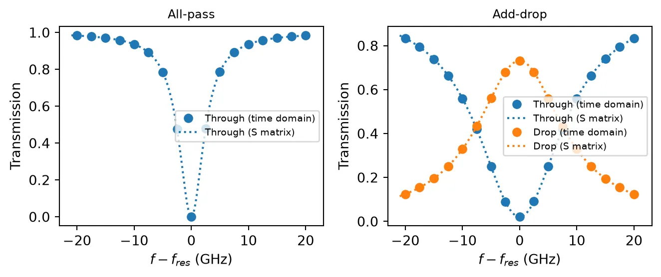
Cavity Charging and Ring-Down
Section titled “Cavity Charging and Ring-Down”A resonator does not respond instantly. Starting the simulation with the cavity empty and the laser on resonance, the through-port power begins at the bare bus transmission and sinks toward the critically-coupled zero as the ring charges over many round trips. The transient decays with the cavity field lifetime , which is tied to the linewidth by , so the same physics can be read in either domain.
# Drive the ring exactly on resonance, starting from an empty cavitylink = pf.Component("ringdown_link")laser_ref = link.add_reference(pfa.cw_laser(power=1e-3))ring_ref = link.add_reference(ring)termination_ref = link.add_reference(pfa.electrical_termination())ring_ref.connect("P0", laser_ref["P0"])termination_ref.connect("E0", ring_ref["E0"])link.add_port(ring_ref["P1"], "out")link.add_model(pf.CircuitModel(), "Circuit")
num_steps = 15000t = np.arange(num_steps) * time_steptime_stepper = link.setup_time_stepper(    time_step=time_step, carrier_frequency=f_res, show_progress=False)a = time_stepper.step(steps=num_steps, time_step=time_step)["out@0"]
# Fit the exponential decay of the field toward its steady stateresidual = np.abs(a - a[-1]) / np.sqrt(1e-3)window = (t > 10e-12) & (t < 150e-12)slope = np.polyfit(t[window], np.log(residual[window]), 1)[0]tau = -1 / slope
fig, ax = plt.subplots(figsize=(7, 3), tight_layout=True)ax.plot(t * 1e12, np.abs(a) ** 2 * 1e3)ax.axvline(tau * 1e12, color="k", linestyle=":", linewidth=1)ax.text(tau * 1e12 + 4, 0.75, "field lifetime $\\tau$", fontsize=9)ax.set(xlabel="Time (ps)", ylabel="Through power (mW)")ax.set_title(    "Ring driven at resonance: the through power sinks to zero as the cavity charges",    fontsize=9,)
print(f"Fitted field lifetime: {tau * 1e12:.1f} ps")print(f"1 / (pi FWHM) from the reference spectrum: {1 / (np.pi * fwhm) * 1e12:.1f} ps")
Fitted field lifetime: 59.0 ps1 / (pi FWHM) from the reference spectrum: 61.2 ps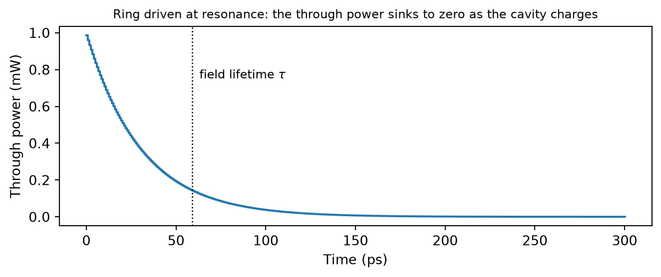
Thermal Tuning
Section titled “Thermal Tuning”Rings are usually stabilized and tuned with integrated heaters. The dn_dT coefficient (with temperature and reference_temperature) shifts the ring index thermally; for silicon, /K moves the resonance by GHz/K. Sweeping the temperature with the laser fixed on the cold resonance walks the resonance through the laser, tracing the (mirrored) line shape in temperature.
dn_dt = 1.8e-4
# Same ring, but with a thermo-optic coefficientring_thermal = pfa.ring_resonator(    kappa1=kappa,    length=length,    n_eff=n_eff,    reference_frequency=f_ref,    n_group=n_group,    propagation_loss=loss,    dn_dT=dn_dt,)
temperatures = 293 + np.linspace(-0.8, 0.8, 17)transmission = []for temperature in temperatures:    # Update the operating temperature and rerun the same circuit    ring_thermal.update(temperature=temperature)    link = pf.Component("thermal_link")    laser_ref = link.add_reference(pfa.cw_laser(power=1e-3))    ring_ref = link.add_reference(ring_thermal)    termination_ref = link.add_reference(pfa.electrical_termination())    ring_ref.connect("P0", laser_ref["P0"])    termination_ref.connect("E0", ring_ref["E0"])    link.add_port(ring_ref["P1"], "out")    link.add_model(pf.CircuitModel(), "Circuit")    time_stepper = link.setup_time_stepper(        time_step=time_step, carrier_frequency=f_res, show_progress=False    )    a = time_stepper.step(steps=num_settle, time_step=time_step, show_progress=False)["out@0"]    transmission.append(np.abs(a[-1]) ** 2 / 1e-3)
fig, ax = plt.subplots(figsize=(7, 3), tight_layout=True)ax.plot(temperatures - 293, transmission, "o-", markersize=4)ax.set(xlabel="Temperature change (K)", ylabel="Transmission")
shift_per_kelvin = f_res * dn_dt / n_groupprint(f"Expected resonance shift: {shift_per_kelvin / 1e9:.1f} GHz/K "      f"({fwhm / shift_per_kelvin * 1e3:.0f} mK per linewidth)")
Expected resonance shift: 8.3 GHz/K (626 mK per linewidth)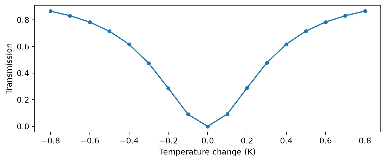
Electro-Optic Modulation
Section titled “Electro-Optic Modulation”The dn_dv coefficient turns the ring into a modulator: the voltage on E0 shifts the effective index, and with it the resonance frequency, by per volt. For a phase-shifter section characterized by its figure of merit, the two are related through the phase accumulated over the ring,
so our /V corresponds to V·cm, representative of a depletion-mode silicon junction. Biasing the laser on the flank of the resonance, where the transmission slope is steepest, converts the resonance shift into intensity modulation: we bias half a linewidth above resonance and drive with a 0.2 V, 2 GHz sine from a signal_source. For the dynamics of microring modulators at frequencies comparable to the cavity linewidth, including the optical peaking effect, see the Microring Modulator Optical Peaking example.
dn_dv = 5e-5
# Bias the laser half a linewidth above resonance (maximum slope region)f_laser = f_res + fwhm / 2ring_eo = pfa.ring_resonator(    kappa1=kappa,    length=length,    n_eff=n_eff,    reference_frequency=f_ref,    n_group=n_group,    propagation_loss=loss,    dn_dv=dn_dv,)
drive_freq = 2e9source = pfa.signal_source(frequency=drive_freq, amplitude=0.2 / np.sqrt(z0))
# Laser and drive source connected to the ring, through port exposedmrm = pf.Component("mrm_link")laser_ref = mrm.add_reference(pfa.cw_laser(power=1e-3))ring_ref = mrm.add_reference(ring_eo)source_ref = mrm.add_reference(source)ring_ref.connect("P0", laser_ref["P0"])source_ref.connect("E0", ring_ref["E0"])mrm.add_port(ring_ref["P1"], "out")mrm.add_model(pf.CircuitModel(), "Circuit")
# A monitor on the electrical port records the voltage that drives the ringnum_steps = 100000t = np.arange(num_steps) * time_steptime_stepper = mrm.setup_time_stepper(    time_step=time_step,    carrier_frequency=f_laser,    time_stepper_kwargs={"monitors": {"drive": ring_ref["E0"]}},)output = time_stepper.step(steps=num_steps, time_step=time_step)power = np.abs(output["out@0"]) ** 2 * 1e3drive = np.real(output["drive@0-"]) * np.sqrt(z0)
# Plot the steady state, after the initial cavity charging transientwindow = slice(25000, None)fig, (ax1, ax2) = plt.subplots(2, 1, figsize=(7, 4), sharex=True, tight_layout=True)ax1.plot(t[window] * 1e9, drive[window])ax1.set_ylabel("Drive voltage (V)")ax2.plot(t[window] * 1e9, power[window])ax2.set(xlabel="Time (ns)", ylabel="Through power (mW)")
print(f"Resonance shift: {f_res * dn_dv / n_group / 1e9:.2f} GHz/V")
Resonance shift: 2.31 GHz/V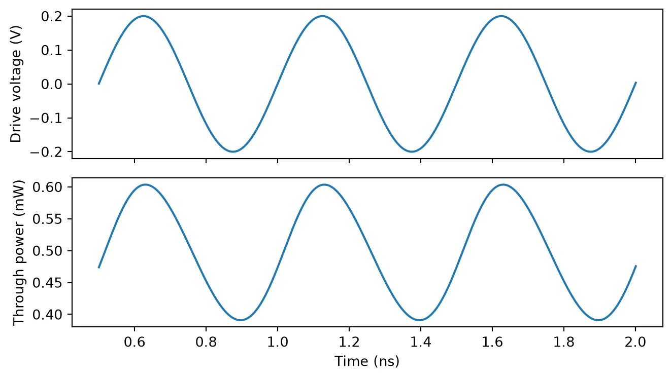
The f_3dB argument models the electrical bandwidth of the tuning port: a first-order low-pass filter applied directly to the input voltage, before it is converted to an index shift. With GHz and the same 2 GHz drive, the voltage reaching the ring is attenuated by (and delayed by the filter phase), which shows up directly in the modulation swing.
# Enable the electrical low-pass filter and rerun the same circuitring_eo.update(f_3dB=1e9)time_stepper = mrm.setup_time_stepper(    time_step=time_step, carrier_frequency=f_laser, show_progress=False)power_filtered = np.abs(    time_stepper.step(steps=num_steps, time_step=time_step, show_progress=False)["out@0"]) ** 2 * 1e3
fig, ax = plt.subplots(figsize=(7, 3), tight_layout=True)ax.plot(t[window] * 1e9, power[window], label="No filter")ax.plot(t[window] * 1e9, power_filtered[window], label="$f_{3dB}$ = 1 GHz")ax.set(xlabel="Time (ns)", ylabel="Through power (mW)")ax.legend(fontsize=8)
swing = power[window].max() - power[window].min()swing_filtered = power_filtered[window].max() - power_filtered[window].min()filter_response = 1 / np.sqrt(1 + (drive_freq / 1e9) ** 2)print(f"Swing ratio: {swing_filtered / swing:.3f} "      f"(first-order filter response at 2 GHz: {filter_response:.3f})")
Swing ratio: 0.450 (first-order filter response at 2 GHz: 0.447)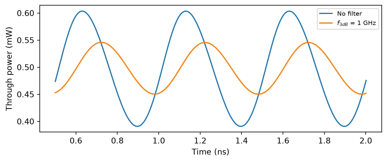
Summary
Section titled “Summary”pfa.ring_resonatormodels an all-pass ring withkappa1or an add-drop ring withkappa1andkappa2; ports map to input, through, drop, and add in sorted order, plus the electrical tuning portE0(close it with an electrical_termination when unused).- The coupler convention is shared with the frequency-domain RingModel, so time-domain and S-matrix results line up directly.
reference_frequencymarks wheren_effis specified: the time stepper follows the carrier automatically with the first-order dispersion , so sweeps need no parameter updates. Choose the time step as an integer fraction of the round-trip time.- Cavity dynamics come out naturally: the charging transient decays with the field lifetime .
dn_dTtunes the resonance thermally anddn_dvelectro-optically, with for a phase shifter specified by ; biasing on the resonance flank converts the shift into intensity modulation, the basis of the microring modulator.f_3dBapplies a first-order low-pass filter directly to the input voltage, modeling the electrical bandwidth of the tuning port.