

800G Coherent Link Simulation
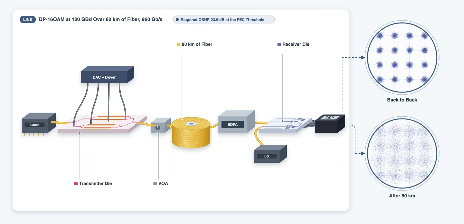
This page simulates the two chips of the series in one link. The link carries dual-polarization 16QAM at 120 GBd. The page ends with the bit error rate (BER) against the optical signal-to-noise ratio (OSNR) for two receiver bandwidths. It compares the BER with the theory curve of the technology page.
The circuit is the layout itself. The two dies of the layout page are instances of one netlist, together with the lasers, 80 km of single-mode fiber and an optical amplifier. Every device of the dies carries the model of its component page:
- the FDTD and EME results of the transmitter page and the receiver page, stored as models right after each calculation
- an analytic waveguide model on every route, which the layout page sets before it draws the routes
The route lengths, the skew between the X and Y paths and the matched photodiode routes all come from the drawn dies. This page writes the digital signal processing (DSP) of the receiver in numpy, so the reader can follow and change each step.
References
- Kikuchi, Kazuro. “Fundamentals of coherent optical fiber communications.” Journal of Lightwave Technology 2016 34 (1), 157-179, doi: 10.1109/JLT.2015.2463719.
- Savory, Seb J. “Digital coherent optical receivers: algorithms and subsystems.” IEEE Journal of Selected Topics in Quantum Electronics 2010 16 (5), 1164-1179, doi: 10.1109/JSTQE.2010.2044751.
- Pfau, Timo, Sebastian Hoffmann, and Reinhold Noé. “Hardware-efficient coherent digital receiver concept with feedforward carrier recovery for M-QAM constellations.” Journal of Lightwave Technology 2009 27 (8), 989-999, doi: 10.1109/JLT.2008.2010511.
from runpy import run_path
# Coherent_Chip_Layout.qmd defines what this page builds on. Its shared cells are generated into the# module below; see docs/scripts/generate_notebook_modules.py.globals().update(    {k: v for k, v in run_path("misc/coherent_chip_layout.py").items() if not k.startswith("_")})
import warnings
from photonforge.live_viewer import LiveViewerfrom scipy import signal
# The pads of the receiver die are terminals of the die only, and the circuit leaves them outwarnings.filterwarnings( "ignore", message="Terminal .* does not match any reference terminals")# The second input of each hybrid, X, is unused on the die, and no route reaches itwarnings.filterwarnings( "ignore", message="These ports are not connected and will be ignored: 'X'")
# A viewer for this page; open the printed address in a browserviewer = LiveViewer()
baud = 120e9 # Symbol rate (Bd)sps = 4 # Samples per symboln_sym = 16384 # Symbols per polarizationdt = 1 / (baud * sps) # Time step of the simulation (s)carrier = f0 # Carrier frequency of the time steppers (Hz)# Frequencies at which each stepper fits its S matrix: 80 % of the band of the time stepfit_freqs = np.linspace(carrier - 0.8 / (2 * dt), carrier + 0.8 / (2 * dt), 81)
levels = np.array([-3, -1, 1, 3]) / np.sqrt( 10) # 16QAM levels per axis, unit average powergray = np.array([[0, 0], [0, 1], [1, 1], [1, 0]]) # Gray code of each levelLiveViewer started at http://127.0.0.1:35025. Call its 'stop()' method to free the port.The transmitter die
Section titled “The transmitter die”The transmitter die of the layout page carries everything the link needs:
- the models of the transmitter page on its devices, and the model of the MZM on each modulator
- a model on every route, and one time stepper for each whole route
- the 90 degree bias in the model of each Q heater
- the four drive ports
XI,XQ,YIandYQ, and a circuit model for the die
# The transmitter die: two fiber facets and four drive portsprint(f"ports of the transmitter die: {sorted(tx_chip.ports)}")viewer(tx_die)ports of the transmitter die: ['IN', 'OUT', 'XI', 'XQ', 'YI', 'YQ'];fill:%23221f20;font-weight:bold;font-size:282.800000px;}.terminal{fill:none;stroke:%23805080;stroke-width:35.350000;}.dashed{stroke-dasharray:176.750000,106.050000;}.port{fill:none;stroke:%23805080;stroke-width:70.700000;}.virtual-connection{fill:none;stroke:%23907090;stroke-width:53.025000;}.layer_31_0{stroke:%23d4467c;fill:url(%23pat-layer_31_0);fill-opacity:0.492;}.label_31_0{fill:%23d4467c;}.layer_6_0{stroke:%237c605a;fill:url(%23pat-layer_6_0);fill-opacity:0.492;}.label_6_0{fill:%237c605a;}.layer_6_1{stroke:%2300d080;fill:url(%23pat-layer_6_1);fill-opacity:0.492;}.label_6_1{fill:%2300d080;}.layer_201_0{stroke:%23857b75;fill:url(%23pat-layer_201_0);fill-opacity:0.492;}.label_201_0{fill:%23857b75;}.layer_50_1{stroke:%23c7031c;fill:url(%23pat-layer_50_1);fill-opacity:0.492;}.label_50_1{fill:%23c7031c;}.layer_21_1{stroke:%233503fc;fill:url(%23pat-layer_21_1);fill-opacity:0.492;}.label_21_1{fill:%233503fc;}.layer_4_0{stroke:%235179b5;fill:url(%23pat-layer_4_0);fill-opacity:0.492;}.label_4_0{fill:%235179b5;}.layer_2_0{stroke:%237d57de;fill:url(%23pat-layer_2_0);fill-opacity:0.492;}.label_2_0{fill:%237d57de;}.layer_3_0{stroke:%23000080;fill:url(%23pat-layer_3_0);fill-opacity:0.492;}.label_3_0{fill:%23000080;}.layer_2_1{stroke:%23ff00ff;fill:url(%23pat-layer_2_1);fill-opacity:0.492;}.label_2_1{fill:%23ff00ff;}.layer_3_1{stroke:%236750bf;fill:url(%23pat-layer_3_1);fill-opacity:0.492;}.label_3_1{fill:%236750bf;}.layer_21_0{stroke:%233503fc;fill:url(%23pat-layer_21_0);fill-opacity:0.492;}.label_21_0{fill:%233503fc;}.layer_990_0{stroke:%23473328;fill:none;}.label_990_0{fill:%23473328;}</style><defs><path id=%22port-symbol%22 class=%22port%22 d=%22M 0,-141.400000 L 212.100000,0 0,141.400000%22 /><path id=%22ref-port-symbol%22 class=%22port%22 style=%22stroke-opacity:0.33;%22 d=%22M 0,-106.050000 C 141.400000,-106.050000 141.400000,106.050000 0,106.050000%22 /><circle id=%22port-bend-symbol%22 style=%22stroke-width:0;stroke:none;fill:%23805080;fill-opacity:1;%22 cx=%220%22 cy=%220%22 r=%2263.630000%22 /><circle id=%22connection-symbol%22 style=%22stroke-width:0;stroke:none;fill:%23907090;fill-opacity:1;%22 cx=%220%22 cy=%220%22 r=%2274.235000%22 /><pattern id=%22pat-layer_31_0%22 patternUnits=%22userSpaceOnUse%22 width=%22106.050000%22 height=%22106.050000%22 patternTransform=%22translate(81.097059,100.468421)%22><circle cx=%2253.025000%22 cy=%2253.025000%22 r=%2217.675000%22 style=%22stroke:none;fill:%23d4467c;fill-opacity:1.0%22 /></pattern><pattern id=%22pat-layer_6_0%22 patternUnits=%22userSpaceOnUse%22 width=%22176.750000%22 height=%22176.750000%22 patternTransform=%22translate(83.176471,83.723684)%22><line x1=%220%22 y1=%2288.375000%22 x2=%22176.750000%22 y2=%2288.375000%22 style=%22stroke:%237c605a;stroke-width:17.675000%22 /></pattern><pattern id=%22pat-layer_6_1%22 patternUnits=%22userSpaceOnUse%22 width=%22106.050000%22 height=%22106.050000%22 patternTransform=%22translate(24.952941,66.978947)%22><line x1=%2253.025000%22 y1=%220%22 x2=%2253.025000%22 y2=%22106.050000%22 style=%22stroke:%2300d080;stroke-width:17.675000%22 /></pattern><pattern id=%22pat-layer_201_0%22 patternUnits=%22userSpaceOnUse%22 width=%22106.050000%22 height=%22106.050000%22 patternTransform=%22translate(81.097059,39.071053)%22><line x1=%2253.025000%22 y1=%220%22 x2=%2253.025000%22 y2=%22106.050000%22 style=%22stroke:%23857b75;stroke-width:17.675000%22 /><line x1=%220%22 y1=%2253.025000%22 x2=%22106.050000%22 y2=%2253.025000%22 style=%22stroke:%23857b75;stroke-width:17.675000%22 /></pattern><pattern id=%22pat-layer_50_1%22 patternUnits=%22userSpaceOnUse%22 width=%22106.050000%22 height=%22106.050000%22 patternTransform=%22translate(37.429412,11.163158)%22><line x1=%220%22 y1=%220%22 x2=%22106.050000%22 y2=%22106.050000%22 style=%22stroke:%23c7031c;stroke-width:17.675000%22 /><line x1=%22-53.025000%22 y1=%2253.025000%22 x2=%2253.025000%22 y2=%22159.075000%22 style=%22stroke:%23c7031c;stroke-width:17.675000%22 /><line x1=%2253.025000%22 y1=%22-53.025000%22 x2=%22159.075000%22 y2=%2253.025000%22 style=%22stroke:%23c7031c;stroke-width:17.675000%22 /><line x1=%22106.050000%22 y1=%220%22 x2=%220%22 y2=%22106.050000%22 style=%22stroke:%23c7031c;stroke-width:17.675000%22 /><line x1=%22159.075000%22 y1=%2253.025000%22 x2=%2253.025000%22 y2=%22159.075000%22 style=%22stroke:%23c7031c;stroke-width:17.675000%22 /><line x1=%2253.025000%22 y1=%22-53.025000%22 x2=%22-53.025000%22 y2=%2253.025000%22 style=%22stroke:%23c7031c;stroke-width:17.675000%22 /></pattern><pattern id=%22pat-layer_21_1%22 patternUnits=%22userSpaceOnUse%22 width=%22176.750000%22 height=%22176.750000%22 patternTransform=%22translate(72.779412,55.815789)%22><circle cx=%2288.375000%22 cy=%2288.375000%22 r=%2217.675000%22 style=%22stroke:none;fill:%233503fc;fill-opacity:1.0%22 /></pattern><pattern id=%22pat-layer_4_0%22 patternUnits=%22userSpaceOnUse%22 width=%22176.750000%22 height=%22176.750000%22 patternTransform=%22translate(114.367647,55.815789)%22><line x1=%2288.375000%22 y1=%220%22 x2=%2288.375000%22 y2=%22176.750000%22 style=%22stroke:%235179b5;stroke-width:17.675000%22 /></pattern><pattern id=%22pat-layer_2_0%22 patternUnits=%22userSpaceOnUse%22 width=%22176.750000%22 height=%22176.750000%22 patternTransform=%22translate(145.558824,27.907895)%22><line x1=%220%22 y1=%220%22 x2=%22176.750000%22 y2=%22176.750000%22 style=%22stroke:%237d57de;stroke-width:17.675000%22 /><line x1=%22-88.375000%22 y1=%2288.375000%22 x2=%2288.375000%22 y2=%22265.125000%22 style=%22stroke:%237d57de;stroke-width:17.675000%22 /><line x1=%2288.375000%22 y1=%22-88.375000%22 x2=%22265.125000%22 y2=%2288.375000%22 style=%22stroke:%237d57de;stroke-width:17.675000%22 /></pattern><pattern id=%22pat-layer_3_0%22 patternUnits=%22userSpaceOnUse%22 width=%22106.050000%22 height=%22106.050000%22 patternTransform=%22translate(24.952941,78.142105)%22><line x1=%220%22 y1=%220%22 x2=%22106.050000%22 y2=%22106.050000%22 style=%22stroke:%23000080;stroke-width:17.675000%22 /><line x1=%22-53.025000%22 y1=%2253.025000%22 x2=%2253.025000%22 y2=%22159.075000%22 style=%22stroke:%23000080;stroke-width:17.675000%22 /><line x1=%2253.025000%22 y1=%22-53.025000%22 x2=%22159.075000%22 y2=%2253.025000%22 style=%22stroke:%23000080;stroke-width:17.675000%22 /></pattern><pattern id=%22pat-layer_2_1%22 patternUnits=%22userSpaceOnUse%22 width=%22106.050000%22 height=%22106.050000%22 patternTransform=%22translate(62.382353,33.489474)%22><line x1=%22106.050000%22 y1=%220%22 x2=%220%22 y2=%22106.050000%22 style=%22stroke:%23ff00ff;stroke-width:17.675000%22 /><line x1=%22159.075000%22 y1=%2253.025000%22 x2=%2253.025000%22 y2=%22159.075000%22 style=%22stroke:%23ff00ff;stroke-width:17.675000%22 /><line x1=%2253.025000%22 y1=%22-53.025000%22 x2=%22-53.025000%22 y2=%2253.025000%22 style=%22stroke:%23ff00ff;stroke-width:17.675000%22 /></pattern><pattern id=%22pat-layer_3_1%22 patternUnits=%22userSpaceOnUse%22 width=%22176.750000%22 height=%22176.750000%22 patternTransform=%22translate(0.000000,158.144737)%22><line x1=%220%22 y1=%220%22 x2=%22176.750000%22 y2=%22176.750000%22 style=%22stroke:%236750bf;stroke-width:17.675000%22 /><line x1=%22-88.375000%22 y1=%2288.375000%22 x2=%2288.375000%22 y2=%22265.125000%22 style=%22stroke:%236750bf;stroke-width:17.675000%22 /><line x1=%2288.375000%22 y1=%22-88.375000%22 x2=%22265.125000%22 y2=%2288.375000%22 style=%22stroke:%236750bf;stroke-width:17.675000%22 /></pattern><pattern id=%22pat-layer_21_0%22 patternUnits=%22userSpaceOnUse%22 width=%22106.050000%22 height=%22106.050000%22 patternTransform=%22translate(68.620588,16.744737)%22><line x1=%220%22 y1=%2253.025000%22 x2=%22106.050000%22 y2=%2253.025000%22 style=%22stroke:%233503fc;stroke-width:17.675000%22 /></pattern><g id=%22C1%22 data-name=%22chip_frame__XGG7RMFTWHLFGIJ2FMUKYSVV27DTLG2ZXHEW43VQJHFEQWJ6ZLDA%22><rect class=%22layer_6_0%22 x=%22-10050.000000%22 y=%22-2475.000000%22 width=%2220100.000000%22 height=%224950.000000%22 /><rect class=%22layer_6_1%22 x=%22-10100.000000%22 y=%22-2525.000000%22 width=%2220200.000000%22 height=%225050.000000%22 /></g><g id=%22C2%22 data-name=%22DPIQ_m_10000P0_r_True%22><use transform=%22translate(-10050.000000 0.000000)%22 href=%22%23C3%22 /><use transform=%22translate(-9665.000000 0.000000)%22 href=%22%23C4%22 /><use transform=%22translate(-9250.000000 1150.000000)%22 href=%22%23C4%22 /><use transform=%22translate(0.000000 0.000000)%22 href=%22%23C5%22 /><use transform=%22translate(-8046.619000 1450.000000)%22 href=%22%23C6%22 /><use transform=%22translate(0.000000 0.000000)%22 href=%22%23C7%22 /><use transform=%22translate(3597.529000 1450.000000)%22 href=%22%23C8%22 /><use transform=%22translate(0.000000 0.000000)%22 href=%22%23C9%22 /><use transform=%22translate(-8046.619000 850.000000)%22 href=%22%23C6%22 /><use transform=%22translate(0.000000 0.000000)%22 href=%22%23C10%22 /><use transform=%22translate(3597.529000 850.000000)%22 href=%22%23C11%22 /><use transform=%22translate(0.000000 0.000000)%22 href=%22%23C12%22 /><use transform=%22translate(4972.529000 1150.000000) rotate(180.000000)%22 href=%22%23C4%22 /><use transform=%22translate(0.000000 0.000000)%22 href=%22%23C13%22 /><use transform=%22translate(0.000000 0.000000)%22 href=%22%23C14%22 /><use transform=%22translate(-9250.000000 -1150.000000)%22 href=%22%23C4%22 /><use transform=%22translate(0.000000 0.000000)%22 href=%22%23C15%22 /><use transform=%22translate(-8046.619000 -850.000000)%22 href=%22%23C6%22 /><use transform=%22translate(0.000000 0.000000)%22 href=%22%23C16%22 /><use transform=%22translate(3597.529000 -850.000000)%22 href=%22%23C8%22 /><use transform=%22translate(0.000000 0.000000)%22 href=%22%23C17%22 /><use transform=%22translate(-8046.619000 -1450.000000)%22 href=%22%23C6%22 /><use transform=%22translate(0.000000 0.000000)%22 href=%22%23C18%22 /><use transform=%22translate(3597.529000 -1450.000000)%22 href=%22%23C11%22 /><use transform=%22translate(0.000000 0.000000)%22 href=%22%23C19%22 /><use transform=%22translate(4972.529000 -1150.000000) rotate(180.000000)%22 href=%22%23C4%22 /><use transform=%22translate(0.000000 0.000000)%22 href=%22%23C20%22 /><use transform=%22translate(0.000000 0.000000)%22 href=%22%23C21%22 /><use transform=%22translate(9640.000000 0.000000) rotate(-180.000000) scale(1 -1)%22 href=%22%23C22%22 /><use transform=%22translate(9640.000000 0.000000)%22 href=%22%23C23%22 /><use transform=%22translate(10050.000000 0.000000) rotate(180.000000)%22 href=%22%23C24%22 /><use transform=%22translate(0.000000 0.000000)%22 href=%22%23C25%22 /><use transform=%22translate(0.000000 0.000000)%22 href=%22%23C26%22 /></g><g id=%22C10%22 data-name=%22route__X5ZKFHB5PFCVD36WIQ2HDIHCKJHAXELZJH2MDKI2WENHCIGQPW2Q%22><use transform=%22translate(-9198.250000 1148.350000)%22 href=%22%23C27%22 /><use transform=%22translate(-9098.250000 1048.350000) rotate(270.000000)%22 href=%22%23C28%22 /><use transform=%22translate(-9098.250000 950.000000) rotate(270.000000)%22 href=%22%23C29%22 /><use transform=%22translate(-8998.250000 850.000000)%22 href=%22%23C30%22 /></g><g id=%22C11%22 data-name=%22heated_straight__PUFZ6BAOVTTYNR5ADJVYKZTHCIZ3E5NQ2ESQCJPCZIWXDRJOIGPA%22><use transform=%22translate(0.000000 0.000000)%22 href=%22%23C31%22 /><use transform=%22translate(0.000000 1.220000)%22 href=%22%23C32%22 /><rect class=%22terminal dashed%22 x=%22-50.000000%22 y=%2211.720000%22 width=%22100.000000%22 height=%22100.000000%22 /><rect class=%22terminal dashed%22 x=%22650.000000%22 y=%2211.720000%22 width=%22100.000000%22 height=%22100.000000%22 /></g><g id=%22C12%22 data-name=%22route__LRELHOHS7BVGSS62AVV4D3SOPU7VXF4JBZ3ZBHI4CHOPJ667JH3Q%22><use transform=%22translate(3397.529000 850.000000)%22 href=%22%23C33%22 /></g><g id=%22C13%22 data-name=%22route__ELFIYTNQR7KXIKKVMMARY426O4VM6HDJXOPAJQ3MDVT2E2BKYYCQ%22><use transform=%22translate(4297.529000 1450.000000)%22 href=%22%23C27%22 /><use transform=%22translate(4397.529000 1350.000000) rotate(270.000000)%22 href=%22%23C28%22 /><use transform=%22translate(4397.529000 1251.650000) rotate(270.000000)%22 href=%22%23C29%22 /><use transform=%22translate(4497.529000 1151.650000)%22 href=%22%23C34%22 /></g><g id=%22C14%22 data-name=%22route__BV533WNMOOU3QWDEEQFYEHAFI2JDP76Q3WQAWGPKJE4BIOPYW5WA%22><use transform=%22translate(4297.529000 850.000000)%22 href=%22%23C29%22 /><use transform=%22translate(4397.529000 950.000000) rotate(90.000000)%22 href=%22%23C28%22 /><use transform=%22translate(4397.529000 1048.350000) rotate(90.000000)%22 href=%22%23C27%22 /><use transform=%22translate(4497.529000 1148.350000)%22 href=%22%23C34%22 /></g><g id=%22C15%22 data-name=%22route__Q7OYJ3SX7PJWSIY2QU6RENMY43MLWPGP64P55EFNTSK5U76BFAMA%22><use transform=%22translate(-9613.250000 -1.650000)%22 href=%22%23C27%22 /><use transform=%22translate(-9513.250000 -101.650000) rotate(270.000000)%22 href=%22%23C35%22 /><use transform=%22translate(-9513.250000 -1050.000000) rotate(270.000000)%22 href=%22%23C29%22 /><use transform=%22translate(-9413.250000 -1150.000000)%22 href=%22%23C36%22 /></g><g id=%22C16%22 data-name=%22route__76P4VT36RSMEKBOHIH2I37VQJYWGBXQRMTUDTXMBBGTMDCHVZ44A%22><use transform=%22translate(-9198.250000 -1148.350000)%22 href=%22%23C29%22 /><use transform=%22translate(-9098.250000 -1048.350000) rotate(90.000000)%22 href=%22%23C28%22 /><use transform=%22translate(-9098.250000 -950.000000) rotate(90.000000)%22 href=%22%23C27%22 /><use transform=%22translate(-8998.250000 -850.000000)%22 href=%22%23C30%22 /></g><g id=%22C17%22 data-name=%22route__MIC42DOWMHY3X3EBES7OKCZ3TYE35FWBKE3WMGMSOTBOQBMOPWGQ%22><use transform=%22translate(3397.529000 -850.000000)%22 href=%22%23C33%22 /></g><g id=%22C18%22 data-name=%22route__KZGNVK6XHEUMH2LCFHRXCRSEZ3UX5JE4DX2BANU3DL3UILRROAIA%22><use transform=%22translate(-9198.250000 -1151.650000)%22 href=%22%23C27%22 /><use transform=%22translate(-9098.250000 -1251.650000) rotate(270.000000)%22 href=%22%23C28%22 /><use transform=%22translate(-9098.250000 -1350.000000) rotate(270.000000)%22 href=%22%23C29%22 /><use transform=%22translate(-8998.250000 -1450.000000)%22 href=%22%23C30%22 /></g><g id=%22C19%22 data-name=%22route__XMYRQUTGY4NTBZUSJQHXUCVTLR46P5CEYEFQLPO5RJX2OSVE5S2Q%22><use transform=%22translate(3397.529000 -1450.000000)%22 href=%22%23C33%22 /></g><g id=%22C20%22 data-name=%22route__Z2KWMSHB6GISPO2D62QZWCFBOEUYWW2HCCXCODNWTFGCKAAQZQWA%22><use transform=%22translate(4297.529000 -850.000000)%22 href=%22%23C27%22 /><use transform=%22translate(4397.529000 -950.000000) rotate(270.000000)%22 href=%22%23C28%22 /><use transform=%22translate(4397.529000 -1048.350000) rotate(270.000000)%22 href=%22%23C29%22 /><use transform=%22translate(4497.529000 -1148.350000)%22 href=%22%23C34%22 /></g><g id=%22C21%22 data-name=%22route__FDL3Q4YYPBAVDSPTFQK2YSXGFJ2TNKZFFFKSPA6EWAC6MTUEPE7Q%22><use transform=%22translate(4297.529000 -1450.000000)%22 href=%22%23C29%22 /><use transform=%22translate(4397.529000 -1350.000000) rotate(90.000000)%22 href=%22%23C28%22 /><use transform=%22translate(4397.529000 -1251.650000) rotate(90.000000)%22 href=%22%23C27%22 /><use transform=%22translate(4497.529000 -1151.650000)%22 href=%22%23C34%22 /></g><g id=%22C22%22 data-name=%22PRC__KQY3E6LNVCJCW73UMW2CQR56BMUMU7PUZU4OEHO252VNI3VNWSHQ%22><rect class=%22layer_2_0%22 x=%220.000000%22 y=%22-0.500000%22 width=%221800.000000%22 height=%221.000000%22 /><path class=%22layer_2_0%22 d=%22M 10.000000,-2.150000 110.000000,-1.150000 1610.000000,-1.550000 1750.000000,-2.550000 1800.000000,-2.900000 1800.000000,-1.900000 1750.000000,-1.900000 1610.000000,-0.900000 110.000000,-0.900000 10.000000,-1.900000 z%22 /><rect class=%22layer_2_0%22 x=%221800.000000%22 y=%22-0.500000%22 width=%22110.000000%22 height=%221.000000%22 /><path class=%22layer_2_0%22 d=%22M 1800.000000,-2.900000 1805.000000,-2.900000 1807.077000,-2.913000 1809.155000,-2.950000 1811.232000,-3.012000 1813.310000,-3.096000 1815.389000,-3.202000 1817.467000,-3.329000 1819.546000,-3.475000 1821.625000,-3.639000 1823.704000,-3.821000 1825.784000,-4.019000 1827.864000,-4.232000 1829.944000,-4.459000 1832.025000,-4.700000 1834.105000,-4.952000 1838.267000,-5.488000 1842.430000,-6.059000 1846.595000,-6.656000 1854.926000,-7.894000 1863.261000,-9.133000 1867.430000,-9.731000 1871.601000,-10.303000 1873.686000,-10.577000 1877.858000,-11.093000 1879.944000,-11.334000 1882.031000,-11.562000 1884.117000,-11.776000 1886.204000,-11.975000 1888.292000,-12.158000 1890.379000,-12.323000 1892.467000,-12.469000 1894.555000,-12.596000 1896.644000,-12.703000 1898.732000,-12.787000 1900.821000,-12.849000 1902.911000,-12.887000 1905.000000,-12.900000 1910.000000,-12.900000 1910.000000,-11.900000 1905.000000,-11.900000 1902.923000,-11.887000 1900.845000,-11.850000 1898.768000,-11.788000 1896.690000,-11.704000 1894.611000,-11.598000 1892.533000,-11.471000 1890.454000,-11.325000 1888.375000,-11.161000 1886.296000,-10.979000 1884.216000,-10.781000 1882.136000,-10.568000 1880.056000,-10.341000 1877.976000,-10.100000 1875.895000,-9.848000 1873.814000,-9.585000 1869.651000,-9.030000 1865.488000,-8.445000 1861.323000,-7.838000 1857.157000,-7.218000 1848.823000,-5.973000 1844.654000,-5.365000 1840.485000,-4.779000 1836.314000,-4.223000 1834.228000,-3.960000 1832.142000,-3.707000 1830.056000,-3.466000 1827.969000,-3.238000 1825.883000,-3.024000 1823.796000,-2.825000 1821.708000,-2.642000 1819.621000,-2.477000 1817.533000,-2.331000 1815.445000,-2.204000 1813.356000,-2.097000 1811.268000,-2.013000 1809.179000,-1.951000 1807.089000,-1.913000 1805.000000,-1.900000 1800.000000,-1.900000 z%22 /><path class=%22layer_3_0%22 d=%22M 1800.000000,-7.400000 1805.000000,-7.400000 1807.022000,-7.412000 1809.047000,-7.449000 1811.074000,-7.509000 1813.104000,-7.592000 1815.137000,-7.695000 1817.173000,-7.819000 1819.211000,-7.962000 1821.251000,-8.123000 1823.295000,-8.302000 1825.341000,-8.497000 1827.390000,-8.707000 1829.441000,-8.931000 1831.495000,-9.168000 1835.611000,-9.678000 1839.737000,-10.228000 1843.873000,-10.809000 1848.020000,-11.414000 1856.343000,-12.657000 1860.520000,-13.279000 1864.706000,-13.889000 1868.904000,-14.479000 1873.111000,-15.040000 1875.218000,-15.306000 1877.328000,-15.562000 1879.441000,-15.806000 1881.556000,-16.037000 1883.674000,-16.254000 1885.795000,-16.456000 1887.918000,-16.642000 1890.044000,-16.810000 1892.173000,-16.960000 1894.304000,-17.089000 1896.438000,-17.198000 1898.574000,-17.285000 1900.714000,-17.348000 1902.855000,-17.387000 1905.000000,-17.400000 1910.000000,-17.400000 1910.000000,-7.400000 1905.000000,-7.400000 1902.978000,-7.388000 1900.953000,-7.351000 1898.926000,-7.291000 1896.896000,-7.208000 1894.863000,-7.105000 1892.827000,-6.981000 1890.789000,-6.838000 1888.749000,-6.677000 1886.705000,-6.498000 1884.659000,-6.303000 1882.610000,-6.093000 1880.559000,-5.869000 1878.505000,-5.632000 1874.389000,-5.122000 1870.263000,-4.572000 1866.127000,-3.991000 1861.980000,-3.386000 1857.824000,-2.767000 1849.480000,-1.521000 1845.294000,-0.911000 1841.096000,-0.321000 1836.889000,0.240000 1834.782000,0.506000 1832.672000,0.762000 1830.559000,1.006000 1828.444000,1.237000 1826.326000,1.454000 1824.205000,1.656000 1822.082000,1.842000 1819.956000,2.010000 1817.827000,2.160000 1815.696000,2.289000 1813.562000,2.398000 1811.426000,2.485000 1809.286000,2.548000 1807.145000,2.587000 1805.000000,2.600000 1800.000000,2.600000 z%22 /><path class=%22layer_3_0%22 d=%22M 1914.500000,4.909000 1809.373000,7.047000 1807.200000,7.087000 1805.014000,7.100000 1799.997000,7.100000 -4.500000,4.995000 -4.500000,-4.318000 9.613000,-6.647000 1902.823000,-21.887000 1904.986000,-21.900000 1914.500000,-21.900000 z%22 /></g><g id=%22C23%22 data-name=%22straight__XP6FCPRCEREILINEV7ZQBSGZIKRMRTUMBFFFLZ57HIQ5ANJEMUBA%22><path class=%22layer_2_0%22 d=%22M 0.000000,-0.500000 50.000000,-0.500000 50.000000,0.500000 0.000000,0.500000 z%22 /><path class=%22layer_3_0%22 d=%22M 0.000000,-5.000000 50.000000,-5.000000 50.000000,5.000000 0.000000,5.000000 z%22 /></g><g id=%22C24%22 data-name=%22edge_coupler_two_mode%22><path class=%22layer_2_0%22 d=%22M 120.000000,-0.125000 360.000000,-0.500000 360.000000,0.500000 120.000000,0.125000 z%22 /><path class=%22layer_3_0%22 d=%22M 0.000000,-0.125000 360.000000,-2.825000 360.000000,2.825000 0.000000,0.125000 z%22 /><rect class=%22layer_3_1%22 x=%220.000000%22 y=%22-10.000000%22 width=%22360.000000%22 height=%2220.000000%22 /></g><g id=%22C25%22 data-name=%22route__2BYBEH4RUS775LQB2XYC6ERLJFJ46AUT3VFUKWAQ5C26JRE64VZA%22><use transform=%22translate(4997.529000 1150.000000)%22 href=%22%23C27%22 /><use transform=%22translate(5097.529000 1050.000000) rotate(270.000000)%22 href=%22%23C37%22 /><use transform=%22translate(5097.529000 100.000000) rotate(270.000000)%22 href=%22%23C29%22 /><use transform=%22translate(5197.529000 0.000000)%22 href=%22%23C38%22 /></g><g id=%22C26%22 data-name=%22route__MFQWUI6KJEMJIVA3JMHBXUDUHQWEFKOQYGUBSZNV4TOSOYVZWG6A%22><use transform=%22translate(4997.529000 -1150.000000)%22 href=%22%23C29%22 /><use transform=%22translate(5097.529000 -1050.000000) rotate(90.000000)%22 href=%22%23C39%22 /><use transform=%22translate(5097.529000 -112.400000) rotate(90.000000)%22 href=%22%23C27%22 /><use transform=%22translate(5197.529000 -12.400000)%22 href=%22%23C38%22 /></g><g id=%22C3%22 data-name=%22edge_coupler__D4E7NKX2GQ3U2736LLE4YDC3XWAYHPRUI55W2MOYTHNRCAOLWJFA%22><path class=%22layer_2_0%22 d=%22M 120.000000,-0.125000 360.000000,-0.500000 360.000000,0.500000 120.000000,0.125000 z%22 /><path class=%22layer_3_0%22 d=%22M 0.000000,-0.125000 360.000000,-2.825000 360.000000,2.825000 0.000000,0.125000 z%22 /><rect class=%22layer_3_1%22 x=%220.000000%22 y=%22-10.000000%22 width=%22360.000000%22 height=%2220.000000%22 /></g><g id=%22C4%22 data-name=%22mmi1x2_optimized1550__5BW446PTZ5GA5JJQP4YIM7MIICG5QRCNS2C5EIB7EXTMBVURDDXA%22><rect class=%22layer_2_0%22 x=%220.000000%22 y=%22-3.000000%22 width=%2226.750000%22 height=%226.000000%22 /><path class=%22layer_2_0%22 d=%22M -25.000000,-0.500000 -12.500000,-0.625000 0.000000,-0.750000 0.000000,0.750000 -12.500000,0.625000 -25.000000,0.500000 z%22 /><path class=%22layer_2_0%22 d=%22M 51.750000,-1.150000 39.250000,-1.025000 26.750000,-0.900000 26.750000,-2.400000 39.250000,-2.275000 51.750000,-2.150000 z%22 /><path class=%22layer_2_0%22 d=%22M 51.750000,2.150000 39.250000,2.275000 26.750000,2.400000 26.750000,0.900000 39.250000,1.025000 51.750000,1.150000 z%22 /><rect class=%22layer_3_0%22 x=%220.000000%22 y=%22-7.500000%22 width=%2226.750000%22 height=%2215.000000%22 /><path class=%22layer_3_0%22 d=%22M -25.000000,-5.000000 -12.500000,-5.125000 0.000000,-5.250000 0.000000,5.250000 -12.500000,5.125000 -25.000000,5.000000 z%22 /><path class=%22layer_3_0%22 d=%22M 51.750000,3.350000 39.250000,3.475000 26.750000,3.600000 26.750000,-6.900000 39.250000,-6.775000 51.750000,-6.650000 z%22 /><path class=%22layer_3_0%22 d=%22M 51.750000,6.650000 39.250000,6.775000 26.750000,6.900000 26.750000,-3.600000 39.250000,-3.475000 51.750000,-3.350000 z%22 /></g><g id=%22C5%22 data-name=%22route__SZNFH2437M55PZ5LZFBJMH4XJW4EBJ762BDVVHSC2RLUZFU4MYZA%22><use transform=%22translate(-9613.250000 1.650000)%22 href=%22%23C29%22 /><use transform=%22translate(-9513.250000 101.650000) rotate(90.000000)%22 href=%22%23C35%22 /><use transform=%22translate(-9513.250000 1050.000000) rotate(90.000000)%22 href=%22%23C27%22 /><use transform=%22translate(-9413.250000 1150.000000)%22 href=%22%23C36%22 /></g><g id=%22C6%22 data-name=%22mzm_unbalanced_high_speed__FUHWN2K7L4E7LW5SRAYTKXXGEFFXWGALWC3FN3N5GWDSTNKZ2RAQ%22><use transform=%22translate(0.000000 15.500000)%22 href=%22%23C40%22 /><use transform=%22translate(0.000000 -15.500000)%22 href=%22%23C40%22 /><use transform=%22translate(-310.000000 59.048000)%22 href=%22%23C41%22 /><use transform=%22translate(-526.631000 1.650000)%22 href=%22%23C42%22 /><use transform=%22translate(-578.381000 0.000000)%22 href=%22%23C43%22 /><use transform=%22translate(-310.000000 -59.048000) scale(1 -1)%22 href=%22%23C41%22 /><use transform=%22translate(-526.631000 -1.650000) scale(1 -1)%22 href=%22%23C42%22 /><use transform=%22translate(10000.000000 15.500000) scale(1 -1)%22 href=%22%23C41%22 /><use transform=%22translate(10310.000000 59.048000)%22 href=%22%23C44%22 /><use transform=%22translate(10385.000000 134.048000) rotate(90.000000)%22 href=%22%23C45%22 /><use transform=%22translate(10460.000000 229.048000) rotate(180.000000)%22 href=%22%23C44%22 /><use transform=%22translate(10460.000000 229.048000)%22 href=%22%23C31%22 /><use transform=%22translate(11235.000000 154.048000) rotate(90.000000)%22 href=%22%23C44%22 /><use transform=%22translate(11235.000000 154.048000) rotate(270.000000)%22 href=%22%23C45%22 /><use transform=%22translate(10000.000000 -15.500000)%22 href=%22%23C41%22 /><use transform=%22translate(10385.000000 -134.048000) rotate(90.000000)%22 href=%22%23C44%22 /><use transform=%22translate(10385.000000 -134.048000) rotate(270.000000)%22 href=%22%23C45%22 /><use transform=%22translate(10385.000000 -154.048000) rotate(270.000000)%22 href=%22%23C44%22 /><use transform=%22translate(10460.000000 -229.048000)%22 href=%22%23C46%22 /><use transform=%22translate(11160.000000 -229.048000)%22 href=%22%23C44%22 /><use transform=%22translate(11235.000000 -154.048000) rotate(90.000000)%22 href=%22%23C45%22 /><use transform=%22translate(11235.000000 134.048000) rotate(270.000000)%22 href=%22%23C47%22 /><use transform=%22translate(11367.398000 -1.650000) rotate(180.000000)%22 href=%22%23C47%22 /><use transform=%22translate(11419.148000 0.000000) rotate(180.000000)%22 href=%22%23C43%22 /><use transform=%22translate(0.000000 0.000000)%22 href=%22%23C48%22 /><use transform=%22translate(-310.000000 0.000000)%22 href=%22%23C49%22 /><use transform=%22translate(10310.000000 0.000000) rotate(180.000000) scale(1 -1)%22 href=%22%23C49%22 /><rect class=%22terminal dashed%22 x=%22-310.000000%22 y=%22-200.500000%22 width=%2210.000000%22 height=%22122.404760%22 /><rect class=%22terminal dashed%22 x=%2210300.000000%22 y=%22-200.500000%22 width=%2210.000000%22 height=%22122.404760%22 transform=%22translate(10305.000000 -139.297620) rotate(180.000000) translate(-10305.000000 139.297620)%22 /><rect class=%22terminal dashed%22 x=%22-310.000000%22 y=%2278.095240%22 width=%2210.000000%22 height=%22122.404760%22 /><rect class=%22terminal dashed%22 x=%2210300.000000%22 y=%2278.095240%22 width=%2210.000000%22 height=%22122.404760%22 transform=%22translate(10305.000000 139.297620) rotate(180.000000) translate(-10305.000000 -139.297620)%22 /><rect class=%22terminal dashed%22 x=%22-310.000000%22 y=%22-40.000000%22 width=%2210.000000%22 height=%2280.000000%22 /><rect class=%22terminal dashed%22 x=%2210300.000000%22 y=%22-40.000000%22 width=%2210.000000%22 height=%2280.000000%22 transform=%22translate(10305.000000 0.000000) rotate(180.000000) translate(-10305.000000 -0.000000)%22 /><rect class=%22terminal dashed%22 x=%2210422.500000%22 y=%22-217.348000%22 width=%2275.000000%22 height=%2275.000000%22 /><rect class=%22terminal dashed%22 x=%2211122.500000%22 y=%22-217.348000%22 width=%2275.000000%22 height=%2275.000000%22 /></g><g id=%22C7%22 data-name=%22route__4QDWA3XCMIPWWEXEJMSWZBBSZXB7KH5LXFRKHOGGLWP7TEF7YBQA%22><use transform=%22translate(-9198.250000 1151.650000)%22 href=%22%23C29%22 /><use transform=%22translate(-9098.250000 1251.650000) rotate(90.000000)%22 href=%22%23C28%22 /><use transform=%22translate(-9098.250000 1350.000000) rotate(90.000000)%22 href=%22%23C27%22 /><use transform=%22translate(-8998.250000 1450.000000)%22 href=%22%23C30%22 /></g><g id=%22C8%22 data-name=%22heated_straight__225ZA4BR2FT5VM27LOBQRHUCCVMOAF4IY6CHNOZ3DUXMMAVXEHOA%22><use transform=%22translate(0.000000 0.000000)%22 href=%22%23C31%22 /><use transform=%22translate(0.000000 1.220000)%22 href=%22%23C32%22 /><rect class=%22terminal dashed%22 x=%22-50.000000%22 y=%2211.720000%22 width=%22100.000000%22 height=%22100.000000%22 /><rect class=%22terminal dashed%22 x=%22650.000000%22 y=%2211.720000%22 width=%22100.000000%22 height=%22100.000000%22 /></g><g id=%22C9%22 data-name=%22route__EMNY2SLB5C53UMYHVQWMADWKRTQEGJS7ESQG4SVTEB34RMM2NO2A%22><use transform=%22translate(3397.529000 1450.000000)%22 href=%22%23C33%22 /></g><g id=%22C27%22 data-name=%22bend__U56IBPOLKIPT5RYMJXDLW7PAS5WQIS3F4HU7YGA7SBLUNOXBMUIQ%22><path class=%22layer_2_0%22 d=%22M 0.000000,-0.500000 2.004000,-0.520000 3.005000,-0.545000 5.007000,-0.626000 7.007000,-0.747000 9.005000,-0.908000 10.002000,-1.004000 11.993000,-1.225000 12.987000,-1.351000 13.980000,-1.487000 15.961000,-1.788000 16.949000,-1.954000 18.920000,-2.315000 20.883000,-2.716000 21.862000,-2.931000 22.838000,-3.156000 23.812000,-3.391000 25.752000,-3.890000 27.683000,-4.428000 29.602000,-5.005000 30.557000,-5.308000 32.457000,-5.943000 33.403000,-6.274000 34.345000,-6.615000 36.218000,-7.326000 37.149000,-7.695000 39.001000,-8.462000 39.920000,-8.859000 41.748000,-9.682000 43.558000,-10.541000 45.351000,-11.436000 47.125000,-12.367000 48.005000,-12.846000 49.750000,-13.830000 51.475000,-14.850000 52.330000,-15.372000 54.023000,-16.443000 55.695000,-17.548000 57.344000,-18.686000 58.970000,-19.858000 59.774000,-20.455000 61.364000,-21.675000 62.928000,-22.927000 63.701000,-23.564000 64.468000,-24.210000 65.981000,-25.523000 67.467000,-26.867000 68.926000,-28.240000 70.357000,-29.643000 71.760000,-31.074000 73.133000,-32.533000 74.477000,-34.019000 75.790000,-35.532000 76.436000,-36.299000 77.703000,-37.851000 78.325000,-38.636000 79.545000,-40.226000 80.732000,-41.840000 81.314000,-42.656000 82.452000,-44.305000 83.557000,-45.977000 84.628000,-47.670000 85.664000,-49.385000 86.170000,-50.250000 87.154000,-51.995000 87.633000,-52.875000 88.564000,-54.649000 89.459000,-56.442000 90.318000,-58.252000 91.141000,-60.080000 91.538000,-60.999000 92.305000,-62.851000 93.034000,-64.717000 93.385000,-65.655000 93.726000,-66.597000 94.379000,-68.492000 94.692000,-69.443000 94.995000,-70.398000 95.572000,-72.317000 96.110000,-74.248000 96.609000,-76.188000 96.844000,-77.162000 97.069000,-78.138000 97.489000,-80.097000 97.685000,-81.080000 98.046000,-83.051000 98.212000,-84.039000 98.513000,-86.020000 98.649000,-87.013000 98.775000,-88.007000 98.996000,-89.998000 99.092000,-90.995000 99.253000,-92.993000 99.374000,-94.993000 99.455000,-96.995000 99.480000,-97.996000 99.500000,-100.000000 100.500000,-100.000000 100.480000,-97.976000 100.454000,-96.965000 100.373000,-94.942000 100.317000,-93.932000 100.174000,-91.913000 100.088000,-90.905000 99.884000,-88.891000 99.767000,-87.886000 99.640000,-86.882000 99.503000,-85.879000 99.356000,-84.878000 99.199000,-83.879000 98.854000,-81.884000 98.469000,-79.897000 98.262000,-78.907000 97.817000,-76.933000 97.580000,-75.949000 97.333000,-74.967000 97.076000,-73.989000 96.809000,-73.013000 96.246000,-71.069000 95.644000,-69.136000 95.003000,-67.217000 94.668000,-66.262000 94.323000,-65.310000 93.606000,-63.418000 92.850000,-61.540000 92.057000,-59.678000 91.646000,-58.754000 90.797000,-56.916000 89.911000,-55.097000 89.454000,-54.194000 88.514000,-52.402000 88.030000,-51.513000 87.036000,-49.750000 86.006000,-48.008000 84.942000,-46.286000 83.843000,-44.587000 83.281000,-43.745000 82.710000,-42.909000 82.131000,-42.080000 80.948000,-40.437000 79.732000,-38.819000 78.484000,-37.226000 77.848000,-36.439000 76.552000,-34.884000 75.893000,-34.117000 75.225000,-33.356000 73.868000,-31.855000 72.481000,-30.381000 71.776000,-29.655000 71.064000,-28.936000 69.619000,-27.519000 68.145000,-26.132000 67.398000,-25.450000 65.883000,-24.107000 65.116000,-23.448000 63.561000,-22.152000 62.774000,-21.516000 61.181000,-20.268000 59.563000,-19.052000 57.920000,-17.869000 57.091000,-17.290000 56.255000,-16.719000 55.413000,-16.157000 53.714000,-15.058000 51.992000,-13.994000 50.250000,-12.964000 48.487000,-11.970000 47.598000,-11.486000 46.705000,-11.012000 44.903000,-10.089000 43.084000,-9.203000 42.167000,-8.774000 40.322000,-7.943000 38.460000,-7.150000 36.582000,-6.394000 35.638000,-6.031000 33.738000,-5.332000 32.783000,-4.997000 30.864000,-4.356000 28.931000,-3.754000 26.987000,-3.191000 26.011000,-2.924000 25.033000,-2.667000 24.051000,-2.420000 23.067000,-2.183000 21.093000,-1.738000 20.103000,-1.531000 18.116000,-1.146000 16.121000,-0.801000 15.122000,-0.644000 14.121000,-0.497000 13.118000,-0.360000 12.114000,-0.233000 11.109000,-0.116000 9.095000,0.088000 8.087000,0.174000 6.068000,0.317000 5.058000,0.373000 4.047000,0.418000 2.024000,0.480000 0.000000,0.500000 z%22 /><path class=%22layer_3_0%22 d=%22M 0.000000,-5.000000 1.913000,-5.019000 3.825000,-5.077000 4.781000,-5.120000 5.736000,-5.173000 7.644000,-5.308000 9.550000,-5.481000 10.501000,-5.582000 12.400000,-5.813000 13.348000,-5.942000 15.239000,-6.230000 16.182000,-6.388000 18.064000,-6.733000 19.939000,-7.116000 20.873000,-7.321000 21.805000,-7.536000 23.663000,-7.994000 25.511000,-8.489000 27.348000,-9.022000 29.175000,-9.591000 30.083000,-9.889000 31.892000,-10.513000 33.687000,-11.173000 35.469000,-11.870000 36.355000,-12.231000 38.115000,-12.981000 39.860000,-13.766000 41.588000,-14.587000 43.299000,-15.441000 44.993000,-16.330000 46.669000,-17.253000 48.326000,-18.210000 49.963000,-19.200000 51.580000,-20.222000 53.176000,-21.277000 54.751000,-22.364000 56.303000,-23.482000 57.832000,-24.631000 59.338000,-25.811000 60.820000,-27.021000 61.552000,-27.637000 62.997000,-28.891000 64.416000,-30.174000 65.809000,-31.486000 67.175000,-32.825000 68.514000,-34.191000 69.826000,-35.584000 71.109000,-37.003000 72.363000,-38.448000 73.587000,-39.918000 74.189000,-40.662000 75.369000,-42.168000 76.518000,-43.697000 77.636000,-45.249000 78.723000,-46.824000 79.778000,-48.420000 80.800000,-50.037000 81.790000,-51.674000 82.747000,-53.331000 83.670000,-55.007000 84.559000,-56.701000 85.413000,-58.412000 86.234000,-60.140000 87.019000,-61.885000 87.769000,-63.645000 88.483000,-65.420000 88.827000,-66.313000 89.487000,-68.108000 90.111000,-69.917000 90.698000,-71.737000 91.249000,-73.569000 91.511000,-74.489000 92.006000,-76.337000 92.464000,-78.195000 92.679000,-79.127000 93.080000,-80.998000 93.267000,-81.936000 93.612000,-83.818000 93.770000,-84.761000 94.058000,-86.652000 94.307000,-88.549000 94.418000,-89.499000 94.519000,-90.450000 94.692000,-92.356000 94.827000,-94.264000 94.880000,-95.219000 94.957000,-97.131000 94.995000,-99.043000 95.000000,-100.000000 105.000000,-100.000000 104.995000,-98.943000 104.979000,-97.886000 104.915000,-95.772000 104.867000,-94.716000 104.808000,-93.660000 104.739000,-92.605000 104.660000,-91.551000 104.468000,-89.445000 104.357000,-88.394000 104.102000,-86.295000 103.805000,-84.201000 103.640000,-83.157000 103.465000,-82.114000 103.280000,-81.073000 103.084000,-80.034000 102.878000,-78.997000 102.661000,-77.962000 102.434000,-76.930000 102.197000,-75.900000 101.949000,-74.872000 101.691000,-73.847000 101.422000,-72.824000 101.143000,-71.804000 100.854000,-70.787000 100.555000,-69.773000 100.246000,-68.762000 99.926000,-67.754000 99.596000,-66.750000 98.907000,-64.751000 98.547000,-63.757000 98.177000,-62.766000 97.797000,-61.780000 97.407000,-60.797000 97.007000,-59.818000 96.598000,-58.844000 96.179000,-57.873000 95.311000,-55.945000 94.862000,-54.987000 94.404000,-54.034000 93.937000,-53.086000 93.460000,-52.143000 92.973000,-51.204000 92.477000,-50.270000 91.457000,-48.418000 90.933000,-47.500000 90.399000,-46.587000 89.857000,-45.680000 89.306000,-44.778000 88.745000,-43.881000 87.597000,-42.105000 87.010000,-41.226000 86.413000,-40.353000 85.195000,-38.625000 84.572000,-37.770000 83.302000,-36.080000 82.654000,-35.245000 81.334000,-33.593000 79.980000,-31.969000 79.291000,-31.167000 78.594000,-30.372000 77.889000,-29.584000 76.455000,-28.030000 74.990000,-26.505000 73.495000,-25.010000 71.970000,-23.545000 70.416000,-22.111000 69.628000,-21.406000 68.833000,-20.709000 68.031000,-20.020000 66.407000,-18.666000 65.584000,-18.002000 63.920000,-16.698000 63.078000,-16.059000 62.230000,-15.428000 61.375000,-14.805000 60.514000,-14.192000 58.774000,-12.990000 57.895000,-12.403000 56.119000,-11.255000 55.222000,-10.694000 54.320000,-10.143000 52.500000,-9.067000 51.582000,-8.543000 49.730000,-7.523000 48.796000,-7.027000 47.857000,-6.540000 46.914000,-6.063000 45.966000,-5.596000 45.013000,-5.138000 44.055000,-4.689000 42.127000,-3.821000 41.156000,-3.402000 40.182000,-2.993000 39.203000,-2.593000 38.220000,-2.203000 37.234000,-1.823000 36.243000,-1.453000 35.249000,-1.093000 33.250000,-0.404000 32.246000,-0.074000 31.238000,0.246000 30.227000,0.555000 29.213000,0.854000 28.196000,1.143000 27.176000,1.422000 26.153000,1.691000 25.128000,1.949000 24.100000,2.197000 23.070000,2.434000 22.038000,2.661000 21.003000,2.878000 19.966000,3.084000 18.927000,3.280000 17.886000,3.465000 16.843000,3.640000 15.799000,3.805000 13.705000,4.102000 11.606000,4.357000 10.555000,4.468000 8.449000,4.660000 7.395000,4.739000 6.340000,4.808000 5.284000,4.867000 4.228000,4.915000 2.114000,4.979000 1.057000,4.995000 0.000000,5.000000 z%22 /></g><g id=%22C28%22 data-name=%22straight__LTQNO7ZIGEUW3RTDW4OZJHDK73G2D2F4WJTL2EB5PEVG62RVKM3Q%22><path class=%22layer_2_0%22 d=%22M 0.000000,-0.500000 98.350000,-0.500000 98.350000,0.500000 0.000000,0.500000 z%22 /><path class=%22layer_3_0%22 d=%22M 0.000000,-5.000000 98.350000,-5.000000 98.350000,5.000000 0.000000,5.000000 z%22 /></g><g id=%22C29%22 data-name=%22bend__7UPFXPJEGAUP3FEKPLZ5EGXFK4Z3NCVZU7XWIR6DWXE2D7TFVXDQ%22><path class=%22layer_2_0%22 d=%22M 0.000000,-0.500000 2.024000,-0.480000 4.047000,-0.418000 5.058000,-0.373000 6.068000,-0.317000 8.087000,-0.174000 9.095000,-0.088000 11.109000,0.116000 12.114000,0.233000 13.118000,0.360000 14.121000,0.497000 15.122000,0.644000 16.121000,0.801000 18.116000,1.146000 20.103000,1.531000 21.093000,1.738000 23.067000,2.183000 24.051000,2.420000 25.033000,2.667000 26.011000,2.924000 26.987000,3.191000 28.931000,3.754000 30.864000,4.356000 32.783000,4.997000 33.738000,5.332000 35.638000,6.031000 36.582000,6.394000 38.460000,7.150000 40.322000,7.943000 42.167000,8.774000 43.084000,9.203000 44.903000,10.089000 46.705000,11.012000 47.598000,11.486000 48.487000,11.970000 50.250000,12.964000 51.992000,13.994000 53.714000,15.058000 55.413000,16.157000 56.255000,16.719000 57.091000,17.290000 57.920000,17.869000 59.563000,19.052000 61.181000,20.268000 62.774000,21.516000 63.561000,22.152000 65.116000,23.448000 65.883000,24.107000 67.398000,25.450000 68.145000,26.132000 69.619000,27.519000 71.064000,28.936000 71.776000,29.655000 72.481000,30.381000 73.868000,31.855000 75.225000,33.356000 75.893000,34.117000 77.204000,35.659000 77.848000,36.439000 78.484000,37.226000 79.732000,38.819000 80.948000,40.437000 82.131000,42.080000 82.710000,42.909000 83.281000,43.745000 83.843000,44.587000 84.942000,46.286000 86.006000,48.008000 87.036000,49.750000 88.030000,51.513000 88.514000,52.402000 89.454000,54.194000 89.911000,55.097000 90.797000,56.916000 91.646000,58.754000 92.057000,59.678000 92.850000,61.540000 93.606000,63.418000 94.323000,65.310000 94.668000,66.262000 95.003000,67.217000 95.644000,69.136000 96.246000,71.069000 96.809000,73.013000 97.076000,73.989000 97.333000,74.967000 97.580000,75.949000 97.817000,76.933000 98.262000,78.907000 98.469000,79.897000 98.854000,81.884000 99.199000,83.879000 99.356000,84.878000 99.640000,86.882000 99.767000,87.886000 99.884000,88.891000 100.088000,90.905000 100.174000,91.913000 100.317000,93.932000 100.373000,94.942000 100.454000,96.965000 100.480000,97.976000 100.500000,100.000000 99.500000,100.000000 99.480000,97.996000 99.455000,96.995000 99.374000,94.993000 99.253000,92.993000 99.092000,90.995000 98.996000,89.998000 98.775000,88.007000 98.649000,87.013000 98.513000,86.020000 98.212000,84.039000 98.046000,83.051000 97.685000,81.080000 97.489000,80.097000 97.069000,78.138000 96.844000,77.162000 96.609000,76.188000 96.110000,74.248000 95.572000,72.317000 94.995000,70.398000 94.692000,69.443000 94.379000,68.492000 93.726000,66.597000 93.385000,65.655000 93.034000,64.717000 92.305000,62.851000 91.538000,60.999000 91.141000,60.080000 90.318000,58.252000 89.459000,56.442000 89.016000,55.544000 88.103000,53.760000 87.633000,52.875000 87.154000,51.995000 86.170000,50.250000 85.664000,49.385000 84.628000,47.670000 83.557000,45.977000 82.452000,44.305000 81.314000,42.656000 80.732000,41.840000 79.545000,40.226000 78.325000,38.636000 77.703000,37.851000 76.436000,36.299000 75.790000,35.532000 74.477000,34.019000 73.133000,32.533000 71.760000,31.074000 70.357000,29.643000 68.926000,28.240000 67.467000,26.867000 65.981000,25.523000 64.468000,24.210000 63.701000,23.564000 62.928000,22.927000 61.364000,21.675000 59.774000,20.455000 58.970000,19.858000 57.344000,18.686000 55.695000,17.548000 54.023000,16.443000 52.330000,15.372000 51.475000,14.850000 49.750000,13.830000 48.005000,12.846000 47.125000,12.367000 45.351000,11.436000 43.558000,10.541000 41.748000,9.682000 39.920000,8.859000 39.001000,8.462000 37.149000,7.695000 36.218000,7.326000 34.345000,6.615000 33.403000,6.274000 32.457000,5.943000 30.557000,5.308000 29.602000,5.005000 27.683000,4.428000 25.752000,3.890000 23.812000,3.391000 22.838000,3.156000 21.862000,2.931000 20.883000,2.716000 18.920000,2.315000 16.949000,1.954000 15.961000,1.789000 14.971000,1.633000 13.980000,1.487000 12.987000,1.351000 11.993000,1.225000 10.002000,1.004000 9.005000,0.908000 7.007000,0.747000 5.007000,0.626000 3.005000,0.545000 2.004000,0.520000 0.000000,0.500000 z%22 /><path class=%22layer_3_0%22 d=%22M 0.000000,-5.000000 1.057000,-4.995000 2.114000,-4.979000 4.228000,-4.915000 5.284000,-4.867000 6.340000,-4.808000 7.395000,-4.739000 8.449000,-4.660000 10.555000,-4.468000 11.606000,-4.357000 13.705000,-4.102000 15.799000,-3.805000 16.843000,-3.640000 17.886000,-3.465000 18.927000,-3.280000 19.966000,-3.084000 21.003000,-2.878000 22.038000,-2.661000 23.070000,-2.434000 24.100000,-2.197000 25.128000,-1.949000 26.153000,-1.691000 27.176000,-1.422000 28.196000,-1.143000 29.213000,-0.854000 30.227000,-0.555000 31.238000,-0.246000 32.246000,0.074000 33.250000,0.404000 35.249000,1.093000 36.243000,1.453000 37.234000,1.823000 38.220000,2.203000 39.203000,2.593000 40.182000,2.993000 41.156000,3.402000 42.127000,3.821000 44.055000,4.689000 45.013000,5.138000 45.966000,5.596000 46.914000,6.063000 48.796000,7.027000 49.730000,7.523000 51.582000,8.543000 52.500000,9.067000 54.320000,10.143000 55.222000,10.694000 56.119000,11.255000 57.895000,12.403000 58.774000,12.990000 60.514000,14.192000 61.375000,14.805000 62.230000,15.428000 63.078000,16.059000 63.920000,16.698000 65.584000,18.002000 66.407000,18.666000 68.031000,20.020000 68.833000,20.709000 69.628000,21.406000 70.416000,22.111000 71.970000,23.545000 73.495000,25.010000 74.990000,26.505000 76.455000,28.030000 77.889000,29.584000 78.594000,30.372000 79.291000,31.167000 79.980000,31.969000 81.334000,33.593000 82.654000,35.245000 83.302000,36.080000 84.572000,37.770000 85.195000,38.625000 86.413000,40.353000 87.010000,41.226000 87.597000,42.105000 88.745000,43.881000 89.306000,44.778000 89.857000,45.680000 90.399000,46.587000 90.933000,47.500000 91.457000,48.418000 92.477000,50.270000 92.973000,51.204000 93.460000,52.143000 93.937000,53.086000 94.404000,54.034000 94.862000,54.987000 95.311000,55.945000 96.179000,57.873000 96.598000,58.844000 97.007000,59.818000 97.407000,60.797000 97.797000,61.780000 98.177000,62.766000 98.547000,63.757000 98.907000,64.751000 99.596000,66.750000 99.926000,67.754000 100.246000,68.762000 100.555000,69.773000 100.854000,70.787000 101.143000,71.804000 101.422000,72.824000 101.691000,73.847000 101.949000,74.872000 102.197000,75.900000 102.434000,76.930000 102.661000,77.962000 102.878000,78.997000 103.084000,80.034000 103.280000,81.073000 103.465000,82.114000 103.640000,83.157000 103.805000,84.201000 104.102000,86.295000 104.357000,88.394000 104.468000,89.445000 104.660000,91.551000 104.739000,92.605000 104.808000,93.660000 104.867000,94.716000 104.915000,95.772000 104.979000,97.886000 104.995000,98.943000 105.000000,100.000000 95.000000,100.000000 94.995000,99.043000 94.957000,97.131000 94.880000,95.219000 94.827000,94.264000 94.692000,92.356000 94.519000,90.450000 94.418000,89.499000 94.307000,88.549000 94.058000,86.652000 93.770000,84.761000 93.612000,83.818000 93.267000,81.936000 93.080000,80.998000 92.679000,79.127000 92.464000,78.195000 92.006000,76.337000 91.511000,74.489000 91.249000,73.569000 90.698000,71.737000 90.111000,69.917000 89.487000,68.108000 88.827000,66.313000 88.483000,65.420000 87.769000,63.645000 87.019000,61.885000 86.234000,60.140000 85.413000,58.412000 84.559000,56.701000 83.670000,55.007000 82.747000,53.331000 81.790000,51.674000 80.800000,50.037000 79.778000,48.420000 78.723000,46.824000 77.636000,45.249000 76.518000,43.697000 75.369000,42.168000 74.189000,40.662000 73.587000,39.918000 72.363000,38.448000 71.109000,37.003000 69.826000,35.584000 68.514000,34.191000 67.175000,32.825000 65.809000,31.486000 64.416000,30.174000 62.997000,28.891000 61.552000,27.637000 60.820000,27.021000 59.338000,25.811000 57.832000,24.631000 56.303000,23.482000 54.751000,22.364000 53.176000,21.277000 51.580000,20.222000 49.963000,19.200000 48.326000,18.210000 46.669000,17.253000 44.993000,16.330000 43.299000,15.441000 41.588000,14.587000 39.860000,13.766000 38.115000,12.981000 36.355000,12.231000 35.469000,11.870000 33.687000,11.173000 31.892000,10.513000 30.083000,9.889000 29.175000,9.591000 27.348000,9.022000 25.511000,8.489000 23.663000,7.994000 21.805000,7.536000 20.873000,7.321000 19.939000,7.116000 18.064000,6.733000 16.182000,6.388000 15.239000,6.230000 13.348000,5.942000 12.400000,5.813000 10.501000,5.582000 9.550000,5.481000 7.644000,5.308000 5.736000,5.173000 4.781000,5.120000 3.825000,5.077000 1.913000,5.019000 0.000000,5.000000 z%22 /></g><g id=%22C30%22 data-name=%22straight__J4XVKJ5A7ZYMOWDEHRD3JRED4HED4YFIYLLNHWW23MR7QLRHNOIA%22><path class=%22layer_2_0%22 d=%22M 0.000000,-0.500000 348.250000,-0.500000 348.250000,0.500000 0.000000,0.500000 z%22 /><path class=%22layer_3_0%22 d=%22M 0.000000,-5.000000 348.250000,-5.000000 348.250000,5.000000 0.000000,5.000000 z%22 /></g><g id=%22C31%22 data-name=%22straight__ZA5JNMVKEXYDGKRQTFOQJX7YQZKBHLQHOPNJILLCHSNJYDVBJZRA%22><path class=%22layer_2_0%22 d=%22M 0.000000,-0.500000 700.000000,-0.500000 700.000000,0.500000 0.000000,0.500000 z%22 /><path class=%22layer_3_0%22 d=%22M 0.000000,-5.000000 700.000000,-5.000000 700.000000,5.000000 0.000000,5.000000 z%22 /></g><g id=%22C32%22 data-name=%22straight_heater__BJ4KYMM6LOI3XKNTPI7V6XO67BWAHNNOSK3CXMWMY4MMWCRDJE4A%22><path class=%22layer_21_1%22 d=%22M 650.000000,110.500000 650.000000,60.500000 650.000000,10.500000 689.167000,10.500000 697.000000,0.500000 3.000000,0.500000 10.833000,10.500000 50.000000,10.500000 50.000000,60.500000 50.000000,110.500000 -50.000000,110.500000 -50.000000,60.500000 -50.000000,10.500000 -8.333000,10.500000 0.000000,0.500000 0.000000,-0.500000 700.000000,-0.500000 700.000000,0.500000 708.333000,10.500000 750.000000,10.500000 750.000000,60.500000 750.000000,110.500000 z%22 /><rect class=%22terminal dashed%22 x=%22-50.000000%22 y=%2210.500000%22 width=%22100.000000%22 height=%22100.000000%22 /><rect class=%22terminal dashed%22 x=%22650.000000%22 y=%2210.500000%22 width=%22100.000000%22 height=%22100.000000%22 /></g><g id=%22C33%22 data-name=%22straight__T4VV237V2HOZ6YJ5BNX52S3QSS5M5YDCF7O74NBLVUVM5LGKGZLA%22><path class=%22layer_2_0%22 d=%22M 0.000000,-0.500000 200.000000,-0.500000 200.000000,0.500000 0.000000,0.500000 z%22 /><path class=%22layer_3_0%22 d=%22M 0.000000,-5.000000 200.000000,-5.000000 200.000000,5.000000 0.000000,5.000000 z%22 /></g><g id=%22C34%22 data-name=%22straight__4HZPPNRDWXISQAKBKK57DMZQQYHPWCWGU36WN4UNXGF3S4OO2UCA%22><path class=%22layer_2_0%22 d=%22M 0.000000,-0.500000 423.250000,-0.500000 423.250000,0.500000 0.000000,0.500000 z%22 /><path class=%22layer_3_0%22 d=%22M 0.000000,-5.000000 423.250000,-5.000000 423.250000,5.000000 0.000000,5.000000 z%22 /></g><g id=%22C35%22 data-name=%22straight__UMZMG7IA5I73WK6CWO7WRMXWOA4Y2G4L3GCEGEFZFF2SHR6ZBFYQ%22><path class=%22layer_2_0%22 d=%22M 0.000000,-0.500000 948.350000,-0.500000 948.350000,0.500000 0.000000,0.500000 z%22 /><path class=%22layer_3_0%22 d=%22M 0.000000,-5.000000 948.350000,-5.000000 948.350000,5.000000 0.000000,5.000000 z%22 /></g><g id=%22C36%22 data-name=%22straight__25AWRJ26NG62AMZN53YUOSB4QJQ45KNHIWGKDSWOELKTIS4Z25NA%22><path class=%22layer_2_0%22 d=%22M 0.000000,-0.500000 138.250000,-0.500000 138.250000,0.500000 0.000000,0.500000 z%22 /><path class=%22layer_3_0%22 d=%22M 0.000000,-5.000000 138.250000,-5.000000 138.250000,5.000000 0.000000,5.000000 z%22 /></g><g id=%22C37%22 data-name=%22straight__C77TC5KFO7PZ3FDJGHZMP7FY4JEW5UAA52IZY6XLGD2EPSNHJETA%22><path class=%22layer_2_0%22 d=%22M 0.000000,-0.500000 950.000000,-0.500000 950.000000,0.500000 0.000000,0.500000 z%22 /><path class=%22layer_3_0%22 d=%22M 0.000000,-5.000000 950.000000,-5.000000 950.000000,5.000000 0.000000,5.000000 z%22 /></g><g id=%22C38%22 data-name=%22straight__VCYIDKRT3PLUILOOGQMI6GE5JV7QBMZJ5GPYW2PFMMBP4MBZPC7Q%22><path class=%22layer_2_0%22 d=%22M 0.000000,-0.500000 2532.471000,-0.500000 2532.471000,0.500000 0.000000,0.500000 z%22 /><path class=%22layer_3_0%22 d=%22M 0.000000,-5.000000 2532.471000,-5.000000 2532.471000,5.000000 0.000000,5.000000 z%22 /></g><g id=%22C39%22 data-name=%22straight__ELCPBNRHGFKQ34IGIYHRHYNE6YGFMK2KCS5D3YFMI2NPUAFNCFIA%22><path class=%22layer_2_0%22 d=%22M 0.000000,-0.500000 937.600000,-0.500000 937.600000,0.500000 0.000000,0.500000 z%22 /><path class=%22layer_3_0%22 d=%22M 0.000000,-5.000000 937.600000,-5.000000 937.600000,5.000000 0.000000,5.000000 z%22 /></g><g id=%22C40%22 data-name=%22eo_phase_shifter__7CPATXEULWHRROFHC3UWA33EGQJ6O52KGI5VFBTJV57LNE4A6JCQ%22><use transform=%22translate(0.000000 0.000000)%22 href=%22%23C50%22 /><use transform=%22translate(100.000000 0.000000)%22 href=%22%23C51%22 /><use transform=%22translate(10000.000000 0.000000) rotate(180.000000)%22 href=%22%23C50%22 /></g><g id=%22C41%22 data-name=%22s_bend_spline__YMLJF3WVRN2BKZ7KNYNHKCBZELTV5MG2Q5D57VU2MGW7VMIZ2ETQ%22><path class=%22layer_2_0%22 d=%22M 0.000000,-0.500000 5.000000,-0.500000 8.121000,-0.514000 11.241000,-0.556000 14.362000,-0.625000 17.483000,-0.720000 20.604000,-0.842000 23.725000,-0.988000 26.846000,-1.160000 29.967000,-1.356000 33.088000,-1.575000 36.210000,-1.817000 39.331000,-2.082000 42.453000,-2.369000 45.574000,-2.677000 48.696000,-3.005000 51.818000,-3.354000 54.940000,-3.722000 58.062000,-4.109000 61.184000,-4.514000 64.307000,-4.937000 67.429000,-5.378000 70.551000,-5.834000 73.674000,-6.307000 76.797000,-6.795000 79.919000,-7.298000 83.042000,-7.815000 86.165000,-8.345000 89.288000,-8.889000 92.411000,-9.445000 95.535000,-10.013000 98.658000,-10.592000 101.781000,-11.181000 108.029000,-12.390000 114.276000,-13.635000 120.524000,-14.910000 126.772000,-16.211000 133.021000,-17.534000 139.270000,-18.873000 151.769000,-21.582000 164.269000,-24.301000 170.520000,-25.652000 176.771000,-26.992000 183.022000,-28.315000 189.274000,-29.617000 195.526000,-30.893000 201.779000,-32.139000 208.031000,-33.349000 214.285000,-34.519000 217.411000,-35.087000 220.538000,-35.644000 223.665000,-36.188000 226.792000,-36.719000 229.919000,-37.237000 233.047000,-37.740000 236.174000,-38.229000 239.301000,-38.702000 242.429000,-39.160000 245.557000,-39.601000 248.684000,-40.024000 251.812000,-40.431000 254.940000,-40.818000 258.068000,-41.187000 261.196000,-41.536000 264.324000,-41.866000 267.453000,-42.174000 270.581000,-42.461000 273.710000,-42.727000 276.838000,-42.970000 279.967000,-43.190000 283.096000,-43.386000 286.225000,-43.558000 289.354000,-43.705000 292.483000,-43.827000 295.612000,-43.923000 298.741000,-43.992000 301.871000,-44.034000 305.000000,-44.047000 310.000000,-44.048000 310.000000,-43.048000 305.000000,-43.047000 301.879000,-43.034000 298.759000,-42.992000 295.638000,-42.923000 292.517000,-42.827000 289.396000,-42.706000 286.275000,-42.559000 283.154000,-42.388000 280.033000,-42.192000 276.912000,-41.973000 273.791000,-41.730000 270.669000,-41.465000 267.547000,-41.179000 264.426000,-40.871000 261.304000,-40.542000 258.182000,-40.194000 255.060000,-39.825000 251.938000,-39.438000 248.816000,-39.033000 245.693000,-38.610000 242.571000,-38.170000 239.449000,-37.713000 236.326000,-37.241000 233.203000,-36.753000 230.081000,-36.250000 226.958000,-35.733000 223.835000,-35.202000 220.712000,-34.659000 217.589000,-34.103000 214.465000,-33.535000 211.342000,-32.956000 205.095000,-31.767000 201.971000,-31.157000 195.724000,-29.913000 189.476000,-28.638000 183.228000,-27.337000 176.979000,-26.014000 170.730000,-24.675000 164.481000,-23.324000 151.981000,-20.605000 139.480000,-17.895000 133.229000,-16.556000 126.978000,-15.232000 120.726000,-13.930000 114.474000,-12.654000 108.221000,-11.409000 101.969000,-10.199000 95.715000,-9.029000 92.589000,-8.461000 89.462000,-7.904000 86.335000,-7.360000 83.208000,-6.829000 80.081000,-6.311000 76.953000,-5.807000 73.826000,-5.319000 70.699000,-4.845000 67.571000,-4.388000 64.443000,-3.947000 61.316000,-3.523000 58.188000,-3.117000 55.060000,-2.729000 51.932000,-2.361000 48.804000,-2.011000 45.676000,-1.682000 42.547000,-1.373000 39.419000,-1.086000 36.291000,-0.821000 33.162000,-0.578000 30.033000,-0.358000 26.904000,-0.162000 23.775000,0.010000 20.646000,0.157000 17.517000,0.279000 14.388000,0.375000 11.259000,0.444000 8.129000,0.486000 5.000000,0.500000 0.000000,0.500000 z%22 /><path class=%22layer_3_0%22 d=%22M 0.000000,-5.000000 5.000000,-5.000000 8.080000,-5.014000 11.161000,-5.055000 14.243000,-5.123000 17.326000,-5.217000 20.410000,-5.337000 23.495000,-5.483000 26.581000,-5.652000 29.668000,-5.846000 32.756000,-6.063000 35.845000,-6.303000 38.935000,-6.565000 42.026000,-6.849000 45.118000,-7.154000 48.211000,-7.479000 51.305000,-7.825000 54.400000,-8.190000 57.495000,-8.573000 60.592000,-8.975000 63.690000,-9.395000 66.789000,-9.832000 69.889000,-10.285000 72.990000,-10.755000 76.091000,-11.239000 79.194000,-11.739000 82.298000,-12.253000 85.402000,-12.780000 88.508000,-13.321000 91.615000,-13.874000 94.722000,-14.439000 97.830000,-15.015000 104.050000,-16.199000 110.273000,-17.422000 116.500000,-18.678000 122.730000,-19.963000 128.965000,-21.272000 135.202000,-22.601000 147.688000,-25.300000 160.188000,-28.020000 172.702000,-30.724000 178.965000,-32.058000 185.230000,-33.375000 191.500000,-34.668000 197.773000,-35.933000 204.050000,-37.166000 210.330000,-38.362000 213.472000,-38.945000 216.615000,-39.516000 219.758000,-40.075000 222.902000,-40.623000 226.048000,-41.157000 229.194000,-41.678000 232.341000,-42.185000 235.490000,-42.677000 238.639000,-43.153000 241.789000,-43.614000 244.940000,-44.058000 248.092000,-44.485000 251.245000,-44.895000 254.400000,-45.286000 257.555000,-45.658000 260.711000,-46.010000 263.868000,-46.342000 267.026000,-46.654000 270.185000,-46.944000 273.345000,-47.212000 276.506000,-47.458000 279.668000,-47.680000 282.831000,-47.878000 285.995000,-48.052000 289.160000,-48.201000 292.326000,-48.324000 295.493000,-48.421000 298.661000,-48.491000 301.830000,-48.533000 305.000000,-48.547000 310.000000,-48.548000 310.001000,-38.548000 305.001000,-38.547000 301.920000,-38.534000 298.839000,-38.492000 295.757000,-38.424000 292.674000,-38.330000 289.590000,-38.210000 286.505000,-38.065000 283.419000,-37.895000 280.332000,-37.702000 277.244000,-37.485000 274.155000,-37.245000 271.065000,-36.983000 267.974000,-36.699000 264.882000,-36.394000 261.789000,-36.068000 258.695000,-35.723000 255.600000,-35.358000 252.505000,-34.974000 249.408000,-34.572000 246.310000,-34.153000 243.211000,-33.716000 240.111000,-33.262000 237.010000,-32.793000 233.909000,-32.308000 230.806000,-31.809000 227.702000,-31.295000 224.598000,-30.767000 221.492000,-30.227000 218.385000,-29.674000 215.278000,-29.109000 212.170000,-28.533000 205.950000,-27.349000 199.727000,-26.126000 193.500000,-24.870000 187.270000,-23.585000 181.036000,-22.275000 174.798000,-20.946000 168.557000,-19.602000 156.064000,-16.888000 143.557000,-14.171000 137.298000,-12.824000 131.036000,-11.489000 124.770000,-10.173000 118.500000,-8.880000 112.227000,-7.614000 105.950000,-6.381000 99.670000,-5.185000 96.528000,-4.603000 93.385000,-4.032000 90.242000,-3.472000 87.098000,-2.925000 83.952000,-2.391000 80.806000,-1.870000 77.659000,-1.363000 74.510000,-0.871000 71.361000,-0.394000 68.211000,0.066000 65.060000,0.511000 61.908000,0.938000 58.755000,1.347000 55.600000,1.738000 52.445000,2.110000 49.289000,2.463000 46.132000,2.795000 42.974000,3.106000 39.815000,3.396000 36.655000,3.664000 33.494000,3.910000 30.332000,4.132000 27.169000,4.331000 24.005000,4.504000 20.840000,4.653000 17.674000,4.776000 14.507000,4.873000 11.339000,4.943000 8.170000,4.986000 5.000000,5.000000 0.000000,5.000000 z%22 /></g><g id=%22C42%22 data-name=%22s_bend_spline__DD2KBK34U6UBE7F37LR3EEOI2WUMPGQVOLZBLUOFUWKHUU33UBNQ%22><path class=%22layer_2_0%22 d=%22M 0.000000,-0.500000 5.000000,-0.500000 7.161000,-0.481000 9.322000,-0.426000 11.482000,-0.335000 13.643000,-0.208000 15.803000,-0.047000 17.963000,0.147000 20.123000,0.374000 22.282000,0.633000 24.442000,0.924000 26.601000,1.245000 28.760000,1.595000 30.919000,1.974000 33.077000,2.382000 35.235000,2.816000 37.393000,3.278000 39.551000,3.765000 41.709000,4.276000 43.866000,4.812000 46.024000,5.372000 48.181000,5.954000 50.338000,6.557000 52.494000,7.182000 54.651000,7.827000 56.807000,8.491000 58.963000,9.174000 61.119000,9.875000 63.275000,10.593000 65.430000,11.327000 67.586000,12.077000 69.741000,12.842000 71.896000,13.620000 74.051000,14.412000 76.206000,15.216000 78.360000,16.032000 82.669000,17.695000 86.977000,19.396000 91.284000,21.127000 95.591000,22.883000 99.897000,24.658000 108.508000,28.237000 117.117000,31.816000 121.420000,33.589000 125.723000,35.344000 130.025000,37.073000 134.327000,38.771000 138.628000,40.431000 140.778000,41.245000 142.928000,42.048000 145.078000,42.838000 147.228000,43.614000 149.377000,44.377000 151.527000,45.125000 153.676000,45.857000 155.825000,46.573000 157.974000,47.271000 160.123000,47.952000 162.271000,48.614000 164.420000,49.256000 166.568000,49.879000 168.716000,50.480000 170.864000,51.059000 173.011000,51.616000 175.158000,52.150000 177.306000,52.659000 179.453000,53.143000 181.599000,53.602000 183.746000,54.034000 185.892000,54.439000 188.038000,54.817000 190.184000,55.165000 192.330000,55.484000 194.475000,55.772000 196.621000,56.030000 198.766000,56.255000 200.910000,56.448000 203.055000,56.608000 205.199000,56.734000 207.344000,56.824000 209.488000,56.879000 211.632000,56.898000 216.631000,56.898000 216.631000,57.898000 211.631000,57.898000 209.470000,57.879000 207.310000,57.824000 205.149000,57.732000 202.989000,57.606000 200.828000,57.445000 198.668000,57.251000 196.509000,57.023000 194.349000,56.764000 192.190000,56.474000 190.030000,56.153000 187.872000,55.803000 185.713000,55.423000 183.554000,55.016000 181.396000,54.581000 179.238000,54.120000 177.080000,53.633000 174.922000,53.121000 172.765000,52.585000 170.608000,52.026000 168.451000,51.444000 166.294000,50.840000 164.137000,50.216000 161.981000,49.571000 159.824000,48.906000 157.668000,48.223000 155.512000,47.523000 153.357000,46.805000 151.201000,46.070000 149.046000,45.320000 146.891000,44.556000 144.736000,43.777000 142.581000,42.986000 138.271000,41.366000 133.963000,39.702000 129.655000,38.002000 125.347000,36.271000 121.040000,34.514000 116.734000,32.740000 108.123000,29.160000 99.515000,25.582000 95.212000,23.808000 90.909000,22.054000 86.606000,20.325000 82.305000,18.627000 78.004000,16.966000 75.854000,16.152000 73.703000,15.350000 71.554000,14.560000 69.404000,13.783000 67.254000,13.021000 65.105000,12.273000 62.955000,11.541000 60.806000,10.825000 58.657000,10.126000 56.509000,9.446000 54.360000,8.784000 52.212000,8.141000 50.064000,7.519000 47.916000,6.918000 45.768000,6.338000 43.620000,5.782000 41.473000,5.248000 39.326000,4.739000 37.179000,4.254000 35.032000,3.796000 32.886000,3.363000 30.739000,2.958000 28.593000,2.581000 26.447000,2.233000 24.302000,1.914000 22.156000,1.625000 20.011000,1.368000 17.866000,1.142000 15.721000,0.949000 13.576000,0.790000 11.432000,0.664000 9.288000,0.573000 7.144000,0.518000 5.000000,0.500000 0.000000,0.500000 z%22 /><path class=%22layer_3_0%22 d=%22M 0.000000,-5.000000 5.000000,-5.000000 7.238000,-4.981000 8.357000,-4.957000 10.592000,-4.881000 12.826000,-4.768000 15.057000,-4.620000 17.287000,-4.436000 19.514000,-4.219000 21.739000,-3.968000 23.962000,-3.685000 26.183000,-3.371000 28.402000,-3.026000 30.618000,-2.651000 32.833000,-2.247000 35.045000,-1.816000 37.255000,-1.357000 39.463000,-0.872000 41.669000,-0.361000 43.873000,0.174000 46.075000,0.733000 48.274000,1.315000 50.472000,1.919000 52.668000,2.545000 54.862000,3.191000 57.054000,3.856000 59.244000,4.540000 61.432000,5.243000 63.619000,5.963000 65.804000,6.699000 67.987000,7.450000 70.168000,8.217000 72.347000,8.997000 74.525000,9.791000 76.702000,10.597000 78.876000,11.414000 83.221000,13.081000 87.559000,14.785000 91.892000,16.519000 96.218000,18.277000 100.539000,20.053000 109.162000,23.635000 117.764000,27.213000 122.055000,28.986000 126.342000,30.738000 130.622000,32.466000 134.896000,34.161000 139.164000,35.819000 143.426000,37.432000 145.555000,38.221000 147.682000,38.996000 149.807000,39.757000 151.931000,40.503000 154.052000,41.233000 156.173000,41.948000 158.291000,42.645000 160.407000,43.324000 162.522000,43.985000 164.635000,44.626000 166.746000,45.248000 168.855000,45.849000 170.962000,46.428000 173.067000,46.985000 175.170000,47.519000 177.271000,48.029000 179.370000,48.515000 181.466000,48.975000 183.561000,49.410000 185.654000,49.818000 187.744000,50.199000 189.832000,50.553000 191.919000,50.877000 194.002000,51.172000 196.084000,51.437000 198.164000,51.671000 200.241000,51.874000 202.317000,52.045000 204.390000,52.183000 206.462000,52.287000 208.531000,52.358000 210.082000,52.388000 211.632000,52.398000 216.632000,52.398000 216.631000,62.398000 211.631000,62.398000 209.393000,62.378000 207.157000,62.321000 204.922000,62.227000 202.690000,62.096000 200.459000,61.930000 198.231000,61.729000 196.005000,61.495000 193.781000,61.228000 191.559000,60.929000 189.339000,60.600000 187.121000,60.240000 184.906000,59.850000 182.692000,59.433000 180.481000,58.987000 178.272000,58.515000 176.065000,58.017000 173.860000,57.494000 171.658000,56.947000 169.457000,56.376000 167.258000,55.783000 165.061000,55.168000 162.866000,54.533000 160.673000,53.877000 158.482000,53.202000 156.293000,52.508000 154.106000,51.797000 151.920000,51.069000 149.736000,50.325000 147.554000,49.566000 145.374000,48.793000 143.195000,48.005000 141.018000,47.206000 138.842000,46.394000 136.668000,45.571000 134.496000,44.737000 130.156000,43.042000 125.822000,41.315000 121.495000,39.562000 117.173000,37.790000 112.856000,36.004000 104.241000,32.418000 95.648000,28.854000 91.361000,27.095000 87.079000,25.361000 82.803000,23.657000 78.533000,21.989000 74.270000,20.364000 72.141000,19.570000 70.013000,18.788000 67.887000,18.020000 65.762000,17.266000 63.640000,16.528000 61.519000,15.805000 59.399000,15.099000 57.282000,14.411000 55.166000,13.741000 53.053000,13.090000 50.941000,12.458000 48.831000,11.847000 46.723000,11.257000 44.617000,10.689000 42.513000,10.143000 40.411000,9.621000 38.311000,9.123000 36.213000,8.650000 34.117000,8.202000 32.024000,7.780000 29.932000,7.385000 27.843000,7.018000 25.756000,6.679000 23.671000,6.369000 21.588000,6.089000 19.507000,5.840000 17.428000,5.621000 15.352000,5.434000 13.278000,5.280000 11.205000,5.158000 9.135000,5.071000 7.067000,5.018000 5.000000,5.000000 0.000000,5.000000 z%22 /></g><g id=%22C43%22 data-name=%22mmi1x2_optimized1550__LSPHSTP7P7UTWHD7YXW72C5XOA6UJ2DG6KNQZMELDS5TWPWLXEVA%22><rect class=%22layer_2_0%22 x=%220.000000%22 y=%22-3.000000%22 width=%2226.750000%22 height=%226.000000%22 /><path class=%22layer_2_0%22 d=%22M -25.000000,-0.500000 -12.500000,-0.625000 0.000000,-0.750000 0.000000,0.750000 -12.500000,0.625000 -25.000000,0.500000 z%22 /><path class=%22layer_2_0%22 d=%22M 51.750000,-1.150000 39.250000,-1.025000 26.750000,-0.900000 26.750000,-2.400000 39.250000,-2.275000 51.750000,-2.150000 z%22 /><path class=%22layer_2_0%22 d=%22M 51.750000,2.150000 39.250000,2.275000 26.750000,2.400000 26.750000,0.900000 39.250000,1.025000 51.750000,1.150000 z%22 /><rect class=%22layer_3_0%22 x=%220.000000%22 y=%22-7.500000%22 width=%2226.750000%22 height=%2215.000000%22 /><path class=%22layer_3_0%22 d=%22M -25.000000,-5.000000 -12.500000,-5.125000 0.000000,-5.250000 0.000000,5.250000 -12.500000,5.125000 -25.000000,5.000000 z%22 /><path class=%22layer_3_0%22 d=%22M 51.750000,3.350000 39.250000,3.475000 26.750000,3.600000 26.750000,-6.900000 39.250000,-6.775000 51.750000,-6.650000 z%22 /><path class=%22layer_3_0%22 d=%22M 51.750000,6.650000 39.250000,6.775000 26.750000,6.900000 26.750000,-3.600000 39.250000,-3.475000 51.750000,-3.350000 z%22 /></g><g id=%22C44%22 data-name=%22l_bend__WOMLBZ2VDY26SJTNHNXFJZJAJ7BYUN4BVEBH34TND4CSXFRFZQXA%22><path class=%22layer_2_0%22 d=%22M 0.000000,-0.500000 3.939000,-0.496000 7.881000,-0.468000 9.852000,-0.437000 11.825000,-0.391000 13.797000,-0.327000 15.770000,-0.242000 17.742000,-0.132000 19.713000,0.005000 21.683000,0.172000 22.667000,0.267000 24.633000,0.486000 26.594000,0.741000 28.551000,1.038000 29.528000,1.202000 30.502000,1.378000 31.475000,1.566000 32.445000,1.765000 33.413000,1.976000 34.378000,2.201000 35.340000,2.438000 36.300000,2.688000 37.255000,2.952000 38.207000,3.230000 39.155000,3.523000 40.098000,3.830000 41.037000,4.152000 41.970000,4.488000 42.899000,4.841000 43.821000,5.209000 44.736000,5.593000 45.646000,5.993000 46.547000,6.409000 47.442000,6.843000 48.328000,7.292000 49.205000,7.759000 50.074000,8.243000 50.932000,8.745000 51.781000,9.264000 52.618000,9.800000 53.445000,10.354000 54.259000,10.926000 55.061000,11.516000 55.850000,12.123000 56.625000,12.748000 57.385000,13.391000 58.131000,14.052000 58.860000,14.730000 59.574000,15.426000 60.270000,16.140000 60.948000,16.869000 61.609000,17.615000 62.252000,18.375000 62.877000,19.150000 63.484000,19.939000 64.074000,20.741000 64.646000,21.555000 65.200000,22.382000 65.736000,23.219000 66.255000,24.068000 66.757000,24.926000 67.241000,25.795000 67.708000,26.672000 68.158000,27.558000 68.591000,28.453000 69.007000,29.355000 69.407000,30.264000 69.791000,31.179000 70.159000,32.101000 70.512000,33.030000 70.848000,33.963000 71.170000,34.902000 71.477000,35.845000 71.770000,36.793000 72.048000,37.745000 72.312000,38.700000 72.562000,39.660000 72.799000,40.622000 73.024000,41.587000 73.235000,42.555000 73.435000,43.525000 73.622000,44.498000 73.798000,45.472000 74.116000,47.426000 74.259000,48.406000 74.514000,50.367000 74.733000,52.333000 74.916000,54.302000 75.067000,56.272000 75.190000,58.244000 75.287000,60.216000 75.362000,62.189000 75.416000,64.161000 75.454000,66.134000 75.478000,68.105000 75.498000,72.046000 75.500000,75.000000 74.500000,75.000000 74.498000,72.048000 74.478000,68.115000 74.454000,66.149000 74.416000,64.185000 74.362000,62.221000 74.288000,60.259000 74.192000,58.299000 74.070000,56.341000 73.919000,54.386000 73.738000,52.435000 73.522000,50.487000 73.400000,49.515000 73.127000,47.576000 72.975000,46.609000 72.812000,45.644000 72.639000,44.681000 72.454000,43.720000 72.257000,42.762000 72.048000,41.807000 71.827000,40.855000 71.593000,39.906000 71.346000,38.960000 71.086000,38.018000 70.812000,37.080000 70.524000,36.147000 70.222000,35.218000 69.905000,34.295000 69.574000,33.377000 69.227000,32.464000 68.866000,31.558000 68.488000,30.658000 68.096000,29.766000 67.687000,28.880000 67.262000,28.003000 66.820000,27.133000 66.362000,26.273000 65.888000,25.422000 65.397000,24.581000 64.889000,23.750000 64.363000,22.930000 63.821000,22.121000 63.262000,21.324000 62.685000,20.540000 62.092000,19.769000 61.481000,19.012000 60.853000,18.269000 60.208000,17.541000 59.545000,16.829000 58.867000,16.133000 58.171000,15.455000 57.459000,14.792000 56.731000,14.147000 55.988000,13.519000 55.231000,12.908000 54.460000,12.315000 53.676000,11.738000 52.879000,11.179000 52.070000,10.637000 51.250000,10.111000 50.419000,9.603000 49.578000,9.112000 48.727000,8.638000 47.867000,8.180000 46.997000,7.738000 46.120000,7.313000 45.234000,6.904000 44.342000,6.512000 43.442000,6.134000 42.536000,5.773000 41.623000,5.426000 40.705000,5.095000 39.782000,4.778000 38.853000,4.476000 37.920000,4.188000 36.982000,3.914000 36.040000,3.654000 35.094000,3.407000 34.145000,3.173000 33.193000,2.952000 32.238000,2.743000 31.280000,2.546000 30.319000,2.361000 29.356000,2.188000 28.391000,2.025000 27.424000,1.873000 25.485000,1.600000 24.513000,1.478000 23.540000,1.366000 21.590000,1.167000 19.637000,1.002000 17.680000,0.866000 15.721000,0.757000 13.760000,0.672000 11.797000,0.609000 9.833000,0.563000 7.868000,0.532000 3.936000,0.504000 0.000000,0.500000 z%22 /><path class=%22layer_3_0%22 d=%22M 0.000000,-5.000000 3.953000,-4.996000 7.936000,-4.967000 9.939000,-4.936000 11.949000,-4.889000 13.966000,-4.824000 15.991000,-4.736000 18.021000,-4.624000 20.058000,-4.482000 22.100000,-4.309000 24.146000,-4.101000 26.196000,-3.854000 27.221000,-3.715000 28.248000,-3.565000 29.274000,-3.404000 30.300000,-3.231000 31.327000,-3.046000 32.353000,-2.848000 33.378000,-2.637000 34.402000,-2.414000 35.425000,-2.176000 36.447000,-1.924000 37.467000,-1.658000 38.485000,-1.376000 39.501000,-1.079000 40.514000,-0.767000 41.524000,-0.438000 42.530000,-0.093000 43.533000,0.268000 44.531000,0.647000 45.524000,1.044000 46.513000,1.458000 47.495000,1.891000 48.471000,2.341000 49.441000,2.811000 50.403000,3.300000 51.358000,3.808000 52.304000,4.335000 53.241000,4.882000 54.168000,5.449000 55.085000,6.036000 55.991000,6.644000 56.885000,7.271000 57.767000,7.920000 58.635000,8.589000 59.490000,9.279000 60.331000,9.989000 61.155000,10.720000 61.964000,11.472000 62.756000,12.244000 63.528000,13.036000 64.280000,13.845000 65.011000,14.669000 65.721000,15.510000 66.411000,16.365000 67.080000,17.233000 67.729000,18.115000 68.356000,19.009000 68.964000,19.915000 69.551000,20.832000 70.118000,21.759000 70.665000,22.696000 71.192000,23.642000 71.700000,24.597000 72.189000,25.559000 72.659000,26.529000 73.109000,27.505000 73.542000,28.487000 73.956000,29.476000 74.353000,30.469000 74.732000,31.467000 75.093000,32.470000 75.438000,33.476000 75.767000,34.486000 76.079000,35.499000 76.376000,36.515000 76.658000,37.533000 76.924000,38.553000 77.176000,39.575000 77.414000,40.598000 77.637000,41.622000 77.848000,42.647000 78.046000,43.673000 78.231000,44.700000 78.404000,45.726000 78.565000,46.752000 78.715000,47.779000 78.854000,48.804000 79.101000,50.854000 79.309000,52.900000 79.482000,54.942000 79.624000,56.979000 79.736000,59.009000 79.824000,61.034000 79.889000,63.051000 79.936000,65.061000 79.967000,67.064000 79.996000,71.047000 80.000000,75.000000 70.000000,75.000000 70.000000,73.035000 69.987000,69.129000 69.968000,67.187000 69.938000,65.253000 69.893000,63.327000 69.831000,61.409000 69.748000,59.500000 69.643000,57.599000 69.512000,55.708000 69.352000,53.827000 69.162000,51.956000 68.938000,50.097000 68.678000,48.250000 68.379000,46.417000 68.215000,45.506000 68.040000,44.598000 67.855000,43.695000 67.658000,42.796000 67.450000,41.902000 67.231000,41.012000 67.000000,40.128000 66.757000,39.248000 66.502000,38.374000 66.234000,37.506000 65.953000,36.644000 65.660000,35.788000 65.354000,34.939000 65.034000,34.097000 64.701000,33.262000 64.354000,32.434000 63.993000,31.615000 63.619000,30.804000 63.230000,30.002000 62.827000,29.209000 62.411000,28.426000 61.979000,27.652000 61.534000,26.889000 61.074000,26.137000 60.599000,25.396000 60.110000,24.667000 59.607000,23.950000 59.089000,23.246000 58.557000,22.555000 58.011000,21.877000 57.450000,21.214000 56.876000,20.566000 56.287000,19.933000 55.685000,19.315000 55.067000,18.713000 54.434000,18.124000 53.786000,17.550000 53.123000,16.989000 52.445000,16.443000 51.754000,15.911000 51.050000,15.393000 50.333000,14.890000 49.604000,14.401000 48.863000,13.926000 48.111000,13.466000 47.348000,13.021000 46.574000,12.589000 45.791000,12.173000 44.998000,11.770000 44.196000,11.381000 43.385000,11.007000 42.566000,10.646000 41.738000,10.299000 40.903000,9.966000 40.061000,9.646000 39.212000,9.340000 38.356000,9.047000 37.494000,8.766000 36.626000,8.498000 35.752000,8.243000 34.872000,8.000000 33.988000,7.769000 33.098000,7.550000 32.204000,7.342000 31.305000,7.145000 30.402000,6.960000 29.494000,6.785000 28.583000,6.621000 26.750000,6.322000 25.828000,6.188000 23.975000,5.946000 23.044000,5.839000 21.173000,5.648000 19.292000,5.488000 17.401000,5.357000 15.500000,5.252000 13.591000,5.169000 11.673000,5.107000 9.747000,5.062000 7.813000,5.032000 5.871000,5.013000 3.922000,5.004000 0.000000,5.000000 z%22 /></g><g id=%22C45%22 data-name=%22straight__T7Q76BW76RM3NZS4KUDSHHXQRIKZDQLV5HA3DDZWNXOB7J5QUVZQ%22><path class=%22layer_2_0%22 d=%22M 0.000000,-0.500000 20.000000,-0.500000 20.000000,0.500000 0.000000,0.500000 z%22 /><path class=%22layer_3_0%22 d=%22M 0.000000,-5.000000 20.000000,-5.000000 20.000000,5.000000 0.000000,5.000000 z%22 /></g><g id=%22C46%22 data-name=%22heated_straight__EHE23S35VWUWWI4MH4ON5DFU4MCFEB7VCLC5NYFY4AECW2EQEL6A%22><use transform=%22translate(0.000000 0.000000)%22 href=%22%23C31%22 /><use transform=%22translate(0.000000 1.200000)%22 href=%22%23C52%22 /><rect class=%22terminal dashed%22 x=%22-37.500000%22 y=%2211.700000%22 width=%2275.000000%22 height=%2275.000000%22 /><rect class=%22terminal dashed%22 x=%22662.500000%22 y=%2211.700000%22 width=%2275.000000%22 height=%2275.000000%22 /><rect class=%22terminal dashed%22 x=%22-37.500000%22 y=%2211.700000%22 width=%2275.000000%22 height=%2275.000000%22 /><rect class=%22terminal dashed%22 x=%22662.500000%22 y=%2211.700000%22 width=%2275.000000%22 height=%2275.000000%22 /></g><g id=%22C47%22 data-name=%22l_bend__6UGRA5AJ5OBFBCDI3GNJKJYBZ4RZXJOT7DUVD6O574W4ZN77WHPQ%22><path class=%22layer_2_0%22 d=%22M 0.000000,-0.500000 6.952000,-0.493000 10.429000,-0.476000 13.907000,-0.443000 17.385000,-0.389000 20.864000,-0.308000 24.342000,-0.195000 27.820000,-0.045000 29.558000,0.046000 31.296000,0.149000 33.034000,0.263000 34.770000,0.390000 36.506000,0.530000 38.241000,0.684000 39.975000,0.853000 41.707000,1.037000 43.438000,1.237000 45.167000,1.454000 46.894000,1.688000 48.619000,1.940000 50.341000,2.210000 52.060000,2.500000 53.776000,2.809000 55.488000,3.139000 57.196000,3.490000 58.900000,3.862000 60.599000,4.257000 62.292000,4.674000 63.980000,5.115000 65.662000,5.580000 67.337000,6.069000 69.005000,6.584000 70.665000,7.124000 72.316000,7.690000 73.958000,8.282000 75.590000,8.902000 77.212000,9.549000 78.823000,10.224000 80.421000,10.928000 82.007000,11.660000 83.579000,12.422000 85.137000,13.213000 86.679000,14.034000 87.445000,14.455000 88.962000,15.321000 90.463000,16.218000 91.944000,17.145000 93.407000,18.103000 94.848000,19.092000 96.268000,20.113000 96.970000,20.634000 98.355000,21.701000 99.717000,22.800000 100.388000,23.360000 101.710000,24.505000 102.362000,25.089000 103.006000,25.681000 104.273000,26.888000 105.510000,28.125000 106.717000,29.392000 107.309000,30.036000 108.469000,31.346000 109.038000,32.010000 110.151000,33.359000 110.697000,34.043000 111.764000,35.428000 112.799000,36.837000 113.306000,37.550000 114.295000,38.991000 115.253000,40.454000 116.180000,41.935000 117.077000,43.436000 117.943000,44.953000 118.778000,46.488000 119.584000,48.038000 120.361000,49.603000 121.107000,51.182000 121.825000,52.775000 122.515000,54.379000 123.176000,55.996000 123.809000,57.623000 124.415000,59.260000 124.995000,60.907000 125.548000,62.562000 126.075000,64.226000 126.576000,65.897000 127.053000,67.576000 127.506000,69.261000 127.935000,70.952000 128.341000,72.648000 128.725000,74.350000 129.086000,76.056000 129.427000,77.766000 129.746000,79.480000 130.045000,81.197000 130.325000,82.918000 130.586000,84.641000 130.829000,86.367000 131.055000,88.095000 131.263000,89.825000 131.455000,91.557000 131.631000,93.290000 131.793000,95.024000 131.940000,96.759000 132.073000,98.496000 132.194000,100.233000 132.302000,101.971000 132.399000,103.709000 132.484000,105.447000 132.624000,108.925000 132.729000,112.404000 132.803000,115.882000 132.851000,119.361000 132.880000,122.838000 132.898000,129.791000 132.898000,132.398000 131.898000,132.398000 131.898000,129.792000 131.880000,122.844000 131.851000,119.371000 131.803000,115.900000 131.729000,112.429000 131.625000,108.960000 131.485000,105.493000 131.400000,103.761000 131.304000,102.029000 131.196000,100.298000 131.076000,98.569000 130.943000,96.840000 130.797000,95.113000 130.636000,93.387000 130.461000,91.662000 130.270000,89.940000 130.062000,88.219000 129.838000,86.501000 129.597000,84.786000 129.338000,83.073000 129.059000,81.363000 128.762000,79.657000 128.445000,77.955000 128.107000,76.257000 127.748000,74.563000 127.367000,72.874000 126.964000,71.191000 126.539000,69.513000 126.090000,67.842000 125.617000,66.178000 125.119000,64.521000 124.597000,62.872000 124.049000,61.231000 123.475000,59.599000 122.874000,57.978000 122.247000,56.366000 121.592000,54.766000 120.910000,53.178000 120.200000,51.602000 119.461000,50.039000 118.693000,48.491000 117.896000,46.958000 117.069000,45.440000 116.213000,43.940000 115.327000,42.457000 114.411000,40.993000 113.464000,39.548000 112.487000,38.124000 111.480000,36.722000 110.442000,35.342000 109.911000,34.662000 108.827000,33.318000 107.713000,32.000000 107.144000,31.351000 105.984000,30.073000 105.393000,29.445000 104.188000,28.210000 102.953000,27.005000 102.325000,26.414000 101.689000,25.830000 100.398000,24.685000 99.742000,24.124000 98.411000,23.025000 97.056000,21.956000 95.676000,20.918000 94.978000,20.411000 93.564000,19.419000 92.130000,18.457000 90.675000,17.525000 89.202000,16.624000 87.710000,15.753000 86.201000,14.912000 84.676000,14.100000 83.135000,13.318000 81.579000,12.564000 80.010000,11.840000 78.428000,11.143000 76.833000,10.475000 75.227000,9.834000 73.611000,9.220000 71.984000,8.633000 70.348000,8.072000 68.703000,7.537000 67.050000,7.027000 65.389000,6.542000 63.721000,6.081000 62.047000,5.644000 60.366000,5.229000 58.680000,4.838000 56.989000,4.468000 55.293000,4.120000 53.592000,3.792000 51.888000,3.485000 50.180000,3.197000 48.469000,2.928000 46.755000,2.678000 45.038000,2.445000 43.319000,2.230000 41.597000,2.031000 39.874000,1.848000 38.149000,1.680000 36.422000,1.526000 34.694000,1.387000 32.965000,1.260000 31.234000,1.147000 29.503000,1.045000 27.771000,0.954000 24.305000,0.804000 20.836000,0.692000 17.366000,0.611000 13.895000,0.557000 10.422000,0.524000 6.949000,0.507000 0.000000,0.500000 z%22 /><path class=%22layer_3_0%22 d=%22M 0.000000,-5.000000 6.966000,-4.993000 10.460000,-4.976000 13.962000,-4.943000 17.472000,-4.888000 20.988000,-4.806000 24.511000,-4.692000 26.275000,-4.621000 29.808000,-4.447000 31.576000,-4.343000 33.345000,-4.227000 35.115000,-4.097000 36.886000,-3.954000 38.658000,-3.797000 40.431000,-3.624000 42.203000,-3.436000 43.976000,-3.231000 45.749000,-3.008000 47.521000,-2.768000 49.293000,-2.509000 51.063000,-2.231000 52.832000,-1.933000 54.600000,-1.615000 56.366000,-1.275000 58.129000,-0.913000 59.889000,-0.528000 61.646000,-0.120000 63.399000,0.313000 65.148000,0.769000 66.892000,1.251000 68.631000,1.759000 70.364000,2.294000 72.090000,2.855000 73.809000,3.445000 75.520000,4.062000 77.223000,4.709000 78.916000,5.384000 80.599000,6.090000 82.271000,6.826000 83.931000,7.592000 85.578000,8.390000 87.212000,9.220000 88.832000,10.082000 90.436000,10.976000 92.023000,11.903000 93.593000,12.863000 95.144000,13.856000 96.676000,14.883000 97.434000,15.409000 98.934000,16.487000 100.411000,17.599000 101.141000,18.167000 101.865000,18.744000 103.293000,19.924000 103.998000,20.527000 104.695000,21.138000 105.386000,21.757000 106.070000,22.386000 106.746000,23.022000 107.416000,23.667000 108.731000,24.982000 109.376000,25.652000 110.012000,26.328000 110.641000,27.012000 111.871000,28.400000 112.474000,29.105000 113.654000,30.533000 114.231000,31.257000 115.359000,32.723000 115.911000,33.464000 116.989000,34.964000 117.515000,35.722000 118.542000,37.254000 119.535000,38.805000 120.495000,40.375000 121.422000,41.962000 122.316000,43.566000 123.178000,45.186000 124.008000,46.820000 124.806000,48.467000 125.572000,50.127000 126.308000,51.799000 127.014000,53.482000 127.689000,55.175000 128.336000,56.878000 128.953000,58.589000 129.543000,60.308000 130.104000,62.034000 130.639000,63.767000 131.147000,65.506000 131.629000,67.250000 132.086000,68.999000 132.518000,70.752000 132.926000,72.509000 133.311000,74.269000 133.673000,76.032000 134.013000,77.798000 134.331000,79.566000 134.629000,81.335000 134.908000,83.105000 135.166000,84.877000 135.406000,86.649000 135.629000,88.422000 135.834000,90.195000 136.022000,91.967000 136.195000,93.740000 136.352000,95.512000 136.495000,97.283000 136.625000,99.053000 136.741000,100.822000 136.845000,102.590000 137.019000,106.123000 137.151000,109.649000 137.249000,113.169000 137.316000,116.682000 137.360000,120.188000 137.384000,123.686000 137.398000,130.659000 137.398000,132.398000 127.398000,132.398000 127.398000,130.661000 127.384000,123.734000 127.360000,120.282000 127.318000,116.837000 127.252000,113.401000 127.157000,109.973000 127.028000,106.554000 126.949000,104.848000 126.860000,103.144000 126.760000,101.443000 126.648000,99.745000 126.525000,98.049000 126.388000,96.356000 126.238000,94.666000 126.073000,92.980000 125.894000,91.297000 125.700000,89.617000 125.490000,87.942000 125.264000,86.270000 125.020000,84.603000 124.759000,82.940000 124.480000,81.283000 124.182000,79.630000 123.865000,77.983000 123.528000,76.342000 123.170000,74.707000 122.792000,73.079000 122.393000,71.458000 121.971000,69.845000 121.528000,68.239000 121.061000,66.642000 120.571000,65.054000 120.058000,63.476000 119.520000,61.907000 118.958000,60.349000 118.371000,58.803000 117.758000,57.268000 117.120000,55.746000 116.456000,54.238000 115.766000,52.743000 115.049000,51.263000 114.305000,49.798000 113.534000,48.349000 112.736000,46.918000 111.911000,45.504000 111.058000,44.110000 110.177000,42.734000 109.269000,41.379000 108.333000,40.046000 107.369000,38.735000 106.377000,37.447000 105.357000,36.183000 104.311000,34.945000 103.236000,33.733000 102.135000,32.548000 101.006000,31.392000 99.850000,30.263000 98.665000,29.162000 97.453000,28.087000 96.215000,27.041000 94.951000,26.021000 93.663000,25.029000 92.352000,24.065000 91.019000,23.129000 89.664000,22.221000 88.288000,21.340000 86.894000,20.487000 85.480000,19.662000 84.049000,18.864000 82.600000,18.093000 81.135000,17.349000 79.655000,16.632000 78.160000,15.942000 76.652000,15.278000 75.130000,14.640000 73.595000,14.027000 72.049000,13.440000 70.491000,12.878000 68.922000,12.340000 67.344000,11.827000 65.756000,11.337000 64.159000,10.870000 62.553000,10.427000 60.940000,10.005000 59.319000,9.606000 57.691000,9.228000 56.056000,8.870000 54.415000,8.533000 52.768000,8.216000 51.115000,7.918000 49.458000,7.639000 47.795000,7.378000 46.128000,7.134000 44.456000,6.908000 42.781000,6.698000 41.101000,6.504000 39.418000,6.325000 37.732000,6.160000 36.042000,6.010000 34.349000,5.873000 32.653000,5.750000 30.955000,5.638000 29.254000,5.538000 27.550000,5.449000 25.844000,5.370000 24.136000,5.301000 20.712000,5.190000 17.280000,5.110000 13.839000,5.056000 10.391000,5.024000 6.935000,5.007000 0.000000,5.000000 z%22 /></g><g id=%22C48%22 data-name=%22trail_cpw__6QKSEBRZAF2KUTYP44ZFNU5LI4WQAL7K47TSPYNJUDRPUZ7F4D3Q%22><use transform=%22translate(30.000000 -20.500000)%22 href=%22%23C53%22 /><use transform=%22translate(79.700000 -20.500000)%22 href=%22%23C53%22 /><use transform=%22translate(129.400000 -20.500000)%22 href=%22%23C53%22 /><use transform=%22translate(179.100000 -20.500000)%22 href=%22%23C53%22 /><use transform=%22translate(228.800000 -20.500000)%22 href=%22%23C53%22 /><use transform=%22translate(278.500000 -20.500000)%22 href=%22%23C53%22 /><use transform=%22translate(328.200000 -20.500000)%22 href=%22%23C53%22 /><use transform=%22translate(377.900000 -20.500000)%22 href=%22%23C53%22 /><use transform=%22translate(427.600000 -20.500000)%22 href=%22%23C53%22 /><use transform=%22translate(477.300000 -20.500000)%22 href=%22%23C53%22 /><use transform=%22translate(527.000000 -20.500000)%22 href=%22%23C53%22 /><use transform=%22translate(576.700000 -20.500000)%22 href=%22%23C53%22 /><use transform=%22translate(626.400000 -20.500000)%22 href=%22%23C53%22 /><use transform=%22translate(676.100000 -20.500000)%22 href=%22%23C53%22 /><use transform=%22translate(725.800000 -20.500000)%22 href=%22%23C53%22 /><use transform=%22translate(775.500000 -20.500000)%22 href=%22%23C53%22 /><use transform=%22translate(825.200000 -20.500000)%22 href=%22%23C53%22 /><use transform=%22translate(874.900000 -20.500000)%22 href=%22%23C53%22 /><use transform=%22translate(924.600000 -20.500000)%22 href=%22%23C53%22 /><use transform=%22translate(974.300000 -20.500000)%22 href=%22%23C53%22 /><use transform=%22translate(1024.000000 -20.500000)%22 href=%22%23C53%22 /><use transform=%22translate(1073.700000 -20.500000)%22 href=%22%23C53%22 /><use transform=%22translate(1123.400000 -20.500000)%22 href=%22%23C53%22 /><use transform=%22translate(1173.100000 -20.500000)%22 href=%22%23C53%22 /><use transform=%22translate(1222.800000 -20.500000)%22 href=%22%23C53%22 /><use transform=%22translate(1272.500000 -20.500000)%22 href=%22%23C53%22 /><use transform=%22translate(1322.200000 -20.500000)%22 href=%22%23C53%22 /><use transform=%22translate(1371.900000 -20.500000)%22 href=%22%23C53%22 /><use transform=%22translate(1421.600000 -20.500000)%22 href=%22%23C53%22 /><use transform=%22translate(1471.300000 -20.500000)%22 href=%22%23C53%22 /><use transform=%22translate(1521.000000 -20.500000)%22 href=%22%23C53%22 /><use transform=%22translate(1570.700000 -20.500000)%22 href=%22%23C53%22 /><use transform=%22translate(1620.400000 -20.500000)%22 href=%22%23C53%22 /><use transform=%22translate(1670.100000 -20.500000)%22 href=%22%23C53%22 /><use transform=%22translate(1719.800000 -20.500000)%22 href=%22%23C53%22 /><use transform=%22translate(1769.500000 -20.500000)%22 href=%22%23C53%22 /><use transform=%22translate(1819.200000 -20.500000)%22 href=%22%23C53%22 /><use transform=%22translate(1868.900000 -20.500000)%22 href=%22%23C53%22 /><use transform=%22translate(1918.600000 -20.500000)%22 href=%22%23C53%22 /><use transform=%22translate(1968.300000 -20.500000)%22 href=%22%23C53%22 /><use transform=%22translate(2018.000000 -20.500000)%22 href=%22%23C53%22 /><use transform=%22translate(2067.700000 -20.500000)%22 href=%22%23C53%22 /><use transform=%22translate(2117.400000 -20.500000)%22 href=%22%23C53%22 /><use transform=%22translate(2167.100000 -20.500000)%22 href=%22%23C53%22 /><use transform=%22translate(2216.800000 -20.500000)%22 href=%22%23C53%22 /><use transform=%22translate(2266.500000 -20.500000)%22 href=%22%23C53%22 /><use transform=%22translate(2316.200000 -20.500000)%22 href=%22%23C53%22 /><use transform=%22translate(2365.900000 -20.500000)%22 href=%22%23C53%22 /><use transform=%22translate(2415.600000 -20.500000)%22 href=%22%23C53%22 /><use transform=%22translate(2465.300000 -20.500000)%22 href=%22%23C53%22 /><use transform=%22translate(2515.000000 -20.500000)%22 href=%22%23C53%22 /><use transform=%22translate(2564.700000 -20.500000)%22 href=%22%23C53%22 /><use transform=%22translate(2614.400000 -20.500000)%22 href=%22%23C53%22 /><use transform=%22translate(2664.100000 -20.500000)%22 href=%22%23C53%22 /><use transform=%22translate(2713.800000 -20.500000)%22 href=%22%23C53%22 /><use transform=%22translate(2763.500000 -20.500000)%22 href=%22%23C53%22 /><use transform=%22translate(2813.200000 -20.500000)%22 href=%22%23C53%22 /><use transform=%22translate(2862.900000 -20.500000)%22 href=%22%23C53%22 /><use transform=%22translate(2912.600000 -20.500000)%22 href=%22%23C53%22 /><use transform=%22translate(2962.300000 -20.500000)%22 href=%22%23C53%22 /><use transform=%22translate(3012.000000 -20.500000)%22 href=%22%23C53%22 /><use transform=%22translate(3061.700000 -20.500000)%22 href=%22%23C53%22 /><use transform=%22translate(3111.400000 -20.500000)%22 href=%22%23C53%22 /><use transform=%22translate(3161.100000 -20.500000)%22 href=%22%23C53%22 /><use transform=%22translate(3210.800000 -20.500000)%22 href=%22%23C53%22 /><use transform=%22translate(3260.500000 -20.500000)%22 href=%22%23C53%22 /><use transform=%22translate(3310.200000 -20.500000)%22 href=%22%23C53%22 /><use transform=%22translate(3359.900000 -20.500000)%22 href=%22%23C53%22 /><use transform=%22translate(3409.600000 -20.500000)%22 href=%22%23C53%22 /><use transform=%22translate(3459.300000 -20.500000)%22 href=%22%23C53%22 /><use transform=%22translate(3509.000000 -20.500000)%22 href=%22%23C53%22 /><use transform=%22translate(3558.700000 -20.500000)%22 href=%22%23C53%22 /><use transform=%22translate(3608.400000 -20.500000)%22 href=%22%23C53%22 /><use transform=%22translate(3658.100000 -20.500000)%22 href=%22%23C53%22 /><use transform=%22translate(3707.800000 -20.500000)%22 href=%22%23C53%22 /><use transform=%22translate(3757.500000 -20.500000)%22 href=%22%23C53%22 /><use transform=%22translate(3807.200000 -20.500000)%22 href=%22%23C53%22 /><use transform=%22translate(3856.900000 -20.500000)%22 href=%22%23C53%22 /><use transform=%22translate(3906.600000 -20.500000)%22 href=%22%23C53%22 /><use transform=%22translate(3956.300000 -20.500000)%22 href=%22%23C53%22 /><use transform=%22translate(4006.000000 -20.500000)%22 href=%22%23C53%22 /><use transform=%22translate(4055.700000 -20.500000)%22 href=%22%23C53%22 /><use transform=%22translate(4105.400000 -20.500000)%22 href=%22%23C53%22 /><use transform=%22translate(4155.100000 -20.500000)%22 href=%22%23C53%22 /><use transform=%22translate(4204.800000 -20.500000)%22 href=%22%23C53%22 /><use transform=%22translate(4254.500000 -20.500000)%22 href=%22%23C53%22 /><use transform=%22translate(4304.200000 -20.500000)%22 href=%22%23C53%22 /><use transform=%22translate(4353.900000 -20.500000)%22 href=%22%23C53%22 /><use transform=%22translate(4403.600000 -20.500000)%22 href=%22%23C53%22 /><use transform=%22translate(4453.300000 -20.500000)%22 href=%22%23C53%22 /><use transform=%22translate(4503.000000 -20.500000)%22 href=%22%23C53%22 /><use transform=%22translate(4552.700000 -20.500000)%22 href=%22%23C53%22 /><use transform=%22translate(4602.400000 -20.500000)%22 href=%22%23C53%22 /><use transform=%22translate(4652.100000 -20.500000)%22 href=%22%23C53%22 /><use transform=%22translate(4701.800000 -20.500000)%22 href=%22%23C53%22 /><use transform=%22translate(4751.500000 -20.500000)%22 href=%22%23C53%22 /><use transform=%22translate(4801.200000 -20.500000)%22 href=%22%23C53%22 /><use transform=%22translate(4850.900000 -20.500000)%22 href=%22%23C53%22 /><use transform=%22translate(4900.600000 -20.500000)%22 href=%22%23C53%22 /><use transform=%22translate(4950.300000 -20.500000)%22 href=%22%23C53%22 /><use transform=%22translate(5000.000000 -20.500000)%22 href=%22%23C53%22 /><use transform=%22translate(5049.700000 -20.500000)%22 href=%22%23C53%22 /><use transform=%22translate(5099.400000 -20.500000)%22 href=%22%23C53%22 /><use transform=%22translate(5149.100000 -20.500000)%22 href=%22%23C53%22 /><use transform=%22translate(5198.800000 -20.500000)%22 href=%22%23C53%22 /><use transform=%22translate(5248.500000 -20.500000)%22 href=%22%23C53%22 /><use transform=%22translate(5298.200000 -20.500000)%22 href=%22%23C53%22 /><use transform=%22translate(5347.900000 -20.500000)%22 href=%22%23C53%22 /><use transform=%22translate(5397.600000 -20.500000)%22 href=%22%23C53%22 /><use transform=%22translate(5447.300000 -20.500000)%22 href=%22%23C53%22 /><use transform=%22translate(5497.000000 -20.500000)%22 href=%22%23C53%22 /><use transform=%22translate(5546.700000 -20.500000)%22 href=%22%23C53%22 /><use transform=%22translate(5596.400000 -20.500000)%22 href=%22%23C53%22 /><use transform=%22translate(5646.100000 -20.500000)%22 href=%22%23C53%22 /><use transform=%22translate(5695.800000 -20.500000)%22 href=%22%23C53%22 /><use transform=%22translate(5745.500000 -20.500000)%22 href=%22%23C53%22 /><use transform=%22translate(5795.200000 -20.500000)%22 href=%22%23C53%22 /><use transform=%22translate(5844.900000 -20.500000)%22 href=%22%23C53%22 /><use transform=%22translate(5894.600000 -20.500000)%22 href=%22%23C53%22 /><use transform=%22translate(5944.300000 -20.500000)%22 href=%22%23C53%22 /><use transform=%22translate(5994.000000 -20.500000)%22 href=%22%23C53%22 /><use transform=%22translate(6043.700000 -20.500000)%22 href=%22%23C53%22 /><use transform=%22translate(6093.400000 -20.500000)%22 href=%22%23C53%22 /><use transform=%22translate(6143.100000 -20.500000)%22 href=%22%23C53%22 /><use transform=%22translate(6192.800000 -20.500000)%22 href=%22%23C53%22 /><use transform=%22translate(6242.500000 -20.500000)%22 href=%22%23C53%22 /><use transform=%22translate(6292.200000 -20.500000)%22 href=%22%23C53%22 /><use transform=%22translate(6341.900000 -20.500000)%22 href=%22%23C53%22 /><use transform=%22translate(6391.600000 -20.500000)%22 href=%22%23C53%22 /><use transform=%22translate(6441.300000 -20.500000)%22 href=%22%23C53%22 /><use transform=%22translate(6491.000000 -20.500000)%22 href=%22%23C53%22 /><use transform=%22translate(6540.700000 -20.500000)%22 href=%22%23C53%22 /><use transform=%22translate(6590.400000 -20.500000)%22 href=%22%23C53%22 /><use transform=%22translate(6640.100000 -20.500000)%22 href=%22%23C53%22 /><use transform=%22translate(6689.800000 -20.500000)%22 href=%22%23C53%22 /><use transform=%22translate(6739.500000 -20.500000)%22 href=%22%23C53%22 /><use transform=%22translate(6789.200000 -20.500000)%22 href=%22%23C53%22 /><use transform=%22translate(6838.900000 -20.500000)%22 href=%22%23C53%22 /><use transform=%22translate(6888.600000 -20.500000)%22 href=%22%23C53%22 /><use transform=%22translate(6938.300000 -20.500000)%22 href=%22%23C53%22 /><use transform=%22translate(6988.000000 -20.500000)%22 href=%22%23C53%22 /><use transform=%22translate(7037.700000 -20.500000)%22 href=%22%23C53%22 /><use transform=%22translate(7087.400000 -20.500000)%22 href=%22%23C53%22 /><use transform=%22translate(7137.100000 -20.500000)%22 href=%22%23C53%22 /><use transform=%22translate(7186.800000 -20.500000)%22 href=%22%23C53%22 /><use transform=%22translate(7236.500000 -20.500000)%22 href=%22%23C53%22 /><use transform=%22translate(7286.200000 -20.500000)%22 href=%22%23C53%22 /><use transform=%22translate(7335.900000 -20.500000)%22 href=%22%23C53%22 /><use transform=%22translate(7385.600000 -20.500000)%22 href=%22%23C53%22 /><use transform=%22translate(7435.300000 -20.500000)%22 href=%22%23C53%22 /><use transform=%22translate(7485.000000 -20.500000)%22 href=%22%23C53%22 /><use transform=%22translate(7534.700000 -20.500000)%22 href=%22%23C53%22 /><use transform=%22translate(7584.400000 -20.500000)%22 href=%22%23C53%22 /><use transform=%22translate(7634.100000 -20.500000)%22 href=%22%23C53%22 /><use transform=%22translate(7683.800000 -20.500000)%22 href=%22%23C53%22 /><use transform=%22translate(7733.500000 -20.500000)%22 href=%22%23C53%22 /><use transform=%22translate(7783.200000 -20.500000)%22 href=%22%23C53%22 /><use transform=%22translate(7832.900000 -20.500000)%22 href=%22%23C53%22 /><use transform=%22translate(7882.600000 -20.500000)%22 href=%22%23C53%22 /><use transform=%22translate(7932.300000 -20.500000)%22 href=%22%23C53%22 /><use transform=%22translate(7982.000000 -20.500000)%22 href=%22%23C53%22 /><use transform=%22translate(8031.700000 -20.500000)%22 href=%22%23C53%22 /><use transform=%22translate(8081.400000 -20.500000)%22 href=%22%23C53%22 /><use transform=%22translate(8131.100000 -20.500000)%22 href=%22%23C53%22 /><use transform=%22translate(8180.800000 -20.500000)%22 href=%22%23C53%22 /><use transform=%22translate(8230.500000 -20.500000)%22 href=%22%23C53%22 /><use transform=%22translate(8280.200000 -20.500000)%22 href=%22%23C53%22 /><use transform=%22translate(8329.900000 -20.500000)%22 href=%22%23C53%22 /><use transform=%22translate(8379.600000 -20.500000)%22 href=%22%23C53%22 /><use transform=%22translate(8429.300000 -20.500000)%22 href=%22%23C53%22 /><use transform=%22translate(8479.000000 -20.500000)%22 href=%22%23C53%22 /><use transform=%22translate(8528.700000 -20.500000)%22 href=%22%23C53%22 /><use transform=%22translate(8578.400000 -20.500000)%22 href=%22%23C53%22 /><use transform=%22translate(8628.100000 -20.500000)%22 href=%22%23C53%22 /><use transform=%22translate(8677.800000 -20.500000)%22 href=%22%23C53%22 /><use transform=%22translate(8727.500000 -20.500000)%22 href=%22%23C53%22 /><use transform=%22translate(8777.200000 -20.500000)%22 href=%22%23C53%22 /><use transform=%22translate(8826.900000 -20.500000)%22 href=%22%23C53%22 /><use transform=%22translate(8876.600000 -20.500000)%22 href=%22%23C53%22 /><use transform=%22translate(8926.300000 -20.500000)%22 href=%22%23C53%22 /><use transform=%22translate(8976.000000 -20.500000)%22 href=%22%23C53%22 /><use transform=%22translate(9025.700000 -20.500000)%22 href=%22%23C53%22 /><use transform=%22translate(9075.400000 -20.500000)%22 href=%22%23C53%22 /><use transform=%22translate(9125.100000 -20.500000)%22 href=%22%23C53%22 /><use transform=%22translate(9174.800000 -20.500000)%22 href=%22%23C53%22 /><use transform=%22translate(9224.500000 -20.500000)%22 href=%22%23C53%22 /><use transform=%22translate(9274.200000 -20.500000)%22 href=%22%23C53%22 /><use transform=%22translate(9323.900000 -20.500000)%22 href=%22%23C53%22 /><use transform=%22translate(9373.600000 -20.500000)%22 href=%22%23C53%22 /><use transform=%22translate(9423.300000 -20.500000)%22 href=%22%23C53%22 /><use transform=%22translate(9473.000000 -20.500000)%22 href=%22%23C53%22 /><use transform=%22translate(9522.700000 -20.500000)%22 href=%22%23C53%22 /><use transform=%22translate(9572.400000 -20.500000)%22 href=%22%23C53%22 /><use transform=%22translate(9622.100000 -20.500000)%22 href=%22%23C53%22 /><use transform=%22translate(9671.800000 -20.500000)%22 href=%22%23C53%22 /><use transform=%22translate(9721.500000 -20.500000)%22 href=%22%23C53%22 /><use transform=%22translate(9771.200000 -20.500000)%22 href=%22%23C53%22 /><use transform=%22translate(9820.900000 -20.500000)%22 href=%22%23C53%22 /><use transform=%22translate(9870.600000 -20.500000)%22 href=%22%23C53%22 /><use transform=%22translate(9920.300000 -20.500000)%22 href=%22%23C53%22 /><use transform=%22translate(9970.000000 -20.500000)%22 href=%22%23C53%22 /><use transform=%22translate(30.000000 10.500000)%22 href=%22%23C53%22 /><use transform=%22translate(79.700000 10.500000)%22 href=%22%23C53%22 /><use transform=%22translate(129.400000 10.500000)%22 href=%22%23C53%22 /><use transform=%22translate(179.100000 10.500000)%22 href=%22%23C53%22 /><use transform=%22translate(228.800000 10.500000)%22 href=%22%23C53%22 /><use transform=%22translate(278.500000 10.500000)%22 href=%22%23C53%22 /><use transform=%22translate(328.200000 10.500000)%22 href=%22%23C53%22 /><use transform=%22translate(377.900000 10.500000)%22 href=%22%23C53%22 /><use transform=%22translate(427.600000 10.500000)%22 href=%22%23C53%22 /><use transform=%22translate(477.300000 10.500000)%22 href=%22%23C53%22 /><use transform=%22translate(527.000000 10.500000)%22 href=%22%23C53%22 /><use transform=%22translate(576.700000 10.500000)%22 href=%22%23C53%22 /><use transform=%22translate(626.400000 10.500000)%22 href=%22%23C53%22 /><use transform=%22translate(676.100000 10.500000)%22 href=%22%23C53%22 /><use transform=%22translate(725.800000 10.500000)%22 href=%22%23C53%22 /><use transform=%22translate(775.500000 10.500000)%22 href=%22%23C53%22 /><use transform=%22translate(825.200000 10.500000)%22 href=%22%23C53%22 /><use transform=%22translate(874.900000 10.500000)%22 href=%22%23C53%22 /><use transform=%22translate(924.600000 10.500000)%22 href=%22%23C53%22 /><use transform=%22translate(974.300000 10.500000)%22 href=%22%23C53%22 /><use transform=%22translate(1024.000000 10.500000)%22 href=%22%23C53%22 /><use transform=%22translate(1073.700000 10.500000)%22 href=%22%23C53%22 /><use transform=%22translate(1123.400000 10.500000)%22 href=%22%23C53%22 /><use transform=%22translate(1173.100000 10.500000)%22 href=%22%23C53%22 /><use transform=%22translate(1222.800000 10.500000)%22 href=%22%23C53%22 /><use transform=%22translate(1272.500000 10.500000)%22 href=%22%23C53%22 /><use transform=%22translate(1322.200000 10.500000)%22 href=%22%23C53%22 /><use transform=%22translate(1371.900000 10.500000)%22 href=%22%23C53%22 /><use transform=%22translate(1421.600000 10.500000)%22 href=%22%23C53%22 /><use transform=%22translate(1471.300000 10.500000)%22 href=%22%23C53%22 /><use transform=%22translate(1521.000000 10.500000)%22 href=%22%23C53%22 /><use transform=%22translate(1570.700000 10.500000)%22 href=%22%23C53%22 /><use transform=%22translate(1620.400000 10.500000)%22 href=%22%23C53%22 /><use transform=%22translate(1670.100000 10.500000)%22 href=%22%23C53%22 /><use transform=%22translate(1719.800000 10.500000)%22 href=%22%23C53%22 /><use transform=%22translate(1769.500000 10.500000)%22 href=%22%23C53%22 /><use transform=%22translate(1819.200000 10.500000)%22 href=%22%23C53%22 /><use transform=%22translate(1868.900000 10.500000)%22 href=%22%23C53%22 /><use transform=%22translate(1918.600000 10.500000)%22 href=%22%23C53%22 /><use transform=%22translate(1968.300000 10.500000)%22 href=%22%23C53%22 /><use transform=%22translate(2018.000000 10.500000)%22 href=%22%23C53%22 /><use transform=%22translate(2067.700000 10.500000)%22 href=%22%23C53%22 /><use transform=%22translate(2117.400000 10.500000)%22 href=%22%23C53%22 /><use transform=%22translate(2167.100000 10.500000)%22 href=%22%23C53%22 /><use transform=%22translate(2216.800000 10.500000)%22 href=%22%23C53%22 /><use transform=%22translate(2266.500000 10.500000)%22 href=%22%23C53%22 /><use transform=%22translate(2316.200000 10.500000)%22 href=%22%23C53%22 /><use transform=%22translate(2365.900000 10.500000)%22 href=%22%23C53%22 /><use transform=%22translate(2415.600000 10.500000)%22 href=%22%23C53%22 /><use transform=%22translate(2465.300000 10.500000)%22 href=%22%23C53%22 /><use transform=%22translate(2515.000000 10.500000)%22 href=%22%23C53%22 /><use transform=%22translate(2564.700000 10.500000)%22 href=%22%23C53%22 /><use transform=%22translate(2614.400000 10.500000)%22 href=%22%23C53%22 /><use transform=%22translate(2664.100000 10.500000)%22 href=%22%23C53%22 /><use transform=%22translate(2713.800000 10.500000)%22 href=%22%23C53%22 /><use transform=%22translate(2763.500000 10.500000)%22 href=%22%23C53%22 /><use transform=%22translate(2813.200000 10.500000)%22 href=%22%23C53%22 /><use transform=%22translate(2862.900000 10.500000)%22 href=%22%23C53%22 /><use transform=%22translate(2912.600000 10.500000)%22 href=%22%23C53%22 /><use transform=%22translate(2962.300000 10.500000)%22 href=%22%23C53%22 /><use transform=%22translate(3012.000000 10.500000)%22 href=%22%23C53%22 /><use transform=%22translate(3061.700000 10.500000)%22 href=%22%23C53%22 /><use transform=%22translate(3111.400000 10.500000)%22 href=%22%23C53%22 /><use transform=%22translate(3161.100000 10.500000)%22 href=%22%23C53%22 /><use transform=%22translate(3210.800000 10.500000)%22 href=%22%23C53%22 /><use transform=%22translate(3260.500000 10.500000)%22 href=%22%23C53%22 /><use transform=%22translate(3310.200000 10.500000)%22 href=%22%23C53%22 /><use transform=%22translate(3359.900000 10.500000)%22 href=%22%23C53%22 /><use transform=%22translate(3409.600000 10.500000)%22 href=%22%23C53%22 /><use transform=%22translate(3459.300000 10.500000)%22 href=%22%23C53%22 /><use transform=%22translate(3509.000000 10.500000)%22 href=%22%23C53%22 /><use transform=%22translate(3558.700000 10.500000)%22 href=%22%23C53%22 /><use transform=%22translate(3608.400000 10.500000)%22 href=%22%23C53%22 /><use transform=%22translate(3658.100000 10.500000)%22 href=%22%23C53%22 /><use transform=%22translate(3707.800000 10.500000)%22 href=%22%23C53%22 /><use transform=%22translate(3757.500000 10.500000)%22 href=%22%23C53%22 /><use transform=%22translate(3807.200000 10.500000)%22 href=%22%23C53%22 /><use transform=%22translate(3856.900000 10.500000)%22 href=%22%23C53%22 /><use transform=%22translate(3906.600000 10.500000)%22 href=%22%23C53%22 /><use transform=%22translate(3956.300000 10.500000)%22 href=%22%23C53%22 /><use transform=%22translate(4006.000000 10.500000)%22 href=%22%23C53%22 /><use transform=%22translate(4055.700000 10.500000)%22 href=%22%23C53%22 /><use transform=%22translate(4105.400000 10.500000)%22 href=%22%23C53%22 /><use transform=%22translate(4155.100000 10.500000)%22 href=%22%23C53%22 /><use transform=%22translate(4204.800000 10.500000)%22 href=%22%23C53%22 /><use transform=%22translate(4254.500000 10.500000)%22 href=%22%23C53%22 /><use transform=%22translate(4304.200000 10.500000)%22 href=%22%23C53%22 /><use transform=%22translate(4353.900000 10.500000)%22 href=%22%23C53%22 /><use transform=%22translate(4403.600000 10.500000)%22 href=%22%23C53%22 /><use transform=%22translate(4453.300000 10.500000)%22 href=%22%23C53%22 /><use transform=%22translate(4503.000000 10.500000)%22 href=%22%23C53%22 /><use transform=%22translate(4552.700000 10.500000)%22 href=%22%23C53%22 /><use transform=%22translate(4602.400000 10.500000)%22 href=%22%23C53%22 /><use transform=%22translate(4652.100000 10.500000)%22 href=%22%23C53%22 /><use transform=%22translate(4701.800000 10.500000)%22 href=%22%23C53%22 /><use transform=%22translate(4751.500000 10.500000)%22 href=%22%23C53%22 /><use transform=%22translate(4801.200000 10.500000)%22 href=%22%23C53%22 /><use transform=%22translate(4850.900000 10.500000)%22 href=%22%23C53%22 /><use transform=%22translate(4900.600000 10.500000)%22 href=%22%23C53%22 /><use transform=%22translate(4950.300000 10.500000)%22 href=%22%23C53%22 /><use transform=%22translate(5000.000000 10.500000)%22 href=%22%23C53%22 /><use transform=%22translate(5049.700000 10.500000)%22 href=%22%23C53%22 /><use transform=%22translate(5099.400000 10.500000)%22 href=%22%23C53%22 /><use transform=%22translate(5149.100000 10.500000)%22 href=%22%23C53%22 /><use transform=%22translate(5198.800000 10.500000)%22 href=%22%23C53%22 /><use transform=%22translate(5248.500000 10.500000)%22 href=%22%23C53%22 /><use transform=%22translate(5298.200000 10.500000)%22 href=%22%23C53%22 /><use transform=%22translate(5347.900000 10.500000)%22 href=%22%23C53%22 /><use transform=%22translate(5397.600000 10.500000)%22 href=%22%23C53%22 /><use transform=%22translate(5447.300000 10.500000)%22 href=%22%23C53%22 /><use transform=%22translate(5497.000000 10.500000)%22 href=%22%23C53%22 /><use transform=%22translate(5546.700000 10.500000)%22 href=%22%23C53%22 /><use transform=%22translate(5596.400000 10.500000)%22 href=%22%23C53%22 /><use transform=%22translate(5646.100000 10.500000)%22 href=%22%23C53%22 /><use transform=%22translate(5695.800000 10.500000)%22 href=%22%23C53%22 /><use transform=%22translate(5745.500000 10.500000)%22 href=%22%23C53%22 /><use transform=%22translate(5795.200000 10.500000)%22 href=%22%23C53%22 /><use transform=%22translate(5844.900000 10.500000)%22 href=%22%23C53%22 /><use transform=%22translate(5894.600000 10.500000)%22 href=%22%23C53%22 /><use transform=%22translate(5944.300000 10.500000)%22 href=%22%23C53%22 /><use transform=%22translate(5994.000000 10.500000)%22 href=%22%23C53%22 /><use transform=%22translate(6043.700000 10.500000)%22 href=%22%23C53%22 /><use transform=%22translate(6093.400000 10.500000)%22 href=%22%23C53%22 /><use transform=%22translate(6143.100000 10.500000)%22 href=%22%23C53%22 /><use transform=%22translate(6192.800000 10.500000)%22 href=%22%23C53%22 /><use transform=%22translate(6242.500000 10.500000)%22 href=%22%23C53%22 /><use transform=%22translate(6292.200000 10.500000)%22 href=%22%23C53%22 /><use transform=%22translate(6341.900000 10.500000)%22 href=%22%23C53%22 /><use transform=%22translate(6391.600000 10.500000)%22 href=%22%23C53%22 /><use transform=%22translate(6441.300000 10.500000)%22 href=%22%23C53%22 /><use transform=%22translate(6491.000000 10.500000)%22 href=%22%23C53%22 /><use transform=%22translate(6540.700000 10.500000)%22 href=%22%23C53%22 /><use transform=%22translate(6590.400000 10.500000)%22 href=%22%23C53%22 /><use transform=%22translate(6640.100000 10.500000)%22 href=%22%23C53%22 /><use transform=%22translate(6689.800000 10.500000)%22 href=%22%23C53%22 /><use transform=%22translate(6739.500000 10.500000)%22 href=%22%23C53%22 /><use transform=%22translate(6789.200000 10.500000)%22 href=%22%23C53%22 /><use transform=%22translate(6838.900000 10.500000)%22 href=%22%23C53%22 /><use transform=%22translate(6888.600000 10.500000)%22 href=%22%23C53%22 /><use transform=%22translate(6938.300000 10.500000)%22 href=%22%23C53%22 /><use transform=%22translate(6988.000000 10.500000)%22 href=%22%23C53%22 /><use transform=%22translate(7037.700000 10.500000)%22 href=%22%23C53%22 /><use transform=%22translate(7087.400000 10.500000)%22 href=%22%23C53%22 /><use transform=%22translate(7137.100000 10.500000)%22 href=%22%23C53%22 /><use transform=%22translate(7186.800000 10.500000)%22 href=%22%23C53%22 /><use transform=%22translate(7236.500000 10.500000)%22 href=%22%23C53%22 /><use transform=%22translate(7286.200000 10.500000)%22 href=%22%23C53%22 /><use transform=%22translate(7335.900000 10.500000)%22 href=%22%23C53%22 /><use transform=%22translate(7385.600000 10.500000)%22 href=%22%23C53%22 /><use transform=%22translate(7435.300000 10.500000)%22 href=%22%23C53%22 /><use transform=%22translate(7485.000000 10.500000)%22 href=%22%23C53%22 /><use transform=%22translate(7534.700000 10.500000)%22 href=%22%23C53%22 /><use transform=%22translate(7584.400000 10.500000)%22 href=%22%23C53%22 /><use transform=%22translate(7634.100000 10.500000)%22 href=%22%23C53%22 /><use transform=%22translate(7683.800000 10.500000)%22 href=%22%23C53%22 /><use transform=%22translate(7733.500000 10.500000)%22 href=%22%23C53%22 /><use transform=%22translate(7783.200000 10.500000)%22 href=%22%23C53%22 /><use transform=%22translate(7832.900000 10.500000)%22 href=%22%23C53%22 /><use transform=%22translate(7882.600000 10.500000)%22 href=%22%23C53%22 /><use transform=%22translate(7932.300000 10.500000)%22 href=%22%23C53%22 /><use transform=%22translate(7982.000000 10.500000)%22 href=%22%23C53%22 /><use transform=%22translate(8031.700000 10.500000)%22 href=%22%23C53%22 /><use transform=%22translate(8081.400000 10.500000)%22 href=%22%23C53%22 /><use transform=%22translate(8131.100000 10.500000)%22 href=%22%23C53%22 /><use transform=%22translate(8180.800000 10.500000)%22 href=%22%23C53%22 /><use transform=%22translate(8230.500000 10.500000)%22 href=%22%23C53%22 /><use transform=%22translate(8280.200000 10.500000)%22 href=%22%23C53%22 /><use transform=%22translate(8329.900000 10.500000)%22 href=%22%23C53%22 /><use transform=%22translate(8379.600000 10.500000)%22 href=%22%23C53%22 /><use transform=%22translate(8429.300000 10.500000)%22 href=%22%23C53%22 /><use transform=%22translate(8479.000000 10.500000)%22 href=%22%23C53%22 /><use transform=%22translate(8528.700000 10.500000)%22 href=%22%23C53%22 /><use transform=%22translate(8578.400000 10.500000)%22 href=%22%23C53%22 /><use transform=%22translate(8628.100000 10.500000)%22 href=%22%23C53%22 /><use transform=%22translate(8677.800000 10.500000)%22 href=%22%23C53%22 /><use transform=%22translate(8727.500000 10.500000)%22 href=%22%23C53%22 /><use transform=%22translate(8777.200000 10.500000)%22 href=%22%23C53%22 /><use transform=%22translate(8826.900000 10.500000)%22 href=%22%23C53%22 /><use transform=%22translate(8876.600000 10.500000)%22 href=%22%23C53%22 /><use transform=%22translate(8926.300000 10.500000)%22 href=%22%23C53%22 /><use transform=%22translate(8976.000000 10.500000)%22 href=%22%23C53%22 /><use transform=%22translate(9025.700000 10.500000)%22 href=%22%23C53%22 /><use transform=%22translate(9075.400000 10.500000)%22 href=%22%23C53%22 /><use transform=%22translate(9125.100000 10.500000)%22 href=%22%23C53%22 /><use transform=%22translate(9174.800000 10.500000)%22 href=%22%23C53%22 /><use transform=%22translate(9224.500000 10.500000)%22 href=%22%23C53%22 /><use transform=%22translate(9274.200000 10.500000)%22 href=%22%23C53%22 /><use transform=%22translate(9323.900000 10.500000)%22 href=%22%23C53%22 /><use transform=%22translate(9373.600000 10.500000)%22 href=%22%23C53%22 /><use transform=%22translate(9423.300000 10.500000)%22 href=%22%23C53%22 /><use transform=%22translate(9473.000000 10.500000)%22 href=%22%23C53%22 /><use transform=%22translate(9522.700000 10.500000)%22 href=%22%23C53%22 /><use transform=%22translate(9572.400000 10.500000)%22 href=%22%23C53%22 /><use transform=%22translate(9622.100000 10.500000)%22 href=%22%23C53%22 /><use transform=%22translate(9671.800000 10.500000)%22 href=%22%23C53%22 /><use transform=%22translate(9721.500000 10.500000)%22 href=%22%23C53%22 /><use transform=%22translate(9771.200000 10.500000)%22 href=%22%23C53%22 /><use transform=%22translate(9820.900000 10.500000)%22 href=%22%23C53%22 /><use transform=%22translate(9870.600000 10.500000)%22 href=%22%23C53%22 /><use transform=%22translate(9920.300000 10.500000)%22 href=%22%23C53%22 /><use transform=%22translate(9970.000000 10.500000)%22 href=%22%23C53%22 /><path class=%22layer_21_0%22 d=%22M 0.000000,-200.500000 10000.000000,-200.500000 10000.000000,-20.500000 0.000000,-20.500000 z%22 /><path class=%22layer_21_0%22 d=%22M 0.000000,20.500000 10000.000000,20.500000 10000.000000,200.500000 0.000000,200.500000 z%22 /><path class=%22layer_21_0%22 d=%22M 0.000000,-10.500000 10000.000000,-10.500000 10000.000000,10.500000 0.000000,10.500000 z%22 /></g><g id=%22C49%22 data-name=%22cpw_pad_linear__TT46JIHHH4BHUNJOPLADVELMJBQTO6URASCQA5LVAWZTI6NC6P6Q%22><path class=%22layer_21_0%22 d=%22M 0.000000,-40.000000 10.000000,-40.000000 310.000000,-10.500000 310.000000,10.500000 10.000000,40.000000 0.000000,40.000000 z%22 /><path class=%22layer_21_0%22 d=%22M 0.000000,78.095000 10.000000,78.095000 310.000000,20.500000 310.000000,200.500000 0.000000,200.500000 z%22 /><path class=%22layer_21_0%22 d=%22M 0.000000,-200.500000 310.000000,-200.500000 310.000000,-20.500000 10.000000,-78.095000 0.000000,-78.095000 z%22 /><rect class=%22terminal dashed%22 x=%220.000000%22 y=%22-200.500000%22 width=%2210.000000%22 height=%22122.404760%22 /><rect class=%22terminal dashed%22 x=%220.000000%22 y=%2278.095240%22 width=%2210.000000%22 height=%22122.404760%22 /><rect class=%22terminal dashed%22 x=%220.000000%22 y=%22-40.000000%22 width=%2210.000000%22 height=%2280.000000%22 /></g><g id=%22C50%22 data-name=%22transition__27AIF2ERO2LKTHSGA5UMAFMPLY6ADXHPGPP7OPGVFUXQ6VYRC2MA%22><path class=%22layer_2_0%22 d=%22M 0.000000,-0.500000 20.000000,-0.650000 40.000000,-0.800000 60.000000,-0.950000 80.000000,-1.100000 100.000000,-1.250000 100.000000,1.250000 80.000000,1.100000 60.000000,0.950000 40.000000,0.800000 20.000000,0.650000 0.000000,0.500000 z%22 /><path class=%22layer_3_0%22 d=%22M 0.000000,-5.000000 20.000000,-5.000000 40.000000,-5.000000 60.000000,-5.000000 80.000000,-5.000000 100.000000,-5.000000 100.000000,5.000000 80.000000,5.000000 60.000000,5.000000 40.000000,5.000000 20.000000,5.000000 0.000000,5.000000 z%22 /></g><g id=%22C51%22 data-name=%22straight__WCTJWBDWRCTZMH2HKAZN7NQK3WZI37VZEOL67OBEEFI4QYRELR4A%22><path class=%22layer_2_0%22 d=%22M 0.000000,-1.250000 9800.000000,-1.250000 9800.000000,1.250000 0.000000,1.250000 z%22 /><path class=%22layer_3_0%22 d=%22M 0.000000,-5.000000 9800.000000,-5.000000 9800.000000,5.000000 0.000000,5.000000 z%22 /></g><g id=%22C52%22 data-name=%22straight_heater__KWEKKJHB4CMTFGSAMJV2TZNBMS4IVPUISFEEXOJMLL63FAO6VCXA%22><path class=%22layer_21_1%22 d=%22M 662.500000,85.500000 662.500000,48.000000 662.500000,10.500000 689.737000,10.500000 697.000000,0.500000 3.000000,0.500000 10.263000,10.500000 37.500000,10.500000 37.500000,48.000000 37.500000,85.500000 -37.500000,85.500000 -37.500000,48.000000 -37.500000,10.500000 -7.895000,10.500000 0.000000,0.500000 0.000000,-0.500000 700.000000,-0.500000 700.000000,0.500000 707.895000,10.500000 737.500000,10.500000 737.500000,48.000000 737.500000,85.500000 z%22 /><rect class=%22terminal dashed%22 x=%22-37.500000%22 y=%2210.500000%22 width=%2275.000000%22 height=%2275.000000%22 /><rect class=%22terminal dashed%22 x=%22662.500000%22 y=%2210.500000%22 width=%2275.000000%22 height=%2275.000000%22 /></g><g id=%22C53%22 data-name=%22T_RAIL%22><path class=%22layer_21_0%22 d=%22M 4.000000,0.000000 3.990000,0.000000 3.922000,0.006000 3.846000,0.025000 3.773000,0.055000 3.706000,0.096000 3.647000,0.147000 3.596000,0.206000 3.555000,0.273000 3.525000,0.346000 3.506000,0.422000 3.500000,0.500000 3.500000,1.000000 3.506000,1.078000 3.525000,1.155000 3.555000,1.227000 3.596000,1.294000 3.647000,1.354000 3.706000,1.405000 3.773000,1.446000 3.846000,1.476000 3.922000,1.494000 4.000000,1.500000 21.850000,1.500000 21.928000,1.506000 22.005000,1.525000 22.077000,1.555000 22.144000,1.596000 22.204000,1.647000 22.255000,1.706000 22.296000,1.773000 22.326000,1.846000 22.344000,1.922000 22.350000,2.000000 22.350000,2.500000 22.344000,2.578000 22.326000,2.655000 22.296000,2.727000 22.255000,2.794000 22.204000,2.854000 22.144000,2.905000 22.077000,2.946000 22.005000,2.976000 21.928000,2.994000 21.860000,3.000000 21.850000,3.000000 -21.850000,3.000000 -21.860000,3.000000 -21.928000,2.994000 -22.004000,2.976000 -22.077000,2.946000 -22.144000,2.905000 -22.203000,2.854000 -22.254000,2.794000 -22.295000,2.727000 -22.325000,2.655000 -22.344000,2.578000 -22.350000,2.500000 -22.350000,2.000000 -22.344000,1.922000 -22.325000,1.846000 -22.295000,1.773000 -22.254000,1.706000 -22.203000,1.647000 -22.144000,1.596000 -22.077000,1.555000 -22.004000,1.525000 -21.928000,1.506000 -21.850000,1.500000 -4.000000,1.500000 -3.922000,1.494000 -3.845000,1.476000 -3.773000,1.446000 -3.706000,1.405000 -3.646000,1.354000 -3.595000,1.294000 -3.554000,1.227000 -3.524000,1.155000 -3.506000,1.078000 -3.500000,1.000000 -3.500000,0.500000 -3.506000,0.422000 -3.524000,0.346000 -3.554000,0.273000 -3.595000,0.206000 -3.646000,0.147000 -3.706000,0.096000 -3.773000,0.055000 -3.845000,0.025000 -3.922000,0.006000 -3.990000,0.000000 -4.000000,0.000000 z%22 /><path class=%22layer_21_0%22 d=%22M -4.000000,10.000000 -3.990000,10.000000 -3.922000,9.994000 -3.845000,9.975000 -3.773000,9.945000 -3.706000,9.904000 -3.646000,9.853000 -3.595000,9.794000 -3.554000,9.727000 -3.524000,9.654000 -3.506000,9.578000 -3.500000,9.500000 -3.500000,9.000000 -3.506000,8.922000 -3.524000,8.845000 -3.554000,8.773000 -3.595000,8.706000 -3.646000,8.646000 -3.706000,8.595000 -3.773000,8.554000 -3.845000,8.524000 -3.922000,8.506000 -4.000000,8.500000 -21.850000,8.500000 -21.928000,8.494000 -22.004000,8.475000 -22.077000,8.445000 -22.144000,8.404000 -22.203000,8.353000 -22.254000,8.294000 -22.295000,8.227000 -22.325000,8.154000 -22.344000,8.078000 -22.350000,8.000000 -22.350000,7.500000 -22.344000,7.422000 -22.325000,7.345000 -22.295000,7.273000 -22.254000,7.206000 -22.203000,7.146000 -22.144000,7.095000 -22.077000,7.054000 -22.004000,7.024000 -21.928000,7.006000 -21.860000,7.000000 -21.850000,7.000000 21.850000,7.000000 21.860000,7.000000 21.928000,7.006000 22.005000,7.024000 22.077000,7.054000 22.144000,7.095000 22.204000,7.146000 22.255000,7.206000 22.296000,7.273000 22.326000,7.345000 22.344000,7.422000 22.350000,7.500000 22.350000,8.000000 22.344000,8.078000 22.326000,8.154000 22.296000,8.227000 22.255000,8.294000 22.204000,8.353000 22.144000,8.404000 22.077000,8.445000 22.005000,8.475000 21.928000,8.494000 21.850000,8.500000 4.000000,8.500000 3.922000,8.506000 3.846000,8.524000 3.773000,8.554000 3.706000,8.595000 3.647000,8.646000 3.596000,8.706000 3.555000,8.773000 3.525000,8.845000 3.506000,8.922000 3.500000,9.000000 3.500000,9.500000 3.506000,9.578000 3.525000,9.654000 3.555000,9.727000 3.596000,9.794000 3.647000,9.853000 3.706000,9.904000 3.773000,9.945000 3.846000,9.975000 3.922000,9.994000 3.990000,10.000000 4.000000,10.000000 z%22 /></g></defs><g transform=%22scale(1 -1)%22><g id=%22C0%22 data-name=%22DPIQ_DIE%22><use transform=%22translate(0.000000 0.000000)%22 href=%22%23C1%22 /><use transform=%22translate(0.000000 0.000000)%22 href=%22%23C2%22 /></g></g></svg>)
%22><rect x=%22-30.00%22 y=%22-30.00%22 width=%2260.00%22 height=%2260.00%22 fill=%22%23f4f5f7%22 stroke=%22%23232530%22 stroke-width=%221%22/></g><text x=%220.00%22 y=%22-60.00%22 font-size=%226.5%22 fill=%22%23232530%22 font-weight=%22400%22 text-anchor=%22middle%22 dominant-baseline=%22middle%22 stroke=%22%23ffffff%22 stroke-width=%222.27%22 stroke-linejoin=%22round%22 paint-order=%22stroke%22>chip_frame</text><text x=%220.00%22 y=%22-28.20%22 font-size=%229%22 fill=%22%23232530%22 font-weight=%22400%22 text-anchor=%22middle%22 dominant-baseline=%22hanging%22 stroke=%22%23ffffff%22 stroke-width=%223.15%22 stroke-linejoin=%22round%22 paint-order=%22stroke%22>chip_frame_1</text><g transform=%22matrix(1 -0 0 1 0.000 60.000)%22><rect x=%22-30.00%22 y=%22-30.00%22 width=%2260.00%22 height=%2260.00%22 fill=%22%23f4f5f7%22 stroke=%22%23232530%22 stroke-width=%221%22/><circle cx=%22-30.00%22 cy=%220.00%22 r=%224%22 fill=%22%2300643c%22 stroke=%22%2300643c%22 stroke-width=%221%22/><circle cx=%2230.00%22 cy=%220.00%22 r=%224%22 fill=%22%2300643c%22 stroke=%22%2300643c%22 stroke-width=%221%22/><circle cx=%22-15.00%22 cy=%2230.00%22 r=%224%22 fill=%22%23f44e6a%22 stroke=%22%23f44e6a%22 stroke-width=%221%22/><circle cx=%2215.00%22 cy=%2230.00%22 r=%224%22 fill=%22%23f44e6a%22 stroke=%22%23f44e6a%22 stroke-width=%221%22/><circle cx=%22-15.00%22 cy=%22-30.00%22 r=%224%22 fill=%22%23f44e6a%22 stroke=%22%23f44e6a%22 stroke-width=%221%22/><circle cx=%2215.00%22 cy=%22-30.00%22 r=%224%22 fill=%22%23f44e6a%22 stroke=%22%23f44e6a%22 stroke-width=%221%22/></g><text x=%22-26.75%22 y=%2260.00%22 font-size=%226.5%22 fill=%22%23434756%22 font-weight=%22400%22 text-anchor=%22start%22 dominant-baseline=%22middle%22 stroke=%22%23ffffff%22 stroke-width=%222.27%22 stroke-linejoin=%22round%22 paint-order=%22stroke%22>IN</text><text x=%2226.75%22 y=%2260.00%22 font-size=%226.5%22 fill=%22%23434756%22 font-weight=%22400%22 text-anchor=%22end%22 dominant-baseline=%22middle%22 stroke=%22%23ffffff%22 stroke-width=%222.27%22 stroke-linejoin=%22round%22 paint-order=%22stroke%22>OUT</text><text x=%22-15.00%22 y=%2286.75%22 font-size=%226.5%22 fill=%22%23434756%22 font-weight=%22400%22 text-anchor=%22middle%22 dominant-baseline=%22auto%22 stroke=%22%23ffffff%22 stroke-width=%222.27%22 stroke-linejoin=%22round%22 paint-order=%22stroke%22>YI</text><text x=%2215.00%22 y=%2286.75%22 font-size=%226.5%22 fill=%22%23434756%22 font-weight=%22400%22 text-anchor=%22middle%22 dominant-baseline=%22auto%22 stroke=%22%23ffffff%22 stroke-width=%222.27%22 stroke-linejoin=%22round%22 paint-order=%22stroke%22>YQ</text><text x=%22-15.00%22 y=%2233.25%22 font-size=%226.5%22 fill=%22%23434756%22 font-weight=%22400%22 text-anchor=%22middle%22 dominant-baseline=%22hanging%22 stroke=%22%23ffffff%22 stroke-width=%222.27%22 stroke-linejoin=%22round%22 paint-order=%22stroke%22>XI</text><text x=%2215.00%22 y=%2233.25%22 font-size=%226.5%22 fill=%22%23434756%22 font-weight=%22400%22 text-anchor=%22middle%22 dominant-baseline=%22hanging%22 stroke=%22%23ffffff%22 stroke-width=%222.27%22 stroke-linejoin=%22round%22 paint-order=%22stroke%22>XQ</text><text x=%220.00%22 y=%2260.00%22 font-size=%226.5%22 fill=%22%23232530%22 font-weight=%22400%22 text-anchor=%22middle%22 dominant-baseline=%22middle%22 stroke=%22%23ffffff%22 stroke-width=%222.27%22 stroke-linejoin=%22round%22 paint-order=%22stroke%22>DPIQ_m_10000P0_r_True</text><text x=%220.00%22 y=%2295.80%22 font-size=%229%22 fill=%22%23232530%22 font-weight=%22400%22 text-anchor=%22middle%22 dominant-baseline=%22hanging%22 stroke=%22%23ffffff%22 stroke-width=%223.15%22 stroke-linejoin=%22round%22 paint-order=%22stroke%22>DPIQ_m_10000P0_r_True_1</text><g fill=%22none%22 stroke-width=%222%22></g></svg>)
Drive signals
Section titled “Drive signals”Each of the four tributaries (X and Y, I and Q) carries a random sequence of 16QAM levels. The transmitter DSP shapes them and prepares them for the modulator:
- Pulse shaping with a root-raised-cosine (RRC) filter of roll-off 0.1, which confines the signal to GHz. The receiver applies the same filter, and the product is a raised cosine with no intersymbol interference.
- Digital-to-analog conversion (DAC) with 8 bits and a 60 GHz second-order response, clipped at four standard deviations of the signal.
- Pre-distortion by an arcsine. An MZM at its null produces a field proportional to . A drive therefore makes the field proportional to . The peak is 90 % of full swing.
- The electrode response: a filter with the EO response of the 10 mm line from the transmitter page.
These steps are the digital part of the transmitter, so they stay in numpy. The cell then simulates the transmitter die alone, to measure its output power.
v_pi_param = (    2 * vpil_eff / modulation_length)  # Voltage that shifts one arm of the MZM by pi (V)roll = 0.1  # RRC roll-offdac_bandwidth = 60e9  # Bandwidth of the DAC response (Hz)dac_bits = 8  # DAC resolutionpeak = 0.9  # Peak of the pre-distorted drive, as a fraction of full swingrng = np.random.default_rng(11)  # Random generator of the transmitted symbols
# Draw the symbol index of each tributary, and the frequency axis of the drivesymbols = {t: rng.integers(0, 4, n_sym) for t in ("XI", "XQ", "YI", "YQ")}f_axis = np.fft.fftfreq(n_sym * sps, dt)
# Root-raised-cosine magnitude response at the symbol ratedef rrc_spectrum(f):    af, f1, f2 = np.abs(f), (1 - roll) * baud / 2, (1 + roll) * baud / 2    # Pass band up to f1, zero above f2    h = np.where(af <= f1, 1.0, 0.0)    # Cosine roll-off between f1 and f2    mid = (af > f1) & (af <= f2)    h[mid] = np.sqrt(0.5 * (1 + np.cos(np.pi / (roll * baud) * (af[mid] - f1))))    return h
# DAC response: a second-order Butterworth low-pass, conjugate at negative frequenciesb, a = signal.butter(2, 2 * np.pi * dac_bandwidth, analog=True)_, h_dac = signal.freqs(b, a, worN=2 * np.pi * np.abs(f_axis))h_dac = np.where(f_axis >= 0, h_dac, np.conj(h_dac))
# Electrode response of the transmitter page, conjugated to match the sign convention of numpy's FFTh_eo = np.conj(eo_response(np.abs(f_axis), modulation_length))h_eo = np.where(f_axis >= 0, h_eo, np.conj(h_eo))
drive = {}q_dac = 2 ** (dac_bits - 1) - 1  # Largest DAC codefor t, k in symbols.items():    # Put one impulse per symbol, with the 16QAM level of that symbol    impulses = np.zeros(n_sym * sps)    impulses[::sps] = levels[k]    # Shape the pulses with the RRC filter    x = np.real(np.fft.ifft(np.fft.fft(impulses) * rrc_spectrum(f_axis)))    # Quantize to the DAC codes, with full scale at four standard deviations    full_scale = 4.0 * np.std(x)    x = np.round(np.clip(x / full_scale, -1, 1) * q_dac) / q_dac    # Filter with the DAC response    x = np.real(np.fft.ifft(np.fft.fft(x) * h_dac))    # Pre-distort by the arcsine, so the field of the MZM follows x    v = np.arcsin(np.clip(peak * x / np.max(np.abs(x)), -1, 1)) * v_pi_param / np.pi    # Filter with the electrode response    drive[t] = np.real(np.fft.ifft(np.fft.fft(v) * h_eo))
# Drive voltages as wave amplitudes on 50 ohm, the input of every simulation belowdrive_inputs = pf.TimeSeries(    {f"{t}@0": (v / np.sqrt(50.0)).astype(complex) for t, v in drive.items()},    time_step=dt,)print(f"peak drive {max(np.max(np.abs(v)) for v in drive.values()):.2f} V")
laser_dbm = 16.0  # Laser power into the input fiber (dBm)linewidth = 100e3  # Linewidth of the transmitter laser and of the LO (Hz)
# Simulate the transmitter die alone, fed by its laser, to measure its output powertx_only = pf.component_from_netlist(    {        "name": "TX_ONLY",        "instances": {            "laser": pfa.cw_laser(                power=1e-3 * 10 ** (laser_dbm / 10), linewidth=linewidth, seed=3            ),            "tx": tx_chip,        },        "virtual connections": [(("tx", "IN"), ("laser", "P0"))],        "ports": [("tx", t, t) for t in ("XI", "XQ", "YI", "YQ")]        + [("tx", "OUT", "OUT")],    })tx_only.add_model(pf.CircuitModel(), "Circuit")with warnings.catch_warnings():    # The pole fits of the PSR-like devices report errors near 1e-3, which stay small    warnings.filterwarnings("ignore", message="Fitting error")    tx_stepper = tx_only.setup_time_stepper(        dt, carrier, show_progress=False, time_stepper_kwargs={"frequencies": fit_freqs}    )tx_out = tx_stepper.step(drive_inputs, show_progress=False)
# Output power in both polarizations, after the start-up of the circuitstartup = 4096  # Samples skipped at the start of each recorde_tx = np.array([np.asarray(tx_out["OUT@0"]), np.asarray(tx_out["OUT@1"])])tx_out_dbm = 10 * np.log10(    np.mean(np.sum(np.abs(e_tx[:, startup:]) ** 2, axis=0)) / 1e-3)print(f"transmitter output {tx_out_dbm:.2f} dBm in both polarizations")
fig, ax = plt.subplots(1, 1, figsize=(6, 4))t_ns = np.arange(400) * dt * 1e9ax.plot(t_ns, drive["XI"][4000:4400], label="XI")ax.plot(t_ns, drive["XQ"][4000:4400], label="XQ")ax.set_xlabel("time (ns)")ax.set_ylabel("drive (V)")ax.legend()plt.show()
peak drive 1.75 VUploading task 'Mode-LNsinglemoderidgewaveguideforC-bandTEmode…'Uploading task 'Mode-LNsinglemoderidgewaveguideforC-bandTEmode…'Uploading task 'Mode-LNstripwaveguideforC-bandTEmode…'Uploading task 'Mode-LNstripwaveguideforC-bandTEmode…'Uploading task 'Mode-LNsinglemoderidgewaveguideforC-bandTEmode…'Uploading task 'Mode-LNsinglemoderidgewaveguideforC-bandTEmode…'Starting task 'Mode-LNsinglemoderidgewaveguideforC-bandTEmode': https://tidy3d.simulation.cloud/workbench?taskId=mo-04474ed2-b771-4f12-ba2c-a2f67ffc9f98Starting task 'Mode-LNsinglemoderidgewaveguideforC-bandTEmode': https://tidy3d.simulation.cloud/workbench?taskId=mo-feb3805b-53fa-4f57-9d5c-24f6bbdc9a9dStarting task 'Mode-LNstripwaveguideforC-bandTEmode': https://tidy3d.simulation.cloud/workbench?taskId=mo-cf5fffae-183d-4392-848b-f364bc891740Starting task 'Mode-LNsinglemoderidgewaveguideforC-bandTEmode': https://tidy3d.simulation.cloud/workbench?taskId=mo-949c727b-065f-407d-b575-a639a7f25df2Starting task 'Mode-LNstripwaveguideforC-bandTEmode': https://tidy3d.simulation.cloud/workbench?taskId=mo-4a5560fe-c1b9-49fc-95db-248cf492041cDownloading data from 'Mode-LNsinglemoderidgewaveguideforC-bandTEmode'…Starting task 'Mode-LNsinglemoderidgewaveguideforC-bandTEmode': https://tidy3d.simulation.cloud/workbench?taskId=mo-88bdedf8-9524-42dd-84f9-7312124ceeb3Downloading data from 'Mode-LNsinglemoderidgewaveguideforC-bandTEmode'…Downloading data from 'Mode-LNstripwaveguideforC-bandTEmode'…Downloading data from 'Mode-LNsinglemoderidgewaveguideforC-bandTEmode'…Downloading data from 'Mode-LNstripwaveguideforC-bandTEmode'…Downloading data from 'Mode-LNsinglemoderidgewaveguideforC-bandTEmode'…transmitter output -1.00 dBm in both polarizations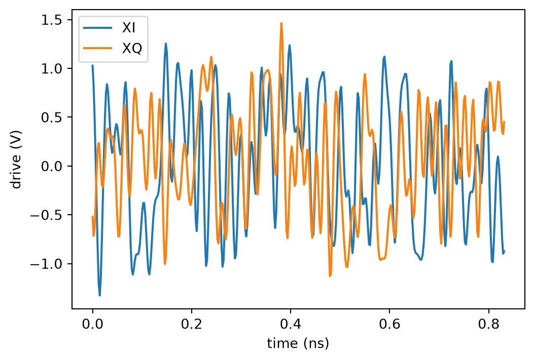
The transmitter delivers about dBm from a 16 dBm laser. The modulators sit at their null, and the 16QAM field averages well below the peak the modulator can deliver. The edge couplers, the MMIs, the modulator arms and the routes add several decibels more.
The receiver die
Section titled “The receiver die”The receiver die of the layout page carries its models too. Each photodiode is its own cell, with
the front-end model of the receiver page and its own noise seed. Its output E0 is a port of the
die, named after the hybrid output that feeds it. coherent_rx_die takes the two bandwidths of
the front end and a seed. Each simulation below therefore builds the die again, with new noise.
The page compares two front ends:
- A: the 67 GHz photodiode with the 80 GHz TIA of the receiver page, 47 GHz together
- B: two equal poles at 124 GHz, 80 GHz together, the bandwidth of the 128 GBd receivers on the market
fronts = {    "A": (67e9, 80e9),    "B": (124.3e9, 124.3e9),}  # Photodiode and TIA bandwidths (Hz)outputs = ("Ip", "In", "Qp", "Qn")  # Hybrid outputs of each polarizationpd_names = [    pol + o for pol in ("X", "Y") for o in outputs]  # Front-end outputs of the receiver die
# The receiver die: the two fiber inputs and the eight front-end outputsprint(f"ports of the receiver die: {sorted(rx_die.ports)}")viewer(rx_die)
ports of the receiver die: ['LO', 'SIG', 'XIn', 'XIp', 'XQn', 'XQp', 'YIn', 'YIp', 'YQn', 'YQp'];fill:%23221f20;font-weight:bold;font-size:58.080000px;}.terminal{fill:none;stroke:%23805080;stroke-width:7.260000;}.dashed{stroke-dasharray:36.300000,21.780000;}.port{fill:none;stroke:%23805080;stroke-width:14.520000;}.virtual-connection{fill:none;stroke:%23907090;stroke-width:10.890000;}.layer_10_0{stroke:%23878787;fill:%23888888;fill-opacity:0.094;}.label_10_0{fill:%23878787;}.layer_16_0{stroke:%23737373;fill:url(%23pat-layer_16_0);fill-opacity:0.492;}.label_16_0{fill:%23737373;}.layer_99_0{stroke:%232e7d5b;fill:none;}.label_99_0{fill:%232e7d5b;}.layer_7_0{stroke:%237a5c99;fill:url(%23pat-layer_7_0);fill-opacity:0.492;}.label_7_0{fill:%237a5c99;}.layer_11_0{stroke:%23666666;fill:%23666666;fill-opacity:0.094;}.label_11_0{fill:%23666666;}.layer_12_0{stroke:%23b88b14;fill:url(%23pat-layer_12_0);fill-opacity:0.492;}.label_12_0{fill:%23b88b14;}.layer_14_0{stroke:%23838383;fill:%23b0b0b0;fill-opacity:0.094;}.label_14_0{fill:%23838383;}.layer_15_0{stroke:%23000000;fill:url(%23pat-layer_15_0);fill-opacity:0.492;}.label_15_0{fill:%23000000;}.layer_8_0{stroke:%232e8b57;fill:url(%23pat-layer_8_0);fill-opacity:0.492;}.label_8_0{fill:%232e8b57;}.layer_1_0{stroke:%231f4e79;fill:url(%23pat-layer_1_0);fill-opacity:0.492;}.label_1_0{fill:%231f4e79;}.layer_2_0{stroke:%234f8fc0;fill:url(%23pat-layer_2_0);fill-opacity:0.492;}.label_2_0{fill:%234f8fc0;}.layer_4_0{stroke:%233aa596;fill:url(%23pat-layer_4_0);fill-opacity:0.492;}.label_4_0{fill:%233aa596;}.layer_6_0{stroke:%231c6b61;fill:url(%23pat-layer_6_0);fill-opacity:0.492;}.label_6_0{fill:%231c6b61;}.layer_3_0{stroke:%23c8385a;fill:url(%23pat-layer_3_0);fill-opacity:0.492;}.label_3_0{fill:%23c8385a;}.layer_5_0{stroke:%238b1c38;fill:url(%23pat-layer_5_0);fill-opacity:0.492;}.label_5_0{fill:%238b1c38;}.layer_13_0{stroke:%23878787;fill:%23aaaaaa;fill-opacity:0.094;}.label_13_0{fill:%23878787;}</style><defs><path id=%22port-symbol%22 class=%22port%22 d=%22M 0,-29.040000 L 43.560000,0 0,29.040000%22 /><path id=%22ref-port-symbol%22 class=%22port%22 style=%22stroke-opacity:0.33;%22 d=%22M 0,-21.780000 C 29.040000,-21.780000 29.040000,21.780000 0,21.780000%22 /><circle id=%22port-bend-symbol%22 style=%22stroke-width:0;stroke:none;fill:%23805080;fill-opacity:1;%22 cx=%220%22 cy=%220%22 r=%2213.068000%22 /><circle id=%22connection-symbol%22 style=%22stroke-width:0;stroke:none;fill:%23907090;fill-opacity:1;%22 cx=%220%22 cy=%220%22 r=%2215.246000%22 /><pattern id=%22pat-layer_16_0%22 patternUnits=%22userSpaceOnUse%22 width=%2236.300000%22 height=%2236.300000%22 patternTransform=%22translate(21.352941,9.552632)%22><circle cx=%2218.150000%22 cy=%2218.150000%22 r=%223.630000%22 style=%22stroke:none;fill:%23737373;fill-opacity:1.0%22 /></pattern><pattern id=%22pat-layer_7_0%22 patternUnits=%22userSpaceOnUse%22 width=%2236.300000%22 height=%2236.300000%22 patternTransform=%22translate(32.029412,1.910526)%22><line x1=%2218.150000%22 y1=%220%22 x2=%2218.150000%22 y2=%2236.300000%22 style=%22stroke:%237a5c99;stroke-width:3.630000%22 /><line x1=%220%22 y1=%2218.150000%22 x2=%2236.300000%22 y2=%2218.150000%22 style=%22stroke:%237a5c99;stroke-width:3.630000%22 /></pattern><pattern id=%22pat-layer_12_0%22 patternUnits=%22userSpaceOnUse%22 width=%2236.300000%22 height=%2236.300000%22 patternTransform=%22translate(34.164706,34.389474)%22><line x1=%220%22 y1=%2218.150000%22 x2=%2236.300000%22 y2=%2218.150000%22 style=%22stroke:%23b88b14;stroke-width:3.630000%22 /></pattern><pattern id=%22pat-layer_15_0%22 patternUnits=%22userSpaceOnUse%22 width=%2221.780000%22 height=%2221.780000%22 patternTransform=%22translate(3.843529,14.902105)%22><circle cx=%2210.890000%22 cy=%2210.890000%22 r=%223.630000%22 style=%22stroke:none;fill:%23000000;fill-opacity:1.0%22 /></pattern><pattern id=%22pat-layer_8_0%22 patternUnits=%22userSpaceOnUse%22 width=%2236.300000%22 height=%2236.300000%22 patternTransform=%22translate(10.676471,22.926316)%22><line x1=%220%22 y1=%220%22 x2=%2236.300000%22 y2=%2236.300000%22 style=%22stroke:%232e8b57;stroke-width:3.630000%22 /><line x1=%22-18.150000%22 y1=%2218.150000%22 x2=%2218.150000%22 y2=%2254.450000%22 style=%22stroke:%232e8b57;stroke-width:3.630000%22 /><line x1=%2218.150000%22 y1=%22-18.150000%22 x2=%2254.450000%22 y2=%2218.150000%22 style=%22stroke:%232e8b57;stroke-width:3.630000%22 /></pattern><pattern id=%22pat-layer_1_0%22 patternUnits=%22userSpaceOnUse%22 width=%2236.300000%22 height=%2236.300000%22 patternTransform=%22translate(14.947059,21.015789)%22><line x1=%220%22 y1=%220%22 x2=%2236.300000%22 y2=%2236.300000%22 style=%22stroke:%231f4e79;stroke-width:3.630000%22 /><line x1=%22-18.150000%22 y1=%2218.150000%22 x2=%2218.150000%22 y2=%2254.450000%22 style=%22stroke:%231f4e79;stroke-width:3.630000%22 /><line x1=%2218.150000%22 y1=%22-18.150000%22 x2=%2254.450000%22 y2=%2218.150000%22 style=%22stroke:%231f4e79;stroke-width:3.630000%22 /></pattern><pattern id=%22pat-layer_2_0%22 patternUnits=%22userSpaceOnUse%22 width=%2236.300000%22 height=%2236.300000%22 patternTransform=%22translate(29.894118,5.731579)%22><line x1=%2236.300000%22 y1=%220%22 x2=%220%22 y2=%2236.300000%22 style=%22stroke:%234f8fc0;stroke-width:3.630000%22 /><line x1=%2254.450000%22 y1=%2218.150000%22 x2=%2218.150000%22 y2=%2254.450000%22 style=%22stroke:%234f8fc0;stroke-width:3.630000%22 /><line x1=%2218.150000%22 y1=%22-18.150000%22 x2=%22-18.150000%22 y2=%2218.150000%22 style=%22stroke:%234f8fc0;stroke-width:3.630000%22 /></pattern><pattern id=%22pat-layer_4_0%22 patternUnits=%22userSpaceOnUse%22 width=%2236.300000%22 height=%2236.300000%22 patternTransform=%22translate(23.488235,11.463158)%22><circle cx=%2218.150000%22 cy=%2218.150000%22 r=%223.630000%22 style=%22stroke:none;fill:%233aa596;fill-opacity:1.0%22 /></pattern><pattern id=%22pat-layer_6_0%22 patternUnits=%22userSpaceOnUse%22 width=%2236.300000%22 height=%2236.300000%22 patternTransform=%22translate(17.082353,17.194737)%22><line x1=%220%22 y1=%220%22 x2=%2236.300000%22 y2=%2236.300000%22 style=%22stroke:%231c6b61;stroke-width:3.630000%22 /><line x1=%22-18.150000%22 y1=%2218.150000%22 x2=%2218.150000%22 y2=%2254.450000%22 style=%22stroke:%231c6b61;stroke-width:3.630000%22 /><line x1=%2218.150000%22 y1=%22-18.150000%22 x2=%2254.450000%22 y2=%2218.150000%22 style=%22stroke:%231c6b61;stroke-width:3.630000%22 /><line x1=%2236.300000%22 y1=%220%22 x2=%220%22 y2=%2236.300000%22 style=%22stroke:%231c6b61;stroke-width:3.630000%22 /><line x1=%2254.450000%22 y1=%2218.150000%22 x2=%2218.150000%22 y2=%2254.450000%22 style=%22stroke:%231c6b61;stroke-width:3.630000%22 /><line x1=%2218.150000%22 y1=%22-18.150000%22 x2=%22-18.150000%22 y2=%2218.150000%22 style=%22stroke:%231c6b61;stroke-width:3.630000%22 /></pattern><pattern id=%22pat-layer_3_0%22 patternUnits=%22userSpaceOnUse%22 width=%2236.300000%22 height=%2236.300000%22 patternTransform=%22translate(8.541176,26.747368)%22><circle cx=%2218.150000%22 cy=%2218.150000%22 r=%223.630000%22 style=%22stroke:none;fill:%23c8385a;fill-opacity:1.0%22 /></pattern><pattern id=%22pat-layer_5_0%22 patternUnits=%22userSpaceOnUse%22 width=%2236.300000%22 height=%2236.300000%22 patternTransform=%22translate(2.135294,32.478947)%22><line x1=%220%22 y1=%220%22 x2=%2236.300000%22 y2=%2236.300000%22 style=%22stroke:%238b1c38;stroke-width:3.630000%22 /><line x1=%22-18.150000%22 y1=%2218.150000%22 x2=%2218.150000%22 y2=%2254.450000%22 style=%22stroke:%238b1c38;stroke-width:3.630000%22 /><line x1=%2218.150000%22 y1=%22-18.150000%22 x2=%2254.450000%22 y2=%2218.150000%22 style=%22stroke:%238b1c38;stroke-width:3.630000%22 /><line x1=%2236.300000%22 y1=%220%22 x2=%220%22 y2=%2236.300000%22 style=%22stroke:%238b1c38;stroke-width:3.630000%22 /><line x1=%2254.450000%22 y1=%2218.150000%22 x2=%2218.150000%22 y2=%2254.450000%22 style=%22stroke:%238b1c38;stroke-width:3.630000%22 /><line x1=%2218.150000%22 y1=%22-18.150000%22 x2=%22-18.150000%22 y2=%2218.150000%22 style=%22stroke:%238b1c38;stroke-width:3.630000%22 /></pattern><g id=%22C1%22 data-name=%22EC_SWG_RX__IXKDBF452OEUCRTSPI4M6WI54Y5V2R2SLS5M65ULSDCFNRX6NQPQ%22><rect class=%22layer_1_0%22 x=%220.000000%22 y=%22-0.120000%22 width=%220.198000%22 height=%220.240000%22 /><rect class=%22layer_1_0%22 x=%220.400000%22 y=%22-0.120000%22 width=%220.198080%22 height=%220.240000%22 /><rect class=%22layer_1_0%22 x=%220.796000%22 y=%22-0.120000%22 width=%220.198160%22 height=%220.240000%22 /><rect class=%22layer_1_0%22 x=%221.188040%22 y=%22-0.120000%22 width=%220.198240%22 height=%220.240000%22 /><rect class=%22layer_1_0%22 x=%221.576155%22 y=%22-0.120000%22 width=%220.198310%22 height=%220.240000%22 /><rect class=%22layer_1_0%22 x=%221.960395%22 y=%22-0.120000%22 width=%220.198390%22 height=%220.240000%22 /><rect class=%22layer_1_0%22 x=%222.340785%22 y=%22-0.120000%22 width=%220.198470%22 height=%220.240000%22 /><rect class=%22layer_1_0%22 x=%222.717390%22 y=%22-0.120000%22 width=%220.198540%22 height=%220.240000%22 /><rect class=%22layer_1_0%22 x=%223.090210%22 y=%22-0.120000%22 width=%220.198620%22 height=%220.240000%22 /><rect class=%22layer_1_0%22 x=%223.459305%22 y=%22-0.120000%22 width=%220.198690%22 height=%220.240000%22 /><rect class=%22layer_1_0%22 x=%223.824720%22 y=%22-0.120000%22 width=%220.198760%22 height=%220.240000%22 /><rect class=%22layer_1_0%22 x=%224.186470%22 y=%22-0.120000%22 width=%220.198840%22 height=%220.240000%22 /><rect class=%22layer_1_0%22 x=%224.544610%22 y=%22-0.120000%22 width=%220.198900%22 height=%220.240000%22 /><rect class=%22layer_1_0%22 x=%224.899160%22 y=%22-0.120000%22 width=%220.198980%22 height=%220.240000%22 /><rect class=%22layer_1_0%22 x=%225.250165%22 y=%22-0.120000%22 width=%220.199050%22 height=%220.240000%22 /><rect class=%22layer_1_0%22 x=%225.597670%22 y=%22-0.120000%22 width=%220.199120%22 height=%220.240000%22 /><rect class=%22layer_1_0%22 x=%225.941685%22 y=%22-0.120000%22 width=%220.199190%22 height=%220.240000%22 /><rect class=%22layer_1_0%22 x=%226.282270%22 y=%22-0.120000%22 width=%220.199260%22 height=%220.240000%22 /><rect class=%22layer_1_0%22 x=%226.619450%22 y=%22-0.120000%22 width=%220.199320%22 height=%220.240000%22 /><rect class=%22layer_1_0%22 x=%226.953255%22 y=%22-0.120000%22 width=%220.199390%22 height=%220.240000%22 /><rect class=%22layer_1_0%22 x=%227.283720%22 y=%22-0.120000%22 width=%220.199460%22 height=%220.240000%22 /><rect class=%22layer_1_0%22 x=%227.610890%22 y=%22-0.120000%22 width=%220.199520%22 height=%220.240000%22 /><rect class=%22layer_1_0%22 x=%227.934780%22 y=%22-0.120000%22 width=%220.199580%22 height=%220.240000%22 /><rect class=%22layer_1_0%22 x=%228.255425%22 y=%22-0.120000%22 width=%220.199650%22 height=%220.240000%22 /><rect class=%22layer_1_0%22 x=%228.572870%22 y=%22-0.120000%22 width=%220.199720%22 height=%220.240000%22 /><rect class=%22layer_1_0%22 x=%228.887145%22 y=%22-0.120000%22 width=%220.199770%22 height=%220.240000%22 /><rect class=%22layer_1_0%22 x=%229.198270%22 y=%22-0.120000%22 width=%220.199840%22 height=%220.240000%22 /><rect class=%22layer_1_0%22 x=%229.506290%22 y=%22-0.120000%22 width=%220.199900%22 height=%220.240000%22 /><rect class=%22layer_1_0%22 x=%229.811230%22 y=%22-0.120000%22 width=%220.199960%22 height=%220.240000%22 /><rect class=%22layer_1_0%22 x=%2210.113115%22 y=%22-0.120000%22 width=%220.128570%22 height=%220.240000%22 /><rect class=%22layer_1_0%22 x=%2210.241685%22 y=%22-0.050000%22 width=%220.171430%22 height=%220.100000%22 /><rect class=%22layer_1_0%22 x=%2210.413115%22 y=%22-0.120000%22 width=%220.128570%22 height=%220.240000%22 /><rect class=%22layer_1_0%22 x=%2210.541685%22 y=%22-0.051060%22 width=%220.171430%22 height=%220.102120%22 /><rect class=%22layer_1_0%22 x=%2210.713115%22 y=%22-0.120000%22 width=%220.128570%22 height=%220.240000%22 /><rect class=%22layer_1_0%22 x=%2210.841685%22 y=%22-0.052120%22 width=%220.171430%22 height=%220.104240%22 /><rect class=%22layer_1_0%22 x=%2211.013115%22 y=%22-0.120000%22 width=%220.128570%22 height=%220.240000%22 /><rect class=%22layer_1_0%22 x=%2211.141685%22 y=%22-0.053180%22 width=%220.171430%22 height=%220.106360%22 /><rect class=%22layer_1_0%22 x=%2211.313115%22 y=%22-0.120000%22 width=%220.128570%22 height=%220.240000%22 /><rect class=%22layer_1_0%22 x=%2211.441685%22 y=%22-0.054240%22 width=%220.171430%22 height=%220.108480%22 /><rect class=%22layer_1_0%22 x=%2211.613115%22 y=%22-0.120000%22 width=%220.128570%22 height=%220.240000%22 /><rect class=%22layer_1_0%22 x=%2211.741685%22 y=%22-0.055300%22 width=%220.171430%22 height=%220.110600%22 /><rect class=%22layer_1_0%22 x=%2211.913115%22 y=%22-0.120000%22 width=%220.128570%22 height=%220.240000%22 /><rect class=%22layer_1_0%22 x=%2212.041685%22 y=%22-0.056360%22 width=%220.171430%22 height=%220.112720%22 /><rect class=%22layer_1_0%22 x=%2212.213115%22 y=%22-0.120000%22 width=%220.128570%22 height=%220.240000%22 /><rect class=%22layer_1_0%22 x=%2212.341685%22 y=%22-0.057420%22 width=%220.171430%22 height=%220.114840%22 /><rect class=%22layer_1_0%22 x=%2212.513115%22 y=%22-0.120000%22 width=%220.128570%22 height=%220.240000%22 /><rect class=%22layer_1_0%22 x=%2212.641685%22 y=%22-0.058480%22 width=%220.171430%22 height=%220.116960%22 /><rect class=%22layer_1_0%22 x=%2212.813115%22 y=%22-0.120000%22 width=%220.128570%22 height=%220.240000%22 /><rect class=%22layer_1_0%22 x=%2212.941685%22 y=%22-0.059550%22 width=%220.171430%22 height=%220.119100%22 /><rect class=%22layer_1_0%22 x=%2213.113115%22 y=%22-0.120000%22 width=%220.128570%22 height=%220.240000%22 /><rect class=%22layer_1_0%22 x=%2213.241685%22 y=%22-0.060610%22 width=%220.171430%22 height=%220.121220%22 /><rect class=%22layer_1_0%22 x=%2213.413115%22 y=%22-0.120000%22 width=%220.128570%22 height=%220.240000%22 /><rect class=%22layer_1_0%22 x=%2213.541685%22 y=%22-0.061670%22 width=%220.171430%22 height=%220.123340%22 /><rect class=%22layer_1_0%22 x=%2213.713115%22 y=%22-0.120000%22 width=%220.128570%22 height=%220.240000%22 /><rect class=%22layer_1_0%22 x=%2213.841685%22 y=%22-0.062730%22 width=%220.171430%22 height=%220.125460%22 /><rect class=%22layer_1_0%22 x=%2214.013115%22 y=%22-0.120000%22 width=%220.128570%22 height=%220.240000%22 /><rect class=%22layer_1_0%22 x=%2214.141685%22 y=%22-0.063790%22 width=%220.171430%22 height=%220.127580%22 /><rect class=%22layer_1_0%22 x=%2214.313115%22 y=%22-0.120000%22 width=%220.128570%22 height=%220.240000%22 /><rect class=%22layer_1_0%22 x=%2214.441685%22 y=%22-0.064850%22 width=%220.171430%22 height=%220.129700%22 /><rect class=%22layer_1_0%22 x=%2214.613115%22 y=%22-0.120000%22 width=%220.128570%22 height=%220.240000%22 /><rect class=%22layer_1_0%22 x=%2214.741685%22 y=%22-0.065910%22 width=%220.171430%22 height=%220.131820%22 /><rect class=%22layer_1_0%22 x=%2214.913115%22 y=%22-0.120000%22 width=%220.128570%22 height=%220.240000%22 /><rect class=%22layer_1_0%22 x=%2215.041685%22 y=%22-0.066970%22 width=%220.171430%22 height=%220.133940%22 /><rect class=%22layer_1_0%22 x=%2215.213115%22 y=%22-0.120000%22 width=%220.128570%22 height=%220.240000%22 /><rect class=%22layer_1_0%22 x=%2215.341685%22 y=%22-0.068030%22 width=%220.171430%22 height=%220.136060%22 /><rect class=%22layer_1_0%22 x=%2215.513115%22 y=%22-0.120000%22 width=%220.128570%22 height=%220.240000%22 /><rect class=%22layer_1_0%22 x=%2215.641685%22 y=%22-0.069090%22 width=%220.171430%22 height=%220.138180%22 /><rect class=%22layer_1_0%22 x=%2215.813115%22 y=%22-0.120000%22 width=%220.128570%22 height=%220.240000%22 /><rect class=%22layer_1_0%22 x=%2215.941685%22 y=%22-0.070150%22 width=%220.171430%22 height=%220.140300%22 /><rect class=%22layer_1_0%22 x=%2216.113115%22 y=%22-0.120000%22 width=%220.128570%22 height=%220.240000%22 /><rect class=%22layer_1_0%22 x=%2216.241685%22 y=%22-0.071210%22 width=%220.171430%22 height=%220.142420%22 /><rect class=%22layer_1_0%22 x=%2216.413115%22 y=%22-0.120000%22 width=%220.128570%22 height=%220.240000%22 /><rect class=%22layer_1_0%22 x=%2216.541685%22 y=%22-0.072270%22 width=%220.171430%22 height=%220.144540%22 /><rect class=%22layer_1_0%22 x=%2216.713115%22 y=%22-0.120000%22 width=%220.128570%22 height=%220.240000%22 /><rect class=%22layer_1_0%22 x=%2216.841685%22 y=%22-0.073330%22 width=%220.171430%22 height=%220.146660%22 /><rect class=%22layer_1_0%22 x=%2217.013115%22 y=%22-0.120000%22 width=%220.128570%22 height=%220.240000%22 /><rect class=%22layer_1_0%22 x=%2217.141685%22 y=%22-0.074390%22 width=%220.171430%22 height=%220.148780%22 /><rect class=%22layer_1_0%22 x=%2217.313115%22 y=%22-0.120000%22 width=%220.128570%22 height=%220.240000%22 /><rect class=%22layer_1_0%22 x=%2217.441685%22 y=%22-0.075450%22 width=%220.171430%22 height=%220.150900%22 /><rect class=%22layer_1_0%22 x=%2217.613115%22 y=%22-0.120000%22 width=%220.128570%22 height=%220.240000%22 /><rect class=%22layer_1_0%22 x=%2217.741685%22 y=%22-0.076520%22 width=%220.171430%22 height=%220.153040%22 /><rect class=%22layer_1_0%22 x=%2217.913115%22 y=%22-0.120000%22 width=%220.128570%22 height=%220.240000%22 /><rect class=%22layer_1_0%22 x=%2218.041685%22 y=%22-0.077580%22 width=%220.171430%22 height=%220.155160%22 /><rect class=%22layer_1_0%22 x=%2218.213115%22 y=%22-0.120000%22 width=%220.128570%22 height=%220.240000%22 /><rect class=%22layer_1_0%22 x=%2218.341685%22 y=%22-0.078640%22 width=%220.171430%22 height=%220.157280%22 /><rect class=%22layer_1_0%22 x=%2218.513115%22 y=%22-0.120000%22 width=%220.128570%22 height=%220.240000%22 /><rect class=%22layer_1_0%22 x=%2218.641685%22 y=%22-0.079700%22 width=%220.171430%22 height=%220.159400%22 /><rect class=%22layer_1_0%22 x=%2218.813115%22 y=%22-0.120000%22 width=%220.128570%22 height=%220.240000%22 /><rect class=%22layer_1_0%22 x=%2218.941685%22 y=%22-0.080760%22 width=%220.171430%22 height=%220.161520%22 /><rect class=%22layer_1_0%22 x=%2219.113115%22 y=%22-0.120000%22 width=%220.128570%22 height=%220.240000%22 /><rect class=%22layer_1_0%22 x=%2219.241685%22 y=%22-0.081820%22 width=%220.171430%22 height=%220.163640%22 /><rect class=%22layer_1_0%22 x=%2219.413115%22 y=%22-0.120000%22 width=%220.128570%22 height=%220.240000%22 /><rect class=%22layer_1_0%22 x=%2219.541685%22 y=%22-0.082880%22 width=%220.171430%22 height=%220.165760%22 /><rect class=%22layer_1_0%22 x=%2219.713115%22 y=%22-0.120000%22 width=%220.128570%22 height=%220.240000%22 /><rect class=%22layer_1_0%22 x=%2219.841685%22 y=%22-0.083940%22 width=%220.171430%22 height=%220.167880%22 /><rect class=%22layer_1_0%22 x=%2220.013115%22 y=%22-0.120000%22 width=%220.128570%22 height=%220.240000%22 /><rect class=%22layer_1_0%22 x=%2220.141685%22 y=%22-0.085000%22 width=%220.171430%22 height=%220.170000%22 /><rect class=%22layer_1_0%22 x=%2220.313115%22 y=%22-0.120000%22 width=%220.128570%22 height=%220.240000%22 /><rect class=%22layer_1_0%22 x=%2220.441685%22 y=%22-0.086060%22 width=%220.171430%22 height=%220.172120%22 /><rect class=%22layer_1_0%22 x=%2220.613115%22 y=%22-0.120000%22 width=%220.128570%22 height=%220.240000%22 /><rect class=%22layer_1_0%22 x=%2220.741685%22 y=%22-0.087120%22 width=%220.171430%22 height=%220.174240%22 /><rect class=%22layer_1_0%22 x=%2220.913115%22 y=%22-0.120000%22 width=%220.128570%22 height=%220.240000%22 /><rect class=%22layer_1_0%22 x=%2221.041685%22 y=%22-0.088180%22 width=%220.171430%22 height=%220.176360%22 /><rect class=%22layer_1_0%22 x=%2221.213115%22 y=%22-0.120000%22 width=%220.128570%22 height=%220.240000%22 /><rect class=%22layer_1_0%22 x=%2221.341685%22 y=%22-0.089240%22 width=%220.171430%22 height=%220.178480%22 /><rect class=%22layer_1_0%22 x=%2221.513115%22 y=%22-0.120000%22 width=%220.128570%22 height=%220.240000%22 /><rect class=%22layer_1_0%22 x=%2221.641685%22 y=%22-0.090300%22 width=%220.171430%22 height=%220.180600%22 /><rect class=%22layer_1_0%22 x=%2221.813115%22 y=%22-0.120000%22 width=%220.128570%22 height=%220.240000%22 /><rect class=%22layer_1_0%22 x=%2221.941685%22 y=%22-0.091360%22 width=%220.171430%22 height=%220.182720%22 /><rect class=%22layer_1_0%22 x=%2222.113115%22 y=%22-0.120000%22 width=%220.128570%22 height=%220.240000%22 /><rect class=%22layer_1_0%22 x=%2222.241685%22 y=%22-0.092420%22 width=%220.171430%22 height=%220.184840%22 /><rect class=%22layer_1_0%22 x=%2222.413115%22 y=%22-0.120000%22 width=%220.128570%22 height=%220.240000%22 /><rect class=%22layer_1_0%22 x=%2222.541685%22 y=%22-0.093480%22 width=%220.171430%22 height=%220.186960%22 /><rect class=%22layer_1_0%22 x=%2222.713115%22 y=%22-0.120000%22 width=%220.128570%22 height=%220.240000%22 /><rect class=%22layer_1_0%22 x=%2222.841685%22 y=%22-0.094550%22 width=%220.171430%22 height=%220.189100%22 /><rect class=%22layer_1_0%22 x=%2223.013115%22 y=%22-0.120000%22 width=%220.128570%22 height=%220.240000%22 /><rect class=%22layer_1_0%22 x=%2223.141685%22 y=%22-0.095610%22 width=%220.171430%22 height=%220.191220%22 /><rect class=%22layer_1_0%22 x=%2223.313115%22 y=%22-0.120000%22 width=%220.128570%22 height=%220.240000%22 /><rect class=%22layer_1_0%22 x=%2223.441685%22 y=%22-0.096670%22 width=%220.171430%22 height=%220.193340%22 /><rect class=%22layer_1_0%22 x=%2223.613115%22 y=%22-0.120000%22 width=%220.128570%22 height=%220.240000%22 /><rect class=%22layer_1_0%22 x=%2223.741685%22 y=%22-0.097730%22 width=%220.171430%22 height=%220.195460%22 /><rect class=%22layer_1_0%22 x=%2223.913115%22 y=%22-0.120000%22 width=%220.128570%22 height=%220.240000%22 /><rect class=%22layer_1_0%22 x=%2224.041685%22 y=%22-0.098790%22 width=%220.171430%22 height=%220.197580%22 /><rect class=%22layer_1_0%22 x=%2224.213115%22 y=%22-0.120000%22 width=%220.128570%22 height=%220.240000%22 /><rect class=%22layer_1_0%22 x=%2224.341685%22 y=%22-0.099850%22 width=%220.171430%22 height=%220.199700%22 /><rect class=%22layer_1_0%22 x=%2224.513115%22 y=%22-0.120000%22 width=%220.128570%22 height=%220.240000%22 /><rect class=%22layer_1_0%22 x=%2224.641685%22 y=%22-0.100910%22 width=%220.171430%22 height=%220.201820%22 /><rect class=%22layer_1_0%22 x=%2224.813115%22 y=%22-0.120000%22 width=%220.128570%22 height=%220.240000%22 /><rect class=%22layer_1_0%22 x=%2224.941685%22 y=%22-0.101970%22 width=%220.171430%22 height=%220.203940%22 /><rect class=%22layer_1_0%22 x=%2225.113115%22 y=%22-0.120000%22 width=%220.128570%22 height=%220.240000%22 /><rect class=%22layer_1_0%22 x=%2225.241685%22 y=%22-0.103030%22 width=%220.171430%22 height=%220.206060%22 /><rect class=%22layer_1_0%22 x=%2225.413115%22 y=%22-0.120000%22 width=%220.128570%22 height=%220.240000%22 /><rect class=%22layer_1_0%22 x=%2225.541685%22 y=%22-0.104090%22 width=%220.171430%22 height=%220.208180%22 /><rect class=%22layer_1_0%22 x=%2225.713115%22 y=%22-0.120000%22 width=%220.128570%22 height=%220.240000%22 /><rect class=%22layer_1_0%22 x=%2225.841685%22 y=%22-0.105150%22 width=%220.171430%22 height=%220.210300%22 /><rect class=%22layer_1_0%22 x=%2226.013115%22 y=%22-0.120000%22 width=%220.128570%22 height=%220.240000%22 /><rect class=%22layer_1_0%22 x=%2226.141685%22 y=%22-0.106210%22 width=%220.171430%22 height=%220.212420%22 /><rect class=%22layer_1_0%22 x=%2226.313115%22 y=%22-0.120000%22 width=%220.128570%22 height=%220.240000%22 /><rect class=%22layer_1_0%22 x=%2226.441685%22 y=%22-0.107270%22 width=%220.171430%22 height=%220.214540%22 /><rect class=%22layer_1_0%22 x=%2226.613115%22 y=%22-0.120000%22 width=%220.128570%22 height=%220.240000%22 /><rect class=%22layer_1_0%22 x=%2226.741685%22 y=%22-0.108330%22 width=%220.171430%22 height=%220.216660%22 /><rect class=%22layer_1_0%22 x=%2226.913115%22 y=%22-0.120000%22 width=%220.128570%22 height=%220.240000%22 /><rect class=%22layer_1_0%22 x=%2227.041685%22 y=%22-0.109390%22 width=%220.171430%22 height=%220.218780%22 /><rect class=%22layer_1_0%22 x=%2227.213115%22 y=%22-0.120000%22 width=%220.128570%22 height=%220.240000%22 /><rect class=%22layer_1_0%22 x=%2227.341685%22 y=%22-0.110450%22 width=%220.171430%22 height=%220.220900%22 /><rect class=%22layer_1_0%22 x=%2227.513115%22 y=%22-0.120000%22 width=%220.128570%22 height=%220.240000%22 /><rect class=%22layer_1_0%22 x=%2227.641685%22 y=%22-0.111520%22 width=%220.171430%22 height=%220.223040%22 /><rect class=%22layer_1_0%22 x=%2227.813115%22 y=%22-0.120000%22 width=%220.128570%22 height=%220.240000%22 /><rect class=%22layer_1_0%22 x=%2227.941685%22 y=%22-0.112580%22 width=%220.171430%22 height=%220.225160%22 /><rect class=%22layer_1_0%22 x=%2228.113115%22 y=%22-0.120000%22 width=%220.128570%22 height=%220.240000%22 /><rect class=%22layer_1_0%22 x=%2228.241685%22 y=%22-0.113640%22 width=%220.171430%22 height=%220.227280%22 /><rect class=%22layer_1_0%22 x=%2228.413115%22 y=%22-0.120000%22 width=%220.128570%22 height=%220.240000%22 /><rect class=%22layer_1_0%22 x=%2228.541685%22 y=%22-0.114700%22 width=%220.171430%22 height=%220.229400%22 /><rect class=%22layer_1_0%22 x=%2228.713115%22 y=%22-0.120000%22 width=%220.128570%22 height=%220.240000%22 /><rect class=%22layer_1_0%22 x=%2228.841685%22 y=%22-0.115760%22 width=%220.171430%22 height=%220.231520%22 /><rect class=%22layer_1_0%22 x=%2229.013115%22 y=%22-0.120000%22 width=%220.128570%22 height=%220.240000%22 /><rect class=%22layer_1_0%22 x=%2229.141685%22 y=%22-0.116820%22 width=%220.171430%22 height=%220.233640%22 /><rect class=%22layer_1_0%22 x=%2229.313115%22 y=%22-0.120000%22 width=%220.128570%22 height=%220.240000%22 /><rect class=%22layer_1_0%22 x=%2229.441685%22 y=%22-0.117880%22 width=%220.171430%22 height=%220.235760%22 /><rect class=%22layer_1_0%22 x=%2229.613115%22 y=%22-0.120000%22 width=%220.128570%22 height=%220.240000%22 /><rect class=%22layer_1_0%22 x=%2229.741685%22 y=%22-0.118940%22 width=%220.171430%22 height=%220.237880%22 /><rect class=%22layer_1_0%22 x=%2229.913115%22 y=%22-0.120000%22 width=%220.128570%22 height=%220.240000%22 /><rect class=%22layer_1_0%22 x=%2230.041685%22 y=%22-0.120000%22 width=%220.171430%22 height=%220.240000%22 /><path class=%22layer_1_0%22 d=%22M 30.213000,-0.120000 33.482000,-0.122000 36.466000,-0.124000 39.185000,-0.126000 41.659000,-0.127000 43.912000,-0.129000 45.966000,-0.131000 47.832000,-0.133000 49.526000,-0.135000 51.068000,-0.137000 52.481000,-0.139000 53.784000,-0.140000 54.990000,-0.142000 56.110000,-0.144000 57.156000,-0.146000 58.134000,-0.148000 59.055000,-0.150000 59.925000,-0.152000 60.749000,-0.153000 61.532000,-0.155000 62.275000,-0.157000 62.982000,-0.159000 63.655000,-0.161000 64.297000,-0.163000 64.909000,-0.165000 65.494000,-0.166000 66.054000,-0.168000 66.591000,-0.170000 67.106000,-0.172000 67.600000,-0.174000 68.077000,-0.176000 68.539000,-0.178000 68.987000,-0.179000 69.423000,-0.181000 69.847000,-0.183000 70.260000,-0.185000 70.662000,-0.187000 71.055000,-0.189000 71.438000,-0.191000 71.812000,-0.192000 72.177000,-0.194000 72.533000,-0.196000 72.880000,-0.198000 73.218000,-0.200000 73.548000,-0.202000 73.869000,-0.204000 74.184000,-0.205000 74.491000,-0.207000 74.792000,-0.209000 75.087000,-0.211000 75.375000,-0.213000 75.658000,-0.215000 75.936000,-0.217000 76.209000,-0.218000 76.477000,-0.220000 76.740000,-0.222000 76.999000,-0.224000 77.253000,-0.226000 77.503000,-0.228000 77.749000,-0.230000 77.991000,-0.231000 78.229000,-0.233000 78.463000,-0.235000 78.693000,-0.237000 78.920000,-0.239000 79.143000,-0.241000 79.363000,-0.243000 79.580000,-0.244000 79.794000,-0.246000 80.005000,-0.248000 80.213000,-0.250000 81.213000,-0.250000 81.213000,0.250000 80.213000,0.250000 80.005000,0.248000 79.794000,0.246000 79.580000,0.244000 79.363000,0.243000 79.143000,0.241000 78.920000,0.239000 78.693000,0.237000 78.463000,0.235000 78.229000,0.233000 77.991000,0.231000 77.749000,0.230000 77.503000,0.228000 77.253000,0.226000 76.999000,0.224000 76.740000,0.222000 76.477000,0.220000 76.209000,0.218000 75.936000,0.217000 75.658000,0.215000 75.375000,0.213000 75.087000,0.211000 74.792000,0.209000 74.491000,0.207000 74.184000,0.205000 73.869000,0.204000 73.548000,0.202000 73.218000,0.200000 72.880000,0.198000 72.533000,0.196000 72.177000,0.194000 71.812000,0.192000 71.438000,0.191000 71.055000,0.189000 70.662000,0.187000 70.260000,0.185000 69.847000,0.183000 69.423000,0.181000 68.987000,0.179000 68.539000,0.178000 68.077000,0.176000 67.600000,0.174000 67.106000,0.172000 66.591000,0.170000 66.054000,0.168000 65.494000,0.166000 64.909000,0.165000 64.297000,0.163000 63.655000,0.161000 62.982000,0.159000 62.275000,0.157000 61.532000,0.155000 60.749000,0.153000 59.925000,0.152000 59.055000,0.150000 58.134000,0.148000 57.156000,0.146000 56.110000,0.144000 54.990000,0.142000 53.784000,0.140000 52.481000,0.139000 51.068000,0.137000 49.526000,0.135000 47.832000,0.133000 45.966000,0.131000 43.912000,0.129000 41.659000,0.127000 39.185000,0.126000 36.466000,0.124000 33.482000,0.122000 30.213000,0.120000 z%22 /><rect class=%22layer_16_0%22 x=%22-20.000000%22 y=%22-10.000000%22 width=%2220.000000%22 height=%2220.000000%22 /><g transform=%22translate(-1.000000 0.000000) rotate(0.000000)%22><use href=%22%23ref-port-symbol%22 /></g></g><g id=%22C10%22 data-name=%22PD_CHEN_f_p_67000000000P0_f_t_80000000000P0_see_2%22><path class=%22layer_1_0%22 d=%22M -10.000000,-0.250000 0.000000,-2.200000 14.200000,-2.200000 14.200000,2.200000 0.000000,2.200000 -10.000000,0.250000 z%22 /><rect class=%22layer_3_0%22 x=%220.000000%22 y=%220.000000%22 width=%2214.200000%22 height=%222.200000%22 /><rect class=%22layer_4_0%22 x=%220.000000%22 y=%22-2.200000%22 width=%2214.200000%22 height=%222.200000%22 /><rect class=%22layer_5_0%22 x=%220.000000%22 y=%221.200000%22 width=%2214.200000%22 height=%221.000000%22 /><rect class=%22layer_6_0%22 x=%220.000000%22 y=%22-2.200000%22 width=%2214.200000%22 height=%221.000000%22 /><rect class=%22layer_7_0%22 x=%220.000000%22 y=%22-0.250000%22 width=%2214.200000%22 height=%220.500000%22 /><path class=%22layer_8_0%22 d=%22M -10.000000,-0.100000 0.000000,-0.250000 0.000000,0.250000 -10.000000,0.100000 z%22 /><rect class=%22layer_10_0%22 x=%220.500000%22 y=%22-2.000000%22 width=%2213.200000%22 height=%220.600000%22 /><rect class=%22layer_10_0%22 x=%220.500000%22 y=%221.400000%22 width=%2213.200000%22 height=%220.600000%22 /><rect class=%22layer_14_0%22 x=%220.000000%22 y=%22-2.200000%22 width=%2214.200000%22 height=%221.000000%22 /><rect class=%22layer_14_0%22 x=%220.000000%22 y=%221.200000%22 width=%2214.200000%22 height=%221.000000%22 /><rect class=%22terminal dashed%22 x=%220.000000%22 y=%221.200000%22 width=%2214.200000%22 height=%221.000000%22 /><rect class=%22terminal dashed%22 x=%220.000000%22 y=%22-2.200000%22 width=%2214.200000%22 height=%221.000000%22 /></g><g id=%22C11%22 data-name=%22PD_CHEN_f_p_67000000000P0_f_t_80000000000P0_see_3%22><path class=%22layer_1_0%22 d=%22M -10.000000,-0.250000 0.000000,-2.200000 14.200000,-2.200000 14.200000,2.200000 0.000000,2.200000 -10.000000,0.250000 z%22 /><rect class=%22layer_3_0%22 x=%220.000000%22 y=%220.000000%22 width=%2214.200000%22 height=%222.200000%22 /><rect class=%22layer_4_0%22 x=%220.000000%22 y=%22-2.200000%22 width=%2214.200000%22 height=%222.200000%22 /><rect class=%22layer_5_0%22 x=%220.000000%22 y=%221.200000%22 width=%2214.200000%22 height=%221.000000%22 /><rect class=%22layer_6_0%22 x=%220.000000%22 y=%22-2.200000%22 width=%2214.200000%22 height=%221.000000%22 /><rect class=%22layer_7_0%22 x=%220.000000%22 y=%22-0.250000%22 width=%2214.200000%22 height=%220.500000%22 /><path class=%22layer_8_0%22 d=%22M -10.000000,-0.100000 0.000000,-0.250000 0.000000,0.250000 -10.000000,0.100000 z%22 /><rect class=%22layer_10_0%22 x=%220.500000%22 y=%22-2.000000%22 width=%2213.200000%22 height=%220.600000%22 /><rect class=%22layer_10_0%22 x=%220.500000%22 y=%221.400000%22 width=%2213.200000%22 height=%220.600000%22 /><rect class=%22layer_14_0%22 x=%220.000000%22 y=%22-2.200000%22 width=%2214.200000%22 height=%221.000000%22 /><rect class=%22layer_14_0%22 x=%220.000000%22 y=%221.200000%22 width=%2214.200000%22 height=%221.000000%22 /><rect class=%22terminal dashed%22 x=%220.000000%22 y=%221.200000%22 width=%2214.200000%22 height=%221.000000%22 /><rect class=%22terminal dashed%22 x=%220.000000%22 y=%22-2.200000%22 width=%2214.200000%22 height=%221.000000%22 /></g><g id=%22C12%22 data-name=%22PD_CHEN_f_p_67000000000P0_f_t_80000000000P0_see_4%22><path class=%22layer_1_0%22 d=%22M -10.000000,-0.250000 0.000000,-2.200000 14.200000,-2.200000 14.200000,2.200000 0.000000,2.200000 -10.000000,0.250000 z%22 /><rect class=%22layer_3_0%22 x=%220.000000%22 y=%220.000000%22 width=%2214.200000%22 height=%222.200000%22 /><rect class=%22layer_4_0%22 x=%220.000000%22 y=%22-2.200000%22 width=%2214.200000%22 height=%222.200000%22 /><rect class=%22layer_5_0%22 x=%220.000000%22 y=%221.200000%22 width=%2214.200000%22 height=%221.000000%22 /><rect class=%22layer_6_0%22 x=%220.000000%22 y=%22-2.200000%22 width=%2214.200000%22 height=%221.000000%22 /><rect class=%22layer_7_0%22 x=%220.000000%22 y=%22-0.250000%22 width=%2214.200000%22 height=%220.500000%22 /><path class=%22layer_8_0%22 d=%22M -10.000000,-0.100000 0.000000,-0.250000 0.000000,0.250000 -10.000000,0.100000 z%22 /><rect class=%22layer_10_0%22 x=%220.500000%22 y=%22-2.000000%22 width=%2213.200000%22 height=%220.600000%22 /><rect class=%22layer_10_0%22 x=%220.500000%22 y=%221.400000%22 width=%2213.200000%22 height=%220.600000%22 /><rect class=%22layer_14_0%22 x=%220.000000%22 y=%22-2.200000%22 width=%2214.200000%22 height=%221.000000%22 /><rect class=%22layer_14_0%22 x=%220.000000%22 y=%221.200000%22 width=%2214.200000%22 height=%221.000000%22 /><rect class=%22terminal dashed%22 x=%220.000000%22 y=%221.200000%22 width=%2214.200000%22 height=%221.000000%22 /><rect class=%22terminal dashed%22 x=%220.000000%22 y=%22-2.200000%22 width=%2214.200000%22 height=%221.000000%22 /></g><g id=%22C13%22 data-name=%22PD_CHEN_f_p_67000000000P0_f_t_80000000000P0_see_5%22><path class=%22layer_1_0%22 d=%22M -10.000000,-0.250000 0.000000,-2.200000 14.200000,-2.200000 14.200000,2.200000 0.000000,2.200000 -10.000000,0.250000 z%22 /><rect class=%22layer_3_0%22 x=%220.000000%22 y=%220.000000%22 width=%2214.200000%22 height=%222.200000%22 /><rect class=%22layer_4_0%22 x=%220.000000%22 y=%22-2.200000%22 width=%2214.200000%22 height=%222.200000%22 /><rect class=%22layer_5_0%22 x=%220.000000%22 y=%221.200000%22 width=%2214.200000%22 height=%221.000000%22 /><rect class=%22layer_6_0%22 x=%220.000000%22 y=%22-2.200000%22 width=%2214.200000%22 height=%221.000000%22 /><rect class=%22layer_7_0%22 x=%220.000000%22 y=%22-0.250000%22 width=%2214.200000%22 height=%220.500000%22 /><path class=%22layer_8_0%22 d=%22M -10.000000,-0.100000 0.000000,-0.250000 0.000000,0.250000 -10.000000,0.100000 z%22 /><rect class=%22layer_10_0%22 x=%220.500000%22 y=%22-2.000000%22 width=%2213.200000%22 height=%220.600000%22 /><rect class=%22layer_10_0%22 x=%220.500000%22 y=%221.400000%22 width=%2213.200000%22 height=%220.600000%22 /><rect class=%22layer_14_0%22 x=%220.000000%22 y=%22-2.200000%22 width=%2214.200000%22 height=%221.000000%22 /><rect class=%22layer_14_0%22 x=%220.000000%22 y=%221.200000%22 width=%2214.200000%22 height=%221.000000%22 /><rect class=%22terminal dashed%22 x=%220.000000%22 y=%221.200000%22 width=%2214.200000%22 height=%221.000000%22 /><rect class=%22terminal dashed%22 x=%220.000000%22 y=%22-2.200000%22 width=%2214.200000%22 height=%221.000000%22 /></g><g id=%22C14%22 data-name=%22PD_CHEN_f_p_67000000000P0_f_t_80000000000P0_see_6%22><path class=%22layer_1_0%22 d=%22M -10.000000,-0.250000 0.000000,-2.200000 14.200000,-2.200000 14.200000,2.200000 0.000000,2.200000 -10.000000,0.250000 z%22 /><rect class=%22layer_3_0%22 x=%220.000000%22 y=%220.000000%22 width=%2214.200000%22 height=%222.200000%22 /><rect class=%22layer_4_0%22 x=%220.000000%22 y=%22-2.200000%22 width=%2214.200000%22 height=%222.200000%22 /><rect class=%22layer_5_0%22 x=%220.000000%22 y=%221.200000%22 width=%2214.200000%22 height=%221.000000%22 /><rect class=%22layer_6_0%22 x=%220.000000%22 y=%22-2.200000%22 width=%2214.200000%22 height=%221.000000%22 /><rect class=%22layer_7_0%22 x=%220.000000%22 y=%22-0.250000%22 width=%2214.200000%22 height=%220.500000%22 /><path class=%22layer_8_0%22 d=%22M -10.000000,-0.100000 0.000000,-0.250000 0.000000,0.250000 -10.000000,0.100000 z%22 /><rect class=%22layer_10_0%22 x=%220.500000%22 y=%22-2.000000%22 width=%2213.200000%22 height=%220.600000%22 /><rect class=%22layer_10_0%22 x=%220.500000%22 y=%221.400000%22 width=%2213.200000%22 height=%220.600000%22 /><rect class=%22layer_14_0%22 x=%220.000000%22 y=%22-2.200000%22 width=%2214.200000%22 height=%221.000000%22 /><rect class=%22layer_14_0%22 x=%220.000000%22 y=%221.200000%22 width=%2214.200000%22 height=%221.000000%22 /><rect class=%22terminal dashed%22 x=%220.000000%22 y=%221.200000%22 width=%2214.200000%22 height=%221.000000%22 /><rect class=%22terminal dashed%22 x=%220.000000%22 y=%22-2.200000%22 width=%2214.200000%22 height=%221.000000%22 /></g><g id=%22C15%22 data-name=%22PD_CHEN_f_p_67000000000P0_f_t_80000000000P0_see_7%22><path class=%22layer_1_0%22 d=%22M -10.000000,-0.250000 0.000000,-2.200000 14.200000,-2.200000 14.200000,2.200000 0.000000,2.200000 -10.000000,0.250000 z%22 /><rect class=%22layer_3_0%22 x=%220.000000%22 y=%220.000000%22 width=%2214.200000%22 height=%222.200000%22 /><rect class=%22layer_4_0%22 x=%220.000000%22 y=%22-2.200000%22 width=%2214.200000%22 height=%222.200000%22 /><rect class=%22layer_5_0%22 x=%220.000000%22 y=%221.200000%22 width=%2214.200000%22 height=%221.000000%22 /><rect class=%22layer_6_0%22 x=%220.000000%22 y=%22-2.200000%22 width=%2214.200000%22 height=%221.000000%22 /><rect class=%22layer_7_0%22 x=%220.000000%22 y=%22-0.250000%22 width=%2214.200000%22 height=%220.500000%22 /><path class=%22layer_8_0%22 d=%22M -10.000000,-0.100000 0.000000,-0.250000 0.000000,0.250000 -10.000000,0.100000 z%22 /><rect class=%22layer_10_0%22 x=%220.500000%22 y=%22-2.000000%22 width=%2213.200000%22 height=%220.600000%22 /><rect class=%22layer_10_0%22 x=%220.500000%22 y=%221.400000%22 width=%2213.200000%22 height=%220.600000%22 /><rect class=%22layer_14_0%22 x=%220.000000%22 y=%22-2.200000%22 width=%2214.200000%22 height=%221.000000%22 /><rect class=%22layer_14_0%22 x=%220.000000%22 y=%221.200000%22 width=%2214.200000%22 height=%221.000000%22 /><rect class=%22terminal dashed%22 x=%220.000000%22 y=%221.200000%22 width=%2214.200000%22 height=%221.000000%22 /><rect class=%22terminal dashed%22 x=%220.000000%22 y=%22-2.200000%22 width=%2214.200000%22 height=%221.000000%22 /></g><g id=%22C16%22 data-name=%22route_auto__MAPFN6Q7T2M3IYTINYRYMSVHE5GX2ZPG2U5RCB5OYFVVCTWCU74Q%22><use transform=%22translate(83.213000 -635.000000)%22 href=%22%23C20%22 /><use transform=%22translate(1155.000000 -635.000000)%22 href=%22%23C21%22 /><use transform=%22translate(100.000000 -635.000000)%22 href=%22%23C22%22 /><use transform=%22translate(1160.000000 -5.000000) rotate(90.000000)%22 href=%22%23C21%22 /><use transform=%22translate(1160.000000 -630.000000)%22 href=%22%23C23%22 /><use transform=%22translate(1155.000000 0.000000)%22 href=%22%23C24%22 /></g><g id=%22C17%22 data-name=%22route_auto__WUQUPMHIEEMSNZG5ATSEAOI2ZR7O5Z7QUPTS77HTEEU2JEEBUFNQ%22><use transform=%22translate(0.000000 0.000000)%22 href=%22%23C25%22 /><use transform=%22translate(0.000000 0.000000)%22 href=%22%23C26%22 /></g><g id=%22C18%22 data-name=%22route_auto__XBUIHFE7KFYMLYQJHDGGSDILCYQXONLANVB7YZWJV3ZN6W36G5FA%22><use transform=%22translate(0.000000 0.000000)%22 href=%22%23C27%22 /><use transform=%22translate(0.000000 0.000000)%22 href=%22%23C28%22 /><use transform=%22translate(0.000000 0.000000)%22 href=%22%23C29%22 /><use transform=%22translate(0.000000 0.000000)%22 href=%22%23C30%22 /><use transform=%22translate(0.000000 0.000000)%22 href=%22%23C31%22 /><use transform=%22translate(0.000000 0.000000)%22 href=%22%23C32%22 /><use transform=%22translate(0.000000 0.000000)%22 href=%22%23C33%22 /><use transform=%22translate(0.000000 0.000000)%22 href=%22%23C34%22 /></g><g id=%22C19%22 data-name=%22route_auto__R35WF7ARRLSTZXY34OXPL7XQPSCZCOAHMEEQFHCFFJSZ4VPPE7RQ%22><use transform=%22translate(0.000000 0.000000)%22 href=%22%23C35%22 /><use transform=%22translate(0.000000 0.000000)%22 href=%22%23C36%22 /></g><g id=%22C2%22 data-name=%22transition__FDEH3P5JF4M3L5TQZF7FD3OLP3DA7UDFH32HHYN4HQE3POKSY5WA%22><path class=%22layer_1_0%22 d=%22M 0.000000,-0.250000 2.000000,-0.245000 4.000000,-0.240000 6.000000,-0.235000 8.000000,-0.230000 10.000000,-0.225000 10.000000,0.225000 8.000000,0.230000 6.000000,0.235000 4.000000,0.240000 2.000000,0.245000 0.000000,0.250000 z%22 /></g><g id=%22C3%22 data-name=%22PSR__3UA5VT6MUOS3NDV5ECT2CS5Z6L7TVIGQAGSXTFJLGFHG6I2CQD4Q%22><path class=%22layer_1_0%22 d=%22M 0.000000,-0.225000 50.000000,-0.275000 100.000000,-0.425000 100.000000,0.425000 50.000000,0.275000 0.000000,0.225000 z%22 /><path class=%22layer_1_0%22 d=%22M 100.000000,-0.425000 103.000000,-0.424000 106.000000,-0.423000 109.000000,-0.422000 112.000000,-0.421000 115.000000,-0.420000 118.000000,-0.419000 121.000000,-0.418000 124.000000,-0.417000 127.000000,-0.416000 130.000000,-0.415000 133.000000,-0.414000 136.000000,-0.413000 139.000000,-0.412000 142.000000,-0.411000 145.000000,-0.410000 148.000000,-0.409000 151.000000,-0.408000 154.000000,-0.407000 157.000000,-0.406000 160.000000,-0.405000 163.000000,-0.404000 166.000000,-0.403000 169.000000,-0.402000 172.000000,-0.401000 175.000000,-0.400000 178.000000,-0.399000 181.000000,-0.398000 184.000000,-0.397000 187.000000,-0.396000 190.000000,-0.395000 193.000000,-0.394000 196.000000,-0.393000 199.000000,-0.392000 202.000000,-0.391000 205.000000,-0.390000 208.000000,-0.389000 211.000000,-0.388000 214.000000,-0.387000 217.000000,-0.386000 220.000000,-0.385000 223.000000,-0.384000 226.000000,-0.383000 229.000000,-0.382000 232.000000,-0.381000 235.000000,-0.380000 238.000000,-0.379000 241.000000,-0.378000 244.000000,-0.377000 247.000000,-0.376000 250.000000,-0.375000 253.000000,-0.374000 256.000000,-0.373000 259.000000,-0.372000 262.000000,-0.371000 265.000000,-0.370000 268.000000,-0.369000 271.000000,-0.368000 274.000000,-0.367000 277.000000,-0.366000 280.000000,-0.365000 283.000000,-0.364000 286.000000,-0.363000 289.000000,-0.362000 292.000000,-0.361000 295.000000,-0.360000 298.000000,-0.359000 301.000000,-0.358000 304.000000,-0.357000 307.000000,-0.356000 310.000000,-0.355000 313.000000,-0.354000 316.000000,-0.353000 319.000000,-0.352000 322.000000,-0.351000 325.000000,-0.350000 328.000000,-0.349000 331.000000,-0.348000 334.000000,-0.347000 337.000000,-0.346000 340.000000,-0.345000 343.000000,-0.344000 346.000000,-0.343000 349.000000,-0.342000 352.000000,-0.341000 355.000000,-0.340000 358.000000,-0.339000 361.000000,-0.338000 364.000000,-0.337000 367.000000,-0.336000 370.000000,-0.335000 373.000000,-0.334000 376.000000,-0.333000 379.000000,-0.332000 382.000000,-0.331000 385.000000,-0.330000 388.000000,-0.329000 391.000000,-0.328000 394.000000,-0.327000 397.000000,-0.326000 400.000000,-0.325000 403.000000,-0.325000 406.000000,-0.325000 409.000000,-0.325000 412.000000,-0.325000 415.000000,-0.325000 418.000000,-0.325000 421.000000,-0.325000 424.000000,-0.325000 427.000000,-0.325000 430.000000,-0.325000 433.000000,-0.325000 436.000000,-0.325000 439.000000,-0.325000 442.000000,-0.325000 445.000000,-0.325000 448.000000,-0.325000 451.000000,-0.325000 454.000000,-0.325000 457.000000,-0.325000 460.000000,-0.325000 460.000000,0.325000 457.000000,0.325000 454.000000,0.325000 451.000000,0.325000 448.000000,0.325000 445.000000,0.325000 442.000000,0.325000 439.000000,0.325000 436.000000,0.325000 433.000000,0.325000 430.000000,0.325000 427.000000,0.325000 424.000000,0.325000 421.000000,0.325000 418.000000,0.325000 415.000000,0.325000 412.000000,0.325000 409.000000,0.325000 406.000000,0.325000 403.000000,0.325000 400.000000,0.325000 397.000000,0.326000 394.000000,0.327000 391.000000,0.328000 388.000000,0.329000 385.000000,0.330000 382.000000,0.331000 379.000000,0.332000 376.000000,0.333000 373.000000,0.334000 370.000000,0.335000 367.000000,0.336000 364.000000,0.337000 361.000000,0.338000 358.000000,0.339000 355.000000,0.340000 352.000000,0.341000 349.000000,0.342000 346.000000,0.343000 343.000000,0.344000 340.000000,0.345000 337.000000,0.346000 334.000000,0.347000 331.000000,0.348000 328.000000,0.349000 325.000000,0.350000 322.000000,0.351000 319.000000,0.352000 316.000000,0.353000 313.000000,0.354000 310.000000,0.355000 307.000000,0.356000 304.000000,0.357000 301.000000,0.358000 298.000000,0.359000 295.000000,0.360000 292.000000,0.361000 289.000000,0.362000 286.000000,0.363000 283.000000,0.364000 280.000000,0.365000 277.000000,0.366000 274.000000,0.367000 271.000000,0.368000 268.000000,0.369000 265.000000,0.370000 262.000000,0.371000 259.000000,0.372000 256.000000,0.373000 253.000000,0.374000 250.000000,0.375000 247.000000,0.376000 244.000000,0.377000 241.000000,0.378000 238.000000,0.379000 235.000000,0.380000 232.000000,0.381000 229.000000,0.382000 226.000000,0.383000 223.000000,0.384000 220.000000,0.385000 217.000000,0.386000 214.000000,0.387000 211.000000,0.388000 208.000000,0.389000 205.000000,0.390000 202.000000,0.391000 199.000000,0.392000 196.000000,0.393000 193.000000,0.394000 190.000000,0.395000 187.000000,0.396000 184.000000,0.397000 181.000000,0.398000 178.000000,0.399000 175.000000,0.400000 172.000000,0.401000 169.000000,0.402000 166.000000,0.403000 163.000000,0.404000 160.000000,0.405000 157.000000,0.406000 154.000000,0.407000 151.000000,0.408000 148.000000,0.409000 145.000000,0.410000 142.000000,0.411000 139.000000,0.412000 136.000000,0.413000 133.000000,0.414000 130.000000,0.415000 127.000000,0.416000 124.000000,0.417000 121.000000,0.418000 118.000000,0.419000 115.000000,0.420000 112.000000,0.421000 109.000000,0.422000 106.000000,0.423000 103.000000,0.424000 100.000000,0.425000 z%22 /><path class=%22layer_1_0%22 d=%22M 100.000000,-0.825000 103.000000,-0.827000 106.000000,-0.829000 109.000000,-0.831000 112.000000,-0.833000 115.000000,-0.835000 118.000000,-0.837000 121.000000,-0.839000 124.000000,-0.841000 127.000000,-0.843000 130.000000,-0.845000 133.000000,-0.847000 136.000000,-0.849000 139.000000,-0.851000 142.000000,-0.853000 145.000000,-0.855000 148.000000,-0.857000 151.000000,-0.859000 154.000000,-0.861000 157.000000,-0.863000 160.000000,-0.865000 163.000000,-0.867000 166.000000,-0.869000 169.000000,-0.871000 172.000000,-0.873000 175.000000,-0.875000 178.000000,-0.877000 181.000000,-0.879000 184.000000,-0.881000 187.000000,-0.883000 190.000000,-0.885000 193.000000,-0.887000 196.000000,-0.889000 199.000000,-0.891000 202.000000,-0.893000 205.000000,-0.895000 208.000000,-0.897000 211.000000,-0.899000 214.000000,-0.901000 217.000000,-0.903000 220.000000,-0.905000 223.000000,-0.907000 226.000000,-0.909000 229.000000,-0.911000 232.000000,-0.913000 235.000000,-0.915000 238.000000,-0.917000 241.000000,-0.919000 244.000000,-0.921000 247.000000,-0.923000 250.000000,-0.925000 253.000000,-0.927000 256.000000,-0.929000 259.000000,-0.931000 262.000000,-0.933000 265.000000,-0.935000 268.000000,-0.937000 271.000000,-0.939000 274.000000,-0.941000 277.000000,-0.943000 280.000000,-0.945000 283.000000,-0.947000 286.000000,-0.949000 289.000000,-0.951000 292.000000,-0.953000 295.000000,-0.955000 298.000000,-0.957000 301.000000,-0.959000 304.000000,-0.961000 307.000000,-0.963000 310.000000,-0.965000 313.000000,-0.967000 316.000000,-0.969000 319.000000,-0.971000 322.000000,-0.973000 325.000000,-0.975000 328.000000,-0.977000 331.000000,-0.979000 334.000000,-0.981000 337.000000,-0.983000 340.000000,-0.985000 343.000000,-0.987000 346.000000,-0.989000 349.000000,-0.991000 352.000000,-0.993000 355.000000,-0.995000 358.000000,-0.997000 361.000000,-0.999000 364.000000,-1.001000 367.000000,-1.003000 370.000000,-1.005000 373.000000,-1.007000 376.000000,-1.009000 379.000000,-1.011000 382.000000,-1.013000 385.000000,-1.015000 388.000000,-1.017000 391.000000,-1.019000 394.000000,-1.021000 397.000000,-1.023000 400.000000,-1.025000 403.000000,-1.035000 406.000000,-1.065000 409.000000,-1.115000 412.000000,-1.185000 415.000000,-1.275000 418.000000,-1.385000 421.000000,-1.515000 424.000000,-1.665000 427.000000,-1.835000 430.000000,-2.025000 433.000000,-2.235000 436.000000,-2.465000 439.000000,-2.715000 442.000000,-2.985000 445.000000,-3.275000 448.000000,-3.585000 451.000000,-3.915000 454.000000,-4.265000 457.000000,-4.635000 460.000000,-5.025000 460.000000,-4.525000 457.000000,-4.135000 454.000000,-3.765000 451.000000,-3.415000 448.000000,-3.085000 445.000000,-2.775000 442.000000,-2.485000 439.000000,-2.215000 436.000000,-1.965000 433.000000,-1.735000 430.000000,-1.525000 427.000000,-1.335000 424.000000,-1.165000 421.000000,-1.015000 418.000000,-0.885000 415.000000,-0.775000 412.000000,-0.685000 409.000000,-0.615000 406.000000,-0.565000 403.000000,-0.535000 400.000000,-0.525000 397.000000,-0.526000 394.000000,-0.527000 391.000000,-0.528000 388.000000,-0.529000 385.000000,-0.530000 382.000000,-0.531000 379.000000,-0.532000 376.000000,-0.533000 373.000000,-0.534000 370.000000,-0.535000 367.000000,-0.536000 364.000000,-0.537000 361.000000,-0.538000 358.000000,-0.539000 355.000000,-0.540000 352.000000,-0.541000 349.000000,-0.542000 346.000000,-0.543000 343.000000,-0.544000 340.000000,-0.545000 337.000000,-0.546000 334.000000,-0.547000 331.000000,-0.548000 328.000000,-0.549000 325.000000,-0.550000 322.000000,-0.551000 319.000000,-0.552000 316.000000,-0.553000 313.000000,-0.554000 310.000000,-0.555000 307.000000,-0.556000 304.000000,-0.557000 301.000000,-0.558000 298.000000,-0.559000 295.000000,-0.560000 292.000000,-0.561000 289.000000,-0.562000 286.000000,-0.563000 283.000000,-0.564000 280.000000,-0.565000 277.000000,-0.566000 274.000000,-0.567000 271.000000,-0.568000 268.000000,-0.569000 265.000000,-0.570000 262.000000,-0.571000 259.000000,-0.572000 256.000000,-0.573000 253.000000,-0.574000 250.000000,-0.575000 247.000000,-0.576000 244.000000,-0.577000 241.000000,-0.578000 238.000000,-0.579000 235.000000,-0.580000 232.000000,-0.581000 229.000000,-0.582000 226.000000,-0.583000 223.000000,-0.584000 220.000000,-0.585000 217.000000,-0.586000 214.000000,-0.587000 211.000000,-0.588000 208.000000,-0.589000 205.000000,-0.590000 202.000000,-0.591000 199.000000,-0.592000 196.000000,-0.593000 193.000000,-0.594000 190.000000,-0.595000 187.000000,-0.596000 184.000000,-0.597000 181.000000,-0.598000 178.000000,-0.599000 175.000000,-0.600000 172.000000,-0.601000 169.000000,-0.602000 166.000000,-0.603000 163.000000,-0.604000 160.000000,-0.605000 157.000000,-0.606000 154.000000,-0.607000 151.000000,-0.608000 148.000000,-0.609000 145.000000,-0.610000 142.000000,-0.611000 139.000000,-0.612000 136.000000,-0.613000 133.000000,-0.614000 130.000000,-0.615000 127.000000,-0.616000 124.000000,-0.617000 121.000000,-0.618000 118.000000,-0.619000 115.000000,-0.620000 112.000000,-0.621000 109.000000,-0.622000 106.000000,-0.623000 103.000000,-0.624000 100.000000,-0.625000 z%22 /><path class=%22layer_2_0%22 d=%22M 0.000000,-0.225000 50.000000,-0.775000 100.000000,-0.425000 100.000000,0.425000 50.000000,0.775000 0.000000,0.225000 z%22 /></g><g id=%22C4%22 data-name=%22transition__SSVUN5NC5CZURRCBCWFP7724TLS3VD2VXSZTQK3EHQPBNVDMTN4A%22><path class=%22layer_1_0%22 d=%22M 0.000000,-0.325000 2.000000,-0.310000 4.000000,-0.295000 6.000000,-0.280000 8.000000,-0.265000 10.000000,-0.250000 10.000000,0.250000 8.000000,0.265000 6.000000,0.280000 4.000000,0.295000 2.000000,0.310000 0.000000,0.325000 z%22 /></g><g id=%22C5%22 data-name=%22HYBRID%22><use transform=%22translate(0.000000 0.000000)%22 href=%22%23C7%22 /><use transform=%22translate(6.550000 9.450000) rotate(90.000000)%22 href=%22%23C37%22 /><use transform=%22translate(6.550000 -9.450000) rotate(270.000000)%22 href=%22%23C37%22 /><use transform=%22translate(16.000000 0.000000)%22 href=%22%23C37%22 /><use transform=%22translate(6.100000 -4.350000) rotate(90.000000)%22 href=%22%23C38%22 /><use transform=%22translate(2.100000 0.350000)%22 href=%22%23C38%22 /><use transform=%22translate(11.000000 -0.450000) rotate(180.000000)%22 href=%22%23C38%22 /><use transform=%22translate(7.000000 4.450000) rotate(270.000000)%22 href=%22%23C38%22 /><use transform=%22translate(6.100000 -4.350000) rotate(270.000000)%22 href=%22%23C39%22 /><use transform=%22translate(6.100000 4.350000) rotate(90.000000)%22 href=%22%23C39%22 /></g><g id=%22C6%22 data-name=%22transition__OXWXCGSMU5IKMI43NO7JGVFEIQTNVDNOALRY6DIXTTCIBFTTL5DA%22><path class=%22layer_1_0%22 d=%22M 0.000000,-0.250000 0.400000,-0.250000 0.800000,-0.250000 1.200000,-0.250000 1.600000,-0.250000 2.000000,-0.250000 2.000000,0.250000 1.600000,0.250000 1.200000,0.250000 0.800000,0.250000 0.400000,0.250000 0.000000,0.250000 z%22 /></g><g id=%22C7%22 data-name=%22Y_SPLITTER%22><path class=%22layer_1_0%22 d=%22M 0.000000,-0.250000 0.167000,-0.250000 0.333000,-0.300000 0.500000,-0.350000 0.667000,-0.450000 0.833000,-0.630000 1.000000,-0.700000 1.167000,-0.700000 1.333000,-0.700000 1.500000,-0.700000 1.667000,-0.655000 1.833000,-0.600000 2.000000,-0.600000 2.000000,0.600000 1.833000,0.600000 1.667000,0.655000 1.500000,0.700000 1.333000,0.700000 1.167000,0.700000 1.000000,0.700000 0.833000,0.630000 0.667000,0.450000 0.500000,0.350000 0.333000,0.300000 0.167000,0.250000 0.000000,0.250000 z%22 /><path class=%22layer_1_0%22 d=%22M 2.000000,0.100000 2.100000,0.100000 2.100000,0.600000 2.000000,0.600000 z%22 /><path class=%22layer_1_0%22 d=%22M 2.000000,-0.600000 2.100000,-0.600000 2.100000,-0.100000 2.000000,-0.100000 z%22 /></g><g id=%22C8%22 data-name=%22PD_CHEN_f_p_67000000000P0_f_t_80000000000P0_see_0%22><path class=%22layer_1_0%22 d=%22M -10.000000,-0.250000 0.000000,-2.200000 14.200000,-2.200000 14.200000,2.200000 0.000000,2.200000 -10.000000,0.250000 z%22 /><rect class=%22layer_3_0%22 x=%220.000000%22 y=%220.000000%22 width=%2214.200000%22 height=%222.200000%22 /><rect class=%22layer_4_0%22 x=%220.000000%22 y=%22-2.200000%22 width=%2214.200000%22 height=%222.200000%22 /><rect class=%22layer_5_0%22 x=%220.000000%22 y=%221.200000%22 width=%2214.200000%22 height=%221.000000%22 /><rect class=%22layer_6_0%22 x=%220.000000%22 y=%22-2.200000%22 width=%2214.200000%22 height=%221.000000%22 /><rect class=%22layer_7_0%22 x=%220.000000%22 y=%22-0.250000%22 width=%2214.200000%22 height=%220.500000%22 /><path class=%22layer_8_0%22 d=%22M -10.000000,-0.100000 0.000000,-0.250000 0.000000,0.250000 -10.000000,0.100000 z%22 /><rect class=%22layer_10_0%22 x=%220.500000%22 y=%22-2.000000%22 width=%2213.200000%22 height=%220.600000%22 /><rect class=%22layer_10_0%22 x=%220.500000%22 y=%221.400000%22 width=%2213.200000%22 height=%220.600000%22 /><rect class=%22layer_14_0%22 x=%220.000000%22 y=%22-2.200000%22 width=%2214.200000%22 height=%221.000000%22 /><rect class=%22layer_14_0%22 x=%220.000000%22 y=%221.200000%22 width=%2214.200000%22 height=%221.000000%22 /><rect class=%22terminal dashed%22 x=%220.000000%22 y=%221.200000%22 width=%2214.200000%22 height=%221.000000%22 /><rect class=%22terminal dashed%22 x=%220.000000%22 y=%22-2.200000%22 width=%2214.200000%22 height=%221.000000%22 /></g><g id=%22C9%22 data-name=%22PD_CHEN_f_p_67000000000P0_f_t_80000000000P0_see_1%22><path class=%22layer_1_0%22 d=%22M -10.000000,-0.250000 0.000000,-2.200000 14.200000,-2.200000 14.200000,2.200000 0.000000,2.200000 -10.000000,0.250000 z%22 /><rect class=%22layer_3_0%22 x=%220.000000%22 y=%220.000000%22 width=%2214.200000%22 height=%222.200000%22 /><rect class=%22layer_4_0%22 x=%220.000000%22 y=%22-2.200000%22 width=%2214.200000%22 height=%222.200000%22 /><rect class=%22layer_5_0%22 x=%220.000000%22 y=%221.200000%22 width=%2214.200000%22 height=%221.000000%22 /><rect class=%22layer_6_0%22 x=%220.000000%22 y=%22-2.200000%22 width=%2214.200000%22 height=%221.000000%22 /><rect class=%22layer_7_0%22 x=%220.000000%22 y=%22-0.250000%22 width=%2214.200000%22 height=%220.500000%22 /><path class=%22layer_8_0%22 d=%22M -10.000000,-0.100000 0.000000,-0.250000 0.000000,0.250000 -10.000000,0.100000 z%22 /><rect class=%22layer_10_0%22 x=%220.500000%22 y=%22-2.000000%22 width=%2213.200000%22 height=%220.600000%22 /><rect class=%22layer_10_0%22 x=%220.500000%22 y=%221.400000%22 width=%2213.200000%22 height=%220.600000%22 /><rect class=%22layer_14_0%22 x=%220.000000%22 y=%22-2.200000%22 width=%2214.200000%22 height=%221.000000%22 /><rect class=%22layer_14_0%22 x=%220.000000%22 y=%221.200000%22 width=%2214.200000%22 height=%221.000000%22 /><rect class=%22terminal dashed%22 x=%220.000000%22 y=%221.200000%22 width=%2214.200000%22 height=%221.000000%22 /><rect class=%22terminal dashed%22 x=%220.000000%22 y=%22-2.200000%22 width=%2214.200000%22 height=%221.000000%22 /></g><g id=%22C20%22 data-name=%22straight__FDPYGOE62HYQSDMWSGFPRTU75BR2J2POSXAJKKO3AZFJCRYCYDMQ%22><path class=%22layer_1_0%22 d=%22M 0.000000,-0.250000 16.787000,-0.250000 16.787000,0.250000 0.000000,0.250000 z%22 /></g><g id=%22C21%22 data-name=%22bend__MTMOMZD4KM5IQLAI2RUS6YFMTXPXVBWWS6GODIVQ7UDPLVZHXFHA%22><path class=%22layer_1_0%22 d=%22M 0.000000,-0.250000 0.242000,-0.244000 0.484000,-0.228000 0.725000,-0.200000 0.965000,-0.161000 1.202000,-0.111000 1.437000,-0.050000 1.668000,0.022000 1.897000,0.105000 2.121000,0.197000 2.340000,0.300000 2.555000,0.413000 2.764000,0.536000 3.164000,0.810000 3.354000,0.961000 3.537000,1.120000 3.880000,1.463000 4.039000,1.646000 4.190000,1.836000 4.464000,2.236000 4.587000,2.445000 4.700000,2.660000 4.803000,2.879000 4.895000,3.103000 4.978000,3.332000 5.050000,3.563000 5.111000,3.798000 5.161000,4.035000 5.200000,4.275000 5.228000,4.516000 5.250000,5.000000 4.750000,5.000000 4.730000,4.562000 4.669000,4.127000 4.624000,3.912000 4.569000,3.700000 4.504000,3.490000 4.345000,3.081000 4.252000,2.883000 4.039000,2.499000 3.791000,2.137000 3.654000,1.965000 3.359000,1.641000 3.200000,1.490000 2.863000,1.209000 2.501000,0.961000 2.311000,0.850000 1.919000,0.655000 1.510000,0.496000 1.300000,0.431000 1.088000,0.376000 0.873000,0.331000 0.438000,0.270000 0.000000,0.250000 z%22 /></g><g id=%22C22%22 data-name=%22straight__5QSYZ5SHKVQSTRBKASEMVJYEX5LEKFL5PATGMGDHPRGYJR57ZC2A%22><path class=%22layer_1_0%22 d=%22M 0.000000,-0.250000 1055.000000,-0.250000 1055.000000,0.250000 0.000000,0.250000 z%22 /></g><g id=%22C23%22 data-name=%22straight__XKH6F3NYHJEXSCV2QOMQDP5O565ZK2M3U4DDJ2WWIH7POAG6KWLA%22><path class=%22layer_1_0%22 d=%22M 0.250000,0.000000 0.250000,625.000000 -0.250000,625.000000 -0.250000,0.000000 z%22 /></g><g id=%22C24%22 data-name=%22straight__7TYI4LMN3F4XFY2L2AMWSIUDLUQW7ZCVF3XS73TM2GRAHRUBMGYA%22><path class=%22layer_1_0%22 d=%22M 0.000000,0.250000 -5.000000,0.250000 -5.000000,-0.250000 0.000000,-0.250000 z%22 /></g><g id=%22C25%22 data-name=%22route_auto_0__1147P9_0P35__1021_299P55%22><use transform=%22translate(1147.900000 0.350000) rotate(180.000000)%22 href=%22%23C40%22 /><use transform=%22translate(1135.000000 5.000000) rotate(180.000000) scale(1 -1)%22 href=%22%23C41%22 /><use transform=%22translate(1130.000000 294.550000) rotate(90.000000)%22 href=%22%23C41%22 /><use transform=%22translate(1130.000000 10.000000)%22 href=%22%23C42%22 /><use transform=%22translate(1125.000000 299.550000)%22 href=%22%23C43%22 /><use transform=%22translate(1025.000000 299.550000)%22 href=%22%23C44%22 /></g><g id=%22C26%22 data-name=%22route_auto_1__1147P9_N0P35__1021_N300P45%22><use transform=%22translate(1147.900000 -0.350000)%22 href=%22%23C45%22 /><use transform=%22translate(1135.000000 -0.350000) rotate(180.000000)%22 href=%22%23C41%22 /><use transform=%22translate(1130.000000 -295.450000) rotate(270.000000) scale(1 -1)%22 href=%22%23C41%22 /><use transform=%22translate(1130.000000 -5.350000)%22 href=%22%23C46%22 /><use transform=%22translate(1125.000000 -300.450000)%22 href=%22%23C43%22 /><use transform=%22translate(1025.000000 -300.450000)%22 href=%22%23C44%22 /></g><g id=%22C27%22 data-name=%22route_auto_0__1014_285P1__800_235P1%22><use transform=%22translate(1014.000000 285.100000) rotate(360.000000)%22 href=%22%23C47%22 /><use transform=%22translate(1014.000000 275.000000) rotate(270.000000) scale(1 -1)%22 href=%22%23C41%22 /><use transform=%22translate(924.500000 270.000000) rotate(180.000000) scale(1 -1)%22 href=%22%23C41%22 /><use transform=%22translate(1009.000000 270.000000)%22 href=%22%23C48%22 /><use transform=%22translate(919.500000 305.197000) rotate(90.000000)%22 href=%22%23C41%22 /><use transform=%22translate(919.500000 275.000000)%22 href=%22%23C49%22 /><use transform=%22translate(909.500000 310.197000) rotate(180.000000)%22 href=%22%23C41%22 /><use transform=%22translate(914.500000 310.197000)%22 href=%22%23C50%22 /><use transform=%22translate(904.500000 275.000000) rotate(270.000000) scale(1 -1)%22 href=%22%23C41%22 /><use transform=%22translate(904.500000 305.197000)%22 href=%22%23C51%22 /><use transform=%22translate(815.000000 270.000000) rotate(180.000000)%22 href=%22%23C41%22 /><use transform=%22translate(899.500000 270.000000)%22 href=%22%23C48%22 /><use transform=%22translate(810.000000 240.100000) rotate(270.000000) scale(1 -1)%22 href=%22%23C41%22 /><use transform=%22translate(810.000000 265.000000)%22 href=%22%23C52%22 /><use transform=%22translate(805.000000 235.100000)%22 href=%22%23C24%22 /></g><g id=%22C28%22 data-name=%22route_auto_1__1014P9_285P1__800_175P1%22><use transform=%22translate(1014.900000 285.100000) rotate(360.000000)%22 href=%22%23C47%22 /><use transform=%22translate(1014.900000 180.100000) rotate(270.000000) scale(1 -1)%22 href=%22%23C41%22 /><use transform=%22translate(1014.900000 275.000000) rotate(360.000000)%22 href=%22%23C53%22 /><use transform=%22translate(919.565000 175.100000) rotate(180.000000) scale(1 -1)%22 href=%22%23C54%22 /><use transform=%22translate(1009.900000 175.100000)%22 href=%22%23C55%22 /><use transform=%22translate(904.950000 182.351000) rotate(180.000000)%22 href=%22%23C54%22 /><use transform=%22translate(909.950000 182.351000)%22 href=%22%23C50%22 /><use transform=%22translate(895.335000 175.100000)%22 href=%22%23C55%22 /><use transform=%22translate(805.000000 175.100000)%22 href=%22%23C24%22 /></g><g id=%22C29%22 data-name=%22route_auto_2__1014P9_314__800_424%22><use transform=%22translate(1014.900000 314.000000) rotate(450.000000)%22 href=%22%23C56%22 /><use transform=%22translate(1020.000000 419.000000) rotate(90.000000)%22 href=%22%23C41%22 /><use transform=%22translate(1020.000000 325.000000)%22 href=%22%23C57%22 /><use transform=%22translate(1015.000000 424.000000)%22 href=%22%23C58%22 /><use transform=%22translate(805.000000 424.000000)%22 href=%22%23C24%22 /></g><g id=%22C30%22 data-name=%22route_auto_3__1014_314__800_364%22><use transform=%22translate(1014.000000 314.000000) rotate(360.000000)%22 href=%22%23C59%22 /><use transform=%22translate(1014.000000 325.000000) rotate(90.000000)%22 href=%22%23C41%22 /><use transform=%22translate(924.500000 330.000000) rotate(180.000000) scale(1 -1)%22 href=%22%23C41%22 /><use transform=%22translate(1009.000000 330.000000)%22 href=%22%23C48%22 /><use transform=%22translate(919.500000 365.197000) rotate(90.000000)%22 href=%22%23C41%22 /><use transform=%22translate(919.500000 335.000000)%22 href=%22%23C49%22 /><use transform=%22translate(909.500000 370.197000) rotate(180.000000)%22 href=%22%23C41%22 /><use transform=%22translate(914.500000 370.197000)%22 href=%22%23C50%22 /><use transform=%22translate(904.500000 335.000000) rotate(270.000000) scale(1 -1)%22 href=%22%23C41%22 /><use transform=%22translate(904.500000 365.197000)%22 href=%22%23C51%22 /><use transform=%22translate(815.000000 330.000000) rotate(180.000000) scale(1 -1)%22 href=%22%23C41%22 /><use transform=%22translate(899.500000 330.000000)%22 href=%22%23C48%22 /><use transform=%22translate(810.000000 359.000000) rotate(90.000000)%22 href=%22%23C41%22 /><use transform=%22translate(810.000000 335.000000)%22 href=%22%23C60%22 /><use transform=%22translate(805.000000 364.000000)%22 href=%22%23C24%22 /></g><g id=%22C31%22 data-name=%22route_auto_4__1014_N314P9__800_N364P9%22><use transform=%22translate(1014.000000 -314.900000) rotate(360.000000)%22 href=%22%23C47%22 /><use transform=%22translate(1014.000000 -325.000000) rotate(270.000000) scale(1 -1)%22 href=%22%23C41%22 /><use transform=%22translate(924.500000 -330.000000) rotate(180.000000) scale(1 -1)%22 href=%22%23C41%22 /><use transform=%22translate(1009.000000 -330.000000)%22 href=%22%23C48%22 /><use transform=%22translate(919.500000 -294.803000) rotate(90.000000)%22 href=%22%23C41%22 /><use transform=%22translate(919.500000 -325.000000)%22 href=%22%23C49%22 /><use transform=%22translate(909.500000 -289.803000) rotate(180.000000)%22 href=%22%23C41%22 /><use transform=%22translate(914.500000 -289.803000)%22 href=%22%23C50%22 /><use transform=%22translate(904.500000 -325.000000) rotate(270.000000) scale(1 -1)%22 href=%22%23C41%22 /><use transform=%22translate(904.500000 -294.803000)%22 href=%22%23C51%22 /><use transform=%22translate(815.000000 -330.000000) rotate(180.000000)%22 href=%22%23C41%22 /><use transform=%22translate(899.500000 -330.000000)%22 href=%22%23C48%22 /><use transform=%22translate(810.000000 -359.900000) rotate(270.000000) scale(1 -1)%22 href=%22%23C41%22 /><use transform=%22translate(810.000000 -335.000000)%22 href=%22%23C52%22 /><use transform=%22translate(805.000000 -364.900000)%22 href=%22%23C24%22 /></g><g id=%22C32%22 data-name=%22route_auto_5__1014P9_N314P9__800_N424P9%22><use transform=%22translate(1014.900000 -314.900000) rotate(360.000000)%22 href=%22%23C47%22 /><use transform=%22translate(1014.900000 -419.900000) rotate(270.000000) scale(1 -1)%22 href=%22%23C41%22 /><use transform=%22translate(1014.900000 -325.000000) rotate(360.000000)%22 href=%22%23C53%22 /><use transform=%22translate(919.565000 -424.900000) rotate(180.000000) scale(1 -1)%22 href=%22%23C54%22 /><use transform=%22translate(1009.900000 -424.900000)%22 href=%22%23C55%22 /><use transform=%22translate(904.950000 -417.649000) rotate(180.000000)%22 href=%22%23C54%22 /><use transform=%22translate(909.950000 -417.649000)%22 href=%22%23C50%22 /><use transform=%22translate(895.335000 -424.900000)%22 href=%22%23C55%22 /><use transform=%22translate(805.000000 -424.900000)%22 href=%22%23C24%22 /></g><g id=%22C33%22 data-name=%22route_auto_6__1014P9_N286__800_N176%22><use transform=%22translate(1014.900000 -286.000000) rotate(450.000000)%22 href=%22%23C56%22 /><use transform=%22translate(1020.000000 -181.000000) rotate(90.000000)%22 href=%22%23C41%22 /><use transform=%22translate(1020.000000 -275.000000)%22 href=%22%23C57%22 /><use transform=%22translate(1015.000000 -176.000000)%22 href=%22%23C58%22 /><use transform=%22translate(805.000000 -176.000000)%22 href=%22%23C24%22 /></g><g id=%22C34%22 data-name=%22route_auto_7__1014_N286__800_N236%22><use transform=%22translate(1014.000000 -286.000000) rotate(360.000000)%22 href=%22%23C59%22 /><use transform=%22translate(1014.000000 -275.000000) rotate(90.000000)%22 href=%22%23C41%22 /><use transform=%22translate(924.500000 -270.000000) rotate(180.000000) scale(1 -1)%22 href=%22%23C41%22 /><use transform=%22translate(1009.000000 -270.000000)%22 href=%22%23C48%22 /><use transform=%22translate(919.500000 -234.803000) rotate(90.000000)%22 href=%22%23C41%22 /><use transform=%22translate(919.500000 -265.000000)%22 href=%22%23C49%22 /><use transform=%22translate(909.500000 -229.803000) rotate(180.000000)%22 href=%22%23C41%22 /><use transform=%22translate(914.500000 -229.803000)%22 href=%22%23C50%22 /><use transform=%22translate(904.500000 -265.000000) rotate(270.000000) scale(1 -1)%22 href=%22%23C41%22 /><use transform=%22translate(904.500000 -234.803000)%22 href=%22%23C51%22 /><use transform=%22translate(815.000000 -270.000000) rotate(180.000000) scale(1 -1)%22 href=%22%23C41%22 /><use transform=%22translate(899.500000 -270.000000)%22 href=%22%23C48%22 /><use transform=%22translate(810.000000 -241.000000) rotate(90.000000)%22 href=%22%23C41%22 /><use transform=%22translate(810.000000 -265.000000)%22 href=%22%23C60%22 /><use transform=%22translate(805.000000 -236.000000)%22 href=%22%23C24%22 /></g><g id=%22C35%22 data-name=%22route_auto_0__561P213_0__1000_300%22><use transform=%22translate(561.213000 0.000000)%22 href=%22%23C61%22 /><use transform=%22translate(630.000000 0.000000)%22 href=%22%23C21%22 /><use transform=%22translate(565.000000 0.000000)%22 href=%22%23C62%22 /><use transform=%22translate(635.000000 315.000000) rotate(90.000000) scale(1 -1)%22 href=%22%23C21%22 /><use transform=%22translate(635.000000 5.000000)%22 href=%22%23C63%22 /><use transform=%22translate(980.000000 320.000000) scale(1 -1)%22 href=%22%23C21%22 /><use transform=%22translate(640.000000 320.000000)%22 href=%22%23C64%22 /><use transform=%22translate(985.000000 305.000000) rotate(270.000000)%22 href=%22%23C21%22 /><use transform=%22translate(985.000000 315.000000)%22 href=%22%23C65%22 /><use transform=%22translate(990.000000 300.000000)%22 href=%22%23C66%22 /></g><g id=%22C36%22 data-name=%22route_auto_1__551P213_N4P775__1000_N300%22><use transform=%22translate(551.213000 -4.775000)%22 href=%22%23C67%22 /><use transform=%22translate(555.000000 -4.775000) scale(1 -1)%22 href=%22%23C21%22 /><use transform=%22translate(560.000000 -275.000000) rotate(270.000000)%22 href=%22%23C21%22 /><use transform=%22translate(560.000000 -9.775000)%22 href=%22%23C68%22 /><use transform=%22translate(980.000000 -280.000000) scale(1 -1)%22 href=%22%23C21%22 /><use transform=%22translate(565.000000 -280.000000)%22 href=%22%23C69%22 /><use transform=%22translate(985.000000 -295.000000) rotate(270.000000)%22 href=%22%23C21%22 /><use transform=%22translate(985.000000 -285.000000)%22 href=%22%23C65%22 /><use transform=%22translate(990.000000 -300.000000)%22 href=%22%23C66%22 /></g><g id=%22C37%22 data-name=%22MMI%22><path class=%22layer_1_0%22 d=%22M 4.000000,0.800000 1.600000,0.740000 0.000000,0.740000 -1.600000,0.740000 -4.000000,0.800000 -5.000000,0.700000 -5.000000,0.200000 -4.000000,0.100000 -4.000000,0.000000 -4.000000,-0.100000 -5.000000,-0.200000 -5.000000,-0.700000 -4.000000,-0.800000 -1.600000,-0.740000 0.000000,-0.740000 1.600000,-0.740000 4.000000,-0.800000 5.000000,-0.700000 5.000000,-0.200000 4.000000,-0.100000 4.000000,0.000000 4.000000,0.100000 5.000000,0.200000 5.000000,0.700000 z%22 /></g><g id=%22C38%22 data-name=%22BEND%22><path class=%22layer_1_0%22 d=%22M 0.000000,-0.250000 0.419000,-0.248000 0.845000,-0.234000 1.277000,-0.196000 1.494000,-0.165000 1.710000,-0.122000 1.926000,-0.067000 2.140000,0.002000 2.349000,0.086000 2.553000,0.185000 2.748000,0.299000 2.935000,0.427000 3.112000,0.569000 3.277000,0.723000 3.431000,0.888000 3.573000,1.065000 3.701000,1.252000 3.815000,1.447000 3.914000,1.651000 3.998000,1.860000 4.067000,2.074000 4.122000,2.290000 4.165000,2.506000 4.219000,2.939000 4.243000,3.368000 4.250000,4.000000 3.750000,4.000000 3.744000,3.384000 3.721000,2.983000 3.672000,2.591000 3.634000,2.399000 3.586000,2.212000 3.528000,2.030000 3.457000,1.853000 3.374000,1.683000 3.278000,1.519000 3.171000,1.363000 3.053000,1.215000 2.924000,1.076000 2.785000,0.947000 2.637000,0.829000 2.481000,0.722000 2.317000,0.626000 2.147000,0.543000 1.970000,0.472000 1.788000,0.414000 1.601000,0.366000 1.409000,0.328000 1.215000,0.300000 0.818000,0.265000 0.412000,0.252000 0.000000,0.250000 z%22 /></g><g id=%22C39%22 data-name=%22FILLER%22><path class=%22layer_1_0%22 d=%22M 0.000000,-0.250000 0.100000,-0.250000 0.100000,0.250000 0.000000,0.250000 z%22 /></g><g id=%22C40%22 data-name=%22s_bend__PMBBW4DGLSH5G2E72VTFHWEB2CZECUCCYWERUZ7C7WTEJKCPCHUA%22><path class=%22layer_1_0%22 d=%22M 0.000000,-0.250000 0.341000,-0.256000 0.682000,-0.274000 1.021000,-0.303000 1.360000,-0.344000 1.697000,-0.397000 2.032000,-0.462000 2.364000,-0.538000 2.694000,-0.625000 3.021000,-0.724000 3.343000,-0.834000 3.662000,-0.955000 3.977000,-1.088000 4.286000,-1.230000 4.591000,-1.384000 4.890000,-1.548000 5.183000,-1.722000 5.470000,-1.907000 5.751000,-2.101000 6.024000,-2.304000 6.290000,-2.517000 6.570000,-2.741000 6.858000,-2.955000 7.152000,-3.159000 7.454000,-3.353000 7.762000,-3.536000 8.076000,-3.708000 8.396000,-3.870000 8.722000,-4.020000 9.052000,-4.159000 9.387000,-4.286000 9.726000,-4.402000 10.069000,-4.506000 10.416000,-4.598000 10.765000,-4.678000 11.117000,-4.745000 11.471000,-4.801000 11.827000,-4.844000 12.184000,-4.875000 12.542000,-4.894000 12.900000,-4.900000 12.900000,-4.400000 12.559000,-4.394000 12.218000,-4.376000 11.879000,-4.347000 11.540000,-4.306000 11.203000,-4.253000 10.868000,-4.188000 10.536000,-4.112000 10.206000,-4.025000 9.879000,-3.926000 9.557000,-3.816000 9.238000,-3.695000 8.923000,-3.562000 8.614000,-3.420000 8.309000,-3.266000 8.010000,-3.102000 7.717000,-2.928000 7.430000,-2.743000 7.149000,-2.549000 6.876000,-2.346000 6.610000,-2.132000 6.330000,-1.909000 6.042000,-1.695000 5.748000,-1.491000 5.446000,-1.297000 5.138000,-1.114000 4.824000,-0.942000 4.504000,-0.780000 4.178000,-0.630000 3.848000,-0.491000 3.513000,-0.364000 3.174000,-0.248000 2.831000,-0.144000 2.484000,-0.052000 2.135000,0.028000 1.783000,0.095000 1.429000,0.151000 1.073000,0.194000 0.716000,0.225000 0.358000,0.244000 0.000000,0.250000 z%22 /></g><g id=%22C41%22 data-name=%22bend__DSYGLJZIVN44MMOR6XXDYSDREUHAOFB7FUW67MN4R2S4HYPTKJKQ%22><path class=%22layer_1_0%22 d=%22M 0.000000,-0.250000 0.242000,-0.244000 0.484000,-0.228000 0.725000,-0.200000 0.965000,-0.161000 1.202000,-0.111000 1.437000,-0.050000 1.668000,0.022000 1.897000,0.105000 2.121000,0.197000 2.340000,0.300000 2.555000,0.413000 2.764000,0.536000 3.164000,0.810000 3.354000,0.961000 3.537000,1.120000 3.880000,1.463000 4.039000,1.646000 4.190000,1.836000 4.464000,2.236000 4.587000,2.445000 4.700000,2.660000 4.803000,2.879000 4.895000,3.103000 4.978000,3.332000 5.050000,3.563000 5.111000,3.798000 5.161000,4.035000 5.200000,4.275000 5.228000,4.516000 5.250000,5.000000 4.750000,5.000000 4.730000,4.562000 4.669000,4.127000 4.624000,3.912000 4.569000,3.700000 4.504000,3.490000 4.345000,3.081000 4.252000,2.883000 4.039000,2.499000 3.791000,2.137000 3.654000,1.965000 3.359000,1.641000 3.200000,1.490000 2.863000,1.209000 2.501000,0.961000 2.311000,0.850000 1.919000,0.655000 1.510000,0.496000 1.300000,0.431000 1.088000,0.376000 0.873000,0.331000 0.438000,0.270000 0.000000,0.250000 z%22 /></g><g id=%22C42%22 data-name=%22straight__LEQ4CS5U7GOHHRVHPDZHCUZUN63FIBOJTSRD43T2YUCF76ZCUUPQ%22><path class=%22layer_1_0%22 d=%22M 0.250000,0.000000 0.250000,284.550000 -0.250000,284.550000 -0.250000,0.000000 z%22 /></g><g id=%22C43%22 data-name=%22straight__DVNFHHMRR6QTUFOHS7V2WM5BCBNBRLRFBNFE4BXMTIWX76PR4DNA%22><path class=%22layer_1_0%22 d=%22M 0.000000,0.250000 -100.000000,0.250000 -100.000000,-0.250000 0.000000,-0.250000 z%22 /></g><g id=%22C44%22 data-name=%22straight__UVI5YEA6CJUL4YFMBGLIGWQ4UDAD7CX4KNIOG2IOAF2YFOIPOZMA%22><path class=%22layer_1_0%22 d=%22M 0.000000,0.250000 -4.000000,0.250000 -4.000000,-0.250000 0.000000,-0.250000 z%22 /></g><g id=%22C45%22 data-name=%22straight__YFUK6WXZYSLF3RVKT2JC4KTSVT3WNBREV4RJCMYQFYZZYFY3JMYA%22><path class=%22layer_1_0%22 d=%22M 0.000000,0.250000 -12.900000,0.250000 -12.900000,-0.250000 0.000000,-0.250000 z%22 /></g><g id=%22C46%22 data-name=%22straight__HQQIKT7HECC47XJW35RQ23OZWKHPIYJC6JEOZWVAGJV5CIXDSW2Q%22><path class=%22layer_1_0%22 d=%22M -0.250000,0.000000 -0.250000,-290.100000 0.250000,-290.100000 0.250000,0.000000 z%22 /></g><g id=%22C47%22 data-name=%22straight__HIQ7WE6IJFS4PLGEHEJKWOEZBA4VM4GQEMWM4VGM27JL7TFBZNGA%22><path class=%22layer_1_0%22 d=%22M -0.250000,0.000000 -0.250000,-10.100000 0.250000,-10.100000 0.250000,0.000000 z%22 /></g><g id=%22C48%22 data-name=%22straight__L7FTMOOIBCL4IPGNXYPXTBFVQYOGXV3XDJVSGOSXSE6FT637CFRQ%22><path class=%22layer_1_0%22 d=%22M 0.000000,0.250000 -84.500000,0.250000 -84.500000,-0.250000 0.000000,-0.250000 z%22 /></g><g id=%22C49%22 data-name=%22straight__NIXLNMB4GFMSXXDXHKZKX7ZTOYLB7OTTF6EWXSFGQJURMRSIKANA%22><path class=%22layer_1_0%22 d=%22M 0.250000,0.000000 0.250000,30.197000 -0.250000,30.197000 -0.250000,0.000000 z%22 /></g><g id=%22C50%22 data-name=%22straight__JT6UFH6ZVMO7M65QWJGBFJYKLHLMO6BOPTDVB2A4AR7KEYVHJOFA%22><path class=%22layer_1_0%22 d=%22M 0.000000,0.250000 -5.000000,0.250000 -5.000000,-0.250000 0.000000,-0.250000 z%22 /></g><g id=%22C51%22 data-name=%22straight__4ZOABK7TPNC4FDHABBCDDPJTKDMG7GRMP2DFOCYK37XU2NSDMF5A%22><path class=%22layer_1_0%22 d=%22M -0.250000,0.000000 -0.250000,-30.197000 0.250000,-30.197000 0.250000,0.000000 z%22 /></g><g id=%22C52%22 data-name=%22straight__GKCWDDDTP5WHJP7OZSQYXVGYXOTUG5WLJ35EQMXN5RLKEDRJ7OPA%22><path class=%22layer_1_0%22 d=%22M -0.250000,0.000000 -0.250000,-24.900000 0.250000,-24.900000 0.250000,0.000000 z%22 /></g><g id=%22C53%22 data-name=%22straight__QXHZWJPGFESAV3BJ2V2DDBHZ24AEVZFP3LVJ24YOL2FMJ5DQOMEQ%22><path class=%22layer_1_0%22 d=%22M -0.250000,0.000000 -0.250000,-94.900000 0.250000,-94.900000 0.250000,0.000000 z%22 /></g><g id=%22C54%22 data-name=%22s_bend__3WUU3OYUYNJQ5AIS2BCOWS6CD6P6VHIXC4QXZUDXC35XWUAANMWQ%22><path class=%22layer_1_0%22 d=%22M 0.000000,-0.250000 0.261000,-0.244000 0.521000,-0.224000 0.780000,-0.192000 1.037000,-0.147000 1.291000,-0.089000 1.543000,-0.018000 1.790000,0.065000 2.033000,0.160000 2.271000,0.267000 2.503000,0.385000 2.730000,0.515000 2.949000,0.656000 3.161000,0.808000 3.366000,0.971000 3.562000,1.143000 3.749000,1.325000 3.927000,1.515000 4.095000,1.715000 4.253000,1.922000 4.401000,2.137000 4.538000,2.360000 4.663000,2.588000 4.777000,2.823000 4.880000,3.063000 4.970000,3.308000 5.048000,3.557000 5.118000,3.782000 5.200000,4.004000 5.293000,4.221000 5.396000,4.433000 5.509000,4.640000 5.633000,4.841000 5.767000,5.036000 5.910000,5.223000 6.062000,5.404000 6.223000,5.576000 6.393000,5.741000 6.570000,5.897000 6.755000,6.043000 6.947000,6.181000 7.145000,6.309000 7.350000,6.426000 7.560000,6.534000 7.776000,6.630000 7.995000,6.716000 8.219000,6.791000 8.447000,6.855000 8.677000,6.907000 8.909000,6.948000 9.144000,6.978000 9.379000,6.995000 9.615000,7.001000 9.615000,7.501000 9.354000,7.495000 9.094000,7.475000 8.835000,7.443000 8.578000,7.398000 8.324000,7.340000 8.072000,7.269000 7.825000,7.186000 7.582000,7.091000 7.344000,6.984000 7.112000,6.866000 6.885000,6.736000 6.666000,6.595000 6.454000,6.443000 6.249000,6.280000 6.053000,6.108000 5.866000,5.927000 5.688000,5.736000 5.520000,5.536000 5.362000,5.329000 5.214000,5.114000 5.077000,4.891000 4.952000,4.663000 4.838000,4.428000 4.735000,4.188000 4.645000,3.943000 4.567000,3.694000 4.497000,3.469000 4.415000,3.247000 4.322000,3.030000 4.219000,2.818000 4.106000,2.611000 3.982000,2.410000 3.848000,2.215000 3.705000,2.028000 3.553000,1.847000 3.392000,1.675000 3.222000,1.510000 3.045000,1.354000 2.860000,1.208000 2.668000,1.070000 2.470000,0.942000 2.265000,0.825000 2.055000,0.717000 1.839000,0.621000 1.620000,0.535000 1.396000,0.460000 1.168000,0.396000 0.938000,0.344000 0.706000,0.303000 0.471000,0.273000 0.236000,0.256000 0.000000,0.250000 z%22 /></g><g id=%22C55%22 data-name=%22straight__AISJAULH5IO3CLT6ZCICRXHOFISORDMI7VYV5ZPPT5OV6JJUTK3A%22><path class=%22layer_1_0%22 d=%22M 0.000000,0.250000 -90.335000,0.250000 -90.335000,-0.250000 0.000000,-0.250000 z%22 /></g><g id=%22C56%22 data-name=%22s_bend__3ITULZH6C6EEA6F53ZCTTFS2Y56QZWJ3XXGMNNFKEPRGRTWAVKYQ%22><path class=%22layer_1_0%22 d=%22M 0.000000,-0.250000 0.274000,-0.255000 0.549000,-0.272000 0.822000,-0.299000 1.094000,-0.336000 1.364000,-0.385000 1.632000,-0.444000 1.897000,-0.514000 2.160000,-0.594000 2.419000,-0.684000 2.675000,-0.785000 2.926000,-0.895000 3.173000,-1.016000 3.415000,-1.146000 3.651000,-1.285000 4.107000,-1.591000 4.537000,-1.933000 4.741000,-2.116000 4.938000,-2.307000 5.128000,-2.506000 5.309000,-2.712000 5.504000,-2.932000 5.707000,-3.145000 5.918000,-3.350000 6.137000,-3.546000 6.364000,-3.734000 6.598000,-3.912000 6.839000,-4.081000 7.087000,-4.240000 7.340000,-4.390000 7.599000,-4.529000 7.864000,-4.658000 8.133000,-4.777000 8.407000,-4.885000 8.685000,-4.981000 8.966000,-5.067000 9.251000,-5.142000 9.538000,-5.205000 9.828000,-5.257000 10.119000,-5.298000 10.412000,-5.327000 10.706000,-5.344000 11.000000,-5.350000 11.000000,-4.850000 10.726000,-4.845000 10.451000,-4.828000 10.178000,-4.801000 9.906000,-4.763000 9.636000,-4.715000 9.368000,-4.656000 9.103000,-4.586000 8.840000,-4.506000 8.581000,-4.416000 8.325000,-4.315000 8.074000,-4.205000 7.827000,-4.084000 7.585000,-3.954000 7.349000,-3.815000 6.893000,-3.509000 6.463000,-3.167000 6.259000,-2.984000 6.062000,-2.793000 5.872000,-2.594000 5.691000,-2.388000 5.496000,-2.168000 5.293000,-1.955000 5.082000,-1.750000 4.863000,-1.554000 4.636000,-1.366000 4.402000,-1.188000 4.161000,-1.019000 3.913000,-0.860000 3.660000,-0.710000 3.401000,-0.571000 3.136000,-0.442000 2.867000,-0.323000 2.593000,-0.215000 2.315000,-0.119000 2.034000,-0.033000 1.749000,0.042000 1.462000,0.105000 1.172000,0.157000 0.881000,0.198000 0.588000,0.227000 0.294000,0.244000 0.000000,0.250000 z%22 /></g><g id=%22C57%22 data-name=%22straight__JT67IN4W26RTQU7VOGH7L4UMKLXPPBWXRXRGJIJVP2ZG37RVCHHQ%22><path class=%22layer_1_0%22 d=%22M 0.250000,0.000000 0.250000,94.000000 -0.250000,94.000000 -0.250000,0.000000 z%22 /></g><g id=%22C58%22 data-name=%22straight__WGAOEDVHYSQMMTXWA3MTW2IQRBWHEYYCYEZWH3ZN3CWONMYQJTHA%22><path class=%22layer_1_0%22 d=%22M 0.000000,0.250000 -210.000000,0.250000 -210.000000,-0.250000 0.000000,-0.250000 z%22 /></g><g id=%22C59%22 data-name=%22straight__YE4KHHPRGLM6ZYXWSNI4F5MGQOANCSVMKR3QH5CU7U6C2QJXFRPA%22><path class=%22layer_1_0%22 d=%22M 0.250000,0.000000 0.250000,11.000000 -0.250000,11.000000 -0.250000,0.000000 z%22 /></g><g id=%22C60%22 data-name=%22straight__RSTL57RZP56VJIORRZKVMDOOYHW7GKADNNAS2H4NNDWG3BJFSXIQ%22><path class=%22layer_1_0%22 d=%22M 0.250000,0.000000 0.250000,24.000000 -0.250000,24.000000 -0.250000,0.000000 z%22 /></g><g id=%22C61%22 data-name=%22straight__OERTV6GJIJQDVCMYHLK2RRC7J5TIXGWJX6CMQZE2YXIIDSZRZWGA%22><path class=%22layer_1_0%22 d=%22M 0.000000,-0.250000 3.787000,-0.250000 3.787000,0.250000 0.000000,0.250000 z%22 /></g><g id=%22C62%22 data-name=%22straight__MGXYZHJ4A3DZQO3MATMMCQGLLYGENBQAO4RW75S3U77DWZSYHJVQ%22><path class=%22layer_1_0%22 d=%22M 0.000000,-0.250000 65.000000,-0.250000 65.000000,0.250000 0.000000,0.250000 z%22 /></g><g id=%22C63%22 data-name=%22straight__CDF2QAX752547XVICFMDKNH5XRD5NUFKE75JAQQAKFOQ5TBEH4BQ%22><path class=%22layer_1_0%22 d=%22M 0.250000,0.000000 0.250000,310.000000 -0.250000,310.000000 -0.250000,0.000000 z%22 /></g><g id=%22C64%22 data-name=%22straight__NC4R7EJDAKBJGOSD4QRQKWMGMHYRAN53BG4NCRYMXGLCQGFKSVQA%22><path class=%22layer_1_0%22 d=%22M 0.000000,-0.250000 340.000000,-0.250000 340.000000,0.250000 0.000000,0.250000 z%22 /></g><g id=%22C65%22 data-name=%22straight__JNFPH32JDBDVXXQIQLSR3OIA4ZQTJDAIIK4X7VXPVL6JAXWH6SDA%22><path class=%22layer_1_0%22 d=%22M -0.250000,0.000000 -0.250000,-10.000000 0.250000,-10.000000 0.250000,0.000000 z%22 /></g><g id=%22C66%22 data-name=%22straight__AGW6ZD3KBSZGXRMWHULYL7TIQCWM5Y5RS4ZK5F7SKH7RLOAOFIRQ%22><path class=%22layer_1_0%22 d=%22M 0.000000,-0.250000 10.000000,-0.250000 10.000000,0.250000 0.000000,0.250000 z%22 /></g><g id=%22C67%22 data-name=%22straight__IXZ44U2Y2MGZMPLDAZTFTBU7DYEGHWVXDRMCSEWUARSJZSSUKSRQ%22><path class=%22layer_1_0%22 d=%22M 0.000000,-0.250000 3.787000,-0.250000 3.787000,0.250000 0.000000,0.250000 z%22 /></g><g id=%22C68%22 data-name=%22straight__EF2QMFK5WLS5M236XM5EVILZCAPGF4PH3WOFZM7YMJAV4HEOZRNA%22><path class=%22layer_1_0%22 d=%22M -0.250000,0.000000 -0.250000,-265.225000 0.250000,-265.225000 0.250000,0.000000 z%22 /></g><g id=%22C69%22 data-name=%22straight__H3BC2US7BRMPDL5B2P6SFPWKRLEVOFSHT6BBIRQQKDXGZ3FQOPAQ%22><path class=%22layer_1_0%22 d=%22M 0.000000,-0.250000 415.000000,-0.250000 415.000000,0.250000 0.000000,0.250000 z%22 /></g></defs><g transform=%22scale(1 -1)%22><g id=%22C0%22 data-name=%22COHERENT_RX_DIE%22><use transform=%22translate(0.000000 0.000000)%22 href=%22%23C1%22 /><use transform=%22translate(81.213000 0.000000)%22 href=%22%23C2%22 /><use transform=%22translate(91.213000 0.000000)%22 href=%22%23C3%22 /><use transform=%22translate(551.213000 0.000000)%22 href=%22%23C4%22 /><use transform=%22translate(1021.000000 299.550000) rotate(180.000000)%22 href=%22%23C5%22 /><use transform=%22translate(1021.000000 -300.450000) rotate(180.000000)%22 href=%22%23C5%22 /><use transform=%22translate(0.000000 -635.000000)%22 href=%22%23C1%22 /><use transform=%22translate(81.213000 -635.000000)%22 href=%22%23C6%22 /><use transform=%22translate(1150.000000 0.000000) rotate(180.000000)%22 href=%22%23C7%22 /><use transform=%22translate(790.000000 235.100000) rotate(180.000000)%22 href=%22%23C8%22 /><use transform=%22translate(790.000000 175.100000) rotate(180.000000)%22 href=%22%23C9%22 /><use transform=%22translate(790.000000 424.000000) rotate(180.000000)%22 href=%22%23C10%22 /><use transform=%22translate(790.000000 364.000000) rotate(180.000000)%22 href=%22%23C11%22 /><use transform=%22translate(790.000000 -364.900000) rotate(180.000000)%22 href=%22%23C12%22 /><use transform=%22translate(790.000000 -424.900000) rotate(180.000000)%22 href=%22%23C13%22 /><use transform=%22translate(790.000000 -176.000000) rotate(180.000000)%22 href=%22%23C14%22 /><use transform=%22translate(790.000000 -236.000000) rotate(180.000000)%22 href=%22%23C15%22 /><use transform=%22translate(0.000000 0.000000)%22 href=%22%23C16%22 /><use transform=%22translate(0.000000 0.000000)%22 href=%22%23C17%22 /><use transform=%22translate(0.000000 0.000000)%22 href=%22%23C18%22 /><use transform=%22translate(0.000000 0.000000)%22 href=%22%23C19%22 /><rect class=%22layer_14_0%22 x=%22771.800000%22 y=%22365.200000%22 width=%226.000000%22 height=%2257.600000%22 /><rect class=%22layer_14_0%22 x=%22771.800000%22 y=%22176.300000%22 width=%226.000000%22 height=%2257.600000%22 /><path class=%22layer_14_0%22 d=%22M 777.800000,426.200000 740.500000,426.200000 740.500000,570.000000 739.500000,570.000000 739.500000,425.200000 777.800000,425.200000 z%22 /><rect class=%22layer_14_0%22 x=%22700.000000%22 y=%22530.000000%22 width=%2280.000000%22 height=%2280.000000%22 /><path class=%22layer_14_0%22 d=%22M 771.800000,395.000000 641.000000,395.000000 641.000000,570.000000 639.000000,570.000000 639.000000,393.000000 771.800000,393.000000 z%22 /><rect class=%22layer_14_0%22 x=%22600.000000%22 y=%22530.000000%22 width=%2280.000000%22 height=%2280.000000%22 /><path class=%22layer_14_0%22 d=%22M 777.800000,362.800000 540.500000,362.800000 540.500000,570.000000 539.500000,570.000000 539.500000,361.800000 777.800000,361.800000 z%22 /><rect class=%22layer_14_0%22 x=%22500.000000%22 y=%22530.000000%22 width=%2280.000000%22 height=%2280.000000%22 /><path class=%22layer_14_0%22 d=%22M 777.800000,237.300000 440.500000,237.300000 440.500000,570.000000 439.500000,570.000000 439.500000,236.300000 777.800000,236.300000 z%22 /><rect class=%22layer_14_0%22 x=%22400.000000%22 y=%22530.000000%22 width=%2280.000000%22 height=%2280.000000%22 /><path class=%22layer_14_0%22 d=%22M 771.800000,206.100000 341.000000,206.100000 341.000000,570.000000 339.000000,570.000000 339.000000,204.100000 771.800000,204.100000 z%22 /><rect class=%22layer_14_0%22 x=%22300.000000%22 y=%22530.000000%22 width=%2280.000000%22 height=%2280.000000%22 /><path class=%22layer_14_0%22 d=%22M 777.800000,173.900000 240.500000,173.900000 240.500000,570.000000 239.500000,570.000000 239.500000,172.900000 777.800000,172.900000 z%22 /><rect class=%22layer_14_0%22 x=%22200.000000%22 y=%22530.000000%22 width=%2280.000000%22 height=%2280.000000%22 /><rect class=%22layer_14_0%22 x=%22771.800000%22 y=%22-234.800000%22 width=%226.000000%22 height=%2257.600000%22 /><rect class=%22layer_14_0%22 x=%22771.800000%22 y=%22-423.700000%22 width=%226.000000%22 height=%2257.600000%22 /><path class=%22layer_14_0%22 d=%22M 777.800000,-426.100000 739.500000,-426.100000 739.500000,-570.000000 740.500000,-570.000000 740.500000,-427.100000 777.800000,-427.100000 z%22 /><rect class=%22layer_14_0%22 x=%22700.000000%22 y=%22-610.000000%22 width=%2280.000000%22 height=%2280.000000%22 /><path class=%22layer_14_0%22 d=%22M 771.800000,-393.900000 639.000000,-393.900000 639.000000,-570.000000 641.000000,-570.000000 641.000000,-395.900000 771.800000,-395.900000 z%22 /><rect class=%22layer_14_0%22 x=%22600.000000%22 y=%22-610.000000%22 width=%2280.000000%22 height=%2280.000000%22 /><path class=%22layer_14_0%22 d=%22M 777.800000,-362.700000 539.500000,-362.700000 539.500000,-570.000000 540.500000,-570.000000 540.500000,-363.700000 777.800000,-363.700000 z%22 /><rect class=%22layer_14_0%22 x=%22500.000000%22 y=%22-610.000000%22 width=%2280.000000%22 height=%2280.000000%22 /><path class=%22layer_14_0%22 d=%22M 777.800000,-237.200000 439.500000,-237.200000 439.500000,-570.000000 440.500000,-570.000000 440.500000,-238.200000 777.800000,-238.200000 z%22 /><rect class=%22layer_14_0%22 x=%22400.000000%22 y=%22-610.000000%22 width=%2280.000000%22 height=%2280.000000%22 /><path class=%22layer_14_0%22 d=%22M 771.800000,-205.000000 339.000000,-205.000000 339.000000,-570.000000 341.000000,-570.000000 341.000000,-207.000000 771.800000,-207.000000 z%22 /><rect class=%22layer_14_0%22 x=%22300.000000%22 y=%22-610.000000%22 width=%2280.000000%22 height=%2280.000000%22 /><path class=%22layer_14_0%22 d=%22M 777.800000,-173.800000 239.500000,-173.800000 239.500000,-570.000000 240.500000,-570.000000 240.500000,-174.800000 777.800000,-174.800000 z%22 /><rect class=%22layer_14_0%22 x=%22200.000000%22 y=%22-610.000000%22 width=%2280.000000%22 height=%2280.000000%22 /><rect class=%22layer_15_0%22 x=%22705.000000%22 y=%22535.000000%22 width=%2270.000000%22 height=%2270.000000%22 /><rect class=%22layer_15_0%22 x=%22605.000000%22 y=%22535.000000%22 width=%2270.000000%22 height=%2270.000000%22 /><rect class=%22layer_15_0%22 x=%22505.000000%22 y=%22535.000000%22 width=%2270.000000%22 height=%2270.000000%22 /><rect class=%22layer_15_0%22 x=%22405.000000%22 y=%22535.000000%22 width=%2270.000000%22 height=%2270.000000%22 /><rect class=%22layer_15_0%22 x=%22305.000000%22 y=%22535.000000%22 width=%2270.000000%22 height=%2270.000000%22 /><rect class=%22layer_15_0%22 x=%22205.000000%22 y=%22535.000000%22 width=%2270.000000%22 height=%2270.000000%22 /><rect class=%22layer_15_0%22 x=%22705.000000%22 y=%22-605.000000%22 width=%2270.000000%22 height=%2270.000000%22 /><rect class=%22layer_15_0%22 x=%22605.000000%22 y=%22-605.000000%22 width=%2270.000000%22 height=%2270.000000%22 /><rect class=%22layer_15_0%22 x=%22505.000000%22 y=%22-605.000000%22 width=%2270.000000%22 height=%2270.000000%22 /><rect class=%22layer_15_0%22 x=%22405.000000%22 y=%22-605.000000%22 width=%2270.000000%22 height=%2270.000000%22 /><rect class=%22layer_15_0%22 x=%22305.000000%22 y=%22-605.000000%22 width=%2270.000000%22 height=%2270.000000%22 /><rect class=%22layer_15_0%22 x=%22205.000000%22 y=%22-605.000000%22 width=%2270.000000%22 height=%2270.000000%22 /><rect class=%22layer_99_0%22 x=%220.000000%22 y=%22-660.000000%22 width=%221300.000000%22 height=%221320.000000%22 /><g transform=%22translate(782.900000 173.400000) rotate(270.000000)%22><path class=%22port%22 d=%22M 0,-0.500000 V 0.500000%22 /><use href=%22%23port-symbol%22 /></g><text class=%22label%22 text-anchor=%22start%22 dominant-baseline=%22text-before-edge%22 x=%22782.900000%22 y=%22-173.400000%22>XIn</text><g transform=%22translate(782.900000 233.400000) rotate(270.000000)%22><path class=%22port%22 d=%22M 0,-0.500000 V 0.500000%22 /><use href=%22%23port-symbol%22 /></g><text class=%22label%22 text-anchor=%22start%22 dominant-baseline=%22text-before-edge%22 x=%22782.900000%22 y=%22-233.400000%22>XIp</text><g transform=%22translate(782.900000 422.300000) rotate(270.000000)%22><path class=%22port%22 d=%22M 0,-0.500000 V 0.500000%22 /><use href=%22%23port-symbol%22 /></g><text class=%22label%22 text-anchor=%22start%22 dominant-baseline=%22text-before-edge%22 x=%22782.900000%22 y=%22-422.300000%22>XQn</text><g transform=%22translate(782.900000 362.300000) rotate(270.000000)%22><path class=%22port%22 d=%22M 0,-0.500000 V 0.500000%22 /><use href=%22%23port-symbol%22 /></g><text class=%22label%22 text-anchor=%22start%22 dominant-baseline=%22text-before-edge%22 x=%22782.900000%22 y=%22-362.300000%22>XQp</text><g transform=%22translate(782.900000 -426.600000) rotate(270.000000)%22><path class=%22port%22 d=%22M 0,-0.500000 V 0.500000%22 /><use href=%22%23port-symbol%22 /></g><text class=%22label%22 text-anchor=%22start%22 dominant-baseline=%22text-before-edge%22 x=%22782.900000%22 y=%22426.600000%22>YIn</text><g transform=%22translate(782.900000 -366.600000) rotate(270.000000)%22><path class=%22port%22 d=%22M 0,-0.500000 V 0.500000%22 /><use href=%22%23port-symbol%22 /></g><text class=%22label%22 text-anchor=%22start%22 dominant-baseline=%22text-before-edge%22 x=%22782.900000%22 y=%22366.600000%22>YIp</text><g transform=%22translate(782.900000 -177.700000) rotate(270.000000)%22><path class=%22port%22 d=%22M 0,-0.500000 V 0.500000%22 /><use href=%22%23port-symbol%22 /></g><text class=%22label%22 text-anchor=%22start%22 dominant-baseline=%22text-before-edge%22 x=%22782.900000%22 y=%22177.700000%22>YQn</text><g transform=%22translate(782.900000 -237.700000) rotate(270.000000)%22><path class=%22port%22 d=%22M 0,-0.500000 V 0.500000%22 /><use href=%22%23port-symbol%22 /></g><text class=%22label%22 text-anchor=%22start%22 dominant-baseline=%22text-before-edge%22 x=%22782.900000%22 y=%22237.700000%22>YQp</text><g transform=%22translate(-1.000000 -635.000000) rotate(0.000000)%22><use href=%22%23port-symbol%22 /></g><text class=%22label%22 text-anchor=%22start%22 dominant-baseline=%22text-after-edge%22 x=%22-1.000000%22 y=%22635.000000%22>LO</text><g transform=%22translate(-1.000000 0.000000) rotate(0.000000)%22><use href=%22%23port-symbol%22 /></g><text class=%22label%22 text-anchor=%22start%22 dominant-baseline=%22text-after-edge%22 x=%22-1.000000%22 y=%22-0.000000%22>SIG</text><g transform=%22translate(340.000000 570.000000)%22><text class=%22label label_14_0%22 text-anchor=%22middle%22 dominant-baseline=%22central%22 x=%220%22 y=%220%22>XI_OUT</text></g><rect class=%22terminal%22 x=%22300.000000%22 y=%22530.000000%22 width=%2280.000000%22 height=%2280.000000%22 /><g transform=%22translate(240.000000 570.000000)%22><text class=%22label label_14_0%22 text-anchor=%22middle%22 dominant-baseline=%22central%22 x=%220%22 y=%220%22>XI_Vn</text></g><rect class=%22terminal%22 x=%22200.000000%22 y=%22530.000000%22 width=%2280.000000%22 height=%2280.000000%22 /><g transform=%22translate(440.000000 570.000000)%22><text class=%22label label_14_0%22 text-anchor=%22middle%22 dominant-baseline=%22central%22 x=%220%22 y=%220%22>XI_Vp</text></g><rect class=%22terminal%22 x=%22400.000000%22 y=%22530.000000%22 width=%2280.000000%22 height=%2280.000000%22 /><g transform=%22translate(640.000000 570.000000)%22><text class=%22label label_14_0%22 text-anchor=%22middle%22 dominant-baseline=%22central%22 x=%220%22 y=%220%22>XQ_OUT</text></g><rect class=%22terminal%22 x=%22600.000000%22 y=%22530.000000%22 width=%2280.000000%22 height=%2280.000000%22 /><g transform=%22translate(540.000000 570.000000)%22><text class=%22label label_14_0%22 text-anchor=%22middle%22 dominant-baseline=%22central%22 x=%220%22 y=%220%22>XQ_Vn</text></g><rect class=%22terminal%22 x=%22500.000000%22 y=%22530.000000%22 width=%2280.000000%22 height=%2280.000000%22 /><g transform=%22translate(740.000000 570.000000)%22><text class=%22label label_14_0%22 text-anchor=%22middle%22 dominant-baseline=%22central%22 x=%220%22 y=%220%22>XQ_Vp</text></g><rect class=%22terminal%22 x=%22700.000000%22 y=%22530.000000%22 width=%2280.000000%22 height=%2280.000000%22 /><g transform=%22translate(640.000000 -570.000000)%22><text class=%22label label_14_0%22 text-anchor=%22middle%22 dominant-baseline=%22central%22 x=%220%22 y=%220%22>YI_OUT</text></g><rect class=%22terminal%22 x=%22600.000000%22 y=%22-610.000000%22 width=%2280.000000%22 height=%2280.000000%22 /><g transform=%22translate(740.000000 -570.000000)%22><text class=%22label label_14_0%22 text-anchor=%22middle%22 dominant-baseline=%22central%22 x=%220%22 y=%220%22>YI_Vn</text></g><rect class=%22terminal%22 x=%22700.000000%22 y=%22-610.000000%22 width=%2280.000000%22 height=%2280.000000%22 /><g transform=%22translate(540.000000 -570.000000)%22><text class=%22label label_14_0%22 text-anchor=%22middle%22 dominant-baseline=%22central%22 x=%220%22 y=%220%22>YI_Vp</text></g><rect class=%22terminal%22 x=%22500.000000%22 y=%22-610.000000%22 width=%2280.000000%22 height=%2280.000000%22 /><g transform=%22translate(340.000000 -570.000000)%22><text class=%22label label_14_0%22 text-anchor=%22middle%22 dominant-baseline=%22central%22 x=%220%22 y=%220%22>YQ_OUT</text></g><rect class=%22terminal%22 x=%22300.000000%22 y=%22-610.000000%22 width=%2280.000000%22 height=%2280.000000%22 /><g transform=%22translate(440.000000 -570.000000)%22><text class=%22label label_14_0%22 text-anchor=%22middle%22 dominant-baseline=%22central%22 x=%220%22 y=%220%22>YQ_Vn</text></g><rect class=%22terminal%22 x=%22400.000000%22 y=%22-610.000000%22 width=%2280.000000%22 height=%2280.000000%22 /><g transform=%22translate(240.000000 -570.000000)%22><text class=%22label label_14_0%22 text-anchor=%22middle%22 dominant-baseline=%22central%22 x=%220%22 y=%220%22>YQ_Vp</text></g><rect class=%22terminal%22 x=%22200.000000%22 y=%22-610.000000%22 width=%2280.000000%22 height=%2280.000000%22 /><g transform=%22translate(782.900000 425.700000)%22><use href=%22%23connection-symbol%22 /></g><g transform=%22translate(740.000000 570.000000)%22><use href=%22%23connection-symbol%22 /></g><path class=%22virtual-connection dashed%22 d=%22M 740.000000,570.000000 L 782.900000,425.700000%22 /><g transform=%22translate(782.900000 422.300000)%22><use href=%22%23connection-symbol%22 /></g><g transform=%22translate(782.900000 365.700000)%22><use href=%22%23connection-symbol%22 /></g><g transform=%22translate(640.000000 570.000000)%22><use href=%22%23connection-symbol%22 /></g><path class=%22virtual-connection dashed%22 d=%22M 640.000000,570.000000 L 782.900000,422.300000 M 782.900000,422.300000 L 782.900000,365.700000%22 /><g transform=%22translate(782.900000 362.300000)%22><use href=%22%23connection-symbol%22 /></g><g transform=%22translate(540.000000 570.000000)%22><use href=%22%23connection-symbol%22 /></g><path class=%22virtual-connection dashed%22 d=%22M 540.000000,570.000000 L 782.900000,362.300000%22 /><g transform=%22translate(782.900000 236.800000)%22><use href=%22%23connection-symbol%22 /></g><g transform=%22translate(440.000000 570.000000)%22><use href=%22%23connection-symbol%22 /></g><path class=%22virtual-connection dashed%22 d=%22M 440.000000,570.000000 L 782.900000,236.800000%22 /><g transform=%22translate(782.900000 233.400000)%22><use href=%22%23connection-symbol%22 /></g><g transform=%22translate(782.900000 176.800000)%22><use href=%22%23connection-symbol%22 /></g><g transform=%22translate(340.000000 570.000000)%22><use href=%22%23connection-symbol%22 /></g><path class=%22virtual-connection dashed%22 d=%22M 340.000000,570.000000 L 782.900000,233.400000 M 782.900000,233.400000 L 782.900000,176.800000%22 /><g transform=%22translate(782.900000 173.400000)%22><use href=%22%23connection-symbol%22 /></g><g transform=%22translate(240.000000 570.000000)%22><use href=%22%23connection-symbol%22 /></g><path class=%22virtual-connection dashed%22 d=%22M 240.000000,570.000000 L 782.900000,173.400000%22 /><g transform=%22translate(782.900000 -426.600000)%22><use href=%22%23connection-symbol%22 /></g><g transform=%22translate(740.000000 -570.000000)%22><use href=%22%23connection-symbol%22 /></g><path class=%22virtual-connection dashed%22 d=%22M 740.000000,-570.000000 L 782.900000,-426.600000%22 /><g transform=%22translate(782.900000 -366.600000)%22><use href=%22%23connection-symbol%22 /></g><g transform=%22translate(782.900000 -423.200000)%22><use href=%22%23connection-symbol%22 /></g><g transform=%22translate(640.000000 -570.000000)%22><use href=%22%23connection-symbol%22 /></g><path class=%22virtual-connection dashed%22 d=%22M 640.000000,-570.000000 L 782.900000,-423.200000 M 782.900000,-423.200000 L 782.900000,-366.600000%22 /><g transform=%22translate(782.900000 -363.200000)%22><use href=%22%23connection-symbol%22 /></g><g transform=%22translate(540.000000 -570.000000)%22><use href=%22%23connection-symbol%22 /></g><path class=%22virtual-connection dashed%22 d=%22M 540.000000,-570.000000 L 782.900000,-363.200000%22 /><g transform=%22translate(782.900000 -237.700000)%22><use href=%22%23connection-symbol%22 /></g><g transform=%22translate(440.000000 -570.000000)%22><use href=%22%23connection-symbol%22 /></g><path class=%22virtual-connection dashed%22 d=%22M 440.000000,-570.000000 L 782.900000,-237.700000%22 /><g transform=%22translate(782.900000 -177.700000)%22><use href=%22%23connection-symbol%22 /></g><g transform=%22translate(782.900000 -234.300000)%22><use href=%22%23connection-symbol%22 /></g><g transform=%22translate(340.000000 -570.000000)%22><use href=%22%23connection-symbol%22 /></g><path class=%22virtual-connection dashed%22 d=%22M 340.000000,-570.000000 L 782.900000,-234.300000 M 782.900000,-234.300000 L 782.900000,-177.700000%22 /><g transform=%22translate(782.900000 -174.300000)%22><use href=%22%23connection-symbol%22 /></g><g transform=%22translate(240.000000 -570.000000)%22><use href=%22%23connection-symbol%22 /></g><path class=%22virtual-connection dashed%22 d=%22M 240.000000,-570.000000 L 782.900000,-174.300000%22 /></g></g></svg>)
The link circuit
Section titled “The link circuit”The cell below builds one netlist for each simulation. Both cases start with the transmitter laser, the transmitter die and the receiver die. The LO is a second laser with the same 100 kHz linewidth, 1.5 GHz above the transmitter laser, as two free-running lasers are. The DSP must find and remove that offset.
- Back to back: a variable optical attenuator (VOA) between the dies sets dBm at the receiver fiber.
- 80 km link: a VOA sets the launch power, followed by the fiber, its polarization mode dispersion (PMD) and an erbium-doped fiber amplifier (EDFA).
The parts of the link come from the abstract library:
- Fiber: fiber with both polarizations, 80 km with 0.2 dB/km of loss and its chromatic dispersion.
- PMD: pmd_fiber, a random realization of the fiber’s birefringence with a mean differential group delay of 1 ps.
- EDFA: one optical_amplifier per polarization, between two polarization_splitter_rotator blocks, with a 5 dB noise figure. Its gain control holds the receiver input at dBm.
- VOA: 1 m of fiber with the loss of the attenuator and no dispersion.
- LO input: a polarization splitter-rotator puts the LO into the TE mode of the receiver fiber. A single-mode port connected to a two-mode port would pass no light. The unused input of the splitter-rotator ends in a termination.
The launch power sets the OSNR. The amplifier gain is the 16 dB span loss plus the step from the launch power to dBm. The ASE of both polarizations in 0.1 nm is
with the noise figure. The OSNR is the dBm of signal over .
p_rx_dbm = -5.0  # Signal power at the receiver fiber (dBm)lo_dbm = 0.0  # LO power at its fiber (dBm)lo_offset = 1.5e9  # LO frequency above the transmitter laser (Hz)length_km, alpha_db_km = 80.0, 0.2  # Fiber length (km) and loss (dB/km)span_db = length_km * alpha_db_km  # Fiber loss (dB)nf_db = 5.0  # EDFA noise figure (dB)mean_dgd = 1.0  # Mean differential group delay of the fiber (ps)voa_km = 1e-3  # Length of the fiber that stands for a VOA (km)h_nu = 6.62607015e-34 * carrier  # Photon energy (J)
# The 80 km fiber, with both polarizations; the DSP also uses it to compensate the dispersionfiber = pfa.fiber(length_km=length_km, attenuation=alpha_db_km, dual_polarization=True)
# VOA: a short fiber with the loss of the attenuator and no dispersiondef voa(loss_db):    return pfa.fiber(        length_km=voa_km,        attenuation=loss_db / voa_km,        dispersion=0,        dispersion_slope=0,        dual_polarization=True,    )
# The link circuit: back to back if launch_dbm is None, otherwise the 80 km link at that launch powerdef build_link(front, seed, launch_dbm=None):    f_pd, f_tia = fronts[front]    # Lasers, dies and the splitter-rotator that puts the LO into the TE mode (mode 1) of its fiber    instances = {        "laser": pfa.cw_laser(            power=1e-3 * 10 ** (laser_dbm / 10), linewidth=linewidth, seed=3        ),        "tx": tx_chip,        "rx": coherent_rx_die(f_pd=f_pd, f_tia=f_tia, seed=seed),        "lo": pfa.cw_laser(            power=1e-3 * 10 ** (lo_dbm / 10),            linewidth=linewidth,            seed=seed + 1000,            frequency=carrier + lo_offset,        ),        "lo_pol": pfa.polarization_splitter_rotator(),        "lo_end": pfa.optical_termination(),    }    # The LO enters the splitter-rotator at P2, and its unused P1 ends in a termination    connections = [        (("tx", "IN"), ("laser", "P0")),        (("lo_pol", "P2"), ("lo", "P0")),        (("lo_end", "P0"), ("lo_pol", "P1")),        (("rx", "LO"), ("lo_pol", "P0")),    ]    if launch_dbm is None:        # Back to back: one VOA between the dies        instances["voa"] = voa(tx_out_dbm - p_rx_dbm)        connections += [(("voa", "P0"), ("tx", "OUT")), (("rx", "SIG"), ("voa", "P1"))]    else:        # EDFA gain: the span loss plus the step from the launch power to the receiver input        gain_db = span_db + p_rx_dbm - launch_dbm        instances |= {            "voa": voa(tx_out_dbm - launch_dbm),            "fiber": fiber,            "pmd": pfa.pmd_fiber(                length_km=length_km, pmd=mean_dgd / np.sqrt(length_km), seed=100 + seed            ),            "split": pfa.polarization_splitter_rotator(),            "edfa_0": pfa.optical_amplifier(                gain=gain_db, noise_figure=nf_db, seed=200 + 10 * seed            ),            "edfa_1": pfa.optical_amplifier(                gain=gain_db, noise_figure=nf_db, seed=201 + 10 * seed            ),            "combine": pfa.polarization_splitter_rotator(),        }        # VOA, fiber, PMD, one EDFA per polarization, and the receiver        connections += [            (("voa", "P0"), ("tx", "OUT")),            (("fiber", "P0"), ("voa", "P1")),            (("pmd", "P0"), ("fiber", "P1")),            (("split", "P0"), ("pmd", "P1")),            (("edfa_0", "P0"), ("split", "P1")),            (("edfa_1", "P0"), ("split", "P2")),            (("combine", "P1"), ("edfa_0", "P1")),            (("combine", "P2"), ("edfa_1", "P1")),            (("rx", "SIG"), ("combine", "P0")),        ]    # Ports: the four drive inputs and the eight photodiode outputs    ports = [("tx", t, t) for t in ("XI", "XQ", "YI", "YQ")] + [        ("rx", n, n) for n in pd_names    ]    link = pf.component_from_netlist(        {            "name": "LINK",            "instances": instances,            "virtual connections": connections,            "ports": ports,        }    )    link.add_model(pf.CircuitModel(), "Circuit")    return link
# OSNR in 0.1 nm at the EDFA output for a launch powerdef osnr_db(launch_dbm):    gain = 10 ** ((span_db + p_rx_dbm - launch_dbm) / 10)    p_ase = 2 * 10 ** (nf_db / 10) / 2 * (gain - 1) * h_nu * b_ref    return 10 * np.log10(1e-3 * 10 ** (p_rx_dbm / 10) / p_ase)
# Balanced outputs in volts: I = Ip - In, and Q = Qn - Qp, which gives the field rather than its conjugatedef balanced(out, pol):    v = {o: np.real(np.asarray(out[f"{pol}{o}@0"])) * np.sqrt(50.0) for o in outputs}    return v["Ip"] - v["In"], v["Qn"] - v["Qp"]
# 8-bit analog-to-digital converter, full scale at four standard deviationsdef adc(x, bits=8):    full = 4.0 * np.std(x)    q = 2 ** (bits - 1) - 1    return np.round(np.clip(x / full, -1, 1) * q) / q * full
Receiver DSP
Section titled “Receiver DSP”The four ADC outputs go through the standard chain of a coherent receiver [2]:
- IQ orthogonalization. The Gram-Schmidt procedure removes the part of Q that correlates with I. This corrects the phase error of the hybrid. The procedure then normalizes both.
- Chromatic dispersion compensation. The dispersion of the fiber is a known all-pass phase. The DSP applies the inverse phase in the frequency domain, together with the RRC matched filter, and keeps two samples per symbol.
- Frequency offset estimation. The fourth power of 16QAM removes most of its modulation and leaves a tone at four times the offset between the lasers.
- Polarization demultiplexing. A 2x2 multiple-input multiple-output (MIMO) equalizer with 21 taps at half-symbol spacing undoes the polarization rotation and the PMD of the fiber. It also equalizes the bandwidth of the chips. The least-mean-squares (LMS) algorithm trains its taps on a known preamble of 4096 symbols, as a real frame carries. The taps then stay constant, because the channel does not change over the 136 ns record.
- Carrier phase recovery. Blind phase search [3] tests 32 phases per quarter turn. It keeps the phase whose decisions sit closest to the constellation, averaged over 128 symbols. This tracks the phase noise of the two lasers.
- Pilots. Blind phase search leaves a quarter-turn ambiguity. One known pilot symbol in every 64 sets the quadrant, with a vote over five neighbouring pilots.
- Decisions and BER. Gray decoding against the transmitted bits, after 3000 symbols for the equalizer to settle.
def dsp(    outs,    fiber=None,    n_taps=21,    bps_window=128,    n_train=4096,    train_mus=(2e-3, 5e-4, 1e-4),):    # 1) and 2): orthogonalize I and Q, compensate the dispersion, apply the matched filter    f4 = np.fft.fftfreq(outs.shape[1], dt)    z = []    for p in range(2):        # Remove the mean of I and Q, and normalize I        i, q = (            outs[2 * p] - outs[2 * p].mean(),            outs[2 * p + 1] - outs[2 * p + 1].mean(),        )        i = i / np.sqrt(np.mean(i**2))        # Remove the part of Q that correlates with I, and normalize Q        q = q - np.mean(q * i) * i        q = q / np.sqrt(np.mean(q**2))        # Inverse phase of the fiber; back to back there is nothing to undo        cd = (            1.0            if fiber is None            else np.exp(-1j * np.angle(fiber.s_matrix(carrier - f4)[("P0@0", "P1@0")]))        )        # Apply the inverse phase and the RRC filter, then keep two samples per symbol        zz = np.fft.ifft(np.fft.fft(i + 1j * q) * cd * rrc_spectrum(f4))        z.append(zz[:: sps // 2])    z = np.array(z)    # Normalize each polarization to unit power    z /= np.sqrt(np.mean(np.abs(z) ** 2, axis=1, keepdims=True))
    # 3) Frequency offset: the peak of the 4th-power spectrum sits at 4 times the offset    n = z.shape[1]    spectrum = np.abs(np.fft.fft(z[0] ** 4, 8 * n))    f_offset = np.fft.fftfreq(8 * n, 1 / (2 * baud))[int(np.argmax(spectrum))] / 4    # Remove the offset from both polarizations    z *= np.exp(-2j * np.pi * f_offset * np.arange(n) / (2 * baud))
    # 4) Frame sync: find the sample phase and the lag where the preamble starts    ref = {        pol: levels[symbols[pol + "I"]] + 1j * levels[symbols[pol + "Q"]]        for pol in ("X", "Y")    }    best = None    for phase in (0, 1):        for p in range(2):            for pol in ("X", "Y"):                # Cross-correlate one sample phase of one output with one transmitted polarization                zz = z[p, phase::2]                m = min(len(zz), n_sym)                cc = np.abs(                    np.fft.ifft(                        np.fft.fft(zz[:m], 2 * m)                        * np.conj(np.fft.fft(ref[pol][:m], 2 * m))                    )                )[:m]                if best is None or cc.max() > best[0]:                    best = (cc.max(), int(np.argmax(cc)), phase)    _, lag0, phase0 = best    # Start the equalizer as a pass-through: a unit centre tap on each diagonal    w = np.zeros((2, 2, n_taps), complex)    w[0, 0, n_taps // 2] = w[1, 1, n_taps // 2] = 1    ns = n // 2 - n_taps  # Number of equalizer outputs    # Output k carries the transmitted symbol k - shift    shift = lag0 - (n_taps // 2 - phase0) // 2    k_train = np.arange(max(0, shift), min(ns, shift + n_train + max(0, -shift)))    # Train the taps with LMS on the preamble, with a decreasing step    for mu in train_mus:        for k in k_train:            u = z[:, 2 * k : 2 * k + n_taps][:, ::-1]            yk = np.einsum("abt,bt->a", w, u)            d = np.array([ref["X"][k - shift], ref["Y"][k - shift]])            w -= mu * (yk - d)[:, None, None] * np.conj(u)[None, :, :]    # Equalize the whole record with the fixed taps    y = np.zeros((2, ns), complex)    for k in range(ns):        y[:, k] = np.einsum("abt,bt->a", w, z[:, 2 * k : 2 * k + n_taps][:, ::-1])
    # 5) Blind phase search, and 6) the quadrant from the pilots    const = (        levels[:, None] + 1j * levels[None, :]    ).ravel()  # The 16 constellation points    phis = np.arange(32) / 32 * np.pi / 2  # Test phases over a quarter turn    out = np.zeros_like(y)    kk = np.arange(ns)    for p, pol in enumerate(("X", "Y")):        # Distance of each rotated symbol to its nearest constellation point, averaged over the window        rot = y[p][None, :] * np.exp(1j * phis)[:, None]        dist = np.min(np.abs(rot[:, :, None] - const[None, None, :]) ** 2, axis=2)        dist = signal.fftconvolve(dist, np.ones((1, bps_window)), mode="same", axes=1)        # Pick the best test phase per symbol, unwrapped with a quarter-turn period        phase = np.unwrap(phis[np.argmin(dist, axis=0)] * 4) / 4        yc = y[p] * np.exp(1j * phase)        # Pilots: one known symbol in every 64 of the transmitted sequence        m_ref = kk - shift        pilots = kk[(m_ref >= 0) & (m_ref < n_sym) & (m_ref % 64 == 0)]        # Quadrant of each pilot, then a majority vote over five neighbouring pilots        q = np.mod(            np.round(                np.angle(ref[pol][pilots - shift] * np.conj(yc[pilots])) / (np.pi / 2)            ),            4,        )        votes = np.array(            [                np.bincount(q[max(0, i - 2) : i + 3].astype(int), minlength=4).argmax()                for i in range(len(q))            ]        )        # Apply the quadrant of the nearest pilot to each symbol        quadrant = votes[np.clip(np.searchsorted(pilots, kk - 32), 0, len(pilots) - 1)]        out[p] = yc * 1j ** np.round(quadrant)
    # 7) Assign each output to its polarization, decide, and count bit errors    res = {}    # Skip the settling of the equalizer at the start, and the wrap of the circular filter at the end    skip, tail = 3000, 1000    for p in range(2):        # Find the transmitted polarization, the quarter turn and the lag that match this output best        best = None        for pol in ("X", "Y"):            for r4 in range(4):                o = out[p] * 1j**r4                cc = np.abs(                    np.fft.ifft(                        np.fft.fft(o, 2 * ns) * np.conj(np.fft.fft(ref[pol], 2 * ns))                    )                )[:ns]                lag = int(np.argmax(cc))                if best is None or cc[lag] > best[0]:                    best = (cc[lag], pol, r4, lag)        _, pol, r4, lag = best        # Align the output with the transmitted symbols and remove the complex gain        o = (out[p] * 1j**r4)[lag + skip : ns - tail]        r = ref[pol][skip : ns - lag - tail]        o = o / (np.vdot(r, o) / np.vdot(r, r))        # Error vector magnitude against the transmitted symbols        evm = np.sqrt(np.mean(np.abs(o - r) ** 2) / np.mean(np.abs(r) ** 2))        # Decide each axis to the nearest level and count the Gray-coded bit errors        decide = lambda x: np.argmin(np.abs(x[:, None] - levels[None, :]), axis=1)        errors = np.sum(gray[decide(o.real)] != gray[decide(r.real)]) + np.sum(            gray[decide(o.imag)] != gray[decide(r.imag)]        )        res[pol] = dict(            evm=float(evm), errors=int(errors), bits=int(4 * len(r)), symbols=o        )    return res, float(f_offset)
# Simulate one link circuit, detect, and run the DSPdef simulate(front, seed, launch_dbm=None):    link = build_link(front, seed, launch_dbm)    with warnings.catch_warnings():        # The pole fits of the PSR-like devices report errors near 1e-3, which stay small        warnings.filterwarnings("ignore", message="Fitting error")        stepper = link.setup_time_stepper(            dt,            carrier,            show_progress=False,            time_stepper_kwargs={"frequencies": fit_freqs},        )    out = stepper.step(drive_inputs, show_progress=False)    # Digitize the four balanced outputs: XI, XQ, YI and YQ    outs = np.array([adc(v) for pol in ("X", "Y") for v in balanced(out, pol)])    # Run the DSP, with the dispersion compensation only on the 80 km link    res, f_offset = dsp(outs, None if launch_dbm is None else fiber)    # BER over both polarizations    ber = sum(r["errors"] for r in res.values()) / sum(r["bits"] for r in res.values())    return ber, res, f_offset
Back to back
Section titled “Back to back”The first simulation connects the transmitter die straight to the receiver die through the VOA. What remains are the impairments of the two chips, the lasers and the converters:
- the limited bandwidth of the modulators and the front end
- the phase error and the imbalance of the hybrids
- the polarization-dependent losses of the couplers and the rotators
- the quantization of the DAC and the ADC
- the noise of the photodiodes and the TIAs
# Simulate back to back with front end Aber_b2b, res, f_offset = simulate("A", seed=0)print(f"estimated laser offset {f_offset * 1e-9:.3f} GHz")for pol in ("X", "Y"):    print(        f"{pol}: EVM {100 * res[pol]['evm']:.2f} %, {res[pol]['errors']} errors in {res[pol]['bits']} bits"    )
fig, ax = plt.subplots(1, 2, figsize=(9, 4.5))for a, pol in zip(ax, ("X", "Y")):    o = res[pol]["symbols"]    a.plot(o.real, o.imag, ".", ms=1, alpha=0.3)    a.set_aspect("equal")    a.set_xlim(-1.5, 1.5)    a.set_ylim(-1.5, 1.5)    a.set_title(f"{pol} polarization, back to back")plt.show()
Uploading task 'Mode-StripwaveguideTE500nm…'Uploading task 'Mode-StripwaveguideTE500nm…'Uploading task 'Mode-StripwaveguideTE500nm…'Uploading task 'Mode-StripwaveguideTE500nm…'Uploading task 'Mode-StripwaveguideTE500nm…'Uploading task 'Mode-StripwaveguideTE500nm…'Starting task 'Mode-StripwaveguideTE500nm': https://tidy3d.simulation.cloud/workbench?taskId=mo-5d42e4f0-c24c-495d-ab25-70127c5a1ef2Starting task 'Mode-StripwaveguideTE500nm': https://tidy3d.simulation.cloud/workbench?taskId=mo-8fdc9520-f395-4268-b500-26b13395b80fStarting task 'Mode-StripwaveguideTE500nm': https://tidy3d.simulation.cloud/workbench?taskId=mo-7509df48-95a4-415c-953e-8bc5e50d5ccaStarting task 'Mode-StripwaveguideTE500nm': https://tidy3d.simulation.cloud/workbench?taskId=mo-6cd007c1-7e2a-4e67-98eb-3de6a274686cStarting task 'Mode-StripwaveguideTE500nm': https://tidy3d.simulation.cloud/workbench?taskId=mo-80f61838-4b77-4905-ac05-a8cf5fe14a24Downloading data from 'Mode-StripwaveguideTE500nm'…Starting task 'Mode-StripwaveguideTE500nm': https://tidy3d.simulation.cloud/workbench?taskId=mo-348fa8da-1d4a-4455-a855-203e9c07704fDownloading data from 'Mode-StripwaveguideTE500nm'…Downloading data from 'Mode-StripwaveguideTE500nm'…Downloading data from 'Mode-StripwaveguideTE500nm'…Downloading data from 'Mode-StripwaveguideTE500nm'…Downloading data from 'Mode-StripwaveguideTE500nm'…estimated laser offset 1.499 GHzX: EVM 8.84 %, 0 errors in 49396 bitsY: EVM 8.86 %, 0 errors in 49396 bits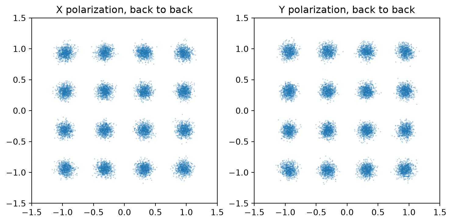
The back-to-back constellations are clean, with an error vector magnitude (EVM) of about 9 % and no bit errors. The noise of the TIAs and the quantization of the converters set most of the EVM.
The 80 km link
Section titled “The 80 km link”The cell below sweeps the launch power from to dBm for both front ends. The OSNR then goes from about 19 to 35 dB. Each point is a new circuit with a new realization of the PMD. It also has new seeds for the noise of the lasers, the amplifiers and the photodiodes.
launches = [ -18.0, -16.0, -14.0, -12.0, -10.0, -8.0, -4.0, -2.0,] # Launch powers into the fiber (dBm)results = {}for front in fronts: rows = [] for k, launch in enumerate(launches): # Simulate the link at this launch power, with seed k for every random process ber, res, _ = simulate(front, seed=k, launch_dbm=launch) rows.append((osnr_db(launch), ber, res)) print( f"front end {front}, launch {launch:+5.1f} dBm: OSNR {osnr_db(launch):5.1f} dB, BER {ber:.2e}, " f"EVM X {100 * res['X']['evm']:.1f} % Y {100 * res['Y']['evm']:.1f} %" ) results[front] = rowsfront end A, launch -18.0 dBm: OSNR 19.0 dB, BER 1.06e-01, EVM X 39.4 % Y 45.4 %front end A, launch -16.0 dBm: OSNR 21.0 dB, BER 6.04e-02, EVM X 30.0 % Y 33.8 %front end A, launch -14.0 dBm: OSNR 23.0 dB, BER 2.92e-02, EVM X 24.1 % Y 26.5 %front end A, launch -12.0 dBm: OSNR 25.0 dB, BER 1.29e-02, EVM X 20.0 % Y 21.8 %front end A, launch -10.0 dBm: OSNR 27.0 dB, BER 3.74e-03, EVM X 16.3 % Y 18.4 %front end A, launch -8.0 dBm: OSNR 29.0 dB, BER 9.50e-04, EVM X 14.1 % Y 15.3 %front end A, launch -4.0 dBm: OSNR 33.1 dB, BER 5.52e-05, EVM X 11.8 % Y 12.3 %front end A, launch -2.0 dBm: OSNR 35.2 dB, BER 1.10e-05, EVM X 11.5 % Y 10.9 %front end B, launch -18.0 dBm: OSNR 19.0 dB, BER 1.02e-01, EVM X 38.5 % Y 43.1 %front end B, launch -16.0 dBm: OSNR 21.0 dB, BER 5.78e-02, EVM X 29.5 % Y 33.2 %front end B, launch -14.0 dBm: OSNR 23.0 dB, BER 2.68e-02, EVM X 23.6 % Y 26.0 %front end B, launch -12.0 dBm: OSNR 25.0 dB, BER 1.07e-02, EVM X 19.4 % Y 21.1 %front end B, launch -10.0 dBm: OSNR 27.0 dB, BER 2.68e-03, EVM X 15.8 % Y 17.4 %front end B, launch -8.0 dBm: OSNR 29.0 dB, BER 4.53e-04, EVM X 13.2 % Y 14.4 %front end B, launch -4.0 dBm: OSNR 33.1 dB, BER 0.00e+00, EVM X 10.3 % Y 11.1 %front end B, launch -2.0 dBm: OSNR 35.2 dB, BER 0.00e+00, EVM X 9.5 % Y 10.1 %BER against OSNR
Section titled “BER against OSNR”The cell below plots both front ends against the theory curve of the technology page. It also finds the OSNR that each front end needs at the FEC threshold, , and at . It interpolates BER between the simulated points.
osnr_axis = np.linspace(18, 38, 200)  # OSNR axis of the theory curve (dB)ber_theory = ber_16qam(10 ** (osnr_axis / 10) * b_ref / baud)
fig, ax = plt.subplots(1, 1, figsize=(6.5, 4.5))ax.semilogy(osnr_axis, ber_theory, "k-", label="theory")labels = {"A": "47 GHz front end", "B": "80 GHz front end"}for front, rows in results.items():    osnr = np.array([r[0] for r in rows])    ber = np.array([max(r[1], 1e-6) for r in rows])    ax.semilogy(osnr, ber, "o-", label=labels[front])    # Interpolate log BER on the points with errors, for each target BER    nonzero = np.array([r[1] for r in rows]) > 0    for target in (ber_fec, 1e-3):        need = np.interp(-np.log10(target), -np.log10(ber[nonzero]), osnr[nonzero])        print(f"{labels[front]}: required OSNR {need:.1f} dB at BER {target:.0e}")# Required OSNR of the theory curvefor target in (ber_fec, 1e-3):    snr_req = brentq(lambda s: ber_16qam(s) - target, 1, 1e4)    print(        f"theory: required OSNR {10 * np.log10(snr_req * baud / b_ref):.1f} dB at BER {target:.0e}"    )ax.axhline(ber_fec, color="0.5", ls="--", lw=1)ax.set_xlabel("OSNR in 0.1 nm (dB)")ax.set_ylabel("BER")ax.set_ylim(1e-5, 0.5)ax.legend()plt.show()
47 GHz front end: required OSNR 23.9 dB at BER 2e-0247 GHz front end: required OSNR 28.9 dB at BER 1e-0380 GHz front end: required OSNR 23.6 dB at BER 2e-0280 GHz front end: required OSNR 28.1 dB at BER 1e-03theory: required OSNR 22.5 dB at BER 2e-02theory: required OSNR 26.4 dB at BER 1e-03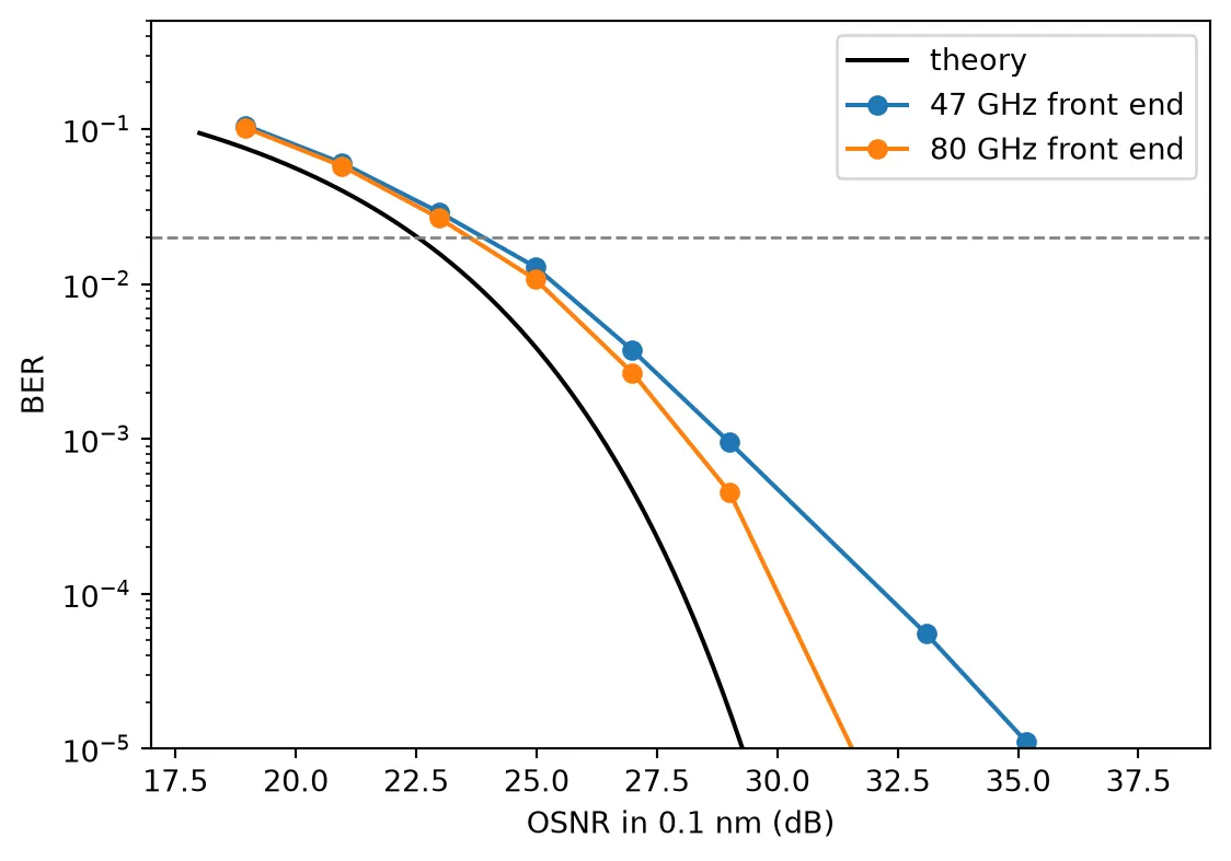
# Constellations at the OSNR closest to the FEC threshold, for both front endsfig, ax = plt.subplots(1, 2, figsize=(9, 4.5))for a, (front, rows) in zip(ax, results.items()): osnr, ber, res = min( rows, key=lambda r: abs(np.log10(max(r[1], 1e-9)) - np.log10(ber_fec)) ) o = res["X"]["symbols"] a.plot(o.real, o.imag, ".", ms=1, alpha=0.2) a.set_aspect("equal") a.set_xlim(-1.5, 1.5) a.set_ylim(-1.5, 1.5) a.set_title(f"{labels[front]}\nOSNR {osnr:.1f} dB, BER {ber:.1e}")plt.show()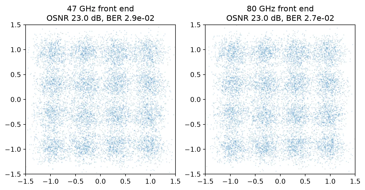
At the FEC threshold the two front ends need 1.1 to 1.4 dB more OSNR than the theory curve. The 80 GHz front end gains only 0.3 dB over the 47 GHz front end. At the gap grows to 1.7 and 2.5 dB. There the link has OSNR to spare, and the residual intersymbol interference of the narrower front end matters more. An 800G link of this kind runs at the FEC threshold, so the 47 GHz front end of the receiver page stays.
The remaining penalty comes from the chips and the converters together:
- the quantization of the 8-bit DAC and ADC
- the TIA noise
- the phase noise that the carrier recovery leaves
- the imbalance of the hybrids
From an OSNR of 33 dB the 80 GHz front end makes no error in about 99,000 bits.
Summary
Section titled “Summary”| Quantity | Value |
|---|---|
| Line rate | 960 Gb/s, DP-16QAM at 120 GBd |
| Transmitter | LNOI400, 10 mm T-rail modulators, 2.95 V, EO bandwidth 101 GHz |
| Receiver | SOI, SWG edge coupler, Sacher PSR, MMI hybrid, Ge photodiode, 47 GHz front end |
| Channel | 80 km SMF, 1 ps PMD, EDFA with a 5 dB noise figure |
| Required OSNR at | 23.9 dB (47 GHz), 23.6 dB (80 GHz), theory 22.5 dB |
| Required OSNR at | 28.9 dB (47 GHz), 28.1 dB (80 GHz), theory 26.4 dB |