Time-Domain Simulation of a Mach–Zehnder Modulator
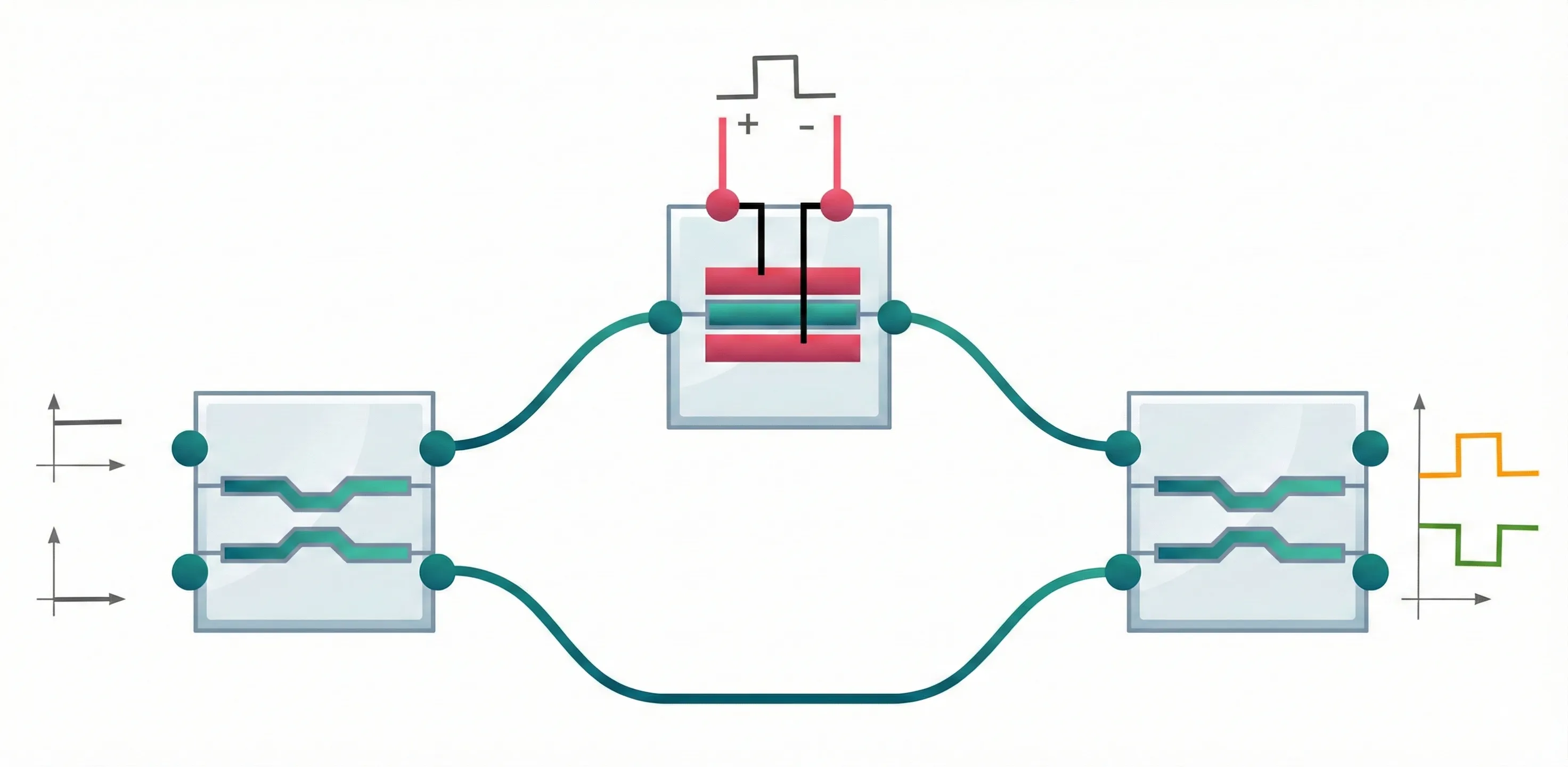
Mach–Zehnder modulators (MZMs) are a core building block of high-speed optical transmitters. They modulate a continuous-wave (CW) optical carrier by splitting light into two arms, applying a voltage-controlled phase shift in one (or both) arms, and recombining the fields in an output coupler.
In this example, we build a compact, time-domain MZM testbench using PhotonForge:
- Couplers:
pfa.directional_coupler()(frequency-domain S-parameters internally converted to time domain during simulation) - Phase shifter:
AnalyticWaveguideModel+PhaseModTimeStepper(length-aware phase modulation, optional voltage-dependent loss, optional RC bandwidth) - Electrical drive:
pfa.signal_source()generating an NRZ PRBS waveform - Optical excitation:
pfa.cw_laser()(no detuning; laser frequency equals the carrier)
import numpy as npimport photonforge as pfimport photonforge.abstract as pfafrom matplotlib import pyplot as pltfrom photonforge.live_viewer import LiveViewer
viewer = LiveViewer()
# Set the default technologypf.config.default_technology = pf.basic_technology()
LiveViewer started at http://127.0.0.1:41237. Call its 'stop()' method to free the port.Silicon PN-depletion MZM parameters
Section titled “Silicon PN-depletion MZM parameters”We choose a set of typical starting parameters for a lumped PN-depletion phase shifter in silicon.
Note (lumped vs. travelling-wave EO drive):
This tutorial usesPhaseModTimeStepper, which models a lumped electro-optic phase modulator: the electrical drive is applied uniformly along the device and the travelling RF wave / transmission-line effects are neglected (no distributed RF propagation, reflections, or velocity mismatch).To include a travelling-wave electrode model with a terminated transmission line, use TerminatedModTimeStepper.
Phase modulation figure of merit
PhaseModTimeStepper uses the standard length-aware phase law:
- : phase shifter length
- : efficiency in units of V·length (here V·μm)
- The corresponding half-wave voltage is
For an MZM biased near quadrature (maximum slope), a common choice is:
Loss and bandwidth knobs
This example also includes:
- Propagation loss specified in dB/μm.
- Optional voltage-dependent loss (linear coefficient).
- A simple RC-limited electrical bandwidth model via a first-order low-pass filter with time constant .
# Optical carrier (1550 nm)lambda0 = 1.55f_c = pf.C_0 / lambda0
# NRZ bit-rate (Hz)bit_rate = 25e9
# Electrical port impedance used by PhaseModTimeStepper to convert field -> voltsZ0 = 50.0  # ohm
# Phase shifter (silicon PN depletion) parameterslength_um = 500.0  # 0.5 mmn_eff = 2.4n_group = 4.0
# V_piL in V·um (high pergood depletion modulators ~ 1 V·cm => 10000 V·um)v_piL = 10000.0  # 1 V·cm
# Loss (dB/um). Example: 15 dB/cm => 15 * 1e-4 dB/umpropagation_loss = 15.0e-4  # dB/um
# Voltage-dependent loss (small; dB/um/V)dloss_dv = 0.5e-4  # 0.5 dB/cm/V
# RC-limited electrical bandwidth (Hz)f_rc = 20e9
Quadrature bias point
Section titled “Quadrature bias point”The MZM output depends on the differential phase between the two arms. For the arm that contains the phase shifter, the total optical phase at the carrier wavelength can be written as
Quadrature operation corresponds to a differential phase of
where the integer accounts for the fact that phase is defined modulo for intensity transfer. Solving for gives
In code, we pick to shift the target phase close to (so the resulting bias voltage is in a practical range):
# Bias / drive voltages (NRZ levels)m = int(2 * n_eff * length_um / lambda0)phi0 = 2 * np.pi * n_eff * length_um / lambda0V_bias = (v_piL / (np.pi * length_um)) * ((np.pi / 2 + m * np.pi) - phi0)
V_pp = 2.0  # volts, peak-to-peak between NRZ levelsV_low = V_bias - V_pp / 2V_high = V_bias + V_pp / 2
(V_bias, V_low, V_high)
(2.2580645161361805, 1.2580645161361805, 3.2580645161361805)Directional couplers
Section titled “Directional couplers”We model the MZM input/output splitters using pfa.directional_coupler(). This creates a 4-port optical component (ports P0–P3) with built-in default S-parameters.
During a time-domain simulation, PhotonForge automatically converts frequency-domain components into an equivalent time-domain representation (internally using a poles-and-residues fit over the provided frequency grid). This lets us freely combine:
- compact time-domain models (the EO phase shifter), and
- frequency-domain S-matrix models (the couplers)
in a single circuit simulation.
directional_coupler = pfa.directional_coupler()viewer(directional_coupler)
Electro-optic phase shifter
Section titled “Electro-optic phase shifter”We now build the active device in the MZM arm: a two-port optical phase shifter with a single electrical drive port, created in one line with pfa.phase_modulator.
Phase and voltage conventions
The phase modulation law is:
In the time-domain circuit, the electrical input is represented as a (generally complex) wave amplitude . The modulator converts this to a physical voltage using the port impedance:
In this tutorial we explicitly set z0 = 50 Ω so the mapping from waveform amplitude to volts is unambiguous.
phase_shifter = pfa.phase_modulator( n_eff=n_eff, n_group=n_group, length=length_um, v_piL=v_piL, z0=Z0, propagation_loss=propagation_loss, dloss_dv=dloss_dv, f_3dB=f_rc,)viewer(phase_shifter)
NRZ PRBS electrical drive
Section titled “NRZ PRBS electrical drive”To drive the PN-depletion phase shifter, we create an electrical source component using pfa.signal_source(). It exposes a single electrical port E0.
NRZ PRBS waveform
We use:
waveform="trapezoid"to approximate an NRZ waveform with finite rise/fall time.prbs=7to generate a pseudorandom bit sequence.
For this waveform type, the generated values range from offset to offset + amplitude.
Mapping “desired volts” to signal_source amplitude
The PhaseModTimeStepper consumes an electrical wave amplitude and converts it to voltage via:
So if we want NRZ levels and , we choose:
This is exactly what the next cell implements (with ).
nrz_source = pfa.signal_source( frequency=bit_rate, amplitude=(V_high - V_low) / (Z0**0.5), offset=V_low / (Z0**0.5), waveform="trapezoid", width=1, rise=0.1, fall=0.1, prbs=7, seed=123,)viewer(nrz_source)
Optical excitation (CW laser)
Section titled “Optical excitation (CW laser)”The time-domain solver operates on complex envelopes referenced to a carrier frequency. We excite the modulator with an ideal CW laser using pfa.cw_laser(), which returns a single-port optical component (port P0).
- No detuning: The laser frequency is automatically set to the carrier
f_c. - The second input of the first coupler is intentionally kept dark by connecting a 0 W CW laser (
pfa.cw_laser(power=0.0)), which provides a well-defined boundary condition without injecting light.
This mirrors typical transmitter operation where a single laser feeds one input of the MZM.
# CW laser source (no detuning: frequency = f_c)laser = pfa.cw_laser(power=1e-3)
# Dark termination for the unused optical inputlaser_dark = pfa.cw_laser(power=0.0)
viewer(laser)
MZM-circuit assembly
Section titled “MZM-circuit assembly”To make the example easy to reproduce and publish, we assemble the full testbench using a single netlist dictionary and component_from_netlist.
What goes into the netlist
The netlist declares:
- instances: the building blocks (couplers, phase shifter, electrical driver, laser, dark termination)
- connections / virtual connections: how their ports are wired together
- ports: which ports are exposed as the top-level interface
- models: a
CircuitModelthat enables circuit-level simulation
External interface
Because both the lasers and the NRZ driver are included as internal sources, the top-level component exposes only the two optical output ports. This is convenient for time-domain simulation: we can run ts.step(...) without providing any explicit input TimeSeries.
# Assemble whole circuit via netlistnetlist = {    "name": "MZM_PhaseModTimeStepper_Testbench",    "instances": {        "in_dc": {"component": directional_coupler, "origin": (0, 0)},        "out_dc": {"component": directional_coupler, "origin": (11, 0)},        "ps": {"component": phase_shifter, "origin": (9, 1)},        "drv": {"component": nrz_source, "origin": (9, -1.2)},        "laser": {"component": laser, "origin": (-2.5, 0.8)},        "dark": {"component": laser_dark, "origin": (-2.5, -0.8)},    },    "connections": [        # Optical inputs        (("laser", "P0"), ("in_dc", "P1")),        (("dark", "P0"), ("in_dc", "P0")),        # MZM arms        (("ps", "P0"), ("in_dc", "P3")),        (("out_dc", "P1"), ("ps", "P1")),        # Electrical drive        (("drv", "E0"), ("ps", "E0")),    ],    "virtual connections": [        (("in_dc", "P2"), ("out_dc", "P0")),    ],    # Expose only optical outputs for now    "ports": [("out_dc", "P2"), ("out_dc", "P3")],    "models": [(pf.CircuitModel(), "Circuit")],}
mzm_tb = pf.component_from_netlist(netlist)viewer(mzm_tb);fill:%23221f20;font-weight:bold;font-size:1.142400px;}.terminal{fill:none;stroke:%23805080;stroke-width:0.142800;}.dashed{stroke-dasharray:0.714000,0.428400;}.port{fill:none;stroke:%23805080;stroke-width:0.285600;}.virtual-connection{fill:none;stroke:%23907090;stroke-width:0.214200;}.layer_5_0{stroke:%23998573;fill:url(%23pat-layer_5_0);fill-opacity:0.492;}.label_5_0{fill:%23998573;}.layer_3_0{stroke:%238851ad;fill:url(%23pat-layer_3_0);fill-opacity:0.492;}.label_3_0{fill:%238851ad;}.layer_4_0{stroke:%23535e59;fill:url(%23pat-layer_4_0);fill-opacity:0.492;}.label_4_0{fill:%23535e59;}.layer_1_0{stroke:%23858d89;fill:url(%23pat-layer_1_0);fill-opacity:0.492;}.label_1_0{fill:%23858d89;}.layer_2_0{stroke:%235b98b9;fill:url(%23pat-layer_2_0);fill-opacity:0.492;}.label_2_0{fill:%235b98b9;}</style><defs><path id=%22port-symbol%22 class=%22port%22 d=%22M 0,-0.571200 L 0.856800,0 0,0.571200%22 /><path id=%22ref-port-symbol%22 class=%22port%22 style=%22stroke-opacity:0.33;%22 d=%22M 0,-0.428400 C 0.571200,-0.428400 0.571200,0.428400 0,0.428400%22 /><circle id=%22port-bend-symbol%22 style=%22stroke-width:0;stroke:none;fill:%23805080;fill-opacity:1;%22 cx=%220%22 cy=%220%22 r=%220.257040%22 /><circle id=%22connection-symbol%22 style=%22stroke-width:0;stroke:none;fill:%23907090;fill-opacity:1;%22 cx=%220%22 cy=%220%22 r=%220.299880%22 /><pattern id=%22pat-layer_5_0%22 patternUnits=%22userSpaceOnUse%22 width=%220.714000%22 height=%220.714000%22 patternTransform=%22translate(0.042000,0.638842)%22><line x1=%220.714000%22 y1=%220%22 x2=%220%22 y2=%220.714000%22 style=%22stroke:%23998573;stroke-width:0.071400%22 /><line x1=%221.071000%22 y1=%220.357000%22 x2=%220.357000%22 y2=%221.071000%22 style=%22stroke:%23998573;stroke-width:0.071400%22 /><line x1=%220.357000%22 y1=%22-0.357000%22 x2=%22-0.357000%22 y2=%220.357000%22 style=%22stroke:%23998573;stroke-width:0.071400%22 /></pattern><pattern id=%22pat-layer_3_0%22 patternUnits=%22userSpaceOnUse%22 width=%220.428400%22 height=%220.428400%22 patternTransform=%22translate(0.100800,0.315663)%22><circle cx=%220.214200%22 cy=%220.214200%22 r=%220.071400%22 style=%22stroke:none;fill:%238851ad;fill-opacity:1.0%22 /></pattern><pattern id=%22pat-layer_4_0%22 patternUnits=%22userSpaceOnUse%22 width=%220.714000%22 height=%220.714000%22 patternTransform=%22translate(0.462000,0.225474)%22><line x1=%220.357000%22 y1=%220%22 x2=%220.357000%22 y2=%220.714000%22 style=%22stroke:%23535e59;stroke-width:0.071400%22 /><line x1=%220%22 y1=%220.357000%22 x2=%220.714000%22 y2=%220.357000%22 style=%22stroke:%23535e59;stroke-width:0.071400%22 /></pattern><pattern id=%22pat-layer_1_0%22 patternUnits=%22userSpaceOnUse%22 width=%220.714000%22 height=%220.714000%22 patternTransform=%22translate(0.294000,0.413368)%22><circle cx=%220.357000%22 cy=%220.357000%22 r=%220.071400%22 style=%22stroke:none;fill:%23858d89;fill-opacity:1.0%22 /></pattern><pattern id=%22pat-layer_2_0%22 patternUnits=%22userSpaceOnUse%22 width=%220.714000%22 height=%220.714000%22 patternTransform=%22translate(0.588000,0.112737)%22><line x1=%220%22 y1=%220%22 x2=%220.714000%22 y2=%220.714000%22 style=%22stroke:%235b98b9;stroke-width:0.071400%22 /><line x1=%22-0.357000%22 y1=%220.357000%22 x2=%220.357000%22 y2=%221.071000%22 style=%22stroke:%235b98b9;stroke-width:0.071400%22 /><line x1=%220.357000%22 y1=%22-0.357000%22 x2=%221.071000%22 y2=%220.357000%22 style=%22stroke:%235b98b9;stroke-width:0.071400%22 /></pattern><g id=%22C1%22 data-name=%22Directional Coupler%22><path class=%22layer_0_32767%22 d=%22M 0.000000,9.600000 0.000000,7.715000 0.000000,7.465000 0.000000,4.935000 0.000000,4.685000 0.000000,0.000000 11.120000,0.000000 11.120000,4.685000 11.120000,4.935000 11.120000,7.465000 11.120000,7.715000 11.120000,9.600000 z M 11.000000,7.715000 9.520000,7.715000 9.520000,8.000000 6.820000,8.000000 6.180000,7.350000 4.980000,7.350000 4.320000,8.000000 1.620000,8.000000 1.620000,7.715000 0.120000,7.715000 0.120000,9.480000 11.000000,9.480000 z M 11.000000,4.935000 9.520000,4.935000 9.520000,5.220000 7.180000,5.220000 6.520000,5.880000 4.620000,5.880000 3.980000,5.220000 1.600000,5.220000 1.600000,4.935000 0.120000,4.935000 0.120000,7.465000 1.620000,7.465000 1.620000,7.180000 3.980000,7.180000 4.620000,6.520000 6.520000,6.520000 7.180000,7.180000 9.520000,7.180000 9.520000,7.465000 11.000000,7.465000 z M 11.000000,0.120000 0.120000,0.120000 0.120000,4.685000 1.600000,4.685000 1.600000,4.420000 1.620000,4.400000 4.320000,4.400000 5.000000,5.080000 6.150000,5.080000 6.820000,4.400000 9.520000,4.400000 9.520000,4.685000 11.000000,4.685000 z%22 /><path class=%22layer_0_32767%22 d=%22M 1.612000,2.205000 1.132000,2.205000 1.132000,1.165000 1.612000,1.165000 1.812000,1.365000 1.812000,2.005000 z M 1.652000,1.445000 1.532000,1.325000 1.292000,1.325000 1.292000,2.045000 1.532000,2.045000 1.652000,1.925000 z%22 /><path class=%22layer_0_32767%22 d=%22M 2.036000,1.725000 2.036000,1.165000 2.196000,1.165000 2.196000,1.725000 z%22 /><path class=%22layer_0_32767%22 d=%22M 2.036000,2.045000 2.036000,1.885000 2.196000,1.885000 2.196000,2.045000 z%22 /><path class=%22layer_0_32767%22 d=%22M 3.060000,1.645000 3.060000,1.746000 2.921000,1.885000 2.641000,1.885000 2.580000,1.826000 2.521000,1.885000 2.420000,1.885000 2.420000,1.165000 2.580000,1.165000 2.580000,1.645000 2.660000,1.725000 2.820000,1.725000 2.900000,1.645000 z%22 /><path class=%22layer_0_32767%22 d=%22M 3.284000,1.325000 3.284000,1.165000 3.444000,1.165000 3.444000,1.325000 z%22 /><path class=%22layer_0_32767%22 d=%22M 5.204000,1.426000 5.065000,1.426000 4.964000,1.325000 4.804000,1.325000 4.724000,1.405000 4.724000,1.645000 4.804000,1.725000 4.964000,1.725000 5.065000,1.626000 5.204000,1.626000 5.204000,1.706000 5.025000,1.885000 4.745000,1.885000 4.564000,1.706000 4.564000,1.346000 4.745000,1.165000 5.025000,1.165000 5.204000,1.346000 z%22 /><path class=%22layer_0_32767%22 d=%22M 5.889000,1.885000 5.609000,1.885000 5.428000,1.706000 5.428000,1.346000 5.609000,1.165000 5.889000,1.165000 6.068000,1.346000 6.068000,1.706000 z M 5.908000,1.405000 5.828000,1.325000 5.668000,1.325000 5.588000,1.405000 5.588000,1.645000 5.668000,1.725000 5.828000,1.725000 5.908000,1.645000 z%22 /><path class=%22layer_0_32767%22 d=%22M 6.852000,1.165000 6.852000,1.885000 6.692000,1.885000 6.692000,1.405000 6.612000,1.325000 6.532000,1.325000 6.452000,1.405000 6.452000,1.885000 6.292000,1.885000 6.292000,1.346000 6.473000,1.165000 6.633000,1.165000 6.692000,1.226000 6.753000,1.165000 z%22 /><path class=%22layer_0_32767%22 d=%22M 7.537000,1.885000 7.076000,1.885000 7.076000,0.845000 7.236000,0.845000 7.236000,1.165000 7.537000,1.165000 7.716000,1.346000 7.716000,1.706000 z M 7.556000,1.405000 7.476000,1.325000 7.236000,1.325000 7.236000,1.725000 7.476000,1.725000 7.556000,1.645000 z%22 /><path class=%22layer_0_32767%22 d=%22M 8.260000,1.325000 8.100000,1.325000 8.100000,2.205000 7.940000,2.205000 7.940000,1.285000 8.060000,1.165000 8.260000,1.165000 z%22 /><path class=%22layer_0_32767%22 d=%22M 9.004000,1.885000 8.604000,1.885000 8.484000,1.765000 8.484000,1.285000 8.604000,1.165000 9.084000,1.165000 9.084000,1.325000 8.644000,1.325000 8.644000,1.445000 9.004000,1.445000 9.124000,1.565000 9.124000,1.765000 z M 8.964000,1.605000 8.644000,1.605000 8.644000,1.725000 8.964000,1.725000 z%22 /><path class=%22layer_0_32767%22 d=%22M 9.988000,1.645000 9.988000,1.746000 9.849000,1.885000 9.569000,1.885000 9.508000,1.826000 9.449000,1.885000 9.348000,1.885000 9.348000,1.165000 9.508000,1.165000 9.508000,1.645000 9.588000,1.725000 9.748000,1.725000 9.828000,1.645000 z%22 /></g><g id=%22C2%22 data-name=%22Phase Modulator%22><path class=%22layer_0_32767%22 d=%22M 5.165000,10.180000 4.915000,10.180000 0.000000,10.180000 0.000000,6.645000 0.000000,6.395000 0.000000,0.000000 10.060000,0.000000 10.060000,6.395000 10.060000,6.645000 10.060000,10.180000 z M 9.940000,6.645000 8.460000,6.645000 8.460000,7.180000 6.080000,7.180000 6.060000,7.200000 6.080000,7.400000 8.460000,7.400000 8.460000,8.580000 5.165000,8.580000 5.165000,10.060000 9.940000,10.060000 z M 6.130000,6.230000 6.080000,6.180000 5.980000,6.280000 5.880000,6.180000 5.830000,6.230000 5.830000,6.800000 5.880000,6.860000 5.980000,6.760000 6.080000,6.860000 6.130000,6.800000 z M 6.130000,7.560000 6.080000,7.500000 5.980000,7.600000 5.880000,7.500000 5.830000,7.560000 5.830000,8.430000 5.880000,8.480000 5.980000,8.380000 6.080000,8.480000 6.130000,8.430000 z M 5.860000,7.180000 1.600000,7.180000 1.600000,6.645000 0.120000,6.645000 0.120000,10.060000 4.915000,10.060000 4.915000,8.580000 1.600000,8.580000 1.600000,7.400000 5.860000,7.400000 5.880000,7.380000 z M 4.230000,8.280000 4.180000,8.230000 3.980000,8.230000 3.930000,8.280000 3.930000,8.430000 3.980000,8.480000 4.080000,8.380000 4.180000,8.480000 4.230000,8.430000 z M 9.940000,0.120000 0.120000,0.120000 0.120000,6.395000 1.600000,6.395000 1.600000,5.860000 5.860000,5.860000 5.880000,5.830000 5.860000,5.630000 1.600000,5.630000 1.600000,4.400000 8.460000,4.400000 8.460000,5.630000 6.080000,5.630000 6.060000,5.660000 6.080000,5.860000 8.460000,5.860000 8.460000,6.395000 9.940000,6.395000 z M 6.130000,5.230000 6.080000,5.180000 5.880000,5.180000 5.830000,5.230000 5.830000,5.480000 5.880000,5.530000 5.980000,5.430000 6.080000,5.530000 6.130000,5.480000 z%22 /><path class=%22layer_0_32767%22 d=%22M 1.467000,2.045000 0.926000,2.045000 0.926000,1.005000 1.086000,1.005000 1.086000,1.405000 1.467000,1.405000 1.646000,1.586000 1.646000,1.866000 z M 1.486000,1.645000 1.406000,1.565000 1.086000,1.565000 1.086000,1.885000 1.406000,1.885000 1.486000,1.805000 z%22 /><path class=%22layer_0_32767%22 d=%22M 2.510000,1.005000 2.510000,1.426000 2.331000,1.605000 2.030000,1.605000 2.030000,2.045000 1.870000,2.045000 1.870000,1.005000 2.030000,1.005000 2.030000,1.445000 2.270000,1.445000 2.350000,1.365000 2.350000,1.005000 z%22 /><path class=%22layer_0_32767%22 d=%22M 3.294000,1.725000 2.814000,1.725000 2.734000,1.645000 2.734000,1.565000 3.214000,1.565000 3.214000,1.445000 2.854000,1.445000 2.734000,1.325000 2.734000,1.125000 2.854000,1.005000 3.374000,1.005000 3.374000,1.645000 z M 3.214000,1.165000 2.894000,1.165000 2.894000,1.285000 3.214000,1.285000 z%22 /><path class=%22layer_0_32767%22 d=%22M 3.678000,1.005000 4.118000,1.005000 4.238000,1.125000 4.238000,1.325000 4.118000,1.445000 3.758000,1.445000 3.758000,1.565000 4.238000,1.565000 4.238000,1.645000 4.158000,1.725000 3.678000,1.725000 3.598000,1.645000 3.598000,1.405000 3.718000,1.285000 4.078000,1.285000 4.078000,1.165000 3.598000,1.165000 3.598000,1.085000 z%22 /><path class=%22layer_0_32767%22 d=%22M 4.982000,1.725000 4.582000,1.725000 4.462000,1.605000 4.462000,1.125000 4.582000,1.005000 5.062000,1.005000 5.062000,1.165000 4.622000,1.165000 4.622000,1.285000 4.982000,1.285000 5.102000,1.405000 5.102000,1.605000 z M 4.942000,1.445000 4.622000,1.445000 4.622000,1.565000 4.942000,1.565000 z%22 /><path class=%22layer_0_32767%22 d=%22M 6.222000,1.725000 6.222000,1.005000 6.382000,1.005000 6.382000,1.485000 6.462000,1.565000 6.542000,1.485000 6.542000,1.005000 6.702000,1.005000 6.702000,1.485000 6.782000,1.565000 6.862000,1.485000 6.862000,1.005000 7.022000,1.005000 7.022000,1.546000 6.843000,1.725000 6.723000,1.725000 6.622000,1.626000 6.523000,1.725000 z%22 /><path class=%22layer_0_32767%22 d=%22M 7.707000,1.725000 7.427000,1.725000 7.246000,1.546000 7.246000,1.186000 7.427000,1.005000 7.707000,1.005000 7.886000,1.186000 7.886000,1.546000 z M 7.726000,1.245000 7.646000,1.165000 7.486000,1.165000 7.406000,1.245000 7.406000,1.485000 7.486000,1.565000 7.646000,1.565000 7.726000,1.485000 z%22 /><path class=%22layer_0_32767%22 d=%22M 8.590000,2.045000 8.590000,1.685000 8.291000,1.685000 8.110000,1.506000 8.110000,1.186000 8.291000,1.005000 8.750000,1.005000 8.750000,2.045000 z M 8.590000,1.165000 8.350000,1.165000 8.270000,1.245000 8.270000,1.445000 8.350000,1.525000 8.590000,1.525000 z%22 /><path class=%22layer_0_32767%22 d=%22M 8.974000,1.165000 8.974000,1.005000 9.134000,1.005000 9.134000,1.165000 z%22 /></g><g id=%22C3%22 data-name=%22Source%22><path class=%22layer_0_32767%22 d=%22M 0.000000,9.700000 0.000000,0.000000 11.640000,0.000000 11.640000,6.125000 11.640000,6.375000 11.640000,9.700000 z M 11.520000,6.375000 5.880000,6.375000 5.880000,8.100000 3.650000,8.100000 3.620000,8.080000 3.620000,4.820000 3.600000,4.800000 1.720000,4.800000 1.720000,4.420000 3.620000,4.420000 3.650000,4.400000 4.020000,4.420000 4.020000,7.700000 4.050000,7.720000 5.450000,7.720000 5.500000,7.680000 5.500000,4.800000 5.480000,4.780000 5.500000,4.400000 5.850000,4.400000 5.880000,4.420000 9.920000,4.420000 9.920000,4.800000 5.900000,4.800000 5.880000,4.820000 5.880000,6.125000 11.520000,6.125000 11.520000,0.120000 0.120000,0.120000 0.120000,9.580000 11.520000,9.580000 z%22 /><path class=%22layer_0_32767%22 d=%22M 1.460000,2.026000 1.281000,2.205000 0.921000,2.205000 0.740000,2.026000 0.740000,1.805000 0.940000,1.605000 1.220000,1.605000 1.300000,1.525000 1.300000,1.405000 1.220000,1.325000 0.980000,1.325000 0.881000,1.426000 0.740000,1.426000 0.740000,1.346000 0.921000,1.165000 1.281000,1.165000 1.460000,1.346000 1.460000,1.565000 1.260000,1.765000 0.980000,1.765000 0.900000,1.845000 0.900000,1.965000 0.980000,2.045000 1.220000,2.045000 1.321000,1.946000 1.460000,1.946000 z%22 /><path class=%22layer_0_32767%22 d=%22M 1.684000,1.725000 1.684000,1.165000 1.844000,1.165000 1.844000,1.725000 z%22 /><path class=%22layer_0_32767%22 d=%22M 1.684000,2.045000 1.684000,1.885000 1.844000,1.885000 1.844000,2.045000 z%22 /><path class=%22layer_0_32767%22 d=%22M 2.249000,1.885000 2.068000,1.706000 2.068000,1.346000 2.249000,1.165000 2.548000,1.165000 2.548000,1.005000 2.228000,1.005000 2.228000,0.845000 2.588000,0.845000 2.708000,0.965000 2.708000,1.885000 z M 2.548000,1.325000 2.308000,1.325000 2.228000,1.405000 2.228000,1.645000 2.308000,1.725000 2.548000,1.725000 z%22 /><path class=%22layer_0_32767%22 d=%22M 2.932000,1.885000 2.932000,1.165000 3.092000,1.165000 3.092000,1.645000 3.172000,1.725000 3.252000,1.725000 3.332000,1.645000 3.332000,1.165000 3.492000,1.165000 3.492000,1.706000 3.313000,1.885000 3.153000,1.885000 3.092000,1.826000 3.033000,1.885000 z%22 /><path class=%22layer_0_32767%22 d=%22M 4.276000,1.885000 3.796000,1.885000 3.716000,1.805000 3.716000,1.725000 4.196000,1.725000 4.196000,1.605000 3.836000,1.605000 3.716000,1.485000 3.716000,1.285000 3.836000,1.165000 4.356000,1.165000 4.356000,1.805000 z M 4.196000,1.325000 3.876000,1.325000 3.876000,1.445000 4.196000,1.445000 z%22 /><path class=%22layer_0_32767%22 d=%22M 4.900000,1.325000 4.740000,1.325000 4.740000,2.205000 4.580000,2.205000 4.580000,1.285000 4.700000,1.165000 4.900000,1.165000 z%22 /><path class=%22layer_0_32767%22 d=%22M 6.100000,1.165000 6.540000,1.165000 6.660000,1.285000 6.660000,1.485000 6.540000,1.605000 6.180000,1.605000 6.180000,1.725000 6.660000,1.725000 6.660000,1.805000 6.580000,1.885000 6.100000,1.885000 6.020000,1.805000 6.020000,1.565000 6.140000,1.445000 6.500000,1.445000 6.500000,1.325000 6.020000,1.325000 6.020000,1.245000 z%22 /><path class=%22layer_0_32767%22 d=%22M 7.345000,1.885000 7.065000,1.885000 6.884000,1.706000 6.884000,1.346000 7.065000,1.165000 7.345000,1.165000 7.524000,1.346000 7.524000,1.706000 z M 7.364000,1.405000 7.284000,1.325000 7.124000,1.325000 7.044000,1.405000 7.044000,1.645000 7.124000,1.725000 7.284000,1.725000 7.364000,1.645000 z%22 /><path class=%22layer_0_32767%22 d=%22M 8.308000,1.165000 8.308000,1.885000 8.148000,1.885000 8.148000,1.405000 8.068000,1.325000 7.988000,1.325000 7.908000,1.405000 7.908000,1.885000 7.748000,1.885000 7.748000,1.346000 7.929000,1.165000 8.089000,1.165000 8.148000,1.226000 8.209000,1.165000 z%22 /><path class=%22layer_0_32767%22 d=%22M 9.172000,1.645000 9.172000,1.746000 9.033000,1.885000 8.753000,1.885000 8.692000,1.826000 8.633000,1.885000 8.532000,1.885000 8.532000,1.165000 8.692000,1.165000 8.692000,1.645000 8.772000,1.725000 8.932000,1.725000 9.012000,1.645000 z%22 /><path class=%22layer_0_32767%22 d=%22M 10.036000,1.426000 9.897000,1.426000 9.796000,1.325000 9.636000,1.325000 9.556000,1.405000 9.556000,1.645000 9.636000,1.725000 9.796000,1.725000 9.897000,1.626000 10.036000,1.626000 10.036000,1.706000 9.857000,1.885000 9.577000,1.885000 9.396000,1.706000 9.396000,1.346000 9.577000,1.165000 9.857000,1.165000 10.036000,1.346000 z%22 /><path class=%22layer_0_32767%22 d=%22M 10.780000,1.885000 10.380000,1.885000 10.260000,1.765000 10.260000,1.285000 10.380000,1.165000 10.860000,1.165000 10.860000,1.325000 10.420000,1.325000 10.420000,1.445000 10.780000,1.445000 10.900000,1.565000 10.900000,1.765000 z M 10.740000,1.605000 10.420000,1.605000 10.420000,1.725000 10.740000,1.725000 z%22 /></g><g id=%22C4%22 data-name=%22CW Laser%22><path class=%22layer_0_32767%22 d=%22M 0.000000,9.600000 0.000000,0.000000 10.500000,0.000000 10.500000,6.075000 10.500000,6.325000 10.500000,9.600000 z M 10.380000,6.325000 8.900000,6.325000 8.900000,8.000000 1.600000,8.000000 1.600000,4.400000 8.900000,4.400000 8.900000,6.075000 10.380000,6.075000 10.380000,0.120000 0.120000,0.120000 0.120000,9.480000 10.380000,9.480000 z M 7.840000,6.100000 7.800000,6.060000 6.920000,6.060000 7.320000,5.660000 7.140000,5.460000 6.740000,5.860000 6.700000,5.830000 6.700000,4.860000 6.640000,4.800000 6.470000,4.800000 6.420000,4.860000 6.420000,5.830000 6.370000,5.860000 5.970000,5.460000 5.770000,5.630000 6.200000,6.060000 1.740000,6.060000 1.700000,6.100000 1.800000,6.200000 1.700000,6.300000 1.740000,6.360000 6.140000,6.360000 5.770000,6.760000 5.970000,6.930000 6.340000,6.560000 6.420000,6.580000 6.420000,7.480000 6.470000,7.530000 6.640000,7.530000 6.700000,7.480000 6.700000,6.580000 6.770000,6.560000 7.140000,6.900000 7.320000,6.730000 6.940000,6.360000 7.800000,6.360000 7.840000,6.300000 z%22 /><path class=%22layer_0_32767%22 d=%22M 2.351000,1.005000 2.570000,1.205000 2.570000,1.365000 2.410000,1.365000 2.410000,1.285000 2.290000,1.165000 2.130000,1.165000 2.010000,1.285000 2.010000,1.765000 2.130000,1.885000 2.290000,1.885000 2.410000,1.765000 2.410000,1.685000 2.570000,1.685000 2.570000,1.845000 2.370000,2.045000 2.050000,2.045000 1.850000,1.845000 1.850000,1.205000 2.050000,1.005000 z%22 /><path class=%22layer_0_32767%22 d=%22M 2.794000,1.005000 2.975000,1.005000 3.274000,1.306000 3.575000,1.005000 3.754000,1.005000 3.754000,2.045000 3.594000,2.045000 3.594000,1.325000 3.514000,1.325000 3.274000,1.565000 3.034000,1.325000 2.954000,1.325000 2.954000,2.045000 2.794000,2.045000 z%22 /><path class=%22layer_0_32767%22 d=%22M 5.194000,1.165000 5.034000,1.165000 5.034000,2.045000 4.874000,2.045000 4.874000,1.125000 4.994000,1.005000 5.194000,1.005000 z%22 /><path class=%22layer_0_32767%22 d=%22M 5.978000,1.725000 5.498000,1.725000 5.418000,1.645000 5.418000,1.565000 5.898000,1.565000 5.898000,1.445000 5.538000,1.445000 5.418000,1.325000 5.418000,1.125000 5.538000,1.005000 6.058000,1.005000 6.058000,1.645000 z M 5.898000,1.165000 5.578000,1.165000 5.578000,1.285000 5.898000,1.285000 z%22 /><path class=%22layer_0_32767%22 d=%22M 6.362000,1.005000 6.802000,1.005000 6.922000,1.125000 6.922000,1.325000 6.802000,1.445000 6.442000,1.445000 6.442000,1.565000 6.922000,1.565000 6.922000,1.645000 6.842000,1.725000 6.362000,1.725000 6.282000,1.645000 6.282000,1.405000 6.402000,1.285000 6.762000,1.285000 6.762000,1.165000 6.282000,1.165000 6.282000,1.085000 z%22 /><path class=%22layer_0_32767%22 d=%22M 7.666000,1.725000 7.266000,1.725000 7.146000,1.605000 7.146000,1.125000 7.266000,1.005000 7.746000,1.005000 7.746000,1.165000 7.306000,1.165000 7.306000,1.285000 7.666000,1.285000 7.786000,1.405000 7.786000,1.605000 z M 7.626000,1.445000 7.306000,1.445000 7.306000,1.565000 7.626000,1.565000 z%22 /><path class=%22layer_0_32767%22 d=%22M 8.650000,1.485000 8.650000,1.586000 8.511000,1.725000 8.231000,1.725000 8.170000,1.666000 8.111000,1.725000 8.010000,1.725000 8.010000,1.005000 8.170000,1.005000 8.170000,1.485000 8.250000,1.565000 8.410000,1.565000 8.490000,1.485000 z%22 /></g><g id=%22C5%22 data-name=%22CW Laser%22><path class=%22layer_0_32767%22 d=%22M 0.000000,9.600000 0.000000,0.000000 10.500000,0.000000 10.500000,6.075000 10.500000,6.325000 10.500000,9.600000 z M 10.380000,6.325000 8.900000,6.325000 8.900000,8.000000 1.600000,8.000000 1.600000,4.400000 8.900000,4.400000 8.900000,6.075000 10.380000,6.075000 10.380000,0.120000 0.120000,0.120000 0.120000,9.480000 10.380000,9.480000 z M 7.840000,6.100000 7.800000,6.060000 6.920000,6.060000 7.320000,5.660000 7.140000,5.460000 6.740000,5.860000 6.700000,5.830000 6.700000,4.860000 6.640000,4.800000 6.470000,4.800000 6.420000,4.860000 6.420000,5.830000 6.370000,5.860000 5.970000,5.460000 5.770000,5.630000 6.200000,6.060000 1.740000,6.060000 1.700000,6.100000 1.800000,6.200000 1.700000,6.300000 1.740000,6.360000 6.140000,6.360000 5.770000,6.760000 5.970000,6.930000 6.340000,6.560000 6.420000,6.580000 6.420000,7.480000 6.470000,7.530000 6.640000,7.530000 6.700000,7.480000 6.700000,6.580000 6.770000,6.560000 7.140000,6.900000 7.320000,6.730000 6.940000,6.360000 7.800000,6.360000 7.840000,6.300000 z%22 /><path class=%22layer_0_32767%22 d=%22M 2.351000,1.005000 2.570000,1.205000 2.570000,1.365000 2.410000,1.365000 2.410000,1.285000 2.290000,1.165000 2.130000,1.165000 2.010000,1.285000 2.010000,1.765000 2.130000,1.885000 2.290000,1.885000 2.410000,1.765000 2.410000,1.685000 2.570000,1.685000 2.570000,1.845000 2.370000,2.045000 2.050000,2.045000 1.850000,1.845000 1.850000,1.205000 2.050000,1.005000 z%22 /><path class=%22layer_0_32767%22 d=%22M 2.794000,1.005000 2.975000,1.005000 3.274000,1.306000 3.575000,1.005000 3.754000,1.005000 3.754000,2.045000 3.594000,2.045000 3.594000,1.325000 3.514000,1.325000 3.274000,1.565000 3.034000,1.325000 2.954000,1.325000 2.954000,2.045000 2.794000,2.045000 z%22 /><path class=%22layer_0_32767%22 d=%22M 5.194000,1.165000 5.034000,1.165000 5.034000,2.045000 4.874000,2.045000 4.874000,1.125000 4.994000,1.005000 5.194000,1.005000 z%22 /><path class=%22layer_0_32767%22 d=%22M 5.978000,1.725000 5.498000,1.725000 5.418000,1.645000 5.418000,1.565000 5.898000,1.565000 5.898000,1.445000 5.538000,1.445000 5.418000,1.325000 5.418000,1.125000 5.538000,1.005000 6.058000,1.005000 6.058000,1.645000 z M 5.898000,1.165000 5.578000,1.165000 5.578000,1.285000 5.898000,1.285000 z%22 /><path class=%22layer_0_32767%22 d=%22M 6.362000,1.005000 6.802000,1.005000 6.922000,1.125000 6.922000,1.325000 6.802000,1.445000 6.442000,1.445000 6.442000,1.565000 6.922000,1.565000 6.922000,1.645000 6.842000,1.725000 6.362000,1.725000 6.282000,1.645000 6.282000,1.405000 6.402000,1.285000 6.762000,1.285000 6.762000,1.165000 6.282000,1.165000 6.282000,1.085000 z%22 /><path class=%22layer_0_32767%22 d=%22M 7.666000,1.725000 7.266000,1.725000 7.146000,1.605000 7.146000,1.125000 7.266000,1.005000 7.746000,1.005000 7.746000,1.165000 7.306000,1.165000 7.306000,1.285000 7.666000,1.285000 7.786000,1.405000 7.786000,1.605000 z M 7.626000,1.445000 7.306000,1.445000 7.306000,1.565000 7.626000,1.565000 z%22 /><path class=%22layer_0_32767%22 d=%22M 8.650000,1.485000 8.650000,1.586000 8.511000,1.725000 8.231000,1.725000 8.170000,1.666000 8.111000,1.725000 8.010000,1.725000 8.010000,1.005000 8.170000,1.005000 8.170000,1.485000 8.250000,1.565000 8.410000,1.565000 8.490000,1.485000 z%22 /></g></defs><g transform=%22scale(1 -1)%22><g id=%22C0%22 data-name=%22MZM_PhaseModTimeStepper_Testbench%22><use transform=%22translate(0.000000 0.000000)%22 href=%22%23C1%22 /><use transform=%22translate(21.180000 0.000000)%22 href=%22%23C1%22 /><use transform=%22translate(11.120000 1.070000)%22 href=%22%23C2%22 /><use transform=%22translate(9.910000 22.890000) rotate(-90.000000)%22 href=%22%23C3%22 /><use transform=%22translate(-10.500000 1.390000)%22 href=%22%23C4%22 /><use transform=%22translate(-10.500000 -1.390000)%22 href=%22%23C5%22 /><g transform=%22translate(32.300000 4.810000) rotate(180.000000)%22><path class=%22port%22 d=%22M 0,-0.500000 V 0.500000%22 /><use href=%22%23port-symbol%22 /></g><text class=%22label%22 text-anchor=%22end%22 dominant-baseline=%22text-before-edge%22 x=%2232.300000%22 y=%22-4.810000%22>P0</text><g transform=%22translate(32.300000 7.590000) rotate(180.000000)%22><path class=%22port%22 d=%22M 0,-0.500000 V 0.500000%22 /><use href=%22%23port-symbol%22 /></g><text class=%22label%22 text-anchor=%22end%22 dominant-baseline=%22text-before-edge%22 x=%2232.300000%22 y=%22-7.590000%22>P1</text><g transform=%22translate(11.120000 4.810000)%22><use href=%22%23connection-symbol%22 /></g><g transform=%22translate(21.180000 4.810000)%22><use href=%22%23connection-symbol%22 /></g><path class=%22virtual-connection%22 d=%22M 11.120000,4.810000 C 12.796667,4.810000 19.503333,4.810000 21.180000,4.810000%22 /></g></g></svg>)
%22><use href=%22%23g-dc%22 transform=%22translate(-30.00 -30.00) scale(1.2)%22/><circle cx=%22-30.00%22 cy=%22-6.54%22 r=%224%22 fill=%22%2300643c%22 stroke=%22%2300643c%22 stroke-width=%221%22/><circle cx=%22-30.00%22 cy=%2210.05%22 r=%224%22 fill=%22%2300643c%22 stroke=%22%2300643c%22 stroke-width=%221%22/><circle cx=%2230.00%22 cy=%22-6.51%22 r=%224%22 fill=%22%2300643c%22 stroke=%22%2300643c%22 stroke-width=%221%22/><circle cx=%2230.00%22 cy=%2210.17%22 r=%224%22 fill=%22%2300643c%22 stroke=%22%2300643c%22 stroke-width=%221%22/></g><text x=%22192.00%22 y=%2291.80%22 font-size=%229%22 fill=%22%23232530%22 font-weight=%22400%22 text-anchor=%22middle%22 dominant-baseline=%22hanging%22 stroke=%22%23ffffff%22 stroke-width=%223.15%22 stroke-linejoin=%22round%22 paint-order=%22stroke%22>Directional_Coupler_1</text><g transform=%22matrix(1 -0 0 1 576.000 -60.000)%22><use href=%22%23g-dc%22 transform=%22translate(-30.00 -30.00) scale(1.2)%22/><circle cx=%22-30.00%22 cy=%22-6.54%22 r=%224%22 fill=%22%2300643c%22 stroke=%22%2300643c%22 stroke-width=%221%22/><circle cx=%22-30.00%22 cy=%2210.05%22 r=%224%22 fill=%22%2300643c%22 stroke=%22%2300643c%22 stroke-width=%221%22/><circle cx=%2230.00%22 cy=%22-6.51%22 r=%224%22 fill=%22%2300643c%22 stroke=%22%2300643c%22 stroke-width=%221%22/><circle cx=%2230.00%22 cy=%2210.17%22 r=%224%22 fill=%22%2300643c%22 stroke=%22%2300643c%22 stroke-width=%221%22/></g><text x=%22576.00%22 y=%22-28.20%22 font-size=%229%22 fill=%22%23232530%22 font-weight=%22400%22 text-anchor=%22middle%22 dominant-baseline=%22hanging%22 stroke=%22%23ffffff%22 stroke-width=%223.15%22 stroke-linejoin=%22round%22 paint-order=%22stroke%22>Directional_Coupler_2</text><text x=%22618.00%22 y=%22-66.51%22 font-size=%2210%22 fill=%22%23b8461c%22 font-weight=%22700%22 text-anchor=%22start%22 dominant-baseline=%22middle%22 stroke=%22%23ffffff%22 stroke-width=%223.50%22 stroke-linejoin=%22round%22 paint-order=%22stroke%22>P1</text><text x=%22618.00%22 y=%22-49.83%22 font-size=%2210%22 fill=%22%23b8461c%22 font-weight=%22700%22 text-anchor=%22start%22 dominant-baseline=%22middle%22 stroke=%22%23ffffff%22 stroke-width=%223.50%22 stroke-linejoin=%22round%22 paint-order=%22stroke%22>P0</text><g transform=%22matrix(1 -0 0 1 384.000 -60.000)%22><rect x=%22-30.00%22 y=%22-30.00%22 width=%2260.00%22 height=%2260.00%22 fill=%22%23f4f5f7%22 stroke=%22%23232530%22 stroke-width=%221%22/><use href=%22%23g-eo_ps%22 transform=%22translate(-30.00 -30.00) scale(1.2)%22/><circle cx=%22-30.00%22 cy=%220.00%22 r=%224%22 fill=%22%2300643c%22 stroke=%22%2300643c%22 stroke-width=%221%22/><circle cx=%2230.00%22 cy=%220.00%22 r=%224%22 fill=%22%2300643c%22 stroke=%22%2300643c%22 stroke-width=%221%22/><circle cx=%220.00%22 cy=%22-30.00%22 r=%224%22 fill=%22%23f44e6a%22 stroke=%22%23f44e6a%22 stroke-width=%221%22/></g><text x=%22384.00%22 y=%22-28.20%22 font-size=%229%22 fill=%22%23232530%22 font-weight=%22400%22 text-anchor=%22middle%22 dominant-baseline=%22hanging%22 stroke=%22%23ffffff%22 stroke-width=%223.15%22 stroke-linejoin=%22round%22 paint-order=%22stroke%22>Phase_Modulator_1</text><g transform=%22matrix(6.12323e-17 1 -1 6.12323e-17 192.000 -60.000)%22><rect x=%22-30.00%22 y=%22-30.00%22 width=%2260.00%22 height=%2260.00%22 fill=%22%23f4f5f7%22 stroke=%22%23232530%22 stroke-width=%221%22/><use href=%22%23g-source%22 transform=%22translate(-30.00 -30.00) scale(1.2)%22/><circle cx=%2230.00%22 cy=%220.00%22 r=%224%22 fill=%22%23f44e6a%22 stroke=%22%23f44e6a%22 stroke-width=%221%22/></g><text x=%22192.00%22 y=%22-24.20%22 font-size=%229%22 fill=%22%23232530%22 font-weight=%22400%22 text-anchor=%22middle%22 dominant-baseline=%22hanging%22 stroke=%22%23ffffff%22 stroke-width=%223.15%22 stroke-linejoin=%22round%22 paint-order=%22stroke%22>Source_1</text><g transform=%22matrix(1 -0 0 1 0.000 -60.000)%22><rect x=%22-30.00%22 y=%22-30.00%22 width=%2260.00%22 height=%2260.00%22 fill=%22%23f4f5f7%22 stroke=%22%23232530%22 stroke-width=%221%22/><use href=%22%23g-cw_laser%22 transform=%22translate(-30.00 -30.00) scale(1.2)%22/><circle cx=%2230.00%22 cy=%220.00%22 r=%224%22 fill=%22%2300643c%22 stroke=%22%2300643c%22 stroke-width=%221%22/></g><text x=%220.00%22 y=%22-28.20%22 font-size=%229%22 fill=%22%23232530%22 font-weight=%22400%22 text-anchor=%22middle%22 dominant-baseline=%22hanging%22 stroke=%22%23ffffff%22 stroke-width=%223.15%22 stroke-linejoin=%22round%22 paint-order=%22stroke%22>CW_Laser_1</text><g transform=%22matrix(1 -0 0 1 0.000 60.000)%22><rect x=%22-30.00%22 y=%22-30.00%22 width=%2260.00%22 height=%2260.00%22 fill=%22%23f4f5f7%22 stroke=%22%23232530%22 stroke-width=%221%22/><use href=%22%23g-cw_laser%22 transform=%22translate(-30.00 -30.00) scale(1.2)%22/><circle cx=%2230.00%22 cy=%220.00%22 r=%224%22 fill=%22%2300643c%22 stroke=%22%2300643c%22 stroke-width=%221%22/></g><text x=%220.00%22 y=%2291.80%22 font-size=%229%22 fill=%22%23232530%22 font-weight=%22400%22 text-anchor=%22middle%22 dominant-baseline=%22hanging%22 stroke=%22%23ffffff%22 stroke-width=%223.15%22 stroke-linejoin=%22round%22 paint-order=%22stroke%22>CW_Laser_2</text><g fill=%22none%22 stroke-width=%222%22></g></svg>)
Time-domain simulation
Section titled “Time-domain simulation”With the full testbench assembled, we obtain a circuit time-stepper and run the simulation.
Time-step selection
For NRZ at bit rate , a practical choice is to use a fixed number of samples per unit interval (UI):
Frequency grid for time-domain conversion
Frequency-domain components (the couplers) must be converted to time domain. The frequencies grid provided in time_stepper_kwargs defines the band used by the internal fitting/conversion. A simple and robust choice is a symmetric span around the carrier that covers the modulation sidebands.
Outputs
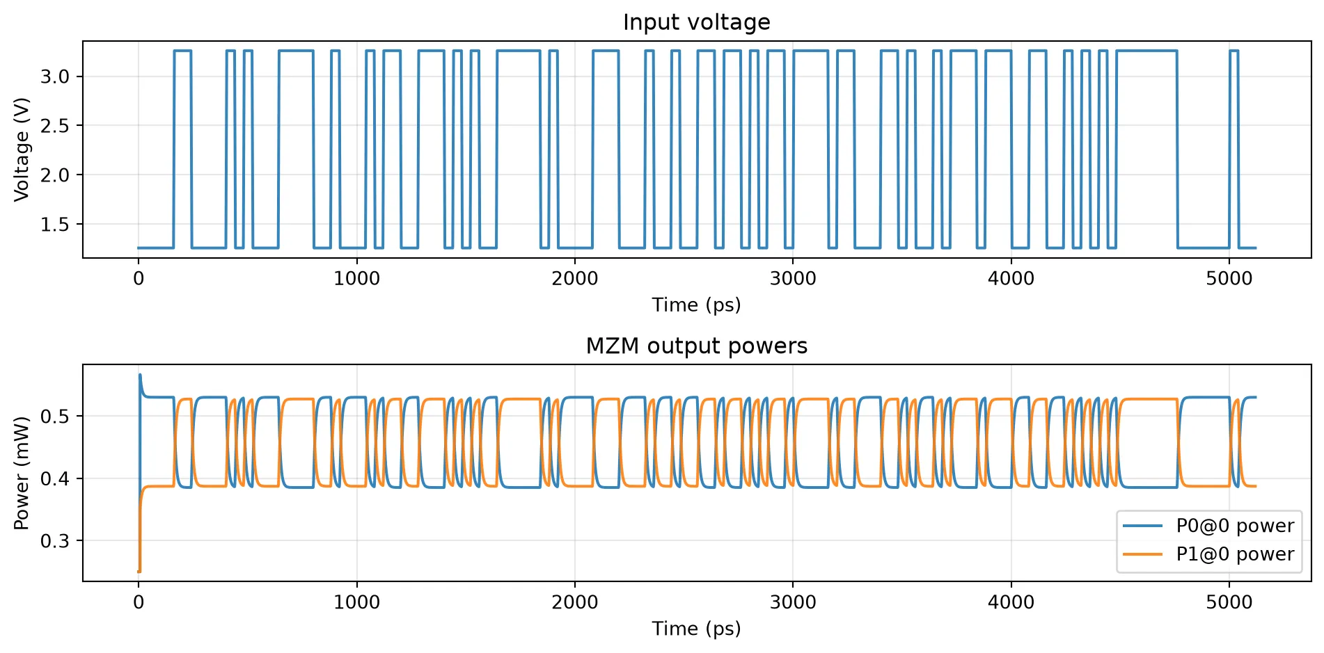
The outputs are complex envelopes at the external optical ports. We plot output power as for both ports. We also add a monitor to the NRZ drive to extract input voltage and visualize it.
# Time grid: choose samples/bit and number of bitssamples_per_bit = 100n_bits = 128
time_step = 1.0 / (bit_rate * samples_per_bit)N_steps = int(n_bits * samples_per_bit)t = time_step * np.arange(N_steps)
# Resolve subcomponent references for monitor placementrefs = mzm_tb.referencesnrz_source_ref = refs[3]
# Build time-stepper (frequency grid used internally for fitting/conversion)ts = mzm_tb.setup_time_stepper(    time_step=time_step,    carrier_frequency=f_c,    time_stepper_kwargs={        "frequencies": np.linspace(f_c - 200 * bit_rate, f_c + 200 * bit_rate, 100),        "monitors": {"drive": nrz_source_ref["E0"]},    },)
# Runts.reset()outputs = ts.step(steps=N_steps, time_step=time_step)
k0 = "P0@0"k1 = "P1@0"k2 = "drive@0+"
A0 = outputs[k0]A1 = outputs[k1]input_drive = outputs[k2]
P0 = np.abs(A0) ** 2P1 = np.abs(A1) ** 2v_in = np.real(input_drive) * np.sqrt(Z0)
# Plot output powersfig, ax = plt.subplots(2, 1, figsize=(10, 5))
ax[0].plot(t * 1e12, v_in, label="Input voltage", alpha=0.9)ax[0].set_xlabel("Time (ps)")ax[0].set_ylabel("Voltage (V)")ax[0].set_title("Input voltage")ax[0].grid(True, alpha=0.3)
ax[1].plot(t * 1e12, P0 * 1e3, label=f"{k0} power", alpha=0.9)ax[1].plot(t * 1e12, P1 * 1e3, label=f"{k1} power", alpha=0.9)ax[1].set_xlabel("Time (ps)")ax[1].set_ylabel("Power (mW)")ax[1].set_title("MZM output powers")ax[1].grid(True, alpha=0.3)ax[1].legend()
plt.tight_layout()plt.show()