

Analytic Dual-Ring Resonator Model
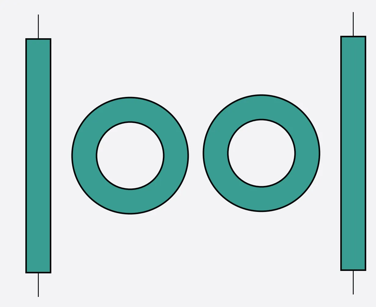
This guide covers pf.DualRingModel, which models two side-coupled ring
resonators sharing an inter-ring coupling. The serially-coupled (second-order)
topology produces a wider, flatter passband in the drop channel and steeper
roll-off compared with a single ring, making it attractive for WDM add-drop
filters and higher-order electro-optic modulators.
Device Topology
Section titled “Device Topology”Two rings sit between two bus waveguides. The coupling coefficients are:
kappa1: field coupling from Bus 1 into Ring 1.kappa2: field coupling between Ring 1 and Ring 2 (inter-ring).kappa3: field coupling from Ring 2 into Bus 2 (setkappa3=Nonefor single-bus).
For the double-bus configuration the 4-port S-matrix is
where and are the through-port transmissions and is the drop-port transmission. A signal entering at P0 (Bus 1 in) exits at P1 (Bus 1 out, through) and P2 (Bus 2 in, drop).
Transfer Functions
Section titled “Transfer Functions”The round-trip field amplitude for ring is
where is the propagation loss in dB/µm, the round-trip length, and the effective and group indices, and the reference frequency.
Each directional coupler with field coupling has a through-field
Through port
Section titled “Through port”Ring 2 together with its bus coupler acts as an effective mirror seen by Ring 1. Collapsing Ring 2 + Bus 2 into :
Then Ring 1 with that effective mirror gives the through-port transmission :
Drop port
Section titled “Drop port”The drop-port transmission collects light that passes through all three couplers (, , ) and half a round-trip in each ring:
These are the exact expressions used internally by pf.DualRingModel.
For the single-bus case (kappa3=None) set , .
import matplotlib.pyplot as pltimport numpy as npimport photonforge as pffrom photonforge.utils import C_0
pf.config.default_technology = pf.basic_technology()
C = C_0  # speed of light in µm/s
lam0 = 1.55  # µmf0 = C / lam0n_eff = 2.418n_g = 4.2L = 50.0  # µmloss = 1e-3  # dB/µm
print(f"f0 = {f0:.4e} Hz")print(f"FSR = {lam0**2/(n_g*L)*1e3:.2f} nm")
f0 = 1.9341e+14 HzFSR = 11.44 nmSingle Ring vs Dual Ring
Section titled “Single Ring vs Dual Ring”Compare a single add-drop ring with a dual-ring system having the same bus coupling strengths. The dual ring shows a wider drop passband and steeper edges.
lam = np.linspace(1.5480, 1.5520, 10001)freqs = C / lam
# Single ring add-dropsingle = pf.RingModel(    kappa1=1j * 0.3,    kappa2=1j * 0.3,    n_eff=n_eff,    n_group=n_g,    length=L,    propagation_loss=loss,    reference_frequency=f0,)bb_single = single.black_box_component(port_spec="Strip")s_single = bb_single.s_matrix(freqs)thru_s = s_single[("P0@0", "P1@0")]drop_s = s_single[("P0@0", "P2@0")]
# Dual ring (double-bus add-drop)dual = pf.DualRingModel(    kappa1=1j * 0.3,    kappa2=1j * 0.15,    kappa3=1j * 0.3,    n_eff1=n_eff,    n_eff2=n_eff,    n_group1=n_g,    n_group2=n_g,    length1=L,    length2=L,    propagation_loss1=loss,    propagation_loss2=loss,    reference_frequency=f0,)bb_dual = dual.black_box_component(port_spec="Strip")s_dual = bb_dual.s_matrix(freqs)thru_d = s_dual[("P0@0", "P1@0")]drop_d = s_dual[("P0@0", "P2@0")]
fig, axes = plt.subplots(1, 2, figsize=(9, 3.5))for ax, T_single, T_dual, title in zip(    axes,    [thru_s, drop_s],    [thru_d, drop_d],    ["Through", "Drop"],):    ax.plot(        lam * 1e3,        10 * np.log10(np.abs(T_single) ** 2),        color="#e07b54",        ls="--",        label="Single ring",        lw=1.5,    )    ax.plot(        lam * 1e3,        10 * np.log10(np.abs(T_dual) ** 2),        color="#3a9d92",        label="Dual ring",        lw=1.5,    )    ax.set_xlabel("Wavelength (nm)")    ax.set_ylabel("Transmission (dB)")    ax.set_title(title)    ax.legend(fontsize=9)    ax.set_ylim(-30, 1)    ax.grid(True, alpha=0.2)
fig.suptitle(r"$\kappa_1=\kappa_3=0.3$, $\kappa_2=0.15$", y=1.01, fontsize=10)fig.tight_layout()plt.show()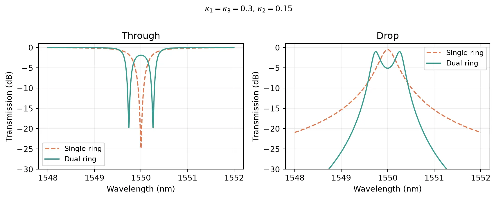
Inter-ring Coupling kappa2 Sweep
Section titled “Inter-ring Coupling kappa2 Sweep”The inter-ring coupling strength kappa2 controls the eigenmode splitting.
Larger kappa2 spreads the two resonance peaks further apart, widening the
passband. Choosing kappa2 independently from the bus couplings lets the
designer trade bandwidth for passband flatness.
kappa2_values = [0.05, 0.10, 0.20, 0.30]colors = ["#1a5276", "#3a9d92", "#e07b54", "#8e44ad"]
fig, axes = plt.subplots(1, 2, figsize=(9, 3.5))
for k2_abs, color in zip(kappa2_values, colors):    dual_v = pf.DualRingModel(        kappa1=1j * 0.3,        kappa2=1j * k2_abs,        kappa3=1j * 0.3,        n_eff1=n_eff,        n_eff2=n_eff,        n_group1=n_g,        n_group2=n_g,        length1=L,        length2=L,        propagation_loss1=loss,        propagation_loss2=loss,        reference_frequency=f0,    )    bb_v = dual_v.black_box_component(port_spec="Strip")    s_v = bb_v.s_matrix(freqs)    thru_v = s_v[("P0@0", "P1@0")]    drop_v = s_v[("P0@0", "P2@0")]
    lbl = rf"$|\kappa_2|={k2_abs}$"    axes[0].plot(        lam * 1e3, 10 * np.log10(np.abs(thru_v) ** 2), color=color, label=lbl, lw=1.5    )    axes[1].plot(        lam * 1e3, 10 * np.log10(np.abs(drop_v) ** 2), color=color, label=lbl, lw=1.5    )
for ax, title in zip(axes, ["Through", "Drop"]):    ax.set_xlabel("Wavelength (nm)")    ax.set_ylabel("Transmission (dB)")    ax.set_title(title)    ax.legend(fontsize=8, loc="best")    ax.set_ylim(-30, 1)    ax.grid(True, alpha=0.2)
fig.suptitle(    r"Varying inter-ring coupling $\kappa_2$ ($\kappa_1=\kappa_3=0.3$)", y=1.01)fig.tight_layout()plt.show()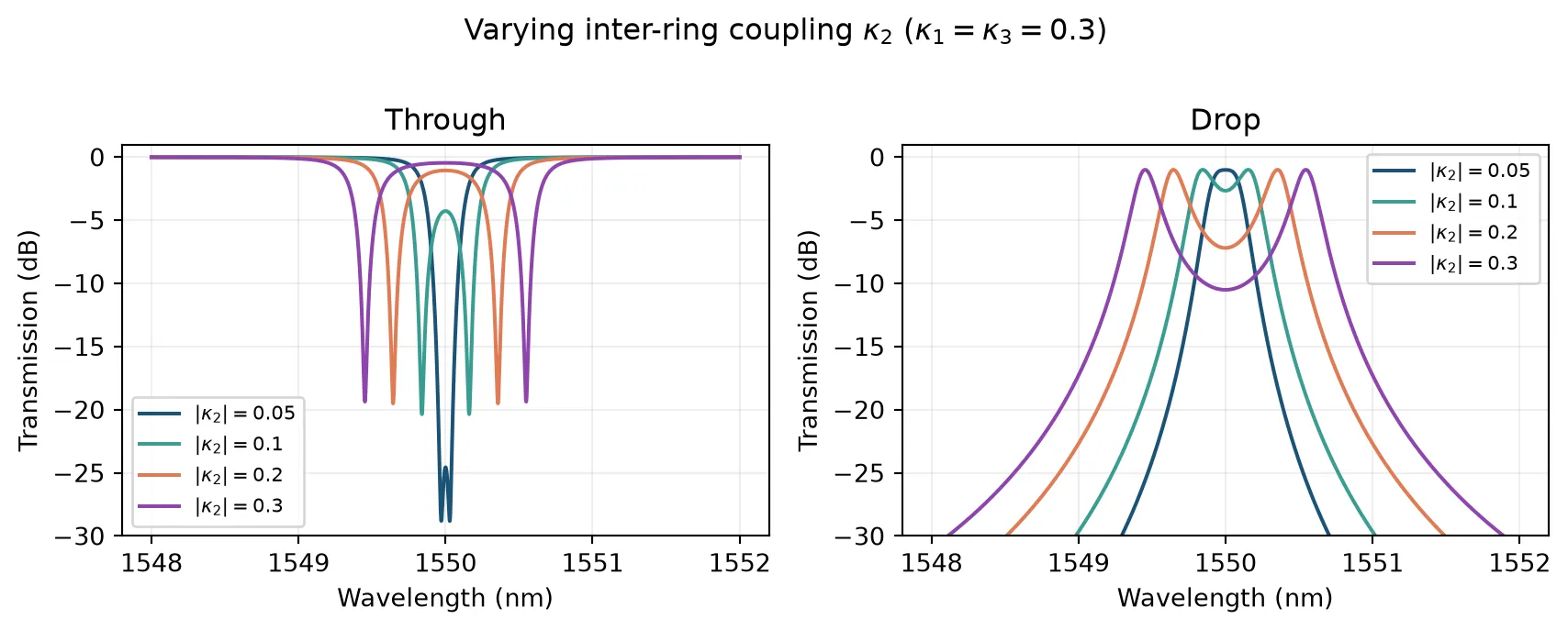
Flat-top Filter Response
Section titled “Flat-top Filter Response”A single add-drop ring has a Lorentzian (first-order) drop response. Two coupled rings produce two eigenmodes whose resonance frequencies straddle the individual ring resonance. With matched rings (, ) the result is a wider, flatter passband and steeper roll-off (second-order filter).
Maximally-Flat Design
Section titled “Maximally-Flat Design”For a symmetric double-bus dual ring (), the maximally-flat (Butterworth) passband condition explained in this example is:
where and
are power coupling coefficients. In terms of the field coupling amplitudes passed
to DualRingModel:
This balances the eigenmode splitting against the linewidth so that the two resonance peaks merge into a single flat passband. Choosing smaller gives a single-peak (under-split) response; larger gives a double-peak (over-split) response.
# Flat-top design: |kappa2| = |kappa1|**2 / sqrt(2)k_bus = 0.3  # |kappa1| = |kappa3| (field)k2_flat = k_bus**2 / np.sqrt(2)  # flat-top condition (field)
k2_cases = [    (0.03, r"Under-split, $|\kappa_2|=0.03$"),    (k2_flat, rf"Flat-top, $|\kappa_2|={k2_flat:.4f}$"),    (0.12, r"Over-split, $|\kappa_2|=0.12$"),]colors_ft = ["#1a5276", "#3a9d92", "#e07b54"]
lam_ft = np.linspace(1.5493, 1.5507, 50001)freqs_ft = C / lam_ft
fig, axes = plt.subplots(1, 2, figsize=(9, 3.5))
for (k2, lbl), color in zip(k2_cases, colors_ft):    m = pf.DualRingModel(        kappa1=1j * k_bus,        kappa2=1j * k2,        kappa3=1j * k_bus,        n_eff1=n_eff,        n_eff2=n_eff,        n_group1=n_g,        n_group2=n_g,        length1=L,        length2=L,        propagation_loss1=loss,        propagation_loss2=loss,        reference_frequency=f0,    )    bb = m.black_box_component(port_spec="Strip")    s = bb.s_matrix(freqs_ft)    thru_ft = s[("P0@0", "P1@0")]    drop_ft = s[("P0@0", "P2@0")]    axes[0].plot(        lam_ft * 1e3,        10 * np.log10(np.abs(thru_ft) ** 2),        color=color,        label=lbl,        lw=1.5,    )    axes[1].plot(        lam_ft * 1e3,        10 * np.log10(np.abs(drop_ft) ** 2),        color=color,        label=lbl,        lw=1.5,    )
for ax, title in zip(axes, ["Through", "Drop"]):    ax.set_xlabel("Wavelength (nm)")    ax.set_ylabel("Transmission (dB)")    ax.set_title(title)    ax.legend(fontsize=8)    ax.set_ylim(-20, 1)    ax.grid(True, alpha=0.2)
fig.suptitle(    r"Flat-top design: $|\kappa_2| = |\kappa_1|^2/\sqrt{2}$ "    r"($\kappa_1=\kappa_3=0.3$)",    y=1.01,    fontsize=10,)fig.tight_layout()plt.show()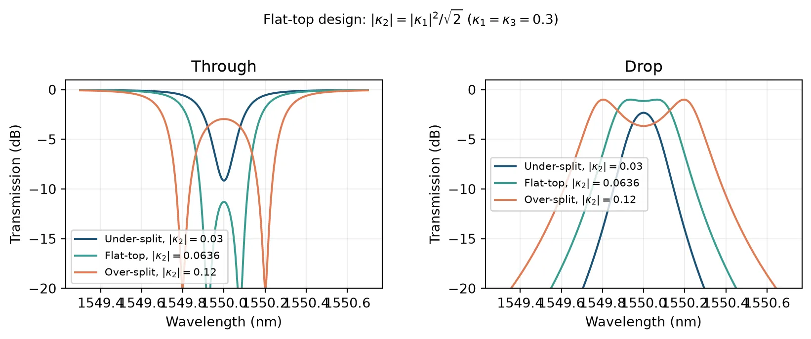
Ring Detuning
Section titled “Ring Detuning”When the two rings have different effective indices, their resonances are offset. Detuning breaks the eigenmode symmetry: one peak couples more strongly to the drop port, and the passband splits into unequal peaks. At large detuning the rings effectively decouple. This can arise from fabrication variations or be introduced intentionally for dispersion engineering.
lam_det = np.linspace(1.5460, 1.5540, 10001)freqs_det = C / lam_det
delta_nm_list = [0.0, 0.15, 0.30, 0.60]colors_det = ["#1a5276", "#3a9d92", "#e07b54", "#8e44ad"]
fig, axes = plt.subplots(1, 2, figsize=(9, 3.5))
for delta_nm, color in zip(delta_nm_list, colors_det):    dn_eff2 = n_g * (delta_nm * 1e-3) / lam0    dual_det = pf.DualRingModel(        kappa1=1j * 0.3,        kappa2=1j * 0.15,        kappa3=1j * 0.3,        n_eff1=n_eff,        n_eff2=n_eff + dn_eff2,        n_group1=n_g,        n_group2=n_g,        length1=L,        length2=L,        propagation_loss1=loss,        propagation_loss2=loss,        reference_frequency=f0,    )    bb_det = dual_det.black_box_component(port_spec="Strip")    s_det = bb_det.s_matrix(freqs_det)    thru_det = s_det[("P0@0", "P1@0")]    drop_det = s_det[("P0@0", "P2@0")]
    lbl = rf"$\Delta\lambda_{{\rm det}}={delta_nm}$ nm"    axes[0].plot(        lam_det * 1e3,        10 * np.log10(np.abs(thru_det) ** 2),        color=color,        label=lbl,        lw=1.5,    )    axes[1].plot(        lam_det * 1e3,        10 * np.log10(np.abs(drop_det) ** 2),        color=color,        label=lbl,        lw=1.5,    )
for ax, title in zip(axes, ["Through", "Drop"]):    ax.set_xlabel("Wavelength (nm)")    ax.set_ylabel("Transmission (dB)")    ax.set_title(title)    ax.legend(fontsize=8, loc="best")    ax.set_ylim(-30, 1)    ax.grid(True, alpha=0.2)
fig.suptitle(r"Ring detuning ($\kappa_1=\kappa_3=0.3$, $\kappa_2=0.15$)", y=1.01)fig.tight_layout()plt.show()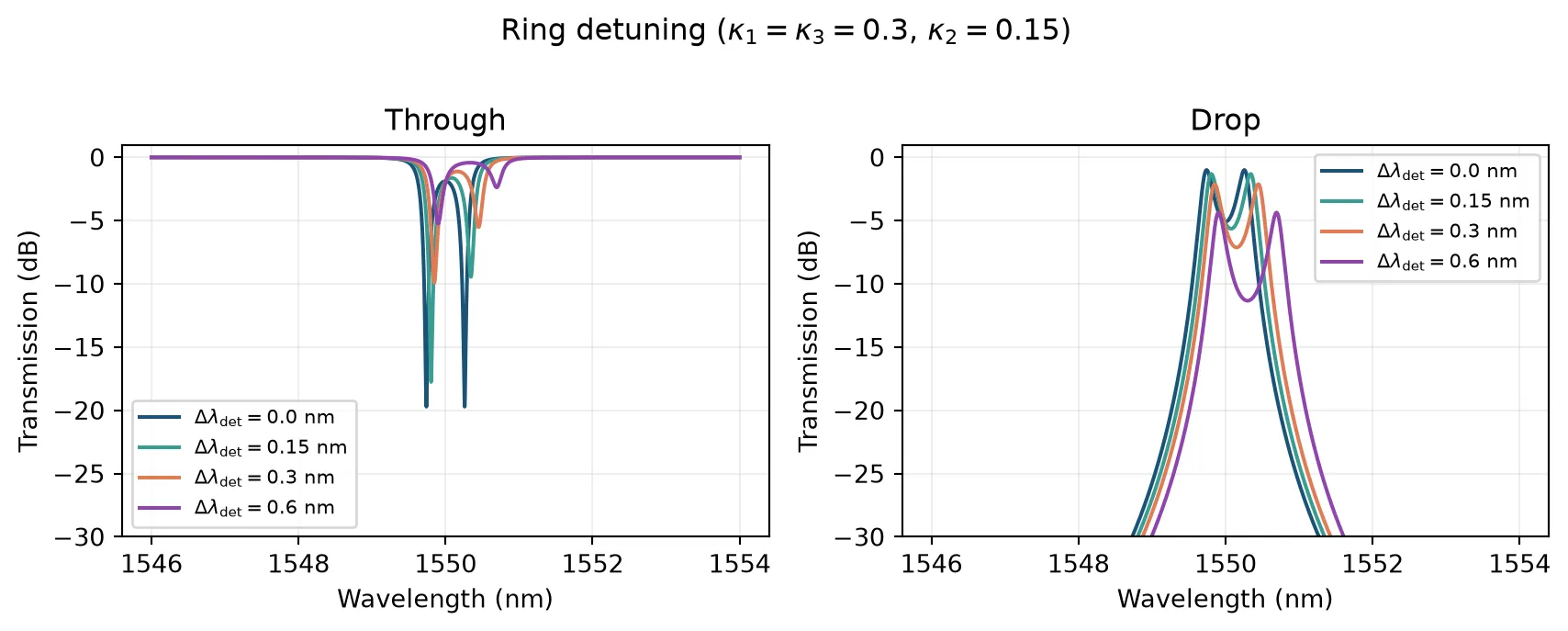
Single-bus (All-pass) Mode
Section titled “Single-bus (All-pass) Mode”Setting kappa3=None removes the second bus waveguide. The result is a two-port
all-pass filter whose through port shows two coupled resonance dips. This is useful
as a notch filter or group-delay element.
FSR_nm = lam0**2 / (n_g * L) * 1e3lam_fsr = np.linspace(lam0 - FSR_nm / 2 * 1e-3, lam0 + FSR_nm / 2 * 1e-3, 20001)freqs_fsr = C / lam_fsr
# kappa1=0.15 gives near-critical coupling for deep resonance dips;# kappa2=0.20 gives well-resolved splittingdual_sb = pf.DualRingModel(    kappa1=1j * 0.15,    kappa2=1j * 0.20,    kappa3=None,    n_eff1=n_eff,    n_eff2=n_eff,    n_group1=n_g,    n_group2=n_g,    length1=L,    length2=L,    propagation_loss1=loss,    propagation_loss2=loss,    reference_frequency=f0,)bb_sb = dual_sb.black_box_component(port_spec="Strip")s_sb = bb_sb.s_matrix(freqs_fsr)thru_sb = s_sb[("P0@0", "P1@0")]
fig, ax = plt.subplots(figsize=(7, 3))ax.plot(lam_fsr * 1e3, 10 * np.log10(np.abs(thru_sb) ** 2), color="#3a9d92", lw=1.5)ax.set_xlabel("Wavelength (nm)")ax.set_ylabel("Transmission (dB)")ax.set_title(r"Single-bus dual ring: through port (one FSR)")ax.set_ylim(-50, 1)ax.grid(True, alpha=0.2)fig.tight_layout()plt.show()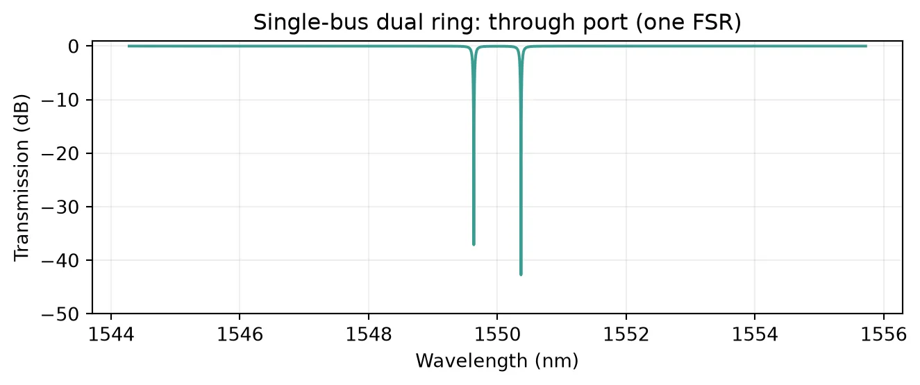
Differential Thermal Tuning
Section titled “Differential Thermal Tuning”DualRingModel accepts independent temperatures temperature1 and temperature2
for each ring. For silicon, K,
giving a resonance shift of roughly 0.068 nm/K. Tuning one ring relative to the
other introduces a controlled detuning, allowing the passband shape to be reshaped
dynamically after fabrication.
dn_dT = 1.85e-4  # Si thermo-optic coefficient, 1/K
lam_th = np.linspace(1.5480, 1.5520, 10001)freqs_th = C / lam_th
dT1_values = [0, 2, 5, 10]colors_th = ["#1a5276", "#3a9d92", "#e07b54", "#8e44ad"]
fig, axes = plt.subplots(1, 2, figsize=(9, 3.5))
for dT1, color in zip(dT1_values, colors_th):    dual_th = pf.DualRingModel(        kappa1=1j * 0.3,        kappa2=1j * 0.15,        kappa3=1j * 0.3,        n_eff1=n_eff,        n_eff2=n_eff,        n_group1=n_g,        n_group2=n_g,        length1=L,        length2=L,        propagation_loss1=loss,        propagation_loss2=loss,        dn1_dT=dn_dT,        dn2_dT=dn_dT,        reference_frequency=f0,        temperature1=293.0 + dT1,        temperature2=293.0,    )    bb_th = dual_th.black_box_component(port_spec="Strip")    s_th = bb_th.s_matrix(freqs_th)    thru_th = s_th[("P0@0", "P1@0")]    drop_th = s_th[("P0@0", "P2@0")]
    lbl = rf"$\Delta T_1={dT1}$ K"    axes[0].plot(        lam_th * 1e3,        10 * np.log10(np.abs(thru_th) ** 2),        color=color,        label=lbl,        lw=1.5,    )    axes[1].plot(        lam_th * 1e3,        10 * np.log10(np.abs(drop_th) ** 2),        color=color,        label=lbl,        lw=1.5,    )
for ax, title in zip(axes, ["Through", "Drop"]):    ax.set_xlabel("Wavelength (nm)")    ax.set_ylabel("Transmission (dB)")    ax.set_title(title)    ax.legend(fontsize=8, loc="best")    ax.set_ylim(-30, 1)    ax.grid(True, alpha=0.2)
fig.suptitle(    r"Differential thermal tuning ($\Delta T_2=0$, $\Delta T_1$ varies)", y=1.01)fig.tight_layout()plt.show()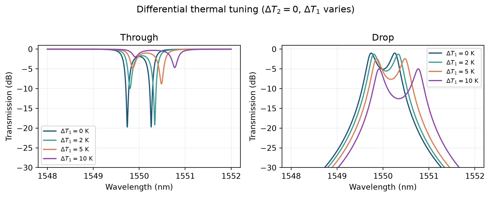
Electro-optic Control
Section titled “Electro-optic Control”Like RingModel, DualRingModel supports voltage-dependent index modulation via
dn1_dv, dn1_dv2, dn2_dv, dn2_dv2 for each ring independently. Each ring can
also have voltage-dependent loss (dloss_dv_1, dloss_dv2_1, etc.).
For detailed EO modulation theory and examples, see the Analytic Ring Model guide.
Dual-ring electro-optic modulators are less common than single-ring designs, so we do not provide detailed examples here. The physics is straightforward: each ring independently shifts its resonance based on voltage, allowing differential phase or amplitude modulation across the two rings.
DualRingModel API Reference
Section titled “DualRingModel API Reference”| Parameter | Type | Default | Notes |
|---|---|---|---|
kappa1 | complex | required | Bus 1 coupling (magnitude + phase) |
kappa2 | complex | required | Inter-ring coupling |
kappa3 | complex | None | None | Bus 2 coupling (None = single-bus) |
n_eff1, n_eff2 | float | required | Ring effective indices |
n_group1, n_group2 | float | None | n_eff | Group indices (defaults to n_eff) |
length1, length2 | float | required | Round-trip lengths (µm) |
propagation_loss1, propagation_loss2 | float | 0.0 | Loss (dB/µm) |
reference_frequency | float | None | None | Taylor expansion point (Hz) |
dn1_dT, dn2_dT | float | 0.0 | Thermo-optic coefficient (1/K) |
temperature1, temperature2 | float | 293.0 | Operating temperature (K) |
dn1_dv, dn2_dv | float | 0.0 | Linear EO (1/V) |
dn1_dv2, dn2_dv2 | float | 0.0 | Quadratic EO (1/V) |
voltage1, voltage2 | float | 0.0 | Operating voltage (V) |
For more parameters (chromatic dispersion, loss temperature/voltage sensitivity, etc.),
see the full pf.DualRingModel docstring.