

Time-Domain Simulation of a Mach–Zehnder Interferometer
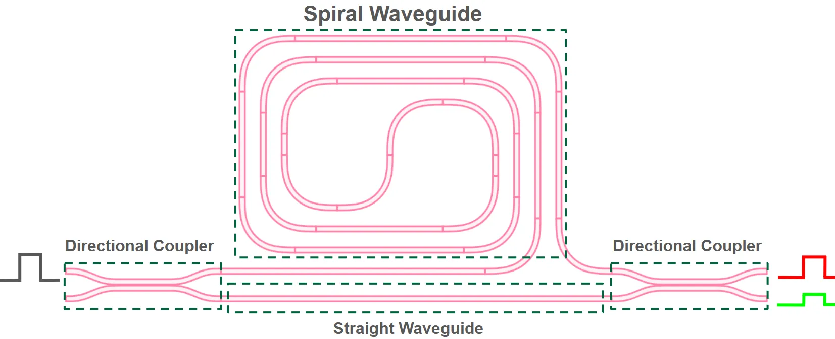
In this notebook, we design and simulate a passive Mach–Zehnder Interferometer (MZI) in the time domain. This structure contains no active modulation components—all elements are passive, including the spiral delay line used to introduce an optical path length difference between the two arms.
The goal is to demonstrate how PhotonForge can perform layout-aware time-domain simulations of passive photonic circuits with minimal user effort.
By simply calling the time-stepper once on the assembled MZI, PhotonForge automatically:
- Computes the frequency-domain S‑matrix of each component (using analytical models or full-wave solvers like Tidy3D).
- Generates a pole–residue fit for each response to enable efficient time-domain evaluation.
- Propagates the input waveforms through the circuit to obtain the output signals.
This workflow requires no manual fitting or convolution code—PhotonForge handles the entire process internally.
import numpy as npimport photonforge as pfimport siepic_forge as siepic_pdkfrom matplotlib import pyplot as pltWe begin by setting up the default technology, component parameters and frequencies for our MZI simulation.
# Set the default technology to SiEPIC OpenEBLpf.config.default_technology = siepic_pdk.ebeam()
# Define default keyword arguments for all componentspf.config.default_kwargs = {    "radius": 5,  # default bend radius in microns    "euler_fraction": 0.5,  # fraction of bend length as Euler curve    "port_spec": "TE_1550_500",  # default port specification (waveguide type)}
# Define the optical carrier frequency (around 1550 nm wavelength)f_c = 193.4e12  # Hz
# Define the electrical modulation frequencyf_m = 10e9  # Hz
Directional Coupler
Section titled “Directional Coupler”We create a directional coupler using an S-bend geometry with specified coupling distance, length, and offset parameters, designed for 50% coupling efficiency at 1550 nm wavelength. We add an analytical DirectionalCouplerModel for the coupler to enable efficient circuit-level simulations, and a Tidy3DModel for high-accuracy simulations.
# Create a parametric S-bend directional couplerdirectional_coupler = pf.parametric.s_bend_coupler(    coupling_distance=0.6,  # gap between coupling waveguides (µm)    coupling_length=4.7,  # length of coupling region (µm)    s_bend_length=5,  # length of S-bend transition (µm)    s_bend_offset=1,  # lateral offset of S-bend (µm)    model=pf.Tidy3DModel(        port_symmetries=[            ("P1", "P0", "P3", "P2"),  # reflection across x-axis            ("P2", "P3", "P0", "P1"),  # reflection across y-axis            ("P3", "P2", "P1", "P0"),  # inversion symmetry        ]    ),)
# Add analytical model for faster circuit simulations, this is the current active modeldirectional_coupler.add_model(pf.DirectionalCouplerModel(), "Analytical")
# Display the couplerdirectional_coupler
Then, we define a rectangular spiral with 7 turns, aligned along the y-axis:
spiral = pf.parametric.rectangular_spiral(turns=7, align_ports="y")spiral;fill:%23221f20;font-weight:bold;font-size:0.936000px;}.terminal{fill:none;stroke:%23805080;stroke-width:0.117000;}.dashed{stroke-dasharray:0.585000,0.351000;}.port{fill:none;stroke:%23805080;stroke-width:0.234000;}.virtual-connection{fill:none;stroke:%23907090;stroke-width:0.175500;}.layer_31_0{stroke:%238c78ef;fill:url(%23pat-layer_31_0);fill-opacity:0.492;}.label_31_0{fill:%238c78ef;}.layer_33_0{stroke:%238c78ef;fill:url(%23pat-layer_33_0);fill-opacity:0.492;}.label_33_0{fill:%238c78ef;}.layer_102_0{stroke:%238c78ef;fill:url(%23pat-layer_102_0);fill-opacity:0.492;}.label_102_0{fill:%238c78ef;}.layer_110_0{stroke:%238c78ef;fill:url(%23pat-layer_110_0);fill-opacity:0.492;}.label_110_0{fill:%238c78ef;}.layer_189_0{stroke:%23000000;fill:none;}.label_189_0{fill:%23000000;}.layer_201_0{stroke:%2300ee00;fill:url(%23pat-layer_201_0);fill-opacity:0.492;}.label_201_0{fill:%2300ee00;}.layer_401_0{stroke:%236a8ad2;fill:url(%23pat-layer_401_0);fill-opacity:0.492;}.label_401_0{fill:%236a8ad2;}.layer_202_0{stroke:%23007600;fill:url(%23pat-layer_202_0);fill-opacity:0.492;}.label_202_0{fill:%23007600;}.layer_68_0{stroke:%23008000;fill:url(%23pat-layer_68_0);fill-opacity:0.492;}.label_68_0{fill:%23008000;}.layer_5_0{stroke:%236a8ad2;fill:url(%23pat-layer_5_0);fill-opacity:0.492;}.label_5_0{fill:%236a8ad2;}.layer_998_0{stroke:%23000000;fill:none;}.label_998_0{fill:%23000000;}.layer_312_1{stroke:%2300b8b8;fill:url(%23pat-layer_312_1);fill-opacity:0.492;}.label_312_1{fill:%2300b8b8;}.layer_312_0{stroke:%2300b8b8;fill:url(%23pat-layer_312_0);fill-opacity:0.492;}.label_312_0{fill:%2300b8b8;}.layer_402_0{stroke:%23ff0000;fill:url(%23pat-layer_402_0);fill-opacity:0.492;}.label_402_0{fill:%23ff0000;}.layer_401_4{stroke:%236a8ad2;fill:url(%23pat-layer_401_4);fill-opacity:0.492;}.label_401_4{fill:%236a8ad2;}.layer_389_0{stroke:%23ff00ff;fill:url(%23pat-layer_389_0);fill-opacity:0.492;}.label_389_0{fill:%23ff00ff;}.layer_402_1{stroke:%23ff0000;fill:url(%23pat-layer_402_1);fill-opacity:0.492;}.label_402_1{fill:%23ff0000;}.layer_350_1{stroke:%23697a00;fill:url(%23pat-layer_350_1);fill-opacity:0.492;}.label_350_1{fill:%23697a00;}.layer_401_1{stroke:%236a8ad2;fill:url(%23pat-layer_401_1);fill-opacity:0.492;}.label_401_1{fill:%236a8ad2;}.layer_313_2{stroke:%2301d95b;fill:url(%23pat-layer_313_2);fill-opacity:0.492;}.label_313_2{fill:%2301d95b;}.layer_313_1{stroke:%2301d95b;fill:url(%23pat-layer_313_1);fill-opacity:0.492;}.label_313_1{fill:%2301d95b;}.layer_313_0{stroke:%2301d95b;fill:url(%23pat-layer_313_0);fill-opacity:0.492;}.label_313_0{fill:%2301d95b;}.layer_400_0{stroke:%23a96868;fill:url(%23pat-layer_400_0);fill-opacity:0.492;}.label_400_0{fill:%23a96868;}.layer_312_3{stroke:%2300b8b8;fill:url(%23pat-layer_312_3);fill-opacity:0.492;}.label_312_3{fill:%2300b8b8;}.layer_389_1{stroke:%23ff00ff;fill:url(%23pat-layer_389_1);fill-opacity:0.492;}.label_389_1{fill:%23ff00ff;}.layer_401_3{stroke:%236a8ad2;fill:url(%23pat-layer_401_3);fill-opacity:0.492;}.label_401_3{fill:%236a8ad2;}.layer_403_2{stroke:%23500080;fill:url(%23pat-layer_403_2);fill-opacity:0.492;}.label_403_2{fill:%23500080;}.layer_403_3{stroke:%23500080;fill:url(%23pat-layer_403_3);fill-opacity:0.492;}.label_403_3{fill:%23500080;}.layer_403_1{stroke:%23500080;fill:url(%23pat-layer_403_1);fill-opacity:0.492;}.label_403_1{fill:%23500080;}.layer_403_0{stroke:%23500080;fill:url(%23pat-layer_403_0);fill-opacity:0.492;}.label_403_0{fill:%23500080;}.layer_311_1{stroke:%23ac6c56;fill:url(%23pat-layer_311_1);fill-opacity:0.492;}.label_311_1{fill:%23ac6c56;}.layer_311_0{stroke:%23ac6c56;fill:url(%23pat-layer_311_0);fill-opacity:0.492;}.label_311_0{fill:%23ac6c56;}.layer_301_1{stroke:%23800057;fill:url(%23pat-layer_301_1);fill-opacity:0.492;}.label_301_1{fill:%23800057;}.layer_301_0{stroke:%23800057;fill:url(%23pat-layer_301_0);fill-opacity:0.492;}.label_301_0{fill:%23800057;}.layer_305_1{stroke:%23808080;fill:url(%23pat-layer_305_1);fill-opacity:0.492;}.label_305_1{fill:%23808080;}.layer_305_0{stroke:%23808080;fill:url(%23pat-layer_305_0);fill-opacity:0.492;}.label_305_0{fill:%23808080;}.layer_999_0{stroke:%230000ff;fill:url(%23pat-layer_999_0);fill-opacity:0.492;}.label_999_0{fill:%230000ff;}.layer_81_0{stroke:%23808080;fill:url(%23pat-layer_81_0);fill-opacity:0.492;}.label_81_0{fill:%23808080;}.layer_290_0{stroke:%23a46eda;fill:none;}.label_290_0{fill:%23a46eda;}.layer_205_0{stroke:%2349b203;fill:url(%23pat-layer_205_0);fill-opacity:0.492;}.label_205_0{fill:%2349b203;}.layer_11_0{stroke:%230000ff;fill:url(%23pat-layer_11_0);fill-opacity:0.492;}.label_11_0{fill:%230000ff;}.layer_12_0{stroke:%23a57b00;fill:url(%23pat-layer_12_0);fill-opacity:0.492;}.label_12_0{fill:%23a57b00;}.layer_13_0{stroke:%23800057;fill:url(%23pat-layer_13_0);fill-opacity:0.492;}.label_13_0{fill:%23800057;}.layer_6_0{stroke:%23ff0000;fill:url(%23pat-layer_6_0);fill-opacity:0.492;}.label_6_0{fill:%23ff0000;}.layer_1_10{stroke:%23c96585;fill:url(%23pat-layer_1_10);fill-opacity:0.492;}.label_1_10{fill:%23c96585;}.layer_1_11{stroke:%23800000;fill:url(%23pat-layer_1_11);fill-opacity:0.492;}.label_1_11{fill:%23800000;}.layer_200_0{stroke:%23ff0000;fill:url(%23pat-layer_200_0);fill-opacity:0.492;}.label_200_0{fill:%23ff0000;}.layer_1_0{stroke:%23c96585;fill:url(%23pat-layer_1_0);fill-opacity:0.492;}.label_1_0{fill:%23c96585;}.layer_2_0{stroke:%23a46eda;fill:url(%23pat-layer_2_0);fill-opacity:0.492;}.label_2_0{fill:%23a46eda;}.layer_20_0{stroke:%2353793d;fill:url(%23pat-layer_20_0);fill-opacity:0.492;}.label_20_0{fill:%2353793d;}.layer_22_0{stroke:%23ec7600;fill:url(%23pat-layer_22_0);fill-opacity:0.492;}.label_22_0{fill:%23ec7600;}.layer_24_0{stroke:%2300b8b8;fill:url(%23pat-layer_24_0);fill-opacity:0.492;}.label_24_0{fill:%2300b8b8;}.layer_21_0{stroke:%23736264;fill:url(%23pat-layer_21_0);fill-opacity:0.492;}.label_21_0{fill:%23736264;}.layer_23_0{stroke:%23697a00;fill:url(%23pat-layer_23_0);fill-opacity:0.492;}.label_23_0{fill:%23697a00;}.layer_25_0{stroke:%23008000;fill:url(%23pat-layer_25_0);fill-opacity:0.492;}.label_25_0{fill:%23008000;}.layer_350_0{stroke:%23697a00;fill:url(%23pat-layer_350_0);fill-opacity:0.492;}.label_350_0{fill:%23697a00;}.layer_10_0{stroke:%23000000;fill:none;}.label_10_0{fill:%23000000;}.layer_203_0{stroke:%23008000;fill:url(%23pat-layer_203_0);fill-opacity:0.492;}.label_203_0{fill:%23008000;}.layer_40_0{stroke:%230000ff;fill:url(%23pat-layer_40_0);fill-opacity:0.492;}.label_40_0{fill:%230000ff;}.layer_401_2{stroke:%236a8ad2;fill:url(%23pat-layer_401_2);fill-opacity:0.492;}.label_401_2{fill:%236a8ad2;}.layer_301_2{stroke:%23800057;fill:url(%23pat-layer_301_2);fill-opacity:0.492;}.label_301_2{fill:%23800057;}</style><defs><path id=%22port-symbol%22 class=%22port%22 d=%22M 0,-0.468000 L 0.702000,0 0,0.468000%22 /><path id=%22ref-port-symbol%22 class=%22port%22 style=%22stroke-opacity:0.33;%22 d=%22M 0,-0.351000 C 0.468000,-0.351000 0.468000,0.351000 0,0.351000%22 /><circle id=%22port-bend-symbol%22 style=%22stroke-width:0;stroke:none;fill:%23805080;fill-opacity:1;%22 cx=%220%22 cy=%220%22 r=%220.210600%22 /><circle id=%22connection-symbol%22 style=%22stroke-width:0;stroke:none;fill:%23907090;fill-opacity:1;%22 cx=%220%22 cy=%220%22 r=%220.245700%22 /><pattern id=%22pat-layer_31_0%22 patternUnits=%22userSpaceOnUse%22 width=%220.585000%22 height=%220.585000%22 patternTransform=%22translate(0.447353,0.554211)%22><line x1=%220%22 y1=%220%22 x2=%220.585000%22 y2=%220.585000%22 style=%22stroke:%238c78ef;stroke-width:0.058500%22 /><line x1=%22-0.292500%22 y1=%220.292500%22 x2=%220.292500%22 y2=%220.877500%22 style=%22stroke:%238c78ef;stroke-width:0.058500%22 /><line x1=%220.292500%22 y1=%22-0.292500%22 x2=%220.877500%22 y2=%220.292500%22 style=%22stroke:%238c78ef;stroke-width:0.058500%22 /></pattern><pattern id=%22pat-layer_33_0%22 patternUnits=%22userSpaceOnUse%22 width=%220.585000%22 height=%220.585000%22 patternTransform=%22translate(0.344118,0.061579)%22><line x1=%220%22 y1=%220%22 x2=%220.585000%22 y2=%220.585000%22 style=%22stroke:%238c78ef;stroke-width:0.058500%22 /><line x1=%22-0.292500%22 y1=%220.292500%22 x2=%220.292500%22 y2=%220.877500%22 style=%22stroke:%238c78ef;stroke-width:0.058500%22 /><line x1=%220.292500%22 y1=%22-0.292500%22 x2=%220.877500%22 y2=%220.292500%22 style=%22stroke:%238c78ef;stroke-width:0.058500%22 /></pattern><pattern id=%22pat-layer_102_0%22 patternUnits=%22userSpaceOnUse%22 width=%220.585000%22 height=%220.585000%22 patternTransform=%22translate(0.000000,0.030789)%22><line x1=%220%22 y1=%220%22 x2=%220.585000%22 y2=%220.585000%22 style=%22stroke:%238c78ef;stroke-width:0.058500%22 /><line x1=%22-0.292500%22 y1=%220.292500%22 x2=%220.292500%22 y2=%220.877500%22 style=%22stroke:%238c78ef;stroke-width:0.058500%22 /><line x1=%220.292500%22 y1=%22-0.292500%22 x2=%220.877500%22 y2=%220.292500%22 style=%22stroke:%238c78ef;stroke-width:0.058500%22 /></pattern><pattern id=%22pat-layer_110_0%22 patternUnits=%22userSpaceOnUse%22 width=%220.585000%22 height=%220.585000%22 patternTransform=%22translate(0.172059,0.400263)%22><line x1=%220%22 y1=%220%22 x2=%220.585000%22 y2=%220.585000%22 style=%22stroke:%238c78ef;stroke-width:0.058500%22 /><line x1=%22-0.292500%22 y1=%220.292500%22 x2=%220.292500%22 y2=%220.877500%22 style=%22stroke:%238c78ef;stroke-width:0.058500%22 /><line x1=%220.292500%22 y1=%22-0.292500%22 x2=%220.877500%22 y2=%220.292500%22 style=%22stroke:%238c78ef;stroke-width:0.058500%22 /></pattern><pattern id=%22pat-layer_201_0%22 patternUnits=%22userSpaceOnUse%22 width=%220.585000%22 height=%220.585000%22 patternTransform=%22translate(0.447353,0.215526)%22><circle cx=%220.292500%22 cy=%220.292500%22 r=%220.058500%22 style=%22stroke:none;fill:%2300ee00;fill-opacity:1.0%22 /></pattern><pattern id=%22pat-layer_401_0%22 patternUnits=%22userSpaceOnUse%22 width=%220.351000%22 height=%220.351000%22 patternTransform=%22translate(0.041294,0.055421)%22><line x1=%220%22 y1=%220%22 x2=%220.351000%22 y2=%220.351000%22 style=%22stroke:%236a8ad2;stroke-width:0.058500%22 /><line x1=%22-0.175500%22 y1=%220.175500%22 x2=%220.175500%22 y2=%220.526500%22 style=%22stroke:%236a8ad2;stroke-width:0.058500%22 /><line x1=%220.175500%22 y1=%22-0.175500%22 x2=%220.526500%22 y2=%220.175500%22 style=%22stroke:%236a8ad2;stroke-width:0.058500%22 /><line x1=%220.351000%22 y1=%220%22 x2=%220%22 y2=%220.351000%22 style=%22stroke:%236a8ad2;stroke-width:0.058500%22 /><line x1=%220.526500%22 y1=%220.175500%22 x2=%220.175500%22 y2=%220.526500%22 style=%22stroke:%236a8ad2;stroke-width:0.058500%22 /><line x1=%220.175500%22 y1=%22-0.175500%22 x2=%22-0.175500%22 y2=%220.175500%22 style=%22stroke:%236a8ad2;stroke-width:0.058500%22 /></pattern><pattern id=%22pat-layer_202_0%22 patternUnits=%22userSpaceOnUse%22 width=%220.351000%22 height=%220.351000%22 patternTransform=%22translate(0.061941,0.332526)%22><circle cx=%220.175500%22 cy=%220.175500%22 r=%220.058500%22 style=%22stroke:none;fill:%23007600;fill-opacity:1.0%22 /></pattern><pattern id=%22pat-layer_68_0%22 patternUnits=%22userSpaceOnUse%22 width=%220.585000%22 height=%220.585000%22 patternTransform=%22translate(0.000000,0.215526)%22><circle cx=%220.292500%22 cy=%220.292500%22 r=%220.058500%22 style=%22stroke:none;fill:%23008000;fill-opacity:1.0%22 /></pattern><pattern id=%22pat-layer_5_0%22 patternUnits=%22userSpaceOnUse%22 width=%220.351000%22 height=%220.351000%22 patternTransform=%22translate(0.020647,0.314053)%22><line x1=%220.175500%22 y1=%220%22 x2=%220.175500%22 y2=%220.351000%22 style=%22stroke:%236a8ad2;stroke-width:0.058500%22 /></pattern><pattern id=%22pat-layer_312_1%22 patternUnits=%22userSpaceOnUse%22 width=%220.351000%22 height=%220.351000%22 patternTransform=%22translate(0.082588,0.277105)%22><line x1=%220%22 y1=%220%22 x2=%220.351000%22 y2=%220.351000%22 style=%22stroke:%2300b8b8;stroke-width:0.058500%22 /><line x1=%22-0.175500%22 y1=%220.175500%22 x2=%220.175500%22 y2=%220.526500%22 style=%22stroke:%2300b8b8;stroke-width:0.058500%22 /><line x1=%220.175500%22 y1=%22-0.175500%22 x2=%220.526500%22 y2=%220.175500%22 style=%22stroke:%2300b8b8;stroke-width:0.058500%22 /></pattern><pattern id=%22pat-layer_312_0%22 patternUnits=%22userSpaceOnUse%22 width=%220.585000%22 height=%220.585000%22 patternTransform=%22translate(0.275294,0.369474)%22><line x1=%220.292500%22 y1=%220%22 x2=%220.292500%22 y2=%220.585000%22 style=%22stroke:%2300b8b8;stroke-width:0.058500%22 /></pattern><pattern id=%22pat-layer_402_0%22 patternUnits=%22userSpaceOnUse%22 width=%220.585000%22 height=%220.585000%22 patternTransform=%22translate(0.309706,0.431053)%22><line x1=%220.292500%22 y1=%220%22 x2=%220.292500%22 y2=%220.585000%22 style=%22stroke:%23ff0000;stroke-width:0.058500%22 /><line x1=%220%22 y1=%220.292500%22 x2=%220.585000%22 y2=%220.292500%22 style=%22stroke:%23ff0000;stroke-width:0.058500%22 /></pattern><pattern id=%22pat-layer_401_4%22 patternUnits=%22userSpaceOnUse%22 width=%220.351000%22 height=%220.351000%22 patternTransform=%22translate(0.061941,0.277105)%22><line x1=%220.175500%22 y1=%220%22 x2=%220.175500%22 y2=%220.351000%22 style=%22stroke:%236a8ad2;stroke-width:0.058500%22 /></pattern><pattern id=%22pat-layer_389_0%22 patternUnits=%22userSpaceOnUse%22 width=%220.351000%22 height=%220.351000%22 patternTransform=%22translate(0.061941,0.073895)%22><line x1=%220.175500%22 y1=%220%22 x2=%220.175500%22 y2=%220.351000%22 style=%22stroke:%23ff00ff;stroke-width:0.058500%22 /><line x1=%220%22 y1=%220.175500%22 x2=%220.351000%22 y2=%220.175500%22 style=%22stroke:%23ff00ff;stroke-width:0.058500%22 /></pattern><pattern id=%22pat-layer_402_1%22 patternUnits=%22userSpaceOnUse%22 width=%220.351000%22 height=%220.351000%22 patternTransform=%22translate(0.103235,0.314053)%22><line x1=%220%22 y1=%220%22 x2=%220.351000%22 y2=%220.351000%22 style=%22stroke:%23ff0000;stroke-width:0.058500%22 /><line x1=%22-0.175500%22 y1=%220.175500%22 x2=%220.175500%22 y2=%220.526500%22 style=%22stroke:%23ff0000;stroke-width:0.058500%22 /><line x1=%220.175500%22 y1=%22-0.175500%22 x2=%220.526500%22 y2=%220.175500%22 style=%22stroke:%23ff0000;stroke-width:0.058500%22 /><line x1=%220.351000%22 y1=%220%22 x2=%220%22 y2=%220.351000%22 style=%22stroke:%23ff0000;stroke-width:0.058500%22 /><line x1=%220.526500%22 y1=%220.175500%22 x2=%220.175500%22 y2=%220.526500%22 style=%22stroke:%23ff0000;stroke-width:0.058500%22 /><line x1=%220.175500%22 y1=%22-0.175500%22 x2=%22-0.175500%22 y2=%220.175500%22 style=%22stroke:%23ff0000;stroke-width:0.058500%22 /></pattern><pattern id=%22pat-layer_350_1%22 patternUnits=%22userSpaceOnUse%22 width=%220.351000%22 height=%220.351000%22 patternTransform=%22translate(0.309706,0.277105)%22><circle cx=%220.175500%22 cy=%220.175500%22 r=%220.058500%22 style=%22stroke:none;fill:%23697a00;fill-opacity:1.0%22 /></pattern><pattern id=%22pat-layer_401_1%22 patternUnits=%22userSpaceOnUse%22 width=%220.585000%22 height=%220.585000%22 patternTransform=%22translate(0.516176,0.184737)%22><line x1=%220%22 y1=%220%22 x2=%220.585000%22 y2=%220.585000%22 style=%22stroke:%236a8ad2;stroke-width:0.058500%22 /><line x1=%22-0.292500%22 y1=%220.292500%22 x2=%220.292500%22 y2=%220.877500%22 style=%22stroke:%236a8ad2;stroke-width:0.058500%22 /><line x1=%220.292500%22 y1=%22-0.292500%22 x2=%220.877500%22 y2=%220.292500%22 style=%22stroke:%236a8ad2;stroke-width:0.058500%22 /><line x1=%220.585000%22 y1=%220%22 x2=%220%22 y2=%220.585000%22 style=%22stroke:%236a8ad2;stroke-width:0.058500%22 /><line x1=%220.877500%22 y1=%220.292500%22 x2=%220.292500%22 y2=%220.877500%22 style=%22stroke:%236a8ad2;stroke-width:0.058500%22 /><line x1=%220.292500%22 y1=%22-0.292500%22 x2=%22-0.292500%22 y2=%220.292500%22 style=%22stroke:%236a8ad2;stroke-width:0.058500%22 /></pattern><pattern id=%22pat-layer_313_2%22 patternUnits=%22userSpaceOnUse%22 width=%220.351000%22 height=%220.351000%22 patternTransform=%22translate(0.144529,0.184737)%22><line x1=%220%22 y1=%220%22 x2=%220.351000%22 y2=%220.351000%22 style=%22stroke:%2301d95b;stroke-width:0.058500%22 /><line x1=%22-0.175500%22 y1=%220.175500%22 x2=%220.175500%22 y2=%220.526500%22 style=%22stroke:%2301d95b;stroke-width:0.058500%22 /><line x1=%220.175500%22 y1=%22-0.175500%22 x2=%220.526500%22 y2=%220.175500%22 style=%22stroke:%2301d95b;stroke-width:0.058500%22 /></pattern><pattern id=%22pat-layer_313_1%22 patternUnits=%22userSpaceOnUse%22 width=%220.585000%22 height=%220.585000%22 patternTransform=%22translate(0.378529,0.215526)%22><line x1=%220.292500%22 y1=%220%22 x2=%220.292500%22 y2=%220.585000%22 style=%22stroke:%2301d95b;stroke-width:0.058500%22 /></pattern><pattern id=%22pat-layer_313_0%22 patternUnits=%22userSpaceOnUse%22 width=%220.351000%22 height=%220.351000%22 patternTransform=%22translate(0.309706,0.073895)%22><line x1=%220.175500%22 y1=%220%22 x2=%220.175500%22 y2=%220.351000%22 style=%22stroke:%2301d95b;stroke-width:0.058500%22 /></pattern><pattern id=%22pat-layer_400_0%22 patternUnits=%22userSpaceOnUse%22 width=%220.585000%22 height=%220.585000%22 patternTransform=%22translate(0.412941,0.338684)%22><line x1=%220%22 y1=%220%22 x2=%220.585000%22 y2=%220.585000%22 style=%22stroke:%23a96868;stroke-width:0.058500%22 /><line x1=%22-0.292500%22 y1=%220.292500%22 x2=%220.292500%22 y2=%220.877500%22 style=%22stroke:%23a96868;stroke-width:0.058500%22 /><line x1=%220.292500%22 y1=%22-0.292500%22 x2=%220.877500%22 y2=%220.292500%22 style=%22stroke:%23a96868;stroke-width:0.058500%22 /><line x1=%220.585000%22 y1=%220%22 x2=%220%22 y2=%220.585000%22 style=%22stroke:%23a96868;stroke-width:0.058500%22 /><line x1=%220.877500%22 y1=%220.292500%22 x2=%220.292500%22 y2=%220.877500%22 style=%22stroke:%23a96868;stroke-width:0.058500%22 /><line x1=%220.292500%22 y1=%22-0.292500%22 x2=%22-0.292500%22 y2=%220.292500%22 style=%22stroke:%23a96868;stroke-width:0.058500%22 /></pattern><pattern id=%22pat-layer_312_3%22 patternUnits=%22userSpaceOnUse%22 width=%220.351000%22 height=%220.351000%22 patternTransform=%22translate(0.268412,0.036947)%22><line x1=%220.351000%22 y1=%220%22 x2=%220%22 y2=%220.351000%22 style=%22stroke:%2300b8b8;stroke-width:0.058500%22 /><line x1=%220.526500%22 y1=%220.175500%22 x2=%220.175500%22 y2=%220.526500%22 style=%22stroke:%2300b8b8;stroke-width:0.058500%22 /><line x1=%220.175500%22 y1=%22-0.175500%22 x2=%22-0.175500%22 y2=%220.175500%22 style=%22stroke:%2300b8b8;stroke-width:0.058500%22 /></pattern><pattern id=%22pat-layer_389_1%22 patternUnits=%22userSpaceOnUse%22 width=%220.585000%22 height=%220.585000%22 patternTransform=%22translate(0.550588,0.215526)%22><line x1=%220.292500%22 y1=%220%22 x2=%220.292500%22 y2=%220.585000%22 style=%22stroke:%23ff00ff;stroke-width:0.058500%22 /><line x1=%220%22 y1=%220.292500%22 x2=%220.585000%22 y2=%220.292500%22 style=%22stroke:%23ff00ff;stroke-width:0.058500%22 /></pattern><pattern id=%22pat-layer_401_3%22 patternUnits=%22userSpaceOnUse%22 width=%220.585000%22 height=%220.585000%22 patternTransform=%22translate(0.240882,0.369474)%22><line x1=%220%22 y1=%220.292500%22 x2=%220.585000%22 y2=%220.292500%22 style=%22stroke:%236a8ad2;stroke-width:0.058500%22 /></pattern><pattern id=%22pat-layer_403_2%22 patternUnits=%22userSpaceOnUse%22 width=%220.351000%22 height=%220.351000%22 patternTransform=%22translate(0.165176,0.221684)%22><line x1=%220%22 y1=%220%22 x2=%220.351000%22 y2=%220.351000%22 style=%22stroke:%23500080;stroke-width:0.058500%22 /><line x1=%22-0.175500%22 y1=%220.175500%22 x2=%220.175500%22 y2=%220.526500%22 style=%22stroke:%23500080;stroke-width:0.058500%22 /><line x1=%220.175500%22 y1=%22-0.175500%22 x2=%220.526500%22 y2=%220.175500%22 style=%22stroke:%23500080;stroke-width:0.058500%22 /><line x1=%220.351000%22 y1=%220%22 x2=%220%22 y2=%220.351000%22 style=%22stroke:%23500080;stroke-width:0.058500%22 /><line x1=%220.526500%22 y1=%220.175500%22 x2=%220.175500%22 y2=%220.526500%22 style=%22stroke:%23500080;stroke-width:0.058500%22 /><line x1=%220.175500%22 y1=%22-0.175500%22 x2=%22-0.175500%22 y2=%220.175500%22 style=%22stroke:%23500080;stroke-width:0.058500%22 /></pattern><pattern id=%22pat-layer_403_3%22 patternUnits=%22userSpaceOnUse%22 width=%220.585000%22 height=%220.585000%22 patternTransform=%22translate(0.137647,0.461842)%22><line x1=%220%22 y1=%220%22 x2=%220.585000%22 y2=%220.585000%22 style=%22stroke:%23500080;stroke-width:0.058500%22 /><line x1=%22-0.292500%22 y1=%220.292500%22 x2=%220.292500%22 y2=%220.877500%22 style=%22stroke:%23500080;stroke-width:0.058500%22 /><line x1=%220.292500%22 y1=%22-0.292500%22 x2=%220.877500%22 y2=%220.292500%22 style=%22stroke:%23500080;stroke-width:0.058500%22 /><line x1=%220.585000%22 y1=%220%22 x2=%220%22 y2=%220.585000%22 style=%22stroke:%23500080;stroke-width:0.058500%22 /><line x1=%220.877500%22 y1=%220.292500%22 x2=%220.292500%22 y2=%220.877500%22 style=%22stroke:%23500080;stroke-width:0.058500%22 /><line x1=%220.292500%22 y1=%22-0.292500%22 x2=%22-0.292500%22 y2=%220.292500%22 style=%22stroke:%23500080;stroke-width:0.058500%22 /></pattern><pattern id=%22pat-layer_403_1%22 patternUnits=%22userSpaceOnUse%22 width=%220.585000%22 height=%220.585000%22 patternTransform=%22translate(0.412941,0.277105)%22><line x1=%220.292500%22 y1=%220%22 x2=%220.292500%22 y2=%220.585000%22 style=%22stroke:%23500080;stroke-width:0.058500%22 /><line x1=%220%22 y1=%220.292500%22 x2=%220.585000%22 y2=%220.292500%22 style=%22stroke:%23500080;stroke-width:0.058500%22 /></pattern><pattern id=%22pat-layer_403_0%22 patternUnits=%22userSpaceOnUse%22 width=%220.351000%22 height=%220.351000%22 patternTransform=%22translate(0.330353,0.110842)%22><line x1=%220.175500%22 y1=%220%22 x2=%220.175500%22 y2=%220.351000%22 style=%22stroke:%23500080;stroke-width:0.058500%22 /><line x1=%220%22 y1=%220.175500%22 x2=%220.351000%22 y2=%220.175500%22 style=%22stroke:%23500080;stroke-width:0.058500%22 /></pattern><pattern id=%22pat-layer_311_1%22 patternUnits=%22userSpaceOnUse%22 width=%220.585000%22 height=%220.585000%22 patternTransform=%22translate(0.481765,0.123158)%22><line x1=%220%22 y1=%220%22 x2=%220.585000%22 y2=%220.585000%22 style=%22stroke:%23ac6c56;stroke-width:0.058500%22 /><line x1=%22-0.292500%22 y1=%220.292500%22 x2=%220.292500%22 y2=%220.877500%22 style=%22stroke:%23ac6c56;stroke-width:0.058500%22 /><line x1=%220.292500%22 y1=%22-0.292500%22 x2=%220.877500%22 y2=%220.292500%22 style=%22stroke:%23ac6c56;stroke-width:0.058500%22 /></pattern><pattern id=%22pat-layer_311_0%22 patternUnits=%22userSpaceOnUse%22 width=%220.351000%22 height=%220.351000%22 patternTransform=%22translate(0.020647,0.018474)%22><line x1=%220%22 y1=%220%22 x2=%220.351000%22 y2=%220.351000%22 style=%22stroke:%23ac6c56;stroke-width:0.058500%22 /><line x1=%22-0.175500%22 y1=%220.175500%22 x2=%220.175500%22 y2=%220.526500%22 style=%22stroke:%23ac6c56;stroke-width:0.058500%22 /><line x1=%220.175500%22 y1=%22-0.175500%22 x2=%220.526500%22 y2=%220.175500%22 style=%22stroke:%23ac6c56;stroke-width:0.058500%22 /></pattern><pattern id=%22pat-layer_301_1%22 patternUnits=%22userSpaceOnUse%22 width=%220.585000%22 height=%220.585000%22 patternTransform=%22translate(0.412941,0.246316)%22><line x1=%220%22 y1=%220.292500%22 x2=%220.585000%22 y2=%220.292500%22 style=%22stroke:%23800057;stroke-width:0.058500%22 /></pattern><pattern id=%22pat-layer_301_0%22 patternUnits=%22userSpaceOnUse%22 width=%220.351000%22 height=%220.351000%22 patternTransform=%22translate(0.330353,0.092368)%22><line x1=%220%22 y1=%220.175500%22 x2=%220.351000%22 y2=%220.175500%22 style=%22stroke:%23800057;stroke-width:0.058500%22 /></pattern><pattern id=%22pat-layer_305_1%22 patternUnits=%22userSpaceOnUse%22 width=%220.585000%22 height=%220.585000%22 patternTransform=%22translate(0.206471,0.431053)%22><line x1=%220.292500%22 y1=%220%22 x2=%220.292500%22 y2=%220.585000%22 style=%22stroke:%23808080;stroke-width:0.058500%22 /><line x1=%220%22 y1=%220.292500%22 x2=%220.585000%22 y2=%220.292500%22 style=%22stroke:%23808080;stroke-width:0.058500%22 /></pattern><pattern id=%22pat-layer_305_0%22 patternUnits=%22userSpaceOnUse%22 width=%220.351000%22 height=%220.351000%22 patternTransform=%22translate(0.206471,0.203211)%22><line x1=%220.175500%22 y1=%220%22 x2=%220.175500%22 y2=%220.351000%22 style=%22stroke:%23808080;stroke-width:0.058500%22 /><line x1=%220%22 y1=%220.175500%22 x2=%220.351000%22 y2=%220.175500%22 style=%22stroke:%23808080;stroke-width:0.058500%22 /></pattern><pattern id=%22pat-layer_999_0%22 patternUnits=%22userSpaceOnUse%22 width=%220.351000%22 height=%220.351000%22 patternTransform=%22translate(0.123882,0.129316)%22><line x1=%220.175500%22 y1=%220%22 x2=%220.175500%22 y2=%220.351000%22 style=%22stroke:%230000ff;stroke-width:0.058500%22 /></pattern><pattern id=%22pat-layer_81_0%22 patternUnits=%22userSpaceOnUse%22 width=%220.351000%22 height=%220.351000%22 patternTransform=%22translate(0.123882,0.314053)%22><line x1=%220.175500%22 y1=%220%22 x2=%220.175500%22 y2=%220.351000%22 style=%22stroke:%23808080;stroke-width:0.058500%22 /><line x1=%220%22 y1=%220.175500%22 x2=%220.351000%22 y2=%220.175500%22 style=%22stroke:%23808080;stroke-width:0.058500%22 /></pattern><pattern id=%22pat-layer_205_0%22 patternUnits=%22userSpaceOnUse%22 width=%220.351000%22 height=%220.351000%22 patternTransform=%22translate(0.144529,0.240158)%22><line x1=%220%22 y1=%220%22 x2=%220.351000%22 y2=%220.351000%22 style=%22stroke:%2349b203;stroke-width:0.058500%22 /><line x1=%22-0.175500%22 y1=%220.175500%22 x2=%220.175500%22 y2=%220.526500%22 style=%22stroke:%2349b203;stroke-width:0.058500%22 /><line x1=%220.175500%22 y1=%22-0.175500%22 x2=%220.526500%22 y2=%220.175500%22 style=%22stroke:%2349b203;stroke-width:0.058500%22 /><line x1=%220.351000%22 y1=%220%22 x2=%220%22 y2=%220.351000%22 style=%22stroke:%2349b203;stroke-width:0.058500%22 /><line x1=%220.526500%22 y1=%220.175500%22 x2=%220.175500%22 y2=%220.526500%22 style=%22stroke:%2349b203;stroke-width:0.058500%22 /><line x1=%220.175500%22 y1=%22-0.175500%22 x2=%22-0.175500%22 y2=%220.175500%22 style=%22stroke:%2349b203;stroke-width:0.058500%22 /></pattern><pattern id=%22pat-layer_11_0%22 patternUnits=%22userSpaceOnUse%22 width=%220.351000%22 height=%220.351000%22 patternTransform=%22translate(0.185824,0.129316)%22><line x1=%220.351000%22 y1=%220%22 x2=%220%22 y2=%220.351000%22 style=%22stroke:%230000ff;stroke-width:0.058500%22 /><line x1=%220.526500%22 y1=%220.175500%22 x2=%220.175500%22 y2=%220.526500%22 style=%22stroke:%230000ff;stroke-width:0.058500%22 /><line x1=%220.175500%22 y1=%22-0.175500%22 x2=%22-0.175500%22 y2=%220.175500%22 style=%22stroke:%230000ff;stroke-width:0.058500%22 /></pattern><pattern id=%22pat-layer_12_0%22 patternUnits=%22userSpaceOnUse%22 width=%220.351000%22 height=%220.351000%22 patternTransform=%22translate(0.330353,0.332526)%22><line x1=%220%22 y1=%220%22 x2=%220.351000%22 y2=%220.351000%22 style=%22stroke:%23a57b00;stroke-width:0.058500%22 /><line x1=%22-0.175500%22 y1=%220.175500%22 x2=%220.175500%22 y2=%220.526500%22 style=%22stroke:%23a57b00;stroke-width:0.058500%22 /><line x1=%220.175500%22 y1=%22-0.175500%22 x2=%220.526500%22 y2=%220.175500%22 style=%22stroke:%23a57b00;stroke-width:0.058500%22 /></pattern><pattern id=%22pat-layer_13_0%22 patternUnits=%22userSpaceOnUse%22 width=%220.351000%22 height=%220.351000%22 patternTransform=%22translate(0.123882,0.184737)%22><line x1=%220.351000%22 y1=%220%22 x2=%220%22 y2=%220.351000%22 style=%22stroke:%23800057;stroke-width:0.058500%22 /><line x1=%220.526500%22 y1=%220.175500%22 x2=%220.175500%22 y2=%220.526500%22 style=%22stroke:%23800057;stroke-width:0.058500%22 /><line x1=%220.175500%22 y1=%22-0.175500%22 x2=%22-0.175500%22 y2=%220.175500%22 style=%22stroke:%23800057;stroke-width:0.058500%22 /></pattern><pattern id=%22pat-layer_6_0%22 patternUnits=%22userSpaceOnUse%22 width=%220.585000%22 height=%220.585000%22 patternTransform=%22translate(0.275294,0.277105)%22><line x1=%220%22 y1=%220.292500%22 x2=%220.585000%22 y2=%220.292500%22 style=%22stroke:%23ff0000;stroke-width:0.058500%22 /></pattern><pattern id=%22pat-layer_1_10%22 patternUnits=%22userSpaceOnUse%22 width=%220.351000%22 height=%220.351000%22 patternTransform=%22translate(0.020647,0.055421)%22><line x1=%220%22 y1=%220%22 x2=%220.351000%22 y2=%220.351000%22 style=%22stroke:%23c96585;stroke-width:0.058500%22 /><line x1=%22-0.175500%22 y1=%220.175500%22 x2=%220.175500%22 y2=%220.526500%22 style=%22stroke:%23c96585;stroke-width:0.058500%22 /><line x1=%220.175500%22 y1=%22-0.175500%22 x2=%220.526500%22 y2=%220.175500%22 style=%22stroke:%23c96585;stroke-width:0.058500%22 /><line x1=%220.351000%22 y1=%220%22 x2=%220%22 y2=%220.351000%22 style=%22stroke:%23c96585;stroke-width:0.058500%22 /><line x1=%220.526500%22 y1=%220.175500%22 x2=%220.175500%22 y2=%220.526500%22 style=%22stroke:%23c96585;stroke-width:0.058500%22 /><line x1=%220.175500%22 y1=%22-0.175500%22 x2=%22-0.175500%22 y2=%220.175500%22 style=%22stroke:%23c96585;stroke-width:0.058500%22 /></pattern><pattern id=%22pat-layer_1_11%22 patternUnits=%22userSpaceOnUse%22 width=%220.585000%22 height=%220.585000%22 patternTransform=%22translate(0.481765,0.184737)%22><line x1=%220.292500%22 y1=%220%22 x2=%220.292500%22 y2=%220.585000%22 style=%22stroke:%23800000;stroke-width:0.058500%22 /><line x1=%220%22 y1=%220.292500%22 x2=%220.585000%22 y2=%220.292500%22 style=%22stroke:%23800000;stroke-width:0.058500%22 /></pattern><pattern id=%22pat-layer_200_0%22 patternUnits=%22userSpaceOnUse%22 width=%220.585000%22 height=%220.585000%22 patternTransform=%22translate(0.206471,0.461842)%22><line x1=%220%22 y1=%220%22 x2=%220.585000%22 y2=%220.585000%22 style=%22stroke:%23ff0000;stroke-width:0.058500%22 /><line x1=%22-0.292500%22 y1=%220.292500%22 x2=%220.292500%22 y2=%220.877500%22 style=%22stroke:%23ff0000;stroke-width:0.058500%22 /><line x1=%220.292500%22 y1=%22-0.292500%22 x2=%220.877500%22 y2=%220.292500%22 style=%22stroke:%23ff0000;stroke-width:0.058500%22 /><line x1=%220.585000%22 y1=%220%22 x2=%220%22 y2=%220.585000%22 style=%22stroke:%23ff0000;stroke-width:0.058500%22 /><line x1=%220.877500%22 y1=%220.292500%22 x2=%220.292500%22 y2=%220.877500%22 style=%22stroke:%23ff0000;stroke-width:0.058500%22 /><line x1=%220.292500%22 y1=%22-0.292500%22 x2=%22-0.292500%22 y2=%220.292500%22 style=%22stroke:%23ff0000;stroke-width:0.058500%22 /></pattern><pattern id=%22pat-layer_1_0%22 patternUnits=%22userSpaceOnUse%22 width=%220.351000%22 height=%220.351000%22 patternTransform=%22translate(0.144529,0.203211)%22><line x1=%220.351000%22 y1=%220%22 x2=%220%22 y2=%220.351000%22 style=%22stroke:%23c96585;stroke-width:0.058500%22 /><line x1=%220.526500%22 y1=%220.175500%22 x2=%220.175500%22 y2=%220.526500%22 style=%22stroke:%23c96585;stroke-width:0.058500%22 /><line x1=%220.175500%22 y1=%22-0.175500%22 x2=%22-0.175500%22 y2=%220.175500%22 style=%22stroke:%23c96585;stroke-width:0.058500%22 /></pattern><pattern id=%22pat-layer_2_0%22 patternUnits=%22userSpaceOnUse%22 width=%220.585000%22 height=%220.585000%22 patternTransform=%22translate(0.481765,0.092368)%22><line x1=%220%22 y1=%220%22 x2=%220.585000%22 y2=%220.585000%22 style=%22stroke:%23a46eda;stroke-width:0.058500%22 /><line x1=%22-0.292500%22 y1=%220.292500%22 x2=%220.292500%22 y2=%220.877500%22 style=%22stroke:%23a46eda;stroke-width:0.058500%22 /><line x1=%220.292500%22 y1=%22-0.292500%22 x2=%220.877500%22 y2=%220.292500%22 style=%22stroke:%23a46eda;stroke-width:0.058500%22 /></pattern><pattern id=%22pat-layer_20_0%22 patternUnits=%22userSpaceOnUse%22 width=%220.585000%22 height=%220.585000%22 patternTransform=%22translate(0.137647,0.338684)%22><line x1=%220%22 y1=%220.292500%22 x2=%220.585000%22 y2=%220.292500%22 style=%22stroke:%2353793d;stroke-width:0.058500%22 /></pattern><pattern id=%22pat-layer_22_0%22 patternUnits=%22userSpaceOnUse%22 width=%220.585000%22 height=%220.585000%22 patternTransform=%22translate(0.034412,0.431053)%22><line x1=%220%22 y1=%220%22 x2=%220.585000%22 y2=%220.585000%22 style=%22stroke:%23ec7600;stroke-width:0.058500%22 /><line x1=%22-0.292500%22 y1=%220.292500%22 x2=%220.292500%22 y2=%220.877500%22 style=%22stroke:%23ec7600;stroke-width:0.058500%22 /><line x1=%220.292500%22 y1=%22-0.292500%22 x2=%220.877500%22 y2=%220.292500%22 style=%22stroke:%23ec7600;stroke-width:0.058500%22 /><line x1=%220.585000%22 y1=%220%22 x2=%220%22 y2=%220.585000%22 style=%22stroke:%23ec7600;stroke-width:0.058500%22 /><line x1=%220.877500%22 y1=%220.292500%22 x2=%220.292500%22 y2=%220.877500%22 style=%22stroke:%23ec7600;stroke-width:0.058500%22 /><line x1=%220.292500%22 y1=%22-0.292500%22 x2=%22-0.292500%22 y2=%220.292500%22 style=%22stroke:%23ec7600;stroke-width:0.058500%22 /></pattern><pattern id=%22pat-layer_24_0%22 patternUnits=%22userSpaceOnUse%22 width=%220.585000%22 height=%220.585000%22 patternTransform=%22translate(0.516176,0.523421)%22><line x1=%220.292500%22 y1=%220%22 x2=%220.292500%22 y2=%220.585000%22 style=%22stroke:%2300b8b8;stroke-width:0.058500%22 /><line x1=%220%22 y1=%220.292500%22 x2=%220.585000%22 y2=%220.292500%22 style=%22stroke:%2300b8b8;stroke-width:0.058500%22 /></pattern><pattern id=%22pat-layer_21_0%22 patternUnits=%22userSpaceOnUse%22 width=%220.351000%22 height=%220.351000%22 patternTransform=%22translate(0.227118,0.055421)%22><line x1=%220%22 y1=%220.175500%22 x2=%220.351000%22 y2=%220.175500%22 style=%22stroke:%23736264;stroke-width:0.058500%22 /></pattern><pattern id=%22pat-layer_23_0%22 patternUnits=%22userSpaceOnUse%22 width=%220.351000%22 height=%220.351000%22 patternTransform=%22translate(0.165176,0.110842)%22><line x1=%220%22 y1=%220%22 x2=%220.351000%22 y2=%220.351000%22 style=%22stroke:%23697a00;stroke-width:0.058500%22 /><line x1=%22-0.175500%22 y1=%220.175500%22 x2=%220.175500%22 y2=%220.526500%22 style=%22stroke:%23697a00;stroke-width:0.058500%22 /><line x1=%220.175500%22 y1=%22-0.175500%22 x2=%220.526500%22 y2=%220.175500%22 style=%22stroke:%23697a00;stroke-width:0.058500%22 /><line x1=%220.351000%22 y1=%220%22 x2=%220%22 y2=%220.351000%22 style=%22stroke:%23697a00;stroke-width:0.058500%22 /><line x1=%220.526500%22 y1=%220.175500%22 x2=%220.175500%22 y2=%220.526500%22 style=%22stroke:%23697a00;stroke-width:0.058500%22 /><line x1=%220.175500%22 y1=%22-0.175500%22 x2=%22-0.175500%22 y2=%220.175500%22 style=%22stroke:%23697a00;stroke-width:0.058500%22 /></pattern><pattern id=%22pat-layer_25_0%22 patternUnits=%22userSpaceOnUse%22 width=%220.351000%22 height=%220.351000%22 patternTransform=%22translate(0.103235,0.166263)%22><line x1=%220.175500%22 y1=%220%22 x2=%220.175500%22 y2=%220.351000%22 style=%22stroke:%23008000;stroke-width:0.058500%22 /><line x1=%220%22 y1=%220.175500%22 x2=%220.351000%22 y2=%220.175500%22 style=%22stroke:%23008000;stroke-width:0.058500%22 /></pattern><pattern id=%22pat-layer_350_0%22 patternUnits=%22userSpaceOnUse%22 width=%220.585000%22 height=%220.585000%22 patternTransform=%22translate(0.068824,0.369474)%22><line x1=%220.585000%22 y1=%220%22 x2=%220%22 y2=%220.585000%22 style=%22stroke:%23697a00;stroke-width:0.058500%22 /><line x1=%220.877500%22 y1=%220.292500%22 x2=%220.292500%22 y2=%220.877500%22 style=%22stroke:%23697a00;stroke-width:0.058500%22 /><line x1=%220.292500%22 y1=%22-0.292500%22 x2=%22-0.292500%22 y2=%220.292500%22 style=%22stroke:%23697a00;stroke-width:0.058500%22 /></pattern><pattern id=%22pat-layer_203_0%22 patternUnits=%22userSpaceOnUse%22 width=%220.585000%22 height=%220.585000%22 patternTransform=%22translate(0.344118,0.307895)%22><line x1=%220.585000%22 y1=%220%22 x2=%220%22 y2=%220.585000%22 style=%22stroke:%23008000;stroke-width:0.058500%22 /><line x1=%220.877500%22 y1=%220.292500%22 x2=%220.292500%22 y2=%220.877500%22 style=%22stroke:%23008000;stroke-width:0.058500%22 /><line x1=%220.292500%22 y1=%22-0.292500%22 x2=%22-0.292500%22 y2=%220.292500%22 style=%22stroke:%23008000;stroke-width:0.058500%22 /></pattern><pattern id=%22pat-layer_40_0%22 patternUnits=%22userSpaceOnUse%22 width=%220.585000%22 height=%220.585000%22 patternTransform=%22translate(0.275294,0.092368)%22><circle cx=%220.292500%22 cy=%220.292500%22 r=%220.058500%22 style=%22stroke:none;fill:%230000ff;fill-opacity:1.0%22 /></pattern><pattern id=%22pat-layer_401_2%22 patternUnits=%22userSpaceOnUse%22 width=%220.351000%22 height=%220.351000%22 patternTransform=%22translate(0.227118,0.166263)%22><line x1=%220%22 y1=%220.175500%22 x2=%220.351000%22 y2=%220.175500%22 style=%22stroke:%236a8ad2;stroke-width:0.058500%22 /></pattern><pattern id=%22pat-layer_301_2%22 patternUnits=%22userSpaceOnUse%22 width=%220.351000%22 height=%220.351000%22 patternTransform=%22translate(0.165176,0.203211)%22><line x1=%220.175500%22 y1=%220%22 x2=%220.175500%22 y2=%220.351000%22 style=%22stroke:%23800057;stroke-width:0.058500%22 /></pattern><g id=%22C1%22 data-name=%22bend__JDEFDLCQOWSMWVIHIYGT5BTN3IQ6QDLL224Z5HKBCHIOQZBQWUEA%22><path class=%22layer_1_0%22 d=%22M 0.000000,-0.250000 0.516000,-0.252000 1.026000,-0.269000 1.277000,-0.286000 1.772000,-0.349000 2.015000,-0.397000 2.252000,-0.457000 2.484000,-0.532000 2.709000,-0.622000 2.926000,-0.728000 3.134000,-0.849000 3.333000,-0.986000 3.522000,-1.137000 3.699000,-1.301000 3.863000,-1.478000 4.014000,-1.667000 4.151000,-1.866000 4.272000,-2.074000 4.378000,-2.291000 4.468000,-2.516000 4.543000,-2.748000 4.603000,-2.985000 4.651000,-3.228000 4.687000,-3.474000 4.714000,-3.723000 4.742000,-4.228000 4.750000,-5.000000 5.250000,-5.000000 5.248000,-4.477000 5.230000,-3.947000 5.184000,-3.412000 5.144000,-3.143000 5.091000,-2.876000 5.023000,-2.610000 4.939000,-2.347000 4.835000,-2.089000 4.713000,-1.839000 4.573000,-1.598000 4.416000,-1.369000 4.242000,-1.151000 4.052000,-0.948000 3.849000,-0.758000 3.631000,-0.584000 3.402000,-0.427000 3.161000,-0.287000 2.911000,-0.165000 2.653000,-0.061000 2.390000,0.023000 2.124000,0.091000 1.857000,0.144000 1.588000,0.184000 1.053000,0.230000 0.523000,0.248000 0.000000,0.250000 z%22 /></g><g id=%22C10%22 data-name=%22straight__QPEZXKTMQNQ35G4ATFU5RSSGUXL5NBEU7GYTJ7ME3CPY3VDYVBIQ%22><path class=%22layer_1_0%22 d=%22M 0.000000,-0.250000 9.000000,-0.250000 9.000000,0.250000 0.000000,0.250000 z%22 /></g><g id=%22C2%22 data-name=%22bend__HTD4WS2ADSE6OVQHH73AD2WRPLJQL4EJUPD5QLZY5DYFSZ3OJYPA%22><path class=%22layer_1_0%22 d=%22M 0.000000,-0.250000 0.523000,-0.248000 1.053000,-0.230000 1.588000,-0.184000 1.857000,-0.144000 2.124000,-0.091000 2.390000,-0.023000 2.653000,0.061000 2.911000,0.165000 3.161000,0.287000 3.402000,0.427000 3.631000,0.584000 3.849000,0.758000 4.052000,0.948000 4.242000,1.151000 4.416000,1.369000 4.573000,1.598000 4.713000,1.839000 4.835000,2.089000 4.939000,2.347000 5.023000,2.610000 5.091000,2.876000 5.144000,3.143000 5.184000,3.412000 5.230000,3.947000 5.248000,4.477000 5.250000,5.000000 4.750000,5.000000 4.742000,4.228000 4.714000,3.723000 4.687000,3.474000 4.651000,3.228000 4.603000,2.985000 4.543000,2.748000 4.468000,2.516000 4.378000,2.291000 4.272000,2.074000 4.151000,1.866000 4.014000,1.667000 3.863000,1.478000 3.699000,1.301000 3.522000,1.137000 3.333000,0.986000 3.134000,0.849000 2.926000,0.728000 2.709000,0.622000 2.484000,0.532000 2.252000,0.457000 2.015000,0.397000 1.772000,0.349000 1.277000,0.286000 1.026000,0.269000 0.516000,0.252000 0.000000,0.250000 z%22 /></g><g id=%22C3%22 data-name=%22straight__VG74VL53FQWDLGN6FDNVJI6O5O2IEVT7NWSGPKAGQED3GCMEPGFQ%22><path class=%22layer_1_0%22 d=%22M 0.000000,-0.250000 1.500000,-0.250000 1.500000,0.250000 0.000000,0.250000 z%22 /></g><g id=%22C4%22 data-name=%22straight__JDQKUYK3KFN5XE7PM7TVLSQP6DCQK3LH7JT663XVWNRR4PX665AQ%22><path class=%22layer_1_0%22 d=%22M 0.000000,-0.250000 11.500000,-0.250000 11.500000,0.250000 0.000000,0.250000 z%22 /></g><g id=%22C5%22 data-name=%22straight__3KL4BQDTWRLDD5MZTSA2LFBJPSM2KVPHXOD7S4BM74THCDBQIGCQ%22><path class=%22layer_1_0%22 d=%22M 0.000000,-0.250000 4.500000,-0.250000 4.500000,0.250000 0.000000,0.250000 z%22 /></g><g id=%22C6%22 data-name=%22straight__RUR2BOMZ3Q4G7ZYHEK6DHOIRKJVXKENYVHRT34S5TOSCZFQNYNJA%22><path class=%22layer_1_0%22 d=%22M 0.000000,-0.250000 14.500000,-0.250000 14.500000,0.250000 0.000000,0.250000 z%22 /></g><g id=%22C7%22 data-name=%22straight__SVNWDFCY4SBAHK7XFHINBF5YONPXEZZEUA32B74XQYPH7MMXHVOQ%22><path class=%22layer_1_0%22 d=%22M 0.000000,-0.250000 7.500000,-0.250000 7.500000,0.250000 0.000000,0.250000 z%22 /></g><g id=%22C8%22 data-name=%22straight__R4ACBKCH4BFZXJ63GPBULU7D4HOSZNNXOZTFHBBQKINLGKPWITPA%22><path class=%22layer_1_0%22 d=%22M 0.000000,-0.250000 22.500000,-0.250000 22.500000,0.250000 0.000000,0.250000 z%22 /></g><g id=%22C9%22 data-name=%22straight__O55QCM5NGEN3G5B45CWF4WKNKXJGUANGDMNCTSCTT4OBU2WZAFUQ%22><path class=%22layer_1_0%22 d=%22M 0.000000,-0.250000 17.500000,-0.250000 17.500000,0.250000 0.000000,0.250000 z%22 /></g></defs><g transform=%22scale(1 -1)%22><g id=%22C0%22 data-name=%22rectangular_spiral_a_y_t_7%22><use transform=%22translate(14.500000 9.500000) rotate(270.000000)%22 href=%22%23C1%22 /><use transform=%22translate(19.500000 14.500000) rotate(180.000000)%22 href=%22%23C2%22 /><use transform=%22translate(9.500000 4.500000) rotate(180.000000)%22 href=%22%23C1%22 /><use transform=%22translate(24.500000 9.500000) rotate(90.000000)%22 href=%22%23C2%22 /><use transform=%22translate(4.500000 9.500000) rotate(90.000000)%22 href=%22%23C3%22 /><use transform=%22translate(24.500000 8.000000) rotate(90.000000)%22 href=%22%23C3%22 /><use transform=%22translate(4.500000 11.000000) rotate(90.000000)%22 href=%22%23C1%22 /><use transform=%22translate(19.500000 3.000000)%22 href=%22%23C2%22 /><use transform=%22translate(9.500000 16.000000)%22 href=%22%23C4%22 /><use transform=%22translate(8.000000 3.000000)%22 href=%22%23C4%22 /><use transform=%22translate(21.000000 16.000000)%22 href=%22%23C1%22 /><use transform=%22translate(3.000000 8.000000) rotate(270.000000)%22 href=%22%23C2%22 /><use transform=%22translate(26.000000 11.000000) rotate(270.000000)%22 href=%22%23C5%22 /><use transform=%22translate(3.000000 12.500000) rotate(270.000000)%22 href=%22%23C5%22 /><use transform=%22translate(26.000000 6.500000) rotate(270.000000)%22 href=%22%23C1%22 /><use transform=%22translate(8.000000 17.500000) rotate(180.000000)%22 href=%22%23C2%22 /><use transform=%22translate(21.000000 1.500000) rotate(180.000000)%22 href=%22%23C6%22 /><use transform=%22translate(22.500000 17.500000) rotate(180.000000)%22 href=%22%23C6%22 /><use transform=%22translate(6.500000 1.500000) rotate(180.000000)%22 href=%22%23C1%22 /><use transform=%22translate(27.500000 12.500000) rotate(90.000000)%22 href=%22%23C2%22 /><use transform=%22translate(1.500000 6.500000) rotate(90.000000)%22 href=%22%23C7%22 /><use transform=%22translate(27.500000 5.000000) rotate(90.000000)%22 href=%22%23C7%22 /><use transform=%22translate(1.500000 14.000000) rotate(90.000000)%22 href=%22%23C1%22 /><use transform=%22translate(22.500000 0.000000)%22 href=%22%23C2%22 /><use transform=%22translate(0.000000 0.000000)%22 href=%22%23C8%22 /><use transform=%22translate(6.500000 19.000000)%22 href=%22%23C9%22 /><use transform=%22translate(24.000000 19.000000)%22 href=%22%23C1%22 /><use transform=%22translate(29.000000 14.000000) rotate(270.000000)%22 href=%22%23C10%22 /><use transform=%22translate(29.000000 5.000000) rotate(270.000000)%22 href=%22%23C2%22 /><g transform=%22translate(0.000000 0.000000) rotate(0.000000)%22><path class=%22port%22 d=%22M 0,-0.750000 V 0.750000%22 /><use href=%22%23port-symbol%22 /></g><text class=%22label%22 text-anchor=%22start%22 dominant-baseline=%22text-after-edge%22 x=%220.000000%22 y=%22-0.000000%22>P0</text><g transform=%22translate(34.000000 0.000000) rotate(180.000000)%22><path class=%22port%22 d=%22M 0,-0.750000 V 0.750000%22 /><use href=%22%23port-symbol%22 /></g><text class=%22label%22 text-anchor=%22end%22 dominant-baseline=%22text-before-edge%22 x=%2234.000000%22 y=%22-0.000000%22>P1</text></g></g></svg>)
and a straight waveguide to match the spiral length minus the modulator length.
wg = pf.parametric.straight(length=spiral.size()[0])wg
MZI Assembly
Section titled “MZI Assembly”We now integrate the previously defined components to construct the full MZI. External ports are collected from the two couplers and the modulator’s electrical control port, making it possible to inject optical signals and apply modulation voltage. A CircuitModel is added so that PhotonForge can simulate the device as a network of interconnected subcomponents in the time domain. This completes the layout and connectivity for our MZI, ready for time-domain simulation with optical and electrical inputs.
# Define netlist for assembling the tunable photonic unitnetlist_mzi = {    "name": "MZI",    "instances": {        "dc0": directional_coupler,  # input coupler        "spiral": spiral,        "wg": wg,        "dc1": directional_coupler,  # output coupler    },    # Explicitly define connections between component ports    "connections": [        (("wg", "P0"), ("dc0", "P2")),        (("dc1", "P0"), ("wg", "P1")),        (("spiral", "P0"), ("dc0", "P3")),    ],    # Define external ports of the tunable unit    "ports": [("dc0", "P0"), ("dc0", "P1"), ("dc1", "P2"), ("dc1", "P3")],    # Assign circuit model to the assembled unit    "models": [(pf.CircuitModel(), "Circuit")],}
# Create a photonic component from the defined netlistmzi = pf.component_from_netlist(netlist_mzi)
# Visualize the assembled tunable unitmzi;fill:%23221f20;font-weight:bold;font-size:1.157600px;}.terminal{fill:none;stroke:%23805080;stroke-width:0.144700;}.dashed{stroke-dasharray:0.723500,0.434100;}.port{fill:none;stroke:%23805080;stroke-width:0.289400;}.virtual-connection{fill:none;stroke:%23907090;stroke-width:0.217050;}.layer_31_0{stroke:%238c78ef;fill:url(%23pat-layer_31_0);fill-opacity:0.492;}.label_31_0{fill:%238c78ef;}.layer_33_0{stroke:%238c78ef;fill:url(%23pat-layer_33_0);fill-opacity:0.492;}.label_33_0{fill:%238c78ef;}.layer_102_0{stroke:%238c78ef;fill:url(%23pat-layer_102_0);fill-opacity:0.492;}.label_102_0{fill:%238c78ef;}.layer_110_0{stroke:%238c78ef;fill:url(%23pat-layer_110_0);fill-opacity:0.492;}.label_110_0{fill:%238c78ef;}.layer_189_0{stroke:%23000000;fill:none;}.label_189_0{fill:%23000000;}.layer_201_0{stroke:%2300ee00;fill:url(%23pat-layer_201_0);fill-opacity:0.492;}.label_201_0{fill:%2300ee00;}.layer_401_0{stroke:%236a8ad2;fill:url(%23pat-layer_401_0);fill-opacity:0.492;}.label_401_0{fill:%236a8ad2;}.layer_202_0{stroke:%23007600;fill:url(%23pat-layer_202_0);fill-opacity:0.492;}.label_202_0{fill:%23007600;}.layer_68_0{stroke:%23008000;fill:url(%23pat-layer_68_0);fill-opacity:0.492;}.label_68_0{fill:%23008000;}.layer_5_0{stroke:%236a8ad2;fill:url(%23pat-layer_5_0);fill-opacity:0.492;}.label_5_0{fill:%236a8ad2;}.layer_998_0{stroke:%23000000;fill:none;}.label_998_0{fill:%23000000;}.layer_312_1{stroke:%2300b8b8;fill:url(%23pat-layer_312_1);fill-opacity:0.492;}.label_312_1{fill:%2300b8b8;}.layer_312_0{stroke:%2300b8b8;fill:url(%23pat-layer_312_0);fill-opacity:0.492;}.label_312_0{fill:%2300b8b8;}.layer_402_0{stroke:%23ff0000;fill:url(%23pat-layer_402_0);fill-opacity:0.492;}.label_402_0{fill:%23ff0000;}.layer_401_4{stroke:%236a8ad2;fill:url(%23pat-layer_401_4);fill-opacity:0.492;}.label_401_4{fill:%236a8ad2;}.layer_389_0{stroke:%23ff00ff;fill:url(%23pat-layer_389_0);fill-opacity:0.492;}.label_389_0{fill:%23ff00ff;}.layer_402_1{stroke:%23ff0000;fill:url(%23pat-layer_402_1);fill-opacity:0.492;}.label_402_1{fill:%23ff0000;}.layer_350_1{stroke:%23697a00;fill:url(%23pat-layer_350_1);fill-opacity:0.492;}.label_350_1{fill:%23697a00;}.layer_401_1{stroke:%236a8ad2;fill:url(%23pat-layer_401_1);fill-opacity:0.492;}.label_401_1{fill:%236a8ad2;}.layer_313_2{stroke:%2301d95b;fill:url(%23pat-layer_313_2);fill-opacity:0.492;}.label_313_2{fill:%2301d95b;}.layer_313_1{stroke:%2301d95b;fill:url(%23pat-layer_313_1);fill-opacity:0.492;}.label_313_1{fill:%2301d95b;}.layer_313_0{stroke:%2301d95b;fill:url(%23pat-layer_313_0);fill-opacity:0.492;}.label_313_0{fill:%2301d95b;}.layer_400_0{stroke:%23a96868;fill:url(%23pat-layer_400_0);fill-opacity:0.492;}.label_400_0{fill:%23a96868;}.layer_312_3{stroke:%2300b8b8;fill:url(%23pat-layer_312_3);fill-opacity:0.492;}.label_312_3{fill:%2300b8b8;}.layer_389_1{stroke:%23ff00ff;fill:url(%23pat-layer_389_1);fill-opacity:0.492;}.label_389_1{fill:%23ff00ff;}.layer_401_3{stroke:%236a8ad2;fill:url(%23pat-layer_401_3);fill-opacity:0.492;}.label_401_3{fill:%236a8ad2;}.layer_403_2{stroke:%23500080;fill:url(%23pat-layer_403_2);fill-opacity:0.492;}.label_403_2{fill:%23500080;}.layer_403_3{stroke:%23500080;fill:url(%23pat-layer_403_3);fill-opacity:0.492;}.label_403_3{fill:%23500080;}.layer_403_1{stroke:%23500080;fill:url(%23pat-layer_403_1);fill-opacity:0.492;}.label_403_1{fill:%23500080;}.layer_403_0{stroke:%23500080;fill:url(%23pat-layer_403_0);fill-opacity:0.492;}.label_403_0{fill:%23500080;}.layer_311_1{stroke:%23ac6c56;fill:url(%23pat-layer_311_1);fill-opacity:0.492;}.label_311_1{fill:%23ac6c56;}.layer_311_0{stroke:%23ac6c56;fill:url(%23pat-layer_311_0);fill-opacity:0.492;}.label_311_0{fill:%23ac6c56;}.layer_301_1{stroke:%23800057;fill:url(%23pat-layer_301_1);fill-opacity:0.492;}.label_301_1{fill:%23800057;}.layer_301_0{stroke:%23800057;fill:url(%23pat-layer_301_0);fill-opacity:0.492;}.label_301_0{fill:%23800057;}.layer_305_1{stroke:%23808080;fill:url(%23pat-layer_305_1);fill-opacity:0.492;}.label_305_1{fill:%23808080;}.layer_305_0{stroke:%23808080;fill:url(%23pat-layer_305_0);fill-opacity:0.492;}.label_305_0{fill:%23808080;}.layer_999_0{stroke:%230000ff;fill:url(%23pat-layer_999_0);fill-opacity:0.492;}.label_999_0{fill:%230000ff;}.layer_81_0{stroke:%23808080;fill:url(%23pat-layer_81_0);fill-opacity:0.492;}.label_81_0{fill:%23808080;}.layer_290_0{stroke:%23a46eda;fill:none;}.label_290_0{fill:%23a46eda;}.layer_205_0{stroke:%2349b203;fill:url(%23pat-layer_205_0);fill-opacity:0.492;}.label_205_0{fill:%2349b203;}.layer_11_0{stroke:%230000ff;fill:url(%23pat-layer_11_0);fill-opacity:0.492;}.label_11_0{fill:%230000ff;}.layer_12_0{stroke:%23a57b00;fill:url(%23pat-layer_12_0);fill-opacity:0.492;}.label_12_0{fill:%23a57b00;}.layer_13_0{stroke:%23800057;fill:url(%23pat-layer_13_0);fill-opacity:0.492;}.label_13_0{fill:%23800057;}.layer_6_0{stroke:%23ff0000;fill:url(%23pat-layer_6_0);fill-opacity:0.492;}.label_6_0{fill:%23ff0000;}.layer_1_10{stroke:%23c96585;fill:url(%23pat-layer_1_10);fill-opacity:0.492;}.label_1_10{fill:%23c96585;}.layer_1_11{stroke:%23800000;fill:url(%23pat-layer_1_11);fill-opacity:0.492;}.label_1_11{fill:%23800000;}.layer_200_0{stroke:%23ff0000;fill:url(%23pat-layer_200_0);fill-opacity:0.492;}.label_200_0{fill:%23ff0000;}.layer_1_0{stroke:%23c96585;fill:url(%23pat-layer_1_0);fill-opacity:0.492;}.label_1_0{fill:%23c96585;}.layer_2_0{stroke:%23a46eda;fill:url(%23pat-layer_2_0);fill-opacity:0.492;}.label_2_0{fill:%23a46eda;}.layer_20_0{stroke:%2353793d;fill:url(%23pat-layer_20_0);fill-opacity:0.492;}.label_20_0{fill:%2353793d;}.layer_22_0{stroke:%23ec7600;fill:url(%23pat-layer_22_0);fill-opacity:0.492;}.label_22_0{fill:%23ec7600;}.layer_24_0{stroke:%2300b8b8;fill:url(%23pat-layer_24_0);fill-opacity:0.492;}.label_24_0{fill:%2300b8b8;}.layer_21_0{stroke:%23736264;fill:url(%23pat-layer_21_0);fill-opacity:0.492;}.label_21_0{fill:%23736264;}.layer_23_0{stroke:%23697a00;fill:url(%23pat-layer_23_0);fill-opacity:0.492;}.label_23_0{fill:%23697a00;}.layer_25_0{stroke:%23008000;fill:url(%23pat-layer_25_0);fill-opacity:0.492;}.label_25_0{fill:%23008000;}.layer_350_0{stroke:%23697a00;fill:url(%23pat-layer_350_0);fill-opacity:0.492;}.label_350_0{fill:%23697a00;}.layer_10_0{stroke:%23000000;fill:none;}.label_10_0{fill:%23000000;}.layer_203_0{stroke:%23008000;fill:url(%23pat-layer_203_0);fill-opacity:0.492;}.label_203_0{fill:%23008000;}.layer_40_0{stroke:%230000ff;fill:url(%23pat-layer_40_0);fill-opacity:0.492;}.label_40_0{fill:%230000ff;}.layer_401_2{stroke:%236a8ad2;fill:url(%23pat-layer_401_2);fill-opacity:0.492;}.label_401_2{fill:%236a8ad2;}.layer_301_2{stroke:%23800057;fill:url(%23pat-layer_301_2);fill-opacity:0.492;}.label_301_2{fill:%23800057;}</style><defs><path id=%22port-symbol%22 class=%22port%22 d=%22M 0,-0.578800 L 0.868200,0 0,0.578800%22 /><path id=%22ref-port-symbol%22 class=%22port%22 style=%22stroke-opacity:0.33;%22 d=%22M 0,-0.434100 C 0.578800,-0.434100 0.578800,0.434100 0,0.434100%22 /><circle id=%22port-bend-symbol%22 style=%22stroke-width:0;stroke:none;fill:%23805080;fill-opacity:1;%22 cx=%220%22 cy=%220%22 r=%220.260460%22 /><circle id=%22connection-symbol%22 style=%22stroke-width:0;stroke:none;fill:%23907090;fill-opacity:1;%22 cx=%220%22 cy=%220%22 r=%220.303870%22 /><pattern id=%22pat-layer_31_0%22 patternUnits=%22userSpaceOnUse%22 width=%220.723500%22 height=%220.723500%22 patternTransform=%22translate(0.553265,0.685421)%22><line x1=%220%22 y1=%220%22 x2=%220.723500%22 y2=%220.723500%22 style=%22stroke:%238c78ef;stroke-width:0.072350%22 /><line x1=%22-0.361750%22 y1=%220.361750%22 x2=%220.361750%22 y2=%221.085250%22 style=%22stroke:%238c78ef;stroke-width:0.072350%22 /><line x1=%220.361750%22 y1=%22-0.361750%22 x2=%221.085250%22 y2=%220.361750%22 style=%22stroke:%238c78ef;stroke-width:0.072350%22 /></pattern><pattern id=%22pat-layer_33_0%22 patternUnits=%22userSpaceOnUse%22 width=%220.723500%22 height=%220.723500%22 patternTransform=%22translate(0.425588,0.076158)%22><line x1=%220%22 y1=%220%22 x2=%220.723500%22 y2=%220.723500%22 style=%22stroke:%238c78ef;stroke-width:0.072350%22 /><line x1=%22-0.361750%22 y1=%220.361750%22 x2=%220.361750%22 y2=%221.085250%22 style=%22stroke:%238c78ef;stroke-width:0.072350%22 /><line x1=%220.361750%22 y1=%22-0.361750%22 x2=%221.085250%22 y2=%220.361750%22 style=%22stroke:%238c78ef;stroke-width:0.072350%22 /></pattern><pattern id=%22pat-layer_102_0%22 patternUnits=%22userSpaceOnUse%22 width=%220.723500%22 height=%220.723500%22 patternTransform=%22translate(0.000000,0.038079)%22><line x1=%220%22 y1=%220%22 x2=%220.723500%22 y2=%220.723500%22 style=%22stroke:%238c78ef;stroke-width:0.072350%22 /><line x1=%22-0.361750%22 y1=%220.361750%22 x2=%220.361750%22 y2=%221.085250%22 style=%22stroke:%238c78ef;stroke-width:0.072350%22 /><line x1=%220.361750%22 y1=%22-0.361750%22 x2=%221.085250%22 y2=%220.361750%22 style=%22stroke:%238c78ef;stroke-width:0.072350%22 /></pattern><pattern id=%22pat-layer_110_0%22 patternUnits=%22userSpaceOnUse%22 width=%220.723500%22 height=%220.723500%22 patternTransform=%22translate(0.212794,0.495026)%22><line x1=%220%22 y1=%220%22 x2=%220.723500%22 y2=%220.723500%22 style=%22stroke:%238c78ef;stroke-width:0.072350%22 /><line x1=%22-0.361750%22 y1=%220.361750%22 x2=%220.361750%22 y2=%221.085250%22 style=%22stroke:%238c78ef;stroke-width:0.072350%22 /><line x1=%220.361750%22 y1=%22-0.361750%22 x2=%221.085250%22 y2=%220.361750%22 style=%22stroke:%238c78ef;stroke-width:0.072350%22 /></pattern><pattern id=%22pat-layer_201_0%22 patternUnits=%22userSpaceOnUse%22 width=%220.723500%22 height=%220.723500%22 patternTransform=%22translate(0.553265,0.266553)%22><circle cx=%220.361750%22 cy=%220.361750%22 r=%220.072350%22 style=%22stroke:none;fill:%2300ee00;fill-opacity:1.0%22 /></pattern><pattern id=%22pat-layer_401_0%22 patternUnits=%22userSpaceOnUse%22 width=%220.434100%22 height=%220.434100%22 patternTransform=%22translate(0.051071,0.068542)%22><line x1=%220%22 y1=%220%22 x2=%220.434100%22 y2=%220.434100%22 style=%22stroke:%236a8ad2;stroke-width:0.072350%22 /><line x1=%22-0.217050%22 y1=%220.217050%22 x2=%220.217050%22 y2=%220.651150%22 style=%22stroke:%236a8ad2;stroke-width:0.072350%22 /><line x1=%220.217050%22 y1=%22-0.217050%22 x2=%220.651150%22 y2=%220.217050%22 style=%22stroke:%236a8ad2;stroke-width:0.072350%22 /><line x1=%220.434100%22 y1=%220%22 x2=%220%22 y2=%220.434100%22 style=%22stroke:%236a8ad2;stroke-width:0.072350%22 /><line x1=%220.651150%22 y1=%220.217050%22 x2=%220.217050%22 y2=%220.651150%22 style=%22stroke:%236a8ad2;stroke-width:0.072350%22 /><line x1=%220.217050%22 y1=%22-0.217050%22 x2=%22-0.217050%22 y2=%220.217050%22 style=%22stroke:%236a8ad2;stroke-width:0.072350%22 /></pattern><pattern id=%22pat-layer_202_0%22 patternUnits=%22userSpaceOnUse%22 width=%220.434100%22 height=%220.434100%22 patternTransform=%22translate(0.076606,0.411253)%22><circle cx=%220.217050%22 cy=%220.217050%22 r=%220.072350%22 style=%22stroke:none;fill:%23007600;fill-opacity:1.0%22 /></pattern><pattern id=%22pat-layer_68_0%22 patternUnits=%22userSpaceOnUse%22 width=%220.723500%22 height=%220.723500%22 patternTransform=%22translate(0.000000,0.266553)%22><circle cx=%220.361750%22 cy=%220.361750%22 r=%220.072350%22 style=%22stroke:none;fill:%23008000;fill-opacity:1.0%22 /></pattern><pattern id=%22pat-layer_5_0%22 patternUnits=%22userSpaceOnUse%22 width=%220.434100%22 height=%220.434100%22 patternTransform=%22translate(0.025535,0.388405)%22><line x1=%220.217050%22 y1=%220%22 x2=%220.217050%22 y2=%220.434100%22 style=%22stroke:%236a8ad2;stroke-width:0.072350%22 /></pattern><pattern id=%22pat-layer_312_1%22 patternUnits=%22userSpaceOnUse%22 width=%220.434100%22 height=%220.434100%22 patternTransform=%22translate(0.102141,0.342711)%22><line x1=%220%22 y1=%220%22 x2=%220.434100%22 y2=%220.434100%22 style=%22stroke:%2300b8b8;stroke-width:0.072350%22 /><line x1=%22-0.217050%22 y1=%220.217050%22 x2=%220.217050%22 y2=%220.651150%22 style=%22stroke:%2300b8b8;stroke-width:0.072350%22 /><line x1=%220.217050%22 y1=%22-0.217050%22 x2=%220.651150%22 y2=%220.217050%22 style=%22stroke:%2300b8b8;stroke-width:0.072350%22 /></pattern><pattern id=%22pat-layer_312_0%22 patternUnits=%22userSpaceOnUse%22 width=%220.723500%22 height=%220.723500%22 patternTransform=%22translate(0.340471,0.456947)%22><line x1=%220.361750%22 y1=%220%22 x2=%220.361750%22 y2=%220.723500%22 style=%22stroke:%2300b8b8;stroke-width:0.072350%22 /></pattern><pattern id=%22pat-layer_402_0%22 patternUnits=%22userSpaceOnUse%22 width=%220.723500%22 height=%220.723500%22 patternTransform=%22translate(0.383029,0.533105)%22><line x1=%220.361750%22 y1=%220%22 x2=%220.361750%22 y2=%220.723500%22 style=%22stroke:%23ff0000;stroke-width:0.072350%22 /><line x1=%220%22 y1=%220.361750%22 x2=%220.723500%22 y2=%220.361750%22 style=%22stroke:%23ff0000;stroke-width:0.072350%22 /></pattern><pattern id=%22pat-layer_401_4%22 patternUnits=%22userSpaceOnUse%22 width=%220.434100%22 height=%220.434100%22 patternTransform=%22translate(0.076606,0.342711)%22><line x1=%220.217050%22 y1=%220%22 x2=%220.217050%22 y2=%220.434100%22 style=%22stroke:%236a8ad2;stroke-width:0.072350%22 /></pattern><pattern id=%22pat-layer_389_0%22 patternUnits=%22userSpaceOnUse%22 width=%220.434100%22 height=%220.434100%22 patternTransform=%22translate(0.076606,0.091389)%22><line x1=%220.217050%22 y1=%220%22 x2=%220.217050%22 y2=%220.434100%22 style=%22stroke:%23ff00ff;stroke-width:0.072350%22 /><line x1=%220%22 y1=%220.217050%22 x2=%220.434100%22 y2=%220.217050%22 style=%22stroke:%23ff00ff;stroke-width:0.072350%22 /></pattern><pattern id=%22pat-layer_402_1%22 patternUnits=%22userSpaceOnUse%22 width=%220.434100%22 height=%220.434100%22 patternTransform=%22translate(0.127676,0.388405)%22><line x1=%220%22 y1=%220%22 x2=%220.434100%22 y2=%220.434100%22 style=%22stroke:%23ff0000;stroke-width:0.072350%22 /><line x1=%22-0.217050%22 y1=%220.217050%22 x2=%220.217050%22 y2=%220.651150%22 style=%22stroke:%23ff0000;stroke-width:0.072350%22 /><line x1=%220.217050%22 y1=%22-0.217050%22 x2=%220.651150%22 y2=%220.217050%22 style=%22stroke:%23ff0000;stroke-width:0.072350%22 /><line x1=%220.434100%22 y1=%220%22 x2=%220%22 y2=%220.434100%22 style=%22stroke:%23ff0000;stroke-width:0.072350%22 /><line x1=%220.651150%22 y1=%220.217050%22 x2=%220.217050%22 y2=%220.651150%22 style=%22stroke:%23ff0000;stroke-width:0.072350%22 /><line x1=%220.217050%22 y1=%22-0.217050%22 x2=%22-0.217050%22 y2=%220.217050%22 style=%22stroke:%23ff0000;stroke-width:0.072350%22 /></pattern><pattern id=%22pat-layer_350_1%22 patternUnits=%22userSpaceOnUse%22 width=%220.434100%22 height=%220.434100%22 patternTransform=%22translate(0.383029,0.342711)%22><circle cx=%220.217050%22 cy=%220.217050%22 r=%220.072350%22 style=%22stroke:none;fill:%23697a00;fill-opacity:1.0%22 /></pattern><pattern id=%22pat-layer_401_1%22 patternUnits=%22userSpaceOnUse%22 width=%220.723500%22 height=%220.723500%22 patternTransform=%22translate(0.638382,0.228474)%22><line x1=%220%22 y1=%220%22 x2=%220.723500%22 y2=%220.723500%22 style=%22stroke:%236a8ad2;stroke-width:0.072350%22 /><line x1=%22-0.361750%22 y1=%220.361750%22 x2=%220.361750%22 y2=%221.085250%22 style=%22stroke:%236a8ad2;stroke-width:0.072350%22 /><line x1=%220.361750%22 y1=%22-0.361750%22 x2=%221.085250%22 y2=%220.361750%22 style=%22stroke:%236a8ad2;stroke-width:0.072350%22 /><line x1=%220.723500%22 y1=%220%22 x2=%220%22 y2=%220.723500%22 style=%22stroke:%236a8ad2;stroke-width:0.072350%22 /><line x1=%221.085250%22 y1=%220.361750%22 x2=%220.361750%22 y2=%221.085250%22 style=%22stroke:%236a8ad2;stroke-width:0.072350%22 /><line x1=%220.361750%22 y1=%22-0.361750%22 x2=%22-0.361750%22 y2=%220.361750%22 style=%22stroke:%236a8ad2;stroke-width:0.072350%22 /></pattern><pattern id=%22pat-layer_313_2%22 patternUnits=%22userSpaceOnUse%22 width=%220.434100%22 height=%220.434100%22 patternTransform=%22translate(0.178747,0.228474)%22><line x1=%220%22 y1=%220%22 x2=%220.434100%22 y2=%220.434100%22 style=%22stroke:%2301d95b;stroke-width:0.072350%22 /><line x1=%22-0.217050%22 y1=%220.217050%22 x2=%220.217050%22 y2=%220.651150%22 style=%22stroke:%2301d95b;stroke-width:0.072350%22 /><line x1=%220.217050%22 y1=%22-0.217050%22 x2=%220.651150%22 y2=%220.217050%22 style=%22stroke:%2301d95b;stroke-width:0.072350%22 /></pattern><pattern id=%22pat-layer_313_1%22 patternUnits=%22userSpaceOnUse%22 width=%220.723500%22 height=%220.723500%22 patternTransform=%22translate(0.468147,0.266553)%22><line x1=%220.361750%22 y1=%220%22 x2=%220.361750%22 y2=%220.723500%22 style=%22stroke:%2301d95b;stroke-width:0.072350%22 /></pattern><pattern id=%22pat-layer_313_0%22 patternUnits=%22userSpaceOnUse%22 width=%220.434100%22 height=%220.434100%22 patternTransform=%22translate(0.383029,0.091389)%22><line x1=%220.217050%22 y1=%220%22 x2=%220.217050%22 y2=%220.434100%22 style=%22stroke:%2301d95b;stroke-width:0.072350%22 /></pattern><pattern id=%22pat-layer_400_0%22 patternUnits=%22userSpaceOnUse%22 width=%220.723500%22 height=%220.723500%22 patternTransform=%22translate(0.510706,0.418868)%22><line x1=%220%22 y1=%220%22 x2=%220.723500%22 y2=%220.723500%22 style=%22stroke:%23a96868;stroke-width:0.072350%22 /><line x1=%22-0.361750%22 y1=%220.361750%22 x2=%220.361750%22 y2=%221.085250%22 style=%22stroke:%23a96868;stroke-width:0.072350%22 /><line x1=%220.361750%22 y1=%22-0.361750%22 x2=%221.085250%22 y2=%220.361750%22 style=%22stroke:%23a96868;stroke-width:0.072350%22 /><line x1=%220.723500%22 y1=%220%22 x2=%220%22 y2=%220.723500%22 style=%22stroke:%23a96868;stroke-width:0.072350%22 /><line x1=%221.085250%22 y1=%220.361750%22 x2=%220.361750%22 y2=%221.085250%22 style=%22stroke:%23a96868;stroke-width:0.072350%22 /><line x1=%220.361750%22 y1=%22-0.361750%22 x2=%22-0.361750%22 y2=%220.361750%22 style=%22stroke:%23a96868;stroke-width:0.072350%22 /></pattern><pattern id=%22pat-layer_312_3%22 patternUnits=%22userSpaceOnUse%22 width=%220.434100%22 height=%220.434100%22 patternTransform=%22translate(0.331959,0.045695)%22><line x1=%220.434100%22 y1=%220%22 x2=%220%22 y2=%220.434100%22 style=%22stroke:%2300b8b8;stroke-width:0.072350%22 /><line x1=%220.651150%22 y1=%220.217050%22 x2=%220.217050%22 y2=%220.651150%22 style=%22stroke:%2300b8b8;stroke-width:0.072350%22 /><line x1=%220.217050%22 y1=%22-0.217050%22 x2=%22-0.217050%22 y2=%220.217050%22 style=%22stroke:%2300b8b8;stroke-width:0.072350%22 /></pattern><pattern id=%22pat-layer_389_1%22 patternUnits=%22userSpaceOnUse%22 width=%220.723500%22 height=%220.723500%22 patternTransform=%22translate(0.680941,0.266553)%22><line x1=%220.361750%22 y1=%220%22 x2=%220.361750%22 y2=%220.723500%22 style=%22stroke:%23ff00ff;stroke-width:0.072350%22 /><line x1=%220%22 y1=%220.361750%22 x2=%220.723500%22 y2=%220.361750%22 style=%22stroke:%23ff00ff;stroke-width:0.072350%22 /></pattern><pattern id=%22pat-layer_401_3%22 patternUnits=%22userSpaceOnUse%22 width=%220.723500%22 height=%220.723500%22 patternTransform=%22translate(0.297912,0.456947)%22><line x1=%220%22 y1=%220.361750%22 x2=%220.723500%22 y2=%220.361750%22 style=%22stroke:%236a8ad2;stroke-width:0.072350%22 /></pattern><pattern id=%22pat-layer_403_2%22 patternUnits=%22userSpaceOnUse%22 width=%220.434100%22 height=%220.434100%22 patternTransform=%22translate(0.204282,0.274168)%22><line x1=%220%22 y1=%220%22 x2=%220.434100%22 y2=%220.434100%22 style=%22stroke:%23500080;stroke-width:0.072350%22 /><line x1=%22-0.217050%22 y1=%220.217050%22 x2=%220.217050%22 y2=%220.651150%22 style=%22stroke:%23500080;stroke-width:0.072350%22 /><line x1=%220.217050%22 y1=%22-0.217050%22 x2=%220.651150%22 y2=%220.217050%22 style=%22stroke:%23500080;stroke-width:0.072350%22 /><line x1=%220.434100%22 y1=%220%22 x2=%220%22 y2=%220.434100%22 style=%22stroke:%23500080;stroke-width:0.072350%22 /><line x1=%220.651150%22 y1=%220.217050%22 x2=%220.217050%22 y2=%220.651150%22 style=%22stroke:%23500080;stroke-width:0.072350%22 /><line x1=%220.217050%22 y1=%22-0.217050%22 x2=%22-0.217050%22 y2=%220.217050%22 style=%22stroke:%23500080;stroke-width:0.072350%22 /></pattern><pattern id=%22pat-layer_403_3%22 patternUnits=%22userSpaceOnUse%22 width=%220.723500%22 height=%220.723500%22 patternTransform=%22translate(0.170235,0.571184)%22><line x1=%220%22 y1=%220%22 x2=%220.723500%22 y2=%220.723500%22 style=%22stroke:%23500080;stroke-width:0.072350%22 /><line x1=%22-0.361750%22 y1=%220.361750%22 x2=%220.361750%22 y2=%221.085250%22 style=%22stroke:%23500080;stroke-width:0.072350%22 /><line x1=%220.361750%22 y1=%22-0.361750%22 x2=%221.085250%22 y2=%220.361750%22 style=%22stroke:%23500080;stroke-width:0.072350%22 /><line x1=%220.723500%22 y1=%220%22 x2=%220%22 y2=%220.723500%22 style=%22stroke:%23500080;stroke-width:0.072350%22 /><line x1=%221.085250%22 y1=%220.361750%22 x2=%220.361750%22 y2=%221.085250%22 style=%22stroke:%23500080;stroke-width:0.072350%22 /><line x1=%220.361750%22 y1=%22-0.361750%22 x2=%22-0.361750%22 y2=%220.361750%22 style=%22stroke:%23500080;stroke-width:0.072350%22 /></pattern><pattern id=%22pat-layer_403_1%22 patternUnits=%22userSpaceOnUse%22 width=%220.723500%22 height=%220.723500%22 patternTransform=%22translate(0.510706,0.342711)%22><line x1=%220.361750%22 y1=%220%22 x2=%220.361750%22 y2=%220.723500%22 style=%22stroke:%23500080;stroke-width:0.072350%22 /><line x1=%220%22 y1=%220.361750%22 x2=%220.723500%22 y2=%220.361750%22 style=%22stroke:%23500080;stroke-width:0.072350%22 /></pattern><pattern id=%22pat-layer_403_0%22 patternUnits=%22userSpaceOnUse%22 width=%220.434100%22 height=%220.434100%22 patternTransform=%22translate(0.408565,0.137084)%22><line x1=%220.217050%22 y1=%220%22 x2=%220.217050%22 y2=%220.434100%22 style=%22stroke:%23500080;stroke-width:0.072350%22 /><line x1=%220%22 y1=%220.217050%22 x2=%220.434100%22 y2=%220.217050%22 style=%22stroke:%23500080;stroke-width:0.072350%22 /></pattern><pattern id=%22pat-layer_311_1%22 patternUnits=%22userSpaceOnUse%22 width=%220.723500%22 height=%220.723500%22 patternTransform=%22translate(0.595824,0.152316)%22><line x1=%220%22 y1=%220%22 x2=%220.723500%22 y2=%220.723500%22 style=%22stroke:%23ac6c56;stroke-width:0.072350%22 /><line x1=%22-0.361750%22 y1=%220.361750%22 x2=%220.361750%22 y2=%221.085250%22 style=%22stroke:%23ac6c56;stroke-width:0.072350%22 /><line x1=%220.361750%22 y1=%22-0.361750%22 x2=%221.085250%22 y2=%220.361750%22 style=%22stroke:%23ac6c56;stroke-width:0.072350%22 /></pattern><pattern id=%22pat-layer_311_0%22 patternUnits=%22userSpaceOnUse%22 width=%220.434100%22 height=%220.434100%22 patternTransform=%22translate(0.025535,0.022847)%22><line x1=%220%22 y1=%220%22 x2=%220.434100%22 y2=%220.434100%22 style=%22stroke:%23ac6c56;stroke-width:0.072350%22 /><line x1=%22-0.217050%22 y1=%220.217050%22 x2=%220.217050%22 y2=%220.651150%22 style=%22stroke:%23ac6c56;stroke-width:0.072350%22 /><line x1=%220.217050%22 y1=%22-0.217050%22 x2=%220.651150%22 y2=%220.217050%22 style=%22stroke:%23ac6c56;stroke-width:0.072350%22 /></pattern><pattern id=%22pat-layer_301_1%22 patternUnits=%22userSpaceOnUse%22 width=%220.723500%22 height=%220.723500%22 patternTransform=%22translate(0.510706,0.304632)%22><line x1=%220%22 y1=%220.361750%22 x2=%220.723500%22 y2=%220.361750%22 style=%22stroke:%23800057;stroke-width:0.072350%22 /></pattern><pattern id=%22pat-layer_301_0%22 patternUnits=%22userSpaceOnUse%22 width=%220.434100%22 height=%220.434100%22 patternTransform=%22translate(0.408565,0.114237)%22><line x1=%220%22 y1=%220.217050%22 x2=%220.434100%22 y2=%220.217050%22 style=%22stroke:%23800057;stroke-width:0.072350%22 /></pattern><pattern id=%22pat-layer_305_1%22 patternUnits=%22userSpaceOnUse%22 width=%220.723500%22 height=%220.723500%22 patternTransform=%22translate(0.255353,0.533105)%22><line x1=%220.361750%22 y1=%220%22 x2=%220.361750%22 y2=%220.723500%22 style=%22stroke:%23808080;stroke-width:0.072350%22 /><line x1=%220%22 y1=%220.361750%22 x2=%220.723500%22 y2=%220.361750%22 style=%22stroke:%23808080;stroke-width:0.072350%22 /></pattern><pattern id=%22pat-layer_305_0%22 patternUnits=%22userSpaceOnUse%22 width=%220.434100%22 height=%220.434100%22 patternTransform=%22translate(0.255353,0.251321)%22><line x1=%220.217050%22 y1=%220%22 x2=%220.217050%22 y2=%220.434100%22 style=%22stroke:%23808080;stroke-width:0.072350%22 /><line x1=%220%22 y1=%220.217050%22 x2=%220.434100%22 y2=%220.217050%22 style=%22stroke:%23808080;stroke-width:0.072350%22 /></pattern><pattern id=%22pat-layer_999_0%22 patternUnits=%22userSpaceOnUse%22 width=%220.434100%22 height=%220.434100%22 patternTransform=%22translate(0.153212,0.159932)%22><line x1=%220.217050%22 y1=%220%22 x2=%220.217050%22 y2=%220.434100%22 style=%22stroke:%230000ff;stroke-width:0.072350%22 /></pattern><pattern id=%22pat-layer_81_0%22 patternUnits=%22userSpaceOnUse%22 width=%220.434100%22 height=%220.434100%22 patternTransform=%22translate(0.153212,0.388405)%22><line x1=%220.217050%22 y1=%220%22 x2=%220.217050%22 y2=%220.434100%22 style=%22stroke:%23808080;stroke-width:0.072350%22 /><line x1=%220%22 y1=%220.217050%22 x2=%220.434100%22 y2=%220.217050%22 style=%22stroke:%23808080;stroke-width:0.072350%22 /></pattern><pattern id=%22pat-layer_205_0%22 patternUnits=%22userSpaceOnUse%22 width=%220.434100%22 height=%220.434100%22 patternTransform=%22translate(0.178747,0.297016)%22><line x1=%220%22 y1=%220%22 x2=%220.434100%22 y2=%220.434100%22 style=%22stroke:%2349b203;stroke-width:0.072350%22 /><line x1=%22-0.217050%22 y1=%220.217050%22 x2=%220.217050%22 y2=%220.651150%22 style=%22stroke:%2349b203;stroke-width:0.072350%22 /><line x1=%220.217050%22 y1=%22-0.217050%22 x2=%220.651150%22 y2=%220.217050%22 style=%22stroke:%2349b203;stroke-width:0.072350%22 /><line x1=%220.434100%22 y1=%220%22 x2=%220%22 y2=%220.434100%22 style=%22stroke:%2349b203;stroke-width:0.072350%22 /><line x1=%220.651150%22 y1=%220.217050%22 x2=%220.217050%22 y2=%220.651150%22 style=%22stroke:%2349b203;stroke-width:0.072350%22 /><line x1=%220.217050%22 y1=%22-0.217050%22 x2=%22-0.217050%22 y2=%220.217050%22 style=%22stroke:%2349b203;stroke-width:0.072350%22 /></pattern><pattern id=%22pat-layer_11_0%22 patternUnits=%22userSpaceOnUse%22 width=%220.434100%22 height=%220.434100%22 patternTransform=%22translate(0.229818,0.159932)%22><line x1=%220.434100%22 y1=%220%22 x2=%220%22 y2=%220.434100%22 style=%22stroke:%230000ff;stroke-width:0.072350%22 /><line x1=%220.651150%22 y1=%220.217050%22 x2=%220.217050%22 y2=%220.651150%22 style=%22stroke:%230000ff;stroke-width:0.072350%22 /><line x1=%220.217050%22 y1=%22-0.217050%22 x2=%22-0.217050%22 y2=%220.217050%22 style=%22stroke:%230000ff;stroke-width:0.072350%22 /></pattern><pattern id=%22pat-layer_12_0%22 patternUnits=%22userSpaceOnUse%22 width=%220.434100%22 height=%220.434100%22 patternTransform=%22translate(0.408565,0.411253)%22><line x1=%220%22 y1=%220%22 x2=%220.434100%22 y2=%220.434100%22 style=%22stroke:%23a57b00;stroke-width:0.072350%22 /><line x1=%22-0.217050%22 y1=%220.217050%22 x2=%220.217050%22 y2=%220.651150%22 style=%22stroke:%23a57b00;stroke-width:0.072350%22 /><line x1=%220.217050%22 y1=%22-0.217050%22 x2=%220.651150%22 y2=%220.217050%22 style=%22stroke:%23a57b00;stroke-width:0.072350%22 /></pattern><pattern id=%22pat-layer_13_0%22 patternUnits=%22userSpaceOnUse%22 width=%220.434100%22 height=%220.434100%22 patternTransform=%22translate(0.153212,0.228474)%22><line x1=%220.434100%22 y1=%220%22 x2=%220%22 y2=%220.434100%22 style=%22stroke:%23800057;stroke-width:0.072350%22 /><line x1=%220.651150%22 y1=%220.217050%22 x2=%220.217050%22 y2=%220.651150%22 style=%22stroke:%23800057;stroke-width:0.072350%22 /><line x1=%220.217050%22 y1=%22-0.217050%22 x2=%22-0.217050%22 y2=%220.217050%22 style=%22stroke:%23800057;stroke-width:0.072350%22 /></pattern><pattern id=%22pat-layer_6_0%22 patternUnits=%22userSpaceOnUse%22 width=%220.723500%22 height=%220.723500%22 patternTransform=%22translate(0.340471,0.342711)%22><line x1=%220%22 y1=%220.361750%22 x2=%220.723500%22 y2=%220.361750%22 style=%22stroke:%23ff0000;stroke-width:0.072350%22 /></pattern><pattern id=%22pat-layer_1_10%22 patternUnits=%22userSpaceOnUse%22 width=%220.434100%22 height=%220.434100%22 patternTransform=%22translate(0.025535,0.068542)%22><line x1=%220%22 y1=%220%22 x2=%220.434100%22 y2=%220.434100%22 style=%22stroke:%23c96585;stroke-width:0.072350%22 /><line x1=%22-0.217050%22 y1=%220.217050%22 x2=%220.217050%22 y2=%220.651150%22 style=%22stroke:%23c96585;stroke-width:0.072350%22 /><line x1=%220.217050%22 y1=%22-0.217050%22 x2=%220.651150%22 y2=%220.217050%22 style=%22stroke:%23c96585;stroke-width:0.072350%22 /><line x1=%220.434100%22 y1=%220%22 x2=%220%22 y2=%220.434100%22 style=%22stroke:%23c96585;stroke-width:0.072350%22 /><line x1=%220.651150%22 y1=%220.217050%22 x2=%220.217050%22 y2=%220.651150%22 style=%22stroke:%23c96585;stroke-width:0.072350%22 /><line x1=%220.217050%22 y1=%22-0.217050%22 x2=%22-0.217050%22 y2=%220.217050%22 style=%22stroke:%23c96585;stroke-width:0.072350%22 /></pattern><pattern id=%22pat-layer_1_11%22 patternUnits=%22userSpaceOnUse%22 width=%220.723500%22 height=%220.723500%22 patternTransform=%22translate(0.595824,0.228474)%22><line x1=%220.361750%22 y1=%220%22 x2=%220.361750%22 y2=%220.723500%22 style=%22stroke:%23800000;stroke-width:0.072350%22 /><line x1=%220%22 y1=%220.361750%22 x2=%220.723500%22 y2=%220.361750%22 style=%22stroke:%23800000;stroke-width:0.072350%22 /></pattern><pattern id=%22pat-layer_200_0%22 patternUnits=%22userSpaceOnUse%22 width=%220.723500%22 height=%220.723500%22 patternTransform=%22translate(0.255353,0.571184)%22><line x1=%220%22 y1=%220%22 x2=%220.723500%22 y2=%220.723500%22 style=%22stroke:%23ff0000;stroke-width:0.072350%22 /><line x1=%22-0.361750%22 y1=%220.361750%22 x2=%220.361750%22 y2=%221.085250%22 style=%22stroke:%23ff0000;stroke-width:0.072350%22 /><line x1=%220.361750%22 y1=%22-0.361750%22 x2=%221.085250%22 y2=%220.361750%22 style=%22stroke:%23ff0000;stroke-width:0.072350%22 /><line x1=%220.723500%22 y1=%220%22 x2=%220%22 y2=%220.723500%22 style=%22stroke:%23ff0000;stroke-width:0.072350%22 /><line x1=%221.085250%22 y1=%220.361750%22 x2=%220.361750%22 y2=%221.085250%22 style=%22stroke:%23ff0000;stroke-width:0.072350%22 /><line x1=%220.361750%22 y1=%22-0.361750%22 x2=%22-0.361750%22 y2=%220.361750%22 style=%22stroke:%23ff0000;stroke-width:0.072350%22 /></pattern><pattern id=%22pat-layer_1_0%22 patternUnits=%22userSpaceOnUse%22 width=%220.434100%22 height=%220.434100%22 patternTransform=%22translate(0.178747,0.251321)%22><line x1=%220.434100%22 y1=%220%22 x2=%220%22 y2=%220.434100%22 style=%22stroke:%23c96585;stroke-width:0.072350%22 /><line x1=%220.651150%22 y1=%220.217050%22 x2=%220.217050%22 y2=%220.651150%22 style=%22stroke:%23c96585;stroke-width:0.072350%22 /><line x1=%220.217050%22 y1=%22-0.217050%22 x2=%22-0.217050%22 y2=%220.217050%22 style=%22stroke:%23c96585;stroke-width:0.072350%22 /></pattern><pattern id=%22pat-layer_2_0%22 patternUnits=%22userSpaceOnUse%22 width=%220.723500%22 height=%220.723500%22 patternTransform=%22translate(0.595824,0.114237)%22><line x1=%220%22 y1=%220%22 x2=%220.723500%22 y2=%220.723500%22 style=%22stroke:%23a46eda;stroke-width:0.072350%22 /><line x1=%22-0.361750%22 y1=%220.361750%22 x2=%220.361750%22 y2=%221.085250%22 style=%22stroke:%23a46eda;stroke-width:0.072350%22 /><line x1=%220.361750%22 y1=%22-0.361750%22 x2=%221.085250%22 y2=%220.361750%22 style=%22stroke:%23a46eda;stroke-width:0.072350%22 /></pattern><pattern id=%22pat-layer_20_0%22 patternUnits=%22userSpaceOnUse%22 width=%220.723500%22 height=%220.723500%22 patternTransform=%22translate(0.170235,0.418868)%22><line x1=%220%22 y1=%220.361750%22 x2=%220.723500%22 y2=%220.361750%22 style=%22stroke:%2353793d;stroke-width:0.072350%22 /></pattern><pattern id=%22pat-layer_22_0%22 patternUnits=%22userSpaceOnUse%22 width=%220.723500%22 height=%220.723500%22 patternTransform=%22translate(0.042559,0.533105)%22><line x1=%220%22 y1=%220%22 x2=%220.723500%22 y2=%220.723500%22 style=%22stroke:%23ec7600;stroke-width:0.072350%22 /><line x1=%22-0.361750%22 y1=%220.361750%22 x2=%220.361750%22 y2=%221.085250%22 style=%22stroke:%23ec7600;stroke-width:0.072350%22 /><line x1=%220.361750%22 y1=%22-0.361750%22 x2=%221.085250%22 y2=%220.361750%22 style=%22stroke:%23ec7600;stroke-width:0.072350%22 /><line x1=%220.723500%22 y1=%220%22 x2=%220%22 y2=%220.723500%22 style=%22stroke:%23ec7600;stroke-width:0.072350%22 /><line x1=%221.085250%22 y1=%220.361750%22 x2=%220.361750%22 y2=%221.085250%22 style=%22stroke:%23ec7600;stroke-width:0.072350%22 /><line x1=%220.361750%22 y1=%22-0.361750%22 x2=%22-0.361750%22 y2=%220.361750%22 style=%22stroke:%23ec7600;stroke-width:0.072350%22 /></pattern><pattern id=%22pat-layer_24_0%22 patternUnits=%22userSpaceOnUse%22 width=%220.723500%22 height=%220.723500%22 patternTransform=%22translate(0.638382,0.647342)%22><line x1=%220.361750%22 y1=%220%22 x2=%220.361750%22 y2=%220.723500%22 style=%22stroke:%2300b8b8;stroke-width:0.072350%22 /><line x1=%220%22 y1=%220.361750%22 x2=%220.723500%22 y2=%220.361750%22 style=%22stroke:%2300b8b8;stroke-width:0.072350%22 /></pattern><pattern id=%22pat-layer_21_0%22 patternUnits=%22userSpaceOnUse%22 width=%220.434100%22 height=%220.434100%22 patternTransform=%22translate(0.280888,0.068542)%22><line x1=%220%22 y1=%220.217050%22 x2=%220.434100%22 y2=%220.217050%22 style=%22stroke:%23736264;stroke-width:0.072350%22 /></pattern><pattern id=%22pat-layer_23_0%22 patternUnits=%22userSpaceOnUse%22 width=%220.434100%22 height=%220.434100%22 patternTransform=%22translate(0.204282,0.137084)%22><line x1=%220%22 y1=%220%22 x2=%220.434100%22 y2=%220.434100%22 style=%22stroke:%23697a00;stroke-width:0.072350%22 /><line x1=%22-0.217050%22 y1=%220.217050%22 x2=%220.217050%22 y2=%220.651150%22 style=%22stroke:%23697a00;stroke-width:0.072350%22 /><line x1=%220.217050%22 y1=%22-0.217050%22 x2=%220.651150%22 y2=%220.217050%22 style=%22stroke:%23697a00;stroke-width:0.072350%22 /><line x1=%220.434100%22 y1=%220%22 x2=%220%22 y2=%220.434100%22 style=%22stroke:%23697a00;stroke-width:0.072350%22 /><line x1=%220.651150%22 y1=%220.217050%22 x2=%220.217050%22 y2=%220.651150%22 style=%22stroke:%23697a00;stroke-width:0.072350%22 /><line x1=%220.217050%22 y1=%22-0.217050%22 x2=%22-0.217050%22 y2=%220.217050%22 style=%22stroke:%23697a00;stroke-width:0.072350%22 /></pattern><pattern id=%22pat-layer_25_0%22 patternUnits=%22userSpaceOnUse%22 width=%220.434100%22 height=%220.434100%22 patternTransform=%22translate(0.127676,0.205626)%22><line x1=%220.217050%22 y1=%220%22 x2=%220.217050%22 y2=%220.434100%22 style=%22stroke:%23008000;stroke-width:0.072350%22 /><line x1=%220%22 y1=%220.217050%22 x2=%220.434100%22 y2=%220.217050%22 style=%22stroke:%23008000;stroke-width:0.072350%22 /></pattern><pattern id=%22pat-layer_350_0%22 patternUnits=%22userSpaceOnUse%22 width=%220.723500%22 height=%220.723500%22 patternTransform=%22translate(0.085118,0.456947)%22><line x1=%220.723500%22 y1=%220%22 x2=%220%22 y2=%220.723500%22 style=%22stroke:%23697a00;stroke-width:0.072350%22 /><line x1=%221.085250%22 y1=%220.361750%22 x2=%220.361750%22 y2=%221.085250%22 style=%22stroke:%23697a00;stroke-width:0.072350%22 /><line x1=%220.361750%22 y1=%22-0.361750%22 x2=%22-0.361750%22 y2=%220.361750%22 style=%22stroke:%23697a00;stroke-width:0.072350%22 /></pattern><pattern id=%22pat-layer_203_0%22 patternUnits=%22userSpaceOnUse%22 width=%220.723500%22 height=%220.723500%22 patternTransform=%22translate(0.425588,0.380789)%22><line x1=%220.723500%22 y1=%220%22 x2=%220%22 y2=%220.723500%22 style=%22stroke:%23008000;stroke-width:0.072350%22 /><line x1=%221.085250%22 y1=%220.361750%22 x2=%220.361750%22 y2=%221.085250%22 style=%22stroke:%23008000;stroke-width:0.072350%22 /><line x1=%220.361750%22 y1=%22-0.361750%22 x2=%22-0.361750%22 y2=%220.361750%22 style=%22stroke:%23008000;stroke-width:0.072350%22 /></pattern><pattern id=%22pat-layer_40_0%22 patternUnits=%22userSpaceOnUse%22 width=%220.723500%22 height=%220.723500%22 patternTransform=%22translate(0.340471,0.114237)%22><circle cx=%220.361750%22 cy=%220.361750%22 r=%220.072350%22 style=%22stroke:none;fill:%230000ff;fill-opacity:1.0%22 /></pattern><pattern id=%22pat-layer_401_2%22 patternUnits=%22userSpaceOnUse%22 width=%220.434100%22 height=%220.434100%22 patternTransform=%22translate(0.280888,0.205626)%22><line x1=%220%22 y1=%220.217050%22 x2=%220.434100%22 y2=%220.217050%22 style=%22stroke:%236a8ad2;stroke-width:0.072350%22 /></pattern><pattern id=%22pat-layer_301_2%22 patternUnits=%22userSpaceOnUse%22 width=%220.434100%22 height=%220.434100%22 patternTransform=%22translate(0.204282,0.251321)%22><line x1=%220.217050%22 y1=%220%22 x2=%220.217050%22 y2=%220.434100%22 style=%22stroke:%23800057;stroke-width:0.072350%22 /></pattern><g id=%22C1%22 data-name=%22s_bend_coupler__G6NPGI3MTXLNZPPBX6L7KADL6GQJICO4WD7BLYU5TXVTKHWALDWQ%22><path class=%22layer_1_0%22 d=%22M 0.000000,-0.250000 0.657000,-0.238000 0.995000,-0.208000 1.331000,-0.154000 1.662000,-0.075000 1.985000,0.028000 2.596000,0.269000 3.182000,0.501000 3.472000,0.593000 3.767000,0.663000 4.067000,0.712000 4.370000,0.738000 4.682000,0.749000 5.000000,0.750000 9.700000,0.750000 10.018000,0.749000 10.330000,0.738000 10.633000,0.712000 10.933000,0.663000 11.228000,0.593000 11.518000,0.501000 12.104000,0.269000 12.715000,0.028000 13.038000,-0.075000 13.369000,-0.154000 13.705000,-0.208000 14.043000,-0.238000 14.700000,-0.250000 14.700000,0.250000 14.382000,0.251000 14.070000,0.262000 13.767000,0.288000 13.467000,0.337000 13.172000,0.407000 12.882000,0.499000 12.296000,0.731000 11.685000,0.972000 11.362000,1.075000 11.031000,1.154000 10.695000,1.208000 10.357000,1.238000 9.700000,1.250000 5.000000,1.250000 4.343000,1.238000 4.005000,1.208000 3.669000,1.154000 3.338000,1.075000 3.015000,0.972000 2.404000,0.731000 1.818000,0.499000 1.528000,0.407000 1.233000,0.337000 0.933000,0.288000 0.630000,0.262000 0.318000,0.251000 0.000000,0.250000 z%22 /><path class=%22layer_1_0%22 d=%22M 14.700000,2.850000 14.043000,2.838000 13.705000,2.808000 13.369000,2.754000 13.038000,2.675000 12.715000,2.572000 12.104000,2.331000 11.518000,2.099000 11.228000,2.007000 10.933000,1.937000 10.633000,1.888000 10.330000,1.862000 10.018000,1.851000 9.700000,1.850000 5.000000,1.850000 4.682000,1.851000 4.370000,1.862000 4.067000,1.888000 3.767000,1.937000 3.472000,2.007000 3.182000,2.099000 2.596000,2.331000 1.985000,2.572000 1.662000,2.675000 1.331000,2.754000 0.995000,2.808000 0.657000,2.838000 0.000000,2.850000 0.000000,2.350000 0.318000,2.349000 0.630000,2.338000 0.933000,2.312000 1.233000,2.263000 1.528000,2.193000 1.818000,2.101000 2.404000,1.869000 3.015000,1.628000 3.338000,1.525000 3.669000,1.446000 4.005000,1.392000 4.343000,1.362000 5.000000,1.350000 9.700000,1.350000 10.357000,1.362000 10.695000,1.392000 11.031000,1.446000 11.362000,1.525000 11.685000,1.628000 12.296000,1.869000 12.882000,2.101000 13.172000,2.193000 13.467000,2.263000 13.767000,2.312000 14.070000,2.338000 14.382000,2.349000 14.700000,2.350000 z%22 /></g><g id=%22C2%22 data-name=%22rectangular_spiral_a_y_t_7%22><use transform=%22translate(14.500000 9.500000) rotate(270.000000)%22 href=%22%23C4%22 /><use transform=%22translate(19.500000 14.500000) rotate(180.000000)%22 href=%22%23C5%22 /><use transform=%22translate(9.500000 4.500000) rotate(180.000000)%22 href=%22%23C4%22 /><use transform=%22translate(24.500000 9.500000) rotate(90.000000)%22 href=%22%23C5%22 /><use transform=%22translate(4.500000 9.500000) rotate(90.000000)%22 href=%22%23C6%22 /><use transform=%22translate(24.500000 8.000000) rotate(90.000000)%22 href=%22%23C6%22 /><use transform=%22translate(4.500000 11.000000) rotate(90.000000)%22 href=%22%23C4%22 /><use transform=%22translate(19.500000 3.000000)%22 href=%22%23C5%22 /><use transform=%22translate(9.500000 16.000000)%22 href=%22%23C7%22 /><use transform=%22translate(8.000000 3.000000)%22 href=%22%23C7%22 /><use transform=%22translate(21.000000 16.000000)%22 href=%22%23C4%22 /><use transform=%22translate(3.000000 8.000000) rotate(270.000000)%22 href=%22%23C5%22 /><use transform=%22translate(26.000000 11.000000) rotate(270.000000)%22 href=%22%23C8%22 /><use transform=%22translate(3.000000 12.500000) rotate(270.000000)%22 href=%22%23C8%22 /><use transform=%22translate(26.000000 6.500000) rotate(270.000000)%22 href=%22%23C4%22 /><use transform=%22translate(8.000000 17.500000) rotate(180.000000)%22 href=%22%23C5%22 /><use transform=%22translate(21.000000 1.500000) rotate(180.000000)%22 href=%22%23C9%22 /><use transform=%22translate(22.500000 17.500000) rotate(180.000000)%22 href=%22%23C9%22 /><use transform=%22translate(6.500000 1.500000) rotate(180.000000)%22 href=%22%23C4%22 /><use transform=%22translate(27.500000 12.500000) rotate(90.000000)%22 href=%22%23C5%22 /><use transform=%22translate(1.500000 6.500000) rotate(90.000000)%22 href=%22%23C10%22 /><use transform=%22translate(27.500000 5.000000) rotate(90.000000)%22 href=%22%23C10%22 /><use transform=%22translate(1.500000 14.000000) rotate(90.000000)%22 href=%22%23C4%22 /><use transform=%22translate(22.500000 0.000000)%22 href=%22%23C5%22 /><use transform=%22translate(0.000000 0.000000)%22 href=%22%23C11%22 /><use transform=%22translate(6.500000 19.000000)%22 href=%22%23C12%22 /><use transform=%22translate(24.000000 19.000000)%22 href=%22%23C4%22 /><use transform=%22translate(29.000000 14.000000) rotate(270.000000)%22 href=%22%23C13%22 /><use transform=%22translate(29.000000 5.000000) rotate(270.000000)%22 href=%22%23C5%22 /></g><g id=%22C3%22 data-name=%22straight_l_34P0%22><path class=%22layer_1_0%22 d=%22M 0.000000,-0.250000 34.000000,-0.250000 34.000000,0.250000 0.000000,0.250000 z%22 /></g><g id=%22C10%22 data-name=%22straight__SVNWDFCY4SBAHK7XFHINBF5YONPXEZZEUA32B74XQYPH7MMXHVOQ%22><path class=%22layer_1_0%22 d=%22M 0.000000,-0.250000 7.500000,-0.250000 7.500000,0.250000 0.000000,0.250000 z%22 /></g><g id=%22C11%22 data-name=%22straight__R4ACBKCH4BFZXJ63GPBULU7D4HOSZNNXOZTFHBBQKINLGKPWITPA%22><path class=%22layer_1_0%22 d=%22M 0.000000,-0.250000 22.500000,-0.250000 22.500000,0.250000 0.000000,0.250000 z%22 /></g><g id=%22C12%22 data-name=%22straight__O55QCM5NGEN3G5B45CWF4WKNKXJGUANGDMNCTSCTT4OBU2WZAFUQ%22><path class=%22layer_1_0%22 d=%22M 0.000000,-0.250000 17.500000,-0.250000 17.500000,0.250000 0.000000,0.250000 z%22 /></g><g id=%22C13%22 data-name=%22straight__QPEZXKTMQNQ35G4ATFU5RSSGUXL5NBEU7GYTJ7ME3CPY3VDYVBIQ%22><path class=%22layer_1_0%22 d=%22M 0.000000,-0.250000 9.000000,-0.250000 9.000000,0.250000 0.000000,0.250000 z%22 /></g><g id=%22C4%22 data-name=%22bend__JDEFDLCQOWSMWVIHIYGT5BTN3IQ6QDLL224Z5HKBCHIOQZBQWUEA%22><path class=%22layer_1_0%22 d=%22M 0.000000,-0.250000 0.516000,-0.252000 1.026000,-0.269000 1.277000,-0.286000 1.772000,-0.349000 2.015000,-0.397000 2.252000,-0.457000 2.484000,-0.532000 2.709000,-0.622000 2.926000,-0.728000 3.134000,-0.849000 3.333000,-0.986000 3.522000,-1.137000 3.699000,-1.301000 3.863000,-1.478000 4.014000,-1.667000 4.151000,-1.866000 4.272000,-2.074000 4.378000,-2.291000 4.468000,-2.516000 4.543000,-2.748000 4.603000,-2.985000 4.651000,-3.228000 4.687000,-3.474000 4.714000,-3.723000 4.742000,-4.228000 4.750000,-5.000000 5.250000,-5.000000 5.248000,-4.477000 5.230000,-3.947000 5.184000,-3.412000 5.144000,-3.143000 5.091000,-2.876000 5.023000,-2.610000 4.939000,-2.347000 4.835000,-2.089000 4.713000,-1.839000 4.573000,-1.598000 4.416000,-1.369000 4.242000,-1.151000 4.052000,-0.948000 3.849000,-0.758000 3.631000,-0.584000 3.402000,-0.427000 3.161000,-0.287000 2.911000,-0.165000 2.653000,-0.061000 2.390000,0.023000 2.124000,0.091000 1.857000,0.144000 1.588000,0.184000 1.053000,0.230000 0.523000,0.248000 0.000000,0.250000 z%22 /></g><g id=%22C5%22 data-name=%22bend__HTD4WS2ADSE6OVQHH73AD2WRPLJQL4EJUPD5QLZY5DYFSZ3OJYPA%22><path class=%22layer_1_0%22 d=%22M 0.000000,-0.250000 0.523000,-0.248000 1.053000,-0.230000 1.588000,-0.184000 1.857000,-0.144000 2.124000,-0.091000 2.390000,-0.023000 2.653000,0.061000 2.911000,0.165000 3.161000,0.287000 3.402000,0.427000 3.631000,0.584000 3.849000,0.758000 4.052000,0.948000 4.242000,1.151000 4.416000,1.369000 4.573000,1.598000 4.713000,1.839000 4.835000,2.089000 4.939000,2.347000 5.023000,2.610000 5.091000,2.876000 5.144000,3.143000 5.184000,3.412000 5.230000,3.947000 5.248000,4.477000 5.250000,5.000000 4.750000,5.000000 4.742000,4.228000 4.714000,3.723000 4.687000,3.474000 4.651000,3.228000 4.603000,2.985000 4.543000,2.748000 4.468000,2.516000 4.378000,2.291000 4.272000,2.074000 4.151000,1.866000 4.014000,1.667000 3.863000,1.478000 3.699000,1.301000 3.522000,1.137000 3.333000,0.986000 3.134000,0.849000 2.926000,0.728000 2.709000,0.622000 2.484000,0.532000 2.252000,0.457000 2.015000,0.397000 1.772000,0.349000 1.277000,0.286000 1.026000,0.269000 0.516000,0.252000 0.000000,0.250000 z%22 /></g><g id=%22C6%22 data-name=%22straight__VG74VL53FQWDLGN6FDNVJI6O5O2IEVT7NWSGPKAGQED3GCMEPGFQ%22><path class=%22layer_1_0%22 d=%22M 0.000000,-0.250000 1.500000,-0.250000 1.500000,0.250000 0.000000,0.250000 z%22 /></g><g id=%22C7%22 data-name=%22straight__JDQKUYK3KFN5XE7PM7TVLSQP6DCQK3LH7JT663XVWNRR4PX665AQ%22><path class=%22layer_1_0%22 d=%22M 0.000000,-0.250000 11.500000,-0.250000 11.500000,0.250000 0.000000,0.250000 z%22 /></g><g id=%22C8%22 data-name=%22straight__3KL4BQDTWRLDD5MZTSA2LFBJPSM2KVPHXOD7S4BM74THCDBQIGCQ%22><path class=%22layer_1_0%22 d=%22M 0.000000,-0.250000 4.500000,-0.250000 4.500000,0.250000 0.000000,0.250000 z%22 /></g><g id=%22C9%22 data-name=%22straight__RUR2BOMZ3Q4G7ZYHEK6DHOIRKJVXKENYVHRT34S5TOSCZFQNYNJA%22><path class=%22layer_1_0%22 d=%22M 0.000000,-0.250000 14.500000,-0.250000 14.500000,0.250000 0.000000,0.250000 z%22 /></g></defs><g transform=%22scale(1 -1)%22><g id=%22C0%22 data-name=%22MZI%22><use transform=%22translate(0.000000 0.000000)%22 href=%22%23C1%22 /><use transform=%22translate(14.700000 2.600000)%22 href=%22%23C2%22 /><use transform=%22translate(14.700000 0.000000)%22 href=%22%23C3%22 /><use transform=%22translate(48.700000 0.000000)%22 href=%22%23C1%22 /><g transform=%22translate(0.000000 0.000000) rotate(0.000000)%22><path class=%22port%22 d=%22M 0,-0.750000 V 0.750000%22 /><use href=%22%23port-symbol%22 /></g><text class=%22label%22 text-anchor=%22start%22 dominant-baseline=%22text-after-edge%22 x=%220.000000%22 y=%22-0.000000%22>P0</text><g transform=%22translate(0.000000 2.600000) rotate(0.000000)%22><path class=%22port%22 d=%22M 0,-0.750000 V 0.750000%22 /><use href=%22%23port-symbol%22 /></g><text class=%22label%22 text-anchor=%22start%22 dominant-baseline=%22text-after-edge%22 x=%220.000000%22 y=%22-2.600000%22>P1</text><g transform=%22translate(63.400000 0.000000) rotate(-180.000000)%22><path class=%22port%22 d=%22M 0,-0.750000 V 0.750000%22 /><use href=%22%23port-symbol%22 /></g><text class=%22label%22 text-anchor=%22end%22 dominant-baseline=%22text-after-edge%22 x=%2263.400000%22 y=%22-0.000000%22>P2</text><g transform=%22translate(63.400000 2.600000) rotate(180.000000)%22><path class=%22port%22 d=%22M 0,-0.750000 V 0.750000%22 /><use href=%22%23port-symbol%22 /></g><text class=%22label%22 text-anchor=%22end%22 dominant-baseline=%22text-before-edge%22 x=%2263.400000%22 y=%22-2.600000%22>P3</text></g></g></svg>)
%22><use href=%22%23g-dc%22 transform=%22translate(-30.00 -30.00) scale(1.2)%22/><circle cx=%22-30.00%22 cy=%22-6.54%22 r=%224%22 fill=%22%2300643c%22 stroke=%22%2300643c%22 stroke-width=%221%22/><circle cx=%22-30.00%22 cy=%2210.05%22 r=%224%22 fill=%22%2300643c%22 stroke=%22%2300643c%22 stroke-width=%221%22/><circle cx=%2230.00%22 cy=%22-6.51%22 r=%224%22 fill=%22%2300643c%22 stroke=%22%2300643c%22 stroke-width=%221%22/><circle cx=%2230.00%22 cy=%2210.17%22 r=%224%22 fill=%22%2300643c%22 stroke=%22%2300643c%22 stroke-width=%221%22/></g><text x=%220.00%22 y=%2291.80%22 font-size=%229%22 fill=%22%23232530%22 font-weight=%22400%22 text-anchor=%22middle%22 dominant-baseline=%22hanging%22 stroke=%22%23ffffff%22 stroke-width=%223.15%22 stroke-linejoin=%22round%22 paint-order=%22stroke%22>s_bend_coupler_1</text><text x=%22-42.00%22 y=%2253.46%22 font-size=%2210%22 fill=%22%23b8461c%22 font-weight=%22700%22 text-anchor=%22end%22 dominant-baseline=%22middle%22 stroke=%22%23ffffff%22 stroke-width=%223.50%22 stroke-linejoin=%22round%22 paint-order=%22stroke%22>P1</text><text x=%22-42.00%22 y=%2270.05%22 font-size=%2210%22 fill=%22%23b8461c%22 font-weight=%22700%22 text-anchor=%22end%22 dominant-baseline=%22middle%22 stroke=%22%23ffffff%22 stroke-width=%223.50%22 stroke-linejoin=%22round%22 paint-order=%22stroke%22>P0</text><g transform=%22matrix(1 -0 0 1 192.000 -60.000)%22><use href=%22%23g-spiral%22 transform=%22translate(-30.00 -30.00) scale(1.2)%22/><circle cx=%22-30.00%22 cy=%2220.07%22 r=%224%22 fill=%22%2300643c%22 stroke=%22%2300643c%22 stroke-width=%221%22/><circle cx=%2230.00%22 cy=%22-20.19%22 r=%224%22 fill=%22%2300643c%22 stroke=%22%2300643c%22 stroke-width=%221%22/></g><text x=%22192.00%22 y=%22-28.20%22 font-size=%229%22 fill=%22%23232530%22 font-weight=%22400%22 text-anchor=%22middle%22 dominant-baseline=%22hanging%22 stroke=%22%23ffffff%22 stroke-width=%223.15%22 stroke-linejoin=%22round%22 paint-order=%22stroke%22>rectangular_spiral_a_y_t_7_1</text><g transform=%22matrix(1 -0 0 1 192.000 60.000)%22><use href=%22%23g-wg%22 transform=%22translate(-30.00 -30.00) scale(1.2)%22/><circle cx=%22-30.00%22 cy=%220.00%22 r=%224%22 fill=%22%2300643c%22 stroke=%22%2300643c%22 stroke-width=%221%22/><circle cx=%2230.00%22 cy=%220.00%22 r=%224%22 fill=%22%2300643c%22 stroke=%22%2300643c%22 stroke-width=%221%22/></g><text x=%22192.00%22 y=%2291.80%22 font-size=%229%22 fill=%22%23232530%22 font-weight=%22400%22 text-anchor=%22middle%22 dominant-baseline=%22hanging%22 stroke=%22%23ffffff%22 stroke-width=%223.15%22 stroke-linejoin=%22round%22 paint-order=%22stroke%22>straight_l_34P0_1</text><g transform=%22matrix(1 -0 0 1 384.000 -60.000)%22><use href=%22%23g-dc%22 transform=%22translate(-30.00 -30.00) scale(1.2)%22/><circle cx=%22-30.00%22 cy=%22-6.54%22 r=%224%22 fill=%22%2300643c%22 stroke=%22%2300643c%22 stroke-width=%221%22/><circle cx=%22-30.00%22 cy=%2210.05%22 r=%224%22 fill=%22%2300643c%22 stroke=%22%2300643c%22 stroke-width=%221%22/><circle cx=%2230.00%22 cy=%22-6.51%22 r=%224%22 fill=%22%2300643c%22 stroke=%22%2300643c%22 stroke-width=%221%22/><circle cx=%2230.00%22 cy=%2210.17%22 r=%224%22 fill=%22%2300643c%22 stroke=%22%2300643c%22 stroke-width=%221%22/></g><text x=%22384.00%22 y=%22-28.20%22 font-size=%229%22 fill=%22%23232530%22 font-weight=%22400%22 text-anchor=%22middle%22 dominant-baseline=%22hanging%22 stroke=%22%23ffffff%22 stroke-width=%223.15%22 stroke-linejoin=%22round%22 paint-order=%22stroke%22>s_bend_coupler_2</text><text x=%22426.00%22 y=%22-66.51%22 font-size=%2210%22 fill=%22%23b8461c%22 font-weight=%22700%22 text-anchor=%22start%22 dominant-baseline=%22middle%22 stroke=%22%23ffffff%22 stroke-width=%223.50%22 stroke-linejoin=%22round%22 paint-order=%22stroke%22>P3</text><text x=%22426.00%22 y=%22-49.83%22 font-size=%2210%22 fill=%22%23b8461c%22 font-weight=%22700%22 text-anchor=%22start%22 dominant-baseline=%22middle%22 stroke=%22%23ffffff%22 stroke-width=%223.50%22 stroke-linejoin=%22round%22 paint-order=%22stroke%22>P2</text><g fill=%22none%22 stroke-width=%222%22></g></svg>)
Time-Stepper Initialization
Section titled “Time-Stepper Initialization”One of the key advantages of PhotonForge is how simple it is for the user to set up a time-domain simulation. With just a few lines of code to create a TimeStepper, PhotonForge magically handles all the complexity behind the scenes:
- It computes the frequency-domain S‑matrix for each component in the MZI.
- It automatically generates a pole–residue fit of these responses.
- It prepares the time-domain solver that will propagate the input waveforms through the MZI.
The user only needs to provide:
- The desired
time_step - The optical
carrier_frequency - A frequency sweep range for spectral fitting
Once this is done, the simulation engine is fully initialized and ready to evolve the optical fields through the MZI over time—no manual fitting, no extra setup.
# Choose a time step small enough to resolve the modulation periodtime_step = 0.001 / f_m
# Create a time-stepper for the MZI with the given simulation parametersts = mzi.setup_time_stepper(    time_step=time_step,    carrier_frequency=f_c,    time_stepper_kwargs={        "frequencies": np.linspace(f_c - 200 * f_m, f_c + 200 * f_m, 100)    },)
Uploading task 'Mode-StripTE1550nmw500nm…'Uploading task 'Mode-StripTE1550nmw500nm…'Uploading task 'Mode-StripTE1550nmw500nm…'Uploading task 'Mode-StripTE1550nmw500nm…'Starting task 'Mode-StripTE1550nmw500nm': https://tidy3d.simulation.cloud/workbench?taskId=mo-06955229-6aad-4fea-87cb-9990e1534223Starting task 'Mode-StripTE1550nmw500nm': https://tidy3d.simulation.cloud/workbench?taskId=mo-65a1e951-abf9-45d2-8846-18a1df6f19c1Starting task 'Mode-StripTE1550nmw500nm': https://tidy3d.simulation.cloud/workbench?taskId=mo-dcd5e88d-4639-44f3-b858-b77251c19c85Starting task 'Mode-StripTE1550nmw500nm': https://tidy3d.simulation.cloud/workbench?taskId=mo-4d2f3aaa-b7c7-41c8-b740-d532972da80aDownloading data from 'Mode-StripTE1550nmw500nm'…Downloading data from 'Mode-StripTE1550nmw500nm'…Downloading data from 'Mode-StripTE1550nmw500nm'…Downloading data from 'Mode-StripTE1550nmw500nm'…Input Signal Definition
We define the electrical and optical signals that drive the MZI during the time-domain simulation. These inputs will be used by the time-stepper to propagate signals through the MZI.
# Simulation gridN_steps = 2000t = time_step * np.arange(N_steps)
# RZ digital signal parametersbit_rate = f_mbit_period = 1 / bit_rateduty_cycle = 0.5pulse_width = duty_cycle * bit_period  # high-level duration
# time within each bitτ = t % bit_period
# Build waveformrz = np.zeros_like(t)rz[τ < pulse_width] = 1.0
# Package into TimeSeriesA0_in = np.zeros_like(t)A1_in = rz
inputs = pf.TimeSeries(    values={        "P0@0": A0_in,        "P1@0": A1_in,    },    time_step=time_step,)
plt.plot(t, np.abs(A1_in) ** 2, color="blue")plt.ylabel("Input Power")plt.xlabel("time(s)")plt.grid()plt.show()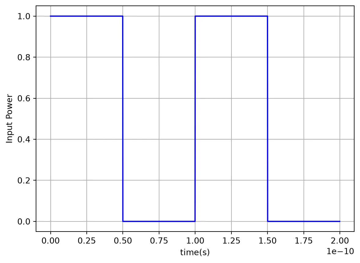
Running the Time-Domain Simulation
Section titled “Running the Time-Domain Simulation”-
Resetting the Time-Stepper
We callts.resetto ensure the simulation starts with a clean internal state, preventing residual values from previous runs. -
Executing the Simulation
Thestepmethod of the time-stepper is used to propagate the defined optical and electrical inputs through the MZI over the simulation time, producing the output waveforms.
The resulting outputs object contains the simulated time-domain signals at all output ports of the MZI.
# Reset the time-stepper to ensure a clean simulation startts.reset()
# Run the simulation for the given input waveformsoutputs = ts.step(inputs)
# Plot PhotonForge simulation results for both output portsplt.plot(t, np.abs(A1_in) ** 2, label="Input Signal")plt.plot(t, np.abs(outputs["P2@0"]) ** 2, label="Port 2")plt.plot(t, np.abs(outputs["P3@0"]) ** 2, label="Port 3")
# Labels and legendplt.xlabel("Time (s)")plt.ylabel("Power")plt.legend(loc="upper right")plt.grid(True)plt.show()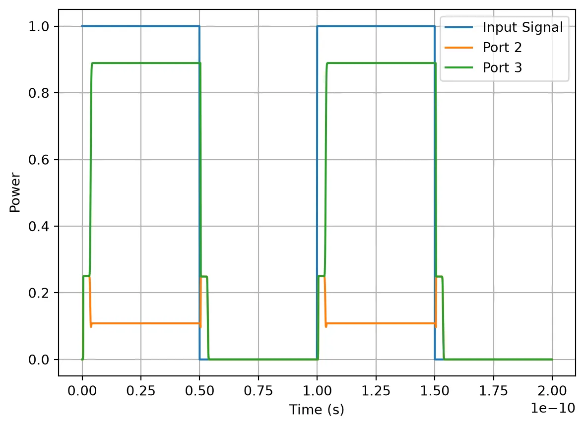
Interpreting the Time-Domain Output
Section titled “Interpreting the Time-Domain Output”At the very start, the outputs are almost identical, showing only a small shift due to the short delay through the straight arm.
This is why both outputs track each other right after the input changes.
Once the signal traveling through the spiral delay line arrives—after a larger delay—the two optical paths recombine with a relative phase difference.
This phase difference causes interference, leading to the characteristic constructive and destructive output pattern of an MZI.
Important: In this example the instantaneous phase difference is not exactly 0 or π, so we do not observe full transmission or perfect extinction. Instead, the outputs settle at partial contrast:
In summary:
- Small initial delay → outputs look the same.
- Larger spiral-induced delay → interference starts, splitting power between the two output ports, with partial (not complete) constructive/destructive interference.
Activating Tidy3D for High-Accuracy Simulation
Section titled “Activating Tidy3D for High-Accuracy Simulation”We switch the directional coupler and spiral bends to use their Tidy3D full-wave models, enabling more accurate simulations that capture electromagnetic effects beyond analytical approximations.
# Use Tidy3D model for bends inside spiralspiral.update(bend_kwargs={"model": pf.Tidy3DModel()})
# Use Tidy3D model for directional couplerdirectional_coupler.activate_model("Tidy3D")
Tidy3DModel(run_time=None, medium=None, symmetry=(0, 0, 0), boundary_spec=None, monitors=(), structures=(), grid_spec=None, shutoff=None, subpixel=None, courant=None, port_symmetries=[('P1', 'P0', 'P3', 'P2'), ('P2', 'P3', 'P0', 'P1'), ('P3', 'P2', 'P1', 'P0')], bounds=((None, None, None), (None, None, None)), source_gap=None, simulation_updates=None, autograd_config=None, verbose=True)After activating the high-fidelity models, we re-initialize the MZI’s time-stepper for time-domain simulation. We also reduce rms_error_tolerance to suppress warnings that occur when the pole-residue fit error exceeds this value. While increasing the Tidy3D simulation accuracy would also prevent this warning, the current setting provides sufficient accuracy for the final results.
# Setting rms_error_tolerance for pole-residue fitpf.config.default_time_steppers["*"] = pf.SMatrixTimeStepper(rms_error_tolerance=0.001)
# Set up time stepperts_td = mzi.setup_time_stepper(    time_step=time_step,    carrier_frequency=f_c,    time_stepper_kwargs={        "frequencies": np.linspace(f_c - 200 * f_m, f_c + 200 * f_m, 100),    },)
# Run the simulation for the given input waveformsoutputs_td = ts_td.step(inputs)plt.plot(t, np.abs(A1_in) ** 2, label="Input Signal")plt.plot(t, np.abs(outputs_td["P2@0"]) ** 2, label="Port 2")plt.plot(t, np.abs(outputs_td["P3@0"]) ** 2, label="Port 3")
# Labels and legendplt.xlabel("Time (s)")plt.ylabel("Power")plt.legend(loc="upper right")plt.grid(True)plt.show()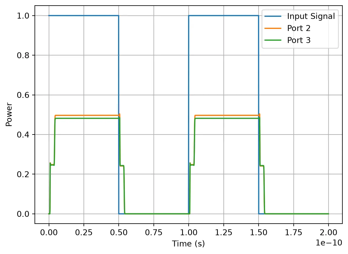
Why Do the Time-Domain Results Differ Between the Analytic and Tidy3D Models?
When using the Tidy3D model for bends, the full-wave solver captures subtle effects that are not included in the analytic bend model.
In particular, the effective index in the bend region differs slightly from that of a straight waveguide, which changes the optical phase accumulated along each arm of the MZI.
These phase changes lead to:
- A shift in the interference spectrum of the MZI.
- Corresponding changes in the S-matrix at a given frequency (both phase and amplitude can be affected).
- A different time-domain output waveform when driven with the same input.