

Verilog-A Export
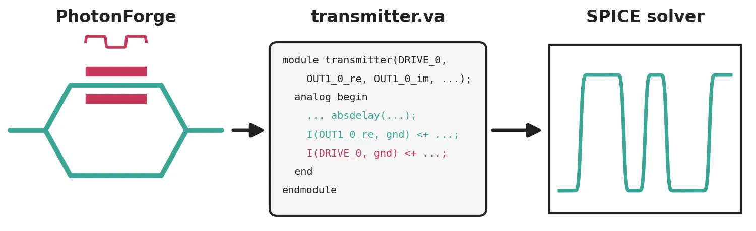
TimeStepper.write_verilog_a writes a configured time stepper as one self-contained Verilog-A module. The time stepper can belong to a single component or to a whole circuit; for a circuit, every component is written into the same module. The exported photonic circuit can then be placed in a SPICE netlist next to the driver, the transimpedance amplifier and the rest of the electronics, so the complete transceiver is simulated in one circuit simulator.
This guide exports a Mach-Zehnder transmitter, laser included, compiles the module with OpenVAF-Reloaded and simulates it in ngspice with the same drive signal used in PhotonForge.
Compiler and simulator
Section titled “Compiler and simulator”The exported modules use the Verilog-A absdelay operator for propagation delays and
white_noise for noise sources, and both the compiler and the simulator must implement them.
This guide uses OpenVAF-Reloaded 23.6.0 and ngspice-46 from the
Ngspice_OpenVAF_Enhancements
repository, which provides prebuilt binaries for Windows, Linux and macOS in its
bin/<platform>/<architecture> folders. Take both programs from the same folder and put it on
the system path so that openvaf-r and ngspice are found.
import subprocess
import matplotlib.pyplot as pltimport numpy as npimport photonforge as pfimport photonforge.abstract as pfaimport siepic_forge as siepicfrom scipy.ndimage import gaussian_filter1d
# SiEPIC EBeam silicon process, with its 500 nm strip waveguide as the default portpf.config.default_technology = siepic.ebeam()pf.config.default_kwargs = {"euler_fraction": 0.5, "port_spec": "TE_1550_500"}
viewer = pf.live_viewer.LiveViewer()
LiveViewer started at http://127.0.0.1:43277. Call its 'stop()' method to free the port.Transmitter circuit
Section titled “Transmitter circuit”The transmitter is a Mach-Zehnder interferometer fed by a CW laser. One arm is a 2 mm silicon phase shifter with V cm, so its half-wave voltage is V, and a 30 GHz electro-optic bandwidth. The other arm is a plain waveguide of the same length. Two s-bend directional couplers split and recombine the light.
The phase shifter is a straight waveguide with an electrode on either side and an electrical
port E0 for the drive. Its behavior comes from
AnalyticWaveguideModel, with a
PhaseModTimeStepper attached for the time
domain. The reference arm uses
AnalyticWaveguideTimeStepper.
f_c = pf.C_0 / 1.55  # carrier frequency, pf.C_0 is in um/sbit_rate = 10e9time_step = 0.5e-12  # 200 samples per bitz0 = 50.0  # reference impedance of the ports
# Waveguide shared by both armslength = 2000.0  # umwaveguide = dict(    n_eff=2.4,    n_group=4.2,    reference_frequency=f_c,    length=length,    propagation_loss=1e-4,  # dB/um, that is 1 dB/cm)v_pil = 1.5e4  # V um, that is 1.5 V cmv_pi = v_pil / length  # 7.5 V
@pf.parametric_componentdef phase_shifter(*, length=length):    component = pf.parametric.straight(length=length)
    # Electrodes on the metal layer, 1.1 um from the waveguide center    component.add(        "M1_heater",        pf.Rectangle((0, 1.1), (length, 1.9)),        pf.Rectangle((0, -1.9), (length, -1.1)),    )
    # Virtual electrical port for the drive, on the upper electrode    component.add_port(        pf.Port(            (length / 2, 1.5),            90,            spec=pf.virtual_port_spec(classification="electrical"),        )    )
    # The time stepper attached to the model is what gets exported    model = pf.AnalyticWaveguideModel(v_piL=v_pil, **waveguide)    model.time_stepper = pf.PhaseModTimeStepper(v_piL=v_pil, f_3dB=30e9, **waveguide)    component.add_model(model)    return component
@pf.parametric_componentdef reference_arm(*, length=length):    # Same waveguide without the electro-optic effect; the delay is applied directly    model = pf.AnalyticWaveguideModel(**waveguide)    model.time_stepper = pf.AnalyticWaveguideTimeStepper(**waveguide)    return pf.parametric.straight(length=length, model=model)
# 10 um s-bend offsets separate the two arms by 20 umcoupler = pf.parametric.s_bend_coupler(    coupling_distance=0.6,    coupling_length=4.7,    s_bend_length=40,    s_bend_offset=10,    model=pf.DirectionalCouplerModel(),)
# 1 mW laser, and a termination for the unused input of the first couplerlaser = pfa.cw_laser(power=1e-3, frequency=f_c)termination = pfa.optical_termination()
The netlist places the arms and the second coupler with physical connections; the last pair of ports meets geometrically and closes the interferometer. The laser and the termination have no layout, so each is placed next to its coupler port and attached with a virtual connection. The circuit exposes three ports: the drive and the two optical outputs.
transmitter = pf.component_from_netlist( { "name": "Transmitter", "instances": { # Abstract blocks are built at the origin, so place them by their ports "laser": {"component": laser, "origin": (-20, 0)}, "dump": {"component": termination, "origin": (-20, 20.6)}, "dc0": coupler, "ref": reference_arm(), "arm": phase_shifter(), "dc1": coupler, }, "connections": [ (("ref", "P0"), ("dc0", "P2")), (("dc1", "P0"), ("ref", "P1")), (("arm", "P0"), ("dc0", "P3")), ], "virtual connections": [ (("laser", "P0"), ("dc0", "P0")), (("dump", "P0"), ("dc0", "P1")), ], "ports": [ ("arm", "E0", "DRIVE"), ("dc1", "P2", "OUT1"), ("dc1", "P3", "OUT2"), ], "models": [(pf.CircuitModel(), "Circuit")], })viewer(transmitter);fill:%23221f20;font-weight:bold;font-size:9.918400px;}.terminal{fill:none;stroke:%23805080;stroke-width:1.239800;}.dashed{stroke-dasharray:6.199000,3.719400;}.port{fill:none;stroke:%23805080;stroke-width:2.479600;}.virtual-connection{fill:none;stroke:%23907090;stroke-width:1.859700;}.layer_31_0{stroke:%238c78ef;fill:url(%23pat-layer_31_0);fill-opacity:0.492;}.label_31_0{fill:%238c78ef;}.layer_33_0{stroke:%238c78ef;fill:url(%23pat-layer_33_0);fill-opacity:0.492;}.label_33_0{fill:%238c78ef;}.layer_102_0{stroke:%238c78ef;fill:url(%23pat-layer_102_0);fill-opacity:0.492;}.label_102_0{fill:%238c78ef;}.layer_110_0{stroke:%238c78ef;fill:url(%23pat-layer_110_0);fill-opacity:0.492;}.label_110_0{fill:%238c78ef;}.layer_189_0{stroke:%23000000;fill:none;}.label_189_0{fill:%23000000;}.layer_201_0{stroke:%2300ee00;fill:url(%23pat-layer_201_0);fill-opacity:0.492;}.label_201_0{fill:%2300ee00;}.layer_401_0{stroke:%236a8ad2;fill:url(%23pat-layer_401_0);fill-opacity:0.492;}.label_401_0{fill:%236a8ad2;}.layer_202_0{stroke:%23007600;fill:url(%23pat-layer_202_0);fill-opacity:0.492;}.label_202_0{fill:%23007600;}.layer_68_0{stroke:%23008000;fill:url(%23pat-layer_68_0);fill-opacity:0.492;}.label_68_0{fill:%23008000;}.layer_5_0{stroke:%236a8ad2;fill:url(%23pat-layer_5_0);fill-opacity:0.492;}.label_5_0{fill:%236a8ad2;}.layer_998_0{stroke:%23000000;fill:none;}.label_998_0{fill:%23000000;}.layer_312_1{stroke:%2300b8b8;fill:url(%23pat-layer_312_1);fill-opacity:0.492;}.label_312_1{fill:%2300b8b8;}.layer_312_0{stroke:%2300b8b8;fill:url(%23pat-layer_312_0);fill-opacity:0.492;}.label_312_0{fill:%2300b8b8;}.layer_402_0{stroke:%23ff0000;fill:url(%23pat-layer_402_0);fill-opacity:0.492;}.label_402_0{fill:%23ff0000;}.layer_401_4{stroke:%236a8ad2;fill:url(%23pat-layer_401_4);fill-opacity:0.492;}.label_401_4{fill:%236a8ad2;}.layer_389_0{stroke:%23ff00ff;fill:url(%23pat-layer_389_0);fill-opacity:0.492;}.label_389_0{fill:%23ff00ff;}.layer_402_1{stroke:%23ff0000;fill:url(%23pat-layer_402_1);fill-opacity:0.492;}.label_402_1{fill:%23ff0000;}.layer_350_1{stroke:%23697a00;fill:url(%23pat-layer_350_1);fill-opacity:0.492;}.label_350_1{fill:%23697a00;}.layer_401_1{stroke:%236a8ad2;fill:url(%23pat-layer_401_1);fill-opacity:0.492;}.label_401_1{fill:%236a8ad2;}.layer_313_2{stroke:%2301d95b;fill:url(%23pat-layer_313_2);fill-opacity:0.492;}.label_313_2{fill:%2301d95b;}.layer_313_1{stroke:%2301d95b;fill:url(%23pat-layer_313_1);fill-opacity:0.492;}.label_313_1{fill:%2301d95b;}.layer_313_0{stroke:%2301d95b;fill:url(%23pat-layer_313_0);fill-opacity:0.492;}.label_313_0{fill:%2301d95b;}.layer_400_0{stroke:%23a96868;fill:url(%23pat-layer_400_0);fill-opacity:0.492;}.label_400_0{fill:%23a96868;}.layer_312_3{stroke:%2300b8b8;fill:url(%23pat-layer_312_3);fill-opacity:0.492;}.label_312_3{fill:%2300b8b8;}.layer_389_1{stroke:%23ff00ff;fill:url(%23pat-layer_389_1);fill-opacity:0.492;}.label_389_1{fill:%23ff00ff;}.layer_401_3{stroke:%236a8ad2;fill:url(%23pat-layer_401_3);fill-opacity:0.492;}.label_401_3{fill:%236a8ad2;}.layer_403_2{stroke:%23500080;fill:url(%23pat-layer_403_2);fill-opacity:0.492;}.label_403_2{fill:%23500080;}.layer_403_3{stroke:%23500080;fill:url(%23pat-layer_403_3);fill-opacity:0.492;}.label_403_3{fill:%23500080;}.layer_403_1{stroke:%23500080;fill:url(%23pat-layer_403_1);fill-opacity:0.492;}.label_403_1{fill:%23500080;}.layer_403_0{stroke:%23500080;fill:url(%23pat-layer_403_0);fill-opacity:0.492;}.label_403_0{fill:%23500080;}.layer_311_1{stroke:%23ac6c56;fill:url(%23pat-layer_311_1);fill-opacity:0.492;}.label_311_1{fill:%23ac6c56;}.layer_311_0{stroke:%23ac6c56;fill:url(%23pat-layer_311_0);fill-opacity:0.492;}.label_311_0{fill:%23ac6c56;}.layer_301_1{stroke:%23800057;fill:url(%23pat-layer_301_1);fill-opacity:0.492;}.label_301_1{fill:%23800057;}.layer_301_0{stroke:%23800057;fill:url(%23pat-layer_301_0);fill-opacity:0.492;}.label_301_0{fill:%23800057;}.layer_305_1{stroke:%23808080;fill:url(%23pat-layer_305_1);fill-opacity:0.492;}.label_305_1{fill:%23808080;}.layer_305_0{stroke:%23808080;fill:url(%23pat-layer_305_0);fill-opacity:0.492;}.label_305_0{fill:%23808080;}.layer_999_0{stroke:%230000ff;fill:url(%23pat-layer_999_0);fill-opacity:0.492;}.label_999_0{fill:%230000ff;}.layer_81_0{stroke:%23808080;fill:url(%23pat-layer_81_0);fill-opacity:0.492;}.label_81_0{fill:%23808080;}.layer_290_0{stroke:%23a46eda;fill:none;}.label_290_0{fill:%23a46eda;}.layer_205_0{stroke:%2349b203;fill:url(%23pat-layer_205_0);fill-opacity:0.492;}.label_205_0{fill:%2349b203;}.layer_11_0{stroke:%230000ff;fill:url(%23pat-layer_11_0);fill-opacity:0.492;}.label_11_0{fill:%230000ff;}.layer_12_0{stroke:%23a57b00;fill:url(%23pat-layer_12_0);fill-opacity:0.492;}.label_12_0{fill:%23a57b00;}.layer_13_0{stroke:%23800057;fill:url(%23pat-layer_13_0);fill-opacity:0.492;}.label_13_0{fill:%23800057;}.layer_6_0{stroke:%23ff0000;fill:url(%23pat-layer_6_0);fill-opacity:0.492;}.label_6_0{fill:%23ff0000;}.layer_1_10{stroke:%23c96585;fill:url(%23pat-layer_1_10);fill-opacity:0.492;}.label_1_10{fill:%23c96585;}.layer_1_11{stroke:%23800000;fill:url(%23pat-layer_1_11);fill-opacity:0.492;}.label_1_11{fill:%23800000;}.layer_200_0{stroke:%23ff0000;fill:url(%23pat-layer_200_0);fill-opacity:0.492;}.label_200_0{fill:%23ff0000;}.layer_1_0{stroke:%23c96585;fill:url(%23pat-layer_1_0);fill-opacity:0.492;}.label_1_0{fill:%23c96585;}.layer_2_0{stroke:%23a46eda;fill:url(%23pat-layer_2_0);fill-opacity:0.492;}.label_2_0{fill:%23a46eda;}.layer_20_0{stroke:%2353793d;fill:url(%23pat-layer_20_0);fill-opacity:0.492;}.label_20_0{fill:%2353793d;}.layer_22_0{stroke:%23ec7600;fill:url(%23pat-layer_22_0);fill-opacity:0.492;}.label_22_0{fill:%23ec7600;}.layer_24_0{stroke:%2300b8b8;fill:url(%23pat-layer_24_0);fill-opacity:0.492;}.label_24_0{fill:%2300b8b8;}.layer_21_0{stroke:%23736264;fill:url(%23pat-layer_21_0);fill-opacity:0.492;}.label_21_0{fill:%23736264;}.layer_23_0{stroke:%23697a00;fill:url(%23pat-layer_23_0);fill-opacity:0.492;}.label_23_0{fill:%23697a00;}.layer_25_0{stroke:%23008000;fill:url(%23pat-layer_25_0);fill-opacity:0.492;}.label_25_0{fill:%23008000;}.layer_350_0{stroke:%23697a00;fill:url(%23pat-layer_350_0);fill-opacity:0.492;}.label_350_0{fill:%23697a00;}.layer_10_0{stroke:%23000000;fill:none;}.label_10_0{fill:%23000000;}.layer_203_0{stroke:%23008000;fill:url(%23pat-layer_203_0);fill-opacity:0.492;}.label_203_0{fill:%23008000;}.layer_40_0{stroke:%230000ff;fill:url(%23pat-layer_40_0);fill-opacity:0.492;}.label_40_0{fill:%230000ff;}.layer_401_2{stroke:%236a8ad2;fill:url(%23pat-layer_401_2);fill-opacity:0.492;}.label_401_2{fill:%236a8ad2;}.layer_301_2{stroke:%23800057;fill:url(%23pat-layer_301_2);fill-opacity:0.492;}.label_301_2{fill:%23800057;}</style><defs><path id=%22port-symbol%22 class=%22port%22 d=%22M 0,-4.959200 L 7.438800,0 0,4.959200%22 /><path id=%22ref-port-symbol%22 class=%22port%22 style=%22stroke-opacity:0.33;%22 d=%22M 0,-3.719400 C 4.959200,-3.719400 4.959200,3.719400 0,3.719400%22 /><circle id=%22port-bend-symbol%22 style=%22stroke-width:0;stroke:none;fill:%23805080;fill-opacity:1;%22 cx=%220%22 cy=%220%22 r=%222.231640%22 /><circle id=%22connection-symbol%22 style=%22stroke-width:0;stroke:none;fill:%23907090;fill-opacity:1;%22 cx=%220%22 cy=%220%22 r=%222.603580%22 /><pattern id=%22pat-layer_31_0%22 patternUnits=%22userSpaceOnUse%22 width=%226.199000%22 height=%226.199000%22 patternTransform=%22translate(4.740412,5.872737)%22><line x1=%220%22 y1=%220%22 x2=%226.199000%22 y2=%226.199000%22 style=%22stroke:%238c78ef;stroke-width:0.619900%22 /><line x1=%22-3.099500%22 y1=%223.099500%22 x2=%223.099500%22 y2=%229.298500%22 style=%22stroke:%238c78ef;stroke-width:0.619900%22 /><line x1=%223.099500%22 y1=%22-3.099500%22 x2=%229.298500%22 y2=%223.099500%22 style=%22stroke:%238c78ef;stroke-width:0.619900%22 /></pattern><pattern id=%22pat-layer_33_0%22 patternUnits=%22userSpaceOnUse%22 width=%226.199000%22 height=%226.199000%22 patternTransform=%22translate(3.646471,0.652526)%22><line x1=%220%22 y1=%220%22 x2=%226.199000%22 y2=%226.199000%22 style=%22stroke:%238c78ef;stroke-width:0.619900%22 /><line x1=%22-3.099500%22 y1=%223.099500%22 x2=%223.099500%22 y2=%229.298500%22 style=%22stroke:%238c78ef;stroke-width:0.619900%22 /><line x1=%223.099500%22 y1=%22-3.099500%22 x2=%229.298500%22 y2=%223.099500%22 style=%22stroke:%238c78ef;stroke-width:0.619900%22 /></pattern><pattern id=%22pat-layer_102_0%22 patternUnits=%22userSpaceOnUse%22 width=%226.199000%22 height=%226.199000%22 patternTransform=%22translate(0.000000,0.326263)%22><line x1=%220%22 y1=%220%22 x2=%226.199000%22 y2=%226.199000%22 style=%22stroke:%238c78ef;stroke-width:0.619900%22 /><line x1=%22-3.099500%22 y1=%223.099500%22 x2=%223.099500%22 y2=%229.298500%22 style=%22stroke:%238c78ef;stroke-width:0.619900%22 /><line x1=%223.099500%22 y1=%22-3.099500%22 x2=%229.298500%22 y2=%223.099500%22 style=%22stroke:%238c78ef;stroke-width:0.619900%22 /></pattern><pattern id=%22pat-layer_110_0%22 patternUnits=%22userSpaceOnUse%22 width=%226.199000%22 height=%226.199000%22 patternTransform=%22translate(1.823235,4.241421)%22><line x1=%220%22 y1=%220%22 x2=%226.199000%22 y2=%226.199000%22 style=%22stroke:%238c78ef;stroke-width:0.619900%22 /><line x1=%22-3.099500%22 y1=%223.099500%22 x2=%223.099500%22 y2=%229.298500%22 style=%22stroke:%238c78ef;stroke-width:0.619900%22 /><line x1=%223.099500%22 y1=%22-3.099500%22 x2=%229.298500%22 y2=%223.099500%22 style=%22stroke:%238c78ef;stroke-width:0.619900%22 /></pattern><pattern id=%22pat-layer_201_0%22 patternUnits=%22userSpaceOnUse%22 width=%226.199000%22 height=%226.199000%22 patternTransform=%22translate(4.740412,2.283842)%22><circle cx=%223.099500%22 cy=%223.099500%22 r=%220.619900%22 style=%22stroke:none;fill:%2300ee00;fill-opacity:1.0%22 /></pattern><pattern id=%22pat-layer_401_0%22 patternUnits=%22userSpaceOnUse%22 width=%223.719400%22 height=%223.719400%22 patternTransform=%22translate(0.437576,0.587274)%22><line x1=%220%22 y1=%220%22 x2=%223.719400%22 y2=%223.719400%22 style=%22stroke:%236a8ad2;stroke-width:0.619900%22 /><line x1=%22-1.859700%22 y1=%221.859700%22 x2=%221.859700%22 y2=%225.579100%22 style=%22stroke:%236a8ad2;stroke-width:0.619900%22 /><line x1=%221.859700%22 y1=%22-1.859700%22 x2=%225.579100%22 y2=%221.859700%22 style=%22stroke:%236a8ad2;stroke-width:0.619900%22 /><line x1=%223.719400%22 y1=%220%22 x2=%220%22 y2=%223.719400%22 style=%22stroke:%236a8ad2;stroke-width:0.619900%22 /><line x1=%225.579100%22 y1=%221.859700%22 x2=%221.859700%22 y2=%225.579100%22 style=%22stroke:%236a8ad2;stroke-width:0.619900%22 /><line x1=%221.859700%22 y1=%22-1.859700%22 x2=%22-1.859700%22 y2=%221.859700%22 style=%22stroke:%236a8ad2;stroke-width:0.619900%22 /></pattern><pattern id=%22pat-layer_202_0%22 patternUnits=%22userSpaceOnUse%22 width=%223.719400%22 height=%223.719400%22 patternTransform=%22translate(0.656365,3.523642)%22><circle cx=%221.859700%22 cy=%221.859700%22 r=%220.619900%22 style=%22stroke:none;fill:%23007600;fill-opacity:1.0%22 /></pattern><pattern id=%22pat-layer_68_0%22 patternUnits=%22userSpaceOnUse%22 width=%226.199000%22 height=%226.199000%22 patternTransform=%22translate(0.000000,2.283842)%22><circle cx=%223.099500%22 cy=%223.099500%22 r=%220.619900%22 style=%22stroke:none;fill:%23008000;fill-opacity:1.0%22 /></pattern><pattern id=%22pat-layer_5_0%22 patternUnits=%22userSpaceOnUse%22 width=%223.719400%22 height=%223.719400%22 patternTransform=%22translate(0.218788,3.327884)%22><line x1=%221.859700%22 y1=%220%22 x2=%221.859700%22 y2=%223.719400%22 style=%22stroke:%236a8ad2;stroke-width:0.619900%22 /></pattern><pattern id=%22pat-layer_312_1%22 patternUnits=%22userSpaceOnUse%22 width=%223.719400%22 height=%223.719400%22 patternTransform=%22translate(0.875153,2.936368)%22><line x1=%220%22 y1=%220%22 x2=%223.719400%22 y2=%223.719400%22 style=%22stroke:%2300b8b8;stroke-width:0.619900%22 /><line x1=%22-1.859700%22 y1=%221.859700%22 x2=%221.859700%22 y2=%225.579100%22 style=%22stroke:%2300b8b8;stroke-width:0.619900%22 /><line x1=%221.859700%22 y1=%22-1.859700%22 x2=%225.579100%22 y2=%221.859700%22 style=%22stroke:%2300b8b8;stroke-width:0.619900%22 /></pattern><pattern id=%22pat-layer_312_0%22 patternUnits=%22userSpaceOnUse%22 width=%226.199000%22 height=%226.199000%22 patternTransform=%22translate(2.917176,3.915158)%22><line x1=%223.099500%22 y1=%220%22 x2=%223.099500%22 y2=%226.199000%22 style=%22stroke:%2300b8b8;stroke-width:0.619900%22 /></pattern><pattern id=%22pat-layer_402_0%22 patternUnits=%22userSpaceOnUse%22 width=%226.199000%22 height=%226.199000%22 patternTransform=%22translate(3.281824,4.567684)%22><line x1=%223.099500%22 y1=%220%22 x2=%223.099500%22 y2=%226.199000%22 style=%22stroke:%23ff0000;stroke-width:0.619900%22 /><line x1=%220%22 y1=%223.099500%22 x2=%226.199000%22 y2=%223.099500%22 style=%22stroke:%23ff0000;stroke-width:0.619900%22 /></pattern><pattern id=%22pat-layer_401_4%22 patternUnits=%22userSpaceOnUse%22 width=%223.719400%22 height=%223.719400%22 patternTransform=%22translate(0.656365,2.936368)%22><line x1=%221.859700%22 y1=%220%22 x2=%221.859700%22 y2=%223.719400%22 style=%22stroke:%236a8ad2;stroke-width:0.619900%22 /></pattern><pattern id=%22pat-layer_389_0%22 patternUnits=%22userSpaceOnUse%22 width=%223.719400%22 height=%223.719400%22 patternTransform=%22translate(0.656365,0.783032)%22><line x1=%221.859700%22 y1=%220%22 x2=%221.859700%22 y2=%223.719400%22 style=%22stroke:%23ff00ff;stroke-width:0.619900%22 /><line x1=%220%22 y1=%221.859700%22 x2=%223.719400%22 y2=%221.859700%22 style=%22stroke:%23ff00ff;stroke-width:0.619900%22 /></pattern><pattern id=%22pat-layer_402_1%22 patternUnits=%22userSpaceOnUse%22 width=%223.719400%22 height=%223.719400%22 patternTransform=%22translate(1.093941,3.327884)%22><line x1=%220%22 y1=%220%22 x2=%223.719400%22 y2=%223.719400%22 style=%22stroke:%23ff0000;stroke-width:0.619900%22 /><line x1=%22-1.859700%22 y1=%221.859700%22 x2=%221.859700%22 y2=%225.579100%22 style=%22stroke:%23ff0000;stroke-width:0.619900%22 /><line x1=%221.859700%22 y1=%22-1.859700%22 x2=%225.579100%22 y2=%221.859700%22 style=%22stroke:%23ff0000;stroke-width:0.619900%22 /><line x1=%223.719400%22 y1=%220%22 x2=%220%22 y2=%223.719400%22 style=%22stroke:%23ff0000;stroke-width:0.619900%22 /><line x1=%225.579100%22 y1=%221.859700%22 x2=%221.859700%22 y2=%225.579100%22 style=%22stroke:%23ff0000;stroke-width:0.619900%22 /><line x1=%221.859700%22 y1=%22-1.859700%22 x2=%22-1.859700%22 y2=%221.859700%22 style=%22stroke:%23ff0000;stroke-width:0.619900%22 /></pattern><pattern id=%22pat-layer_350_1%22 patternUnits=%22userSpaceOnUse%22 width=%223.719400%22 height=%223.719400%22 patternTransform=%22translate(3.281824,2.936368)%22><circle cx=%221.859700%22 cy=%221.859700%22 r=%220.619900%22 style=%22stroke:none;fill:%23697a00;fill-opacity:1.0%22 /></pattern><pattern id=%22pat-layer_401_1%22 patternUnits=%22userSpaceOnUse%22 width=%226.199000%22 height=%226.199000%22 patternTransform=%22translate(5.469706,1.957579)%22><line x1=%220%22 y1=%220%22 x2=%226.199000%22 y2=%226.199000%22 style=%22stroke:%236a8ad2;stroke-width:0.619900%22 /><line x1=%22-3.099500%22 y1=%223.099500%22 x2=%223.099500%22 y2=%229.298500%22 style=%22stroke:%236a8ad2;stroke-width:0.619900%22 /><line x1=%223.099500%22 y1=%22-3.099500%22 x2=%229.298500%22 y2=%223.099500%22 style=%22stroke:%236a8ad2;stroke-width:0.619900%22 /><line x1=%226.199000%22 y1=%220%22 x2=%220%22 y2=%226.199000%22 style=%22stroke:%236a8ad2;stroke-width:0.619900%22 /><line x1=%229.298500%22 y1=%223.099500%22 x2=%223.099500%22 y2=%229.298500%22 style=%22stroke:%236a8ad2;stroke-width:0.619900%22 /><line x1=%223.099500%22 y1=%22-3.099500%22 x2=%22-3.099500%22 y2=%223.099500%22 style=%22stroke:%236a8ad2;stroke-width:0.619900%22 /></pattern><pattern id=%22pat-layer_313_2%22 patternUnits=%22userSpaceOnUse%22 width=%223.719400%22 height=%223.719400%22 patternTransform=%22translate(1.531518,1.957579)%22><line x1=%220%22 y1=%220%22 x2=%223.719400%22 y2=%223.719400%22 style=%22stroke:%2301d95b;stroke-width:0.619900%22 /><line x1=%22-1.859700%22 y1=%221.859700%22 x2=%221.859700%22 y2=%225.579100%22 style=%22stroke:%2301d95b;stroke-width:0.619900%22 /><line x1=%221.859700%22 y1=%22-1.859700%22 x2=%225.579100%22 y2=%221.859700%22 style=%22stroke:%2301d95b;stroke-width:0.619900%22 /></pattern><pattern id=%22pat-layer_313_1%22 patternUnits=%22userSpaceOnUse%22 width=%226.199000%22 height=%226.199000%22 patternTransform=%22translate(4.011118,2.283842)%22><line x1=%223.099500%22 y1=%220%22 x2=%223.099500%22 y2=%226.199000%22 style=%22stroke:%2301d95b;stroke-width:0.619900%22 /></pattern><pattern id=%22pat-layer_313_0%22 patternUnits=%22userSpaceOnUse%22 width=%223.719400%22 height=%223.719400%22 patternTransform=%22translate(3.281824,0.783032)%22><line x1=%221.859700%22 y1=%220%22 x2=%221.859700%22 y2=%223.719400%22 style=%22stroke:%2301d95b;stroke-width:0.619900%22 /></pattern><pattern id=%22pat-layer_400_0%22 patternUnits=%22userSpaceOnUse%22 width=%226.199000%22 height=%226.199000%22 patternTransform=%22translate(4.375765,3.588895)%22><line x1=%220%22 y1=%220%22 x2=%226.199000%22 y2=%226.199000%22 style=%22stroke:%23a96868;stroke-width:0.619900%22 /><line x1=%22-3.099500%22 y1=%223.099500%22 x2=%223.099500%22 y2=%229.298500%22 style=%22stroke:%23a96868;stroke-width:0.619900%22 /><line x1=%223.099500%22 y1=%22-3.099500%22 x2=%229.298500%22 y2=%223.099500%22 style=%22stroke:%23a96868;stroke-width:0.619900%22 /><line x1=%226.199000%22 y1=%220%22 x2=%220%22 y2=%226.199000%22 style=%22stroke:%23a96868;stroke-width:0.619900%22 /><line x1=%229.298500%22 y1=%223.099500%22 x2=%223.099500%22 y2=%229.298500%22 style=%22stroke:%23a96868;stroke-width:0.619900%22 /><line x1=%223.099500%22 y1=%22-3.099500%22 x2=%22-3.099500%22 y2=%223.099500%22 style=%22stroke:%23a96868;stroke-width:0.619900%22 /></pattern><pattern id=%22pat-layer_312_3%22 patternUnits=%22userSpaceOnUse%22 width=%223.719400%22 height=%223.719400%22 patternTransform=%22translate(2.844247,0.391516)%22><line x1=%223.719400%22 y1=%220%22 x2=%220%22 y2=%223.719400%22 style=%22stroke:%2300b8b8;stroke-width:0.619900%22 /><line x1=%225.579100%22 y1=%221.859700%22 x2=%221.859700%22 y2=%225.579100%22 style=%22stroke:%2300b8b8;stroke-width:0.619900%22 /><line x1=%221.859700%22 y1=%22-1.859700%22 x2=%22-1.859700%22 y2=%221.859700%22 style=%22stroke:%2300b8b8;stroke-width:0.619900%22 /></pattern><pattern id=%22pat-layer_389_1%22 patternUnits=%22userSpaceOnUse%22 width=%226.199000%22 height=%226.199000%22 patternTransform=%22translate(5.834353,2.283842)%22><line x1=%223.099500%22 y1=%220%22 x2=%223.099500%22 y2=%226.199000%22 style=%22stroke:%23ff00ff;stroke-width:0.619900%22 /><line x1=%220%22 y1=%223.099500%22 x2=%226.199000%22 y2=%223.099500%22 style=%22stroke:%23ff00ff;stroke-width:0.619900%22 /></pattern><pattern id=%22pat-layer_401_3%22 patternUnits=%22userSpaceOnUse%22 width=%226.199000%22 height=%226.199000%22 patternTransform=%22translate(2.552529,3.915158)%22><line x1=%220%22 y1=%223.099500%22 x2=%226.199000%22 y2=%223.099500%22 style=%22stroke:%236a8ad2;stroke-width:0.619900%22 /></pattern><pattern id=%22pat-layer_403_2%22 patternUnits=%22userSpaceOnUse%22 width=%223.719400%22 height=%223.719400%22 patternTransform=%22translate(1.750306,2.349095)%22><line x1=%220%22 y1=%220%22 x2=%223.719400%22 y2=%223.719400%22 style=%22stroke:%23500080;stroke-width:0.619900%22 /><line x1=%22-1.859700%22 y1=%221.859700%22 x2=%221.859700%22 y2=%225.579100%22 style=%22stroke:%23500080;stroke-width:0.619900%22 /><line x1=%221.859700%22 y1=%22-1.859700%22 x2=%225.579100%22 y2=%221.859700%22 style=%22stroke:%23500080;stroke-width:0.619900%22 /><line x1=%223.719400%22 y1=%220%22 x2=%220%22 y2=%223.719400%22 style=%22stroke:%23500080;stroke-width:0.619900%22 /><line x1=%225.579100%22 y1=%221.859700%22 x2=%221.859700%22 y2=%225.579100%22 style=%22stroke:%23500080;stroke-width:0.619900%22 /><line x1=%221.859700%22 y1=%22-1.859700%22 x2=%22-1.859700%22 y2=%221.859700%22 style=%22stroke:%23500080;stroke-width:0.619900%22 /></pattern><pattern id=%22pat-layer_403_3%22 patternUnits=%22userSpaceOnUse%22 width=%226.199000%22 height=%226.199000%22 patternTransform=%22translate(1.458588,4.893947)%22><line x1=%220%22 y1=%220%22 x2=%226.199000%22 y2=%226.199000%22 style=%22stroke:%23500080;stroke-width:0.619900%22 /><line x1=%22-3.099500%22 y1=%223.099500%22 x2=%223.099500%22 y2=%229.298500%22 style=%22stroke:%23500080;stroke-width:0.619900%22 /><line x1=%223.099500%22 y1=%22-3.099500%22 x2=%229.298500%22 y2=%223.099500%22 style=%22stroke:%23500080;stroke-width:0.619900%22 /><line x1=%226.199000%22 y1=%220%22 x2=%220%22 y2=%226.199000%22 style=%22stroke:%23500080;stroke-width:0.619900%22 /><line x1=%229.298500%22 y1=%223.099500%22 x2=%223.099500%22 y2=%229.298500%22 style=%22stroke:%23500080;stroke-width:0.619900%22 /><line x1=%223.099500%22 y1=%22-3.099500%22 x2=%22-3.099500%22 y2=%223.099500%22 style=%22stroke:%23500080;stroke-width:0.619900%22 /></pattern><pattern id=%22pat-layer_403_1%22 patternUnits=%22userSpaceOnUse%22 width=%226.199000%22 height=%226.199000%22 patternTransform=%22translate(4.375765,2.936368)%22><line x1=%223.099500%22 y1=%220%22 x2=%223.099500%22 y2=%226.199000%22 style=%22stroke:%23500080;stroke-width:0.619900%22 /><line x1=%220%22 y1=%223.099500%22 x2=%226.199000%22 y2=%223.099500%22 style=%22stroke:%23500080;stroke-width:0.619900%22 /></pattern><pattern id=%22pat-layer_403_0%22 patternUnits=%22userSpaceOnUse%22 width=%223.719400%22 height=%223.719400%22 patternTransform=%22translate(3.500612,1.174547)%22><line x1=%221.859700%22 y1=%220%22 x2=%221.859700%22 y2=%223.719400%22 style=%22stroke:%23500080;stroke-width:0.619900%22 /><line x1=%220%22 y1=%221.859700%22 x2=%223.719400%22 y2=%221.859700%22 style=%22stroke:%23500080;stroke-width:0.619900%22 /></pattern><pattern id=%22pat-layer_311_1%22 patternUnits=%22userSpaceOnUse%22 width=%226.199000%22 height=%226.199000%22 patternTransform=%22translate(5.105059,1.305053)%22><line x1=%220%22 y1=%220%22 x2=%226.199000%22 y2=%226.199000%22 style=%22stroke:%23ac6c56;stroke-width:0.619900%22 /><line x1=%22-3.099500%22 y1=%223.099500%22 x2=%223.099500%22 y2=%229.298500%22 style=%22stroke:%23ac6c56;stroke-width:0.619900%22 /><line x1=%223.099500%22 y1=%22-3.099500%22 x2=%229.298500%22 y2=%223.099500%22 style=%22stroke:%23ac6c56;stroke-width:0.619900%22 /></pattern><pattern id=%22pat-layer_311_0%22 patternUnits=%22userSpaceOnUse%22 width=%223.719400%22 height=%223.719400%22 patternTransform=%22translate(0.218788,0.195758)%22><line x1=%220%22 y1=%220%22 x2=%223.719400%22 y2=%223.719400%22 style=%22stroke:%23ac6c56;stroke-width:0.619900%22 /><line x1=%22-1.859700%22 y1=%221.859700%22 x2=%221.859700%22 y2=%225.579100%22 style=%22stroke:%23ac6c56;stroke-width:0.619900%22 /><line x1=%221.859700%22 y1=%22-1.859700%22 x2=%225.579100%22 y2=%221.859700%22 style=%22stroke:%23ac6c56;stroke-width:0.619900%22 /></pattern><pattern id=%22pat-layer_301_1%22 patternUnits=%22userSpaceOnUse%22 width=%226.199000%22 height=%226.199000%22 patternTransform=%22translate(4.375765,2.610105)%22><line x1=%220%22 y1=%223.099500%22 x2=%226.199000%22 y2=%223.099500%22 style=%22stroke:%23800057;stroke-width:0.619900%22 /></pattern><pattern id=%22pat-layer_301_0%22 patternUnits=%22userSpaceOnUse%22 width=%223.719400%22 height=%223.719400%22 patternTransform=%22translate(3.500612,0.978789)%22><line x1=%220%22 y1=%221.859700%22 x2=%223.719400%22 y2=%221.859700%22 style=%22stroke:%23800057;stroke-width:0.619900%22 /></pattern><pattern id=%22pat-layer_305_1%22 patternUnits=%22userSpaceOnUse%22 width=%226.199000%22 height=%226.199000%22 patternTransform=%22translate(2.187882,4.567684)%22><line x1=%223.099500%22 y1=%220%22 x2=%223.099500%22 y2=%226.199000%22 style=%22stroke:%23808080;stroke-width:0.619900%22 /><line x1=%220%22 y1=%223.099500%22 x2=%226.199000%22 y2=%223.099500%22 style=%22stroke:%23808080;stroke-width:0.619900%22 /></pattern><pattern id=%22pat-layer_305_0%22 patternUnits=%22userSpaceOnUse%22 width=%223.719400%22 height=%223.719400%22 patternTransform=%22translate(2.187882,2.153337)%22><line x1=%221.859700%22 y1=%220%22 x2=%221.859700%22 y2=%223.719400%22 style=%22stroke:%23808080;stroke-width:0.619900%22 /><line x1=%220%22 y1=%221.859700%22 x2=%223.719400%22 y2=%221.859700%22 style=%22stroke:%23808080;stroke-width:0.619900%22 /></pattern><pattern id=%22pat-layer_999_0%22 patternUnits=%22userSpaceOnUse%22 width=%223.719400%22 height=%223.719400%22 patternTransform=%22translate(1.312729,1.370305)%22><line x1=%221.859700%22 y1=%220%22 x2=%221.859700%22 y2=%223.719400%22 style=%22stroke:%230000ff;stroke-width:0.619900%22 /></pattern><pattern id=%22pat-layer_81_0%22 patternUnits=%22userSpaceOnUse%22 width=%223.719400%22 height=%223.719400%22 patternTransform=%22translate(1.312729,3.327884)%22><line x1=%221.859700%22 y1=%220%22 x2=%221.859700%22 y2=%223.719400%22 style=%22stroke:%23808080;stroke-width:0.619900%22 /><line x1=%220%22 y1=%221.859700%22 x2=%223.719400%22 y2=%221.859700%22 style=%22stroke:%23808080;stroke-width:0.619900%22 /></pattern><pattern id=%22pat-layer_205_0%22 patternUnits=%22userSpaceOnUse%22 width=%223.719400%22 height=%223.719400%22 patternTransform=%22translate(1.531518,2.544853)%22><line x1=%220%22 y1=%220%22 x2=%223.719400%22 y2=%223.719400%22 style=%22stroke:%2349b203;stroke-width:0.619900%22 /><line x1=%22-1.859700%22 y1=%221.859700%22 x2=%221.859700%22 y2=%225.579100%22 style=%22stroke:%2349b203;stroke-width:0.619900%22 /><line x1=%221.859700%22 y1=%22-1.859700%22 x2=%225.579100%22 y2=%221.859700%22 style=%22stroke:%2349b203;stroke-width:0.619900%22 /><line x1=%223.719400%22 y1=%220%22 x2=%220%22 y2=%223.719400%22 style=%22stroke:%2349b203;stroke-width:0.619900%22 /><line x1=%225.579100%22 y1=%221.859700%22 x2=%221.859700%22 y2=%225.579100%22 style=%22stroke:%2349b203;stroke-width:0.619900%22 /><line x1=%221.859700%22 y1=%22-1.859700%22 x2=%22-1.859700%22 y2=%221.859700%22 style=%22stroke:%2349b203;stroke-width:0.619900%22 /></pattern><pattern id=%22pat-layer_11_0%22 patternUnits=%22userSpaceOnUse%22 width=%223.719400%22 height=%223.719400%22 patternTransform=%22translate(1.969094,1.370305)%22><line x1=%223.719400%22 y1=%220%22 x2=%220%22 y2=%223.719400%22 style=%22stroke:%230000ff;stroke-width:0.619900%22 /><line x1=%225.579100%22 y1=%221.859700%22 x2=%221.859700%22 y2=%225.579100%22 style=%22stroke:%230000ff;stroke-width:0.619900%22 /><line x1=%221.859700%22 y1=%22-1.859700%22 x2=%22-1.859700%22 y2=%221.859700%22 style=%22stroke:%230000ff;stroke-width:0.619900%22 /></pattern><pattern id=%22pat-layer_12_0%22 patternUnits=%22userSpaceOnUse%22 width=%223.719400%22 height=%223.719400%22 patternTransform=%22translate(3.500612,3.523642)%22><line x1=%220%22 y1=%220%22 x2=%223.719400%22 y2=%223.719400%22 style=%22stroke:%23a57b00;stroke-width:0.619900%22 /><line x1=%22-1.859700%22 y1=%221.859700%22 x2=%221.859700%22 y2=%225.579100%22 style=%22stroke:%23a57b00;stroke-width:0.619900%22 /><line x1=%221.859700%22 y1=%22-1.859700%22 x2=%225.579100%22 y2=%221.859700%22 style=%22stroke:%23a57b00;stroke-width:0.619900%22 /></pattern><pattern id=%22pat-layer_13_0%22 patternUnits=%22userSpaceOnUse%22 width=%223.719400%22 height=%223.719400%22 patternTransform=%22translate(1.312729,1.957579)%22><line x1=%223.719400%22 y1=%220%22 x2=%220%22 y2=%223.719400%22 style=%22stroke:%23800057;stroke-width:0.619900%22 /><line x1=%225.579100%22 y1=%221.859700%22 x2=%221.859700%22 y2=%225.579100%22 style=%22stroke:%23800057;stroke-width:0.619900%22 /><line x1=%221.859700%22 y1=%22-1.859700%22 x2=%22-1.859700%22 y2=%221.859700%22 style=%22stroke:%23800057;stroke-width:0.619900%22 /></pattern><pattern id=%22pat-layer_6_0%22 patternUnits=%22userSpaceOnUse%22 width=%226.199000%22 height=%226.199000%22 patternTransform=%22translate(2.917176,2.936368)%22><line x1=%220%22 y1=%223.099500%22 x2=%226.199000%22 y2=%223.099500%22 style=%22stroke:%23ff0000;stroke-width:0.619900%22 /></pattern><pattern id=%22pat-layer_1_10%22 patternUnits=%22userSpaceOnUse%22 width=%223.719400%22 height=%223.719400%22 patternTransform=%22translate(0.218788,0.587274)%22><line x1=%220%22 y1=%220%22 x2=%223.719400%22 y2=%223.719400%22 style=%22stroke:%23c96585;stroke-width:0.619900%22 /><line x1=%22-1.859700%22 y1=%221.859700%22 x2=%221.859700%22 y2=%225.579100%22 style=%22stroke:%23c96585;stroke-width:0.619900%22 /><line x1=%221.859700%22 y1=%22-1.859700%22 x2=%225.579100%22 y2=%221.859700%22 style=%22stroke:%23c96585;stroke-width:0.619900%22 /><line x1=%223.719400%22 y1=%220%22 x2=%220%22 y2=%223.719400%22 style=%22stroke:%23c96585;stroke-width:0.619900%22 /><line x1=%225.579100%22 y1=%221.859700%22 x2=%221.859700%22 y2=%225.579100%22 style=%22stroke:%23c96585;stroke-width:0.619900%22 /><line x1=%221.859700%22 y1=%22-1.859700%22 x2=%22-1.859700%22 y2=%221.859700%22 style=%22stroke:%23c96585;stroke-width:0.619900%22 /></pattern><pattern id=%22pat-layer_1_11%22 patternUnits=%22userSpaceOnUse%22 width=%226.199000%22 height=%226.199000%22 patternTransform=%22translate(5.105059,1.957579)%22><line x1=%223.099500%22 y1=%220%22 x2=%223.099500%22 y2=%226.199000%22 style=%22stroke:%23800000;stroke-width:0.619900%22 /><line x1=%220%22 y1=%223.099500%22 x2=%226.199000%22 y2=%223.099500%22 style=%22stroke:%23800000;stroke-width:0.619900%22 /></pattern><pattern id=%22pat-layer_200_0%22 patternUnits=%22userSpaceOnUse%22 width=%226.199000%22 height=%226.199000%22 patternTransform=%22translate(2.187882,4.893947)%22><line x1=%220%22 y1=%220%22 x2=%226.199000%22 y2=%226.199000%22 style=%22stroke:%23ff0000;stroke-width:0.619900%22 /><line x1=%22-3.099500%22 y1=%223.099500%22 x2=%223.099500%22 y2=%229.298500%22 style=%22stroke:%23ff0000;stroke-width:0.619900%22 /><line x1=%223.099500%22 y1=%22-3.099500%22 x2=%229.298500%22 y2=%223.099500%22 style=%22stroke:%23ff0000;stroke-width:0.619900%22 /><line x1=%226.199000%22 y1=%220%22 x2=%220%22 y2=%226.199000%22 style=%22stroke:%23ff0000;stroke-width:0.619900%22 /><line x1=%229.298500%22 y1=%223.099500%22 x2=%223.099500%22 y2=%229.298500%22 style=%22stroke:%23ff0000;stroke-width:0.619900%22 /><line x1=%223.099500%22 y1=%22-3.099500%22 x2=%22-3.099500%22 y2=%223.099500%22 style=%22stroke:%23ff0000;stroke-width:0.619900%22 /></pattern><pattern id=%22pat-layer_1_0%22 patternUnits=%22userSpaceOnUse%22 width=%223.719400%22 height=%223.719400%22 patternTransform=%22translate(1.531518,2.153337)%22><line x1=%223.719400%22 y1=%220%22 x2=%220%22 y2=%223.719400%22 style=%22stroke:%23c96585;stroke-width:0.619900%22 /><line x1=%225.579100%22 y1=%221.859700%22 x2=%221.859700%22 y2=%225.579100%22 style=%22stroke:%23c96585;stroke-width:0.619900%22 /><line x1=%221.859700%22 y1=%22-1.859700%22 x2=%22-1.859700%22 y2=%221.859700%22 style=%22stroke:%23c96585;stroke-width:0.619900%22 /></pattern><pattern id=%22pat-layer_2_0%22 patternUnits=%22userSpaceOnUse%22 width=%226.199000%22 height=%226.199000%22 patternTransform=%22translate(5.105059,0.978789)%22><line x1=%220%22 y1=%220%22 x2=%226.199000%22 y2=%226.199000%22 style=%22stroke:%23a46eda;stroke-width:0.619900%22 /><line x1=%22-3.099500%22 y1=%223.099500%22 x2=%223.099500%22 y2=%229.298500%22 style=%22stroke:%23a46eda;stroke-width:0.619900%22 /><line x1=%223.099500%22 y1=%22-3.099500%22 x2=%229.298500%22 y2=%223.099500%22 style=%22stroke:%23a46eda;stroke-width:0.619900%22 /></pattern><pattern id=%22pat-layer_20_0%22 patternUnits=%22userSpaceOnUse%22 width=%226.199000%22 height=%226.199000%22 patternTransform=%22translate(1.458588,3.588895)%22><line x1=%220%22 y1=%223.099500%22 x2=%226.199000%22 y2=%223.099500%22 style=%22stroke:%2353793d;stroke-width:0.619900%22 /></pattern><pattern id=%22pat-layer_22_0%22 patternUnits=%22userSpaceOnUse%22 width=%226.199000%22 height=%226.199000%22 patternTransform=%22translate(0.364647,4.567684)%22><line x1=%220%22 y1=%220%22 x2=%226.199000%22 y2=%226.199000%22 style=%22stroke:%23ec7600;stroke-width:0.619900%22 /><line x1=%22-3.099500%22 y1=%223.099500%22 x2=%223.099500%22 y2=%229.298500%22 style=%22stroke:%23ec7600;stroke-width:0.619900%22 /><line x1=%223.099500%22 y1=%22-3.099500%22 x2=%229.298500%22 y2=%223.099500%22 style=%22stroke:%23ec7600;stroke-width:0.619900%22 /><line x1=%226.199000%22 y1=%220%22 x2=%220%22 y2=%226.199000%22 style=%22stroke:%23ec7600;stroke-width:0.619900%22 /><line x1=%229.298500%22 y1=%223.099500%22 x2=%223.099500%22 y2=%229.298500%22 style=%22stroke:%23ec7600;stroke-width:0.619900%22 /><line x1=%223.099500%22 y1=%22-3.099500%22 x2=%22-3.099500%22 y2=%223.099500%22 style=%22stroke:%23ec7600;stroke-width:0.619900%22 /></pattern><pattern id=%22pat-layer_24_0%22 patternUnits=%22userSpaceOnUse%22 width=%226.199000%22 height=%226.199000%22 patternTransform=%22translate(5.469706,5.546474)%22><line x1=%223.099500%22 y1=%220%22 x2=%223.099500%22 y2=%226.199000%22 style=%22stroke:%2300b8b8;stroke-width:0.619900%22 /><line x1=%220%22 y1=%223.099500%22 x2=%226.199000%22 y2=%223.099500%22 style=%22stroke:%2300b8b8;stroke-width:0.619900%22 /></pattern><pattern id=%22pat-layer_21_0%22 patternUnits=%22userSpaceOnUse%22 width=%223.719400%22 height=%223.719400%22 patternTransform=%22translate(2.406671,0.587274)%22><line x1=%220%22 y1=%221.859700%22 x2=%223.719400%22 y2=%221.859700%22 style=%22stroke:%23736264;stroke-width:0.619900%22 /></pattern><pattern id=%22pat-layer_23_0%22 patternUnits=%22userSpaceOnUse%22 width=%223.719400%22 height=%223.719400%22 patternTransform=%22translate(1.750306,1.174547)%22><line x1=%220%22 y1=%220%22 x2=%223.719400%22 y2=%223.719400%22 style=%22stroke:%23697a00;stroke-width:0.619900%22 /><line x1=%22-1.859700%22 y1=%221.859700%22 x2=%221.859700%22 y2=%225.579100%22 style=%22stroke:%23697a00;stroke-width:0.619900%22 /><line x1=%221.859700%22 y1=%22-1.859700%22 x2=%225.579100%22 y2=%221.859700%22 style=%22stroke:%23697a00;stroke-width:0.619900%22 /><line x1=%223.719400%22 y1=%220%22 x2=%220%22 y2=%223.719400%22 style=%22stroke:%23697a00;stroke-width:0.619900%22 /><line x1=%225.579100%22 y1=%221.859700%22 x2=%221.859700%22 y2=%225.579100%22 style=%22stroke:%23697a00;stroke-width:0.619900%22 /><line x1=%221.859700%22 y1=%22-1.859700%22 x2=%22-1.859700%22 y2=%221.859700%22 style=%22stroke:%23697a00;stroke-width:0.619900%22 /></pattern><pattern id=%22pat-layer_25_0%22 patternUnits=%22userSpaceOnUse%22 width=%223.719400%22 height=%223.719400%22 patternTransform=%22translate(1.093941,1.761821)%22><line x1=%221.859700%22 y1=%220%22 x2=%221.859700%22 y2=%223.719400%22 style=%22stroke:%23008000;stroke-width:0.619900%22 /><line x1=%220%22 y1=%221.859700%22 x2=%223.719400%22 y2=%221.859700%22 style=%22stroke:%23008000;stroke-width:0.619900%22 /></pattern><pattern id=%22pat-layer_350_0%22 patternUnits=%22userSpaceOnUse%22 width=%226.199000%22 height=%226.199000%22 patternTransform=%22translate(0.729294,3.915158)%22><line x1=%226.199000%22 y1=%220%22 x2=%220%22 y2=%226.199000%22 style=%22stroke:%23697a00;stroke-width:0.619900%22 /><line x1=%229.298500%22 y1=%223.099500%22 x2=%223.099500%22 y2=%229.298500%22 style=%22stroke:%23697a00;stroke-width:0.619900%22 /><line x1=%223.099500%22 y1=%22-3.099500%22 x2=%22-3.099500%22 y2=%223.099500%22 style=%22stroke:%23697a00;stroke-width:0.619900%22 /></pattern><pattern id=%22pat-layer_203_0%22 patternUnits=%22userSpaceOnUse%22 width=%226.199000%22 height=%226.199000%22 patternTransform=%22translate(3.646471,3.262632)%22><line x1=%226.199000%22 y1=%220%22 x2=%220%22 y2=%226.199000%22 style=%22stroke:%23008000;stroke-width:0.619900%22 /><line x1=%229.298500%22 y1=%223.099500%22 x2=%223.099500%22 y2=%229.298500%22 style=%22stroke:%23008000;stroke-width:0.619900%22 /><line x1=%223.099500%22 y1=%22-3.099500%22 x2=%22-3.099500%22 y2=%223.099500%22 style=%22stroke:%23008000;stroke-width:0.619900%22 /></pattern><pattern id=%22pat-layer_40_0%22 patternUnits=%22userSpaceOnUse%22 width=%226.199000%22 height=%226.199000%22 patternTransform=%22translate(2.917176,0.978789)%22><circle cx=%223.099500%22 cy=%223.099500%22 r=%220.619900%22 style=%22stroke:none;fill:%230000ff;fill-opacity:1.0%22 /></pattern><pattern id=%22pat-layer_401_2%22 patternUnits=%22userSpaceOnUse%22 width=%223.719400%22 height=%223.719400%22 patternTransform=%22translate(2.406671,1.761821)%22><line x1=%220%22 y1=%221.859700%22 x2=%223.719400%22 y2=%221.859700%22 style=%22stroke:%236a8ad2;stroke-width:0.619900%22 /></pattern><pattern id=%22pat-layer_301_2%22 patternUnits=%22userSpaceOnUse%22 width=%223.719400%22 height=%223.719400%22 patternTransform=%22translate(1.750306,2.153337)%22><line x1=%221.859700%22 y1=%220%22 x2=%221.859700%22 y2=%223.719400%22 style=%22stroke:%23800057;stroke-width:0.619900%22 /></pattern><g id=%22C1%22 data-name=%22CW Laser%22><path class=%22layer_0_32767%22 d=%22M 0.000000,9.600000 0.000000,0.000000 10.500000,0.000000 10.500000,6.075000 10.500000,6.325000 10.500000,9.600000 z M 10.380000,6.325000 8.900000,6.325000 8.900000,8.000000 1.600000,8.000000 1.600000,4.400000 8.900000,4.400000 8.900000,6.075000 10.380000,6.075000 10.380000,0.120000 0.120000,0.120000 0.120000,9.480000 10.380000,9.480000 z M 7.840000,6.100000 7.800000,6.060000 6.920000,6.060000 7.320000,5.660000 7.140000,5.460000 6.740000,5.860000 6.700000,5.830000 6.700000,4.860000 6.640000,4.800000 6.470000,4.800000 6.420000,4.860000 6.420000,5.830000 6.370000,5.860000 5.970000,5.460000 5.770000,5.630000 6.200000,6.060000 1.740000,6.060000 1.700000,6.100000 1.800000,6.200000 1.700000,6.300000 1.740000,6.360000 6.140000,6.360000 5.770000,6.760000 5.970000,6.930000 6.340000,6.560000 6.420000,6.580000 6.420000,7.480000 6.470000,7.530000 6.640000,7.530000 6.700000,7.480000 6.700000,6.580000 6.770000,6.560000 7.140000,6.900000 7.320000,6.730000 6.940000,6.360000 7.800000,6.360000 7.840000,6.300000 z%22 /><path class=%22layer_0_32767%22 d=%22M 2.351000,1.005000 2.570000,1.205000 2.570000,1.365000 2.410000,1.365000 2.410000,1.285000 2.290000,1.165000 2.130000,1.165000 2.010000,1.285000 2.010000,1.765000 2.130000,1.885000 2.290000,1.885000 2.410000,1.765000 2.410000,1.685000 2.570000,1.685000 2.570000,1.845000 2.370000,2.045000 2.050000,2.045000 1.850000,1.845000 1.850000,1.205000 2.050000,1.005000 z%22 /><path class=%22layer_0_32767%22 d=%22M 2.794000,1.005000 2.975000,1.005000 3.274000,1.306000 3.575000,1.005000 3.754000,1.005000 3.754000,2.045000 3.594000,2.045000 3.594000,1.325000 3.514000,1.325000 3.274000,1.565000 3.034000,1.325000 2.954000,1.325000 2.954000,2.045000 2.794000,2.045000 z%22 /><path class=%22layer_0_32767%22 d=%22M 5.194000,1.165000 5.034000,1.165000 5.034000,2.045000 4.874000,2.045000 4.874000,1.125000 4.994000,1.005000 5.194000,1.005000 z%22 /><path class=%22layer_0_32767%22 d=%22M 5.978000,1.725000 5.498000,1.725000 5.418000,1.645000 5.418000,1.565000 5.898000,1.565000 5.898000,1.445000 5.538000,1.445000 5.418000,1.325000 5.418000,1.125000 5.538000,1.005000 6.058000,1.005000 6.058000,1.645000 z M 5.898000,1.165000 5.578000,1.165000 5.578000,1.285000 5.898000,1.285000 z%22 /><path class=%22layer_0_32767%22 d=%22M 6.362000,1.005000 6.802000,1.005000 6.922000,1.125000 6.922000,1.325000 6.802000,1.445000 6.442000,1.445000 6.442000,1.565000 6.922000,1.565000 6.922000,1.645000 6.842000,1.725000 6.362000,1.725000 6.282000,1.645000 6.282000,1.405000 6.402000,1.285000 6.762000,1.285000 6.762000,1.165000 6.282000,1.165000 6.282000,1.085000 z%22 /><path class=%22layer_0_32767%22 d=%22M 7.666000,1.725000 7.266000,1.725000 7.146000,1.605000 7.146000,1.125000 7.266000,1.005000 7.746000,1.005000 7.746000,1.165000 7.306000,1.165000 7.306000,1.285000 7.666000,1.285000 7.786000,1.405000 7.786000,1.605000 z M 7.626000,1.445000 7.306000,1.445000 7.306000,1.565000 7.626000,1.565000 z%22 /><path class=%22layer_0_32767%22 d=%22M 8.650000,1.485000 8.650000,1.586000 8.511000,1.725000 8.231000,1.725000 8.170000,1.666000 8.111000,1.725000 8.010000,1.725000 8.010000,1.005000 8.170000,1.005000 8.170000,1.485000 8.250000,1.565000 8.410000,1.565000 8.490000,1.485000 z%22 /></g><g id=%22C2%22 data-name=%22WG Termination%22><path class=%22layer_0_32767%22 d=%22M 0.000000,7.670000 0.000000,5.375000 0.000000,5.125000 0.000000,0.000000 10.980000,0.000000 10.980000,7.670000 z M 10.860000,0.120000 0.120000,0.120000 0.120000,5.125000 1.600000,5.125000 1.600000,4.400000 3.880000,4.400000 4.030000,4.450000 4.360000,4.470000 4.530000,4.530000 9.380000,5.250000 3.900000,6.070000 1.600000,6.070000 1.600000,5.375000 0.120000,5.375000 0.120000,7.550000 10.860000,7.550000 z%22 /><path class=%22layer_0_32767%22 d=%22M 1.330000,2.045000 1.330000,1.885000 1.650000,1.885000 1.650000,1.005000 1.810000,1.005000 1.810000,1.885000 2.130000,1.885000 2.130000,2.045000 z%22 /><path class=%22layer_0_32767%22 d=%22M 2.874000,1.725000 2.474000,1.725000 2.354000,1.605000 2.354000,1.125000 2.474000,1.005000 2.954000,1.005000 2.954000,1.165000 2.514000,1.165000 2.514000,1.285000 2.874000,1.285000 2.994000,1.405000 2.994000,1.605000 z M 2.834000,1.445000 2.514000,1.445000 2.514000,1.565000 2.834000,1.565000 z%22 /><path class=%22layer_0_32767%22 d=%22M 3.858000,1.485000 3.858000,1.586000 3.719000,1.725000 3.439000,1.725000 3.378000,1.666000 3.319000,1.725000 3.218000,1.725000 3.218000,1.005000 3.378000,1.005000 3.378000,1.485000 3.458000,1.565000 3.618000,1.565000 3.698000,1.485000 z%22 /><path class=%22layer_0_32767%22 d=%22M 4.082000,1.725000 4.082000,1.005000 4.242000,1.005000 4.242000,1.485000 4.322000,1.565000 4.402000,1.485000 4.402000,1.005000 4.562000,1.005000 4.562000,1.485000 4.642000,1.565000 4.722000,1.485000 4.722000,1.005000 4.882000,1.005000 4.882000,1.546000 4.703000,1.725000 4.583000,1.725000 4.482000,1.626000 4.383000,1.725000 z%22 /><path class=%22layer_0_32767%22 d=%22M 5.106000,1.565000 5.106000,1.005000 5.266000,1.005000 5.266000,1.565000 z%22 /><path class=%22layer_0_32767%22 d=%22M 5.106000,1.885000 5.106000,1.725000 5.266000,1.725000 5.266000,1.885000 z%22 /><path class=%22layer_0_32767%22 d=%22M 5.490000,1.725000 5.490000,1.005000 5.650000,1.005000 5.650000,1.485000 5.730000,1.565000 5.810000,1.565000 5.890000,1.485000 5.890000,1.005000 6.050000,1.005000 6.050000,1.546000 5.871000,1.725000 5.711000,1.725000 5.650000,1.666000 5.591000,1.725000 z%22 /><path class=%22layer_0_32767%22 d=%22M 6.834000,1.725000 6.354000,1.725000 6.274000,1.645000 6.274000,1.565000 6.754000,1.565000 6.754000,1.445000 6.394000,1.445000 6.274000,1.325000 6.274000,1.125000 6.394000,1.005000 6.914000,1.005000 6.914000,1.645000 z M 6.754000,1.165000 6.434000,1.165000 6.434000,1.285000 6.754000,1.285000 z%22 /><path class=%22layer_0_32767%22 d=%22M 7.618000,1.165000 7.458000,1.165000 7.458000,1.645000 7.618000,1.645000 7.618000,1.805000 7.458000,1.805000 7.458000,2.045000 7.298000,2.045000 7.298000,1.805000 7.138000,1.805000 7.138000,1.645000 7.298000,1.645000 7.298000,1.125000 7.418000,1.005000 7.618000,1.005000 z%22 /><path class=%22layer_0_32767%22 d=%22M 7.842000,1.565000 7.842000,1.005000 8.002000,1.005000 8.002000,1.565000 z%22 /><path class=%22layer_0_32767%22 d=%22M 7.842000,1.885000 7.842000,1.725000 8.002000,1.725000 8.002000,1.885000 z%22 /><path class=%22layer_0_32767%22 d=%22M 8.687000,1.725000 8.407000,1.725000 8.226000,1.546000 8.226000,1.186000 8.407000,1.005000 8.687000,1.005000 8.866000,1.186000 8.866000,1.546000 z M 8.706000,1.245000 8.626000,1.165000 8.466000,1.165000 8.386000,1.245000 8.386000,1.485000 8.466000,1.565000 8.626000,1.565000 8.706000,1.485000 z%22 /><path class=%22layer_0_32767%22 d=%22M 9.090000,1.725000 9.090000,1.005000 9.250000,1.005000 9.250000,1.485000 9.330000,1.565000 9.410000,1.565000 9.490000,1.485000 9.490000,1.005000 9.650000,1.005000 9.650000,1.546000 9.471000,1.725000 9.311000,1.725000 9.250000,1.666000 9.191000,1.725000 z%22 /></g><g id=%22C3%22 data-name=%22s_bend_coupler__T43DW5MYGBEVBB67QVC5O3FRRVYF4FD3J57VK7PZRGB2V2O6V6VQ%22><path class=%22layer_1_0%22 d=%22M 0.000000,-0.250000 1.309000,-0.248000 2.621000,-0.235000 3.934000,-0.199000 5.248000,-0.129000 5.904000,-0.078000 6.560000,-0.014000 7.216000,0.064000 7.869000,0.157000 8.520000,0.265000 9.168000,0.388000 9.813000,0.526000 10.455000,0.679000 11.094000,0.846000 11.728000,1.028000 12.358000,1.225000 12.983000,1.436000 13.603000,1.661000 14.218000,1.900000 14.827000,2.153000 15.431000,2.416000 16.623000,2.973000 17.798000,3.559000 20.118000,4.779000 21.272000,5.393000 22.429000,5.995000 23.595000,6.577000 24.183000,6.857000 24.774000,7.127000 25.369000,7.387000 25.969000,7.636000 26.573000,7.871000 27.182000,8.092000 27.797000,8.300000 28.416000,8.493000 29.039000,8.671000 29.666000,8.836000 30.297000,8.986000 30.931000,9.121000 31.568000,9.242000 32.207000,9.349000 32.849000,9.440000 33.493000,9.517000 34.139000,9.580000 34.787000,9.630000 35.436000,9.670000 36.736000,9.721000 38.040000,9.744000 40.000000,9.750000 44.700000,9.750000 46.007000,9.748000 47.312000,9.735000 48.614000,9.699000 49.264000,9.670000 49.913000,9.630000 50.561000,9.580000 51.207000,9.517000 51.851000,9.440000 52.493000,9.349000 53.132000,9.242000 53.769000,9.121000 54.403000,8.986000 55.034000,8.836000 55.661000,8.671000 56.284000,8.493000 56.903000,8.300000 57.518000,8.092000 58.127000,7.871000 58.731000,7.636000 59.331000,7.387000 59.926000,7.127000 60.517000,6.857000 61.689000,6.289000 62.850000,5.696000 64.582000,4.779000 66.902000,3.559000 68.077000,2.973000 69.269000,2.416000 69.873000,2.153000 70.482000,1.900000 71.097000,1.661000 71.717000,1.436000 72.342000,1.225000 72.972000,1.028000 73.606000,0.846000 74.245000,0.679000 74.887000,0.526000 75.532000,0.388000 76.180000,0.265000 76.831000,0.157000 77.484000,0.064000 78.140000,-0.014000 78.796000,-0.078000 79.452000,-0.129000 80.766000,-0.199000 82.079000,-0.235000 83.391000,-0.248000 84.700000,-0.250000 84.700000,0.250000 82.740000,0.256000 81.436000,0.279000 80.136000,0.330000 79.487000,0.370000 78.839000,0.420000 78.193000,0.483000 77.549000,0.560000 76.907000,0.651000 76.268000,0.758000 75.631000,0.879000 74.997000,1.014000 74.366000,1.164000 73.739000,1.329000 73.116000,1.507000 72.497000,1.700000 71.882000,1.908000 71.273000,2.129000 70.669000,2.364000 70.069000,2.613000 69.474000,2.873000 68.883000,3.143000 68.295000,3.423000 67.129000,4.005000 65.972000,4.607000 64.818000,5.221000 62.498000,6.441000 61.323000,7.027000 60.131000,7.584000 59.527000,7.847000 58.918000,8.100000 58.303000,8.339000 57.683000,8.564000 57.058000,8.775000 56.428000,8.972000 55.794000,9.154000 55.155000,9.321000 54.513000,9.474000 53.868000,9.612000 53.220000,9.735000 52.569000,9.843000 51.916000,9.936000 51.260000,10.014000 50.604000,10.078000 49.948000,10.129000 48.634000,10.199000 47.321000,10.235000 46.009000,10.248000 44.700000,10.250000 40.000000,10.250000 38.691000,10.248000 37.379000,10.235000 36.066000,10.199000 34.752000,10.129000 34.096000,10.078000 33.440000,10.014000 32.784000,9.936000 32.131000,9.843000 31.480000,9.735000 30.832000,9.612000 30.187000,9.474000 29.545000,9.321000 28.906000,9.154000 28.272000,8.972000 27.642000,8.775000 27.017000,8.564000 26.397000,8.339000 25.782000,8.100000 25.173000,7.847000 24.569000,7.584000 23.377000,7.027000 22.202000,6.441000 19.882000,5.221000 18.150000,4.304000 16.989000,3.711000 15.817000,3.143000 15.226000,2.873000 14.631000,2.613000 14.031000,2.364000 13.427000,2.129000 12.818000,1.908000 12.203000,1.700000 11.584000,1.507000 10.961000,1.329000 10.334000,1.164000 9.703000,1.014000 9.069000,0.879000 8.432000,0.758000 7.793000,0.651000 7.151000,0.560000 6.507000,0.483000 5.861000,0.420000 5.213000,0.370000 4.564000,0.330000 3.914000,0.301000 2.612000,0.265000 1.307000,0.252000 0.000000,0.250000 z%22 /><path class=%22layer_1_0%22 d=%22M 84.700000,20.850000 83.391000,20.848000 82.079000,20.835000 80.766000,20.799000 79.452000,20.729000 78.796000,20.678000 78.140000,20.614000 77.484000,20.536000 76.831000,20.443000 76.180000,20.335000 75.532000,20.212000 74.887000,20.074000 74.245000,19.921000 73.606000,19.754000 72.972000,19.572000 72.342000,19.375000 71.717000,19.164000 71.097000,18.939000 70.482000,18.700000 69.873000,18.447000 69.269000,18.184000 68.077000,17.627000 66.902000,17.041000 64.582000,15.821000 63.428000,15.207000 62.271000,14.605000 61.105000,14.023000 60.517000,13.743000 59.926000,13.473000 59.331000,13.213000 58.731000,12.964000 58.127000,12.729000 57.518000,12.508000 56.903000,12.300000 56.284000,12.107000 55.661000,11.929000 55.034000,11.764000 54.403000,11.614000 53.769000,11.479000 53.132000,11.358000 52.493000,11.251000 51.851000,11.160000 51.207000,11.083000 50.561000,11.020000 49.913000,10.970000 49.264000,10.930000 47.964000,10.879000 46.660000,10.856000 44.700000,10.850000 40.000000,10.850000 38.693000,10.852000 37.388000,10.865000 36.086000,10.901000 35.436000,10.930000 34.787000,10.970000 34.139000,11.020000 33.493000,11.083000 32.849000,11.160000 32.207000,11.251000 31.568000,11.358000 30.931000,11.479000 30.297000,11.614000 29.666000,11.764000 29.039000,11.929000 28.416000,12.107000 27.797000,12.300000 27.182000,12.508000 26.573000,12.729000 25.969000,12.964000 25.369000,13.213000 24.774000,13.473000 24.183000,13.743000 23.011000,14.311000 21.850000,14.904000 20.118000,15.821000 17.798000,17.041000 16.623000,17.627000 15.431000,18.184000 14.827000,18.447000 14.218000,18.700000 13.603000,18.939000 12.983000,19.164000 12.358000,19.375000 11.728000,19.572000 11.094000,19.754000 10.455000,19.921000 9.813000,20.074000 9.168000,20.212000 8.520000,20.335000 7.869000,20.443000 7.216000,20.536000 6.560000,20.614000 5.904000,20.678000 5.248000,20.729000 3.934000,20.799000 2.621000,20.835000 1.309000,20.848000 0.000000,20.850000 0.000000,20.350000 1.960000,20.344000 3.264000,20.321000 4.564000,20.270000 5.213000,20.230000 5.861000,20.180000 6.507000,20.117000 7.151000,20.040000 7.793000,19.949000 8.432000,19.842000 9.069000,19.721000 9.703000,19.586000 10.334000,19.436000 10.961000,19.271000 11.584000,19.093000 12.203000,18.900000 12.818000,18.692000 13.427000,18.471000 14.031000,18.236000 14.631000,17.987000 15.226000,17.727000 15.817000,17.457000 16.405000,17.177000 17.571000,16.595000 18.728000,15.993000 19.882000,15.379000 22.202000,14.159000 23.377000,13.573000 24.569000,13.016000 25.173000,12.753000 25.782000,12.500000 26.397000,12.261000 27.017000,12.036000 27.642000,11.825000 28.272000,11.628000 28.906000,11.446000 29.545000,11.279000 30.187000,11.126000 30.832000,10.988000 31.480000,10.865000 32.131000,10.757000 32.784000,10.664000 33.440000,10.586000 34.096000,10.522000 34.752000,10.471000 36.066000,10.401000 37.379000,10.365000 38.691000,10.352000 40.000000,10.350000 44.700000,10.350000 46.009000,10.352000 47.321000,10.365000 48.634000,10.401000 49.948000,10.471000 50.604000,10.522000 51.260000,10.586000 51.916000,10.664000 52.569000,10.757000 53.220000,10.865000 53.868000,10.988000 54.513000,11.126000 55.155000,11.279000 55.794000,11.446000 56.428000,11.628000 57.058000,11.825000 57.683000,12.036000 58.303000,12.261000 58.918000,12.500000 59.527000,12.753000 60.131000,13.016000 61.323000,13.573000 62.498000,14.159000 64.818000,15.379000 66.550000,16.296000 67.711000,16.889000 68.883000,17.457000 69.474000,17.727000 70.069000,17.987000 70.669000,18.236000 71.273000,18.471000 71.882000,18.692000 72.497000,18.900000 73.116000,19.093000 73.739000,19.271000 74.366000,19.436000 74.997000,19.586000 75.631000,19.721000 76.268000,19.842000 76.907000,19.949000 77.549000,20.040000 78.193000,20.117000 78.839000,20.180000 79.487000,20.230000 80.136000,20.270000 80.786000,20.299000 82.088000,20.335000 83.393000,20.348000 84.700000,20.350000 z%22 /></g><g id=%22C4%22 data-name=%22straight__NQC7JSRBOJEIT3RNKM5J4NQHCGZHP6IFY4AAUOGBFIZFQCGJEWWA%22><path class=%22layer_1_0%22 d=%22M 0.000000,-0.250000 2000.000000,-0.250000 2000.000000,0.250000 0.000000,0.250000 z%22 /></g><g id=%22C5%22 data-name=%22straight_l_2000P0%22><path class=%22layer_1_0%22 d=%22M 0.000000,-0.250000 2000.000000,-0.250000 2000.000000,0.250000 0.000000,0.250000 z%22 /><rect class=%22layer_11_0%22 x=%220.000000%22 y=%221.100000%22 width=%222000.000000%22 height=%220.800000%22 /><rect class=%22layer_11_0%22 x=%220.000000%22 y=%22-1.900000%22 width=%222000.000000%22 height=%220.800000%22 /></g></defs><g transform=%22scale(1 -1)%22><g id=%22C0%22 data-name=%22Transmitter%22><use transform=%22translate(-20.000000 0.000000)%22 href=%22%23C1%22 /><use transform=%22translate(-20.000000 20.600000)%22 href=%22%23C2%22 /><use transform=%22translate(0.000000 0.000000)%22 href=%22%23C3%22 /><use transform=%22translate(84.700000 0.000000)%22 href=%22%23C4%22 /><use transform=%22translate(84.700000 20.600000)%22 href=%22%23C5%22 /><use transform=%22translate(2084.700000 0.000000)%22 href=%22%23C3%22 /><g transform=%22translate(1084.700000 22.100000) rotate(90.000000)%22><path class=%22port%22 d=%22M 0,-0.500000 V 0.500000%22 /><use href=%22%23port-symbol%22 /></g><text class=%22label%22 text-anchor=%22end%22 dominant-baseline=%22text-after-edge%22 x=%221084.700000%22 y=%22-22.100000%22>DRIVE</text><g transform=%22translate(2169.400000 0.000000) rotate(-180.000000)%22><path class=%22port%22 d=%22M 0,-0.750000 V 0.750000%22 /><use href=%22%23port-symbol%22 /></g><text class=%22label%22 text-anchor=%22end%22 dominant-baseline=%22text-after-edge%22 x=%222169.400000%22 y=%22-0.000000%22>OUT1</text><g transform=%22translate(2169.400000 20.600000) rotate(180.000000)%22><path class=%22port%22 d=%22M 0,-0.750000 V 0.750000%22 /><use href=%22%23port-symbol%22 /></g><text class=%22label%22 text-anchor=%22end%22 dominant-baseline=%22text-before-edge%22 x=%222169.400000%22 y=%22-20.600000%22>OUT2</text><g transform=%22translate(-9.500000 6.200000)%22><use href=%22%23connection-symbol%22 /></g><g transform=%22translate(0.000000 0.000000)%22><use href=%22%23connection-symbol%22 /></g><path class=%22virtual-connection%22 d=%22M -9.500000,6.200000 C -7.609306,6.200000 -1.890694,0.000000 0.000000,0.000000%22 /><g transform=%22translate(-20.000000 25.850000)%22><use href=%22%23connection-symbol%22 /></g><g transform=%22translate(0.000000 20.600000)%22><use href=%22%23connection-symbol%22 /></g><path class=%22virtual-connection%22 d=%22M -20.000000,25.850000 C -23.446264,25.850000 -3.446264,20.600000 0.000000,20.600000%22 /></g></g></svg>)
%22><rect x=%22-30.00%22 y=%22-30.00%22 width=%2260.00%22 height=%2260.00%22 fill=%22%23f4f5f7%22 stroke=%22%23232530%22 stroke-width=%221%22/><use href=%22%23g-cw_laser%22 transform=%22translate(-30.00 -30.00) scale(1.2)%22/><circle cx=%2230.00%22 cy=%220.00%22 r=%224%22 fill=%22%2300643c%22 stroke=%22%2300643c%22 stroke-width=%221%22/></g><text x=%220.00%22 y=%2291.80%22 font-size=%229%22 fill=%22%23232530%22 font-weight=%22400%22 text-anchor=%22middle%22 dominant-baseline=%22hanging%22 stroke=%22%23ffffff%22 stroke-width=%223.15%22 stroke-linejoin=%22round%22 paint-order=%22stroke%22>CW_Laser_1</text><g transform=%22matrix(1 -0 0 1 0.000 -60.000)%22><use href=%22%23g-termination%22 transform=%22translate(-30.00 -30.00) scale(1.2)%22/><circle cx=%22-30.00%22 cy=%220.00%22 r=%224%22 fill=%22%2300643c%22 stroke=%22%2300643c%22 stroke-width=%221%22/></g><text x=%220.00%22 y=%22-28.20%22 font-size=%229%22 fill=%22%23232530%22 font-weight=%22400%22 text-anchor=%22middle%22 dominant-baseline=%22hanging%22 stroke=%22%23ffffff%22 stroke-width=%223.15%22 stroke-linejoin=%22round%22 paint-order=%22stroke%22>WG_Termination_1</text><g transform=%22matrix(1 -0 0 1 192.000 -60.000)%22><use href=%22%23g-dc%22 transform=%22translate(-30.00 -30.00) scale(1.2)%22/><circle cx=%22-30.00%22 cy=%22-6.54%22 r=%224%22 fill=%22%2300643c%22 stroke=%22%2300643c%22 stroke-width=%221%22/><circle cx=%22-30.00%22 cy=%2210.05%22 r=%224%22 fill=%22%2300643c%22 stroke=%22%2300643c%22 stroke-width=%221%22/><circle cx=%2230.00%22 cy=%22-6.51%22 r=%224%22 fill=%22%2300643c%22 stroke=%22%2300643c%22 stroke-width=%221%22/><circle cx=%2230.00%22 cy=%2210.17%22 r=%224%22 fill=%22%2300643c%22 stroke=%22%2300643c%22 stroke-width=%221%22/></g><text x=%22192.00%22 y=%22-28.20%22 font-size=%229%22 fill=%22%23232530%22 font-weight=%22400%22 text-anchor=%22middle%22 dominant-baseline=%22hanging%22 stroke=%22%23ffffff%22 stroke-width=%223.15%22 stroke-linejoin=%22round%22 paint-order=%22stroke%22>s_bend_coupler_1</text><g transform=%22matrix(1 -0 0 1 384.000 60.000)%22><use href=%22%23g-wg%22 transform=%22translate(-30.00 -30.00) scale(1.2)%22/><circle cx=%22-30.00%22 cy=%220.00%22 r=%224%22 fill=%22%2300643c%22 stroke=%22%2300643c%22 stroke-width=%221%22/><circle cx=%2230.00%22 cy=%220.00%22 r=%224%22 fill=%22%2300643c%22 stroke=%22%2300643c%22 stroke-width=%221%22/></g><text x=%22384.00%22 y=%2291.80%22 font-size=%229%22 fill=%22%23232530%22 font-weight=%22400%22 text-anchor=%22middle%22 dominant-baseline=%22hanging%22 stroke=%22%23ffffff%22 stroke-width=%223.15%22 stroke-linejoin=%22round%22 paint-order=%22stroke%22>straight_1</text><g transform=%22matrix(1 -0 0 1 384.000 -60.000)%22><rect x=%22-30.00%22 y=%22-30.00%22 width=%2260.00%22 height=%2260.00%22 fill=%22%23f4f5f7%22 stroke=%22%23232530%22 stroke-width=%221%22/><use href=%22%23g-wg%22 transform=%22translate(-30.00 -30.00) scale(1.2)%22/><circle cx=%22-30.00%22 cy=%220.00%22 r=%224%22 fill=%22%2300643c%22 stroke=%22%2300643c%22 stroke-width=%221%22/><circle cx=%2230.00%22 cy=%220.00%22 r=%224%22 fill=%22%2300643c%22 stroke=%22%2300643c%22 stroke-width=%221%22/><circle cx=%220.00%22 cy=%22-30.00%22 r=%224%22 fill=%22%23f44e6a%22 stroke=%22%23f44e6a%22 stroke-width=%221%22/></g><text x=%22384.00%22 y=%22-28.20%22 font-size=%229%22 fill=%22%23232530%22 font-weight=%22400%22 text-anchor=%22middle%22 dominant-baseline=%22hanging%22 stroke=%22%23ffffff%22 stroke-width=%223.15%22 stroke-linejoin=%22round%22 paint-order=%22stroke%22>straight_l_2000P0_1</text><text x=%22384.00%22 y=%22-102.00%22 font-size=%2210%22 fill=%22%23b8461c%22 font-weight=%22700%22 text-anchor=%22middle%22 dominant-baseline=%22auto%22 stroke=%22%23ffffff%22 stroke-width=%223.50%22 stroke-linejoin=%22round%22 paint-order=%22stroke%22>DRIVE</text><g transform=%22matrix(1 -0 0 1 576.000 -60.000)%22><use href=%22%23g-dc%22 transform=%22translate(-30.00 -30.00) scale(1.2)%22/><circle cx=%22-30.00%22 cy=%22-6.54%22 r=%224%22 fill=%22%2300643c%22 stroke=%22%2300643c%22 stroke-width=%221%22/><circle cx=%22-30.00%22 cy=%2210.05%22 r=%224%22 fill=%22%2300643c%22 stroke=%22%2300643c%22 stroke-width=%221%22/><circle cx=%2230.00%22 cy=%22-6.51%22 r=%224%22 fill=%22%2300643c%22 stroke=%22%2300643c%22 stroke-width=%221%22/><circle cx=%2230.00%22 cy=%2210.17%22 r=%224%22 fill=%22%2300643c%22 stroke=%22%2300643c%22 stroke-width=%221%22/></g><text x=%22576.00%22 y=%22-28.20%22 font-size=%229%22 fill=%22%23232530%22 font-weight=%22400%22 text-anchor=%22middle%22 dominant-baseline=%22hanging%22 stroke=%22%23ffffff%22 stroke-width=%223.15%22 stroke-linejoin=%22round%22 paint-order=%22stroke%22>s_bend_coupler_2</text><text x=%22618.00%22 y=%22-66.51%22 font-size=%2210%22 fill=%22%23b8461c%22 font-weight=%22700%22 text-anchor=%22start%22 dominant-baseline=%22middle%22 stroke=%22%23ffffff%22 stroke-width=%223.50%22 stroke-linejoin=%22round%22 paint-order=%22stroke%22>OUT2</text><text x=%22618.00%22 y=%22-49.83%22 font-size=%2210%22 fill=%22%23b8461c%22 font-weight=%22700%22 text-anchor=%22start%22 dominant-baseline=%22middle%22 stroke=%22%23ffffff%22 stroke-width=%223.50%22 stroke-linejoin=%22round%22 paint-order=%22stroke%22>OUT1</text><g fill=%22none%22 stroke-width=%222%22></g></svg>)
Simulation in PhotonForge
Section titled “Simulation in PhotonForge”The drive is a 10 Gb/s non-return-to-zero (NRZ) pattern of 16 random bits with smoothed edges. It swings 2 V peak to peak around , which biases the interferometer at quadrature. The electrical key of a matched port carries the voltage divided by .
# 16 random bits, each held for one bit period, with edges of about 20 psrng = np.random.default_rng(1)bits = rng.integers(0, 2, 16)samples_per_bit = round(1 / (bit_rate * time_step))time = time_step * np.arange(bits.size * samples_per_bit)nrz = np.repeat(bits, samples_per_bit).astype(float)nrz = gaussian_filter1d(nrz, sigma=8e-12 / time_step, mode="nearest")volts = v_pi / 2 + 2.0 * (nrz - 0.5)
stepper = transmitter.setup_time_stepper(    time_step=time_step, carrier_frequency=f_c, show_progress=False)inputs = pf.TimeSeries({"DRIVE@0": (volts / np.sqrt(z0)).astype(complex)}, time_step, 0)stepper.reset()outputs = stepper.step(inputs, show_progress=False)photonforge_power = {    key: np.abs(outputs.values[key]) ** 2 for key in ("OUT1@0", "OUT2@0")}
Export to Verilog-A
Section titled “Export to Verilog-A”One call writes the whole transmitter, laser and termination included, as a single module. The module name defaults to the file name, and the header of the file lists its terminals in order:
- each optical port becomes two terminals,
_reand_im, for the real and imaginary parts of the field; - each electrical port becomes one terminal;
- the last terminal,
gnd, is the common reference.
source = stepper.write_verilog_a("transmitter.va")
# The header is the block of comment lines at the top of the fileheader = [line for line in source.read_text().splitlines() if line.startswith("//")]print("\n".join(header))
# "// Terminals: DRIVE_0, ..." becomes a list of names for the netlistterminals = next(line for line in header if line.startswith("// Terminals:"))terminals = terminals.split(": ")[1].split(", ")
// Generated by PhotonForge from a configured TimeStepper.// Backend: openvaf// Port convention: travelling_wave// Time stepper: CircuitTimeStepper// Keys: DRIVE@0, OUT1@0, OUT2@0// Terminals: DRIVE_0, OUT1_0_re, OUT1_0_im, OUT2_0_re, OUT2_0_im, gnd// Carrier frequency: 1.93414489032258062e+14 Hz// Optical z0: 5.00000000000000000e+01 ohm// Electrical DRIVE@0 z0: 5.00000000000000000e+01 ohmOpenVAF compiles the source into transmitter.osdi, which ngspice loads directly.
# check=True raises an error if the compiler failssubprocess.run(["openvaf-r", "transmitter.va"], check=True);Simulation in ngspice
Section titled “Simulation in ngspice”Every terminal is a port with reference impedance . A voltage source of twice the drive voltage behind launches the drive, and a resistor to ground terminates each optical terminal; the output field is then the terminal voltage divided by .
The OSDI model is loaded with pre_osdi and instantiated with a line starting with N. The
maximum internal step is an eighth of the time step, so ngspice resolves the drive edges.
# One PWL vertex per sample, twice the voltage because the source sits behind z0pwl = "\n".join(f"+ {t:.12e} {2 * v:.12e}" for t, v in zip(time, volts))
netlist = f"""* Mach-Zehnder transmitter driven by an NRZ pattern.model tx transmitterVdrive drive 0 PWL({pwl}+)Rdrive drive DRIVE_0 {z0}* Matched loads terminate both optical outputsRout1_re OUT1_0_re 0 {z0}Rout1_im OUT1_0_im 0 {z0}Rout2_re OUT2_0_re 0 {z0}Rout2_im OUT2_0_im 0 {z0}* The last terminal, gnd, goes to node 0N1 {' '.join(terminals[:-1])} 0 tx.tran {time_step / 8:.6e} {time[-1]:.6e} 0 {time_step / 8:.6e}.controlpre_osdi transmitter.osdiset numdgt=17runwrdata transmitter.txt v(OUT1_0_re) v(OUT1_0_im) v(OUT2_0_re) v(OUT2_0_im)quit.endc.end"""
with open("transmitter.cir", "w") as file:    file.write(netlist)
# Batch mode, with the simulator messages written to a log filesubprocess.run( ["ngspice", "-b", "-o", "transmitter.log", "transmitter.cir"], check=True);******** ngspice-46 : Circuit level simulation program** Compiled with KLU Direct Linear Solver** The U. C. Berkeley CAD Group** Copyright 1985-1994, Regents of the University of California.** Copyright 2001-2025, The ngspice team.** Please get your ngspice manual from https://ngspice.sourceforge.io/docs.html** Please file your bug-reports at http://ngspice.sourceforge.net/bugrep.html** Creation Date: Fri Sep 11 18:11:56 UTC 2026******
Batch mode
Comments and warnings go to log-file: transmitter.logThe output power is the sum of the squared real and imaginary terminal voltages divided by . The two outputs are complementary: the drive moves the interferometer about quadrature, and the power leaving one output is missing from the other.
# wrdata writes a time column before every vector, so each output takes four columnsdata = np.loadtxt("transmitter.txt")ngspice_power = {}for index, key in enumerate(("OUT1@0", "OUT2@0")):    column = 4 * index    # ngspice picks its own time points, so interpolate onto the PhotonForge grid    v_re = np.interp(time, data[:, column], data[:, column + 1])    v_im = np.interp(time, data[:, column + 2], data[:, column + 3])    ngspice_power[key] = (v_re**2 + v_im**2) / z0
fig, axes = plt.subplots(3, 1, figsize=(9, 7), sharex=True)axes[0].plot(time * 1e12, volts, color="tab:red")axes[0].set_ylabel("Drive (V)")for ax, key in zip(axes[1:], ("OUT1@0", "OUT2@0")):    ax.plot(time * 1e12, photonforge_power[key] * 1e3, lw=2.5, label="PhotonForge")    ax.plot(time * 1e12, ngspice_power[key] * 1e3, "--", color="k", label="ngspice")    ax.set_ylabel(f"{key[:4]} power (mW)")axes[1].legend(loc="upper left")axes[2].set_xlabel("Time (ps)")for ax in axes:    ax.grid(alpha=0.3)fig.tight_layout()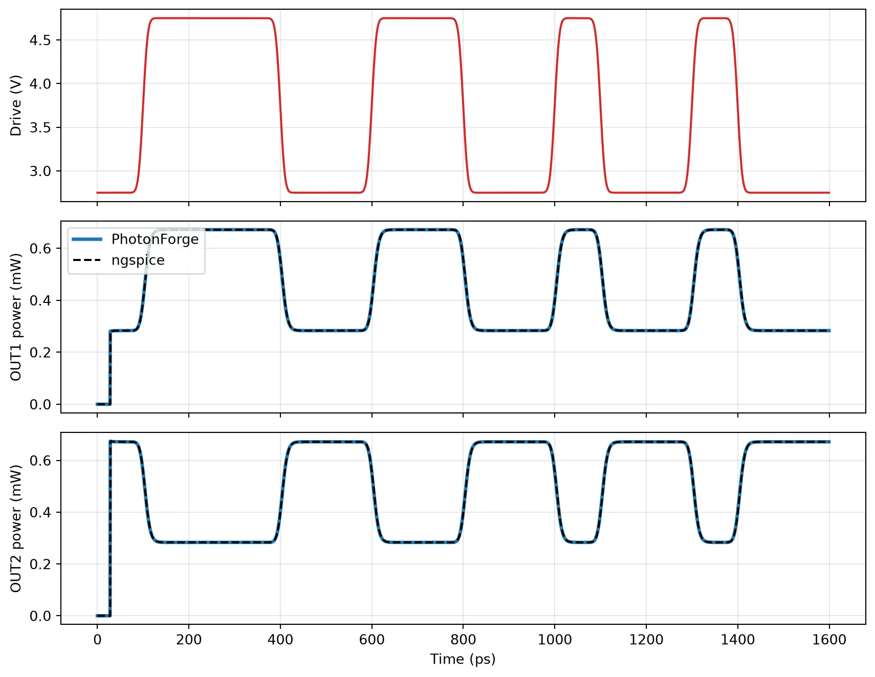
Summary
Section titled “Summary”write_verilog_awrites a configured time stepper, from a single component or a full circuit, as one self-contained Verilog-A module. Configure it first withsetup_time_stepper.- The file header lists the module terminals in order:
_reand_impairs for optical ports, one terminal per electrical port, andgndlast. - The module compiles with OpenVAF-Reloaded and runs in ngspice, where the transmitter reproduces the PhotonForge simulation and can be combined with the surrounding electronics.