

Custom Component Library
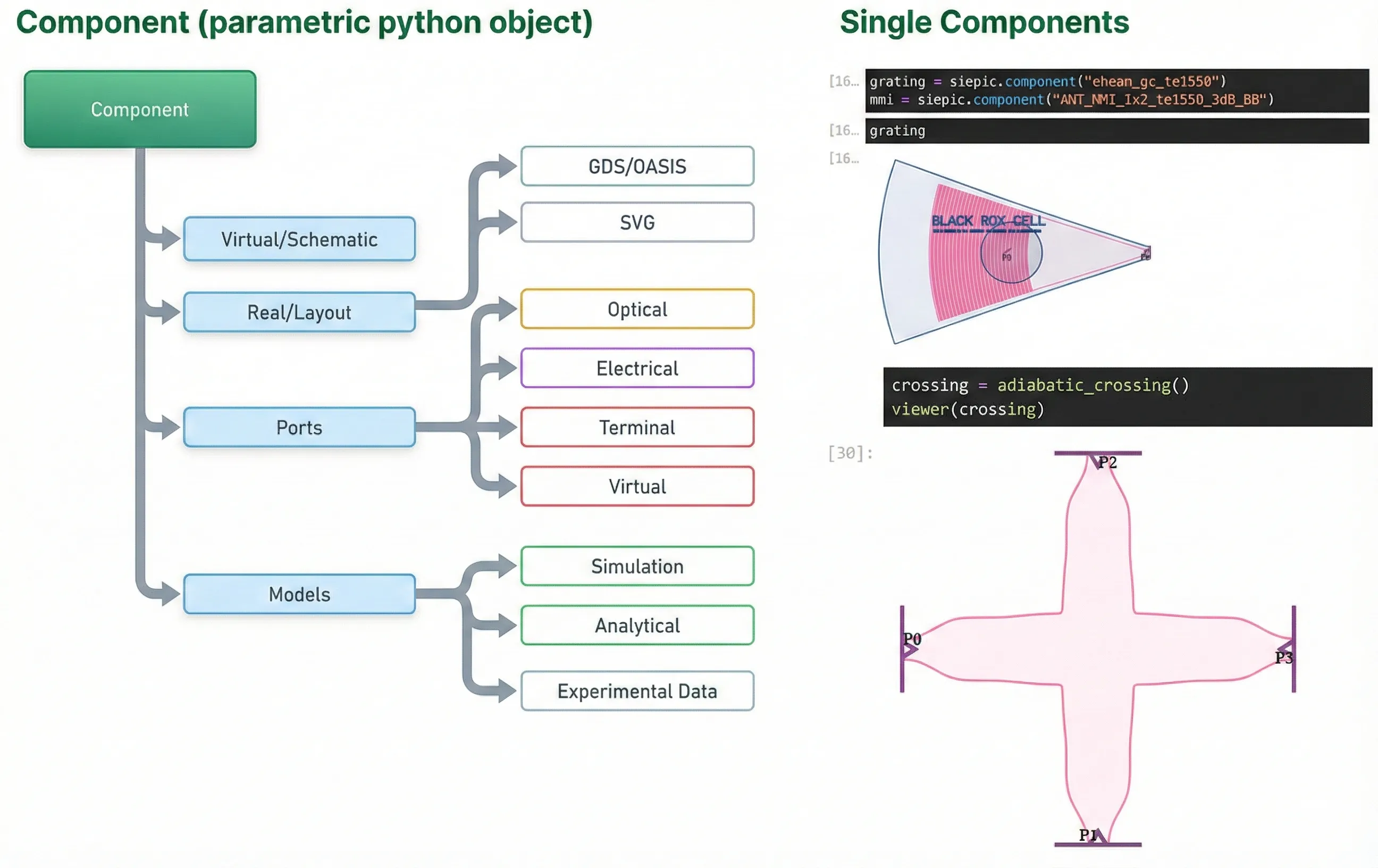
PhotonForge components are PCells (parameterized cells). They can be real or virtual, and they can be hierarchical.
- Models: simulation, analytical equations, or measured experimental data
- Ports: optical, electrical, or virtual
- Layout import: Cadence OpenAccess database or GDS/OASIS files
Getting Started
Section titled “Getting Started”Load the technology.
# Load the technology stack and helper importsfrom runpy import run_path
# Loading_Technology.qmd defines what this notebook builds on. Its shared cells are# generated into the module below; see docs/scripts/generate_notebook_modules.py.globals().update(    {k: v for k, v in run_path("misc/loading_technology.py").items() if not k.startswith("_")})
# Reduce Tidy3D logging noise in the notebooktd.config.logging.level = "ERROR"
We import a few utilities, start the interactive viewer, and set technology-specific defaults (optical port spec, default bend radius, and Tidy3D mesh refinement).
import warnings
from photonforge.live_viewer import LiveViewerfrom photonforge.stencil import as_component
# Suppress warnings about unmatched terminals and portswarnings.filterwarnings(    "ignore", message="Terminal.*does not match any reference terminals")
warnings.filterwarnings(    "ignore", message=".*not connected and will be ignored.*")viewer = LiveViewer()
port_spec = tech.ports["TE_1550_500"]  # optical port definitionpf.config.default_kwargs["port_spec"] = port_specpf.config.default_kwargs["radius"] = 5  # default bend radius (µm)pf.config.default_kwargs["euler_fraction"] = 0.5pf.config.default_mesh_refinement = 12  # default mesh refinement for Tidy3D simulations
rib = tech.ports["Rib_TE_1550_500"]
LiveViewer started at http://127.0.0.1:34337. Call its 'stop()' method to free the port.We set up the wavelength/frequency grid for frequency sweeps and define a carrier point (, ) used for single-frequency mode solves.
We also define a nominal propagation loss model (used later in analytical / compact models) so that device responses include realistic insertion loss.
wavelengths = np.linspace(1.543, 1.558, 201)lambda0 = 1.55
freqs = pf.C_0 / wavelengthsfreq0 = pf.C_0 / lambda0
# Waveguide propertiespropagation_loss = 3.0 / 10000.0  # propagation loss: 3 dB/cm (converted to dB/µm)
We solve for the waveguide eigenmodes at the carrier wavelength to extract effective index and group index values used later for analytical models.
The next cell runs the mode solver for the default strip waveguide, and the following cell repeats the same workflow for the rib waveguide.
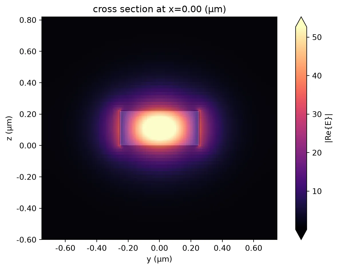
# Solve the strip waveguide mode at the carrier frequencymode_solver = pf.port_modes(port_spec, [freq0], mesh_refinement=50, group_index=True)
# Plot the mode electric-field profilemode_solver.plot_field("E", mode_index=0, f=freq0)
# Extract the fundamental-mode effective and group indicesn_eff = mode_solver.data.n_eff.isel(mode_index=0).item()n_group = mode_solver.data.n_group.isel(mode_index=0).item()
mode_solver.data.to_dataframe()
Uploading task 'Mode-ModeSolver…'Starting task 'Mode-ModeSolver': https://tidy3d.simulation.cloud/workbench?taskId=mo-9aa492f6-5c1d-4747-abd0-2918b66e7b00Downloading data from 'Mode-ModeSolver'…| wavelength | n eff | k eff | loss (dB/cm) | TE (Ey) fraction | wg TE fraction | wg TM fraction | mode area | group index | dispersion (ps/(nm km)) | ||
|---|---|---|---|---|---|---|---|---|---|---|---|
| f | mode_index | ||||||||||
| 1.934145e+14 | 0 | 1.55 | 2.443192 | 0.0 | 0.0 | 0.983501 | 0.764069 | 0.81791 | 0.190715 | 4.187462 | 515.572826 |
# Solve the rib waveguide mode at the carrier frequencymode_solver_rib = pf.port_modes(rib, [freq0], mesh_refinement=50, group_index=True)
# Plot the mode electric-field profilemode_solver_rib.plot_field("E")
# Extract the fundamental-mode group indexn_group_rib = mode_solver_rib.data.n_group.isel(mode_index=0).item()
# Extract the fundamental-mode effective indexn_eff_rib = mode_solver_rib.data.n_eff.isel(mode_index=0).item()
Uploading task 'Mode-ModeSolver…'Starting task 'Mode-ModeSolver': https://tidy3d.simulation.cloud/workbench?taskId=mo-3de4306f-e76f-4523-a01b-a6c5b21cc7fbDownloading data from 'Mode-ModeSolver'…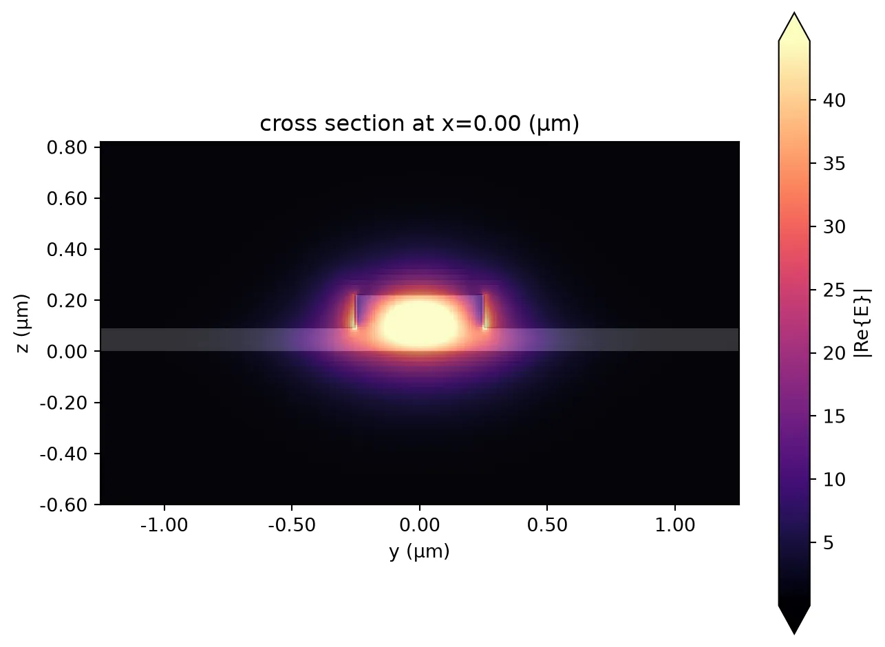
Edge Coupler
Section titled “Edge Coupler”Edge couplers provide efficient fiber-to-chip coupling by expanding the guided mode near the facet to better match the fiber mode. In this notebook we use an angled inverse-taper edge coupler geometry that is parameterized for reuse and quick sweeps.
Design Tip: High coupling efficiency requires matching the mode profiles of the chip and the fiber. We use a lensed fiber (2.5 µm spot diameter) to focus the light, while simultaneously using a narrow inverse taper tip (150 nm) to expand the waveguide mode. A long adiabatic taper is used to transition seamlessly between the standard 500 nm waveguide and the narrow tip without scattering losses.
To minimize back-reflections (return loss), the waveguide tip is angled (typically 7°–15°). A straight facet would reflect light directly back into the laser, causing instability. The angle ensures that any reflected light is steered away from the guided mode and radiated into the cladding. Return loss can be further reduced by filling the gap with an index-matching material (such as epoxy or fluid), which minimizes Fresnel reflections at the facet.
See the PhotonForge edge coupler example for more details.
@pf.parametric_component(name_prefix="Angled Fiber")def angled_edge_coupler(    *,    width_tip=0.1,  # Width of the taper tip (µm)    length_taper=10,  # Length of the adiabatic taper (µm)    angle_taper=7,  # Angle of the waveguide facet (degrees)    waist_radius=2.0,  # Mode field radius of the fiber (µm)    fiber_distance=3.0,  # Distance from facet to fiber (µm)    angle_fiber=10.2,  # Angle of fiber incidence (degrees)    trench_layer="Deep Trench",  # Layer for the etch opening):    """    Creates an angled inverse taper edge coupler for low-reflection fiber coupling.
    Parameters:        width_tip (float): Width of the waveguide tip (µm).        length_taper (float): Length of the adiabatic taper (µm).        angle_taper (float): Angle of the waveguide facet (degrees).        waist_radius (float): Mode field radius of the coupling fiber (µm).        fiber_distance (float): Distance between the fiber and the facet (µm).        angle_fiber (float): Angle of the fiber incidence (degrees).        trench_layer (str): Layer name for the deep trench opening.
    Returns:        Component: The edge coupler component with optical ports.    """    # Get waveguide width and silicon thickness from the technology    port_spec = tech.ports["TE_1550_500"]    core_width, _ = port_spec.path_profile_for("Si")    core_thickness = tech.parametric_kwargs["si_thickness"]
    # Unit vectors for the taper direction and fiber axis (degrees -> radians)    v_taper = np.array(        (np.cos(angle_taper / 180 * np.pi), np.sin(angle_taper / 180 * np.pi))    )    v_fiber = np.array(        (np.cos(angle_fiber / 180 * np.pi), np.sin(angle_fiber / 180 * np.pi))    )
    # Build the silicon inverse taper    endpoint = pf.snap_to_grid(length_taper * v_taper)    taper = (        pf.Path(-waist_radius * v_taper, width_tip)        .segment((0, 0))        .segment(endpoint, core_width)    )
    # Taper endpoint after a small bend to guarantee that the waveguide port    # grid-aligned    if angle_taper > 0:        radius = 5        endpoint = pf.snap_to_grid(            endpoint + radius * np.array((abs(v_taper[1]), 1 - v_taper[0]))        )        base = 90 if angle_taper > 0 else -90        taper.arc(90 + angle_taper, 90, radius, endpoint=endpoint)
    component = pf.Component(technology=siepic.ebeam())
    # Define the fiber port position from distance and fiber angle    fiber_center = -fiber_distance * v_fiber    port_fiber = pf.GaussianPort(        center=(fiber_center[0], fiber_center[1], core_thickness / 2),        input_vector=(v_fiber[0], v_fiber[1], 0),        waist_radius=waist_radius,        polarization_angle=0,  # TE polarization    )
    # Define the on-chip port at the end of the taper    port_waveguide = pf.Port(endpoint, 180, port_spec)
    component.add_port([port_fiber, port_waveguide])
    # Add taper and trench opening near the facet    # The size of Trench defines the boundary of the simulation so it is important to be sufficiently large    component.add(        "Si",        taper,        trench_layer,        pf.Rectangle(            (-fiber_distance - waist_radius, -5 * waist_radius),            (                0,                max(                    5 * waist_radius,                    port_waveguide.center[1] + port_spec.width / (2 * v_taper[0]),                ),            ),        ),    )
    model = pf.Tidy3DModel()    component.add_model(model, "Tidy3D")    return component
angle_fiber = 15 # degrees# Estimate taper angle using Snell's law (n ≈ 1.45)angle_taper = np.arcsin(np.sin(angle_fiber / 180 * np.pi) / 1.45) / np.pi * 180print(f"Taper angle: {angle_taper}°")
edge_coupler = angled_edge_coupler( width_tip=0.15, length_taper=25, angle_taper=angle_taper, waist_radius=2.5 / 2, fiber_distance=3, angle_fiber=angle_fiber,)
# Visualize the geometryviewer(edge_coupler)Taper angle: 10.282162084410936°
# Simulate and plot the edge-coupler S-matrixs_matrix_ec = edge_coupler.s_matrix(freqs)_ = pf.plot_s_matrix(s_matrix_ec, y="dB", input_ports=["P0"])Uploading task 'P0@0…'Uploading task 'P1@0…'Starting task 'P0@0': https://tidy3d.simulation.cloud/workbench?taskId=fdve-4e361375-de71-4eed-80b3-05466ec46792Starting task 'P1@0': https://tidy3d.simulation.cloud/workbench?taskId=fdve-fd4b11e4-4232-45ae-9c99-944fac6ad19aDownloading data from 'P0@0'…Downloading data from 'P1@0'…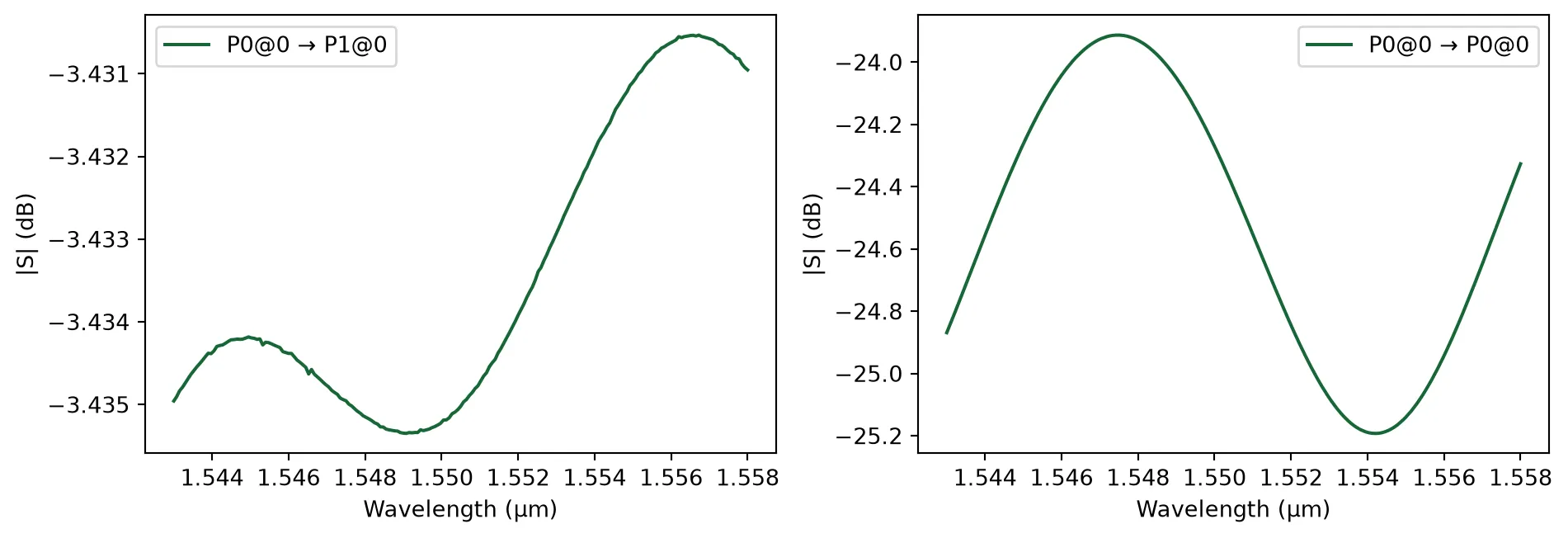
Monitor Tap
Section titled “Monitor Tap”This section defines a weak directional coupler used as a monitor tap (99:1) to sample a small fraction of the optical power for calibration and control.
Design Tip: To achieve a weak coupling ratio (1%), we must limit the power transfer between waveguides. This is typically done by increasing the gap or decreasing the coupling length.
Because the coupling coefficient is sensitive to geometry, the precise parameters are best found via a parameter sweep. A common approach is to fix the gap (e.g., a fabrication-safe value like 300 nm) and sweep the coupling length to dial in the exact 1% split.
@pf.parametric_component(name_prefix="Monitor Tap")def monitor_tap(    *,    coupling_gap=0.3,  # gap between waveguides (µm)    coupling_length=2.4,  # coupling region length (µm)    coupling_offset=5,  # S-bend offset for coupler (µm)    s_bend_length=20,  # drop-arm S-bend length (µm)    s_bend_offset=10,  # drop-arm offset (µm)):    """    99:1 S-bend directional coupler.
    99% transmission on the through port (P0 -> P1).    1% coupling to the tap port (P0 -> P2, routed via S-bend).    """    wg_width, _ = port_spec.path_profile_for("Si")
    # Create the directional coupler    tidy3d_model = pf.Tidy3DModel(        verbose=True,        port_symmetries=[            ("P1", "P0", "P3", "P2"),            ("P2", "P3", "P0", "P1"),            ("P3", "P2", "P1", "P0"),        ],    )    coupler = pf.parametric.s_bend_coupler(        coupling_distance=wg_width + coupling_gap,        coupling_length=coupling_length,        s_bend_offset=coupling_offset,        model=tidy3d_model,    )
    # Create an S-bend to route the monitor port    s_bend = pf.parametric.s_bend(        length=s_bend_length,        offset=s_bend_offset,        model=pf.WaveguideModel(),    )
    # Assemble the component via a netlist    netlist = {        "instances": {"COUPLER": coupler, "S_BEND": s_bend},        "connections": [            (("S_BEND", "P0"), ("COUPLER", "P3")),        ],        "ports": [            ("COUPLER", "P0"),  # Input            ("COUPLER", "P2"),  # Through (99%)            ("S_BEND", "P1"),  # Monitor tap (1%)            ("COUPLER", "P1"),  # Drop (unused)        ],        "models": [pf.CircuitModel()],    }
    return pf.component_from_netlist(netlist)
pm = monitor_tap()viewer(pm);fill:%23221f20;font-weight:bold;font-size:1.050888px;}.terminal{fill:none;stroke:%23805080;stroke-width:0.131361;}.dashed{stroke-dasharray:0.656805,0.394083;}.port{fill:none;stroke:%23805080;stroke-width:0.262722;}.virtual-connection{fill:none;stroke:%23907090;stroke-width:0.197042;}.layer_31_0{stroke:%238c78ef;fill:url(%23pat-layer_31_0);fill-opacity:0.492;}.label_31_0{fill:%238c78ef;}.layer_33_0{stroke:%238c78ef;fill:url(%23pat-layer_33_0);fill-opacity:0.492;}.label_33_0{fill:%238c78ef;}.layer_102_0{stroke:%238c78ef;fill:url(%23pat-layer_102_0);fill-opacity:0.492;}.label_102_0{fill:%238c78ef;}.layer_110_0{stroke:%238c78ef;fill:url(%23pat-layer_110_0);fill-opacity:0.492;}.label_110_0{fill:%238c78ef;}.layer_189_0{stroke:%23000000;fill:none;}.label_189_0{fill:%23000000;}.layer_201_0{stroke:%2300ee00;fill:url(%23pat-layer_201_0);fill-opacity:0.492;}.label_201_0{fill:%2300ee00;}.layer_401_0{stroke:%236a8ad2;fill:url(%23pat-layer_401_0);fill-opacity:0.492;}.label_401_0{fill:%236a8ad2;}.layer_202_0{stroke:%23007600;fill:url(%23pat-layer_202_0);fill-opacity:0.492;}.label_202_0{fill:%23007600;}.layer_68_0{stroke:%23008000;fill:url(%23pat-layer_68_0);fill-opacity:0.492;}.label_68_0{fill:%23008000;}.layer_5_0{stroke:%236a8ad2;fill:url(%23pat-layer_5_0);fill-opacity:0.492;}.label_5_0{fill:%236a8ad2;}.layer_998_0{stroke:%23000000;fill:none;}.label_998_0{fill:%23000000;}.layer_312_1{stroke:%2300b8b8;fill:url(%23pat-layer_312_1);fill-opacity:0.492;}.label_312_1{fill:%2300b8b8;}.layer_312_0{stroke:%2300b8b8;fill:url(%23pat-layer_312_0);fill-opacity:0.492;}.label_312_0{fill:%2300b8b8;}.layer_402_0{stroke:%23ff0000;fill:url(%23pat-layer_402_0);fill-opacity:0.492;}.label_402_0{fill:%23ff0000;}.layer_401_4{stroke:%236a8ad2;fill:url(%23pat-layer_401_4);fill-opacity:0.492;}.label_401_4{fill:%236a8ad2;}.layer_389_0{stroke:%23ff00ff;fill:url(%23pat-layer_389_0);fill-opacity:0.492;}.label_389_0{fill:%23ff00ff;}.layer_402_1{stroke:%23ff0000;fill:url(%23pat-layer_402_1);fill-opacity:0.492;}.label_402_1{fill:%23ff0000;}.layer_350_1{stroke:%23697a00;fill:url(%23pat-layer_350_1);fill-opacity:0.492;}.label_350_1{fill:%23697a00;}.layer_401_1{stroke:%236a8ad2;fill:url(%23pat-layer_401_1);fill-opacity:0.492;}.label_401_1{fill:%236a8ad2;}.layer_313_2{stroke:%2301d95b;fill:url(%23pat-layer_313_2);fill-opacity:0.492;}.label_313_2{fill:%2301d95b;}.layer_313_1{stroke:%2301d95b;fill:url(%23pat-layer_313_1);fill-opacity:0.492;}.label_313_1{fill:%2301d95b;}.layer_313_0{stroke:%2301d95b;fill:url(%23pat-layer_313_0);fill-opacity:0.492;}.label_313_0{fill:%2301d95b;}.layer_400_0{stroke:%23a96868;fill:url(%23pat-layer_400_0);fill-opacity:0.492;}.label_400_0{fill:%23a96868;}.layer_312_3{stroke:%2300b8b8;fill:url(%23pat-layer_312_3);fill-opacity:0.492;}.label_312_3{fill:%2300b8b8;}.layer_389_1{stroke:%23ff00ff;fill:url(%23pat-layer_389_1);fill-opacity:0.492;}.label_389_1{fill:%23ff00ff;}.layer_401_3{stroke:%236a8ad2;fill:url(%23pat-layer_401_3);fill-opacity:0.492;}.label_401_3{fill:%236a8ad2;}.layer_403_2{stroke:%23500080;fill:url(%23pat-layer_403_2);fill-opacity:0.492;}.label_403_2{fill:%23500080;}.layer_403_3{stroke:%23500080;fill:url(%23pat-layer_403_3);fill-opacity:0.492;}.label_403_3{fill:%23500080;}.layer_403_1{stroke:%23500080;fill:url(%23pat-layer_403_1);fill-opacity:0.492;}.label_403_1{fill:%23500080;}.layer_403_0{stroke:%23500080;fill:url(%23pat-layer_403_0);fill-opacity:0.492;}.label_403_0{fill:%23500080;}.layer_311_1{stroke:%23ac6c56;fill:url(%23pat-layer_311_1);fill-opacity:0.492;}.label_311_1{fill:%23ac6c56;}.layer_311_0{stroke:%23ac6c56;fill:url(%23pat-layer_311_0);fill-opacity:0.492;}.label_311_0{fill:%23ac6c56;}.layer_301_1{stroke:%23800057;fill:url(%23pat-layer_301_1);fill-opacity:0.492;}.label_301_1{fill:%23800057;}.layer_301_0{stroke:%23800057;fill:url(%23pat-layer_301_0);fill-opacity:0.492;}.label_301_0{fill:%23800057;}.layer_305_1{stroke:%23808080;fill:url(%23pat-layer_305_1);fill-opacity:0.492;}.label_305_1{fill:%23808080;}.layer_305_0{stroke:%23808080;fill:url(%23pat-layer_305_0);fill-opacity:0.492;}.label_305_0{fill:%23808080;}.layer_999_0{stroke:%230000ff;fill:url(%23pat-layer_999_0);fill-opacity:0.492;}.label_999_0{fill:%230000ff;}.layer_81_0{stroke:%23808080;fill:url(%23pat-layer_81_0);fill-opacity:0.492;}.label_81_0{fill:%23808080;}.layer_290_0{stroke:%23a46eda;fill:none;}.label_290_0{fill:%23a46eda;}.layer_205_0{stroke:%2349b203;fill:url(%23pat-layer_205_0);fill-opacity:0.492;}.label_205_0{fill:%2349b203;}.layer_11_0{stroke:%230000ff;fill:url(%23pat-layer_11_0);fill-opacity:0.492;}.label_11_0{fill:%230000ff;}.layer_12_0{stroke:%23a57b00;fill:url(%23pat-layer_12_0);fill-opacity:0.492;}.label_12_0{fill:%23a57b00;}.layer_13_0{stroke:%23800057;fill:url(%23pat-layer_13_0);fill-opacity:0.492;}.label_13_0{fill:%23800057;}.layer_6_0{stroke:%23ff0000;fill:url(%23pat-layer_6_0);fill-opacity:0.492;}.label_6_0{fill:%23ff0000;}.layer_1_10{stroke:%23c96585;fill:url(%23pat-layer_1_10);fill-opacity:0.492;}.label_1_10{fill:%23c96585;}.layer_1_11{stroke:%23800000;fill:url(%23pat-layer_1_11);fill-opacity:0.492;}.label_1_11{fill:%23800000;}.layer_200_0{stroke:%23ff0000;fill:url(%23pat-layer_200_0);fill-opacity:0.492;}.label_200_0{fill:%23ff0000;}.layer_1_0{stroke:%23c96585;fill:url(%23pat-layer_1_0);fill-opacity:0.492;}.label_1_0{fill:%23c96585;}.layer_2_0{stroke:%23a46eda;fill:url(%23pat-layer_2_0);fill-opacity:0.492;}.label_2_0{fill:%23a46eda;}.layer_20_0{stroke:%2353793d;fill:url(%23pat-layer_20_0);fill-opacity:0.492;}.label_20_0{fill:%2353793d;}.layer_22_0{stroke:%23ec7600;fill:url(%23pat-layer_22_0);fill-opacity:0.492;}.label_22_0{fill:%23ec7600;}.layer_24_0{stroke:%2300b8b8;fill:url(%23pat-layer_24_0);fill-opacity:0.492;}.label_24_0{fill:%2300b8b8;}.layer_21_0{stroke:%23736264;fill:url(%23pat-layer_21_0);fill-opacity:0.492;}.label_21_0{fill:%23736264;}.layer_23_0{stroke:%23697a00;fill:url(%23pat-layer_23_0);fill-opacity:0.492;}.label_23_0{fill:%23697a00;}.layer_25_0{stroke:%23008000;fill:url(%23pat-layer_25_0);fill-opacity:0.492;}.label_25_0{fill:%23008000;}.layer_350_0{stroke:%23697a00;fill:url(%23pat-layer_350_0);fill-opacity:0.492;}.label_350_0{fill:%23697a00;}.layer_10_0{stroke:%23000000;fill:none;}.label_10_0{fill:%23000000;}.layer_203_0{stroke:%23008000;fill:url(%23pat-layer_203_0);fill-opacity:0.492;}.label_203_0{fill:%23008000;}.layer_40_0{stroke:%230000ff;fill:url(%23pat-layer_40_0);fill-opacity:0.492;}.label_40_0{fill:%230000ff;}.layer_401_2{stroke:%236a8ad2;fill:url(%23pat-layer_401_2);fill-opacity:0.492;}.label_401_2{fill:%236a8ad2;}.layer_301_2{stroke:%23800057;fill:url(%23pat-layer_301_2);fill-opacity:0.492;}.label_301_2{fill:%23800057;}</style><defs><path id=%22port-symbol%22 class=%22port%22 d=%22M 0,-0.525444 L 0.788166,0 0,0.525444%22 /><path id=%22ref-port-symbol%22 class=%22port%22 style=%22stroke-opacity:0.33;%22 d=%22M 0,-0.394083 C 0.525444,-0.394083 0.525444,0.394083 0,0.394083%22 /><circle id=%22port-bend-symbol%22 style=%22stroke-width:0;stroke:none;fill:%23805080;fill-opacity:1;%22 cx=%220%22 cy=%220%22 r=%220.236450%22 /><circle id=%22connection-symbol%22 style=%22stroke-width:0;stroke:none;fill:%23907090;fill-opacity:1;%22 cx=%220%22 cy=%220%22 r=%220.275858%22 /><pattern id=%22pat-layer_31_0%22 patternUnits=%22userSpaceOnUse%22 width=%220.656805%22 height=%220.656805%22 patternTransform=%22translate(0.502263,0.622236)%22><line x1=%220%22 y1=%220%22 x2=%220.656805%22 y2=%220.656805%22 style=%22stroke:%238c78ef;stroke-width:0.065681%22 /><line x1=%22-0.328403%22 y1=%220.328403%22 x2=%220.328403%22 y2=%220.985208%22 style=%22stroke:%238c78ef;stroke-width:0.065681%22 /><line x1=%220.328403%22 y1=%22-0.328403%22 x2=%220.985208%22 y2=%220.328403%22 style=%22stroke:%238c78ef;stroke-width:0.065681%22 /></pattern><pattern id=%22pat-layer_33_0%22 patternUnits=%22userSpaceOnUse%22 width=%220.656805%22 height=%220.656805%22 patternTransform=%22translate(0.386356,0.069137)%22><line x1=%220%22 y1=%220%22 x2=%220.656805%22 y2=%220.656805%22 style=%22stroke:%238c78ef;stroke-width:0.065681%22 /><line x1=%22-0.328403%22 y1=%220.328403%22 x2=%220.328403%22 y2=%220.985208%22 style=%22stroke:%238c78ef;stroke-width:0.065681%22 /><line x1=%220.328403%22 y1=%22-0.328403%22 x2=%220.985208%22 y2=%220.328403%22 style=%22stroke:%238c78ef;stroke-width:0.065681%22 /></pattern><pattern id=%22pat-layer_102_0%22 patternUnits=%22userSpaceOnUse%22 width=%220.656805%22 height=%220.656805%22 patternTransform=%22translate(0.000000,0.034569)%22><line x1=%220%22 y1=%220%22 x2=%220.656805%22 y2=%220.656805%22 style=%22stroke:%238c78ef;stroke-width:0.065681%22 /><line x1=%22-0.328403%22 y1=%220.328403%22 x2=%220.328403%22 y2=%220.985208%22 style=%22stroke:%238c78ef;stroke-width:0.065681%22 /><line x1=%220.328403%22 y1=%22-0.328403%22 x2=%220.985208%22 y2=%220.328403%22 style=%22stroke:%238c78ef;stroke-width:0.065681%22 /></pattern><pattern id=%22pat-layer_110_0%22 patternUnits=%22userSpaceOnUse%22 width=%220.656805%22 height=%220.656805%22 patternTransform=%22translate(0.193178,0.449393)%22><line x1=%220%22 y1=%220%22 x2=%220.656805%22 y2=%220.656805%22 style=%22stroke:%238c78ef;stroke-width:0.065681%22 /><line x1=%22-0.328403%22 y1=%220.328403%22 x2=%220.328403%22 y2=%220.985208%22 style=%22stroke:%238c78ef;stroke-width:0.065681%22 /><line x1=%220.328403%22 y1=%22-0.328403%22 x2=%220.985208%22 y2=%220.328403%22 style=%22stroke:%238c78ef;stroke-width:0.065681%22 /></pattern><pattern id=%22pat-layer_201_0%22 patternUnits=%22userSpaceOnUse%22 width=%220.656805%22 height=%220.656805%22 patternTransform=%22translate(0.502263,0.241981)%22><circle cx=%220.328403%22 cy=%220.328403%22 r=%220.065681%22 style=%22stroke:none;fill:%2300ee00;fill-opacity:1.0%22 /></pattern><pattern id=%22pat-layer_401_0%22 patternUnits=%22userSpaceOnUse%22 width=%220.394083%22 height=%220.394083%22 patternTransform=%22translate(0.046363,0.062224)%22><line x1=%220%22 y1=%220%22 x2=%220.394083%22 y2=%220.394083%22 style=%22stroke:%236a8ad2;stroke-width:0.065681%22 /><line x1=%22-0.197042%22 y1=%220.197042%22 x2=%220.197042%22 y2=%220.591125%22 style=%22stroke:%236a8ad2;stroke-width:0.065681%22 /><line x1=%220.197042%22 y1=%22-0.197042%22 x2=%220.591125%22 y2=%220.197042%22 style=%22stroke:%236a8ad2;stroke-width:0.065681%22 /><line x1=%220.394083%22 y1=%220%22 x2=%220%22 y2=%220.394083%22 style=%22stroke:%236a8ad2;stroke-width:0.065681%22 /><line x1=%220.591125%22 y1=%220.197042%22 x2=%220.197042%22 y2=%220.591125%22 style=%22stroke:%236a8ad2;stroke-width:0.065681%22 /><line x1=%220.197042%22 y1=%22-0.197042%22 x2=%22-0.197042%22 y2=%220.197042%22 style=%22stroke:%236a8ad2;stroke-width:0.065681%22 /></pattern><pattern id=%22pat-layer_202_0%22 patternUnits=%22userSpaceOnUse%22 width=%220.394083%22 height=%220.394083%22 patternTransform=%22translate(0.069544,0.373342)%22><circle cx=%220.197042%22 cy=%220.197042%22 r=%220.065681%22 style=%22stroke:none;fill:%23007600;fill-opacity:1.0%22 /></pattern><pattern id=%22pat-layer_68_0%22 patternUnits=%22userSpaceOnUse%22 width=%220.656805%22 height=%220.656805%22 patternTransform=%22translate(0.000000,0.241981)%22><circle cx=%220.328403%22 cy=%220.328403%22 r=%220.065681%22 style=%22stroke:none;fill:%23008000;fill-opacity:1.0%22 /></pattern><pattern id=%22pat-layer_5_0%22 patternUnits=%22userSpaceOnUse%22 width=%220.394083%22 height=%220.394083%22 patternTransform=%22translate(0.023181,0.352601)%22><line x1=%220.197042%22 y1=%220%22 x2=%220.197042%22 y2=%220.394083%22 style=%22stroke:%236a8ad2;stroke-width:0.065681%22 /></pattern><pattern id=%22pat-layer_312_1%22 patternUnits=%22userSpaceOnUse%22 width=%220.394083%22 height=%220.394083%22 patternTransform=%22translate(0.092725,0.311118)%22><line x1=%220%22 y1=%220%22 x2=%220.394083%22 y2=%220.394083%22 style=%22stroke:%2300b8b8;stroke-width:0.065681%22 /><line x1=%22-0.197042%22 y1=%220.197042%22 x2=%220.197042%22 y2=%220.591125%22 style=%22stroke:%2300b8b8;stroke-width:0.065681%22 /><line x1=%220.197042%22 y1=%22-0.197042%22 x2=%220.591125%22 y2=%220.197042%22 style=%22stroke:%2300b8b8;stroke-width:0.065681%22 /></pattern><pattern id=%22pat-layer_312_0%22 patternUnits=%22userSpaceOnUse%22 width=%220.656805%22 height=%220.656805%22 patternTransform=%22translate(0.309085,0.414824)%22><line x1=%220.328403%22 y1=%220%22 x2=%220.328403%22 y2=%220.656805%22 style=%22stroke:%2300b8b8;stroke-width:0.065681%22 /></pattern><pattern id=%22pat-layer_402_0%22 patternUnits=%22userSpaceOnUse%22 width=%220.656805%22 height=%220.656805%22 patternTransform=%22translate(0.347720,0.483962)%22><line x1=%220.328403%22 y1=%220%22 x2=%220.328403%22 y2=%220.656805%22 style=%22stroke:%23ff0000;stroke-width:0.065681%22 /><line x1=%220%22 y1=%220.328403%22 x2=%220.656805%22 y2=%220.328403%22 style=%22stroke:%23ff0000;stroke-width:0.065681%22 /></pattern><pattern id=%22pat-layer_401_4%22 patternUnits=%22userSpaceOnUse%22 width=%220.394083%22 height=%220.394083%22 patternTransform=%22translate(0.069544,0.311118)%22><line x1=%220.197042%22 y1=%220%22 x2=%220.197042%22 y2=%220.394083%22 style=%22stroke:%236a8ad2;stroke-width:0.065681%22 /></pattern><pattern id=%22pat-layer_389_0%22 patternUnits=%22userSpaceOnUse%22 width=%220.394083%22 height=%220.394083%22 patternTransform=%22translate(0.069544,0.082965)%22><line x1=%220.197042%22 y1=%220%22 x2=%220.197042%22 y2=%220.394083%22 style=%22stroke:%23ff00ff;stroke-width:0.065681%22 /><line x1=%220%22 y1=%220.197042%22 x2=%220.394083%22 y2=%220.197042%22 style=%22stroke:%23ff00ff;stroke-width:0.065681%22 /></pattern><pattern id=%22pat-layer_402_1%22 patternUnits=%22userSpaceOnUse%22 width=%220.394083%22 height=%220.394083%22 patternTransform=%22translate(0.115907,0.352601)%22><line x1=%220%22 y1=%220%22 x2=%220.394083%22 y2=%220.394083%22 style=%22stroke:%23ff0000;stroke-width:0.065681%22 /><line x1=%22-0.197042%22 y1=%220.197042%22 x2=%220.197042%22 y2=%220.591125%22 style=%22stroke:%23ff0000;stroke-width:0.065681%22 /><line x1=%220.197042%22 y1=%22-0.197042%22 x2=%220.591125%22 y2=%220.197042%22 style=%22stroke:%23ff0000;stroke-width:0.065681%22 /><line x1=%220.394083%22 y1=%220%22 x2=%220%22 y2=%220.394083%22 style=%22stroke:%23ff0000;stroke-width:0.065681%22 /><line x1=%220.591125%22 y1=%220.197042%22 x2=%220.197042%22 y2=%220.591125%22 style=%22stroke:%23ff0000;stroke-width:0.065681%22 /><line x1=%220.197042%22 y1=%22-0.197042%22 x2=%22-0.197042%22 y2=%220.197042%22 style=%22stroke:%23ff0000;stroke-width:0.065681%22 /></pattern><pattern id=%22pat-layer_350_1%22 patternUnits=%22userSpaceOnUse%22 width=%220.394083%22 height=%220.394083%22 patternTransform=%22translate(0.347720,0.311118)%22><circle cx=%220.197042%22 cy=%220.197042%22 r=%220.065681%22 style=%22stroke:none;fill:%23697a00;fill-opacity:1.0%22 /></pattern><pattern id=%22pat-layer_401_1%22 patternUnits=%22userSpaceOnUse%22 width=%220.656805%22 height=%220.656805%22 patternTransform=%22translate(0.579534,0.207412)%22><line x1=%220%22 y1=%220%22 x2=%220.656805%22 y2=%220.656805%22 style=%22stroke:%236a8ad2;stroke-width:0.065681%22 /><line x1=%22-0.328403%22 y1=%220.328403%22 x2=%220.328403%22 y2=%220.985208%22 style=%22stroke:%236a8ad2;stroke-width:0.065681%22 /><line x1=%220.328403%22 y1=%22-0.328403%22 x2=%220.985208%22 y2=%220.328403%22 style=%22stroke:%236a8ad2;stroke-width:0.065681%22 /><line x1=%220.656805%22 y1=%220%22 x2=%220%22 y2=%220.656805%22 style=%22stroke:%236a8ad2;stroke-width:0.065681%22 /><line x1=%220.985208%22 y1=%220.328403%22 x2=%220.328403%22 y2=%220.985208%22 style=%22stroke:%236a8ad2;stroke-width:0.065681%22 /><line x1=%220.328403%22 y1=%22-0.328403%22 x2=%22-0.328403%22 y2=%220.328403%22 style=%22stroke:%236a8ad2;stroke-width:0.065681%22 /></pattern><pattern id=%22pat-layer_313_2%22 patternUnits=%22userSpaceOnUse%22 width=%220.394083%22 height=%220.394083%22 patternTransform=%22translate(0.162269,0.207412)%22><line x1=%220%22 y1=%220%22 x2=%220.394083%22 y2=%220.394083%22 style=%22stroke:%2301d95b;stroke-width:0.065681%22 /><line x1=%22-0.197042%22 y1=%220.197042%22 x2=%220.197042%22 y2=%220.591125%22 style=%22stroke:%2301d95b;stroke-width:0.065681%22 /><line x1=%220.197042%22 y1=%22-0.197042%22 x2=%220.591125%22 y2=%220.197042%22 style=%22stroke:%2301d95b;stroke-width:0.065681%22 /></pattern><pattern id=%22pat-layer_313_1%22 patternUnits=%22userSpaceOnUse%22 width=%220.656805%22 height=%220.656805%22 patternTransform=%22translate(0.424991,0.241981)%22><line x1=%220.328403%22 y1=%220%22 x2=%220.328403%22 y2=%220.656805%22 style=%22stroke:%2301d95b;stroke-width:0.065681%22 /></pattern><pattern id=%22pat-layer_313_0%22 patternUnits=%22userSpaceOnUse%22 width=%220.394083%22 height=%220.394083%22 patternTransform=%22translate(0.347720,0.082965)%22><line x1=%220.197042%22 y1=%220%22 x2=%220.197042%22 y2=%220.394083%22 style=%22stroke:%2301d95b;stroke-width:0.065681%22 /></pattern><pattern id=%22pat-layer_400_0%22 patternUnits=%22userSpaceOnUse%22 width=%220.656805%22 height=%220.656805%22 patternTransform=%22translate(0.463627,0.380256)%22><line x1=%220%22 y1=%220%22 x2=%220.656805%22 y2=%220.656805%22 style=%22stroke:%23a96868;stroke-width:0.065681%22 /><line x1=%22-0.328403%22 y1=%220.328403%22 x2=%220.328403%22 y2=%220.985208%22 style=%22stroke:%23a96868;stroke-width:0.065681%22 /><line x1=%220.328403%22 y1=%22-0.328403%22 x2=%220.985208%22 y2=%220.328403%22 style=%22stroke:%23a96868;stroke-width:0.065681%22 /><line x1=%220.656805%22 y1=%220%22 x2=%220%22 y2=%220.656805%22 style=%22stroke:%23a96868;stroke-width:0.065681%22 /><line x1=%220.985208%22 y1=%220.328403%22 x2=%220.328403%22 y2=%220.985208%22 style=%22stroke:%23a96868;stroke-width:0.065681%22 /><line x1=%220.328403%22 y1=%22-0.328403%22 x2=%22-0.328403%22 y2=%220.328403%22 style=%22stroke:%23a96868;stroke-width:0.065681%22 /></pattern><pattern id=%22pat-layer_312_3%22 patternUnits=%22userSpaceOnUse%22 width=%220.394083%22 height=%220.394083%22 patternTransform=%22translate(0.301358,0.041482)%22><line x1=%220.394083%22 y1=%220%22 x2=%220%22 y2=%220.394083%22 style=%22stroke:%2300b8b8;stroke-width:0.065681%22 /><line x1=%220.591125%22 y1=%220.197042%22 x2=%220.197042%22 y2=%220.591125%22 style=%22stroke:%2300b8b8;stroke-width:0.065681%22 /><line x1=%220.197042%22 y1=%22-0.197042%22 x2=%22-0.197042%22 y2=%220.197042%22 style=%22stroke:%2300b8b8;stroke-width:0.065681%22 /></pattern><pattern id=%22pat-layer_389_1%22 patternUnits=%22userSpaceOnUse%22 width=%220.656805%22 height=%220.656805%22 patternTransform=%22translate(0.618169,0.241981)%22><line x1=%220.328403%22 y1=%220%22 x2=%220.328403%22 y2=%220.656805%22 style=%22stroke:%23ff00ff;stroke-width:0.065681%22 /><line x1=%220%22 y1=%220.328403%22 x2=%220.656805%22 y2=%220.328403%22 style=%22stroke:%23ff00ff;stroke-width:0.065681%22 /></pattern><pattern id=%22pat-layer_401_3%22 patternUnits=%22userSpaceOnUse%22 width=%220.656805%22 height=%220.656805%22 patternTransform=%22translate(0.270449,0.414824)%22><line x1=%220%22 y1=%220.328403%22 x2=%220.656805%22 y2=%220.328403%22 style=%22stroke:%236a8ad2;stroke-width:0.065681%22 /></pattern><pattern id=%22pat-layer_403_2%22 patternUnits=%22userSpaceOnUse%22 width=%220.394083%22 height=%220.394083%22 patternTransform=%22translate(0.185451,0.248895)%22><line x1=%220%22 y1=%220%22 x2=%220.394083%22 y2=%220.394083%22 style=%22stroke:%23500080;stroke-width:0.065681%22 /><line x1=%22-0.197042%22 y1=%220.197042%22 x2=%220.197042%22 y2=%220.591125%22 style=%22stroke:%23500080;stroke-width:0.065681%22 /><line x1=%220.197042%22 y1=%22-0.197042%22 x2=%220.591125%22 y2=%220.197042%22 style=%22stroke:%23500080;stroke-width:0.065681%22 /><line x1=%220.394083%22 y1=%220%22 x2=%220%22 y2=%220.394083%22 style=%22stroke:%23500080;stroke-width:0.065681%22 /><line x1=%220.591125%22 y1=%220.197042%22 x2=%220.197042%22 y2=%220.591125%22 style=%22stroke:%23500080;stroke-width:0.065681%22 /><line x1=%220.197042%22 y1=%22-0.197042%22 x2=%22-0.197042%22 y2=%220.197042%22 style=%22stroke:%23500080;stroke-width:0.065681%22 /></pattern><pattern id=%22pat-layer_403_3%22 patternUnits=%22userSpaceOnUse%22 width=%220.656805%22 height=%220.656805%22 patternTransform=%22translate(0.154542,0.518530)%22><line x1=%220%22 y1=%220%22 x2=%220.656805%22 y2=%220.656805%22 style=%22stroke:%23500080;stroke-width:0.065681%22 /><line x1=%22-0.328403%22 y1=%220.328403%22 x2=%220.328403%22 y2=%220.985208%22 style=%22stroke:%23500080;stroke-width:0.065681%22 /><line x1=%220.328403%22 y1=%22-0.328403%22 x2=%220.985208%22 y2=%220.328403%22 style=%22stroke:%23500080;stroke-width:0.065681%22 /><line x1=%220.656805%22 y1=%220%22 x2=%220%22 y2=%220.656805%22 style=%22stroke:%23500080;stroke-width:0.065681%22 /><line x1=%220.985208%22 y1=%220.328403%22 x2=%220.328403%22 y2=%220.985208%22 style=%22stroke:%23500080;stroke-width:0.065681%22 /><line x1=%220.328403%22 y1=%22-0.328403%22 x2=%22-0.328403%22 y2=%220.328403%22 style=%22stroke:%23500080;stroke-width:0.065681%22 /></pattern><pattern id=%22pat-layer_403_1%22 patternUnits=%22userSpaceOnUse%22 width=%220.656805%22 height=%220.656805%22 patternTransform=%22translate(0.463627,0.311118)%22><line x1=%220.328403%22 y1=%220%22 x2=%220.328403%22 y2=%220.656805%22 style=%22stroke:%23500080;stroke-width:0.065681%22 /><line x1=%220%22 y1=%220.328403%22 x2=%220.656805%22 y2=%220.328403%22 style=%22stroke:%23500080;stroke-width:0.065681%22 /></pattern><pattern id=%22pat-layer_403_0%22 patternUnits=%22userSpaceOnUse%22 width=%220.394083%22 height=%220.394083%22 patternTransform=%22translate(0.370902,0.124447)%22><line x1=%220.197042%22 y1=%220%22 x2=%220.197042%22 y2=%220.394083%22 style=%22stroke:%23500080;stroke-width:0.065681%22 /><line x1=%220%22 y1=%220.197042%22 x2=%220.394083%22 y2=%220.197042%22 style=%22stroke:%23500080;stroke-width:0.065681%22 /></pattern><pattern id=%22pat-layer_311_1%22 patternUnits=%22userSpaceOnUse%22 width=%220.656805%22 height=%220.656805%22 patternTransform=%22translate(0.540898,0.138275)%22><line x1=%220%22 y1=%220%22 x2=%220.656805%22 y2=%220.656805%22 style=%22stroke:%23ac6c56;stroke-width:0.065681%22 /><line x1=%22-0.328403%22 y1=%220.328403%22 x2=%220.328403%22 y2=%220.985208%22 style=%22stroke:%23ac6c56;stroke-width:0.065681%22 /><line x1=%220.328403%22 y1=%22-0.328403%22 x2=%220.985208%22 y2=%220.328403%22 style=%22stroke:%23ac6c56;stroke-width:0.065681%22 /></pattern><pattern id=%22pat-layer_311_0%22 patternUnits=%22userSpaceOnUse%22 width=%220.394083%22 height=%220.394083%22 patternTransform=%22translate(0.023181,0.020741)%22><line x1=%220%22 y1=%220%22 x2=%220.394083%22 y2=%220.394083%22 style=%22stroke:%23ac6c56;stroke-width:0.065681%22 /><line x1=%22-0.197042%22 y1=%220.197042%22 x2=%220.197042%22 y2=%220.591125%22 style=%22stroke:%23ac6c56;stroke-width:0.065681%22 /><line x1=%220.197042%22 y1=%22-0.197042%22 x2=%220.591125%22 y2=%220.197042%22 style=%22stroke:%23ac6c56;stroke-width:0.065681%22 /></pattern><pattern id=%22pat-layer_301_1%22 patternUnits=%22userSpaceOnUse%22 width=%220.656805%22 height=%220.656805%22 patternTransform=%22translate(0.463627,0.276549)%22><line x1=%220%22 y1=%220.328403%22 x2=%220.656805%22 y2=%220.328403%22 style=%22stroke:%23800057;stroke-width:0.065681%22 /></pattern><pattern id=%22pat-layer_301_0%22 patternUnits=%22userSpaceOnUse%22 width=%220.394083%22 height=%220.394083%22 patternTransform=%22translate(0.370902,0.103706)%22><line x1=%220%22 y1=%220.197042%22 x2=%220.394083%22 y2=%220.197042%22 style=%22stroke:%23800057;stroke-width:0.065681%22 /></pattern><pattern id=%22pat-layer_305_1%22 patternUnits=%22userSpaceOnUse%22 width=%220.656805%22 height=%220.656805%22 patternTransform=%22translate(0.231814,0.483962)%22><line x1=%220.328403%22 y1=%220%22 x2=%220.328403%22 y2=%220.656805%22 style=%22stroke:%23808080;stroke-width:0.065681%22 /><line x1=%220%22 y1=%220.328403%22 x2=%220.656805%22 y2=%220.328403%22 style=%22stroke:%23808080;stroke-width:0.065681%22 /></pattern><pattern id=%22pat-layer_305_0%22 patternUnits=%22userSpaceOnUse%22 width=%220.394083%22 height=%220.394083%22 patternTransform=%22translate(0.231814,0.228153)%22><line x1=%220.197042%22 y1=%220%22 x2=%220.197042%22 y2=%220.394083%22 style=%22stroke:%23808080;stroke-width:0.065681%22 /><line x1=%220%22 y1=%220.197042%22 x2=%220.394083%22 y2=%220.197042%22 style=%22stroke:%23808080;stroke-width:0.065681%22 /></pattern><pattern id=%22pat-layer_999_0%22 patternUnits=%22userSpaceOnUse%22 width=%220.394083%22 height=%220.394083%22 patternTransform=%22translate(0.139088,0.145188)%22><line x1=%220.197042%22 y1=%220%22 x2=%220.197042%22 y2=%220.394083%22 style=%22stroke:%230000ff;stroke-width:0.065681%22 /></pattern><pattern id=%22pat-layer_81_0%22 patternUnits=%22userSpaceOnUse%22 width=%220.394083%22 height=%220.394083%22 patternTransform=%22translate(0.139088,0.352601)%22><line x1=%220.197042%22 y1=%220%22 x2=%220.197042%22 y2=%220.394083%22 style=%22stroke:%23808080;stroke-width:0.065681%22 /><line x1=%220%22 y1=%220.197042%22 x2=%220.394083%22 y2=%220.197042%22 style=%22stroke:%23808080;stroke-width:0.065681%22 /></pattern><pattern id=%22pat-layer_205_0%22 patternUnits=%22userSpaceOnUse%22 width=%220.394083%22 height=%220.394083%22 patternTransform=%22translate(0.162269,0.269636)%22><line x1=%220%22 y1=%220%22 x2=%220.394083%22 y2=%220.394083%22 style=%22stroke:%2349b203;stroke-width:0.065681%22 /><line x1=%22-0.197042%22 y1=%220.197042%22 x2=%220.197042%22 y2=%220.591125%22 style=%22stroke:%2349b203;stroke-width:0.065681%22 /><line x1=%220.197042%22 y1=%22-0.197042%22 x2=%220.591125%22 y2=%220.197042%22 style=%22stroke:%2349b203;stroke-width:0.065681%22 /><line x1=%220.394083%22 y1=%220%22 x2=%220%22 y2=%220.394083%22 style=%22stroke:%2349b203;stroke-width:0.065681%22 /><line x1=%220.591125%22 y1=%220.197042%22 x2=%220.197042%22 y2=%220.591125%22 style=%22stroke:%2349b203;stroke-width:0.065681%22 /><line x1=%220.197042%22 y1=%22-0.197042%22 x2=%22-0.197042%22 y2=%220.197042%22 style=%22stroke:%2349b203;stroke-width:0.065681%22 /></pattern><pattern id=%22pat-layer_11_0%22 patternUnits=%22userSpaceOnUse%22 width=%220.394083%22 height=%220.394083%22 patternTransform=%22translate(0.208632,0.145188)%22><line x1=%220.394083%22 y1=%220%22 x2=%220%22 y2=%220.394083%22 style=%22stroke:%230000ff;stroke-width:0.065681%22 /><line x1=%220.591125%22 y1=%220.197042%22 x2=%220.197042%22 y2=%220.591125%22 style=%22stroke:%230000ff;stroke-width:0.065681%22 /><line x1=%220.197042%22 y1=%22-0.197042%22 x2=%22-0.197042%22 y2=%220.197042%22 style=%22stroke:%230000ff;stroke-width:0.065681%22 /></pattern><pattern id=%22pat-layer_12_0%22 patternUnits=%22userSpaceOnUse%22 width=%220.394083%22 height=%220.394083%22 patternTransform=%22translate(0.370902,0.373342)%22><line x1=%220%22 y1=%220%22 x2=%220.394083%22 y2=%220.394083%22 style=%22stroke:%23a57b00;stroke-width:0.065681%22 /><line x1=%22-0.197042%22 y1=%220.197042%22 x2=%220.197042%22 y2=%220.591125%22 style=%22stroke:%23a57b00;stroke-width:0.065681%22 /><line x1=%220.197042%22 y1=%22-0.197042%22 x2=%220.591125%22 y2=%220.197042%22 style=%22stroke:%23a57b00;stroke-width:0.065681%22 /></pattern><pattern id=%22pat-layer_13_0%22 patternUnits=%22userSpaceOnUse%22 width=%220.394083%22 height=%220.394083%22 patternTransform=%22translate(0.139088,0.207412)%22><line x1=%220.394083%22 y1=%220%22 x2=%220%22 y2=%220.394083%22 style=%22stroke:%23800057;stroke-width:0.065681%22 /><line x1=%220.591125%22 y1=%220.197042%22 x2=%220.197042%22 y2=%220.591125%22 style=%22stroke:%23800057;stroke-width:0.065681%22 /><line x1=%220.197042%22 y1=%22-0.197042%22 x2=%22-0.197042%22 y2=%220.197042%22 style=%22stroke:%23800057;stroke-width:0.065681%22 /></pattern><pattern id=%22pat-layer_6_0%22 patternUnits=%22userSpaceOnUse%22 width=%220.656805%22 height=%220.656805%22 patternTransform=%22translate(0.309085,0.311118)%22><line x1=%220%22 y1=%220.328403%22 x2=%220.656805%22 y2=%220.328403%22 style=%22stroke:%23ff0000;stroke-width:0.065681%22 /></pattern><pattern id=%22pat-layer_1_10%22 patternUnits=%22userSpaceOnUse%22 width=%220.394083%22 height=%220.394083%22 patternTransform=%22translate(0.023181,0.062224)%22><line x1=%220%22 y1=%220%22 x2=%220.394083%22 y2=%220.394083%22 style=%22stroke:%23c96585;stroke-width:0.065681%22 /><line x1=%22-0.197042%22 y1=%220.197042%22 x2=%220.197042%22 y2=%220.591125%22 style=%22stroke:%23c96585;stroke-width:0.065681%22 /><line x1=%220.197042%22 y1=%22-0.197042%22 x2=%220.591125%22 y2=%220.197042%22 style=%22stroke:%23c96585;stroke-width:0.065681%22 /><line x1=%220.394083%22 y1=%220%22 x2=%220%22 y2=%220.394083%22 style=%22stroke:%23c96585;stroke-width:0.065681%22 /><line x1=%220.591125%22 y1=%220.197042%22 x2=%220.197042%22 y2=%220.591125%22 style=%22stroke:%23c96585;stroke-width:0.065681%22 /><line x1=%220.197042%22 y1=%22-0.197042%22 x2=%22-0.197042%22 y2=%220.197042%22 style=%22stroke:%23c96585;stroke-width:0.065681%22 /></pattern><pattern id=%22pat-layer_1_11%22 patternUnits=%22userSpaceOnUse%22 width=%220.656805%22 height=%220.656805%22 patternTransform=%22translate(0.540898,0.207412)%22><line x1=%220.328403%22 y1=%220%22 x2=%220.328403%22 y2=%220.656805%22 style=%22stroke:%23800000;stroke-width:0.065681%22 /><line x1=%220%22 y1=%220.328403%22 x2=%220.656805%22 y2=%220.328403%22 style=%22stroke:%23800000;stroke-width:0.065681%22 /></pattern><pattern id=%22pat-layer_200_0%22 patternUnits=%22userSpaceOnUse%22 width=%220.656805%22 height=%220.656805%22 patternTransform=%22translate(0.231814,0.518530)%22><line x1=%220%22 y1=%220%22 x2=%220.656805%22 y2=%220.656805%22 style=%22stroke:%23ff0000;stroke-width:0.065681%22 /><line x1=%22-0.328403%22 y1=%220.328403%22 x2=%220.328403%22 y2=%220.985208%22 style=%22stroke:%23ff0000;stroke-width:0.065681%22 /><line x1=%220.328403%22 y1=%22-0.328403%22 x2=%220.985208%22 y2=%220.328403%22 style=%22stroke:%23ff0000;stroke-width:0.065681%22 /><line x1=%220.656805%22 y1=%220%22 x2=%220%22 y2=%220.656805%22 style=%22stroke:%23ff0000;stroke-width:0.065681%22 /><line x1=%220.985208%22 y1=%220.328403%22 x2=%220.328403%22 y2=%220.985208%22 style=%22stroke:%23ff0000;stroke-width:0.065681%22 /><line x1=%220.328403%22 y1=%22-0.328403%22 x2=%22-0.328403%22 y2=%220.328403%22 style=%22stroke:%23ff0000;stroke-width:0.065681%22 /></pattern><pattern id=%22pat-layer_1_0%22 patternUnits=%22userSpaceOnUse%22 width=%220.394083%22 height=%220.394083%22 patternTransform=%22translate(0.162269,0.228153)%22><line x1=%220.394083%22 y1=%220%22 x2=%220%22 y2=%220.394083%22 style=%22stroke:%23c96585;stroke-width:0.065681%22 /><line x1=%220.591125%22 y1=%220.197042%22 x2=%220.197042%22 y2=%220.591125%22 style=%22stroke:%23c96585;stroke-width:0.065681%22 /><line x1=%220.197042%22 y1=%22-0.197042%22 x2=%22-0.197042%22 y2=%220.197042%22 style=%22stroke:%23c96585;stroke-width:0.065681%22 /></pattern><pattern id=%22pat-layer_2_0%22 patternUnits=%22userSpaceOnUse%22 width=%220.656805%22 height=%220.656805%22 patternTransform=%22translate(0.540898,0.103706)%22><line x1=%220%22 y1=%220%22 x2=%220.656805%22 y2=%220.656805%22 style=%22stroke:%23a46eda;stroke-width:0.065681%22 /><line x1=%22-0.328403%22 y1=%220.328403%22 x2=%220.328403%22 y2=%220.985208%22 style=%22stroke:%23a46eda;stroke-width:0.065681%22 /><line x1=%220.328403%22 y1=%22-0.328403%22 x2=%220.985208%22 y2=%220.328403%22 style=%22stroke:%23a46eda;stroke-width:0.065681%22 /></pattern><pattern id=%22pat-layer_20_0%22 patternUnits=%22userSpaceOnUse%22 width=%220.656805%22 height=%220.656805%22 patternTransform=%22translate(0.154542,0.380256)%22><line x1=%220%22 y1=%220.328403%22 x2=%220.656805%22 y2=%220.328403%22 style=%22stroke:%2353793d;stroke-width:0.065681%22 /></pattern><pattern id=%22pat-layer_22_0%22 patternUnits=%22userSpaceOnUse%22 width=%220.656805%22 height=%220.656805%22 patternTransform=%22translate(0.038636,0.483962)%22><line x1=%220%22 y1=%220%22 x2=%220.656805%22 y2=%220.656805%22 style=%22stroke:%23ec7600;stroke-width:0.065681%22 /><line x1=%22-0.328403%22 y1=%220.328403%22 x2=%220.328403%22 y2=%220.985208%22 style=%22stroke:%23ec7600;stroke-width:0.065681%22 /><line x1=%220.328403%22 y1=%22-0.328403%22 x2=%220.985208%22 y2=%220.328403%22 style=%22stroke:%23ec7600;stroke-width:0.065681%22 /><line x1=%220.656805%22 y1=%220%22 x2=%220%22 y2=%220.656805%22 style=%22stroke:%23ec7600;stroke-width:0.065681%22 /><line x1=%220.985208%22 y1=%220.328403%22 x2=%220.328403%22 y2=%220.985208%22 style=%22stroke:%23ec7600;stroke-width:0.065681%22 /><line x1=%220.328403%22 y1=%22-0.328403%22 x2=%22-0.328403%22 y2=%220.328403%22 style=%22stroke:%23ec7600;stroke-width:0.065681%22 /></pattern><pattern id=%22pat-layer_24_0%22 patternUnits=%22userSpaceOnUse%22 width=%220.656805%22 height=%220.656805%22 patternTransform=%22translate(0.579534,0.587668)%22><line x1=%220.328403%22 y1=%220%22 x2=%220.328403%22 y2=%220.656805%22 style=%22stroke:%2300b8b8;stroke-width:0.065681%22 /><line x1=%220%22 y1=%220.328403%22 x2=%220.656805%22 y2=%220.328403%22 style=%22stroke:%2300b8b8;stroke-width:0.065681%22 /></pattern><pattern id=%22pat-layer_21_0%22 patternUnits=%22userSpaceOnUse%22 width=%220.394083%22 height=%220.394083%22 patternTransform=%22translate(0.254995,0.062224)%22><line x1=%220%22 y1=%220.197042%22 x2=%220.394083%22 y2=%220.197042%22 style=%22stroke:%23736264;stroke-width:0.065681%22 /></pattern><pattern id=%22pat-layer_23_0%22 patternUnits=%22userSpaceOnUse%22 width=%220.394083%22 height=%220.394083%22 patternTransform=%22translate(0.185451,0.124447)%22><line x1=%220%22 y1=%220%22 x2=%220.394083%22 y2=%220.394083%22 style=%22stroke:%23697a00;stroke-width:0.065681%22 /><line x1=%22-0.197042%22 y1=%220.197042%22 x2=%220.197042%22 y2=%220.591125%22 style=%22stroke:%23697a00;stroke-width:0.065681%22 /><line x1=%220.197042%22 y1=%22-0.197042%22 x2=%220.591125%22 y2=%220.197042%22 style=%22stroke:%23697a00;stroke-width:0.065681%22 /><line x1=%220.394083%22 y1=%220%22 x2=%220%22 y2=%220.394083%22 style=%22stroke:%23697a00;stroke-width:0.065681%22 /><line x1=%220.591125%22 y1=%220.197042%22 x2=%220.197042%22 y2=%220.591125%22 style=%22stroke:%23697a00;stroke-width:0.065681%22 /><line x1=%220.197042%22 y1=%22-0.197042%22 x2=%22-0.197042%22 y2=%220.197042%22 style=%22stroke:%23697a00;stroke-width:0.065681%22 /></pattern><pattern id=%22pat-layer_25_0%22 patternUnits=%22userSpaceOnUse%22 width=%220.394083%22 height=%220.394083%22 patternTransform=%22translate(0.115907,0.186671)%22><line x1=%220.197042%22 y1=%220%22 x2=%220.197042%22 y2=%220.394083%22 style=%22stroke:%23008000;stroke-width:0.065681%22 /><line x1=%220%22 y1=%220.197042%22 x2=%220.394083%22 y2=%220.197042%22 style=%22stroke:%23008000;stroke-width:0.065681%22 /></pattern><pattern id=%22pat-layer_350_0%22 patternUnits=%22userSpaceOnUse%22 width=%220.656805%22 height=%220.656805%22 patternTransform=%22translate(0.077271,0.414824)%22><line x1=%220.656805%22 y1=%220%22 x2=%220%22 y2=%220.656805%22 style=%22stroke:%23697a00;stroke-width:0.065681%22 /><line x1=%220.985208%22 y1=%220.328403%22 x2=%220.328403%22 y2=%220.985208%22 style=%22stroke:%23697a00;stroke-width:0.065681%22 /><line x1=%220.328403%22 y1=%22-0.328403%22 x2=%22-0.328403%22 y2=%220.328403%22 style=%22stroke:%23697a00;stroke-width:0.065681%22 /></pattern><pattern id=%22pat-layer_203_0%22 patternUnits=%22userSpaceOnUse%22 width=%220.656805%22 height=%220.656805%22 patternTransform=%22translate(0.386356,0.345687)%22><line x1=%220.656805%22 y1=%220%22 x2=%220%22 y2=%220.656805%22 style=%22stroke:%23008000;stroke-width:0.065681%22 /><line x1=%220.985208%22 y1=%220.328403%22 x2=%220.328403%22 y2=%220.985208%22 style=%22stroke:%23008000;stroke-width:0.065681%22 /><line x1=%220.328403%22 y1=%22-0.328403%22 x2=%22-0.328403%22 y2=%220.328403%22 style=%22stroke:%23008000;stroke-width:0.065681%22 /></pattern><pattern id=%22pat-layer_40_0%22 patternUnits=%22userSpaceOnUse%22 width=%220.656805%22 height=%220.656805%22 patternTransform=%22translate(0.309085,0.103706)%22><circle cx=%220.328403%22 cy=%220.328403%22 r=%220.065681%22 style=%22stroke:none;fill:%230000ff;fill-opacity:1.0%22 /></pattern><pattern id=%22pat-layer_401_2%22 patternUnits=%22userSpaceOnUse%22 width=%220.394083%22 height=%220.394083%22 patternTransform=%22translate(0.254995,0.186671)%22><line x1=%220%22 y1=%220.197042%22 x2=%220.394083%22 y2=%220.197042%22 style=%22stroke:%236a8ad2;stroke-width:0.065681%22 /></pattern><pattern id=%22pat-layer_301_2%22 patternUnits=%22userSpaceOnUse%22 width=%220.394083%22 height=%220.394083%22 patternTransform=%22translate(0.185451,0.228153)%22><line x1=%220.197042%22 y1=%220%22 x2=%220.197042%22 y2=%220.394083%22 style=%22stroke:%23800057;stroke-width:0.065681%22 /></pattern><g id=%22C1%22 data-name=%22s_bend_coupler__SHKTXYG2Z3VIBUTBOGTAKCMPY3BJ4Y345YW3MTQPPHSL7JQEA2GQ%22><path class=%22layer_1_0%22 d=%22M 0.000000,-0.250000 0.680000,-0.242000 1.026000,-0.221000 1.375000,-0.182000 1.725000,-0.115000 2.071000,-0.017000 2.405000,0.116000 2.725000,0.280000 3.028000,0.475000 3.309000,0.699000 3.568000,0.949000 3.800000,1.218000 4.009000,1.501000 4.200000,1.790000 4.547000,2.375000 4.885000,2.944000 5.063000,3.214000 5.253000,3.471000 5.458000,3.709000 5.681000,3.925000 5.925000,4.119000 6.186000,4.287000 6.462000,4.429000 6.751000,4.543000 7.050000,4.628000 7.359000,4.687000 7.676000,4.723000 8.000000,4.742000 8.661000,4.750000 11.061000,4.750000 11.722000,4.742000 12.046000,4.723000 12.363000,4.687000 12.672000,4.628000 12.971000,4.543000 13.260000,4.429000 13.536000,4.287000 13.797000,4.119000 14.041000,3.925000 14.264000,3.709000 14.469000,3.471000 14.659000,3.214000 14.837000,2.944000 15.175000,2.375000 15.522000,1.790000 15.713000,1.501000 15.922000,1.218000 16.154000,0.949000 16.413000,0.699000 16.694000,0.475000 16.997000,0.280000 17.317000,0.116000 17.651000,-0.017000 17.997000,-0.115000 18.347000,-0.182000 18.696000,-0.221000 19.042000,-0.242000 19.722000,-0.250000 19.722000,0.250000 19.061000,0.258000 18.737000,0.277000 18.420000,0.313000 18.111000,0.372000 17.812000,0.457000 17.523000,0.571000 17.247000,0.713000 16.986000,0.881000 16.742000,1.075000 16.519000,1.291000 16.314000,1.529000 16.124000,1.786000 15.946000,2.056000 15.608000,2.625000 15.261000,3.210000 15.070000,3.499000 14.861000,3.782000 14.629000,4.051000 14.370000,4.301000 14.089000,4.525000 13.786000,4.720000 13.466000,4.884000 13.132000,5.017000 12.786000,5.115000 12.436000,5.182000 12.087000,5.221000 11.741000,5.242000 11.061000,5.250000 8.661000,5.250000 7.981000,5.242000 7.635000,5.221000 7.286000,5.182000 6.936000,5.115000 6.590000,5.017000 6.256000,4.884000 5.936000,4.720000 5.633000,4.525000 5.352000,4.301000 5.093000,4.051000 4.861000,3.782000 4.652000,3.499000 4.461000,3.210000 4.114000,2.625000 3.776000,2.056000 3.598000,1.786000 3.408000,1.529000 3.203000,1.291000 2.980000,1.075000 2.736000,0.881000 2.475000,0.713000 2.199000,0.571000 1.910000,0.457000 1.611000,0.372000 1.302000,0.313000 0.985000,0.277000 0.661000,0.258000 0.000000,0.250000 z%22 /><path class=%22layer_1_0%22 d=%22M 19.722000,11.050000 19.042000,11.042000 18.696000,11.021000 18.347000,10.982000 17.997000,10.915000 17.651000,10.817000 17.317000,10.684000 16.997000,10.520000 16.694000,10.325000 16.413000,10.101000 16.154000,9.851000 15.922000,9.582000 15.713000,9.299000 15.522000,9.010000 15.175000,8.425000 14.837000,7.856000 14.659000,7.586000 14.469000,7.329000 14.264000,7.091000 14.041000,6.875000 13.797000,6.681000 13.536000,6.513000 13.260000,6.371000 12.971000,6.257000 12.672000,6.172000 12.363000,6.113000 12.046000,6.077000 11.722000,6.058000 11.061000,6.050000 8.661000,6.050000 8.000000,6.058000 7.676000,6.077000 7.359000,6.113000 7.050000,6.172000 6.751000,6.257000 6.462000,6.371000 6.186000,6.513000 5.925000,6.681000 5.681000,6.875000 5.458000,7.091000 5.253000,7.329000 5.063000,7.586000 4.885000,7.856000 4.547000,8.425000 4.200000,9.010000 4.009000,9.299000 3.800000,9.582000 3.568000,9.851000 3.309000,10.101000 3.028000,10.325000 2.725000,10.520000 2.405000,10.684000 2.071000,10.817000 1.725000,10.915000 1.375000,10.982000 1.026000,11.021000 0.680000,11.042000 0.000000,11.050000 0.000000,10.550000 0.661000,10.542000 0.985000,10.523000 1.302000,10.487000 1.611000,10.428000 1.910000,10.343000 2.199000,10.229000 2.475000,10.087000 2.736000,9.919000 2.980000,9.725000 3.203000,9.509000 3.408000,9.271000 3.598000,9.014000 3.776000,8.744000 4.114000,8.175000 4.461000,7.590000 4.652000,7.301000 4.861000,7.018000 5.093000,6.749000 5.352000,6.499000 5.633000,6.275000 5.936000,6.080000 6.256000,5.916000 6.590000,5.783000 6.936000,5.685000 7.286000,5.618000 7.635000,5.579000 7.981000,5.558000 8.661000,5.550000 11.061000,5.550000 11.741000,5.558000 12.087000,5.579000 12.436000,5.618000 12.786000,5.685000 13.132000,5.783000 13.466000,5.916000 13.786000,6.080000 14.089000,6.275000 14.370000,6.499000 14.629000,6.749000 14.861000,7.018000 15.070000,7.301000 15.261000,7.590000 15.608000,8.175000 15.946000,8.744000 16.124000,9.014000 16.314000,9.271000 16.519000,9.509000 16.742000,9.725000 16.986000,9.919000 17.247000,10.087000 17.523000,10.229000 17.812000,10.343000 18.111000,10.428000 18.420000,10.487000 18.737000,10.523000 19.061000,10.542000 19.722000,10.550000 z%22 /></g><g id=%22C2%22 data-name=%22s_bend__OFFHTNA75PQE7JRWOCQF2YCKFOJF3SI3QQHCFLZ4THIQ5FGFYADQ%22><path class=%22layer_1_0%22 d=%22M 0.000000,-0.250000 0.740000,-0.248000 1.485000,-0.234000 2.232000,-0.195000 2.607000,-0.163000 2.981000,-0.120000 3.355000,-0.064000 3.727000,0.005000 4.097000,0.090000 4.464000,0.190000 4.825000,0.307000 5.182000,0.439000 5.532000,0.586000 5.876000,0.749000 6.212000,0.926000 6.540000,1.118000 6.859000,1.324000 7.169000,1.543000 7.470000,1.776000 7.760000,2.021000 8.039000,2.278000 8.307000,2.543000 8.817000,3.097000 9.296000,3.672000 9.754000,4.259000 10.200000,4.850000 10.643000,5.438000 11.094000,6.015000 11.560000,6.574000 11.802000,6.845000 12.050000,7.107000 12.307000,7.361000 12.571000,7.604000 12.845000,7.835000 13.128000,8.055000 13.421000,8.262000 13.722000,8.456000 14.031000,8.637000 14.348000,8.804000 14.672000,8.957000 15.002000,9.096000 15.338000,9.221000 15.679000,9.330000 16.025000,9.425000 16.374000,9.505000 16.728000,9.571000 17.084000,9.624000 17.804000,9.697000 18.532000,9.734000 19.264000,9.748000 20.000000,9.750000 20.000000,10.250000 18.888000,10.243000 18.142000,10.218000 17.393000,10.163000 17.019000,10.120000 16.645000,10.064000 16.273000,9.995000 15.903000,9.910000 15.536000,9.810000 15.175000,9.693000 14.818000,9.561000 14.468000,9.414000 14.124000,9.251000 13.788000,9.074000 13.460000,8.882000 13.141000,8.676000 12.831000,8.457000 12.530000,8.224000 12.240000,7.979000 11.961000,7.722000 11.693000,7.457000 11.183000,6.903000 10.704000,6.328000 10.246000,5.741000 9.800000,5.150000 9.133000,4.272000 8.676000,3.702000 8.198000,3.155000 7.950000,2.893000 7.693000,2.639000 7.429000,2.396000 7.155000,2.165000 6.872000,1.945000 6.579000,1.738000 6.278000,1.544000 5.969000,1.363000 5.652000,1.196000 5.328000,1.043000 4.998000,0.904000 4.662000,0.779000 4.321000,0.670000 3.975000,0.575000 3.626000,0.495000 3.272000,0.429000 2.916000,0.376000 2.196000,0.303000 1.468000,0.266000 0.736000,0.252000 0.000000,0.250000 z%22 /></g></defs><g transform=%22scale(1 -1)%22><g id=%22C0%22 data-name=%22Monitor Tap__BBVDAKBS4XJ7OGTO7DBEB3RGUFW5UHYRIO77IXX3WLEQD5EQCIUA%22><use transform=%22translate(0.000000 0.000000)%22 href=%22%23C1%22 /><use transform=%22translate(19.722000 10.800000)%22 href=%22%23C2%22 /><g transform=%22translate(0.000000 0.000000) rotate(0.000000)%22><path class=%22port%22 d=%22M 0,-0.750000 V 0.750000%22 /><use href=%22%23port-symbol%22 /></g><text class=%22label%22 text-anchor=%22start%22 dominant-baseline=%22text-after-edge%22 x=%220.000000%22 y=%22-0.000000%22>P0</text><g transform=%22translate(19.722000 0.000000) rotate(-180.000000)%22><path class=%22port%22 d=%22M 0,-0.750000 V 0.750000%22 /><use href=%22%23port-symbol%22 /></g><text class=%22label%22 text-anchor=%22end%22 dominant-baseline=%22text-after-edge%22 x=%2219.722000%22 y=%22-0.000000%22>P1</text><g transform=%22translate(39.722000 20.800000) rotate(180.000000)%22><path class=%22port%22 d=%22M 0,-0.750000 V 0.750000%22 /><use href=%22%23port-symbol%22 /></g><text class=%22label%22 text-anchor=%22end%22 dominant-baseline=%22text-before-edge%22 x=%2239.722000%22 y=%22-20.800000%22>P2</text><g transform=%22translate(0.000000 10.800000) rotate(0.000000)%22><path class=%22port%22 d=%22M 0,-0.750000 V 0.750000%22 /><use href=%22%23port-symbol%22 /></g><text class=%22label%22 text-anchor=%22start%22 dominant-baseline=%22text-after-edge%22 x=%220.000000%22 y=%22-10.800000%22>P3</text></g></g></svg>)
%22><use href=%22%23g-dc%22 transform=%22translate(-30.00 -30.00) scale(1.2)%22/><circle cx=%22-30.00%22 cy=%22-6.54%22 r=%224%22 fill=%22%2300643c%22 stroke=%22%2300643c%22 stroke-width=%221%22/><circle cx=%22-30.00%22 cy=%2210.05%22 r=%224%22 fill=%22%2300643c%22 stroke=%22%2300643c%22 stroke-width=%221%22/><circle cx=%2230.00%22 cy=%22-6.51%22 r=%224%22 fill=%22%2300643c%22 stroke=%22%2300643c%22 stroke-width=%221%22/><circle cx=%2230.00%22 cy=%2210.17%22 r=%224%22 fill=%22%2300643c%22 stroke=%22%2300643c%22 stroke-width=%221%22/></g><text x=%220.00%22 y=%2231.80%22 font-size=%229%22 fill=%22%23232530%22 font-weight=%22400%22 text-anchor=%22middle%22 dominant-baseline=%22hanging%22 stroke=%22%23ffffff%22 stroke-width=%223.15%22 stroke-linejoin=%22round%22 paint-order=%22stroke%22>s_bend_coupler_1</text><text x=%22-42.00%22 y=%22-6.54%22 font-size=%2210%22 fill=%22%23b8461c%22 font-weight=%22700%22 text-anchor=%22end%22 dominant-baseline=%22middle%22 stroke=%22%23ffffff%22 stroke-width=%223.50%22 stroke-linejoin=%22round%22 paint-order=%22stroke%22>P3</text><text x=%22-42.00%22 y=%2210.05%22 font-size=%2210%22 fill=%22%23b8461c%22 font-weight=%22700%22 text-anchor=%22end%22 dominant-baseline=%22middle%22 stroke=%22%23ffffff%22 stroke-width=%223.50%22 stroke-linejoin=%22round%22 paint-order=%22stroke%22>P0</text><text x=%2242.00%22 y=%2210.17%22 font-size=%2210%22 fill=%22%23b8461c%22 font-weight=%22700%22 text-anchor=%22start%22 dominant-baseline=%22middle%22 stroke=%22%23ffffff%22 stroke-width=%223.50%22 stroke-linejoin=%22round%22 paint-order=%22stroke%22>P1</text><g transform=%22matrix(1 -0 0 1 192.000 0.000)%22><use href=%22%23g-s-bend%22 transform=%22translate(-30.00 -30.00) scale(1.2)%22/><circle cx=%22-30.00%22 cy=%2212.54%22 r=%224%22 fill=%22%2300643c%22 stroke=%22%2300643c%22 stroke-width=%221%22/><circle cx=%2230.00%22 cy=%22-13.28%22 r=%224%22 fill=%22%2300643c%22 stroke=%22%2300643c%22 stroke-width=%221%22/></g><text x=%22192.00%22 y=%2231.80%22 font-size=%229%22 fill=%22%23232530%22 font-weight=%22400%22 text-anchor=%22middle%22 dominant-baseline=%22hanging%22 stroke=%22%23ffffff%22 stroke-width=%223.15%22 stroke-linejoin=%22round%22 paint-order=%22stroke%22>s_bend_1</text><text x=%22234.00%22 y=%22-13.28%22 font-size=%2210%22 fill=%22%23b8461c%22 font-weight=%22700%22 text-anchor=%22start%22 dominant-baseline=%22middle%22 stroke=%22%23ffffff%22 stroke-width=%223.50%22 stroke-linejoin=%22round%22 paint-order=%22stroke%22>P2</text><g fill=%22none%22 stroke-width=%222%22></g></svg>)
# Simulate and plot the power monitor S-matrixs_matrix_pm = pm.s_matrix(freqs)_ = pf.plot_s_matrix(s_matrix_pm, input_ports=["P0"])14:33:30 -03 Loading simulation from local cache. View cached task using web UI at 'https://tidy3d.simulation.cloud/workbench?taskId=fdve-5c9a99db-692 4-4ed7-801f-848c54e45412'.
Uploading task 'Mode-StripTE1550nmw500nm…'Starting task 'Mode-StripTE1550nmw500nm': https://tidy3d.simulation.cloud/workbench?taskId=mo-c74a11a8-1b44-408f-bbe9-5758d4e8b985Downloading data from 'Mode-StripTE1550nmw500nm'…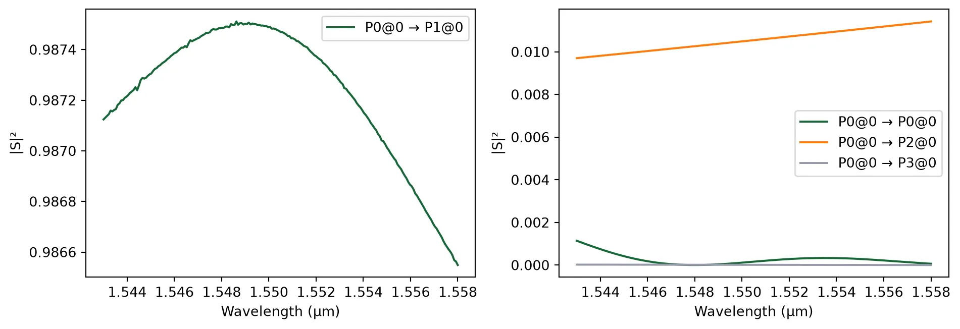
Monitor Photodiode
Section titled “Monitor Photodiode”The monitor photodiode is an integrated detector used to convert a fraction of the optical signal into an electrical current for power tracking. This component is modeled after the Keysight N1030A specifications, providing a high-bandwidth (65 GHz) response for real-time monitoring of signal integrity and link performance.
@pf.parametric_component(name_prefix="Monitor PD")def monitor_photodiode(    *,    width=100,  # detector box size (µm)    pad_width=25,  # metal pad size (µm)):    """    Monitor photodiode with a realistic 65 GHz detector model.
    Based on Keysight N1030A specifications (65 GHz unamplified module).    Includes an optical input port and electrical terminals for readout.    """    c = pf.Component()
    # Photodetector active area (black box)    rect = pf.Rectangle(center=(0, 0), size=(width, width))    c.add("Dream Photonics Black Box-Not Fabricated", rect)
    # Add a text label    text_comp = as_component(        layer="Text",        stencil="text",        text_string="Monitor PD",        size=10.0,    )    text_ref = pf.Reference(text_comp, origin=(-width / 4, 0))    c.add_reference(text_ref)
    # Optical input port    port_in = pf.Port(        center=(-width / 2.0, 0),        spec=port_spec,        input_direction=0,    )    # Electrical output port    port_out = pf.Port(        center=(width / 2.0, 0),        spec=pf.virtual_port_spec(classification="electrical"),        input_direction=0,    )    c.add_port([port_in, port_out])
    # Metal pads for electrical readout (GSG configuration)    rect_signal = pf.Rectangle(center=(0, 0), size=(pad_width, pad_width))    rect_signal.y_min = pad_width / 2.0    rect_signal.x_max = width / 2.0
    rect_ground = rect_signal.copy()    rect_ground.y_max = -pad_width / 2.0
    c.add("M2_router", rect_signal, rect_ground)
    # Electrical terminals    signal_pad = pf.Terminal("M2_router", rect_signal.copy())    ground_pad = pf.Terminal("M2_router", rect_ground.copy())    c.add_terminal([signal_pad, ground_pad])
    # Use one-port termination model to enable frequency domain simulations    detector_model = pf.TerminationModel()
    # Photodiode time-domain model (Keysight N1030A, 65 GHz)    detector_model.time_stepper = pf.PhotodiodeTimeStepper(        responsivity=0.85,  # A/W (InGaAs at 1550 nm)        gain=50.0,  # V/A (50 Ω load)        saturation_current=6.8e-3,  # A (8 mW max input)        dark_current=10e-9,  # A (10 nA typical)        thermal_noise=3.3e-22,  # A^2/Hz (Johnson noise)        filter_frequency=65e9,  # Hz (65 GHz bandwidth)        roll_off=2,    )    c.add_model(detector_model, "Photodiode")
    return c
pd = monitor_photodiode()viewer(pd);fill:%23221f20;font-weight:bold;font-size:4.400000px;}.terminal{fill:none;stroke:%23805080;stroke-width:0.550000;}.dashed{stroke-dasharray:2.750000,1.650000;}.port{fill:none;stroke:%23805080;stroke-width:1.100000;}.virtual-connection{fill:none;stroke:%23907090;stroke-width:0.825000;}.layer_31_0{stroke:%238c78ef;fill:url(%23pat-layer_31_0);fill-opacity:0.492;}.label_31_0{fill:%238c78ef;}.layer_33_0{stroke:%238c78ef;fill:url(%23pat-layer_33_0);fill-opacity:0.492;}.label_33_0{fill:%238c78ef;}.layer_102_0{stroke:%238c78ef;fill:url(%23pat-layer_102_0);fill-opacity:0.492;}.label_102_0{fill:%238c78ef;}.layer_110_0{stroke:%238c78ef;fill:url(%23pat-layer_110_0);fill-opacity:0.492;}.label_110_0{fill:%238c78ef;}.layer_189_0{stroke:%23000000;fill:none;}.label_189_0{fill:%23000000;}.layer_201_0{stroke:%2300ee00;fill:url(%23pat-layer_201_0);fill-opacity:0.492;}.label_201_0{fill:%2300ee00;}.layer_401_0{stroke:%236a8ad2;fill:url(%23pat-layer_401_0);fill-opacity:0.492;}.label_401_0{fill:%236a8ad2;}.layer_202_0{stroke:%23007600;fill:url(%23pat-layer_202_0);fill-opacity:0.492;}.label_202_0{fill:%23007600;}.layer_68_0{stroke:%23008000;fill:url(%23pat-layer_68_0);fill-opacity:0.492;}.label_68_0{fill:%23008000;}.layer_5_0{stroke:%236a8ad2;fill:url(%23pat-layer_5_0);fill-opacity:0.492;}.label_5_0{fill:%236a8ad2;}.layer_998_0{stroke:%23000000;fill:none;}.label_998_0{fill:%23000000;}.layer_312_1{stroke:%2300b8b8;fill:url(%23pat-layer_312_1);fill-opacity:0.492;}.label_312_1{fill:%2300b8b8;}.layer_312_0{stroke:%2300b8b8;fill:url(%23pat-layer_312_0);fill-opacity:0.492;}.label_312_0{fill:%2300b8b8;}.layer_402_0{stroke:%23ff0000;fill:url(%23pat-layer_402_0);fill-opacity:0.492;}.label_402_0{fill:%23ff0000;}.layer_401_4{stroke:%236a8ad2;fill:url(%23pat-layer_401_4);fill-opacity:0.492;}.label_401_4{fill:%236a8ad2;}.layer_389_0{stroke:%23ff00ff;fill:url(%23pat-layer_389_0);fill-opacity:0.492;}.label_389_0{fill:%23ff00ff;}.layer_402_1{stroke:%23ff0000;fill:url(%23pat-layer_402_1);fill-opacity:0.492;}.label_402_1{fill:%23ff0000;}.layer_350_1{stroke:%23697a00;fill:url(%23pat-layer_350_1);fill-opacity:0.492;}.label_350_1{fill:%23697a00;}.layer_401_1{stroke:%236a8ad2;fill:url(%23pat-layer_401_1);fill-opacity:0.492;}.label_401_1{fill:%236a8ad2;}.layer_313_2{stroke:%2301d95b;fill:url(%23pat-layer_313_2);fill-opacity:0.492;}.label_313_2{fill:%2301d95b;}.layer_313_1{stroke:%2301d95b;fill:url(%23pat-layer_313_1);fill-opacity:0.492;}.label_313_1{fill:%2301d95b;}.layer_313_0{stroke:%2301d95b;fill:url(%23pat-layer_313_0);fill-opacity:0.492;}.label_313_0{fill:%2301d95b;}.layer_400_0{stroke:%23a96868;fill:url(%23pat-layer_400_0);fill-opacity:0.492;}.label_400_0{fill:%23a96868;}.layer_312_3{stroke:%2300b8b8;fill:url(%23pat-layer_312_3);fill-opacity:0.492;}.label_312_3{fill:%2300b8b8;}.layer_389_1{stroke:%23ff00ff;fill:url(%23pat-layer_389_1);fill-opacity:0.492;}.label_389_1{fill:%23ff00ff;}.layer_401_3{stroke:%236a8ad2;fill:url(%23pat-layer_401_3);fill-opacity:0.492;}.label_401_3{fill:%236a8ad2;}.layer_403_2{stroke:%23500080;fill:url(%23pat-layer_403_2);fill-opacity:0.492;}.label_403_2{fill:%23500080;}.layer_403_3{stroke:%23500080;fill:url(%23pat-layer_403_3);fill-opacity:0.492;}.label_403_3{fill:%23500080;}.layer_403_1{stroke:%23500080;fill:url(%23pat-layer_403_1);fill-opacity:0.492;}.label_403_1{fill:%23500080;}.layer_403_0{stroke:%23500080;fill:url(%23pat-layer_403_0);fill-opacity:0.492;}.label_403_0{fill:%23500080;}.layer_311_1{stroke:%23ac6c56;fill:url(%23pat-layer_311_1);fill-opacity:0.492;}.label_311_1{fill:%23ac6c56;}.layer_311_0{stroke:%23ac6c56;fill:url(%23pat-layer_311_0);fill-opacity:0.492;}.label_311_0{fill:%23ac6c56;}.layer_301_1{stroke:%23800057;fill:url(%23pat-layer_301_1);fill-opacity:0.492;}.label_301_1{fill:%23800057;}.layer_301_0{stroke:%23800057;fill:url(%23pat-layer_301_0);fill-opacity:0.492;}.label_301_0{fill:%23800057;}.layer_305_1{stroke:%23808080;fill:url(%23pat-layer_305_1);fill-opacity:0.492;}.label_305_1{fill:%23808080;}.layer_305_0{stroke:%23808080;fill:url(%23pat-layer_305_0);fill-opacity:0.492;}.label_305_0{fill:%23808080;}.layer_999_0{stroke:%230000ff;fill:url(%23pat-layer_999_0);fill-opacity:0.492;}.label_999_0{fill:%230000ff;}.layer_81_0{stroke:%23808080;fill:url(%23pat-layer_81_0);fill-opacity:0.492;}.label_81_0{fill:%23808080;}.layer_290_0{stroke:%23a46eda;fill:none;}.label_290_0{fill:%23a46eda;}.layer_205_0{stroke:%2349b203;fill:url(%23pat-layer_205_0);fill-opacity:0.492;}.label_205_0{fill:%2349b203;}.layer_11_0{stroke:%230000ff;fill:url(%23pat-layer_11_0);fill-opacity:0.492;}.label_11_0{fill:%230000ff;}.layer_12_0{stroke:%23a57b00;fill:url(%23pat-layer_12_0);fill-opacity:0.492;}.label_12_0{fill:%23a57b00;}.layer_13_0{stroke:%23800057;fill:url(%23pat-layer_13_0);fill-opacity:0.492;}.label_13_0{fill:%23800057;}.layer_6_0{stroke:%23ff0000;fill:url(%23pat-layer_6_0);fill-opacity:0.492;}.label_6_0{fill:%23ff0000;}.layer_1_10{stroke:%23c96585;fill:url(%23pat-layer_1_10);fill-opacity:0.492;}.label_1_10{fill:%23c96585;}.layer_1_11{stroke:%23800000;fill:url(%23pat-layer_1_11);fill-opacity:0.492;}.label_1_11{fill:%23800000;}.layer_200_0{stroke:%23ff0000;fill:url(%23pat-layer_200_0);fill-opacity:0.492;}.label_200_0{fill:%23ff0000;}.layer_1_0{stroke:%23c96585;fill:url(%23pat-layer_1_0);fill-opacity:0.492;}.label_1_0{fill:%23c96585;}.layer_2_0{stroke:%23a46eda;fill:url(%23pat-layer_2_0);fill-opacity:0.492;}.label_2_0{fill:%23a46eda;}.layer_20_0{stroke:%2353793d;fill:url(%23pat-layer_20_0);fill-opacity:0.492;}.label_20_0{fill:%2353793d;}.layer_22_0{stroke:%23ec7600;fill:url(%23pat-layer_22_0);fill-opacity:0.492;}.label_22_0{fill:%23ec7600;}.layer_24_0{stroke:%2300b8b8;fill:url(%23pat-layer_24_0);fill-opacity:0.492;}.label_24_0{fill:%2300b8b8;}.layer_21_0{stroke:%23736264;fill:url(%23pat-layer_21_0);fill-opacity:0.492;}.label_21_0{fill:%23736264;}.layer_23_0{stroke:%23697a00;fill:url(%23pat-layer_23_0);fill-opacity:0.492;}.label_23_0{fill:%23697a00;}.layer_25_0{stroke:%23008000;fill:url(%23pat-layer_25_0);fill-opacity:0.492;}.label_25_0{fill:%23008000;}.layer_350_0{stroke:%23697a00;fill:url(%23pat-layer_350_0);fill-opacity:0.492;}.label_350_0{fill:%23697a00;}.layer_10_0{stroke:%23000000;fill:none;}.label_10_0{fill:%23000000;}.layer_203_0{stroke:%23008000;fill:url(%23pat-layer_203_0);fill-opacity:0.492;}.label_203_0{fill:%23008000;}.layer_40_0{stroke:%230000ff;fill:url(%23pat-layer_40_0);fill-opacity:0.492;}.label_40_0{fill:%230000ff;}.layer_401_2{stroke:%236a8ad2;fill:url(%23pat-layer_401_2);fill-opacity:0.492;}.label_401_2{fill:%236a8ad2;}.layer_301_2{stroke:%23800057;fill:url(%23pat-layer_301_2);fill-opacity:0.492;}.label_301_2{fill:%23800057;}</style><defs><path id=%22port-symbol%22 class=%22port%22 d=%22M 0,-2.200000 L 3.300000,0 0,2.200000%22 /><path id=%22ref-port-symbol%22 class=%22port%22 style=%22stroke-opacity:0.33;%22 d=%22M 0,-1.650000 C 2.200000,-1.650000 2.200000,1.650000 0,1.650000%22 /><circle id=%22port-bend-symbol%22 style=%22stroke-width:0;stroke:none;fill:%23805080;fill-opacity:1;%22 cx=%220%22 cy=%220%22 r=%220.990000%22 /><circle id=%22connection-symbol%22 style=%22stroke-width:0;stroke:none;fill:%23907090;fill-opacity:1;%22 cx=%220%22 cy=%220%22 r=%221.155000%22 /><pattern id=%22pat-layer_31_0%22 patternUnits=%22userSpaceOnUse%22 width=%222.750000%22 height=%222.750000%22 patternTransform=%22translate(2.102941,2.605263)%22><line x1=%220%22 y1=%220%22 x2=%222.750000%22 y2=%222.750000%22 style=%22stroke:%238c78ef;stroke-width:0.275000%22 /><line x1=%22-1.375000%22 y1=%221.375000%22 x2=%221.375000%22 y2=%224.125000%22 style=%22stroke:%238c78ef;stroke-width:0.275000%22 /><line x1=%221.375000%22 y1=%22-1.375000%22 x2=%224.125000%22 y2=%221.375000%22 style=%22stroke:%238c78ef;stroke-width:0.275000%22 /></pattern><pattern id=%22pat-layer_33_0%22 patternUnits=%22userSpaceOnUse%22 width=%222.750000%22 height=%222.750000%22 patternTransform=%22translate(1.617647,0.289474)%22><line x1=%220%22 y1=%220%22 x2=%222.750000%22 y2=%222.750000%22 style=%22stroke:%238c78ef;stroke-width:0.275000%22 /><line x1=%22-1.375000%22 y1=%221.375000%22 x2=%221.375000%22 y2=%224.125000%22 style=%22stroke:%238c78ef;stroke-width:0.275000%22 /><line x1=%221.375000%22 y1=%22-1.375000%22 x2=%224.125000%22 y2=%221.375000%22 style=%22stroke:%238c78ef;stroke-width:0.275000%22 /></pattern><pattern id=%22pat-layer_102_0%22 patternUnits=%22userSpaceOnUse%22 width=%222.750000%22 height=%222.750000%22 patternTransform=%22translate(0.000000,0.144737)%22><line x1=%220%22 y1=%220%22 x2=%222.750000%22 y2=%222.750000%22 style=%22stroke:%238c78ef;stroke-width:0.275000%22 /><line x1=%22-1.375000%22 y1=%221.375000%22 x2=%221.375000%22 y2=%224.125000%22 style=%22stroke:%238c78ef;stroke-width:0.275000%22 /><line x1=%221.375000%22 y1=%22-1.375000%22 x2=%224.125000%22 y2=%221.375000%22 style=%22stroke:%238c78ef;stroke-width:0.275000%22 /></pattern><pattern id=%22pat-layer_110_0%22 patternUnits=%22userSpaceOnUse%22 width=%222.750000%22 height=%222.750000%22 patternTransform=%22translate(0.808824,1.881579)%22><line x1=%220%22 y1=%220%22 x2=%222.750000%22 y2=%222.750000%22 style=%22stroke:%238c78ef;stroke-width:0.275000%22 /><line x1=%22-1.375000%22 y1=%221.375000%22 x2=%221.375000%22 y2=%224.125000%22 style=%22stroke:%238c78ef;stroke-width:0.275000%22 /><line x1=%221.375000%22 y1=%22-1.375000%22 x2=%224.125000%22 y2=%221.375000%22 style=%22stroke:%238c78ef;stroke-width:0.275000%22 /></pattern><pattern id=%22pat-layer_201_0%22 patternUnits=%22userSpaceOnUse%22 width=%222.750000%22 height=%222.750000%22 patternTransform=%22translate(2.102941,1.013158)%22><circle cx=%221.375000%22 cy=%221.375000%22 r=%220.275000%22 style=%22stroke:none;fill:%2300ee00;fill-opacity:1.0%22 /></pattern><pattern id=%22pat-layer_401_0%22 patternUnits=%22userSpaceOnUse%22 width=%221.650000%22 height=%221.650000%22 patternTransform=%22translate(0.194118,0.260526)%22><line x1=%220%22 y1=%220%22 x2=%221.650000%22 y2=%221.650000%22 style=%22stroke:%236a8ad2;stroke-width:0.275000%22 /><line x1=%22-0.825000%22 y1=%220.825000%22 x2=%220.825000%22 y2=%222.475000%22 style=%22stroke:%236a8ad2;stroke-width:0.275000%22 /><line x1=%220.825000%22 y1=%22-0.825000%22 x2=%222.475000%22 y2=%220.825000%22 style=%22stroke:%236a8ad2;stroke-width:0.275000%22 /><line x1=%221.650000%22 y1=%220%22 x2=%220%22 y2=%221.650000%22 style=%22stroke:%236a8ad2;stroke-width:0.275000%22 /><line x1=%222.475000%22 y1=%220.825000%22 x2=%220.825000%22 y2=%222.475000%22 style=%22stroke:%236a8ad2;stroke-width:0.275000%22 /><line x1=%220.825000%22 y1=%22-0.825000%22 x2=%22-0.825000%22 y2=%220.825000%22 style=%22stroke:%236a8ad2;stroke-width:0.275000%22 /></pattern><pattern id=%22pat-layer_202_0%22 patternUnits=%22userSpaceOnUse%22 width=%221.650000%22 height=%221.650000%22 patternTransform=%22translate(0.291176,1.563158)%22><circle cx=%220.825000%22 cy=%220.825000%22 r=%220.275000%22 style=%22stroke:none;fill:%23007600;fill-opacity:1.0%22 /></pattern><pattern id=%22pat-layer_68_0%22 patternUnits=%22userSpaceOnUse%22 width=%222.750000%22 height=%222.750000%22 patternTransform=%22translate(0.000000,1.013158)%22><circle cx=%221.375000%22 cy=%221.375000%22 r=%220.275000%22 style=%22stroke:none;fill:%23008000;fill-opacity:1.0%22 /></pattern><pattern id=%22pat-layer_5_0%22 patternUnits=%22userSpaceOnUse%22 width=%221.650000%22 height=%221.650000%22 patternTransform=%22translate(0.097059,1.476316)%22><line x1=%220.825000%22 y1=%220%22 x2=%220.825000%22 y2=%221.650000%22 style=%22stroke:%236a8ad2;stroke-width:0.275000%22 /></pattern><pattern id=%22pat-layer_312_1%22 patternUnits=%22userSpaceOnUse%22 width=%221.650000%22 height=%221.650000%22 patternTransform=%22translate(0.388235,1.302632)%22><line x1=%220%22 y1=%220%22 x2=%221.650000%22 y2=%221.650000%22 style=%22stroke:%2300b8b8;stroke-width:0.275000%22 /><line x1=%22-0.825000%22 y1=%220.825000%22 x2=%220.825000%22 y2=%222.475000%22 style=%22stroke:%2300b8b8;stroke-width:0.275000%22 /><line x1=%220.825000%22 y1=%22-0.825000%22 x2=%222.475000%22 y2=%220.825000%22 style=%22stroke:%2300b8b8;stroke-width:0.275000%22 /></pattern><pattern id=%22pat-layer_312_0%22 patternUnits=%22userSpaceOnUse%22 width=%222.750000%22 height=%222.750000%22 patternTransform=%22translate(1.294118,1.736842)%22><line x1=%221.375000%22 y1=%220%22 x2=%221.375000%22 y2=%222.750000%22 style=%22stroke:%2300b8b8;stroke-width:0.275000%22 /></pattern><pattern id=%22pat-layer_402_0%22 patternUnits=%22userSpaceOnUse%22 width=%222.750000%22 height=%222.750000%22 patternTransform=%22translate(1.455882,2.026316)%22><line x1=%221.375000%22 y1=%220%22 x2=%221.375000%22 y2=%222.750000%22 style=%22stroke:%23ff0000;stroke-width:0.275000%22 /><line x1=%220%22 y1=%221.375000%22 x2=%222.750000%22 y2=%221.375000%22 style=%22stroke:%23ff0000;stroke-width:0.275000%22 /></pattern><pattern id=%22pat-layer_401_4%22 patternUnits=%22userSpaceOnUse%22 width=%221.650000%22 height=%221.650000%22 patternTransform=%22translate(0.291176,1.302632)%22><line x1=%220.825000%22 y1=%220%22 x2=%220.825000%22 y2=%221.650000%22 style=%22stroke:%236a8ad2;stroke-width:0.275000%22 /></pattern><pattern id=%22pat-layer_389_0%22 patternUnits=%22userSpaceOnUse%22 width=%221.650000%22 height=%221.650000%22 patternTransform=%22translate(0.291176,0.347368)%22><line x1=%220.825000%22 y1=%220%22 x2=%220.825000%22 y2=%221.650000%22 style=%22stroke:%23ff00ff;stroke-width:0.275000%22 /><line x1=%220%22 y1=%220.825000%22 x2=%221.650000%22 y2=%220.825000%22 style=%22stroke:%23ff00ff;stroke-width:0.275000%22 /></pattern><pattern id=%22pat-layer_402_1%22 patternUnits=%22userSpaceOnUse%22 width=%221.650000%22 height=%221.650000%22 patternTransform=%22translate(0.485294,1.476316)%22><line x1=%220%22 y1=%220%22 x2=%221.650000%22 y2=%221.650000%22 style=%22stroke:%23ff0000;stroke-width:0.275000%22 /><line x1=%22-0.825000%22 y1=%220.825000%22 x2=%220.825000%22 y2=%222.475000%22 style=%22stroke:%23ff0000;stroke-width:0.275000%22 /><line x1=%220.825000%22 y1=%22-0.825000%22 x2=%222.475000%22 y2=%220.825000%22 style=%22stroke:%23ff0000;stroke-width:0.275000%22 /><line x1=%221.650000%22 y1=%220%22 x2=%220%22 y2=%221.650000%22 style=%22stroke:%23ff0000;stroke-width:0.275000%22 /><line x1=%222.475000%22 y1=%220.825000%22 x2=%220.825000%22 y2=%222.475000%22 style=%22stroke:%23ff0000;stroke-width:0.275000%22 /><line x1=%220.825000%22 y1=%22-0.825000%22 x2=%22-0.825000%22 y2=%220.825000%22 style=%22stroke:%23ff0000;stroke-width:0.275000%22 /></pattern><pattern id=%22pat-layer_350_1%22 patternUnits=%22userSpaceOnUse%22 width=%221.650000%22 height=%221.650000%22 patternTransform=%22translate(1.455882,1.302632)%22><circle cx=%220.825000%22 cy=%220.825000%22 r=%220.275000%22 style=%22stroke:none;fill:%23697a00;fill-opacity:1.0%22 /></pattern><pattern id=%22pat-layer_401_1%22 patternUnits=%22userSpaceOnUse%22 width=%222.750000%22 height=%222.750000%22 patternTransform=%22translate(2.426471,0.868421)%22><line x1=%220%22 y1=%220%22 x2=%222.750000%22 y2=%222.750000%22 style=%22stroke:%236a8ad2;stroke-width:0.275000%22 /><line x1=%22-1.375000%22 y1=%221.375000%22 x2=%221.375000%22 y2=%224.125000%22 style=%22stroke:%236a8ad2;stroke-width:0.275000%22 /><line x1=%221.375000%22 y1=%22-1.375000%22 x2=%224.125000%22 y2=%221.375000%22 style=%22stroke:%236a8ad2;stroke-width:0.275000%22 /><line x1=%222.750000%22 y1=%220%22 x2=%220%22 y2=%222.750000%22 style=%22stroke:%236a8ad2;stroke-width:0.275000%22 /><line x1=%224.125000%22 y1=%221.375000%22 x2=%221.375000%22 y2=%224.125000%22 style=%22stroke:%236a8ad2;stroke-width:0.275000%22 /><line x1=%221.375000%22 y1=%22-1.375000%22 x2=%22-1.375000%22 y2=%221.375000%22 style=%22stroke:%236a8ad2;stroke-width:0.275000%22 /></pattern><pattern id=%22pat-layer_313_2%22 patternUnits=%22userSpaceOnUse%22 width=%221.650000%22 height=%221.650000%22 patternTransform=%22translate(0.679412,0.868421)%22><line x1=%220%22 y1=%220%22 x2=%221.650000%22 y2=%221.650000%22 style=%22stroke:%2301d95b;stroke-width:0.275000%22 /><line x1=%22-0.825000%22 y1=%220.825000%22 x2=%220.825000%22 y2=%222.475000%22 style=%22stroke:%2301d95b;stroke-width:0.275000%22 /><line x1=%220.825000%22 y1=%22-0.825000%22 x2=%222.475000%22 y2=%220.825000%22 style=%22stroke:%2301d95b;stroke-width:0.275000%22 /></pattern><pattern id=%22pat-layer_313_1%22 patternUnits=%22userSpaceOnUse%22 width=%222.750000%22 height=%222.750000%22 patternTransform=%22translate(1.779412,1.013158)%22><line x1=%221.375000%22 y1=%220%22 x2=%221.375000%22 y2=%222.750000%22 style=%22stroke:%2301d95b;stroke-width:0.275000%22 /></pattern><pattern id=%22pat-layer_313_0%22 patternUnits=%22userSpaceOnUse%22 width=%221.650000%22 height=%221.650000%22 patternTransform=%22translate(1.455882,0.347368)%22><line x1=%220.825000%22 y1=%220%22 x2=%220.825000%22 y2=%221.650000%22 style=%22stroke:%2301d95b;stroke-width:0.275000%22 /></pattern><pattern id=%22pat-layer_400_0%22 patternUnits=%22userSpaceOnUse%22 width=%222.750000%22 height=%222.750000%22 patternTransform=%22translate(1.941176,1.592105)%22><line x1=%220%22 y1=%220%22 x2=%222.750000%22 y2=%222.750000%22 style=%22stroke:%23a96868;stroke-width:0.275000%22 /><line x1=%22-1.375000%22 y1=%221.375000%22 x2=%221.375000%22 y2=%224.125000%22 style=%22stroke:%23a96868;stroke-width:0.275000%22 /><line x1=%221.375000%22 y1=%22-1.375000%22 x2=%224.125000%22 y2=%221.375000%22 style=%22stroke:%23a96868;stroke-width:0.275000%22 /><line x1=%222.750000%22 y1=%220%22 x2=%220%22 y2=%222.750000%22 style=%22stroke:%23a96868;stroke-width:0.275000%22 /><line x1=%224.125000%22 y1=%221.375000%22 x2=%221.375000%22 y2=%224.125000%22 style=%22stroke:%23a96868;stroke-width:0.275000%22 /><line x1=%221.375000%22 y1=%22-1.375000%22 x2=%22-1.375000%22 y2=%221.375000%22 style=%22stroke:%23a96868;stroke-width:0.275000%22 /></pattern><pattern id=%22pat-layer_312_3%22 patternUnits=%22userSpaceOnUse%22 width=%221.650000%22 height=%221.650000%22 patternTransform=%22translate(1.261765,0.173684)%22><line x1=%221.650000%22 y1=%220%22 x2=%220%22 y2=%221.650000%22 style=%22stroke:%2300b8b8;stroke-width:0.275000%22 /><line x1=%222.475000%22 y1=%220.825000%22 x2=%220.825000%22 y2=%222.475000%22 style=%22stroke:%2300b8b8;stroke-width:0.275000%22 /><line x1=%220.825000%22 y1=%22-0.825000%22 x2=%22-0.825000%22 y2=%220.825000%22 style=%22stroke:%2300b8b8;stroke-width:0.275000%22 /></pattern><pattern id=%22pat-layer_389_1%22 patternUnits=%22userSpaceOnUse%22 width=%222.750000%22 height=%222.750000%22 patternTransform=%22translate(2.588235,1.013158)%22><line x1=%221.375000%22 y1=%220%22 x2=%221.375000%22 y2=%222.750000%22 style=%22stroke:%23ff00ff;stroke-width:0.275000%22 /><line x1=%220%22 y1=%221.375000%22 x2=%222.750000%22 y2=%221.375000%22 style=%22stroke:%23ff00ff;stroke-width:0.275000%22 /></pattern><pattern id=%22pat-layer_401_3%22 patternUnits=%22userSpaceOnUse%22 width=%222.750000%22 height=%222.750000%22 patternTransform=%22translate(1.132353,1.736842)%22><line x1=%220%22 y1=%221.375000%22 x2=%222.750000%22 y2=%221.375000%22 style=%22stroke:%236a8ad2;stroke-width:0.275000%22 /></pattern><pattern id=%22pat-layer_403_2%22 patternUnits=%22userSpaceOnUse%22 width=%221.650000%22 height=%221.650000%22 patternTransform=%22translate(0.776471,1.042105)%22><line x1=%220%22 y1=%220%22 x2=%221.650000%22 y2=%221.650000%22 style=%22stroke:%23500080;stroke-width:0.275000%22 /><line x1=%22-0.825000%22 y1=%220.825000%22 x2=%220.825000%22 y2=%222.475000%22 style=%22stroke:%23500080;stroke-width:0.275000%22 /><line x1=%220.825000%22 y1=%22-0.825000%22 x2=%222.475000%22 y2=%220.825000%22 style=%22stroke:%23500080;stroke-width:0.275000%22 /><line x1=%221.650000%22 y1=%220%22 x2=%220%22 y2=%221.650000%22 style=%22stroke:%23500080;stroke-width:0.275000%22 /><line x1=%222.475000%22 y1=%220.825000%22 x2=%220.825000%22 y2=%222.475000%22 style=%22stroke:%23500080;stroke-width:0.275000%22 /><line x1=%220.825000%22 y1=%22-0.825000%22 x2=%22-0.825000%22 y2=%220.825000%22 style=%22stroke:%23500080;stroke-width:0.275000%22 /></pattern><pattern id=%22pat-layer_403_3%22 patternUnits=%22userSpaceOnUse%22 width=%222.750000%22 height=%222.750000%22 patternTransform=%22translate(0.647059,2.171053)%22><line x1=%220%22 y1=%220%22 x2=%222.750000%22 y2=%222.750000%22 style=%22stroke:%23500080;stroke-width:0.275000%22 /><line x1=%22-1.375000%22 y1=%221.375000%22 x2=%221.375000%22 y2=%224.125000%22 style=%22stroke:%23500080;stroke-width:0.275000%22 /><line x1=%221.375000%22 y1=%22-1.375000%22 x2=%224.125000%22 y2=%221.375000%22 style=%22stroke:%23500080;stroke-width:0.275000%22 /><line x1=%222.750000%22 y1=%220%22 x2=%220%22 y2=%222.750000%22 style=%22stroke:%23500080;stroke-width:0.275000%22 /><line x1=%224.125000%22 y1=%221.375000%22 x2=%221.375000%22 y2=%224.125000%22 style=%22stroke:%23500080;stroke-width:0.275000%22 /><line x1=%221.375000%22 y1=%22-1.375000%22 x2=%22-1.375000%22 y2=%221.375000%22 style=%22stroke:%23500080;stroke-width:0.275000%22 /></pattern><pattern id=%22pat-layer_403_1%22 patternUnits=%22userSpaceOnUse%22 width=%222.750000%22 height=%222.750000%22 patternTransform=%22translate(1.941176,1.302632)%22><line x1=%221.375000%22 y1=%220%22 x2=%221.375000%22 y2=%222.750000%22 style=%22stroke:%23500080;stroke-width:0.275000%22 /><line x1=%220%22 y1=%221.375000%22 x2=%222.750000%22 y2=%221.375000%22 style=%22stroke:%23500080;stroke-width:0.275000%22 /></pattern><pattern id=%22pat-layer_403_0%22 patternUnits=%22userSpaceOnUse%22 width=%221.650000%22 height=%221.650000%22 patternTransform=%22translate(1.552941,0.521053)%22><line x1=%220.825000%22 y1=%220%22 x2=%220.825000%22 y2=%221.650000%22 style=%22stroke:%23500080;stroke-width:0.275000%22 /><line x1=%220%22 y1=%220.825000%22 x2=%221.650000%22 y2=%220.825000%22 style=%22stroke:%23500080;stroke-width:0.275000%22 /></pattern><pattern id=%22pat-layer_311_1%22 patternUnits=%22userSpaceOnUse%22 width=%222.750000%22 height=%222.750000%22 patternTransform=%22translate(2.264706,0.578947)%22><line x1=%220%22 y1=%220%22 x2=%222.750000%22 y2=%222.750000%22 style=%22stroke:%23ac6c56;stroke-width:0.275000%22 /><line x1=%22-1.375000%22 y1=%221.375000%22 x2=%221.375000%22 y2=%224.125000%22 style=%22stroke:%23ac6c56;stroke-width:0.275000%22 /><line x1=%221.375000%22 y1=%22-1.375000%22 x2=%224.125000%22 y2=%221.375000%22 style=%22stroke:%23ac6c56;stroke-width:0.275000%22 /></pattern><pattern id=%22pat-layer_311_0%22 patternUnits=%22userSpaceOnUse%22 width=%221.650000%22 height=%221.650000%22 patternTransform=%22translate(0.097059,0.086842)%22><line x1=%220%22 y1=%220%22 x2=%221.650000%22 y2=%221.650000%22 style=%22stroke:%23ac6c56;stroke-width:0.275000%22 /><line x1=%22-0.825000%22 y1=%220.825000%22 x2=%220.825000%22 y2=%222.475000%22 style=%22stroke:%23ac6c56;stroke-width:0.275000%22 /><line x1=%220.825000%22 y1=%22-0.825000%22 x2=%222.475000%22 y2=%220.825000%22 style=%22stroke:%23ac6c56;stroke-width:0.275000%22 /></pattern><pattern id=%22pat-layer_301_1%22 patternUnits=%22userSpaceOnUse%22 width=%222.750000%22 height=%222.750000%22 patternTransform=%22translate(1.941176,1.157895)%22><line x1=%220%22 y1=%221.375000%22 x2=%222.750000%22 y2=%221.375000%22 style=%22stroke:%23800057;stroke-width:0.275000%22 /></pattern><pattern id=%22pat-layer_301_0%22 patternUnits=%22userSpaceOnUse%22 width=%221.650000%22 height=%221.650000%22 patternTransform=%22translate(1.552941,0.434211)%22><line x1=%220%22 y1=%220.825000%22 x2=%221.650000%22 y2=%220.825000%22 style=%22stroke:%23800057;stroke-width:0.275000%22 /></pattern><pattern id=%22pat-layer_305_1%22 patternUnits=%22userSpaceOnUse%22 width=%222.750000%22 height=%222.750000%22 patternTransform=%22translate(0.970588,2.026316)%22><line x1=%221.375000%22 y1=%220%22 x2=%221.375000%22 y2=%222.750000%22 style=%22stroke:%23808080;stroke-width:0.275000%22 /><line x1=%220%22 y1=%221.375000%22 x2=%222.750000%22 y2=%221.375000%22 style=%22stroke:%23808080;stroke-width:0.275000%22 /></pattern><pattern id=%22pat-layer_305_0%22 patternUnits=%22userSpaceOnUse%22 width=%221.650000%22 height=%221.650000%22 patternTransform=%22translate(0.970588,0.955263)%22><line x1=%220.825000%22 y1=%220%22 x2=%220.825000%22 y2=%221.650000%22 style=%22stroke:%23808080;stroke-width:0.275000%22 /><line x1=%220%22 y1=%220.825000%22 x2=%221.650000%22 y2=%220.825000%22 style=%22stroke:%23808080;stroke-width:0.275000%22 /></pattern><pattern id=%22pat-layer_999_0%22 patternUnits=%22userSpaceOnUse%22 width=%221.650000%22 height=%221.650000%22 patternTransform=%22translate(0.582353,0.607895)%22><line x1=%220.825000%22 y1=%220%22 x2=%220.825000%22 y2=%221.650000%22 style=%22stroke:%230000ff;stroke-width:0.275000%22 /></pattern><pattern id=%22pat-layer_81_0%22 patternUnits=%22userSpaceOnUse%22 width=%221.650000%22 height=%221.650000%22 patternTransform=%22translate(0.582353,1.476316)%22><line x1=%220.825000%22 y1=%220%22 x2=%220.825000%22 y2=%221.650000%22 style=%22stroke:%23808080;stroke-width:0.275000%22 /><line x1=%220%22 y1=%220.825000%22 x2=%221.650000%22 y2=%220.825000%22 style=%22stroke:%23808080;stroke-width:0.275000%22 /></pattern><pattern id=%22pat-layer_205_0%22 patternUnits=%22userSpaceOnUse%22 width=%221.650000%22 height=%221.650000%22 patternTransform=%22translate(0.679412,1.128947)%22><line x1=%220%22 y1=%220%22 x2=%221.650000%22 y2=%221.650000%22 style=%22stroke:%2349b203;stroke-width:0.275000%22 /><line x1=%22-0.825000%22 y1=%220.825000%22 x2=%220.825000%22 y2=%222.475000%22 style=%22stroke:%2349b203;stroke-width:0.275000%22 /><line x1=%220.825000%22 y1=%22-0.825000%22 x2=%222.475000%22 y2=%220.825000%22 style=%22stroke:%2349b203;stroke-width:0.275000%22 /><line x1=%221.650000%22 y1=%220%22 x2=%220%22 y2=%221.650000%22 style=%22stroke:%2349b203;stroke-width:0.275000%22 /><line x1=%222.475000%22 y1=%220.825000%22 x2=%220.825000%22 y2=%222.475000%22 style=%22stroke:%2349b203;stroke-width:0.275000%22 /><line x1=%220.825000%22 y1=%22-0.825000%22 x2=%22-0.825000%22 y2=%220.825000%22 style=%22stroke:%2349b203;stroke-width:0.275000%22 /></pattern><pattern id=%22pat-layer_11_0%22 patternUnits=%22userSpaceOnUse%22 width=%221.650000%22 height=%221.650000%22 patternTransform=%22translate(0.873529,0.607895)%22><line x1=%221.650000%22 y1=%220%22 x2=%220%22 y2=%221.650000%22 style=%22stroke:%230000ff;stroke-width:0.275000%22 /><line x1=%222.475000%22 y1=%220.825000%22 x2=%220.825000%22 y2=%222.475000%22 style=%22stroke:%230000ff;stroke-width:0.275000%22 /><line x1=%220.825000%22 y1=%22-0.825000%22 x2=%22-0.825000%22 y2=%220.825000%22 style=%22stroke:%230000ff;stroke-width:0.275000%22 /></pattern><pattern id=%22pat-layer_12_0%22 patternUnits=%22userSpaceOnUse%22 width=%221.650000%22 height=%221.650000%22 patternTransform=%22translate(1.552941,1.563158)%22><line x1=%220%22 y1=%220%22 x2=%221.650000%22 y2=%221.650000%22 style=%22stroke:%23a57b00;stroke-width:0.275000%22 /><line x1=%22-0.825000%22 y1=%220.825000%22 x2=%220.825000%22 y2=%222.475000%22 style=%22stroke:%23a57b00;stroke-width:0.275000%22 /><line x1=%220.825000%22 y1=%22-0.825000%22 x2=%222.475000%22 y2=%220.825000%22 style=%22stroke:%23a57b00;stroke-width:0.275000%22 /></pattern><pattern id=%22pat-layer_13_0%22 patternUnits=%22userSpaceOnUse%22 width=%221.650000%22 height=%221.650000%22 patternTransform=%22translate(0.582353,0.868421)%22><line x1=%221.650000%22 y1=%220%22 x2=%220%22 y2=%221.650000%22 style=%22stroke:%23800057;stroke-width:0.275000%22 /><line x1=%222.475000%22 y1=%220.825000%22 x2=%220.825000%22 y2=%222.475000%22 style=%22stroke:%23800057;stroke-width:0.275000%22 /><line x1=%220.825000%22 y1=%22-0.825000%22 x2=%22-0.825000%22 y2=%220.825000%22 style=%22stroke:%23800057;stroke-width:0.275000%22 /></pattern><pattern id=%22pat-layer_6_0%22 patternUnits=%22userSpaceOnUse%22 width=%222.750000%22 height=%222.750000%22 patternTransform=%22translate(1.294118,1.302632)%22><line x1=%220%22 y1=%221.375000%22 x2=%222.750000%22 y2=%221.375000%22 style=%22stroke:%23ff0000;stroke-width:0.275000%22 /></pattern><pattern id=%22pat-layer_1_10%22 patternUnits=%22userSpaceOnUse%22 width=%221.650000%22 height=%221.650000%22 patternTransform=%22translate(0.097059,0.260526)%22><line x1=%220%22 y1=%220%22 x2=%221.650000%22 y2=%221.650000%22 style=%22stroke:%23c96585;stroke-width:0.275000%22 /><line x1=%22-0.825000%22 y1=%220.825000%22 x2=%220.825000%22 y2=%222.475000%22 style=%22stroke:%23c96585;stroke-width:0.275000%22 /><line x1=%220.825000%22 y1=%22-0.825000%22 x2=%222.475000%22 y2=%220.825000%22 style=%22stroke:%23c96585;stroke-width:0.275000%22 /><line x1=%221.650000%22 y1=%220%22 x2=%220%22 y2=%221.650000%22 style=%22stroke:%23c96585;stroke-width:0.275000%22 /><line x1=%222.475000%22 y1=%220.825000%22 x2=%220.825000%22 y2=%222.475000%22 style=%22stroke:%23c96585;stroke-width:0.275000%22 /><line x1=%220.825000%22 y1=%22-0.825000%22 x2=%22-0.825000%22 y2=%220.825000%22 style=%22stroke:%23c96585;stroke-width:0.275000%22 /></pattern><pattern id=%22pat-layer_1_11%22 patternUnits=%22userSpaceOnUse%22 width=%222.750000%22 height=%222.750000%22 patternTransform=%22translate(2.264706,0.868421)%22><line x1=%221.375000%22 y1=%220%22 x2=%221.375000%22 y2=%222.750000%22 style=%22stroke:%23800000;stroke-width:0.275000%22 /><line x1=%220%22 y1=%221.375000%22 x2=%222.750000%22 y2=%221.375000%22 style=%22stroke:%23800000;stroke-width:0.275000%22 /></pattern><pattern id=%22pat-layer_200_0%22 patternUnits=%22userSpaceOnUse%22 width=%222.750000%22 height=%222.750000%22 patternTransform=%22translate(0.970588,2.171053)%22><line x1=%220%22 y1=%220%22 x2=%222.750000%22 y2=%222.750000%22 style=%22stroke:%23ff0000;stroke-width:0.275000%22 /><line x1=%22-1.375000%22 y1=%221.375000%22 x2=%221.375000%22 y2=%224.125000%22 style=%22stroke:%23ff0000;stroke-width:0.275000%22 /><line x1=%221.375000%22 y1=%22-1.375000%22 x2=%224.125000%22 y2=%221.375000%22 style=%22stroke:%23ff0000;stroke-width:0.275000%22 /><line x1=%222.750000%22 y1=%220%22 x2=%220%22 y2=%222.750000%22 style=%22stroke:%23ff0000;stroke-width:0.275000%22 /><line x1=%224.125000%22 y1=%221.375000%22 x2=%221.375000%22 y2=%224.125000%22 style=%22stroke:%23ff0000;stroke-width:0.275000%22 /><line x1=%221.375000%22 y1=%22-1.375000%22 x2=%22-1.375000%22 y2=%221.375000%22 style=%22stroke:%23ff0000;stroke-width:0.275000%22 /></pattern><pattern id=%22pat-layer_1_0%22 patternUnits=%22userSpaceOnUse%22 width=%221.650000%22 height=%221.650000%22 patternTransform=%22translate(0.679412,0.955263)%22><line x1=%221.650000%22 y1=%220%22 x2=%220%22 y2=%221.650000%22 style=%22stroke:%23c96585;stroke-width:0.275000%22 /><line x1=%222.475000%22 y1=%220.825000%22 x2=%220.825000%22 y2=%222.475000%22 style=%22stroke:%23c96585;stroke-width:0.275000%22 /><line x1=%220.825000%22 y1=%22-0.825000%22 x2=%22-0.825000%22 y2=%220.825000%22 style=%22stroke:%23c96585;stroke-width:0.275000%22 /></pattern><pattern id=%22pat-layer_2_0%22 patternUnits=%22userSpaceOnUse%22 width=%222.750000%22 height=%222.750000%22 patternTransform=%22translate(2.264706,0.434211)%22><line x1=%220%22 y1=%220%22 x2=%222.750000%22 y2=%222.750000%22 style=%22stroke:%23a46eda;stroke-width:0.275000%22 /><line x1=%22-1.375000%22 y1=%221.375000%22 x2=%221.375000%22 y2=%224.125000%22 style=%22stroke:%23a46eda;stroke-width:0.275000%22 /><line x1=%221.375000%22 y1=%22-1.375000%22 x2=%224.125000%22 y2=%221.375000%22 style=%22stroke:%23a46eda;stroke-width:0.275000%22 /></pattern><pattern id=%22pat-layer_20_0%22 patternUnits=%22userSpaceOnUse%22 width=%222.750000%22 height=%222.750000%22 patternTransform=%22translate(0.647059,1.592105)%22><line x1=%220%22 y1=%221.375000%22 x2=%222.750000%22 y2=%221.375000%22 style=%22stroke:%2353793d;stroke-width:0.275000%22 /></pattern><pattern id=%22pat-layer_22_0%22 patternUnits=%22userSpaceOnUse%22 width=%222.750000%22 height=%222.750000%22 patternTransform=%22translate(0.161765,2.026316)%22><line x1=%220%22 y1=%220%22 x2=%222.750000%22 y2=%222.750000%22 style=%22stroke:%23ec7600;stroke-width:0.275000%22 /><line x1=%22-1.375000%22 y1=%221.375000%22 x2=%221.375000%22 y2=%224.125000%22 style=%22stroke:%23ec7600;stroke-width:0.275000%22 /><line x1=%221.375000%22 y1=%22-1.375000%22 x2=%224.125000%22 y2=%221.375000%22 style=%22stroke:%23ec7600;stroke-width:0.275000%22 /><line x1=%222.750000%22 y1=%220%22 x2=%220%22 y2=%222.750000%22 style=%22stroke:%23ec7600;stroke-width:0.275000%22 /><line x1=%224.125000%22 y1=%221.375000%22 x2=%221.375000%22 y2=%224.125000%22 style=%22stroke:%23ec7600;stroke-width:0.275000%22 /><line x1=%221.375000%22 y1=%22-1.375000%22 x2=%22-1.375000%22 y2=%221.375000%22 style=%22stroke:%23ec7600;stroke-width:0.275000%22 /></pattern><pattern id=%22pat-layer_24_0%22 patternUnits=%22userSpaceOnUse%22 width=%222.750000%22 height=%222.750000%22 patternTransform=%22translate(2.426471,2.460526)%22><line x1=%221.375000%22 y1=%220%22 x2=%221.375000%22 y2=%222.750000%22 style=%22stroke:%2300b8b8;stroke-width:0.275000%22 /><line x1=%220%22 y1=%221.375000%22 x2=%222.750000%22 y2=%221.375000%22 style=%22stroke:%2300b8b8;stroke-width:0.275000%22 /></pattern><pattern id=%22pat-layer_21_0%22 patternUnits=%22userSpaceOnUse%22 width=%221.650000%22 height=%221.650000%22 patternTransform=%22translate(1.067647,0.260526)%22><line x1=%220%22 y1=%220.825000%22 x2=%221.650000%22 y2=%220.825000%22 style=%22stroke:%23736264;stroke-width:0.275000%22 /></pattern><pattern id=%22pat-layer_23_0%22 patternUnits=%22userSpaceOnUse%22 width=%221.650000%22 height=%221.650000%22 patternTransform=%22translate(0.776471,0.521053)%22><line x1=%220%22 y1=%220%22 x2=%221.650000%22 y2=%221.650000%22 style=%22stroke:%23697a00;stroke-width:0.275000%22 /><line x1=%22-0.825000%22 y1=%220.825000%22 x2=%220.825000%22 y2=%222.475000%22 style=%22stroke:%23697a00;stroke-width:0.275000%22 /><line x1=%220.825000%22 y1=%22-0.825000%22 x2=%222.475000%22 y2=%220.825000%22 style=%22stroke:%23697a00;stroke-width:0.275000%22 /><line x1=%221.650000%22 y1=%220%22 x2=%220%22 y2=%221.650000%22 style=%22stroke:%23697a00;stroke-width:0.275000%22 /><line x1=%222.475000%22 y1=%220.825000%22 x2=%220.825000%22 y2=%222.475000%22 style=%22stroke:%23697a00;stroke-width:0.275000%22 /><line x1=%220.825000%22 y1=%22-0.825000%22 x2=%22-0.825000%22 y2=%220.825000%22 style=%22stroke:%23697a00;stroke-width:0.275000%22 /></pattern><pattern id=%22pat-layer_25_0%22 patternUnits=%22userSpaceOnUse%22 width=%221.650000%22 height=%221.650000%22 patternTransform=%22translate(0.485294,0.781579)%22><line x1=%220.825000%22 y1=%220%22 x2=%220.825000%22 y2=%221.650000%22 style=%22stroke:%23008000;stroke-width:0.275000%22 /><line x1=%220%22 y1=%220.825000%22 x2=%221.650000%22 y2=%220.825000%22 style=%22stroke:%23008000;stroke-width:0.275000%22 /></pattern><pattern id=%22pat-layer_350_0%22 patternUnits=%22userSpaceOnUse%22 width=%222.750000%22 height=%222.750000%22 patternTransform=%22translate(0.323529,1.736842)%22><line x1=%222.750000%22 y1=%220%22 x2=%220%22 y2=%222.750000%22 style=%22stroke:%23697a00;stroke-width:0.275000%22 /><line x1=%224.125000%22 y1=%221.375000%22 x2=%221.375000%22 y2=%224.125000%22 style=%22stroke:%23697a00;stroke-width:0.275000%22 /><line x1=%221.375000%22 y1=%22-1.375000%22 x2=%22-1.375000%22 y2=%221.375000%22 style=%22stroke:%23697a00;stroke-width:0.275000%22 /></pattern><pattern id=%22pat-layer_203_0%22 patternUnits=%22userSpaceOnUse%22 width=%222.750000%22 height=%222.750000%22 patternTransform=%22translate(1.617647,1.447368)%22><line x1=%222.750000%22 y1=%220%22 x2=%220%22 y2=%222.750000%22 style=%22stroke:%23008000;stroke-width:0.275000%22 /><line x1=%224.125000%22 y1=%221.375000%22 x2=%221.375000%22 y2=%224.125000%22 style=%22stroke:%23008000;stroke-width:0.275000%22 /><line x1=%221.375000%22 y1=%22-1.375000%22 x2=%22-1.375000%22 y2=%221.375000%22 style=%22stroke:%23008000;stroke-width:0.275000%22 /></pattern><pattern id=%22pat-layer_40_0%22 patternUnits=%22userSpaceOnUse%22 width=%222.750000%22 height=%222.750000%22 patternTransform=%22translate(1.294118,0.434211)%22><circle cx=%221.375000%22 cy=%221.375000%22 r=%220.275000%22 style=%22stroke:none;fill:%230000ff;fill-opacity:1.0%22 /></pattern><pattern id=%22pat-layer_401_2%22 patternUnits=%22userSpaceOnUse%22 width=%221.650000%22 height=%221.650000%22 patternTransform=%22translate(1.067647,0.781579)%22><line x1=%220%22 y1=%220.825000%22 x2=%221.650000%22 y2=%220.825000%22 style=%22stroke:%236a8ad2;stroke-width:0.275000%22 /></pattern><pattern id=%22pat-layer_301_2%22 patternUnits=%22userSpaceOnUse%22 width=%221.650000%22 height=%221.650000%22 patternTransform=%22translate(0.776471,0.955263)%22><line x1=%220.825000%22 y1=%220%22 x2=%220.825000%22 y2=%221.650000%22 style=%22stroke:%23800057;stroke-width:0.275000%22 /></pattern><g id=%22C1%22 data-name=%22as_component_la_Text_si_10P0_st_text_te_Monitor_PD%22><path class=%22layer_10_0%22 d=%22M 0.000000,2.000000 1.000000,2.000000 1.000000,6.500000 1.500000,6.500000 3.000000,5.000000 4.500000,6.500000 5.000000,6.500000 5.000000,2.000000 6.000000,2.000000 6.000000,8.500000 4.880000,8.500000 3.000000,6.630000 1.130000,8.500000 0.000000,8.500000 z%22 /><path class=%22layer_10_0%22 d=%22M 10.400000,2.000000 11.400000,3.000000 11.400000,5.380000 10.280000,6.500000 8.530000,6.500000 7.400000,5.380000 7.400000,3.000000 8.400000,2.000000 8.900000,2.000000 8.900000,3.000000 8.400000,3.500000 8.400000,5.000000 8.900000,5.500000 9.900000,5.500000 10.400000,5.000000 10.400000,3.500000 9.900000,3.000000 9.900000,2.000000 z%22 /><path class=%22layer_10_0%22 d=%22M 12.800000,6.500000 12.800000,2.000000 13.800000,2.000000 13.800000,5.000000 14.300000,5.500000 14.800000,5.500000 15.300000,5.000000 15.300000,2.000000 16.300000,2.000000 16.300000,5.380000 15.180000,6.500000 14.180000,6.500000 13.800000,6.130000 13.430000,6.500000 z%22 /><path class=%22layer_10_0%22 d=%22M 17.700000,5.500000 17.700000,2.000000 18.700000,2.000000 18.700000,5.500000 z%22 /><path class=%22layer_10_0%22 d=%22M 17.700000,7.500000 17.700000,6.500000 18.700000,6.500000 18.700000,7.500000 z%22 /><path class=%22layer_10_0%22 d=%22M 23.100000,3.000000 22.100000,3.000000 22.100000,6.000000 23.100000,6.000000 23.100000,7.000000 22.100000,7.000000 22.100000,8.500000 21.100000,8.500000 21.100000,7.000000 20.100000,7.000000 20.100000,6.000000 21.100000,6.000000 21.100000,2.750000 21.850000,2.000000 23.100000,2.000000 z%22 /><path class=%22layer_10_0%22 d=%22M 27.500000,2.000000 28.500000,3.000000 28.500000,5.380000 27.380000,6.500000 25.630000,6.500000 24.500000,5.380000 24.500000,3.000000 25.500000,2.000000 26.000000,2.000000 26.000000,3.000000 25.500000,3.500000 25.500000,5.000000 26.000000,5.500000 27.000000,5.500000 27.500000,5.000000 27.500000,3.500000 27.000000,3.000000 27.000000,2.000000 z%22 /><path class=%22layer_10_0%22 d=%22M 33.900000,5.000000 33.900000,5.630000 33.030000,6.500000 31.280000,6.500000 30.900000,6.130000 30.530000,6.500000 29.900000,6.500000 29.900000,2.000000 30.900000,2.000000 30.900000,5.000000 31.400000,5.500000 32.400000,5.500000 32.900000,5.000000 z%22 /><path class=%22layer_10_0%22 d=%22M 40.900000,2.000000 41.900000,2.000000 41.900000,7.500000 43.900000,7.500000 44.400000,7.000000 44.400000,6.000000 43.900000,5.500000 42.900000,5.500000 42.900000,4.500000 44.280000,4.500000 45.400000,5.630000 45.400000,7.380000 44.280000,8.500000 40.900000,8.500000 z%22 /><path class=%22layer_10_0%22 d=%22M 49.800000,2.000000 51.050000,3.250000 51.050000,7.250000 49.800000,8.500000 46.800000,8.500000 46.800000,5.750000 47.800000,5.750000 47.800000,7.500000 49.300000,7.500000 50.050000,6.750000 50.050000,3.750000 49.300000,3.000000 47.800000,3.000000 47.800000,4.750000 46.800000,4.750000 46.800000,2.000000 z%22 /></g></defs><g transform=%22scale(1 -1)%22><g id=%22C0%22 data-name=%22Monitor PD_p_25_w_100%22><use transform=%22translate(-25.000000 0.000000)%22 href=%22%23C1%22 /><rect class=%22layer_12_0%22 x=%2225.000000%22 y=%2212.500000%22 width=%2225.000000%22 height=%2225.000000%22 /><rect class=%22layer_12_0%22 x=%2225.000000%22 y=%22-37.500000%22 width=%2225.000000%22 height=%2225.000000%22 /><rect class=%22layer_998_0%22 x=%22-50.000000%22 y=%22-50.000000%22 width=%22100.000000%22 height=%22100.000000%22 /><g transform=%22translate(50.000000 0.000000) rotate(0.000000)%22><path class=%22port%22 d=%22M 0,-0.500000 V 0.500000%22 /><use href=%22%23port-symbol%22 /></g><text class=%22label%22 text-anchor=%22start%22 dominant-baseline=%22text-after-edge%22 x=%2250.000000%22 y=%22-0.000000%22>E0</text><g transform=%22translate(-50.000000 0.000000) rotate(0.000000)%22><path class=%22port%22 d=%22M 0,-0.750000 V 0.750000%22 /><use href=%22%23port-symbol%22 /></g><text class=%22label%22 text-anchor=%22start%22 dominant-baseline=%22text-after-edge%22 x=%22-50.000000%22 y=%22-0.000000%22>P0</text><g transform=%22translate(37.500000 25.000000)%22><text class=%22label label_12_0%22 text-anchor=%22middle%22 dominant-baseline=%22central%22 x=%220%22 y=%220%22>T0</text></g><rect class=%22terminal%22 x=%2225.000000%22 y=%2212.500000%22 width=%2225.000000%22 height=%2225.000000%22 /><g transform=%22translate(37.500000 -25.000000)%22><text class=%22label label_12_0%22 text-anchor=%22middle%22 dominant-baseline=%22central%22 x=%220%22 y=%220%22>T1</text></g><rect class=%22terminal%22 x=%2225.000000%22 y=%22-37.500000%22 width=%2225.000000%22 height=%2225.000000%22 /></g></g></svg>)
%22><rect x=%22-30.00%22 y=%22-30.00%22 width=%2260.00%22 height=%2260.00%22 fill=%22%23f4f5f7%22 stroke=%22%23232530%22 stroke-width=%221%22/><use href=%22%23g-photodiode%22 transform=%22translate(-30.00 -30.00) scale(1.2)%22/></g><text x=%220.00%22 y=%2231.80%22 font-size=%229%22 fill=%22%23232530%22 font-weight=%22400%22 text-anchor=%22middle%22 dominant-baseline=%22hanging%22 stroke=%22%23ffffff%22 stroke-width=%223.15%22 stroke-linejoin=%22round%22 paint-order=%22stroke%22>as_component_la_Text_si_10P0_st_text_te_Monitor_PD_1</text><g fill=%22none%22 stroke-width=%222%22></g></svg>)
Y-Splitter
Section titled “Y-Splitter”This section defines a splitter/combiner for distributing optical power between one input and two outputs. We use a PDK component.
Design Tip: One of the most robust approaches for low-loss splitting is an adiabatic Y-junction. By gradually expanding the input waveguide, the fundamental mode evolves smoothly into the two output arms with minimal scattering or reflection.
Fabrication Note: Because perfectly sharp tips are impossible to manufacture, a “healed” geometry (blunted tip) is used to ensure the gap size respects the foundry’s minimum feature size (e.g., 60 nm) while maintaining adiabatic behavior.
# Load and visualize an adiabatic Y-junction splitter PCellsplitter = siepic.component("ebeam_y_1550")viewer(splitter)
# Simulate and plot the splitter S-matrixs_matrix_splitter = splitter.s_matrix(freqs)_ = pf.plot_s_matrix(s_matrix_splitter, input_ports=["P0"])# Add the simulation results as a DataModel to avoid future FDTD simulations for different frequencies# splitter.add_model(pf.DataModel(s_matrix_splitter))14:34:24 -03 Loading simulation from local cache. View cached task using web UI at 'https://tidy3d.simulation.cloud/workbench?taskId=fdve-3b1440c5-2e6 9-4d29-93a1-add71dfa93c7'.
             Loading simulation from local cache. View cached task using web UI
             at
             'https://tidy3d.simulation.cloud/workbench?taskId=fdve-96c9bbec-a87
             7-4ccf-b33e-f37939ad32a3'.
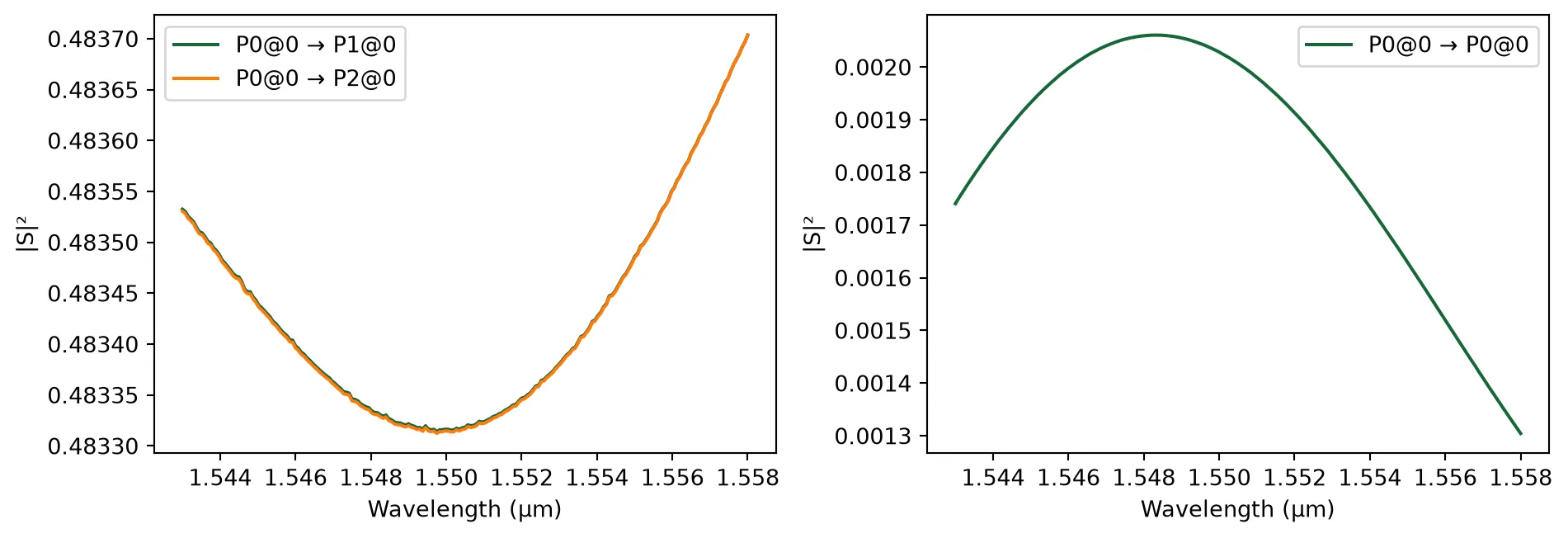
Directional Couplers for the MUX
Section titled “Directional Couplers for the MUX”We will build a 4-channel MUX using a dual-ring resonator.
Reference:
De Heyn, P., et al., “Fabrication-Tolerant Four-Channel Wavelength-Division-Multiplexing Filter Based on Collectively Tuned Si Microrings,” Journal of Lightwave Technology, 2013 31 (16), 2785–2792, doi: 10.1109/JLT.2013.2273391.
First, we define a directional coupler component. A grid_spec of 25 is used to ensure the high mesh accuracy necessary for simulating resonant structures.
@pf.parametric_component(name_prefix="Directional Coupler")def directional_coupler(    *,    coupling_gap=0.340,  # gap between waveguides (µm)    radius=5,  # bend radius (µm)    coupling_length=9,  # coupling region length (µm)    heater_width=4.0,  # heater width (µm)):    """    Tunable directional coupler with thermal heaters.
    Used for:    - Ring-to-ring coupling in add-drop filters    - Bus-to-ring coupling in resonators    """    wg_width, _ = port_spec.path_profile_for("Si")    coupling_distance = wg_width + coupling_gap
    component = pf.parametric.dual_ring_coupler(        coupling_distance=coupling_distance,        radius=radius,        coupling_length=coupling_length,        model=pf.Tidy3DModel(            grid_spec=25,            port_symmetries=[                ("P1", "P0", "P3", "P2"),                ("P2", "P3", "P0", "P1"),                ("P3", "P2", "P1", "P0"),            ],        ),    )
    left_corner = component.ports["P1"].center - (        0,        heater_width / 2 + radius + coupling_distance / 2,    )    right_corner = component.ports["P3"].center + (        0,        heater_width / 2 - radius - coupling_distance / 2,    )    component.add("M1_heater", pf.Rectangle(left_corner, right_corner))
    return component
Two-Ring Resonator Filter
Section titled “Two-Ring Resonator Filter”This section builds a two-ring add–drop resonator filter (2RR) as a reusable WDM building block, including heaters for thermal tuning.
Design Tip: To achieve a flat-top (maximally flat) passband in a two-ring add–drop filter (with identical rings), choose the coupling gaps such that the bus-to-ring and ring-to-ring coupling coefficients satisfy the following synthesis relation:
where:
- : bus-to-ring (external) power coupling coefficient ( in our design)
- : ring-to-ring (internal) power coupling coefficient ( in our design)
This condition ensures a maximally flat spectral response by properly balancing external and internal coupling strengths.
dc_rr = directional_coupler(coupling_gap=0.348)viewer(dc_rr)
# Run a finer wavelength sweep to visualize the 2RR filter responses_matrix_rr = dc_rr.s_matrix(freqs, model_kwargs={"inputs": ["P0"]})_ = pf.plot_s_matrix(s_matrix_rr, input_ports=["P0"])p3 = np.abs(s_matrix_rr[("P0@0", "P3@0")]) ** 2p2 = np.abs(s_matrix_rr[("P0@0", "P2@0")]) ** 2print( f"The internal coupling ratio at the center wavelength is: {p3[len(freqs)//2]/p2[len(freqs)//2]:.4f}")Uploading task 'P0@0…'Starting task 'P0@0': https://tidy3d.simulation.cloud/workbench?taskId=fdve-c8dde4c0-f2f9-4f09-a376-351cc62f5efdDownloading data from 'P0@0'…The internal coupling ratio at the center wavelength is: 0.0210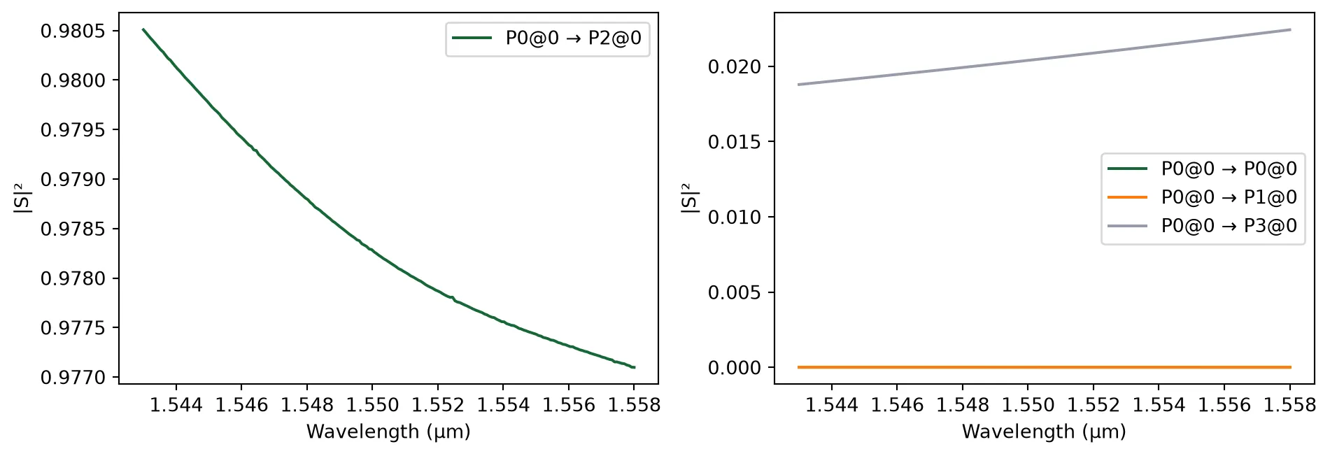
dc_br = directional_coupler(coupling_gap=0.22)viewer(dc_br)
s_matrix_br = dc_br.s_matrix(freqs, model_kwargs={"inputs": ["P0"]})_ = pf.plot_s_matrix(s_matrix_br, input_ports=["P0"])p3 = np.abs(s_matrix_br[("P0@0", "P3@0")]) ** 2p2 = np.abs(s_matrix_br[("P0@0", "P2@0")]) ** 2print( f"The external coupling ratio at the center wavelength is: {p3[len(freqs)//2]/p2[len(freqs)//2]:.3f}")14:34:29 -03 Loading simulation from local cache. View cached task using web UI at 'https://tidy3d.simulation.cloud/workbench?taskId=fdve-9f729794-8ae 2-4a51-8c2f-26e5d6ac6b4b'.
The external coupling ratio at the center wavelength is: 0.211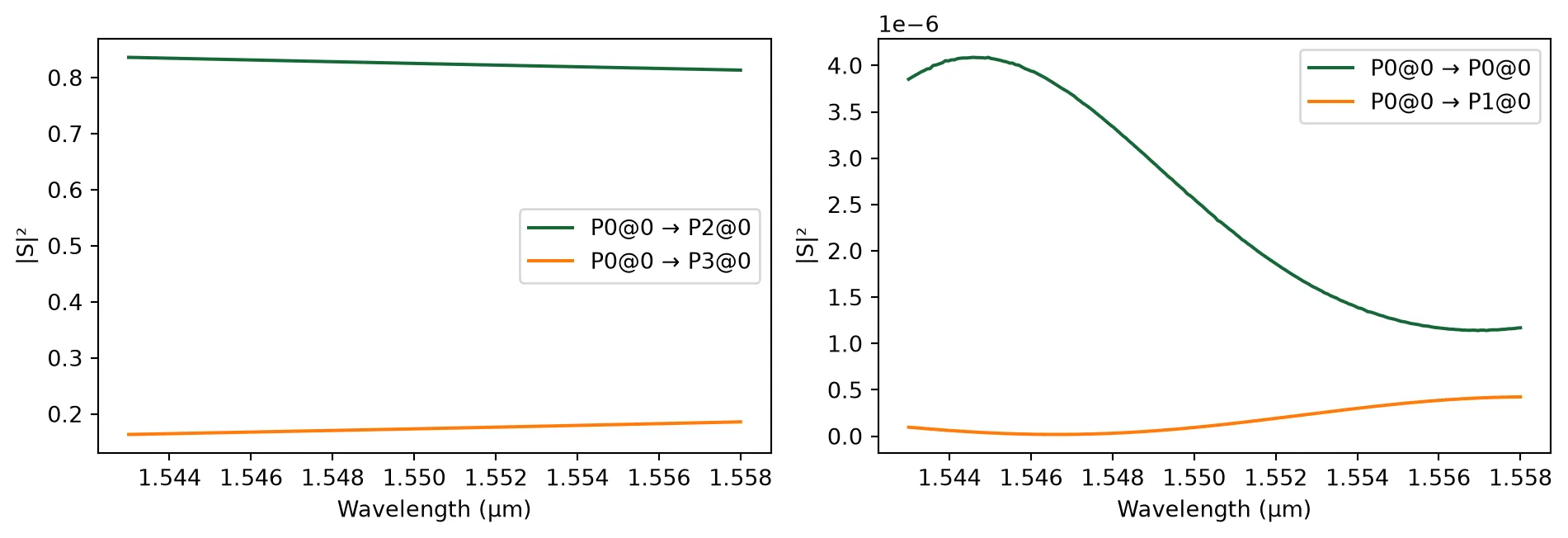
@pf.parametric_component(name_prefix="2RR Filter")def filter_2rr(    *,    coupling_length=9.0,  # coupling length (µm)    radius=5.0,  # ring radius (µm)    rr_gap=0.348,  # ring-to-ring gap (µm)    br_gap=0.220,  # bus-to-ring gap (µm)    pad_width=10,  # bond pad width (µm)):    """    Two-ring resonator (2RR) add-drop filter.
    Architecture:    - Two rings coupled via a ring-to-ring coupler.    - Each ring coupled to the bus waveguide.    - Thermal tuning via heaters.    """    # Create coupler components    dc_2rr = directional_coupler(        coupling_gap=rr_gap,        radius=radius,        coupling_length=coupling_length,    )
    dc_2br = directional_coupler(        coupling_gap=br_gap,        radius=radius,        coupling_length=coupling_length,    )
    # Create helper components    bend = pf.parametric.bend()  # 90 deg bend (default)    wg = pf.parametric.straight(length=60)
    # Assemble the 2RR filter via a netlist    netlist_2rr = {        "instances": {            "bus_coupler0": dc_2br,            "bus_coupler1": dc_2br,            "ring_coupler0": dc_2rr,            "bend0": bend,            "bend1": bend,            "wg0": wg,            "wg1": wg,            "wg2": wg,        },        "connections": [            (("ring_coupler0", "P0"), ("bus_coupler0", "P1")),            (("bus_coupler1", "P3"), ("ring_coupler0", "P1")),            (("bend0", "P0"), ("bus_coupler1", "P2")),            (("bend1", "P1"), ("bus_coupler1", "P0")),            (("wg0", "P1"), ("bus_coupler0", "P0")),            (("wg1", "P1"), ("bend0", "P1")),            (("wg2", "P1"), ("bus_coupler0", "P2")),        ],        "ports": [            ("wg0", "P0"),            ("wg1", "P0"),            ("wg2", "P0"),            ("bend1", "P0"),        ],        "models": [pf.CircuitModel()],    }
    two_rr = pf.component_from_netlist(netlist_2rr)
    # Add bond pads for heater control (heater terminals)    p0_center = np.array(dc_2br.ports["P0"].center)    p3_center = np.array(dc_2br.ports["P3"].center)
    bp1 = pf.Rectangle(center=p0_center, size=(pad_width, 2 * pad_width))    bp1.x_max = p0_center[0] + pad_width / 2.0 - 1.0    bp1.y_max = p0_center[1] - pad_width / 2.0
    rect1 = pf.Rectangle(center=p0_center, size=(pad_width / 2.0, pad_width * 4))    rect1.x_max = bp1.x_max    rect1.y_min = bp1.y_max
    bp2 = bp1.copy()    bp2.x_min = p3_center[0] - pad_width / 2.0 + 1.0    bp2.y_min = p3_center[1] + pad_width / 2.0 + 4 * radius
    rect2 = rect1.copy()    rect2.x_min = bp2.x_min    rect2.y_max = bp2.y_min
    two_rr.add("M2_router", bp1, rect1, bp2, rect2)
    signal_pad = pf.Terminal("M2_router", bp1.copy())    ground_pad = pf.Terminal("M2_router", bp2.copy())    two_rr.add_terminal([signal_pad, ground_pad])
    return two_rr
two_rr = filter_2rr()viewer(two_rr);fill:%23221f20;font-weight:bold;font-size:5.091680px;}.terminal{fill:none;stroke:%23805080;stroke-width:0.636460;}.dashed{stroke-dasharray:3.182300,1.909380;}.port{fill:none;stroke:%23805080;stroke-width:1.272920;}.virtual-connection{fill:none;stroke:%23907090;stroke-width:0.954690;}.layer_31_0{stroke:%238c78ef;fill:url(%23pat-layer_31_0);fill-opacity:0.492;}.label_31_0{fill:%238c78ef;}.layer_33_0{stroke:%238c78ef;fill:url(%23pat-layer_33_0);fill-opacity:0.492;}.label_33_0{fill:%238c78ef;}.layer_102_0{stroke:%238c78ef;fill:url(%23pat-layer_102_0);fill-opacity:0.492;}.label_102_0{fill:%238c78ef;}.layer_110_0{stroke:%238c78ef;fill:url(%23pat-layer_110_0);fill-opacity:0.492;}.label_110_0{fill:%238c78ef;}.layer_189_0{stroke:%23000000;fill:none;}.label_189_0{fill:%23000000;}.layer_201_0{stroke:%2300ee00;fill:url(%23pat-layer_201_0);fill-opacity:0.492;}.label_201_0{fill:%2300ee00;}.layer_401_0{stroke:%236a8ad2;fill:url(%23pat-layer_401_0);fill-opacity:0.492;}.label_401_0{fill:%236a8ad2;}.layer_202_0{stroke:%23007600;fill:url(%23pat-layer_202_0);fill-opacity:0.492;}.label_202_0{fill:%23007600;}.layer_68_0{stroke:%23008000;fill:url(%23pat-layer_68_0);fill-opacity:0.492;}.label_68_0{fill:%23008000;}.layer_5_0{stroke:%236a8ad2;fill:url(%23pat-layer_5_0);fill-opacity:0.492;}.label_5_0{fill:%236a8ad2;}.layer_998_0{stroke:%23000000;fill:none;}.label_998_0{fill:%23000000;}.layer_312_1{stroke:%2300b8b8;fill:url(%23pat-layer_312_1);fill-opacity:0.492;}.label_312_1{fill:%2300b8b8;}.layer_312_0{stroke:%2300b8b8;fill:url(%23pat-layer_312_0);fill-opacity:0.492;}.label_312_0{fill:%2300b8b8;}.layer_402_0{stroke:%23ff0000;fill:url(%23pat-layer_402_0);fill-opacity:0.492;}.label_402_0{fill:%23ff0000;}.layer_401_4{stroke:%236a8ad2;fill:url(%23pat-layer_401_4);fill-opacity:0.492;}.label_401_4{fill:%236a8ad2;}.layer_389_0{stroke:%23ff00ff;fill:url(%23pat-layer_389_0);fill-opacity:0.492;}.label_389_0{fill:%23ff00ff;}.layer_402_1{stroke:%23ff0000;fill:url(%23pat-layer_402_1);fill-opacity:0.492;}.label_402_1{fill:%23ff0000;}.layer_350_1{stroke:%23697a00;fill:url(%23pat-layer_350_1);fill-opacity:0.492;}.label_350_1{fill:%23697a00;}.layer_401_1{stroke:%236a8ad2;fill:url(%23pat-layer_401_1);fill-opacity:0.492;}.label_401_1{fill:%236a8ad2;}.layer_313_2{stroke:%2301d95b;fill:url(%23pat-layer_313_2);fill-opacity:0.492;}.label_313_2{fill:%2301d95b;}.layer_313_1{stroke:%2301d95b;fill:url(%23pat-layer_313_1);fill-opacity:0.492;}.label_313_1{fill:%2301d95b;}.layer_313_0{stroke:%2301d95b;fill:url(%23pat-layer_313_0);fill-opacity:0.492;}.label_313_0{fill:%2301d95b;}.layer_400_0{stroke:%23a96868;fill:url(%23pat-layer_400_0);fill-opacity:0.492;}.label_400_0{fill:%23a96868;}.layer_312_3{stroke:%2300b8b8;fill:url(%23pat-layer_312_3);fill-opacity:0.492;}.label_312_3{fill:%2300b8b8;}.layer_389_1{stroke:%23ff00ff;fill:url(%23pat-layer_389_1);fill-opacity:0.492;}.label_389_1{fill:%23ff00ff;}.layer_401_3{stroke:%236a8ad2;fill:url(%23pat-layer_401_3);fill-opacity:0.492;}.label_401_3{fill:%236a8ad2;}.layer_403_2{stroke:%23500080;fill:url(%23pat-layer_403_2);fill-opacity:0.492;}.label_403_2{fill:%23500080;}.layer_403_3{stroke:%23500080;fill:url(%23pat-layer_403_3);fill-opacity:0.492;}.label_403_3{fill:%23500080;}.layer_403_1{stroke:%23500080;fill:url(%23pat-layer_403_1);fill-opacity:0.492;}.label_403_1{fill:%23500080;}.layer_403_0{stroke:%23500080;fill:url(%23pat-layer_403_0);fill-opacity:0.492;}.label_403_0{fill:%23500080;}.layer_311_1{stroke:%23ac6c56;fill:url(%23pat-layer_311_1);fill-opacity:0.492;}.label_311_1{fill:%23ac6c56;}.layer_311_0{stroke:%23ac6c56;fill:url(%23pat-layer_311_0);fill-opacity:0.492;}.label_311_0{fill:%23ac6c56;}.layer_301_1{stroke:%23800057;fill:url(%23pat-layer_301_1);fill-opacity:0.492;}.label_301_1{fill:%23800057;}.layer_301_0{stroke:%23800057;fill:url(%23pat-layer_301_0);fill-opacity:0.492;}.label_301_0{fill:%23800057;}.layer_305_1{stroke:%23808080;fill:url(%23pat-layer_305_1);fill-opacity:0.492;}.label_305_1{fill:%23808080;}.layer_305_0{stroke:%23808080;fill:url(%23pat-layer_305_0);fill-opacity:0.492;}.label_305_0{fill:%23808080;}.layer_999_0{stroke:%230000ff;fill:url(%23pat-layer_999_0);fill-opacity:0.492;}.label_999_0{fill:%230000ff;}.layer_81_0{stroke:%23808080;fill:url(%23pat-layer_81_0);fill-opacity:0.492;}.label_81_0{fill:%23808080;}.layer_290_0{stroke:%23a46eda;fill:none;}.label_290_0{fill:%23a46eda;}.layer_205_0{stroke:%2349b203;fill:url(%23pat-layer_205_0);fill-opacity:0.492;}.label_205_0{fill:%2349b203;}.layer_11_0{stroke:%230000ff;fill:url(%23pat-layer_11_0);fill-opacity:0.492;}.label_11_0{fill:%230000ff;}.layer_12_0{stroke:%23a57b00;fill:url(%23pat-layer_12_0);fill-opacity:0.492;}.label_12_0{fill:%23a57b00;}.layer_13_0{stroke:%23800057;fill:url(%23pat-layer_13_0);fill-opacity:0.492;}.label_13_0{fill:%23800057;}.layer_6_0{stroke:%23ff0000;fill:url(%23pat-layer_6_0);fill-opacity:0.492;}.label_6_0{fill:%23ff0000;}.layer_1_10{stroke:%23c96585;fill:url(%23pat-layer_1_10);fill-opacity:0.492;}.label_1_10{fill:%23c96585;}.layer_1_11{stroke:%23800000;fill:url(%23pat-layer_1_11);fill-opacity:0.492;}.label_1_11{fill:%23800000;}.layer_200_0{stroke:%23ff0000;fill:url(%23pat-layer_200_0);fill-opacity:0.492;}.label_200_0{fill:%23ff0000;}.layer_1_0{stroke:%23c96585;fill:url(%23pat-layer_1_0);fill-opacity:0.492;}.label_1_0{fill:%23c96585;}.layer_2_0{stroke:%23a46eda;fill:url(%23pat-layer_2_0);fill-opacity:0.492;}.label_2_0{fill:%23a46eda;}.layer_20_0{stroke:%2353793d;fill:url(%23pat-layer_20_0);fill-opacity:0.492;}.label_20_0{fill:%2353793d;}.layer_22_0{stroke:%23ec7600;fill:url(%23pat-layer_22_0);fill-opacity:0.492;}.label_22_0{fill:%23ec7600;}.layer_24_0{stroke:%2300b8b8;fill:url(%23pat-layer_24_0);fill-opacity:0.492;}.label_24_0{fill:%2300b8b8;}.layer_21_0{stroke:%23736264;fill:url(%23pat-layer_21_0);fill-opacity:0.492;}.label_21_0{fill:%23736264;}.layer_23_0{stroke:%23697a00;fill:url(%23pat-layer_23_0);fill-opacity:0.492;}.label_23_0{fill:%23697a00;}.layer_25_0{stroke:%23008000;fill:url(%23pat-layer_25_0);fill-opacity:0.492;}.label_25_0{fill:%23008000;}.layer_350_0{stroke:%23697a00;fill:url(%23pat-layer_350_0);fill-opacity:0.492;}.label_350_0{fill:%23697a00;}.layer_10_0{stroke:%23000000;fill:none;}.label_10_0{fill:%23000000;}.layer_203_0{stroke:%23008000;fill:url(%23pat-layer_203_0);fill-opacity:0.492;}.label_203_0{fill:%23008000;}.layer_40_0{stroke:%230000ff;fill:url(%23pat-layer_40_0);fill-opacity:0.492;}.label_40_0{fill:%230000ff;}.layer_401_2{stroke:%236a8ad2;fill:url(%23pat-layer_401_2);fill-opacity:0.492;}.label_401_2{fill:%236a8ad2;}.layer_301_2{stroke:%23800057;fill:url(%23pat-layer_301_2);fill-opacity:0.492;}.label_301_2{fill:%23800057;}</style><defs><path id=%22port-symbol%22 class=%22port%22 d=%22M 0,-2.545840 L 3.818760,0 0,2.545840%22 /><path id=%22ref-port-symbol%22 class=%22port%22 style=%22stroke-opacity:0.33;%22 d=%22M 0,-1.909380 C 2.545840,-1.909380 2.545840,1.909380 0,1.909380%22 /><circle id=%22port-bend-symbol%22 style=%22stroke-width:0;stroke:none;fill:%23805080;fill-opacity:1;%22 cx=%220%22 cy=%220%22 r=%221.145628%22 /><circle id=%22connection-symbol%22 style=%22stroke-width:0;stroke:none;fill:%23907090;fill-opacity:1;%22 cx=%220%22 cy=%220%22 r=%221.336566%22 /><pattern id=%22pat-layer_31_0%22 patternUnits=%22userSpaceOnUse%22 width=%223.182300%22 height=%223.182300%22 patternTransform=%22translate(2.433524,3.014811)%22><line x1=%220%22 y1=%220%22 x2=%223.182300%22 y2=%223.182300%22 style=%22stroke:%238c78ef;stroke-width:0.318230%22 /><line x1=%22-1.591150%22 y1=%221.591150%22 x2=%221.591150%22 y2=%224.773450%22 style=%22stroke:%238c78ef;stroke-width:0.318230%22 /><line x1=%221.591150%22 y1=%22-1.591150%22 x2=%224.773450%22 y2=%221.591150%22 style=%22stroke:%238c78ef;stroke-width:0.318230%22 /></pattern><pattern id=%22pat-layer_33_0%22 patternUnits=%22userSpaceOnUse%22 width=%223.182300%22 height=%223.182300%22 patternTransform=%22translate(1.871941,0.334979)%22><line x1=%220%22 y1=%220%22 x2=%223.182300%22 y2=%223.182300%22 style=%22stroke:%238c78ef;stroke-width:0.318230%22 /><line x1=%22-1.591150%22 y1=%221.591150%22 x2=%221.591150%22 y2=%224.773450%22 style=%22stroke:%238c78ef;stroke-width:0.318230%22 /><line x1=%221.591150%22 y1=%22-1.591150%22 x2=%224.773450%22 y2=%221.591150%22 style=%22stroke:%238c78ef;stroke-width:0.318230%22 /></pattern><pattern id=%22pat-layer_102_0%22 patternUnits=%22userSpaceOnUse%22 width=%223.182300%22 height=%223.182300%22 patternTransform=%22translate(0.000000,0.167489)%22><line x1=%220%22 y1=%220%22 x2=%223.182300%22 y2=%223.182300%22 style=%22stroke:%238c78ef;stroke-width:0.318230%22 /><line x1=%22-1.591150%22 y1=%221.591150%22 x2=%221.591150%22 y2=%224.773450%22 style=%22stroke:%238c78ef;stroke-width:0.318230%22 /><line x1=%221.591150%22 y1=%22-1.591150%22 x2=%224.773450%22 y2=%221.591150%22 style=%22stroke:%238c78ef;stroke-width:0.318230%22 /></pattern><pattern id=%22pat-layer_110_0%22 patternUnits=%22userSpaceOnUse%22 width=%223.182300%22 height=%223.182300%22 patternTransform=%22translate(0.935971,2.177363)%22><line x1=%220%22 y1=%220%22 x2=%223.182300%22 y2=%223.182300%22 style=%22stroke:%238c78ef;stroke-width:0.318230%22 /><line x1=%22-1.591150%22 y1=%221.591150%22 x2=%221.591150%22 y2=%224.773450%22 style=%22stroke:%238c78ef;stroke-width:0.318230%22 /><line x1=%221.591150%22 y1=%22-1.591150%22 x2=%224.773450%22 y2=%221.591150%22 style=%22stroke:%238c78ef;stroke-width:0.318230%22 /></pattern><pattern id=%22pat-layer_201_0%22 patternUnits=%22userSpaceOnUse%22 width=%223.182300%22 height=%223.182300%22 patternTransform=%22translate(2.433524,1.172426)%22><circle cx=%221.591150%22 cy=%221.591150%22 r=%220.318230%22 style=%22stroke:none;fill:%2300ee00;fill-opacity:1.0%22 /></pattern><pattern id=%22pat-layer_401_0%22 patternUnits=%22userSpaceOnUse%22 width=%221.909380%22 height=%221.909380%22 patternTransform=%22translate(0.224633,0.301481)%22><line x1=%220%22 y1=%220%22 x2=%221.909380%22 y2=%221.909380%22 style=%22stroke:%236a8ad2;stroke-width:0.318230%22 /><line x1=%22-0.954690%22 y1=%220.954690%22 x2=%220.954690%22 y2=%222.864070%22 style=%22stroke:%236a8ad2;stroke-width:0.318230%22 /><line x1=%220.954690%22 y1=%22-0.954690%22 x2=%222.864070%22 y2=%220.954690%22 style=%22stroke:%236a8ad2;stroke-width:0.318230%22 /><line x1=%221.909380%22 y1=%220%22 x2=%220%22 y2=%221.909380%22 style=%22stroke:%236a8ad2;stroke-width:0.318230%22 /><line x1=%222.864070%22 y1=%220.954690%22 x2=%220.954690%22 y2=%222.864070%22 style=%22stroke:%236a8ad2;stroke-width:0.318230%22 /><line x1=%220.954690%22 y1=%22-0.954690%22 x2=%22-0.954690%22 y2=%220.954690%22 style=%22stroke:%236a8ad2;stroke-width:0.318230%22 /></pattern><pattern id=%22pat-layer_202_0%22 patternUnits=%22userSpaceOnUse%22 width=%221.909380%22 height=%221.909380%22 patternTransform=%22translate(0.336949,1.808886)%22><circle cx=%220.954690%22 cy=%220.954690%22 r=%220.318230%22 style=%22stroke:none;fill:%23007600;fill-opacity:1.0%22 /></pattern><pattern id=%22pat-layer_68_0%22 patternUnits=%22userSpaceOnUse%22 width=%223.182300%22 height=%223.182300%22 patternTransform=%22translate(0.000000,1.172426)%22><circle cx=%221.591150%22 cy=%221.591150%22 r=%220.318230%22 style=%22stroke:none;fill:%23008000;fill-opacity:1.0%22 /></pattern><pattern id=%22pat-layer_5_0%22 patternUnits=%22userSpaceOnUse%22 width=%221.909380%22 height=%221.909380%22 patternTransform=%22translate(0.112316,1.708393)%22><line x1=%220.954690%22 y1=%220%22 x2=%220.954690%22 y2=%221.909380%22 style=%22stroke:%236a8ad2;stroke-width:0.318230%22 /></pattern><pattern id=%22pat-layer_312_1%22 patternUnits=%22userSpaceOnUse%22 width=%221.909380%22 height=%221.909380%22 patternTransform=%22translate(0.449266,1.507405)%22><line x1=%220%22 y1=%220%22 x2=%221.909380%22 y2=%221.909380%22 style=%22stroke:%2300b8b8;stroke-width:0.318230%22 /><line x1=%22-0.954690%22 y1=%220.954690%22 x2=%220.954690%22 y2=%222.864070%22 style=%22stroke:%2300b8b8;stroke-width:0.318230%22 /><line x1=%220.954690%22 y1=%22-0.954690%22 x2=%222.864070%22 y2=%220.954690%22 style=%22stroke:%2300b8b8;stroke-width:0.318230%22 /></pattern><pattern id=%22pat-layer_312_0%22 patternUnits=%22userSpaceOnUse%22 width=%223.182300%22 height=%223.182300%22 patternTransform=%22translate(1.497553,2.009874)%22><line x1=%221.591150%22 y1=%220%22 x2=%221.591150%22 y2=%223.182300%22 style=%22stroke:%2300b8b8;stroke-width:0.318230%22 /></pattern><pattern id=%22pat-layer_402_0%22 patternUnits=%22userSpaceOnUse%22 width=%223.182300%22 height=%223.182300%22 patternTransform=%22translate(1.684747,2.344853)%22><line x1=%221.591150%22 y1=%220%22 x2=%221.591150%22 y2=%223.182300%22 style=%22stroke:%23ff0000;stroke-width:0.318230%22 /><line x1=%220%22 y1=%221.591150%22 x2=%223.182300%22 y2=%221.591150%22 style=%22stroke:%23ff0000;stroke-width:0.318230%22 /></pattern><pattern id=%22pat-layer_401_4%22 patternUnits=%22userSpaceOnUse%22 width=%221.909380%22 height=%221.909380%22 patternTransform=%22translate(0.336949,1.507405)%22><line x1=%220.954690%22 y1=%220%22 x2=%220.954690%22 y2=%221.909380%22 style=%22stroke:%236a8ad2;stroke-width:0.318230%22 /></pattern><pattern id=%22pat-layer_389_0%22 patternUnits=%22userSpaceOnUse%22 width=%221.909380%22 height=%221.909380%22 patternTransform=%22translate(0.336949,0.401975)%22><line x1=%220.954690%22 y1=%220%22 x2=%220.954690%22 y2=%221.909380%22 style=%22stroke:%23ff00ff;stroke-width:0.318230%22 /><line x1=%220%22 y1=%220.954690%22 x2=%221.909380%22 y2=%220.954690%22 style=%22stroke:%23ff00ff;stroke-width:0.318230%22 /></pattern><pattern id=%22pat-layer_402_1%22 patternUnits=%22userSpaceOnUse%22 width=%221.909380%22 height=%221.909380%22 patternTransform=%22translate(0.561582,1.708393)%22><line x1=%220%22 y1=%220%22 x2=%221.909380%22 y2=%221.909380%22 style=%22stroke:%23ff0000;stroke-width:0.318230%22 /><line x1=%22-0.954690%22 y1=%220.954690%22 x2=%220.954690%22 y2=%222.864070%22 style=%22stroke:%23ff0000;stroke-width:0.318230%22 /><line x1=%220.954690%22 y1=%22-0.954690%22 x2=%222.864070%22 y2=%220.954690%22 style=%22stroke:%23ff0000;stroke-width:0.318230%22 /><line x1=%221.909380%22 y1=%220%22 x2=%220%22 y2=%221.909380%22 style=%22stroke:%23ff0000;stroke-width:0.318230%22 /><line x1=%222.864070%22 y1=%220.954690%22 x2=%220.954690%22 y2=%222.864070%22 style=%22stroke:%23ff0000;stroke-width:0.318230%22 /><line x1=%220.954690%22 y1=%22-0.954690%22 x2=%22-0.954690%22 y2=%220.954690%22 style=%22stroke:%23ff0000;stroke-width:0.318230%22 /></pattern><pattern id=%22pat-layer_350_1%22 patternUnits=%22userSpaceOnUse%22 width=%221.909380%22 height=%221.909380%22 patternTransform=%22translate(1.684747,1.507405)%22><circle cx=%220.954690%22 cy=%220.954690%22 r=%220.318230%22 style=%22stroke:none;fill:%23697a00;fill-opacity:1.0%22 /></pattern><pattern id=%22pat-layer_401_1%22 patternUnits=%22userSpaceOnUse%22 width=%223.182300%22 height=%223.182300%22 patternTransform=%22translate(2.807912,1.004937)%22><line x1=%220%22 y1=%220%22 x2=%223.182300%22 y2=%223.182300%22 style=%22stroke:%236a8ad2;stroke-width:0.318230%22 /><line x1=%22-1.591150%22 y1=%221.591150%22 x2=%221.591150%22 y2=%224.773450%22 style=%22stroke:%236a8ad2;stroke-width:0.318230%22 /><line x1=%221.591150%22 y1=%22-1.591150%22 x2=%224.773450%22 y2=%221.591150%22 style=%22stroke:%236a8ad2;stroke-width:0.318230%22 /><line x1=%223.182300%22 y1=%220%22 x2=%220%22 y2=%223.182300%22 style=%22stroke:%236a8ad2;stroke-width:0.318230%22 /><line x1=%224.773450%22 y1=%221.591150%22 x2=%221.591150%22 y2=%224.773450%22 style=%22stroke:%236a8ad2;stroke-width:0.318230%22 /><line x1=%221.591150%22 y1=%22-1.591150%22 x2=%22-1.591150%22 y2=%221.591150%22 style=%22stroke:%236a8ad2;stroke-width:0.318230%22 /></pattern><pattern id=%22pat-layer_313_2%22 patternUnits=%22userSpaceOnUse%22 width=%221.909380%22 height=%221.909380%22 patternTransform=%22translate(0.786215,1.004937)%22><line x1=%220%22 y1=%220%22 x2=%221.909380%22 y2=%221.909380%22 style=%22stroke:%2301d95b;stroke-width:0.318230%22 /><line x1=%22-0.954690%22 y1=%220.954690%22 x2=%220.954690%22 y2=%222.864070%22 style=%22stroke:%2301d95b;stroke-width:0.318230%22 /><line x1=%220.954690%22 y1=%22-0.954690%22 x2=%222.864070%22 y2=%220.954690%22 style=%22stroke:%2301d95b;stroke-width:0.318230%22 /></pattern><pattern id=%22pat-layer_313_1%22 patternUnits=%22userSpaceOnUse%22 width=%223.182300%22 height=%223.182300%22 patternTransform=%22translate(2.059135,1.172426)%22><line x1=%221.591150%22 y1=%220%22 x2=%221.591150%22 y2=%223.182300%22 style=%22stroke:%2301d95b;stroke-width:0.318230%22 /></pattern><pattern id=%22pat-layer_313_0%22 patternUnits=%22userSpaceOnUse%22 width=%221.909380%22 height=%221.909380%22 patternTransform=%22translate(1.684747,0.401975)%22><line x1=%220.954690%22 y1=%220%22 x2=%220.954690%22 y2=%221.909380%22 style=%22stroke:%2301d95b;stroke-width:0.318230%22 /></pattern><pattern id=%22pat-layer_400_0%22 patternUnits=%22userSpaceOnUse%22 width=%223.182300%22 height=%223.182300%22 patternTransform=%22translate(2.246329,1.842384)%22><line x1=%220%22 y1=%220%22 x2=%223.182300%22 y2=%223.182300%22 style=%22stroke:%23a96868;stroke-width:0.318230%22 /><line x1=%22-1.591150%22 y1=%221.591150%22 x2=%221.591150%22 y2=%224.773450%22 style=%22stroke:%23a96868;stroke-width:0.318230%22 /><line x1=%221.591150%22 y1=%22-1.591150%22 x2=%224.773450%22 y2=%221.591150%22 style=%22stroke:%23a96868;stroke-width:0.318230%22 /><line x1=%223.182300%22 y1=%220%22 x2=%220%22 y2=%223.182300%22 style=%22stroke:%23a96868;stroke-width:0.318230%22 /><line x1=%224.773450%22 y1=%221.591150%22 x2=%221.591150%22 y2=%224.773450%22 style=%22stroke:%23a96868;stroke-width:0.318230%22 /><line x1=%221.591150%22 y1=%22-1.591150%22 x2=%22-1.591150%22 y2=%221.591150%22 style=%22stroke:%23a96868;stroke-width:0.318230%22 /></pattern><pattern id=%22pat-layer_312_3%22 patternUnits=%22userSpaceOnUse%22 width=%221.909380%22 height=%221.909380%22 patternTransform=%22translate(1.460114,0.200987)%22><line x1=%221.909380%22 y1=%220%22 x2=%220%22 y2=%221.909380%22 style=%22stroke:%2300b8b8;stroke-width:0.318230%22 /><line x1=%222.864070%22 y1=%220.954690%22 x2=%220.954690%22 y2=%222.864070%22 style=%22stroke:%2300b8b8;stroke-width:0.318230%22 /><line x1=%220.954690%22 y1=%22-0.954690%22 x2=%22-0.954690%22 y2=%220.954690%22 style=%22stroke:%2300b8b8;stroke-width:0.318230%22 /></pattern><pattern id=%22pat-layer_389_1%22 patternUnits=%22userSpaceOnUse%22 width=%223.182300%22 height=%223.182300%22 patternTransform=%22translate(2.995106,1.172426)%22><line x1=%221.591150%22 y1=%220%22 x2=%221.591150%22 y2=%223.182300%22 style=%22stroke:%23ff00ff;stroke-width:0.318230%22 /><line x1=%220%22 y1=%221.591150%22 x2=%223.182300%22 y2=%221.591150%22 style=%22stroke:%23ff00ff;stroke-width:0.318230%22 /></pattern><pattern id=%22pat-layer_401_3%22 patternUnits=%22userSpaceOnUse%22 width=%223.182300%22 height=%223.182300%22 patternTransform=%22translate(1.310359,2.009874)%22><line x1=%220%22 y1=%221.591150%22 x2=%223.182300%22 y2=%221.591150%22 style=%22stroke:%236a8ad2;stroke-width:0.318230%22 /></pattern><pattern id=%22pat-layer_403_2%22 patternUnits=%22userSpaceOnUse%22 width=%221.909380%22 height=%221.909380%22 patternTransform=%22translate(0.898532,1.205924)%22><line x1=%220%22 y1=%220%22 x2=%221.909380%22 y2=%221.909380%22 style=%22stroke:%23500080;stroke-width:0.318230%22 /><line x1=%22-0.954690%22 y1=%220.954690%22 x2=%220.954690%22 y2=%222.864070%22 style=%22stroke:%23500080;stroke-width:0.318230%22 /><line x1=%220.954690%22 y1=%22-0.954690%22 x2=%222.864070%22 y2=%220.954690%22 style=%22stroke:%23500080;stroke-width:0.318230%22 /><line x1=%221.909380%22 y1=%220%22 x2=%220%22 y2=%221.909380%22 style=%22stroke:%23500080;stroke-width:0.318230%22 /><line x1=%222.864070%22 y1=%220.954690%22 x2=%220.954690%22 y2=%222.864070%22 style=%22stroke:%23500080;stroke-width:0.318230%22 /><line x1=%220.954690%22 y1=%22-0.954690%22 x2=%22-0.954690%22 y2=%220.954690%22 style=%22stroke:%23500080;stroke-width:0.318230%22 /></pattern><pattern id=%22pat-layer_403_3%22 patternUnits=%22userSpaceOnUse%22 width=%223.182300%22 height=%223.182300%22 patternTransform=%22translate(0.748776,2.512342)%22><line x1=%220%22 y1=%220%22 x2=%223.182300%22 y2=%223.182300%22 style=%22stroke:%23500080;stroke-width:0.318230%22 /><line x1=%22-1.591150%22 y1=%221.591150%22 x2=%221.591150%22 y2=%224.773450%22 style=%22stroke:%23500080;stroke-width:0.318230%22 /><line x1=%221.591150%22 y1=%22-1.591150%22 x2=%224.773450%22 y2=%221.591150%22 style=%22stroke:%23500080;stroke-width:0.318230%22 /><line x1=%223.182300%22 y1=%220%22 x2=%220%22 y2=%223.182300%22 style=%22stroke:%23500080;stroke-width:0.318230%22 /><line x1=%224.773450%22 y1=%221.591150%22 x2=%221.591150%22 y2=%224.773450%22 style=%22stroke:%23500080;stroke-width:0.318230%22 /><line x1=%221.591150%22 y1=%22-1.591150%22 x2=%22-1.591150%22 y2=%221.591150%22 style=%22stroke:%23500080;stroke-width:0.318230%22 /></pattern><pattern id=%22pat-layer_403_1%22 patternUnits=%22userSpaceOnUse%22 width=%223.182300%22 height=%223.182300%22 patternTransform=%22translate(2.246329,1.507405)%22><line x1=%221.591150%22 y1=%220%22 x2=%221.591150%22 y2=%223.182300%22 style=%22stroke:%23500080;stroke-width:0.318230%22 /><line x1=%220%22 y1=%221.591150%22 x2=%223.182300%22 y2=%221.591150%22 style=%22stroke:%23500080;stroke-width:0.318230%22 /></pattern><pattern id=%22pat-layer_403_0%22 patternUnits=%22userSpaceOnUse%22 width=%221.909380%22 height=%221.909380%22 patternTransform=%22translate(1.797064,0.602962)%22><line x1=%220.954690%22 y1=%220%22 x2=%220.954690%22 y2=%221.909380%22 style=%22stroke:%23500080;stroke-width:0.318230%22 /><line x1=%220%22 y1=%220.954690%22 x2=%221.909380%22 y2=%220.954690%22 style=%22stroke:%23500080;stroke-width:0.318230%22 /></pattern><pattern id=%22pat-layer_311_1%22 patternUnits=%22userSpaceOnUse%22 width=%223.182300%22 height=%223.182300%22 patternTransform=%22translate(2.620718,0.669958)%22><line x1=%220%22 y1=%220%22 x2=%223.182300%22 y2=%223.182300%22 style=%22stroke:%23ac6c56;stroke-width:0.318230%22 /><line x1=%22-1.591150%22 y1=%221.591150%22 x2=%221.591150%22 y2=%224.773450%22 style=%22stroke:%23ac6c56;stroke-width:0.318230%22 /><line x1=%221.591150%22 y1=%22-1.591150%22 x2=%224.773450%22 y2=%221.591150%22 style=%22stroke:%23ac6c56;stroke-width:0.318230%22 /></pattern><pattern id=%22pat-layer_311_0%22 patternUnits=%22userSpaceOnUse%22 width=%221.909380%22 height=%221.909380%22 patternTransform=%22translate(0.112316,0.100494)%22><line x1=%220%22 y1=%220%22 x2=%221.909380%22 y2=%221.909380%22 style=%22stroke:%23ac6c56;stroke-width:0.318230%22 /><line x1=%22-0.954690%22 y1=%220.954690%22 x2=%220.954690%22 y2=%222.864070%22 style=%22stroke:%23ac6c56;stroke-width:0.318230%22 /><line x1=%220.954690%22 y1=%22-0.954690%22 x2=%222.864070%22 y2=%220.954690%22 style=%22stroke:%23ac6c56;stroke-width:0.318230%22 /></pattern><pattern id=%22pat-layer_301_1%22 patternUnits=%22userSpaceOnUse%22 width=%223.182300%22 height=%223.182300%22 patternTransform=%22translate(2.246329,1.339916)%22><line x1=%220%22 y1=%221.591150%22 x2=%223.182300%22 y2=%221.591150%22 style=%22stroke:%23800057;stroke-width:0.318230%22 /></pattern><pattern id=%22pat-layer_301_0%22 patternUnits=%22userSpaceOnUse%22 width=%221.909380%22 height=%221.909380%22 patternTransform=%22translate(1.797064,0.502468)%22><line x1=%220%22 y1=%220.954690%22 x2=%221.909380%22 y2=%220.954690%22 style=%22stroke:%23800057;stroke-width:0.318230%22 /></pattern><pattern id=%22pat-layer_305_1%22 patternUnits=%22userSpaceOnUse%22 width=%223.182300%22 height=%223.182300%22 patternTransform=%22translate(1.123165,2.344853)%22><line x1=%221.591150%22 y1=%220%22 x2=%221.591150%22 y2=%223.182300%22 style=%22stroke:%23808080;stroke-width:0.318230%22 /><line x1=%220%22 y1=%221.591150%22 x2=%223.182300%22 y2=%221.591150%22 style=%22stroke:%23808080;stroke-width:0.318230%22 /></pattern><pattern id=%22pat-layer_305_0%22 patternUnits=%22userSpaceOnUse%22 width=%221.909380%22 height=%221.909380%22 patternTransform=%22translate(1.123165,1.105431)%22><line x1=%220.954690%22 y1=%220%22 x2=%220.954690%22 y2=%221.909380%22 style=%22stroke:%23808080;stroke-width:0.318230%22 /><line x1=%220%22 y1=%220.954690%22 x2=%221.909380%22 y2=%220.954690%22 style=%22stroke:%23808080;stroke-width:0.318230%22 /></pattern><pattern id=%22pat-layer_999_0%22 patternUnits=%22userSpaceOnUse%22 width=%221.909380%22 height=%221.909380%22 patternTransform=%22translate(0.673899,0.703456)%22><line x1=%220.954690%22 y1=%220%22 x2=%220.954690%22 y2=%221.909380%22 style=%22stroke:%230000ff;stroke-width:0.318230%22 /></pattern><pattern id=%22pat-layer_81_0%22 patternUnits=%22userSpaceOnUse%22 width=%221.909380%22 height=%221.909380%22 patternTransform=%22translate(0.673899,1.708393)%22><line x1=%220.954690%22 y1=%220%22 x2=%220.954690%22 y2=%221.909380%22 style=%22stroke:%23808080;stroke-width:0.318230%22 /><line x1=%220%22 y1=%220.954690%22 x2=%221.909380%22 y2=%220.954690%22 style=%22stroke:%23808080;stroke-width:0.318230%22 /></pattern><pattern id=%22pat-layer_205_0%22 patternUnits=%22userSpaceOnUse%22 width=%221.909380%22 height=%221.909380%22 patternTransform=%22translate(0.786215,1.306418)%22><line x1=%220%22 y1=%220%22 x2=%221.909380%22 y2=%221.909380%22 style=%22stroke:%2349b203;stroke-width:0.318230%22 /><line x1=%22-0.954690%22 y1=%220.954690%22 x2=%220.954690%22 y2=%222.864070%22 style=%22stroke:%2349b203;stroke-width:0.318230%22 /><line x1=%220.954690%22 y1=%22-0.954690%22 x2=%222.864070%22 y2=%220.954690%22 style=%22stroke:%2349b203;stroke-width:0.318230%22 /><line x1=%221.909380%22 y1=%220%22 x2=%220%22 y2=%221.909380%22 style=%22stroke:%2349b203;stroke-width:0.318230%22 /><line x1=%222.864070%22 y1=%220.954690%22 x2=%220.954690%22 y2=%222.864070%22 style=%22stroke:%2349b203;stroke-width:0.318230%22 /><line x1=%220.954690%22 y1=%22-0.954690%22 x2=%22-0.954690%22 y2=%220.954690%22 style=%22stroke:%2349b203;stroke-width:0.318230%22 /></pattern><pattern id=%22pat-layer_11_0%22 patternUnits=%22userSpaceOnUse%22 width=%221.909380%22 height=%221.909380%22 patternTransform=%22translate(1.010848,0.703456)%22><line x1=%221.909380%22 y1=%220%22 x2=%220%22 y2=%221.909380%22 style=%22stroke:%230000ff;stroke-width:0.318230%22 /><line x1=%222.864070%22 y1=%220.954690%22 x2=%220.954690%22 y2=%222.864070%22 style=%22stroke:%230000ff;stroke-width:0.318230%22 /><line x1=%220.954690%22 y1=%22-0.954690%22 x2=%22-0.954690%22 y2=%220.954690%22 style=%22stroke:%230000ff;stroke-width:0.318230%22 /></pattern><pattern id=%22pat-layer_12_0%22 patternUnits=%22userSpaceOnUse%22 width=%221.909380%22 height=%221.909380%22 patternTransform=%22translate(1.797064,1.808886)%22><line x1=%220%22 y1=%220%22 x2=%221.909380%22 y2=%221.909380%22 style=%22stroke:%23a57b00;stroke-width:0.318230%22 /><line x1=%22-0.954690%22 y1=%220.954690%22 x2=%220.954690%22 y2=%222.864070%22 style=%22stroke:%23a57b00;stroke-width:0.318230%22 /><line x1=%220.954690%22 y1=%22-0.954690%22 x2=%222.864070%22 y2=%220.954690%22 style=%22stroke:%23a57b00;stroke-width:0.318230%22 /></pattern><pattern id=%22pat-layer_13_0%22 patternUnits=%22userSpaceOnUse%22 width=%221.909380%22 height=%221.909380%22 patternTransform=%22translate(0.673899,1.004937)%22><line x1=%221.909380%22 y1=%220%22 x2=%220%22 y2=%221.909380%22 style=%22stroke:%23800057;stroke-width:0.318230%22 /><line x1=%222.864070%22 y1=%220.954690%22 x2=%220.954690%22 y2=%222.864070%22 style=%22stroke:%23800057;stroke-width:0.318230%22 /><line x1=%220.954690%22 y1=%22-0.954690%22 x2=%22-0.954690%22 y2=%220.954690%22 style=%22stroke:%23800057;stroke-width:0.318230%22 /></pattern><pattern id=%22pat-layer_6_0%22 patternUnits=%22userSpaceOnUse%22 width=%223.182300%22 height=%223.182300%22 patternTransform=%22translate(1.497553,1.507405)%22><line x1=%220%22 y1=%221.591150%22 x2=%223.182300%22 y2=%221.591150%22 style=%22stroke:%23ff0000;stroke-width:0.318230%22 /></pattern><pattern id=%22pat-layer_1_10%22 patternUnits=%22userSpaceOnUse%22 width=%221.909380%22 height=%221.909380%22 patternTransform=%22translate(0.112316,0.301481)%22><line x1=%220%22 y1=%220%22 x2=%221.909380%22 y2=%221.909380%22 style=%22stroke:%23c96585;stroke-width:0.318230%22 /><line x1=%22-0.954690%22 y1=%220.954690%22 x2=%220.954690%22 y2=%222.864070%22 style=%22stroke:%23c96585;stroke-width:0.318230%22 /><line x1=%220.954690%22 y1=%22-0.954690%22 x2=%222.864070%22 y2=%220.954690%22 style=%22stroke:%23c96585;stroke-width:0.318230%22 /><line x1=%221.909380%22 y1=%220%22 x2=%220%22 y2=%221.909380%22 style=%22stroke:%23c96585;stroke-width:0.318230%22 /><line x1=%222.864070%22 y1=%220.954690%22 x2=%220.954690%22 y2=%222.864070%22 style=%22stroke:%23c96585;stroke-width:0.318230%22 /><line x1=%220.954690%22 y1=%22-0.954690%22 x2=%22-0.954690%22 y2=%220.954690%22 style=%22stroke:%23c96585;stroke-width:0.318230%22 /></pattern><pattern id=%22pat-layer_1_11%22 patternUnits=%22userSpaceOnUse%22 width=%223.182300%22 height=%223.182300%22 patternTransform=%22translate(2.620718,1.004937)%22><line x1=%221.591150%22 y1=%220%22 x2=%221.591150%22 y2=%223.182300%22 style=%22stroke:%23800000;stroke-width:0.318230%22 /><line x1=%220%22 y1=%221.591150%22 x2=%223.182300%22 y2=%221.591150%22 style=%22stroke:%23800000;stroke-width:0.318230%22 /></pattern><pattern id=%22pat-layer_200_0%22 patternUnits=%22userSpaceOnUse%22 width=%223.182300%22 height=%223.182300%22 patternTransform=%22translate(1.123165,2.512342)%22><line x1=%220%22 y1=%220%22 x2=%223.182300%22 y2=%223.182300%22 style=%22stroke:%23ff0000;stroke-width:0.318230%22 /><line x1=%22-1.591150%22 y1=%221.591150%22 x2=%221.591150%22 y2=%224.773450%22 style=%22stroke:%23ff0000;stroke-width:0.318230%22 /><line x1=%221.591150%22 y1=%22-1.591150%22 x2=%224.773450%22 y2=%221.591150%22 style=%22stroke:%23ff0000;stroke-width:0.318230%22 /><line x1=%223.182300%22 y1=%220%22 x2=%220%22 y2=%223.182300%22 style=%22stroke:%23ff0000;stroke-width:0.318230%22 /><line x1=%224.773450%22 y1=%221.591150%22 x2=%221.591150%22 y2=%224.773450%22 style=%22stroke:%23ff0000;stroke-width:0.318230%22 /><line x1=%221.591150%22 y1=%22-1.591150%22 x2=%22-1.591150%22 y2=%221.591150%22 style=%22stroke:%23ff0000;stroke-width:0.318230%22 /></pattern><pattern id=%22pat-layer_1_0%22 patternUnits=%22userSpaceOnUse%22 width=%221.909380%22 height=%221.909380%22 patternTransform=%22translate(0.786215,1.105431)%22><line x1=%221.909380%22 y1=%220%22 x2=%220%22 y2=%221.909380%22 style=%22stroke:%23c96585;stroke-width:0.318230%22 /><line x1=%222.864070%22 y1=%220.954690%22 x2=%220.954690%22 y2=%222.864070%22 style=%22stroke:%23c96585;stroke-width:0.318230%22 /><line x1=%220.954690%22 y1=%22-0.954690%22 x2=%22-0.954690%22 y2=%220.954690%22 style=%22stroke:%23c96585;stroke-width:0.318230%22 /></pattern><pattern id=%22pat-layer_2_0%22 patternUnits=%22userSpaceOnUse%22 width=%223.182300%22 height=%223.182300%22 patternTransform=%22translate(2.620718,0.502468)%22><line x1=%220%22 y1=%220%22 x2=%223.182300%22 y2=%223.182300%22 style=%22stroke:%23a46eda;stroke-width:0.318230%22 /><line x1=%22-1.591150%22 y1=%221.591150%22 x2=%221.591150%22 y2=%224.773450%22 style=%22stroke:%23a46eda;stroke-width:0.318230%22 /><line x1=%221.591150%22 y1=%22-1.591150%22 x2=%224.773450%22 y2=%221.591150%22 style=%22stroke:%23a46eda;stroke-width:0.318230%22 /></pattern><pattern id=%22pat-layer_20_0%22 patternUnits=%22userSpaceOnUse%22 width=%223.182300%22 height=%223.182300%22 patternTransform=%22translate(0.748776,1.842384)%22><line x1=%220%22 y1=%221.591150%22 x2=%223.182300%22 y2=%221.591150%22 style=%22stroke:%2353793d;stroke-width:0.318230%22 /></pattern><pattern id=%22pat-layer_22_0%22 patternUnits=%22userSpaceOnUse%22 width=%223.182300%22 height=%223.182300%22 patternTransform=%22translate(0.187194,2.344853)%22><line x1=%220%22 y1=%220%22 x2=%223.182300%22 y2=%223.182300%22 style=%22stroke:%23ec7600;stroke-width:0.318230%22 /><line x1=%22-1.591150%22 y1=%221.591150%22 x2=%221.591150%22 y2=%224.773450%22 style=%22stroke:%23ec7600;stroke-width:0.318230%22 /><line x1=%221.591150%22 y1=%22-1.591150%22 x2=%224.773450%22 y2=%221.591150%22 style=%22stroke:%23ec7600;stroke-width:0.318230%22 /><line x1=%223.182300%22 y1=%220%22 x2=%220%22 y2=%223.182300%22 style=%22stroke:%23ec7600;stroke-width:0.318230%22 /><line x1=%224.773450%22 y1=%221.591150%22 x2=%221.591150%22 y2=%224.773450%22 style=%22stroke:%23ec7600;stroke-width:0.318230%22 /><line x1=%221.591150%22 y1=%22-1.591150%22 x2=%22-1.591150%22 y2=%221.591150%22 style=%22stroke:%23ec7600;stroke-width:0.318230%22 /></pattern><pattern id=%22pat-layer_24_0%22 patternUnits=%22userSpaceOnUse%22 width=%223.182300%22 height=%223.182300%22 patternTransform=%22translate(2.807912,2.847321)%22><line x1=%221.591150%22 y1=%220%22 x2=%221.591150%22 y2=%223.182300%22 style=%22stroke:%2300b8b8;stroke-width:0.318230%22 /><line x1=%220%22 y1=%221.591150%22 x2=%223.182300%22 y2=%221.591150%22 style=%22stroke:%2300b8b8;stroke-width:0.318230%22 /></pattern><pattern id=%22pat-layer_21_0%22 patternUnits=%22userSpaceOnUse%22 width=%221.909380%22 height=%221.909380%22 patternTransform=%22translate(1.235481,0.301481)%22><line x1=%220%22 y1=%220.954690%22 x2=%221.909380%22 y2=%220.954690%22 style=%22stroke:%23736264;stroke-width:0.318230%22 /></pattern><pattern id=%22pat-layer_23_0%22 patternUnits=%22userSpaceOnUse%22 width=%221.909380%22 height=%221.909380%22 patternTransform=%22translate(0.898532,0.602962)%22><line x1=%220%22 y1=%220%22 x2=%221.909380%22 y2=%221.909380%22 style=%22stroke:%23697a00;stroke-width:0.318230%22 /><line x1=%22-0.954690%22 y1=%220.954690%22 x2=%220.954690%22 y2=%222.864070%22 style=%22stroke:%23697a00;stroke-width:0.318230%22 /><line x1=%220.954690%22 y1=%22-0.954690%22 x2=%222.864070%22 y2=%220.954690%22 style=%22stroke:%23697a00;stroke-width:0.318230%22 /><line x1=%221.909380%22 y1=%220%22 x2=%220%22 y2=%221.909380%22 style=%22stroke:%23697a00;stroke-width:0.318230%22 /><line x1=%222.864070%22 y1=%220.954690%22 x2=%220.954690%22 y2=%222.864070%22 style=%22stroke:%23697a00;stroke-width:0.318230%22 /><line x1=%220.954690%22 y1=%22-0.954690%22 x2=%22-0.954690%22 y2=%220.954690%22 style=%22stroke:%23697a00;stroke-width:0.318230%22 /></pattern><pattern id=%22pat-layer_25_0%22 patternUnits=%22userSpaceOnUse%22 width=%221.909380%22 height=%221.909380%22 patternTransform=%22translate(0.561582,0.904443)%22><line x1=%220.954690%22 y1=%220%22 x2=%220.954690%22 y2=%221.909380%22 style=%22stroke:%23008000;stroke-width:0.318230%22 /><line x1=%220%22 y1=%220.954690%22 x2=%221.909380%22 y2=%220.954690%22 style=%22stroke:%23008000;stroke-width:0.318230%22 /></pattern><pattern id=%22pat-layer_350_0%22 patternUnits=%22userSpaceOnUse%22 width=%223.182300%22 height=%223.182300%22 patternTransform=%22translate(0.374388,2.009874)%22><line x1=%223.182300%22 y1=%220%22 x2=%220%22 y2=%223.182300%22 style=%22stroke:%23697a00;stroke-width:0.318230%22 /><line x1=%224.773450%22 y1=%221.591150%22 x2=%221.591150%22 y2=%224.773450%22 style=%22stroke:%23697a00;stroke-width:0.318230%22 /><line x1=%221.591150%22 y1=%22-1.591150%22 x2=%22-1.591150%22 y2=%221.591150%22 style=%22stroke:%23697a00;stroke-width:0.318230%22 /></pattern><pattern id=%22pat-layer_203_0%22 patternUnits=%22userSpaceOnUse%22 width=%223.182300%22 height=%223.182300%22 patternTransform=%22translate(1.871941,1.674895)%22><line x1=%223.182300%22 y1=%220%22 x2=%220%22 y2=%223.182300%22 style=%22stroke:%23008000;stroke-width:0.318230%22 /><line x1=%224.773450%22 y1=%221.591150%22 x2=%221.591150%22 y2=%224.773450%22 style=%22stroke:%23008000;stroke-width:0.318230%22 /><line x1=%221.591150%22 y1=%22-1.591150%22 x2=%22-1.591150%22 y2=%221.591150%22 style=%22stroke:%23008000;stroke-width:0.318230%22 /></pattern><pattern id=%22pat-layer_40_0%22 patternUnits=%22userSpaceOnUse%22 width=%223.182300%22 height=%223.182300%22 patternTransform=%22translate(1.497553,0.502468)%22><circle cx=%221.591150%22 cy=%221.591150%22 r=%220.318230%22 style=%22stroke:none;fill:%230000ff;fill-opacity:1.0%22 /></pattern><pattern id=%22pat-layer_401_2%22 patternUnits=%22userSpaceOnUse%22 width=%221.909380%22 height=%221.909380%22 patternTransform=%22translate(1.235481,0.904443)%22><line x1=%220%22 y1=%220.954690%22 x2=%221.909380%22 y2=%220.954690%22 style=%22stroke:%236a8ad2;stroke-width:0.318230%22 /></pattern><pattern id=%22pat-layer_301_2%22 patternUnits=%22userSpaceOnUse%22 width=%221.909380%22 height=%221.909380%22 patternTransform=%22translate(0.898532,1.105431)%22><line x1=%220.954690%22 y1=%220%22 x2=%220.954690%22 y2=%221.909380%22 style=%22stroke:%23800057;stroke-width:0.318230%22 /></pattern><g id=%22C1%22 data-name=%22dual_ring_coupler__WEP7MH5LIHATILQOCKRZMH7UMSUNDNG7BI4RB5J4OLGSEX44IIRA%22><path class=%22layer_1_0%22 d=%22M -9.250000,-10.720000 -9.248000,-10.204000 -9.231000,-9.694000 -9.214000,-9.443000 -9.151000,-8.948000 -9.103000,-8.705000 -9.043000,-8.468000 -8.968000,-8.236000 -8.878000,-8.011000 -8.772000,-7.794000 -8.651000,-7.586000 -8.514000,-7.387000 -8.363000,-7.198000 -8.199000,-7.021000 -8.022000,-6.857000 -7.833000,-6.706000 -7.634000,-6.569000 -7.426000,-6.448000 -7.209000,-6.342000 -6.984000,-6.252000 -6.752000,-6.177000 -6.515000,-6.117000 -6.272000,-6.069000 -6.026000,-6.033000 -5.777000,-6.006000 -5.272000,-5.978000 -4.500000,-5.970000 4.500000,-5.970000 5.016000,-5.972000 5.526000,-5.989000 5.777000,-6.006000 6.272000,-6.069000 6.515000,-6.117000 6.752000,-6.177000 6.984000,-6.252000 7.209000,-6.342000 7.426000,-6.448000 7.634000,-6.569000 7.833000,-6.706000 8.022000,-6.857000 8.199000,-7.021000 8.363000,-7.198000 8.514000,-7.387000 8.651000,-7.586000 8.772000,-7.794000 8.878000,-8.011000 8.968000,-8.236000 9.043000,-8.468000 9.103000,-8.705000 9.151000,-8.948000 9.187000,-9.194000 9.214000,-9.443000 9.242000,-9.948000 9.250000,-10.720000 9.750000,-10.720000 9.748000,-10.197000 9.730000,-9.667000 9.684000,-9.132000 9.644000,-8.863000 9.591000,-8.596000 9.523000,-8.330000 9.439000,-8.067000 9.335000,-7.809000 9.213000,-7.559000 9.073000,-7.318000 8.916000,-7.089000 8.742000,-6.871000 8.552000,-6.668000 8.349000,-6.478000 8.131000,-6.304000 7.902000,-6.147000 7.661000,-6.007000 7.411000,-5.885000 7.153000,-5.781000 6.890000,-5.697000 6.624000,-5.629000 6.357000,-5.576000 6.088000,-5.536000 5.553000,-5.490000 5.023000,-5.472000 4.500000,-5.470000 -4.500000,-5.470000 -5.023000,-5.472000 -5.553000,-5.490000 -6.088000,-5.536000 -6.357000,-5.576000 -6.624000,-5.629000 -6.890000,-5.697000 -7.153000,-5.781000 -7.411000,-5.885000 -7.661000,-6.007000 -7.902000,-6.147000 -8.131000,-6.304000 -8.349000,-6.478000 -8.552000,-6.668000 -8.742000,-6.871000 -8.916000,-7.089000 -9.073000,-7.318000 -9.213000,-7.559000 -9.335000,-7.809000 -9.439000,-8.067000 -9.523000,-8.330000 -9.591000,-8.596000 -9.644000,-8.863000 -9.684000,-9.132000 -9.730000,-9.667000 -9.748000,-10.197000 -9.750000,-10.720000 z%22 /><path class=%22layer_1_0%22 d=%22M 9.250000,0.000000 9.248000,-0.516000 9.231000,-1.026000 9.214000,-1.277000 9.151000,-1.772000 9.103000,-2.015000 9.043000,-2.252000 8.968000,-2.484000 8.878000,-2.709000 8.772000,-2.926000 8.651000,-3.134000 8.514000,-3.333000 8.363000,-3.522000 8.199000,-3.699000 8.022000,-3.863000 7.833000,-4.014000 7.634000,-4.151000 7.426000,-4.272000 7.209000,-4.378000 6.984000,-4.468000 6.752000,-4.543000 6.515000,-4.603000 6.272000,-4.651000 6.026000,-4.687000 5.777000,-4.714000 5.272000,-4.742000 4.500000,-4.750000 -4.500000,-4.750000 -5.016000,-4.748000 -5.526000,-4.731000 -5.777000,-4.714000 -6.272000,-4.651000 -6.515000,-4.603000 -6.752000,-4.543000 -6.984000,-4.468000 -7.209000,-4.378000 -7.426000,-4.272000 -7.634000,-4.151000 -7.833000,-4.014000 -8.022000,-3.863000 -8.199000,-3.699000 -8.363000,-3.522000 -8.514000,-3.333000 -8.651000,-3.134000 -8.772000,-2.926000 -8.878000,-2.709000 -8.968000,-2.484000 -9.043000,-2.252000 -9.103000,-2.015000 -9.151000,-1.772000 -9.187000,-1.526000 -9.214000,-1.277000 -9.242000,-0.772000 -9.250000,0.000000 -9.750000,0.000000 -9.748000,-0.523000 -9.730000,-1.053000 -9.684000,-1.588000 -9.644000,-1.857000 -9.591000,-2.124000 -9.523000,-2.390000 -9.439000,-2.653000 -9.335000,-2.911000 -9.213000,-3.161000 -9.073000,-3.402000 -8.916000,-3.631000 -8.742000,-3.849000 -8.552000,-4.052000 -8.349000,-4.242000 -8.131000,-4.416000 -7.902000,-4.573000 -7.661000,-4.713000 -7.411000,-4.835000 -7.153000,-4.939000 -6.890000,-5.023000 -6.624000,-5.091000 -6.357000,-5.144000 -6.088000,-5.184000 -5.553000,-5.230000 -5.023000,-5.248000 -4.500000,-5.250000 4.500000,-5.250000 5.023000,-5.248000 5.553000,-5.230000 6.088000,-5.184000 6.357000,-5.144000 6.624000,-5.091000 6.890000,-5.023000 7.153000,-4.939000 7.411000,-4.835000 7.661000,-4.713000 7.902000,-4.573000 8.131000,-4.416000 8.349000,-4.242000 8.552000,-4.052000 8.742000,-3.849000 8.916000,-3.631000 9.073000,-3.402000 9.213000,-3.161000 9.335000,-2.911000 9.439000,-2.653000 9.523000,-2.390000 9.591000,-2.124000 9.644000,-1.857000 9.684000,-1.588000 9.730000,-1.053000 9.748000,-0.523000 9.750000,0.000000 z%22 /><rect class=%22layer_11_0%22 x=%22-9.500000%22 y=%22-7.360000%22 width=%2219.000000%22 height=%224.000000%22 /></g><g id=%22C2%22 data-name=%22dual_ring_coupler__6DCU55EOIV7IYQYHAHLHJ33FWWWPAMXO4W7ONRRL6NNENDW2EVHQ%22><path class=%22layer_1_0%22 d=%22M -9.250000,-10.848000 -9.248000,-10.332000 -9.231000,-9.822000 -9.214000,-9.571000 -9.151000,-9.076000 -9.103000,-8.833000 -9.043000,-8.596000 -8.968000,-8.364000 -8.878000,-8.139000 -8.772000,-7.922000 -8.651000,-7.714000 -8.514000,-7.515000 -8.363000,-7.326000 -8.199000,-7.149000 -8.022000,-6.985000 -7.833000,-6.834000 -7.634000,-6.697000 -7.426000,-6.576000 -7.209000,-6.470000 -6.984000,-6.380000 -6.752000,-6.305000 -6.515000,-6.245000 -6.272000,-6.197000 -6.026000,-6.161000 -5.777000,-6.134000 -5.272000,-6.106000 -4.500000,-6.098000 4.500000,-6.098000 5.016000,-6.100000 5.526000,-6.117000 5.777000,-6.134000 6.272000,-6.197000 6.515000,-6.245000 6.752000,-6.305000 6.984000,-6.380000 7.209000,-6.470000 7.426000,-6.576000 7.634000,-6.697000 7.833000,-6.834000 8.022000,-6.985000 8.199000,-7.149000 8.363000,-7.326000 8.514000,-7.515000 8.651000,-7.714000 8.772000,-7.922000 8.878000,-8.139000 8.968000,-8.364000 9.043000,-8.596000 9.103000,-8.833000 9.151000,-9.076000 9.187000,-9.322000 9.214000,-9.571000 9.242000,-10.076000 9.250000,-10.848000 9.750000,-10.848000 9.748000,-10.325000 9.730000,-9.795000 9.684000,-9.260000 9.644000,-8.991000 9.591000,-8.724000 9.523000,-8.458000 9.439000,-8.195000 9.335000,-7.937000 9.213000,-7.687000 9.073000,-7.446000 8.916000,-7.217000 8.742000,-6.999000 8.552000,-6.796000 8.349000,-6.606000 8.131000,-6.432000 7.902000,-6.275000 7.661000,-6.135000 7.411000,-6.013000 7.153000,-5.909000 6.890000,-5.825000 6.624000,-5.757000 6.357000,-5.704000 6.088000,-5.664000 5.553000,-5.618000 5.023000,-5.600000 4.500000,-5.598000 -4.500000,-5.598000 -5.023000,-5.600000 -5.553000,-5.618000 -6.088000,-5.664000 -6.357000,-5.704000 -6.624000,-5.757000 -6.890000,-5.825000 -7.153000,-5.909000 -7.411000,-6.013000 -7.661000,-6.135000 -7.902000,-6.275000 -8.131000,-6.432000 -8.349000,-6.606000 -8.552000,-6.796000 -8.742000,-6.999000 -8.916000,-7.217000 -9.073000,-7.446000 -9.213000,-7.687000 -9.335000,-7.937000 -9.439000,-8.195000 -9.523000,-8.458000 -9.591000,-8.724000 -9.644000,-8.991000 -9.684000,-9.260000 -9.730000,-9.795000 -9.748000,-10.325000 -9.750000,-10.848000 z%22 /><path class=%22layer_1_0%22 d=%22M 9.250000,0.000000 9.248000,-0.516000 9.231000,-1.026000 9.214000,-1.277000 9.151000,-1.772000 9.103000,-2.015000 9.043000,-2.252000 8.968000,-2.484000 8.878000,-2.709000 8.772000,-2.926000 8.651000,-3.134000 8.514000,-3.333000 8.363000,-3.522000 8.199000,-3.699000 8.022000,-3.863000 7.833000,-4.014000 7.634000,-4.151000 7.426000,-4.272000 7.209000,-4.378000 6.984000,-4.468000 6.752000,-4.543000 6.515000,-4.603000 6.272000,-4.651000 6.026000,-4.687000 5.777000,-4.714000 5.272000,-4.742000 4.500000,-4.750000 -4.500000,-4.750000 -5.016000,-4.748000 -5.526000,-4.731000 -5.777000,-4.714000 -6.272000,-4.651000 -6.515000,-4.603000 -6.752000,-4.543000 -6.984000,-4.468000 -7.209000,-4.378000 -7.426000,-4.272000 -7.634000,-4.151000 -7.833000,-4.014000 -8.022000,-3.863000 -8.199000,-3.699000 -8.363000,-3.522000 -8.514000,-3.333000 -8.651000,-3.134000 -8.772000,-2.926000 -8.878000,-2.709000 -8.968000,-2.484000 -9.043000,-2.252000 -9.103000,-2.015000 -9.151000,-1.772000 -9.187000,-1.526000 -9.214000,-1.277000 -9.242000,-0.772000 -9.250000,0.000000 -9.750000,0.000000 -9.748000,-0.523000 -9.730000,-1.053000 -9.684000,-1.588000 -9.644000,-1.857000 -9.591000,-2.124000 -9.523000,-2.390000 -9.439000,-2.653000 -9.335000,-2.911000 -9.213000,-3.161000 -9.073000,-3.402000 -8.916000,-3.631000 -8.742000,-3.849000 -8.552000,-4.052000 -8.349000,-4.242000 -8.131000,-4.416000 -7.902000,-4.573000 -7.661000,-4.713000 -7.411000,-4.835000 -7.153000,-4.939000 -6.890000,-5.023000 -6.624000,-5.091000 -6.357000,-5.144000 -6.088000,-5.184000 -5.553000,-5.230000 -5.023000,-5.248000 -4.500000,-5.250000 4.500000,-5.250000 5.023000,-5.248000 5.553000,-5.230000 6.088000,-5.184000 6.357000,-5.144000 6.624000,-5.091000 6.890000,-5.023000 7.153000,-4.939000 7.411000,-4.835000 7.661000,-4.713000 7.902000,-4.573000 8.131000,-4.416000 8.349000,-4.242000 8.552000,-4.052000 8.742000,-3.849000 8.916000,-3.631000 9.073000,-3.402000 9.213000,-3.161000 9.335000,-2.911000 9.439000,-2.653000 9.523000,-2.390000 9.591000,-2.124000 9.644000,-1.857000 9.684000,-1.588000 9.730000,-1.053000 9.748000,-0.523000 9.750000,0.000000 z%22 /><rect class=%22layer_11_0%22 x=%22-9.500000%22 y=%22-7.424000%22 width=%2219.000000%22 height=%224.000000%22 /></g><g id=%22C3%22 data-name=%22bend%22><path class=%22layer_1_0%22 d=%22M 0.000000,-0.250000 0.523000,-0.248000 1.053000,-0.230000 1.588000,-0.184000 1.857000,-0.144000 2.124000,-0.091000 2.390000,-0.023000 2.653000,0.061000 2.911000,0.165000 3.161000,0.287000 3.402000,0.427000 3.631000,0.584000 3.849000,0.758000 4.052000,0.948000 4.242000,1.151000 4.416000,1.369000 4.573000,1.598000 4.713000,1.839000 4.835000,2.089000 4.939000,2.347000 5.023000,2.610000 5.091000,2.876000 5.144000,3.143000 5.184000,3.412000 5.230000,3.947000 5.248000,4.477000 5.250000,5.000000 4.750000,5.000000 4.742000,4.228000 4.714000,3.723000 4.687000,3.474000 4.651000,3.228000 4.603000,2.985000 4.543000,2.748000 4.468000,2.516000 4.378000,2.291000 4.272000,2.074000 4.151000,1.866000 4.014000,1.667000 3.863000,1.478000 3.699000,1.301000 3.522000,1.137000 3.333000,0.986000 3.134000,0.849000 2.926000,0.728000 2.709000,0.622000 2.484000,0.532000 2.252000,0.457000 2.015000,0.397000 1.772000,0.349000 1.277000,0.286000 1.026000,0.269000 0.516000,0.252000 0.000000,0.250000 z%22 /></g><g id=%22C4%22 data-name=%22straight_l_60%22><path class=%22layer_1_0%22 d=%22M 0.000000,-0.250000 60.000000,-0.250000 60.000000,0.250000 0.000000,0.250000 z%22 /></g></defs><g transform=%22scale(1 -1)%22><g id=%22C0%22 data-name=%222RR Filter_br_0P22_co_9P0_pa_10_ra_5P0_rr_0P348%22><use transform=%22translate(0.000000 0.000000)%22 href=%22%23C1%22 /><use transform=%22translate(0.000000 10.848000) rotate(180.000000)%22 href=%22%23C1%22 /><use transform=%22translate(0.000000 10.848000)%22 href=%22%23C2%22 /><use transform=%22translate(-9.500000 21.568000) rotate(90.000000)%22 href=%22%23C3%22 /><use transform=%22translate(14.500000 26.568000) rotate(180.000000)%22 href=%22%23C3%22 /><use transform=%22translate(-9.500000 -70.720000) rotate(90.000000)%22 href=%22%23C4%22 /><use transform=%22translate(-74.500000 26.568000)%22 href=%22%23C4%22 /><use transform=%22translate(9.500000 -70.720000) rotate(90.000000)%22 href=%22%23C4%22 /><rect class=%22layer_12_0%22 x=%22-15.500000%22 y=%22-35.720000%22 width=%2210.000000%22 height=%2220.000000%22 /><rect class=%22layer_12_0%22 x=%22-10.500000%22 y=%22-15.720000%22 width=%225.000000%22 height=%2240.000000%22 /><rect class=%22layer_12_0%22 x=%225.500000%22 y=%2225.000000%22 width=%2210.000000%22 height=%2220.000000%22 /><rect class=%22layer_12_0%22 x=%225.500000%22 y=%22-15.000000%22 width=%225.000000%22 height=%2240.000000%22 /><g transform=%22translate(-9.500000 -70.720000) rotate(90.000000)%22><path class=%22port%22 d=%22M 0,-0.750000 V 0.750000%22 /><use href=%22%23port-symbol%22 /></g><text class=%22label%22 text-anchor=%22end%22 dominant-baseline=%22text-after-edge%22 x=%22-9.500000%22 y=%2270.720000%22>P0</text><g transform=%22translate(-74.500000 26.568000) rotate(0.000000)%22><path class=%22port%22 d=%22M 0,-0.750000 V 0.750000%22 /><use href=%22%23port-symbol%22 /></g><text class=%22label%22 text-anchor=%22start%22 dominant-baseline=%22text-after-edge%22 x=%22-74.500000%22 y=%22-26.568000%22>P1</text><g transform=%22translate(9.500000 -70.720000) rotate(90.000000)%22><path class=%22port%22 d=%22M 0,-0.750000 V 0.750000%22 /><use href=%22%23port-symbol%22 /></g><text class=%22label%22 text-anchor=%22end%22 dominant-baseline=%22text-after-edge%22 x=%229.500000%22 y=%2270.720000%22>P2</text><g transform=%22translate(14.500000 26.568000) rotate(180.000000)%22><path class=%22port%22 d=%22M 0,-0.750000 V 0.750000%22 /><use href=%22%23port-symbol%22 /></g><text class=%22label%22 text-anchor=%22end%22 dominant-baseline=%22text-before-edge%22 x=%2214.500000%22 y=%22-26.568000%22>P3</text><g transform=%22translate(-10.500000 -25.720000)%22><text class=%22label label_12_0%22 text-anchor=%22middle%22 dominant-baseline=%22central%22 x=%220%22 y=%220%22>T0</text></g><rect class=%22terminal%22 x=%22-15.500000%22 y=%22-35.720000%22 width=%2210.000000%22 height=%2220.000000%22 /><g transform=%22translate(10.500000 35.000000)%22><text class=%22label label_12_0%22 text-anchor=%22middle%22 dominant-baseline=%22central%22 x=%220%22 y=%220%22>T1</text></g><rect class=%22terminal%22 x=%225.500000%22 y=%2225.000000%22 width=%2210.000000%22 height=%2220.000000%22 /></g></g></svg>)
%22><rect x=%22-30.00%22 y=%22-30.00%22 width=%2260.00%22 height=%2260.00%22 fill=%22%23f4f5f7%22 stroke=%22%23232530%22 stroke-width=%221%22/><use href=%22%23g-dc%22 transform=%22translate(-30.00 -30.00) scale(1.2)%22/><circle cx=%22-15.00%22 cy=%2230.00%22 r=%224%22 fill=%22%2300643c%22 stroke=%22%2300643c%22 stroke-width=%221%22/><circle cx=%2215.00%22 cy=%2230.00%22 r=%224%22 fill=%22%2300643c%22 stroke=%22%2300643c%22 stroke-width=%221%22/><circle cx=%22-15.00%22 cy=%22-30.00%22 r=%224%22 fill=%22%2300643c%22 stroke=%22%2300643c%22 stroke-width=%221%22/><circle cx=%2215.00%22 cy=%22-30.00%22 r=%224%22 fill=%22%2300643c%22 stroke=%22%2300643c%22 stroke-width=%221%22/></g><text x=%22384.00%22 y=%2295.80%22 font-size=%229%22 fill=%22%23232530%22 font-weight=%22400%22 text-anchor=%22middle%22 dominant-baseline=%22hanging%22 stroke=%22%23ffffff%22 stroke-width=%223.15%22 stroke-linejoin=%22round%22 paint-order=%22stroke%22>dual_ring_coupler_1</text><g transform=%22matrix(-1 -1.22465e-16 1.22465e-16 -1 384.000 -60.000)%22><rect x=%22-30.00%22 y=%22-30.00%22 width=%2260.00%22 height=%2260.00%22 fill=%22%23f4f5f7%22 stroke=%22%23232530%22 stroke-width=%221%22/><use href=%22%23g-dc%22 transform=%22translate(-30.00 -30.00) scale(1.2)%22/><circle cx=%22-15.00%22 cy=%2230.00%22 r=%224%22 fill=%22%2300643c%22 stroke=%22%2300643c%22 stroke-width=%221%22/><circle cx=%2215.00%22 cy=%2230.00%22 r=%224%22 fill=%22%2300643c%22 stroke=%22%2300643c%22 stroke-width=%221%22/><circle cx=%22-15.00%22 cy=%22-30.00%22 r=%224%22 fill=%22%2300643c%22 stroke=%22%2300643c%22 stroke-width=%221%22/><circle cx=%2215.00%22 cy=%22-30.00%22 r=%224%22 fill=%22%2300643c%22 stroke=%22%2300643c%22 stroke-width=%221%22/></g><text x=%22384.00%22 y=%22-24.20%22 font-size=%229%22 fill=%22%23232530%22 font-weight=%22400%22 text-anchor=%22middle%22 dominant-baseline=%22hanging%22 stroke=%22%23ffffff%22 stroke-width=%223.15%22 stroke-linejoin=%22round%22 paint-order=%22stroke%22>dual_ring_coupler_2</text><g transform=%22matrix(1 -0 0 1 576.000 0.000)%22><rect x=%22-30.00%22 y=%22-30.00%22 width=%2260.00%22 height=%2260.00%22 fill=%22%23f4f5f7%22 stroke=%22%23232530%22 stroke-width=%221%22/><use href=%22%23g-dc%22 transform=%22translate(-30.00 -30.00) scale(1.2)%22/><circle cx=%22-15.00%22 cy=%2230.00%22 r=%224%22 fill=%22%2300643c%22 stroke=%22%2300643c%22 stroke-width=%221%22/><circle cx=%2215.00%22 cy=%2230.00%22 r=%224%22 fill=%22%2300643c%22 stroke=%22%2300643c%22 stroke-width=%221%22/><circle cx=%22-15.00%22 cy=%22-30.00%22 r=%224%22 fill=%22%2300643c%22 stroke=%22%2300643c%22 stroke-width=%221%22/><circle cx=%2215.00%22 cy=%22-30.00%22 r=%224%22 fill=%22%2300643c%22 stroke=%22%2300643c%22 stroke-width=%221%22/></g><text x=%22576.00%22 y=%2235.80%22 font-size=%229%22 fill=%22%23232530%22 font-weight=%22400%22 text-anchor=%22middle%22 dominant-baseline=%22hanging%22 stroke=%22%23ffffff%22 stroke-width=%223.15%22 stroke-linejoin=%22round%22 paint-order=%22stroke%22>dual_ring_coupler_3</text><g transform=%22matrix(6.12323e-17 -1 1 6.12323e-17 192.000 -60.000)%22><use href=%22%23g-bend%22 transform=%22translate(-30.00 -30.00) scale(1.2)%22/><circle cx=%22-30.00%22 cy=%228.00%22 r=%224%22 fill=%22%2300643c%22 stroke=%22%2300643c%22 stroke-width=%221%22/><circle cx=%226.00%22 cy=%22-30.00%22 r=%224%22 fill=%22%2300643c%22 stroke=%22%2300643c%22 stroke-width=%221%22/></g><text x=%22192.00%22 y=%22-24.20%22 font-size=%229%22 fill=%22%23232530%22 font-weight=%22400%22 text-anchor=%22middle%22 dominant-baseline=%22hanging%22 stroke=%22%23ffffff%22 stroke-width=%223.15%22 stroke-linejoin=%22round%22 paint-order=%22stroke%22>bend_1</text><g transform=%22matrix(-1 -1.22465e-16 1.22465e-16 -1 576.000 -120.000)%22><use href=%22%23g-bend%22 transform=%22translate(-30.00 -30.00) scale(1.2)%22/><circle cx=%22-30.00%22 cy=%228.00%22 r=%224%22 fill=%22%2300643c%22 stroke=%22%2300643c%22 stroke-width=%221%22/><circle cx=%226.00%22 cy=%22-30.00%22 r=%224%22 fill=%22%2300643c%22 stroke=%22%2300643c%22 stroke-width=%221%22/></g><text x=%22576.00%22 y=%22-84.20%22 font-size=%229%22 fill=%22%23232530%22 font-weight=%22400%22 text-anchor=%22middle%22 dominant-baseline=%22hanging%22 stroke=%22%23ffffff%22 stroke-width=%223.15%22 stroke-linejoin=%22round%22 paint-order=%22stroke%22>bend_2</text><text x=%22618.00%22 y=%22-128.00%22 font-size=%2210%22 fill=%22%23b8461c%22 font-weight=%22700%22 text-anchor=%22start%22 dominant-baseline=%22middle%22 stroke=%22%23ffffff%22 stroke-width=%223.50%22 stroke-linejoin=%22round%22 paint-order=%22stroke%22>P3</text><g transform=%22matrix(6.12323e-17 -1 1 6.12323e-17 192.000 60.000)%22><use href=%22%23g-wg%22 transform=%22translate(-30.00 -30.00) scale(1.2)%22/><circle cx=%22-30.00%22 cy=%220.00%22 r=%224%22 fill=%22%2300643c%22 stroke=%22%2300643c%22 stroke-width=%221%22/><circle cx=%2230.00%22 cy=%220.00%22 r=%224%22 fill=%22%2300643c%22 stroke=%22%2300643c%22 stroke-width=%221%22/></g><text x=%22192.00%22 y=%2295.80%22 font-size=%229%22 fill=%22%23232530%22 font-weight=%22400%22 text-anchor=%22middle%22 dominant-baseline=%22hanging%22 stroke=%22%23ffffff%22 stroke-width=%223.15%22 stroke-linejoin=%22round%22 paint-order=%22stroke%22>straight_l_60_1</text><text x=%22192.00%22 y=%22102.00%22 font-size=%2210%22 fill=%22%23b8461c%22 font-weight=%22700%22 text-anchor=%22middle%22 dominant-baseline=%22hanging%22 stroke=%22%23ffffff%22 stroke-width=%223.50%22 stroke-linejoin=%22round%22 paint-order=%22stroke%22>P0</text><g transform=%22matrix(1 -0 0 1 0.000 -60.000)%22><use href=%22%23g-wg%22 transform=%22translate(-30.00 -30.00) scale(1.2)%22/><circle cx=%22-30.00%22 cy=%220.00%22 r=%224%22 fill=%22%2300643c%22 stroke=%22%2300643c%22 stroke-width=%221%22/><circle cx=%2230.00%22 cy=%220.00%22 r=%224%22 fill=%22%2300643c%22 stroke=%22%2300643c%22 stroke-width=%221%22/></g><text x=%220.00%22 y=%22-28.20%22 font-size=%229%22 fill=%22%23232530%22 font-weight=%22400%22 text-anchor=%22middle%22 dominant-baseline=%22hanging%22 stroke=%22%23ffffff%22 stroke-width=%223.15%22 stroke-linejoin=%22round%22 paint-order=%22stroke%22>straight_l_60_2</text><text x=%22-42.00%22 y=%22-60.00%22 font-size=%2210%22 fill=%22%23b8461c%22 font-weight=%22700%22 text-anchor=%22end%22 dominant-baseline=%22middle%22 stroke=%22%23ffffff%22 stroke-width=%223.50%22 stroke-linejoin=%22round%22 paint-order=%22stroke%22>P1</text><g transform=%22matrix(6.12323e-17 -1 1 6.12323e-17 576.000 120.000)%22><use href=%22%23g-wg%22 transform=%22translate(-30.00 -30.00) scale(1.2)%22/><circle cx=%22-30.00%22 cy=%220.00%22 r=%224%22 fill=%22%2300643c%22 stroke=%22%2300643c%22 stroke-width=%221%22/><circle cx=%2230.00%22 cy=%220.00%22 r=%224%22 fill=%22%2300643c%22 stroke=%22%2300643c%22 stroke-width=%221%22/></g><text x=%22576.00%22 y=%22155.80%22 font-size=%229%22 fill=%22%23232530%22 font-weight=%22400%22 text-anchor=%22middle%22 dominant-baseline=%22hanging%22 stroke=%22%23ffffff%22 stroke-width=%223.15%22 stroke-linejoin=%22round%22 paint-order=%22stroke%22>straight_l_60_3</text><text x=%22576.00%22 y=%22162.00%22 font-size=%2210%22 fill=%22%23b8461c%22 font-weight=%22700%22 text-anchor=%22middle%22 dominant-baseline=%22hanging%22 stroke=%22%23ffffff%22 stroke-width=%223.50%22 stroke-linejoin=%22round%22 paint-order=%22stroke%22>P2</text><g fill=%22none%22 stroke-width=%222%22></g></svg>)
s_matrix_2rr = two_rr.s_matrix(freqs, model_kwargs={"inputs": ["P0"]})_ = pf.plot_s_matrix(s_matrix_2rr, y="dB", input_ports=["P0"])14:34:31 -03 Loading simulation from local cache. View cached task using web UI at 'https://tidy3d.simulation.cloud/workbench?taskId=fdve-9f729794-8ae 2-4a51-8c2f-26e5d6ac6b4b'.
             Loading simulation from local cache. View cached task using web UI
             at
             'https://tidy3d.simulation.cloud/workbench?taskId=mo-81e9dd57-705f-
             4fe7-8c7e-267916c7d770'.
             Loading simulation from local cache. View cached task using web UI
             at
             'https://tidy3d.simulation.cloud/workbench?taskId=mo-04e86392-7676-
             4da4-8faf-a9e2f899cb00'.
             Loading simulation from local cache. View cached task using web UI
             at
             'https://tidy3d.simulation.cloud/workbench?taskId=fdve-c8dde4c0-f2f
             9-4f09-a376-351cc62f5efd'.
14:34:32 -03 Loading simulation from local cache. View cached task using web UI
             at
             'https://tidy3d.simulation.cloud/workbench?taskId=mo-b1c209d6-3627-
             47fe-b922-bd31f0fad990'.
             Loading simulation from local cache. View cached task using web UI
             at
             'https://tidy3d.simulation.cloud/workbench?taskId=mo-ab36a9bc-4576-
             4ccb-a9f2-392fbfde3007'.
             Loading simulation from local cache. View cached task using web UI
             at
             'https://tidy3d.simulation.cloud/workbench?taskId=mo-6e9b88da-d14c-
             42bc-b629-871e05f7da7c'.
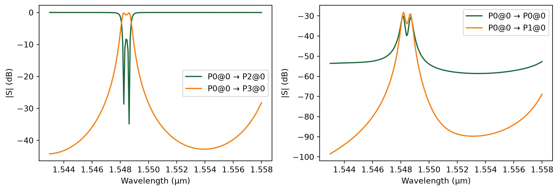
Four-Channel WDM
Section titled “Four-Channel WDM”When cascading multiple resonator filters into a WDM, the ring free spectral range (FSR) and the desired channel spacing must be co-designed to avoid channel collisions and routing ambiguity.
Design Tip: WDM Channel Spacing & FSR
To create a 4-channel WDM, we stagger the resonance of each filter by 1/4 of the Free Spectral Range (FSR).
Theory:
-
Free Spectral Range (FSR): The frequency spacing between consecutive resonances is determined by the group index () and total ring perimeter ():
-
Channel Shift: We need to shift the resonance by , which corresponds to a phase shift of . The required change in ring perimeter () is:
Since our parameterized
coupling_lengthadds to the ring twice (once per side), the requiredadded_lengthparameter is:
L_ring = 2 * np.pi * 5 + 2 * 9  # approximate perimeter (µm)
# Compute the FSR and required resonance shiftfsr_nm = (lambda0**2) / (n_group * L_ring) * 1000added_length = pf.snap_to_grid(lambda0 / (8 * n_eff))
print(f"Est. FSR: {fsr_nm:.1f} nm")print(f"Required added_length: {added_length*1000:.1f} nm")
Est. FSR: 11.6 nmRequired added_length: 79.0 nm@pf.parametric_component(name_prefix="WDM 4ch")def wdm_4channel( *, coupling_length=9.0, # base coupling length (µm) added_length=added_length, # incremental length per channel (µm) radius=5, # ring radius (µm)): """ 4-channel C-band WDM using cascaded 2RR filters.
Each 2RR uses a slightly different coupling length to tune the resonance to a different wavelength. """ # Create four filters with incremental coupling lengths two_rr_0 = filter_2rr(coupling_length=coupling_length, radius=radius) two_rr_1 = filter_2rr(coupling_length=coupling_length + added_length, radius=radius) two_rr_2 = filter_2rr( coupling_length=coupling_length + 2 * added_length, radius=radius ) two_rr_3 = filter_2rr( coupling_length=coupling_length + 3 * added_length, radius=radius )
# Output waveguide wg = pf.parametric.straight(length=60)
# Netlist for 4-channel MUX netlist = { "instances": { "2rr0": two_rr_0, "2rr1": two_rr_1, "2rr2": two_rr_2, "2rr3": two_rr_3, "wg": wg, }, "connections": [ (("2rr1", "P1"), ("2rr0", "P3")), (("2rr2", "P1"), ("2rr1", "P3")), (("2rr3", "P1"), ("2rr2", "P3")), (("wg", "P0"), ("2rr3", "P3")), ], "ports": [ ("2rr0", "P1"), # Input (P0) ("2rr0", "P0"), # Ch1 add (P1) ("2rr0", "P2"), # Ch1 drop (P2) ("2rr1", "P0"), # Ch2 add (P3) ("2rr1", "P2"), # Ch2 drop (P4) ("2rr2", "P0"), # Ch3 add (P5) ("2rr2", "P2"), # Ch3 drop (P6) ("2rr3", "P0"), # Ch4 add (P7) ("2rr3", "P2"), # Ch4 drop (P8) ("wg", "P1"), # Through output (P9) ], # Terminals will be used for electrical routing "terminals": [ ("2rr0", "T0"), ("2rr0", "T1"), ("2rr1", "T0"), ("2rr1", "T1"), ("2rr2", "T0"), ("2rr2", "T1"), ("2rr3", "T0"), ("2rr3", "T1"), ], "models": [pf.CircuitModel()], }
return pf.component_from_netlist(netlist)
wdm = wdm_4channel()viewer(wdm);fill:%23221f20;font-weight:bold;font-size:6.294704px;}.terminal{fill:none;stroke:%23805080;stroke-width:0.786838;}.dashed{stroke-dasharray:3.934190,2.360514;}.port{fill:none;stroke:%23805080;stroke-width:1.573676;}.virtual-connection{fill:none;stroke:%23907090;stroke-width:1.180257;}.layer_31_0{stroke:%238c78ef;fill:url(%23pat-layer_31_0);fill-opacity:0.492;}.label_31_0{fill:%238c78ef;}.layer_33_0{stroke:%238c78ef;fill:url(%23pat-layer_33_0);fill-opacity:0.492;}.label_33_0{fill:%238c78ef;}.layer_102_0{stroke:%238c78ef;fill:url(%23pat-layer_102_0);fill-opacity:0.492;}.label_102_0{fill:%238c78ef;}.layer_110_0{stroke:%238c78ef;fill:url(%23pat-layer_110_0);fill-opacity:0.492;}.label_110_0{fill:%238c78ef;}.layer_189_0{stroke:%23000000;fill:none;}.label_189_0{fill:%23000000;}.layer_201_0{stroke:%2300ee00;fill:url(%23pat-layer_201_0);fill-opacity:0.492;}.label_201_0{fill:%2300ee00;}.layer_401_0{stroke:%236a8ad2;fill:url(%23pat-layer_401_0);fill-opacity:0.492;}.label_401_0{fill:%236a8ad2;}.layer_202_0{stroke:%23007600;fill:url(%23pat-layer_202_0);fill-opacity:0.492;}.label_202_0{fill:%23007600;}.layer_68_0{stroke:%23008000;fill:url(%23pat-layer_68_0);fill-opacity:0.492;}.label_68_0{fill:%23008000;}.layer_5_0{stroke:%236a8ad2;fill:url(%23pat-layer_5_0);fill-opacity:0.492;}.label_5_0{fill:%236a8ad2;}.layer_998_0{stroke:%23000000;fill:none;}.label_998_0{fill:%23000000;}.layer_312_1{stroke:%2300b8b8;fill:url(%23pat-layer_312_1);fill-opacity:0.492;}.label_312_1{fill:%2300b8b8;}.layer_312_0{stroke:%2300b8b8;fill:url(%23pat-layer_312_0);fill-opacity:0.492;}.label_312_0{fill:%2300b8b8;}.layer_402_0{stroke:%23ff0000;fill:url(%23pat-layer_402_0);fill-opacity:0.492;}.label_402_0{fill:%23ff0000;}.layer_401_4{stroke:%236a8ad2;fill:url(%23pat-layer_401_4);fill-opacity:0.492;}.label_401_4{fill:%236a8ad2;}.layer_389_0{stroke:%23ff00ff;fill:url(%23pat-layer_389_0);fill-opacity:0.492;}.label_389_0{fill:%23ff00ff;}.layer_402_1{stroke:%23ff0000;fill:url(%23pat-layer_402_1);fill-opacity:0.492;}.label_402_1{fill:%23ff0000;}.layer_350_1{stroke:%23697a00;fill:url(%23pat-layer_350_1);fill-opacity:0.492;}.label_350_1{fill:%23697a00;}.layer_401_1{stroke:%236a8ad2;fill:url(%23pat-layer_401_1);fill-opacity:0.492;}.label_401_1{fill:%236a8ad2;}.layer_313_2{stroke:%2301d95b;fill:url(%23pat-layer_313_2);fill-opacity:0.492;}.label_313_2{fill:%2301d95b;}.layer_313_1{stroke:%2301d95b;fill:url(%23pat-layer_313_1);fill-opacity:0.492;}.label_313_1{fill:%2301d95b;}.layer_313_0{stroke:%2301d95b;fill:url(%23pat-layer_313_0);fill-opacity:0.492;}.label_313_0{fill:%2301d95b;}.layer_400_0{stroke:%23a96868;fill:url(%23pat-layer_400_0);fill-opacity:0.492;}.label_400_0{fill:%23a96868;}.layer_312_3{stroke:%2300b8b8;fill:url(%23pat-layer_312_3);fill-opacity:0.492;}.label_312_3{fill:%2300b8b8;}.layer_389_1{stroke:%23ff00ff;fill:url(%23pat-layer_389_1);fill-opacity:0.492;}.label_389_1{fill:%23ff00ff;}.layer_401_3{stroke:%236a8ad2;fill:url(%23pat-layer_401_3);fill-opacity:0.492;}.label_401_3{fill:%236a8ad2;}.layer_403_2{stroke:%23500080;fill:url(%23pat-layer_403_2);fill-opacity:0.492;}.label_403_2{fill:%23500080;}.layer_403_3{stroke:%23500080;fill:url(%23pat-layer_403_3);fill-opacity:0.492;}.label_403_3{fill:%23500080;}.layer_403_1{stroke:%23500080;fill:url(%23pat-layer_403_1);fill-opacity:0.492;}.label_403_1{fill:%23500080;}.layer_403_0{stroke:%23500080;fill:url(%23pat-layer_403_0);fill-opacity:0.492;}.label_403_0{fill:%23500080;}.layer_311_1{stroke:%23ac6c56;fill:url(%23pat-layer_311_1);fill-opacity:0.492;}.label_311_1{fill:%23ac6c56;}.layer_311_0{stroke:%23ac6c56;fill:url(%23pat-layer_311_0);fill-opacity:0.492;}.label_311_0{fill:%23ac6c56;}.layer_301_1{stroke:%23800057;fill:url(%23pat-layer_301_1);fill-opacity:0.492;}.label_301_1{fill:%23800057;}.layer_301_0{stroke:%23800057;fill:url(%23pat-layer_301_0);fill-opacity:0.492;}.label_301_0{fill:%23800057;}.layer_305_1{stroke:%23808080;fill:url(%23pat-layer_305_1);fill-opacity:0.492;}.label_305_1{fill:%23808080;}.layer_305_0{stroke:%23808080;fill:url(%23pat-layer_305_0);fill-opacity:0.492;}.label_305_0{fill:%23808080;}.layer_999_0{stroke:%230000ff;fill:url(%23pat-layer_999_0);fill-opacity:0.492;}.label_999_0{fill:%230000ff;}.layer_81_0{stroke:%23808080;fill:url(%23pat-layer_81_0);fill-opacity:0.492;}.label_81_0{fill:%23808080;}.layer_290_0{stroke:%23a46eda;fill:none;}.label_290_0{fill:%23a46eda;}.layer_205_0{stroke:%2349b203;fill:url(%23pat-layer_205_0);fill-opacity:0.492;}.label_205_0{fill:%2349b203;}.layer_11_0{stroke:%230000ff;fill:url(%23pat-layer_11_0);fill-opacity:0.492;}.label_11_0{fill:%230000ff;}.layer_12_0{stroke:%23a57b00;fill:url(%23pat-layer_12_0);fill-opacity:0.492;}.label_12_0{fill:%23a57b00;}.layer_13_0{stroke:%23800057;fill:url(%23pat-layer_13_0);fill-opacity:0.492;}.label_13_0{fill:%23800057;}.layer_6_0{stroke:%23ff0000;fill:url(%23pat-layer_6_0);fill-opacity:0.492;}.label_6_0{fill:%23ff0000;}.layer_1_10{stroke:%23c96585;fill:url(%23pat-layer_1_10);fill-opacity:0.492;}.label_1_10{fill:%23c96585;}.layer_1_11{stroke:%23800000;fill:url(%23pat-layer_1_11);fill-opacity:0.492;}.label_1_11{fill:%23800000;}.layer_200_0{stroke:%23ff0000;fill:url(%23pat-layer_200_0);fill-opacity:0.492;}.label_200_0{fill:%23ff0000;}.layer_1_0{stroke:%23c96585;fill:url(%23pat-layer_1_0);fill-opacity:0.492;}.label_1_0{fill:%23c96585;}.layer_2_0{stroke:%23a46eda;fill:url(%23pat-layer_2_0);fill-opacity:0.492;}.label_2_0{fill:%23a46eda;}.layer_20_0{stroke:%2353793d;fill:url(%23pat-layer_20_0);fill-opacity:0.492;}.label_20_0{fill:%2353793d;}.layer_22_0{stroke:%23ec7600;fill:url(%23pat-layer_22_0);fill-opacity:0.492;}.label_22_0{fill:%23ec7600;}.layer_24_0{stroke:%2300b8b8;fill:url(%23pat-layer_24_0);fill-opacity:0.492;}.label_24_0{fill:%2300b8b8;}.layer_21_0{stroke:%23736264;fill:url(%23pat-layer_21_0);fill-opacity:0.492;}.label_21_0{fill:%23736264;}.layer_23_0{stroke:%23697a00;fill:url(%23pat-layer_23_0);fill-opacity:0.492;}.label_23_0{fill:%23697a00;}.layer_25_0{stroke:%23008000;fill:url(%23pat-layer_25_0);fill-opacity:0.492;}.label_25_0{fill:%23008000;}.layer_350_0{stroke:%23697a00;fill:url(%23pat-layer_350_0);fill-opacity:0.492;}.label_350_0{fill:%23697a00;}.layer_10_0{stroke:%23000000;fill:none;}.label_10_0{fill:%23000000;}.layer_203_0{stroke:%23008000;fill:url(%23pat-layer_203_0);fill-opacity:0.492;}.label_203_0{fill:%23008000;}.layer_40_0{stroke:%230000ff;fill:url(%23pat-layer_40_0);fill-opacity:0.492;}.label_40_0{fill:%230000ff;}.layer_401_2{stroke:%236a8ad2;fill:url(%23pat-layer_401_2);fill-opacity:0.492;}.label_401_2{fill:%236a8ad2;}.layer_301_2{stroke:%23800057;fill:url(%23pat-layer_301_2);fill-opacity:0.492;}.label_301_2{fill:%23800057;}</style><defs><path id=%22port-symbol%22 class=%22port%22 d=%22M 0,-3.147352 L 4.721028,0 0,3.147352%22 /><path id=%22ref-port-symbol%22 class=%22port%22 style=%22stroke-opacity:0.33;%22 d=%22M 0,-2.360514 C 3.147352,-2.360514 3.147352,2.360514 0,2.360514%22 /><circle id=%22port-bend-symbol%22 style=%22stroke-width:0;stroke:none;fill:%23805080;fill-opacity:1;%22 cx=%220%22 cy=%220%22 r=%221.416308%22 /><circle id=%22connection-symbol%22 style=%22stroke-width:0;stroke:none;fill:%23907090;fill-opacity:1;%22 cx=%220%22 cy=%220%22 r=%221.652360%22 /><pattern id=%22pat-layer_31_0%22 patternUnits=%22userSpaceOnUse%22 width=%223.934190%22 height=%223.934190%22 patternTransform=%22translate(3.008498,3.727127)%22><line x1=%220%22 y1=%220%22 x2=%223.934190%22 y2=%223.934190%22 style=%22stroke:%238c78ef;stroke-width:0.393419%22 /><line x1=%22-1.967095%22 y1=%221.967095%22 x2=%221.967095%22 y2=%225.901285%22 style=%22stroke:%238c78ef;stroke-width:0.393419%22 /><line x1=%221.967095%22 y1=%22-1.967095%22 x2=%225.901285%22 y2=%221.967095%22 style=%22stroke:%238c78ef;stroke-width:0.393419%22 /></pattern><pattern id=%22pat-layer_33_0%22 patternUnits=%22userSpaceOnUse%22 width=%223.934190%22 height=%223.934190%22 patternTransform=%22translate(2.314229,0.414125)%22><line x1=%220%22 y1=%220%22 x2=%223.934190%22 y2=%223.934190%22 style=%22stroke:%238c78ef;stroke-width:0.393419%22 /><line x1=%22-1.967095%22 y1=%221.967095%22 x2=%221.967095%22 y2=%225.901285%22 style=%22stroke:%238c78ef;stroke-width:0.393419%22 /><line x1=%221.967095%22 y1=%22-1.967095%22 x2=%225.901285%22 y2=%221.967095%22 style=%22stroke:%238c78ef;stroke-width:0.393419%22 /></pattern><pattern id=%22pat-layer_102_0%22 patternUnits=%22userSpaceOnUse%22 width=%223.934190%22 height=%223.934190%22 patternTransform=%22translate(0.000000,0.207063)%22><line x1=%220%22 y1=%220%22 x2=%223.934190%22 y2=%223.934190%22 style=%22stroke:%238c78ef;stroke-width:0.393419%22 /><line x1=%22-1.967095%22 y1=%221.967095%22 x2=%221.967095%22 y2=%225.901285%22 style=%22stroke:%238c78ef;stroke-width:0.393419%22 /><line x1=%221.967095%22 y1=%22-1.967095%22 x2=%225.901285%22 y2=%221.967095%22 style=%22stroke:%238c78ef;stroke-width:0.393419%22 /></pattern><pattern id=%22pat-layer_110_0%22 patternUnits=%22userSpaceOnUse%22 width=%223.934190%22 height=%223.934190%22 patternTransform=%22translate(1.157115,2.691814)%22><line x1=%220%22 y1=%220%22 x2=%223.934190%22 y2=%223.934190%22 style=%22stroke:%238c78ef;stroke-width:0.393419%22 /><line x1=%22-1.967095%22 y1=%221.967095%22 x2=%221.967095%22 y2=%225.901285%22 style=%22stroke:%238c78ef;stroke-width:0.393419%22 /><line x1=%221.967095%22 y1=%22-1.967095%22 x2=%225.901285%22 y2=%221.967095%22 style=%22stroke:%238c78ef;stroke-width:0.393419%22 /></pattern><pattern id=%22pat-layer_201_0%22 patternUnits=%22userSpaceOnUse%22 width=%223.934190%22 height=%223.934190%22 patternTransform=%22translate(3.008498,1.449438)%22><circle cx=%221.967095%22 cy=%221.967095%22 r=%220.393419%22 style=%22stroke:none;fill:%2300ee00;fill-opacity:1.0%22 /></pattern><pattern id=%22pat-layer_401_0%22 patternUnits=%22userSpaceOnUse%22 width=%222.360514%22 height=%222.360514%22 patternTransform=%22translate(0.277708,0.372713)%22><line x1=%220%22 y1=%220%22 x2=%222.360514%22 y2=%222.360514%22 style=%22stroke:%236a8ad2;stroke-width:0.393419%22 /><line x1=%22-1.180257%22 y1=%221.180257%22 x2=%221.180257%22 y2=%223.540771%22 style=%22stroke:%236a8ad2;stroke-width:0.393419%22 /><line x1=%221.180257%22 y1=%22-1.180257%22 x2=%223.540771%22 y2=%221.180257%22 style=%22stroke:%236a8ad2;stroke-width:0.393419%22 /><line x1=%222.360514%22 y1=%220%22 x2=%220%22 y2=%222.360514%22 style=%22stroke:%236a8ad2;stroke-width:0.393419%22 /><line x1=%223.540771%22 y1=%221.180257%22 x2=%221.180257%22 y2=%223.540771%22 style=%22stroke:%236a8ad2;stroke-width:0.393419%22 /><line x1=%221.180257%22 y1=%22-1.180257%22 x2=%22-1.180257%22 y2=%221.180257%22 style=%22stroke:%236a8ad2;stroke-width:0.393419%22 /></pattern><pattern id=%22pat-layer_202_0%22 patternUnits=%22userSpaceOnUse%22 width=%222.360514%22 height=%222.360514%22 patternTransform=%22translate(0.416561,2.236276)%22><circle cx=%221.180257%22 cy=%221.180257%22 r=%220.393419%22 style=%22stroke:none;fill:%23007600;fill-opacity:1.0%22 /></pattern><pattern id=%22pat-layer_68_0%22 patternUnits=%22userSpaceOnUse%22 width=%223.934190%22 height=%223.934190%22 patternTransform=%22translate(0.000000,1.449438)%22><circle cx=%221.967095%22 cy=%221.967095%22 r=%220.393419%22 style=%22stroke:none;fill:%23008000;fill-opacity:1.0%22 /></pattern><pattern id=%22pat-layer_5_0%22 patternUnits=%22userSpaceOnUse%22 width=%222.360514%22 height=%222.360514%22 patternTransform=%22translate(0.138854,2.112039)%22><line x1=%221.180257%22 y1=%220%22 x2=%221.180257%22 y2=%222.360514%22 style=%22stroke:%236a8ad2;stroke-width:0.393419%22 /></pattern><pattern id=%22pat-layer_312_1%22 patternUnits=%22userSpaceOnUse%22 width=%222.360514%22 height=%222.360514%22 patternTransform=%22translate(0.555415,1.863564)%22><line x1=%220%22 y1=%220%22 x2=%222.360514%22 y2=%222.360514%22 style=%22stroke:%2300b8b8;stroke-width:0.393419%22 /><line x1=%22-1.180257%22 y1=%221.180257%22 x2=%221.180257%22 y2=%223.540771%22 style=%22stroke:%2300b8b8;stroke-width:0.393419%22 /><line x1=%221.180257%22 y1=%22-1.180257%22 x2=%223.540771%22 y2=%221.180257%22 style=%22stroke:%2300b8b8;stroke-width:0.393419%22 /></pattern><pattern id=%22pat-layer_312_0%22 patternUnits=%22userSpaceOnUse%22 width=%223.934190%22 height=%223.934190%22 patternTransform=%22translate(1.851384,2.484752)%22><line x1=%221.967095%22 y1=%220%22 x2=%221.967095%22 y2=%223.934190%22 style=%22stroke:%2300b8b8;stroke-width:0.393419%22 /></pattern><pattern id=%22pat-layer_402_0%22 patternUnits=%22userSpaceOnUse%22 width=%223.934190%22 height=%223.934190%22 patternTransform=%22translate(2.082806,2.898877)%22><line x1=%221.967095%22 y1=%220%22 x2=%221.967095%22 y2=%223.934190%22 style=%22stroke:%23ff0000;stroke-width:0.393419%22 /><line x1=%220%22 y1=%221.967095%22 x2=%223.934190%22 y2=%221.967095%22 style=%22stroke:%23ff0000;stroke-width:0.393419%22 /></pattern><pattern id=%22pat-layer_401_4%22 patternUnits=%22userSpaceOnUse%22 width=%222.360514%22 height=%222.360514%22 patternTransform=%22translate(0.416561,1.863564)%22><line x1=%221.180257%22 y1=%220%22 x2=%221.180257%22 y2=%222.360514%22 style=%22stroke:%236a8ad2;stroke-width:0.393419%22 /></pattern><pattern id=%22pat-layer_389_0%22 patternUnits=%22userSpaceOnUse%22 width=%222.360514%22 height=%222.360514%22 patternTransform=%22translate(0.416561,0.496950)%22><line x1=%221.180257%22 y1=%220%22 x2=%221.180257%22 y2=%222.360514%22 style=%22stroke:%23ff00ff;stroke-width:0.393419%22 /><line x1=%220%22 y1=%221.180257%22 x2=%222.360514%22 y2=%221.180257%22 style=%22stroke:%23ff00ff;stroke-width:0.393419%22 /></pattern><pattern id=%22pat-layer_402_1%22 patternUnits=%22userSpaceOnUse%22 width=%222.360514%22 height=%222.360514%22 patternTransform=%22translate(0.694269,2.112039)%22><line x1=%220%22 y1=%220%22 x2=%222.360514%22 y2=%222.360514%22 style=%22stroke:%23ff0000;stroke-width:0.393419%22 /><line x1=%22-1.180257%22 y1=%221.180257%22 x2=%221.180257%22 y2=%223.540771%22 style=%22stroke:%23ff0000;stroke-width:0.393419%22 /><line x1=%221.180257%22 y1=%22-1.180257%22 x2=%223.540771%22 y2=%221.180257%22 style=%22stroke:%23ff0000;stroke-width:0.393419%22 /><line x1=%222.360514%22 y1=%220%22 x2=%220%22 y2=%222.360514%22 style=%22stroke:%23ff0000;stroke-width:0.393419%22 /><line x1=%223.540771%22 y1=%221.180257%22 x2=%221.180257%22 y2=%223.540771%22 style=%22stroke:%23ff0000;stroke-width:0.393419%22 /><line x1=%221.180257%22 y1=%22-1.180257%22 x2=%22-1.180257%22 y2=%221.180257%22 style=%22stroke:%23ff0000;stroke-width:0.393419%22 /></pattern><pattern id=%22pat-layer_350_1%22 patternUnits=%22userSpaceOnUse%22 width=%222.360514%22 height=%222.360514%22 patternTransform=%22translate(2.082806,1.863564)%22><circle cx=%221.180257%22 cy=%221.180257%22 r=%220.393419%22 style=%22stroke:none;fill:%23697a00;fill-opacity:1.0%22 /></pattern><pattern id=%22pat-layer_401_1%22 patternUnits=%22userSpaceOnUse%22 width=%223.934190%22 height=%223.934190%22 patternTransform=%22translate(3.471344,1.242376)%22><line x1=%220%22 y1=%220%22 x2=%223.934190%22 y2=%223.934190%22 style=%22stroke:%236a8ad2;stroke-width:0.393419%22 /><line x1=%22-1.967095%22 y1=%221.967095%22 x2=%221.967095%22 y2=%225.901285%22 style=%22stroke:%236a8ad2;stroke-width:0.393419%22 /><line x1=%221.967095%22 y1=%22-1.967095%22 x2=%225.901285%22 y2=%221.967095%22 style=%22stroke:%236a8ad2;stroke-width:0.393419%22 /><line x1=%223.934190%22 y1=%220%22 x2=%220%22 y2=%223.934190%22 style=%22stroke:%236a8ad2;stroke-width:0.393419%22 /><line x1=%225.901285%22 y1=%221.967095%22 x2=%221.967095%22 y2=%225.901285%22 style=%22stroke:%236a8ad2;stroke-width:0.393419%22 /><line x1=%221.967095%22 y1=%22-1.967095%22 x2=%22-1.967095%22 y2=%221.967095%22 style=%22stroke:%236a8ad2;stroke-width:0.393419%22 /></pattern><pattern id=%22pat-layer_313_2%22 patternUnits=%22userSpaceOnUse%22 width=%222.360514%22 height=%222.360514%22 patternTransform=%22translate(0.971976,1.242376)%22><line x1=%220%22 y1=%220%22 x2=%222.360514%22 y2=%222.360514%22 style=%22stroke:%2301d95b;stroke-width:0.393419%22 /><line x1=%22-1.180257%22 y1=%221.180257%22 x2=%221.180257%22 y2=%223.540771%22 style=%22stroke:%2301d95b;stroke-width:0.393419%22 /><line x1=%221.180257%22 y1=%22-1.180257%22 x2=%223.540771%22 y2=%221.180257%22 style=%22stroke:%2301d95b;stroke-width:0.393419%22 /></pattern><pattern id=%22pat-layer_313_1%22 patternUnits=%22userSpaceOnUse%22 width=%223.934190%22 height=%223.934190%22 patternTransform=%22translate(2.545652,1.449438)%22><line x1=%221.967095%22 y1=%220%22 x2=%221.967095%22 y2=%223.934190%22 style=%22stroke:%2301d95b;stroke-width:0.393419%22 /></pattern><pattern id=%22pat-layer_313_0%22 patternUnits=%22userSpaceOnUse%22 width=%222.360514%22 height=%222.360514%22 patternTransform=%22translate(2.082806,0.496950)%22><line x1=%221.180257%22 y1=%220%22 x2=%221.180257%22 y2=%222.360514%22 style=%22stroke:%2301d95b;stroke-width:0.393419%22 /></pattern><pattern id=%22pat-layer_400_0%22 patternUnits=%22userSpaceOnUse%22 width=%223.934190%22 height=%223.934190%22 patternTransform=%22translate(2.777075,2.277689)%22><line x1=%220%22 y1=%220%22 x2=%223.934190%22 y2=%223.934190%22 style=%22stroke:%23a96868;stroke-width:0.393419%22 /><line x1=%22-1.967095%22 y1=%221.967095%22 x2=%221.967095%22 y2=%225.901285%22 style=%22stroke:%23a96868;stroke-width:0.393419%22 /><line x1=%221.967095%22 y1=%22-1.967095%22 x2=%225.901285%22 y2=%221.967095%22 style=%22stroke:%23a96868;stroke-width:0.393419%22 /><line x1=%223.934190%22 y1=%220%22 x2=%220%22 y2=%223.934190%22 style=%22stroke:%23a96868;stroke-width:0.393419%22 /><line x1=%225.901285%22 y1=%221.967095%22 x2=%221.967095%22 y2=%225.901285%22 style=%22stroke:%23a96868;stroke-width:0.393419%22 /><line x1=%221.967095%22 y1=%22-1.967095%22 x2=%22-1.967095%22 y2=%221.967095%22 style=%22stroke:%23a96868;stroke-width:0.393419%22 /></pattern><pattern id=%22pat-layer_312_3%22 patternUnits=%22userSpaceOnUse%22 width=%222.360514%22 height=%222.360514%22 patternTransform=%22translate(1.805099,0.248475)%22><line x1=%222.360514%22 y1=%220%22 x2=%220%22 y2=%222.360514%22 style=%22stroke:%2300b8b8;stroke-width:0.393419%22 /><line x1=%223.540771%22 y1=%221.180257%22 x2=%221.180257%22 y2=%223.540771%22 style=%22stroke:%2300b8b8;stroke-width:0.393419%22 /><line x1=%221.180257%22 y1=%22-1.180257%22 x2=%22-1.180257%22 y2=%221.180257%22 style=%22stroke:%2300b8b8;stroke-width:0.393419%22 /></pattern><pattern id=%22pat-layer_389_1%22 patternUnits=%22userSpaceOnUse%22 width=%223.934190%22 height=%223.934190%22 patternTransform=%22translate(3.702767,1.449438)%22><line x1=%221.967095%22 y1=%220%22 x2=%221.967095%22 y2=%223.934190%22 style=%22stroke:%23ff00ff;stroke-width:0.393419%22 /><line x1=%220%22 y1=%221.967095%22 x2=%223.934190%22 y2=%221.967095%22 style=%22stroke:%23ff00ff;stroke-width:0.393419%22 /></pattern><pattern id=%22pat-layer_401_3%22 patternUnits=%22userSpaceOnUse%22 width=%223.934190%22 height=%223.934190%22 patternTransform=%22translate(1.619961,2.484752)%22><line x1=%220%22 y1=%221.967095%22 x2=%223.934190%22 y2=%221.967095%22 style=%22stroke:%236a8ad2;stroke-width:0.393419%22 /></pattern><pattern id=%22pat-layer_403_2%22 patternUnits=%22userSpaceOnUse%22 width=%222.360514%22 height=%222.360514%22 patternTransform=%22translate(1.110830,1.490851)%22><line x1=%220%22 y1=%220%22 x2=%222.360514%22 y2=%222.360514%22 style=%22stroke:%23500080;stroke-width:0.393419%22 /><line x1=%22-1.180257%22 y1=%221.180257%22 x2=%221.180257%22 y2=%223.540771%22 style=%22stroke:%23500080;stroke-width:0.393419%22 /><line x1=%221.180257%22 y1=%22-1.180257%22 x2=%223.540771%22 y2=%221.180257%22 style=%22stroke:%23500080;stroke-width:0.393419%22 /><line x1=%222.360514%22 y1=%220%22 x2=%220%22 y2=%222.360514%22 style=%22stroke:%23500080;stroke-width:0.393419%22 /><line x1=%223.540771%22 y1=%221.180257%22 x2=%221.180257%22 y2=%223.540771%22 style=%22stroke:%23500080;stroke-width:0.393419%22 /><line x1=%221.180257%22 y1=%22-1.180257%22 x2=%22-1.180257%22 y2=%221.180257%22 style=%22stroke:%23500080;stroke-width:0.393419%22 /></pattern><pattern id=%22pat-layer_403_3%22 patternUnits=%22userSpaceOnUse%22 width=%223.934190%22 height=%223.934190%22 patternTransform=%22translate(0.925692,3.105939)%22><line x1=%220%22 y1=%220%22 x2=%223.934190%22 y2=%223.934190%22 style=%22stroke:%23500080;stroke-width:0.393419%22 /><line x1=%22-1.967095%22 y1=%221.967095%22 x2=%221.967095%22 y2=%225.901285%22 style=%22stroke:%23500080;stroke-width:0.393419%22 /><line x1=%221.967095%22 y1=%22-1.967095%22 x2=%225.901285%22 y2=%221.967095%22 style=%22stroke:%23500080;stroke-width:0.393419%22 /><line x1=%223.934190%22 y1=%220%22 x2=%220%22 y2=%223.934190%22 style=%22stroke:%23500080;stroke-width:0.393419%22 /><line x1=%225.901285%22 y1=%221.967095%22 x2=%221.967095%22 y2=%225.901285%22 style=%22stroke:%23500080;stroke-width:0.393419%22 /><line x1=%221.967095%22 y1=%22-1.967095%22 x2=%22-1.967095%22 y2=%221.967095%22 style=%22stroke:%23500080;stroke-width:0.393419%22 /></pattern><pattern id=%22pat-layer_403_1%22 patternUnits=%22userSpaceOnUse%22 width=%223.934190%22 height=%223.934190%22 patternTransform=%22translate(2.777075,1.863564)%22><line x1=%221.967095%22 y1=%220%22 x2=%221.967095%22 y2=%223.934190%22 style=%22stroke:%23500080;stroke-width:0.393419%22 /><line x1=%220%22 y1=%221.967095%22 x2=%223.934190%22 y2=%221.967095%22 style=%22stroke:%23500080;stroke-width:0.393419%22 /></pattern><pattern id=%22pat-layer_403_0%22 patternUnits=%22userSpaceOnUse%22 width=%222.360514%22 height=%222.360514%22 patternTransform=%22translate(2.221660,0.745425)%22><line x1=%221.180257%22 y1=%220%22 x2=%221.180257%22 y2=%222.360514%22 style=%22stroke:%23500080;stroke-width:0.393419%22 /><line x1=%220%22 y1=%221.180257%22 x2=%222.360514%22 y2=%221.180257%22 style=%22stroke:%23500080;stroke-width:0.393419%22 /></pattern><pattern id=%22pat-layer_311_1%22 patternUnits=%22userSpaceOnUse%22 width=%223.934190%22 height=%223.934190%22 patternTransform=%22translate(3.239921,0.828251)%22><line x1=%220%22 y1=%220%22 x2=%223.934190%22 y2=%223.934190%22 style=%22stroke:%23ac6c56;stroke-width:0.393419%22 /><line x1=%22-1.967095%22 y1=%221.967095%22 x2=%221.967095%22 y2=%225.901285%22 style=%22stroke:%23ac6c56;stroke-width:0.393419%22 /><line x1=%221.967095%22 y1=%22-1.967095%22 x2=%225.901285%22 y2=%221.967095%22 style=%22stroke:%23ac6c56;stroke-width:0.393419%22 /></pattern><pattern id=%22pat-layer_311_0%22 patternUnits=%22userSpaceOnUse%22 width=%222.360514%22 height=%222.360514%22 patternTransform=%22translate(0.138854,0.124238)%22><line x1=%220%22 y1=%220%22 x2=%222.360514%22 y2=%222.360514%22 style=%22stroke:%23ac6c56;stroke-width:0.393419%22 /><line x1=%22-1.180257%22 y1=%221.180257%22 x2=%221.180257%22 y2=%223.540771%22 style=%22stroke:%23ac6c56;stroke-width:0.393419%22 /><line x1=%221.180257%22 y1=%22-1.180257%22 x2=%223.540771%22 y2=%221.180257%22 style=%22stroke:%23ac6c56;stroke-width:0.393419%22 /></pattern><pattern id=%22pat-layer_301_1%22 patternUnits=%22userSpaceOnUse%22 width=%223.934190%22 height=%223.934190%22 patternTransform=%22translate(2.777075,1.656501)%22><line x1=%220%22 y1=%221.967095%22 x2=%223.934190%22 y2=%221.967095%22 style=%22stroke:%23800057;stroke-width:0.393419%22 /></pattern><pattern id=%22pat-layer_301_0%22 patternUnits=%22userSpaceOnUse%22 width=%222.360514%22 height=%222.360514%22 patternTransform=%22translate(2.221660,0.621188)%22><line x1=%220%22 y1=%221.180257%22 x2=%222.360514%22 y2=%221.180257%22 style=%22stroke:%23800057;stroke-width:0.393419%22 /></pattern><pattern id=%22pat-layer_305_1%22 patternUnits=%22userSpaceOnUse%22 width=%223.934190%22 height=%223.934190%22 patternTransform=%22translate(1.388538,2.898877)%22><line x1=%221.967095%22 y1=%220%22 x2=%221.967095%22 y2=%223.934190%22 style=%22stroke:%23808080;stroke-width:0.393419%22 /><line x1=%220%22 y1=%221.967095%22 x2=%223.934190%22 y2=%221.967095%22 style=%22stroke:%23808080;stroke-width:0.393419%22 /></pattern><pattern id=%22pat-layer_305_0%22 patternUnits=%22userSpaceOnUse%22 width=%222.360514%22 height=%222.360514%22 patternTransform=%22translate(1.388538,1.366613)%22><line x1=%221.180257%22 y1=%220%22 x2=%221.180257%22 y2=%222.360514%22 style=%22stroke:%23808080;stroke-width:0.393419%22 /><line x1=%220%22 y1=%221.180257%22 x2=%222.360514%22 y2=%221.180257%22 style=%22stroke:%23808080;stroke-width:0.393419%22 /></pattern><pattern id=%22pat-layer_999_0%22 patternUnits=%22userSpaceOnUse%22 width=%222.360514%22 height=%222.360514%22 patternTransform=%22translate(0.833123,0.869663)%22><line x1=%221.180257%22 y1=%220%22 x2=%221.180257%22 y2=%222.360514%22 style=%22stroke:%230000ff;stroke-width:0.393419%22 /></pattern><pattern id=%22pat-layer_81_0%22 patternUnits=%22userSpaceOnUse%22 width=%222.360514%22 height=%222.360514%22 patternTransform=%22translate(0.833123,2.112039)%22><line x1=%221.180257%22 y1=%220%22 x2=%221.180257%22 y2=%222.360514%22 style=%22stroke:%23808080;stroke-width:0.393419%22 /><line x1=%220%22 y1=%221.180257%22 x2=%222.360514%22 y2=%221.180257%22 style=%22stroke:%23808080;stroke-width:0.393419%22 /></pattern><pattern id=%22pat-layer_205_0%22 patternUnits=%22userSpaceOnUse%22 width=%222.360514%22 height=%222.360514%22 patternTransform=%22translate(0.971976,1.615089)%22><line x1=%220%22 y1=%220%22 x2=%222.360514%22 y2=%222.360514%22 style=%22stroke:%2349b203;stroke-width:0.393419%22 /><line x1=%22-1.180257%22 y1=%221.180257%22 x2=%221.180257%22 y2=%223.540771%22 style=%22stroke:%2349b203;stroke-width:0.393419%22 /><line x1=%221.180257%22 y1=%22-1.180257%22 x2=%223.540771%22 y2=%221.180257%22 style=%22stroke:%2349b203;stroke-width:0.393419%22 /><line x1=%222.360514%22 y1=%220%22 x2=%220%22 y2=%222.360514%22 style=%22stroke:%2349b203;stroke-width:0.393419%22 /><line x1=%223.540771%22 y1=%221.180257%22 x2=%221.180257%22 y2=%223.540771%22 style=%22stroke:%2349b203;stroke-width:0.393419%22 /><line x1=%221.180257%22 y1=%22-1.180257%22 x2=%22-1.180257%22 y2=%221.180257%22 style=%22stroke:%2349b203;stroke-width:0.393419%22 /></pattern><pattern id=%22pat-layer_11_0%22 patternUnits=%22userSpaceOnUse%22 width=%222.360514%22 height=%222.360514%22 patternTransform=%22translate(1.249684,0.869663)%22><line x1=%222.360514%22 y1=%220%22 x2=%220%22 y2=%222.360514%22 style=%22stroke:%230000ff;stroke-width:0.393419%22 /><line x1=%223.540771%22 y1=%221.180257%22 x2=%221.180257%22 y2=%223.540771%22 style=%22stroke:%230000ff;stroke-width:0.393419%22 /><line x1=%221.180257%22 y1=%22-1.180257%22 x2=%22-1.180257%22 y2=%221.180257%22 style=%22stroke:%230000ff;stroke-width:0.393419%22 /></pattern><pattern id=%22pat-layer_12_0%22 patternUnits=%22userSpaceOnUse%22 width=%222.360514%22 height=%222.360514%22 patternTransform=%22translate(2.221660,2.236276)%22><line x1=%220%22 y1=%220%22 x2=%222.360514%22 y2=%222.360514%22 style=%22stroke:%23a57b00;stroke-width:0.393419%22 /><line x1=%22-1.180257%22 y1=%221.180257%22 x2=%221.180257%22 y2=%223.540771%22 style=%22stroke:%23a57b00;stroke-width:0.393419%22 /><line x1=%221.180257%22 y1=%22-1.180257%22 x2=%223.540771%22 y2=%221.180257%22 style=%22stroke:%23a57b00;stroke-width:0.393419%22 /></pattern><pattern id=%22pat-layer_13_0%22 patternUnits=%22userSpaceOnUse%22 width=%222.360514%22 height=%222.360514%22 patternTransform=%22translate(0.833123,1.242376)%22><line x1=%222.360514%22 y1=%220%22 x2=%220%22 y2=%222.360514%22 style=%22stroke:%23800057;stroke-width:0.393419%22 /><line x1=%223.540771%22 y1=%221.180257%22 x2=%221.180257%22 y2=%223.540771%22 style=%22stroke:%23800057;stroke-width:0.393419%22 /><line x1=%221.180257%22 y1=%22-1.180257%22 x2=%22-1.180257%22 y2=%221.180257%22 style=%22stroke:%23800057;stroke-width:0.393419%22 /></pattern><pattern id=%22pat-layer_6_0%22 patternUnits=%22userSpaceOnUse%22 width=%223.934190%22 height=%223.934190%22 patternTransform=%22translate(1.851384,1.863564)%22><line x1=%220%22 y1=%221.967095%22 x2=%223.934190%22 y2=%221.967095%22 style=%22stroke:%23ff0000;stroke-width:0.393419%22 /></pattern><pattern id=%22pat-layer_1_10%22 patternUnits=%22userSpaceOnUse%22 width=%222.360514%22 height=%222.360514%22 patternTransform=%22translate(0.138854,0.372713)%22><line x1=%220%22 y1=%220%22 x2=%222.360514%22 y2=%222.360514%22 style=%22stroke:%23c96585;stroke-width:0.393419%22 /><line x1=%22-1.180257%22 y1=%221.180257%22 x2=%221.180257%22 y2=%223.540771%22 style=%22stroke:%23c96585;stroke-width:0.393419%22 /><line x1=%221.180257%22 y1=%22-1.180257%22 x2=%223.540771%22 y2=%221.180257%22 style=%22stroke:%23c96585;stroke-width:0.393419%22 /><line x1=%222.360514%22 y1=%220%22 x2=%220%22 y2=%222.360514%22 style=%22stroke:%23c96585;stroke-width:0.393419%22 /><line x1=%223.540771%22 y1=%221.180257%22 x2=%221.180257%22 y2=%223.540771%22 style=%22stroke:%23c96585;stroke-width:0.393419%22 /><line x1=%221.180257%22 y1=%22-1.180257%22 x2=%22-1.180257%22 y2=%221.180257%22 style=%22stroke:%23c96585;stroke-width:0.393419%22 /></pattern><pattern id=%22pat-layer_1_11%22 patternUnits=%22userSpaceOnUse%22 width=%223.934190%22 height=%223.934190%22 patternTransform=%22translate(3.239921,1.242376)%22><line x1=%221.967095%22 y1=%220%22 x2=%221.967095%22 y2=%223.934190%22 style=%22stroke:%23800000;stroke-width:0.393419%22 /><line x1=%220%22 y1=%221.967095%22 x2=%223.934190%22 y2=%221.967095%22 style=%22stroke:%23800000;stroke-width:0.393419%22 /></pattern><pattern id=%22pat-layer_200_0%22 patternUnits=%22userSpaceOnUse%22 width=%223.934190%22 height=%223.934190%22 patternTransform=%22translate(1.388538,3.105939)%22><line x1=%220%22 y1=%220%22 x2=%223.934190%22 y2=%223.934190%22 style=%22stroke:%23ff0000;stroke-width:0.393419%22 /><line x1=%22-1.967095%22 y1=%221.967095%22 x2=%221.967095%22 y2=%225.901285%22 style=%22stroke:%23ff0000;stroke-width:0.393419%22 /><line x1=%221.967095%22 y1=%22-1.967095%22 x2=%225.901285%22 y2=%221.967095%22 style=%22stroke:%23ff0000;stroke-width:0.393419%22 /><line x1=%223.934190%22 y1=%220%22 x2=%220%22 y2=%223.934190%22 style=%22stroke:%23ff0000;stroke-width:0.393419%22 /><line x1=%225.901285%22 y1=%221.967095%22 x2=%221.967095%22 y2=%225.901285%22 style=%22stroke:%23ff0000;stroke-width:0.393419%22 /><line x1=%221.967095%22 y1=%22-1.967095%22 x2=%22-1.967095%22 y2=%221.967095%22 style=%22stroke:%23ff0000;stroke-width:0.393419%22 /></pattern><pattern id=%22pat-layer_1_0%22 patternUnits=%22userSpaceOnUse%22 width=%222.360514%22 height=%222.360514%22 patternTransform=%22translate(0.971976,1.366613)%22><line x1=%222.360514%22 y1=%220%22 x2=%220%22 y2=%222.360514%22 style=%22stroke:%23c96585;stroke-width:0.393419%22 /><line x1=%223.540771%22 y1=%221.180257%22 x2=%221.180257%22 y2=%223.540771%22 style=%22stroke:%23c96585;stroke-width:0.393419%22 /><line x1=%221.180257%22 y1=%22-1.180257%22 x2=%22-1.180257%22 y2=%221.180257%22 style=%22stroke:%23c96585;stroke-width:0.393419%22 /></pattern><pattern id=%22pat-layer_2_0%22 patternUnits=%22userSpaceOnUse%22 width=%223.934190%22 height=%223.934190%22 patternTransform=%22translate(3.239921,0.621188)%22><line x1=%220%22 y1=%220%22 x2=%223.934190%22 y2=%223.934190%22 style=%22stroke:%23a46eda;stroke-width:0.393419%22 /><line x1=%22-1.967095%22 y1=%221.967095%22 x2=%221.967095%22 y2=%225.901285%22 style=%22stroke:%23a46eda;stroke-width:0.393419%22 /><line x1=%221.967095%22 y1=%22-1.967095%22 x2=%225.901285%22 y2=%221.967095%22 style=%22stroke:%23a46eda;stroke-width:0.393419%22 /></pattern><pattern id=%22pat-layer_20_0%22 patternUnits=%22userSpaceOnUse%22 width=%223.934190%22 height=%223.934190%22 patternTransform=%22translate(0.925692,2.277689)%22><line x1=%220%22 y1=%221.967095%22 x2=%223.934190%22 y2=%221.967095%22 style=%22stroke:%2353793d;stroke-width:0.393419%22 /></pattern><pattern id=%22pat-layer_22_0%22 patternUnits=%22userSpaceOnUse%22 width=%223.934190%22 height=%223.934190%22 patternTransform=%22translate(0.231423,2.898877)%22><line x1=%220%22 y1=%220%22 x2=%223.934190%22 y2=%223.934190%22 style=%22stroke:%23ec7600;stroke-width:0.393419%22 /><line x1=%22-1.967095%22 y1=%221.967095%22 x2=%221.967095%22 y2=%225.901285%22 style=%22stroke:%23ec7600;stroke-width:0.393419%22 /><line x1=%221.967095%22 y1=%22-1.967095%22 x2=%225.901285%22 y2=%221.967095%22 style=%22stroke:%23ec7600;stroke-width:0.393419%22 /><line x1=%223.934190%22 y1=%220%22 x2=%220%22 y2=%223.934190%22 style=%22stroke:%23ec7600;stroke-width:0.393419%22 /><line x1=%225.901285%22 y1=%221.967095%22 x2=%221.967095%22 y2=%225.901285%22 style=%22stroke:%23ec7600;stroke-width:0.393419%22 /><line x1=%221.967095%22 y1=%22-1.967095%22 x2=%22-1.967095%22 y2=%221.967095%22 style=%22stroke:%23ec7600;stroke-width:0.393419%22 /></pattern><pattern id=%22pat-layer_24_0%22 patternUnits=%22userSpaceOnUse%22 width=%223.934190%22 height=%223.934190%22 patternTransform=%22translate(3.471344,3.520065)%22><line x1=%221.967095%22 y1=%220%22 x2=%221.967095%22 y2=%223.934190%22 style=%22stroke:%2300b8b8;stroke-width:0.393419%22 /><line x1=%220%22 y1=%221.967095%22 x2=%223.934190%22 y2=%221.967095%22 style=%22stroke:%2300b8b8;stroke-width:0.393419%22 /></pattern><pattern id=%22pat-layer_21_0%22 patternUnits=%22userSpaceOnUse%22 width=%222.360514%22 height=%222.360514%22 patternTransform=%22translate(1.527391,0.372713)%22><line x1=%220%22 y1=%221.180257%22 x2=%222.360514%22 y2=%221.180257%22 style=%22stroke:%23736264;stroke-width:0.393419%22 /></pattern><pattern id=%22pat-layer_23_0%22 patternUnits=%22userSpaceOnUse%22 width=%222.360514%22 height=%222.360514%22 patternTransform=%22translate(1.110830,0.745425)%22><line x1=%220%22 y1=%220%22 x2=%222.360514%22 y2=%222.360514%22 style=%22stroke:%23697a00;stroke-width:0.393419%22 /><line x1=%22-1.180257%22 y1=%221.180257%22 x2=%221.180257%22 y2=%223.540771%22 style=%22stroke:%23697a00;stroke-width:0.393419%22 /><line x1=%221.180257%22 y1=%22-1.180257%22 x2=%223.540771%22 y2=%221.180257%22 style=%22stroke:%23697a00;stroke-width:0.393419%22 /><line x1=%222.360514%22 y1=%220%22 x2=%220%22 y2=%222.360514%22 style=%22stroke:%23697a00;stroke-width:0.393419%22 /><line x1=%223.540771%22 y1=%221.180257%22 x2=%221.180257%22 y2=%223.540771%22 style=%22stroke:%23697a00;stroke-width:0.393419%22 /><line x1=%221.180257%22 y1=%22-1.180257%22 x2=%22-1.180257%22 y2=%221.180257%22 style=%22stroke:%23697a00;stroke-width:0.393419%22 /></pattern><pattern id=%22pat-layer_25_0%22 patternUnits=%22userSpaceOnUse%22 width=%222.360514%22 height=%222.360514%22 patternTransform=%22translate(0.694269,1.118138)%22><line x1=%221.180257%22 y1=%220%22 x2=%221.180257%22 y2=%222.360514%22 style=%22stroke:%23008000;stroke-width:0.393419%22 /><line x1=%220%22 y1=%221.180257%22 x2=%222.360514%22 y2=%221.180257%22 style=%22stroke:%23008000;stroke-width:0.393419%22 /></pattern><pattern id=%22pat-layer_350_0%22 patternUnits=%22userSpaceOnUse%22 width=%223.934190%22 height=%223.934190%22 patternTransform=%22translate(0.462846,2.484752)%22><line x1=%223.934190%22 y1=%220%22 x2=%220%22 y2=%223.934190%22 style=%22stroke:%23697a00;stroke-width:0.393419%22 /><line x1=%225.901285%22 y1=%221.967095%22 x2=%221.967095%22 y2=%225.901285%22 style=%22stroke:%23697a00;stroke-width:0.393419%22 /><line x1=%221.967095%22 y1=%22-1.967095%22 x2=%22-1.967095%22 y2=%221.967095%22 style=%22stroke:%23697a00;stroke-width:0.393419%22 /></pattern><pattern id=%22pat-layer_203_0%22 patternUnits=%22userSpaceOnUse%22 width=%223.934190%22 height=%223.934190%22 patternTransform=%22translate(2.314229,2.070626)%22><line x1=%223.934190%22 y1=%220%22 x2=%220%22 y2=%223.934190%22 style=%22stroke:%23008000;stroke-width:0.393419%22 /><line x1=%225.901285%22 y1=%221.967095%22 x2=%221.967095%22 y2=%225.901285%22 style=%22stroke:%23008000;stroke-width:0.393419%22 /><line x1=%221.967095%22 y1=%22-1.967095%22 x2=%22-1.967095%22 y2=%221.967095%22 style=%22stroke:%23008000;stroke-width:0.393419%22 /></pattern><pattern id=%22pat-layer_40_0%22 patternUnits=%22userSpaceOnUse%22 width=%223.934190%22 height=%223.934190%22 patternTransform=%22translate(1.851384,0.621188)%22><circle cx=%221.967095%22 cy=%221.967095%22 r=%220.393419%22 style=%22stroke:none;fill:%230000ff;fill-opacity:1.0%22 /></pattern><pattern id=%22pat-layer_401_2%22 patternUnits=%22userSpaceOnUse%22 width=%222.360514%22 height=%222.360514%22 patternTransform=%22translate(1.527391,1.118138)%22><line x1=%220%22 y1=%221.180257%22 x2=%222.360514%22 y2=%221.180257%22 style=%22stroke:%236a8ad2;stroke-width:0.393419%22 /></pattern><pattern id=%22pat-layer_301_2%22 patternUnits=%22userSpaceOnUse%22 width=%222.360514%22 height=%222.360514%22 patternTransform=%22translate(1.110830,1.366613)%22><line x1=%221.180257%22 y1=%220%22 x2=%221.180257%22 y2=%222.360514%22 style=%22stroke:%23800057;stroke-width:0.393419%22 /></pattern><g id=%22C1%22 data-name=%222RR Filter_br_0P22_co_9P0_pa_10_ra_5_rr_0P348%22><use transform=%22translate(0.000000 0.000000)%22 href=%22%23C6%22 /><use transform=%22translate(0.000000 10.848000) rotate(180.000000)%22 href=%22%23C6%22 /><use transform=%22translate(0.000000 10.848000)%22 href=%22%23C7%22 /><use transform=%22translate(-9.500000 21.568000) rotate(90.000000)%22 href=%22%23C8%22 /><use transform=%22translate(14.500000 26.568000) rotate(180.000000)%22 href=%22%23C8%22 /><use transform=%22translate(-9.500000 -70.720000) rotate(90.000000)%22 href=%22%23C5%22 /><use transform=%22translate(-74.500000 26.568000)%22 href=%22%23C5%22 /><use transform=%22translate(9.500000 -70.720000) rotate(90.000000)%22 href=%22%23C5%22 /><rect class=%22layer_12_0%22 x=%22-15.500000%22 y=%22-35.720000%22 width=%2210.000000%22 height=%2220.000000%22 /><rect class=%22layer_12_0%22 x=%22-10.500000%22 y=%22-15.720000%22 width=%225.000000%22 height=%2240.000000%22 /><rect class=%22layer_12_0%22 x=%225.500000%22 y=%2225.000000%22 width=%2210.000000%22 height=%2220.000000%22 /><rect class=%22layer_12_0%22 x=%225.500000%22 y=%22-15.000000%22 width=%225.000000%22 height=%2240.000000%22 /><rect class=%22terminal dashed%22 x=%22-15.500000%22 y=%22-35.720000%22 width=%2210.000000%22 height=%2220.000000%22 /><rect class=%22terminal dashed%22 x=%225.500000%22 y=%2225.000000%22 width=%2210.000000%22 height=%2220.000000%22 /></g><g id=%22C2%22 data-name=%222RR Filter_br_0P22_co_9P079_pa_10_ra_5_rr_0P348%22><use transform=%22translate(0.000000 0.000000)%22 href=%22%23C9%22 /><use transform=%22translate(0.000000 10.848000) rotate(180.000000)%22 href=%22%23C9%22 /><use transform=%22translate(0.000000 10.848000)%22 href=%22%23C10%22 /><use transform=%22translate(-9.540000 21.568000) rotate(90.000000)%22 href=%22%23C8%22 /><use transform=%22translate(14.540000 26.568000) rotate(180.000000)%22 href=%22%23C8%22 /><use transform=%22translate(-9.540000 -70.720000) rotate(90.000000)%22 href=%22%23C5%22 /><use transform=%22translate(-74.540000 26.568000)%22 href=%22%23C5%22 /><use transform=%22translate(9.540000 -70.720000) rotate(90.000000)%22 href=%22%23C5%22 /><rect class=%22layer_12_0%22 x=%22-15.540000%22 y=%22-35.720000%22 width=%2210.000000%22 height=%2220.000000%22 /><rect class=%22layer_12_0%22 x=%22-10.540000%22 y=%22-15.720000%22 width=%225.000000%22 height=%2240.000000%22 /><rect class=%22layer_12_0%22 x=%225.540000%22 y=%2225.000000%22 width=%2210.000000%22 height=%2220.000000%22 /><rect class=%22layer_12_0%22 x=%225.540000%22 y=%22-15.000000%22 width=%225.000000%22 height=%2240.000000%22 /><rect class=%22terminal dashed%22 x=%22-15.540000%22 y=%22-35.720000%22 width=%2210.000000%22 height=%2220.000000%22 /><rect class=%22terminal dashed%22 x=%225.540000%22 y=%2225.000000%22 width=%2210.000000%22 height=%2220.000000%22 /></g><g id=%22C3%22 data-name=%222RR Filter_br_0P22_co_9P158_pa_10_ra_5_rr_0P348%22><use transform=%22translate(0.000000 0.000000)%22 href=%22%23C11%22 /><use transform=%22translate(0.000000 10.848000) rotate(180.000000)%22 href=%22%23C11%22 /><use transform=%22translate(0.000000 10.848000)%22 href=%22%23C12%22 /><use transform=%22translate(-9.579000 21.568000) rotate(90.000000)%22 href=%22%23C8%22 /><use transform=%22translate(14.579000 26.568000) rotate(180.000000)%22 href=%22%23C8%22 /><use transform=%22translate(-9.579000 -70.720000) rotate(90.000000)%22 href=%22%23C5%22 /><use transform=%22translate(-74.579000 26.568000)%22 href=%22%23C5%22 /><use transform=%22translate(9.579000 -70.720000) rotate(90.000000)%22 href=%22%23C5%22 /><rect class=%22layer_12_0%22 x=%22-15.579000%22 y=%22-35.720000%22 width=%2210.000000%22 height=%2220.000000%22 /><rect class=%22layer_12_0%22 x=%22-10.579000%22 y=%22-15.720000%22 width=%225.000000%22 height=%2240.000000%22 /><rect class=%22layer_12_0%22 x=%225.579000%22 y=%2225.000000%22 width=%2210.000000%22 height=%2220.000000%22 /><rect class=%22layer_12_0%22 x=%225.579000%22 y=%22-15.000000%22 width=%225.000000%22 height=%2240.000000%22 /><rect class=%22terminal dashed%22 x=%22-15.579000%22 y=%22-35.720000%22 width=%2210.000000%22 height=%2220.000000%22 /><rect class=%22terminal dashed%22 x=%225.579000%22 y=%2225.000000%22 width=%2210.000000%22 height=%2220.000000%22 /></g><g id=%22C4%22 data-name=%222RR Filter_br_0P22_co_9P237_pa_10_ra_5_rr_0P348%22><use transform=%22translate(0.000000 0.000000)%22 href=%22%23C13%22 /><use transform=%22translate(0.000000 10.848000) rotate(180.000000)%22 href=%22%23C13%22 /><use transform=%22translate(0.000000 10.848000)%22 href=%22%23C14%22 /><use transform=%22translate(-9.619000 21.568000) rotate(90.000000)%22 href=%22%23C8%22 /><use transform=%22translate(14.619000 26.568000) rotate(180.000000)%22 href=%22%23C8%22 /><use transform=%22translate(-9.619000 -70.720000) rotate(90.000000)%22 href=%22%23C5%22 /><use transform=%22translate(-74.619000 26.568000)%22 href=%22%23C5%22 /><use transform=%22translate(9.619000 -70.720000) rotate(90.000000)%22 href=%22%23C5%22 /><rect class=%22layer_12_0%22 x=%22-15.619000%22 y=%22-35.720000%22 width=%2210.000000%22 height=%2220.000000%22 /><rect class=%22layer_12_0%22 x=%22-10.619000%22 y=%22-15.720000%22 width=%225.000000%22 height=%2240.000000%22 /><rect class=%22layer_12_0%22 x=%225.619000%22 y=%2225.000000%22 width=%2210.000000%22 height=%2220.000000%22 /><rect class=%22layer_12_0%22 x=%225.619000%22 y=%22-15.000000%22 width=%225.000000%22 height=%2240.000000%22 /><rect class=%22terminal dashed%22 x=%22-15.619000%22 y=%22-35.720000%22 width=%2210.000000%22 height=%2220.000000%22 /><rect class=%22terminal dashed%22 x=%225.619000%22 y=%2225.000000%22 width=%2210.000000%22 height=%2220.000000%22 /></g><g id=%22C5%22 data-name=%22straight_l_60%22><path class=%22layer_1_0%22 d=%22M 0.000000,-0.250000 60.000000,-0.250000 60.000000,0.250000 0.000000,0.250000 z%22 /></g><g id=%22C10%22 data-name=%22dual_ring_coupler__4URYEEMR56SLF4BFHFI7TEIRMJDLFK6TTBOSKRHDXWNCIXMGFWJA%22><path class=%22layer_1_0%22 d=%22M -9.290000,-10.848000 -9.288000,-10.332000 -9.271000,-9.822000 -9.254000,-9.571000 -9.191000,-9.076000 -9.143000,-8.833000 -9.083000,-8.596000 -9.008000,-8.364000 -8.918000,-8.139000 -8.812000,-7.922000 -8.691000,-7.714000 -8.554000,-7.515000 -8.403000,-7.326000 -8.239000,-7.149000 -8.062000,-6.985000 -7.873000,-6.834000 -7.674000,-6.697000 -7.466000,-6.576000 -7.249000,-6.470000 -7.024000,-6.380000 -6.792000,-6.305000 -6.555000,-6.245000 -6.312000,-6.197000 -6.066000,-6.161000 -5.817000,-6.134000 -5.312000,-6.106000 -4.540000,-6.098000 4.540000,-6.098000 5.056000,-6.100000 5.565000,-6.117000 5.817000,-6.134000 6.312000,-6.197000 6.554000,-6.245000 6.792000,-6.305000 7.024000,-6.380000 7.248000,-6.470000 7.465000,-6.576000 7.674000,-6.697000 7.873000,-6.834000 8.062000,-6.985000 8.239000,-7.149000 8.403000,-7.326000 8.554000,-7.515000 8.691000,-7.714000 8.812000,-7.922000 8.918000,-8.139000 9.008000,-8.364000 9.083000,-8.596000 9.143000,-8.833000 9.191000,-9.076000 9.227000,-9.322000 9.271000,-9.822000 9.288000,-10.332000 9.290000,-10.848000 9.790000,-10.848000 9.782000,-10.060000 9.752000,-9.528000 9.723000,-9.260000 9.684000,-8.991000 9.631000,-8.724000 9.563000,-8.458000 9.479000,-8.195000 9.375000,-7.937000 9.253000,-7.687000 9.113000,-7.446000 8.956000,-7.217000 8.782000,-6.999000 8.592000,-6.796000 8.388000,-6.606000 8.171000,-6.432000 7.942000,-6.275000 7.701000,-6.135000 7.451000,-6.013000 7.193000,-5.909000 6.930000,-5.825000 6.664000,-5.757000 6.396000,-5.704000 6.128000,-5.664000 5.593000,-5.618000 5.063000,-5.600000 4.540000,-5.598000 -4.540000,-5.598000 -5.063000,-5.600000 -5.593000,-5.618000 -6.128000,-5.664000 -6.397000,-5.704000 -6.664000,-5.757000 -6.930000,-5.825000 -7.193000,-5.909000 -7.451000,-6.013000 -7.701000,-6.135000 -7.942000,-6.275000 -8.171000,-6.432000 -8.389000,-6.606000 -8.592000,-6.796000 -8.782000,-6.999000 -8.956000,-7.217000 -9.113000,-7.446000 -9.253000,-7.687000 -9.375000,-7.937000 -9.479000,-8.195000 -9.563000,-8.458000 -9.631000,-8.724000 -9.684000,-8.991000 -9.724000,-9.260000 -9.770000,-9.795000 -9.788000,-10.325000 -9.790000,-10.848000 z%22 /><path class=%22layer_1_0%22 d=%22M 9.290000,0.000000 9.288000,-0.516000 9.271000,-1.026000 9.254000,-1.277000 9.191000,-1.772000 9.143000,-2.015000 9.083000,-2.252000 9.008000,-2.484000 8.918000,-2.709000 8.812000,-2.926000 8.691000,-3.134000 8.554000,-3.333000 8.403000,-3.522000 8.239000,-3.699000 8.062000,-3.863000 7.873000,-4.014000 7.674000,-4.151000 7.466000,-4.272000 7.249000,-4.378000 7.024000,-4.468000 6.792000,-4.543000 6.555000,-4.603000 6.312000,-4.651000 6.066000,-4.687000 5.817000,-4.714000 5.312000,-4.742000 4.540000,-4.750000 -4.539000,-4.750000 -5.056000,-4.748000 -5.565000,-4.731000 -5.817000,-4.714000 -6.312000,-4.651000 -6.554000,-4.603000 -6.792000,-4.543000 -7.024000,-4.468000 -7.248000,-4.378000 -7.465000,-4.272000 -7.674000,-4.151000 -7.873000,-4.014000 -8.062000,-3.863000 -8.239000,-3.699000 -8.403000,-3.522000 -8.554000,-3.333000 -8.691000,-3.134000 -8.812000,-2.926000 -8.918000,-2.709000 -9.008000,-2.484000 -9.083000,-2.252000 -9.143000,-2.015000 -9.191000,-1.772000 -9.227000,-1.526000 -9.271000,-1.026000 -9.288000,-0.516000 -9.290000,0.000000 -9.790000,0.000000 -9.782000,-0.788000 -9.752000,-1.320000 -9.723000,-1.588000 -9.684000,-1.857000 -9.631000,-2.124000 -9.563000,-2.390000 -9.479000,-2.653000 -9.375000,-2.911000 -9.253000,-3.161000 -9.113000,-3.402000 -8.956000,-3.631000 -8.782000,-3.849000 -8.592000,-4.052000 -8.388000,-4.242000 -8.171000,-4.416000 -7.942000,-4.573000 -7.701000,-4.713000 -7.451000,-4.835000 -7.193000,-4.939000 -6.930000,-5.023000 -6.664000,-5.091000 -6.396000,-5.144000 -6.128000,-5.184000 -5.593000,-5.230000 -5.063000,-5.248000 -4.539000,-5.250000 4.540000,-5.250000 5.063000,-5.248000 5.593000,-5.230000 6.128000,-5.184000 6.397000,-5.144000 6.664000,-5.091000 6.930000,-5.023000 7.193000,-4.939000 7.451000,-4.835000 7.701000,-4.713000 7.942000,-4.573000 8.171000,-4.416000 8.389000,-4.242000 8.592000,-4.052000 8.782000,-3.849000 8.956000,-3.631000 9.113000,-3.402000 9.253000,-3.161000 9.375000,-2.911000 9.479000,-2.653000 9.563000,-2.390000 9.631000,-2.124000 9.684000,-1.857000 9.724000,-1.588000 9.770000,-1.053000 9.788000,-0.523000 9.790000,0.000000 z%22 /><rect class=%22layer_11_0%22 x=%22-9.540000%22 y=%22-7.424000%22 width=%2219.080000%22 height=%224.000000%22 /></g><g id=%22C11%22 data-name=%22dual_ring_coupler__6CBT6YLB6JDDSC6QFAA46GEWYPUCN6JSXMTR6XAKMOXBSSZYIQHA%22><path class=%22layer_1_0%22 d=%22M -9.329000,-10.720000 -9.327000,-10.204000 -9.310000,-9.694000 -9.293000,-9.443000 -9.230000,-8.948000 -9.182000,-8.705000 -9.122000,-8.468000 -9.047000,-8.236000 -8.957000,-8.011000 -8.851000,-7.794000 -8.730000,-7.586000 -8.593000,-7.387000 -8.442000,-7.198000 -8.278000,-7.021000 -8.101000,-6.857000 -7.912000,-6.706000 -7.713000,-6.569000 -7.505000,-6.448000 -7.288000,-6.342000 -7.063000,-6.252000 -6.831000,-6.177000 -6.594000,-6.117000 -6.351000,-6.069000 -6.105000,-6.033000 -5.856000,-6.006000 -5.351000,-5.978000 -4.579000,-5.970000 4.579000,-5.970000 5.095000,-5.972000 5.605000,-5.989000 5.856000,-6.006000 6.351000,-6.069000 6.594000,-6.117000 6.831000,-6.177000 7.063000,-6.252000 7.288000,-6.342000 7.505000,-6.448000 7.713000,-6.569000 7.912000,-6.706000 8.101000,-6.857000 8.278000,-7.021000 8.442000,-7.198000 8.593000,-7.387000 8.730000,-7.586000 8.851000,-7.794000 8.957000,-8.011000 9.047000,-8.236000 9.122000,-8.468000 9.182000,-8.705000 9.230000,-8.948000 9.266000,-9.194000 9.293000,-9.443000 9.321000,-9.948000 9.329000,-10.720000 9.829000,-10.720000 9.827000,-10.197000 9.809000,-9.667000 9.763000,-9.132000 9.723000,-8.863000 9.670000,-8.596000 9.602000,-8.330000 9.518000,-8.067000 9.414000,-7.809000 9.292000,-7.559000 9.152000,-7.318000 8.995000,-7.089000 8.821000,-6.871000 8.631000,-6.668000 8.428000,-6.478000 8.210000,-6.304000 7.981000,-6.147000 7.740000,-6.007000 7.490000,-5.885000 7.232000,-5.781000 6.969000,-5.697000 6.703000,-5.629000 6.436000,-5.576000 6.167000,-5.536000 5.632000,-5.490000 5.102000,-5.472000 4.579000,-5.470000 -4.579000,-5.470000 -5.102000,-5.472000 -5.632000,-5.490000 -6.167000,-5.536000 -6.436000,-5.576000 -6.703000,-5.629000 -6.969000,-5.697000 -7.232000,-5.781000 -7.490000,-5.885000 -7.740000,-6.007000 -7.981000,-6.147000 -8.210000,-6.304000 -8.428000,-6.478000 -8.631000,-6.668000 -8.821000,-6.871000 -8.995000,-7.089000 -9.152000,-7.318000 -9.292000,-7.559000 -9.414000,-7.809000 -9.518000,-8.067000 -9.602000,-8.330000 -9.670000,-8.596000 -9.723000,-8.863000 -9.763000,-9.132000 -9.809000,-9.667000 -9.827000,-10.197000 -9.829000,-10.720000 z%22 /><path class=%22layer_1_0%22 d=%22M 9.329000,0.000000 9.327000,-0.516000 9.310000,-1.026000 9.293000,-1.277000 9.230000,-1.772000 9.182000,-2.015000 9.122000,-2.252000 9.047000,-2.484000 8.957000,-2.709000 8.851000,-2.926000 8.730000,-3.134000 8.593000,-3.333000 8.442000,-3.522000 8.278000,-3.699000 8.101000,-3.863000 7.912000,-4.014000 7.713000,-4.151000 7.505000,-4.272000 7.288000,-4.378000 7.063000,-4.468000 6.831000,-4.543000 6.594000,-4.603000 6.351000,-4.651000 6.105000,-4.687000 5.856000,-4.714000 5.351000,-4.742000 4.579000,-4.750000 -4.579000,-4.750000 -5.095000,-4.748000 -5.605000,-4.731000 -5.856000,-4.714000 -6.351000,-4.651000 -6.594000,-4.603000 -6.831000,-4.543000 -7.063000,-4.468000 -7.288000,-4.378000 -7.505000,-4.272000 -7.713000,-4.151000 -7.912000,-4.014000 -8.101000,-3.863000 -8.278000,-3.699000 -8.442000,-3.522000 -8.593000,-3.333000 -8.730000,-3.134000 -8.851000,-2.926000 -8.957000,-2.709000 -9.047000,-2.484000 -9.122000,-2.252000 -9.182000,-2.015000 -9.230000,-1.772000 -9.266000,-1.526000 -9.293000,-1.277000 -9.321000,-0.772000 -9.329000,0.000000 -9.829000,0.000000 -9.827000,-0.523000 -9.809000,-1.053000 -9.763000,-1.588000 -9.723000,-1.857000 -9.670000,-2.124000 -9.602000,-2.390000 -9.518000,-2.653000 -9.414000,-2.911000 -9.292000,-3.161000 -9.152000,-3.402000 -8.995000,-3.631000 -8.821000,-3.849000 -8.631000,-4.052000 -8.428000,-4.242000 -8.210000,-4.416000 -7.981000,-4.573000 -7.740000,-4.713000 -7.490000,-4.835000 -7.232000,-4.939000 -6.969000,-5.023000 -6.703000,-5.091000 -6.436000,-5.144000 -6.167000,-5.184000 -5.632000,-5.230000 -5.102000,-5.248000 -4.579000,-5.250000 4.579000,-5.250000 5.102000,-5.248000 5.632000,-5.230000 6.167000,-5.184000 6.436000,-5.144000 6.703000,-5.091000 6.969000,-5.023000 7.232000,-4.939000 7.490000,-4.835000 7.740000,-4.713000 7.981000,-4.573000 8.210000,-4.416000 8.428000,-4.242000 8.631000,-4.052000 8.821000,-3.849000 8.995000,-3.631000 9.152000,-3.402000 9.292000,-3.161000 9.414000,-2.911000 9.518000,-2.653000 9.602000,-2.390000 9.670000,-2.124000 9.723000,-1.857000 9.763000,-1.588000 9.809000,-1.053000 9.827000,-0.523000 9.829000,0.000000 z%22 /><rect class=%22layer_11_0%22 x=%22-9.579000%22 y=%22-7.360000%22 width=%2219.158000%22 height=%224.000000%22 /></g><g id=%22C12%22 data-name=%22dual_ring_coupler__ZDMGVT22YDRV2AW7TBSRZPGCLYS43G3434N3MCURSCPCUGHLFG3Q%22><path class=%22layer_1_0%22 d=%22M -9.329000,-10.848000 -9.327000,-10.332000 -9.310000,-9.822000 -9.293000,-9.571000 -9.230000,-9.076000 -9.182000,-8.833000 -9.122000,-8.596000 -9.047000,-8.364000 -8.957000,-8.139000 -8.851000,-7.922000 -8.730000,-7.714000 -8.593000,-7.515000 -8.442000,-7.326000 -8.278000,-7.149000 -8.101000,-6.985000 -7.912000,-6.834000 -7.713000,-6.697000 -7.505000,-6.576000 -7.288000,-6.470000 -7.063000,-6.380000 -6.831000,-6.305000 -6.594000,-6.245000 -6.351000,-6.197000 -6.105000,-6.161000 -5.856000,-6.134000 -5.351000,-6.106000 -4.579000,-6.098000 4.579000,-6.098000 5.095000,-6.100000 5.605000,-6.117000 5.856000,-6.134000 6.351000,-6.197000 6.594000,-6.245000 6.831000,-6.305000 7.063000,-6.380000 7.288000,-6.470000 7.505000,-6.576000 7.713000,-6.697000 7.912000,-6.834000 8.101000,-6.985000 8.278000,-7.149000 8.442000,-7.326000 8.593000,-7.515000 8.730000,-7.714000 8.851000,-7.922000 8.957000,-8.139000 9.047000,-8.364000 9.122000,-8.596000 9.182000,-8.833000 9.230000,-9.076000 9.266000,-9.322000 9.293000,-9.571000 9.321000,-10.076000 9.329000,-10.848000 9.829000,-10.848000 9.827000,-10.325000 9.809000,-9.795000 9.763000,-9.260000 9.723000,-8.991000 9.670000,-8.724000 9.602000,-8.458000 9.518000,-8.195000 9.414000,-7.937000 9.292000,-7.687000 9.152000,-7.446000 8.995000,-7.217000 8.821000,-6.999000 8.631000,-6.796000 8.428000,-6.606000 8.210000,-6.432000 7.981000,-6.275000 7.740000,-6.135000 7.490000,-6.013000 7.232000,-5.909000 6.969000,-5.825000 6.703000,-5.757000 6.436000,-5.704000 6.167000,-5.664000 5.632000,-5.618000 5.102000,-5.600000 4.579000,-5.598000 -4.579000,-5.598000 -5.102000,-5.600000 -5.632000,-5.618000 -6.167000,-5.664000 -6.436000,-5.704000 -6.703000,-5.757000 -6.969000,-5.825000 -7.232000,-5.909000 -7.490000,-6.013000 -7.740000,-6.135000 -7.981000,-6.275000 -8.210000,-6.432000 -8.428000,-6.606000 -8.631000,-6.796000 -8.821000,-6.999000 -8.995000,-7.217000 -9.152000,-7.446000 -9.292000,-7.687000 -9.414000,-7.937000 -9.518000,-8.195000 -9.602000,-8.458000 -9.670000,-8.724000 -9.723000,-8.991000 -9.763000,-9.260000 -9.809000,-9.795000 -9.827000,-10.325000 -9.829000,-10.848000 z%22 /><path class=%22layer_1_0%22 d=%22M 9.329000,0.000000 9.327000,-0.516000 9.310000,-1.026000 9.293000,-1.277000 9.230000,-1.772000 9.182000,-2.015000 9.122000,-2.252000 9.047000,-2.484000 8.957000,-2.709000 8.851000,-2.926000 8.730000,-3.134000 8.593000,-3.333000 8.442000,-3.522000 8.278000,-3.699000 8.101000,-3.863000 7.912000,-4.014000 7.713000,-4.151000 7.505000,-4.272000 7.288000,-4.378000 7.063000,-4.468000 6.831000,-4.543000 6.594000,-4.603000 6.351000,-4.651000 6.105000,-4.687000 5.856000,-4.714000 5.351000,-4.742000 4.579000,-4.750000 -4.579000,-4.750000 -5.095000,-4.748000 -5.605000,-4.731000 -5.856000,-4.714000 -6.351000,-4.651000 -6.594000,-4.603000 -6.831000,-4.543000 -7.063000,-4.468000 -7.288000,-4.378000 -7.505000,-4.272000 -7.713000,-4.151000 -7.912000,-4.014000 -8.101000,-3.863000 -8.278000,-3.699000 -8.442000,-3.522000 -8.593000,-3.333000 -8.730000,-3.134000 -8.851000,-2.926000 -8.957000,-2.709000 -9.047000,-2.484000 -9.122000,-2.252000 -9.182000,-2.015000 -9.230000,-1.772000 -9.266000,-1.526000 -9.293000,-1.277000 -9.321000,-0.772000 -9.329000,0.000000 -9.829000,0.000000 -9.827000,-0.523000 -9.809000,-1.053000 -9.763000,-1.588000 -9.723000,-1.857000 -9.670000,-2.124000 -9.602000,-2.390000 -9.518000,-2.653000 -9.414000,-2.911000 -9.292000,-3.161000 -9.152000,-3.402000 -8.995000,-3.631000 -8.821000,-3.849000 -8.631000,-4.052000 -8.428000,-4.242000 -8.210000,-4.416000 -7.981000,-4.573000 -7.740000,-4.713000 -7.490000,-4.835000 -7.232000,-4.939000 -6.969000,-5.023000 -6.703000,-5.091000 -6.436000,-5.144000 -6.167000,-5.184000 -5.632000,-5.230000 -5.102000,-5.248000 -4.579000,-5.250000 4.579000,-5.250000 5.102000,-5.248000 5.632000,-5.230000 6.167000,-5.184000 6.436000,-5.144000 6.703000,-5.091000 6.969000,-5.023000 7.232000,-4.939000 7.490000,-4.835000 7.740000,-4.713000 7.981000,-4.573000 8.210000,-4.416000 8.428000,-4.242000 8.631000,-4.052000 8.821000,-3.849000 8.995000,-3.631000 9.152000,-3.402000 9.292000,-3.161000 9.414000,-2.911000 9.518000,-2.653000 9.602000,-2.390000 9.670000,-2.124000 9.723000,-1.857000 9.763000,-1.588000 9.809000,-1.053000 9.827000,-0.523000 9.829000,0.000000 z%22 /><rect class=%22layer_11_0%22 x=%22-9.579000%22 y=%22-7.424000%22 width=%2219.158000%22 height=%224.000000%22 /></g><g id=%22C13%22 data-name=%22dual_ring_coupler__G3KXXMQA3GY3LSHQIMB3K5254YACEP4YAG6KQFX74R7QGVQFYM3Q%22><path class=%22layer_1_0%22 d=%22M -9.369000,-10.720000 -9.367000,-10.204000 -9.350000,-9.694000 -9.333000,-9.443000 -9.270000,-8.948000 -9.222000,-8.705000 -9.162000,-8.468000 -9.087000,-8.236000 -8.997000,-8.011000 -8.891000,-7.794000 -8.770000,-7.586000 -8.633000,-7.387000 -8.482000,-7.198000 -8.318000,-7.021000 -8.141000,-6.857000 -7.952000,-6.706000 -7.753000,-6.569000 -7.545000,-6.448000 -7.328000,-6.342000 -7.103000,-6.252000 -6.871000,-6.177000 -6.634000,-6.117000 -6.391000,-6.069000 -6.145000,-6.033000 -5.896000,-6.006000 -5.391000,-5.978000 -4.619000,-5.970000 4.619000,-5.970000 5.135000,-5.972000 5.644000,-5.989000 5.896000,-6.006000 6.391000,-6.069000 6.633000,-6.117000 6.871000,-6.177000 7.103000,-6.252000 7.327000,-6.342000 7.544000,-6.448000 7.753000,-6.569000 7.952000,-6.706000 8.141000,-6.857000 8.318000,-7.021000 8.482000,-7.198000 8.633000,-7.387000 8.770000,-7.586000 8.891000,-7.794000 8.997000,-8.011000 9.087000,-8.236000 9.162000,-8.468000 9.222000,-8.705000 9.270000,-8.948000 9.306000,-9.194000 9.350000,-9.694000 9.367000,-10.204000 9.369000,-10.720000 9.869000,-10.720000 9.861000,-9.932000 9.831000,-9.400000 9.802000,-9.132000 9.763000,-8.863000 9.710000,-8.596000 9.642000,-8.330000 9.558000,-8.067000 9.454000,-7.809000 9.332000,-7.559000 9.192000,-7.318000 9.035000,-7.089000 8.861000,-6.871000 8.671000,-6.668000 8.467000,-6.478000 8.250000,-6.304000 8.021000,-6.147000 7.780000,-6.007000 7.530000,-5.885000 7.272000,-5.781000 7.009000,-5.697000 6.743000,-5.629000 6.475000,-5.576000 6.207000,-5.536000 5.672000,-5.490000 5.142000,-5.472000 4.619000,-5.470000 -4.619000,-5.470000 -5.142000,-5.472000 -5.672000,-5.490000 -6.207000,-5.536000 -6.476000,-5.576000 -6.743000,-5.629000 -7.009000,-5.697000 -7.272000,-5.781000 -7.530000,-5.885000 -7.780000,-6.007000 -8.021000,-6.147000 -8.250000,-6.304000 -8.468000,-6.478000 -8.671000,-6.668000 -8.861000,-6.871000 -9.035000,-7.089000 -9.192000,-7.318000 -9.332000,-7.559000 -9.454000,-7.809000 -9.558000,-8.067000 -9.642000,-8.330000 -9.710000,-8.596000 -9.763000,-8.863000 -9.803000,-9.132000 -9.849000,-9.667000 -9.867000,-10.197000 -9.869000,-10.720000 z%22 /><path class=%22layer_1_0%22 d=%22M 9.369000,0.000000 9.367000,-0.516000 9.350000,-1.026000 9.333000,-1.277000 9.270000,-1.772000 9.222000,-2.015000 9.162000,-2.252000 9.087000,-2.484000 8.997000,-2.709000 8.891000,-2.926000 8.770000,-3.134000 8.633000,-3.333000 8.482000,-3.522000 8.318000,-3.699000 8.141000,-3.863000 7.952000,-4.014000 7.753000,-4.151000 7.545000,-4.272000 7.328000,-4.378000 7.103000,-4.468000 6.871000,-4.543000 6.634000,-4.603000 6.391000,-4.651000 6.145000,-4.687000 5.896000,-4.714000 5.391000,-4.742000 4.619000,-4.750000 -4.618000,-4.750000 -5.135000,-4.748000 -5.644000,-4.731000 -5.896000,-4.714000 -6.391000,-4.651000 -6.633000,-4.603000 -6.871000,-4.543000 -7.103000,-4.468000 -7.327000,-4.378000 -7.544000,-4.272000 -7.753000,-4.151000 -7.952000,-4.014000 -8.141000,-3.863000 -8.318000,-3.699000 -8.482000,-3.522000 -8.633000,-3.333000 -8.770000,-3.134000 -8.891000,-2.926000 -8.997000,-2.709000 -9.087000,-2.484000 -9.162000,-2.252000 -9.222000,-2.015000 -9.270000,-1.772000 -9.306000,-1.526000 -9.350000,-1.026000 -9.367000,-0.516000 -9.369000,0.000000 -9.869000,0.000000 -9.861000,-0.788000 -9.831000,-1.320000 -9.802000,-1.588000 -9.763000,-1.857000 -9.710000,-2.124000 -9.642000,-2.390000 -9.558000,-2.653000 -9.454000,-2.911000 -9.332000,-3.161000 -9.192000,-3.402000 -9.035000,-3.631000 -8.861000,-3.849000 -8.671000,-4.052000 -8.467000,-4.242000 -8.250000,-4.416000 -8.021000,-4.573000 -7.780000,-4.713000 -7.530000,-4.835000 -7.272000,-4.939000 -7.009000,-5.023000 -6.743000,-5.091000 -6.475000,-5.144000 -6.207000,-5.184000 -5.672000,-5.230000 -5.142000,-5.248000 -4.618000,-5.250000 4.619000,-5.250000 5.142000,-5.248000 5.672000,-5.230000 6.207000,-5.184000 6.476000,-5.144000 6.743000,-5.091000 7.009000,-5.023000 7.272000,-4.939000 7.530000,-4.835000 7.780000,-4.713000 8.021000,-4.573000 8.250000,-4.416000 8.468000,-4.242000 8.671000,-4.052000 8.861000,-3.849000 9.035000,-3.631000 9.192000,-3.402000 9.332000,-3.161000 9.454000,-2.911000 9.558000,-2.653000 9.642000,-2.390000 9.710000,-2.124000 9.763000,-1.857000 9.803000,-1.588000 9.849000,-1.053000 9.867000,-0.523000 9.869000,0.000000 z%22 /><rect class=%22layer_11_0%22 x=%22-9.619000%22 y=%22-7.360000%22 width=%2219.238000%22 height=%224.000000%22 /></g><g id=%22C14%22 data-name=%22dual_ring_coupler__ND7YGP5NL4FJPGYARUMO2BVPDWXDWWZJKSROVYGIGGYZNERR4I7A%22><path class=%22layer_1_0%22 d=%22M -9.369000,-10.848000 -9.367000,-10.332000 -9.350000,-9.822000 -9.333000,-9.571000 -9.270000,-9.076000 -9.222000,-8.833000 -9.162000,-8.596000 -9.087000,-8.364000 -8.997000,-8.139000 -8.891000,-7.922000 -8.770000,-7.714000 -8.633000,-7.515000 -8.482000,-7.326000 -8.318000,-7.149000 -8.141000,-6.985000 -7.952000,-6.834000 -7.753000,-6.697000 -7.545000,-6.576000 -7.328000,-6.470000 -7.103000,-6.380000 -6.871000,-6.305000 -6.634000,-6.245000 -6.391000,-6.197000 -6.145000,-6.161000 -5.896000,-6.134000 -5.391000,-6.106000 -4.619000,-6.098000 4.619000,-6.098000 5.135000,-6.100000 5.644000,-6.117000 5.896000,-6.134000 6.391000,-6.197000 6.633000,-6.245000 6.871000,-6.305000 7.103000,-6.380000 7.327000,-6.470000 7.544000,-6.576000 7.753000,-6.697000 7.952000,-6.834000 8.141000,-6.985000 8.318000,-7.149000 8.482000,-7.326000 8.633000,-7.515000 8.770000,-7.714000 8.891000,-7.922000 8.997000,-8.139000 9.087000,-8.364000 9.162000,-8.596000 9.222000,-8.833000 9.270000,-9.076000 9.306000,-9.322000 9.350000,-9.822000 9.367000,-10.332000 9.369000,-10.848000 9.869000,-10.848000 9.861000,-10.060000 9.831000,-9.528000 9.802000,-9.260000 9.763000,-8.991000 9.710000,-8.724000 9.642000,-8.458000 9.558000,-8.195000 9.454000,-7.937000 9.332000,-7.687000 9.192000,-7.446000 9.035000,-7.217000 8.861000,-6.999000 8.671000,-6.796000 8.467000,-6.606000 8.250000,-6.432000 8.021000,-6.275000 7.780000,-6.135000 7.530000,-6.013000 7.272000,-5.909000 7.009000,-5.825000 6.743000,-5.757000 6.475000,-5.704000 6.207000,-5.664000 5.672000,-5.618000 5.142000,-5.600000 4.619000,-5.598000 -4.619000,-5.598000 -5.142000,-5.600000 -5.672000,-5.618000 -6.207000,-5.664000 -6.476000,-5.704000 -6.743000,-5.757000 -7.009000,-5.825000 -7.272000,-5.909000 -7.530000,-6.013000 -7.780000,-6.135000 -8.021000,-6.275000 -8.250000,-6.432000 -8.468000,-6.606000 -8.671000,-6.796000 -8.861000,-6.999000 -9.035000,-7.217000 -9.192000,-7.446000 -9.332000,-7.687000 -9.454000,-7.937000 -9.558000,-8.195000 -9.642000,-8.458000 -9.710000,-8.724000 -9.763000,-8.991000 -9.803000,-9.260000 -9.849000,-9.795000 -9.867000,-10.325000 -9.869000,-10.848000 z%22 /><path class=%22layer_1_0%22 d=%22M 9.369000,0.000000 9.367000,-0.516000 9.350000,-1.026000 9.333000,-1.277000 9.270000,-1.772000 9.222000,-2.015000 9.162000,-2.252000 9.087000,-2.484000 8.997000,-2.709000 8.891000,-2.926000 8.770000,-3.134000 8.633000,-3.333000 8.482000,-3.522000 8.318000,-3.699000 8.141000,-3.863000 7.952000,-4.014000 7.753000,-4.151000 7.545000,-4.272000 7.328000,-4.378000 7.103000,-4.468000 6.871000,-4.543000 6.634000,-4.603000 6.391000,-4.651000 6.145000,-4.687000 5.896000,-4.714000 5.391000,-4.742000 4.619000,-4.750000 -4.618000,-4.750000 -5.135000,-4.748000 -5.644000,-4.731000 -5.896000,-4.714000 -6.391000,-4.651000 -6.633000,-4.603000 -6.871000,-4.543000 -7.103000,-4.468000 -7.327000,-4.378000 -7.544000,-4.272000 -7.753000,-4.151000 -7.952000,-4.014000 -8.141000,-3.863000 -8.318000,-3.699000 -8.482000,-3.522000 -8.633000,-3.333000 -8.770000,-3.134000 -8.891000,-2.926000 -8.997000,-2.709000 -9.087000,-2.484000 -9.162000,-2.252000 -9.222000,-2.015000 -9.270000,-1.772000 -9.306000,-1.526000 -9.350000,-1.026000 -9.367000,-0.516000 -9.369000,0.000000 -9.869000,0.000000 -9.861000,-0.788000 -9.831000,-1.320000 -9.802000,-1.588000 -9.763000,-1.857000 -9.710000,-2.124000 -9.642000,-2.390000 -9.558000,-2.653000 -9.454000,-2.911000 -9.332000,-3.161000 -9.192000,-3.402000 -9.035000,-3.631000 -8.861000,-3.849000 -8.671000,-4.052000 -8.467000,-4.242000 -8.250000,-4.416000 -8.021000,-4.573000 -7.780000,-4.713000 -7.530000,-4.835000 -7.272000,-4.939000 -7.009000,-5.023000 -6.743000,-5.091000 -6.475000,-5.144000 -6.207000,-5.184000 -5.672000,-5.230000 -5.142000,-5.248000 -4.618000,-5.250000 4.619000,-5.250000 5.142000,-5.248000 5.672000,-5.230000 6.207000,-5.184000 6.476000,-5.144000 6.743000,-5.091000 7.009000,-5.023000 7.272000,-4.939000 7.530000,-4.835000 7.780000,-4.713000 8.021000,-4.573000 8.250000,-4.416000 8.468000,-4.242000 8.671000,-4.052000 8.861000,-3.849000 9.035000,-3.631000 9.192000,-3.402000 9.332000,-3.161000 9.454000,-2.911000 9.558000,-2.653000 9.642000,-2.390000 9.710000,-2.124000 9.763000,-1.857000 9.803000,-1.588000 9.849000,-1.053000 9.867000,-0.523000 9.869000,0.000000 z%22 /><rect class=%22layer_11_0%22 x=%22-9.619000%22 y=%22-7.424000%22 width=%2219.238000%22 height=%224.000000%22 /></g><g id=%22C6%22 data-name=%22dual_ring_coupler__PZQDPVPKGBDNZBWFM26AMAKMFUSD7NOGIED7QLRLHU5MEQX4A5RA%22><path class=%22layer_1_0%22 d=%22M -9.250000,-10.720000 -9.248000,-10.204000 -9.231000,-9.694000 -9.214000,-9.443000 -9.151000,-8.948000 -9.103000,-8.705000 -9.043000,-8.468000 -8.968000,-8.236000 -8.878000,-8.011000 -8.772000,-7.794000 -8.651000,-7.586000 -8.514000,-7.387000 -8.363000,-7.198000 -8.199000,-7.021000 -8.022000,-6.857000 -7.833000,-6.706000 -7.634000,-6.569000 -7.426000,-6.448000 -7.209000,-6.342000 -6.984000,-6.252000 -6.752000,-6.177000 -6.515000,-6.117000 -6.272000,-6.069000 -6.026000,-6.033000 -5.777000,-6.006000 -5.272000,-5.978000 -4.500000,-5.970000 4.500000,-5.970000 5.016000,-5.972000 5.526000,-5.989000 5.777000,-6.006000 6.272000,-6.069000 6.515000,-6.117000 6.752000,-6.177000 6.984000,-6.252000 7.209000,-6.342000 7.426000,-6.448000 7.634000,-6.569000 7.833000,-6.706000 8.022000,-6.857000 8.199000,-7.021000 8.363000,-7.198000 8.514000,-7.387000 8.651000,-7.586000 8.772000,-7.794000 8.878000,-8.011000 8.968000,-8.236000 9.043000,-8.468000 9.103000,-8.705000 9.151000,-8.948000 9.187000,-9.194000 9.214000,-9.443000 9.242000,-9.948000 9.250000,-10.720000 9.750000,-10.720000 9.748000,-10.197000 9.730000,-9.667000 9.684000,-9.132000 9.644000,-8.863000 9.591000,-8.596000 9.523000,-8.330000 9.439000,-8.067000 9.335000,-7.809000 9.213000,-7.559000 9.073000,-7.318000 8.916000,-7.089000 8.742000,-6.871000 8.552000,-6.668000 8.349000,-6.478000 8.131000,-6.304000 7.902000,-6.147000 7.661000,-6.007000 7.411000,-5.885000 7.153000,-5.781000 6.890000,-5.697000 6.624000,-5.629000 6.357000,-5.576000 6.088000,-5.536000 5.553000,-5.490000 5.023000,-5.472000 4.500000,-5.470000 -4.500000,-5.470000 -5.023000,-5.472000 -5.553000,-5.490000 -6.088000,-5.536000 -6.357000,-5.576000 -6.624000,-5.629000 -6.890000,-5.697000 -7.153000,-5.781000 -7.411000,-5.885000 -7.661000,-6.007000 -7.902000,-6.147000 -8.131000,-6.304000 -8.349000,-6.478000 -8.552000,-6.668000 -8.742000,-6.871000 -8.916000,-7.089000 -9.073000,-7.318000 -9.213000,-7.559000 -9.335000,-7.809000 -9.439000,-8.067000 -9.523000,-8.330000 -9.591000,-8.596000 -9.644000,-8.863000 -9.684000,-9.132000 -9.730000,-9.667000 -9.748000,-10.197000 -9.750000,-10.720000 z%22 /><path class=%22layer_1_0%22 d=%22M 9.250000,0.000000 9.248000,-0.516000 9.231000,-1.026000 9.214000,-1.277000 9.151000,-1.772000 9.103000,-2.015000 9.043000,-2.252000 8.968000,-2.484000 8.878000,-2.709000 8.772000,-2.926000 8.651000,-3.134000 8.514000,-3.333000 8.363000,-3.522000 8.199000,-3.699000 8.022000,-3.863000 7.833000,-4.014000 7.634000,-4.151000 7.426000,-4.272000 7.209000,-4.378000 6.984000,-4.468000 6.752000,-4.543000 6.515000,-4.603000 6.272000,-4.651000 6.026000,-4.687000 5.777000,-4.714000 5.272000,-4.742000 4.500000,-4.750000 -4.500000,-4.750000 -5.016000,-4.748000 -5.526000,-4.731000 -5.777000,-4.714000 -6.272000,-4.651000 -6.515000,-4.603000 -6.752000,-4.543000 -6.984000,-4.468000 -7.209000,-4.378000 -7.426000,-4.272000 -7.634000,-4.151000 -7.833000,-4.014000 -8.022000,-3.863000 -8.199000,-3.699000 -8.363000,-3.522000 -8.514000,-3.333000 -8.651000,-3.134000 -8.772000,-2.926000 -8.878000,-2.709000 -8.968000,-2.484000 -9.043000,-2.252000 -9.103000,-2.015000 -9.151000,-1.772000 -9.187000,-1.526000 -9.214000,-1.277000 -9.242000,-0.772000 -9.250000,0.000000 -9.750000,0.000000 -9.748000,-0.523000 -9.730000,-1.053000 -9.684000,-1.588000 -9.644000,-1.857000 -9.591000,-2.124000 -9.523000,-2.390000 -9.439000,-2.653000 -9.335000,-2.911000 -9.213000,-3.161000 -9.073000,-3.402000 -8.916000,-3.631000 -8.742000,-3.849000 -8.552000,-4.052000 -8.349000,-4.242000 -8.131000,-4.416000 -7.902000,-4.573000 -7.661000,-4.713000 -7.411000,-4.835000 -7.153000,-4.939000 -6.890000,-5.023000 -6.624000,-5.091000 -6.357000,-5.144000 -6.088000,-5.184000 -5.553000,-5.230000 -5.023000,-5.248000 -4.500000,-5.250000 4.500000,-5.250000 5.023000,-5.248000 5.553000,-5.230000 6.088000,-5.184000 6.357000,-5.144000 6.624000,-5.091000 6.890000,-5.023000 7.153000,-4.939000 7.411000,-4.835000 7.661000,-4.713000 7.902000,-4.573000 8.131000,-4.416000 8.349000,-4.242000 8.552000,-4.052000 8.742000,-3.849000 8.916000,-3.631000 9.073000,-3.402000 9.213000,-3.161000 9.335000,-2.911000 9.439000,-2.653000 9.523000,-2.390000 9.591000,-2.124000 9.644000,-1.857000 9.684000,-1.588000 9.730000,-1.053000 9.748000,-0.523000 9.750000,0.000000 z%22 /><rect class=%22layer_11_0%22 x=%22-9.500000%22 y=%22-7.360000%22 width=%2219.000000%22 height=%224.000000%22 /></g><g id=%22C7%22 data-name=%22dual_ring_coupler__CTGDPL3MCUEE2MNX3CPLGMAOHU7V5SOA77PKJCZFMXPLS6CVB6VQ%22><path class=%22layer_1_0%22 d=%22M -9.250000,-10.848000 -9.248000,-10.332000 -9.231000,-9.822000 -9.214000,-9.571000 -9.151000,-9.076000 -9.103000,-8.833000 -9.043000,-8.596000 -8.968000,-8.364000 -8.878000,-8.139000 -8.772000,-7.922000 -8.651000,-7.714000 -8.514000,-7.515000 -8.363000,-7.326000 -8.199000,-7.149000 -8.022000,-6.985000 -7.833000,-6.834000 -7.634000,-6.697000 -7.426000,-6.576000 -7.209000,-6.470000 -6.984000,-6.380000 -6.752000,-6.305000 -6.515000,-6.245000 -6.272000,-6.197000 -6.026000,-6.161000 -5.777000,-6.134000 -5.272000,-6.106000 -4.500000,-6.098000 4.500000,-6.098000 5.016000,-6.100000 5.526000,-6.117000 5.777000,-6.134000 6.272000,-6.197000 6.515000,-6.245000 6.752000,-6.305000 6.984000,-6.380000 7.209000,-6.470000 7.426000,-6.576000 7.634000,-6.697000 7.833000,-6.834000 8.022000,-6.985000 8.199000,-7.149000 8.363000,-7.326000 8.514000,-7.515000 8.651000,-7.714000 8.772000,-7.922000 8.878000,-8.139000 8.968000,-8.364000 9.043000,-8.596000 9.103000,-8.833000 9.151000,-9.076000 9.187000,-9.322000 9.214000,-9.571000 9.242000,-10.076000 9.250000,-10.848000 9.750000,-10.848000 9.748000,-10.325000 9.730000,-9.795000 9.684000,-9.260000 9.644000,-8.991000 9.591000,-8.724000 9.523000,-8.458000 9.439000,-8.195000 9.335000,-7.937000 9.213000,-7.687000 9.073000,-7.446000 8.916000,-7.217000 8.742000,-6.999000 8.552000,-6.796000 8.349000,-6.606000 8.131000,-6.432000 7.902000,-6.275000 7.661000,-6.135000 7.411000,-6.013000 7.153000,-5.909000 6.890000,-5.825000 6.624000,-5.757000 6.357000,-5.704000 6.088000,-5.664000 5.553000,-5.618000 5.023000,-5.600000 4.500000,-5.598000 -4.500000,-5.598000 -5.023000,-5.600000 -5.553000,-5.618000 -6.088000,-5.664000 -6.357000,-5.704000 -6.624000,-5.757000 -6.890000,-5.825000 -7.153000,-5.909000 -7.411000,-6.013000 -7.661000,-6.135000 -7.902000,-6.275000 -8.131000,-6.432000 -8.349000,-6.606000 -8.552000,-6.796000 -8.742000,-6.999000 -8.916000,-7.217000 -9.073000,-7.446000 -9.213000,-7.687000 -9.335000,-7.937000 -9.439000,-8.195000 -9.523000,-8.458000 -9.591000,-8.724000 -9.644000,-8.991000 -9.684000,-9.260000 -9.730000,-9.795000 -9.748000,-10.325000 -9.750000,-10.848000 z%22 /><path class=%22layer_1_0%22 d=%22M 9.250000,0.000000 9.248000,-0.516000 9.231000,-1.026000 9.214000,-1.277000 9.151000,-1.772000 9.103000,-2.015000 9.043000,-2.252000 8.968000,-2.484000 8.878000,-2.709000 8.772000,-2.926000 8.651000,-3.134000 8.514000,-3.333000 8.363000,-3.522000 8.199000,-3.699000 8.022000,-3.863000 7.833000,-4.014000 7.634000,-4.151000 7.426000,-4.272000 7.209000,-4.378000 6.984000,-4.468000 6.752000,-4.543000 6.515000,-4.603000 6.272000,-4.651000 6.026000,-4.687000 5.777000,-4.714000 5.272000,-4.742000 4.500000,-4.750000 -4.500000,-4.750000 -5.016000,-4.748000 -5.526000,-4.731000 -5.777000,-4.714000 -6.272000,-4.651000 -6.515000,-4.603000 -6.752000,-4.543000 -6.984000,-4.468000 -7.209000,-4.378000 -7.426000,-4.272000 -7.634000,-4.151000 -7.833000,-4.014000 -8.022000,-3.863000 -8.199000,-3.699000 -8.363000,-3.522000 -8.514000,-3.333000 -8.651000,-3.134000 -8.772000,-2.926000 -8.878000,-2.709000 -8.968000,-2.484000 -9.043000,-2.252000 -9.103000,-2.015000 -9.151000,-1.772000 -9.187000,-1.526000 -9.214000,-1.277000 -9.242000,-0.772000 -9.250000,0.000000 -9.750000,0.000000 -9.748000,-0.523000 -9.730000,-1.053000 -9.684000,-1.588000 -9.644000,-1.857000 -9.591000,-2.124000 -9.523000,-2.390000 -9.439000,-2.653000 -9.335000,-2.911000 -9.213000,-3.161000 -9.073000,-3.402000 -8.916000,-3.631000 -8.742000,-3.849000 -8.552000,-4.052000 -8.349000,-4.242000 -8.131000,-4.416000 -7.902000,-4.573000 -7.661000,-4.713000 -7.411000,-4.835000 -7.153000,-4.939000 -6.890000,-5.023000 -6.624000,-5.091000 -6.357000,-5.144000 -6.088000,-5.184000 -5.553000,-5.230000 -5.023000,-5.248000 -4.500000,-5.250000 4.500000,-5.250000 5.023000,-5.248000 5.553000,-5.230000 6.088000,-5.184000 6.357000,-5.144000 6.624000,-5.091000 6.890000,-5.023000 7.153000,-4.939000 7.411000,-4.835000 7.661000,-4.713000 7.902000,-4.573000 8.131000,-4.416000 8.349000,-4.242000 8.552000,-4.052000 8.742000,-3.849000 8.916000,-3.631000 9.073000,-3.402000 9.213000,-3.161000 9.335000,-2.911000 9.439000,-2.653000 9.523000,-2.390000 9.591000,-2.124000 9.644000,-1.857000 9.684000,-1.588000 9.730000,-1.053000 9.748000,-0.523000 9.750000,0.000000 z%22 /><rect class=%22layer_11_0%22 x=%22-9.500000%22 y=%22-7.424000%22 width=%2219.000000%22 height=%224.000000%22 /></g><g id=%22C8%22 data-name=%22bend%22><path class=%22layer_1_0%22 d=%22M 0.000000,-0.250000 0.523000,-0.248000 1.053000,-0.230000 1.588000,-0.184000 1.857000,-0.144000 2.124000,-0.091000 2.390000,-0.023000 2.653000,0.061000 2.911000,0.165000 3.161000,0.287000 3.402000,0.427000 3.631000,0.584000 3.849000,0.758000 4.052000,0.948000 4.242000,1.151000 4.416000,1.369000 4.573000,1.598000 4.713000,1.839000 4.835000,2.089000 4.939000,2.347000 5.023000,2.610000 5.091000,2.876000 5.144000,3.143000 5.184000,3.412000 5.230000,3.947000 5.248000,4.477000 5.250000,5.000000 4.750000,5.000000 4.742000,4.228000 4.714000,3.723000 4.687000,3.474000 4.651000,3.228000 4.603000,2.985000 4.543000,2.748000 4.468000,2.516000 4.378000,2.291000 4.272000,2.074000 4.151000,1.866000 4.014000,1.667000 3.863000,1.478000 3.699000,1.301000 3.522000,1.137000 3.333000,0.986000 3.134000,0.849000 2.926000,0.728000 2.709000,0.622000 2.484000,0.532000 2.252000,0.457000 2.015000,0.397000 1.772000,0.349000 1.277000,0.286000 1.026000,0.269000 0.516000,0.252000 0.000000,0.250000 z%22 /></g><g id=%22C9%22 data-name=%22dual_ring_coupler__EF6ISN33W2HC6IAOFEDAHXJ4E2GSLGY3PN6GCR5RB2KBFZEAOWWA%22><path class=%22layer_1_0%22 d=%22M -9.290000,-10.720000 -9.288000,-10.204000 -9.271000,-9.694000 -9.254000,-9.443000 -9.191000,-8.948000 -9.143000,-8.705000 -9.083000,-8.468000 -9.008000,-8.236000 -8.918000,-8.011000 -8.812000,-7.794000 -8.691000,-7.586000 -8.554000,-7.387000 -8.403000,-7.198000 -8.239000,-7.021000 -8.062000,-6.857000 -7.873000,-6.706000 -7.674000,-6.569000 -7.466000,-6.448000 -7.249000,-6.342000 -7.024000,-6.252000 -6.792000,-6.177000 -6.555000,-6.117000 -6.312000,-6.069000 -6.066000,-6.033000 -5.817000,-6.006000 -5.312000,-5.978000 -4.540000,-5.970000 4.540000,-5.970000 5.056000,-5.972000 5.565000,-5.989000 5.817000,-6.006000 6.312000,-6.069000 6.554000,-6.117000 6.792000,-6.177000 7.024000,-6.252000 7.248000,-6.342000 7.465000,-6.448000 7.674000,-6.569000 7.873000,-6.706000 8.062000,-6.857000 8.239000,-7.021000 8.403000,-7.198000 8.554000,-7.387000 8.691000,-7.586000 8.812000,-7.794000 8.918000,-8.011000 9.008000,-8.236000 9.083000,-8.468000 9.143000,-8.705000 9.191000,-8.948000 9.227000,-9.194000 9.271000,-9.694000 9.288000,-10.204000 9.290000,-10.720000 9.790000,-10.720000 9.782000,-9.932000 9.752000,-9.400000 9.723000,-9.132000 9.684000,-8.863000 9.631000,-8.596000 9.563000,-8.330000 9.479000,-8.067000 9.375000,-7.809000 9.253000,-7.559000 9.113000,-7.318000 8.956000,-7.089000 8.782000,-6.871000 8.592000,-6.668000 8.388000,-6.478000 8.171000,-6.304000 7.942000,-6.147000 7.701000,-6.007000 7.451000,-5.885000 7.193000,-5.781000 6.930000,-5.697000 6.664000,-5.629000 6.396000,-5.576000 6.128000,-5.536000 5.593000,-5.490000 5.063000,-5.472000 4.540000,-5.470000 -4.540000,-5.470000 -5.063000,-5.472000 -5.593000,-5.490000 -6.128000,-5.536000 -6.397000,-5.576000 -6.664000,-5.629000 -6.930000,-5.697000 -7.193000,-5.781000 -7.451000,-5.885000 -7.701000,-6.007000 -7.942000,-6.147000 -8.171000,-6.304000 -8.389000,-6.478000 -8.592000,-6.668000 -8.782000,-6.871000 -8.956000,-7.089000 -9.113000,-7.318000 -9.253000,-7.559000 -9.375000,-7.809000 -9.479000,-8.067000 -9.563000,-8.330000 -9.631000,-8.596000 -9.684000,-8.863000 -9.724000,-9.132000 -9.770000,-9.667000 -9.788000,-10.197000 -9.790000,-10.720000 z%22 /><path class=%22layer_1_0%22 d=%22M 9.290000,0.000000 9.288000,-0.516000 9.271000,-1.026000 9.254000,-1.277000 9.191000,-1.772000 9.143000,-2.015000 9.083000,-2.252000 9.008000,-2.484000 8.918000,-2.709000 8.812000,-2.926000 8.691000,-3.134000 8.554000,-3.333000 8.403000,-3.522000 8.239000,-3.699000 8.062000,-3.863000 7.873000,-4.014000 7.674000,-4.151000 7.466000,-4.272000 7.249000,-4.378000 7.024000,-4.468000 6.792000,-4.543000 6.555000,-4.603000 6.312000,-4.651000 6.066000,-4.687000 5.817000,-4.714000 5.312000,-4.742000 4.540000,-4.750000 -4.539000,-4.750000 -5.056000,-4.748000 -5.565000,-4.731000 -5.817000,-4.714000 -6.312000,-4.651000 -6.554000,-4.603000 -6.792000,-4.543000 -7.024000,-4.468000 -7.248000,-4.378000 -7.465000,-4.272000 -7.674000,-4.151000 -7.873000,-4.014000 -8.062000,-3.863000 -8.239000,-3.699000 -8.403000,-3.522000 -8.554000,-3.333000 -8.691000,-3.134000 -8.812000,-2.926000 -8.918000,-2.709000 -9.008000,-2.484000 -9.083000,-2.252000 -9.143000,-2.015000 -9.191000,-1.772000 -9.227000,-1.526000 -9.271000,-1.026000 -9.288000,-0.516000 -9.290000,0.000000 -9.790000,0.000000 -9.782000,-0.788000 -9.752000,-1.320000 -9.723000,-1.588000 -9.684000,-1.857000 -9.631000,-2.124000 -9.563000,-2.390000 -9.479000,-2.653000 -9.375000,-2.911000 -9.253000,-3.161000 -9.113000,-3.402000 -8.956000,-3.631000 -8.782000,-3.849000 -8.592000,-4.052000 -8.388000,-4.242000 -8.171000,-4.416000 -7.942000,-4.573000 -7.701000,-4.713000 -7.451000,-4.835000 -7.193000,-4.939000 -6.930000,-5.023000 -6.664000,-5.091000 -6.396000,-5.144000 -6.128000,-5.184000 -5.593000,-5.230000 -5.063000,-5.248000 -4.539000,-5.250000 4.540000,-5.250000 5.063000,-5.248000 5.593000,-5.230000 6.128000,-5.184000 6.397000,-5.144000 6.664000,-5.091000 6.930000,-5.023000 7.193000,-4.939000 7.451000,-4.835000 7.701000,-4.713000 7.942000,-4.573000 8.171000,-4.416000 8.389000,-4.242000 8.592000,-4.052000 8.782000,-3.849000 8.956000,-3.631000 9.113000,-3.402000 9.253000,-3.161000 9.375000,-2.911000 9.479000,-2.653000 9.563000,-2.390000 9.631000,-2.124000 9.684000,-1.857000 9.724000,-1.588000 9.770000,-1.053000 9.788000,-0.523000 9.790000,0.000000 z%22 /><rect class=%22layer_11_0%22 x=%22-9.540000%22 y=%22-7.360000%22 width=%2219.080000%22 height=%224.000000%22 /></g></defs><g transform=%22scale(1 -1)%22><g id=%22C0%22 data-name=%22WDM 4ch_a_0P079_c_9P0_r_5%22><use transform=%22translate(0.000000 0.000000)%22 href=%22%23C1%22 /><use transform=%22translate(89.040000 0.000000)%22 href=%22%23C2%22 /><use transform=%22translate(178.159000 0.000000)%22 href=%22%23C3%22 /><use transform=%22translate(267.357000 0.000000)%22 href=%22%23C4%22 /><use transform=%22translate(281.976000 26.568000)%22 href=%22%23C5%22 /><g transform=%22translate(-74.500000 26.568000) rotate(0.000000)%22><path class=%22port%22 d=%22M 0,-0.750000 V 0.750000%22 /><use href=%22%23port-symbol%22 /></g><text class=%22label%22 text-anchor=%22start%22 dominant-baseline=%22text-after-edge%22 x=%22-74.500000%22 y=%22-26.568000%22>P0</text><g transform=%22translate(-9.500000 -70.720000) rotate(90.000000)%22><path class=%22port%22 d=%22M 0,-0.750000 V 0.750000%22 /><use href=%22%23port-symbol%22 /></g><text class=%22label%22 text-anchor=%22end%22 dominant-baseline=%22text-after-edge%22 x=%22-9.500000%22 y=%2270.720000%22>P1</text><g transform=%22translate(9.500000 -70.720000) rotate(90.000000)%22><path class=%22port%22 d=%22M 0,-0.750000 V 0.750000%22 /><use href=%22%23port-symbol%22 /></g><text class=%22label%22 text-anchor=%22end%22 dominant-baseline=%22text-after-edge%22 x=%229.500000%22 y=%2270.720000%22>P2</text><g transform=%22translate(79.500000 -70.720000) rotate(90.000000)%22><path class=%22port%22 d=%22M 0,-0.750000 V 0.750000%22 /><use href=%22%23port-symbol%22 /></g><text class=%22label%22 text-anchor=%22end%22 dominant-baseline=%22text-after-edge%22 x=%2279.500000%22 y=%2270.720000%22>P3</text><g transform=%22translate(98.580000 -70.720000) rotate(90.000000)%22><path class=%22port%22 d=%22M 0,-0.750000 V 0.750000%22 /><use href=%22%23port-symbol%22 /></g><text class=%22label%22 text-anchor=%22end%22 dominant-baseline=%22text-after-edge%22 x=%2298.580000%22 y=%2270.720000%22>P4</text><g transform=%22translate(168.580000 -70.720000) rotate(90.000000)%22><path class=%22port%22 d=%22M 0,-0.750000 V 0.750000%22 /><use href=%22%23port-symbol%22 /></g><text class=%22label%22 text-anchor=%22end%22 dominant-baseline=%22text-after-edge%22 x=%22168.580000%22 y=%2270.720000%22>P5</text><g transform=%22translate(187.738000 -70.720000) rotate(90.000000)%22><path class=%22port%22 d=%22M 0,-0.750000 V 0.750000%22 /><use href=%22%23port-symbol%22 /></g><text class=%22label%22 text-anchor=%22end%22 dominant-baseline=%22text-after-edge%22 x=%22187.738000%22 y=%2270.720000%22>P6</text><g transform=%22translate(257.738000 -70.720000) rotate(90.000000)%22><path class=%22port%22 d=%22M 0,-0.750000 V 0.750000%22 /><use href=%22%23port-symbol%22 /></g><text class=%22label%22 text-anchor=%22end%22 dominant-baseline=%22text-after-edge%22 x=%22257.738000%22 y=%2270.720000%22>P7</text><g transform=%22translate(276.976000 -70.720000) rotate(90.000000)%22><path class=%22port%22 d=%22M 0,-0.750000 V 0.750000%22 /><use href=%22%23port-symbol%22 /></g><text class=%22label%22 text-anchor=%22end%22 dominant-baseline=%22text-after-edge%22 x=%22276.976000%22 y=%2270.720000%22>P8</text><g transform=%22translate(341.976000 26.568000) rotate(180.000000)%22><path class=%22port%22 d=%22M 0,-0.750000 V 0.750000%22 /><use href=%22%23port-symbol%22 /></g><text class=%22label%22 text-anchor=%22end%22 dominant-baseline=%22text-before-edge%22 x=%22341.976000%22 y=%22-26.568000%22>P9</text><g transform=%22translate(-10.500000 -25.720000)%22><text class=%22label label_12_0%22 text-anchor=%22middle%22 dominant-baseline=%22central%22 x=%220%22 y=%220%22>T0</text></g><rect class=%22terminal%22 x=%22-15.500000%22 y=%22-35.720000%22 width=%2210.000000%22 height=%2220.000000%22 /><g transform=%22translate(10.500000 35.000000)%22><text class=%22label label_12_0%22 text-anchor=%22middle%22 dominant-baseline=%22central%22 x=%220%22 y=%220%22>T1</text></g><rect class=%22terminal%22 x=%225.500000%22 y=%2225.000000%22 width=%2210.000000%22 height=%2220.000000%22 /><g transform=%22translate(78.500000 -25.720000)%22><text class=%22label label_12_0%22 text-anchor=%22middle%22 dominant-baseline=%22central%22 x=%220%22 y=%220%22>T2</text></g><rect class=%22terminal%22 x=%2273.500000%22 y=%22-35.720000%22 width=%2210.000000%22 height=%2220.000000%22 /><g transform=%22translate(99.580000 35.000000)%22><text class=%22label label_12_0%22 text-anchor=%22middle%22 dominant-baseline=%22central%22 x=%220%22 y=%220%22>T3</text></g><rect class=%22terminal%22 x=%2294.580000%22 y=%2225.000000%22 width=%2210.000000%22 height=%2220.000000%22 /><g transform=%22translate(167.580000 -25.720000)%22><text class=%22label label_12_0%22 text-anchor=%22middle%22 dominant-baseline=%22central%22 x=%220%22 y=%220%22>T4</text></g><rect class=%22terminal%22 x=%22162.580000%22 y=%22-35.720000%22 width=%2210.000000%22 height=%2220.000000%22 /><g transform=%22translate(188.738000 35.000000)%22><text class=%22label label_12_0%22 text-anchor=%22middle%22 dominant-baseline=%22central%22 x=%220%22 y=%220%22>T5</text></g><rect class=%22terminal%22 x=%22183.738000%22 y=%2225.000000%22 width=%2210.000000%22 height=%2220.000000%22 /><g transform=%22translate(256.738000 -25.720000)%22><text class=%22label label_12_0%22 text-anchor=%22middle%22 dominant-baseline=%22central%22 x=%220%22 y=%220%22>T6</text></g><rect class=%22terminal%22 x=%22251.738000%22 y=%22-35.720000%22 width=%2210.000000%22 height=%2220.000000%22 /><g transform=%22translate(277.976000 35.000000)%22><text class=%22label label_12_0%22 text-anchor=%22middle%22 dominant-baseline=%22central%22 x=%220%22 y=%220%22>T7</text></g><rect class=%22terminal%22 x=%22272.976000%22 y=%2225.000000%22 width=%2210.000000%22 height=%2220.000000%22 /></g></g></svg>)
s_matrix_wdm = wdm.s_matrix(freqs, model_kwargs={"inputs": ["P0"]})_ = pf.plot_s_matrix(s_matrix_wdm, y="dB", input_ports=["P0"])14:34:35 -03 Loading simulation from local cache. View cached task using web UI at 'https://tidy3d.simulation.cloud/workbench?taskId=fdve-9f729794-8ae 2-4a51-8c2f-26e5d6ac6b4b'.
14:34:36 -03 Loading simulation from local cache. View cached task using web UI
             at
             'https://tidy3d.simulation.cloud/workbench?taskId=fdve-c8dde4c0-f2f
             9-4f09-a376-351cc62f5efd'.
14:34:37 -03 Loading simulation from local cache. View cached task using web UI
             at
             'https://tidy3d.simulation.cloud/workbench?taskId=fdve-47c76bab-9d2
             e-44fd-ab98-8d842c32474d'.
14:34:38 -03 Loading simulation from local cache. View cached task using web UI
             at
             'https://tidy3d.simulation.cloud/workbench?taskId=fdve-4193fea1-0ff
             a-4cb7-ada7-dc4ee3057fb0'.
             Loading simulation from local cache. View cached task using web UI
             at
             'https://tidy3d.simulation.cloud/workbench?taskId=fdve-e40a603f-cec
             9-479c-845e-3862df12dc5a'.
14:34:39 -03 Loading simulation from local cache. View cached task using web UI
             at
             'https://tidy3d.simulation.cloud/workbench?taskId=fdve-ab3e6d5a-dc9
             d-47e1-a23d-3b686173a10b'.
14:34:40 -03 Loading simulation from local cache. View cached task using web UI
             at
             'https://tidy3d.simulation.cloud/workbench?taskId=fdve-e33d7eca-a4a
             c-474f-9820-ca36cc658afa'.
             Loading simulation from local cache. View cached task using web UI
             at
             'https://tidy3d.simulation.cloud/workbench?taskId=fdve-76405fb1-dc5
             1-4368-a5f7-e4496195d502'.
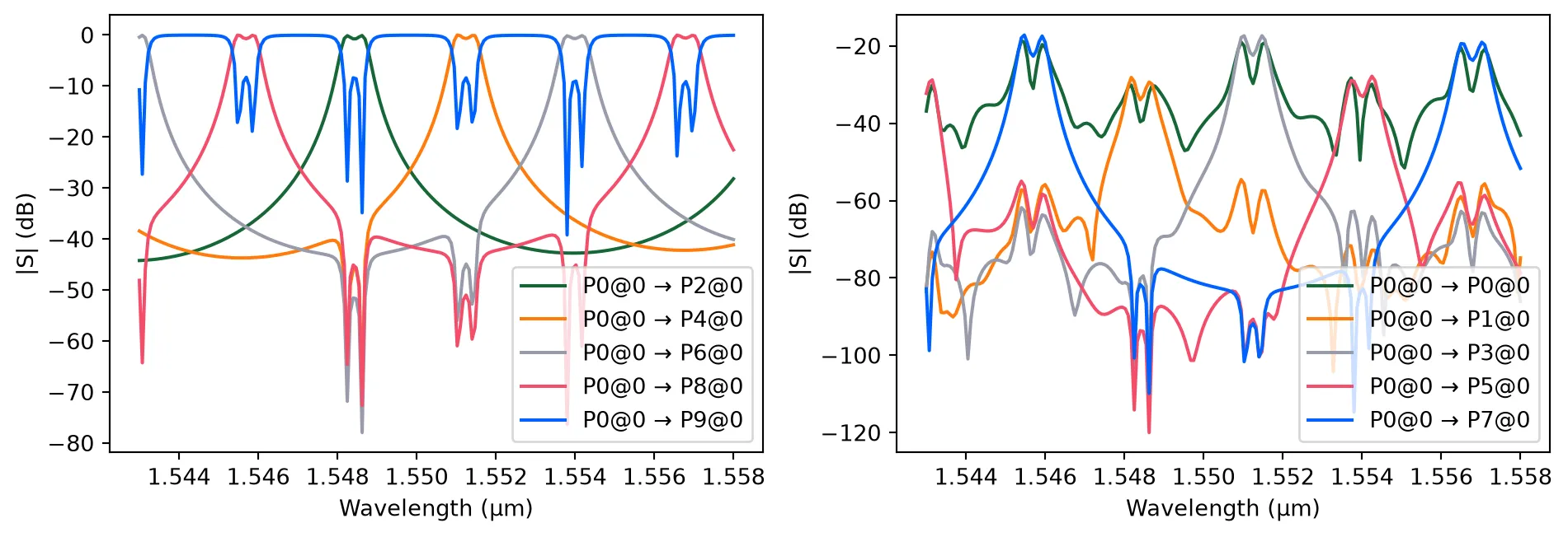
Thermo-Optic Phase Shifter
Section titled “Thermo-Optic Phase Shifter”@pf.parametric_component(name_prefix="Thermo-Optic Phase Shifter")def thermo_optic_phase_shifter( *, heater_length=100, # heater length (µm) heater_width=5, # heater width (µm) pad_width=25, # bond pad width (µm) heater_overlap=5, # heater overlap into pad (µm) dn_dT=1.8e-4, # Temperature sensitivity for effective index (K⁻¹) temperature=293.0, # Waveguide temperature (K)): """ Thermo-optic phase shifter using a resistive heater.
Architecture: - Straight waveguide - Resistive heater (M1_heater) above waveguide - Bond pads (M2_router) for electrical connections
Phase shift achieved through the thermo-optic effect: Δφ ≈ (2π/λ) × dn/dT × ΔT × L
For Si at 1550 nm: dn/dT ≈ 1.8×10⁻⁴ K⁻¹ (as an approximation, same value can be used for effective index) Typical efficiency: ~10-20 mW for π phase shift """ # Create a straight waveguide swg = pf.parametric.straight(length=heater_length) thermal_model = pf.AnalyticWaveguideModel( n_eff=n_eff, reference_frequency=freq0, length=heater_length, propagation_loss=propagation_loss, n_group=n_group, dn_dT=dn_dT, temperature=temperature, ) swg.add_model(thermal_model)
# Create bond pads pad1 = pf.Path((-pad_width * 1.5, 0), width=pad_width).segment( (-0.5 * pad_width, 0) ) pad2 = pad1.copy() pad2.x_min = heater_length + 0.5 * pad_width
# Add terminals signal_pad = pf.Terminal("M2_router", pad1.copy()) ground_pad = pf.Terminal("M2_router", pad2.copy()) swg.add_terminal([signal_pad, ground_pad])
# Create heater path # Path: pad1 → taper → narrow heater → taper → pad2 heater = ( pf.Path((-0.5 * pad_width - heater_overlap, 0), pad_width) .segment((-0.5 * pad_width, 0), pad_width) .segment((0, 0), heater_width) .segment((heater_length, 0), heater_width) .segment((heater_length + 0.5 * pad_width, 0), pad_width) .segment((heater_length + 0.5 * pad_width + heater_overlap, 0), pad_width) )
# Add pads and heater to component swg.add("M2_router", pad1, pad2) swg.add("M1_heater", heater)
return swg
heater = thermo_optic_phase_shifter()viewer(heater)
Thermo-Optic Tuning Verification This simulation compares the phase response of the heater at two different temperatures (300 K and 330 K) to verify the tuning efficiency. By extracting the phase of the parameter, we can estimate the phase shift per degree Kelvin, ensuring the shifter provides sufficient range for thermal compensation or signal modulation.
# Compare phase response at two temperatures to estimate thermo-optic tuningheater.update(temperature=330)s_heater_hot = heater.s_matrix(freqs)heater.update(temperature=293)s_heater_cold = heater.s_matrix(freqs)plt.plot( wavelengths, np.unwrap(np.angle(s_heater_cold[("P0@0", "P1@0")])), label="Cold (293 K)",)plt.plot( wavelengths, np.unwrap(np.angle(s_heater_hot[("P0@0", "P1@0")])), label="Hot (330 K)",)plt.xlabel("Wavelength (µm)")plt.ylabel("Phase (rad)")plt.legend()plt.grid(True)plt.tight_layout()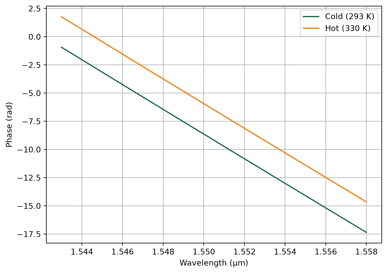
PN Phase Shifter
Section titled “PN Phase Shifter”An MZM converts phase modulation into intensity modulation using two interferometer arms with phase shifters.
Design Tip: MZM Length vs. Extinction Ratio
Trade-off: Determining the optimal phase shifter length is a balance between signal quality and performance.
- Too Short: You won’t achieve the required phase shift for your available voltage swing (), resulting in a poor Extinction Ratio (ER) (the “eye” won’t open fully).
- Too Long: You get excellent ER, but you suffer from higher optical loss (absorption from dopants) and a larger footprint.
The Math: To find the “sweet spot” (minimum length for a target ER), we work backward from the desired contrast:
-
Target Phase Shift (): For a push-pull MZM biased at quadrature, the ER is determined by the peak phase excursion :
-
Required : We calculate how efficient the modulator needs to be to achieve that given your drive voltage (where ):
-
Required Length (): Finally, we use the modulator’s efficiency metric, to find the physical length:
def calculate_mzm_length(target_er_db, vpi_l, v_applied):    """    Calculates the required length of an MZM for a given Extinction Ratio.    The Bias point is assumed to be 'quadrature' (max slope) for this calculation.
    Parameters:    - target_er_db: Desired Extinction Ratio in dB    - vpi_l: Push-Pull Drive Modulation efficiency product (V*cm)    - v_applied: Peak-to-peak drive voltage (Volts)
    Returns:    - length: Required length in um    """
    # Convert ER from dB to linear power ratio (Pmax / Pmin)    er_linear = 10 ** (target_er_db / 10.0)
    # Determine the required modulation index (sin(phi))    sin_phi = (er_linear - 1) / (er_linear + 1)
    # Calculate the phase shift (phi) in radians    phi_rad = np.asin(sin_phi)
    # Determine V_peak (half of v_applied)    v_peak = v_applied / 2.0
    # Calculate the required Half-Wave Voltage (V_pi)    if phi_rad == 0:        return 0.0, 0.0  # Avoid division by zero
    v_pi_req = (np.pi * v_peak) / phi_rad
    # Calculate required Length    length = vpi_l / v_pi_req * 1e4
    return length
# --- Configuration ---target_er = 3.0  # dBvpi_L_v_cm = 1.0  # Push-pull drive (V.cm)voltage_pp = 2.0  # Volts
# --- Calculation ---ps_length = calculate_mzm_length(target_er, vpi_L_v_cm, voltage_pp)
Important Note: The value used above is for the push-pull system (combined efficiency). When defining the physics for a single phase-shifter arm (as we do in the component definition below), use twice this value (i.e., ).
RF Design & Impedance Matching
Section titled “RF Design & Impedance Matching”High-speed traveling-wave modulators require careful RF engineering to ensure the electrical signal efficiently drives the optical phase shifter without debilitating reflections. We define an RF CPW port spec so electro-optic components can expose consistent electrical terminals.
Design Tip: A complete physical model of a PN modulator must account for the distributed RC loading of the active PN junction, which lowers the transmission line’s impedance and slows the RF phase velocity. Because modeling this active loading is highly complex, we will start by designing a baseline, unloaded 50 Ω Coplanar Waveguide (CPW).
The primary physical knobs for tuning the characteristic impedance of a CPW are the signal trace width and the gap spacing. Two quick rules of thumb:
- Increasing the gap increases the impedance (less capacitive coupling to ground).
- Increasing the signal width decreases the impedance (more surface area, higher capacitance).
# Create a CPW port spec for RF electrodesfreqs_rf = np.linspace(2, 30, 11) * 1e9cpw_spec = pf.cpw_spec("M2_router", signal_width=35.0, gap=10.0, ground_width=75)tech.add_port("CPW", cpw_spec)Layers
| Name | Layer | Description | Color | Pattern | Device marker | Conductive | Min. width (μm) | Min. spacing (μm) |
|---|---|---|---|---|---|---|---|---|
| Si | (1, 0) | SiEPIC - Waveguide | #ff80a818 | \\ | ||||
| PinRec | (1, 10) | SiEPIC | #ff80a818 | xx | ||||
| PinRecM | (1, 11) | SiEPIC | #80000018 | + | ||||
| Si Slab | (2, 0) | Dedicated Run Layers - Device…… Layer Partial Etch | #c080ff18 | / | ||||
| Direct Metal | (5, 0) | Dedicated Run Layers | #80a8ff18 | || | ||||
| Oxide open to BOX | (6, 0) | Dedicated Run Layers | #ff000018 | - | ||||
| Text | (10, 0) | Text-Not Fabricated | #00000018 | hollow | ||||
| M1_heater | (11, 0) | TiW Heater | #0000ff18 | \\ | ||||
| M2_router | (12, 0) | TiW/Au Routing Bilayer | #ffbf0018 | // | ||||
| M_Open | (13, 0) | Bond Pad Open | #80005718 | \\ | ||||
| Si n | (20, 0) | Dedicated Run Layers | #afff8018 | - | ||||
| Si p | (21, 0) | Dedicated Run Layers | #ffd9df18 | = | ||||
| Si n+ | (22, 0) | Dedicated Run Layers | #ff800018 | x | ||||
| Si p+ | (23, 0) | Dedicated Run Layers | #ddff0018 | xx | ||||
| Si n++ | (24, 0) | Dedicated Run Layers | #00ffff18 | + | ||||
| Si p++ | (25, 0) | Dedicated Run Layers | #00800018 | ++ | ||||
| ANT Reserved | (31, 0) | SiEPIC/ANT Reserved | #9580ff18 | / | ||||
| ANT Reserved 1 | (33, 0) | ANT Reserved | #9580ff18 | / | ||||
| Via to silicon | (40, 0) | Dedicated Run Layers | #0000ff18 | . | ||||
| DevRec | (68, 0) | SiEPIC | #00800018 | . | ||||
| FbrTgt | (81, 0) | SiEPIC/Dedicated Run Layers | #80808018 | ++ | ||||
| ANT Reserved 2 | (102, 0) | ANT Reserved | #9580ff18 | / | ||||
| ANT Reserved 3 | (110, 0) | ANT Reserved | #9580ff18 | / | ||||
| Custom Dicing | (189, 0) | #00000018 | hollow | |||||
| SEM Imaging | (200, 0) | #ff000018 | x | |||||
| Deep Trench | (201, 0) | #00ff0018 | . | |||||
| Deep Trench Handling Exclusion | (202, 0) | #00760018 | : | |||||
| Thermal Isolation Trenches | (203, 0) | #00800018 | \ | |||||
| Laser Integration Shelf | (205, 0) | Dedicated Run Layers | #69ff0518 | xx | ||||
| Floor Plan-Not Fabricated | (290, 0) | #c080ff18 | hollow | |||||
Error: device layer width is…… less than design rule | (301, 0) | DRC Errors | #80005718 | = | ||||
Error: device layer spacing is…… less than design rule | (301, 1) | DRC Errors | #80005718 | - | ||||
Warning: polygons/paths on…… PinRec layer (1/10) will NOT be fabricated | (301, 2) | DRC Errors | #80005718 | || | ||||
Error: direct metal width is…… less than 5 microns | (305, 0) | DRC Errors | #80808018 | ++ | ||||
Error: direct metal spacing is…… less than 10 microns | (305, 1) | DRC Errors | #80808018 | + | ||||
Error: TiW width is less than 3…… microns | (311, 0) | DRC Errors | #ffa08018 | // | ||||
Error: TiW spacing is less than…… 3 microns | (311, 1) | DRC Errors | #ffa08018 | / | ||||
Error: Al width is less than…… design rule | (312, 0) | DRC Errors | #00ffff18 | | | ||||
Error: Al spacing is less than…… design rule | (312, 1) | DRC Errors | #00ffff18 | // | ||||
Error: Spacing between TiW and…… Al is less than 5 microns | (312, 3) | DRC Errors | #00ffff18 | \\ | ||||
Error: Oxide window width is…… less than 10 microns | (313, 0) | DRC Errors | #01ff6b18 | || | ||||
Error: Oxide window spacing is…… less than 10 microns | (313, 1) | DRC Errors | #01ff6b18 | | | ||||
Error: Oxide window is not…… placed over Al | (313, 2) | DRC Errors | #01ff6b18 | // | ||||
| Standard Design Area | (350, 0) | DRC Errors | #ddff0018 | \ | ||||
Error: Features outside design…… area. Verify design size and centering. | (350, 1) | DRC Errors | #ddff0018 | : | ||||
Error: Dicing lane width is…… less than 100 microns | (389, 0) | DRC Errors | #ff00ff18 | ++ | ||||
Error: Spacing between dicing…… lane and devices is less than 50 microns | (389, 1) | DRC Errors | #ff00ff18 | + | ||||
Error: SEM width is less than…… 500 nm | (400, 0) | DRC Errors | #ff9d9d18 | x | ||||
| Deep Trench Design Area | (401, 0) | DRC Errors | #80a8ff18 | xx | ||||
Error: Metal, SEM, or handling…… region overlap with deep trenches. Verify design centering | (401, 1) | DRC Errors | #80a8ff18 | x | ||||
Warning: Silicon features…… outside deep trench design area. Verify accuracy before submission | (401, 2) | DRC Errors | #80a8ff18 | = | ||||
Error: Spacing between metal…… and deep trench is less than 30 microns | (401, 3) | DRC Errors | #80a8ff18 | - | ||||
Error: Deep trench width is…… less than 260 microns | (401, 4) | DRC Errors | #80a8ff18 | || | ||||
Error: Deep trench handling…… area missing. Please add handling area of size shown by polygons | (402, 0) | DRC Errors | #ff000018 | + | ||||
Error: Features inside deep…… trench handling area | (402, 1) | DRC Errors | #ff000018 | xx | ||||
Error: Thermal isolation width…… is less than design rule | (403, 0) | DRC Errors | #50008018 | ++ | ||||
Error: Thermal isolation…… spacing is less than design rule | (403, 1) | DRC Errors | #50008018 | + | ||||
Error: Spacing between thermal…… isolation and metal is less than design rule | (403, 2) | DRC Errors | #50008018 | xx | ||||
Error: Thermal isolation and…… device layer overlap, or spacing is less than design rule | (403, 3) | DRC Errors | #50008018 | x | ||||
Dream Photonics Black Box-Not…… Fabricated | (998, 0) | #00000018 | hollow | |||||
| Errors | (999, 0) | SiEPIC | #0000ff18 | || |
Extrusion specs
| # | Mask | Limits (μm) | Sidewall (°) | Opt. Medium | Elec. Medium |
|---|---|---|---|---|---|
| 0 | () | -inf, 0 | 0 | cSi_Li1993_293K | Si |
| 1 | () | -2, 1.8 | 0 | SiO2_Palik_LowLoss | SiO2 |
| 2 | 'M1_heater'**0.3 | 1.5, 2 | 0 | SiO2_Palik_LowLoss | SiO2 |
| 3 | 'M2_router'**0.3 | 1.5, 4 | 0 | SiO2_Palik_LowLoss | SiO2 |
| 4 | 'M1_heater' | 1.5, 1.7 | 0 | cSi_Li1993_293K | LossyMetalMedium……(frequency_range=(100000000.0, 200000000000.0), conductivity=0.2, fit_param={'max_num_poles': 16}) |
| 5 | 'M2_router' | 1.7, 3.7 | 0 | Al_Rakic1995 | LossyMetalMedium……(frequency_range=(100000000.0, 200000000000.0), conductivity=38.0, fit_param={'max_num_poles': 16}) |
| 6 | 'M_Open' | 3.7, 4 | 0 | Medium() | Medium() |
| 7 | 'Oxide open to BOX' | 0, inf | 0 | Medium() | Medium() |
| 8 | 'Si' | 0, 0.22 | 0 | cSi_Li1993_293K | Si |
| 9 | 'Si Slab' | 0, 0.09 | 0 | cSi_Li1993_293K | Si |
| 10 | 'Deep Trench' + 'Thermal…… Isolation Trenches' | -inf, inf | 0 | Medium() | Medium() |
Ports
| Name | Classification | Description | Width (μm) | Limits (μm) | Radius (μm) | Modes | Target n_eff | Path profiles (μm) | Voltage path | Current path |
|---|---|---|---|---|---|---|---|---|---|---|
| CPW | electrical | CPW (signal width: 35.0, gap:…… 10.0) | 203 | -200.426, 205.826 | 0 | 1 | auto | 'gnd0'@'M2_router': 75 (-65),…… 'gnd1'@'M2_router': 75 (+65), 'signal'@'M2_router': 35 | (27.5, 2.7) (17.5, 2.7) | (22.5, 8.7) (-22.5, 8.7)…… (-22.5, -3.3) (22.5, -3.3) |
| MM_TE_1550_2000 | optical | Multimode Strip TE 1550 nm,…… w=2000 nm | 6 | -2, 2.22 | 0 | 10 | 3.5 | 'Si': 2 | ||
| MM_TE_1550_3000 | optical | Multimode Strip TE 1550 nm,…… w=3000 nm | 6 | -2, 2.22 | 0 | 15 | 3.5 | 'Si': 3 | ||
| Rib_TE_1310_350 | optical | Rib (90 nm slab) TE 1310 nm,…… w=350 nm | 2.35 | -0.6, 0.82 | 0 | 1 | 3.5 | 'Si': 0.35, 'Si Slab': 3 | ||
| Rib_TE_1550_500 | optical | Rib (90 nm slab) TE 1550 nm,…… w=500 nm | 2.5 | -0.6, 0.82 | 0 | 1 | 3.5 | 'Si': 0.5, 'Si Slab': 3 | ||
| Slot_TE_1550_500 | optical | Slot TE 1550 nm, w=500 nm,…… gap=100nm | 3 | -1, 1.22 | 0 | 1 | 3.5 | 'Si': 0.2 (-0.15), 'Si': 0.2…… (+0.15) | ||
| TE-TM_1550_450 | optical | Strip TE-TM 1550, w=450 nm | 2.2 | -1, 1.22 | 0 | 2 | 3.5 | 'Si': 0.45 | ||
| TE_1310_350 | optical | Strip TE 1310 nm, w=350 nm | 1.5 | -0.6, 0.82 | 0 | 1 | 3.5 | 'Si': 0.35 | ||
| TE_1310_410 | optical | Strip TE 1310 nm, w=410 nm | 1.5 | -0.6, 0.82 | 0 | 1 | 3.5 | 'Si': 0.41 | ||
| TE_1550_500 | optical | Strip TE 1550 nm, w=500 nm | 1.5 | -0.6, 0.82 | 0 | 1 | 3.5 | 'Si': 0.5 | ||
| TM_1310_350 | optical | Strip TM 1310 nm, w=350 nm | 1.5 | -0.6, 0.82 | 0 | 1 + 1 (TM) | 3.5 | 'Si': 0.35 | ||
| TM_1550_500 | optical | Strip TM 1550 nm, w=500 nm | 1.5 | -0.6, 0.82 | 0 | 1 + 1 (TM) | 3.5 | 'Si': 0.5 | ||
| eskid_TE_1550 | optical | eskid TE 1550 | 2 | -0.7, 0.92 | 0 | 1 | 3.5 | 'Si': 0.35, 'Si': 0.06…… (+0.265), 'Si': 0.06 (-0.265), 'Si': 0.06 (+0.385), 'Si': 0.06 (-0.385), 'Si': 0.06 (+0.505), 'Si': 0.06 (-0.505), 'Si': 0.06 (+0.625), 'Si': 0.06 (-0.625) |
Background medium
- Optical: Medium()
- Electrical: Medium()
Solving the CPW mode gives the real impedance the phase shifter presents across the band.
# Calculate RF mode, impedance, and group index for the active phase shifter CPWmode_solver_rf, z0_rf = pf.port_modes(    cpw_spec, freqs_rf, mesh_refinement=30, impedance=True, group_index=True)
plt.plot(freqs_rf / 1e9, z0_rf.isel(mode_index=0).real)plt.xlabel("Frequency (GHz)")plt.ylabel("Real Impedance (Ω)")plt.show()
Uploading task 'Mode-ModeSolver…'Starting task 'Mode-ModeSolver': https://tidy3d.simulation.cloud/workbench?taskId=mo-3f5a4ea0-cc25-464c-8604-721c3926b0faDownloading data from 'Mode-ModeSolver'…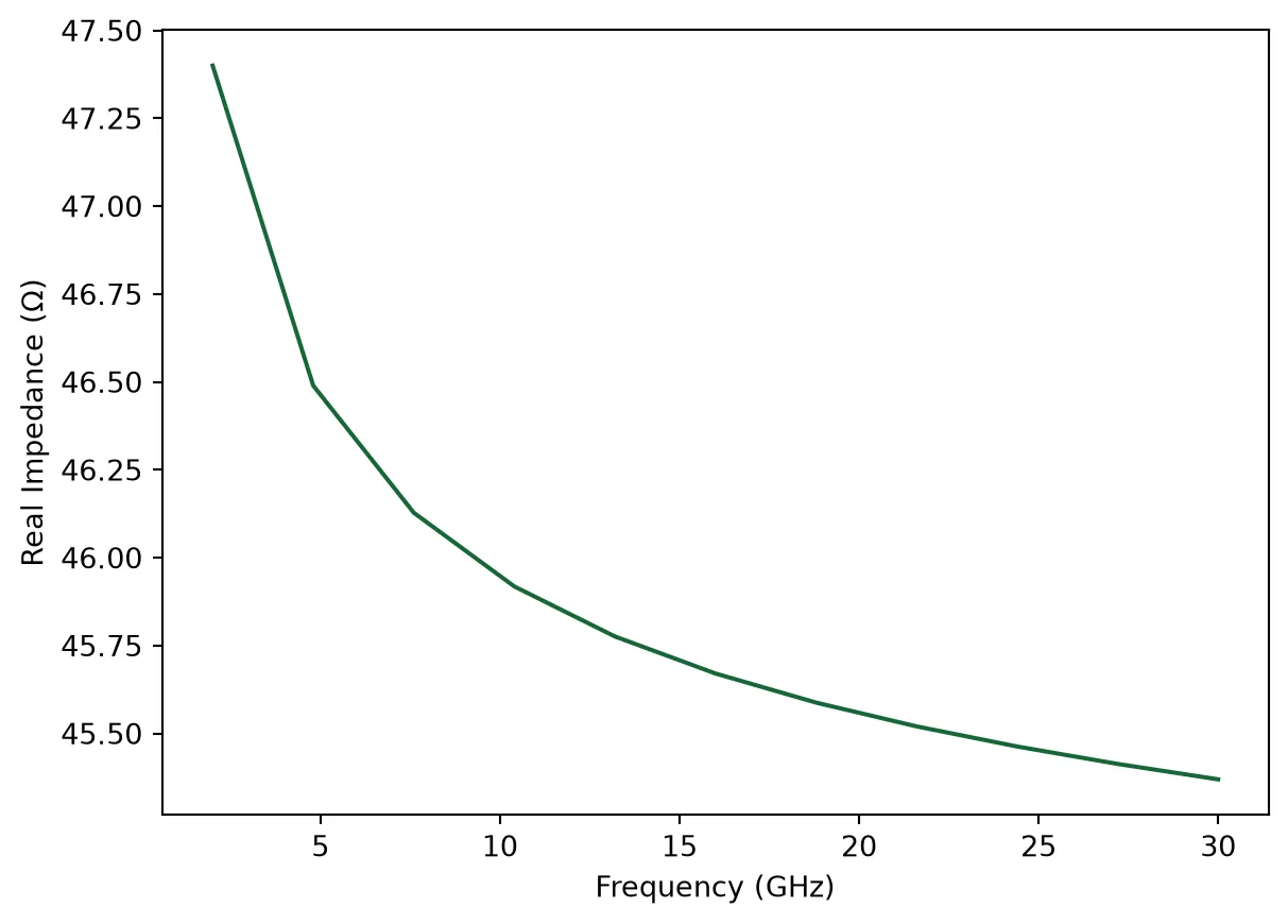
Design Tip: The RF probe pads themselves act as transmission lines. To ensure a clean signal transition from external RF probes (which are typically 50 Ω) onto the chip, we define a separate, wider CPW geometry for the Ground-Signal-Ground (GSG) pads and verify their impedance.
# Define a CPW port spec for the GSG padspad_size = 100.0pad_gap = 50.0 # (µm) gap distance from signal to groundcpw_spec_pad = pf.cpw_spec( "M2_router", signal_width=pad_size, gap=pad_gap, ground_width=pad_size)tech.add_port("CPW_Pad", cpw_spec_pad)Layers
| Name | Layer | Description | Color | Pattern | Device marker | Conductive | Min. width (μm) | Min. spacing (μm) |
|---|---|---|---|---|---|---|---|---|
| Si | (1, 0) | SiEPIC - Waveguide | #ff80a818 | \\ | ||||
| PinRec | (1, 10) | SiEPIC | #ff80a818 | xx | ||||
| PinRecM | (1, 11) | SiEPIC | #80000018 | + | ||||
| Si Slab | (2, 0) | Dedicated Run Layers - Device…… Layer Partial Etch | #c080ff18 | / | ||||
| Direct Metal | (5, 0) | Dedicated Run Layers | #80a8ff18 | || | ||||
| Oxide open to BOX | (6, 0) | Dedicated Run Layers | #ff000018 | - | ||||
| Text | (10, 0) | Text-Not Fabricated | #00000018 | hollow | ||||
| M1_heater | (11, 0) | TiW Heater | #0000ff18 | \\ | ||||
| M2_router | (12, 0) | TiW/Au Routing Bilayer | #ffbf0018 | // | ||||
| M_Open | (13, 0) | Bond Pad Open | #80005718 | \\ | ||||
| Si n | (20, 0) | Dedicated Run Layers | #afff8018 | - | ||||
| Si p | (21, 0) | Dedicated Run Layers | #ffd9df18 | = | ||||
| Si n+ | (22, 0) | Dedicated Run Layers | #ff800018 | x | ||||
| Si p+ | (23, 0) | Dedicated Run Layers | #ddff0018 | xx | ||||
| Si n++ | (24, 0) | Dedicated Run Layers | #00ffff18 | + | ||||
| Si p++ | (25, 0) | Dedicated Run Layers | #00800018 | ++ | ||||
| ANT Reserved | (31, 0) | SiEPIC/ANT Reserved | #9580ff18 | / | ||||
| ANT Reserved 1 | (33, 0) | ANT Reserved | #9580ff18 | / | ||||
| Via to silicon | (40, 0) | Dedicated Run Layers | #0000ff18 | . | ||||
| DevRec | (68, 0) | SiEPIC | #00800018 | . | ||||
| FbrTgt | (81, 0) | SiEPIC/Dedicated Run Layers | #80808018 | ++ | ||||
| ANT Reserved 2 | (102, 0) | ANT Reserved | #9580ff18 | / | ||||
| ANT Reserved 3 | (110, 0) | ANT Reserved | #9580ff18 | / | ||||
| Custom Dicing | (189, 0) | #00000018 | hollow | |||||
| SEM Imaging | (200, 0) | #ff000018 | x | |||||
| Deep Trench | (201, 0) | #00ff0018 | . | |||||
| Deep Trench Handling Exclusion | (202, 0) | #00760018 | : | |||||
| Thermal Isolation Trenches | (203, 0) | #00800018 | \ | |||||
| Laser Integration Shelf | (205, 0) | Dedicated Run Layers | #69ff0518 | xx | ||||
| Floor Plan-Not Fabricated | (290, 0) | #c080ff18 | hollow | |||||
Error: device layer width is…… less than design rule | (301, 0) | DRC Errors | #80005718 | = | ||||
Error: device layer spacing is…… less than design rule | (301, 1) | DRC Errors | #80005718 | - | ||||
Warning: polygons/paths on…… PinRec layer (1/10) will NOT be fabricated | (301, 2) | DRC Errors | #80005718 | || | ||||
Error: direct metal width is…… less than 5 microns | (305, 0) | DRC Errors | #80808018 | ++ | ||||
Error: direct metal spacing is…… less than 10 microns | (305, 1) | DRC Errors | #80808018 | + | ||||
Error: TiW width is less than 3…… microns | (311, 0) | DRC Errors | #ffa08018 | // | ||||
Error: TiW spacing is less than…… 3 microns | (311, 1) | DRC Errors | #ffa08018 | / | ||||
Error: Al width is less than…… design rule | (312, 0) | DRC Errors | #00ffff18 | | | ||||
Error: Al spacing is less than…… design rule | (312, 1) | DRC Errors | #00ffff18 | // | ||||
Error: Spacing between TiW and…… Al is less than 5 microns | (312, 3) | DRC Errors | #00ffff18 | \\ | ||||
Error: Oxide window width is…… less than 10 microns | (313, 0) | DRC Errors | #01ff6b18 | || | ||||
Error: Oxide window spacing is…… less than 10 microns | (313, 1) | DRC Errors | #01ff6b18 | | | ||||
Error: Oxide window is not…… placed over Al | (313, 2) | DRC Errors | #01ff6b18 | // | ||||
| Standard Design Area | (350, 0) | DRC Errors | #ddff0018 | \ | ||||
Error: Features outside design…… area. Verify design size and centering. | (350, 1) | DRC Errors | #ddff0018 | : | ||||
Error: Dicing lane width is…… less than 100 microns | (389, 0) | DRC Errors | #ff00ff18 | ++ | ||||
Error: Spacing between dicing…… lane and devices is less than 50 microns | (389, 1) | DRC Errors | #ff00ff18 | + | ||||
Error: SEM width is less than…… 500 nm | (400, 0) | DRC Errors | #ff9d9d18 | x | ||||
| Deep Trench Design Area | (401, 0) | DRC Errors | #80a8ff18 | xx | ||||
Error: Metal, SEM, or handling…… region overlap with deep trenches. Verify design centering | (401, 1) | DRC Errors | #80a8ff18 | x | ||||
Warning: Silicon features…… outside deep trench design area. Verify accuracy before submission | (401, 2) | DRC Errors | #80a8ff18 | = | ||||
Error: Spacing between metal…… and deep trench is less than 30 microns | (401, 3) | DRC Errors | #80a8ff18 | - | ||||
Error: Deep trench width is…… less than 260 microns | (401, 4) | DRC Errors | #80a8ff18 | || | ||||
Error: Deep trench handling…… area missing. Please add handling area of size shown by polygons | (402, 0) | DRC Errors | #ff000018 | + | ||||
Error: Features inside deep…… trench handling area | (402, 1) | DRC Errors | #ff000018 | xx | ||||
Error: Thermal isolation width…… is less than design rule | (403, 0) | DRC Errors | #50008018 | ++ | ||||
Error: Thermal isolation…… spacing is less than design rule | (403, 1) | DRC Errors | #50008018 | + | ||||
Error: Spacing between thermal…… isolation and metal is less than design rule | (403, 2) | DRC Errors | #50008018 | xx | ||||
Error: Thermal isolation and…… device layer overlap, or spacing is less than design rule | (403, 3) | DRC Errors | #50008018 | x | ||||
Dream Photonics Black Box-Not…… Fabricated | (998, 0) | #00000018 | hollow | |||||
| Errors | (999, 0) | SiEPIC | #0000ff18 | || |
Extrusion specs
| # | Mask | Limits (μm) | Sidewall (°) | Opt. Medium | Elec. Medium |
|---|---|---|---|---|---|
| 0 | () | -inf, 0 | 0 | cSi_Li1993_293K | Si |
| 1 | () | -2, 1.8 | 0 | SiO2_Palik_LowLoss | SiO2 |
| 2 | 'M1_heater'**0.3 | 1.5, 2 | 0 | SiO2_Palik_LowLoss | SiO2 |
| 3 | 'M2_router'**0.3 | 1.5, 4 | 0 | SiO2_Palik_LowLoss | SiO2 |
| 4 | 'M1_heater' | 1.5, 1.7 | 0 | cSi_Li1993_293K | LossyMetalMedium……(frequency_range=(100000000.0, 200000000000.0), conductivity=0.2, fit_param={'max_num_poles': 16}) |
| 5 | 'M2_router' | 1.7, 3.7 | 0 | Al_Rakic1995 | LossyMetalMedium……(frequency_range=(100000000.0, 200000000000.0), conductivity=38.0, fit_param={'max_num_poles': 16}) |
| 6 | 'M_Open' | 3.7, 4 | 0 | Medium() | Medium() |
| 7 | 'Oxide open to BOX' | 0, inf | 0 | Medium() | Medium() |
| 8 | 'Si' | 0, 0.22 | 0 | cSi_Li1993_293K | Si |
| 9 | 'Si Slab' | 0, 0.09 | 0 | cSi_Li1993_293K | Si |
| 10 | 'Deep Trench' + 'Thermal…… Isolation Trenches' | -inf, inf | 0 | Medium() | Medium() |
Ports
| Name | Classification | Description | Width (μm) | Limits (μm) | Radius (μm) | Modes | Target n_eff | Path profiles (μm) | Voltage path | Current path |
|---|---|---|---|---|---|---|---|---|---|---|
| CPW | electrical | CPW (signal width: 35.0, gap:…… 10.0) | 203 | -200.426, 205.826 | 0 | 1 | auto | 'gnd0'@'M2_router': 75 (-65),…… 'gnd1'@'M2_router': 75 (+65), 'signal'@'M2_router': 35 | (27.5, 2.7) (17.5, 2.7) | (22.5, 8.7) (-22.5, 8.7)…… (-22.5, -3.3) (22.5, -3.3) |
| CPW_Pad | electrical | CPW (signal width: 100.0, gap:…… 50.0) | 398 | -613.296, 618.696 | 0 | 1 | auto | 'gnd0'@'M2_router': 100 (-150),…… 'gnd1'@'M2_router': 100 (+150), 'signal'@'M2_router': 100 | (100, 2.7) (50, 2.7) | (75, 28.7) (-75, 28.7) (-75,…… -23.3) (75, -23.3) |
| MM_TE_1550_2000 | optical | Multimode Strip TE 1550 nm,…… w=2000 nm | 6 | -2, 2.22 | 0 | 10 | 3.5 | 'Si': 2 | ||
| MM_TE_1550_3000 | optical | Multimode Strip TE 1550 nm,…… w=3000 nm | 6 | -2, 2.22 | 0 | 15 | 3.5 | 'Si': 3 | ||
| Rib_TE_1310_350 | optical | Rib (90 nm slab) TE 1310 nm,…… w=350 nm | 2.35 | -0.6, 0.82 | 0 | 1 | 3.5 | 'Si': 0.35, 'Si Slab': 3 | ||
| Rib_TE_1550_500 | optical | Rib (90 nm slab) TE 1550 nm,…… w=500 nm | 2.5 | -0.6, 0.82 | 0 | 1 | 3.5 | 'Si': 0.5, 'Si Slab': 3 | ||
| Slot_TE_1550_500 | optical | Slot TE 1550 nm, w=500 nm,…… gap=100nm | 3 | -1, 1.22 | 0 | 1 | 3.5 | 'Si': 0.2 (-0.15), 'Si': 0.2…… (+0.15) | ||
| TE-TM_1550_450 | optical | Strip TE-TM 1550, w=450 nm | 2.2 | -1, 1.22 | 0 | 2 | 3.5 | 'Si': 0.45 | ||
| TE_1310_350 | optical | Strip TE 1310 nm, w=350 nm | 1.5 | -0.6, 0.82 | 0 | 1 | 3.5 | 'Si': 0.35 | ||
| TE_1310_410 | optical | Strip TE 1310 nm, w=410 nm | 1.5 | -0.6, 0.82 | 0 | 1 | 3.5 | 'Si': 0.41 | ||
| TE_1550_500 | optical | Strip TE 1550 nm, w=500 nm | 1.5 | -0.6, 0.82 | 0 | 1 | 3.5 | 'Si': 0.5 | ||
| TM_1310_350 | optical | Strip TM 1310 nm, w=350 nm | 1.5 | -0.6, 0.82 | 0 | 1 + 1 (TM) | 3.5 | 'Si': 0.35 | ||
| TM_1550_500 | optical | Strip TM 1550 nm, w=500 nm | 1.5 | -0.6, 0.82 | 0 | 1 + 1 (TM) | 3.5 | 'Si': 0.5 | ||
| eskid_TE_1550 | optical | eskid TE 1550 | 2 | -0.7, 0.92 | 0 | 1 | 3.5 | 'Si': 0.35, 'Si': 0.06…… (+0.265), 'Si': 0.06 (-0.265), 'Si': 0.06 (+0.385), 'Si': 0.06 (-0.385), 'Si': 0.06 (+0.505), 'Si': 0.06 (-0.505), 'Si': 0.06 (+0.625), 'Si': 0.06 (-0.625) |
Background medium
- Optical: Medium()
- Electrical: Medium()
The pads are much wider than the phase-shifter electrodes, so their impedance is checked separately.
# Calculate impedance for the pad CPW geometrymode_solver_pad, z0_pad = pf.port_modes(    cpw_spec_pad, freqs_rf, mesh_refinement=30, impedance=True, group_index=True)
plt.plot(freqs_rf / 1e9, z0_pad.isel(mode_index=0).real)plt.xlabel("Frequency (GHz)")plt.ylabel("Real Impedance (Ω)")plt.show()
Uploading task 'Mode-ModeSolver…'Starting task 'Mode-ModeSolver': https://tidy3d.simulation.cloud/workbench?taskId=mo-1385846b-7123-4b10-a512-9b88d139aecfDownloading data from 'Mode-ModeSolver'…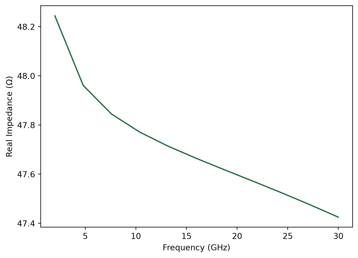
On-Chip Termination Material & Geometry
Section titled “On-Chip Termination Material & Geometry”To prevent electrical back-reflections at the end of the traveling-wave electrode, the line must be terminated with an on-chip load matching the characteristic impedance (50 Ω). In a GSG (Ground-Signal-Ground) layout, this is efficiently achieved using two parallel 100 Ω resistors bridging the center signal trace to each ground trace.
Why use the Heater layer? Standard routing metals (like thick Aluminum or Copper) have high conductivity. If we tried to make a 100 Ω resistor out of standard routing metal, the trace would have to be microscopically narrow or incredibly long! Instead, we use the heater_metal layer (often TiN, TaN, or doped polysilicon). Because this layer is both physically thin () and has a lower conductivity (), it provides a high sheet resistance (), allowing us to hit 100 Ω with a compact, DRC-safe footprint.
# Calculate the required physical width for the 100 ohm termination resistors# We solve the resistance equation R = L / (sigma * W * t) for W.# Here, L is the distance the current travels (pad_gap).
heater_thickness = tech.parametric_kwargs["heater_thickness"]heater_conductivity = tech.parametric_kwargs["heater_metal"]["electrical"].conductivity
target_resistance = 100.0  # (Ohms) Two 100 Ohm resistors in parallel yield 50 Ohms
# Calculate required width (W = L / (R * sigma * t))termination_width = pad_gap / (    target_resistance * heater_conductivity * heater_thickness)
print(f"Required termination width for 100 Ohms: {termination_width:.2f} µm")
Required termination width for 100 Ohms: 12.50 µm@pf.parametric_component(name_prefix="PN Phase Shifter")def pn_phase_shifter( *, length=3000, # phase shifter length (µm) n_eff=n_eff_rib, # phase shifter effective index n_group=n_group_rib, # phase shifter group index ref_freq=freq0, # reference frequency for the effective and group indices propagation_loss=5e-4, # phase shifter propagation loss (dB/µm) v_piL=vpi_L_v_cm * 2 * 1e4, # Vpi.L (V.µm) f3db=50e9, # 3 dB bandwidth taper_length=10, # taper length (µm) i_width=0.15, # intrinsic region width (µm) p_width=0.5, # p-doping/n-doping width (µm) pp_width=1.0, # p++ doping/n++ doping width (µm) pad_size=pad_size, # RF pad size (µm) pad_distance=300, # pad distance from shifter (µm) pad_separation=pad_gap + pad_size, # pad separation (signal-ground) (µm) termination_width=termination_width, # Termination width): """ PN junction depletion-mode phase shifter for high-speed modulation.
Architecture: - Rib waveguide (wider than strip for lower loss) - PN junction laterally placed across waveguide - Doping regions: p-contact, N, N++ - Traveling-wave electrode (CPW) for high bandwidth - Dual-arm configuration for push-pull MZM
Physics: - Free-carrier plasma dispersion effect - Reverse-biased PN junction depletes carriers - Phase shift: Δφ ∝ ΔV × L
Specs: - Vπ·L: ~1-2 V·cm - Loss: < 5 dB/cm - Bandwidth: > 50 GHz """ rib_width = tech.ports["Rib_TE_1550_500"].width
# Create strip-to-rib tapers taper = pf.parametric.transition( port_spec1=port_spec, port_spec2=rib, length=taper_length, min_width=0.1 )
# Create straight rib section straight = pf.parametric.straight(port_spec=rib, length=length, name="PS Arm")
# Add virtual electrical port for time domain simulation elec_vir = pf.virtual_port_spec(classification="electrical") straight.add_port(pf.Port((length / 2, 0), -90, spec=elec_vir))
# Create top arm phase modulator mod_model = pf.AnalyticWaveguideModel( n_eff=n_eff, reference_frequency=ref_freq, length=length, propagation_loss=propagation_loss, n_group=n_group, v_piL=v_piL, ) mod_model.time_stepper = pf.PhaseModTimeStepper( length=length, n_eff=n_eff, n_group=n_group, v_piL=v_piL, propagation_loss=propagation_loss, f_3dB=f3db, )
straight.add_model(mod_model)
# Build component c = pf.Component()
# Each arm is a taper in, the rib section, and the same taper reversed on the way out. # The rib ports are named because its electrical port E0 would otherwise come first. arm_parts = {"taper": taper, "rib": straight} arm_sequence = "taper - P0:rib:P1 - P1:taper"
# Add first arm (top) arm = pf.reference_chain(arm_parts, arm_sequence) c.add(*arm) ps = arm[1]
c.add_port([arm[0]["P0"], arm[-1]["P0"]])
# Add doping regions to straight section doping_regions = [ # (center, width, layer) ((i_width + p_width) / 2, p_width, "Si n"), # N-doping ((i_width + pp_width) / 2 + p_width, pp_width, "Si n++"), # N++ doping (-(i_width + p_width) / 2, p_width, "Si p"), # P-doping (-(i_width + pp_width) / 2 - p_width, pp_width, "Si p++"), # P++ doping ]
for y, width, layer in doping_regions: straight.add( layer, pf.Rectangle(center=(length / 2, y), size=(length, width)), # pf.Rectangle(corner2=(length, -y), size=(length, width)), )
# Add CPW transmission line w1, off1, _ = cpw_spec.path_profiles["gnd1"] w0, off0, _ = cpw_spec.path_profiles["signal"] offset = (w0 / 2 + off1 - w1 / 2) / 2
cpw = pf.parametric.straight(port_spec=cpw_spec, length=length + 2 * taper_length)
cpw_ref = pf.Reference(cpw, (0, -offset)) c.add(cpw_ref)
# Add second arm (bottom, for push-pull operation) arm_2 = pf.reference_chain(arm_parts, arm_sequence) for ref in arm_2: ref.translate((0, -2 * offset)) c.add(*arm_2) ps_2 = arm_2[1]
c.add_port([arm_2[0]["P0"], arm_2[-1]["P0"], ps["E0"], ps_2["E0"]])
# Add RF terminals (pads) c.add_terminal( { f"{name}:{side}": pf.Terminal( "M2_router", pf.Rectangle(center=(x, y - offset), size=(pad_size, pad_size)), ) for x, side in [ (-pad_distance - pad_size / 2, "in"), (length + 2 * taper_length + pad_distance + pad_size / 2, "out"), ] for y, name in [ (-pad_separation, "gnd0"), (0, "signal"), (pad_separation, "gnd1"), ] } )
# Route from pads to CPW for p, side in [("E0", "in"), ("E1", "out")]: for name in ("gnd0", "signal", "gnd1"): c.add( pf.parametric.route_taper( terminal1=c[f"{name}:{side}"], terminal2=cpw_ref[p].terminals(name) ) )
# Add integrated termination at input c.add( "M1_heater", pf.Path(c["gnd0:in"].center(), termination_width).segment( c["gnd1:in"].center() ), )
# Add circuit model c.add_model(pf.CircuitModel(), "Circuit")
# Removing cpw models and ports to avoid warnings and errors because this component is not involved in circuit simulation cpw.remove_model(list(cpw.models.keys())[0]) for port in list(cpw.ports.keys()): cpw.remove_port(port)
return c
ps = pn_phase_shifter(length=ps_length)viewer(ps);fill:%23221f20;font-weight:bold;font-size:23.592700px;}.terminal{fill:none;stroke:%23805080;stroke-width:2.949088;}.dashed{stroke-dasharray:14.745438,8.847263;}.port{fill:none;stroke:%23805080;stroke-width:5.898175;}.virtual-connection{fill:none;stroke:%23907090;stroke-width:4.423631;}.layer_31_0{stroke:%238c78ef;fill:url(%23pat-layer_31_0);fill-opacity:0.492;}.label_31_0{fill:%238c78ef;}.layer_33_0{stroke:%238c78ef;fill:url(%23pat-layer_33_0);fill-opacity:0.492;}.label_33_0{fill:%238c78ef;}.layer_102_0{stroke:%238c78ef;fill:url(%23pat-layer_102_0);fill-opacity:0.492;}.label_102_0{fill:%238c78ef;}.layer_110_0{stroke:%238c78ef;fill:url(%23pat-layer_110_0);fill-opacity:0.492;}.label_110_0{fill:%238c78ef;}.layer_189_0{stroke:%23000000;fill:none;}.label_189_0{fill:%23000000;}.layer_201_0{stroke:%2300ee00;fill:url(%23pat-layer_201_0);fill-opacity:0.492;}.label_201_0{fill:%2300ee00;}.layer_401_0{stroke:%236a8ad2;fill:url(%23pat-layer_401_0);fill-opacity:0.492;}.label_401_0{fill:%236a8ad2;}.layer_202_0{stroke:%23007600;fill:url(%23pat-layer_202_0);fill-opacity:0.492;}.label_202_0{fill:%23007600;}.layer_68_0{stroke:%23008000;fill:url(%23pat-layer_68_0);fill-opacity:0.492;}.label_68_0{fill:%23008000;}.layer_5_0{stroke:%236a8ad2;fill:url(%23pat-layer_5_0);fill-opacity:0.492;}.label_5_0{fill:%236a8ad2;}.layer_998_0{stroke:%23000000;fill:none;}.label_998_0{fill:%23000000;}.layer_312_1{stroke:%2300b8b8;fill:url(%23pat-layer_312_1);fill-opacity:0.492;}.label_312_1{fill:%2300b8b8;}.layer_312_0{stroke:%2300b8b8;fill:url(%23pat-layer_312_0);fill-opacity:0.492;}.label_312_0{fill:%2300b8b8;}.layer_402_0{stroke:%23ff0000;fill:url(%23pat-layer_402_0);fill-opacity:0.492;}.label_402_0{fill:%23ff0000;}.layer_401_4{stroke:%236a8ad2;fill:url(%23pat-layer_401_4);fill-opacity:0.492;}.label_401_4{fill:%236a8ad2;}.layer_389_0{stroke:%23ff00ff;fill:url(%23pat-layer_389_0);fill-opacity:0.492;}.label_389_0{fill:%23ff00ff;}.layer_402_1{stroke:%23ff0000;fill:url(%23pat-layer_402_1);fill-opacity:0.492;}.label_402_1{fill:%23ff0000;}.layer_350_1{stroke:%23697a00;fill:url(%23pat-layer_350_1);fill-opacity:0.492;}.label_350_1{fill:%23697a00;}.layer_401_1{stroke:%236a8ad2;fill:url(%23pat-layer_401_1);fill-opacity:0.492;}.label_401_1{fill:%236a8ad2;}.layer_313_2{stroke:%2301d95b;fill:url(%23pat-layer_313_2);fill-opacity:0.492;}.label_313_2{fill:%2301d95b;}.layer_313_1{stroke:%2301d95b;fill:url(%23pat-layer_313_1);fill-opacity:0.492;}.label_313_1{fill:%2301d95b;}.layer_313_0{stroke:%2301d95b;fill:url(%23pat-layer_313_0);fill-opacity:0.492;}.label_313_0{fill:%2301d95b;}.layer_400_0{stroke:%23a96868;fill:url(%23pat-layer_400_0);fill-opacity:0.492;}.label_400_0{fill:%23a96868;}.layer_312_3{stroke:%2300b8b8;fill:url(%23pat-layer_312_3);fill-opacity:0.492;}.label_312_3{fill:%2300b8b8;}.layer_389_1{stroke:%23ff00ff;fill:url(%23pat-layer_389_1);fill-opacity:0.492;}.label_389_1{fill:%23ff00ff;}.layer_401_3{stroke:%236a8ad2;fill:url(%23pat-layer_401_3);fill-opacity:0.492;}.label_401_3{fill:%236a8ad2;}.layer_403_2{stroke:%23500080;fill:url(%23pat-layer_403_2);fill-opacity:0.492;}.label_403_2{fill:%23500080;}.layer_403_3{stroke:%23500080;fill:url(%23pat-layer_403_3);fill-opacity:0.492;}.label_403_3{fill:%23500080;}.layer_403_1{stroke:%23500080;fill:url(%23pat-layer_403_1);fill-opacity:0.492;}.label_403_1{fill:%23500080;}.layer_403_0{stroke:%23500080;fill:url(%23pat-layer_403_0);fill-opacity:0.492;}.label_403_0{fill:%23500080;}.layer_311_1{stroke:%23ac6c56;fill:url(%23pat-layer_311_1);fill-opacity:0.492;}.label_311_1{fill:%23ac6c56;}.layer_311_0{stroke:%23ac6c56;fill:url(%23pat-layer_311_0);fill-opacity:0.492;}.label_311_0{fill:%23ac6c56;}.layer_301_1{stroke:%23800057;fill:url(%23pat-layer_301_1);fill-opacity:0.492;}.label_301_1{fill:%23800057;}.layer_301_0{stroke:%23800057;fill:url(%23pat-layer_301_0);fill-opacity:0.492;}.label_301_0{fill:%23800057;}.layer_305_1{stroke:%23808080;fill:url(%23pat-layer_305_1);fill-opacity:0.492;}.label_305_1{fill:%23808080;}.layer_305_0{stroke:%23808080;fill:url(%23pat-layer_305_0);fill-opacity:0.492;}.label_305_0{fill:%23808080;}.layer_999_0{stroke:%230000ff;fill:url(%23pat-layer_999_0);fill-opacity:0.492;}.label_999_0{fill:%230000ff;}.layer_81_0{stroke:%23808080;fill:url(%23pat-layer_81_0);fill-opacity:0.492;}.label_81_0{fill:%23808080;}.layer_290_0{stroke:%23a46eda;fill:none;}.label_290_0{fill:%23a46eda;}.layer_205_0{stroke:%2349b203;fill:url(%23pat-layer_205_0);fill-opacity:0.492;}.label_205_0{fill:%2349b203;}.layer_11_0{stroke:%230000ff;fill:url(%23pat-layer_11_0);fill-opacity:0.492;}.label_11_0{fill:%230000ff;}.layer_12_0{stroke:%23a57b00;fill:url(%23pat-layer_12_0);fill-opacity:0.492;}.label_12_0{fill:%23a57b00;}.layer_13_0{stroke:%23800057;fill:url(%23pat-layer_13_0);fill-opacity:0.492;}.label_13_0{fill:%23800057;}.layer_6_0{stroke:%23ff0000;fill:url(%23pat-layer_6_0);fill-opacity:0.492;}.label_6_0{fill:%23ff0000;}.layer_1_10{stroke:%23c96585;fill:url(%23pat-layer_1_10);fill-opacity:0.492;}.label_1_10{fill:%23c96585;}.layer_1_11{stroke:%23800000;fill:url(%23pat-layer_1_11);fill-opacity:0.492;}.label_1_11{fill:%23800000;}.layer_200_0{stroke:%23ff0000;fill:url(%23pat-layer_200_0);fill-opacity:0.492;}.label_200_0{fill:%23ff0000;}.layer_1_0{stroke:%23c96585;fill:url(%23pat-layer_1_0);fill-opacity:0.492;}.label_1_0{fill:%23c96585;}.layer_2_0{stroke:%23a46eda;fill:url(%23pat-layer_2_0);fill-opacity:0.492;}.label_2_0{fill:%23a46eda;}.layer_20_0{stroke:%2353793d;fill:url(%23pat-layer_20_0);fill-opacity:0.492;}.label_20_0{fill:%2353793d;}.layer_22_0{stroke:%23ec7600;fill:url(%23pat-layer_22_0);fill-opacity:0.492;}.label_22_0{fill:%23ec7600;}.layer_24_0{stroke:%2300b8b8;fill:url(%23pat-layer_24_0);fill-opacity:0.492;}.label_24_0{fill:%2300b8b8;}.layer_21_0{stroke:%23736264;fill:url(%23pat-layer_21_0);fill-opacity:0.492;}.label_21_0{fill:%23736264;}.layer_23_0{stroke:%23697a00;fill:url(%23pat-layer_23_0);fill-opacity:0.492;}.label_23_0{fill:%23697a00;}.layer_25_0{stroke:%23008000;fill:url(%23pat-layer_25_0);fill-opacity:0.492;}.label_25_0{fill:%23008000;}.layer_350_0{stroke:%23697a00;fill:url(%23pat-layer_350_0);fill-opacity:0.492;}.label_350_0{fill:%23697a00;}.layer_10_0{stroke:%23000000;fill:none;}.label_10_0{fill:%23000000;}.layer_203_0{stroke:%23008000;fill:url(%23pat-layer_203_0);fill-opacity:0.492;}.label_203_0{fill:%23008000;}.layer_40_0{stroke:%230000ff;fill:url(%23pat-layer_40_0);fill-opacity:0.492;}.label_40_0{fill:%230000ff;}.layer_401_2{stroke:%236a8ad2;fill:url(%23pat-layer_401_2);fill-opacity:0.492;}.label_401_2{fill:%236a8ad2;}.layer_301_2{stroke:%23800057;fill:url(%23pat-layer_301_2);fill-opacity:0.492;}.label_301_2{fill:%23800057;}</style><defs><path id=%22port-symbol%22 class=%22port%22 d=%22M 0,-11.796350 L 17.694525,0 0,11.796350%22 /><path id=%22ref-port-symbol%22 class=%22port%22 style=%22stroke-opacity:0.33;%22 d=%22M 0,-8.847263 C 11.796350,-8.847263 11.796350,8.847263 0,8.847263%22 /><circle id=%22port-bend-symbol%22 style=%22stroke-width:0;stroke:none;fill:%23805080;fill-opacity:1;%22 cx=%220%22 cy=%220%22 r=%225.308358%22 /><circle id=%22connection-symbol%22 style=%22stroke-width:0;stroke:none;fill:%23907090;fill-opacity:1;%22 cx=%220%22 cy=%220%22 r=%226.193084%22 /><pattern id=%22pat-layer_31_0%22 patternUnits=%22userSpaceOnUse%22 width=%2214.745438%22 height=%2214.745438%22 patternTransform=%22translate(11.275923,13.969362)%22><line x1=%220%22 y1=%220%22 x2=%2214.745438%22 y2=%2214.745438%22 style=%22stroke:%238c78ef;stroke-width:1.474544%22 /><line x1=%22-7.372719%22 y1=%227.372719%22 x2=%227.372719%22 y2=%2222.118156%22 style=%22stroke:%238c78ef;stroke-width:1.474544%22 /><line x1=%227.372719%22 y1=%22-7.372719%22 x2=%2222.118156%22 y2=%227.372719%22 style=%22stroke:%238c78ef;stroke-width:1.474544%22 /></pattern><pattern id=%22pat-layer_33_0%22 patternUnits=%22userSpaceOnUse%22 width=%2214.745438%22 height=%2214.745438%22 patternTransform=%22translate(8.673787,1.552151)%22><line x1=%220%22 y1=%220%22 x2=%2214.745438%22 y2=%2214.745438%22 style=%22stroke:%238c78ef;stroke-width:1.474544%22 /><line x1=%22-7.372719%22 y1=%227.372719%22 x2=%227.372719%22 y2=%2222.118156%22 style=%22stroke:%238c78ef;stroke-width:1.474544%22 /><line x1=%227.372719%22 y1=%22-7.372719%22 x2=%2222.118156%22 y2=%227.372719%22 style=%22stroke:%238c78ef;stroke-width:1.474544%22 /></pattern><pattern id=%22pat-layer_102_0%22 patternUnits=%22userSpaceOnUse%22 width=%2214.745438%22 height=%2214.745438%22 patternTransform=%22translate(0.000000,0.776076)%22><line x1=%220%22 y1=%220%22 x2=%2214.745438%22 y2=%2214.745438%22 style=%22stroke:%238c78ef;stroke-width:1.474544%22 /><line x1=%22-7.372719%22 y1=%227.372719%22 x2=%227.372719%22 y2=%2222.118156%22 style=%22stroke:%238c78ef;stroke-width:1.474544%22 /><line x1=%227.372719%22 y1=%22-7.372719%22 x2=%2222.118156%22 y2=%227.372719%22 style=%22stroke:%238c78ef;stroke-width:1.474544%22 /></pattern><pattern id=%22pat-layer_110_0%22 patternUnits=%22userSpaceOnUse%22 width=%2214.745438%22 height=%2214.745438%22 patternTransform=%22translate(4.336893,10.088984)%22><line x1=%220%22 y1=%220%22 x2=%2214.745438%22 y2=%2214.745438%22 style=%22stroke:%238c78ef;stroke-width:1.474544%22 /><line x1=%22-7.372719%22 y1=%227.372719%22 x2=%227.372719%22 y2=%2222.118156%22 style=%22stroke:%238c78ef;stroke-width:1.474544%22 /><line x1=%227.372719%22 y1=%22-7.372719%22 x2=%2222.118156%22 y2=%227.372719%22 style=%22stroke:%238c78ef;stroke-width:1.474544%22 /></pattern><pattern id=%22pat-layer_201_0%22 patternUnits=%22userSpaceOnUse%22 width=%2214.745438%22 height=%2214.745438%22 patternTransform=%22translate(11.275923,5.432530)%22><circle cx=%227.372719%22 cy=%227.372719%22 r=%221.474544%22 style=%22stroke:none;fill:%2300ee00;fill-opacity:1.0%22 /></pattern><pattern id=%22pat-layer_401_0%22 patternUnits=%22userSpaceOnUse%22 width=%228.847263%22 height=%228.847263%22 patternTransform=%22translate(1.040854,1.396936)%22><line x1=%220%22 y1=%220%22 x2=%228.847263%22 y2=%228.847263%22 style=%22stroke:%236a8ad2;stroke-width:1.474544%22 /><line x1=%22-4.423631%22 y1=%224.423631%22 x2=%224.423631%22 y2=%2213.270894%22 style=%22stroke:%236a8ad2;stroke-width:1.474544%22 /><line x1=%224.423631%22 y1=%22-4.423631%22 x2=%2213.270894%22 y2=%224.423631%22 style=%22stroke:%236a8ad2;stroke-width:1.474544%22 /><line x1=%228.847263%22 y1=%220%22 x2=%220%22 y2=%228.847263%22 style=%22stroke:%236a8ad2;stroke-width:1.474544%22 /><line x1=%2213.270894%22 y1=%224.423631%22 x2=%224.423631%22 y2=%2213.270894%22 style=%22stroke:%236a8ad2;stroke-width:1.474544%22 /><line x1=%224.423631%22 y1=%22-4.423631%22 x2=%22-4.423631%22 y2=%224.423631%22 style=%22stroke:%236a8ad2;stroke-width:1.474544%22 /></pattern><pattern id=%22pat-layer_202_0%22 patternUnits=%22userSpaceOnUse%22 width=%228.847263%22 height=%228.847263%22 patternTransform=%22translate(1.561282,8.381617)%22><circle cx=%224.423631%22 cy=%224.423631%22 r=%221.474544%22 style=%22stroke:none;fill:%23007600;fill-opacity:1.0%22 /></pattern><pattern id=%22pat-layer_68_0%22 patternUnits=%22userSpaceOnUse%22 width=%2214.745438%22 height=%2214.745438%22 patternTransform=%22translate(0.000000,5.432530)%22><circle cx=%227.372719%22 cy=%227.372719%22 r=%221.474544%22 style=%22stroke:none;fill:%23008000;fill-opacity:1.0%22 /></pattern><pattern id=%22pat-layer_5_0%22 patternUnits=%22userSpaceOnUse%22 width=%228.847263%22 height=%228.847263%22 patternTransform=%22translate(0.520427,7.915972)%22><line x1=%224.423631%22 y1=%220%22 x2=%224.423631%22 y2=%228.847263%22 style=%22stroke:%236a8ad2;stroke-width:1.474544%22 /></pattern><pattern id=%22pat-layer_312_1%22 patternUnits=%22userSpaceOnUse%22 width=%228.847263%22 height=%228.847263%22 patternTransform=%22translate(2.081709,6.984681)%22><line x1=%220%22 y1=%220%22 x2=%228.847263%22 y2=%228.847263%22 style=%22stroke:%2300b8b8;stroke-width:1.474544%22 /><line x1=%22-4.423631%22 y1=%224.423631%22 x2=%224.423631%22 y2=%2213.270894%22 style=%22stroke:%2300b8b8;stroke-width:1.474544%22 /><line x1=%224.423631%22 y1=%22-4.423631%22 x2=%2213.270894%22 y2=%224.423631%22 style=%22stroke:%2300b8b8;stroke-width:1.474544%22 /></pattern><pattern id=%22pat-layer_312_0%22 patternUnits=%22userSpaceOnUse%22 width=%2214.745438%22 height=%2214.745438%22 patternTransform=%22translate(6.939029,9.312908)%22><line x1=%227.372719%22 y1=%220%22 x2=%227.372719%22 y2=%2214.745438%22 style=%22stroke:%2300b8b8;stroke-width:1.474544%22 /></pattern><pattern id=%22pat-layer_402_0%22 patternUnits=%22userSpaceOnUse%22 width=%2214.745438%22 height=%2214.745438%22 patternTransform=%22translate(7.806408,10.865059)%22><line x1=%227.372719%22 y1=%220%22 x2=%227.372719%22 y2=%2214.745438%22 style=%22stroke:%23ff0000;stroke-width:1.474544%22 /><line x1=%220%22 y1=%227.372719%22 x2=%2214.745438%22 y2=%227.372719%22 style=%22stroke:%23ff0000;stroke-width:1.474544%22 /></pattern><pattern id=%22pat-layer_401_4%22 patternUnits=%22userSpaceOnUse%22 width=%228.847263%22 height=%228.847263%22 patternTransform=%22translate(1.561282,6.984681)%22><line x1=%224.423631%22 y1=%220%22 x2=%224.423631%22 y2=%228.847263%22 style=%22stroke:%236a8ad2;stroke-width:1.474544%22 /></pattern><pattern id=%22pat-layer_389_0%22 patternUnits=%22userSpaceOnUse%22 width=%228.847263%22 height=%228.847263%22 patternTransform=%22translate(1.561282,1.862582)%22><line x1=%224.423631%22 y1=%220%22 x2=%224.423631%22 y2=%228.847263%22 style=%22stroke:%23ff00ff;stroke-width:1.474544%22 /><line x1=%220%22 y1=%224.423631%22 x2=%228.847263%22 y2=%224.423631%22 style=%22stroke:%23ff00ff;stroke-width:1.474544%22 /></pattern><pattern id=%22pat-layer_402_1%22 patternUnits=%22userSpaceOnUse%22 width=%228.847263%22 height=%228.847263%22 patternTransform=%22translate(2.602136,7.915972)%22><line x1=%220%22 y1=%220%22 x2=%228.847263%22 y2=%228.847263%22 style=%22stroke:%23ff0000;stroke-width:1.474544%22 /><line x1=%22-4.423631%22 y1=%224.423631%22 x2=%224.423631%22 y2=%2213.270894%22 style=%22stroke:%23ff0000;stroke-width:1.474544%22 /><line x1=%224.423631%22 y1=%22-4.423631%22 x2=%2213.270894%22 y2=%224.423631%22 style=%22stroke:%23ff0000;stroke-width:1.474544%22 /><line x1=%228.847263%22 y1=%220%22 x2=%220%22 y2=%228.847263%22 style=%22stroke:%23ff0000;stroke-width:1.474544%22 /><line x1=%2213.270894%22 y1=%224.423631%22 x2=%224.423631%22 y2=%2213.270894%22 style=%22stroke:%23ff0000;stroke-width:1.474544%22 /><line x1=%224.423631%22 y1=%22-4.423631%22 x2=%22-4.423631%22 y2=%224.423631%22 style=%22stroke:%23ff0000;stroke-width:1.474544%22 /></pattern><pattern id=%22pat-layer_350_1%22 patternUnits=%22userSpaceOnUse%22 width=%228.847263%22 height=%228.847263%22 patternTransform=%22translate(7.806408,6.984681)%22><circle cx=%224.423631%22 cy=%224.423631%22 r=%221.474544%22 style=%22stroke:none;fill:%23697a00;fill-opacity:1.0%22 /></pattern><pattern id=%22pat-layer_401_1%22 patternUnits=%22userSpaceOnUse%22 width=%2214.745438%22 height=%2214.745438%22 patternTransform=%22translate(13.010680,4.656454)%22><line x1=%220%22 y1=%220%22 x2=%2214.745438%22 y2=%2214.745438%22 style=%22stroke:%236a8ad2;stroke-width:1.474544%22 /><line x1=%22-7.372719%22 y1=%227.372719%22 x2=%227.372719%22 y2=%2222.118156%22 style=%22stroke:%236a8ad2;stroke-width:1.474544%22 /><line x1=%227.372719%22 y1=%22-7.372719%22 x2=%2222.118156%22 y2=%227.372719%22 style=%22stroke:%236a8ad2;stroke-width:1.474544%22 /><line x1=%2214.745438%22 y1=%220%22 x2=%220%22 y2=%2214.745438%22 style=%22stroke:%236a8ad2;stroke-width:1.474544%22 /><line x1=%2222.118156%22 y1=%227.372719%22 x2=%227.372719%22 y2=%2222.118156%22 style=%22stroke:%236a8ad2;stroke-width:1.474544%22 /><line x1=%227.372719%22 y1=%22-7.372719%22 x2=%22-7.372719%22 y2=%227.372719%22 style=%22stroke:%236a8ad2;stroke-width:1.474544%22 /></pattern><pattern id=%22pat-layer_313_2%22 patternUnits=%22userSpaceOnUse%22 width=%228.847263%22 height=%228.847263%22 patternTransform=%22translate(3.642990,4.656454)%22><line x1=%220%22 y1=%220%22 x2=%228.847263%22 y2=%228.847263%22 style=%22stroke:%2301d95b;stroke-width:1.474544%22 /><line x1=%22-4.423631%22 y1=%224.423631%22 x2=%224.423631%22 y2=%2213.270894%22 style=%22stroke:%2301d95b;stroke-width:1.474544%22 /><line x1=%224.423631%22 y1=%22-4.423631%22 x2=%2213.270894%22 y2=%224.423631%22 style=%22stroke:%2301d95b;stroke-width:1.474544%22 /></pattern><pattern id=%22pat-layer_313_1%22 patternUnits=%22userSpaceOnUse%22 width=%2214.745438%22 height=%2214.745438%22 patternTransform=%22translate(9.541166,5.432530)%22><line x1=%227.372719%22 y1=%220%22 x2=%227.372719%22 y2=%2214.745438%22 style=%22stroke:%2301d95b;stroke-width:1.474544%22 /></pattern><pattern id=%22pat-layer_313_0%22 patternUnits=%22userSpaceOnUse%22 width=%228.847263%22 height=%228.847263%22 patternTransform=%22translate(7.806408,1.862582)%22><line x1=%224.423631%22 y1=%220%22 x2=%224.423631%22 y2=%228.847263%22 style=%22stroke:%2301d95b;stroke-width:1.474544%22 /></pattern><pattern id=%22pat-layer_400_0%22 patternUnits=%22userSpaceOnUse%22 width=%2214.745438%22 height=%2214.745438%22 patternTransform=%22translate(10.408544,8.536832)%22><line x1=%220%22 y1=%220%22 x2=%2214.745438%22 y2=%2214.745438%22 style=%22stroke:%23a96868;stroke-width:1.474544%22 /><line x1=%22-7.372719%22 y1=%227.372719%22 x2=%227.372719%22 y2=%2222.118156%22 style=%22stroke:%23a96868;stroke-width:1.474544%22 /><line x1=%227.372719%22 y1=%22-7.372719%22 x2=%2222.118156%22 y2=%227.372719%22 style=%22stroke:%23a96868;stroke-width:1.474544%22 /><line x1=%2214.745438%22 y1=%220%22 x2=%220%22 y2=%2214.745438%22 style=%22stroke:%23a96868;stroke-width:1.474544%22 /><line x1=%2222.118156%22 y1=%227.372719%22 x2=%227.372719%22 y2=%2222.118156%22 style=%22stroke:%23a96868;stroke-width:1.474544%22 /><line x1=%227.372719%22 y1=%22-7.372719%22 x2=%22-7.372719%22 y2=%227.372719%22 style=%22stroke:%23a96868;stroke-width:1.474544%22 /></pattern><pattern id=%22pat-layer_312_3%22 patternUnits=%22userSpaceOnUse%22 width=%228.847263%22 height=%228.847263%22 patternTransform=%22translate(6.765554,0.931291)%22><line x1=%228.847263%22 y1=%220%22 x2=%220%22 y2=%228.847263%22 style=%22stroke:%2300b8b8;stroke-width:1.474544%22 /><line x1=%2213.270894%22 y1=%224.423631%22 x2=%224.423631%22 y2=%2213.270894%22 style=%22stroke:%2300b8b8;stroke-width:1.474544%22 /><line x1=%224.423631%22 y1=%22-4.423631%22 x2=%22-4.423631%22 y2=%224.423631%22 style=%22stroke:%2300b8b8;stroke-width:1.474544%22 /></pattern><pattern id=%22pat-layer_389_1%22 patternUnits=%22userSpaceOnUse%22 width=%2214.745438%22 height=%2214.745438%22 patternTransform=%22translate(13.878059,5.432530)%22><line x1=%227.372719%22 y1=%220%22 x2=%227.372719%22 y2=%2214.745438%22 style=%22stroke:%23ff00ff;stroke-width:1.474544%22 /><line x1=%220%22 y1=%227.372719%22 x2=%2214.745438%22 y2=%227.372719%22 style=%22stroke:%23ff00ff;stroke-width:1.474544%22 /></pattern><pattern id=%22pat-layer_401_3%22 patternUnits=%22userSpaceOnUse%22 width=%2214.745438%22 height=%2214.745438%22 patternTransform=%22translate(6.071651,9.312908)%22><line x1=%220%22 y1=%227.372719%22 x2=%2214.745438%22 y2=%227.372719%22 style=%22stroke:%236a8ad2;stroke-width:1.474544%22 /></pattern><pattern id=%22pat-layer_403_2%22 patternUnits=%22userSpaceOnUse%22 width=%228.847263%22 height=%228.847263%22 patternTransform=%22translate(4.163418,5.587745)%22><line x1=%220%22 y1=%220%22 x2=%228.847263%22 y2=%228.847263%22 style=%22stroke:%23500080;stroke-width:1.474544%22 /><line x1=%22-4.423631%22 y1=%224.423631%22 x2=%224.423631%22 y2=%2213.270894%22 style=%22stroke:%23500080;stroke-width:1.474544%22 /><line x1=%224.423631%22 y1=%22-4.423631%22 x2=%2213.270894%22 y2=%224.423631%22 style=%22stroke:%23500080;stroke-width:1.474544%22 /><line x1=%228.847263%22 y1=%220%22 x2=%220%22 y2=%228.847263%22 style=%22stroke:%23500080;stroke-width:1.474544%22 /><line x1=%2213.270894%22 y1=%224.423631%22 x2=%224.423631%22 y2=%2213.270894%22 style=%22stroke:%23500080;stroke-width:1.474544%22 /><line x1=%224.423631%22 y1=%22-4.423631%22 x2=%22-4.423631%22 y2=%224.423631%22 style=%22stroke:%23500080;stroke-width:1.474544%22 /></pattern><pattern id=%22pat-layer_403_3%22 patternUnits=%22userSpaceOnUse%22 width=%2214.745438%22 height=%2214.745438%22 patternTransform=%22translate(3.469515,11.641135)%22><line x1=%220%22 y1=%220%22 x2=%2214.745438%22 y2=%2214.745438%22 style=%22stroke:%23500080;stroke-width:1.474544%22 /><line x1=%22-7.372719%22 y1=%227.372719%22 x2=%227.372719%22 y2=%2222.118156%22 style=%22stroke:%23500080;stroke-width:1.474544%22 /><line x1=%227.372719%22 y1=%22-7.372719%22 x2=%2222.118156%22 y2=%227.372719%22 style=%22stroke:%23500080;stroke-width:1.474544%22 /><line x1=%2214.745438%22 y1=%220%22 x2=%220%22 y2=%2214.745438%22 style=%22stroke:%23500080;stroke-width:1.474544%22 /><line x1=%2222.118156%22 y1=%227.372719%22 x2=%227.372719%22 y2=%2222.118156%22 style=%22stroke:%23500080;stroke-width:1.474544%22 /><line x1=%227.372719%22 y1=%22-7.372719%22 x2=%22-7.372719%22 y2=%227.372719%22 style=%22stroke:%23500080;stroke-width:1.474544%22 /></pattern><pattern id=%22pat-layer_403_1%22 patternUnits=%22userSpaceOnUse%22 width=%2214.745438%22 height=%2214.745438%22 patternTransform=%22translate(10.408544,6.984681)%22><line x1=%227.372719%22 y1=%220%22 x2=%227.372719%22 y2=%2214.745438%22 style=%22stroke:%23500080;stroke-width:1.474544%22 /><line x1=%220%22 y1=%227.372719%22 x2=%2214.745438%22 y2=%227.372719%22 style=%22stroke:%23500080;stroke-width:1.474544%22 /></pattern><pattern id=%22pat-layer_403_0%22 patternUnits=%22userSpaceOnUse%22 width=%228.847263%22 height=%228.847263%22 patternTransform=%22translate(8.326835,2.793872)%22><line x1=%224.423631%22 y1=%220%22 x2=%224.423631%22 y2=%228.847263%22 style=%22stroke:%23500080;stroke-width:1.474544%22 /><line x1=%220%22 y1=%224.423631%22 x2=%228.847263%22 y2=%224.423631%22 style=%22stroke:%23500080;stroke-width:1.474544%22 /></pattern><pattern id=%22pat-layer_311_1%22 patternUnits=%22userSpaceOnUse%22 width=%2214.745438%22 height=%2214.745438%22 patternTransform=%22translate(12.143302,3.104303)%22><line x1=%220%22 y1=%220%22 x2=%2214.745438%22 y2=%2214.745438%22 style=%22stroke:%23ac6c56;stroke-width:1.474544%22 /><line x1=%22-7.372719%22 y1=%227.372719%22 x2=%227.372719%22 y2=%2222.118156%22 style=%22stroke:%23ac6c56;stroke-width:1.474544%22 /><line x1=%227.372719%22 y1=%22-7.372719%22 x2=%2222.118156%22 y2=%227.372719%22 style=%22stroke:%23ac6c56;stroke-width:1.474544%22 /></pattern><pattern id=%22pat-layer_311_0%22 patternUnits=%22userSpaceOnUse%22 width=%228.847263%22 height=%228.847263%22 patternTransform=%22translate(0.520427,0.465645)%22><line x1=%220%22 y1=%220%22 x2=%228.847263%22 y2=%228.847263%22 style=%22stroke:%23ac6c56;stroke-width:1.474544%22 /><line x1=%22-4.423631%22 y1=%224.423631%22 x2=%224.423631%22 y2=%2213.270894%22 style=%22stroke:%23ac6c56;stroke-width:1.474544%22 /><line x1=%224.423631%22 y1=%22-4.423631%22 x2=%2213.270894%22 y2=%224.423631%22 style=%22stroke:%23ac6c56;stroke-width:1.474544%22 /></pattern><pattern id=%22pat-layer_301_1%22 patternUnits=%22userSpaceOnUse%22 width=%2214.745438%22 height=%2214.745438%22 patternTransform=%22translate(10.408544,6.208605)%22><line x1=%220%22 y1=%227.372719%22 x2=%2214.745438%22 y2=%227.372719%22 style=%22stroke:%23800057;stroke-width:1.474544%22 /></pattern><pattern id=%22pat-layer_301_0%22 patternUnits=%22userSpaceOnUse%22 width=%228.847263%22 height=%228.847263%22 patternTransform=%22translate(8.326835,2.328227)%22><line x1=%220%22 y1=%224.423631%22 x2=%228.847263%22 y2=%224.423631%22 style=%22stroke:%23800057;stroke-width:1.474544%22 /></pattern><pattern id=%22pat-layer_305_1%22 patternUnits=%22userSpaceOnUse%22 width=%2214.745438%22 height=%2214.745438%22 patternTransform=%22translate(5.204272,10.865059)%22><line x1=%227.372719%22 y1=%220%22 x2=%227.372719%22 y2=%2214.745438%22 style=%22stroke:%23808080;stroke-width:1.474544%22 /><line x1=%220%22 y1=%227.372719%22 x2=%2214.745438%22 y2=%227.372719%22 style=%22stroke:%23808080;stroke-width:1.474544%22 /></pattern><pattern id=%22pat-layer_305_0%22 patternUnits=%22userSpaceOnUse%22 width=%228.847263%22 height=%228.847263%22 patternTransform=%22translate(5.204272,5.122099)%22><line x1=%224.423631%22 y1=%220%22 x2=%224.423631%22 y2=%228.847263%22 style=%22stroke:%23808080;stroke-width:1.474544%22 /><line x1=%220%22 y1=%224.423631%22 x2=%228.847263%22 y2=%224.423631%22 style=%22stroke:%23808080;stroke-width:1.474544%22 /></pattern><pattern id=%22pat-layer_999_0%22 patternUnits=%22userSpaceOnUse%22 width=%228.847263%22 height=%228.847263%22 patternTransform=%22translate(3.122563,3.259518)%22><line x1=%224.423631%22 y1=%220%22 x2=%224.423631%22 y2=%228.847263%22 style=%22stroke:%230000ff;stroke-width:1.474544%22 /></pattern><pattern id=%22pat-layer_81_0%22 patternUnits=%22userSpaceOnUse%22 width=%228.847263%22 height=%228.847263%22 patternTransform=%22translate(3.122563,7.915972)%22><line x1=%224.423631%22 y1=%220%22 x2=%224.423631%22 y2=%228.847263%22 style=%22stroke:%23808080;stroke-width:1.474544%22 /><line x1=%220%22 y1=%224.423631%22 x2=%228.847263%22 y2=%224.423631%22 style=%22stroke:%23808080;stroke-width:1.474544%22 /></pattern><pattern id=%22pat-layer_205_0%22 patternUnits=%22userSpaceOnUse%22 width=%228.847263%22 height=%228.847263%22 patternTransform=%22translate(3.642990,6.053390)%22><line x1=%220%22 y1=%220%22 x2=%228.847263%22 y2=%228.847263%22 style=%22stroke:%2349b203;stroke-width:1.474544%22 /><line x1=%22-4.423631%22 y1=%224.423631%22 x2=%224.423631%22 y2=%2213.270894%22 style=%22stroke:%2349b203;stroke-width:1.474544%22 /><line x1=%224.423631%22 y1=%22-4.423631%22 x2=%2213.270894%22 y2=%224.423631%22 style=%22stroke:%2349b203;stroke-width:1.474544%22 /><line x1=%228.847263%22 y1=%220%22 x2=%220%22 y2=%228.847263%22 style=%22stroke:%2349b203;stroke-width:1.474544%22 /><line x1=%2213.270894%22 y1=%224.423631%22 x2=%224.423631%22 y2=%2213.270894%22 style=%22stroke:%2349b203;stroke-width:1.474544%22 /><line x1=%224.423631%22 y1=%22-4.423631%22 x2=%22-4.423631%22 y2=%224.423631%22 style=%22stroke:%2349b203;stroke-width:1.474544%22 /></pattern><pattern id=%22pat-layer_11_0%22 patternUnits=%22userSpaceOnUse%22 width=%228.847263%22 height=%228.847263%22 patternTransform=%22translate(4.683845,3.259518)%22><line x1=%228.847263%22 y1=%220%22 x2=%220%22 y2=%228.847263%22 style=%22stroke:%230000ff;stroke-width:1.474544%22 /><line x1=%2213.270894%22 y1=%224.423631%22 x2=%224.423631%22 y2=%2213.270894%22 style=%22stroke:%230000ff;stroke-width:1.474544%22 /><line x1=%224.423631%22 y1=%22-4.423631%22 x2=%22-4.423631%22 y2=%224.423631%22 style=%22stroke:%230000ff;stroke-width:1.474544%22 /></pattern><pattern id=%22pat-layer_12_0%22 patternUnits=%22userSpaceOnUse%22 width=%228.847263%22 height=%228.847263%22 patternTransform=%22translate(8.326835,8.381617)%22><line x1=%220%22 y1=%220%22 x2=%228.847263%22 y2=%228.847263%22 style=%22stroke:%23a57b00;stroke-width:1.474544%22 /><line x1=%22-4.423631%22 y1=%224.423631%22 x2=%224.423631%22 y2=%2213.270894%22 style=%22stroke:%23a57b00;stroke-width:1.474544%22 /><line x1=%224.423631%22 y1=%22-4.423631%22 x2=%2213.270894%22 y2=%224.423631%22 style=%22stroke:%23a57b00;stroke-width:1.474544%22 /></pattern><pattern id=%22pat-layer_13_0%22 patternUnits=%22userSpaceOnUse%22 width=%228.847263%22 height=%228.847263%22 patternTransform=%22translate(3.122563,4.656454)%22><line x1=%228.847263%22 y1=%220%22 x2=%220%22 y2=%228.847263%22 style=%22stroke:%23800057;stroke-width:1.474544%22 /><line x1=%2213.270894%22 y1=%224.423631%22 x2=%224.423631%22 y2=%2213.270894%22 style=%22stroke:%23800057;stroke-width:1.474544%22 /><line x1=%224.423631%22 y1=%22-4.423631%22 x2=%22-4.423631%22 y2=%224.423631%22 style=%22stroke:%23800057;stroke-width:1.474544%22 /></pattern><pattern id=%22pat-layer_6_0%22 patternUnits=%22userSpaceOnUse%22 width=%2214.745438%22 height=%2214.745438%22 patternTransform=%22translate(6.939029,6.984681)%22><line x1=%220%22 y1=%227.372719%22 x2=%2214.745438%22 y2=%227.372719%22 style=%22stroke:%23ff0000;stroke-width:1.474544%22 /></pattern><pattern id=%22pat-layer_1_10%22 patternUnits=%22userSpaceOnUse%22 width=%228.847263%22 height=%228.847263%22 patternTransform=%22translate(0.520427,1.396936)%22><line x1=%220%22 y1=%220%22 x2=%228.847263%22 y2=%228.847263%22 style=%22stroke:%23c96585;stroke-width:1.474544%22 /><line x1=%22-4.423631%22 y1=%224.423631%22 x2=%224.423631%22 y2=%2213.270894%22 style=%22stroke:%23c96585;stroke-width:1.474544%22 /><line x1=%224.423631%22 y1=%22-4.423631%22 x2=%2213.270894%22 y2=%224.423631%22 style=%22stroke:%23c96585;stroke-width:1.474544%22 /><line x1=%228.847263%22 y1=%220%22 x2=%220%22 y2=%228.847263%22 style=%22stroke:%23c96585;stroke-width:1.474544%22 /><line x1=%2213.270894%22 y1=%224.423631%22 x2=%224.423631%22 y2=%2213.270894%22 style=%22stroke:%23c96585;stroke-width:1.474544%22 /><line x1=%224.423631%22 y1=%22-4.423631%22 x2=%22-4.423631%22 y2=%224.423631%22 style=%22stroke:%23c96585;stroke-width:1.474544%22 /></pattern><pattern id=%22pat-layer_1_11%22 patternUnits=%22userSpaceOnUse%22 width=%2214.745438%22 height=%2214.745438%22 patternTransform=%22translate(12.143302,4.656454)%22><line x1=%227.372719%22 y1=%220%22 x2=%227.372719%22 y2=%2214.745438%22 style=%22stroke:%23800000;stroke-width:1.474544%22 /><line x1=%220%22 y1=%227.372719%22 x2=%2214.745438%22 y2=%227.372719%22 style=%22stroke:%23800000;stroke-width:1.474544%22 /></pattern><pattern id=%22pat-layer_200_0%22 patternUnits=%22userSpaceOnUse%22 width=%2214.745438%22 height=%2214.745438%22 patternTransform=%22translate(5.204272,11.641135)%22><line x1=%220%22 y1=%220%22 x2=%2214.745438%22 y2=%2214.745438%22 style=%22stroke:%23ff0000;stroke-width:1.474544%22 /><line x1=%22-7.372719%22 y1=%227.372719%22 x2=%227.372719%22 y2=%2222.118156%22 style=%22stroke:%23ff0000;stroke-width:1.474544%22 /><line x1=%227.372719%22 y1=%22-7.372719%22 x2=%2222.118156%22 y2=%227.372719%22 style=%22stroke:%23ff0000;stroke-width:1.474544%22 /><line x1=%2214.745438%22 y1=%220%22 x2=%220%22 y2=%2214.745438%22 style=%22stroke:%23ff0000;stroke-width:1.474544%22 /><line x1=%2222.118156%22 y1=%227.372719%22 x2=%227.372719%22 y2=%2222.118156%22 style=%22stroke:%23ff0000;stroke-width:1.474544%22 /><line x1=%227.372719%22 y1=%22-7.372719%22 x2=%22-7.372719%22 y2=%227.372719%22 style=%22stroke:%23ff0000;stroke-width:1.474544%22 /></pattern><pattern id=%22pat-layer_1_0%22 patternUnits=%22userSpaceOnUse%22 width=%228.847263%22 height=%228.847263%22 patternTransform=%22translate(3.642990,5.122099)%22><line x1=%228.847263%22 y1=%220%22 x2=%220%22 y2=%228.847263%22 style=%22stroke:%23c96585;stroke-width:1.474544%22 /><line x1=%2213.270894%22 y1=%224.423631%22 x2=%224.423631%22 y2=%2213.270894%22 style=%22stroke:%23c96585;stroke-width:1.474544%22 /><line x1=%224.423631%22 y1=%22-4.423631%22 x2=%22-4.423631%22 y2=%224.423631%22 style=%22stroke:%23c96585;stroke-width:1.474544%22 /></pattern><pattern id=%22pat-layer_2_0%22 patternUnits=%22userSpaceOnUse%22 width=%2214.745438%22 height=%2214.745438%22 patternTransform=%22translate(12.143302,2.328227)%22><line x1=%220%22 y1=%220%22 x2=%2214.745438%22 y2=%2214.745438%22 style=%22stroke:%23a46eda;stroke-width:1.474544%22 /><line x1=%22-7.372719%22 y1=%227.372719%22 x2=%227.372719%22 y2=%2222.118156%22 style=%22stroke:%23a46eda;stroke-width:1.474544%22 /><line x1=%227.372719%22 y1=%22-7.372719%22 x2=%2222.118156%22 y2=%227.372719%22 style=%22stroke:%23a46eda;stroke-width:1.474544%22 /></pattern><pattern id=%22pat-layer_20_0%22 patternUnits=%22userSpaceOnUse%22 width=%2214.745438%22 height=%2214.745438%22 patternTransform=%22translate(3.469515,8.536832)%22><line x1=%220%22 y1=%227.372719%22 x2=%2214.745438%22 y2=%227.372719%22 style=%22stroke:%2353793d;stroke-width:1.474544%22 /></pattern><pattern id=%22pat-layer_22_0%22 patternUnits=%22userSpaceOnUse%22 width=%2214.745438%22 height=%2214.745438%22 patternTransform=%22translate(0.867379,10.865059)%22><line x1=%220%22 y1=%220%22 x2=%2214.745438%22 y2=%2214.745438%22 style=%22stroke:%23ec7600;stroke-width:1.474544%22 /><line x1=%22-7.372719%22 y1=%227.372719%22 x2=%227.372719%22 y2=%2222.118156%22 style=%22stroke:%23ec7600;stroke-width:1.474544%22 /><line x1=%227.372719%22 y1=%22-7.372719%22 x2=%2222.118156%22 y2=%227.372719%22 style=%22stroke:%23ec7600;stroke-width:1.474544%22 /><line x1=%2214.745438%22 y1=%220%22 x2=%220%22 y2=%2214.745438%22 style=%22stroke:%23ec7600;stroke-width:1.474544%22 /><line x1=%2222.118156%22 y1=%227.372719%22 x2=%227.372719%22 y2=%2222.118156%22 style=%22stroke:%23ec7600;stroke-width:1.474544%22 /><line x1=%227.372719%22 y1=%22-7.372719%22 x2=%22-7.372719%22 y2=%227.372719%22 style=%22stroke:%23ec7600;stroke-width:1.474544%22 /></pattern><pattern id=%22pat-layer_24_0%22 patternUnits=%22userSpaceOnUse%22 width=%2214.745438%22 height=%2214.745438%22 patternTransform=%22translate(13.010680,13.193286)%22><line x1=%227.372719%22 y1=%220%22 x2=%227.372719%22 y2=%2214.745438%22 style=%22stroke:%2300b8b8;stroke-width:1.474544%22 /><line x1=%220%22 y1=%227.372719%22 x2=%2214.745438%22 y2=%227.372719%22 style=%22stroke:%2300b8b8;stroke-width:1.474544%22 /></pattern><pattern id=%22pat-layer_21_0%22 patternUnits=%22userSpaceOnUse%22 width=%228.847263%22 height=%228.847263%22 patternTransform=%22translate(5.724699,1.396936)%22><line x1=%220%22 y1=%224.423631%22 x2=%228.847263%22 y2=%224.423631%22 style=%22stroke:%23736264;stroke-width:1.474544%22 /></pattern><pattern id=%22pat-layer_23_0%22 patternUnits=%22userSpaceOnUse%22 width=%228.847263%22 height=%228.847263%22 patternTransform=%22translate(4.163418,2.793872)%22><line x1=%220%22 y1=%220%22 x2=%228.847263%22 y2=%228.847263%22 style=%22stroke:%23697a00;stroke-width:1.474544%22 /><line x1=%22-4.423631%22 y1=%224.423631%22 x2=%224.423631%22 y2=%2213.270894%22 style=%22stroke:%23697a00;stroke-width:1.474544%22 /><line x1=%224.423631%22 y1=%22-4.423631%22 x2=%2213.270894%22 y2=%224.423631%22 style=%22stroke:%23697a00;stroke-width:1.474544%22 /><line x1=%228.847263%22 y1=%220%22 x2=%220%22 y2=%228.847263%22 style=%22stroke:%23697a00;stroke-width:1.474544%22 /><line x1=%2213.270894%22 y1=%224.423631%22 x2=%224.423631%22 y2=%2213.270894%22 style=%22stroke:%23697a00;stroke-width:1.474544%22 /><line x1=%224.423631%22 y1=%22-4.423631%22 x2=%22-4.423631%22 y2=%224.423631%22 style=%22stroke:%23697a00;stroke-width:1.474544%22 /></pattern><pattern id=%22pat-layer_25_0%22 patternUnits=%22userSpaceOnUse%22 width=%228.847263%22 height=%228.847263%22 patternTransform=%22translate(2.602136,4.190809)%22><line x1=%224.423631%22 y1=%220%22 x2=%224.423631%22 y2=%228.847263%22 style=%22stroke:%23008000;stroke-width:1.474544%22 /><line x1=%220%22 y1=%224.423631%22 x2=%228.847263%22 y2=%224.423631%22 style=%22stroke:%23008000;stroke-width:1.474544%22 /></pattern><pattern id=%22pat-layer_350_0%22 patternUnits=%22userSpaceOnUse%22 width=%2214.745438%22 height=%2214.745438%22 patternTransform=%22translate(1.734757,9.312908)%22><line x1=%2214.745438%22 y1=%220%22 x2=%220%22 y2=%2214.745438%22 style=%22stroke:%23697a00;stroke-width:1.474544%22 /><line x1=%2222.118156%22 y1=%227.372719%22 x2=%227.372719%22 y2=%2222.118156%22 style=%22stroke:%23697a00;stroke-width:1.474544%22 /><line x1=%227.372719%22 y1=%22-7.372719%22 x2=%22-7.372719%22 y2=%227.372719%22 style=%22stroke:%23697a00;stroke-width:1.474544%22 /></pattern><pattern id=%22pat-layer_203_0%22 patternUnits=%22userSpaceOnUse%22 width=%2214.745438%22 height=%2214.745438%22 patternTransform=%22translate(8.673787,7.760757)%22><line x1=%2214.745438%22 y1=%220%22 x2=%220%22 y2=%2214.745438%22 style=%22stroke:%23008000;stroke-width:1.474544%22 /><line x1=%2222.118156%22 y1=%227.372719%22 x2=%227.372719%22 y2=%2222.118156%22 style=%22stroke:%23008000;stroke-width:1.474544%22 /><line x1=%227.372719%22 y1=%22-7.372719%22 x2=%22-7.372719%22 y2=%227.372719%22 style=%22stroke:%23008000;stroke-width:1.474544%22 /></pattern><pattern id=%22pat-layer_40_0%22 patternUnits=%22userSpaceOnUse%22 width=%2214.745438%22 height=%2214.745438%22 patternTransform=%22translate(6.939029,2.328227)%22><circle cx=%227.372719%22 cy=%227.372719%22 r=%221.474544%22 style=%22stroke:none;fill:%230000ff;fill-opacity:1.0%22 /></pattern><pattern id=%22pat-layer_401_2%22 patternUnits=%22userSpaceOnUse%22 width=%228.847263%22 height=%228.847263%22 patternTransform=%22translate(5.724699,4.190809)%22><line x1=%220%22 y1=%224.423631%22 x2=%228.847263%22 y2=%224.423631%22 style=%22stroke:%236a8ad2;stroke-width:1.474544%22 /></pattern><pattern id=%22pat-layer_301_2%22 patternUnits=%22userSpaceOnUse%22 width=%228.847263%22 height=%228.847263%22 patternTransform=%22translate(4.163418,5.122099)%22><line x1=%224.423631%22 y1=%220%22 x2=%224.423631%22 y2=%228.847263%22 style=%22stroke:%23800057;stroke-width:1.474544%22 /></pattern><g id=%22C1%22 data-name=%22transition__YAN24LBVF7TGIP3U3LDSFED77FGJ5ULSFCBWCBULWKZM6NQMGX3A%22><path class=%22layer_1_0%22 d=%22M 0.000000,-0.250000 2.000000,-0.250000 4.000000,-0.250000 6.000000,-0.250000 8.000000,-0.250000 10.000000,-0.250000 10.000000,0.250000 8.000000,0.250000 6.000000,0.250000 4.000000,0.250000 2.000000,0.250000 0.000000,0.250000 z%22 /><path class=%22layer_2_0%22 d=%22M 0.000000,-0.050000 2.000000,-0.340000 4.000000,-0.630000 6.000000,-0.920000 8.000000,-1.210000 10.000000,-1.500000 10.000000,1.500000 8.000000,1.210000 6.000000,0.920000 4.000000,0.630000 2.000000,0.340000 0.000000,0.050000 z%22 /></g><g id=%22C2%22 data-name=%22PS Arm%22><path class=%22layer_1_0%22 d=%22M 0.000000,-0.250000 1078.175000,-0.250000 1078.175000,0.250000 0.000000,0.250000 z%22 /><path class=%22layer_2_0%22 d=%22M 0.000000,-1.500000 1078.175000,-1.500000 1078.175000,1.500000 0.000000,1.500000 z%22 /><rect class=%22layer_20_0%22 x=%22-0.000015%22 y=%220.075000%22 width=%221078.175050%22 height=%220.500000%22 /><rect class=%22layer_21_0%22 x=%22-0.000015%22 y=%22-0.575000%22 width=%221078.175050%22 height=%220.500000%22 /><rect class=%22layer_24_0%22 x=%22-0.000015%22 y=%220.575000%22 width=%221078.175050%22 height=%221.000000%22 /><rect class=%22layer_25_0%22 x=%22-0.000015%22 y=%22-1.575000%22 width=%221078.175050%22 height=%221.000000%22 /></g><g id=%22C3%22 data-name=%22straight__RTZMRTPRNPWZIRJZEXAI7XEEPVAPDDELYU4J2T2QGAN263JZL5ZA%22><path class=%22layer_12_0%22 d=%22M 0.000000,-102.500000 1098.175000,-102.500000 1098.175000,-27.500000 0.000000,-27.500000 z%22 /><path class=%22layer_12_0%22 d=%22M 0.000000,27.500000 1098.175000,27.500000 1098.175000,102.500000 0.000000,102.500000 z%22 /><path class=%22layer_12_0%22 d=%22M 0.000000,-17.500000 1098.175000,-17.500000 1098.175000,17.500000 0.000000,17.500000 z%22 /></g><g id=%22C4%22 data-name=%22route_taper__ZSYTY2HD5XWJJ63DUZF5T2NHHGCR73OOYWI3QK66LUPETNTGOVCA%22><path class=%22layer_12_0%22 d=%22M -300.000000,-122.500000 -400.000000,-122.500000 -400.000000,-222.500000 -300.000000,-222.500000 0.000000,-125.000000 0.000000,-50.000000 z%22 /><rect class=%22terminal dashed%22 x=%22-400.000000%22 y=%22-222.500000%22 width=%22100.000000%22 height=%22100.000000%22 /><rect class=%22terminal dashed%22 x=%220.000000%22 y=%22-125.000000%22 width=%220.000000%22 height=%2275.000000%22 /></g><g id=%22C5%22 data-name=%22route_taper__XM7UBDSOKP27MLIJI7TVVOTOAMQ7T5QFF323EUNLGWMHCL2VYHWQ%22><path class=%22layer_12_0%22 d=%22M -300.000000,27.500000 -400.000000,27.500000 -400.000000,-72.500000 -300.000000,-72.500000 0.000000,-40.000000 0.000000,-5.000000 z%22 /><rect class=%22terminal dashed%22 x=%22-400.000000%22 y=%22-72.500000%22 width=%22100.000000%22 height=%22100.000000%22 /><rect class=%22terminal dashed%22 x=%220.000000%22 y=%22-40.000000%22 width=%220.000000%22 height=%2235.000000%22 /></g><g id=%22C6%22 data-name=%22route_taper__ZMNKUZTAVOAVJ2F4HBX2LMWALGBHAYKIOSSVPVY3GKBYTQ6MS4NQ%22><path class=%22layer_12_0%22 d=%22M -300.000000,177.500000 -400.000000,177.500000 -400.000000,77.500000 -300.000000,77.500000 0.000000,5.000000 0.000000,80.000000 z%22 /><rect class=%22terminal dashed%22 x=%22-400.000000%22 y=%2277.500000%22 width=%22100.000000%22 height=%22100.000000%22 /><rect class=%22terminal dashed%22 x=%220.000000%22 y=%225.000000%22 width=%220.000000%22 height=%2275.000000%22 /></g><g id=%22C7%22 data-name=%22route_taper__3C6GDGVLROEI64PYQK37VZRFFGLPENPIIX6YBNTJQGZSNJYYYXAA%22><path class=%22layer_12_0%22 d=%22M 1098.175000,-50.000000 1098.175000,-125.000000 1398.175000,-222.500000 1498.175000,-222.500000 1498.175000,-122.500000 1398.175000,-122.500000 z%22 /><rect class=%22terminal dashed%22 x=%221398.175050%22 y=%22-222.500000%22 width=%22100.000000%22 height=%22100.000000%22 /><rect class=%22terminal dashed%22 x=%221098.175000%22 y=%22-125.000000%22 width=%220.000000%22 height=%2275.000000%22 transform=%22translate(1098.175000 -87.500000) rotate(180.000000) translate(-1098.175000 87.500000)%22 /></g><g id=%22C8%22 data-name=%22route_taper__BY5N2JHDKA5CDKFWSQGLADWC4TBB2X7EHPRK4DIBD4WE3QA6EE3A%22><path class=%22layer_12_0%22 d=%22M 1098.175000,-5.000000 1098.175000,-40.000000 1398.175000,-72.500000 1498.175000,-72.500000 1498.175000,27.500000 1398.175000,27.500000 z%22 /><rect class=%22terminal dashed%22 x=%221398.175050%22 y=%22-72.500000%22 width=%22100.000000%22 height=%22100.000000%22 /><rect class=%22terminal dashed%22 x=%221098.175000%22 y=%22-40.000000%22 width=%220.000000%22 height=%2235.000000%22 transform=%22translate(1098.175000 -22.500000) rotate(180.000000) translate(-1098.175000 22.500000)%22 /></g><g id=%22C9%22 data-name=%22route_taper__LXDDL63NT7G77ENORJJGBICDUT7BERXXZ4RFTDE32N67SCMJVHKQ%22><path class=%22layer_12_0%22 d=%22M 1098.175000,80.000000 1098.175000,5.000000 1398.175000,77.500000 1498.175000,77.500000 1498.175000,177.500000 1398.175000,177.500000 z%22 /><rect class=%22terminal dashed%22 x=%221398.175050%22 y=%2277.500000%22 width=%22100.000000%22 height=%22100.000000%22 /><rect class=%22terminal dashed%22 x=%221098.175000%22 y=%225.000000%22 width=%220.000000%22 height=%2275.000000%22 transform=%22translate(1098.175000 42.500000) rotate(180.000000) translate(-1098.175000 -42.500000)%22 /></g></defs><g transform=%22scale(1 -1)%22><g id=%22C0%22 data-name=%22PN Phase Shifter__6XFRPSHY7OW5RGXAX74CZHKMF7MUL6ITOSHPZNC3NVAGHPNI7NXA%22><use transform=%22translate(0.000000 0.000000)%22 href=%22%23C1%22 /><use transform=%22translate(10.000000 0.000000)%22 href=%22%23C2%22 /><use transform=%22translate(1098.175000 0.000000) rotate(180.000000)%22 href=%22%23C1%22 /><use transform=%22translate(0.000000 -22.500000)%22 href=%22%23C3%22 /><use transform=%22translate(0.000000 -45.000000)%22 href=%22%23C1%22 /><use transform=%22translate(10.000000 -45.000000)%22 href=%22%23C2%22 /><use transform=%22translate(1098.175000 -45.000000) rotate(180.000000)%22 href=%22%23C1%22 /><use transform=%22translate(0.000000 0.000000)%22 href=%22%23C4%22 /><use transform=%22translate(0.000000 0.000000)%22 href=%22%23C5%22 /><use transform=%22translate(0.000000 0.000000)%22 href=%22%23C6%22 /><use transform=%22translate(0.000000 0.000000)%22 href=%22%23C7%22 /><use transform=%22translate(0.000000 0.000000)%22 href=%22%23C8%22 /><use transform=%22translate(0.000000 0.000000)%22 href=%22%23C9%22 /><path class=%22layer_11_0%22 d=%22M -343.750000,-172.500000 -343.750000,127.500000 -356.250000,127.500000 -356.250000,-172.500000 z%22 /><g transform=%22translate(549.087500 0.000000) rotate(-90.000000)%22><path class=%22port%22 d=%22M 0,-0.500000 V 0.500000%22 /><use href=%22%23port-symbol%22 /></g><text class=%22label%22 text-anchor=%22end%22 dominant-baseline=%22text-before-edge%22 x=%22549.087500%22 y=%22-0.000000%22>E0</text><g transform=%22translate(549.087500 -45.000000) rotate(-90.000000)%22><path class=%22port%22 d=%22M 0,-0.500000 V 0.500000%22 /><use href=%22%23port-symbol%22 /></g><text class=%22label%22 text-anchor=%22end%22 dominant-baseline=%22text-before-edge%22 x=%22549.087500%22 y=%2245.000000%22>E1</text><g transform=%22translate(0.000000 0.000000) rotate(0.000000)%22><path class=%22port%22 d=%22M 0,-0.750000 V 0.750000%22 /><use href=%22%23port-symbol%22 /></g><text class=%22label%22 text-anchor=%22start%22 dominant-baseline=%22text-after-edge%22 x=%220.000000%22 y=%22-0.000000%22>P0</text><g transform=%22translate(1098.175000 0.000000) rotate(180.000000)%22><path class=%22port%22 d=%22M 0,-0.750000 V 0.750000%22 /><use href=%22%23port-symbol%22 /></g><text class=%22label%22 text-anchor=%22end%22 dominant-baseline=%22text-before-edge%22 x=%221098.175000%22 y=%22-0.000000%22>P1</text><g transform=%22translate(0.000000 -45.000000) rotate(0.000000)%22><path class=%22port%22 d=%22M 0,-0.750000 V 0.750000%22 /><use href=%22%23port-symbol%22 /></g><text class=%22label%22 text-anchor=%22start%22 dominant-baseline=%22text-after-edge%22 x=%220.000000%22 y=%2245.000000%22>P2</text><g transform=%22translate(1098.175000 -45.000000) rotate(180.000000)%22><path class=%22port%22 d=%22M 0,-0.750000 V 0.750000%22 /><use href=%22%23port-symbol%22 /></g><text class=%22label%22 text-anchor=%22end%22 dominant-baseline=%22text-before-edge%22 x=%221098.175000%22 y=%2245.000000%22>P3</text><g transform=%22translate(-350.000000 -172.500000)%22><text class=%22label label_12_0%22 text-anchor=%22middle%22 dominant-baseline=%22central%22 x=%220%22 y=%220%22>gnd0:in</text></g><rect class=%22terminal%22 x=%22-400.000000%22 y=%22-222.500000%22 width=%22100.000000%22 height=%22100.000000%22 /><g transform=%22translate(1448.175050 -172.500000)%22><text class=%22label label_12_0%22 text-anchor=%22middle%22 dominant-baseline=%22central%22 x=%220%22 y=%220%22>gnd0:out</text></g><rect class=%22terminal%22 x=%221398.175050%22 y=%22-222.500000%22 width=%22100.000000%22 height=%22100.000000%22 /><g transform=%22translate(-350.000000 127.500000)%22><text class=%22label label_12_0%22 text-anchor=%22middle%22 dominant-baseline=%22central%22 x=%220%22 y=%220%22>gnd1:in</text></g><rect class=%22terminal%22 x=%22-400.000000%22 y=%2277.500000%22 width=%22100.000000%22 height=%22100.000000%22 /><g transform=%22translate(1448.175050 127.500000)%22><text class=%22label label_12_0%22 text-anchor=%22middle%22 dominant-baseline=%22central%22 x=%220%22 y=%220%22>gnd1:out</text></g><rect class=%22terminal%22 x=%221398.175050%22 y=%2277.500000%22 width=%22100.000000%22 height=%22100.000000%22 /><g transform=%22translate(-350.000000 -22.500000)%22><text class=%22label label_12_0%22 text-anchor=%22middle%22 dominant-baseline=%22central%22 x=%220%22 y=%220%22>signal:in</text></g><rect class=%22terminal%22 x=%22-400.000000%22 y=%22-72.500000%22 width=%22100.000000%22 height=%22100.000000%22 /><g transform=%22translate(1448.175050 -22.500000)%22><text class=%22label label_12_0%22 text-anchor=%22middle%22 dominant-baseline=%22central%22 x=%220%22 y=%220%22>signal:out</text></g><rect class=%22terminal%22 x=%221398.175050%22 y=%22-72.500000%22 width=%22100.000000%22 height=%22100.000000%22 /></g></g></svg>)
Mach-Zehnder Modulator (MZM) Test Assembly
Section titled “Mach-Zehnder Modulator (MZM) Test Assembly”To validate the calculated phase shifter length and the resulting extinction ratio, we assemble a test MZM using a virtual netlist. This configuration pairs the Y-junction splitters with the dual-arm PN phase shifter to simulate the full interference-based intensity modulation. This “virtual” assembly allows for rapid DC verification of the modulation depth before proceeding to the physical routing of the high-speed electrodes.
# Define the Netlist for the Mach-Zehnder Modulatornetlist_mzm = {    "name": "MZM_PushPull_Virtual",    "instances": {        "SPLITTER": {"component": splitter, "origin": (-100, -15)},        "ARM": ps,        "COMBINER": {            "component": splitter,            "origin": (ps_length + 100, -15),            "rotation": 180,        },    },    # using "virtual_connections" allows logical linking without physical routing    "virtual_connections": [        # Splitter Output 2 -> Top Arm Input        (("SPLITTER", "P2"), ("ARM", "P0")),        # Splitter Output 1 -> Bottom Arm Input        (("SPLITTER", "P1"), ("ARM", "P2")),        # Top Arm Output -> Combiner Input 1        (("ARM", "P1"), ("COMBINER", "P1")),        # Bottom Arm Output -> Combiner Input 2        (("ARM", "P3"), ("COMBINER", "P2")),    ],    "ports": [        ("SPLITTER", "P0"),  # Optical Input        ("COMBINER", "P0"),  # Optical Output    ],    "models": [pf.CircuitModel()],}
# Create component from netlistmzm_device = pf.component_from_netlist(netlist_mzm)
viewer(mzm_device);fill:%23221f20;font-weight:bold;font-size:23.592700px;}.terminal{fill:none;stroke:%23805080;stroke-width:2.949088;}.dashed{stroke-dasharray:14.745438,8.847263;}.port{fill:none;stroke:%23805080;stroke-width:5.898175;}.virtual-connection{fill:none;stroke:%23907090;stroke-width:4.423631;}.layer_31_0{stroke:%238c78ef;fill:url(%23pat-layer_31_0);fill-opacity:0.492;}.label_31_0{fill:%238c78ef;}.layer_33_0{stroke:%238c78ef;fill:url(%23pat-layer_33_0);fill-opacity:0.492;}.label_33_0{fill:%238c78ef;}.layer_102_0{stroke:%238c78ef;fill:url(%23pat-layer_102_0);fill-opacity:0.492;}.label_102_0{fill:%238c78ef;}.layer_110_0{stroke:%238c78ef;fill:url(%23pat-layer_110_0);fill-opacity:0.492;}.label_110_0{fill:%238c78ef;}.layer_189_0{stroke:%23000000;fill:none;}.label_189_0{fill:%23000000;}.layer_201_0{stroke:%2300ee00;fill:url(%23pat-layer_201_0);fill-opacity:0.492;}.label_201_0{fill:%2300ee00;}.layer_401_0{stroke:%236a8ad2;fill:url(%23pat-layer_401_0);fill-opacity:0.492;}.label_401_0{fill:%236a8ad2;}.layer_202_0{stroke:%23007600;fill:url(%23pat-layer_202_0);fill-opacity:0.492;}.label_202_0{fill:%23007600;}.layer_68_0{stroke:%23008000;fill:url(%23pat-layer_68_0);fill-opacity:0.492;}.label_68_0{fill:%23008000;}.layer_5_0{stroke:%236a8ad2;fill:url(%23pat-layer_5_0);fill-opacity:0.492;}.label_5_0{fill:%236a8ad2;}.layer_998_0{stroke:%23000000;fill:none;}.label_998_0{fill:%23000000;}.layer_312_1{stroke:%2300b8b8;fill:url(%23pat-layer_312_1);fill-opacity:0.492;}.label_312_1{fill:%2300b8b8;}.layer_312_0{stroke:%2300b8b8;fill:url(%23pat-layer_312_0);fill-opacity:0.492;}.label_312_0{fill:%2300b8b8;}.layer_402_0{stroke:%23ff0000;fill:url(%23pat-layer_402_0);fill-opacity:0.492;}.label_402_0{fill:%23ff0000;}.layer_401_4{stroke:%236a8ad2;fill:url(%23pat-layer_401_4);fill-opacity:0.492;}.label_401_4{fill:%236a8ad2;}.layer_389_0{stroke:%23ff00ff;fill:url(%23pat-layer_389_0);fill-opacity:0.492;}.label_389_0{fill:%23ff00ff;}.layer_402_1{stroke:%23ff0000;fill:url(%23pat-layer_402_1);fill-opacity:0.492;}.label_402_1{fill:%23ff0000;}.layer_350_1{stroke:%23697a00;fill:url(%23pat-layer_350_1);fill-opacity:0.492;}.label_350_1{fill:%23697a00;}.layer_401_1{stroke:%236a8ad2;fill:url(%23pat-layer_401_1);fill-opacity:0.492;}.label_401_1{fill:%236a8ad2;}.layer_313_2{stroke:%2301d95b;fill:url(%23pat-layer_313_2);fill-opacity:0.492;}.label_313_2{fill:%2301d95b;}.layer_313_1{stroke:%2301d95b;fill:url(%23pat-layer_313_1);fill-opacity:0.492;}.label_313_1{fill:%2301d95b;}.layer_313_0{stroke:%2301d95b;fill:url(%23pat-layer_313_0);fill-opacity:0.492;}.label_313_0{fill:%2301d95b;}.layer_400_0{stroke:%23a96868;fill:url(%23pat-layer_400_0);fill-opacity:0.492;}.label_400_0{fill:%23a96868;}.layer_312_3{stroke:%2300b8b8;fill:url(%23pat-layer_312_3);fill-opacity:0.492;}.label_312_3{fill:%2300b8b8;}.layer_389_1{stroke:%23ff00ff;fill:url(%23pat-layer_389_1);fill-opacity:0.492;}.label_389_1{fill:%23ff00ff;}.layer_401_3{stroke:%236a8ad2;fill:url(%23pat-layer_401_3);fill-opacity:0.492;}.label_401_3{fill:%236a8ad2;}.layer_403_2{stroke:%23500080;fill:url(%23pat-layer_403_2);fill-opacity:0.492;}.label_403_2{fill:%23500080;}.layer_403_3{stroke:%23500080;fill:url(%23pat-layer_403_3);fill-opacity:0.492;}.label_403_3{fill:%23500080;}.layer_403_1{stroke:%23500080;fill:url(%23pat-layer_403_1);fill-opacity:0.492;}.label_403_1{fill:%23500080;}.layer_403_0{stroke:%23500080;fill:url(%23pat-layer_403_0);fill-opacity:0.492;}.label_403_0{fill:%23500080;}.layer_311_1{stroke:%23ac6c56;fill:url(%23pat-layer_311_1);fill-opacity:0.492;}.label_311_1{fill:%23ac6c56;}.layer_311_0{stroke:%23ac6c56;fill:url(%23pat-layer_311_0);fill-opacity:0.492;}.label_311_0{fill:%23ac6c56;}.layer_301_1{stroke:%23800057;fill:url(%23pat-layer_301_1);fill-opacity:0.492;}.label_301_1{fill:%23800057;}.layer_301_0{stroke:%23800057;fill:url(%23pat-layer_301_0);fill-opacity:0.492;}.label_301_0{fill:%23800057;}.layer_305_1{stroke:%23808080;fill:url(%23pat-layer_305_1);fill-opacity:0.492;}.label_305_1{fill:%23808080;}.layer_305_0{stroke:%23808080;fill:url(%23pat-layer_305_0);fill-opacity:0.492;}.label_305_0{fill:%23808080;}.layer_999_0{stroke:%230000ff;fill:url(%23pat-layer_999_0);fill-opacity:0.492;}.label_999_0{fill:%230000ff;}.layer_81_0{stroke:%23808080;fill:url(%23pat-layer_81_0);fill-opacity:0.492;}.label_81_0{fill:%23808080;}.layer_290_0{stroke:%23a46eda;fill:none;}.label_290_0{fill:%23a46eda;}.layer_205_0{stroke:%2349b203;fill:url(%23pat-layer_205_0);fill-opacity:0.492;}.label_205_0{fill:%2349b203;}.layer_11_0{stroke:%230000ff;fill:url(%23pat-layer_11_0);fill-opacity:0.492;}.label_11_0{fill:%230000ff;}.layer_12_0{stroke:%23a57b00;fill:url(%23pat-layer_12_0);fill-opacity:0.492;}.label_12_0{fill:%23a57b00;}.layer_13_0{stroke:%23800057;fill:url(%23pat-layer_13_0);fill-opacity:0.492;}.label_13_0{fill:%23800057;}.layer_6_0{stroke:%23ff0000;fill:url(%23pat-layer_6_0);fill-opacity:0.492;}.label_6_0{fill:%23ff0000;}.layer_1_10{stroke:%23c96585;fill:url(%23pat-layer_1_10);fill-opacity:0.492;}.label_1_10{fill:%23c96585;}.layer_1_11{stroke:%23800000;fill:url(%23pat-layer_1_11);fill-opacity:0.492;}.label_1_11{fill:%23800000;}.layer_200_0{stroke:%23ff0000;fill:url(%23pat-layer_200_0);fill-opacity:0.492;}.label_200_0{fill:%23ff0000;}.layer_1_0{stroke:%23c96585;fill:url(%23pat-layer_1_0);fill-opacity:0.492;}.label_1_0{fill:%23c96585;}.layer_2_0{stroke:%23a46eda;fill:url(%23pat-layer_2_0);fill-opacity:0.492;}.label_2_0{fill:%23a46eda;}.layer_20_0{stroke:%2353793d;fill:url(%23pat-layer_20_0);fill-opacity:0.492;}.label_20_0{fill:%2353793d;}.layer_22_0{stroke:%23ec7600;fill:url(%23pat-layer_22_0);fill-opacity:0.492;}.label_22_0{fill:%23ec7600;}.layer_24_0{stroke:%2300b8b8;fill:url(%23pat-layer_24_0);fill-opacity:0.492;}.label_24_0{fill:%2300b8b8;}.layer_21_0{stroke:%23736264;fill:url(%23pat-layer_21_0);fill-opacity:0.492;}.label_21_0{fill:%23736264;}.layer_23_0{stroke:%23697a00;fill:url(%23pat-layer_23_0);fill-opacity:0.492;}.label_23_0{fill:%23697a00;}.layer_25_0{stroke:%23008000;fill:url(%23pat-layer_25_0);fill-opacity:0.492;}.label_25_0{fill:%23008000;}.layer_350_0{stroke:%23697a00;fill:url(%23pat-layer_350_0);fill-opacity:0.492;}.label_350_0{fill:%23697a00;}.layer_10_0{stroke:%23000000;fill:none;}.label_10_0{fill:%23000000;}.layer_203_0{stroke:%23008000;fill:url(%23pat-layer_203_0);fill-opacity:0.492;}.label_203_0{fill:%23008000;}.layer_40_0{stroke:%230000ff;fill:url(%23pat-layer_40_0);fill-opacity:0.492;}.label_40_0{fill:%230000ff;}.layer_401_2{stroke:%236a8ad2;fill:url(%23pat-layer_401_2);fill-opacity:0.492;}.label_401_2{fill:%236a8ad2;}.layer_301_2{stroke:%23800057;fill:url(%23pat-layer_301_2);fill-opacity:0.492;}.label_301_2{fill:%23800057;}</style><defs><path id=%22port-symbol%22 class=%22port%22 d=%22M 0,-11.796350 L 17.694525,0 0,11.796350%22 /><path id=%22ref-port-symbol%22 class=%22port%22 style=%22stroke-opacity:0.33;%22 d=%22M 0,-8.847263 C 11.796350,-8.847263 11.796350,8.847263 0,8.847263%22 /><circle id=%22port-bend-symbol%22 style=%22stroke-width:0;stroke:none;fill:%23805080;fill-opacity:1;%22 cx=%220%22 cy=%220%22 r=%225.308358%22 /><circle id=%22connection-symbol%22 style=%22stroke-width:0;stroke:none;fill:%23907090;fill-opacity:1;%22 cx=%220%22 cy=%220%22 r=%226.193084%22 /><pattern id=%22pat-layer_31_0%22 patternUnits=%22userSpaceOnUse%22 width=%2214.745438%22 height=%2214.745438%22 patternTransform=%22translate(11.275923,13.969362)%22><line x1=%220%22 y1=%220%22 x2=%2214.745438%22 y2=%2214.745438%22 style=%22stroke:%238c78ef;stroke-width:1.474544%22 /><line x1=%22-7.372719%22 y1=%227.372719%22 x2=%227.372719%22 y2=%2222.118156%22 style=%22stroke:%238c78ef;stroke-width:1.474544%22 /><line x1=%227.372719%22 y1=%22-7.372719%22 x2=%2222.118156%22 y2=%227.372719%22 style=%22stroke:%238c78ef;stroke-width:1.474544%22 /></pattern><pattern id=%22pat-layer_33_0%22 patternUnits=%22userSpaceOnUse%22 width=%2214.745438%22 height=%2214.745438%22 patternTransform=%22translate(8.673787,1.552151)%22><line x1=%220%22 y1=%220%22 x2=%2214.745438%22 y2=%2214.745438%22 style=%22stroke:%238c78ef;stroke-width:1.474544%22 /><line x1=%22-7.372719%22 y1=%227.372719%22 x2=%227.372719%22 y2=%2222.118156%22 style=%22stroke:%238c78ef;stroke-width:1.474544%22 /><line x1=%227.372719%22 y1=%22-7.372719%22 x2=%2222.118156%22 y2=%227.372719%22 style=%22stroke:%238c78ef;stroke-width:1.474544%22 /></pattern><pattern id=%22pat-layer_102_0%22 patternUnits=%22userSpaceOnUse%22 width=%2214.745438%22 height=%2214.745438%22 patternTransform=%22translate(0.000000,0.776076)%22><line x1=%220%22 y1=%220%22 x2=%2214.745438%22 y2=%2214.745438%22 style=%22stroke:%238c78ef;stroke-width:1.474544%22 /><line x1=%22-7.372719%22 y1=%227.372719%22 x2=%227.372719%22 y2=%2222.118156%22 style=%22stroke:%238c78ef;stroke-width:1.474544%22 /><line x1=%227.372719%22 y1=%22-7.372719%22 x2=%2222.118156%22 y2=%227.372719%22 style=%22stroke:%238c78ef;stroke-width:1.474544%22 /></pattern><pattern id=%22pat-layer_110_0%22 patternUnits=%22userSpaceOnUse%22 width=%2214.745438%22 height=%2214.745438%22 patternTransform=%22translate(4.336893,10.088984)%22><line x1=%220%22 y1=%220%22 x2=%2214.745438%22 y2=%2214.745438%22 style=%22stroke:%238c78ef;stroke-width:1.474544%22 /><line x1=%22-7.372719%22 y1=%227.372719%22 x2=%227.372719%22 y2=%2222.118156%22 style=%22stroke:%238c78ef;stroke-width:1.474544%22 /><line x1=%227.372719%22 y1=%22-7.372719%22 x2=%2222.118156%22 y2=%227.372719%22 style=%22stroke:%238c78ef;stroke-width:1.474544%22 /></pattern><pattern id=%22pat-layer_201_0%22 patternUnits=%22userSpaceOnUse%22 width=%2214.745438%22 height=%2214.745438%22 patternTransform=%22translate(11.275923,5.432530)%22><circle cx=%227.372719%22 cy=%227.372719%22 r=%221.474544%22 style=%22stroke:none;fill:%2300ee00;fill-opacity:1.0%22 /></pattern><pattern id=%22pat-layer_401_0%22 patternUnits=%22userSpaceOnUse%22 width=%228.847263%22 height=%228.847263%22 patternTransform=%22translate(1.040854,1.396936)%22><line x1=%220%22 y1=%220%22 x2=%228.847263%22 y2=%228.847263%22 style=%22stroke:%236a8ad2;stroke-width:1.474544%22 /><line x1=%22-4.423631%22 y1=%224.423631%22 x2=%224.423631%22 y2=%2213.270894%22 style=%22stroke:%236a8ad2;stroke-width:1.474544%22 /><line x1=%224.423631%22 y1=%22-4.423631%22 x2=%2213.270894%22 y2=%224.423631%22 style=%22stroke:%236a8ad2;stroke-width:1.474544%22 /><line x1=%228.847263%22 y1=%220%22 x2=%220%22 y2=%228.847263%22 style=%22stroke:%236a8ad2;stroke-width:1.474544%22 /><line x1=%2213.270894%22 y1=%224.423631%22 x2=%224.423631%22 y2=%2213.270894%22 style=%22stroke:%236a8ad2;stroke-width:1.474544%22 /><line x1=%224.423631%22 y1=%22-4.423631%22 x2=%22-4.423631%22 y2=%224.423631%22 style=%22stroke:%236a8ad2;stroke-width:1.474544%22 /></pattern><pattern id=%22pat-layer_202_0%22 patternUnits=%22userSpaceOnUse%22 width=%228.847263%22 height=%228.847263%22 patternTransform=%22translate(1.561282,8.381617)%22><circle cx=%224.423631%22 cy=%224.423631%22 r=%221.474544%22 style=%22stroke:none;fill:%23007600;fill-opacity:1.0%22 /></pattern><pattern id=%22pat-layer_68_0%22 patternUnits=%22userSpaceOnUse%22 width=%2214.745438%22 height=%2214.745438%22 patternTransform=%22translate(0.000000,5.432530)%22><circle cx=%227.372719%22 cy=%227.372719%22 r=%221.474544%22 style=%22stroke:none;fill:%23008000;fill-opacity:1.0%22 /></pattern><pattern id=%22pat-layer_5_0%22 patternUnits=%22userSpaceOnUse%22 width=%228.847263%22 height=%228.847263%22 patternTransform=%22translate(0.520427,7.915972)%22><line x1=%224.423631%22 y1=%220%22 x2=%224.423631%22 y2=%228.847263%22 style=%22stroke:%236a8ad2;stroke-width:1.474544%22 /></pattern><pattern id=%22pat-layer_312_1%22 patternUnits=%22userSpaceOnUse%22 width=%228.847263%22 height=%228.847263%22 patternTransform=%22translate(2.081709,6.984681)%22><line x1=%220%22 y1=%220%22 x2=%228.847263%22 y2=%228.847263%22 style=%22stroke:%2300b8b8;stroke-width:1.474544%22 /><line x1=%22-4.423631%22 y1=%224.423631%22 x2=%224.423631%22 y2=%2213.270894%22 style=%22stroke:%2300b8b8;stroke-width:1.474544%22 /><line x1=%224.423631%22 y1=%22-4.423631%22 x2=%2213.270894%22 y2=%224.423631%22 style=%22stroke:%2300b8b8;stroke-width:1.474544%22 /></pattern><pattern id=%22pat-layer_312_0%22 patternUnits=%22userSpaceOnUse%22 width=%2214.745438%22 height=%2214.745438%22 patternTransform=%22translate(6.939029,9.312908)%22><line x1=%227.372719%22 y1=%220%22 x2=%227.372719%22 y2=%2214.745438%22 style=%22stroke:%2300b8b8;stroke-width:1.474544%22 /></pattern><pattern id=%22pat-layer_402_0%22 patternUnits=%22userSpaceOnUse%22 width=%2214.745438%22 height=%2214.745438%22 patternTransform=%22translate(7.806408,10.865059)%22><line x1=%227.372719%22 y1=%220%22 x2=%227.372719%22 y2=%2214.745438%22 style=%22stroke:%23ff0000;stroke-width:1.474544%22 /><line x1=%220%22 y1=%227.372719%22 x2=%2214.745438%22 y2=%227.372719%22 style=%22stroke:%23ff0000;stroke-width:1.474544%22 /></pattern><pattern id=%22pat-layer_401_4%22 patternUnits=%22userSpaceOnUse%22 width=%228.847263%22 height=%228.847263%22 patternTransform=%22translate(1.561282,6.984681)%22><line x1=%224.423631%22 y1=%220%22 x2=%224.423631%22 y2=%228.847263%22 style=%22stroke:%236a8ad2;stroke-width:1.474544%22 /></pattern><pattern id=%22pat-layer_389_0%22 patternUnits=%22userSpaceOnUse%22 width=%228.847263%22 height=%228.847263%22 patternTransform=%22translate(1.561282,1.862582)%22><line x1=%224.423631%22 y1=%220%22 x2=%224.423631%22 y2=%228.847263%22 style=%22stroke:%23ff00ff;stroke-width:1.474544%22 /><line x1=%220%22 y1=%224.423631%22 x2=%228.847263%22 y2=%224.423631%22 style=%22stroke:%23ff00ff;stroke-width:1.474544%22 /></pattern><pattern id=%22pat-layer_402_1%22 patternUnits=%22userSpaceOnUse%22 width=%228.847263%22 height=%228.847263%22 patternTransform=%22translate(2.602136,7.915972)%22><line x1=%220%22 y1=%220%22 x2=%228.847263%22 y2=%228.847263%22 style=%22stroke:%23ff0000;stroke-width:1.474544%22 /><line x1=%22-4.423631%22 y1=%224.423631%22 x2=%224.423631%22 y2=%2213.270894%22 style=%22stroke:%23ff0000;stroke-width:1.474544%22 /><line x1=%224.423631%22 y1=%22-4.423631%22 x2=%2213.270894%22 y2=%224.423631%22 style=%22stroke:%23ff0000;stroke-width:1.474544%22 /><line x1=%228.847263%22 y1=%220%22 x2=%220%22 y2=%228.847263%22 style=%22stroke:%23ff0000;stroke-width:1.474544%22 /><line x1=%2213.270894%22 y1=%224.423631%22 x2=%224.423631%22 y2=%2213.270894%22 style=%22stroke:%23ff0000;stroke-width:1.474544%22 /><line x1=%224.423631%22 y1=%22-4.423631%22 x2=%22-4.423631%22 y2=%224.423631%22 style=%22stroke:%23ff0000;stroke-width:1.474544%22 /></pattern><pattern id=%22pat-layer_350_1%22 patternUnits=%22userSpaceOnUse%22 width=%228.847263%22 height=%228.847263%22 patternTransform=%22translate(7.806408,6.984681)%22><circle cx=%224.423631%22 cy=%224.423631%22 r=%221.474544%22 style=%22stroke:none;fill:%23697a00;fill-opacity:1.0%22 /></pattern><pattern id=%22pat-layer_401_1%22 patternUnits=%22userSpaceOnUse%22 width=%2214.745438%22 height=%2214.745438%22 patternTransform=%22translate(13.010680,4.656454)%22><line x1=%220%22 y1=%220%22 x2=%2214.745438%22 y2=%2214.745438%22 style=%22stroke:%236a8ad2;stroke-width:1.474544%22 /><line x1=%22-7.372719%22 y1=%227.372719%22 x2=%227.372719%22 y2=%2222.118156%22 style=%22stroke:%236a8ad2;stroke-width:1.474544%22 /><line x1=%227.372719%22 y1=%22-7.372719%22 x2=%2222.118156%22 y2=%227.372719%22 style=%22stroke:%236a8ad2;stroke-width:1.474544%22 /><line x1=%2214.745438%22 y1=%220%22 x2=%220%22 y2=%2214.745438%22 style=%22stroke:%236a8ad2;stroke-width:1.474544%22 /><line x1=%2222.118156%22 y1=%227.372719%22 x2=%227.372719%22 y2=%2222.118156%22 style=%22stroke:%236a8ad2;stroke-width:1.474544%22 /><line x1=%227.372719%22 y1=%22-7.372719%22 x2=%22-7.372719%22 y2=%227.372719%22 style=%22stroke:%236a8ad2;stroke-width:1.474544%22 /></pattern><pattern id=%22pat-layer_313_2%22 patternUnits=%22userSpaceOnUse%22 width=%228.847263%22 height=%228.847263%22 patternTransform=%22translate(3.642990,4.656454)%22><line x1=%220%22 y1=%220%22 x2=%228.847263%22 y2=%228.847263%22 style=%22stroke:%2301d95b;stroke-width:1.474544%22 /><line x1=%22-4.423631%22 y1=%224.423631%22 x2=%224.423631%22 y2=%2213.270894%22 style=%22stroke:%2301d95b;stroke-width:1.474544%22 /><line x1=%224.423631%22 y1=%22-4.423631%22 x2=%2213.270894%22 y2=%224.423631%22 style=%22stroke:%2301d95b;stroke-width:1.474544%22 /></pattern><pattern id=%22pat-layer_313_1%22 patternUnits=%22userSpaceOnUse%22 width=%2214.745438%22 height=%2214.745438%22 patternTransform=%22translate(9.541165,5.432530)%22><line x1=%227.372719%22 y1=%220%22 x2=%227.372719%22 y2=%2214.745438%22 style=%22stroke:%2301d95b;stroke-width:1.474544%22 /></pattern><pattern id=%22pat-layer_313_0%22 patternUnits=%22userSpaceOnUse%22 width=%228.847263%22 height=%228.847263%22 patternTransform=%22translate(7.806408,1.862582)%22><line x1=%224.423631%22 y1=%220%22 x2=%224.423631%22 y2=%228.847263%22 style=%22stroke:%2301d95b;stroke-width:1.474544%22 /></pattern><pattern id=%22pat-layer_400_0%22 patternUnits=%22userSpaceOnUse%22 width=%2214.745438%22 height=%2214.745438%22 patternTransform=%22translate(10.408544,8.536832)%22><line x1=%220%22 y1=%220%22 x2=%2214.745438%22 y2=%2214.745438%22 style=%22stroke:%23a96868;stroke-width:1.474544%22 /><line x1=%22-7.372719%22 y1=%227.372719%22 x2=%227.372719%22 y2=%2222.118156%22 style=%22stroke:%23a96868;stroke-width:1.474544%22 /><line x1=%227.372719%22 y1=%22-7.372719%22 x2=%2222.118156%22 y2=%227.372719%22 style=%22stroke:%23a96868;stroke-width:1.474544%22 /><line x1=%2214.745438%22 y1=%220%22 x2=%220%22 y2=%2214.745438%22 style=%22stroke:%23a96868;stroke-width:1.474544%22 /><line x1=%2222.118156%22 y1=%227.372719%22 x2=%227.372719%22 y2=%2222.118156%22 style=%22stroke:%23a96868;stroke-width:1.474544%22 /><line x1=%227.372719%22 y1=%22-7.372719%22 x2=%22-7.372719%22 y2=%227.372719%22 style=%22stroke:%23a96868;stroke-width:1.474544%22 /></pattern><pattern id=%22pat-layer_312_3%22 patternUnits=%22userSpaceOnUse%22 width=%228.847263%22 height=%228.847263%22 patternTransform=%22translate(6.765554,0.931291)%22><line x1=%228.847263%22 y1=%220%22 x2=%220%22 y2=%228.847263%22 style=%22stroke:%2300b8b8;stroke-width:1.474544%22 /><line x1=%2213.270894%22 y1=%224.423631%22 x2=%224.423631%22 y2=%2213.270894%22 style=%22stroke:%2300b8b8;stroke-width:1.474544%22 /><line x1=%224.423631%22 y1=%22-4.423631%22 x2=%22-4.423631%22 y2=%224.423631%22 style=%22stroke:%2300b8b8;stroke-width:1.474544%22 /></pattern><pattern id=%22pat-layer_389_1%22 patternUnits=%22userSpaceOnUse%22 width=%2214.745438%22 height=%2214.745438%22 patternTransform=%22translate(13.878059,5.432530)%22><line x1=%227.372719%22 y1=%220%22 x2=%227.372719%22 y2=%2214.745438%22 style=%22stroke:%23ff00ff;stroke-width:1.474544%22 /><line x1=%220%22 y1=%227.372719%22 x2=%2214.745438%22 y2=%227.372719%22 style=%22stroke:%23ff00ff;stroke-width:1.474544%22 /></pattern><pattern id=%22pat-layer_401_3%22 patternUnits=%22userSpaceOnUse%22 width=%2214.745438%22 height=%2214.745438%22 patternTransform=%22translate(6.071651,9.312908)%22><line x1=%220%22 y1=%227.372719%22 x2=%2214.745438%22 y2=%227.372719%22 style=%22stroke:%236a8ad2;stroke-width:1.474544%22 /></pattern><pattern id=%22pat-layer_403_2%22 patternUnits=%22userSpaceOnUse%22 width=%228.847263%22 height=%228.847263%22 patternTransform=%22translate(4.163418,5.587745)%22><line x1=%220%22 y1=%220%22 x2=%228.847263%22 y2=%228.847263%22 style=%22stroke:%23500080;stroke-width:1.474544%22 /><line x1=%22-4.423631%22 y1=%224.423631%22 x2=%224.423631%22 y2=%2213.270894%22 style=%22stroke:%23500080;stroke-width:1.474544%22 /><line x1=%224.423631%22 y1=%22-4.423631%22 x2=%2213.270894%22 y2=%224.423631%22 style=%22stroke:%23500080;stroke-width:1.474544%22 /><line x1=%228.847263%22 y1=%220%22 x2=%220%22 y2=%228.847263%22 style=%22stroke:%23500080;stroke-width:1.474544%22 /><line x1=%2213.270894%22 y1=%224.423631%22 x2=%224.423631%22 y2=%2213.270894%22 style=%22stroke:%23500080;stroke-width:1.474544%22 /><line x1=%224.423631%22 y1=%22-4.423631%22 x2=%22-4.423631%22 y2=%224.423631%22 style=%22stroke:%23500080;stroke-width:1.474544%22 /></pattern><pattern id=%22pat-layer_403_3%22 patternUnits=%22userSpaceOnUse%22 width=%2214.745438%22 height=%2214.745438%22 patternTransform=%22translate(3.469515,11.641135)%22><line x1=%220%22 y1=%220%22 x2=%2214.745438%22 y2=%2214.745438%22 style=%22stroke:%23500080;stroke-width:1.474544%22 /><line x1=%22-7.372719%22 y1=%227.372719%22 x2=%227.372719%22 y2=%2222.118156%22 style=%22stroke:%23500080;stroke-width:1.474544%22 /><line x1=%227.372719%22 y1=%22-7.372719%22 x2=%2222.118156%22 y2=%227.372719%22 style=%22stroke:%23500080;stroke-width:1.474544%22 /><line x1=%2214.745438%22 y1=%220%22 x2=%220%22 y2=%2214.745438%22 style=%22stroke:%23500080;stroke-width:1.474544%22 /><line x1=%2222.118156%22 y1=%227.372719%22 x2=%227.372719%22 y2=%2222.118156%22 style=%22stroke:%23500080;stroke-width:1.474544%22 /><line x1=%227.372719%22 y1=%22-7.372719%22 x2=%22-7.372719%22 y2=%227.372719%22 style=%22stroke:%23500080;stroke-width:1.474544%22 /></pattern><pattern id=%22pat-layer_403_1%22 patternUnits=%22userSpaceOnUse%22 width=%2214.745438%22 height=%2214.745438%22 patternTransform=%22translate(10.408544,6.984681)%22><line x1=%227.372719%22 y1=%220%22 x2=%227.372719%22 y2=%2214.745438%22 style=%22stroke:%23500080;stroke-width:1.474544%22 /><line x1=%220%22 y1=%227.372719%22 x2=%2214.745438%22 y2=%227.372719%22 style=%22stroke:%23500080;stroke-width:1.474544%22 /></pattern><pattern id=%22pat-layer_403_0%22 patternUnits=%22userSpaceOnUse%22 width=%228.847263%22 height=%228.847263%22 patternTransform=%22translate(8.326835,2.793872)%22><line x1=%224.423631%22 y1=%220%22 x2=%224.423631%22 y2=%228.847263%22 style=%22stroke:%23500080;stroke-width:1.474544%22 /><line x1=%220%22 y1=%224.423631%22 x2=%228.847263%22 y2=%224.423631%22 style=%22stroke:%23500080;stroke-width:1.474544%22 /></pattern><pattern id=%22pat-layer_311_1%22 patternUnits=%22userSpaceOnUse%22 width=%2214.745438%22 height=%2214.745438%22 patternTransform=%22translate(12.143301,3.104303)%22><line x1=%220%22 y1=%220%22 x2=%2214.745438%22 y2=%2214.745438%22 style=%22stroke:%23ac6c56;stroke-width:1.474544%22 /><line x1=%22-7.372719%22 y1=%227.372719%22 x2=%227.372719%22 y2=%2222.118156%22 style=%22stroke:%23ac6c56;stroke-width:1.474544%22 /><line x1=%227.372719%22 y1=%22-7.372719%22 x2=%2222.118156%22 y2=%227.372719%22 style=%22stroke:%23ac6c56;stroke-width:1.474544%22 /></pattern><pattern id=%22pat-layer_311_0%22 patternUnits=%22userSpaceOnUse%22 width=%228.847263%22 height=%228.847263%22 patternTransform=%22translate(0.520427,0.465645)%22><line x1=%220%22 y1=%220%22 x2=%228.847263%22 y2=%228.847263%22 style=%22stroke:%23ac6c56;stroke-width:1.474544%22 /><line x1=%22-4.423631%22 y1=%224.423631%22 x2=%224.423631%22 y2=%2213.270894%22 style=%22stroke:%23ac6c56;stroke-width:1.474544%22 /><line x1=%224.423631%22 y1=%22-4.423631%22 x2=%2213.270894%22 y2=%224.423631%22 style=%22stroke:%23ac6c56;stroke-width:1.474544%22 /></pattern><pattern id=%22pat-layer_301_1%22 patternUnits=%22userSpaceOnUse%22 width=%2214.745438%22 height=%2214.745438%22 patternTransform=%22translate(10.408544,6.208605)%22><line x1=%220%22 y1=%227.372719%22 x2=%2214.745438%22 y2=%227.372719%22 style=%22stroke:%23800057;stroke-width:1.474544%22 /></pattern><pattern id=%22pat-layer_301_0%22 patternUnits=%22userSpaceOnUse%22 width=%228.847263%22 height=%228.847263%22 patternTransform=%22translate(8.326835,2.328227)%22><line x1=%220%22 y1=%224.423631%22 x2=%228.847263%22 y2=%224.423631%22 style=%22stroke:%23800057;stroke-width:1.474544%22 /></pattern><pattern id=%22pat-layer_305_1%22 patternUnits=%22userSpaceOnUse%22 width=%2214.745438%22 height=%2214.745438%22 patternTransform=%22translate(5.204272,10.865059)%22><line x1=%227.372719%22 y1=%220%22 x2=%227.372719%22 y2=%2214.745438%22 style=%22stroke:%23808080;stroke-width:1.474544%22 /><line x1=%220%22 y1=%227.372719%22 x2=%2214.745438%22 y2=%227.372719%22 style=%22stroke:%23808080;stroke-width:1.474544%22 /></pattern><pattern id=%22pat-layer_305_0%22 patternUnits=%22userSpaceOnUse%22 width=%228.847263%22 height=%228.847263%22 patternTransform=%22translate(5.204272,5.122099)%22><line x1=%224.423631%22 y1=%220%22 x2=%224.423631%22 y2=%228.847263%22 style=%22stroke:%23808080;stroke-width:1.474544%22 /><line x1=%220%22 y1=%224.423631%22 x2=%228.847263%22 y2=%224.423631%22 style=%22stroke:%23808080;stroke-width:1.474544%22 /></pattern><pattern id=%22pat-layer_999_0%22 patternUnits=%22userSpaceOnUse%22 width=%228.847263%22 height=%228.847263%22 patternTransform=%22translate(3.122563,3.259518)%22><line x1=%224.423631%22 y1=%220%22 x2=%224.423631%22 y2=%228.847263%22 style=%22stroke:%230000ff;stroke-width:1.474544%22 /></pattern><pattern id=%22pat-layer_81_0%22 patternUnits=%22userSpaceOnUse%22 width=%228.847263%22 height=%228.847263%22 patternTransform=%22translate(3.122563,7.915972)%22><line x1=%224.423631%22 y1=%220%22 x2=%224.423631%22 y2=%228.847263%22 style=%22stroke:%23808080;stroke-width:1.474544%22 /><line x1=%220%22 y1=%224.423631%22 x2=%228.847263%22 y2=%224.423631%22 style=%22stroke:%23808080;stroke-width:1.474544%22 /></pattern><pattern id=%22pat-layer_205_0%22 patternUnits=%22userSpaceOnUse%22 width=%228.847263%22 height=%228.847263%22 patternTransform=%22translate(3.642990,6.053390)%22><line x1=%220%22 y1=%220%22 x2=%228.847263%22 y2=%228.847263%22 style=%22stroke:%2349b203;stroke-width:1.474544%22 /><line x1=%22-4.423631%22 y1=%224.423631%22 x2=%224.423631%22 y2=%2213.270894%22 style=%22stroke:%2349b203;stroke-width:1.474544%22 /><line x1=%224.423631%22 y1=%22-4.423631%22 x2=%2213.270894%22 y2=%224.423631%22 style=%22stroke:%2349b203;stroke-width:1.474544%22 /><line x1=%228.847263%22 y1=%220%22 x2=%220%22 y2=%228.847263%22 style=%22stroke:%2349b203;stroke-width:1.474544%22 /><line x1=%2213.270894%22 y1=%224.423631%22 x2=%224.423631%22 y2=%2213.270894%22 style=%22stroke:%2349b203;stroke-width:1.474544%22 /><line x1=%224.423631%22 y1=%22-4.423631%22 x2=%22-4.423631%22 y2=%224.423631%22 style=%22stroke:%2349b203;stroke-width:1.474544%22 /></pattern><pattern id=%22pat-layer_11_0%22 patternUnits=%22userSpaceOnUse%22 width=%228.847263%22 height=%228.847263%22 patternTransform=%22translate(4.683845,3.259518)%22><line x1=%228.847263%22 y1=%220%22 x2=%220%22 y2=%228.847263%22 style=%22stroke:%230000ff;stroke-width:1.474544%22 /><line x1=%2213.270894%22 y1=%224.423631%22 x2=%224.423631%22 y2=%2213.270894%22 style=%22stroke:%230000ff;stroke-width:1.474544%22 /><line x1=%224.423631%22 y1=%22-4.423631%22 x2=%22-4.423631%22 y2=%224.423631%22 style=%22stroke:%230000ff;stroke-width:1.474544%22 /></pattern><pattern id=%22pat-layer_12_0%22 patternUnits=%22userSpaceOnUse%22 width=%228.847263%22 height=%228.847263%22 patternTransform=%22translate(8.326835,8.381617)%22><line x1=%220%22 y1=%220%22 x2=%228.847263%22 y2=%228.847263%22 style=%22stroke:%23a57b00;stroke-width:1.474544%22 /><line x1=%22-4.423631%22 y1=%224.423631%22 x2=%224.423631%22 y2=%2213.270894%22 style=%22stroke:%23a57b00;stroke-width:1.474544%22 /><line x1=%224.423631%22 y1=%22-4.423631%22 x2=%2213.270894%22 y2=%224.423631%22 style=%22stroke:%23a57b00;stroke-width:1.474544%22 /></pattern><pattern id=%22pat-layer_13_0%22 patternUnits=%22userSpaceOnUse%22 width=%228.847263%22 height=%228.847263%22 patternTransform=%22translate(3.122563,4.656454)%22><line x1=%228.847263%22 y1=%220%22 x2=%220%22 y2=%228.847263%22 style=%22stroke:%23800057;stroke-width:1.474544%22 /><line x1=%2213.270894%22 y1=%224.423631%22 x2=%224.423631%22 y2=%2213.270894%22 style=%22stroke:%23800057;stroke-width:1.474544%22 /><line x1=%224.423631%22 y1=%22-4.423631%22 x2=%22-4.423631%22 y2=%224.423631%22 style=%22stroke:%23800057;stroke-width:1.474544%22 /></pattern><pattern id=%22pat-layer_6_0%22 patternUnits=%22userSpaceOnUse%22 width=%2214.745438%22 height=%2214.745438%22 patternTransform=%22translate(6.939029,6.984681)%22><line x1=%220%22 y1=%227.372719%22 x2=%2214.745438%22 y2=%227.372719%22 style=%22stroke:%23ff0000;stroke-width:1.474544%22 /></pattern><pattern id=%22pat-layer_1_10%22 patternUnits=%22userSpaceOnUse%22 width=%228.847263%22 height=%228.847263%22 patternTransform=%22translate(0.520427,1.396936)%22><line x1=%220%22 y1=%220%22 x2=%228.847263%22 y2=%228.847263%22 style=%22stroke:%23c96585;stroke-width:1.474544%22 /><line x1=%22-4.423631%22 y1=%224.423631%22 x2=%224.423631%22 y2=%2213.270894%22 style=%22stroke:%23c96585;stroke-width:1.474544%22 /><line x1=%224.423631%22 y1=%22-4.423631%22 x2=%2213.270894%22 y2=%224.423631%22 style=%22stroke:%23c96585;stroke-width:1.474544%22 /><line x1=%228.847263%22 y1=%220%22 x2=%220%22 y2=%228.847263%22 style=%22stroke:%23c96585;stroke-width:1.474544%22 /><line x1=%2213.270894%22 y1=%224.423631%22 x2=%224.423631%22 y2=%2213.270894%22 style=%22stroke:%23c96585;stroke-width:1.474544%22 /><line x1=%224.423631%22 y1=%22-4.423631%22 x2=%22-4.423631%22 y2=%224.423631%22 style=%22stroke:%23c96585;stroke-width:1.474544%22 /></pattern><pattern id=%22pat-layer_1_11%22 patternUnits=%22userSpaceOnUse%22 width=%2214.745438%22 height=%2214.745438%22 patternTransform=%22translate(12.143301,4.656454)%22><line x1=%227.372719%22 y1=%220%22 x2=%227.372719%22 y2=%2214.745438%22 style=%22stroke:%23800000;stroke-width:1.474544%22 /><line x1=%220%22 y1=%227.372719%22 x2=%2214.745438%22 y2=%227.372719%22 style=%22stroke:%23800000;stroke-width:1.474544%22 /></pattern><pattern id=%22pat-layer_200_0%22 patternUnits=%22userSpaceOnUse%22 width=%2214.745438%22 height=%2214.745438%22 patternTransform=%22translate(5.204272,11.641135)%22><line x1=%220%22 y1=%220%22 x2=%2214.745438%22 y2=%2214.745438%22 style=%22stroke:%23ff0000;stroke-width:1.474544%22 /><line x1=%22-7.372719%22 y1=%227.372719%22 x2=%227.372719%22 y2=%2222.118156%22 style=%22stroke:%23ff0000;stroke-width:1.474544%22 /><line x1=%227.372719%22 y1=%22-7.372719%22 x2=%2222.118156%22 y2=%227.372719%22 style=%22stroke:%23ff0000;stroke-width:1.474544%22 /><line x1=%2214.745438%22 y1=%220%22 x2=%220%22 y2=%2214.745438%22 style=%22stroke:%23ff0000;stroke-width:1.474544%22 /><line x1=%2222.118156%22 y1=%227.372719%22 x2=%227.372719%22 y2=%2222.118156%22 style=%22stroke:%23ff0000;stroke-width:1.474544%22 /><line x1=%227.372719%22 y1=%22-7.372719%22 x2=%22-7.372719%22 y2=%227.372719%22 style=%22stroke:%23ff0000;stroke-width:1.474544%22 /></pattern><pattern id=%22pat-layer_1_0%22 patternUnits=%22userSpaceOnUse%22 width=%228.847263%22 height=%228.847263%22 patternTransform=%22translate(3.642990,5.122099)%22><line x1=%228.847263%22 y1=%220%22 x2=%220%22 y2=%228.847263%22 style=%22stroke:%23c96585;stroke-width:1.474544%22 /><line x1=%2213.270894%22 y1=%224.423631%22 x2=%224.423631%22 y2=%2213.270894%22 style=%22stroke:%23c96585;stroke-width:1.474544%22 /><line x1=%224.423631%22 y1=%22-4.423631%22 x2=%22-4.423631%22 y2=%224.423631%22 style=%22stroke:%23c96585;stroke-width:1.474544%22 /></pattern><pattern id=%22pat-layer_2_0%22 patternUnits=%22userSpaceOnUse%22 width=%2214.745438%22 height=%2214.745438%22 patternTransform=%22translate(12.143301,2.328227)%22><line x1=%220%22 y1=%220%22 x2=%2214.745438%22 y2=%2214.745438%22 style=%22stroke:%23a46eda;stroke-width:1.474544%22 /><line x1=%22-7.372719%22 y1=%227.372719%22 x2=%227.372719%22 y2=%2222.118156%22 style=%22stroke:%23a46eda;stroke-width:1.474544%22 /><line x1=%227.372719%22 y1=%22-7.372719%22 x2=%2222.118156%22 y2=%227.372719%22 style=%22stroke:%23a46eda;stroke-width:1.474544%22 /></pattern><pattern id=%22pat-layer_20_0%22 patternUnits=%22userSpaceOnUse%22 width=%2214.745438%22 height=%2214.745438%22 patternTransform=%22translate(3.469515,8.536832)%22><line x1=%220%22 y1=%227.372719%22 x2=%2214.745438%22 y2=%227.372719%22 style=%22stroke:%2353793d;stroke-width:1.474544%22 /></pattern><pattern id=%22pat-layer_22_0%22 patternUnits=%22userSpaceOnUse%22 width=%2214.745438%22 height=%2214.745438%22 patternTransform=%22translate(0.867379,10.865059)%22><line x1=%220%22 y1=%220%22 x2=%2214.745438%22 y2=%2214.745438%22 style=%22stroke:%23ec7600;stroke-width:1.474544%22 /><line x1=%22-7.372719%22 y1=%227.372719%22 x2=%227.372719%22 y2=%2222.118156%22 style=%22stroke:%23ec7600;stroke-width:1.474544%22 /><line x1=%227.372719%22 y1=%22-7.372719%22 x2=%2222.118156%22 y2=%227.372719%22 style=%22stroke:%23ec7600;stroke-width:1.474544%22 /><line x1=%2214.745438%22 y1=%220%22 x2=%220%22 y2=%2214.745438%22 style=%22stroke:%23ec7600;stroke-width:1.474544%22 /><line x1=%2222.118156%22 y1=%227.372719%22 x2=%227.372719%22 y2=%2222.118156%22 style=%22stroke:%23ec7600;stroke-width:1.474544%22 /><line x1=%227.372719%22 y1=%22-7.372719%22 x2=%22-7.372719%22 y2=%227.372719%22 style=%22stroke:%23ec7600;stroke-width:1.474544%22 /></pattern><pattern id=%22pat-layer_24_0%22 patternUnits=%22userSpaceOnUse%22 width=%2214.745438%22 height=%2214.745438%22 patternTransform=%22translate(13.010680,13.193286)%22><line x1=%227.372719%22 y1=%220%22 x2=%227.372719%22 y2=%2214.745438%22 style=%22stroke:%2300b8b8;stroke-width:1.474544%22 /><line x1=%220%22 y1=%227.372719%22 x2=%2214.745438%22 y2=%227.372719%22 style=%22stroke:%2300b8b8;stroke-width:1.474544%22 /></pattern><pattern id=%22pat-layer_21_0%22 patternUnits=%22userSpaceOnUse%22 width=%228.847263%22 height=%228.847263%22 patternTransform=%22translate(5.724699,1.396936)%22><line x1=%220%22 y1=%224.423631%22 x2=%228.847263%22 y2=%224.423631%22 style=%22stroke:%23736264;stroke-width:1.474544%22 /></pattern><pattern id=%22pat-layer_23_0%22 patternUnits=%22userSpaceOnUse%22 width=%228.847263%22 height=%228.847263%22 patternTransform=%22translate(4.163418,2.793872)%22><line x1=%220%22 y1=%220%22 x2=%228.847263%22 y2=%228.847263%22 style=%22stroke:%23697a00;stroke-width:1.474544%22 /><line x1=%22-4.423631%22 y1=%224.423631%22 x2=%224.423631%22 y2=%2213.270894%22 style=%22stroke:%23697a00;stroke-width:1.474544%22 /><line x1=%224.423631%22 y1=%22-4.423631%22 x2=%2213.270894%22 y2=%224.423631%22 style=%22stroke:%23697a00;stroke-width:1.474544%22 /><line x1=%228.847263%22 y1=%220%22 x2=%220%22 y2=%228.847263%22 style=%22stroke:%23697a00;stroke-width:1.474544%22 /><line x1=%2213.270894%22 y1=%224.423631%22 x2=%224.423631%22 y2=%2213.270894%22 style=%22stroke:%23697a00;stroke-width:1.474544%22 /><line x1=%224.423631%22 y1=%22-4.423631%22 x2=%22-4.423631%22 y2=%224.423631%22 style=%22stroke:%23697a00;stroke-width:1.474544%22 /></pattern><pattern id=%22pat-layer_25_0%22 patternUnits=%22userSpaceOnUse%22 width=%228.847263%22 height=%228.847263%22 patternTransform=%22translate(2.602136,4.190809)%22><line x1=%224.423631%22 y1=%220%22 x2=%224.423631%22 y2=%228.847263%22 style=%22stroke:%23008000;stroke-width:1.474544%22 /><line x1=%220%22 y1=%224.423631%22 x2=%228.847263%22 y2=%224.423631%22 style=%22stroke:%23008000;stroke-width:1.474544%22 /></pattern><pattern id=%22pat-layer_350_0%22 patternUnits=%22userSpaceOnUse%22 width=%2214.745438%22 height=%2214.745438%22 patternTransform=%22translate(1.734757,9.312908)%22><line x1=%2214.745438%22 y1=%220%22 x2=%220%22 y2=%2214.745438%22 style=%22stroke:%23697a00;stroke-width:1.474544%22 /><line x1=%2222.118156%22 y1=%227.372719%22 x2=%227.372719%22 y2=%2222.118156%22 style=%22stroke:%23697a00;stroke-width:1.474544%22 /><line x1=%227.372719%22 y1=%22-7.372719%22 x2=%22-7.372719%22 y2=%227.372719%22 style=%22stroke:%23697a00;stroke-width:1.474544%22 /></pattern><pattern id=%22pat-layer_203_0%22 patternUnits=%22userSpaceOnUse%22 width=%2214.745438%22 height=%2214.745438%22 patternTransform=%22translate(8.673787,7.760757)%22><line x1=%2214.745438%22 y1=%220%22 x2=%220%22 y2=%2214.745438%22 style=%22stroke:%23008000;stroke-width:1.474544%22 /><line x1=%2222.118156%22 y1=%227.372719%22 x2=%227.372719%22 y2=%2222.118156%22 style=%22stroke:%23008000;stroke-width:1.474544%22 /><line x1=%227.372719%22 y1=%22-7.372719%22 x2=%22-7.372719%22 y2=%227.372719%22 style=%22stroke:%23008000;stroke-width:1.474544%22 /></pattern><pattern id=%22pat-layer_40_0%22 patternUnits=%22userSpaceOnUse%22 width=%2214.745438%22 height=%2214.745438%22 patternTransform=%22translate(6.939029,2.328227)%22><circle cx=%227.372719%22 cy=%227.372719%22 r=%221.474544%22 style=%22stroke:none;fill:%230000ff;fill-opacity:1.0%22 /></pattern><pattern id=%22pat-layer_401_2%22 patternUnits=%22userSpaceOnUse%22 width=%228.847263%22 height=%228.847263%22 patternTransform=%22translate(5.724699,4.190809)%22><line x1=%220%22 y1=%224.423631%22 x2=%228.847263%22 y2=%224.423631%22 style=%22stroke:%236a8ad2;stroke-width:1.474544%22 /></pattern><pattern id=%22pat-layer_301_2%22 patternUnits=%22userSpaceOnUse%22 width=%228.847263%22 height=%228.847263%22 patternTransform=%22translate(4.163418,5.122099)%22><line x1=%224.423631%22 y1=%220%22 x2=%224.423631%22 y2=%228.847263%22 style=%22stroke:%23800057;stroke-width:1.474544%22 /></pattern><g id=%22C1%22 data-name=%22ebeam_y_1550%22><path class=%22layer_1_0%22 d=%22M 6.500000,-3.000000 6.500000,-2.500000 6.456000,-2.500000 6.356000,-2.499000 6.344000,-2.499000 6.293000,-2.498000 6.283000,-2.498000 6.244000,-2.497000 6.237000,-2.497000 6.237000,-2.997000 6.279000,-2.998000 6.286000,-2.998000 6.341000,-2.999000 6.354000,-2.999000 6.458000,-3.000000 z%22 /><path class=%22layer_1_0%22 d=%22M 5.033000,-2.404000 5.019000,-2.402000 5.003000,-2.400000 4.959000,-2.394000 4.903000,-2.386000 4.814000,-2.373000 4.743000,-2.362000 4.725000,-2.359000 4.718000,-2.358000 4.700000,-2.355000 4.693000,-2.354000 4.603000,-2.339000 4.592000,-2.337000 4.574000,-2.334000 4.552000,-2.330000 4.540000,-2.328000 4.414000,-2.305000 4.372000,-2.297000 4.326000,-2.288000 4.256000,-2.274000 4.217000,-2.266000 4.208000,-2.264000 4.193000,-2.261000 4.189000,-2.260000 4.165000,-2.255000 4.086000,-2.238000 4.073000,-2.235000 4.041000,-2.228000 4.037000,-2.227000 4.032000,-2.226000 3.962000,-2.210000 3.799000,-2.171000 3.731000,-2.154000 3.623000,-2.126000 3.512000,-2.096000 3.437000,-2.075000 3.336000,-2.046000 3.323000,-2.042000 3.282000,-2.030000 3.180000,-1.999000 3.174000,-1.997000 3.164000,-1.994000 3.075000,-1.966000 3.013000,-1.946000 2.869000,-1.898000 2.849000,-1.891000 2.834000,-1.886000 2.820000,-1.881000 2.785000,-1.869000 2.706000,-1.841000 2.648000,-1.820000 2.532000,-1.777000 2.527000,-1.775000 2.516000,-1.771000 2.461000,-1.750000 2.451000,-1.746000 2.445000,-1.744000 2.265000,-2.210000 2.267000,-2.211000 2.301000,-2.224000 2.311000,-2.228000 2.412000,-2.266000 2.491000,-2.295000 2.555000,-2.318000 2.669000,-2.358000 2.681000,-2.362000 2.701000,-2.369000 2.722000,-2.376000 2.763000,-2.390000 2.863000,-2.423000 2.922000,-2.442000 3.017000,-2.472000 3.102000,-2.498000 3.200000,-2.527000 3.203000,-2.528000 3.217000,-2.532000 3.220000,-2.533000 3.262000,-2.545000 3.272000,-2.548000 3.315000,-2.560000 3.325000,-2.563000 3.434000,-2.593000 3.442000,-2.595000 3.460000,-2.600000 3.468000,-2.602000 3.475000,-2.604000 3.483000,-2.606000 3.509000,-2.613000 3.590000,-2.634000 3.714000,-2.665000 3.735000,-2.670000 3.751000,-2.674000 3.781000,-2.681000 3.810000,-2.688000 3.875000,-2.703000 3.941000,-2.718000 3.955000,-2.721000 3.977000,-2.726000 4.065000,-2.745000 4.147000,-2.762000 4.257000,-2.784000 4.263000,-2.785000 4.288000,-2.790000 4.294000,-2.791000 4.357000,-2.803000 4.363000,-2.804000 4.395000,-2.810000 4.485000,-2.826000 4.503000,-2.829000 4.508000,-2.830000 4.550000,-2.837000 4.561000,-2.839000 4.653000,-2.854000 4.757000,-2.870000 4.811000,-2.878000 4.860000,-2.885000 4.875000,-2.887000 4.881000,-2.888000 4.993000,-2.903000 4.994000,-2.903000 5.024000,-2.907000 5.033000,-2.908000 z%22 /><path class=%22layer_1_0%22 d=%22M 6.237000,-2.997000 6.237000,-2.497000 6.203000,-2.496000 6.198000,-2.496000 6.166000,-2.495000 6.164000,-2.495000 6.135000,-2.494000 6.130000,-2.494000 6.103000,-2.493000 6.101000,-2.493000 6.076000,-2.492000 6.074000,-2.492000 6.052000,-2.491000 6.050000,-2.491000 6.028000,-2.490000 6.025000,-2.490000 6.004000,-2.489000 6.001000,-2.489000 5.982000,-2.488000 5.979000,-2.488000 5.960000,-2.487000 5.958000,-2.487000 5.902000,-2.484000 5.900000,-2.484000 5.863000,-2.482000 5.830000,-2.480000 5.829000,-2.480000 5.798000,-2.478000 5.796000,-2.478000 5.692000,-2.471000 5.680000,-2.470000 5.678000,-2.470000 5.625000,-2.466000 5.577000,-2.462000 5.575000,-2.462000 5.551000,-2.460000 5.541000,-2.459000 5.472000,-2.453000 5.368000,-2.443000 5.292000,-2.435000 5.194000,-2.424000 5.119000,-2.415000 5.112000,-2.414000 5.033000,-2.404000 5.033000,-2.908000 5.040000,-2.909000 5.049000,-2.910000 5.064000,-2.912000 5.114000,-2.918000 5.132000,-2.920000 5.148000,-2.922000 5.228000,-2.931000 5.294000,-2.938000 5.406000,-2.949000 5.407000,-2.949000 5.429000,-2.951000 5.438000,-2.952000 5.451000,-2.953000 5.507000,-2.958000 5.508000,-2.958000 5.555000,-2.962000 5.593000,-2.965000 5.594000,-2.965000 5.619000,-2.967000 5.647000,-2.969000 5.648000,-2.969000 5.660000,-2.970000 5.676000,-2.971000 5.689000,-2.972000 5.705000,-2.973000 5.718000,-2.974000 5.749000,-2.976000 5.750000,-2.976000 5.765000,-2.977000 5.766000,-2.977000 5.814000,-2.980000 5.868000,-2.983000 5.869000,-2.983000 5.887000,-2.984000 5.888000,-2.984000 5.926000,-2.986000 5.927000,-2.986000 5.946000,-2.987000 5.949000,-2.987000 5.968000,-2.988000 5.969000,-2.988000 6.014000,-2.990000 6.017000,-2.990000 6.039000,-2.991000 6.040000,-2.991000 6.065000,-2.992000 6.068000,-2.992000 6.094000,-2.993000 6.095000,-2.993000 6.123000,-2.994000 6.127000,-2.994000 6.156000,-2.995000 6.159000,-2.995000 6.191000,-2.996000 6.195000,-2.996000 6.233000,-2.997000 z%22 /><path class=%22layer_1_0%22 d=%22M 2.445000,-1.744000 0.235000,-0.890000 0.055000,-1.356000 2.265000,-2.210000 z%22 /><path class=%22layer_1_0%22 d=%22M -0.762000,-0.555000 -0.772000,-0.552000 -0.815000,-0.540000 -0.825000,-0.537000 -0.934000,-0.507000 -0.942000,-0.505000 -0.960000,-0.500000 -0.968000,-0.498000 -0.975000,-0.496000 -0.983000,-0.494000 -1.009000,-0.487000 -1.090000,-0.466000 -1.214000,-0.435000 -1.235000,-0.430000 -1.251000,-0.426000 -1.310000,-0.412000 -1.332000,-0.407000 -1.340000,-0.405000 -1.441000,-0.382000 -1.455000,-0.379000 -1.468000,-0.376000 -1.565000,-0.355000 -1.647000,-0.338000 -1.757000,-0.316000 -1.763000,-0.315000 -1.788000,-0.310000 -1.794000,-0.309000 -1.895000,-0.290000 -1.968000,-0.277000 -2.003000,-0.271000 -2.008000,-0.270000 -2.050000,-0.263000 -2.061000,-0.261000 -2.153000,-0.246000 -2.230000,-0.234000 -2.311000,-0.222000 -2.360000,-0.215000 -2.375000,-0.213000 -2.381000,-0.212000 -2.493000,-0.197000 -2.494000,-0.197000 -2.524000,-0.193000 -2.533000,-0.192000 -2.540000,-0.191000 -2.549000,-0.190000 -2.564000,-0.188000 -2.614000,-0.182000 -2.632000,-0.180000 -2.648000,-0.178000 -2.710000,-0.171000 -2.794000,-0.162000 -2.906000,-0.151000 -2.907000,-0.151000 -2.929000,-0.149000 -2.938000,-0.148000 -2.951000,-0.147000 -3.007000,-0.142000 -3.008000,-0.142000 -3.043000,-0.139000 -3.093000,-0.135000 -3.094000,-0.135000 -3.147000,-0.131000 -3.148000,-0.131000 -3.160000,-0.130000 -3.176000,-0.129000 -3.189000,-0.128000 -3.205000,-0.127000 -3.218000,-0.126000 -3.249000,-0.124000 -3.250000,-0.124000 -3.265000,-0.123000 -3.266000,-0.123000 -3.314000,-0.120000 -3.368000,-0.117000 -3.369000,-0.117000 -3.387000,-0.116000 -3.388000,-0.116000 -3.426000,-0.114000 -3.427000,-0.114000 -3.446000,-0.113000 -3.449000,-0.113000 -3.468000,-0.112000 -3.469000,-0.112000 -3.514000,-0.110000 -3.517000,-0.110000 -3.539000,-0.109000 -3.540000,-0.109000 -3.565000,-0.108000 -3.568000,-0.108000 -3.594000,-0.107000 -3.595000,-0.107000 -3.623000,-0.106000 -3.627000,-0.106000 -3.656000,-0.105000 -3.659000,-0.105000 -3.691000,-0.104000 -3.695000,-0.104000 -3.733000,-0.103000 -3.737000,-0.103000 -3.779000,-0.102000 -3.786000,-0.102000 -3.841000,-0.101000 -3.854000,-0.101000 -3.958000,-0.100000 -4.000000,-0.100000 -4.000000,-0.600000 -3.956000,-0.600000 -3.856000,-0.601000 -3.844000,-0.601000 -3.793000,-0.602000 -3.783000,-0.602000 -3.744000,-0.603000 -3.737000,-0.603000 -3.703000,-0.604000 -3.698000,-0.604000 -3.666000,-0.605000 -3.664000,-0.605000 -3.635000,-0.606000 -3.630000,-0.606000 -3.603000,-0.607000 -3.601000,-0.607000 -3.576000,-0.608000 -3.574000,-0.608000 -3.552000,-0.609000 -3.550000,-0.609000 -3.528000,-0.610000 -3.525000,-0.610000 -3.504000,-0.611000 -3.501000,-0.611000 -3.482000,-0.612000 -3.479000,-0.612000 -3.460000,-0.613000 -3.458000,-0.613000 -3.402000,-0.616000 -3.400000,-0.616000 -3.330000,-0.620000 -3.329000,-0.620000 -3.298000,-0.622000 -3.296000,-0.622000 -3.192000,-0.629000 -3.180000,-0.630000 -3.178000,-0.630000 -3.125000,-0.634000 -3.077000,-0.638000 -3.075000,-0.638000 -3.051000,-0.640000 -3.018000,-0.643000 -2.994000,-0.645000 -2.868000,-0.657000 -2.792000,-0.665000 -2.677000,-0.678000 -2.619000,-0.685000 -2.612000,-0.686000 -2.533000,-0.696000 -2.519000,-0.698000 -2.503000,-0.700000 -2.459000,-0.706000 -2.334000,-0.724000 -2.243000,-0.738000 -2.225000,-0.741000 -2.218000,-0.742000 -2.200000,-0.745000 -2.193000,-0.746000 -2.103000,-0.761000 -2.092000,-0.763000 -2.074000,-0.766000 -2.052000,-0.770000 -2.040000,-0.772000 -1.909000,-0.796000 -1.872000,-0.803000 -1.826000,-0.812000 -1.756000,-0.826000 -1.717000,-0.834000 -1.708000,-0.836000 -1.693000,-0.839000 -1.689000,-0.840000 -1.577000,-0.864000 -1.573000,-0.865000 -1.541000,-0.872000 -1.537000,-0.873000 -1.532000,-0.874000 -1.458000,-0.891000 -1.299000,-0.929000 -1.231000,-0.946000 -1.192000,-0.956000 -1.123000,-0.974000 -1.034000,-0.998000 -0.976000,-1.014000 -0.881000,-1.041000 -0.836000,-1.054000 -0.823000,-1.058000 -0.762000,-1.076000 z%22 /><path class=%22layer_1_0%22 d=%22M 0.235000,-0.890000 0.233000,-0.889000 0.199000,-0.876000 0.189000,-0.872000 0.088000,-0.834000 0.031000,-0.813000 -0.055000,-0.782000 -0.086000,-0.771000 -0.169000,-0.742000 -0.181000,-0.738000 -0.201000,-0.731000 -0.222000,-0.724000 -0.263000,-0.710000 -0.363000,-0.677000 -0.422000,-0.658000 -0.517000,-0.628000 -0.612000,-0.599000 -0.703000,-0.572000 -0.717000,-0.568000 -0.720000,-0.567000 -0.762000,-0.555000 -0.762000,-1.076000 -0.680000,-1.101000 -0.674000,-1.103000 -0.651000,-1.110000 -0.575000,-1.134000 -0.513000,-1.154000 -0.369000,-1.202000 -0.349000,-1.209000 -0.334000,-1.214000 -0.320000,-1.219000 -0.285000,-1.231000 -0.181000,-1.268000 -0.107000,-1.295000 -0.032000,-1.323000 -0.027000,-1.325000 -0.016000,-1.329000 0.039000,-1.350000 0.049000,-1.354000 0.055000,-1.356000 z%22 /><path class=%22layer_1_0%22 d=%22M 6.244000,2.497000 6.283000,2.498000 6.293000,2.498000 6.344000,2.499000 6.356000,2.499000 6.456000,2.500000 6.500000,2.500000 6.500000,3.000000 6.458000,3.000000 6.354000,2.999000 6.341000,2.999000 6.286000,2.998000 6.279000,2.998000 6.237000,2.997000 6.237000,2.497000 z%22 /><path class=%22layer_1_0%22 d=%22M 2.451000,1.746000 2.461000,1.750000 2.516000,1.771000 2.527000,1.775000 2.532000,1.777000 2.648000,1.820000 2.706000,1.841000 2.785000,1.869000 2.820000,1.881000 2.834000,1.886000 2.849000,1.891000 2.869000,1.898000 3.013000,1.946000 3.075000,1.966000 3.164000,1.994000 3.174000,1.997000 3.180000,1.999000 3.282000,2.030000 3.323000,2.042000 3.336000,2.046000 3.437000,2.075000 3.512000,2.096000 3.623000,2.126000 3.731000,2.154000 3.799000,2.171000 3.962000,2.210000 4.032000,2.226000 4.037000,2.227000 4.041000,2.228000 4.073000,2.235000 4.086000,2.238000 4.165000,2.255000 4.189000,2.260000 4.193000,2.261000 4.208000,2.264000 4.217000,2.266000 4.256000,2.274000 4.326000,2.288000 4.372000,2.297000 4.414000,2.305000 4.540000,2.328000 4.552000,2.330000 4.574000,2.334000 4.592000,2.337000 4.603000,2.339000 4.693000,2.354000 4.700000,2.355000 4.718000,2.358000 4.725000,2.359000 4.743000,2.362000 4.814000,2.373000 4.903000,2.386000 4.959000,2.394000 5.003000,2.400000 5.019000,2.402000 5.033000,2.404000 5.033000,2.908000 5.024000,2.907000 4.994000,2.903000 4.993000,2.903000 4.881000,2.888000 4.875000,2.887000 4.860000,2.885000 4.811000,2.878000 4.757000,2.870000 4.653000,2.854000 4.561000,2.839000 4.550000,2.837000 4.508000,2.830000 4.503000,2.829000 4.485000,2.826000 4.395000,2.810000 4.363000,2.804000 4.357000,2.803000 4.294000,2.791000 4.288000,2.790000 4.263000,2.785000 4.257000,2.784000 4.147000,2.762000 4.065000,2.745000 3.977000,2.726000 3.955000,2.721000 3.941000,2.718000 3.875000,2.703000 3.810000,2.688000 3.781000,2.681000 3.751000,2.674000 3.735000,2.670000 3.714000,2.665000 3.590000,2.634000 3.509000,2.613000 3.483000,2.606000 3.475000,2.604000 3.468000,2.602000 3.460000,2.600000 3.442000,2.595000 3.434000,2.593000 3.325000,2.563000 3.315000,2.560000 3.272000,2.548000 3.262000,2.545000 3.220000,2.533000 3.217000,2.532000 3.203000,2.528000 3.200000,2.527000 3.102000,2.498000 3.017000,2.472000 2.922000,2.442000 2.863000,2.423000 2.763000,2.390000 2.722000,2.376000 2.701000,2.369000 2.681000,2.362000 2.669000,2.358000 2.555000,2.318000 2.491000,2.295000 2.412000,2.266000 2.311000,2.228000 2.301000,2.224000 2.267000,2.211000 2.265000,2.210000 2.445000,1.744000 z%22 /><path class=%22layer_1_0%22 d=%22M 5.112000,2.414000 5.119000,2.415000 5.194000,2.424000 5.292000,2.435000 5.368000,2.443000 5.472000,2.453000 5.541000,2.459000 5.551000,2.460000 5.575000,2.462000 5.577000,2.462000 5.625000,2.466000 5.678000,2.470000 5.680000,2.470000 5.692000,2.471000 5.796000,2.478000 5.798000,2.478000 5.829000,2.480000 5.830000,2.480000 5.863000,2.482000 5.900000,2.484000 5.902000,2.484000 5.958000,2.487000 5.960000,2.487000 5.979000,2.488000 5.982000,2.488000 6.001000,2.489000 6.004000,2.489000 6.025000,2.490000 6.028000,2.490000 6.050000,2.491000 6.052000,2.491000 6.074000,2.492000 6.076000,2.492000 6.101000,2.493000 6.103000,2.493000 6.130000,2.494000 6.135000,2.494000 6.164000,2.495000 6.166000,2.495000 6.198000,2.496000 6.203000,2.496000 6.237000,2.497000 6.237000,2.997000 6.233000,2.997000 6.195000,2.996000 6.191000,2.996000 6.159000,2.995000 6.156000,2.995000 6.127000,2.994000 6.123000,2.994000 6.095000,2.993000 6.094000,2.993000 6.068000,2.992000 6.065000,2.992000 6.040000,2.991000 6.039000,2.991000 6.017000,2.990000 6.014000,2.990000 5.969000,2.988000 5.968000,2.988000 5.949000,2.987000 5.946000,2.987000 5.927000,2.986000 5.926000,2.986000 5.888000,2.984000 5.887000,2.984000 5.869000,2.983000 5.868000,2.983000 5.814000,2.980000 5.766000,2.977000 5.765000,2.977000 5.750000,2.976000 5.749000,2.976000 5.718000,2.974000 5.705000,2.973000 5.689000,2.972000 5.676000,2.971000 5.660000,2.970000 5.648000,2.969000 5.647000,2.969000 5.619000,2.967000 5.594000,2.965000 5.593000,2.965000 5.555000,2.962000 5.508000,2.958000 5.507000,2.958000 5.451000,2.953000 5.438000,2.952000 5.429000,2.951000 5.407000,2.949000 5.406000,2.949000 5.294000,2.938000 5.228000,2.931000 5.148000,2.922000 5.132000,2.920000 5.114000,2.918000 5.064000,2.912000 5.049000,2.910000 5.040000,2.909000 5.033000,2.908000 5.033000,2.404000 z%22 /><path class=%22layer_1_0%22 d=%22M 2.445000,1.744000 2.265000,2.210000 0.055000,1.356000 0.235000,0.890000 z%22 /><path class=%22layer_1_0%22 d=%22M -3.958000,0.100000 -3.854000,0.101000 -3.841000,0.101000 -3.786000,0.102000 -3.779000,0.102000 -3.737000,0.103000 -3.733000,0.103000 -3.695000,0.104000 -3.691000,0.104000 -3.659000,0.105000 -3.656000,0.105000 -3.627000,0.106000 -3.623000,0.106000 -3.595000,0.107000 -3.594000,0.107000 -3.568000,0.108000 -3.565000,0.108000 -3.540000,0.109000 -3.539000,0.109000 -3.517000,0.110000 -3.514000,0.110000 -3.469000,0.112000 -3.468000,0.112000 -3.449000,0.113000 -3.446000,0.113000 -3.427000,0.114000 -3.426000,0.114000 -3.388000,0.116000 -3.387000,0.116000 -3.369000,0.117000 -3.368000,0.117000 -3.314000,0.120000 -3.266000,0.123000 -3.265000,0.123000 -3.250000,0.124000 -3.249000,0.124000 -3.218000,0.126000 -3.205000,0.127000 -3.189000,0.128000 -3.176000,0.129000 -3.160000,0.130000 -3.148000,0.131000 -3.147000,0.131000 -3.094000,0.135000 -3.093000,0.135000 -3.043000,0.139000 -3.008000,0.142000 -3.007000,0.142000 -2.951000,0.147000 -2.938000,0.148000 -2.929000,0.149000 -2.907000,0.151000 -2.906000,0.151000 -2.794000,0.162000 -2.710000,0.171000 -2.648000,0.178000 -2.632000,0.180000 -2.614000,0.182000 -2.564000,0.188000 -2.549000,0.190000 -2.540000,0.191000 -2.533000,0.192000 -2.524000,0.193000 -2.494000,0.197000 -2.493000,0.197000 -2.381000,0.212000 -2.375000,0.213000 -2.360000,0.215000 -2.311000,0.222000 -2.230000,0.234000 -2.153000,0.246000 -2.061000,0.261000 -2.050000,0.263000 -2.008000,0.270000 -2.003000,0.271000 -1.968000,0.277000 -1.895000,0.290000 -1.794000,0.309000 -1.788000,0.310000 -1.763000,0.315000 -1.757000,0.316000 -1.647000,0.338000 -1.565000,0.355000 -1.468000,0.376000 -1.455000,0.379000 -1.441000,0.382000 -1.340000,0.405000 -1.332000,0.407000 -1.310000,0.412000 -1.251000,0.426000 -1.235000,0.430000 -1.214000,0.435000 -1.090000,0.466000 -1.009000,0.487000 -0.983000,0.494000 -0.975000,0.496000 -0.968000,0.498000 -0.960000,0.500000 -0.942000,0.505000 -0.934000,0.507000 -0.825000,0.537000 -0.815000,0.540000 -0.772000,0.552000 -0.762000,0.555000 -0.762000,1.076000 -0.823000,1.058000 -0.836000,1.054000 -0.881000,1.041000 -0.976000,1.014000 -1.034000,0.998000 -1.123000,0.974000 -1.192000,0.956000 -1.231000,0.946000 -1.299000,0.929000 -1.458000,0.891000 -1.532000,0.874000 -1.537000,0.873000 -1.541000,0.872000 -1.573000,0.865000 -1.577000,0.864000 -1.689000,0.840000 -1.693000,0.839000 -1.708000,0.836000 -1.717000,0.834000 -1.756000,0.826000 -1.826000,0.812000 -1.872000,0.803000 -1.909000,0.796000 -2.040000,0.772000 -2.052000,0.770000 -2.074000,0.766000 -2.092000,0.763000 -2.103000,0.761000 -2.193000,0.746000 -2.200000,0.745000 -2.218000,0.742000 -2.225000,0.741000 -2.243000,0.738000 -2.334000,0.724000 -2.459000,0.706000 -2.503000,0.700000 -2.519000,0.698000 -2.533000,0.696000 -2.612000,0.686000 -2.619000,0.685000 -2.677000,0.678000 -2.792000,0.665000 -2.868000,0.657000 -2.994000,0.645000 -3.018000,0.643000 -3.051000,0.640000 -3.075000,0.638000 -3.077000,0.638000 -3.125000,0.634000 -3.178000,0.630000 -3.180000,0.630000 -3.192000,0.629000 -3.296000,0.622000 -3.298000,0.622000 -3.329000,0.620000 -3.330000,0.620000 -3.400000,0.616000 -3.402000,0.616000 -3.458000,0.613000 -3.460000,0.613000 -3.479000,0.612000 -3.482000,0.612000 -3.501000,0.611000 -3.504000,0.611000 -3.525000,0.610000 -3.528000,0.610000 -3.550000,0.609000 -3.552000,0.609000 -3.574000,0.608000 -3.576000,0.608000 -3.601000,0.607000 -3.603000,0.607000 -3.630000,0.606000 -3.635000,0.606000 -3.664000,0.605000 -3.666000,0.605000 -3.698000,0.604000 -3.703000,0.604000 -3.737000,0.603000 -3.744000,0.603000 -3.783000,0.602000 -3.793000,0.602000 -3.844000,0.601000 -3.856000,0.601000 -3.956000,0.600000 -4.000000,0.600000 -4.000000,0.100000 z%22 /><path class=%22layer_1_0%22 d=%22M -0.720000,0.567000 -0.717000,0.568000 -0.703000,0.572000 -0.612000,0.599000 -0.517000,0.628000 -0.422000,0.658000 -0.363000,0.677000 -0.263000,0.710000 -0.222000,0.724000 -0.201000,0.731000 -0.181000,0.738000 -0.169000,0.742000 -0.086000,0.771000 -0.055000,0.782000 0.031000,0.813000 0.088000,0.834000 0.189000,0.872000 0.199000,0.876000 0.233000,0.889000 0.235000,0.890000 0.055000,1.356000 0.049000,1.354000 0.039000,1.350000 -0.016000,1.329000 -0.027000,1.325000 -0.032000,1.323000 -0.107000,1.295000 -0.181000,1.268000 -0.285000,1.231000 -0.320000,1.219000 -0.334000,1.214000 -0.349000,1.209000 -0.369000,1.202000 -0.513000,1.154000 -0.575000,1.134000 -0.651000,1.110000 -0.674000,1.103000 -0.680000,1.101000 -0.762000,1.076000 -0.762000,0.555000 z%22 /><path class=%22layer_1_0%22 d=%22M -5.122000,0.662000 -5.135000,0.654000 -5.145000,0.647000 -5.157000,0.638000 -5.162000,0.634000 -5.163000,0.633000 -5.169000,0.628000 -5.179000,0.619000 -5.204000,0.594000 -5.214000,0.583000 -5.216000,0.581000 -5.230000,0.565000 -5.232000,0.563000 -5.237000,0.557000 -5.245000,0.548000 -5.250000,0.542000 -5.251000,0.541000 -5.256000,0.535000 -5.257000,0.534000 -5.262000,0.528000 -5.263000,0.527000 -5.268000,0.521000 -5.269000,0.520000 -5.274000,0.514000 -5.275000,0.513000 -5.280000,0.507000 -5.295000,0.490000 -5.297000,0.488000 -5.305000,0.479000 -5.344000,0.440000 -5.352000,0.433000 -5.357000,0.429000 -5.358000,0.428000 -5.368000,0.420000 -5.380000,0.411000 -5.390000,0.404000 -5.396000,0.400000 -5.401000,0.397000 -5.404000,0.395000 -5.414000,0.389000 -5.421000,0.385000 -5.434000,0.378000 -5.442000,0.374000 -5.453000,0.369000 -5.457000,0.367000 -5.469000,0.362000 -5.471000,0.361000 -5.481000,0.357000 -5.484000,0.356000 -5.489000,0.354000 -5.492000,0.353000 -5.497000,0.351000 -5.536000,0.338000 -5.556000,0.332000 -5.584000,0.324000 -5.588000,0.323000 -5.591000,0.322000 -5.595000,0.321000 -5.609000,0.317000 -5.613000,0.316000 -5.616000,0.315000 -5.620000,0.314000 -5.623000,0.313000 -5.627000,0.312000 -5.630000,0.311000 -5.634000,0.310000 -5.654000,0.304000 -5.670000,0.299000 -5.697000,0.290000 -5.711000,0.285000 -5.768000,0.266000 -5.778000,0.263000 -5.796000,0.258000 -5.808000,0.255000 -5.813000,0.254000 -5.817000,0.253000 -5.833000,0.250000 -5.855000,0.247000 -5.856000,0.247000 -5.866000,0.246000 -5.868000,0.246000 -5.883000,0.245000 -5.926000,0.245000 -5.945000,0.246000 -5.947000,0.246000 -5.961000,0.247000 -5.963000,0.247000 -5.975000,0.248000 -5.976000,0.248000 -5.987000,0.249000 -5.989000,0.249000 -5.999000,0.250000 -6.000000,0.250000 -6.000000,-0.250000 -5.999000,-0.250000 -5.989000,-0.249000 -5.987000,-0.249000 -5.976000,-0.248000 -5.975000,-0.248000 -5.963000,-0.247000 -5.961000,-0.247000 -5.947000,-0.246000 -5.945000,-0.246000 -5.926000,-0.245000 -5.883000,-0.245000 -5.868000,-0.246000 -5.866000,-0.246000 -5.856000,-0.247000 -5.855000,-0.247000 -5.833000,-0.250000 -5.817000,-0.253000 -5.813000,-0.254000 -5.808000,-0.255000 -5.796000,-0.258000 -5.778000,-0.263000 -5.768000,-0.266000 -5.711000,-0.285000 -5.697000,-0.290000 -5.670000,-0.299000 -5.654000,-0.304000 -5.634000,-0.310000 -5.630000,-0.311000 -5.627000,-0.312000 -5.623000,-0.313000 -5.620000,-0.314000 -5.616000,-0.315000 -5.613000,-0.316000 -5.609000,-0.317000 -5.595000,-0.321000 -5.591000,-0.322000 -5.588000,-0.323000 -5.584000,-0.324000 -5.556000,-0.332000 -5.536000,-0.338000 -5.497000,-0.351000 -5.492000,-0.353000 -5.489000,-0.354000 -5.484000,-0.356000 -5.481000,-0.357000 -5.471000,-0.361000 -5.469000,-0.362000 -5.457000,-0.367000 -5.453000,-0.369000 -5.442000,-0.374000 -5.434000,-0.378000 -5.421000,-0.385000 -5.414000,-0.389000 -5.404000,-0.395000 -5.401000,-0.397000 -5.396000,-0.400000 -5.390000,-0.404000 -5.380000,-0.411000 -5.368000,-0.420000 -5.358000,-0.428000 -5.357000,-0.429000 -5.352000,-0.433000 -5.344000,-0.440000 -5.305000,-0.479000 -5.297000,-0.488000 -5.295000,-0.490000 -5.280000,-0.507000 -5.275000,-0.513000 -5.274000,-0.514000 -5.269000,-0.520000 -5.268000,-0.521000 -5.263000,-0.527000 -5.262000,-0.528000 -5.257000,-0.534000 -5.256000,-0.535000 -5.251000,-0.541000 -5.250000,-0.542000 -5.245000,-0.548000 -5.237000,-0.557000 -5.232000,-0.563000 -5.230000,-0.565000 -5.216000,-0.581000 -5.214000,-0.583000 -5.204000,-0.594000 -5.179000,-0.619000 -5.169000,-0.628000 -5.163000,-0.633000 -5.162000,-0.634000 -5.157000,-0.638000 -5.145000,-0.647000 -5.135000,-0.654000 -5.122000,-0.662000 z%22 /><path class=%22layer_1_0%22 d=%22M -4.910000,-0.703000 -4.884000,-0.702000 -4.880000,-0.702000 -4.860000,-0.701000 -4.856000,-0.701000 -4.835000,-0.700000 -4.831000,-0.700000 -4.804000,-0.699000 -4.695000,-0.699000 -4.669000,-0.700000 -4.665000,-0.700000 -4.645000,-0.701000 -4.642000,-0.701000 -4.623000,-0.702000 -4.619000,-0.702000 -4.597000,-0.703000 -4.538000,-0.703000 -4.522000,-0.702000 -4.520000,-0.702000 -4.510000,-0.701000 -4.509000,-0.701000 -4.492000,-0.699000 -4.485000,-0.698000 -4.473000,-0.696000 -4.453000,-0.692000 -4.444000,-0.690000 -4.424000,-0.685000 -4.421000,-0.684000 -4.410000,-0.681000 -4.407000,-0.680000 -4.403000,-0.679000 -4.397000,-0.677000 -4.387000,-0.674000 -4.372000,-0.669000 -4.361000,-0.665000 -4.355000,-0.663000 -4.328000,-0.653000 -4.323000,-0.651000 -4.320000,-0.650000 -4.310000,-0.646000 -4.307000,-0.645000 -4.292000,-0.639000 -4.289000,-0.638000 -4.279000,-0.634000 -4.276000,-0.633000 -4.271000,-0.631000 -4.268000,-0.630000 -4.263000,-0.628000 -4.260000,-0.627000 -4.255000,-0.625000 -4.232000,-0.617000 -4.206000,-0.609000 -4.182000,-0.603000 -4.167000,-0.600000 -4.161000,-0.599000 -4.160000,-0.599000 -4.154000,-0.598000 -4.146000,-0.597000 -4.145000,-0.597000 -4.136000,-0.596000 -4.135000,-0.596000 -4.123000,-0.595000 -4.067000,-0.595000 -4.051000,-0.596000 -4.049000,-0.596000 -4.037000,-0.597000 -4.035000,-0.597000 -4.024000,-0.598000 -4.023000,-0.598000 -4.012000,-0.599000 -4.011000,-0.599000 -4.001000,-0.600000 -4.000000,-0.600000 -4.000000,0.600000 -4.001000,0.600000 -4.011000,0.599000 -4.012000,0.599000 -4.023000,0.598000 -4.024000,0.598000 -4.035000,0.597000 -4.037000,0.597000 -4.049000,0.596000 -4.051000,0.596000 -4.067000,0.595000 -4.123000,0.595000 -4.135000,0.596000 -4.136000,0.596000 -4.145000,0.597000 -4.146000,0.597000 -4.154000,0.598000 -4.160000,0.599000 -4.161000,0.599000 -4.167000,0.600000 -4.182000,0.603000 -4.206000,0.609000 -4.232000,0.617000 -4.255000,0.625000 -4.260000,0.627000 -4.263000,0.628000 -4.268000,0.630000 -4.271000,0.631000 -4.276000,0.633000 -4.279000,0.634000 -4.289000,0.638000 -4.292000,0.639000 -4.307000,0.645000 -4.310000,0.646000 -4.320000,0.650000 -4.323000,0.651000 -4.328000,0.653000 -4.355000,0.663000 -4.361000,0.665000 -4.372000,0.669000 -4.387000,0.674000 -4.397000,0.677000 -4.403000,0.679000 -4.407000,0.680000 -4.410000,0.681000 -4.421000,0.684000 -4.424000,0.685000 -4.444000,0.690000 -4.453000,0.692000 -4.473000,0.696000 -4.485000,0.698000 -4.492000,0.699000 -4.509000,0.701000 -4.510000,0.701000 -4.520000,0.702000 -4.522000,0.702000 -4.538000,0.703000 -4.597000,0.703000 -4.619000,0.702000 -4.623000,0.702000 -4.642000,0.701000 -4.645000,0.701000 -4.665000,0.700000 -4.669000,0.700000 -4.695000,0.699000 -4.804000,0.699000 -4.831000,0.700000 -4.835000,0.700000 -4.856000,0.701000 -4.860000,0.701000 -4.880000,0.702000 -4.884000,0.702000 -4.910000,0.703000 -4.957000,0.703000 -4.975000,0.702000 -4.978000,0.702000 -4.989000,0.701000 -4.991000,0.701000 -5.008000,0.699000 -5.009000,0.699000 -5.015000,0.698000 -5.016000,0.698000 -5.028000,0.696000 -5.038000,0.694000 -5.047000,0.692000 -5.062000,0.688000 -5.077000,0.683000 -5.090000,0.678000 -5.092000,0.677000 -5.099000,0.674000 -5.115000,0.666000 -5.122000,0.662000 -5.122000,-0.662000 -5.115000,-0.666000 -5.099000,-0.674000 -5.092000,-0.677000 -5.090000,-0.678000 -5.077000,-0.683000 -5.062000,-0.688000 -5.047000,-0.692000 -5.038000,-0.694000 -5.028000,-0.696000 -5.016000,-0.698000 -5.015000,-0.698000 -5.009000,-0.699000 -5.008000,-0.699000 -4.991000,-0.701000 -4.989000,-0.701000 -4.978000,-0.702000 -4.975000,-0.702000 -4.957000,-0.703000 z%22 /><rect class=%22layer_1_0%22 x=%226.500000%22 y=%22-3.000000%22 width=%220.900000%22 height=%220.500000%22 /><rect class=%22layer_1_0%22 x=%226.500000%22 y=%222.500000%22 width=%220.900000%22 height=%220.500000%22 /><rect class=%22layer_1_0%22 x=%22-7.400000%22 y=%22-0.250000%22 width=%221.400000%22 height=%220.500000%22 /><path class=%22layer_1_10%22 d=%22M -7.350000,0.250000 -7.450000,0.250000 -7.450000,-0.250000 -7.350000,-0.250000 z%22 /><path class=%22layer_1_10%22 d=%22M 7.350000,2.500000 7.450000,2.500000 7.450000,3.000000 7.350000,3.000000 z%22 /><path class=%22layer_1_10%22 d=%22M 7.350000,-3.000000 7.450000,-3.000000 7.450000,-2.500000 7.350000,-2.500000 z%22 /><rect class=%22layer_68_0%22 x=%22-7.400000%22 y=%22-3.500000%22 width=%2214.800000%22 height=%227.000000%22 /></g><g id=%22C2%22 data-name=%22PN Phase Shifter__6XFRPSHY7OW5RGXAX74CZHKMF7MUL6ITOSHPZNC3NVAGHPNI7NXA%22><use transform=%22translate(0.000000 0.000000)%22 href=%22%23C3%22 /><use transform=%22translate(10.000000 0.000000)%22 href=%22%23C4%22 /><use transform=%22translate(1098.175000 0.000000) rotate(180.000000)%22 href=%22%23C3%22 /><use transform=%22translate(0.000000 -22.500000)%22 href=%22%23C5%22 /><use transform=%22translate(0.000000 -45.000000)%22 href=%22%23C3%22 /><use transform=%22translate(10.000000 -45.000000)%22 href=%22%23C4%22 /><use transform=%22translate(1098.175000 -45.000000) rotate(180.000000)%22 href=%22%23C3%22 /><use transform=%22translate(0.000000 0.000000)%22 href=%22%23C6%22 /><use transform=%22translate(0.000000 0.000000)%22 href=%22%23C7%22 /><use transform=%22translate(0.000000 0.000000)%22 href=%22%23C8%22 /><use transform=%22translate(0.000000 0.000000)%22 href=%22%23C9%22 /><use transform=%22translate(0.000000 0.000000)%22 href=%22%23C10%22 /><use transform=%22translate(0.000000 0.000000)%22 href=%22%23C11%22 /><path class=%22layer_11_0%22 d=%22M -343.750000,-172.500000 -343.750000,127.500000 -356.250000,127.500000 -356.250000,-172.500000 z%22 /><rect class=%22terminal dashed%22 x=%22-400.000000%22 y=%22-222.500000%22 width=%22100.000000%22 height=%22100.000000%22 /><rect class=%22terminal dashed%22 x=%221398.175050%22 y=%22-222.500000%22 width=%22100.000000%22 height=%22100.000000%22 /><rect class=%22terminal dashed%22 x=%22-400.000000%22 y=%2277.500000%22 width=%22100.000000%22 height=%22100.000000%22 /><rect class=%22terminal dashed%22 x=%221398.175050%22 y=%2277.500000%22 width=%22100.000000%22 height=%22100.000000%22 /><rect class=%22terminal dashed%22 x=%22-400.000000%22 y=%22-72.500000%22 width=%22100.000000%22 height=%22100.000000%22 /><rect class=%22terminal dashed%22 x=%221398.175050%22 y=%22-72.500000%22 width=%22100.000000%22 height=%22100.000000%22 /></g><g id=%22C10%22 data-name=%22route_taper__BY5N2JHDKA5CDKFWSQGLADWC4TBB2X7EHPRK4DIBD4WE3QA6EE3A%22><path class=%22layer_12_0%22 d=%22M 1098.175000,-5.000000 1098.175000,-40.000000 1398.175000,-72.500000 1498.175000,-72.500000 1498.175000,27.500000 1398.175000,27.500000 z%22 /><rect class=%22terminal dashed%22 x=%221398.175050%22 y=%22-72.500000%22 width=%22100.000000%22 height=%22100.000000%22 /><rect class=%22terminal dashed%22 x=%221098.175000%22 y=%22-40.000000%22 width=%220.000000%22 height=%2235.000000%22 transform=%22translate(1098.175000 -22.500000) rotate(180.000000) translate(-1098.175000 22.500000)%22 /></g><g id=%22C11%22 data-name=%22route_taper__LXDDL63NT7G77ENORJJGBICDUT7BERXXZ4RFTDE32N67SCMJVHKQ%22><path class=%22layer_12_0%22 d=%22M 1098.175000,80.000000 1098.175000,5.000000 1398.175000,77.500000 1498.175000,77.500000 1498.175000,177.500000 1398.175000,177.500000 z%22 /><rect class=%22terminal dashed%22 x=%221398.175050%22 y=%2277.500000%22 width=%22100.000000%22 height=%22100.000000%22 /><rect class=%22terminal dashed%22 x=%221098.175000%22 y=%225.000000%22 width=%220.000000%22 height=%2275.000000%22 transform=%22translate(1098.175000 42.500000) rotate(180.000000) translate(-1098.175000 -42.500000)%22 /></g><g id=%22C3%22 data-name=%22transition__YAN24LBVF7TGIP3U3LDSFED77FGJ5ULSFCBWCBULWKZM6NQMGX3A%22><path class=%22layer_1_0%22 d=%22M 0.000000,-0.250000 2.000000,-0.250000 4.000000,-0.250000 6.000000,-0.250000 8.000000,-0.250000 10.000000,-0.250000 10.000000,0.250000 8.000000,0.250000 6.000000,0.250000 4.000000,0.250000 2.000000,0.250000 0.000000,0.250000 z%22 /><path class=%22layer_2_0%22 d=%22M 0.000000,-0.050000 2.000000,-0.340000 4.000000,-0.630000 6.000000,-0.920000 8.000000,-1.210000 10.000000,-1.500000 10.000000,1.500000 8.000000,1.210000 6.000000,0.920000 4.000000,0.630000 2.000000,0.340000 0.000000,0.050000 z%22 /></g><g id=%22C4%22 data-name=%22PS Arm%22><path class=%22layer_1_0%22 d=%22M 0.000000,-0.250000 1078.175000,-0.250000 1078.175000,0.250000 0.000000,0.250000 z%22 /><path class=%22layer_2_0%22 d=%22M 0.000000,-1.500000 1078.175000,-1.500000 1078.175000,1.500000 0.000000,1.500000 z%22 /><rect class=%22layer_20_0%22 x=%22-0.000015%22 y=%220.075000%22 width=%221078.175050%22 height=%220.500000%22 /><rect class=%22layer_21_0%22 x=%22-0.000015%22 y=%22-0.575000%22 width=%221078.175050%22 height=%220.500000%22 /><rect class=%22layer_24_0%22 x=%22-0.000015%22 y=%220.575000%22 width=%221078.175050%22 height=%221.000000%22 /><rect class=%22layer_25_0%22 x=%22-0.000015%22 y=%22-1.575000%22 width=%221078.175050%22 height=%221.000000%22 /></g><g id=%22C5%22 data-name=%22straight__RTZMRTPRNPWZIRJZEXAI7XEEPVAPDDELYU4J2T2QGAN263JZL5ZA%22><path class=%22layer_12_0%22 d=%22M 0.000000,-102.500000 1098.175000,-102.500000 1098.175000,-27.500000 0.000000,-27.500000 z%22 /><path class=%22layer_12_0%22 d=%22M 0.000000,27.500000 1098.175000,27.500000 1098.175000,102.500000 0.000000,102.500000 z%22 /><path class=%22layer_12_0%22 d=%22M 0.000000,-17.500000 1098.175000,-17.500000 1098.175000,17.500000 0.000000,17.500000 z%22 /></g><g id=%22C6%22 data-name=%22route_taper__ZSYTY2HD5XWJJ63DUZF5T2NHHGCR73OOYWI3QK66LUPETNTGOVCA%22><path class=%22layer_12_0%22 d=%22M -300.000000,-122.500000 -400.000000,-122.500000 -400.000000,-222.500000 -300.000000,-222.500000 0.000000,-125.000000 0.000000,-50.000000 z%22 /><rect class=%22terminal dashed%22 x=%22-400.000000%22 y=%22-222.500000%22 width=%22100.000000%22 height=%22100.000000%22 /><rect class=%22terminal dashed%22 x=%220.000000%22 y=%22-125.000000%22 width=%220.000000%22 height=%2275.000000%22 /></g><g id=%22C7%22 data-name=%22route_taper__XM7UBDSOKP27MLIJI7TVVOTOAMQ7T5QFF323EUNLGWMHCL2VYHWQ%22><path class=%22layer_12_0%22 d=%22M -300.000000,27.500000 -400.000000,27.500000 -400.000000,-72.500000 -300.000000,-72.500000 0.000000,-40.000000 0.000000,-5.000000 z%22 /><rect class=%22terminal dashed%22 x=%22-400.000000%22 y=%22-72.500000%22 width=%22100.000000%22 height=%22100.000000%22 /><rect class=%22terminal dashed%22 x=%220.000000%22 y=%22-40.000000%22 width=%220.000000%22 height=%2235.000000%22 /></g><g id=%22C8%22 data-name=%22route_taper__ZMNKUZTAVOAVJ2F4HBX2LMWALGBHAYKIOSSVPVY3GKBYTQ6MS4NQ%22><path class=%22layer_12_0%22 d=%22M -300.000000,177.500000 -400.000000,177.500000 -400.000000,77.500000 -300.000000,77.500000 0.000000,5.000000 0.000000,80.000000 z%22 /><rect class=%22terminal dashed%22 x=%22-400.000000%22 y=%2277.500000%22 width=%22100.000000%22 height=%22100.000000%22 /><rect class=%22terminal dashed%22 x=%220.000000%22 y=%225.000000%22 width=%220.000000%22 height=%2275.000000%22 /></g><g id=%22C9%22 data-name=%22route_taper__3C6GDGVLROEI64PYQK37VZRFFGLPENPIIX6YBNTJQGZSNJYYYXAA%22><path class=%22layer_12_0%22 d=%22M 1098.175000,-50.000000 1098.175000,-125.000000 1398.175000,-222.500000 1498.175000,-222.500000 1498.175000,-122.500000 1398.175000,-122.500000 z%22 /><rect class=%22terminal dashed%22 x=%221398.175050%22 y=%22-222.500000%22 width=%22100.000000%22 height=%22100.000000%22 /><rect class=%22terminal dashed%22 x=%221098.175000%22 y=%22-125.000000%22 width=%220.000000%22 height=%2275.000000%22 transform=%22translate(1098.175000 -87.500000) rotate(180.000000) translate(-1098.175000 87.500000)%22 /></g></defs><g transform=%22scale(1 -1)%22><g id=%22C0%22 data-name=%22MZM_PushPull_Virtual%22><use transform=%22translate(-100.000000 -15.000000)%22 href=%22%23C1%22 /><use transform=%22translate(0.000000 0.000000)%22 href=%22%23C2%22 /><use transform=%22translate(1178.175050 -15.000000) rotate(180.000000)%22 href=%22%23C1%22 /><g transform=%22translate(-107.400000 -15.000000) rotate(0.000000)%22><path class=%22port%22 d=%22M 0,-0.750000 V 0.750000%22 /><use href=%22%23port-symbol%22 /></g><text class=%22label%22 text-anchor=%22start%22 dominant-baseline=%22text-after-edge%22 x=%22-107.400000%22 y=%2215.000000%22>P0</text><g transform=%22translate(1185.575000 -15.000000) rotate(180.000000)%22><path class=%22port%22 d=%22M 0,-0.750000 V 0.750000%22 /><use href=%22%23port-symbol%22 /></g><text class=%22label%22 text-anchor=%22end%22 dominant-baseline=%22text-before-edge%22 x=%221185.575000%22 y=%2215.000000%22>P1</text><g transform=%22translate(-92.600000 -12.250000)%22><use href=%22%23connection-symbol%22 /></g><g transform=%22translate(0.000000 0.000000)%22><use href=%22%23connection-symbol%22 /></g><path class=%22virtual-connection%22 d=%22M -92.600000,-12.250000 C -77.032207,-12.250000 -15.567793,0.000000 0.000000,0.000000%22 /><g transform=%22translate(-92.600000 -17.750000)%22><use href=%22%23connection-symbol%22 /></g><g transform=%22translate(0.000000 -45.000000)%22><use href=%22%23connection-symbol%22 /></g><path class=%22virtual-connection%22 d=%22M -92.600000,-17.750000 C -76.512287,-17.750000 -16.087713,-45.000000 0.000000,-45.000000%22 /><g transform=%22translate(1098.175000 0.000000)%22><use href=%22%23connection-symbol%22 /></g><g transform=%22translate(1170.775000 -12.250000)%22><use href=%22%23connection-symbol%22 /></g><path class=%22virtual-connection%22 d=%22M 1098.175000,0.000000 C 1110.446039,-0.000000 1158.503961,-12.250000 1170.775000,-12.250000%22 /><g transform=%22translate(1098.175000 -45.000000)%22><use href=%22%23connection-symbol%22 /></g><g transform=%22translate(1170.775000 -17.750000)%22><use href=%22%23connection-symbol%22 /></g><path class=%22virtual-connection%22 d=%22M 1098.175000,-45.000000 C 1111.099269,-45.000000 1157.850731,-17.750000 1170.775000,-17.750000%22 /></g></g></svg>)
%22><use href=%22%23g-y-splitter%22 transform=%22translate(-30.00 -30.00) scale(1.2)%22/><circle cx=%22-30.00%22 cy=%220.00%22 r=%224%22 fill=%22%2300643c%22 stroke=%22%2300643c%22 stroke-width=%221%22/><circle cx=%2230.00%22 cy=%22-8.74%22 r=%224%22 fill=%22%2300643c%22 stroke=%22%2300643c%22 stroke-width=%221%22/><circle cx=%2230.00%22 cy=%229.97%22 r=%224%22 fill=%22%2300643c%22 stroke=%22%2300643c%22 stroke-width=%221%22/></g><text x=%220.00%22 y=%2231.80%22 font-size=%229%22 fill=%22%23232530%22 font-weight=%22400%22 text-anchor=%22middle%22 dominant-baseline=%22hanging%22 stroke=%22%23ffffff%22 stroke-width=%223.15%22 stroke-linejoin=%22round%22 paint-order=%22stroke%22>ebeam_y_1550_1</text><text x=%22-42.00%22 y=%220.00%22 font-size=%2210%22 fill=%22%23b8461c%22 font-weight=%22700%22 text-anchor=%22end%22 dominant-baseline=%22middle%22 stroke=%22%23ffffff%22 stroke-width=%223.50%22 stroke-linejoin=%22round%22 paint-order=%22stroke%22>P0</text><g transform=%22matrix(1 -0 0 1 192.000 0.000)%22><rect x=%22-30.00%22 y=%22-30.00%22 width=%2260.00%22 height=%2260.00%22 fill=%22%23f4f5f7%22 stroke=%22%23232530%22 stroke-width=%221%22/><use href=%22%23g-eo_ps%22 transform=%22translate(-30.00 -30.00) scale(1.2)%22/><circle cx=%22-30.00%22 cy=%22-22.50%22 r=%224%22 fill=%22%2300643c%22 stroke=%22%2300643c%22 stroke-width=%221%22/><circle cx=%22-30.00%22 cy=%227.50%22 r=%224%22 fill=%22%2300643c%22 stroke=%22%2300643c%22 stroke-width=%221%22/><circle cx=%2230.00%22 cy=%22-22.50%22 r=%224%22 fill=%22%2300643c%22 stroke=%22%2300643c%22 stroke-width=%221%22/><circle cx=%2230.00%22 cy=%227.50%22 r=%224%22 fill=%22%2300643c%22 stroke=%22%2300643c%22 stroke-width=%221%22/><circle cx=%22-7.50%22 cy=%22-30.00%22 r=%224%22 fill=%22%23f44e6a%22 stroke=%22%23f44e6a%22 stroke-width=%221%22/><circle cx=%227.50%22 cy=%22-30.00%22 r=%224%22 fill=%22%23f44e6a%22 stroke=%22%23f44e6a%22 stroke-width=%221%22/><circle cx=%22-30.00%22 cy=%22-7.50%22 r=%224%22 fill=%22%23f44e6a%22 stroke=%22%23f44e6a%22 stroke-width=%221%22/><circle cx=%22-30.00%22 cy=%2222.50%22 r=%224%22 fill=%22%23f44e6a%22 stroke=%22%23f44e6a%22 stroke-width=%221%22/><circle cx=%2230.00%22 cy=%22-7.50%22 r=%224%22 fill=%22%23f44e6a%22 stroke=%22%23f44e6a%22 stroke-width=%221%22/><circle cx=%2230.00%22 cy=%2222.50%22 r=%224%22 fill=%22%23f44e6a%22 stroke=%22%23f44e6a%22 stroke-width=%221%22/><circle cx=%22-22.50%22 cy=%22-30.00%22 r=%224%22 fill=%22%23f44e6a%22 stroke=%22%23f44e6a%22 stroke-width=%221%22/><circle cx=%2222.50%22 cy=%22-30.00%22 r=%224%22 fill=%22%23f44e6a%22 stroke=%22%23f44e6a%22 stroke-width=%221%22/></g><text x=%22192.00%22 y=%2231.80%22 font-size=%229%22 fill=%22%23232530%22 font-weight=%22400%22 text-anchor=%22middle%22 dominant-baseline=%22hanging%22 stroke=%22%23ffffff%22 stroke-width=%223.15%22 stroke-linejoin=%22round%22 paint-order=%22stroke%22>PN_Phase_Shifter_1</text><g transform=%22matrix(-1 -1.22465e-16 1.22465e-16 -1 384.000 0.000)%22><use href=%22%23g-y-splitter%22 transform=%22translate(-30.00 -30.00) scale(1.2)%22/><circle cx=%22-30.00%22 cy=%220.00%22 r=%224%22 fill=%22%2300643c%22 stroke=%22%2300643c%22 stroke-width=%221%22/><circle cx=%2230.00%22 cy=%22-8.74%22 r=%224%22 fill=%22%2300643c%22 stroke=%22%2300643c%22 stroke-width=%221%22/><circle cx=%2230.00%22 cy=%229.97%22 r=%224%22 fill=%22%2300643c%22 stroke=%22%2300643c%22 stroke-width=%221%22/></g><text x=%22384.00%22 y=%2231.80%22 font-size=%229%22 fill=%22%23232530%22 font-weight=%22400%22 text-anchor=%22middle%22 dominant-baseline=%22hanging%22 stroke=%22%23ffffff%22 stroke-width=%223.15%22 stroke-linejoin=%22round%22 paint-order=%22stroke%22>ebeam_y_1550_2</text><text x=%22426.00%22 y=%220.00%22 font-size=%2210%22 fill=%22%23b8461c%22 font-weight=%22700%22 text-anchor=%22start%22 dominant-baseline=%22middle%22 stroke=%22%23ffffff%22 stroke-width=%223.50%22 stroke-linejoin=%22round%22 paint-order=%22stroke%22>P1</text><g fill=%22none%22 stroke-width=%222%22></g></svg>)
DC Verification: Extinction Ratio
Here we verify the design by simulating the static transmission at different voltage states.
We drive the MZM with the design voltage swing of 2 Vₚₚ (toggling between -1 V and +1 V relative to the bias).
Observation:
The plot below confirms that this voltage swing results in an Extinction Ratio (ER) of ~3 dB, successfully validating the length calculation performed in the previous step.
v_bias = 7voltages = [-1, 0, 1]
plt.figure()for v_app in voltages:    # Update dictionary based on your previous cell structure    updates = {        (ps.name, 0, "PS Arm", 0): {"model_updates": {"voltage": v_bias + v_app}},        (ps.name, 0, "PS Arm", 1): {"model_updates": {"voltage": -v_app}},    }
    # Compute S-matrix and extract Transmission (P0 -> P1)    S = mzm_device.s_matrix(freqs, model_kwargs={"updates": updates})    T_dB = 20 * np.log10(np.abs(S["P0@0", "P1@0"]))
    plt.plot(wavelengths, T_dB, label=f"V_app={v_app}V")
plt.xlabel("Wavelength (µm)")plt.ylabel("Transmission (dB)")plt.legend()plt.grid(True)
14:35:18 -03 Loading simulation from local cache. View cached task using web UI at 'https://tidy3d.simulation.cloud/workbench?taskId=fdve-94e16d2f-20a 9-4157-8bb2-b0bffdcdd245'.
             Loading simulation from local cache. View cached task using web UI
             at
             'https://tidy3d.simulation.cloud/workbench?taskId=fdve-fa4754b6-fce
             1-4baf-8c15-d6d1414da3de'.
             Loading simulation from local cache. View cached task using web UI
             at
             'https://tidy3d.simulation.cloud/workbench?taskId=mo-78ae519b-97bd-
             4133-b29d-29f14e70a5ec'.
             Loading simulation from local cache. View cached task using web UI
             at
             'https://tidy3d.simulation.cloud/workbench?taskId=mo-66aa27c6-b7ec-
             45d2-9034-87621b9afe66'.
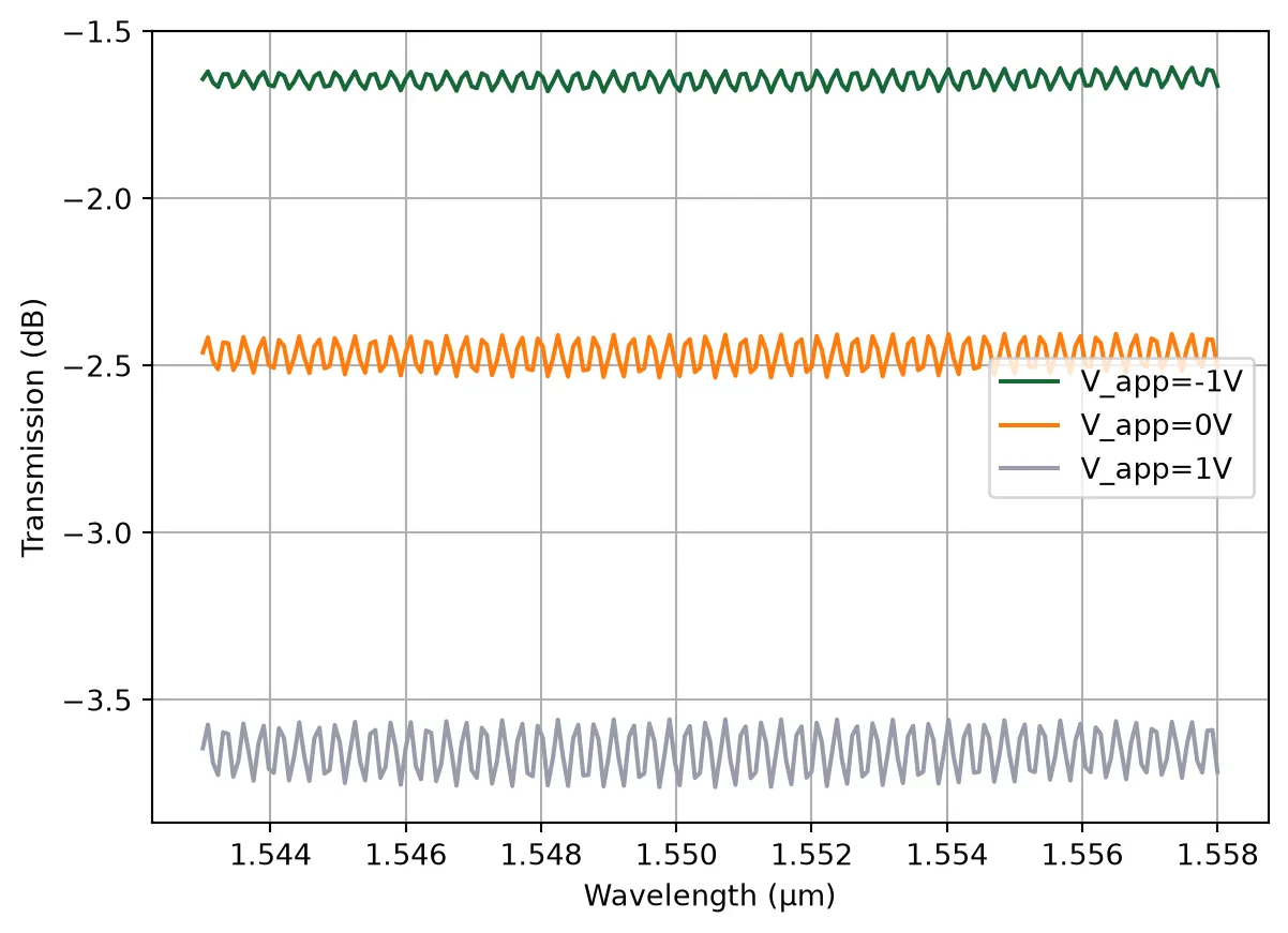
Waveguide Crossing
Section titled “Waveguide Crossing”Waveguide crossings are essential for complex routing in high-density PICs, allowing signal paths to intersect with minimal interference.
Reference:
Y. Ma et al., “Ultralow loss single layer submicron silicon waveguide crossing for SOI optical interconnect,” Opt Express, 2023 21 (24), 29374–29382, doi: 10.1364/OE.21.029374
Design Tip:
The Challenge: A direct waveguide intersection causes high loss and crosstalk because light diffracts (spreads out) as it crosses the unguided gap.
The Solution: We widen the waveguide before the crossing. A larger optical mode has a narrower divergence angle (), allowing it to “jump” the gap with minimal scattering.
Optimization: A linear taper is often too long. To minimize the footprint, we use an optimization algorithm (e.g., particle swarm optimization) to find a cubic-spline width profile. This algorithm determines the fastest possible rate of expansion that remains adiabatic, meaning the mode evolves smoothly without scattering energy into higher-order modes.
from scipy.interpolate import make_interp_spline
default_widths = (    0.5,    0.6,    0.95,    1.32,    1.44,    1.46,    1.466,    1.52,    1.58,    1.62,    1.76,    2.15,    0.5,)
@pf.parametric_component(name_prefix="Crossing")def adiabatic_crossing(    *,    arm_length=4.5,  # Length of crossing arms (µm)    widths=default_widths,):    """    Create a 4-arm adiabatic crossing with smooth cubic taper profiles.
    Parameters:        arm_length (float): Length of the main arm (µm).        widths (Sequence[float]): Target waveguide widths (µm) along each arm.
    Returns:        A crossing component.    """    # Number of points used to discretize the cubic spline profile.    num_points = int(arm_length / pf.config.tolerance)
    wg_width, _ = port_spec.path_profile_for("Si")  # extract initial waveguide width
    # Create cubic spline interpolation for widths    coords = np.linspace(0, arm_length, len(widths))    spline = make_interp_spline(coords, widths[::-1], k=3)
    # Pre-compute widths and positions from the interpolation    coords = np.linspace(0, arm_length, num_points)    widths = spline(coords)
    arm1 = pf.Path((0, 0), wg_width)    for x, w in zip(coords[1:], widths[1:]):        arm1.segment((x, 0), w)
    arm2 = arm1.copy().rotate(90)    arm3 = arm1.copy().rotate(180)    arm4 = arm1.copy().rotate(270)
    c = pf.Component()    c.add("Si", *pf.boolean([arm1, arm2], [arm3, arm4], "+"))
    # Add ports    c.add_port(c.detect_ports([port_spec]))    assert len(c.ports) == 4, "Port detection failed: expected exactly 4 ports."
    # Add Tidy3D simulation model with symmetry conditions    c.add_model(        pf.Tidy3DModel(            port_symmetries=[                ("P1", "P0", "P3", "P2"),  # symmetry about x-axis                ("P2", "P3", "P0", "P1"),  # symmetry about y-axis                ("P3", "P2", "P1", "P0"),  # inversion symmetry            ],        ),        "Tidy3D",    )    return c
crossing = adiabatic_crossing()viewer(crossing)
# Compute the scattering matrix of the crossing over the frequency ranges_matrix_crossing = crossing.s_matrix(freqs)# Plot the magnitude of the S-matrix to evaluate transmission and crosstalk_ = pf.plot_s_matrix(s_matrix_crossing, input_ports=["P0"])# Add the simulation results as a DataModel to avoid future FDTD simulations for different frequencies# crossing.add_model(pf.DataModel(s_matrix_crossing))14:35:22 -03 Loading simulation from local cache. View cached task using web UI at 'https://tidy3d.simulation.cloud/workbench?taskId=fdve-31cdd096-751 5-4e8f-a6be-462bf11f483f'.
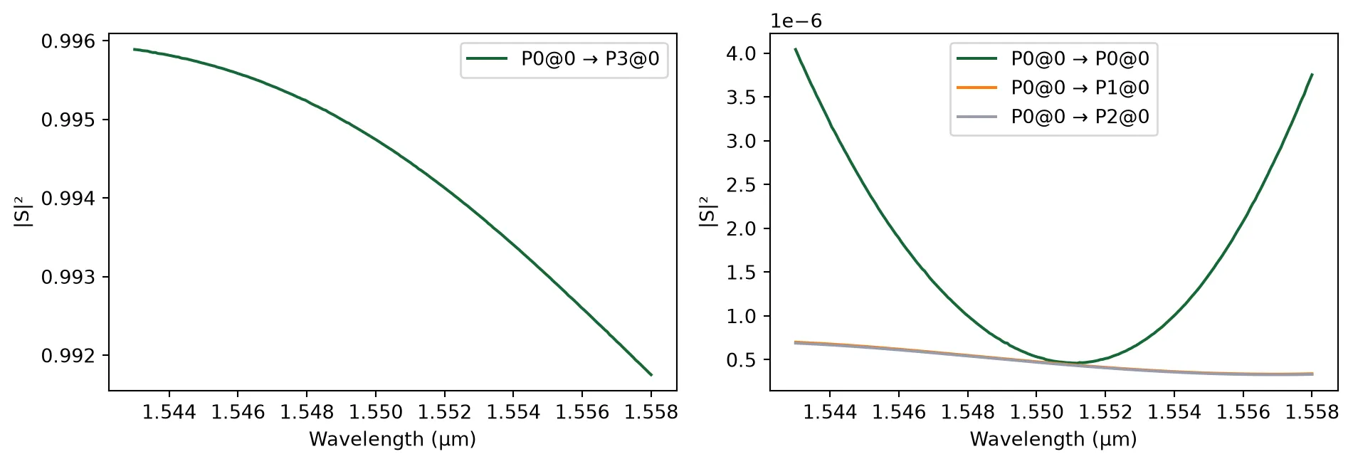
Optical Termination
Section titled “Optical Termination”This section defines a low-reflection waveguide termination used to suppress back-reflections at open waveguide ends.
Design Tip: To prevent destabilizing back-reflections (return loss), avoid abrupt waveguide cuts. Instead, use an adiabatic tapered termination.
By gradually narrowing the waveguide to a sharp tip (e.g., < 100 nm), the optical mode is forced to expand and radiate smoothly into the cladding (“mode deconfinement”). This “squeezes” the light out without creating a reflective facet, typically achieving reflections lower than -30 dB.
# Load and visualize a low-reflection waveguide terminator PCelltermination = siepic.component("ebeam_terminator_te1550")viewer(termination)
Simulation shows very low return loss (< -45 dB).
# Simulate and plot the terminator S-matrixs_matrix_termination = termination.s_matrix(freqs)_ = pf.plot_s_matrix(s_matrix_termination, y="dB", input_ports=["P0"])# Add the simulation results as a DataModel to avoid future FDTD simulations for different frequencies# termination.add_model(pf.DataModel(s_matrix_termination))14:35:23 -03 Loading simulation from local cache. View cached task using web UI at 'https://tidy3d.simulation.cloud/workbench?taskId=fdve-2228c8c5-ab3 3-4fd2-a674-02782a625875'.
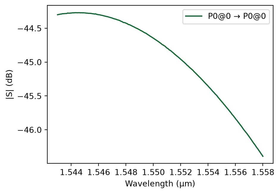
Bond Pads
Section titled “Bond Pads”Bond pads are the primary electrical interface between the photonic chip and the external environment. These large metal areas (typically 100 × 100 µm) are designed for wire bonding or flip-chip packaging, providing reliable electrical connections for DC biasing of heaters and high-speed RF signaling for modulators. The design ensures low contact resistance and sufficient surface area to accommodate standard packaging tolerances.
bp = pf.Component("BondPad")bp.add_terminal(pf.Terminal("M2_router", pf.Rectangle(size=(100, 100))), add_structure=True)bp.add("M_Open", pf.Rectangle(size=(95, 95)))viewer(bp)