Workbench Layout#
The Flow360 workbench provides an intuitive interface for computational fluid dynamics (CFD) simulations. This document describes the key areas of the workbench layout and their functions.
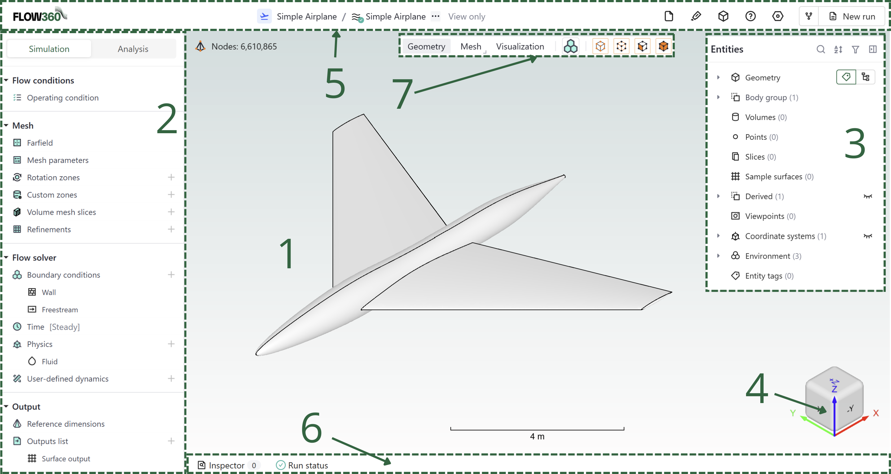
Main Interface Sections#
Section |
Description |
|---|---|
1 |
|
2 |
|
3 |
|
4 |
Coordinate system |
5 |
|
6 |
|
7 |
See also
For the workflow and interface overview, see the User Guide: Workflows & Interfaces.
Detailed Descriptions#
Viewer region#
The central workspace where the geometry, mesh, and simulation results are displayed.
This interactive 3D viewport allows you to:
Rotate (hold left mouse button), pan (hold right mouse button), and zoom the model (use the scroll)
Select and inspect geometric features (left click)
Preview created entities such as volumes or slices
View mesh details
Visualize simulation results and flow fields
Tip
Click right-mouse button while hovering in the model view area to see additional settings.
Simulation setup / Analysis#
A comprehensive control panel containing all simulation parameters and settings.
In this panel you will:
Type in your meshing parameters
Set up the simulation’s physics
Change the solver numerics
Define anticipated outputs
Analyze and monitor the solution
Visualise the results
Entities browser#
Dedicated controls for visual representation of the model and results.
Geometry display options
Mesh visualization settings
Results visualization tools
Display modes and rendering options
Coordinate system#
Persistent coordinate system.
X, Y, and Z axes orientation
Current view direction
Bottom status bar#
Information and status display
Current operation status
Progress indicators
Inspector tools
Run status information
Viewer bar#
Allows you to switch between different modes as well as choosing selection options.
The possible view modes depend on the project creation method and are:
Geometry: presents the geometry of the simulated object.
Mesh: shows the surface mesh generated on the surfaces
Visualisation: visualises the flow field according to the chosen criteria (eg. Cp contour on surface)
The selection methods can be checked and unchecked and allow for the selection of following entities:
Points
Edges
Faces
Bodies