Mesh parameters#
The Mesh parameters in Flow360 provide fundamental control over mesh generation, affecting both surface and volume mesh characteristics. These settings serve as global defaults that determine the quality and characteristics of the computational mesh.
Available Options#
Surface mesh#
Option |
Description |
Applicable |
|---|---|---|
Maximum allowable edge length for surface elements |
always |
|
Smallest length scale to be resolved by surface meshing |
Geometry AI |
|
Maximum angle a single surface mesh element can span |
always |
|
Target number of nodes for the surface mesh |
beta mesher, Geometry AI |
|
Controls the size progression of elements grown from edges |
|
|
Maximum aspect ratio for surface cells |
|
|
Whether to resolve boundaries between adjacent faces |
|
|
Maximum iterations for surface mesh adaptation |
|
Volume mesh#
Option |
Description |
Applicable |
|---|---|---|
First layer thickness for volumetric anisotropic layers |
always |
|
Growth rate for prismatic boundary layer elements |
|
|
Growth rate of the farfield (octree) volume cells away from the surface |
|
|
Global scaling factor for mesh refinement |
|
|
Controls mesh behavior in narrow gaps |
|
|
Fixed number of boundary layer elements |
|
|
Tolerance for sliding interface detection |
|
|
Number of boundary layer edge-splitting layers at geometric corners |
|
|
Base spacing for the octree volume mesher |
|
Geometry#
Option |
Description |
Applicable |
|---|---|---|
Threshold size below which geometry gaps are closed |
|
|
Whether thin geometry features should be resolved |
|
|
Removes internal geometry not visible to flow |
|
|
Minimum passage size that hidden geometry removal can resolve |
|
|
Removes (or thickens) baffle faces found during hidden geometry removal |
|
|
Tolerance for detecting planar faces |
|
See also
For a deeper discussion of the meshing workflow and parameters, see Meshing.
Detailed Descriptions#
Surface mesh#
Surface max edge length#
Defines the maximum allowable length for any mesh edge on surfaces.
Required
Units: Length
Notes:
Can be overridden using Surface Refinement
Should be chosen based on geometry scale and required resolution
Affects overall mesh density and computational cost
Geometry accuracy#
The smallest length scale that will be resolved accurately by the surface meshing process.
Required (when using Geometry AI)
Units: Length
Notes:
Only available when using Geometry AI
Can be overridden with Geometry Refinement
A smaller value results in a finer mesh and higher cell count
The Geometry AI mesher may stop early due to resource limits before fully achieving the requested accuracy; check the process log for an indication of early termination
Important
Geometry accuracy warnings
The meshing form evaluates your Geometry accuracy value against the geometry bounding box (BBox) diagonal and displays a warning indicator on the field when the value falls outside the recommended range:
Condition |
Warning |
Consequence |
|---|---|---|
Value > 0.01 × BBox diagonal |
Geometry accuracy too coarse |
The mesher may fail to resolve small geometric features, causing it to “eat into” the underlying geometry. |
Value < 1e-5 × BBox diagonal |
Geometry accuracy too fine |
The resulting surface mesh will be unnecessarily large, significantly increasing cell count and meshing time. |
These are warnings only — the mesh may still complete successfully. However, values outside this range often lead to suboptimal results.
How to resolve:
If the warning indicates the value is too coarse, reduce Geometry accuracy or, preferably, use a Geometry Refinement to apply a finer accuracy locally on the specific faces or regions that require it, rather than lowering the global value.
If the warning indicates the value is too fine, increase Geometry accuracy or use local Geometry Refinement only on the faces that can have a coarser resolution.
Using local geometry refinements on specific faces is strongly recommended over adjusting the global Geometry accuracy value, as it gives you precise control without unnecessarily inflating the overall mesh size.
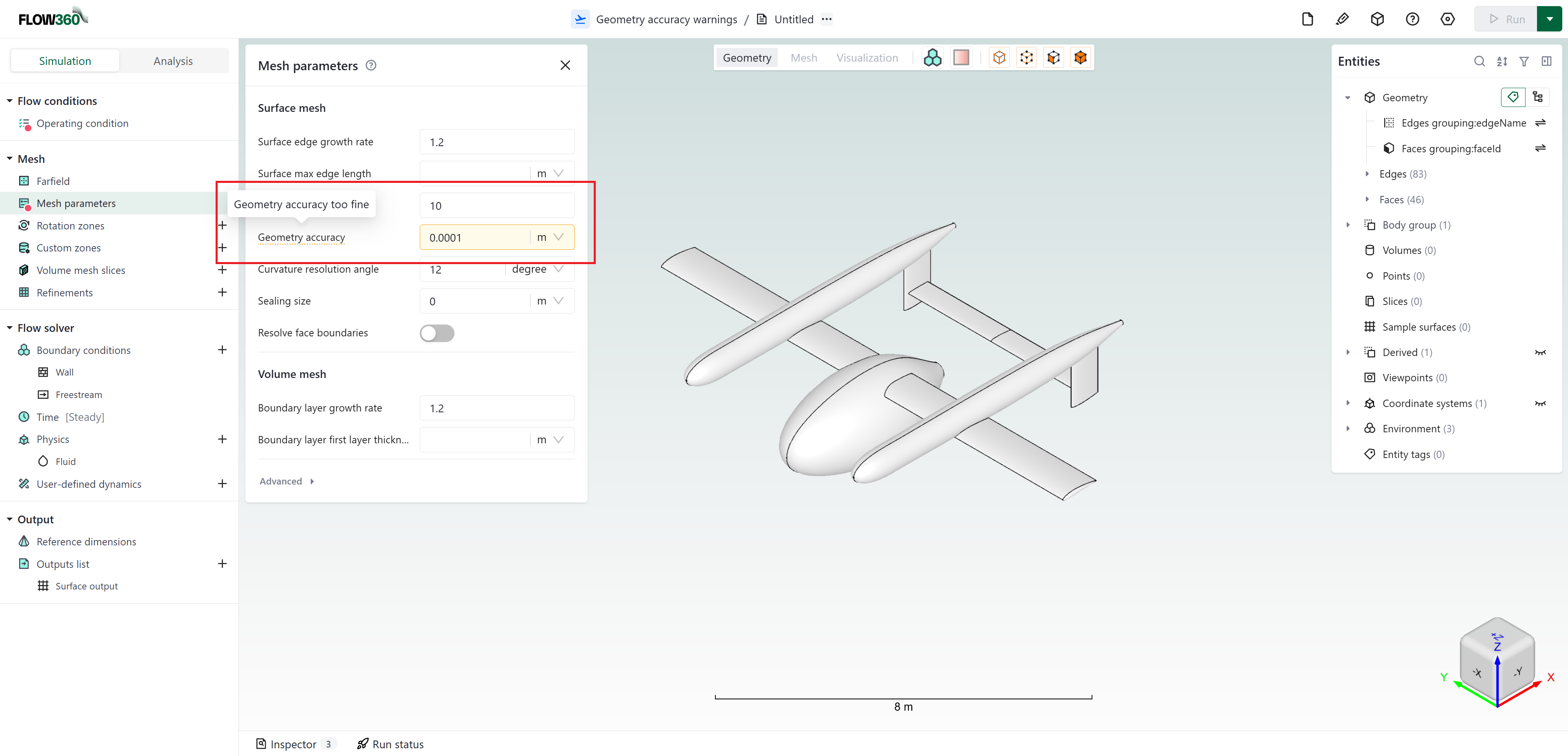
The Geometry accuracy field displays a yellow warning indicator when the value falls outside the recommended range relative to the geometry bounding box. The tooltip shown here reads “Geometry accuracy too fine”.#
Curvature resolution angle#
Specifies the maximum angular deviation allowed in the surface mesh.
Default:
12 degreesUnits: Angle
Notes:
Controls both:
Angle between cell normal and underlying surface normal
Angle between line segment normal and underlying curve normal
Can be overridden per face only when using Geometry AI
Lower values capture curvature more accurately but increase mesh density
Target surface node count#
Target number of nodes for the surface mesh. When specified, the surface mesher scales the initial metric to achieve approximately this number of surface mesh nodes.
Default:
NoneUnits: Count
Notes:
Available with Geometry AI and beta surface meshers
Cannot be overridden per face
The specified parameters are not modified directly, the initial metric is scaled to achieve the target count, so resulting Curvature resolution angle may be different than specified. Surface max edge length is enforced regardless, which may lead to discrepancies between the target node count and the resulting node count.
This setting does not affect the geometry-resolving behaviour of the mesher (controlled by parameters like Geometry accuracy).
Useful for quickly controlling overall mesh density without manually tuning individual length-scale parameters
Surface edge growth rate#
Controls the size progression of mesh elements grown from edges, affecting the transition between regions of different refinement (anisotropic to isotropic).
Default:
1.2Units: Dimensionless
Advanced option — found under the Advanced section in the UI
Notes:
Values must be greater than or equal to
1.0, typically1.1–1.25Cannot be overridden per edge
Higher values lead to faster mesh size growth but may reduce quality
Surface max aspect ratio#
Maximum aspect ratio allowed for surface mesh cells.
Default:
10Units: Dimensionless
Advanced option — found under the Advanced section in the UI
Notes:
Only available when using Geometry AI
Cannot be overridden per face
Lower values enforce more isotropic surface cells
Resolve face boundaries#
Toggle to specify whether boundaries between adjacent faces should be resolved accurately using anisotropic mesh refinement.
Default:
OffAdvanced option — found under the Advanced section in the UI
Notes:
Only applicable to Geometry AI
Can be overridden per face with Surface Refinement
Improves mesh quality at face intersections
Surface max adaptation iterations#
Maximum number of adaptation iterations for the surface mesher.
Default:
50Units: Count
Advanced option — found under the Advanced section in the UI
Notes:
Only available when using Geometry AI
Higher values may improve mesh quality but increase meshing time
Volume mesh#
Boundary layer first layer thickness#
Specifies the height of the first prismatic layer adjacent to wall surfaces.
Required
Units: Length
Notes:
Can be overridden using Boundary Layer Refinement
Critical for achieving desired y+ values
Should be calculated based on Reynolds number and desired y+ value
Boundary layer growth rate#
Defines the growth rate of prismatic layers in the boundary layer region.
Default:
1.2Units: Dimensionless
Advanced option — found under the Advanced section in the UI
Notes:
Controls thickness progression of successive boundary layer elements
Values must be greater than or equal to
1.0, typically1.1–1.25Lower values create more gradual growth but increase total element count
Critical for accurate boundary layer resolution
Volume edge growth rate#
Controls how quickly the target cell size grows with distance from the surface as the farfield (octree) mesh expands away from it.
Default:
1.1Units: Dimensionless
Advanced option (found under the Advanced section in the UI)
Notes:
Only supported by the beta mesher; on other meshers a non-default value is ignored
It sets the target cell size the mesher aims for at each distance from the surface, not the size ratio between neighbouring cells. The octree always changes cell size in
2:1steps; the growth rate controls how far apart those steps fallValues must be greater than
1.0, typically1.05–1.3Lower values keep the size steps closer together, giving smoother gradation (more cells); higher values let the mesh coarsen faster (fewer cells)
Controls only the isotropic farfield growth; the prismatic boundary layer growth is set separately by Boundary layer growth rate
Refinement factor#
Global scaling factor that affects the overall mesh refinement level.
Default:
1Units: Dimensionless
Advanced option — found under the Advanced section in the UI
Notes:
Not supported with beta mesher
Adjusts all spacings in refinement regions and first layer thickness to generate r-times finer mesh
For example, if
refinement factor = 2, all spacings will be divided by ( 2^{1/3} ), resulting in approximately 2× more nodesUseful for quick mesh resolution studies
Gap treatment strength#
Controls how the mesh transitions in narrow gaps between surfaces.
Default:
0(beta mesher uses1.0)Units: Dimensionless (range: 0–1)
Advanced option — found under the Advanced section in the UI
Notes:
0= no treatment,1= most conservative treatmentHigher values dedicate more space to isotropic mesh in narrow gaps
Critical for mesh quality in tight geometric spaces
Number of boundary layers#
Specifies a fixed number of volumetric anisotropic (boundary layer) elements.
Default: Automatic (mesher calculates required layers)
Units: Count
Advanced option — found under the Advanced section in the UI
Notes:
Only supported by the beta mesher
Cannot be overridden per face
When not specified, the volume mesher automatically calculates the required number of layers to grow boundary layer elements to isotropic size
Sliding interface tolerance#
Tolerance used for detecting or creating curves lying on sliding interfaces.
Default:
0.01Units: Dimensionless (relative to smallest sliding interface radius defined within a case)
Advanced option — found under the Advanced section in the UI
Notes:
Edge split layers at corners#
Number of layers in the boundary layer mesh that are considered for edge splitting at geometric corners.
Default:
1Units: Count
Advanced option — found under the Advanced section in the UI
Notes:
Only supported by the beta mesher
Set to
0to disable edge splitting at corners
Octree base spacing#
Sets the base cell size for the octree volume mesher, from which all element sizes in the volume mesh are derived.
Default:
1 × project length unitUnits: Length
Advanced option — found under the Advanced section in the UI
Notes:
Available with the beta mesher
The octree mesher generates a hierarchy of cell sizes that are successive halves or doubles of the base spacing (e.g.,
base/2,base/4, … orbase*2,base*4, …)To achieve the desired mesh resolution, set the base spacing so that the target refinement spacings align with values in this series
Geometry#
Sealing size#
Threshold size below which all geometry gaps are automatically closed.
Default:
0 mUnits: Length
Advanced option — found under the Advanced section in the UI
Notes:
Only available when using Geometry AI
Can be overridden with Geometry Refinement
Useful for closing small holes or gaps in imperfect CAD geometry
Preserve thin geometry#
Toggle to specify whether thin geometry features should be resolved accurately during the surface meshing process.
Default:
OffAdvanced option — found under the Advanced section in the UI
Notes:
Only available when using Geometry AI
Resolves features with thickness roughly equal to Geometry accuracy
Can be overridden with Geometry Refinement
May improve mesh quality but increase meshing time
Min passage size#
Minimum passage size that the hidden geometry removal algorithm can resolve.
Default: Derived automatically from Geometry accuracy and Sealing size
Units: Length
Advanced option — found under the Advanced section in the UI
Notes:
Only available when using Geometry AI
Can only be specified when Remove hidden geometry is enabled
Internal regions connected by passages smaller than this value may not be detected and removed
If not specified, the value is derived from Geometry accuracy and Sealing size
Can be overridden per face via Geometry Refinement
Remove baffle faces#
Toggle controlling how baffle faces are handled. A baffle face is an input face with both sides facing the exterior flow, detected during hidden geometry removal. When on, baffle faces are removed; when off, each baffle is thickened into a closed shell so it survives as a manifold part of the mesh.
Default:
On(baffle faces are removed)Advanced option — found under the Advanced section in the UI
Notes:
Only available when using Geometry AI
Baffle faces are detected as part of hidden geometry removal
This is a meshing preprocessing step: a baffle face does not survive as a non-manifold face in the final mesh (it is either removed or thickened). It is not the same thing as a sample surface (see the note below)
Note
Baffle face vs. sample surface. These two non-manifold-surface concepts are easy to confuse but serve opposite purposes:
Concept |
What it is |
When it is used |
|---|---|---|
Baffle face |
A non-manifold input face (both sides facing the exterior) that the mesher removes or thickens into a manifold mesh, controlled by Remove baffle faces above. A meshing preprocessing step (Geometry AI only). |
Cleaning up CAD before meshing. The baffle does not survive as a non-manifold face in the final mesh. |
Sample surface |
A user-uploaded non-manifold surface used to monitor scalar quantities (e.g. mass flow rate) at internal locations such as an HVAC outlet. It is not represented in the mesh; the flow solution is sampled onto it. See Sample Surfaces. |
Post-run measurements at internal cross-sections of a manifold mesh. |
Planar face tolerance#
Tolerance used for detecting planar faces in the input geometry that need to be remeshed, such as symmetry planes.
Default:
1e-6Units: Dimensionless (relative to largest bounding box dimension)
Advanced option — found under the Advanced section in the UI
Notes:
Cannot be overridden per face
Used to identify and preserve flat surfaces during meshing
💡 Tips
Set Surface max edge length based on the largest geometric features requiring resolution
For Geometry AI workflows, start with a larger Geometry accuracy and decrease iteratively to find the optimal balance
Calculate Boundary layer first layer thickness based on desired \(y^+\) value using Reynolds number and flow conditions. Remember that \(y^+\) changes dynamically with flow velocity and fluid properties, not just mesh size.
Enable Preserve thin geometry when your model has thin features (e.g., trailing edges, fins) that must be captured
Enable Remove hidden geometry when your geometry contains internal cavities or parts (e.g., engine compartments, interior trim) that are hidden from the flow and should not affect the mesh
❓ Frequently Asked Questions
How do I determine the appropriate first layer thickness?
Calculate based on desired y+ value using Reynolds number and flow conditions. For turbulent flow with wall functions, target y+ ≈ 30–100. For resolving the viscous sublayer, target y+ < 1.
What is Geometry accuracy and when do I need it?
Geometry accuracy defines the smallest feature size the surface mesher will resolve. It is required when using Geometry AI and should be set based on the smallest important geometric features in your model.
When should I use Preserve thin geometry?
Enable this when your geometry contains thin features (like trailing edges or cooling fins) with thickness close to the Geometry accuracy value that must be captured accurately.
What surface edge growth rate should I use?
Start with the default of
1.2. Use lower values (1.1–1.15) for more gradual transitions in critical regions, and higher values (up to1.3) where rapid growth is acceptable.What is the difference between volume edge growth rate and boundary layer growth rate?
Boundary layer growth rate controls the thickness progression of the prismatic layers grown normal to the wall. Volume edge growth rate (beta mesher only) controls how quickly the isotropic farfield (octree) cells grow as they move away from the surface. They govern different parts of the volume mesh and are set independently.
How does gap treatment strength affect my mesh?
Higher values create more isotropic cells in narrow gaps, improving mesh quality but potentially increasing cell count. For automotive simulations, a value of
1.0is recommended.When should I use Remove hidden geometry?
Enable this when your geometry contains internal parts that are enclosed and not exposed to the flow (e.g., a steering column inside a car cabin). Removing such geometry reduces mesh complexity and meshing time without affecting solution accuracy.
What should I set Min passage size to?
In most cases, leaving it unset is sufficient — the mesher derives an appropriate value from Geometry accuracy and Sealing size. Set it explicitly only when internal cavities are connected by very thin passages that you need to ensure are detected.
🐍 Python Example Usage
See also
Python API:
Example Library notebooks:
import flow360 as fl

# Basic meshing defaults
meshing_defaults = fl.MeshingDefaults(
    surface_edge_growth_rate=1.2,
    surface_max_edge_length=0.1 * fl.u.m,
    curvature_resolution_angle=12 * fl.u.deg,
    boundary_layer_growth_rate=1.2,
    boundary_layer_first_layer_thickness=0.01 * fl.u.mm,
    volume_edge_growth_rate=1.1,  # beta mesher only
    octree_spacing=fl.OctreeSpacing(base_spacing=0.1 * fl.u.m),
)

# With Geometry AI features
meshing_defaults_gai = fl.MeshingDefaults(
    geometry_accuracy=0.001 * fl.u.m,
    surface_edge_growth_rate=1.2,
    surface_max_edge_length=0.1 * fl.u.m,
    surface_max_aspect_ratio=10,
    curvature_resolution_angle=12 * fl.u.deg,
    boundary_layer_growth_rate=1.2,
    boundary_layer_first_layer_thickness=0.01 * fl.u.mm,
    octree_spacing=fl.OctreeSpacing(base_spacing=0.1 * fl.u.m),
    preserve_thin_geometry=True,
    sealing_size=0.0001 * fl.u.m,
    remove_hidden_geometry=True,
    min_passage_size=0.005 * fl.u.m,
    target_surface_node_count=500000,
)