Starting Project#
This document describes how to start a project in Flow360 GUI.
New Project#
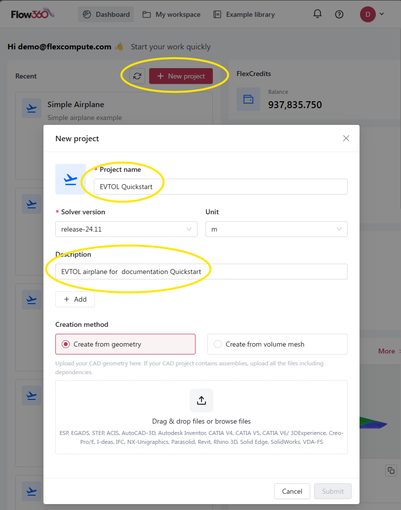
The New Project window is the entry point for creating CFD simulations in Flow360. It allows users to choose between geometry-based or mesh-based workflows.
Available Options#
Option |
Description |
Default |
|---|---|---|
Project name |
Unique identifier for your simulation project |
|
Solver version |
Flow360 solver release version |
Latest stable release |
Unit |
Physical unit for the geometry/mesh |
|
Description |
Optional project description and notes |
Empty |
Creation method |
Method for creating the simulation (from geometry/from surface mesh/from volume mesh) |
|
See also
For the workflow and interface overview, see the User Guide: Workflows & Interfaces.
Detailed Descriptions#
Project name#
Unique name that identifies your simulation project in the Flow360 system.
Default:
UntitledExample:
Wing_Analysis_M08
Tip
Choose a descriptive name that helps identify the project purpose.
Solver version#
Specifies the Flow360 solver version to be used for the simulation.
Default: Latest stable release
Example:
release-24.11
Tip
It’s recommended to use the latest stable release unless specific version compatibility is required.
Unit#
Defines the physical unit for interpreting mesh/geometry dimensions.
Default:
m(meter)Example:
inch
Tip
Ensure this matches the units used in your CAD or mesh file to avoid scaling issues.
Description#
Optional field for adding project notes, objectives, or other relevant information.
Default: Empty
Example:
High-lift configuration analysis at takeoff conditions
Note
Below the description field you can add tags to your project by clicking the + Add icon.
Creation methods#
Choose how to initialize your project.
From geometry: The uploaded CAD geometry becomes a root of the project. It is necessary to run surface meshing and volume meshing steps before launching the simulation.
Supported formats: ESP, EGADS, STEP, IGES, ACIS, AutoCAD-3D, Autodesk Inventor, CATIA V4-V6, Creo-Pro/E, I-deas, IFC, NX-Unigraphics, Parasolid, Revit, Rhino 3D, Solid Edge, SolidWorks, VDA-FS, UGrid, CGNS, STL
Requirements:
Clean, watertight geometry
Properly defined assemblies with all dependencies
From surface mesh: Use a pre-generated surface mesh file as a root of the project. It is necessary to run volume meshing before launching the simulation.
Supported formats: UGrid, CGNS, STL
Requirements:
Valid surface mesh
Triangular elements
From volume mesh: Use a pre-generated volume mesh file as a root of the project. By using this method, the case does not need any additional pre-processing and is ready for running.
Supported formats: UGrid, CGNS
Requirements:
Valid volume mesh
Acceptable element types:
Tetrahedrons
Hexahedrons
Prisms
Pyramids
Resuming an Interrupted Upload#
If a geometry or mesh upload is interrupted (for example by a lost connection or a closed browser tab), you can retry it without deleting the project and starting over.
When an upload fails or is cancelled, Flow360 marks the project with an Upload Error status and shows a Retry button in two places:
On the project card in the dashboard, next to the error status.
On the project loading screen, when you open a project whose upload did not finish.
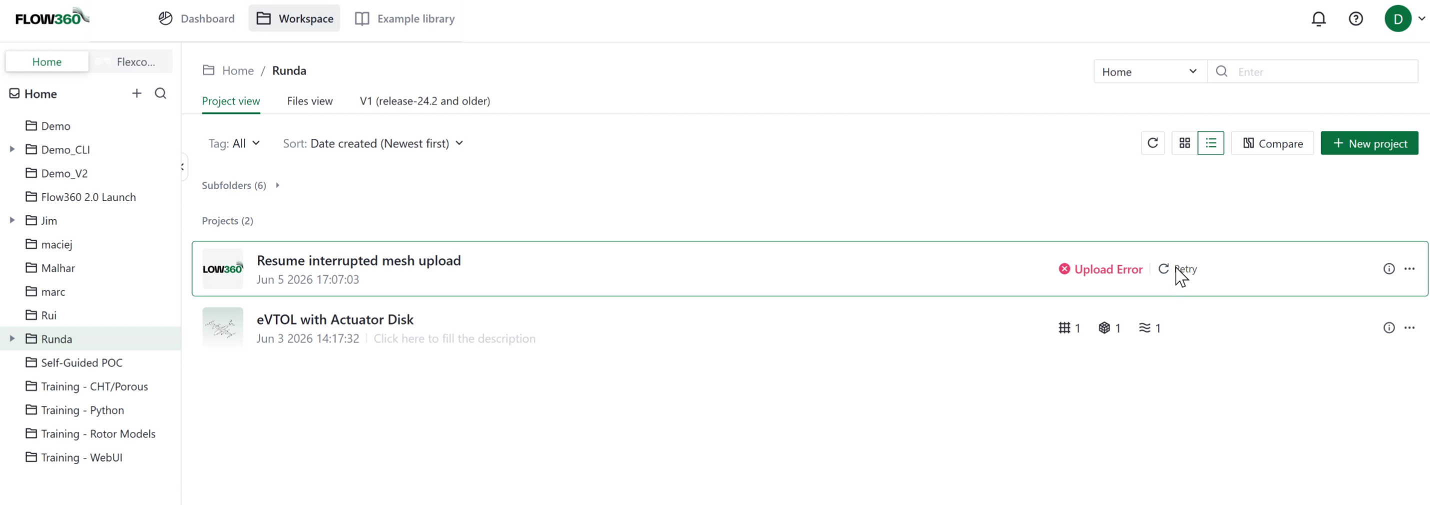
Clicking Retry lets you re-upload the affected files and continue with the same project, keeping the simulation setup you have already configured. You no longer have to delete the project and recreate it from scratch after a failed upload. This applies to geometry, surface mesh, and volume mesh uploads.
Note
Only the project creator can retry an interrupted upload.
❓ Frequently Asked Questions
What happens if my geometry has multiple parts?
For assemblies, upload all required files including dependencies. The system will maintain the assembly structure.
Can I change the project unit after project creation?
Yes, the project unit can be changed after project creation. Keep in mind that this does not affect units assigned during simulation setup.
What if my CAD format is not listed?
Consider converting your geometry to one of the supported formats using CAD translation software.
Do you have to upload the surface mesh with the farfield?
No, you can upload the surface mesh of the object you want to simulate and use the Automatic Farfield option. You can also upload your custom farfield as part of the surface mesh file.
🐍 Python Example Usage
See also
The same project creation is available through the Python API via Project, using its from_geometry, from_surface_mesh, and from_volume_mesh constructors:
Below is a Python code example showing how to create a new project programmatically:
import flow360 as fl

# Create a new project from geometry
geo_project = fl.Project.from_geometry("my_geometry.csm", "Project from geometry", length_unit=fl.u.m)

# Create a new project from surface mesh
sm_project = fl.Project.from_surface_mesh("my_surface_mesh.stl", "Project from surface mesh", length_unit=fl.u.inch)

# Create a new project from volume mesh
vm_project = fl.Project.from_volume_mesh("my_volume_mesh.cgns", "Project from volume mesh", length_unit=fl.u.mm)