Meshing#
Flow360 offers different approaches to meshing, which are developed to suit different needs and workflows. The meshing algorithms can be divided into surface and volume meshers, each having its own advantages. They are available in four combinations forming full meshing workflows.
Available workflows#
Flow360 supports multiple meshing workflows. This section provides a high-level map of the available options and links to the workflows. There are currently four mesher workflows available in Flow360 summarised in Mesher workflows below:
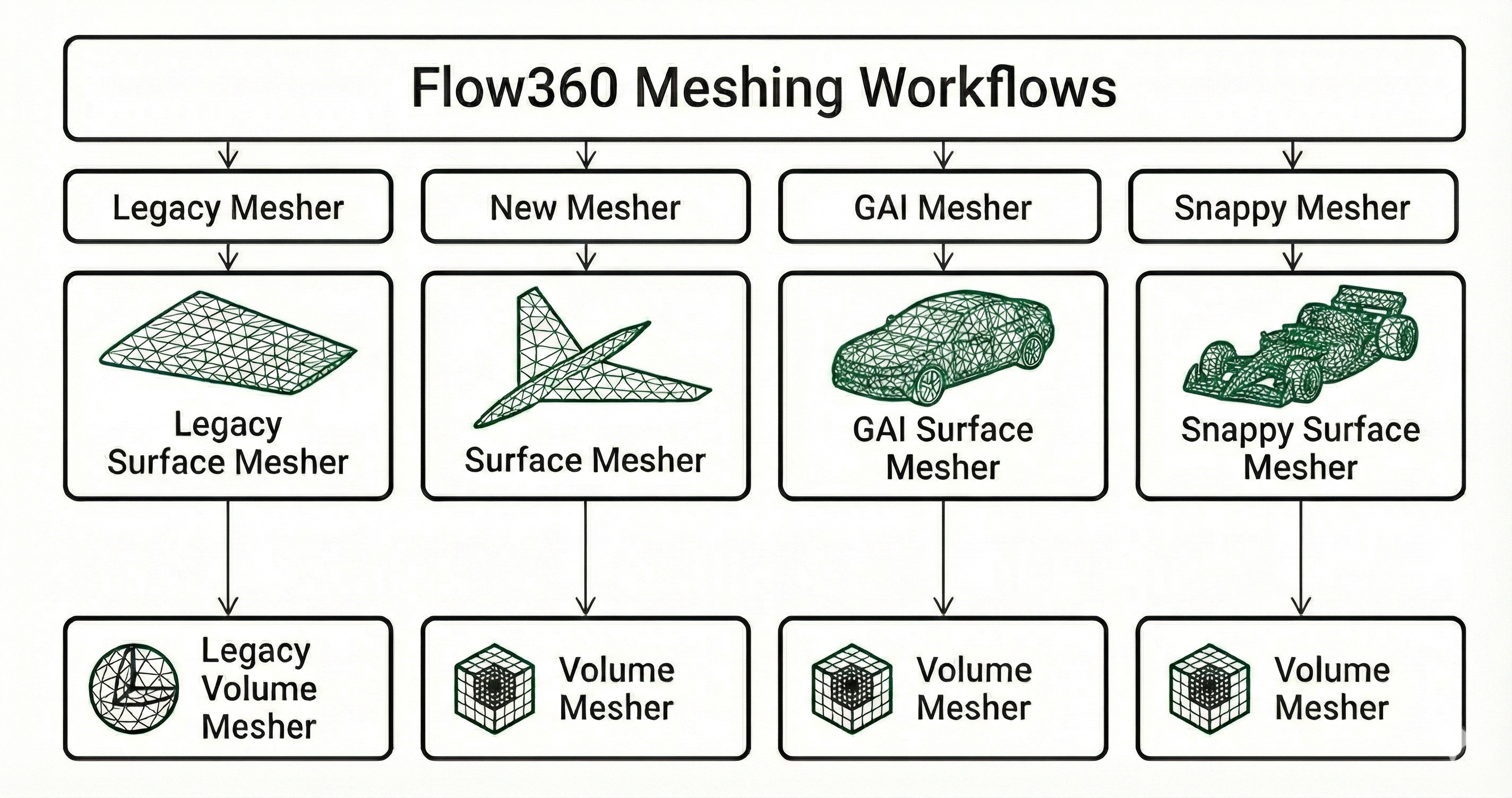
Mesher workflows#
Go to Example Library to see more available examples for each mesher workflow. Here is a high-level overview of the mesher workflows advantages and disadvantages:
Workflow |
Characteristics |
|---|---|
Legacy mesher |
|
New mesher |
|
Geometry AI mesher |
|
Snappy mesher |
|
Selecting a workflow#
Which surface and volume mesher run is controlled by two toggles, the beta mesher toggle and the GAI toggle, available in both the WebUI and the Python API:
Beta mesher toggle |
GAI toggle |
Surface mesher |
Volume mesher |
|---|---|---|---|
Off |
n/a |
Legacy mesher |
Legacy mesher |
On |
Off |
Beta surface mesher |
Volume Mesher |
On |
On |
GAI surface mesher |
Volume Mesher |
The volume stage is the Volume Mesher whenever the beta mesher toggle is on, regardless of the GAI toggle; the GAI toggle only selects which surface mesher feeds it. The snappy workflow is selected through its own surface-mesher option and also feeds the Volume Mesher.
Pick a mesher#
Each column below corresponds to a full meshing workflow. Click any card to open its dedicated page.
Legacy mesher
New mesher
Geometry AI mesher
Snappy mesher
↓
↓
↓
↓