Viewer Region#
The viewer region is the primary visualization interface in Flow360 GUI, providing interactive 3D visualization capabilities for geometry inspection, mesh analysis, and results visualization.
Example Views#
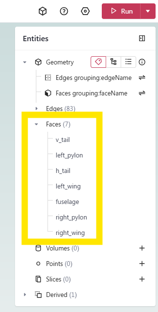
Geometry View Mode#
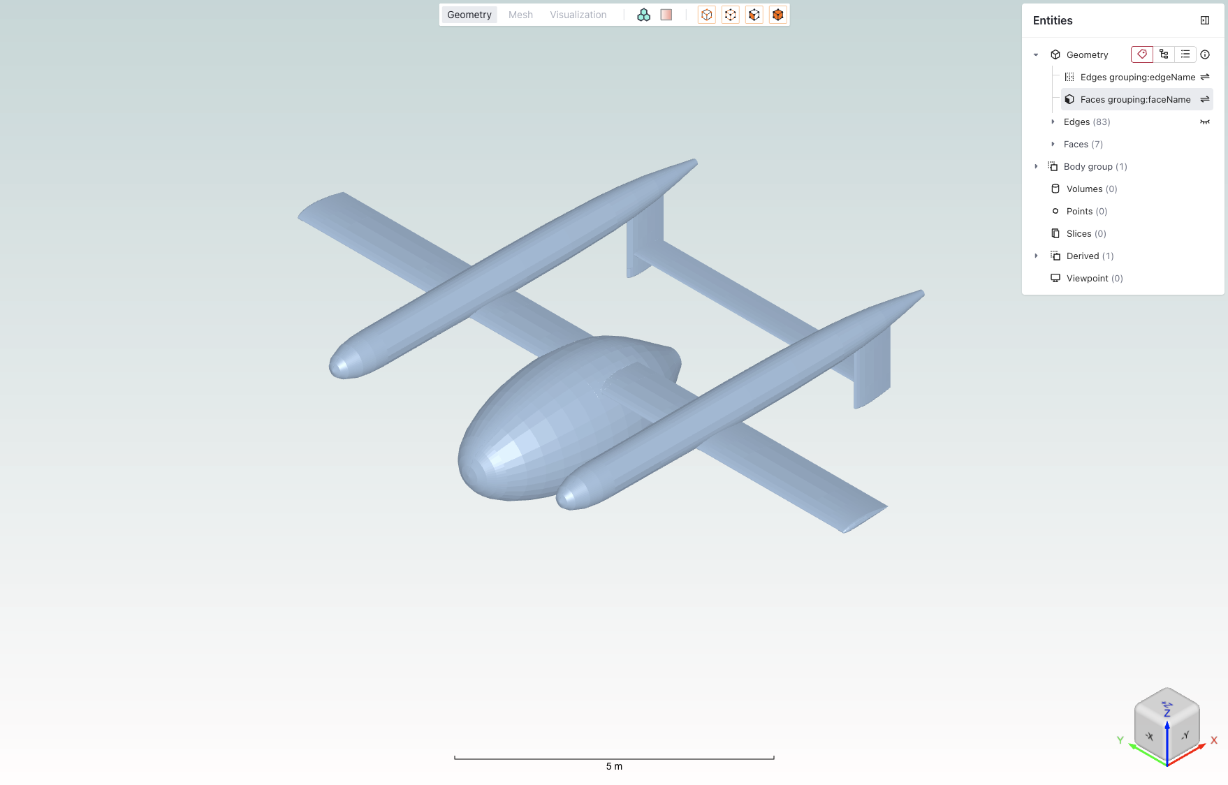 Example of the geometry view mode showing a CAD model with entity selection panel.
Mesh View Mode#
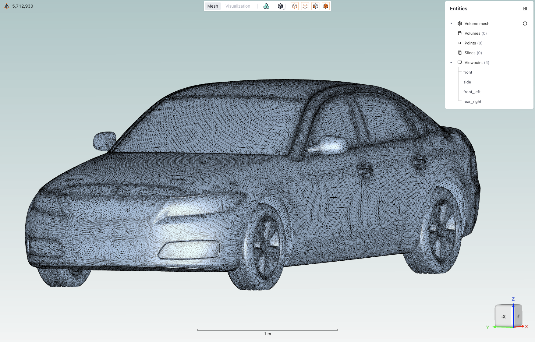 Example of the mesh view mode displaying a mesh visualization.
Core Features#
Feature |
Icon |
Description |
|---|---|---|
View modes |
|
Toggle between Geometry, Mesh, and Visualization views |
Boundary conditions |
|
Toggle coloring of boundaries based on their assigned boundary condition |
Render mode |
|
Switch geometry display between Solid and Transparent, in both the Geometry and Boundary Condition views |
Mesh diagnostics |
|
Open surface or volume mesh quality diagnostics (available when a mesh is displayed) |
Mesh resolution |
|
Switch the displayed model between low and high resolution (level of detail) for large models |
Entity selection mode |
|
Tools for selecting and managing geometry entities |
Entities visibility |
|
Toggle the visibility of entities by clicking the eye icon when hovering over them |
Mesh metrics |
|
Expand the mesh metrics view by clicking on the icon when in mesh view |
Viewpoints |
|
Controls for saving and loading specific camera positions |
Viewpoint presets |
|
Frame the model automatically from preset orthographic or isometric directions via the Viewpoint menu (“Fit to model” / “Fit to flow”), without positioning the camera by hand |
Length scale indicator |
|
Visual reference showing model dimensions to help maintain perspective |
Rotation cube |
|
Interactive orientation widget for quick view rotation to standard angles |


Detailed Descriptions#
View modes#
Toggle between Geometry/Mesh/Visualization views using top toolbar tabs.
Geometry: View CAD geometry
Mesh: Inspect surface and volume mesh
Visualization: View simulation results and post-processing
Note
Each mode provides context-specific tools and options.
Boundary conditions#
Toggle coloring of boundaries based on their assigned boundary condition.
Note
Helps verify boundary condition assignments before mesh generation.
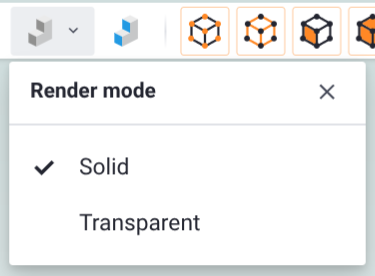
Render mode#
Switch how geometry surfaces are drawn, between Solid and Transparent.
Solid: the default. Surfaces are drawn opaque.
Transparent: surfaces are drawn semi-transparent, so you can see through outer surfaces to inspect faces that would otherwise be hidden (for example internal walls or occluded boundaries).
The render mode is selected from a dropdown in the top toolbar and is available in both the Geometry view and the Boundary Condition view, so coloring by boundary condition can be combined with transparent display. The render mode applies to the whole model; to adjust individual surfaces, set their appearance (color and material) selectively from the surface properties in the entity browser.
Note
Transparent mode is useful for checking boundary-condition assignments on internal or occluded faces before mesh generation.
Mesh diagnostics#
Open the mesh diagnostics tools to assess mesh quality. Available when a surface or volume mesh is displayed.
Surface mesh diagnostics: analyze the quality of the surface mesh.
Volume mesh diagnostics: analyze the quality of the volume mesh through automatically generated slices.
See Surface Mesh Diagnostics and Volume Mesh Diagnostics for details.
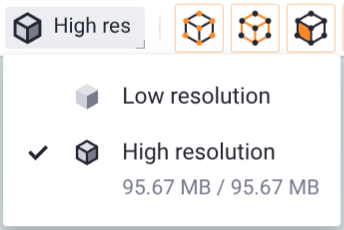
Mesh resolution#
Switch the displayed model between low and high resolution (level of detail).
Low resolution: a lightweight version that loads quickly, useful for navigating large models.
High resolution: the full-detail version. The menu also shows the downloaded and total data size for this level.
Note
The control appears only when more than one resolution level is available for the displayed item.
Entity selection mode#
Tools for selecting and managing geometry entities.
Entity Type |
Icon |
Description |
|---|---|---|
Points |
|
Select individual points/vertices |
Edges |
|
Select edge elements |
Faces |
|
Select face/surface elements |
Volumes |
|
Select volume elements |


Note
You can use any combination of selection modes.
Entities visibility#
Toggle the visibility of entities by clicking the eye icon when hovering over them.
Mesh metrics#
Quantitative mesh quality assessment tools for analyzing both surface and volume mesh characteristics.
Element types overview#
The mesh quality visualization provides statistics for different element types commonly found in CFD meshes:
Nodes are present in every mesh and represent the intersection points of mesh elements, they are fundamental to defining the mesh structure and geometry.
Surface Elements:
Triangles: Primary surface mesh elements
Quadrilaterals: Optional structured surface elements
Volume Elements:
Tetrahedrons: Unstructured volume elements
Prisms: Boundary layer elements
Pyramids: Transition elements between different element types
Hexahedrons: Structured volume elements
Surface metrics
Key metrics for assessing surface mesh quality:
Metric
Description
Importance
Area
Face area of surface elements
Identifies areas of highly non-uniform mesh resolution
Area Ratio
Ratio between adjacent face areas
Indicates mesh growth rate and smoothness
Aspect Ratio
Ratio between longest and shortest edge
Measures element skewness and potential numerical issues
First Layer Height
Height of first prismatic layer
Critical for boundary layer resolution
Volume metrics
Essential metrics for volume mesh quality assessment:
Metric
Description
Importance
Aspect Ratio
Element shape quality indicator
Identifies highly stretched or compressed elements
Volume
Element volume measurement
Helps detect very small or large elements that might affect solution stability
Viewpoint presets#
The Viewpoint menu can frame the model for you from a set of preset directions, so you do not have to position the camera by hand. Selecting a preset fits the geometry to the view automatically, based on the model’s bounding box.
Open the menu from the Viewpoint button at the bottom-right corner of the viewer (visible in the views above), then pick a preset:

Fit to model: frames the whole model from the chosen direction.
Fit to flow: frames the model with an offset suited to viewing the flow/wake direction.
Each group offers orthographic directions (Front, Back, Left, Right, Top, Bottom) and the eight isometric corner directions (for example, Left-Front-Top).
Note
The Viewpoint menu is also where you save and load your own viewpoints (see the Viewpoints section below). Additional framing actions (Fit view, Fit selected, and Reset view) are available from the right-click context menu in the viewer.
Viewpoints#
Controls for saving and loading specific camera positions.
Usage:
Click the + icon to add a new viewpoint that will be the current camera position
Name the viewpoint to be representative of the camera position
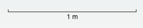
Length scale indicator#
Visual reference showing model dimensions to help maintain perspective.
Features:
Dynamic scale adjustment
Unit system consistency
Reference dimension display
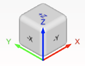
Rotation cube#
Interactive orientation widget for quick view rotation to standard angles.
Usage:
Click cube faces for orthogonal views
Click vertices or edges for isometric views
Note
For keyboard shortcuts and navigation controls, see Keyboard Shortcuts. In addition to orbit, pan, and zoom, the viewer supports screen-normal rotation (roll): hold Alt (Windows/Linux) or Option (macOS) while dragging with the left mouse button to rotate the model about the axis pointing out of the screen, for finer control of its orientation.
❓ Frequently Asked Questions
How can I reset the view if I get disoriented?
Use the “Fit to Screen” option in the view menu.
Why can’t I select certain entities?
Verify that the correct entity type is enabled in the selection toolbar.
How do I save a custom viewpoint?
Use the “Save Viewpoint” option in the View context menu after positioning the view as desired.