BET Disk#
The BETDisk model needs a complete aerodynamic and geometric definition of the rotor: the sectional lift and drag polars (nested by Mach number, Reynolds number and angle of attack), the chord and twist distributions along the blade, and the placement of the rotor(s) in the mesh. Assembling all of this by hand is tedious and error prone, especially the nested sectional_polars.
BET Translators#
To avoid building the model by hand, the Python API and the WEBUI can both construct a complete BETDisk directly from the native input files of common propeller and airfoil analysis tools. Each supported format has a dedicated file class that loads the data and a matching BETDisk constructor that assembles the model:
Format |
File class |
Constructor |
What the file already contains |
Extra inputs you must provide |
|---|---|---|---|---|
XROTOR |
|
|
Full propeller definition: blade geometry, chord and twist, sectional polars and number of blades. |
Rotor placement. |
DFDC |
|
|
Same as XROTOR, for a ducted rotor. |
Rotor placement. |
C81 |
|
|
Sectional polars only (2D airfoil data). |
Number of blades, plus the blade geometry through the geometry file. |
XFOIL |
|
|
Sectional polars only (one polar per Mach number). |
Number of blades, plus the blade geometry through the geometry file. |
All radii, chords and sectional-polar radial stations are expressed in grid units (the length unit of your mesh), and twist is given in degrees measured from the rotation plane. i.e. 0 degrees twist means the mean chord axis is aligned with the rotation direction, 90 degrees means it is aligned with the thrust axis.
XROTOR#
XROTOR is a widely used, open source, lower fidelity propeller design and analysis tool. A single XROTOR file describes the entire propeller (air properties, tip radius, advance ratio, number of blades, the aerodynamic sections and the geometry stations), so, in addition to the XROTOR file, the translator only needs the rotor placement location inside the CFD domain and freestream operating conditions.
How to create it: no separate file has to be authored, you pass your existing XROTOR input file straight to XROTORFile. It is the standard XROTOR propeller definition, recognizable by its XROTOR VERSION: header line followed by the case and aerodynamic section blocks. The file fully describes the propeller, but you still supply the rotor placement (rotation axis and location inside the CFD domain) and the operating conditions, as described under Common inputs below.
DFDC#
DFDC (Ducted Fan Design Code) shares XROTOR’s file structure but additionally models a duct. The translator uses only the rotor definition from the file: the duct itself is not created by the translator. If the duct is aerodynamically important, it must be built in CAD, meshed, and included in the simulation as ordinary wall geometry.
How to create it: as with XROTOR, no separate file has to be authored, you pass your existing DFDC input file straight to DFDCFile. The rotor placement (rotation axis and location inside the CFD domain) and the operating conditions are still required, as described under Common inputs below.
C81#
The C81 2D airfoil data format is a common NASA format for tabulated airfoil polars. A C81 file stores only 2D lift and drag polars, so the blade geometry and the number of blades have to be supplied alongside it.
The C81 translator therefore takes two kinds of file:
One C81 polar file per radial section. A single C81 file holds the polars for all Mach numbers at that section: the first line is a title, the second line lists the Mach numbers, and each subsequent row is an angle of attack followed by the coefficient value at each Mach number.
One geometry file (a CSV that you write) that ties everything together. It has two blocks, each introduced by a comment line that starts with
#:#Radial station (grid units), polar definition file 13.5, Xv15_c81_section1Polars.csv 25.5, Xv15_c81_section2Polars.csv 150, Xv15_c81_section5Polars.csv #Radial station (grid units), chord (grid units), twist (deg from rotation plane) 3.45, 17.01, 33.27 5.87, 17.01, 32.38 150.0, 14.00, -6.10
The first block maps each sectional radius to its C81 polar file; the second block defines the chord and twist distribution along the blade.
The radial stations in the first block (where the polars are defined) are independent of the radii in the second block (the chord and twist distribution): they do not need to match or even have the same count. Choose the polar stations wherever your airfoil data is defined, typically only at the few radii where the section meaningfully changes, and define the chord and twist as finely as the blade geometry requires. Both distributions are linearly interpolated along the blade, so the only requirement is one polar per first-block station.
How to create it: produce the C81 polar file for each blade section from your airfoil data source, then author the geometry CSV in the layout above. Point C81File at that geometry CSV (its file_path argument): the polar files the CSV references are then loaded automatically from the same directory, so you do not list them on the constructor yourself.
XFOIL#
XFOIL is one of the most common 2D airfoil analysis tools. As with C81, an XFOIL polar contains only 2D aerodynamic data, so the blade geometry and the number of blades must be supplied. The difference is that each XFOIL polar file covers a single Mach number, so several polar files are needed per section to span a range of Mach numbers.
The XFOIL translator takes the same two kinds of file as C81, with one change to the geometry file: each radial-station row lists one polar file per Mach number.
#Radial station (grid units), polar file for Mach 1, polar file for Mach 2, ...
13.5, sec0XfoilPolarM0.dat, sec0XfoilPolarM1.dat, sec0XfoilPolarM2.dat, sec0XfoilPolarM3.dat
25.5, sec1XfoilPolarM0.dat, sec1XfoilPolarM1.dat, sec1XfoilPolarM2.dat, sec1XfoilPolarM3.dat
#Radial station (grid units), chord (grid units), twist (deg from rotation plane)
3.45,  17.01, 33.27
150.0, 14.00, -6.10
How to create it: in XFOIL, run a polar accumulation (the PACC command) at each Mach and Reynolds number you need for each blade section and save the resulting polar files. Then author the geometry CSV listing those files per section. Point XFOILFile at that geometry CSV (its file_path argument): the polar files it references are loaded automatically from the same directory.
Common inputs#
Whichever format you start from, the constructor also needs the rotor placement and operating point:
entities: theCylinderthat defines the BET region. Its centre, axis, outer radius and height set the rotation centre, rotation axis, disk radius and disk thickness.rotation_direction_rule:"rightHand"or"leftHand", fixing the rotation and thrust directions using the right hand rule.omega: the rotation speed.chord_ref: the reference chord used to non-dimensionalise the sectional loadings.n_loading_nodes: the number of radial nodes used to compute the sectional thrust and torque coefficients (20 is a good default). This is for visualization of the resulting blade loading only. It does NOT affect the resulting solver calculations.length_unitandangle_unit: the units in which the file’s lengths and angles are expressed.
from_c81 and from_xfoil additionally require number_of_blades, because the C81 and XFOIL inputs carry no blade-count information (XROTOR and DFDC files already include it). For an unsteady BET Line simulation, also provide blade_line_chord and initial_blade_direction.
Examples and reference#
Each constructor returns a fully populated BETDisk that is added to the models list of your SimulationParams, exactly like a manually defined disk. For a complete, runnable setup, the full parameter list, and the equivalent web-interface workflow, follow the cross-references below.
See also
The Isolated Wing with BET Disk example for a complete, runnable setup that builds a
BETDiskfrom an XROTOR file with the Python API.The BETDisk Python API reference for the full parameter list and the
from_xrotor,from_dfdc,from_c81andfrom_xfoilconstructors.The BET Disk WebUI workflow for driving the same translators from the web interface.
BET Sectional Polars#
If you build the sectional polars yourself rather than using one of the translators above, a number of aspects must be considered when generating them. Firstly, continuity through the entire alpha range including at extreme angles (180 ° and -180 °) must be enforced to ensure numerical stability. Such high angles are not likely to occur at the end of the simulation, but may be encountered during the convergence history, especially near the hub region. Discontinuous forcing terms will increase the likelihood of solution divergence. To avoid this, the following setup is recommended:
For each of the BETDisks add values for -180 ° at the beginning of the list and +180 ° at the end of the list
For each of the sectional polars (number defined by number of radial stations within the sectional polar input) and each BET disk, set the lift (and drag) coefficients to equal values at the beginning and the end of the (inner-most) list (corresponding to alpha = -180 ° and +180 °). If not available, a value of zero can be used for lift and 0.1 for drag. See example polars Sample Cl and Cd polars for various mach numbers showing good continuity across the whole range of alphas = -180 ° to +180 ° and Same sample Cl and Cd polars as above but zoomed in on alphas = -45 ° to +45 ° for various Mach numbers. below
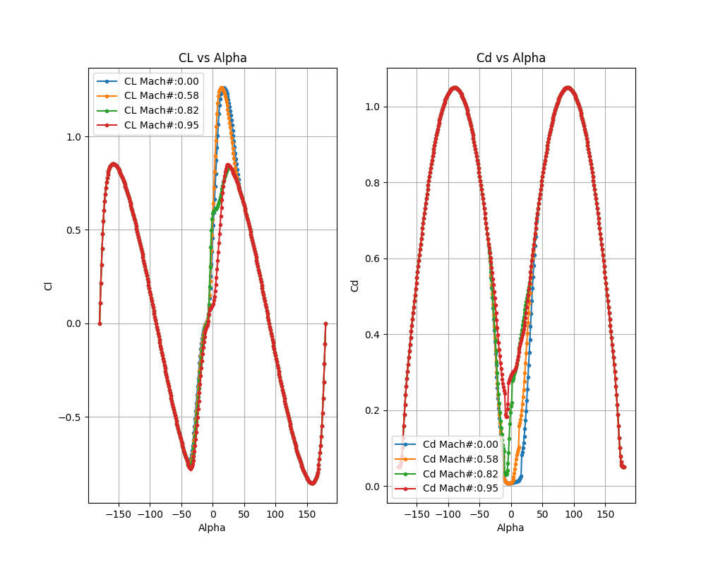
Sample Cl and Cd polars for various mach numbers showing good continuity across the whole range of alphas = -180 ° to +180 °#
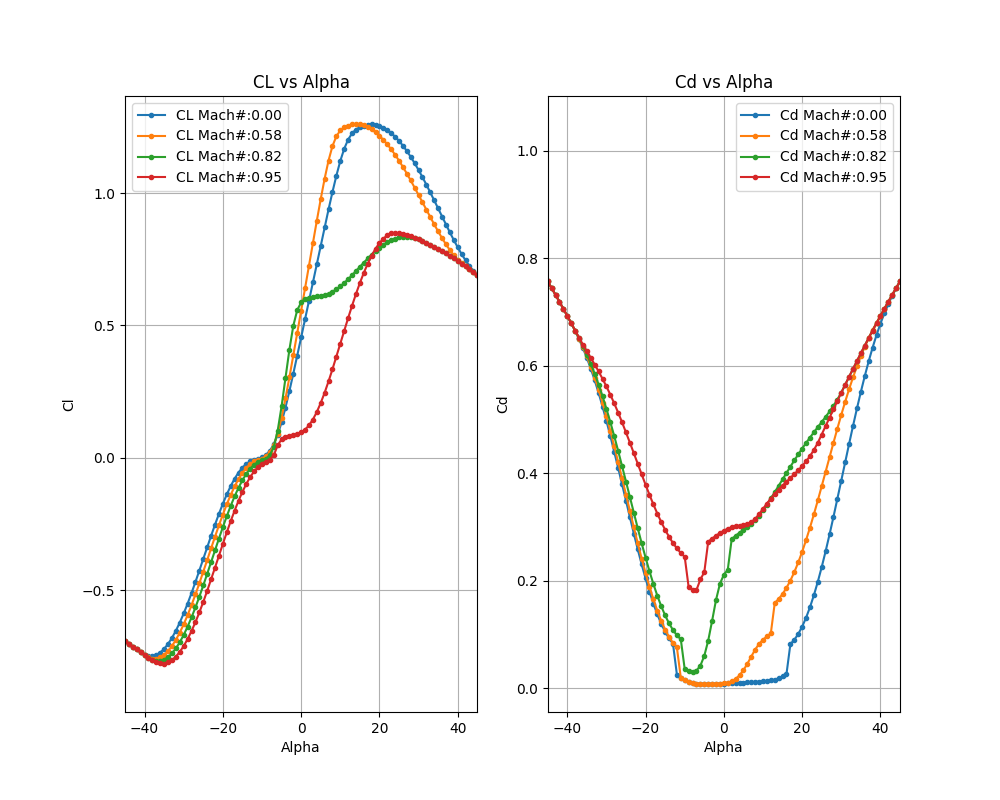
Same sample Cl and Cd polars as above but zoomed in on alphas = -45 ° to +45 ° for various Mach numbers.#
The first index in the sectional polar nested lists corresponds to the MachNumbers,
the second index corresponds to the ReynoldsNumbers, and the third index corresponds to the sectional alphas.
If only a single value of Reynolds or Mach number is provided, the sectional coefficients will not vary with local Mach or Reynolds number.
For multiple values given, the sectional coefficient (lift and drag) values are linearly interpolated according to the local alpha/Mach/Reynolds number in the solution field.
If values are sparse in certain parts of the alpha/Mach/Reynolds space then the interpolation will not be accurate.
Another important aspect when generating the sectional polars is the post stall behavior of the lift and drag coefficients. As the lift and drag coefficients are also interpolated in a piecewise-linear fashion, high nonlinearity in these regions may cause numerical instability within the CFD simulation. The recommendation is to approximate these regions, by smoothing the sectional polar curves. This aspect will only become a consideration if post stall alphas are encountered within the BET region during the CFD simulation, which may occur throughout the convergence history.
The next consideration is the definition of the remaining BET required information, including the geometric data, rotational speed, etc. The available BET translators also process this information.
The
chordandtwistdistributions are typically obtained from the geometric information of the rotor. The chord affects the local lift and drag magnitude, whereas the twist affects the local angle of attack (which affects the local lift and drag).The
radiusassociated with chords and twists do not need to coincide with the radial stations of the sectional polars, as the data will be linearly interpolated.It is recommended to add a point at a
radiusof zero with zerochordand 90 °twistat the root to prevent a tip vortex from escaping there. For more information see this section.
See Sample twist vs propeller span in mesh units and Sample chord vs propeller span in mesh units below for an example of the twist and chord distributions of the XV15 propellers.
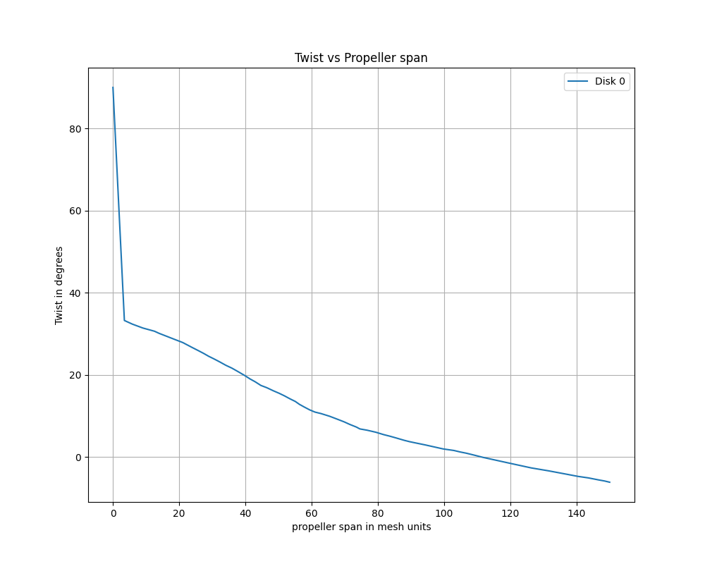
Sample twist vs propeller span in mesh units#
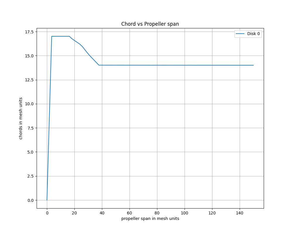
Sample chord vs propeller span in mesh units#
Post-processing the BET loading#
Once a case with a BET disk has run, Flow360 automatically exports the blade-element loading as tabular (CSV) data, so the rotor and propeller performance can be analyzed without post-processing the volume field files. This includes the per-disk force, moment, lift and drag coefficients and the sectional thrust and torque coefficients along the blade radius.
See also
BET Coefficient Distributions for the contents of the exported tables, their columns and units, and how to download them.