Viewer Region#
The viewer region is the primary visualization interface in Flow360 GUI, providing interactive 3D visualization capabilities for geometry inspection, mesh analysis, and results visualization.
Example Views#
Geometry View Mode#
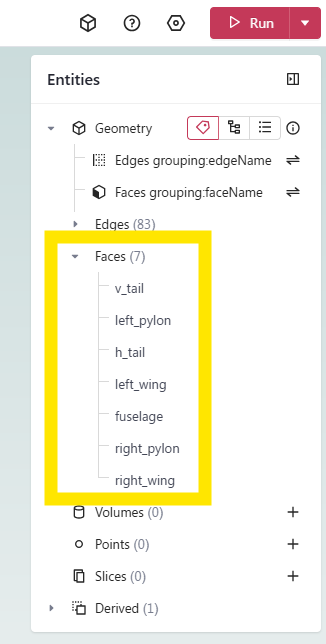
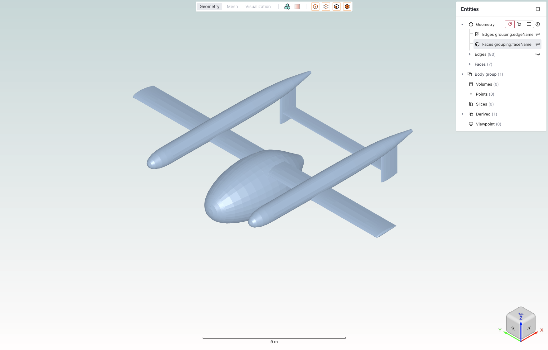 Example of the geometry view mode showing a CAD model with entity selection panel.
Mesh View Mode#
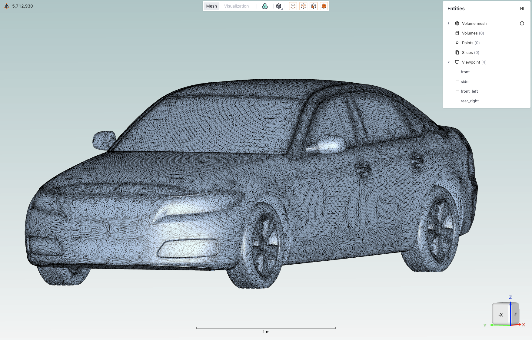 Example of the mesh view mode displaying a mesh visualization.
Core Features#
Feature |
Icon |
Description |
|---|---|---|
View modes |
|
Toggle between Geometry, Mesh, and Visualization views |
Boundary conditions |
|
Toggle coloring of boundaries based on their assigned boundary condition |
Diagnostic tools |
|
Geometry quality inspection features |
Mesh display |
|
Mesh display options: solid or solid with edges |
Entity selection mode |
|
Tools for selecting and managing geometry entities |
Entities visibility |
|
Toggle the visibility of entities by clicking the eye icon when hovering over them |
Mesh metrics |
|
Expand the mesh metrics view by clicking on the icon when in mesh view |
Viewpoints |
|
Controls for saving and loading specific camera positions |
Length scale indicator |
|
Visual reference showing model dimensions to help maintain perspective |
Rotation cube |
|
Interactive orientation widget for quick view rotation to standard angles |


Detailed Descriptions#
View modes#
Toggle between Geometry/Mesh/Visualization views using top toolbar tabs.
Geometry: View CAD geometry
Mesh: Inspect surface and volume mesh
Visualization: View simulation results and post-processing
Note: Each mode provides context-specific tools and options.
Boundary conditions#
Toggle coloring of boundaries based on their assigned boundary condition.
Note: Helps verify boundary condition assignments before mesh generation.
Diagnostic tools#
Tools for geometry quality inspection and validation that color areas of geometry depending on their level of confidence.
Mesh display#
Control the visualization of mesh elements and their properties. Can be set as either solid or solid with edges.
Entity selection mode#
Tools for selecting and managing geometry entities.
Entity Type |
Icon |
Description |
|---|---|---|
Points |
|
Select individual points/vertices |
Edges |
|
Select edge elements |
Faces |
|
Select face/surface elements |
Volumes |
|
Select volume elements |


Note: You can use any combination of selection modes.
Entities visibility#
Toggle the visibility of entities by clicking the eye icon when hovering over them.
Mesh metrics#
Quantitative mesh quality assessment tools for analyzing both surface and volume mesh characteristics.
Element types overview#
The mesh quality visualization provides statistics for different element types commonly found in CFD meshes:
Nodes are present in every mesh and represent the intersection points of mesh elements, they are fundamental to defining the mesh structure and geometry.
Surface Elements:
Triangles: Primary surface mesh elements
Quadrilaterals: Optional structured surface elements
Volume Elements:
Tetrahedrons: Unstructured volume elements
Prisms: Boundary layer elements
Pyramids: Transition elements between different element types
Hexahedrons: Structured volume elements
Surface metrics
Key metrics for assessing surface mesh quality:
Metric
Description
Importance
Area
Face area of surface elements
Identifies areas of highly non-uniform mesh resolution
Area Ratio
Ratio between adjacent face areas
Indicates mesh growth rate and smoothness
Aspect Ratio
Ratio between longest and shortest edge
Measures element skewness and potential numerical issues
First Layer Height
Height of first prismatic layer
Critical for boundary layer resolution
Volume metrics
Essential metrics for volume mesh quality assessment:
Metric
Description
Importance
Aspect Ratio
Element shape quality indicator
Identifies highly stretched or compressed elements
Volume
Element volume measurement
Helps detect very small or large elements that might affect solution stability
Viewpoints#
Controls for saving and loading specific camera positions.
Usage:
Click the + icon to add a new viewpoint that will be the current camera position
Name the viewpoint to be representative of the camera position
Length scale indicator#
Visual reference showing model dimensions to help maintain perspective.
Features:
Dynamic scale adjustment
Unit system consistency
Reference dimension display
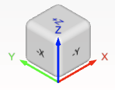
Rotation cube#
Interactive orientation widget for quick view rotation to standard angles.
Usage:
Click cube faces for orthogonal views
Click vertices or edges for isometric views
💡 Tips
Use keyboard shortcuts (Ctrl/Cmd) with mouse operations for enhanced control
Save frequently used viewpoints for quick access
Customize entity visibility to focus on areas of interest
Use the fit-to-view option when navigating large models
❓ Frequently Asked Questions
How can I reset the view if I get disoriented?
Use the “Fit to Screen” option in the view menu.
Why can’t I select certain entities?
Verify that the correct entity type is enabled in the selection toolbar.
How do I save a custom viewpoint?
Use the “Save Viewpoint” option in the View context menu after positioning the view as desired.