Lumped Ports and Elements
This page describes how to set up lumped ports and elements in Flexcompute RF (also Flex RF).
The lumped port or element represents a discrete circuit connection between a pair of metallic structures in the simulation domain. The lumped port is used to excite and terminate the structure with a given impedance. The lumped element is used to represent a passive circuit load connected to the structure.
Lumped Ports
Section titled “Lumped Ports”The LumpedPort represents a planar, uniform current excitation with a fixed impedance termination.
# Define a lumped portmy_port_1 = LumpedPort( name="My Port 1", center=(0,0,0), size=(0, 200, 300), voltage_axis=2, # voltage drop direction (2 = z) impedance=50, # port impedance)The default impedance is 50. The LumpedPort has the following additional restrictions:
- The
LumpedPortmust be planar (exactly one zero-size dimension). If a 1D port is desired, instead provide a small but finite width along its lateral axis. - Only axis-aligned planes are supported at this time.
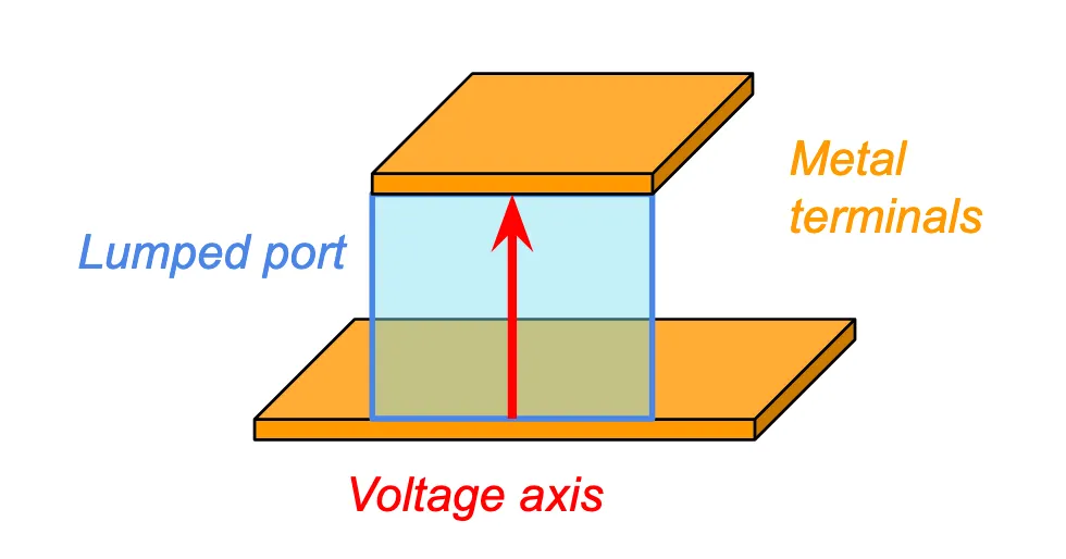
An example lumped port orientation is shown above. The port is shown in blue, and the connected port structures (metal terminals) in orange. The voltage_axis, in red, should always point in the direction that connects the two terminals.
For coaxial terminals, use the CoaxialLumpedPort.
# Define coaxial lumped portmy_coaxial_port_1 = CoaxialLumpedPort( name="My Coaxial Port 1", center=(0,0,0), inner_diameter=1000, # inner diameter in um outer_diameter=2000, # outer diameter in um normal_axis=0, # normal axis (0 = x) direction="+", # direction of signal along normal axis impedance=50, # port impedance)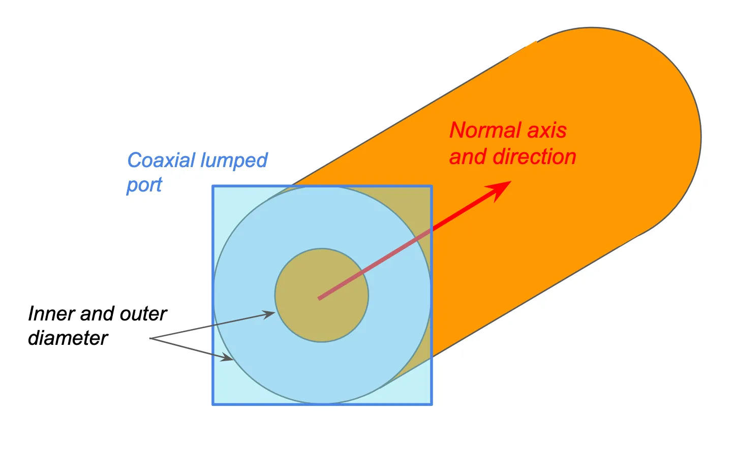
The CoaxialLumpedPort uses the analytical coaxial mode as the source. This means that the port structures must be circular and must match the physical port dimensions. Any discrepancy will result in parasitic effects in the S-parameters.
Lumped Elements
Section titled “Lumped Elements”For simple resistive elements, use the LumpedResistor or CoaxialLumpedResistor.
# Define a lumped resistormy_resistor = LumpedResistor(    name="My resistor",    center=(0,0,0),    size=(0, 400, 300),    voltage_axis=2,       # voltage drop direction (2 = z)    resistance=100.0,     # element resistance)
# Define a coaxial lumped resistormy_coaxial_resistor = CoaxialLumpedResistor(    name="My Coaxial Port 1",    center=(0,0,0),    inner_diameter=1000,   # inner diameter in um    outer_diameter=2000,   # outer diameter in um    normal_axis=0,         # normal axis (0 = x)    resistance=25.0,       # element resistance)
For general-purpose lumped elements, use the LinearLumpedElement. This object connects the element terminals to a passive circuit with arbitrary topology. Use the CircuitImpedanceModel and LumpedCircuitComponent to specify the circuit topology.
# Build the following circuit using CircuitImpedanceModel#       (0)         (1)         (2)#  port+ o---( R )---+---( L )---+---o port-#                    |           |#                    +---( C )---+resistor = LumpedCircuitComponent(    element_type = 'R',    node_plus = 0,    node_minus = 1,    value = 25.0      # Ohms)capacitor = LumpedCircuitComponent(    element_type = 'C',    node_plus = 1,    node_minus = 2,    value = 1e-12     # 1 pF)inductor = LumpedCircuitComponent(    element_type = 'L',    node_plus = 1,    node_minus = 2,    value = 1e-9     # 1 nH)my_circuit = CircuitImpedanceModel(    components = [resistor, capacitor, inductor],    port_node_plus = 0,    port_node_minus = 2,)
# Apply circuit to lumped elementmy_lumped_element = LinearLumpedElement(    center=(0,0, 250),    size=(0, 200, 500),    name='my lumped element',    voltage_axis=2,    network = my_circuit     # Connect circuit here)