Meshing
This page covers how to control the mesh/grid settings in Flexcompute RF (also Flex RF).
The RF solver currently uses the finite difference time-domain (FDTD) method. In FDTD, the simulation domain is rendered onto a rectilinear spatial grid. Each grid cell, also known as an Yee cell, represents a location where the field solution is sampled. For the FDTD user, there are two general categories of length scales to be aware of when it comes to defining the grid:
-
Electromagnetic (EM) length scale: this primarily consists of the EM wavelength in the local medium, but depending on the application, could include other quantities such as mode propagation and attenuation lengths, skin depth, and sharp field gradients.
-
Geometric length scale: this refers to the minimum feature size of the device. Common features include metal layer thickness, gaps, radii of curvature, and sharp corners. Note that not every geometry feature is of equal importance — only features that contribute significantly to the EM behavior of the device need to be finely resolved.
To obtain good results, the minimum grid size should be small enough to resolve both categories. In typical RF/microwave applications at low frequencies, the geometric length scale is usually the dominating factor.
Basic Usage
Section titled “Basic Usage”The overall grid specification is defined by the GridSpec object.
Simulation├── grid_spec: GridSpec # Grid specification for base Simulation│ ├── grid_x: ... # Grid type for x-direction│ ├── grid_y: ... # Grid type for y-direction│ ├── grid_z: ... # Grid type for z-direction│ ├── override_structures: ... # List of mesh override structures│ ├── snapping_points: ... # List of snapping points│ ├── layer_refinement_specs: ... # List of layer refinement specs│ └── wavelength: ... # Reference wavelength for automesher (if used)└── ...Each entry grid_x, grid_y, grid_z accepts one of the basic grid types: AutoGrid, UniformGrid, QuasiUniformGrid, or CustomGrid. Additional refinement objects are optionally specified in override_structures, snapping_points, and layer_refinement_specs. More on the refinement objects later.
For the majority of use cases, it is recommended to use AutoGrid for all three Cartesian directions. In that case, simply use the GridSpec.auto() convenience method.
# Define a grid specification that uses the automesher in all three directionsmy_grid_spec = GridSpec.auto( wavelength = rf.C_0/f_max, # Set reference wavelength based on simulation frequency min_steps_per_wvl = 15, # Min. number of grid cells per wavelength min_steps_per_sim_size = 20, # Min. number of grid cells per longest edge of sim domain dl_min = 3.0, # Suggested min. grid cell size (in um) override_structures = [...], # Last three parameters contain optional refinement settings snapping_points = [...], # (more on those later) layer_refinement_specs = [...],)Use the min_steps_per_wvl and/or min_steps_per_sim_size parameters to set the cell size upper bound for the automesher. Use the dl_min parameter to set the cell size lower bound.
The grid is generated upon definition of the base Simulation object.
# Define a Simulation with a GridSpec# The grid is constructed at this pointsim = Simulation(    grid_spec = my_grid_spec,    ...)
# Use Simulation.grid_info to get grid statisticsprint(sim.grid_info)
In addition to the Simulation.grid_info attribute, use the Simulation.plot_grid() method to plot the grid for inspection. Typically, this is used in conjunction with Simulation.plot() or TerminalComponentModeler.plot_sim() to overlay the simulation domain for context.
# Inspect the constructed grid at z=10fig, ax = plt.subplots(figsize=(8,8))sim.plot_grid(z=10, ax=ax) # Plot the gridtcm.plot_sim(z=0, ax=ax) # Also, plot the structures and simulation objectsplt.show()In addition to the AutoGrid, the following grid types are available for specialized applications:
- The
UniformGridgrid type creates a uniform grid with fixed spacingdl. - The
QuasiUniformGridgrid type behaves similarly to theUniformGrid, but respects snapping points for structure boundaries. - The
CustomGridgrid type allows the user to manually specify grid cell boundaries.
Please refer to their respective API reference page for more details.
Grid Refinement
Section titled “Grid Refinement”Grid refinement objects allow the user to specify additional constraints on the grid within a user-defined spatial region. The GridSpec supports the following grid refinement specifications:
- The
snapping_pointsparameter accepts a list of 3D coordinates that grid boundaries must pass through. - The
override_structuresparameter accepts a list ofMeshOverrideStructureobjects. The latter is aBox-shaped object that enforces direct cell size constraints within its bounds. - The
layer_refinement_specsparameter accepts a list ofLayerRefinementSpecobjects. The latter is aBox-shaped object that enforces indirect cell size constraints in the normal and in-plane directions separately. It also implements automated corner finding and gap resolution.
Mesh Override Structure
Section titled “Mesh Override Structure”The MeshOverrideStructure object imposes direct cell size constraints within its Box-shaped bounds. There are two ways to specify the constraint.
The first method is to use the dl parameter to set the cell size upper bound directly.
# Define a mesh override structure for a specific spatial regionmy_override_structure = MeshOverrideStructure( geometry = Box(center=(0,0,0), size=(200, 200, 500)), # Spatial region dl = (5, 5, None) # Cell size upper bound of 5um in x, y. No constraint in z.)Use None to signify no constraint for a particular axis.
The second method is to use a fictitious medium to implicitly restrict the cell size.
# Define a mesh override structure using a mediummy_override_structure = MeshOverrideStructure( geometry = Box(center=(0,0,0), size=(200, 200, 500)), # Spatial region background_medium = Medium(permittivity=11.0) # Reference medium for refinement)In this case, the automesher will mesh the refinement region as if it were filled by the specified background_medium. Note that the background_medium will not actually be used in the simulation.
Use the enforce, shadow, and drop_outside_sim parameters to handle situations when MeshOverrideStructure objects overlap with each other or the simulation boundaries. Please refer to the API reference for more details.
Layer Refinement Spec
Section titled “Layer Refinement Spec”The LayerRefinementSpec is designed to impose indirect cell size and position constraints based on certain geometry factors. It is primarily designed to be used around metallic planar structures (e.g., a metal plane in a printed circuit board).
LayerRefinementSpec│ # Basic parameters├── center, size # Center and size of refinement region├── axis # Normal axis (determines normal and in-plane axes)│ # Normal dir. refinement options├── min_steps_along_axis # Min. grid cells along normal dir.├── bounds_snapping # Whether/how to snap grid boundaries to normal boundaries├── bounds_refinement # Optional refinement at normal boundaries│ # In-plane refinement options├── corner_snapping # Whether to snap to in-plane metal corners├── corner_refinement # Optional refinement around metal corners├── corner_finder # Algorithm used to find corners├── gap_meshing_iters # Num. of iterations used for automated gap meshing (0 = off)└── ...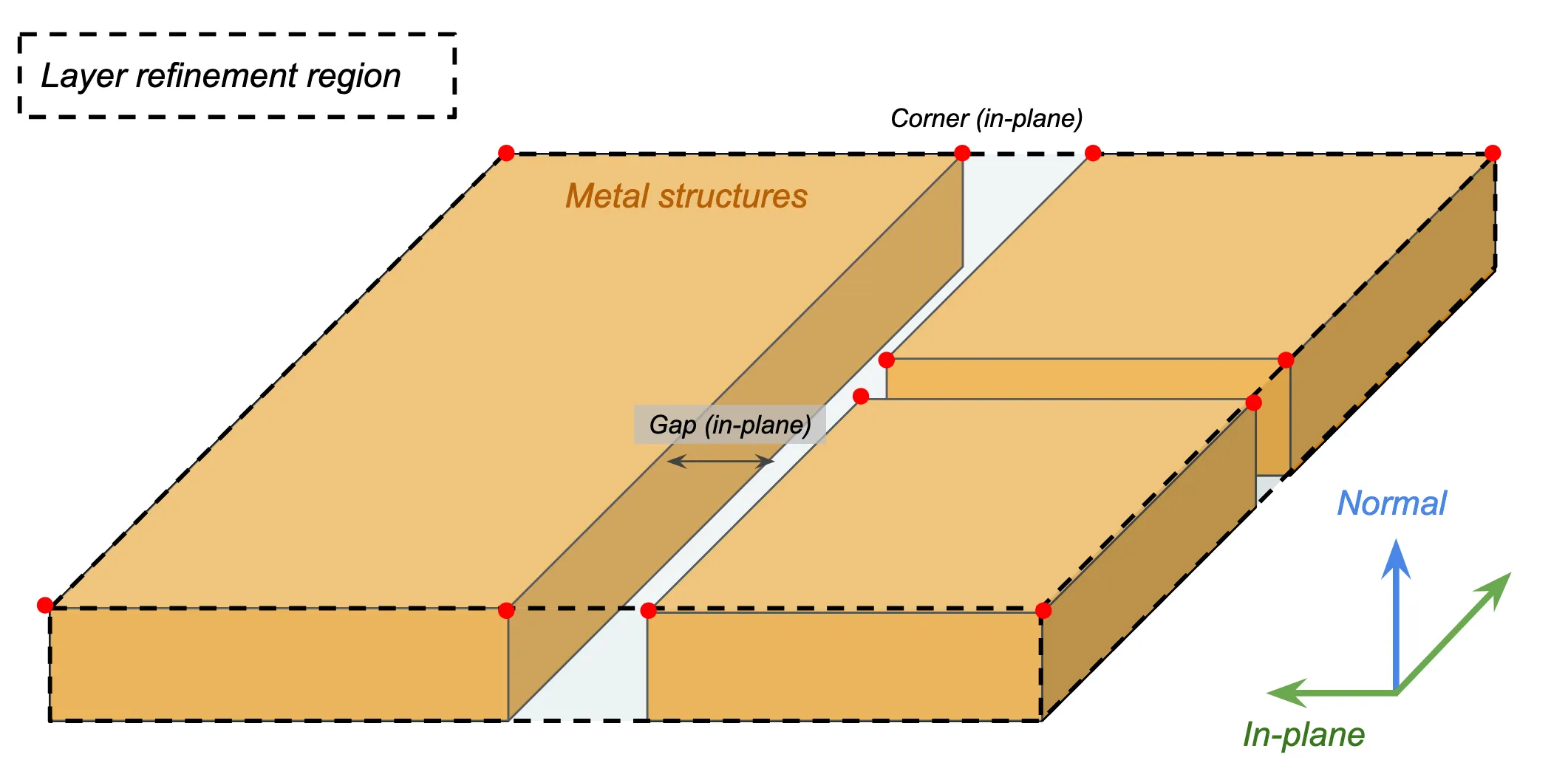
The center, size, axis parameters determine the refinement region and the plane normal direction. The axis should normally be aligned with the metal thickness direction. Alternatively, the LayerRefinementSpec.from_structures() convenience method automatically identifies center, size, and axis based on the supplied structures.
# Define center/size/axis for LayerRefinementSpecmy_lr_spec = LayerRefinementSpec(    center=(0,0,10),    size=(500, 500, 20),    axis=2,               # Normal in z direction    ...)
# Define center/size/axis using structures# Normal axis is determined based on smallest dimension of the bounding boxmy_lr_spec = LayerRefinementSpec.from_structures(    structures = [signal_trace, patch_antenna, ...],    ...)
Along the normal direction, the min_steps_along_axis parameter constrains the number of grid cells used to resolve the metal thickness. Typical recommended values are None (default) or 1 for a coarse/regular simulation, and the range of 2 to 5 for S-parameter convergence. Higher values may be necessary for convergence of 2D mode properties like mode impedance.
# Define grid size constraint along structure thicknessmy_lr_spec = LayerRefinementSpec( ..., min_steps_along_axis = 1, # Min. 1 grid step along normal dir. ...)Use bounds_snapping and bounds_refinement to apply additional refinement along normal boundaries. Note that this is normally not needed if the min_steps_along_axis parameter is set.
Along the in-plane directions, metal corners and gaps are automatically identified by default. The grid is automatically snapped to metal corners. Use the corner_refinement parameter in conjunction with GridRefinement to specify refinement parameters around identified corners.
my_lr_spec = LayerRefinementSpec( ..., corner_refinement = GridRefinement(dl = 0.05*mm, num_cells = 2), ...)In the above example, we set a maximum grid size of 0.05 mm for each of the 2x2 adjacent cells at the corner. We recommend setting dl based on the smallest in-plane feature size, e.g., the smallest trace width or via/hole size. It is usually fine to set num_cells to 2 unless a larger refinement region around each corner is desired.
Use the gap_meshing_iters parameter to control the number of iterations used to resolve in-plane metal gaps. It is important to ensure that a metal gap is not spanned by a single grid cell, as that can lead to an unintentional electrical short and significantly alter the behavior of the device.
Putting it all together, a typical LayerRefinementSpec might look like the following:
my_lr_spec = LayerRefinementSpec.from_structures( structures = [signal_trace, patch_antenna, ... ], min_steps_along_axis = 1, corner_refinement = GridRefinement(dl = 0.05*mm, num_cells=2))Notice that we let most parameters use their default values. The two most important parameters in regular usage are min_steps_along_axis and corner_refinement. Use these two parameters to fine-tune the level of refinement.
Note that for devices with multiple metallic layers, individual LayerRefinementSpec objects must be defined for each layer. Use a Python dictionary to optionally share settings easily across multiple objects.
# Define a common set of LayerRefinementSpec settings using a Python dictlr_settings = {    "min_steps_along_axis": 1    "corner_refinement": GridRefinement(dl = 5, num_cells=2)}
# Use the common settings in multiple LayerRefinementSpecslr_spec1 = LayerRefinementSpec.from_structures(    structures = [layer1_structures],    **lr_settings)lr_spec2 = LayerRefinementSpec.from_structures(    structures = [layer2_structures],    **lr_settings)
Subpixel Averaging
Section titled “Subpixel Averaging”Subpixel averaging is a numerical method used to accurately resolve material boundaries that do not line up with the FDTD grid boundaries. Under normal circumstances, the default settings are appropriate and the user does not need to provide custom settings. Should a custom SubpixelSpec be necessary, please refer to the API reference for more details.