SectionalPolars Best Practices.#
If you do decide to implement your own scripts to generate the BETDisks section of the Flow360.json input files, a number of aspects must be considered when generating the sectional polars for Flow360.json input. Firstly, continuity through the entire alpha range including at extreme angles (180 ° and -180 °) must be enforced to ensure numerical stability. Such high angles are not likely to occur at the end of the simulation, but may be encountered during the convergence history, especially near the hub region. Discontinuous forcing terms will increase the likelihood of solution divergence. To avoid this, the following setup is recommended:
For each of the BETDisks add values for -180 ° at the beginning of the list and +180 ° at the end of the list
For each of the sectional polars (number defined by number of radial stations within the sectional polar input) and each BET disk, set the lift (and drag) coefficients to equal values at the beginning and the end of the (inner-most) list (corresponding to alpha = -180 ° and +180 °). If not available, a value of zero can be used for lift and 1 for drag. See example polars
secPolarPlotandsecPolarPlotZoombelow
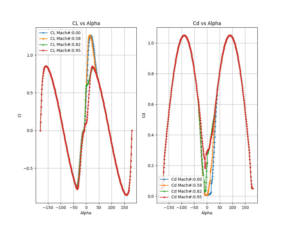
Sample Cl and Cd polars for various mach numbers showing good continuity across the whole range of alphas = -180 ° to +180 °#
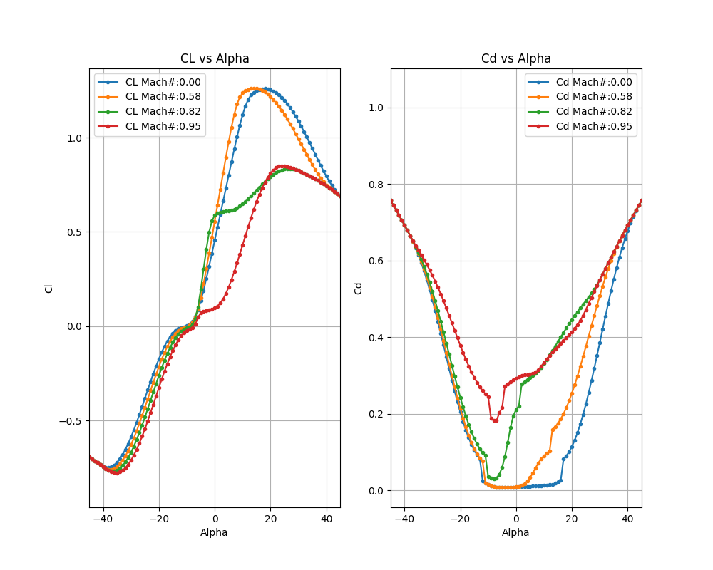
Same sample Cl and Cd polars as above but zoomed in on alphas = -45 ° to +45 ° for various Mach numbers.#
As described in the BETDisks section, the first index in the sectional polar nested lists corresponds to the MachNumbers, the second index corresponds to the ReynoldsNumbers, and the third index corresponds to the sectional alphas. If only a single value of Reynolds or Mach number is provided, the sectional coefficients will not vary with local Mach or Reynolds number. For multiple values given, the sectional coefficient (lift and drag) values are linearly interpolated according to the local alpha/Mach/Reynolds number in the solution field. If values are sparse in certain parts of the alpha/Mach/Reynolds space then the interpolation will not be accurate.
Another important aspect when generating the sectional polars is the post stall behavior of the lift and drag coefficients. As the lift and drag coefficients are also interpolated in a piecewise-linear fashion, high nonlinearity in these regions may cause numerical instability within the CFD simulation. The recommendation is to approximate these regions, by smoothing the sectional polar curves. This aspect will only become a consideration if post stall alphas are encountered within the BET region during the CFD simulation, which may occur throughout the convergence history.
The next consideration is the definition of the remaining BET required information, including the geometric data, rotational speed, etc. The available BET translators also process this information.
The
chordandtwistdistributions are typically obtained from the geometric information of the rotor. The chord affects the local lift and drag magnitude, whereas the twist affects the local angle of attack (which affects the local lift and drag).The
radiusassociated with chords and twists do not need to coincide with the radial stations of the sectional polars, as the data will be linearly interpolated.It is recommended to add a point at a
radiusof zero with zerochordand 90 °twistat the root to prevent a tip vortex from escaping there. For more information see this section.
See twistVspanPlot and chordVspanPlot below for an example of the twist and chord distributions of the XV15 propellers.
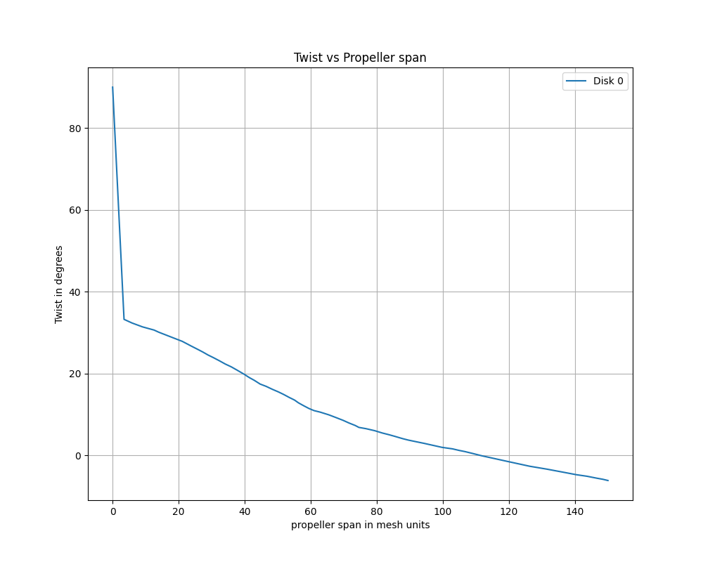
Sample twist vs propeller span in mesh units#
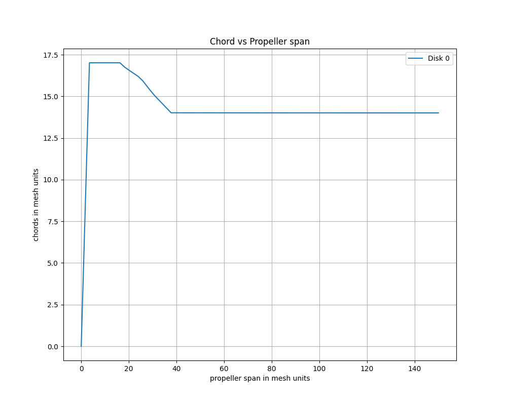
Sample chord vs propeller span in mesh units#