Meshing Recommendations#
Introduction#
Mesh generation for CFD is a critical aspect of the analysis process. This documentation aims to provide a high-level description of requirements and best-practices recommended for use in Flow360.
Experienced CFD users are likely familiar with most aspects of this documentation and can continue applying their typical meshing processes. Those less experienced with CFD, or meshing for CFD more specifically, are suggested to use this guide as a starting point. Review of initial simulation results will often provide guidance for mesh improvements.
Note
The majority of guidance provided here is presented in the context of traditional aircraft, but should also be similarly applied to comparable geometry.
The purpose of any mesh is to provide a stencil for the calculation of the discretized governing equations of the flow field. Stencil spacings, often referred to as mesh refinement, and type of grid system, defined by shape and arrangement, are important to CFD because they can affect the ability to obtain accurate solutions. That is, the choice of grid spacing, arrangement, and fineness can have a strong influence on the accuracy of flow solutions. Please keep in mind that the underlying geometry is used to generate the surface mesh. The flow solution is affected by the surface mesh and not by the underlying geometry.
To that end, it is important to consider the quantities of interest and flow physics when building meshes. They should be purposefully built to capture flow features of interest and those impactful to critical analysis results.
Questions to consider when building meshes:
Where are large gradients (boundary layers, tip vortices, shocks, transition) expected in the flow field?
What regions of the model (wing, control surface, wake) are most important to the desired results?
What are the operating conditions (Mach, altitude, \(\alpha\), \(\beta\), \(\Omega\)) and are they expected to vary?
What balance of accuracy (flow physics captured) versus speed (solver wall-time) is desired?
The following are recommended best-practices for generating a suitable mesh for CFD. Recommendations are intentionally general to allow for users to develop meshes with their own tools and processes.
Surface Mesh#
Triangular (tri) and quadrilateral (quad) elements are allowable
Elements must be first-order
Adjacent element size should grow by about \(1.2\), this is applicable to node spacing along edges and within the interior of surfaces
Refinement should be present in regions where large gradients are expected
Leading edges (LE) and trailing edges (TE)
Wing/rotor tips
Concave (wing-fuselage juncture) and convex (chine, struts, landing gear) regions
Where opposing surfaces are in close proximity to one another
Elements should be isotropic to the greatest extent possible
Most meshing software attempts to follow this guidance
Geometric features, especially edges, can impose constraints that affect isotropy (see “Geometry” below)
Anisotropic elements are appropriate for regions where the general flow direction is known a priori
LE and TE: along edge refine in streamwise direction and coarsen in spanwise direction, increase element size progressively away from edge until isotropic
TE (blunt): multiple elements should be present between parallel edges
Farfield:
Encloses entire fluid domain where flow solution occurs
Size to roughly \(\text{100x}\) largest dimension of no-slip surfaces, centered around geometry
Edges should have at least \(20\) nodes in all directions, target isotropic elements
Depending on the intended boundary condition(s), a sphere (farfield) or box (inlet-outlet) is typically preferred
Sliding interfaces:
There must be two surfaces (patches) on either side of the sliding interface
The nodal locations on both sides of the interface are permitted to be non-conformal (i.e. the nodal locations are not required to match exactly on either side of the interface). Note: non-conformal meshes only support boundary-based interfaces and not zone-grid connectivity interfaces.
The elements on the surfaces may be composed of both triangles and quadrilaterals
Elements on the sliding interface surfaces should be as close to isotropic as possible for the greatest accuracy
The surfaces must remain aligned within 20% of the surface meshes’ maximum edge length as they undergo movement relative to one another
The sliding interface should be roughly \(\text{3-5%}\) larger in diameter than the diameter of the rotating geometry and roughly \(\text{10%}\) larger in height (axis of rotation direction) than the maximum height of the rotating geometry
Geometry:
The following recommendations are intended to help generate high quality meshes.
All surfaces orientation should be defined with wall normals pointing towards the surrounding fluid
LE should be defined by edge along the entire span
TE should be blunt (two parallel edges) or rounded (single edge, similar to LE), sharp TEs are also appropriate
Avoid small acute angles and edges that join tangentially as these can result in poor quality elements
Must be watertight, that is no gaps or degenerate surfaces can be present
Remove or neglect edges that are not necessary for controlling mesh size and arrangement to improve mesh uniformity
Simplify geometry where impact to flow and results is minimal, and where generating quality mesh is challenging
Element Sizing#
Recommendations for surface mesh sizing and quality metrics are provided here. These are target values and should not be considered absolute requirements. An additional consideration is often required when complex flow and geometric features impose restrictions during mesh generation.
The following table provides guidance for specifying element lengths for the surface mesh. Node spacing, and resulting element sizing, typically is handled along edges bounding surface patches. As such, this table provides guidance based on common features (LE, TE) found in traditional aircraft that should be defined by bounding edges. Maximum cell sizes are also provided at the component level and are applicable to interior surface element sizing.
Component |
Feature |
Reference |
Criteria |
Source |
|---|---|---|---|---|
Global |
general guidance |
|||
Max |
D |
1%∙D |
||
Min |
MAC |
1%∙MAC |
||
Fuselage |
HLPW4 (Mesh C) |
|||
Max |
MAC |
1%∙MAC |
||
Nose |
D |
TBD |
||
Empennage |
D |
TBD |
||
Root |
b |
0.1%∙b |
spanwise spacing (at juncture) |
|
Wing |
HLPW4 (Mesh C) |
|||
Max |
MAC |
1%∙MAC |
||
LE |
c |
0.1%∙c |
chordwise spacing |
|
c |
1%∙c |
spanwise spacing (AR=10) |
||
TE |
t |
25%∙t |
chordwise spacing (4x elem across blunt TE) |
|
t |
250%∙t |
spanwise spacing (AR=10) |
||
Root/Tip |
b |
0.1%∙b |
spanwise spacing (at juncture or tip) |
|
Rotor |
mimic HLPW4 (Mesh C) |
|||
Max |
D |
1%∙D/2 |
||
LE |
c |
0.1%∙c |
chordwise spacing |
|
c |
1%∙c |
spanwise spacing (AR=10) |
||
TE |
t |
25%∙t |
chordwise spacing (4x elem across blunt TE) |
|
t |
250%∙t |
spanwise spacing (AR=10) |
||
Root/Tip |
D |
0.1%∙D/2 |
spanwise spacing (at juncture or tip) |
|
Cylinder |
general guidance |
|||
Max |
D |
10%∙D |
||
Tip |
D |
1%∙pi∙D |
min element size along circumference (target 100 cells) |
|
Length |
L |
1%∙L |
max element size along axial length |
Definitions
MAC = mean aerodynamic chord (from primary aerodynamic surface)
D = effective diameter (max width for fuselage, disk diameter for rotor)
L = total length (nose-tail for fuselage, largest length otherwise)
c = local chord length (component chord for flap, tip chord for wing)
b = local span length (semi-span for wing, component span for flap)
t = thickness (trailing edge for wing, fore-aft distance for rotor disk)
HLPW4 = 4th AIAA CFD High Lift Prediction Workshop
Directions
Consider the applicable geometry (components and features) of the working model
Add comparable geometry not defined here, this may include scenarios where features vary significantly within a given component or multiple components of similar type exist
Measure reference geometry directly or copy from specification material and calculate node spacings using the same units present in the working model
Apply the resulting node spacing in the model, noting that the smaller of two values should be utilized where conflicts arise
Note
It is inevitable that components and features of a given model will not directly align with the guidance provided here. It is recommended to size these elements based on the local flow gradients expected and to consider mesh refinement studies, especially if these components/features will have a significant impact on the overall analysis results.
Quality Metrics#
Quality metrics reported can vary by meshing software, surface/volume element type, and the selected export type specified by the user. As such, the following quality metrics are general and may need to be modified for review in various meshing software.
\(\text{Max included angle} < 160^{\circ}\)
A large maximum included angle typically results in a highly skewed element
Problematic elements are typically found between parallel edges with dissimilar node spacing/distributions and between edges that join tangentially
Match node spacing between parallel edges and/or join surfaces at shared edge
\(\text{Aspect ratio} < 100\) (measure of isotropy)
A highly anisotropic element will be much larger in one direction versus another
Problematic elements are typically found at LE and TE
Reduce maximum node spacing along the edge in relation to spacing perpendicular to the edge
\(\text{Area ratio} < 20\) (measure of growth rate)
Disparate element lengths will result in adjacent elements differing greatly in size
Problematic elements are typically found where node spacing unintentionally varies by large amounts between neighboring edges
Modify node spacing along neighboring edges to match at intersections
Additional checks:
Intersecting elements = element faces pass through one another
Distance from geometry = nodes are not located on the underlying geometry
Missing elements = surface mesh failed to generate or gaps remain (not watertight)
Flow360 will perform a surface mesh quality check once the user uploads a mesh. The check will return warnings based on the following metrics:
Name |
Definition |
Criteria |
|---|---|---|
Area |
Area of the surface element in grid unit. This must be positive. |
[0, inf] |
Area ratio |
Area ratio of two adjecent surface elements with the larger area always being the numerator. Elements sharing grid nodes are considered adjecent. |
[1, 500] |
Aspect ratio |
The ratio of the longest distance over shortest distance between any two grid nodes in a surface element. |
[1, 1000] |
Volume Mesh#
Tetrahedral (tet), pyramid (pyr), prism (pri), and hexahedral (hex) elements are allowable
Elements must be first-order
Domains:
Multiple fluid domains are allowable but should create a continuous flowfield
Interfaces between domains must be conformal
Overset mesh is not currently supported in Flow360
If mesh motion is intended see Sliding interfaces above
Nearfield domains (geometry enclosures) should be generated with max element size consistent with that of the surface mesh, target isotropic volume elements
Farfield domains (flowfield enclosures) should increase mesh size away from geometry at a recommended growth rate (GR) of roughly \(1.2\) to a maximum value consistent with farfield boundary surface mesh
Layers:
Growth of anisotropic layers from surface mesh is an important aspect of CFD meshes for flowfields with boundary layers
In general, the first layer height (normal distance from no-slip wall) should be specified to attain the desired \(y^+\) values and the total number of layers should be sufficient to fully enclose the resulting boundary layer
A target of \(y^+ < 1\) and \(\text{GR} < 1.2\) is typically appropriate
When transition is important, target \(\text{GR} < 1.1\) and consider a constant layer height for the first \(\text{2-4}\) layers
Similarly target the above when separation is important/expected
When capturing the flow separation is important applying stretching normal to the no-slip wall boundary helps
Additional refinement of the underlying surface mesh may also be required to adequately capture the elevated streamwise gradients that can occur in transitional/separated boundary layers
Numerous approximation formulas for the flat-plate skin friction from literature are often appropriate for estimating the required first layer height, see here as an example
A smooth transition of element size is preferable by generating layers to an isotropic height, that is the final layer height is roughly equivalent to the underlying surface mesh size
Refinement region:
Off-body refinement is important for capturing flow features away from the surface (wakes, shocks) that may impact the accuracy of results
The size and extent of refinement regions is dependent upon the flow features being captured as well as the operating conditions to be simulated
Refinement regions should fully enclose the geometry producing off-body flow features, by roughly \(10%\) geometry scale in all directions
In the downstream direction, extend refinement regions at least \(\text{2x}\) the local characteristic length (chord, diameter)
Choose a shape that is representative of the flow features of interest (cylinder/rotor, box/wing, cone/shock)
Ensure refinement region encloses flow features at different flow angles (\(\alpha\), \(\beta\)) and speeds (\(M\), \(\Omega\))
Refinement regions should restrict the maximum element size allowable within
Reference the max surface element length
Mesh sizing of \(\text{maxSurfaceElementLength} \cdot \sqrt{3}\) is recommended for refinement regions near surfaces
Larger refinement regions can be extended further downstream, while still enclosing smaller refinement regions, with incrementally larger sizing applied
Refinement regions for actuator disks, BET disks and BET lines
Radius: 110% ~ 120% rotor radius
Thickness: 75% max chord length or 10% ~ 15% rotor radius
Axial Spacing: 20+ layers along the axial/thickness direction to resolve the strong gradient
Circumferential Spacing: 540/720/900 cells along the circumferential direction for typical coarse/medium/fine meshes
Radial Spacing: Edge length along the radial and circumferential directions should be roughly the same
Element Sizing#
As noted above, volume elements in the immediate vicinity of geometry expected to create off-body flow features of importance should have their maximum size restricted to \(\text{maxSurfaceElementLength} \cdot \sqrt{3}\). Outside of these regions of interest, it is generally appropriate to generate volume elements with a \(\text{GR} = 1.2\) and a maximum size equivalent to the farfield boundaries.
Quality Metrics#
Volume mesh quality metrics also vary widely. The following are general metrics to target. However, solution convergence in Flow360 and investigation of mesh refinement in the vicinity of flow features of interest are often the best assessments of mesh quality.
\(\text{Equivolume skewness} < 0.95\) (measure of actual versus optimal volume)
Only applicable to tetrahedral elements
Tetrahedral elements should be nearly optimal unless adjacent elements influence skewness
Problematic elements are typically found where layers stop growing prematurely
Refine surface mesh underlying stopped layers to allow for more isotropic volume elements
Additional checks:
Intersecting elements = element faces pass through one another
Negative volume = degenerate elements that fold/twist back on themselves
Flow360 will perform a volume mesh quality check once the user uploads a mesh. The check will return warnings based on the following metrics:
Name |
Definition |
Criteria |
|---|---|---|
First layer thickness ratio |
The ratio of average first layer thickness for a boundary relative to the overall average. 1 |
[0.1, 10] |
Volume |
Volume of the volumetric element in grid unit. This must be positive. |
[0, inf] |
Aspect ratio |
The ratio of the longest distance over shortest distance between any two grid nodes in a volumetric element. |
[1, 100000] |
\(y^+\) |
The estimated \(y^+\) value on each |
Average \(y^+\) [0.01, 10], Max \(y^+\) < 50 |
- Note:
The first layer thickness (FLT) is calculated as the minimum length from connected edges at each surface node projected to the surface normal direction. The value is in the grid unit. The average FLT of each
Wallboundary is the arithmetic average of the FLT of all surface nodes on the boundary. The overall average FLT is the node-count-weighted average of the FLT for allWallboundaries.The average and maximum \(y^+\) values are calculated for each
Wallboundary using the average and maximum FLT, respectively.
y+ Estimation#
The mesh \(y^+\) is estimated using flat plate boundary layer theory,
where \(L\) is the reference length for the flow condition and \(\Delta s\) is the first layer thickness. All values are dimensional. Flow conditions and the reference length need to be determined from user inputs.
The reference length differs case by case. For wing and propeller types of simulations, a good choice for the reference length is the leading edge radius, which can be estimated as 0.25% of the chord length. The chord length is estimated as the dimension of a bounding box in the freestream direction.
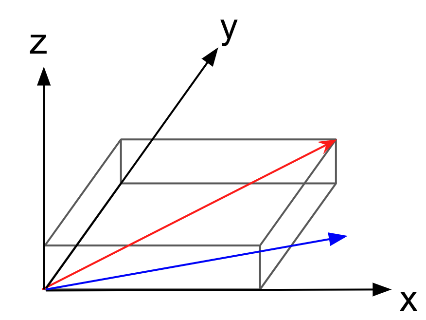
Fig. 7.2.1 Estimation of an equivalent chord length for a boundary. The grey box is the bounding box and the blue vector is the freestream direction.#
The chord length for each Wall boundary is estimated by projecting the diagonal of the bounding box (red vector in Fig. 7.2.1) to the freestream direction (blue vector in Fig. 7.2.1).
The freestream velocity is determined from reference_velocity_magnitude or velocity_magnitude, depending on the simulation settings.
BET and AD Refinement Regions#
For BET and AD simulations, one key aspect is the mesh topology and spacing in the region of the propeller disk. Because the BET/AD will be adding energy to the flow, it is important that the mesh be sufficiently refined in the propeller region to allow for the distribution of source terms across multiple nodes. To that end, the following criteria are recommended when generating a volumetric mesh refinement region for BET/AD modeling:
The mesh should have at least 20 nodes in the axial direction (as in along the thrust vector, normal to the disk plane). This allows for the sharp pressure difference caused by the BET/AD forcing terms to be adequately resolved, leading to good convergence.
Typically, a refinement region
heightalong the thrust axis of 10 to 15% of the rotor radius is recommended. The approximate maximum thickness swept by the propeller along the thrust axis is another reasonable value to use.An
outer_radiusof 1.1 to 1.2 times the rotor radius is recommended.The node spacing in the circumferential and radial directions will depend on the characteristics of the rotor and the flow condition, but generally, the aspect ratios of the cells should be kept below 5 for a high quality BET/AD mesh.
Investigations regarding the mesh topology (structured versus unstructured) in the BET region have shown minor impact on the results, although, for unstructured meshes, an isotropic distribution is recommended. The main set of meshing recommendations is summarized in the table below.
Please see the 2 figures below for a visual of a BET/AD volume mesh refinement region with a simple wing in front of it.
Parameter |
Recommended Value |
|---|---|
Axial direction extent |
15-20% rotor radius ( for a 10-15% rotor radius disk thickness in simulation) |
Radial direction extent |
approx. 1.1 to 1.2 rotor radius |
Number of nodes in axial direction |
min. 20 nodes |
Aspect ratio of cells |
less than 5 |
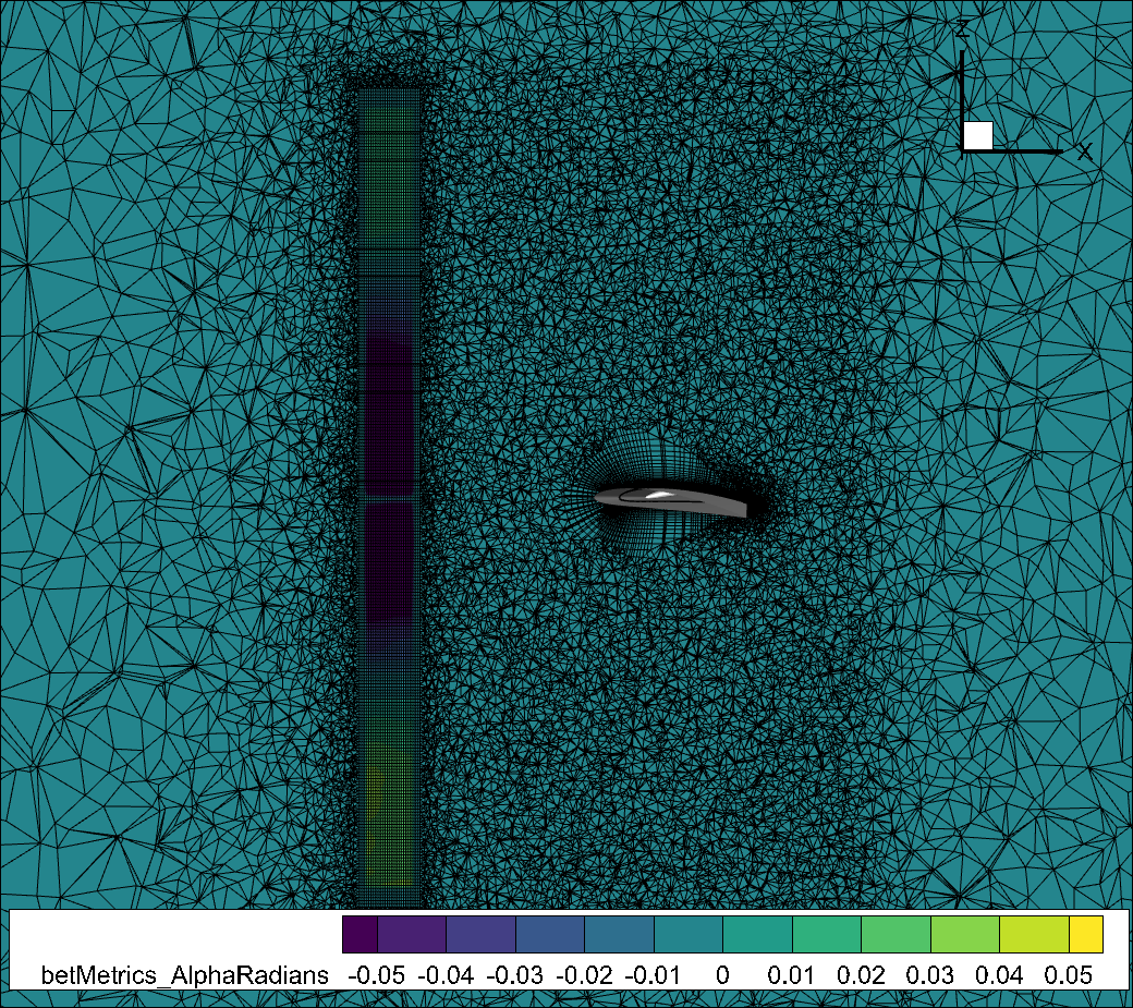
Fig. 7.2.2 Slice of a volume mesh for a BET/AD simulation with a wing behind the BET/AD region. The slice shows the BET/AD refinement region in the axial direction. As discussed below, notice the structured rotorDisk refinement region within an unstructured refinement region to better capture the physics of interest.#
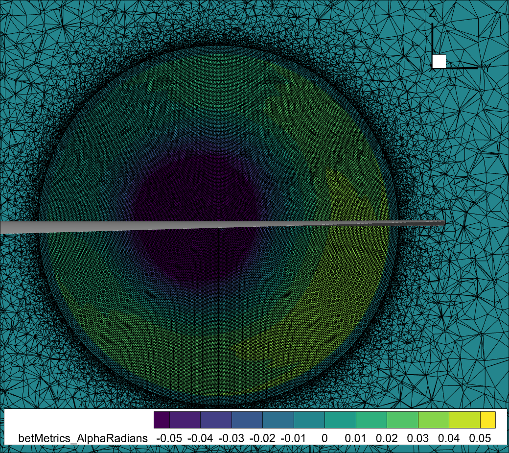
Fig. 7.2.3 Slice of the volume mesh at the BET/AD center, showing the BET/AD refinement region in the radial and azimuthal direction.#
Modeling a Hub in BET/AD Simulations#
With respect to modeling the hub, we have a few options:
We can include the hub directly within the BET/AD formulation. For BET simulations, this means defining polars and blade geometry all the way to the center of the propeller at r=0. For AD it means providing thrust and circumferential force distributions that mimic a hub in the center. This entails that our rotor disk refinement region must be a cylinder.
The hub geometry can be included as a no-slip wall in the mesh. This forces the BET/AD refinement region to have a hole in the middle (i.e., cylindrical doughnut). That hole will need to be of a radius slightly larger than the hub geometry in that region. To produce a quality volume mesh in the gap region it is important that:
The hub surface mesh is of similar edge length to the rotor disk refinement region’s local edge length near the hub.
The gap between the hub and the mesh refinement region be large enough so that the volume mesh has space to grow adequately. As a no-slip wall boundary, the hub geometry must also have layers grown from the surface.
Automated Meshing Refinement Regions for BET/AD Simulations#
For BET/AD simulations, the AxisymmetricRefinement method is recommended as it creates a structured mesh region, allowing for anisotropic cells and mesh count savings. Alternatively, we can use UniformRefinement to create an unstructured refinement region with isotropic cells. As shown above, these two approaches can be combined to create a structured BET/AD refinement region surrounded by a larger unstructured refinement region, to better capture the flow physics in the regions of the highest gradients.