CGNS Mesh Format and Multizone Interface Connectivity#
Introduction#
This section will introduce a new feature of Flow360 available from release-23.3.2.0 onwards that greatly simplifies the mesh and simulation setup process for cases with multiple volume zones, such as conjugate heat transfer (CHT) or sliding interface simulations. This new feature saves time and minimizes the likelihood of setup errors. Prior to release-23.3.2.0 boundary conditions needed to be assigned at each volume zone interface and those boundaries specified in the case JSON inputs. For release-23.3.2.0 onwards, the Flow360 CGNS mesh reader will recognize the various volume zones present in the mesh and automatically interpret the corresponding interfaces. Solver settings related to individual volume zones are now assigned directly.
The CFD General Notation System (CGNS) offers a universal, portable and expandable framework for storing and retrieving data related to computational fluid dynamics (CFD) analyses. It comprises a set of guidelines and open-source software that adhere to these standards. Additionally, it has earned the status of being a recommended practice by the American Institute of Aeronautics and Astronautics (AIAA). The CGNS format uses a hierarchical structure to store all information related to CFD simulation, including mesh, time-dependent solutions, reference states, descriptions of governing equations, etc. In the present document, only its capability of storing mesh information is introduced. More details can be found at CGNS’s official website.
A CGNS mesh could consist of one or multiple volume zones. For example, the data structure of a three-zone CGNS mesh is shown in Fig. 7.2.4. Within each volume zone, the corresponding mesh information is contained including, coordinates of grid points, connectivity between 3D and 2D elements, boundary conditions and connectivity of multizone interfaces.
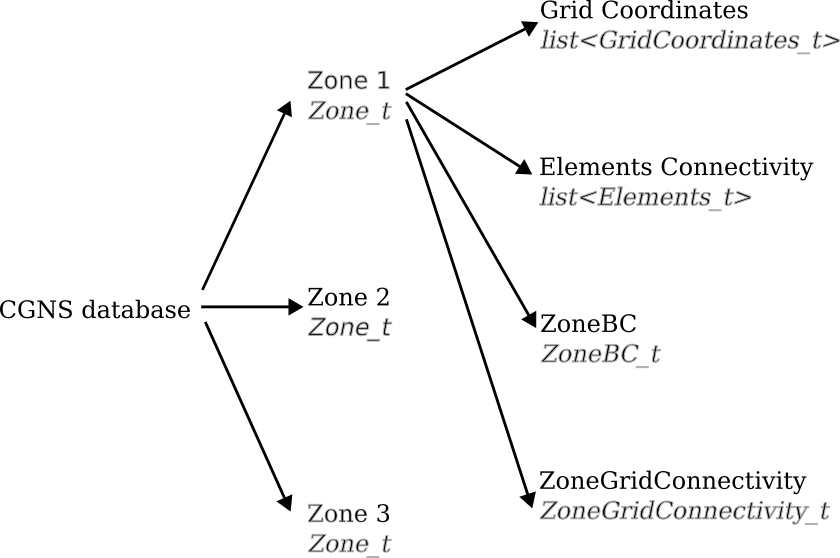
Fig. 7.2.4 Topological based hierarchical structure of a three-zone CGNS mesh#
Multizone Interface Connectivity#
For each volume zone, the connectivity information between itself and a specific adjacent volume zone is grouped together in a ZoneGridConnectivity_t structure entity. In this section, the CGNS format stores the name of the volume zone it is adjacent to, the type of the corresponding interface and the topology details. Three types of multizone interfaces are supported in CGNS standard: Abutting1to1 (conformal), Abutting (conformal or non-conformal) and Overset. More details can be found at Multizone Interface Connectivity.
According to the official Multizone Interface Connectivity documentation, each zone boundary segment should be exclusively defined by either a boundary condition, appearing under ZoneBC section, or a multizone interface connectivity, appearing under ZoneGridConnectivity, but not both simultaneously. The above restriction is ensured automatically by the CGNS library, which has been integrated into many meshing software. The only thing users need to pay attention to is to make sure the right options provided by the meshing tools are checked during the exporting of CGNS meshes. Based on our experience, by default, most meshing tools export multizone interfaces (or interior interfaces) as ZoneGridConnectivity unless those interfaces are assigned to a boundary condition explicitly.
Added in version release-23.3.2.0: Flow360 supports reading the ZoneGridConnectivity from CGNS meshes. Before release-23.3.2.0, Flow360 neglected the ZoneGridConnectivity, so no matter if a boundary segment is an exterior boundary or interior interface between volume zones, it had to be exported as a boundary condition stored under ZoneBC.
To provide a better explanation, two CGNS meshes are listed showing two different ways of storing multizone interfaces in CGNS format:
|
They have identical information except that the legacy one stores interior interfaces as boundary conditions under ZoneBC, while the new one stores interior interfaces as multizone interface connectivity under ZoneGridConnectivity. Their file structures are shown in Fig. 7.2.5 via CGNSview. In the legacy mesh, each zone omits ZoneGridConnecvitity and the interior interfaces (named as rotationInterface) are treated in the same way like other common boundaries, i.e. blade and farField. In the new mesh, each zone has ZoneGridConnectivity and the ZoneBC section does not include the interior interfaces.
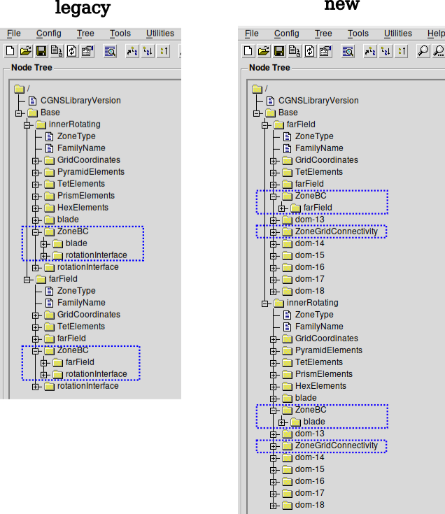
Fig. 7.2.5 Comparison of two CGNS meshes storing interfaces between volume zones differently#
Tip
We highly recommend users to export the interfaces between volume zones as ZoneGridConnectivity instead of ZoneBC, since ZoneGridConnectivity provides more information than ZoneBC. If the mesh with multiple volume zones does not have ZoneGridConnectivity, Flow360 will try to detect the multizone interfaces automatically.
Collaboration with Volume Models#
Not only does generating CGNS meshes with ZoneGridConnectivity information eliminate the tedious process of assigning boundary names to multizone interfaces, but it also maximizes the benefits brought by Volume Models when configuring a CFD case. Based on zoneGridConnectivity, Flow360 can conveniently find the proper treatment on those interfaces between zones based on the parameters provided in the entities. Although Flow360 can automatically detect the information about the zone grid connectivity if it is not available in mesh files, generating meshes with ZoneGridConnectivity can save the time cost of the detection.
Interpretations in surfaceOutput#
Unlike the boundaries defined by ZoneBC in CGNS meshes, the multizone interfaces defined by ZoneGridConnectivity don’t have specific names stored in mesh files. To support exporting contours of flow solution on those multizone interfaces in Flow360, a convention is introduced to reference them. For a CGNS mesh containing two blocks: ZoneA and ZoneB, shown in Fig. 7.2.6. There are two interior interfaces between these two zones. The interface which belongs to ZoneA can be referenced by name ZoneA/Interface_ZoneB. Similarly, the interface which belongs to ZoneB can be referenced by name ZoneB/Interface_ZoneA.
Note
For the sake of clarity in presentation, the red and black interfaces in Fig. 7.2.6 do not overlap, but in actual meshes, they are on top of each other in three-dimensional space.
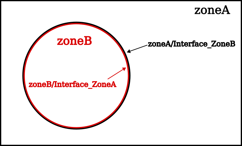
Fig. 7.2.6 Convention to reference multizone interfaces in CGNS meshes#