

How GeometryAI works#
This page explains what the GeometryAI Surface Mesher does with your geometry and introduces each control in the order you are likely to meet it. It is about understanding the controls; the exact fields, defaults and ranges live in the WebUI mesh parameters and the Python meshing reference. For a step-by-step first mesh and per-scenario settings, see Best practices.
The mental model#
Think of GeometryAI as rebuilding your model rather than meshing it directly. It first turns the input geometry, however imperfect, into a single closed surface, and only then does it lay a mesh on that surface. Every parameter you set falls on one side of that line or the other.
The geometry processing step reconstructs the surface. Along the way it can apply basic spatial transformations and boolean operations to solids (defined in separate CAD files), resolve intersections between parts, patch holes, construct the farfield geometry, and split the model into a half-model about the symmetry plane. It also decides which surfaces bound the fluid: which side of each body the flow is on, and whether geometry hidden from the flow is discarded.
The surface meshing step then meshes the reconstructed surface, honouring the global density controls and any per-face or per-region refinements you have added.
Because the surface is rebuilt, GeometryAI always returns a valid, watertight mesh, even from dirty input. That reconstructed surface exists only inside the mesher: what you get back is a surface mesh, never a repaired CAD model, and your input geometry is left as it was. A practical consequence is that you rarely need to get everything right the first time: generate a mesh with the defaults, look at it, and then tighten only where the geometry or the flow requires it.
Every control on this page is available both in the WebUI and in the Python API, so the same reasoning applies however you set up the case.
Geometry accuracy: how faithfully the geometry is captured#
The one setting you must provide is Geometry accuracy. It is the smallest length scale that the geometry processing step resolves accurately: features smaller than this may be smoothed over, features larger than this are captured. It governs how faithfully the reconstructed surface follows your CAD, especially around small features and sharp edges.
It is easy to mistake it for a mesh-size control, and it is not one. Geometry accuracy decides how well the geometry is captured; how dense the mesh is on that geometry is controlled separately (see Surface mesh density). A finer accuracy resolves finer geometric detail at the cost of longer geometry processing. It can raise the node count indirectly and locally, because sharper edges and higher local curvature need more nodes to represent, but on a smooth shape the effect on the overall count is small.
|
|
|---|---|
|
|
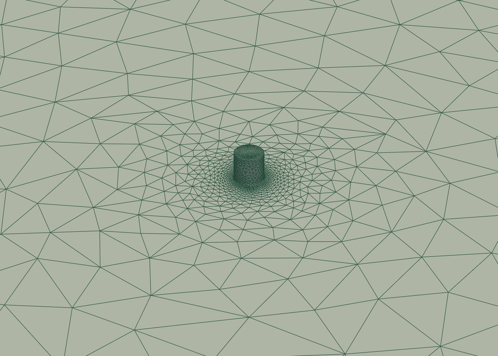
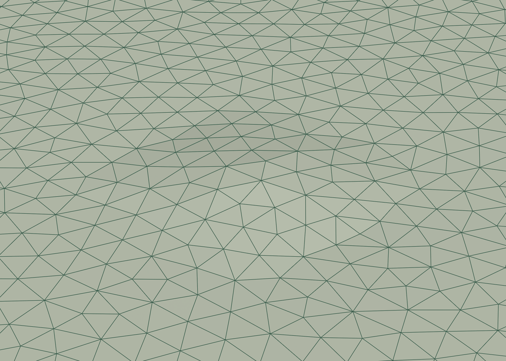
Both meshes use the same Target surface node count; only Geometry accuracy differs. At 0.5 mm the bolt is captured and meshed crisply. At 25 mm it is smaller than the Geometry accuracy and is smoothed into a faint bump, while the mesh on the plate around it stays about as dense as before. The accuracy decides which features survive. Once the bolt has been smoothed over by too large a Geometry accuracy, the node budget only decides how many cells describe what is left, and no number of extra nodes would bring the bolt back.
Geometry accuracy is an absolute length, not a fraction of the model size: it corresponds to the smallest edge you want to capture. The same trailing edge needs the same geometry accuracy whether it sits on a small or a large body.
Finer is not free. Lowering the global value to capture one small local feature refines the whole model, which inflates both the node count and the meshing time. The recommended way of working is therefore:
Start from the default global
Geometry accuracy. It is set automatically when GeometryAI is enabled and is a sensible baseline for the bulk of the geometry.Add local geometry refinements on the specific faces that carry small features (thin trailing edges, small gaps, tight radii) to set a finer accuracy only there. See Local refinements: tightening only where it matters.
This keeps the global accuracy, and the meshing time, moderate while still resolving the features that matter. The mesher accepts a wide range of values; its main guard is a sanity floor, and if the value is finer than 1e-5 times the bounding box diagonal it warns that this is unreasonably fine for the model and recommends increasing it.
Two things can go wrong here, and both show up in the process log:
A wrong unit. In the WebUI,
Geometry accuracyand the other mesh input lengths (Surface max edge length,Sealing size,Min passage size) use the project length unit by default, but you can also enter an explicit unit. A value given in the wrong unit, for example one far smaller than intended, produces a much finer mesh than expected and very long meshing times. In the Python API each value carries its own explicit unit.Early termination. The mesher may stop before fully achieving the requested accuracy if system resource constraints are encountered during surface meshing. The log then says so and reports the finest accuracy actually reached. If you see this, coarsen the global value, or, preferably, move the fine accuracy into a local geometry refinement on the faces that need it.
Where to set it: WebUI mesh parameters · geometry_accuracy.
Cleaning up imperfect CAD#
Because GeometryAI reconstructs the surface, it can also clean the geometry along the way. Four independent options cover the usual problems with production CAD: openings you want closed, thin parts you want kept, internal geometry the flow never sees, and zero-thickness baffles. All four are specific to the GeometryAI Surface Mesher, and the usual advice is to try them before resorting to manual CAD repair: Sealing size and Remove hidden geometry alone are usually enough to turn a dirty, non-watertight production model into a meshable one. That combination of simplicity and robustness is the main reason to choose this mesher for automotive and other complex, detailed geometries.
Sealing gaps and holes#
Real models have real openings: the central hole of a torus, a slot in a panel, a gap between two parts. Some of them you want the flow to pass through; others you would rather close so the mesh treats the part as solid. Sealing size is how you express that intent: any physical opening smaller than this size is closed, anything larger stays open.
This is a matter of intent, not of watertightness. Small cracks and leaks between faces that would break watertightness are closed regardless of this setting, because producing a watertight surface does not depend on it. Setting Sealing size to zero therefore does not give you a leaky mesh; it only leaves the physical openings alone.
No sealing |
|
|---|---|
|
|
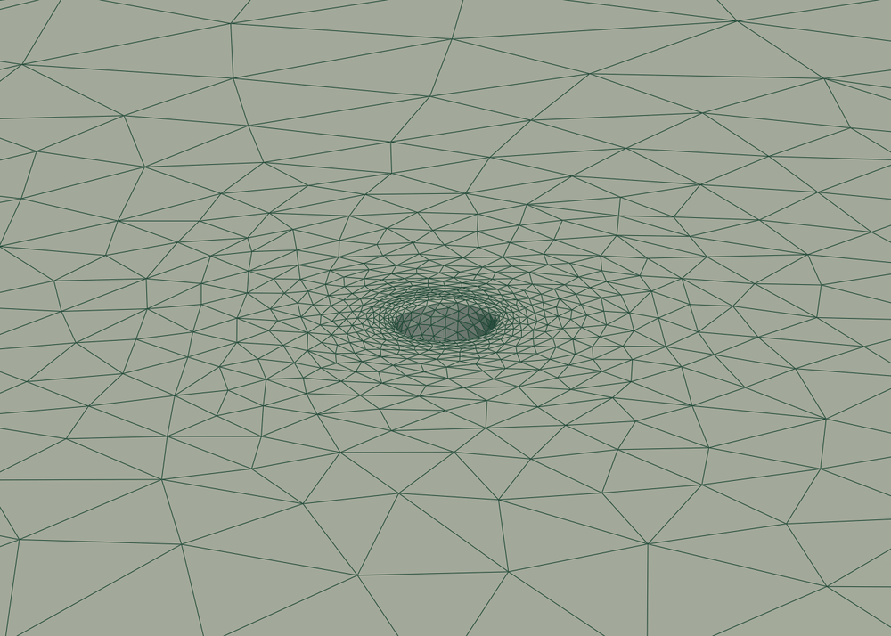
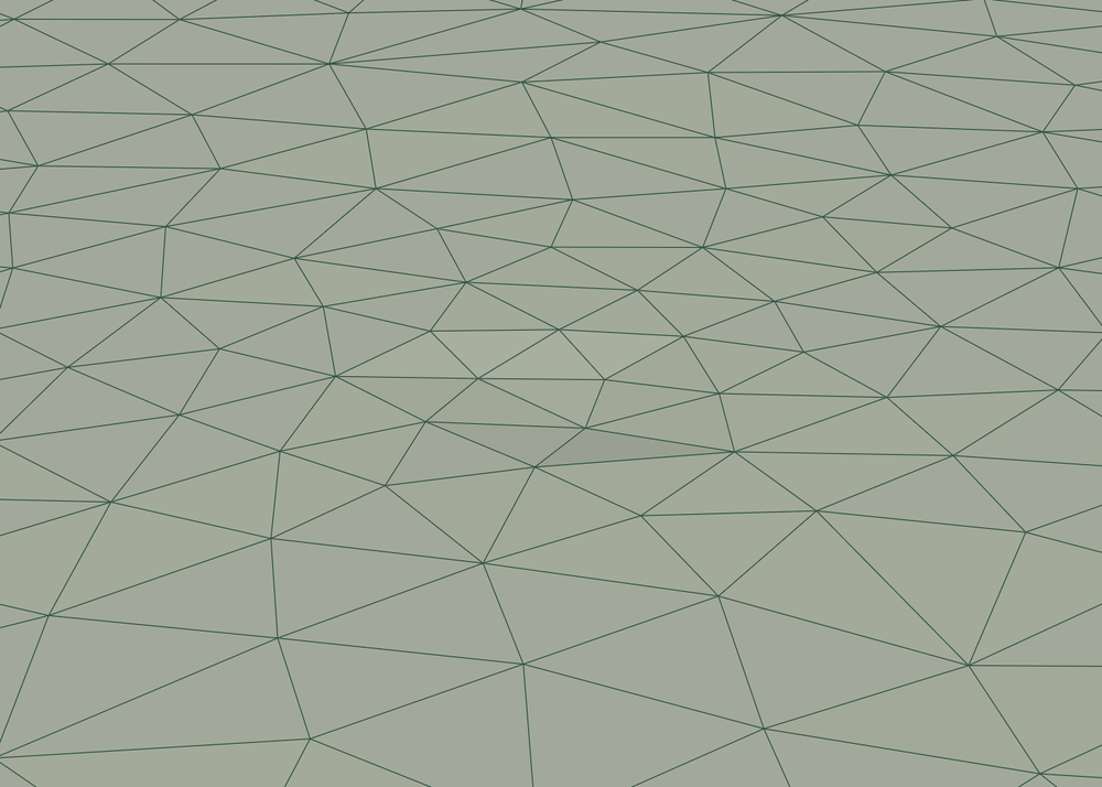
Both meshes use a 0.5 mm Geometry accuracy. Without sealing, the hole is meshed open, with the mesh graded around it. With Sealing size set above the hole diameter the hole is sealed flush and the rest of the mesh is unchanged. A Geometry accuracy coarser than the hole would also remove it, but then every feature smaller than the accuracy degrades with it; Sealing size closes only the openings.
Sealing works in two complementary ways, and it helps to know both because they have different limits.
The first way offsets the reconstructed surface to bridge the opening. That needs the geometry around the opening to be thick enough to carry the offset, so an opening wider than the surrounding wall is thick cannot be closed like this: the offset that would bridge the gap would also consume the thin wall beside it.

Offset-based sealing closes an opening only where the surrounding geometry is thicker than the gap is wide.#
The second way works on the imported geometry itself, capping small planar openings before the surface is reconstructed. It works for the case the first way fails on: an opening wider than the geometry is thick. It introduces no setting of its own, using the same Sealing size, resolved per face group and per Geometry Refinement box like the other cleanup sizes. It is available through the V2 CAD importer.
An opening is capped this way when it is bounded by a closed loop of edges belonging to a single face group, is close to planar, and its smaller in-plane extent is below Sealing size. In practice the face-group condition decides most cases. Where the surrounding faces and the wall of the opening carry separate face ids, the loop closes within one of them and the opening is capped. Where they share a face id (or were grouped together upstream), no such loop exists, this step does not see the opening at all, and the offset-based sealing takes over with its thickness limit.

Geometry-level sealing follows the face layout: separate face ids for the surrounding faces and the wall of the opening give a closed loop that can be capped, while a single shared face id leaves nothing for this step to close.#
Where to set it: WebUI mesh parameters · sealing_size. Set it to zero to leave physical openings open.
Preserving thin features#
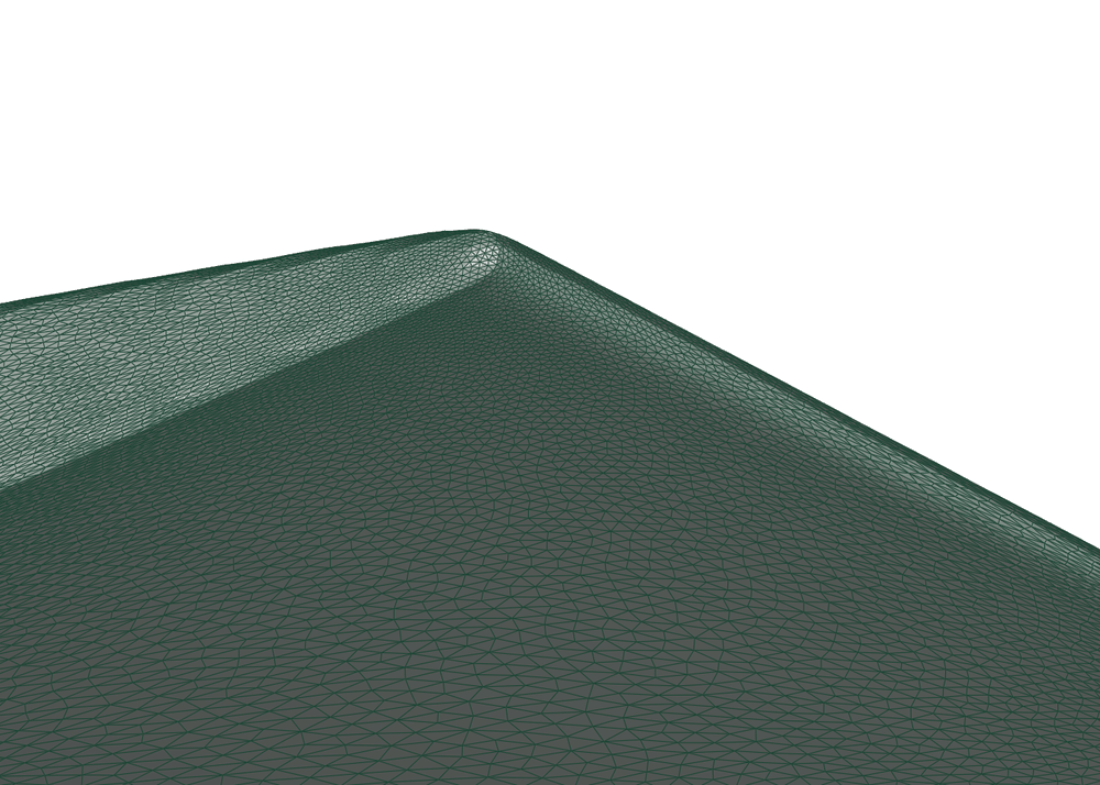
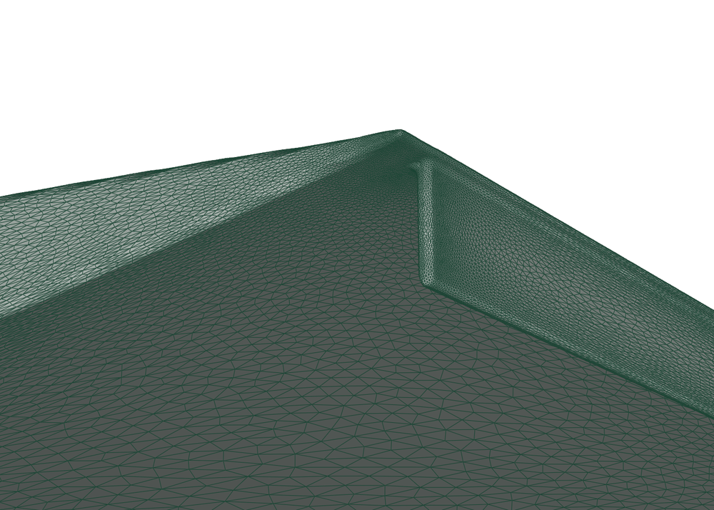
Trailing edges, fins and thin walls are the first things a surface reconstruction loses, because a part thinner than the length scale being resolved simply disappears. With Preserve thin geometry off, a thin feature needs a thickness of roughly three times the Geometry accuracy to survive. With it on, thin features down to the scale of the Geometry accuracy are preserved accurately, at the cost of a finer local mesh.
|
|
|---|---|
|
|
The flap is thinner than the roughly three-times-accuracy threshold, so with the option off it collapses entirely and only the blunted trailing edge remains. With the option on, and nothing else changed, the flap is kept at its full height and thickness and meshed finely.
Since the cost is local, the option is best applied locally too: turn it on through a geometry refinement on the thin parts (see Local refinements: tightening only where it matters) and leave the rest of the model coarse.
Where to set it: WebUI mesh parameters · preserve_thin_geometry.
Handling baffle faces#
A baffle face is a face exposed to the flow on both sides: a baffle, a zero-thickness wall. Hidden-geometry removal detects them, and Baffle face treatment decides what happens to them:
default(the default value) applies no special handling at this stage. The baffle faces pass through geometry cleanup unchanged and are left to the rest of the GeometryAI process, which may still modify them; for example, a nonzeroSealing sizeseals the gap around a baffle.removedeletes them.thickeninflates each one into a thin closed shell so that it survives as a manifold part of the mesh.
Any choice other than default requires Remove hidden geometry to be on.
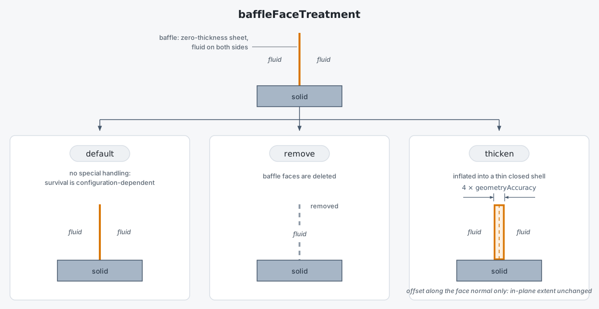
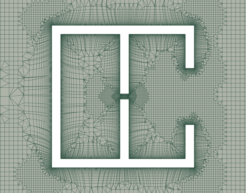
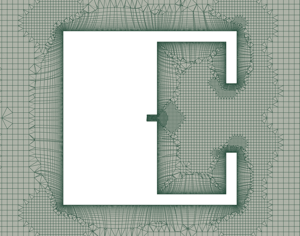
The three baffle face treatments applied to the same zero-thickness face. thicken keeps the face’s in-plane extent and only gains thickness.#
|
|
|---|---|
|
|
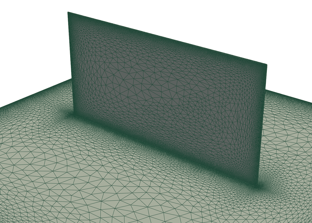
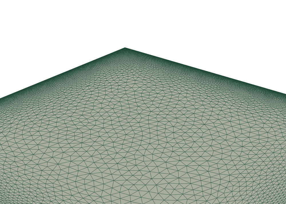
The plate and the fin are uploaded as two CAD files and meshed with Remove hidden geometry on. With thicken the fin becomes a thin closed shell and stays in the simulation as a wall. With remove the fin is deleted and only the plate is meshed.
Baffle thicken outward and Baffle thicken inward control how far a thickened shell extends to either side of the original face, each as a multiple of Geometry accuracy. Both default to 2.0, so the shell straddles the face evenly. Setting Baffle thicken inward to the full thickness and Baffle thicken outward to zero grows the shell entirely inward, which keeps an exterior panel where the CAD put it. That is the usual choice when the outer surface is aerodynamically significant, as with a car’s fascia or fenders. Their sum is the total thickness and must be at least 4.0; for a physically thinner shell, locally reduce Geometry accuracy on those faces so the same thickness becomes a larger multiple of it.
A baffle face has flow on both sides, so it has no outward direction of its own. GeometryAI treats the side with more open space around it as outward. Where the two sides are equally exposed the direction cannot be determined, and the requested total is split symmetrically instead; the setup reports this.
The treatment and both extents can be set for an individual face group through a per-face override on a Geometry Refinement, added under Refinements in the WebUI. It overrides the global setting on the faces the refinement lists, while face groups that leave it unset keep the global value. This override applies to surfaces only, so it cannot be combined with a Box region in the same refinement.
Where to set it: WebUI mesh parameters · baffle_face_treatment, baffle_thicken_outward, baffle_thicken_inward · per face: baffle_face_treatment, baffle_thicken_outward, baffle_thicken_inward.
Transformations: moving, rotating, scaling, and mirroring parts#
Sometimes the geometry is correct but not where you want it: a control surface to be tried at three deflections, a wheel to be moved fore and aft, a component modelled once but needed on both sides of the vehicle. GeometryAI can reposition and duplicate bodies as part of geometry processing, so you do not have to go back to CAD and re-export a file for every variant.
Both operations act on a body group, and bodies are grouped by the CAD file they came from. A part you want to move on its own therefore has to arrive in its own file.
Transform. You describe the movement once as a coordinate system: a reference point, a rotation axis and angle, scale factors, and a translation. Scaling and rotation act about the reference point, and the translation is applied after them. Body groups are then assigned to that coordinate system and all follow it, so changing one number and re-running gives the next point in a position, incidence, or size sweep. Coordinate systems can also be defined relative to one another, which lets a part move with the assembly it belongs to.
Mirror. Create a mirrored copy of a body group about a plane, given by a normal and an origin, so a component modelled on one side of a symmetry plane appears on both.
Both are available only with GeometryAI. Any other mesher rejects the case before it runs, so if the work involves moving or mirroring anything, choose GeometryAI from the start.
Where to set it: WebUI Coordinate systems and the Mirror action on a body group in the Entities browser · Draft coordinate systems and mirroring · runnable snippet.
Local refinements: tightening only where it matters#
Most tuning of a GeometryAI mesh should happen locally, on the faces or in the regions that need it, rather than by changing global values. Two per-face refinement types are available:
Geometry RefinementoverridesGeometry accuracy(and, optionally,Preserve thin geometry,Sealing size, andMin passage size) on a selected set of faces. This is the recommended way to resolve a small or detailed feature without refining the whole model. The override works in both directions: faces carrying only coarse features can be given aGeometry accuracylarger than the global value.The same refinement can instead be scoped to a
Boxregion, which suits features known by location rather than by face. Inside the box, the values it sets replace the per-face values of every surface passing through it (in either direction, so a box may also be coarser than the surfaces it covers), while anything the box leaves unset keeps its per-face value. Where two or more boxes overlap, they combine as described in Overlapping refinement boxes.Surface Refinementoverrides surface mesh density controls such asSurface max edge length,Curvature resolution angle, andResolve face boundarieson selected faces (see Surface mesh density for what those do).
With the GeometryAI surface mesher a uniform refinement (a volumetric refinement region) also refines the surface mesh inside the region. See Effect on the surface mesh for how each workflow treats this.
Where to set it: WebUI geometry refinement · WebUI surface refinement · GeometryRefinement · SurfaceRefinement. Both are listed with the other refinements in the Meshing reference.
Overlapping refinement boxes#
Refinement boxes are allowed to overlap, and no validation warning is raised when they do. In the overlap region every box that reaches a location contributes, with no priority and no ordering: the result does not depend on the order in which the boxes are listed. Each setting is combined with its own rule, and in every case the outcome is the more conservative one, so one box can never relax another.
Setting |
Overlapping boxes combine as |
|---|---|
|
The finest (smallest) value wins, so the overlap only ever gets finer. |
|
The largest value wins. A value of zero means “do not seal here” and counts as set, but it loses against any overlapping box with a positive sealing size. |
|
Each box is first resolved on its own, then the smallest of those per-box results wins. A box resolves to its own value if it sets one, and otherwise to a value derived from its own |
|
Enabled if any overlapping box enables it. A box that disables it only takes effect where no enabling box reaches. |
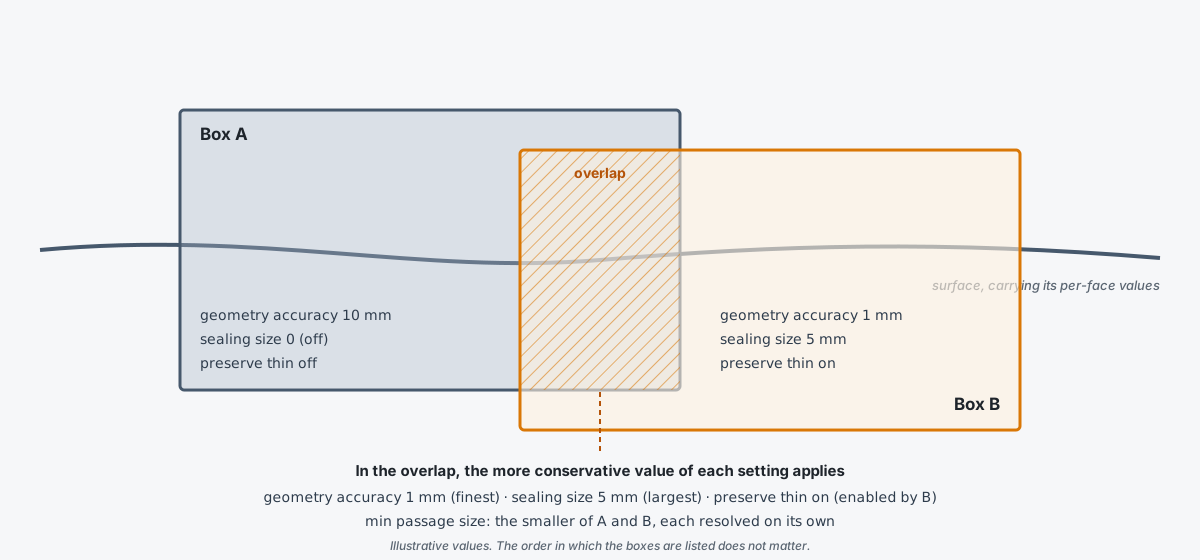
Two overlapping refinement boxes and the values that apply where they intersect: each setting takes the more conservative of the two.#
Two consequences follow from these rules:
There is no way to carve a “relaxed pocket” inside a refined region: a box cannot coarsen the accuracy, switch off sealing, or switch off thin-feature preservation where another box has set the opposite.
Overlapping boxes are resolved independently and are never merged setting by setting. If one box sets only
Sealing sizeand another sets onlyGeometry accuracy, the overlap does not combine the first box’s sealing with the second box’s accuracy when derivingMin passage size. Each box is resolved using the per-face values for what it does not set, and the smaller of the two results is used.
Box faces are not razor sharp either. Geometry accuracy and Min passage size are applied to the mesher’s octree cells with a deliberately conservative test, so a box’s influence extends slightly beyond its nominal faces (on the order of the local cell size) and the effective overlap is a little larger than the geometric intersection. Sealing size and Preserve thin geometry are applied by exact point containment, so their region is the true geometric box; for Preserve thin geometry the test is made per surface triangle, and a triangle is treated as inside as soon as any part of it lies in an enabling box, so “on” spills slightly outside the box while “off” does not.
The practical recommendation is to prefer non-overlapping boxes, and to size each box with a margin around the feature it targets rather than relying on precise behaviour at a box face. Where boxes must overlap, expect the more conservative setting (finer, more sealing, thin features on) everywhere in the intersection. The surface mesher log lists every refinement box with the values it sets (unset quantities are printed as unset), which is the place to check what was actually applied; it shows the boxes as configured, not the combined result in an overlap.
Surface mesh density#
Once the geometry is captured, a second family of controls decides how many nodes are laid on it and how they are distributed. Newcomers usually leave these at their defaults for a first mesh and come back to them when the mesh is too large or too coarse for the flow.
The quickest lever is Target surface node count. Set it and the mesher aims for that many nodes, adjusting cell sizes across the whole model to get there. This is the simplest way to control overall mesh density without tuning individual length scales, and it does not change how the geometry itself is resolved, which remains governed by Geometry accuracy.
The target is a goal, not a guarantee, because Surface max edge length still holds everywhere. It is an upper bound on cell size, so wherever it binds it can only add nodes, never remove them. That is why a target that is not met is almost always overshot rather than undershot: ask for a low node count together with a fine edge length and the edge length decides the mesh. To let the target drive the mesh instead, keep Surface max edge length generous so that it does not bind.
The individual controls, for when you need them:
Surface max edge length: an upper bound on surface cell edge length, enforced regardless of the other controls, so it acts as a hard cap on element size. Because surface nodes are always projected onto the geometry, a small value also yields good curvature resolution on its own: a fine edge length cannot leave a curved surface under-resolved. Keep a generous (large) global value and tighten it only where needed through a local surface refinement (see Local refinements: tightening only where it matters).Curvature resolution angle: the maximum angular deviation allowed between a surface element and the underlying surface. Lower values capture curvature more accurately but increase the node count.Surface max aspect ratio: the maximum aspect ratio of surface cells. Lower values force more isotropic cells.Surface edge growth rate: how quickly surface edges grow in length away from regions of high curvature or small max edge length constraints. Typical values are1.1to1.25.Resolve face boundaries: when enabled, the boundaries between adjacent faces are resolved accurately with anisotropic refinement. Enable it when face-to-face boundaries (for example between a body and an appendage) must be captured sharply.
Where to set them: WebUI mesh parameters · target_surface_node_count · surface_max_edge_length · curvature_resolution_angle · surface_max_aspect_ratio · surface_edge_growth_rate · resolve_face_boundaries.
Farfield and half-model#
Your CAD does not need to contain a farfield body. GeometryAI builds the farfield analytically as part of geometry processing, in one of two styles selected through Type on the farfield form:
Automated farfieldgenerates a (semi)sphere or cylinder sized relative to the geometry bounding box. This is the general-purpose choice for external aerodynamics.Wind tunnelbuilds a rectangular tunnel and is intended for ground-vehicle and wind-tunnel-correlation work. It supports several floor treatments (static floor, fully moving floor, central belt, and wheel belts) to represent moving-ground conditions.
For symmetric configurations, the mesher can split the geometry into a half-model about the symmetry plane, which roughly halves the mesh size and suits zero-yaw simulations. It is requested with Domain type, which also selects which side of the plane is kept. Every farfield type accepts it when meshing a geometry with GeometryAI.
Supplying Domain type explicitly overrides the automatic symmetry plane detection that otherwise infers the domain from the geometry bounding box, and a half-model whose geometry lies entirely on the discarded side is rejected rather than meshed. When you start from a surface mesh instead of a geometry there is no surface mesher to trim the model, so a half-model can then only be requested on the automated farfield.
Where to set it: WebUI farfield · AutomatedFarfield · WindTunnelFarfield · AutomatedFarfield.domain_type, UserDefinedFarfield.domain_type, WindTunnelFarfield.domain_type. The full set of farfield classes is listed under Farfield zone specifications.
Limits: sharp edges and thin features#
GeometryAI represents sharp edges implicitly through the reconstructed surface rather than conforming mesh edges to feature lines. Edge-based refinements therefore do not apply, and Surface Edge Refinement (WebUI, SurfaceEdgeRefinement) is not supported with this mesher.
To sharpen the representation of an edge, refine the Geometry accuracy (a smaller value), locally where possible. Features thinner than the active thickness threshold (see Preserving thin features) are best resolved with a local geometry refinement or by enabling Preserve thin geometry on those parts.
For geometries whose accuracy hinges on conforming the mesh to sharp feature edges, the Surface Mesher (watertight input) or the Snappy Surface Mesher can be a good complement.