

Best practices#
This page is the practical companion to How GeometryAI works: how to get a first GeometryAI mesh, what to change when it is not what you wanted, how to run a refinement study, and how to tell the mesher which region is the fluid for each common type of case.
Your first GeometryAI mesh#
The mesher always returns a valid surface, so you do not have to get everything right before the first run. Decide how big the mesh is allowed to be, mesh with the defaults, then fix what you see.
Set the size budget before you mesh. Use
Target surface node countas the single lever for how big the surface mesh is, and leaveSurface max edge lengthgenerous so it does not silently dominate (see Surface mesh density). Deciding this first is what protects you from the expensive mistake: a mesh that comes out too coarse is quick to spot and quick to fix, whereas length scales entered far finer than intended, or in the wrong unit, produce an enormous mesh and very long meshing times before anything is there to look at.Keep the other defaults and generate a mesh.
Geometry accuracyis set automatically when GeometryAI is enabled and is a sensible baseline for the bulk of the geometry.Read the process log. It tells you whether the mesher stopped early before reaching the requested accuracy, and it lists the refinements it found. If it reports early termination, coarsen the global accuracy or move the fine accuracy into a local refinement.
Look at the surface and fix things locally. A lost trailing edge, a smoothed-over fillet or an open gap is a job for a local
Geometry Refinementon those faces, not for a finer global value (see Local refinements: tightening only where it matters). To check the shape as a whole rather than feature by feature, colour the mesh byGAI Deviation Distancein the Surface Mesh Diagnostics tool: it is the distance from each mesh node to the input geometry, so it shows at a glance where and by how much the rebuilt surface moved away from your CAD.Check the fluid region. Make sure the mesh encloses the region you meant to simulate: outside the model for external aerodynamics, inside the cavity for internal flow, the gap between model and tunnel for a wind-tunnel case. Defining the fluid domain below explains the three controls that decide this.
Only once the mesh resolves the geometry you care about is it worth tuning the individual density controls, and then a refinement study tells you whether the answer still depends on the mesh (see Running a mesh refinement study).
What to reach for when something looks wrong#
What you see |
What to do |
|---|---|
The CAD has gaps, leaks or small holes you want closed |
Set |
A hole or slot you wanted open has been sealed |
Lower |
A trailing edge, fin or thin wall has disappeared |
Turn on |
Internal parts the flow never sees are being meshed |
Turn on |
A small feature is smoothed over |
Add a |
The mesh is far larger, or meshing far slower, than expected |
Check the unit of |
The node count overshoots |
|
The mesh stopped at a coarser accuracy than requested |
Resource limits were hit. Coarsen the global |
The wrong region was meshed (inside instead of outside, or the tunnel was ignored) |
Check |
Recommended settings#
A compact reference for the main controls, once you know what they do. Each row links to the WebUI field, the Python attribute, and the explanation.
Parameter |
Recommended starting point |
When to adjust |
|---|---|---|
|
Default global value |
Refine locally with a geometry refinement rather than lowering it globally. If the process log reports early termination, coarsen the global value or move the fine accuracy into a local refinement. |
|
Generous (large) global value |
Keep it generous so it does not silently dominate the node-count target; tighten it locally with a surface refinement only where finer elements are needed. |
|
The primary lever for overall mesh size |
For a refinement study, scale it by |
|
Off; enable only where needed |
Turn on, ideally through a local geometry refinement, for thin parts such as trailing edges and fins, keeping the rest of the mesh coarse. |
|
Use for dirty or non-watertight CAD |
Prefer these cleanup options over manual CAD repair; together they handle most production geometries. |
|
Use for symmetric, zero-yaw cases |
Roughly halves the mesh size. |
For general meshing guidance that applies across all workflows, see the meshing knowledge base.
Running a mesh refinement study#
To study mesh convergence you want each level to be a uniformly finer version of the last, not a mesh where one constraint quietly took over. Use Target surface node count as the single driver and keep Surface max edge length in step with it:
Multiply
Target surface node countby a refinement factorx(for example2for a finer level,0.5for a coarser one).Scale
Surface max edge lengthby1 / sqrt(x)at the same time. Node density on a surface scales with the inverse square of the edge length, so this keeps the edge-length cap consistent with the requested node count and prevents it from binding unexpectedly between levels.
Keeping the two in step means the curvature scaling continues to drive the mesh at every level, so successive meshes differ by a controlled, roughly uniform factor. If Surface max edge length is left fixed while only the node count changes, it eventually becomes the binding constraint and the meshes stop refining as expected (see Surface mesh density).
Where to set them: WebUI mesh parameters · target_surface_node_count · surface_max_edge_length.
Defining the fluid domain#
A surface mesh alone does not say which side of it the air is on. For a car in free air the fluid is outside the body; for a duct it is inside; for a car in a wind tunnel it is the gap between the two. When the GeometryAI workflow meshes an assembly it has to make that decision for every body, and three independent controls drive it:
Mesh exterior, set per body group, declares which side of a body the fluid is on (outside or inside).Remove hidden geometry, a single global toggle, decides whether occluded interior faces are discarded.Seed pointvolumes select which connected region is the fluid; the flood starts from them.
This section explains what each control does, how they combine, and which combination to use for the common simulation scenarios. The mechanics of generating the zones themselves (custom volumes, custom zones, the flood-fill workflow) are covered in Volume Mesher; this section is about choosing the settings that delimit the domain.
Note
These controls apply to the GAI surface mesher workflow. See Meshing for how the beta mesher and GAI toggles select each workflow.
Mesh exterior#
Mesh exterior, written mesh_exterior in the body-group settings, is a per-body-group flag (true by default) that declares which side of a body the fluid is on:
true(the default): the fluid is outside the body. The body is a solid the flow passes around, such as the object of study (a car, an aircraft, a building).false: the fluid is inside the body. The body is an enclosure whose interior is meshed and whose faces bound the domain from the outside, such as a wind tunnel or a user-defined farfield.
The fluid domain is the region that is outside every mesh_exterior=true body and inside every mesh_exterior=false body. For a car inside a wind tunnel, that is exactly the gap between them: outside the car and inside the tunnel.
Because it defaults to true, most cases never set it explicitly: an external-aerodynamics model, and the walls that bound an internal-flow cavity, all keep the default. You only set false on a body that should contain the fluid, such as an enclosing wind tunnel or user-defined farfield. Setting such an enclosing body to true instead would tell the mesher the fluid is outside it, which is not what you want, and a seed point cannot make up for it (see the seed does not replace the flag below).
Where to set it: per body group in the geometry browser, see GUI Guide: Geometry. mesh_exterior is a beta feature and its interface may change.
Seed points and flooding#
Within the fluid side defined by mesh_exterior, the mesher picks the connected region to mesh by flooding it from one or more seed points. When no seed point is supplied, the default seeds are the corners of the geometry bounding box, which is what makes ordinary external-aerodynamics cases work without any explicit seeding.
The seed selects and orients the fluid region; it does not change which side of a body is fluid. Place the seed outside the object for external aerodynamics, inside the enclosed region for internal flow (for example the cabin of an HVAC model), and in the gap between the model and an enclosing wind tunnel.
Important
A seed point is not a substitute for mesh_exterior. Seeding inside a body that is left at mesh_exterior=true does not turn its interior into the fluid domain; the flag, not the seed, decides which side of each body is fluid. An enclosing wind tunnel must therefore be mesh_exterior=false regardless of where the seed is placed.
Seed points describe a single fluid zone with GeometryAI, however many seed point volumes and points are defined; Zones produced by each definition covers that and how several zones are obtained instead.
Where to set it: WebUI seed point volume · SeedpointVolume (point_in_mesh); on the Python side the workflow is described in Volume Mesher.
Choosing settings per scenario#
The table below summarises the typical combination for each common scenario. Default seeding means the bounding-box corner seeds, with no explicit seed point.
Scenario |
|
|
Seeding |
|---|---|---|---|
External aerodynamics (car, aircraft) with an automated farfield |
|
On if the model has hidden interior parts; otherwise off |
Default seeding (outside the model) |
Internal flow (HVAC, duct, manifold) |
|
Usually on, to discard surfaces outside the cavity |
Seed point inside the cavity |
Wind tunnel or user-defined farfield enclosing a model |
|
As needed on the model |
Seed point in the gap between the model and the enclosure |
Porous media |
|
As needed |
Seed so the porous medium lies inside the meshed domain |
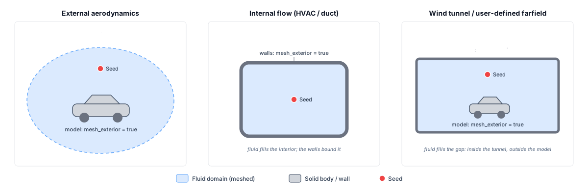
Fluid-domain classification for the common scenarios. mesh_exterior sets which side of each body is fluid (outside a true body, inside a false body), and the seed selects the connected region to mesh.#
See also
Body-group setup: GUI Guide: Geometry
Hidden-geometry and mesh defaults: mesh parameters
Farfield types: farfield
Seed-point volumes: seed point volume
Zone generation and the flood-fill workflow: Volume Mesher
Python API: meshing reference
Comparison with a standard wrapper#
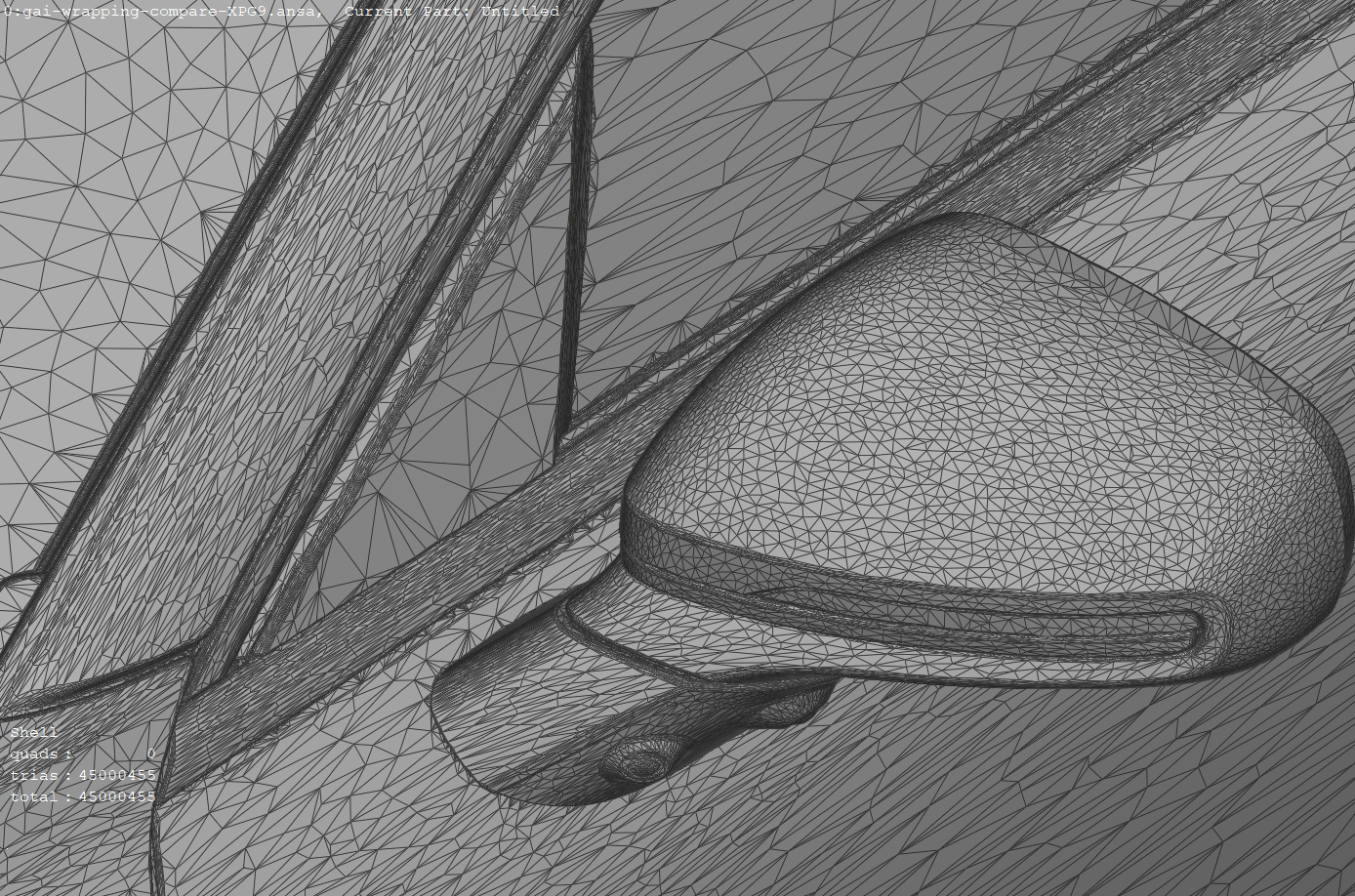
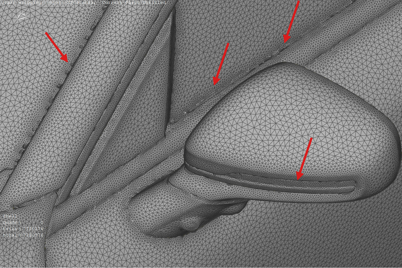
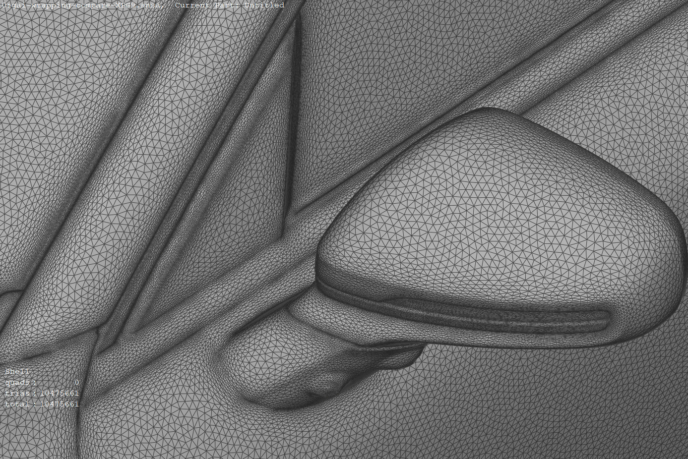
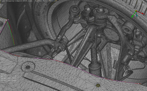
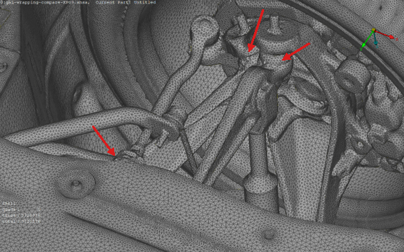
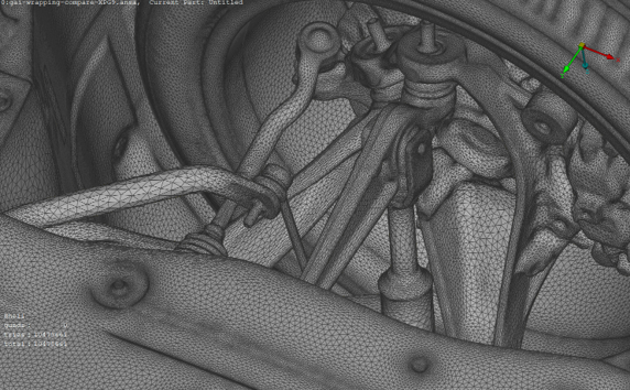
The comparisons below show the input geometry, the result of a standard wrapper, and the GeometryAI surface for the same detailed regions. The red arrows highlight regions where the standard wrapper produces defects (intersections or non-manifold elements) that GeometryAI avoids.
Input geometry |
Standard wrapper |
GeometryAI |
|---|---|---|
|
|
|
Input geometry |
Standard wrapper |
GeometryAI |
|---|---|---|
|
|
|