

Launching a case with the WebUI#
Now that we have generated a volume mesh, we can launch a case.
The Simulation tab on the left of the screen contains 4 sections:
Flow conditions: the vehicle’s operating condition.
Mesh: the farfield, mesh parameters and refinements, covered in the previous Quick Start tutorial.
Flow solver: the boundary conditions, time stepping, physics models and user-defined dynamics. User-defined dynamics allow custom expressions to calculate specific variables, as explained in this tutorial.
Output: the reference dimensions and the list of solution outputs that will be generated and available for download.
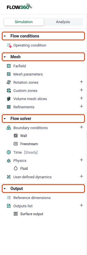
The 4 setup sections.#
The full setup workflow is described in General Workflow in Flow360 GUI.
Creating a new run#
Click New run in the top bar, enter a run name in the popup and click Confirm. The new run starts from the volume mesh and keeps all its current parameters.
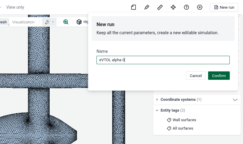
Creating a new run.#
Under Output, the Reference dimensions default to a Moment length of 1 in each direction and an Area of 1, in the project length unit and its square. Those values are adequate here, so leave them as they are.
The Operating condition under Flow conditions is still missing a velocity. The Inspector in the status bar at the bottom reports the missing input as an error.
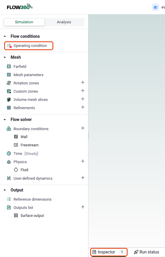
Notification that some required inputs are missing.#
Click the Inspector to see more information about each error.
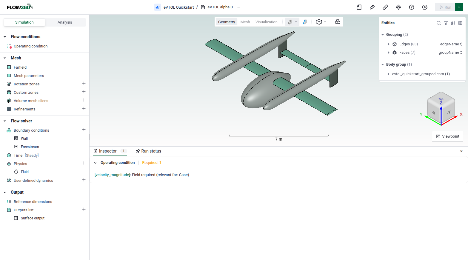
Inspector message outlining the missing inputs.#
To fix this, click Operating condition and set Velocity magnitude to 50 m/s. The Alpha angle, Beta angle and the fluid properties can also be modified, but we will leave them at their defaults.
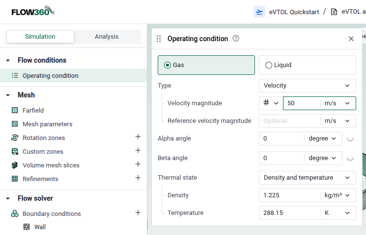
Entering the flow conditions.#
The Physics item under Flow solver adds models such as rotation and virtual propeller models or others.
The Time item selects a steady or unsteady simulation and defines the time stepping. The default is steady.
Last but not least, the Outputs list under Output adds output types depending on the data you require. A Surface output with the Cp, yPlus, Cf and CfVec fields on all surfaces is included by default.
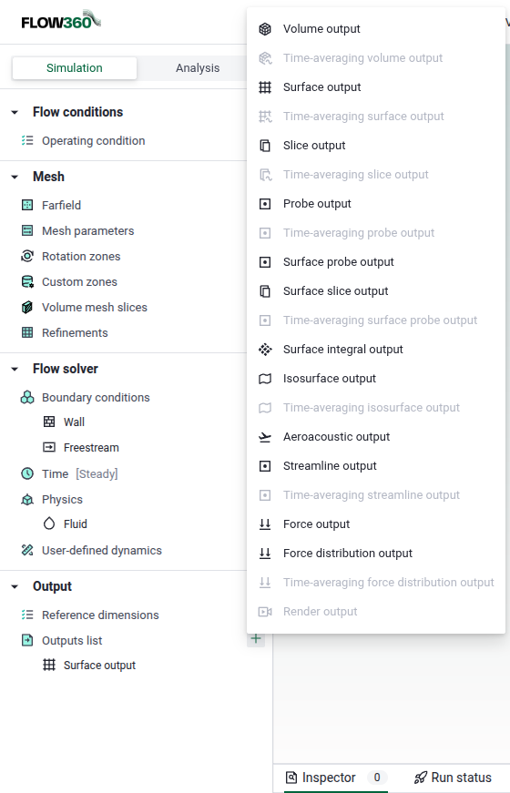
Adding outputs to the Outputs list.#
Assigning boundary conditions#
The Boundary conditions item under Flow solver assigns a boundary condition to each surface of the geometry.
The eVTOL geometry was divided into the following face groups in the .csm file, through the groupName attribute of its faces:
Fuselage
Left wing
Right wing
Left pylon
Right pylon
Vertical tail
Horizontal tail
Because the faces were grouped by groupName before meshing (see the meshing tutorial), the Faces entry of the Entities panel lists these seven groups.
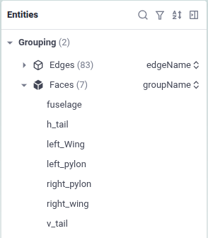
The 7 faces defining our eVTOL as defined in the CAD input .csm file.#
By default, a Wall boundary condition is assigned to all surfaces of the model and a Freestream boundary condition to the automated farfield. These defaults are what this tutorial needs. If needed, you can change the boundary conditions in this section.
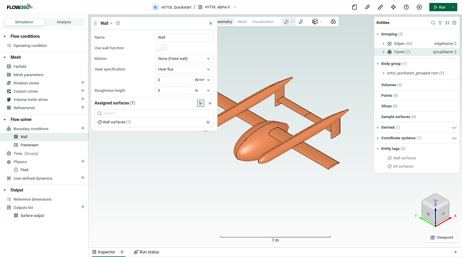
Default wall and freestream boundaries.#
Now that the setup is complete, click Run at the top right of the workspace. In the Preview window, check the run name and click Run to launch the simulation.
Tracking a case status#
The case status can be tracked in the Run status panel at the bottom of the screen, next to the Inspector mentioned above.
The Dashboard view under the Analysis tab shows the most useful information about the run on one screen. See Dashboard for details.
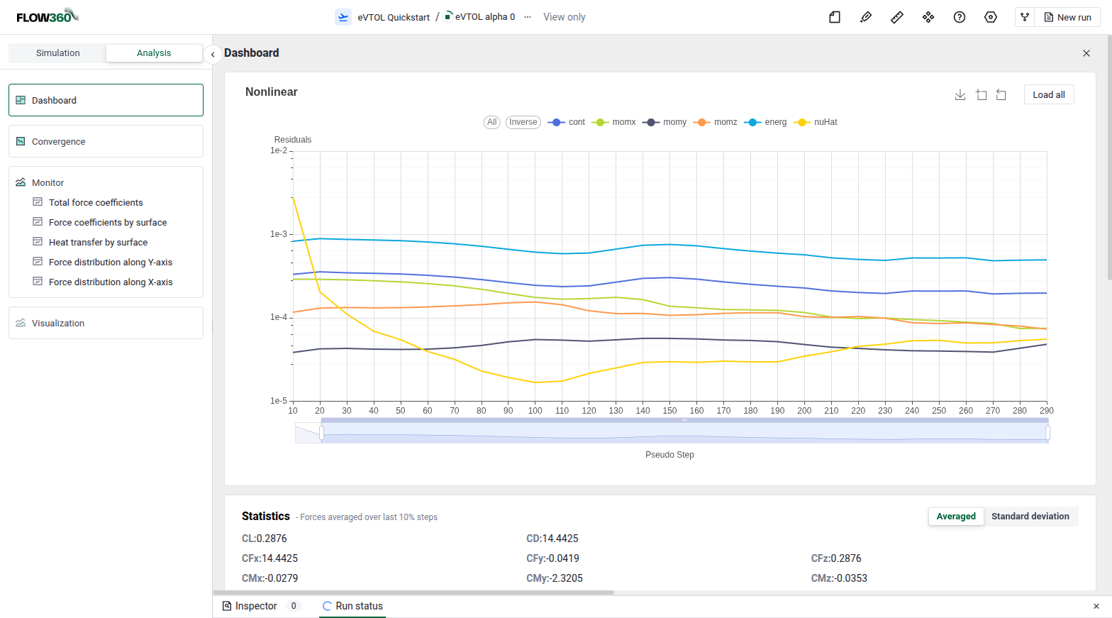
Run dashboard to monitor the most useful information.#
Forking a case#
You may want to continue a case for longer, or restart a new case using a completed case as a starting point. Both are done with the Fork option, which creates a child case with the same settings as the parent case. You can then change some settings if you choose, and Run the child case. To only continue the parent case for more iterations, there is no need to change any settings.
To fork, click the Fork button next to New run in the top bar, enter the child case’s name, click Confirm, change any settings you want on the left-hand panel, and click Run.
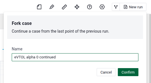
Forking an existing case.#
The project tree#
The project tree gives quick access to all the entities in your project. Its root is the CAD geometry or mesh you uploaded, and every entity generated from that root is displayed with its relationship to the others. Open the project tree by clicking the project name at the top middle of the view.
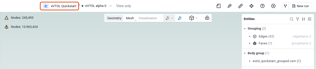
Accessing the project tree.#
The project tree shows the root CAD geometry, the surface mesh and the volume mesh derived from it, and every case run on that mesh. In the example below, two more cases were created for alpha angles of 2 and 4 degrees, and the forked child case is shown as dependent on its parent case. Click an entity to bring it up in the workbench viewer and analyze it in more detail. See Project Tree for more.
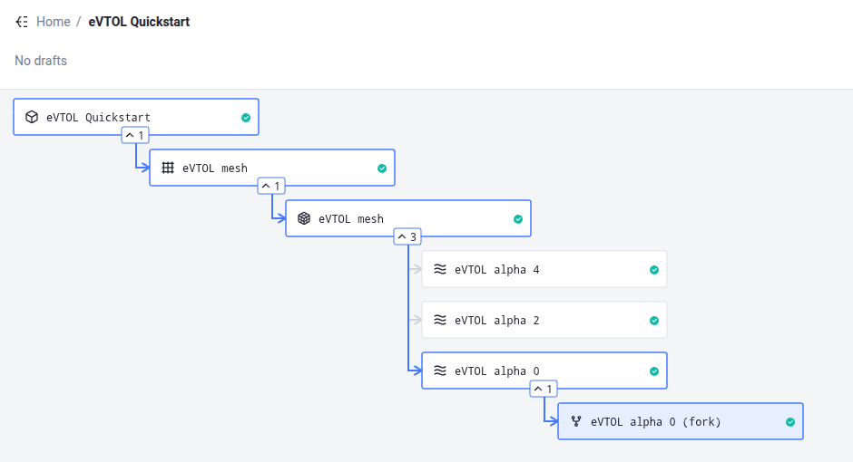
Using the project tree to navigate inside your project.#
Now that we have run a case, we will look at the results in the next Quick Start tutorial on post-processing.