

General Workflow in Flow360 GUI#
This document outlines the systematic approach to setting up and running CFD simulations using the Flow360 graphical user interface.
Workbench view#
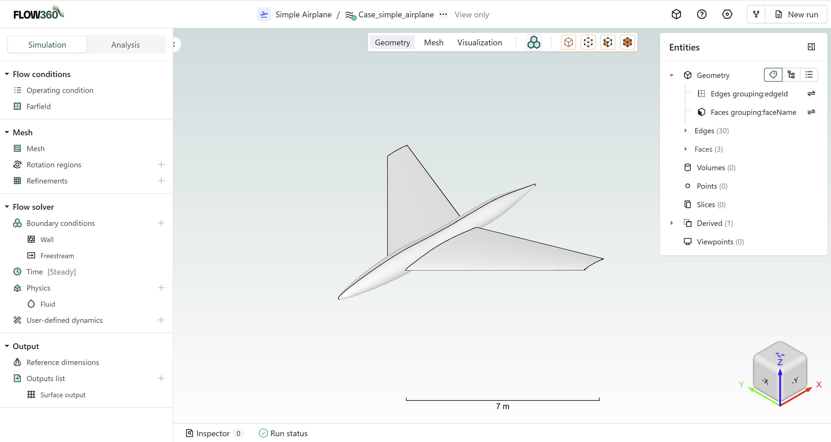
For the regions of the workbench, see Workbench Layout.
Primary Workflow Steps#
Step |
Description |
Location |
|---|---|---|
Setup |
Configure simulation parameters |
Simulation tab |
Verify |
Verify setup using inspector |
Bottom status bar |
Run |
Initiate simulation run |
Top-right corner |
Monitor |
Track simulation progress |
Analysis tab |
Visualize |
View results |
Central viewer region |
See also
For the workflow and interface overview, see the User Guide: Workflows & Interfaces.
Related GUI-guide steps:
Meshing: Mesh
Output configuration: Output
Visualization: Visualization
Convergence monitoring: Convergence
Detailed Descriptions#
Setup#
Configure simulation parameters in a top-to-bottom sequence through the left sidebar.
Create or open a project. Create a project from a geometry, a surface mesh or a volume mesh, as described in Starting a Project, or open an existing project from the Dashboard.
Flow conditions: set the operating condition of the gas or liquid.
Mesh: set the farfield, the meshing defaults, rotation zones, custom zones and refinements. Projects created from geometry or from a surface mesh need this step. A project created from a volume mesh needs no additional meshing.
-
Boundary conditions: for each boundary condition (for example Wall or Freestream), select its faces in Assigned surfaces.
Time: choose steady or unsteady time stepping.
Physics: set the fluid model and any solid, rotation, BET disk, actuator disk or porous medium models.
User-defined dynamics, if needed.
Output: set the Reference dimensions and add entries to the Outputs list.
For detailed documentation of each setup panel, see the Simulation Setup guide.
Verify#
Verify simulation setup completeness using the inspector tool.
Location: Bottom status bar
Success Indicator: Inspector showing 0 errors
Run#
Initiate the simulation process including surface and volume meshing.
Location: Top-right corner “Run” button
Scope: Complete workflow from geometry to solution
Run Preview Dialog#
When you click Run, a Preview dialog appears before the simulation is submitted. This dialog lets you review the simulation configuration and choose how to pay for the compute resources.
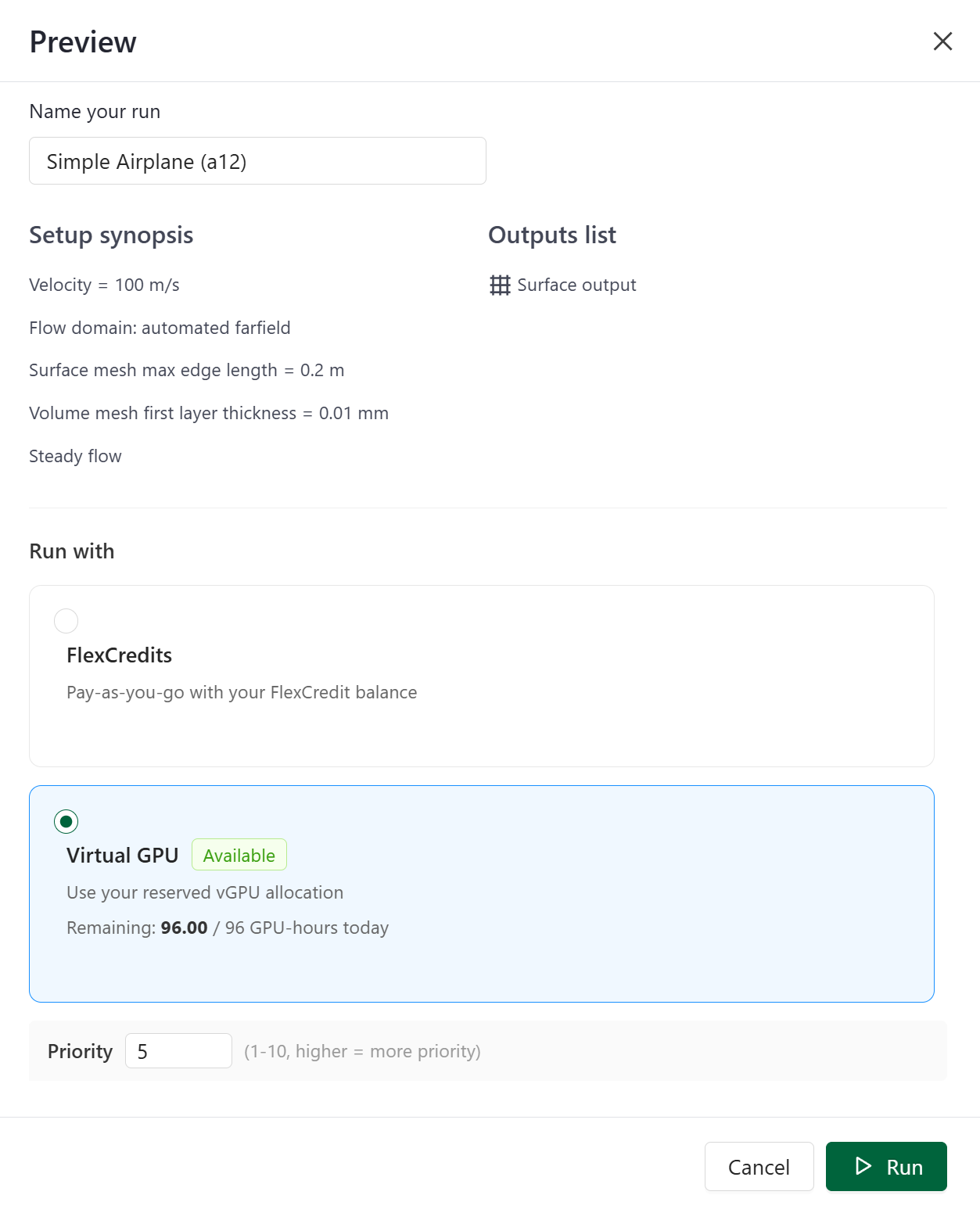
The Run with section offers two compute options:
Option |
Description |
|---|---|
FlexCredits |
Pay-as-you-go using your FlexCredit balance. The run is dispatched immediately to the standard queue. |
Virtual GPU |
Use your reserved vGPU daily allocation. Shows availability status (Available / Unavailable) and the remaining GPU-hours for today (e.g., Remaining: 96.00 / 96 GPU-hours today). |
When Virtual GPU is selected, a Priority field (1–10) appears. Higher priority jobs are scheduled before lower-priority ones when vGPU slots are limited.
Note
The Virtual GPU option is only available if your account includes a vGPU license. If no vGPU allocation is active, only the FlexCredits option is shown.
For full details on managing your vGPU queue, daily allocation, and job priorities, see the Virtual GPU Scheduler page.
Monitor#
Track simulation progress and analyze numerical results.
Access: “Analysis” tab adjacent to “Simulation”
Features: Real-time convergence monitoring
For detailed documentation of the analysis tools, see the Analysis guide, including Convergence plots and Monitor outputs.
Visualize#
Inspect mesh and results using the central viewer.
Controls: Viewer bar for mode selection
Options: Geometry, mesh, and solution visualization
For detailed documentation of visualization options, see the Visualization page.