

Automated Meshing with the WebUI#
After uploading a CAD geometry into a new project (see the previous Quick Start tutorial), the next step is to mesh it. This tutorial uses the beta mesher to generate both the surface mesh and the volume mesh from the geometry.
Turning on the beta mesher#
The mesher is chosen per project in the Project settings drawer. A new project uses the mesher set as your account’s Default mesher, which is the Legacy mesher unless you have changed it.
Open the project created in the previous tutorial.
Click the gear (Settings) button in the top bar and select Project settings.
On the Run settings tab, turn on Beta mesher. Leave GeometryAI off: while it is on, the project uses the GeometryAI mesher and the Beta mesher toggle cannot be changed.
Close the drawer.
The toggle can only be changed while you are editing a draft run, which is the state a newly created project opens in. See Project Settings for the other settings in this drawer.
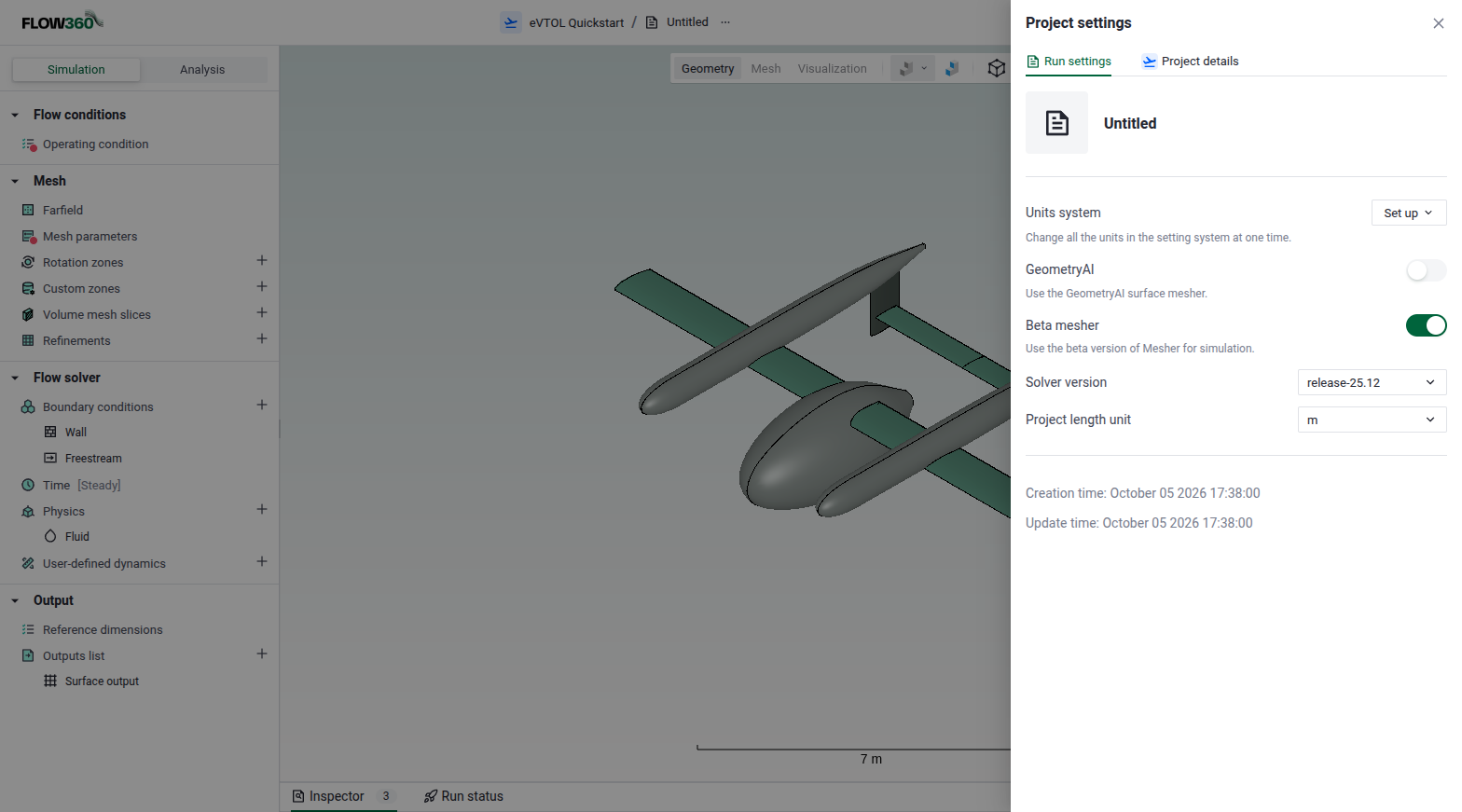
Turning on the beta mesher in Project settings.#
Tip
To start every new project with the beta mesher, set Default mesher to Beta mesher in your account preferences (see Preferences). The preference is applied the first time you open a new geometry project.
Grouping the faces#
The faces of the eVTOL are grouped in the .csm file through their groupName attribute. The mesh keeps one boundary per face group, so choose the grouping before meshing.
In the Entities panel on the right, the Faces entry is grouped by faceId by default, one entry per CAD face. Set the grouping selector next to Faces to groupName and confirm. Faces now lists the seven groups of the eVTOL.
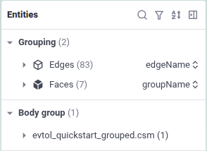
Grouping the faces by groupName.#
Note
Switching the grouping clears what is already assigned to the faces, such as boundary conditions or refinements, so set it first.
Setting the mesh parameters#
The mesh settings are in the Mesh section of the Simulation tab on the left. The Farfield keeps its default Automated farfield type, so nothing needs to change there for this tutorial.
Click Mesh parameters to open its panel. Two fields have no default and must be filled in before meshing:
Surface max edge length: enter
0.1m.Boundary layer first layer thickness: enter
1e-6m.
Keep the defaults for the other fields, including a Curvature resolution angle of 12 degrees. Each parameter is described in Mesh parameters, and our meshing guidelines help choose values for your own geometries.
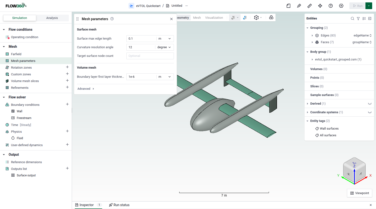
Required mesh parameters for the eVTOL.#
Note
The beta mesher does not offer the Surface edge refinement used by the legacy mesher, so the leading-edge refinement from earlier versions of this tutorial is not needed. The refinements that the beta mesher supports are listed in Refinements.
Running the meshers#
With the required settings in place, launch the meshing tool chain from the Run button at the top right. The main Run button runs the whole simulation, so use the arrow next to it instead. Its menu offers Up to surface mesh and Up to volume mesh.
Select Up to volume mesh. In the Preview window, name your run and click Run up to volume mesh. The surface mesh is generated first, then the volume mesh.
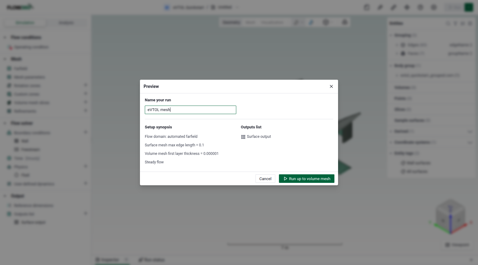
Launching the surface and volume meshers.#
Inspecting the mesh#
Once a mesh is available, click Mesh in the view selector at the top of the viewer and select Mesh (Surface) or Mesh (Volume). The viewer first loads a low-resolution preview. To see the mesh elements, click Low res and select High resolution.
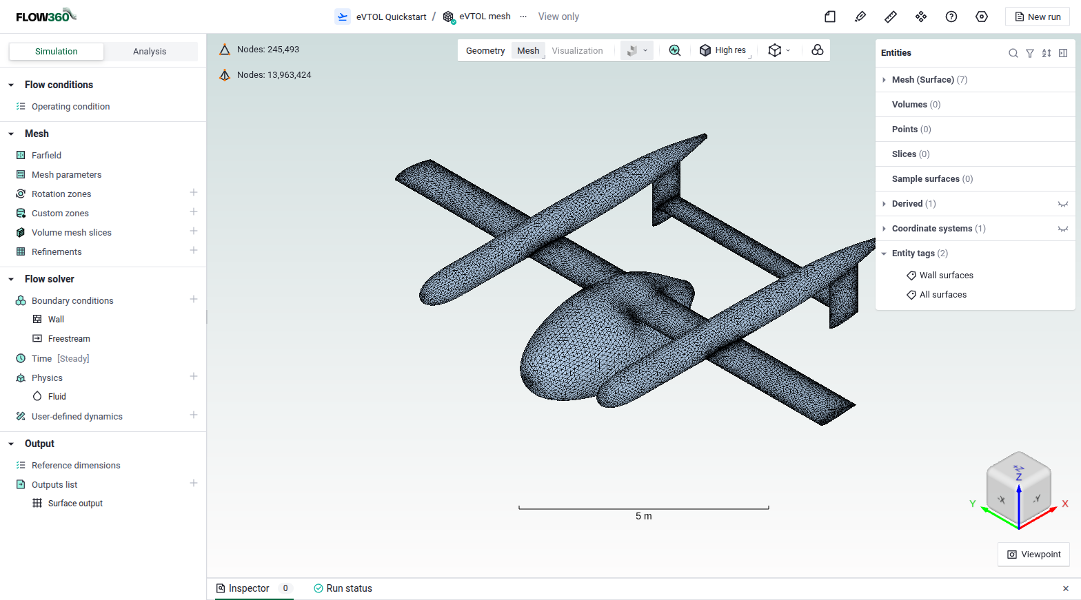
Viewing the generated mesh.#
To navigate the view:
Hold the right mouse button and drag to pan.
Scroll the mouse wheel to zoom in and out.
Hold the left mouse button and drag to rotate.
Click a face, edge or corner of the Rotation cube to snap to that view.
The full list of mouse and keyboard controls is in Keyboard Shortcuts.
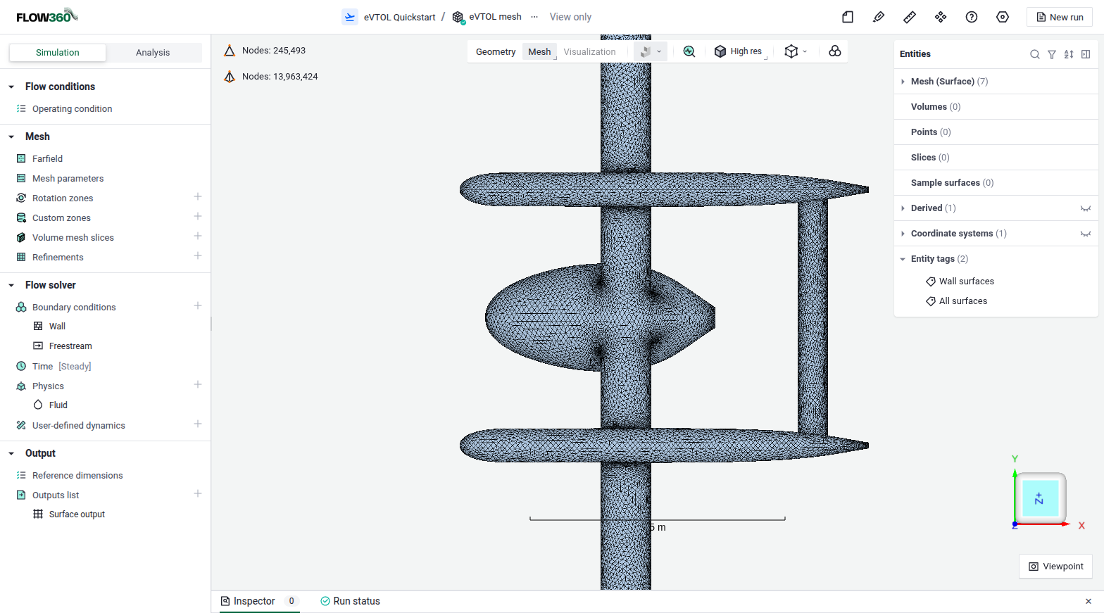
Using the rotation cube to align the view.#
Congratulations, you now have a mesh that is ready to run simulations on. You can now proceed to the next quick start tutorial on launching a case.