
MRF Rotor#
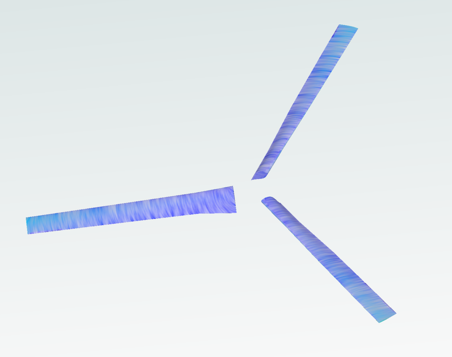
This notebook explains the implementation of the Multiple Reference Approximation (MRF) for rotor modelling. The geometry consists of an isolated XV15 rotorcraft.
1. Create a project from geometry:#
Load python libraries and Flow360 client.
Get geometry files from example database. The geometry used in the path
XV15_CSM.geometryis “XV15_Wing.csm”, if you want to use your own geometry, replace this file path with your local path to your CAD file.Load the geometry according to the length unit used in the CAD software in which the model has been created
Note: The settings in this example are by no means a validation setup; they are crafted to showcase the capabilities of Flow360 and we have intentionally reduced node count and example FC cost. The meshing settings below produce a volume mesh of about 2.4 million nodes (5.5 million cells). For rigorous validation, modify the settings as needed.
[1]:
import flow360 as fl
from flow360.examples.XV15_csm import XV15_CSM

import numpy as np
import matplotlib.pyplot as plt

XV15_CSM.get_files()
project = fl.Project.from_geometry(XV15_CSM.geometry, length_unit="inch", name="MRF Rotor")
geometry = project.geometry
[09:05:53] INFO: The file (XV15_Wing.csm) is being downloaded, please wait.
[09:06:12] INFO: Geometry successfully submitted:
                   type        = Geometry
                   name        = MRF Rotor
                   id          = geo-03eef0fa-ef3b-4a8f-b4d2-41b73f276bff
                   status      = uploaded
                   project id  = prj-09d6aa35-01b2-4217-b69e-998e7b9c1507
INFO: Waiting for geometry to be processed.
2. Geometry Primitives Definition:#
In order to apply the MRF approximation we have to define a cylinder corresponding to the rotating zone encapsulating the cylinder. We also define two cylinders for volumetric refinements: a slightly smaller one inside the rotating zone, which sets the cell size around the blades, and a longer one downstream of the rotor, which refines its wake.
The farfield is defined automatically and determines the limits of the simulation domain. This is also included in this code snippet with the class fl.AutomatedFarfield().
[2]:
with fl.SI_unit_system:

    farfield = fl.AutomatedFarfield()
    R = 3.81
    MRF_cylinder = fl.Cylinder(
        center=(0, 0, 0),
        outer_radius=170 * fl.u.inch,
        height=40 * fl.u.inch,
        axis=(0, 0, -1),
        name="RotatingCylinder",
    )

    Rotor_refinement_cylinder = fl.Cylinder(
        center=(0, 0, 0) * fl.u.inch,
        outer_radius=165 * fl.u.inch,
        height=36 * fl.u.inch,
        axis=(0, 0, -1),
        name="RotorRefinementCylinder",
    )

    Wake_Cylinder = fl.Cylinder(
        center=(0, 0, -140) * fl.u.inch,
        outer_radius=170 * fl.u.inch,
        height=320 * fl.u.inch,
        axis=(0, 0, -1),
        name="WakeCylinder",
    )
[09:06:49] INFO: using: SI unit system for unit inference.
3. Rotating Zone Definition#
We use the RotatingCylinder Object to define the mesh volume zone in which the MRF approximation will be applied. We have to define the mesh properties at the interface between the volume zones, which will in turn, determine the overall mesh quality of the volume zone.
To control the cell size inside the rotating zone, a uniform volumetric refinement is applied to the slightly smaller Rotor_refinement_cylinder in section 4.1.
[3]:
RotatingZone = fl.RotationVolume(
    name="RotatingZone",
    spacing_axial=3 * fl.u.inch,
    spacing_circumferential=4 * fl.u.inch,
    spacing_radial=4 * fl.u.inch,
    entities=MRF_cylinder,
    enclosed_entities=geometry["*"],
)
4. Case Parameters Definition:#
4.1 Meshing:#
Having defined the basic information about the rotating zone we can define the different parameters which drive the simulation, starting from the meshing. The required inputs are:
Meshing Defaults: in this section the basic parameters needed to create the surface and volume meshes are determined. In this case the first layer thickness keeps y+ below 2 on the blades (below 1 over most of the blade surface, with a mean of about 0.5), while the surface edge length, curvature resolution angle and growth rates are chosen to limit the cell count
Volume Zones: for multizone meshes, all volume zones have to be specified. In this case we have a farfield and the rotating zone
Refinements: a number of refinements can be included to increase the accuracy of the mesh. Here, one uniform refinement sets the cell size around the blades and a coarser one covers the wake.
[4]:
meshing = fl.MeshingParams(
    defaults=fl.MeshingDefaults(
        surface_max_edge_length=3 * fl.u.inch,
        boundary_layer_first_layer_thickness=1.5e-6 * fl.u.m,
        curvature_resolution_angle=20 * fl.u.deg,
        boundary_layer_growth_rate=1.3,
        surface_edge_growth_rate=1.4,
        volume_edge_growth_rate=1.2,
    ),
    volume_zones=[farfield, RotatingZone],
    refinements=[
        fl.UniformRefinement(entities=Rotor_refinement_cylinder, spacing=4 * fl.u.inch),
        fl.UniformRefinement(entities=Wake_Cylinder, spacing=8 * fl.u.inch),
    ],
)
4.2 Final MRF Definition:#
The MRF zone is established by defining a rotating region in the solver parameters. Using fl.Rotation() inside a fl.Steady configuration allows the solver to apply the MRF approximation.
[5]:
omega = 589 * fl.u.rpm

MRF = fl.Rotation(name="MRF", volumes=MRF_cylinder, spec=fl.AngularVelocity(omega))

time_stepping = fl.Steady(max_steps=1500, CFL=fl.AdaptiveCFL(convergence_limiting_factor=0.75))
4.3 Dynamic parameters:#
Having defined the time-stepping scheme and the MRF rotating zone. We have to specify the turbulence model, and reference geometry. All the parameters are then groped under the following sections. The physical configuration is intended to demonstrate the numerical implementation of a forward-flight case, rather than to represent a realistic operating condition for the rotor.
[6]:
with fl.SI_unit_system:

    params = fl.SimulationParams(
        operating_condition=fl.AerospaceCondition.from_mach(
            mach=0.12,
            alpha=-90 * fl.u.deg,
        ),
        reference_geometry=fl.ReferenceGeometry(
            moment_center=(0, 0, 0), moment_length=(R, R, R), area=np.pi * R**2
        ),
        time_stepping=time_stepping,
        meshing=meshing,
        models=[
            fl.Fluid(
                navier_stokes_solver=fl.NavierStokesSolver(
                    absolute_tolerance=1e-10,
                    riemann_solver=fl.RoeFlux(low_mach_preconditioner=True),
                ),
                turbulence_model_solver=fl.SpalartAllmaras(),
            ),
            fl.Wall(surfaces=geometry["*"]),
            fl.Freestream(surfaces=farfield.farfield),
            MRF,
        ],
        outputs=[
            fl.SurfaceOutput(
                surfaces=geometry["*"],
                output_fields=[
                    "primitiveVars",
                    "Cp",
                    "Cf",
                    "CfVec",
                    "yPlus",
                ],
            ),
            fl.VolumeOutput(
                output_fields=[
                    "Mach",
                    "primitiveVars",
                    "qcriterion",
                    "Cp",
                ]
            ),
        ],
    )
INFO: using: SI unit system for unit inference.
5. Running the case#
Here we run the case using the beta mesher.
[7]:
case = project.run_case(params=params, name="Steady MRF", use_beta_mesher=True)
[09:06:51] INFO: Selecting beta/in-house mesher for possible meshing tasks.
[09:06:53] INFO: Successfully submitted:
                   type        = Case
                   name        = Steady MRF
                   id          = case-4be5bf8d-e96b-4282-b3c6-1ce97bc55f3e
                   status      = pending
                   project id  = prj-09d6aa35-01b2-4217-b69e-998e7b9c1507
6. Numerical and Force Convergence#
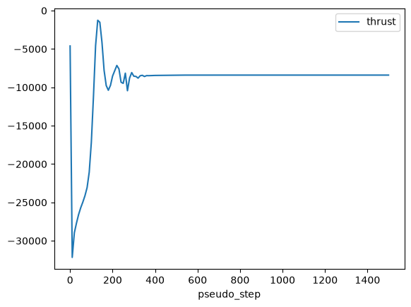
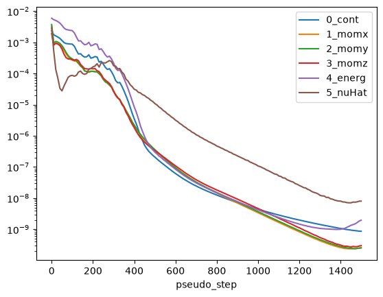
Having ran the case we can plot the thrust and non-linear residuals. Note that for the thrust we will need to use dimensional quantities from the case.
[8]:
case.wait()

# Reference quantities
density = case.params.operating_condition.thermal_state.density
U_ref = (
    case.params.operating_condition.reference_velocity_magnitude
    or case.params.operating_condition.velocity_magnitude
)
A_ref = case.params.reference_geometry.area

# Get results
results = case.results

# Plot thrust
total_forces = case.results.total_forces.as_dataframe()
total_forces["thrust"] = total_forces["CFz"] * 0.5 * density * U_ref**2 * A_ref
total_forces.plot("pseudo_step", ["thrust"])

# Plot non-linear residuals
non_linear = case.results.nonlinear_residuals.as_dataframe()
non_linear.plot(
    "pseudo_step",
    ["0_cont", "1_momx", "2_momy", "3_momz", "4_energ", "5_nuHat"],
    logy=True,
)
plt.show()
[09:34:12] INFO: Saved to /tmp/tmpc7neyryb/b0e07458-9838-487f-9b3f-fb35eb44e4ac.csv
INFO: Saved to /tmp/tmpc7neyryb/a85a19d4-43ff-4b93-894a-701c8ddb3f53.csv