

Top Bar#
The Flow360 GUI top bar provides essential navigation and project management functionality, enabling efficient workflow control and access to key features.
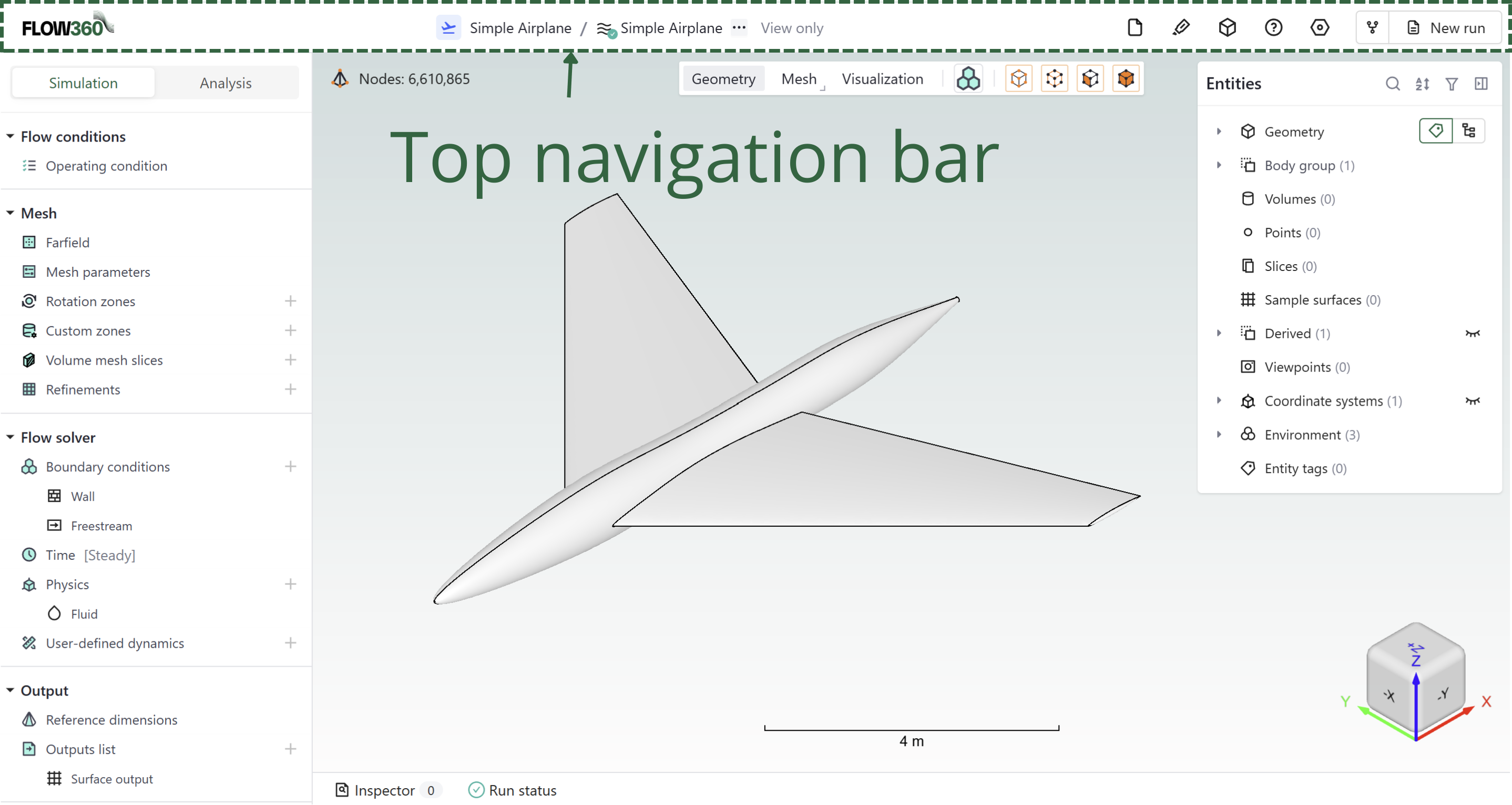
Available Components (from left to right)#
Component |
Icon |
Description |
|---|---|---|
Flow360 logo |
|
Return to Flow360 Dashboard |
Project tree |
|
Hierarchical view of project components. See Project tree |
More |
|
Export/import settings via three-dot menu |
View only |
|
Indicates view-only mode for the project |
Assets |
|
Access project assets and resources |
Resource |
|
Import geometry resources (GeometryAI only) and sample surfaces |
Probe |
|
Show location of entered coordinates or show coordinates of a clicked location |
Measure |
|
Measure the distance between two points picked in the viewer |
Help |
|
Access documentation and support |
Settings |
|
Access to project and variable settings |
Fork/New run |
|
Create project variants |



See also
For the workflow and interface overview, see the User Guide: Workflows & Interfaces.
Detailed Descriptions#
Flow360 logo#
Quick access to return to the Flow360 Dashboard, maintaining efficient workflow navigation.
Project tree#
Hierarchical organization of project components, providing structured access to simulation elements.
Expandable/collapsible structure
Visual status indicators
Direct component access
See Project tree for more details
More#
Additional project management options accessible via a three-dot menu.
Import/Export simulation settings
Import/Export viewpoints
View only#
Notification that the project is currently being viewed in view-only mode.
Simulation parameters cannot be changed in this mode
To exit, click on New run or select a component from the project tree
Assets#
 Central repository for project-related resources and files.
Information about each asset
Downloadable files list for each asset
Resource#
 Import geometry resources and sample surfaces.
Geometry resource: Import additional geometry files (GeometryAI only)
Sample surface: Import sample surface data
Probe#
 Show location of entered coordinates or show coordinates of a clicked location.
Enter coordinates to highlight a location in the viewer
Click on geometry to display coordinates of that point
Measure#
Measure the distance between two points in the viewer.
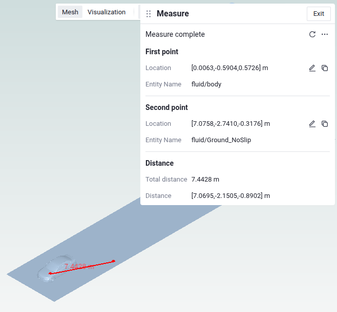
Click the  icon to open the Measure panel, then pick two points in the viewer. Each point is placed where you click on the surface shown in the viewer (geometry, mesh, results or a slice), as with Probe. On geometry, this is the displayed tessellation of the CAD, so on curved faces the point can lie slightly off the exact surface. Points are not moved to the nearest mesh node or edge.
First point and Second point: the location of each picked point and the name of the entity it lies on
Distance: the total distance between the two points and its x, y and z components
Click Exit to close the tool.
Help#
 Access to documentation, support resources, and guidance materials.
Project settings#
 Configuration interface for project-specific parameters. Includes run settings and project details.
Fork/New run#
Create an extension of a case based on current configuration.
See Forking section in the Project tree documentation for more information.