tidy3d.PML#
- class PML[source]#
Bases:
AbsorberSpecSpecifies a standard PML along a single dimension.
- Parameters:
name (Optional[str] = None) – Optional unique name for boundary.
num_layers (int = 12) – Number of layers of standard PML.
parameters (
PMLParams= PMLParams(kappa_min=1.0, kappa_max=3.0, alpha_order=1, alpha_max=0.0)) – Parameters of the complex frequency-shifted absorption poles.extrude_structures (bool = True) – Automatically extrude structures into the absorbing region (e.g., PML or adiabatic absorber). Any structure located within 2 cells of a simulation boundary will be extended through the full thickness of the PML/absorber. The extruded region is assigned the material properties of the structure 2 cells from the simulation boundary. Extrusion is performed along the direction normal to the PML/absorber surface.
Notes
1D Model Illustration
Consider a transformed wave equation in the \(x\) dimension below [1]:
\[\left( \left( \frac{1}{s(x)} \frac{\delta}{\delta x} \right)^2 - \frac{1}{c^2} \frac{\delta^2}{\delta t^2} \right) E = 0\]where the wave stretch factor \(s(x)\) depends on the PML boundary position in the \(x\) dimension.
\[\begin{split}s(x) = \left \{ \begin{array}{lr} 1, & \text{for } x < 0 \\ 1 - \frac{\sigma}{i \omega \epsilon_0}, & \text{for } x > 0 \end{array} \right \}\end{split}\]The wave equation can be solved and plotted accordingly as a function of the \(x\) dimension.
\[\begin{split}E(x) = \left \{ \begin{array}{lr} e^{i(kx - \omega t)}, & \text{for } x < 0 \\ e^{i(kx - \omega t)} \times e^{-\frac{\sigma x}{c \epsilon_0}} & \text{for } x > 0 \end{array} \right \}\end{split}\]Hence, we see how this PML stretch factor induces frequency-independent exponential attentation and no reflection after the boundary at \(x=0\).

Usage Caveats
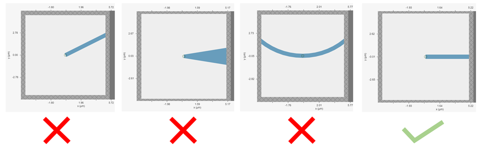
A perfectly matched layer (PML) is the most commonly used boundary condition in FDTD simulations to truncate a simulation domain and absorb outgoing radiation. However, many divergence issues are associated with the use of PML. One of the most common causes of a diverged simulation is structures inserted into PML at an angle.
Incorporating a dispersive material into the PML can also cause simulation divergence in certain scenarios. If your simulation lacks any structures inserted into the PML at an angle, but includes dispersive material in PML, it is advisable to substitute a nondispersive material for the dispersive material. Alternatively, if dispersion is necessary, switching from the
PMLtoAbsorbercan effectively address the issue.The PML can effectively absorb outgoing radiation with minimum reflection as if the radiation just propagates into the free space. However, it’s important to keep in mind that the PML only absorbs propagating fields. For evanescent fields, the PML can act as an amplification medium and cause a simulation to diverge. In Tidy3D, a warning will appear if the distance between a structure is smaller than half of a wavelength to prevent evanescent fields from leaking into PML. In most cases, the evanescent field will naturally die off within half a wavelength, but in some instances, a larger distance may be required.
Note
Practical Advice
For best results, structures that intersect with the PML or simulation edges should extend all the way through using
td.inf:Structure(geometry=Box(size=(td.inf, width, height)), medium=core)
Structures that terminate inside PML can cause evanescent fields at the interface to be amplified by the absorber, potentially leading to simulation divergence.
Example
>>> pml = PML(num_layers=10)
See also
Attributes
- num_layers#
- parameters#
- extrude_structures#