Automated Meshing for Internal Flow
Contents
7.7. Automated Meshing for Internal Flow#
This tutorial shows how to create a mesh for internal flow using the automated meshing process.
7.7.1. Geometry#
As shown in Fig. 7.7.1, the geometry is a wind tunnel enclosing a sphere that is supported by four cylindrical struts. The corresponding CSM file is provided, so the readers can easily reconstruct the geometry on their local machines.
Several details are worth emphasizing in the CSM file:
For internal flow, a single solid body representing the fluid must be provided to the automated meshing process. To do this, once the wind tunnel (box) and the sphere with struts are constructed, the next step is to
subtractthe sphere and struts from the wind tunnel.Fig. 7.7.1 shows the
faceNameandgroupNameattributes on the faces of the wind tunnel. In general faces with the samefaceNamewill be treated as the same surface patch for assigning surface (maxEdgeLength) and volume (firstLayerThickness) mesh attributes. Conversely, the user can set different surface and volume mesh attributes for faces with a differentfaceName. Faces with the samegroupNamewill be considered as the same boundary when exporting the CGNS file.

Fig. 7.7.1 Sphere in wind tunnel, geometry with face attributes. sideNegY is hidden to show the interior of the wind tunnel.#
7.7.2. Surface Mesh#
The surfaceMesh.json is provided as follows:
{
    "maxEdgeLength": 1,
    "curvatureResolutionAngle": 15,
    "growthRate": 1.2,
    "faces": {
        "sphere": {"maxEdgeLength": 0.1},
        "strut":  {"maxEdgeLength": 0.01}
    }
}
Noteworthy details in this surfaceMesh.json:
The global
maxEdgeLengthgoverns the mesh size on all faces.In subsection
faces, users can define localmaxEdgeLengthfor the sphere and struts, overwriting the globalmaxEdgeLength.
7.7.3. Volume Mesh#
The volumeMesh.json is provided as follows:
{
    "refinementFactor": 1.0,
    "volume": {
        "firstLayerThickness": 1e-6,
        "growthRate": 1.2
    },
    "farfield": {
        "type": "user-defined"
    },
    "faces": {
        "floor": {
            "type": "aniso",
            "firstLayerThickness": 1e-5
        },
        "ceiling": {
            "type": "none"
        },
        "adjacent2floor": {
            "type": "projectAnisoSpacing"
        }
    }
}
Regarding the volumeMesh.json above, please note that:
farfieldis set asuser-defined, indicating that the user already provided the “farfield” geometry, which is the wind tunnel box in this example.In the
facessubsection, the keys should match the attributefaceNamein the CSM file.By default, all
facesare treated asanisoand the globalfirstLayerThicknessis applied.The
flooris set asaniso, so the localfirstLayerThickness1e-5 overwrites the global value of 1e-6. The first layer thicknesses provided here are just for illustration. The users need to adjust these values according to the target \(y^+\) in their simulations.The
ceilingis set asnone, hence the anisotropic layers won’t be grown from the ceiling. Meanwhile, the surface mesh on the ceiling remains unaltered when generating the volume mesh.The faces adjacent to the floor
adjacent2floorare set asprojectAnisoSpacing. The surface mesh on those faces is updated when populating the volume mesh. As shown in Fig. 7.7.2, the “spacing” of anisotropic layers grown from the floor are “projected” onto the faces adjacent to the floor.
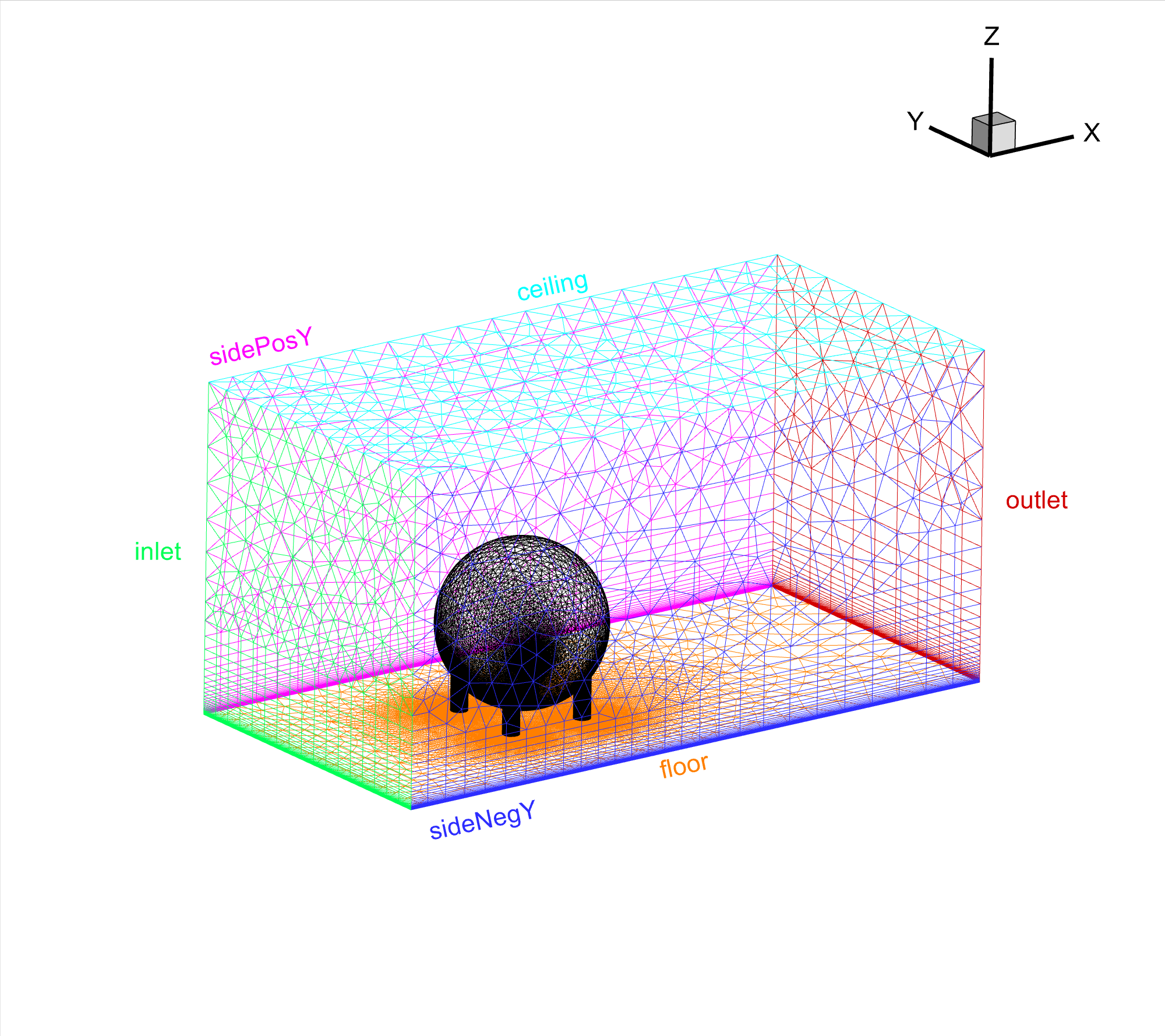
Fig. 7.7.2 Sphere in wind tunnel, populated volume mesh.#