Automated Meshing
Contents
3.3. Automated Meshing#
3.3.1. Overview#
Flow360 offers automated meshing, from CAD geometry to a surface mesh and finally to a volume mesh. The supported CAD format is *.csm file which is Engineering Sketch Pad (EPS) format. The generated volume format is CGNS.
3.3.2. Geometry#
The Engineering Sketch Pad is a solid-modeling, feature-based, web-enabled system for building parametric geometry. It can be downloaded from ESP’s website. Please check out pre-built ESP, you don’t need to compile software from source. The geometry in ESP is described in a text *.csm file containing all CAD instructions. See csm example:
# Branches:
sphere    0   0   0   1

attribute groupName $mysphere

end
which will create a sphere of radius = 1 at (0, 0, 0). The sphere will be labelled as mysphere.
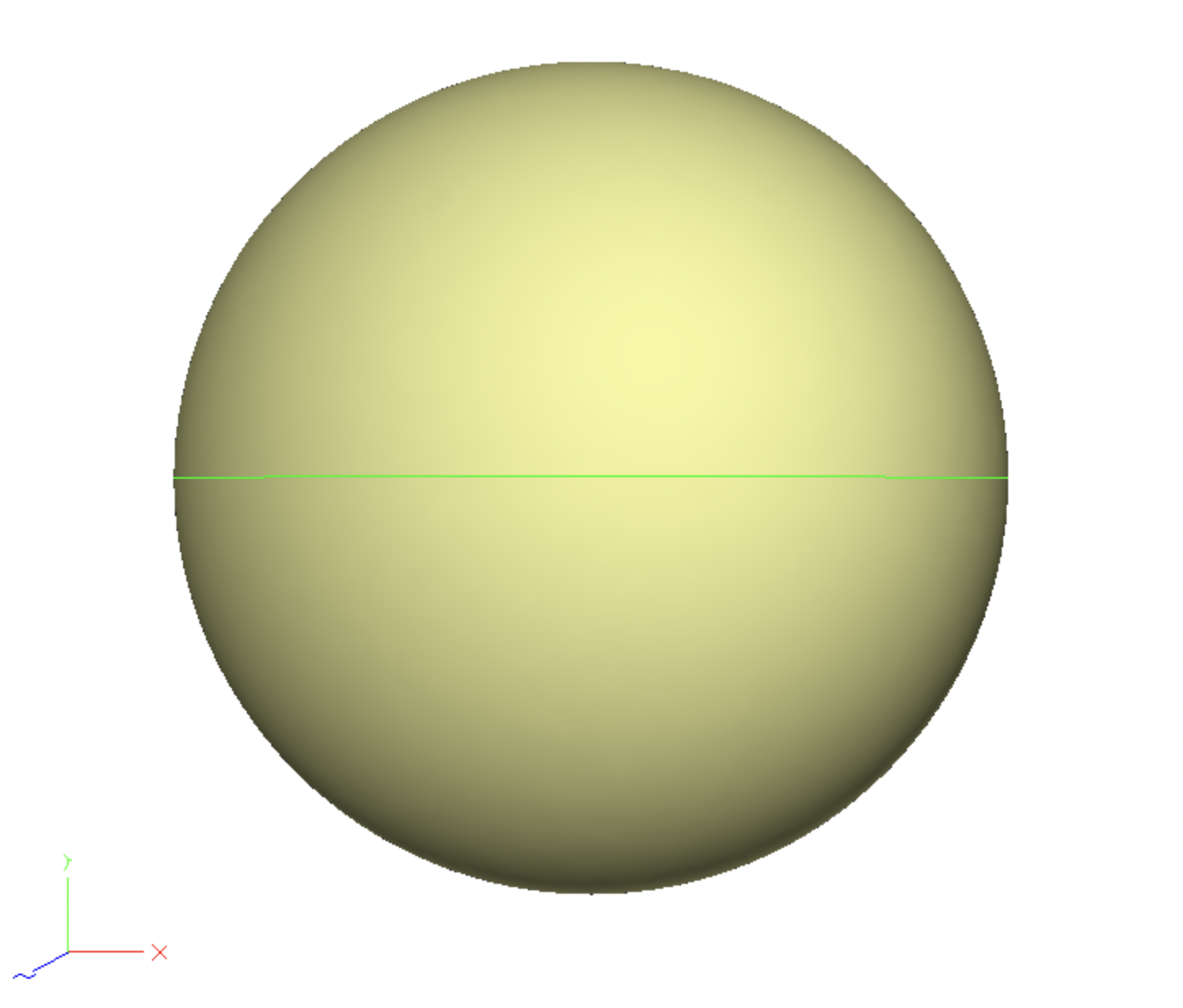
Fig. 3.3.1 Engineering Sketch Pad view of the geometry.#
3.3.3. Surface Meshing#
The surface mesher takes the geometry file and configuration JSON file as input parameters and generates a surface mesh. The meshing configuration file (which can be defined as a dictionary in python), also called surfaceMesh.json, contains information such as maximum element edge length, curvature resolution angle or growth rate of 2D layers. See JSON example:
{
    "maxEdgeLength": 0.1,
    "curvatureResolutionAngle": 15,
    "growthRate": 1.2,
    "faces": {
        "mysphere": {
            "maxEdgeLength": 0.05
        }
    }
}
The surface mesh is created by submitting a geometry file and JSON file using NewSurfaceMeshFromGeometry() function. See the example below:
import flow360client
surfaceMeshId = flow360client.NewSurfaceMeshFromGeometry("path/to/geometry.csm", "surfaceMesh.json", surfaceMeshName="my_surface_mesh", solverVersion='release-22.2.3.0')
The above code will create a surface mesh of geometry using "maxEdgeLength": 0.05 on a surface labelled as mysphere, see line 4 of the *.csm file.
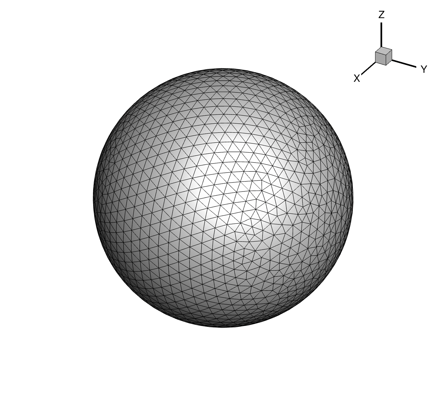
Fig. 3.3.2 Auto-generated surface mesh.#
Inputs:
geometry.csm file
surface mesh config.json (or defined as a dictionary in Python)
Outputs:
surface mesh
surfaceMeshId
For a full description of config.json for surface mesher see here.
3.3.4. Volume Meshing#
The volume mesher takes a surfaceMeshId and a config JSON as arguments and generates a CGNS mesh suitable for the Flow360 solver. The JSON configuration file (or a dictionary in Python) specifies the first layer thickness, growth rate, sizes and location of refinement zones and actuator disks. All geometry from ESP is treated as a no-slip wall therefore prism layers will be grown off geometry surfaces.
The farfield will be created automatically:
cylindrical for quasi 3D cases if
farfield->type: "quasi-3d"is specified. Both sides of the farfield will be set as a symmetry boundary condition.semi-spherical if the geometry is bounded by
y=0plane. They=0plane will be set as a symmetry plane boundary condition.spherical otherwise.
Below is an example volume mesh JSON configuration:
{
    "refinement": [
        {
            "size": [4, 3, 2],
            "axisOfRotation": [ 0, 0, 1 ],
            "angleOfRotation": 45,
            "center": [2, 0, 0],
            "spacing": 0.05
        }
    ],
    "volume": {
        "firstLayerThickness": 1e-3,
        "growthRate": 1.2
    }
}
The volume mesh is created by NewMeshFromSurface() function using surfaceMeshId and config.json. See the example below:
volumeMeshId = flow360client.NewMeshFromSurface(surfaceMeshId, "volumeMesh.json", meshName="my_volume_mesh")
The above code will create a volume mesh out of the surface mesh. The refinement zone of size=4x3x2 will be placed with its centre at (2,0,0). Additionally, it will be rotated by 45 degrees around the [0,0,1] axis. Spacing of 0.05 will be applied in this zone.
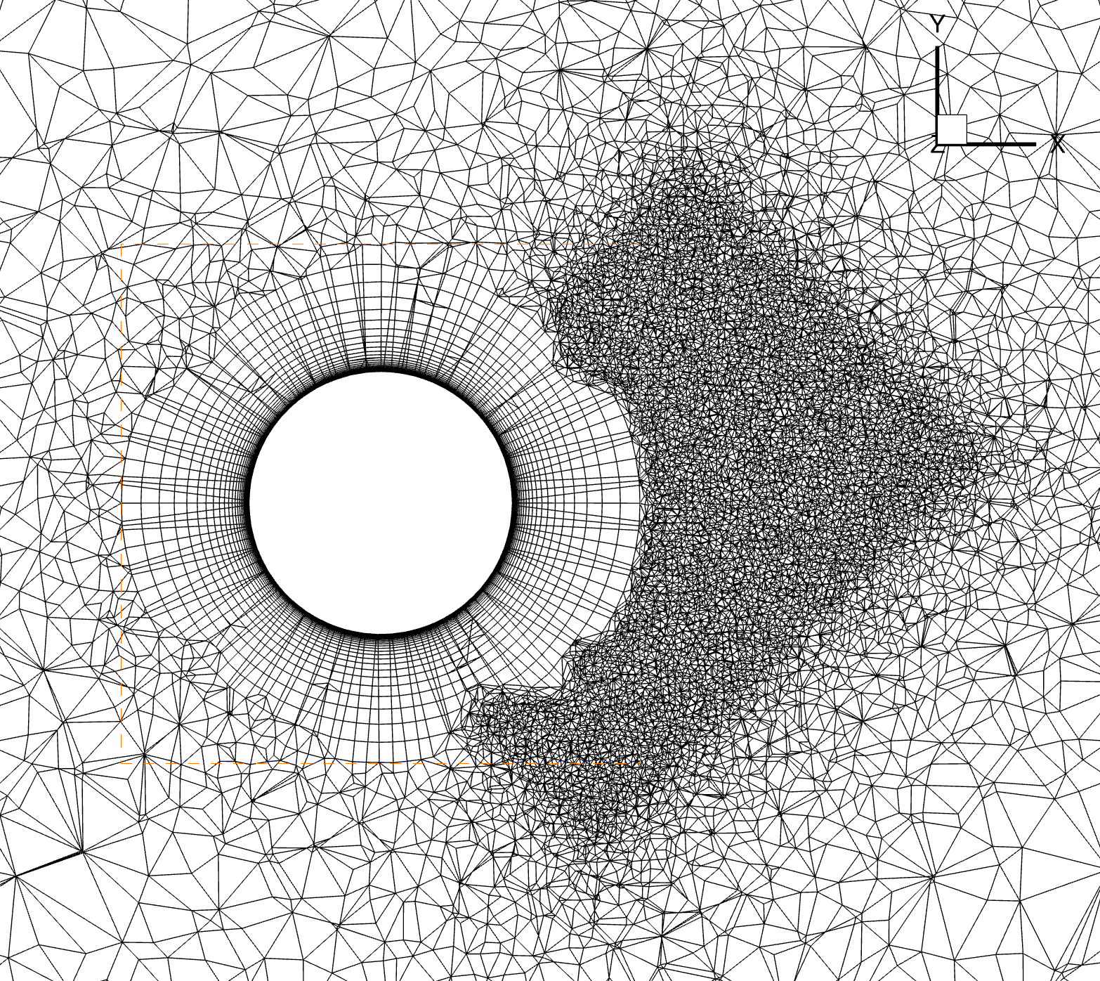
Fig. 3.3.3 Auto-generated volume mesh.#
Inputs:
surfaceMeshIdvolume mesh config.json or python dict
Outputs:
volume CGNS mesh
Flow360Mesh.json
volumeMeshId
For a full description of config.json for volume mesher see here.
3.3.5. JSON surface mesher#
Option |
Type |
Default |
Example |
Description |
|---|---|---|---|---|
maxEdgeLength |
float |
REQUIRED |
0.1 |
Maximum length of element edge. This value will be overwritten on any face who have a different value for maxEdgeLength defined. |
curvatureResolutionAngle |
float |
REQUIRED |
15 |
Maximum angular deviation in degrees. If the angle between the normal line segment and the normal to the underlying geometry curve at a grid point is larger than the specified angle, a new grid point will be added in the middle of the segment. |
growthRate |
float |
REQUIRED |
1.2 |
Growth rate of layers being grown from edges |
edges |
dict |
{} |
<edgeName>: {…} sets parameters for the edge named <edgeName>. The edge must be labelled in ESP (*.csm file). For details see here. |
|
faces |
dict |
{} |
<faceName>: {…} sets parameters for the face named <faceName>. The face must be labelled in ESP (*.csm file). For details see here. |
3.3.5.1. edges#
Option |
Type |
Default |
Example |
Description |
|---|---|---|---|---|
<edgeName>-> type |
["aniso", "projectAnisoSpacing"] |
REQUIRED |
"aniso" |
type="aniso": anisotropic surface cells growing along the orthogonal direction to the edge named <edgeName>. See Fig. 3.3.4. type="projectAnisoSpacing": project spacing, see: Fig. 3.3.5. |
<edgeName>-> method |
["angle", "height", "aspectRatio"] |
REQUIRED |
"height" |
For type="aniso": how anisotropic surface cells grow. "angle": first layer thickness resolves surface curvature angle provided by "value"; "height": provide absolute value for first layer thickness; "aspectRatio": provide aspect ratio of the first surface cell grown from the edge. |
<edgeName>-> value |
float |
REQUIRED |
1e-3 |
For type="aniso": value used in "method" of growing surface cells from the edge. |
Example:
"edges": {
    "leadingEdge":  {
        "type": "aniso",
        "method": "angle",
        "value": 1
    },
    "trailingEdge":  {
        "type": "aniso",
        "method": "height",
        "value": 1e-3
    },
    "hubCircle": {
        "type": "aniso",
        "method": "height",
        "value": 0.1
    },
    "hubSplitEdge": {
        "type": "projectAnisoSpacing"
    }
}
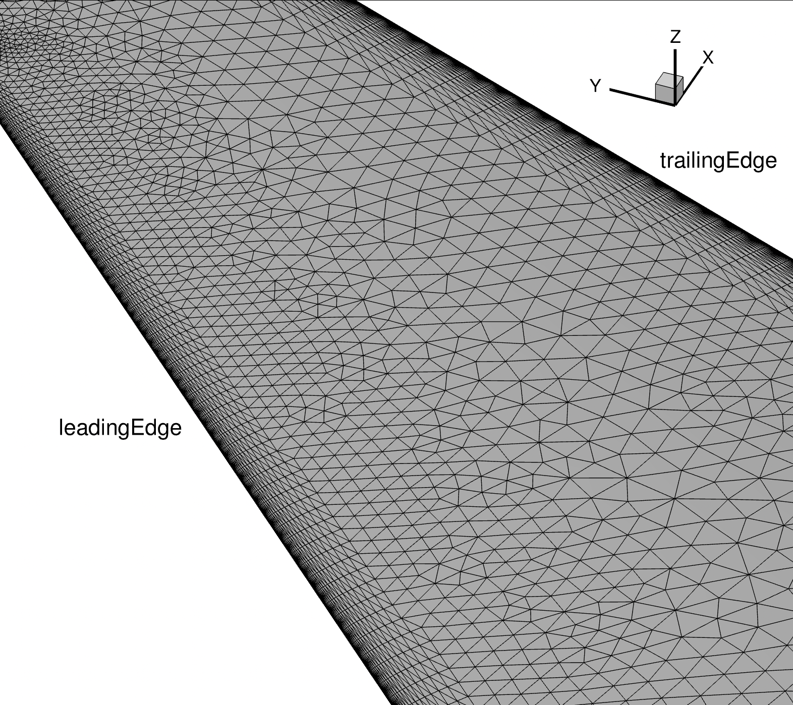
Fig. 3.3.4 Surface mesh of a wing. Leading edge and trailing edge are labelled and first layer thickness is applied to the layers grown from the edges.#
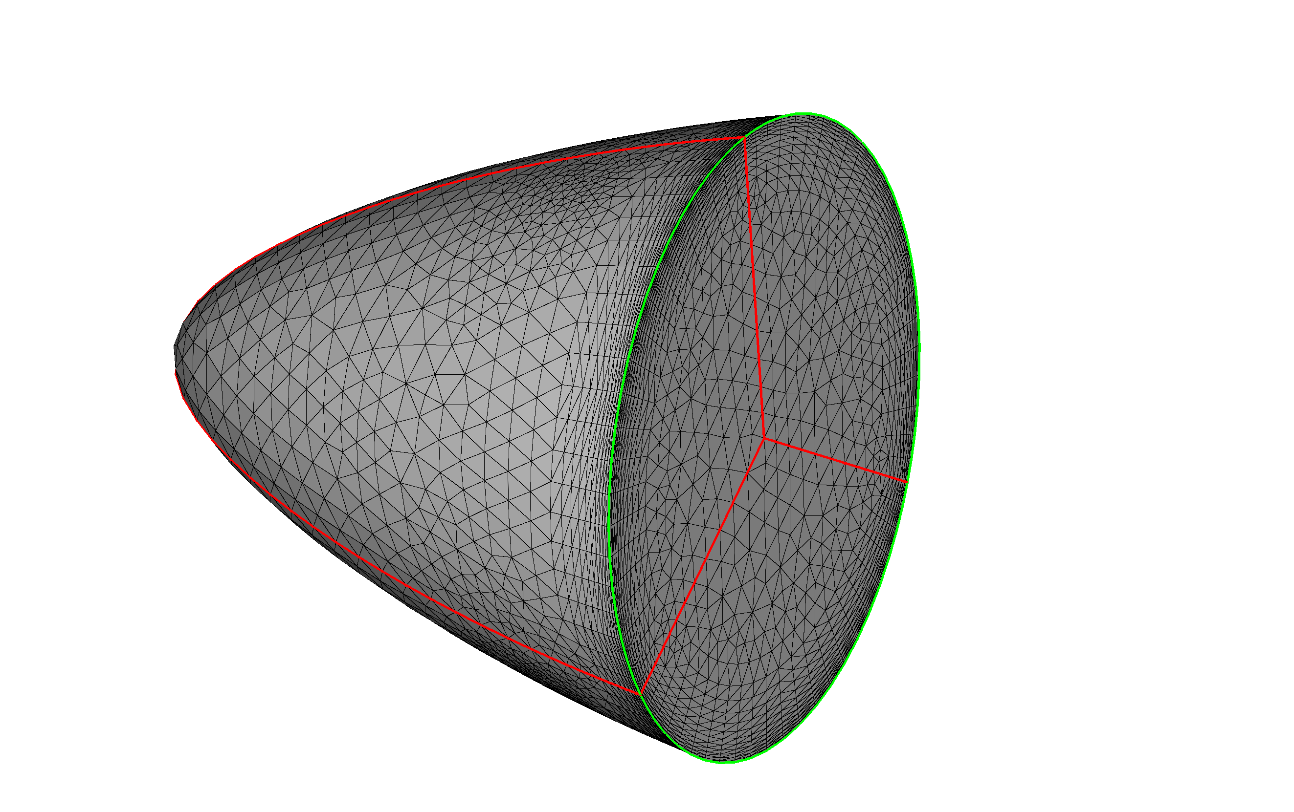
Fig. 3.3.5 Example of edge type “projectAnisoSpacing”. See the above JSON example: “hubCircle” colored green, “hubSplitEdge” colored red which is of type “projectAnisoSpacing”. The anisotropic spacing on the neighboring patches will be “projected” to the edge, i.e., the nodes distribution along the edge will be updated.#
3.3.5.2. faces#
Option |
Type |
Default |
Example |
Description |
|---|---|---|---|---|
<faceName>-> maxEdgeLength |
float |
REQUIRED |
0.05 |
Maximum length of element edge for the face named <faceName>. This overwrites the global maxEdgeLength for that face only. |
Example:
"faces": {
    "rightWing": {
        "maxEdgeLength": 0.05
    },
    "fuselage": {
        "maxEdgeLength": 0.05
    }
}
3.3.6. JSON volume mesher#
Option |
Type |
Default |
Example |
Description |
|---|---|---|---|---|
refinementFactor |
float |
1 |
2 |
If refinementFactor=r is provided all spacings in refinement regions and first layer thickness will be adjusted to generate r-times finer mesh. For example, if refinementFactor=2, all spacings will be divided by \(2^{1/3}\approx 1.26\) , so the resulting mesh will have approximately 2 times more nodes. |
volume |
dict |
REQUIRED |
First layer thickness and growth rate for prism layers being grown out of the surface. It is applied to all surface mesh faces. |
|
volume-> firstLayerThickness |
float |
REQUIRED |
1e-5 |
First layer thickness for volume prism layers. |
volume-> growthRate |
float |
REQUIRED |
1.2 |
Growth rate for volume prism layers. |
volume-> gapTreatmentStrength |
float |
0 |
0 |
Narrow gap treatment strength used when two surfaces are in close proximity. Use a value between 0 and 1, where 0 is no treatment and 1 is the most conservative treatment. This parameter has a global impact where the anisotropic transition into the isotropic mesh. However, the impact on regions without close proximity is negligible. See the examples below. |
farfield |
dict |
It indicates the type of the volume mesh and its farfield boundary, the default is a sphere, or semi-sphere when the model has a symmetry plane. |
||
farfield-> type |
["auto", "quasi-3d"] |
"auto" |
"quasi-3d" |
Farfield shape: "auto" for spherical and semi-spherical; "quasi-3d" for 2D simulations. |
refinement |
list(dict) |
[] |
Description of refinement zones. For details see here. |
|
rotorDisks |
list(dict) |
[] |
Description of rotor disks. This generates a cylindrical shape (hollowed or not). Used for actuator disks or BET disks. For details see here. |
|
slidingInterfaces |
list(dict) |
[] |
Description of sliding interfaces. This generates a cylindrical shape (hollowed or not) with concentric mesh. For details see here. |
Gap treatment examples:
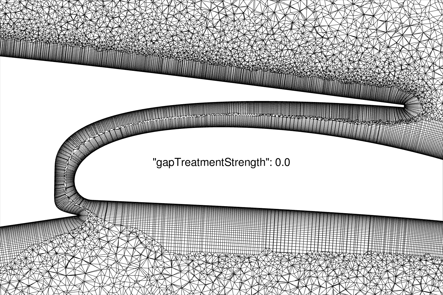
Fig. 3.3.6 Default configuration, gapTreatmentStrength=0#

Fig. 3.3.7 gapTreatmentStrength=0.25#
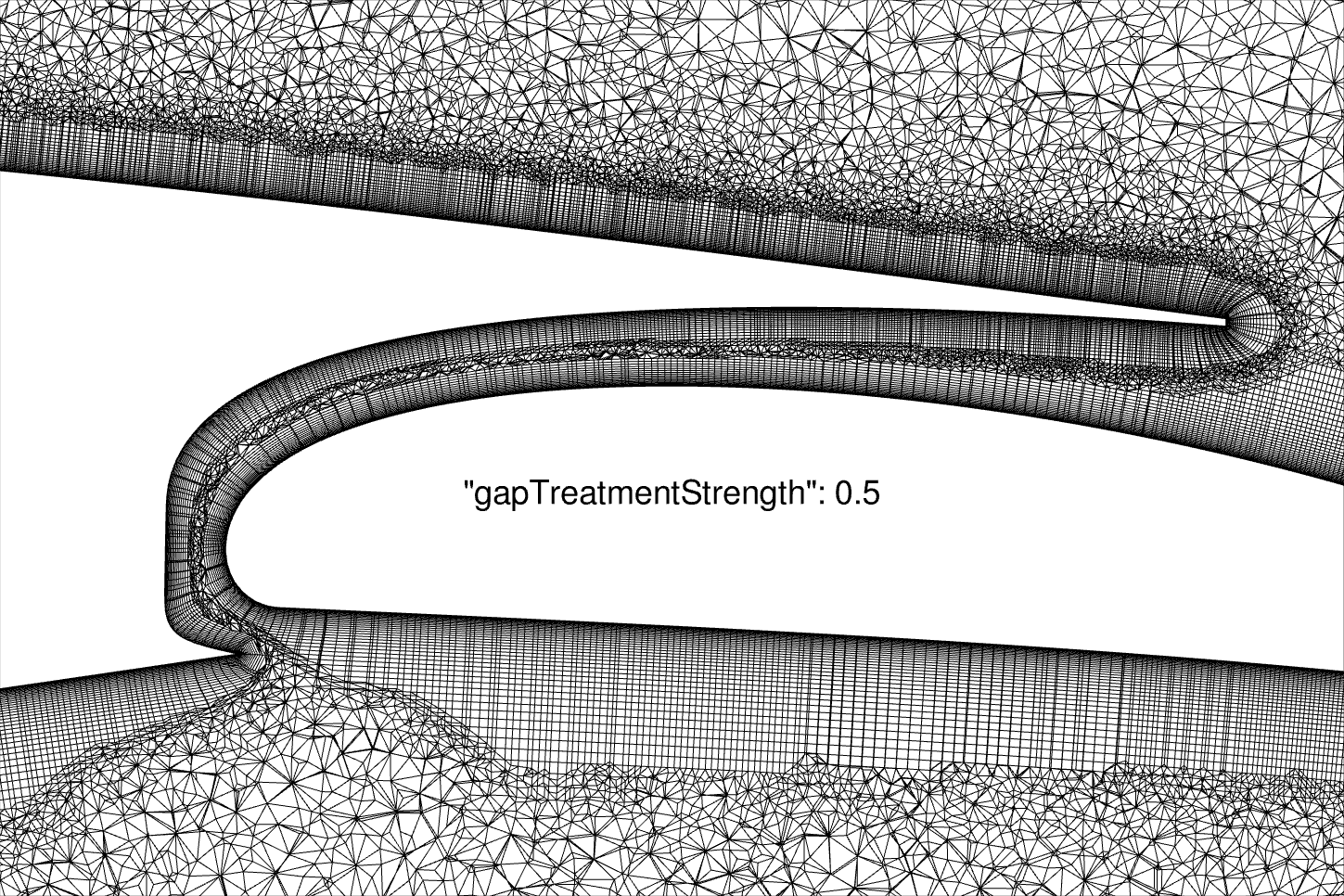
Fig. 3.3.8 gapTreatmentStrength=0.5#
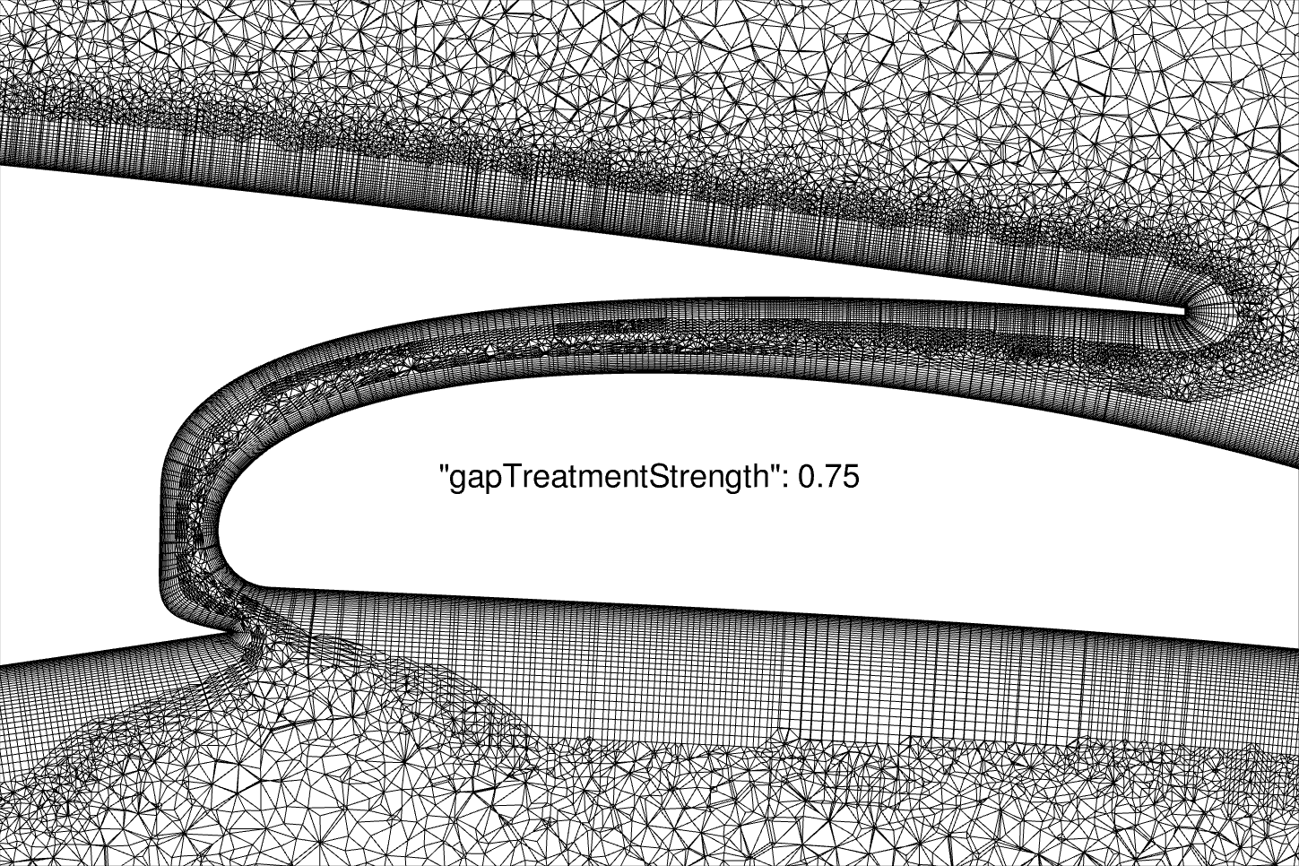
Fig. 3.3.9 gapTreatmentStrength=0.75#
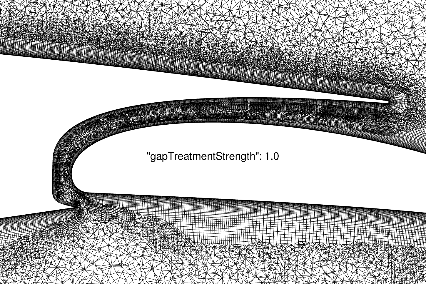
Fig. 3.3.10 gapTreatmentStrength=1.0#
The larger gapTreatmentStrength is, the more space is dedicated to isotropic mesh than anisotropic mesh in narrow gaps.
3.3.6.1. refinement (list)#
Option |
Type |
Default |
Example |
Description |
|---|---|---|---|---|
type |
["box", "cylinder"] |
"box" |
"box" |
Shape of the refinement zone: box or cylinder. |
center |
3-array |
REQUIRED |
[2, 0, 0] |
Coordinate of geometrical center. |
spacing |
float |
REQUIRED |
0.05 |
Cell spacing applied in the refinement zone. |
size |
3-array |
REQUIRED for box |
[4, 3, 2] |
Size of the box in x, y and z directions. |
axisOfRotation |
3-array |
REQUIRED for box |
[0, 0, 1] |
Axis of rotation for the box. |
angleOfRotation |
float |
REQUIRED for box |
45 |
Angle (in degrees) of rotation for the box. |
radius |
float |
REQUIRED for cylinder |
4 |
Radius of the cylinder. |
length |
float |
REQUIRED for cylinder |
5 |
Length of the cylinder. |
axis |
3-array |
REQUIRED for cylinder |
[0, 0, 1] |
Axis of the cylinder. |
Example:
"refinement": [
 {
     "size": [4, 3, 2],
     "center": [2, 0, 0],
     "spacing": 0.05,
     "axisOfRotation": [ 0, 0, 1 ],
     "angleOfRotation": 45
 },
 {
     "type": "cylinder",
     "radius": 4,
     "length": 5,
     "center": [5, 0, 0],
     "spacing": 0.05,
     "axis": [1, 0, 0]
 }]
3.3.6.2. rotorDisks (list)#
Option |
Type |
Default |
Example |
Description |
|---|---|---|---|---|
name |
string |
index (0, 1, 2…) |
"rotor" |
Name for the rotor disk. The boundary name will become: rotorDisk-<name>. |
innerRadius |
float |
REQUIRED |
0 |
Inner radius of rotor disk, if greater than 0 then "donut" shape is created. |
outerRadius |
float |
REQUIRED |
10 |
Outer radius of rotor disk. |
thickness |
float |
REQUIRED |
0.5 |
Thickness of rotor disk. |
axisThrust |
3-array |
REQUIRED |
[1, 0, 0] |
Axis of thrust of rotor disk. The cylindrical shape is rotated such its axis is aligned with axisThrust. |
center |
3-array |
REQUIRED |
[0, 0, 0] |
Position of center of the rotor disk. |
spacingAxial |
float |
REQUIRED |
0.01 |
Spacing along the axial direction. |
spacingRadial |
float |
REQUIRED |
0.03 |
Spacing along the radial direction. |
spacingCircumferential |
float |
REQUIRED |
0.03 |
Spacing along the circumferential direction. |
Example:
"rotorDisks": [
     {
         "name": "enclosed",
         "innerRadius": 0,
         "outerRadius": 0.75,
         "thickness": 0.1,
         "axisThrust": [1, 0, 0],
         "center": [0, 5.0, 0],
         "spacingAxial": 0.1,
         "spacingRadial": 0.1,
         "spacingCircumferential": 0.1
     },
     {
         "innerRadius": 0,
         "outerRadius": 0.75,
         "thickness": 0.1,
         "axisThrust": [0, 0, 1],
         "center": [0, -5, 0],
         "spacingAxial": 0.1,
         "spacingRadial": 0.1,
         "spacingCircumferential": 0.1
     }
 ],
3.3.6.3. slidingInterfaces (list)#
Option |
Type |
Default |
Example |
Description |
|---|---|---|---|---|
name |
string |
index (0, 1, 2…) |
"interface" |
Name for the sliding interface. The boundary name will become: "slidingInterface-<name>". |
innerRadius |
float |
REQUIRED |
0 |
Inner radius of sliding interface, if greater than 0 then "donut" shape is created. |
outerRadius |
float |
REQUIRED |
10 |
Outer radius of sliding interface. |
thickness |
float |
REQUIRED |
0.5 |
Thickness of sliding interface. |
axisOfRotation |
3-array |
REQUIRED |
[1, 0, 0] |
Axis of rotation of the sliding interface. The cylindrical shape is positioned such its axis is aligned with axisOfRotation. |
center |
3-array |
REQUIRED |
[0, 0, 0] |
Position of center of the sliding interface. |
spacingAxial |
float |
REQUIRED |
0.01 |
Spacing along the axial direction. |
spacingRadial |
float |
REQUIRED |
0.03 |
Spacing along the radial direction. |
spacingCircumferential |
float |
REQUIRED |
0.03 |
Spacing along the circumferential direction. |
enclosedObjects |
[] |
REQUIRED |
["hub", "blade1", "blade2", "blade3"] |
Objects enclosed by this sliding interface. Can be faces, other sliding intefaces or rotor disks. |
Example:
"slidingInterfaces": [
    {
        "name": "inner",
        "innerRadius": 0,
        "outerRadius": 0.75,
        "thickness": 0.5,
        "axisOfRotation": [0, 0, 1],
        "center": [0, 0, 0],
        "spacingAxial": 0.2,
        "spacingRadial": 0.2,
        "spacingCircumferential": 0.2,
        "enclosedObjects": ["hub", "blade1", "blade2", "blade3"]
    }, {
        "name": "mid",
        "innerRadius": 0,
        "outerRadius": 2.0,
        "thickness": 2.0,
        "axisOfRotation": [0, 1, 0],
        "center": [0, 0, 0],
        "spacingAxial": 0.2,
        "spacingRadial": 0.2,
        "spacingCircumferential": 0.2,
        "enclosedObjects": ["slidingInterface-inner"]
    }, {
        "innerRadius": 0,
        "outerRadius": 2.0,
        "thickness": 2.0,
        "axisOfRotation": [0, 1, 0],
        "center": [0, 5, 0],
        "spacingAxial": 0.2,
        "spacingRadial": 0.2,
        "spacingCircumferential": 0.2,
        "enclosedObjects": ["rotorDisk-enclosed"]
    }, {
        "innerRadius": 1.5,
        "outerRadius": 2.0,
        "thickness": 2.0,
        "axisOfRotation": [0, 1, 0],
        "center": [0, -5, 0],
        "spacingAxial": 0.2,
        "spacingRadial": 0.2,
        "spacingCircumferential": 0.2,
        "enclosedObjects": []
    }, {
        "name": "outer",
        "innerRadius": 0,
        "outerRadius": 8,
        "thickness": 6,
        "axisOfRotation": [1, 0, 0],
        "center": [0, 0, 0],
        "spacingAxial": 0.4,
        "spacingRadial": 0.4,
        "spacingCircumferential": 0.4,
        "enclosedObjects": ["slidingInterface-mid", "rotorDisk-1", "slidingInterface-2", "slidingInterface-3"]
    }
],
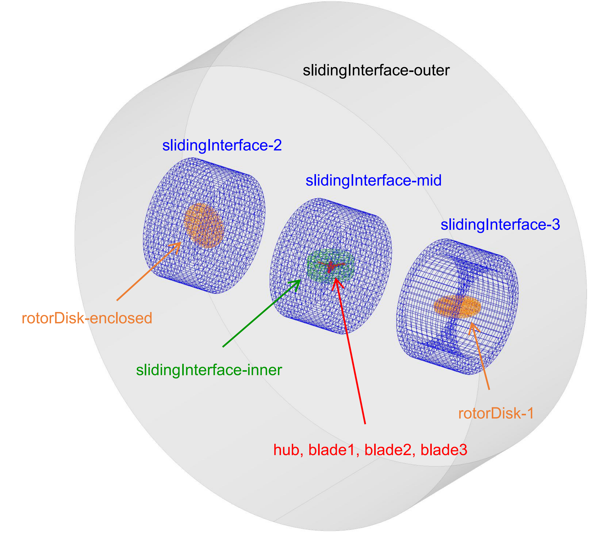
Fig. 3.3.11 Rotor disks and sliding interfaces generated according to the above configuration.#