2.4. User Defined Dynamics
In Flow360, users are now able to specify arbitrary dynamics. In what follows, an example for a Proportional-Integral (PI) controller is given.
2.4.1. PI controller for angle of attack to control lift coefficient
In this example, we add a controller to om6Wing case study. Based on the entries of the configuration file in this case study, the resulting value of the lift coefficient, CL, obtained from the simulation is ~0.26. Our objective is to add a controller to this case study such that for a given target value of CL (e.g., 0.4), the required angle of attack, alphaAngle , is estimated. To this end, a PI controller is defined under userDefinedDynamics in the configuration file as:
 1"userDefinedDynamics" : [
 2    {
 3        "dynamicsName" : "alphaController",
 4        "inputVars" : ["CL"],
 5        "constants" : {"CLTarget": 0.4,
 6                       "Kp": 0.2,
 7                       "Ki": 0.002
 8        },
 9        "outputVars" : ["alphaAngle"],
10        "stateVarsInitialValue" : ["alphaAngle", "0.0"],
11        "updateLaw" : ["if (pseudoStep > 500) state[0] + Kp * (CLTarget - CL) + Ki * state[1]; else state[0];",
12                        "if (pseudoStep > 500) state[1] + (CLTarget - CL); else state[1];"],
13        "outputLaw" : ["if (pseudoStep > 500) state[0]; else alphaAngle;"],
14        "inputBoundaryPatches" : ["1"]
15    }
16]
The complete case configuration file can be downloaded here: Flow360.json.
Some of the parameters are dicussed in more detail here:
dynamicsName: This is a name selected by the user for the dynamics. The results of user-defined dynamics are saved to udd_dynamicsName_v2.csv.
constants: This includes a list of all the constants related to this dynamics. These constants will be used in the equations for
updateLawandinputLaw. In the above-mentioned example,CLTarget,Kp, andKiare the target value of the lift coefficient, the proportional gain of the controller, and the integral gain of the controller, respectively.stateVarsInitialValue: There are two state variables for this controller. The first one,
state[0], is the angle of attack computed by the controller, and the second one,state[1], is the summation of error(CLTarget - CL)over iterations. The initial values ofstate[0]andstate[1]are set toalphaAngleand0, respectively.updateLaw: The related equations for the state variables are specified here. The first and the second equations correspond to equations for
state[0]andstate[1], respectively. The conditional statement forces the controller not to be run for the first 500 pseudoSteps. This ensures that the flow field is established to some extent before the controller is initialized.outputLaw: The relations between
outputVarsand the state variables are specified. For this example, we set the output variable equal to the angle of attack calculated by the controller (i.e.,state[0]).inputBoundaryPatches: The related boundary conditions for the inputs of the user-defined dynamics are specified here. In this example, the noSlipWall boundary conditions are where
CLis calcualted. As seen in the configuration file, the boundary name for the No-Slip boundary condition is"1".
The following figure shows the values of lift coefficient, CL, and angle of attack, alphaAngle, versus the steps, pseudoStep. As specified in the configuration file, the initial value of angle of attack is 3.06. With the specified user-defined dynamics, alphaAngle is adjusted to a final value of 4.61 so that CL = 0.4 is achieved.
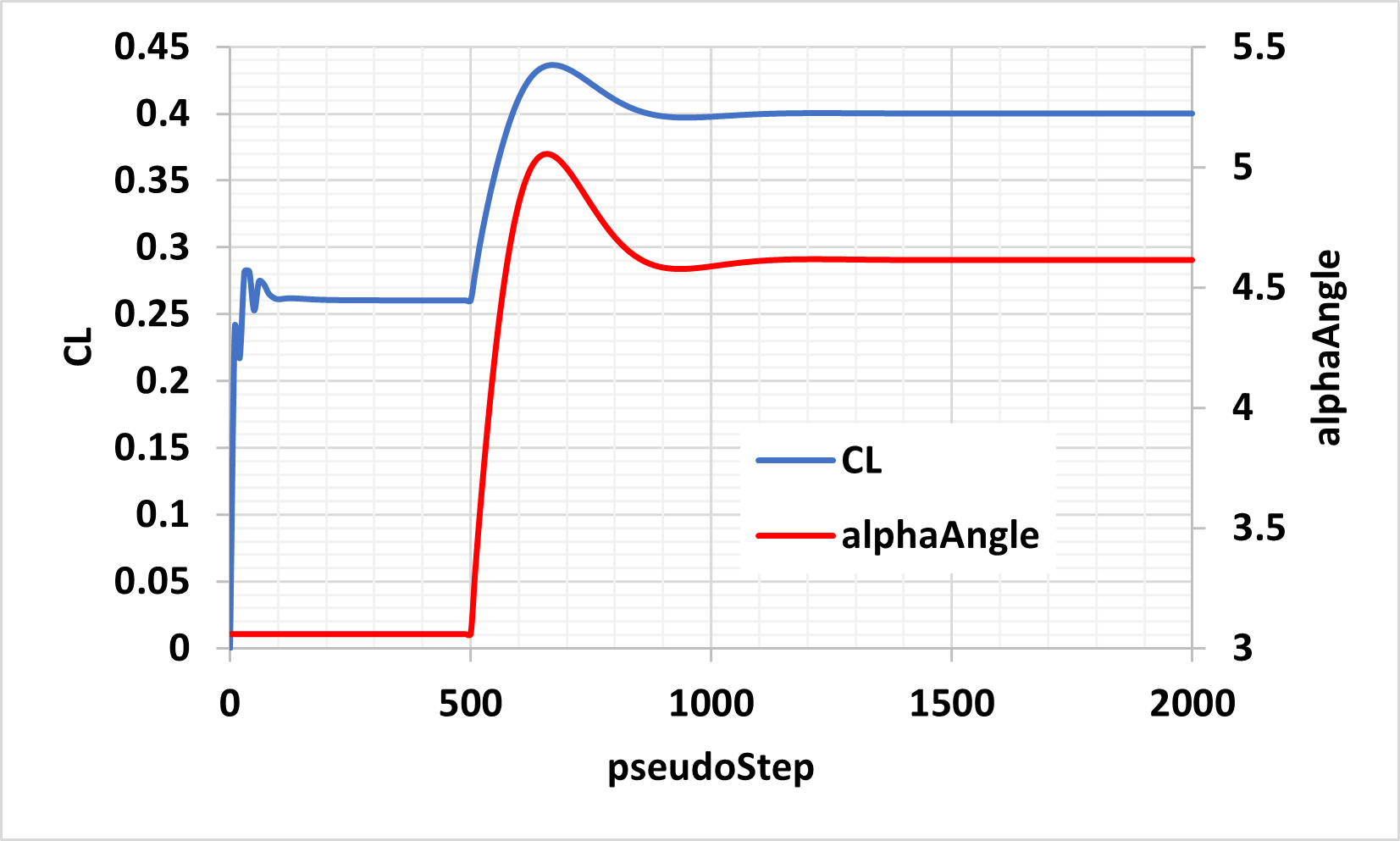
Fig. 2.4.1 Results of alphaController for om6Wing case study.